Programming DDS for Printer Files - IBM
160
IBM i 7.2 Programming DDS for printer files IBM
-
Upload
khangminh22 -
Category
Documents
-
view
2 -
download
0
Transcript of Programming DDS for Printer Files - IBM

IBM i7.2
ProgrammingDDS for printer files
IBM

Note
Before using this information and the product it supports, read the information in “Notices” on page149.
This edition applies to IBM i 7.2 (product number 5770-SS1) and to all subsequent releases and modifications untilotherwise indicated in new editions. This version does not run on all reduced instruction set computer (RISC) models nordoes it run on CISC models.
This document may contain references to Licensed Internal Code. Licensed Internal Code is Machine Code and islicensed to you under the terms of the IBM License Agreement for Machine Code.© Copyright International Business Machines Corporation 2001, 2013.US Government Users Restricted Rights – Use, duplication or disclosure restricted by GSA ADP Schedule Contract withIBM Corp.

Contents
DDS for printer files............................................................................................... 1What's new for IBM i 7.2..............................................................................................................................1PDF file for DDS for printer files...................................................................................................................1Defining a printer file....................................................................................................................................2
Conventions and terminology for DDS information............................................................................... 3Positional entries for printer files (positions 1 through 44).................................................................. 4
Sequence number for printer files (positions 1 through 5)............................................................. 4Form type for printer files (position 6)............................................................................................. 4Comment for printer files (position 7).............................................................................................. 4Condition for printer files (positions 7 through 16)......................................................................... 4Type of name or specification for printer files (position 17)............................................................5Reserved for printer files (position 18)............................................................................................ 5Name for printer files (positions 19 through 28)............................................................................. 5
Record format name in printer files............................................................................................ 5Field name in printer files............................................................................................................6Constant fields in printer files..................................................................................................... 6
Reference for printer files (position 29)........................................................................................... 7Length for printer files (positions 30 through 34)............................................................................7Data type for printer files (position 35)............................................................................................ 8Decimal positions for printer files (positions 36 and 37).............................................................. 10Usage for printer files (position 38)................................................................................................10Location for printer files (positions 39 through 44).......................................................................10
Line (positions 39 through 41)..................................................................................................11Position (positions 42 through 44)........................................................................................... 11
Keyword entries for printer files (positions 45 through 80)..................................................................... 12Keywords supported for printer file device type of *AFPDS............................................................... 13AFPRSC (AFP Resource) keyword in printer files................................................................................ 14ALIAS (Alternative Name) keyword in printer files..............................................................................23BARCODE (Bar Code) keyword in printer files.....................................................................................24BLKFOLD (Blank Fold) keyword in printer files....................................................................................36BOX (Box) keyword in printer files....................................................................................................... 36CDEFNT (Coded Font Name) keyword in printer files......................................................................... 39CHRID (Character Identifier) keyword in printer files......................................................................... 41CHRSIZ (Character Size) keyword in printer files................................................................................42COLOR (Color) keyword in printer files................................................................................................ 43CPI (Characters Per Inch) keyword in printer files..............................................................................46CVTDTA (Convert Data) keyword in printer files..................................................................................49DATE (Date) keyword in printer files.................................................................................................... 52DATFMT (Date Format) keyword in printer files.................................................................................. 54DATSEP (Date Separator) keyword in printer files...............................................................................55DFNCHR (Define Character) keyword in printer files.......................................................................... 56
Selecting which code points to redefine........................................................................................ 63Dot matrix........................................................................................................................................63Specifying dots to be printed in the dot matrix..............................................................................64
DFT (Default) keyword in printer files..................................................................................................66DLTEDT (Delete Edit) keyword in printer files......................................................................................67DOCIDXTAG (Document Index Tag) keyword in printer files.............................................................. 68DRAWER (Drawer) keyword in printer files..........................................................................................69DTASTMCMD (Data Stream Command) keyword in printer files.........................................................70DUPLEX (Duplex) keyword in printer files............................................................................................71EDTCDE (Edit Code) keyword in printer files....................................................................................... 72
iii

IBM i edit codes in printer files.......................................................................................................73User-defined edit codes in printer files..........................................................................................75
EDTWRD (Edit Word) keyword in printer files......................................................................................77Parts of an edit word in printer files............................................................................................... 78Forming the body of an edit word in printer files...........................................................................79Forming the status of an edit word in printer files.........................................................................79Formatting the expansion of an edit word in printer files..............................................................80
ENDPAGE (End Page) keyword in printer files.....................................................................................81ENDPAGGRP (End Page Group) keyword in printer files.....................................................................82FLTFIXDEC (Floating-Point to Fixed Decimal) keyword in printer files.............................................. 82FLTPCN (Floating-Point Precision) keyword in printer files................................................................ 83FNTCHRSET (Font Character Set) keyword in printer files................................................................. 84FONT (Font) keyword in printer files....................................................................................................86FONTNAME (Font name) keyword in printer files................................................................................88FORCE (Force) keyword in printer files................................................................................................92GDF (Graphic Data File) keyword in printer files................................................................................. 92HIGHLIGHT (Highlight) keyword in printer files..................................................................................95INDARA (Indicator Area) keyword in printer files............................................................................... 96INDTXT (Indicator Text) keyword in printer files.................................................................................96INVDTAMAP (Invoke Data Map) keyword in printer files.................................................................... 97INVMMAP (Invoke Medium Map) keyword in printer files.................................................................. 98LINE (Line) keyword in printer files......................................................................................................99LPI (Lines Per Inch) keyword in printer files..................................................................................... 102MSGCON (Message Constant) keyword in printer files..................................................................... 103OUTBIN (Output Bin) keyword in printer files...................................................................................104OVERLAY (Overlay) keyword in printer files...................................................................................... 105PAGNBR (Page Number) keyword in printer files..............................................................................108PAGRTT (Page Rotation) keyword in printer files..............................................................................109PAGSEG (Page Segment) keyword in printer files.............................................................................111POSITION (Position) keyword in printer files....................................................................................114PRTQLTY (Print Quality) keyword in printer files...............................................................................115REF (Reference) keyword in printer files...........................................................................................116REFFLD (Referenced Field) keyword in printer files......................................................................... 117RELPOS (Relative Position) keyword in printer files..........................................................................118SKIPA (Skip After) keyword in printer files........................................................................................119SKIPB (Skip Before) keyword in printer files.....................................................................................120SPACEA (Space After) keyword in printer files..................................................................................120SPACEB (Space Before) keyword in printer files............................................................................... 121STAPLE (Staple) keyword in printer files........................................................................................... 121STRPAGGRP (Start Page Group) keyword in printer files..................................................................123TEXT (Text) keyword in printer files...................................................................................................123TIME (Time) keyword in printer files................................................................................................. 124TIMFMT (Time Format) keyword in printer files................................................................................124TIMSEP (Time Separator) keyword in printer files............................................................................125TRNSPY (Transparency) keyword in printer files.............................................................................. 126TXTRTT (Text Rotation) keyword in printer files............................................................................... 128UNDERLINE (Underline) keyword in printer files.............................................................................. 129UNISCRIPT (Unicode Text Layout) keyword in printer files..............................................................130ZFOLD (Z-fold) keyword in printer files............................................................................................. 134
CODE128 character set in DDS............................................................................................................... 135Unicode considerations for printer files..................................................................................................136
Positional entry considerations for printer files that use UTF-16 data............................................ 137Keyword considerations for printer files that use UTF-16 data (positions 45 through 80).............137
CCSID (Coded Character Set Identifier) keyword........................................................................138DBCS considerations for printer files...................................................................................................... 139
Positional entry considerations for printer files that use DBCS........................................................139Length (positions 30 through 34).................................................................................................139Data type or keyboard shift (position 35).................................................................................... 140
iv

Decimal positions (positions 36 and 37)..................................................................................... 140Keyword considerations for printer files that use DBCS................................................................... 140
CHRSIZ (Character Size) keyword................................................................................................140DFNLIN (Define Line) keyword.....................................................................................................141IGCALTTYP (Alternative Data Type) keyword.............................................................................. 143IGCANKCNV (Alphanumeric-to-DBCS Conversion) keyword......................................................143IGCCDEFNT (DBCS Coded Font) keyword................................................................................... 145IGCCHRRTT (DBCS Character Rotation) keyword....................................................................... 146
Additional considerations for describing printer files that contain DBCS data................................147Related information for DDS for printer files.......................................................................................... 148
Notices..............................................................................................................149Programming interface information........................................................................................................150Trademarks.............................................................................................................................................. 150Terms and conditions.............................................................................................................................. 151
v

vi

DDS for printer filesYou can use data description specifications (DDS) to define printer files. This topic provides theinformation you need to code the positional and keyword entries that define these files.
Note: By using the code examples, you agree to the terms of the “Code license and disclaimerinformation” on page 148.
What's new for IBM i 7.2Read about new or significantly changed information for the DDS for printer files topic collection.
Changes to the Bar Code (BARCODE) keywordSeveral additional bar codes types and modifiers are now supported for the Bar Code (BARCODE)keyword. The new bar code types now supported include:
• QR Code• Code 93• USPS Intelligent Mail• Royal Mail Red Tag• GS1 Databar
Additional modifiers on previously supported bar code types add support for the following bar codes:
• UCC/EAN 128 (GS1-128)• USPS intelligent Mail Container• GS1 ITF-14
In addition, several other bar code changes have been made. See “BARCODE (Bar Code) keyword inprinter files” on page 24
Changes to the Font name (FONTNAME) keywordThe font names of the TrueType and OpenType fonts provided in option 43 of the IBM® i have changed.Support for the use of the old names is provided. See “FONTNAME (Font name) keyword in printer files”on page 88.
How to see what's new or changedTo help you see where technical changes have been made, the information center uses:
• The image to mark where new or changed information begins.• The image to mark where new or changed information ends.
To find other information about what's new or changed this release, see the Memo to users.
PDF file for DDS for printer filesYou can view and print a PDF file of this information.
To view or download the PDF version of this document, select DDS for printer files.
Saving PDF filesTo save a PDF on your workstation for viewing or printing:
© Copyright IBM Corp. 2001, 2013 1

1. Right-click the PDF link in your browser.2. Click the option that saves the PDF locally.3. Navigate to the directory in which you want to save the PDF.4. Click Save.
Downloading Adobe ReaderYou need Adobe Reader installed on your system to view or print these PDFs. You can download a freecopy from the Adobe Web site (www.adobe.com/products/acrobat/readstep.html) .
Related referenceRelated information for DDS for printer filesProduct manuals, Web sites, and other information center topic collections contain information thatrelates to the DDS for printer files topic collection. You can view or print any of the PDF files.
Defining a printer fileWhen defining a printer file using data description specifications (DDS), you should follow these rules forfilling in positions 1 through 44 of the DDS form for printer files.
About this taskSpecify the entries in the following order to define a printer file:
Procedure1. Optional: File-level entries2. Record-level entries3. Field-level entries
ResultsSpecify at least one record format in each file. The maximum number of record formats in a printer file is1024. The maximum number of fields in any one record format is 32 767. The maximum combined lengthof all named fields and indicators in a record format is 32 767 bytes.
Note: Specify the file name through the Create Printer File (CRTPRTF) command, not through DDS.
See DDS concepts for the following general information:
• An explanation of file level, record level, and field level in the overview topic.• A complete printer file example in the examples topic.• Syntax rules for specifying DDS keywords.
Figure 1 on page 3 shows a printer file code example.
2 IBM i: DDS for printer files

Note: By using the code examples, you agree to the terms of the “Code license and disclaimerinformation” on page 148.
|...+....1....+....2....+....3....+....4....+....5....+....6....+....7....+....800010A* PRINTER FILE CODING EXAMPLE00020A*00030A R TITLER SKIPB(3)00040A FLD1 40 47SPACEA(2) UNDERLINE00050A 30 FLD2 40 47SPACEA(2) UNDERLINE00060A*00070A R AUTHORR00080A 66'by'00090A FIELD1 40 47SPACEB(1)00100A 50DFT('Task Force I')00110A 31 SPACEA(1)00120A 31 65'and'00130A 31 FIELD2 40 4700140A*00150A R PUBR SKIPB(58)00160A 47'Published by Department'00170A DEPT 3 0 +100180A 47DATE EDTCDE(Y)00190A SPACEB(1)00200A N1500210AO 32 33 34 47TIME00220A SPACEB(1) A
Figure 1. Printer file code example
Related conceptsRules for DDS keywords and parameter valuesKeyword entries for printer files (positions 45 through 80)These are valid keyword entries for defining printer files.Related referenceExamples: DDS coding
Conventions and terminology for DDS informationThe DDS information uses these conventions and terminology.
• A keyword is a name that identifies a function.• A parameter is an argument that identifies a value or set of values you can use to tailor the function the
keyword specifies. It is shown between the parentheses on a keyword.• A value is an actual value that you can use for a parameter.• In the keyword descriptions, this field or this record format means the field or record format that you aredefining.
• The expression use this file- or record-level keyword means the keyword is valid only at the file or recordlevel.
• To specify a keyword means to code the keyword in the DDS for a file. This contrasts with to select akeyword or when a keyword is in effect, both of which mean that any conditioning (such as one or moreoption indicators) is satisfied when an application program issues an input or output operation.
• Current source or source you are defining means the DDS that together make up the description of onefile.
• In sample displays, character fields are shown as Xs and numeric fields are shown as Ns.• The 5250 Work Station Feature is a feature of the OS/2 communications manager that allows the
personal computer to perform like a 5250 display station and to use functions of the IBM i operatingsystem.
• Logical file includes join logical files, simple logical files, and multiple-format logical files.
DDS for printer files 3

• Page means to move information up or down on the display. Roll means the same as page. Paging keysare the same as roll keys. The PAGEDOWN keyword is the same as the ROLLUP keyword. The PAGEUPkeyword is the same as the ROLLDOWN keyword.
Positional entries for printer files (positions 1 through 44)You specify positional entries for printer files in the first 44 positions of the data description specifications(DDS) form.
To code the remaining part of the form, see “Keyword entries for printer files (positions 45 through 80)”on page 12.
The printer file example in “Defining a printer file” on page 2 shows some positional entries for printerfiles.
Sequence number for printer files (positions 1 through 5)You can specify a sequence number in these positions for each line on the DDS form.
The sequence number is optional and for documentation purposes only.
Form type for printer files (position 6)You can enter an A in this position to designate this form as a DDS form.
The form type is optional and for documentation purposes only.
Comment for printer files (position 7)You can enter an asterisk (*) in this position to identify this line as a comment, and then use positions 8through 80 for comment text.
A blank line (no characters specified in positions 7 through 80) is also treated as a comment. Commentlines can appear anywhere in DDS and are kept only in the source file. Comments appear on the sourcecomputer printout but not on the expanded source computer printout.
Condition for printer files (positions 7 through 16)You use these positions to specify option indicators (2-digit numbers from 01 to 99). Then you canhave your program set option indicators on (hexadecimal F1) or off (hexadecimal F0) to select a field orkeyword.
By specifying two to nine indicators that must all be in effect (set off if N is specified; set on if N is notspecified) before the field or the keyword is selected, you create an AND condition.
Note: You must specify the field or keyword on the same line as the last (or only) set of indicators youspecified.
Specify up to nine indicators for each condition and nine conditions for each field or keyword. A maximumof 81 indicators can be specified for each keyword when nine indicators are used with nine conditions.
By specifying several conditions for a field or keyword, you create an OR relationship. If any one of theconditions is satisfied, the field or the keyword is selected.
Note: Conditions within the OR relationship can consist of one indicator or of several indicators joined byAND. Indicators can be joined by AND to form a condition; conditions can be joined by OR to give yourprogram several ways to select the field or the keyword.
Specify the conditions by entering the following values:Position 7 (AND)
If you need more than three indicators to form an AND condition, specify them in the same positionson the next line or lines of the DDS form. Specify A in position 7 on the following lines to designate thecontinuation of the AND condition, or leave it blank because A is the default.
4 IBM i: DDS for printer files

Position 7 (OR)If you specify several conditions that are to be joined by OR, each condition must start on a new lineand each condition except the first must have an O in position 7. An O specified for the first conditionproduces a warning message, and that position is assumed to be blank.
Positions 8, 11, 14 (NOT)If you want an indicator to be off instead of on to satisfy a condition, specify N in the position justpreceding the indicator (position 8, 11, or 14).
Specifying a condition for more than one field or keyword in printer filesIf you specify a condition for a field, the field name (or the constant) and the last (or only) indicator mustbe on the same line. If you specify one or more keywords for the field, the condition applies only to thisfield, not to the keywords. If the field is not selected for an output operation, no keywords specified forthat field are in effect, regardless of how the condition for the keywords is specified. For example, if, in theprinter file example in “Defining a printer file” on page 2, indicator 30 is off, SPACEA and UNDERLINE arenot in effect.
If you want to specify a condition for one or more keywords, specify the keywords and the last (or only)indicator on the same line. If the condition applies to keywords on multiple lines, keyword continuationmust be used for the indicators to apply to all the keywords.
Type of name or specification for printer files (position 17)The value in this position identifies the type of name in positions 19 through 28.
The valid entries for printer files are:
Entry Meaning
R Record format name
Blank Field name
The printer file example in “Defining a printer file” on page 2 shows how to code the name type.
For more information about types of names, see “Name for printer files (positions 19 through 28)” onpage 5.
Reserved for printer files (position 18)This position does not apply to any file type.
Leave this position blank unless you use it for comment text.
Name for printer files (positions 19 through 28)You specify record format names and field names in these positions.
Name must begin in position 19.
The printer file example in “Defining a printer file” on page 2 shows how to specify record format namesand field names.
Related conceptsRules for DDS keywords and parameter values
Record format name in printer filesWhen you specify an R in position 17, the name specified in positions 19 through 28 is a record formatname.
You can specify more than one record format for a printer file, but each name must be unique within thatfile. You must also specify field names or constant fields to complete a record format in a printer file.
DDS for printer files 5

Field name in printer filesWhen position 17 is left blank, the name specified in positions 19 through 28 is a field name.
Field names must be unique within the record format.
Constant fields in printer filesConstant fields are unnamed fields (positions 19 through 28 must be blank), or fields with a special name(*NONE) when the POSITION keyword is used in the record.
The following rules apply when you specify a constant field:
• Positions 17 through 38 must be blank if you specify the location of the field in positions 39 through 44.• Positions 17, 18, and 29 through 44 must be blank if you specify the POSITION keyword.• The field can be conditioned using option indicators (positions 7 through 16).• You can specify a constant field in a record format that has a BOX, ENDPAGE, GDF, LINE, OVERLAY,
or PAGSEG keyword specified on the record, only if you have specified a POSITION keyword on theconstant field.
• The constant itself is defined in positions 45 through 80 using one of the following constant fieldkeywords:
– Explicit DFT keyword (specify the value within apostrophes with the DFT keyword)– Implicit DFT keyword (specify the value within apostrophes without the DFT keyword)– DATE keyword (specify no value)– TIME keyword (specify no value)– PAGNBR keyword (specify no value)– MSGCON keyword (specify the message description, the message file, the library name, and the
length of the message description)• The EDTCDE or the EDTWRD keyword can be specified for constant fields only when DATE, TIME, or
PAGNBR keywords are also specified.
When specifying a location (positions 39 through 44) for constant fields, you can specify the fields in anyorder if you use line numbers. If you do not use line numbers, you must specify the fields in the order inwhich they are to appear on the printed page.
When you specify the POSITION keyword with a constant field, the special name *NONE signifies thestart of the field in the DDS source. Therefore, you must specify the POSITION keyword or any otherkeyword associated with the constant field, either on the same line as the constant field keyword or on asubsequent line.
Related conceptsDATE (Date) keyword in printer filesYou use this field-level keyword to display the current date or the current system date as a constant fieldthat is 6 or 8 bytes long.Related referenceTIME (Time) keyword in printer filesThis field-level keyword prints the current system time as a constant field 6 bytes long.PAGNBR (Page Number) keyword in printer filesYou use this field-level keyword to specify the location of an unnamed, 4-digit, zoned decimal field tocontain the page number.MSGCON (Message Constant) keyword in printer files
6 IBM i: DDS for printer files

You use this field-level keyword to indicate that the text for a constant field is contained in a messagedescription.
Reference for printer files (position 29)You specify R in position 29 to copy the attributes of a previously defined, named field (the referencedfield) to the field that you are defining. If you do not specify R, you must specify the field attributes.
For example, you might want to reference fields for an externally defined file to print a report from adatabase file.
When using the reference function, specify the referenced field name, even if it is the same as thereferencing field. (The referenced field name can be in a previously created database file specified onthe REF or REFFLD keywords.) The field attributes referenced are the length, data type, and decimalpositions of the field, as well as the ALIAS, FLTPCN, TEXT, DATFMT, DATSEP, TIMFMT, TIMSEP, and editingkeywords.
If the referenced field name is the same as the field that you are defining, specify R in position 29 and thename of the field that you are defining in positions 19 through 28. If the referenced field is different fromthe field that you are defining, specify the name of the referenced field with the REFFLD keyword.
Position 29 must be blank at the file and record levels.
You can specify the name of the file defining the referenced field as a parameter value with the REF or theREFFLD keyword.
If you do not want to copy all the attributes from the previously defined field, specify those attributes forthe field that you are defining, as follows:
• To override editing keywords (EDTCDE or EDTWRD), specify EDTCDE or EDTWRD for the field that youare defining. To delete these keywords, specify DLTEDT for the field that you are defining.
• Validity checking keywords (CHECK, COMP, RANGE, VALUES), if specified for the referenced field, areignored in the printer file.
When you override some specifications, others are affected:
• If you specify a value for data type, field length, or decimal positions for the field that you are defining,editing keywords are not copied from the referenced field.
• Packed decimal and binary fields are not supported for printer files. Therefore, when you referencefields of these types, the data type is converted to zoned decimal (S in position 35) in the printer file.
Note: After the printer file is created, the referenced file can be deleted or changed without affectingthe field definitions in the printer file. To incorporate changes made in the referenced file, delete andre-create the printer file.
Related conceptsWhen to specify REF and REFFLD keywords for DDS filesLength for printer files (positions 30 through 34)You must specify the field length in these positions for each named field (unless you copy the field lengthfrom a referenced field).Related referenceREFFLD (Referenced Field) keyword in printer filesYou use this field-level keyword when referring to a field under one of these conditions.
Length for printer files (positions 30 through 34)You must specify the field length in these positions for each named field (unless you copy the field lengthfrom a referenced field).
Your entry represents the number of bytes of data to be passed from your program when an outputoperation is done for this field. (If the field is to be edited, the associated edit code or edit word is used
DDS for printer files 7

to determine the printed length of the field.) The printer file example in “Defining a printer file” on page 2shows how to code the field length.
The maximum length of a zoned decimal field is 63. Data description specifications allow a maximum fieldlength of 32 767 characters. If the field length causes the field to extend beyond the page size, a warningdiagnostic appears. The maximum length of a single precision floating-point field is 9 digits; the maximumlength of a double precision floating-point field is 17 digits.
If you use a referenced field, override the referenced length by specifying a new value or by specifying theincrease or decrease in length. To increase the length, specify +n, where n is the increase. To decreasethe length, specify -n, where n is the decrease. For example, an entry of +4 indicates that the field isto be 4 digits longer than the referenced field. The field length can be overridden without overriding thedecimals.
If you specify length, it must be right-aligned; leading zeros are optional.
The following example shows correct and incorrect field-length specifications. FIELD1 shows the fieldlength specified incorrectly. FIELD2 and FIELD3 show the field length specified correctly.
|...+....1....+....2....+....3....+....4....+....500010A FIELD1 7 A00020A FIELD2 7 A00030A FIELD3 R +7
For floating-point fields, 7 positions will be added to the length you specify in positions 30 through 34.The 7 extra positions are for the significand sign, the decimal point or comma, the exponent character, theexponent sign, and the exponent.
In some cases, if you specify a value for length, some keywords specified with the field in the databasefile are not included in the printer file.
Related conceptsReference for printer files (position 29)You specify R in position 29 to copy the attributes of a previously defined, named field (the referencedfield) to the field that you are defining. If you do not specify R, you must specify the field attributes.
Data type for printer files (position 35)You can use this position to specify the data type associated with a field.
The valid entries for this field for a printer file are:
Entry Meaning
S Zoned decimal
A Character
F Floating point
L Date
T Time
Z Timestamp
Note: The O (open) and G (graphic) support DDS printer files that use double-byte character set (DBCS).The G (graphic) data type also supports DDS printer files that use UTF-16 and UCS-2.
The printer file example in “Defining a printer file” on page 2 shows how to code the data type.
If you do not specify a data type and do not duplicate one from a referenced field, the IBM i operatingsystem assigns a default value as follows:
• A (character) if the decimal positions (36 and 37) are blank
8 IBM i: DDS for printer files

• S (zoned decimal) if the decimal positions (36 and 37) contain a number in the range 0 through 63
Notes:
1. Specify 0 in position 37 to indicate an integer numeric field.2. Specify F in position 35 for a single precision floating-point field. Use the FLTPCN keyword to specify
double precision or to change the precision of an already specified floating-point field.3. A floating-point value consists of five parts: (a) the significand sign, (b) the significand, (c) the
exponent character (d) the exponent sign, and (e) the exponent.
The significand sign is not printed for a positive value. The number of digits in the significand isdetermined by the length specified (positions 30 through 34). The location of the decimal point orthe comma is determined by the decimal positions specified (positions 36 and 37). The exponentcharacter and the exponent sign are always printed. The exponent is always 3 digits.
The printed length for a floating-point field is 7 positions greater than the length specified in positions30 through 34. The 7 extra positions are for (a) the significand sign, (b) the decimal point or comma, (c)the exponent character, (d) the exponent sign, and (e) the 3 exponent digits.
4. Date, Time, and Timestamp restrictions:
The field length (*DDS positions 30 and 34) for these data types must be blank. The field length isdetermined by the following rules:
• For Date (L), the format specified on the DATFMT keyword dictates the length of the field. If theDATFMT keyword is not specified, then the format is set to *ISO as default, which has a field lengthof 10.
• For Time (T), the format specified on the TIMFMT keyword dictates the length of the field. All formatsfor the TIMFMT keyword, including the default of *ISO when TIMFMT is not specified, has a fieldlength of 8.
• For Timestamp (Z), the field length is 26.
Fields that specify these data types are treated as alphanumeric data when printed. It is up to theapplication program to provide the data in the correct format and length according to the data type andkeywords specified for these fields.
Blank is the only supported value for decimal positions (DDS positions 36 and 37).
Zero suppression is not supported for these data types. EDTCDE and EDTWRD keywords are not validand the operating system does not perform zero suppression by default as it does for signed-numericfields.
The following field level keywords are not allowed with these data types.
BARCODE FLTFIXDEC
BLKFOLD FLTPCN
DATE IGCCDEFNT
DFT IGCCHRRTT
EDTCDE MSGCON
EDTWRD PAGNBR
TIME
Related conceptsData type or keyboard shift (position 35)
DDS for printer files 9

You must type an O in this position to make a field a DBCS-open field.
Decimal positions for printer files (positions 36 and 37)You use these positions to specify the decimal placement within a zoned decimal field and the data typeof the field as it appears in your program.
If you leave these positions blank, the IBM i operating system assumes a data type of character for thefield.
If you enter a number in these positions, the IBM i operating system assumes a data type of zoneddecimal for the field. The number specified is the number of positions to the right of the decimal point. Itmust be less than or equal to the field length, with a maximum of 63. The printer file example in “Defininga printer file” on page 2 shows how to code decimal positions.
If you use a referenced field, you do not need to specify decimal positions because the information isretrieved from the referenced file. You can override or change the decimal positions retrieved.
To override the decimal positions, specify the new value. To change the decimal positions, specify theamount by which you want to increase or decrease the field and precede the amount with either a + or -.For example, an entry of +4 indicates that there are 4 more digits to the right of the decimal point than inthe referenced field.
Note: High-level languages can impose specific length and value restrictions on the decimal positions.Observe these restrictions for files used by those languages.
Usage for printer files (position 38)You use this position to specify that a named field is an output-only or a program-to-system field. Do notmake an entry in this position for a constant (unnamed) field.
The valid entries for printer files are:
• O or blank: Output only• P: Program-to-system (special output field)
Output-only fields pass data from a program to the printer when the program prints a record.
A program-to-system field is a named, numeric, or alphanumeric output-only field used to pass databetween the program and the system. It is not printed. A program can send data to the field with anoutput operation, but the data is not printed.
The following rules apply to program-to-system fields:
• The field is always named.• Locations are not valid.• Length, data type, and decimal positions are specified as for other named fields.• If a program-to-system field is used in the record format, it must be specified as a parameter on a
keyword within the same record format.• Program-to-system fields must appear after all data fields.
Location for printer files (positions 39 through 44)These positions specify where the beginning of the field that you are defining appears on the page. Youspecify the line in positions 39 through 41, and the position in positions 42 through 44.
The following conditions apply:
• When line numbers are specified, fields can appear in any order. They will be sequenced again intoline-position order when placed in the printer file.
• When line numbers are not specified, the field order within the printer file is the same as that specifiedin the DDS.
10 IBM i: DDS for printer files

• When fields or space/skip keywords are conditioned, the data description processor treats them as ifthey were selected when diagnosing overlapping fields.
• For a record format with several fields, when a field that has skip/space keywords is conditioned or afield-level skip/space keyword is conditioned, a warning message appears indicating that overlappingfields might occur and not be diagnosed.
• When the page size is exceeded because of field length, location, or associated skip/space keywords, orbecause of a combination of these, a warning message appears.
• The maximum that can be entered for line number is 255. The actual maximum for the page can be less,depending on the page-length value of the PAGESIZE parameter on the Create Printer file (CRTPRTF)command and on the lines per inch specified.
• The maximum value that can be entered for position number is 255. The actual maximum for the pagedepends on the page-width value of the PAGESIZE parameter on the Create Printer File (CRTPRTF)command and on the characters per inch, either specified or implicit in the font being used.
• The overflow line (the last printed line on a page) depends on the values of OVRFLW and PAGESIZEparameters on the Create Printer File (CRTPRTF), Change Printer File (CHGPRTF), and Override withPrinter File (OVRPRTF) commands. For externally defined files, RPG cannot control page overflow.
• When externally defined files are used by high-level language compilers, the fields are sequenced inthe output record area according to the DDS. Refer to the appropriate high-level language manual forspecific information. If fields overlap, the printer overprints. See the expanded source in the compilerprintout generated by the Create Printer File command for field lengths and output buffer positions.
• These positions must be blank if the POSITION keyword is specified.
Line (positions 39 through 41)These positions specify the line on the page in which the field begins.
The entry must be right-aligned; leading zeros are optional. Line numbers can be specified for eithernamed or unnamed fields within a record. If you specify a line number for one field within a record, youmust specify either a line number in positions 39 through 41 or a plus value (+n) in positions 42 through44 for all fields within that record.
Line numbers are not valid if one of the skip or space keywords has been specified at either the recordlevel or field level. Line numbers are valid, however, if one of the skip keywords has been specified at thefile level. (Space keywords are not valid at the file level.)
Position (positions 42 through 44)These positions specify the starting position of the field.
The position you specify is based on the value of the characters per inch value for the printer file, which iseither specified or implicit in the font being used. If the printer file uses *DEVD for the font, a coded font,or a font character set, text fields are positioned using blanks (x'40') to position to the required columns.Non-text fields, such as barcodes, are positioned using an implied value of 10 CPI. If a proportionalspaced font is being used, this might produce columns which do not line up. It is recommended that thePosition keyword be used for this situation. The entry must be right-aligned; leading zeros are optional.
If you specify a location of a field in a record and the field is not ignored, you can specify the locationof subsequent fields within that record by leaving the line number blank and specifying a plus value (+n)for 42 through 44 (position entry). The plus value indicates the number of spaces to be left between theend of the previous field and the beginning of the field that you are defining. The plus value must be inthe range of 0 through 99. If you specify a plus value, the line number entry must be blank. If the plusvalue causes an implicit space operation and line numbers are not being used for the record format, thenskip/space keywords must be used to cause spacing to occur.
The system uses the page width specified on the CRTPRTF command as the width limit when figuring fieldpositions. For example, a user specifies the page width as 132. If the record format being created usesreference positioning instead of hard-coded positions, the fields will be wrapped at position 132. If a linenumber is specified on a field in the format, the overlapping fields are wrapped to the next line. If no linenumber is specified for the format, the data is wrapped over the data at the beginning of that same line.
DDS for printer files 11

After the positions are calculated, the real values are stored and treated as if they were hard-coded.Therefore, if a field was wrapped and now resides on line 1, position 5, that is where the field remainseven if the page width is increased using the CHGPRTF command.
Figure 2 on page 12 illustrates this problem and two possible solutions (for a page width of 132characters).
Note: By using the code examples, you agree to the terms of the “Code license and disclaimerinformation” on page 148.
|...+....1....+....2....+....3....+....4....+....5....+....6....+....7....+....8 A* A* POSITION PLUS VALUE CAUSES PRFLD1 TO OVERLAP PRFLD2 A* A R PRTOUT SKIPB(1) A PRFLD1 130 1TEXT('START LOC 1,1 END LOC 1,130') A PRFLD2 130 +2TEXT('OVERLAPS PRFLD1') A* A* SOLUTION 1 TO PREVENT OVERLAP IS TO SPECIFY SPACEA OR SKIPA WITH PRFLD1 A* OR TO SPECIFY SPACEB OR SKIPB WITH PRFLD2 A* A R PRTOUT2 SKIPB(1) A PRFLD1A 130 1 A PRFLD2A 130 +2SPACEB(1) A* A* SOLUTION 2 PROVIDES A FUNCTIONAL EQUIVALENT NOT USING SKIP/SPACE A* A R PRTOUT3 A PRFLD1B 130 1 1 A PRFLD2B 130 +2 A
Figure 2. Specifying the line and position location
If FOLD(*YES) is specified for the CRTPRTF, CHGPRTF, or OVRPRTF command, any field that extendsbeyond the end of a line is continued on the next line. The break occurs at the end of the line but you cancause it to be folded at a blank by specifying the BLKFOLD keyword. If FOLD(*NO) is in effect, a field thatextends beyond the end of a line is truncated.
The data description specifications determine which fields appear on the same print line. The datadescription processor diagnoses overlap at file creation time. Keywords or fields containing optionalkeywords are assumed to be selected. Therefore, no overlap check is made for the cases in which thekeywords or fields are not selected. In Figure 3 on page 12, no fields will overlap unless indicator 01is on, in which case F1, F3, and F4 will overlap. A diagnostic is sent for the format indicating that fieldselection or conditioning of space/skip keywords can cause fields to overlap at run time.
On some printers, printer throughput speed is better when fields on the same line are specified in the DDSin right-to-left order.
|...+....1....+....2....+....3....+....4....+....5....+....6....+....7....+....8 A* A* OVERLAPPING FIELDS ONLY IF IND 01 IS ON A* A R REC1 SKIPB(1) A F1 1 1 A NO1 F2 1 1SPACEB(1) SPACEA(1) A F3 1 1 A F4 1 1 A NO1 SPACEB(1) A
Figure 3. Overlapping fields
Keyword entries for printer files (positions 45 through 80)These are valid keyword entries for defining printer files.
The keywords are entered in positions 45 through 80 (functions).
12 IBM i: DDS for printer files

Related conceptsRules for DDS keywords and parameter valuesRelated tasksDefining a printer fileWhen defining a printer file using data description specifications (DDS), you should follow these rules forfilling in positions 1 through 44 of the DDS form for printer files.
Keywords supported for printer file device type of *AFPDS.Beginning with OS/400® V3R1, the Advanced Function Printing (AFP) subsystem was a separatelyorderable feature of the IBM i operating system, called Print Services Facility (PSF).
There are two separate subsystems in the IBM i operating system. The original IBM i printing subsystemcontinues to support line printers, ASCII printers, and a subset of IBM Intelligent Printer Data Stream(IPDS) printers and print functions. Full support for all IPDS printers is provided by the integrated AFPprinting subsystem. The printing subsystem used to process application output is determined by thedevice description of the target printer. Only printers defined as DEVTYPE(*IPDS) and AFP(*YES) (bothspecified in the printer device description) are controlled by the AFP printing subsystem.
In order to print based on the values specified for certain keywords, PSF is required. For example, somespooled files generated with DEVTYPE(*AFPDS) can only be printed by PSF. Most can also be printed on aprinter configured to use Host Print Transform.
Here is a list of DDS keywords that are valid for printer files that have the printer device type (DEVTYPE)parameter value specified as *AFPDS. Restrictions on DDS keywords are contained in this list as well.
• AFPRSC• ALIAS• BARCODE• BOX• CDEFNT• CHRID (Only applies to output printed using a printer resident font. If a coded font (CDEFNT) or a font
character set and code page combination (FNTCHRSET) is specified, the CHRID keyword is ignored anda message issued.)
• CHRSIZ• COLOR (Color is ignored if your printer does not support color printing.)• CVTDTA• DATE• DATFMT• DATSEP• DFT• DLTEDT• DOCIDXTAG• DRAWER• DTASTMCMD• DUPLEX• EDTCDE• EDTWORD• ENDPAGE• ENDPAGGRP• FLTFIXDEC• FLTPCN
DDS for printer files 13

• FONT• FORCE• FNTCHRSET• GDF (only supported for printing by PSF)• HIGHLIGHT (Only applies to output printed using a printer resident font. If a coded font (CDEFNT) or
a font character set and code page combination (FNTCHRSET) is specified, the HIGHLIGHT keyword isignored and a message issued.)
• IGCCDEFNT• INDARA• INDTXT• INVMMAP• LINE• MSGCON• OVERLAY• OUTBIN• PAGNBR• PAGRTT• PAGSEG• POSITION• PRTQLTY• REF• REFFLD• SKIPA (Not allowed at the file level in a spooled file with printer device type *AFPDS.)• SKIPB (Not allowed at the file level in a spooled file with printer device type *AFPDS.)• STAPLE (only supported for printing by PSF)• STRPAGGRP• TEXT• TIME• TIMFMT• TIMSEP• TXTRTT• UNDERLINE (When you create an AFPDS spooled file to be distributed to the IBM System z® platform,
do not use the DDS UNDERLINE keyword because it does not print correctly.)• UNISCRIPT• ZFOLD (only supported for printing by PSF)
Related informationOverview of AFP printing
AFPRSC (AFP Resource) keyword in printer filesYou use this record-level keyword to specify an Advanced Function Printing (AFP) resource or a non-AFPresource stored in the integrated file system.
The AFPRSC keyword cannot be used to specify fonts, overlays, page segments, form definitions, or pagedefinitions.
The format of the keyword is:
14 IBM i: DDS for printer files

Note: By using the code examples, you agree to the terms of the “Code license and disclaimerinformation” on page 148.
AFPRSC ('resource-name' | &resource-name-field object-type | object-comp-id | &object-type-field position-down | &position-down-field position-across | &position-across-field [(*SIZE width | &width-field height | &height-field)] [(*ROTATION rotation | &rotation-field-name)] [(*PATH 'path-to-use' | *NONE | *CWD | &path-to-use-field-name)] [(*MAPOPT mapping-option | &mapping-option-field-name)] [(*COLORPRF color-profile | color-profile-comp-id | &color-profile-field-name)] [(*SECRSC 'external-name' | &external-name-field secondary-resource-type | sec-resource-comp-id | &sec-resource-type-field-name 'internal-name' | internal-name-hex-id | &internal-name-field 'secondary-resource-path' | *NONE | *CWD | &secondary-resource-path-field)])
Note: When you provide the resource-name, path-to-use, external-name, or secondary-resource-path asa literal value, the operating system assumes that it is specified in the coded character set identifier(CCSID) of the DDS source physical file. When you provide the resource-name, path-to-use, external-name, or secondary-resource-path as a program-to-system field, the operating system assumes that it isspecified in the default job CCSID.
The resource-name is the name of the file in the integrated file system, including the file extension, ifthere is one. If the complete name is not specified, the resource will not be found. The maximum size ofthe quoted string is 250 bytes. The name cannot contain characters that can be interpreted as path namedelimiters. To ensure portability across all AFP platforms, see the MO:DCA Reference (SC31-6802) bookfor a list of characters that are allowed in an external resource name.
The object-type describes the format of the data in the named file. Currently supported values are listedin the following table under the Object type name column. An object-comp-id value can be providedinstead of the object-type. The corresponding object-comp-id values are listed in the following tableunder the Component ID column. The maximum size value allowed for an object-comp-id is 99999. Thefollowing table lists the currently supported object-types and the numeric value that identifies the type ofthe object:
Table 1. Object types supported on the AFPRSC keyword
Object type name Component ID Description
*JFIF 23 Commonly referred to as JPG
*PDFSPO 25 A PDF single-page object
*PDFSPOTR 49 A PDF single-page object with transparency
*PCLPO 34 A PCL page object
*BCOCA – (see note) An AFPDS BCOCA (bar code) object
*GOCA – (see note) An AFPDS GOCA (graphics) object
*IOCA – (see note) An AFPDS IOCA (image) object
*TIFF 14 Tag Image File Format
Note: The component ID for this object type is not used by the operating system.
If you specify an object component ID value that is not supported by the device, the result will beunpredictable and will depend on the device to which the file is sent.
The position-down parameter defines the vertical starting point of the resource relative to the marginsspecified on the FRONTMGN or BACKMGN parameter on the CRTPRTF command. Valid values are 0 to57.790 cm (0 to 22.750 in).
DDS for printer files 15

The position-across parameter defines the horizontal starting point of the resource relative to the marginsspecified on the FRONTMGN or BACKMGN parameter on the CRTPRTF command. Valid values are 0 to57.790 cm (0 to 22.750 in).
Note: The UOM parameter on the CRTPRTF command determines the units of measure for the position-down and position-across parameter values. If the value specified for a parameter is outside the validrange, it is flagged when the spooled file is created.
An error message is issued at print time if the resource does not fit on the page.
Use the optional width and height parameters to specify the size of the resource. They are specified as anexpression of the form (*SIZE width height). If these parameters are omitted, then the size of the resourcewill not be changed (the resource will print with the size it was originally created with).
The optional width parameter defines the width of the resource. Valid values are 0.001 to 57.790 cm(0.001 to 22.750 in). If the width is specified, then the height parameter must also be specified.
The optional height parameter defines the height of the resource. Valid values are 0.001 to 57.790 cm(0.001 to 22.750 in). If the height is specified, then the width parameter must also be specified.
Note: The UOM parameter on the CRTPRTF command determines the units of measure for the width andheight parameter values. If the value specified for a parameter is outside the valid range, it is flaggedwhen the spooled file is created.
The optional rotation parameter allows you to specify a rotation value for the resource. Valid values are 0,90, 180, and 270. It is specified as an expression of the form (*ROTATION rotation).
Consider the following additional points about the rotation parameter:
• If the rotation parameter is omitted, then AFP or non-AFP resources are not automatically rotated whenusing the PAGRTT parameter on the printer file.
• Verify that your printer supports this function.
Use the optional path-to-use parameter to further qualify the AFP resource. You should specifythis parameter as an expression of the form (*PATH path-to-use). If you do not specify the path-to-use parameter, the environment variable QIBM_AFP_RESOURCES_PATH and the explicit path /QIBM/UserData/OS400/AFPresources are used to search for the file. You can specify these values for thepath-to-use parameter:
• *NONE. A path is not specified. *NONE has the same effect as if the path-to-use parameter is notsupplied at all.
• *CWD. The current working directory for the job is specified.• path-to-use. An absolute path name is specified. This must be a single directory. The value is a quoted
string whose maximum length when the path name is provided in the DDS is 2000.
Note: When you reference a resource, if you specify (*PATH *NONE) or if you do not specify *PATHat all, the resource must be available through directories specified with the environment variableQIBM_AFP_RESOURCES_PATH or the explicit path /QIBM/UserData/OS400/AFPresources.
See “How the operating system searches for resources on the path-to-use or the secondary-resource-path parameter” on page 20 for more information.
Use the optional mapping-option parameter to specify how the object should be mapped in the objectplacement area. It is specified as an expression of the form (*MAPOPT mapping-option).
The following table shows the available mapping options.
16 IBM i: DDS for printer files

Mapping option DDS value Description
Position *P It specifies that the object is positioned at the upperleft corner of the object placement area, as definedby the position-across and position-down parameters.Any portion of the object that falls outside the objectplacement area, as defined by the object's size, is nottrimmed. If this occurs, the printer will report an errorirrespective of the printer file's value for the FIDELITYparameter.
Position and trim *PT It specifies that the object is positioned at the upperleft corner of the object placement area, as definedby the position-across and position-down parameters.Any portion of the object that falls outside the objectplacement area, as defined by the object's size, istrimmed.
Scale to fit *ST It specifies that the object is scaled to fit within the objectplacement area. The object is centered in the objectplacement area and it is scaled up or down to fit this area.Scaling is symmetrical. This option ensures that all of thedata in the object is presented at the largest possible sizeand the object is not trimmed.
Center and trim *CT It specifies that the object is centered in the objectplacement area. Any portion of the object that fallsoutside the object placement area is trimmed.
Scale to fill *SL It specifies that the object is centered in the objectplacement area. The object is then scaled, so that itcompletely fills the object placement area. This mightrequire that the object be asymmetrically scaled.
Not all options are available for all types of objects. The following table shows which options are available.If you do not specify a mapping option, the default mapping option for the object type is used.
Object type Available mapping options
*BCOCA *P (default)
*GOCA *PT (default), *ST, *CT, *SL
*IOCA *PT (default), *ST, *CT, *SL
All others *PT (default), *P, *ST, *CT, *SL
Use the optional color-profile parameter to specify a color profile, if it is required by the object. It isspecified as an expression of the form (*COLORPRF color-profile). The color profile is resident within aprinter. A PostScript level 1 file might contain color that is specific to a geography-based offset pressstandard, which defines the color rendering.
Note: The color-profile parameter requires device support, and should be used only when you are certainthat the intended device supports the color profile that you want to specify. Specifying a color profile thatis not supported by a device can produce unpredictable results.
The following table lists the color profiles that are supported in AFP environments, and the numericvalue that identifies the color profile. The currently supported values for color-profile are defined in theColor profile name column; the equivalent values for color-profile-comp-id are listed in the Component IDcolumn. The maximum size value for a color-profile-comp-id is 99999.
DDS for printer files 17

Color profile name Component ID Description
*CMYKSWOP 0 CMYKSWOP (US)
*CMYKEURO 1 CMYK Euroscale (Europe)
If you specify an unsupported color-profile-comp-id value, the result will depend on the printer to whichthe file is sent. Some printers do not support a color profile with certain object types. If you specify any ofthese unsupported combinations, the result will depend on the printer to which the file is sent.
Use the optional secondary resource parameter to specify up to 5 secondary resources for the namedresource. It is specified as an expression of the form (*SECRSC external-name secondary-resource-type internal-name secondary-resource-path). A secondary resource is a resource that resides in theintegrated file system and is referenced within the file identified by the resource-name (also called theprimary resource).
Note: Use of this optional parameter requires device support. Use this parameter when the resourceidentified in the resource-name parameter requires one or more secondary resources. Support forsecondary resources is device dependent. This option should be used only when it is known that theresource identified in the resource-name field requires a secondary resource and that the necessarydevice support exists. Otherwise, unpredictable results might occur.
The external-name is the name of the file, including the file extension, if there is one. If the completename is not specified, the secondary resource cannot be found. The value is a quoted string whosemaximum size is 250 bytes. The name cannot contain characters that can be interpreted as path namedelimiters.
The secondary-resource-type identifies the type of the secondary resource. The following table lists thecorresponding secondary-resource-types and the numeric value that identifies the type of the secondaryresource. Currently supported values for the secondary-resource-type are listed in the Resource typename column; the equivalent values for sec-resource-comp-id are listed under the Component ID column.The maximum size value for a sec-resource-comp-id is 99999.
Resource type name Component ID Description
*PDFRO 26 PDF resource object
*IOCAFS45RO 47 IOCA FS45 resource object
If you specify an unsupported sec-resource-comp-id value, the result depends on the device to whichthe file is sent. Some devices do not support secondary resources with certain object types. Also, somedevices do not support any secondary resource or object type combination. If you specify any of theseunsupported combinations, the result depends on the device to which the file is sent.
The internal-name is the name of the secondary resource as it is referenced in the primary resource.The value is a quoted string or a HEX string (internal-name-hex-id). This value might be different thanthe external-name. You must obtain the internal-name from the person or application that generated theprimary resource. The maximum length of a quoted string is 250 bytes. The format of the internal-name-hex-id is X'hhhh' where 'h' are hexadecimal characters. The maximum number of HEX characters is 500.Therefore, the maximum length of a HEX string is 503 bytes.
You can specify a path indicating where the resource is stored with the secondary-resource-path. Thepossible values are listed as follows:
• *NONE. A path is not specified.• *CWD. The current working directory for the job is specified.• Secondary-resource-path. An absolute path name is specified. This must be a single directory. The
value is a quoted string whose maximum length when the path name is provided in the DDS is 2000.
Note: When referring to these resources, if you specify *NONE for the secondary resourcepath, the resource must be available through directories specified with environment variableQIBM_AFP_RESOURCES_PATH or the explicit path /QIBM/UserData/OS400/AFPresources.
18 IBM i: DDS for printer files

See “How the operating system searches for resources on the path-to-use or the secondary-resource-path parameter” on page 20 for more information.
You can specify the resource-name, object-type, position-down, position-across, width, height, rotation,path-to-use, mapping-option, color-profile, external-name, secondary-resource-type, internal-name, andsecondary-resource-path parameters as constants, program-to-system fields, or a combination of both.For example, the required parameters can be expressed in the following ways:
AFPRSC('Some resource name' *JFIF 10.2 11.2 ... )AFPRSC(&field1 *JFIF 10.2 11.2 ... )AFPRSC(&field1 &field2 10.2 11.2 ... )AFPRSC(&field1 &field2 &field3 12.3 ... )AFPRSC(&field1 *JFIF 10.3 &field3 ... )AFPRSC(&field1 &field2 &field3 &field4 ... )
When you specify the resource-name as a program-to-system field, the field must exist in the samerecord format as the AFPRSC keyword. It must be defined with a length in the range 1 to 250, data type A(character), and usage P (program-to-system).
When you specify the object-type as a program-to-system field, the field must exist in the same recordformat as the AFPRSC keyword. It must be defined with a length of 10, data type A (character), and usageP (program-to-system). If you provide a numeric component ID for the value of the field, assign a zoneddecimal value, left-aligned in the field, and padded with blanks or HEX zeros. The maximum size of thenumeric component ID value is 99999.
When you specify position-down or position-across as program-to-system fields, the fields must exist inthe same record format as the AFPRSC keyword. The fields must be defined as length 5 with 3 decimalpositions, data type S, and usage P.
When you specify the width or height fields as program-to-system fields, the fields must exist in the samerecord format as the AFPRSC keyword. The fields must be defined as length 5 with 3 decimal positions,data type S, and usage P.
A program-to-system field for rotation must exist in the same record format as the AFPRSC keyword, andit must be defined as length 3 with 0 decimal positions, data type S, and usage P.
When you specify path-to-use as a program-to-system field, the field must exist in the same recordformat as the AFPRSC keyword. It must be defined with a length in the range 1 to 5000, data type A(character), and usage P.
When you specify mapping-option as a program-to-system field, the field must exist in the same recordformat as the AFPRSC keyword. It must be defined as length 3, data type A (character), and usage P.
When you specify color-profile as a program-to-system field, the field must exist in the same recordformat as the AFPRSC keyword. It must be defined as length 9, data type A (character), and usage P. Ifyou provide a numeric component ID for the value of the field, assign a zoned decimal value, left- alignedin the field, and padded with blanks or HEX zeros. The maximum size of the numeric component ID valueis 99999.
When you specify external-name as a program-to-system field, the field must exist in the same recordformat as the AFPRSC keyword. It must be defined with a length in the range of 1 to 250, data type A(character), and usage P.
When you specify secondary-resource-type as a program-to-system field, the field must exist in thesame record format as the AFPRSC keyword. It must be defined as length 11, data type A (character),and usage P. If you provide a numeric component ID for the value of the field, assign a zoned decimalvalue, left-aligned in the field and padded with blanks or HEX zeros. The maximum size of the numericcomponent ID value is 99999.
When you specify internal-name as a program-to-system field, the field must exist in the same recordformat as the AFPRSC keyword. It must be defined with a length in the range of 3 to 252, data type A(character), and usage P. The first two bytes of the field's value must be a two byte binary length field. Thevalue in the length field indicates the length of the name in the remainder of the program-to-system field.
DDS for printer files 19

When you specify secondary-resource-path as a program-to-system field, the field must exist in the samerecord format as the AFPRSC keyword. It must be defined with a length in the range of 1 to 5000, datatype A (character), and usage P.
Specify DEVTYPE(*AFPDS) on the CRTPRTF command when AFPRSC is specified in the file. If DEVTYPE ischanged to anything other than *AFPDS, the keyword is ignored and a warning message is issued at printtime.
When the AFPRSC keyword is specified on a record format, all fields within the record format must bepositioned using the POSITION keyword.
An error message is issued if a constant field is specified in a record format where the AFPRSC keyword isalso specified.
Each resource-name can only be used to refer to a single AFP or non-AFP resource per page. Eachexternal-name can be used only to refer to a single secondary resource per page. Multiple instances of thesame resource are allowed on a page. Identical names that are specified with different paths are treatedas different resources and will result in an error.
A maximum of 10 AFP or non-AFP resources can be used on a single page. Only one AFPRSC keyword canbe used on a record.
AFP or non-AFP resources are not automatically rotated when using the PAGRTT keyword or the PAGRTTparameter on the printer file.
You cannot specify AFPRSC with the following keywords:
• SPACEA• SPACEB• SKIPA• SKIPB
Option indicators are valid for this keyword.
How the operating system searches for resources on the path-to-use or thesecondary-resource-path parameterThe operating system searches for resources for the path-to-use parameter or the secondary-resource-path parameter in the following way:
• If you do not specify the path-to-use parameter for the primary resource path, or you specify (PATH*NONE), or if you specify *NONE for the secondary resource path:
1. If Print Services Facility (PSF) is being used, the following is done:
– The paths specified with the system-level value for environment variableQIBM_AFP_RESOURCES_PATH are searched for Data Object Resource Access Tables that specifythe resource for which the search is being conducted. Independent disk pools are not included inthe Resource Access Table (RAT) search. Subdirectories are not searched for a Data Object RAT.If the resource is specified in the RAT and one or more Color Management Resources (CMR) areassociated with the resource, PSF will search for the CMRs.
– If a Data Object RAT is not found or does not specify the resource, the /QIBM/UserData/OS400/AFPresources directory on the system ASP is searched for a Data Object RAT. Subdirectories arenot searched for a Data Object RAT. If the resource is specified in the RAT and one or more CMRsare associated with the resource, PSF will search for the CMRs.
2. The paths specified with the system-level value for environment variableQIBM_AFP_RESOURCES_PATH are searched, unless PSF is being used and the resource has beenfound.
3. If the resource is not found, and the spooled file resides on an independent disk pool,the /<independent-disk-pool-name>/QIBM/UserData/OS400/AFPresources directory, if it exists, is
20 IBM i: DDS for printer files

searched. You are responsible for creating directory /QIBM/UserData/OS400/AFPresources on anindependent disk pool. Subdirectories are not searched.
4. If the resource is not found or the spooled file resides on *SYSBAS, the /QIBM/UserData/OS400/AFPresources directory on the system ASP is searched. Subdirectories are not searched.
• If you specify (*PATH *CWD) for the primary resource path or *CWD for the secondary resource path:
1. The current working directory for the job that generated the spooled file is searched.2. If the resource is not found, the paths specified with the system-level value for environment variable
QIBM_AFP_RESOURCES_PATH are searched.3. If the resource is not found and the spooled file resides on an independent disk pool,
the /<independent-disk-pool-name>/QIBM/UserData/OS400/AFPresources directory, if it exists, issearched. You are responsible for creating directory /QIBM/UserData/OS400/AFPresources on anindependent disk pool. Subdirectories are not searched.
4. If the resource is not found or the spooled file resides on *SYSBAS, the /QIBM/UserData/OS400/AFPresources directory on the system ASP is searched. Subdirectories are not searched.
5. If Print Services Facility (PSF) is being used and the resource has not been found then the followingis done:
– The paths specified with the system-level value for environment variableQIBM_AFP_RESOURCES_PATH are searched for Data Object Resource Access Tables (RAT) thatspecify the resource for which the search is being conducted. Independent disk pools are notincluded in the Data Object RAT search. If the resource is specified in the RAT and one or moreCMRs are associated with the resource, PSF will search for the CMRs.
– If a Data Object RAT is not found or does not specify the resource, the /QIBM/UserData/OS400/AFPresources directory on the system ASP is searched for a Data Object RAT. Subdirectories arenot searched for a Data Object RAT. If the resource is specified in the RAT and one or more CMRsare associated with the resource, PSF will search for the CMRs.
• If you specify a path name, the specified path, which must be absolute and a single directory, issearched. If the resource is not found, an error is reported. No further searching is performed.
When you specify a specific path name and send the spooled file to another IBM i model, that path mustexist on the receiving system. If the path does not exist on the receiving system, an error is reported whensearching for the resource.
When you specify *CWD or a specific path and send the spooled file to a system other than one runningIBM i, the path information will be ignored by the receiving system.
Example 1The following example shows how to specify the AFPRSC keyword.
|...+....1....+....2....+....3....+....4....+....5....+....6....+....7....+....8 A* A R REC1 AFPRSC('My_resource' *PDFSPO 1.234 + A 14.62) A* A R REC2 AFPRSC(&RESN &RESTYP &POSD &POSA) A RESN 125A P A RESTYP 10A P A POSD 5S 3P A POSA 5S 3P A* A R REC3 AFPRSC('Some_resource' *IOCA + A 4.332 5.661 (*SIZE 10.12 12.345) + A (*ROTATION 90) (*PATH *CWD)) A R REC4 AFPRSC(&RESN &RESTYP &POSD &POSA + A (*SIZE &WDTH &HGT) + A (*ROTATION &ROT) (*PATH &PATH)) A RESN 125A P A RESTYP 10A P A POSD 5S 3P A POSA 5S 3P A WDTH 5S 3P A HGT 5S 3P
DDS for printer files 21

A ROT 3S 0P A PATH 500A P A R REC5 A 10 AFPRSC('Optional_resource' + A *PDFSPO + A 1.2 4.6 (*MAPOPT *P)(*COLORPRF + A *CMYKSWOP) + A (*SECRSC 'My resource' 26 + A 'Internal name' '/My/path') A
Note: The UOM parameter on the CRTPRTF command determines the units of measure for the parametervalues for the size and positioning parameters.
REC1 prints resource 'My_resource' found in either the environment variableQIBM_AFP_RESOURCES_PATH or the explicit path /QIBM/UserData/OS400/AFPresources. The resourceis a PDFSPO resource. The resource prints 1.234 units down and 14.62 units across from the marginsspecified on the FRONTMGN or BACKMGN parameter on the CRTPRTF command.
REC2 allows the application program to specify the resource name, resource type, the position down andthe position across parameters by setting program variables at run time. The resource name is providedin variable RESN. The object type of the resource is provided in RESTYP. The resource is positioned by thevalues in POSD (position down) and POSA (position across).
REC3 uses optional keyword parameters. The resource named 'Some_resource' prints 4.332 units downand 5.661 units across from the margins specified on the FRONTMGN or BACKMGN parameter on theCRTPRTF command. The resource is an IOCA object. It prints with a size of 10.12 units by 12.345 units. Itis rotated 90 degrees and found in the user's current working directory.
REC4 uses program-to-system fields for all of the parameters for the keyword. Therefore, the values forthe parameters are supplied at run time.
REC5 prints the resource named 'Optional resource' only if indicator 10 is on. REC5 also illustratesthe use of additional optional parameters. The position mapping option is requested. A color profile ofCMYKSWOP is requested. A secondary resource object 'My resource' whose secondary resource type isPDF resource object is provided; its internal name is 'Internal name' and it is found in path '/My/path'.
Example 2The second example uses DDS and P-fields.
|...+....1....+....2....+....3....+....4....+....5....+....6....+....7....+....8 * R REC1 AFPRSC(&RESN &OBJT &OFFD &OFFA) * RESN 10A P OBJT 10A P OFFD 5S 3P OFFA 5S 3P
The following example illustrates the location of the resource using the previous DDS code. Theapplication program specifies the resource name and object type by setting fields RESN and OBJT.The application program also sets a value of 2 in field OFFD and a value of 2 in field OFFA. Both theFRONTMGN and BACKMGN parameters on the CRTPRTF command are set to 2.
22 IBM i: DDS for printer files

Related referencePOSITION (Position) keyword in printer filesYou use this field-level keyword to define the location of a named field on the page.Related informationPage rotation (PAGRTT) parameter
ALIAS (Alternative Name) keyword in printer filesYou use this field-level keyword to specify an alternative name for a field.
When the program is compiled, the alternative name is brought into the program instead of the DDS fieldname. The high-level language compiler in use determines if the alternative name is used. Refer to theappropriate high-level language reference manual for information about ALIAS support for that language.
The format of the keyword is:
ALIAS(alternative-name)
The alternative-name parameter must be different from all other alternative names and from all DDS fieldnames in the record format. If a duplicate name is found, an error appears on the field name or alternativename.
An alternative name cannot be used within DDS or any other IBM i function (for example, as a key fieldname, as the field name specified for the REFFLD keyword, or as a field name used in the Copy File (CPYF)command).
When you reference a field that has the ALIAS keyword, the ALIAS keyword is copied in unless the ALIASkeyword is explicitly specified on the referencing field.
Option indicators are not valid for this keyword.
DDS for printer files 23

ExampleThe following example shows how to specify the ALIAS keyword.
|...+....1....+....2....+....3....+....4....+....5....+....6....+....7....+....800070A FIELDA 25A 1 2ALIAS(CUSTOMERNAME) A
In this example, the alternative name for FIELDA is CUSTOMERNAME.
Related conceptsNaming conventions
BARCODE (Bar Code) keyword in printer filesYou use this field-level keyword to print a field as a user-specified bar code. The BARCODE keyword isvalid only for Intelligent Printer Data Stream (IPDS) and host print transform printers and only for printerfiles with device type *IPDS or *AFPDS specified.
The format of the keyword is:
BARCODE(bar-code-ID [height] [[*HRZ | *VRT] [*HRI | *HRITOP | *NOHRI] [*AST | *NOAST] [modifier] [unit-width] [symbol-width] [wide/narrow-ratio] [PDF417 data] [Data Matrix data] [Maxicode data] [QR Code data]])
The bar-code-ID parameter is required. You can specify the bar-code-ID parameter as a specialalphanumeric value up to 10 characters long, or as a numeric ID. Valid special values for the bar-code-IDare listed in Table 2 on page 25. If you specify a numeric value for the bar-code-ID, then you also mustspecify the bar code modifier parameter. See the documentation for your printer for the bar-code-IDs andmodifiers that it supports.
The height parameter is optional, but if you specify it, it must be the second parameter following thekeyword. You can specify the height in one of two ways:
• Specify the height in number of print lines. Valid values for the bar code height are 1-9.• Specify the height in inches or centimeters. When you specify the height in this way, the valid format
is (height *UOM). Valid values are 0.25 to 25.40 cm (0.10 to 10.00 inches). For the PDF417 barcode type, valid values are 0.02 to 25.40 cm (0.01 to 10.00 inches). The UOM parameter on the CreatePrinter File (CRTPRTF) command determines the unit of measure for the height.
The value you specify for the bar code height does not include the human readable interpretation belowthe bar code. If you do not specify the height parameter, the printer uses a default height.
Note: For some bar codes, the height is specified by the symbology so the height given here is ignored.For other bar codes such as the GS1 Databar bar code, some modifiers require the bar code height to beat least as tall as a certain multiplier of the module width. In those cases, the height is adjusted to matchthe requirements of the symbology.
You can specify the last 11 parameters (all optional) in any order. Using these parameters, you can specifythat BARCODE:
• Print the bar code horizontally or vertically. The default is horizontal printing (*HRZ).• Include or exclude the human readable interpretation of the bar code. The default is to include the
human readable interpretation printed at the bottom of the bar code (*HRI).• Indicate that the human readable interpretation is to be printed at the top (*HRITOP) of the bar code.
(Check individual printer manuals for different bar code support of *HRITOP.)• Include or exclude asterisks around the human readable interpretation for CODE3OF9 bar codes. The
default is to exclude the asterisks (*NOAST).
24 IBM i: DDS for printer files

• Select the bar code modifier. This modifier is a one-character hexadecimal value that cannot behexadecimal FF.
• Specify the width (in inches) of the narrow bar/space. It is specified as an expression of the form(*WIDTH value). For more information about how to specify expressions, in the DDS Conceptsinformation. The valid values for the parameter are 0.007 through 0.208.
• Specify the ratio of the wide bar/space to the narrow bar/space. It is specified as an expression of theform: (*RATIO value). The valid values for the parameter are 2.00 through 3.00.
• Specify the requested symbol width for the bar code in inches. It is specified as an expression of theform (*SWIDTH value). Printers that support this parameter attempt to create the widest bar codesymbol that fits within the requested symbol width specified. For these printers, the module width isignored. The valid values are 0.00 - 9.99. If a value of zero is specified or this parameter is not specified,the requested symbol width is ignored and the module width is used to determine the bar code size.
• Specify additional bar code information for the two-dimensional bar codes PDF417, Maxicode, DataMatrix, and QR Code. You can specify only one of these two-dimensional bar code data values. SeeSpecifying two-dimensional bar codes for more information.
Note: The overall bar code width is dependent on:
• Ratio or width parameter in user DDS.• Requested symbol width in user DDS.• Actual customer data in the bar code.• Limitations of printer hardware, such as PEL density, pins, and so on.
If you specify an optional parameter that does not apply to the bar-code-ID you have specified, theprinter ignores the optional parameter.
If you attempt to print a bar code on a printer that does not support bar codes, the digits in the code aretreated as text, and a diagnostic message results in stating that the bar code might not print.
The line and position you specify for the field is used as the upper left corner of the bar code. Because theline specified in the DDS is the base line (the imaginary line on which characters are printed) and this lineis used as the upper edge of the bar code, the bar code appears to extend down from the bottom of theline you specify.
The following table describes valid data types, field lengths, and the numeric IDs for the BARCODE field.
Table 2. Valid bar code definitions
Bar Code ID Data type Field length Numeric ID
MSI S 1 through 31 2
UPCA S 11 3
UPCE S 10 5
UPC2 S 2 6
UPC5 S 5 7
EAN8 S 7 8
EAN13 S 12 9
EAN2 S 2 22
EAN5 S 5 23
CODEABAR A 1 through 50 13
CODE128 A 1 through 50 17
CODE3OF9 A 1 through 50 1
DDS for printer files 25

Table 2. Valid bar code definitions (continued)
Bar Code ID Data type Field length Numeric ID
INTERL2OF5 S 1 through 31 12
INDUST2OF5 S 1 through 31 10
MATRIX2OF5 S 1 through 31 11
POSTNET S 1 through 31 24
POSTNET (PLANET) 5 S 1 through 31 24
RM4SCC A 1 through 50 26
AP4SCC A 8 through 39 31
DUTCHKIX A 1 through 50 26
JPBC A 7 through 50 27
PDF417 A 1 through 1850 30
MAXICODE A 1 through 138 29
DATAMATRIX A 1 through 3116 28
QRCODE A, O, G 1 through 7089 32
CODE93 A 1 through 50 33
INTELMAIL S 1 through 31 34
REDTAG S 1 through 21 35
DATABAR A 1 through 74 36
The following table describes the supported bar codes.
Table 3. Bar codes supported by DDS
BARCODE Digits per code Range of characters allowed Valid bar codemodifier
MSI (changed Plessey) 311 0 through 9 01 through 09
UPC-A 11 0 through 9 00
UPC-E 10 0 through 9 00
UPC-2 digit add on (mustfollow a UPC A or E bar code)
2 0 through 9 00
UPC-5 digit add on (mustfollow a UPC A or E bar code)
5 0 through 9 00
EAN-8 7 0 through 9 00
EAN-13 12 0 through 9 00
EAN-2 digit add on (mustfollow an EAN 8 or 13 barcode)
2 0 through 9 00
EAN-5 digit add on (mustfollow an EAN 8 or 13 barcode)
5 0 through 9 00
26 IBM i: DDS for printer files

Table 3. Bar codes supported by DDS (continued)
BARCODE Digits per code Range of characters allowed Valid bar codemodifier
INDUST2OF5 or Industrial 2 of5
31 0 through 9 01 02
MATRIX2OF5 or Matrix 2 of 5 31 0 through 9 01 02
INTERL2OF5 or Interleaved 2of 5
31 0 through 9 01-048
CODEABAR Up to 50 characters 0 through 9A through D(begin/end only)- . $ / + :
01 02
CODE128 Up to 50 characters 7 Refer to “CODE128 characterset in DDS” on page 135
012 02-056
CODE3OF9 or Code 3 of 9 Up to 50 characters 0 through 9A through Z(uppercase only)- . $ / + %and blank
01 02
POSTNET Up to 31 characters 0 through 9 Ignored
POSTNET (PLANET)5 Up to 31 characters 0 through 9 04
RM4SCC or Royal Mail Up to 50 characters 0 through 9A through Z
00
AP4SCC or Australia Post BarCode
13 through 39 0 through 9A through Za through zspace, #
01 through 08
DUTCHKIX or Royal Mail DutchKIX
Up to 50 characters 0 through 9A through Za through z
01
JPBC or Japan Postal Bar Code Up to 50 characters 0 through 9, A through Z, and - 00 013
PDF417 Up to 1850 characters4
Any 1 byte character 00 01
MAXICODE or MaxiCode Up to 138 characters 4 Any 1 byte character 00
DATAMATRIX or Data Matrix Up to 3116 characters4
Any 1 byte character 00
QRCODE or QR Code Up to 7089 characters4
Any 1 byte character 02
DDS for printer files 27

Table 3. Bar codes supported by DDS (continued)
BARCODE Digits per code Range of characters allowed Valid bar codemodifier
CODE93 or Code 93 Up to 50 characters 0 through 9A through Z(uppercase only)- . $ / + %and blanka - representing shift 1b - representing shift 2c - representing shift 3d - representing shift 4
00
INTELMAIL or USPS IntelligentMail (previously called USPSFour-State)
Up to 31 characters 7 0 through 9 00-03
REDTAG or Royal Mail Red Tag Up to 21 characters 0 through 9 00
DATABAR or GS1 DataBar Up to 74 characters 7 0 through 9A through Za through z! " % & ' ( ) * + , - ./ : ; < = > ? _blank, and FNC1
00-04 11-1B
Notes:
1. The 4234 Printer supports only 14 digits.2. The value 01 for the bar code modifier is not valid for some printers.3. The value 01 provides migration support for application programs that use an AFP font to print Japan Postal
Bar Codes. Data written into the field must be valid characters in the AFP font. The application programmust also write the start, stop, and bar code modifier characters.
4. For PDF417, up to 1850 text characters, or 1108 bytes of binary data, per symbol, depending on thesecurity level; refer to the symbology specification. For Maxicode, up to 93 alphanumeric characters persymbol, depending on the encoding, or up to 138 numeric characters per symbol; refer to the symbologyspecification. For Data Matrix, up to 3116 characters, depending on whether the data is character ornumeric; refer to the symbology specification. For QR Code, up to 7089 characters, depending on whetherthe data is character or numeric; refer to the symbology specification.
5. The PLANET bar code is selected by specifying the POSTNET bar-code-ID and a bar code modifier of 04.6. The UCC/EAN 128 (or GS1-128) bar code can be selected by specifying the CODE128 bar-code-ID and a
bar code modifier of 03 or 04. The USPS Intelligent Mail Container bar code can be selected by specifyingthe CODE128 bar-code-ID and a bar code modifier of 05.
7. Different modifiers have different requirements for the number of characters allowed and for the set ofvalid characters. Refer to the printer documentation or the symbology specification for each bar code todetermine the valid values.
8. The GS1 ITF-14 bar code (Interleaved 2 of 5 with bearer bars) can be selected by specifying theINTERL2OF5 bar-code-ID and a bar code modifier or 03 or 04.
CODEABAR field data must begin with an A, B, C, or D and must end with an A, B, C, or D. For example,A11224455C or D33447799D.
Do not specify BARCODE in the same field with the CHRSIZ, CHRID, CVTDTA, DATE, EDTCDE, EDTWRD,FONT, HIGHLIGHT, PAGNBR, TIME, or UNDERLINE keywords.
28 IBM i: DDS for printer files

See the CVTDTA keyword for information about coding IPDS bar code commands.
If you specify CHRSIZ at the record level, it applies to all fields in that record. If you specify BARCODE inone of those fields, the BARCODE keyword is not allowed.
You cannot specify BARCODE on the same record format with BLKFOLD, CPI, or DFNCHR.
When you specify BARCODE on a numeric field, the number of decimal positions must be zero.
When you specify BARCODE on a constant field, the only valid bar-code-IDs are CODEABAR, CODE128,and CODE3OF9, and you must also specify the DFT keyword either implicitly or explicitly.
Specify DEVTYPE (*IPDS) or DEVTYPE(*AFPDS) on the CRTPRTF command when BARCODE is specified inthe file.
BARCODE is allowed only on data types S and A (see Table 3 on page 26 for restrictions) except for the QRCode bar code which is also allowed on O and G data types.
Option indicators are not valid for this keyword.
Japan Postal Bar Codes (bar-code-ID = JPBC) uses only the bar-code-ID parameter, the bar code printorientation parameter ([*HRZ | *VRT]), and the bar code modifier parameter. All other parameters havepredetermined values, so any input for them is ignored.
User-specified bar code modifiers are not checked for their validity, and might cause bar code errors ifthey are not valid. The Intelligent Printer Data Stream Reference manual contains more information aboutbar codes and valid bar code modifiers.
Specifying two-dimensional bar codesYou can specify additional parameters for the two-dimensional bar codes PDF417, Maxicode, Data Matrix,and QR Code.
PDF417: The additional data is specified as an expression of the form:
(*PDF417 row-size number-rows security [escape-indicator] [*MACRO(&data-field-name)] [convert-indicator] [trim-indicator])
row-sizeThis required parameter for the PDF417 bar code specifies the number of data symbol characters perrow. Valid values are in the range of 1 through 30.
number-rowsThis required parameter for the PDF417 bar code specifies the number of rows. Valid values are in therange of 3 through 90. You can specify a special value of *MIN (minimum) to instruct the printer togenerate the minimum number of rows that are necessary.
securityThis required parameter for the PDF417 bar code specifies the security level. Valid values are in therange of 0 through 8. Each higher security level causes more error correction code words to be addedto the symbol. At a particular security level, a number of code words can be missing or erased, and thesymbol can still be recovered.
escape-indicatorThis optional parameter for the PDF417 bar code specifies whether the backslash character withinthe bar code data is treated as an escape character according to the PDF417 symbology specification.Escape characters (started with backslash) allow reader programming to be specified within the barcode data. Valid values for the escape-indicator are:
• *NOESCAPE indicates that each backslash character found in the bar code data is treated as anormal data character and therefore all escape sequences are ignored. Specify *NOESCAPE if thebar code data is an image or binary data. *NOESCAPE is the default value if no escape indicator isspecified.
• *ESCAPE indicates that each backslash character found in the bar code data is treated as an escapecharacter according to the PDF417 symbology specification.
DDS for printer files 29

*MACRO(&data-field-name)This optional parameter allows PDF417 Control Block coding to be specified (as defined in section G.2of the Uniform Symbology Specification PDF417). The macro-data must be specified as a program-to-system field. The field must exist in the same record format as the BARCODE keyword. The length ofthe macro data is limited by the rules for a record format; that is, the maximum combined length of allnamed fields and indicators in a record format is 32 767 bytes. The data type must be A (character),and usage P (program-to-system).
convert-indicatorThis optional parameter for the PDF417 bar code specifies that the normal EBCDIC to ASCIIconversion of the data is not to be done. The only valid value for the convert-indicator is*NOCONVERT. If *NOCONVERT is specified, the data is assumed to be in the default encoding (ASCII)and is not converted before the bar code is built. If this parameter is not specified, the normaltranslation from EBCDIC to ASCII takes place. See “EBCDIC-to-ASCII translation of two-dimensionalbar codes” on page 35 for more information about the translation.
trim-indicatorThis optional parameter for the PDF417 bar code specifies that trailing blanks in the bar code datashould be trimmed and not sent to the printer. The only valid value for the trim-indicator is *TRIM. If*TRIM is specified, all blanks which follow the last non-blank character in the data will be removedand not passed on to the printer. If this parameter is not specified, trailing blanks will not be removed.If *NOCONVERT is specified with *TRIM, trailing ASCII blanks (X'20') will be trimmed. Otherwise,trailing EBCDIC blanks (X'40') will be trimmed.
Maxicode: The additional data is specified as an expression of the form:
(*MAXICODE symbol-mode [zipper-indicator] [escape-indicator] [sequence-data] [convert-indicator] [trim-indicator])
symbol-modeThis required parameter for the Maxicode bar code specifies the symbol-mode for the MaxiCode barcode. Valid values are in the range of 2 through 6:
• 2 – Structured Carrier Message, numeric postal code• 3 – Structured Carrier Message, alphanumeric postal code• 4 – Standard code• 5 – Full ECC symbol• 6 – Reader program, SEC. No data is transmitted.
zipper-indicatorThis optional parameter for the Maxicode bar code specifies whether to print a zipper pattern andcontrast block. The valid values for the zipper-indicator are:
• *NOZIPPER indicates that a zipper pattern is not to be printed with the bar code. *NOZIPPER is thedefault value if no zipper-indicator is specified.
• *ZIPPER indicates that a zipper pattern is to be printed with the bar code.
escape-indicatorThis optional parameter specifies whether the backslash character within the bar code data istreated as an escape character according to the Maxicode symbology specification. Escape characters(started with backslash) allow reader programming to be specified within the bar code data. Validvalues for the escape-indicator are:
• *NOESCAPE indicates that each backslash character found in the bar code data is treated as anormal data character and therefore all escape sequences are ignored. Specify *NOESCAPE if thebar code data is an image or binary data. *NOESCAPE is the default value if no escape indicator isspecified.
• *ESCAPE indicates that each backslash character found in the bar code data is treated as an escapecharacter according to the Maxicode symbology specification.
30 IBM i: DDS for printer files

sequence-indicatorThis optional parameter for the Maxicode bar code specifies whether this bar code is part of astructured append. The Maxicode bar code can be logically linked together to encode large amountsof data. The logically linked symbols can be presented on the same or different media and arelogically recombined after they are scanned. The sequence data for the Maxicode consists of twoparts of the following form:
*SEQUENCE(sequence-indicator total-symbols)
sequence-indicator specifies the structured append sequence indicator. Valid values are 0 - 8.
total-symbols specifies the total number of structured append symbols. Valid values are 2 - 8.
convert-indicatorThis optional parameter for the Maxicode bar code specifies that the normal EBCDIC to ASCIIconversion of the data should not be done. The only valid value for the convert-indicator is*NOCONVERT. If *NOCONVERT is specified, the data will be assumed to be in the default encoding(ASCII) and will not be converted before the bar code is built. If this parameter is not specified,the normal translation from EBCDIC to ASCII will take place. See “EBCDIC-to-ASCII translation oftwo-dimensional bar codes” on page 35 for more information about the translation.
trim-indicatorThis optional parameter for the Maxicode bar code specifies that trailing blanks in the bar code datashould be trimmed and not sent to the printer. The only valid value for the trim-indicator is *TRIM. If*TRIM is specified, all blanks which follow the last non-blank character in the data will be removedand not passed on to the printer. If this parameter is not specified, trailing blanks will not be removed.If *NOCONVERT is specified with *TRIM, trailing ASCII blanks (X'20') will be trimmed. Otherwise,trailing EBCDIC blanks (X'40') will be trimmed.
Data Matrix: The additional data is specified as an expression of the form:
(*DATAMATRIX row-size number-rows [alternate-data-type] [reader] [header-trailer] [escape-indicator] [sequence-indicator] [convert-indicator] [encoding-scheme] [trim-indicator])
You can specify the following parameters for the Data Matrix bar code, in the following order:
row-sizeThis required parameter for the Data Matrix bar code specifies the row size. Data Matrix bar codesare square symbols or rectangle symbols. The square symbols are 10 by 10 to 144 by 144 and therectangle symbols are 8 by 18 to 16 by 48. A special value of *DFT can be specified to have the printerselect the row size based on the amount of symbol data.
number-rowsThis required parameter for the Data Matrix bar code specifies the number of rows. Data Matrix barcodes are square symbols or rectangle symbols. The square symbols are 10 by 10 to 144 by 144 andthe rectangle symbols are 8 by 18 to 16 by 48. A special value of *DFT can be specified to have theprinter select the number of rows based on the amount of symbol data.
alternate-data-typeThis optional parameter for the Data Matrix bar code specifies the data type for the defined symbol.Valid values are:
• *USRDEF indicates that the symbol is a user-defined symbol. *USRDEF is the default value if noalternate-data-type is specified.
• *AIMSTD indicates that the symbol conforms to the specific industry standards as authorized byAIM international.
• *UCCEAN indicates that the symbol conforms to the UCC/EAN application identifier standard format.
readerThis optional parameter for the Data Matrix bar code specifies whether this bar code encodes amessage used to program the reader system. Valid values are:
DDS for printer files 31

• *DATA indicates that bar code data is supplied. *DATA is the default value if no reader indicator isspecified.
• *RDRPRG indicates that the symbol contains a message used to program the bar code reader.
header-trailerThis optional parameter for the Data Matrix bar code specifies whether header and trailersinstructions to the bar code reader are to be included. Valid values are:
• *NO indicates that no header or trailers are to be inserted. *NO is the default value if no header-trailer value is specified.
• *HEADER5 indicates that the bar code reader will insert a 05 Macro code word.• *HEADER6 indicates that the bar code reader will insert a 06 Macro code word.
escape-indicatorThis optional parameter specifies whether the backslash character within the bar code data is treatedas an escape character according to the Data Matrix symbology specification. Escape characters(started with backslash) allow reader programming to be specified within the bar code data. Validvalues for the escape-indicator are:
• *NOESCAPE indicates that each backslash character found in the bar code data is treated as anormal data character and therefore all escape sequences are ignored. Specify *NOESCAPE if thebar code data is an image or binary data. *NOESCAPE is the default value if no escape indicator isspecified.
• *ESCAPE indicates that each backslash character found in the bar code data is treated as an escapecharacter according to the Data Matrix symbology specification.
sequence-indicatorThis optional parameter for the Data Matrix bar code specifies whether this bar code is part of astructured append. The Data Matrix bar code can be logically linked together to encode large amountsof data. The logically linked symbols can be presented on the same or different media and arelogically recombined after they are scanned. The sequence data for the Data Matrix consists of threeparts of the following form:
*SEQUENCE(sequence-indicator total-symbols file-id)
sequence-indicator specifies the structured append sequence indicator. Valid values are in the rangeof 1 through 16.
total-symbols specifies the total number of symbols that is logically linked in a sequence of symbols.Valid values are in the range of 2 through 16.
file-id specifies a 2 byte unique file identification for a set of structured-append symbols. Whenspecifying the file-id, the format is X'nnnn', where nnnn is the 2 byte file ID in hexadecimal.
convert-indicatorThis optional parameter for the Data Matrix bar code specifies that the normal EBCDIC to ASCIIconversion of the data should not be done. The only valid value for the convert-indicator is*NOCONVERT. If *NOCONVERT is specified, the data will be assumed to be in the default encoding(ASCII) and will not be converted before the bar code is built. If this parameter is not specified,the normal translation from EBCDIC to ASCII will take place. See “EBCDIC-to-ASCII translation oftwo-dimensional bar codes” on page 35 for more information about the translation.
encoding-schemeThis optional parameter for the Data Matrix bar code specifies the encoding scheme used to producethe bar code symbol. Valid values are:
• *DEVDFT - this encoding scheme indicates that the BCOCA receiver uses a device-specific methodof selecting and switching among encoding schemes. *DEVDFT is the default if no encoding-schemeis specified.
32 IBM i: DDS for printer files

• *ASCII - this encoding scheme produces 4 bits per data character for double digit numerics, 8 bitsper data character for ASCII values 0-127, and 16 bits per data character for Extended ASCII values128-255.
• *C40 - this encoding scheme is used when the input data is primarily uppercase alphanumeric andproduces 5.33 bits per data character.
• *TEXT - this encoding scheme is used when the input data is primarily lowercase alphanumeric andproduces 5.33 bits per data character.
• *X12 - this encoding scheme is used when the input data is defined with the ANSI X12 EDI data setand produces 5.33 bits per data character.
• *EDIFACT - this encoding scheme is used when the input data is ASCII values 32-94 and produces 6bits per data character.
• *BASE256 - this encoding scheme is used when the input data is binary (for example image ornon-text data) and produces 8 bits per data character.
• *AUTO - this encoding scheme indicates that the BCOCA receiver starts with ASCII encoding andswitches between encoding schemes as needed to produce the minimum symbol data characters.
trim-indicatorThis optional parameter for the Data Matrix bar code specifies that trailing blanks in the bar code datashould be trimmed and not sent to the printer. The only valid value for the trim-indicator is *TRIM. If*TRIM is specified, all blanks which follow the last non-blank character in the data will be removedand not passed on to the printer. If this parameter is not specified, trailing blanks will not be removed.If *NOCONVERT is specified with *TRIM, trailing ASCII blanks (X'20') will be trimmed. Otherwise,trailing EBCDIC blanks (X'40') will be trimmed.
Note: When a structured append is specified, you must specify *NO for the header and trailer, andyou must specify *DATA for the reader. For valid combinations of row-size and number-rows, see thesymbology specification.
QR Code: The additional data is specified as an expression of the form:
(*QRCODE verson error-correction [alternate-data-type] [escape-indicator] [sequence-indicator] [convert-indicator] [trim-indicator])
You can specify the following parameters for the QR Code bar code, in the following order:
versionThis required parameter for the QR Code bar code specifies the requested size of the symbol; eachversion specifies a particular number of modules per row and column with the size of each squaremodule determined by the module width parameter. The valid values are 0 - 40. If 0 is specified forthis parameter, an appropriate row/column size is used based on the amount of symbol data; thesmallest symbol that can accommodate the amount of data is produced.
error-correctionThis required parameter for the QR Code bar code specifies the level of error correction to be usedfor the symbol. Each higher level of error correction causes more error correction code words to beadded to the symbol and therefore leaves fewer code words for symbol data. Refer to the QR Codesymbology specification for more information about how many code words are available for symboldata for each version and error-correction level combination. Four different levels of Reed-Solomonerror correction can be selected:
• 0 - Level L allows recovery of 7% of symbol code words• 1 - Level M allows recovery of 15% of symbol code words• 2 - Level Q allows recovery of 25% of symbol code words• 3 - Level H allows recovery of 30% of symbol code words
alternate-data-typeThis optional parameter for the QR Code bar code specifies the data type for the defined symbol. Validvalues are:
DDS for printer files 33

• *USRDEF indicates that this symbol is user-defined. *USRDEF is the default value if no alternate-data-type is specified.
• *AIMSTD (application-indicator) indicates that the symbol conforms to the specific industry orapplication standards as authorized by AIM international. The application-indicator is a numericvalue 0 - 255.
• *UCCEAN indicates that the symbol conforms to the UCC/EAN application identifier standard format.
escape-indicatorThis optional parameter for the QR Code bar code specifies whether the X'5C'(¥) character within thebar code data is treated as an escape character according to the QR Code symbology specification.Escape characters allow reader programming to be specified within the bar code data. Valid values forthe escape-indicator are:
• *NOESCAPE indicates that each X'5C' (¥) character found in the bar code data is treated as a normaldata character and therefore all escape sequences are ignored. Specify *NOESCAPE if the bar codedata is an image or binary data. *NOESCAPE is the default value if no escape indicator is specified.
• *ESCAPE indicates that each X'5C' (¥) character found in the bar code data is treated as an escapecharacter according to the QR Code symbology specification.
sequence-indicatorThis optional parameter for the QR Code bar code specifies whether this bar code is part of astructured append. The QR Code bar code can be logically linked together to encode large amounts ofdata. The logically linked symbols can be presented on the same or different media and are logicallyrecombined after they are scanned. The sequence data for the QR Code consists of three parts of thefollowing form:
*SEQUENCE(sequence-indicator total-symbols parity-data)
sequence-indicator specifies the structured append sequence indicator. Valid values are in the rangeof 1 through 16.
total-symbols specifies the total number of symbols that is logically linked in a sequence of symbols.Valid values are in the range of 2 through 16.
parity-data specifies parity data for a structured-append symbol. The parity-data value must becalculated from the entire message that is broken into structured-append symbols; the parity-datavalue should be the same in each of the structured-append symbols. Valid values are in the rangefrom 0 through 255.
convert-indicatorThis optional parameter for the QR Code bar code specifies whether the BCOCA receiver is totranslate the data from EBCDIC to ASCII or whether the data is already in ASCII. The valid valuesfor the convert-indicator are:
• *NOCONVERT - The data will be assumed to be in the default encoding (ASCII) and will not betranslated before the bar code is built.
• *CONVERT(conversion-type) - The data will be translated from EBCDIC to ASCII before the barcode symbol is produced. The translation that will be used will be based on the conversion-typevalue given. The valid values for the conversion-type are 1 though 9. For types 1-3, this translationwill be done by the printer. These types are the only types supported by IPDS printers. For types4-9, the translation to ASCII will be done by the system before the data is sent to the printer. See“EBCDIC-to-ASCII translation of two-dimensional bar codes” on page 35 for more informationabout the translation. The values and their meanings are as follows:
– 1 - convert from EBCDIC code page 500 to ASCII– 2 - convert from EBCDIC code page 290 to ASCII– 3 - convert from EBCDIC code page 1027 to ASCII– 4 - convert from EBCDIC CCSID 5026 to ASCII CCSID 943– 5 - convert from EBCDIC CCSID 1399 to ASCII CCSID 943
34 IBM i: DDS for printer files

– 6 - convert from EBCDIC CCSID 5026 to ASCII CCSID 932– 7 - convert from EBCDIC CCSID 1399 to ASCII CCSID 932– 8 - convert from EBCDIC CCSID 5026 to ASCII CCSID 942– 9 - convert from EBCDIC CCSID 1399 to ASCII CCSID 942
If this parameter is not specified, the printer will translate from EBCDIC code page 500 to ASCIIbefore producing the symbol as if *CONVERT(1) was specified.
trim-indicatorThis optional parameter for the QR Code bar code specifies that trailing blanks in the bar code datashould be trimmed and not sent to the printer. The only valid value for the trim-indicator is *TRIM. If*TRIM is specified, all blanks which follow the last non-blank character in the data will be removedand not passed on to the printer. If this parameter is not specified, trailing blanks will not be removed.If *NOCONVERT is specified with *TRIM, trailing ASCII blanks (X'20') will be trimmed. Otherwise,trailing EBCDIC blanks (X'40') will be trimmed.
EBCDIC-to-ASCII translation of two-dimensional bar codesThe two-dimensional bar codes PDF417, Maxicode, Data Matrix, and QR Code are ASCII bar codes.Unless the convert-indicator specified for these bar codes indicates that no conversion is to be done, thesystem will translate the data to an expected EBCDIC or ASCII code page. To do this translation, thesystem extracts the CCSID of the job that generated the spooled file and translates the EBCDIC data tocode page 500 for PDF417, Maxicode, and Data Matrix bar codes. The printer then translates the datafrom code page 500 to the appropriate ASCII code page before producing the bar code symbol.
For QR Code bar codes, the system translates the data to various code pages depending on theconversion type specified. For conversion types 1 through 3, the system translates the data from theCCSID of the job to EBCDIC code pages 500, 290, or 1027. The printer then translates the data fromthose expected EBCDIC code pages to the appropriate ASCII code page before the bar code symbol isproduced. For conversion types 4 through 9, the system assumes that the data is either in EBCDIC CCSID5026 or 1399 and translates the data to ASCII CCSIDs 943, 932, or 942. The printer does no furthertranslation before producing the bar code symbol.
When the printer creates the bar code symbol, Maxicode and Data Matrix bar codes are assumed to be in8859-1 code page. The IBM equivalent is ASCII code page 819. ASCII code page 437 is used for PDF417and ASCII code page 897 is used for QR Code conversion types 1-3.
ExampleThe following example shows how to specify the BARCODE keyword.
|...+....1....+....2....+....3....+....4....+....5....+....6....+....7....+....8 A FIELD1 11S O 2 4BARCODE(UPCA 6) A FIELD2 3A 10 6BARCODE(CODE30F9 4 *NOHRI- A *AST X'02') A FIELD3 10S O 4 5BARCODE(UPCE 6 (*RATIO 2.75) *HRZ + A X'00' (*WIDTH .02)) A FIELD4 10A O 5 5BARCODE(CODEABAR 1 (*RATIO 2.1) + A *HRITOP) A 6 5'01234567' A BARCODE(CODE128 2 *HRITOP *HRZ + A (*WIDTH 0.1) (*RATIO 2) X'01') A FIELD5 10A 0 12 5BARCODE(CODEABAR (2.0 *UOM)) A FIELD6 10S 0 15 5BARCODE(10 X'01') A FIELD7 25A 24 45BARCODE(QRCODE 1 *HRZ + A X'02' (*WIDTH .05) (*SWIDTH 1.5) + A (*QRCODE 4 1 *CONVERT(1) + A *TRIM *AIMSTD(99)))
Related tasksRules for DDS keywords and parameter values
DDS for printer files 35

BLKFOLD (Blank Fold) keyword in printer filesYou use this field-level keyword for named fields that overflow onto subsequent print lines. This keywordcauses folding to occur at a blank rather than at the end of a line. If the BLKFOLD keyword is not specified,the line folds at the end of the physical print line.
This keyword has no parameters.
BLKFOLD has effect only if you specify FOLD(*YES) on the CRTPRTF, CHGPRTF, or OVRPRTF command. Ifyou specify FOLD(*NO), BLKFOLD has no effect until a CHGPRTF or OVRPRTF command with FOLD(*YES)is issued.
When you use BLKFOLD, the field length is not increased; therefore, a portion of the output data might betruncated.
You cannot specify BLKFOLD on a floating-point field (F in position 35).
Use BLKFOLD only with SCS printers. A warning message results at creation time if BLKFOLD is specifiedin a file created with DEVTYPE(*IPDS) or DEVTYPE(*AFPDS). You cannot specify BLKFOLD on the samerecord format with IPDS printer keywords or keywords that support Advanced Function Printing (AFP). Ifany format in the file contains a combination of SCS and IPDS printer keywords or AFP-support keywords,the file is not created.
Option indicators are not valid for this keyword. However, option indicators can be used to condition thefield (whether named or constant) associated with this keyword.
ExampleThe following example shows how to specify the BLKFOLD keyword.
|...+....1....+....2....+....3....+....4....+....5....+....6....+....7....+....800010A FIELD1 180A 10 20BLKFOLD A
BOX (Box) keyword in printer filesYou use this record-level keyword to print a rectangle.
The format of the keyword is:
BOX(first-corner-down | &first-corner-down-fieldfirst-corner-across | &first-corner-across-fielddiagonal-corner-down | &diagonal-corner-down-fielddiagonal-corner-across | &diagonal-corner-across-fieldline-width | &line-width-field[color value])
The first-corner-down, first-corner-across, diagonal-corner-down, and diagonal-corner-acrossparameters define the diagonal corners of the box. All are required parameters.
You can specify the corner position parameters as constants, program-to-system fields, or a combinationof both, as shown in the following lines:
• BOX(1.2 0.5 5.1 6.3 0.2)• BOX(1.2 &field2 5.1 &field4 0.2)• BOX(&field1 &field2 &field3 &field4 0.2)
The first-corner-down parameter defines the vertical starting point of the BOX relative to the marginsspecified on the FRONTMGN or BACKMGN parameter of the CRTPRTF command. Valid values are 0 to57.790 cm (0 to 22.750 in.).
When you specify the first-corner-down parameter as a program-to-system field, the field must exist inthe same record format as the BOX keyword. It must be defined as length of 5 with 3 decimal positions,data type S (character), and usage P (program-to-system).
36 IBM i: DDS for printer files

The first-corner-across parameter defines the horizontal starting point of the BOX relative to the marginsspecified on the FRONTMGN or BACKMGN parameter of the CRTPRTF command. Valid values are 0 to57.790 cm (0 to 22.750 in.).
When you specify the first-corner-across parameter as a program-to-system field, the field must exist inthe same record format as the BOX keyword. It must be defined as length of 5 with 3 decimal positions,data type S (character), and usage P (program-to-system).
The diagonal-corner-down parameter defines the vertical end point of the BOX relative to the marginsspecified on the FRONTMGN or BACKMGN parameter of the CRTPRTF command. Valid values are 0 to57.790 cm (0 to 22.750 in.).
When you specify the diagonal-corner-down parameter as a program-to-system field, the field must existin the same record format as the BOX keyword. It must be defined as length of 5 with 3 decimal positions,data type S (character), and usage P (program-to-system).
The diagonal-corner-across parameter defines the horizontal end point of the BOX relative to the marginsspecified on the FRONTMGN or BACKMGN parameter of the CRTPRTF command. Valid values are 0 to57.790 cm (0 to 22.750 in.).
When you specify the diagonal-corner-across parameter as a program-to-system field, the field mustexist in the same record format as the BOX keyword. It must be defined as length of 5 with 3 decimalpositions, data type S (character), and usage P (program-to-system).
The line-width parameter is required and defines the width of the lines. Valid values are 0.001 to 57.790cm (0.001 to 22.750 in.). The following special values can also be specified:
Value Line width
*NARROW 12/1440 in. (0.008 in., 0.022 cm)
*MEDIUM 24/1440 in. (0.017 in., 0.042 cm)
*WIDE 36/1440 in. (0.025 in., 0.064 cm)
When you specify the line-width parameter as a program-to-system field, the field must exist in the samerecord format as the BOX keyword. It must be defined as length of 5 with 3 decimal spaces, data typeS (character), and usage P (program-to-system). The special values of *NARROW, *MEDIUM, or *WIDEcannot be specified using a program-to-system field.
Notes:
1. The UOM parameter on the CRTPRTF command determines the units of measure for the first-corner-down, first-corner-across, diagonal-corner-down, diagonal-corner-across, and line-width parametervalues. If the value specified for a parameter is outside the valid range, it is flagged when the spooledfile is created.
2. Depending on printer hardware, lines smaller than approximately 0.010 cm (0.004 in.) might not printbecause of printer resolution. No message is issued when this occurs.
The line width is drawn on the inside of the box.
ColorThe optional color parameter lets you specify the color of the lines. Specify the color as an expression inone of the following forms:
• Color name method: (*COLOR color-name)• RGB (red/green/blue) color model: (*COLOR *RGB rvalue gvalue bvalue)• CMYK (cyan/magenta/yellow/black) color model: (*COLOR *CMYK cvalue mvalue yvaluekvalue)
• CIELAB color model: (*COLOR *CIELAB lvalue c1value c2value)• Highlight color model: (*COLOR *HIGHLIGHT hvalue coverage)
DDS for printer files 37

Using the BOX keywordWhen the BOX keyword is specified on a record format, all fields within the record format must bepositioned using the POSITION keyword.
An error message is issued if a constant field is specified in a record format where the BOX keyword isalso specified.
An error message is issued at application run time if the box extends beyond the page boundaries.
Specify DEVTYPE(*AFPDS) on the CRTPRTF command when BOX is specified in the file. If DEVTYPE ischanged to anything other than *AFPDS, the keyword is ignored and a warning message is issued at printtime.
You can specify this keyword multiple times on a record.
You cannot specify BOX with the SPACEA, SPACEB, SKIPA, or SKIPB keywords.
Option indicators are valid for this keyword.
Example 1The following example shows how to specify the BOX keyword.
|...+....1....+....2....+....3....+....4....+....5....+....6....+....7....+....8 A* A R BOX1 BOX(1.2 0.5 5.1 6.3 0.2) A* A R BOX2 BOX(2 5 5.0 3.33 *WIDE) A BOX(0.5 0.1 2.1 2.0 0.09) A* A R BOX3 A 01 BOX(0 0 8.5 11.0 0.5) A* A R BOX4 BOX(2.5 0.5 5.1 6.3 0.2 + A (*COLOR *HIGHLIGHT 3 75) A
Note: The UOM parameter on the CRTPRTF command determines the units of measure for the parametervalues.
BOX1 prints a box with one corner located 1.2 units down and 0.5 units across from the location specifiedon the margins specified on the FRONTMGN or BACKMGN parameter on the CRTPRTF command. Thediagonal corner of this box is located 5.1 units down and 6.3 units across from the margins specified onthe CRTPRTF command. The edges of the box are 0.2 units wide.
BOX2 prints two boxes. The first box starts 2 units down and 5 units across from the margins specifiedon the FRONTMGN or BACKMGN parameter on the CRTPRTF command. The diagonal corner of this box islocated 5.0 units down and 3.33 units across from the margins specified on the CRTPRTF command. Theedges of the box are determined by the special value *WIDE.
The second box starts 0.5 units down and 0.1 units across from the margins specified on the FRONTMGNor BACKMGN parameter on the CRTPRTF command. The diagonal corner of this box is located 2.1 unitsdown and 2.0 units across from the margins specified on the CRTPRTF command. The edges of the boxare 0.09 units wide.
BOX3 prints only if indicator 01 is on.
BOX4 specifies to use highlight color 3 (which is determined by printer) with 75% coverage.
Example 2The following example shows how to specify the BOX keyword.
|...+....1....+....2....+....3....+....4....+....5....+....6....+....7....+....8 * R BOX1 BOX(2 3 4 7 0.2) * R BOX2 BOX(3 5 6 9 0.2)
38 IBM i: DDS for printer files

* *
The following example illustrates the location of the boxes using the DDS code in example 2. BOX1 spanscolumns 3 through 7 and rows 2 through 4. BOX2 spans columns 5 through 9 and rows 3 through 6.
Related conceptsCOLOR (Color) keyword in printer filesYou use this field-level keyword to specify the color for a field.Related referencePOSITION (Position) keyword in printer filesYou use this field-level keyword to define the location of a named field on the page.
CDEFNT (Coded Font Name) keyword in printer filesYou use this field-level or record-level keyword to specify the coded font for printing named or constantfields within a record.
The format of the keyword is:
CDEFNT([library-name/ | &library-name-field/] coded-font-name | &coded-font-name-field [(*POINTSIZE height-value | &height-value-field width-value | &width-value-field)])
The coded-font-name parameter is required and can be up to 8 characters in length.
Use the optional library-name parameter to further qualify the coded font name. If you do not specifya library name, *LIBL is used to search for the coded font name at print time. If *LIBL is used, thesystem-supplied font libraries are added to the library list when searching for the requested font. To view
DDS for printer files 39

the IBM-supplied coded font names, you can use the Work with Font Resources (WRKFNTRSC) commandand specify coded fonts. The IBM-supplied coded font names all start with the characters X0.
Using the library-name parameter allows the coded font name to be located more rapidly. However, thelibrary list is still used to locate the character set and code page defined by the coded font name.
You can specify the library-name and coded-font-name as constants, as program-to-system fields, or as acombination of both, as shown in the following examples:
• [library-name/]coded-font-name...• [library-name/]&field1...• [&field2/]coded-font-name...
When you specify the library-name as a program-to-system field, the field must exist in the same recordformat as the CDEFNT keyword. It must be defined as length of 10, data type A (character), and usage P(program-to-system).
When you specify the coded-font-name as a program-to-system field, the field must exist in the samerecord format as the CDEFNT keyword. It must be defined as length of 8, data type A (character), andusage P (program-to-system).
Note: If an application uses private resources (for example, fonts, page segments, overlays, or GDFfiles not distributed with the system), be aware of the following information. When referencing theseresources, if you specify *LIBL or you do not specify a library name, the resources must be availablethrough the library list used by the application creating the spooled file.
Use the optional point-size parameter to further define a numeric font that specifies a point size. Specifythe point-size parameter as an expression in the following form:
(*POINTSIZE height-value width-value)
The height-value specifies the point size for the height of the font. The width-value specifies the point sizefor the width of the font. If the font is to be uniformly scaled (where the height and width are the same),then you can specify only the height-value. You cannot specify the width-value without the height-value.The valid values for this parameter are 0.1 through 999.9.
You can specify the point-size height and point-size width as constants, as program-to-system fields, oras a combination of both, as shown in the following examples:
• [(*POINTSIZE height-value &field1)]• [(*POINTSIZE &field2 width-value)]
When you specify the point-size height-value or width-value as a program-to-system field, the fields mustexist in the same record format as the CDEFNT keyword. They must be defined as length 4 with 1 decimalposition, data type S, and usage P (program-to-system).
Notes:
1. For raster fonts, Print Services Facility (PSF) ignores the point size. PSF does not do any validation atspool intercept time, and it does not issue any error messages.
2. You must specify a point size for outline coded fonts. However, some outline coded fonts have adefault point size specified with them. If you do not specify a point size for these coded fonts, then thedefault point size specified with the coded font is used.
If you do not specify a point size for an outline coded font that does not contain a default point size,then PSF cannot print the spooled file. The spooled file is held at print writer time. PSF does not do anyvalidation at spool intercept time.
The coded font value is validated at print time. An error message is issued if it is not valid or when theresource cannot be located.
Specify DEVTYPE(*AFPDS) on the CRTPRTF command when CDEFNT is specified in the file. If DEVTYPE ischanged to anything other than *AFPDS, the keyword is ignored and a warning message is issued at printtime.
40 IBM i: DDS for printer files

CDEFNT cannot be specified at the same level as the FONT or FNTCHRSET keywords.
Option indicators are valid for this keyword.
ExampleThe following example shows how to specify the CDEFNT keyword.
|...+....1....+....2....+....3....+....4....+....5....+....6....+....7....+....8 A* A R REC1 A FLD1 8A 10 13CDEFNT(QFNTCPL/X0BRTR) A* A FLD2 10A 11 13CDEFNT(QFNTCPL/X0BRTP + A (*POINTSIZE 10.1)) A FLD3 10A 20 13CDEFNT(QFNTCPL/X0BRTP + A (*POINTSIZE 5.0 3.0))
FLD1 specifies coded font X0BRTR, which is found in library QFNTCPL. FLD2 specifies font X0BRTP fromlibrary QFNTCPL and a point size of 10.1 for that field. FLD3 specifies font X0BRTP with a vertical pointsize of 5.0 and a horizontal point size of 3.0.
CHRID (Character Identifier) keyword in printer filesYou use this field-level keyword to specify that a graphic character set and code page other than thedevice default can be used for this field.
This can be important when extended alphabetics (characters such as u with an umlaut or c with a cedilla)are to be printed.
This keyword has no parameters.
If you do not specify CHRID for a field, data printed in that field is printed in the character set of theprinter device. How the data is printed depends on how code points used in the original code pagecorrespond to the code page used on the device. For example, a slash (/) can be printed as a blank,because X'51' is an empty code point in the basic U.S. character set.
The CHRID keyword is not valid on constant fields or numeric fields (fields with decimal positionsspecified in positions 36 through 37).
The CHRID keyword is ignored for fields in printer files that specify *JOBCCSID for the CHRID parameteron the Create Printer File (CRTPRTF), Change Printer File (CHGPRTF), or Override Printer File (OVRPRTF)commands. All printer data is assumed to be in the CCSID of the current job for these printer files.
In SCS printer files (DEVTYPE(*SCS) on the CRTPRTF command), you cannot specify CHRID on the samefield as the TRNSPY keyword. In IPDS printer files (DEVTYPE(*IPDS) on the CRTPRTF command), you canspecify CHRID on the same field as the TRNSPY keyword. However, a warning message results in statingthat the DEVTYPE should not be changed to *SCS.
For printer files created with DEVTYPE(*AFPDS), CHRID applies only to files that use registered font IDs. Ifthe file uses downloaded coded fonts or character set/code pages, the keyword is ignored and a message
is issued. See the IBM Infoprint Fonts: Font Summary book for a listing of font IDs.
If the DFNCHR keyword is specified for a record format, the CHRID keyword cannot be specified in thatrecord format. If the DFNCHR keyword is specified at the file level, CHRID cannot be specified in that file.
Option indicators are not valid for this keyword. However, option indicators can be used to condition thefield associated with this keyword.
ExampleThe following example shows how to specify the CHRID keyword.
|...+....1....+....2....+....3....+....4....+....5....+....6....+....7....+....800010A R RECORD1
DDS for printer files 41

00020A TITLE 40 1 20CHRID A
The field TITLE is a named field. With CHRID specified, the printer attempts to print the appropriatecharacters.
Related conceptsIBM i globalizationRelated informationCHRID values supported
CHRSIZ (Character Size) keyword in printer filesYou use this record-level or field-level keyword to expand the width and height of a record or field. TheCHRSIZ keyword is valid only for Intelligent Printer Data Stream (IPDS) printers and only for printer fileswith device type *IPDS or *AFPDS specified.
The format of the keyword is:
CHRSIZ(width height)
The valid values for the width and height parameters are 1.0 through 20.0.
Any formatting you choose, such as using a specific font or editing through the EDTCDE and EDTWRDkeywords, is done before the expansion.
If you specify CHRSIZ on a record, it applies to all fields in that record for which you do not specifyCHRSIZ at the field level. When you specify a numeric font (for example: 011–Courier 10 pitch) withCHRSIZ, the printer scales the hardware fonts (scaling with integer values only).
Graphics fonts can also be specified with CHRSIZ. When you specify a GDDM graphic font (for example:ADMMVSS) with CHRSIZ, the system scales the graphic font. You can use decimal values to scale graphicfonts.
It is recommended that you do not use FONT (*DEVD) (on the CRTPRTF, CHGPRTF, or OVRPRTFcommand) when using CHRSIZ. If you do use FONT (*DEVD), then fields specified with CHRSIZ arepositioned on the page assuming that the font in the device description is a 10-pitch font.
In expanding a field, CHRSIZ uses the current font and lines-per-inch value. For example, if you specifyFONT(011), a 10-pitch font, and lpi(6) for the printer file, specifying CHRSIZ (3 3) for a 10-character fieldexpands the field to 3 inches wide (30 characters/10 characters per inch) and 1/2 inch high (3 lines/6lines per inch).
Note: If the current font is a coded font or font character set/code page, 10-pitch is assumed whenpositioning the field.
If, however, you specified FONT(222), a 15-pitch font, and lpi(4) on a record format, the 10-character fieldmentioned previously expands to 2 inches wide (30 characters/15 characters per inch) and 3/4 inch high(3 lines/4 lines per inch).
You cannot specify a hardware font on the FONT keyword when a decimal value is specified on theCHRSIZ keyword. If both of these keywords apply to the same field (specified either at the record or fieldlevel), the file is not created.
Note: When you specify FONT(*VECTOR) with the CHRSIZ keyword, the 4234 printer uses a default codepage.
The CHRSIZ keyword does not work if the specified font is a typographic font and the printer is eithera 3812 or 3816 printer. Typographic fonts are not scalable on these printers. This is a limitation of theprinter. The typographic fonts are as follows:
42 IBM i: DDS for printer files

751105110531056
135116532103
Note: CHRSIZ is not supported on some printers due to printer limitations. For example, 3825, 3827, and3900 only support downloaded fonts.
When you create a file, exceeding or overlapping the page length is not diagnosed for expanded height. Itis diagnosed, however, for expanded width. The field length used is the DDS field length multiplied by theexpansion width that you specify on CHRSIZ and rounded up to the integer value.
Valid data types for this keyword are A, F, and S.
Option indicators are not valid for this keyword.
ExampleThe following example shows how to specify the CHRSIZ keyword.
|...+....1....+....2....+....3....+....4....+....5....+....6....+....7....+....8 A R RECORD1 CHRSIZ(3 3) A 02 03 FONT(222) A FIELD1 3A 6 01 A FIELD2 6A 16 01CHRSIZ(2.5 2) A FONT(ADMMVSS) A FIELD3 6S 0 20 01CHRISIZ(1 1) A
In the example, FIELD1 is printed using CHRSIZ(3 3). FIELD2 is printed using CHRSIZ(2.5 2). Note thatthe decimal CHRSIZ is valid because the FONT specified for the field is not numeric. FIELD3 prints usingCHRSIZ(1 1).
Related referenceCHRSIZ (Character Size) keywordYou use this record-level or field-level keyword to expand the printed characters to twice their normalwidth, their normal height, or their normal size (width and height).
COLOR (Color) keyword in printer filesYou use this field-level keyword to specify the color for a field.
This keyword can be used only with printers that provide support for it, such as the 4224 and the InfoprintHi-Lite Color Printer, model 4005-HCI. If you do not specify COLOR or if the keyword is not valid for aprinter device, black (the default value) is used.
The format of the keyword is:
COLOR(color-name | *RGB rvalue gvalue bvalue | *CMYK cvalue mvalue yvalue kvalue | *CIELAB lvalue c1value c2value | *HIGHLIGHT hvalue coverage)
You can specify color for a view by using one of five methods:
• Color name• RGB (red/green/blue) color model• CMYK (cyan/magenta/yellow/black) color model• CIELAB color model• Highlight color model
DDS for printer files 43

Color name modelFor the color-name, you can specify one, and only one, of the following parameter values for COLOR:
Parameter Meaning
BLK Black
BLU Blue
BRN Brown
GRN Green
PNK Pink
RED Red
TRQ Turquoise
YLW Yellow
RGB color modelFor the RGB color model, specify three RGB integer values in the following form:
COLOR (*RGB rvalue gvalue bvalue)
The rvalue represents a value for red; gvalue represents a value for green; and bvalue represents a valuefor blue. Specify each of the three integer values as a percentage from 0 to 100.
Note: An RGB specification of *RGB 0 0 0 is black. An RGB specification of *RGB 100 100 100 is white.Any other value is a color somewhere between black and white, depending on the output device.
CMYK color modelFor the CMYK color model, specify four integer values in the following form:
COLOR (*CMYK cvalue mvalue yvalue kvalue)
The cvalue represents a value for cyan, mvalue represents a value for magenta, yvalue represents a valuefor yellow, and kvalue represents a value for black. Specify each of the four integer values as a percentagefrom 0 to 100.
CIELAB color modelFor the CIELAB color model, specify three values in the following form:
COLOR (*CIELAB lvalue c1value c2value)
The lvalue specifies the luminance value. The valid range for the lvalue is 0.00 to 100.00. Use signedintegers from -127 to 127 for the c1value and c2value to specify the chrominance differences.
Highlight color modelFor the Highlight color model, specify two values in the following form:
COLOR (*HIGHLIGHT hvalue coverage)
Highlight colors are device-dependent. You can specify them for the IBM InfoPrint Hi-Lite Color Printer,Model 4005-HCI. You can specify an integer within the range of 0 to 65535 for the hvalue.
44 IBM i: DDS for printer files

The coverage value indicates the amount of the highlight color that is to be used. Specify the coveragevalue as a percentage from 0 to 100. If you specify less than 100 percent, the remaining coverage isachieved with the specified color.
Notes:
1. An hvalue of 0 indicates that there is no default value defined. Therefore, the default color of thepresentation device is used, and the remaining coverage is achieved with the default color.
2. The following monochrome IBM IPDS printers support gray scaling when you specify highlight color:
• Infoprint 60• Infoprint 62• Infoprint 2000• Infoprint 3000• Infoprint 4000
These printers must be at ucode level 8.3 or later.
Using the COLOR keywordIf you use COLOR on the same record format with the BLKFOLD, CPI, or DFNCHR keyword, the file is notcreated.
COLOR is valid on IPDS and IPDS AFP(*YES) printers. If you specify DEVTYPE(*SCS) on the CRTPRTFcommand, a warning message results but the file is created successfully.
Valid data types for this keyword are A, S, and F.
When you specify COLOR more than once for a field, you must specify option indicators each time youspecify COLOR. If more than one COLOR is in effect when printing the field, the first one in effect is used.You cannot specify the same color more than once on the same field. The following example shows theeffects of specifying COLOR for a field.
Option indicators are valid for this keyword.
ExampleThe following example shows how to specify the COLOR keyword.
|...+....1....+....2....+....3....+....4....+....5....+....6....+....7....+....8 A 99 1 3'PRINT RED TEXT' A COLOR(RED) A FIELD1 3A 12 01TEXT('PINK IF 02, + A YELLOW IF 07, + A BLACK IF NEITHER') A 02 COLOR(PNK) A 07 COLOR(YLW) A FIELD2 10A 20 01COLOR(*CIELAB 76.0 -25 65) A
In the example, if indicator 99 is ON, the constant field 'PRINT RED TEXT' prints in red. FIELD1 prints inpink, yellow, or black, depending on the indicators 02 and 07. FIELD2 specifies to print using the CIELABcolor model. The luminance value is 76.0; the c1value is -25; and the c2value is 65.
Related conceptsBOX (Box) keyword in printer filesYou use this record-level keyword to print a rectangle.Related referenceLINE (Line) keyword in printer files
DDS for printer files 45

You use this record-level keyword to print a horizontal or vertical line.
CPI (Characters Per Inch) keyword in printer filesThis record-level or field-level keyword specifies the horizontal printing density for the record format orfield that you are defining.
Use CPI to:
• Darken logos and other printed graphics that you create using the DFNCHR keyword• Place more data in less space on printed forms• Fit the appearance of a form to your needs
The format of the keyword is:
CPI (10 | 15)
10 or 15 specifies the number of characters per inch.
This keyword is valid only for the 5224 and 5225 SCS printers. If you do not specify CPI, the density is setby the CPI parameter on the Create Printer File (CRTPRTF), Change Printer File (CHGPRTF), or Overridewith Printer File (OVRPRTF) command.
If you specify CPI at the record level, all fields in the record format are at the same density except thosefor which you specify CPI at the field level.
If you specify CPI at the field level, you can specify different densities for fields printed on the sameline. The position you specify for each field (in positions 42 through 44) is based on the value of the CPIparameter on the CRTPRTF, CHGPRTF, or OVRPRTF command (see the following examples).
When you specify CPI at the field level, overlapping fields are not diagnosed.
A warning message results at creation time if you specify CPI in a file created with DEVTYPE(*IPDS) orDEVTYPE(*AFPDS). To change the CPI, you must specify the FONT keyword.
You cannot specify CPI on the same record format as the DRAWER keyword.
Option indicators are valid for this keyword.
ExamplesThe following examples show how to specify the CPI keyword for a record format.
Example 1
|...+....1....+....2....+....3....+....4....+....5....+....6....+....7....+....800010A R RECORD100020A 02 CPI(15)00030A FLD1 20 3 100040A FLD2 5 0 +200050A R RECORD2 SPACEB(1)00060A FLD3 1 A
In this example, if option indicator 02 is set to on, both FLD1 and FLD2 in RECORD1 are printed at 15characters per inch. If option indicator 02 is set to off, FLD1 and FLD2 are printed at the density specifiedfor the CPI parameter on the CRTPRTF, CHGPRTF, or OVRPRTF command.
The printer spaces one line before printing RECORD2. FLD3 in RECORD2 is printed at the density specifiedfor the CPI parameter on the CRTPRTF, CHGPRTF, or OVRPRTF command.
46 IBM i: DDS for printer files

Example 2
The following example shows what happens when a field at 15 CPI is printed between fields printed at 10CPI.
|...+....1....+....2....+....3....+....4....+....5....+....6....+....7....+....800010A R RCDA SPACEA(1)00020A FLD1 10 100030A FLD2 10 11CPI(15)100040A FLD3 10 21 A
In this example, all positions entries 1 refer to columns measured at 10 CPI (as specified on the CRTPRTF,OVRPRTF, or CHGPRTF command). Therefore, RCDA is printed as follows:
11111111112222222222 3333333333
FLD2, being compressed at 15 CPI, uses less room than FLD1 or FLD3. To avoid the gap, specify FLD3more to the left. To calculate the position of FLD3, add the length of FLD2 to the specified position ofFLD2. To calculate the length of FLD2, use the following formula:
length specified X file density = printed lengthdensity for the field
or, for FLD2:
10 X 10 = 10 X 2 = 6.67 (rounded up to 7)15 3
Add 7 to 11, the specified position of FLD2, as follows:
7 + 11 = 18
The resulting corrected DDS for Example 2 becomes:
R RCDA SPACEA(1)FLD1 10 1FLD2 10 11CPI(15)FLD3 10 18
The record format then prints as follows:
11111111112222222222 3333333333
Example 3
The following example shows what happens when a field at 10 CPI is printed between fields printed at 15CPI.
|...+....1....+....2....+....3....+....4....+....5....+....6....+....7....+....800010A R RCDB SPACEA(1)00020A FLD4 10 100030A FLD5 10 11CPI(10) 100040A FLD6 10 21 A
In this example, the positions entries 1 refer to positions measured at 15 CPI (as specified on theCRTPRTF, OVRPRTF, or CHGPRTF command). The system uses the following formula to calculate thebeginning position of fields printed at 10 CPI within files printed at 15 CPI:
2(specified position - 1) + 1 = printed position (truncated if fractional)3
or, for FLD5:
DDS for printer files 47

2(11-1) + 1 = 7.67 (truncated to 7)3
The truncation can cause overprinting of FLD4 by FLD5, as shown in the following example:
44444444445555556666666666666
To avoid the overprinting, specify FLD5 one more position to the right (position 12).
To calculate the position of FLD6, add the length of FLD5 to the position of FLD5. To calculate the lengthof FLD5, use the following formula:
length specified X density for the file = printed lengthdensity for the field
or, for FLD5:
10 X 15 = 15 (rounded up if necessary)10
Add 15 to the (adjusted) position of FLD5:
15 + 12 = 27
The resulting corrected DDS for Example 3 becomes:
R RCDB SPACEA(1)FLD4 10 1FLD5 10 12CPI(10)FLD6 10 27
The record format then prints as follows:
4444444444 5555555555 6666666666
Example 4
The following example shows the effect of the CPI keyword on how the system truncates or folds fields atthe right side of the printer form. This depends on the values of the FOLD and PAGESIZE parameters onthe CRTPRTF, CHGPRTF, or OVRPRTF commands.
|...+....1....+....2....+....3....+....4....+....5....+....6....+....7....+....800010A R RCDC SPACEA(1)00020A FLD7 10 14000030A FLD8 10 150CPI(10) A
In this example, if the file is being printed at 15 CPI with a forms width of 160, FLD7 and FLD8 are printedas follows:
• FLD7 starts at position 140 for a print length of 10 at 15 CPI (16.9 mm or 0.667 inch).• FLD8 starts at position 150 for a print length of 10 at 10 CPI (25.4 mm or one inch).
Printing FLD8 at position 150 calculated at 15 CPI causes FLD8 to extend beyond the right margin.Therefore, FLD8 is either truncated or folded onto the next line (depending on the FOLD parameter on theCRTPRTF, CHGPRTF, or OVRPRTF command). To calculate the length of FLD8, use the following formula:
length specified X density for the file = printed lengthdensity for the field
or, for FLD8:
10 X 15 = 15 (truncated to next lower integer if necessary)10
48 IBM i: DDS for printer files

Note: When a file printed at 15 CPI contains fields printed at 10 CPI, the right margin of the form isadjusted for all fields according to the following formula:
2(specified length of the field - 1) + 1 = adjustment3 (truncated if fractional)
Related referenceFONT (Font) keyword in printer filesYou use this record-level or field-level keyword to specify the font ID for printing named or constant fieldswithin a record.
CVTDTA (Convert Data) keyword in printer filesThis field-level keyword converts character data to hexadecimal data when the field is passed to theprinter.
You can use the CVTDTA keyword to define:
• Logos or emblems for a letterhead on your forms• Alternative character sets or symbols (such as a copyright symbol)• The appearance of a physical form (by adding vertical and horizontal lines that act as boundaries on the
form or between positions on an invoice)• IPDS bar-code commands
This keyword has no parameters.
In an SCS printer file (DEVTYPE(*SCS) on the CRTPRTF command), specify CVTDTA only when you use theDFNCHR keyword. Furthermore, use CVTDTA when you define characters for unassigned code points. Acode point is one of the 256 values that you can assign a character in a character set. An unassignedcode point is a code point to which no character is assigned. On the IBM i operating system, a codepoint is identified by a 2-digit hexadecimal number. For example, in the EBCDIC character set, code pointhexadecimal C1 is assigned the character A; hexadecimal 51 is an unassigned code point.
CVTDTA is valid for the 5224, 5225, and IPDS printers. For IPDS printers, CVTDTA allows you to specifycode points to be included in the data stream. These code points print as preassigned on the printer. Donot use the CVTDTA keyword with the TRNSPY and DFNCHR keywords for IPDS printers.
If you define characters for unassigned code points, perform one of the following tasks:
• Specify CVTDTA• Work with hexadecimal data in your program
Specify CVTDTA only for named fields. For user-defined characters in constant fields, use the DFT andDFNCHR keywords.
In an SCS printer file (DEVTYPE(*SCS) on the CRTPRTF command), if you specify CVTDTA, you must alsospecify the TRNSPY keyword. In printer files created with DEVTYPE(*IPDS) or DEVTYPE(*AFPDS) on theCRTPRTF command, if you specify CVTDTA, you do not need to specify the TRNSPY keyword. However, awarning message appears stating that the DEVTYPE should not be changed to *SCS.
If you specify CVTDTA on a field, the length of the field must be an even number. The printed length of thefield is the length you specify, divided by two.
If you specify CVTDTA for a field, the character data that your program passes in the field must containonly valid hexadecimal characters (0 through 9 and A through F). Blanks, whether embedded or trailing,are not valid hexadecimal characters. If characters that are not valid are specified in the field at programrun time, the IBM i operating system sends escape message CPF5234 to your program.
Option indicators are not valid for this keyword.
The following rules apply to using DDS CVTDTA for bar-code commands:
• The support is only for printers with device type *IPDS.
DDS for printer files 49

• The support allows the following commands:
– WBCC (Write Bar-Code Control)– WBC (Write Bar Code)– END
All three commands must be in the same field. No other commands can be in that field.• The length of the field must be exact.• The length within each command must be exact.• Optional - the file can contain a DDS BARCODE keyword on another record in the file. This record does
not have to be used. It indicates to the IBM i operating system that bar codes can be expected when thefile is used.
• Correlation IDs are not required on the IPDS commands.• No validity checking is done on the user's bar-code data. Data that is not valid will cause the printer to
report that the command is not valid.• Examples of the commands are shown in Figure 4 on page 51. Add the lengths of these commands
in the example totals 69 (45 + 17 + 7 = 69). This will be multiplied by two to indicate the number ofcharacters included in the CVTDTA field. This means the field with CVTDTA for this example requires alength of 138 (69 x 2 = 138).
• See the Intelligent printer data stream reference manual for more information about bar-codecommands.
50 IBM i: DDS for printer files

Figure 4. Command format for bar-code commands using CVTDTA (Part 1 of 2)
DDS for printer files 51

Figure 5. Command format for bar-code commands using CVTDTA (Part 2 of 2)
Related referenceTRNSPY (Transparency) keyword in printer filesThis field-level keyword prevents code points that you have redefined (using the DFNCHR keyword) frombeing interpreted as SCS printer control commands when your program sends an output operation thatprints the field that you are defining.
DATE (Date) keyword in printer filesYou use this field-level keyword to display the current date or the current system date as a constant fieldthat is 6 or 8 bytes long.
You can specify the DATE keyword and the location of the field. Also, you can name the field withthe special name *NONE, if the POSITION keyword is used in the record to specify the location of thefields. Optionally, you can specify the CDEFNT, CHRSIZ, COLOR, EDTCDE, EDTWRD, FNTCHRSET, FONT,HIGHLIGHT, UNDERLINE, or TEXT keyword.
If the POSITION keyword is used, you must specify the name *NONE (positions 19 through 29). IfPOSITION keyword is not used, positions 17 through 38 must be blank.
The format of the keyword is:
DATE([*JOB | *SYS] [*Y|*YY])
The *JOB value causes the current job date to be printed. If you do not specify a parameter, *JOB is used.The *SYS parameter causes the current system date to be printed.
52 IBM i: DDS for printer files

If you specify *Y, 2 digits represent the year in the date format that the DATFMT job attribute designates.If you specify *YY, 4 digits represent the year in the date format that the DATFMT job attribute designates.If you do not specify a parameter, *Y is specified by default.
The W edit code on the EDTCDE keyword returns a correctly formatted date only if a four digit year (*YY) isrequested, and the job attribute DATFMT is YMD.
If you specify EDTCDE(Y) for a DATE field, separators are added according the date format of the DATFMTjob attribute. For example, using EDTCDE(Y) when the DATFMT job attribute specifies *MDY changes thedate from
mmddyy
to
mm/dd/yy
The slashes (/) represent the job attribute DATSEP at run time and the job attribute DATFMT determinesthe order of the month, day, and year. (DATFMT can be *SYSVAL, indicating that your program is to retrievethe date from the system value QDATFMT, or MDY, DMY, YMD, or JUL, where M=month, D=day, Y=year,and JUL=Julian.)
Field length depends on the following factors:
1. The format of the DATFMT job attribute.2. Whether the date field includes separators. The EDTCDE keyword controls separators.3. The number of digits that represent the year. The DATE keyword controls the number of year digits.
If the DATFMT specified for the job is *JUL (Julian), you cannot use the EDTWRD keyword to edit theresult.
Option indicators are not valid for this keyword. However, option indicators can be used to condition thefield associated with this keyword.
ExampleThe following example shows how to specify the DATE keyword.
|...+....1....+....2....+....3....+....4....+....5....+....6....+....7....+....8 A R REC01 A 1 56 A DATE A 21 2 56 A DATE(*JOB *Y) A 22 2 56 A DATE EDTCDE(Y) A 23 2 56 A DATE(*JOB) EDTCDE(Y) A 24 2 56 A DATE(*SYS) A 25 2 56 A DATE(*SYS *YY) EDTCDE(Y) A
The job date is printed without editing on line position 56.
The job date is also printed without editing if option indicator 21 is on. The job date is printed with editing,if either option indicator 22 or 23 is on. The system date is printed without editing, if option indicator 24 ison. The system date is printed with editing and a 4 digit year, if option indicator 25 is on.
Related conceptsConstant fields in printer files
DDS for printer files 53

Constant fields are unnamed fields (positions 19 through 28 must be blank), or fields with a special name(*NONE) when the POSITION keyword is used in the record.
DATFMT (Date Format) keyword in printer filesYou use this field-level keyword to specify the format of a date field. This keyword is valid only for datefields (data type L).
The format of the keyword is:
DATFMT(date-format)
The date-format parameter specifies the format of a date. The following table describes the valid dateformats and their default separator values.
Format name Date-formatparameter
Date format andseparator
Field length Example
Job default *JOB
Month/day/year *MDY mm/dd/yy 8 06/21/90
Day/month/year *DMY dd/mm/yy 8 21/06/90
Year/month/day *YMD yy/mm/dd 8 90/06/21
Julian *JUL yy/ddd 6 90/172
Internationalstandardsorganization
*ISO yyyy-mm-dd 10 1990-06-21
IBM USA standard *USA mm/dd/yyyy 10 06/21/1990
IBM Europeanstandard
*EUR dd.mm.yyyy 10 21.06.1990
Japanese industrialstandard Christianera
*JIS yyyy-mm-dd 10 1990-06-21
If you do not specify the DATFMT keyword, the default is *ISO.
If you specify *JOB, the high-level language and the application handle the format as *ISO. On output, thesystem converts the format to the format that the Date Format Job Definition Attribute specifies. On input,the system converts the format to *ISO before it passes control to the application. There are always 10spaces reserved on the display screen for a Date field with DATFMT(*JOB), even though 8 characters inthe case of *MDY, *DMY, and *YMD, or 6 characters in the case of *JUL are displayed.
If you specify the *ISO, *USA, *EUR, or *JIS value, you cannot specify the DATSEP keyword. These dateformats have fixed separators.
The DATFMT keyword overrides the job attribute for a date field. It does not change the system default.
It is the responsibility of the high-level language and the application to format the date field according tothe format specified on the DATFMT keyword and use the separators specified on the DATSEP keyword.The system does not format fields on output. The system validates the date field (L data type) on inputaccording to the format that the DATFMT keyword specifies and the separator that the DATSEP keywordspecifies.
Option indicators are not valid for this keyword, although option indicators can be used to condition thefield for which it is specified.
54 IBM i: DDS for printer files

ExampleThe following example shows how to specify the DATFMT keyword.
|...+....1....+....2....+....3....+....4....+....5....+....6....+....7....+....800010A00020A R RECORD00030A DATFLD1 L B 5 2DATFMT(*JUL)00040A DATFLD2 L B 5 22DATFMT(*EUR)00050A DATFLD3 L B 5 42DATFMT(*JOB) A
If the date to be displayed is June 21, 1990, the date format defined in the Job Definition Attributes is*MDY and the date separator defined in the Job Definition Attributes is a slash (/), the following values willbe displayed when RECORD is written.
DATFLD1 90/172DATFLD2 21.06.1990DATFLD3 06/21/90
DATSEP (Date Separator) keyword in printer filesYou use this field-level keyword to specify the separator character for a date field. This keyword is validonly for date fields (data type L).
The format of the keyword is:
DATSEP(*JOB | 'date-separator')
The date separator parameter specifies the separator character that appears between the year, month,and day. Valid values are a slash (/), dash (–), period (.), comma (,) or blank ( ). Single quotation marksmust enclose the parameter.
If you specify the *ISO, *USA, *EUR, or *JIS date format value for the DATFMT keyword, you cannotspecify the DATSEP keyword. These formats have fixed date separators.
If you do not specify the DATSEP keyword and the format that DATFMT specifies does not have a fixeddate separator, DATSEP is set to *JOB as default.
If you specify *JOB or if DATSEP defaults to *JOB, the high-level language and the application will handlethe separator as a slash (/). On output the system converts the separator that was specified by the DateSeparator Job Definition Attribute. On input the system converts the separator to a slash (/) before itpasses control to the application.
The DATSEP keyword overrides the job attribute. It does not change the system default.
It is the responsibility of the high-level language and the application to format the date field accordingto the format specified for the DATFMT keyword and to use the separators specified for the DATSEPkeyword. The system does not format fields on output. The system validates the date field on inputaccording to the format that the DATFMT keyword specifies and the separator that the DATSEP keywordspecifies.
Option indicators are not valid for this keyword, although option indicators can be used to condition thefield for which it is specified.
ExampleThe following example shows how to specify the DATSEP keyword.
|...+....1....+....2....+....3....+....4....+....5....+....6....+....7....+....800010A00020A R RECORD100030A DATFLD2 L B 5 2DATFMT(*DMY) DATSEP('-')00040A DATFLD4 L B 5 22DATFMT(*JUL) DATSEP(' ')00050A DATFLD6 L B 5 42DATFMT(*JOB) DATSEP(*JOB) A
DDS for printer files 55

If you want to display the date June 21, 1990, the date format defined in the Job Definition Attributesis *MDY and the date separator defined in the Job Definition Attributes is /, the following values will bedisplayed when RECORD1 is written.
DATFLD2 21-06-90DATFLD4 90 172DATFLD6 06/21/90
DFNCHR (Define Character) keyword in printer filesYou use this file-level or record-level keyword to define characters of your own design for the 5224 Printerand 5225 Printer.
With this keyword you can specify DFNCHR more than once at the file or record level, or as many as 50characters each time you specify DFNCHR.
The format of the keyword is:
DFNCHR(X'code-point-1' X'dot-matrix-pattern-1'[X'code-point-2' X'dot-matrix-pattern-2'...[X'code-point-50' X'dot-matrix-pattern-50']])
Note: You cannot specify more than 5000 characters in a single DDS statement. If you need to specifymore than 5000 characters in specifying DFNCHR several times together, start a new DDS statement byspecifying an option indicator for the new DFNCHR keywords. To avoid having to set the indicators on,specify an N (for example, N50). This causes the conditioning to be on for the keyword with no programaction.
User-defined characters can take up one print position (as in example 1) or more than one print position(as in examples 2 and 3). For each print position, specify a code point and a dot matrix pattern. In theEBCDIC character set, hexadecimal C1 is assigned the character A; hexadecimal 51 is an unassigned codepoint.
You define a dot matrix pattern in DDS by specifying nine 2-digit pairs of hexadecimal digits. You canspecify only the characters 0 through 9 and A through F.
When your program sends an output operation to a record format for which DFNCHR defines code pointsdifferent from those defined for the previous output operation, the IBM i operating system loads the newdefinitions, thereby changing the defined characters. This process can slow printing.
If, however, the same DFNCHR keywords are in effect for two output operations in a row, the IBM ioperating system does not reload code points for the second output operation.
You can use DFNCHR only with SCS printers. It cannot be specified on the same record format with IPDSprinter keywords, such as COLOR, LPI, and BARCODE. If any format in the file contains a combination ofSCS and IPDS printer keywords, the file is not created.
If you specify DFNCHR in a file created with DEVTYPE(*IPDS) or DEVTYPE(*AFPDS), a warning messageappears at creation time.
You cannot specify DFNCHR on the same record format as the DRAWER keyword. If any format in the filecontains DFNCHR at the record-level and a DRAWER keyword, the file is not created.
Option indicators are valid for this keyword.
ExamplesThe following examples show how to specify DFNCHR.
56 IBM i: DDS for printer files

Example 1
The following example uses a single dot matrix to show how to specify DFNCHR at the record level so thathexadecimal 7C prints © instead of @.
|...+....1....+....2....+....3....+....4....+....5....+....6....+....7....+....81200010A R RECORD DFNCHR(X'7C' X'007E813CC324817E00')00020A 58 4DFT(X'7C') TRNSPY00030A +2DFT('1982') A
This example redefines code point hexadecimal 7C1, normally @ in the EBCDIC character set, as acopyright mark. The copyright mark is printed as follows (on line 58 of a printer form):
© 1982
The hexadecimal digits 2 define the following dot matrix pattern:
1 2 3 4 5 6 7 8 9
RSLL763-1
Figure 6. Dot matrix pattern for example 1
Example 2
The following example uses a dot matrix for a large character. This example shows how to specifyDFNCHR at the file level for a character two positions wide by two lines high.
|...+....1....+....2....+....3....+....4....+....5....+....6....+....7....+....81200010A DFNCHR(X'51' X'000000FF00FF00E700' +00020A X'52' X'E700E700E700E10000' +00030A X'53' X'0000009C001F000700' +00040A X'54' X'07000700FF00FC0000' +00050A X'55' X'00000000FF00E700E7' +00060A X'56' X'00E700E700E3000000' +00070A X'57' X'000000001E00070007' +00080A X'58' X'0007000700FE000000')00090A R RECORD100100A 3 58 4DFT(X'5152') TRNSPY00110A 58 4DFT(X'5556') TRNSPY00120A 59 4DFT(X'5354') TRNSPY00130A 59 4DFT(X'5758') TRNSPY A
Example 2 redefines eight code points (hexadecimal 51 through hexadecimal 58) 1. Each position of thetwo-by-two character is printed twice so that adjacent horizontal dots can print. The hexadecimal codes 2define the dot matrix pattern.
The information marked 3 shows how the large character 5 looks when printed (using four print positions,two on line 58 and two on line 59 of a printer form):
Note: The file should be at 9 lpi to avoid a horizontal gap in the large character (LPI parameter on theCRTPRTF, CHGPRTF, or OVRPRTF command).
In the grid pattern, mark the dot patterns for as many as nine print columns (three across and threedown), as shown in example 2.
DDS for printer files 57

1 2 3 4 5 6 7 8 9 1 2 3 4 5 6 7 8 9 1 2 3 4 5 6 7 8 9
RSLL768-0
Figure 7. Specifying the grid pattern for example 2 (points 51 through 54)
Use Table: Hexadecimal digits for the bit patterns in “Specifying dots to be printed in the dot matrix” onpage 64 to determine which hexadecimal digit to specify for each half-column in the grid pattern.
For each print position, complete one row of the grid pattern (one pair of hexadecimal digits to each box)as shown in Figure 8 on page 58 for code points 51 through 54.
1 2 3 4 5 6 7 8 9
Code
Points
51
52
53
54
00
E7
00
07
00
E7
00
07
00
00
00
00
FF
00
9C
00
00
E7
00
FF
FF
00
1F
00
00
E1
00
FC
E7
00
07
00
00
00
00
00
RSLL769-0
Figure 8. Completing code points for example 2 (points 51 through 54)
58 IBM i: DDS for printer files

In the grid pattern, mark the dot patterns for as many as nine print columns (three across and threedown), as shown in Figure 9 on page 59.
1 2 3 4 5 6 7 8 9 1 2 3 4 5 6 7 8 9 1 2 3 4 5 6 7 8 9
RSLL770-0
Figure 9. Specifying the grid pattern for example 2 (points 55 through 58)
Use Table: Hexadecimal digits for the bit patterns in “Specifying dots to be printed in the dot matrix” onpage 64 to determine which hexadecimal digit to specify for each half-column in the grid pattern.
For each print position, complete one row of the grid pattern (one pair of hexadecimal digits to each box)as shown in Figure 10 on page 60 for code points 55 through 58.
DDS for printer files 59

1 2 3 4 5 6 7 8 9
Code
Points
55
56
57
58
00
E7
00
07
00
E7
00
07
00
00
00
00
FF
00
1E
00
00
E3
00
FE
E7
00
07
00
E7
00
07
00
00
00
00
00
00
00
00
00
RSLL772-0
Figure 10. Completing the code points for example 2 (points 55 through 58)
Example 3
The following example uses a dot matrix for a large graphic to show how to specify DFNCHR at the filelevel for a large graphic three columns wide by two lines high.
|...+....1....+....2....+....3....+....4....+....5....+....6....+....7....+....800010A 1200020A DFNCHR(X'B1' X'FF00E000D000C800C4' +00030A X'B2' X'00C200C100C100C200' +00040A X'B3' X'C400C800D000E000FF' +00050A X'B4' X'FF0007000800130023' +00060A X'B5' X'004300830083004300' +00070A X'B6' X'230013000B000700FF' +00080A X'B7' X'00FF00F000D800CC00' +00090A X'B8' X'C600C100C100C100C6' +00100A X'B9' X'00CC00D800F000FF00' +00110A X'BA' X'00FF000F001B003300' +00120A X'BB' X'630083008300830063' +00130A X'BC' X'0033001B000F00FF00')00140A R RECORD1 CPI(15)00150A 58 4DFT(X'B1B2B3') TRNSPY00160A 58 4DFT(X'B7B8B9') TRNSPY00170A 59 4DFT(X'B4B5B6') TRNSPY00180A 59 4DFT(X'BABBBC') TRNSPY A
The example redefines 12 code points (hexadecimal B1 through hexadecimal BC) 1. Each column of thethree-by-two character prints twice so that adjacent horizontal dots can print. The hexadecimal codes 2define the dot matrix pattern.
This example prints an X inside a grid using three print columns (on lines 58 and 59 on a printer form).
Note: The file should be at 9 lpi to avoid a horizontal gap in the large character (LPI parameter on theCRTPRTF, CHGPRTF, or OVRPRTF command).
Mark the dot patterns for as many as nine print columns (three across and three down) in the grid, asshown in the example.
60 IBM i: DDS for printer files

1 2 3 4 5 6 7 8 9 1 2 3 4 5 6 7 8 9 1 2 3 4 5 6 7 8 9
RSLL774-0
Figure 11. Specifying the grid pattern for example 3 (points B1 through B6)
Use Table: Hexadecimal digits for the bit patterns in “Specifying dots to be printed in the dot matrix” onpage 64 to determine which hexadecimal digit to specify for each half-column in the grid. For each printposition, complete one row of the grid pattern (one pair of hexadecimal digits to each box) as shown inFigure 12 on page 61.
1 2 3 4 5 6 7 8 9
Code
Points
B1
B2
B3
B4
B5
B6
00
C2
00
00
43
00
00
C1
00
00
83
00
FF
00
C4
FF
00
23
00
C1
00
00
83
00
C8
00
E0
13
00
07
C4
00
FF
23
00
FF
E0
00
C8
07
00
13
00
C2
00
00
43
00
RSLL775-0
D0
00
D0
0B
00
0B
Figure 12. Completing the code points for example 3 (points B1 through B6)
DDS for printer files 61
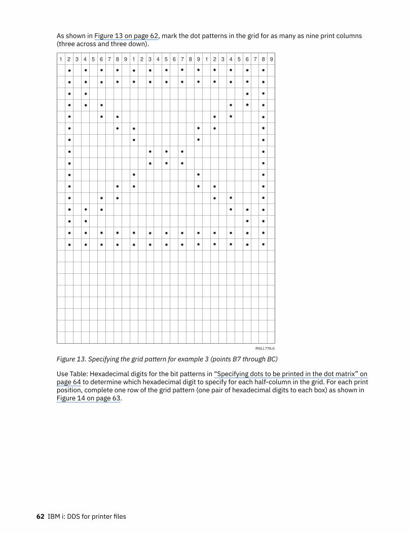
As shown in Figure 13 on page 62, mark the dot patterns in the grid for as many as nine print columns(three across and three down).
1 2 3 4 5 6 7 8 9 1 2 3 4 5 6 7 8 9 1 2 3 4 5 6 7 8 9
RSLL776-0
Figure 13. Specifying the grid pattern for example 3 (points B7 through BC)
Use Table: Hexadecimal digits for the bit patterns in “Specifying dots to be printed in the dot matrix” onpage 64 to determine which hexadecimal digit to specify for each half-column in the grid. For each printposition, complete one row of the grid pattern (one pair of hexadecimal digits to each box) as shown inFigure 14 on page 63.
62 IBM i: DDS for printer files

1 2 3 4 5 6 7 8 9
Code
Points
B7
B8
B9
BA
BB
BC
FF
00
CC
FF
00
33
F0
00
D8
0F
00
1B
00
C6
00
00
63
00
D8
00
F0
1B
00
0F
00
C1
00
00
83
00
00
C5
00
00
63
00
00
C1
00
00
83
00
CC
00
F0
33
00
FF
RSLL777-0
00
C1
00
00
83
00
Figure 14. Completing the code points for example 3 (points B7 through BC)
Selecting which code points to redefineYou can define any code point except hexadecimal 00.
When you define a code point, you can perform one of the following tasks:
• Redefine an existing character. If you then attempt to print that character, the alternate character isprinted. Example 1 uses such a code point.
• Define a character for an unassigned code point (for which there is no existing character in your systemcharacter set). Example 2 uses such code points.
If you redefine an existing character, select which character to print (the existing character or theredefined character) by specifying option indicators for the DFNCHR keyword. If you select DFNCHR,the user-defined character is printed. If you do not select DFNCHR, the existing character is printed.
Note: Output operations run faster when you define an unassigned code point. An unassigned code pointavoids the reloading of code points when your program selects different DFNCHR keywords.
Dot matrixThe dot matrix for the 5224 Printer and 5225 Printer is a matrix of 8 row by 9 column. All 8 rows and 9columns are printed regardless of the CPI or LPI settings.
The vertical distance between dots is always 0.352 mm (0.014 inch) regardless of the LPI setting (LPIparameter on the CRTPRTF command). The LPI setting determines the space between lines, not theheight of characters. At a setting of 9 lpi (2.82 mm or 0.111 inch for each line), there is no vertical spacebetween lines if all rows of dots are used. However, the normal character set does not use the bottom rowof dots (line 8) in the matrix, so that even at 9 lpi there is some space between lines. If you choose, userow 8 to define your own characters.
The horizontal distance between dots depends on the CPI setting. At 10 CPI, each column is spaced0.262 mm (0.0111 inches) apart, giving each character 2.54 mm (0.1 inches). At 15 CPI, each column isspaced 0.188 mm (0.0074 inches) apart, giving each character 1.69 mm (0.0667 inches). The standardcharacter set does not use columns 1 and 9 (to allow spacing between characters).
You can use columns 1 and 9 to define your own characters with one restriction: the 5224 Printer and5225 Printer cannot print two adjacent horizontal dots. To print two adjacent horizontal dots (such as in asolid underline), the line must be printed twice. This can be done using a different set of code points oneach pass, one to define the odd dots, and the other to define the even dots. Both passes occur duringone output operation. If your program attempts to print two adjacent horizontal dots, no error messageappears, but one of the dots is not printed. (The last position of dots in one character and the first positionin the character to its right are considered adjacent dots.) There is no restriction on adjacent vertical dots.
On any one output operation, each code point represents a single eight-by-nine matrix. To printcharacters larger than this requires more than one eight-by-nine matrix, each one normally defined bya different code point. Overprinting is also required.
DDS for printer files 63

For example, to print a double-wide character, specify a code point for the left half of the character andanother code point for the right half. Double-high characters require a code point for the top half of thecharacter and another for the bottom half. On the first line, the top half of all characters are printed, andon the next line, the bottom half of all characters. You must specify lpi(9) on the CRTPRTF, CHGPRTF, orOVRPRTF command to avoid a space between the top and bottom halves. Using DDS, you can define twofields in one record format, one for the upper half and one for the lower half. Example 2 shows a charactertwo wide by two high.
Specifying dots to be printed in the dot matrixWhen you define a dot matrix pattern for a user-defined character, specify nine 2-digit pairs ofhexadecimal digits.
Each 2-digit pair corresponds with a column in the matrix, the first pair with the first column, the secondpair with the second column, and so forth. Specify the left character of each pair to control which dots areprinted in the upper half of the column. Specify the right character to control the lower half.
Use the approach shown in Figure 15 on page 64 to specify the dot matrix pattern for a copyright mark,which prints as ©. The binary equivalent is 0111 1110, which corresponds to the placement of dots incolumn 2.
00 007E 7E8181 3C C3 24
0 1 1 1 1 1 1 0
Hex 7 Hex E
Hex 7E
Row
1
2
3
4
5
6
7
8
1 2 3 4 5 6 7 8 9
RSLL764-1
Figure 15. Specifying the dot matrix for a copyright mark
Use the form in Figure 16 on page 65 to plan your dot patterns and specify the required hexadecimaldigits for characters as large as three columns wide by three lines high. In this grid pattern, mark the dotpatterns for as many as nine print positions (three across and three down).
64 IBM i: DDS for printer files

1 2 3 4 5 6 7 8 9 1 2 3 4 5 6 7 8 9 1 2 3 4 5 6 7 8 9
RSLL765-0
Figure 16. Grid pattern for specifying dot matrix characters
Use Table 4 on page 65 to determine which hexadecimal digit to specify for each half-column in the gridpattern.
Table 4. Hexadecimal digits for the bit patterns
Bit patterns Hexadecimal digits Bit patterns Hexadecimal digits
0000 0 1000 8
0001 1 1001 9
0010 2 1010 A
0011 3 1011 B
0100 4 1100 C
0101 5 1101 D
0110 6 1110 E
0111 7 1111 F
DDS for printer files 65

For each print position, complete one row of the grid pattern, shown in Figure 17 on page 66. Thereshould be one pair of hexadecimal digits to each box.
1 2 3 4 5 6 7 8 9
Code
Points
RSLL766-0
Figure 17. Completing the grid pattern
DFT (Default) keyword in printer filesYou use the DFT keyword to specify constant values for constant fields.
The format of the keyword is:
DFT('value')'value'DFT(X'hexadecimal-value')X'hexadecimal-value'
Constant values can be:
• A character value, in which each character prints as you specify it. The number of characters is equalto the printed length of the field. (Within the value, two adjacent single quotation marks are printed asone.) See example 1.
• A hexadecimal value, in which two characters identify a code point in the character set. Thesecharacters print in this field (define alternate characters using DFNCHR). The printed length is halfthe number of characters you specify between single quotation marks. You must specify the TRNSPYkeyword if you specify a hexadecimal value for DFT. See example 2.
You can specify DFT implicitly by omitting DFT and the parentheses (this is true for both character andhexadecimal values). Specify the value within single quotation marks. For hexadecimal values, you mustalso precede the value with an X.
The EDTCDE and EDTWRD keywords cannot be specified with the DFT keyword.
Option indicators are not valid for this keyword. However, they can be used to condition the constant fieldwith which this keyword is specified, specifying the last option indicator on the same line as the fieldlocation.
Example 1
The following example shows how to specify DFT using character values.
|...+....1....+....2....+....3....+....4....+....5....+....6....+....7....+....800010A R SUPPLIES00020A PENS 20 2 100030A INK 20 3 100040A PAPER 20 4 100050A 7 9DFT('ON')00060A 8 9'ON'00070A00080A 01 12 1'Hotel name: 'Terrace Inn'00100A00110A 02 12 1'Hotel name: 'Riverview Inn' A
66 IBM i: DDS for printer files

The specifications DFT('ON') and 'ON' are equivalent and show the difference between specifying DFTexplicitly and implicitly.
If indicator 01 is on, this prints:
Hotel name: 'Terrace Inn'
If indicator 02 is on and indicator 01 is off, this prints:
Hotel name: 'Riverview Inn'
Example 2
The following example shows how to specify DFT for a constant field containing an alternate character.
|...+....1....+....2....+....3....+....4....+....5....+....6....+....7....+....81200010A R RECORD DFNCHR(X'7C' X'007E813CC324817E00')00020A 358 4DFT(X'7C') TRNSPY 400030A +2DFT('1982') A
The constant field for which DFT is specified 1 appears on line 58, position 4. The character definedfor hexadecimal 7C prints in this field. DFNCHR 2, specified at the record level for this example, defineshexadecimal 7C as a copyright mark.
Here are some equivalent ways to specify the value as defined in this example 3:
DFT(X'7C')X'7C'DFT('©')'©'
The TRNSPY keyword 4 is required when hexadecimal values are specified for DFT.
DLTEDT (Delete Edit) keyword in printer filesThis field-level keyword lets the IBM i operating system ignore any EDTCDE or EDTWRD keyword that isspecified for the referenced field. If a field description is referred to from a database file, DLTEDT preventscertain information from being referenced.
This keyword has no parameters.
This keyword is valid only when you specify R in position 29 for this field, and also specify either the REFor the REFFLD keyword.
If replacement edit information is needed, specify the EDTCDE or the EDTWRD for the field that youdefine. The new keyword overrides the editing from the referenced field. In this case, you do not need tospecify DLTEDT.
Option indicators are not valid for this keyword.
ExampleThe following example shows how to specify the DLTEDT keyword.
|...+....1....+....2....+....3....+....4....+....5....+....6....+....7....+....800010A AMT R 5 20DLTEDT A
DDS for printer files 67

DOCIDXTAG (Document Index Tag) keyword in printer filesYou use this record-level keyword to create an indexing tag in the document for use by presentationsystems such as Advanced Function Printing (AFP), or for use by postprocessor applications such asContent Manager OnDemand.
The format of the keyword is:
DOCIDXTAG(attribute-name | &attribute-name-field attribute-value | &attribute-value-field tag-level | &attribute-tag-level-field)
The attribute-name parameter is required and defines the name of the indexing attribute (for example,"Policy Number"). The maximum number of characters in the attribute name is 250. Blanks are allowed aspart of the attribute name.
When you specify the attribute-name parameter as a program-to-system field, the field must exist in thesame record format as the DOCIDXTAG keyword. It must be defined as length of 1-250, type A (character)and usage P (program-to-system).
The attribute-value parameter is required and defines the value of the indexing attribute (for example,"43127").The maximum number of characters in the attribute value is 250. Blanks are allowed as part ofthe attribute-value.
When you specify the attribute-value parameter as a program-to-system field, the field must exist in thesame record format as the DOCIDXTAG keyword. It must be defined as length of 1-250, type A (character)and usage P (program-to-system).
The tag-level parameter is required and defines the level of the indexing tag. There are two special valuesallowed for this parameter. GROUP and PAGE. GROUP specifies that the attribute name and value areattached to the current group.
Notes:
1. Group level tags are selectable using the SELECT GROUP function of the AFP Viewer. PAGE specifiesthat the attribute name and value are attached to the current page
2. Page level tags are selectable using the GO TO function of the AFP Viewer. Group level tags areselectable using the SELECT GROUP function of the AFP Viewer. PAGE specifies that the attributename and value are attached to the current page.
.
When you specify the tag-level parameter as a program-to-system field, the field must exist in the samerecord format as the DOCIDXTAG keyword. It must be defined as length of 5, type A (character) and usageP (program-to-system).
This keyword is valid with DEVTYPE(*AFPDS). If DEVTYPE is changed to anything other than *AFPDS, thekeyword will be ignored and a warning message will be issued at print time.
Option indicators are valid for this keyword.
Example|...+....1....+....2....+....3....+....4....+....5....+....6....+....7....+.... A A R RECORD1 A 02 DOCIDXTAG('Policy Number' '43127' + A GROUP) A R RECORD2 DOCIDXTAG( &ATTNAM &ATTVAL PAGE) A ATTNAM 20A P A ATTVAL 10A P A
In the example, RECORD1 specifies an indexing attribute name of 'Policy Number' and an attributevalue of '43127'. This is a group level tag. RECORD2 allows the application program to specify theattribute-name and attribute-value by specifying variables ATTNAM and ATTVAL. This is a page level tag.
68 IBM i: DDS for printer files

DRAWER (Drawer) keyword in printer filesYou use this record-level keyword to specify the drawer from which noncontinuous forms are selected.
The format of the keyword is:
DRAWER(drawer-number | &drawer-number)
Drawer-number specifies the drawer from which the paper or the envelope is to be fed. Valid values are 1- 255 and *E1 as follows:1
The paper is fed from the first drawer on the sheet-feed paper handler.2
The paper is fed from the second drawer on the sheet-feed paper handler.n
The paper is fed from the nth drawer on the sheet-feed paper handler.*E1
The envelope is fed from the envelope drawer on the sheet-feed paper handler.
You can specify the drawer number as a constant or a program-to-system field. When you specify thedrawer number as a program-to-system field, the field must exist in the same record format as theDRAWER keyword. It must be defined as a length of 4, data type A and usage P.
If you do not specify the DRAWER keyword, the value specified on the DRAWER parameter of theCRTPRTF, CHGPRTF or OVRPRTF command determines the paper source drawer.
DRAWER is ignored at run time if it is not specified on a page boundary. The printer is on a page boundarywhen no named or constant fields are processed for a page. As soon as a named or constant field isprocessed, the printer is no longer on a page boundary. The printer is on a page boundary again when aSKIP, SPACE, or ENDPAGE keyword is processed that causes the printer to move to a new page.
DRAWER, SKIP, and SPACE keywords are processed in the following order:
SKIPBSPACEBDRAWERSPACEASKIPA
DRAWER is in effect only for the record format specified. After records with the specified record formatare processed, the paper-source drawer for the next record format (if the DRAWER keyword is notspecified) is the drawer specified at the file level (CRTPRTF, CHGPRTF, or OVRPRTF command).
For files created with DEVTYPE(*SCS), if the DRAWER keyword is specified on a record format that spansseveral pages, it remains in effect only for the page on which it is specified.
You cannot specify DRAWER on the same record format with the CPI keyword or a record-level DFNCHRkeyword. If any format in the file contains both DRAWER and either CPI or a record-level DFNCHRkeyword, the file is not created.
Option indicators are valid for this keyword.
Note: Only one drawer keyword for each record format is valid at any time. Even with option indicators, itis not valid to specify more that one drawer keyword per record format.
ExampleThe following example shows how to specify the DRAWER keyword.
DDS for printer files 69

Note: By using the code examples, you agree to the terms of the “Code license and disclaimerinformation” on page 148.
|...+....1....+....2....+....3....+....4....+....5....+....6....+....7....+....800010A R RECORD1 SKIPB(3)00020A FIELD1 10 1SPACEA(1)00030A FIELD2 5 1SPACEA(1)00040A00050A R RECORD2 DRAWER(2)00060A FIELD3 5 100070A FIELD4 5 6SKIPA(1)00080A00090A R RECORD3 DRAWER(2)00100A FIELD5 10 1SPACEA(1)00110A FIELD6 10 1SKIPA(1)00120A FIELD7 10 1SPACEA(1)00130A FIELD8 10 1SPACEA(1)00140A00150A R RECORD400160A FIELD9 10 1SKIPB(30)00170A FIELD10 10 2100180A R RECORD5 SKIPB(3)00190A FIELD11 10 1SPACEA(1)00200A FIELD12 10 1SPACEA(1)00210A R RECORD6 SKIPB(1) DRAWER(&FIELD14)00220A FIELD13 10 100230A FIELD14 4 P
The printer is not on a page boundary after record format RECORD1 is processed. When record formatRECORD2 is processed, DRAWER is ignored and paper continues to come from the source drawerpreviously specified (file level). Because SKIPA(1) is specified for FIELD4 of RECORD2, the printer ison a page boundary after RECORD2 is processed. The paper for both pages of RECORD3 comes fromdrawer 2. The paper source for record formats RECORD4 and RECORD5 is the drawer specified at the filelevel (drawer 1 in this example). But because RECORD4 starts in the middle of a page, it prints on thesame page as RECORD3 (drawer 2). Record format RECORD5 prints on a different page (SKIPB(3)) andprints on paper from drawer 1. RECORD6 allows the application program to specify the drawer-number bysetting field FIELD14.
DTASTMCMD (Data Stream Command) keyword in printer filesYou use this record-level or field-level keyword to store a data stream command or some other piece ofinformation in a spooled file.
This command can be used to determine how to process a record or field on a particular page of thespooled file. DTASTMCMD is valid only for printer files with device type *AFPDS specified.
The format of the keyword is:
DTASTMCMD(text |&text-field);
The text must be enclosed in single quotation marks. If the length of the text is greater than 255characters, an error message will be signaled at compile time.
The program-to-system field specified must exist in the same record format as the DTASTMCMD keyword.If the length of the program-to-system field is greater than 255 characters, an error message will besignaled at compile time.
User applications or user specified programs that need to know how to process a particular page in thespooled file can search the data stream and retrieve the data stream command. This will be enclosed inan AFPDS (MODCA) NOP command. The NOP will be built into the datastream before any printable datafor the record or field containing the keyword. Since this information is just being stored, this keywordwill not have a direct effect on the actual file. For more information about the NOP command, refer to theMO:DCA Reference, SC31-6802.
Option indicators are valid for this keyword.
Note: You can specify this keyword only once for each record and once for each field.
70 IBM i: DDS for printer files

ExampleThe following example shows how to specify the DTASTMCMD keyword.
|...+....1....+....2....+....3....+....4....+....5....+....6....+....7....+....8 A R RECORD1 DTASTMCMD('TEXT(Record 1)') A FIELD1 10A 5 5 A 01 DTASTMCMD('TEXT(Field 1)') A FIELD2 10A 10 5DTASTMCMD(&DATA); A DATA 10A P A
The data stream for the record RECORD1 has the text for DTASTMCMD as TEXT(Record 1). If indicator01 is optioned on, the data stream for the field FIELD1 has the text for DTASTMCMD as TEXT(Field 1). Ifindicator 01 is optioned off, no data stream text is generated for DTASTMCMD on FIELD1. FIELD2 will usewhat is contained in DATA as the text for DTASTMCMD.
DUPLEX (Duplex) keyword in printer filesYou use this record-level keyword to specify whether output is printed on one side or two sides of thepaper.
The format of the keyword is:
DUPLEX(duplex-value | &duplex-value)
The possible values are:
*NOThe output is printed on one side of the paper.
*YESThe output is printed on both sides of the paper, with the top of each printed page at the same end ofthe sheet of paper. This is typically done for output that is bound at the side.
*TUMBLEThe output is printed on both sides of the paper, with the top of one printed page at the opposite endfrom the top of the other printed page. This is typically done for output that is bound at the top.
You can specify the duplex value as a constant or program-to-system field. When you specify the duplexvalue as a program-to-system field, the field must exist in the same record format as the DUPLEXkeyword. The field must be defined as length 7 and type A (character), and usage P (program-to-system).
Specify DEVTYPE(*AFPDS) on the CRTPRTF command when DUPLEX is specified in the file. If DEVTYPE ischanged to anything other than *AFPDS, the keyword is ignored and a warning message is issued at printtime.
If currently printing on the front side of the sheet, the current sheet will be ejected and a new sheet fed in.If you do not specify the DUPLEX keyword, the value specified on the DUPLEX parameter on the CRTPRTF,CHGPRTF, or OVRPRTF command determines the duplex value.
DUPLEX is ignored at run time if it is not specified on a page boundary. The printer is on a page boundarywhen no named or constant fields are processed for a page. After a named or constant field is processed,the printer is no longer on a page boundary. The printer is on a page boundary again when a SKIP, SPACE,ENDPAGE, or INVMMAP keyword is processed that causes the printer to move to a new page, DUPLEX,SKIP, and SPACE keywords are processed in the following order:
SKIPB SPACEB DUPLEX SPACEA SKIPA
DUPLEX is in effect only for the record format specified. After records with the specified record formatare processed, the duplex value for the next record format (if the DUPLEX keyword is not specified) is theduplex specified at the file level (CRTPRTF, CHGPRTF, or OVRPRTF) command.
DDS for printer files 71

Option indicators are valid for this keyword.
Note: Use of this DDS keyword will cause a spooled file to be generated that will not be correctly printedwhen sending the spooled file to MVS™. The spooled file with not print and will be held on the outputqueue by Print Services Facility (PSF)/MVS.
ExampleThe following example shows how to specify the DUPLEX keyword.
|...+....1....+....2....+....3....+....4....+....5....+....6....+....7....+....8 A* A R REC1 DUPLEX(*YES) A FLD1 5A 60 10 A*
Duplex printing is selected when record format REC1 prints.
EDTCDE (Edit Code) keyword in printer filesYou use this keyword to edit output-capable numeric fields.
The format of the keyword is:
EDTCDE(edit-code [* | floating-currency-symbol])
Depending on which edit code you specify, you can change the appearance of the printed fields asfollows:
• Leading zeros are suppressed.• The field can be punctuated with commas and periods to show decimal position and to group digits by
threes.• Negative values can be printed with a minus sign or CR to the right.• Zero values can be printed as zeros or blanks.• Asterisks can be printed to the left of significant digits to provide asterisk protection.• A currency symbol (corresponding to the system value QCURSYM) can be printed immediately to the left
of the farthest- right significant digit (called a floating-currency symbol). For fixed-currency symbols,use the EDTWRD keyword.
• The field can be further edited using a user-defined edit code.
EDTCDE covers most editing requirements. Use the EDTWRD keyword when EDTCDE is not sufficient.
EDTCDE is valid only for fields with S or a blank in position 35 (Data Type).
You cannot specify EDTCDE and EDTWRD for the same field. If you specify EDTCDE for a field previouslydefined in a database file, you need not specify EDTCDE for the field that you are defining. Instead, specifyR in column 29 to refer to the previously defined field. The editing specified for that field is included in theprinter file. If you specify length, data type, or decimal columns for a printer file field, editing specified forthe referenced field is not included in the printer file and you must specify editing again in the printer file.
The DFT keyword cannot be specified with the EDTCDE keyword.
Option indicators are not valid for this keyword.
You can specify two kinds of edit codes: IBM i edit codes and user-defined edit codes.
72 IBM i: DDS for printer files

ExampleThe following example shows how to specify the EDTCDE keyword.
|...+....1....+....2....+....3....+....4....+....5....+....6....+....7....+....800050A PRICE 5 2 5 2EDTCDE(J *) A
Related conceptsEDTCDE keyword for display files
IBM i edit codes in printer filesThis topic describes the definition and functions of edit codes.
The IBM i edit codes are:
1 through 4A through DJ through QW through Z
Note: The IBM i hardware operates with a preferred sign of F, which is equivalent to using edit code X. Ifthe DATE or TIME keyword is specified with edit code X, the separator character is not displayed.
Asterisk fill or floating currency symbol in printer filesYou can optionally specify asterisk fill or floating currency symbol with edit codes 1 through 4, A throughD, and J through Q.
When you specify asterisk fill, an asterisk (*) is written for each zero suppressed. A complete field ofasterisks is printed for a zero-balance field.
When you specify floating-currency symbol, the symbol appears to the left of the first significant digit. Itdoes not print on a zero balance when an edit code is used that suppresses the zero balance. The symbolyou specify must match the system value for the currency symbol (QCURSYM). (The symbol must matchwhen the file is created. It does not have to match when the file is used.)
Note: If an edit code is changed after a file is created, the new edit code is not used unless the file isre-created. Instead, the editing specified at the time the file was created continues to be used.
The following table summarizes the functions provided by IBM i edit codes.
Table 5. Summary chart for IBM i edit codes
Edit codes Commas1
printedDecimalpoints1
printed
Signsprintedwhennegativenumber
Blank valueofQDECFMTsystemvalue
I value ofQDECFMTsystemvalue
J value ofQDECFMTsystemvalue
Leadingzerosuppressed
1 Yes Yes No sign .00 or 0 ,00 or 0 0,00 or 0 Yes
2 Yes Yes No sign Blanks Blanks Blanks Yes
3 Yes No sign .00 or 0 ,00 or 0 0,00 or 0 Yes
4 Yes No sign Blanks Blanks Blanks Yes
A Yes Yes CR .00 or 0 ,00 or 0 0,00 or 0 Yes
B Yes Yes CR Blanks Blanks Blanks Yes
C Yes CR .00 or 0 ,00 or 0 0,00 or 0 Yes
D Yes CR Blanks Blanks Blanks Yes
DDS for printer files 73

Table 5. Summary chart for IBM i edit codes (continued)
Edit codes Commas1
printedDecimalpoints1
printed
Signsprintedwhennegativenumber
Blank valueofQDECFMTsystemvalue
I value ofQDECFMTsystemvalue
J value ofQDECFMTsystemvalue
Leadingzerosuppressed
J Yes Yes -(Minus) .00 or 0 ,00 or 0 0,00 or 0 Yes
K Yes Yes -(Minus) Blanks Blanks Blanks Yes
L Yes -(Minus) .00 or 0 ,00 or 0 0,00 or 0 Yes
M Yes -(Minus) Blanks Blanks Blanks Yes
N Yes Yes -(Minus) .00 or 0 ,00 or 0 0,00 or 0 Yes
O Yes Yes -(Minus) Blanks Blanks Blanks Yes
P Yes -(Minus) .00 or 0 ,00 or 0 0,00 or 0 Yes
Q Yes -(Minus) Blanks Blanks Blanks Yes
W2 Yes
Y3 Yes
Z4 Yes
74 IBM i: DDS for printer files

Table 5. Summary chart for IBM i edit codes (continued)
Edit codes Commas1
printedDecimalpoints1
printed
Signsprintedwhennegativenumber
Blank valueofQDECFMTsystemvalue
I value ofQDECFMTsystemvalue
J value ofQDECFMTsystemvalue
Leadingzerosuppressed
Notes:
1. The QDECFMT system value determines the decimal point character (period as used in the U.S.), thecharacter used to separate groups of three digits (comma as used in the U.S.), and the type of zerosuppression (depending on comma and period placement).
2. The W edit code suppresses the farthest-left zero of a date field that is five digits long. It also suppressesthe three farthest-left zeros of a field that is six to eight digits long. The W edit code also inserts slashes (/)between the month, day, and year according to the following pattern:
• nn/nnn• nnnn/nn• nnnn/nnn• nnnn/nn/nn
3. The Y edit code suppresses the farthest-left zero of a date field that is three to six digits long or eight digitslong, and it suppresses the two farthest-left zeros of a field that is seven positions long. The Y edit code alsoinserts slashes (/) between the month, day, and year according to the following pattern:
• nn/n• nn/nn• nn/nn/n• nn/nn/nn• nnn/nn/nn• nn/nn/nnnn
If the DATE keyword is specified with EDTCDE(Y), the separator character used is the job attribute, DATSEPat run time. If a separator character is not specified on the DATSEP job attribute, the system value,QDATSEP, is used (where slash (/) is the default value). If, at file creation time, DATFMT is JUL (Julian), thedate is formatted as nnnnn. If EDTCDE(Y) is specified, the date is formatted as nn/nnn, where the slash (/)represents the job date separator.
4. The Z edit code removes the sign (plus and minus) from a numeric field. The sign of the units column ischanged to a hexadecimal F before the field is written.
Related conceptsSystems managementRelated referenceSystem values
User-defined edit codes in printer filesEdit codes 5 through 9 are user-defined edit codes.
A user-defined edit code can do more editing than an IBM i edit code. For example, you might need toedit numbers that include hyphens (such as telephone numbers) or more than one decimal point. You canuse user-defined edit codes for these functions. These edit codes are named QEDIT5, QEDIT6, QEDIT7,QEDIT8, and QEDIT9, and can be referred to in DDS or a high-level language program by number (5, 6, 7,8, or 9).
A user-defined edit code is an IBM i object and must exist before printer file creation. It is created usingthe Create Edit Description (CRTEDTD) command. When you create a printer file in which a user-defined
DDS for printer files 75

edit code is specified, editing information is extracted from the previously created edit description.Changing a user-defined edit code after printer file creation does not affect the printer file unless theprinter file is re-created.
The following table shows valid edit codes with examples of unedited source data and edited output. Zerosuppression and decimal characters are determined by the system value QDECFMT. The date separatorcharacter is determined by the job attribute DATSEP. In this figure, QDECFMT is assumed to equal x(blank), and DATSEP is assumed to equal / (slash).
Table 6. Valid edit codes, source data, and edited output
Edit codes Positivenumber withtwo decimalpositions
Positivenumber withno decimalpositions
Negativenumber withthree decimalpositions1
Negativenumber withno decimalpositions
Zero balancewith twodecimalpositions1
Zero balancewith nodecimalpositions1
Unedited 1234567 1234567 xxxx125– xxxx125– xxxxxx xxxxxx
1 12,345.67 1,234,567 .125 125 .00 0
2 12,345.67 1,234,567 .125 125
3 12345.67 1234567 .125 125 .00 0
4 12345.67 1234567 .125 125
A 12,345.67 1,234,567 .125CR 125CR .00 0
B 12,345.67 1,234,567 .125CR 125CR
C 12345.67 1234567 .125CR 125CR .00 0
D 12345.67 1234567 .125CR 125CR
J 12,345.67 1,234,567 .125- 125- .00 0
K 12,345.67 1,234,567 .125- 125-
L 12345.67 1234567 .125- 125- .00 0
M 12345.67 1234567 .125- 125-
N 12,345.67 1,234,567 -.125 -125 .00 0
O 12,345.67 1,234,567 -.125 -125
P 12345.67 1234567 -.125 -125 .00 0
Q 12345.67 1234567 -.125 -125
W2 1234/567 1234/567 0/125 0/125 0/000 0/000
Y3 123/45/67 123/45/67 0/01/25 0/01/25 0/00/00 0/00/00
Z4 1234567 1234567 125 125
76 IBM i: DDS for printer files

Table 6. Valid edit codes, source data, and edited output (continued)
Edit codes Positivenumber withtwo decimalpositions
Positivenumber withno decimalpositions
Negativenumber withthree decimalpositions1
Negativenumber withno decimalpositions
Zero balancewith twodecimalpositions1
Zero balancewith nodecimalpositions1
Notes:
1. The x represents a blank.2. The W edit code suppresses the farthest-left zero of a date field that is five digits long. It also suppresses
the three farthest-left zeros of a field that is six to eight digits long. For more information, see the secondfootnote in Table: Summary chart for IBM i edit codes in “IBM i edit codes in printer files” on page 73.
3. The Y edit code suppresses the farthest-left zero of a date field that is three to six digits long, and itsuppresses the two farthest-left zeros of a field that is seven positions long. For more information, see thesecond footnote in Table: Summary chart for IBM i edit codes in “IBM i edit codes in printer files” on page73.
4. The Z edit code removes the sign (plus or minus) and suppresses leading zeros.
EDTWRD (Edit Word) keyword in printer filesIf you cannot accomplish the required editing by using the EDTCDE keyword, specify an edit word instead.
An edit word specifies the form in which the field values are to print and clarifies the data by insertingcharacters, such as decimal points, commas, floating- and fixed-currency symbols, and credit balanceindicators. Also use it to suppress leading zeros and to provide asterisk fill protection.
The format of the keyword is:
EDTWRD('edit-word')
If you specify EDTWRD in a field previously defined in a database file, you need not specify EDTWRDfor the field you are defining. Instead, specify R in column 29 to refer to the previously defined field.The editing specified for the referenced field is then included in the printer file. If, however, you specifylength, data type, or decimal positions for a printer file field, editing specified for the referenced field isnot included in the printer file, and you must specify editing in the printer file.
ExampleThe following example shows how to specify the EDTWRD keyword.
|...+....1....+....2....+....3....+....4....+....5....+....6....+....7....+....800010A CRYCST 7 2 5 2EDTWRD(' $0. ') A
Figure 18 on page 78 shows sample edit words with the program value of the field and the printed valueof the field (as edited).
DDS for printer files 77

Figure 18. Sample edit words
Parts of an edit word in printer filesAn edit word consists of the body, the status, and the expansion.
The following illustration shows the three parts.
The body contains the digits transferred from the data field to the output record. It begins at the farthest-left column of the edit word and ends with the farthest-right character that can be replaced by a digit. The
78 IBM i: DDS for printer files
number of blanks (plus one zero or an asterisk) it contains is equal to the number of digits of the data fieldto be edited.
The status positions display the sign (+ or -) of the data field. It continues to the right of the body and haseither a CR (credit) or - (minus) symbol, which print only when the field is negative. Edit words without theCR or - symbol have no status columns.
The expansion positions are not changed by the edit operation. The expansion starts at the first positionto the right of the status (or body, if status is not specified) and ends with the farthest-right character ofthe edit word.
Forming the body of an edit word in printer filesThese characters have special meanings when used in the body of an edit word.
BlankA blank is replaced with the character from the corresponding position of the data field. A blankposition is referred to as a digit position.
AmpersandAn ampersand causes a blank in the edited field. The ampersand is not printed.
ZeroTo stop zero suppression, place a zero in the farthest-right position where it is to stop. The zero is thenreplaced with the character from the corresponding position of the data field, unless that characteris a zero. Any zeros in the data that appear to the right of the stop-zero-suppression character areprinted. The stop-zero-suppression character is considered a digit position; however, when it is thefirst character, it can not represent the digit position. At least one leading zero is suppressed. Eachzero that is suppressed is replaced by a blank.
AsteriskPlacing an asterisk in the farthest-right position where zero suppression is to stop, stops zerosuppression and replaces the zeros with asterisks (asterisk protection). An asterisk preceding a zerois interpreted as representing asterisk protection. In this case, the zero prints as a constant. Anyasterisks or zeros to the right of the stop-zero-suppression character are constants.
Currency symbol
A currency symbol coded immediately to the left of the zero suppression code causes the insertionof a currency symbol in the position to the left of the first significant digit. It is called the floating-currency symbol when used in this manner.
A currency symbol coded in the farthest-left column of the edit word is fixed and prints in the samelocation each time. When used in this manner, it is called the fixed-currency symbol.
The currency symbol is not considered a digit-replace position. This symbol must correspond to thesystem value QCURSYM.
Decimals and commas
Decimals and commas are printed in the same relative positions in which they are coded in the editword unless they are to the left of the first significant digit. In that case, they are blanked out orreplaced by an asterisk.
All other characters are printed if they are to the right of significant digits in the data field. If they areto the left of the high-order significant digits in the data, they are blanked out or replaced by asterisksif asterisk protection is being used.
Forming the status of an edit word in printer filesThese characters have special meanings when used in the status of an edit word.
AmpersandIt causes a blank in the edited output field. An ampersand cannot be placed in the edited output field.
DDS for printer files 79

CR or minus symbolIf the sign in the edited output field is plus (+), these positions are blanked out. If the sign in theedited output field is minus (-), these positions remain undisturbed.
Formatting the expansion of an edit word in printer filesThe characters in the expansion portion of an edit word are always written.
The expansion cannot contain blanks. If a blank is required in the edited output field, specify anampersand in the body of the edit word.
Follow these guidelines when specifying a valid edit word:
• You cannot specify both EDTWRD and EDTCDE for the same field.• You must enclose the edit word in apostrophes.• The EDTWRD keyword is valid for numeric-only fields (S specified in position 35).• The sum of the blanks and stop-zero-suppression characters (digit positions) in the edit word must
equal the length of the field.• If the stop-zero-suppression characters is the first character in the edit word, the sum of the blanks can
equal the length of the field or the length of the field minus one.• If you use the floating-currency symbol, it is not counted as a digit position. For example, if you specify
the floating-currency symbol for a field length of 7 and 2 decimal positions, the edit word is:
EDTWRD('____$0.__')
where _ represents a blank.• If you want to show a negative sign with a negative number, include a sign in the edit word. Use either
the minus sign (-) or the letters CR (credit) to the right of the last digit replacement character. Theseprint only if the number is negative.
Option indicators are not valid for this keyword.
The DFT keyword cannot be specified with the EDTWRD keyword.
ExampleThe following example shows how to specify the EDTWRD keyword.
|...+....1....+....2....+....3....+....4....+....5....+....6....+....7....+....800010A CRYCST 7 2 5 2EDTWRD(' $0. ') A
Figure 19 on page 81 shows sample edit words with the program value of the field and the printed valueof the field (as edited).
80 IBM i: DDS for printer files

Figure 19. Sample edit words
Related conceptsEDTWRD keyword for display files
ENDPAGE (End Page) keyword in printer filesYou use this record-level keyword to eject the current page after the record is printed.
This keyword has no parameters.
Specify DEVTYPE(*AFPDS) on the CRTPRTF command when ENDPAGE is specified in the file. If DEVTYPEis changed to anything other than *AFPDS, the keyword is ignored and a warning message is issued atprint time.
DDS for printer files 81

An error message is issued if a constant field is specified in a record format where the ENDPAGE keywordis also specified.
You cannot specify ENDPAGE with the following keywords:
SPACEASPACEBSKIPASKIPB
Option indicators are valid for this keyword.
ExampleThe following example shows how to specify the ENDPAGE keyword.
|...+....1....+....2....+....3....+....4....+....5....+....6....+....7....+....8 A* A R REC1 ENDPAGE A FLD1 5A 66 10 A* A R REC2 A 01 ENDPAGE A FLD1 5A POSITION(8.5 10.2) A
A page eject always occurs after REC1 prints.
If indicator 01 is on when the application writes REC2, a page eject occurs after REC2 prints. If indicator01 is off when the application writes REC2, no page eject occurs.
ENDPAGGRP (End Page Group) keyword in printer filesYou use this record-level keyword to end a logical grouping of pages that were previously started with theSTRPAGGRP keyword. If no group is active, this keyword is ignored.
The keyword has no parameters.
Notes:
1. Groups of pages cannot be nested or overlapped, each group must be ended before another can begin.2. This keyword is valid with DEVTYPE(*AFPDS). If DEVTYPE is changed to anything other than *AFPDS,
the keyword will be ignored and a warning message will be issued at print time.3. To end the logical group of pages on the current page, the ENDPAGGRP keyword must be issued
before skipping to a new page. If you use the ENDPAGE keyword to end a page, then the ENDPAGGRPkeyword must be issued before the ENDPAGE keyword.
Option indicators are valid for this keyword.
ExampleThe following example shows how to specify the ENDPAGGRP keyword.
|...+....1....+....2....+....3....+....4....+....5....+....6....+....7....+.... A A R RECORD1 ENDPAGGRP A
In the example, RECORD1 ends a group that had been previously started with the STRPAGGRP keyword.
FLTFIXDEC (Floating-Point to Fixed Decimal) keyword in printer filesYou use this field-level keyword to print a number in a floating-point field in fixed decimal notation.
This keyword has no parameters.
82 IBM i: DDS for printer files

When you use FLTFIXDEC, the floating-point number is first converted to the equivalent number withan exponent of zero. If the resulting number (digits and exponent) fits in the field defined by the lengthand decimal positions values, the number is printed with the exponent suppressed and aligned at thedecimal point. If the number does not fit in the field, the number prints in standard floating-point form,n.nnnnnnE+nnn. When the FLTFIXDEC keyword is specified, the length of the field is the DDS length plustwo (the sign and the decimal point). The minimum length of the field is six.
When the number is too large or small for the fixed-point form, specified by the FLTFIXDEC keywordwith the total digits and fractional digits specified for the field, a floating-point form prints that presentsthe significand as follows (the significand is the string of digits with the decimal point to the left of theexponent sign E):
• Total significand decimal digits: DDS total digits minus 5• Fractional significand digits: DDS total digits minus 6
Option indicators are not valid for this keyword.
ExampleThe following example shows how to specify the FLTFIXDEC keyword.
|...+....1....+....2....+....3....+....4....+....5....+....6....+....7....+....8 A R RECFMT1 A FIELD1 1OF 3 1 2FLTFIXDEC A FLTPCN(*DOUBLE) A
These output numbers are converted as follows:
Output number Printed as
-4.99994321000000E-004 '-4.0000E-004'
-5.00010000000000E-004 ' -0.001'
-2.69123400000000E-002 ' -0.027'
-0.00000000000000E+000 ' 0.000'
0.00000000000000E+000 ' 0.000'
2.71828182845900E+003 ' 2718.282'
3.14159000000000E-052 ' 3.14163-052'
9.87654321012345E+006 ' 9876543.210'
9.99999999960000E+006 ' 1.0000E+007'
FLTPCN (Floating-Point Precision) keyword in printer filesYou use this keyword to specify the precision of a floating-point field.
The format of the keyword is:
FLTPCN(*SINGLE | *DOUBLE)
The *SINGLE parameter specifies single precision and the *DOUBLE parameter specifies doubleprecision. This keyword is valid for floating-point fields only (data type F).
A single-precision field can be up to 9 digits; a double-precision field can be up to 17 digits. If you specifya field length greater than 9 (single precision) or 17 (double precision), an error message is issued and thefile is not created.
Option indicators are not valid for this keyword.
DDS for printer files 83

ExampleThe following example shows how to specify the FLTPCN keyword.
|...+....1....+....2....+....3....+....4....+....5....+....6....+....7....+....800090A FIELDA 17F 4 2 3FLTPCN(*DOUBLE) A
FIELDA is a floating-point field with double precision.
FNTCHRSET (Font Character Set) keyword in printer filesYou use this file-level, record-level, or field-level keyword to specify the font for printing a named orconstant field within a record.
The format of the keyword is:
FNTCHRSET([library-name/ | &library-name-field/] font-character-set | &font-character-set-field [library-name/ | &library-name-field/] code-page | &code-page-field [(*POINTSIZE height-value | &height-value-field width-value | &width-value-field)])
When a program-to-system field is described below for a FNTCHRSET parameter, the program-to-systemfield is allowed only when the keyword is used at the record or field level.
The font-character-set and code-page parameters are required. Both can be up to eight characters long.
Use the optional library-name parameter to further qualify the font character set or code page. If library-name is not specified, *LIBL is used to search for the font character set and code page. If *LIBL is used,the system-supplied font libraries are added to the library list when searching for the requested font. Toview the IBM-supplied font character set names or code page names, you can use the Work with FontResources (WRKFNTRSC) command and specify font character sets or code pages. The IBM-supplied fontcharacter set names all start with the characters C0 and the IBM-supplied code page names all start withT1.
You can specify the library-name and font-character-set as constants, as program-to-system fields, or asa combination of both, as shown in the following examples:
• [library-name/]font-character-set...• [library-name/]&field1• [&field2/]font-character-set...
When you specify the library-name as a program-to-system field, the field must exist in the same recordformat as the FNTCHRSET keyword. It must be defined as length of 10, data type A (character), and usageP (program-to-system).
When you specify the font-character-set as a program-to-system field, the field must exist in the samerecord format as the FNTCHRSET keyword. It must be defined as length of 8, data type A (character), andusage P (program-to-system).
You can specify the library-name and code-page as constants, as program-to-system fields, or as acombination of both, as shown in the following examples:
• [library-name/]code-page...• [library-name/]&field1• [&field2/]code-page...
When you specify the library-name as a program-to-system field, the field must exist in the same recordformat as the FNTCHRSET keyword. It must be defined as length of 10, data type A (character), and usageP (program-to-system).
84 IBM i: DDS for printer files

When you specify the code-page as a program-to-system field, the field must exist in the same recordformat as the FNTCHRSET keyword. It must be defined as length of 8, data type A (character), and usageP (program-to-system).
Note: If an application uses private resources (for example, fonts, page segments, overlays, or GDFfiles not distributed with the system), be aware of the following information. When referencing theseresources, if you specify *LIBL or you do not specify a library name, the resources must be availablethrough the library list used by the application creating the spooled file.
Use the optional point-size parameter to further define a numeric font that specifies a point size. Specifythe point-size parameter as an expression of the following form:
(*POINTSIZE height-value width-value)
The height-value specifies the point size for the height of the font. The width-value specifies the point sizefor the width of the font. If the font is to be uniformly scaled (where the height and width are the same),then you can specify only the height-value. You cannot specify the width-value without the height-value.The valid values for this parameter are 0.1 through 999.9.
You can specify the point-size height and point-size width as constants, as program-to-system fields, oras a combination of both, as shown in the following examples:
• [(*POINTSIZE height-value &field1)]• [(*POINTSIZE &field2 width-value)]
When you specify the point-size height-value or width-value as a program-to-system field, the fields mustexist in the same record format as the FNTCHRSET keyword. They must be defined as length 4 with 1decimal position, data type S, and usage P (program-to-system).
Notes:
1. For raster fonts, Print Services Facility (PSF) ignores the point size. PSF does not do any validation atspool intercept time, and it does not issue any error messages.
2. If you do not specify a point size for an outline font, then PSF cannot print the spooled file. The spooledfile is held at print writer time. PSF does not do any validation at spool intercept time.
The font character set and code page values are validated at print time. An error message is issued if theyare not valid.
Note: When a printer file is created and a character set and code page are specified for the font characterset (FNTCHRSET) parameter, column spacing is done using this printer file-level parameter. Any fonts orcode pages specified in the FNTCHRSET keyword are ignored and the font and code page specified in theprinter file parameter FNTCHRSET is used.
Specify DEVTYPE(*AFPDS) on the CRTPRTF command when FNTCHRSET is specified in the file. IfDEVTYPE is changed to anything other than *AFPDS, the keyword is ignored and a warning messageis issued at print time.
FNTCHRSET cannot be specified at the same level as the FONT and CDEFNT keywords.
Option indicators are valid for this keyword.
ExampleThe following example shows how to specify the FNTCHRSET keyword.
|...+....1....+....2....+....3....+....4....+....5....+....6....+....7....+....8 A* A R REC1 A FLD1A 14A 3 8FNTCHRSET(C0S0CE12 T1L0PCHN) A* A FLD2A 10A 5 8FNTCHRSET(USERLIB/FNTCHR + A USERLIB/CODEPG1 + A (*POINTSIZE 99.9)) A*
DDS for printer files 85

A FLD3A 10A 5 8FNTCHRSET(FNTCHR CODEPG1 + A (*POINTSIZE 5.0 3.0))
FLD1A specifies font character set C0S0CE12 and code page T1L0PCHN. *LIBL is used to search for thefont character set and code page. FLD2A specifies the font character set FNTCHR, which exists in libraryUSERLIB, and code page CODEPG1, which exists in library USERLIB. FLD2A prints with a point size of99.9. FLD3A specifies font character set FNTCHR and code page CODEPG1, with a vertical point size of5.0 and a horizontal point size of 3.0.
FONT (Font) keyword in printer filesYou use this record-level or field-level keyword to specify the font ID for printing named or constant fieldswithin a record.
The format of the keyword is:
FONT(font-identifier | &font-identifier-field [(*POINTSIZE height-value | &height-value-field width-value | &width-value-field)])
The font-identifier is a required parameter and must be the first parameter following the keyword. Specifyeither a numeric font identifier or a graphic font name, or *VECTOR.
You can specify the font-identifier as a constant or program-to-system field as shown in the followingexamples:
• font-identifier...• &field1...
When you specify the font-identifier as a program-to-system field, the field must exist in the same recordformat as the FONT keyword. It must be defined as length of 10, data type A (character), and usage P(program-to-system).
For scalable printer-resident fonts, you can use the optional point-size parameter to further define anumeric font that specifies a point size. Specify the point-size parameter as an expression of the followingform:
(*POINTSIZE height-value width-value)
The height-value specifies the point size for the height of the font. The width-value specifies the point sizefor the width of the font. If the font is to be uniformly scaled (where the height and width are the same),then you can specify only the height-value. You cannot specify the width-value without the height-value.The valid values for this parameter are 0.1 through 999.9.
You can specify the point-size height and point-size width as constants, as program-to-system fields, oras a combination of both, as shown in the following examples:
• [(*POINTSIZE height-value &field1)]• [(*POINTSIZE &field2 width-value)]
When you specify the point-size height-value or width-value as a program-to-system field, the fields mustexist in the same record format as the FONT keyword. They must be defined as length 4 with 1 decimalposition, data type S, and usage P (program-to-system).
For non-scalable printer-resident fonts, the point size parameter is ignored.
For DEVTYPE(*IPDS), the width parameter of the point size is ignored.
A warning message is issued at creation time if you specify the point-size parameter on the FONT keywordwith a graphic font name, or *VECTOR. In that case, the point-size parameter is ignored.
If you do not specify this keyword, the font ID and point size are set by the font parameter on theCRTPRTF, CHGPRTF, or OVRPRTF command. If you specify this keyword at the record level, all fieldsin the record format use the same font ID and point size except those for which you specify the FONTkeyword at the field level.
86 IBM i: DDS for printer files

You can specify graphic fonts (alphanumeric characters) or hardware fonts (numeric font identifiers). Forgraphic fonts, use graphic symbol sets (GSS) available with the IBM i operating system, GDDM, PGR,and BGU. Only vector symbols (where each character is built with a set of straight or curved lines) aresupported. However, most of the vector symbol sets supplied by the operating system and GDDM aresupported. Image symbols are not supported. In searching for the graphic symbol set, *LIBL is used forthe qualified library name.
The name of a graphic font can consist of up to 10 alphanumeric characters.
The hardware font can consist of up to 10 digits and must be a registered font number. See the IBM
Infoprint Fonts: Font Summary book for a listing of font IDs.
You can specify *VECTOR on the FONT keyword to take advantage of vector fonts on the 4234IPDS printer. Vector fonts print expanded characters faster than they can be printed using thePRTQLTY(*DRAFT) keyword. Use the CHRSIZ keyword to specify expanded characters.
Note: When you specify FONT(*VECTOR) with the CHRSIZ keyword, the 4234 printer uses a default codepage.
Vector fonts are valid only for the following characters:
• A through Z• 0 through 9• Special characters (. + $ * - / % and a blank)
If the data to be printed contains any characters other than these, all characters are printed using adefault font on the printer.
FONT(*VECTOR) has no effect on characters that have not been expanded. If FONT(*VECTOR) is specifiedon a record or field for which CHRSIZ (1 1) applies or to which no CHRSIZ keyword applies, a warningmessage is issued.
Note: If you use FONT(*VECTOR) on a 4224 or 3812 printer, the printer uses a default font and code page.
The font name or number and the point size values are not checked during file creation. If the specifiedfont-id and point size values are not valid, a diagnostic is issued while the record prints and the keywordare not used.
When FONT is specified at the field level, overlapping fields are not diagnosed.
When you use a graphics font on the CRTPRTF, CHGPRTF, or OVRPRTF command, the font ID has animplied page code associated with it. To get the code you want, you must use the proper font ID; the codepage specified on the CHRID parameter is not used.
If you specify OCR-A font with the CHRID keyword, the fonts require code pages 892. If you specifyOCR-B font with the CHRID keyword, the fonts require code pages 893.
A warning message is issued at creation time if a FONT DDS keyword is specified in a file created withDEVTYPE(*IPDS) and FONT(*DEVD). For SCS printer files, the FONT keyword is ignored when the record orfield is printed. For IPDS printers, the FONT keyword can be changed at the record or field level.
When printing a file that uses the FONT keyword to an IPDS AFP(*YES) printer that does not supportregistered fonts, a font substitution is performed.
When you specify FONT(*CPI) with either the CRTPRTF, CHGPRTF, or OVRPRTF command to a device thatuses font support, the host system selects a font with the pitch of the CPI for the current printer file.
FONT(graphic-font-name) and CHRID cannot apply to the same field. The CHRID keyword is ignored if:
• You specify FONT(graphic-font-name) and CHRID on the same field.• You specify FONT(graphic-font-name) at the record level and a field in the record specifies CHRID but
not a numeric FONT.
You cannot specify FONT at the same level as the CDEFNT and FNTCHRSET keywords.
You can specify this keyword only once for each record and once per field.
DDS for printer files 87

This keyword is valid for data types A, S, and F.
Option indicators are valid for this keyword.
ExampleThe following example shows how to specify the FONT keyword.
|...+....1....+....2....+....3....+....4....+....5....+....6....+....7....+....800010A R RECORD100020A 02 03 FONT(222)00030A FLD1 6A 16 0100040A 01 FONT(ADMMVSS)00050A FLD2 6S 20 0100060A R RECORD200070A 04 FONT(16951 (*POINTSIZE 10))00080A FLD3 6A 16 0100090A 05 FONT(16951 (*POINTSIZE 12))00100A FLD4 6S 20 01FONT(4919)00110A00120A FLD5 10A 30 01FONT(416 +00130A 05 (*POINTSIZE 5.0 3.0))
FLD1 uses the multinational vector symbol set (FONT(ADMMVSS)) if indicator 01 is on, or Gothic 15(FONT(222)) if indicator 01 is off and indicators 02 and 03 are on. Otherwise, the font specified on theCRTPRTF command is used.
FLD2 uses Gothic 15 if indicators 02 and 03 are on. Otherwise, the font specified on the CRTPRTFcommand is used.
FLD3 uses Century Schoolbook** with a point size of 12 (FONT(16951 (*POINTSIZE 12))) if indicator 05is on, or Century Schoolbook with a point size of 10 if indicator 05 is off and indicator 04 is on. Otherwise,the font specified on the CRTPRTF command is used.
FLD4 uses Goudy old style (FONT(4919)).
FLD5 specifies font 416 with a vertical point size of 5.0 and a horizontal point size of 3.0.
Related referenceCPI (Characters Per Inch) keyword in printer filesThis record-level or field-level keyword specifies the horizontal printing density for the record format orfield that you are defining.
FONTNAME (Font name) keyword in printer filesYou use this file-level, record-level, or field-level keyword to specify the TrueType font name for printingnamed or constant fields within a record.
The format of the keyword is:
FONTNAME('font-name-string' | &font-name-field (*POINTSIZE height-value | &height-value-field width-value | &width-value-field) [(*ROTATION rotation-value | &rotation-value-field)] [(*CODEPAGE [library-name/ | &library-name-field/] code-page-name | &code-page-name-field)] [(*IGCCODEPAGE [library-name/ | &library-name-field/] IGC-code-page-name | &IGC-code-page-name-field)])
When a program-to-system field is described for a FONTNAME parameter, the program-to-system field isallowed only when the keyword is used at the record or field level.
The font-name parameter is required. It can be up to 125 characters long.
You can specify the font-name as a constant string or as a program-to-system field, as shown in thefollowing examples:
• ('font-name-string'...• (&field1...
88 IBM i: DDS for printer files

When you specify the font-name as a program-to-system field, the field must exist in the same recordformat as the FONTNAME keyword. It must be defined as data type A (character), usage P (program-to-system), and its length must not exceed 125 characters.
For additional information about TrueType and OpenType fonts and a list of the fonts included in IBM i(installed with option 43 – Additional fonts), see TrueType and OpenType fonts.
Use the point-size parameter to further define a TrueType font, which requires a point size. Specify thepoint-size parameter as an expression of the form (*POINTSIZE height-value width-value). The height-value specifies the point size for the height of the font. The width-value specifies the point size for thewidth of the font. If the font is to be uniformly scaled (height and width the same), then you need specifythe height value only. If you want to specify a width value, then you must also specify the height value.The valid values for the height and width parameters are 0.1 through 999.9.
If you omit the point-size parameter, unpredictable results occur when the file is printed.
You can specify the height-value and width-value as constants, as program-to-system fields, or as acombination of both, as shown in the following examples:
• (*POINTSIZE height-value width-value)...• (*POINTSIZE &field1 &field2)...• (*POINTSIZE &field1 width-value)...• (*POINTSIZE height-value &field2)...
When you specify the height-value or width-value as a program-to-system field, the fields must exist inthe same record format as the FONTNAME keyword. They must be defined as length 4 with one decimalposition, data type S (zoned decimal), and usage P (program-to-system).
Use the optional rotation parameter to specify the clockwise rotation, in degrees, for the printedcharacters. Specify the rotation parameter as an expression of the form
[(*ROTATION rotation-value | &rotation-value-field)]
Valid values are integers 0, 90, 180, and 270. To achieve vertical printing of a field, specify a rotationvalue of 270 and also specify the field-level TXTRTT keyword.
You can specify the rotation value as a constant or as a program-to-system field, as shown in the followingexamples:
• [(*ROTATION rotation)]...• [(*ROTATION &field1)]...
When you specify the rotation value as a program-to-system field, the field must exist in the same recordformat as the FONTNAME keyword. It must be defined as length 3, data type S (zoned decimal), andusage P (program-to-system).
Use the optional code-page-name parameter to print single-byte EBCDIC data with a TrueType font. Ifyou do not specify either the optional code-page-name parameter or the optional igccode-page-nameparameter, the print data must be Unicode-encoded. The code-page-name parameter can be up to eightcharacters in length. The single-byte code page must be a font resource (*FNTRSC) object with the codepage (CDEPAG) attribute that reflects the encoding of the print data.
Use the optional library-name parameter to further qualify the code page. If library-name is not specified,*LIBL is used to search for the code page. If *LIBL is used, the system-supplied font libraries are added tothe library list when searching for the requested code page.
Note: If an application uses private resources (for example, fonts, page segments, overlays, or GDFfiles not distributed with the system), be aware of the following information. When referencing theseresources, if you specify *LIBL or you do not specify a library name, the resources must be availablethrough the library list used by the application which created the spooled file.
The code page is validated at print time. An error message is issued if it is not valid.
DDS for printer files 89

You can specify the library name and code page name as constants or as program-to-system fields, asshown in the following examples:
• [(*CODEPAGE [library-name/] code-page-name)]...• [(*CODEPAGE [library-name/] &field1)]...• [(*CODEPAGE [&field2/] code-page-name)]...• [(*CODEPAGE [&field2/] &field1)]...
When you specify the library name as a program-to-system field, the field must exist in the same recordformat as the FONTNAME keyword. It must be defined as length of 10, data type A (character), and usageP (program-to-system).
When you specify the code page name as a program-to-system field, the field must exist in the samerecord format as the FONTNAME keyword. It must be defined as length of 8, data type A (character), andusage P (program-to-system).
Use the optional igccode-page-name parameter to print double-byte EBCDIC data with a TrueType font.If you do not specify either the optional code-page-name parameter or the optional igccode-page-nameparameter, the print data must be UCS-2 or UTF-16 encoded. The igccode-page-name parameter can beup to eight characters in length. The double-byte code page must be a font resource (*FNTRSC) objectwith the code page (CDEPAG) attribute that reflects the encoding of the print data.
Use the optional library-name parameter to further qualify the double-byte code page. If library-name isnot specified, *LIBL is used to search for the double-byte code page. If *LIBL is used, the system-suppliedfont libraries are added to the library list when searching for the requested double-byte code page.
Note: If an application uses private resources (for example, fonts, page segments, overlays, or GDFfiles not distributed with the system), be aware of the following information. When referencing theseresources, if you specify *LIBL or you do not specify a library name, the resources must be availablethrough the library list used by the application which created the spooled file.
The double-byte code page is validated at print time. An error message is issued if it is not valid. You canspecify the library name and double-byte code page name as constants or as program-to-system fields,as shown in the following examples:
• [(*IGCCODEPAGE [library-name/] igccode-page-name)]...• [(*IGCCODEPAGE [library-name/] &field1)]...• [(*IGCCODEPAGE [&field2/] igccode-page-name)]...• [(*IGCCODEPAGE [&field2/] &field1)]...
When you specify the library name as a program-to-system field, the field must exist in the same recordformat as the FONTNAME keyword. It must be defined as length of 10, data type A (character), and usageP (program-to-system).
When you specify the double-byte code page name as a program-to-system field, the field must existin the same record format as the FONTNAME keyword. It must be defined as length of 8, data type A(character), and usage P (program-to- system).
Note: When a printer file is created and a character set and code page are specified for the font characterset (FNTCHRSET) parameter, column spacing is done using this printer file level parameter. Any fonts orcode pages specified in the FONTNAME keyword are ignored and the font and code page specified in theprinter file parameter FNTCHRSET is used.
Specify DEVTYPE(*AFPDS) on the CRTPRTF command when FONTNAME is specified in the file. IfDEVTYPE is changed to anything other than *AFPDS, the keyword is ignored and a warning messageis issued at print time.
FONTNAME with *CODEPAGE cannot be specified at the same level as the FONT, FNTCHRSET, or CDEFNTkeyword, and it cannot be specified with the CCSID keyword.
FONTNAME with *IGCCODEPAGE cannot be specified at the same level as the IGCCDEFNT keyword and itcannot be specified with the CCSID keyword.
90 IBM i: DDS for printer files

FONTNAME without *CODEPAGE or *IGCCODEPAGE cannot be specified at the same level as the FONT,FNTCHRSET, CDEFNT, or IGCCDEFNT keyword.
FONTNAME without *CODEPAGE or *IGCCODEPAGE can be specified only with the CCSID keyword (withthe *NOCONVERT parameter). Use this combination to print Unicode data, using a field with data typeG. If FONTNAME without *CODEPAGE or *IGCCODEPAGE is specified at the file level or record level, it isused to print the Unicode data, even if a FNTCHRSET keyword is used to specify an AFP Unicode migrationfont.
Option indicators are valid for this keyword.
ExampleThe following example shows how to specify the FONTNAME keyword.
Note: By using the code examples, you agree to the terms of the “Code license and disclaimerinformation” on page 148.
|...+....1....+....2....+....3....+....4....+....5....+....6....+....7....+....8 A* A R REC1 FONTNAME('WT SansDuo' + A (*POINTSIZE 15.1) + A (*CODEPAGE USERLIB/CDP1)) A* A FLD1A 14G 3 8FONTNAME('WT Sans' + A (*POINTSIZE 10.0)) + A CCSID(13488 *NOCONVERT) A* A FLD2A 6A 4 8FONTNAME('WT SansDuo' + A (*POINTSIZE 99.9) + A (*CODEPAGE USERLIB/&DATA1)) A DATA1 8A P A* A FLD3A 10G 5 8FONTNAME('WT Serif J' + A (*POINTSIZE 5.0 3.0) + A (*ROTATION 270) + A (*IGCCODEPAGE + A USERLIB/IGCCDP1)) A* A FLD4A 10O 7 8FONTNAME('WT Serif J' + A (*POINTSIZE 7.0 5.0) + A (*ROTATION 270) + A (*CODEPAGE USERLIB/CDP2) + A (*IGCCODEPAGE + A USERLIB/IGCCDP2)) + A TXTRTT(90) A* A FLD5A 8A 8 8
FLD1A is printed using a TrueType font called WT Sans, with Unicode data, a CCSID of 13488, and a pointsize of 10.0.
FLD2A is printed using a TrueType font called WT SansDuo. It allows the application program to specifythe code page name by setting the field &DATA1. The code page exists in library USERLIB. The point sizeis 99.9.
FLD3A is printed using a TrueType font called WT Serif J, a double-byte code page IGCCDP1, which existsin library USERLIB, a vertical point size of 5.0 and a horizontal point size of 3.0. The individual charactersare rotated 270 degrees in a clockwise direction.
FLD4A is printed using a TrueType font called WT Serif J, code page CDP2, which exists in libraryUSERLIB, double-byte code page IGCCDP2, which exists in library USERLIB, a vertical point size of7.0 and a horizontal point size of 5.0. The individual characters are rotated 90 degrees in a clockwisedirection. The text is also rotated 270 degrees, resulting in vertical printing.
FLD5A is printed using a TrueType font called WT SansDuo, code page CDP1, which exists in libraryUSERLIB, and a point size of 15.1.
DDS for printer files 91

FORCE (Force) keyword in printer filesYou use this record-level keyword for duplex printing to force a new sheet of paper to be fed before therecord is printed.
This keyword has no parameters.
Specify DEVTYPE(*AFPDS) on the CRTPRTF command when FORCE is specified in the file. If DEVTYPE ischanged to anything other than *AFPDS, the keyword is ignored and a warning message is issued at printtime.
If currently printing on the front side of the sheet, then the current sheet will be ejected, and a new sheetfed in. This keyword is ignored for simplex printing.
Option indicators are valid for this keyword.
Note: Use of this DDS keyword will cause a spooled file to be generated that will not be correctly printedwhen sending the spooled file to MVS. The spool file with not print and will be held on the output queueby PSF/MVS.
ExampleThe following example shows how to specify the FORCE keyword.
|...+....1....+....2....+....3....+....4....+....5....+....6....+....7....+....8 A* A R REC1 FORCE A FLD1 5A 60 10 A*
A new sheet is always fed before REC1 prints.
GDF (Graphic Data File) keyword in printer filesYou use this record-level keyword to print a graphic data file.
The format of the keyword is:
GDF(library-name | &library-name-fieldgraph-file | &graph-file-fieldgraph-member | &graph-member-fieldposition-down | &position-down-fieldposition-across | &position-across-fieldgraph-depth | &graph-depth-fieldgraph-width | &graph-width-fieldgraph-rotation | &graph-rotation-field);
The graph-file and graph-member parameters identify the chart to be printed. Both are requiredparameters.
Use the optional library-name parameter to further qualify the graphic data file and member. If you do notspecify the library-name parameter, *LIBL is used to search for the graphic data file at print time.
You can specify the library-name, graph-file, graph-member, position-down, position-across, graph-depth, graph-width, and graph-rotation parameters as constants, program-to-system fields, or acombination of both, as shown in the following examples:
• [library-name/]graph-file graph-member...• [library-name/]&field1 graph-member...• [&field2/]graph-file &field3...• [&field4/]&field5 &field6...
When you specify library-name, graph-file, or graph-member parameters as program-to-system fields,the fields must exist in the same record format as the GDF keyword. They must be defined as length 10,data type A (character), and usage P (program-to-system).
92 IBM i: DDS for printer files

When you specify the position-down, position-across, graphic-depth, or graphic-width parameters asprogram-to-system fields, the fields must be defined as length 5 with 3 decimal positions, data type S,and usage P. When you specify the graphic-rotation parameter as a program-to-system field, the fieldmust be defined as having a length of 3 with zero decimal positions.
The position-down parameter is required and defines the vertical starting point of the chart relative to themargins specified on the FRONTMGN or BACKMGN parameter on the CRTPRTF command. Valid values are0 to 57.790 cm (0 to 22.750 in.).
The position-across parameter is required and defines the horizontal starting point of the chart relative tothe margins specified on the FRONTMGN or BACKMGN parameter on the CRTPRTF command. Valid valuesare 0 to 57.790 cm (0 to 22.750 in.).
The graph-depth parameter is required and defines the depth of the chart. The chart is scaled to fit withinthe area specified by the graph-depth parameter. Valid values are 0.001 to 57.790 cm (0.001 to 22.750in.).
The graph-width parameter is required and defines the width of the chart. The chart is scaled to fit withinthe area specified by the graph-width parameter. Valid values are 0.001 to 57.790 cm (0.001 to 22.750in.).
Note: The UOM parameter on the CRTPRTF command determines the units of measure for the position-down, position-across, graph-depth, and graph-width parameter values. If the value specified for aparameter is outside the valid range, it is flagged when the spooled file is created.
The graph-rotation parameter is required and defines the orientation of the chart with respect to the texton the page. Valid values are 0, 90, 180, and 270.
An error message is issued at print time if the chart is not positioned on the page.
Note: The graphic data file must conform to the IBM Graphic Object Content Architecture (GOCA) DR2Subset, Version 0 (DR/2V0).
You can create graphics data format files with the Business Graphics Utility (BGU) licensed program or theGraphical Data Display Manager (GDDM), which is a function of the IBM i system. As soon as the objectsexist, you can print them with the DDS graphics data format file (GDF) keyword to determine the location(library), identity (file and member name), position (down and across with a possibility of three decimalpositions, for example, 1.001), size (width and depth), and rotation of the object.
You can use the Display Graphics Data File (DSPGDF) command to view the objects on a display station.Viewing the object before using the DDS GDF keyword to print it can help with selecting the positionvalues required on the GDF keyword.
Specify DEVTYPE(*AFPDS) on the CRTPRTF command when GDF is specified in the file. If DEVTYPE ischanged to anything other than *AFPDS, the keyword is ignored and a warning message is issued at printtime.
When GDF is specified on a record format, all fields within the record format must be positioned using thePOSITION keyword.
An error message is issued if a constant field is specified in a record format where the GDF keyword isalso specified.
You can specify this keyword multiple times on a record.
You cannot specify GDF with the following keywords:
• SPACEA• SPACEB• SKIPA• SKIPB
Option indicators are valid for this keyword.
DDS for printer files 93

Example 1The following example shows how to specify the GDF keyword.
Note: By using the code examples, you agree to the terms of the “Code license and disclaimerinformation” on page 148.
|...+....1....+....2....+....3....+....4....+....5....+....6....+....7....+....8 A* A R REC1 GDF(GRAPHLIB/GFILE MYGRAPH 1.557 + A 2.831 7.0 4.5 90) A* A R REC2 GDF(&GLIB/&GFILE &GRAF &POSD + A &POSA &GDEP &GWID &GROT); A GLIB 10A P A GFILE 10A P A GRAF 10A P A POSD 5S 3P A POSA 5S 3P A GDEP 5S 3P A GWID 5S 3P A GROT 3S 0P A* A R REC3 GDF(GFILE MYGRAF 2.0 7.0 4.5 11.25 + A 180) A* A GDF(GFILE YOURGRAF 0.1 0.5 3.67 + A 6.5 90) A* A R REC4 A 01 GDF(YOURFILE THATGRAF 2.5 7.3 3.0 + A 5.25 0) A*
Note: The UOM parameter on the CRTPRTF command determines the units of measure for the parametervalues.
REC1 prints member MYGRAPH from file GFILE in library GRAPHLIB. The chart prints 1.557 units downand 2.831 units across from the margins specified on the FRONTMGN or BACKMGN parameter on theCRTPRTF command. The chart is 7.0 units deep, 4.5 units wide, and is rotated 90 degrees.
REC2 allows the application program to specify the library by setting the field GLIB, specify the fileby setting the field GFILE, and specify the graph names by setting GRAF. The application programalso specifies the position-down value (POSD), the position-across value (POSA), the graph-depth value(GDEP), the graph-width value (GWID), and the graph-rotation value (GROT).
REC3 prints two charts. MYGRAF prints 2.0 units down and 7.0 units across from the margins specified onthe FRONTMGN or BACKMGN parameter on the CRTPRTF command. The chart is 4.5 units deep, 11.25units wide, and is rotated 180 degrees. YOURGRAF prints 0.1 units down and 0.5 units across from themargins specified on the CRTPRTF command. The chart is 3.67 units deep, 6.5 units wide, and is rotated90 degrees. Both charts are located using *LIBL and file GFILE.
REC4 prints THATGRAF only if indicator 01 is on.
Example 2In the following example, the library name is GRAPHLIB; the file name is GRFILE; and the member nameis BARCHART.
|...+....1....+....2....+....3....+....4....+....5....+....6....+....7....+....8 * R REC1 GDF(GRAPHLIB/GRFILE BARCHART + 2.0 2.0 3.0 2.0 90) *
The following diagram shows:
94 IBM i: DDS for printer files

• The location of the margins (2 units down and 2 units across) as specified on the printer file being used.• The starting position (2.0 units down and 2.0 units across from the location of the margins) of the
member BARCHART.• The depth (3.0 units) and the width (2.0 units) of the member called BARCHART.• The rotation (90 degrees) of the member BARCHART.
Related referencePOSITION (Position) keyword in printer filesYou use this field-level keyword to define the location of a named field on the page.
HIGHLIGHT (Highlight) keyword in printer filesYou use this record-level or field-level keyword to indicate that a field should be printed in bold letters.
This keyword has no parameters.
This keyword is valid for both IPDS and SCS printers.
For files created with DEVTYPE(*AFPDS), this keyword applies only to registered font IDs. If HIGHLIGHT isused with a coded font or character set and code page, a message is issued. See the IBM Infoprint Fonts:
Font Summary book for a listing of font IDs.
If you specify HIGHLIGHT at the record level, the keyword applies to all fields in that record. Thus, if boththe record- and field-level HIGHLIGHT keywords are specified and either indicator condition is met, theHIGHLIGHT keyword is used.
The HIGHLIGHT keyword might not apply during printing because of the font being used. Do not useHIGHLIGHT if a numeric font that does not support the highlight font is specified, or if a graphics font isspecified.
DDS for printer files 95

The HIGHLIGHT keyword is valid on either named or constant fields.
This keyword is valid for data types A, S, and F. You can specify HIGHLIGHT only once for each record andonce for each field.
Option indicators are valid for this keyword.
ExampleThe following example shows how to specify the HIGHLIGHT keyword.
|...+....1....+....2....+....3....+....4....+....5....+....6....+....7....+....8 A R RECORD1 A 01 HIGHLIGHT A 4 01'HIGHLIGHT IF 01' A FLD1 3A 11 01TEXT('HIGHTLIGHT IF 02N90 + A OR 01') A 02N90 HIGHLIGHT A
INDARA (Indicator Area) keyword in printer filesYou use this file-level keyword to remove option indicators from the buffer (also called the record area)and to place them in a 99-byte separate indicator area.
This keyword has no parameters.
If you specify the INDARA keyword, some high-level languages require that you specify in your programthat a separate indicator area is to be used. See the appropriate high-level language manual.
If you originally specified the INDARA keyword on a file, you can add, change, or delete option indicatorsin the DDS and re-create the file without having to re-create the high-level language program. You can dothis because the field locations in the buffer have not changed and, therefore, the level check data hasnot changed. If the program is to take advantage of new indicators, however, change and re-create theprogram.
Option indicators are not valid for this keyword.
ExampleThe following example shows how to specify the INDARA keyword.
|...+....1....+....2....+....3....+....4....+....5....+....6....+....7....+....800010A INDARA00020A R RCD00030A 41 SPACEB(1)00040A ACTNBR 10 2 A
If you specify the INDARA keyword, option indicator 41 is removed from the buffer for record format RCDand placed in the separate indicator area. Only ACTNBR, a named field, remains in the buffer for RCD.
INDTXT (Indicator Text) keyword in printer filesYou use this file-level, record-level, or field-level keyword to associate a descriptive text (indicating intentor use) with a specific indicator. You can specify the INDTXT keyword once for each indicator.
The format of the keyword is:
INDTXT(indicator 'indicator-text')
If you specify the INDTXT keyword, indicator-text is a required parameter value. Indicator use text mustbe a character constant and must be enclosed in single quotation marks. If the length of the text is greaterthan 50 characters, the high-level language compiler only uses the first 50 characters.
Option indicators are not valid for this keyword.
96 IBM i: DDS for printer files

Note: This specification by itself does not cause the specified indicator to appear in the output recordarea. The specification merely provides text to be associated with the indicator. If you do not specifythe indicator elsewhere, the text is lost without a diagnostic. Also, after an indicator is given a textualassignment (either by this keyword or the response indicator text), no other textual assignment is made.
ExampleThe following example shows how to specify the INDTXT keyword.
|...+....1....+....2....+....3....+....4....+....5....+....6....+....7....+....800010A INDTXT(02 'Alternate month')00020A R MASTER00030A MTH 2 1000040A 02 ALTMTH 2 1000050A A
The INDTXT keyword describes the use of option indicator 02. In a compiler listing for a high-levellanguage, 'Alternate month' is printed as a comment with the description of indicator 02.
INVDTAMAP (Invoke Data Map) keyword in printer filesYou use this record-level keyword to specify a data map that defines the layout of a formatted page.
A page definition is used to map the line data. Functions that can be done by different data maps in a pagedefinition include multiple-up or rotated printing, changing fonts, and lines per inch.
The format of the keyword is:
INVDTAMAP(data-map-name | &data-map-name-field)
The data-map-name parameter is required and defines a data map in the page definition. This parameteris 8 characters. You can specify the data map name as a constant or program-to-system field.
When you specify the data-map-name parameter as a program-to-system field, the field must exist inthe same record format as the INVDTAMAP keyword. It must be defined as length of 8, data type A(character), and usage P (program-to-system).
This keyword is valid with DEVTYPE(*LINE) or DEVTYPE(*AFPDSLINE). Also, a page definition must bespecified on the print file. If DEVTYPE is changed to anything other than *LINE or *AFPDSLINE, thekeyword will be ignored and a warning message will be issued at print time.
The INVDTAMAP, SKIP, and SPACE keywords are processed in the following order. If you specify thiskeyword at the field level, skipping is performed before the field prints.
SKIPB SPACEB INVDTAMAP SPACEA SKIPA
Note: Feature Print Services Facility (PSF) is required to use this keyword. If PSF is not installed,you will not be able to print files by using this keyword, nor by specifying DEVTYPE(*LINE) orDEVTYPE(*AFPDSLINE).
The data map specified remains in effect for the remainder of the file unless changed by anotherINVDTAMAP keyword.
Option indicators are valid for this keyword.
ExampleThe following example shows how to specify the INVDTAMAP keyword.
|...+....1....+....2....+....3....+....4....+....5....+....6....+....7....+.... A
DDS for printer files 97

A R RECORD1 A 02 INVDTAMAP(MAP1) A R RECORD2 INVDTAMAP(&MAP) A MAP 8A P A
In the example, RECORD1 uses a new data map (MAP1). RECORD2 allows the application program tospecify the name of data map by setting program variable MAP.
INVMMAP (Invoke Medium Map) keyword in printer filesYou use this record-level keyword to call a new medium map.
Invoke medium map (IMM) specifies the name of the medium in a form definition. The medium map in theform definition allows the user to select or change print parameters, such as input drawer, page rotation,or overlays.
The format of the keyword is:
INVMMAP(medium-map-name | &medium-map-name-field);
The medium-map-name parameter is required and defines a medium map in the form definition. Thisparameter is 8 characters. You can specify the medium map name as a constant or program-to-systemfield.
When you specify the medium-map-name parameter as a program-to-system field, the field must existin the same record format as the INVMMAP keyword. It must be defined as length of 8, data type A(character), and usage P (program-to-system).
This keyword is valid with DEVTYPE(*AFPDS) and also a form definition must be specified on the printfile. If DEVTYPE is changed to anything other than *AFPDS, the keyword will be ignored and a warningmessage will be issued at print time.
The INVMMAP, SKIP, and SPACE keywords are processed in the following order. If you specify thiskeyword at the field level, skipping is performed before the field prints.
SKIPB SPACEB INVMMAP SPACEA SKIPA
The medium map specified remains in effect for the remainder of the file unless changed by anotherINVMMAP keyword.
Option indicators are valid for this keyword.
ExampleThe following example shows how to specify the INVMMAP keyword.
|...+....1....+....2....+....3....+....4....+....5....+....6....+....7....+....8 A A R RECORD1 A 02 INVMMAP(MAP1) A R RECORD2 INVMMAP(&MAP) A MAP 8A P A
In the example, RECORD1 uses a new medium map (MAP1). RECORD2 allows the application program tospecify the name of medium map by setting program variable MAP.
98 IBM i: DDS for printer files

LINE (Line) keyword in printer filesYou use this record-level keyword to print a horizontal or vertical line.
The format of the keyword is:
LINE(position-down | &position-down-fieldposition-across | &position-across-fieldline-length | &line-length-fieldline-directionline-width | &line-width-field[line-pad][color value])
The position-down parameter is required and defines the vertical starting point of the line relative to themargins specified on the FRONTMGN or BACKMGN parameter on the CRTPRTF command. Valid values are0 to 57.790 cm (0 to 22.750 in.).
The position-across parameter is required and defines the horizontal starting point of the line relative tothe margins specified on the FRONTMGN or BACKMGN parameter on the CRTPRTF command. Valid valuesare 0 to 57.790 cm (0 to 22.750 in.).
You can specify the position-down and position-across parameters as constants, program-to-systemfields, or a combination of both, as shown in the following examples:
• LINE(0.5 7.1 … )• LINE(&field1 1.3 … )• LINE(2.75 &field2 … )• LINE(&field3 &field4 … )
Field1, field2, field3, and field4 are the names of program-to-system fields. The fields must exist in thesame record format as the LINE keyword and be defined as having length 5 with 3 decimal positions, datatype S (zoned decimal), and usage P (program-to-system).
The line-length parameter is required and defines the length of the line. Valid values are 0.001 to 57.790cm (0.001 to 22.750 in.). The parameter can be a program-to-system field. The field must exist in thesame record format as the LINE keyword and be defined as having length 5 with 3 decimal positions, datatype S (zoned decimal), and usage P (program-to-system).
The line-width parameter is required and defines the width of the line. Valid values are 0.001 to 57.790cm (0.001 to 22.750 in.). The parameter can be a program-to-system field. The field must exist in thesame record format as the LINE keyword and be defined as having length 5 with 3 decimal positions,data type S (zoned decimal), and usage P (program-to-system). Instead of a numeric value or program-to-system field, the following special values can also be specified:
Value Line width
*NARROW 12/1440 in. (0.008 in., 0.022 cm)
*MEDIUM 24/1440 in. (0.017 in., 0.042 cm)
*WIDE 36/1440 in. (0.025 in., 0.064 cm)
Notes:
1. The UOM parameter on the CRTPRTF command determines the units of measure for the position-down, position-across, line-length, and line-width parameter values. If the value specified for aparameter is outside the valid range, it is flagged when the spooled file is created.
2. Depending on printer hardware, lines smaller than approximately 0.004 in. (0.010 cm) might not printbecause of printer resolution. No message is issued when this occurs.
The line-direction parameter is required and can have a value of horizontal (*HRZ) or vertical (*VRT).
The line-pad parameter is optional. It specifies where the line-width value is placed in relationship to theactual line coordinates. For example, if line-width is 5 and line-pad is *TOP, the line extends above the
DDS for printer files 99

point identified by the position-across and position-down parameters. Valid values are *TOP and *BOT for*HRZ lines, and *LEFT and *RIGHT for *VRT lines. The defaults are *BOT for horizontal lines and *RIGHTfor vertical lines.
The optional color parameter lets you specify the color of the line. Specify the color as an expression inone of the following forms:
• Color name method: (*COLOR color-name)• RGB (red/green/blue) color model: (*COLOR *RGB rvalue gvalue bvalue)• CMYK (cyan/magenta/yellow/black) color model: (*COLOR *CMYK cvalue mvalue yvaluekvalue)
• CIELAB color model: (*COLOR *CIELAB lvalue c1value c2value)• Highlight color model: (*COLOR *HIGHLIGHT hvalue coverage)
When the LINE keyword is specified on a record format, all fields within the record format must bepositioned using the POSITION keyword.
An error message is issued if a constant field is specified in a record format where the LINE keyword isalso specified.
An error message is issued at print time if the line does not fit on the page.
Specify DEVTYPE(*AFPDS) on the CRTPRTF command when LINE is specified in the file. If DEVTYPE ischanged to anything other than *AFPDS, the keyword is ignored and a warning message is issued at printtime.
You can specify this keyword a maximum of 40 times on a record.
You cannot specify LINE with the following keywords:
• SPACEA• SPACEB• SKIPA• SKIPB
Option indicators are valid for this keyword.
Example 1The following example shows how to specify the LINE keyword.
|...+....1....+....2....+....3....+....4....+....5....+....6....+....7....+....8 A* A R REC1 LINE(1.5 3.0 4.25 *HRZ 0.2 *TOP) A* A R REC2 LINE(2.1 1.5 7.5 *HRZ 0.05 *BOT) A LINE(&FLD1 &FLD2 4.25 *VRT 0.01 + A *LEFT) A FLD1 5S 3P A FLD2 5S 3P A* A R REC3 A 02 LINE(1.0 1.1 6 *HRZ 1) A* A R REC4 LINE(3.5 6.0 4.25 *HRZ 0.2 *TOP + A* (*COLOR *RGB 20 15 75)) A A
Note: The UOM parameter on the CRTPRTF command determines the units of measure for the parametervalues.
REC1 prints a horizontal line 4.25 units long. The line starts 1.5 units down and 3.0 units across from themargins specified on the FRONTMGN or BACKMGN parameter on the CRTPRTF command. The line is 0.2units wide. The extra width is added at the top of the line.
100 IBM i: DDS for printer files

REC2 prints two lines. The first line, printed horizontally, starts 2.1 units down and 1.5 units across fromthe margins specified on the FRONTMGN or BACKMGN parameter on the CRTPRTF command. The line is7.5 units long and 0.05 units wide. The extra width is added below the line.
The position of the second line is determined by the value assigned to program-to-system fields FLD1 andFLD2. The line, printed vertically, is 4.25 units long and 0.01 units wide. The extra width is added on theleft side of the line.
REC3 prints a line only if indicator 02 is on. The extra width is added on the bottom of the line.
REC4 prints a line with the RGB color model and specifies color values of 20, 15, and 75.
Example 2The following example uses DDS and P-fields.
|...+....1....+....2....+....3....+....4....+....5....+....6....+....7....+....8 * R REC1 LINE(4 3 5 *HRZ .01) LINE(&FLD1&FLD2 2 *VRT .015 *RIGHT) FLD1 5S 3P FLD2 5S 3P
The following example illustrates the location of the lines using the previous DDS code, when theapplication assigns a numeric value of 3 to FLD1 and a numeric value of 5 to FLD2. Both the FRONTMGNand BACKMGN parameters on the CRTPRTF command are set to 2. Line 1 starts at 4 down and 3 acrossand its horizontal length is 5. Line 2 starts at 3 down and 5 across and its vertical length is 2.
Related conceptsCOLOR (Color) keyword in printer files
DDS for printer files 101

You use this field-level keyword to specify the color for a field.Related referencePOSITION (Position) keyword in printer filesYou use this field-level keyword to define the location of a named field on the page.
LPI (Lines Per Inch) keyword in printer filesYou can use this record-level keyword to change lines per inch within a file.
If you do not specify LPI for a record, the LPI value is set from the LPI value on the CRTPRTF, CHGPRTF, orOVRPRTF command.
The format of the keyword is:
LPI( 4 | 6 | 8 | 9 | 12)
4, 6, 8, 9, and 12 are the valid parameter values.
When you use multiple LPI per page, all skip-to line numbers (on SKIPB, SKIPA) become absolutepositions (fixed locations on the paper). For example, if the page length is 66 lines and the file LPI value is6, then the forms are 11.0 inches long. If you indicate that it should skip to line number 48, it skips down8 inches on the page and prints. If, in this example, you print 24 lines at 6 LPI (4 inches) and then print 24lines at 8 LPI (3 inches), the 48th line is 7 inches down on the page.
In both of these examples, 48 lines are processed. If a SKIPB(55) keyword is used, the first example skipsto line 55, based on 6 LPI (55/6 inch down the page). In the second example, a page eject occurs andprinting starts on line 55, based on 8 LPI (55/8 inch down the page). A page eject occurs in the secondexample because 7 inches was printed down on the page. A skip to line 55, based on 8 LPI, is less than 7inches. Therefore, to print on line 55, the current page must be ejected.
Data is processed in a sequential fashion based on location, not on line number. If you use a skip-to to goto a line number that is a location above the current location (even though the line number is greater thanthe current line number), a page eject occurs. Printing continues on the next page.
When using multiple LPI per page, all spacing (SPACEA and SPACEB) is done relative to the currentposition. For example, if you print 24 lines at 6 LPI (4 inches), and then print 24 lines at 8 LPI (3 inches),the 48th line is 7 inches down on the page. If you then do a SPACEA(4) (LPI is still 8 LPI), you will spacedown 1/2 inch from the last line and be a total of 7.5 inches down on the page. It is recommended thatyou use SPACEA and SPACEB keywords when you use the LPI keyword.
The LPI, SKIP, and SPACE keywords are processed in the following order:
LPISKIPBSPACEBSPACEASKIPA
Thus, the SPACE and SKIP keywords use the new LPI value. The LPI for the next and the following linesprint at the LPI value specified on the LPI parameter. This parameter value remains in effect until the nextrecord format processes. At the end of the record format, the LPI value changes back to the file level.
The LPI takes effect only on a line boundary. If you change the LPI within a line, the new value takes effectat the end of the line and no diagnostic appears.
You cannot specify this keyword on the same record format with BLKFOLD, CPI, or DFNCHR. If you useany of these keywords with LPI, the file is not created.
This keyword is valid for IPDS printers and printers capable of Advanced Function Printing support. Awarning message is issued when you specify the LPI keyword in a file created with DEVTYPE(*SCS).
The overflow line number (OVRFLW parameter on the CRTPRTF command) is not converted to an absoluteposition (in inches) based on the file-level LPI value. The overflow condition signals when the overflowposition (in inches) is reached.
102 IBM i: DDS for printer files

Example: Page length = 66, LPI = 6, OVRFLW = 60 (10 inches).
• Print 36 lines at 6 LPI (6 inches).• Print 16 lines at 4 LPI (4 inches).
After line 52 processes, the overflow condition is signaled.
Option indicators are not valid for this keyword.
ExampleThe following example shows how to specify the LPI keyword.
|...+....1....+....2....+....3....+....4....+....5....+....6....+....7....+....8 A R RECORD1 LPI(6) A SPACEB(6) A
Regardless of the LPI you specify on the CRTPRTF, CHGPRTF, or OVRPRTF command, the printer devicespaces down one inch before it prints the next line.
MSGCON (Message Constant) keyword in printer filesYou use this field-level keyword to indicate that the text for a constant field is contained in a messagedescription.
If the message description does not exist at DDS compilation time, the file is not created. If you changethe message description, you must create the file again.
The format of the keyword is:
MSGCON(length message-ID [library-name/]message-file-name)
The length parameter specifies the maximum length of the message description. The length can be from 1to 132 bytes. If the message description is less than the length specified, the remaining bytes are paddedwith blanks (hexadecimal 40). If the message description is longer than the length specified, the messagedescription is truncated to the specified length and a warning message appears.
The message-ID parameter specifies the message description that contains the text to use as the value ofthe constant field.
The message-file-name parameter identifies the message file that contains the message description. Thelibrary-name parameter is optional.
You must explicitly specify the MSGCON keyword for the field. You can use the MSGCON keyword toinitialize a named field, only if you use POSITION (Position) keyword in the record and use the specialname *NONE.
The DFT and MSGCON keywords are functionally equivalent. If you specify the DFT and MSGCONkeywords for the same field, the MSGCON keyword is ignored and the file is not created.
You cannot specify the DATE, DFT, EDTCDE, EDTWRD, and TIME keywords with the MSGCON keyword.
Option indicators are not valid for this keyword. However, they can be used to condition the field withwhich this keyword is specified.
ExampleThe following example shows how to specify the MSGCON keyword.
|...+....1....+....2....+....3....+....4....+....5....+....6....+....7....+....800010A R RECORD100020A 2 1MSGCON(10 MSG0001 MESSAGES/MSGF) A
MSG0001 in message file MSGF in library MESSAGES contains the message text.
DDS for printer files 103

Related conceptsConstant fields in printer filesConstant fields are unnamed fields (positions 19 through 28 must be blank), or fields with a special name(*NONE) when the POSITION keyword is used in the record.
OUTBIN (Output Bin) keyword in printer filesYou use this record-level keyword to specify the destination of the output on printers capable of multipleoutput bins.
The format of the keyword is:
OUTBIN(output-bin number | &output-bin number)
The possible values are:
*DEVDThe destination of the output is the device default output bin.
output-binSpecify the output bin for the destination of the output. Valid values range from 1 through 65535.
You can specify the output bin number as a constant or a program-to-system field. When you specify theoutput bin number as a program-to-system field, the field must exist in the same record format as theOUTBIN keyword. It must be defined as a length of 5 with 0 decimal positions, data type S and usage P.
If you do not specify the OUTBIN keyword, the value specified on the OUTBIN parameter on the CRTPRTF,CHGPRTF, or OVRPRTF command determines the output bin value.
Specify DEVTYPE(*AFPDS) on the CRTPRTF command when OUTBIN is specified in the file. If DEVTYPE ischanged to anything other than *AFPDS, the keyword is ignored and a warning message is issued at printtime.
OUTBIN is ignored at run time if it is not specified on a page boundary. The printer is on a page boundarywhen no named or constant fields are processed for a page. As soon as a named or constant field isprocessed, the printer is no longer on a page boundary. The printer is on a page boundary again when aSKIP, SPACE, ENDPAGE, or INVMMAP keyword is processed, which causes the printer to move to a newpage.
OUTBIN, SKIP, and SPACE keywords are processed in the following order:
SKIPBSPACEBOUTBINSPACEASKIPA
OUTBIN is in effect only for the record format specified. After records with the specified record format areprocessed, the output bin for the next record format (if the OUTBIN keyword is not specified) is the outbinspecified at the file level (CRTPRTF, CHGPRTF, or OVRPRTF ) command.
Job and file separator pages will only be placed into the output bin specified on the printer file.
Option indicators are valid for this keyword.
Note: Using this DDS keyword can cause the system to generate a spooled file that cannot be correctlyprinted when sent to MVS. The spooled file does not print and is held on the output queue by PSF or MVS.
ExampleThe following example shows how to specify the OUTBIN keyword.
|...+....1....+....2....+....3....+....4....+....5....+....6....+....7....+....8 A* A R REC1 OUTBIN(2)
104 IBM i: DDS for printer files

A FLD1 5A 60 10 A*
When REC1 is printed, it is directed to output bin 2.
OVERLAY (Overlay) keyword in printer filesYou use this record-level keyword to print an overlay.
The format of the keyword is:
OVERLAY([(library-name | &library-name-field)/overlay-name] | &overlay-name-field] position-down | &position-down-field position-across | &position-across-field [(*ROTATION rotation-field) | &rotation-field-name)])
The overlay-name, position-down, and position-across parameters are required.
Use the optional library-name parameter to further qualify the overlay. If you do not specify the library-name parameter, *LIBL is used to search for the overlay at print time.
Note: If an application uses private resources (for example, fonts, page segments, overlays, or GDFfiles not distributed with the system), be aware of the following information. When referencing theseresources, if you specify *LIBL or you do not specify a library name, the resources must be availablethrough the library list used by the application creating the spooled file.
You can specify the library-name, overlay-name, position-down, position-across, and rotation parametersas constants, program-to-system fields, or a combination of both, as shown in the following examples:
• [library-name/]overlay-name...• [library-name/]&field1...• [&field2/]overlay-name...• [&field3/]&field4...
When you specify the library-name as a program-to-system field, the field must exist in the same recordformat as the OVERLAY keyword. It must be defined as length of 10, data type A (character), and usage P(program-to-system).
When you specify the overlay-name as a program-to-system field, the field must exist in the same recordformat as the OVERLAY keyword. It must be defined as length of 8, data type A (character), and usage P(program-to-system).
When you specify the position-down or position-across as program-to-system fields, the fields must bedefined as length 5 with 3 decimal positions, data type S, and usage P. A program-to-system field forrotation must be defined as length 3 with 0 decimal positions, data type S and usage P.
The position-down parameter defines the vertical starting point of the overlay relative to the marginsspecified on the FRONTMGN or BACKMGN parameter on the CRTPRTF command. Valid values are 0 to57.790 cm (0 to 22.750 in.).
The position-across parameter defines the horizontal starting point of the overlay relative to the marginsspecified on the FRONTMGN or BACKMGN parameter on the CRTPRTF command. Valid values are 0 to57.790 cm (0 to 22.750 in.).
Note: The UOM parameter on the CRTPRTF command determines the units of measure for the position-down and position-across parameter values. If the value specified for a parameter is outside the validrange, it is flagged when the spooled file is created.
An error message is issued at print time if the overlay does not fit on the page.
The optional rotation parameter allows you to specify a rotation value for the overlay. Valid values are 0,90, 180 and 270. It is specified as an expression of the form (*ROTATION rotation). Consider the followingadditional points about the rotation parameter:
DDS for printer files 105

• If the rotation parameter is omitted, then overlays are not automatically rotated when using the PAGRTT
parameter on the printer file. See the iSeries Guide to Output book for information about overlays.• The following IBM printers support the rotation parameter:
– Infoprint 60– Infoprint 2000– Infoprint 3000– Infoprint 4000– Infoprint Hi-Lite Color Printer, model 4005-HCI
These printers must be at ucode level 9.2 or later.
Specify DEVTYPE(*AFPDS) on the CRTPRTF command when OVERLAY is specified in the file. If DEVTYPEis changed to anything other than *AFPDS, the keyword is ignored and a warning message is issued atprint time.
When the OVERLAY keyword is specified on a record format, all fields within the record format must bepositioned using the POSITION keyword.
An error message is issued if a constant field is specified in a record format where the OVERLAY keywordis also specified.
You can specify this keyword multiple times on a record.
A maximum of 10 overlays can be used on a single page.
Overlays are not automatically rotated when using the PAGRTT keyword or the PAGRTT parameter on theprinter file.
You cannot specify OVERLAY with the following keywords:
• SPACEA• SPACEB• SKIPA• SKIPB
Option indicators are valid for this keyword.
Example 1The following example shows how to specify the OVERLAY keyword.
Note: By using the code examples, you agree to the terms of the “Code license and disclaimerinformation” on page 148.
|...+....1....+....2....+....3....+....4....+....5....+....6....+....7....+....8 A* A R REC1 OVERLAY(MYLIB/OVL04 1.234 14.62) A* A R REC2 OVERLAY(&LIB/&OVLS &POSD &POSA); A LIB 10A P A OVLS 8A P A POSD 5S 3P A POSA 5S 3P A* A R REC3 OVERLAY(MYOVL 11.219 0.2) A OVERLAY(YOUROVL 7.3 9.27) A* A R REC4 A 01 OVERLAY(MYLOGO 0.0 3.01) A* A R REC5 OVERLAY(&LIB2/&OVL2 &POSD2 &POSA2 + A (*ROTATION 90)) A LIB2 10A P A OVL2 8A P A POSD2 5S 3P A POSA2 5S 3P
106 IBM i: DDS for printer files

A* A
Note: The UOM parameter on the CRTPRTF command determines the units of measure for the parametervalues.
REC1 prints overlay OVL04 found in library MYLIB. The overlay prints 1.234 units down and 14.62 unitsacross from the margins specified on the FRONTMGN or BACKMGN parameter on the CRTPRTF command.
REC2 allows the application program to specify the library by setting program variables LIB and overlayname by setting program variables OVLS. The application specifies the overlay position at run time bysetting POSD and POSA.
REC3 prints two overlays. MYOVL prints 11.219 units down and 0.2 units across from the marginsspecified on the FRONTMGN or BACKMGN parameter on the CRTPRTF command. YOUROVL prints 7.3units down and 9.27 units across from the margins specified on the CRTPRTF command. Both overlaysare located using *LIBL.
REC4 prints MYLOGO only if indicator 01 is on.
REC5 allows the application program to specify the library by setting field LIB2 and specify overlay nameby setting field OVL2. The overlay position is specified by the application at run time by setting POSD2 andPOSA2. The overlay rotation is set to a value of 90 degrees.
Example 2The second example uses DDS and P-fields.
|...+....1....+....2....+....3....+....4....+....5....+....6....+....7....+....8
* R REC1 OVERLAY(&MYLIB/&MYOVL + &OFFD &OFFA * MYLIB 10A P MYOVL 8A P OFFD 5S 3P OFFA 5S 3P
The following example illustrates the location of the overlay using the previous DDS code. The applicationprogram specifies the library by setting field MYLIB and specifies overlay name by setting field MYOVL.The application program also sets a value of 2 in field OFFD and a value of 2 in field OFFA. Both theFRONTMGN and BACKMGN parameters on the CRTPRTF command are set to 2.
DDS for printer files 107

Related referencePOSITION (Position) keyword in printer filesYou use this field-level keyword to define the location of a named field on the page.Related informationPage rotation (PAGRTT) parameterOverlays
PAGNBR (Page Number) keyword in printer filesYou use this field-level keyword to specify the location of an unnamed, 4-digit, zoned decimal field tocontain the page number.
Specify only the PAGNBR keyword, the location of the field (the location of the field can be either positiononly, or line number and position), or name the field with the special name *NONE if the POSITION(Position) keyword is used in the record to specify the location of the fields. Optionally, you can specify theCHRSIZ, COLOR, FONT, HIGHLIGHT, UNDERLINE, or TEXT keyword.
This keyword has no parameters.
When the printer file is opened, the IBM i operating system sets the page count to zero and increases it byone before it prints each new page. This is done even if you do not specify the PAGNBR keyword. The pagenumber is printed each time any field for which the PAGNBR keyword is specified is printed. The pagenumber does not increase beyond 9999; it stays 9999 until it is reset. To reset the page count, conditionPAGNBR with option indicators. The IBM i operating system resets the page number when your programselects PAGNBR (see the following examples).
You can also specify EDTCDE or EDTWRD with the PAGNBR keyword.
Option indicators are valid for this keyword.
108 IBM i: DDS for printer files

You can specify the field (location only) and the keyword on one line with no indicators or on separatelines with separate indicators. The following sections explain the differences.
Example 1: Specifying on one line with no indicators in printer filesThe page number is always printed, and you cannot reset the page number to one, as shown in thefollowing example.
|...+....1....+....2....+....3....+....4....+....5....+....6....+....7....+....800100A R RECORD00110A 1 60'PAGE:'00120A +1PAGNBR A
Note: On lines 110 and 120 two constant fields are specified: 'PAGE:' and the page number itself (locationspecified as +1).
Example 2: Specifying on separate lines with separate indicators in printer filesIf the field indicator (01 in the following example) is off, the field is not printed, even if the keywordindicator (02 in the following example) is set on. If the field indicator is on, the field is printed. The pagecount is increased when the keyword indicator is off. The page count is reset to one when the keywordindicator is on. The page number prints whether the keyword indicator is off or on.
|...+....1....+....2....+....3....+....4....+....5....+....6....+....7....+....800100A R RECORD00110A 01 1 60'PAGE'00120A 01 +100130A 02 PAGNBR A
Related conceptsConstant fields in printer filesConstant fields are unnamed fields (positions 19 through 28 must be blank), or fields with a special name(*NONE) when the POSITION keyword is used in the record.
PAGRTT (Page Rotation) keyword in printer filesYou use this record-level keyword to specify the degree of rotation of the text with respect to the way thepage is loaded into the printer.
The PAGRTT keyword is valid only for the 3812, 3816, 3820, 3825, 3827, 3835, and 4028 printers. Ifyou do not specify a PAGRTT keyword for a record, the page rotation is set from the value specified onthe Create Printer File (CRTPRTF), Change Printer File (CHGPRTF), or Override Printer File (OVRPRTF)commands.
The format of the keyword is:
PAGRTT(0 | 90 | 180 | 270)
The valid parameter values for the keyword are 0, 90, 180, and 270. Zero indicates no rotation. The othervalues specify the number of degrees rotation clockwise from the 0 degree rotation column.
Note: For the 3835 Printer using landscape paper, a counterclockwise rotation is used for a DDS file.
The PAGRTT keyword does not cause an implicit page eject. If the paper is not on a page boundary, thekeyword is not used, and a diagnostic message is issued.
The PAGRTT, SKIP, and SPACE keywords are processed in the following order:
SKIPBSPACEBPAGRTT
DDS for printer files 109

SPACEASKIPA
The PAGRTT keyword remains in effect for the duration of the record format. If a PAGRTT keyword is notused on the next record format, it reverts back to the PAGRTT value specified at the command level.
Notes:
1. The PAGRTT keyword remains in effect for the entire page. At the end of a record format that specifiesPAGRTT, the file is not changed back to the file-level rotation until the next page is processed. Forexample, the file does not return to rotation 0 until record E is written if the file-level parameterspecifies PAGRTT(0) and you write one of the following record formats:
• Record format A (PAGRTT (90))• Record format B (same page as record A)• Record format C (same page as record A)• Record format D (same page as record A)• Record format E (next page)
2. For files created with DEVTYPE(*SCS), if the PAGRTT keyword is specified on a record format thatspans several pages, it remains in effect only for the page on which it is specified.
When a page rotates, the page length and page width are exchanged so that the length becomes thewidth and the width becomes the length. This exchange cannot be done under the following conditions:
• PAGRTT on the CRTPRTF, CHGPRTF, or OVRPRTF command is *DEVD or *COR.• The font on the CRT/CHG/OVRPRTF command is *DEVD.
When the length and width cannot be exchanged, a diagnostic message is issued.
Folding and truncation support is not performed when pages rotate. That is, the BLKFOLD DDS keywordand the FOLD parameter on the CRTPRTF, CHGPRTF, or OVRPRTF commands are not used.
Option indicators are valid for this keyword.
ExampleThe following example shows how to specify the PAGRTT keyword.
|...+....1....+....2....+....3....+....4....+....5....+....6....+....7....+....8 A R RECORD1 A 02 SKIPB(1) A 02 PAGRTT(270) A FIELD1 3A 2 01 A R RECORD2 A FIELD1 3A 6 01 A R RECORD3 A FIELD1 3A 5 01 A
If indicator 02 is on, RECORD1 is rotated 270 degrees. SKIPB(1) is specified so that the record starts on anew page.
When RECORD2 is printed, it will also be rotated 270 degrees because it is on the same page asRECORD1.
RECORD3 uses the PAGRTT value specified on the CRTPRTF, CHGPRTF, or OVRPRTF commands, becauseit is on a new page.
110 IBM i: DDS for printer files

PAGSEG (Page Segment) keyword in printer filesYou use this record-level keyword to print a page segment.
The format of the keyword is:
PAGSEG(library-name | &library-name-field/ page-segment-name | &page-segment-name-field position-down | &position-down-field position-across | &position-across-field [(*SIZE height | height-field width | &width-field)] [(*ROTATION rotation | &rotation)]
The page-segment-name, position-down, and position-across parameters are required.
Use the optional library-name parameter to further qualify the page segment. If you do not specify thelibrary name, *LIBL is used to search for the page segment at print time.
Note: If an application uses private resources (for example, fonts, page segments, overlays, or GDF filesnot distributed with the system), be aware of the following. When referencing these resources, if youspecify *LIBL or you do not specify a library name, the resources must be available through the library listused by the application creating the spooled file.
You can specify the library-name, page-segment-name, position-down, position-across, width, height androtation parameters as constants, program-to-system fields, or a combination of both, as shown in thefollowing examples:
• [library-name/]page-segment-name...• [library-name/]&field1...• [&field2/]page-segment-name...• [&field3/]&field4...
When you specify the library-name as a program-to-system field, the field must exist in the same recordformat as the PAGSEG keyword. It must be defined as length of 10, data type A (character), and usage P(program-to-system).
When you specify the page-segment-name as a program-to-system field, the field must exist in the samerecord format as the PAGSEG keyword. It must be defined as length of 8, data type A (character), andusage P (program-to-system).
When you specify the position-down, position-across, width, or height parameters as program-to-systemfields, the fields must be defined as length 5 with 3 decimal positions, data type S, and usage P. Rotationmust be defined as length with 3 and 0 decimal points, data type S and usage P.
The position-down parameter defines the vertical starting point of the page segment relative to themargins specified on the FRONTMGN or BACKMGN parameter on the CRTPRTF command. Valid values are0 to 57.790 cm (0 to 22.750 in.).
The position-across parameter defines the horizontal starting point of the page segment relative to themargins specified on the FRONTMGN or BACKMGN parameter on the CRTPRTF command. Valid values are0 to 57.790 cm (0 to 22.750 in.).
Note: The UOM parameter on the CRTPRTF command determines the units of measure for the position-down and position-across parameter values. If the value specified for a parameter is outside the validrange, it is flagged when the spooled file is created.
An error message is issued at print time if the page segment does not fit on the page.
Use the optional height and width parameters to specify the size of the page segment. They are specifiedas an expression of the form (*SIZE height width). If these parameters are omitted, then the size of thepage segment is not changed (the page segment prints with the size it was originally created with).
The optional height parameter defines the height of the page segment. Valid values are 0.001 to 57.790cm (0.001 to 22.750 in.). If the height is specified, then the width parameter must also be specified.
DDS for printer files 111

The optional width parameter defines the width of the page segment. Valid values are 0.001 to 57.790 cm(0.001 to 22.750 in.). If the width is specified, then the height parameter must also be specified.
The optional rotation parameter allows you to specify a rotation value for the page segment. It is specifiedas an expression of the form (*ROTATION rotation). Valid values are 0, 90, 180 and 270.
Note: If the rotation parameter is omitted, then page segments are not automatically rotated when usingthe PAGRTT parameter on the printer file.
Specify DEVTYPE(*AFPDS) on the CRTPRTF command when PAGSEG is specified in the file. If DEVTYPE ischanged to anything other than *AFPDS, the keyword is ignored and a warning message is issued at printtime.
When PAGSEG is specified on a record format, all fields within the record format must be positioned usingthe POSITION keyword.
An error message is issued if a constant field is specified in a record format where the PAGSEG keyword isalso specified.
You can specify the PAGSEG keyword multiple times on a record.
A maximum of 10 page segments can be used per page.
Page segments are not automatically rotated when using the PAGRTT keyword or the PAGRTT parameter
on the printer file. See the iSeries Guide to Output book for information about page segments .
You cannot specify PAGSEG at the same level as the following keywords:
• SPACEA• SPACEB• SKIPA• SKIPB
Option indicators are valid for this keyword.
Example 1The following example shows how to specify the PAGSEG keyword.
|...+....1....+....2....+....3....+....4....+....5....+....6....+....7....+....8 A* A R REC1 PAGSEG(MYLIB/PAGSEG5 3.527 4.162) A* A R REC2 PAGSEG(&LIB/&PSEG &POSD &POSA); A LIB 10A P A PSEG 8A P A POSD 5S 3P A POSA 5S 3P A* A R REC3 PAGSEG(MYSEG 0.0 3.759) A PAGSEG(YOURSEG 0.0 5.233) A* A R REC4 A 01 PAGSEG(MYSEG 0.0 3.01) A* A
Note: The UOM parameter on the CRTPRTF command determines the units of measure for the parametervalues.
REC1 prints page segment PAGSEG5 found in library MYLIB. The page segment prints 3.527 units downand 4.162 units across from the margins specified on the FRONTMGN or BACKMGN parameter on theCRTPRTF command.
REC2 allows the application program to specify the library by setting field LIB and specify page segmentname by setting field PSEG. The application specifies the page segment position at run time by settingPOSD and POSA.
112 IBM i: DDS for printer files

REC3 prints two page segments. MYSEG prints 0 units down and 3.759 units across from the marginsspecified on the FRONTMGN or BACKMGN parameter on the CRTPRTF command. YOURSEG prints 0 unitsdown and 5.233 units across from the margins specified on the CRTPRTF command. Both page segmentsare located using *LIBL.
REC4 prints MYSEG only if indicator 01 is on.
Example 2The second example uses DDS and P-fields.
|...+....1....+....2....+....3....+....4....+....5....+....6....+....7....+....8 * R REC1 PAGSEG(&MYLIB/&PAGSEG + &OFFD &OFFA * MYLIB 10A P PAGSEG 8A P OFFD 5S 3P OFFA 5S 3P
The following graphic illustrates the location of the page segment using the previous DDS code. Theapplication program specifies the library by setting field MYLIB and specifies the page segment name bysetting field PAGSEG. The application program also sets a value of 2 in field OFFD and a value of 2 in fieldOFFA. Both the FRONTMGN and BACKMGN parameters on the CRTPRTF command are set to 2.
Related referencePOSITION (Position) keyword in printer filesYou use this field-level keyword to define the location of a named field on the page.Related informationPage rotation (PAGRTT) parameter
DDS for printer files 113

Page segments
POSITION (Position) keyword in printer filesYou use this field-level keyword to define the location of a named field on the page.
The format of the keyword is:
POSITION(position-down | &position-down-fieldposition-across | &position-across-field)
The position-down parameter is required and defines the vertical starting point of the field relative to themargins specified on the FRONTMGN or BACKMGN parameter on the CRTPRTF command. Valid values are0 to 57.790 cm (0 to 22.750 in.).
The position-across parameter is required and defines the horizontal starting point of the field relative tothe margins specified on the FRONTMGN or BACKMGN parameter on the CRTPRTF command. Valid valuesare 0 to 57.790 cm (0 to 22.750 in.).
You can specify the position-down and position-across parameters as constants, program-to-systemfields, or a combination of both, as shown in the following examples:
• POSITION(3.56 6.24)• POSITION(&field1 9.625)• POSITION(0.5 &field2)• POSITION(&field3 &field4)
Field1, field2, field3, and field4 are the names of program-to-system fields. The fields must exist in thesame record format as the POSITION keyword and be defined as having length 5 with 3 decimal positions,data type S (zoned decimal), and usage P (program-to-system).
Note: The UOM parameter on the CRTPRTF command determines the units of measure for the position-down and position-across parameter values. If the value specified for a parameter is outside the validrange, it is flagged when the spooled file is created.
An error message is issued at print time if the field does not fit on the page.
An error message is issued at creation time if line and position values, columns 39 through 44, are alsospecified.
Because the POSITION keyword allows a field to be positioned anywhere on the page, a new page is notgenerated by the use of the position keyword. The ENDPAGE keyword should be used to end the currentpage and proceed to the next page.
If the POSITION keyword is specified for a field, all fields in the record format must also have thePOSITION keyword specified. Location entries in positions 39 through 44 are not allowed.
You can specify constant fields where the POSITION keyword is also specified. You just need to use aspecial name (*NONE).
Specify DEVTYPE(*AFPDS) on the CRTPRTF command when POSITION is specified in the file. If DEVTYPEis changed to anything other than *AFPDS, the keyword is ignored and a warning message is issued atprint time.
You cannot specify POSITION with the following keywords:
• SPACEA• SPACEB• SKIPA• SKIPB
Option indicators are valid for this keyword.
114 IBM i: DDS for printer files

ExampleThe following example shows how to specify the POSITION keyword.
|...+....1....+....2....+....3....+....4....+....5....+....6....+....7....+....8 A* A R REC1 A FLD1 6S 2 POSITION(2.0 1.983) A* A FLD2 42A POSITION(&FLD2A &FLD2B) A FLD2A 5S 3P A FLD2B 5S 3P A*
Note: The UOM parameter on the CRTPRTF command determines the units of measure for the parametervalues.
In REC1, FLD1 prints 2.0 units down and 1.983 units across from the margins specified on theFRONTMGN or BACKMGN parameter on the CRTPRTF command.
The application program determines the position of FLD2 by assigning values to program-to-systemvariables FLD2A and FLD2B.
Related conceptsAFPRSC (AFP Resource) keyword in printer filesYou use this record-level keyword to specify an Advanced Function Printing (AFP) resource or a non-AFPresource stored in the integrated file system.BOX (Box) keyword in printer filesYou use this record-level keyword to print a rectangle.Related referenceGDF (Graphic Data File) keyword in printer filesYou use this record-level keyword to print a graphic data file.LINE (Line) keyword in printer filesYou use this record-level keyword to print a horizontal or vertical line.OVERLAY (Overlay) keyword in printer filesYou use this record-level keyword to print an overlay.PAGSEG (Page Segment) keyword in printer filesYou use this record-level keyword to print a page segment.
PRTQLTY (Print Quality) keyword in printer filesYou use this record-level or field-level keyword to vary the print quality within the file.
The format of the keyword is:
PRTQLTY(print-quality)
The parameter is required and must be one of the following special values:
• *STD (Standard quality)• *DRAFT (Draft quality)• *NLQ (Near letter quality)• *FASTDRAFT (Fast draft quality)
The PRTQLTY keyword is allowed only on records or fields for which a CHRSIZ or BARCODE keywordapplies.
If you do not specify this keyword, the print quality is set by the PRTQLTY parameter on the CRTPRTF,CHGPRTF, and OVRPRTF commands.
If you specify PRTQLTY at the record level, it applies to all fields in that record that do not have PRTQLTYspecified at the field level.
DDS for printer files 115

PRTQLTY is valid for IPDS printers only. If you specify this keyword in a file created with DEVTYPE(*SCS), awarning message is issued at file creation time.
If you specify this keyword in a file created with DEVTYPE(*AFPDS), the print quality can only change ona page boundary. If PRTQLTY is received before any data is placed on the page, the quality of the pagechanges. Otherwise, the keyword is ignored and a diagnostic message is sent to the application program.
If you use PRTQLTY in the same record format with BLKFOLD, CPI, or DFNCHR keyword, the file is notcreated.
Option indicators are allowed for this keyword.
ExampleThe following example shows how to specify the PRTQLTY keyword.
|...+....1....+....2....+....3....+....4....+....5....+....6....+....7....+....8 A R RECORD A FIELD3 10S O 4 65BARCODE(UPCE 6) A PRTQLTY(*DRAFT) A
The UPCE bar code in FIELD3 is printed with draft quality.
REF (Reference) keyword in printer filesYou use this file-level keyword to specify the name of a file from which field descriptions are to beretrieved.
The format of the keyword is:
REF([library-name/]data-base-file-name [record-format-name])
Use REF when you want to duplicate descriptive information from one or more fields in a previouslydefined record format. You can code the file name once on the REF keyword rather than on the REFFLDkeyword with each of the field descriptions that reference the file.
If there is more than one record format in the referenced file, specify a record format name as aparameter value for this keyword to tell the IBM i operating system which record format to use, unless theformats should be searched sequentially.
The database-file-name is required for this keyword. The record-format-name and the library-name areoptional.
If you do not specify the library-name, the current library list at file creation time is used. If you donot specify the record-format-name, each format is searched in order (as they are specified). The firstoccurrence of the field name is used.
You can specify a distributed data management (DDM) file on this keyword. When you use a DDM file,the data-base-file-name and library-name are the DDM file and library names on the source system. Therecord-format-name is the record format name in the remote file on the target system.
Note: IDDU files cannot be used as reference files.
Option indicators are not valid for this keyword.
ExamplesThe following examples show how to specify the REF keyword.
Example 1
|...+....1....+....2....+....3....+....4....+....5....+....6....+....7....+....800010A REF(FILE1)00020A R RECORD
116 IBM i: DDS for printer files

00030A FLD1 R 2 2 A
FLD1 has the same attributes as the first (or only) FLD1 in FILE1.
Example 2
|...+....1....+....2....+....3....+....4....+....5....+....6....+....7....+....800010A REF(LIB1/FILE1 RECORD2)00020A R RECORD00030A FLD1 R 2 2 A
FLD1 has the same attributes as FLD1 in RECORD2 in FILE1 in LIB1.
Related conceptsWhen to specify REF and REFFLD keywords for DDS files
REFFLD (Referenced Field) keyword in printer filesYou use this field-level keyword when referring to a field under one of these conditions.
• The name of the referenced field is different from the name in positions 19 through 28.• The name of the referenced field is the same as the name in positions 19 through 28, but the record
format, file, or library of the referenced field is different from that specified with the REF keyword.• The referenced field occurs in the same DDS source file as the referencing field.
The format of the keyword is:
REFFLD([record-format-name/]referenced-field-name[*SRC | [library-name/]data-base-file-name])
The referenced-field-name is required even if it is the same as the referencing field. Use the record-format-name when the referenced file contains more than one record format. Use *SRC (rather than thedatabase-file-name) when the referenced field name is in the same DDS source file as the referencingfield. *SRC is the default value when the database-file-name and the library-name are not specified.
Note: When you refer to a field in the same DDS source file, the field being referred to must precede thefield being defined.
Specify the database-file-name (qualified by its library-name, if necessary) when you want to search aparticular database file.
If, in the same DDS source file, you specify REF at the file level and REFFLD at the field level, theparticular search sequence depends on both the REF and REFFLD keywords.
You must specify an R in position 29. In some cases, some keywords specified with the field in thedatabase file are not included in the printer file.
You can specify a distributed data management (DDM) file on this keyword.
When you use a DDM file, the data-base-file-name and library-name are the DDM file and library nameson the source system. The referenced-field-name and the record-format-name are the field name and therecord format name in the remote file on the target system.
Note: IDDU files cannot be used as reference files.
Option indicators are not valid for this keyword.
ExampleThe following example shows how to specify the REFFLD keyword.
|...+....1....+....2....+....3....+....4....+....5....+....6....+....7....+....800010A R FMAT100020A ITEM 5 1
DDS for printer files 117
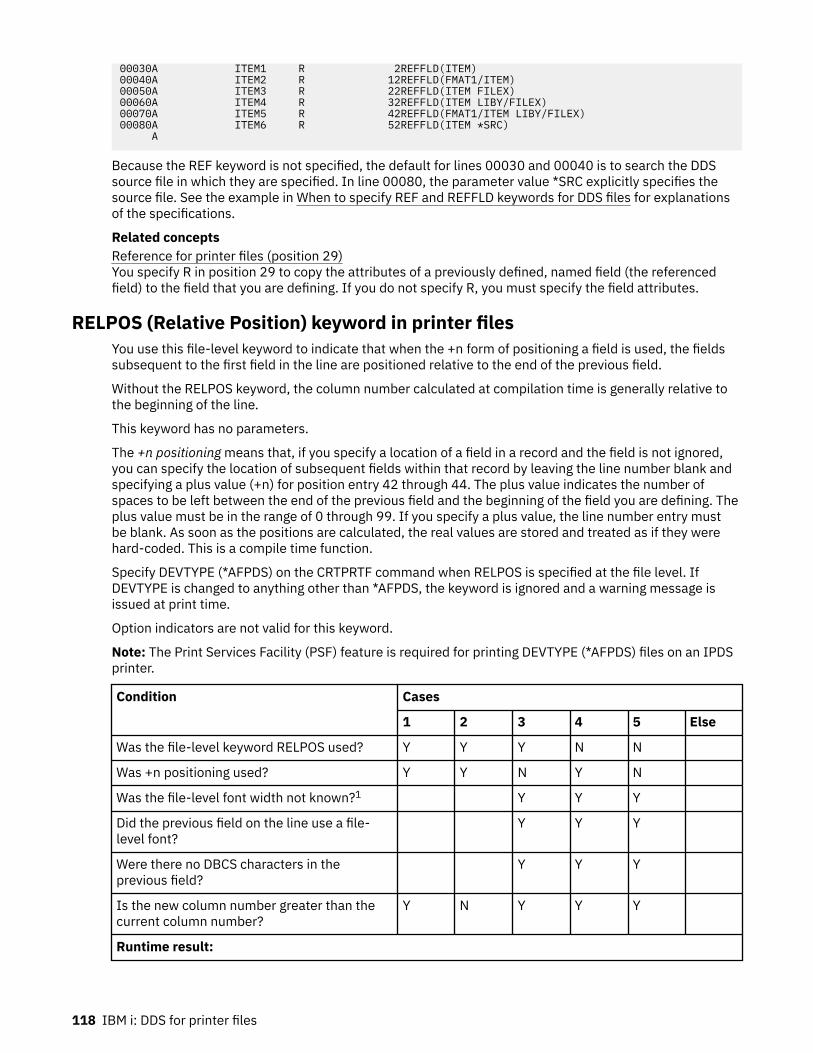
00030A ITEM1 R 2REFFLD(ITEM)00040A ITEM2 R 12REFFLD(FMAT1/ITEM)00050A ITEM3 R 22REFFLD(ITEM FILEX)00060A ITEM4 R 32REFFLD(ITEM LIBY/FILEX)00070A ITEM5 R 42REFFLD(FMAT1/ITEM LIBY/FILEX)00080A ITEM6 R 52REFFLD(ITEM *SRC) A
Because the REF keyword is not specified, the default for lines 00030 and 00040 is to search the DDSsource file in which they are specified. In line 00080, the parameter value *SRC explicitly specifies thesource file. See the example in When to specify REF and REFFLD keywords for DDS files for explanationsof the specifications.
Related conceptsReference for printer files (position 29)You specify R in position 29 to copy the attributes of a previously defined, named field (the referencedfield) to the field that you are defining. If you do not specify R, you must specify the field attributes.
RELPOS (Relative Position) keyword in printer filesYou use this file-level keyword to indicate that when the +n form of positioning a field is used, the fieldssubsequent to the first field in the line are positioned relative to the end of the previous field.
Without the RELPOS keyword, the column number calculated at compilation time is generally relative tothe beginning of the line.
This keyword has no parameters.
The +n positioning means that, if you specify a location of a field in a record and the field is not ignored,you can specify the location of subsequent fields within that record by leaving the line number blank andspecifying a plus value (+n) for position entry 42 through 44. The plus value indicates the number ofspaces to be left between the end of the previous field and the beginning of the field you are defining. Theplus value must be in the range of 0 through 99. If you specify a plus value, the line number entry mustbe blank. As soon as the positions are calculated, the real values are stored and treated as if they werehard-coded. This is a compile time function.
Specify DEVTYPE (*AFPDS) on the CRTPRTF command when RELPOS is specified at the file level. IfDEVTYPE is changed to anything other than *AFPDS, the keyword is ignored and a warning message isissued at print time.
Option indicators are not valid for this keyword.
Note: The Print Services Facility (PSF) feature is required for printing DEVTYPE (*AFPDS) files on an IPDSprinter.
Condition Cases
1 2 3 4 5 Else
Was the file-level keyword RELPOS used? Y Y Y N N
Was +n positioning used? Y Y N Y N
Was the file-level font width not known?1 Y Y Y
Did the previous field on the line use a file-level font?
Y Y Y
Were there no DBCS characters in theprevious field?
Y Y Y
Is the new column number greater than thecurrent column number?
Y N Y Y Y
Runtime result:
118 IBM i: DDS for printer files

Condition Cases
1 2 3 4 5 Else
The new field is offset from the end of theprevious field.
Y Y Y Y
The new field is positioned from the beginningof the line.
Y Y
1If the printer file FONT parameter is *DEVD, or the printer file has a FNTCHRSET or CDEFNT specified atthe file level, the file-level font width is not known.
Example
The following example shows how to specify the RELPOS keyword.
|...+....1....+....2....+....3....+....4....+....5....+....6....+....7....+....8
A* A RELPOS A R REC1 FONT(1051) A* (1051 specifies Sonoran Serif) A FLD1 5A 1 10 A FLD2 5A +2 A*
FLD2 is placed two spaces to the right of the end of FLD1. Depending on the width of the characters usedin FLD1, the start of FLD2 might vary. Without the RELPOS keyword, FLD2 is placed in column 17 of theline; the exception to this statement is noted in columns 3 through 5 of the previous table.
SKIPA (Skip After) keyword in printer filesYou use this file-level, record-level, or field-level keyword to specify that the printer device is to skip to aspecific line number after it prints one or more lines.
The format of the keyword is:
SKIPA(skip-after-line-number)
The parameter value is required and must be in the range 1 through 255.
If you specify the keyword at the file level, you must option it with one or more indicators. If you specifythe keyword at the record or field level, option indicators are optional. The specified skip is performedafter each record in the file prints.
If you specify the keyword at the record level, skipping is performed after all the lines associated with therecord print and before any file-level SKIPA keywords are applied.
If you specify the keyword at the field level, skipping is performed after the field prints.
Note: If you do not use line numbers and do not specify skip or space keywords, overprinting can result.
You can specify this keyword once at the file level, once at the record level, and once for each field.
This keyword is valid at the file level for all records, but not at the record level or the field level forrecords that have line numbers specified (positions 39 through 41). (The line number entries are flaggedas errors.)
The SKIPA keyword is not valid at either the field level or record level if the record format also has theBOX, ENDPAGE, GDF, LINE, OVERLAY, PAGSEG, or POSITION keywords specified.
This keyword is not allowed at the file level for files defined as DEVTYPE(*AFPDS) on the CRTPRTFcommand.
Option indicators are valid for this keyword.
DDS for printer files 119

ExampleThe following example shows how to specify the SKIPA keyword.
|...+....1....+....2....+....3....+....4....+....5....+....6....+....7....+....800011A FIELDA 132A 1SKIPA(12) A
SKIPB (Skip Before) keyword in printer filesYou use this file-level, record-level, or field-level keyword to specify that the printer device is to skip to aspecific line number before it prints the next lines.
The format of the keyword is:
SKIPB(skip-before-line-number)
The parameter value is required and must be in the range 1 through 255.
If you specify this keyword at the file level, you must option it with one or more indicators; otherwise,option indicators are optional. The specified skip is performed before each record in the file prints andafter any file-level SKIPB operations are applied.
If you specify this keyword at the record level, skipping is performed before any of the lines associatedwith that record print.
If you specify this keyword at the field level, skipping is performed before the field prints.
You can specify this keyword once at the file level, once at the record level, and once for each field.
This keyword is valid at the file level for all records, but not at the record or field level for records thathave line numbers specified (positions 39 through 41). (The line numbers are flagged as errors.)
Note: If you do not use line numbers and do not specify skip or space keywords, overprinting can result.
The SKIPB keyword is not valid at either the field level or record level if the record format also has theBOX, ENDPAGE, GDF, LINE, OVERLAY, PAGSEG, or POSITION keywords specified.
This keyword is not allowed at the file level for files defined as DEVTYPE(*AFPDS) on the CRTPRTFcommand.
Option indicators are valid for this keyword.
ExampleThe following example shows how to specify the SKIPB keyword.
|...+....1....+....2....+....3....+....4....+....5....+....6....+....7....+....800022A R RFMTPR SKIPB(5) A
SPACEA (Space After) keyword in printer filesYou use this record-level or field-level keyword to specify that the printer device is to space some numberof lines after it prints one or more lines.
The format of the keyword is:
SPACEA(space-after-value)
The parameter value is required and must be in the range 0 through 255.
If you specify this keyword at the record level, spacing occurs after all lines associated with that recordare printed. You can specify this keyword only once at the record level and once for each field.
If you specify SPACEA at the field level, spacing is performed after the field is printed.
120 IBM i: DDS for printer files

This keyword is not valid for records with specified line numbers (positions 39 through 41). (The linenumbers are flagged as errors.)
Note: If you do not use line numbers and do not specify space or skip keywords, overprinting can result.
The SPACEA keyword is not valid at either the field level or record level if the record format also has theBOX, ENDPAGE, GDF, LINE, OVERLAY, PAGSEG, or POSITION keywords specified.
Option indicators are valid for this keyword.
ExampleThe following example shows how to specify the SPACEA keyword.
|...+....1....+....2....+....3....+....4....+....5....+....6....+....7....+....800100A R RFMTPR SPACEA(1)00101A FIELDA 132 1 A
SPACEB (Space Before) keyword in printer filesYou use this record-level or field-level keyword to specify that the printer device is to space some numberof lines before it prints the next line or lines.
The format of the keyword is:
SPACEB(space-before-value)
The parameter value is required and must be in the range 0 through 255.
If you specify this keyword at the record level, spacing occurs before any lines associated with that recordare printed. You can specify this keyword only once at the record level or once for each field.
If you specify SPACEB at the field level, spacing is performed before the line containing that field prints.
This keyword is not valid for records with specified line numbers (positions 39 through 41). (The linenumbers are flagged as errors.)
Note: If you do not use line numbers and do not specify space or skip keywords, overprinting can result.
The SPACEB keyword is not valid at either the field level or record level if the record format also has theBOX, ENDPAGE, GDF, LINE, OVERLAY, PAGSEG, or POSITION keywords specified.
Option indicators are valid for this keyword.
ExampleThe following example shows how to specify the SPACEB keyword.
|...+....1....+....2....+....3....+....4....+....5....+....6....+....7....+....800010A FIELDA 25A 55SPACEB(3)00011A FIELDB 30 100 A
STAPLE (Staple) keyword in printer filesYou use this record-level keyword to specify that a stapling operation should be performed within thespooled file.
The stapling operation must be defined on the CORNERSTPL, EDGESTITCH, or SADLSTITCH parameterson the CRTPRTF, CHGPRTF, or OVRPRTF commands. If no stapling is defined on the printer file, then theSTAPLE keyword is ignored. If you do not specify the STAPLE keyword, the entire spooled file will bestapled according to the definition on the EDGESTITCH, SADLSTITCH, or CORNERSTPL parameters.
DDS for printer files 121

The format of the keyword is:
STAPLE([on/off-indicator])
When a STAPLE keyword is processed, the printer ejects a page, and all previous pages that have beenstacked since the last staple operation are stapled together. This includes pages that were processedsince the beginning of the spooled file, since the last STAPLE keyword was issued, or since staplingresumed after the last STAPLE(*ON) was issued.
For example, for simple printing, if the STAPLE keyword where issued at the beginning of page 5, then theprevious 4 pages are stapled together. Some printers might not support the stapling of a single page.
The optional off-on stapling indicator specifies whether stapling should be turned off within the spooledfile.
*OFFSpecifies that stapling is turned off. All previous pages that were processed since the beginning ofthe spooled file, since the last STAPLE keyword was issued, or since stapling resumed after the lastSTAPLE(*ON) was issued are stapled together. STAPLE(*OFF) remains in effect until a STAPLE(*ON)keyword is issued. STAPLE(*OFF) must be specified on a record format issued on a page boundary.
*ONSpecifies that stapling is to resume. This is normally issued after a STAPLE(*OFF) was issued ona previous record format. If stapling is currently defined as on, then this keyword is ignored.STAPLE(*ON) remains in effect until a STAPLE(*OFF) keyword is issued. STAPLE(*ON) must bespecified on a record format issued on a page boundary. The STAPLE(*ON) keyword does not causeany previously processed pages to be stapled.
STAPLE is ignored at run time if it is not specified on a page boundary. The printer is on a page boundarywhen no named or constant fields are processed for a page. After a named or constant field is processed,the printer is no longer on a page boundary. The printer is on a page boundary again when a SKIP, SPACE,ENDPAGE, FORCE, or INVMMAP keyword is processed, which causes the printer to move to a new page.
STAPLE, SKIP, and SPACE keywords are processed in the following order:
SKIPBSPACEBSTAPLESPACEASKIPA
The stapling operation will cause the ejection of the current sheet of paper. When duplexing is in effect(specified on the printer file or DDS), if STAPLE is issued when starting an odd page (for example, page 5),then the previous 4 pages (2 sheets of paper) will be stapled. If STAPLE is issued when starting an evenpage (for example, page 6), then the previous 5 pages (3 sheets of paper) will be stapled. The back side ofthe third sheet of paper will be blank.
Option indicators are valid for this keyword. Only one STAPLE keyword for each record format is valid atany time.
Example|...+....1....+....2....+....3....+....4....+....5....+....6....+....7....+....800010A R RECORD1 SKIPB(3) 00020A FIELD1 10 1SPACEA(1) 00030A FIELD2 5 1SPACEA(1) 00040A R RECORD2 STAPLE 00050A FIELD1 5 1 00060A R RECORD3 STAPLE SKIPB(1) 00070A FIELD1 10 1 00080A 00090A R RECORD4 STAPLE(*OFF) SKIPB(1)00100A
The printer is not on a page boundary after record format RECORD1 is processed. When record formatRECORD2 is processed, STAPLE is ignored. Because SKIPB(1) is specified on RECORD3, the printer is on a
122 IBM i: DDS for printer files

page boundary when STAPLE is processed. All previous processed pages since the last stapling operationwill be stapled together. RECORD 4 turns off stapling. All previous processed pages since the last staplingoperation will be stapled together. Stapling will not resume unless a STAPLE(*ON) is issued on a anotherrecord format.
STRPAGGRP (Start Page Group) keyword in printer filesYou use this record-level keyword to begin a logical grouping of pages.
Page Groups can be used for indexing and retrieving information in a document by online viewingproducts such as Advanced Function Printing and Content Manager OnDemand.
Pages separated with the STRPAGGRP and ENDPAGGRP DDS keywords can be indexed with the AttributeName and Attribute Value parameters of the DOCIDXTAG keyword.
The format of the keyword is:
STRPAGGRP(group-name | &group-name)
The group-name parameter is required and defines the name of the group to be started. The group nameshould be unique within a document. The maximum number of characters in the group name is 250.Blanks are allowed as part of the group name.
Note: Groups of pages cannot be nested or overlapped, each group must be ended (ENDPAGGRPkeyword) before another can begin.
When you specify the group-name parameter as a program-to-system field, the field must exist inthe same record format as the STRPAGGRP keyword. It must be defined as length of 1 -250, type A(character), and usage P (program-to-system).
This keyword is valid with DEVTYPE(*AFPDS). If DEVTYPE is changed to anything other than *AFPDS, thekeyword will be ignored and a warning message will be issued at print time.
Option indicators are valid for this keyword.
ExampleThe following example shows how to specify the STRPAGGRP keyword.
|...+....1....+....2....+....3....+....4....+....5....+....6....+....7....+.... A A R RECORD1 A 02 STRPAGGRP('ACCOUNT NUMBER') A R RECORD2 STRPAGGRP(&GROUP) A GROUP 50A P A
In the example, RECORD1 starts a group named 'ACCOUNT NUMBER'. RECORD2 allows the applicationprogram to specify the name of group by setting program variable GROUP.
TEXT (Text) keyword in printer filesYou use this record-level or field-level keyword to supply a text description (or comment) for the recordformat or field that is used for program documentation.
The format of the keyword is:
TEXT('description')
The text must be enclosed in single quotation marks. If the length of the text is greater than 50 positions,only the first 50 characters are used by the high-level language compiler.
Option indicators are not valid for this keyword.
DDS for printer files 123
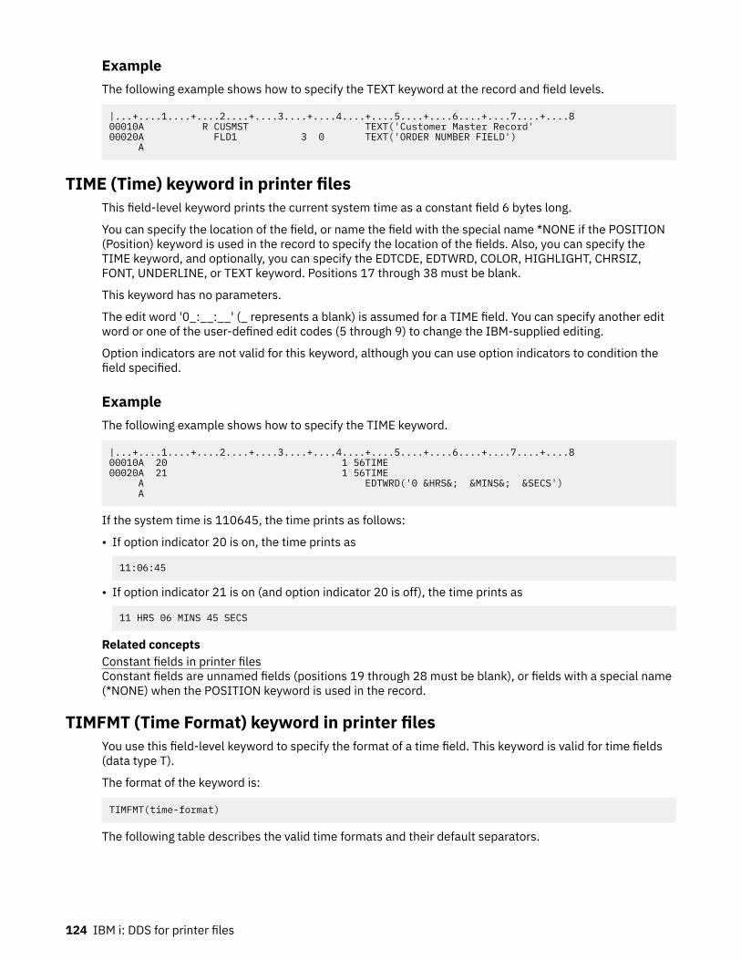
ExampleThe following example shows how to specify the TEXT keyword at the record and field levels.
|...+....1....+....2....+....3....+....4....+....5....+....6....+....7....+....800010A R CUSMST TEXT('Customer Master Record'00020A FLD1 3 0 TEXT('ORDER NUMBER FIELD') A
TIME (Time) keyword in printer filesThis field-level keyword prints the current system time as a constant field 6 bytes long.
You can specify the location of the field, or name the field with the special name *NONE if the POSITION(Position) keyword is used in the record to specify the location of the fields. Also, you can specify theTIME keyword, and optionally, you can specify the EDTCDE, EDTWRD, COLOR, HIGHLIGHT, CHRSIZ,FONT, UNDERLINE, or TEXT keyword. Positions 17 through 38 must be blank.
This keyword has no parameters.
The edit word '0_:__:__' (_ represents a blank) is assumed for a TIME field. You can specify another editword or one of the user-defined edit codes (5 through 9) to change the IBM-supplied editing.
Option indicators are not valid for this keyword, although you can use option indicators to condition thefield specified.
ExampleThe following example shows how to specify the TIME keyword.
|...+....1....+....2....+....3....+....4....+....5....+....6....+....7....+....800010A 20 1 56TIME00020A 21 1 56TIME A EDTWRD('0 &HRS&; &MINS&; &SECS') A
If the system time is 110645, the time prints as follows:
• If option indicator 20 is on, the time prints as
11:06:45
• If option indicator 21 is on (and option indicator 20 is off), the time prints as
11 HRS 06 MINS 45 SECS
Related conceptsConstant fields in printer filesConstant fields are unnamed fields (positions 19 through 28 must be blank), or fields with a special name(*NONE) when the POSITION keyword is used in the record.
TIMFMT (Time Format) keyword in printer filesYou use this field-level keyword to specify the format of a time field. This keyword is valid for time fields(data type T).
The format of the keyword is:
TIMFMT(time-format)
The following table describes the valid time formats and their default separators.
124 IBM i: DDS for printer files

Format name Time formatparameter
Time format andseparator
Field length Example
Hours:Minutes:Seconds *HMS hh:mm:ss 8 14:00:00
International StandardsOrganization
*ISO hh.mm.ss 8 14.00.00
IBM USA Standard *USA hh:mm AM or
hh:mm PM
8 2:00 pm
IBM European Standard *EUR hh.mm.ss 8 14.00.00
Japanese Industrial StandardChristian Era
*JIS hh:mm:ss 8 14:00:00
If you do not specify the TIMFMT keyword, the default is *ISO.
If you specify the time-format parameter value as *ISO, *USA, *EUR, or *JIS, you cannot specify theTIMSEP keyword. These formats have fixed separators.
The TIMFMT keyword overrides the job attribute for a time field. It does not change the system default.
It is the responsibility of the high-level language and the application to format the time field according tothe format specified for the TIMFMT keyword and use the separators specified on the TIMSEP keyword.The system does not format fields on output. The system validates the time field on input according to theformat that the TIMFMT keyword specifies and the separator that the TIMSEP keyword specifies.
Option indicators are not valid for this keyword, although option indicators can condition the field forwhich it is specified.
ExampleThe following example shows how to specify the TIMFMT keyword.
|...+....1....+....2....+....3....+....4....+....5....+....6....+....7....+....800010A00020A R RECORD00030A TIMFLD1 T B 5 2TIMFMT(*ISO)00040A TIMFLD2 T B 5 22TIMFMT(*USA)00050A TIMFLD3 T B 5 42TIMFMT(*HMS) TIMSEP(',') A
If you want to display 2 o'clock p.m., the following values appear where RECORD1 is written.
TIMFLD1 14.00.00TIMFLD2 02:00 PMTIMFLD3 14,00,00
TIMSEP (Time Separator) keyword in printer filesYou use this field-level keyword to specify separator characters for time fields. This keyword is valid onlyfor time fields (data type T).
The format of the keyword is:
TIMSEP(*JOB | 'time-separator')
The time-separator parameter specifies the separator character that appears between the hour, minute,and second values. Valid values are a colon (:), a period (.), a comma (,), and a blank ( ). Single quotationmarks must enclose the parameter.
If you specify the *ISO, *USA, *EUR, or *JIS time-format value for the TIMFMT keyword, you can notspecify the TIMSEP keyword. These formats have fixed separators.
DDS for printer files 125

If you do not specify the TIMSEP keyword and you specify TIMFMT as a format that does not have a fixeddate separator, the TIMSEP defaults to *JOB.
If you specify *JOB or if TIMSEP defaults to *JOB, the high level language and the application handlethe separator as a colon (:). On output the system converts the separator that was specified by the TimeSeparator Job Definition Attribute. On input, the system converts the separator to a colon (:) before itpasses control to the application.
The TIMSEP keyword overrides the job attribute for a time field. It does not change the system default.
It is the responsibility of the high-level language and the application to format the time field according tothe format specified for the TIMFMT keyword and use the separators specified for the TIMSEP keyword.The system does not format fields on output. The system validates the time field on input according to theformat that the TIMFMT keyword specifies and the separator that the TIMSEP keyword specifies.
Option indicators are not valid for this keyword, although option indicators can condition the field forwhich it is specified.
ExampleThe following example shows how to specify the TIMSEP keyword.
|...+....1....+....2....+....3....+....4....+....5....+....6....+....7....+....800010A00020A R RECORD00030A TIMFLD1 T TIMFMT(*HMS) TIMSEP(' ')00040A TIMFLD2 T TIMFMT(*HMS) TIMSEP('.')00050A TIMFLD3 T TIMFMT(*HMS) TIMSEP(*JOB)
If you want to display 2 o'clock p.m. and the time separator defined by the Job Definition Attribute is acolon (:), the following values is displayed when RECORD1 is written.
TIMFLD1 14 00 00TIMFLD2 14.00.00TIMFLD3 14:00:00
TRNSPY (Transparency) keyword in printer filesThis field-level keyword prevents code points that you have redefined (using the DFNCHR keyword) frombeing interpreted as SCS printer control commands when your program sends an output operation thatprints the field that you are defining.
This keyword has no parameters.
If you do not specify the TRNSPY keyword for a field in which your program passes hexadecimal data toan SCS printer, code points can be interpreted as SCS commands that affect printer operation. A codepoint is one of the 256 values that you can assign to a character in a character set. On the IBM i operatingsystem, a code point is identified by a 2-digit hexadecimal number.
You must specify the TRNSPY keyword when you specify:
• The CVTDTA keyword in a printer file created with DEVTYPE(*SCS)• A hexadecimal value (with or without the DFT keyword explicitly specified)
In a file created with DEVTYPE(*IPDS), you need not specify the TRNSPY keyword with the CVTDTAkeyword. However, a warning message appears stating that the DEVTYPE should not be changed to *SCS.
If you specify TRNSPY in a file created with DEVTYPE(*AFPDS), a warning message appears at creationtime.
The TRNSPY keyword is valid only when the data type is character.
When you specify the TRNSPY keyword with the CVTDTA keyword, your program can place character datain the field and the IBM i operating system converts it to hexadecimal data when the field is passed to theprinter. Each pair of hexadecimal digits corresponds to a code point in the character set of your system.Using the DFNCHR keyword, you can define characters of your own design for the 5224 Printer or 5225
126 IBM i: DDS for printer files

Printer. Also, the printed length of the field is one half the length you specify. Therefore, the length of thefield must be an even number.
If you specify the TRNSPY keyword without the CVTDTA keyword, the field length you specify is theprinted length.
This keyword is supported only for the 5224 Printer and 5225 Printer.
Option indicators are not valid for this keyword.
ExamplesThe following examples show how to specify the TRNSPY keyword.
Example 1
The following example shows how to specify the TRNSPY keyword with the CVTDTA keyword. When yourprogram passes character data in a field, the IBM i operation system converts it to hexadecimal data.
|...+....1....+....2....+....3....+....4....+....5....+....6....+....7....+....800010A R RECORD SPACEB(1)00020A FLD1 10 1TRNSPY CVTDTA00030A FLD2 20 6TRNSPY CVTDTA A
The program can pass character data in FLD1 and FLD2. The IBM i operating system converts it tohexadecimal data for the printer. Only the characters 0 through 9 and A through F are valid. Blanks are notvalid.
The printed length of FLD1 and FLD2 is one half the specified length (FLD1 is 5 positions long; FLD2 is 10positions long).
You must also specify the DFNCHR keyword with this DDS in order to print user-defined characters.
The following is how RECORD prints when the contents of FLD1 are 'C1C1C1C1C1' and the contents ofFLD2 are 'C2C2C2C2C2C2C2C2C2C2':
AAAAABBBBBBBBBB
Example 2
The following example shows how to specify the TRNSPY keyword without the CVTDTA keyword. In thisexample, your program must pass hexadecimal data in the field.
|...+....1....+....2....+....3....+....4....+....5....+....6....+....7....+....800010A R RECORD2 SPACEB(1)00020A FLD3 5 1TRNSPY00030A FLD4 10 6TRNSPY A
The program must pass hexadecimal data in FLD3 and FLD4. Only hexadecimal characters 0 through 9and A through F are valid. Blanks are not valid. Without the CVTDTA keyword, the printed length of bothfields is the specified length.
Related conceptsCVTDTA (Convert Data) keyword in printer files
DDS for printer files 127

This field-level keyword converts character data to hexadecimal data when the field is passed to theprinter.
TXTRTT (Text Rotation) keyword in printer filesYou use this field-level keyword to rotate any text contained in the field.
The format of the keyword is:
TXTRTT(field-rotation)
The field-rotation parameter is required and controls the rotation of the field. Valid values are 0, 90, 180,and 270 degrees.
Specify DEVTYPE(*AFPDS) on the CRTPRTF command when TXTRTT is specified in the file. If DEVTYPE ischanged to anything other than *AFPDS, the keyword is ignored and a warning message is issued at printtime.
Option indicators are valid for this keyword.
CHRSIZ is handled as graphic font and cannot be used with the field-level keyword TXTRTT.
Example 1The following example shows how to specify the TXTRTT keyword.
|...+....1....+....2....+....3....+....4....+....5....+....6....+....7....+....8 A* A R REC1 A FLD05 10 35 15TXTRTT(90) A* A R REC2 A FLD06 7S 2 TXTRTT(270) A POSITION(6.5 13.8) A
FLD05 in REC1 is rotated 90 degrees.
FLD06 in REC2 is rotated 270 degrees.
Example 2The following example shows how to specify the TXTRTT keyword.
|...+....1....+....2....+....3....+....4....+....5....+....6....+....7....+....8 * R REC1 FLD05 16 3 5TXTRTT(0) * R REC2 FLD06 16 TXTRTT(270) POSITION(6 7)
Record 1 (REC1) field 5 (FLD05), shows the coding using the row/column method of positioning. Record 2(REC2) field 6 (FLD06), shows the coding using the absolute method of positioning.
The following diagram shows:
• The position of FLD05 in REC1 with the row/column method of positioning. Rotation is 0 degrees.• The position of FLD06 in REC2 with the absolute method of positioning. Rotation is 270 degrees.
Scale and position should not be considered in this diagram.
128 IBM i: DDS for printer files

Text for field 5 begins in column 5 and extends along row 3. Text for field 6 begins in row 6 and extendsupward along column 7.
UNDERLINE (Underline) keyword in printer filesYou use this field-level keyword to specify that the IBM i operating system underlines the field when it isprinted.
Specify UNDERLINE only if the printer supports underlining.
This keyword has no parameters.
Option indicators are valid for this keyword.
DDS for printer files 129

ExampleThe following example shows how to specify the UNDERLINE keyword.
|...+....1....+....2....+....3....+....4....+....5....+....6....+....7....+....800100A ALLOC R 17 1100101A 03 04 UNDERLINE A
UNISCRIPT (Unicode Text Layout) keyword in printer filesYou use this field-level keyword to control the selection of text marked for complex script processing.
The keyword has two possible formats:
UNISCRIPT
All of the parameters for the UNISCRIPT keyword have defaults. When the keyword is provided withoutparameters, the default for each parameter value is used.
You can also use the keyword with one or more optional parameters. The parameters can be provided inany order.
UNISCRIPT([*PRECHK] [*NORMALIZE] [(*ICULOC 'locale_constant_string' | *NONE | &iculocale_field_name)] [(*PARDIR *RL | *LR | *PREV | *CALC | ¶graph_dir_field)] [(*ALTIPOS position_value | &alternate_inline_position_field])
If a parameter is not provided, the default for that parameter value is used.
Use the precheck_data parameter, *PRECHK, to request that the data be tested at print time to determinewhether complex layout techniques are needed. When this optional parameter is specified, the datais first analyzed to determine whether complex text layout is required to properly present the string.If complex layout is not required, the Unicode data is not marked and is processed with traditionaltext-layout techniques. As such, any subsequent UNISCRIPT parameters are ignored for this field. Ifcomplex layout is required or this parameter is omitted, the data is marked for complex text layout.You must have installed IBM i Option 39—International Components for Unicode (ICU)—to perform thispreprocessing.
Use the icu_locale parameter, *ICULOC, to specify a locale to guide the application of the text layoutfunctions. Most applications can determine the correct layout for the text using the Unicode code pointsalone. However, a small number of TrueType fonts provide substitute glyphs for specific languages,countries, or regions. For example, if a single font contains both Chinese and Japanese glyphs, alocale will be needed to access the correct character variant. The specification of an ICU locale is notrecommended unless the font is known to contain such variants and the print application is limited to thatlanguage or region.
The parameter is an expression of the form (*ICULOC value). The allowed values are:
• *NONE. No locale name is associated with the field data. This is the default.
The default locale of the presentation system is used to guide the text layout of the data.• locale_constant_string is a quoted string from 2 to 96 bytes long.
The locale name must adhere to the convention used by the ICU functions used by the presentationsystem. In general, an ICU locale consists of one, two, or three ordered codes separated by anunderscore. The first is a two- or three-letter lowercase language code from the ISO-639 standard.The locale can be further qualified by a two- or three-letter uppercase region code from the ISO-3166standard. For each of these codes, the two-character value is used if one is defined. The third qualifier,the variant code, is an arbitrary string that is application specific.
Because the quoted string value can contain lowercase characters, its encoding must be consideredin order to be correctly interpreted. If the user provides a constant string as input, the DDS compilerverifies that the source member is tagged with a (non-*HEX) CCSID.
130 IBM i: DDS for printer files

The locale name can be provided in a program-to-system field. The field must be found in the samerecord format as the UNISCRIPT keyword, and have a data type of A (character) with a length of from 2 to96.
When the host print transform function is used to print the document, the locale name specified must beone of those provided with ICU in IBM i Option 39. If the specified locale is not found, a substitute localeis found based on the class hierarchy for defined locales.
Use the paragraph_direction parameter, *PARDIR, to specify how the overriding paragraph direction isdetermined. This value is used as input when the bidirectional algorithm is applied to the data. It will alsobe used to determine whether to place the text at the current or alternate inline position, if an alternateposition is specified. This parameter can be specified as a special value or as a program-to-system field.
The parameter is an expression of the form (*PARDIR value). The supported special values and theirdefinitions are listed as follows:
• *CALC. The paragraph direction is determined by the complex text run based on the first strongdirectional character that is encountered. If no such characters are found in the string, the defaultparagraph direction of left-to-right is used. This is the default value.
• *RL. The paragraph direction is set to right-to-left.• *LR. The paragraph direction is set to left-to-right.• *PREV. The paragraph direction is determined by the previous complex text run. If the field is the first
complex text run for the page, the paragraph direction is determined by the text data based on thefirst strong directional character that is encountered. If no such characters are found in the string, thedefault paragraph direction of left-to-right is used.
If the parameter value is a program-to-system field, the field must be found in the same record format asthe UNISCRIPT keyword and have a data type of A (character) with a length of 5.
Use the alternate-inline-position parameter, *ALTIPOS, to specify an alternate position on the current lineto be used in place of the current inline (across) position for text runs of different paragraph directions.This allows fields with a right-to-left paragraph direction to be right-aligned and those with a left-to-rightparagraph direction to be left-aligned. The determination of which position is used as the starting pointfor a given paragraph direction is based on the relationship between the current inline direction and theparagraph direction. See the following examples for a discussion of how this parameter is used.
The alternate-inline-position value is applied relative to the margins specified on the FRONTMGN orBACKMGN parameter on the CRTPRTF command. Valid values are 0 to 57.790 cm (0 to 22.750 in).The UOM parameter on the CRTPRTF command determines the units of measure for the alternate-inline-position parameter value. If the value specified is outside the valid range, it is flagged when the spooledfile is created.
The parameter is an expression of the form (*ALTIPOS value). The value can be provided in a program-to-system field. The field must be found in the same record format as the UNISCRIPT keyword, and havea data type of S (numeric) with a length of 5, and 3 decimal positions. If the alternate-inline-positionparameter is not provided, no additional positioning action is done; this is the default.
Specify DEVTYPE(*AFPDS) on the CRTPRTF command when UNISCRIPT is specified in the file. IfDEVTYPE is changed to anything other than *AFPDS, the keyword is ignored and a warning messageis issued at print time.
When the UNISCRIPT keyword is used on a field, the following considerations also apply. The fieldmust have a G data type and it must use the CCSID keyword with a UCS-2 or UTF-16 CCSID and the*NOCONVERT parameter. Because the keyword offers no benefit unless a TrueType font is also applied tothe data, the FONTNAME keyword (without code page parameters) is also required.
Option indicators are valid for this keyword.
ExamplesIn the following examples, case is used to indicate different implicit character types for those unfamiliarwith right-to-left letters. Uppercase letters stand for right-to-left characters (such as Arabic or Hebrew),
DDS for printer files 131

and lowercase letters stand for left-to-right characters (such as English or Russian). In storage, Unicodecharacters are stored in logical order. For these examples, consider the following text string: "TEXTtext".
If *RL or *CALC is specified for the paragraph direction parameter, this string is rendered in the followingway:
text TXET
If *LR is specified, it is rendered as:
TXET text
When alternate-inline-position is omitted, the field will be placed at the normal position and laid outin the current inline direction, regardless of the specified or calculated paragraph direction. By default,*AFPDS printer files use a left-to-right (L-to-R) inline direction. A right-to-left (R-to-L) inline directioncan be achieved by specifying a value of 180 degrees for the *ROTATION parameter of the FONTNAMEkeyword and for the TXTRTT keyword. Assuming that the current inline position is P1 and the paragraphdirection is R-to-L, then:
• If the inline direction is L-to-R, the string is rendered as
(P1)text TXET
• If the inline direction is R-to-L, the string is rendered as
text TXET(P1)
The alternate-inline-position parameter allows applications to position L-to-R and R-to-L text correctlywithout having to change the inline direction. It is used in the following way:
• If the inline direction is L-to-R (0 degree character rotation), the alternate_inline_position (P2) is usedfor a field with a R-to-L paragraph direction. The normal inline position (P1) is used if the paragraphdirection is L-to-R.
• If the inline direction is R-to-L (180 degree character rotation), the alternate inline position (P2) is usedfor paragraphs with a L-to-R direction. The normal inline position (P1) is used if the paragraph directionis R-to-L.
When an alternate-inline-position (P2) is specified, our example string is positioned in the followingmanner:
• If the current inline direction is L-to-R and the paragraph direction is R-to-L, the string is rendered as
(P1) text TXET(P2)
• If the current inline direction is L-to-R and the paragraph direction is L-to-R, the string is rendered as
(P1)TXET text (P2)
• If the current inline direction is R-to-L and the paragraph direction is L-to-R, the string is rendered as
(P1) (P2)TXET text
• If the current inline direction is R-to-L and the paragraph direction is R-to-L, the string is rendered as
text TXET(P1) (P2)
If alternate positions are used throughout a document to produce a significantly different report layout forR-to-L scripts, it is very important that all fields are interpreted with the same paragraph direction. Thespecial value of *PREV is provided for the *PARDIR parameter for this purpose. A program-to-system fieldcan also be used to achieve this goal.
132 IBM i: DDS for printer files

Note that Unicode bidirectional processing is not supported for either of the vertical inline directionsrepresented by character rotation values of 90 and 270 degrees, and the alternate-inline-position isignored.
The following example shows how to specify the UNISCRIPT keyword.
Note: By using the code examples, you agree to the terms of the “Code license and disclaimerinformation” on page 148.
|...+....1....+....2....+....3....+....4....+....5....+....6....+....7....+....8 A* A R REC1 A F1 10G 3 8UNISCRIPT A CCSID(13488 *NOCONVERT) A FONTNAME('Monotype Sans WT' + A (*POINTSIZE 10.0)) A* A R REC2 CCSID(1200 *NOCONVERT) A FONTNAME('Monotype Sans WT' + A (*POINTSIZE 10.0)) A F2 10G 4 8UNISCRIPT(*NORMALIZE + A (*ICULOC 'zh_HK') + A (*PARDIR *RL) + A (*ALTIPOS 5.77)) A F3 10G 5 8UNISCRIPT(*PRECHK + A (*ICULOC &ICULOC) + A (*PARDIR &PARDIR) + A (*ALTIPOS &ALTPOS)) A ICULOC 20A P A PARDIR 5A P A ALTPOS 5S 3P A
Note: The UOM parameter on the CRTPRTF command determines the units of measure for the parametervalue of the alternate-inline-position parameter.
Field F1 in record REC1 uses the default values of the UNISCRIPT keyword. The text in F1 is notpre-checked to determine whether complex text layout is required. The data in the field will not benormalized by the presentation device. The ICU locale name is provided by the presentation system. Theparagraph direction is determined by the first strong directional character that is found in the text in F1.The alternate-inline-position parameter is not provided, so no additional positioning processing is done.The CCSID keyword with a UCS-2 or UTF-16 CCSID and the *NOCONVERT parameter is required. TheFONTNAME keyword is also required.
Record REC2 uses the CCSID and FONTNAME keywords at the record level. These keywords are appliedto each G data type field in the format. The result is that any G field with the UNISCRIPT keyword will alsohave the required CCSID and FONTNAME keywords.
Field F2 in REC2 uses the UNISCRIPT keyword with all the parameter values provided. The text will benormalized by the presentation device. The ICU locale for Hong Kong S.A.R. of PRC is requested.The paragraph direction is set to right-to-left. The text is positioned at 5.77 units across from the marginsspecified on the FRONTMGN or BACKMGN parameter on the CRTPRTF command.
Field F3 in REC2 provides some of the values for the UNISCRIPT parameters in program-to-system fields.Note that *PRECHK and *NORMALIZE do not support a program-to-system field parameter. Because the*NORMALIZE parameter is omitted in this example, the text is not normalized by the presentation device(the default). Because the *PRECHK parameter is specified, the text in the field is prechecked for complextext.
Related referenceSystem-supplied locales and recommended CCSIDsRelated informationUnicode Normalization FormsIBM Globalization - ICU
DDS for printer files 133

ZFOLD (Z-fold) keyword in printer filesYou use this record-level keyword to specify that a z-fold operation is performed on the current sheet.
The z-fold operation causes the current sheet to be first folded in half inwards (so the front side of thesheet is now inside the fold) along a line parallel to the reference edge. The half of the sheet furthestfrom the reference edge is again folded in half outwards along a line parallel to the reference edge. Forexample, when applied to an 11 x 17 in. sheet with the reference edge along a short side, the result is an8.5 x 11 in. foldout.
This finishing operation is applied to each medium, or sheet.
The format of the keyword is:
ZFOLD(reference-edge paper-type)
The reference-edge and paper-type parameters are required.
You can specify the following values for these two parameters:
• reference-edge:*BOT
The reference edge is the bottom edge of the media.*RIGHT
The reference edge is the right edge of the media.*TOP
The reference edge is the top edge of the media.*LEFT
The reference edge is the left edge of the media.*DEVD
The reference edge is the default reference edge used by the device.• paper-type:
*LEDGERThe paper to be used is ledger-sized (11 x 17 in.).
*A3The paper to be used is A3-sized (297 mm x 420 mm).
Specify DEVTYPE(*AFPDS) on the CRTPRTF command when ZFOLD is specified in the file. If DEVTYPE ischanged to anything other than *AFPDS, the keyword is ignored and a warning message is issued at printtime.
If ZFOLD is specified for a printer that does not support z-fold operations, the value specified forFIDELITY in the printer file controls whether the file prints.
ZFOLD is ignored at run time if it is not specified on a page boundary. The printer is on a page boundarywhen no named or constant fields are processed for a page. After a named or constant field is processed,the printer is no longer on a page boundary. The printer is on a page boundary again when a SKIP, SPACE,or ENDPAGE keyword is processed that causes the printer to move to a new page.
ZFOLD, SKIP, and SPACE keywords are processed in the following order:
SKIPBSPACEBZFOLDSPACEASKIPA
ZFOLD is in effect only for the record format specified. For the record format in which ZFOLD is specified,the page size is changed to the size of the paper-type specified for ZFOLD: ledger or A3. After records withthe specified record format are processed, the page size for the next record format (if the ZFOLD keywordis not specified) is the page size specified at the file level (CRTPRTF, CHGPRTF, or OVRPRTF command).
134 IBM i: DDS for printer files

ZFOLD is in effect for just a single sheet. If consecutive sheets are to have a z-fold operation applied,then ZFOLD must be specified for each sheet. Printers can support a varying maximum number of sheetsnumber of sheets per spooled file that have had a z-fold operation applied to them. Check your printer'shardware reference for this information.
The reference edges supported by a printer vary. Check your printer's hardware reference for thisinformation.
Example|...+....1....+....2....+....3....+....4....+....5....+....6....+....7....+....8 A* A R REC1 ZFOLD(*DEVD *LEDGER) A*
When REC1 is printed, it is z-folded by the printer's post processor.
Only one ZFOLD keyword for each record format is valid at any time. Even with option indicators,specifying more than one ZFOLD keyword per record format is not valid.
The overflow line number is recomputed if you specify ZFOLD, because the page size is either ledger orA3. The new overflow line number maintains the distance between the overflow line and the bottom ofthe page as specified in the printer file. The overflow number specified in the printer file will be restoredwhen processing is complete for ZFOLD. So if the file level specifies an overflow line which is 1" from thebottom of the page, the overflow line for a page on which ZFOLD is specified is also 1" from the bottom ofthe page.
Refer to your printer's documentation for additional information about the z-fold operation.
Option indicators are valid for this keyword.
Note: Use of this DDS keyword causes an IBM i spooled file to be generated so that it is not correctlyprinted when sending the spooled file to MVS. The spooled file does not print and is held on the outputqueue by PSF/MVS.
CODE128 character set in DDSThis table lists the range of characters available in the CODE128 bar code-character set.
Table 7. CODE128 character set (EBCDIC)
Character
Hexadecimal
Character Hexadecimal
Character Hexadecimal
Character Hexadecimal
NUL 00 . 4B i 89 I C9
SOH 01 < 4C FNC 1 8F } D0
STX 02 ( 4D j 91 J D1
ETX 03 + 4E k 92 K D2
HT 05 Solidverticalbar, orpipe
4F l 93 L D3
VT 0B & 50 m 94 M D4
FF 0C ! 5A n 95 N D5
CR 0D $ 5B o 96 O D6
SO 0E * 5C p 97 P D7
SI 0F ) 5D q 98 Q D8
DDS for printer files 135

Table 7. CODE128 character set (EBCDIC) (continued)
Character
Hexadecimal
Character Hexadecimal
Character Hexadecimal
Character Hexadecimal
DLE 10 ; 5E r 99 R D9
DC1 11 - 60 ~ A1 \ E0
DC2 12 / 61 s A2 S E2
DC3 13 , 6B t A3 T E3
BS 16 % 6C u A4 U E4
CAN 18 _ 6D v A5 V E5
EM 19 > 6E w A6 W E6
GS 1D ? 6F x A7 X E7
RS 1E ` 79 y A8 Y E8
US 1F : 7A z A9 Z E9
FS 22 # 7B ¬ B0 FNC 2 EA
LF 25 @ 7C ¢ BA 0 F0
ETB 26 ' 7D | BB 1 F1
ESC 27 = 7E FNC 4 BE 2 F2
ENQ 2D " 7F C0 3 F3
ACK 2E a 81 A C1 4 F4
BEL 2F b 82 B C2 5 F5
SYN 32 c 83 C C3 6 F6
EOT 37 d 84 D C4 7 F7
DC4 3C e 85 E C5 8 F8
NAK 3D f 86 F C6 9 F9
SUB 3F g 87 G C7 FNC 3 FA
SP 40 h 88 H C8 DEL FF
Unicode considerations for printer filesBe aware of these Unicode considerations for positional entries and keyword entries for printer files.
Unicode is a universal encoding scheme for written characters and text, which enables the exchangeof data internationally. A Unicode field can contain all types of characters used on the IBM i operatingsystem, including ideographic (DBCS) characters. In this topic, the term code unit means the minimal bitcombination that can represent a unit of encoded text for processing or interchange.
DDS printer files support two transformation formats (encoding forms) of Unicode:
• UTF-16 is a 16-bit encoding form designed to provide code values for over a million characters and asuperset of UCS-2. UTF-16 data is stored in graphic data types. The CCSID value for data in UTF-16format is 1200.
A UTF-16 code unit is 2 bytes in length. A UTF-16 character can be 1 or 2 code units (2 or 4 bytes)in length. A UTF-16 data string can contain any character, including UTF-16 surrogates and combiningcharacters.
136 IBM i: DDS for printer files

• UCS-2 is the Universal Character Set coded in 2 octets, which means that characters are representedin 16 bits per character. UCS-2 data is stored in graphic data types. The CCSID value for data in UCS-2format is 13488.
UCS-2 is a subset of UTF-16 and can no longer support all of the characters defined by Unicode. UCS-2is identical to UTF-16 except that UTF-16 also supports combining characters and surrogates. If you donot need combining characters and surrogates, you might choose to use UCS-2.
Positional entry considerations for printer files that use UTF-16 dataThese are Unicode considerations for length, data type, and decimal positions for printer files.
Positions that are not mentioned have no special considerations for UTF-16. UTF-16 also implies UCS-2.
Length (positions 30 through 34)Specify the length of the field in these positions. The length of a field containing UTF-16 data can rangefrom 1 through 16 383 code units. When determining the program length of a field containing UTF-16data, consider the following conditions:
• Each UTF-16 code unit is 2 bytes long.• Specify the program length of the field as the number of UTF-16 code units (count surrogate pairs as
two code units). For example, a field containing 3 UTF-16 code units has 6 bytes of data.• The field's default print length is equal to the field's program length, or 2 times the number of UTF-16
code units.• After converting between UTF-16 data and EBCDIC, the resulting data might be equal to, longer than
or shorter than the original length data. This depends on the target CCSID specified on the CHRIDparameter of the printer file. For example, 1 UTF-16 code unit consists of 2 bytes of data. That code unitmight convert to 1 SBCS character composed of 1 byte of data, 1 graphic-DBCS character composed of2 bytes of data, or 1 bracketed DBCS character composed of 4 bytes of data.
• You can use the alternate-field-length parm on the CCSID keyword to specify the field's print lengthseparately from the program length.
Data type (position 35)The only valid data type for UTF-16 data is the G data type.
G (Graphic)Type G in combination with the CCSID keyword to specify that this field contains UTF-16 data.
Normally, the field contains graphic-DBCS data if you specified G. In combination with the CCSIDkeyword, however, the field now contains UTF-16 data.
Decimal positions (positions 36 and 37)Leave these positions blank when using UTF-16 data.
Keyword considerations for printer files that use UTF-16 data (positions 45through 80)
The CCSID keyword for printer files specifies that a G-type field supports UTF-16 data instead of DBCS-graphical data.
You can specify the CCSID keyword with all keywords that a G-type field currently allows. In addition, youcan use the FNTCHRSET keyword on a G-type field when you also use the CCSID keyword.
DDS for printer files 137

CCSID (Coded Character Set Identifier) keywordYou use this file-, record-, or field-level keyword to specify that a G-type field supports UTF-16 datainstead of DBCS-graphical data. Each UTF-16 code unit (which includes UCS-2 characters) is 2 bytes long.
The format of the keyword is:
CCSID(UTF16-CCSID | &UTF16-CCSID-field | *REFC [*CONVERT | *NOCONVERT] [alternate-field-length])
The UTF16-CCSID parameter is required. Use the UTF16-CCSID parameter to specify a CCSID (codedcharacter set identifier) that uses the UTF-16 encoding scheme for this field. You can specify the UTF16-CCSID parameter either as a number up to 5 digits long or as a program-to-system field. You must definethe program-to-system field with a length of 5 and with the S data type.
You can specify a special value of *REFC instead of a UTF16-CCSID value. It is only valid on referencefields, and you must code the referenced field with a CCSID keyword that specifies a UTF16-CCSIDvalue. Normally, the printer file CCSID keyword overrides any CCSID keyword attributes taken from thereferenced field. If you specify *REFC, the UTF16-CCSID value comes from the referenced field.
The *CONVERT parameter is optional and specifies whether the UTF-16 data is converted to a targetCCSID specified on the CHRID parameter of the CRTPRTF, CHGPRTF, or OVRPRTF commands. *CONVERTis the default. If you specify the CCSID keyword with *NOCONVERT, the UTF-16 data is not converted tothe target CCSID.
If *NOCONVERT is active for a printer file whose DEVTYPE is *AFPDS, the application must also use eithera TrueType font or one of the AFP Unicode migration fonts. If you do not specify either a TrueType fontor one of the AFP Unicode migration fonts, the output will be interpreted as single-byte data and willprobably be unprintable.
If *NOCONVERT is active for a printer file whose DEVTYPE is *LINE or *AFPDSLINE, the application mustalso use one of the AFP Unicode migration fonts. If you do not specify an AFP Unicode migration font, theoutput will be interpreted as single-byte data and will probably be unprintable.
If *NOCONVERT is active and the file DEVTYPE is *AFPDS, specify a TrueType font with the FONTNAMEkeyword, or specify an AFP Unicode migration font character set and code page with the FNTCHRSETkeyword. If the file DEVTYPE is *LINE or *AFPDSLINE, specify the AFP Unicode migration font characterset and code page in the page definition for the printer file.
If *NOCONVERT is specified for a printer file whose DEVTYPE is *SCS, a diagnostic message is issuedwhen the printer file is used, and the UTF-16 data is converted to the target CCSID.
The alternate-field-length parameter is optional and is valid only when you specify the CCSID keyword atthe field level and the *CONVERT parameter is active. Specify the alternate-field-length as the number ofUTF-16 code units.
When UTF-16 data is involved in an output operation and the *CONVERT parameter is active, the data isconverted from the associated UTF-16 CCSID to the target CCSID. Generally, the length of the data willchange when this conversion occurs. Therefore, you can use the alternate-field-length value to specify aprinted field length that is different from the default printed field length. The default printed field length ofa 'G' data type field is twice the number of characters that are specified for the field length.
The alternate-field-length value can help avoid truncation of field data when the data length will belonger after conversion than the default printed field length. The alternate-field-length value can also helpincrease the available line space by limiting the printed field length when the data length will be shorterafter conversion. The field length will still be used to define the field's output buffer length.
For example, a printer file contains the following information:
FLD1 10G 2 2 CCSID(X Y)
138 IBM i: DDS for printer files

• X is the UTF-16 CCSID associated with the field data. Y is the alternate-field-length of this field. If youdid not specify Y, then the default printed field length of FLD1 is 20 printed positions (twice the numberof UTF-16 code units specified on the field length).
• If you know that the UTF-16 data is constructed from single byte data, you can specify the alternate-field-length, Y, as 5 UTF-16 code units; FLD1 has a printed field length of 10 printed positions (twice thenumber of UTF-16 code units specified on the alternate-field-length).
• If you know that the UTF-16 data is constructed from double-byte data, you can specify the alternate-field-length, Y, as 11 UTF-16 code units; FLD1 has a printed field length of 22 printed positions (twicethe number of UTF-16 code units specified on the alternate-field-length). This allows space for theshift-out and shift-in characters.
If you specify the CCSID keyword at the field-level and either the record- or the file-level, the field-levelkeyword takes precedence. If the you specify the CCSID keyword at the file- or record-level and no G-typefields exist, then the keyword is ignored.
On output, field data that is longer than the specified field length is truncated.
The CCSID keyword is not valid for files whose DEVTYPE is *IPDS.
You can specify the CCSID keyword with all keywords that are currently allowed on a G-type field.
Option indicators are not valid for this keyword.
ExampleThe following example shows how to specify the CCSID keyword.
|...+....1....+....2....+....3....+....4....+....5....+....6....+....7....+....800010A CCSID(13488)00010A R RECORD100020A FIELD1 30G00030A FIELD2 10G CCSID(1200 *CONVERT 6)00010A R RECORD2 CCSID(1200 *NOCONVERT)00020A FIELD3 20G A
FIELD1 is assigned a CCSID value of 13488. FIELD2 is assigned a CCSID value of 1200 and has a fieldlength of 6 UTF-16 code units (12 SBCS characters). FIELD3 is assigned a CCSID value of 1200, and thedata is not converted during an output operation.
DBCS considerations for printer filesBe aware of these double-byte character set (DBCS) considerations for DDS printer files.
These functions are supported on both DBCS and non-DBCS systems.
Related conceptsGeneral considerations for using DBCS text with DDS files
Positional entry considerations for printer files that use DBCSThese are double-byte character set (DBCS) considerations for the length, data type, and decimalpositional entries on printer files.
The positions that are not mentioned have no special considerations for DBCS.
Length (positions 30 through 34)The length of a field containing bracketed-DBCS data can range from 4 through 32 767 bytes. The lengthof a DBCS-graphic field can range from 1 through 16 383 characters. However, because a field cannotspan a printed page, the maximum length of a field might not reach the maximum size.
When determining the length of a DBCS field, consider the following information:
DDS for printer files 139

• Each DBCS character is 2 bytes long.• For DBCS-graphic fields, the length of the field is specified in number of DBCS characters.• Include both shift-control characters in the length of the field for fields with a data type of O. Together,
these characters are 2 bytes long.
For example, a bracketed-DBCS field that contains up to 3 DBCS characters, 1 shift-in character and 1shift-out character, has 8 bytes of data:
(3 characters x 2 bytes) + (shift-out + shift-in) = 8
A DBCS-graphic field that contains up to 3 DBCS characters has 6 bytes of data:
(3 characters x 2 bytes) = 6
Data type or keyboard shift (position 35)You must type an O in this position to make a field a DBCS-open field.
You can use DBCS and alphanumeric data in the same field. Use shift-control characters to distinguishDBCS from alphanumeric data.
Type a G in this position to make a field a DBCS-graphic field.
Related referenceData type for printer files (position 35)You can use this position to specify the data type associated with a field.
Decimal positions (positions 36 and 37)Leave these positions blank when using double-byte character set (DBCS) data.
Keyword considerations for printer files that use DBCSYou cannot use these keywords with double-byte character set (DBCS) data fields (the data type specifiedin position 35 is O or G).
BARCODEBLKFOLDCDEFNTCHRIDCOLORCPICVTDTADATEDATFMT
DATSEPDFTDLTEDTEDTCDEEDTWRDFLTFIXDECFLTPCNFNTCHRSETFONT
HIGHLIGHTMSGCONPAGNBRTIMETIMFMTTIMSEPTRNSPY
Do not use the IGCALTTYP and IGCANKCNV keywords on DBCS-graphic data fields (G specified inposition 35).
CHRSIZ (Character Size) keywordYou use this record-level or field-level keyword to expand the printed characters to twice their normalwidth, their normal height, or their normal size (width and height).
Before expanding the characters, the system performs any formatting operations specified, such as thosespecified with the DDS keywords EDTCDE and EDTWRD.
The format of this keyword is:
CHRSIZ(width [height])
140 IBM i: DDS for printer files

The valid values for the width and height parameters are 1 and 2. The width parameter is required; theheight parameter is optional. If height is not specified, it defaults to 1.
This format is valid only on the 5553 printer.
Consider the following conditions when using CHRSIZ(width [height]):
• It can be used for both DBCS and alphanumeric data.• It can be specified with the IGCCHRRTT keyword. The characters are first rotated, then expanded.• It cannot be specified on a record or on a field in a record if that record also contains COLOR, BARCODE,
or LPI.• It expands characters in alphanumeric fields specified with the keyword IGCANKCNV. Characters in
other alphanumeric fields are not expanded.• If you specify CHRSIZ(1) at the field level, data will be printed in its normal width even when CHRSIZ(2)
is specified for the record.• Option indicators are not allowed with this keyword.
ExampleThe following example shows how to specify the CHRSIZ keyword on the DDS coding form.
|...+....1....+....2....+....3....+....4....+....5....+....6....+....7....+....800010A*00020A*00030A R RECORD1 CHRSIZ(2 1)00040A FIELD1 23O 20SPACEA(2)00050A FIELD2 80A 20SPACEA(2) CHRSIZ(1 1)00060A FIELD3 41O 20SPACEA(2)00070A FIELD4 45O 20SPACEA(2) CHRSIZ(1 2)00080A FIELD5 40A 20SPACEA(2) CHRSIZ(1)00090A FIELD6 25A 20SPACEA(2) CHRSIZ(2 2) A
In the example, the DBCS characters in FIELD1 and FIELD3 expand to twice their normal width whenprinted. The DBCS characters in FIELD2 and FIELD5 are in their normal size when printed. The DBCScharacters in FIELD4 expand to twice their normal height when printed. The DBCS characters in FIELD6expand to twice their normal size (width and height) when printed.
Related conceptsCHRSIZ (Character Size) keyword in printer filesYou use this record-level or field-level keyword to expand the width and height of a record or field. TheCHRSIZ keyword is valid only for Intelligent Printer Data Stream (IPDS) printers and only for printer fileswith device type *IPDS or *AFPDS specified.
DFNLIN (Define Line) keywordYou use this record-level keyword to draw a horizontal or a vertical line.
A horizontal line is drawn at the bottom of the character spaces from left to right. A vertical line is drawnon the right edge of the character spaces from top to bottom.
The format of this keyword is:
DFNLIN(direction start_line start_position length)
The direction parameter specifies whether the defined line is horizontal or vertical. The value specifiedmust be one of the following ones:
• *VRT• *HRZ
DDS for printer files 141

The start line parameter specifies the line number, from the top of the page, where the defined line starts.The possible values are 1 through 255, but the value specified must not exceed the page length valuespecified on the PAGESIZE parameter of the Create Printer File (CRTPRTF) command.
The start position parameter specifies the position number, from the left margin of the page, where thedefined line starts. The possible values are 1 through 378, but the value specified should not exceed thepage width value specified on the PAGESIZE parameter of the CRTPRTF command.
The length parameter specifies the length in number of lines when the defined line is vertical or in numberof characters when the defined line is horizontal.
The length specified must be greater than zero. For a vertical line, the sum of the length and the value ofthe start line parameter cannot exceed 255. Although 255 is the maximum value of this sum, valid valuesmust not exceed the page length specified on the PAGESIZE parameter of the CRTPRTF command.
For a horizontal line, the sum of the length and the value of the start position parameter cannot exceed378. Although 378 is the maximum value of this sum, valid values must not exceed the page widthspecified on the PAGESIZE parameter of the CRTPRTF command.
All parameters are required.
A warning message is issued at creation time in any of the following situations:
• The start line value specified is larger than the page length value specified on the PAGESIZE parameterof the CRTPRTF command.
• The start position value specified is larger than the page width value specified on the PAGESIZEparameter of the CRTPRTF command.
• The sum of the length and the start line value for a vertical line is larger than the page length specifiedon the PAGESIZE parameter of the CRTPRTF command.
• The sum of the length and the start position value for a horizontal line is larger than the page widthspecified on the PAGESIZE parameter of the CRTPRTF command.
The DFNLIN keyword can be specified more than once at the record level.
Option indicators are allowed for this keyword.
The DFNLIN keyword cannot be specified on a record that also contains keywords that are valid only onIPDS printers (such as COLOR, BARCODE, and LPI). If DFNLIN is specified with any of those keywords, asevere error (severity 30) message will be issued.
If the DFNLIN keyword is specified when a printer file is created with DEVTYPE(*IPDS), a warning(severity 10) message is issued but the keyword is not ignored at creation time. However, the keyword isignored and a message is issued when the printer file is used.
If the DFNLIN keyword is specified with a printer file created with DEVTYPE(*AFPDS), the keyword isignored and a warning message is issued.
ExampleThe following example shows how to specify the DFNLIN keyword on the DDS form.
|...+....1....+....2....+....3....+....4....+....5....+....6....+....7....+....800010A*00020A*00030A R RECORD1 DFNLIN(*HRZ 4 12 20)00040A DFNLIN(*VRT 5 12 6)00050A DFNLIN(*HRZ 10 12 20)00060A DFNLIN(*VRT 5 32 6) A
The output of RECORD1 format is a box.
The output of the first DFNLIN keyword is a horizontal line. The line is drawn to the right from the twelfthcharacter position on the fourth line for a length of 20 characters.
142 IBM i: DDS for printer files

The output of the second DFNLIN keyword is a vertical line. The line is drawn down from the twelfthcharacter position on the fifth line for a length of 6 lines.
The output of the third DFNLIN keyword is a horizontal line. The line is drawn to the right from the endingpoint of the second line (10 = 4 + 6) for a length of 20 characters.
The output of the fourth DFNLIN keyword is a vertical line. The line is drawn down from the ending pointof the first line (32 = 12 + 20) for a length of 6 lines.
IGCALTTYP (Alternative Data Type) keywordYou use this field-level keyword to change alphanumeric character fields to the DBCS fields of data typeO.
This keyword has no parameters.
Put the keyword function into effect by changing the IGCDTA parameter value in the file description, usingthe CRTPRTF, CHGPRTF, or OVRPRTF command. Fields specified with this keyword are alphanumericcharacter fields when you specify IGCDTA(*NO) and are DBCS fields of data type O when you specifyIGCDTA(*YES). For example, create the file by specifying IGCDTA(*NO) on the CRTPRTF command. Whenusing the file to print DBCS data, override the file with the OVRPRTF command, specifying IGCDTA(*YES).To override the printer file IGCPRTF, type:
OVRPRTF FILE(IGCLIB/IGCPRTF) IGCDTA(*YES)
Consider the following conditions when using the IGCALTTYP keyword:
• You can specify IGCALTTYP only for character fields. Do not specify it for DBCS fields.• You cannot specify IGCALTTYP when other keywords defined for the field depend on the data type,
because the function of this keyword is to change the data type.• Option indicators are not allowed with IGCALTTYP.• This keyword is ignored for files created with DEVTYPE(*AFPDS).• The following keywords are not allowed with the IGCALTTYP keyword:
BLKFOLDCPICVTDTAIGCANKCHVTRNSCY
ExampleThe following example shows how to specify the IGCALTTYP keyword on the DDS coding form.
|...+....1....+....2....+....3....+....4....+....5....+....6....+....7....+....800010A*00020A*00030A R TITLER SKIPB(3)00040A FLD1 40 47SPACEA(2) UNDERLINE00050A 30 FLD2 40A 47SPACEA(2) UNDERLINE IGCALTTYP A
When the IGCALTTYP keyword is put into effect, FLD2 can contain DBCS data.
IGCANKCNV (Alphanumeric-to-DBCS Conversion) keywordYou use this field-level keyword to convert alphanumeric characters to equivalent DBCS characters(Japanese only).
Each DBCS character is printed twice as wide as a printed alphanumeric character.
This keyword has no parameters.
DDS for printer files 143

In addition to converting alphanumeric characters, the system adds shift-control characters at thebeginning and end of converted character strings.
For example, the string
ABCDE
appears as:
0EA B C D E0F
after it is converted. Note that shift-control characters were added to the string (0E=shift-out, 0F=shift-in).
You may specify IGCANKCNV for any named field.
Consider the following information when using the IGCANKCNV keyword:
• The converted characters are printed according to the instructions specified for printing DBCS data,such as expanded characters. For example, if you specify the CHRSIZ(2) keyword, the charactersconverted by this keyword are doubled in width.
• This conversion does not affect other attributes of a file. For example, if you specify this DDS keywordfor a field that contains floating-point data, the system leaves the data in the floating-point format. Onlythe printed appearance of the field changes. Also, any other attributes defined for the field are stillapplicable, even those that are not valid for DBCS fields.
• The following DDS keywords are ignored when you specify the keyword IGCANKCNV:
BLKFOLDCPIDFTIGCALTTYP
• The length of the printed string of characters expanded by the IGCANKCNV function is at least twotimes the length of the original string plus two positions for the shift-control characters. For example,after a string of four Katakana characters is converted, its length is:
10 ((4 characters by 2) + 2 shift-control characters)
If you specify additional characters to be included in the string, such as with the EDTWRD function,those characters also are expanded and the length of the string changes accordingly. For example,suppose you specify a 4-position field that also includes a dollar sign and a decimal point, such as:
$12.34
After the field is converted, the field length is 14. The four numbers in the field are expanded(eight positions), the dollar sign and the decimal point are expanded (four positions) and shift-controlcharacters are added (two positions).
• The field for which IGCANKCNV is specified should not contain any DBCS data. The system does notsupport conversion of fields with both alphanumeric and DBCS data. If a field with IGCANKCNV containsDBCS characters, the results of the conversion cannot be predicted.
• The field for which IGCANKCNV is specified cannot be a DBCS-graphic field (a field with a data type ofG).
• The system replaces unprintable alphanumeric characters before it converts them to equivalent DBCScharacters as specified by the RPLUNPRT value on the Create Printer File (CRTPRTF) command.
• The output must be printed on a DBCS printer.• A warning message appears if IGCANKCNV is specified in a file created with DEVTYPE(*IPDS).• For files created with DEVTYPE(*AFPDS), characters in the field specified with IGCANKCNV are printed
using the font identified by the IGCCDEFNT keyword.• IGCANKCNV cannot be specified on a record or on a field in a record if that record also contains COLOR,
BARCODE, or LPI.
144 IBM i: DDS for printer files

• Option indicators are not allowed with IGCANKCNV.
ExampleThe following example shows how to specify the IGCANKCNV keyword on the DDS coding form.
|...+....1....+....2....+....3....+....4....+....5....+....6....+....7....+....800010A*00020A*00030A R RECORD CHRSIZ(2) SKIPB(3)00040A FLDA 400 20SPACEA(2)00050A FLDB 80A 20SPACEA(2) CHRISIZ(1)00060A FLDC 20A 20SPACEA(2) IGCANKCNV A
The alphanumeric characters printed from FLDC are converted to equivalent DBCS characters. Theseconverted characters are then expanded because the record was specified with the DDS keywordCHRSIZ(2).
IGCCDEFNT (DBCS Coded Font) keywordYou use this record- or field-level keyword to specify the DBCS-coded font for printing named or constantfields.
The format of this keyword is:
IGCCDEFNT([library-name/ | &library-name-field/] coded-font-name | &coded-font-name-field [(*POINTSIZE height-value | &height-value-field width-value | &width-value-field)])
The coded-font parameter is required and must be the name of an IBM i DBCS-coded font. It can be up to8 characters long.
Use the optional library-name parameter to further qualify the coded-font. If you do not specify the libraryname, *LIBL is used to search for the coded font at print time. If *LIBL is used, the system-suppliedfont libraries are added to the library list when searching for the requested font. Using the library-nameparameter allows the coded font name to be located more rapidly. However, the library list is still used tolocate the character set and code page defined by the coded font name.
You can specify the library-name and coded-font-name as constants, as program-to-system fields, or as acombination of both, as shown in the following code:
• [library-name/]coded-font-name...• [library-name/]&field1...• [&field2/]coded-font-name...
When you specify the library-name as a program-to-system field, the field must exist in the same recordformat as the IGCCDEFNT keyword. It must be defined as length of 10, data type A (character), and usageP (program-to-system).
When you specify the coded-font-name as a program-to-system field, the field must exist in the samerecord format as the IGCCDEFNT keyword. It must be defined as length of 8, data type A (character), andusage P (program-to-system).
To view the IBM-supplied coded font names, you can use the Work with Font Resources (WRKFNTRSC)command and specify coded fonts. The IBM-supplied coded font names all start with the characters X0.
Note: If an application uses private resources (for example, fonts, page segments, overlays, or GDFfiles not distributed with the system), be aware of the following information. When referencing theseresources, if you specify *LIBL or you do not specify a library name, the resources must be availablethrough the library list used by the application creating the spooled file.
DDS for printer files 145

Use the optional point-size parameter to further define a DBCS coded font that specifies a point size.Specify the point-size parameter as an expression in the following form:
(*POINTSIZE height-value width-value)
The height-value specifies the point size for the height of the font. The width-value specifies the point sizefor the width of the font. If the font is to be uniformly scaled (where the height and width are the same),then you can specify only the height-value. You cannot specify the width-value without the height-value.The valid values for this parameter are 0.1 through 999.9.
You can specify the point-size height and point-size width as constants, as program-to-system fields, oras a combination of both, as shown in the following code:
• [(*POINTSIZE height-value &field1)]• [(*POINTSIZE &field2 width-value)]
When you specify the point-size height-value or width-value as a program-to-system field, the fields mustexist in the same record format as the IGCCDEFNT keyword. They must be defined as length 4 with 1decimal position, data type S, and usage P (program-to-system).
Notes:
1. For raster DBCS fonts, Print Services Facility (PSF) ignores the point size. PSF does not do anyvalidation at spool intercept time, and it does not issue any error messages.
2. If you do not specify a point size for an outline DBCS font, then PSF cannot print the spooled file. Thespooled file is held at print writer time. PSF does not do any validation at spool intercept time.
The coded font value is validated at print time. An error message is issued if the value is not valid, or whenthe resource cannot be located.
Specify DEVTYPE(*AFPDS) on the CRTPRTF command when you have specified IGCCDEFNT in the file. Ifyou change the DEVTYPE parameter to anything other than the *AFPDS value, the keyword is ignored, anda warning message is issued at print time.
Option indicators are valid for this keyword.
ExampleThe following example shows how to specify the IGCCDEFNT keyword.
|...+....1....+....2....+....3....+....4....+....5....+....6....+....7....+....8 A* A R REC A FLD1 24O 2 14IGCCDEFNT(XOG16B) A FLD2 24O 3 14IGCCDEFNT(USERLIB/XOG16C + A (*POINTSIZE 10.0))
FLD1 in REC specifies coded font XOG16B. *LIBL is used to locate the DBCS resource. FLD2 specifiesDBCS font XOG16C from library USERLIB. FLD2 will be printed with a point size of 10.0.
IGCCHRRTT (DBCS Character Rotation) keywordThis field- or record-level keyword rotates each DBCS character 90 degrees counterclockwise beforeprinting.
Rotation allows the system to print the characters so the printout can be read vertically. Use this keywordonly for printer files to be printed with 5553 printers or IPDS AFP(*YES) printers. This keyword has noparameters.
Consider the following conditions when using this keyword:
• Use IGCCHRRTT only with DBCS fields (the data type specified in position 35 is O or G) or with DBCS inconstant fields.
146 IBM i: DDS for printer files

• IGCCHRRTT rotates characters in alphanumeric fields specified with the DDS keyword IGCANKCNV, butdoes not rotate other alphanumeric characters.
• The system ignores IGCCHRRTT if IGCCHRRTT(*YES) is specified on the CRTPRTF, CHGPRTF, orOVRPRTF command.
• If IGCCHRRTT is specified in a file created with DEVTYPE(*IPDS), a warning message appears.• Characters in a field specified with the IGCCHRRTT keyword are rotated 270 degrees with respect to the
page for files created with DEVTYPE(*AFPDS). Only DBCS characters are rotated.• Option indicators are not allowed with this keyword.
ExampleThe following example shows how to specify the IGCCHRRTT keyword on the DDS coding form.
|...+....1....+....2....+....3....+....4....+....5....+....6....+....7....+....800010A*00020A*00030A R TITLER SKIPB(3)00035A IGCCHRRTT00040A FLD1 400 47SPACEA(2) UNDERLINE A
The printer prints DBCS characters from this format 90 degrees counterclockwise. The DBCS output canbe read vertically.
Additional considerations for describing printer files that contain DBCS dataConsider this information when describing a printer file that contains double-byte character set (DBCS)data.
• If you describe fields in the file as DBCS fields, the system considers the file to be DBCS even if you donot specify IGCDTA(*YES) on the file creation command.
• Specify IGCDTA(*YES) on the CRTPRTF command when DBCS data is present in the file, but is notindicated in DDS. For example, specify IGCDTA(*YES) if the file sends messages that are DBCS (DDSkeyword, MSGCON).
• Each printed DBCS character is twice as wide as a printed alphanumeric character. The location of acharacter on a printed page, as specified in DDS, is affected by the value specified for the CPI andIGCCPI parameters in the file description. Although the system does not use the CPI or IGCCPI valuesto determine the printed length of a field, this value does affect the physical space used on a printedform.
The physical space occupied on a printed form is also affected by the method used to print the shift-control characters. Specify shift-control character printing in the file description (IGCSOSI parameter onthe CRTPRTF, CHGPRTF, and OVRPRTF commands). The IGCSOSI value specified for the printer file isignored for DBCS-graphic fields. These fields are printed as if IGCSOSI(*NO) was specified.
Note: DDS does not consider the values specified for the CPI, IGCCPI, and IGCSOSI parameter valueswhen calculating the printed length. Therefore, overlapping might occur when the field is actuallyprinted, although the problem is not indicated when the DDS file is compiled.
This information applies to constant fields with DBCS data and to named fields.• When using the reference function in a printer file, if you refer to a field in a database file that has data
type J, O, or E, DDS assigns data type O for the field in the printer file. If you refer to a field that has datatype G, DDS assigns data type G for the field in the printer file.
DDS for printer files 147

Related information for DDS for printer filesProduct manuals, Web sites, and other information center topic collections contain information thatrelates to the DDS for printer files topic collection. You can view or print any of the PDF files.
Manuals
• iSeries Guide to Output, S544-5319 (7831 KB)
• IBM Infoprint Fonts: Font Summary, G544-5846 (2518 KB)
Web sites
• Unicode Normalization Forms (www.unicode.org/unicode/reports/tr15)
This Web site provides information about specifications for four normalized forms of Unicode text.
• IBM Globalization - ICU (www.ibm.com/software/globalization/icu/index.jsp)
This Web site provides information about the International Component for Unicode (ICU).
Other information• IBM i globalization• Systems management
Related referencePDF file for DDS for printer filesYou can view and print a PDF file of this information.
Code license and disclaimer informationIBM grants you a nonexclusive copyright license to use all programming code examples from which youcan generate similar function tailored to your own specific needs.
SUBJECT TO ANY STATUTORY WARRANTIES WHICH CANNOT BE EXCLUDED, IBM, ITS PROGRAMDEVELOPERS AND SUPPLIERS MAKE NO WARRANTIES OR CONDITIONS EITHER EXPRESS OR IMPLIED,INCLUDING BUT NOT LIMITED TO, THE IMPLIED WARRANTIES OR CONDITIONS OF MERCHANTABILITY,FITNESS FOR A PARTICULAR PURPOSE, AND NON-INFRINGEMENT, REGARDING THE PROGRAM ORTECHNICAL SUPPORT, IF ANY.
UNDER NO CIRCUMSTANCES IS IBM, ITS PROGRAM DEVELOPERS OR SUPPLIERS LIABLE FOR ANY OFTHE FOLLOWING, EVEN IF INFORMED OF THEIR POSSIBILITY:
1. LOSS OF, OR DAMAGE TO, DATA;2. DIRECT, SPECIAL, INCIDENTAL, OR INDIRECT DAMAGES, OR FOR ANY ECONOMIC CONSEQUENTIAL
DAMAGES; OR3. LOST PROFITS, BUSINESS, REVENUE, GOODWILL, OR ANTICIPATED SAVINGS.
SOME JURISDICTIONS DO NOT ALLOW THE EXCLUSION OR LIMITATION OF DIRECT, INCIDENTAL, ORCONSEQUENTIAL DAMAGES, SO SOME OR ALL OF THE ABOVE LIMITATIONS OR EXCLUSIONS MAY NOTAPPLY TO YOU.
148 IBM i: DDS for printer files

Notices
This information was developed for products and services offered in the U.S.A.
IBM may not offer the products, services, or features discussed in this document in other countries.Consult your local IBM representative for information on the products and services currently available inyour area. Any reference to an IBM product, program, or service is not intended to state or imply thatonly that IBM product, program, or service may be used. Any functionally equivalent product, program, orservice that does not infringe any IBM intellectual property right may be used instead. However, it is theuser's responsibility to evaluate and verify the operation of any non-IBM product, program, or service.
IBM may have patents or pending patent applications covering subject matter described in thisdocument. The furnishing of this document does not grant you any license to these patents. You cansend license inquiries, in writing, to:
IBM Director of LicensingIBM CorporationNorth Castle DriveArmonk, NY 10504-1785U.S.A.
For license inquiries regarding double-byte (DBCS) information, contact the IBM Intellectual PropertyDepartment in your country or send inquiries, in writing, to:
Intellectual Property LicensingLegal and Intellectual Property LawIBM Japan Ltd.1623-14, Shimotsuruma, Yamato-shiKanagawa 242-8502 Japan
The following paragraph does not apply to the United Kingdom or any other country where suchprovisions are inconsistent with local law: INTERNATIONAL BUSINESS MACHINES CORPORATIONPROVIDES THIS PUBLICATION "AS IS" WITHOUT WARRANTY OF ANY KIND, EITHER EXPRESS ORIMPLIED, INCLUDING, BUT NOT LIMITED TO, THE IMPLIED WARRANTIES OF NON-INFRINGEMENT,MERCHANTABILITY OR FITNESS FOR A PARTICULAR PURPOSE. Some states do not allow disclaimer ofexpress or implied warranties in certain transactions, therefore, this statement may not apply to you.
This information could include technical inaccuracies or typographical errors. Changes are periodicallymade to the information herein; these changes will be incorporated in new editions of the publication.IBM may make improvements and/or changes in the product(s) and/or the program(s) described in thispublication at any time without notice.
Any references in this information to non-IBM Web sites are provided for convenience only and do not inany manner serve as an endorsement of those Web sites. The materials at those Web sites are not part ofthe materials for this IBM product and use of those Web sites is at your own risk.
IBM may use or distribute any of the information you supply in any way it believes appropriate withoutincurring any obligation to you.
Licensees of this program who wish to have information about it for the purpose of enabling: (i) theexchange of information between independently created programs and other programs (including thisone) and (ii) the mutual use of the information which has been exchanged, should contact:
IBM CorporationSoftware Interoperability Coordinator, Department YBWA3605 Highway 52 NRochester, MN 55901U.S.A.
© Copyright IBM Corp. 2001, 2013 149

Such information may be available, subject to appropriate terms and conditions, including in some cases,payment of a fee.
The licensed program described in this document and all licensed material available for it are provided byIBM under terms of the IBM Customer Agreement, IBM International Program License Agreement or anyequivalent agreement between us.
Any performance data contained herein was determined in a controlled environment. Therefore, theresults obtained in other operating environments may vary significantly. Some measurements may havebeen made on development-level systems and there is no guarantee that these measurements will bethe same on generally available systems. Furthermore, some measurements may have been estimatedthrough extrapolation. Actual results may vary. Users of this document should verify the applicable datafor their specific environment.
Information concerning non-IBM products was obtained from the suppliers of those products, theirpublished announcements or other publicly available sources. IBM has not tested those products andcannot confirm the accuracy of performance, compatibility or any other claims related to non-IBMproducts. Questions on the capabilities of non-IBM products should be addressed to the suppliers ofthose products.
All statements regarding IBM's future direction or intent are subject to change or withdrawal withoutnotice, and represent goals and objectives only.
This information is for planning purposes only. The information herein is subject to change before theproducts described become available.
This information contains examples of data and reports used in daily business operations. To illustratethem as completely as possible, the examples include the names of individuals, companies, brands, andproducts. All of these names are fictitious and any similarity to the names and addresses used by anactual business enterprise is entirely coincidental.
COPYRIGHT LICENSE:
This information contains sample application programs in source language, which illustrate programmingtechniques on various operating platforms. You may copy, modify, and distribute these sample programsin any form without payment to IBM, for the purposes of developing, using, marketing or distributingapplication programs conforming to the application programming interface for the operating platformfor which the sample programs are written. These examples have not been thoroughly tested underall conditions. IBM, therefore, cannot guarantee or imply reliability, serviceability, or function of theseprograms. The sample programs are provided "AS IS", without warranty of any kind. IBM shall not beliable for any damages arising out of your use of the sample programs.
Each copy or any portion of these sample programs or any derivative work, must include a copyrightnotice as follows:© (your company name) (year). Portions of this code are derived from IBM Corp. Sample Programs.© Copyright IBM Corp. _enter the year or years_.
Programming interface informationThis DDS for printer files publication documents intended Programming Interfaces that allow thecustomer to write programs to obtain the services of IBM i.
TrademarksIBM, the IBM logo, and ibm.com are trademarks or registered trademarks of International BusinessMachines Corp., registered in many jurisdictions worldwide. Other product and service names might betrademarks of IBM or other companies. A current list of IBM trademarks is available on the Web at"Copyright and trademark information" at www.ibm.com/legal/copytrade.shtml.
Adobe, the Adobe logo, PostScript, and the PostScript logo are either registered trademarks ortrademarks of Adobe Systems Incorporated in the United States, and/or other countries.
150 Notices

Other product and service names might be trademarks of IBM or other companies.
Terms and conditionsPermissions for the use of these publications is granted subject to the following terms and conditions.
Personal Use: You may reproduce these publications for your personal, noncommercial use provided thatall proprietary notices are preserved. You may not distribute, display or make derivative works of thesepublications, or any portion thereof, without the express consent of IBM.
Commercial Use: You may reproduce, distribute and display these publications solely within yourenterprise provided that all proprietary notices are preserved. You may not make derivative works ofthese publications, or reproduce, distribute or display these publications or any portion thereof outsideyour enterprise, without the express consent of IBM.
Except as expressly granted in this permission, no other permissions, licenses or rights are granted, eitherexpress or implied, to the publications or any information, data, software or other intellectual propertycontained therein.
IBM reserves the right to withdraw the permissions granted herein whenever, in its discretion, the useof the publications is detrimental to its interest or, as determined by IBM, the above instructions are notbeing properly followed.
You may not download, export or re-export this information except in full compliance with all applicablelaws and regulations, including all United States export laws and regulations.
IBM MAKES NO GUARANTEE ABOUT THE CONTENT OF THESE PUBLICATIONS. THE PUBLICATIONSARE PROVIDED "AS-IS" AND WITHOUT WARRANTY OF ANY KIND, EITHER EXPRESSED OR IMPLIED,INCLUDING BUT NOT LIMITED TO IMPLIED WARRANTIES OF MERCHANTABILITY, NON-INFRINGEMENT,AND FITNESS FOR A PARTICULAR PURPOSE.
Notices 151

152 IBM i: DDS for printer files


IBM®
Product Number: 5770-SS1