
Published on Plants in Action Home > Printer-friendly PDF > Printer-friendly PDF
Upload
khangminh22Category
view
3download
0
Mantenimiento
InfoPrint 6700-M40 Series Thermal Printer
G550-0997-03
User’s Manual
Periféricos Informáticos C/Canteras, 15 28860 Paracuellos de Jarama (Madrid) Tel: 00 34 917481604 Web: https://mpi.com.es/

Mante
nimiento Periféricos Informáticos C/Canteras, 15 28860 Paracuellos de Jarama (Madrid) Tel: 00 34 917481604 Web: https://mpi.com.es/
Mantenimiento
InfoPrint 6700-M40 Series Thermal Printer
G550-0997-03
User’s Manual
Periféricos Informáticos C/Canteras, 15 28860 Paracuellos de Jarama (Madrid) Tel: 00 34 917481604 Web: https://mpi.com.es/

Mante
Fourth Edition (October 2010)
This edition applies to the InfoPrint 6700-M40 Series Thermal Printer and replaces the following publication: InfoPrint 6700-M40 Series Thermal Printer: User’s Manual, G550-0997-02.
You can send comments by e-mail to [email protected] or by mail to:
InfoPrint Solutions Company, LLC 6300 Diagonal Hwy 002J Boulder, CO 80301-9270 U.S.A.
This product is or contains commercial computer software and commercial computer software documentation developed exclusively at private expense. As specified in Federal Acquisition Regulation 12.212 in the case of civilian agencies and Defense Federal Acquisition Regulation Supplement 227.7202 in the case of military agencies, use, duplication and disclosure by agencies of the U.S. Government shall solely be in accordance with the accompanying International Program License Agreement in case of software products and in accordance with the licensing terms specified in the product’s documentation in the case of hardware products.
© Copyright InfoPrint Solutions Company 2008, 2010. All rights reserved.
Before using this information and the product it supports, read the information in “Notices” on page 275.
Note!
Visit our home page at: http://www.infoprint.comInternet
nimiento Periféricos Informáticos C/Canteras, 15 28860 Paracuellos de Jarama (Madrid) Tel: 00 34 917481604 Web: https://mpi.com.es/

Table of Contents
Mantenimiento
1 Introduction ......................................................... 11Requesting Service.............................................................................. 11
The 6700-M40 Thermal Printer............................................................ 11
Standard Features ........................................................................ 12
Optional Features.......................................................................... 13
Thermal Printer Technology ................................................................ 14
The Printing Process..................................................................... 14
Thermal Consumables......................................................................... 15
Media Selection............................................................................. 15
Ribbons ......................................................................................... 15
Safety And Notices .............................................................................. 16
Manual Conventions ............................................................................ 17
Related Documents ............................................................................. 17
2 Operation ............................................................ 19Unpacking The Printer ......................................................................... 19
Installation............................................................................................ 20
Power Cord Requirements ............................................................ 22
Setting Up The Printer ......................................................................... 23
Loading Ribbon ............................................................................. 24
Loading Roll Media ....................................................................... 27
Loading Fanfold Media.................................................................. 32
Operating Modes ................................................................................. 36
Controls And Indicators ....................................................................... 37
Power Switch ................................................................................ 37
Powering On The Printer............................................................... 37
Control Panel ................................................................................ 38
Media Handling Modes ........................................................................ 42
Printhead Pressure Adjustment ........................................................... 43
Media Thickness Adjustment ........................................................ 43
Media Width Adjustment ............................................................... 44
Printhead Alignment ...................................................................... 46
Positioning The Media Sensors ........................................................... 47
Sensing Different Media Types ..................................................... 49
Periféricos Informáticos C/Canteras, 15 28860 Paracuellos de Jarama (Madrid) Tel: 00 34 917481604 Web: https://mpi.com.es/

Table of Contents
Mante
Running Auto Calibrate........................................................................ 50
Running Media Profile ......................................................................... 51
Running Manual Calibrate ................................................................... 53
3 Standard Interfaces............................................. 55Overview.............................................................................................. 55
Auto Switching ..................................................................................... 55
Centronics Parallel Interface................................................................ 56
Centronics Parallel Interface Signals ............................................ 57
IEEE 1284 Parallel Interface................................................................ 58
Compatibility Mode........................................................................ 58
Nibble Mode .................................................................................. 58
Byte Mode ..................................................................................... 58
Signals .......................................................................................... 59
RS-232 Serial Interface ....................................................................... 61
4 Configuring The Printer ....................................... 63Overview.............................................................................................. 63
Setting Printer Configuration Parameters ..................................... 63
Moving Within The Configuration Menu ........................................ 63
Selecting A Menu Option .............................................................. 65
Changing Printer Settings ............................................................. 66
Hidden Menus...................................................................................... 67
Menu Overview.................................................................................... 68
Main Menu ........................................................................................... 69
MEDIA SETUP Menu .......................................................................... 71
MEDIA SETUP Submenus............................................................ 72
SENSOR SETUP Menu....................................................................... 87
SENSOR SETUP Submenus........................................................ 88
EMULATION MENU ............................................................................ 94
Overview ....................................................................................... 94
EMULATION Submenus ............................................................. 100
PRINTER SETUP Menu .................................................................... 109
PRINTER SETUP Submenus ..................................................... 111
INTERFACES Menu.......................................................................... 120
INTERFACES Submenus ........................................................... 123
CONFIGURATION MENU................................................................. 141
CONFIGURATION Submenus.................................................... 142
DIAGNOSTICS Menu........................................................................ 144
DIAGNOSTICS Submenus ......................................................... 145
Saving A Configuration ...................................................................... 147
Auto Save Configuration.................................................................... 148
Specifying A Power-Up Configuration ............................................... 150
nimiento Periféricos Informáticos C/Canteras, 15 28860 Paracuellos de Jarama (Madrid) Tel: 00 34 917481604 Web: https://mpi.com.es/

Table of Contents
Mantenimiento
Modifying A Saved Configuration ...................................................... 151
Printing A Configuration..................................................................... 153
Loading A Saved Configuration ......................................................... 154
5 Downloading Software ...................................... 155Loading Flash Memory ...................................................................... 155
Downloading Software With The Firmware Download Utility............. 156
Downloading Software Through The Parallel Port............................. 157
Downloading Software Through The Ethernet................................... 158
Downloading Software Through The Ethernet Using FTP................. 160
Downloading Software Through The USB Port ................................. 162
Downloading Software If Flash Contains Only Boot Or Corrupt Code ..................................................................................... 163
Using TrueType Fonts ....................................................................... 164
Downloading TrueType Fonts............................................................ 164
InfoPrint Windows Driver............................................................. 165
PGL Emulation (Online) .............................................................. 165
Download Mode .......................................................................... 166
PTR_SETUP ............................................................................... 168
Labeling Applications .................................................................. 168
Select And Print Downloaded TrueType Fonts.................................. 169
.................................................................................................... 169
6 Routine Care And Troubleshooting................... 171Cleaning............................................................................................. 171
Exterior Cleaning......................................................................... 171
Interior Cleaning.......................................................................... 171
General Cleaning ........................................................................ 171
Cleaning The Printhead, Platen Roller And Media Sensors........ 172
Printer Tests ...................................................................................... 175
Troubleshooting Common Situations................................................. 175
Improving Processing Time......................................................... 175
Data Exchange............................................................................ 176
Controlling Print Quality............................................................... 177
Determining Printhead Wear ....................................................... 177
Replacing The Printhead ................................................................... 178
Restore The Printer To Operation ..................................................... 180
Solving Other Printer Problems................................................... 181
Printer Alarms ............................................................................. 187
Fault Messages........................................................................... 187
Status Messages......................................................................... 210
Periféricos Informáticos C/Canteras, 15 28860 Paracuellos de Jarama (Madrid) Tel: 00 34 917481604 Web: https://mpi.com.es/

Table of Contents
Mante
A Specifications .................................................... 213Print Method................................................................................ 213
Media .......................................................................................... 214
Ribbon......................................................................................... 216
Indicators And Switches.............................................................. 217
Memory ....................................................................................... 217
Optional Expanded Memory Cartridge........................................ 217
Media Cutter Option .................................................................... 218
Host Interfaces ............................................................................ 218
Power .......................................................................................... 219
Environmental ............................................................................. 219
Physical Dimensions ................................................................... 220
Acoustic Noise ............................................................................ 220
B Printer Options .................................................. 221Hardware Options.............................................................................. 221
Interface And RFID Options............................................................... 222
Ethernet Interface Card............................................................... 222
RFID............................................................................................ 223
Software Options ............................................................................... 235
Installing The QCMC ......................................................................... 237
Saving The Printer’s Configuration To The QCMC............................ 239
Copying The QCMC “Snapshot” Image to a Second Printer ............. 240
Updating The Printer Configuration To The QCMC .................... 242
Loading New Firmware On The Printer....................................... 243
Install The EMC ................................................................................. 244
Using The Standard Peel Without Liner Rewinder ............................ 246
Configure the Printer Menu ......................................................... 246
Load Media ................................................................................. 247
Using The Full Media Rewinder Option ............................................. 249
Configure the Printer Menu ......................................................... 249
Load Media ................................................................................. 249
Rewinder Full Sensor Setup ....................................................... 252
Using The Full Media Rewinder With 3 Inch Diameter Core Adapters ............................................................................................ 253
Configure The Printer Menu........................................................ 253
Install The Core Adapters And Media Take-Up Core.................. 253
Load Media ................................................................................. 255
Rewinder Full Sensor Setup ....................................................... 257
nimiento Periféricos Informáticos C/Canteras, 15 28860 Paracuellos de Jarama (Madrid) Tel: 00 34 917481604 Web: https://mpi.com.es/

Table of Contents
Mantenimiento
Using The Standard Peel With Liner Rewinder Option...................... 258
Configure the Printer Menu ......................................................... 258
Load Media ................................................................................. 259
Removing Label Liner From The Rewinder................................. 263
Ordering Supplies And Accessories .................................................. 264
Genuine InfoPrint Solutions Company Thermal Transfer Ribbons ....................................................................................... 265
Ribbons 450M ............................................................................. 266
Printheads ................................................................................... 266
Accessories ................................................................................. 266
C ASCII Control Codes......................................... 267
D Glossary............................................................ 269
Notices .............................................................. 275Product recycling and disposal .......................................................... 277
Trademarks........................................................................................ 277
Communication statements ............................................................... 278
Periféricos Informáticos C/Canteras, 15 28860 Paracuellos de Jarama (Madrid) Tel: 00 34 917481604 Web: https://mpi.com.es/

Table of Contents
Mante
nimiento Periféricos Informáticos C/Canteras, 15 28860 Paracuellos de Jarama (Madrid) Tel: 00 34 917481604 Web: https://mpi.com.es/
Mantenimiento
1 Introduction
Requesting ServiceFollow the actions in the troubleshooting tables in Chapter 5. Most problems can be easily resolved using these tables. If you are unable to resolve the problem, you may want to request service from your InfoPrint Solutions service team.
You may call for service free of charge during the printer's warranty period. You can obtain service after the warranty period has expired if you sign a service contract agreement with an authorized service provider. You also can obtain service on a billable-per-call basis after the warranty period has expired. Please have your service contract information and printer serial number available when you call. The four digit machine type is 5403. Please enter this number when prompted.
NOTE: Technical support is also available from the InfoPrint Solutions Company Printing Systems Division home page at: http://www.infoprint.com
The 6700-M40 Thermal PrinterThe 6700-M40 series consists of a family of high quality, direct thermal and thermal transfer printers specifically designed for printing labels and tags from any MS-DOS®, Windows®, or ASCII based compatible computer.
The 6700-M40 series is comprised of the products detailed in Table 1.
NOTE: All models are RFID Ready.
Table 1. 6700-M40 Thermal Printer Max Print Speed, Print Density, and Max Print Width
ModelMax Print
Speed (ips)Printing
Density (dpi)Max Print
Width (inches)
6700-M40 10 203 4.1
6700-M40 10 305 4.1
11
Periféricos Informáticos C/Canteras, 15 28860 Paracuellos de Jarama (Madrid) Tel: 00 34 917481604 Web: https://mpi.com.es/

Chapter 1 The 6700-M40 Thermal Printer
Mante
Standard Features
• 8MB Flash memory (fixed on controller PCBA)
• 32MB DRAM memory (fixed on controller PCBA)
• Bar Codes: Supports over 30 types of bar codes.
• Download: Fonts, forms, and graphics to printer memory.
• Emulations:
• Printronix IGP®/PGL®. Provides printer system commands for text, barcodes, graphics, lines, and boxes.
• ZGL Interpreter: Zebra®
• TGL Interpreter: TEC®
• IGL Interpreter: Intermec®
• STGL Interpreter: SATO®
• DGL Interpreter: Datamax®
• MGL Interpreter: Monarch®
• IEGL Interpreter: IER Siège®
Interpreters are powerful integration tools that allows the 6700-M40 printer to function in virtually all legacy ZPL, TEC, IPL, SATO, DPL™, MPCL II®, and IER® application environments without requiring modification to host data stream.
• Fanfold media handling
• High Resolution Printhead: 203 dpi or 305 dpi for sharp graphics and text.
• Media sensing: Horizontal positioning for gap, notch, hole, or black mark sensing.
• Media capacity: Eight inch diameter roll media on three inch core (203mm diameter on 76.2mm diameter core)
• Print speeds: Up to 10 ips (both 203 and 305 dpi)
• Printheads: Snap-in, interchangeable 203 dpi and 305 dpi
• Printing: On demand single label and batch label
• Resident Fonts: Letter Gothic Bold (#93779), Courier Bold (#93952), CG Triumvirate Bold Condensed (#92250), OCR-A (#90993), OCR-B (#91409), CG Triumverate (#92244), CG Triumverate Bold (#92248), and CG Times (#92500).
• Ribbon capacity: 450m on one inch core (4.5 µm ribbon thickness)
12
nimiento Periféricos Informáticos C/Canteras, 15 28860 Paracuellos de Jarama (Madrid) Tel: 00 34 917481604 Web: https://mpi.com.es/

Optional Features
Mantenimiento
• Standard Interfaces:
• Serial: RS-232
• USB 2.0 Universal Serial Bus
• Parallel: Centronics®-compatible parallel, IEEE® 1284 compliant parallel
• Thermal Transfer and Direct Thermal Printing
• Ventless System: for operation in environments with airborne particulate matter without compromising performance.
Optional Features
Ask your authorized representative about the following enhancement options:
• Expanded Memory Cartridge (EMC): The expanded memory cartridge (EMC) is a user installable option. The EMC can be ordered in any of these configurations as a factory option kit or as a field upgrade kit:
• Expanded Memory - 32MB Expanded Memory Cartridge that provides additional Flash memory for forms, logos, and fonts (see “Optional Expanded Memory Cartridge” on page 217).
• Asian TrueType® Fonts - Separate cartridges containing fonts for Simplified Chinese, Korean, or Japanese allows PGL or ZGL to print complex Double Byte Character Set (DBCS) characters (see “DBCS Character Sets and Fonts” on page 235).
• Andalé TrueType® Fonts - Separate cartridges containing Andalé
TrueType® fonts allowing PGL or ZGL to print characters for virtually every language used in the world today, including simplified and traditional Chinese, Japanese, and Korean. (see “Andalé Fonts” on page 235).
• Quick Change Memory Cartridge (QCMC) - This cartridge option provides an easy way to copy a printer’s firmware and configuration settings from one printer to another. A “snapshot image” of the source printer is stored on the QCMC and a simple interface is provided to copy that image to a target printer. Once the image has been copied to the target printer, the two printers will be identically configured. The QCMC has its own resident network MAC address that will be used in place of the printer’s LAN/WLAN MAC address when the cartridge is left installed in a printer (see “Quick Change Memory Cartridge (QCMC)” on page 236).
• Full Media Rewinder: In batch rewind mode, rewinds printed labels into a removable roll.
• Label Taken Sensor: Detects presence and removal of labels in Peel-Off mode. Included only with the Standard Peel without Liner Rewinder or Standard Peel with Liner Rewinder options.
• Media Cutter: Automatically cuts printed media when the media exits the printer.
13
Periféricos Informáticos C/Canteras, 15 28860 Paracuellos de Jarama (Madrid) Tel: 00 34 917481604 Web: https://mpi.com.es/

Chapter 1 Thermal Printer Technology
Mante
• Ethernet Interface Card: Allows you to attach the printer to a LAN (Local Area Network) rather than attaching it directly to a host computer. The Printer Management Utility (PMU) remote management software is standard with this option.
Ethernet adapters are available as user installable option, mounted inside the printer with the 10/100Base-T (UTP) connection only.
• Ethernet, Wireless: Provides wireless 802.11b/g connectivity without expensive cabling and reconfigurations required from a wired network. PMU is standard with this option.
• Real Time Clock: A clock chip with internal battery that keeps track of the year, month, day, hour, minute, and second values. It continues to operate when the printer is off.
• RFID Encoder: The RFID (Radio Frequency Identification) encoder programs smart labels (tags with embedded inlays).
• Standard Peel with Liner Rewinder: In Label Peel-Off mode, peels off labels one at a time before printing the next label and rewinds the liner into a discardable roll.
• Standard Peel without Liner Rewinder: The Peel-Off mode peels labels while discarding the dispensed liner in front of the printer.
For more information about printer options, see Appendix B on page 221.
Thermal Printer TechnologyQuiet and fast, with excellent print quality, your multifunction thermal printer uses an inline thermal printhead. The thermal printer operates differently from a line matrix or laser printer, because the thermal printer uses a printhead with heating elements and special paper or ribbon.
The Printing Process
The thermal printhead allows two modes of operation:
• Direct Thermal
During direct thermal printing, the thermal printhead selectively heats small, rectangular thermal dots. When these contact the coated thermal paper, the dyes and developers in the coating react to the heat and develop an image. This mode of printing is generally used for short-term labeling applications.
• Thermal Transfer
During thermal transfer printing, the heated thermal dots contact a thermal ribbon. The heat reacts with the ribbon and bonds the image to the paper. This method is used especially for abrasive, long-storage applications and for specialized applications, such as in extreme environmental conditions or where tamper-proofing is required.
14
nimiento Periféricos Informáticos C/Canteras, 15 28860 Paracuellos de Jarama (Madrid) Tel: 00 34 917481604 Web: https://mpi.com.es/

Media Selection
Mantenimiento
Thermal Consumables
Media Selection
Since there are two print modes of operation, there are two kinds of thermal media:
• Direct thermal media
• Thermal transfer media
Direct thermal media is paper coated with special chemicals that act as an accelerator, acceptor dye, and binder. During direct thermal mode, the heat from the thermal printhead contacts the paper, causing a chemical reaction which results in a printed image.
Thermal transfer media requires ribbon. A wide range of InfoPrint Solutions Company thermal transfer media is available, such as film or synthetic paper substitutes. Most of these media options can be die-cut for easy label applications. The wide selection of media sizes and face stocks have been tested with InfoPrint Solutions Company ribbons for print quality and usage.
NOTE: The term “media” used in this manual refers to all the different kinds of label or tag stock that can be used in the printer.
Ribbons
InfoPrint Solutions Company offers a wide range of ribbons specifically engineered to enhance printing capabilities and to prevent premature printhead wear. Therefore, you should use a Genuine InfoPrint Solutions Company Thermal Ribbon in your printer.
See “Genuine InfoPrint Solutions Company Thermal Transfer Ribbons” on page 265 for more information.
IMPORTANT To avoid print quality problems use only 450M ribbons in the printer.
15
Periféricos Informáticos C/Canteras, 15 28860 Paracuellos de Jarama (Madrid) Tel: 00 34 917481604 Web: https://mpi.com.es/

Chapter 1 Safety And Notices
Mante
Safety And NoticesFor your safety and to protect valuable equipment, read and comply with all information highlighted under special headings:
ATTENTION Attention indicates the possibility of damage to a device, program, system, or data.
IMPORTANT Important indicates information vital to proper operation of the printer.
NOTE: A note gives you helpful information and tips about printer operation.
This symbol indicates the presence of a hazard that could cause death or serious injury.
This symbol indicates the presence of a hazard that could cause moderate or minor injury.
This symbol indicates a heavy assembly that requires two or more persons to lift or hold.
This symbol indicates a part or assembly that is hot enough to burn you.
This symbol indicates a part or assembly that is sharp enough to cut you.
DANGER
CAUTION
CAUTION
CAUTION
CAUTION
16
nimiento Periféricos Informáticos C/Canteras, 15 28860 Paracuellos de Jarama (Madrid) Tel: 00 34 917481604 Web: https://mpi.com.es/

Mantenimiento
Manual Conventions• Operator panel keys are often shown by their symbol or icon (located on
the control panel directly below the key).
Example: Press the ↵ key for ENTER.
• LCD fault messages display the specific fault in uppercase letters. A corrective action in upper and lowercase letters displays below the fault message.
Example: PAPER OUT Load Paper
• Key combinations are indicated by the + (plus) symbol.
Example: Press the Up key + Down key at the same time.
Related Documents• Quick Setup Guide — Explains how to unpack, install, and set up the
printer.
• Maintenance Manual — Explains how to maintain and repair the line matrix printer at the field service level of maintenance.
• IGP (PGL) Programmer's Reference Manual — Provides information used with the optional IGP (PGL) Printronix emulation enhancement feature.
• ZGL™ Programmer’s Reference Manual — Provides information for the printer to function in the legacy ZPL application environment without requiring modification to host data stream.
• TGL™ Programmer’s Reference Manual — Provides information for the printer to function in the legacy TEC application environment without requiring modification to host data stream.
• IGL™ Programmer’s Reference Manual — Provides information for the printer to function in the legacy IPL application environment without requiring modification to host data stream.
• STGL™ Programmer’s Reference Manual — Provides information for the printer to function in the legacy SGL application environment without requiring modification to host data stream.
• DGL™ Programmer’s Reference Manual — Provides information for the printer to function in the legacy DGL application environment without requiring modification to host data stream.
• MGL™ Programmer’s Reference Manual — Provides information for the printer to function in the legacy MGL application environment without requiring modification to host data stream.
• IEGL® Programmer’s Reference Manual — Provides information for the printer to function in the legacy IER application environment without requiring modification to host data stream.
17
Periféricos Informáticos C/Canteras, 15 28860 Paracuellos de Jarama (Madrid) Tel: 00 34 917481604 Web: https://mpi.com.es/

Chapter 1 Related Documents
Mante
• Ethernet Interface Card User's Manual — Information about network protocols, configuration, and operation.
• Printer Management Utility User’s Manual — Information about the printer management utility which allows you to organize all of the printers in your office remotely in a single database, download software and printer settings from a host computer with a single mouse click.
• RFID Label Reference Manual — Explains the use of the InfoPrint 6700-M40 printer and RFID label application.
18
nimiento Periféricos Informáticos C/Canteras, 15 28860 Paracuellos de Jarama (Madrid) Tel: 00 34 917481604 Web: https://mpi.com.es/

Mantenimiento
2 Operation
Unpacking The PrinterThe printer is shipped in a carton and protective bag. The top lid of the carton has instructions for removing the internal packing material. Keep all packing material in case repacking is required.
ATTENTION Avoid touching the electrical connectors to prevent electrostatic discharge damage while setting up the printer. The discharge of accumulated electrostatic energy can damage or destroy the printhead or electronic components used in this device.
Figure 1. This Illustration Shows an Exploded View of Unpackaging the Printer
Shipping Container
Packing Material (4)
Printer
Accessories
Plastic BagLifting Strap (2)
19
Periféricos Informáticos C/Canteras, 15 28860 Paracuellos de Jarama (Madrid) Tel: 00 34 917481604 Web: https://mpi.com.es/

Chapter 2 Installation
Mante
1. Place the shipping container upright on a flat, level surface.
2. Open the box and remove the first layer of packing material along with any lose items.
3. Remove the accessories box and set it aside.
4. Pull the printer out of the shipping container by using the two plastic straps as handles.
5. Remove the bands and plastic bag.
6. Check that all components on the packing list are included.
InstallationThe following sections will guide you through the printer installation process.
1. Place the printer on a flat level surface that allows easy access to all sides of the printer.
ATTENTION Never operate the printer on its side or upside down.
2. Set the printer power switch to O (Off).
IMPORTANT In compliance with international safety standards, this printer has been equipped with a three-pronged power cord. When inserted in a correctly wired power outlet, the ground conductor will ensure that the printer chassis is at ground (earth) potential. Do not use adapter plugs or remove the grounding prong from the cable plug. If an extension cord is required, ensure that a three-wire cable with a properly grounded plug is used.
3. Attach the AC power cord to the AC power receptacle in the back of the printer.
4. Attach the AC power cord to a grounded (three prong) electrical outlet of the proper voltage. See “Power Cord Requirements” on page 22.
5. Attach Communication Interface:
a. Parallel Interface
Attach a suitable parallel printer cable from the computer to the Centronics/IEEE 1284 interface connector at the back of the printer. Snap the bail locks to the Centronics connector to secure the interface cable to the printer.
Failure to properly ground the printer may result in electric shock to the operator.
CAUTION
20
nimiento Periféricos Informáticos C/Canteras, 15 28860 Paracuellos de Jarama (Madrid) Tel: 00 34 917481604 Web: https://mpi.com.es/

Mantenimiento
b. Serial Interface
Attach a suitable serial printer cable from the computer to the DB-9 RS-232 serial interface connector at the back of the printer. For additional information on serial cable wiring, refer to “Routine Care And Troubleshooting” on page 171.
c. USB
Attach a USB cable with noise suppresion filters on BOTH ends from the computer to the USB connector at the back of the printer.
NOTE: The printer supports simultaneous connection of the parallel, serial, and USB interfaces using the Auto Switching feature. Auto Switching is described on page 55.
d. Ethernet Connection
Insert a suitable ethernet cable from your hub or switch to the ethernet connector located in the I/O panel in the rear of your printer.
Figure 2. This Illustration Shows the Interface Panel with Ethernet Option
Parallel Interface
Serial Interface RS-232
Ethernet Interface (optional)
USB Connection
21
Periféricos Informáticos C/Canteras, 15 28860 Paracuellos de Jarama (Madrid) Tel: 00 34 917481604 Web: https://mpi.com.es/

Chapter 2 Installation
Mante
Figure 3. This Illustration Shows the Wireless Interface Panel
Power Cord Requirements
In compliance with international safety standards, this printer is equipped with a three-pronged electrical plug on the power cord. When this power cord is plugged into a correctly wired power outlet, the ground conductor ensures that the printer chassis is at ground (earth) electrical potential.
IMPORTANT Never use adapter plugs without grounding prong. Never remove the grounding prong from the power cable plug. If using an extension cord, make sure it is a three-wire cable with a properly grounded plug.
Wireless Antenna
Wireless Interface
Failure to properly ground the printer can result in electrical shock to the operator.
CAUTION
22
nimiento Periféricos Informáticos C/Canteras, 15 28860 Paracuellos de Jarama (Madrid) Tel: 00 34 917481604 Web: https://mpi.com.es/

Mantenimiento
Setting Up The PrinterNOTE: This section describes the procedures for loading various types of
ribbon and media. You can also refer to instructions on the printer itself, on a label on the inside of the media cover.
The term “media” in this manual refers to all the different kinds of paper, label, or tag stock material that can be printed on by the printer. Your thermal printer can print on continuous paper, adhesive backed labels, or non-adhesive tags packaged in roll or fanfold form.
IMPORTANT For best results, use only genuine InfoPrint Solutions Company supplies. See “Ordering Supplies And Accessories” on page 264.
ATTENTION DO NOT TOUCH the printhead or the electronic components under the pivoting deck. The discharge of electrostatic energy that accumulates on the surface of the human body or other surfaces can damage or destroy the printhead or electronic components used in this device.
ATTENTION Do not close the pivoting deck without label stock installed between the printhead and the platen, because debris on the platen may damage the printhead.
ATTENTION Avoid touching the electrical connectors while setting up the printer to prevent electrostatic discharge damage. The discharge of accumulated electrostatic energy can damage or destroy the printhead or electronic components used in this printer.
IMPORTANT Adhesive backed labels that DO NOT lay flat on the liner can jam the printer. This can cause the label to peel off the liner. The exposed edges can stick to the label guides and rollers inside the printer.
If you run out of labels while printing, do not turn off the printer while reloading labels, because you can lose data.
23
Periféricos Informáticos C/Canteras, 15 28860 Paracuellos de Jarama (Madrid) Tel: 00 34 917481604 Web: https://mpi.com.es/

Chapter 2 Setting Up The Printer
Mante
Loading Ribbon
For direct thermal media (no ribbon required), go to page 27.
Figure 4. This Illustration Shows the Ribbon Roll on the Ribbon Supply Spindle and the Ribbon Take-Up Core on the Ribbon Take-Up Spindle
IMPORTANT Clean the printhead, platen roller, and media sensor every time you change the ribbon. See “Cleaning The Printhead, Platen Roller And Media Sensors” on page 172.
1. Raise the media cover.
2. Install the ribbon take-up core on the ribbon take-up spindle.
NOTE: The first ribbon take-up core comes with the printer. Thereafter, move the empty core from the ribbon supply spindle to the take-up spindle after the ribbon is used up.
3. Slide the ribbon roll onto the ribbon supply spindle until it is flush with the flange.
4. Open the pivoting deck and printhead by rotating the deck lock lever fully counterclockwise until the deck and printhead swing upward.
Ribbon Roll
Ribbon Supply Spindle
Deck Lock Lever
Pivoting Deck
Ribbon Take-Up Core
Ribbon Take-Up Spindle
Media Cover
Flange
24
nimiento Periféricos Informáticos C/Canteras, 15 28860 Paracuellos de Jarama (Madrid) Tel: 00 34 917481604 Web: https://mpi.com.es/

Loading Ribbon
Mantenimiento
Figure 5. This Illustration Shows the Ribbon Routing Path From the Printer’s Side View
5. Thread the end of the ribbon under the ribbon guide rollers, between the platen (rubber drive roller) and the printhead, and between the ribbon take-up and supply spindles.
NOTE: Make sure to thread the ribbon behind the ribbon take-up spindle.
NOTE: The alternate ribbon path is for inside ink ribbon.
Printhead
Ribbon Guide Roller (2)
Ribbon
Ribbon Supply Spindle
Ribbon Take-Up Spindle
Ribbon Take-Up Core
Alternate Ribbon Path
Platen (not shown)
25
Periféricos Informáticos C/Canteras, 15 28860 Paracuellos de Jarama (Madrid) Tel: 00 34 917481604 Web: https://mpi.com.es/

Chapter 2 Setting Up The Printer
Mante
Figure 6. This Illustration Shows the Routed Ribbon Attached to the Ribbon Take-Up Core
IMPORTANT Never attach the ribbon to the ribbon take-up spindle without a ribbon take-up core installed.
6. Attach the ribbon to the ribbon take-up core on the ribbon take-up spindle with tape.
7. Manually rotate the take-up spindle counterclockwise until the ribbon leader has passed the printhead.
8. Rotate the deck lock lever fully clockwise to close the pivoting deck, and attached printhead.
Ribbon Take-up Spindle
Ribbon Take-up Core
Deck Lock Lever
Ribbon Leader
Pivoting Deck
Printhead
26
nimiento Periféricos Informáticos C/Canteras, 15 28860 Paracuellos de Jarama (Madrid) Tel: 00 34 917481604 Web: https://mpi.com.es/

Loading Roll Media
Mantenimiento
Loading Roll Media
Figure 7. This Illustration Shows the Pivoting Deck Open and the Media Hanger Guide Slid Outward to the End of the Media Hanger
IMPORTANT If you are using direct thermal mode, clean the printhead, platen roller, and lower media sensor every time you change the media. See “Cleaning The Printhead, Platen Roller And Media Sensors” on page 172.
1. Slide the media hanger guide outward to the end of the media hanger (as shown).
2. Remove and dispose of any empty media core.
3. Open the pivoting deck by rotating the deck lock lever fully counterclockwise.
Media Hanger Guide
Deck Lock Lever
Pivoting Deck
Media Cover
Media Hanger
27
Periféricos Informáticos C/Canteras, 15 28860 Paracuellos de Jarama (Madrid) Tel: 00 34 917481604 Web: https://mpi.com.es/

Chapter 2 Setting Up The Printer
Mante
Figure 8. This Illustration Shows the Media Roll Loaded Onto the Media Hanger
4. Place the media roll onto the media hanger and slide the media roll until it is flush with the printer’s side wall.
NOTE: For information regarding smart labels, refer to the RFID Labeling Reference Manual.
5. Slide the media hanger guide against the media roll to prevent horizontal travel, but make sure the media roll can rotate freely.
Media Roll
Media Hanger Guide
Media Hanger
Side Wall
28
nimiento Periféricos Informáticos C/Canteras, 15 28860 Paracuellos de Jarama (Madrid) Tel: 00 34 917481604 Web: https://mpi.com.es/

Loading Roll Media
Mantenimiento
Figure 9. This Illustration Shows the Media Routing Path From the Printer’s Side View
6. Thread the media under the media damper, through the media sensor assembly, and then between the platen (rubber drive roller) and the printhead.
NOTE: If you have the standard peel option, full media rewinder, or Standard Peel with Liner Rewinder, see “Using The Standard Peel Without Liner Rewinder” on page 246, “Using The Full Media Rewinder Option” on page 249, or “Using The Standard Peel With Liner Rewinder Option” on page 258 for proper threading instructions.
NOTE: The alternate media path is for inside wound label media.
ATTENTION If the blue media width guide locking knob is too loose or is removed, the media width guide will fall off the printer.
7. Turn the blue media width guide locking knob counterclockwise just enough to slide the media width guide, and no more.
8. Position the media width guide lightly against the outside edge of the installed media and tighten the blue locking knob by turning it clockwise.
Media
Printhead
Platen (not shown)
Media Damper
Media Width GuideMedia Sensor
Assembly
Blue Locking Knob Alternate
Media Path
29
Periféricos Informáticos C/Canteras, 15 28860 Paracuellos de Jarama (Madrid) Tel: 00 34 917481604 Web: https://mpi.com.es/

Chapter 2 Setting Up The Printer
Mante
Figure 10. This Illustration Shows the Media Sensor Assembly Adjusted Over the Media
9. Check the horizontal position of the media sensor assembly (see “Positioning The Media Sensors” on page 47).
10. Align the left (inside) edge of the media with the inside media edge guide.
Media Sensor Assembly
Inside Media Edge GuideMedia
(left edge)
30
nimiento Periféricos Informáticos C/Canteras, 15 28860 Paracuellos de Jarama (Madrid) Tel: 00 34 917481604 Web: https://mpi.com.es/

Loading Roll Media
Mantenimiento
Figure 11. This Illustration Shows the Ribbon and Media Loaded with the Pivoting Deck Closed
11. Rotate the deck lock lever fully clockwise to close the pivoting deck. This locks the pivoting deck and printhead into print position.
IMPORTANT Ensure the printhead is down and locked before attempting to advance media or print. Failure to do so will cause the “PRINT HEAD UP Close Print Head” fault message to display.
12. Verify that Print Mode in the printer configuration menu is set for the media type installed (Direct or Transfer). The Print Mode submenu is located in the MEDIA SETUP menu. See “MEDIA SETUP Menu” on page 71 for details.
13. Verify the Gap/Mark Sensor selection matches the type of media installed. See “Sensing Different Media Types” on page 49.
• If you have not run an Auto Calibrate, do so now. See “Running Auto Calibrate” on page 50.
• If you have already run an Auto Calibrate, complete the following steps:
a. Close the media cover.
b. Press the (Feed) key once to verify that the media advances.
c. Press the (Pause) key to place the printer online.
Deck Lock LeverPivoting Deck
31
Periféricos Informáticos C/Canteras, 15 28860 Paracuellos de Jarama (Madrid) Tel: 00 34 917481604 Web: https://mpi.com.es/

Chapter 2 Setting Up The Printer
Mante
Loading Fanfold Media
Figure 12. This Illustration Shows the Loading of Fanfold Media
1. Open the media cover.
2. Slide the media hanger guide outward to the end of the media hanger.
3. Place the fanfold media either behind or beneath the printer, depending on the desired fanfold supply location. Insert the first few labels through either the rear or bottom panel opening.
4. Place the media over the media hanger, flush against the back of the printer.
5. Slide the media hanger guide against the outer edge of the fanfold media to prevent horizontal travel.
6. Open the pivoting deck by rotating the deck lock lever fully counterclockwise until the deck and printhead swing upward.
Media Hanger Guide
Fanfold Media
Media Hanger
Deck Lock Lever
Pivoting Deck
Media Cover
Bottom Panel Opening
Media Damper
32
nimiento Periféricos Informáticos C/Canteras, 15 28860 Paracuellos de Jarama (Madrid) Tel: 00 34 917481604 Web: https://mpi.com.es/

Loading Fanfold Media
Mantenimiento
Figure 13. This Illustration Shows How to Secure Media Under the Media Damper Using the Locking Knob and the Media Width Guide
7. Thread the media under the media damper, through the media sensor assembly, and then between the platen (rubber drive roller) and the printhead. You can also refer to the label inside the media cover for media loading instructions.
ATTENTION If the media width guide locking knob is too loose or is removed, the media width guide will fall off the printer.
8. Turn the media width guide locking knob counterclockwise just enough to slide the media width guide, and no more.
9. Position the metal guide lightly against the outside edge of the installed media and tighten the locking knob by turning it clockwise.
10. Check the horizontal position of the media sensor assembly (see “Positioning The Media Sensors” on page 47).
Media Sensor Assembly
Media Sensor Handle
Media Damper
Platen
Media Width Guide
Locking Knob
33
Periféricos Informáticos C/Canteras, 15 28860 Paracuellos de Jarama (Madrid) Tel: 00 34 917481604 Web: https://mpi.com.es/

Chapter 2 Setting Up The Printer
Mante
Figure 14. This Illustration Shows Media Alignment Along the Inside Media Edge Guide
11. Align the left (inside) edge of the media with the inside media edge guide.
Inside Media Edge Guide
Media (left edge)
34
nimiento Periféricos Informáticos C/Canteras, 15 28860 Paracuellos de Jarama (Madrid) Tel: 00 34 917481604 Web: https://mpi.com.es/

Loading Fanfold Media
Mantenimiento
Figure 15. This Illustration Shows the Ribbon and Media Loaded with the Pivoting Deck Closed
12. Close the pivoting deck by rotating the deck lock lever fully clockwise.
IMPORTANT Ensure the pivoting deck is down and locked before attempting to advance media or print. Failure to do so will cause the “PRINT HEAD UP Close Print Head” fault message to display.
13. Verify that Print Mode submenu is set for the media type installed (direct or transfer). The Print Mode submenu is located in the MEDIA SETUP menu. See “Main Menu” on page 69 for more information. Also, if thermal transfer media is installed, see “Loading Ribbon” on page 24.
14. Verify the Gap/Mark Sensor selection matches the type of media installed. See “Sensing Different Media Types” on page 49.
Deck Lock LeverPivoting Deck
35
Periféricos Informáticos C/Canteras, 15 28860 Paracuellos de Jarama (Madrid) Tel: 00 34 917481604 Web: https://mpi.com.es/

Chapter 2 Operating Modes
Mante
For direct thermal operation (no ribbon required) or thermal transfer operation (ribbon required):
• If you have not run an Auto Calibrate, do so now. See “Running Auto Calibrate” on page 50.
• If you have already run an Auto Calibrate, complete the following steps:
a. Close the media cover.
b. Press the (Feed) key once to verify that the media advances.
c. Press the (Pause) key to place the printer online.
NOTE: When changing to Online mode, if the operator has changed menu items, but not saved the changes in a configuration, the operator will be prompted to save the changes.
Operating ModesThe current operating mode can be selected through the control panel keys or can result from routine operations such as powering on the printer.
Online: In online mode, the printer can receive and print data sent from the host. Pressing the Pause key toggles the printer between the online and offline modes. The ONLINE status indicator is lit green in online mode.
Offline: In offline mode, you can perform operator functions such as loading media or changing ribbon. Pressing the Pause key toggles the printer from offline to online mode. The ONLINE status indicator is not illuminated in offline mode.
Menu: Pressing the MENU key takes the printer offline and into Menu mode. In this mode, you can navigate through all configuration and status menus and change the printer configuration.
Fault: In fault mode, a fault condition exists that must be cleared before printing can continue. The FAULT status indicator flashes red, the alarm beeps (if configured to do so), and a descriptive fault message displays. The ONLINE status indicator turns off.
The fault must be corrected first and then the message cleared by pressing the Pause key before normal printing can continue.
36
nimiento Periféricos Informáticos C/Canteras, 15 28860 Paracuellos de Jarama (Madrid) Tel: 00 34 917481604 Web: https://mpi.com.es/

Power Switch
Mantenimiento
Controls And Indicators
Power Switch
The power switch is located on the bottom front panel of the printer. To apply power, place the switch in the | (On) position. When you first power on the printer, a series of initialization messages will appear on the LCD (Liquid Crystal Display) on the control panel.
To remove power, place the power switch in the O (Off) position.
Powering On The Printer
When you power on the printer, it executes a self-test. During the self-test, the LCD momentarily displays the DPI resolution (203 or 305 DPI) of the installed printhead. The default power-on state is online. Once the printer has successfully initialized, the ONLINE status indicator light illuminates, and the active LCD indicates ONLINE, the printer model (6700-M40), the printhead installed (203 or 305 dpi), the communication interface, and the emulation selected.
If there is a fault during the self-test, the FAULT (!) status indicator flashes, and a fault message appears on the display. The alarm may also sound, if configured to do so.
37
Periféricos Informáticos C/Canteras, 15 28860 Paracuellos de Jarama (Madrid) Tel: 00 34 917481604 Web: https://mpi.com.es/

Chapter 2 Controls And Indicators
Mante
Control Panel
The control panel is located on the front of the printer and includes an LCD, indicators, and control keys (buttons).
Figure 16. This Illustration Shows the Control Panel
Liquid Crystal Display (LCD)
A backlighted LCD that will display up to four rows of 16 characters each or eight rows of 21 characters each.
Pause Key
The Pause key toggles the printer between Online and Offline Modes. The key performs the following in Online, Offline, Fault, and Menu modes:
• Online Mode – sets the printer to Offline Mode.
• Offline Mode – sets the printer to Online Mode.
• Fault Mode – causes the printer to recheck the faults; if the faults have been cleared, the printer toggles to the Offline mode.
• Menu Mode – sets the printer to Menu Mode.
NOTE: When changing to Online mode, if the operator has changed menu items, but not saved the changes in a configuration, the operator will be prompted to save the changes.
Online Indicator Fault Indicator
LCD (Liquid Crystal Display)
Left Key
Up Key
Down Key
Enter Key
Pause Key
Menu Key
Right Key
Feed Key
Cancel Key
NOTE: Press the Down and ↵ (Enter) keys at the same time to lock or unlock the ↵ key.
38
nimiento Periféricos Informáticos C/Canteras, 15 28860 Paracuellos de Jarama (Madrid) Tel: 00 34 917481604 Web: https://mpi.com.es/

Control Panel
Mantenimiento
Feed Key
The Feed Key advances the media one label length in Online and Offline Mode. If there is data in the printer, the printer will print the data before ejecting the label. This key is inactive in all other modes.
Menu Key
In Online, Offline, or Fault modes, the Menu key causes the printer to enter the Menu mode and the top level menu icons to display. In Menu mode, the Menu key will move to the first Icon position in the top level Icon menu. This key is inactive in all other modes.
Cancel Key
If enabled, the Cancel key clears all data in the printer data buffer in Offline mode. In Menu mode, this key moves up to the previous higher level menu.
↵ Enter Key
• In Menu mode (at the icon menu level): pressing the Enter key will move down into the menu tree for the highlighted icon.
• Within a menu tree: if the highlighted menu contains submenus instead of a selectable parameter, pressing the Enter key will move down into the submenus of that menu. If the highlighted menu is a display only menu then pressing the Enter key performs no function. If the highlighted menu has selectable parameters, pressing the unlocked Enter key will select the displayed parameter. An asterisk (*) displays next to the selected parameter.
If the highlighted menu is an executable menu, pressing the unlocked Enter key will cause the function associated with the executable menu to run. If the Enter key is locked, pressing the Enter key for highlighted menus that are executable or contain selectable parameters will cause a momentary display of THE ↵ KEY IS LOCKED message.
NOTE: Press the Down and ↵ key at the same time to lock/unlock the ↵ key.
For special Network Address menus or String menus, pressing the Enter key will move down into a special multiple segment setting menu. Exit this menu by pressing Enter again to save the changes or Cancel to exit without saving the changes. This key is inactive in all other modes.
39
Periféricos Informáticos C/Canteras, 15 28860 Paracuellos de Jarama (Madrid) Tel: 00 34 917481604 Web: https://mpi.com.es/

Chapter 2 Controls And Indicators
Mante
Up Key
In Menu mode (at the icon menu level), this key will move to the next row of icons. If on the bottom row it will move up the top row of icons. If at the top of the menu tree, pressing the Up key will go to the bottom of the menu tree. Within each menu, this key will scroll to the previous submenu in the menu tree.
If in special multiple segment setting menus for Network Address menus or string menus, pressing the Up key will increment the segment or character value. If at the top of the segment or character value range, pressing the Up key will go to the bottom of that value range.
In Offline mode, the Up key takes you to the Load Config. menu. See “Loading A Saved Configuration” Method 1 on page 154.
This key is inactive in all other states. This key is typematic and if held down will start to accelerate.
Down Key
In Menu mode (at the icon menu level), this key will move to the next row of icons. If on the top row it will move to the bottom row of icons. If at the bottom of the menu tree, pressing the Down key will go to the top of the menu tree. Within each menu, this key will scroll to the next submenu in the menu tree.
If in special multiple segment setting menus for Network Address menus or String menus, pressing the Down key will decrement the segment or character value. If at the bottom of the segment or character value range, pressing the Down key will go to the top of that value range.
This key is inactive in all other states. This key is typematic and if held down will start to accelerate.
Right Key
In Offline mode, this key adjusts the display brightness of the LCD. In Menu mode (at the icon menu level), this key will advance from one menu icon to the next menu icon. If at the end of one row of icons it will move to the beginning of the other row of icons.
Within a menu tree, if the highlighted menu has a selectable parameter, pressing the Right key causes the parameter to increment or display the next parameter on the list. If at the top of the parameter range, pressing the Right key will move to the bottom of the parameter range.
If in special multiple segment setting menus for Network Address menus or String menus, pressing the Right key will move to the next segment or character without losing changes made to the current segment or character. If at the end of the segments or characters, pressing the Right key will go to the beginning of the segments or characters. None of the changes to the segments or characters will take affect until the Enter Key is pressed.
This key is inactive in all other states. This key is typematic and if held down will start to accelerate.
40
nimiento Periféricos Informáticos C/Canteras, 15 28860 Paracuellos de Jarama (Madrid) Tel: 00 34 917481604 Web: https://mpi.com.es/

Control Panel
Mantenimiento
Left Key
In Offline mode, this key adjusts the display brightness of the LCD. In Menu mode (at the icon menu level), this key will advance from one menu icon to the previous menu icon. If at the beginning of one row of icons it will move to the end of the other row of icons.
Within a menu tree, if the highlighted menu has a selectable parameter, pressing the Left key causes the parameter to decrement or display the previous parameter on the list. If at the bottom of the parameter range, pressing the Left key will move to the top of the parameter range.
If in special multiple segment setting menus for Network Address menus or String menus, pressing the Left key will move to the previous segment or character without losing changes made to the current segment or character. If at the begining of the segments or characters, pressing the Left key will go to the end of the segments or characters. None of the changes to the segments or characters will take affect until the Enter Key is pressed.
This key is inactive in all other states. This key is typematic and if held down will start to accelerate.
Combination Keys
• Menu Unlock Combo Key
A combination key whose default setting is the Enter and Down keys pressed simultaneously. In Menu mode, this key toggles locking and unlocking of the Enter key. This key is inactive in all other modes. When the Enter key is locked it prevents the operator from modifying the menu settings. The default is the Enter and Down keys.
NOTE: To change the default menu lock/unlock combo keys to a different key or combination, select PRINTER SETUP Set Lock Key. Admin User must be enabled for the Set Lock Key option to display.
• Soft Reset Combo Key
A combination key that causes the printer to perform a soft reset by pressing the Left and Right keys simultaneously in Offline and Menu modes. This combo key is inactive in all other modes.
• Download Combo Key
A combination key that places the printer in download mode.
Online Indicator
Indicates when the printer is online or offline. The online indicator stays lit when the printer is online, ready to print and blinks while accepting data from the host.
(!) Fault Indicator
Flashes during a fault condition.
41
Periféricos Informáticos C/Canteras, 15 28860 Paracuellos de Jarama (Madrid) Tel: 00 34 917481604 Web: https://mpi.com.es/

Chapter 2 Media Handling Modes
Mante
Media Handling ModesBefore you load media, you must decide which media handling mode to use:
• Tear-Off Strip (factory default). Printer prints on the media and sends it out the front until the print buffer is empty, then positions the last label over the tear bar for removal.
• Continuous. Prints on the media and sends it out the front of the printer.
• Peel-Off. Prints and peels die-cut labels from the liner without assistance. The printer waits for you to take away the label before printing the next one (on-demand printing). Supported only when Standard Peel or Standard Peel with Liner Rewinder option is installed. When either option is installed with liner attached, a “Remove Label” message will display to remind you to remove the label before the next one can be printed.
NOTE: This mode is only supported when the Standard Peel without Liner Rewinder option or Standard Peel with Liner Rewinder option is installed.
NOTE: If the Peel-Off option is not installed, the error message “OPTION NOT INSTALLED” displays. Requires the Standard Peel with or without Liner Rewinder options to be installed.
• Cut. When the optional media cutter is installed, it automatically cuts media after each label is printed or after a specified number of labels have been printed when a software cut command has been issued. It cuts continuous roll paper, labels, or tag stock.
NOTE: The Cut option is not allowed if the cutter is not installed. The error message “OPTION NOT INSTALLED” displays.
• Rewind. In rewind mode the printer unwinds the media from the media supply roll or fanfold label stack, prints the labels, and rewinds the printed media and its carrier web onto the optional rewind spindle. For the optional Rewinder, use “Rewind” for Batch Rewind mode (see “Using The Full Media Rewinder Option” on page 249).
NOTE: “OPTION NOT INSTALLED” displays if the Full Media Rewinder option is not installed.
Once you have decided on the mode, configure the printer. See Chapter 4 for more information.
42
nimiento Periféricos Informáticos C/Canteras, 15 28860 Paracuellos de Jarama (Madrid) Tel: 00 34 917481604 Web: https://mpi.com.es/

Media Thickness Adjustment
Mantenimiento
Printhead Pressure Adjustment
Media Thickness Adjustment
Figure 17. This Illustration Shows the Printhead Pressure Switch, Printhead Balance Adjustment Dial, and the Indicator Window
This procedure adjusts the printhead pressure to accomodate media of different thicknesses. This will minimize printhead wear and optimize print quality. The printhead pressure switch has two positions, high and normal.
Follow this procedure to adjust the media thickness:
1. Rotate the printhead balance adjustment dial until “A” appears in the indicator window (see Detail A above).
NOTE: The dial must be set to “A”. If you have the dial set to a numerical value, you cannot slide the printhead pressure switch.
Printhead Balance Adjustment Dial
Printhead Pressure Switch
(blue)
A
A
Metal Tab
Indicator Window
43
Periféricos Informáticos C/Canteras, 15 28860 Paracuellos de Jarama (Madrid) Tel: 00 34 917481604 Web: https://mpi.com.es/

Chapter 2 Printhead Pressure Adjustment
Mante
2. Slide the printhead pressure switch to NORMAL or HIGH depending on the media thickness (see Table 2). Make sure to slide the blue printhead pressure switch completely to either side of the metal tab.
3. Adjust the media width by rotating the printhead balance adjustment dial to the appropriate setting (see page 45). Do not leave the dial in the “A” position.
Media Width Adjustment
Figure 18. This Illustration Shows the Printhead Balance Adjustment Dial and the Indicator Window
Media width adjustment allows you to vary printhead pressure along the platen from one end to the other. If the printhead pressure is out of balance, the printed image will be darker on one side of the label than the other and the media will travel in the direction with the least resistance.
Table 2. Media Thickness Adjustment
Media Setting Inches Millimeters
Thin paper, normal label, etc. NORMAL 0.003 to 0.008 0.076 to 0.200
Thick paper, tag stock, etc. HIGH 0.008 to 0.010 0.200 to 0.254
Printhead Balance Adjustment Dial
B
B
Indicator Window
3
44
nimiento Periféricos Informáticos C/Canteras, 15 28860 Paracuellos de Jarama (Madrid) Tel: 00 34 917481604 Web: https://mpi.com.es/

Media Width Adjustment
Mantenimiento
The printhead balance adjustment dial is scaled in numerals to help you balance adjustment based on the width of the media. The balance shown in the indicator window is the active setting.
1. Determine the correct value based on the media width (see Table 3).
2. Rotate the printhead balance adjustment dial until the correct value appears in the indicator window (see Detail B above).
Table 3. Printhead Balance Adjustment Ranges
Printhead Balance Dial Setting
A 1 to 2 2 to 4 4 to 5
Paper Width N/A (Used to adjust the printhead pressure switch only. See page 43)
1.00 to 2.16 inches(25mm to 55mm)
2.16 to 3.15 inches(55mm to 80mm)
3.15 to 5.15 inches(80mm to 131mm)
45
Periféricos Informáticos C/Canteras, 15 28860 Paracuellos de Jarama (Madrid) Tel: 00 34 917481604 Web: https://mpi.com.es/

Chapter 2 Printhead Pressure Adjustment
Mante
Printhead Alignment
Align the printhead under the following conditions: to improve the print quality when running difficult media with major differences in thickness, when adjusting for media thickness (with the printhead pressure switch) did not yield adequate print quality, or when you replace the printhead.
The printhead must be parallel with the platen for consistent image printing across the label. If the printhead is misaligned, labels will print with uneven ink distribution (i.e. splotches and fading ink). When you align the printhead, you are moving the printhead forward and backward in relation to the platen.
Figure 19. This Illustration Shows How to Use the Printhead Alignment Tool to Adjust the Printhead Alignment Dial
Tool Clip
Pivoting Deck
Deck Lock LeverPrinthead
Alignment Dial
Printhead Alignment Tool
A
A
46
nimiento Periféricos Informáticos C/Canteras, 15 28860 Paracuellos de Jarama (Madrid) Tel: 00 34 917481604 Web: https://mpi.com.es/

Printhead Alignment
Mantenimiento
1. Raise the media cover.
2. Open the pivoting deck by rotating the deck lock lever fully counterclockwise.
3. Remove the printhead alignment tool (yellow screwdriver) from the tool clip.
4. Use the printhead alignment tool to turn the printhead alignment dial. Turn the printhead alignment dial UP for THICKER stocks and DOWN for THINNER stocks.
5. Close the pivoting deck by rotating the deck lock lever fully clockwise.
6. Run a print test, such as the checkerboard or gray scale. See “Printer Tests” on page 145.
7. If necessary repeat steps 4 to 6 until the desired alignment is achieved.
8. Lower the media cover.
Positioning The Media SensorsYour printer is equipped with a media sensor assembly that detects the top-of-form position on media with label length indicators (gaps, notches, holes, or black marks). These sensors also detect when a Paper Out condition exists.
See page 215 for media and label length indicators.
The media sensors should not be placed in the path of media features that could cause false gap detection or paper out faults. Such features are dark pre-printing, rounded die-cut label corners, vertical gaps associated with side-by-side labels, and extraneous cut-outs, as shown below.
Figure 20. This Illustration Shows A Label with Dark Pre-Printing, Cut-Outs, Vertical Gaps, and Rounded Die-Cut Label Corners
Vertical Gap and Rounded Die-cut Label Corners
Extraneous Cut-out
Dark Pre-printing
Position the media sensors in either of
the grey shaded areas.
47
Periféricos Informáticos C/Canteras, 15 28860 Paracuellos de Jarama (Madrid) Tel: 00 34 917481604 Web: https://mpi.com.es/

Chapter 2 Positioning The Media Sensors
Mante
Figure 21. This Illustration Shows How to Use the Media Sensor Handle to Slide the Media Sensor Assembly
Sensing Media with Horizontal Black Marks or Inboard Notches1. Use the media sensor handle to horizontally position the media sensor
assembly so that the sensor indicators (embossed on both sides) are aligned with the reference marks on the media.
2. Select Mark in the Gap/Mark Sensor submenu under the SENSOR SETUP menu. See “Sensing Different Media Types” on page 49.
NOTE: If using media with shallow notches, i.e. notches that are cut short where the media sensor cannot be adjusted to detect the notch, be sure to select Mark in the Gap/Mark Sensor submenu under SENSOR SETUP menu. For Mark sensing, the ribbon must be loaded, see “Loading Ribbon” on page 24.
3. Perform an Auto Calibrate. See “Running Auto Calibrate” on page 50.
Sensing Media with No Label Length Indicators1. When using media without label length indicators (no gaps, notches,
holes, or marks) or when you want to ignore all existing length indicators, place the media sensor in the center of the media so it can detect when a Paper Out condition exists.
2. Select Disable in the Gap/Mark Sensor submenu under SENSOR SETUP. See “Sensing Different Media Types” on page 49.
3. Perform an Auto Calibrate. See “Running Auto Calibrate” on page 50.
Media Sensor Handle
Media Sensor Assembly
Media
Mark Sensor Indicator (both sides) Gap Sensor Indicator
(both sides)
48
nimiento Periféricos Informáticos C/Canteras, 15 28860 Paracuellos de Jarama (Madrid) Tel: 00 34 917481604 Web: https://mpi.com.es/

Sensing Different Media Types
Mantenimiento
Sensing Media with Gapped Liner1. Use the media sensor handle to horizontally position the media sensor
assembly so that the sensor indicators (embossed on both sides) are aligned with the reference marks on the media.
2. Select Gap in the Gap/Mark Sensor submenu under the SENSOR SETUP menu. See “Sensing Different Media Types” on page 49.
3. Perform an Auto Calibrate. See “Running Auto Calibrate” on page 50.
Sensing Different Media Types
The printer’s media sensors can detect the different types of label length indicators on a large variety of media types. This is accomplished by selecting the correct sensor option: Gap, Mark, or Disable under Gap/Mark Sensor in the SENSOR SETUP menu. Figure 32 on page 215 illustrates the different media types and label length indicators used on them.
1. Press to place the printer in Menu mode.
2. Press the Down + ↵ (Enter) keys together until “THE ↵ KEY IS UNLOCKED” displays.
3. Press the Right key until SENSOR SETUP displays.
4. Press ↵ to enter the SENSOR SETUP.
5. Press the Down key until Gap*/Mark Sensor/Disable (the currently enabled) option displays.
6. Press Left or Right keys until the option that matches the type of label length indicators on the installed media displays:
• Mark. Select when using media that has horizontal black marks located on the underside of the label liner or tag stock or narrow width inboard notches.
• Gap. Select when using media with a liner space between die-cut labels or when using tag stock with holes or wide inboard notches as label length indicators on white background media.
• Disable. Select when using media with no label length indicators (no gaps, notches, holes, or black marks) or when you want the printer to ignore all existing label length indicators on the installed media.
NOTE: When you select Disable, the length of each label is based on the Label Length value entered in the MEDIA SETUP menu or the value sent via host software.
7. Press ↵ to enable the displayed option. An asterisk (*) appears next to the selection.
8. Run Auto Calibrate (see to page 50).
9. Press Pause until OFFLINE appears on the LCD.
...
49
Periféricos Informáticos C/Canteras, 15 28860 Paracuellos de Jarama (Madrid) Tel: 00 34 917481604 Web: https://mpi.com.es/

Chapter 2 Running Auto Calibrate
Mante
Running Auto CalibrateYou can initiate Run Auto-Cal (Auto Calibrate) via the the SENSOR SETUP menu.
NOTE: Verify that the Gap/Mark Sensor option (Gap, Mark, or Disable) matches the installed media. See “Sensing Different Media Types” on page 49.
Check that the media sensors are horizontally positioned to permit sensing of the label length indicators. See “Positioning The Media Sensors” on page 47.
If Use Label Length is enabled in the SENSOR SETUP menu, make sure the Label Length value entered in the MEDIA SETUP menu matches the physical length of the installed media. Entering the correct length forces the printer to advance media far enough during calibrate for long labels (so actual gaps and marks can be detected).
If you try to do an Auto Calibrate when Peel-Off Media Handling is enabled, the LCD will display “CANNOT CALIBRATE/Disable Peel-Off.” Before you can do an Auto Calibrate, you must select another media handling mode or enable the Cal in Peel mode option under the SENSOR SETUP menu. Cal in Peel Mode displays only if Admin User is Enabled under the PRINTER SETUP menu.
1. Press to place the printer in Menu mode.
2. Press Down + ↵ (Enter) keys together until “THE ↵ KEY IS UNLOCKED” displays.
3. Press the Right key until SENSOR SETUP displays.
4. Press ↵ to enter the SENSOR SETUP menu.
5. Press Down key until Run Auto-Cal displays.
6. Press ↵ to select the option. Media advances until it can accurately detect the label length indicators and then stops at the Top-of-Form position. The Sensed Distance value will then display for one second.
7. Auto Calibrate is successful when the Sensed Distance value correctly matches that of the installed media:
• Gap/Mark Sensor = Gap: The Sensed Distance value is the physical length of one label plus the length of one gap, notch, or hole.
• Gap/Mark Sensor = Mark: The Sensed Distance value is the physical distance from the trailing edge of one black mark to the trailing edge of the next.
• Gap/Mark Sensor = Disable: Not applicable. If Gap/Mark Sensor is set to Disable, the Sensed Distance value will not be updated.
If “GAP NOT DETECTED” displays, run auto calibrate again.
If auto calibrate continues to end with an incorrect Sensed Distance value displayed or a fault message displayed, run Manual Calibrate as described on page 53 or see Table 15 on page 188.
...
50
nimiento Periféricos Informáticos C/Canteras, 15 28860 Paracuellos de Jarama (Madrid) Tel: 00 34 917481604 Web: https://mpi.com.es/

Sensing Different Media Types
Mantenimiento
NOTE: The amount of media sampled during Auto Calibrate is based on the length of a label and transitions detected, without error, between a label and its label length indicators.
8. Press the (Pause) key until OFFLINE displays.
9. Press the (Feed) key several times. Each time you press Feed, the media advances one label length and stops.
NOTE: After a form feed, the position of the leading edge of the next label depends on the type of Media Handling mode selected under the MEDIA SETUP menu. Tear-Off Strip Media Handling will position the label edge at the tear bar, while Continuous will position the label edge under the printhead.
10. Press the (Pause) key until ONLINE displays.
NOTE: When changing to Online mode, if the operator has changed menu items, but not saved the changes in a configuration, the operator will be prompted to save the changes.
11. Once the correct Top-Of-Form (TOF) sensing is confirmed, you will need to save it to the desired configuration menu before powering off the printer. See “Saving A Configuration” on page 147.
Running Media ProfileThe Media Profile printout shows the relationship of the Paper Out Threshold and the Gap/Mark Threshold values, illustrates if and when each label length indicator is detected, and shows the difference between the label length indicators and the label. The profile printout (see Figure 22 on page 52) helps you set the thresholds for difficult media. This includes pre-printed labels and labels with poor gap/media dynamic range.
Once Media Profile is initiated, the printer will continue to advance media and print the profile in landscape orientation until you press ↵ to stop printing.
NOTE: Verify the SENSOR SETUP menu Gap/Mark Sensor option (Gap, Mark, or Disable) matches the installed media. See “Sensing Different Media Types” on page 49.
You will need a minimum installed label width of two inches to support the Profile printout.
Ensure the media sensors are horizontally positioned to permit sensing of the label length indicators. See “Positioning The Media Sensors” on page 47.
Ensure the Print Mode option selected in the MEDIA SETUP menu matches the media installed. Select Direct for heat sensitive media (no ribbon required) or Transfer for thermal transfer media (ribbon required).
1. Press to place the printer in Menu mode.
2. Press the Down + ↵ (Enter) keys together until “THE ↵ KEY IS UNLOCKED” displays.
3. Press the Right key until SENSOR SETUP displays.
...
51
Periféricos Informáticos C/Canteras, 15 28860 Paracuellos de Jarama (Madrid) Tel: 00 34 917481604 Web: https://mpi.com.es/

Chapter 2 Running Media Profile
Mante
4. Press ↵ to enter the SENSOR SETUP menu.
5. Press the Down key until Run Profile displays and then press ↵. (The printer will continue to print the profile until you press ↵.)
The printer will advance media and continue to print a dynamic profile image depicting the relationship of the label and any label length indicators detected.
6. Press ↵. The printer will stop printing.
7. Press the Pause key until OFFLINE displays.
NOTE: The Gap/Mark and Paper Out Threshold values shown on the Profile printout represent the last values determined from a successful Auto or Manual Calibrate or the factory default values if no Auto or Manual Calibrate was performed.
Figure 22. This Illustration Shows a Media Profile Printout
In Figure 22, the tent shapped pulse immediately following the liner gap shows that the gap was easily detected. A very low amplitude pulse may be due to a dirty sensor or low contrast media where there is very little opacity difference between the label and the liner gap.
255
191
127
063
000
Paper Out(167)
Gap (109)
Label Feed Direction
52
nimiento Periféricos Informáticos C/Canteras, 15 28860 Paracuellos de Jarama (Madrid) Tel: 00 34 917481604 Web: https://mpi.com.es/

Mantenimiento
Running Manual CalibrateManual Calibrate should be performed only when the values derived from Auto Calibrate fail to improve the media sensors’ ability to sense label length indicators on the installed media. You must first enable Admin User in the PRINTER SETUP menu before accessing or initializing Run Manual Cal (manual calibrate) in the SENSOR SETUP menu.
NOTE: Verify the Gap/Mark Sensor option (Gap, Mark, or Disable) matches the installed media. See “Sensing Different Media Types” on page 49.
Ensure the media sensors are horizontally positioned to permit sensing of the label length indicators. See “Positioning The Media Sensors” on page 47.
Ensure the Print Mode option selected in the MEDIA SETUP menu matches the media installed. Select Direct for heat sensitive media (no ribbon required) or Transfer for thermal transfer media (ribbon required).
If you try to do a Manual Calibrate when Peel-Off Media Handling is enabled, the LCD will display, CANNOT CALIBRATE/Disable Peel-Off. Before you can do a Manual Calibrate, you must select another media handling mode or enable the Cal in Peel Mode option under the SENSOR SETUP menu. Cal in Peel Mode displays only if Admin User is enabled under the PRINTER SETUP menu.
1. Press to place the printer in Menu mode.
2. Press the Down + ↵ (Enter) keys together until “THE ↵ KEY IS UNLOCKED” displays.
3. Press the Right key until PRINTER SETUP displays.
4. Press ↵ to Enter the PRINTER SETUP menu.
5. Press Up key until Admin User displays, then press the Right key until until Enable displays.
6. Press ↵ to select Enable. An asterisk (*) appears next to Enable.
7. Press to go back to the Main menu.
8. Press the Right key until SENSOR SETUP displays.
9. Press ↵ to Enter the SENSOR SETUP menu.
10. Press Down key until Run Manual Cal displays, then press the ↵.
11. Follow the instructions displayed on the LCD. Example: “REMOVE MEDIA/Press Enter” indicates that you must open the pivoting deck and remove the ribbon and media from under the printhead, close and lock the pivoting deck, and press the ↵ key.
NOTE: When requested to load an item make sure to place the item in a position where the media sensor can detect the item. For example, when requested to “LOAD MARK” place the Mark (Black TOF Line) at the media sensor.
...
...
53
Periféricos Informáticos C/Canteras, 15 28860 Paracuellos de Jarama (Madrid) Tel: 00 34 917481604 Web: https://mpi.com.es/

Chapter 2 Running Manual Calibrate
Mante
12. During the last step of Run Manual Cal, the printer advances the media and attempts to detect the label length indicators and stop at the Top-of-Form position. The Sensed Distance value will then display for one second. The calibrate is successful when the Sensed Distance value correctly matches that of the installed media. If “CALIBRATION FAIL/See Manual” displays, run a manual calibrate again.
NOTE: The amount of media sampled during manual calibration is based on the length of a label and the transitions detected without error, between a label and its label length indicators.
13. Press the (Pause) key until OFFLINE displays.
14. Press the (Feed) key several times. Each time you presss the media advances one label length and stops.
NOTE: After a form feed, the position of the leading edge of the next label depends on the type of Media Handling mode selected under the MEDIA SETUP menu. Tear-Off Strip Media Handling positions the label edge at the tear bar, while Continuous positions the label edge under the printhead.
15. Once the correct values are confirmed, save them to the desired configuration menu before powering off the printer. See “Saving A Configuration” on page 147.
54
nimiento Periféricos Informáticos C/Canteras, 15 28860 Paracuellos de Jarama (Madrid) Tel: 00 34 917481604 Web: https://mpi.com.es/

Mantenimiento
3 Standard Interfaces
OverviewThis chapter describes the host interfaces provided with the printer. The printer interface is the point where the data line from the host computer plugs into the printer. The interface processes all communications signals and data to and from the host computer. Plus, with the Auto Switching feature, you can configure the printer to accept several interfaces at the same time.
In addition to descriptions for the multi-line interfaces, this chapter also provides instructions for configuration of terminating resistors for the parallel and serial interfaces.
Auto SwitchingThis feature gives the printer the ability to handle multiple data streams sequentially. With Auto Switching, the printer can service hosts attached to the serial, parallel, USB, or Ethernet as if they were the only interface connected.
For example, if the host computer sends one print job to the RS-232 serial port and a separate print job to the IEEE 1284 parallel port, the printer's Auto Switching will handle both jobs, in the order they were received, without the user having to reconfigure the selected interface between jobs.
Standard Host Interfaces• Centronics parallel
• IEEE 1284 parallel bidirectional port
• RS-232 Serial Port
• USB 2.0 Universal Serial Bus
Optional Host Interfaces• Ethernet 10/100Base-T
• Wireless Ethernet
55
Periféricos Informáticos C/Canteras, 15 28860 Paracuellos de Jarama (Madrid) Tel: 00 34 917481604 Web: https://mpi.com.es/

Chapter 3 Centronics Parallel Interface
Mante
Centronics Parallel Interface
NOTE: The length of the data cable from the host computer to the printer must not exceed 15 feet (5 meters).
Table 4. Centronics Interface Connector Pin Assignments
Input Signals Output Signals Miscellaneous
Signal Pin Signal Pin Signal Pin
DATA LINE 1 Return
2 20
ACKNOWLEDGE Return
10 28
CHASSIS GROUND 17
DATA LINE 2 Return
3 21
ONLINE Return
13 28
GROUND 30
DATA LINE 3 Return
4 22
FAULT Return
32 29
Spares 14
DATA LINE 4 Return
5 23
PAPER EMPTY Return
12 28
No Connection 34,35, 36
DATA LINE 5 Return
6 24
BUSY Return
11 29
+5 Volts 18
DATA LINE 6 Return
7 25
DATA LINE 7 Return
8 26
DATA LINE 8 Return
9 27
DATA STROBE Return
1 19
PAPER INSTRUCTION Return
15 29
PRIME Return
31 30
56
nimiento Periféricos Informáticos C/Canteras, 15 28860 Paracuellos de Jarama (Madrid) Tel: 00 34 917481604 Web: https://mpi.com.es/

Centronics Parallel Interface Signals
Mantenimiento
Centronics Parallel Interface Signals
Table 5. Centronix Parallel Interface Signals
Signals Purpose
Data Lines 1 through 8 Provide eight standard or inverted levels from the host that specify character data, plot data, or a control code. Data Line 8 allows access to the extended ASCII character set. You may enable or disable this line via the Data Bit 8 parameter on the Centronics Parallel submenu.
Data Strobe Carries a low true, 100 ns minimum pulse from the host that clocks data into the printer.
Acknowledge A low true pulse from the printer indicating the character or function code has been received and the printer is ready for the next data transfer.
Online A high true level from the printer to indicate the printer is ready for data transfer and the Pause key on the control panel has been activated. When the printer is in online mode, it may accept data from the host.
Paper Empty (PE) A high true level from the printer to indicate the printer is in a paper empty or paper jam fault.
Busy A high true level from the printer to indicate the printer cannot receive data.
Prime A high true level from the host to indicate the printer should perform a warm start (printer is reset to the power-up configuration values).
Paper Instruction (PI) Carries a VFU signal from the host with the same timing and polarity as the data line.
Fault A low true level from the printer indicates a printer fault.
57
Periféricos Informáticos C/Canteras, 15 28860 Paracuellos de Jarama (Madrid) Tel: 00 34 917481604 Web: https://mpi.com.es/

Chapter 3 IEEE 1284 Parallel Interface
Mante
IEEE 1284 Parallel InterfaceThe IEEE 1284 supports three operating modes, which are determined by negotiation between the printer and the host.
Compatibility Mode
This mode provides compatibility with Centronics-like host I/O (see Table 4). Data is transferred from the host to the printer in 8-bit bytes over the data lines.
Compatibility Mode can be combined with Nibble and Byte Modes to provide bidirectional communication.
Nibble Mode
Eight bits equals one byte. When a byte of data is sent to the printer, the eight bits are sent over eight data lines.
Some devices cannot send data over their eight data lines. To bypass this, the IEEE 1284 permits data to be sent as half a byte over four status lines. (Half a byte equals one nibble.) Two sequential four-bit nibbles are sent over the lines.
Data is transferred from printer to host in four-bit nibbles over the status lines, and the host controls the transmission.
Byte Mode
The printer and host send data to each other along eight data lines (one bit per line).
If bidirectional communication is supported by the printer and the host, the host will take control of the data transfer.
58
nimiento Periféricos Informáticos C/Canteras, 15 28860 Paracuellos de Jarama (Madrid) Tel: 00 34 917481604 Web: https://mpi.com.es/

Signals
Mantenimiento
Signals
Table 6 lists each of the signals associated with the corresponding pins on the IEEE 1284 interface. Descriptions of the signals follow.
Table 6. IEEE 1284 Signals
Pin Source of DataType of Mode
Compatible Nibble Byte
1 Host nStrobe HostClk Host/Clk
2 Host/Printer Data 1 (LSB)
3 Host/Printer Data 2
4 Host/Printer Data 3
5 Host/Printer Data 4
6 Host/Printer Data 5
7 Host/Printer Data 6
8 Host/Printer Data 7
9 Host/Printer Data 8 (MSB)
10 Printer nAck PtrClk PtrClk
11 Printer Busy PtrBusy PtrBusy
12 Printer PError AckDataReq AckDataReq
13 Printer Select Xflag Xflag
14 Host nAutoFd Host Busy HostAck
15 Not Defined
16 Logic Grid
17 Chassis Grid
18 Printer Peripheral Logic High
19 Signal Ground (nStrobe)
20 Signal Ground (Data 1)
21 Signal Ground (Data 2)
22 Signal Ground (Data 3)
23 Signal Ground (Data 4)
24 Signal Ground (Data 5)
25 Signal Ground (Data 6)
59
Periféricos Informáticos C/Canteras, 15 28860 Paracuellos de Jarama (Madrid) Tel: 00 34 917481604 Web: https://mpi.com.es/

Chapter 3 IEEE 1284 Parallel Interface
Mante
NOTE: The length of the data cable from the host computer to the printer should not exceed 32 feet (10 meters).
Host Clock / nWrite. Driven by the host. Data is transferred from the host to the printer. When the printer sends data, two types are available. If it is Nibble Mode, the signal is set high. If it is Byte Mode, the signal is set low.
Data 1 through Data 8. These pins are host-driven in Compatibility Mode and bidirectional in Byte Mode. They are not used in Nibble Mode. Data 1 is the least significant bit; Data 8 is the most significant bit.
Printer Clock / Peripheral Clock / Interrupt. Driven by the printer. A signal from the printer indicating the character or function code has been received and the printer is ready for the next data transfer.
Printer Busy / Peripheral Acknowledge / nWait. Driven by the printer. Indicates the printer cannot receive data. (Data bits 4 and 8 in Nibble Mode.)
Acknowledge Data Request / nAcknowledge Reverse. Driven by the printer. Indicates the printer is in a fault condition. (Data bits 3 and 7 in Nibble Mode.)
Xflag. Driven by the printer. A high true level indicating the printer is ready for data transfer and the printer is online. (Data bits 2 and 6 in Nibble Mode.)
Host Busy / Host Acknowledge / NDStrobe. Driven by the host. Activates auto-line feed mode.
Peripheral Logic High. Driven by the printer. When the line is high, the printer indicates all of its signals are in a valid state. When the line is low, the printer indicates its power is off or its signals are in an invalid state.
26 Signal Ground (Data 7)
27 Signal Ground (Data 8)
28 Signal Ground (PError, Select, nAck)
29 Signal Ground (Busy, nFault)
30 Signal Ground (nAutoFd, nSelectIn, nInit)
31 Host nInit
32 Printer NFault nDataAvail aDataAvail
33 Not Defined
34 Not Defined
35 Not Defined
36 Host nSelectIn 1284 Active 1284 Active
Table 6. IEEE 1284 Signals (continued)
Pin Source of DataType of Mode
Compatible Nibble Byte
60
nimiento Periféricos Informáticos C/Canteras, 15 28860 Paracuellos de Jarama (Madrid) Tel: 00 34 917481604 Web: https://mpi.com.es/

SignalsRS-232 Serial Interface
Mantenimiento
nReverse Request. Driven by the host. Resets the interface and forces a return to Compatibility Mode idle phase.
nData Available / nPeripheral Request. Driven by the printer. Indicates the printer has encountered an error. (Data bits 1 and 5 in Nibble Mode.)
1284 Active / nAStrobe. Driven by the host. A peripheral device is selected.
Host Logic High. Driven by the host. When set to high, the host indicates all of its signals are in a valid state. When set to low, the host indicates its power is off or its signals are in an invalid state.
nInit. Resets init interface from the host.
RS-232 Serial InterfaceNOTE: The RS-232 serial interface circuit characteristics are compatible with
the Electronic Industry Association Specification EIA®-232-E.
The RS-232 serial interface enables the printer to operate with bit serial devices that are compatible with an RS-232 controller. The input serial data transfer rate (in baud) is selectable from the printer's control panel. Baud rates of 600, 1200, 2400, 4800, 9600, 19200, 38400, 57600, and 115200 are available.
The length of the data cable from the host computer to the printer must not exceed 50 feet (15 meters) for RS-232
Received Data (RXD). Serial data stream to the printer.
Transmitted Data (TXD). Serial data stream from the printer for transmitting status and control information to the host. Subject to protocol selection.
Request To Send (RTS). Control signal from the printer. Subject to configuration.
Clear To Send (CTS). Status signal to the printer indicating the host is ready to receive data/status signals from the printer.
Data Set Ready (DSR). Status signal to the printer indicating the host is in a ready condition.
Table 7. RS-232 Serial Interface Connector (9 Pin) Assignments
Input Signals Output Signals Miscellaneous
Signal Pin Signal Pin Signal Pin
Receive Data (RXD) 2 Transmit Status & Control Data (TXD)
3 Chassis/Signal Ground 5
Clear To Send (CTS) 8 Request To Send (RTS) 7
Data Set Ready (DSR) 6 Data Terminal Ready (DTR) 4
Data Carrier Detect (DCD) 1
61
Periféricos Informáticos C/Canteras, 15 28860 Paracuellos de Jarama (Madrid) Tel: 00 34 917481604 Web: https://mpi.com.es/

Chapter 3 RS-232 Serial Interface
Mante
Data Carrier Detect (DCD). Status signal to the printer. The ON condition is required for the printer to receive data.
Data Terminal Ready (DTR). Control signal from the printer. Subject to configuration.
62
nimiento Periféricos Informáticos C/Canteras, 15 28860 Paracuellos de Jarama (Madrid) Tel: 00 34 917481604 Web: https://mpi.com.es/

Mantenimiento
4 Configuring The Printer
OverviewThis chapter provides information about:
• Setting, saving, modifying, and printing configurations
• Configuration menus
Setting Printer Configuration Parameters
Configuration parameters are set from the control panel or are retrieved from the printer’s memory. The parameters define how the printer will respond to command and interface signals from the host computer.
The configuration menu structure consists of main menus and the options applicable to each menu.
NOTE: Some configurations refer to printer options that may not be present in your printer. If you select an option or feature that is not present, no action will be performed by the printer or an “OPTION NOT INSTALLED” message will display on the LCD.
Moving Within The Configuration Menu
You can navigate through the configuration menus using the appropriate navigation keys, as shown in Figure 16. (See “Controls And Indicators” on page 37 for more details on the function of the operator panel keys.)
You can select different options and save them as the power on default; however, you can only save them to configuration menus 1-8. The factory configuration menu can be altered, but not saved.
When the printer is online, the first line of the LCD displays “ONLINE” and the second line lists the active interface port and emulation type.
To configure the printer:
1. Press the key to enter the printer menu system. Eight menu icons display on the LCD. The MEDIA SETUP icon is selected (highlighted).
2. You can move through configuration main menus in two ways:
• Press the right key to move right or the left key to move left.
• Press the down key to move down or the up key to move up between menu icons displayed within each column.
...
63
Periféricos Informáticos C/Canteras, 15 28860 Paracuellos de Jarama (Madrid) Tel: 00 34 917481604 Web: https://mpi.com.es/

Chapter 4 Overview
Mante
NOTE: In menus with numeric ranges of more than 50 numbers, hold down the right or left key for more than 2 seconds to move through the range in increments of 5. To move in increments of 1 again, release your hold on the right or left key.
Table 8: Keys for Menu Navigation
Step Press LCD Notes
1 OFFLINE
2 DOWN Key+ ↵ THE ↵ KEY IS
UNLOCKED
Unlocks the ENTER key to allow you to make configuration changes.
3 MEDIA SETUP Enters the printer menus.
4 ↵ MEDIA SETUP Print Intensity:
-3*
Enters the MEDIA SETUP Menu.
5 DOWN Key UNTIL Print Mode:Transfer*
Print Mode is selected.
6 LEFT Key or RIGHT Key
Print Mode:Direct
Cycles through the choices.
7 ↵ Print ModeDirect*
Selects the Direct transfer mode.
8
MEDIA SETUP Print Intensity:
In Menu mode, this key moves up to the previous higher level menu.
...
64
nimiento Periféricos Informáticos C/Canteras, 15 28860 Paracuellos de Jarama (Madrid) Tel: 00 34 917481604 Web: https://mpi.com.es/

Selecting A Menu Option
Mantenimiento
Selecting A Menu Option
To select an option, you need to press the ↵ key. By default, however, the ↵ key is “locked” when the printer is turned on to prevent accidental changes to the configuration menu. If you press the ↵ key when the key is locked, the message “The ↵ KEY IS LOCKED” displays on the LCD for one second and the value will not be selected.
To unlock the ↵ key, press the Down + ↵ (Enter) keys simultaneously (if the combination keys have not been otherwise reconfigured). This toggles the ENTER/LOCK function.
• If this function is performed while the ↵ key is locked, the message “The ↵ KEY IS UNLOCKED” displays for one second, and the ↵ key will be unlocked.
• If this function is performed while the ↵ key is unlocked, the message “The ↵ KEY IS LOCKED” displays for one second, and the ↵ key will be locked.
When you press the ↵ key (with the ↵ key unlocked), you select the value or option that displays. An asterisk displays after the value you selected, and the configuration is changed immediately.
IMPORTANT This change takes effect for all subsequent data and operations for the printer as soon as the ↵ key is pressed and the asterisk (*) is displayed. The configuration change(s) stay in effect only while the printer is powered on. When the power is turned off, all current configurations will be lost unless changes made to it are saved via the CONFIGURATION menu. To save configuration information permanently or to select it as the power-up default, see “Saving A Configuration” on page 147.
When you make a menu change and attempt to go Online without saving the changes to a configuration, you will be prompted to save the changes (provided that Auto Save is set to Enable in the CONFIGURATION MENU). For more information on Auto Save Configuration, see page 148.
65
Periféricos Informáticos C/Canteras, 15 28860 Paracuellos de Jarama (Madrid) Tel: 00 34 917481604 Web: https://mpi.com.es/

Chapter 4 Overview
Mante
Changing Printer Settings
You can change (or “configure”) printer settings, such as print speed or emulations, through the control panel as follows:
1. Press the key to enter the Menu configuration. MEDIA SETUP is selected.
2. Press the ↵ key to enter the MEDIA SETUP menu. Print Intensity is selected.
3. Press the Down key to cycle through these options:
• Print Intensity
• Print Speed
• Print Mode
• Media Handling
• Tear Off Adjust
• Label Length
• Label Width
• Ver Image Shift
• Hor Image Shift
• Orientation
• Units
4. When the desired submenu is selected, press the Left or Right keys to scroll through the values or options.
5. Press the ↵ key to select a value. An asterisk (*) displays next to the selected value or option.
6. If there are more submenu values or options you want to change, use the ,Up, Down, Left, and Right keys to access the value and the ↵ key to
select it. At any time, you may press the key to return to the Main menu.
7. At any time, you may press the Pause key twice to exit the Configuration menu and place the printer online. Once you have finished selecting all your options, save your configuration.
IMPORTANT If you do not save your configuration, all your new values will be lost when you power off the printer. See “Saving A Configuration” on page 147 and “Auto Save Configuration” on page 148.
...
......
66
nimiento Periféricos Informáticos C/Canteras, 15 28860 Paracuellos de Jarama (Madrid) Tel: 00 34 917481604 Web: https://mpi.com.es/

Changing Printer Settings
Mantenimiento
Hidden MenusBy default, menu items for advanced users are hidden (they do not appear in the menu structure). To display these hidden menus:
1. Press to enter Menu mode.
2. Press the Down and ↵ keys at the same time until THE ↵ KEY IS UNLOCKED displays.
3. Press the Right key until PRINTER SETUP displays.
4. Press ↵ to enter the PRINTER SETUP menu.
5. Press the Up key until Admin User displays.
6. Press the Right key until Enable displays.
7. Press ↵ to select it. An asterisk (*) displays after Enable. The hidden menus will now appear.
8. If there are more submenu values or options you want to change, use the ,Up, Down, Left, and Right keys to access the value and the ↵ key to
select it. At any time, you may press the key to return to the Main menu.
9. At any time, you may press the Pause key twice to exit the Configuration menu and place the printer online. Once you have finished selecting all your options, save your configuration.
IMPORTANT If you do not save your configuration, all your new values will be lost when you power off the printer. See “Saving A Configuration” on page 147 and “Auto Save Configuration” on page 148.
......
67
Periféricos Informáticos C/Canteras, 15 28860 Paracuellos de Jarama (Madrid) Tel: 00 34 917481604 Web: https://mpi.com.es/

Chapter 4 Menu Overview
Mante
Menu Overview
MEDIA SETUP
Control various parameters related to print quality, media, and ribbon.
PRINTER SETUP
Set the menus needed to configure the printer.
SENSOR SETUP
Select the correct media sensing for the media type installed and perform media sensor calibration.
Select the desired Active IGP emulation, other emulations, and various printer operating parameters.
CONFIGURATION
Name, store, and retrieve up to eight custom printer configurations.
Setup and status reporting for RFID encoder if installed.
DIAGNOSTICS
Select various printer tests, monitor and recordprinter performance.
Press to select the next main menu.
Press the Up or Down keys to move within each main menu.
...
RFIDINTERFACES
Set host interfaces.
EMULATION
68
nimiento Periféricos Informáticos C/Canteras, 15 28860 Paracuellos de Jarama (Madrid) Tel: 00 34 917481604 Web: https://mpi.com.es/

Mantenimiento
Main Menu
Gap/Mark Sensor
Run Auto-Cal Run Profile Sensed Distance Gap/Mark Thresh Paper Out Thresh Run Manual Cal Pwr up Action Head Auto-Cal Online Auto-Cal Gap Windowing Gap Length Cal in Peel Mode Min Calib Delta Use Label Length Threshhold Range Mark TOF Detect
SENSORSETUP
(page 87)
Print Intensity Print Speed Print Mode Media Handling Adv Continuous Tear Off Adjust Label Length Label Width Ver Image Shift Hor Image Shift Orientation Auto Map Select Auto Label Width Num Auto Labels Slew Speed Ctrl Slew Speed 4 Print Direction Label Wait Time Label Missing Clip Page Fault Reprint Ribbon Low Units Set Label Length TOF Detect Fault Ticket Save Mode TOF Adjust Mode TOF Adjust
MEDIA SETUP
(page 71)
NOTES:
Italicized items are available only Admin User is set to Enable (in the PRINTER SETUP menu).1 This menu appears only if the RFID option is installed and no user defined CST
is loaded.2 This menu appears only if a CST (Character Sequence Table) file is loaded.3 This menu appears only if an EMC (Expanded Memory Cartridge) is installed.4 This menu appears when Slew Speed Ctrl is set to Manual (in the MEDIA SETUP
menu).5 This menu appears only if the real time clock option is installed.6 Updates the set parameters only if the real time clock option is installed.
EMULATION
(page 94)
Select Emulation Setup xxx Diagnostics
SMT: Status 1
PAA: Status 2
Power Saver Time Pwr Save Control Display Language Alarm Power-up State PTX Setup Parse Ptx Setup SFCC Cancel Key Ret. Status Port Compatibility Del Char frm Fls Ld char from Fls Save Char to Fls Del Char frm RAM Ld Char at PwrUp Del Set frm Fls Ld Set from Fls Save Set to Fls Del Set from RAM Ld Set at PwrUp Main FFS EMC FFS 3
Optimize&Reboot Print File List Auto Locking Set Lock Key Max Font Buffer Max Cache Memory Max Cached Char Standard Chars. Bold Chars. Extra Bold Char. OCR-A Chars. OCR-B Chars. Tall Characters Batch Counter Date 5, 6
Disp. Intensity Bot Line Display Admin User
PRINTER SETUP
(page 109)
69
Periféricos Informáticos C/Canteras, 15 28860 Paracuellos de Jarama (Madrid) Tel: 00 34 917481604 Web: https://mpi.com.es/

Chapter 4 Main Menu
Mante
Save Config. Load Config. Print Config. Delete Config. Power-Up Config. Protect Configs. Name Config 1 Name Config 2 Name Config 3 Name Config 4 Name Config 5 Name Config 6 Name Config 7 Name Config 8 Reset Cfg Names Auto Save
CONFIGURATION
(page 141)
RFID DIAGNOSTICS
(page 144)
Printer Tests Test Count Software Build Feature File 1
Hex Dump Mode Print Error Log Clear Error Log FLASH Installed EMC FLASH Installed 2 DRAM Installed Ptr On Time Printer Usage PrintHead Usage Head On Time Reset Head Data Head Resolution Head Voltage
Refer to the RFID Labeling Reference Manual.
Host Interface ETHERNET PORT ETHERNET SETTING 3
WLAN SETTING 4
Parallel Port 5
CENTRONICS 6
IEEE 1284 7
USB Port Serial Port Printer Mgmt
INTERFACE(page 120)
NOTES:
Italicized items are available only when you enable Admin User in the PRINTER SETUP menu.1 This menu only appears if Feature File is loaded.2 This menu only appears only if the EMC is installed.3 This menu only appears only if the ethernet is installed.4 This menu only appears only if the wireless ethernet is installed.5 This menu only appears if Host Interface is set to Auto Switching.6 This menu only appears if Host Interface is set to Centronics.7 This menu only appears if Host Interface is set to IEEE 1284.
70
nimiento Periféricos Informáticos C/Canteras, 15 28860 Paracuellos de Jarama (Madrid) Tel: 00 34 917481604 Web: https://mpi.com.es/

Mantenimiento
MEDIA SETUP Menu
MEDIA SETUP
(from page 69)
Print Intensity Print Speed Print Mode
0* -15 to 15
4 ips* 1 ips to 10 ips
Transfer* Direct
Media Handling
Tear-Off Strip* Peel-Off Cut Rewind Continuous
Adv Continuous
Standard* Tear-Off Tear Strip Full Cut Strip
Label Length
6 inches* 1
0.1 to 99.0 inches
Label Width
4.1 inches * 1
0.1 to 4.1 inches
Ver Image Shift
0.00 inches 1
-1.00 to X 2
Hor Image Shift
0.00 inches* 1
-1.00 to 1.00
Tear Off Adjust
0.00* -1.00 to 0.20
Slew Speed Ctrl
Automatic* Manual
Print Direction
Head First* Foot First
Label Wait Time
0.1 seconds* 00.1 to 60.0 seconds
Label Missing
Fault Disable* Fault Enable
Clip Page
Enable* Disable
Fault Reprint
Disable* Enable
Ribbon Low
Disable* Enable
Units
In Inches* In Millimeters
Set LabelLength
Manual* Automatic
TOF Detect Fault
3 Labels* 9 Labels 1 Label
TOF Adjust Mode
Disable* Enable
TOF Adjust
0.40 inches* 0.00 to 0.40 inches 4
Notes:
* = Factory Default
Italicized items are available when Admin User is set to Enable in the PRINTER SETUP menu.1 You can change the unit value from inches to millimeters under Units (in MEDIA SETUP) when Admin User is set to
Enable (in the PRINTER SETUP menu).2 Based on the current value setting for Label Length (in the MEDIA SETUP menu) up to a maximum of 12.80 inches.3 Maximum value depends on the amount of DRAM available for page memory, label length, and label width
(see Appendix A, “Specifications”).4 In increments of 0.01 inch.5 This menu appears when Slew Speed Ctrl is set to Manual (in the MEDIA SETUP menu).
Slew Speed 5
4 ips* 1 to 10 ips
Orientation
Portrait* Landscape Inv. Portrait Inv. Landscape
Auto MapSelect
Disable* Enable
Ticket Save Mode
Disable* Enable
Auto Label Width
4.1 inches* 1
00.1 to 4.1 inches
Num Auto Labels
2 labels* 1 to 40 labels 6
71
Periféricos Informáticos C/Canteras, 15 28860 Paracuellos de Jarama (Madrid) Tel: 00 34 917481604 Web: https://mpi.com.es/

Chapter 4 MEDIA SETUP Menu
Mante
MEDIA SETUP Submenus
Print Intensity
This option specifies the level of thermal energy from the printhead to be used for the type of media and ribbon installed.
Large numbers imply more heat (thermal energy) to be applied for each dot. This has a significant effect on print quality. The print intensity and speed must match the media and ribbon type to obtain the best possible print quality and barcode grades.
The range is -15 to 15.
The factory default is 0.
Print Speed
This option specifies the speed in inches per second (ips) at which the media passes through the printer while printing.
The range is 1 to 10 ips (in increments of 1 ips).
The factory default is 4 ips.
Print Mode
This option specifies the type of printing to be done.
• Transfer (factory default). Indicates Thermal Transfer printing (ribbon installed).
• Direct. Indicates Direct Thermal printing (no ribbon) and requires special heat sensitive media.
Media Handling
This option specifies how the printer will handle the media (labels or tag stock).
• Tear-Off Strip (factory default). Printer prints on the media and sends it out the front until the print buffer is empty, then positions the last label (cross perforation following) over the tear bar for removal.
• Peel-Off. Prints and peels die-cut labels from the liner without assistance. The printer waits for you to take away the label before printing the next one (on-demand printing). Supported only when Standard Peel or Peel with Liner Rewinder option is installed. When either option is installed, a “Remove Label” message will display to remind you to remove the label before the next one can be printed.
NOTE: If the Peel-Off option is not installed, the error message “OPTION NOT INSTALLED” displays. Requires the Standard Peel without Liner Rewinder or Standard Peel with Liner Rewinder option. Not allowed if the options are not installed.
72
nimiento Periféricos Informáticos C/Canteras, 15 28860 Paracuellos de Jarama (Madrid) Tel: 00 34 917481604 Web: https://mpi.com.es/

MEDIA SETUP Submenus
Mantenimiento
• Cut. When the optional media cutter is installed, it automatically cuts media after each label is printed or after a specified number of labels have been printed when a software cut command has been issued. It cuts continuous roll paper, labels, or tag stock.
NOTE: The Cut option is not allowed if the cutter is not installed. The error message “OPTION NOT INSTALLED” displays.
• Rewind. In rewind mode the printer unwinds the media from the media supply spindle or fanfold label stack, prints the labels, and rewinds the printed media and its carrier web onto the optional rewind spindle.
NOTE: The Batch Label Rewinder option is not allowed if the rewinder is not installed. The error message “OPTION NOT INSTALLED” displays.
• Continuous. Printer prints on the media until the print buffer is empty and then stops at the next top of form.
Adv Continuous
Allows selection of special media modes when Continuous Media Handling mode (see page 72) is selected.
• Standard (factory default). Labels are printed and sent out the front. The cross perforation following the last printed label is not aligned at the tear bar. No auto feeding of a blank label should exist between print jobs, but you may need to press the Feed key to move approximately .80 inches of the last printed label from under the printhead. If performed, this feed causes a blank label at the beginning of the next print job.
• Tear-Off. Same as Standard, but the cross perforation following the last printed label is aligned at the tear bar. No blank label is needed to remove the last printed label. No blank label should exist between print jobs. A no print zone, .80 inches long, exists from the leading edge of each printed label. This option supports label lengths 2.50 inches or longer.
• Tear Strip Full. Same as Standard, but the cross perforation following the last printed label is automatically aligned at the tear bar once the print buffer is empty for a period of Label Wait Time. (Media does not get aligned at tear bar until Tear-Strip Time expires.) When printable data is again detected, a blank label is automatically fed, resulting in one blank label between each print job. This option supports label lengths 2.50 inches or longer. Shorter label lengths cause two or more blank labels to be automatically fed at the beginning of each print job.
• Cut Strip. Same as Standard, but the cross perforation following the last printed label is automatically aligned to the cut position once the print buffer is empty for a period of Label Wait Time. (Media does not get aligned at the cut position until Label Wait Time expires.) When printable data is again detected, a blank label is automatically fed, resulting in one blank label between each print job. This option supports label lengths 2.50 inches or longer. Shorter label lengths cause two or more blank labels to be automatically fed at the beginning of each print job.
73
Periféricos Informáticos C/Canteras, 15 28860 Paracuellos de Jarama (Madrid) Tel: 00 34 917481604 Web: https://mpi.com.es/

Chapter 4 MEDIA SETUP Menu
Mante
Tear Off Adjust
This option represents the distance to advance (+ shift) or pull back (– shift) the stop position of a label when Tear-Off Strip, Peel-Off, or Cut media handling option is enabled. The allowable range is -1.00 inches to + 0.2 inches, in .01 inch increments.
The factory default is 0.00 inches.
Label Length
This option specifies the user-selected Label Length in inches or millimeters. In most applications, the user-selected Label Length will match the physical label length. Physical label length is the actual label length of the media installed.
When setting label length, consider the following:
Label Length can also be manually entered via the control panel MEDIA SETUP menu or sent via host computer using the appropriate software command.
A Host Forms Length (Label Length) value sent from the host computer will override and change the manually entered Label Length value in the MEDIA SETUP menu.
• Physical Label Length is the actual measurable length of the label. The following list of different media types explains how the physical label lengths are determined:
• Die-cut labels – measurable length of the removable label (leading edge to trailing edge). This does not include the liner material or gap.
• Tag Stock with notches or holes – measurable length from the trailing edge of one notch or hole to the leading edge of the next notch or hole.
• Tag Stock with black marks on underside – measurable length from the trailing edge of one black mark to the trailing edge of the next black mark.
NOTE: The printer can be configured to detect the leading edge of the black mark using the Mark TOF Detect option in the SENSOR SETUP menu.
• Continuous media (no label length indicators) – measurable length should be within + 1-2% the Label Length value entered in the MEDIA SETUP menu, or the value sent via host software command.
• Logical Label Length (Host Forms Length) is the length that a user or programmer bases his printable image on. In most cases this length should be slightly less than the Physical Label Length. This allows the entire image to be printed within the boundaries of the label length indicators (gaps, notches, holes, or black marks).
When the Logical Label Length is greater than the Physical Label Length and Clip Page = Enable (in the MEDIA SETUP menu), the printer will clip the bottom portion of the image that exceeds the Physical Label length. In this case, the printable data that was not printed will be lost.
74
nimiento Periféricos Informáticos C/Canteras, 15 28860 Paracuellos de Jarama (Madrid) Tel: 00 34 917481604 Web: https://mpi.com.es/

MEDIA SETUP Submenus
Mantenimiento
When the Logical Label Length is greater than the Physical Label Length and Clip Page = Disable, the printer will continue to print the image onto the next physical label and ignore the gap or mark based on the label length value set in the MEDIA SETUP menu.
When the Logical Label Length is less than the Physical Label Length, the printer will print the entire image and leave blank the remaining length of the physical label as it advances to the Top-of-Form of the next label. This is true regardless of the Clip Page setting.
The allowable Label Length range is 00.1 to 99.0 inches (2.5 - 2514.6mm). The factory default is 6 inches. Maximum Label Length range is dependent on the Label Width value selected, printhead installed (203 or 305 DPI).
NOTE: See “Set Label Length” on page 85.
Label Width
This option specifies the physical width of the image to be printed. The value can be specified in inches or millimeters depending on the setting of the Units submenu under the MEDIA SETUP menu. The allowable range in inches is 0.1 to 4.1 inches. The allowable range in millimeters is 2.5 to 104 mm.
Ver Image Shift
This option specifies the amount to shift an image vertically up (-) toward the leading edge or down (+) toward the trailing edge for precise positioning on the label. The actual height of the image is not affected by this parameter. The allowable range is -1.00 inches to the current Label Length value setting, up to a maximum of 12.80 inches, in .01 inch increments.
The factory default value is 0.00 inches.
Hor Image Shift
This option specifies the amount to shift an image horizontally outboard (-) or inboard (+) for precise positioning on the label. The actual width of the image is not affected by this parameter. The allowable range is -1.00 to +1.00 inches in .01 inch increments.
The factory default value is 0.00 inches.
Figure 23. This Illustration Shows the Direction of an Image Being Shifted Horizontally
4 inches
6 inches
FEED
Leading Edge
(+) A (-)
75
Periféricos Informáticos C/Canteras, 15 28860 Paracuellos de Jarama (Madrid) Tel: 00 34 917481604 Web: https://mpi.com.es/

Chapter 4 MEDIA SETUP Menu
Mante
Orientation
This menu item selects the image orientation to be used when printing the label.
• Portrait. Portrait refers to vertical page orientation, where the height of a page is greater than its width. The top edge of the image is parallel to the leading edge of the media. The following illustration is an example, with the operator viewing the front of the printer.
NOTE: Portrait orientation applies to the PGL emulation. This is regarded as Inverse Portrait using ZGL.
Figure 24. This Illustration Demonstrates Portrait Image Orientation or Vertical Page Orientation
• Landscape. Landscape refers to horizontal orientation, where the width of a page is greater than its height. The top edge of the image is the left edge of the media. The following illustration is an example, with the operator viewing the front of the printer.
NOTE: Landscape orientation applies to the PGL emulation. This is regarded as Inverse Landscape using ZGL.
Figure 25. This Illustration Demonstrates Landscape Image Orientation or Horizontal Page Orientation
4 inches
6 inches
FEED
The top edge of the image is parallel to the leading edge of the media.
Leading Edge
FEED
The
top
edge
of
the
imag
e is
pa
ralle
l to
the
left
edge
of t
he m
edia
.
Leading Edge
4 inches
6 inches
76
nimiento Periféricos Informáticos C/Canteras, 15 28860 Paracuellos de Jarama (Madrid) Tel: 00 34 917481604 Web: https://mpi.com.es/

MEDIA SETUP Submenus
Mantenimiento
• Inv. Portrait. Inverse Portrait refers to vertical page orientation, where the height of a page is greater than its width. The top edge of the image is parallel to the trailing edge of the media. The following illustration is an example, with the operator viewing the front of the printer.
NOTE: Inverse Portrait orientation applies to the PGL emulation. This is regarded as Portrait using ZGL.
Figure 26. This Illustration Demonstrates Inverse Portrait Image Orientation or Vertical Page Orientation
• Inv. Landscape. Inverse Landscape refers to horizontal orientation, where the width of a page is greater than its height. The top edge of the image is the right edge of the media (the left edge of the image is the trailing edge of the media). The factory default is Portrait. The following illustration is an example, with the operator viewing the front of the printer.
NOTE: Inverse Landscape orientation applies to the PGL emulation. This is regarded as Landscape using ZGL.
Figure 27. This Illustration Demonstrates Inverse Landscape Image Orientation or Horizontal Page Orientation
FEED The top edge of the image is parallel to the trailing edge of the media.
Leading Edge
Trailing Edge
4 inches
6 inches
FEED The top edge of
the image is
parallel to the right edge of the m
edia.
Leading Edge
4 inches
6 inches
77
Periféricos Informáticos C/Canteras, 15 28860 Paracuellos de Jarama (Madrid) Tel: 00 34 917481604 Web: https://mpi.com.es/

Chapter 4 MEDIA SETUP Menu
Mante
Auto Map SelectThis option specifies the maximum print width to be used by the application. The IGP/Auto Label Mapping® feature allows backward compatibility of programs written for Printronix P5000 and P7000 and InfoPrint 6400 and 6500 line matrix printers using the Printronix PGL graphics language. It allows the printer to print two-up (or other multi-up) labels. Instead of printing multiple labels across the printer, it prints the leftmost label and the rightmost label, so the printout will be twice as long but half as wide.
When enabled, the printer will automatically reposition the horizontally adjacent labels to a vertically adjacent position, or a combination of horizontal and vertical positions based on the values selected under the Auto Label Width and Num Auto Labels menu items.
When disabled, excess data in any program sent to the printer with horizontally adjacent labels that exceed the physical page width of the printer will be clipped or wrapped depending upon the setting of the Autowrap menu option.
The options are Disable (the factory default) and Enable.
Examples
All of the examples below assume that the logical form length is set to the label length.
Example 1: Simple Case
Problem: A file has been constructed with two horizontally adjacent 4” labels for a printer with a physical width of 8”. The user now wants to use this file with a printer that has a 4” physical width.
Solution: The user sets Auto Label Width to 4” (the width of the label), configures the Num Auto Labels to 2, and enables the Auto Label Mapping feature.
Printer Operation: The printer will print the first (leftmost) 4” label first. Once the first label has been completed, the printer will print the second 4” label. These labels will appear vertically adjacent on the form.
Label 1 Label 2
Label 1
Label 2
Line-Matrix Printer Output
Thermal Printer Output
Wide Web Width NarrowWebWidth
78
nimiento Periféricos Informáticos C/Canteras, 15 28860 Paracuellos de Jarama (Madrid) Tel: 00 34 917481604 Web: https://mpi.com.es/

MEDIA SETUP Submenus
Mantenimiento
Example 2: Uneven Number Case
Problem: A file has been constructed with three horizontally adjacent 2” labels. The user now desires to use this file with a printer that has a 4” physical width.
Solution #1: The user sets Auto Label Width to 4” (the width of two labels), configures the Num Auto Labels to 2, and enables the Auto Label Mapping feature.
Printer Operation for Solution #1: The printer will print the first two labels at the same time. These first two labels will be horizontally adjacent. Once these labels have been completed, the printer will print the remaining 2” labels along with a blank 2” label.
Solution #2: The user sets Auto Label Width to 2”, configures the Num Auto Labels to 3, and enables the Auto Label Mapping feature.
Printer Operation for Solution #2: The printer will print the first 2” label by itself, the second 2” label by itself, and finally, the last 2” label by itself.
Label1
Label2
Label3
Label1
Label2
Label3
BlankLabel
File Contents: Print Output:
Label1
Label2
Label3
Label1
Label2
Label3
79
Periféricos Informáticos C/Canteras, 15 28860 Paracuellos de Jarama (Madrid) Tel: 00 34 917481604 Web: https://mpi.com.es/

Chapter 4 MEDIA SETUP Menu
Mante
Example 3: Past Maximum File Width
Problem: A file has been constructed with three horizontally adjacent 4” labels. The user now desires to use this file with a printer that has a 8” physical width. The user should have used a solution similar to one of the solutions in the section above, but the user erroneously enters an Auto Label Width of 12” and a Num Auto Labels of 3.
Printer Operation: Maximum Num Auto Labels = (20”/12”) = 1.67 rounded up to 2. The printer will automatically reduce the Num Auto Labels to 2.
Example 4: Blank Label Case
Problem: A file exists with two horizontally adjacent 4” labels. The user now wants to use this file with a printer that has a 4” physical width. The user decides to set the Num Labels to 3 and the Label Width to 4” despite the fact that these values are not optimum.
Printer Operation: The maximum Num Auto Labels = (20”/4”) = 5. The selected value of 3 is legal. After the file is sent, the printer will begin by printing the first 4” width label. Once that label is complete, it will print the second 4” width label. Finally, once both of those labels have been printed, the printer will print a blank 4” label.
Auto Label WidthThe width of a single label to be printed or the maximum width of the media that will be used for the print file. The value is selectable from 00.1 inch through the maximum print width of the printer.
NOTE: The maximum Auto Label Width value will be limited to the current MEDIA CONTROL/Label Width value selected in the configuration menu.
The default value depends on model width and size of DRAM installed.
Label1
Label2
Label1
Label2
File Contents: Print Output:
BlankLabel
80
nimiento Periféricos Informáticos C/Canteras, 15 28860 Paracuellos de Jarama (Madrid) Tel: 00 34 917481604 Web: https://mpi.com.es/

MEDIA SETUP Submenus
Mantenimiento
Num Auto LabelsThe desired number of labels to be printed vertically adjacent on the form. The value is selectable with a range of 1 through 40 labels.
The factory default is 2.
Slew Speed Ctrl
The speed at which the printer moves media without actually printing on it.
• Automatic (factory default). Always the same as the print speed.
• Manual. Allows you to set the slew speed. The maximum speed depends on your printer model (see Table 17 on page 213).
Print Direction
This option determines the basic print image orientation.
NOTE: Print Direction will not change the orientation of any print test patterns in the DIAGNOSTIC menu.
Print Direction has two options:
• Head First
• Foot First
For example, with Portrait orientation, when you select Head First, the top-of-form will come out of the printer first. Conversely, when you select Foot First, the bottom-of-form will come out first.
Figure 28. This Illustration Shows Both Head First and Foot First Print Direction
Head First
FEED
A
A
Foot First
81
Periféricos Informáticos C/Canteras, 15 28860 Paracuellos de Jarama (Madrid) Tel: 00 34 917481604 Web: https://mpi.com.es/

Chapter 4 MEDIA SETUP Menu
Mante
Print Direction and Orientation are two independent options that can be combined to produce the following results depending on the Active IGP Emulation:
The factory default is Head First when PGL is enabled.
The factory default is Foot First when ZGL is enabled.
Label Wait Time
When Media Handling is set to Tear-Off Strip or when Media Handling is set to Continuous and Continuous Mode is set to Tear Strip Full, Label Wait Time specifies the number of seconds after the buffer is empty that the printer will wait before it advances media to the tear bar position.
When Media Handling is set to Peel-Off, Label Wait Time specifies the number of seconds the printer will wait after a label is removed from the peel bar before starting to print the next label.
The range is 0.1 to 60.0 seconds, and the factory default is 0.1 second.
Table 9. Results of Using the Head First Print Direction with Different Orientation Options
Print DirectionOption
Orientation OptionResult in Active IGP Emulations
(PGL)
Head First Portrait Portrait
Head First Landscape Landscape
Head First Inv. Portrait Inv. Portrait
Head First Inv. Landscape Inv. Landscape
Table 10. Results of Using the Foot First Print Direction with Different Orientation Options
Print DirectionOption
Orientation Option Result in Active ZGL Emulation
Foot First Portrait Portrait
Foot First Landscape Inv. Landscape
Foot First Inv. Portrait Inv. Portrait
Foot First Inv. Landscape Landscape
82
nimiento Periféricos Informáticos C/Canteras, 15 28860 Paracuellos de Jarama (Madrid) Tel: 00 34 917481604 Web: https://mpi.com.es/

MEDIA SETUP Submenus
Mantenimiento
Label Missing
If enabled, causes the Label Taken Sensor to first check for the presence of a printed label at the tear bar for Peel Off and Tear Off Media Media Handling Modes only.
• Fault Disable (factory default). The printer does not generate a fault condition if a missing label is encountered. The printer will continue printing the next label.
• Fault Enable. The printer generates a fault condition if a missing label is encountered.
Clip Page
This option determines how the printer handles images that are too large for one physical page length when using gap or black mark media.
• Enable (factory default). When the user-selected page length is greater than the physical page length, the printer clips the excess data to fit the physical page. The excess data is lost. The media sensor constantly looks for the gap, notch, hole, or black mark and when detected, uses it as the Top-of-Form position for the next label and clips any remaining data from the label being printed.
• Disable. When the user-selected page length (logical length) is greater than the physical page length dictated by the gap, notch, hole, or black mark on media, the printer continues to print the remaining excess data onto the next physical page.
The media sensor looks for the gap, notch, hole, or black mark only after the media has advanced the distance specified by the Label Length value in the MEDIA SETUP menu or by the Host Forms Length value sent via the software. Any gaps, notches, holes, or black marks that exist prior to reaching the Label Length or Host Forms Length value are ignored.
When Clip Page is set to Disable, Mark and Gap media sensing reliability can be improved and the sensor problems described below can be fixed:
• The image starts to print at an erroneous distance from the top-of-form, especially towards the end of a roll where the media is severely curled or scalloped.
• The image is incorrectly positioned as a result of the media sensor triggering off of a dark, pre-printed image on the label or multiple gaps within the label.
• The printer starts to print one label and then another all on the same physical label, especially at the end of a roll where the media is severely curled.
• An occasional blank label appears within a print job (in between printed labels).
When Clip Page is set to Disable, the printer ignores any pre-printed dark marks or multiple gaps on a label that could mistakenly be detected as the next top-of-form position based on the specified Label Length value. The Label Length option is in the MEDIA SETUP menu.
83
Periféricos Informáticos C/Canteras, 15 28860 Paracuellos de Jarama (Madrid) Tel: 00 34 917481604 Web: https://mpi.com.es/

Chapter 4 MEDIA SETUP Menu
Mante
NOTE: When Clip Page = Disable, the correct Label Length value must be entered. If the value is too long, the printer will ignore the actual gap or mark it needs to detect. When using Gap sensing, the Label Length value is equal to the physical length of a die cut or removable label. When using Mark sensing, the Label Length value is the physical distance from the leading edge of one black mark to the leading edge of the next black mark.
Fault Reprint
This option determines how the printer handles data that was printing when an error occurred.
• Disable (factory default). The printer will not reprint the label that was printing when the error condition occurred.
• Enable. The printer reprints the label that was printing when the error condition occurred.
NOTE: When Fault Reprint is set to Enable and a RIBBON OUT condition occurs, some labels may not reprint. This depends on the label length, print speed selected, and the additional time it takes to detect this condition. Be sure to verify that all labels were reprinted after a RIBBON OUT condition by using the Ribbon Low indicator as described on page 84.
Ribbon Low
When enabled, and the ribbon remaining on the supply spindle is less than 1/8 full, the Attention indicator will flash, and "Ribbon Low" displays on the last line of the LCD. A Ribbon Low warning will not prevent printing.
The options are Disable (factory default) and Enable.
Ribbon Low displays if Admin User is set to Enable in the PRINTER SETUP menu.
Units
This item selects either millimeters or inches as the unit of measure.
The options are In Inches (factory default) and In Millimeters.
84
nimiento Periféricos Informáticos C/Canteras, 15 28860 Paracuellos de Jarama (Madrid) Tel: 00 34 917481604 Web: https://mpi.com.es/

MEDIA SETUP Submenus
Mantenimiento
Set Label Length
This feature selects whether the Sensed Distance value derived from an Auto or Manual Calibrate will be used to set the Label Length value in the MEDIA SETUP menu.
• Manual (factory default). The Sensed Distance value derived from an Auto or Manual Calibrate will not override or change the Label Length value.
• Automatic. When an Auto or Manual Calibrate is performed, the Sensed Distance value derived from either calibrate will override and change the Label Length value. If no Auto or Manual Calibrate is performed, the current Label Length value will be used.
NOTE: When Set Label Length = Automatic and Gap/Mark Sensor = Gap, the printer will subtract the Gap Length value (in the SENSOR SETUP menu) from the Sensed Distance value obtained when the Auto or Manual Calibrate was performed.
If you set the label length to Automatic, the Enable setting for Use Label Length under the Sensor Setup menu will be ignored.
TOF Detect Fault
Allows selection of three different TOF (Top-of-Form) detection faults.
NOTE: The correct Label Length value, equal to the physical length of the installed label, must be entered MEDIA SETUP menu.
• 3 Labels (factory default). The printer displays a Gap Not Detected fault and stops printing when media has advanced a distance equal to three or more times the Label Length value set in menu.
• 9 Labels
• 1 Label
85
Periféricos Informáticos C/Canteras, 15 28860 Paracuellos de Jarama (Madrid) Tel: 00 34 917481604 Web: https://mpi.com.es/

Chapter 4 MEDIA SETUP Menu
Mante
Ticket Save ModeThis option determines the action of the media for Continuous (std), Tear-Off, Tear-Off Strip and Cut Media Handling Modes after the printer is first powered up or after the printhead has been opened and then closed. When enabled, this option eliminates wasting label(s) or ticket stock when the printer advances media to search for the next TOF position.
• Enable. The printer will assume that media is at the TOF position after cycling power or after the printhead is opened and then closed. When a print job is sent it is printed without advancing media to search for the next TOF position.
NOTE: The user must ensure that media is at the correct TOF position (cross perforation, liner gap, notch or mark at the tear bar edge) before cycling power or before closing and locking the pivoting deck. In addition, media must be calibrated and the correct Media Handling Mode, Label Length and Gap/Mark Sensor selected and saved as the Power-Up Config. Option applies to 3.75 inch or longer label lengths only.
• Disable (factory default). The printer assumes that the media is not at the correct TOF position after cycling power or after the printhead is opened and then closed and advances media until the next gap, notch or mark is detected by the Media Sensor(s). When print data is sent, printing begins only after the next TOF is detected, resulting in one or more blank labels being advanced.
NOTE: When set to Enable, Online Auto-Cal and Head-Auto-Cal will automatically be set to Disable. The printer will not reset any settings to Enable when Ticket Save Mode is later disabled.
TOF Adjust Mode
• Disable (factory default). This option disables the “TOF Adjust” distance set using the TOF Adjust menu (see TOF Adjust below).
• Enable. This option enables the “TOF Adjust” distance set using the TOF Adjust menu (see TOF Adjust below).
TOF Adjust
This opton sets the distance from the Top Of Form (TOF) that is left blank (unprinted) after a label has been removed in Tear-Off Strip. Normally printing is done starting at TOF, but when this mode is enabled the start position for printing can be adjusted from 0.00 to 0.40 inches from TOF (in increments of 0.01 inch). This adjustment can be helpful if a die cut label sticks to the platen by means of jagged edges created during removal of a poorly die cut label when using the tear bar. By controlling how much blank space there is from TOF, you can control how much the media is called back after it is torn off.
86
nimiento Periféricos Informáticos C/Canteras, 15 28860 Paracuellos de Jarama (Madrid) Tel: 00 34 917481604 Web: https://mpi.com.es/

Mantenimiento
SENSOR SETUP Menu
SENSOR SETUP
(from page 69)
Gap/Mark Sensor
Run Auto-Cal Run Profile
Gap* Disable Mark
Sensed Distance
0.00 inches* 3
0.01 inches to xx inches 4
Pwr UpAction
Auto-Cal* Seek TOF Disable
Head Auto-Cal
Enable* Disable
Gap/Mark Thresh 4
000 to 255 1
Gap Length
0.12 inches* 0.05 to 1.00 inches
Min CalibDelta
20* 012 to 050
Use Label Length
Disable* Enable
Paper Out Thresh 4
000 to 255 2
Run Manual Cal
Online Auto-Cal
Disable* Enable
Gap Windowing
Disable* Enable
Cal in Peel Mode
Disable* Enable
Threshold Range
50%* 5% to 95%
Notes:
* = Factory Default
Italicized items are available only when you enable Admin User (in the PRINTER SETUP menu).1 The value depends on the sensor settings and calibration results.2 If Gap/Mark Sensor (in the SENSOR SETUP menu) is set for Gap or Disable sensing, the factory default is 190.
If Gap/Mark Sensor is set for Mark, the factory default is 150.3 You can change the unit value to millimeters. Set Units submenu to “In Millimeters” (in the MEDIA SETUP menu).4 The value range varies depending on calibration results.5 This option applies only when Gap/Mark Sensor is set to Mark.
Mark TOF Detect 5
Mark Trail Edge* Mark Lead Edge
87
Periféricos Informáticos C/Canteras, 15 28860 Paracuellos de Jarama (Madrid) Tel: 00 34 917481604 Web: https://mpi.com.es/

Chapter 4 SENSOR SETUP Menu
Mante
SENSOR SETUP Submenus
Gap/Mark SensorThe available options specify the sensor type needed for detecting the Top-of-Form position on media with label length indicators (gaps, notches, holes, or black marks).
• Gap (factory default). Select when using media with a liner space between die-cut labels or when using tag stock with holes as label length indicators on white background media. The Top-of-Form position is the leading edge of the die cut label (trailing edge of the gap, notch, or hole).
• Disable. Select when using media with no label length indicators (no gaps, notches, holes, or black marks), or when you want the printer to ignore all existing label length indicators on the installed media.
NOTE: When you select Disable, the length of each label is based on the Label Length value entered in the MEDIA SETUP menu or the value sent via host software.
• Mark. Select when using media that has horizontal black marks or inbound notches located on the underside of the label liner or tag stock. The Top-of-Form position is the trailing edge of the black mark. The Top-of-Form depends on the Mark TOF Detect menu.
Run Auto-Cal (Auto-Calibrate)This feature is used to set the sensitivity and reliability of the Media Sensor in detecting gaps, notches, holes, or black marks on the installed media, as well as a paper out condition.
Press the ↵ key with “Run Auto-Cal” displayed. The printer will then advance media the distance needed to accurately detect the label length indicators, then stop at the Top-of-Form position and momentarily display the Sensed Distance. The process takes a few seconds to complete. The end result will be a change to the Gap/Mark Threshold, Paper Out Threshold, and Sensed Distance values that the printer will use. The changes in values take effect immediately within the current configuration menu.
Run Auto-Cal is completed successfully when the Sensed Distance displayed correctly matches that of the installed media. When Gap is selected, the Sensed Distance should match the length from the trailing edge of one gap to the trailing edge of the next gap (one label + one gap). When Mark is selected, the Sensed Distance should match the length from the trailing edge of one black mark to the trailing edge of the next black mark.
Run Auto-Cal supports label lengths up to 35 inches for Gap or Mark sensing when Use Label Length is set to Disable.
88
nimiento Periféricos Informáticos C/Canteras, 15 28860 Paracuellos de Jarama (Madrid) Tel: 00 34 917481604 Web: https://mpi.com.es/

SENSOR SETUP Submenus
Mantenimiento
Run ProfileThis feature provides a graphical printout showing the relationship of the Paper Out Threshold and the Gap/Mark Threshold. The profile printout assists you in setting the thresholds for difficult media. This includes preprinted labels, and labels with poor gap/media dynamic range.
When selected, the printer will advance media and print the media profile along the length of each label. The printer will continue to print the profile until you press ↵.
Sensed DistanceThis value (in inches) represents the distance that was sensed between the TOF of one label to the TOF of the next label. With gapped media installed, the distance equals the physical label length plus one gap, notch, or hole (trailing edge of one gap, notch, or hole to the trailing edge of the next gap, notch, or hole). With black mark media installed, the distance equals the trailing edge of one black mark to the trailing edge of the next. This value is automatically determined only after successful completion of Auto or Manual Calibrate and cannot be changed manually.
The factory default is 0.00 inches.
Gap/Mark ThreshThis menu item sets a value that, when exceeded by the output of the media sensor, is recognized by the printer as a gap (or black mark). When Auto or Manual Paper Calibrate is performed, the value displayed is equal to the gap/mark threshold value set by this procedure. If running the procedure does not provide a reliable Top-Of-Form detection, e.g., when using unusual media, the Gap/Mark Thresh value can be manually set to the desired value.
The range is 000 to 255. The factory default value depends on the calibration results.
NOTE: If Gap/Mark Sensor (in SENSOR SETUP menu) is set for Gap sensing, the factory default is 140. If Gap/Mark Sensor is set for Mark, the factory default is 75.
Paper Out ThreshThis menu item selects a value that, when exceeded by the output of the media sensor, is recognized by the printer as a paper out condition. When Auto or Manual Calibrate is performed, the value displayed is equal to the paper out threshold value set by this procedure. If running the procedure does not provide a reliable paper out detection, e.g., when using non-standard media, the Paper Out Thresh value can be manually set to the desired value.
The range is 000 to 255. The factory default value depends on the calibration results.
NOTE: If Gap/Mark Sensor (in SENSOR SETUP menu) is set for Gap or Disable sensing, the factory default is 190. If Gap/Mark Sensor is set for Mark, the factory default is 150.
89
Periféricos Informáticos C/Canteras, 15 28860 Paracuellos de Jarama (Madrid) Tel: 00 34 917481604 Web: https://mpi.com.es/

Chapter 4 SENSOR SETUP Menu
Mante
Run Manual CalRun Manual Cal is another method of improving the printer’s media sensing and is only used when Auto Calibrate has failed or the Gap/Mark Threshold or Paper Out Threshold values derived from Auto Calibrate do not improve the media sensors’ gap or mark sensing capability.
To initiate Run Manual Cal, press ↵ when “Run Manual Cal” displays under the SENSOR SETUP menu. You will then be prompted for the remaining steps.
Example: “REMOVE MEDIA/Press Enter”
NOTE: When requested to load an item make sure to place the item in a position where the media sensor can detect the item. For example, when requested to “LOAD MARK” place the Mark (Black TOF Line) at the media sensor.
During the last stage of Run Manual Cal, the printer uses the statically derived values, advances media, stops at the Top-of-Form position, and momentarily displays the Sensed Distance. This process takes longer than Auto Calibrate, and the end result is a change to the Gap/Mark Threshold, Paper Out Threshold, and Sensed Distance values that the printer will use. These value changes take effect immediately within the current configuration menu.
Run Manual Cal is completed successfully when the displayed Sensed Distance correctly matches that of the installed media. When Gap is selected, the Sensed Distance should match the length from the trailing edge of one gap to the trailing edge of the next gap (or one label + one gap). When Mark is selected, the Sensed Distance should match the length from the leading edge of one black mark to the leading edge of the next black mark.
Run Auto-Cal supports label lengths up to 35 inches for Gap or Mark sensing when Use Label Length is set to Disable.
Pwr Up Action• Auto-Cal (factory default). When the printer is first powered on, it will
complete its initialization and self-tests and then perform an Auto Calibrate. Once the Auto Calibrate is complete, the printer will momentarily display the Sensed Distance determined by the Auto Calibrate.
NOTE: If the printer is in Peel mode a calibration will not be done unless “Cal in Peel Mode” is set to enable.
• Seek TOF. Moves the media to TOF at power up provided that the user has already calibrated media using gap/mark sensor. A seek to TOF will not be done if Gap/Mark Sensor is set to Disable or Ticket Save Mode is set to Enable.
• Disable. No movement at power up.
90
nimiento Periféricos Informáticos C/Canteras, 15 28860 Paracuellos de Jarama (Madrid) Tel: 00 34 917481604 Web: https://mpi.com.es/
SENSOR SETUP Submenus
Mantenimiento
Head Auto-CalThis option selects whether the printer does a media calibration after a Printhead Open fault.
• Enable (factory default). Performs media calibration each time the Printhead Open fault condition is cleared.
• Disable. No media calibration after Printhead Open fault.
NOTE: A calibration will not be done if there is print data pending (data in buffer) when the head open fault is cleared, and Head Auto-Cal is enabled. If the printer is in Peel mode, the calibration will not be done unless “Cal in Peel Mode” is set to enable.
Online Auto-CalThe options for Online Auto-Cal are:
• Disable (factory default).
• Enable. Whenever the printer is brought online, it automatically performs an Run Auto-Cal (see “Run Auto-Cal (Auto-Calibrate)” on page 88). Once the Run Auto- Cal is complete, the printer momentarily displays the Sensed Distance determined by the Auto Calibrate and then resumes printing any pending jobs.
NOTE: A calibration will not be done when there is data in the buffer and when Error Recover (in MEDIA SETUP menu) is enabled (see page 71). If the printer is in Peel mode, the calibration will not be done unless “Cal in Peel Mode” is set to enable.
Gap WindowingThis feature compensates for any early falling edges or spurious peaks and troughs that may appear within the gap length in media. These edges or peaks and troughs can cause unreliable detection of the leading edge of the next label (top-of-form). Use Gap Windowing to resolve the following problems:
• Loss of one or more complete (serialized) labels.
• Start of an image printed in the middle of a gap, especially with fanfold, perforated media.
• Top part of an image lost when printing in head-first orientation.
The options for Gap Windowing are Disable and Enable:
• Disable (factory default). When the leading edge of a gap is detected, the printer continuously looks for the leading edge of the next label and uses it as the TOF position. Perforations or unusual media discrepancies within the gap can cause inaccurate TOF detection.
91
Periféricos Informáticos C/Canteras, 15 28860 Paracuellos de Jarama (Madrid) Tel: 00 34 917481604 Web: https://mpi.com.es/

Chapter 4 SENSOR SETUP Menu
Mante
• Enable. When the leading edge of a gap is detected, the printer ignores the first 90% of the gap length value specified in the Gap Length menu option. The result is that cross perforations or unusual media discrepancies within the gap are filtered out, allowing the printer to reliably detect the actual leading edge of the next label and use it as the TOF position.
NOTE: If Gap Windowing is enabled, the Gap Length menu must be set correctly.
Gap LengthGap Length is the actual length (height) of a label gap measured in .01 inch increments. The range is 0.05 to 1.00 inches.
The factory default is 0.12 inches.
NOTE: If Gap Windowing is set to Enable, you must enter the correct Gap Length. If the Gap Length is too long, the image will shift down from the leading edge (TOF) of the label.
Cal in Peel ModeThis option allows you to perform a calibration (Run Auto-Cal or Pwr Up Auto-Cal) in Peel-Off Media Handling mode.
• Disable (factory default). The printer will not permit calibration and a “CANNOT CALIBRATE/Disable Peel-Off” message will briefly display. Additionally, if “Pwr Up Auto-Cal” or “Head Auto-Cal” is enabled, the printer will not perform calibration at power up or when the printhead is closed.
• Enable. Run Auto-Cal can be performed from the front panel, and if the Pwr Up Auto-Cal option is enabled, calibration will be performed at power up.
NOTE: Calibration in Peel-Off mode does not stop and wait for you to remove peeled labels. Therefore, be prepared to remove the labels as they are automatically peeled.
Min Calib DeltaMinimum Calibrate Delta changes the minimum threshold value the sensor(s) require to detect the difference between the label and a gap, notch, hole or black mark. This allows bolder gaps (such as notches or holes) to be used as the TOF while intermediate gaps (liner) can be ignored. Increasing the Min Calib Delta makes the sensor(s) less sensitive to intermediate gaps and noise. Decreasing the Min Calib Delta makes the sensor(s) more sensitive for detecting gaps on low contrast media, where there is very little difference between the label and the gap (liner).
The range is 012 - 050. The factory default is 20.
92
nimiento Periféricos Informáticos C/Canteras, 15 28860 Paracuellos de Jarama (Madrid) Tel: 00 34 917481604 Web: https://mpi.com.es/

SENSOR SETUP Submenus
Mantenimiento
Use Label LengthDetermines whether or not the Label Length value set in the MEDIA SETUP menu is used during Run Auto-Cal.
• Disable (factory default). Run Auto-Cal relies exclusively in its ability to detect varying transitions between labels and gaps, notches, holes, or black marks while advancing media during the calibrate process to determine Sensed Distance. The amount of media advanced is based on the number of transitions detected.
NOTE: Although the “Use Label Length” keeps its value (enable/disable) at all times, it will always be disabled when “Set Label Length” is set to “Automatic”. The correct setting will take effect when “Set Label Length” is set to manual. Based on the setting on the “Set Label Length” menu in the Media Setup menu, the “Use Label Length” menu will be ignored (disabled).
• Enable. The Label Length value set in the MEDIA SETUP menu is used in the calibrate algorithm. This causes the Run Auto-Cal process to advance media the minimum distance required to detect the true gap, notch, hole, or black mark used for TOF (Top-of-Form) sensing. This resolves problems where the sensor(s) may mistake high noise levels or preprinted images within the label as the gap, notch, hole, or black mark that could result in a sensed distance value much shorter than the actual label length. Example: A 0.2 inch calibrated Sensed Distance with a 3.0 inch long label installed.
NOTE: Setting the Label Length value less than half the actual length of the label in use will result in erroneous Sensed Distance values when Run Auto-Cal is performed.
Threshold RangeThis option allows the user to select the optimal threshold range for the label stock in use. The printer defaults to using a threshold range of 50% of the positive going pulse (see Media Profile) that represents each gap, notch or mark detected after doing an Auto or Manual Calibrate. The printer then detects anything within the label with that threshold range as TOF. While this range is ideal for most medias, some labels with a preprinted image, liner gap or inlay can confuse the media sensor(s) causing a false TOF detection. In most cases this can be resolved by selecting a higher threshold range so the printer will only trigger on the true TOF (gap, notch or mark) position.
The range is: 5% to 95% in 5% increments
The factory default is 50%.
NOTE: Set the label length value in the Media Setup menu to the actual length of the installed labels. A new threshold range will not take affect until an Auto or Manual Calibrate is successfully performed. A Media Profile should be run after a Calibrate to visually verify that the new range is the best possible selection.
93
Periféricos Informáticos C/Canteras, 15 28860 Paracuellos de Jarama (Madrid) Tel: 00 34 917481604 Web: https://mpi.com.es/

Chapter 4 EMULATION MENU
Mante
Mark TOF DetectAllows the user to select which edge of the black line is used for TOF (Top Of Form). The leading edge refers to the first edge seen by the media sensor as the media feeds out of the printer or the start of the black line.
• Mark Trail Edge (factory default). Trailing edge or end of black line denotes TOF.
• Mark Lead Edge. Leading edge or start of black line denotes TOF.
NOTE: This option applies only when Gap/Mark Sensor is set to Mark.
EMULATION MENU
Overview
This section covers the following emulations:
• PGL (page 96)
• ZGL Config. (Refer to the ZGL Programmer’s Reference Manual.)
• TGL Config. (Refer to the TGL Programmer’s Reference Manual.)
• IGL Config. (Refer to the IGL Programmer’s Reference Manual.)
• STGL Config. (Refer to the STGL Programmer’s Reference Manual.)
• DGL Config. (Refer to the DGL Programmer’s Reference Manual.)
• MGL Config. (Refer to the MGL Programmer’s Reference Manual.)
• IEGL Config. (Refer to the IEGL Programmer’s Reference Manual.)
You can select emulation default parameters directly from the control panel, or by control codes as explained in the appropriate Programmer's Reference Manual.
IMPORTANT BEFORE you reconfigure an emulation, print a configuration sheet to see all current settings.
PGLThe PGL emulation is the software based Printronix Graphics Language (PGL) for the Printronix thermal printer family. It is based upon, and compatible with, the IGP-100/200/400 board. It includes the following features:
On-Line Form and Label Generation makes it easy to create forms or labels with a “preprinted” look for each application. PGL programs control all graphic functions, dramatically reducing host computer programming and processing time.
Graphic capabilities include boxes, vertical and horizontal lines with user-selectable thickness, logos, and special alphanumeric print features. Forms and graphic designs can be duplicated horizontally and vertically.
94
nimiento Periféricos Informáticos C/Canteras, 15 28860 Paracuellos de Jarama (Madrid) Tel: 00 34 917481604 Web: https://mpi.com.es/

Mantenimiento
Alphanumeric data can appear as prepositioned “fixed” information (entered when the form is created), be overlayed onto the form (positioned in a specific location after the form is created), or may be dynamically merged with the form.
Selectable Bar Codes provide you with the appropriate bar code for your application using standard wide-to-narrow ratios. A wide selection of bar codes are available: Australian 4-State, Codabar, Code 39, Code 128 Subset A, B, and C, Data Matrix, EAN 8, EAN 13, FIM, Interleaved 2 of 5, German I 2/5, Intelligent Mail, ITF 14, Matrix, Maxicode, MSI A through D, PDF-417, Planet, Plessey, POSTNET, PostBar, Royal Mail, UCC/EAN-128, UPC-A, UPC-E, UPCSHIP, and UPS 11. UPC and EAN bar codes can also specify add-on data. Refer to the IGP®/PGL® Programmer’s Reference Manual for more information.
Expanded and Compressed Character Print attract attention where needed. Alphanumeric height and width are controlled independently for a wide range of character sizes up to 113 times the standard character size (up to 11.3 inches wide and tall). Compressed print sizes of 12, 13, 15, and 17 characters per inch (cpi) are available.
Logos are created using alphanumeric commands and add many print and shading features for a “customized” appearance to forms, reports, and labels.
Rotated Alphanumerics permit new concepts in form design. Normal, expanded, and compressed character strings can be rotated 90 degrees clockwise or counterclockwise, or they can be printed upside down.
Reversed Print permits highlighting and contrasting by printing white characters on a dark background.
Automatic Increment/Decrement Capability allows batch form processing. You can identify individual numeric and bar code data fields, which includes automatic increment or decrement functions.
Scaling Capability permits graphic elements, such as corners or boxes, to retain their physical shapes and sizes when printed in a horizontal and vertical density other than the base density of 60 x 72 dpi.
Multinational Character Sets provide 32 international character sets, each 96 characters in length. This feature also allows you to create your own character sets using characters defined and stored in memory.
Extended Character Sets provide the user additional character sets besides the 32 international character sets. Use the ~ISET command to select different character sets including UTF-8 as well as alternate character sets by entering a two-byte string enclosed within single quotes.
95
Periféricos Informáticos C/Canteras, 15 28860 Paracuellos de Jarama (Madrid) Tel: 00 34 917481604 Web: https://mpi.com.es/

Chapter 4 EMULATION MENU
Mante
EMULATION
(from page 69)
Select Emulation Setup
See page 97 or refer to the PGL Programmer’s Reference Manual
PGL* ZGL TGL IGL STGL DGL MGL
PGL Setup 4
Refer to the ZGL Programmer’s Reference Manual
ZGL Setup 4
Refer to the TGL Programmer’s Reference Manual
TGL Setup 4
Refer to the STGL Programmer’s Reference Manual
STGL Setup 4
Refer to the DGL Programmer’s Reference Manual
DGL Setup 4
Notes:
* = Factory Default
Italicized items are available only when you enable Admin User (in the PRINTER SETUP menu).1 This menu appears only if PGL is selected in the Select submenu.2 xxx is set to the active emulation (PGL, ZGL, TGL, IGL, STGL, DGL, or MGL).3 xxx is set to the active emulation (ZGL, TGL, IGL, STGL, DGL, or MGL). 4 This menu appears only if the emulation is selected in the Select submenu.
xxx Diagnostics 2
PGL Diagnostics 1
xxx Diagnostics 3
On* Debug Fault Off Host
Disable* Print Debug Port
Refer to the IGL Programmer’s Reference Manual
IGL Setup 4
Refer to the MGL Programmer’s Reference Manual
MGL Setup 4
Refer to the IEGL Programmer’s Reference Manual
IEGL Setup 4
96
nimiento Periféricos Informáticos C/Canteras, 15 28860 Paracuellos de Jarama (Madrid) Tel: 00 34 917481604 Web: https://mpi.com.es/

Mantenimiento
PGL Setup
PGL SETUP
(from page 94)
Character Group
See page 99
Standard Sets
0) ASCII* 1) German 2) Swedish 3) Danish 4) Norwegian 5) Finnish 6) English 7) Dutch 8) French
Select LPI
6* 1 to 1000
Define CR Code
CR = CR* CR = CR + LF
Define LF Code
LF = LF* LF = CR + LF
Autowrap
Disable* Enable
Auto Uppercase
Disable* Enable
Slash 0
Disable* Enable
Select SFCC
126* 1 - 255
Host Form Length
Enable* Var. Length Var Dynamic Len Disable
Var Form Adjust
00.0 inches* 00.1 inches to 03.0 inches
Var Form Type
Add Nothing* Add;0 Add;X
OptimizedRatio
Disable* Enable
PI Slew Range
16* 15
CR Edit
Disable* Enable
Skip Cmd Prefix
Enable* Disable
Ignore Text
Disable* Enable
Ext Execute Copy
Disable* Enable
AI 00 Spaces
Disable* Enable
Select SO Char
14* 0 to 255
Do FF at TOF
Enable* Disable
Expanded Font
Scalable* Block Alt Block 1
FormsHandling
Disable* Auto Reject Auto TOF
Notes:
* = Factory Default
Italicized items are available only when Admin User is set to Enable (in the PRINTER SETUP menu).
9) Spanish 10) Italian 11) Turkish 12) CP 437 13) CP 850 14-15) Reserved 16-23) Dwn Overlay 24-31) User Def.
Ignore Mode
Disable* Enable
Select Char
0* 0 to 255
Scalable Size
Normal* Block
PGL Normal
LP+ Menu* PGL Menu
Power on IGP/PGL
Enable* Disable
IGP100 Compatbl.
Disable* Enable
97
Periféricos Informáticos C/Canteras, 15 28860 Paracuellos de Jarama (Madrid) Tel: 00 34 917481604 Web: https://mpi.com.es/

Chapter 4 EMULATION MENU
Mante
PGL SETUP(continued
from page 97)
Lead PDF Dist
0.10 Inches* 0.01 inches to 0.10 inches
Trunc Dyn Data
Disable* Enable
VerticalAdjust
0 Dots* -20 to 20 dots
Boundary Check
Enable* Disable
Repeat Form Opt
Enable* Disable
Preparser
Disable* Enable
Storage Select
DISK = EMC* DISK = PCB FLASH
Notes:
* = Factory Default
Italicized items are available only when Admin User is set to Enable (in the PRINTER SETUP menu).
User-Def Ratio
Enable* Disable
I-2/5 Selection
Leading Zero* Trailing Space X2 DPD Modulo 7 CD
C39 Compatbl.
Disable* Enable
UPC Descenders
Always* Never Only With PDF
98
nimiento Periféricos Informáticos C/Canteras, 15 28860 Paracuellos de Jarama (Madrid) Tel: 00 34 917481604 Web: https://mpi.com.es/

Mantenimiento
StandardSets*
Arabic Sets Cyrillic Sets EuropeanSets
Greek Sets
Hebrew Sets Turkish Sets
0) ASCII* 1) German 2) Swedish 3) Danish 4) Norwegian 5) Finnish 6) English 7) Dutch 8) French 9) Spanish 10) Italian 11) Turkish 12) CP 437 13) CP 850 14-15) Reserved 16-23) Dwn Overlay 24-31) User Def.
ASMO 449* ASMO 449+ ASMO 708 ASMO 708+ MS DOS CP710 MS DOS CP720 Sakr CP714 Aptec CP715 CP 786 IBM CP864 IBM CP1046 Arabic Lam One Arabic Lam Two Win. CP 1256 Farsi 1 Farsi 2 1098 Farsi 1285
Code Page 866* Cyrillic CP 437 Cyrillic 113 Cyrillic 8859-5 ISO 915 Code Page 855 Cyrillic 7 Bit Ukrainian Bulgarian Win. CP 1251 Latvian 866 CP 1048
Latin 2 8859-2* Code Page 852 Mazovia Kamenicky Roman 8 PC-437 Slavic Slavic 1250 Code Page 865 Code Page 860 Latin 1 8859-1 Latin 5 8859-9 Latin 9 8859-15 Polish POL1 Win. CP 1250 Win. CP 1252 Win. CP 1257 CP 858 EURO Lith. CP 773 Serbo Croatic 1 Serbo Croatic 2 CP 774 CP 775 ISO 8859-4
DEC 256 Greek* ELOT 928 Greek Greek 3 ABY Greek ABG Greek ELOT 927 Greek Greek 851 Greek 437 Greek 8859-7 Win. CP 1253 Greek 813 EURO Greek 869 EURO
Hebrew Old* Hebrew New Hebrew DEC Latin-1 Hebrew Win. CP 1255
Data Gen. Turk.* DEC Turkish IBM Turkish Siemens Turkish PTT Turkish IBC Turkish Bull Turkish AS400 Turkish Unisys Turkish NCR Turkish PST Turkish UNIS-1 Turkish Code Page 853 INFO Turkish Win. CP 1254 Code Page 857 Azeri
Notes:
* = Factory Default.1 UTF-8 can be used with any font to access all of the characters available in that font. For a font with the full Unicode set, the Andalé font is available for purchase, see page 235.
To access the desired basic character set, use the Left and Right keys. To select the set, press the ↵ key. After you have selected the basic set, access the subset selection menu by pressing the Down key. Once in the subset menu, access the desired subset by pressing the Left and Right keys and select it by pressing the ↵ key.
UTF-8 1
CharacterGroup
(from page 97)
99
Periféricos Informáticos C/Canteras, 15 28860 Paracuellos de Jarama (Madrid) Tel: 00 34 917481604 Web: https://mpi.com.es/

Chapter 4 EMULATION MENU
Mante
EMULATION Submenus
Select
This function allows you to activate any resident emulation listed in the menu. The factory default is PGL.
There are two methods for selecting the desired emulation:
• Select the emulation under the Select menu option and save it as Power-up Config.
• Send a host command to switch the emulation automatically (see the appropriate Programmer’s Reference Manual for details).
xxx Diagnostics
NOTE: xxx is set to the active emulation (PGL, ZGL, TGL, IGL, STGL, DGL, MGL, or IEGL).
• PGL Diagnostics. This item sets the error reporting capability of the printer for PGL forms as follows:
• On (factory default). Full error checking reported. Any element that falls off the current page is reported as an error.
• Debug. Puts the printer in debug mode whenever a form is defined in CREATE mode. Each line of the CREATE form will be printed along with an error if one has occurred.
• Fault. Allows you to halt the printer if a PGL error occurs. If you select this option, the PGL error prints on the paper, the message “IGP/PGL Error” displays on the front panel, and the printer goes offline. You must clear the error before the printer can resume normal operation.
• Off. There is no error checking. Graphic elements such as alpha, line, barcodes, etc. will be clipped if they are beyond the page boundaries.
• Host. Returns error messages to the host computer.
• xxx Diagnostics
NOTE: xxx is set to the active emulation (ZGL, TGL, IGL, STGL, DGL, MGL, or IEGL).
• Disable. Prints the best results and will not log errors.
• Print. Prints the labels with best results and prints the errors on a separate label.
• Debug Port. Prints the label and sends the errors to the Debug port.
Emulation Setup
Options for setting up the emulations. The options are PGL Setup, ZGL Setup, TGL Setup, STGL Setup, IGL Setup, DGL Setup, MGL Setup and IEGL Setup. Refer to the appropriate Programmer’s Reference Manual.
100
nimiento Periféricos Informáticos C/Canteras, 15 28860 Paracuellos de Jarama (Madrid) Tel: 00 34 917481604 Web: https://mpi.com.es/

EMULATION Submenus
Mantenimiento
PGL Setup SubmenusNOTE: The submenu descriptions do not include ZGL, TGL, IGL, STGL,
DGL, MGL, and IEGL emulations.
Character Group and Character Sets
This menu item selects the character set used by the printer. See page 99 for the available character sets.
Select LPI
This is the number of lines to be printed per inch. For example, at 6 lpi there is 1/6 inch from the top of one print line to the top of the next print line.
The options are 1 to 1000 LPI. The factory default is 6.0 LPI.
Define CR Code
This option controls the action of the printer when it receives a Carriage Return code (0D hex) from the host computer. If this feature is enabled, each time the printer receives a carriage return, it inserts an additional Line Feed code (0A hex) into the data stream. Do not use this feature if the host computer sends line feeds to the printer.
• CR = CR (factory default). Does not insert an extra line feed after each carriage return.
• CR = CR + LF. Inserts an extra line feed after each carriage return. The next print position will be print position 1 of the next line.
Define LF Code
This parameter forces the printer to insert an automatic Carriage Return code into the data stream whenever a Line Feed code occurs. This can be used in most installations, but it is required if the host computer does not send carriage returns to the printer.
NOTE: For this menu to take effect in PGL, PGL Normal needs to be set to PGL Menu (see page 97).
• LF = LF (factory default). Does not perform an automatic carriage return. The next print position will be at the current print character position on the next line.
• LF = CR + LF. Performs an automatic carriage return. The next print position will be print position 1 of the next line.
Autowrap
This parameter determines if text will wrap to the next line when the line of text exceeds the right margin.
• Disable (factory default). Truncates the text beyond the right margin until a CR or CR + LF is received.
• Enable. Automatically inserts a CR + LF after a full print line.
101
Periféricos Informáticos C/Canteras, 15 28860 Paracuellos de Jarama (Madrid) Tel: 00 34 917481604 Web: https://mpi.com.es/

Chapter 4 EMULATION MENU
Mante
Auto Uppercase
This parameter enables the printer to print text in all uppercase when using the ALPHA command.
• Disable (factory default). The printer will print text in upper and lowercase.
• Enable. The printer will print text in uppercase only.
Slash 0
This parameter allows you to print the numeral “0” with or without the slash. This option applies to all character sets except OCR A and OCR B.
• Disable (factory default). Zero is printed without a slash.
• Enable. Zero is printed with a slash.
Select SFCC
You can specify which decimal code (1-255) will be used as the Special Function Control Code (SFCC). The SFCC denotes that the following data is a PGL command.
The range is 1-255, and the factory default is 126.
Host Form Length
Determines how the physical label length (see Label Length under the MEDIA SETUP menu) is affected upon receiving an EXECUTE command.
• Enable (factory default). The physical label length will change to match the form length (specified in CREATE command). The physical label size remains at the new setting until another EXECUTE command is received, or the PRINTER SETUP menu settings are changed.
• Var. Length. The physical label length is the longest print element defined in CREATE mode, including both static and dynamic elements, plus the setting of “Var Form Adjust” with CREATE;NAME;0.
• Var Dynamic Len. The physical label length will change to the longest print element defined in the form, including the dynamic element in EXECUTE mode and the static element in CREATE mode, plus the setting of “Var Form Adjust” with CREATE;NAME;0.
• Disable. Forms printed in EXECUTE mode do not change the physical label size. Therefore, the size of the form (defined in CREATE mode) must fit within the current label dimensions, or errors may occur.
NOTE: The difference between Var. Length and Var Dynamic Len is for example, CREATE;NAME;0. If there are 10 dynamic fields defined in CREATE mode, but only three dynamic fields are used in EXECUTE mode (for Var. Length), the label length will be based on the longest printed element among the 10 dynamic field and the static element defined in CREATE mode. For Var Dynamic Len, the label length will be based on the longest printed element among the three fields defined in EXECUTE mode and the Static element defined in CREATE mode.
102
nimiento Periféricos Informáticos C/Canteras, 15 28860 Paracuellos de Jarama (Madrid) Tel: 00 34 917481604 Web: https://mpi.com.es/

EMULATION Submenus
Mantenimiento
Var Form Adjust
This specifies an amount (in tenths of inches) to add to the length of variable-length forms. Variable-length forms use a semicolon at the end of the CREATE command: ~CREATE;<FORMNAME>;0.
Var Form Type
• Add Nothing (factory default). When selected, no action is taken.
• Add ;0. When selected, the form length ends at the longest printed element. (Same as ∼CREATE;filename;0)
• Add ;X. When selected, the form length is the same as the physical page length (the Label Length menu under MEDIA SETUP). (Same as ∼CREATE;filename;X).
Optimized Ratio
This option selects different bar code ratios for certain bar codes including Code 39 and Interleaved 2 of 5. It is included for compatibility with the IGP-X00 printers.
• Disable (factory default). Use standard bar code ratios.
• Enable. Select the alternate bar code ratios.
PI Slew Range
You can specify how many lines the paper will feed.
• 16 (factory default). A paper slew of 0-15 will move 1-16 lines.
• 15. A paper slew of 1-15 will move 1-15 lines. A paper slew of 0 will move 1 line.
CR Edit
This parameter determines if a carriage return will be followed by a line feed.
• Disable (factory default). The printer ignores all carriage returns that are not followed by line feeds.
• Enable. The printer processes all carriage returns, even for those that are not followed by line feeds.
Skip Cmd Prefix
Stands for Skip Command Prefix. This parameter determines if the printer will print any data before a PGL command is received.
Ignore Text
• Disable (factory default). When disabled, text in normal mode will be printed. Attributes to be printed depend on the PGL Normal menu setting.
• Enable. When enabled, any line of text (non-PGL commands) in normal mode will be ignored.
103
Periféricos Informáticos C/Canteras, 15 28860 Paracuellos de Jarama (Madrid) Tel: 00 34 917481604 Web: https://mpi.com.es/

Chapter 4 EMULATION MENU
Mante
Power on IGP/PGL
You can set the IGP/PGL feature so that it is enabled or disabled when the printer is powered on.
• Enable (factory default). IPG/PGL is enabled when the printer is powered on. (The PGL feature is initialized in Normal mode).
• Disable. PGL is disabled when the printer is powered on. (The PGL feature is initialized in Quiet mode).
Ext Execute Copy
• Disable (factory default). Dynamic data, overlay data, etc. are not allowed if the optional Form Count parameter (number of forms to print) is specified as part of the Execute command. (This setting is IGP-100 compatible.)
• Enable. Dynamic data, overlay data, etc. are allowed within a form where the Form Count parameter is specified in the Execute command. In this case, the same form is printed for whatever the Form Count is. Incremental data is not incremented since the printing page is the same. The overlay data is only printed with the first form and not on subsequent forms, and each form is printed on a separate page.
AI 00 Spaces
This option is designated for EAN/UCC-128 barcodes whose application identifier (AI) is 00.
• Disable (factory default). The printable data field is printed with the AI enclosed in parentheses. This is the standard EAN/UCC-128 format.
• Enable. The printable data field is printed with the UCC fields separated by spaces. This option is IGP-X00 compatible.
Select SO Char
Allows you to specify a decimal code from 0 through 255 to be used in place of SO (Shift Out) as the control code which allows access for the alternate set of control function characters. See the description of the Code 128 barcodes in the PGL Programmer's Reference Manual for details.
The range is 0 to 255, and the default is 14.
Ignore Mode
This parameter instructs the IGP to ignore the character selected under the Select Character menu.
• Disable (factory default). The IGP does not ignore any characters.
• Enable. The IGP ignores the character specified in the Select Character menu.
104
nimiento Periféricos Informáticos C/Canteras, 15 28860 Paracuellos de Jarama (Madrid) Tel: 00 34 917481604 Web: https://mpi.com.es/

EMULATION Submenus
Mantenimiento
Select Char
This parameter selects which character to discard when Ignore Mode is enabled.
• 0 (the default)
• 0 - 255. Any character from 0 to 255 in decimal.
Do FF at TOF
Determines whether the printer, with media already set at the TOF (Top-of-Form) position, will advance media to the next TOF position upon receipt of an FF command.
• Enable (factory default). The printer will advance media from the present TOF position to the next TOF position upon receipt of an FF command, causing a blank form.
• Disable. The printer will not advance media from the present TOF position to the next TOF position upon receipt of an FF command.
IGP100 Compatibl.
This parameter forces the output to correspond with IGP-100 printer output in cases where there are differences.
The options are Disable (factory default) and Enable.
Expanded Font
Expanded font allows you to print characters in different sizes with specified parameters and to select which font face to use.
• Scalable (factory default). Uses scalable fonts.
• Block. Uses block fonts.
• Alt Block 1. Uses alternative block fonts with a different character set.
Scalable Size
This option determines whether scalable characters are sized based on normal scaling or based on the size of block characters. If the option Block is set, then the scalable character are made to be the same size as block characters in the old IGP-X00 printers.
The options are Normal (factory default) and Block.
Forms Handling
This submenu allows the user to handle the form in the following ways:
• Disable (factory default). No effect.
• Auto Eject. Automatically moves to the next TOF if the form is in the middle of the page, and then ejects a page by performing a form feed ( FF).
• Auto TOF. Automatically does a form feed (FF) to the next top of form if the form is in the middle of the page.
105
Periféricos Informáticos C/Canteras, 15 28860 Paracuellos de Jarama (Madrid) Tel: 00 34 917481604 Web: https://mpi.com.es/

Chapter 4 EMULATION MENU
Mante
PGL Normal
This option determines whether PGL passes the text data in Normal mode or whether PGL will print the data text itself.
• LP+ Menu (factory default). PGL will pass the text data to the menu only in default setting state.
• PGL Menu. PGL will always print the text data itself.
UPC Descenders
This parameter allows you to print bar code descenders when human readable data is not presented in the UPC/EAN bar codes.
• Always (factory default). UPC/EAN bar codes are printed with descenders, even if there is no human readable data.
• Never. UPC/EAN bar codes are printed without descenders if the PDF command is present.
• Only With PDF. UPC/EAN bar codes are printed with descenders only when the PDF command is presented.
I-2/5 Selection
This option is added to be compatible with a special IGP-X00 customization. Usually, if Interleaved 2/5 bar codes have an odd number of digits, a leading zero is inserted in front of the data. However, this special IGP-X00 customization gives you the option of adding a space character at the end of the bar code instead.
• Leading Zero (factory default). A leading zero is inserted in front of the data.
• Trailing Space. A space is inserted at the end of the data instead of a leading zero.
• X2 DPD. When selected, I-2/5 bar code with a magnification X2 will use the specially configured ratios 3:3:6:5 rather than 3:6:9:12 for compatibility issues.
• Modulo 7 CD. The I-2/5 bar code uses a modulo 7 check digit instead of the default modulo 10 check digit.
C39 Compatbl.
This menu makes the old method of decoding C39 alternative character set compatible with the new method. For example in the old method for barcode data, %K123%M, the barcode scans as [123]. The new method scans the barcode as %K123%M.
• Disable (factory default). Uses the current way of decoding.
• Enable. Matches the old method of decoding.
106
nimiento Periféricos Informáticos C/Canteras, 15 28860 Paracuellos de Jarama (Madrid) Tel: 00 34 917481604 Web: https://mpi.com.es/

EMULATION Submenus
Mantenimiento
User-Def Ratio
This option allows you to ignore the user-defined barcode ratio and replace it with the default ratio (X1).
• Enable (factory default). Allows the user-defined barcode ratio.
• Disable. The user-defined barcode ratio will be replaced with the default ratio (X1).
Lead PDF Dist
Adjusts the leading and trailing character spacing distance of the PDF for UPC/EAN barcodes.
The range is 0.01- 0.10 inches in 0.01 inch increments, and the factory default is 0.10 inches.
Trunc Dyn Data
This submenu allows the user to truncate the dynamic data up to the maximum data length specified in Create Mode.
• Disable (factory default). If the dynamic data exceeds the maximum data length, an error will report.
• Enable. If the dynamic data exceeds the maximum data length, the data truncates.
Vertical Adjust
This option is to adjust printer dpi to expand or shrink the vertical position of graphic elements and the height of the vertical line. The factory default is 0 dots. The adjustment range is from -20 dots to 20 dots with respect to the current printer dpi.
Boundary Check
This option turns on or off the page boundary check for all print elements.
• Enable (factory default). When enabled, an out of bound error is reported if the print element is out of the page boundary.
• Disabled. When disabled, no out of bound error is reported. The out of bound print element prints over the page boundary.
Repeat Form Opt
• Enable (factory default). Speeds up the processing of repeated forms for PGL, thereby resulting in increased printer throughput. This option provides no speed benefit for forms that are unrelated to one another and should be disabled under those circumstances.
• Disable. Should be selected when subsequent forms are unrelated to one another.
107
Periféricos Informáticos C/Canteras, 15 28860 Paracuellos de Jarama (Madrid) Tel: 00 34 917481604 Web: https://mpi.com.es/

Chapter 4 EMULATION MENU
Mante
Preparser
Allows users to send the Preparser command to the printer through any port.
• Disable (factory default). Does not use the Preparser command.
• Enable. Sends the Preparser command
Storage Select
Allows the user to map the parameter DISK to either EMC (Expanded Memory Cartridge) or PC Flash (PC Board Flash).
• Disk = EMC (the factory default)
• Disk = PCB Flash
108
nimiento Periféricos Informáticos C/Canteras, 15 28860 Paracuellos de Jarama (Madrid) Tel: 00 34 917481604 Web: https://mpi.com.es/

EMULATION Submenus
Mantenimiento
PRINTER SETUP Menu
PRINTER SETUP
(from page 69)
SMT: Status 1
Disable* Enable
Display Language
English* German French Italian Spanish Portuguese Simp. Chinese Trad. Chinese Korean
Save Char to Fls
Del Charfrm RAM
Ld Char at PwrUp
Disable* Enable
Del Setfrom RAM
Ld Setat PwrUp
Disable* Enable
Main FFS
Overwrite Files* Enable* Disable
View Main Files Delete Files Flash Avail.
Notes:
* = Factory Default
Italicized items are available only when Admin User is set to Enable (in the PRINTER SETUP menu).1 This menu appears if the RFID option is installed.2 This menu appears if the RFID option is not installed and a CST (Character Sequence Table) file was loaded.
Power Saver Time
15 minutes* 30 minutes 45 minutes 60 minutes 240 minutes 1 minute 5 minutes 10 minutes
Pwr Save Control
Enable* Disable
Alarm
On* Cont. Beep Off
Power-up State
Online* Offline
PTX Setup Parse
Enable* Ignore Disable
PTX Setup SFCC
21h* 01-FF
Ret. Status Port
Automatic* Disable E-Net Data Port Serial E-Net Stat Port USB IEEE 1284
Del Char frm Fls
Ld Char from Fls
Save Setto Fls
PAA: Status 2
Disable* Enable
Del Setfrm Fls
Ld Set from Fls
Cancel Key
Enable* Disable
Compatibility
Disable* Laser P5000 T3000 T1006
109
Periféricos Informáticos C/Canteras, 15 28860 Paracuellos de Jarama (Madrid) Tel: 00 34 917481604 Web: https://mpi.com.es/

Chapter 4 PRINTER SETUP Menu
Mante
PRINTER SETUP(continued
from page 109)
Set Lock Key
Tall Characters
Batch Counter
Disp. Intensity
Notes:
* = Factory Default
Italicized items are available only when Admin User is set to Enable (in the PRINTER SETUP menu).3 This menu appears if the EMC is installed.4 This menu appears only if the real time clock option is installed.
Max FontBuffer
100 KBytes* 100 to 1800 Kbytes
Max Cache Memory
900 KBytes* 50 to 2000 KBytes
Max Cached Char
01 KBytes* 01 to 20 KBytes
Standard Chars.
340* 0 to 512
Extra Bold Char.
OCR-A Chars.
384* 0 to 512
OCR-B Chars.
304* 0 to 512
504* 0 to 512
Bold Chars.
448* 0 to 512
Disable* Enable
Disable* Enable
10* 0 to 20
Auto Locking
Disable* Enable
Print File List
Optimize&Reboot
EMC FFS 3
Overwrite Files* Enable* Disable
View EMC Files Delete Files Flash Avail.
Date 4
AdminUser
Disable* Enable
Bot Line Display
Ribbon Life* Current Config No Display
Feed Key Online
Feed* Reprint Last
110
nimiento Periféricos Informáticos C/Canteras, 15 28860 Paracuellos de Jarama (Madrid) Tel: 00 34 917481604 Web: https://mpi.com.es/

PRINTER SETUP Submenus
Mantenimiento
PRINTER SETUP Submenus
SMT: StatusSee “Software Migration Tools (SMT)” in the RFID Labeling Reference Manual.
• Disable (factory default). The printer disables the use of the Software Migration Tools functionality.
• Enable. The printer enables the use of the Software Migration Tools functionality.
PAA: StatusSee “Printronix Application Adapter” in the Printer Management Utility (PMU) User’s Manual.
• Disable (factory default). The printer disables the use of PAA functionality.
• Enable. The printer enables the use of PAA functionality.
Power Saver TimeThe time interval you specify for this parameter sets the amount of idle time before the printer goes into Power Saver mode.
Pressing any key removes the power saver message from the control panel. Sending a print job to the printer also turns off power saver mode.
The options are 1, 5, 10, 15, 30, 45, 60, and 240 minutes.
The factory default is 15 minutes.
Pwr Save ControlPwr Save Control allows you to enable and disable Power Saver mode. If enabled, the menu for Power Saver Time is in effect.
The options are Enable (factory default), Ignore, and Disable.
Display LanguageThis parameter chooses the language that will appear on the LCD: English, German, French, Italian, Spanish, Portuguese, Simplified Chinese, Traditional Chinese, or Korean.
The factory default is English.
Alarm• On (factory default). An audible alarm sounds (3 beeps) when a fault
occurs, such as a paper jam.
• Cont. Beep. A continuous audible alarm sounds when a fault occurs, which can be stopped by pressing CLEAR.
• Off. No audible alarm sounds.
111
Periféricos Informáticos C/Canteras, 15 28860 Paracuellos de Jarama (Madrid) Tel: 00 34 917481604 Web: https://mpi.com.es/

Chapter 4 PRINTER SETUP Menu
Mante
Power-up State• Online (factory default). The printer powers up in the online state.
• Offline. The printer powers up in the offline state. This selection must be saved as a power-up configuration to be used.
Ptx Setup Parse• Enable (factory default). Will parse and execute the PTX SETUP
commands.
• Ignore. Will parse the PTX SETUP commands but not act on them.
• Disable. Will not parse the PTX SETUP commands so they will print out as text.
Ptx Setup SFCCAllows you to choose the hex value of the ASCII character you wish to use as the SFCC for the PTX SETUP command. Valid hex values are 01-FF.
The factory default value is hex 21, which corresponds to the “!” character.
Cancel Key• Enable (factory default). When enabled, the key may be used in
offline mode to clear all data in the print buffer, and deleted data will not be printed.
• Disable.
Ret. Status PortThis option selects the port for the Return Status Commands (i.e., ~STATUS (PGL) and ~HS (ZGL)) to send the status data back to the Host. The options are Automatic (factory default), Disable, E-NET Data Port, Serial, E-NET Stat Port, USB, and IEEE 1284.
Automatic uses the currently active host port. However, if in AutoSwitching mode and no port is currently active, Automatic will use the last active port.
112
nimiento Periféricos Informáticos C/Canteras, 15 28860 Paracuellos de Jarama (Madrid) Tel: 00 34 917481604 Web: https://mpi.com.es/

PRINTER SETUP Submenus
Mantenimiento
CompatibilityThis parameter allows you to make 6700-M40 series thermal printers compatible with other printers.
When trying to preserve compatibility with respect to barcodes, you may not always be able to make them equal in size. This is due to the various dot-per-inch differences between printer types. When an exact match cannot be made, the barcode is reduced in size so that the form bounds will not be compromised and the barcode will be readable.
• Default (factory default). Use for optimum performance.
• Laser. Forces the output to correspond with the Printronix laser line of printers.
• P5000. Forces the output to correspond with the P5000 line of line matrix printers.
• T3000. Forces the output to correspond with the T3000 line of thermal printers.
• T1006. Forces the output to correspond with the T1006 line of thermal printers.
Del Char frm FlsThis option deletes downloaded character(s) from flash memory.
Ld Char from FlsThis option loads downloaded character(s) from flash memory.
Save Char to FlsThis option saves downloaded character(s) to flash memory.
Del Char frm RAMThis option deletes downloaded character(s) from RAM.
Ld Char at PwrUpThis option loads downloaded character(s) from flash memory to RAM at Power Up. The options are Disable (factory default) and Enable.
Del Set frm FlsThis option deletes downloaded overlay set(s) from flash memory.
Ld Set from FlsThis option loads downloaded overlay set(s) from flash memory.
Save Set to FlsThis option saves downloaded overlay set(s) to flash memory.
113
Periféricos Informáticos C/Canteras, 15 28860 Paracuellos de Jarama (Madrid) Tel: 00 34 917481604 Web: https://mpi.com.es/

Chapter 4 PRINTER SETUP Menu
Mante
Del Set from RAMThis option deletes the downloaded overlay set(s) from RAM.
Ld Set at PwrUpThis option loads the downloaded overlay set from flash memory at Power Up. The options are Disable (factory default) and Enable.
Main FFS• Overwrite Files
• Enable (factory default). Allows you to overwrite files in the main flash file system with exception to protected files. When you try to overwrite or delete a protected file, the control panel LCD will display an error message.
• Disable. Allows you to prevent files in the main flash file system from being overwritten.
• View Main Files. Displays the list of files in the main flash file system.
• Delete Files. Allows you to delete files in the main flash file system, with exception to protected files. After a file is deleted, a question mark will appear in front of the deleted file name to indicate that the file in the main FFS is no longer usable. Contact your administrator for further assistance.
• Flash Avail. The amount of flash available for the user to save or download files into the main flash.
EMC FFS• Overwrite Files
• Enable (factory default). Allows you to overwrite files in the Extended Flash file system with exception to protected files. When you try to overwrite or delete a protected file, the control panel LCD will display an error message.
• Disable. Allows you to prevent files in the Extended Flash file system from being overwritten.
• View EMC Files. Displays the list of files in the Extd file system.
• Delete Files. Allows you to delete files in the Extended Flash file system system with exception to protected files. After a file is deleted, a question mark will appear in front of the deleted file name to indicate that the file in the EMC is no longer usable. Contact your administrator for assistance.
• Flash Avail. The amount of flash available for the user to save or download files into Extended Flash.
114
nimiento Periféricos Informáticos C/Canteras, 15 28860 Paracuellos de Jarama (Madrid) Tel: 00 34 917481604 Web: https://mpi.com.es/

PRINTER SETUP Submenus
Mantenimiento
Optimize&RebootReclaims flash space from deleted flash files. After pressing ↵ wait for the printer to reboot.
NOTE: The Optimize feature will optimize both the Main and Extd file system (if present).
Print File ListPrints a summary of the files stored in the Main and Extended Flash file system (if present).
Auto Locking• Disable (factory default). The ↵ (ENTER) key must be locked manually.
• Enable. The printer automatically locks the ↵ key five minutes after the last control panel key press.
Set Lock KeyNormally, to lock or unlock the printer menu, the ↓ and ↵ keys are pressed at the same time. The Set Lock Key parameter lets you choose different keys to lock or unlock the printer menu. You may choose almost any group of keys as the new lock and unlock keys. You cannot use the ↵ key or any key combinations which are already used for another function. There is no limit to how many keys can be selected.
To set the new lock key:
1. Go to the PRINTER SETUP main menu and select “Set Lock Key.”
2. Press ↵. The display reads, “Select a new lock key.”
3. Press the combination of keys that you want to be the new lock key. Make sure you press all keys selected at the same time.
4. If the selection is valid, the display will read, “Enter the new lock key again.” Press the same combination of keys a second time. If the selection is invalid, the display will read, “Invalid key selection.” Return to step 2 and start over.
5. If the new lock key combination is entered again correctly, the display will read, “Lock key has been changed.” If it was entered incorrectly, the display will read, “Validation failed.” Start over at step 1.
6. After entering the new lock combination successfully, press the Pause key to put the printer back online.
NOTE: The new lock combination will remain even if the printer is powered off and back on.
Max Font BufferThe maximum amount of DRAM allocated for downloading fonts (TrueType, Scalable, or Bitmap).
The range is 100 to 800 Kbytes, and the factory default is 100 Kbytes.
115
Periféricos Informáticos C/Canteras, 15 28860 Paracuellos de Jarama (Madrid) Tel: 00 34 917481604 Web: https://mpi.com.es/

Chapter 4 PRINTER SETUP Menu
Mante
Max Cache MemoryThe Maximum Cache Memory option specifies the size of the memory block that can be allocated to the font cache. The font cache stores bitmaps that are created on demand from the font outlines stored on the printer flash. The cache allows the printer to print scalable fonts at optimum speed.
To calculate the memory requirement, use this equation:
(HS x VS x Average Height x Average Width x NumOf Char) / 8
Where: HS = Horizontal resolution VS = Vertical resolution Average Height = Average character height (inches) Average Width = Average character width (inches NumOfChar = Number of Characters to be cached
The allowable range is 50 KBytes through 2000 KBytes in 50-KByte increments.
The factory default is 900 KB.
NOTE: For most applications, the default settings for font memory are acceptable. Therefore, do not change the defaults unless your application requires an uncommon memory configuration.
Max Cached Char
The Maximum Cached Characters option specifies the size of the largest character that can be stored in the font cache. To calculate the memory requirement, use this equation:
(HS x VS x Average Height x Average Width) / 8
Where: HS = Horizontal resolution VS = Vertical resolution Average Height = Average character height (inches) Average Width = Average character width (inches NumOfChar = Number of Characters to be cached
For example, with a print head that prints at 203 dpi you would use the following formula:
Therefore, select a value that is equal to or greater than 5,151. The closest available value is 6 KBytes.
The allowable range is 1 KByte through 20 KBytes, in 1 KByte increments.
The factory default is 01 KBytes.
NOTE: For most applications, the default settings for font memory are acceptable. Therefore, do not change the defaults unless your application requires an uncommon memory configuration.
203 X 203 X 1 X 1
8= 5,151
116
nimiento Periféricos Informáticos C/Canteras, 15 28860 Paracuellos de Jarama (Madrid) Tel: 00 34 917481604 Web: https://mpi.com.es/

PRINTER SETUP Submenus
Mantenimiento
Standard Chars.This menu entry permits you to adjust the thickness or font weight of standard text fonts.
The range is 0 to 512, and the factory default is 340.
Bold Chars.This menu entry permits you to adjust the thickness or font weight of bold text fonts. This menu will not take effect unless you save it in a configuration and the printer is powered up with that configuration.
The range is 0 to 512, and the factory default is 448.
Extra Bold Char.This menu entry permits you to adjust the thickness or font weight of extra bold text fonts.
The range is 0 to 512, and the factory default is 504.
NOTE: For most applications, the default settings for font memory are acceptable. Therefore, do not change the defaults unless your application requires an uncommon memory configuration.
OCR-A Chars.Character weight adjustment of resident OCR-A characters.
The range is 0 to 512, and the factory default is 384.
OCR-B Chars.Character weight adjustment of resident OCR-B characters.
The range is 0 to 512, and the factory default is 304.
Tall CharactersIncreases the point height of resident Intellifont characters.
• Disable (factory default). Standard resident font character point height is maintained.
• Enable. Increases the point height of resident Intellifont characters approximately 10%.
117
Periféricos Informáticos C/Canteras, 15 28860 Paracuellos de Jarama (Madrid) Tel: 00 34 917481604 Web: https://mpi.com.es/

Chapter 4 PRINTER SETUP Menu
Mante
Batch CounterDisplays the number of pages remaining in a print job.
• Disable (factory default). The # Pages remaining to be printed will not display. Instead, the Active emulation and interface will display on the second line of the control panel LCD.
• Enable. The # Pages remaining to be printed will display on the second line of the control panel LCD. This feature is supported in PGL and ZGL only. The PGL Execute command to support this feature is ~EXECUTE;NAME;(#Pages). The ZGL Execute command is ^PQ(#Pages).
NOTE: If the correct execute command is absent from the print file, “0 Pages” will continually display on the control panel LCD.
DateThis menu allows you to set the date and time. The date is expressed in hh:mm YYYYMMMDD.
hh = hour (24 hour format) mm = minute MMM = month DD = day YYYY = year
Feed Key OnlineSelects the Feed key action when the printer is online.
• Feed (factory default). A blank label is fed when the printer is online and the Feed key is pressed.
• Reprint Last. Reprints previous printed label if the printer is online and the Feed key is pressed.
NOTE: Pressing the Feed key when the printer is offline results in a blank label being fed. Labels fed while the printer is offline are considered printed pages. This results in blank feeds if online feeds are done following an offline feed when using the Reprint Last setting.
Disp. IntensitySets the Display Intensity values from 0 to 20. The factory default is 10.
118
nimiento Periféricos Informáticos C/Canteras, 15 28860 Paracuellos de Jarama (Madrid) Tel: 00 34 917481604 Web: https://mpi.com.es/

PRINTER SETUP Submenus
Mantenimiento
Bot Line Display• Ribbon Life (factory default). The last line of the display shows the ribbon
life. When the printer is online and after a few labels have been fed, "Ribbon Life" and 1 to 4 asterisks will display on the last line of the LCD indicating the approximate amount of ribbon remaining on the supply spindle, based on a standard 450m ribbon. An exact value cannot be determined, since ribbon thickness and roll lengths vary:
Ribbon Life **** = Full to 3/4 full
Ribbon Life -*** = less than 3/4 to 1/2 full
Ribbon Life --** = less than 1/2 to 1/4 full
Ribbon Life ---* = less than 1/4 to 1/8 full
• Current Config. The last line of the display shows the name of the current configuration, which is the last loaded or saved configuration.
• No Display. The last line of the display is empty.
Admin User• Disable (factory default).
• Enable. When enabled, this function permits access to submenu items which would not normally be changed by a typical user.
119
Periféricos Informáticos C/Canteras, 15 28860 Paracuellos de Jarama (Madrid) Tel: 00 34 917481604 Web: https://mpi.com.es/

Chapter 4 INTERFACES Menu
Mante
INTERFACES Menu
INTERFACES
(from page 70)
Host Interface
Auto Switching* Centronics Serial IEEE 1284 Ethernet 1
USB
Notes:
* = Factory Default
Italicized items are available only when Admin User is set to Enable (in the PRINTER SETUP menu).1 This menu appears if a ethernet or wireless ethernet is installed.2 This menu item appears only if an ethernet is installed.3 This menu appears only if a wireless option is installed.4 This menu appears only if a 802.11b radio card is installed.
ETHERNET PORT 1
Timeout* 10 sec* 1-60 sec
Switch Out On Data Timeout* Session Close
ETHERNET SETTING
IP Address 2
Subnet Mask 2
Gateway Address 2
MAC Address 2
IP Assignment 2
DHCP Disable Enable*
BootP Disable Enable*
NetBIOS Enable* Disable
ASCII Data Port 9100* 1023 - 65535
Keep Alive Timer 3 minutes* 2-10 minutes
Ethernet Speed 2
Auto Select* 10 Half Duplex 10 Full Duplex 100 Half Duplex 100 Full Duplex
Job Control Standard* Enhanced Off
Offline Process Disable* Enable
WLAN SETTING 3
IP Address Subnet Mask Gateway Address MAC Address IP Assignment 2
DHCP Disable Enable*
BootP Disable Enable*
Signal Strength Operation Mode 4
SSID Name Reset SSID Name Min Xfer Rate
Auto-negotiate* 1 Mb/sec. 2 Mb/sec. 5.5 Mb/sec. 11 Mb/sec.
Channel 4
Default* 1-15
Antenna Primary* Auxiliary
Power Mgmt 0 ms 0 - 1000 ms
Transmit Power 100% 0 -100%
Preamble 4 Default* Short Long
Internat. Mode Disable* Enable
Auth Method Open Shared
EAP Mode None* Leap Peap TTLS
EAP Username Reset EAP User Reset EAP Pswd WEP Key 1 WEP Key 2 WEP Key 3 WEP Key 4 Default WEP Key
0* 0 - 4
Reset WEP Keys WPA Mode
Disable* Personal Enterprise
WPA Cipher Disable* TKIP AES TKIP+AES
WPA P-Phs Reset WPA P-Phs
120
nimiento Periféricos Informáticos C/Canteras, 15 28860 Paracuellos de Jarama (Madrid) Tel: 00 34 917481604 Web: https://mpi.com.es/
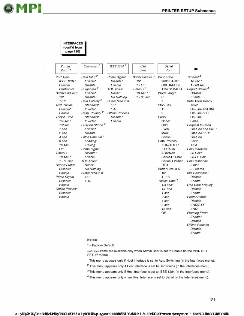
PRINTER SETUP Submenus
Mantenimiento
Serial Port
Baud Rate 9600 BAUD* 600 BAUD to 115200 BAUD
Word Length 8* 7
Stop Bits 1* 2
Parity None* Odd Even Mark Sense
Data Protocol XON/XOFF* ETX/ACK ACK/NAK Series1 1Char Series 1 2Char DTR
Buffer Size in K 16* 1 - 16
Trickle Time 4
1/4 sec* 1/2 sec 1 sec 2 sec 4 sec 8 sec 16 sec Off
ParallelPort 1, 4
Port Type IEEE 1284* Disable Centronics
Buffer Size in K 16* 1-16
Auto Trickle Disable* Enable
Trickle Time 1/4 sec* 1/2 sec 1 sec 2 sec 4 sec 8 sec 16 sec Off
Timeout 10 sec.* 1 - 60 sec.
Report Status Disable* Enable
Prime Signal Disable* Enable
Offline Process Disable* Enable
USBPort
Buffer Size in K 16* 1 - 16
Timeout 1
10 sec.* 1 - 60 sec.
INTERFACES (cont’d from
page 120)
Centronics 2
Data Bit 8 2
Enable* Disable
PI Ignored 2
Enable* Disable
Data Polarity 2
Standard* Inverted
Resp. Polarity 2
Standard* Inverted
Busy on Strobe 2
Enable* Disable
Latch Data On 2
Leading* Trailing
Prime Signal Disable* Enable
TOF Action Reset* Do Nothing
Buffer Size in K 16* 1-16
IEEE 1284 3
Prime Signal Disable* Enable
TOF Action Reset* Do Nothing
Buffer Size in K 16* 1-16
Offline Process Disable* Enable
Timeout 4
10 sec.* 1 - 60 sec.
Report Status 4
Disable* Enable
Data Term Ready True* On-Line and BNF Off-Line or BF On-Line False
Request to Send On-Line and BNF* Off-Line or BF On-Line False True
Poll Character 00 Hex* 00-FF Hex
Poll Response 0 ms* 0 - 30 ms
Idle Response Disable* Enable
One Char Enquiry Disable* Enable
Printer Status Disable* ENQ/STX ENQ
Framing Errors Enable* Disable
Offline Process Disable* Enable
Notes:
* = Factory Default
Italicized items are available only when Admin User is set to Enable (in the PRINTER SETUP menu).1 This menu appears only if Host Interface is set to Auto Switching (in the Interfaces menu).2 This menu appears only if Host Interface is set to Centronics (in the Interfaces menu).3 This menu appears only if Host Interface is set to IEEE 1284 (in the Interfaces menu).4 This menu appears only when Host Interface is set to Serial (in the Interfaces menu).
121
Periféricos Informáticos C/Canteras, 15 28860 Paracuellos de Jarama (Madrid) Tel: 00 34 917481604 Web: https://mpi.com.es/

Chapter 4 INTERFACES Menu
Mante
Printer Mgmt
PNE Port Disable* Serial Ethernet 1
Mgmt Protocol PXML* UCP
Select Port 2
Debug Host
Baud Rate 2
9600 BAUD 2400 BAUD to 115200 BAUD
Word Length 2
8* 7
Stop Bits 2
1* 2
Parity 2
None* Odd Even
Modem 2
Disable* Enable
Modem NUM 2
Enable* Disable
Modem Status 2
Enable* Disable
Dial Method 2
Tone* Pulse
PNE Port Number 1, 3
3001* 1023 - 65535
PNE Port Timeout 1, 3
100 Seconds* 1 - 255
Status Port Number 1
3002* 1023 - 65535
Mgmt Port Number 1
3007* 1023 - 65535
INTERFACES (cont’d from
page 120)
Notes:
* = Factory Default
Italicized items are available only when Admin User is set to Enable (in the PRINTER SETUP menu).1 This option appears if a ethernet is installed.2 This menu appears if PNE Port is set to Serial.3 If the PNE port is set to Ethernet.
122
nimiento Periféricos Informáticos C/Canteras, 15 28860 Paracuellos de Jarama (Madrid) Tel: 00 34 917481604 Web: https://mpi.com.es/

INTERFACES Submenus
Mantenimiento
INTERFACES Submenus
Host InterfaceThis option allows you to send print jobs through any interface with autoswitching selected as host interface. It also allows a particular interface from the menu to be selected.
The options are Auto Switching (factory default), Centronics, Serial, IEEE 1284, and Ethernet.
NOTE: The Ethernet option appears only if Ethernet is installed.
ETHERNET PORT• Timeout. This is the value used by the printer to time out the current port
and check the other selected Port Types for data to print. When the printer has not received data from the host after a certain period of time, it needs to time out to service the other ports.
The range is 1 to 60 seconds, and the factory default is 10 seconds.
• Switch Out On.
• Data Timeout (the default). Allows Autoswitching when no data has been received for the selected timeout period.
• Session Close. Allows Autoswitching only when the Network Socket is closed. If the Ethernet Adapter is not installed the Network Socket is always reported as closed and this menu option is ignored.
ETHERNET SETTING• IP Address.This item allows you to set the IP Address for the TCP/IP
protocol in four three-digit segments (SEG1 through SEG4). If the IP Address is assigned by Bootp, ARP or DHCP, it is dynamic and read-only.
The factory defaults for the SEG1 through SEG4 are 000, 000, 000, and 000.
After specifying an IP address, you are prompted to:
Press ↵ to Save & Exit
Press to Exit
Press to Edit.
NOTE: When changing the IP Address, the printer resets the ethernet when the printer is placed online. When the printer resets the ethernet, the LCD displays DO NOT POWER OFF. The printer will then reboot to re-establish communication with the ethernet.
123
Periféricos Informáticos C/Canteras, 15 28860 Paracuellos de Jarama (Madrid) Tel: 00 34 917481604 Web: https://mpi.com.es/

Chapter 4 INTERFACES Menu
Mante
• Subnet Mask. This item allows you to set the Subnet Mask for the TCP/IP protocol in four three-digit segments (SEG1 through SEG4). If the Subnet Mask is assigned by Bootp, Arp or DHCP, it is dynamic and read-only.
The defaults for the SEG1 through SEG4 are 000, 000, 000, and 000.
After specifying a Subnet Mask, you are prompted to:
Press ↵ to Save & Exit
Press to Exit
Press to Edit.
NOTE: When changing the Subnet Mask, the printer resets the ethernet when the printer is placed online. When the printer resets the ethernet, the LCD displays DO NOT POWER OFF. The printer will then reboot to re-establish communication with the ethernet.
• Gateway Address. This item allows you to set the Gateway Address for the TCP/IP protocol in four three-digit segments (SEG1 through SEG4). If the Gateway Address is assigned by Bootp, ARP or DHCP, it is dynamic and read-only.
The defaults for the SEG1 through SEG4 are 000, 000, 000, and 000.
After specifying a Subnet Mask, you are prompted to:
Press ↵ to Save & Exit
Press to Exit
Press to Edit.
NOTE: When changing the Gateway Address, the printer resets the ethernet when the printer is placed online. When the printer resets the ethernet, the LCD displays DO NOT POWER OFF. The printer will then reboot to re-establish communication with the ethernet.
• MAC Address. This item is the Manufacturer’s Assigned Number, and is unique for each ethernet. It is read-only.
• IP Assignment
• DHCP. You can enable/disable the DHCP protocol using this option, but consult your administrator for the appropriate setting.
The options are Enable (factory default) and Disable.
NOTE: When changing the DHCP, the printer resets the ethernet when the printer is placed online. When the printer resets the ethernet, the LCD displays DO NOT POWER OFF. The printer will then reboot to re-establish communication with the ethernet.
124
nimiento Periféricos Informáticos C/Canteras, 15 28860 Paracuellos de Jarama (Madrid) Tel: 00 34 917481604 Web: https://mpi.com.es/

INTERFACES Submenus
Mantenimiento
• BootP
You can enable or disable the BootP protocol using this option, but consult your administration for the appropriate setting.
The options are Enable (factory default) and Disable.
NOTE: When changing the BootP option, the printer resets the ethernet when the printer is placed online. When the printer resets the ethernet, the LCD displays DO NOT POWER OFF. The printer will then reboot to re-establish communication with the ethernet.
• NetBIOS Protocol
• Enable (factory default). The ethernet will respond to the NetBIOS protocol.
• Disable. The ethernet does not recognize the NetBIOS protocol.
• ASCII Data Port. This option allows you to set the port number for ASCII print jobs. The data port number needs to match your host system setting.
The range is 1023 - 65535, and the factory default is 9100.
• Keep Alive Timer. This is the time that the Keep Alive Timer will run. Keep in mind that with the Keep Alive Timer on, the tcp connection will stay connected even after the print job has terminated.
The range is 2-10 minutes, and the factory default is 3 minutes.
• Ethernet Speed. This menu appears only if a 10/100Base-T ethernet is installed.
The Ethernet Speed menu has five different speed modes to allow compatibility with different systems and networks:
• Auto Select (factory default). Tells the 10/100Base-T ethernet to perform an auto detection scheme and configure itself to be 10 Half Duplex, 10 Full Duplex, 100 Half Duplex, or 100 Full Duplex.
• 10 Half Duplex. Tells the 10/100Base-T ethernet to communicate at 10 Megabits per second using half duplex.
• 10 Full Duplex. Tells the 10/100Base-T ethernet to communicate at 10 Megabits per second using full duplex.
• 100 Half Duplex. Tells the 10/100Base-T ethernet to communicate at 100 Megabits per second using half duplex.
• 100 Full Duplex. Tells the 10/100Base-T ethernet to communicate at 100 Megabits per second using full duplex.
• Job Control
• Standard (factory default). The ethernet waits for the entire job to be received before it indicates the job is done.
• Enhanced. The ethernet waits for the entire job to be printed before it indicates the job is done.
• Off. There is no synchronization between the ethernet and the printer.
NOTE: For detailed information about using the Ethernet, refer to the Ethernet Interface Card User’s Manual.
125
Periféricos Informáticos C/Canteras, 15 28860 Paracuellos de Jarama (Madrid) Tel: 00 34 917481604 Web: https://mpi.com.es/

Chapter 4 INTERFACES Menu
Mante
• Offline Process
• Disable (factory default). When set to disable, the printer does not process parallel/network data while offline.
• Enable. When set to enable, the printer continues to process (but not print) the current network/parallel job while the printer is offline until the printer's buffer is full.
WLAN SETTING• IP Address. This item allows you to set the IP Address for the TCP/IP
protocol in four three-digit segments (SEG1 through SEG4). If the IP Address is assigned by Bootp, ARP or DHCP, it is dynamic and read-only.
The defaults for the SEG1 through SEG4 are 000, 000, 000, and 000.
After specifying a Subnet Mask, you are prompted to:
Press ↵ to Save & Exit
Press to Exit
Press to Edit.
NOTE: When changing the IP Address, the printer resets the ethernet when the printer is placed online. When the printer resets the ethernet, the LCD displays DO NOT POWER OFF. The printer will then reboot to re-establish communication with the ethernet.
• Subnet Mask. This item allows you to set the Subnet Mask for the TCP/IP protocol in four three-digit segments (SEG1 through SEG4). If the Subnet Mask is assigned by Bootp, Arp or DHCP, it is dynamic and read-only.
The defaults for the SEG1 through SEG4 are 000, 000, 000, and 000.
After specifying a Subnet Mask, you are prompted to:
Press ↵ to Save & Exit
Press to Exit
Press to Edit.
NOTE: When changing the IP Address, the printer resets the ethernet when the printer is placed online. When the printer resets the ethernet, the LCD displays DO NOT POWER OFF. The printer will then reboot to re-establish communication with the ethernet.
126
nimiento Periféricos Informáticos C/Canteras, 15 28860 Paracuellos de Jarama (Madrid) Tel: 00 34 917481604 Web: https://mpi.com.es/

INTERFACES Submenus
Mantenimiento
• Gateway Address. This item allows you to set the Gateway Address for the TCP/IP protocol in four three-digit segments (SEG1 through SEG4). If the Gateway Address is assigned by Bootp, ARP or DHCP, it is dynamic and read-only.
The defaults for the SEG1 through SEG4 are 000, 000, 000, and 000.
After specifying a Subnet Mask, you are prompted to:
Press ↵ to Save & Exit
Press to Exit
Press to Edit.
NOTE: When changing the IP Address, the printer resets the ethernet when the printer is placed online. When the printer resets the ethernet, the LCD displays DO NOT POWER OFF. The printer will then reboot to re-establish communication with the ethernet.
• MAC Address. This item is the Manufacturer’s Assigned Number, and is unique for the ethernet and the Wireless option. It is read-only.
• IP Assignment
• DHCP. You can enable/disable the DHCP protocol using this option, but consult your administrator for the appropriate setting.
The options are Disable (factory default) and Enable.
NOTE: When changing the DHCP, the printer resets the ethernet when the printer is placed online. When the printer resets the ethernet, the LCD displays DO NOT POWER OFF. The printer will then reboot to re-establish communication with the ethernet.
• BootP
You can enable or disable the BootP protocol using this option, but consult your administration for the appropriate setting.
The options are Enable (factory default) and Disable.
NOTE: When changing the DHCP, the printer resets the ethernet when the printer is placed online. When the printer resets the ethernet, the LCD displays DO NOT POWER OFF. The printer will then reboot to re-establish communication with the ethernet.
• Signal Strength. This menu displays the strength of the wireless signal.
NOTE: This is a display value only and cannot be changed.
• Operation Mode. Allows you to select the way the Wireless option communicates:
• Infrastructure (factory default). The Wireless option must go through an Access Point.
• Pseudo IBSS. Proprietary, peer-to-peer communication (without an Access Point). The two peers must be specific to one manufacturer.
• Ad Hoc. Standard, peer-to-peer communication (without an Access Point). The two peers can be from different manufacturers.
127
Periféricos Informáticos C/Canteras, 15 28860 Paracuellos de Jarama (Madrid) Tel: 00 34 917481604 Web: https://mpi.com.es/

Chapter 4 INTERFACES Menu
Mante
• SSID Name. A 1-32 character, case-sensitive string that identifies the Extended Service Set Identification (ESS_ID) network the unit is part of. (ESS_ID is also called NET_ID.) These characters can be alphanumeric, symbols, or spaces. The SSID name and alphanumeric characters are divided into three parts in the control panel menu as “SSID Name (01-15)”, “SSID Name (16-30)” and “SSID Name (31-32).
• Reset SSID Name. Allows you to reset the SSID name.
• Min Xfer Rate. Allows you to set the minimum speed at which the Wireless Option will accept a connection (in millions bits per second). The options are Auto-negotiate (factory default), 1Mb/sec., 2Mb/sec., 5.5Mb/sec., and 11Mb/sec.
• Channel. Allows you to select the RF channel. The options are Default and 1-15.
NOTE: The Channel option is hidden for 802.11g radio card.
• Preamble. The length of the preamble in transmit packets.
• Default (the default). The Wireless option automatically determines the length.
• Short. For newer printers which can handle higher transfer rate speeds.
• Long. For older printers, which cannot handle higher transfer rate speeds.
• Antenna. The type of antenna used:
• Primary (factory default). Select when you want to use the Primary antenna on the server.
• Auxiliary. Select when you want to use the Auxiliary antenna on the server.
• Power Mgmt. This allows you to set power-save mode and sleep time. A value specifying the sleep time in milliseconds will be provided. If set to zero, power-save mode will be disabled.
The range is 0-1000 ms., and the factory default is 0 ms.
• Transmit Power. The power level as a percentage of full power.
The range is 0 - 100%, and the factory default is 100%.
• Internat. Mode. When enabled, the Wireless option adapts to international frequency requirements in Europe.
The options are Disable (factory default) and Enable.
• EAP Mode. This selects the EAP authentication method.
• LEAP selects Cisco LEAP authentication.
• PEAP selects PEAP authentication.
• TTLS selects TTLS authentication.
• None (factory default) disables EAP authentication.
128
nimiento Periféricos Informáticos C/Canteras, 15 28860 Paracuellos de Jarama (Madrid) Tel: 00 34 917481604 Web: https://mpi.com.es/

INTERFACES Submenus
Mantenimiento
• EAP Username
• EAP Username (01-15). The first 15 characters of the EAP user name (maximum number of characters is 32).
• EAP Username (16-30). Characters 16 to 30 of the EAP user name (maximum number of characters is 32).
• EAP User (31-32). Characters 31 to 32 of the EAP password (maximum number of characters is 32).
• Reset EAP User. Resets the EAP user name to an empty string.
• EAP Password
• EAP Password (01-15). The first 15 characters of the EAP password (maximum number of characters is 32).
• EAP Password (16-30). Characters 16 to 30 of the EAP password (maximum number of characters is 32).
• EAP Password (31-32). Characters 31 to 32 of the EAP password (maximum number of characters is 32).
• Reset EAP Pswd. Resets the EAP password to an empty string.
• Auth Method. This feature allows the user to select the authentication method used for the wireless network interface.
• Open (factory default). Selects open authentication.
• Shared. Selects shared key authentication.
• WEP Key 1 through 4. These are the individual characters of the encryption key. If the "WEP Key x Width" is set to 40 Bits, the key values can be entered in the following 5 sub menus (BYTE 1, …, BYTE 5). If the "WEP Key x Width" is set to 128 Bits, the key values can be entered in the following 13 sub menus (BYTE 1, …, BYTE 13). The key values must configure to match the corresponding key in the Access Point's key configuration.
NOTE: The WEP Key Width is the number of bits used for encryption. This can be set to either 40 Bits or 128 Bits and must match the Access Point's configuration.
• Default WEP Key. This feature enables you to encrypt (scramble) information for security purposes. With this feature, you can set up to four encryption keys, in either ASCII or hexadecimal format, and in either 40 or 128 bits. (The more bits you choose, the more difficult it will be to decode the information.)
The default key must match the Access Point's configuration. If the Access Point is configured to use "Open System", the default key should be set to 0. If the Access Point is configured to use 40-bit or 128-bit WEP encryption key, the encryption key must be set to the same setting as the Access Point's setting. There are four keys (1-4) that an Access Point can use. If the Access Point is set to use key 1, the default key must be set to 1 to correspond to the Access Point's setting.
NOTE: None of the WEP Key Configuration menus display on the configuration printout.
129
Periféricos Informáticos C/Canteras, 15 28860 Paracuellos de Jarama (Madrid) Tel: 00 34 917481604 Web: https://mpi.com.es/

Chapter 4 INTERFACES Menu
Mante
• Reset WEP Keys. Allows you to reset all four WEP keys (WEP Key 1 through WEP Key 4) at one time.
• WPA Mode. Selects the WPA wireless security mode.
• Disable (the default). WPA security is disabled.
• Personal. Selects personal or pre-shared key mode for WPA security.
• Enterprise. Selects EAP authentication methods.
• WPA Cipher. Selects the WPA wireless security cipher setting. Options include:
• Disable (the default)
• TKIP
• AES
• TKIP+AES
• WPA P-Phs. Allows you to set the individual bytes of the WPA passphrase.
• Reset WPA P-Phs. Allows you to reset all 32 bytes of the WPA passphrase at once.
Parallel Port• Port Type. This menu item selects the type of printer parallel port
interface to be used with the host.
The options are IEEE 1284 (factory default), Disable, and Centronics.
• Buffer Size in K. This option configures the amount of memory allocated for the Ethernet buffer. The range is 1-16 Kbytes, in 1-Kbyte increments.
The factory default is 16 Kbytes.
• Auto Trickle. This feature is used to prevent a host computer from “timing out” because the parallel interface is “busy” for too long.
• Disable (factory default). The Auto Trickle feature is not used.
• Enable. When the printer’s buffers are almost full, the printer begins to trickle data in from the host (at the rate set in the Trickle Time menu) until the buffers start to empty out.
• Trickle Time. When the printer is printing data from a host and a second print job is received by the printer from a different host, Trickle Time prevents the second host from timing out while it is waiting for its data to be printed. In order to support this feature, the port has to be able to accept data from the host and store it for future use.
For example, if the printer is printing a job from the serial port, and then receives a second print job from the parallel port, the data from the parallel port will “trickle” bit by bit into the printer buffer to prevent a timeout error from being sent back to the host connected to the parallel port.
130
nimiento Periféricos Informáticos C/Canteras, 15 28860 Paracuellos de Jarama (Madrid) Tel: 00 34 917481604 Web: https://mpi.com.es/
INTERFACES Submenus
Mantenimiento
The selected value is the time that the printer waits before getting the next byte of data from the host. The Trickle Time value should be less than the host time out value, but not too much shorter or else the printer fills up its buffer too fast.
The options are 1/4 (factory default), 1/2, 1, 2, 4, 8, and 16 seconds and Off.
• Timeout. This is the value used by the printer to time out from the current port and check the other selected port types for data to print. When the printer has not received data from the host after a certain period of time, it needs to time out in order to service the other ports.
The range is 1-60 seconds, and the factory default is 10 seconds.
• Report Status
• Disable (factory default). When a fault occurs on the printer, only the active port reports the fault to the host.
• Enable. The port will report any fault even when it is not the current active port.
• Prime Signal
• Disable (factory default). The parallel port will not perform a warm start (reboot) if the host asserts the Prime Signal.
• Enable. The parallel port will perform a warm start (reboot) if the host asserts the Prime Signal.
• Offline Process
• Disable (factory default). When set to disable, the printer does not process parallel/network data while offline.
• Enable. When set to enable, the printer continues to process (but not print) the current network/parallel job while the printer is offline until the printer's buffer is full.
Centronics• Data Bit 8
• Enable (factory default). The PI line is not passed directly from host to printer; all 8 bits are used for data bits, and characters in the hex 80-FF range can be accessed.
• Disable. When the host PI line is enabled, data bit 8 internally indicates PI line status. To use the PI line, disable data bit 8, and enable the Host PI configuration option (under the PI Ignored option).
NOTE: Data bit 8 is interpreted as either data bit 8 or PI signal, but never both. When enabled as data bit 8, data bit 8 has priority over the PI signal, and all data above hex 7F is used to access character data and not to interpret PI line data.
131
Periféricos Informáticos C/Canteras, 15 28860 Paracuellos de Jarama (Madrid) Tel: 00 34 917481604 Web: https://mpi.com.es/

Chapter 4 INTERFACES Menu
Mante
Conversely, when data bit 8 is disabled and the PI signal is used, data bit 8 of the data is reserved for use as the PI function, and you cannot access characters in the hex 80-FF range. Therefore, to access characters in the hex 80-FF range, data bit 8 must be enabled.
• PI Ignored. The PI (Paper Instruction) signal is used to control vertical paper motion.
• Enable (factory default). Ignores the PI signal and treats the data as characters or control codes.
• Disable. Causes the printer to interpret the eight data lines as VFU commands when the PI signal is true.
• Data Polarity. The Data Polarity parameter must be set to match the data polarity of your host computer.
• Standard (factory default). Does not expect the host computer to invert the data.
• Inverted. Expects the data received on the data lines from the host computer to be inverted. Ones become zeros and vice versa.
• Resp. Polarity. The Response Polarity parameter must be set to match the response polarity of your host computer.
• Standard (factory default). Does not invert the response signal.
• Inverted. Inverts the response signal sent to the host computer.
• Busy on Strobe
• Enable (factory default). Asserts a busy signal after each character is received.
• Disable. Asserts a busy signal only when the print buffers are full.
• Latch Data On. Specifies whether the data is read on the leading or trailing edge of the data strobe signal.
The options are Leading (factory default) and Trailing.
• Prime Signal
• Disable (factory default). A prime signal from the host is ignored.
• Enable. A prime signal from the host resets the printer.
• TOF Action
• Reset (factory default). If the printer is reset by a prime signal the printer first moves to the next TOF.
• Do Nothing. If the printer is reset by a prime signal the printer will not move to the next TOF.
• Buffer Size in K. This option configures the amount of memory allocated for the Ethernet buffer. The range is 1-16 Kbytes, in 1-Kbyte increments.
The factory default is 16 Kbytes.
132
nimiento Periféricos Informáticos C/Canteras, 15 28860 Paracuellos de Jarama (Madrid) Tel: 00 34 917481604 Web: https://mpi.com.es/

INTERFACES Submenus
Mantenimiento
IEEE 1284• Prime Signal
• Disable (factory default). A prime signal from the host is ignored.
• Enable. A prime signal from the host resets the printer.
• TOF Action
• Reset (factory default). If the printer is reset by a prime signal the printer first moves to the next TOF.
• Do Nothing. If the printer is reset by a prime signal the printer will not move to the next TOF.
• Buffer Size in K. This option configures the amount of memory allocated for the Ethernet buffer. The range is 1-16 Kbytes, in 1-Kbyte increments.
The factory default is 16 Kbytes.
• Offline Process
• Disable (factory default). When set to disable, the printer does not process parallel/network data while offline.
• Enable. When set to enable, the printer continues to process (but not print) the current network/parallel job while the printer is offline until the printer's buffer is full.
USB Port• Buffer Size in K. This option configures the amount of memory allocated
for the serial port buffer. The range is 1-16 Kbytes, in 1-Kbyte increments.
The factory default is 16.
• Timeout. This item allows you to set the time that the printer, when it has not received data from its host, will begin to service all other host ports looking for data to print.
The range is 1-60 seconds, and the default is 10 seconds.
Serial Port• Baud Rate. Sets the baud rate of the serial interface in the printer. Baud
rate is the speed at which serial data is transferred between the host computer and the printer. The options for the RS-232 interface are 600, 1200, 2400, 4800, 9600, 19200, 38400, 57600, and 115200 Baud.
NOTE: If you select a baud rate that is greater than 19200 and you experience data loss, you may need to lower the baud rate. The factory default is 16K.
The factory default is 9600.
• Word Length. Sets the length of the serial data word. The length of the data word can be set to 7 or 8 bits and must match the corresponding data bits setting in the host computer.
The factory default is 8.
133
Periféricos Informáticos C/Canteras, 15 28860 Paracuellos de Jarama (Madrid) Tel: 00 34 917481604 Web: https://mpi.com.es/

Chapter 4 INTERFACES Menu
Mante
• Stop Bits. Sets the number of stop bits in the serial data word. Either 1 or 2 stop bits can be selected. The setting must match the corresponding stop bit setting in the host computer.
The factory default is 1.
• Parity. The options are Odd, Even, Mark, Sense, or None (factory default). The setting must match the corresponding parity setting in the host computer.
• Data Protocol. You can select one of the following serial interface protocols to meet the host interface requirements.
• XON / XOFF (factory default). The printer controls the flow of communication from the host by turning the transmission on and off. In some situations, such as when the buffer is full or the timing of signals is too slow or too fast, the printer will tell the host to stop transmission by sending an XOFF character. An XOFF character is sent when the number of empty bytes in the buffer is less than or equal to 25 percent of the buffer size. If the host keeps sending data after an XOFF is sent, the printer firmware will continue to send an XOFF for every 16 characters received. When cleared, the printer will resume receiving data (XON). The data does not have any End of Text codes; XON / XOFF is a non-block protocol.
• ETX / ACK. End of Text / Acknowledge. The host controls the flow of communication to the printer by sending a block of data and ending the block with an End of Text (ETX) signal. When the printer receives the ETX signal, it will acknowledge the ETX, thereby acknowledging it has received the entire block of data.
• ACK / NAK. ACK means acknowledge; the device acknowledges it has accepted a transmission. NAK means negative acknowledge; the device did not receive the transmission.
• Series1 1 Char. The printer controls the flow of communication from the host by turning the transmission on and off using response characters sent to the host. If the number of valid bytes in the buffer reaches 75 percent of the buffer size, the online or offline and buffer full response character is sent. If the buffer is completely full, an online or offline buffer full response is sent every time a character is sent from the host. Whenever the printer state changes to online or offline, the appropriate response character is sent. If the idle response option is enabled, the printer will send a response character every two seconds while the number of valid bytes in the buffer is less than 75 percent of the buffer size. If a poll character is received (configurable from the Poll Character xx Hex option on the front panel from hex 0 through FF), the printer will send a response character n milliseconds later (configurable from the Poll Character xx MS on the front panel from 0 through 30). This n milliseconds is called the poll delay. The poll character will be removed from the input data stream and will not be processed. This may cause problems with the transmission of binary data (e.g., control codes, bit image, etc.). If a poll delay is started due to the receipt of a poll character and another poll character is received, the second poll character has no effect and is removed from the input data stream. If a transition (from buffer full
134
nimiento Periféricos Informáticos C/Canteras, 15 28860 Paracuellos de Jarama (Madrid) Tel: 00 34 917481604 Web: https://mpi.com.es/

INTERFACES Submenus
Mantenimiento
to empty or online to offline) occurs during a poll delay, the new printer state will be sent at the end of the poll delay.
The response characters are described below.
• Series1 2 Char. This protocol behaves exactly the same as the Series 1 Char except there is a two-character response to the host. The response characters are described in the following table:
• DTR. The printer controls the data flow by sending this hardware signal to the host. If there is enough room in the printer buffer, the printer will send a high signal; if the buffer is full, the printer will send a low signal. DTR tells the host if it is safe to send more data. (If the host sends data during an unsafe condition, data will be lost.)
• Buffer Size in K. This option configures the amount of memory allocated for the serial port buffer. The range is 1-16 Kbytes, in 1-Kbyte increments.
The factory default is 16.
• Trickle Time. When the printer is printing data from a host and a second job is received by the printer from a different host, Trickle Time prevents the second host from timing out while it is waiting for its data to be printed. In order to support this feature, the port has to be able to accept data from the host and store it for future use.
For example, if the printer is printing a job from the serial port and then receives a second print job from the parallel port, the data from the parallel port will “trickle” bit by bit into the printer buffer to prevent a timeout error from being sent back to the host connected to the parallel port.
The selected value is the time that the printer waits before getting the next byte of data from the host. The Trickle Time value should be less than the host time out value, but not too much shorter or else the printer fills up its buffer too fast.
Printer State Response
Online and Buffer Empty CR
Online and Buffer Full 3
Offline and Buffer Empty 0
Offline and Buffer Full 2
Printer State Response
Online and Buffer Empty 1 CR
Online and Buffer Full 3 CR
Offline and Buffer Empty 0 CR
Offline and Buffer Full 2 CR
135
Periféricos Informáticos C/Canteras, 15 28860 Paracuellos de Jarama (Madrid) Tel: 00 34 917481604 Web: https://mpi.com.es/

Chapter 4 INTERFACES Menu
Mante
The options are 1/4 (factory default), 1/2, 1, 2, 4, 8, and 16 seconds and Off.
• Timeout. This is the value used by the printer to time out from the current port and check the other selected Port Types for data to print. When the printer has not received data from the host after a certain period of time, it needs to time out in order to service the other ports.
The range is 1 to 60 seconds, and the factory default is 10 seconds.
• Report Status. When a fault condition occurs in the printer, normally only the active port reports the fault to the host. With this menu item enabled, the port will report any fault even when it is not the current, active port.
The options are Disable (factory default) and Enable.
• Data Term Ready. Stands for Data Terminal Ready. This configuration is part of hardware flow control and determines when the Data Terminal Ready (DTR) signal is generated. This signal indicates if the printer is ready to receive data.
• True (factory default). Continuously asserts the DTR signal.
• On-Line and BNF (buffer not full). Asserts the DTR signal when the printer is online and the internal serial buffer is not full.
• Off-Line or BF (buffer full). Asserts the DTR signal when the printer is offline or the internal serial buffer is full.
• On-Line. Asserts the DTR signal when the printer is online.
• False. Never asserts the DTR signal.
• Request to Send. This configuration is part of hardware flow control and determines when the Request to Send (RTS) signal is generated. This signal indicates whether or not the printer is ready to receive data.
• On-Line and BNF (factory default). Asserts the RTS signal when the printer is online and the internal serial buffer is not full.
• Off-Line or BF. Asserts the RTS signal when the printer is offline or the internal serial buffer is full.
• On-Line. Asserts the RTS signal when the printer is online.
• False. Never asserts the RTS signal.
• True. Continuously asserts the RTS signal.
• Poll Character. This option is for the Series1 protocol. Whenever the printer receives this character, it sends a response to the host indicating the current state of the printer (see Series1 protocol).
The range is 00-FF Hex, and the factory default is 00 Hex.
• Poll Response. This option is for the Series1 protocol. After receiving a poll character, the printer will wait the poll response time in milliseconds before sending the response.
The range is 0-30 ms, and the factory default is 0 ms.
136
nimiento Periféricos Informáticos C/Canteras, 15 28860 Paracuellos de Jarama (Madrid) Tel: 00 34 917481604 Web: https://mpi.com.es/

INTERFACES Submenus
Mantenimiento
• Idle Response. This option is for the Series1 protocol.
• Disable (factory default).
• Enable. The printer sends a response character every two seconds while the number of valid bytes in the buffer is less than 75 percent of the buffer size.
• One Char Enquiry. The One Char Enquiry mode uses the Poll Character to detect a request from the host and sends a response back to the host. This option also allows you to turn on and off this feature.
The Poll Character is removed from the data stream. If the Data Protocol is set to ETX/ACK, ACK/NAK, or Series1, One Char Enquiry is automatically disabled.
The options are Disable (factory default) and Enable.
Table 11. One Char Enquiry Response Characters
Printer State Response (hex)
Online and Buffer Not Full 22
Online and Buffer Full 23
Offline and Buffer Not Full 20
Offline and Buffer Full 21
137
Periféricos Informáticos C/Canteras, 15 28860 Paracuellos de Jarama (Madrid) Tel: 00 34 917481604 Web: https://mpi.com.es/

Chapter 4 INTERFACES Menu
Mante
• Printer Status
• Disable (factory default). Printer status ignored.
• ENQ/STX (see Table 12).
• ENQ (see Table 13).
When enabled, the printer will respond to an ENQ character by sending a status byte to the host. The type of status byte is determined by a Front Panel Menu selection. The selections allowed are ENQ/STX and ENQ. The ENQ is removed from the data stream.
Table 12. ENQ/STX Status Byte
Bit Printer Status
0 Set when the printer is not online or the buffer is full.
1 Set when the printer is offline.
2 Clear during a paper out or RibbonMinder fault.
3 Always set.
4 Set during a Head Open fault.
5 Set during a buffer overflow fault.
6 Set during a parity or framing error fault.
7 Always clear.
Table 13. ENQ Status Byte
Bit Printer Status
0 Set when the label has printed.
1 Set when the label is presented.
2 Set while the printer is online.
3 Always set.
4 Set printing in the batch mode.
5 Set during a Ribbon fault.
6 Set during a Paper Out fault.
7 Set during a Head Open fault.
138
nimiento Periféricos Informáticos C/Canteras, 15 28860 Paracuellos de Jarama (Madrid) Tel: 00 34 917481604 Web: https://mpi.com.es/

INTERFACES Submenus
Mantenimiento
• Framing Errors. These are possible errors that can occur when serial interface settings of the printer do not match those of the host computer.
• Enable (factory default). If a framing error occurs, a fault message will display on the control panel.
• Disable. If a framing error occurs, a fault message will not display on the control panel
• Offline Process
• Disable (factory default). When set to disable, the printer does not process parallel/network data while offline.
• Enable. When set to enable, the printer continues to process (but not print) the current network/parallel job while the printer is offline until the printer's buffer is full.
Printer Mgmt• PNE Port. This menu selects which port the printer expects PNE to
connect to, via Ethernet or Serial. The factory default is Disable.
• Mgmt Protocol. Since PXML and UCP management protocols share the same Ethernet Port, only one can be active at a time. This menu selects the active Management Protocol Interface, either PXML or UCP. The factory default is PXML.
• Select Port
• Debug (factory default). If the PNE Port is set to Serial then the PNE will communicate through the Debug Serial Port.
• Host. If the PNE Port is set to Serial then the PNE will communicate through the Host Serial Port. This cannot be selected if Host Interface is set to Auto Switching or Serial.
• Baud Rate. Sets the baud rate of the serial interface used to communicate to the PNE. Baud rate is the speed at which serial data is transferred between the PNE and the printer. The options for the RS-232 interface are 600, 1200, 2400, 4800, 9600, 19200, 38400, 57600, and 115200 Baud.
NOTE: If you select a baud rate that is greater than 19200 and you experience data loss, you may need to lower the baud rate. The factory default is 9600.
• Word Length. Sets the length of the serial data word. The length of the data word can be set to 7 or 8 bits and must match the corresponding data bits setting in the PNE. The factory default is 8.
• Stop Bits. Sets the number of stop bits in the serial data word. Either 1 or 2 stop bits can be selected. The setting must match the corresponding stop bit setting in the PNE. The factory default is 1.
• Parity. The options are Odd, Even, Mark, Sense, or None. The setting must match the corresponding parity setting in the PNE. The factory default is None.
139
Periféricos Informáticos C/Canteras, 15 28860 Paracuellos de Jarama (Madrid) Tel: 00 34 917481604 Web: https://mpi.com.es/

Chapter 4 INTERFACES Menu
Mante
• Modem
This menu enables or disables the modem interface. After changing the modem menus, save the configuration as the power-up configuration and reboot the printer. The factory default is Disable.
NOTE: Connect the modem to the selected serial interface for printer management (debug or host serial), and power on the modem before powering on the printer. The printer will search for a modem at power-up, and display a message on the printer front panel if a modem is detected.
• Modem NVM
This setting defines whether the modem configuration, as stored in the modem's NVM, should be used, or if the printer should send a modem intialization string. When enabled, the printer will only send an ATZ0 command to the modem on power-up. This command resets the modem to configuration 0. When disabled, the printer sends a generic modem initialization string on power-up. The factory default is Enable.
NOTE: This generic initialization string does not work for all modem types. If the initilization string does not work, the modem must be configured manually, the setting must be stored in configuration 0, and the printer 'Modem NVM' menu must be set to enable.
• Modem Status
• Enable (factory default). Displays the modem status commands on the printer control panel.
• Disable. Does not display the modem status commands on the printer control panel.
• Dial Method
• Tone (factory default). Sets the modem to use the tone dialing method.
• Pulse. Sets the modem to use the pulse dialing method.
• PNE Port Number. This menu selects the port number the printer expects the PNE to connect through. The factory default is 3001 and the range is from 1023 to 65535.
• PNE Port Timeout. If the PNE has not communicated to the printer within a timeout period, the PNE session closes. The factory default is 100 seconds. The range is from 1 to 255 seconds.
• Status Port Number. This is the Ethernet Port number the emulations can use to communicate status to the host computer.
• Mgmt Port Number. This is the Ethernet Port number the PXML or UCP will use to communicate to the printer.
140
nimiento Periféricos Informáticos C/Canteras, 15 28860 Paracuellos de Jarama (Madrid) Tel: 00 34 917481604 Web: https://mpi.com.es/

Mantenimiento
CONFIGURATION MENU
CONFIGURATION
(from page 70)
Save Config.
Cfg 1* Cfg 1 to Cfg 8
DeleteConfig.
Cfg All* All 1 to 8
Notes:
* = Factory Default
Italicized items are available only when Admin User is set to Enable (in the PRINTER SETUP menu).1 These menus allow the setting of a 15 character string.
Load Config.
Factory* 1 to 8
PrintConfig
Current* Factory Power-Up All 1 to 8
Power-Up Config.
Factory* 1 to 8
Protect Configs.
Disable* Enable
Name Config 1 1
Name Config 2 1
Name Config 3 1
Name Config 4 1
Name Config 5 1
Name Config 6 1
Name Config 7 1
Name Config 8 1
Reset Cfg Names
Auto Save
Cfg 1* 1 to 8 All
Enable* Disable
Cfg 1* Cfg 2* Cfg 3* Cfg 4* Cfg 5* Cfg 6*
Cfg 7* Cfg 8*
141
Periféricos Informáticos C/Canteras, 15 28860 Paracuellos de Jarama (Madrid) Tel: 00 34 917481604 Web: https://mpi.com.es/

Chapter 4 CONFIGURATION MENU
Mante
CONFIGURATION Submenus
Save ConfigThis option allows you to save up to eight unique configurations to meet different print job requirements. This eliminates the need to change the parameter settings for each new job. The configurations are stored in memory and will not be lost if you turn off the printer. If the Protect Configs. parameter is enabled, the new configuration will not be saved unless the existing configuration has been deleted first. The Factory default configuration cannot be changed and saved under the Factory menu, but can be changed and saved as one of the eight unique configurations. See “Saving A Configuration” on page 147 for details.
The factory default is Cfg 1.
Load ConfigThe printer can store up to eight configurations in memory. This parameter allows you to select and load a specific configuration.
The options are 1 to 8 and Factory. The factory default is Factory.
Print ConfigThis option is used to print a listing of various stored printer configurations. We recommend you store printouts of your configurations in a safe place for quick referral.
The options are Current (factory default), Factory, Power-Up, All, and 1 to 8.
Delete ConfigYou can delete one or all of your eight customized configurations. The factory default configuration cannot be deleted.
The factory default is All.
Power-Up ConfigYou can specify any one of nine configurations (1-8 saved custom configurations or Factory) as the power-up configuration.
The factory default is Factory.
Protect ConfigYou can specify whether or not a new configuration should overwrite an existing configuration when you activate the Save Configs. parameter. When disabled (factory default), the new configuration will overwrite the existing configuration. When enabled, the new configuration will not overwrite the existing configuration, and the message “CONFIG. EXISTS / Delete First” displays.
The factory default is Disable.
142
nimiento Periféricos Informáticos C/Canteras, 15 28860 Paracuellos de Jarama (Madrid) Tel: 00 34 917481604 Web: https://mpi.com.es/

Mantenimiento
Name Config 1 to Name Config 8You may specify a 15-character name which can be used to refer to a configuration. The name you enter for a configuration will be used in the Load Config., Save Config., Print Config., Delete Config., and Power-Up Config. menus. The names can only be cleared by using the Reset Cfg Names menu.
When you move into the Name Configs. menu, the middle line of the display shows the current configuration name. The first character of the current configuration name is highlighted.
Press ↑ or ↓ to cycle through the values available for that character at the cursor location. Press → to move to the next character to be modified. Press ← to go back to a character you have already modified. Continue until you have entered the name you want to give to this configuration, then press ↵ to save. The name you entered will now represent this configuration on the printer's front panel. To exit this menu without saving, press the key. The configuration name will revert to the last saved value.
The factory default is the configuration number.
Reset Cfg NamesYou can reset specific configuration names back to the default value of the configuration number. You can also reset all configuration names by selecting All.
The options are 1 to 8 and All. The factory default is Cfg 1.
Auto Save• Enable (factory default). When a change has been made to a Config.
menu, this option automatically prompts the user to save or not save the change to a Config #.
If you are currently in the Factory Config. menus and make a change, pressing Enter saves to Config 1 or the next available Config. and becomes the Power-Up Config. If the Current Config is Config 1 and a menu change is made, pressing Enter will save the change to Config 1.
• Disable. The printer will not prompt you to save any changes made.
143
Periféricos Informáticos C/Canteras, 15 28860 Paracuellos de Jarama (Madrid) Tel: 00 34 917481604 Web: https://mpi.com.es/

Chapter 4 DIAGNOSTICS Menu
Mante
DIAGNOSTICS Menu
DIAGNOSTICS
(from page 70)
PrinterTests
Checkerboard* Grey Grid Current Config Left Test Right Test Combo Test Ethernet Test 1
Barcode Demo RFID Report 2
Hex Dump Mode
Disable* Enable
Test Count
5 Pages* 10 Pages Continuous 1 Page 2 Pages
Software Build
XXXXXX 3
PrintError Log
Clear Error Log
FLASH Installed
Ptr On Time
XX Megabytes 3
DRAM Installed
XX Megabytes 3 XXX.X Hours 3
Printer Usage
XXXXX Inches 3
Head On Time
XX.X Hours 3
Reset Head Data
Head Resolution
XXX DPI 3
Head Voltage
XX.XX+X.XX volts 3
* = Factory Default
Italicized items are available only when Admin User is set to Enable (in the PRINTER SETUP menu).1 This menu appears only if the Ethernet Interface adapter is installed.2 This menu appears only if the RFID encoder is installed.3 You cannot change this value; it is a display only item.4 This menu appears only if a Feature file is loaded.5 This menu appears only if the EMC (Expanded Memory Cartridge) is installed.
Feature File 4
XXXXXX- XXX
Printhead Usage
XXXXX Inches
EMC FLASH Installed 5
XX Megabytes 3
144
nimiento Periféricos Informáticos C/Canteras, 15 28860 Paracuellos de Jarama (Madrid) Tel: 00 34 917481604 Web: https://mpi.com.es/

DIAGNOSTICS Submenus
Mantenimiento
DIAGNOSTICS Submenus
Printer TestsThe printer tests below allow you to check for proper printer operation and print quality:
• Checkerboard (factory default). This pattern helps identify marginal printhead elements, quality of edge sharpness, and uneven print quality.
• Grey. This pattern helps identify burned out printhead elements and uneven print quality.
• Grid. This pattern helps identify edge sharpness and uneven print quality.
• Current Config. Prints the current printer configuration and helps identify the text print quality. Also prints Printhead statistical data in the header.
• Left Test. Prints a pattern containing a series of ladder-type bar code symbols, starting with four and decrementing by one symbol on each print until a single symbol prints on the left side. This pattern helps identify ribbon wrinkle problems.
• Right Test. Prints a pattern containing a series of ladder-type bar code symbols, starting with four and decrementing by one symbol on each print until a single symbol prints on the right side. This pattern helps identify ribbon wrinkle problems.
• Combo Test. Prints a combined left test and right test.
• Ethernet Test. This item appears only if the ethernet adapter is installed. Prints the ethernet statistics stored on the ethernet adapter.
• Barcode Demo. Prints text and barcodes with the barcodes positioned at the left and right margins of the standard label media supplied with the printer. The test automatically produces output for 4 inch printers at 203 dpi and 305 dpi.
• RFID Report. This item appears only if the RFID encoder is installed. Prints a report of RFID statistics since the printer was turned on or since the last data reset.
Once you have selected the desired test pattern, press ↵ to start printing. If the Test Count option is set to Continuous (factory default), press ↵ again to stop printing.
Test CountThis item selects the number of times the selected test pattern will be printed.
The options are 5 Pages (factory default), 10 Pages, Continuous, 1 Page, and 2 Pages.
Software BuildThis is the reference number which includes the program file part number and revision number of the software installed in the printer, e.g., 358186 V1.07G.
145
Periféricos Informáticos C/Canteras, 15 28860 Paracuellos de Jarama (Madrid) Tel: 00 34 917481604 Web: https://mpi.com.es/
Chapter 4 DIAGNOSTICS Menu
Mante
Feature FileDisplays the part number only when a feature file has been installed.
Hex Dump Mode• Disable (factory default).
• Enable. The printer prints out data sent from the host in hexadecimal format.
Print Error LogPrints the current log of errors. Most non-routine faults (RIBBON FAULT, PRINT HEAD HOT) are stored in the error log.
Clear Error Log
Clears entries in the error log.
FLASH InstalledDisplays the amount of FLASH memory installed in megabytes.
EMC FLASH InstalledDisplays the amount of EMC FLASH memory installed in megabytes.
DRAM InstalledDisplays the amount of DRAM installed in megabytes.
Ptr On TimeDisplays the cumulative time in hours the printer has been powered on. This value is set to zero at the factory after burn-in testing.
Printer UsageDisplays the cumulative number of inches the printer has moved media. This value is set to zero at the factory after burn-in testing.
PrintHead UsageDisplays the length of media actually printed since the last Reset Head Data operation. This value is set to zero at the factory after burn-in testing.
Head On TimeDisplays the time that power has been applied to the printhead since the last Reset Head Data operation. This value is set to zero at the factory after burn-in testing.
146
nimiento Periféricos Informáticos C/Canteras, 15 28860 Paracuellos de Jarama (Madrid) Tel: 00 34 917481604 Web: https://mpi.com.es/

Mantenimiento
Reset Head DataResets all printhead statistics values (Head Prt Dist and Head On Time) to zero.
Head ResolutionDisplays the printhead resolution installed in dots per inch (203 dpi or 305 dpi).
Head VoltageDisplays the applied printhead voltage.
Saving A ConfigurationYou can save up to eight different configurations to meet eight unique print job requirements. These configurations are saved and stored in the printer and are not lost when the printer is turned off.
NOTE: If the Protect Config. option is enabled, the new configuration will not be saved until the existing configuration is deleted.
Follow these steps to save a new configuration:
1. Press the key to enter the menu configuration.
2. Press the Right key until CONFIGURATION displays.
3. Press the ↵ key to enter the CONFIGURATION menu.
4. Press the Down key until the following option is selected:
5. Press the Left or Right keys to cycle through the options (1-8).
NOTE: Factory is not listed because changes made to the factory configuration cannot be saved under Factory.
...
CONFIGURATION
Save Config.
1*
147
Periféricos Informáticos C/Canteras, 15 28860 Paracuellos de Jarama (Madrid) Tel: 00 34 917481604 Web: https://mpi.com.es/

Chapter 4 Auto Save Configuration
Mante
6. When the desired number displays, press the ↵ key to select it. The following message displays briefly:
When processing is completed, the display shows:
NOTE: If the configuration number has been previously saved and Protect Config. is enabled under the CONFIGURATION menu, the following error message displays:
If the above occurs, see “Modifying A Saved Configuration” on page 151, step 4.
7. Print your configuration and store it in a safe place for future reference. Refer to “Printing A Configuration” on page 153.
Auto Save Configuration
Auto Save FunctionalityThe Auto Save Configuration function is triggered when the operator has made a change to a menu that is normally saved as part of a printer configuration and attempts to go online without saving these changes to a configuration.
NOTE: Menus that are automatically saved as part of the Printer Settings, such as the Network Addresses, will not trigger the Auto Save Configuration function.
The Auto Save Configuration function works with the active configuration. The active configuration is the configuration that was last loaded or saved. When a configuration is loaded, either as the Power-Up default, by the emulation’s response to a host command, or by the operator from the front panel, that configuration is the active configuration. If the operator saves a configuration from the front panel, that configuration becomes the active configuration.
The Auto Save Configuration function will sometimes need to find an open configuration. An open configuration is a configuration that has not yet been used to save a configuration. The Auto Save Configuration function will start with Configuration #1 and check each configuration to see if a configuration
Saving Configuration
Save Config. X*
CONFIG. EXISTS Delete First
148
nimiento Periféricos Informáticos C/Canteras, 15 28860 Paracuellos de Jarama (Madrid) Tel: 00 34 917481604 Web: https://mpi.com.es/

Mantenimiento
has been saved in that configuration number. The first empty configuration found is used as the open configuration.
The Auto Save Configuration cannot save a configuration to the Factory Configuration. If the active configuration is the Factory Configuration then the Auto Save Configuration function must find an open configuration into which to save the active configuration.
To disable the Auto Save Configuration, set Auto Save (in the Configuration menu) to Disable. The Auto Save menu displays only if Admin User is set to Enable in the Printer Setup menu.
Auto Save FeatureWhen an operator has made a change to a menu and attempts to go Online without saving the changes to a configuration, the following prompt displays:
The active option is highlighted. The operator can use the Up and Down keys to scroll through the different options. The keys will loop at the top and bottom options. The ↵ (Enter) key selects the highlighted option. The printer will go Online after performing the selected option.
NOTE: Only the Up, Down, and Enter keys work at the Menu Changes Detected prompt.
• Save Permanently (default option). This option will cause the printer to save the configuration to the active configuration and make the active configuration the Power-Up default configuration. If the active configuration is the Factory Configuration, the printer will save the configuration to an open configuration and make that open configuration the Power-Up default configuration.
If there is no open configuration, the operator must decide which configuration to overwrite. In this case the printer will display the Save Configuration menu, otherwise, the printer will go Online.
• Save Temporarily. Menu changes will be implemented, but will not be saved once the printer is powered off.
• Cancel Changes. This option will cause the printer to reload the Active Configuration and then go Online.
• Restore Factory. This option will cause the printer to reload the Factory Configuration and then go Online.
NOTE: A printer fault during the Auto Save process will cause the automatic selection of Save Temporarily.
Menu Changes Detected
Save Permanently Save Temporarily Cancel Changes Restore Factory
Press ↵ to Select
149
Periféricos Informáticos C/Canteras, 15 28860 Paracuellos de Jarama (Madrid) Tel: 00 34 917481604 Web: https://mpi.com.es/

Chapter 4 Specifying A Power-Up Configuration
Mante
Specifying A Power-Up ConfigurationYou can specify any one of the nine configurations (1-8 or Factory) as the power-up configuration:
1. Press the key to enter the menu configuration.
2. Press the Right key until the following displays:
3. Press the ↵ key to enter the PRINTER SETUP menu.
4. Press the Up key until the following option is selected:
5. Press the ↵ key to enter the Admin User submenu.
6. Press the Right key until the following displays:
7. Press the ↵ key to select Enable. An asterisk appears after Enable. Setting Admin User to Enable allows the user to see hidden submenus.
8. Press the key go to the main menu.
9. Press the Right key until the following displays:
10. Press the ↵ key to enter the CONFIGURATION menu.
11. Press the Down key until the following message displays:
...
PRINTER SETUP
PRINTER SETUP
Admin User
Admin User
Enable
...
CONFIGURATION
Power-Up Config.
Factory*
150
nimiento Periféricos Informáticos C/Canteras, 15 28860 Paracuellos de Jarama (Madrid) Tel: 00 34 917481604 Web: https://mpi.com.es/

Mantenimiento
12. Press the Left or Right keys to cycle through the options (1-8 and Factory). When the desired number displays, press the ↵ key to select it. The following message displays:
NOTE: If the configuration number has not been saved previously, the following error message displays:
If this error message displays, see “Saving A Configuration” on page 147. Once you have saved a configuration, repeat the steps in this procedure.
Modifying A Saved ConfigurationYou can change a saved configuration by rewriting over it. For example, you can modify Config. 1, shown below. Suppose you want to keep all the settings but you want to select the parallel Centronics interface instead of the IEEE 1284 interface.
1. Load the configuration to be changed (for example, Config. 1).
a. Press the key to enter the menu configuration. MEDIA SETUP is selected.
b. Press the Right key until the following displays:
c. Press the ↵ key to enter the CONFIGURATION menu.
d. Press the Down key until the following displays:
e. Press the Left or Right keys to cycle through the options Factory, 1-8.
Power-Up Config. X*
CONFIG. DOES NOT EXIST/Save First
...
CONFIGURATION
Load Config.
1*
151
Periféricos Informáticos C/Canteras, 15 28860 Paracuellos de Jarama (Madrid) Tel: 00 34 917481604 Web: https://mpi.com.es/

Chapter 4 Modifying A Saved Configuration
Mante
f. When the desired number displays, press the ↵ key to select it. The following message displays:
Then, the following message displays when it is loaded:
2. Move through the menu and change all the desired values. (In this example, press the key then the Right key until EMULATION displays. Press the Right key until Select: IGL displays.
3. Press the ↵ key to select each new value. An asterisk (*) displays.
4. Before saving the modified configuration, you must delete the original configuration if the Protect Config. option is enabled.
a. Press the Up or Down keys until the following message displays:
b. Press the Left or Right keys to cycle through the options (1-8). When the desired number displays, press the ↵ key to select it. The following message displays:
Then, the following displays when it is deleted:
5. Save the new configuration as described in the “Saving A Configuration” on page 147. Make sure you select the same number (e.g., Config. 1) when saving the modified configuration. The new configuration writes over the existing one.
6. Print a copy of this newest configuration and store it in a safe place. Refer to “Printing A Configuration” on page 153.
Loading Saved Configuration
Load Config.
X*
...
Delete Config.
1*
Deleting Configuration
Delete Config.
X*
152
nimiento Periféricos Informáticos C/Canteras, 15 28860 Paracuellos de Jarama (Madrid) Tel: 00 34 917481604 Web: https://mpi.com.es/

Mantenimiento
Printing A ConfigurationWe recommend that you print and store your configurations for future reference. The printout provides a list of the parameters that were set when you configured the printer.
To print a configuration:
1. Press the key to enter the Main menu.
2. Press the Right key until the following message displays:
3. Press the ↵ key to enter the CONFIGURATION menu.
4. Press the Down key until the following message displays:
5. Press the Left or Right keys to cycle through the following printout options:
Current* Factory Power-Up All 1-8 customized configurations
6. When the desired option displays, press the ↵ key. The printer prints the specified configuration.
NOTE: If the configuration you want to print has not been saved, the following message displays momentarily:
This message indicates that no configuration menu has been saved under the configuration value you have selected and therefore cannot be printed. You must either select another configuration to print or load and then save a configuration to that configuration value first.
...
CONFIGURATION
Print Config.
Current*
CONFIG. DOES NOT EXIST/Save First
153
Periféricos Informáticos C/Canteras, 15 28860 Paracuellos de Jarama (Madrid) Tel: 00 34 917481604 Web: https://mpi.com.es/

Chapter 4 Loading A Saved Configuration
Mante
Loading A Saved Configuration
Method 11. Press the key to place the printer offline.
2. Press the Up key. The following message displays:
3. Press the Up key until the desired configuration displays.
4. Press ↵. Loading Saved/Configuration dispalys.
NOTE: Only configurations that have previously been saved appear as options in the Load Config menu. If no configurations have been saved, the only option under Load Config will be Factory.
Method 2To use a different configuration:
1. Press the key to enter the Main menu.
2. Press the Right key until the following message displays:
3. Press the ↵ key to enter the CONFIGURATION menu.
4. Press the Right key until the following message displays:
5. Press Left or Right keys until the desired configuration displays.
6. Press ↵. Loading Saved/Configuration displays.
NOTE: Only configurations that have previously been saved appear as options in the Load Config menu. If no configurations have been saved, the only option under Load Config will be Factory.
If using Method 2, only the saved configuration will display. The factory config will not display. If there are no saved configurations, then the message “No Saved Configs” will display.
Load Config.
Cfg1*
...
CONFIGURATION
Load Config.
Factory*
154
nimiento Periféricos Informáticos C/Canteras, 15 28860 Paracuellos de Jarama (Madrid) Tel: 00 34 917481604 Web: https://mpi.com.es/

Mantenimiento
5 Downloading Software
Loading Flash MemoryFlash memory is contained in a SIMM (single in-line memory module) located on the controller PCBA. Printer control languages (the “emulations”) and printer operating system software are loaded into flash memory at the factory, but there are occasions when you may have to load this software:
• You have replaced the controller PCBA
• You have replaced flash memory
• The customer needs to upgrade printer software
Emulation and operating system software are included as files on a CD that comes with the printer. You will copy the appropriate file from the CD to a computer’s hard disk, then download the file from the computer into printer memory.
IMPORTANT When downloading emulation and operating system software to the printer, all other optional fonts (except those on the EMC), customer-supplied logos, setup files, feature files, and TIFF files will be erased. You will then need to reload those files. Before starting a download procedure, be sure that you have all the necessary files on hand.
You can load software through the serial, parallel, USB, or ethernet port of the printer, and you can do it four ways:
• You can load software through any printer port except USB by using the Firmware Download Utility included on the CD that comes with the printer. (See page 156.)
• You can use a command prompt session to load software through the parallel port. (See page 157.)
• If the printer has the ethernet installed, you can load software through the ethernet port. (See page 158.)
• You can use a command prompt session to load software through the USB port (See page 162.)
155
Periféricos Informáticos C/Canteras, 15 28860 Paracuellos de Jarama (Madrid) Tel: 00 34 917481604 Web: https://mpi.com.es/

Chapter 5 Downloading Software With The Firmware Download Utility
Mante
Downloading Software With The Firmware Download UtilityThe Firmware Download Utility (FDU) allows you to load program files into the printer with an easy to use graphical interface. The FDU is a utility program included on the CD that comes with the printer. It can be used on computers running the Windows or UNIX® (such as Linux® or Solaris™) operating systems. With the FDU, you can choose the printer port through which to load software (all are supported), configure the port, and initiate the download.
The FDU is a Java™-based program, so you need the Java 2 Platform, Standard Edition (J2SE™) Java Runtime Environment (JRE) installed on your computer. The Windows version of the J2SE JRE is included on the CD that comes with the printer in the form of an executable file. Copy this file to your computer and double-click it; it will self-extract and install the J2SE JRE on your computer.
NOTE: If you have a Linux or Solaris system, you can download the J2SE JRE for your system from http://java.sun.com/j2se.
If you have another UNIX system, see your system administrator.
Conditions for use of the included Java Software are set forth in the Sun Microsystems Binary Code License Agreement (http://java.com/en/download/license.jsp). In the event of any conflicting terms, the Binary Code License Agreement controls.
1. Make a configuration printout of all saved configurations. See page 153.
2. Set the printer power switch to O (Off).
3. Disconnect the data (signal) cable(s) from the printer interface connectors.
4. Connect a printer data cable to the parallel, serial, or ethernet port of the computer you will use to download the software.
5. Connect the printer data cable to the appropriate I/O port of the printer.
6. On the printer control panel, press and hold down the ↵ and keys. Without releasing the keys, power the printer on. When you see “DECOMPRESSING PROGRAM” on the on the LCD, release the keys.
7. Wait until you see “FIRMWARE DOWNLOAD MODE” on the LCD before doing the next step. This can take about a minute to appear, depending on the emulations and interfaces installed in the printer.
8. On your computer, create a directory named download at the root level of the hard drive (e.g., C:\download on a Windows computer).
9. Insert the printer emulation software CD into your computer’s CD drive.
10. Copy the FDU.jar file from the CD to your computer.
11. Select the emulation set you want to download into the printer. The filename is a six digit number plus .exe. For example: 123456.exe This is the file you will download into the printer.
12. Copy the file to the download directory you created in step 8.
156
nimiento Periféricos Informáticos C/Canteras, 15 28860 Paracuellos de Jarama (Madrid) Tel: 00 34 917481604 Web: https://mpi.com.es/

Mantenimiento
13. Double-click the FDU.jar file (for command line prompt users, type java -jar fdu.jar<Enter>). It will launch in its own window. Use the FDU to enter the emulation part number, to select the I/O connection and its corresponding settings, and to initiate the download.
IMPORTANT Do not interrupt the downloading process once it has started. Interrupting a download will leave the flash memory on the controller PCBA incompletely loaded, and the printer may not boot up.
14. When the new software has successfully loaded into flash memory and the printer has reset itself, set the printer power switch to O (Off).
15. Remove the CD from your computer and store it with the printer.
16. If required, reconnect the data input cable(s) to the printer.
17. Set the printer power switch to | (On).
18. Using the configuration printout(s) you made in step 1, page 156, restore the printer configurations.
Downloading Software Through The Parallel Port1. Make a configuration printout of all saved configurations. See page 153.
2. Set the printer power switch to O (Off).
3. Disconnect the data (signal) cable(s) from the printer interface connectors.
4. Connect a parallel data printer cable to the LPT1 port of a computer running the Windows (95, 98, Me, NT, 2000, XP, Server 2003, or Vista) operating system.
5. Connect the data cable to the appropriate I/O port of the printer.
6. On the printer control panel, press and hold down the ↵ and keys. Without releasing the keys, power the printer on. When you see “DECOMPRESSING PROGRAM” on the on the LCD, release the keys.
7. Wait until you see “WAITING FOR DOWNLOAD” on the LCD before proceeding. This can take about a minute to appear, depending on the emulations and interfaces installed in the printer.
8. Using Windows Explorer, create a directory named download at the root level of your C: hard drive (C:\download).
9. Insert the printer emulation software CD into your computer’s CD drive.
10. Select the emulation set you want to download into the printer. The filename is a six digit number plus .exe. For example: 123456.exe This is the file you will download into the printer.
11. Copy the file to the download directory you created in step 8.
12. Start a command prompt session. (The Start Menu icon is usually labeled MS-DOS® Prompt or Command Prompt.)
13. At the command prompt type: C:<Enter> cd \download<Enter>
157
Periféricos Informáticos C/Canteras, 15 28860 Paracuellos de Jarama (Madrid) Tel: 00 34 917481604 Web: https://mpi.com.es/

Chapter 5 Downloading Software Through The Ethernet
Mante
14. Enter the following command: filename.exe -pb<Enter> where filename.exe is the file name you noted in step 10. This command takes the file on the hard drive and copies it as a binary file into the flash memory on the printer controller board.
IMPORTANT Do not interrupt the downloading process once it has started. Interrupting a download will leave the flash memory on the controller PCBA incompletely loaded, and the printer may not boot up.
While the file is copied into memory, the printer LCD informs you of the load process and status.
15. When the new software has successfully loaded into flash memory and the printer has reset itself, set the printer power switch to O (Off).
16. Remove the CD from the host computer and store it with the printer.
17. If required, reconnect the data input cable(s) to the printer.
18. Set the printer power switch to | (On).
19. Using the configuration printout(s) you made in step 1 on page 157, restore the printer configurations.
Downloading Software Through The EthernetIMPORTANT To load software through the ethernet, you need the IP Address of the
printer and the flash memory must contain basic printer code. If the flash memory was replaced, or if a download was interrupted (e.g., by a power outage), you must load software through the parallel port. (See “Downloading Software If Flash Contains Only Boot Or Corrupt Code” on page 163.)
1. Make a configuration printout of all saved configurations. See page 153.
2. Set the printer power switch to O (Off).
3. Connect the ethernet cable to the printer interface.
4. Set the printer power switch to | (On).
5. Wait until you see “ONLINE” on the LCD before doing the next step. This can take about a minute to appear, depending on the emulations and interfaces installed in the printer.
6. Using Windows Explorer, create a directory named download at the root level of your C: hard drive (C:\download).
7. Insert the printer emulation software CD into your computer’s CD drive.
8. Select the emulation set you want to download into the printer. The filename is a six digit number plus .exe. For example: 123456.exe This is the file you will download into the printer.
9. Copy the file to the download directory you created in step 6.
10. Start a command prompt session. (The Start Menu icon is usually labeled MS-DOS® Prompt or Command Prompt.)
158
nimiento Periféricos Informáticos C/Canteras, 15 28860 Paracuellos de Jarama (Madrid) Tel: 00 34 917481604 Web: https://mpi.com.es/

Mantenimiento
11. At the command prompt type: C:<Enter> cd \download<Enter>
12. Enter the following command: filename.exe -n xxx.xxx.xxx.xxx<Enter> where filename.exe is the file name you noted in step 8 and xxx.xxx.xxx.xxx is the IP address of the printer. This command takes the file on the hard drive and copies it as a binary file into the flash memory on the printer controller board.
NOTE: If the software does not download, use the Firmware Download Utility (page 156).
IMPORTANT Do not interrupt the downloading process once it has started. Interrupting a download will leave the flash memory on the controller PCBA incompletely loaded, and the printer may not boot up.
While the file is copied into memory, the printer LCD informs you of the load process and status.
13. When the new software has successfully loaded into flash memory and the printer has reset itself, set the printer power switch to O (Off).
14. Remove the CD from the host computer and store it with the printer.
15. If required, reconnect the data input cable(s) to the printer.
16. Set the printer power switch to | (On).
17. Using the configuration printout(s) you made in step 1 on page 158, restore the printer configurations.
159
Periféricos Informáticos C/Canteras, 15 28860 Paracuellos de Jarama (Madrid) Tel: 00 34 917481604 Web: https://mpi.com.es/

Chapter 5 Downloading Software Through The Ethernet Using FTP
Mante
Downloading Software Through The Ethernet Using FTPIMPORTANT To load software through the ethernet, you need the IP Address of the
printer and the flash memory must contain basic printer code. If the flash memory was replaced, or if a download was interrupted (e.g., by a power outage), you must load software through the parallel port. (See “Downloading Software If Flash Contains Only Boot Or Corrupt Code” on page 163.)
1. Make a configuration printout of all saved configurations. See page 153.
2. Set the printer power switch to O (Off).
3. Connect the ethernet cable to the printer interface.
4. On the printer control panel, press and hold down the ↵ and keys. Without releasing the keys, power the printer on. When you see “DECOMPRESSING PROGRAM” on the on the LCD, release the keys.
5. Wait until you see “WAITING FOR DOWNLOAD” on the LCD before proceeding. This can take about a minute to appear, depending on the emulations and interfaces installed in the printer.
6. Using Windows Explorer, create a directory named download at the root level of your C: hard drive (C:\download).
7. Insert the printer emulation software CD into your computer’s CD drive.
8. Select the emulation set you want to download into the printer. The filename is a six digit number plus .exe. For example: 123456.exe This file contains the file you will download into the printer.
9. Copy the file to the download directory you created in step 6.
10. Start a command prompt session in Windows. (The Start Menu icon is usually labeled MS-DOS Prompt or Command Prompt.)
11. At the command prompt type:
C:<Enter> cd \download<Enter>
12. Extract the download file by typing the filename of the .exe file. Example: For 123456.exe, the extracted file will be the same name as the .exe file but with a .prg extension. 123456.prg is the file you will download into the printer.
13. Start the FTP (file transfer protocol) program by typing:
ftp xxx.xxx.xxx.xxx<Enter> where xxx.xxx.xxx.xxx is the IP Address of the printer.
14. Log in to the printer by typing:
root<Enter>
You are given a password prompt.
NOTE: The default is no password. If the FTP program requires a password, contact the system administrator.
15. At the password prompt, press <Enter>.
160
nimiento Periféricos Informáticos C/Canteras, 15 28860 Paracuellos de Jarama (Madrid) Tel: 00 34 917481604 Web: https://mpi.com.es/

Mantenimiento
16. Once logged in, type the following sequence at the command prompt to download the filename.prg file to the printer:
cd dest<Enter> cd d1prn<Enter> bin<Enter> put filename.prg<Enter> where filename.prg is the file name you noted in step 8.
IMPORTANT Do not interrupt the downloading process once it has started. Interrupting a download will leave the flash memory on the controller PCBA and ethernet incompletely loaded, and the printer may not boot up.
17. When the download is complete, exit the FTP program by typing:
quit<Enter>
18. When the new software has successfully loaded into flash memory and the printer has reset itself, set the printer power switch to O (Off).
19. Remove the CD from the host computer and store it with the printer.
20. If required, reconnect the data input cable(s) to the printer.
21. Set the printer power switch to | (On).
22. Using the configuration printout(s) you made in step 1 on page 160, restore the printer configurations.
161
Periféricos Informáticos C/Canteras, 15 28860 Paracuellos de Jarama (Madrid) Tel: 00 34 917481604 Web: https://mpi.com.es/

Chapter 5 Downloading Software Through The USB Port
Mante
Downloading Software Through The USB PortNormally the host communicates with the printer’s USB port with a Windows driver. The Windows driver cannot be used to transfer a program file to the printer.
To download software through the USB Port, perform the following steps:
1. Using Windows Explorer, create a directory named download at the root level of your C: hard drive (C:\download).
2. Insert the printer emulation software CD into your computer’s CD drive.
3. Select the emulation set you want to download into the printer. The filename is a six digit number plus .exe. For example: 123456.exe This file contains the file you will download into the printer.
4. Copy the file to the download directory you created in step 1.
5. Make the printer sharable on the host PC. This is done through the printer’s Properties\Sharing tab. Make note of the printer’s shared name.
6. Start a command prompt session. (The Start Menu icon is usually labeled Command Prompt or MS-DOS Prompt.)
7. At the command prompt type:
C: <Enter> cd \download<Enter>
8. Extract the downloaded file by typing the filename of the .exe file. Example: For 123456.exe, the extracted file will be the same name as the .exe file but with a .prg extension. 123456.prg is the file you will download into the printer.
9. At the command prompt type:
NET USE LPT1\\Comp_Name\Shared_Name /Persistent:YES <Enter> where Comp_Name is the computer name found in the computer’s System Properties\Computer Name tab and Shared_Name is the printer’s shared name found in the printer’s Properties\Sharing tab.
This command should be all on the same line. It redirects output on LPT1 to the shared printer.
10. To check status of connection type:
Net View \\Comp_Name<Enter> where Comp_Name is the computer name found in the computer’s System Properties\Computer Name tab.
Now the printer is ready.
11. To use the COPY command to send the program file to the printer type:
COPY /b filename.prg lpt1:<Enter> where filename.prg is the file name you noted in step 3.
12. To stop using LPT1 for USB, type:
NET USE LPT1 /DELETE<Enter>
162
nimiento Periféricos Informáticos C/Canteras, 15 28860 Paracuellos de Jarama (Madrid) Tel: 00 34 917481604 Web: https://mpi.com.es/

Mantenimiento
Downloading Software If Flash Contains Only Boot Or Corrupt Code
If the flash memory contains only boot code (e.g., if it is new), or if a download was interrupted (e.g., by a power outage), you must download software through the printer’s parallel port using the three-key initialization sequence covered in this section.
1. Make sure the printer’s parallel port is available.
2. Set the printer power switch to O (Off).
3. Disconnect the data (signal) cable(s) from the printer interface connectors.
4. Connect a parallel data printer cable to the LPT1 port of a computer running the Windows (95, 98, Me, NT, 2000, XP, Server 2003, or Vista) operating system.
5. Connect the data cable to the Centronics port of the printer.
6. On the printer control panel, press and hold down the ↵ and keys. Without releasing the keys, power the printer on. When you see “DECOMPRESSING PROGRAM” on the on the LCD, release the keys.
7. Using Windows Explorer, create a directory named download at the root level of your C: hard drive (C:\download).
8. Insert the printer emulation software CD into your computer’s CD drive.
9. Select the emulation set you want to download into the printer. The filename is a six digit number plus .exe. For example: 123456.exe This is the file you will download into the printer.
10. Copy the file to the download directory you created in step 7.
11. Start a command prompt session. (The Start Menu icon is usually labeled MS-DOS Prompt or Command Prompt.)
12. At the command prompt type: C:<Enter> cd \download<Enter>
13. Enter the following command: filename.exe -pb<Enter> where filename.exe is the file name you noted in step 8. This command decompresses the file on the hard drive and copies it as a binary file into the flash memory on the printer controller board.
14. After the software successfully loads into flash memory, the printer will reset itself.
NOTE: For 6700-M40 printers, the RFID reader firmware will not upgrade using this download method. If the RFID reader needs to be upgraded, repeat the download process using one of the methods described earlier after completing the three-key download.
163
Periféricos Informáticos C/Canteras, 15 28860 Paracuellos de Jarama (Madrid) Tel: 00 34 917481604 Web: https://mpi.com.es/

Chapter 5 Using TrueType Fonts
Mante
15. If you have an external ethernet:
a. Set the printer power switch to O (Off).
b. Connect the external ethernet to the parallel port.
c. Connect the ethernet cable to the ethernet.
d. Starting at step 4, page 160, repeat the “Downloading Software Through The Ethernet” procedure. (In other words, use the two-key method to load software again.) This ensures that all necessary code is loaded into printer memory.
Using TrueType FontsTrueType fonts allow you to customize the look of your forms and labels. You are able to download TrueType fonts purchased from various sources into your printer. The fonts are available for purchase on websites such as www.fonts.com and www.myfonts.com.
The following sections discuss how to:
• download TrueType fonts (see below)
• select and print TrueType fonts (see page 169)
• use TrueType fonts to print DBCS using UTF-8 (see page 170)
Downloading TrueType FontsYou can download TrueType fonts to your printer by using any of the following:
• InfoPrint Windows Driver
• PGL Emulation (Online)
• Download Mode (after adding a header)
• PTR_SETUP
• Labeling Applications
Once a TrueType font is downloaded, it will be stored in the Flash file system as a resident font. Regardless of printer power cycles, the downloaded font will stay in the printer until the user deletes it. The user can find the list of all printer resident fonts under PRINTER SETUPMain FFSView File List after enabling Admin User in the PRINTER SETUP menu. To delete a downloaded font from the Flash file system, the user should select the font under PRINTER SETUPMain FFSDelete File List and then select PRINTER SETUPOptimize & Reboot.
164
nimiento Periféricos Informáticos C/Canteras, 15 28860 Paracuellos de Jarama (Madrid) Tel: 00 34 917481604 Web: https://mpi.com.es/

InfoPrint Windows Driver
Mantenimiento
InfoPrint Windows Driver
A TrueType font can be downloaded from a PC through the InfoPrint Windows Driver.
1. Load the InfoPrint Windows driver provided with your printer on the Manuals and Utilities CD on Windows 2000/XP.
2. Once the printer driver is installed on the PC, right-click the printer driver and select Properties.
3. Click the TT Font Download tab to access all the available system TrueType fonts.
4. Select the TrueType font(s) from the Available System TrueType Fonts pane you want to download.
5. Click the Download button to download font(s) to the printer while it is online.
PGL Emulation (Online)
A TrueType font can be loaded by creating a file that appends a PGL command to the font and then sending that file to the printer. Use the PGL FONTLOAD command:
~FONTLOAD;FontName;FontSize;Location where
FontName - TrueType font name, e.g. arial.ttf FontSize - TrueType font size, e.g. file size for arial.ttf Location - Specify the download location to Flash EMC - Specify the download location to EMC.
For example:
~FONTLOAD;arial.ttf;60548;DISK Insert binary data of arial.ttf here... END
After the file is created, it can be copied to the appropriate I/O port of the printer while the printer is online, just like any other print file (for example: copy/b filename.ext lpt1 or LPT1).
165
Periféricos Informáticos C/Canteras, 15 28860 Paracuellos de Jarama (Madrid) Tel: 00 34 917481604 Web: https://mpi.com.es/

Chapter 5 Downloading TrueType Fonts
Mante
Download Mode
To download a TrueType font to the printer through Download mode, first add a header to the font, then place the printer in Download mode and download the font.
Adding A HeaderA TrueType font can be converted to a downloadable format by appending a header to the font file using the cnvt2fls.exe utility.
1. Start a Command prompt window.
2. Copy cnvt2fls.exe and addtthdr.bat from your startup CD to your working directory.
3. In your working directory, include the TrueType font file in .ttf format (e.g., arial.ttf).
4. Convert the TrueType font file .ttf to a downloadable format .dwn with the following command: addtthdr (filename without extension).
Example: addtthdr arial This creates the file arial.dwn.
5. Put the printer in download mode and send the downloadable font file (e.g., arial.dwn) to the printer through the appropriate I/O port of the printer.
To put the printer in download mode, see “Download TrueType Fonts Via The Parallel or Serial Port” on page 166 and “Download TrueType Fonts Via The Ethernet Using FTP” on page 168.
Download TrueType Fonts Via The Parallel or Serial Port1. Set the printer power switch to O (Off).
2. Connect a parallel data cable to the LPT1 port or a serial cable to the COM1 port of an computer running the Windows (95, 98, Me, NT, 2000, or XP) operating system.
NOTE: You can connect the cable to the LPT2 port on the computer if the LPT1 port is already in use. The load commands are different if you use this port, as described in the notes after step 10.
3. Verify that the data cable is connected to the appropriate I/O port on the printer and to the host computer.
4. Power on the computer and allow it to boot up.
5. On the printer control panel, press and hold down the appropriate combo keys.
• To download fonts to the EMC, the combo keys are → (Right Arrow),
↵ (Enter), and (Cancel).
• To download fonts to Flash, the combo keys are ↵ (Enter) and
(Cancel).
Without releasing the keys, power the printer on. Continue holding down the combo keys.
166
nimiento Periféricos Informáticos C/Canteras, 15 28860 Paracuellos de Jarama (Madrid) Tel: 00 34 917481604 Web: https://mpi.com.es/

Download Mode
Mantenimiento
6. When you see the power-up splash screen on the LCD, release the combo keys.
7. Wait until you see “Status: Firmware Download Mode” on the LCD before proceeding. This can take about a minute to appear, depending on the emulations and interfaces installed in the printer.
8. Start a command prompt session. (The Start Menu icon is usually labeled MS-DOS Prompt or Command Prompt.)
9. Make note of the file name with the .dwn extension of each file you want to download to the printer.
10. At the command prompt type:
copy /b filename.dwn LPT1<Enter> (where filename.dwn is file name you noted in step 9.)
NOTE: If you are loading the file using the LPT2 port on the computer, type the following command:
copy /b filename.dwn LPT2<Enter> (where filename.dwn is a file you noted in step 9.)
If you are loading the file using the serial port on the computer, type the following commands:
mode COM1:9600,N,8,1,P<Enter> copy /b filename.dwn COM1<Enter> (where filename.dwn is a file you noted in step 9.)
The 9600 baud rate is the only selection some systems can use. The baud rate information entered in the above commands must match the Baud Rate setting (in the SERIAL PORT menu) saved in the Power-Up Config.
You can download the fonts one at a time by entering one file name per the copy command or you can copy multiple files in one copy command.
To download one file at a time, enter the following at the command prompt:
copy /b filename.dwn LPT1<Enter>
To download multiple files, enter the following at the command prompt, for example:
copy /b filename1.dwn+filename2.dwn+...LPT1<Enter>
11. While the font file is copied into the flash memory, the printer LCD informs you of the load process and status. When the new file is successfully loaded into memory, the printer will reset itself and go online.
167
Periféricos Informáticos C/Canteras, 15 28860 Paracuellos de Jarama (Madrid) Tel: 00 34 917481604 Web: https://mpi.com.es/

Chapter 5 Downloading TrueType Fonts
Mante
12. To verify that the fonts have been downloaded:
NOTE: Admin User must be set to Enable in the PRINTER SETUP menu.
a. Perform a configuration printout.
— OR —
b. Select PRINTER SETUPMain FFSView File List. The new file names will appear with the same file name you downloaded, but with a .ttf extension.
NOTE: The TrueType font typefaces cannot be selected via the printer control panel. They can only be selected via a software command from the host.
13. Press (Pause) key to place the printer online and return the printer to normal operation.
Download TrueType Fonts Via The Ethernet Using FTP1. Put the printer into download mode. See “Download Mode” on page 166.
2. Use FTP to transfer the binary font file (.dwn instead of .prg) to the printer through the Ethernet. See “Downloading Software Through The Ethernet Using FTP” on page 160. Follow the instructions for flash download operation.
Once the fonts are loaded, they will be visible in a configuration listing or in a View File List menu option. It may be necessary to enable Admin User to see the View File List menu. The font files will be shown with extension .ttf for “TrueType font.”
PTR_SETUP
PTR_SETUP can be used to load TrueType fonts into the file system. Please see the PTR_SETUP chapter in the PGL Programmer’s Reference Manual for details.
Example:
!PTR_SETUP FILE_IO-CAPTURE; “ARIAL.TTF”. PTR_END
Arial TrueType font binary data
NOTE: Do not add any LF/FF at the end of the binary data
!PTR_SETUP FILE_IO-CAPTURE;””. PTR_END
Labeling Applications
A TrueType font can be downloaded through several labeling applications, such as Codesoft, Loftware, and Bartender. Please contact the appropriate company for more details.
168
nimiento Periféricos Informáticos C/Canteras, 15 28860 Paracuellos de Jarama (Madrid) Tel: 00 34 917481604 Web: https://mpi.com.es/

Mantenimiento
Select And Print Downloaded TrueType FontsAfter downloading the TrueType font using any of the following methods, you can access the downloaded TrueType font by using the command as described in the PGL Programmer’s Reference Manual.
To Print ASCII CharactersYou can print characters from your font using the currently selected character set. You can also select a new character set using the ISET command.
Example:
~CREATE;FORM FONT;NAME ARIAL.TTF ALPHA 10;10;2;2;$01234$ STOP END ~EXECUTE;FORM;1
To Print All CharactersYou can print all of the characters in your font using UTF-8. You must have a UTF-8 datastream to print.
Example:
~CREATE;FORM ISET;’UTF8’ FONT;NAME ARIAL.TTF ALPHA 10;10;2;2;$UTF-8 data$ STOP END ~EXECUTE;FORM;1
169
Periféricos Informáticos C/Canteras, 15 28860 Paracuellos de Jarama (Madrid) Tel: 00 34 917481604 Web: https://mpi.com.es/

Chapter 5 Select And Print Downloaded TrueType Fonts
Mante
To Print Double Byte Characters (DBCS)You can print double byte (DBCS) characters through UTF-8 with a non-DBCS printer (without a DBCS font cartridge). The following conditions must be met:
1. The font must be a TrueType font which supports DBCS characters.
2. The font must have the characters arranged in Unicode order.
3. You must use a UTF-8 data stream to print.
4. The printer’s DRAM, Flash memory, or EMC must have enough memory to hold the font file.
To check for the available amount of Flash memory, select PRINTER SETUPMain FFSFlash Avail.
To check for the available amount of EMC memory, select PRINTER SETUPEMC FFSFlash Avail.
You can also print a configuration printout for memory availability, see “CONFIGURATION MENU” on page 141. For information on EMC, see “Expanded Memory Cartridge (EMC)” on page 221.
When all conditions are met, you can access the DBCS TrueType font by using the FONT;NAME command with the UTF-8 command ISET;‘UTF8’ or FONT;SYMSET ‘UTF8’ as described in the IGP/PGL Programmer’s Reference Manual.
Example:
~CREATE;FORM ISET;‘UTF8’ FONT;NAME dbcsfont.ttf ALPHA 10;10;2;2;$DBCS UTF-8 data$ STOP END ~EXECUTE;FORM;1
NOTE: Some DBCS fonts may require a larger buffer size to print, otherwise it will print as blank. To adjust the Max Font Buffer and Max Cache Memory value through the front panel, select PRINTER SETUPMax Font Buffer or PRINTER SETUPMax Cache Memory. See “PRINTER SETUP Menu” on page 109.
If the Max Font Buffer or Max Cache Memory value is changed, you must save the config as power-up config and recycle the printer power for the value to take effect.
170
nimiento Periféricos Informáticos C/Canteras, 15 28860 Paracuellos de Jarama (Madrid) Tel: 00 34 917481604 Web: https://mpi.com.es/

Mantenimiento
6 Routine Care And
Troubleshooting
CleaningDepending on the media used, the printer may accumulate residues (media dust, adhesives, etc.) as a by-product of normal printing. To maintain top printing quality, you should remove these residues by cleaning the printer periodically.
Exterior Cleaning
Clean the exterior surfaces with a clean, lint-free cloth. If necessary, use a mild detergent or desktop cleaning solution.
ATTENTION Do not use abrasive cleaning agents or solvents.
Interior Cleaning
Clean the interior of the printer by removing any dirt and lint with a soft-bristled, non-metallic brush. Use a vacuum cleaner to remove the residue.
General Cleaning
Periodically clean all rollers, guides, and assemblies. Use low pressure air to remove dust in the printer. Use isopropyl alcohol and a cotton swab to clean any areas where media dust, adhesives, etc. have accumulated.
171
Periféricos Informáticos C/Canteras, 15 28860 Paracuellos de Jarama (Madrid) Tel: 00 34 917481604 Web: https://mpi.com.es/

Chapter 6 Cleaning
Mante
Cleaning The Printhead, Platen Roller And Media Sensors
NOTE: You do not need to turn off the printer before cleaning the printhead, platen roller, or media sensors.
Printhead CleaningAs you use your printer, the printhead may become dirty which can result in poor print quality. Clean the printhead each time you install new ribbon (thermal transfer print mode) or install new media (direct thermal print mode). Clean the printhead with a cotton swab and isopropyl alcohol supplied with the printer.
By keeping your printhead clean, you will help maintain its life.
Platen Roller CleaningMedia dust and adhesive residue on the platen roller can degrade print quality and cause voids in your label image. Clean the platen roller at the same time as the printhead.
Use a small amount of isopropyl alcohol on a lint free cloth to clean the platen roller. With the pivoting deck open, the platen roller can be rotated forward by hand to access and clean its entire surface area.
Media Sensor Cleaning
ATTENTION Do not use solvents or abrasive agents to clean the media sensors. They can damage sensor lens covers.
The lower media sensor should be cleaned to ensure reliable TOF and Paper Out sensing. Clean the media sensor at the same time as the printhead.
The lower media sensor can be wiped clean using a soft cloth or swab with isopropyl alcohol. Remove media dust by vacuuming or blowing air across the lens cover.
172
nimiento Periféricos Informáticos C/Canteras, 15 28860 Paracuellos de Jarama (Madrid) Tel: 00 34 917481604 Web: https://mpi.com.es/

Cleaning The Printhead, Platen Roller And Media Sensors
Mantenimiento
Figure 29. This Illustration Shows the Areas to Clean: the Printhead, Platen Roller, and Media Sensors
Pivoting Deck
Printhead Heating Elements (underneath, not shown)
Deck Lock Lever
Media Sensor Assembly
Platen Roller
A
A
Print Element
Printhead Assembly
Printhead Release Lever
173
Periféricos Informáticos C/Canteras, 15 28860 Paracuellos de Jarama (Madrid) Tel: 00 34 917481604 Web: https://mpi.com.es/

Chapter 6 Cleaning
Mante
1. Rotate the deck lock lever counterclockwise to open the pivoting deck and remove any media and ribbon (if loaded) to gain access to the printhead heating elements area.
2. Gently rub a cotton swab with Isopropyl alcohol across the printhead heating elements (light brown area).
3. Allow the printhead to dry for one minute before reloading the media and ribbon.
4. Clean the platen roller.
5. Clean the media sensors with a soft cloth.
Cutter Option CleaningThe cutter requires only periodic cleaning.
Perform the following procedure whenever too much dust or debris is visible.
1. Set the printer power switch to O (Off).
2. Rotate the deck lock lever fully counterclockwise until the pivoting deck swings upward.
3. Open the cutter cover by sliding the cutter cover release lever to the right.
4. Use a cloth with a light amount of WD-40 oil to clean adhesive from the cutter guides. Adhesive oil must be cleaned from the guides with a dry cloth to prevent dust attraction.
5. Loosen the thumbscrew on the right side of the front panel and swing it open.
6. Use a vacuum or can of compressed air with a nozzle around the area of the cutter blade to remove any dust or debris.
7. Use a cloth with a light amount of WD-40 oil to clean adhesive from the cutter blade. Adhesive oil must be cleaned from the blade and guides with a dry cloth to prevent dust attraction.
ATTENTION Do not use isopropyl alcohol to clean the cutter blade – it dissolves oils required for lubrication.
8. Close the front panel and tighten the screw.
9. Properly route the media through the printer and cutter.
10. Close the cutter cover.
11. Close the pivoting deck by rotating the deck lock lever fully clockwise.
12. Set the printer power switch to | (On).
13. Test the printer cutting operation by selecting one of the test patterns to print. Select Printer Tests in the DIAGNOSTICS menu (see “DIAGNOSTICS Menu” on page 144).
Keep your fingers away from the cutter blade. It is sharp.
CAUTION
174
nimiento Periféricos Informáticos C/Canteras, 15 28860 Paracuellos de Jarama (Madrid) Tel: 00 34 917481604 Web: https://mpi.com.es/

Improving Processing Time
Mantenimiento
Printer TestsA sequence of automatic tests is performed during printer power-up. If any faults are detected at that time, a fault message will display.
Before setting the printer for online operation, run a test print. The printer tests option has various tests which allow you to check for proper printer operation and print quality.
You can print test patterns from the DIAGNOSTICS menu. For more information, see page 145.
NOTE: Before attempting to print test labels, you must set up the printer for the type of media installed. See “MEDIA SETUP Menu” on page 71. for more information.
Troubleshooting Common SituationsOccasionally, situations occur that require some troubleshooting skill. Possible problem situations and potential solutions are listed in this section. While not every conceivable situation is addressed here, you may find some of these tips helpful. Contact a qualified service technician for problems that persist or are not covered in this section.
Improving Processing Time
Before looking at solutions for decreasing processing time and increasing throughput, it may help to understand what happens during processing. When the printer receives a format command, it enters the label formatting mode. Label formatting requires time to process the label data into the printer buffers.
The time required varies, depending on the complexity of the label format and on the size of the area being printed. Once the data has been mapped into memory, the printer will start printing as many labels as requested by the quantity command. In most cases, there is no delay between labels, however, when using Label Peel-Off media handling, the printer stops between each label and waits for the label to be removed.
175
Periféricos Informáticos C/Canteras, 15 28860 Paracuellos de Jarama (Madrid) Tel: 00 34 917481604 Web: https://mpi.com.es/

Chapter 6 Troubleshooting Common Situations
Mante
Data Exchange
Many things can cause data loss or communications problems. This section suggests some ways to isolate these problems and determine their cause.
HandshakingHandshaking is the exchange of signals between two computers (or a computer and a peripheral input or output device) to indicate the status of the data being transferred. In the serial mode, the printer uses both hardware and software handshaking and transmits both forms simultaneously when the input buffer is full.
The printer can be used with either serial, parallel, USB, or optional ethernet host interfaces. Parallel interfaces are usually straightforward, with no special settings required. Serial interfaces; however, have a variety of possible communication parameter settings. The two methods of handshaking that can be used, hardware and software, are explained below.
• Hardware Handshaking
This electrical signal is controlled by the logic state on pin 4 of the serial interface connector J2 (at the back of the printer). The signal will go high when the printer is ready to receive data. The signal will go low when the printer is in the busy state, which indicates that the printer input buffer is full and can no longer receive data.
• Software Handshaking
XON and XOFF are software signals that control serial data flow between the printer and the host system. When the printer input buffer is full, the printer transmits an XOFF (CTRL S) character that signals the host to stop sending data. When memory space becomes available in the input buffer, the printer sends an XON (CTRL Q) character, which tells the host that the printer is ready to receive more data.
If the printer appears to have communication problems, the self-test configuration test labels (see page 145) and character hex dump mode (see page 146) should be checked. The tests can help identify printer configuration errors that can cause problems.
Both of these test procedures are covered in this chapter. Configuration items to check include the following:
• Check that the data string being sent to the printer contains the correct information.
• Verify that the correct host interface port is being used and that the communication parameters match those of the host (e.g., baud rate, parity, etc.).
• Verify that the correct interface cable is installed between the host and the printer.
176
nimiento Periféricos Informáticos C/Canteras, 15 28860 Paracuellos de Jarama (Madrid) Tel: 00 34 917481604 Web: https://mpi.com.es/

Controlling Print Quality
Mantenimiento
Controlling Print Quality
Four factors have the greatest effect on print quality:
• The amount of heat applied by the printhead elements (print intensity)
• The speed at which media is moving under the printhead (print speed)
• The amount of printhead pressure (see page 43 to 47).
• Media and ribbon compatibility (see page 265 to page 266)
For example, low-cost direct thermal media often has very high reaction temperatures, which means that it takes a great deal of heat to make a clear image. Resin ribbons and film media may require higher print intensity for a quality image. Resin ribbons usually transfer images better on smooth surfaced film or polyester labels but do not work as well on rougher textured paper labels.
The printer has two ways to increase the heat of printhead elements:
• Running the printer slower by changing the print speed via the host or the MEDIA SETUP menu.
• Setting the print intensity to a higher value with the Print Intensity function, accessed via the host or through the MEDIA SETUP menu. This causes more heat to be transferred into the media, thereby generating a darker image.
Also, the printhead should be cleaned frequently to ensure that foreign material does not accumulate on the printhead and interfere with heat transfer. If smears, voids, or white lines appear in the printed form, the printhead should be cleaned with a cotton swab and isopropyl alcohol (see Figure 29 on page 173).
The cleaning should be done as a matter of routine whenever you install a new ribbon (thermal transfer mode) or when you install new media (direct thermal mode).
Determining Printhead Wear
The most common signs of a worn printhead are fixed vertical streaks that are always the same size and in the same place on the printout. To determine if vertical streaks are caused by a worn printhead, follow these methods:
1. Clean the printhead thoroughly with a cotton swab and isopropyl alcohol. Test again for vertical streaks.
2. Remove the printhead (see page 178) and examine it for contamination or damage such as scratches, dents, or other marks on the light brown area containing the heating elements. Clean and install it, then test again for vertical streaks.
3. Load an alternate roll of media. Test again for vertical streaks.
4. Load an alternate roll of ribbon. Test again for vertical streaks.
If after performing all these tests you still see fixed vertical streaks, you must replace the printhead.
177
Periféricos Informáticos C/Canteras, 15 28860 Paracuellos de Jarama (Madrid) Tel: 00 34 917481604 Web: https://mpi.com.es/

Chapter 6 Replacing The Printhead
Mante
Replacing The Printhead1. Set the printer power switch to O (Off).
2. Unplug the printer power cord from the printer or the AC power source.
3. Disconnect the data signal cable(s) from the printer interface(s).
4. Remove the ribbon and media (e.g., paper, label, or tag stock material).
Figure 30. This Illustration Shows an Exploded View of How to Disconnect and Remove the Printhead Assembly
ATTENTION Oils from your hands can damage the light brown area (heating elements) of the printhead. Do not touch the light brown area when you handle the printhead assembly.
Always unplug the printer power cord from the printer or power outlet before doing any installation procedure. Failure to remove power could result in injury to you and damage the equipment. When applicable, you will be instructed to apply power.
CAUTION
Pivoting Deck
Deck Lock Lever
Printhead Assembly
Printhead Release Lever
Release Tab
Power Supply Cable Assembly
Printhead Controller Cable Assembly
178
nimiento Periféricos Informáticos C/Canteras, 15 28860 Paracuellos de Jarama (Madrid) Tel: 00 34 917481604 Web: https://mpi.com.es/

Mantenimiento
5. Open the pivoting deck by rotating the deck lock lever fully counterclockwise. The pivoting deck will swing upward, exposing the bottom of the printhead assembly.
ATTENTION To prevent electrostatic damage to electronic components, ground yourself by touching an unpainted part of the printer frame before handling and installing the printhead.
6. Touch an unpainted part of the printer frame before touching the printhead.
7. Press the printhead release lever and lower the old printhead.
8. Push the release tab down on the power supply cable assembly and remove the cable from the printhead assembly.
9. Remove the printhead controller cable assembly from the printhead assembly.
Figure 31. This Illustration Shows How to Connect the New Printhead to the Pivoting Deck
10. Position the new printhead below the pivoting deck and connect the printhead controller and power supply cable assemblies.
11. Lift the printhead upward into the pivoting deck.
12. Align the left printhead notch with the arrow on the left side of the pivoting deck and snap it onto the support shaft.
13. Align the right printhead notch with the arrow on the right side of the pivoting deck and snap it onto the support shaft.
Power Supply Cable Assembly
Printhead Controller Cable Assembly
Printhead
Pivoting Deck
Printhead Release Lever
Notch(2)
Support Shaft
Arrow(2)
179
Periféricos Informáticos C/Canteras, 15 28860 Paracuellos de Jarama (Madrid) Tel: 00 34 917481604 Web: https://mpi.com.es/

Chapter 6 Restore The Printer To Operation
Mante
14. Make sure that the cable assemblies do not extend past the printhead cover and into the media or ribbon path.
15. Align the new printhead (see “Media Thickness Adjustment” on page 43 or “Printhead Alignment” on page 46).
Restore The Printer To Operation1. Inspect the light brown area of the printhead for smudges or fingerprints.
If necessary, gently clean the light brown area with a soft, lint-free cloth (or a cotton swab) moistened with isopropyl alcohol.
2. Install the ribbon and media (e.g., paper, label, or tag stock material).
3. Close the pivoting deck by rotating the deck lock lever fully clockwise. (Figure 30.)
4. Close the media cover.
5. Plug the AC power cord into the printer and the power source.
6. Set the printer power switch to | (On).
7. Press to place the printer in Menu mode.
8. Press the Down + ↵ (Enter) keys at the same time until “ENTER SWITCH UNLOCKED” displays.
9. Press the Right key until DIAGNOSTICS displays.
10. Press ↵ to enter the DIAGNOSTICS menu.
11. Press the Down key until Reset Head Data displays.
NOTE: Admin User under the PRINTER SETUP menu must be set to Enable for Reset Head Data to appear.
12. Press ↵ to select Reset Head Data. The message “RESETTING/HEAD DATA” displays. (This sets the Head Print Distance and Head On Time values to zero.)
13. Test printer operation and check print quality by selecting the DIAGNOSTICS → Printer Tests menu and printing one of the test patterns. (Refer to page 145.)
...
180
nimiento Periféricos Informáticos C/Canteras, 15 28860 Paracuellos de Jarama (Madrid) Tel: 00 34 917481604 Web: https://mpi.com.es/

Solving Other Printer Problems
Mantenimiento
Solving Other Printer Problems
Table 14. Printer Problems and Solutions
Symptom Solution/Explanation
Communications Failures. 1. Check the interface cable.
2. Check the configuration to ensure the correct interface is enabled.
3. Verify the printer is receiving data by viewing the flashing Online indicator on the control panel.
CONTROL PANEL
LCD message display is illuminated and the printer appears to be working, but nothing is printing.
1. Verify that the active emulation set on the control panel matches the emulation data sent to the printer.
2. Verify that the SFCC selection on the control panel matches the SFCC utilized within the emulation data that is sent to the printer.
3. Verify that the labels are the correct type (direct or thermal transfer).
4. If using direct thermal media, check that the media is loaded with the direct thermal side facing up.
5. Check that the transfer ribbon is correctly routed. Route transfer ribbon with ink side down as it passes under the printhead.
6. Check that the printhead assembly is properly closed by making sure the printhead latch is fully engaged.
7. Verify that the ribbon and media are compatible; incompatibility can cause extremely light printing. Match the ribbon to the type of media being used.
8. Check that the Print Intensity is correct. Set the Print Intensity in the MEDIA SETUP menu or via the host software.
9. Check that the Label Width parameter value does not exceed the width of the media installed. Set the Label Width in the MEDIA SETUP menu.
10. Run the Checkerboard test print pattern from the DIAGNOSTICS menu. Note any imbalance of the print on the page. The printhead pressure may need adjustment.
11. Remove the printhead completely and re-install it ensuring the cables are correctly seated.
181
Periféricos Informáticos C/Canteras, 15 28860 Paracuellos de Jarama (Madrid) Tel: 00 34 917481604 Web: https://mpi.com.es/

Chapter 6 Restore The Printer To Operation
Mante
LCD message display is illuminated and the printer appears to be working, but nothing prints and “Invalid Data” displays.
This message informs the user that the printer has received data, but no valid commands were found. This typically occurs when an incorrect emulation or SFCC was selected. This message will continue to display until new data is received or when the printer is put offline.
1. If the emulation and SFCC are correct, additional diagnostic information can be obtained by selecting the desired option under the “xxx Diagnostics” menu, found under the Emulations menu.
2. Afer selecting the desired option, rerun the job to obtain the additional diagnostic information.
ATTENTION! status indicator is flashing.
1. When the status indicator light is flashing, check the LCD for a specific fault message. If a fault message displays, refer to Table 15, Fault Messages on page 188.
2. Check for an Out-of-Media condition or missing labels in the middle of a roll. Load the correct media.
3. Check that the ribbon and label stock are correctly routed. Load ribbon and label stock correctly.
POWER FAILURES
Printer fails to turn on, the display is not backlit.
1. Check that the printer AC power cord is correctly attached to the printer and to the AC power outlet.
2. Have a qualified electrician test the AC wall outlet for the correct power range. Locate the printer in an area that has the correct power range.
3. Check the AC power cord. Replace a damaged AC power cord or one that you suspect may be bad.
4. Call your authorized service representative.
PRINT QUALITY
• Label(s) did not get printed within a multi label print job.
• A portion of the printed image was clipped off and the beginning of the next label was printed on the same physical label.
1. If the serial interface is being used, verify that the correct data protocol is selected to match the host interface protocol. Print data may have been lost.
2. If Clip Page = Enable in the MEDIA SETUP menu, the printer may have falsely detected a gap, hole, or black mark and then clipped (discarded) the remaining printable data for the label. To fix this:
a. Perform Auto Calibrate. See “Running Auto Calibrate” on page 50.
b. Decrease Gap Threshold value by 2 or 3 increments. See “Gap/Mark Thresh” on page 89.
c. Set Clip Page to Disable. Set Label Length to correct physical length value. See “Clip Page” on page 83.
Table 14. Printer Problems and Solutions (continued)
Symptom Solution/Explanation
182
nimiento Periféricos Informáticos C/Canteras, 15 28860 Paracuellos de Jarama (Madrid) Tel: 00 34 917481604 Web: https://mpi.com.es/

Solving Other Printer Problems
Mantenimiento
Media moves, but no image prints in ONLINE mode.
1. Make sure the power supply cable has a good connection to the right side of the printhead.
2. Place the printer offline and print the Checkerboard diagnostic test pattern (see page 145). If the pattern prints, there is a communication problem between the host computer and the printer.
Media moves, but no image prints in Direct Thermal mode.
1. Media is not the type for direct thermal printing. Install direct thermal media.
2. Direct thermal media is installed wrong side up. Reinstall the media with the correct side facing the printhead.
Media and ribbon move, but no image prints in Thermal Transfer mode.
1. Print the Checkerboard diagnostic test pattern and check that the image appears on the used portion of ribbon. If the image is on the ribbon, the ribbon may be installed with the transfer side against the printhead, instead of against the media.
2. The ribbon may be designed for another model printer.
3. The ribbon may not be compatible with the media.
When narrow media is installed, the media moves but no image prints.
Verify the Label Width value in the MEDIA SETUP menu agrees with the width of the installed media. Too large a value will start the image too far to the right and off the media.
Printing is faded or of poor quality.
1. Clean the printhead.
2. Close the pivoting deck by rotating the deck lock lever fully clockwise.
3. Verify that the printhead balance adjustment dial is properly set. See “Printhead Pressure Adjustment” on page 43.
4. Verify that the Print Speed and Intensity values are correct. Adjust Print Speed in the MEDIA SETUP menu or via host software. Adjust Print Intensity in the MEDIA SETUP menu or via host software.
5. Verify that the printhead alignment is optimized. See “Printhead Alignment” on page 46.
Table 14. Printer Problems and Solutions (continued)
Symptom Solution/Explanation
183
Periféricos Informáticos C/Canteras, 15 28860 Paracuellos de Jarama (Madrid) Tel: 00 34 917481604 Web: https://mpi.com.es/

Chapter 6 Restore The Printer To Operation
Mante
Prints strange characters instead of the correct label format.
1. If the printer serial interface is being used, check that the printer serial baud rate setting matches the baud rate of the host computer. Reset the printer via software, or turn the printer off and then on.
2. Check if the printer serial host interface is set for 8 data bits but the transmitting device is set for 7 data bits (or vice-versa). Check the current setting by viewing it on the LCD, and use the INTERFACES menu to adjust the settings, if necessary.
3. If the printer parallel interface is being used, make sure the parallel interface terminating resistors are correct for the host computer drivers.
• Start of image is printed an erroneous distance from the top-of-form.
• The printer starts to print one label and then another, all within the same physical label.
1. Make sure the Label Length value matches the actual physical length of the label installed and run Auto-Cal (see page 50).
These symptoms could be caused by:
• severely curled labels near the end of a media roll
• the media sensor triggering off of a dark, preprinted image on the label
• multiple gaps within the physical label.
2. In the MEDIA SETUP menu, set Clip Page to Disable.
3. Run a Media Profile (see page 51).
4. If the Media Profile printout shows that preprinted images or an RFID antenna tag has an amplitude approaching the Gap/Mark Threshold level, position the media sensor to avoid the image or increase the Threshold Range percent value in the SENSOR SETUP menu. Run Auto-Cal again and Media Profile to verify there is an improvement.
• Loss of one or more serialized labels within a print job.
• Start of image is printed in the middle of the gap.
• The top part of the image is lost when printing with Head First orientation selected.
1. In the SENSOR SETUP menu, set Gap Windowing to Enable.
2. Set Gap Length to equal the physical gap length of the media installed. The range is 0.05 to 1.00 inches.
The likely cause of these symptoms is that Clip Page = Enable and a cross-perforation, radical fold or flaw in the liner has caused the media sensor to detect this as the leading edge (TOF) of the new label or end of label (EOF), or both.
Table 14. Printer Problems and Solutions (continued)
Symptom Solution/Explanation
184
nimiento Periféricos Informáticos C/Canteras, 15 28860 Paracuellos de Jarama (Madrid) Tel: 00 34 917481604 Web: https://mpi.com.es/

Solving Other Printer Problems
Mantenimiento
Smears or voids in printed image.
1. Clean the printhead.
2. Make sure the printhead temperature (Print Intensity) is not too high. Change the Print Intensity value in the MEDIA SETUP menu. See “Print Intensity” on page 72.
3. Verify that the printhead pressure switch are positioned correctly to match the media thickness installed.
4. Make sure the printhead balance adjustment dial is set properly for the media width installed.
5. Make sure that the ribbon is routed correctly and not routed through the media sensor assembly.
6. Skin oils can adhere to the surface of label stock, causing fingerprints which inhibit thermal transfer. Wipe label stock with a cloth, or remove a few feet of labels to expose a clean area. Handle labels by the edges.
7. Check that the media has not been mishandled before or during installation in the printer. Soiled media or media with fingerprints will prevent proper ribbon transfer.
8. Check that media has not been installed inside out. Surfaces on both sides may look identical but can produce big differences in print quality.
9. Make sure the correct ribbon and media combination are being used. Use the correct ribbon type.
10. Check the ribbon for creases or folds across its surface. Smooth out the ribbon to remove any creases.
11. Reduce the Print Speed value through the MEDIA SETUP menu or via host software.
12. If using ribbon (Transfer Print mode), do not use direct thermal media.
Table 14. Printer Problems and Solutions (continued)
Symptom Solution/Explanation
185
Periféricos Informáticos C/Canteras, 15 28860 Paracuellos de Jarama (Madrid) Tel: 00 34 917481604 Web: https://mpi.com.es/

Chapter 6 Restore The Printer To Operation
Mante
PRINTER OPERATION
Advances several labels when Feed key is pressed.
1. Check that labels are loaded correctly. (See “Loading Roll Media” on page 27.)
2. Check that the Label Length (in the MEDIA SETUP menu, or sent by the host computer) agrees with the length of the media installed. Although gaps, holes, notches, or black marks are used to establish the Top-of-Form position, a larger page length will override the gap and skip a page or more if Clip Page (in the MEDIA SETUP menu) is set to Disable. Set Page Length to match the media being used.
3. Check that the printer is optimized to detect the type of media installed. Perform Auto Calibrate for gapped and black mark media. (See “Running Auto Calibrate” on page 50.)
4. Adjust the media sensor horizontally to detect gaps, holes, notches, or narrow width black marks. (See “Positioning The Media Sensors” on page 47.)
5. If the problem persists, run the Media Profile printout to see if the label length indicators are being sensed.
6. Run Manual Calibrate. (See “Running Manual Calibrate” on page 53.)
Print is too small or too large. Ensure the proper printhead is installed (203 or 305 dpi).
• Print quality is good, but the printer skips every other label.
• An occasional blank label occurs within a print job, but no labels are lost.
1. Make sure that the label is not formatted too close to the top edge of the form. Leave white space equal to eight dot rows at the top of the label. 305 dpi = .0264 inches. 203 dpi = .04 inches.
2. Check that Clip Page = Enable in the MEDIA SETUP menu. Clip Page = Enable causes any printable data to be clipped off and lost once the next TOF position (transmissive gap, notch, hole, or reflective mark) is detected. Clip Page = Disable allows the printer to ignore a gap or mark. The printer looks for the gap or mark after the specified Label Length is first reached.
Table 14. Printer Problems and Solutions (continued)
Symptom Solution/Explanation
186
nimiento Periféricos Informáticos C/Canteras, 15 28860 Paracuellos de Jarama (Madrid) Tel: 00 34 917481604 Web: https://mpi.com.es/

Printer Alarms
Mantenimiento
Printer Alarms
The printer has built-in alarms that monitor printer status and media stock conditions. Alarm messages display indicating the present status of the printer and media stock levels. The alarms also indicate if the printer electronics detect an error condition.
Fault Messages
If a fault condition occurs in the printer, the FAULT indicator on the control panel flashes on and off and the message display indicates the specific fault. Fault messages are summarized in Table 15.
Displayed faults fall into one of two categories:
• Operator correctable
• Field service required
Operator-Correctable Fault MessagesFor the operator-correctable faults, follow the suggested corrective action under the solution section of the table. After correcting the displayed fault, press the (Pause) key to clear the error message and status indicator and resume printing. If the fault message reappears, power off the printer and wait 15 seconds before powering on the printer again. If the error condition persists, contact your authorized service representative.
RIBBON
Printer cuts (melts) through the transfer ribbon.
1. Verify that Print Intensity is set to the proper level in the MEDIA SETUP menu.
2. Verify that Print Mode in the MEDIA SETUP menu is set for Transfer and not Direct Thermal.
Printing stops and the FAULT status indicator flashes.
1. Check that the media sensor is clean and undamaged.
2. Check that the gap between the bottom of a label and the top of the next label is at least 0.100 inch. Use only labels and tag stock approved for this printer.
3. Inspect for a jammed label. Remove the jammed label.
4. Check that the transfer ribbon and label stock are routed correctly.
Table 14. Printer Problems and Solutions (continued)
Symptom Solution/Explanation
187
Periféricos Informáticos C/Canteras, 15 28860 Paracuellos de Jarama (Madrid) Tel: 00 34 917481604 Web: https://mpi.com.es/

Chapter 6 Restore The Printer To Operation
Mante
Fault Messages Requiring Field Service AttentionIf a fault is not correctable by the operator, the fault message is followed by an asterisk (*). This usually indicates that an authorized service representative is needed. You should try two steps to clear the fault before calling your authorized service representative:
1. Set the printer power switch to O (off), wait 15 seconds, then turn the printer on again. Run your print job again. If the message does not appear, it was a false indication and no further attention is required.
2. If the message reappears, press the (Pause) key. If the message goes away, it was a false indication and no further attention is required. If the message reappears, call your authorized service representative.
Table 15. Fault Messages
Displayed MessageCan User Correct?
Explanation Solution
24V POWER FAIL Yes +24 VDC: an internal power failure.
Power off the printer for 15 seconds, then power back on. If the problem persists, contact your authorized customer service representative.
B11 ERROR: RAM TEST FAILED Cycle Power
Yes The printer found a defective memory location.
Power off the printer for 15 seconds, then power back on. If the problem persists, contact your authorized customer service representative.
B12 ERROR: PROGRAM MISSING Repeat Download
Yes The printer cannot find the data controller program or the validation checksum is corrupt.
Cycle power. If the problem persists, repeat download.
B22 ERROR: DECOMPRESS SIZE Repeat Download
Yes Problem when downloading.
Cycle power. If problem persists repeat download.
B23 ERROR: DECOMPRESS CKSUM Repeat Download
Yes Problem when downloading.
Cycle power. If problem persists repeat download.
BAD VFU CHANNEL Yes The user tried to use an undefined VFU channel.
Use defined channels.
188
nimiento Periféricos Informáticos C/Canteras, 15 28860 Paracuellos de Jarama (Madrid) Tel: 00 34 917481604 Web: https://mpi.com.es/

Fault Messages
CAUTION
Mantenimiento
CALIBRATION FAIL See User Manual
Yes Calibration values derirved from Manual Calibrate were not acceptable.
Perform a Run Manual Cal (run manual calibrate) again.
CANNOT CALIBRATE Disable Peel-Off
Yes Run Auto-Calibrate was attempted with Peel-Off Media Handling selected.NOTE: You can perform Auto Calibrate in Peel-Off mode if Cal in Peel Mode = Enable. Be prepared to catch labels during Run Auto-Calibrate.
1. Select another Media Handling option in the MEDIA SETUP menu.
2. Enable Cal in Peel Mode in the SENSOR SETUP menu. NOTE: Admin User must = Enable in the PRINTER SETUP menu.
CARTRIDGE REMOVED Check Cartridge
Yes The cartridge was removed while the printer was powered on.
1. Power off the printer.
2. Install the cartridge.
3. Power on the printer.
Copy Complete Run Auto-Cal After Reboot
Yes The QCMC has finished copying to the printer.
1. Power off the printer.
2. Install the cartridge.
3. Power on the printer.
CUTTER FAULT Jam or Cut Fail
Yes 1. Cutter assembly is not in the closed position.
2. Cutter option was not able to complete a full cut cycle due to a jam.
3. Cutter PCBA detected current overload and opened circuit breaker on cutter PCBA.
1. Place the cutter assembly in the closed position.
2. Clear obstruction from the cutter assembly.
3. Insure media thickness is within specification. Wait a few minutes for the cutter circuit breaker to automatically reset. Press (PAUSE) to clear the fault message and resume printing.
DO NOT PWR OFFCopying QCMC to Printer XX%
Yes The QCMC is copying data to the printer.
Wait for the copy to complete and the printer to reboot.
Table 15. Fault Messages
Displayed MessageCan User Correct?
Explanation Solution
189
Periféricos Informáticos C/Canteras, 15 28860 Paracuellos de Jarama (Madrid) Tel: 00 34 917481604 Web: https://mpi.com.es/

Chapter 6 Restore The Printer To Operation
Mante
DO NOT PWR OFF Saving Setup To QCMC... XX%
Yes The printer is saving to a QCMC cartridge.
Wait for the saving to complete and the printer to reboot.
DOWNLOADER ERROR BEYOND XXMB EMC Repeat Download
No Printer contains an XX MB EMC and the firmware attempted to access the EMC beyond its limit.
NOTE: XX represents the number of Megabytes.
Contact your authorized service representative.
DOWNLOADER ERROR EXTERNAL FLASH IS FULL File Too Big
Yes An attempt was made to download to a Full EMC.
Delete and optimize files.
DOWNLOADER ERROR FLASH NOT ERASED Repeat Download
Yes The printer encountered an error trying to program flash memory.
Try downloading again or contact your authorized customer service representative.
DOWNLOADER ERROR FLASH WRITE #1 Repeat Download
No A Flash Write to Main Flash failed to complete.
Try downloading again or contact your authorized service representative.
DOWNLOADER ERROR FLASH WRITE #2 Repeat Download
No A Flash Write to Main Flash failed to complete.
Try downloading again or contact your authorized service representative.
DOWNLOADER ERROR FLASH WRITE #3 Repeat Download
No A Flash Write to Expanded Flash failed to complete.
Try downloading again or contact your authorized service representative.
DOWNLOADER ERROR FLASH WRITE #4 Repeat Download
No A Flash Write failed to Expanded complete.
Try downloading again or contact your authorized service representative.
DOWNLOADER ERROR FLASH: W ADDR BAD Repeat Download
No An attempt was made to write to FLASH where no FLASH exists.
Try downloading again or contact your authorized service representative.
DOWNLOADER ERROR MAIN FLASH IS FULL Optimize Files
Yes An attempt was made to download to a full main Flash memory.
Delete and optimize files.
Table 15. Fault Messages
Displayed MessageCan User Correct?
Explanation Solution
190
nimiento Periféricos Informáticos C/Canteras, 15 28860 Paracuellos de Jarama (Madrid) Tel: 00 34 917481604 Web: https://mpi.com.es/

Fault Messages
Mantenimiento
DOWNLOADER ERROR NO EMC DETECTED Repeat Download
No The printer does not contain an EMC and the firmware attempted to access the EMC.
Install EMC or contact your authorized service representative.
E00 EXE @ ADDR0See User Manual
Yes An illegal or unsupported instruction was attempted in the application program.
1. Cycle Power. Run the print job again. If the message appears, load the latest emulation software.
2. Cycle power. Run the print job again. If the message appears, record the display message and send it to your next higher support facility.
E01A TYPE 0x40See User Manual
Yes An illegal or unsupported instruction was attempted in the application program.
1. Cycle Power. Run the print job again. If the message appears, load the latest emulation software.
2. Cycle power. Run the print job again. If the message appears, record the display message and send it to your next higher support facility.
E01B TYPE 0x60See User Manual
Yes An illegal or unsupported instruction was attempted in the application program.
1. Cycle Power. Run the print job again. If the message appears, load the latest emulation software.
2. Cycle power. Run the print job again. If the message appears, record the display message and send it to your next higher support facility.
Table 15. Fault Messages
Displayed MessageCan User Correct?
Explanation Solution
191
Periféricos Informáticos C/Canteras, 15 28860 Paracuellos de Jarama (Madrid) Tel: 00 34 917481604 Web: https://mpi.com.es/

Chapter 6 Restore The Printer To Operation
Mante
E02 MACHINE CHKSee User Manual
Yes An illegal or unsupported instruction was attempted in the application program.
1. Cycle Power. Run the print job again. If the message appears, load the latest emulation software.
2. Cycle power. Run the print job again. If the message appears, record the display message and send it to your next higher support facility.
E03A DSI HASH LSee User Manual
Yes An illegal or unsupported instruction was attempted in the application program.
1. Cycle Power. Run the print job again. If the message appears, load the latest emulation software.
2. Cycle power. Run the print job again. If the message appears, record the display message and send it to your next higher support facility.
E03B DSI HASH SSee User Manual
Yes An illegal or unsupported instruction was attempted in the application program.
1. Cycle Power. Run the print job again. If the message appears, load the latest emulation software.
2. Cycle power. Run the print job again. If the message appears, record the display message and send it to your next higher support facility.
Table 15. Fault Messages
Displayed MessageCan User Correct?
Explanation Solution
192
nimiento Periféricos Informáticos C/Canteras, 15 28860 Paracuellos de Jarama (Madrid) Tel: 00 34 917481604 Web: https://mpi.com.es/

Fault Messages
Mantenimiento
E03C DSI BAT PLSee User Manual
Yes An illegal or unsupported instruction was attempted in the application program.
1. Cycle Power. Run the print job again. If the message appears, load the latest emulation software.
2. Cycle power. Run the print job again. If the message appears, record the display message and send it to your next higher support facility.
E03D DSI BAT PSSee User Manual
Yes An illegal or unsupported instruction was attempted in the application program.
1. Cycle Power. Run the print job again. If the message appears, load the latest emulation software.
2. Cycle power. Run the print job again. If the message appears, record the display message and send it to your next higher support facility.
E03E DSI CXIWXSee User Manual
Yes An illegal or unsupported instruction was attempted in the application program.
1. Cycle Power. Run the print job again. If the message appears, load the latest emulation software.
2. Cycle power. Run the print job again. If the message appears, record the display message and send it to your next higher support facility.
Table 15. Fault Messages
Displayed MessageCan User Correct?
Explanation Solution
193
Periféricos Informáticos C/Canteras, 15 28860 Paracuellos de Jarama (Madrid) Tel: 00 34 917481604 Web: https://mpi.com.es/

Chapter 6 Restore The Printer To Operation
Mante
E03F DSI CXOWXSee User Manual
Yes An illegal or unsupported instruction was attempted in the application program.
1. Cycle Power. Run the print job again. If the message appears, load the latest emulation software.
2. Cycle power. Run the print job again. If the message appears, record the display message and send it to your next higher support facility.
E03G DSI ECXIWXSee User Manual
Yes An illegal or unsupported instruction was attempted in the application program.
1. Cycle Power. Run the print job again. If the message appears, load the latest emulation software.
2. Cycle power. Run the print job again. If the message appears, record the display message and send it to your next higher support facility.
E03H DSI ECXOWXSee User Manual
Yes An illegal or unsupported instruction was attempted in the application program.
1. Cycle Power. Run the print job again. If the message appears, load the latest emulation software.
2. Cycle power. Run the print job again. If the message appears, record the display message and send it to your next higher support facility.
Table 15. Fault Messages
Displayed MessageCan User Correct?
Explanation Solution
194
nimiento Periféricos Informáticos C/Canteras, 15 28860 Paracuellos de Jarama (Madrid) Tel: 00 34 917481604 Web: https://mpi.com.es/

Fault Messages
Mantenimiento
E04A ISI NO TRASee User Manual
Yes An illegal or unsupported instruction was attempted in the application program.
1. Cycle Power. Run the print job again. If the message appears, load the latest emulation software.
2. Cycle power. Run the print job again. If the message appears, record the display message and send it to your next higher support facility.
E04B ISI DIRECTSee User Manual
Yes An illegal or unsupported instruction was attempted in the application program.
1. Cycle Power. Run the print job again. If the message appears, load the latest emulation software.
2. Cycle power. Run the print job again. If the message appears, record the display message and send it to your next higher support facility.
E04C ISI PROTECSee User Manual
Yes An illegal or unsupported instruction was attempted in the application program.
1. Cycle Power. Run the print job again. If the message appears, load the latest emulation software.
2. Cycle power. Run the print job again. If the message appears, record the display message and send it to your next higher support facility.
Table 15. Fault Messages
Displayed MessageCan User Correct?
Explanation Solution
195
Periféricos Informáticos C/Canteras, 15 28860 Paracuellos de Jarama (Madrid) Tel: 00 34 917481604 Web: https://mpi.com.es/

Chapter 6 Restore The Printer To Operation
Mante
E06 NOT ALIGNEDSee User Manual
Yes An illegal or unsupported instruction was attempted in the application program.
1. Cycle Power. Run the print job again. If the message appears, load the latest emulation software.
2. Cycle power. Run the print job again. If the message appears, record the display message and send it to your next higher support facility.
E07 ILLEGAL INSSee User Manual
Yes An illegal or unsupported instruction was attempted in the application program.
1. Cycle Power. Run the print job again. If the message appears, load the latest emulation software.
2. Cycle power. Run the print job again. If the message appears, record the display message and send it to your next higher support facility.
E08 FLOATINGPNTSee User Manual
Yes An illegal or unsupported instruction was attempted in the application program.
1. Cycle Power. Run the print job again. If the message appears, load the latest emulation software.
2. Cycle power. Run the print job again. If the message appears, record the display message and send it to your next higher support facility.
EC SOFTWARE FAIL Cycle Power
Yes/No Engine control software failure.
Power off the printer for 15 seconds, then power back on. If the problem persists, contact your authorized customer service representative.
Table 15. Fault Messages
Displayed MessageCan User Correct?
Explanation Solution
196
nimiento Periféricos Informáticos C/Canteras, 15 28860 Paracuellos de Jarama (Madrid) Tel: 00 34 917481604 Web: https://mpi.com.es/

Fault Messages
Mantenimiento
EMC NOT FOUNDPWR OFF PRINTERInsert Cartridge
Yes The printer does not contain an EMC and the firmware attempted to access the EMC.
Install EMC or contact your authorized customer service representative.
ENTER to Stop Yes Normal message when a test print pattern that will run continuously has been enabled.
Press the ↵ (ENTER) key to stop printing the test pattern.
ERROR: DC PROGRAM NOT VALID
Yes/No The printer cannot find the data controller program or the validation checksum is corrupt.
Power off the printer for 15 seconds, then power back on. If the problem persists, contact your authorized customer service representative.
ERROR: FLASH DID NOT PROGRAM
Yes/No The printer encountered an error trying to program flash memory.
Power off the printer for 15 seconds, then power back on. If the problem persists, contact your authorized customer service representative.
ERROR: INSUFFICIENT DRAM Cycle Power
Yes/No Not enough RAM memory available for a printer function.
1. Power off the printer for 15 seconds, then power back on again.
2. If the message reappears, delete files from FFS as they are copied into RAM.
3. Select the Optimize & Reboot menu option.
4. If the message reappears, replace the controller PCBA. Write down the message and return it with the defective board.
Table 15. Fault Messages
Displayed MessageCan User Correct?
Explanation Solution
197
Periféricos Informáticos C/Canteras, 15 28860 Paracuellos de Jarama (Madrid) Tel: 00 34 917481604 Web: https://mpi.com.es/

Chapter 6 Restore The Printer To Operation
Mante
ERROR: INSUFFICIENT FLASH Cycle Power
Yes The printer requires more flash memory to run the downloaded program.
1. Power off the printer for 15 seconds, then power back on. If the problem persists, contact your authorized customer service representative.
2. Consider installing an optional Expanded Memory Cartridge (EMC) that adds 32 MB of Flash memory to the printer.
ERROR: PROGRAM NEEDS MORE DRAM
Yes/No The program exceeds the memory limitations of the printer.
Download a smaller program.
ERROR: PROGRAM NOT COMPATIBLE
Yes The printer is not compatible with the downloaded program.
Power off the printer for 15 seconds, then power back on. If the problem persists, contact your authorized customer service representative.
ERROR: PROGRAM NOT VALID
Yes The printer does not see a program in flash memory.
Power off the printer for 15 seconds, then power back on. If the problem persists, contact your authorized customer service representative.
ERROR: SHORT AT ADDRESS XXXX
Yes/No Hardware failure in DRAM or Main PCBA controller circuitry.
Power off the printer for 15 seconds, then power back on. If the problem persists, contact your authorized customer service representative.
ERROR: WRITING TO FLASH
Yes/No Hardware or software fault in flash memory.
Set the Overwrite Files menu option to Enable.
ERROR: WRONG CHECKSUM Repeat Download
Yes The printer received the complete program but the checksum did not match. The data may have been corrupted during download.
Power off the printer for 15 seconds, then power back on. If the problem persists, contact your authorized customer service representative, or repeat download.
Table 15. Fault Messages
Displayed MessageCan User Correct?
Explanation Solution
198
nimiento Periféricos Informáticos C/Canteras, 15 28860 Paracuellos de Jarama (Madrid) Tel: 00 34 917481604 Web: https://mpi.com.es/

Fault Messages
Mantenimiento
ERROR OCCURRED: CLEARING QUEUES Please Wait
Yes An interim message displays while the printer discards host data it cannot use because a fault condition exists. While this message displays, the asterisk (*) rotates.
Wait. When the asterisk (*) stops rotating, a different fault message will appear; troubleshoot the final message.
FILE EXISTS Enable Overwrite
Yes The printer operator tried to save a file using the name of an existing stored file.
Set the Overwrite Files menu option to Enable.
FILE SYS FULL Delete Files
Yes Insufficient flash memory available to store file.
1. Delete any files that are not used or are no longer needed, by using the Delete Files menu option.
2. Select the menu option Optimize & Reboot.
3. Check the Flash Avail menu option to determine if there is enough flash to store the file.
FILE SYS FULL File Too Big
Yes/No Insufficient flash memory available to store file.
Delete unncessary files and select the Optimze&Reboot menu option. Check the Flash Avail menu option to determine if there is enough flash to store the file you wish to save. Files too large for onboard flash may be saved on the (optional) Extended Memory Cartridge (EMC).
FILE SYS FULL Optimize & Reboot
Yes Insufficient flash memory available to store file.
Enter the PRINTER SETUP menu and use the Optimize & Reboot feature.
Table 15. Fault Messages
Displayed MessageCan User Correct?
Explanation Solution
199
Periféricos Informáticos C/Canteras, 15 28860 Paracuellos de Jarama (Madrid) Tel: 00 34 917481604 Web: https://mpi.com.es/

Chapter 6 Restore The Printer To Operation
Mante
FILE SYS WRITE Check Flash
Yes/No Problem writing to flash memory.
Power off the printer for 15 seconds, then power back on. If the problem persists, contact your authorized customer service representative.
GAP NOT DETECTED Check Sensor and Calibrate
Yes The printer is set for Gap or Mark sensing, but no gap or mark was detected.
1. Check that the setting of the Gap/Mark Sensor in the SENSOR SETUP menu matches the installed media.
2. Check the position of the media sensors. (See “Positioning The Media Sensors” on page 47.)
3. Clean the sensor assembly and paper path.
4. Run Auto-Cal to improve the sensor’s ability to detect the media in use.
5. Run the Media Profile printout in the SENSOR SETUP menu.
6. Run Manual Calibrate. (See “Running Manual Calibrate” on page 53.)
7. Manually change the Gap/Mark Thresh and/or Paper Out Thresh values.
H00: PCI SLOT? See User Manual
No The controller board is not communicating with a PCI card. This could indicate a bad PCI card, poor connection, or problem in the PCI bus.
Contact your authorized service representative.
Table 15. Fault Messages
Displayed MessageCan User Correct?
Explanation Solution
200
nimiento Periféricos Informáticos C/Canteras, 15 28860 Paracuellos de Jarama (Madrid) Tel: 00 34 917481604 Web: https://mpi.com.es/
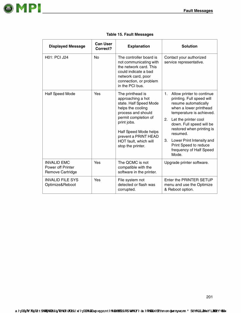
Fault Messages
Mantenimiento
H01: PCI J24 No The controller board is not communicating with the network card. This could indicate a bad network card, poor connection, or problem in the PCI bus.
Contact your authorized service representative.
Half Speed Mode Yes The printhead is approaching a hot state. Half Speed Mode helps the cooling process and should permit completion of print jobs. Half Speed Mode helps prevent a PRINT HEAD HOT fault, which will stop the printer.
1. Allow printer to continue printing. Full speed will resume automatically when a lower printhead temperature is achieved.
2. Let the printer cool down. Full speed will be restored when printing is resumed.
3. Lower Print Intensity and Print Speed to reduce frequency of Half Speed Mode.
INVALID EMCPower off Printer Remove Cartridge
Yes The QCMC is not compatible with the software in the printer.
Upgrade printer software.
INVALID FILE SYS Optimize&Reboot
Yes File system not detected or flash was corrupted.
Enter the PRINTER SETUP menu and use the Optimize & Reboot option.
Table 15. Fault Messages
Displayed MessageCan User Correct?
Explanation Solution
201
Periféricos Informáticos C/Canteras, 15 28860 Paracuellos de Jarama (Madrid) Tel: 00 34 917481604 Web: https://mpi.com.es/

Chapter 6 Restore The Printer To Operation
Mante
LABEL MISSING Check Media Path
Yes The Label Taken Sensor did not detect the label present over the tear bar with Peel-Off Media Handling mode enabled.
• The label was removed before the printer stopped printing or before the LCD “Remove Label” message displayed.
• The label slipped behind the platen roller.
• The label wrapped around the platen roller.
• Peel-Off Media Handling mode was mistakenly selected.
1. Press the Pause key to continue printing and then wait for the LCD “Remove Label” message before removing the label.
2. Open the pivoting deck, reinstall the label, close the printhead, press the Pause key, and continue printing.
3. Open the pivoting deck and remove wrapped labels from the platen. Clean all adhesive from the platen. Reinstall labels, close the deck, press the Pause key, and continue printing.
4. Select the correct Media Handling mode in the MEDIA SETUP menu.
LABEL READY Remove Label
Yes • A label was detected at the front of the printer by the Label Taken Sensor. This is the normal reminder message when Peel-Off Media Handling has been selected.
• A label was removed, but the “Remove Label” message remained.
• The incorrect Media Handling mode was selected.
1. Remove the label from the front of the printer to allow the next label to print.
2. Verify that a front door assembly is installed on the printer and that it is properly closed. Ensure that no debris is obstructing the door mirror or the Label Taken Sensor.
3. In the MEDIA SETUP menu, change Media Handling to the correct selection.
Table 15. Fault Messages
Displayed MessageCan User Correct?
Explanation Solution
202
nimiento Periféricos Informáticos C/Canteras, 15 28860 Paracuellos de Jarama (Madrid) Tel: 00 34 917481604 Web: https://mpi.com.es/

Fault Messages
Mantenimiento
LOADING PROGRAM FROM PORT XX%
Yes The new emulation program is loading into printer RAM. XX% indicates how much of the program has loaded.
No action required.
LOADING PROGRAM INTO FLASH
Yes A program is getting loaded into flash.
No action required.
MEMORY REMOVED Check EMC
Yes The EMC was removed while the printer was powered on.
1. Power off the printer.
2. Install the EMC.
3. Power on the printer.
MEDIA OUT Load Media
Yes The printer does not sense media:
• Media was not installed or has run out.
• A break in media has occurred.
• Media was not routed or installed correctly.
• The media sensor is not positioned correctly.
• Media is installed correctly, but the sensor is not detecting it.
• Gap/Mark Thresh value may be set too high and/or Paper Out Thresh may be set too low.
1. Install media. If a break occurred, reinstall the media. Press the Pause key to clear the fault message. Check the media installation procedures on page 27.
2. Verify the media sensor is properly positioned. Run Auto-Cal to improve the ability of the sensor to detect the installed media.
3. Check if the Gap/Mark Thresh is too high or the Paper Out Thresh is too low. Lower the Gap/Mark Thresh or raise the Paper Out Thresh value.
4. If using media with no gaps or black marks, perform Run Auto-Cal to establish a valid Paper Out Thresh.
Table 15. Fault Messages
Displayed MessageCan User Correct?
Explanation Solution
203
Periféricos Informáticos C/Canteras, 15 28860 Paracuellos de Jarama (Madrid) Tel: 00 34 917481604 Web: https://mpi.com.es/

Chapter 6 Restore The Printer To Operation
Mante
MODE NOT COMPATIBLE WITH CUTTER Check Media Mode
Yes Peel-Off Media Handling selection was attempted with the cutter option still installed. This mode requires that the front door assembly be installed to use the Label Taken Sensor.
Select a different Media Handling Mode.
MISSING PRINT HEAD See Manual
Yes The printer does not detect installation of the printhead.
1. Install the printhead.
2. Install or reset the printhead signal cable and printer cable.
NOT ENOUGH SPACE ON EMCDelete EMC File And Optimize
Yes There was not enough room on the expanded memory cartridge (EMC) to save the QCMC.
1. Cycle power, skip the QCMC configuration using the Cancel key.
2. Delete some files from the EMC.
NON VOLATILE MEMORY FAILED
Yes/No The printer assigns a certain amount of simulated NVRAM for storage of saved configurations. Large emulations reduce the amount of space available for saving configurations, which means that sometimes fewer than eight configurations can be saved. If this message appears when saving a configuration, it means the printer is out of memory. Previously saved configurations will still be available, but the one that was “saved” when the message appeared is not in memory. If this message appears at power-up, it means the flash memory is defective.
1. If the message appears at power-up, call your authorized customer service representative.
2. If the message appears while saving a configuration, the printer is out of memory and will not save that or subsequent configurations. (Previously saved configurations are still okay.)
3. Limit the number of saved configurations to seven.
Table 15. Fault Messages
Displayed MessageCan User Correct?
Explanation Solution
204
nimiento Periféricos Informáticos C/Canteras, 15 28860 Paracuellos de Jarama (Madrid) Tel: 00 34 917481604 Web: https://mpi.com.es/

Fault Messages
Mantenimiento
OPTION NOT INSTALLED
Yes 1. Selection of Peel-Off, Cut, or Rewind Media Handling was attempted when the option was not properly installed.
2. The printer is powered on with the cutter not connected correctly.
1. Check that the correct selection was attempted and that the option is installed.
2. Check that the appropriate option is installed and connected correctly before powering on the printer.
3. If the error persists, contact your authorized customer service representative.
PGL ERROR Yes Appears when the "Fault" option is selected from Error Report in the front panel.
Deselect "Fault" from Error Report on the front control panel.
PRINT HEAD UP Close Print Head
Yes Printhead is not closed. Close the printhead pivoting deck.
PRINTER HARDWARE NOT COMPATIBLEPower Off Printer Remove Cartridge
Yes The printer used to configure the QCMC has different hardware options than the printer to be configured.
Change the hardware configuration of the new printer to match the original printer.
PRINTER UNDER REMOTE CONTROL
Yes Indicates that remote management software has control of the printer.
Press any key on the printer.
PRINTHEAD HOT Wait 5 Minutes Go Online
Yes/No The printhead has become overheated.
1. Allow the printhead to cool down for 5 minutes, then press Pause. Resume printing.
2. If possible, reduce print intensity.
3. If problem persists, contact your authorized service representative.
PROGRAM IS NOT COMPATIBLE WITH THIS PRINTER Repeat Download
No An attempt was made to download a non-compatible program file.
Try downloading again. If problem persists, contact your authorized service representative.
Table 15. Fault Messages
Displayed MessageCan User Correct?
Explanation Solution
205
Periféricos Informáticos C/Canteras, 15 28860 Paracuellos de Jarama (Madrid) Tel: 00 34 917481604 Web: https://mpi.com.es/

Chapter 6 Restore The Printer To Operation
Mante
QCMC DATA ERROR ON EMCDelete & Resave QCMC Data
Yes The data on the QCMC is corrupted.
Delete the existing QCMC and recopy from the original printer.
QCMC DETECTED Copy to Printer?Yes...Press <ENTER> No...Press <CANCEL>
Yes The printer detected a QCMC with a saved configuration.
To configure the printer with the QCMC, press the Enter key, otherwise press the Cancel key.
QCMC DETECTED Save to QCMC?Yes...Press <ENTER> No...Press <CANCEL>
Yes The printer detected a QCMC cartridge without a saved image.
If the printer is completely configured with the desired state, press the Enter key. If you do not wish to save at this time, press Cancel.
REWINDER FULLRemove Roll
Yes The Rewinder Full Sensor has detected a roll full condition.
Remove the roll from the rewind spindle.
RFID CNTRY BAD:Set Country Freq
No The RFID country frequency has not been set.
Set RFID country through RFID menus. If problem persists contact your authorized customer service representative.
RFID Comm Err Check Cable
Yes RFID error: communication cannot be established with the RFID encoder.
Disable the RFID reader or contact your authorized customer service representative.
RFID FW ERRVersion Mismatch
Yes The printer firmware version does not match the installed RFID encoder.
Contact your authorized customer service representative.
RFID KIL FIELD: Not Supported!
No The KIL field was accessed on a tag which does not support the KIL field.
Contact your authorized customer service representative.
RFID LOCK CMD: Not Supported!
No A lock command was executed on a tag which does not support locking. Most Gen 2 tags support locking but some do not.
Contact your authorized customer service representative.
Table 15. Fault Messages
Displayed MessageCan User Correct?
Explanation Solution
206
nimiento Periféricos Informáticos C/Canteras, 15 28860 Paracuellos de Jarama (Madrid) Tel: 00 34 917481604 Web: https://mpi.com.es/

Fault Messages
Mantenimiento
RFID TAG FAILURE Check Media
Yes Failed tag. Error displays in STOP mode, causing the printer to halt.
Initiate reprint of the label from the host. When the error is cleared, the label with the failed tag moves forward to the next TOF position.
RFID TAG MAX RETRY Check Media
Yes Failed tag. Error displays in OVERSTRIKE mode. Each failed label prints with the OVERSTRIKE pattern; the form retries until the label retry count is exhausted.
Clear the error. When the error is cleared, the label with the failed tag moves forward such that the next label is in position.
Ribbon Low Yes 1. The supply spool is getting low.
2. If there is a large amount of ribbon still on the supply spool, then the Ribbon Low message is being displayed falsely.
1. Replace ribbon.
2. Disable Ribbon Low in the MEDIA SETUP menu.
RIBBON OUT Load Ribbon
Yes 1. The ribbon supply spool is empty.
2. The ribbon has broken.
1. Replace the ribbon.
2. Reinstall the ribbon.
SECURITY CODE VIOLATION
Yes The software being used is not correct for the printer.
1. Load the correct software.
2. Power off the printer for 15 seconds, then power back on again. If the problem persists, contact your authorized customer service representative.
Table 15. Fault Messages
Displayed MessageCan User Correct?
Explanation Solution
207
Periféricos Informáticos C/Canteras, 15 28860 Paracuellos de Jarama (Madrid) Tel: 00 34 917481604 Web: https://mpi.com.es/

Chapter 6 Restore The Printer To Operation
Mante
SERIAL BUFFER OVERFLOW
Yes Host sent data after the printer buffer was full (Serial Interface).
1. Make a configuration printout.
2. Verify that the printer matches the host serial interface configuration settings for Data Protocol, Baud Rate, Data Bits, Stop Bits, Parity, Data Terminal Ready, and Request to Send.
3. Set printer serial interface parameters to match those of the host.
SERIAL BUFFER OVERRUN
Yes Receive overrun (Serial Interface).
1. Make a configuration printout.
2. Verify that the printer matches the host serial interface configuration settings for Data Protocol, Baud Rate, Data Bits, Stop Bits, Parity, Data Terminal Ready, and Request to Send.
3. Set the printer serial interface parameter to match those of the host.
SERIAL FRAMING ERROR
Yes Serial framing error over a serial interface.
Match the serial interface settings of the printer to those of the host computer.
SERIAL PARITY ERROR Yes Parity error (serial interface).
Check your serial host interface parameter settings. If necessary, change them so they match the settings of the attached host.
SOFTWARE ERROR Cycle Power
Yes/No 1. Application software tried to perform an illegal power function.
2. There are damaged logic circuits on the controller PCBA.
1. Recycle the printer power. If possible, print a job that has previously worked.
2. If the problem persists, contact your authorized service representative.
Table 15. Fault Messages
Displayed MessageCan User Correct?
Explanation Solution
208
nimiento Periféricos Informáticos C/Canteras, 15 28860 Paracuellos de Jarama (Madrid) Tel: 00 34 917481604 Web: https://mpi.com.es/

Fault Messages
Mantenimiento
WAITING FOR PROGRAM DOWNLOAD
Yes Normal message when the printer is powered up while holding down both the ↵ (Enter) and
(Cancel) keys in preparation to download software to the printer.
1. Complete the downloading software procedure.
2. Exit this procedure by cycling printer power.
WIRELESS ADAPTER NOT COMPATIBLE
Yes The type of wireless card is incompatible with the printer software.
The PCMCIA radio card that you installed may be incompatible with the dual ethernet interface in the printer. Verify the approved brand and model number of the radio card with your printer service provider and install the correct version. If using the correct radio card does not resolve this problem, call your service provider for further support.
Table 15. Fault Messages
Displayed MessageCan User Correct?
Explanation Solution
209
Periféricos Informáticos C/Canteras, 15 28860 Paracuellos de Jarama (Madrid) Tel: 00 34 917481604 Web: https://mpi.com.es/

Chapter 6 Restore The Printer To Operation
Mante
Status Messages
Table 16. Status Messages
Displayed MessageCan User Correct?
Explanation Solution
203 DPI Head Installed
N/A Normal power-up message. The printer is running its initialization routine and indicating DPI resolution of the installed printhead.
No action required.
305 DPI Head Installed
N/A Normal power-up message. The printer is running its initialization routine and indicating DPI resolution of the installed printhead.
No action required.
B20:FIRMWARE DOWNLOAD N/A Forced download mode only.
No action is required.
B21STATUS: PRINTER RESET
N/A The printer is automatically reseting after a download.
No action is required.
CLEARING PROGRAM FROM FLASH
N/A Emulation software successfully loaded into printer RAM and the checksum matched. The old program is now being deleted from flash memory.
No action required.
D50 STATUS: CLEARING FLASH Please Wait
N/A Emulation software successfully loaded into printer RAM and the checksum matched. The old program is now being deleted from flash memory. Forced download mode only.
No action required.
D51: PROGRAMMING FLASH LOADING PROGRAM INTO FLASH Please Wait
N/A A program is getting loaded into flash.
No action is required.
210
nimiento Periféricos Informáticos C/Canteras, 15 28860 Paracuellos de Jarama (Madrid) Tel: 00 34 917481604 Web: https://mpi.com.es/

Status Messages
Mantenimiento
DO NOT POWER OFF N/A This is a standard warning message that displays while the printer is downloading software.
Do not power off the printer until downloading is complete.
ETHERNET INITIALIZING Please Wait
N/A Ethernet is initializing. No action is required.
ETHERNET READY N/A Ethernet Interface has finished initializing.
No action is required.
ETHERNET RESETTING Please Wait
N/A Ethernet Interface is being reset.
No action is required.
LOADING PROGRAM INTO FLASH Please Wait
N/A Expanded Flash Cartridge download mode only.
No action is required.
POWER SAVER MODE N/A This is a status message. The printer is in low-energy idle state, the higher voltages are off, the front panel is dimmed, and only +5Vdc logic circuits are active.
No action required. Send a print job or pressing any control panel key turns off power saver mode.
PRINTER RESETTING Please Wait
N/A Printer finished loading the program into flash memory and is automatically resetting itself.
No action is required.
RESTORING BOOT CODE
Yes Normal download initialization message.
No action required.
SDRAM TEST 32MB N/A Status only not an error. No action is required.
STATUS: LOADING FIRMWARE Please Wait
N/A Normal message when the printer is powered up while holding down
both the (Menu) and the Down keys in preparation to download software to the printer.
Complete the downloading software procedure.
Table 16. Status Messages
Displayed MessageCan User Correct?
Explanation Solution
211
Periféricos Informáticos C/Canteras, 15 28860 Paracuellos de Jarama (Madrid) Tel: 00 34 917481604 Web: https://mpi.com.es/

Chapter 6 Restore The Printer To Operation
Mante
TESTING HARDWARE PLEASE WAIT
Yes Normal power-up message. Printer is running its initialization routine.
No action required.
THE ↵ KEY IS LOCKED
Yes A momentary status message that appears when an attempt is made to change a menu option or perform a diagnostic print test. By default, the ↵ (Enter) key is locked when the printer powers on.
1. Unlock the Enter key by pressing DOWN + ↵ at the same time. (This is the factory default key combination.)
2. A different unlock key combination will be in affect if the Set Lock Key option in the Printer Setup menu was used.
THE ↵ KEY IS UNLOCKED
Yes A momentary status message that appears when the ↵ (Enter) key is unlocked, permitting configuration parameters to be changed.
1. No action is necessary if you want the ↵ key unlocked.
2. Press the DOWN + ↵ keyat the same time if you want to lock the ↵ key.
To Stop Press ↵ N/A Normal message when a test print pattern that will run continuously is printing.
Press the ↵ (Enter) key to stop printing the test pattern.
Table 16. Status Messages
Displayed MessageCan User Correct?
Explanation Solution
212
nimiento Periféricos Informáticos C/Canteras, 15 28860 Paracuellos de Jarama (Madrid) Tel: 00 34 917481604 Web: https://mpi.com.es/

Mantenimiento
A Specifications
Print Method
Table 17. Printing Specifications
6700-M40 6700-M40
Print Resolution (dpi) 203 305
Method Direct or Thermal Transfer
Direct or Thermal Transfer
Max. Print Speed (ips) 10 10
Max. Slew Speed (ips) 10 10
Max. Print Width (in.) 4.1 (104.1 mm) 4.1 (104.1 mm)
Flash Memory (MB) Standard 8 8
Flash Memory (MB) Maximum with Expanded Memory Cartridge (EMC) option
40 40
DRAM (MB) Standard/Max (fixed) 32 32
Max. Print Length (in.) at max. width, std. MB DRAM 99 (2515 mm) 99 (2515 mm)
213
Periféricos Informáticos C/Canteras, 15 28860 Paracuellos de Jarama (Madrid) Tel: 00 34 917481604 Web: https://mpi.com.es/

Appendix A
Mante
Media
Table 18. Media - General Information
Type Roll-fed, die-cut continuous or fanfold labels, tags or tickets; most direct thermal or thermal transfer materials.
Supply Roll 8.0 inch (203.2 mm) maximum outside diameter on a 3 inch (76.2 mm) diameter core.
Rewinder Accepts a full roll of backing from an 8 inch diameter roll of labels.
Label Material Thermal transfer plain-coated papers, vinyl, Mylar, metallized paper, non-woven fabric, fine woven fabric, thermal-visible light scannable paper, infrared scannable paper, thermal ticket/tag stock, thermally-sensitive plastic stock.
Media Sensing Horizontally moveable sensor assembly. When set to Gap, the assembly detects die-cut labels on liner media and notches and holes in tag stock. When set to Mark, it senses a black mark on the underside of tag or label stock. When set to Disable, it senses no label indicators or ignores all existing label length indicators on the installed media. Also detects paper out.
Label Taken Sensor Detects when a printed label is at the printer exit throat. Used only for Peel-Off Media Handling mode.
Label Peel-Off Peels and presents label to the operator, one at a time. Label Peel-Off is supported only when using the Standard Peel option or Peel-Liner Rewinder option.
Standard Peel Peels labels while discarding the dispensed liner in front of the printer. Optional installation.
214
nimiento Periféricos Informáticos C/Canteras, 15 28860 Paracuellos de Jarama (Madrid) Tel: 00 34 917481604 Web: https://mpi.com.es/

Media
Mantenimiento
Figure 32. This Illustration Shows Media Dimensions
I. Tag Specification(Mark Sensing)
II. Tag Specification(Gap Sensing)
III. Label Specification(Gap Sensing)
Direction of Media Motion
Black Mark (on underside)
Direction of Media MotionDirection of Media Motion
RecommendedCross PerfLocation
RecommendedCross PerfLocation
G
Table 19. Media Specifications
6700-M40
A Label Width Range 0.87 to 5.0 inches22 to 128 mm
B Liner Width Range 1.0 to 5.15 inches25 to 131 mm
C Min. Gap/Hole/Notch Height 0.10 in.2.54 mm
D Media Length Range
Tear-Off Strip Mode 0.25 in. (6 mm) to 99 in. (2515 mm)
Peel-Off Mode 1 in. (25.4 mm) to 39 in. (991 mm)
Cut Mode 1 in. (25.4 mm) to 99 in. (2515 mm)
Rewind Mode 0.5 in. (13 mm) to 99 in. (2515 mm)
Continuous Mode 0.25 in. (6 mm) to 99 in. (2515 mm)
E Media Thickness Range 0.0023 to 0.010 in.0.06 to 0.254 mm
G Width of Inter-label notch/hole 0.25* to 0.50 in.6.35 to 12.7 mm
I Min Refl. Mark Width 0.5 in.12.7 mm
K Min. Refl. Mark Height 0.10 in.2.54 mm
These figures are approximate and depend upon the active emulation and application.
* You may need to select Mark sensing instead of Gap sensing for notch widths .25 in. or less due to limited inside travel of the Gap sensor.
215
Periféricos Informáticos C/Canteras, 15 28860 Paracuellos de Jarama (Madrid) Tel: 00 34 917481604 Web: https://mpi.com.es/

Appendix A
Mante
Media ThicknessThe printer supports media thickness ranging from .002 to 0.010 inches (0.051 to 0.254 mm).
Media Capacity
Ribbon
IMPORTANT Do not use ribbons longer than 450M in the printer.
Table 20. Roll and Fanfold Media Capacity
Media Type
Roll Supply 8.0 inches (maximum outside diameter) on 3 inch inside diameter core 203 mm on 76.2 mm core
Fanfold Supply 7.87 inches (200 mm) maximum height at rear entrance.
Table 21. Ribbon Specifications
Ribbon length 1476 feet (450 m)
Ribbon description Coated side in (ink on the inside of the ribbon) and coated side out (ink on the outside of the ribbon).
Ribbon core Internal diameter, 1.0 inch (25.4 mm)
Maximum outer diameter 3.3 inches (83.8 mm)
Maximum ribbon width 5.0 inches (127 mm)
Minimum ribbon width 1.55 inches (39.4 mm)
Ribbon width for optimum performance
0.59 inches (15mm) wider than the media
216
nimiento Periféricos Informáticos C/Canteras, 15 28860 Paracuellos de Jarama (Madrid) Tel: 00 34 917481604 Web: https://mpi.com.es/

Indicators And Switches
Mantenimiento
Indicators And Switches
Memory
Optional Expanded Memory Cartridge
ATTENTION You must power off the printer before you install or remove the EMC, or you may damage the EMC and the printer. If you remove the EMC after powering on the printer with the EMC installed, the fault message "MEMORY REMOVED Check EMC" will display. You cannot clear this message by reinserting the EMC. You must cycle power.
The expanded memory cartridge (EMC) is a user installable 32MB memory storage cartridge that provides additional flash memory for downloading forms, logos, and fonts. The EMC can be ordered as a factory option kit or as a field upgrade kit that allows users to increase the printer flash memory capacity. Refer to pages 244 to 246 for installation instructions. The EMC can also come as a preloaded factory kit with one Asian TrueType font (see “DBCS Character Sets and Fonts” on page 235), with the Andalé TrueType scaleable font or QCMC option.
Table 22. Indicators, Switches, Keys, and Message Display
Indicator Lights: Online, Fault
Switches: Power
Keys: Pause, Feed, ↑ (Up), ↓ (Down), ← (Left), → (Right),↵ (Enter), (Menu), (Cancel),
Message Display: One row of text and two rows of menu icons or 4 rows of 16 characters per row for error messages, print status, and recalling stored formats. Eight rows of 21 characters per row for changing menu settings.
Table 23. Memory Specifications
Flash Memory (standard) 8MB fixed on Controller PCBA
DRAM (standard) 32MB fixed on Controller PCBA
Flash Optional Memory 32MB on Expanded Memory Cartridge
...
217
Periféricos Informáticos C/Canteras, 15 28860 Paracuellos de Jarama (Madrid) Tel: 00 34 917481604 Web: https://mpi.com.es/

Appendix A
Mante
Media Cutter Option
The media cutter is designed to cut tags and label liner. Avoid cutting through the adhesive backed portion of any media.
Host Interfaces
Table 24. Media Cutter Specifications
Typical Life More than 1,000,000 cuts
Warranty 500,000 cuts
Environment Same specifications as printer
Cutting Method Single-edged blade, up/down slice motion
Media Thickness Range 0.0025 to 0.010 in. (0.064 to 0.254 mm)
Media Width Range 1.00 to 5.15 inches (25.4 to 130.8 mm)
Media Length Range 1.00 to 99 in. (25.4 to 2515 mm)
Table 25. Host Interface Characteristics
1. Serial RS-232 at 600, 1200, 2400, 4800, 9600, 19200, 38400, 57600, or 115200 baud.
2. Parallel (Centronics compatible) or IEEE 1284 bi-directional.
3. USB 2.0 Universal Serial Bus
The RS-232 host interface shall have the following characteristics:
Character Set: ANSI® ASCII character set
Word Length: Selectable 7-bit or 8-bit data format
Handshaking: XON/XOFF (in receive mode only) CTS/DTR. Clear To Send (CTS)/Data Terminal Ready (DTR) ETX/ACK. End of Text (ETX)/Acknowledge (ACK) ACK/NAK. Acknowledge (ACK)/Negative acknowledge (NAK) Series 1 Char Series 2 Char
Input Buffer: Selectable from 1 through 16 kbytes. XOFF is transmitted and DTR goes low when buffer is equal to or less than 25% of full. XON is transmitted and DTR goes high when buffer is 25% above empty. Characters are transmitted with no parity from the printer
218
nimiento Periféricos Informáticos C/Canteras, 15 28860 Paracuellos de Jarama (Madrid) Tel: 00 34 917481604 Web: https://mpi.com.es/

Power
Mantenimiento
Power
Environmental
Table 26. Power Source and Grounding
Power Source 230 VAC 50 Hz auto-ranging power supply.
Grounding Unit must be connected to a properly grounded receptacle.
Table 27. Power Consumption
Operating Mode Watts
Power Saver 15.6 Watts
Idle 24 Watts
Maximum 156 Watts (@ 30% print density)
Table 28. Environmental Information
Operating Temperature: 32° F to 104° F (0° C to 40° C)
Storage Temperature: -23° F to 104° F (-5° C to 60° C)
Operating Humidity: Storage Humidity:
10% to 90%, non-condensing5% to 90% non-condensing
Ventilation: Free air movement
Dust: Non-conducting, non-corrosive
NOTE: These conditions do not apply to media or ribbon storage.
219
Periféricos Informáticos C/Canteras, 15 28860 Paracuellos de Jarama (Madrid) Tel: 00 34 917481604 Web: https://mpi.com.es/

Appendix A
Mante
Physical Dimensions
Acoustic Noise
Under typical operating conditions the noise level generated will not exceed 66 dBa regardless of printhead resolution, media, ribbon, or print speed. This is in accordance with ISO 7779 and declared in accordance with ISO 9296.
Table 29. Printer Physical Dimension
Dimensions (Inches) Weight
6700-M40, unpacked excluding options
12.13H x 11W x 18.75D 31.8 lbs. (14.5kg)
Standard Peel with Liner Rewinder
18.62H x 11.0W x 18.75D 50.0 lbs. (22.7kg)
Full Media Rewinder 18.62H x 11.0W x 21.50 D 50.0 lbs. (22.7kg)
Standard Peel without Liner Rewinder
12.12H x 11.0W x 18.75D 33.0 lbs. (15kg)
Cutter 12.13H x 11.0W x 18.75D 33.8 lbs. (15.4kg)
220
nimiento Periféricos Informáticos C/Canteras, 15 28860 Paracuellos de Jarama (Madrid) Tel: 00 34 917481604 Web: https://mpi.com.es/

Mantenimiento
B Printer Options
Options are offered with the printer to enhance its capabilities and to provide a large degree of application flexibility. A description of the option complement is given below. Field-installable options include installation instructions.
Hardware Options
Expanded Memory Cartridge (EMC)The expanded memory cartridge (EMC) is a user installable option. The EMC can be ordered in any of these configurations as a factory option kit or as a field upgrade kit:
• Expanded Memory - 32MB Expanded Memory Cartridge that provides additional Flash memory for forms, logos, and fonts (see “Optional Expanded Memory Cartridge” on page 217).
• Asian TrueType® Fonts - Separate cartridges containing fonts for Simplified Chinese, Korean, or Japanese allows PGL or ZGL to print complex Double Byte Character Set (DBCS) characters (see “DBCS Character Sets and Fonts” on page 235).
• Andalé TrueType® Fonts - Separate cartridges containing Andalé TrueType® fonts allowing PGL or ZGL to print characters for virtually every language used in the world today, including simplified and traditional Chinese, Japanese, and Korean. (see “Andalé Fonts” on page 235).
• Quick Change Memory Cartridge (QCMC) - This cartridge option provides an easy way to copy a printer’s firmware and configuration settings from one printer to another. A “snapshot image” of the source printer is stored onto the QCMC and a simple interface is provided to copy that image to a target printer. Once the image has been copied to the target printer, the two printers will be identically configured. The QCMC has its own resident network MAC address that will be used in place of the printer’s LAN/WLAN MAC address when the cartridge is left installed in a printer (see “Quick Change Memory Cartridge (QCMC)” on page 236).
Full Media RewinderIn full rewind mode, rewinds printed labels into a removable roll. The printer can be ordered with a rewinder or it can be field installed at a later date by an authorized service representative.
221
Periféricos Informáticos C/Canteras, 15 28860 Paracuellos de Jarama (Madrid) Tel: 00 34 917481604 Web: https://mpi.com.es/

Appendix B Interface And RFID Options
Mante
Media CutterThe printer may be ordered with a cutter mechanism installed (for cutting tags and label liner), or the option can be field installed by the user at a later date. Once installed, the printer can be configured to automatically cut media after each label or a specified number of labels is printed.
NOTE: The Cutter option is not supported when the Full Media Rewinder or Standard Peel option is installed.
Real Time ClockA clock chip with internal battery that keeps track of the year, month, day, hour, minute, and second values. It continues to operate when the printer is off. The printer may be ordered with this option installed or it can be field installed at a later date by an authorized service representative.
RFIDThe RFID encoder programs smart labels (tags with embedded inlays). The printer may be ordered with an RFID encoder installed (making it a 6700-M40 printer) or it can be field installed by an authorized service representative.
Standard PeelThis option provides the ability to peel labels while discarding the dispensed liner in front of the printer. This option may be field installed by an authorized service representative.
Standard Peel with Liner RewinderIn label peel-off mode, peels off labels one at a time before printing the next label and rewinds the liner into a discardable roll.
Interface And RFID Options
Ethernet Interface Card
This option permits placing the printer on a LAN rather than attaching it directly to a host system. The printer may be ordered with the ethernet included in the shipping carton or it can be field installed at a later date. Both are user installable at the rear panel of the printer. Two ethernet types are available:
• Ethernet 10/100Base-T. The Ethernet 10/100Base-T NIC supports data transfer rates of 100 Mbps.
• Wireless 802.11b/g. The wireless ethernet provides wireless 802.11b/g connectivity without expensive cabling and reconfigurations required from a wired network. The Printer Management Utility (PMU) remote management software is standard with the wireless ethernet.
The printer can support only one ethernet option at a time. Ethernet installation instructions are available as part of the optional kit as well as in the Maintenance Manual.
222
nimiento Periféricos Informáticos C/Canteras, 15 28860 Paracuellos de Jarama (Madrid) Tel: 00 34 917481604 Web: https://mpi.com.es/

RFID
Mantenimiento
RFID
The RFID option permits encoding of Class 1 Gen 2 RFID tags and is mounted inside the printer. The printer may be ordered with RFID installed, or it can be field installed by an authorized service representative.
Radio Frequency StatementsRF Exposure
To comply with FCC and IC RF exposure requirements, the device is approved for operation with a minimum separation distance of 20cm for all persons.
Co-location
To comply with FCC part 15C and IC RSS 210 requirements, the device must not be co-located or operating in conjunction with any other transmitter or antenna other than those allowed by InfoPrint Solutions Company for this device.
Antenna
Removal or alteration of the antenna could void FCC and IC approvals and negate your authority to operate the product.
Intended Use
Non-specific short range device operating in the band 869.4 to 869.95 MHz for Home and Office environment in E.E.A and Switzerland.
Please note that this device has been certified for residential use and may be used in any environment.
223
Periféricos Informáticos C/Canteras, 15 28860 Paracuellos de Jarama (Madrid) Tel: 00 34 917481604 Web: https://mpi.com.es/

Appendix B Interface And RFID Options
Mante
This wireless device may cause radio wave interference during operation.
OPERATING INSTRUCTIONS UNDER WHICH THE RADIOCOMMUNICATION EQUIPMENT ARE EXEMPTED FROM LICENSING
To maximize frequency sharing while minimizing radio interference, the following operating conditions are imposed to confine the propagation of radio signals within a building or at a localized site.
1. The radiocommunication equipment shall be used for in-building or localized on-site operations;
2. The radiocommunication equipment shall operate at frequencies or frequency bands designated by IDA on non-exclusive basis;
3. The radiocommunication equipment shall not operate beyond maximum permissable output power designated by IDA to confine the propagation of radio signals to a small localized area;
4. For an on-site localized operation with little obstruction by the nearby buildings or terrain, height of any external antenna, if installation approved by IDA, shall not be more than 10 meters above ground level to limit the radio wave propagation; and
5. No repeater station shall be used to extend the radio coverage.
• Without permission granted by the NCC, any company, enterprise, or user is not allowed to change frequency, enhance transmitting power or alter original characteristic as well as performance to an approved low power radio-frequency devices.
• The low power radio-frequency devices shall not influence aircraft security and interfere legal communications. If found, the user shall cease operating immediately until no interference is achieved. The said legal communications means radio communications is operated in compliance with the Telecommunications Act. The low power radio-frequency devices must be susceptible with the interference from legal communications or ISM radio wave radiated devices.
224
nimiento Periféricos Informáticos C/Canteras, 15 28860 Paracuellos de Jarama (Madrid) Tel: 00 34 917481604 Web: https://mpi.com.es/

RFID
Mantenimiento
For Reducing RF Influence, Use Properly
Subject to indoor use only with conditions that no harmful to authorized radio station and free of interference protection.
The device needs to be installed by trained engineers and is restricted to fixed, point-to-point operations.
225
Periféricos Informáticos C/Canteras, 15 28860 Paracuellos de Jarama (Madrid) Tel: 00 34 917481604 Web: https://mpi.com.es/

Appendix B Interface And RFID Options
Mante
Notice for user in the European Union and EFTA countries for InfoPrint Solutions Company 5403-M40 with RFID featureThe Declaration of Conformity for the 5403-M40 with RFID feature:
226
nimiento Periféricos Informáticos C/Canteras, 15 28860 Paracuellos de Jarama (Madrid) Tel: 00 34 917481604 Web: https://mpi.com.es/

RFID
Mantenimiento
English
Printronix hereby declares that this InfoPrint Solutions Company 5403-M40 is in compliance with the essential requirements and other relevant provisions of Directive 1999/5/EC.
Bulgarian
Printronix декларирам на своя отговорност, че далекосъобщително устройство InfoPrint Solutions Company 5403-М40 съответства на съществените изисквания по 1999/5/ЕС.
Czech
Printronix tímto prohlašuje, že InfoPrint Solutions Company 5403-M40 je ve shodě se základními požadavky a s dalšími příslušnými ustanoveními Nařízení 1999/5/ES.
Danish
Undertegnede Printronix erklærer herved, at følgende udstyr InfoPrint Solutions Company 5403-M40 de væsentlige krav og øvrige relevante krav i direktiv 1999/5/EF.
Dutch
Hierbij verklaart Printronix dat het toestel InfoPrint Solutions Company 5403-M40 in overeenstemming is met de essentiële eisen en de andere relevante bepalingen van richtlijn 1999/5/EG.
Bij deze verklaart Printronix dat deze InfoPrint Solutions Company 5403-M40 voldoet aan de essentiële eisen en aan de overige relevante bepalingen van Richtlijn 1999/5/EC.
Estonian
Käesolevaga kinnitab Printronix seadme InfoPrint Solutions Company 5403-M40 vastavust direktiivi 1999/5/EÜ põhinõuetele ja nimetatud direktiivist tulenevatele teistele asjakohastele sätetele.
Finnish
Printronix vakuuttaa täten että InfoPrint Solutions Company 5403-M40 tyyppinen laite on direktiivin 1999/5/EY oleellisten vaatimusten ja sitä koskevien direktiivin muiden ehtojen mukainen.
French
Par la présente, Printronix déclare que l'appareil InfoPrint Solutions Company 5403-M40 est conforme aux exigences essentielles et aux autres dispositions pertinentes de la directive 1999/5/CE.
Par la présente, Printronix déclare que ce InfoPrint Solutions Company 5403-M40 est conforme aux exigences essentielles et aux autres dispositions de la directive 1999/5/CE qui lui sont applicables.
227
Periféricos Informáticos C/Canteras, 15 28860 Paracuellos de Jarama (Madrid) Tel: 00 34 917481604 Web: https://mpi.com.es/

Appendix B Interface And RFID Options
Mante
German
Hiermit erklärt Printronix, dass sich InfoPrint Solutions Company 5403-M40 in Übereinstimmung mit den grundlegenden Anforderungen und den anderen relevanten Vorschriften der Richtlinie 1999/5/EG befindet.
Hiermit erklärt Printronix die Übereinstimmung des Gerätes InfoPrint Solutions Company 5403-M40 mit den grundlegenden Anforderungen und den anderen relevanten Festlegungen der Richtlinie 1999/5/EG.
Greek
ΜΕ ΤΗΝ ΠΑΡΟΥΣΑ Printronix ∆ΗΛΩΝΕΙ ΟΤΙ InfoPrint Solutions Company 5403-M40 ΣΥΜΜΟΡΦΩΝΕΤΑΙ ΠΡΟΣ ΤΙΣ ΟΥΣΙΩ∆ΕΙΣ ΑΠΑΙΤΗΣΕΙΣ ΚΑΙ ΤΙΣ ΛΟΙΠΕΣ ΣΧΕΤΙΚΕΣ ∆ΙΑΤΑΞΕΙΣ ΤΗΣ Ο∆ΗΓΙΑΣ 1999/5/ΕΚ.
HungarianPrintronix ezennel kijelenti, hogy ez a InfoPrint Solutions Company 5403-M40 termék megfelel az alapvető követelményeknek és az 1999/5/EC irányelv más vonatkozó rendelkezéseinek.
Icelandic
Printronix lysir her med yfir að thessi bunadur, InfoPrint Solutions Company 5403-M40, uppfyllir allar grunnkrofur, sem gerdar eru i R&TTE tilskipun ESB nr 1999/5/EC
ItalianCon la presente Printronix dichiara che questo InfoPrint Solutions Company 5403-M40 è conforme ai requisiti essenziali ed alle altre disposizioni pertinenti stabilite dalla direttiva 1999/5/CE.
LatvianAr šo Printronix deklarē, ka InfoPrint Solutions Company 5403-M40 atbilst Direktīvas 1999/5/EK būtiskajām prasībām un citiem ar to saistītajiem noteikumiem.
Lithuanian
Printronix deklaruoja, kad irenginys InfoPrint Solutions Company 5403-M40 tenkina 1999/5/EB Direktyvos esminius reikalavimus ir kitas sios direktyvos nuostatas
Maltese
Hawnhekk, Printronix, jiddikjara li dan InfoPrint Solutions Company 5403-M40 jikkonforma mal-ħtigijiet essenzjali u ma provvedimenti oħrajn relevanti li hemm fid-Dirrettiva 1999/5/EC.
PolishPrintronix, deklarujemy z pełną odpowiedzialnością, że wyrób InfoPrint Solutions Company 5403-M40 podstawowe wymagania i odpowiada warunkom zawartym w dyrektywie 1999/5/EC.
PortuguesePrintronix declara que este InfoPrint Solutions Company 5403-M40 está conforme com os requisitos essenciais e outras provições da Directiva 1999/5/CE.
228
nimiento Periféricos Informáticos C/Canteras, 15 28860 Paracuellos de Jarama (Madrid) Tel: 00 34 917481604 Web: https://mpi.com.es/

RFID
Mantenimiento
RomanianPrintronix declară că aparatul InfoPrint Solutions Company 5403-M40 este în conformi-tate cu cerinţele esenţiale şi cu alte prevederi relevante ale otărârii Guvernului nr. 88/2003 (Directivei 1999/5/EC).
SlovakPrintronix týmto vyhlasuje, že tento InfoPrint Solutions Company 5403-M40 vyhovuje technickým požiadavkám A ďalším ustanoveniam smernice 1999/5/ES, ktoré sa na tento výrobok vzťahujú.
SlovenianS tem dokumentom Printronix, izjavlja, da je ta InfoPrint Solutions Company 5403-M40 v skladu z bistvenimi zahtevami in z drugimi ustreznimi določili Direktive 1999/5/EC.
SpanishPor medio de la presente Printronix declara que el InfoPrint Solutions Company 5403-M40 cumple con los requisitos esenciales y cualesquiera otras disposiciones aplica-bles o exigibles de la Directiva 1999/5/CE.
SwedishHärmed intygar Printronix att denna InfoPrint Solutions Company 5403-M40 står I överensstämmelse med de väsentliga egenskapskrav och övriga relevanta bestämmelser som framgår av direktiv 1999/5/EG.
Notice for user in the European Union and EFTA countries for Compact flash Radio Card – 802.11bg LA-5127 (Models LA-5127C1 & LA-5127C2)
229
Periféricos Informáticos C/Canteras, 15 28860 Paracuellos de Jarama (Madrid) Tel: 00 34 917481604 Web: https://mpi.com.es/

Appendix B Interface And RFID Options
Mante
The Declaration of Conformity for the Compact flash Radio Card – 802.11bg LA-5127 (Models LA-5127C1 & LA-5127C2):
This device is intended for indoor use.
230
nimiento Periféricos Informáticos C/Canteras, 15 28860 Paracuellos de Jarama (Madrid) Tel: 00 34 917481604 Web: https://mpi.com.es/

RFID
Mantenimiento
This device is approved under the Symbol Technologies brand: Symbol Technologies, Inc., is the Enterprise Mobility business of Motorola Inc (“Motorola”).
Symbol Technologies Ltd. Redwood, Chineham Business Park, Crockford Lane, Basingstoke, Hampshire, RG24 8WQ United Kingdom
Telephone +44 (0) 1256 790790. Fax: +44 (0) 1256 817481. Website: www.motorola.com
Symbol Technologies Limited. Registration No: 1096253 - England
DECLARATION OF CONFORMITY
With regard to Part 15 of the FCC Rules & Regulations European Directives 1999/5/EC & 2002/95/EEC
Manufacturer’s Name: Symbol Technologies Inc.
Manufacturer’s Address: One Symbol Plaza, Holtsville NY 11742-1300
LA-5127 Compact Flash Radio Card - 802.11b/g Declares under our sole responsibility that the Product(s): Model: LA-5127C2 (connector version)
LA-5127A2 (Antenna version)
RoHS - This product is in Compliance with RoHS Directive 2002/95/EEC
Is in Conformity with the following: Radio Specifications:
Wideband 2.4 GHz Systems EN 300 328 V1.7.1
EMC Specifications:
Radio Wideband Systems EN 301 489-1 V1.6.1; EN 301 489-17 V1.2.1 IT Emissions EN55022: 2006, Class B IT Immunity EN55024: 1998 +A1: 2001 +A2: 2003 Medical Electrical Equipment IEC 60601-1-2: 2001 +A1: 2004, EN 60601-1-2: 2001 +A1: 2006 Radio Frequency Devices 47CFR15: 1998 (FCC Part 15 Class B) Interference Equipment ICES 003 Class B
Safety Specifications:
IT Equipment EN 60950-1:2006 IEC 60950-1:2001 UL 60950-1, CSA C22.2 No.60950-1 Specific Absorption Rate (SAR) EN50392: 2004 FCC OFR47 Part 2; OET Bulletin 65c RSS 102 Issue 2
The conformity assessment procedure referred to in Article 10(5) and detailed in Annex IV of Directive 1999/5/EC has been followed with the involvement of the following Notified Body: Telefication, Edisonstaat 12A, 6902 PH Zevenaar, The Netherlands
Identification mark:
0560The equipment will also carry the Class 2 equipment identifier
Signed on behalf of Symbol Technologies Inc
(Signature of authorized person) Original Date of Issue: 10 August 2007 Alan Parrish Rev: Rev B Director, Regulatory Date: 30 September 2008
231
Periféricos Informáticos C/Canteras, 15 28860 Paracuellos de Jarama (Madrid) Tel: 00 34 917481604 Web: https://mpi.com.es/

Appendix B Interface And RFID Options
Mante
EnglishSymbol Technologies Inc. hereby declares that this Compact flash Radio Card – 802.11bg LA-5127 (Models LA-5127C1 & LA-5127C2) is in compliance with the essential Requirements and other relevant provisions of Directive 1999/5/EC.
Bulgarian
Symbol Technologies Inc. декларирам на своя отговорност, че далекосъобщително устройство Compact flash Radio Card – 802.11bg LA-5127 (Model LA-5127C1 & LA-5127C2) съответства на съществените изисквания по 1999/5/EC.
Czech
Symbol Technologies Inc. tímto prohlašuje, že Compact flash Radio Card - 802.11bg LA-5127 (Model LA-5127C1 & LA-5127C2) je ve shodě se základními požadavky a s dalšími příslušnými ustanoveními Nařízení 1999/5/ES.
Danish
Undertegnede Symbol Technologies Inc. erklærer herved, at følgende udstyr Compact flash Radio Card - 802.11 bg LA-5127 (Model LA-5127C1 & LA-5127C2) overholder de væsentlige krav og øvrige relevante krav i direktiv 1999/5/EF.
DutchHierbij verklaart Symbol Technologies Inc. dat het toestel Compact flash Radio Card – 802.11bg LA-5127 (Models LA-5127C1 & LA-5127C2) in overeenstemming is met de essentiële eisen en de andere relevante bepalingen van richtlijn 1999/5/EG.
Bij deze verklaart Symbol Technologies Inc. dat deze Compact flash Radio Card – 802.11bg LA-5127 (Models LA-5127C1 & LA-5127C2) voldoet aan de essentiële eisen en aan de overige relevante bepalingen van Richtlijn 1999/5/EC.
Estonian
Käesolevaga kinnitab Symbol Technologies Inc. seadme Compact flash Radio Card – 802.11bg LA-5127 (Models LA-5127C1 & LA-5127C2) vastavust direktiivi 1999/5/EÜ põhinõuetele ja nimetatud direktiivist tulenevatele teistele asjakohastele sätetele.
Finnish
Symbol Technologies Inc. vakuuttaa täten että Compact flash Radio Card – 802.11bg LA-5127 (Models LA-5127C1 & LA-5127C2) tyyppinen laite on direktiivin 1999/5/EY oleellisten vaatimusten ja sitä koskevien direktiivin muiden ehtojen mukainen.
FrenchPar la présente, Symbol Technologies Inc. déclare que l'appareil Compact flash Radio Card – 802.11bg LA-5127 (Models LA-5127C1 & LA-5127C2) est conforme aux exi-gences essentielles et aux autres dispositions pertinentes de la directive 1999/5/CE.
Par la présente, Symbol Technologies Inc. déclare que ce Compact flash Radio Card – 802.11bg LA-5127 (Models LA-5127C1 & LA-5127C2) est conforme aux exigences essentielles et aux autres dispositions de la directive 1999/5/CE qui lui sont applicables.
232
nimiento Periféricos Informáticos C/Canteras, 15 28860 Paracuellos de Jarama (Madrid) Tel: 00 34 917481604 Web: https://mpi.com.es/

RFID
Mantenimiento
GermanHiermit erklärt Symbol Technologies Inc., dass sich Compact flash Radio Card – 802.11bg LA-5127 (Models LA-5127C1 & LA-5127C2) in Übereinstimmung mit den grundlegenden Anforderungen und den anderen relevanten Vorschriften der Richtlinie 1999/5/EG befindet.
Hiermit erklärt Symbol Technologies Inc. die Übereinstimmung des Gerätes Compact flash Radio Card – 802.11bg LA-5127 (Models LA-5127C1 & LA-5127C2) mit den grundlegenden Anforderungen und den anderen relevanten Festlegungen der Richtlinie 1999/5/EG.
GreekΜΕ ΤΗΝ ΠΑΡΟΥΣΑ Symbol Technologies Inc. ∆ΗΛΩΝΕΙ ΟΤΙ Compact flash Radio Card – 802.11bg LA-5127 (Models LA-5127C1 & LA-5127C2) ΣΥΜΜΟΡΦΩΝΕΤΑΙ ΠΡΟΣ ΤΙΣ ΟΥΣΙΩ∆ΕΙΣ ΑΠΑΙΤΗΣΕΙΣ ΚΑΙ ΤΙΣ ΛΟΙΠΕΣ ΣΧΕΤΙΚΕΣ ∆ΙΑΤΑΞΕΙΣ ΤΗΣ Ο∆ΗΓΙΑΣ 1999/5/ΕΚ.
Hungarian
Symbol Technologies Inc. ezennel kijelenti, hogy ez a Compact flash Radio Card – 802.11bg LA-5127 (Models LA-5127C1 & LA-5127C2) termék megfelel az alapvetõ követelményeknek és az 1999/5/EC irányelv más vonatkozó rendelkezéseinek.
Icelandic
Symbol Technologies Inc. lysir her med yfir að thessi bunadur, Compact flash Radio Card – 802.11bg LA-5127 (Models LA-5127C1 & LA-5127C2), uppfyllir allar grunnkrofur, sem gerdar eru i R&TTE tilskipun ESB nr 1999/5/EC
ItalianCon la presente Symbol Technologies Inc. dichiara che questo Compact flash Radio Card – 802.11bg LA-5127 (Models LA-5127C1 & LA-5127C2) è conforme ai requisiti essen-ziali ed alle altre disposizioni pertinenti stabilite dalla direttiva 1999/5/CE.
Latvian
Ar šo Symbol Technologies Inc. deklarç, ka Compact flash Radio Card – 802.11bg LA-5127 (Models LA-5127C1 & LA-5127C2) atbilst Direktîvas 1999/5/EK bûtiskajâm prasîbâm un citiem ar to saistîtajiem noteikumiem.
Lithuanian
Symbol Technologies Inc. deklaruoja, kad irenginys Compact flash Radio Card – 802.11bg LA-5127 (Models LA-5127C1 & LA-5127C2) tenkina 1999/5/EB Direktyvos esminius reikalavimus ir kitas sios direktyvos nuostatas
Maltese
Hawnhekk, Symbol Technologies Inc., jiddikjara li dan Compact flash Radio Card – 802.11 bg LA-5127 (Model LA-5127C1 & LA-5127C2) jikkonforma mal-ħtigijiet essenzjali u ma provvedimenti oħrajn relevanti li hemm fid-Dirrettiva 1999/5/EC.
233
Periféricos Informáticos C/Canteras, 15 28860 Paracuellos de Jarama (Madrid) Tel: 00 34 917481604 Web: https://mpi.com.es/

Appendix B Interface And RFID Options
Mante
PolishSymbol Technologies Inc., deklarujemy z pełną odpowiedzialnością, że wyrób Compact flash Radio Card – 802.11bg LA-5127 (Models LA-5127C1 & LA-5127C2) spełnia podstawowe wymagania i odpowiada warunkom zawartym w dyrektywie 1999/5/EC.
PortugueseSymbol Technologies Inc. declara que este Compact flash Radio Card – 802.11bg LA- 5127 (Models LA-5127C1 & LA-5127C2) está conforme com os requisitos essenci-ais e outras proviçőes da Directiva 1999/5/CE.
RomanianSymbol Technologies Inc. declară că aparatul Compact flash Radio Card – 802.11bg LA-5127 (Models LA-5127C1 & LA-5127C2) este în conformitate cu cerinţele esenţiale şi cu alte prevederi relevante ale otărârii Guvernului nr. 88/2003 (Directivei 1999/5/EC).
SlovakSymbol Technologies Inc. týmto vyhlasuje, že tento Compact flash Radio Card – 802.11bg LA-5127 (Models LA-5127C1 & LA-5127C2) vyhovuje technickým požiadavkám a ďalším ustanoveniam smernice 1999/5/ES, ktoré sa na tento výrobok vzt’ahujú.
SlovenianS tem dokumentom Symbol Technologies Inc., izjavlja, da je ta Compact flash Radio Card – 802.11bg LA-5127 (Models LA-5127C1 & LA-5127C2) v skladu z bistvenimi zahtevami in z drugimi ustreznimi določili Direktive 1999/5/EC.
SpanishPor medio de la presente Symbol Technologies Inc. declara que el Compact flash Radio Card – 802.11bg LA-5127 (Models LA-5127C1 & LA-5127C2) cumple con los requisitos esenciales y cualesquiera otras disposiciones aplicables o exigibles de la Directiva 1999/5/CE.
SwedishHärmed intygar Symbol Technologies Inc. att denna Compact flash Radio Card – 802.11bg LA-5127 (Models LA-5127C1 & LA-5127C2) stĺr I överensstämmelse med de väsentliga egenskapskrav och övriga relevanta bestämmelser som framgĺr av direktiv 1999/5/EG.
234
nimiento Periféricos Informáticos C/Canteras, 15 28860 Paracuellos de Jarama (Madrid) Tel: 00 34 917481604 Web: https://mpi.com.es/

Mantenimiento
Software OptionsNOTE: The following software options utilize the Expanded Memory
Cartridge (EMC) technology. Each of these software options are shipped preloaded, on their own individual EMC.
CAUTION You must power off the printer before you install or remove the EMC, or you may damage the EMC and the printer. If you remove the EMC after powering on the printer with the EMC installed, the fault message "MEMORY REMOVED Check EMC" will display. You cannot clear this message by reinserting the EMC. You must cycle power.
DBCS Character Sets and FontsOptional Asian Double Byte Character Set (DBCS) language cartridges can be ordered. Each cartridge contains one Asian DBCS character set and font, supporting Simplified Chinese, Korean, or Japanese, as well as user addressable memory area to expand the printer flash memory capacity.
Andalé FontsThe optional Andalé font is a TrueType® scalable font containing characters for virtually all languages used in the world today, such as Chinese, Japanese, and Korean. Four different versions of the font are available for purchase. Each of the four versions contains all of the same characters. The files differ in that a few of the characters are customized for certain regions of the world. Use UTF-8 encoded Unicode (recommended) or the 256 character multinational character sets to address the font in PGL and ZGL. With the ZGL emulation, it is also possible to use the Andalé font with downloaded character sets. Only one version of the Andalé font will be present on the cartridge. For the font to be used, the cartridge must be installed at power-up. The font will be listed on the configuration printout under Features Enabled (only one font will be present).
Korean Andale, Ver 1.00A Traditional Chinese Andale, Ver 1.00A Simplified Chinese Andale, Ver 1.00A Japanese Andale, Ver 1.00A
The font name and size will be listed on the configuration printout of the file system, under the EMC FFS file list.
235
Periféricos Informáticos C/Canteras, 15 28860 Paracuellos de Jarama (Madrid) Tel: 00 34 917481604 Web: https://mpi.com.es/

Appendix B Software Options
Mante
Quick Change Memory Cartridge (QCMC)The QCMC provides the ability to duplicate an entire printer’s firmware, saved configurations, and custom files quickly through the printer’s control panel with a user friendly interface. No external host or files are needed to transfer this information to the QCMC. A “snapshot image” is saved of the printer’s firmware, configuration settings, and custom files. The saved image can be copied to any number of printers using the same QCMC so that the printers will be identically configured (assumes same printer hardware and options are present).
The QCMC has its own resident network MAC address that will be used in place of the printer’s LAN/WLAN MAC address when the cartridge is left installed in a printer. This allows a mission critical printer to be exchanged quickly with a spare printer that will be identically configured, including the network MAC address.
The following are examples of how the QCMC may make printer management more convenient:
• A site has 10 printers to install that should all be configured identically. Rather than inputting the information through the control panel individually to each printer, insert the QCMC into the first printer, capture the changes, then easily share the image with the other nine printers.
• A site is adding additional printers and wants them configured the same as the printers already installed, but is unsure what changes were originally made. By using the QCMC to capture the exact image of the older printers, no custom settings will be missed.
• A printer is set up on a network that is configured to only allow recognized MAC addresses to access the network. If the printer with the QCMC installed needs repair and must be removed from the network, the MAC that resides on the QCMC can be easily transferred to the replacement printer, along with all the configuration information and any other files stored as the “snapshot image” on the QCMC, making the replacement printer an exact duplicate for the downed printer. By using the MAC address that resides on the QCMC, the replacement printer can be installed without notifying the network administrator, thereby simplifying the exchange.
236
nimiento Periféricos Informáticos C/Canteras, 15 28860 Paracuellos de Jarama (Madrid) Tel: 00 34 917481604 Web: https://mpi.com.es/

Mantenimiento
Installing The QCMCCAUTION You must power off the printer before you install or remove the QCMC,
or you may damage the QCMC and the printer. If you remove the QCMC after powering on the printer with the QCMC installed, the fault message “MEMORY REMOVED Check QCMC” will display. You cannot clear this message by reinserting the QCMC. You must cycle power.
1. Set the printer power switch to O (Off) from the front of the printer.
2. Raise the media cover.
Figure 33. Powering Off the Printer
Media Cover
Power Switch
A
See page 238.
237
Periféricos Informáticos C/Canteras, 15 28860 Paracuellos de Jarama (Madrid) Tel: 00 34 917481604 Web: https://mpi.com.es/

Appendix B Installing The QCMC
Mante
Figure 34. Installing the QCMC
3. Press the release tab and remove the QCMC slot cover.
4. Plug the QCMC (with the arrow positioned as shown) into the QCMC slot.
5. Install the QCMC slot cover.
6. Lower the media cover.
7. Set the printer power switch to | (On).
8. Make sure the Enter key is not locked and that Admin User is set to Enable.
9. Follow the instructions shown on the printer control panel to set up the Quick Change feature. See “Saving The Printer’s Configuration To The QCMC” on page 239.
QCMC Slot Cover
QCMC Slot
Arrow
Release Tab
AFrom page 237.
QCMC
238
nimiento Periféricos Informáticos C/Canteras, 15 28860 Paracuellos de Jarama (Madrid) Tel: 00 34 917481604 Web: https://mpi.com.es/

Mantenimiento
Saving The Printer’s Configuration To The QCMCThe QCMC must be installed in the printer with the power off.
NOTE: The MAC address residing on the QCMC will be used in place of the MAC assigned to the printer’s own network card whenever the QCMC is installed. If your network utilizes a MAC address control list (where only certain MAC addresses are allowed on the network), then ensure that the QCMC’s MAC address is added to the network’s control list. If you do not want to identify the printer with the QCMC’s MAC address, make sure the QCMC is removed from the printer before reattaching the printer to the network.
When the printer software detects the presence of a QCMC at power-up, a check of the QCMC will be performed to determine if there is already a saved flash image available. If no printer flash image exists on the QCMC, the software will then check to see if there are any saved configurations in the printer’s NVRAM memory. If the QCMC is blank (no flash image) and saved configurations are detected in the printer’s NVRAM then the you will be prompted with a message on the front panel to save the printer’s configuration to the QCMC.
NOTE: This screen will appear every time at power-up until the printer’s flash is saved to the QCMC.
If the <CANCEL> key is pressed, the printer will reboot into normal operation and not save any information to the QCMC. On subsequent power-ups the Save message on page 239 will display again.
When the <ENTER> key is pressed, the printer will not go online, but instead will copy the printer’s entire flash image to the QCMC, creating a snapshot of the printer’s memory. Information will be stored on the QCMC indicating all of the options that are installed on the printer: DPI, RFID, Cutter, Peel, Rewind, NIC, etc.
Below is a list of items that will be saved to the QCMC:
• Printer Program File (software)
• Custom configurations (1–8)
• Feature files or CST’s that have been downloaded on the printer.
• All variable settings from the printer’s NVRAM
• Network settings (if LAN/WLAN is installed), including IP Address
• Other user files, such as fonts, bitmaps, or graphics files downloaded to the printer.
QMC DETECTED
Save to QCMC?
Continue Press <ENTER>
Skip Press <CANCEL>
239
Periféricos Informáticos C/Canteras, 15 28860 Paracuellos de Jarama (Madrid) Tel: 00 34 917481604 Web: https://mpi.com.es/

Appendix B Copying The QCMC “Snapshot” Image to a Second Printer
Mante
While the printer is saving its QCMC settings to the EMC, the following message will display. Do not interrupt the process.
Upon successful completion of saving a flash image to the QCMC, the printer will display a message indicating the operation is complete. The printer will then reboot into normal operation.
If there is not enough space on the EMC to save the entire flash image, you will be prompted with the following message.
This is a fatal error and requires user intervention. Cycle power on the printer, when prompted to save the QCMC select <CANCEL> to skip. The printer will boot online and allow access to the EMC file menus located under the Printer Control menu (Admin. User must be set to Enable to see the EMC menus. see step b on page 245). Delete unnecessary EMC files then try the QCMC Save operation again.
Copying The QCMC “Snapshot” Image to a Second PrinterAlways power off the printer before removing or inserting the QCMC. Place the QCMC into the second printer’s memory slot. Upon power up, the printer software detects the presence of a QCMC and a check of the QCMC will be performed to determine if there is already a saved flash image from this QCMC on the printer. If no, the following message will display:
DO NOT PWR OFF
Saving Setup
To QCMC...
XX%
Save Complete
Printer Will Now
Reboot...
NOT ENOUGH
SPACE ON EMC
Delete EMC File
And Optimize
240
nimiento Periféricos Informáticos C/Canteras, 15 28860 Paracuellos de Jarama (Madrid) Tel: 00 34 917481604 Web: https://mpi.com.es/

Mantenimiento
NOTE: This message will appear every time at power-up until the QCMC settings are copied to the printer.
If the <CANCEL> key is pressed, the printer will reboot into normal operation and not copy any information to the printer. On subsequent power-ups the Copy message above will display again if the QCMC remains installed in the printer.
NOTE: If the QCMC remains installed in the printer, the MAC address onboard will be used in place of the resident MAC address to the printer’s LAN/WAN interface card.
When the <ENTER> key is pressed, the printer will not go online immediately, but will copy the contents of the QCMC to the printer’s flash, creating a clone of the original printer. Before the copy process is allowed to continue, checks of the printer configuration will be made. If either of the checks fail, a message will display on the front panel (in the hierarchy shown on page 241) and the printer will not copy any settings.
This means that the QCMC is not compatible with the printer’s software. A software upgrade is required, or a different configured QCMC will be needed.
This means that the printer’s hardware options do not match the original printer’s options.
A QCMC validation check will be performed to ensure the data stored on the EMC is not corrupted. If the test fails the following fault message will display.
QCMC DETECTED
Copy to Printer?
Yes...Press <ENTER>
No...Press <CANCEL>
INVALID EMC
Power Off Printer
Remove Cartridge
PRINTER HARDWARE
NOT COMPATIBLE
Power Off Printer
Remove Cartridge
241
Periféricos Informáticos C/Canteras, 15 28860 Paracuellos de Jarama (Madrid) Tel: 00 34 917481604 Web: https://mpi.com.es/

Appendix B Copying The QCMC “Snapshot” Image to a Second Printer
Mante
This means that the data on the QCMC was not saved properly, and must be deleted then resaved. Follow the instructions for deleting files, then repeat the copying process.
If all the checks pass, then the printer will copy the files from the QCMC to the target printer.
Upon successful completion, the printer will display the following message on the front panel and reboot into normal operation. Once the printer boots Online, it is necessary to select a “Run Auto-Cal” option located under the “Sensor Setup” menu.
NOTE: The IP address from the original printer has also been copied onto the second printer. If you wish to change the IP address on the second printer, refer to “Ethernet Setting” or “WLAN Setting” located under the “Interfaces” menu on page 120.
Updating The Printer Configuration To The QCMC
Before a new printer flash image can be saved to a QCMC, the existing QCMC files must first be deleted. With the QCMC installed in the original host printer or a target printer, set “Admin User” to Enable under the “Printer Control” menu. Select the “Delete Saved QCMC/Files And Reboot <ENTER>” option. The files will be deleted and the printer will reboot and optimize the flash on the EMC. Cycle power on the printer and follow the instructions in the “Saving The Printer’s Configuration To The QCMC” section on page 239.
QCMC DATA ERROR
ON EMC
Delete & Resave
QCMC Data
DO NOT PWR OFF
Copying QCMC To
Printer...
XX%
Copy Complete
Run Auto-Cal
After Reboot
242
nimiento Periféricos Informáticos C/Canteras, 15 28860 Paracuellos de Jarama (Madrid) Tel: 00 34 917481604 Web: https://mpi.com.es/

Loading New Firmware On The Printer
Mantenimiento
Loading New Firmware On The Printer
Loading new firmware onto the host or to the target printer erases the NVRAM. This is the same as the printer’s flash never being saved to a QCMC, or the printer having never been cloned with a QCMC.
NOTE: If an EMC with saved QCMC settings is installed in the printer during program download, all QCMC settings on the EMC will be erased as well.
ExceptionsIf you remove the module with power on, the MEMORY REMOVED Check EMC error message will display. It is necessary to power off and reboot the printer (with the cartridge in or out) to clear this error.
If the cartridge is removed when the printer’s power is off, the printer’s own MAC address will be available to the network when power is restored. No other variable data will be lost. Data on the QCMC will be maintained as well.
243
Periféricos Informáticos C/Canteras, 15 28860 Paracuellos de Jarama (Madrid) Tel: 00 34 917481604 Web: https://mpi.com.es/

Appendix B Install The EMC
Mante
Install The EMCATTENTION You must power off the printer before you install or remove the EMC, or
you may damage the EMC and the printer. If you remove the EMC after powering on the printer with the EMC installed, the fault message “MEMORY REMOVED Check EMC” will display. You cannot clear this message by reinserting the EMC. You must cycle power.
1. Set the printer power switch to O (Off) from the front of the printer.
2. Raise the media cover.
Figure 35. This Illustration Shows the EMC Location within the Printer
Media Cover
Power Switch
A
See page 245.
244
nimiento Periféricos Informáticos C/Canteras, 15 28860 Paracuellos de Jarama (Madrid) Tel: 00 34 917481604 Web: https://mpi.com.es/
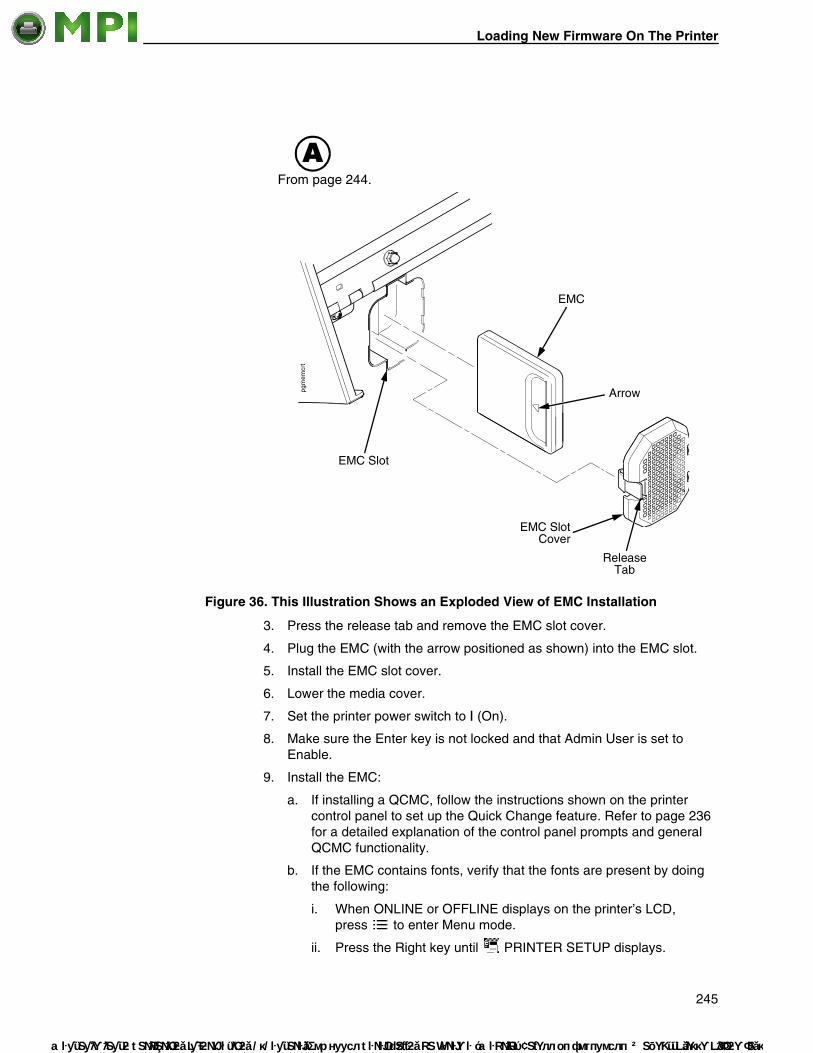
Loading New Firmware On The Printer
Mantenimiento
Figure 36. This Illustration Shows an Exploded View of EMC Installation
3. Press the release tab and remove the EMC slot cover.
4. Plug the EMC (with the arrow positioned as shown) into the EMC slot.
5. Install the EMC slot cover.
6. Lower the media cover.
7. Set the printer power switch to | (On).
8. Make sure the Enter key is not locked and that Admin User is set to Enable.
9. Install the EMC:
a. If installing a QCMC, follow the instructions shown on the printer control panel to set up the Quick Change feature. Refer to page 236 for a detailed explanation of the control panel prompts and general QCMC functionality.
b. If the EMC contains fonts, verify that the fonts are present by doing the following:
i. When ONLINE or OFFLINE displays on the printer’s LCD, press to enter Menu mode.
ii. Press the Right key until PRINTER SETUP displays.
EMC Slot Cover
EMC Slot
EMC
Arrow
Release Tab
AFrom page 244.
245
Periféricos Informáticos C/Canteras, 15 28860 Paracuellos de Jarama (Madrid) Tel: 00 34 917481604 Web: https://mpi.com.es/

Appendix B Using The Standard Peel Without Liner Rewinder
Mante
iii. Press ↵ to enter the PRINTER SETUP menu.
iv. Press the Up key until Admin User displays.
v. Select Enable and press ↵ to enable the option.
vi. Press the Up key until EMC FSS displays.
vii. Press ↵ to enter the EMC FSS menu.
viii. Press the Down key until View EMC Files displays.
ix. Press ↵ to enter the View EMC Files menu.
x. Press the Down key to scroll through the list of files stored on the EMC.
xi Find the font file name on the list.
c. If the EMC is memory only verify that the cartridge is installed correctly by doing the following:
i When ONLINE or OFFLINE displays on the printer’s LCD, press to enter Menu mode.
ii Press the Left key until DIAGNOSTICS displays.
iii Press ↵ to enter the DIAGNOSTICS menu.
iv Press the Down key until EMC FLASH Installed displays. The amount of memory displays in megabytes. If this does not appear, the EMC has not been properly installed. Start over at step 1 on page 244.
Using The Standard Peel Without Liner Rewinder
Configure the Printer Menu
1. Set Media Handling to Peel-Off in the MEDIA SETUP menu. See Chapter 4, “Configuring The Printer” on page 63 for more information.
2. Calibrate the printer (see “Running Auto Calibrate” on page 50).
NOTE: Calibration in Peel-Off mode is allowed only if Cal in Peel Mode is set to Enable. Cal in Peel Mode appears only if only if Admin User is set to Enable in the PRINTER SETUP menu.
ATTENTION When the printer calibrates in peel-off mode, a series of labels will quickly dispense. Be prepared to remove the peeled labels as they automatically peel or the printer will jam.
246
nimiento Periféricos Informáticos C/Canteras, 15 28860 Paracuellos de Jarama (Madrid) Tel: 00 34 917481604 Web: https://mpi.com.es/

Load Media
Mantenimiento
Load Media
Figure 37. This Illustration Shows Ribbon and Media Loading for Standard Peel Operation
1. To load media, refer to “Loading Roll Media” on page 27 and complete steps 1 through 7.
2. Open the standard peel door by pulling it out and down.
3. Thread the media over the peel bar, behind the standard peel roller, and through the standard peel opening (see Figure 37).
4. Horizontally center the standard peel roller over the label.
5. Peel the label (located over the tear bar) off the liner (refer to Figure 37). This will prevent the labels from sticking to the tear bar during the initial print feed.
Media Cover
Media Damper
Media Width Guide
Standard Peel Door
Standard Peel Roller
Label
Peel Bar
Deck Lock Lever
Pivoting Deck
Standard Peel Opening
NOTE: Peel shaded label off liner.
247
Periféricos Informáticos C/Canteras, 15 28860 Paracuellos de Jarama (Madrid) Tel: 00 34 917481604 Web: https://mpi.com.es/

Appendix B Using The Standard Peel Without Liner Rewinder
Mante
Figure 38. This Illustration Shows a Dispensed Label During the Standard Peel Operation
6. Rotate the deck lock lever clockwise to close the pivoting deck.
7. Close the standard peel door by pulling upward and it will lock in place.
8. Press the (Feed) key to advance the media to the next TOF (Top-of-Form) position. A label dispenses with the liner falling in front of the printer.
9. Press the (Pause) key until ONLINE displays.
10. Close the media cover.
Label
Liner
Deck Lock Lever
Standard Peel Door
248
nimiento Periféricos Informáticos C/Canteras, 15 28860 Paracuellos de Jarama (Madrid) Tel: 00 34 917481604 Web: https://mpi.com.es/

Configure the Printer Menu
Mantenimiento
Using The Full Media Rewinder OptionThe Full Media Rewinder allows you to automatically rewind printed labels into a roll after they have been printed.
Configure the Printer Menu
1. Set Media Handling to Rewind in the MEDIA SETUP menu. (See Chapter 4, “Configuring The Printer” for more information.)
2. Calibrate the printer (see “Running Auto Calibrate” on page 50).
Load Media
Figure 39. This Illustration Shows Ribbon and Media Loading on the Media Rewinder
1. To load media, refer to “Loading Roll Media” on page 27 and complete steps 1 through 10. Be sure to open the side cover.
2. Thread the media over the front of the media guide, around the media guide roller, and through the frame opening toward the rewinder. See Figure 39 and Figure 40.
NOTE: The alternate ribbon path is for inside ink ribbon. The alternate media path is for inside wound label path.
Media Guide
Media
Media Guide Roller
Media Rewinder Clip
Side Cover
Media Cover
Frame Opening
Rewinder
Media Damper
249
Periféricos Informáticos C/Canteras, 15 28860 Paracuellos de Jarama (Madrid) Tel: 00 34 917481604 Web: https://mpi.com.es/

Appendix B Using The Full Media Rewinder Option
M
Mante
Figure 40. This Illustration Shows the Ribbon Rewind Path on the Full Media Rewinder
3. Loosen the thumbscrew, pull it outward, position the wind direction lever in the desired location, and tighten the thumbscrew. See Figure 40.
NOTE: Wind direction lever in lower position = clockwise rotation. Wind direction lever in upper position = counterclockwise rotation.
IMPORTANT If you do not complete the following step, it will be extremely difficult to remove the printed labels from the rewinder.
4. Remove the media rewinder clip.
5. Wrap the leading edge of the media around the rewinder.
6. Slide the media flush against the left edge of the rewinder.
Media
Media Guide
edia Guide Roller
Rewinder
Frame Opening
Alternate Media Path
Thumbscrew
NOTE: The wind direction lever (not shown) is located behind the thumbscrew.
Rewinder Full Sensor
Alternate Rewind Path
Sensor Thumbscrew
250
nimiento Periféricos Informáticos C/Canteras, 15 28860 Paracuellos de Jarama (Madrid) Tel: 00 34 917481604 Web: https://mpi.com.es/

Load Media
Mantenimiento
Figure 41. This Illustration Shows How to Use the Media Rewinder Clip to Secure Media onto the Rewinder
7. Insert the media rewinder clip to secure the media. See Figure 41.
8. Manually rotate the rewinder one full revolution until the media is taut.
9. Install the media retainer onto the rewinder until it is flush against the media.
10. Tighten the thumbscrew
11. Rotate the deck lock lever clockwise to close the pivoting deck.
12. Press the (Feed) key to advance the media to the next TOF (Top-of-Form) position.
13. Press the (Pause) key until ONLINE displays.
14. Close the side cover and media cover.
IMPORTANT The rewinder supports a maximum diameter of 8 inches of printed labels. Exceeding this diameter can cause printed labels to rub on the bottom pan.
Media Rewinder Clip
Rewinder
Media
Thumbscrew
Media Retainer
251
Periféricos Informáticos C/Canteras, 15 28860 Paracuellos de Jarama (Madrid) Tel: 00 34 917481604 Web: https://mpi.com.es/

Appendix B Using The Full Media Rewinder Option
Mante
Rewinder Full Sensor Setup
1. Open the side cover and media cover.
2. Position the rewinder full sensor in the lower position and tighten the thumbscrew. See Figure 40.
NOTE: When the rewinder full sensor detects a roll full condition, the rewinder beeps and the message “REWINDER FULL Remove Roll” displays.
3. Close the side cover and media cover.
Remove Printed Media from the Rewinder1. Open the media cover and side cover.
2. Press the (Feed) key to advance the last printed label past the printhead, and tear the liner from behind the last printed label.
3. Manually rewind the remaining printed labels onto the rewinder by turning the rewinder.
4. Pull the media rewinder clip (along with the printed labels) off the rewinder.
5. Remove the printed labels from the media rewinder clip. Set the printed labels aside.
6. Insert the media rewinder clip into the rewinder.
7. Close the side cover and media cover.
252
nimiento Periféricos Informáticos C/Canteras, 15 28860 Paracuellos de Jarama (Madrid) Tel: 00 34 917481604 Web: https://mpi.com.es/

Configure The Printer Menu
Mantenimiento
Using The Full Media Rewinder With 3 Inch Diameter Core Adapters
Using the full media rewinder with 3 inch diameter core adapters allows you to automatically rewind printed labels onto a 3 inch diameter media take-up core after they have been printed.
Configure The Printer Menu
1. Set Media Handling to Rewind in the MEDIA SETUP menu. (See “Configuring The Printer” on page 63 for more information.)
2. Calibrate the printer (see “Running Auto Calibrate” on page 50).
Install The Core Adapters And Media Take-Up Core
Figure 42. Installing the Inside Core Adapter
1. Slide the inside core adapter onto the rewinder until it is flush against the rewinder flange.
2. Tighten the thumbscrew.
pgrwlod1
pgrwlod2
A
Inside Core Adapter
Thumbscrew
A
Rewinder
Rewinder Flange
253
Periféricos Informáticos C/Canteras, 15 28860 Paracuellos de Jarama (Madrid) Tel: 00 34 917481604 Web: https://mpi.com.es/

Appendix B Using The Full Media Rewinder With 3 Inch Diameter Core Adapters
Mante
Figure 43. Installing the Outside Core Adapter
3. Slide the outside core adapter onto the rewinder. Place it about 1/2 inch further in than the width of the media take-up core you are going to use. For example, if the media take-up core is 4 inches wide, the distance from the rewinder flange to the outside edge of the outside core adapter should be about 3 1/2 inches.
4. Tighten the thumbscrew.
Figure 44. Installing the Media Take-Up Core
5. Slide a 3 inch diameter media take-up core onto the rewinder over the two core adapters until it is flush with the rewinder flange. You should have about 1/2 inch from the outside edge of the outside core adapter to the edge of the media take-up core.
pgrwlod3
Rewinder Flange
Thumbscrew Outside Edge
Outside Core Adapter
Rewinder
pgrwlod4
pgrwlod5
B
B
Rewinder Flange
Media Take-Up
Core
254
nimiento Periféricos Informáticos C/Canteras, 15 28860 Paracuellos de Jarama (Madrid) Tel: 00 34 917481604 Web: https://mpi.com.es/

Load Media
M
Mantenimiento
Load Media
1. To load media, refer to “Loading Roll Media” on page 27 and complete step 1 through step 10. Be sure to open the side cover.
2. Thread the media over the front of the media guide, around the media guide roller, and through the frame opening toward the media take-up core. See Figure 45.
NOTE: The alternate media path is for inside wound label.
Figure 45. Media Rewind Path
3. Loosen the thumbscrew, pull it outward, position the wind direction lever in the desired location, and tighten the thumbscrew. See Figure 45.
NOTE: Wind direction lever in lower position = clockwise rotation. Wind direction lever in upper position = counterclockwise rotation.
pgrwlod6
Media
Media Guide
edia Guide Roller
Media Take-Up Core
Frame Opening
Alternate Media Path
Thumbscrew
NOTE: The wind direction lever (not shown) is located behind the thumbscrew.
Rewinder Full Sensor
Alternate Rewind Path
Sensor Thumbscrew
255
Periféricos Informáticos C/Canteras, 15 28860 Paracuellos de Jarama (Madrid) Tel: 00 34 917481604 Web: https://mpi.com.es/

Appendix B Using The Full Media Rewinder With 3 Inch Diameter Core Adapters
Mante
Figure 46. Securing Media on the Media Take-Up Core
4. Wrap the leading edge of the media around the media take-up core. See Figure 46.
5. Slide the media flush against the left edge of the rewinder flange.
6. Tape the leading edge of the media onto the media take-up core.
7. Manually rotate the media take-up core one full revolution until the media is taut. See Figure 47.
Figure 47. Tightening the Media on the Media Take-Up Core
pgrwlod7
Media
Media Take-Up Core
Tape
Rewinder Flange
pgrwlod8
Media Take-Up Core
256
nimiento Periféricos Informáticos C/Canteras, 15 28860 Paracuellos de Jarama (Madrid) Tel: 00 34 917481604 Web: https://mpi.com.es/

Rewinder Full Sensor Setup
Mantenimiento
Figure 48. Installing the End Plate
8. Install the media retainer onto the rewinder as shown in Figure 48 until it is flush against the media take-up core.
9. Tighten the thumbscrew.
10. Rotate the deck lock lever clockwise to close the pivoting deck.
11. Press the (Feed) key to advance the media to the next TOF (Top-of-Form) position.
12. Press the (Pause) key until ONLINE displays.
13. Close the side cover and media cover.
IMPORTANT The rewinder supports a maximum diameter of 8 inches of printed labels (including 3 inch media take-up core diameter). Exceeding this diameter can cause printed labels to rub on the bottom pan.
Rewinder Full Sensor Setup
1. Open the side cover and media cover.
2. Position the rewinder full sensor in the lower position and tighten the sensor thumbscrew. See Figure 45 on page 255.
NOTE: When the rewinder full sensor detects a roll full condition, the rewinder beeps and the message REWINDER FULL Remove Roll displays.
3. Close the side cover and media cover.
pgrwlod9
Media Retainer
Rewinder
Media Take-Up Core
Thumbscrew
257
Periféricos Informáticos C/Canteras, 15 28860 Paracuellos de Jarama (Madrid) Tel: 00 34 917481604 Web: https://mpi.com.es/

Appendix B Using The Standard Peel With Liner Rewinder Option
Mante
Figure 49. Removing the Media Roll
Remove Printed Media from the Rewinder1. Open the media cover and side cover.
2. Press the (Feed) key to advance the last printed label past the printhead, and tear the liner from behind the last printed label.
3. Manually rewind the remaining printed labels onto the media roll by turning the media retainer (refer to Figure 48 on page 257).
4. Loosen the thumbscrew and remove the media retainer.
5. Remove the media roll from the rewinder as shown in Figure 49, and set the roll aside.
6. Close the side cover and media cover.
Using The Standard Peel With Liner Rewinder OptionThe Standard Peel with Liner Rewinder allows you to automatically peel die-cut labels off their liner (backing) and dispense them one at a time while rewinding the liner.
Configure the Printer Menu
1. Set Media Handling to Peel-Off under the MEDIA SETUP menu. (See “Configuring The Printer” on page 63 for more information.)
2. Calibrate the printer (see “Running Auto Calibrate” on page 50).
pgrwld
10
Media Roll
258
nimiento Periféricos Informáticos C/Canteras, 15 28860 Paracuellos de Jarama (Madrid) Tel: 00 34 917481604 Web: https://mpi.com.es/

Load Media
Mantenimiento
Load Media
Figure 50. This Illustration Shows Media Loading on the Standard Peel with Liner Rewinder
1. Open the media cover.
2. Open the side cover and refer to the Label and Ribbon Routes label on the inside of the side cover.
3. Open the pivoting deck by rotating the deck lock lever fully counterclockwise.
4. Open the peel-off door by pulling it upward, then forward.
5. Remove approximately 18 to 24 inches of labels from the liner. This will prevent the labels from sticking to the tear bar during the initial print feed.
Media Cover
Side Cover
Label
Knurled Roller
Rubber Roller
Platen
Media Rewinder Clip
Rewinder
Peel-Off Door
Pivoting Deck
Deck Lock Lever
Media Damper
259
Periféricos Informáticos C/Canteras, 15 28860 Paracuellos de Jarama (Madrid) Tel: 00 34 917481604 Web: https://mpi.com.es/

Appendix B Using The Standard Peel With Liner Rewinder Option
Mante
6. Thread the media under the media damper, over the platen, and in between the knurled roller and the rubber roller. See Figure 50 and Figure 51.
7. Thread the liner under the rubber roller.
8. Remove the media rewinder clip.
Figure 51. This Illustration Shows Media Path for the Standard Peel with Liner Rewinder
9. Wrap the leading edge of the liner over and around the rewinder.
10. Slide the liner flush against the left edge of the rewinder.
Label
Rewinder
Peel-Off Door
Tear Bar
Alternate Ribbon Path
Rubber RollerKnurled Roller (open position)
Liner
Media
Platen
Alternate Media Path
Pivoting Deck
Thumbscrew
NOTE: The wind direction lever (not shown) is located behind the thumbscrew.
Knurled Roller (closed position)
260
nimiento Periféricos Informáticos C/Canteras, 15 28860 Paracuellos de Jarama (Madrid) Tel: 00 34 917481604 Web: https://mpi.com.es/

Load Media
Mantenimiento
Figure 52. This Illustration Shows How to Use the Media Rewinder Clip to Secure Liner onto the Rewinder
11. Insert the media rewinder clip to secure the media. See Figure 52.
12. Manually rotate the rewinder one full revolution clockwise until the liner is taut.
13. Remove labels from the liner so that behind the tear bar the liner is without labels for approximately 1.5 inches.
14. Remove labels from the liner so that below the tear bar the liner is without labels for approximately 2 inches.
15. Rotate the deck lock lever fully clockwise to close the pivoting deck.
pgrewcl2
Media Rewinder Clip
Rewinder
Liner
261
Periféricos Informáticos C/Canteras, 15 28860 Paracuellos de Jarama (Madrid) Tel: 00 34 917481604 Web: https://mpi.com.es/

Appendix B Using The Standard Peel With Liner Rewinder Option
Mante
Figure 53. This Illustration Shows the Standard Peel with Liner Rewinder In Peel-Off Mode
16. Close the peel-off door and snap it down to lock it in place.
17. Press the (Feed) key. The label advances to the peel-off position, and “LABEL READY Remove Label” displays on the LCD. The liner remains on the rewinder. See Figure 53.
18. Press the (Pause) key until ONLINE displays.
19. Close the side cover and media cover.
Tear Bar
Label
Liner
Media Rewinder Clip
Rewinder
Peel-Off Door
Deck Lock Lever
Media Cover
Side CoverPivoting Deck
262
nimiento Periféricos Informáticos C/Canteras, 15 28860 Paracuellos de Jarama (Madrid) Tel: 00 34 917481604 Web: https://mpi.com.es/

Removing Label Liner From The Rewinder
Mantenimiento
IMPORTANT The rewinder supports a maximum diameter of 8 inches of liner (including rewinder diameter). Exceeding this diameter can cause the liner to rub on the bottom pan.
Removing Label Liner From The Rewinder
1. Open the media cover and side cover.
2. Open the peel-off door by pulling it upward, then forward.
3. Tear the liner at the tear bar.
4. Manually turn the rewinder to rewind the remaining liner onto the rewinder.
5. Pull the media rewinder clip (along with the liner) off the rewinder.
6. Remove the liner from the media rewinder clip and discard the liner.
7. Insert the media rewinder clip into the rewinder.
8. Close the side cover and media cover.
9. Close the peel-off door by pulling it towards the rewinder then snapping it downward.
263
Periféricos Informáticos C/Canteras, 15 28860 Paracuellos de Jarama (Madrid) Tel: 00 34 917481604 Web: https://mpi.com.es/

Appendix B Ordering Supplies And Accessories
Mante
Ordering Supplies And AccessoriesThe best printing solution is achieved when the printer, ribbon, and media are matched to the application requirements. The use of Genuine InfoPrint Solutions Company Thermal Ribbons will ensure optimum image quality, consistent bar code performance, and extended life of the printhead.
NOTE: To order consumables including thermal ribbons, printheads, and cleaning pens, contact an InfoPrint Solutions Company service representative at the phone numbers below or visit http://www.infoprint.com.
North America(877) 6InfoPrint (877-646-3677)
Asia PacificFor the countries below, contact www.infoprint.com
Latin AmericaContact www.infoprint.com
Europe, Middle East and Africa32-4364-4131
Australia Malaysia
Bangladesh Myanmar
Brunei New Zealand
Cambodia Philippines
China Singapore
Hong Kong Sri Lanka
India Taiwan
Indonesia Thailand
Korea Vietnam
Laos
264
nimiento Periféricos Informáticos C/Canteras, 15 28860 Paracuellos de Jarama (Madrid) Tel: 00 34 917481604 Web: https://mpi.com.es/

Genuine InfoPrint Solutions Company Thermal Transfer Ribbons
Mantenimiento
Call Toll FreeBelgium 0800 71950
Denmark 800 15534
Finland 08001-13112
France 0800-905871
Germany 0800 18 18 005
Ireland 900-983131
Italy 800 878349
Norway 800-11389
Sweden 0207 94270
UK 0800 968679
Priority Fulfillment Service (PFS)500 North Central Expressway Plano, TX 75074 Fax: (972) 881-9201
Genuine InfoPrint Solutions Company Thermal Transfer Ribbons
The following is a list of Genuine InfoPrint Solutions Company Thermal Transfer ribbons:
InfoPrint Solutions Company Wide Spectrum Wax Ribbon 8300Provides superior print quality for coated and uncoated paper and tag stocks.
InfoPrint Solutions Company Resin Ribbon 8600A premium resin formula for excellent image and scuff resistance, while achieving premium print quality on a wide range of synthetic films and coated papers.
265
Periféricos Informáticos C/Canteras, 15 28860 Paracuellos de Jarama (Madrid) Tel: 00 34 917481604 Web: https://mpi.com.es/

Appendix B Ordering Supplies And Accessories
Mante
Ribbons 450M
To order ribbons, refer to the part numbers in Table 30.
Printheads
To order printheads, refer to the part numbers in Table 31.
Accessories
Field installable accessories available for your thermal printer are listed below. Contact your authorized supplier for more details.
• 32MB Expanded Memory Cartridge (EMC)
• Ethernet Card (10/100 Base-T)
• Ethernet 802.11b/g, Wireless
• Full Media Rewinder
• Media Cutter
• RFID
• Standard Peel with Liner Rewinder
• Standard Peel-Off Kit
• Font Cartridges
• Quick Change Memory Cartridge (QCMC)
Table 30. Ribbon Type and Part Numbers
Ribbon Type Part Number
Wax, 60mm 44D7576
Wax, 83mm 44D7577
Wax, 110mm 44D7578
Resin, 60mm 44D7579
Resin, 83mm 44D7580
Resin, 110mm 44D7581
Table 31. Printheads and Part Numbers
Printhead Part Number
203 dpi 44D7571
305 dpi 44D7572
266
nimiento Periféricos Informáticos C/Canteras, 15 28860 Paracuellos de Jarama (Madrid) Tel: 00 34 917481604 Web: https://mpi.com.es/

Mantenimiento
267
C ASCII Control Codes
Char Dec Hex Char Dec Hex Char Dec Hex Char Dec Hex
NUL 0 00 32 20 @ 64 40 ` 96 60
SOH 1 01 ! 33 21 A 65 41 a 97 61
STX 2 02 + 34 22 B 66 42 b 98 62
EXT 3 03 # 35 23 C 67 43 c 99 63
EOT 4 04 $ 36 24 D 68 44 d 100 64
ENQ 5 05 % 37 25 E 69 45 e 101 65
ACK 6 06 & 38 26 F 70 46 f 102 66
BEL 7 07 + 39 27 G 71 47 g 103 67
BS 8 08 ( 40 28 H 72 48 h 104 68
HT 9 09 ) 41 29 I 73 49 i 105 69
LF 10 0A * 42 2A J 74 4A j 106 6A
VT 11 0B + 43 2B K 75 4B k 107 6B
FF 12 0C , 44 2C L 76 4C l 108 6C
CR 13 0D - 45 2D M 77 4D m 109 6D
SO 14 0E . 46 2E N 78 4E n 110 6E
SI 15 0F / 47 2F O 79 4F o 111 6F
DLE 16 10 0 48 30 P 80 50 p 112 70
DC1 17 11 1 49 31 Q 81 51 q 113 71
DC2 18 12 2 50 32 R 82 52 r 114 72
DC3 19 13 3 51 33 S 83 53 s 115 73
DC4 20 14 4 52 34 T 84 54 t 116 74
NAK 21 15 5 53 35 U 85 55 u 117 75
SYN 22 16 6 54 36 V 86 56 v 118 76
ETB 23 17 7 55 37 W 87 57 w 119 77
CAN 24 18 8 56 38 X 88 58 x 120 78
EM 25 19 9 57 39 Y 89 59 y 121 79
SUB 26 1A : 58 3A Z 90 5A z 122 7A
ESC 27 1B ; 59 3B [ 91 5B 123 7B
FS 28 1C < 60 3C \ 92 5C | 124 7C
GS 29 1D = 61 3D ] 93 5D 125 7D
Periféricos Informáticos C/Canteras, 15 28860 Paracuellos de Jarama (Madrid) Tel: 00 34 917481604 Web: https://mpi.com.es/

Appendix C
Mante
NOTE: For the hardware handshake XON/XOFF commands: XON = Ctrl Q (DC1) XOFF = Ctrl S (DC3)
RS 30 1E > 62 3E ^ 94 5E ~ 126 7E
US 31 1F ? 63 3F _ 95 5F 127 7F
Char Dec Hex Char Dec Hex Char Dec Hex Char Dec Hex
268
nimiento Periféricos Informáticos C/Canteras, 15 28860 Paracuellos de Jarama (Madrid) Tel: 00 34 917481604 Web: https://mpi.com.es/

Mantenimiento
D Glossary
Baud (rate) Baud Rate is the number of information bits that can be transmitted between the printer and the computer in one second. For example, one baud equals one bit per second in a series of binary signals. Both the printer and the computer must be configured to the same baud rate.
BIT Binary digIT. A digit in the binary number system, represented by a 0 or a 1. A bit is the smallest unit of storage in a digital computer.
Boot-up The start-up procedure which causes a computer operating system to be loaded into main memory.
Buffer An area of storage into which data is read or written temporarily during data transfers.
Configuration Refers to the operating properties that define how the printer responds to signals and commands received from the host computer at the printer interface. These properties are called configuration parameters and are set to match the operating characteristics of the host computer system.
Continuous Media Media comprised of one continuous length without a gap, notch, hole, or black mark to establish a predetermined label or tag length. With this media type, the Host Form Length or user-selected Label Length sets the desired length of each label.
Continuous Media Handling Mode A media handling mode that advances media in the
forward direction only.
Controller An independent functional logic unit in a data processing system that controls data paths between one or more units of peripheral equipment.
Data Bits Binary information sent to the printer; a character set grouping containing letters, digits, and punctuation marks to be printed.
269
Periféricos Informáticos C/Canteras, 15 28860 Paracuellos de Jarama (Madrid) Tel: 00 34 917481604 Web: https://mpi.com.es/

Appendix D
Mante
Default A value, parameter, attribute, or option that is assigned by a program or system when another has not been specified by the user.
Diagnostic Pertaining to the detection and isolation of a printer malfunction or mistake.
Direct Thermal Media Media coated with special chemicals that act as an
accelerator, acceptor dye, and binder. In Direct Thermal mode, the heat from the selected rectangular elements in the thermal printhead makes direct contact with the media (no ribbon is used) and causes a chemical reaction that creates the image on the media.
Direct Thermal Printing A printing method in which no ribbon is used to
transfer data from the printhead to the media to create an image. The thermal printhead selectively heats small rectangular elements which make direct contact with the coated media.
DRAM Dynamic Random Access Memory. Can be read from or written to at any time. DRAM is volatile: whatever is in DRAM is lost when power is turned off.
Expanded Memory Cartridge (EMC) The expanded memory cartridge (EMC) is an extra 32MB Flash memory storage cartridge that allows users to download forms, logos, and fonts.
Fanfold Media Media supplied in a fanfold stack instead of a roll format.
Flash Memory Nonvolatile memory. See Nonvolatile Memory.
Font A collection of printing characteristics for printing alphanumeric characters, all of which combine to produce a distinctive style of print.
Host Computer The computer that stores, processes, and sends data to be printed, which communicates directly with the printer. The term “host” is used to indicate the controlling computer, since modern printers are themselves microprocessor-controlled computer systems.
PGL Intelligent Graphics Printing software for the Printronix Graphics Language, designated for Printronix printers. IGP/PGL provides online forms, barcodes, and many alphanumeric text-generation capabilities and is compatible with earlier versions of Printronix IGP protocol and programming.
270
nimiento Periféricos Informáticos C/Canteras, 15 28860 Paracuellos de Jarama (Madrid) Tel: 00 34 917481604 Web: https://mpi.com.es/

Mantenimiento
Interface The hardware component used to link two devices by common physical interconnection, signal, and functional characteristics.
IPS The speed at which the media is printed based on a rate of Inches-Per-Second.
Label Liner (backing) The material labels are attached to during their manufacturing process. Attachment is usually accomplished with an adhesive. After printing, labels can be easily removed from the liner and the liner discarded or recycled.
Label Taken Sensor A sensor located at the front of the printer to detect the presence of a label extended out the front of the printer. The sensor is used only during Peel-Off Media Handling to sense a label and then detect its removal prior to printing the next label.
Media Material onto which data is printed by the printer. The types of media supported by the printer are die-cut labels or tag stock, supplied in roll or fanfold format. Media is further described by the type of sensing used to detect the Top-of-Form position based on the label length indicators used. Transmissive (Gap) media uses a liner gap, notch, or hole between labels, and Reflective (Mark) media uses a horizontal black mark located on the underside of the tag stock or label liner. Continuous media (with no label length indicators) uses no sensing method, and the operator determines which label length is desired.
Media Sensor The sensor used to detect the presence of media in the paper path as well as the gap, notch, or hole position of Transmissive media or the horizontal black mark on Reflective media.
Memory See RAM, Nonvolatile Memory, DRAM, and Flash Memory.
Nonvolatile Memory Nonvolatile memory stores variables that must be preserved when the printer is turned off, such as configuration parameters and printer usage statistics. Nonvolatile memory is preserved because RAM is housed on the controller board, which contains an independent, battery-operated power supply. When printer power is turned off, the battery supplies the power needed to keep stored data active. Nonvolatile memory also includes storage in disk.
NVRAM Acronym of Nonvolatile Random-Access Memory. See Nonvolatile Memory.
271
Periféricos Informáticos C/Canteras, 15 28860 Paracuellos de Jarama (Madrid) Tel: 00 34 917481604 Web: https://mpi.com.es/

Appendix D
Mante
Parity (check) Parity checking is the addition of a non-data bit to data, resulting in the number of “1 bits” being either always even or always odd. Parity is used to detect transmission errors. Parity represents value in the check digit of the received or transmitted data.
PCBA Printed Circuit Board Assembly. A PCB with components (ICs, resistors, capacitors, etc.) installed.
Port A data channel used for receiving data from or transmitting data to one or more external devices.
Protocol The rules and conventions that govern communication between a printer and a host computer. A protocol includes codes for printing text and graphics and codes instructing the printer to perform special operations.
Quick Change Memory Cartridge (QCMC) This cartridge provides a way to easily copy a printer’s firmware and configuration settings from one printer to another. A “snapshot image” of the source printer is stored onto the QCMC and a simple interface is provided to copy that image to a target printer.
RAM Random-Access Memory. Also called “main memory” or “working memory.” It is the active memory of the printer into which programs are loaded. RAM is saved to volatile memory because data in RAM is lost when power is turned off or interrupted.
Reflective Mark Sensing Use of the media sensor to transmit and receive infrared light off the underside of media to detect horizontal black marks used for determining the Top-of-Form position on labels or for indicating a Paper Out condition.
Resolution A measure expressing the number of component units in a given range used to create an image; in printing, expressed as the number of dots per inch (dpi) horizontally and vertically.
RFID Encoder The RFID (Radio Frequency Identification) encoder programs smart labels (tags with embedded inlays).
Roll Media Media supplied in a roll format, on a 3-inch cardboard core.
272
nimiento Periféricos Informáticos C/Canteras, 15 28860 Paracuellos de Jarama (Madrid) Tel: 00 34 917481604 Web: https://mpi.com.es/

Mantenimiento
Sensed Distance Gap/Mark Sensor = Gap: The Sensed Distance value is the physical length of one label plus the length of one gap. Gap/Mark Sensor = Mark: The Sensed Distance value is the physical distance from the trailing edge of one black mark to the trailing edge of the next.
Slew Vertical paper movement.
Stop Bits The signal which indicates the end of a character or element.
Thermal Transfer Media Media specifically designed to work with a ribbon for
image transfer. In Thermal Transfer mode, compatibility between the ribbon and the media is critical in producing a high quality, long lasting image.
Thermal Transfer Printing A printing method in which the printhead presses a
specially coated ribbon against the media. The printhead elements react with the ribbon and bond the image to the media.
Transmissive (Gap) Sensing Use of the media sensor to transmit infrared light
through the media to detect gaps, holes, or notches for determining the Top-of-Form position on labels or for indicating a Paper Out condition.
273
Periféricos Informáticos C/Canteras, 15 28860 Paracuellos de Jarama (Madrid) Tel: 00 34 917481604 Web: https://mpi.com.es/

Appendix D
Mante
274
nimiento Periféricos Informáticos C/Canteras, 15 28860 Paracuellos de Jarama (Madrid) Tel: 00 34 917481604 Web: https://mpi.com.es/

Mantenimiento
Notices
This information was developed for products and services offered in the U.S.A.
InfoPrint Solutions Company may not offer the products, services, or features discussed in this document in other countries. Consult your local InfoPrint Solutions Company representative for information on the products and services currently available in your area. Any reference to an InfoPrint Solutions Company product, program, or service is not intended to state or imply that only that InfoPrint Solutions Company product, program, or service may be used. Any functionally equivalent product, program, or service that does not infringe any InfoPrint Solutions Company intellectual property rights may be used instead. However, it is the user’s responsibility to evaluate and verify the operation of any non-InfoPrint Solutions Company product, program, or service.
References in this document to InfoPrint Solutions Company products, product features, programs or services do not imply that InfoPrint Solutions Company intends to make such products, product features, programs or services available in all countries in which InfoPrint Solutions Company operates or does business.
InfoPrint Solutions Company may have patents or pending patent applications covering subject matter described in this document. The furnishing of this document does not give you any license to these patents. You can send license inquiries, in writing, to:
InfoPrint Solutions Company, LLC 6300 Diagonal Hwy 002J Boulder, CO 80301-9270 U.S.A.
The following paragraph does not apply to the United Kingdom or any other country where such provisions are inconsistent with local law: INFOPRINT SOLUTIONS COMPANY PROVIDES THIS PUBLICATION “AS IS” WITHOUT WARRANTY OF ANY KIND, EITHER EXPRESS OR IMPLIED, INCLUDING, BUT NOT LIMITED TO, THE IMPLIED WARRANTIES OF NON-INFRINGEMENT, MERCHANTABILITY OR FITNESS FOR A PARTICULAR PURPOSE. Some states do not allow disclaimer of express or implied warranties in certain transactions, therefore, this statement may not apply to you.
This information could include technical inaccuracies or typographical errors. Changes are periodically made to the information herein; these changes will be incorporated in new editions of the publication. InfoPrint Solutions Company may make improvements and/or changes in the product(s) described in this publication at any time without notice.
275
Periféricos Informáticos C/Canteras, 15 28860 Paracuellos de Jarama (Madrid) Tel: 00 34 917481604 Web: https://mpi.com.es/

Mante
Any references in this information to non-InfoPrint Solutions Company Web sites are provided for convenience only and do not in any manner serve as an endorsement of those Web sites. The materials at those Web sites are not part of the materials for this InfoPrint Solutions Company product and use of those Web sites is at your own risk.
InfoPrint Solutions Company may use or distribute any of the information you supply in any way it believes appropriate without incurring any obligation to you.
Any performance data contained herein was determined in a controlled environment. Therefore, the results obtained in other operating environments may vary significantly. Some measurements may have been made on development-level systems and there is no guarantee that these measurements will be the same on generally available systems. Furthermore, some measurement may have been estimated through extrapolation. Actual results may vary. Users of this document should verify the applicable data for their specific environment.
Information concerning non-InfoPrint Solutions Company products was obtained from the suppliers of those products, their published announcements or other publicly available sources. InfoPrint Solutions Company has not tested those products and cannot confirm the accuracy of performance, compatibility or any other claims related to non-InfoPrint Solutions Company products. Questions on the capabilities of non-InfoPrint Solutions Company products should be addressed to the suppliers of those products.
If you are viewing this information softcopy, the photographs and color illustrations may not appear.
This unit must be recycled or discarded according to applicable local and national regulations. InfoPrint Solutions Company encourages owners of information technology (IT) equipment to responsibly recycle their equipment when it is no longer needed. InfoPrint Solutions Company offers a variety of product return programs and services in several countries to assist equipment owners in recycling their IT products. Information on InfoPrint Solutions Company product recycling offerings can be found on InfoPrint Solutions Company’s Internet site at: http://www.infoprint.com
Notice: This mark applies only to countries within the European Union (EU), Norway, and Switzerland.
276
nimiento Periféricos Informáticos C/Canteras, 15 28860 Paracuellos de Jarama (Madrid) Tel: 00 34 917481604 Web: https://mpi.com.es/

Mantenimiento
Appliances are labeled in accordance with European Directive 2002/96/EC concerning waste electrical and electronic equipment (WEEE). The Directive determines the framework for the return and recycling of used appliances as applicable throughout the European Union. This label is applied to various products to indicate that the product is not to be thrown away, but rather reclaimed upon end of life per this Directive.
In accordance with the European WEEE Directive, electrical and electronic equipment (EEE) is to be collected separately and to be reused, recycled, or recovered at end of life. Users of EEE with the WEEE marking per Annex IV of the WEEE Directive, as shown above, must not dispose of end of life EEE as unsorted municipal waste, but use the collection framework available to customers for the return, recycling and recovery of WEEE. Customer participation is important to minimize any potential effects of EEE on the environment and human health due to the potential presence of hazardous substances in EEE. For proper collection and treatment, contact your local InfoPrint Solutions Company representative.
Product recycling and disposalThis unit must be disposed of according to applicable local and national regulations. Infoprint Solutions Company encourages owners of information technology (IT) equipment to responsibily dispose of their equipment when it is no longer needed. InfoPrint Solutions Company offers a variety of location-specific product return programs to assist equipment owners with the responsible disposal of their InfoPrint-branded equipment. Information on InfoPrint Solutions Company equipment disposal offerings can be found on InfoPrint Solutions Company's internet site at:http://www.infoprint.com/takeback
In the United States of America, information on InfoPrint equipment disposal offerings can also be obtained by calling 1-888-776-0924.
TrademarksThese terms are trademarks or registered trademarks of Ricoh Co., Ltd., in the United States, other countries, or both:
• InfoPrint
• Infoprint
• Ricoh
IBM, the IBM logo, and ibm.com are trademarks or registered trademarks of International Business Machines Corporation in the United States, other countries, or both. If these and other IBM trademarked terms are marked on their first occurrence in this information with a trademark symbol (® or ™), these symbols indicate U.S. registered or common law trademarks owned by IBM at the time this information was published. Such trademarks may also be registered or common law trademarks in other countries. A current list of IBM trademarks is available on the Web at "Copyright and trademark information" at www.ibm.com/legal/copytrade.shtml
277
Periféricos Informáticos C/Canteras, 15 28860 Paracuellos de Jarama (Madrid) Tel: 00 34 917481604 Web: https://mpi.com.es/

Communication statements
Mante
Other company, product, or service names may be trademarks or service marks of others.
Communication statementsFederal Communications Commission (FCC) Statement
This equipment has been tested and found to comply with the limits for a Class B digital device, pursuant to Part 15 of the FCC Rules. These limits are designed to provide reasonable protection against harmful interference in a residential installation. This equipment generates, uses, and can radiate radio frequency energy and, if not installed and used in accordance with the instructions, may cause harmful interference to radio communications. However, there is no guarantee that interference will not occur in a particular installation. If this equipment does cause harmful interference to radio or television reception, which can be determined by turning the equipment off and on, the user is encouraged to try to correct the interference by one or more of the following measures:
• Reorient or relocate the receiving antenna.
• Increase the separation between the equipment and receiver.
• Connect the equipment into an outlet on a circuit different from that to which the receiver is connected.
• Consult an InfoPrint Solutions Company authorized dealer or service representative for help.
InfoPrint Solutions Company is not responsible for any radio or television interference caused by unauthorized changes or modifications to this equipment. Unauthorized changes or modifications could void the user’s authority to operate the equipment.
Properly shielded and grounded cables and connectors must be used in order to meet FCC emission limits. Proper cables and connectors are available from InfoPrint Solutions Company authorized dealers. InfoPrint Solutions Company is not responsible for any radio or television interference caused by using other than recommended cables and connectors or by unauthorized changes or modifications to this equipment. Unauthorized changes or modifications could void the user’s authority to operate the equipment.
This device complies with Part 15 of the FCC Rules. Operation is subject to the following two conditions: (1) this device may not cause harmful interference, and (2) this device must accept any interference received, including interference that may cause undesired operation.
Responsible Party:
InfoPrint Solutions Company, LLC 6300 Diagonal Hwy 002J Boulder, CO 80301-9270 U.S.A.
278
nimiento Periféricos Informáticos C/Canteras, 15 28860 Paracuellos de Jarama (Madrid) Tel: 00 34 917481604 Web: https://mpi.com.es/

Mantenimiento
European Union (EU) Conformity Statement: This product is in conformity with the protection requirements of EU Council Directive 2004/108/EC on the approximation of the laws of the Member States relating to electromagnetic compatibility. InfoPrint Solutions Company cannot accept responsibility for any failure to satisfy the protection requirements resulting from a non-recommended modification of the product, including the fitting of non-InfoPrint Solutions Company option cards.
This product has been tested and found to comply with the limits for Class B Information Technology Equipment according to European Standard EN 55022. The limits for Class B equipment were derived for typical residential environments to provide reasonable protection against interference against licensed communication devices.
Industry Canada Compliance Statement
This Class B digital apparatus complies with Canadian ICES-003.
Cet appareil numérique de la classe B est conform à la norme NMB-003 du Canada.
Japanese VCCI Class B:
German Conformity Statement
Zulassungsbescheinigung laut dem Deutschen Gesetz über die elektromagnetische Verträglichkeit von Geraten (EMVG) vom 30. August 1995 (bzw.der EMC EG Richtlinie 89/336)
Dieses Gerät ist berechtigt, in Übereinstimmung mit dem Deutschen EMVG das EG-Konformitätszeichen — CE — zu führen.
Verantwortlich für die Konformitätserklärung nach Paragraph 5 des EMVG ist die InfoPrint Solutions Company Deutschland Informationssysteme GmbH, 70548 Stuttgart
Informationen in Hinsicht EMVG Paragraph 3 Abs. (2) 2:
EN 50082–1 Hinweis:
“Wird dieses Gerät in einer industriellen Umgebung betrieben (wie in EN 50024–2 festgelegt), dann kann es dabei eventuell gestört werden. In solch einem Fall ist der Abstand bzw. die Abschirmung zu der industriellen Störquelle zu vergrößern.”
Anmerkung:
Um die Einhaltung des EMVG sicherzustellen sind die Geräte, wie in den InfoPrint Solutions Company Handbüchern angegeben, zu installieren und zu betreiben.
Das Gerät erfüllt die Schutzanforderungen nach EN 50082–1 und EN 55022 Klasse B.
279
Periféricos Informáticos C/Canteras, 15 28860 Paracuellos de Jarama (Madrid) Tel: 00 34 917481604 Web: https://mpi.com.es/

Communication statements
Mante
Korea:
JEITA Statement:
The following statement applies to this InfoPrint Solutions Company product. The statement for other InfoPrint Solutions Company products intended for use with this product will appear in their accompanying manuals.
Federal Communications Commission (FCC) Statement
Attention: This equipment generates, uses, and can radiate radio frequency energy and if not installed and used in accordance with the instructions manual, may cause interference to radio communications. As temporarily permitted by regulation it has not been tested for compliance with the limits for Class A computing devices pursuant to Subpart J of Part 15 of FCC Rules, which are designed to provide reasonable protection against such interference. Operation of this equipment in a residential area is likely to cause interference in which case the user at his own expense will be required to take whatever measures may be required to correct the interference.
DANGER
This product is equipped with a 3-wire power cord and plug for the user’s safety. Use this power cord in conjunction with a properly grounded electrical outlet to avoid electrical shock.
280
nimiento Periféricos Informáticos C/Canteras, 15 28860 Paracuellos de Jarama (Madrid) Tel: 00 34 917481604 Web: https://mpi.com.es/

Mantenimiento
Software License AgreementYour printer contains, among other software, Printronix operating software including, but not limited to the Embedded Configurable Operating System (the “eCos Software”) as embedded software. The terms of this Agreement apply only to the eCos Software, and all other embedded software supplied with the printer. You accept the terms of this Agreement by your initial use of your printer.
1. Object Code License
Printronix grants you a nonexclusive license to use the Printronix Software, the eCos Software and all other embedded software (collectively, the “Embedded Software” or the “Software”) only in conjunction with the printer. As the rightful possessor of the printer, you may make a reasonable number of copies of the Software as necessary for backup, configuration, and restoration of the printer. You must reproduce the copyright notice and any other legend of ownership on each copy of the Software you make. You may transfer possession of the Software and its media to another party only with the transfer of the printer on which the Software is used. If you do so, you must give the other party a copy of these terms and provide all user documentation to that party. When you do so, you must destroy any copies of Software not resident in the printer. Your license for the Software terminates when you no longer rightfully possess the printer. No other rights under this license are granted.
2. Source Code
A source code version of eCos Software is available under the terms of the Red Hat eCos Public License v1.1 at www.printronix.com. Printronix grants no rights whatsoever in the source code for the Printronix Software.
3. No Warranty
THE EMBEDDED SOFTWARE IS PROVIDED UNDER THIS LICENSE ON AN “AS IS” BASIS, WITHOUT WARRANTY OF ANY KIND, EITHER EXPRESSED OR IMPLIED, INCLUDING, WITHOUT LIMITATION, WARRANTIES THAT THE EMBEDDED SOFTWARE IS FREE OF DEFECTS, MERCHANTABLE, FIT FOR A PARTICULAR PURPOSE OR NON-INFRINGING. THE ENTIRE RISK AS TO THE QUALITY AND PERFORMANCE OF THE EMBEDDED SOFTWARE IS WITH YOU.
SHOULD ANY OF THE EMBEDDED SOFTWARE PROVE DEFECTIVE IN ANY RESPECT, YOU (NOT RED HAT, PRINTRONIX, ANY OTHER CONTRIBUTOR OR ANY DISTRIBUTOR) ASSUME THE COST OF ANY NECESSARY SERVICING, REPAIR OR CORRECTION. THIS DISCLAIMER OF WARRANTY CONSTITUTES AN ESSENTIAL PART OF THIS LICENSE. NO USE OF ANY OF THE EMBEDDED SOFTWARE IS AUTHORIZED HEREUNDER EXCEPT UNDER THIS DISCLAIMER.
4. Conflicting Terms
You agree that this Agreement provides you no more rights with regards to warranty, support, indemnity or liability terms with respect to Red Hat, Inc., Printronix Inc, or any contributor to the Embedded Software than that provided by the Red Hat eCos Public License v.1.1 or any express warranty that may be made by Printronix, Inc.
281
Periféricos Informáticos C/Canteras, 15 28860 Paracuellos de Jarama (Madrid) Tel: 00 34 917481604 Web: https://mpi.com.es/

Communication statements
Mante
5. Limitation of Liability
UNDER NO CIRCUMSTANCES AND UNDER NO LEGAL THEORY, WHETHER TORT (INCLUDING NEGLIGENCE), CONTRACT OR OTHERWISE, SHALL RED HAT, PRINTRONIX, ANY OTHER CONTRIBUTOR, OR ANY DISTRIBUTOR OF THE EMBEDDED SOFTWARE, OR ANY PART THEREOF, OR ANY SUPPLIER OF ANY OF SUCH PARTIES, BE LIABLE TO YOU OR ANY OTHER PERSON FOR ANY INDIRECT, SPECIAL, INCIDENTAL, OR CONSEQUENTIAL DAMAGES OF ANY CHARACTER INCLUDING, WITHOUT LIMITATION, DAMAGES FOR LOSS OF GOODWILL, WORK STOPPAGE, COMPUTER FAILURE OR MALFUNCTION. OR ANY AND ALL OTHER COMMERCIAL DAMAGES OR LOSSES, EVEN IF SUCH PARTY SHALL HAVE BEEN INFORMED OF THE POSSIBILITY OF SUCH DAMAGES. THIS LIMITATION OF LIABILITY SHALL NOT APPLY TO LIABILITY FOR DEATH OR PERSONAL INJURY RESULTING FROM SUCH PARTY’S NEGLIGENCE TO THE EXTENT APPLICABLE LAW PROHIBITS SUCH LIMITATION. SOME JURISDICTIONS DO NOT ALLOW THE EXCLUSION OR LIMITATION OF INCIDENTAL OR CONSEQUENTIAL DAMAGES SO THAT EXCLUSION AND LIMITATION MAY NOT APPLY TO YOU.
6. Red Hat Statement With Regards to eCos Software
Part of the software embedded in this product is eCos – Embedded Configurable Operating System, a trademark of Red Hat. Portions created by Red Hat are Copyright (C) 1998, 1999, 2000 Red Hat, Inc. (http://www.redhat.com). All Rights Reserved.
THE SOFTWARE IN THIS PRODUCT WAS IN PART PROVIDED BY RED HAT AND ANY EXPRESS OR IMPLIED WARRANTIES, INCLUDING, BUT NOT LIMITED TO, THE IMPLIED WARRANTIES OF MERCHANT ABILITY AND FITNESS FOR A PARTICULAR PURPOSE ARE DISCLAIMED. IN NO EVENT SHALL THE AUTHOR BE LIABLE FOR ANY DIRECT, INDIRECT, INCIDENTAL, SPECIAL, EXEMPLARY, OR CONSEQUENTIAL DAMAGES (INCLUDING, BUT NOT LIMITED TO, PROCUREMENT OR SUBSTITUTE GOODS OR SERVICES; LOSS OF USE, DATA, OR PROFITS; OR BUSINESS INTERRUPTION) HOWEVER CAUSED AND ON ANY THEORY OF LIABILITY, WHETHER IN CONTRACT, STRICT LIABILITY, OR TORT (INCLUDING NEGLIGENCE OR OTHERWISE) ARISING IN ANY WAY OUT OF THE USE OF THIS SOFTWARE, EVEN IF ADVISED OF THE POSSIBLITY OF SUCH DAMAGE.
7. U.S. Government Users
The Embedded Software is a “commercial item,” as that term is defined in 48 C.F.R. 2.101 (Oct 1995), consisting of “commercial computer software” and “commercial computer software documentation,” as such terms are used in 48 C.F.R 12.212 (Sept. 1995). Consistent with 48 C.F.R. 12.212 and 48 C.F.R. 227.7202-1 through 227.7202-4 (June 1995), all U.S. Government End Users acquire Covered Code with only those rights set forth herein.
8. Miscellaneous
This Agreement represents the complete agreement concerning subject matter hereof. If any provision of this Agreement is held to be unenforceable. This Agreement shall be governed by California law provisions (except to the extent applicable law, if any, provides otherwise), excluding its conflict-of-law provisions.
282
nimiento Periféricos Informáticos C/Canteras, 15 28860 Paracuellos de Jarama (Madrid) Tel: 00 34 917481604 Web: https://mpi.com.es/

Mantenimiento
Limited Software Product WarrantyPrintronix, Inc. warrants that for ninety (90) days after delivery, the Software will perform in accordance with specifications published by Printronix, Inc. Printronix, Inc. does not warrant that the Software is free from all bugs, errors and omissions.
Remedy
Your exclusive remedy and the sole liability of Printronix, Inc. in connection with the Software is replacement of defective software with a copy of the same version and revision level.
Disclaimer of Warranties and Limitation of Remedies
1. THE PARTIES AGREE THAT ALL OTHER WARRANTIES, EXPRESS OR IMPLIED, INCLUDING WARRANTIES OF FITNESS FOR A PARTICULAR PURPOSE AND MERCHANTABILITY ARE EXCLUDED.
Printronix, Inc. does not warrant that the functions contained in the Software will meet your requirements or that the operation of the Software will be uninterrupted or error free. Printronix, Inc. reserves the right to make changes and/or improvements in the Software without notice at any time.
2. IN NO EVENT WILL PRINTRONIX, INC. BE LIABLE FOR LOST PROFITS, LOST DATA, BUSINESS INTERRUPTIONS, OR ANY OTHER DIRECT, INDIRECT, INCIDENTAL OR CONSEQUENTIAL DAMAGES ARISING OUT OF THE USE OF OR INABILITY TO USE THIS PRODUCT, EVEN IF PRINTRONIX, INC. HAS BEEN ADVISED OF THE POSSIBILITY OF SUCH DAMAGES, OR ANY DAMAGES CAUSED BY THE ABUSE OR MANIPULATION OF THE SOFTWARE. SOME STATES DO NOT ALLOW THE EXCLUSION OR LIMITATION OF LIABILITY FOR CONSEQUENTIAL OR INCIDENTAL DAMAGES, SO THE ABOVE LIMITATION MAY NOT APPLY TO YOU.
3. Printronix, Inc. will not be liable for any loss or damage caused by delay in furnishing a Software Product or any other performance under this Agreement.
4. Our entire liability and your exclusive remedies for our liability of any kind (including liability for negligence except liability for personal injury caused solely by our negligence) for the Software Product covered by this Agreement and all other performance or nonperformance by us under or related to this Agreement are limited to the remedies specified by this Agreement.
5. California law governs this Agreement.
283
Periféricos Informáticos C/Canteras, 15 28860 Paracuellos de Jarama (Madrid) Tel: 00 34 917481604 Web: https://mpi.com.es/

Communication statements
Mante
Termination of License AgreementThis License shall continue until terminated. This license may be terminated by agreement between you and Printronix, Inc. or by Printronix, Inc. If you fail to comply with the terms of this License and such failure is not corrected within thirty (30) days after notice. When this License is terminated, you shall return to the place you obtained them, the printer and all copies of the Software and documentation.
U.S. Government Restricted RightsUse, duplication or disclosure by the government is subject to restrictions as set forth in the Rights in Technical Data and Computer Software clause at FAR 242.227-7013, subdivision (b) (3) (ii) or subparagraph (c) (1) (ii), as appropriate. Further use, duplication or disclosure is subject to restrictions applicable to restricted rights software as set forth in FAR 52.227-19 (c) (2).
Acknowledgement of Terms and ConditionsYOU ACKNOWLEDGE THAT YOU HAVE READ THIS AGREEMENT, UNDERSTAND IT, AND AGREE TO BE BOUND BY ITS TERMS AND CONDITIONS. NEITHER PARTY SHALL BE BOUND BY ANY STATEMENT OR REPRESENTATION NOT CONTAINED IN THIS AGREEMENT. NO CHANGE IN THIS AGREEMENT IS EFFECTIVE UNLESS WRITTEN AND SIGNED BY PROPERLY AUTHORIZED REPRESENTATIVES OF EACH PARTY. BY USING THIS PRINTER, YOU AGREE TO ACCEPT THE TERMS AND CONDITIONS OF THIS AGREEMENT.
284
nimiento Periféricos Informáticos C/Canteras, 15 28860 Paracuellos de Jarama (Madrid) Tel: 00 34 917481604 Web: https://mpi.com.es/

Index
Mante
Numerics
1284 Parallel Interface, 58
203 DPI, 210
24V POWER FAIL, 188
305 DPI, 210
450M ribbons, 266
A
Accessories, 264
Acoustic Noise, 220
Adjustments
media width, 44
Admin User Enable, 67
Admin User option, 119
AI 00 Spaces option, 104
Alarm option, 111
Alarms, printer, 187
Andalé Fonts, 235
Auto Calibrate, run, 50
Auto Label Width option, 80
Auto Locking option, 115
Auto Map Select option, 78
Auto Save Configuration, 148
Auto Save Feature, 149
Auto Save option, 143
Auto Switching, 55
optional host interfaces, 55
standard host interfaces, 55
Auto Uppercase option, 102
Autowrap option, 101
B
B11 ERROR RAM TEST FAILED, 188
B12 ERROR PROGRAM MISSING, 188
B20 Firmware Download, 210
B22 DECOMPRESS SIZE, 188
B23 ERROR DECOMPRESS CKSUM, 188
BAD VFU CHANNEL, 188
Batch Counter option, 118
Bold Chars. option, 117
Bot Line Display option, 119
Boundary Check option, 107
Byte Mode, IEEE 1284 interface, 58
C
C39 Compatbl. option, 106
Cable Length, Centronics parallel interface, 56
Cal in Peel Mode option, 92
CALIBRATION FAIL, 189
Cancel Key, 39
Cancel Key option, 112
CANNOT CALIBRATE Disable Peel-Off, 189
CARTRIDGE REMOVED, 189
Centronics
interface signals, 57
parallel interface, 56
pin assignments, 56
Centronics option, 131
Change Printer Settings, 66
Cleaning
cutter option, 174
exterior, 171
general, 171
interior, 171
media sensor, 172
285
nimiento Periféricos Informáticos C/Canteras, 15 28860 Paracuellos de Jarama (Madrid) Tel: 00 34 917481604 Web: https://mpi.com.es/

Mante
platen roller, 172
printhead, 172
Clear Error Log option, 146
CLEARING PROGRAM FROM FLASH, 210
Clip Page option, 83
Communication, IEEE 1284 parallel (bidirectional), 58
Compatibility Mode, IEEE 1284 interface, 58
Compatibility option, 113
CONFIGURATION
menu, 141
submenu, 142
Configuration
auto save, 148
loading saved, 154
modify saved, 151
printing, 153
save, 147
specify power-up, 150
Configuration Menu
move within, 63
overview, 68
Configure Printer, 63
Control Panel, 38
Cancel key, 39
Down key, 40
Download Combo key, 41
Enter key, 39
fault indicator, 41
Feed key, 39
Left key, 41
liquid crystal display (LCD), 38
Menu key, 39
Menu Unlock combo key, 41
online indicator, 41
Pause key, 38
Right key, 40
Soft Reset combo key, 41
Up key, 40
Control Print Quality, 177
Controls, 37
Copy Complete Run Auto-Cal After Reboot, 189
Copying QCMC snapshot image, Quick Change
Memory Cartridge (QCMC), 240
CR Edit option, 103
CUTTER FAULT Check Cutter, 189
Cutter Option, cleaning, 174
D
D50 STATUS CLEARING FLASH, 210
D51 PROGRAMMING FLASH LOADING
PROGRAM INTO FLASH, 210
Data Exchange, 176
Date option, 118
DBCS Character Sets, 235
DBCS Fonts, 235
Define CR code option, 101
Define LF code option, 101
Del Char frm Fls option, 113
Del Char frm RAM option, 113
Del Set frm Fls option, 113
Del Set from RAM option, 114
Delete Config option, 142
Determine Printhead Wear, 177
DIAGNOSTICS
menu, 144
submenu, 145
Direct Thermal Printing, 14
Display Intensity option, 118
Display Language option, 111
Do FF at TOF option, 105
DO NOT POWER OFF, 211
DO NOT PWR OFF Copying QCMC to Printer, 189
DO NOT PWR OFF Saving QCMC to Printer, 190
Documentation list, 17
Down Key, 40
Download Combo Key, 41
Download Mode, 166
Download TrueType Font to DBCS Through UTF-8, 166
DOWNLOADER ERROR BEYOND 8MB EMC, 190
DOWNLOADER ERROR EXTERNAL FLASH IS
FULL, 190
DOWNLOADER ERROR FLASH NOT ERRASED, 190
286
nimiento Periféricos Informáticos C/Canteras, 15 28860 Paracuellos de Jarama (Madrid) Tel: 00 34 917481604 Web: https://mpi.com.es/

Mante
DOWNLOADER ERROR FLASH W ADDR BAD, 190
DOWNLOADER ERROR FLASH WRITE #1, 190
DOWNLOADER ERROR FLASH WRITE #2, 190
DOWNLOADER ERROR FLASH WRITE #3, 190
DOWNLOADER ERROR FLASH WRITE #4, 190
DOWNLOADER ERROR MAIN FLASH IS FULL, 190
DOWNLOADER ERROR NO EMC DETECTED, 191
Downloading Software
Ethernet, 158
Ethernet and FTP, 160
Firmware Download Utility, 156
Flash contains Boot Code, 163
Parallel Port, 157
Serial Port, 156
USB Port, 162
Downloading TrueType Fonts, 164
DRAM Installed option, 146
E
E00 EXE @ ADDR0 message, 191
E01A TYPE 0x40 message, 191
E01B TYPE 0x60 message, 191
E02 MACHINE CHK message, 192
E03A DSI HASH L message, 192
E03B DSI HASH S message, 192
E03C DSI BAT PL message, 193
E03D DSI BAT message, 193
E03E DSI CXIWX message, 193
E03F DSI CXOWX message, 194
E03G DSI ECXIWX message, 194
E03H DSI ECXOWX message, 194
E04A ISI NO TRA message, 195
E04B ISI DIRECT message, 195
E04C ISI PROTEC message, 195
E06 NOT ALIGNED message, 196
E07 ILLEGAL INS message, 196
E08 FLOATINGPNT message, 196
EC SOFTWARE FAIL, 196
EMC FFS option, 114
EMC FLASH Installed option, 146
EMC NOT FOUND PWR OFF PRINTER, 197
EMULATION
menu, 94
submenus, 100
Emulation Setup option, 100
Emulations overview, 94
Enter Key, 39
ENTER to Stop, 197
Environmental, specifications, 219
ERROR DC PROGRAM NOT VALID, 197
ERROR FLASH DID NOT PROGRAM, 197
ERROR INSUFFICIENT DRAM, 197
ERROR INSUFFICIENT FLASH, 198
ERROR OCCURRED CLEARING QUEUES, 199
ERROR PROGRAM NEEDS MORE DRAM, 198
ERROR PROGRAM NOT COMPATIBLE, 198
ERROR PROGRAM NOT VALID, 198
ERROR SHORT AT ADDRESS XXXX, 198
ERROR WRITING TO FLASH, 198
ERROR WRONG CHECKSUM, 198
Ethernet and FTP, downloading software, 160
ETHERNET INITIALIZING, 211
Ethernet Port option, 123
ETHERNET READY, 211
ETHERNET RESETTING, 211
Ethernet Setting option, 123
Ethernet, downloading software, 158
Exchange, data, 176
Expanded Font option, 105
Expanded Memory Cartridge, 217, 221
Ext Execute Copy option, 104
Extra Bold Char. option, 117
F
Fanfold Media, load, 32
Fault Indicator, 41
Fault Message
24V POWER FAIL, 188
B11 ERROR RAM TEST FAILED, 188
B12 ERROR PROGRAM MISSING, 188
B22 ERROR DECOMPRESS SIZE, 188
B23 ERROR DECOMPRESS CKSUM, 188
BAD VFU CHANNEL, 188
287
nimiento Periféricos Informáticos C/Canteras, 15 28860 Paracuellos de Jarama (Madrid) Tel: 00 34 917481604 Web: https://mpi.com.es/

Mante
CALIBRATION FAIL, 189
CANNOT CALIBRATE Disable Peel-Off, 189
CARTRIDGE REMOVED, 189
Copy Complete Run Auto-Cal After Reboot, 189
CUTTER FAULT Check Cutter, 189
DO NOT PWR OFF Copying QCMC to Printer, 189
DO NOT PWR OFF Saving QCMC to Printer, 190
DOWNLOADER ERROR BEYOND 8MB EMC, 190
DOWNLOADER ERROR EXTERNAL FLASH IS FULL, 190
DOWNLOADER ERROR FLASH NOT
ERASED, 190
DOWNLOADER ERROR FLASH W ADDR BAD, 190
DOWNLOADER ERROR FLASH WRITE #1, 190
DOWNLOADER ERROR FLASH WRITE #2, 190
DOWNLOADER ERROR FLASH WRITE #3, 190
DOWNLOADER ERROR FLASH WRITE #4, 190
DOWNLOADER ERROR MAIN FLASH IS FULL, 190
DOWNLOADER ERROR NO EMC
DETECTED, 191
E00 EXE @ ADDR0, 191
E01A TYPE 0x40, 191
E01B TYPE 0x60, 191
E02 MACHINE CHK, 192
E03A DSI HASH L, 192
E03B DSI HASH S, 192
E03C DSI BAT PL, 193
E03D DSI BAT, 193
E03E DSI CXIWX, 193
E03F DSI CXOWX, 194
E03G DSI ECXIWX, 194
E03H DSI ECXOWX, 194
E04A ISI NO TRA, 195
E04B ISI DIRECT, 195
E04C ISI PROTEC, 195
E06 NOT ALIGNED, 196
E07 ILLEGAL INS, 196
E08 FLOATINGPNT, 196
EC SOFTWARE FAIL, 196
EMC NOT FOUND PWR OFF PRINTER, 197
ENTER to Stop, 197
ERROR DC PROGRAM NOT VALID, 197
ERROR FLASH DID NOT PROGRAM, 197
ERROR INSUFFICIENT DRAM, 197
ERROR INSUFFICIENT FLASH, 198
ERROR OCCURRED CLEARING QUEUES, 199
ERROR PROGRAM NEEDS MORE DRAM, 198
ERROR PROGRAM NOT COMPATIBLE, 198
ERROR PROGRAM NOT VALID, 198
ERROR SHORT AT ADDRESS XXXX, 198
ERROR WRITING TO FLASH, 198
ERROR WRONG CHECKSUM, 198
FILE EXISTS Enable Overwrite, 199
FILE SYS WRITE, 200
FILE SYSTEM FULL Delete Files, 199
FILE SYSTEM FULL File Too Big, 199
FILE SYSTEM FULL Optimize & Reboot, 199
GAP NOT DETECTED, 200
H00 PCI SLOT?, 200
H01 PCI J24, 201
Half Speed Mode, 201
INVALID EMC, 201
INVALID FILE SYS, 201
LABEL MISSING, 202
LABEL READY, 202
LOADING PROGRAM FROM PORT XX%, 203
LOADING PROGRAM INTO FLASH, 203
MEDIA OUT, 203
MEMORY REMOVED, 203
MISSING PRINT HEAD, 204
MODE NOT COMPATIBLE WITH CUTTER, 204
NON VOLATILE MEMORY FAILED, 204
OPTION NOT INSTALLED, 205
288
nimiento Periféricos Informáticos C/Canteras, 15 28860 Paracuellos de Jarama (Madrid) Tel: 00 34 917481604 Web: https://mpi.com.es/

Mante
PGL ERROR, 205
PRINT HEAD UP, 205
PRINTER HARDWARE NOT COMPATIBLE, 205
PRINTER UNDER REMOTE CONTROL, 205
PRINTHEAD HOT, 205
PROGRAM IS NOT COMPATIBLE WITH THIS
PRINTER, 205
QCMC DATA ERROR ON QCMC, 206
QCMC DETECTED Copy to Printer?, 206
QCMC DETECTED Save to QCMC?, 206
REWINDER FULL, 206
RFID CNTRY BAD, 206
RFID Comm Err, 206
RFID FW ERR, 206
RFID KIL FIELD, 206
RFID LOCK CMD, 206
RFID TAG FAILURE, 207
RFID TAG MAX RETRY, 207
Ribbon Low, 207
RIBBON OUT, 207
SECURITY CODE VIOLATION, 207
SERIAL BUFFER OVERFLOW, 208
SERIAL BUFFER OVERRUN, 208
SERIAL FRAMING ERROR, 208
SERIAL PARITY ERROR, 208
SOFTWARE ERROR, 208
WAITING FOR PROGRAM DOWNLOAD, 209
WIRELESS ADAPTER NOT COMPATIBLE, 209
Fault Messages, 187
Fault Mode, 36
Fault Reprint option, 84
Feature File option, 146
Feed Key, 39
Feed Key Online option, 118
FILE EXISTS Enable Overwrite, 199
FILE SYS WRITE, 200
FILE SYSTEM FULL Delete Files, 199
FILE SYSTEM FULL File Too Big, 199
FILE SYSTEM FULL Optimize & Reboot, 199
Firmware Download Utility, downloading software, 156
Flash Contains Boot Code, downloading software, 163
FLASH Installed option, 146
Flash Memory, load, 155
Fonts
Downloading TrueType, 164
TrueType, 164
Forms Handling option, 105
Full Media Rewinder, 221, 249
Full Media Rewinder with 3 Inch Diameter Core
Adapters, 253
G
Gap Length option, 92
GAP NOT DETECTED, 200
Gap Sensing, 49
Gap Windowing option, 91
Gap/Mark Sensor option, 88
Gap/Mark Thresh option, 89
H
H00 PCI SLOT?, 200
H01 PCI J24, 201
Half Speed Mode, 201
Hardware options, 221
Head Auto-Cal option, 91
Head On Time option, 146
Head Resolution option, 147
Head Voltage option, 147
Hex Dump Mode option, 146
Hidden Menus, 67
Hor Image Shift option, 75
Horizontal Black Marks, sensing, 48
Host Form Length option, 102
Host interface characteristics, 218
Host Interface option, 123
I
I-2/5 Selection option, 106
IEEE 1284 Interface
Byte mode, 58
Compatibility mode, 58
Nibble mode, 58
signals, 59
289
nimiento Periféricos Informáticos C/Canteras, 15 28860 Paracuellos de Jarama (Madrid) Tel: 00 34 917481604 Web: https://mpi.com.es/

Mante
IEEE 1284 option, 133
Ignore Mode option, 104
Ignore Text option, 103
IGP100 Compatibl. option, 105
Inboard Notches, sensing, 48
Indicator
fault, 41
online, 41
Indicators, 37
Indicators, specifications, 217
InfoPrint Windows Driver, 165
Installation, printer, 20
Installing Quick Change Memory Cartridge
(QCMC), 237
Interface Options, 222
INTERFACES
menu, 120
submenu, 123
Interfaces, 55
Centronics parallel, 56
IEEE 1284, 58
INVALID EMC, 201
INVALID FILE SYS, 201
L
Label Length option, 74
Label Length, RS-232 Serial, 61
LABEL MISSING, 202
Label Missing option, 83
LABEL READY, 202
Label Wait Time option, 82
Label Width option, 75
Labeling Applications, 168
LCD, 38
Ld Char at PwrUp option, 113
Ld Char from Fls option, 113
Ld Set at PwrUp option, 114
Ld Set from Fls option, 113
Lead PDF Dist option, 107
Left Key, 41
Liquid Crystal Display, 38
Liquid Crystal Display (LCD), 38
Load Config, 142
Load Fanfold Media, 32
Load Media, 27, 32
Load Ribbon, 24
Load Roll Media, 27
Load Saved Configuration, 154
Loading Flash Memory, 155
Loading New Firmware on Printer, Quick Change
Memory Cartridge (QCMC), 243
LOADING PROGRAM FROM PORT XX%, 203
LOADING PROGRAM INTO FLASH, 211
LOADING PROGRAMINTO FLASH, 203
Locking the Enter key, 39
M
Main FFS option, 114
Main Menu, 69
Manual
conventions, 17
notices, 16
related documents, 17
safety, 16
Manual Calibrate, run, 53
Mark Sensing, 49
Mark TOF Detect option, 94
Max Cache Memory option, 116
Max Cached Char option, 116
Max Font Buffer option, 115
Media
dimensions, 215
load, 27, 32
specifications, 214
Media Cutter, 222
Media Cutter, specifications, 218
Media Handling Modes, 42
Media Handling option, 72
MEDIA OUT, 203
Media Profile, run, 51
Media Selection, 15
Media Sensor, cleaning, 172
Media Sensors
different media types, 49
media with gapped liner, 49
media with horizontal black marks, 48
290
nimiento Periféricos Informáticos C/Canteras, 15 28860 Paracuellos de Jarama (Madrid) Tel: 00 34 917481604 Web: https://mpi.com.es/

Mante
media with inboard notches, 48
media with no label length indicators, 48
positioning, 47
MEDIA SETUP
menu, 71
submenus, 72
Media specifications matrix, 215
Media Thickness Adjustment, 43
Media Types, sensing, 49
Media Width Adjustment, 44
Media wtih Gapped Liner, sensing, 49
MEMORY REMOVED, 203
Memory, specifications, 217
Menu
CONFIGURATION, 141
DIAGNOSTICS, 144
EMULATION, 94
hidden, 67
INTERFACES, 120
main menu configuration, 69
MEDIA SETUP, 71
overview, 68
PRINTER SETUP, 109
select option, 65
SENSOR SETUP, 87
Menu Changes Detected prompt, 149
Menu Key, 39
Menu mode, 36
Menu Unlock Combo Key, 41
Messages
fault, 187
status, 210
Min Calib Delta option, 92
MISSING PRINT HEAD, 204
MODE NOT COMPATIBLE WITH CUTTER, 204
Modes
media handling, 42
operating, 36
Modify Saved Configurations, 151
N
Name Config option, 143
Nibble Mode, IEEE 1284 interface, 58
No Label Length Indicators, sensing, 48
NON VOLATILE MEMORY FAILED, 204
Notices, 16
Num Auto Labels option, 81
O
OCR-A Chars. option, 117
OCR-B Chars. option, 117
Offline Mode, 36
Online Auto-Cal option, 91
Online Indicator, 41
Online Mode, 36
Online Status indicator, 38
Operating Modes, 36
Fault, 36
Menu, 36
Offline, 36
Online, 36
Optimize&Reboot option, 115
Optimized Ratio option, 103
OPTION NOT INSTALLED, 205
Option, standard peel without liner rewinder, 246
Optional Features, 13
Optional Host Interfaces, 55
Options
Andalé Fonts, 235
DBCS character sets, 235
DBCS fonts, 235
ethernet interface, 222
expanded memory cartridge, 221
full media rewinder, 221
full media rewinder with 3 inch diameter core
adapters, 253
hardware, 221
interface, 222
media cutter, 222
printer, 221
Quick Change Memory Cartridge, 236
real time clock, 222
RFID, 222
291
nimiento Periféricos Informáticos C/Canteras, 15 28860 Paracuellos de Jarama (Madrid) Tel: 00 34 917481604 Web: https://mpi.com.es/

Mante
software, 235
standard peel, 222
standard peel with liner rewinder, 222
Orientation option, 76
P
PAA:Status option, 111
Paper Out Thresh option, 89
Parallel Port option, 130
Parallel Port, downloading software, 157
Part Number
printhead, 266
ribbons, 266
Pause Key, 38
PGL Emulation
submenus, 101
PGL Emulation (Online), 165
PGL ERROR, 205
PGL Normal option, 106
Physical Dimensions Specification, 220
PI Slew Range option, 103
Pin Assignments, Centronics parallel interface, 56
Platen Roller, cleaning, 172
Position Media Sensors, 47
Power Cord Requirements, 22
Power on IGP/PGL option, 104
Power On Printer, 37
POWER SAVER MODE, 211
Power Saver Time option, 111
Power source and grounding, 219
Power Switch, 37
Power-Up Config option, 142
Power-up Configuration, specify, 150
Power-up State option, 112
Preparser option, 108
Print Config option, 142
Print Configuration, 153
Print Direction option, 81
Print Error Log option, 146
Print File List option, 115
PRINT HEAD UP, 205
Print Intensity option, 72
Print Mode option, 72
Print Quality, control, 177
Print Speed option, 72
Printer
alarms, 187
change settings, 66
configure, 63
control panel, 38
controls, 37
exterior cleaning, 171
fault messages, 187
general cleaning, 171
indicators, 37
installation, 20
interior cleaning, 171
model, 11
move within configuration menu, 63
operating modes, 36
optional features, 13
options, 221
physical dimension specification, 220
position media sensors, 47
power cord requirements, 22
power on, 37
power switch, 37
printing process, 14
restore operation, 180
self-test, 175
set configuration parameters, 63
setup, 23
solve problems, 181
standard features, 12
standard interfaces, 55
status messages, 210
unpack, 19
PRINTER HARDWARE NOT COMPATIBLE, 205
Printer Mgmt option, 139
PRINTER RESET, 210
PRINTER RESETTING, 211
PRINTER SETUP
menu, 109
submenus, 111
292
nimiento Periféricos Informáticos C/Canteras, 15 28860 Paracuellos de Jarama (Madrid) Tel: 00 34 917481604 Web: https://mpi.com.es/

Mante
Printer tests
barcode, 145
checkerboard, 145
combo test, 145
current config., 145
Ethernet test page, 145
grey, 145
grid, 145
left test, 145
RFID report, 145
right test, 145
Printer Tests option, 145
PRINTER UNDER REMOTE CONTROL, 205
Printer Usage option, 146
Printhead
cleaning, 172
replace, 178
Printhead Alignment, 46
PRINTHEAD HOT, 205
Printhead Pressure Adjustment, 43
PrintHead Usage option, 146
Printhead Wear, 177
Printhead, part number, 266
Printing Adjustments, media width, 44
Printing Process, 14
direct thermal printing, 14
thermal transfer printing, 14
Printing, specifications, 213
Problems, solve, 181
Processing Time, improve, 175
PROGRAM IS NOT COMPATIBLE WITH THIS
PRINTER, 205
Protect Config option, 142
Ptr On Time option, 146
PTR_SETUP, 168
Ptx Setup Parse option, 112
Ptx Setup SFCC option, 112
Pwr Save Control option, 111
Pwr Up Action option, 90
Q
QCMC, 236
QCMC DATA ERROR ON QCMC, 206
QCMC DETECTED Copy to Printer?, 206
QCMC DETECTED Save to QCMC?, 206
Quick Change Memory Cartridge (QCMC), 236
copying QCMC snapshot image, 240
installation, 237
loading new firmware on printer, 243
saving printer’s configuration, 239
updating printer configuration, 242
R
Real Time Clock, 222
Repeat Form Opt option, 107
Replace Printhead, 178
Reset Cfg Names option, 143
Reset Head Data option, 147
Restore Printer To Operation, 180
RESTORING BOOT CODE, 211
Ret. Status Port option, 112
REWINDER FULL, 206
Rewinder, full media, 249
Rewinder, full media with 3 inch diameter core
adapters, 253
RFID, 222
RFID CNTRY BAD, 206
RFID Comm Err, 206
RFID FW ERR, 206
RFID KIL FIELD, 206
RFID LOCK CMD, 206
RFID TAG FAILURE, 207
RFID TAG MAX RETRY, 207
RFID, options, 222
Ribbon, 15
450M, 266
InfoPrint Solutions Company, 265
load, 24
part number, 266
ribbon 8300, 265
ribbon 8600, 265
specifications, 216
293
nimiento Periféricos Informáticos C/Canteras, 15 28860 Paracuellos de Jarama (Madrid) Tel: 00 34 917481604 Web: https://mpi.com.es/

Mante
Ribbon Low, 207
Ribbon Low option, 84
RIBBON OUT, 207
Right Key, 40
Roll Media, load, 27
RS-232 Serial Interface, 61
cable length, 61
Run Auto Calibrate, 50
Run Auto-Cal option, 88
Run Manual Cal option, 90
Run Manual Calibrate, 53
Run Media Profile, 51
Run Profile option, 89
S
Safety, 16
Save Char to Fls option, 113
Save Config, 142
Save Configuration, 147
Save Set to Fls option, 113
Save, auto, 148
Saving Printer’s Configuration, Quick Change
Memory Cartridge (QCMC), 239
Scalable Size option, 105
SECURITY CODE VIOLATION, 207
Select Char option, 105
Select LPI option, 101
Select Menu Option, 65
Select option, 100
Select SFCC option, 102
Select SO Char option, 104
Self-test, printer, 175
Sensed Distance, 89
SENSOR SETUP
menu, 87
submenus, 88
SERIAL BUFFER OVERFLOW, 208
SERIAL BUFFER OVERRUN, 208
SERIAL FRAMING ERROR, 208
Serial Interface, RS-232, 61
SERIAL PARITY ERROR, 208
Serial Port option, 133
Serial Port, downloading software, 156
Set Label Length option, 85
Set Lock Key option, 115
Set Printer Configuration Parameters, 63
Settings, change, 66
Setup Printer, 23
load fanfold media, 32
load ribbon, 24
load roll media, 27
Signals, Centronics parallel interface, 57
Signals, IEEE 1284 Interface, 59
Skip Cmd Prefix option, 103
Slash 0 option, 102
Slew Speed Ctrl option, 81
SMT:Status option, 111
Soft Reset Combo Key, 41
Software Build option, 145
SOFTWARE ERROR, 208
Software Options, 235
Solve Printer Problems, 181
Specifications
acoustic noise, 220
environmental, 219
host interface, 218
media, 214
media cutter, 218
media dimensions, 215
memory, 217
optional expanded memory, 217
physical dimensions, 220
power, 219
printing, 213
ribbon, 216
switches, 217
Standard Chars. option, 117
Standard Features, 12
Standard Host Interfaces, 55
Standard Interfaces, 55
Standard Peel, 222
Standard Peel with Liner Rewinder, 222, 258
Standard Peel without Liner Rewinder Option, 246
STATUS LOADING FIRMWARE, 211
294
nimiento Periféricos Informáticos C/Canteras, 15 28860 Paracuellos de Jarama (Madrid) Tel: 00 34 917481604 Web: https://mpi.com.es/

Mante
Status Message
203 DPI, 210
305 DPI, 210
B20 Firmware Download, 210
B21 PRINTER RESET, 210
CLEARING PROGRAM FROM FLASH, 210
D50 STATUS CLEARING FLASH, 210
D51 PROGRAMMING FLASH LOADING
PROGRAM INTO FLASH, 210
DO NOT POWER OFF, 211
ETHERNET INITIALIZING, 211
ETHERNET READY, 211
ETHERNET RESETTING, 211
LOADING PROGRAM INTO FLASH, 211
POWER SAVER MODE, 211
PRINTER RESETTING, 211
RESTORING BOOT CODE, 211
STATUS LOADING FIRMWARE, 211
TESTING HARDWARE PLEASE WAIT, 212
THE ENTER KEY IS LOCKED, 212
THE ENTER KEY IS UNLOCKED, 212
To stop Press Enter, 212
Status Messages, 210
Storage Select option, 108
Switches, specifications, 217
T
Tall Characters option, 117
Test Count option, 145
TESTING HARDWARE PLEASE WAIT, 212
THE ENTER KEY IS LOCKED, 212
THE ENTER KEY IS UNLOCKED, 212
Thermal Consumables, 15
media selection, 15
ribbons, 15
Thermal Printer Technology, 14
Thermal Transfer Printing, 14
Thermal Transfer Ribbons, 265
Threshold Range option, 93
Ticket Save Mode option, 86
To stop Press Enter, 212
TOF Adjust Mode option, 86
TOF Adjust option, 86
TOF Detect Fault option, 85
Troubleshoot, 175
control panel, 181
improve processing time, 175
power failures, 182
print quality, 182
printer operation, 186
printer problems, 181
ribbon, 187
TrueType Font, download to DBCS through UTF-8,
166
TrueType Fonts, 164
TrueType Fonts, downloaded, 169
Trunc Dyn Data option, 107
U
Units option, 84
Unlocking the Enter key, 39
Unpack Printer, 19
Up Key, 40
UPC Descenders option, 106
Updating Printer Configuration, Quick Change
Memory Cartridge (QCMC), 242
USB Port option, 133
USB Port, downloading software, 162
Use Label Length option, 93
User-Def Ratio option, 107
Using Downloaded TrueType Fonts, 169
UTF-8, download TrueType Font to DBCS, 166
V
Var Form Adjust option, 103
Var Form Type option, 103
Ver Image Shift option, 75
Vertical Adjust option, 107
W
WAITING FOR PROGRAM DOWNLOAD, 209
Windows Driver, 165
WIRELESS ADAPTER NOT COMPATIBLE, 209
WLAN Setting option, 126
X
xxx Diagnostics option, 100
295
nimiento Periféricos Informáticos C/Canteras, 15 28860 Paracuellos de Jarama (Madrid) Tel: 00 34 917481604 Web: https://mpi.com.es/

Mante
296
nimiento Periféricos Informáticos C/Canteras, 15 28860 Paracuellos de Jarama (Madrid) Tel: 00 34 917481604 Web: https://mpi.com.es/

Mantenimiento
Periféricos Informáticos C/Canteras, 15 28860 Paracuellos de Jarama (Madrid) Tel: 00 34 917481604 Web: https://mpi.com.es/
Mante
Printed in U.S.A
G550-0997-03
*07G550099703*
nimiento Periféricos Informáticos C/Canteras, 15 28860 Paracuellos de Jarama (Madrid) Tel: 00 34 917481604 Web: https://mpi.com.es/
Copyright © 2022 FDOKUMEN