Administrator Console 82 - MPI
81
Administrator Console 82 Figure 55 TCP/IP Socket Screen Data Prefix/Data Suffix The user can add a prefix and suffix for each tag read record. Note: Data Prefix and Data Suffix should be in a character sequence only. Configure Antenna Power See Table 8. Inventory Control Parameters See Table 8. Tag Field Selection See Table 8 (defaults vary). Table 10 TCP/IP Socket Configurable Options Option Description TCP/IP - This section displays the configurable parameters for the TCP/IP. Port Number This is the TCP/IP port number for which FX Connect will open TCP/IP socket and push data when inventory is running. Configure Antenna Power See Table 8. Inventory Control Parameters See Table 8. Tag Field Selection See Table 8 (defaults vary). Table 9 Keyboard Emulation Configurable Options (Continued) Option Description
-
Upload
khangminh22 -
Category
Documents
-
view
1 -
download
0
Transcript of Administrator Console 82 - MPI

Administrator Console
82
Figure 55 TCP/IP Socket Screen
Data Prefix/Data Suffix The user can add a prefix and suffix for each tag read record.Note: Data Prefix and Data Suffix should be in a character sequence only.
Configure Antenna Power See Table 8.
Inventory Control Parameters See Table 8.
Tag Field Selection See Table 8 (defaults vary).
Table 10 TCP/IP Socket Configurable Options
Option Description
TCP/IP - This section displays the configurable parameters for the TCP/IP.
Port Number This is the TCP/IP port number for which FX Connect will open TCP/IP socket and push data when inventory is running.
Configure Antenna Power See Table 8.
Inventory Control Parameters See Table 8.
Tag Field Selection See Table 8 (defaults vary).
Table 9 Keyboard Emulation Configurable Options (Continued)
Option Description

Administrator Console
83
Figure 56 USB Flash Drive
Running Inventory on FX ConnectTo start the inventory operation for the selected and configured Output mode:
1. From the FX Connect console select Connect.
a. The inventory operation begins per the configured Start Trigger setting.
Table 11 USB Flash Drive Configurable Options
Option Description
Output Format - This section displays the configurable parameters for the USB Flash Drive.
Format Output format that is supported with USB HID is key-value pairs.
Delimiter The delimiter options are comma, space, and tab.
Line Ending The line ending options are None, CRLF, and LF.
Timestamp Format The timestamp format options are UTC and Unix.
Data Prefix/Data Suffix The user can add a prefix and suffix for each tag read record.Note: Data Prefix and Data Suffix should be in a character sequence only.
Configure Antenna Power See Table 8.
Inventory Control Parameters See Table 8.
Tag Field Selection See Table 8 (defaults vary).
NOTE Connect appears after the user selects Save.
Connect changes to Disconnect after a successful connection.

Administrator Console
84
b. The inventory status light turns green when inventory beings running. and turns red when inventory stops per the configured Stop Trigger setting.
2. Select Disconnect.
Configuring the HTTP Post Server
To run the HTTP Server to receive tag data from FX Connect:
1. Open a web browser to connect to the FX reader using the host name or IP address. (See Quick Start for startup instructions.)
2. Click Communication > FX Connect.
3. Install Python 2.7 or greater.4. Go to: github.com/BurntSushi/nfldb/wiki/Python-&-pip-Windows-installation and follow the instructions to install
Python pip.5. Open command shell.6. Install Flask by typing the command: pip install Flask.7. Save the text below as postServer.py.
from flask import Flask, requestapp = Flask(__name__)
@app.route('/', methods = ['POST', 'GET'])
def message():if request.method == 'POST':
app.logger.info('Request received.')app.logger.info('Url: %s', request.url)app.logger.info('Data: %s', (request.data).decode('utf-8'))app.logger.info('Is JSON: %s', request.is_json)
else:app.logger.info('GET request received.')
return 'OK\n'
if __name__ == '__main__':app.run(host='0.0.0.0', port='5001', debug=1)
NOTE Disconnect changes to Connect after a successful disconnection.
NOTE You must have a valid license to run FX Connect. See FX Connect Licensing Management for more information.
NOTE The script above runs HTTP server on port 5001; if needed, change the port number.

Administrator Console
85
8. To see the HTTP Post output, run the command: python postServer.py. This start s the HTTP server which receives tag data from FX Connect and displays the data in the command shell.
Configuring the HTTP Proxy ServerTo setup the Squid proxy server on an Ubuntu machine:
1. Install, start, and enable Squid on the Ubuntu machine using the following commands.$ sudo apt -y install squid$ sudo systemctl start squid$ sudo systemctl enable squid
2. The squid.conf file is created in: /etc/squid/squid.conf.3. The default configuration file contains some configuration directives that affect the behavior of the Squid and
they need to be configured.
Open the squid.conf file and update the lines below, the Save.a. Under rule allowing access from your local networks add the following statements:
acl all src 0.0.0.0/0.0.0.0acl Safe_ports port 8081 # custom http
b. Under access permission configuration add the following statement:http_access allow all
c. Under access permission configuration comment the statements:#http_access allow localhost manager#http_access deny manager
4. Restart the Squid with the following command:sudo systemctl restart squid
5. The proxy server is now ready.6. Check the logs in the proxy server with the following command:
sudo tail -f /var/log/squid/access.log
Configuring USB HID
To run FX Connect in Keyboard Emulation:
1. Open the reader web console to FX Connect (see Figure 52 on page 78).2. Connect the reader to the host machine through the USB Client port (same as RNDIS).
See Figure 7 on page 19 and Figure 10 on page 21 for FX7500 and FX9600 USB Client ports. Windows automatically detects the reader as an HID device when inventory starts on FX Connect and enables the driver.
NOTE It is recommended to use two host PCs - one to control the reader through the web console and another to receive tag data.
NOTE Setting the reader to use USB HID disables RNDIS on the USB client port. The reader cannot be accessed using the RNDIS IP Address (169.254.10.1) in this scenario.

Administrator Console
86
Figure 57 HID Device Detection
3. Open any text editor application or MS Excel to receive push data from the reader. Use your cursor to select the spot where you want to print the tag data.
4. Start the inventory by selecting Connect on reader web console.
Tag data is printed in the application at the selected spot.
Configuring the TCP/IP Socket
To use TCP/IP socket for receiving Tag data
1. Run TCP/IP socket client application on host machine. TCP/IP client will read the Tag data sent by the reader. Below is the simple TCP/IP client application which need to be compiled on host machine:
/* * tcpclient.c - A simple TCP client * usage: tcpclient <server IP> <port> */#include <stdio.h>#include <stdlib.h>#include <string.h>#include <unistd.h>#include <sys/types.h>#include <sys/socket.h>#include <netinet/in.h>#include <netdb.h>#include <sys/ioctl.h>

Administrator Console
87
#define BUFSIZE 10240
/* * error - wrapper for perror */void error(char *msg) { perror(msg); exit(0);}
int main(int argc, char **argv) { int sockfd, portno, n; struct sockaddr_in serveraddr; struct hostent *server; char *hostname; char buf[BUFSIZE]; struct timeval t; int iMode = 1; int count = 0;
/* check command line arguments */ if (argc != 3) { fprintf(stderr,"usage: %s <server IP> <port>\n", argv[0]); exit(0); } hostname = argv[1]; portno = atoi(argv[2]);
/* socket: create the socket */ sockfd = socket(AF_INET, SOCK_STREAM, 0); if (sockfd < 0) error("ERROR opening socket");
/* gethostbyname: get the server's DNS entry */ server = gethostbyname(hostname); if (server == NULL) { fprintf(stderr,"ERROR, no such host as %s\n", hostname); exit(0); } printf("Connecting to server : %s\n", server->h_name);

Administrator Console
88
/* build the server's Internet address */ bzero((char *) &serveraddr, sizeof(serveraddr)); serveraddr.sin_family = AF_INET; bcopy((char *)server->h_addr, (char *)&serveraddr.sin_addr.s_addr, server->h_length); serveraddr.sin_port = htons(portno);
/* connect: create a connection with the server */ if (connect(sockfd, (struct sockaddr *)&serveraddr, sizeof(serveraddr)) < 0){ printf("Connecting to socket failed.\n"); close(sockfd); error("ERROR connecting"); return -1; } while(1){ /* print the server's reply */ bzero(buf, BUFSIZE); n = read(sockfd, buf, BUFSIZE); if (n < 0){ error("ERROR reading from socket"); } else if (n == 0){ printf("Server Socket closed \n"); break; } else { printf("\nMessage: %s", buf); } //if(count++ > 10) // break; } close(sockfd); return 0;}
2. Once compiled, run this application with reader IP and PORT which is already configured on the reader.3. After running the application, click on connect button on the reader web console to run inventory under FX
Connect.4. Application will print the received tag data on screen.

Administrator Console
89
Configuring the USB Flash Drive
To get the tag data in USB drive there no configuration is required. The user just need to attach the USB flash drive in reader and click on Connect button at FX Connect web console.
The tag data will be pushed to USB flash drive in a file named as current timestamp.
FX Connect Licensing ManagementThis section explains, in detail, the licensing model and the licensing mechanism used in FX Connect (a feature available for FX7500 and FX9600 RFID readers). The following areas are discussed:
• The three different modes to acquire a license.• How to return licenses.• Setup and administration of the license server.
FX Connect Licensing ModelFX Connect features require a valid license installed in the reader. The FX Connect license purchased from Zebra determines the number of FX7500/FX9600 readers that can use FX Connect features. Only those readers that successfully acquired a license from the license server can read tags and output the RFID tag data to the designated output option on the FX Connect web page. There is also an option to acquire evaluation/trial licenses. The following sections explain where and how to procure the license. When you acquire the license, the user receives an Activation ID which is used to activate the license on the readers.
Acquiring LicensesTrial and permanent licenses can be ordered from the Zebra ordering portal. For urgent trial version orders, contact the FX Series product manager or your local sales representative. An entitlement email is sent when the order is processed.
Types of LicensesThere are two types of FX Connect licenses.
• FX Connect Evaluation License• FX Connect Perpetual
FX Connect Evaluation License
The evaluation license is a time bound license, based on the procurement type, and can be valid for 30, 60 or 90 days. The license is de-activated when the trial ends. Upon expiration of the trial term, the user is required to purchase a renewal license or switch to a permanent license.
FX Connect Perpetual
FX Connect perpetual is a permanent License and is available for the life of the reader.
Enabling a LicenseTo enable an FX Connect license, acquire the appropriate license type (evaluation or perpetual) and then login to the reader web interface to configure and activate the license.

Administrator Console
90
FX Connect Licensing Mechanism
License Acquisition Modes
FX Connect supports acquiring a license in one of three ways:
• From a Cloud based server (default).• From a Local License Server (LLS) - see page 91.• From an off-line device - see page 93.
Acquiring FX Connect License from Cloud Based Server
With this method of license acquisition, the license server is hosted on the cloud and the FX reader contacts the cloud-based license server to acquire licenses. This is the default mode for purchasing FX Connect licenses. It involves minimal setup and configuration.
Copy and paste the following address of the cloud license server for FX Connect into a web browser. zebra-licensing.flexnetoperations.com/flexnet/deviceservices.
The value of the license_server_url field must be set to this address.
Figure 58 License Acquisition Process From The Cloud
IMPORTANT With this method, the FX reader(s) must be connected to the Internet to acquire license(s) from the cloud server and start operations.
NOTE To circumvent a firewall while contacting the cloud-based license server, set up a proxy server. To do this, go to: https://supportcommunity.zebra.com/s/article/ZSL-Licensing-Server-Connectivity?language=en_US.

Administrator Console
91
Managing the License
Select the License Manager UI page on the reader.
Figure 59 License Manager UI - Acquire License
1. Operation Type: Use the drop-down arrow and select Acquire.2. Offline: Use the drop-down arrow and select False.3. Server URL: The cloud server URL (https://zebra-licensing.flexnetoperations.com/flexnet/deviceservices)
should display. This is the default and should not be modified.4. Activation ID: Enter the appropriate ID. (This is the ID received when you purchase the license.)5. Select Activate.
Upon successful completion of the operation, license information displays on the Available License page (see Available License Tab on page 94).
Acquiring FX Connect License from Local License Server (LLS)
With this license purchase method, the license server resides locally on the private network that is reachable from the reader(s). This method does not require Internet connectivity as license acquisition comes from local sever connectivity.
The local server must be setup before installing the FX Connect license and it must be registered in the Zebra end user licensing portal. For details, go to: www.zebra.com/us/en/support-downloads/software-licensing.html. and select the Manuals link to download the Local License Server Administration Guide for Windows (part number, MN-003302-xx).
Figure 60 illustrates the process of license acquisition from a local license server.

Administrator Console
92
Figure 60 Local License Server Acquisition
Setting Up a Local License Server
To setup a local license server:
1. Install the LLS.2. Configure the LLS.3. Login to the Zebra Licensing Portal and register the LLS.4. Acquire a license(s) for the LLS (see Acquiring Licenses on page 89).5. Input the LLS URL and Activation ID.6. Activate the license.7. The reader receives the license information, queries the LLS for the Activation ID, and acquires the license.
When all steps are complete, the FX reader must be setup to acquire licenses from the LLS. This is accomplished by changing the license_server_url field in HTML page file to the following http://<license_server_ip_or_hostname>:7070. The local license server by default listens on port 7070 which can be changed in the license server configuration. If a non-default port is configured in local license server, then be sure to update the license_server_url field in the HTML page to the same value. The license_activation_id field must be updated to the appropriate value provided by Zebra.
NOTE The following steps are described in detail in the Local License Server Administration Guide for Windows (part number, MN-003302-xx).

Administrator Console
93
Acquiring an FX Connect License From an Off-line Device
The FX Connect license can be activated on a standalone device. The FX7500/FX9600 readers do not require an Internet or Local Area Network. However, the user must download the Capability Response (License.bin file) from the Zebra Licensing Server. For details, go to: www.zebra.com/us/en/support-downloads/software-licensing.html. and select the Manuals link to download the Software Licenses Portal For End Users Quick Reference Guide 2018.08 (part number, MN-123456-xx). Refer to the section Activating Licenses on an Off-line Device for a detailed explanation on downloading the Capability Response from the Zebra Licensing Server.
Requirements To Download the Capability Response
• Device ID - the unique identification number of the FX device on the Zebra Licensing Server. The Device ID must be in the following format:<Model Name>_<Mac_Address> i.e., FX9600_84_24_8D_EF_B2_BBwhere Model Name is the FX7500 or FX9600MAC/IEE address is a 12 digit numberThis information can be found on bottom of device.
Figure 61 Reader Label
• Activation ID - the unique 32-bit alpha-numeric number shared to the user when the license is purchased. This number acts a key to enable the FX reader to activate the license. The Activation ID is in the following format:8c88-d0e7-9f3c-435b-968b-69a8-7f8e-a302
• Downloading Capability Response - the user must login to the Zebra Licensing Server. Refer to the link shared via e-mail when the license is purchased or go to: https://zebra-licensing.flexnetoperations.com/flexnet/deviceservices
• Create the Device ID.• Map the Activation ID to the Device ID.• Click the Download Capability Response. The Lincense.bin file is loaded into the download folder in
the format below:<Device ID>.bin file I.e.., FX9600_84_24_8D_EF_B2_BB.bin
NOTE The email received upon license purchase includes all necessary login information. When using the link above, the Activation ID is your password.

Administrator Console
94
Activating the License on the Device
License manager has two functions:
• Manages the license.• Displays the available licenses.
Managing the License
Managing the license allows the user to upload the License.bin and acquire a license. Select the License Manager UI page on the reader. The following page displays.
Figure 62 License Manager UI - Acquire License
1. Operation Type: Use the drop-down arrow and select Acquire.2. Offline: Use the drop-down arrow and select True.3. Upload License: Select Choose File and browse to find the FX9600_84_24_8D_EF_B2_BB.bin file.4. Select OK.5. Select Activate.
Available License Tab
The Available License page is populated when the license is processed and validated.
Figure 63 Valid Licenses on the FX Connect Device
The following license attributes are displayed.
• License Index• License Name• License Version• Expiry Date• License Count• Device Host ID
NOTE The Capability Response downloads from the server and is only valid for five calendar day. The license.bin file uploads to the reader and is processed and validated.

Administrator Console
95
Figure 63 shows two valid licenses on the FX Connect device.
Returning a License
The license acquired using the steps above can be returned to the cloud server. Click on the License Manager UI page on the FX7500 or FX9600 device. The following page displays.
Figure 64 Return a License
1. Operation Type: Use the drop-down arrow and select Return.2. Offline: Use the drop-down arrow and select False.3. Server URL: The cloud server URL (https://zebra-licensing.flexnetoperations.com/flexnet/deviceservices)
should display. This is the default and should not be modified.4. Activation ID: Enter the appropriate ID. (This is the ID received when you purchase the license.)5. Select Release.6. Upon successful release and completion of this operation, the license is removed from the reader and the
reader reboots. License information is also deleted from the Available License page and the message belowdisplays.
Figure 65 License
NOTE Both Perpetual and Evaluation licenses can be mapped to same Device ID.
NOTE The FX reader must be connected to Internet to a return license.
IMPORTANT If the user is unable to login to the reader web console (for example, if the reader becomes defective), go to: https://www.zebra.com/us/en/about-zebra/contact-zebra/contact-tech-support.html for Zebra Technical Support. At that time, the Zebra licensing team releases the license from the cloud server. The reader requires reboot upon online releasing of the license.

Administrator Console
96
System Time Management Select Date Time to view the System Time Management window. Use this window to set the date and time value of the reader, or to specify an NTP server for the reader to synchronize with.
Figure 66 System Time Management Window
To specify an SNTP server, enter the SNTP server's IP address or name in the SNTP Server Name or IP Address box, and then select Set SNTP Parameters.
To adjust the time manually, select the appropriate value for the user's local time, and select the Set Date and Time button. This adjusts the reader's clock to the value provided if the operation is successful. Otherwise, an appropriate message indicates the reason for the failure.
You can also set the Time Zone (including use of Daylight Savings) using the drop-down menu.
NOTE: The date/time and time zone changes take effect immediately.

Administrator Console
97
IPV6 IP SecSelect IP Sec to view the IPV6 IP Sec window. IP Sec settings allow adding IP Sec pairing of the reader with a partner with a pre-shared key.
Figure 67 IPV6 IP Sec Window
To add an IP Sec entry:
1. Select the Add IP Sec Entry radio button.2. In the IP Address field, specify the IP address of the partner with whom the IP SEC communication is
intended.3. In the Passkey field, enter the pre-shared passkey (from 6 to 15 characters) to use with the partner IP
address. 4. In the Access Level drop-down list, select the IP Sec access level. Options are Transport and Tunnel mode.
Currently the reader only supports Transport mode.5. Select the Add IP Sec Entry button.
To delete an IP Sec entry:
1. Select Delete IP Sec Entry radio button.2. In the IP Address field, specify the IP address of the partner with whom the IP SEC communication is
configured and is to be deleted.3. Select the Delete IP Sec Entry button.

Administrator Console
98
Change PasswordTo ensure the controlled and secured access to reader Administrator Console functions, designate which users and computers are authorized to have system access by setting up authorized user accounts. Only users logging in with a registered user name and password can successfully access Administrator Console functions.
FX Series User Accounts The FX Series supports the following user accounts:
• admin - This user has web access but no shell access, with full privileges to make changes on the reader using the Administrator Console interface and to access to the reader using the FTP interface.
• guest - This user has web access but no shell access, with read-only privileges in the Administrator Console and can not make configuration changes. The guest user does not need a password to log in to the Administrator Console.
• rfidadm - This is the reader administrator, with shell access but no Administrator Console access. rfidadm has full access to the /apps directory and read-only access to most of the other directories, including the /platform, /usr, /lib, /etc, and /bin directories. The rfidadm user can use this account to install and uninstall RFID programs and upload user applications.
Select Change Password to view the Change Password window.
Figure 68 Change Password Window
To set a user password:
1. In the User Name drop-down list, select the user for whom to change the password.2. In the Old Password field, enter the existing password for that user. 3. In the New Password field, enter the new password, and again in the Re-Enter Password field. 4. Select Change Password. The password changes immediately.
NOTE The Change Password function is not supported for the user guest.

Administrator Console
99
Managing User Login and LogoutUsers must log in and log out of the system to ensure that system access is granted only to authorized users, and that only one user is logged in at a time to ensure that multiple users do not make conflicting changes to the system.
If the user performs no action for a period of time, the system automatically logs him or her out. The user must log in again to use the Administrator Console.
GPIOSelect GPIO to view the GPIO Control Page. This window allows viewing and setting the status for GPI pins.
Figure 69 FX7500 Example GPIO Control Page
• Settings - Map the reader GPI and/or GPO with the radio GPIO. Select either Radio or Host for GPIx or GPOx where x = 0 or 1. An attempt to violate this condition changes the selection to either Host GPIx or Host GPOx automatically. The settings are disabled if a configuration is not supported.
• Status - To set a GPO pin high or low, select on the image next to the required pin number:
• Green indicates GPIO HIGH
• Red indicates GPIO LOW
• Yellow indicates GPIO unknown
• GPI Debounce Time - Enter a value of up to 1000 milliseconds to minimize spikes that can occur when a device connects to the GPIO port of the FX reader. The default is 50. Debounce time applies to all input pins, and pins must work independently of each other. Events and callback functions occur only after the debounce time expires, provided the pin state remains at the same level for the debounce time duration. GPIO debounce does not impact GPO and input operations when set to 0.
• Set Properties - Select this when all selections are made.
NOTE: The FX7500 has two inputs and three outputs. The FX9600 has four inputs and four outputs.

Administrator Console
100
ApplicationsSelect Applications to view the User Application Page. This window allows installing applications on the reader and provides details of the installed application.Figure 70 User Application Page
The Existing Packages section includes the following options:
• List of Installed apps - The drop-down menu lists the current packages installed in the reader. • Start/Stop - The image displays the running status as follows. Select the image to toggle the status.
• Green indicates application is running.
• Red indicates application is not running.• AutoStart - Select this check box to run the application at startup. • Uninstall - Removes the package from the reader.• Install - Installs a new package in the reader.
To create packages for the FX Series readers, use any of the standard Debian package creation tools, or create them manually. The FX Series SDK Programmers Guide provides details on creating application packages to install on the reader.
• The package must contain a binary executable compatible with ELF 32-bit LSB executable, ARM, version 1, GNU Linux.
• The name of the binary executable must match the name of the package, excluding the version name. For example, if the package name is package-1_2.1_all (package 1 version 2.1), the name of the binary executable must be package-1. There can be more than one binary in the package.
• The package must contain a startup script in the name of start_packageName.sh to start the binary or binaries in the package. For example, if the package name is package-1_2.1_all.deb (package 1 version 2.1), the name of the startup script must be start_package-1.sh.
• The package must contain a stop script in the name of stop_packageName.sh to stop the binary or binaries in the package. For example, if the package name is package-1_2.1_all.deb (package 1 version 2.1), the name of stop script must be stop_package-1.sh.
NOTE: The reader executes the packages with the privileges of rfidadm user account. See the user accounts section for information on rfidadm user privileges.

Administrator Console
101
Reader ProfilesSelect Profiles in the selection menu to view the Reader Profiles window, which shows the current profiles on the reader and allows performing profile-related operations.
The window displays a set of provided configuration files, or profiles, that a user can re-use and/or modify depending on the reader application or use case. The profiles serve as configuration examples.
Figure 71 Reader Profiles Window
The Reader Profiles window functions are:
• Available Profiles in the Reader - Displays the available reader profiles. • Import - Select to open a file dialog and pick a profile (XML file) from the local PC and import it into the
reader. • Export - Select an available profile and select Export to export profile information and save an XML file onto
the local drive.• Set Active - Activates a selected profile. Select an available profile and select Set Active to load the profile
content in the reader.
• Delete - Select an available profile and select Delete to delete the profile.
Profiles can specify a number of reader parameters, including RF air link profiles. Air link profiles cannot be configured using LLRP or web page interface. See RF Air Link Configuration for more information about air link profile configuration.
NOTE The user cannot make profile active if inventory is in progress.
CAUTION:Swapping profiles between readers using static IP addresses is not recommended. Activating a profile with a static IP address changes the IP of the reader, and if not done properly can make the reader inaccessible.
NOTE: Current Config is a special logical profile that can only be exported to the PC. This cannot be imported, activated, or deleted. Only the profile name indicates that it is the active profile.

Administrator Console
102
FIPS SupportThe FX7500 and FX9600 supports FIPS 140-2 Level 1 for the following interfaces:
• HTTPS
• FTPS
• SSH
• LLRP Server
• IPSec To enable or disable FIPS support in the reader profile, export the profile XML (CurrentConfig) from the reader and set FIPS_MODE_ENABLED to 1 to enable FIPS, or 0 to disable FIPS. Then import the XML to the reader and activate. Changing the FIPS mode restarts the reader. By default, FIPS is disabled.
Firmware Version/Update The Firmware Version window displays the current software and firmware versions and allows upgrading to new firmware. From the selection menu, select Firmware.
Figure 72 Firmware Version
Current Version indicates the binary versions currently running in the reader. Last Known Version indicates binary image versions stored in the backup partition. This window provides version information on the following firmware:
• Boot Loader • OS• File System• Reader Application• LLRP• Radio Firmware • Radio API
Select Revert Back to revert the firmware to last known version. The reader automatically reboots. This option is not enabled if the reader detects an error in the previous firmware update.

Administrator Console
103
Firmware Update The Firmware Update window allows upgrading to new firmware. From the selection menu, select Update.
The reader supports three different methods of updating the firmware:
• Update using a USB drive.• File-based update that allows uploading the firmware files from the PC (or a network location) to the reader
and running the update.• FTP / FTPS / SCP server-based update.
For instructions on updating the firmware, see Firmware Upgrade.
Commit/Discard Functionality ChangesFirmware v3.0.35 or later includes a new auto commit functionality that no longer requires the user to manually commit changes. The Commit/Discard menu was removed.
When the user changes any property and selects Set Properties on the web page, the commit function is automatically executed in the reader.
Region Configuration CommitThe following steps are an example of how the commit/discard functionality works.
1. In the Configure Region Settings window, select the region from the drop-down menu.
Figure 73 Configure Region Settings
2. Select the Communication Standard, if applicable.3. Select Frequency Hopping, if applicable.
NOTE: You must be logged in with Administrator privileges in order to access this window. See Change Password on page 98.

Administrator Console
104
4. Select the appropriate channel(s), if applicable.5. Select the I understand check box.6. Select Set Properties to complete the region selection. The Operation Successful window displays a
Saving. Please wait... message with a progress symbol until the commit completes.
Figure 74 Configure Region Settings, Operation Successful Window
7. When the commit completes, a gray floppy disk icon displays indicating that the commit completed successfully.
Figure 75 Commit Complete
8. If after the successful completion of the commit any other action needs to be taken (for example, a reader reboot), the web page displays the appropriate message above the main setting tab.
Floppy Disk Icon

Administrator Console
105
New Property Change Work FlowThe following steps are an example of how the commit/discard functionality works when changing a property.
1. Select Communication > Services. On the Configure Network Settings screen, select a new Web Server or any other property from the appropriate drop-down menu.
Figure 76 Configure Network Settings
2. Select Set Properties to complete the new selection. 3. The message Saving.Please wait... displays with a progress symbol until the commit completes.
Figure 77 Configure Network Settings, Saving.Please wait... message Window
4. When the commit completes, a gray floppy disk icon displays indicating that the commit completed successfully.
5. If after the successful completion of the commit any other action needs to be taken (for example, a reader reboot), the web page displays the appropriate message above the main setting tab.

Administrator Console
106
Figure 78 Action Message
Figure 79 Reset Reader To Factory Defaults
IMPORTANT With the new version of software, the Discard Functionality option is no longer supported. Changes automatically commit to the reader.
In addition, the reset reader to factory defaults option was moved to the System Shutdown/Restart screen shown in Figure 79.

Administrator Console
107
System LogThe System Log window lists reader log information. Figure 80 System Log Window
This window offers the following options:
• Apply Filter - Select a filter option from the drop-down menu to view logs for particular process and/or severity:• None - Do not apply a filter. • Minimum Severity - When this option is used, the log severity level filters the log content. Logs having
severity levels equal or above the selected severity display.• Process Selection - When this option is used, only the logs for the selected process(es) display. More
than one process can be listed, separated by a comma in the Other Process field.• Minimum Severity & Process Selection - When this option is used, both severity level and process
are used to filter the logs. Only the logs that match the severity level filter and the process filter display.
When you select Process Selection only or Minimum Severity and Process Selection and no process is specified, by default, logs from RM, LLRP, SNMP, and RDMP are considered and display (severity level must match, if enabled).
• Minimum Severity - Select the severity level on which to filter.• Process Selection - Select the types of processes to filter upon.• Other process - To filter for specific processes, enter the process in this text box using a
comma-separated process list string with no spaces. If the log file is empty for the selected filter option, an error message appears in the log text area. Select Save to save the filter settings, which persist upon reader reboot.

Administrator Console
108
• Log area - Select a radio button for one of the two types of log information offered:• System Log - Includes the log information generated by the reader internal instructions. This stores up
to 1 MB of log information, and overwrites the oldest logs first. The log information is saved and restored on proper system reboot (via the Administrator Console).
• Access History - Provides a history log for reader access, including every successful access to the reader through the Administrator Console.
• Select Refresh Log to refresh the information in the log, or Purge Logs to clear the information.• To export the system log select System Log from the Export: pull down menu, then select Export File.
This saves the syslog file (and a zip file if there is more than one log file) in the Downloads folder on the PC.
To export the customer support data file select Customer Support Data File from the Export: pull down menu, then select Export File. This saves the data file in the Downloads folder on the PC.
Configure System LogThis window configures system log settings. If the system log host is not set (or is not valid), log messages are not sent.
Figure 81 Configure System Log Window
This window offers the following options:
• Remote Log Server IP - Configures the host IP address to which log messages are sent. IP address 0.0.0.0 indicates that no host is configured.
• Remote Log Server Port - Remote log server listening port. The default port is 514.• System Log Minimum Severity - The minimum severity above which data is stored in the log file. This
option does not impact remote logging or the logs already stored in the log file.
Select Set Properties to apply the changes. The Operation Successful window displays a Saving. Please wait... message with a progress symbol until the commit completes.
When the commit completes, a gray floppy disk icon displays indicating that the commit completed successfully. See Commit/Discard Functionality Changes on page 103 for more information.

Administrator Console
109
Reader DiagnosticsSelect Diagnostics to view the Reader Diagnostics window, which allows running diagnostics and viewing the diagnostics report.
Figure 82 Reader Diagnostics Window
Selecting Start Diagnostics clears the system log and displays the diagnostics report. The reader reboots when the diagnostics completes. Return to the Diagnostics window to view the diagnostics report.
To export the diagnostics report to a file, on the System Log window, select Process Selection only in Apply Filter, de-select all other processes, and in the Other Process text box enter: rmserver.elf: N-D,llrpserver.elf: N-D

Administrator Console
110
ShutdownTo protect the integrity of the reader data, gracefully reboot the reader via the Administrator Console when necessary.
Figure 83 System Shutdown/Restart Window
To shut down or restart the reader:
1. Select the Shutdown link to display the System Shutdown/Restart window. 2. Check the Please Confirm check box to accept the system shut down and/or restart the system (this may
interrupt normal system operation). 3. Select one of the following options from the What do you want to do drop-down list:
• Restart Reader - saves the user data and then restarts. • Shut down Reader server - the reader saves the user data, stops all reader functions, and waits to be
powered off.4. Select Go.
This window also provides an option to enable or disable the reader watchdog.
The reset reader to factory defaults option is available in this window.

111
Configure and Connect via Wi-Fi and Bluetooth
Wireless Network Advanced ConfigurationThe FX Series uses the wpa_supplicant application to connect with wireless networks. Advanced users can place their own configuration file in the /apps folder to connect to wireless networks. This configuration file is wpa_supplicant.conf. The parameters of this file are well documented in the public domain. Refer to http://linux.die.net/man/5/wpa_supplicant.conf for the most commonly used parameters and http://www.daemon-systems.org/man/wpa_supplicant.conf.5.html for all available parameters. Also see Appendix , Copying Files To and From the Reader for instructions on copying files to /apps directory.
If /apps/wpa_supplicant.conf is present in the reader, the reader uses this file to connect to a wireless network. This supersedes the configuration in the Administrator Console, which changes to reflect the custom configuration file.
Figure 84 Administrator Console Update
There are no text boxes in the user interface for ESSID and password. The console obtains these directly from the custom configuration file.

Wi-Fi Configuration
112
Sample Configuration FilesWireless network with WPA2 encryption type (AP name is "DEV"):
ctrl_interface=/var/run/wpa_supplicantctrl_interface_group=0ap_scan=1
network={ssid="DEV"proto=RSN WPAkey_mgmt=WPA-PSKpairwise=CCMP TKIPgroup=CCMP TKIPpsk="my secret password"
}
Open wireless network (AP Name is DEV_Open):
ctrl_interface=/var/run/wpa_supplicantctrl_interface_group=0ap_scan=1network={
ssid="DEV_Open"key_mgmt=NONE
}
Wireless network with WEP encryption type (AP Name is WEP128):
ctrl_interface=/var/run/wpa_supplicantctrl_interface_group=0ap_scan=1
network={ssid="WEP128"key_mgmt=NONEwep_key0= "my secret password "wep_tx_keyidx=0priority=5
}

Wi-Fi Configuration
113
Configuration file with multiple network blocks:
# Simple case: WPA-PSK, PSK as an ASCII passphrase, allow all valid ciphersnetwork={
ssid="RFID_TNV"psk="123456789"priority=1
}network={
ssid="RFID_TNV_WPA/WPA2"psk="123456789"priority=2
}
Refer to http://linux.die.net/man/5/wpa_supplicant.conf for further examples.
Preferred Configurations for Access Points The FX Series readers support WPA/WPA2 (http://en.wikipedia.org/wiki/Wi-Fi_Protected_Access) and WEP128 (http://en.wikipedia.org/wiki/Wired_Equivalent_Privacy) by default over the Administrator Console.
Other supported protocols are explained in this guide. Refer to the Access Point configuration manual to configure the Access Point to one of the following modes that match the reader configuration:
• WPA / TKIP• WPA1 / CCMP• WEP128• Open Network
Figure 85 Example Open Network Mode

Wi-Fi Configuration
114
Access Point Configuration for Android DeviceOpen NetworkTo configure the access point to an open network for an Android device: 1. Enable the wireless tethering from the settings menu.2. Select Open from the Security drop-down menu.3. Select Save.
Figure 86 Open Network Configuration for Android Device
WPA2 PSKTo configure the access point to WPA2 PSK for an Android device:1. Select WPA2 PSK from the Security drop-down menu.2. Enter a password. 3. Select Save to start the wireless hotspot.
Figure 87 WPA2 PSK Configuration for Android Device

Wi-Fi Configuration
115
WPA PSKTo configure the access point to WPA PSK for an Android device:1. Select WPA PSK from the Security drop-down menu.2. Enter a password. 3. Select Save to start the wireless hotspot.
Figure 88 WPA PSK Configuration for Android Device
Internet Connection Configuration for iPhoneTo configure the personal hotspot for an iPhone: 1. Select Setting.2. Select the Personal Hotspot button to turn on the Internet connection.3. Enter a password.
Figure 89 iPhone Device

Wi-Fi Configuration
116
Connecting to a Wireless Network Using a Wi-Fi Dongle
To connect to a wireless network using a USB Wi-Fi dongle on the FX7500 and FX9600:
1. Plug the supported wireless dongle into the USB host port on the FX7500 and FX9600. Zebra provides native support for USB Wi-Fi adapters with the Realtek chipset RTL 8187 and RTL 8812AU. See Table 7 on page 73 for a list of supported Wi-Fi dongles.
Figure 90 FX7500 USB Host Port Location for Dongle
Figure 91 FX9600 USB Host Port Location for Dongle
2. To confirm that the Wi-Fi dongle is detected properly, log in to the reader Administrator Console. On the Home page ensure the USB Port Status displays Device Connected. Hover the mouse pointer over this link to display the Wi-Fi dongle information shown in Figure 92.
NOTE: The screens in this chapter may differ from actual screens. The applications described may not be available on (or applicable to) all devices. Procedures are not device-specific and are intended to provide a functional overview.
Port 1 Port 2 Port 3 Port 4 GPIO 24 VDC
USB Host Port
USB Host

Wi-Fi Configuration
117
Figure 92 Wi-Fi Dongle Connected
3. Select Communication > Wireless.
Figure 93 Wireless Settings
The Wi-Fi dongle can connect to the wireless network in one of two ways:
• Manually entering the ESSID.• Scanning the current list of APs and choosing the correct one to connect to.
4. Once the APs are scanned, enter the appropriate passkey and enable Connect Automatically (if required to connect to the AP automatically if the connection is lost).

Wi-Fi Configuration
118
Figure 94 Entering Connect Information
5. Select Connect. When the connection to the AP succeeds, an IP is assigned and appears in the IP Address field.
Figure 95 Assigned IP Address
The reader is now accessible using the wireless IP shown in the IP Address field (157.235.207.24 in this case). The Wi-Fi interface supports dynamic addressing mechanisms for both IPV4 and IPv6. There is no provision to set a static IP address.
For wireless IP address details, select Communication > Wi-Fi tab.

Wi-Fi Configuration
119
Figure 96 Wi-Fi Tab - IPV4
The reader can also be accessed via Wi-Fi using an IPV6 address if supported by the network to which the API is connected.
Figure 97 Wi-Fi Tab - IPV6 Connecting to a Peer Device over Bluetooth Using a Bluetooth Dongle

Wi-Fi Configuration
120
Connecting to a Peer Device over Bluetooth Using a Bluetooth DongleTo connect to a peer device over Bluetooth using a USB Bluetooth dongle on the FX7500 and FX9600:
1. Plug the supported Bluetooth dongle into the USB host port on the FX Reader. The Zebra FX9600 provides native support for USB Bluetooth dongles based on chipsets CSR8510 and RT5370L. The following dongles were tested:
Figure 98 USB Host Port Location for Dongle
2. To confirm that the Bluetooth dongle is detected properly, log in to the reader Administrator Console. On the Home page ensure the USB Port Status displays Device Connected. Hover the mouse pointer over this link to display the Bluetooth dongle information.
Figure 99 Bluetooth Dongle Connected Select Communication > Bluetooth.
Table 12 Supported Bluetooth Dongles
Dongle Model Zebra FX7500 Zebra FX9600
Bluetooth CSR 4.0 dongle Qualcomm / Atheros CSR8510 Yes Yes
Bluetooth 3.0+HS Ralink RT5370L Yes Yes
Asus Mini Bluetooth Dongle USB-BT211 Yes Yes
MediaLink Bluetooth Dongle MUA-BA3 Yes Yes
Port 1 Port 2 Port 3 Port 4 GPIO 24 VDC
USB Host Port

Wi-Fi Configuration
121
3. Change the Discoverable and Pairable properties to On.
Figure 100 Changing Discoverable and Pairable Properties
4. Optionally select Use Passkey and enter a passkey to validate the Bluetooth connection. The default passkey for the FX7500 and FX9600 is 0000.
5. Discover the reader from a Bluetooth-enabled device (such as a laptop). Use the host name to identify the reader among the discovered devices (for example: FX7500060C17).
6. After a successful connection, right-click the reader icon (for example: FX7500060C17) in the list of Bluetooth devices and select Connect using > Ad hoc network. This establishes the network connection for later.
Figure 101 Connecting to the Reader
7. The IP address assigned to the Bluetooth interface is 192.168.XX.XX. The last 2 octets are the last 2 octets of the Bluetooth MAC address (found in the Properties window on the PC once the Bluetooth connection is established). Also find this in the Communication > Bluetooth page. Both IPV4 and IPV6 based IP address are supported for adhoc Bluetooth connection between the reader and the client.

Wi-Fi Configuration
122
Figure 102 Communication Bluetooth Tab
Open the web page or sample application to connect to the Bluetooth IP (192.168.67.21 in Figure 102) and read tags.
Copying Files to the ReaderThe FX7500 and FX9600 RFID readers support the SCP, FTP, and FTPS protocols for copying files. See Copying Files To and From the Reader for instructions on copying files to /apps directory.

123
Application Development
IntroductionThe FX Series RFID readers can host embedded applications, so data can be parsed directly on the reader. Since data is processed in real time at the network edge, the amount of data transmitted to your back-end servers is substantially reduced, increasing network bandwidth and improving network performance. Latencies are reduced, improving application performance. And the integration of data into a wide variety of middleware applications is simplified, reducing deployment time and cost. The FX Series also provides flexibility for host embedded applications on the reader or on a separate PC.
Reference GuidesThe following resources can be found on www.zebra.com/support:
• FX Series Reader Software Interface Control Guide, p/n 72E-131718-xx• Programmer’s Guide provided with the Zebra RFID SDK. This introductory guide describes how to perform
various functions using the RFID3 API set.• Zebra FX Series Embedded C/CPP SDK User Guide Linux provides instructions for using the FX Series
Embedded native C/C++ SDK for Linux. • Zebra FX Series Embedded Java SDK User Guide Linux explains how to use the FX Series Embedded
Java SDK for Linux.• Zebra FX Series Embedded Java SDK User Guide Windows describes instruction for using the FX Series
Embedded Java SDK for Windows.• See Related Documents and Software on page 11 for more documentation regarding RFID API and
application development.

124
Firmware Upgrade
Introduction This chapter provides reader firmware update information on using the web-based Administrator Console. The following methods are available to update the firmware on the FX Series readers.
• Update using a USB drive.
• File-based update that allows uploading the firmware files from the PC (or a network location) to the reader and running the update.
• FTP / FTPS / SCP server-based update.Use this procedure to update the following software components:
• uboot
• OS
• Reader Server Application (includes Radio API and Radio firmware)
PrerequisitesThe following items are required to perform the update:
• Reader with power supply or PoE/PoE+ connection
• Laptop (or other host computer)
• An Ethernet cable
• An FTP server
• Current firmware file examples: • OSUpdate.elf• response.txt• u-boot_X.X.X.X.bin (uBoot, X.X.X.X is a filename version)• uImage_ X.X.X.X (OS, X.X.X.X is a filename variable) • rootfs_ X.X.X.X.jffs2 (Root FileSystem, X.X.X.X is a filename variable)• platform_ X.X.X.X.tar.gz (Platform partition, X.X.X.X is a filename variable)
Refer to the release notes to determine which files are updated; not all of the files are updated in every release.

Firmware Upgrade
125
Failsafe UpdateThe FX Series readers provide true failsafe firmware updates. Each partition (such as OS and platform) has an active and backup partition.
The firmware update process always writes the new images to the backup partition. This ensures that any power or network outages in the middle of firmware update does not prevent the reader from being operational. In the case of a firmware update failure, the power LED on the reader lights red.
Update PhasesThe firmware update takes place in three phases:
• Phase 1 - The reader application retrieves the response.txt and OSUpdate.elf files from the ftp server.• Phase 2 - The reader application shuts down and the OSUpdate starts. The files referenced in the
response.txt file are retrieved from the FTP server and written to flash. • Phase 3 - The reader resets after all partitions update successfully. It may also update the RFID firmware if
it detects a different version in the platform partition.
A typical entry in the Response.txt is:
;platform partition
-t5 -fplatform_1.1.15.0.tar.gz -s8004561 -u8130879
The -t parameter is the file type, -f is the name of the file, and -s the size. Ensure the file size is correct. ";" comments out the rest of the line.
NOTE: The Application Server, Radio API, and Radio firmware code all reside in the Platform partition.
Firmware Upgrade
126
Updating FX Series Reader Software
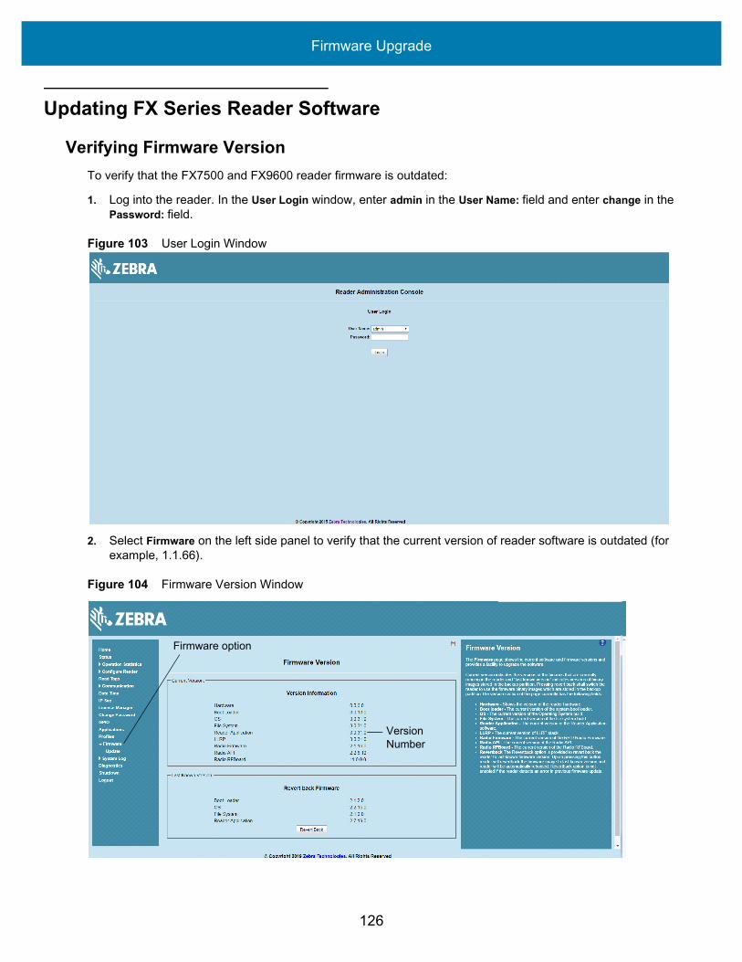
Verifying Firmware VersionTo verify that the FX7500 and FX9600 reader firmware is outdated:
1. Log into the reader. In the User Login window, enter admin in the User Name: field and enter change in the Password: field.
Figure 103 User Login Window
2. Select Firmware on the left side panel to verify that the current version of reader software is outdated (for example, 1.1.66).
Figure 104 Firmware Version Window
Firmware option
Version Number

Firmware Upgrade
127
Updating MethodsDownload the reader update files from www.zebra.com/support:, then use one of three methods to update the reader software to a later version, e.g., 1.1.45.0 or higher:
• Update Using a USB Drive (Recommended)• File-Based Update on page 128• FTP-Based Update on page 131
Update Using a USB Drive (Recommended)1. Copy all reader update files into the root folder of the USB drive.
Figure 105 USB Drive Root Folder
2. Insert the USB drive into the USB host port of the RFID reader.
Figure 106 FX7500 USB Host Port Window
Figure 107 FX9600 USB Host Port Window
Port 1 Port 2 Port 3 Port 4 GPIO 24 VDC
USB Host Port
USB Host Port
USB Host Port USB Client Port

Firmware Upgrade
128
The reader starts the update process in 5 - 7 seconds, and indicates progress as follows:
• The reader continuously blinks the Power LED red.• The reader blinks all four LEDs orange once.• The reader Power LED remains steady orange. • The reader Power LED settles to a steady green to indicate that the update is complete.
Figure 108 FX7500 Reader LEDs
Figure 109 FX9600 Reader LEDs
File-Based Update1. Copy all reader update files into any folder on a host computer.
Power LED
Power LED

Firmware Upgrade
129
Figure 110 Host Computer Folder
2. Log into the reader and navigate to the Firmware Update page.
Figure 111 Firmware Update Window

Firmware Upgrade
130
3. Select File based Upload.
Figure 112 Firmware Update Window
4. Select Browse and navigate to the folder or files that contains the firmware update files.
Figure 113 Browsing Update Folders
Firmware Upgrade
131
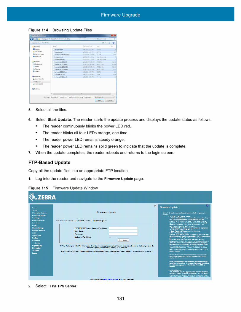
Figure 114 Browsing Update Files
5. Select all the files.
6. Select Start Update. The reader starts the update process and displays the update status as follows:• The reader continuously blinks the power LED red.• The reader blinks all four LEDs orange, one time.• The reader power LED remains steady orange.• The reader power LED remains solid green to indicate that the update is complete.
7. When the update completes, the reader reboots and returns to the login screen.
FTP-Based UpdateCopy all the update files into an appropriate FTP location.
1. Log into the reader and navigate to the Firmware Update page.
Figure 115 Firmware Update Window
2. Select FTP/FTPS Server.

Firmware Upgrade
132
3. Enter the FTP location where the files are located. 4. Enter the User Name and Password for the FTP server login.5. Select Start Update. The reader starts the update process and displays the update status as follows:
• The reader continuously blinks the Power LED red.• The reader blinks all 4 LEDs orange once.• The reader Power LED remains steady orange. • The reader Power LED settles to a steady green to indicate that the update is complete.
6. When the update completes, the reader reboots and returns to the FX login screen.
Verifying Firmware VersionTo verify reader update success:
1. Log into the reader. In the User Login window, enter admin in the User Name: field and enter change in the Password: field.
Figure 116 User Login Window
2. Select Firmware on the left side panel to verify that the current version of reader software is the new version number, e.g., 1.1.68, which indicates that the update was successful.

Firmware Upgrade
133
Figure 117 Firmware Version Window
Version Number

134
Troubleshooting
TroubleshootingTable 13 provides FX Series troubleshooting information.
NOTE: If problems still occur, contact the distributor or call the local contact. See page 11 for contact information.
Table 13 Troubleshooting
Problem/Error Possible Causes Possible SolutionsReader error LED lights after the reader is in operation.
The CPU cannot communicate.
Refer to the system log for error messages.
Reader error LED stays lit on power up.
An error occurred during the power up sequence.
Refer to the system log for error messages.
Cannot access the Administrator Console.
User name and password is unknown.
The default user name is admin and the default password is change. To change the user name and password, see Communications and Power Connections on page 29.
Reader is not reading tags. The tag is out of its read range.
Move the tag into read range. See Read Tags on page 67.
Antennas are not connected. Connect antennas.
Tags are damaged. Confirm that tags are good.
Tags are not EPCgen2. Confirm that tags are EPCgen2.
Cannot connect to the reader. The IP address is unknown. See Communications and Power Connections on page 29 to view the IP address, or use the host name to connect to the reader.

Troubleshooting
135
Certain real time applications are no longer functional.
The node address, IP address, or other reader configuration parameter(s) were changed using the Administrator Console, and the application expects the previous configuration.
Update the settings within the application. Refer to the application manual.
The user closed the browser without logging out of the Administrator Console, so other applications cannot connect to the reader.
Log out of the Administrator Console. The applications can use the Force Login option to log in even when the user closes the browser without logging out. Force Login option is supported for the administrative user.
Cannot log into Administrator Console.
The user forgot the password.
Press and hold the reset button for more than 8 seconds. This resets the reader configuration to factory defaults, including the password. This also removes the contents of the apps partition.
Unable to add SNTP server, reader returning error: Error: Cannot find the specified Host Address
SNTP server is not reachable.
Ensure the SNTP server is accessible.
SNTP server name is not resolvable via DNS server.
Ensure the DNS server name is configured in TCP/IP configuration.
DNS server is not reachable. Ensure the DNS server is accessible.
Operation failed. A user operation did not complete, typically due to invalid input.
Validate all inputs and retry the operation. If it is not successful, see Service Information on page 11.
Invalid User Name and/or Password - Try again.
The user name and/or password were not found in the system, or do not match the current user registry.
Accurately retype login information. If this is not successful, see Service Information on page 11.
Session has Timed-out - Log in again.
The current session was inactive beyond the time-out period (15 minutes), so the system automatically logged out.
Log in again. As a security precaution to protect against unauthorized system access, always log out of the system when finished.
Table 13 Troubleshooting (Continued)
Problem/Error Possible Causes Possible Solutions

Troubleshooting
136
User name is not correct. The user name does not match the current user registry (illegal characters, too long, too short, unknown, or duplicate).
Accurately retype the user name.
User forgot the user ID.Web console supports the following users:- Admin (default password is change)- Guest (no password required)- rfidadm - supported over SSH,FTP/FTPS, SCP, but not over Administrator Console.
Reset the reader to factory defaults and select Admin for user name and enter change in the password field to regain access. See Reset to Factory Defaults LED Sequence on page 34.
Not a legal IP address (1.0.0.0 - 255.255.255.255).Cannot reach the specified IP address.The SNMP Host Link is not valid.
The IP address entered is either formatted inaccurately or cannot be accessed (pinged).
Accurately retype the IP address, and make sure the host device is connected and online. If this is not successful, see Service Information on page 11.
Invalid network mask. The network mask entered is not formatted correctly.
Confirm the correct network mask from the network administrator and enter it correctly.
Invalid SNMP version number. The version number for SNMP protocol is not a supported version.
Use version number 1 for SNMP version 1, and 2 for SNMP version 2c.
Invalid description. The description contained invalid characters (<,>,or').
Correct the description.
Invalid password. The password does not match the current user registry (illegal characters, too long, or too short).
Accurately retype the password.
User forgot the password. Reset the reader to factory defaults and select Admin for user name and enter change in the password field to regain access. See Reset to Factory Defaults LED Sequence on page 34.
The name, serial number, or IP address entered already exists in the system.
The name, serial number, or IP address entered was already used.
Enter a unique value for the new name, serial number, or IP address.
Another administrator is currently logged in. Try again later.
The system does not allow more than one administrator to log in at a time.
Wait until the other administrator logs out (or times out) before logging in or override the current session with the new one.
Table 13 Troubleshooting (Continued)
Problem/Error Possible Causes Possible Solutions

Troubleshooting
137
Backup configuration file does not exist.
The system cannot revert to a backup configuration unless a backup file exists.
Commit the new configuration to create a backup file.
Failed to confirm the new password.
The system requires entering the password identically two times.
Accurately retype the password twice.
Network configuration change(s) have not been saved.
The user requested log out prior to setting and storing the changes made during the session.
Select Set Properties to update the network configuration.
New password is the same as the old one.
The system requires entering a new password (different from the existing password) during the Change Password operation.
Enter a password that is different from the existing password.
Old password is not correct. The system requires entering the existing password during the Change Password operation.
Accurately retype the existing password.
Unspecified error occurred - code: ####
A specific error message is missing for the given status code.
Note the code number, and contact Zebra support. See Service Information on page 11.
The requested page was not found.Internal Web Server Error.
The system experienced an internal web server error.
Contact Zebra support. See Service Information on page 11
Request method was NULL.No query string was provided.
The system does not permit executing a proxy program from the command line rather than the web server.
No action required. The system is reporting that this action is not permitted.
Content length is unknown. The system cannot accept an incorrectly formatted HTTP POST request (from an unsupported browser application).
Use a GET request instead, or update the software.
Couldn't read complete post message.
The system stopped a POST operation before completion.
Retry the operation, and allow it to complete.
Unhandled reply type. The system generated an unexpected value.
Contact Zebra support. See Service Information on page 11.
Failed to open port.Failed to connect.Failed to transmit.Failed to receive.Error during Receive of Command.
Error during receive of command.
Contact Zebra support. See Service Information on page 11.
Table 13 Troubleshooting (Continued)
Problem/Error Possible Causes Possible Solutions

Troubleshooting
138
Invalid Device Address. The device address information (parent) is invalid, missing, or formatted inaccurately.
Contact Zebra support. See Service Information on page 11.
Command parsing state error.Missing argument for the command.Command internal type cast error.Missing operator.Unknown operator.
A command was formatted inaccurately.
Contact Zebra support. See Service Information on page 11.
The action must be confirmed. The user must confirm the requested action before it is executed.
Select the confirmation option when issuing this request.
Invalid network adapter when navigating to the Bluetooth configuration page.
The Bluetooth dongle is not plugged in or not supported.
Plug in a supported Bluetooth dongle and refresh the browser.
Wireless scan error. Wireless dongle is not plugged in or not supported.
Plug in a supported wireless dongle and repeat the wireless scan.
Unable to connect to the wireless network.
Access point is off or unreachable.
Turn on the access point and make sure it is accessible.
Encryption type is not supported in the access point.
Use one of the following supported encryption types: WEP128, WPA/WPA2 and Open.
The wireless page displays Adapter not found.
Connect the wireless adapter to the reader.
Wireless connection is complete, but no IP address.
No DHCP server is running in the network.
Add a DHCP server to the network.
OS update in progress. Firmware update on the reader is ongoing. The current operation is not permitted.
Wait for the firmware update to complete and then retry the operation.
Table 13 Troubleshooting (Continued)
Problem/Error Possible Causes Possible Solutions

Troubleshooting
139
Cannot change password. Cannot change password for guest.
Guest does not need a password to log in to the Administrator Console.
The following reader web console pages do not load correctly:
• Advanced Antenna Configuration
• ReadTags• Services• Serial Port
Communication• FXConnect• License Manager• User Application• Profiles• File based firmware
upload• Syslog Export
Port 8001 is not accessible. Allow port 8001 to be accessible across the networks.These web pages all use port 8001 to communicate to the reader and without this port the pages cannot function.
Table 13 Troubleshooting (Continued)
Problem/Error Possible Causes Possible Solutions

140
Technical Specifications
Technical SpecificationsThe following tables summarize the RFID reader intended operating environment and technical hardware specifications.
Table 14 Technical Specifications
Item Description
Physical and Environmental Characteristics
Dimensions FX7500
FX9600
7.7 in. L x 5.9 in. W x 1.7 in. D(19.56 cm L x 14.99 cm W x 4.32 cm D)9.72 in. L x 7.25 in. W x 2.2 in. D(24.67 cm x 18.42 cm W x 5.56 cm D mm)
Weight FX7500FX9600
1.9 lbs ± 0.1 lbs (0.86 kg +/- 0.05 kg)4.5 lbs (2.1 kg)
Base MaterialFX7500FX9600
Die cast aluminum, sheet metal and plasticDie cast aluminum
Visual Status Indicators Multi-color LEDs: Power, Activity, Status, and Applications
MountingFX7500FX9600
Keyhole and standard VESA (75 mm x 75 mm)Four mounting flanges and Four 100 mm x 100 mm VESA holes for 10-32 screw.
FX Environmental Specifications
Operational Temperature -4° to +131° F / -20° to +55° C
Storage Temperature -40° to +158° F / -40° to +70° C
Humidity 5 to 95% non-condensing
Technical Specifications
141
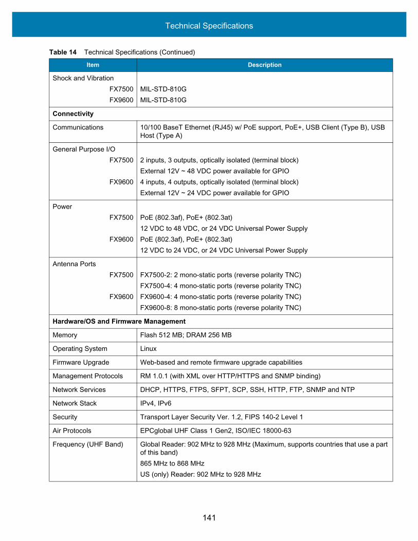
Shock and VibrationFX7500FX9600
MIL-STD-810GMIL-STD-810G
Connectivity
Communications 10/100 BaseT Ethernet (RJ45) w/ PoE support, PoE+, USB Client (Type B), USB Host (Type A)
General Purpose I/OFX7500
FX9600
2 inputs, 3 outputs, optically isolated (terminal block)External 12V ~ 48 VDC power available for GPIO4 inputs, 4 outputs, optically isolated (terminal block)External 12V ~ 24 VDC power available for GPIO
PowerFX7500
FX9600
PoE (802.3af), PoE+ (802.3at)12 VDC to 48 VDC, or 24 VDC Universal Power SupplyPoE (802.3af), PoE+ (802.3at)12 VDC to 24 VDC, or 24 VDC Universal Power Supply
Antenna PortsFX7500
FX9600
FX7500-2: 2 mono-static ports (reverse polarity TNC)FX7500-4: 4 mono-static ports (reverse polarity TNC)FX9600-4: 4 mono-static ports (reverse polarity TNC)FX9600-8: 8 mono-static ports (reverse polarity TNC)
Hardware/OS and Firmware Management
Memory Flash 512 MB; DRAM 256 MB
Operating System Linux
Firmware Upgrade Web-based and remote firmware upgrade capabilities
Management Protocols RM 1.0.1 (with XML over HTTP/HTTPS and SNMP binding)
Network Services DHCP, HTTPS, FTPS, SFPT, SCP, SSH, HTTP, FTP, SNMP and NTP
Network Stack IPv4, IPv6
Security Transport Layer Security Ver. 1.2, FIPS 140-2 Level 1
Air Protocols EPCglobal UHF Class 1 Gen2, ISO/IEC 18000-63
Frequency (UHF Band) Global Reader: 902 MHz to 928 MHz (Maximum, supports countries that use a part of this band)865 MHz to 868 MHzUS (only) Reader: 902 MHz to 928 MHz
Table 14 Technical Specifications (Continued)
Item Description

Technical Specifications
142
Cable Pinouts
10/100bT Ethernet / PoE ConnectorThe 10/100BT Ethernet / PoE connector is an RJ45 receptacle. This port complies with the IEE 802.3af specification for Powered Devices.
Figure 118 Ethernet Connections
Transmit Power OutputFX7500
FX9600
10dBm to +31.5dBm (PoE+, 12V ~ 48V External DC, Universal 24 VDC Power Supply;+10dBm to +30.0dBm (PoE)0dBm to +33.0dBm (PoE+, 12V ~ 24V External DC, Universal 24 VDC Power Supply;+0dBm to +31.5dBm (PoE)
Max Receive SensitivityFX7500FX9600
-82dBm-86dBm
IP Addressing Static and Dynamic
Host Interface Protocol LLRP v1.0.1
API Support Host Applications – .NET, C and Java EMDK;Embedded Applications – C & Java SDK
Warranty
For the complete Zebra hardware product warranty statement, go to: www.zebra.com/warranty
Recommended Services
Support Services Zebra One Care Select and Zebra One Care On Site
Advanced Services RFID Design and Deployment Services
Table 14 Technical Specifications (Continued)
Item Description
Technical Specifications
143
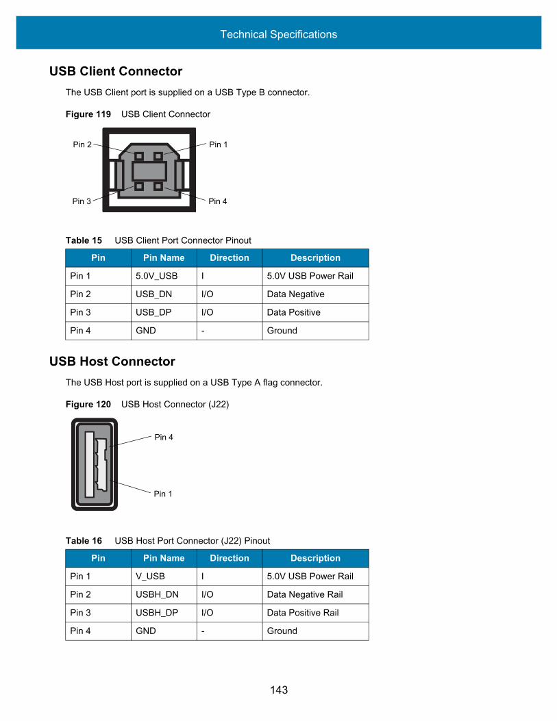
USB Client ConnectorThe USB Client port is supplied on a USB Type B connector.
Figure 119 USB Client Connector
USB Host ConnectorThe USB Host port is supplied on a USB Type A flag connector.
Figure 120 USB Host Connector (J22)
Table 15 USB Client Port Connector Pinout
Pin Pin Name Direction Description
Pin 1 5.0V_USB I 5.0V USB Power Rail
Pin 2 USB_DN I/O Data Negative
Pin 3 USB_DP I/O Data Positive
Pin 4 GND - Ground
Pin 4Pin 3
Pin 1Pin 2
Table 16 USB Host Port Connector (J22) Pinout
Pin Pin Name Direction Description
Pin 1 V_USB I 5.0V USB Power Rail
Pin 2 USBH_DN I/O Data Negative Rail
Pin 3 USBH_DP I/O Data Positive Rail
Pin 4 GND - Ground
Pin 1
Pin 4

Technical Specifications
144
FX7500 GPIO Port ConnectionsThe FX7500 GPIO connector pinouts include the following:
Figure 121 FX7500 RFID Reader GPIO Connection
FX9600 GPIO ConnectionsThe FX9600 GPIO connector pinouts include the following:
Figure 122 FX9600 RFID Reader GPIO Connection
Table 17 FX7500 GPIO Pinouts
Pin # Pin Name Direction Description
1 +24V DC Power O Supplies +24V DC at up to 1 Amp
2 GP output #1 O Signal for GP output #1
3 GP output #2 O Signal for GP output #2
4 GP output #3 O Signal for GP output #3
5 GND - Ground connection
6 GP input #1 I Signal for GP input #1
7 GP input #2 I Signal for GP input #2
8 GND - Ground connection
Pin 8Pin 1
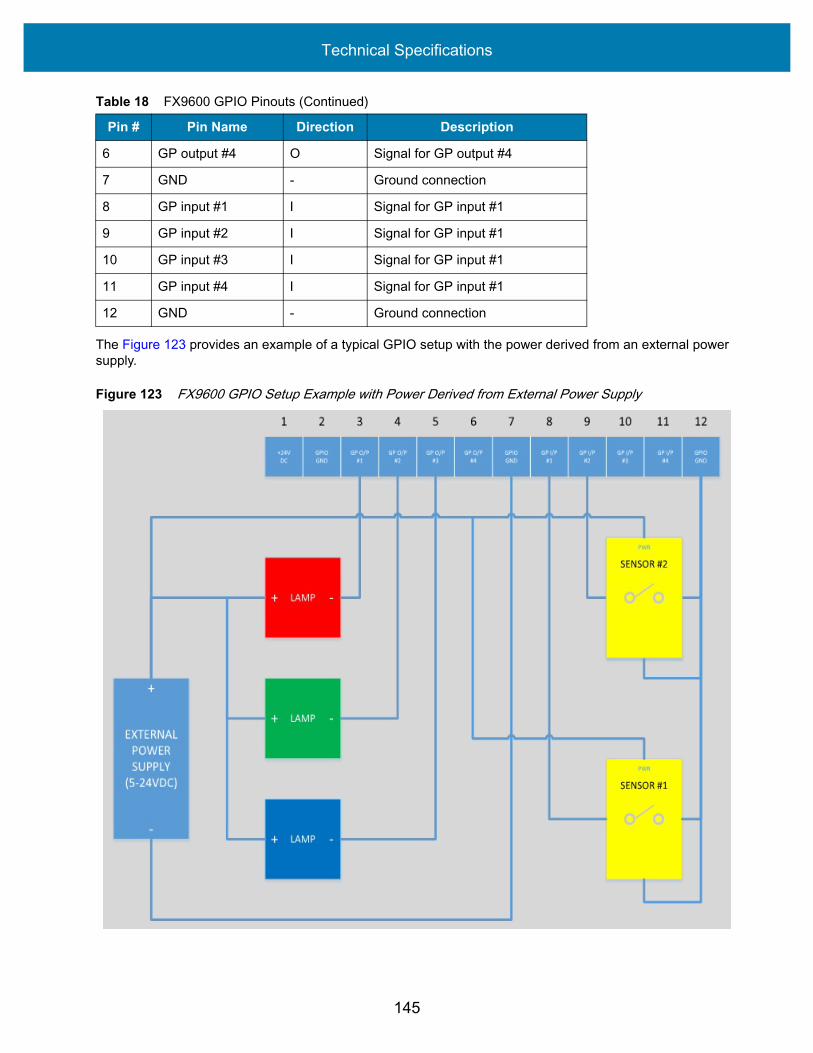
Table 18 FX9600 GPIO Pinouts
Pin # Pin Name Direction Description
1 +24V DC Power O Supplies +24VDC At up to 1 Amp
2 GND - Ground connection
3 GP output #1 O Signal for GP output #1
4 GP output #2 O Signal for GP output #2
5 GP output #3 O Signal for GP output #3
Pin 12Pin 1
Technical Specifications
145
The Figure 123 provides an example of a typical GPIO setup with the power derived from an external power supply.
Figure 123 FX9600 GPIO Setup Example with Power Derived from External Power Supply
6 GP output #4 O Signal for GP output #4
7 GND - Ground connection
8 GP input #1 I Signal for GP input #1
9 GP input #2 I Signal for GP input #1
10 GP input #3 I Signal for GP input #1
11 GP input #4 I Signal for GP input #1
12 GND - Ground connection
Table 18 FX9600 GPIO Pinouts (Continued)
Pin # Pin Name Direction Description

Technical Specifications
146
The Figure 124 provides an example of a typical GPIO setup with the power derived from GPIO 24V Pin.
Figure 124 FX9600 GPIO Setup Example with Power Derived from GPIO 24V Pin

147
Static IP Configuration
IntroductionThis chapter describes three methods of setting the static IP address on an FX7500 and FX9600 RFID Readers.
Reader IP Address or Host Name is Known Set the Static IP Using the Web Console
1. Browse the device using the host name, for example: FX7500CD3B1E.2. Log onto the device.
Figure 125 Reader Administration Console Login Window
3. Select Communication. 4. Set Obtain IP Address via DHCP to Off and enter all required information.

Static IP Configuration
148
Figure 126 Reader Communication Parameters Window
5. Select Set Properties. You can set a static IP that doesn't belong to this DHCP network.6. The window displays a Saving. Please wait... message with a progress symbol until the commit completes.7. When the commit completes, a gray floppy disk icon displays indicating that the commit completed
successfully. The new selection is now set and stored in the reader.8. The message Reader IP Address config has changed. Needs reader reboot to take effect appears. Reset the
device and use the reader with the static IP network.

Static IP Configuration
149
Reader IP is Not Known (DHCP Network Not Available) Set the Static IP Using the Web Console
1. Connect the device and a PC running Windows XP to the same network that doesn't have a DHCP server, or connect the device directly to the PC.
2. Ensure both the device and PC Ethernet jack use at least one LED to indicate network connection detect.3. If the PC uses an assigned static IP, update it to use DHCP. The PC obtains an IP that starts with 169.
Figure 127 Obtain IP Address
4. When possible, ping the host name of the device.
Figure 128 Ping the Host Name
5. Use a browser to connect to the device with the host name, for example: FX7500CD3B1E, or use the IP address obtained from ping replies (for example, 169.254.62.74).
6. Log onto the device. 7. Select Communication. 8. Set Obtain IP Address via DHCP to Off and enter all required information.

Static IP Configuration
150
Figure 129 Reader Communication Parameters Window
9. Select Set Properties. 10. The window displays a Saving. Please wait... message with a progress symbol until the commit completes.11. When the commit completes, a gray floppy disk icon displays indicating that the commit completed
successfully. The new selection is now set and stored in the reader.12. The message Reader IP Address config has changed. Needs reader reboot to take effect appears. Reset the
device and use the reader with the static IP network.

151
RF Air Link Configuration
IntroductionThis appendix lists the different air link configurations supported. The air link configuration is available through LLRP and RFID3 API interfaces.
Radio ModesThe supported modes are exposed as a list of individual UHFC1G2RfModeTableEntry parameters in regulatory capabilities as shown in Table 19 and Table 20. The Mode Index column refers to the index used to walk the C1G2UHFRFModeTable. Refer to the EPCglobal Low Level Reader Protocol (LLRP) Standard.
Table 19 Radio Modes for FCC Readers
RF Mode Index
Divide Ratio
BDR Value
M Value M2=2,
FM0=1, M4=4,M8=8
FLM Value
PIE Value
Min Tari
Max Tari
Step Tari
Spectral Mask
Indicator**
EPC HAG T&C
Conform-ance
1 64/3 640000 1 PR_ASK 1500 6250 6250 0 Dense false
2 64/3 640000 1 PR_ASK 2000 6250 6250 0 Dense false
3 64/3 120000 2 PR_ASK 1500 25000 25000 0 Dense false
4 64/3 120000 2 PR_ASK 1500 12500 23000 2100 Dense false
5 64/3 120000 2 PR_ASK 2000 25000 25000 0 Dense false
6 64/3 120000 2 PR_ASK 2000 12500 23000 2100 Dense false
7 64/3 128000 2 PR_ASK 1500 25000 25000 0 Dense false
8 64/3 128000 2 PR_ASK 1500 12500 23000 2100 Dense false
9 64/3 128000 2 PR_ASK 2000 25000 25000 0 Dense false
10 64/3 128000 2 PR_ASK 2000 12500 23000 2100 Dense false
11 64/3 160000 2 PR_ASK 1500 12500 18800 2100 Dense false
*RF Mode 23 is the automac air link profile which is also the default.**Spectral mask indicator may vary for certain Tari values. Detailed information is available upon request.

RF Air Link Configuration
152
12 64/3 160000 2 PR_ASK 2000 12500 18800 2100 Dense false
13 64/3 60000 4 PR_ASK 1500 25000 25000 0 Dense false
14 64/3 60000 4 PR_ASK 1500 12500 23000 2100 Dense false
15 64/3 60000 4 PR_ASK 2000 25000 25000 0 Dense false
16 64/3 60000 4 PR_ASK 2000 12500 23000 2100 Dense false
17 64/3 64000 4 PR_ASK 1500 25000 25000 0 Dense false
18 64/3 64000 4 PR_ASK 1500 12500 23000 2100 Dense false
19 64/3 64000 4 PR_ASK 2000 25000 25000 0 Dense false
20 64/3 64000 4 PR_ASK 2000 12500 23000 2100 Dense false
21 64/3 80000 4 PR_ASK 1500 12500 18800 2100 Dense false
22 64/3 80000 4 PR_ASK 2000 12500 18800 2100 Dense false
*23 64/3 variable variable PR_ASK variable 6250 25000 variable variable false
24 64/3 320000 1 PR_ASK 1500 12500 18800 2100 Dense false
25 64/3 320000 1 PR_ASK 2000 12500 18800 2100 Dense false
26 64/3 30000 8 PR_ASK 1500 25000 25000 0 Dense false
27 64/3 30000 8 PR_ASK 1500 12500 23000 2100 Dense false
28 64/3 30000 8 PR_ASK 2000 25000 25000 0 Dense false
29 64/3 30000 8 PR_ASK 2000 12500 23000 2100 Dense false
30 64/3 32000 8 PR_ASK 1500 25000 25000 0 Dense false
31 64/3 32000 8 PR_ASK 1500 12500 23000 2100 Dense false
32 64/3 32000 8 PR_ASK 2000 25000 25000 0 Dense false
33 64/3 32000 8 PR_ASK 2000 12500 23000 2100 Dense false
34 64/3 40000 8 PR_ASK 1500 12500 18800 2100 Dense false
35 64/3 40000 8 PR_ASK 2000 12500 18800 2100 Dense false
Table 19 Radio Modes for FCC Readers (Continued)
RF Mode Index
Divide Ratio
BDR Value
M Value M2=2,
FM0=1, M4=4,M8=8
FLM Value
PIE Value
Min Tari
Max Tari
Step Tari
Spectral Mask
Indicator**
EPC HAG T&C
Conform-ance
*RF Mode 23 is the automac air link profile which is also the default.**Spectral mask indicator may vary for certain Tari values. Detailed information is available upon request.

RF Air Link Configuration
153
Table 20 Radio Modes for ETSI Readers
RF Mode Index
Divide Ratio
BDR Value
M Value M2=2,
FM0=1, M4=4,M8=8
FLM Value
PIE Value
Min Tari
Max Tari
Step Tari
Spectral Mask
Indica-tor**
EPC HAG T&C
Conform-ance
1 64/3 120000 2 PR_ASK 1500 25000 25000 0 Dense false
2 64/3 120000 2 PR_ASK 1500 12500 23000 2100 Dense false
3 64/3 120000 2 PR_ASK 2000 25000 25000 0 Dense false
4 64/3 120000 2 PR_ASK 2000 12500 23000 2100 Dense false
5 64/3 128000 2 PR_ASK 1500 25000 25000 0 Dense false
6 64/3 128000 2 PR_ASK 1500 12500 23000 2100 Dense false
7 64/3 128000 2 PR_ASK 2000 25000 25000 0 Dense false
8 64/3 128000 2 PR_ASK 2000 12500 23000 2100 Dense false
9 64/3 160000 2 PR_ASK 1500 12500 18800 2100 Dense false
10 64/3 160000 2 PR_ASK 2000 12500 18800 2100 Dense false
11 64/3 60000 4 PR_ASK 1500 25000 25000 0 Dense false
12 64/3 60000 4 PR_ASK 1500 12500 23000 2100 Dense false
13 64/3 60000 4 PR_ASK 2000 25000 25000 0 Dense false
14 64/3 60000 4 PR_ASK 2000 12500 23000 2100 Dense false
15 64/3 64000 4 PR_ASK 1500 25000 25000 0 Dense false
16 64/3 64000 4 PR_ASK 1500 12500 23000 2100 Dense false
17 64/3 64000 4 PR_ASK 2000 25000 25000 0 Dense false
18 64/3 64000 4 PR_ASK 2000 12500 23000 2100 Dense false
19 64/3 80000 4 PR_ASK 1500 12500 18800 2100 Dense false
20 64/3 80000 4 PR_ASK 2000 12500 18800 2100 Dense false
*21 64/3 variable variable PR_ASK variable 12500 25000 variable variable false
22 64/3 320000 1 PR_ASK 1500 12500 18800 2100 Dense false
23 64/3 320000 1 PR_ASK 2000 12500 18800 2100 Dense false
24 64/3 30000 8 PR_ASK 1500 25000 25000 0 Dense false
25 64/3 30000 8 PR_ASK 1500 12500 23000 2100 Dense false
26 64/3 30000 8 PR_ASK 2000 25000 25000 0 Dense false
27 64/3 30000 8 PR_ASK 2000 12500 23000 2100 Dense false
*RF Mode 21 is the automac air link profile which is also the default.**Spectral mask indicator may vary for certain Tari values. Detailed information is available upon request.

RF Air Link Configuration
154
28 64/3 32000 8 PR_ASK 1500 25000 25000 0 Dense false
29 64/3 32000 8 PR_ASK 1500 12500 23000 2100 Dense false
30 64/3 32000 8 PR_ASK 2000 25000 25000 0 Dense false
31 64/3 32000 8 PR_ASK 2000 12500 23000 2100 Dense false
32 64/3 40000 8 PR_ASK 1500 12500 18800 2100 Dense false
33 64/3 40000 8 PR_ASK 2000 12500 18800 2100 Dense false
Table 20 Radio Modes for ETSI Readers (Continued)
RF Mode Index
Divide Ratio
BDR Value
M Value M2=2,
FM0=1, M4=4,M8=8
FLM Value
PIE Value
Min Tari
Max Tari
Step Tari
Spectral Mask
Indica-tor**
EPC HAG T&C
Conform-ance
*RF Mode 21 is the automac air link profile which is also the default.**Spectral mask indicator may vary for certain Tari values. Detailed information is available upon request.

155
Copying Files To and From the Reader
IntroductionThe FX7500 and FX9600 RFID readers support the SCP, FTP, and FTPS protocols for copying files.
SCPThe following examples illustrate SCP use:
scp SourceFileName rfidadm@MyReaderIP:/apps
scp rfidadm@MyReaderIP:/apps/SourceFileName userid@MyLinuxMachineIP:/MyFolderName
FTPThe following examples illustrate FTP use:
ftp> open
To 157.235.207.146
Connected to 157.235.207.146.
220 Welcome to Thredbo FTP service.
User (157.235.207.146:(none)): rfidadm
331 Please specify the password.
Password:
230 Login successful.
ftp>
Use FTP commands such as is, get, and put to manage files. For more information on FTP commands refer to www.cs.colostate.edu/helpdocs/ftp.html. GUI applications such as FileZilla are also supported on Windows and Linux machines to connect to the FX7500 and FX9600.
FTPSUse any standard GUI tool such as FileZilla, to connect to the FX7500 and FX9600 RFID readers over FTPS.

156
Data Protection
IntroductionThe FX7500 and FX9600 RFID readers store data in transition when it detects a network condition that prevents the reader from sending data. This applies to RFID tag data that the reader application is transmitting to the outbound TCP socket, and is no longer owned by the RFID application because it was sent to the network layer for transmission.
When the reader cannot queue RFID data in the outbound TCP socket when an LLRP connection is already established, it stores all outbound LLRP messages in the data protection queue. The queue can store up to 66,000 messages, which represents more than 5 minutes worth of data when reading 200 tags/second (the nominal data rate in DRM (dense reader mode) configuration). If the network is still unavailable when the data protection queue is full, the oldest messages are discarded to accommodate the most recent tag reports.
This feature can not be disabled and operates regardless of the physical network interface used, meaning RFID data over Wi-Fi and Bluetooth is also protected.

157
Index
Numerics10/100BaseT Ethernet . . . . . . . . . . . . . 13, 19, 20, 21, 23123RFID Desktop
features . . . . . . . . . . . . . . . . . . . . . . . . . . . . . . . . . 37requirements . . . . . . . . . . . . . . . . . . . . . . . . . . . . . 37
Aadministrator console . . . . . . . . . . . . . . . . . . . . . . . . . 38
applications . . . . . . . . . . . . . . . . . . . . . . . . . . . . . 100committing changes . . . . . . . . . . . . . . . . . . . . . . 103communication settings . . . . . . . . . . . . . . . . . . . . 68configure network services . . . . . . . . . . . . . . . . . . 74configure network settings . . . . . . . . . . . . 68, 69, 70configuring system log . . . . . . . . . . . . . . . . . . . . 108discarding changes . . . . . . . . . . . . . . . . . . . . . . . 103firmware version . . . . . . . . . . . . . . . . . . . . . 102, 103GPIO . . . . . . . . . . . . . . . . . . . . . . . . . . . . . . . . . . . 99IPV6 sec . . . . . . . . . . . . . . . . . . . . . . . . . . . . . . . . 97login . . . . . . . . . . . . . . . . . . . . . . . . . . . . . . . . . . . 43main screen . . . . . . . . . . . . . . . . . . . . . . . . . . . . . 45managing login . . . . . . . . . . . . . . . . . . . . . . . . . . . 99reader diagnostics . . . . . . . . . . . . . . . . . . . . . . . . 109reader profiles . . . . . . . . . . . . . . . . . . . . . . . . . . . 101scan control . . . . . . . . . . . . . . . . . . . . . . . . . . . 17, 67set password . . . . . . . . . . . . . . . . . . . . . . . . . . . . . 98setting date and time . . . . . . . . . . . . . . . . . . . . . . . 96shutting down . . . . . . . . . . . . . . . . . . . . . . . . . . . 110status . . . . . . . . . . . . . . . . . . . . . . . . . . . . . . . . . . 47system log . . . . . . . . . . . . . . . . . . . . . . . . . . . . . . 107
air link . . . . . . . . . . . . . . . . . . . . . . . . . . . . . . . . . . . . 151antennas
configuring . . . . . . . . . . . . . . . . . . . . . . . . . . . . . . 55installing . . . . . . . . . . . . . . . . . . . . . . . . . . . . . . . . 28ports . . . . . . . . . . . . . . . . . . . . . . . 13, 19, 20, 21, 22
applications . . . . . . . . . . . . . . . . . . . . . . . . . . . . . . . . 100
Bbluetooth . . . . . . . . . . . . . . . . . . . . . . . . . . . . . . 119, 120
connecting . . . . . . . . . . . . . . . . . . . . . . . . . . 119, 120
Ccable pinouts
ethernet . . . . . . . . . . . . . . . . . . . . . . . . . . . . . . . 142GPIO . . . . . . . . . . . . . . . . . . . . . . . . . . . . . . . . . . 144USB . . . . . . . . . . . . . . . . . . . . . . . . . . . . . . . . . . 143USB client . . . . . . . . . . . . . . . . . . . . . . . . . . . . . . 143USB host . . . . . . . . . . . . . . . . . . . . . . . . . . . . . . 143
chapter descriptions . . . . . . . . . . . . . . . . . . . . . . . . . . 10commit region change . . . . . . . . . . . . . . . . . . . . . . . . . 15committing changes . . . . . . . . . . . . . . . . . . . . . . . . . 103communication . . . . . . . . . . . . . . . . . . . . . . . . . . . 20, 22
ethernet, wired . . . . . . . . . . . . . . . . . . . . . . . . . . . 29communication settings . . . . . . . . . . . . . . . . . . . . . . . . 68configure
antenna . . . . . . . . . . . . . . . . . . . . . . . . . . . . . . . . . 55LLRP . . . . . . . . . . . . . . . . . . . . . . . . . . . . . . . . . . . 71read points . . . . . . . . . . . . . . . . . . . . . . . . . . . 54, 55reader . . . . . . . . . . . . . . . . . . . . . . . . . . . . . . . . . . 53region . . . . . . . . . . . . . . . . . . . . . . . . . . . . . . . . . . 56SNMP . . . . . . . . . . . . . . . . . . . . . . . . . . . . . . . . . . 72static IP . . . . . . . . . . . . . . . . . . . . . . . . . . . . . . . . 147static IP via web console . . . . . . . . . . . . . . 147, 149wireless . . . . . . . . . . . . . . . . . . . . . . . . . . . . . . . . . 73
configuring networkbluetooth . . . . . . . . . . . . . . . . . . . . . . . . . . . . . . . . 70ethernet . . . . . . . . . . . . . . . . . . . . . . . . . . . . . . . . 68services . . . . . . . . . . . . . . . . . . . . . . . . . . . . . . . . 74wi-fi . . . . . . . . . . . . . . . . . . . . . . . . . . . . . . . . . . . . 69
connectingto reader . . . . . . . . . . . . . . . . . . . . . . . . . . . . . . . . 41via bluetooth . . . . . . . . . . . . . . . . . . . . . . . . 119, 120via host name . . . . . . . . . . . . . . . . . . . . . . . . . . . . 42via IP address . . . . . . . . . . . . . . . . . . . . . . . . . . . . 42via wi-fi . . . . . . . . . . . . . . . . . . . . . . . . . . . . . . . . 116
connectionantennas . . . . . . . . . . . . . . . . . . . . . . . . . . . . . . . . 28communication . . . . . . . . . . . . . . . . . . . . . . . . . . . 29port diagram . . . . . . . . . . . . . . . . . . . . . . . . . . . . . 22ports . . . . . . . . . . . . . . . . . . . . . . . . . . . . . . . . 19, 21wired ethernet . . . . . . . . . . . . . . . . . . . . . . . . . . . . 29
conventions

Index
158
notational . . . . . . . . . . . . . . . . . . . . . . . . . . . . . . . 11copying files . . . . . . . . . . . . . . . . . . . . . . . . . . . . 122, 155country list . . . . . . . . . . . . . . . . . . . . . . . . . . . . . . . . . . 15
Ddata protection . . . . . . . . . . . . . . . . . . . . . . . . . . . . . . 156date . . . . . . . . . . . . . . . . . . . . . . . . . . . . . . . . . . . . . . . 96deployments . . . . . . . . . . . . . . . . . . . . . . . . . . . . . . . . 39discarding changes . . . . . . . . . . . . . . . . . . . . . . . . . . 103
Eethernet
pinouts . . . . . . . . . . . . . . . . . . . . . . . . . . . . . . . . 142POE . . . . . . . . . . . . . . . . . . . . . . . . . . . . . . . . . . . 30port . . . . . . . . . . . . . . . . . . . . . . . . . . . . . . . . . 20, 23setup . . . . . . . . . . . . . . . . . . . . . . . . . . . . . . . . 29, 30wired . . . . . . . . . . . . . . . . . . . . . . . . . . . . . . . . . . . 29
event statistics . . . . . . . . . . . . . . . . . . . . . . . . . . . . . . . 51
Ffiles
copying . . . . . . . . . . . . . . . . . . . . . . . . . . . . 122, 155firmware
version . . . . . . . . . . . . . . . . . . . . . . . . . . . . 102, 103firmware update . . . . . . . . . . . . . . . . . . . . . 102, 103, 126
prerequisites . . . . . . . . . . . . . . . . . . . . . . . . . . . . 124first time login . . . . . . . . . . . . . . . . . . . . . . . . . . . . 14, 43FTP
copying files . . . . . . . . . . . . . . . . . . . . . . . . 122, 155FTPS
copying files . . . . . . . . . . . . . . . . . . . . . . . . . . . . 155FX Connect
http proxy server . . . . . . . . . . . . . . . . . . . . . . . . . . 85licensing
acquisition modes . . . . . . . . . . . . . . . . . . . . . . 90activating . . . . . . . . . . . . . . . . . . . . . . . . . . . . 94cloud acquisition . . . . . . . . . . . . . . . . . . . . . . . 90download capability response . . . . . . . . . . . . 93local license server acquisition . . . . . . . . . . . . 91managing license . . . . . . . . . . . . . . . . . . . 91, 94off-line acquisition . . . . . . . . . . . . . . . . . . . . . . 93
licensing evaluationenabling license . . . . . . . . . . . . . . . . . . . . . . . 89perpetual license . . . . . . . . . . . . . . . . . . . . . . 89
licensing model . . . . . . . . . . . . . . . . . . . . . . . . . . . 89running inventory . . . . . . . . . . . . . . . . . . . . . . . . . 83USB HID . . . . . . . . . . . . . . . . . . . . . . . . . . . . . . . . 85using . . . . . . . . . . . . . . . . . . . . . . . . . . . . . . . . . . . 77
GGPIO . . . . . . . . . . . . . . . . . . . . . . . . . . . . . . . . 13, 19, 21
GPIO connections . . . . . . . . . . . . . . . . . . . . . . . .144pinouts . . . . . . . . . . . . . . . . . . . . . . . . . . . . . . . . .144port . . . . . . . . . . . . . . . . . . . . . . . . . . . . . . . . .20, 22
GPIO control . . . . . . . . . . . . . . . . . . . . . . . . . . . . . . . .99
Hhost communication
ethernet, wired . . . . . . . . . . . . . . . . . . . . . . . . . . . .29host name connect . . . . . . . . . . . . . . . . . . . . . . . . . . .14
Iinformation, service . . . . . . . . . . . . . . . . . . . . . . . . . . .11initiating reads . . . . . . . . . . . . . . . . . . . . . . . . . . . .17, 67installation
antennas . . . . . . . . . . . . . . . . . . . . . . . . . . . . . . . .28communication connection . . . . . . . . . . . . . . . . . .29mounting . . . . . . . . . . . . . . . . . . . . . . . . . . . . . . . .25
IP address . . . . . . . . . . . . . . . . . . . . . . . . . . . . . . . . . .41IP ping . . . . . . . . . . . . . . . . . . . . . . . . . . . . . . . . . . . . .41
LLEDs . . . . . . . . . . . . . . . . . . . . . . . . . . . . . . . . . . .20, 23LLRP
configure . . . . . . . . . . . . . . . . . . . . . . . . . . . . . . . .71radio modes . . . . . . . . . . . . . . . . . . . . . . . . .151, 153
log . . . . . . . . . . . . . . . . . . . . . . . . . . . . . . . . . . . . . . .107configuring . . . . . . . . . . . . . . . . . . . . . . . . . . . . . .108
login . . . . . . . . . . . . . . . . . . . . . . . . . . . . . . . . . . . . . . .43first time . . . . . . . . . . . . . . . . . . . . . . . . . . . . . . . . .43managing . . . . . . . . . . . . . . . . . . . . . . . . . . . . . . . .99
Mmounting . . . . . . . . . . . . . . . . . . . . . . . . . . . . . . . .25, 27
concrete wall mounting . . . . . . . . . . . . . . . . . . . . .27drywall mounting . . . . . . . . . . . . . . . . . . . . . . . . . .27wood or metal wall mounting . . . . . . . . . . . . . . . . .27
mounting plate . . . . . . . . . . . . . . . . . . . . . . . . . . . . . . .25multiple reader deployments . . . . . . . . . . . . . . . . . . . .39
NNXP
statistics . . . . . . . . . . . . . . . . . . . . . . . . . . . . . .50, 52
Oobtain reader IP address . . . . . . . . . . . . . . . . . . . . . . .41
PPassword . . . . . . . . . . . . . . . . . . . . . . . . . . .14, 126, 132

Index
159
password . . . . . . . . . . . . . . . . . . . . . . . . 14, 43, 126, 132changing . . . . . . . . . . . . . . . . . . . . . . . . . . . . . . . . 98
pinoutsethernet . . . . . . . . . . . . . . . . . . . . . . . . . . . . . . . . 142GPIO . . . . . . . . . . . . . . . . . . . . . . . . . . . . . . . . . . 144USB . . . . . . . . . . . . . . . . . . . . . . . . . . . . . . . . . . . 143USB client . . . . . . . . . . . . . . . . . . . . . . . . . . . . . . 143USB host . . . . . . . . . . . . . . . . . . . . . . . . . . . . . . . 143
POE . . . . . . . . . . . . . . . . . . . . 13, 19, 20, 21, 23, 30, 142ports . . . . . . . . . . . . . . . . . . . . . . . . . . . . . . . . . . . . 19, 21
descriptions . . . . . . . . . . . . . . . . . . . . . . . . . . . 20, 22ethernet . . . . . . . . . . . . . . . . . . . . . . . . . . . . . . . . . 29
power . . . . . . . . . . . . . . . . . . . . . . . . . . . . . . . . 13, 19, 21POE . . . . . . . . . . . . . . . . . . . . . . . . . . . . . . . . . . . 30port . . . . . . . . . . . . . . . . . . . . . . . . . . . . . . . . . 20, 23
profiles . . . . . . . . . . . . . . . . . . . . . . . . . . . . . . . . . . . . 101
Rread points . . . . . . . . . . . . . . . . . . . . . . . . . . . . . . . 54, 55reader
configuration . . . . . . . . . . . . . . . . . . . . . . . . . . . . . 53connecting . . . . . . . . . . . . . . . . . . . . . . . . . . . . . . . 41GEN2 statistics . . . . . . . . . . . . . . . . . . . . . . . . . . . 49profiles . . . . . . . . . . . . . . . . . . . . . . . . . . . . . . . . 101statistics . . . . . . . . . . . . . . . . . . . . . . . . . . . . . . . . 48
event . . . . . . . . . . . . . . . . . . . . . . . . . . . . . . . . 51NXP . . . . . . . . . . . . . . . . . . . . . . . . . . . . . 50, 52
status . . . . . . . . . . . . . . . . . . . . . . . . . . . . . . . . . . 47reading tags . . . . . . . . . . . . . . . . . . . . . . . . . . . . . . . . . 35
initiating . . . . . . . . . . . . . . . . . . . . . . . . . . . . . . 17, 67rear panel . . . . . . . . . . . . . . . . . . . . . . . . . . . . . . . 13, 22reboot . . . . . . . . . . . . . . . . . . . . . . . . . . . . . . . . . . . . . 39region . . . . . . . . . . . . . . . . . . . . . . . . . . . . . . . . . . . . . . 44region configuration . . . . . . . . . . . . . . . . . . . . . . . . . . . 56region control . . . . . . . . . . . . . . . . . . . . . . . . . . . . . . . . 44region setting . . . . . . . . . . . . . . . . . . . . . . . . . . . . . . . . 15region settings . . . . . . . . . . . . . . . . . . . . . . . . . . . . . . . 15reset . . . . . . . . . . . . . . . . . . . . . . . . . . . 13, 19, 20, 21, 22RFID
FX reader . . . . . . . . . . . . . . . . . . . . . . . . . . . . 18, 21RJ45 . . . . . . . . . . . . . . . . . . . . . . . . . . . . . . . . . . . 20, 23
SSCP
copying files . . . . . . . . . . . . . . . . . . . . . . . . 122, 155service information . . . . . . . . . . . . . . . . . . . . . . . . . . . 11set region . . . . . . . . . . . . . . . . . . . . . . . . . . . . . . . . 15, 44setting date . . . . . . . . . . . . . . . . . . . . . . . . . . . . . . . . . 96setting time . . . . . . . . . . . . . . . . . . . . . . . . . . . . . . . . . 96setup
wired ethernet . . . . . . . . . . . . . . . . . . . . . . . . . . . . 29wired ethernet AC outlet . . . . . . . . . . . . . . . . . . . . 29wired ethernet, power-over . . . . . . . . . . . . . . . . . . 30
shutdown . . . . . . . . . . . . . . . . . . . . . . . . . . . . . . . . . .110SNMP
configure . . . . . . . . . . . . . . . . . . . . . . . . . . . . . . . .72software update . . . . . . . . . . . . . . . . . . . . . . . . . . . . .126specifications . . . . . . . . . . . . . . . . . . . . . . . . . . . . . . .140start-up . . . . . . . . . . . . . . . . . . . . . . . . . . . . . . . . . . . . .14static IP configuration . . . . . . . . . . . . . . . . . . . . . . . . .147
via web console . . . . . . . . . . . . . . . . . . . . . .147, 149Statistics . . . . . . . . . . . . . . . . . . . . . . . . . . . . . . . . . . .51statistics . . . . . . . . . . . . . . . . . . . . . . . . . . . . . . . . . . . .48
event . . . . . . . . . . . . . . . . . . . . . . . . . . . . . . . . . . .51GEN2 . . . . . . . . . . . . . . . . . . . . . . . . . . . . . . . . . . .49NXP . . . . . . . . . . . . . . . . . . . . . . . . . . . . . . . . .50, 52
status . . . . . . . . . . . . . . . . . . . . . . . . . . . . . . . . . . . . . .47system log . . . . . . . . . . . . . . . . . . . . . . . . . . . . . . . . .107
configuring . . . . . . . . . . . . . . . . . . . . . . . . . . . . . .108system time . . . . . . . . . . . . . . . . . . . . . . . . . . . . . . . . .96
Ttags
reading . . . . . . . . . . . . . . . . . . . . . . . . . . . . . .35, 67technical specifications . . . . . . . . . . . . . . . . . . . . . . .140time . . . . . . . . . . . . . . . . . . . . . . . . . . . . . . . . . . . . . . .96tool for RFID readers - 123RFID Desktop . . . . . . . . . .36troubleshooting . . . . . . . . . . . . . . . . . . . . . . . . . . . . .134
Uunpacking . . . . . . . . . . . . . . . . . . . . . . . . . . . . . . . . . .24updating firmware . . . . . . . . . . . . . . . . . . .102, 103, 126
prerequisites . . . . . . . . . . . . . . . . . . . . . . . . . . . .124updating software . . . . . . . . . . . . . . . . . . . . . . . . . . .126USB . . . . . . . . . . . . . . . . . . . . . . . . .13, 19, 21, 116, 127
client pinouts . . . . . . . . . . . . . . . . . . . . . . . . . . . .143host pinouts . . . . . . . . . . . . . . . . . . . . . . . . . . . . .143pinouts . . . . . . . . . . . . . . . . . . . . . . . . . . . . . . . . .143
user ID . . . . . . . . . . . . . . . . . . . . . . . . . . . . . . . . . . . . .43user name . . . . . . . . . . . . . . . . . . . . . . . . . .14, 126, 132user password . . . . . . . . . . . . . . . . . . . . . . . . . . . . . . .43
Vversion control . . . . . . . . . . . . . . . . . . . . . . . . . .102, 103
Wwi-fi . . . . . . . . . . . . . . . . . . . . . . . . . . . . . . . . . . . . . .116
connecting . . . . . . . . . . . . . . . . . . . . . . . . . . . . . .116wired ethernet . . . . . . . . . . . . . . . . . . . . . . . . . . . . . . .29wireless
configure . . . . . . . . . . . . . . . . . . . . . . . . . . . . . . . .73

Index
160
Zzero-configuration networking . . . . . . . . . . . . . . . . . . . 42


www.zebra.com