administrator guide - Cisco Community
548
Beta Review Draft — 7/07/2010 Cisco Small Business Cisco Configuration Assistant Release 2.2(5) Smart Business Communications System Administrator Guide ADMINISTRATOR GUIDE
-
Upload
khangminh22 -
Category
Documents
-
view
1 -
download
0
Transcript of administrator guide - Cisco Community
Beta Review Draft — 7/07/2010
Cisco Small Business
Cisco Configuration Assistant Release 2.2(5)Smart Business Communications SystemAdministrator Guide
ADMINISTRATOR GUIDE

© 2010 Cisco Systems, Inc. All rights reserved. Document Revision Number 78-19560-01
Cisco and the Cisco Logo are trademarks of Cisco Systems, Inc. and/or its affiliates in the U.S. and other countries. A listing of Cisco's trademarks can be found at www.cisco.com/go/trademarks. Third party trademarks mentioned are the property of their respective owners. The use of the word partner does not imply a partnership relationship between Cisco and any other company. (1005R)

Contents
Chapter 1: Cisco Configuration Assistant Basics 15
What is Cisco Configuration Assistant? 16
System Requirements 17
Downloading and Installing CCA 18
Checking for Configuration Assistant Software Updates 19
CCA Version Compatibility Checking 20
User Interface 20
Menu Bar 21
Toolbar 24
Feature Bar 26
Configuration Assistant Desktop 27
Dashboard 28
Topology View 31
Topology Options 38
Annotations 40
Front Panel View 40
Device and Link Status Icons and Graphics 43
Applying and Saving the Configuration 46
Viewing and Managing Errors 47
Voice Warning Messages 48
Setting Preferences 49
Using Online Help 55
Printing Configuration Assistant Windows, Reports, and Graphs 57
Chapter 2: What’s New 59
Current Release 59
Recent Releases 63
Chapter 3: Getting Started with the Configuration 69
Create and Manage Customer Sites 70
About Customer Sites 70
Cisco Configuration Assistant SBCS Administrator Guide 3

Contents
Customer Site Planning 71
Manage Customer Sites 74
Create a New Customer Site 75
Connection Options 77
Modify a Customer Site 78
Adding a Device to an Existing Customer Site 79
Viewing and Listing Devices in a Customer Site 79
Connect to a Site or Standalone Device 80
Using CCA Setup Wizards 83
Which Wizard Should I Use and When? 83
Telephony Setup Wizard 86
Security Setup Wizard 88
Wireless Setup Wizard 91
Device Setup Wizard 94
SR 520-T1 Configuration Utility 94
Phone VPN Setup Wizard 95
Video Monitor Setup Wizard 98
Preparing IP Cameras and Phones for Video Monitoring 101
Back Up and Restore Device Configuration 105
Resources for Planning and Implementing Your SBCS Solution 107
Cisco Small Business Support Community 108
Cisco Smart Designs 109
Cisco UC 540 and UC 560 Platform Reference Guides 109
Cisco SBCS Features Supported Within CCA 109
Chapter 4: Device Properties 111
Hostname 111
System Time 112
Modify System Time 115
Network Time Server 116
Synchronize System Time 117
Cisco Configuration Assistant SBCS Administrator Guide 4

Contents
Time Zone (SA 500 Security Appliances Only) 118
HTTP Port 120
Users and Passwords 121
Create User 124
Modify User Password 125
Modify Enable Password 126
Device Access 126
SNMP 127
Create or Modify SNMP Filter (ESW 500 Series) 131
Create SNMP View 132
Modify SNMP View 132
Create SNMP Group 133
Modify SNMP Group 134
Create SNMP User 135
Modify SNMP User 136
Chapter 5: Ports and Switch Settings 137
Switch Port Settings 137
Modify Port Settings 143
Modify Port Descriptions 143
Filter 144
Smartports 144
Modify Port Roles 146
Port Roles Details 149
Suggested Smartports 149
VLANs 150
Create VLAN 152
Modify VLAN 152
VLAN Synchronization 153
Cisco Configuration Assistant SBCS Administrator Guide 5

Contents
Port Mirroring (ESW 500 Series Switches) 154
Spanning Tree Protocol (CE520 Switches) 155
IGMP Snooping (CE520 Switches) 158
Modify IGMP Snooping 159
MAC Addresses (CE520 Switches) 159
Port Search Window (CE520 Switches) 161
EtherChannels (CE520 Switches) 163
Create Port Groups 166
Modify Port Group 167
Chapter 6: Routing and Network Connections 169
IP Addresses 169
Internet Connection 174
Modify Internet Connection 176
DHCP Server 179
Create DHCP Exclusion 181
Create DHCP Pool 182
Modify DHCP Pool 183
Create DHCP Binding 183
Modify DHCP Binding 184
Static Routing 184
Add Static Route 185
Chapter 7: Wireless 187
Configuring Secure Wireless Settings 187
Create or Modify WLAN SSID 198
Wireless Security Options for AP541N Devices 201
Wireless Security Options for UC 500W and AP 521 Devices 204
Resolve Guest VLAN Window 208
Convert to LAP (Lightweight Access Point) 209
Conversion Settings 210
Cisco Configuration Assistant SBCS Administrator Guide 6

Contents
Conversion Status 211
Wireless LAN Controller Configuration 212
Configuring Wireless Interfaces for a WLAN Controller 213
Create Interface 214
Modify Interfaces 215
Viewing Wireless Client Status for a WLAN Controller 215
Configuring WLAN Users 216
Create WLAN Users 218
Modify WLAN Users 219
Add SSID 220
Web Login 221
DHCP Proxy 222
Wireless Controller Dashboard 223
Configure RADIUS Server Settings for WLAN Controllers 225
Create RADIUS Server Window 226
Modify RADIUS Server Window 226
Chapter 8: Basic Security Features 227
NAT (Network Address Translation) 227
VPN Server 230
VPN Remote 235
Add a Network 237
Add an Account 237
Firewall and DMZ 238
Create DMZ Service 242
Firewall—Edit ACL 242
Security Audit 243
Network Security Settings (CE520 Switches) 245
Add a MAC Address 248
Modify a MAC Address 248
Cisco Configuration Assistant SBCS Administrator Guide 7

Contents
Chapter 9: Advanced Security Features 249
SSL VPN 249
Configure Port Forwarding List 256
Add a User Account 257
Add Intranet Websites 258
Install SSL VPN Client Software Window 258
Intrusion Prevention System (IPS) 259
URL Filtering 262
Chapter 10: Voice System, Network, and Extension Settings 265
Voice System Initialization Window 265
Region Settings for Telephony 266
Voice System, Network, and Extension Settings 269
Voice System Settings 269
Voice Network Settings 271
User Extensions 272
Configuring Overlay Extensions and Intercoms 285
Whisper Intercom Details 290
Octal Lines 290
Analog Extensions 291
PSTN Trunks 292
SIP Trunks 297
Voice Ports 302
Analog Port Settings 302
Voice Trunk Settings 303
Chapter 11: Dial Plan 305
Incoming Dial Plan 305
Direct Dial to Internal User Extensions 307
Direct Dial to Auto Attendant, Groups, Operator 309
Outgoing Dial Plan 311
Add Caller ID for Internal Extensions 320
Cisco Configuration Assistant SBCS Administrator Guide 8

Contents
Trunk Group Parameters 321
Chapter 12: Phone Groups 323
Hunt Groups 323
Call Blast Groups 326
Call Pickup Groups 329
Paging Groups 330
Paging Group Dependency View 334
Chapter 13: Voice Features 337
Voice Mail 337
Music on Hold (MoH) 345
Conferencing and Conference Barge 346
Call Park 353
System Speed Dials 353
Personal Speed Dials 354
Night Service 356
Night Service Phones 359
Chapter 14: Schedules 361
Chapter 15: Auto Attendant 365
Prerequisites 365
Auto Attendant Configuration 366
Prompt Management 369
Sound Recorder 371
Cisco Configuration Assistant SBCS Administrator Guide 9

Contents
Script Management 372
Chapter 16: Basic Automated Call Distribution (ACD) 375
Overview 375
Before You Begin 376
Configure Basic ACD Service 376
Create/Edit Basic ACD Parameters 377
Members of Hunt Group 380
Hunt Group Report Parameters 381
Chapter 17: Multisite Manager 383
Multisite Design Requirements and Guidelines 383
Multisite Configuration Procedures 389
Prerequisites for Multisite Configuration 389
Adding and Configuring Sites 391
Site Settings 396
Configuring DDNS 399
Configuring Quality of Service (QoS) 400
Maximum Calls (Call Admission Control) 402
Exporting and Importing Sites 403
Modifying a Site After the Initial Configuration 405
Deleting a Site 405
Multisite Status Monitoring 406
Voice Features Supported Across Multiple Sites 408
Chapter 18: Applications 409
General Settings 409
Authentication URL 410
Services Menu Access 411
Call Accounting 412
HTTPS Authentication 414
Cisco Configuration Assistant SBCS Administrator Guide 10

Contents
Smart Applications Manager 415
Application-Specific Configuration 416
Unified Messaging (IMAP) 417
Live Record 417
Video Telephony 418
Cisco WebEx PhoneConnect 418
PhoneConnect Configuration Login Window 422
PhoneConnect Application Main Window 423
Select Phone 427
Copy From Device 428
PhoneConnect Advanced Site Configuration 428
Install Language File for WebEx PhoneConnect 430
Single Number Reach (SNR) 431
TimeCardView 433
Chapter 19: Maintenance 439
Cisco UC 500 Software Package 439
View Software Version Information and Device Properties 441
Software Upgrades 441
Upgrade Settings 445
Software Upgrade Status 448
Voicemail Upgrade 449
License Management 452
License Management Actions 456
Upload License File 460
Restart/Reset Devices 461
How to Localize the UC 500 (Non-US/English Locales) 462
File Management 465
Phone Load Management 468
Chapter 20: Monitoring 473
Network 474
Port Statistics 474
Cisco Configuration Assistant SBCS Administrator Guide 11

Contents
Bandwidth Graphs 478
Link Graphs 480
Select Interface 483
Wireless Usage 484
T1/E1/BRI Status 485
DNS and Hosts 485
Security 485
VPN Status 486
Telephony 487
Inventory 490
Inventory Details 491
System Log 491
Multisite Status 491
Health 491
Health Details 492
Event Notification 494
Notification Filter 496
System Messages 496
System Messages Filter 497
Chapter 21: Troubleshooting 499
Circuit Diagnostics (T1 Loopback) 499
Network Diagnostics 501
Ping 502
Trace 503
DHCP Bindings 503
System Status 504
WAN Debug Log (SR520-T1) 504
Telephony Diagnostics 506
Dialplan Test 506
SIP Trunk Registration 508
Cisco Configuration Assistant SBCS Administrator Guide 12

Contents
Voice Troubleshooting Log 510
Phone Debug Log 512
PCM Capture 514
CUE Connectivity Diagnostics 516
Security Diagnostics 519
Firewall/NAT Debug Log 519
VPN Debug Log 521
Generic Debugs 523
IOS Exec Commands 524
CUE Exec Commands 524
Generating a System Troubleshooting Log 525
Links and Connectivity (CE520 Switches) 526
Appendix A: Where to Go From Here 529
Glossary 531
Cisco Configuration Assistant SBCS Administrator Guide 13

Contents
Cisco Configuration Assistant SBCS Administrator Guide 14

1
Cisco Configuration Assistant Basics
Welcome to Cisco Configuration Assistant!
• Click here for instructions on using the help system.
• See Getting Started with the Configuration, page 69 for instructions on creating customer sites and using built-in device configuration wizards.
• See Resources for Planning and Implementing Your SBCS Solution, page 107 for information about SBCS support community and partner resources.
If you are new to Cisco Configuration Assistant (CCA), the information in these sections will help you get started:
• What is Cisco Configuration Assistant?
• System Requirements
• Downloading and Installing CCA
• Checking for Configuration Assistant Software Updates
• CCA Version Compatibility Checking
• User Interface
• Applying and Saving the Configuration
• Viewing and Managing Errors
• Voice Warning Messages
• Setting Preferences
• Using Online Help
• Printing Configuration Assistant Windows, Reports, and Graphs
Cisco Configuration Assistant SBCS Administrator Guide 15

Cisco Configuration Assistant BasicsWhat is Cisco Configuration Assistant?1
What is Cisco Configuration Assistant?
Configuration Assistant is an application for managing Cisco Small Business Pro platforms and devices. Devices can be managed standalone or in device groups, called customer sites, from anywhere in your intranet. Using its graphical interface, you can
• Set up a Cisco Smart Business Communications System (SBCS)
• Configure port connections quickly
• Configure the telephony features of your customer site
• Manage telephony licenses on IP voice devices
• Set up network address translation, virtual private networks, and firewalls
• Configure the wireless LAN features of your customer site, including wireless security and wireless guest access
• Manage and audit network security
• View the entire customer site on a topology map
• View the front panels of managed devices
• Monitor device status, bandwidth, and links
• See inventory and status reports
• Upgrade software on devices
To perform any of these tasks, you select the appropriate feature from the Configuration Assistant feature bar, as shown in the “Feature Bar” section on page 26.
16 Cisco Configuration Assistant SBCS Administrator Guide

Cisco Configuration Assistant BasicsSystem Requirements 1
System Requirements
The PC on which you install Cisco Configuration Assistant must meet these minimum requirements.
System Requirements
Operating Systems Supported (Windows)
Microsoft Windows Vista Ultimate
Microsoft Windows XP, Service Pack 1 or later
Windows XP 64-bit Edition
Windows Vista 64-bit Edition
Windows 7 Professional and Ultimate Editions (64-bit and 32-bit)
You must have write permission to your home directory and to the Cisco Configuration Assistant installation directory so that CCA can create the necessary log files and preference files.
For PCs running Windows Vista and Windows 7, Administrator privileges are required in order to update, install, and use Cisco Configuration Assistant.
Mac OS Support(requires virtualization software)
Mac OS: 10.4.10 and later
Virtual OS: Parallels Desktop 3.0 and later, VMware Fusion: 1.0 and later
Guest OS: Windows XP (Service Pack 2 or later), Windows Vista Ultimate, and Windows 7 Professional and Ultimate Editions (64-bit or 32-bit versions). CCA also supports remote control via Virtual Network Computing (VNC) clients.
Hardware PC with FastEthernet or higher LAN port
Processor 1-GHz Pentium IV or higher
Disk Space 200 MB (300 MB recommended)
Memory 512 MB minimum; 1024 MB recommended
Cisco Configuration Assistant SBCS Administrator Guide 17

Cisco Configuration Assistant BasicsDownloading and Installing CCA1
Downloading and Installing CCA
To install CCA on your PC, follow these steps:
STEP 1 Go to this web address: www.cisco.com/go/configassist.
You must be a registered Cisco.com user, but you need no other access privileges.
STEP 2 In the Support information box, click the Download Software link.
STEP 3 If you are not already logged in, you will be redirected to the Cisco.com Log In page. Enter your Cisco.com username and password to log in.
STEP 4 Find the Cisco Configuration Assistant installer file (for example, Cisco-config-assistant-win-k9-2_2_5-en.exe).
STEP 5 Download the CCA installer, and run it. You can run the installer directly from the web if your browser offers this choice.
CCA is free; there is no charge to download, install, or use it.
When you run the installer, follow the onscreen instructions. On the final page, click Finish to complete the Configuration Assistant installation.
If you are using an older version of CCA, use the Application Update feature to upgrade to the latest version. See the “Checking for Configuration Assistant Software Updates” section on page 19.
Display Screen resolution: 1024 x 768Colors: 65536Font size: Small
Browser Microsoft Internet Explorer 6.0 or later, with Adobe Flash Player 10 or later and Javascript enabled.
To get the latest version of the Adobe Flash Player, go to www.adobe.com. Javascript must be enabled for the Microsoft Internet Explorer browser (required for Dashboard, Wireless Setup Wizard, Phone VPN Setup Wizard, Multisite Manager, and Telephony Setup Wizard).
System Requirements
18 Cisco Configuration Assistant SBCS Administrator Guide

Cisco Configuration Assistant BasicsChecking for Configuration Assistant Software Updates 1
After Configuration Assistant is installed, you see its icon on your desktop, a Configuration Assistant shortcut under the Start menu, and a Configuration Assistant entry under Start > Programs. When you click any of these, you see a partial Configuration Assistant GUI and the Connect window.
In disconnect mode, Configuration Assistant is not connected to a device or customer site; it cannot manage a standalone device or a site. Its menu bar and toolbar support only the tasks that customize Configuration Assistant itself. The feature bar, which usually lists device features, is empty. To connect to a device or create a customer site, see Create and Manage Customer Sites, page 70 and Connect to a Site or Standalone Device, page 80.
Checking for Configuration Assistant Software Updates
You keep Configuration Assistant up to date by searching for and installing updates on Cisco.com.
In order to use the auto-update feature, you must have, at minimum, a guest account on cisco.com.
Configuration Assistant prompts you to search for an update if
• It finds a new device type or a device with upgraded software among the devices it manages.
• You set up a periodic search in the Preferences window and the time interval has expired.
• The version of CCA you are using is older than the version that was previously used to configure the device or customer site to which you are connecting.
You can also search for an update on demand by choosing System > Application Updates from the menu bar.
If Configuration Assistant finds an update, you can read a description of its contents and decide whether to install it.
Cisco Configuration Assistant SBCS Administrator Guide 19

Cisco Configuration Assistant BasicsCCA Version Compatibility Checking1
CCA Version Compatibility Checking
When you launch CCA and connect to a device or customer site, if the version of CCA you are using is older than the version of CCA that was previously used to configure that device or customer site, the CCA Version Conflict dialog appears.
The message “The version of CCA that you are using is older than the previous version that was used to configure this device. This may cause errors. Cisco strongly recommends that you upgrade to CCA version X.x or later. Do you want to upgrade now?”
If you choose Yes, you are prompted to enter your Cisco.com username and password to access CCA application updates.
User Interface
The user interface of Cisco Configuration Assistant makes it easy to manage networking features and to request services from Configuration Assistant itself. These are the main parts of the user interface:
• Menu bar. The row of menus across the top of the Configuration Assistant window. It offers application services, a list of open windows, and online help. To learn more about the menu bar, see Menu Bar, page 21.
• Toolbar. The row of icons directly below the menu bar. They represent the most often used application services and most often configured networking features. To learn what each icon represents, see Toolbar, page 24.
• Configuration Assistant workspace. The main area of the Configuration Assistant window—everything between the toolbar and the status bar. It has two parts, the feature bar and the Configuration Assistant desktop.
• Feature bar. The scalable panel on the left side of the Configuration Assistant workspace in which you select features to configure and tasks to perform. If you do not know the name of a feature, you can search for it. To learn more about the feature bar, see Feature Bar, page 26.
• Configuration Assistant desktop. The right side of the Configuration Assistant workspace, in which the Dashboard, configuration windows, and wizards appear. You view reports here and enter information that configures networking features. To learn more about the Configuration Assistant desktop, see Configuration Assistant Desktop, page 27.
20 Cisco Configuration Assistant SBCS Administrator Guide

Cisco Configuration Assistant BasicsUser Interface 1
• Status bar. The bar at the bottom of the Configuration Assistant window. When Configuration Assistant starts up, the status bar appears and progresses to the right as the devices in the network are learned. The status bar also indicates when voice data is loading. When this process ends, Configuration Assistant is ready to use.
It repeats this learning process for every network polling interval. If you lose connectivity to the customer site or standalone device the status bar shows No connectivity.
• Topology view. A map of your network and much more, depending on the options that you select in the view. To learn more, see Topology View, page 31.
• Front Panel view. A hierarchical list of the devices in your network, a wiring-closet graphic of the devices, and the status of each device and its ports. To learn more, see Front Panel View, page 40.
Menu Bar
The menu bar has features to help you use Configuration Assistant. The features are grouped into these menus: System, Window, and Help.
Cisco Configuration Assistant SBCS Administrator Guide 21

Cisco Configuration Assistant BasicsUser Interface1
Menu Feature What You Can Do
System Connect Connect to a customer site or standalone device.
Refresh Refresh the Front Panel view and the Topology view by polling the site members.
Manage Sites Create and maintain customer sites.
Application Updates
Check for application updates.
System Message Notification
Receive email notifications of system messages.
Page Setup, Print Preview, Print
Use standard printing options to print views, windows, and graphs.
Preferences Set your user preferences.
Feature Bar Set the feature bar viewing mode.
Window Choose a window from the list of open windows
Navigate to a window in a list of open windows.
22 Cisco Configuration Assistant SBCS Administrator Guide

Cisco Configuration Assistant BasicsUser Interface 1
Help Contents See the help topic that introduces Configuration Assistant.
What's New? See a list of the new features and enhancements that were added to Configuration Assistant from release to release.
Help For Active Window
See the help topic for the window or view that is active. You can also access help for the current window by pressing F1.
Feedback Send your feedback on Configuration Assistant to Cisco.
Startup Information See a summary of new and changed features for the current release.
Support Information See how to contact the Cisco Technical Assistance Center (TAC) and how to produce a troubleshooting log that contains information needed by TAC.
About See end user license information and the identifier for the Configuration Assistant release that you are using.
Menu Feature What You Can Do
Cisco Configuration Assistant SBCS Administrator Guide 23

Cisco Configuration Assistant BasicsUser Interface1
Toolbar
The toolbar contains icons for the tasks that you perform most often. This table describes the actions that Configuration Assistant takes when you click icons. Roll the mouse over the icons in the toolbar to display a tooltip that identifies each item.
Icon Action
Connect Opens the Connect window, where you identify a customer site or a standalone device for Configuration Assistant to manage.
Refresh Refreshes the Front Panel view and the Topology view by polling the customer site members. Configuration Assistant updates the status of the devices and ports, and displays any new members.
Print Sends a print file for a graph, a report, or online help selections to a printer.
Preferences Opens the Preferences window, where you can set user preferences.
Save Configuration
Makes permanent the changes that you make to the device configuration; that is, your changes remain in effect after the device is powered off and powered on again.
Voice Opens the Voice window, where you configure options for voice communication.
VPN Server Opens the VPN Server window, where you configure a VPN server to send security policies to a device.
Firewall and DMZ
Opens the Firewall and DMZ window, where you configure a firewall or create a DMZ.
Wireless Networks
Opens the Wireless Networks window, where you configure security features on a WLAN controller and its associated access points.
24 Cisco Configuration Assistant SBCS Administrator Guide

Cisco Configuration Assistant BasicsUser Interface 1
You can also enter terms in field at the right of the toolbar and click Search to search the online help topics for the terms.
Smartports Opens the Smartports window, where you configure ports and devices by applying roles.
Switch Port Settings
Opens the Switch Port Settings window, where you can view the status of ports on a selected device and modify port settings.
Inventory Opens the Inventory window, which displays the inventory for the community—device types, serial numbers, IP addresses, and software versions—or the inventory for a single device.
Health Opens the Health window, where you can monitor a number of device health measurements to avoid downtime and to ensure that your network is running efficiently.
Event Notification
Opens the Event Notification window, which describes network conditions that you should be aware of and that might require your action.
Dashboard Opens the Dashboard window, which provides a graphical view of system health and status, including storage utilization on the UC 500 flash, PoE utilization, temperature, events, voice mail, memory, and CPU utilization.
Topology Opens the Topology view, which shows a network map of the community members, and much more, depending on the topology options that you choose.
Front Panel Opens the Front Panel view, which shows a hierarchical list of the devices in the community, a wiring-closet graphic of the devices, and the status of each device and its ports.
Legend Opens the online help to an explanation of the graphic conventions used in Configuration Assistant.
Help for Active Window
Opens the online help to an explanation of the active window. If no window is active, the Introduction topic is shown.
Feedback Opens a Web page where you can leave feedback on your experience with Configuration Assistant.
Icon Action
Cisco Configuration Assistant SBCS Administrator Guide 25

Cisco Configuration Assistant BasicsUser Interface1
Feature Bar
The feature bar is on the left side of the Configuration Assistant desktop.
The features are grouped into these menus to identify categories of tasks:
• Home, for opening Dashboard, Topology, and Front Panel views, accessing the Multisite Manager, and running device, telephony, phone VPN, wireless, and other setup wizards.
• Configure, for configuring devices, ports, network routing, wireless LANs, security, telephony, and voice features.
• Applications, for enabling and configuring setup options for Smart Applications or third-party applications.
• Monitor, for monitoring your network, viewing system and telephony status reports, and entering Cisco IOS and Cisco Unity Express (CUE) debug commands.
• Troubleshoot, for troubleshooting network and voice problems and creating logs that can be used by the Cisco Small Business Support Center to assist in troubleshooting and resolving system and network issues.
• Maintenance, for maintaining your network, upgrading software, managing licenses, managing phone loads, and managing files on the UC 500.
• Partners Connection, for accessing the Cisco Small Business Support Community, UC 500 product page, RSS feeds, UC 500 software downloads, and the Partner Central site on Cisco.com.
26 Cisco Configuration Assistant SBCS Administrator Guide

Cisco Configuration Assistant BasicsUser Interface 1
When you select a feature on one of these menus, the window for the feature appears.
Standard Mode and Autohide Mode
The feature bar display can be set to standard mode or autohide mode:
• When the feature bar is in standard mode, you can narrow it to increase the space for windows on the Configuration Assistant desktop. To do this, put the cursor on the right edge of the feature bar and drag the cursor to the left.
• When the feature bar is in autohide mode, it appears only when you move the cursor to the left edge of the Configuration Assistant workspace. It disappears again when you move the cursor anywhere in the Configuration Assistant workspace outside the feature bar boundary.
To set the display mode for the feature bar, choose System > Feature Bar from the menubar and choose either Standard Mode or Autohide Mode.
Configuration Assistant Desktop
The Configuration Assistant desktop is the focal point of the user interface. It is where you do these tasks:
• Display the Dashboard, a graphical view of system health and status, including CPU utilization, PoE utilization, storage utilization on the UC 500 flash, temperature, event alerts, VPN status, and voice mail.
• Display the Topology View, a network map of the customer site that Configuration Assistant is managing. The view shows node information, link information, and neighboring devices.
• Display the Front Panel View, a picture of the front panels of the devices in the community. You can click the depicted devices and ports, and choose configuration options from a popup menu.
• Display setup wizards. Some setup wizards, such as the Telephony Setup Wizard, and the SR520-T1 Connectivity Wizard, are launched automatically when you connect to a device that is in factory default state.
• Enter information to configure networking features. You perform this task by using feature windows or guide-mode steps.
• Display reports and graphs. Look for the words Reports and Graphs in the menus on the feature bar. They accompany many of the networking and voice features offered there.
Cisco Configuration Assistant SBCS Administrator Guide 27

Cisco Configuration Assistant BasicsUser Interface1
Launching a view by default when Configuration Assistant connects to a device is preference that you can set. You can launch either view, both views, or neither. See Setting Preferences, page 49.
Dashboard
The Dashboard View requires Version 10.0.0.0 or later of the Adobe Flash Player and Microsoft Internet Explorer to be installed on the PC running Configuration Assistant. To get the latest version of the Adobe Flash Player, go to www.adobe.com. Javascript must be enabled for the Microsoft Internet Explorer browser.
Overview
The Dashboard displays in the main window area when you initially connect to a device or customer site with Cisco Configuration Assistant. It provides an intuitive, at-a-glance, graphical display of system health and status for the Cisco Unified Communications 500 Series and other managed devices.
If you closed the Dashboard window, you can always re-open it by navigating to Home > Dashboard.
You can specify whether the Dashboard is automatically displayed when connected to the network. To access this setting, navigate to System > Preferences, click the General tab, and check or uncheck the Show Dashboard When Connected to Network option.
Using the Dashboard
The Dashboard user interface consists of a series of windows and a palette from which you can drag and drop windows onto the main viewing area:
• Click Show Palette to display the palette. By default it is hidden.
• Use the left and right arrow buttons on the palette to cycle through available windows.
• Drag and drop or double-click icons on the palette to place windows on the display area.
• Position the mouse over items in the graphic display to view tooltips with numeric or percentage values.
Each Dashboard item window provides controls for:
• Minimizing and maximizing the window in the view
28 Cisco Configuration Assistant SBCS Administrator Guide

Cisco Configuration Assistant BasicsUser Interface 1
• Selecting a different device to view, if applicable
• Slideshow browsing mode, with pause and play controls
In slideshow mode, the display updates to display snapshot status information for each device at the specified browsing interval. If there is only one device, selecting slideshow mode has no effect on the display.
• Closing the window and moving it back to the palette
• Configuring window settings
For example, the Temperature dashboard window can be configured to display temperature in either degrees Celsius or Fahrenheit. Data refresh and slideshow browsing intervals can be configured for all windows.
To access configuration settings for dashboard windows, click the settings icon on the window bar.
Changes to the Dashboard view are saved across sessions.
Available System Health and Status Displays
The table below lists and describes available system health and status windows.
Window Description
System Status Displays general information for the selected device:
• Hostname and device type
• WAN IP address, subnet mask, and gateway IP address
• DNS Server IP addresses
• IOS version
• Uptime
• Date last updated
CPU Usage Percentage of CPU capacity in use in the last 5 seconds, 1 minute, and 5 minutes for the selected device.
Cisco Configuration Assistant SBCS Administrator Guide 29

Cisco Configuration Assistant BasicsUser Interface1
PoE Usage Percent available and percent used power for PoE ports on the device.
Position the mouse over the pie chart to view power consumption in Watts.
NOTE PoE usage is not currently displayed for ESW 500 Series switches with PoE.
Flash Usage Percent available and percent used storage for flash memory on the selected device.
Position the mouse over the pie chart to view storage utilization in Mbytes.
Memory Usage Percent available and percent used memory capacity for the selected device. Position the mouse over the pie chart to view memory allocation in Mbytes.
Events Type and description for recent event notification alert messages.
For more detail, navigate to Monitor > Event Notification.
You can also position the mouse over the event to view a tooltip with extended description and recommendation action.
Temperature For devices can measure precise temperature, temperature in degrees Celsius or degrees Fahrenheit.
Window Description
30 Cisco Configuration Assistant SBCS Administrator Guide

Cisco Configuration Assistant BasicsUser Interface 1
Topology View
This view appears when you take any of these actions:
• Connect Configuration Assistant to the devices that you want to manage.
• Choose Home > Topology on the feature bar.
• Click the Topology View icon on the toolbar.
Voicemail Status Displays system and per-mailbox voicemail storage information and status, including:
• Cisco Unity Express (CUE) version
• Percent (%) used across the system
• Per-mailbox information
- User ID/hunt group name associated with the mailbox
- Extension
- Type—Personal or GDM (General Delivery Mailbox)
- Size—Amount of storage allocated, in minutes
VPN Status If EZVPN is configured, displays the public IP address, VPN IP address, and current status: Up - Active; Up - Idle, Up - No IKE, Down - Negotiating, or Down.
VPN status can also be viewed by navigating to Monitor > Reports > VPN Status.
Wireless Client (AP 541N)
For a quick view of wireless client status, choose Home > Dashboard to display the system dashboard, then drag and drop the Wireless Client item from the palette onto the main dashboard area. The Wireless Client dashboard item displays the MAC address, IP address, SSID, security type, and device type for associated wireless clients for AP 541N access points. Wireless LAN controller status and AP 521 status are not displayed on the dashboard.
Window Description
Cisco Configuration Assistant SBCS Administrator Guide 31

Cisco Configuration Assistant BasicsUser Interface1
Overview
Use this view to see the topology of the devices that you manage and their connections. Use its parts—the Toolbar, the Left Frame — Site Member Devices and Neighbors, and the Right Frame — Topology Map—to perform Tasks that manipulate the view, save it, and give you information about the devices in it.
Right-click on icons in the Topology view to locating options for adding or removing a device from the customer site, opening the native device configuration utility, or performing other management tasks. See Tasks, page 35.
Toolbar
The Topology view has its own toolbar. This table describes the actions that Configuration Assistant takes when you use the toolbar options.
32 Cisco Configuration Assistant SBCS Administrator Guide

Cisco Configuration Assistant BasicsUser Interface 1
You can choose any of the first three options from the menu that appears when you right-click anywhere in the background of the right frame.
Option How to Use It
Discover Bonjour Devices
Click to discover Cisco PVC2300 and WVC2300 video cameras and third-party printers with Bonjour support. Right-click on a Bonjour device and choose the Configuration Utility option to manage these devices using their built-in web management tools.
Automatic Layout Click to redistribute the spacing and information in the view.
Save Layout Click to save the locations of the devices in the topology map.
Topology Options Click to launch the Topology Options window, in which you control what you see in the view. For example, you can control how much information is shown about links and nodes by using the check boxes on the Show Information tab. See Topology Options, page 38.
Zoom Controls Whenever the view is launched, the right frame appears at 100% magnification. To zoom out:
• Click or hold down the “–” magnifier icon, or
• Press “–” on the keyboard, or
• Select a lower magnification from the drop-down list, or
• Enter a number less than 100 in the text field.
To zoom in again, use one of these methods:
• Click or hold down the “+” magnifier icon.
• Press “+” on the keyboard.
• Select a higher magnification from the drop-down list.
• Enter a higher number, up to 100, in the text field.
Cisco Configuration Assistant SBCS Administrator Guide 33

Cisco Configuration Assistant BasicsUser Interface1
Left Frame — Site Member Devices and Neighbors
The left frame is a tree diagram. It shows an expanded list with the name of the customer site and each of the site members. There is also a list of neighbor devices of site members.
For a standalone device, the list shows only that device and its neighbors.
If you do not use a mouse, use the Tab key to select the tree, and then use the up and down arrow keys to move within it.
When you select a device in the tree view, the corresponding device is selected in the right frame, and the frame automatically scrolls to make the device visible.
Device Status
The tree shows the status of devices by using these colors:
Using the Popup Window
Right-clicking a device or pressing Shift-F10 in the left frame opens a popup widow. Its menu is a list of tasks—for example, viewing properties, changing the hostname, restarting a device, or seeing a bandwidth graph—that you can perform with the device. This is the same popup window that opens when you right-click a device in the right frame.
Color Status
Red Down or not connected
Green Connected and operating
Blue Unknown
34 Cisco Configuration Assistant SBCS Administrator Guide

Cisco Configuration Assistant BasicsUser Interface 1
Right Frame — Topology Map
The right frame is the topology map. It shows the links among the devices and gives link information. The rules that apply to it are the same as for the left frame:
• Its contents depend on whether you are managing a CCA customer site with multiple devices or a standalone device and whether you have asked to see neighboring devices in the Topology Options window.
• Right-click on a device icon in the Topology view to open windows for performing tasks with the selected device. You can also perform device-independent tasks that manipulate the view in this frame.
For example, the following menu is displayed when you right-click on the UC 500 in the Topology view.
• Device status is shown by the same colors.
Tasks
This table lists the tasks that you can perform from this view and tells you how to do them.
Cisco Configuration Assistant SBCS Administrator Guide 35

Cisco Configuration Assistant BasicsUser Interface1
Task How to Do It
Rearranging the layout
To make devices, links, and information more visible in the view:
• Drag devices to places that you prefer.
• Rubberband devices that you want to move as a group; that is, hold down a mouse button, and draw a rectangle around them. When you drag one device, you then drag them all.
Displaying device and link information
To display the properties of a device or link, right-click or double-click it, and choose Properties from the popup menu. The properties of a device are its name, type, IP address, MAC address, and the Cisco IOS release running on it. The properties of a link are the identities of the connected ports and the state of the link.
To monitor the bandwidth that a device is using, right-click or double-click it, and choose Bandwidth Graphs from the popup menu. To monitor the use of a link, right-click or double-click it, and choose Link Graphs from the popup menu.
Showing VLANs If you are managing multiple devices as part of a customer site, you can show VLAN links on the topology map. Click the options icon to open the Topology Options window, and use the Show VLANs tab.
Adding devices to a customer site
To add a device to a customer site, right-click or double-click any candidate, and choose Add To Site from the popup menu.
Removing devices from a customer site
To remove a device from a customer site, right-click any device, and choose Remove From Site from the popup menu.
36 Cisco Configuration Assistant SBCS Administrator Guide

Cisco Configuration Assistant BasicsUser Interface 1
Refreshing the view
Configuration Assistant periodically polls the managed devices and re-displays the network map when devices are removed or added. If you know that a change has occurred and you want to see the change between polling intervals, click the Refresh view icon on the toolbar.
NOTE To change the polling interval, use the Preferences window.
Changing a hostname
Right-click the device, choose Hostname from the popup window, and use the Hostname window.
Annotating objects and links
You can add a field of text, referred to as an annotation, below devices and network clouds, and at the end points of links. An annotation is useful for displaying descriptive information that does not otherwise appear on the topology map.
When you add a network cloud or link, the Annotation window opens. To annotate a device that is already on the map, right-click it, choose Annotations from the popup window, and use the Annotation window. See Annotations, page 40.
If you want to hide the annotations in the Topology view, open the Topology Options window, and uncheck Annotations on the Show Information tab.
Upgrading software
Drag and drop a software-image file from your PC to a device icon. (The device must be a member of the customer site.) The file can be on a mapped drive or a network drive, as well as on a local drive.
To upgrade the software on more than one device at a time, use the Software Upgrade window.
Discovering Bonjour Devices
Click the Bonjour icon on the Topology toolbar or right-click on the Topology view background and choose Discover Bonjour Devices to discover Cisco PVC2300 and WVC2300 video cameras and third-party printers with Bonjour support. Choose the Configuration Utility option to manage these devices using their built-in web management tools.
Task How to Do It
Cisco Configuration Assistant SBCS Administrator Guide 37

Cisco Configuration Assistant BasicsUser Interface1
Topology Options
This window appears when you select the Topology Options icon in the toolbar in the Topology view. Use the window to specify what you want to see in the Topology view.
Any device that runs the Cisco Discovery Protocol (CDP) will appear on the topology view. Not all of these devices can be managed with Configuration Assistant.
Configuration Assistant has the ability to cross-launch the native device manager or configuration utility for certain devices, such as the SA500 Series secure routers and ESW 500 Series switches. To launch the native device manager, right-click on the device in the Topology view and choose Configuration Utility from the drop-down list menu.
The window has these tabs:
• Show Neighbors, to select the neighbor devices that you want to see
• Show Information, to select the information about links and nodes that you want to see
• Show VLANs, to show VLAN links in the community and to select the colors that represent them
When you finish with the window, click OK.
Adding a network cloud
Right-click the background of the topology map, and choose Add Network Cloud from the popup window. Give the cloud a label in the Annotation window that appears, and drag it to any map area that you like.
You can change the label or remove the cloud by right-clicking it and choosing an action from the menu.
Adding a link You can manually add a link to the map. Point at the node that you want to link from, press Ctrl and click, point to the node that you want to link to, and press Ctrl and click again. Then right click either node and choose Add Link from the popup window. A link is drawn between the nodes, and the Annotation window appears. In its fields, enter labels for the end points of the link.
Task How to Do It
38 Cisco Configuration Assistant SBCS Administrator Guide

Cisco Configuration Assistant BasicsUser Interface 1
Show Neighbors
These check boxes control the neighbors that you can see:
• IP Phones—check to see full-featured telephones that provide voice communication over an IP network.
• Other Neighbors—check to see neighbor devices that are detected by CDP (Cisco Discovery Protocol) for example, access points and devices that Configuration Assistant does not support as community members.
Show Information
These check boxes control the information that is shown for links and nodes on the topology map:
• Interface ID—check to see the IDs of the interfaces to which the links are attached.
• Actual Speed—check to see the link speed information, as opposed to the administrative speed of a link.
• Hostname—check to see the hostnames of nodes.
• IP Address—check to see the IP addresses of nodes.
• MAC Address—check to see the MAC addresses of nodes.
• Annotations—check to see the annotations of links and nodes.
Show VLANs
Follow these steps to show VLAN links on the topology map:
STEP 1 In the VLAN folder, click Assign Color for the VLAN whose links you want to highlight.
STEP 2 In the Color Selection window, click the highlighting color that you want to use, and click OK. The VLAN number moves above the VLAN folder to the list of VLANs that have a highlighting color. The Assign Color button becomes the Modify Color button and shows the color that you selected.
STEP 3 Check the box beside the VLAN number to turn on the highlighting color in the Topology view. If you uncheck the box later, the highlighting is turned off.
Cisco Configuration Assistant SBCS Administrator Guide 39

Cisco Configuration Assistant BasicsUser Interface1
Notes:
• To change the highlighting color of a VLAN, click its Modify Color button, and select a different color in the Color Selection window.
• To remove the highlighting for a VLAN, click its Remove Color button. The VLAN's Modify Color and Remove Color buttons disappear, and the VLAN number returns to the VLAN folder with its Assign Color button.
Annotations
This window appears when you:
• Right-click a device on the topology map and choose Annotations in the popup menu.
• Add a network cloud.
• Add a link between nodes on the topology map; for example, between a device and a network cloud or between devices.
If you are annotating a node, enter descriptive information-for example, a device location-in the text field. The information appears below the node icon. If you are annotating a link, enter identifying information for each of the link endpoints. Click OK when you finish.
You can hide annotations on the topology map by unchecking Annotations on the Show Information tab of the Topology Options window.
Front Panel View
This view appears when you take any of these actions:
• Specify in the Preferences window that you want the Front Panel view to open when Configuration Assistant is connected. See Setting Preferences, page 49.
• Choose Home > Front Panel on the feature bar.
• Click the Front Panel View icon on the toolbar.
The view has two interrelated parts: the Left Frame and the Right Frame. Use them to Select Devices and to Select Ports so that you can check and change settings. You can also Arrange Devices in the view. To see the effect of changes, you can Refresh the View.
40 Cisco Configuration Assistant SBCS Administrator Guide

Cisco Configuration Assistant BasicsUser Interface 1
Left Frame
The left frame is a tree diagram that shows member devices indented below a customer site name. Each device name has a box beside it. Check the box to see the front panel of the device in the right frame.
Not all devices have a front panel view. Also, unknown devices do not show a front panel view.
The tree diagram use these colors to show the device status:
• Green. The device is connected and operating.
• Yellow. A fault condition is detected. Move the mouse pointer over the device icon to see the fault-condition message.
• Red. The device is down or is not connected.
Right Frame
The right frame displays the front panel view for the devices that you selected in the left frame. You see their ports and module slots as you would in a wiring closet.
Select Devices
You can select a device in two ways:
• Click its front panel.
• Select the device icon in the tree diagram.
When you click a device, a yellow rectangle appears around it, showing that it is selected. To select multiple devices, hold down Ctrl, and click the devices that you want to select. To deselect a device, hold down Ctrl, and click the device that you want to deselect.
You can select a group of devices and then right-click a device to display a popup menu. Use the popup menu to check or change device settings. The popup menu options apply only to the selected devices. You can also use feature-bar options to check or change device settings. If a feature-bar option is not applicable to the selected devices, the selection is ignored.
Select Ports
This table shows the options for selecting ports.
NOTE The ports on a WLAN controller cannot be selected.
Cisco Configuration Assistant SBCS Administrator Guide 41

Cisco Configuration Assistant BasicsUser Interface1
To deselect a port, hold down the Ctrl key and click the port that you want to deselect.
When you right-click to select a single port, a popup menu appears. To see a popup menu when you select more than one port, you must right-click one of the ports. Use the popup menu to check or change port settings. The popup menu items apply only to the selected ports. You can also use feature-bar items to check or change port settings. If a feature-bar item is not applicable to the selected ports, the selection is ignored.
Arrange Devices
You can change the order of the devices to reflect the physical setup in your wiring closet. To reposition a device, drag its icon in the tree diagram to a new position.
Refresh the View
To refresh the Front Panel view, click the Refresh icon on the toolbar. This action is useful if you know that a change has occurred in the site and you want to see it immediately.
If you want to... Then...
Select a single port Right- or left-click the port. Right-clicking pops up a menu as well.
Select all the ports on a device
Right-click any port, and choose Select All Ports from the popup menu.
Select multiple ports on the same device or on different devices
Use either of these methods:
• Hold down the Ctrl key, and click the ports that you want to select.
• Rubberband the ports that you want to select; that is, hold down a mouse button and draw a rectangle around a group of ports. If you also hold down the Ctrl key, you can add non-adjacent groups of ports to the selection.
42 Cisco Configuration Assistant SBCS Administrator Guide

Cisco Configuration Assistant BasicsUser Interface 1
Device and Link Status Icons and Graphics
This section explains the graphics and colors that appear on the Topology view, on the Front Panel view, and in the configuration windows. The explanations are divided into these categories:
• Device Icons
• Device Status Icon and Label Colors
• Port Types
• Link Types
• Link Status
Device Icons
These device icons commonly appear in CCA views and windows.
• A device icon is red when the device is down.
• An Unknown device icon appears when Configuration Assistant does not support a device or does not support the Cisco IOS version that the device is running.
Icon Device Icon Device
Customer Site 800 Series access router
Unified Communications 500 Series Platform
IP phone
Switch (ESW 500 Series or Catalyst Express CE520)
Wireless LAN controller
Autonomous Access Point Lightweight Access Point
Cisco Configuration Assistant SBCS Administrator Guide 43

Cisco Configuration Assistant BasicsUser Interface1
You might also see these icons in the topology map:
Device Status Icon and Label Colors
Port Types
Icon Device Icon Device
Stack Modular switch
Layer 3 switch LRE Switch
Unknown Network Cloud
Icon Color
Up Down Unknown
Label Color
Member or Standalone Device
Candidates Edge Device
RJ-45 RJ-45 RJ-45
Small form-factor pluggable (SFP) module (empty)
SFP fiber-optic module (LX, SX, ZX, CWDM, 100BASE-FX)
44 Cisco Configuration Assistant SBCS Administrator Guide

Cisco Configuration Assistant BasicsUser Interface 1
Link Types
NOTE The two pipes represent two or more links. If one pipe is gray and the other is green, one or more links are blocked, and one or more are up.
Link Status
Icon/Link Type Icon/Link Type
10 Mbit (blocked) Gigastack
100 Mbit Trunk
1 Gbit Routed
10 Gbit Edge
Etherchannel Multiple Links
Manually Added Link
Link color Up Blocked
Cisco Configuration Assistant SBCS Administrator Guide 45

Cisco Configuration Assistant BasicsApplying and Saving the Configuration1
Applying and Saving the Configuration
The Save Configuration window appears when you exit Configuration Assistant or choose Configure > Save Configuration on the feature bar.
Overview
When a network device with Cisco IOS is running, it has two sets of configuration settings. One is its startup configuration, which is stored in flash memory. The other is its running configuration, which is stored in RAM. The device uses the running configuration to determine its behavior.
• When you click OK or Apply in a configuration window, you make changes to the running configuration. These changes go into effect immediately.
• When you choose Configure > Save Configuration or click OK when prompted to save the configuration on exit, you are saving changes to the startup configuration for the selected devices. This ensures that the changes are preserved if the device is restarted.
You can use Configuration Assistant to save the running configuration as the startup configuration, which makes permanent any changes that you make to the running configuration.
Saving the running configuration does not save changes that you make in the Topology view. To save the settings in the Topology view, go to Home > Topology and choose Save Layout on the Topology view toolbar.
Procedures
• To save the running configuration of a managed device to its startup configuration, select the device from the Hostname list and click Save.
• To save the running configurations of all the managed devices, select All Devices and click Save.
46 Cisco Configuration Assistant SBCS Administrator Guide

Cisco Configuration Assistant BasicsViewing and Managing Errors 1
Viewing and Managing Errors
Configuration Assistant lets you know when you enter valid information by putting a green border around it.
• Any changed information appears in the status bar.
• When you apply a change, the green border disappears.
Error Management
If you enter invalid information when configuring fields in CCA:
• You see a red border around the fields that contain errors.
• In tabbed windows, the number of errors on each tab is displayed in the tab heading in red.
• The error management bar automatically displays at the bottom of the window.
The error management bar provides a central location for viewing and handling errors as you enter and apply configuration in CCA.
All current errors in open windows are listed, along with the window name, associated dialog (if the error is displayed in a popup dialog), and the associated error message details. The total number of errors in all open windows is displayed at the bottom of the error management bar.
As you resolve errors, the error management bar updates to indicate that the error has been resolved. When all errors are resolved, it closes automatically.
When working with the error management bar:
• Click the arrow buttons in the window hierarchy to navigate the list of errors in each window.
• Click on an error message to bring the associated window into focus and highlight the field with the error.
Cisco Configuration Assistant SBCS Administrator Guide 47

Cisco Configuration Assistant BasicsVoice Warning Messages1
• To resize the error management bar, left click and drag the mouse over the top border of the bar.
• To show or hide the error management bar, click the error icon at the bottom of the window.
If CLI Postview is enabled (see the Advanced tab in the Preferences dialog), the configuration commands sent to the UC 500 or SR 500 are displayed in a pop-up window. See Setting Preferences, page 49.
Voice Warning Messages
The Voice Warning Messages window is displayed when you attempt to access or configure voice features, but your system does not meet one or more required conditions.
Before continuing, make sure that these conditions are met.
Warning Message
Required Action Related Feature or Window
Reset the system to factory default configuration
To run the Telephony Setup Wizard, you must first reset the UC 500 to factory default configuration. This can take up to 20 minutes.
To reset the UC 500 to factory default configuration:
1. From the feature bar on the left, choose Maintenance > Restart/Reset.
2. In the Restart/Reset window, select the Cisco UC 500, check the Reset to Factory Default Configuration option, and click OK.
3. When the reset is completed, re-launch the Telephony Setup Wizard.
Telephony Setup Wizard
Make sure that your PC is directly connected to a LAN port on the UC 500
To run the Telephony Setup Wizard, the PC running Configuration Assistant must be directly connected to a LAN port on the UC 500 and obtain an IP address from the UC 500 using DHCP.
Telephony Setup Wizard
48 Cisco Configuration Assistant SBCS Administrator Guide

Cisco Configuration Assistant BasicsSetting Preferences 1
Setting Preferences
To configure preference settings for Configuration Assistant:
• Choose System > Preferences on the menu bar.
• Click the Preferences icon on the toolbar.
Disable any third-party TFTP service running on your PC
If the feature you are trying to access requires Configuration Assistant to use the built-in TFTP or FTP service to transfer files to or from the UC 500, you must first disable any other third-party TFTP or FTP services running on your PC before continuing.
If you are using a Windows-based PC, you can use Windows Task Manager to locate these applications and close them. However, these services might not be shown on the Applications tab in the Task Manager.
You can also open a command window on your PC and issue the netstat command to see if these services are running and identify them by executable name and process ID. For example:
c:\ netstat -a -b
Once you locate the third-party TFTP or FTP process, you can go to the Processes tab on the Windows Task Manager and manually shut it down by highlighting the process in the list and choosing End Task.
For more information, consult the documentation for your operating system, TFTP application, or FTP application.
Drag and drop files from PC onto the Topology View (Cisco IOS images, MoH files, Basic ACD scripts, and so on)
Telephony Setup Wizard
Configure > Telephony > Auto Attendant
Configure > Telephony > Basic ACD
Configure > Telephony > System Speed Dial
Maintenance > Configuration Archive
Maintenance > Software Upgrade
Maintenance > License Management
Maintenance > Restart/Reset (Reset to Factory Defaults option only)
Warning Message
Required Action Related Feature or Window
Cisco Configuration Assistant SBCS Administrator Guide 49

Cisco Configuration Assistant BasicsSetting Preferences1
Overview
You can customize much of what Configuration Assistant does. For example:
• Choose whether to display the Topology view, Front Panel view, or Dashboard windows when you connect Configuration Assistant to your network.
• Specify how often Configuration Assistant polls the devices it manages to provide up-to-date information.
• Specify how often to check Cisco.com for a newer version of Configuration Assistant.
• Choose whether you want to use a proxy server to download Configuration Assistant updates from Cisco.com.
• Specify the location for archiving saved configurations on the devices that you manage.
• Specify options for system health monitoring.
• Enable or disable display of Cisco IOS commands sent to the router for telephony configuration changes (CLI Postview window).
• Choose whether or not the Cisco.wav file is played at startup.
• Enable or disable collection and upload of Configuration Assistant usage activity to Cisco.
When you exit from Configuration Assistant, your preferences are saved to your PC in a file named .user_preferences. It is stored in this location:
C:\Documents and Settings\<username>\.configuration assistant
You can copy it to other PCs.
The settings on each of the tabs in the Preferences window are explained in the next sections, with their defaults. If you change the defaults, click Set Defaults to restore them.
50 Cisco Configuration Assistant SBCS Administrator Guide

Cisco Configuration Assistant BasicsSetting Preferences 1
General
On the General tab, you can set these polling and start-up preferences.
Setting Description
Network Polling Interval How often Configuration Assistant polls the managed devices to determine their status and the existence of new members. The polling information is used to refresh the Topology view, the Front Panel view, and many of the feature windows. The default is 5 minutes.
LED Polling Interval How often Configuration Assistant polls the LEDs of the managed devices. With each interval, Configuration Assistant displays interface and RPS information with LED colors in the Front Panel view. You can click the button on the left of the view to select the kind of information that the color represents—link status, port speed, duplex state, or power state. The default is 3 minutes.
Graph Polling Interval How often Configuration Assistant queries the managed devices to obtain device- and link-utilization data. This information is used to update the link and the bandwidth graphs. The default is 5 seconds.
Show Topology View when connected to network
Whether the Topology view appears when Configuration Assistant is connected to a device. It is checked by default.
Show Front Panel View when connected to network
Whether the Front Panel view appears when Configuration Assistant is connected to a device. It is unchecked by default.
Show Dashboard when connected to network
Whether the Dashboard view appears when Configuration Assistant is connected to a device. It is checked by default.
Cisco Configuration Assistant SBCS Administrator Guide 51
Cisco Configuration Assistant BasicsSetting Preferences1
Application Updates
Specify how often to search for new updates for the Configuration Assistant application.
In the Check for application updates list, choose Monthly, Weekly, or Never. If you choose Never, Configuration Assistant makes no periodic checks. However, you can check on demand by choosing System > Application Updates on the menu bar.
Proxy Servers
On this tab, you show whether you want to use proxy servers to communicate with the Internet (specifically, with Cisco.com for updates to Configuration Assistant).
Follow these steps:
STEP 1 Check Enable proxy servers to enable communications through proxy servers. When you check this box, you can use the other fields on the tab.
STEP 2 Check Use proxy servers to manage devices to communicate with your network through proxy servers.
STEP 3 To show that HTTP traffic will use a proxy server, enter these values in the HTTP fields:
• The IP address or hostname of the proxy server
You can use a hostname to identify a proxy server only if a DNS server has been set up to resolve the hostname.
• The number of the HTTP port
STEP 4 To show that HTTPS traffic will use a proxy server, enter the appropriate values in the HTTPS fields.
52 Cisco Configuration Assistant SBCS Administrator Guide
Cisco Configuration Assistant BasicsSetting Preferences 1
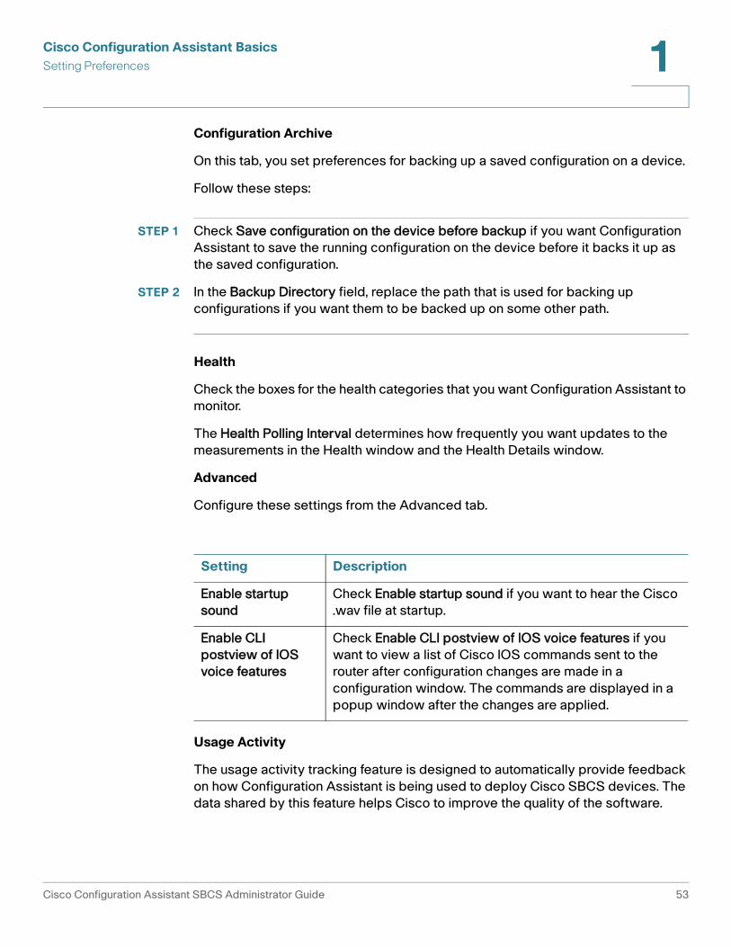
Configuration Archive
On this tab, you set preferences for backing up a saved configuration on a device.
Follow these steps:
STEP 1 Check Save configuration on the device before backup if you want Configuration Assistant to save the running configuration on the device before it backs it up as the saved configuration.
STEP 2 In the Backup Directory field, replace the path that is used for backing up configurations if you want them to be backed up on some other path.
Health
Check the boxes for the health categories that you want Configuration Assistant to monitor.
The Health Polling Interval determines how frequently you want updates to the measurements in the Health window and the Health Details window.
Advanced
Configure these settings from the Advanced tab.
Usage Activity
The usage activity tracking feature is designed to automatically provide feedback on how Configuration Assistant is being used to deploy Cisco SBCS devices. The data shared by this feature helps Cisco to improve the quality of the software.
Setting Description
Enable startup sound
Check Enable startup sound if you want to hear the Cisco .wav file at startup.
Enable CLI postview of IOS voice features
Check Enable CLI postview of IOS voice features if you want to view a list of Cisco IOS commands sent to the router after configuration changes are made in a configuration window. The commands are displayed in a popup window after the changes are applied.
Cisco Configuration Assistant SBCS Administrator Guide 53

Cisco Configuration Assistant BasicsSetting Preferences1
Usage activity tracking is enabled by default, as described in the End User License Agreement (EULA) for Configuration Assistant. To view the EULA, choose Help > About from the Configuration Assistant main menu and click the End User License Agreement link.
Uncheck the Enable usage activity collection option to disable collection and transmission of Configuration Assistant usage data to Cisco.
When this option is enabled, only these usage activity statistics are collected:
• Configuration Assistant version and internationalization
• Types of devices being managed by Configuration Assistant
• Software version for each managed device (for example, Cisco IOS version, switch firmware version, and Cisco Unity Express (CUE) software version)
• User actions
- Feature window launch
- Tab navigation events in feature windows and dialogs
• When Configuration Assistant applies a configuration to a device
No details of the configuration are recorded, only that the user applied a change to the configuration.
• Public IP address of the PC on which Configuration Assistant is installed and from which the data is sent.
This is the WAN or Internet IP address maintained and allocated by your Internet Service Provider (ISP) to the router or firewall at your site.
• Timestamp for each event
• VLAN usage
- Whether or not the default IP address is used for VLAN1 on the UC 500 (192.168.10.x). CCA does not record the VLAN1 IP address; it only checks to see if the default value is being used.
- Total number of VLANs
• Smartport usage: Type of Smartport roles applied
• VPN usage: Types of enabled VPNs (EasyVPN, SSL VPN, or site-to-site VPN). Phone VPNs are not tracked.
54 Cisco Configuration Assistant SBCS Administrator Guide

Cisco Configuration Assistant BasicsUsing Online Help 1
• SIP trunk usage
- Whether or not SIP trunking is enabled
- If enabled, the selected SIP trunk provider
• Wireless usage
- Whether or not wireless is enabled
- Type of wireless security used
- Total number of SSIDs configured
• UC 500 flash usage: Available flash space and total flash space in Mb
The following information is NOT collected:
• Customer names, addresses or other identifying information
• Product serial numbers or other unique identifiers
• Hostnames or IP addresses for devices that are behind the router or firewall at your site
• Phone numbers or any other information that could be used to uniquely identify a customer or VAR
• Cisco.com usernames or passwords
• Usernames or passwords configured on the device
Usage activity data is stored in a text file on the PC running Configuration Assistant and is sent to a server hosted by Cisco on a per-session basis. After the information is sent, it is removed from the user's PC.
An Event Notification alert is generated each time usage activity data is sent.
Using Online Help
Configuration Assistant online help displays in a separate Web browser window. that provides:
• Toolbar with Back, Forward, and Home navigation buttons, Print PDF button, and Search text box
• Contents and Index links on the left
Cisco Configuration Assistant SBCS Administrator Guide 55

Cisco Configuration Assistant BasicsUsing Online Help1
- By default, the Contents list is displayed. Click the Index link to go to the help index.
- Click the Book icons to expand and collapse the topic list.
- While in the Index view, you can enter a word or phrase in the search box above the Index list to search the Index entries.
• Current help topic on the right
For best results, enable JavaScript in your Internet Explorer browser. If prompted in the Information Bar, choose the option to allow blocked content so that you can view and use the help navigation and interface controls.
Access Online Help
To access online help:
• Click Help in a window or dialog
• Press F1 to access help for the active window
• Choose one of these Help menu options from the menubar at the top of the main window:
- Contents. Displays the introduction to CCA topic.
- What’s New. Displays links to information about new features in the current release and recent releases.
- Help for Active Window. Displays online help for the active window. If multiple windows are open, the active window is the window that currently has focus.
Search Online Help
To search the online help, enter a word or phrase in the search box in the top right corner of the online help window, then click Go. Partial matches are supported, but wildcard search characters and patterns such as (*) and (.) are not supported.
Once you click Go, the page updates to display the search results.
• Click on a topic link to display the topic that contains matches for the specified keyword. Matches are highlighted on that page.
• Click the icon to open the topic in a new window, allowing you to easily return to the search results page.
56 Cisco Configuration Assistant SBCS Administrator Guide

Cisco Configuration Assistant BasicsPrinting Configuration Assistant Windows, Reports, and Graphs 1
Open a PDF of the Online Help
Click the PDF button on the Help window toolbar to open a PDF that contains the entire contents of the online help in PDF format.
This allows you to save or print a copy of the Help for offline viewing.
Print Help Topics
Click the Print button on the Help window toolbar to print the current topic.
To print information in Configuration Assistant windows, you can use the Java printing system. See Printing Configuration Assistant Windows, Reports, and Graphs, page 57.
Printing Configuration Assistant Windows, Reports, and Graphs
To print a Configuration Assistant window, view, or graph, follow these steps.
STEP 1 Make sure that the object that you want to print is active.
STEP 2 Choose System > Print from the menubar to send a print file to a printer.
When you print a window, the printout is in a report format. In this format, none of the window information is truncated, as can happen if you use the PrtSc key to print the screen. The report format is also time-stamped, and pages are numbered.
Notes
• The Telephony Setup Wizard, Wireless Setup Wizard, Multisite Manager, and Dashboard windows cannot be printed.
• If the object that you want to print becomes inactive because of a popup error message, you cannot print it until you close the error dialog and make it active again.
• To print a child window (a secondary window that opens when you click a button on the parent window), it must be open and active.
Cisco Configuration Assistant SBCS Administrator Guide 57

Cisco Configuration Assistant BasicsPrinting Configuration Assistant Windows, Reports, and Graphs1
• When you print the Topology view or the Front Panel view, the Print Preview window (System > Print Preview) has a Fit To Page option. Check it if you want the view to be printed on a single page.
58 Cisco Configuration Assistant SBCS Administrator Guide

2
What’s New
For information about new features and supported devices in Cisco Configuration Assistant, see these topics:
• Current Release, page 59
• Recent Releases, page 63
Current Release
Release 2.2(5)
Release 2.2(5) of CCA adds support for these devices and contains the following feature enhancements and user interface changes.
See the Release Notes for Cisco Configuration Assistant Release 2.0 and Later for a list of known issues that were resolved in this release.
Feature Description.
UC 500 Software Pack 8.0.3 support
CCA 2.2(5) supports the UC 500 8.0.3 software pack. For more information and software pack component versions, see the Release Notes for Cisco Configuration Assistant Release 2.0 and Later.
Windows 7 Support (64-bit and 32-bit versions)
CCA can now be used on PCs running the Microsoft Windows operating system. Both 64-bit and 32-bit versions are supported. For important limitations and caveats that apply to CCA and Windows 7, see the Release Notes for Cisco Configuration Assistant Release 2.0 and Later.
NOTE Windows 7 User Account Control (UAC) must be disabled in order for CCA drag-and-drop upgrades and file operations to work.
Cisco Configuration Assistant SBCS Administrator Guide 59

What’s NewCurrent Release2
CCA Version Compatibility Checking
When you launch CCA, the CCA Version Conflict dialog appears if the version of CCA you are using is older than the version of CCA that was previously used to configure the system. You can either close the dialog or choose to upgrade to a newer version of CCA. See CCA Version Compatibility Checking, page 20.
New Devices Supported
IP Phones. CCA 2.2(5) adds support for these CIsco Small Business IP Phone models:
• Cisco SPA 525G2
• Cisco SPA 300 Series
Dialable Intercom
You can now configure dialable intercoms using CCA. These are configured on the User Extensions tab in the Voice window (Configure > Telephony > Voice).
For more information, see Configuring Dialable Intercoms, page 288.
Whisper Intercoms
You can now configure Whisper Intercoms using CCA. These are configured on the User Extensions tab in the Voice window (Configure > Telephony > Voice).
For more information, see Configuring Whisper Intercoms, page 286.
Conference Barge, Privacy, and Shared Octo-Line Extensions
You can now configure Conference Barge with Privacy using CCA. cBarge and Privacy require shared octo-line extensions to be configured.
cBarge and Privacy are configured in the Conference & cBarge window (Configure > Telephony > Voice Features > Conferencing & cBarge). Shared octo-line extensions are configured on the User Extensions tab in the Voice window (Configure > Telephony > Voice).
For more information, see Configuring Conference Barge (cBarge) and Privacy Features, page 348.
Feature Description.
60 Cisco Configuration Assistant SBCS Administrator Guide
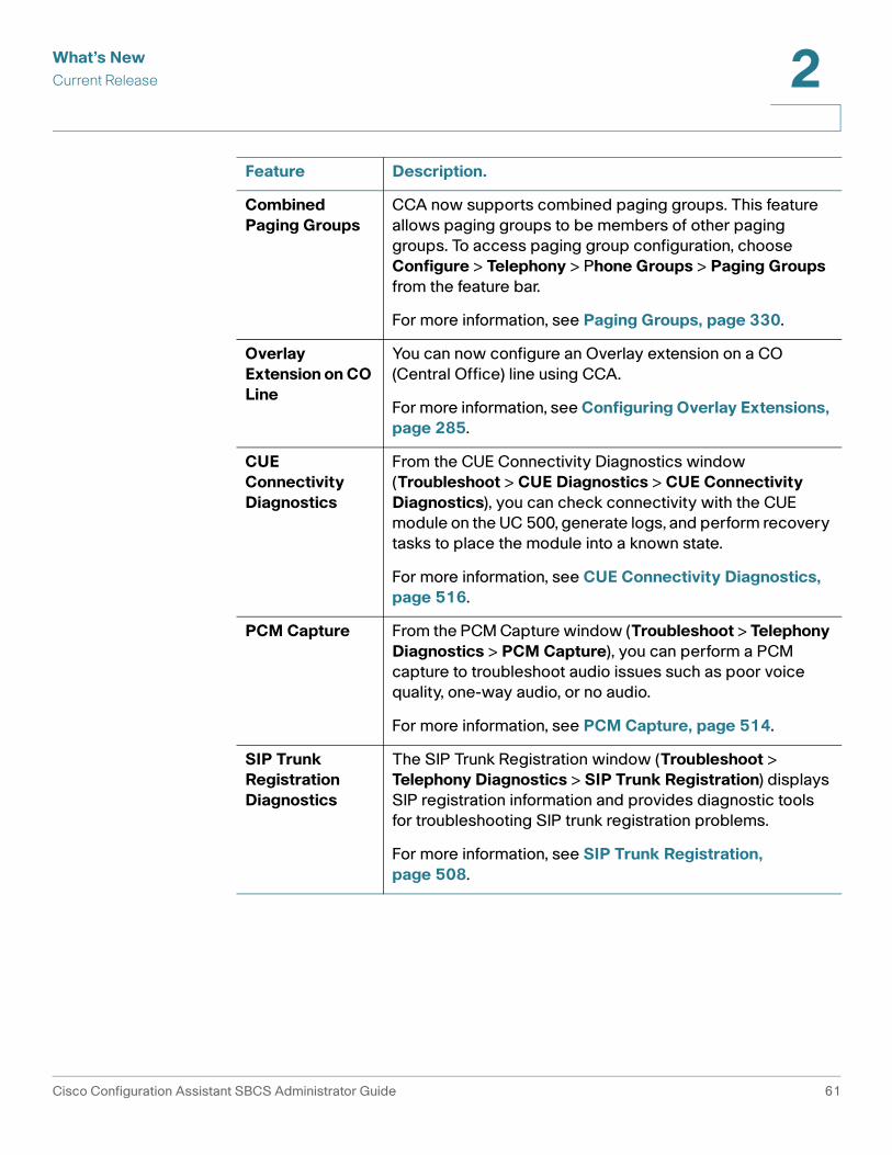
What’s NewCurrent Release 2
Combined Paging Groups
CCA now supports combined paging groups. This feature allows paging groups to be members of other paging groups. To access paging group configuration, choose Configure > Telephony > Phone Groups > Paging Groups from the feature bar.
For more information, see Paging Groups, page 330.
Overlay Extension on CO Line
You can now configure an Overlay extension on a CO (Central Office) line using CCA.
For more information, see Configuring Overlay Extensions, page 285.
CUE Connectivity Diagnostics
From the CUE Connectivity Diagnostics window (Troubleshoot > CUE Diagnostics > CUE Connectivity Diagnostics), you can check connectivity with the CUE module on the UC 500, generate logs, and perform recovery tasks to place the module into a known state.
For more information, see CUE Connectivity Diagnostics, page 516.
PCM Capture From the PCM Capture window (Troubleshoot > Telephony Diagnostics > PCM Capture), you can perform a PCM capture to troubleshoot audio issues such as poor voice quality, one-way audio, or no audio.
For more information, see PCM Capture, page 514.
SIP Trunk Registration Diagnostics
The SIP Trunk Registration window (Troubleshoot > Telephony Diagnostics > SIP Trunk Registration) displays SIP registration information and provides diagnostic tools for troubleshooting SIP trunk registration problems.
For more information, see SIP Trunk Registration, page 508.
Feature Description.
Cisco Configuration Assistant SBCS Administrator Guide 61

What’s NewCurrent Release2
New Default AA Script
The aa_sbcs_v03.aef script is now the default Auto Attendant script. This version of the AA script provides an option for transferring calls to a designated phone number if the caller does not choose an action after the main greeting is played three times.
For more information, see Auto Attendant Configuration, page 366.
Miscellaneous Telephony Feature Enhancements
You can now enable or disable blocking of restricted calls and set calling permissions for common area phone/Fax devices. These settings are configured on the Analog Extensions tab in the Voice window (Configure > Telephony > Voice).
A Use as Teleworker Phone option has been added to the User Extensions tab. When this option is checked, Media Termination Point (MTP) is configured on the selected phone. See Configure Phone Buttons and Settings, page 274.
An Allow video calls option has been added to the User Extensions tab in the Voice window. When this option is checked, Cisco Unified Voice Advantage (CUVA) is enabled on the selected phone. See Configure Phone Buttons and Settings, page 274.
You can now edit the description that displays in the top right corner of IP phones (for example, you can edit this setting to display the full DID (direct inward dial) phone number of the phone). In prior releases, CCA always displayed the First and Last Name of the phone user in this area. This setting is configured on the User Extensions tab in the Voice window. See Configure Phone Buttons and Settings, page 274.
User interface Changes
A toolbar option has been added for logging in to Cisco.com (click the Cisco logo icon on the toolbar).
Feature Description.
62 Cisco Configuration Assistant SBCS Administrator Guide

What’s NewRecent Releases 2
Recent Releases
Release 2.2(4)
Release 2.2(4) of CCA provides these user interface and feature enhancements. See the Release Notes for Cisco Configuration Assistant Release 2.0 and Later for a list of known issues that were resolved in this release.
Feature Description
UC 500 Software Pack 8.0.2 Support
CCA 2.2(4) supports the UC 500 8.0.2 software pack. For more information and software pack component versions, see the Release Notes for Cisco Configuration Assistant Release 2.0 and Later.
Cisco Configuration Assistant SBCS Administrator Guide 63

What’s NewRecent Releases2
User Interface Changes
CCA 2.2(4) includes these user interface changes and enhancements:
• Enable/disable wireless interface option for UC 500/SR 500W platforms with integrated wireless. Uncheck the Enable Wireless Interface option in the WLANs (SSIDs) window to shut down the wireless interface for these platforms. You can still add and update SSID configuration when the interface is disabled.
• Enable playing of Caller ID for incoming voicemail messages. Check the Play Caller ID for Incoming Messages option on the Setup tab in the Voicemail window to enable this feature (Configure > Telephony > Voicemail).
• The IP address and subnet mask for VLANs on the UC 500 (all platforms), SR 520, and SR 520-T1 can now be edited on the Interface Configuration tab in the IP Addresses window (Configure > Routing > IP Addresses).
• The default CFNA Timeout value for phones is increased from 10 to 20 seconds. The default Timeout value for Call Blast group is 16 seconds. These default settings help to ensure that the timeout for Call Blast Groups is lower than the CFNA timeout for member extensions, so that calls are forwarded correctly.
• You can now enter a custom label for Call Park extensions.
• PSTN phone numbers can now begin with a plus “+” character. This includes the PSTN number fields in the incoming dial plan, AA PSTN Main Number, PSTN main number for voicemail access, Caller ID numbers, and DID number fields in the Telephony Setup Wizard.
Feature Description
64 Cisco Configuration Assistant SBCS Administrator Guide

What’s NewRecent Releases 2
Release 2.2(2)
Release 2.2(2) of CCA adds support for configuring these features and devices. See the Release Notes for Cisco Configuration Assistant Release 2.0 and Later for a list of known issues that were resolved in this release.
Feature Description
Security Setup Wizard
Use the new Security Setup Wizard to configure WAN, LAN, and wireless profile settings for SA 500 Series Security Appliances.
Video Monitor Setup Wizard
Use the new Video Monitor Setup Wizard to enable viewing of video from Cisco PVC2300 or WVC2300 Business Internet cameras on SPA 525G IP phones that are part of a Cisco SBCS deployment.
AP541N Support for Wireless Setup Wizard
Use the updated Wireless Setup Wizard to configure and synchronize wireless data, voice, and guest network settings and profiles. The wizard supports Cisco AP541N wireless access points, integrated UC 540W access points, AP 521 autonomous access points, and SPA 525G IP phones operating in wireless G mode.
UC 560 Maximum Simultaneous VPN Connections
For UC 560 platforms, CCA now permits a maximum of 20 simultaneous VPN connections. VPN connections used by EZVPN, SSL VPN, Multisite Manager, and SPA 525G phone VPNs are included in the total number. As in prior releases, the maximum number of simultaneous VPN connections permitted for UC 520 and UC 540 platforms is 10.
Cisco Configuration Assistant SBCS Administrator Guide 65

What’s NewRecent Releases2
Release 2.2(1)
Release 2.2(1) of CCA adds support for configuring these features and devices, along with some minor enhancements. See the Release Notes for Cisco Configuration Assistant Release 2.0 and Later for a list of known issues that were resolved in this release.
Services Ready Platform SRP 500 Series Support
CCA can discover a Services Ready Platform SRP 500 device and display its icon in the Topology view.
The SRP 500 device must be connected to a UC 500 or a port on an ESW 500 Series switch that is connected to a UC 500. You must use the UC 500 or ESW 500 IP address as the starting IP address for discovering the SRP 500. You cannot use the IP address of the SRP 500 to discover the device or network.
To launch the Web-based management tool for the SRP 500, right-click on the icon for the SRP 500 in the Topology view and choose Configuration Utility from the drop-down menu.
UC 500 Software Pack 8.0.1 Support
CCA 2.2(2) supports the UC 500 8.0.1 software pack. For more information and software pack component versions, see the Release Notes for Cisco Configuration Assistant Release 2.0 and Later.
Feature Description
Cisco SA 500 Series Security Appliances, Basic Device Support
Perform these basic configuration and management tasks for Cisco SA 500 Security Appliances: set hostname, configure users and password, set timezone (through NTP), configure basic SNMP settings, perform software upgrades, back up and restore configuration, restart/reset the device.
Launch the Web-based SA 500 Configuration Utility and configure other settings and features. To do this, right-click on the SA 500 icon in the CCA Topology view and choose Configuration Utility from the popup menu.
Feature Description
66 Cisco Configuration Assistant SBCS Administrator Guide
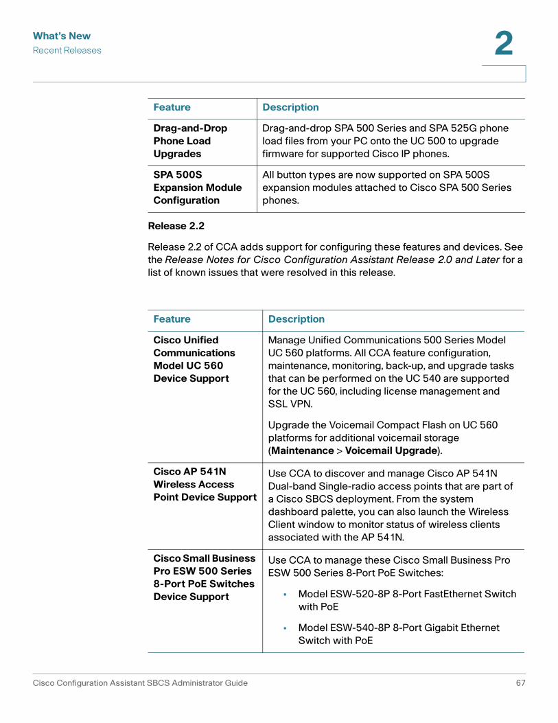
What’s NewRecent Releases 2
Release 2.2
Release 2.2 of CCA adds support for configuring these features and devices. See the Release Notes for Cisco Configuration Assistant Release 2.0 and Later for a list of known issues that were resolved in this release.
Drag-and-Drop Phone Load Upgrades
Drag-and-drop SPA 500 Series and SPA 525G phone load files from your PC onto the UC 500 to upgrade firmware for supported Cisco IP phones.
SPA 500S Expansion Module Configuration
All button types are now supported on SPA 500S expansion modules attached to Cisco SPA 500 Series phones.
Feature Description
Cisco Unified Communications Model UC 560 Device Support
Manage Unified Communications 500 Series Model UC 560 platforms. All CCA feature configuration, maintenance, monitoring, back-up, and upgrade tasks that can be performed on the UC 540 are supported for the UC 560, including license management and SSL VPN.
Upgrade the Voicemail Compact Flash on UC 560 platforms for additional voicemail storage (Maintenance > Voicemail Upgrade).
Cisco AP 541N Wireless Access Point Device Support
Use CCA to discover and manage Cisco AP 541N Dual-band Single-radio access points that are part of a Cisco SBCS deployment. From the system dashboard palette, you can also launch the Wireless Client window to monitor status of wireless clients associated with the AP 541N.
Cisco Small Business Pro ESW 500 Series 8-Port PoE Switches Device Support
Use CCA to manage these Cisco Small Business Pro ESW 500 Series 8-Port PoE Switches:
• Model ESW-520-8P 8-Port FastEthernet Switch with PoE
• Model ESW-540-8P 8-Port Gigabit Ethernet Switch with PoE
Feature Description
Cisco Configuration Assistant SBCS Administrator Guide 67

What’s NewRecent Releases2
SPA 500S Expansion Module Support
Configure buttons on SPA 500S expansion modules attached to Cisco SPA 500 Series phones.
VPN Phone Setup Wizard
Use the VPN Phone Setup Wizard to enable and configure SSL VPN client settings on SPA 525G IP phones.
Centralized Error Message Display and Handling
View error messages that occur during configuration from a single location on the CCA desktop. Click on an error message to bring the corresponding window into focus and highlight the field that contains the error.
Caller ID Enhancements
Configure the phone number to use as the caller ID for each PSTN trunk type and to override the trunk-level caller ID for individual extensions. Choose Configure > Telephony > Dial Plan > Outgoing Dial Plan and click the Caller ID tab to access caller ID options. Per-trunk calling line ID can also be configured for PSTN trunks through the Telephony Setup Wizard.
Discover Bonjour Devices from the Topology View
From the Topology view, discover Cisco PVC2300 and WVC2300 video cameras and third-party printers with Bonjour support. Choose the Configuration Utility option to manage these devices using their built-in web management tools.
SIP Trunk Providers Configure SIP trunks from these additional service providers: Worldexchange and Skype.
Other User Interface Changes
Configure PSTN trunk interface settings from a separate window. Choose Configure > Telephony > Trunks > PSTN Trunks.
Redesigned Topology view.
The default Voicemail Access Extension is now 399. The default AA Extension is now 398.
SSL-VPN configuration now includes an option to enable split tunneling.
Feature Description
68 Cisco Configuration Assistant SBCS Administrator Guide

3
Getting Started with the Configuration
Read the topics in this section to learn about how to use Cisco Configuration Assistant (CCA) to connect to a customer site or standalone device and get started with the configuration. These topics are covered:
• Create and Manage Customer Sites
• Connect to a Site or Standalone Device
• Using CCA Setup Wizards
- Which Wizard Should I Use and When?
- Telephony Setup Wizard
- Security Setup Wizard
- Wireless Setup Wizard
- Device Setup Wizard
- SR 520-T1 Configuration Utility
- Phone VPN Setup Wizard
- Video Monitor Setup Wizard
• Back Up and Restore Device Configuration
• Resources for Planning and Implementing Your SBCS Solution
• Cisco SBCS Features Supported Within CCA
Cisco Configuration Assistant SBCS Administrator Guide 69
Getting Started with the ConfigurationCreate and Manage Customer Sites3
Create and Manage Customer Sites
Read this section to learn about how to create and manage customer sites using CCA:
• About Customer Sites
• Customer Site Planning
• Create a New Customer Site
About Customer Sites
You create a customer site to manage multiple Cisco Smart Business Communications System (SBCS) devices in the same logical group, regardless of their physical locations and the software installed on the devices. You can create, modify, delete, and manage multiple customer sites.
The benefit of creating a customer site is that you can manage and monitor multiple devices such as a UC 500 and SR 500 in a single session without having to reconnect to each device separately. Using a customer site allows CCA to implement solution-level features, such synchronizing VLANs across multiple platforms and multisite deployments.
A customer site can contain up to 25 connected network devices. Each device must have an assigned IP address. Cisco Configuration Assistant uses the automatic discovery capability of Cisco Discovery Protocol (CDP) and the Bonjour protocol to find eligible network devices and to add them to a site. If devices do not have CDP enabled, you can still create a site and manually add the devices.
With CCA, you can communicate securely with every member in a customer site. If a site member fails, you can continue to manage the other members.
Most types of network devices—routers, switches, wireless LAN controllers—can belong to a customer site. For a specific list of eligible devices, see the Release Notes for Cisco Configuration Assistant.
The following basic networking tasks are supported for customer site members, including routers and access points:
• Managing user access
• Upgrading software
• Saving a running configuration
70 Cisco Configuration Assistant SBCS Administrator Guide

Getting Started with the ConfigurationCreate and Manage Customer Sites 3
• Backing up and restoring a configuration
• Managing the system time
• Getting system message notifications
• Changing the HTTP port number
• Getting an inventory report
Customer Site Planning
This section describes the guidelines, requirements, and caveats that you should understand before you create a customer site.
Member and Candidate Characteristics
Members are network devices that belong to a customer site. Candidates are network devices that are not yet part of a customer site.
To join a customer site, a candidate device must
• Be supported by CCA
• Have an IP address that is reachable from the PC running CCA
• Have HTTP or HTTPS enabled on the default ports
Access to these ports must be open if the device is behind a firewall.
Customer Site Device Limits
The combined number of these device types cannot exceed 25:
• UC 500 Series platforms (UC 520, UC 540, and UC 560)
• Cisco Small Business Pro ESW 500 Series switches (all models and SKUs)
• Cisco AP541N Wireless access points
• Catalyst Express CE 520 switches
• Cisco 800 Series routers
• Cisco 870 Series router
• Cisco SR 500 Series Secure Routers
• Cisco SA 500 Series Security Appliances
• Cisco 526 Wireless Express Controllers
Cisco Configuration Assistant SBCS Administrator Guide 71

Getting Started with the ConfigurationCreate and Manage Customer Sites3
• Cisco AP 521 Wireless Express autonomous access points. These are fully featured standalone access points that do not require a Cisco 526 Mobility Controller.
There is no limit on the number of IP phones or lightweight access points—access points managed by a WLAN controller—in a customer site. nor is there a limit on the number of customer sites that CCA can manage.
In addition to the overall limit of 25 devices, there are these device-type limits:
• Catalyst Express and Cisco Small Business Pro ESW 500 Series switches—no more than 15.
• Cisco 800 Series routers plus Unified Communications 500 Series platforms—no more than five (5).
• Cisco 526 Wireless Express Controllers—no more than two (2).
• Cisco AP541N wireless access points and Cisco AP521 autonomous access points plus built-in HWIC access points—no more than ten (10).
If the overall limit or a device-type limit is exceeded, you cannot manage the customer site. You must remove devices until the limit is no longer exceeded.
Automatic Device Discovery
Beginning with the IP address for a starting device and the port numbers for HTTPS and HTTP, CCA uses Cisco Discovery Protocol (CDP) to compile a list of customer site candidates that are within four CDP hops of the starting device. Cisco Configuration Assistant can discover candidate and member devices across multiple networks and VLANs if they have valid IP addresses. See the “Member and Candidate Characteristics” section on page 71 for a list of requirements that network devices must meet to be discovered.
IMPORTANT Do not disable CDP on candidates, members, or any network devices that you might want CCA to discover.
You can edit the list of discovered devices to fit your needs and to add them to the customer site. If CCA does not discover a network device, you can manually add the device.
For instructions on adding discovered devices to a customer site or manually adding devices to a customer site, see the “Adding a Device to an Existing Customer Site” section on page 79.
72 Cisco Configuration Assistant SBCS Administrator Guide

Getting Started with the ConfigurationCreate and Manage Customer Sites 3
Customer Site Names
When you create a customer site, CCA requires that you assign a name to it. The name can contain up to 64 alphanumeric characters and is not case sensitive.
Hostnames
You can edit the default hostname for a customer site member. This is useful if you are configuring a multisite deployment or if there are multiple devices of the same type, for example, AP541N access points or switches. To edit the hostname of a managed device, go to Configure > Device Properties > Hostname.
Passwords
When connecting to a customer site, CCA prompts you for each unique password that has already been assigned for members of the site. Cisco Configuration Assistant attempts to use these passwords to connect to other devices. You are prompted for a password only if the previously entered password does not work for a device.
For example, if a customer site has ten members, and five members share one password and the other five share a different password, CCA prompts you twice, once for each password. Cisco Configuration Assistant does not save the passwords to your PC, so it prompts you for the passwords each time that you attempt to connect to a site.
Communication Protocols
Cisco Configuration Assistant uses HTTPS, HTTP, Telnet, and SSH to communicate with devices. It tries to use HTTPS when discover neighboring devices and when devices are manually added to a customer site. If HTTPS fails, it tries HTTP.
The HTTPS port is fixed at 443; the HTTP port defaults to 80. You can specify a different HTTP port when you create a customer site. Afterward, you use the HTTP Port window to change the HTTP port. The port settings for both HTTPS and HTTP must be the same for all the members of a customer site.
Customer Site Information
Cisco Configuration Assistant saves all individual device information, such as the IP address, the hostname, and the communication protocol, to your local PC. When CCA connects to a customer site, it uses the locally saved data to rediscover the member devices.
If you try to use a different PC to manage an existing customer site, none of the member device information is available. You need to create the customer site again and add the same member devices.
Cisco Configuration Assistant SBCS Administrator Guide 73

Getting Started with the ConfigurationCreate and Manage Customer Sites3
Manage Customer Sites
To manage customer sites, choose Home > Customer Sites from the feature bar.
From the Customer Sites window you can see a list of existing customer sites, create customer sites, modify customer sites, and delete customer sites.
Procedures
• To create a customer site, click Add a New Site to open the Create a New Customer Site window. See Create a New Customer Site, page 75.
• To modify a customer site, select the customer site from the list and click Modify to open the Modify Customer Site window. See Modify a Customer Site, page 78.
• To delete a customer site, select the customer site from the list and click Delete.
When you are done with this window, click OK.
Related Topics
• About Customer Sites, page 70
• Customer Site Planning, page 71
74 Cisco Configuration Assistant SBCS Administrator Guide

Getting Started with the ConfigurationCreate and Manage Customer Sites 3
Create a New Customer Site
This window appears when you click Add New Site from the Customer Sites tab n the Customer Sites window or the Connect window.
If you are new to CCA or are creating a customer site for the first time, see Create and Manage Customer Sites, page 70 to learn more about the purpose and benefits of creating customer sites to manage devices using CCA.
Use this window to create a new customer site and discover devices that you can add to a customer site.
Procedures
To create a new customer site, follow these steps.
STEP 1 In the Customer Site Information section, enter a site name and description for the customer site.
The site name can be up to 64 characters long. You can use the characters A-Z, a-z, 0-9, - (hyphen), and _ (underscore).
In the optional Site Description field, enter your company name, your organization name, or any other identifying text. The text appears as part of the recommended SSID (service set identifier) when you create an SSID for your network.
STEP 2 Optional. Click Connection Options if you want to
• Enter an HTTP port number (because the devices in the customer site do not use the default port of 80).
• Specify the access mode for discovering devices and connecting to the customer site for the first time. The default is Read-only if you are already connected to site whose access mode is Read-only; otherwise, it is Read/Write.
See Connection Options, page 77.
STEP 3 In the Add Devices to Site section, choose an option. Then fill in the fields below the list, and click Start.
Cisco Configuration Assistant SBCS Administrator Guide 75

Getting Started with the ConfigurationCreate and Manage Customer Sites3
This table lists the Discover options, explains what to enter below the list, and describes what CCA enters in the Devices table.
STEP 4 When the discovery begins, the Start button becomes a Stop button. Click it any time that you want to interrupt the discovery process.
See Automatic Device Discovery, page 72 for more information about the device discovery process.
STEP 5 If CCA does not discover a device that you want in your customer site, try Step 3 again with a different Discover option.
STEP 6 Find the rows in the Devices table for the devices that you do not want to add to the customer site, and uncheck them.
Option What to Enter What CCA Displays
Specify a device IP address
The IP address of a single device that you want CCA to discover
Information about the discovered device
Discover Devices > Using a Starting IP Address
The IP address of a device with neighbors that you want to add to your site
Information about the device that you identified and about the neighbors that Cisco Discovery Protocol discovered by using a hop count of 4
Discover Devices > On a Subnet
An IP address and a subnet mask that identify a subnet whose devices you want to add to your site
Information about the devices that it discovers on the subnet
Discover Devices > Within a Range of IP Addresses
The start and end IP addresses whose range delimits the devices that you want to add to your site
Information about the devices that it discovers in the IP address range
76 Cisco Configuration Assistant SBCS Administrator Guide

Getting Started with the ConfigurationCreate and Manage Customer Sites 3
Up to 25 devices can be selected for a customer site. There are also limits on the number of certain device types that can be in a customer site. See Customer Site Device Limits, page 71.
IP phones do not need to be explicitly added to a customer site.
STEP 7 Click OK to add the selected devices to the customer site.
Related Topics
• About Customer Sites, page 70
• Customer Site Planning, page 71
Connection Options
This window appears when you click Connection Options in the Create a New Customer Site window or the Modify a Customer Site window.
• When you create a customer site and discover devices using a starting IP address, subnet, or range of IP addresses, CCA first uses HTTPS protocol to connect. If connection via HTTPS fails, CCA retries the connection using HTTP.
• When you use the Hostname/IP Address option to connect to a single device, CCA connects to the device using the protocol selected in the Advanced Options tab. The default is HTTPS.
• On subsequent connections to a customer site or standalone device, CCA uses the same protocol that was used during device discovery.
You can modify the HTTP Port field only if you are creating a customer site. The field must contain the number of the HTTP port that CCA will use to communicate with devices in the community.
If you enter an HTTP port number other than 80, the default, add and configure the port before you add any devices to the site. To change the port number afterward, use the HTTP Port window.
The port number used for HTTPS connections cannot be changed; it must be 443.
You can select an access mode and a privilege level only if you are creating a customer site. Your selection is used when discovering devices and connecting to the site for the first time.
Click OK when you are finished with this window.
Cisco Configuration Assistant SBCS Administrator Guide 77

Getting Started with the ConfigurationCreate and Manage Customer Sites3
Modify a Customer Site
This window appears when you select a customer site and click Modify on the Customer Sites tab in the Connect window or the customer sites window.
From the Modify a Customer Site window, you can add or remove devices to or from a customer site. You can also
• Click Advanced to enter a new HTTP port number if the HTTP port for the devices in the customer site changes.
• Enter or modify your company name, your organization name, or other identifying text in the Site Description field. The text appears as part of the recommended SSID (service set identifier) when you create an SSID for your network.
Procedures
To add or remove devices to a customer site, follow these steps.
STEP 1 From the Discover list, choose an option. Then fill in the fields below the list, and click Start. See Create a New Customer Site, page 75 for information about the options for discovering and adding devices to a site.
STEP 2 When the discovery begins, the Start button becomes a Stop button. Click it any time that you want to interrupt the discovery process.
STEP 3 If CCA does not discover a device that you want in your customer site, try Step 1 again with a different Discover option.
STEP 4 Find the rows in the Devices table for added devices that you do not want in the customer site, and uncheck them. Up to 25 devices can be in a customer site. There are also limits on the number of certain device types that can be in a customer site. See Customer Site Device Limits, page 71 for more information.
STEP 5 To remove devices that are already in the customer site, uncheck the entries for them in the Devices table.
STEP 6 Click OK to save your changes and close the window.
STEP 7 Choose Home > Topology View to open the Topology view. Icons of the newly discovered devices are displayed in the Topology view.
STEP 8 To add a new device to an existing customer site, right-click on the icon in the Topology view and choose Add to Site from the pop-up menu.
78 Cisco Configuration Assistant SBCS Administrator Guide

Getting Started with the ConfigurationCreate and Manage Customer Sites 3
Related Topics
• Customer Site Planning, page 71
• Create a New Customer Site, page 75
• Connect to a Site or Standalone Device, page 80
• Adding a Device to an Existing Customer Site, page 79
• Viewing and Listing Devices in a Customer Site, page 79
Adding a Device to an Existing Customer Site
You can also add a device to an existing customer site. To do this, right-click a candidate icon in the Topology view, and select Add to Site.
Viewing and Listing Devices in a Customer Site
Follow these steps to view and list devices in a customer site and verify that the site contains the expected devices:
STEP 1 Choose Home > Topology to display the Topology view.
STEP 2 Choose Monitor > Reports > Inventory to display an inventory of the devices in the customer site.
This summary includes device model numbers, serial numbers, software versions, IP information, and location.
STEP 3 Choose Home > Front Panel to display the Front Panel view.
STEP 4 Choose Home > Dashboard to display the system dashboard view.
Cisco Configuration Assistant SBCS Administrator Guide 79
Getting Started with the ConfigurationConnect to a Site or Standalone Device3
Connect to a Site or Standalone Device
When you launch CCA, two windows open: the Cisco Configuration Assistant main window, which contains the user interface, and the Connect window.
You can also open the Connect window by choosing System > Connect from the menu bar.
Cisco Configuration Assistant starts in disconnected mode; that is, it is not connected to a customer site or a standalone device. In this mode, you see the menu bar in the CCA window but only a small number of items in the feature bar. The feature bar is created and populated with device features only when CCA is connected.
The following sections describe how to use each of the tabs in the Connect window:
• Customer Sites, page 80
• Hostname/IP Address, page 82
• Advanced Options, page 82
Customer Sites
To manage and configure multiple devices on your network in a single session, create a customer site.
TIP If you are new to CCA or are creating a customer site for the first time, see Create and Manage Customer Sites, page 70 to learn more about the purpose and benefits of creating customer sites to manage devices using CCA.
From the Customer Sites tab, you can:
• Create a new customer site and connect to it
• Connect to an existing customer site by selecting it from a list.
• Modify or delete an existing customer site.
To create a new customer site, follow these steps.
80 Cisco Configuration Assistant SBCS Administrator Guide

Getting Started with the ConfigurationConnect to a Site or Standalone Device 3
STEP 1 Select the Customer Sites tab in the Connect window and click Add a New Site. The Create a New Customer site dialog appears.
STEP 2 Complete the fields in the Create a New Customer Site dialog, discover devices, and add devices to the site as described in the section Create a New Customer Site, page 75.
STEP 3 Once you have successfully created the customer site, it is displayed in the list of sites on the Customer Sites tab in the Connect window.
STEP 4 Click Connect.
When you connect to a customer site, CCA displays an Authentication: Device dialog that prompts you for each unique password that has been assigned to members of that site. For more information, see Passwords, page 73.
When you have successfully authenticated, a CCA session is established. Only one session at a time can run on a PC.
NOTE After three failed authentication attempts, the device icon is displayed in Red in the Topology view with the message “Unreachable: Authorization Failed.” To retry the connection, choose System > Connect.You are prompted to close the session and restart CCA.
When you are connected to the customer site, the status bar at the bottom of the window displays the message “Determining network information” while CCA discovers devices and builds the Topology view. See Topology View, page 31.
Devices that are part of the site are listed in the left frame of the Topology view (switches, access points, and so on). IP phones and devices that are not part of the customer site are listed under Neighbors in the left frame. Although IP phones are listed under Neighbors, they are configured through CCA.
Customer site members
Neighbor devices and IP phones
Cisco Configuration Assistant SBCS Administrator Guide 81

Getting Started with the ConfigurationConnect to a Site or Standalone Device3
To end a session, close the CCA main window, or choose System > Exit. You will be prompted to save any configuration changes made during that session to a single device or to all devices.
To modify settings for an existing site, select a customer site from the list and click Modify. See Modify a Customer Site, page 78.
To delete a customer site, select the customer site from the list and click Delete.
Hostname/IP Address
Use the Hostname/IP address tab when you want to connect to and manage a single, standalone device by specifying its hostname and IP address.
To connect to a single device, follow these steps.
STEP 1 Click the Hostname/IP Address tab, enter or select a hostname or IP address to connect to the device
STEP 2 Click Connect.
STEP 3 Enter the administrator username and password for authentication.
When you have successfully authenticated, a CCA session is established. Only one session at a time can run on a PC.
NOTE After three failed authentication attempts, the device icon is displayed in Red in the Topology view with the message “Unreachable: Authorization Failed.” To retry the connection, choose System > Connect.You are prompted to close the session and restart CCA.
Advanced Options
On the Advanced Options tab, you can choose whether to grant Read/Write permission for this connection.
When you choose Read/Writer, you have permission to configure networking features with CCA. Otherwise, select Read Only and choose an access level, from 1 to 15.
The default access mode is Read/Write.
82 Cisco Configuration Assistant SBCS Administrator Guide

Getting Started with the ConfigurationUsing CCA Setup Wizards 3
Using CCA Setup Wizards
In addition to the expert mode configuration GUI, CCA provides several setup wizards to assist you in configuring Cisco SBCS solutions, features, and devices.
To access CCA setup wizards, choose Home on the CCA feature bar.
Some wizards are only available if the required devices are members of the customer site to which you are connected. For example, if the customer site does not have wireless capabilities, the Wireless Setup Wizard option is not displayed.
See the following sections:
• Which Wizard Should I Use and When?, page 83
• Telephony Setup Wizard, page 86
• Security Setup Wizard, page 88
• Wireless Setup Wizard, page 91
• Device Setup Wizard, page 94
• SR 520-T1 Configuration Utility, page 94
• Phone VPN Setup Wizard, page 95
• Video Monitor Setup Wizard, page 98
Which Wizard Should I Use and When?
Each of the CCA setup wizards is designed to automate configuration and maintenance for specific devices, features, and types of deployments. Available setup wizards are summarized in the following table.
Cisco Configuration Assistant SBCS Administrator Guide 83

Getting Started with the ConfigurationUsing CCA Setup Wizards3
Wizard What this wizard does When to use this wizard To learn more
Telephony Setup Wizard
For a Cisco SBCS/UC 500 system, the Telephony Setup wizard configures basic WAN and LAN settings, system locale, telephony system settings, voice trunks (except SIP trunks), voice ports, Auto Attendant, schedules, phone users and extensions, inbound call routing, and hunt groups.
The wizard supports all UC 500 platforms. If the UC 500 is behind an SR 500 Series secure router or SA 500 security appliance, the wizard automatically adjusts static routes and ACLs and removes the firewall on the UC 500.
Use this wizard for first-time setup only. This wizard requires a UC 500 with factory default configuration.
Run the Telephony Setup Wizard before running other CCA setup wizards.
If an SR520-T1 secure router provides the WAN connection, you must also run the SR520-T1 Configuration Utility. Run the SR520-T1 Configuration Utility before running the Telephony Setup Wizard. See SR 520-T1 Configuration Utility, page 94.
For SR 520 ADSL/Ethernet secure routers and SA 500 Series Secure routers, configure the WAN connection before running the Telephony Setup Wizard.
Telephony Setup Wizard, page 86
Security Setup Wizard
The Security Setup wizard is used for configuring data-only small business deployments with an SA 500 Series Security Appliance as the WAN edge device, along with Cisco Small Business Pro switches and wireless access points.
This wizard configures basic WAN, LAN, and wireless network setting on the SA 500 Series Security Appliance. It also automates trunk configuration for attached Cisco Small Business Pro ESW 500 Series or CE 520 switches and synchronizes wireless profiles on SA 500 integrated and external AP541N access points that are members of the same customer site.
Use this wizard for first-time setup of an SA 500 data deployment.
You can also re-run the wizard to update these settings for an existing deployment.
This wizard also supports a staging mode that allows you to pre-configure settings without the SA 500 and other devices physically connected to the network. In staging mode you can export and import the configuration to and from a local file before applying the final configuration.
Run this wizard before configuring security features with the SA 500 Configuration Utility.
Security Setup Wizard, page 88
Device Setup Wizard
The Device Setup wizard provides instructions for connecting and configuring basic device settings such as hostname and IP address so that they can be managed by CCA.
These devices are supported:
Cisco Catalyst Express CE 520 switchesCisco AP 521 autonomous access points Cisco WLC 526 wireless LAN controllersCisco SR-520 ADSL/Ethernet secure routers
Use this wizard for first-time setup of these devices from their factory default configuration.
Device Setup Wizard, page 94
84 Cisco Configuration Assistant SBCS Administrator Guide
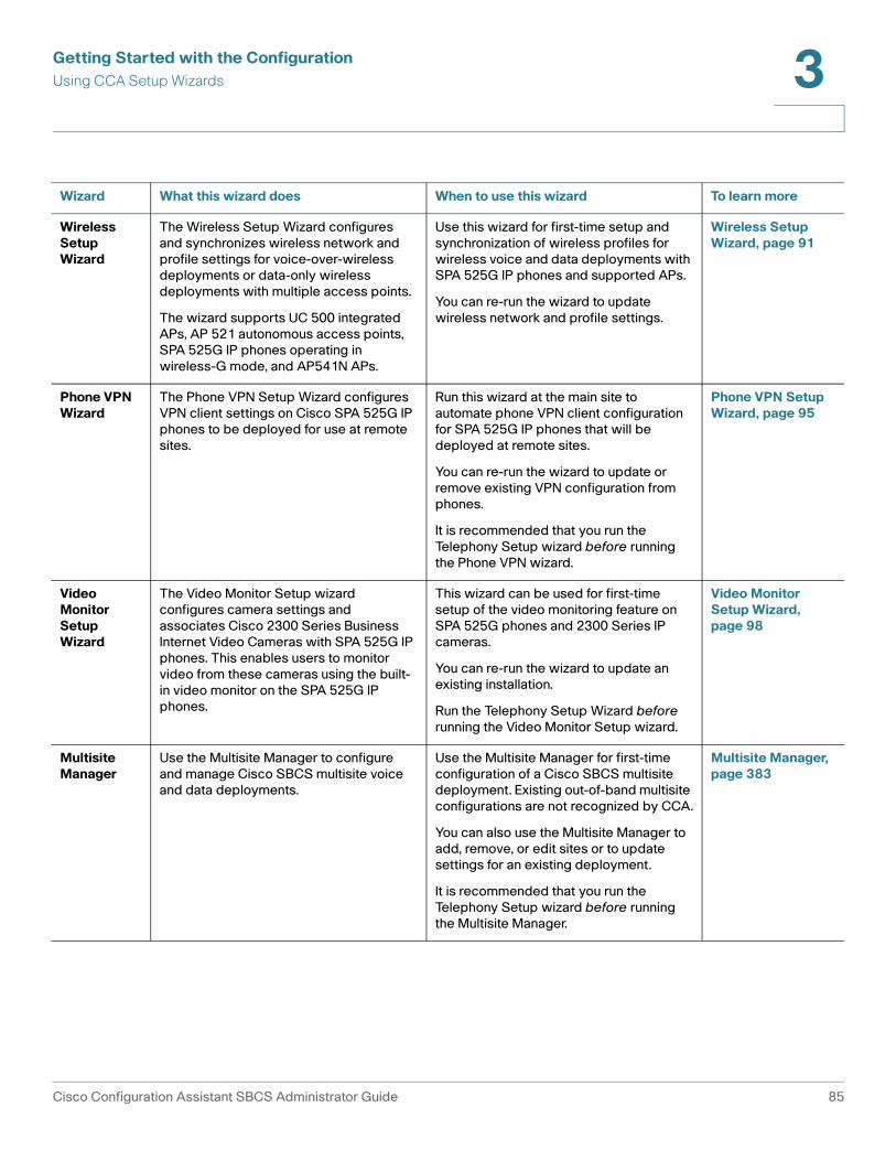
Getting Started with the ConfigurationUsing CCA Setup Wizards 3
Wireless Setup Wizard
The Wireless Setup Wizard configures and synchronizes wireless network and profile settings for voice-over-wireless deployments or data-only wireless deployments with multiple access points.
The wizard supports UC 500 integrated APs, AP 521 autonomous access points, SPA 525G IP phones operating in wireless-G mode, and AP541N APs.
Use this wizard for first-time setup and synchronization of wireless profiles for wireless voice and data deployments with SPA 525G IP phones and supported APs.
You can re-run the wizard to update wireless network and profile settings.
Wireless Setup Wizard, page 91
Phone VPN Wizard
The Phone VPN Setup Wizard configures VPN client settings on Cisco SPA 525G IP phones to be deployed for use at remote sites.
Run this wizard at the main site to automate phone VPN client configuration for SPA 525G IP phones that will be deployed at remote sites.
You can re-run the wizard to update or remove existing VPN configuration from phones.
It is recommended that you run the Telephony Setup wizard before running the Phone VPN wizard.
Phone VPN Setup Wizard, page 95
Video Monitor Setup Wizard
The Video Monitor Setup wizard configures camera settings and associates Cisco 2300 Series Business Internet Video Cameras with SPA 525G IP phones. This enables users to monitor video from these cameras using the built-in video monitor on the SPA 525G IP phones.
This wizard can be used for first-time setup of the video monitoring feature on SPA 525G phones and 2300 Series IP cameras.
You can re-run the wizard to update an existing installation.
Run the Telephony Setup Wizard before running the Video Monitor Setup wizard.
Video Monitor Setup Wizard, page 98
Multisite Manager
Use the Multisite Manager to configure and manage Cisco SBCS multisite voice and data deployments.
Use the Multisite Manager for first-time configuration of a Cisco SBCS multisite deployment. Existing out-of-band multisite configurations are not recognized by CCA.
You can also use the Multisite Manager to add, remove, or edit sites or to update settings for an existing deployment.
It is recommended that you run the Telephony Setup wizard before running the Multisite Manager.
Multisite Manager, page 383
Wizard What this wizard does When to use this wizard To learn more
Cisco Configuration Assistant SBCS Administrator Guide 85

Getting Started with the ConfigurationUsing CCA Setup Wizards3
Telephony Setup Wizard
To launch the Telephony Setup wizard, choose Home > Telephony Setup Wizard from the feature bar. If the UC 500 at the customer site is in factory default configuration, this wizard is launched automatically.
The Telephony Setup Wizard walks you through the steps required to configure a basic telephony solution.
The wizard is intended for initial installations and for cases in which you want to reset the Cisco UC 500 to factory defaults and completely replace the current configuration.
These settings are configured through the wizard:
• Basic network settings such as WAN connection type
• Phones, users, and primary extensions
• Hunt groups and blast groups
• Trunk settings (ISDN BRI, ISDN PRI, and analog trunks) and phone numbers
• Locale-specific dial plan
• Inbound call routing
• Business schedules
• Auto Attendant actions and prompts
When you launch the Telephony Setup Wizard, CCA detects the number of software licenses installed and the currently installed UC 500 software package and/or Cisco IOS software version. Buttons for accessing the CCA expert mode Software Upgrade and License Management windows are provided to allow you to perform software and/or license upgrades before continuing with the wizard. Clicking these buttons exits you from the wizard.
Before You Begin
Before running the Telephony Setup Wizard
• If the PC running CCA has more than one network interface (for example, a dual-NIC for wired and wireless network connection), make sure that only one is enabled.
• Disable any third-party firewall or TFTP services on the PC running CCA.
86 Cisco Configuration Assistant SBCS Administrator Guide

Getting Started with the ConfigurationUsing CCA Setup Wizards 3
• Ensure that the PC running Configuration Assistant is directly connected to a LAN port on the UC 500 and has obtained an IP address from the UC 500 using DHCP.
• Make sure that the UC 500 system is at factory default configuration.
• For non-US locales, download and install localization files in the appropriate location.
• Make sure that you have gathered all the information listed on the Welcome page of the wizard.
• If the UC 500 will be behind an SA 500 Series Security Appliance or SR 500 Series Secure Router, connect the UC 500 WAN to the SA 500 or SR 500 LAN before running the Telephony Setup Wizard.
Using the Telephony Setup Wizard
To access this wizard from the feature bar, navigate to Home > Telephony Setup Wizard.
The configuration you set up via the wizard is not applied until the final page of the wizard. To go back to previously visited pages of the configuration:
• Use the Back button.
• Use the navigation panel on the left side of the page to go to specific pages within a configuration section.
• Use the Summary page links, then click Resume to return to the summary page.
If the changes you make affect other settings configured through the wizard, navigation menu items highlighted in Red indicate errors that must be corrected before continuing.
Once you click Apply Configuration, the settings chosen in the wizard are applied. If you exit the wizard before applying the configuration, all settings entered through the wizard are discarded.
After the initial configuration is established through the wizard and you have verified that basic networking and voice features are working properly, continue configuring additional network, security, and voice features through the main Cisco Configuration Assistant GUI.
Next Steps
These telephony features are not configured through the Telephony Setup wizard:
Cisco Configuration Assistant SBCS Administrator Guide 87

Getting Started with the ConfigurationUsing CCA Setup Wizards3
• Calling permissions for individual phones (call permissions are unrestricted for phones added through the wizard)
• Call blocking for individual phones (call blocking is disabled for phones added through the wizard)
• Intercoms, shared lines, overlays, and octal lines
• Monitor mode and Watch mode lines
• SIP trunk interface
• Basic ACD (automatic call distribution)
• Multi-party conferencing (Ad Hoc/Meet-Me)
• Night service
• Custom outgoing dial plan numbers
• Trunk groups and priorities
• System speed dials
• Paging groups
• Call Pickup groups
• Call Park extensions
See the CCA online help or other sections in this guide for information about how to configure these features in expert mode using CCA.
Security Setup Wizard
To launch the Security Setup Wizard, choose Home > Security Setup Wizard from the feature bar.
NOTE The Security Setup Wizard is intended for use in data-only deployments with SA 500 Series Security Appliances, ESW 500 Series switches, and AP541 access points. If you are deploying a UC 500 telephony solution, run the Telephony Setup Wizard to set up the network.
The Security Setup Wizard can be used for first-time set-up or to edit existing configuration, as described in these sections:
• Overview
• Staging the Configuration
88 Cisco Configuration Assistant SBCS Administrator Guide

Getting Started with the ConfigurationUsing CCA Setup Wizards 3
• Downloading and Installing the Latest Firmware for SA 500, ESW 500, and AP 541N Devices
• Using the Security Setup Wizard
• Next Steps
Overview
Cisco SA 500 Series Security Appliances provide WAN connectivity, routing, firewall, security, remote access, and wireless access for small business networks.
The Security Setup Wizard guides you through the steps required to configure wireless network settings for a Cisco SA 500 Series Security Appliance in a small business data-only network. The wizard also synchronize wireless profile information for integrated SA 500 wireless and AP541N access points that are members of the CCA customer site.
When you apply the configuration through the wizard, CCA automatically sets up 802.1q trunking and synchronizes wireless LAN (WLAN) data and guest profile settings for connected Cisco Small Business Pro devices such as ESW 500 Series switches and AP541N access points.
Staging the Configuration
If CCA detects that the customer site that you are connected to does not contain an SA 500, the wizard automatically runs in staging mode.
In staging mode, you can pre-configure settings and save your progress at any point in the wizard by choosing Export Configuration to File. To resume configuration, re-run the wizard and choose Import Configuration From File.
Once the equipment is available and you are connected to the customer site, re-launch the wizard, import your previously saved configuration, make any needed changes, and apply the configuration.
Downloading and Installing the Latest Firmware for SA 500, ESW 500, and AP 541N Devices
If you are connected to a CCA customer site with an SA 500, the current SA 500 device firmware version is displayed. Version 1.1.21 or later of the SA 500 firmware is required.
To obtain the latest firmware from Cisco.com, follow these links. A Cisco.com login is required.
Cisco Configuration Assistant SBCS Administrator Guide 89

Getting Started with the ConfigurationUsing CCA Setup Wizards3
• Software downloads for SA 500 Series Security Appliances are available at www.cisco.com/go/sa500software.
• For ESW 500 Series switches, a link to the software downloads is available at www.cisco.com/esw500help. Click the Resources tab and choose the Firmware link under Firmware and Release Notes.
• For AP541N access points, software downloads are available at www.cisco.com/go/ap500software.
When you have finished downloading the software, click the Upgrade Software button in the wizard or choose Maintenance > Software Upgrade from the feature bar in CCA to open the CCA Software Upgrade window.
Follow the instructions in the CCA online help to upgrade firmware for these devices. See Software Upgrades, page 441.
Using the Security Setup Wizard
To launch the wizard, choose Home > Security Setup Wizard from the feature bar.
Follow the onscreen instructions in the wizard to configure these settings:
• Administrator password (for security reasons, this must be changed from the default cisco password)
• Timezone, daylight savings time option, and NTP servers
You cannot directly set the system time on the SA 500. Therefore, an NTP server is required. The default servers (0.us.pool.ntp.org and 1.us.pool.ntp.org) are scoped to the United States, rather than the global zone.
• WAN connection (DHCP, Static IP, or PPPoE)
• Data VLAN
• Static routes
• Wireless guest network
• Wireless SSID, VLAN ID, and profile information for data and guest networks.
When you apply the configuration, the wizard synchronizes these wireless profile settings with the integrated SA 520W access point and all AP541N access points on the network. To be synchronized, these access points must be members of the CCA customer site to which you are connected.
Existing configuration is replaced with the new configuration.
90 Cisco Configuration Assistant SBCS Administrator Guide

Getting Started with the ConfigurationUsing CCA Setup Wizards 3
WPA2 security with TKIP + CCMP encryption is automatically configured for the wireless security type.
You can re-run the wizard at any time to modify these settings.
Next Steps
When you have completed the Security Setup Wizard, you can right-click on the SA 500 icon in the Topology view and choose Configuration Utility to run the Web-based SA 500 management software.
From the SA 500 Configuration Utility you can configure security features for the customer site, such as firewall and DMZ, URL filtering, Intrusion Prevention System (IPS), port forwarding, and SSL VPN. These features are not configured through CCA.
Cisco ProtectLink Gateway is a hosted security service that blocks spam and filters URLs to prevent unwanted content from passing into your business network. Follow the instructions in the Cisco SA 500 Series Security Appliances Administration Guide to obtain an Activation Code and enable ProtectLink services on the SA 500. To learn more, visit www.cisco.com/go/protectlink.
For more information, see the Cisco SA 500 Series Security Appliances Administration Guide, available on Cisco.com at the following URL:
www.cisco.com/go/sa500
Click the Resources tab and scroll to the Technical Documentation section to locate the administration guide and other relevant links.
Wireless Setup Wizard
To launch the Wireless Setup wizard, choose Home > Wireless Setup Wizard from the feature bar. The Wireless Setup Wizard menu option is only available if the customer site to which you are connected has wireless capability.
• Overview
• Before You Begin
• Using the Wireless Setup Wizard
Cisco Configuration Assistant SBCS Administrator Guide 91

Getting Started with the ConfigurationUsing CCA Setup Wizards3
Overview
Use the Wireless Setup Wizard to automate configuration of wireless settings for multiple access points or to configure Cisco SBCS voice-over-wireless solutions with Cisco SPA 525G phones operating in wireless-G mode. Wireless network and profile settings are synchronized among access points and SPA 525G phones that are members of the customer site. All UC 500 models are supported.
These wireless devices are supported:
• Integrated UC 500 access points
• Cisco Small Business Pro AP541N access points
• Cisco AP 521 autonomous access points
IMPORTANT If clustering is enabled for AP541N access points that are part of a CCA customer site, do not run the Wireless Setup Wizard to configure these access points.
If you are using Cisco AP541N access points with SPA 525G phones, follow the SBCS deployment guidelines described in the Cisco SBCS 2.0 Voice Over Wireless Deployment Guide. This guide is available on Cisco.com at the following URL:
www.cisco.com/en/US/docs/voice_ip_comm/sbcs/deployment_guides/voice_over_wireless/sbcs_20_vowifi_deployment_guide.pdf
Cisco Model 7921 and 7925 phones can be used with SBCS 2.0 voice over wireless solutions that use AP541N access points. However, the Wireless Setup Wizard does not automatically synchronize wireless profile settings for these phones.
If you are using older Cisco AP 521 autonomous access points with SPA 525G IP phones, follow the reference designs and guidelines specified in the Cisco SPA525G Wireless Deployment Guide for Cisco SBCS. This guide is available on Cisco.com at the following URL:
www.cisco.com/en/US/docs/voice_ip_comm/sbcs/deployment_guides/spa525g_phone/sbcs_spa525g_wireless_deployment_guide.pdf
Before You Begin
Your system must meeting the following requirements:
• CCA version 2.2(2) or later is required for AP541N support via the Wireless Setup Wizard.
• SPA 525G IP phones must be running firmware version 7.1.3 or later
92 Cisco Configuration Assistant SBCS Administrator Guide

Getting Started with the ConfigurationUsing CCA Setup Wizards 3
• UC 500 software pack 7.0 or later
• AP 541N access points must be running firmware version 1.8.0 or later.
• SPA 525G phones that will be connected wirelessly must have a Model PA100 external power supply.
Before running the Wireless Setup wizard, you must
• Gather the following information: SSIDs and passwords (pre-shared keys) that you want to use for the wireless data, voice, and guest networks.
• Connect any external access points (AP541Ns or AP 521s) to the UC 500.
• Connect any SPA 525G phones directly to the LAN side of the UC 500 for wireless profile synchronization.
• Create a CCA customer site for the UC 500, phones, and access points.
• Connect to the customer site and verify that the external access points are members of the customer site.
Using the Wireless Setup Wizard
To run the Wireless Setup Wizard, connect to the customer site you created and choose Home > Wireless Setup Wizard from the feature bar.
Follow the onscreen instruction to configure these settings:
• Enable wireless mode on the SPA 525G phones.
• Configure SSIDs, passwords (pre-shared keys), for wireless data and voice networks.
• Choose whether or not to enable SSID broadcast.
• Enable the guest network, if needed, and configure the SSID, password (pre-shared key), and choose whether to enable SSID broadcast.
The following notes apply to VLAN IDs configured by the Wireless Setup Wizard:
• The voice network VLAN ID is set to 1 (the value reserved by CCA).
• The data network VLAN ID is set to 100 (the value reserved by CCA).
• The guest network VLAN ID is set to 25 (the value reserved by CCA).
- If the cisco-guest SSID already exists on a device in the customer site and its VLAN ID is not set to 25, the existing cisco-guest SSID is deleted and re-created, and its VLAN ID is set to 25.
Cisco Configuration Assistant SBCS Administrator Guide 93

Getting Started with the ConfigurationUsing CCA Setup Wizards3
- If the cisco-guest SSID already exists on a device in the customer site and its VLAN ID is already set to 25, its configuration is not modified.
The wizard automatically configures QoS settings on AP541N access points and WPA2-PSK encryption for wireless security. You do not need to specify these options.
You can re-run the wizard at any time to modify these settings. Each time you run the wizard, it overwrites existing values with the new settings.
Device Setup Wizard
New devices or devices that have been reset to their factory defaults must be set up. Use the Device Setup Wizard to make these devices ready for CCA to manage. To start the wizard, choose Home > Device Setup Wizard on the feature bar. Follow the step-by-step onscreen instructions to set up the device.
NOTE The Cisco SR 520-T1 secure router has its own setup utility, the SR 520-T1 Configuration Utility. This setup utility is launched automatically if the SR 520-T1 device is connected to a UC 500 and is at factory default configuration. See SR 520-T1 Configuration Utility, page 94.
You can configure these devices using the Device Setup Wizard:
• Cisco SR 520 ADSL/Ethernet secure routers
• Switches (Cisco CE 520 and ESW 500 Series)
• Cisco AP 521 autonomous access points
• Cisco WLC 526 wireless LAN controller
The Cisco AP 541N Dual-band Single-radio wireless access point cannot be configured though the Device Setup Wizard.
SR 520-T1 Configuration Utility
If your site includes an SR 520-T1 Secure Router and the SR 520-T1 is at factory default state, choose Home > SR520-T1 Configuration Utility to:
• Set up the T1 WAN connection
• Modify the default the LAN0 IP address during the initial setup (optional)
• View diagnostic information and execute ping tests to verify connectivity
• Upgrade SR 520-T1 software
94 Cisco Configuration Assistant SBCS Administrator Guide

Getting Started with the ConfigurationUsing CCA Setup Wizards 3
For important information about prerequisites and step-by-step procedures, see the Cisco Small Business Pro SR 520-T1 Secure Router Quick Start Guide and the UC 500 and SR 520-T1 Secure Router Setup application note, available on Cisco.com.
Once you have configured the T1 connection, use CCA in expert mode to configure additional settings and features such as NAT, FIrewall and DMZ, administrator accounts, DNS, hostname, NTP, SNMP, static routes, and licensed security features (IPS, SSL VPN, and URL filtering).
Phone VPN Setup Wizard
To launch the Phone VPN Setup Wizard, choose Home > Phone VPN Setup Wizard from the feature bar. The Phone VPN Setup Wizard menu item is only available if the customer site to which you are connected contains at least one SPA 525G IP phone.
• Overview
• Before You Begin
• Launching and Using the Phone VPN Setup Wizard
• Enabling the Phone VPN at the Remote Site
• Modifying Phone VPN Settings After the Initial Installation
Overview
Use the Phone VPN Setup Wizard to configure VPN client settings on Cisco SPA 525G IP phones to be deployed for use at remote sites.
• At the office — Connect the SPA 525G IP phones to the UC 500, configure user extensions using CCA, and run the wizard to configure VPN client settings on the phone and set up VPN user accounts on the server. Once configured, the phone can be unplugged and sent to the remote site.
• At the remote site — The remote user connects the phone to the network at the remote site and enables the VPN client on the phone. The phone initiates a connection to the UC 500 over a secure VPN tunnel using the pre-configured settings. Once connected to the VPN, the phone appears just like any other phone at the main site, and calls between the main site and the remote site go over the VPN.
Cisco Configuration Assistant SBCS Administrator Guide 95

Getting Started with the ConfigurationUsing CCA Setup Wizards3
You can re-run the Phone VPN Setup wizard as needed to add, edit or remove phone VPN client settings on phones, for example, to re-deploy a phone at the main site, configure additional VPN-enabled phones, or change the user associated with the phone.
Before You Begin
Before launching the Phone VPN Setup Wizard, your system must meet the following requirements:
• SSL VPN Server and Anyconnect client settings must be configured for the site. If SSL VPN is not configured, you are asked to configure it before continuing.
A static IP address for the WAN connection is required for SSL VPN server configuration. Also, you must enable Full Tunnel mode. Split Tunnel mode is not supported for phone VPN.
• All SPA 525G IP phones to be configured for VPN must have the latest phone firmware installed. Version 7.4.2 or later is required.
• The SPA 525G IP phones must be powered on and connected to the UC 500 through a LAN port on the UC500 or through a switch or wireless AP that is connected to the UC 500.
• When calculating the total number of simultaneous VPN connections required for a customer site, be sure to include the VPN connections that are used for SPA 525G IP phone VPNs.
The UC 520 and UC 540 platforms support a maximum of 10 simultaneous VPN connections. The UC 560 platform supports a maximum of 20 simultaneous VPN connections.
• The SPA 525G phones must be registered to the UC 500 and display an extension.
• Basic network and telephony settings must be configured for the customer site, using either the Telephony Setup Wizard or the CCA expert mode GUI.
• For ease-of-use, user extension settings such as phone user ID, password, and phone buttons should be configured before running the VPN Phone Setup wizard This is recommended, but not required. User extension settings can still be edited after you run the Phone VPN Setup Wizard.
Launching and Using the Phone VPN Setup Wizard
To launch the Phone VPN Setup Wizard, choose Home > Phone VPN Setup Wizard.
96 Cisco Configuration Assistant SBCS Administrator Guide

Getting Started with the ConfigurationUsing CCA Setup Wizards 3
The wizard discovers SPA 525G phones connected to the UC 500 and displays the MAC address, extension, and phone user ID to help you identify the phones.
Follow the on-screen instructions in the wizard to select phones and enter a VPN username and password for the VPN account to associate with the phone.
As each phone is configured, the Status column updates to indicate success or failure. If the configuration fails for a phone, the wizard continues with the next phone in the list.
Enabling the Phone VPN at the Remote Site
At the remote site, the phone user must follow these steps to set up their SPA 525G IP phone and connect it to the VPN.
STEP 1 Connect the SPA 525G phone to power.
STEP 2 Connect the phone to the network at the remote site (home or remote office).
STEP 3 Wait for the phone to initialize and obtain an IP address from the network at the remote site.
The phone automatically connects to the VPN server.
If you do not want the phone to automatically connect to the VPN server, set the Connect on Bootup option on the SPA 525G IP phone to OFF. To access this setting, press the settings button on the phone and go to Information and Settings > Network Configuration > VPN.
For more information on the Cisco SPA 525G IP phones, go to this URL:
www.cisco.com/go/500phones
Modifying Phone VPN Settings After the Initial Installation
You can re-run the Phone VPN wizard to configure VPN settings for additional SPA 525G phones, edit existing VPN settings, or remove VPN settings from the configuration for phones.
To remove existing VPN configuration from phones, re-run the Phone VPN Setup Wizard and deselect (uncheck) those phones in the list of available phones before applying the configuration.
Cisco Configuration Assistant SBCS Administrator Guide 97

Getting Started with the ConfigurationUsing CCA Setup Wizards3
Video Monitor Setup Wizard
To access the Video Monitor Setup Wizard, choose Home > Video Monitor Setup Wizard from the feature bar.
The Video Monitor Setup Wizard menu item is only available if the customer site to which you are connected has at least one SPA 525G IP phone and one Cisco PVC2300 or WVC2300 Business Internet Video Camera.
• Overview
• Before You Begin
• Preparing IP Cameras and Phones for Video Monitoring
• Launching and Using the Video Monitor Setup Wizard
• Configuring PVC2300/WVC2300 Video Settings
• Viewing Video on SPA 525G Phones
• Modifying Video Monitor Settings After the Initial Installation
Overview
The Video Monitor Setup wizard guides you through the steps required to configure camera settings and associate Cisco 2300 Series Business Internet Video Cameras with SPA 525G IP phones. This enables users to monitor video from the cameras using the built-in camera viewer on the SPA 525G IP phones.
Each SPA 525G IP phone can receive video from up to four (4) Cisco 2300 Series Business Internet Video Cameras. Model PVC2300 (wired, PoE) and WVC2300 (wireless, non-PoE) cameras are supported.
The following limitations apply to video monitoring on SPA 525G phones:
• While monitoring video from the SPA 525G phone, the phone can still make and receive calls. However, inbound calls do not change the display focus, and the only visual indication will be a flashing LED associated with the line being called. To answer inbound calls, simply press the line button.
• If you are viewing video on the phone, the video application stops when you make an outbound call and does not automatically resume.
• There is no audio integration between the IP phone and the cameras.
• You cannot simultaneously enable the VPN client and video monitoring on SPA 525G phones.
98 Cisco Configuration Assistant SBCS Administrator Guide

Getting Started with the ConfigurationUsing CCA Setup Wizards 3
• Door Access Control from the SPA 525G phone using the GPIO ports on the back of the camera is not supported.
Before You Begin
Before launching the Video Monitor Setup wizard, make sure that your system meets these requirements:
• Basic network and telephony settings are configured for the customer site, using either the Telephony Setup Wizard or the CCA expert mode GUI.
• Cisco SPA 525G IP phones must be running phone firmware version 7.4.3 or later and must be members of the CCA customer site to which you are connected. See Preparing IP Cameras and Phones for Video Monitoring, page 101.
• The Cisco 2300 Series Internet Video Cameras must be running camera firmware version 1.1.1.4 or later and must be members of the CCA customer site to which you are connected. The cameras must be assigned a static IP address.
If you are using WVC2300 (wireless, non-PoE) cameras, the default SSID (ciscosb) and wireless profile settings must be configured to match those on the access points and the UC 500.
For information about where to download the latest camera firmware and how to upgrade camera firmware, see Preparing IP Cameras and Phones for Video Monitoring, page 101.
• The PC running CCA must be connected to a CCA customer site that contains the UC 500, SPA 525G IP phones, and Cisco 2300 Series cameras.
Launching and Using the Video Monitor Setup Wizard
STEP 1 When all of the cameras are added to the customer site, choose Home > Video Monitor Setup Wizard to start the wizard.
STEP 2 Follow the onscreen instructions in the wizard to configure camera settings and associate IP phones with the cameras.
a. For each camera in the list, you can edit the camera name and location description, specify a username and password, and specify an extension to call.
The username and password configured through the wizard provides administrative access to the camera by CCA for creating accounts with Monitor privileges on the cameras that are used by the IP phones. The phone
Cisco Configuration Assistant SBCS Administrator Guide 99

Getting Started with the ConfigurationUsing CCA Setup Wizards3
number specified in the Extn to Call field is the extension or phone number that is dialed when a phone user presses the Call softkey on their IP phone while viewing video from the camera.
b. Associate SPA 525G IP phones with IP cameras. Each SPA 525G phone can be associated with up to four (4) cameras.
STEP 3 Review the settings and apply the configuration.
The video cameras and associated IP phones are restarted after the configuration is applied.
IMPORTANT Follow the instructions in the section Configuring PVC2300/WVC2300 Video Settings, page 100 to configure video settings for the cameras that will be sending video to the phones.
Configuring PVC2300/WVC2300 Video Settings
You must change the MJPEG video settings on the WVC2300/PVC2300 cameras to the format required for SPA 525G integration.
For each camera, perform these steps to configure the video settings.
STEP 1 From the Topology view in CCA, right-click on the camera icon and choose Configuration Utility.
STEP 2 From the left navigation menu in the camera configuration utility, choose Audio/Video > Video.
STEP 3 In the MJPEG Settings section, configure these settings:
Resolution: 320*240Max Frame Rate: 10 fpsVideo Quality Control: Select Fixed Quality and set it to Normal.
STEP 4 Save the configuration and exit the PVC2300/WVC2300 Configuration Utility.
IMPORTANT The MJPEG settings for the camera cannot be changed if the camera is integrated with the SPA 525G phone. Changing these settings will prevent the video stream from being displayed on the phone.
100 Cisco Configuration Assistant SBCS Administrator Guide

Getting Started with the ConfigurationUsing CCA Setup Wizards 3
Viewing Video on SPA 525G Phones
Once the phones and cameras have restarted, follow these steps to view video on the SPA 525G IP phones.
STEP 1 On the SPA 525G IP phone, press the settings button.
STEP 2 Use the up and down arrow keys on the phone to navigate to Information and Settings > Video Monitoring and click the center select button.
STEP 3 Choose a camera from the list and click the Monitor softkey.
STEP 4 When the phone is connected to the camera and displays video, press the Call softkey to dial the phone extension you configured through the wizard.
Modifying Video Monitor Settings After the Initial Installation
To add or remove phones and cameras or change settings, you can re-run the wizard.
If wireless IP cameras are used, they must be configured with the same SSID as the data network on the UC 500 and access points. Wireless SSID settings can be edited using the PVC2300/WVC2300 Configuration Utility or by using CCA in expert mode. Choose Configure > Wireless > WLANs (SSIDs) from the feature bar to access these settings in CCA.
You can also view or modify camera device properties such as users and passwords using CCA.
Preparing IP Cameras and Phones for Video Monitoring
See these sections for information updating camera and IP phone firmware and preparing phones and cameras for video monitoring:
• Obtaining the Latest SPA 525G Phone Firmware
• Setting Up Cisco 2300 Series Business Internet Cameras
Obtaining the Latest SPA 525G Phone Firmware
Version 7.4.3 or later of the SPA 525G phone firmware is required for enabling video on SPA 525G phones.
Cisco Configuration Assistant SBCS Administrator Guide 101
Getting Started with the ConfigurationUsing CCA Setup Wizards3
Version 7.4.3 phone firmware is provided in the UC 500 software pack version 8.0.1. To obtain the software, you can either install the 8.0.1 software pack on the UC 500 or download the SPA 525G version 7.4.3 or later phone firmware from Cisco.com and use the drag-and-drop method to upload the firmware to the UC 500.
Setting Up Cisco 2300 Series Business Internet Cameras
Follow these steps to set up and prepare Cisco 2300 Series Business Internet Video Cameras for use with the CCA Video Monitor Setup wizard. You will need to
• Unpack and set up the camera hardware.
• Download the latest camera firmware from Cisco.com.
• Connect your PC to each camera and run the Setup CD that ships with the camera to configure basic settings.
• Assign a static IP address and upgrade the firmware on each camera.
• For WVC2300 (wireless) IP cameras, you must configure the wireless network SSID settings cameras to match those on the data SSID for access points and the UC 500.
• Create a CCA customer site and add the cameras to the site so that you can use CCA to configure video monitoring on Cisco SPA 525G IP phones.
STEP 1 Download version 1.1.1 or later of the Cisco 2300 Series Business Internet Video Cameras to the PC running CCA.
Version V1.1.1 or later of the camera firmware is required.
This software is available on Cisco.com in the following locations:
• Cisco PVC2300 and WVC2300 product pages (Cisco.com U.S. site only).
- PVC2300: www.cisco.com/go/pvc2300software
- WVC2300: www.cisco.com/go/wvc2300software
On the Resources tab, scroll down to the Firmware section and click Download Firmware and Accept License Agreement for Cisco PVC2300 Business Internet Video Camera - Audio/PoE, or or,
Download Firmware and Accept License Agreement for Cisco WVC2300 Wireless-G Business Internet Video Camera - Audio.
102 Cisco Configuration Assistant SBCS Administrator Guide

Getting Started with the ConfigurationUsing CCA Setup Wizards 3
The files are named PVC2300_Firmware.zip and WVC2300_Firmware.zip.
• Cisco Software Download Center (requires Cisco.com login), at
http://www.cisco.com/public/sw-center/index.shtml
In the Select a Product Category box, choose Security > Cisco Physical Security > Cisco Small Business Video Surveillance Cameras (Linksys Business Series) and select the camera model.
STEP 2 Unzip the camera firmware files that you downloaded: PVC2300_Firmware.zip, WVC2300_Firmware.zip.
When upgrading the camera firmware using CCA, you will need the WVC2300 FW_V111R04.bin file or the PVC2300 FW_V111R04.bin file, depending on the camera model you are using.
STEP 3 Unpack and set up the camera hardware as described in the Cisco PVC2300, WVC2300 Business Internet Video Camera with Audio Quick Start Guide. This guide is available on Cisco.com at the following URL:
http://www.cisco.com/en/US/products/ps9944/prod_installation_guides_list.html
STEP 4 Connect the cameras to the UC 500 as described in the Quick Start Guide and apply power.
The Cisco PVC2300 camera can be connected to a PoE port on the UC 500 or ESW 500 Series switch. The Cisco WVC2300 camera uses a power adapter that is supplied with the camera.
STEP 5 Follow the instructions in the Cisco PVC2300, WVC2300 Business Internet Camera with Audio Administration Guide for using the Setup CD to install the software and configure basic network settings.
• Accept the license agreement
• Log in as administrator (admin/admin is the default login).
• Configure basic camera settings (camera name, description, time zone, date, and time).
• On the Network Settings page of the Setup program, choose Fixed IP Address for the configuration type and enter a static IP address to use for the camera (192.168.10.x).
Cisco Configuration Assistant SBCS Administrator Guide 103

Getting Started with the ConfigurationUsing CCA Setup Wizards3
By default, the PVC2300 and WVC2300 cameras use DHCP to obtain an IP address. However, a static IP address must be configured on the cameras to ensure that IP address of the camera always matches the camera IP address configured on the phones. The Video Monitor Setup wizard reads in the IP address configured on the cameras.
• Confirm your settings and exit the setup wizard.
• If you are configuring WVC2300 (wireless, non-PoE) cameras, follow the instructions in the camera administration guide for configuring wireless settings. The wireless network name (SSID) and security settings configured on the cameras must match the SSID settings for the data network on the access points and UC 500.
STEP 6 Upgrade the camera firmware for each camera. Firmware version 1.1.1 or later is required.
c. From a PC connected to the local network (LAN), launch a web browser and connect to the camera using the static IP address you assigned to the camera (for example, 192.168.10.21).
d. Log in as administrator.
e. Click Setup on the toolbar.
f. Click Administration > Firmware. The current version is displayed. If the version is prior to 1.1.1, click Upgrade and follow the onscreen instructions.
g. When prompted to choose an upgrade file, browse to the WVC2300 FW_V111R04.bin file or the PVC2300 FW_V111R04.bin file on your local PC, depending on the camera model you are using.
h. Repeat these steps for each camera.
STEP 7 If you have not already done so, launch CCA and create a CCA customer site.
STEP 8 With the PC running CCA connected to the UC 500 LAN, connect to the customer site that contains the UC 500.
STEP 9 Choose Home > Topology to display the Topology view.
If the cameras you are connecting have already been upgraded to the correct software, they are displayed in the Topology view.
STEP 10 Click the Refresh icon in the Topology view, then right click on each camera and choose Add to Site.
104 Cisco Configuration Assistant SBCS Administrator Guide

Getting Started with the ConfigurationBack Up and Restore Device Configuration 3
You are now ready to launch the Video Monitor Setup Wizard. See Launching and Using the Video Monitor Setup Wizard, page 99.
Back Up and Restore Device Configuration
To access backup and restore options, choose Maintenance > Configuration Archive from the feature bar.
Overview
This section provides instructions for backing up the startup configuration of all devices or a single managed device to your PC or a network drive and how to restore a previously backed up configuration.
In addition to the startup configuration, these files and directories on the UC 500 flash are also backed up and restored:
• System speed dial configuration
• vlan.dat file (VLAN configuration)
• Directories on the flash for BACD prompts, phone desktop images, media (Music On Hold files), and ringtones
- flash:bacdprompts/
- flash:Desktops/
- flash:ringtones/
- flash:media/
If the UC 500 being backed up still has a flat directory structure retained from a prior release, only the startup configuration, VLAN configuration, and speed dials are backed up and restored.
Procedures
This section covers these topics:
• To Back Up a Configuration, page 106
• To Restore a Configuration from a Backup, page 106
• Backup Preferences, page 107
Cisco Configuration Assistant SBCS Administrator Guide 105

Getting Started with the ConfigurationBack Up and Restore Device Configuration3
To Back Up a Configuration
Follow these steps to back up the startup configuration of managed device or all devices:
STEP 1 From the Configuration Archive window, click the Back Up tab.
STEP 2 From the Hostname list, select All Devices or the device with the startup configurations that you want to back up.
STEP 3 In the Backup Note text area, enter any information that will later help you to identify a backed-up configuration as the one that you want to restore.
STEP 4 Click Back Up.
Configuration backups are archived to the directory shown in the Backup Directory field, and the event is recorded on the Restore tab.
TIP You can delete archived configurations that accumulate in the backup directory. The default directory is C:\Documents and Settings\<username>\.configuration assistant\backups.
STEP 5 Click OK.
To Restore a Configuration from a Backup
IMPORTANT You can only restore a configuration to the same UC 500 hardware on which you performed the backup. Configuration migration between two separate UC 500 systems is not supported.
To restore a previously backed up configuration to the startup configuration of a managed device, follow these steps:
STEP 1 In the Configuration Archive window, select the device in the Hostname list that you want to restore to.
STEP 2 Click a button to determine the range of backed-up configurations shown in the Back-Up Configurations list.
106 Cisco Configuration Assistant SBCS Administrator Guide

Getting Started with the ConfigurationResources for Planning and Implementing Your SBCS Solution 3
The top button displays only the backed-up configurations from the device that you selected. The middle button displays the backed up configurations from the device that you selected and from any other devices in your customer site of the same device type. The bottom button displays all the backed-up configurations in the backup directory.
STEP 3 From the Backed-Up Configurations list, select a configuration to restore.
Look at the contents of the Backup Note text area to confirm that the selected configuration is really the one that you want.
STEP 4 Click Restore.
STEP 5 Click Restart to restart the device after a configuration has been restored to it.
Backup Preferences
To back up to a different directory, click Preferences from the Configuration Archive window or choose System > Preferences from the feature bar.
In the Preferences window, choose the Configuration Archive tab and enter a different path and directory.
The tab also has an option to automatically save the running configuration before you back up. If you do not select it, CCA prompts you to save the running configuration if it differs from the startup configuration.
Resources for Planning and Implementing Your SBCS Solution
These resources are provided by Cisco for planning and implementing your SBCS solution:
• Cisco Small Business Support Community, page 108
• Cisco Smart Designs, page 109
• Cisco UC 540 and UC 560 Platform Reference Guides, page 109
Cisco Configuration Assistant SBCS Administrator Guide 107

Getting Started with the ConfigurationResources for Planning and Implementing Your SBCS Solution3
Cisco Small Business Support Community
The Cisco Small Business Support Community site provides resources to assist VARs and Partners with design, implementation, and maintenance for Cisco SBCS platforms.
To access the Cisco Small Business Support Community:
• From within CCA, choose Partners Connection > SB Support Community, or
• Open a Web browser and go to this URL:
www.cisco.com/go/smallbizsupport
These resources include:
• Support areas organized around a product, technology, or country
To go to the Cisco Smart Business Communications System/UC 500 support area, select Support Areas > Voice and Conferencing > SBCS/UC500.
• Discussion forums (requires a Cisco.com login to post messages, but not to read messages)
• Training resources, including a library of support video on demand (VOD) and tutorials
• Links to Cisco support resources:
- Sales support tools
- Design and deployment tools
- Configuration guides and application notes
- UC 500 software downloads
- SBCS warranty information
- Small & Medium Business (SMB) University
108 Cisco Configuration Assistant SBCS Administrator Guide

Getting Started with the ConfigurationCisco SBCS Features Supported Within CCA 3
Cisco Smart Designs
Cisco’s SBCS Smart Design documents provide best practices for network solution design and implementation. These simplified and pre-tested networking solutions are intended to minimize complexity and risk while maximizing partner success. A Partner login is required for access.
Visit this URL to view SBCS Smart Design documents:
www.cisco.com/go/partner/smartdesigns
Cisco UC 540 and UC 560 Platform Reference Guides
To learn more about the capabilities and features of the Model UC 540 and UC 560 platform, refer to the following guides, available on Cisco.com.
• Cisco Unified Communications 500 Series Model 560 for Small Business: Platform Reference Guide
www.cisco.com/en/US/prod/collateral/voicesw/ps6788/vcallcon/ps7293/reference_guide_c07-566560.html
• Cisco Unified Communications 500 Series Model 540 for Small Business: Platform Reference Guide
www.cisco.com/en/US/prod/collateral/voicesw/ps6788/vcallcon/ps7293/C78-557768-00_540_platform_reference_guide_DS_v2a.html
These platform reference guides cover part numbers, available interfaces and modules, licensing, basic call center capabilities, voice resource utilization for conferencing and transcoding, localization support, and hardware specifications for the UC 540 and UC 560 models.
Cisco SBCS Features Supported Within CCA
The Cisco Smart Business Communications System Feature Reference Guide provides guidance to partners on the features that are supported within CCA Release 2.2(4) and earlier, and what to use instead for features that are unsupported in CCA, for example Command Line Interface (CLI). The information is categorized by Voice, Switching, Wireless and Security.
This guide is available on the Partner Central website at the URL listed below. A Partner login is required.
Cisco Configuration Assistant SBCS Administrator Guide 109

Getting Started with the ConfigurationCisco SBCS Features Supported Within CCA3
www.cisco.com/en/US/partner/prod/collateral/voicesw/ps6882/ps10585/partner_reference_c07-557625-00.html
Refer to the Cisco Configuration Assistant Out-of-Band Configuration Guidelines on the site below If you need to use CLI configurations that interoperate with CCA.
http://www.cisco.com/en/US/partner/products/ps7287/prod_installation_guides_list.html
110 Cisco Configuration Assistant SBCS Administrator Guide

4
Device Properties
This section covers configuration of these device properties:
• Hostname
• System Time
• Time Zone (SA 500 Security Appliances Only)
• HTTP Port
• Users and Passwords
• Device Access
• SNMP
Hostname
To modify the hostname for a device:
• Choose Configure > Device Properties > Hostname on the feature bar.
• Right-click on a device in the Topology view and choose Hostname from the popup menu.
Overview
You can give a hostname to an unnamed member of a customer site, or you can change its hostname.
The hostname is displayed in system prompts and in the drop-down Hostname menu in CCA configuration windows.
The name change does not take effect immediately. A message in the status bar shows when the change has occurred.
Cisco Configuration Assistant SBCS Administrator Guide 111

Device PropertiesSystem Time4
Procedures
To modify the hostname for a device, follow these steps:
STEP 1 In the Hostname list, select the device whose name you want to change.
STEP 2 If you selected a device from the Topology view before opening the Hostname window, the Hostname is preset to your selection.
STEP 3 In the New Hostname field, enter a unique name for the device. The maximum length of a hostname is 31 characters.
STEP 4 Click OK. The Topology view is redisplayed with the new name shown for the device.
STEP 5 Save the configuration (Configure > Save Configuration).
System Time
To configure system time settings, choose Configure > Device Properties > System Time.
IMPORTANT You cannot set system time options for the SA 500 from this window. To configure time zone and NTP server settings for the SA 500, choose Configure > Device Properties > Time Zone. See Time Zone (SA 500 Security Appliances Only), page 118.
Overview
From the System Time window, you can
• Manually configure the time and daylight saving time on your network devices,
• Configure NTP (network time protocol) so that the devices request time updates from an NTP server, or
• Synchronize the time on devices to the PC time or to the system time on a particular device.
112 Cisco Configuration Assistant SBCS Administrator Guide
Device PropertiesSystem Time 4
Generally, you do not need to set the system clock if the system is synchronized by a outside timing mechanism such as NTP. If no other time source is available, you should manually set the time. The time specified is relative to the configured time zone.
See these sections for instructions:
• Display the Current Time
• Set the System Time
• Synchronize System Time
• Configure NTP
Display the Current Time
The System Time window automatically displays the current time: hours (in 24-hour format), minutes, time zone, month, date, and year for the all the devices in a community.
Here are some examples of date/time formats:
• Month, date, and year: August/2/2005.
• Hours and minutes: 9:00 (for 9 a.m.) or 13:00 (for 1 p.m.).
• Time zone: (GMT -10:00) Hawaii, meaning it is 10 hours behind Greenwich Mean Time.
Set the System Time
From the System Time window, you can:
• Manually set or modify the time on one or more devices.
• Synchronize the time across devices in a customer site.
To manually set or modify the system time on a device:
STEP 1 Select the row for the device.
STEP 2 Select the month, day, year, hour and minutes from the drop-down lists in the cells of the row.
Your hour selection must be based on 24-hour format. For example, for 9 a.m., enter 09; for 1 p.m., enter 13; for midnight, enter 24.
Cisco Configuration Assistant SBCS Administrator Guide 113

Device PropertiesSystem Time4
STEP 3 Select the correct time zone from the drop-down lists.
The full range of Universal Time Coordinated (UTC) offsets is supported. UTC is the same as Greenwich Mean Time. The offset (difference between UTC and the time zone of the switch) can be a negative or positive number.
For example, Pacific Standard Time has an offset of -8 hours, meaning it is 8 hours behind UTC. Each time zone is displayed with the UTC offset and the major cities or states in that region.
STEP 4 Select Automatic Daylight Saving Adjustment to configure automatic daylight saving time.
Automatic daylight saving is only supported in the U.S.A., Australia, Canada, and Europe, and it begins on the day and time that is set in the local region.
STEP 5 Click OK.
To manually set or modify the system time on multiple devices:
STEP 1 Select the rows for the devices.
STEP 2 Click Modify.
STEP 3 Complete the Modify System Time window, and click OK to save your changes. See Modify System Time, page 115.
STEP 4 Click Apply in the System Time window to put your changes in effect.
STEP 5 Click Refresh to update the window.
Synchronize System Time
To synchronize the time settings across devices in a community:
STEP 1 Click Sync to synchronize all the devices in the site. To synchronize specific devices, select the rows of the devices and click Sync.
STEP 2 Complete the Synchronize System Time window, and click OK to save your changes. See Synchronize System Time, page 117.
114 Cisco Configuration Assistant SBCS Administrator Guide
Device PropertiesSystem Time 4
STEP 3 Click Apply in the System Time window to put your changes in effect.
STEP 4 Click Refresh to update the System Time window.
Configure NTP
To configure an NTP server:
STEP 1 In the System Time window, click NTP.
STEP 2 Complete the fields in the Network Time Server window. See Network Time Server, page 116.
STEP 3 Click Apply to put your changes in effect.
STEP 4 Click Refresh to update the System Time window.
Related Topics
• Modify System Time, page 115
• Synchronize System Time, page 114
• Network Time Server, page 116
Modify System Time
This window appears when you select one or more devices and click Modify in the System Time window.
NOTE If you selected multiple devices that have different settings, the fields for those settings appear blank. If the selected devices have the same settings, the settings appear.
STEP 1 In the Date and Time area, select the correct month, day, and year from the drop-down lists.
STEP 2 Select the correct hour and minutes from the drop-down lists.
Your hour selection must be based on 24-hour format. For example, for 9:00 a.m., enter 09; for 1:00 p.m., enter 13.
STEP 3 Select the correct time zone from the drop-down lists.
Cisco Configuration Assistant SBCS Administrator Guide 115

Device PropertiesSystem Time4
The full range of Universal Time Coordinated (UTC) offsets is supported. UTC is the same as Greenwich Mean Time. The offset (difference between UTC and the time zone of the switch) can be a negative or positive number.
For example, Pacific Standard Time has an offset of -8 hours, meaning it is 8 hours behind UTC. Each time zone is displayed with the UTC offset and the major cities or states in that region.
STEP 4 Select Enable from the drop-down list to configure automatic daylight saving time. Select Disable to disable automatic daylight saving time.
Automatic daylight saving is only supported in the U.S.A., Canada, Australia, and Europe, and it begins on the day and time that is set in the local region.
STEP 5 When you have made your changes, click OK. The System Time window appears.
Network Time Server
This window appears when you click NTP in the System Time window.
Use this window to configure the NTP (Network Time Protocol) client if you want it to regularly send time-of-day requests to an NTP server. The NTP server then synchronizes the client system clock to the server clock when the device requests it.
To enhance security, you can configure NTP authentication. When NTP authentication is set, the device updates the time only if a server provides the correct authentication. For authentication to work properly, you must first obtain the key information from the server administrator and enter it in the NTP Authentication fields.
To configure devices to receive time updates from an NTP server and to configure NTP authentication:
STEP 1 In the IP Address field, enter the IP address of the time server.
STEP 2 Optional: In the Key ID field, specify the authentication key to use when sending packets to the server. Enter a number from 1 to 4294967295.
STEP 3 Optional: In the Key Value field, enter the secret key. Enter up to 32 printable characters, excluding spaces, !, ", #, $, }, |, and ~.
STEP 4 Optional: In the Encryption Type field, enter the number used to encrypt the key value. Enter a number from 1 to 4294967295.
116 Cisco Configuration Assistant SBCS Administrator Guide

Device PropertiesSystem Time 4
STEP 5 Click OK to close the Network Time Server window and return to the System Time window.
Synchronize System Time
This window appears when you click Sync or when you select one or more devices and click Sync in the System Time window.
Overview
This window displays the current time on the PC.
You can synchronize the system time on selected devices to the current time on the PC, or you can synchronize to the system time of a specific device. You can also overwrite the time zone setting on the selected devices.
For example, if you synchronize the system time of a device in New York with the time setting of a device in San Jose that has a time of 1 p.m. (PST), after the synchronization takes place, the device in New York displays the new time setting of 4 p.m. EST. However, if you select the checkbox Overwrite Local Time Zone, the device in New York has the new time setting of 1 p.m. PST (the same as the device in San Jose). The local time is overwritten.
Procedures
To synchronize the system time on selected devices to the current time on the PC:
STEP 1 Select Sync to PC.
STEP 2 Select Overwrite Local Time Zone setting if you want to overwrite the local time zone setting in the selected devices.
STEP 3 Click OK to save changes and to return to the System Time window.
Cisco Configuration Assistant SBCS Administrator Guide 117

Device PropertiesTime Zone (SA 500 Security Appliances Only)4
To synchronize the system time on selected devices to the system time of a specific device:
STEP 1 Select Sync to Device.
STEP 2 Select the device (that you want to use synchronize with) from the pull-down list.
STEP 3 Select Overwrite Local Time Zone setting if you want to overwrite the local time zone setting in the selected devices.
Click OK to save changes and to return to the System Time window.
Time Zone (SA 500 Security Appliances Only)
The Time Zone Management window displays when you choose Configure > Device Properties > Time Zone from the feature bar. This option is available only if you are connected to a standalone SA 500 Series Security Appliance or one is present in the CCA customer site.
Overview
From the Time Zone Management window, you can:
• Set the Time Zone on the SA 500
• Choose whether you want to automatically adjust for daylight savings time
• Specify whether to use the default NTP servers for system time updates or enter up to 2 custom NTP servers
• View the current time on the SA 500
You cannot manually set a system time on the SA 500.
118 Cisco Configuration Assistant SBCS Administrator Guide

Device PropertiesTime Zone (SA 500 Security Appliances Only) 4
Procedues
To manage Time Zone settings on the SA 500, complete the settings as described in the following table, then click OK or Apply.
Setting Description
Hostname Hostname of the SA 500 you are configuring. The default is SA500.
Time Zone Select the correct time zone from the drop-down lists.
The full range of Universal Time Coordinated (UTC) offsets is supported. UTC is the same as Greenwich Mean Time. The offset (difference between UTC and the time zone of the switch) can be a negative or positive number.
For example, Pacific Standard Time has an offset of -8 hours, meaning it is 8 hours behind UTC. Each time zone is displayed with the UTC offset and the major cities or states in that region.
Automatically Adjust for Daylight Savings Time
When this box is checked, the system time on the SA 500 is automatically adjusted for daylight saving time.
Automatic adjustment for daylight saving is only supported in the U.S.A., Canada, Australia, and Europe, and it begins on the day and time that is set in the local region.
Use Default NTP Servers
Configure the SA 500 to receive time updates from the default NTP (Network Time Protocol) servers The default servers are 0.us.ntp.pool.org and 1.us. ntp.pool.org.
Use Custom NTP Servers
When this option is checked, you can specify up to two custom NTP servers to use for time updates.
NTP Server 1NTP Server 2
If Use Custom NTP Servers is checked, enter the hostname or public IP address of the NTP servers in these fields.
Current Time Read-only display of the current date and time on the SA 500, for example, Saturday, January 01, 2010, 22:24:24 (GMT +0000).
Cisco Configuration Assistant SBCS Administrator Guide 119

Device PropertiesHTTP Port4
HTTP Port
To change the HTTP port number for all the devices in a customer site, choose Configure > Device Properties > HTTP Port from the feature bar.
Overview
Configuration Assistant connects to every device in a customer site through an HTTP or HTTPS port.
• You can change the HTTP port number but not the HTTPS port number.
• For HTTPS, the default of 443 is always used.
HTTPS ensures that communications between Configuration Assistant and the managed devices are encrypted. You can use HTTPS only with a crypto image of IOS.
The first time that you connect with HTTPS, you see an alert. It asks whether you will accept a certificate that asserts the connected device is a trusted site. Your choices are Yes, No, Always, and View Certificate.
Answer Yes or Always to continue. You will not be alerted in later Configuration Assistant sessions if you answer Always.
When HTTPS is in use, you see an icon in the status bar.
Procedures
To configure the HTTP port, follow these steps.
STEP 1 Enter a different port number in the HTTP Port field. The default port number is 80. The range of other valid port numbers is 1025 to 65535.
Click OK. The new HTTP port number is propagated to all the members of the customer site.
120 Cisco Configuration Assistant SBCS Administrator Guide
Device PropertiesUsers and Passwords 4
Users and Passwords
To set up passwords and to associate passwords with usernames and privilege levels, choose Configure > Device Properties > Users and Passwords.
Overview
You can manage access to Configuration Assistant by setting up passwords alone or passwords paired with usernames. You can also associate a privilege level with a password and username to manage access on a user by user basis:
Depending on the type of device being configured, different types of privileges can be assigned.
• For Cisco Small Business Pro SA 500 Security Appliances privilege levels include Guest (read-only access), Admin, and SSL VPN User.
• For Cisco AP 541N access points:
- You cannot create additional users or modify the default administrative username (cisco) and privilege level (Admin).
- You can only modify the default administrator password (cisco).
• For Cisco Model PVC2300 and WVC2300 Business Internet Cameras:
- Different privilege levels apply (Admin, Monitor, and Viewer).
- You canot modify the default administrator username (admin), but you can create additional users with Admin privileges.
• For the UC 500 and other IOS-based devices, privilege levels range from 1 to 15:
- Privilege level 15 gives read-write access. Users at this level can see and configure all the options in Configuration Assistant.
- Privilege levels 1 to 14 give read-only access. Options on the feature bar, toolbar, popup menus, and feature windows that can change a device configuration are not shown.
To set up passwords and to associate passwords with usernames and privilege levels, use the Users and Passwords window.
Procedures
From the Users and Passwords window, you can:
• Give Access to All Site Devices
Cisco Configuration Assistant SBCS Administrator Guide 121

Device PropertiesUsers and Passwords4
• Give Access to a Specific Device
Begin by selecting All Devices or a specific device in the Hostname list.
Click OK when you finish configuring users and passwords.
Give Access to All Site Devices
To give access to all devices in the customer site, follow these steps:
STEP 1 In the Admin Username field, enter the username that an administrator will use to access all the devices in the community.
STEP 2 In the Password field, enter the password that the administrator will use. The entry is encrypted and shown as asterisks.
STEP 3 Enter the password again in the Confirm Password field.
Give Access to a Specific Device
NOTE Username, password, and device access options vary, depending on the device or devices selected. If a tab is not displayed for a device, that device does not support that option.
Use these tabs to give access to a specific device:
• Local Username/Password, to associate usernames and passwords with privilege levels
• HTTP Authentication, to specify whether users enter both a username and password or only a password to access Configuration Assistant
• Enable Password, to associate passwords with privilege levels
• Console/Telnet Password, to associate passwords with the console line and Telnet sessions
Local Username/Password
This tab shows usernames, passwords, and their associated privilege levels. Users with a paired username and password on this tab have access to CCA at the associated privilege level.
Options for local username and password configuration vary, depending on the device you are configuring.
For Cisco AP 541N access points:
122 Cisco Configuration Assistant SBCS Administrator Guide

Device PropertiesUsers and Passwords 4
• You cannot create additional users or modify the default administrative username (cisco) and privilege level (Admin).
• You can only modify the default administrator password (cisco).
To enter a new user access record—a new username, password, and privilege level—click Create and use the Create Local Username/Password window. See Create User, page 124.
To modify the password or privilege level in a user access record, select it, click Modify, and use the Modify Local Username/Password window.
To delete a user access record, select it, and click Delete.
HTTP Authentication
On this tab, click Enable Password if you want users to access the selected device by entering only a password. Click Local User Name/Password if you want them to enter both a username and password.
Be sure to also use the Enable Password tab to set up passwords or the Local User Name/Password tab to set up usernames and passwords.
Enable Password
This tab shows privilege levels and passwords. Users who enter a password that is on this tab have access to Configuration Assistant at the associated privilege level.
To create a new password and an associated privilege level, click Create, and use the Create Enable Password window.
NOTE If a password exists for every privilege level from 1 to 15, the Create button is disabled.
To modify a password, select it, click Modify, and use the Modify Enable Password window. See Modify Enable Password, page 126.
To delete a password, select it, and click Delete. Both the password and its privilege level are removed from the tab.
Console/Telnet Password
This tab shows the passwords that are associated with the console line and Telnet sessions.
Cisco Configuration Assistant SBCS Administrator Guide 123

Device PropertiesUsers and Passwords4
In a Telnet session, a Telnet password gives users read-only access to a device. They cannot configure the device. When they telnet to the device, they are prompted for the password, which they share. They are not prompted for a username. If you do not enter a Telnet password or remove it, users are prompted for their username and password on the Local Username/Password tab.
Entering a console password gives users read-write access. If you created an enable password, users must enter it instead of the console password to have read-write access.
To create passwords or to change them, enter them in the Password field, and enter them again in the Confirm Password field.
Create User
This window appears when you click Create on the Local Username/Password tab of the Users and Passwords window. Use it to specify a username, a password, and an associated privilege level.
Available options vary, depending on the device you are configuring.
Follow these steps:
STEP 1 In the Username field, enter the name that a user will use to access Configuration Assistant.
STEP 2 In the Password field, enter the password that a user will use. The entry is encrypted.
STEP 3 Enter the password again in the Confirm Password field.
STEP 4 From the Privilege Level list, select a privilege level. Depending on the device you are configuring, different options for Privilege Level are displayed.
For UC 500 platforms and other IOS devices, Level 15 grants read-write access; levels 1 to 14 grant read-only access.
For SA 500 Security Appliances, you can also set the Privilege Level to Guest (for read-only access) and SSL VPN User.
124 Cisco Configuration Assistant SBCS Administrator Guide
Device PropertiesUsers and Passwords 4
For Cisco Model PVC2300 and WVC2300 Business Internet Cameras, choose one of these privilege levels:
• Admin. Allows the user to administer and control camera and video.
• Monitor — Allows the user to control camera video (manually pan/tilt, toggle between day/night vision, and trigger output ports). Camera users added through the Video Monitor Setup wizard are assigned Monitor privileges.
• Viewer — Allows the user to view video from the camera using a Web browser, IP phone, or other application.
STEP 5 Click OK. When you return to the Users and Passwords window, you see a new entry on the Local Username/Password tab.
Modify User Password
This window appears when you select an entry and click Modify on the Local Username/Password tab of the Users and Passwords window. Use it to modify the password and privilege level associated with a username.
Follow these steps:
STEP 1 If you want to change the password, enter a different password in the Password field. Your entry is encrypted and shown as asterisks.
STEP 2 Enter the password again in the Confirm Password field.
STEP 3 If you want to change the privilege level, select a different privilege level from the Privilege Level list.
STEP 4 Click OK.
Cisco Configuration Assistant SBCS Administrator Guide 125

Device PropertiesDevice Access4
Modify Enable Password
This window appears when you select a password and click Modify on the Enable Password tab of the Users and Passwords window. Use it to modify the password for the associated privilege level.
Follow these steps:
STEP 1 In the Password field, enter a different password for the displayed privilege level. Your entry is encrypted and shown as stars.
STEP 2 Enter the password again in the Confirm Password field.
STEP 3 Click OK.
Device Access
To configure remote device access via Telnet and SSH, choose Configure > Device Properties > Device Access.
Overview
Telnet and SSH allow remote access to and from a device. If your device supports voice features Telnet cannot be disabled. SSH is considered to be more secure than Telnet.
NOTE Voice features cannot be configured if Telnet is disabled.
Procedures
To configure device access, follow these steps.
STEP 1 Begin by selecting a device to be configured from the Hostname list.
STEP 2 To enable Telnet, check the Telnet box.
STEP 3 To enable SSH, check the SSH box.
126 Cisco Configuration Assistant SBCS Administrator Guide

Device PropertiesSNMP 4
SNMP
To configure SNMP (simple network management protocol) settings, choose Configure > Device Properties > SNMP Management.
Overview
Managing SNMP includes these tasks:
• Disabling or enabling SNMP on a standalone switch
• Setting system options
• Adding and removing community strings
• Adding and removing trap managers
• Creating views of MIB objects that are accessible to groups of users
• Associating views with the groups that can access them
• Associating groups with the users that belong to them
Procedures
The window has these tabs:
• System Options, to assign administrative information to a device to help identify it
• Community Strings, to add and remove community strings
• Trap Managers, to add and remove trap managers
• Filter (ESW500 Series Switches), to create sets of traps that can be sent to trap manager (Cisco ESW 500 Series switches only)
• Views, to create views of MIB objects that are accessible to groups of users
• Groups, to associate views with the groups that can access them
• Users, to associate groups with the users that belong to them
Available tabs and SNMP configuration options vary among devices. Not all devices support all of these SNMP configuration options through CCA.
Cisco Configuration Assistant SBCS Administrator Guide 127

Device PropertiesSNMP4
Begin by:
• Selecting a device from the Hostname list. The tabs and their settings apply to the selected device. You see the Views, Groups, and Users tabs only if the device supports SNMP Version 3 or later.
• Ensuring that Enable SNMP is checked.
When you have finished entering settings on the tabs, click OK.
System Options
Although SNMP allows a maximum of 255 characters for each field on this tab, Configuration Assistant truncates this information to shorter lengths. For this reason, we recommend shorter entries. See individual steps in the procedure below for guidelines.
To assign system options:
STEP 1 In the System Location field, enter the physical location of the device. The maximum length of an entry in the System Location field is 129 characters.
STEP 2 In the System Contact field, enter the name or organization responsible for the device. The maximum length of an entry in the System Contact field is 129 characters.
Community Strings
Community strings serve as passwords to authenticate SNMP messages. Each community string is either read-only (RO), which allows MIB-object information to be displayed, or read-write (RW), which allows MIB-object information to be displayed and modified.
The first read-only and first read-write community strings are listed on the SNMP Management window. Because they are necessary for SNMP packet routing, they should not be removed on any device.
The SNMP configuration can also contain user-defined community strings.
If your access mode is read-only, you do not see community strings in this list.
128 Cisco Configuration Assistant SBCS Administrator Guide

Device PropertiesSNMP 4
Adding Community Strings
The selected device supports an unlimited number of community strings of any length.
To add a new community string to a device:
STEP 1 In the New String field, enter a character string.
STEP 2 Select RO (read only) or RW (read-write) to specify the string type.
STEP 3 Click Add to move the new community string to the Current Strings list.
Removing Community Strings
Do not remove the first read-only or the first read-write community string. These strings are required for SNMP functions.
To remove an existing community string:
STEP 1 In the Current Strings list, select the community strings to be deleted.
STEP 2 To remove all community strings, click Select All.
STEP 3 Click Remove.
Trap Managers
A trap manager is a management station that receives traps, the system alerts generated by a device. By default, no trap manager is defined, and no traps are sent.
To enable the selected device to send traps, check Enable Traps. Then check the boxes for the trap types that you want to enable for each IP destination.
To add a new trap manager:
STEP 1 In the IP Address field, enter the IP address of the new trap manager.
STEP 2 In the Community String field, enter the community string for the new trap manager.
STEP 3 In the UPD-Port field, enter the UDP port of the trap manager to which the traps should be sent.
Cisco Configuration Assistant SBCS Administrator Guide 129

Device PropertiesSNMP4
STEP 4 To send every trap type to the trap manager, check Send All Traps. Otherwise, check only the trap types that you want to send.
STEP 5 For a description of the trap types, refer to the documentation for the selected device.
STEP 6 Optional. If you are configuring a trap manager for an ESW 500 Series switch, you can select a filter to apply to this Trap Manager, if any have been defined.
STEP 7 Click Add to move your entry to the Current Managers list.
If your access mode is read-only, you do not see trap managers and their community strings in this list.
To remove a trap manager:
STEP 1 In the Current Managers list, select the trap managers to be deleted.
STEP 2 To remove all existing trap managers, click Select All.
STEP 3 Click Remove.
Filter (ESW500 Series Switches)
The Filter tab applies to Cisco Small Business Pro ESW 500 Series switches only.
This tab enables you to create, modify, and delete SNMP filters. An SNMP filter defines a set of traps that are forwarded to a trap manager. Filters that you create on this tab can be selected on the Trap Managers tab.
To create a filter, follow these steps.
STEP 1 Click Create.
STEP 2 In the Create an SNMP Trap Filter window, enter a descriptive Filter Name, from 1 to 30 characters (spaces are not allowed). After you apply changes, this name is displayed in the Select Filter menu on the Trap Managers tab.
STEP 3 Select one or more OIDs from the Available list and use the Add, Remove, and Select All buttons to move OIDs from the Available to the Selected list.
STEP 4 Click OK to close the Create an SNMP Trap Filter window.
130 Cisco Configuration Assistant SBCS Administrator Guide

Device PropertiesSNMP 4
STEP 5 In the SNMP Management window, click Apply or OK.
To delete a filter, select the filter to be deleted from the list and click Delete. You can only delete filters that are not being used. If the filter is currently being used by any Trap Managers, you will be prompted to remove the filter from the Trap Manager before it can be deleted.
To modify a filter, select the filter to be modified and click Modify.
Create or Modify SNMP Filter (ESW 500 Series)
This window appears when you choose Create or Modify on the Filter tab in the SNMP Management window for Cisco ESW 500 Series switches.
From this window, you can create or modify SNMP filters. An SNMP filter defines a set of traps that are forwarded to a trap manager. Filters that you create in this window can be selected on the Trap Managers tab in the SNMP Management window.
To create or modify an SNMP filter:
STEP 1 Enter a descriptive Filter Name, from 1 to 30 characters (spaces are not allowed). After you apply changes, this name is displayed in the Select Filter menu on the Trap Managers tab.
STEP 2 Use the Add, Remove, and Select All buttons to move OIDs from the Available to the Selected list.
STEP 3 Click OK.
Views
This tab shows the names of the views, collections of MIB objects to which user groups can have:
• Read access
• Write access
• Notification privileges
To create a view and add its name to this tab, click Create, and use the Create SNMP View window. See Create SNMP View, page 132.
Cisco Configuration Assistant SBCS Administrator Guide 131

Device PropertiesSNMP4
To modify a view, select it, click Modify, and use the Modify SNMP View window.
To delete a view, select it and click Delete.
You cannot delete or modify the v1default view.
Create SNMP View
This window appears when you click Create on the Views tab of the SNMP window.
To create an SNMP view, follow these steps.
STEP 1 Enter a name for the view in the View Name field.
STEP 2 Select one or more OIDs-MIB object IDs-from the OIDs list. To select all the OIDs, click Select All.
STEP 3 Click Add to move the selected OIDs into the Included OIDs list. These are the OIDs that will make up the new view. To move OIDs back to the OIDs list, select them and click Remove.
STEP 4 Click OK. The name of the created view is listed on the Views tab of the SNMP window.
Modify SNMP View
This window appears when you select a view and click Modify on the Views tab of the SNMP window.
To modify the SNMP view, follow these steps.
STEP 1 From the OIDs list, select any OIDs that you want to add to the view. Then click Add.
STEP 2 From the Included OIDs list, select any OIDs that you want to remove from the view. Then click Remove.
STEP 3 Click OK.
132 Cisco Configuration Assistant SBCS Administrator Guide

Device PropertiesSNMP 4
Groups
The columns on this tab have these meanings:
To create a group and add its attributes to this tab, click Create, and use the Create SNMP Group window. See Create SNMP Group, page 133.
To modify a group, select it, click Modify, and use the Modify SNMP Group window.
To delete a group, select it, and click Delete.
You cannot delete or modify the v1default group.
Create SNMP Group
This window appears when you click Create on the Groups tab of the SNMP window. Use it to specify the attributes of a group of SNMP users.
To create an SNMP group, follow these steps.
STEP 1 In the Group Name field, enter a name for the new group.
You can enter the name of a group that already exists, so long as you select a different security level. A group name and security level identify a group uniquely.
Column Meaning
Group The name of a group of users
Security Level Whether users are required to enter a password (Authenticate) and whether the password is encrypted (Privacy)
Read View A view to which the group has read access
Write View A view to which the group has write access
Notify View A view to which the group has notification privileges
Cisco Configuration Assistant SBCS Administrator Guide 133

Device PropertiesSNMP4
STEP 2 From the Security Level list, select a security level.
• NoAuthenticate means that packet authentication is not required.
• Authenticate means packet authentication is required.
• Privacy means that packet encryption is required. This option is enabled only if a crytographic software image is installed.
STEP 3 Optional: From the Read View list, select a view to which the group will have read access.
STEP 4 Optional: From the Write View list, select a view to which the group will have write access.
STEP 5 Optional: From the Notify View list, select a view to be sent to the group with notifications.
STEP 6 Click OK. When you return to the SNMP window, you see a new entry on the Groups tab.
Modify SNMP Group
This window appears when you select a group and click Modify on the Groups tab of the SNMP window.
These are the attributes of the group that you can modify:
• The view of MIB objects to which the group has read access.
• The view of MIB objects to which the group has write access.
• The view of MIB objects that is sent to the group with notifications.
For more information on these window options, see the Create SNMP Group topic.
Click OK when you finish.
134 Cisco Configuration Assistant SBCS Administrator Guide
Device PropertiesSNMP 4
Users
This table explains what each of the columns on this tab contains.
To assign a user to a group and add the user to this tab, click Create, and use the Create SNMP User window. See Create SNMP User, page 135.
To modify the attributes of a user, including the group that the user belongs to, select the entry for the user, click Modify, and use the Modify SNMP User window.
To delete a user, select the entry for the user, and click Delete.
Create SNMP User
This window appears when you click Create on the Users tab of the SNMP window. Use it to specify the attributes of an SNMP user.
To create SNMP users, follow these steps.
STEP 1 In the User Name field, enter a name for the user.
STEP 2 From the Group Name list, select the group that the user belongs to. (The group must first be defined on the Groups tab.)
STEP 3 Optional: In the Authentication area, take these actions if the user will need an authentication password:
a. Select an authentication algorithm from the Authentication Algorithm list.
b. Enter a password in the Password field that the user will enter for authentication.
c. Enter the password again in the Confirm Password field.
Column Contents
User The names of users
Group The group to which the adjacent users belong
Authentication Algorithm
The type of algorithm that is used to encrypt the authentication password
Cisco Configuration Assistant SBCS Administrator Guide 135

Device PropertiesSNMP4
STEP 4 Click OK. When you return to the SNMP window, you see a new entry on the Users tab.
Modify SNMP User
his window appears when you select a user and click Modify on the Users tab of the SNMP window.
These are the attributes of the user that you can modify:
• The group that the user belongs to, by selecting a different group name.
• The authentication algorithm, if any.
• The authentication password and confirm password, if any.
For more information on these window options, see the Create SNMP User topic.
Click OK when you finish.
136 Cisco Configuration Assistant SBCS Administrator Guide

5
Ports and Switch Settings
This section covers configuration of ports and switches. It includes these topics:
• Switch Port Settings
• Smartports
• VLANs
• Port Mirroring (ESW 500 Series Switches)
• Spanning Tree Protocol (CE520 Switches)
• IGMP Snooping (CE520 Switches)
• MAC Addresses (CE520 Switches)
• Port Search Window (CE520 Switches)
• EtherChannels (CE520 Switches)
Switch Port Settings
To configure switch port settings:
• Choose Configure > Ports > Switch Port Settings on the feature bar.
• Click the Switchports icon on the toolbar.
Overview
By default, all ports on a switch are enabled, and port parameters are set with initial values. The Port Settings window displays these values and lets you change them.
Cisco Configuration Assistant SBCS Administrator Guide 137
Ports and Switch SettingsSwitch Port Settings5
Some port types automatically negotiate configuration settings. An auto-negotiation mismatch can occur under these conditions:
• When a manually set duplex parameter is different from that set on the attached port
• When a port is set to auto-negotiate and the attached port is set to full duplex with no auto-negotiation
The result of a mismatch on Fast Ethernet ports is reduced performance or link errors. On Gigabit Ethernet ports, the link does not come up, and no statistics are reported.
To correct mismatched port settings, do one of the following:
• Let both ports auto-negotiate both speed and duplex.
• Manually set the speed and duplex parameters for the ports on both ends of the connection.
To connect to a remote Fast Ethernet device that does not auto-negotiate, you should explicitly set the duplex on the local device to a value other than Auto. Speed negotiation works even if the other device does not auto-negotiate.
To connect to a remote Gigabit Ethernet device that does not auto-negotiate, disable auto-negotiation on the local device and set the duplex and flow control parameters to be compatible with the remote device.
Procedures
Begin by selecting a device from the Hostname list. Information about the device ports is on these tabs:
• Configuration Settings, page 139, which displays values that you can set and modify.
• Runtime Status, page 141, which displays the actual status of the ports.
To see a subset of the information on either tab, click Filter, and use the Filter Editor window. See Filter, page 144.
138 Cisco Configuration Assistant SBCS Administrator Guide
Ports and Switch SettingsSwitch Port Settings 5
Configuration Settings
This table explains the information on this tab.
Settings Explanation
Description Text description of the port. Click Describe in the Port Settings window to describe multiple ports.
You cannot use the ? and / characters.
If you selected more than one port, this field is not available.
Status Setting to enable or disable the port, which can be different from the runtime setting. For example, if no device is connected to a port, it can be administratively enabled with a runtime status of DOWN.
If you change other settings on a disabled port, they do not take effect until you enable the port.
When you disable a port, a linkdown trap is sent to the management station if you configured an SNMP manager.
Duplex Setting for duplex: full duplex, half duplex, or auto. The default setting for Gigabit Ethernet and GigaStack GBIC ports is auto. These ports automatically match the duplex capability of an attached device.
To set a duplex value other than auto, the speed value must be other than auto. The duplex value must be auto if the port speed is set to auto and if the port can run at a speed of 1000 Mbps.
GigaStack GBIC stack connections operate in half-duplex mode.
Point-to-point GigaStack GBIC port connections operate in full-duplex mode.
Cisco Configuration Assistant SBCS Administrator Guide 139

Ports and Switch SettingsSwitch Port Settings5
Speed Settings for the 10/100-Mbps and 10/100/1000-Mbps ports:
• 10 (Ports run at a forced speed of 10 Mbps.)
• 100 (Ports run at a forced speed of 100 Mbps.)
• 1000 (Ports run at a forced speed of 1000 Mbps.)
• auto (Ports auto-negotiate and advertise all available speeds.)
• auto 10 (Ports auto-negotiate and advertise a speed of 10 Mbps to the other end of the link.) Not available on ESW 500 Series switches.
• auto 100 (Ports auto-negotiate and advertise a speed of 100 Mbps to the other end of the link.) Not available on ESW 500 Series Switches.
• auto 100 1000 (Ports auto-negotiate and advertise speeds of 100 and 1000 Mbps to the other end of the link.)
• auto 10 1000 (Ports auto-negotiate and advertise speeds of 10 and 1000 Mbps to the other end of the link.)
• auto 1000 (Ports auto-negotiate and advertise a speed of 1000 Mbps to the other end of the link.)
• auto 10 100 (Ports auto-negotiate and advertise speeds of 10 and 100 Mbps to the other end of the link.)
• auto 10 100 1000 (Ports auto-negotiate and advertise speeds of 10, 100, and 1000 Mbps to the other end of the link.)
The default setting for 10/100- and 10/100/1000-Mbps ports is auto. Ethernet ports can automatically match the transmission speed of an attached device.
NOTE You cannot modify the speed settings of these ports:
• 1000BASE-T, SX, LX/LH, ZX, DWDM, and CWDM GBICs
• 1000BASE-SX, LX/LH, ZX, and CWDM SFPs
• XENPAK-10GB-LR, ER, CX4, SR, and LX4
• 100BASE-FX
Settings Explanation
140 Cisco Configuration Assistant SBCS Administrator Guide

Ports and Switch SettingsSwitch Port Settings 5
To modify port settings one port at a time, click the corresponding cell for the port that you want to modify.
To modify the settings of one or more ports:
STEP 1 Select the ports in the Interface column. Hold down the Ctrl key and make your selections, or hold down the Shift key, and select the first and last port in a range.
STEP 2 Click Modify to display the Modify Port Settings window. See Modify Port Settings, page 143.
STEP 3 Complete the fields in the Modify Port Settings window.
STEP 4 Click OK to close the window and return to the Port Settings window.
Runtime Status
This table explains the read-only information on this tab.
Power This setting applies to a single port on a Catalyst Express 500 PoE or ESW 500 Series switch. Select auto if you want the port to detect a power device and supply power to it. Otherwise, select never.
Auto MDIX ESW 500 Series switches only.
Displays the Media Dependent Interface (MDI)/Media Dependent Interface with Crossover (MDIX) status on an ESW 500 switch port. Hubs and switches are deliberately wired opposite the way end stations are wired, so that when a hub or switch is connected to an end station, a straight through Ethernet cable can be used, and the pairs are matched up properly. When two hubs or switches are connected to each other, or two end stations are connected to each other, a crossover cable is used to ensure that the correct pairs are connected. Choose one of the following settings:
• Auto. Use to automatically detect the cable type. This is the default setting.
• MDIX. Use for hubs and switches.
• MDI. Use for end stations.
Settings Explanation
Cisco Configuration Assistant SBCS Administrator Guide 141

Ports and Switch SettingsSwitch Port Settings5
Column Explanation
Interface Identifies the port: Fast Ethernet, Gigabit Ethernet, or FDDI, the module or slot number (0, 1, or 2), and the port number.
Description The description of the interface.
Ethernet Link
The state of the port. The status of a port can be up, down, or administratively down.
Duplex The duplex state of the port (hybrid, half, full). Displays the port duplex mode.
For ESW 500 Series switches, Full indicates that the interface supports transmission between the device and the client in both directions simultaneously, and Half indicates that the interface supports transmission between the device and the client in only one direction at a time.
Speed The speed of the port.
For Gigabit Ethernet ports, this field is read-only and displays 1000 (1000 Mbps).
State Shows whether inline power is being supplied to a connected device.
Budget Amount of power budgeted for the connected device.
Device Shows the type of device that is receiving inline power from the interface.
Class The powered-device IEEE classification. Many powered devices do not require the full 15.4 watts of power available with PoE.
The power classes range from 0 to 4. The default is 0. Power budgeted for the switch depends on the IEEE class.
142 Cisco Configuration Assistant SBCS Administrator Guide

Ports and Switch SettingsSwitch Port Settings 5
Modify Port Settings
The Modify Port Settings window appears when you select multiple ports in the Switch Port Settings window.
Enter or select values for the ports to be modified. See Configuration Settings, page 139 for descriptions of what to enter.
If you select multiple ports and specify a configuration setting that is not valid for a selected port, the current setting remains unchanged. For example, if you select a 10BaseT Ethernet, a Fast Ethernet, and a Gigabit port, and then select a speed of 100 Mbps, the 10BaseT Ethernet port remains set to 10 Mbps, and the Gigabit port remains set to 1000 Mbps.
Click OK to close the window. Your modifications appear in the Port Settings window.
Related Topics
• Configuration Settings, page 139
• Runtime Status, page 141
Modify Port Descriptions
To add or modify port descriptions:
Select one or more ports. If you select one port, click the cell in the Description column for the port that you want to describe. Enter text at the blinking cursor.
If you select more than one port:
STEP 1 Click Describe to display the Basic Port Description window.
STEP 2 Complete the settings in the window. From the Basic Port Description window, you can go to the Advanced Port Description window to specify automatic increment for of up to three descriptors.
STEP 3 Click OK to close the window.
Cisco Configuration Assistant SBCS Administrator Guide 143
Ports and Switch SettingsSmartports5
Filter
The Filter window appears when you click Filter in a Configuration Assistant window or wizard that contains a table. The column names in the table become the field names in this window. Enter selection criteria in the fields to filter out table rows and leave only those that interest you.
Follow these steps:
STEP 1 Leave a field blank if you do not want to filter its corresponding table column—that is, if you have no selection criteria for the column.
STEP 2 To use a field with a drop-down list, select an item for Configuration Assistant to match against entries in the corresponding column.
STEP 3 To use a text-entry field, enter characters for Configuration Assistant to match against entries in the corresponding column. Use a star (*) as a placeholder for a character string of any length. Use a question mark (?) as a placeholder for any single character. To match a string regardless of the characters that precede or follow it, enter *string*.
Examples
• To see only the interfaces in the LRE Software Upgrade window that are enabled for an upgrade, select enable in the Upgrade field of the Filter Editor window that serves the LRE Software Upgrade window.
• To see only the descriptions in the Port Settings window that contain the string 1234, enter *1234* in the Description field of the Filter Editor window that serves the Port Settings window.
STEP 4 Click OK. You return to the Configuration Assistant window or wizard that you were using and see the subset of information that you requested.
Smartports
To configure port connections, you apply roles to the ports. To open the Smartports window and access these settings:
• Choose Configure > Switching > Smartports on the feature bar.
• Click the Smartports icon on the toolbar.
144 Cisco Configuration Assistant SBCS Administrator Guide

Ports and Switch SettingsSmartports 5
• Click Resolve in the Event Notification window to resolve a Smartports event.
Overview
Smartports is a solution that helps you to configure the essential security, availability, and manageability features of your network port connections.
The Smartports window shows you the front panels of devices; you select ports and apply roles to them. You can configure a port connection to these devices:
Procedures
The window shows a front-panel view of the devices in your network. If a port is connected to a device and a role has been applied to it, you see the icon for the connected device over the port. When you move your mouse pointer over the icon, Configuration Assistant identifies the type of device that is connected.
To apply roles to other connected ports or to correct a mistakenly applied role (shown by the Smartports conflict icon), take one of these actions:
• Click Suggest. The icons of the connected devices blink over the ports, and the Suggested Smartports window appears. It suggests the roles to apply to the ports. See Suggested Smartports, page 149.
• Select a port, and click Modify. The Modify Port Roles window appears. You can also use this window to remove Smartports roles or to apply Smartports roles to ports that do not have device connections. See Modify Port Roles, page 146.
Notes:
Device Comment
Desktop An internal endhost with access to the Internet and to the internal subnets of an organization.
IP phone An endhost such as PC can be cascaded to an IP phone.
Switch A switch-to-switch connection.
Router An access router or a UC 500 platform.
Access point An access point can connect to mobile endhosts. Depending on the access-point setup, the mobile endhosts can be either guest or desktop endhosts.
Cisco Configuration Assistant SBCS Administrator Guide 145

Ports and Switch SettingsSmartports5
• To select multiple ports, hold down the CTRL key, and click the ports that you want. You can also rubberband ports by holding down a mouse button and drawing a rectangle around a group of ports. Hold down the CTRL key to rubberband disjoined groups of ports.
• When you use Configuration Assistant to apply a role, it replaces previously applied roles.
When you return to the Smartports window, you see device icons on top of the ports for which you made role selections. If you asked Configuration Assistant to remove roles, the icons that were previously shown are gone.
To see details about configured ports, click Details to open the Port Roles Details window. See Suggested Smartports, page 149.
Related Topics
• Modify Port Roles, page 146
• Port Roles Details, page 149
• Suggested Smartports, page 149
Modify Port Roles
This window appears when you select one or more ports on the Port Setup tab of the Smartports window and click Modify. If you selected one port, the Interface field shows the port name. If you selected more than one, the Interface field shows Multiple.
To apply a role to the selected ports, follow these steps:
From the Role list, select a role that corresponds to the device that you want to connect to.
Device Comment
Desktop An internal endhost with access to the Internet and to the internal subnets of an organization.
IP Phone + Desktop
An endhost such as PC can be cascaded to an IP phone.
Switch A switch-to-switch connection.
146 Cisco Configuration Assistant SBCS Administrator Guide

Ports and Switch SettingsSmartports 5
If you selected a 10-Gigabit Ethernet port, only the Switch and Router choices are available.
Router An access router or a UC 500 platform.
Access point An access point can connect to mobile endhosts. Depending on the access-point setup, the mobile endhosts can be either guest or desktop endhosts.
Device Comment
Cisco Configuration Assistant SBCS Administrator Guide 147
Ports and Switch SettingsSmartports5
Complete the Attributes section according to the role that you selected.
To remove a role from the selected ports, choose none from the Role list. The port is reset to its factory defaults.
Click OK when you finish with the window. The Smartports window returns.
If you selected... Follow these steps...
Desktop Enter the number of a VLAN in the Access VLAN field. This is the VLAN that will send data between the port and the desktop.
IP Phone+Desktop • In the Access VLAN field, choose the data VLAN (usually VLAN1). This is the VLAN that will send data packets to and from the port.
• In the Voice VLAN field, choose the Voice VLAN (usually cisco-voice). This is the VLAN that will send voice packets to and from the port.
Router or Access Point
Enter the number of the native VLAN in the Native VLAN field. The port will be configured as a trunk port and the native VLAN will send untagged traffic.
Switch Enter the number of the native VLAN in the Native VLAN field. The port will be configured as a trunk port, and the native VLAN will send untagged traffic.
Check the Allow Internal VLANs Only check box to allow all traffic for all the VLANs except the Guest and DMZ VLANs. If the checkbox is unchecked, traffic for all VLANs is allowed. If no DMZ or Guest VLAN is configured, this checkbox is disabled. You must configure a Guest or DMZ VLAN to enable this checkbox.
148 Cisco Configuration Assistant SBCS Administrator Guide

Ports and Switch SettingsSmartports 5
Port Roles Details
This window appears when you click Details on the Port Setup tab of the Smartports window.
If you selected ports before clicking Details, you see expanded headings for the devices with the selected ports. If you selected no ports, you see expanded headings for all the devices in the Smartports window.
Under the device headings are expanded port headings, and under these are the role details. If a role is applied to a port, you see the role type and related configuration information. If no role is applied, you see none.
Click OK when you finish with the window.
Suggested Smartports
This window appears when you take either of these actions:
• Click Suggest in the Smartports window.
• Click Resolve in the Event Notification window to apply a Smartports role.
Use the window to:
• Configure VLANs for suggested port roles for IP phones, switches, routers, or access points.
• Correct mistakenly applied roles.
To apply a role to a port:
STEP 1 Accept the role in the Role Suggested column.
Notes:
• Sometimes Configuration Assistant detects the connected device type as a switch when the real device type is a router, and the reverse. Modify the port role if the suggested device type is incorrect.
• If the connected device is an access point, you can accept the suggested Access Point role or modify the port role.
• Configuration Assistant cannot detect a switch or a sniffer that is connected to a Cisco Express 500 switch port. Therefore, you will see no suggested roles for these connections.
Cisco Configuration Assistant SBCS Administrator Guide 149

Ports and Switch SettingsVLANs5
STEP 2 Select a VLAN (two VLANs for IP phones). This table shows what VLAN selections are needed for each type of device connection.
The VLANs that you select must correspond to the connections that you are configuring. If you need a VLAN that is not listed, it does not exist. Close this window and the Smartports window, use the VLANs window to create the VLAN, and then use the Smartports feature again.
STEP 3 Click OK when you finish.
STEP 4 In the Smartports window, click OK to apply the roles for which you configured VLANs.
VLANs
This window appears when you choose Configure > Switching > VLANs on the feature bar.
Overview
A VLAN is a switched network that is logically segmented by function, project team, or application, without regard to the physical locations of the users. VLANs have the same attributes as physical LANs, but you can group end stations even if they are not physically located on the same LAN segment. Any switch port can belong to a VLAN, and unicast, broadcast, and multicast packets are forwarded and flooded only to the end stations in the VLAN.
For connections to You select
An IP phone + desktop An access VLAN and a voice VLAN
Desktop An access VLAN
A switch The native VLAN
A router The native VLAN
An access point The native VLAN
150 Cisco Configuration Assistant SBCS Administrator Guide

Ports and Switch SettingsVLANs 5
VLANs define broadcast domains in a Layer 2 network. A broadcast domain is the set of all devices that will receive broadcast frames originating from any device within the set. Broadcast domains are typically bounded by routers because routers do not forward broadcast frames. Layer 2 switches create broadcast domains based on the configuration of the switch. Switches are multiport bridges that allow you to create multiple broadcast domains. Each broadcast domain is like a distinct virtual bridge within a switch.
You can define one or many virtual bridges within a switch. Each virtual bridge that you create in the switch defines a new broadcast domain (VLAN). Traffic cannot pass directly to another VLAN (between broadcast domains) within the switch or between two switches. To interconnect two different VLANs, you must use routers or Layer 3 switches.
By default, switches are configured with a single VLAN, VLAN 1. If you want to create additional VLANs, you can do this from the VLAN window. You can also use this window to change the name of a VLAN or to remove it.
Procedures
When you select a device from the Hostname list, you see the IDs and names of the VLANs that are associated with it. Up to 15 VLANs can be associated with a device. All devices are associated by default with VLAN 1.
• To create a VLAN, click Create, and use the Create VLAN window. See Create VLAN, page 152.
• To change the name of a VLAN, select the VLAN in this window, click Modify, and change its name in the Modify VLAN window. VLAN 1 is reserved for the use of Configuration Assistant, so you cannot modify its name. See Modify VLAN, page 152.
• To remove a VLAN, select it, and click Remove.
When you create, modify, or remove a VLAN on a switch or a Unified Communications 500 Series platform, your action is automatically duplicated on all the devices of these types in your customer site. The duplication preserves VLAN consistency among the devices. If you add a device to the site that already has a VLAN associated with it, a VLAN conflict occurs with the devices that do not have this VLAN association. When this happens, you are prompted to use the VLAN Synchronization Window to restore VLAN consistency.
When you finish with this window, click OK.
Cisco Configuration Assistant SBCS Administrator Guide 151

Ports and Switch SettingsVLANs5
Related Topics
• Create VLAN, page 152
• Modify VLAN, page 152
• VLAN Synchronization, page 153
Create VLAN
This window appears when you click Create in the VLAN window.
To create a VLAN:
STEP 1 In the VLAN ID field, enter the ID of the VLAN. Use an ID in the range 2 to 1000. Do not enter 1; this ID is reserved.
STEP 2 In the VLAN Name field, the default name is VLANxxxx, where xxxx represents four digits (including leading zeros) equal to the VLAN ID number. You can accept it or enter a VLAN name from 1 to 32 characters for a Data VLAN type.
The name must be unique within the administrative domain.
For Voice and Guest VLAN types, the field is set with a predefined VLAN name that is based on the selected VLAN type.
STEP 3 Click OK.
Modify VLAN
This window appears when you select a VLAN in the VLAN window and click Modify.
You cannot modify the VLAN ID. To modify the VLAN name:
STEP 1 In the VLAN Name field, enter a new VLAN name.
STEP 2 Click OK.
152 Cisco Configuration Assistant SBCS Administrator Guide
Ports and Switch SettingsVLANs 5
VLAN Synchronization
The devices in your community must have the same VLANs configured on them. If they do not, Configuration Assistant displays an event icon on the status bar and records the conflict in the Event Notification window. When you acknowledge the event in that window and click Resolve, the VLAN Synchronization window appears. In this window, you resolve the VLAN conflicts.
This table explains the columns in the window.
When you have chosen actions for each VLAN conflict, click Resolve. You see that your actions are reflected in the open VLAN window.
You cannot click Resolve until you chose an action for each VLAN conflict.
Click Apply in the VLAN window to save the actions and do other tasks there, or click OK to save them and close the window.
Column Explanation
VLAN ID The IDs of the VLANs that have a conflict.
Conflict A description of the conflict:
• Does not exist: The VLAN is not configured on all devices.
• Exists with different name: The VLAN IDs match on all devices, but the VLAN names do not match on all devices.
Resolution Action
A drop-down list of actions that will resolve the conflict. You choose the action that best suits your needs.
Cisco Configuration Assistant SBCS Administrator Guide 153

Ports and Switch SettingsPort Mirroring (ESW 500 Series Switches)5
Port Mirroring (ESW 500 Series Switches)
To configure port mirroring on Cisco ESW500 Series switches, choose Configure > Ports > Port Mirroring from the feature bar.
Overview
Port Mirroring monitors and mirrors network traffic by forwarding copies of incoming and outgoing packets from one port to a monitoring port. Port Mirroring can be used as a diagnostic tool and/or a debugging feature. It also enables switch performance monitoring.
Network administrators configure Port Mirroring by selecting a destination port to copy all packets, and up to 8 different source ports from which the packets are copied.
Important Guidelines
• Before you can configure port mirroring on ESW 500 Series switches, the Smartport role for the Destination Port must be set to Other.
• Do not use switch ports or uplink ports for port mirroring.
• You cannot use the same port as both a destination and a source port.
• Source and destination ports must reside on the same switch.
Procedures
To configure Port Mirroring, configure settings as described below, then click OK.
Setting Description
Destination Port Defines the port to which the source port traffic is mirrored.
Source Port Defines the port from which traffic is to be analyzed. Up to 8 ports can be selected as source ports.
154 Cisco Configuration Assistant SBCS Administrator Guide

Ports and Switch SettingsSpanning Tree Protocol (CE520 Switches) 5
Spanning Tree Protocol (CE520 Switches)
To configure Spanning Tree Protocol (STP) for CE520 Switches, choose Configure > Switching > STP.
Overview
STP (Spanning Tree Protocol) is a standardized technique for maintaining a network of multiple bridges or switches. When the network topology changes, STP prevents the creation of loops by placing ports in a forwarding or blocking state and transparently re-configures bridges and switches. Each VLAN is treated as a separate network, and a separate instance of STP is applied to each.
This switch supports the per-VLAN spanning-tree (PVST+) protocol, based on the IEEE 802.1D standard and Cisco proprietary extensions.
STP parameters are set for each VLAN. For each spanning-tree instance, you can configure a set of global options and a set of port parameters. The switch supports up to 32 spanning-tree instances.
You can configure STP in these ways:
• Change the STP status to disable (or enable) on one more VLANs.
• Change spanning-tree parameters for the root switch.
Type Indicates the port mode configuration for port mirroring. The possible field values are:
• Receive Only. Defines port mirroring for receive traffic only on the selected port.
• Transmit Only. Defines port mirroring for transmitting ports. This is the default value.
• Transmit and Receive. Defines port mirroring on both receiving and transmitting ports.
Setting Description
Cisco Configuration Assistant SBCS Administrator Guide 155
Ports and Switch SettingsSpanning Tree Protocol (CE520 Switches)5
Procedures
The STP window has these tabs:
• STP Status, to disable (or enable) Spanning Tree Protocol (STP) on one or more VLANs
• Current Roots, to view the current spanning tree root settings
Begin by selecting a switch from the Hostname list. The information on the tabs applies to the selected switch.
To see a subset of the port information on the tabs, click Filter, and use the Filter Editor window (see Filter, page 144). Click Refresh to poll the device and to display the most current data.
When you finish configuring STP, click OK.
STP Status
This tab shows whether STP is enabled for each VLAN on the switch. STP is enabled by default. However, by disabling STP, you can avoid the 30-second delay in packet forwarding from a port when a switch re-configures.
This switch supports only the per-VLAN spanning-tree plus (PVST+) protocol, which is represented by pvst in the Spanning-Tree Mode list.
IMPORTANT Disable STP only if you are sure there are no loops in your network topology. If STP is disabled and loops are present in the topology, network performance is degraded by excessive traffic and indefinite packet duplication.
To disable or enable STP:
STEP 1 In the VLAN ID column, select one or more VLANs on which you want to disable or enable STP.
STEP 2 In the Spanning-Tree Status column, select enable from the drop-down list to enable STP for each VLAN that you selected.
Select disable to disable STP for each VLAN that you selected.
Current Roots
For each VLAN, the Current Root tab (a read-only tab) displays the STP settings on the current port switch. These settings, which could be defined on another switch, define the parameters that take effect when the switch is acting as the VLAN root.
156 Cisco Configuration Assistant SBCS Administrator Guide

Ports and Switch SettingsSpanning Tree Protocol (CE520 Switches) 5
These settings are described in the table below.
Field Description
VLAN ID The VLAN to which these settings apply when the switch acts as the root.
MAC Address The MAC address of the root switch.
Priority Identifies the root bridge. The switch with the lowest value has the highest priority and is selected as the root. The default is 32768.
Max Age Sets the number of seconds that a switch waits without receiving STP configuration messages before it attempts a re-configuration. The default for IEEE is 20 seconds; the default for IBM is 10 seconds.
Hello Time Sets the number of seconds between STP configuration messages. For IEEE and IBM, enter a number from 1 to 10. The default is 2 seconds.
Forward Delay Sets the number of seconds that a port waits before changing from its STP learning and listening states to the forwarding state. This delay time ensures that no loop is formed before the switch forwards a packet. The default for IEEE is 15 seconds; the default for IBM is 4 seconds.
Root Path Cost A relative measure used to determine the most favorable path to a destination. See the Path Cost Table, page 158 for details.
Root Port The port to which these settings apply.
Root Bridge If the switch is actually the root of STP for that VLAN, the field displays Yes. Otherwise, the field displays No, and the root port of the device is listed in the Root Port column.
NOTE Each switch in a spanning-tree instance adopts the hello, delay, and max age parameters of the root bridge, regardless of how it is configured.
Cisco Configuration Assistant SBCS Administrator Guide 157
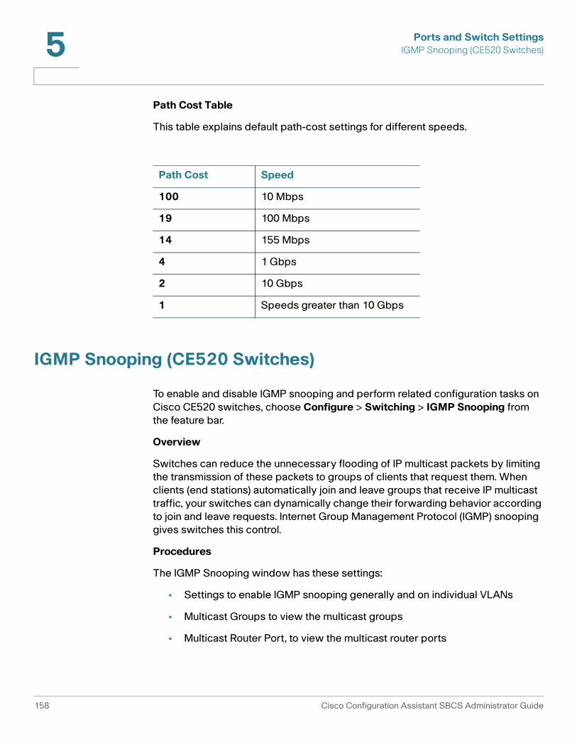
Ports and Switch SettingsIGMP Snooping (CE520 Switches)5
Path Cost Table
This table explains default path-cost settings for different speeds.
IGMP Snooping (CE520 Switches)
To enable and disable IGMP snooping and perform related configuration tasks on Cisco CE520 switches, choose Configure > Switching > IGMP Snooping from the feature bar.
Overview
Switches can reduce the unnecessary flooding of IP multicast packets by limiting the transmission of these packets to groups of clients that request them. When clients (end stations) automatically join and leave groups that receive IP multicast traffic, your switches can dynamically change their forwarding behavior according to join and leave requests. Internet Group Management Protocol (IGMP) snooping gives switches this control.
Procedures
The IGMP Snooping window has these settings:
• Settings to enable IGMP snooping generally and on individual VLANs
• Multicast Groups to view the multicast groups
• Multicast Router Port, to view the multicast router ports
Path Cost Speed
100 10 Mbps
19 100 Mbps
14 155 Mbps
4 1 Gbps
2 10 Gbps
1 Speeds greater than 10 Gbps
158 Cisco Configuration Assistant SBCS Administrator Guide

Ports and Switch SettingsMAC Addresses (CE520 Switches) 5
Before you make selections on the Setting tab, select a device from the Hostnames list. All the choices that you make on this tab will apply to the selected device.
Follow these steps to change the settings:
STEP 1 Enable IGMP Snooping is checked by default. Uncheck it only if you want to disable IGMP snooping on the entire device.
STEP 2 The table shows the VLANs that switch ports belong to and the settings for the VLANs. By default, IGMP snooping is enabled on the VLANs. To change any of these defaults, click Modify, and use the Modify IGMP Snooping Settings window. See Modify IGMP Snooping, page 159.
STEP 3 When you return to the IGMP Snooping window, click OK.
The information shown in the Multicast Groups tab and Multicast Router Ports tab is read-only and cannot be modified.
Modify IGMP Snooping
This window appears when you select a VLAN and click Modify on the IGMP Snooping window while viewing its Settings tab. Use this window to enable or disable IGMP snooping on the selected VLAN.
Follow these steps:
STEP 1 Select either Enable or Disable from the Status list.
STEP 2 When you have made your changes, click OK to close the window and return to the IGMP Snooping window.
MAC Addresses (CE520 Switches)
Switches store the MAC (Media Access Control) addresses of attached devices in a MAC addresses table. You can manage the addresses in this table by choosing Configure > Switching > MAC Addresses from the feature bar.
Cisco Configuration Assistant SBCS Administrator Guide 159

Ports and Switch SettingsMAC Addresses (CE520 Switches)5
Overview
A switch learns the MAC addresses of attached devices, VLAN IDs, and interface numbers by reading the source address of arriving packets. After an entry is removed, the switch relearns it. If the switch encounters a packet for an unknown destination, it floods the packet to all ports of the VLAN.
As stations are added or removed from the network, the switch updates the table, adding new entries and aging those not in use. The switch also updates the table by deleting all addresses associated with a port on which a VLAN membership change occurred.
A switch can learn an address in more than one VLAN, and an address that it learns in one VLAN can be entered as a secure address in another VLAN. An address that the switch learns in one VLAN is unknown in another VLAN until the address is learned.
Procedures
To view or update the MAC address table, follow these steps.
STEP 1 From that Hostname list, select the switch whose stored MAC addresses you want to see.
The table columns have these meanings.
STEP 2 Optional. To delete the addresses and clear the table, click Remove All.
STEP 3 Click OK to close the window.
Column Meaning
MAC Address The MAC address of an attached device.
VLAN ID The VLAN ID that is configured on the sending interface.
Output Interface The interface to which received packets should be forwarded if the MAC address of the sender matches the one in the MAC Address column.
160 Cisco Configuration Assistant SBCS Administrator Guide

Ports and Switch SettingsPort Search Window (CE520 Switches) 5
Port Search Window (CE520 Switches)
To access the Port Search window, choose Monitor > Search from the feature bar. This option is only available if a Cisco CE520 switch is present in the customer site.
Overview
You can search for ports or devices in your network. Perhaps you want to know the type, status, and speed of a port, but you do not know its number or what device it is on. You can find the information quickly if you know something about the text description that was entered for the port. You can also search for devices that are connected to a specific device if you know the MAC address or IP address of that specific device. To search ports or devices, choose, and enter a search phrase, IP address, or MAC address in the Search window.
When you have the port search results, use them to browse the Port Settings window, which gives you configuration settings and run-time status information. When you have the device search results, use them to browse the Topology view, which helps you locate the connected devices.
Procedures
From this window, you can search for ports that have a descriptive word or phrase associated with them. You can also search for devices that are connected to a specific device by entering the IP address or MAC address of the specified device.
Follow these steps:
STEP 1 In the Find Ports With Description/IP Address/MAC Address field, enter a descriptive word or phrase, a MAC address, or an IP address. What you enter is matched against all the devices in the community or cluster.
Enter the MAC address in the format xxxx.xxxx.xxxx.xxxx or xx:xx:xx:xx:xx:xx, where x is a hexadecimal character (0-9, a-f, A-F).
Cisco Configuration Assistant SBCS Administrator Guide 161

Ports and Switch SettingsPort Search Window (CE520 Switches)5
STEP 2 Click Search.
If you entered a port description in the Search field, ports that match the description appear in the Search Results area. This information appears in a table.
If you click Search with no text in the search field, Configuration Assistant shows you a list of all the community members, excluding WLAN controllers, and their ports.
If you entered an IP address or MAC address in the Search field, this information appears in a table:
STEP 3 Click OK when you are done with this window.
Column Explanation
Ports Device name and port number of the ports that match the description.
Description Description of the port.
Column Explanation
Host Name of the device whose IP address or MAC address was entered in the search field.
MAC Address MAC address of the device.
IP Address IP address of the device.
Description Type of device.
162 Cisco Configuration Assistant SBCS Administrator Guide

Ports and Switch SettingsEtherChannels (CE520 Switches) 5
EtherChannels (CE520 Switches)
To view or configure port groups on CE520 switches, choose Configure > Ports > EtherChannels from the feature bar.
Overview
Fast EtherChannel and Gigabit EtherChannel port groups are logical high-speed connections between switches or between switches and servers. Port groups can also provide redundant links between switches. The switch treats the port group as a single logical port; therefore, when you create a port group, the switch uses the configuration of the first port for all ports added to the group. After the group is created, changing STP or VLAN membership parameters for one port in the group automatically changes the parameters for all ports.
One port in each group carries all unknown multicast, broadcast, and STP packets.
The EtherChannels window displays port groups and enables you to:
• Create Fast EtherChannel and Gigabit EtherChannel port groups
• Remove ports from a port group
• Change the forwarding method for a group
Procedures
This window appears when you choose on the feature bar. You can also click here to launch it. Use it to display EtherChannel port groups and to:
• Create Port Groups
• Modify Port Groups
• Delete Port Groups
Begin by selecting a local device from the Hostname list. The information in the Channel Groups area applies to the selected device.
The Load Balance field is set to Source-Destination IP Address by default. This field cannot be modified.
Your choice applies to every port group that you create on the switch.
Cisco Configuration Assistant SBCS Administrator Guide 163

Ports and Switch SettingsEtherChannels (CE520 Switches)5
This table explains the columns in the Channel Groups area.
Create Port Groups
You can create up to 6 port groups. The ports that form a group must be of the same type.
Review Port Group Restrictions, page 165 before you use this procedure.
A port group can both contain up to 16 members if they are in LACP mode. Otherwise, it can contain up to 8 members.
By default, a switch forwards traffic to a port group based on the packet source address. If you configure a static address for a port group, configure the switch to forward packets from the static address to all ports in the group to eliminate the chance of lost packets. If you set the port group to forward packets based on the destination address, configure the switch to forward packets destined for the static address to only one port in the port group. Otherwise, the destination address receives duplicate packets.
To create a port group:
STEP 1 Click Create, and use the Create EtherChannel window. See Create Port Groups, page 166.
You can create a port group on the local device that you selected and, optionally, on a remote device.
Click OK to put your changes into effect and to close the window.
STEP 2 Click OK to close the EtherChannels window.
Column Explanation
Group The number assigned to the port group.
Ports The ports that belong to the group.
Status Either Down or In use. You also see that the group contains Layer 2 interfaces.
164 Cisco Configuration Assistant SBCS Administrator Guide

Ports and Switch SettingsEtherChannels (CE520 Switches) 5
Modify Port Groups
You can modify a port group by:
• Adding a member port
• Removing a member port
• Changing the LACP mode of a member port
To perform any of these tasks, follow these steps.
STEP 1 In the Channel Groups area, select the row for the group that you want to modify.
STEP 2 Click Modify, and use the Modify EtherChannel window. See Modify Port Groups, page 165.
You can modify a port group on the local device that you selected and, optionally, on a remote device.
STEP 3 Click OK to put your changes into effect and to close the window.
STEP 4 Click OK to close the EtherChannels window.
Delete Port Groups
To delete a port group, follow these steps.
STEP 1 In the Channel Groups area, select the row for the group that you want to delete.
STEP 2 Click Delete.
STEP 3 Click OK to close the window.
Port Group Restrictions
Any port can belong to a port group, but these restrictions apply:
• The Switch role must be applied to the port group member.
• No port group member can be configured for port monitoring.
• No port group member can be enabled for port security.
• Port group members must belong to the same set of VLANs and must be all static-access, all multi-VLAN, or all trunk ports.
Cisco Configuration Assistant SBCS Administrator Guide 165

Ports and Switch SettingsEtherChannels (CE520 Switches)5
• Dynamic-access ports cannot be grouped with any other port, not even with other dynamic-access ports.
• A network port cannot be in a destination-based port group.
Create Port Groups
This window appears when you click Create in the EtherChannels window. Use it to assign local ports to a port group on the selected device, and optionally, to assign remote ports to a port group on a remote device.
Only ports that are assigned the switch port role appear in this window.
Follow these steps:
STEP 1 If you are creating port groups on a local and a remote device, select the remote device from the Remote Device list. Under the Remote Ports side of the window, you see the remote ports that are connected to the ports of the local device.
Notice that the options for the remote device are the same as for the local device. When you select options for the local device, do the same for the remote device.
STEP 2 In the Group field, enter the number of the port group that you are creating.
STEP 3 Check the box under In Group for each port that you want to be a group member.
STEP 4 Bypass the Status column. It shows the status of the ports only in the Modify EtherChannel window.
STEP 5 Click in the Mode cells for the selected ports, and select one of these values:
• LACP. The port can form a link aggregate and initiate the channel. The aggregate is formed if the other end is running LACP in active mode.
• On (No LACP). The port does not use LACP. A usable EtherChannel only exists if the port group is connected to another group in this mode.
STEP 6 Click in the Priority cells for the selected ports, and enter a LACP priority if you do not want the default (32768 for LACP).
The port with the highest priority sends the packets.
STEP 7 Click OK to close the window.
The new port group appears in the EtherChannels window.
166 Cisco Configuration Assistant SBCS Administrator Guide
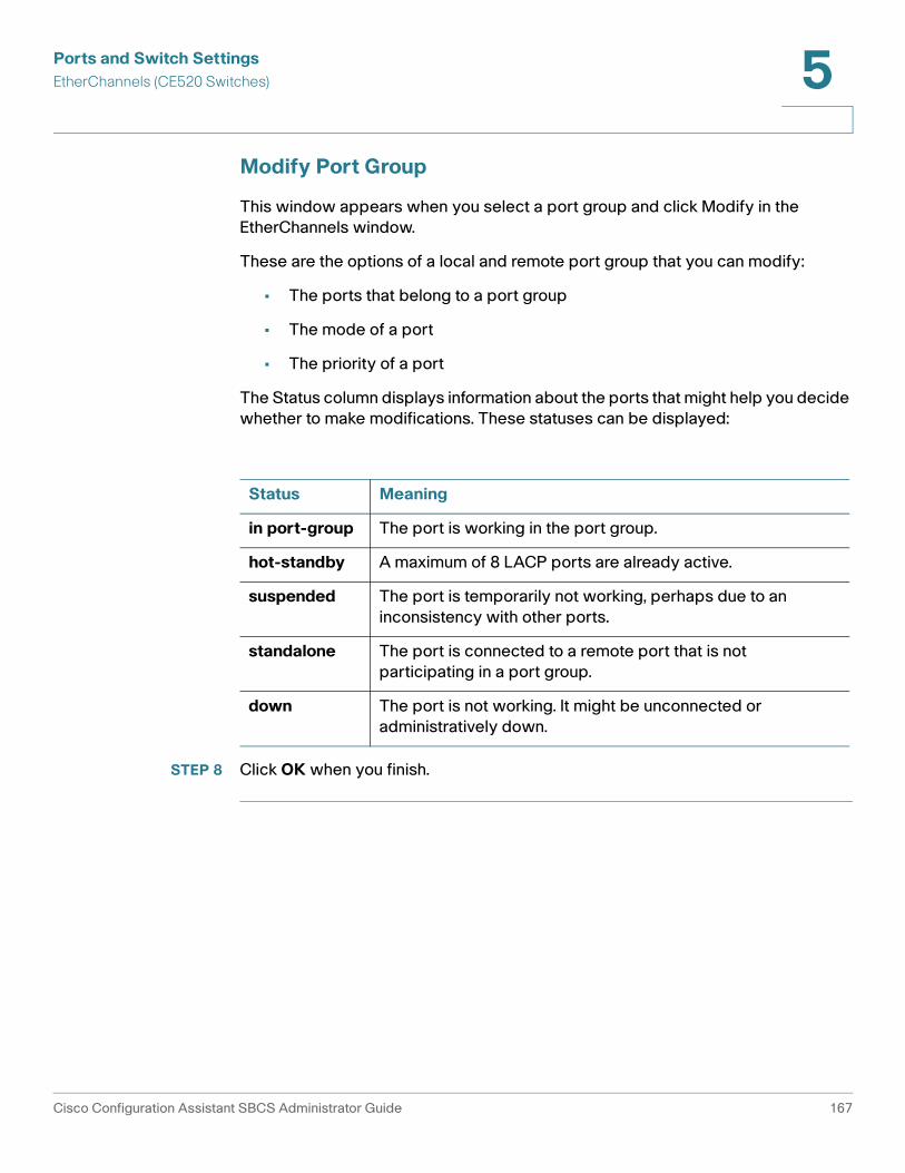
Ports and Switch SettingsEtherChannels (CE520 Switches) 5
Modify Port Group
This window appears when you select a port group and click Modify in the EtherChannels window.
These are the options of a local and remote port group that you can modify:
• The ports that belong to a port group
• The mode of a port
• The priority of a port
The Status column displays information about the ports that might help you decide whether to make modifications. These statuses can be displayed:
STEP 8 Click OK when you finish.
Status Meaning
in port-group The port is working in the port group.
hot-standby A maximum of 8 LACP ports are already active.
suspended The port is temporarily not working, perhaps due to an inconsistency with other ports.
standalone The port is connected to a remote port that is not participating in a port group.
down The port is not working. It might be unconnected or administratively down.
Cisco Configuration Assistant SBCS Administrator Guide 167

Ports and Switch SettingsEtherChannels (CE520 Switches)5
168 Cisco Configuration Assistant SBCS Administrator Guide

6
Routing and Network Connections
This section covers network routing configuration and includes these topics:
• IP Addresses
• Internet Connection
• DHCP Server
• Static Routing
IP Addresses
To manage IP addresses, choose Configure > Routing > IP Addresses from the feature bar. See these topics for information about enabling and configuring IP addresses:
• Overview
• Modifying Default VLANs
• Interface Configuration
• Device Configuration
!CAUTION We do not recommend that you configure IP addressing over a remote WAN
connection. If the connection to the WAN is interrupted, the operation will fail and the system may become unusable.
Cisco Configuration Assistant SBCS Administrator Guide 169

Routing and Network ConnectionsIP Addresses6
Overview
The IP Addresses window has these tabs
• Interface Configuration, to assign or modify an IP address and subnet mask for a VLAN. When you do this, the VLAN becomes an SVI (switched virtual interface). Creating an SVI does not enable routing on the device.
• Device Configuration, to associate a domain name with the selected device
Modifying Default VLANs
Default VLANs are part of the factory configuration for these devices:
• For the UC 500, these default VLANs are created:
- VLAN 1: Default data VLAN for the UC 500.
- VLAN 100: Default voice VLAN for the UC 500.
- BV175: UC 500 wireless data VLAN
• For the SR 520, the default data VLAN is VLAN75.
• For the SR 520-T1, the default data VLANs are LAN0 (FastEthernet0) and LAN1 (FastEthernet1)
You can modify the IP address and subnet mask for these default VLANs on the Interface Configuration tab in the IP Addresses window.
The default data and voice VLAN configuration for the UC 500 can also be modified through the Telephony Setup wizard, which must be run on a system that is at factory default state or through the Multisite Manager.
!CAUTION Modifying IP address of the default data and voice VLANs after initial system
configuration results in changes to other system configuration settings. After you change this configuration, verify that the system functions as expected.
Do not modify these settings over a remote WAN connection.
Editing the Network field for the VLAN100 or VLAN1 interface on the DHCP Pools tab in the DHCP Server window (Configure > Routing > DHCP Server), will have the same effect as changing the IP address of the data and/or voice VLAN on the device.
170 Cisco Configuration Assistant SBCS Administrator Guide

Routing and Network ConnectionsIP Addresses 6
IMPORTANT:
• After changing the default data VLAN IP address, you must manually adjust any custom NAT port mappings rules defined under Configure > Security > NAT.
• After changing the default data VLAN IP address on the UC 500, you must restart any ESW 500 Series switches in the customer site in order to renew the DHCP lease on the ESW 500. This issue could also apply to other devices in the site.
The following table describes configuration settings that are automatically updated by CCA when you the IP address of each of these default VLANs for these devices.
Device Default VLAN Settings that are updated when this VLAN is modified
UC 500 Data VLAN (VLAN1)
The IP address of the data VLAN (VLAN1 / BVI1) is set to the new value.
The existing DHCP address exclusion range is removed and a new DHCP address exclusion range is added, based on the new data VLAN IP.
The existing VPN IP address pool is removed, and a new VPN IP address pool is added, based on the new data VLAN IP address.
Dial peers that use session target to point to the route for the existing data VLAN IP address are modified to point to the new one. For example, if the new data VLAN IP address is 192.168.20.1, the dial peer uses session target ipv4:192.168.20.1.
All ACLs (access control lists) are modified to use the new data VLAN IP address.
If the UC 500 is behind an SR 500:
• All ACLs that refer to the existing subnet are modified to refer to the new one.
• Static routes from the SR 500 to the UC 500 that refer to the existing data VLAN IP address are modified to use the new data VLAN IP address.
If the UC 500 is behind an SA 500 security appliance and the SA 500 has static routes to the existing data VLAN on the UC 500, these are modified to point to the new data VLAN.
Cisco Configuration Assistant SBCS Administrator Guide 171

Routing and Network ConnectionsIP Addresses6
UC 500 Voice VLAN (VLAN100)
UC-500 wireless data VLAN is modified (VLAN75/BVI75) to use the new value.
SCCP control application settings are modified to refer to the new voice VLAN IP address.
ACLs on the UC 500 that refer to the existing voice VLAN IP address are modified to refer to the new one.
If the UC 500 is behind an SR 500 or SA 500, ACLs on the SR 500 or SA 500 that refer to the existing voice VLAN IP address are modified to refer to the new one.
SR 500 and SR 520-T1
Data VLAN
VLAN75 for the SR 500
FastEthernet0/0, FastEthernet0/1 for the SR 520-T1)
The IP address of the data VLAN (VLAN75) is set to the new value.
The existing DHCP address exclusion range is removed and a new DHCP address exclusion range is added, based on the new data VLAN IP.
The existing VPN IP address pool is removed, and a new VPN IP address pool is added, based on the new data VLAN IP address.
All ACLs (access control lists) are modified to use the new data VLAN IP address.
If a UC 500 is behind the SR 500:
• All ACLs that refer to the existing data VLAN IP address are modified to refer to the new subnet.
• Static routes on the UC 500 that refer to the data VLAN IP address of the SR 500 modified to use the new data VLAN IP address.
Network Address Translation (NAT) rules on the SR 500 for forwarding traffic on ports 5060 (SIP) and 1720 (H323) are modified to use the new data LAN IP address.
Default routes for the UC500, if it is connected to an SR 500 and connected to a customer site, are also adjusted to reflect the new value.
Device Default VLAN Settings that are updated when this VLAN is modified
172 Cisco Configuration Assistant SBCS Administrator Guide

Routing and Network ConnectionsIP Addresses 6
Interface Configuration
Begin by selecting a device from the Hostname list.
In the Interface Name column, you see the names of the VLANs that are configured on the selected device. These can be default VLANs that are part of the factory default settings for a device or VLANs that you added.
• To assign a new IP address, click in the IP address column for the selected device, and enter the new IP address.
• To assign a new subnet mask, click the Subnet Mask column for the selected device, and enter a new value.
Click OK or Apply when you are finished.
If you are connected to the default data VLAN on the UC 500 or SR 500, you will lose the connection to the UC 500 when data VLAN IP address for the UC 500 or SR 500 data VLAN is modified. Close CCA, then re-launch CCA and connect to the device or site using the new IP address.
Device Configuration
STEP 1 Begin by selecting a device from the Hostname list.
STEP 2 In the Domain Name field, enter a name that identifies an administrative region in the IP network. You might need to ask your network administrator for this information. When network traffic contains no domain name, the name that you enter is appended to the name of the device, and the fully qualified name is added to the devices hostname table.
STEP 3 Check Enable Domain Lookup to enable servers to translate device names to IP addresses.
STEP 4 In the New Server field, enter the name of a device that you want to use as a DNS server (domain name server), and then click Add. The device is added to the Current Servers list.
STEP 5 To stop using a device as a DNS server, select it in the Current Servers list, and click Remove.
STEP 6 Click OK or Apply.
Cisco Configuration Assistant SBCS Administrator Guide 173

Routing and Network ConnectionsInternet Connection6
Internet Connection
The Internet Connection Window appears when you choose Configure > Routing > Internet Connection from the feature bar.
Overview
The Internet Connection window has two tabs:
• Connection Settings: For enabling and configuring the Internet WAN connection and configuring optional DDNS (Dynamic Domain Name Service) settings.
• Traffic Shaping: For enabling traffic shaping and configuring Quality of Service (QoS) settings (recommended for multisite deployments).
Connection Settings
From this tab, you enable and configure the Internet connection. These connection types are supported:
• PPPoE or PPPoE with a negotiated IP address: PPPoE can be used by multiple hosts on a shared Ethernet interface to open PPP sessions to multiple destinations with one or more bridging modems. If you choose a negotiated IP address, the router obtains an IP address through PPP/IPCP (Point-to-Point Protocol/IP Control Protocol) address negotiation.
• Static IP address: Configure the interface to use a static IP address.
• DHCP: Configure the interface to obtain an IP address from a DHCP server.
You can also configure optional settings for Dynamic DDNS.
To enable and configure the Internet connection, follow these steps.
STEP 1 Choose a device to be configured from the Hostname list.
STEP 2 Choose an interface from the WAN Interfaces list.
STEP 3 Click Modify to open the Modify Internet Connection window. See Modify Internet Connection, page 176.
STEP 4 To save your changes and to close the window, click OK.
174 Cisco Configuration Assistant SBCS Administrator Guide

Routing and Network ConnectionsInternet Connection 6
Traffic Shaping
From this tab, you enable Traffic Shaping and configure QoS settings.
These settings are primarily used in conjunction with configuring the maximum number of simultaneous calls for multisite deployments.
• See Configuring Quality of Service (QoS), page 400 for more information and guidelines for configuring QoS for multisite deployments.
• See Maximum Calls (Call Admission Control), page 402 for information about configuring call admission control based on these settings.
Configure settings as described in the following table. Click OK or Apply when finished.
Setting Description
Traffic Shaping Check this setting to enable QoS and traffic shaping.
Upstream Bandwidth [kbps]
When Traffic Shaping is enabled, enter the actual upstream bandwidth for the site in kbps, as determined by a connection speed test or the Committed Information Rate (CIR) specified in the Service Level Agreement (SLA) for the Internet service provider.
Valid values range from 384 to 100000 kbps.
For example, if the upstream bandwidth is 1.8 Mbps, enter 1800 for the upstream bandwidth.
If the CIR or the results of an connection speed test are not available, enter a value in kbps that is 80% of the upstream bandwidth advertised by the Internet Service Provider (ISP).
Cisco Configuration Assistant SBCS Administrator Guide 175
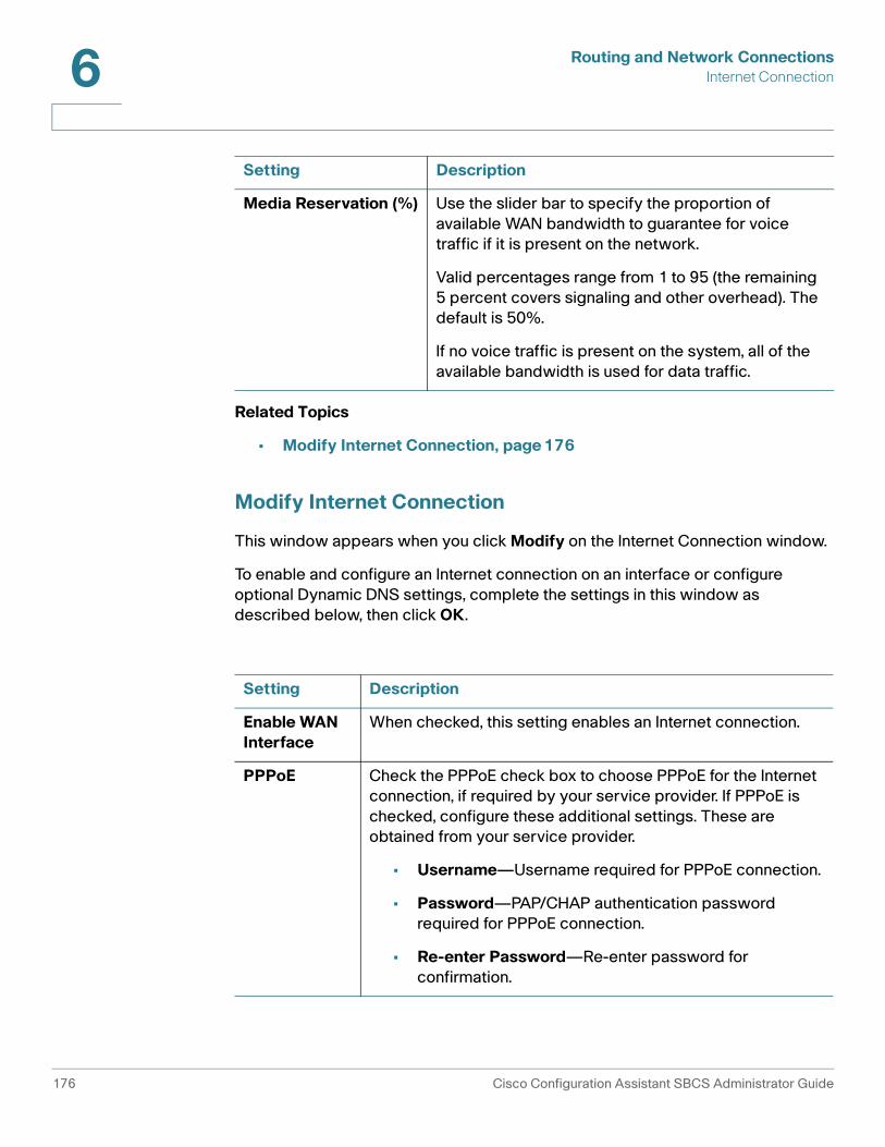
Routing and Network ConnectionsInternet Connection6
Related Topics
• Modify Internet Connection, page 176
Modify Internet Connection
This window appears when you click Modify on the Internet Connection window.
To enable and configure an Internet connection on an interface or configure optional Dynamic DNS settings, complete the settings in this window as described below, then click OK.
Media Reservation (%) Use the slider bar to specify the proportion of available WAN bandwidth to guarantee for voice traffic if it is present on the network.
Valid percentages range from 1 to 95 (the remaining 5 percent covers signaling and other overhead). The default is 50%.
If no voice traffic is present on the system, all of the available bandwidth is used for data traffic.
Setting Description
Enable WAN Interface
When checked, this setting enables an Internet connection.
PPPoE Check the PPPoE check box to choose PPPoE for the Internet connection, if required by your service provider. If PPPoE is checked, configure these additional settings. These are obtained from your service provider.
• Username—Username required for PPPoE connection.
• Password—PAP/CHAP authentication password required for PPPoE connection.
• Re-enter Password—Re-enter password for confirmation.
Setting Description
176 Cisco Configuration Assistant SBCS Administrator Guide
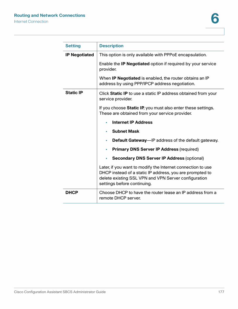
Routing and Network ConnectionsInternet Connection 6
IP Negotiated This option is only available with PPPoE encapsulation.
Enable the IP Negotiated option if required by your service provider.
When IP Negotiated is enabled, the router obtains an IP address by using PPP/IPCP address negotiation.
Static IP Click Static IP to use a static IP address obtained from your service provider.
If you choose Static IP, you must also enter these settings. These are obtained from your service provider.
• Internet IP Address
• Subnet Mask
• Default Gateway—IP address of the default gateway.
• Primary DNS Server IP Address (required)
• Secondary DNS Server IP Address (optional)
Later, if you want to modify the Internet connection to use DHCP instead of a static IP address, you are prompted to delete existing SSL VPN and VPN Server configuration settings before continuing.
DHCP Choose DHCP to have the router lease an IP address from a remote DHCP server.
Setting Description
Cisco Configuration Assistant SBCS Administrator Guide 177

Routing and Network ConnectionsInternet Connection6
HTTP DDNS
Optional. Configure settings for Dynamic Domain Name Service (DDNS).
Site that use DHCP to dynamically obtain an IP address can use a Dynamic DNS (DDNS) hosting service to allow aliasing of dynamic (DHCP) IP addresses to static hostnames.
DDNS can also be configured for devices with an IP Negotiated WAN IP address.
Sites that use DHCP that are also part of a multisite deployment must configure HTTP DDNS.
Provider Choose a DDNS provider from the pull-down menu.
You must create your own DDNS account with one of these providers outside of Configuration Assistant.
These DDNS hosting services are available.
• cgi.tzo.com
• dup.hn.org
• members.dyndns.org
• members.easydns.com
• www.dynx.cx
• www.justlinux.com
• www.zoneedit.com
Hostname Unique hostname for this site, obtained from your DDNS provider. This is usually a fully qualified domain name (FQDN) for example, myhost.mydomain.net, but might be different for some DDNS services. The hostname must be registered.
This field is not validated by Configuration Assistant. Make sure that you have entered the hostname exactly as specified by your DDNS provider.
If you are configuring a multisite deployment, each site must have a unique DDNS hostname.
Setting Description
178 Cisco Configuration Assistant SBCS Administrator Guide

Routing and Network ConnectionsDHCP Server 6
Related Topics
• Configuring DDNS, page 399
• Configuring Quality of Service (QoS), page 400
• Voice Features Supported Across Multiple Sites, page 408
DHCP Server
To configure DHCP Server settings, choose Configure > Routing > DHCP Server from the feature bar.
NOTE You can also configure DHCP IP address pools for the Voice VLAN on the Network tab in the Voice window (Configure > Telephony > Voice).
Overview
A DHCP (Dynamic Host Configuration Protocol) IP address pool is a range of IP addresses that a DHCP server can dynamically issue to client devices. Because not all clients are connected all the time, providing IP addresses as needed reduces the number of IP addresses required to serve a group of clients by reusing the same IP address for different clients at different times.
To manage the DHCP IP address pool, you can:
• Create a DHCP IP address pool that identifies the range of IP addresses in the pool.
• Bind a specific IP address in the pool to a specific MAC address, creating a static IP address for that client device. (Some clients require static IP addresses to maintain connectivity to support running applications.)
• Exclude specific IP address from the pool so that they will not be assigned to a client by the DHCP server. (A few IP addresses in the range might have
Username Account user name, obtained from your DDNS provider.
Password Account password, obtained from your DDNS provider.
Confirm Password
Re-enter the password for confirmation.
Setting Description
Cisco Configuration Assistant SBCS Administrator Guide 179

Routing and Network ConnectionsDHCP Server6
been assigned through other processes. To avoid conflicts, you can exclude those addresses from the pool.)
The range of the pool is calculated from the network number and subnet mask. All available node-level IP addresses are included in the pool and made available to the server unless they are specifically bound to a MAC address or excluded from the pool; the server ignores manual address bindings and exclusions.
The DHCP Server window has these tabs:
• DHCP Pools: Display, create, modify, or delete a DHCP pool of IP addresses.
• DHCP Bindings: Manually assign IP addresses in the DHCP pool to the MAC addresses of clients.
• DHCP Exclusions: Specify the IP address that the DHCP server should not assign to (exclude from) clients.
DHCP Pools
A DHCP (Dynamic Host Configuration Protocol) IP address pool is a range of IP addresses that a DHCP server can dynamically issue to client devices.
Two default DHCP pools are created for the UC 500: phone and default. These default DHCP pools can be modified, but these default pool names are reserved and cannot be modified.
• The phone pool is associated with the Voice VLAN (VLAN 100) on the UC 500. IP addresses from the phone DHCP pool are assigned to IP phones during auto-registration.
• The data pool is associated with the Data VLAN (VLAN1) on the UC 500. IP addresses from this pool are assigned to devices on the data VLAN that request an IP address from the DHCP server.
To display the properties configured for a DHCP pool, click on the DHCP pool name.
To create a new DHCP pool, click Create, and use the Create DHCP Pool window. See Create DHCP Pool, page 182.
To modify an existing DHCP pool, choose the DHCP pool, click Modify, and use the Modify DHCP Pool window. SeeModify DHCP Pool, page 183.
To delete a DHCP pool, choose the DHCP pool name, then click Delete. A window appears, warning you that if you proceed, you will delete the DHCP pool.
To close the window, click OK.
180 Cisco Configuration Assistant SBCS Administrator Guide

Routing and Network ConnectionsDHCP Server 6
DHCP Bindings
Once you create a DHCP pool, you can manually assign IP addresses from that pool to specific devices based on their MAC address.
To create a new DHCP binding, click Create, and use the Create DHCP Binding window. See Create DHCP Binding, page 183.
To modify an existing DHCP binding, choose the pool name, click Modify, and use the Modify DHCP Binding window. See Modify DHCP Binding, page 184.
To delete a DHCP binding, choose the DHCP binding name, then click Delete. A window appears, warning you that if you proceed, you will delete the DHCP binding.
To close the window, click OK.
DHCP Exclusions
From this tab, you specify individual IP addresses or ranges of IP address to be excluded from the DHCP address pool. These addresses cannot be assigned to DHCP clients.
To create a new DHCP exclusion, click Create, and use the Create DHCP Exclusion window. See Create DHCP Exclusion, page 181.
To delete a DHCP exclusion, choose the IP address, and click Delete.
By default, these IP addresses are excluded from DHCP pools:
• 10.1.1.1 through 10.1.1.9 (reserved for IOS and CUE)
• 192.168.10.1 through 192.168.10.9 (reserved for the UC 500)
• 10.1.1.255 and 192.168.10.255 broadcast addresses
DHCP Pool Bindings
Automatic binding -- the DHCP server will create the binding. After the lease time expires, the device may get a new IP.
Manual binding -- you want this device to use this IP address. The lease does not expire.
Create DHCP Exclusion
This window appears when you click Create on the DHCP IP Exclusion tab of the DHCP Server window.
Cisco Configuration Assistant SBCS Administrator Guide 181

Routing and Network ConnectionsDHCP Server6
Use this dialog to add a range of DHCP IP address exclusions.
Follow these steps:
STEP 1 In the Start IP Address field, enter the first DHCP IP address in the range that the DHCP server should not assign to DHCP clients.
STEP 2 In the End IP Address field, enter the last DHCP IP address in the range that the DHCP server should not assign to DHCP clients.
STEP 3 Click OK.
Create DHCP Pool
This window appears when you click Create on the DHCP Pool tab of the DHCP Server window.
Use this dialog to create a DHCP pool and to optionally identify DNS servers, a domain name, a default router, and WINS (Windows Internet Naming Service) servers.
To create a DHCP pool, configure the settings described below, then click OK.
Setting Description
Name Enter the DHCP pool name.
On the UC 500, the phone and data DHCP pool names are reserved for the voice (VLAN100) and data (VLAN1) VLANs.
Network Starting IP address of the DHCP pool.
If you edit the Network setting for the phone and data DHCP pools on the UC 500, this has the same effect as changing the IP address for these default VLANs. See Modifying Default VLANs, page 170.
Subnet Mask Enter the subnet network mask.
DNS Server1 In the DNS Server1 field, enter the IP address of a DNS server. DHCP clients query DNS servers to correlate hostnames to IP addresses.
182 Cisco Configuration Assistant SBCS Administrator Guide

Routing and Network ConnectionsDHCP Server 6
Modify DHCP Pool
This window appears when you click Modify on the DHCP Pools tab of the DHCP Server window.
Use this dialog to modify an existing DHCP pool, including the DNS servers, a domain name, a default router, or the WINS servers.
You cannot modify the name of the default phone and data DHCP pools. All other settings can be modified for these pools.
See Create DHCP Pool, page 182 for an explanation of the fields in this window.
Click OK when you are finished with this window.
Create DHCP Binding
This window appears when you click Create on the DHCP Bindings tab of the DHCP Server window.
To create a DHCP binding, configure settings as described below, then click OK.
DNS Server2 Optional. In the DNS Server2 field, enter the IP address of a second DNS server.
Domain Name Enter the name of the domain. The domain name of a DHCP client places the client in the domain.
WINS Server1, WINS Server2
Optional. In the WINS Server1, WINS Server2 fields, enter the IP address of the WINS servers. These fields specify the WINS servers that are available to a Microsoft DHCP client.
Default Router Optional. In the Default Router field, enter the IP address of the default gateway. When a DHCP client starts, the client begins sending packets to its default gateway. The IP address of the default gateway must be on the same subnet as the client.
Setting Description
Name Enter a name for the DHCP server address pool.
Setting Description
Cisco Configuration Assistant SBCS Administrator Guide 183
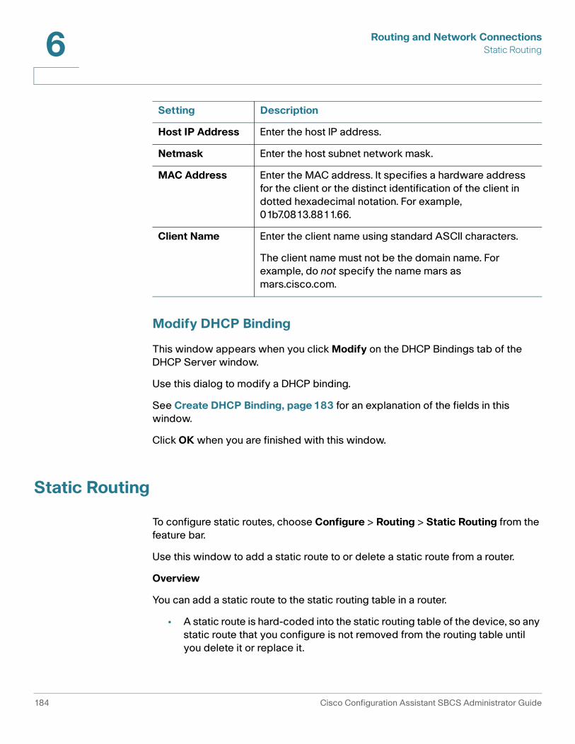
Routing and Network ConnectionsStatic Routing6
Modify DHCP Binding
This window appears when you click Modify on the DHCP Bindings tab of the DHCP Server window.
Use this dialog to modify a DHCP binding.
See Create DHCP Binding, page 183 for an explanation of the fields in this window.
Click OK when you are finished with this window.
Static Routing
To configure static routes, choose Configure > Routing > Static Routing from the feature bar.
Use this window to add a static route to or delete a static route from a router.
Overview
You can add a static route to the static routing table in a router.
• A static route is hard-coded into the static routing table of the device, so any static route that you configure is not removed from the routing table until you delete it or replace it.
Host IP Address Enter the host IP address.
Netmask Enter the host subnet network mask.
MAC Address Enter the MAC address. It specifies a hardware address for the client or the distinct identification of the client in dotted hexadecimal notation. For example, 01b7.0813.8811.66.
Client Name Enter the client name using standard ASCII characters.
The client name must not be the domain name. For example, do not specify the name mars as mars.cisco.com.
Setting Description
184 Cisco Configuration Assistant SBCS Administrator Guide

Routing and Network ConnectionsStatic Routing 6
• A static route has priority over all dynamic routes and reduces processing time by quickly determining the path for a packet. Dynamic routes are learned by the device by using IP routing protocols such as RIP, require more processor time, and age out of the routing table if they are not refreshed.
On the UC 500, a static route is created to 10.1.10.1, the Integrated-Service-Engine-0/0 interface, which is the CUE (Cisco Unity Express) module. Do not delete this route.
Procedures
Begin by selecting the device to be configured from the Hostname list.
• To add a static route, click Add, and use the Add Static Route window. See Add Static Route, page 185.
• To delete a static route, choose the static route to be removed, then click Delete.
Click OK to close the window.
Add Static Route
This window appears when you click Add on the Static Routing window.
To add a static route to a router, configure settings as described below, then click OK to close the window and save your changes.
Setting Description
Destination/Network IP field
Enter the IP address of the destination network.
Network Mask Enter the subnet mask of the destination network.
Gateway IP or Outgoing Interface
Choose an interface from Outgoing Interface list or choose Enter Gateway IP.
If you chose Enter Gateway IP, enter the IP address of the gateway or the outgoing interface in the text box below this field.
Cisco Configuration Assistant SBCS Administrator Guide 185

Routing and Network ConnectionsStatic Routing6
186 Cisco Configuration Assistant SBCS Administrator Guide

7
Wireless
Configuration Assistant provides tools for configuring wireless access points and wireless LAN controllers on your system. This section includes these topics:
• Configuring Secure Wireless Settings
• Convert to LAP (Lightweight Access Point)
• Wireless LAN Controller Configuration, page 212
See Wireless Setup Wizard, page 91 for information on using the CCA Wireless Setup Wizard to configure wireless settings and synchronize wireless profile settings on access points and SPA 525G IP phones.
Configuring Secure Wireless Settings
To configure security on wireless access points, choose Configure > WLANs (SSID) on the feature bar.
From the WLANS (SSIDs) window, you can:
• Configure SSID settings for wireless security
• Choose whether or not to broadcast the SSID
• View the security settings that you configured on the access point
• Configure RADIUS servers
• Configure wirelesss radio settings for autonomous access points
• Configure MAC authentication for AP541N access points
• Enable or disable the wireless interface for UC 500 and SR 500 devices with integrated wireless capabilities
Cisco Configuration Assistant SBCS Administrator Guide 187

WirelessConfiguring Secure Wireless Settings7
NOTE To disable wireless for UC 500 and SR 500 devices with integrated wireless capabilities, uncheck the Enable Wireless Interface option in the WLANs (SSIDs) window. By default, the wireless interface is enabled for these platforms.
Wireless settings vary, depending on the type of access point you are configuring:
• Wireless Settings for Cisco AP541N Access Points
• Wireless Settings for Cisco AP 521 and UC 500 or SR 500 Built-in Access Points
Wireless Settings for Cisco AP541N Access Points
These sections explain the wireless configuration settings on each of the three tabs in the WLANs (SSIDs) window for Cisco AP541N Single-radio Dual-band access points.
• SSIDs
• Radius
• MAC Authentication
NOTE To configure features on the AP541N that are not currently managed through CCA such as clustering, use the AP541N Configuration Utility. To access this utility, right click on the AP541N icon in the Topology view and choose Configuration Utility from the pop-up menu.
SSIDs
From the SSIDs tab, you can view, create, or modify SSIDs and their associated settings for AP541N access points.
Up to sixteen (16) SSIDs can be created on a single AP541N access point.
• To create new SSID, click Create to open the Create or Modify SSID window.
• To modify settings for an existing SSID, select the SSID from the list and click Modify.
For detailed information about SSID settings for AP541N access points, see Create or Modify SSIDs for Cisco AP541N Access Points, page 199.
This table explains the settings displayed in the SSIDs window.
188 Cisco Configuration Assistant SBCS Administrator Guide
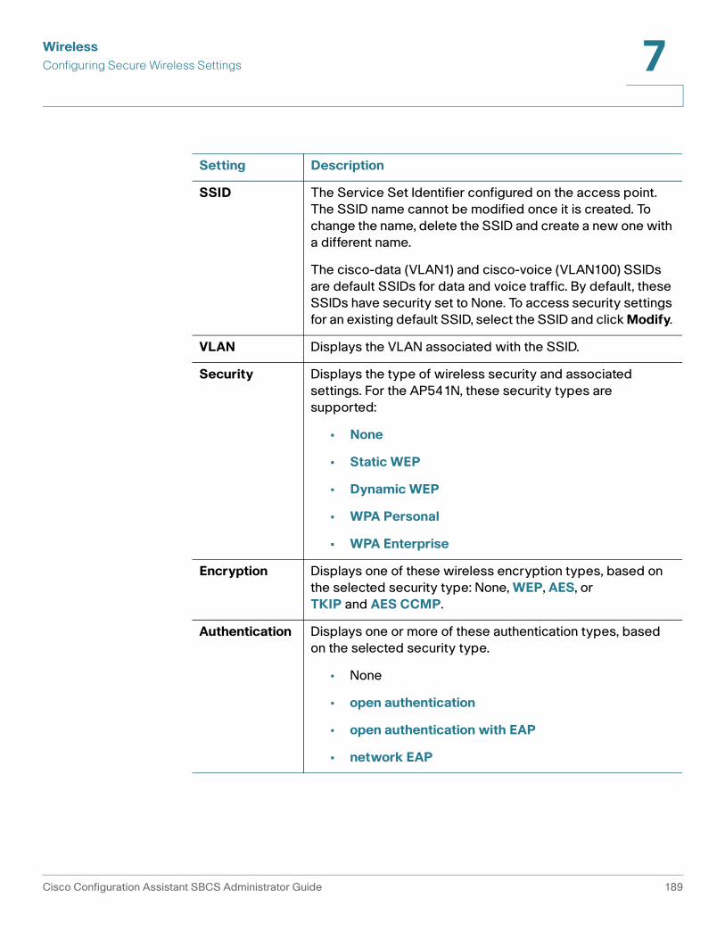
WirelessConfiguring Secure Wireless Settings 7
Setting Description
SSID The Service Set Identifier configured on the access point. The SSID name cannot be modified once it is created. To change the name, delete the SSID and create a new one with a different name.
The cisco-data (VLAN1) and cisco-voice (VLAN100) SSIDs are default SSIDs for data and voice traffic. By default, these SSIDs have security set to None. To access security settings for an existing default SSID, select the SSID and click Modify.
VLAN Displays the VLAN associated with the SSID.
Security Displays the type of wireless security and associated settings. For the AP541N, these security types are supported:
• None
• Static WEP
• Dynamic WEP
• WPA Personal
• WPA Enterprise
Encryption Displays one of these wireless encryption types, based on the selected security type: None, WEP, AES, or TKIP and AES CCMP.
Authentication Displays one or more of these authentication types, based on the selected security type.
• None
• open authentication
• open authentication with EAP
• network EAP
Cisco Configuration Assistant SBCS Administrator Guide 189

WirelessConfiguring Secure Wireless Settings7
Radius
From the Radius tab, you can enable and configure global settings for external RADIUS servers for accounting and authentication of wireless clients. The AP541N does not have a local RADIUS server.
MAC Authentication Type
You can configure a global list of MAC addresses that are allowed or denied access to the network. Choose one of the following MAC Authentication Types:
• Local—Use the MAC Authentication list that you configure on the MAC Authentication tab. See MAC Authentication, page 191.
• Radius—Use the MAC Authentication list configured on the external RADIUS server.
• Disabled—Do not use MAC authentication.
Setting Description
RADIUS IP Address Enter the address for the primary global RADIUS server.
When the first wireless client tries to authenticate with the AP, the AP sends an authentication request to the primary server. If the primary server responds to the authentication request, the AP continues to use this RADIUS server as the primary server, and authentication requests are sent to the address you specify.
RADIUS IP Address-1, RADIUS IP Address-2, RADIUS IP Address-3
Enter up to three IPv4 addresses for the backup RADIUS servers.
If authentication fails with the primary server, each configured backup server is tried in sequence. The address must be valid in order for the AP to attempt to contact the server
Setting Description
190 Cisco Configuration Assistant SBCS Administrator Guide

WirelessConfiguring Secure Wireless Settings 7
MAC Authentication
On the MAC Authentication tab, you specify a list of MAC addresses to control access to the network through the AP based on the MAC address of the wireless client. You also specify whether the clients with those MAC addresses are allowed or denied access to the network. This local list is used when MAC Authentication is set to Local for an SSID configured on the AP541N.
To configure MAC authentication settings, follow these steps.
RADIUS Key The RADIUS Key is the shared secret key for the primary global RADIUS server.
You can enter up to 63 standard alphanumeric and special characters for the RADIUS Key. The key is case-sensitive, and you must configure the same key on the AP and on your RADIUS server.
The RADIUS key is not displayed in plain text as you type it.
RADIUS Key-1, RADIUS Key-2, RADIUS Key-3
Enter the RADIUS key associated with each of the configured backup RADIUS servers.
The server at RADIUS IP Address-1 uses RADIUS Key-1, RADIUS IP Address-2 uses RADIUS Key-2, and so on.
You can enter up to 63 standard alphanumeric and special characters for the Radius Key. The key is case-sensitive, and you must configure the same key on the AP and on your RADIUS server.
The RADIUS key is not displayed in plain text as you type it.
Enable RADIUS Accounting
Enable this option to track and measure the resources a particular user has consumed such as system time, amount of data transmitted and received, and so on.
If you enable RADIUS accounting, it is enabled for the primary RADIUS server and all backup servers.
Setting Description
Cisco Configuration Assistant SBCS Administrator Guide 191
WirelessConfiguring Secure Wireless Settings7
STEP 1 Choose how you want to filter the clients with the MAC addresses specified in the list.
• Choose Allow Addresses in the List to only allow access to clients with the MAC addresses specified in the list.
• Choose Deny Addresses in the List to allow access to all clients except those with the MAC addresses specified in the list.
STEP 2 Click Add to open a new row in the table.
STEP 3 Click anywhere in the row and enter the 12-digit hexadecimal MAC address of the client to add to the list.
Enter MAC addresses using the format xxxx.xxxx.xxxx. For example 0101.FEFE.2345. The dot (.) characters are entered automatically as you type. Do not use colons to separate hexadecimal digits in the MAC address.
STEP 4 Continue adding MAC addresses to the list as needed.
STEP 5 Click Apply or OK when you are finished.
To remove a MAC address from the list, highlight the address in list and click Remove, then click Apply or OK.
Wireless Settings for Cisco AP 521 and UC 500 or SR 500 Built-in Access Points
These sections explain the configuration settings on each of the three tabs in the WLANs (SSIDs) window:
• Wireless Network Names (SSIDs)
• RADIUS Servers
• Access Point Settings
NOTE SR 500 Series Secure Routers with built-in access points have similar settings, but the GUI for configuring these settings does not have separate tabs. See the Wireless Network Names (SSIDs) and RADIUS Servers sections for information about these settings.
192 Cisco Configuration Assistant SBCS Administrator Guide

WirelessConfiguring Secure Wireless Settings 7
Wireless Network Names (SSIDs)
You can configure security features on your autonomous access point. The security features protect wireless communication between the autonomous access point and other wireless devices and prevent unauthorized entry. You can configure different levels of security and encryption on your autonomous access points. The security levels range from no security to high security.
This table explains the columns in this window.
Setting Description
SSID The Service Set Identifier configured on the access point.
VLAN The VLAN associated with the SSID.
Enable wireless interface
This option is only displayed for UC 500 and SR 500 devices with integrated wireless capabilities. When this option is unchecked, the wireless interface on these devices is shut down. You can still configure SSIDs and settings when the wireless interface is shut down.
Security Type of wireless security and associated settings:
• No Security
• WEP , page 205
• EAP, page 205
• LEAP, page 206
• WPA, page 206
• WPA-PSK, page 207
• WPA2, page 207
• WPA2-PSK, page 207
• MAC, page 207
• MAC & EAP, page 208
• Unknown—This appears if the security setting is configured by using the command-line interface and the security setting is not supported by Configuration Assistant.
Cisco Configuration Assistant SBCS Administrator Guide 193

WirelessConfiguring Secure Wireless Settings7
Follow these steps to configure SSIDs and enable security for your autonomous access points.
STEP 1 From the Hostname list, select an access point.
STEP 2 To create a Wireless LAN and select the security settings, select the Wireless Network Names (SSIDs) tab, click Create, and complete the Create WLAN window. See Create or Modify WLAN SSID, page 198.
Multiple WLANs allow users to access different networks through a single autonomous access point.
The number of SSIDs you can create varies, depending on the type of access point being configured. For example, SR 500 devices support a maximum of four (4) SSIDs.
STEP 3 To modify a configuration, select the WLAN, click Modify, and use the Modify WLAN window. See Create or Modify WLAN SSID, page 198.
STEP 4 To delete a configuration, select the WLAN, and click Delete.
STEP 5 To shut down the wireless interface for Cisco UC 500 and SR 500, uncheck the Enable Wireless Interface option. You can still create and modify SSIDs while the interface is shut down. The default the wireless interface is enabled.
Encryption Wireless encryption type:
• None (not recommended)
• WEP
• Dynamic WEP
• TKIP
• AES CCMP
Authentication One or more of these authentication types:
• open authentication
• open authentication with EAP
• network EAP
• WPA-PSK
Setting Description
194 Cisco Configuration Assistant SBCS Administrator Guide
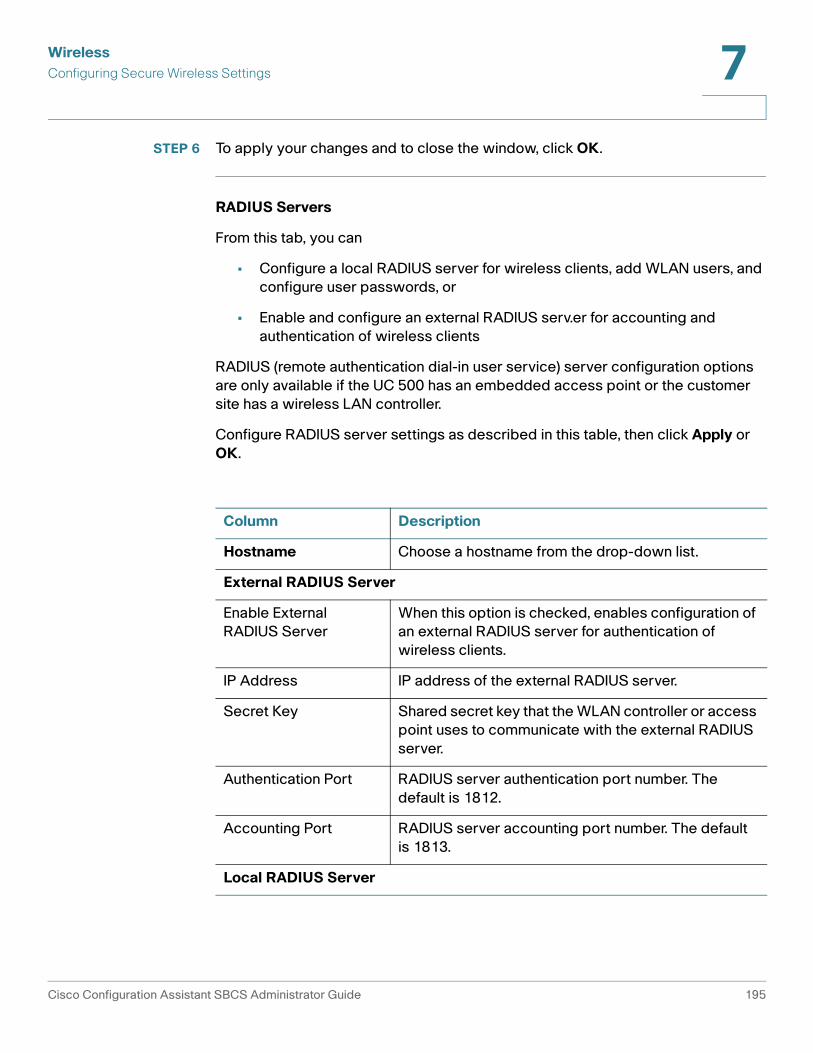
WirelessConfiguring Secure Wireless Settings 7
STEP 6 To apply your changes and to close the window, click OK.
RADIUS Servers
From this tab, you can
• Configure a local RADIUS server for wireless clients, add WLAN users, and configure user passwords, or
• Enable and configure an external RADIUS serv.er for accounting and authentication of wireless clients
RADIUS (remote authentication dial-in user service) server configuration options are only available if the UC 500 has an embedded access point or the customer site has a wireless LAN controller.
Configure RADIUS server settings as described in this table, then click Apply or OK.
Column Description
Hostname Choose a hostname from the drop-down list.
External RADIUS Server
Enable External RADIUS Server
When this option is checked, enables configuration of an external RADIUS server for authentication of wireless clients.
IP Address IP address of the external RADIUS server.
Secret Key Shared secret key that the WLAN controller or access point uses to communicate with the external RADIUS server.
Authentication Port RADIUS server authentication port number. The default is 1812.
Accounting Port RADIUS server accounting port number. The default is 1813.
Local RADIUS Server
Cisco Configuration Assistant SBCS Administrator Guide 195

WirelessConfiguring Secure Wireless Settings7
Access Point Settings
Configure Access Point settings as described in this table, then click OK or Apply.
Enable Local RADIUS Server
When this option is checked, enables configuration of a local RADIUS server for authentication of wireless clients.
Secret Key Shared secret key that the WLAN controller or access point uses to communicate with the local RADIUS server.
Users Username and password for each client allowed to authenticate by using the local RADIUS server.
Click Add to insert a new row in the table and enter a username and password.
MAC Addresses The MAC addresses of the clients allowed to authenticate by using the local RADIUS server.
Click Add to insert a new row in the table and enter the MAC address in the format xxxx.xxxx.xxxx.xxxx. For example: 105b.aaab.99ac.0056
Parameter Description
Channel Settings
The available selection of radio channels is determined by your regulatory domain.
Channel Select the radio channel to use for this access point. When Least Congested Frequency is selected for the channel setting, the device scans for the radio channel that is the least busy and selects that channel for use.
The device scans at power-up and when the radio settings are changed.
You can also select specific channel settings from the Channel drop-down menu.
Column Description
196 Cisco Configuration Assistant SBCS Administrator Guide

WirelessConfiguring Secure Wireless Settings 7
World Mode Settings
Enable World Mode
You can configure the wireless device to support world mode. When you enable world mode, the wireless device adds channel carrier set information to its beacon. Client devices with world mode enabled receive the carrier set information and adjust their settings automatically. For example, a client device used primarily in Japan could rely on world mode to adjust its channel and power settings automatically when it travels to Italy and joins a network there.
Country Choose the primary country for this access point.
Placement Choose indoor, outdoor., or both to indicate the placement of the access point.
Power Level
Power Level settings determine the power level of the radio transmission.
The default power setting is the highest transmit power allowed in your regulatory domain. Government regulations define the highest allowable power level for radio devices. This setting must conform to established standards for the country in which you use the device. To reduce interference, limit the range of your access point; to conserve power, select a lower power setting.
For an 802.11g radio, the Transmit Power setting is divided into CCK Transmitter Power (dBm) and OFDM Transmitter Power (dBm). The power settings may be in mW or in dBm depending on the particular radio that is being configured. The Power Translation Table (see Power Translation Table, page 198) translates both mW and dBm.
CCK Transmitter Power (dBm)
CCK is the modulation used in 802.11g for the lower frequency rates. In most cases you can select the Maximum; available selections range from 3 dBm to 17 dBm.
OFDM Transmitter Power (dBm)
OFDM is the modulation used in 802.11g for higher data rates (above 20 Mbps). In most cases, you can select the Maximum; available selections range from 3 dBm to 17 dBm.
Parameter Description
Cisco Configuration Assistant SBCS Administrator Guide 197

WirelessConfiguring Secure Wireless Settings7
Power Translation Table
Create or Modify WLAN SSID
This window appears when you click Create or Modify n the WLAN (SSIDs) window. Use the window to create a new SSID and to specify security settings for wireless access.
WLAN SSID settings vary, depending on the type of access point you are configuring:
• Create or Modify SSIDs for Cisco AP541N Access Points
• Create or Modify SSIDs for Cisco AP 521 or UC 500 Built-in Access Points
Client Power (dBm)
Client Power determines the maximum power level allowed on client devices that associate to the access point.
When a client device associates to the access point, the access point sends the maximum power level setting to the client. In most cases you can select the Maximum; available selections range from 3 dBm to 17 dBm.
Antenna Settings (UC 520 and UC 540 Wireless SKUs only)
You should only these modify antenna settings if instructed to by Cisco Support. The UC 520 and UC 540 wireless SKUs only have one antenna.
Receive Antenna
For UC 520 and UC 540 wireless SKUs, the Receive Antenna must be set to Default.
Transmit Antenna
For UC 520 and UC 540 wireless SKUs, the Transmit Antenna must be set to Secondary only.
Parameter Description
Approximate Translation Between mW and dBm
dBm -1 2 5 6 7 8 9 10 11 12 13 14 15 16 17 18 19 20 21 22 23 24
mW 1 2 3 4 5 6 8 10 12 15 20 25 30 40 50 60 80 100 125 150 200 250
198 Cisco Configuration Assistant SBCS Administrator Guide
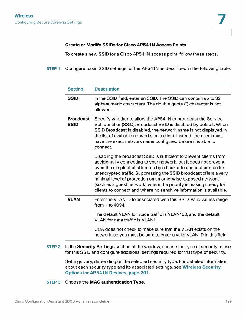
WirelessConfiguring Secure Wireless Settings 7
Create or Modify SSIDs for Cisco AP541N Access Points
To create a new SSID for a Cisco AP541N access point, follow these steps.
STEP 1 Configure basic SSID settings for the AP541N as described in the following table.
STEP 2 In the Security Settings section of the window, choose the type of security to use for this SSID and configure additional settings required for that type of security.
Settings vary, depending on the selected security type. For detailed information about each security type and its associated settings, see Wireless Security Options for AP541N Devices, page 201.
STEP 3 Choose the MAC authentication Type.
Setting Description
SSID In the SSID field, enter an SSID. The SSID can contain up to 32 alphanumeric characters. The double quote (“) character is not allowed.
Broadcast SSID
Specify whether to allow the AP541N to broadcast the Service Set Identifier (SSID). Broadcast SSID is disabled by default. When SSID Broadcast is disabled, the network name is not displayed in the list of available networks on a client. Instead, the client must have the exact network name configured before it is able to connect.
Disabling the broadcast SSID is sufficient to prevent clients from accidentally connecting to your network, but it does not prevent even the simplest of attempts by a hacker to connect or monitor unencrypted traffic. Suppressing the SSID broadcast offers a very minimal level of protection on an otherwise exposed network (such as a guest network) where the priority is making it easy for clients to connect and where no sensitive information is available.
VLAN Enter the VLAN ID to associated with this SSID. Valid values range from 1 to 4094.
The default VLAN for voice traffic is VLAN100, and the default VLAN for data traffic is VLAN1.
CCA does not check to make sure that the VLAN exists on the network, so you must be sure to enter a valid VLAN ID in this field.
Cisco Configuration Assistant SBCS Administrator Guide 199

WirelessConfiguring Secure Wireless Settings7
STEP 4 Click Apply or OK.
Create or Modify SSIDs for Cisco AP 521 or UC 500 Built-in Access Points
To create or modify SSIDs for Cisco AP 521 access points and UC 500 built-in access points, follow these steps:
STEP 1 In the SSID field, enter an SSID. The SSID can contain up to 32 alphanumeric characters.
STEP 2 Check Broadcast in Beacon if you want to broadcast the SSID so that the devices that do not specify an SSID can associate (establish a wireless connection) with the autonomous access point. Only one SSID can be included in beacon (the guest SSID).
STEP 3 In the VLAN field, enter or choose the VLAN ID that you want to associate with the SSID.
If you assign a VLAN to any SSID, you must assign a VLAN to every SSID. You cannot have some SSIDs assigned to VLANs and others assigned to none.
STEP 4 Check the Native VLAN box if you want this VLAN to be the native VLAN.
STEP 5 In the Security Settings area, select the security setting from the Security list. The remaining options in this window depend upon what you choose.
Setting Description
Disabled Do not use MAC authentication.
Local Use the MAC Authentication list that you configure on the MAC Authentication tab in the Wireless (SSIDs) tab. See MAC Authentication, page 191.
Radius Use the MAC Authentication list specified on the external RADIUS server.
200 Cisco Configuration Assistant SBCS Administrator Guide

WirelessConfiguring Secure Wireless Settings 7
You can select No Security, WEP , EAP, LEAP, WPA, WPA-PSK, WPA2,WPA2-PSK, MAC, or MAC & EAP.
See Wireless Security Options for UC 500W and AP 521 Devices, page 204 for a description of each of these settings.
Configuration Assistant automatically selects the encryption and authentication type depending on the security setting that you select.
STEP 6 Click OK to save your changes and to close the window.
Wireless Security Options for AP541N Devices
This section describes wireless security options and related settings for AP541N access points.
None
If you select None as your security mode, no additional security settings are required. Data transferred to and from the access point is not encrypted and no authentication is performed. This mode can be useful during initial network configuration or troubleshooting, but it is not recommended for regular use on the internal network because it is not secure.
Static WEP
Setting Description
The Static WEP security setting requires that the autonomous access point and the client device (device that connects to the wireless device such as a laptop or PC) share the same WEP key to keep the communication private.
Static WEP is not the most secure mode available, but it offers more protection than setting the security mode to None (Plain-text).
If you choose Static WEP, configure these additional settings.
Encryption Ready-only. AES encryption is used.
Authentication Read-only. Network-EAP authentication is used.
Key Length Choose either 64-bits or 128-bits for the encryption key length.
Cisco Configuration Assistant SBCS Administrator Guide 201

WirelessConfiguring Secure Wireless Settings7
Dynamic WEP
Key Type Choose either ASCII or HEX (hexadecimal).
Key You can specify up to four WEP keys. For each key, enter a string of characters. Use the same number of characters for each key. These are the WEP keys shared with the stations using the AP. The keys you enter depend on the Key Type selected.
ASCII. Includes upper and lower case alphabetic letters, the numeric digits, and special symbols such as @ and #.
Hex. Includes digits 0 to 9 and the letters A to F.
The number of characters you enter in the Key fields is determined by the Key Length and Key Type you select. For example, if you use 128-bit ASCII keys, the WEP key must have 13 characters.
Setting Description
Dynamic WEP
Dynamic WEP provides dynamically-generated keys that are periodically refreshed.
This mode requires the use of an external RADIUS server to authenticate users. The AP requires a RADIUS server capable of EAP, such as the Microsoft Internet Authentication Server. To work with Windows clients, the authentication server must support Protected EAP (PEAP) and MSCHAP V2.
If you choose Dynamic WEP for security, configure these additional settings.
Encryption Read-only. AES encryption is used.
Authentication Read-only. Network-eap authentication is used.
Active Server Displays which RADIUS server is currently in use. You can manually update the server by selecting a different server from the drop-down list.
NOTE The Active Server is not stored across restarts. The first configured RADIUS server is selected upon restart.
Setting Description
202 Cisco Configuration Assistant SBCS Administrator Guide

WirelessConfiguring Secure Wireless Settings 7
WPA Personal
Broadcast Key Refresh Rate
Enter a value to set the interval at which the broadcast (group) key is refreshed for clients associated to this SSID.
Valid values range from 1 to 86400 seconds. A value of 0 indicates that the broadcast key is not refreshed.
Session Key Refresh Rate
Enter a value to set the interval at which the AP will refresh session (unicast) keys for each client associated with this SSID.
The valid range is from 0 to 86400 seconds. A value of 0 indicates that the broadcast key is not refreshed.
Setting Description
WPA Personal
WPA Personal is a Wi-Fi Alliance IEEE 802.11i standard that includes AES-CCMP and TKIP encryption. The Personal version of WPA employs a pre-shared key (instead of using IEEE 802.1X)and EAP as is used in the Enterprise WPA security mode. The pre-shared key (PSK) is used for an initial check of credentials only.
This security mode is backwards-compatible for wireless clients that support the original WPA.
If you choose WPA Personal, configure these additional settings.
Encryption Read-only. TKIP, AES-CCM P is used.
Authentication Read-only. Open-EAP, Network-EAP authentication is used.
Key Enter the pre-shared secret key for WPA Personal security. The key can contain from 8 to 63 characters. Acceptable characters include upper and lower case alphabetic letters, digits 0 through 9, and special symbols such as @ and #.
Broadcast Key Refresh Rate
Enter a value from 0 to 86400 seconds to set the interval at which the broadcast (group) key is refreshed for associated clients. A value of 0 indicates that the broadcast key is not refreshed.
Setting Description
Cisco Configuration Assistant SBCS Administrator Guide 203

WirelessConfiguring Secure Wireless Settings7
WPA Enterprise
Wireless Security Options for UC 500W and AP 521 Devices
This section describes wireless security options and related settings for AP 521 access points and UC 500 platforms that have an embedded access point.
Setting Description
WPA Enterprise
WPA Enterprise with RADIUS is an implementation of the Wi-Fi Alliance IEEE 802.11i standard, which includes CCMP (AES), and TKIP mechanisms. The WPA Enterprise mode requires the use of a RADIUS server to authenticate users.
This security mode is backwards-compatible with wireless clients that support the original WPA.
Encryption Read-only. Both TKIP and AES-CCMP are selected.
When both TKIP and CCMP are selected, clients configured to use WPA with RADIUS must have one of the following:
• A valid TKIP RADIUS IP address and RADIUS key
• A valid CCM (AES) IP address and RADIUS key
Active Server Displays which RADIUS server is currently in use. You can manually update the server by selecting a different server from the drop-down list.
NOTE The Active Server is not stored across restarts. The first configured RADIUS server is selected upon restart.
Broadcast Key Refresh Rate
Enter a value to set the interval at which the broadcast (group) key is refreshed for clients associated to this VAP.
Valid values range from 1 to 86400 seconds. A value of 0 indicates that the broadcast key is not refreshed.
Session Key Refresh Rate
Enter a value to set the interval at which the AP will refresh session (unicast) keys for each associated client.
The valid range is from 0 to 86400 seconds. A value of 0 indicates that the broadcast key is not refreshed.
204 Cisco Configuration Assistant SBCS Administrator Guide

WirelessConfiguring Secure Wireless Settings 7
No Security
This is the least secure option. Select it only for an SSID that is used in a public place (guest SSID) and associate it with a VLAN that restricts access to your network. There is no encryption, and the authentication type is open authentication.
WEP
This security setting requires that the autonomous access point and the client device (device that connects to the wireless device such as a laptop or a PC) share the same WEP key to keep the communication private. The encryption type is WEP, and the authentication type is open authentication.
To set this kind of security:
STEP 1 Enter a passphrase in the Passphrase field, and select the bit encryption from the list.
STEP 2 Click Generate. The key field located next to the Key list is automatically filled in. You can change the key number by selecting either 1, 2, 3, or 4 in the Key list. The default key number is 1.
EAP
This security setting enables IEEE 802.1X authentication and requires you to enter the IP address and shared secret for a RADIUS server. The encryption type is dynamic WEP, and the authentication type is open authentication with EAP.
If you select the EAP security type, wireless clients must use EAP settings (for example, EAP-TLS, EAP-FAST, or PEAP). Wireless clients cannot use LEAP settings.
To set this kind of security:
STEP 1 Enter the IP address of the RADIUS server.
STEP 2 Enter the shared secret that the autonomous access point will use to communicate with the RADIUS server.
Cisco Configuration Assistant SBCS Administrator Guide 205

WirelessConfiguring Secure Wireless Settings7
LEAP
This security setting enables IEEE 802.1X authentication and requires you to enter the IP address and shared secret for a RADIUS server. The encryption type is dynamic WEP, and the authentication types are open authentication with EAP and network EAP.
Notes
• If you select the LEAP security type, wireless clients must use LEAP settings.
• Configuration Assistant enables both Open authentication with EAP and Network EAP authentication to allow both Cisco client devices and non-Cisco client devices to associate with the autonomous access point by using the same SSID to perform IEEE 802.1x authentication.
To set this kind of security:
STEP 1 Enter the IP address of the RADIUS server.
STEP 2 Enter the shared secret that the autonomous access point will use to communicate with the RADIUS server.
WPA
This security setting is more secure than the EAP setting. It enables WPA authentication and requires you to enter the IP address and shared secret for a RADIUS server. Client devices that associate to the autonomous access point by using this SSID must be WPA-capable. The encryption type is TKIP, and the authentication types areopen authentication with EAP and network EAP.
Configuration Assistant enables both Open authentication with EAP and Network EAP authentication to allow both Cisco client devices and non-Cisco client devices to associate with the autonomous access point by using the same SSID to perform IEEE 802.1x authentication.
To set this kind of security:
STEP 1 Enter the IP address of the RADIUS server.
STEP 2 Enter the shared secret that the autonomous access point will use to communicate with the RADIUS server.
206 Cisco Configuration Assistant SBCS Administrator Guide

WirelessConfiguring Secure Wireless Settings 7
WPA-PSK
Select this security setting when you want to use the WPA encryption and you do not have access to a RADIUS server. The autonomous access point and the client must device share the same WPA-PSK. The key can be from 8 to 63 characters long. The encryption type is TKIP, and the authentication type is WPA-PSK.
To set this kind of security, enter a key in the WPA Preshared Key field.
WPA2
This security setting is more secure than the WPA setting. It enables WPA2 authentication and requires you to enter the IP address and shared secret for a RADIUS server. Client devices that associate to the autonomous access point by using this SSID must be WPA2-capable. The encryption type is AES CCMP, and the authentication types are open authentication with EAP and network EAP.
Configuration Assistant enables both Open authentication with EAP and Network EAP authentication to allow both Cisco client devices and non-Cisco client devices to associate with the autonomous access point by using the same SSID to perform IEEE 802.1x authentication.
To set this kind of security:
STEP 1 Enter the IP address of the RADIUS server.
STEP 2 Enter the shared secret that the autonomous access point will use to communicate with the RADIUS server.
WPA2-PSK
Select this security setting when you want to use the WPA2 encryption and you do not have access to a RADIUS server. It requires that the autonomous access point and the client device share the same WPA2-PSK. The key can be from 8 to 63 characters long. The encryption type is AES CCMP, and the authentication type is WPA-PSK.
To set this kind of security, enter a key in the WPA2 Preshared Key field.
MAC
Select this security setting when you want to authenticate client devices by using MAC-based authentication.
There is no encryption, and the authentication type is Open authentication.
Cisco Configuration Assistant SBCS Administrator Guide 207

WirelessConfiguring Secure Wireless Settings7
To set this kind of security:
STEP 1 Enter the IP address of the RADIUS server.
STEP 2 Enter the shared secret that the autonomous access point will use to communicate with the RADIUS server.
MAC & EAP
Select this security setting when you want to authenticate client devices by using a combination of MAC-based and EAP authentication. Client devices that associate with the access point by using IEEE 802.11 open authentication first attempt MAC authentication. If MAC authentication succeeds, the client device joins the network; if the client is also using EAP authentication, it attempts to authenticate using EAP. If MAC authentication fails, the access point waits for the client device to attempt EAP authentication.
The encryption type is dynamic WEP, and the authentication types are Open authentication with EAP and Network EAP.
Configuration Assistant enables both Open authentication with EAP and Network EAP authentication to allow both Cisco client devices and non-Cisco client devices to associate with the autonomous access point by using the same SSID to perform 802.1x authentication.
To set this kind of security:
STEP 1 Enter the IP address of the RADIUS server.
STEP 2 Enter the shared secret that the autonomous access point will use to communicate with the RADIUS server.
Resolve Guest VLAN Window
The Resolve Guest VLAN window appears if a Guest VLAN is already configured on an ESW 500 Series switch and you open the WLAN (SSIDs) window with the SR 520 selected as the host.
Click Resolve to create the Guest VLAN on the SR 520. Click Cancel if you do not want CCA to create the Guest VLAN on the SR 520.
208 Cisco Configuration Assistant SBCS Administrator Guide
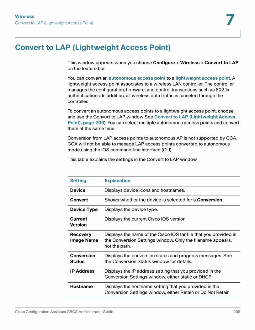
WirelessConvert to LAP (Lightweight Access Point) 7
Convert to LAP (Lightweight Access Point)
This window appears when you choose Configure > Wireless > Convert to LAP on the feature bar.
You can convert an autonomous access point to a lightweight access point. A lightweight access point associates to a wireless LAN controller. The controller manages the configuration, firmware, and control transactions such as 802.1x authentications. In addition, all wireless data traffic is tunneled through the controller.
To convert an autonomous access points to a lightweight access point, choose and use the Convert to LAP window See Convert to LAP (Lightweight Access Point), page 209). You can select multiple autonomous access points and convert them at the same time.
Conversion from LAP access points to autonomous AP is not supported by CCA. CCA will not be able to manage LAP access points converted to autonomous mode using the IOS command-line interface (CLI).
This table explains the settings in the Convert to LAP window.
Setting Explanation
Device Displays device icons and hostnames.
Convert Shows whether the device is selected for a Conversion.
Device Type Displays the device type.
Current Version
Displays the current Cisco IOS version.
Recovery Image Name
Displays the name of the Cisco IOS tar file that you provided in the Conversion Settings window. Only the filename appears, not the path.
Conversion Status
Displays the conversion status and progress messages. See the Conversion Status window for details.
IP Address Displays the IP address setting that you provided in the Conversion Settings window, either static or DHCP.
Hostname Displays the hostname setting that you provided in the Conversion Settings window, either Retain or Do Not Retain.
Cisco Configuration Assistant SBCS Administrator Guide 209

WirelessConvert to LAP (Lightweight Access Point)7
Follow these steps to convert autonomous access points to lightweight access points:
STEP 1 Download the Cisco IOS tar files that you want to use to convert the autonomous access point.
STEP 2 Select one or more autonomous access points.
STEP 3 Click Conversion Settings.
STEP 4 Complete the Conversion Settings window, and click OK to save your entries. See Conversion Settings, page 210.
STEP 5 Check the Convert box beside each device that you want to convert now.
STEP 6 Click Convert to start the conversion process.
The current image is deleted, and the new image is downloaded. You can save the old image by using the command-line interface (CLI).
STEP 7 Click Status to display the Conversion Status window. This window displays the progress of the conversion. See Conversion Status, page 211.
When the conversion process is completed, a confirmation dialog pops up. The status messages list which access points converted successfully and which access points did not.
STEP 8 All configuration changes are automatically saved to flash memory. After 1 minute, the devices are reloaded, and the new image starts running. You can then close the Convert to LAP window.
You lose connectivity to a device when you reload it.
Conversion Settings
This window appears when you select one or more autonomous access points in the Convert to LAP window and click Conversion Settings.
Select DHCP IP Address if you want the WLAN controller to assign a new IP address to the lightweight access point after the conversion.
Select Retain Hostname if you want to retain the same hostname for the lightweight access point after the conversion.
210 Cisco Configuration Assistant SBCS Administrator Guide

WirelessConvert to LAP (Lightweight Access Point) 7
From the Mode list, select Standard to use a conversion image that is stored locally; otherwise, select Remote TFTP Server.
If you selected Standard, enter the filename of the conversion image in the Conversion Image field. You can click Browse to find the file.
If you selected Remote TFTP Server:
STEP 1 In the Conversion Image field, enter the full path and filename of the conversion image.
STEP 2 In the TFTP Server IP Address field, enter the IP address of your TFTP server.
To perform group conversions, your TFTP server must handle multiple requests and sessions simultaneously.
STEP 3 In the Domain Name field, enter the domain name.
STEP 4 In the DNS IP Address field, enter the DNS address.
STEP 5 Click OK to save your settings. They appear in the Convert to LAP window.
Conversion Status
This window appears when you select one or more autonomous access points in the Convert to LAP window and click Status. The window shows detailed messages as they are generated from the autonomous access point during a conversion.
This table explains conversion status messages.
Message Explanation
Click the Conversion Settings button to continue.
The Conversion Settings window needs to be completed before the device can be converted.
Click the Convert button to upgrade the device.
All the parameters are set for the device to be converted.
Determining the total flash size.
The conversion process checks whether there is enough space available to convert the device.
Cisco Configuration Assistant SBCS Administrator Guide 211

WirelessWireless LAN Controller Configuration7
If there is insufficient space on the device to install the new image, a message with a link to the File Management window appears. You can use the File Management window to manage your file systems, and, if necessary, to delete old images to make space for new images.
Click OK when you are done with the window.
Wireless LAN Controller Configuration
The topics in this section cover configuration settings for WLAN controllers:
• Configuring Wireless Interfaces for a WLAN Controller, page 213
• Viewing Wireless Client Status for a WLAN Controller, page 215
• Configuring WLAN Users, page 216
Extracting the info file from the tar image file.
The Cisco IOS image tar file is extracting the info file.
Reading the info file of the tar image file.
Configuration Assistant reads the info file of the Cisco IOS image tar file for details about the Cisco IOS image.
Reload started for the device.
The device is reloading after a successful conversion. Even after the reload is completed, this message appears until you refresh the window.
Device conversion was successful.
The conversion completed successfully.
Device conversion failed.
The conversion failed. See the Details window for more information.
Device conversion in progress.
The conversion for the devices is in process.
Device conversion canceled.
The conversion was canceled.
Uploading the image. The image is being uploaded to the device.
Verifying the IOS image. The device is verifying the image.
Message Explanation
212 Cisco Configuration Assistant SBCS Administrator Guide

WirelessWireless LAN Controller Configuration 7
• DHCP Proxy, page 222
• Wireless Controller Dashboard, page 223
• Configure RADIUS Server Settings for WLAN Controllers, page 225
Configuring Wireless Interfaces for a WLAN Controller
If your system includes a Wireless LAN controller, choose Configure > Wireless Interfaces from the feature bar.
Overview
You can configure dynamic wireless interfaces on a WLAN controller. Dynamic wireless interfaces are analogous to VLANs for wireless LAN clients. A controller can support up to 8 dynamic interfaces (VLANs).
A wireless interface has multiple parameters associated with it, including VLAN identifier, port, IP address, subnet mask, default gateway (for the IP subnet), and DHCP server.
Use this window to view all wireless interface settings on the WLAN controller and to configure dynamic (user-defined) wireless interfaces on the WLAN controller.
Procedures
This table explains the columns in the Wireless Interfaces window.
Follow these steps to configure a dynamic wireless interface on the WLAN controller:
Column Explanation
Name The wireless interface name, including dynamic interfaces and static interfaces (management, ap-manager, and virtual)
VLAN The VLAN associated with the wireless interface
Port The physical port number for the wireless interface
IP Address The IP address of the wireless interface
Cisco Configuration Assistant SBCS Administrator Guide 213

WirelessWireless LAN Controller Configuration7
STEP 1 From the Hostname list, select the WLAN controller.
STEP 2 To create an interface, click Create, and complete the Create Interface window. See Create Interface, page 214.
A controller can support up to eight dynamic interfaces.
To modify a configuration, select the wireless interface name, click Modify, and use the Modify Interface window.
To delete a configuration, select the wireless interface name, and click Delete.
NOTE You can modify and delete only dynamic interfaces. You cannot modify or delete static interfaces.
To save your changes and to close the window, click OK in the Wireless Interfaces window.
Create Interface
This window appears when you click Create in the Wireless Interfaces window. Use the window to create a wireless interface.
STEP 1 In the Interface name field, enter a name for the wireless interface.
STEP 2 In the VLAN ID field, enter the VLAN ID that you want to associate with the wireless interface.
STEP 3 From the Port list, select a port for the wireless interface.
STEP 4 In the IP Address field, enter an IP address for the wireless interface.
STEP 5 From the Subnet Mask list, select the subnet mask for the wireless interface.
STEP 6 In the Gateway IP Address field, enter the IP address of the default gateway.
STEP 7 In the DHCP Server IP Address field, enter the IP address of the DHCP server.
STEP 8 When you complete this window, click OK to save your changes and to close the window.
214 Cisco Configuration Assistant SBCS Administrator Guide

WirelessWireless LAN Controller Configuration 7
Modify Interfaces
This window appears when you click Modify in the Wireless Interfaces window. Use the window to modify the settings for a wireless interface.
Follow these steps:
STEP 1 In the VLAN ID field, enter the VLAN ID that you want to associate with the wireless interface.
STEP 2 From the Port list, select a port for the wireless interface.
STEP 3 In the IP Address field, enter an IP address for the wireless interface.
STEP 4 From the Subnet Mask list, select the subnet mask for the wireless interface.
STEP 5 In the Gateway IP Address field, enter the IP address of the default gateway.
STEP 6 In the DHCP Server IP Address field, enter the IP address of the DHCP server.
STEP 7 When you complete this window, click OK to save your changes and to close the window.
Viewing Wireless Client Status for a WLAN Controller
To display the status of wireless clients on the WLAN controller use the Wireless Clients window.
This table explains the information that you see under the columns in this window.
Column Explanation
MAC Address The MAC address of the client.
Cisco Configuration Assistant SBCS Administrator Guide 215

WirelessWireless LAN Controller Configuration7
To close the window, click OK.
Configuring WLAN Users
You can configure wireless users on the WLAN controller. You can also configure authentication and Web login settings.
Wireless users can be guests or not (for example, employees).
Guest users have access to the Internet and the guests' own network without compromising your network's security. Guest user access is configured with an expiration date.
Status The status of the client connection:
• Idle
• Pending
• Authenticated
• Associated
• Active
• Power Save
• Disassociated
• Exclude
• Probing
AP Name The name of the client's lightweight access point
SSID The SSID of the client
Radio The type of client:
• 802.11a
• 802.11 b
• 802.11g
Authenticated The authentication status of the client (yes or no)
Column Explanation
216 Cisco Configuration Assistant SBCS Administrator Guide

WirelessWireless LAN Controller Configuration 7
Users who are not guests have secure access to the network. There is no expiration date for this type of user access.
Use this window to configure wireless users on the WLAN controller or to view wireless user settings that you configured on the WLAN controller.
This table explains the columns in the Wireless Network Users area.
Follow these steps to configure wireless users for the WLAN controller:
STEP 1 From the Hostname list, select the WLAN controller.
STEP 2 To create a guest or non-guest user, click Create, and complete the Create WLAN User window. See Create WLAN Users, page 218.
STEP 3 To save your changes and to close the window, click OK in the WLAN Users window.
To modify a wireless user, select the user name, click Modify, and use the Modify WLAN User window.
To delete a wireless user, select the user name, and click Delete.
Guest Users are deleted automatically from the Wireless Network Users list when you open the WLAN Users Window and the Guest User end time has expired. If the WLAN Users Window is already open when the Guest User end time expires and you attempt to modify the Guest User, the Guest User will be deleted from the Wireless Network Users list. Click Create to create a new Guest User.
To configure a login page for wireless users, click Configure in the Web Login area. See Web Login, page 221.
Column Explanation
Username The name of the wireless user.
Guest User The guest user status (yes or no).
SSID The SSID name.
End Time The expiry date of the guest user's access.
Description The description of the wireless user.
Cisco Configuration Assistant SBCS Administrator Guide 217

WirelessWireless LAN Controller Configuration7
Create WLAN Users
This window appears when you click Create in the WLAN Users window. Use the window to create a new wireless user.
Overview
You can configure wireless users on the WLAN controller. You can also configure authentication and Web login settings.
Wireless users can be guests or not (for example, employees).
Guest users have access to the Internet and the guests' own network without compromising your network's security. Guest user access is configured with an expiration date.
Users who are not guests have secure access to the network. There is no expiration date for this type of user access.
Procedures
Follow these steps:
STEP 1 In the Username field, enter a name for the wireless user. You can enter up to 24 alphanumeric characters.
STEP 2 In the Password field, enter a password for the wireless user. You can enter up to 24 alphanumeric characters.
STEP 3 In the Confirm Password field, re-enter the password.
STEP 4 In the Description field, enter a description for the wireless user.
STEP 5 If the wireless user is not a guest user, follow these steps:
a. Uncheck the Guest User checkbox.
b. Select an SSID from the SSID list. Only SSIDs that are set with Web-Auth, WEP, WPA1-PSK, or WPA2-PSK security appear.
If you need to create an SSID, click Add SSID (Pre-defined) to open the Add SSID (Pre-defined) window. See Add SSID, page 220
STEP 6 If the wireless user is a guest user, follow these steps:
a. Check the Guest User checkbox.
b. Select an SSID from the SSID list. Only SSIDs that are set with Web-Auth security appear.
218 Cisco Configuration Assistant SBCS Administrator Guide

WirelessWireless LAN Controller Configuration 7
If you need to create an SSID, click Add SSID (Pre-defined) to open the Add SSID (Pre-defined) window. See Add SSID, page 220.
STEP 7 In the End Time area, enter the expiry date by selecting the year, month, day, hour, and minute. The maximum expiry date for a guest user is 30 days from the current date.
When you complete this window, click OK to save your changes and to close the window.
Modify WLAN Users
This window appears when you click Modify in the WLAN Users window. Use the window to modify the wireless user settings.
Follow these steps:
STEP 1 In the Password field, enter a password for the wireless user. You can enter up to 24 alphanumeric characters.
STEP 2 In the Confirm Password field, re-enter the password.
STEP 3 In the Description field, enter a description for the wireless user.
STEP 4 From the SSID list, select an SSID.
STEP 5 If the wireless user is a guest user, modify the expiry date in the End Time area by selecting the year, month, day, hour, and minute. The maximum expiry date for a guest user is 30 days from the current date.
STEP 6 When you complete this window, click OK to save your changes and to close the window.
Cisco Configuration Assistant SBCS Administrator Guide 219
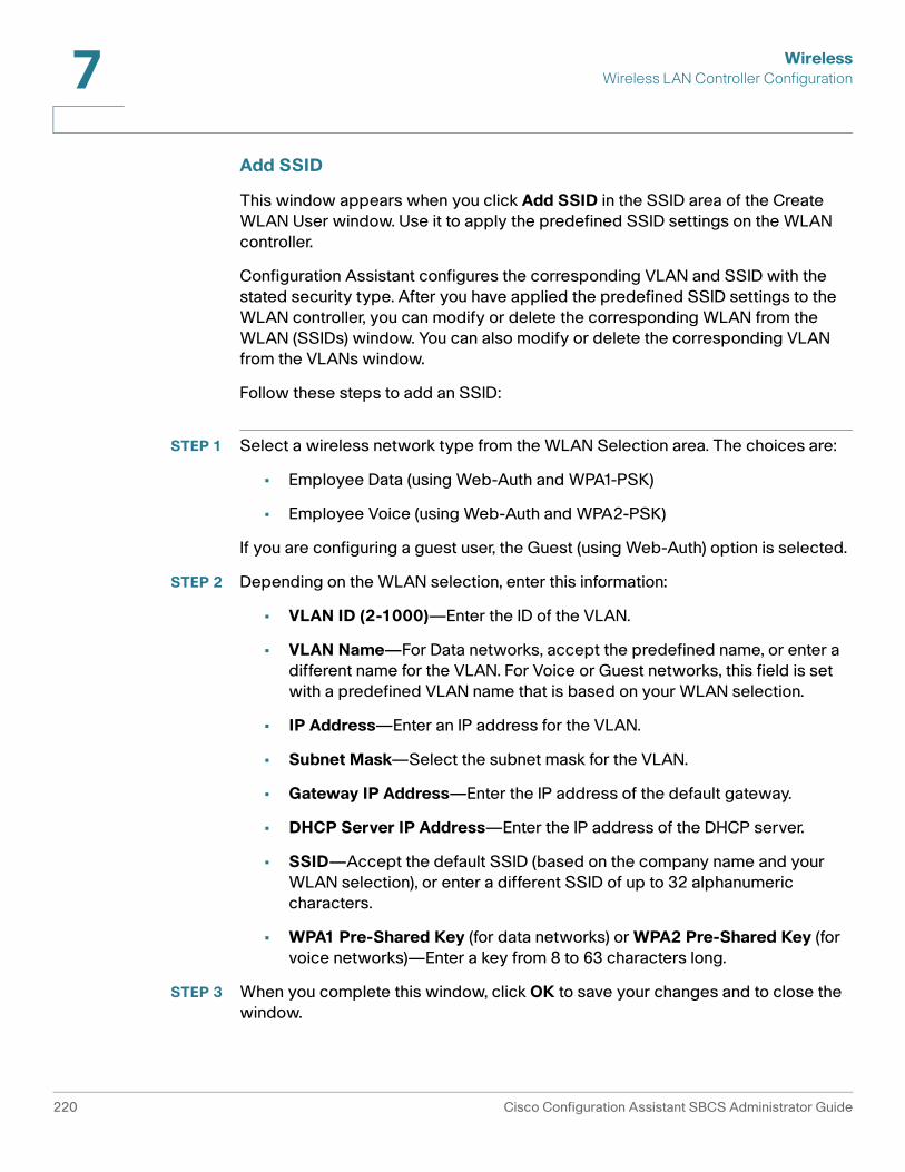
WirelessWireless LAN Controller Configuration7
Add SSID
This window appears when you click Add SSID in the SSID area of the Create WLAN User window. Use it to apply the predefined SSID settings on the WLAN controller.
Configuration Assistant configures the corresponding VLAN and SSID with the stated security type. After you have applied the predefined SSID settings to the WLAN controller, you can modify or delete the corresponding WLAN from the WLAN (SSIDs) window. You can also modify or delete the corresponding VLAN from the VLANs window.
Follow these steps to add an SSID:
STEP 1 Select a wireless network type from the WLAN Selection area. The choices are:
• Employee Data (using Web-Auth and WPA1-PSK)
• Employee Voice (using Web-Auth and WPA2-PSK)
If you are configuring a guest user, the Guest (using Web-Auth) option is selected.
STEP 2 Depending on the WLAN selection, enter this information:
• VLAN ID (2-1000)—Enter the ID of the VLAN.
• VLAN Name—For Data networks, accept the predefined name, or enter a different name for the VLAN. For Voice or Guest networks, this field is set with a predefined VLAN name that is based on your WLAN selection.
• IP Address—Enter an IP address for the VLAN.
• Subnet Mask—Select the subnet mask for the VLAN.
• Gateway IP Address—Enter the IP address of the default gateway.
• DHCP Server IP Address—Enter the IP address of the DHCP server.
• SSID—Accept the default SSID (based on the company name and your WLAN selection), or enter a different SSID of up to 32 alphanumeric characters.
• WPA1 Pre-Shared Key (for data networks) or WPA2 Pre-Shared Key (for voice networks)—Enter a key from 8 to 63 characters long.
STEP 3 When you complete this window, click OK to save your changes and to close the window.
220 Cisco Configuration Assistant SBCS Administrator Guide

WirelessWireless LAN Controller Configuration 7
Web Login
This window appears when you click Configure in the Web Login area of the WLAN Users window. Use it to customize the content and appearance of the Web login page for WLAN users.
Overview
The login page is presented to web users the first time that they access a WLAN with web authentication enabled. Cisco provides a default web login page that can be modified with any text-based HTML editor. However, the Username and Password fields should not be changed, and the Submit method should be retained. After the customized web login page is created, it must be made into a tar file containing the page code and any images desired.
Procedures
Follow these steps to configure the login page.
STEP 1 From the Hostname list, select the WLAN controller.
STEP 2 From the Web Authentication area, select Internal or Customized.
STEP 3 If you select Internal, follow these steps:
a. From the Cisco Logo area, select Show to display the Cisco logo on the login page, or select Hide to hide the logo. The default selection is Show.
b. In the Redirect URL After Login field, enter a URL to which the user will be directed after logging in. Enter the URL by using the www.companyname.com format with up to 254 characters.
c. In the Headline field, enter the login page headline or summary, up to 127 characters. The default headline is “Welcome to the Cisco wireless network.”
d. In the Message field, enter message text, up to 2047 characters. The default message is “Cisco is pleased to provide the wireless LAN infrastructure for your network. Please login and put your air space to work.”
Click Set Default to use the default settings.
STEP 4 If you select Customized, follow these steps:
a. In the TFTP Server IP Address field, enter the IP address of the TFTP server on which the customized web authentication bundle file exists.
The TFTP server cannot run on the same computer as the Cisco WCS,
Cisco Configuration Assistant SBCS Administrator Guide 221

WirelessWireless LAN Controller Configuration7
because the Cisco WCS and the TFTP server use the same communication port.
b. In the Maximum Retries field, enter the number of attempts that the WLAN controller tries to load the web authentication file from the TFTP server on a failure. The default value is 3.
c. In the Timeout (seconds) field, enter the timeout period (in seconds). If the WLAN controller is not able to start downloading the file within this time period, loading does not occur.
d. In the File Path field, enter the path of the web authentication file on the TFTP server. The default value is a slash (/).
e. In the File Name field, enter the name of the file to be transferred.
f. Click Download to download the customized login file.
STEP 5 When you click OK or Apply, the download starts and the customized login file is applied to the device.
DHCP Proxy
To configure a DHCP proxy, choose Configure > DHCP Proxy from the feature bar.
A DHCP proxy helps wireless clients get an IP address from the DHCP server. The WLAN controller receives the DHCP discover request from the wireless client and sends the request to the DHCP server on behalf of the wireless client. When you enable the DHCP proxy, the WLAN controller works between the wireless client and the DHCP server until the wireless client receives an IP address.
You can enable DHCP Proxy if you configured a DHCP server address on all user-defined VLANs for this device.
To enable DHCP proxy, follow these steps.
STEP 1 Select a device to be configured from the Hostname list.
STEP 2 Check the Enable DHCP Proxy box.
STEP 3 Click OK to save your changes and to close the window.
222 Cisco Configuration Assistant SBCS Administrator Guide
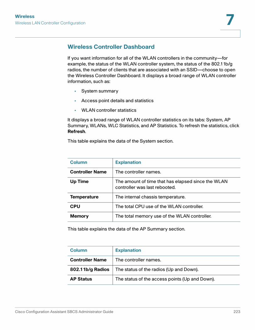
WirelessWireless LAN Controller Configuration 7
Wireless Controller Dashboard
If you want information for all of the WLAN controllers in the community—for example, the status of the WLAN controller system, the status of the 802.11b/g radios, the number of clients that are associated with an SSID—choose to open the Wireless Controller Dashboard. It displays a broad range of WLAN controller information, such as:
• System summary
• Access point details and statistics
• WLAN controller statistics
It displays a broad range of WLAN controller statistics on its tabs: System, AP Summary, WLANs, WLC Statistics, and AP Statistics. To refresh the statistics, click Refresh.
This table explains the data of the System section.
This table explains the data of the AP Summary section.
Column Explanation
Controller Name The controller names.
Up Time The amount of time that has elapsed since the WLAN controller was last rebooted.
Temperature The internal chassis temperature.
CPU The total CPU use of the WLAN controller.
Memory The total memory use of the WLAN controller.
Column Explanation
Controller Name The controller names.
802.11b/g Radios The status of the radios (Up and Down).
AP Status The status of the access points (Up and Down).
Cisco Configuration Assistant SBCS Administrator Guide 223

WirelessWireless LAN Controller Configuration7
This table explains the data of the WLANs section.
This table explains the data of the WLC Statistics section. You can choose to display the data in total numbers or in percentages.
This table explains the data of the AP Statistics section.
Column Explanation
WLAN Name (Controller Name)
The SSID names of the controllers.
Clients The number of clients that are associated with this SSID.
Column Explanation
Controller Name The controller names.
Packets received without error
The total number or the percentage of packets received.
Receive Packets Discarded
The total number or the percentage of received packets discarded.
Packets transmitted without error
The total number or the percentage of packets sent.
Transmit Packets Discarded
The total number or the percentage of sent packets discarded.
Column Explanation
AP Name (Controller Name)
The associated access points with the WLAN controllers.
Transmit Frame Count
The total number of sent frames.
Transmit Failed Count
The total number of frames that failed to be sent.
224 Cisco Configuration Assistant SBCS Administrator Guide

WirelessWireless LAN Controller Configuration 7
Configure RADIUS Server Settings for WLAN Controllers
The Configure RADIUS Servers window appears when you click Configure in the RADIUS Servers area of the WLANs (SSIDs) window for a WLAN controller.
From this window, you can view RADIUS server settings for the WLAN controller and configure up to two RADIUS servers for the WLAN controller. This table explains the columns in this window.
To configure RADIUS servers for the WLAN controller, follow these steps.
STEP 1 From the Hostname list, select the WLAN controller.
STEP 2 Click Create and complete the settings in the Create RADIUS Server window. See Create RADIUS Server Window.
To change the RADIUS server status, select the IP address of the RADIUS server, click Modify and complete the settings in the Modify RADIUS Server Window. See Modify RADIUS Server Window.
To delete a configured RADIUS server, select the IP address of the RADIUS server, and click Delete.
To save your changes and to close the window, click OK in the RADIUS Server window.
Setting Description
IP Address IP address of the RADIUS server.
Auth Port RADIUS authentication port number.
Priority The priority of the RADIUS server. It specifies the order in which the servers are used if one of the servers cannot be reached.
Status The status of the RADIUS server, either Enabled or Disabled.
Cisco Configuration Assistant SBCS Administrator Guide 225

WirelessWireless LAN Controller Configuration7
Create RADIUS Server Window
This window appears when you click Create in the Configure RADIUS Server window. Use the window to specify the RADIUS server settings.
Follow these steps.
STEP 1 In the IP Address field, enter an IP address for the RADIUS server.
STEP 2 In the Auth Port field, enter the RADIUS authentication port number. The default authentication port number is 1812.
STEP 3 In the Secret Key (ASCII) field, enter the shared secret that the WLAN controller will use to communicate with the RADIUS server.
STEP 4 In the Confirm Secret field, re-enter the shared secret.
STEP 5 From the Server Priority Key list, select the server priority.
NOTE Each RADIUS server must use a different priority number.
STEP 6 From the Admin Status list, select Enabled or Disabled.
STEP 7 Click OK to save your changes and to close the window.
Modify RADIUS Server Window
This window appears when you click Modify in the Configure RADIUS Server window. Use the window to change the status of a RADIUS server.
Follow these steps:
STEP 1 From the Admin Status list, select Enabled or Disabled.
STEP 2 Click OK to save your change and to close the window.
226 Cisco Configuration Assistant SBCS Administrator Guide

8
Basic Security Features
This section covers configuration of these basic security features:
• NAT (Network Address Translation)
• VPN Server
• Firewall and DMZ
• Security Audit
• Network Security Settings (CE520 Switches)
NAT (Network Address Translation)
To enable or disable network address translation (NAT), choose Configure > Security > NAT from the feature bar.
From this window, you can:
• Enable or disable Network Address Translation (NAT)
• Configure port mapping
• Configure port forwarding
Overview
When enabled on an interface, NAT (Network Address Translation) maps the private IP addresses on your LAN to a public network IP address from a group of registered public network IP addresses.
Cisco Configuration Assistant SBCS Administrator Guide 227

Basic Security FeaturesNAT (Network Address Translation)8
A valid, registered, globally unique, public IP address is required for accessing the Internet. An organization usually does not own enough public IP addresses to assign a unique public IP address to each client in the organization that needs Internet access. Without NAT, your pool of public IP addresses would be depleted. The internal structure of your LAN would also be displayed to any client on the public network. NAT allows you to use one public IP address to provide Internet access to many of the clients on your LAN.
Using Configuration Assistant, you map the single public IP address assigned to your WAN interface to multiple private IP addresses.
It is easier for an unauthorized client to attack your network if that client can determine the topology of your network by using your network IP addresses. NAT hides your private IP addresses from the Internet. If an attacker cannot guess the structure of your LAN by using the IP addresses, then it is more difficult to break into your network.
In some cases—for example, when you configure a UC 500 with a SIP trunk behind an SR 500 secure router—NAT entries are created automatically by CCA.
NOTE NAT supports only Layer 3 Ethernet interfaces. It does not support Layer 2 switch port interfaces. When you enable NAT on an (untrusted) outside interface, all other qualified interfaces are automatically selected as (trusted) inside interfaces.
Procedures
First, choose a device on which you want to enable NAT from the Hostname list.
To enable NAT, choose an (untrusted) outside interface from the Outside Interface list. Click Details to view information about the selected outside interface.
To create an entry for each port mapping, follow these steps.
STEP 1 To add an entry to the NAT window, click Add.
STEP 2 Choose an application from the pull-down list:
• Web server
• Secure Web server
• E-mail server
• FTP
• SSH
228 Cisco Configuration Assistant SBCS Administrator Guide

Basic Security FeaturesNAT (Network Address Translation) 8
• SFTP
• Other (TCP)
• Other (UDP)
STEP 3 In the Internal address field, enter an IP address that the server uses on your internal network. This is an IP address that cannot be used externally on the Internet.
STEP 4 In the Internal Port field, enter a port number for the inside device, which is the port number used by the server to accept service requests from the internal network.
STEP 5 In the External Port field, enter a port number that NAT is to use for this translation. The port number is used by the server to accept service requests from the Internet.
To increase security by adding a firewall, click Firewall Service, and use the Firewall window.
STEP 6 Click Apply or OK.
To delete a port mapping, follow these steps.
STEP 1 Choose an entry in the window.
STEP 2 Click Delete.
STEP 3 To close the window and save your changes, click OK.
You can delete NAT settings for a device that is behind another NAT device on a fully routed network. For example, when a UC 500 is connected behind an SR 500 Series Secure Router, you can delete the NAT settings on the UC 500.
To delete the entire NAT configuration, follow these steps.
Cisco Configuration Assistant SBCS Administrator Guide 229

Basic Security FeaturesVPN Server8
STEP 1 Click Delete NAT Settings.
If there are entries in the IP table, a window is displayed that warns you that if you proceed, you will delete the NAT configuration settings. Click OK to close the popup dialog and continue.
STEP 2 In the main NAT window, click OK.
VPN Server
To configure VPN server settings, choose Configure > Security > VPN from the feature bar.
!CAUTION Cisco does not recommend that you configure the VPN server over a remote WAN
connection. If the connection to the WAN is interrupted, the operation will fail and the system may become unusable.
Overview
VPN (Virtual Private Network) allows a remote client access to the corporate network.
VPN is required in these circumstances:
• You need access to the SBCS network from a remote computer outside your network firewall.
• You want to use CCA to manage a remote SBCS device across the Internet.
You can authorize a remote VPN device to receive IPsec policies sent by a VPN server. You can also configure a VPN server to send IPsec policies to a remote VPN device.
230 Cisco Configuration Assistant SBCS Administrator Guide
Basic Security FeaturesVPN Server 8
When you authorize remote VPN clients to receive policies from a VPN server, end users can request a connection to their corporate network through a VPN tunnel by entering a password. When a connection is requested and the remote end user is authenticated, a VPN server forwards the parameters to the remote client. Otherwise, the user must manually enter the IPSec parameters to configure the VPN tunnel. Remote VPN devices include Cisco IOS routers, Cisco adaptive security appliances, and Cisco VPN clients.
A VPN group is a group of VPN clients that share the same authentication information and configuration. Pre-shared keys or digital certificates are used for authenticating the client against a group. The group policies can be configured on the local router database or on an external server such as RADIUS or both, a local and an external server.
You can configure a pre-shared key that authenticates a remote client. The pre-shared key adds to the security of the communications between the remote device receiving the IPSec policies and a server. The pre-shared key on the remote device must match the pre-shared key on the VPN server.
NOTE The maximum number of simultaneous VPN connections allowed by CCA for UC 520 and UC 540 platforms is 10. For UC 560 platforms, up to 20 simultaneous VPN connections are allowed. VPN connections used for EZVPN, SSL VPN, Multisite Manager, and SPA 525G phone VPNs are included in this total.
Network Access — VPN Tunnel
Internet Access can be accomplished through the VPN tunnel. The security of the connection is greater, because you have VPN protection between the client and the server. Internet-related data moves through the tunnel to the server, where communications with the Internet takes place, providing the protections configured on the client and the server. This is in comparison to Split Tunneling, where Internet communications are sent and received outside the VPN tunnel, relying only on the protections configured on the client.
Internet Access — Split Tunneling
When you enable split tunneling on a remote network, client communications with local devices or over the Internet with other networks are unencrypted. The data is only encrypted when the end user is communicating with a protected subnetwork, typically the corporate network. This reduces device processing time and increases network performance.
For example, a teleworker uses a VPN client PC to access the corporate network through a router that provides connectivity from the teleworker location through the Internet to the corporate network by using a VPN tunnel. However, there might also be other PCs at the teleworker location that are not part of the corporate
Cisco Configuration Assistant SBCS Administrator Guide 231

Basic Security FeaturesVPN Server8
network and should not be allowed into the VPN. Typical examples would be PCs used by the spouse or children of the teleworker. These PCs do need Internet access, and users are likely to use the teleworker router to avoid installing a second broadband connection in the same home. The IPsec tunnel can be up at all times and use IEEE 802.1x to authenticate corporate users who try to gain access from the remote site. A RADIUS server at the corporate headquarters site holds the database of corporate users. As the tunnel is always available, the remote router can query the database to confirm the 802.1x credentials (username and password) of the teleworker to allow the teleworker access to the VPN, yet exclude all others.
CAUTION Split tunneling can potentially pose a security risk when configured. Because VPN clients have unsecured access to the Internet, the VPN clients can be compromised by an attacker. That attacker might then be able to access the corporate LAN through the IPSec tunnel by using the identity of the VPN client.
Procedures
Begin by selecting a device to be configured from the Hostname list.
Configure settings on each of these tabs in the VPN Server window:
• Server Settings
• User Accounts
• Network Access
• VPN Profile
Server Settings
To enable a VPN server, configure VPN server policies and settings as described in the following table.
Once you are finished configuring server settings, click Apply to apply your settings, click OK to exit the VPN Server window, or click the User Accounts or Network Access tabs to continue configuring VPN settings.
Setting Description
VPN Server Interface(s)
Select or view VPN Server interfaces. If only one interface is displayed, this setting is read-only.
232 Cisco Configuration Assistant SBCS Administrator Guide

Basic Security FeaturesVPN Server 8
To delete a VPN server, follow these steps:
STEP 1 Click Delete.
A window appears, warning you that if you proceed, you will delete the VPN server configuration settings.
STEP 2 To delete the VPN server and close the window, click Yes.
STEP 3 To save your changes and to close the window, click OK.
VPN Group
Configure VPN group settings. A VPN group is a group of VPN clients that share the same authentication information and configuration.
VPN Group Name Read-only field. The default VPN group name used by Configuration Assistant is EZVPN_GROUP_1.
Maximum Connections
Maximum number of VPN group clients that can be connected to the VPN server.
Preshared Keys Enter the pre-shared key for authenticating VPN clients and remote VPN devices, then re-enter the key for confirmation.
The preshared key can contain from 1 to 127 alphanumeric characters. Spaces and the question mark (?) characters are not allowed.
VPN Remote IP Range
Enter a starting IP address and an ending IP address to specify a range of IP addresses from which an available IP address is assigned to a user. Up to 10 IP addresses can be specified for UC 520 or UC 540 platforms; up to 20 IP addresses can be specified for UC 560 platforms.
DNS
Primary DNS Enter the IP address of the primary DNS server for the VPN server.
Secondary DNS Optional. Enter the IP address of the secondary DNS server for the VPN server.
Setting Description
Cisco Configuration Assistant SBCS Administrator Guide 233

Basic Security FeaturesVPN Server8
User Accounts
To create a user account and set a password for users requesting a connection through a VPN tunnel, click Create, and use the Add an Account window. See Add an Account, page 237.
To delete a user account, select the user account, and click Delete.
Network Access
To enable Internet access through the VPN tunnel for a remote site, check the Enable Internet access on remote site checkbox.
If you enable Internet access through the VPN tunnel, Split Tunneling is disabled.
To enable split tunneling and to identify the networks protected by encryption, follow these steps:
STEP 1 Check the Enable Split Tunneling check box.
Only the traffic destined for the protected subnet is encrypted and sent through the VPN tunnel to the home network. All other traffic is sent to the destination subnets, but it is not encrypted, and it is not protected by a VPN tunnel.
STEP 2 Click Create, and use the Add a Network window (see Add a Network, page 237).
To delete a protected subnet, follow these steps:
STEP 1 Choose the network and the mask.
STEP 2 Click Delete.
VPN Profile
From the VPN Profile tab, you can export a profile configuration file (PCF) that your VPN users can import into the Cisco EZVPN client to create a new connection.
The UC 500 must have a static WAN IP address.
To export a PCF file, click Export VPN Profile. The Export VPN Profile option is disabled if you have not configured VPN server settings. Save the .pcf file to your local machine and distribute the file to your VPN users.
234 Cisco Configuration Assistant SBCS Administrator Guide

Basic Security FeaturesVPN Remote 8
VPN Profile Import Instructions
Your VPN users will follow these steps to import the PCF file into the Cisco EZVPN client.
STEP 1 If needed, download and install the Cisco EZVPN client from Cisco.com at www.cisco.com/go/vpnclient.
STEP 2 Start the Cisco EZVPN client.
STEP 3 In the VPN client, click the Import icon or choose Connection > Import the menu bar and browse to the location of the PCF file on the local machine. The profile will appear as a new connection entry.
STEP 4 To use the profile, double-click on the new connection entry and enter your VPN account username and password.
VPN Remote
To access VPN Remote configuration, choose Configure > Security > VPN Remote from the feature bar.
NOTE On Model SR520-T1 secure routers, VPN Remote is a licensed feature. To legally use this security feature, you must purchase the FL-SR520-T1-SEC Security Feature License for the SR520-T1. Contact your Cisco distributor to purchase this license.
To enable VPN remote client services on an SR500 secure router, follow these steps:
STEP 1 Begin by selecting the device to be configured from the Hostname list.
STEP 2 To enable voice services, check the Enable Voice Services on Remote Connection check box.
STEP 3 In the IP PBX Address field, enter the CME (Cisco Unified Communications Manager Express) IP address. For the UC 500, the default value is 10.1.1.1.
STEP 4 In the VPN Server field, enter the IP address or the hostname of the VPN server or concentrator.
Cisco Configuration Assistant SBCS Administrator Guide 235

Basic Security FeaturesVPN Remote8
STEP 5 Optional: In the Enter new preshared key field, enter a pre-shared key to authenticate encrypted tunnels.
The pre-shared key must have at least 8 alphanumeric characters and can contain up to 127 characters. Spaces and the question mark (?) characters are not allowed. If a pre-shared key is configured on the remote VPN device, it must match the pre-shared key configured on a VPN server.
STEP 6 In the Reenter new preshared key field, enter the preshared key.
STEP 7 To save your changes and to close the window, click OK.
To delete the remote device authorization to receive IPSec policies, follow these steps.
STEP 1 Click Delete.
A window appears, warning you that if you proceed, you will delete the VPN remote configuration settings.
STEP 2 To save your changes and to close the window, click OK.
Establishing a VPN Tunnel (End User Client Connection Instructions)
These instructions describe how an end user connected to a service provider using a Cisco SR520 router can establish a VPN tunnel to a central site network. These instructions are provided for the convenience of a system administrator.
To establish a VPN tunnel between a remote user and a central site network, follow these steps.
STEP 1 Launch a Web browser window, such as Internet Explorer.
STEP 2 Enter the IP address of the VPN server in the Address field of the browser. The VPN tunnel Activation Tool window appears, providing the option to connect to a central site network by using VPN or to connect to the Internet.
STEP 3 To connect to the central site network, click Connect Now. The Authentication for VPN tunnel Activation window appears.
STEP 4 Click Continue. The VPN tunnel is established.
236 Cisco Configuration Assistant SBCS Administrator Guide

Basic Security FeaturesVPN Remote 8
Add a Network
This window appears when Split Tunneling is enabled and you click Create on the Network Access tab in the VPN Server window or the SSL VPN window.
Use this window to add the subnetworks for which the packets are tunneled from the VPN or SSL VPN clients. Only traffic destined for these subnetworks are sent through the VPN or SSL VPN tunnel. All other traffic from client connections is sent unencrypted. For more information, see Internet Access — Split Tunneling, page 231.
To add a network, follow these steps:
STEP 1 In the Network field, enter the network IP address.
STEP 2 In the Wildcard Mask field, choose a subnet mask.
STEP 3 Continue adding subnetworks for which you want to permit VPN or SSL VPN access.
STEP 4 To close the window, click OK.
Add an Account
This window appears when you click Create on the User Accounts tab on the VPN Server window.
Use this window to add user authentication details to the local database.
To add an account, follow these steps:
STEP 1 In the Username field, enter the username. The username can contain up to 64 alphanumeric characters. These characters are not allowed: (space), +, #, %, /, \, ?, ; ,<, >, {, }, |, ^, ~, [, ], `, and ".
The administrator account is automatically enabled as a VPN user.
The default VPN user account cannot be deleted.
STEP 2 Enter the password in the Password field and again in the Confirm Password field. The password can contain up to 25 alphanumeric characters. The minimum length of a password is 6 characters. These characters are not allowed: (space), +, ?, /, \, <, >, #, %, {, }, |, ^, ~, [, ], `, and ".
Cisco Configuration Assistant SBCS Administrator Guide 237

Basic Security FeaturesFirewall and DMZ8
STEP 3 To close the window, click OK.
Firewall and DMZ
To configure Firewall and DMZ settings, choose Configure > Security > Firewall and DMZ from the feature bar.
!CAUTION Cisco does not recommend that you configure Firewall and DMZ settings over a
remote WAN connection. If the connection to the WAN is interrupted, the operation will fail and the system may become unusable.
Overview
You can increase your network security by configuring a firewall and a demilitarized zone (DMZ) to protect your LAN.
• If you are configuring a UC520, you are using a CBAC Firewall.
• If you are configuring a SR520 you are using a Zone-based Firewall.
CBAC firewall policy is defined by applying static Access-Control List (ACL) configuration on router interfaces to define the types of traffic allowed through an interface.
Zone-Based Policy Firewall changes the IOS Stateful Inspection model to a zone-based configuration model where router interfaces are assigned to security zones, and firewall inspection policy is applied to traffic moving between the zones. (See the “Conceptual Difference Between Cisco IOS Classic and Zone-Based Firewalls” white paper, available on Cisco.com, for more information.)
Manage the security of your network by performing these tasks:
• Configure a firewall to filter packets arriving at the router, based on the security level you choose. If a packet meets the criteria, it is allowed to pass through the interface or the zone. If a packet does not meet the criteria specified by the security parameters, the packet is dropped.
• Create a DMZ on which to place public access servers so that they will be on a separate, isolated network. This provides extra security for your internal network. The DMZ can be used for public access to the Web and
238 Cisco Configuration Assistant SBCS Administrator Guide

Basic Security FeaturesFirewall and DMZ 8
for Web access to your servers that are accessible from the Internet. To create a DMZ you must first create a firewall.
Procedures
Choose a device on which you want to enable a firewall (and optionally a demilitarized zone) from the Hostname list.
This window has two tabs:
• Firewall, page 239
• DMZ, page 241
From this window you can also click NAT Service to open the NAT window to configure network address translations. See NAT (Network Address Translation), page 227.
Firewall
You follow the same procedure to create or to modify a firewall. Follow these steps:
STEP 1 Choose an outside interface from the Outside (untrusted) Interface/Zone list, or check an inside interface on the Inside (trusted) Interface/Zone list. Outside interfaces connect to your WAN or to the Internet. Inside interfaces connect to your LAN. These guidelines apply:
• If you choose an outside interface, the Inside (trusted) Interface/Zone is shown in gray.
• You can select multiple inside interfaces.
• Do not select the interface through which you accessed Cisco Configuration Assistant as the outside (untrusted) interface.
• You cannot launch Cisco Configuration Assistant through the firewall from the outside (untrusted) interface.
• If you select an outside interface that is already selected as an inside interface or DMZ interface, a warning message appears.
• If you select an inside interface that is already selected as a DMZ interface, a warning message appears.
Cisco Configuration Assistant SBCS Administrator Guide 239

Basic Security FeaturesFirewall and DMZ8
STEP 2 Move the Security Level slider to the level that you want. The Security Level slider is enabled when you select an interface. The Description area lists the filtering rules for each of these security levels:
• High prevents the use of instant messaging and point-to-point applications on the network. The firewall monitors HTTP and e-mail traffic and drops traffic that does not comply with the security protocol. It returns other TCP (Transmission Control Protocol) and UDP (User Datagram Protocol) traffic for sessions started inside the firewall.
• Medium monitors the use of instant messaging and point-to-point applications, and HTTP and e-mail traffic. The firewall returns other TCP and UPD traffic for sessions started inside the firewall.
• Low does not monitor application traffic. The firewall returns other TCP and UPD traffic for sessions started inside the firewall.
STEP 3 In the DNS Primary field, enter the primary DNS (Domain Name Service) server IP address. These restrictions apply:
• If DNS was configured through another means, the DNS IP addresses cannot be configured. To modify the DNS configuration, use the Device Configuration tab in the Configure > Device Properties > IP Addresses window.
• If a DNS is already configured on the device, the DNS IP address appears and you cannot enter DNS IP address.
• If the Security Level slider is set to medium or high and DNS is not configured on the device, a DNS primary IP address is required.
STEP 4 Optional: In the DNS Secondary field, enter the secondary DNS server IP address.
240 Cisco Configuration Assistant SBCS Administrator Guide

Basic Security FeaturesFirewall and DMZ 8
DMZ
To create a DMZ, follow these steps:
STEP 1 From the DMZ Interface menu, choose an interface.
If the interface that you choose is an outside interface or an inside interface that is also identified as the interface for the firewall, a warning dialog appears.
STEP 2 Click Create, and use the Create DMZ Service window. See Create DMZ Service, page 242.
STEP 3 To close the window and to save your changes, click OK.
To delete a DMZ, follow these steps:
STEP 1 Select the IP address.
STEP 2 Click Delete. A confirmation window appears.
STEP 3 To close the window, click Yes.
STEP 4 To close the window and to save your changes, click OK on the Firewall and DMZ window.
Cisco Configuration Assistant SBCS Administrator Guide 241

Basic Security FeaturesFirewall and DMZ8
Create DMZ Service
This window appears when you click Create on the DMZ tab of the Firewall and DMZ window.
Use this dialog to add a demilitarized zone (DMZ) to an interface. You must first configure a firewall.
Follow these steps:
STEP 1 To determine where traffic for the specified TCP or UDP service will be directed, enter an IP address in the IP Address field. If NAT (Network Address Translation) is enabled, enter the NAT-translated address, also known as the inside global address.
STEP 2 From the Server Type list, choose the supported server type. The supported server types are FTP, Web Server, Secure Web Server, Mail Server, SSH, and SFTP.
STEP 3 To close the window, click OK.
Firewall—Edit ACL
The Firewall—Edit ACL window is displayed when:
• Firewall is enabled on the UC 500.
• Custom ACEs (access control entries) were configured out-of-band using the IOS command-line interface.
• Configuration Assistant detects the out-of-band configuration when trying to apply voice configuration.
Use the Move Up and Move Down controls in the window to re-order the entries in the access control list (ACL) as needed, then click OK.
242 Cisco Configuration Assistant SBCS Administrator Guide

Basic Security FeaturesSecurity Audit 8
Security Audit
To perform a security audit, choose Configure > Security > Security Audit from the feature bar.
Overview
You can test the security policies and enable security procedures to ensure secure networking services on your network. By auditing your router security configuration, you can test for the critical security functionality on your router configuration to determine whether potential security problems exist. You can choose to accept or reject the recommended security settings.
These conditions are checked. You can change the settings as needed to adjust the security of your network:
• Disable the finger service
• Disable the PAD service
• Disable the TCP small servers service
• Disable the UDP small servers service
• Disable the IP BOOTP server service
• Disable the IP identification service
• Disable IP source route
• Enable the password encryption service
• Enable TCP keepalives for inbound Telnet sessions
• Enable TCP keepalives for outbound Telnet sessions
• Enable sequence numbers and timestamps on debugs
• Enable IP CEF (Cisco Express Forwarding)
• Disable IP gratuitous ARPs
• Set the minimum password length to less than six characters
• Set the authentication failure rate to less than three retries
• Set the TCP sync wait time
• Enable logging
Cisco Configuration Assistant SBCS Administrator Guide 243

Basic Security FeaturesSecurity Audit8
• Disable SNMP
• Set a scheduler allocation
• Disable the IP redirects
• Disable IP Proxy ARP
• Disable IP directed broadcast
• Disable the MOP (Maintenance Operation Protocol) service
• Disable the IP unreachables
• Disable the IP mask reply
• Disable the IP unreachables on a null interface
• Enable unicast RPF on the outside interfaces
• Enable AAA
Procedures
To run a security audit on a device, follow these steps:
STEP 1 Choose Security Audit from the Security list to display the Security Audit launch button.
STEP 2 From the Hostname list, choose the device to audit.
STEP 3 To display a list of the security audit settings and the recommended actions, click Security Audit. The Security Audit Report window appears.
STEP 4 Use this window to choose which actions to perform to secure your network.
The table shows which security settings are set to the recommended values and which settings are not. Those that are not set to the recommended values represent a potential security problem.
To modify the security configuration of a device, follow these steps:
STEP 1 Choose a device to be audited from the Hostname list.
STEP 2 To configure the recommended security settings for parameters that are not set to the recommended values, click the Fix security problems radio button. To set the security feature to the default value, click the Undo security settings button.
244 Cisco Configuration Assistant SBCS Administrator Guide
Basic Security FeaturesNetwork Security Settings (CE520 Switches) 8
STEP 3 To set the security features to the recommended values, check boxes in the Fix column next to the security settings that did not pass the security audit.
STEP 4 To set the security features to the default values, in the Undo column beside the security settings that passed, check the check boxes. To choose all of the check boxes, check Select All.
STEP 5 To put your security changes into effect and to close the window, click OK.
Network Security Settings (CE520 Switches)
If one or more Catalyst Express CE520 switches are present in the customer site, select a security level for these switches by choosing Configure > Security > Network Security Settings.
Overview
You must set all the Catalyst Express switches in your network at the same security level: low, medium, or high. The levels are defined as follows:
• Low. Broadcast storm control and control over the number of users who can access a port.
• Medium. Low settings plus a table for authorizing the MAC addresses that can access a port.
• High. Low settings plus an identified RADIUS server for authorizing host devices that want access.
Procedures
The Network Security Settings window appears when
• The Event Notification window shows a conflict in network security settings and you click Resolve.
• You choose Configure > Security > Network Security Settings from the feature bar.
The contents of the window depend on whether you set the host access security level to Low, Medium, or High.
Cisco Configuration Assistant SBCS Administrator Guide 245

Basic Security FeaturesNetwork Security Settings (CE520 Switches)8
The Event Notification window directs you to this window for any of these reasons:
• Your Catalyst Express switches are not set at the same security level. To resolve the conflict, set the security level at Low, Medium, or High, and click OK.
• A MAC authentication table contains a MAC address that needs your approval. To perform this task, see Host Level: Medium.
• The RADIUS server configuration for your Catalyst Express switches is not identical. To resolve the conflict, see Host Level: High.
Host Level: Low
At the Low level, Network Assistant uses these security features:
• Enable broadcast storm control for all Catalyst Express switches in the community
Broadcast storm control prevents broadcast packets from flooding the subnet and degrading network performance. A severe broadcast storm can block all network traffic.
• Enable port security control for all Catalyst Express switches in the community
Port security control limits the number of MAC addresses that can access a port at the same time. The maximum number of MAC addresses depends on the Smartports role that is configured on the port. This table shows how the maximum varies by Smartports role.
Smartports Role Maximum Number of MAC Addresses
desktop 1
ipphone 3 if a voice VLAN is configured; otherwise, 2
access-point 30
switch No limit
router No limit
server 1
guest 30
246 Cisco Configuration Assistant SBCS Administrator Guide

Basic Security FeaturesNetwork Security Settings (CE520 Switches) 8
To learn more about the Smartports feature, see Smartports, page 144.
Host Level: Medium
The Medium level adds a security feature called MAC authentication. This means that when a desktop, server, printer, IP phone, access point, switch, or router connects to the community through a Catalyst Express switch port, its MAC address must be explicitly added to the MAC authentication table before it is allowed to access the community.
You add a MAC address to the MAC authentication table when you
• Connect a device to a port on a Catalyst Express switch.
• To approve the MAC address, you select yes in its Approved cell.
• Click Add a MAC Address, and use the Add a MAC Address window. See Add a MAC Address, page 248.
A MAC address is always approved when added.
To change the approval of one or more MAC addresses, select them, click Modify, and use the Modify a MAC Address window. You can also change the approval of a single MAC address by editing its Approved cell. See Modify a MAC Address, page 248.
To delete one or more MAC addresses, select them, and click Delete.
The MAC authentication tables on the Catalyst Express switches in your network must be identical. If they are not, you are prompted to resolve the conflict. You can ask Configuration Assistant to either merge the tables or clear them.
Host Level: High
The High level configures 802.1x on Catalyst Express switches. 802.1x is an authentication protocol that requires hosts to provide their usernames and passwords to access the network. They are forwarded to a RADIUS server, where approved usernames and passwords are stored. You configure the RADIUS server in this window.
NOTE 802.1x authentication applies only to access requests from desktops.
diagnostic No limit
other No limit
Smartports Role Maximum Number of MAC Addresses
Cisco Configuration Assistant SBCS Administrator Guide 247

Basic Security FeaturesNetwork Security Settings (CE520 Switches)8
When you use the High level, MAC authentication is no longer needed, so it is turned off.
To set up 802.1x authentication:
STEP 1 Enter the IP address of the RADIUS server.
STEP 2 Enter the RADIUS key that Catalyst Express switches will use to communicate with the RADIUS server.
STEP 3 Enter a UDP port from 0 to 65535 for RADIUS authorization. If you are running Cisco Secure ACS version 4.0 or later, 1645 is the default UDP port. For earlier versions, it is 1812.
Add a MAC Address
This window appears when you set the Network Security Settings window to the Medium security level and click Add a Preapproved MAC Address.
Enter a MAC address in the MAC Address field and click OK. The MAC address will appear in the Network Security Settings window with an approval status of yes.
Modify a MAC Address
This window appears when you select one or more MAC addresses in the Network Security Settings window and click Modify.
If you selected a single MAC address, it appears in the window; if you selected more than one, you see MAC Address: Multiple.
In the Approve list, select yes or no, and click OK. The status of the selected MAC addresses is changed accordingly.
248 Cisco Configuration Assistant SBCS Administrator Guide

9
Advanced Security Features
This section covers configuration of these advanced security features:
• SSL VPN
• Intrusion Prevention System (IPS)
• URL Filtering
SSL VPN
To access SSL VPN configuration, choose Configure > Security > SSL VPN. SSL VPN can be configured on Cisco SR 500 Series Secure Routers.
To enable and configure SSL VPN, the router must have a static IP address.
NOTE For the model SR520-T1 secure router, SSL VPN is a licensed feature. To legally use this security feature, you must purchase the FL-SR520-T1-SEC Security Feature License for the SR520-T1. Contact your Cisco distributor to purchase this license.
!CAUTION Cisco does not recommend that you configure SSL VPN over a remote WAN
connection. If the connection to the WAN is interrupted, the operation will fail and the system may become unusable.
Overview
SSL (Secure Sockets Layer) VPN (Virtual Private Network) provides remote access connectivity from almost any Internet-enabled location using a Web browser and its native SSL encryption.
Cisco Configuration Assistant SBCS Administrator Guide 249

Advanced Security FeaturesSSL VPN9
The main role of SSL is to provide security for Web traffic. Security includes confidentiality, message integrity, and authentication. SSL achieves these elements of security through the use of cryptography, digital signatures, and certificates. Although application accessibility is constrained relative to IPSec VPNs, SSL-based VPNs allow access to a growing set of common software applications, Web-enabled services such as file access, email, and TCP-based applications (by way of a downloadable client).
Basic Features
The SSL VPN configuration provided through CCA enables the best-practice default configuration wherever possible.
Using an SSL-enabled web browser (Internet Explorer, Netscape, or the equivalent), the user can establish a connection to the SSL VPN gateway. The initial user request to the SSL VPN gateway will be responded to with a user logon HTML page. The username and password are submitted to the gateway for authentication with a RADIUS server (Cisco ACS), and a session is only granted if the authentication is successful.
If a session is established, it is maintained by sending a session cookie to the user browser. This cookie must be embedded in all the following user HTTP requests for authentication at the SSL VPN gateway. If the cookie is missing or incorrect, the session is dropped, and the user can no longer access the corporate network. Normally, the session remains until the user logs out, the session times out, or the session is cleared from the SSL VPN gateway.
Basic SSL VPN configuration provides a clientless mode, with secure access to private web resources and web content. This mode is useful for providing access to content in a web browser, such as Internet access, databases, and online tools that employ a web interface.
When Basic SSL is configured, once the user is authenticated and a session is established, an SSL VPN portal page and toolbar is displayed on the user's web browser. From this page, the user can access all available HTTP sites, access web e-mail, and browse Common Internet File System (CIFS) file servers.
NOTE If a popup blocker is enabled, it is possible that the small SSL VPN toolbar window is not displayed.
Advanced Features
Advanced SSL VPN options provide SSL thin-client mode, and full-tunnel client mode.
• Thin Client (port forwarding) Mode. Thin client mode extends the capability of the cryptographic functions of the web browser to enable
250 Cisco Configuration Assistant SBCS Administrator Guide

Advanced Security FeaturesSSL VPN 9
remote access to TCP-based applications with static ports, such as Post Office Protocol version 3 (POP3), Simple Mail Transfer Protocol (SMTP), Internet Message Access protocol (IMAP), Telnet, and Secure Shell (SSH).
In thin client mode, the VPN user downloads a Java applet by clicking on the link provided in the portal page. The Java applet acts as a TCP proxy on the client machine for the services configured by security gateway administrator. The Thin client download assumes that the user who downloaded the applet has administrative privileges.
• Full Tunnel Mode. Full tunnel client mode offers extensive application support through its dynamically downloaded Cisco Anyconnect client or the Cisco SSL VPN Client (SVC). Full tunnel client mode delivers a lightweight, centrally configured and easy-to-support SSL VPN tunneling client that provides network layer access to virtually any application.
In full-tunnel client mode, an SSL tunnel is used to move data to and from the internal networks at the network (IP) layer. When the user logs into the SSL VPN gateway, the SSL VPN client is automatically downloaded and installed at the end user's PC, and the tunnel connection is established. Once the connection is established, the user has full VPN access to the corporate network. Using full tunnel mode it is also possible to have voice support.
When Full Tunnel mode is enabled, the SSL VPN Anyconnect client must be installed in order for the VPN to function.
NOTE The SSL VPN user must have administrative rights to install applications on their PC in order for automatic download and installation of the SSL VPN client to work.
A Cisco.com login is required to download the client. A link to this software download for this package is provided on the Advanced tab.
• Split Tunneling. When you enable split tunneling on a remote network, client communications with local devices or over the Internet with other networks are unencrypted. The data is only encrypted when the end user is communicating with a protected subnetwork, typically the corporate network. This reduces device processing time and increases network performance.
CAUTION Split tunneling can potentially pose a security risk when configured. Because SSL VPN clients have unsecured access to the Internet, the clients can be compromised by an attacker. That attacker might then be able to access the corporate LAN through the tunnel by using the identity of the client.
Cisco Configuration Assistant SBCS Administrator Guide 251

Advanced Security FeaturesSSL VPN9
Procedures
Begin by selecting a device to be configured from the Hostname list.
This window has two tabs:
• Basic
• Advanced
Basic
On the Basic tab, configure settings as described in the following table, then click OK to close the window.
Setting Description
Digital Certificate Select the digital certificate that will be sent to the client for SSL authentication. If a digital certificate is not present, click Generate Certificate to generate one.
IP Address This read-only field displays the configured static WAN IP address. This is the IP address that will be used to access the VPN portal.
NOTE To launch SSL VPN from the client PC, use the https://ipaddress format in the browser Address field (use https instead of http).
Intranet Websites List of intranet Website to be displayed on the SSL VPN portal page.
To add an Intranet Website:
1. Click Add to insert a new row in the table.
2. Click in the Label field on the new row and enter a descriptive label using alphanumeric characters. The following characters are not allowed: +, #, %, /, \, ?, ; ,<, >, {, }, |, ^, ~, [, ], `, and ".
3. Click in the URL field and enter the URL for the Website. The following characters are not allowed: (space), +, ?, /, \, <, >, #, %, {, }, |, ^, ~, [, ], `, and ".
To delete an Intranet Website, select the site in the list and click Delete.
252 Cisco Configuration Assistant SBCS Administrator Guide

Advanced Security FeaturesSSL VPN 9
Advanced
On the Advanced tab, enable and configure advanced SSL VPN settings as described in the following table. When finished, click OK to close the window.
User Accounts List of user accounts for this SSL VPN.
The administrator account is automatically enabled as a VPN user.
The maximum number of user accounts is 10 for UC 520 and UC 540 platforms, and 20 for UC 560 platforms.
NOTE The maximum number of simultaneous VPN connections allowed by CCA for UC 520 and UC 540 platforms is 10. For UC 560 platforms, up to 20 simultaneous VPN connections are allowed. VPN connections used for EZVPN, SSL VPN, Multisite Manager, and SPA 525G phone VPNs are included in this total.
To add a user account and set a password for users requesting a connection through a VPN tunnel:
1. Click Add to insert a new row in the table.
2. Click in the User Name field on the new row and enter the user ID for the new account.
3. Click in the Password field and enter the password for the user account. The following characters are not allowed: (space), +, ?, /, \, <, >, #, %, {, }, |, ^, ~, [, ], `, and ".
To delete a user account, select the account in the list and click Delete.
Setting Description
Cisco Configuration Assistant SBCS Administrator Guide 253

Advanced Security FeaturesSSL VPN9
Setting Description
Thin Client Enable or disable Thin Client (port forwarding) mode for SSL VPN. When Thin Client is unchecked, clientless mode is used.
Configure Port Forwarding List
When Thin Client is enabled, click Configure Port Forwarding to enable remote access to TCP-based applications such as e-mail, Telnet, and SSH with static ports.
Complete the settings in the Port Forwarding window, as described in Configure Port Forwarding List, page 256.
Full Tunnel Enable or disable Full Tunnel mode for SSL VPN.
Full tunnel mode delivers a lightweight SSL VPN tunneling client that provides network layer access to virtually any application. The client is automatically downloaded and installed to the client PC.
For Full Tunnel mode, the SSL VPN client must be installed.
The VPN user must have administrative rights to install applications on their PC for automatic download and installation of the SSL VPN client to work.
When Full Tunnel mode is enabled, specify a range of IP addresses for clients to use when they connect.
Starting IP Enter the first IP address in the range.
Ending IP Enter the last IP address in the range.
254 Cisco Configuration Assistant SBCS Administrator Guide

Advanced Security FeaturesSSL VPN 9
SSL VPN Client
When the Full Tunnel client is enabled, the Install and Uninstall options become active.
IMPORTANT When Full Tunnel mode is enabled, the SSL VPN client installation is required. If the client is not installed, an error message is displayed to users.
The Install option allows you to install SSL VPN client software (Cisco Anyconnect client Web deployment package on SR 520-T1 secure routers or SSL VPN Client (SVC) on SR520-ADSL/Ethernet secure routers).
Install To install SSL VPN client software, click Install, click Browse to navigate to the location of the file, then click OK.
CCA supports the current Web deployment package for Windows. A link to the download location for this package is provided when you click Install. A Cisco.com login is required for downloading this software. See Install SSL VPN Client Software Window, page 258 for instructions.
Uninstall To uninstall the SSL VPN client software from the router, click Uninstall.
Keep client software installed on the client PC
Check Keep client software installed on the client PC to leave the client software on the user’s PC so that it does not have to be downloaded and installed each time the user connects to the SSL VPN.
TIP Disable this option if you are using SSL VPN for third-party remote access, and you do not want to leave a copy of the client on external PCs.
Setting Description
Cisco Configuration Assistant SBCS Administrator Guide 255

Advanced Security FeaturesSSL VPN9
Configure Port Forwarding List
The Port Forward window appears when you click Configure Port Forwarding List in the SSL VPN window.
Overview
When port forwarding is enabled, the hosts file on the SSL VPN client is modified to map the application to the port number configured in the forwarding list. A Port Forwarding List object defines the mappings of port numbers on the remote client to the application's IP address and port behind the SSL VPN gateway.
Procedures
To add an entry to the Port Forwarding list for each server and port mapping, click Add, configure the settings for each entry as described below, then click OK to close the window and save your settings.
Split Tunneling
Enable split tunneling
Check this option to enable split tunneling. Only the traffic destined for the protected subnet is encrypted and sent through the SSL VPN tunnel to the home network. All other traffic is sent to the destination subnets, but it is not encrypted, and it is not protected by a SSL VPN tunnel.
Click Add to specify local subnets for SSL VPN traffic. See Add a Network, page 237 for a description of fields in this dialog.
To remove a subnet from the list, highlight the subnet entry in the list and click Remove.
Setting Description
Server IP Enter an IP address that the server uses. This is an IP address that cannot be used externally on the Internet.
Server Port Specify the port number of the application for which port forwarding is configured (between 1 and 65535). The service port must be a static port.
Setting Description
256 Cisco Configuration Assistant SBCS Administrator Guide

Advanced Security FeaturesSSL VPN 9
To delete a forwarding port mapping, follow these steps:
STEP 1 Choose an entry in the window.
STEP 2 Click Delete.
STEP 3 Click OK to save your changes and close the window.
Add a User Account
This window appears when you click Add from the User Accounts tab on the SSL VPN window.
To add a user account, configure the settings as described below, then click OK to save your changes and close the window.
NOTE The administrator account is automatically enabled as an SSL VPN user account and it cannot be deleted.
Client Port Specify the port number of the client port (between 1 and 65535). The port must be a static port.
Description Add information about the port forwarding entry (up to 1024 characters). This information is mandatory on IOS routers.
Setting Description
Setting Description
Username The username can contain up to 64 alphanumeric characters. The following characters are not allowed: (space), +, #, %, /, \, ?, ; ,<, >, {, }, |, ^, ~, [, ], `, and ".
Password The password can contain up to 25 alphanumeric characters. The minimum length of a password is 6 characters. The following characters are not allowed: (space), +, ?, /, \, <, >, #, %, {, }, |, ^, ~, [, ], `, and ".
Confirm Password
Re-enter the password for confirmation.
Cisco Configuration Assistant SBCS Administrator Guide 257
Advanced Security FeaturesSSL VPN9
Add Intranet Websites
This window appears when you click Add (Intranet Websites) on the SSL VPN window.
To add a URL, configure the settings as described below, then click OK to save your changes and close the window.
Install SSL VPN Client Software Window
This window appears when you click Install (SSL VPN Client Software) on the SSL VPN window.
Use this window to install SSL VPN client software on the client device. You can also use this window to download the latest version of the SSL VPN Client software. A Cisco.com login is required for downloading the SSL VPN client software.
To install SSL VPN client software on the client device, follow these steps.
STEP 1 If needed, download the SSL VPN Client (SVC) or Cisco Anyconnect Web deployment .pkg file from Cisco.com using the link provided. This link points to the currently supported Microsoft Windows client package (for example, win-2.3.2016-k9.pkg).
STEP 2 Click Browse and navigate to the location of the SSL VPN Client or Anyconnect software package on your local PC.
STEP 3 Select the SSL VPN Client .pkg file.
STEP 4 Click OK. to install the package and return to the SSL VPN window.
Setting Description
URL Label Enter a description of the UR using alphanumeric characters. The following characters are not allowed: +, #, %, /, \, ?, ; ,<, >, {, }, |, ^, ~, [, ], `, and ".
URL Enter the URL. The following characters are not allowed: (space), +, ?, /, \, <, >, #, %, {, }, |, ^, ~, [, ], `, and ".
258 Cisco Configuration Assistant SBCS Administrator Guide

Advanced Security FeaturesIntrusion Prevention System (IPS) 9
Intrusion Prevention System (IPS)
To configure IPS on SR500 Series Secure Routers, choose Configure > Security > IPS from the feature bar.
NOTE For the model SR520-T1 secure router, IPS is a licensed feature. To legally use this security feature, you must purchase the FL-SR520-T1-SEC Security Feature License for the SR520-T1. Contact your Cisco distributor to purchase this license.
Overview
An intrusion prevention system, monitors network and/or system activities for malicious or unwanted behavior and can react, in real-time, to block or prevent those activities.
A network-based IPS operates in-line to monitor all network traffic for malicious code or attacks. When an attack is detected, offending packets are dropped, but all other traffic is allowed to pass. Unlike traditional firewalls, an IPS makes access control decisions based on application content, rather than IP address or ports.
Cisco IOS Intrusion Prevention System (IPS) is an inline, deep-packet inspection feature that effectively mitigates a wide range of network attacks and supports the following features:
• IPS can be configured for inside and outside interfaces that are considered vulnerable to attacks.
• Once IPS interfaces are configured, you must obtain a public key and import an IPS signature package (Signature Definition File or SDF). IPS signature updates are supported for SDM-IPS package files only.
• Signature package updates can be imported after the initial configuration.
• IPS Alerts are provided to notify users of attacks and alerts, risk levels, and actions taken.
NOTE Signature editing, IPS security dashboard, and IPS monitoring features are not supported.
Procedures
Refer to the following topics to configure IPS features:
• Initial IPS Configuration, page 260
• IPS Signature Updates, page 261
Cisco Configuration Assistant SBCS Administrator Guide 259
Advanced Security FeaturesIntrusion Prevention System (IPS)9
• IPS Alerts, page 262
• Deleting IPS Configuration, page 262
Initial IPS Configuration
The initial IPS configuration requires you to choose a device on which to enable IPS, choose interfaces for packet scanning, obtain a public key, download a signature package, and install the signature definition file from the package on the router.
To configure IPS, follow these steps.
STEP 1 Choose a device on which you want to enable IPS from the Hostname list.
STEP 2 Configure the interfaces.
To configure interfaces for IPS, choose an outside interface from the Outside (untrusted) Interface/Zone list or an inside interface on the Inside (trusted) Interface/Zone list. Available interfaces detected on the router are listed in the Inside and Outside columns of the table.
The terms outside and inside refer to the direction for IPS packet scanning for attacks on the interface (incoming or outgoing packet flow).
• When IPS is selected for an interface listed in the Outside column of the table, IPS scans only outgoing packets on that interface.
• Similarly, when IPS is selected for an interface listed in the Inside column of the table, IPS scans only incoming packets on that interface.
• The same interfaces can be configured as both inside and outside interfaces.
You can enable IPS scanning on an interface's outgoing and/or incoming packet flow, and there is no limit on the number of interfaces for which IPS can be enabled.
STEP 3 Download a public key.
Once you have configured the inside and outside interfaces, click on the link provided to download a public key from Cisco.com. Then, copy and paste the key-string section of the key into the text area provided for the key.
The public key is required and is named realm-cisco.pub.
STEP 4 Download and install a signature package.
260 Cisco Configuration Assistant SBCS Administrator Guide

Advanced Security FeaturesIntrusion Prevention System (IPS) 9
You will need to provide your Cisco.com user account login and password for authentication.
To download and install an IPS signature package:
a. Click Install SDF to open the Download Signature Package dialog with a link for downloading an SDM-IPS signature definition file (SDF) package.
b. Click the download link to go to Cisco.com and choose a Cisco IOS SDM-IPS signature package from the list of SDM-IPS signature packages.
Only SDM-IPS packages in the Basic category are supported for use with the SR520. The Basic category supports signature files up to 128 MB in size and is intended for routers with up to 128 MB of memory.
c. Browse to the location of the signature package file (.zip file) on the local PC.
d. Click OK or Apply.
When you click OK or Apply, the configuration is sent to the router. All IPS-related configuration files are placed in the following location: flash:/ips/
Once you have installed the signature package, the Delete IPS Configuration button, IPS Signature Updates tab, and IPS Alerts tabs become active.
IPS Signature Updates
IPS signature updates are only available if IPS was successfully configured and a signature package was downloaded.
IPS signature updates are supported for SDM-IPS package files only. From the IPS Signature Updates tab, you can import new and updated signatures for a selected SDF package.
To import IPS signature updates, follow these steps.
STEP 1 In the IPS window, click the IPS Signature Updates tab.
STEP 2 Click on the link to go to Cisco.com and choose an IPS-SDM .sdf package file to download.
STEP 3 Browse to the location of the SDF package file (.zip file) on the local PC.
STEP 4 Click Extract Signatures to display new and updated signatures as well as signatures that are deployed to the router, but are currently disabled.
Cisco Configuration Assistant SBCS Administrator Guide 261

Advanced Security FeaturesURL Filtering9
STEP 5 Click OK to upload the signatures displayed in the table to the router and update the SDF package version on the router.
IPS Alerts
The IPS Alerts section displays intrusion detection alerts and actions taken, along with information about the alert. The following information is displayed for each alert:
• Signature ID and description of the attack
• Risk rating
• Event action
• Source and destination IP addresses for the attack
• Number of hits and dropped packet counts
Click Show Alerts to view the current list of alerts; click Clear Alerts to clear the list.
Deleting IPS Configuration
To delete the current IPS configuration, click Delete IPS Configuration, then choose OK or Apply.
URL Filtering
To configure URL Filtering on Cisco SR 500 Series Secure Routers, choose Configure > Security > URL Filtering.
Zone Based Firewall (ZBF) configuration must be enabled before you can enable URL filtering.
NOTE For the model SR520-T1 secure router, URL Filtering is a licensed feature. To legally use this security feature, you must purchase the FL-SR520-T1-SEC Security Feature License for the SR520-T1. Contact your Cisco distributor to purchase this license.
Overview
URL filtering allows you to control access to Internet websites by permitting or denying access to specific websites based on a URL list. You can maintain a local URL list on the router.
262 Cisco Configuration Assistant SBCS Administrator Guide

Advanced Security FeaturesURL Filtering 9
CCA supports Black/White lists only (C3PL URL filtering). A Black/White list is a list of URLs that is manually created and maintained by the network security staff for a business. There are no default URLs; it is user-defined. CCA does not currently support use of third-party servers for URL filtering .
The Black/White list:
• Provides a basic solution if a few specific URLs need to be exempted.
• Allows a business to directly manage the URLs to denied as part of company policy.
• Leverages existing network equipment.
Procedures
STEP 1 Choose a device on which you want to manage URL Filtering from the Hostname list.
STEP 2 Set filtering options and manage the list of domain names to be filtered:
a. Check the Enable checkbox to enable URL filtering.
When URL filtering is disabled, you can still add and delete URLs to and from the domain name list, but no filtering is performed. URL filtering is disabled by default.
b. Choose whether to deny all domains except the ones listed or permit all domains except the ones listed.
To add a URL to the list of domain names to be filtered, click Add, click in the row you just added, and type the domain name to be filtered. Partial domain names are accepted, as long as they can be validated (for example, cisco.com.is valid).
The maximum number of URLs allowed in the filter list is100.
c. Continue adding and removing domain names as needed.
STEP 3 Click OK or Apply.
Once you click OK or Apply, the names in the list cannot be modified. You must delete and then re-add the name in order to change it.
Cisco Configuration Assistant SBCS Administrator Guide 263
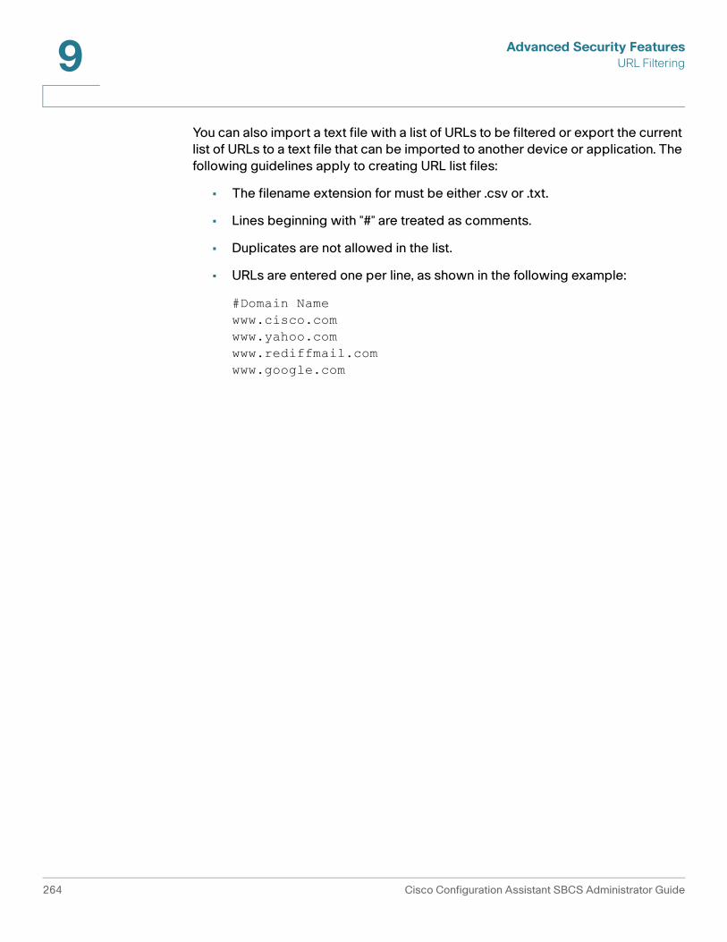
Advanced Security FeaturesURL Filtering9
You can also import a text file with a list of URLs to be filtered or export the current list of URLs to a text file that can be imported to another device or application. The following guidelines apply to creating URL list files:
• The filename extension for must be either .csv or .txt.
• Lines beginning with "#" are treated as comments.
• Duplicates are not allowed in the list.
• URLs are entered one per line, as shown in the following example:
#Domain Namewww.cisco.comwww.yahoo.comwww.rediffmail.comwww.google.com
264 Cisco Configuration Assistant SBCS Administrator Guide

10
Voice System, Network, and Extension Settings
This section covers configuration of basic telephony settings, including these topics:
• Voice Network Settings
• Region Settings for Telephony
• Voice System, Network, and Extension Settings
• User Extensions
• Analog Extensions
• SIP Trunks
• Voice Ports
IMPORTANT Telnet access must be enabled in order to configure voice features. You can check this setting by going to Configure > Device Properties > Device Access.
Voice System Initialization Window
The Voice Initialization window appears when you attempt to open a voice configuration window before initializing system-level voice settings.
Before you can configure any other telephony features, you must configure these settings.
Click OK when you are done, or click Cancel.
If the UC 500 platform you are setting up is in factory default state, use the Telephony Setup Wizard to configure these settings and set up trunking. For more information, see the Telephony Setup Wizard, page 86.
Cisco Configuration Assistant SBCS Administrator Guide 265

Voice System, Network, and Extension SettingsRegion Settings for Telephony10
Region Settings for Telephony
To configure region and locale settings for Telephony, choose Configure > Telephony > Region from the feature bar.
The default system locale for the UC 500 is US/English. Before configuring non-US locale settings in the Region window, you must download the appropriate UC 500 IP Phone Localization .tar file and UC 500 CUE localization files and install them on the UC 500. See How to Localize the UC 500 (Non-US/English Locales), page 462.
These topics are covered:
• Configuring Region Settings
• Updating Localization Files for the Current Region
Field Description
System Mode Choose whether to configure call handling for PBX or Keysystem. The default value is PBX.
When the System Mode is set to Keysystem, the system is placed in a hybrid mode, where SIP trunks are treated as if the system were in PBX mode, and local trunks (FXO, BRI, PRI) are treated as key system lines. In this mode:
• FXO trunks and T1/E1 CAS trunks are configured as direct trunk lines.
• Permissions are not enabled in Keysystem mode. All calls are unrestricted.
Number of Digits Per Extension
Set the extension length. The default value is 3.
Voicemail Access Extension
Internal extension for accessing the voice mail system. The number of digits in the extension must match the specified Number of Digits Per Extension.
266 Cisco Configuration Assistant SBCS Administrator Guide

Voice System, Network, and Extension SettingsRegion Settings for Telephony 10
Configuring Region Settings
From the Region window, you can configure the following locale settings for telephony. When you are finished, click OK or Apply.
Updating Localization Files for the Current Region
After upgrading the UC 500 to a later version of the UC 500 software package, use the Update Localization Files for the Current Region option to:
• Replace Cisco Unified Communications Manager Express (CUCME) IP phone localization files that were removed as a result of selecting the Auto Clean option during an upgrade.
• Update IP phone localization files with newer versions that are compatible with the installed UC 500 software package.
Setting Description
Region Region for Cisco Unified Communications Manager Express.
Call Progress Tone
Choose the appropriate region to set tones and cadences for phones.
Phone Language
Language that appears on user phones.
Voicemail Language
Language of the voice-mail prompts that voice-mail users will hear.
Date Format Date format (dd-mm-yy, mm-dd-yy, yy-mm-dd, yy-dd-mm)
Time Format Time format (12-hour or 24-hour)
Update Language Files for Current Region
Check this option to replace localization files removed by the Auto Clean option when performing a software upgrade or update localization files for the currently selected region. For instructions, see Updating Localization Files for the Current Region, page 267.
Location of Language Files
Read-only. Location where Configuration Assistant looks for phone language files. If you installed Configuration Assistant to the default location, phone language files are located in:
C:\Program Files\Cisco Systems\CiscoSMB\Cisco Configuration Assistant\appdata\phoneloads\
Cisco Configuration Assistant SBCS Administrator Guide 267

Voice System, Network, and Extension SettingsRegion Settings for Telephony10
Follow these guidelines when using this option:
• The localization file must be for the current region configured on the UC 500.
• You cannot use this option for first-time localization of a UC 500 or for installing localization files for a different region.
• This option does not apply to CUE voicemail localization.
IMPORTANT Any firewall software installed on the PC running Configuration Assistant should be configured to allow TFTP and FTP access to and from the UC 500. You must also shut down any third-party TFTP or FTP servers running on the PC with Configuration Assistant installed. Make sure only one network interface is active on the PC running CCA.
To update IP phone localization files for the current region, follow these steps.
STEP 1 Download IP phone localization files for the current region that are compatible with the installed UC 500 software package from Cisco.com (www.cisco.com/go/uc500swpk).
Use the latest versions that are posted to www.cisco.com/go/uc500swpk.
For CME phone localization, the file will be named CME-locale-xx_XX-y.y.y.y.tar, where:
• xx_XX are the language and country codes for the desired locale.
• y.y.y.y.is the CUCME version.
For example, CME-locale-it_IT-4.1.0.2.tar is the file name for the Italian localization file for CME.
STEP 2 Place the downloaded phone localization .tar file in the directory displayed in the Location of Language Files field in the Region window. If you installed Configuration Assistant to the default location, the language file location is
C:\Program Files\Cisco Systems\CiscoSMB\Cisco Configuration Assistant\appdata\phoneloads
STEP 3 Check the Update Localization Files for Current Region option.
STEP 4 Click OK. The phones will restart after the change is applied.
268 Cisco Configuration Assistant SBCS Administrator Guide

Voice System, Network, and Extension SettingsVoice System, Network, and Extension Settings 10
Related Topics
• How to Localize the UC 500 (Non-US/English Locales), page 462
Voice System, Network, and Extension Settings
To access the Voice window, choose Configure > Telephony > Voice from the feature bar.
From the Voice window you configure system and region settings for telephony, user extensions and phone button assignments, and analog extensions.
This section covers the following topics:
• Voice System Settings
• Voice Network Settings
• User Extensions
• Analog Extensions
• Performing a Bulk Import of User and Phone Data
Voice System Settings
Configure these voice system settings on the System tab:
• Hardware Configuration
• System Message
• System Type Settings
Hardware Configuration
The UC 500 hardware configuration is detected and shown in the Hardware Configuration section. CCA restricts the configuration parameters that can be modified, based on the hardware configuration of the router. Typically, these parameters are fixed.
System Message
In the System Message field, enter a message to display on phones, for example, a company name. The message can contain up to 31 characters.
Cisco Configuration Assistant SBCS Administrator Guide 269

Voice System, Network, and Extension SettingsVoice System, Network, and Extension Settings10
System Type Settings
System Type settings are available only for the initial configuration. These settings can also be configured through the Telephony Setup Wizard or the Voice Initialization window. After you apply these settings, these fields become read-only. You must reset the UC 500 to factory defaults to change these settings.
Configure the settings on this tab as described below, then click Apply or OK.
Setting Description
Voice System Type Choose a voice system type, either PBX or Keysystem.
When you choose Keysystem, the system is placed in a hybrid mode, where SIP trunks are treated as PBX lines, and local trunks (FXO, BRI, PRI) are treated as key system lines. In this mode:
• FXO trunks and T1/E1 CAS trunks are configured as direct trunk lines.
• Permissions are not set on key system lines. All calls from these direct trunk lines are unrestricted.
Number of Digits Per Extension
Enter the number of digits for extensions at customer site. The default is 3.
270 Cisco Configuration Assistant SBCS Administrator Guide

Voice System, Network, and Extension SettingsVoice System, Network, and Extension Settings 10
Voice Network Settings
Configure voice network settings as described in the following table. Click OK or Apply when you are finished making changes.
Setting Description
Voice VLAN Choose the subinterface number for voice network. The range is from 1 to 1001. By default, VLAN 100 is the voice VLAN. For typical deployments, this value is not modified.
To configure a different VLAN for voice:
• Chose Configure > Switching > VLANs, and create a new VLAN.
• Refresh the voice screen to read in the new VLAN. The new VLAN appears in the drop-down menu.
• Choose Configure > Switching > Smartports to access the Smartports window, where you can configure each switch port for the new voice VLAN.
DHCP IP Address Pool
Subnet Mask
Enter the IP address and the subnet mask for the first IP address in the range. The default values are 10.1.1.0 and 255.255.255.0, respectively.
Changes to this parameter cause the IP phones to reboot.
IP addresses from this DHCP pool are assigned to phones during auto-registration with the UC 500.
Exclude Address From
Exclude Address To
Enter a starting IP and an ending IP address to specify a range of IP addresses to be excluded from DHCP addressing on the voice network and therefore will not be assigned to IP phones during registration with the UC 500.
The default values exclude addresses from 10.1.1.1 to 10.1.1.10.
Cisco Configuration Assistant SBCS Administrator Guide 271

Voice System, Network, and Extension SettingsVoice System, Network, and Extension Settings10
User Extensions
From User Extensions tab, you can:
• Add, Edit, or Delete Phones and Associated Users
• Configure Phone Buttons and Settings
• Setting Up a Shared Extension, page 281
• Performing a Bulk Import of User and Phone Data
TIP Left-click and drag with the mouse on column headers on the User Extensions tab to rearrange the columns in the view. You can also left-click on columns in the view to sort the data in ascending or descending order.
Add, Edit, or Delete Phones and Associated Users
When you plug an IP phone into the UC 500 it registers automatically and receives an extension and is assigned an IP address on the voice VLAN (VLAN100) using DHCP. The MAC address of the phone is also discovered and displayed. In this case, you only need to configure the user's first and last name, user ID, and password for the phone and, if needed, edit the auto-assigned extension.
You can also manually add a phone to the system. You might want to do this if you are pre-configuring settings for phones and users before the phones are physically connected to the system.
CME IP Address
Subnet Mask
Enter the Cisco Unified Communications Manager Express (CME) IP address and the subnet mask of the router to be configured. This IP address and subnet mask are excluded from DHCP assignments.
The default values are 10.1.1.1 and 255.255.255.0, respectively.
Setting Description
272 Cisco Configuration Assistant SBCS Administrator Guide

Voice System, Network, and Extension SettingsVoice System, Network, and Extension Settings 10
To add and an unregistered phone and associate a user with the phone, follow these steps.
STEP 1 Click Add Phone.
STEP 2 Configure settings for the new phone, as described below.
STEP 3 Click OK or Apply.
To configure additional settings such as buttons, intercoms, call pickup groups, permissions, and call blocking, see Configure Phone Buttons and Settings, page 274.
Field Description
MAC Address MAC address for this IP phone.
Phone Type Phone model.
First Extension Extension to use for button 1 on the phone.
Last Name Last name of the user associated with this phone.
First Name First name of the user associated with this phone.
User ID User ID for this phone user. This ID is used when logging in to Cisco Unity Express User Options web pages to change phone settings.
Password Optional. Password for this IP phone.
This password is used by the phone user to log in to Cisco Unity Express User Options web pages to change phone settings. The password applies only to the Cisco Unity Express GUI, and the IMAP (Internet Message Access Protocol). If this is an SCCP phone, this field also applies to the CME (Cisco Unified Communications Manager Express) GUI.
Cisco Configuration Assistant SBCS Administrator Guide 273

Voice System, Network, and Extension SettingsVoice System, Network, and Extension Settings10
To edit phone settings, follow these steps.
STEP 1 Click in the row for the phone and edit settings as described in Add, Edit, or Delete Phones and Associated Users, page 272.
STEP 2 Edit phone Details and button Options as described in Configure Phone Buttons and Settings, page 274.
STEP 3 Click OK or Apply.
To delete a phone., follow these steps.
STEP 1 Unplug the IP phone from the device.
STEP 2 In the window, choose the phone to be deleted.
STEP 3 To delete the phone, click the Delete button.
Configure Phone Buttons and Settings
When the User Extensions tab is initially selected.
• Details are displayed for the first phone in the list.
• Options for configuring each button on the phone are displayed when you select a line in the button table for the selected phone. By default, line one is selected.
• Depending on the Button Type, different options are shown.
• Analog ports configured with a role of User Phone are listed on the User Extensions page as Analog Phones.
To configure settings for a phone:
STEP 1 Click on a phone to select it. The page updates to display Details for the selected phone with Button 1 selected.
STEP 2 Click in the row that corresponds to the first button on the phone.
STEP 3 Optional. For phones that support expansion modules, the Expansion Module menu lists supported models.
274 Cisco Configuration Assistant SBCS Administrator Guide

Voice System, Network, and Extension SettingsVoice System, Network, and Extension Settings 10
CCA does not automatically discover expansion modules that are connected to phones. If one or more expansion modules are connected to a phone, you must manually select them here. The “x2” selections in the list indicate that two expansion modules are connected to the phone.
When you choose an expansion module from the list, rows are added to the button list for the line buttons on the expansion module and phone model graphic updates to display the expansion module.
STEP 4 Check or uncheck the Use as teleworker phone option to enable or disable MTP.
When Use as teleworker phone is checked, Media Termination Point (MTP) is configured on the phone so that Cisco Unified CME terminates the media stream. The MTP setting causes the UC 500 to act as a proxy. Media packets are forwarded to other IP phones with the IP address of the UC 500 in the source address field. MTP is typically used in remote teleworker phone deployments.
When this option is unchecked, MTP is not configured on the phone.
The Use as teleworker phone checkbox is not displayed for Cisco IP Communicator (CIPC) softphones, since MTP is always configured for CIPC softphones.
STEP 5 Choose whether to allow video calls for this phone.
The Allow video calls setting does not apply to Analog Phones, ATAs, or SIP phones.
• When Allow video calls is checked, Cisco Unified Voice Advantage (CUVA) is enabled for this user’s phone to allow video calls. When coupled with a USB video camera, CUVA enables a PC connected to a Cisco Unified IP Phone or to Cisco IP Communicator to add video to internal calls made on the phone.
• When Allow video calls is unchecked, video calls are not allowed for this phone.
If this setting has been modified from its original value, that value is retained if you change the Phone Type. In most cases, you would only change the Phone Type when adding an unregistered phone. If this is the case, you must manually edit this setting after changing the Phone Type.
By default, Allow video calls is initially un-checked.
NOTE The firmware version for the SPA 500 Series IP Phones that is provided in UC 500 software pack 8.0.3 does not support video calls.
Cisco Configuration Assistant SBCS Administrator Guide 275

Voice System, Network, and Extension SettingsVoice System, Network, and Extension Settings10
For phones configured through the Telephony Setup Wizard, Allow video calls is enabled for all IP phones when the configuration is applied. The Telephony Setup Wizard GUI does not provide any options for enabling or disabling video calls.
STEP 6 For each button on the phone, select a Button Type. Choose from one of the following.
Button Type Description
None No button is configured for this line.
Normal A single line is assigned to the extension. If you want the user to have a voice mailbox, see Setting Up a Personal Mailbox for a Normal User Extension, page 282.
Shared Multiple phones share a single line. For more information, see these topics:
• Setting Up a Shared Extension, page 281
• Setting Up a GDM or Personal Shared Mailbox for a Shared Extension, page 283.
• Mailbox Behavior When the Extension Type is Changed (Normal-to-Shared or Shared-to-Normal), page 283
• Setting Up Shared Octal Line Extensions, page 351.
Monitor Monitor the specified extension only. You can also select a Call Park extension as the line to be monitored. The line status indicates whether the line is either idle or in use. A receptionist can use Monitor buttons to visually monitor the in-use status of phone extensions.
Watch Watch all lines on the phone with the specified extension.
The line status indicator on the Watch button lights Red when any line on the watched phone is in use, out-of-service, or in Do Not Disturb mode. The phone user can press the Watch button to speed-dial the watched extension. Other calls cannot be made or received using a line button that is in watch mode. Incoming calls on a line button that is in watch mode do not ring and do not display caller ID or call-waiting caller ID.
276 Cisco Configuration Assistant SBCS Administrator Guide
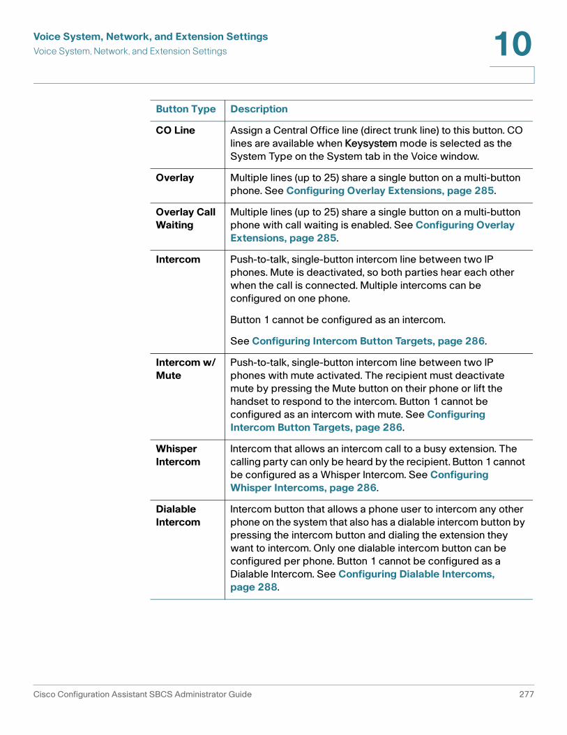
Voice System, Network, and Extension SettingsVoice System, Network, and Extension Settings 10
CO Line Assign a Central Office line (direct trunk line) to this button. CO lines are available when Keysystem mode is selected as the System Type on the System tab in the Voice window.
Overlay Multiple lines (up to 25) share a single button on a multi-button phone. See Configuring Overlay Extensions, page 285.
Overlay Call Waiting
Multiple lines (up to 25) share a single button on a multi-button phone with call waiting is enabled. See Configuring Overlay Extensions, page 285.
Intercom Push-to-talk, single-button intercom line between two IP phones. Mute is deactivated, so both parties hear each other when the call is connected. Multiple intercoms can be configured on one phone.
Button 1 cannot be configured as an intercom.
See Configuring Intercom Button Targets, page 286.
Intercom w/ Mute
Push-to-talk, single-button intercom line between two IP phones with mute activated. The recipient must deactivate mute by pressing the Mute button on their phone or lift the handset to respond to the intercom. Button 1 cannot be configured as an intercom with mute. See Configuring Intercom Button Targets, page 286.
Whisper Intercom
Intercom that allows an intercom call to a busy extension. The calling party can only be heard by the recipient. Button 1 cannot be configured as a Whisper Intercom. See Configuring Whisper Intercoms, page 286.
Dialable Intercom
Intercom button that allows a phone user to intercom any other phone on the system that also has a dialable intercom button by pressing the intercom button and dialing the extension they want to intercom. Only one dialable intercom button can be configured per phone. Button 1 cannot be configured as a Dialable Intercom. See Configuring Dialable Intercoms, page 288.
Button Type Description
Cisco Configuration Assistant SBCS Administrator Guide 277

Voice System, Network, and Extension SettingsVoice System, Network, and Extension Settings10
STEP 7 If you select Normal or Share as the Button Type, enter an Extension Number for the button and enter a label (optional), and configure settings for the selected button, as described below.
Field Description
Dual Line or Octal Line
Line type, either dual or octal. This selection applies only to Normal button and Shared button types. The default value is Octal Line, if the phone supports this feature.
An octal line directory number supports up to eight active calls, both incoming and outgoing, on a single phone button. The Octal Line option is not available for phones that do not support this feature. Octal lines are only available if the UC 500 is running Cisco IOS version 12.4(20)T or later, and the Cisco UC 500 software package version is 7.0(2) or later. For more information, see Octal Lines, page 290.
A shared octal-line extension is required for enabling the Conference Barge (cBarge) feature. See Configuring Conference Barge (cBarge) and Privacy Features, page 348.
Description Specify a description for this phone. This description is displayed in the top right corner on the phone. By default CCA sets this description to the First Name and Last Name configured for the user.
Valid characters in this field are alpha-numeric characters (A-Z, a-z, 0-9, spaces, period (.), underscore (_), and minus (-) sign.
For example, your customer may require the full DID (direct inward dial) phone number to be displayed on phones. You can edit this description field so that it displays the DID number, for example, 555 555-5555.
Block Restricted Numbers
To prevent the user from calling the restricted (blocked) numbers configured in the outgoing dial plan, check the Block Restricted Numbers check box.
278 Cisco Configuration Assistant SBCS Administrator Guide

Voice System, Network, and Extension SettingsVoice System, Network, and Extension Settings 10
Permissions This setting specifies the type of outgoing calls that can be placed from this phone. Permission levels are defined in the outgoing dial plan (Configure > Telephony > Dialplan > Outgoing Dial Plan, Outgoing Call Handling tab). Choose one of the following:
• Unrestricted. Can place outgoing calls to the PSTN without any restrictions.
• Internal. Can place outgoing calls only by dialing internal and emergency numbers. Restricted from placing all other calls.
• Local. Can place outgoing calls only by dialing local, internal, and emergency numbers. Restricted from placing local plus, domestic long distance, or international calls.
• Local plus. Can place outgoing calls by dialing local, internal, and emergency numbers plus additional local numbers as defined in the outgoing dial plan.
• National. Can place outgoing calls only by dialing national long distance, local, internal, and emergency numbers. Restricted from placing national plus numbers and international calls.
• National plus. Can place outgoing calls only by dialing national long distance, local, internal, and emergency numbers, plus additional numbers as defined in the outgoing dial plan. Restricted from placing international calls.
• International. Can place outgoing calls by dialing internal, local, national long distance, emergency, and international numbers.
Field Description
Cisco Configuration Assistant SBCS Administrator Guide 279

Voice System, Network, and Extension SettingsVoice System, Network, and Extension Settings10
Call Forward Busy
Transfer calls to this extension when this line is busy. The default value is Voicemail. Click in the field and select a different option or enter an extension to change the default setting.
When Call Forward No Answer or Call Forward Busy is set to Voicemail, a voice mailbox is created for the user. You can disable the voice mailbox for a user and set mail box size in the Voicemail window (Configure > Telephony >Voicemail). For more information, see Mailboxes, page 343.
Call Forward No Answer
Transfer incoming calls to this extension if there is no answer. The default value is Voicemail. Click in the field and select a different option or enter an extension to change the default setting.
When Call Forward No Answer or Call Forward Busy is set to Voicemail, a voice mailbox is created for the user. You can disable the voice mailbox for a user and set mail box size in the Voicemail window (Configure > Telephony > Voicemail).
If both Call Forward No Answer and Call Forward Busy are set to Voicemail, then later changed to None, the user’s voice mail box is not automatically deleted. You must manually remove the user’s voice mailbox in that case. For more information, see Mailboxes, page 343.
CFNA Timeout, seconds
Number of seconds before unanswered calls are transferred to the Call Forward No Answer destination. The default is 20 seconds.
IMPORTANT If this extension is a member of a Call Blast Group, the CFNA Timeout value you set here must be greater than the Timeout value configured for the Call Blast Group. For example, if the Timeout value for the Call Blast Group that the extension belongs to is 10 seconds, set the CFNA timeout for the extension to at least 11 seconds. Alternatively, you can lower the Timeout value for the Call Blast Group. See Call Blast Groups, page 326.
PSTN Number
Read-only field that displays the PSTN number that is mapped to this extension in the incoming dial plan.
Field Description
280 Cisco Configuration Assistant SBCS Administrator Guide

Voice System, Network, and Extension SettingsVoice System, Network, and Extension Settings 10
STEP 8 Configuration additional settings required for some button types.
a. If you select Monitor as the Button Type, choose an extension from the drop-down menu to monitor. The label of the monitored extension is automatically inserted in the Label field for the Monitor button.
b. If you select Watch as the Button Type, choose an extension from the drop-down menu to monitor the phone that has that extension as its primary extension. The label of the watched extension is automatically inserted in the Label field for the Watch button.
c. If you select Overlay or Overlay Call Waiting as the Button Type, click the Overlay or Overlay Call-Waiting button in the extension field and select at least 2 extensions for the overlay. See Configuring Overlay Extensions, page 285.
d. If you select CO Line as the Button Type, choose a CO line from the drop-down menu in the Extension field, for example, CO 1 (0/1/0). These correspond to direct PSTN trunk lines connected to FXO ports. Edit the Label as needed to identify the CO line.
e. If you select Intercom or Intercom w/ Mute as the Button Type, select a user from the drop-down list in the Extension field. In the Intercom Target popup dialog, select an available button on the selected user's phone for the Target Intercom Button Number, and click OK. See Configuring Intercom Button Targets, page 286.
f. If you select Whisper Intercom, select a user from the drop-down list in the Extension column and configure intercom details. See Configuring Whisper Intercoms, page 286.
g. If you select Dialable Intercom, enter an extension number Extension column and edit the Dialable Intercom settings to the right of the button list. See Configuring Dialable Intercoms, page 288.
STEP 9 Click Apply or OK when you are finished configuring phone settings.
Setting Up a Shared Extension
You can set up a shared extension and add a button for the shared extension to multiple phones so that incoming calls to that extension ring all the phones with a button for the shared extension.
To set up a shared extension, follow these steps.
Cisco Configuration Assistant SBCS Administrator Guide 281

Voice System, Network, and Extension SettingsVoice System, Network, and Extension Settings10
STEP 1 Set up phones and users, as described in Add, Edit, or Delete Phones and Associated Users, page 272.
STEP 2 On the User Extensions tab in the Voice window (Configure > Telephony > Voice), add or select a phone for the shared line.
The button table appears at the bottom of the window.
STEP 3 Click on a button number in the table and set its type to Share.
STEP 4 In the Extension field for that phone button, enter or choose the extension to use for the shared line.
• If no shared extensions are configured on the system, enter a unique extension number to use for the shared line.
• Extensions that are already shared appear in the drop-down list. Choose an existing shared line if you want to add that shared line to the user’s phone.
STEP 5 If this is a new shared extension, configure options for the shared extension such as Dual Line or Octal Line, Permissions, Call Forward Busy, Call Forward No Answer, CFNA Timeout (seconds). The default destination for Call Forward Busy and CFNA is Voicemail.
STEP 6 Click Apply.
STEP 7 Repeat steps 2 through 5 to add the shared line to other phones.
STEP 8 Click OK when you are finished.
STEP 9 Place calls to the shared extension to verify that the extensions are shared on phones as expected.
For options on how to configure mailboxes for shared lines, see Setting Up a GDM or Personal Shared Mailbox for a Shared Extension, page 283.
Setting Up a Personal Mailbox for a Normal User Extension
When you create a Normal extension, a Personal voice mailbox is created for the extension if the user associated with the extension does not already have a Personal mailbox and Call Forward Busy or Call Forward No Answer for the extension is set to Voicemail. Voicemail is the default destination for these settings.
Once the user and their Personal mailbox is created, you can go to the Voicemail window to enable, disable, or change other mailbox settings. See Mailboxes, page 343.
282 Cisco Configuration Assistant SBCS Administrator Guide

Voice System, Network, and Extension SettingsVoice System, Network, and Extension Settings 10
Setting Up a GDM or Personal Shared Mailbox for a Shared Extension
When you create a Shared extension, a general delivery mailbox (GDM) is created for the shared extension if Call Forward Busy or Call Forward No Answer is set to Voicemail (Voicemail is the default destination). Unanswered calls to that shared extension are sent to the GDM for the shared extension. Users with this shared extension can access this GDM mailbox using their own voicemail password.
You also have the option of configuring a Personal shared mailbox for the shared extension. A Personal shared voice mailbox is typically used when a user has more than one phone and they would like to be able to receive calls and access their Personal mailbox from either phone. You can set up that user’s phones with shared extensions that point to the same Personal mailbox.
Personal shared mailboxes are configured on the Mailboxes tab in the Voice window (Configure > Voicemail). You must change the mailbox type for the shared line from the default GDM setting to Personal. When you select Personal as the mailbox type, you must then select a phone user ID from the drop-down menu. Only users with this shared line that do not currently have an enabled Personal voice mail box are listed. Once you set the mailbox Type to Personal and choose a user, phones with that shared extension use the voicemail password associated with the user that owns the Personal shared voice mailbox.
Mailbox Behavior When the Extension Type is Changed (Normal-to-Shared or Shared-to-Normal)
When you change the user extension type from Normal to Shared on the User Extensions tab in the Voice window:
• If there is no existing Personal voice mailbox for that extension and CFB or CFNA is set to None, no voice mailbox is created. If CFB or CFNA is set to Voicemail, a GDM mailbox is created for the shared extension.
• If there is an existing Personal voice mailbox associated with the extension, the mailbox is retained on the system and becomes a Personal shared mailbox for the shared line.
When you change a user extension from Shared to Normal on the User Extensions tab in the Voice window:
• If there is an existing GDM (general delivery mailbox) for the shared extension, the user is removed from the GDM. A Personal mailbox is created for the associated user if CFNA or CFB is configured is set to Voicemail and the user does not already have one. If there are no remaining phone users associated with the shared extension, the GDM is also removed.
Cisco Configuration Assistant SBCS Administrator Guide 283
Voice System, Network, and Extension SettingsVoice System, Network, and Extension Settings10
• If the user associated with the shared extension that is being changed to a Normal extension is also the owner of a Personal shared mailbox for the shared extension, the Personal shared mailbox becomes the Personal mailbox for that user when the change is applied. The remaining extensions associated with that shared line should be changed to Normal extensions or deleted to avoid problems resulting from having shared lines without mailboxes.
For more information about configuring and editing mailbox settings, see Mailboxes, page 343.
Performing a Bulk Import of User and Phone Data
You must configure telephony features (Configure > Telephony > Voice Features) before doing a bulk import of user parameters from an external file.
You can perform a bulk upload of user and phone data from a .csv-format file.
A sample file that shows the format for bulk phone and user data import (sample.csv) is installed with Configuration Assistant. If you installed Configuration Assistant to the default location, this file is located in the following directory:
C:\Program Files\Cisco Systems\CiscoSMB\Cisco Configuration Assistant\appdata
To import phone or user data from an external file, follow these steps.
STEP 1 Choose Configure > Telephony > Voice and select the User Extensions tab.
STEP 2 Click Import and browse to the location of the external file that contains phone and user data.
STEP 3 Click OK.
STEP 4 Verify that the information displayed on the User Extensions tab matches the phone and user data imported from the file.
284 Cisco Configuration Assistant SBCS Administrator Guide

Voice System, Network, and Extension SettingsVoice System, Network, and Extension Settings 10
Configuring Overlay Extensions and Intercoms
When you choose Overlay, Overlay-Call Waiting, Intercom, Dialable Intercom, Whisper Intercom, or Intercom w/Mute as the Type in the phone button table on the User Extensions tab, you are prompted to choose target extensions for the overlay or intercom button. For more information, see one of the following sections:
• Configuring Overlay Extensions
• Configuring Intercom Button Targets
• Configuring Whisper Intercoms
• Configuring Dialable Intercoms
Configuring Overlay Extensions
A normal Overlay extension enables multiple lines (up to 25) to share a single button on a multi-button phone. Overlay extensions require at least two available shared extensions.
Overlay w/ Mute extensions are similar to Overlay extensions, except that call waiting is enabled. With call waiting enabled, if the Overlay extension is in use and a second call comes in on the Overlay extension, the call waiting tone is played and the call is displayed on the IP phone screen.
CCA also supports Overlay configuration on a CO (Central Office) line. This configuration allows a CO Line to share a button with a regular extension. The user can answer calls on that CO Line and see the state of the line, but can still make and receive calls using their regular extension. This functionality is most useful phones with a limited number of buttons.
To choose extensions for an Overlay or Overlay w/ Mute button, follow these steps.
STEP 1 Use the Add, Remove, Select All and Select None buttons to move shared extensions from the Available Extensions list to the Selected Extensions list.
You must choose at least two (2) extensions for the Overlay button. Only shared extensions appear in the Available Extensions list. You can also use the Up and Down arrows to re-order the extensions in the Selected Extensions list.
By default, the label for the first extension number on the Selected list is used for the overlay button label. When you edit the overlay button label, the label for the first extension number is also changed.
STEP 2 Edit the label for the Overlay button, if needed.
Cisco Configuration Assistant SBCS Administrator Guide 285

Voice System, Network, and Extension SettingsVoice System, Network, and Extension Settings10
STEP 3 Click OK.
Configuring Intercom Button Targets
To choose a target for an Intercom button, follow these steps.
STEP 1 In the Intercom Target popup dialog, select an available button on the selected user's phone for the Target Intercom Button Number.
STEP 2 Click OK.
Configuring Whisper Intercoms
The Whisper Intercom allows an intercom call to a busy extension. The calling party can only be heard by the recipient. For more information, see these sections:
• Feature Description, page 286
• Requirements and Limitations, page 286
• Unsupported Phones, page 287
• Procedures, page 287
Feature Description
To place a Whisper Intercom call, the phone user presses the Whisper Intercom button on their phone.
• The phone receiving a Whisper Intercom displays the extension and name of the party that initiated the intercom, and a .zip-zip tone plays before the called party hears the caller’s voice. The Whisper Intercom button lights Amber to indicate one-way audio.
• If the recipient of the Whisper Intercom wants to speak to the phone user who initiated the Whisper Intercom, they press the Whisper Intercom button on their phone, which will then light Green to indicate two-way audio.
• When the recipient of the Whisper Intercom presses the Whisper Intercom button to talk, the active call on their phone is automatically put on hold.
To end a Whisper Intercom call, the phone user presses End Call.
Requirements and Limitations
286 Cisco Configuration Assistant SBCS Administrator Guide

Voice System, Network, and Extension SettingsVoice System, Network, and Extension Settings 10
The following requirements and limitations apply to Whisper Intercoms configured using CCA:
• Whisper Intercom requires Cisco Unified CME 7.1 or later and SCCP 12.0 or later on IP phones.
• A Whisper Intercom button can place calls only to another Whisper Intercom.
• Only one intercom call at a time (either incoming or outgoing) is allowed on a phone.
Unsupported Phones
Whisper Intercoms are not supported for these phones:
• Analog FXS phones
• ATAs
• Cisco Model 793x and 39xx IP Phones
• Cisco Model CP-521 IP Phones
• Cisco Model SPA 501G IP Phones
• Cisco Model 7902, 7905, 7906, 7910, 7911, and 7912 IP phones
Procedures
To configure a Whisper Intercom between two phones, follow these steps.
STEP 1 Launch the Voice window (Configure > Telephony > Voice), and choose the User Extensions tab.
STEP 2 Click on a phone in the list to select it.
STEP 3 Click on the row in the button list for the button on which you want to configure the Whisper Intercom.
STEP 4 In the Type drop-down menu, choose Whisper Intercom.
STEP 5 In the Extension field, choose the user whose phone you want to intercom. The Whisper Intercom Details dialog appears.
STEP 6 Configure detailed settings as described in the section Whisper Intercom Details, page 290.
Cisco Configuration Assistant SBCS Administrator Guide 287

Voice System, Network, and Extension SettingsVoice System, Network, and Extension Settings10
STEP 7 Click OK or Apply.
Configuring Dialable Intercoms
For information about Dialable Intercoms, see these sections:
• Feature Description, page 288
• Unsupported Phones, page 289
• Configuring a Dialable Intercom Button, page 289
Feature Description
Unlike normal Intercoms and Whisper Intercoms, which are always configured between two specific phones, a Dialable Intercom button allows a phone user to to intercom any user on the system that also has a dialable intercom button by pressing their intercom button and dialing the user’s extension.
Dialable intercoms are used by operators or administrative staff who provide support for many employees, as opposed to administrative assistants who are generally responsible for one or two people and have specific intercom buttons on their phone for each person. When this feature is used, a Dialable Intercom button is usually configured on every user’s phone.
CCA does not allow Dialable Intercoms to be configured on button 1 of a phone.
You can optionally configure the Dialable Intercom with or without Mute.
• When Mute is enabled for the intercom, the called phone automatically answers the call in speakerphone mode with Mute activated. The phone beeps when the Intercom call is auto-answered to alert the recipient to the incoming intercom call.
To respond to the intercom call and enable two-way audio, the recipient deactivates the Mute function by pressing the Mute button on their phone or, on some phones, lifting the handset.
• When Mute is disabled, both the caller and the recipient immediately hear each other when the Intercom call is connected.
The benefit of disabling Mute is that the recipient of the intercom call can speak and be heard without having to first deactivate the Mute function. However, nearby background sounds or conversations can be heard as soon as the intercom call is connected.
288 Cisco Configuration Assistant SBCS Administrator Guide

Voice System, Network, and Extension SettingsVoice System, Network, and Extension Settings 10
Unsupported Phones
Dialable Intercoms are not supported on these phones:
• Analog phones
• ATAs
• SIP Phones
Configuring a Dialable Intercom Button
To configure a Dialable Intercom button follow these steps:
STEP 1 Launch the Voice window (Configure > Telephony > Voice), and choose the User Extensions tab.
STEP 2 Click on a phone in the list to select it and display configuration details.
STEP 3 In the button list, click on the number of the button you want to use for the Dialable Intercom. Only one dialable intercom button can be configured per phone.
STEP 4 In the Type drop-down menu, choose Dialable Intercom.
STEP 5 In the Dialable Intercom options area to the right, configure these settings.
a. Choose an extension from the Dialing Digits drop-down menu. This is the extension that users on the system dial to intercom this phone. All normal extensions configured on the phone are listed.
b. Choose whether to enable or disable Mute for intercom calls.
When Mute is enabled, the called phone automatically answers the call in speakerphone mode with Mute activated, and the recipient must deactivate the Mute button in order to speak. When Mute is disabled, both of the parties on the Intercom call immediately hear each other.
STEP 6 Optional. In the Label column of the button list, edit the label for the Dialable Intercom button that is displayed on the phone. The default label is DialableIntercom<Ext>.
STEP 7 Click OK or Apply.
Cisco Configuration Assistant SBCS Administrator Guide 289

Voice System, Network, and Extension SettingsVoice System, Network, and Extension Settings10
Whisper Intercom Details
The Whisper Intercom Details dialog appears when you choose a user from the drop-down list in the Extension column when configuring a Whisper Intercom button.
To complete the Whisper Intercom configuration, follow these steps.
STEP 1 In the Label for the Current User field, enter the text you want to display on this user’s phone desktop for this Intercom button.
When the Whisper Intercom button is pressed, this text is displayed in the To: field of the calling information on this user’s phone.
STEP 2 In the Label for the Target User field, enter the text you want to display on the target user’s phone desktop next to this Intercom button.
When the Whisper Intercom button is pressed on this user’s phone, this label text is displayed in the From: field of the calling information displayed on the target user’s phone.
STEP 3 From the Target Whisper Intercom Button Number drop-down list, choose an available button on the target phone for the intercom.
Octal Lines
An Octal Line directory number supports up to eight active calls, both incoming and outgoing, on a single phone button:
• Unlike a dual-line directory number, which is shared exclusively among phones (after a call is answered, that phone owns both channels of the dual-line directory number), an octal line directory number can split its channels among other phones that share the directory number.
• All phones are allowed to initiate or receive calls on the idle channels of the shared octal line directory number. One octal line directory number can handle multiple calls. Multiple incoming calls to an octal line directory number ring simultaneously.
• After a phone answers a call, the ringing stops on that phone and the call-waiting tone plays for the other incoming calls.
• When phones share an octal line directory number, incoming calls ring on phones without active calls and these phones can answer any of the ringing calls. Phones with an active call hear the call-waiting tone.
290 Cisco Configuration Assistant SBCS Administrator Guide

Voice System, Network, and Extension SettingsAnalog Extensions 10
• After a connected call on an octal line directory number is put on hold, any phone that shares this directory number can pick up the held call. If a phone user is in the process of initiating a call transfer or creating a conference, the call is locked and other phones that share the octal line directory number cannot take the call.
• Missed calls (calls not answered) are not displayed by default.
• A shared octal-line extension is required for enabling the Conference Barge (cBarge) feature. For more information, see Configuring Conference Barge (cBarge) and Privacy Features, page 348.
The following limitations apply to octal lines:
• Octal lines are only available if the Cisco IOS version on the UC 500 is 12.4(20)T or later, and the Cisco Unified Communications Manager Express (CUCME) version is 7.0 or later. Upgrading to the latest UC 500 Software Pack is recommended.
• Not all Cisco IP phone models support octal lines.
• Cisco IP Phone Models 7920, 7902, 7931G, CP-52xG, CP-52xSG, and Cisco SPA 500 Series IP phones do not support octal lines.
• Cisco ATA and analog FXS ports do not support octal lines.
Analog Extensions
The ports listed on the Analog Extensions tab are FXS ports that have been configured with the Common area phone or Fax role from the Configure > Ports > Analog Port Settings window. These devices include legacy analog phones and FAX machines.
These notes apply to configuring analog extensions:
• Advanced features such as voice mail, call forwarding, and so on, are not available on phones configured as analog extensions.
• To prevent the user from calling the restricted (blocked) numbers configured in the outgoing dial plan, check the Block Restricted Numbers check box.
• The Permissions settings specify the type of outgoing calls that can be placed from this phone. For more information, see Permissions, page 279.
Cisco Configuration Assistant SBCS Administrator Guide 291

Voice System, Network, and Extension SettingsPSTN Trunks10
PSTN Trunks
To access PSTN trunk configuration options, choose Configure > Telephony > Trunks > PSTN Trunks. PSTN Trunk settings can also be configured through the Telephony Setup Wizard.
The settings and options displayed on the tabs in the PSTN Trunks window vary, depending on the types of PSTN interfaces available on the UC 500 platform you are configuring.
See the following sections for information on configuring PSTN interfaces.
• FXO
• Basic Rate Interface (BRI)
• T1/E1 Interface
• FXS/DID (VIC Only)
FXO
If there are FXO ports available in the router, this tab displays read-only information indicating the number of FXO ports available. For example: Total Ports: 4 (4 Built-in, 0 VIC)
No user input is required for FXO trunk configuration. For information about viewing status and managing FXO ports, see Voice Ports, page 302.
Basic Rate Interface (BRI)
If a basic rate interface (BRI) is present on the system, configure settings as described in the following table.
NOTE If the ISDN PRI is present and selected and if one or more BRI interfaces are also present, you must set the BRI switch type. The Switch Type parameter is used to set the ISDN switch type on the BRI interface to avoid conflicts.
Setting Description
BRI Switch Type Choose one of the following the BRI switch types, as directed by your service provider: Basic 5ESS, Basic DMS100, NET3, Basic NI, NTT, Basic 1TR6, Basic NET3, VN3, Basic QSIG.
292 Cisco Configuration Assistant SBCS Administrator Guide

Voice System, Network, and Extension SettingsPSTN Trunks 10
T1/E1 Interface
If a T1/E1 interface is present, configure settings as described in the following table. Click OK or Apply when finished.
On UC 560 platforms, up to two (2) T1/E1 ports can be configured; these can be ports on a built-in T1/E1 interface or on a T1/E1 interface installed in a VIC slot.
Bearer Capability Choose one of the following, as directed by your service provider: None, Speech, or 3100Hz.
ISDN Static TEI Choose None or select a number to statically configure the Terminal Endpoint Identifier (TEI) value, as directed by your service provider. The TEI value represents any ISDN-capable device attached to an ISDN network that is the terminal endpoint. TEIs are used to distinguish between several different devices using the same ISDN links.
Setting Description
Connection Type Click the Connection Type radio button to choose either T1 or E1.
This setting is available only for the initial configuration.
After this parameter is set, the field becomes read-only. The T1/E1 options appear if the device has a T1/E1 interface.
Channel Signaling Choose one of the following:
• ISDN PRI
• FXO
• FXS
• E&M
• FGD
Setting Description
Cisco Configuration Assistant SBCS Administrator Guide 293
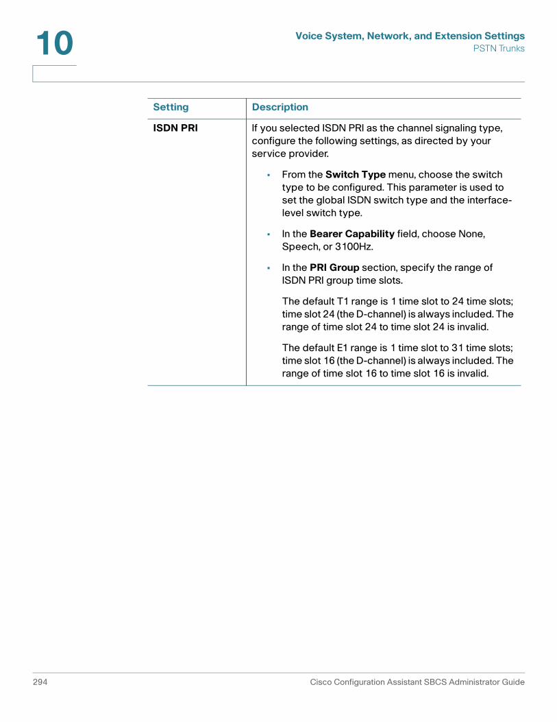
Voice System, Network, and Extension SettingsPSTN Trunks10
ISDN PRI If you selected ISDN PRI as the channel signaling type, configure the following settings, as directed by your service provider.
• From the Switch Type menu, choose the switch type to be configured. This parameter is used to set the global ISDN switch type and the interface-level switch type.
• In the Bearer Capability field, choose None, Speech, or 3100Hz.
• In the PRI Group section, specify the range of ISDN PRI group time slots.
The default T1 range is 1 time slot to 24 time slots; time slot 24 (the D-channel) is always included. The range of time slot 24 to time slot 24 is invalid.
The default E1 range is 1 time slot to 31 time slots; time slot 16 (the D-channel) is always included. The range of time slot 16 to time slot 16 is invalid.
Setting Description
294 Cisco Configuration Assistant SBCS Administrator Guide
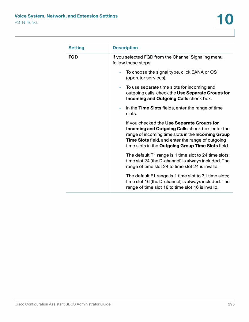
Voice System, Network, and Extension SettingsPSTN Trunks 10
FGD If you selected FGD from the Channel Signaling menu, follow these steps:
• To choose the signal type, click EANA or OS (operator services).
• To use separate time slots for incoming and outgoing calls, check the Use Separate Groups for Incoming and Outgoing Calls check box.
• In the Time Slots fields, enter the range of time slots.
If you checked the Use Separate Groups for Incoming and Outgoing Calls check box, enter the range of incoming time slots in the Incoming Group Time Slots field, and enter the range of outgoing time slots in the Outgoing Group Time Slots field.
The default T1 range is 1 time slot to 24 time slots; time slot 24 (the D-channel) is always included. The range of time slot 24 to time slot 24 is invalid.
The default E1 range is 1 time slot to 31 time slots; time slot 16 (the D-channel) is always included. The range of time slot 16 to time slot 16 is invalid.
Setting Description
Cisco Configuration Assistant SBCS Administrator Guide 295
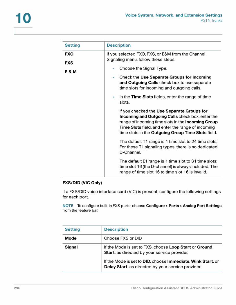
Voice System, Network, and Extension SettingsPSTN Trunks10
FXS/DID (VIC Only)
If a FXS/DID voice interface card (VIC) is present, configure the following settings for each port.
NOTE To configure built-in FXS ports, choose Configure > Ports > Analog Port Settings from the feature bar.
FXO
FXS
E & M
If you selected FXO, FXS, or E&M from the Channel Signaling menu, follow these steps
• Choose the Signal Type.
• Check the Use Separate Groups for Incoming and Outgoing Calls check box to use separate time slots for incoming and outgoing calls.
• In the Time Slots fields, enter the range of time slots.
If you checked the Use Separate Groups for Incoming and Outgoing Calls check box, enter the range of incoming time slots in the Incoming Group Time Slots field, and enter the range of incoming time slots in the Outgoing Group Time Slots field.
The default T1 range is 1 time slot to 24 time slots; For these T1 signaling types, there is no dedicated D-Channel.
The default E1 range is 1 time slot to 31 time slots; time slot 16 (the D-channel) is always included. The range of time slot 16 to time slot 16 is invalid.
Setting Description
Mode Choose FXS or DID
Signal If the Mode is set to FXS, choose Loop Start or Ground Start, as directed by your service provider.
If the Mode is set to DID, choose Immediate, Wink Start, or Delay Start, as directed by your service provider.
Setting Description
296 Cisco Configuration Assistant SBCS Administrator Guide

Voice System, Network, and Extension SettingsSIP Trunks 10
SIP Trunks
To configure SIP trunk settings, choose Configure > Telephony > Trunks > SIP Trunks from the feature bar.
These topics are covered:
• Overview, page 297
• SIP Trunks Tab, page 298
• Advanced Options Tab, page 301
• Generic SIP Trunk Provider Configuration, page 301
Overview
SIP trunk parameters configured in this window vary, depending on the selected Service Provider template. SIP trunk parameter values must be obtained from the ITSP.
If your Internet Telephony Service Provider (ITSP) is not listed, use the Generic SIP Provider template to configure the SIP trunk. For more information about settings CCA automatically configures using this template, see Generic SIP Trunk Provider Configuration, page 301.
From the Advanced Options tab, you can specify IP addresses that are permitted to access your VoIP network.
To learn more about SIP trunking on Cisco SBCS/UC 500 platforms, visit the following link in the Cisco Small Business Support Community:
https://supportforums.cisco.com/docs/DOC-9830/
Caller ID If the Mode is set to DID, enter the number to be displayed for the Caller ID for this FXS port.
Extension N/A for FXS/DID VIC ports.
Permission N/A for FXS/DID VIC ports.
Block Restricted Numbers
N/A for FXS/DID VIC ports.
Setting Description
Cisco Configuration Assistant SBCS Administrator Guide 297

Voice System, Network, and Extension SettingsSIP Trunks10
SIP Trunks Tab
To configure SIP trunk parameters, complete the fields as described in the following table, then click OK or Apply.
Field Description
Service Provider
SIP trunk service provider that this router will connect to for PSTN access.
Cisco-certified SIP Service Providers are identified in the drop-down Service Provider list with Cisco logo.
To configure SIP trunk parameters for other providers, choose Generic SIP Trunk Provider from the Service Provider drop-down list and complete the fields required by that Service Provider. For more information about Generic SIP Trunk Provider configuration, see Generic SIP Trunk Provider Configuration, page 301.
The Add and Delete options in the Service Provider drop-down list are provided so that custom templates for Service Providers can be imported or deleted.
• The built-in templates for Cisco-certified Service Providers cannot be deleted.
• Templates to be imported are obtained from the SIP Service Provider.
When a new Service Provider template is added, it becomes available for selection in the Service Provider list and the appropriate Service Provider-specific configuration settings are displayed when it is selected. For custom templates, version and timestamp information is displayed.
Proxy Server (primary)
IP address or DNS hostname of the primary SIP proxy server for the ITSP.
Proxy Server (secondary)
Optional. IP address or DNS hostname of the secondary (backup) SIP proxy server for the ITSP.
Registrar Server
Optional. IP address or DNS hostname of the SIP registrar server for the ITSP. This field is required if the ITSP requires SIP registrations.
298 Cisco Configuration Assistant SBCS Administrator Guide

Voice System, Network, and Extension SettingsSIP Trunks 10
Outbound Proxy Server
Optional. IP address or DNS hostname of the Session Border Controller (SBC) for the ITSP. This setting is required if the IP address of the SBCS at the ITSP is not the same as the SIP proxy server.
Maximum Number of Calls
Optional. Number of concurrent calls allowed for call admission control. You must configure this setting if the ITSP requires the UC 500 to limit the number of concurrent calls. Check with your ITSP to see whether this setting is required.
The range for the supported number of concurrent calls is listed in brackets, for example, [1-48]. The maximum number of concurrent calls is equal to the number of licenses on the UC 500.
When you change this setting, the Maximum Calls setting configured under Configure > Telephony > Maximum Calls is also updated. See Maximum Calls (Call Admission Control), page 402.
Company Name
Optional. Name of the customer's business to be used for Caller ID. This field is required if a specific Caller ID must be provided for outbound calls. In most cases, this is handled by the ITSP. Check with the ITSP to see whether setting is required.
This value is inserted into the header of the SIP invite.
Digest Authentication
Optional. Username and Password for SIP registration or calling. This setting is required if a SIP Registrar server is present.
Click the Display Password as Plain Text checkbox to toggle display of the password in plain text.
Field Description
Cisco Configuration Assistant SBCS Administrator Guide 299

Voice System, Network, and Extension SettingsSIP Trunks10
To delete a set of per-DID SIP user credentials, follow these steps.
STEP 1 Click in the row in the table that corresponds to the set of credentials you want to delete.
STEP 2 Click Delete.
STEP 3 Click Apply.
Domain Name Service
Optional. SIP Domain Name. Domain name for the SIP server. the SIP Domain Name is specific to Voice over IP (VoIP) services.
Optional. DNS Server Address. IP address of the DNS server for the SIP domain. You can configure a DNS server here if no DNS server is configured and domain names are being used for SIP trunk configuration. However, the preferred location for DNS configuration is on the Device Configuration tab in the IP Addresses window (Configure > Routing > IP Addresses).
User Credentials
Optional. This field is required if the ITSP requires SIP registration with a unique username and password per DID for all DIDs associated to the UC 500. Most ITSPs only register the main number.
To add a set of user credentials for ITSPs that require per-DID SIP authentication:
1. Click Add to create a new row in the table.
2. Click in the Username column for the new row and enter a username. In general, the username field will contain an E.164-format PSTN number.
3. Click in the Password column for the new row and enter the password provided by the ITSP.
4. Click the Enter Password as Plain Text checkbox to toggle display of user passwords in plain text.
5. Repeat these steps to add more credentials.
Field Description
300 Cisco Configuration Assistant SBCS Administrator Guide

Voice System, Network, and Extension SettingsSIP Trunks 10
Generic SIP Trunk Provider Configuration
When Generic SIP Trunk Provider is selected for the SIP provider template, CCA displays all of the configurable options for SIP trunks.
In addition to the configuration options shown, CCA automatically configures these settings on SIP trunks configured using the generic template:
• Voice codec: G.711-ulaw
• Fax codec: G.711
• DTMF (dual-tone multi-frequency) payload: 101
• SIP registration: Registers main number only.
The Generic SIP Trunk template is not compatible with all ITSPs. To request a CCA template for a new SIP provider, go to the following link on the Cisco Small Business Support Community:
https://supportforums.cisco.com/docs/DOC-9685/
Advanced Options Tab
For security reasons, CCA blocks SIP traffic from unknown sources. Configure additional IP addresses here if your provider uses SIP gateways with IP addresses that are different from the proxy servers configured on the SIP Trunks tab.
Consult your SIP provider for the addresses of the SIP gateways that they use.
To configure additional IP addresses that are permitted access to the VoIP network, follow these steps.
STEP 1 Click Add to open a new row in the table for editing.
STEP 2 Enter the IP address.
STEP 3 Configure additional IP addresses, if needed.
STEP 4 Click OK.
Cisco Configuration Assistant SBCS Administrator Guide 301

Voice System, Network, and Extension SettingsVoice Ports10
Voice Ports
This section describes the following voice port configuration:
• Analog Port Settings
• Voice Trunk Settings
Analog Port Settings
This window appears when you choose Configure > Ports > Analog Port Settings on the feature bar.
Overview
From the Analog Port Settings widow, you define how built-in FXS ports will be used and choose a signaling type.
Settings for FXS/DID voice interface card (VIC) ports are configured in the Public Switched Telephone Network section of the System tab in the Voice window (see FXS/DID (VIC Only), page 296).
Procedures
Configure analog port settings as described below, then click OK to apply the configuration.
Settings Explanation
FXS Port Read-only. Displays the FXS port ID, for example, 0/0/0.
302 Cisco Configuration Assistant SBCS Administrator Guide

Voice System, Network, and Extension SettingsVoice Ports 10
Voice Trunk Settings
This window appears when you choose Configure > Ports > Voice Trunk Settings on the feature bar.
Overview
From the Voice Trunk Settings widow, you can view voice trunk port status, reset, shut down, and re-activate voice ports.
By shutting down inactive voice ports, you can ensure that calls are not sent to these ports if there are no devices attached.
When a voice port is shut down, no calls can be directed to it. However, the port is still shown as an available option on other screens in Configuration Assistant. The configuration can still be applied to the port, but the port must be manually re-activated before it can begin using that configuration.
Role Defines how the device connected to this FXS port will be used and where it is configured. Choose one of the following:
• User phone. FXS ports assigned to the user phone role are configured on the User Extensions tab in the Voice window (Configure > Telephony > Voice).
• Common area phone. A common area phone is typically an analog phone located in a lobby or breakroom. Advanced features such as call forwarding, voice mail, and so on, are not available on these phones. FXS ports assigned to this role are configured on the Analog Extensions tab in the Voice window.
• Fax. FXS ports assigned to the Fax role are configured on the Analog Extensions tab in the Voice window.
Description Optional. Enter a description that identifies this FXS port and its usage.
Signal Choose Loop Start or Ground Start as the signal type, depending on what is required by the service provider. The default is Loop Start.
Settings Explanation
Cisco Configuration Assistant SBCS Administrator Guide 303

Voice System, Network, and Extension SettingsVoice Ports10
Procedures
To shut down or reset a voice trunk port, select the port from the list and choose Reset Port or Shutdown Port from the drop-down menu in the Action column.
To re-activate a voice trunk that was shut down, select the port from the list and choose Activate Port from the drop-down menu in the Action column.
304 Cisco Configuration Assistant SBCS Administrator Guide

11
Dial Plan
This section covers incoming and outgoing dial plan configuration, including the following topics:
• Incoming Dial Plan
• Outgoing Dial Plan
• PSTN Trunk Groups
• Dial Plan Templates
Incoming Dial Plan
To configure the incoming dial plan, choose Configure > Telephony > Dial Plan > Incoming Dial Plan from the feature bar.
Before You Begin
Before configuring incoming dial plan settings for direct dialing and incoming FXO calls, make sure that settings on the System tab in the Voice window for BRI, PRI, and FXO trunks have been configured. If SIP trunks are used, make sure these are configured (Configure > Telephony > Trunks > SIP Trunks). Auto Attendant, hunt groups, and call blast groups should also be configured so that they are available as destinations for incoming FXO calls and DID numbers.
The incoming dial plan window has these tabs:
• Incoming FXO Calls
• Direct Dialing
Cisco Configuration Assistant SBCS Administrator Guide 305

Dial PlanIncoming Dial Plan11
Incoming FXO Calls
On the Incoming FXO Calls tab, choose the destination for incoming calls on FXO ports.
To configure destinations for incoming calls to FXO ports, select an FXO port from the list, edit settings as described below, then click OK or Apply.
Field Description
Description Description for this FXO port. You can edit the default value, which initially is the same as the FXO port number, for example, 4 FXO-0/0/1.
Trunk Read-only field that contains the FXO port number, for example, 4 FXO-0/0/1.
Destination Type Destination for inbound calls to this FXO trunk. Choose from the following destination types.
• CO_LINE (direct, “Central Office” trunk line for keysystem mode)
• OPERATOR
• AUTO_ATTENDANT
• BLAST_GROUP
• HUNT_GROUP
• B_ACD (Basic ACD service extension)
Destination If you choose AUTO_ATTENDANT, HUNT_GROUP, BLAST_GROUP, or B_ACD, as the extension type, select the appropriate extension or group from the list of those configured on your system.
If you choose Operator as the extension type, manually enter the extension to be used for the Operator for the site.
If you choose CO_LINE, a read-only description is displayed, for example, Direct Trunk Line - CO1.
306 Cisco Configuration Assistant SBCS Administrator Guide

Dial PlanIncoming Dial Plan 11
Direct Dialing
On the Direct Dialing tab, set up translation rules for mapping incoming PSTN numbers to internal extensions. Two types of translations can be set up:
• Direct Dial to Internal User Extensions. Configure direct inward dial (DID) numbers to ring internal extensions. Use this method to create a one-to-one mapping between a single DID number and a single internal extension. See Direct Dial to Internal User Extensions, page 307.
• Direct Dial to AA, Groups, Operator. Configure a DID number or range of DID numbers to ring a hunt group, call blast group, Basic ACD service, Auto Attendant or Operator extension. See Direct Dial to Auto Attendant, Groups, Operator, page 309.
IMPORTANT For SIP trunking, DID mappings for Auto Attendant and voice mail extensions must be configured through the settings on the Auto Attendant and Voicemail windows, not through the DID settings in the Incoming Dial Plan window.
Direct Dial to Internal User Extensions
This window appears when you click Add from the Direct Dial to Internal User Extensions section in the Incoming Dial Plan window.
Overview
From this window, you configure DID (direct inward dial) numbers to ring internal user extensions. This is done by creating translation rules to define the mapping between each DID number and its corresponding internal extension. A single DID number is mapped to a single internal extension.
The DID number provided by your carrier can have any number of digits. Consult your carrier for the DIDs that have been assigned for your installation.
The maximum number of DID translation rules is 15. However, a single translation rule can be used to map multiple DID numbers to internal extensions by using a range, as shown in this example.
Cisco Configuration Assistant SBCS Administrator Guide 307

Dial PlanIncoming Dial Plan11
Procedures
To configure a translation rule for direct dial to internal user extensions, click Add, complete the fields in the Direct Dial to Internal User Extensions window as described below, then click OK or Apply.
DID Translation Settings
Setting Value
PSTN Range Start Number 9725551000
PSTN Range End Number 9725551005
Internal Extension Range Start Number 200
Internal Extension Range End Number 205
Resulting Configuration
Incoming calls to this DID number Ring this extension
972-555-1000 Ext. 200
972-555-1001 Ext. 201
972-555-1002 Ext. 202
972-555-1003 Ext. 203
972-555-1004 Ext. 204
Field Description
Description Description for the DID extension mapping.
Trunk Choose the digital trunk type from the list that corresponds to the carrier providing the DID numbers, for example, SIP Trunk, BRI Trunk, or PRI Trunk.
308 Cisco Configuration Assistant SBCS Administrator Guide

Dial PlanIncoming Dial Plan 11
Direct Dial to Auto Attendant, Groups, Operator
This window appears when you click Add from the Direct Dial to Auto Attendant, Groups, Operator section in the Incoming Dial Plan window.
From this window you create DID translations to map one or more incoming PSTN numbers to an Auto Attendant, hunt group, call blast group, Basic ACD service, or operator.
To configure direct dial from one or more PSTN numbers to a hunt group, blast group, Basic ACD service, Operator extension, or the Auto Attendant, click Add, complete the fields in the Direct Dial to Auto Attendant, Groups, Operator window as described below, then click OK or Apply.
PSTN Numbers PSTN numbers to map to the corresponding internal extensions.
• To map only one number, enter the same number for the PSTN Range Start Number and PSTN Range End Number.
• To map a range of numbers, enter starting and ending numbers to define the range.
• PSTN numbers can begin with a “+” character.
Internal Extensions
Internal extension numbers to map to PSTN numbers.
• To map only one number, enter the same number for the Internal Extension Start Number and Internal Extension End Number.
• To map a range of numbers, enter starting and ending numbers for internal extensions to define the range.
• The number of internal extensions specified by the range must match the number of PSTN numbers specified by the PSTN range.
Field Description
Cisco Configuration Assistant SBCS Administrator Guide 309

Dial PlanIncoming Dial Plan11
Field Description
Description Description for the DID extension mapping.
Trunk Choose the voice trunk type from the list that corresponds to the carrier providing the DID numbers, for example, SIP Trunk, BRI Trunk, or PRI Trunk.
PSTN Numbers PSTN numbers to map to the corresponding internal destinations.
• To map only one number, enter the same number for the PSTN Range Start Number and PSTN Range End Number.
• To map a range of numbers, enter starting and ending numbers to define the range.
• PSTN numbers can begin with a “+” character.
Internal Extension Type
Choose from the following internal extension types. If an extension type is not listed, no extensions of that type are configured on the system:
• OPERATOR
• AUTO_ATTENDANT
• BLAST_GROUP
• HUNT_GROUP
• B_ACD (Basic ACD service extension)
Internal Extensions
If you choose AUTO_ATTENDANT, HUNT_GROUP, BLAST_GROUP, or B_ACD, as the extension type, select the appropriate extension or group from the list of those configured on your system.
If you choose Operator as the extension type, manually enter the extension to be used for the Operator for the site.
310 Cisco Configuration Assistant SBCS Administrator Guide

Dial PlanOutgoing Dial Plan 11
Outgoing Dial Plan
This window appears when you choose on Configure > Telephony > Outgoing Dial Plan from the feature bar.
NOTE You cannot configure voice features if Telnet is disabled. Use the Device Access window to enable Telnet.
The Outgoing Dial Plan window has these tabs:
• Outgoing Call Handling
• PSTN Trunk Groups
• Caller ID
Outgoing Call Handling
On the Outgoing Call Handling tab, you can:
• Choose a Numbering Plan Locale
• Set the Default Access Code and Digit Collection Timeout
• Configure Outgoing Numbers
• Add or Edit an Outgoing Number
Choose a Numbering Plan Locale
From the Numbering Plan Locale menu, choose one of the following:
• A built-in numbering plan template for a specific locale, for example, Template: Australia or Template: North America.
The following locales have built-in templates: Argentina, Australia, Austria, Belgium, Brazil, Chile, China, Columbia, France, Germany, Indonesia, Ireland, Italy, Japan, Malaysia, Mexico, Netherlands (6-digit or 7-digit), New Zealand, North America (7-digit and 10-digit), Norway, Philippines, Singapore, Slovenia, Spain, Switzerland, UK, Taiwan, Thailand, and Venezuela.
For North America, both 7-digit and 10-digit dial plan templates are provided so that you do not have to manually edit the dial plan for local dialing. Similarly, 6-digit and 7-digit templates are provided for the Netherlands.
• Define a new locale (creates a new, blank numbering plan).
• A custom template based on one of the default templates with modifications or a custom imported template.
Cisco Configuration Assistant SBCS Administrator Guide 311

Dial PlanOutgoing Dial Plan11
Once you choose a numbering plan locale, the tab updates to display the outgoing numbers defined in the selected locale or, if you selected Define New Locale, all outgoing numbers are cleared.
Once you have added or modified any of the outgoing numbers in the default template for a locale, a new dial plan is created with your changes, leaving the original template intact.
When you first apply an outgoing dial plan template, if that template contains any blocked numbers, you are asked whether you want to globally enable or disable call blocking on all user phones. This global option appears only during initial dial plan configuration. If you add or remove blocked numbers after the template is applied, this global enable/disable option is not available. Call blocking on phones added after the dial plan template is applied must be manually configured on the User Extensions tab in the Voice window.
For more information, see Dial Plan Templates, page 317.
Set the Default Access Code and Digit Collection Timeout
An access code is a single-digit number that phone users dial to place external calls. In the Access Code field, enter a single digit, from 0 to 9 or use the default value of 9. This sets the default access code.
If you change the default Access Code for an existing dial plan, Configuration Assistant displays a dialog asking you whether or not you want the default access code to be applied to all outgoing numbers. Choose Yes to update all outgoing numbers in the existing dial plan.
In the Digit Collection Timeout field, enter the number of seconds (from 2 to 120) to wait for user input when dialing or use the default value of 5.
Configure Outgoing Numbers
!CAUTION All changes to dial plan configuration for outgoing numbers must be tested. Errors
in dial plan configuration can result in customers being unable to place calls.
Cisco strongly recommends that you use an actual IP phone to test the outbound dial plan after you have applied the configuration. CCA checks for conflicts within the UC 500, but checking for incompatibility with the Telco provider is out of scope for CCA.
For example, some North American Telco providers require the PSTN access prefix to be sent to the CO, while other providers require the access code to be stripped.
312 Cisco Configuration Assistant SBCS Administrator Guide

Dial PlanOutgoing Dial Plan 11
You may need to Add or Edit an Outgoing Number in the numbering plan to:
• Change permissions for certain types of calls.
Prevent users from dialing certain numbers (call blocking).Call blocking prevents calls to restricted numbers. When a user attempts to place a call to a blocked number, a fast busy signal is played for approximately 10 seconds. The call is terminated, and the line is placed back on-hook. Call blocking can be enabled and disabled on all types of phones except SIP phones. Call blocking is controlled separately from user permissions and must be enabled on a per-phone basis from the More options window on the Users tab in the Voice window. For more information, see Call Blocking Example, page 316.
Call permissions and restricted numbers in the dial plan do not apply to CO (central office) trunk lines. The Block Restricted Calls and Permissions options are not available for CO Lines.
The Telephony Setup wizard does not globally enable call blocking for user phones when the dial plan template is applied. After the wizard completes, you must manually configure call blocking on each phone.
• Permit phone users to place calls to specific numbers that are outside their normal permissions. For example, phone users permitted to dial National Plus numbers may also need to be able to dial an international number to reach the main corporate office. In that case, you can add an outgoing number specifically for that purpose and set its permission to National Plus.
• Edit the Trunk List to route calls to the appropriate trunk in order of preference. For example, if you select PSTN Only for the Trunk List for Local and Local Plus numbers, all local/local plus calls and emergency calls are routed to PSTN trunks. If you select SIP then PSTN as the Trunk Type for International and International Plus calls, these are routed to available SIP trunks first (since they are free), with fallback to PSTN trunks.
Add or Edit an Outgoing Number
To add an outgoing number, click Add Number to insert a new row in the table, configure settings as described in the following table, then click OK or Apply.
Cisco Configuration Assistant SBCS Administrator Guide 313

Dial PlanOutgoing Dial Plan11
Field Description
Permissions Permission level for the outgoing number. You can also define patterns for call blocking.
Each outgoing number has a permission level. The permission level corresponds to the Permissions and Block Restricted Calls settings that are configured on each phone. Permission levels are cumulative, as listed below:
• Blocked. Restricted number. When Block Restricted Numbers is enabled for a phone, calls to these numbers are blocked.
• Emergency. Outgoing number for emergency services calls. Emergency numbers are included in all permission levels.
• Toll-Free. Outgoing number for free calls that is included in all permission levels
• Local. Includes Emergency, Toll-Free, and Local calls.
• Local Plus. Includes Emergency, Toll-Free, Local, and Local Plus numbers
• National Includes Emergency, Toll-Free, Local, Local Plus, and National numbers
• National Plus. Includes Emergency, Toll-Free, Local, Local Plus, National, and National Plus numbers.
• International. Includes Emergency, Toll-Free, Local, Local Plus, National, National Plus, and International numbers.
• International Plus. Includes Emergency, Toll-Free, Local, Local Plus, National, National Plus, International, and International Plus numbers.
• Unrestricted. Includes all permission levels except Blocked.
Description Description of the outgoing number rule. For blocked calls, the description is always Restricted Number, and is displayed automatically.
314 Cisco Configuration Assistant SBCS Administrator Guide

Dial PlanOutgoing Dial Plan 11
Access Code Access code, if needed, for dialing the outgoing number. In most cases, this will be the default access code defined for external calling. You can also enter a different access code for an outgoing number.
Begins With Number or pattern to be matched.
• The pattern must be unique.
• Numbers and patterns are matched beginning with the first digit.
• A number that includes the pattern, but does not begin with the pattern is not matched.
• When specifying a pattern, an “x” matches any digit from 0 through 9. A series of numbers enclosed in brackets ([089]) matches any one of the digits.
• You can also specify a range. For example, [2-9] matches any single digit in the range from 2 to 9.
Number of Digits
Enter the number of digits in the dialed number or select Variable. The number of digits cannot be smaller than the prefix defined in the Begins With field and cannot be larger than 15.
Dial Pattern As you enter patterns in the Begins With field, the Dial Pattern column in the table updates to display the dial pattern that is matched, including the access code.The Dial Pattern column is read-only.
Trunk Priority Trunk priority settings enable you to assign priority to the outgoing trunk with the lowest cost for a given type of call.
Specify a trunk priority for the outgoing number. Choices include PSTN only, SIP only, PSTN then SIP, SIP then PSTN, or None.
Field Description
Cisco Configuration Assistant SBCS Administrator Guide 315

Dial PlanOutgoing Dial Plan11
To edit an outgoing number, locate the number you want to edit, click in the row to select it, make your changes, then click OK.
To delete an outgoing number, locate the number you want to delete, click in the row to select it, click Delete, then click OK.
Call Blocking Example
To configure the dial plan so that outgoing calls to all numbers that begin with 1976 for the North American Dial Plan are blocked, follow these steps.
STEP 1 From the Outgoing Numbers window, click Add Number.
STEP 2 From the Permissions menu, choose Blocked and enter the access code.
STEP 3 In the Begins With field, enter 1976.
STEP 4 In the Number of Digits column, enter 11.
Configure Priority
Optional. Click the Configure Priority button to open the Trunk List Details dialog, where you can view or edit trunk list settings. To edit trunk list settings:
1. Click in the Preference column that corresponds to the trunk whose priority you want to edit and select a new priority, from 1 (highest) to 10 (lowest).
2. Click Add Trunk to add trunk groups that are configured on the system were not added to outgoing numbers when they were created. When a trunk is created, you can choose whether you want to add it to the trunk list for all outgoing numbers. If you did not choose to add it at the time of creation, use this option to add it to an outgoing number.
3. Click Delete Trunk to remove trunks from the list (for example, you can remove a SIP trunk if you want all calls to be routed through ports connected to the PSTN).
4. The Forward Access Code controls whether or not the access code dialed by the user is forwarded to the trunk. By default, Forward Access Code is set to No. Do not modify this field unless it is required by the Service Provider.
5. Click OK.
Field Description
316 Cisco Configuration Assistant SBCS Administrator Guide

Dial PlanOutgoing Dial Plan 11
STEP 5 The Trunk List and Configure Priority settings do not apply to blocked numbers.
STEP 6 Click OK.
Once you have modified the dial plan to add blocked numbers, you must enable Block Restricted Calls on each phone for which you want to block these numbers. To access this setting, choose Configure > Telephony > Voice, select the User Extensions tab, then configure call blocking for each Normal or Shared line button on the phone.
Dial Plan Templates
Through dial plan templates, Configuration Assistant provides support for tailoring the outgoing dial plan to meet locale-specific requirements. From the Outgoing Handling tab, you can:
• Define a new locale that is not based on an existing template. To define a new locale, choose Define New Locale from the Numbering Plan Locale menu. This creates a new, blank numbering plan locale.
• Import a template. When a template is imported, it is copied to the location that contains the Configuration Assistant built-in dial plan templates. Subsequent launches of Configuration Assistant display the new template as an option in the Numbering Plan Locale menu. To import a template, click Import Template.
• Export a new locale or an existing configuration as a template. When a template is exported, you are prompted to enter a unique name for the template. It is saved in the same location as the built-in Configuration Assistant dial plan templates. Subsequent launches of Configuration Assistant display the exported template in the Numbering Plan Locale menu on the Outgoing Call Handling tab. To export a locale or existing configuration as a new template, click Export as Template.
• Delete a locale. To delete a locale, choose Delete Locale from the Numbering Plan Locale menu. Use the arrow keys in the Delete Locale Template dialog to move available locale templates to the deleted locale templates list, then click OK. Click OK again when prompted to confirm the deletion.
Cisco Configuration Assistant SBCS Administrator Guide 317

Dial PlanOutgoing Dial Plan11
PSTN Trunk Groups
PSTN trunk groups provide a way to logically group voice ports into trunk groups to allow flexibility in choosing voice ports for outgoing calls.
NOTE The Least Cost Routing support addressed in this section refers to the process of manually selecting a PSTN or SIP trunk, by dialing a pre-defined access code.
Least Cost Routing refers to the ability to choose the outgoing trunk with the lowest cost for a given type of call.
Configuration Assistant provides support for Least Cost routing by providing the ability to:
• Configure trunk priority for outgoing numbers
• Assign a hunt scheme for voice ports within a trunk group
• Create and manage new PSTN trunk groups to form logical groupings of voice ports
To create a new, custom PSTN trunk group, select the PSTN Trunk Group tab and click Add. See Trunk Group Parameters, page 321.
Caller ID
See these sections for details on how to configure Caller ID settings:
• Specify the Caller ID Per-Call Block Code
• Specify the Default Caller ID to Display for Each PSTN Trunk Group
• Override the Default Caller ID Number for Specific Extensions
Specify the Caller ID Per-Call Block Code
The Caller ID Per Call Block Code is a four-digit code that phone users can dial before making a call. The code must begin with an asterisk (for example, *111).
Users dial the code before making any call on which they do not want their number displayed on the called-party phone. The caller ID is sent, but its presentation parameter is set to “restricted” so that the caller ID is not displayed.
To configure the code, enter a 3-digit number in the Caller ID Per Call Block Code field and click Apply or OK.
The asterisk (*) is automatically inserted by CCA. For example, if you enter 222 as the per-call block code, phone users will dial *222 to block display of their Caller ID for a call.
318 Cisco Configuration Assistant SBCS Administrator Guide
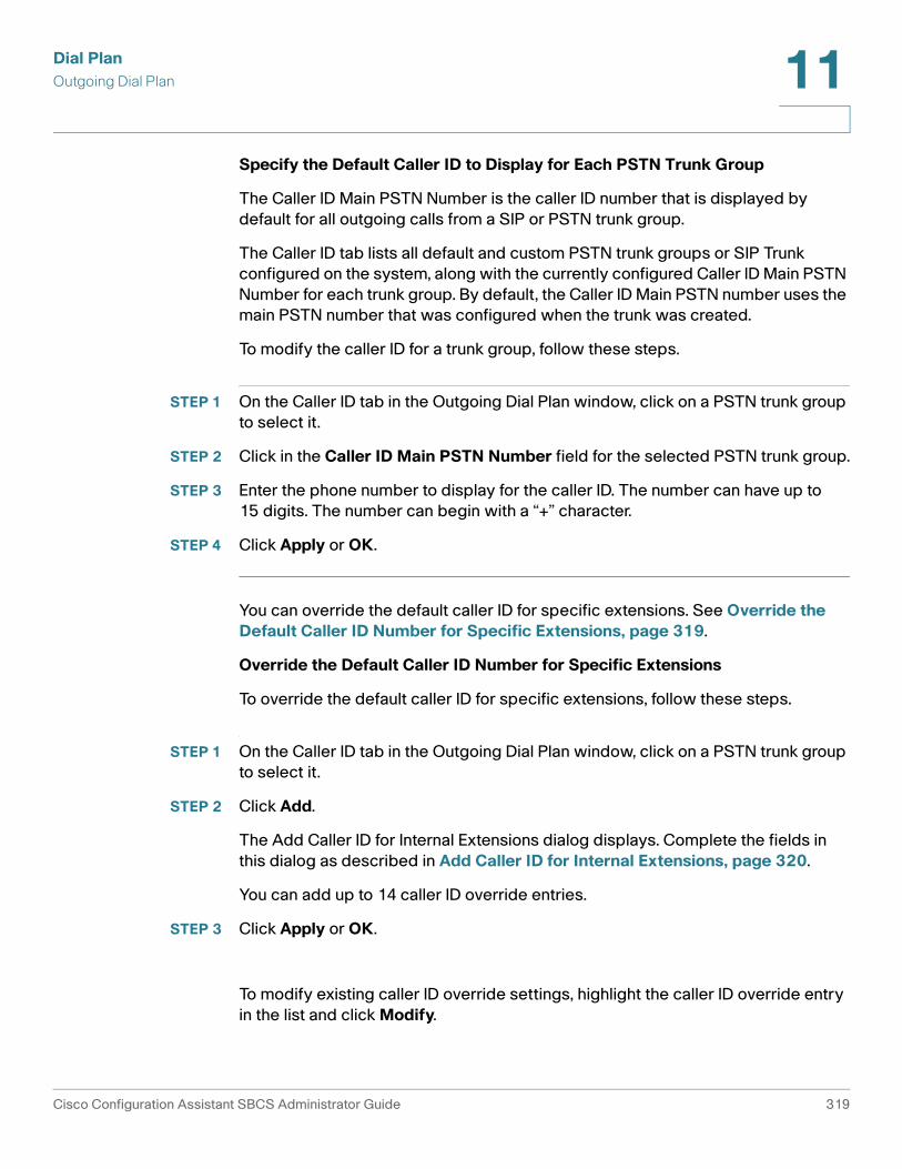
Dial PlanOutgoing Dial Plan 11
Specify the Default Caller ID to Display for Each PSTN Trunk Group
The Caller ID Main PSTN Number is the caller ID number that is displayed by default for all outgoing calls from a SIP or PSTN trunk group.
The Caller ID tab lists all default and custom PSTN trunk groups or SIP Trunk configured on the system, along with the currently configured Caller ID Main PSTN Number for each trunk group. By default, the Caller ID Main PSTN number uses the main PSTN number that was configured when the trunk was created.
To modify the caller ID for a trunk group, follow these steps.
STEP 1 On the Caller ID tab in the Outgoing Dial Plan window, click on a PSTN trunk group to select it.
STEP 2 Click in the Caller ID Main PSTN Number field for the selected PSTN trunk group.
STEP 3 Enter the phone number to display for the caller ID. The number can have up to 15 digits. The number can begin with a “+” character.
STEP 4 Click Apply or OK.
You can override the default caller ID for specific extensions. See Override the Default Caller ID Number for Specific Extensions, page 319.
Override the Default Caller ID Number for Specific Extensions
To override the default caller ID for specific extensions, follow these steps.
STEP 1 On the Caller ID tab in the Outgoing Dial Plan window, click on a PSTN trunk group to select it.
STEP 2 Click Add.
The Add Caller ID for Internal Extensions dialog displays. Complete the fields in this dialog as described in Add Caller ID for Internal Extensions, page 320.
You can add up to 14 caller ID override entries.
STEP 3 Click Apply or OK.
To modify existing caller ID override settings, highlight the caller ID override entry in the list and click Modify.
Cisco Configuration Assistant SBCS Administrator Guide 319
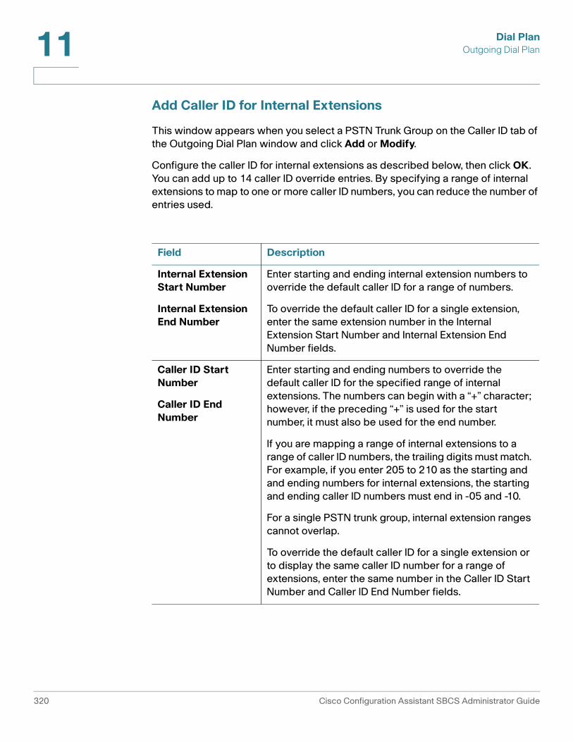
Dial PlanOutgoing Dial Plan11
Add Caller ID for Internal Extensions
This window appears when you select a PSTN Trunk Group on the Caller ID tab of the Outgoing Dial Plan window and click Add or Modify.
Configure the caller ID for internal extensions as described below, then click OK. You can add up to 14 caller ID override entries. By specifying a range of internal extensions to map to one or more caller ID numbers, you can reduce the number of entries used.
Field Description
Internal Extension Start Number
Internal Extension End Number
Enter starting and ending internal extension numbers to override the default caller ID for a range of numbers.
To override the default caller ID for a single extension, enter the same extension number in the Internal Extension Start Number and Internal Extension End Number fields.
Caller ID Start Number
Caller ID End Number
Enter starting and ending numbers to override the default caller ID for the specified range of internal extensions. The numbers can begin with a “+” character; however, if the preceding “+” is used for the start number, it must also be used for the end number.
If you are mapping a range of internal extensions to a range of caller ID numbers, the trailing digits must match. For example, if you enter 205 to 210 as the starting and and ending numbers for internal extensions, the starting and ending caller ID numbers must end in -05 and -10.
For a single PSTN trunk group, internal extension ranges cannot overlap.
To override the default caller ID for a single extension or to display the same caller ID number for a range of extensions, enter the same number in the Caller ID Start Number and Caller ID End Number fields.
320 Cisco Configuration Assistant SBCS Administrator Guide

Dial PlanOutgoing Dial Plan 11
Examples
To override the default caller ID for extensions 205 through 225 with caller ID numbers 12229990005 through 12229990005:
• Enter 205 for the Internal Extension Start Number.
• Enter 225 for the Internal Extension End Number.
• Enter 12229990005 for the Caller ID Start Number.
• Enter 12229990025 for the Caller ID End Number.
To display 12229991200 as the caller ID for internal extensions 200 through 230:
• Enter 200 for the Internal Extension Start Number.
• Enter 230 for the Internal Extension End Number.
• Enter 12229991200 for both the Caller ID Start Number and the Caller ID End Number.
To override the default caller ID for extension 505 only with caller ID 12229991100:
• Enter 505 for both the Internal Extension Start Number and the Internal Extension End Number.
• Enter 12229991100 for both the Caller ID Start Number and the Caller ID End Number.
Trunk Group Parameters
This window displays when you click Add or Modify on the PSTN Trunk Group tab in the Outgoing Dial Plan window.
All voice ports are initially placed in default groups based on the SKU type. For example, ALL_FXO or ALL_ BRI. These default groups can be modified.
When you create a new PSTN trunk group, you are prompted to choose whether you want to add the new trunk as an option for all outgoing numbers or manually add the trunk group to selected numbers as needed.
When you create a new SIP trunk or T1/E1 trunk group, you are prompted to enter a main PSTN number for these trunks. The main PSTN number is required for trunk groups that are not empty. If you create a trunk group, but do not assign voice ports as members, the main PSTN number is not required. If there are voice ports assigned to that trunk group, it is required.
Cisco Configuration Assistant SBCS Administrator Guide 321

Dial PlanOutgoing Dial Plan11
When creating or modifying a PSTN Trunk Group, configure settings as described below, and click OK.
Field Description
Trunk Group Descriptive name for this trunk group.
Hunt Scheme The hunt scheme determines how member voice ports are chosen for outbound calling. The following options are available:
• sequential. Selects the voice port with the highest preference.
• round-robin. Selects the next voice port with free timeslots.
• random. Randomly selects a timeslot.
• longest-idle. Selects the voice port with the timeslot that is idle the longest.
• least-idle. Selects the voice port with the timeslot that is idle the least.
Trunk Type Choose a trunk type from the list of trunk types available on your system.
Trunk Group Members
Choose trunk group members from the list of available voice ports for the selected trunk type.
A voice port can belong to only one PSTN trunk group.
You cannot mix different types of PSTN trunks in a single trunk group. For example, an analog FXO port cannot be a member of a trunk group that contains ISDN BRI ports.
Use the Up and Down arrow keys to re-order the list of voice ports, if the selected hunt scheme is sequential or round-robin.
322 Cisco Configuration Assistant SBCS Administrator Guide

12
Phone Groups
This section provides instructions for configuring these types of phone groups:
• Hunt Groups
• Call Blast Groups
• Call Pickup Groups
• Paging Groups
To configure phone groups, choose Configure > Telephony > Phone Groups from the feature bar.
Hunt Groups
To configure hunt groups, choose Configure > Telephony > Phone Groups > Hunt Groups from the feature bar.
Overview
Use hunt groups to manage distribution of incoming calls to a pre-defined group of extensions (members). The hunt group type determines the order in which members of the hunt group receive calls.
Up to 10 hunt groups can be configured on the system. Each hunt group must have at least one member and can contain up to 32 members.
Once you configure hunt groups, they are available to be selected as destinations for inbound call routing, Auto Attendant, call forward destinations, and other telephony features.
Cisco Configuration Assistant SBCS Administrator Guide 323

Phone GroupsHunt Groups12
Procedures
To enable and configure a hunt group, configure settings as described below, then click OK or Apply.
Setting Description
Enable When this box is checked, the associated hunt group is enabled.
Pilot # Pilot number for this hunt group. This is the extension that is dialed to reach the hunt group. Use the default extension for the pilot number or click in the field and edit it.
Description Optional. Text description that identifies this hunt group. This description is only used in the Hunt Group window. In other parts of the CCA user interface, the hunt group is identified by its number and pilot extension, for example, hunt1 (502).
Hunt Type Determines the order in which calls are received by members of the hunt group. Choose one of the following options:
• Sequential—Call hunting always starts with the pilot number for the group and continues to each number in the group in the order in which they are listed, from top to bottom, in the Members list.
• Longest Idle—Calls go to the directory number that has been idle for the longest time, according to the time stamp of the most recent call to the hunt group taken by that extension. If that extension is unavailable, the search continues to the next extension in the group.
• Peer—Hunt group in which the first number called is selected round-robin from the list.
324 Cisco Configuration Assistant SBCS Administrator Guide

Phone GroupsHunt Groups 12
Members Define the members of the Hunt Group. These are all the numbers that can ring when a call comes in to the pilot number.
1. Click Members to display the list of Available and Selected users at the bottom of the Hunt Groups window.
2. Use the Add and Remove arrow buttons to move items between the list of Available and Selected members. Use CTRL-click and SHIFT-click to select multiple members to move between lists.
3. Use the Up and Down arrows to specify the order in which calls are routed to the Hunt Group.
Timeout (sec)
Number of seconds after which an unanswered call is redirected to the next number in a voice hunt-group list, from 5 to 20 seconds.
No Answer Forward To
Destination for forwarding unanswered calls for the hunt group.
You can choose None, Auto Attendant, Voice Mail, Extension, Hunt Group, Blast Group, B-ACD, or Other Number.
If you select Voice Mail as the destination for No Answer Forward To, a General Delivery Mailbox (GDM) is created for the group. To view GDM mailbox information or change the size of the mailbox, go to Configure > Telephony > Voicemail window and select the Mailboxes tab.
Setting Description
Cisco Configuration Assistant SBCS Administrator Guide 325

Phone GroupsCall Blast Groups12
Call Blast Groups
To configure Call Blast Groups, choose Configure > Telephony > Phone Groups > Call Blast Groups from the feature bar.
Overview
A call blast group is a special type of phone group in which calls to a specified pilot number simultaneously ring multiple phones. This feature can also be used to set up a Single Number Reach scenario in which a call to a user's phone extension simultaneously rings another number (for example, a cell phone number or home phone number) or a different extension.
Up to 10 call blast groups can be configured on the system. Each call blast group must have at least two members and can contain up to 32 members.
Once you configure call blast groups, they are available to be selected as destinations for inbound call routing, Auto Attendant, call forward destinations, and other telephony features.
Procedures
To enable and configure a call blast group, configure settings as described below, then click OK or Apply.
Setting Description
Enable When this box is checked, the associated hunt group is enabled.
Pilot # Pilot number for this call blast group. This is the extension that is dialed to reach the call blast group. Use the default extension for the pilot number or click in the field and edit it.
Description Optional. Text description that identifies this call blast group. This description is only used in the Call Blast Groups window. In other parts of the Configuration Assistant user interface, the call blast group is identified by its number and pilot extension, for example, blast1 (511).
326 Cisco Configuration Assistant SBCS Administrator Guide

Phone GroupsCall Blast Groups 12
Members Define the members of the call blast group. These are all the numbers that will ring when a call comes in to the pilot number.
1. Click Members to display the list of Available and Selected users at the bottom of the Call Blast Groups window.
2. Use the Add and Remove arrow buttons to move members between the list of Available and Selected members. Use CTRL-click and SHIFT-click to select multiple members to move between lists.
To add an external PSTN number (for example, a cell phone number or home phone number) to the list of Available members and move it to the Selected list:
1. In the Other Number field, enter the phone number exactly as you would dial it, including any access codes (up to 16 digits).
2. Click the Add button to the right of the Other Number field to move it to the Available list.
3. Click the Add arrow button to move the Other Number you just added to the Selected list.
To remove an external number from the Selected list, click the Remove arrow button to move it back to the Available list.
Once you close the Call Blast Groups window or select a different Call Blast Group to configure, any external numbers added to the Available list but not moved to the Selected list are removed from the Available list. When you next open the Members selection list, these external phone numbers do not appear in the Available list.
Timeout (sec)
Number of seconds after which an unanswered call is redirected to the destination specified by No Answer Forward To, from 5 to 20 seconds. The default Timeout is 16 seconds.
IMPORTANT The Timeout value for the Call Blast group must be lower than the CFNA Timeout value for any of its member extensions. You may need to lower the Timeout value for a Call Blast Group or raise the CFNA timeout value for member extensions to ensure that this requirement is met.
Setting Description
Cisco Configuration Assistant SBCS Administrator Guide 327

Phone GroupsCall Blast Groups12
No Answer Forward To
Destination for forwarding unanswered calls for the hunt group.
You can choose None, Auto Attendant, Voice Mail, Extension, Hunt Group, Blast Group, B-ACD, or Other Number.
If you select Voice Mail as the destination for No Answer Forward To, a General Delivery Mailbox (GDM) is created for the group. To view GDM mailbox information or change the size of the mailbox, go to Configure > Telephony > Voicemail window and select the Mailboxes tab.
Number Number for the selected destination type selected for No Answer Forward To:
• If you selected Auto Attendant, and multiple Auto Attendants are configured for the site, select the desired Auto Attendant.
• If you selected Other Number, enter the number in the Number field exactly as you would dial it, including any access codes.
• If you selected Extension, select an extension from the list displayed in the Number field.
• If you selected Hunt Group, Blast Group, or B-ACD, select an group or B-ACD service from the list displayed in the Number field.
Setting Description
328 Cisco Configuration Assistant SBCS Administrator Guide

Phone GroupsCall Pickup Groups 12
Call Pickup Groups
To configure Call Pickup groups, choose Configure > Telephony > Phone Groups > Call Pickup Groups from the feature bar.
Overview
Create pickup groups to configure a group of user extensions that can retrieve calls ringing on extensions belonging to members of the same pickup group by pressing the GPickUp softkey on the IP phone and pressing the * key.
The following notes apply to Call Pickup features on SBCS platforms:
• Any phone user can pick up a ringing call by pressing the PickUp softkey on their phone and dialing the ringing extension. No configuration is needed.
• Any phone user can pick up a call ringing on a group pick-up extension by pressing the GPickUp softkey on their phone and dialing the group pick-up extension.
• If the user’s phone and the ringing extension are in the same Call Pickup group, the phone user can retrieve the call by pressing the GPickUp softkey, then the *(star) key on their phone. If there is only one Call PIckup group configured on the system, the user is automatically connected and does not have to press the * key.
Procedures
To enable and configure a pickup group, configure members as described below, then click OK or Apply.
Setting Description
Members Define the extensions that are members of the pickup group.
1. Click Members to display the list of Available and Selected extensions at the bottom of the Pickup Groups window.
2. Use the Add and Remove arrow buttons or the Select All buttons to move extensions between Available and Selected lists. Use CTRL-click and SHIFT-click to select multiple extensions to move between lists.
Cisco Configuration Assistant SBCS Administrator Guide 329

Phone GroupsPaging Groups12
Paging Groups
To configure paging groups, choose Configure > Telephony > Phone Groups > Paging Groups from the feature bar.
Paging Group configuration is described in these sections:
• Overview, page 330
• Creating a Simple Paging Group (Individual Phones Only), page 331
• Creating a Combined Paging Group, page 331
• Editing a Paging Group, page 332
• Deleting a Paging Group
• Paging Group Dependency View, page 334
Overview
You can create paging groups to allow phone users to broadcast announcements to groups of Cisco IP phones by using the phone speakers. You can create up to 10 paging groups.
Only Cisco IP phones can be members of paging groups.
You can also configure combined paging groups. A combined paging group can contain other paging groups as members or a combination of individual phones and other paging groups. For example, a phone in a real estate office may need to receive pages going to the property management department, while a different phone needs to receive pages going to the sales department. In addition, both phones need to receive pages sent to all employees.
The process for configuring a combined paging group has these general steps:
1. First, create each of the individual paging groups required and assigned phones to them.
2. Create the combined paging group and add individual phones that are members of the combined group only.
3. Add the individual paging groups you created in step 1 to the combined paging group.
A paging group can be a member of multiple paging groups, but a phone can be assigned to only one paging group. One level of nesting is supported for combined paging groups. See Nested Paging Groups, page 333 for some examples.
330 Cisco Configuration Assistant SBCS Administrator Guide

Phone GroupsPaging Groups 12
Creating a Simple Paging Group (Individual Phones Only)
To enable and configure a paging group that contains one or more individual phones, follow these steps.
STEP 1 Enable configuration for the group you want to create by checking the Enable option.
STEP 2 In the Paging # field, enter the extension to use for the paging group or accept the default extension. The default extension range for paging groups is 101 through 110.
This is the extension that is dialed to reach the paging group.
STEP 3 Optional. Enter a Description that identifies this paging group. This description is used only in the Paging Groups window and is not displayed on phones.
STEP 4 Add member phones to the paging group.
a. Click the Phones tab at the bottom of the page. The Available list displays the user ID and MAC address for each phone that is not currently part of a paging group.
b. Click on a user ID in the Available list and use the Add and Remove buttons to move members to and from the Selected list. You can also use the CTRL-click and SHIFT-click shortcuts to select multiple phones to move between lists.
STEP 5 Click OK or Apply to create the paging group.
The Members column updates to show the number of phones that are part of the group.
Creating a Combined Paging Group
To create a paging group that contains other paging groups, follow these steps.
STEP 1 Create the paging groups that you want add as members to the combined group and identify individual phones that will be part of the combined group.
See Creating a Simple Paging Group (Individual Phones Only), page 331.
STEP 2 Enable configuration of the combined group by checking the Enable option for the new group.
Cisco Configuration Assistant SBCS Administrator Guide 331

Phone GroupsPaging Groups12
STEP 3 In the Paging # field, enter the extension to use for the paging group or accept the default extension. The default extension range for paging groups is 101 through 110.
This is the extension that is dialed to reach the paging group.
STEP 4 Optional. Enter a text description that identifies this paging group. This description is used only in the Paging Groups window and is not displayed on phones.
STEP 5 Add paging groups and phones to the paging group.
a. To add phones, click the Phones tab at the bottom of the page. The Available list displays the user ID and MAC address for each phone that is not currently part of a paging group.
Click on a user ID in the Available list and use the Add and Remove buttons to move members to and from the Selected list.
b. To add paging groups as member, click the Groups tab at the bottom of the page. Choose group from the Available list and use the Add and Remove buttons to move groups to and from the Selected list.
A paging group can be a member of multiple paging groups, but a phone can be assigned to only one paging group.
You can use the CTRL-click and SHIFT-click shortcuts to select multiple phones or groups.
The Members column updates to reflect the number of phones and paging groups that are part of the group.
STEP 6 Optional. To view dependencies between groups or check for configuration problems in combined paging groups, click Show Group Dependency. See Paging Group Dependency View, page 334.
STEP 7 Click OK or Apply.
Editing a Paging Group
To edit a paging group, click the Phones (n) and Groups (n) button for the group you want to edit.
The Phones and Groups tabs update to display Available and Selected phones and groups for the paging group to be edited.
Use the Add and Remove buttons to edit the group members, then click OK or Apply.
332 Cisco Configuration Assistant SBCS Administrator Guide

Phone GroupsPaging Groups 12
Deleting a Paging Group
To delete a paging group, uncheck the Enable setting that corresponds to the group you want to delete and click OK or Apply.
Before removing a group, you can click Show Group Dependency to see which groups are members of other groups.
TIP If the group you delete is part of a combined paging group, it is automatically removed from the combined paging group. In this case, you may want to update the Description you entered for the combined paging group to reflect the change.
Nested Paging Groups
Combined (“nested”) paging groups are supported up to one level deep.
The following scenario illustrates combined paging groups with one level of nesting:
• Assume paging group 1 contains only phones, paging group 2 contains only phones, and paging group 3 contains paging groups 1 and 2 and some phones. In this scenario, there is one level of nesting.
• A paging call to group 3 reaches all phones in groups 1, 2, and 3.
The paging group dependency view for this scenario is shown below:
Paging groups 1 and 2are nested one levelunder paging group 3
Paging calls to group 3reach all phones inpaging groups 1, 2, and 3
Cisco Configuration Assistant SBCS Administrator Guide 333

Phone GroupsPaging Groups12
The following scenario illustrates combined paging groups with two levels of nesting:
• Assume paging group 1 contains paging group 2 and paging group 2 contains paging group 3. In this scenario, there are two levels of nesting.
• A paging call to group 1 reaches all phones in groups 1 and 2 but does not reach the phones in group 3.
The paging group dependency view for this scenario is shown below:
Paging Group Dependency View
The Paging Group Dependency window appears when you click Show Group Dependency in the Paging Groups window (Configure > Telephony > Phone Groups > Paging Groups).
This window displays a graph that can help you to quickly see which paging groups are members of other paging groups. As shown in the example below:
• The numbers in the view correspond to the number of the paging group listed in the Paging Groups window.
• The arrows in the view indicate which groups are members of other groups. The arrow always points to the member group.
Paging group 3 isnested two levelsunder paging group 1
Calls to paging group 1reach phones inpaging groups 1 and 2but do not reach phonesin paging group 3
334 Cisco Configuration Assistant SBCS Administrator Guide

Phone GroupsPaging Groups 12
Some sample paging group dependency view graphs are shown below.
Paging group 4 has nodependencies on anyother paging group
Paging groups 1 and 2 areboth members of paging group 3
Cisco Configuration Assistant SBCS Administrator Guide 335

Phone GroupsPaging Groups12
336 Cisco Configuration Assistant SBCS Administrator Guide

13
Voice Features
The topics in this section provide instructions for configuring these voice features:
• Voice Mail
• Music on Hold (MoH)
• Conferencing and Conference Barge
• Call Park
• System Speed Dials
• Personal Speed Dials
• Night Service
IMPORTANT Telnet access must be enabled in order to configure voice features. You can check this setting by going to Configure > Device Properties > Device Access.
Voice Mail
To configure Voicemail settings and mailbox options, choose Configure > Telephony > Voicemail from the feature bar. See the following topics for information on how to enable and configure voice mail features.
• Overview
• Setup
• Mailboxes
Overview
From the Voicemail window, you configure basic voice mail settings for the site, view and edit the amount of voicemail storage in minutes for each mailbox, and enable or disable mailboxes for individual users.
Cisco Configuration Assistant SBCS Administrator Guide 337
Voice FeaturesVoice Mail13
The following general notes apply to voice mailboxes:
• When adding users and phones through the Telephony Setup Wizard, voice mailboxes are created if the option to enable voice mail for the user is checked.
• When adding users through the expert mode UI or .csv file upload, Personal mailboxes are initially created on the system for users when Call Forward Busy or Call Forward No Answer settings for any Normal extension are configured to go to voice mail. These settings are configured on the User Extensions tab in the Voice window (Configure > Telephony > Voice).
• The default setting for both Call Forward Busy and Call Forward No Answer is Voicemail. This means that if you add a user and do not modify both of these settings when the user is added, a voice mailbox is automatically created for that user. You can disable the voice mailbox later from the Mailboxes tab in the Voicemail window.
• When you change an existing user’s Call Forward Busy and Call Forward No Answer setting from Voicemail to a different option, the user’s mailbox remains on the system. If you no longer want that user to have a voice mailbox, you must disable it manually from the Mailboxes tab in the Voice window.
• One personal mailbox can be created per user and it can be associated with any one of the Normal extensions configured for the user.
• General Delivery Mailboxes (GDMs) are created for shared lines, hunt groups, and call blast groups when No Answer Forward To is set to Voicemail for the group or shared line. You can also choose to create a Personal shared mailbox for a group.
When you change a user extension from Normal to Shared on the User Extensions tab in the Voice window:
• If there is no existing Personal voice mailbox for that extension and CFB or CFNA is set to None, no voice mailbox is created. If CFB or CFNA is set to Voicemail, a GDM mailbox is created for the shared extension.
• If there is an existing Personal voice mailbox associated with the extension, the mailbox is retained on the system and becomes a Personal shared mailbox for the shared extension.
338 Cisco Configuration Assistant SBCS Administrator Guide

Voice FeaturesVoice Mail 13
When you change a user extension from Shared to Normal on the User Extensions tab in the Voice window:
• If there is an existing GDM mailbox for the shared extension, the associated user is removed from the GDM. A Personal mailbox is created for the user if CFNA or CFB is configured is set to Voicemail and the user does not already have one. If there are no remaining phone users associated with the shared extension, the GDM mailbox is also removed.
• If the user associated with the shared extension that is being changed to a Normal extension is also the owner of the Personal shared mailbox for the shared extension, the Personal shared mailbox becomes the Personal mailbox for that user when the change is applied. The remaining extensions associated with that shared line should be changed to Normal extensions or deleted to avoid problems resulting from having shared lines without mailboxes.
TIP The Dashboard view (Home > Dashboard) provides a Voicemail Status item that displays a summary of system and per-mailbox voice mail storage usage, per-mailbox information, and status.
These topics provide instructions for configuring voicemail setup and mailbox options on the tabs in the Voicemail window:
• Setup
• Mailboxes
Setup
On the Setup tab, you configure basic voice mail settings for a site, such as the voicemail access extension and PSTN number, prefix for direct transfer to voice mail, and choose whether to enable or disable VoiceView Express and LiveReply features.
To configure system voice mail settings, complete the fields on the Setup tab as described below, then click OK or Apply.
Setting Description
Voicemail Access Extension
Internal extension number for voicemail access. The default Voicemail Access Extension is 399.
Cisco Configuration Assistant SBCS Administrator Guide 339

Voice FeaturesVoice Mail13
Voicemail Access PSTN Number
Optional. External PSTN number for voicemail access. This must be a full E.164 number. This is the number that external callers dial to reach voice mail.
The Voicemail Access PSTN Number can begin with a “+” character.
Voicemail Features
Enable or disable additional voicemail features.
VoiceView Express allows phone users to interact with their Cisco Unity Express voice mailbox using their Cisco IP Phone display and softkeys available on the phone.
Users can manage personal mailbox options, manage notifications, send, listen to, record, and manage voicemail messages. The feature provides an alternative to the Telephony User Interface (TUI) and web interface for these tasks. By default, this feature is enabled.
Live Reply enables Cisco Unity Express subscribers who listen to voice mail messages by phone or Voice View Express to reply to another user’s message by pressing 4-4.
When Live Reply is invoked, Cisco Unity Express attempts to establish a call between the two parties. If the attempt is successful, the subscriber is connected to the called party or the voice call is forwarded based on rules defined by the called party.
After the call is ended, the initial connection to voice mail is disconnected. The subscriber is not returned to their voicemail session. To review other voice mail messages after a successful live-reply session, the subscriber must redial the voicemail access number. By default, this feature is disabled.
Setting Description
340 Cisco Configuration Assistant SBCS Administrator Guide

Voice FeaturesVoice Mail 13
Voicemail Features (continued)
Play Caller ID for Incoming Messages. Enables or disables playing of spoken Caller ID for incoming voicemail messages.
When Play Caller ID for Incoming Messages is enabled and an incoming voicemail message is received, depending on whether the incoming call is from an internal or external number:
• Internal calls. If the caller ID information matches an entry in the local directory, the system plays the spoken caller name from the local directory when the recipient listens to that message.
• External calls. If the caller ID information does not match an entry in the local directory, the system plays the sender's telephone number when the recipient listens to that message.
For external calls, the system does not verify that the caller ID information is valid. That function depends on the central office (CO) and the incoming trunk setup.
An external call is one that is from any telephone number that is not listed in the local user directory. Possible sources of external calls are the local telephone company, an IP telephone, or an H.323 gateway. These sources must be configured to present caller ID information to the voice mail system.
Setting Description
Cisco Configuration Assistant SBCS Administrator Guide 341

Voice FeaturesVoice Mail13
Direct Transfer to Voicemail
Check this option to enable Direct Transfer to Voicemail and specify a Voicemail Transfer Prefix..
The Voicemail Transfer Prefix can be a number from 1 through 9. The default value is 6. The prefix is used by the Auto Attendant and by phone users who do not have softkeys for transferring calls to voice mail on their phone. The prefix cannot be the same as the PSTN access code for external calling or the first digit of an internal extension.
When this feature is enabled, the Auto Attendant is updated to include an option for direct transfer to voice mail.
When you enable or disable Direct Transfer to Voicemail, IP phones are restarted and softkeys are added or removed.
When Direct Transfer to Voicemail is enabled, IP phone users with the TrnsferVM softkey on their phones can transfer a call directly to a user or group voice mail box by following these steps:
1. Press the TrnsferVM softkey on their phone.
2. Enter the user or group voice mail extension.
3. Press the TrnsferVM softkey again to make the transfer.
Phone users without a voicemail transfer softkey can transfer a call to voicemail by following these steps:
1. Press the Trnsfer softkey.
2. Enter the voice mail transfer prefix, followed by the user's extension.
For example, if the voice mail transfer prefix is 6 and you want to transfer to voice mail for extension 201, you would press Trnsfer, followed by 6201.
Setting Description
342 Cisco Configuration Assistant SBCS Administrator Guide

Voice FeaturesVoice Mail 13
Mailboxes
From the mailboxes tab you can view storage and summary information for personal and group mailboxes, edit settings for individual mailboxes, and choose whether to enable or disable personal voice mailboxes for each user.
Configure mailbox settings as described blow, then click OK or Apply after making changes.
Field Description
Storage Available and used voice mail storage, in minutes, for the system.
Summary Summary information for each voice mailbox.Size. Mailbox size, in minutes.
Name (User ID) Phone user ID, group ID (for example, hunt1 or blast1), or Shared Line, for the selected mailbox.
Extension User extension, hunt or call blast group pilot extension, or shared line extension for the selected mailbox.
Mailbox Mailbox status, either Enabled or None.
Size Mailbox size, in minutes.
Cisco Configuration Assistant SBCS Administrator Guide 343
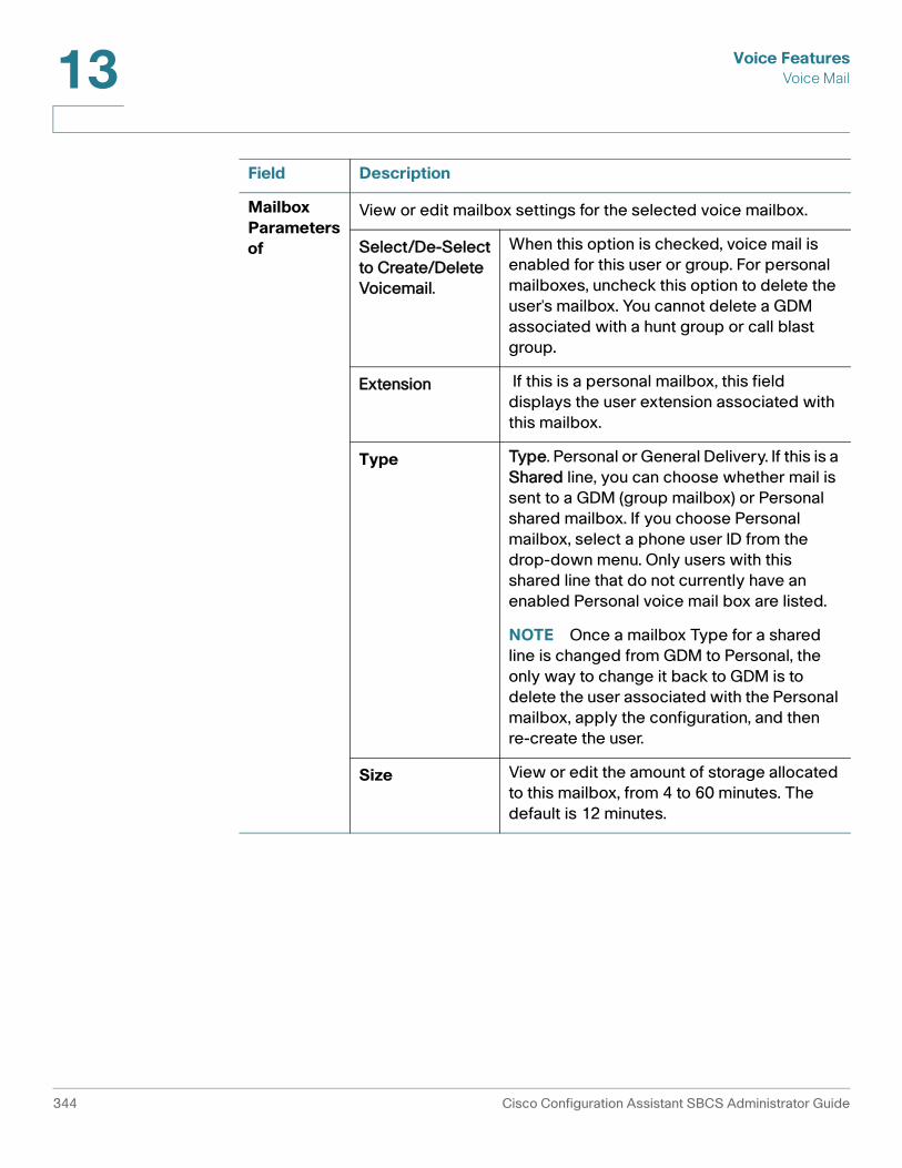
Voice FeaturesVoice Mail13
Mailbox Parameters of
View or edit mailbox settings for the selected voice mailbox.
Select/De-Select to Create/Delete Voicemail.
When this option is checked, voice mail is enabled for this user or group. For personal mailboxes, uncheck this option to delete the user's mailbox. You cannot delete a GDM associated with a hunt group or call blast group.
Extension If this is a personal mailbox, this field displays the user extension associated with this mailbox.
Type Type. Personal or General Delivery. If this is a Shared line, you can choose whether mail is sent to a GDM (group mailbox) or Personal shared mailbox. If you choose Personal mailbox, select a phone user ID from the drop-down menu. Only users with this shared line that do not currently have an enabled Personal voice mail box are listed.
NOTE Once a mailbox Type for a shared line is changed from GDM to Personal, the only way to change it back to GDM is to delete the user associated with the Personal mailbox, apply the configuration, and then re-create the user.
Size View or edit the amount of storage allocated to this mailbox, from 4 to 60 minutes. The default is 12 minutes.
Field Description
344 Cisco Configuration Assistant SBCS Administrator Guide

Voice FeaturesMusic on Hold (MoH) 13
Music on Hold (MoH)
To configure Music on Hold settings, choose Configure > Telephony > Voice Features > Music on Hold from the feature bar.
Overview
Music On Hold (MOH) provides music from a streaming external source or .wav file on the UC 500 flash to a caller who was placed on hold by another caller.
Procedures
To configure music-on-hold, follow these steps.
STEP 1 In the Audio File field, choose None or choose a audio file.
STEP 2 Choose whether to enable music on hold for internal calls and/or enable Music on Hold input from a music source connected to the external Music on Hold port on the UC 500.
• When Enable music on hold for internal calls is checked, internal IP phone-to-IP phone calls placed on hold hear music. Otherwise, internal callers hear tone on hold.
• When Enable external music on hold port is checked, music on hold for internal calls is automatically enabled and cannot be disabled. If an audio file is selected and the external music-on-hold port is also enabled, the music input from the external port takes precedence. The selected audio file serves as a backup music source if the external source fails or is not available.
• MoH for a PSTN or SIP trunk is always enabled, even if MoH for internal calls is disabled. To disable MoH for PSTN or SIP trunk calls, uncheck all options and select None for the audio file.
STEP 3 Click Apply.
To upload a custom Music on Hold audio file (.au file) to the UC 500:
STEP 1 Choose Home > Topology to open the Topology View.
STEP 2 Drag and drop the audio file from your desktop onto the UC 500 icon in the topology view.
Cisco Configuration Assistant SBCS Administrator Guide 345
Voice FeaturesConferencing and Conference Barge13
The audio file must have an .au extension.
Once you have uploaded the file, it becomes available on the Audio File selection list for Music on Hold.
For specifications and instructions on how to create a custom audio file for Music on Hold, see the Cisco Unified Communications Manager Express System Administrator Guide, available on Cisco.com.
Conferencing and Conference Barge
To configure multiparty conferencing, choose Configure > Telephony > Voice Features > Conference & cBarge from the feature bar.
For information about configuring conferencing, see these topics:
• Overview, page 346
• Limitations and Notes that Apply to Multiparty Conferencing, page 348
• Enabling and Configuring Multiparty (MeetMe and Ad Hoc) Conferencing, page 347
• Configuring Conference Barge (cBarge) and Privacy Features, page 348
Overview
Configuration Assistant automatically detects the UC 500 platform you are configuring and automatically determines the maximum supported number of participants per conference and simultaneous conferencing sessions that can be configured for both Meet-Me and Ad Hoc conferencing.
• An Ad Hoc conference is a type of conference in which one party calls another and either party decides to add another party to the call.
• A MeetMe conference is one in which the parties dial a pre-determined MeetMe conference number.
The conference creator presses the MeetMe softkey on their phone, hears a confirmation tone, then dials the MeetMe number. Once the conference is initiated, other parties join the MeetMe conference by dialing the MeetMe number.
346 Cisco Configuration Assistant SBCS Administrator Guide

Voice FeaturesConferencing and Conference Barge 13
When you configure MeetMe conferencing, all phone users have permission to initiate MeetMe conferences. The MeetMe conference creator can press the ConfList softkey to list all participants, RmLstC softkey to remove the last caller that joined, and remove a party from a conference.
MeetMe conferencing softkeys are configured and applied to phones automatically when multiparty conferencing is enabled and MeetMe extensions are set up.
• MeetMe conferences always use hardware conferencing resources;. AdHoc conferences with 3 participants are software-based, while AdHoc conferences with more than 3 participants use hardware conferencing resources.
Cisco UC 500 platforms that support 24 or more users have approximately twice the amount of hardware conferencing resources and can support a greater number of participants and sessions.
NOTE Hardware conferencing is disabled if there are not enough hardware resources. For example, hardware conferencing may be disabled if a T1/E1add-on card is added to an UC 500-16U chassis, because voice ports consume resources that from the same pool of resources allocated for hardware conferencing.
Enabling and Configuring Multiparty (MeetMe and Ad Hoc) Conferencing
To enable and configure multi-party conferencing, follow these steps.
STEP 1 In the Conference window, choose whether to enable multiparty conferencing.
• Check the Enable Multi-Party Conferencing checkbox to enable multiparty conferencing (requires hardware resources).
• If you do not choose to enable multiparty conferencing, specify the Maximum 3-way Calling Sessions allowed.
STEP 2 If Enable Multi-Party Conferencing is checked, configure the following settings.
a. Choose a Mode, either G711 (single mode) or G711/G729 (mixed mode).
The Mode setting determines the amount of hardware conferencing resources required per call. G711 uses fewer hardware conferencing resources than G711/G729.
G711 only mode is recommend for deployments where local trunks only are used. Mixed mode (G711/G729) is recommended for deployments that include SIP trunking, if the SIP Service Provider supports G729.
b. Use the pull-down menu to select the Maximum Participants per conference.
Cisco Configuration Assistant SBCS Administrator Guide 347
Voice FeaturesConferencing and Conference Barge13
c. Use the slider bar to the right of the Sessions menu to allocate sessions between Ad Hoc and Meet-Me conferences. The total number of sessions must be equal to or less than the maximum number of simultaneous sessions.
d. Edit Meet-Me extension numbers or leave the default values.
STEP 3 Click OK or Apply.
’
Limitations and Notes that Apply to Multiparty Conferencing
• If you are configuring a 8- or 16-user system with a VIC and hardware-based Ad Hoc conferencing is already configured on the device, before any VIC card is configured from CCA, Ad Hoc conferencing must be restored to software-based conferencing by unchecking Enable Multiparty Conferencing and clicking Apply.
• If any DSP-related configuration, such as Transcoding, was performed out-of-band on any system, conferencing is not available. You must either remove the existing out-of-band configuration or continue to configure it out-of-band.
Configuring Conference Barge (cBarge) and Privacy Features
For information about cBarge and Privacy features, refer to these topics.
• Conference Barge Feature Description, page 348
• Privacy Feature Description, page 349
• cBarge Example Scenario, page 350
• Prerequisites for cBarge and Privacy, page 350
• Unsupported Phones, page 350
• Setting Up Shared Octal Line Extensions, page 351
• Configuring Conference Barge and Privacy Features, page 352
Conference Barge Feature Description
The cBarge feature allows users with shared octo-lines on their phones to press the cBarge softkey to “barge in” and join a call in progress on that shared octo-line. When a third party joins the call, an Ad Hoc conference is created. Other users who also have cBarge configured for the same shared octo-line can join the conference, up to the maximum number of participants. These guidelines apply to the cBarge feature:
348 Cisco Configuration Assistant SBCS Administrator Guide
Voice FeaturesConferencing and Conference Barge 13
• Maximum cBarge sessions. The maximum number of active cBarge conference sessions is the same as the maximum number of Ad Hoc conference sessions allowed on your system. You can view this information on the Conference tab.
• Maximum number of cBarge participants per session. A cBarge conference supports the maximum number of participants that are configured for Ad Hoc conferencing on your UC 500 platform. You can view this information on the Conference tab.
• If no Ad Hoc conference session is available or the maximum number of participants is reached, the cBarge request is rejected, and an error message is displayed on the initiating phone.
• When any party releases from the call, the call remains a conference call if at least 3 participants remain on the line. If only two participants remain in the conference, they are reconnected as a point-to-point call, which releases the conference bridge resources.
• When the target party parks the call or joins the call with another call, the cBarge initiator and the other parties remain connected.
Privacy Feature Description
The Privacy feature works in conjunction with cBarge. This feature allows users with cBarge enabled for a shared extension to block other users who share the extension from seeing call information, resuming a call, or barging into a call on the shared extension. The phone must have an available line button in order to enable this feature.
When Privacy is configured for a phone with cBarge using CCA:
• A Privacy button is placed on the phone. If no line button is available, a message appears in the CCA Error bar.
• When adding buttons to phones, Personal Speed Dials take precedence over the Privacy button. You may need to remove some Personal Speed Dials from the phone in order to place the Privacy button on the phone. If you add Personal Speed Dials after configuring a Privacy button, the Personal Speed Dials take precedence, and the Privacy button may be replaced if there aren’t enough buttons.
• The phone user can press the Privacy button on their phone to toggle Privacy between On and Off.
• When Privacy is On, the Privacy button on the user’s phone lights Amber.
Cisco Configuration Assistant SBCS Administrator Guide 349

Voice FeaturesConferencing and Conference Barge13
cBarge Example Scenario
In this example, User A and User B both have extension 222 assigned to a button on their respective phones. Extension 222 is configured as a shared octal-line extension. The cBarge feature is enabled for extension 222 on both phones, and Privacy is disabled (Off) on both phones.
The cBarge softkey becomes available when User A presses the line button for Extension 222 to answer an incoming call on the shared line. While User A is on the call on Extension 222, User B can press the cBarge softkey on their phone to join the conversation with User A and the other party on Extension 222. This is accomplished internally by creating an Ad Hoc conference between User A, User B, and the other party on Extension 222.
To extend this example:
• If a third user, User C, also has the shared octal-line extension configured on their phone, they can also press the cBarge softkey on their phone to join the conference.
• If User A then presses the Privacy button on their phone to toggle Privacy On, the cBarge softkey is not available to the other users with Extension 222 on their phone and no other users can join the call.
Prerequisites for cBarge and Privacy
To configure Conference Barge and Privacy features, your system must meet the following requirements:
• UC 500 Software Pack 7.0.2 or later (this that IOS 12.4(20)T2 or later and CUE 7.0 or later is installed) is required. For Cisco 7931 phones, UC 500 Software Pack 8.0.3 is required.
• Multiparty conferencing must be enabled and Ad Hoc conference sessions and participants must configured before you can configure cBarge and Privacy features.
• Shared octal-line extensions must be configured on phones before you can configure cBarge and Privacy features.
Unsupported Phones
cBarge and Privacy features cannot be configured for single-button phones and phones that do not support shared octal-line directory numbers (DNs). Phones that do not support shared octal-line DNs are listed below:
• Analog FXS phones
350 Cisco Configuration Assistant SBCS Administrator Guide

Voice FeaturesConferencing and Conference Barge 13
• ATAs
• Cisco Model 7935,7936,7937 and 39xx phonesModel 7931 phones are supported.
• Cisco Model CP-521 IP Phones
• Cisco Model CP-52xG IP Phones
• Cisco Model 7902, 7905, 7906, 7910, 7911, 7912, 7920, and 7985 IP Phones
• All Cisco SPA 500 Series Phones (Models SPA 501G, SPA 525G, SPA525G2, and SPA 50x)
• All Cisco SPA 300 Series IP Phones
• SCCP analog phones (VG224 type)
Setting Up Shared Octal Line Extensions
For more information about octal lines, see Octal Lines, page 290.
To configure a shared octal-line extension on a phone so that cBarge be enabled on a phone, follow these steps.
STEP 1 From the feature bar, choose Configure > Telephony > Voice.
STEP 2 Click the User Extensions tab.
STEP 3 Click on one of the phones in the list to select it so that you can create a shared octal-line extension on it to use for cBarge.
STEP 4 Choose the button on the phone that you want to use for the shared octal line.
STEP 5 For the selected button, configure these button settings and options.
a. In the Type field, choose Share as the extension type.
b. In the Extension field, choose or enter an extension number.
c. In the Label field, enter a label to identify the shared octal-line extension.
d. In the Options area to the right of the selected button, choose Octal Line.
e. In the Options area to the right of the selected button, configure other settings that you want to apply to the shared line. For more information, see Configure Phone Buttons and Settings, page 274.
STEP 6 Click Apply.
Cisco Configuration Assistant SBCS Administrator Guide 351

Voice FeaturesConferencing and Conference Barge13
STEP 7 Once you have created the shared octal-line extension, you can add that extension as a shared line button to other phones to that those phones can be configured to use the cBarge and Privacy features.
For a list of phones that do not support this feature, see Unsupported Phones, page 350.
STEP 8 Click OK to apply the changes and close the Voice window.
Configuring Conference Barge and Privacy Features
After you have enabled multiparty conferencing and configured the required shared octal-line extensions on phones, follow these steps to configure cBarge and Privacy features for these extensions.
STEP 1 From the feature bar on the left, choose Configure > Telephony > Voice Features > Conference & cBarge.
STEP 2 In the Conference & cBarge window, click the Conference Barge tab.
All phones on the system with shared octal-line extensions are listed. The cBarge and Privacy features are Disabled on these extensions by default.
STEP 3 For each phone, choose whether to enable cBarge and Privacy.
To enable Privacy for a shared octal line, you must have an available line button. If there are no available line buttons on the phone, the error bar displays the message “Cannot enable Privacy on <FirstName LastName> (username) because no line buttons are available.”
STEP 4 Click OK or Apply.
Removing cBarge and Privacy for a User’s Phone
To remove cBarge or Privacy from a phone, follow these steps.
STEP 1 From the feature bar on the left, choose Configure > Telephony > Voice Features > Conference & cBarge.
STEP 2 In the Conference & cBarge window, click the Conference Barge tab.
STEP 3 Locate a user in the list.
352 Cisco Configuration Assistant SBCS Administrator Guide

Voice FeaturesCall Park 13
STEP 4 To remove cBarge from the phone, choose Disabled from the pull-down list in the cBarge column. When you remove cBarge from a phone, the Privacy button is also removed.
STEP 5 To remove the Privacy button from a phone that has cBarge enabled, choose Disabled from the pull-down list in the Privacy column.
Call Park
To configure call park, choose Configure > Telephony > Voice Features > Call Park from the feature bar.
Overview
Call Park provides temporary holding locations for incoming calls. When a call is parked, it is transferred to the parking slot extension and put on hold until it is retrieved by another employee using the Call Pickup feature.
Procedures
To configure Call Park slots and extensions:
STEP 1 The UC 500 should be displayed in the Hostname field.
STEP 2 From the Number of Park Slots menu, choose the number of park slots to be configured.
STEP 3 In the Park Slot Extensions fields, enter the extension to use for each park slot or use the default values.
STEP 4 In the Label field for each new park slot extension, enter a description for each park slot.
System Speed Dials
To configure System Speed Dials, choose Configure > Telephony > Voice Features > System Speed Dial from the feature bar.
From the System Speed Dial window, you can set local speed dial numbers.
Cisco Configuration Assistant SBCS Administrator Guide 353

Voice FeaturesPersonal Speed Dials13
Overview
A list of frequently called numbers can be created for all phones. A phone user can quickly dial a number from a list by using a speed-dial number.
Phone users access these speed dials from the Local Services > Local Speed Dial menu on their phone.
You can add, edit, or delete speed-dial entries. The list entries can be moved up or down the list and appear on the telephone display in the order in which they are listed. A maximum of 32 frequently called numbers can be defined in the list.
Procedures
To enable a local speed-dial menu for all IP phones, perform the following steps:
STEP 1 Click Add.
STEP 2 In the Name field, enter the name of the speed dial.
STEP 3 In the Phone Number field, enter the number for the speed dial.
STEP 4 To reorder a local speed-dial number in the list, select the entry, and click the up arrow or the down arrow. The numbers are listed in the order in which they are displayed on the phone.
STEP 5 To remove a local speed-dial number from the menu, select the entry in the menu, and click Delete in the Local Speed Dials box.
If the list has reached the maximum number of entries allowed, the Add button is disabled.
Personal Speed Dials
To configure personal speed dial buttons on IP phones, choose Configure > Telephony > Voice Features > Personal Speed Dial from the feature bar.
Overview
From the Personal Speed Dial window, you can configure personal speed dial numbers for individual phones. Phone users access these speed dials from the display on their IP phone. This feature can be used to quickly add a large number of speed dials to a reception or administrator phone with an expansion module.
354 Cisco Configuration Assistant SBCS Administrator Guide

Voice FeaturesPersonal Speed Dials 13
For example, the phone user Ted Brown has 205 as his primary extension, an intercom on button 2, and three personal speed dials configured on his phone. Buttons 3 through 5 display personal speed dials.
The following usage guidelines apply to personal speed dials configured from this window:
• Up to 55 personal speed dials can be configured.
• These speed dials are applied in order, beginning with the first available button on the user’s phone.
• Personal speed dial buttons cannot be placed between line or feature buttons. For example, if button 1 is configured as a Normal extension and button 3 is configured as an Intercom button, the first personal speed dial is assigned to button 4. A personal speed dial cannot be assigned to button 2. This also applies to button assignments for phones with expansion modules.
• If the number of personal speed dials configured is greater than the number of buttons on the user’s IP phone, the phone user can access the rest of the speed dials from menus on their IP phone. To access these speed dials:
- Press the services button on their IP phone.
- From the CME Service URLs menu, choose My Phone Apps.
- From the My Phone Apps menu, choose Speed Dial Buttons.
• An IP phone user can also use abbreviated dialing feature with these speed dials. To use abbreviated dialing:
- With the phone on-hook, press the number of the speed dial as it appears in the menu list. For example, to dial the tenth speed dial in the list, the user presses “1” then “0.”
- Press the AbbrDial softkey to dial the number.
Cisco Configuration Assistant SBCS Administrator Guide 355

Voice FeaturesNight Service13
• Speed dials that the user manually adds from the services menu on their phone are also displayed on the Personal Speed Dials window in Configuration Assistant.
• IP phones are restarted automatically after personal speed dial configuration is applied.
Procedures
To configure personal speed dials, for user’s phones, follow these steps.
STEP 1 Click in a row of the table to select a phone for which you want to configure speed dials.
You can sort phones in the list by extension, phone type, first name, last name, user ID, or MAC address.
STEP 2 In the Personal Speed Dial for User <FirstName> <LastName> (<UserID>) section of the dialog, select a speed dial button by number.
STEP 3 Enter a phone number exactly as the user would dial it, including an access code for external dialing or site dialing prefix, if needed.
East Asian double-byte characters are not supported with personal speed dials.
STEP 4 Enter a label to identify the speed dial button on the phone display.
STEP 5 Continue adding speed dial buttons as needed.
STEP 6 Click Apply or OK when you are finished.
The affected phones are restarted automatically. IP phones that are in use are restarted after the current call completes.
Night Service
To configure Night Service, choose Configure > Telephony > Night Service from the feature bar.
Before you can enable Night Service, you must set up a night service schedule from the Night Service Schedule tab in the Schedules window (Configure > Telephony > Schedules). See Night Service Schedule, page 363.
356 Cisco Configuration Assistant SBCS Administrator Guide

Voice FeaturesNight Service 13
Overview
Up to four extensions can be configured for night service. Each extension can be configured with a Call Forward number or a Night Service Bell.
When a call forward number is configured for a night service extension, incoming calls to that extension during night service hours are forwarded to that number.
The night service bell allows you to provide coverage for unstaffed extensions for night-service hours. During night-service hours, extensions configured for night-service bell receive notification of incoming calls with a special “burst” ring. Phone users at the night-service phones can then use the call-pickup feature to answer incoming calls.
To configure night-service phones, at least one of the extensions must be configured with a night service bell.
A user can enter a night-service code to manually toggle night-service treatment off and on from any phone that has an extension assigned to night service. Using the night-service code at any phone with a night-service extension turns night service on or off for all phones with night-service.
Procedures
To configure a night service extension with a call forward number:
STEP 1 In the Extn # field, choose an available extension from the drop-down list.
STEP 2 In the Answer Type field, choose call forward night service.
STEP 3 Enter a number in the Forward to Number field.
Inbound calls to this extension during night service hours are forwarded to this number.
This number can be an external PSTN number or an extension number. When entering an external PSTN number, enter the number exactly as you would dial it, including the access code.
STEP 4 Repeat the steps 1 to 3 to configure night service with a call forward number for more extensions.
STEP 5 Click OK or Apply.
Cisco Configuration Assistant SBCS Administrator Guide 357

Voice FeaturesNight Service13
To configure Night Service with Night Service Bell, follow these steps.
STEP 1 In the Extn # field, choose an available extension from the drop-down list.
STEP 2 In the Answer Type field, choose night service bell.
STEP 3 Click the Night Service Phones button to launch a window for selecting phones.
STEP 4 Select the phones from the available phones list.
STEP 5 Click Add.
STEP 6 Click OK or Apply.
To configure a night service code, follow these steps.
STEP 1 In the Night Service Code field, enter the night service toggle code.
You can enter up to 15 digits. CCA automatically prefixes the code with an asterisk (*).
When choosing a code for toggling Night Service, keep in mind that a default set of feature activation codes (used primarily for analog lines) are sent to the UC 500 by CCA. To avoid overlap with these feature activation codes, the Night Service toggle code should begin with *2, *7, *8, or *9.
STEP 2 Click OK or Apply.
To remove a night service extension, set the Extn# field to None and apply the change. You can also select a different extension and modify any of the other settings.
To modify the list of night service phones, click Night Service Phones, use the Add, Remove, and Select All buttons to update the Selected Phones list, then apply your changes.
Related Topics
• Night Service Phones, page 359
• Night Service Schedule, page 363
358 Cisco Configuration Assistant SBCS Administrator Guide

Voice FeaturesNight Service 13
Night Service Phones
This window appears when you click Night Service Phones in the Night Service window.
Click on phones from the Available list and use the Add, Remove, and Select All arrow buttons to move phones between the Available and Selected Phones lists.
Selected phones are configured as night service phones and will receive notification of incoming calls when night service is active. Phone users at the night-service phones can then press the GPickUp button on their phone to answer incoming calls.
When you are finished choosing phones, click OK.
Related Topics
• Night Service, page 356
• Night Service Schedule, page 363
Cisco Configuration Assistant SBCS Administrator Guide 359

Voice FeaturesNight Service13
360 Cisco Configuration Assistant SBCS Administrator Guide

14
Schedules
To configure schedules, choose Configure > Telephony > Schedules.
Business hours, holidays, and night service schedules are managed from these tabs in the Schedules window:
• Business Hours
• Holidays
• Night Service Schedule
Business Hours
The Business Hours schedule defines open and closed hours. This enables the Auto Attendant to be configured to present different prompts and perform different actions for open and closed hours. You can define up to four different business schedules.
If you are using multiple auto attendants, you can set up a separate schedule for each one. You can configure open and closed hours for each day of the week, in half-hour increments.
To enable and define a schedule:
STEP 1 Select a schedule from the list on the left side of the tab.
STEP 2 Click Enable Business Schedule to enable and open the selected schedule for editing.
STEP 3 Edit the name of the schedule to provide a more descriptive name. The default name is systemschedule.
Cisco Configuration Assistant SBCS Administrator Guide 361
Schedules14
STEP 4 Use the pull-down menus at the top of the window to specify open and closed hours for the days of the week, then click Update Table to refresh the display.
You can also click checkboxes inside the table to set business hours.
Timeslots marked with a check indicate hours that the business is open.
STEP 5 Click Apply or OK.
Holidays
Up to 26 holidays can be defined per year, for the current year and for the next year. On scheduled holidays, the Auto Attendant activates its Closed Hours prompts and actions. Night Service is activated, if it is configured for the site.
You can also modify or delete existing holidays or copy all holidays from the current year to the next year. When copying holidays from the current year to the next year, if the same date appears in both years, the current year entry is used.
NOTE You cannot modify the year for an existing holiday. Delete and re-add the holiday if you need to change the year.
To add a holiday:
STEP 1 In the Schedules window, choose either the current year or next year.
STEP 2 Click Add to open the Add Holiday window (see Add Holiday, page 362).
STEP 3 When finished adding holidays, click OK.
Add Holiday
This window appears when you click Add Holiday from the Schedules window.
To add a holiday, follow these steps.
STEP 1 Click the calendar icon and choose a date from the selected year.
STEP 2 Use the forward (>) and back (<) arrows to go to different months in the calendar.
STEP 3 Enter a description for the holiday. The description can contain up to 64 characters.
STEP 4 Click OK.
362 Cisco Configuration Assistant SBCS Administrator Guide

Schedules 14
Night Service Schedule
Specify the hours that Night Service is enabled for each day of the week.
Once you have configured a night service schedule, go to Configure > Telephony > Night Service to enable and configure this feature.
During Night Service hours:
• Night service is enabled for the specified phones and extensions.
• Calls to extensions with call forward to another number after hours are automatically forwarded to that number.
On holidays, Night Service is activated if it is configured for the site.
To configure Night Service hours, follow these steps.
STEP 1 Select a day of the week from the pull-down menu or click the row corresponding to a day of the week in the Night Service Schedule summary display.
STEP 2 Use the from and to pull-down menus to set the hours for the selected day. Click Delete to clear the hours for that day.
STEP 3 Click Add to add hours. Skip this step if you are deleting hours.
STEP 4 Continue selecting days of the week and setting Night Service hours.
Use the Copy selected row to option to copy settings from one day to a different day of the week, weekend days, or weekdays.
Example: if you want Night Service to be active from 4:00 pm to 9:00 am Monday through Friday and 24 hours on Saturday and Sunday, set up the From Hours and To Hours as shown below:
Day From Hours (HH:MM) To Hours (HH:MM)
Monday 17:00 8:00
Tuesday 17:00 8:00
Wednesday 17:00 8:00
Thursday 17:00 8:00
Friday 17:00 8:00
Cisco Configuration Assistant SBCS Administrator Guide 363

Schedules14
STEP 5 Click Apply or OK.
Related Topics
• Auto Attendant, page 365
• Night Service, page 356
Saturday 9:00 8:00
Sunday 9:00 8:00
Day From Hours (HH:MM) To Hours (HH:MM)
364 Cisco Configuration Assistant SBCS Administrator Guide

15
Auto Attendant
To configure an Auto Attendant and manage Auto Attendant prompts and scripts, choose Configure > Telephony > Auto Attendant.
These topics are covered:
• Prerequisites
• Auto Attendant Configuration
• Prompt Management
• Script Management
Prerequisites
Before setting up Auto Attendant configuration and prompts, these telephony features should already be set up:
NOTE Auto Attendant features cannot be configured if Telnet is disabled. Use the Device Access window to enable Telnet.
• Phone extensions and associated voicemail accounts
• Dial plan and associated voice features
• Schedules for business hours of operation and holidays
• Basic ACD service parameters, if used
• Voicemail transfer prefix, if Direct Transfer to Voicemail is used as an Auto Attendant option
Cisco Configuration Assistant SBCS Administrator Guide 365
Auto AttendantAuto Attendant Configuration15
Auto Attendant Configuration
The Auto Attendant tab initially displays options for enabling or disabling the Auto Attendant and choosing whether to configure a standard Auto Attendant with one level of menus (the default) or a multi-level Auto Attendant with submenus.
For instructions on how to configure the Auto Attendant, see these sections:
• Auto Attendant Modes, page 366
• Configuring a Standard Auto Attendant, page 366
• Configuring a Multi-Level Auto Attendant, page 369
Auto Attendant Modes
Three Auto Attendant modes are available:
• Off. When the Auto Attendant mode is set to Off, the factory default settings are used, and the AA Script is set to aa.aef.
If you choose to disable the Auto Attendant by setting the mode to Off, the dial plan mapping between the AA PSTN number and AA internal extensions are deleted. Voice feature settings that reference the Auto Attendant, such as the main number, hunt groups, and call blast groups, may need to be modified.
• Standard. The Standard Auto Attendant mode enables you to configure up to three (3) Auto Attendants, each with a single level of menus. See Configuring a Standard Auto Attendant, page 366.
• Multi-Level. The Multi-Level Auto Attendant mode enables you to configure the AA so that it presents a main menu with up to three (3) submenus to callers. See Configuring a Multi-Level Auto Attendant, page 369.
When you change the Auto Attendant mode, the existing Auto Attendant configuration is not retained. You must reconfigure all of the parameters if you change modes.
Configuring a Standard Auto Attendant
To configure a standard Auto Attendant, follow these steps.
STEP 1 In the Mode field, make sure that Standard is selected.
STEP 2 In the Number of Auto Attendants, choose the number of Auto Attendants to configure.
366 Cisco Configuration Assistant SBCS Administrator Guide

Auto AttendantAuto Attendant Configuration 15
STEP 3 In the AA Extension field, enter the extension number to be accessed for general company auto attendant functions.
This is usually the main telephone extension number for the office. When a caller dials this extension, the Auto Attendant script runs. The AA Extension must be unique across the system. The default AA Extension is 398.
STEP 4 In the AA PSTN Number field, enter the PSTN number to be accessed for general company Auto Attendant functions.
The PSTN number can begin with a “+” character.
STEP 5 In the AA Script field, choose the AA script that will run when the Auto Attendant is triggered.
These CCA and system scripts are listed.
• aa_sbcs_v03.aef is the default script. This is a more advanced script that supports multi-level AA menus and enables configuration of separate key actions and prompts for business hours and closed hours, based on pre-defined Business and Holiday schedules. It also supports options for Dial by Number and Allow External Transfer, as well as fallback to a configurable number (No Option Transfer To) if the caller does take any action after the main menu prompt plays three times.
• aa_sbcs_v02.aef provides the same functions as aa_sbcs_v03.aef except that it does not support the No Option Transfer To field.
• aa.aef and aasimple.aef are default system scripts that are deployed as part of Cisco Unity Express (CUE). When either of these scripts is selected, CCA allows only the base parameters to be configured (AA extension, AA PSTN number, and AA script).
• aa_transfer2.aef is an updated version of the aa_transfer.aef script that supports two additional key options (# and *) and the Play Prompt action.
You can upload custom user-defined scripts. However, for user-defined scripts, CCA only configures the AA extension and the AA PSTN number. See Script Management, page 372. These configuration steps apply only when the aa_sbcs_v02.aef or aa_sbcs_v03.aef AA script is selected.
Migration between AA Scripts is not supported. If you change the AA Script, any existing configuration is removed.
STEP 6 In the Business Hour Schedule field, choose the business schedule to use for this Auto Attendant.
Cisco Configuration Assistant SBCS Administrator Guide 367
Auto AttendantAuto Attendant Configuration15
STEP 7 Choose whether to enable Dial by Number Anytime and Allow External Transfer. When Dial by Number Anytime is enabled, callers can enter the callee's number at any time and the call will be directed to that number.
STEP 8 If you are using the aa_sbcs_v03.aef script, you can optionally enter an number in the No Option Transfer To field. This number can be an internal extension or an external PSTN number.
• If you specify an external PSTN number, enter the number exactly as you would dial it on the phone, including any access codes.
• If you specify an internal extension, make sure that you have entered the extension correctly. CCA does not check to see whether the extension is valid on your system.
If you specify a number for No Option Transfer To and the caller does not press a key for which an action is defined, the main menu prompt is repeated two more times, then the call is redirected to that number.
If you do not specify number in this field and the caller does not press a key for which an action has been defined, the main menu prompt is repeated two mores times, then the call is ended.
STEP 9 Configure prompts and key actions for both Business Hours and Closed Hours.
a. In the Menu Prompt field, choose the .wav file for the prompt to play when the Auto Attendant is triggered.
b. (Optional) Click Record to use the CCA record and playback feature to record menu prompts.
c. Define key actions. For each key action you wish to define:
• Click in the Mode column to choose the type of action.
• Click in the Parameters column to set input parameters, if needed.
For example, to have the AA direct the call to a hunt group when the user presses 4, select Call Hunt Group in the Mode column, then choose a hunt group from the list of available hunt groups displayed in the Parameter column.
Available actions include Call Blast Group, Call Hunt Group, Call Voicemail, Transfer to Voicemail, Transfer to Basic ACD, Call Extension, Play Prompt, Dial-by-Name, Dial-by-Number, Call Other Number, and None.
368 Cisco Configuration Assistant SBCS Administrator Guide

Auto AttendantPrompt Management 15
If an external number is specified for Call Other Number, make sure that the number is entered exactly you would dial it, including access codes or long distance codes, if required.
STEP 10 Click Apply or OK.
Configuring a Multi-Level Auto Attendant
The Multi-Level Auto Attendant mode enables you to configure the AA to present a main menu with up to three (3) submenus to callers.
If you choose to have multiple Auto Attendants (up to 3 can be defined), additional tabs are displayed for configuring each Auto Attendant, and the same configuration steps apply.
Configuring a multi-level AA with submenus is similar to configuring a Standard Auto Attendant, with these exceptions:
• For the Main menu configuration, the default Auto Attendant script is always used (aa_sbcs_v03.aef), and the script selection option is not displayed.
• For submenus, the aa_transfer2.aef script is always used, and the script selection option is not displayed.
• One additional key action, Call Menu, is provided so that you can assign keys for navigating between the main menu and submenus.
For information about configuring the rest of the settings, see Configuring a Standard Auto Attendant, page 366.
Prompt Management
From the Prompt management tab, you can:
• Create prompts using one of these methods:
- Record prompts using the CCA sound recorder. This method allows you to record and play back prompts from within CCA by using the integrated CCA sound recorder. See Record Prompts Using Sound Recorder, page 370
- Upload previously recorded custom prompts from a PC. You can record and play back .wav files on your PC and upload them to CUE. The .wav file must be recorded in G.711 u-law, 8-kHz, 8-bit mono format
Cisco Configuration Assistant SBCS Administrator Guide 369

Auto AttendantPrompt Management15
(Windows) or G.711 u-law, 44100-Hz, 8-bit mono format (Mac). The prompt cannot be longer than 60 seconds. See Upload Prompts, page 371.
- Use the CUE Greeting Management System to record prompts from a phone. To use this method, you configure an extension for AA prompt management on CUE and assign prompt management privileges to users. The ability to record prompts from a phone eliminates the need for a PC or sound editing software to manage prompts.
The prompt management extension is the extension that users with prompt management privileges dial to record or delete prompts. When a user with prompt management privileges dials the prompt management extension, they must enter their extension number and voice mail PIN to log in. See Enable Prompt Management via Phone and Assign Prompt Management Privileges to Users, page 371.
• Upload prompts. See Upload Prompts, page 371.
• Change the prompt file name.
Filenames for user-created prompts recorded from phones or through the built-in sound recorder are initially named User_Prompt_<time_stame>.wav.
To rename a prompt so that you can easily identify it when assigning it a key, click on the PromptName in the list of Available Prompts, edit the name, and then click OK.
• Delete prompts.
To delete a prompt, click on the PromptName in the list of Available Prompts, click Delete, then click OK.
Record Prompts Using Sound Recorder
To record Auto Attendant or Basic ACD prompts using the integrated sound recorder, follow these steps.
STEP 1 Select the Prompt Management tab in the Auto Attendant window.
STEP 2 In the Create Prompts, Record Using Sound Recorder section of the Prompt Management tab, click Open.
STEP 3 Use the integrated sound recorder to record and save the prompt. See Sound Recorder, page 371.
370 Cisco Configuration Assistant SBCS Administrator Guide

Auto AttendantPrompt Management 15
Upload Prompts
To upload a previously recorded prompt file from your PC:
STEP 1 Select the Prompt Management tab in the Auto Attendant window.
STEP 2 In the Available Prompts section of the Prompt Management window, click Add.
STEP 3 Click Browse to locate the prompt file on your PC.
STEP 4 Optional: Use the Play Prompt controls to listen to the prompt.
STEP 5 Click OK.
Enable Prompt Management via Phone and Assign Prompt Management Privileges to Users
To enable prompt recording from a phone on the system and assign prompt management privileges to users, follow these steps.
STEP 1 Select the Prompt Management tab in the Auto Attendant window.
STEP 2 In the Prompt Recording Extension field, enter the extension to use for recording prompts.
STEP 3 In the Prompt Administrators field, click Users.
STEP 4 In the Assign Prompt Privileges to Users dialog, click the Add and Remove arrow buttons or use SelectAll to manage the list of selected users.
STEP 5 Click OK.
Sound Recorder
This window appears when you click Record from the Prompt Management tab in the Auto Attendant or click Record from the Create/Edit Basic ACD Parameters window.
To record Auto Attendant or Basic ACD prompts using the integrated sound recorder, follow these steps.
Cisco Configuration Assistant SBCS Administrator Guide 371

Auto AttendantScript Management15
STEP 1 Click Record and begin recording your message. You can pause, play back, and stop the recording.
STEP 2 When you are satisfied with your recording, click Browse to navigate to where you want to store the .wav file on your PC and enter an appropriate file name for the prompt.
STEP 3 Click OK. When you click OK, CCA closes the sound recorder and saves the new prompt file to your PC.
Script Management
You can upload, rename, and delete custom Auto Attendant scripts created using the CUE AA script editor.
Up to two (2) custom user-defined AA scripts can be used. A maximum of 12 scripts are allowed; however, 10 of these script slots are reserved for CCA and default CUE system scripts, which cannot be deleted.
For custom, user-defined scripts, CCA only configures the AA extension and the AA PSTN number. You must use the CUE GUI to configure all other script parameters.
CCA-supported AA scripts (such as aa_transfer2.aef, aa_sbcs_v02.aef, and aa_sbcs_v03.aef) and CUE system default AA scripts (such as aa.aef and aasimple.aef) cannot be deleted, modified, renamed, or overwritten.
For information on how to create CUE AA scripts, see the Cisco Unity Express Guide to Writing and Editing Scripts, available on Cisco.com.
Procedures
To upload a custom AA script:, follow these steps.
STEP 1 From the Script Management tab in the Auto Attendant window, click Add.
STEP 2 Click Browse to locate the file on your PC.
STEP 3 Click OK.
372 Cisco Configuration Assistant SBCS Administrator Guide

Auto AttendantScript Management 15
To delete a custom AA Script, follow these steps.
STEP 1 From the Script Management tab in the Auto Attendant window, click on a script in the Available Prompts list to select it.
STEP 2 Click Delete.
You cannot delete a script that is currently being used by the Auto Attendant.
Cisco Configuration Assistant SBCS Administrator Guide 373

Auto AttendantScript Management15
374 Cisco Configuration Assistant SBCS Administrator Guide
16
Basic Automated Call Distribution (ACD)
To configure Basic ACD, choose Configure > Telephony > Basic ACD on the feature bar.
This section covers these topics:
• Overview
• Before You Begin
• Create/Edit Basic ACD Parameters
• Configure Basic ACD Service
• Hunt Group Report Parameters
Overview
Basic ACD provides automatic answering and distribution of incoming calls through interactive menus and hunt groups.
A Basic ACD application consists of one call queue service and up to 10 Basic ACD services. For each Basic ACD service, you configure a pilot number for the service, hunt group parameters, prompts, destination for unanswered calls, timeout, number of retries, and other settings.
The Basic ACD call flow implemented in Configuration Assistant is limited to drop-through mode, in which the Auto Attendant serves as the top-level entry point and control is transferred to Basic ACD for second-level menu actions.
When an Auto Attendant is configured for drop-through mode, the Auto Attendant sends incoming calls directly to a call queue without providing menu choices to callers. Once in the queue, a caller hears ringback if an agent is available or music on hold (MOH) if all agents are busy. If a prompt for drop-through mode is configured, the caller hears the prompt before being sent to the queue as
Cisco Configuration Assistant SBCS Administrator Guide 375

Basic Automated Call Distribution (ACD)Before You Begin16
described. The drop-through prompt is simply a greeting to callers; it might say “Thank you for calling XYZ, Inc. An agent will be with you shortly.” Note that customers cannot make interactive choices in drop-through mode; calls are simply answered and routed to a call queue.
See Create/Edit Basic ACD Parameters, page 377 for an explanation of the summary parameters displayed in the Basic ACD window for configured B-ACD services.
Before You Begin
Before configuring Basic ACD:
• Define the call flow and options to present to callers.
• Determine what prompts are needed and which ones will need to be customized.
• Make sure that phones and users are configured.
• When you configure Basic ACD, Configuration Assistant automatically creates hunt groups to handle Basic ACD forwarding. Parameters for these hunt groups are configured from the Create/Edit Basic ACD Parameters window.
• Configure basic Auto Attendant settings. After you configure the Basic ACD service, the Transfer to Basic ACD option can be selected as an action, which allows you to transfer control from the Auto Attendant to a basic ACD service.
Configure Basic ACD Service
To configure a Basic ACD service, follow these steps.
STEP 1 In the Basic Parameters Summary section of the Basic ACD window, click Create or Modify. The Create/Edit Basic ACD Parameters window opens.
STEP 2 Configure service parameters, hunt groups, and prompts in the Create/Edit Basic ACD Parameters window. See Create/Edit Basic ACD Parameters, page 377 for information about these settings.
376 Cisco Configuration Assistant SBCS Administrator Guide

Basic Automated Call Distribution (ACD)Create/Edit Basic ACD Parameters 16
STEP 3 Click OK or Apply and close the Basic ACD window.
Once you have created the service and its local hunt group, the Transfer to Basic ACD action is now available in the Auto Attendant window. Select this action for a Key to have the Auto Attendant transfer control to the Basic ACD service when the caller presses that key on their phone.
To specify a Basic ACD service as the action for a key press using the Auto Attendant, follow these steps.
This procedure assumes that you have already configured basic Auto Attendant greetings, schedules, and prompts.
STEP 1 Navigate to Configure > Telephony > Auto Attendant.
STEP 2 Select the Auto Attendant tab.
STEP 3 Locate the key that callers will press to be automatically transferred to the Basic ACD service you just configured and choose Transfer to Basic ACD for the Mode.
The Parameter field automatically updates to show the pilot extension for the Basic ACD service. For example: 701 (aaService0).
Create/Edit Basic ACD Parameters
The Create/Edit Basic ACD Parameters window appears when you click Create or Modify in the Basic ACD window (Configure > Telephony > Basic ACD).
Service Parameters
Configure Service Parameters as described below for each Basic ACD service. Up to 10 Basic ACD services can be configured.
Setting Description
Pilot Number Extension for this Basic ACD service. This is the number that is dialed by the Auto Attendant when the Transfer to Basic ACD action is executed.
Cisco Configuration Assistant SBCS Administrator Guide 377
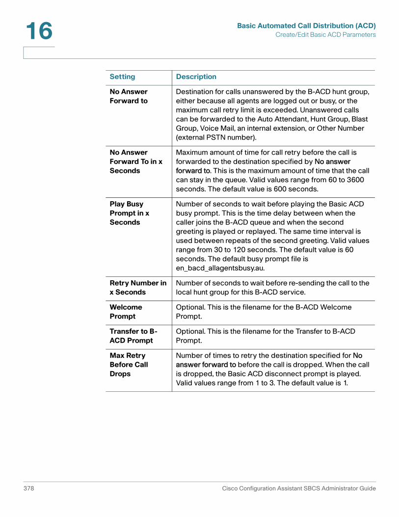
Basic Automated Call Distribution (ACD)Create/Edit Basic ACD Parameters16
No Answer Forward to
Destination for calls unanswered by the B-ACD hunt group, either because all agents are logged out or busy, or the maximum call retry limit is exceeded. Unanswered calls can be forwarded to the Auto Attendant, Hunt Group, Blast Group, Voice Mail, an internal extension, or Other Number (external PSTN number).
No Answer Forward To in x Seconds
Maximum amount of time for call retry before the call is forwarded to the destination specified by No answer forward to. This is the maximum amount of time that the call can stay in the queue. Valid values range from 60 to 3600 seconds. The default value is 600 seconds.
Play Busy Prompt in x Seconds
Number of seconds to wait before playing the Basic ACD busy prompt. This is the time delay between when the caller joins the B-ACD queue and when the second greeting is played or replayed. The same time interval is used between repeats of the second greeting. Valid values range from 30 to 120 seconds. The default value is 60 seconds. The default busy prompt file is en_bacd_allagentsbusy.au.
Retry Number in x Seconds
Number of seconds to wait before re-sending the call to the local hunt group for this B-ACD service.
Welcome Prompt
Optional. This is the filename for the B-ACD Welcome Prompt.
Transfer to B-ACD Prompt
Optional. This is the filename for the Transfer to B-ACD Prompt.
Max Retry Before Call Drops
Number of times to retry the destination specified for No answer forward to before the call is dropped. When the call is dropped, the Basic ACD disconnect prompt is played. Valid values range from 1 to 3. The default value is 1.
Setting Description
378 Cisco Configuration Assistant SBCS Administrator Guide

Basic Automated Call Distribution (ACD)Create/Edit Basic ACD Parameters 16
Hunt Group Parameters
Configure settings for Hunt Group Parameters as described below for each configured Basic ACD service. The Basic ACD hunt group that is created is local to the Basic ACD service.
Setting Description
Hunt Type Defines the order in which calls are distributed to members of the Basic ACD hunt group. Choose one of these types:
• sequential. Calls are routed to Basic ACD hunt group members in the order they are listed in the Members dialog.
• peer. Calls are routed to Basic ACD hunt group members in round-robin order.
• longest-idle. Calls are routed to the member of the Basic ACD hunt group with the longest idle time.
Members Click Members to open a dialog for selecting phones and their associated users as members of this Basic ACD hunt group. See Members of Hunt Group, page 380.
Hunt Timeout Number of seconds before a call that is unanswered by a member of the hunt group is directed to the next member, as specified by the Hunt Type. The default is 8 seconds.
Enable Auto Logout
When this option is checked, autologout is enabled. When the Attempts Before Logout value is exceeded, the agent phone is automatically logged out of the Basic ACD hunt group.
All Agents Logged Out Display Message
Message to display when all agents (hunt group members) are logged out. The default is All Agents Logged Out. The message can contain up to 39 characters.
Attempts Before Logout
Maximum number of unanswered calls to the B-ACD hunt group member (from 1 to 20) before autologout. The default value is 3.
Cisco Configuration Assistant SBCS Administrator Guide 379

Basic Automated Call Distribution (ACD)Create/Edit Basic ACD Parameters16
Prompts
To manage Basic ACD prompts, configure settings as described below. When you are finished making changes, click OK or Apply.
Members of Hunt Group
This window appears when you click the Members button in the Create/Edit Basic ACD Parameters window.
To create or edit the list of hunt group members and their associated phones, follow these steps.
STEP 1 Click on a user in the Available or Selected list. Use the CTRL-click and SHIFT-click keyboard shortcuts to select multiple users in either list.
STEP 2 Use the Add, Remove, and Select All buttons to move selected users between the Available and Selected lists.
STEP 3 Use the Up and Down arrow buttons to order the members of the hunt group.
STEP 4 Click OK to apply your changes.
Setting Description
Welcome Prompt Choose from one of the default Basic ACD prompts listed or click Record to record a custom prompt using the built-in sound recorder.
Transfer to Basic ACD Prompt
Choose from one of the default Basic ACD prompts listed or click Record to record a custom prompt using the built-in sound recorder.
380 Cisco Configuration Assistant SBCS Administrator Guide

Basic Automated Call Distribution (ACD)Hunt Group Report Parameters 16
Hunt Group Report Parameters
The Basic ACD feature uses the CME B-ACD report generator to create simple CSV-format report files that can be imported into a spreadsheet program.
To enable Basic ACD reporting and configure hunt group report parameters, complete the fields in the Hunt Group Report Parameters section of the window as described below.
When you are done configuring Basic ACD hunt group report settings, click OK or Apply.
Setting Description
Enable CME Report
When checked, Basic ACD hunt group report generation is enabled. Basic ACD reporting is disabled by default.
CME Report Location
Location of the TFTP or FTP server and directory for Basic ACD reports. The format is tftp://<ServerIPAddress>/<directory>/<filename> orftp://<ServerIPAddress>/<directory>/<filename>.
For example: tftp://192.168.10.1/bacdrpts/mybacd
Frequency of Reports (hrs)
Frequency of report generation, in hours. Valid values range from 1 to 84.
Manually Upload Reports
If CME reporting is enabled, click Manually Upload Reports to immediately trigger sending of report data to the specified report location on the TFTP server.
This option is unavailable when CME reporting is disabled.
Cisco Configuration Assistant SBCS Administrator Guide 381

Basic Automated Call Distribution (ACD)Hunt Group Report Parameters16
382 Cisco Configuration Assistant SBCS Administrator Guide

17
Multisite Manager
Use the Multisite Manager to configure, manage, and monitor up to 5 Cisco SBCS customer sites connected through a full-mesh VPN.
This feature enables end users at connected sites to place intersite calls using abbreviated dialing and share data over a secure WAN connection. Multisite deployments are well-suited for small businesses with up to 5 locations.
Supported deployment models include customer sites with a single UC 500 or a UC 500 behind a Cisco SR 500 secure router for advanced security features.
• Multisite Design Requirements and Guidelines
• Multisite Configuration Procedures
• Multisite Status Monitoring
• Voice Features Supported Across Multiple Sites
Multisite Design Requirements and Guidelines
Only the following network topologies are supported for individual customer sites that are members of a multisite deployment. Any of these site topologies can be combined as long as the total number of sites is 5 or fewer. The sites are configured with a full-mesh VPN — that is, every site has a direct link to every other site.
• A single UC 500 connected to the WAN.
• A single SR 520-T1 secure router combined with a UC 500. The SR 520-T1 is connected to the WAN and provides advanced security features, and the UC 500 provides voice and data to the site. In this type of deployment, the data VLAN must be unique for both the SR 520-T1 and the UC 500.
For the current release, only the model SR 520-T1 secure router is supported for use in Cisco SBCS multisite deployments configured using CCA.
Cisco Configuration Assistant SBCS Administrator Guide 383

Multisite ManagerMultisite Design Requirements and Guidelines17
IMPORTANT Each site must have a UC 500 for voice and data. The Multisite Manager cannot be used to configure any of the following types of deployments:
• A standalone SR 520-T1 router as one of the sites
• A data-only, site-to-site VPN between two or more SR 500 secure routers
• A remote phone behind an SR 520-T1 without a UC 500
This diagram shows a simple example of a deployment with two sites that illustrates the supported topologies and some of the design requirements discussed in this section.
The above example illustrates these key elements of multisite configuration:
• Site topology. The Charlotte site provides an example of a site that has a UC 500 behind an SR 520-T1, while the San Jose site has a UC 500 only.
• Data VLAN IP addressing must be unique. Since the data VLAN IP addresses must be unique across all sites for any UC 500 and also for any SR 520-T1, the data VLAN IP for the UC 500 at the Charlotte site is set to 192.168.10.1/24, and the data VLAN IP for the UC 500 San Jose is set to 192.168.20.1/24. The VLAN IP for the SR 520-T1 at the Charlotte site is 192.168.75.0/24, and there is no SR 520-T1 present at the San Jose site (otherwise a unique data VLAN IP would also be required for it).
384 Cisco Configuration Assistant SBCS Administrator Guide

Multisite ManagerMultisite Design Requirements and Guidelines 17
• Dial plan and intersite dialing. For this configuration, we have chosen to use an intersite dialing prefix of “8.” The Charlotte site ID is set to “1”, and the San Jose site ID is set to 2. As shown in the example, phone users dial the IntersiteDialingPrefix + Site ID + extension to reach other sites. Both sites have their extension length set to 3. Although it is not required that sites use the same extension length, it is recommended for ease of use and configuration.
• Static IP or DHCP WAN IP addressing is supported. The Charlotte site uses a static WAN IP address, while the San Jose site is configured to use DHCP. Since DHCP is used, Dynamic DNS (DDNS) is configured for the San Jose site.
• Full-mesh VPN with authentication using pre-shared key. A global pre-shared key is configured identically for each site to provide authentication for the VPN tunnel.
• Call admission control. Both sites are configured to allow a maximum of 4 simultaneous calls over the WAN.
This table lists and describes multisite design requirements and guidelines in more details.
IMPORTANT Existing out-of-band configuration is not supported by the Multisite Manager. You must remove existing out-of-band multisite configuration before you can use the Multisite Manager.
Configuration Item Requirements/Recommended Guidelines
Number of sites Up to 5 sites in a full-mesh topology.
Number of IPsec tunnels
For UC 520 and UC540 platforms, each customer site supports up to 10 IPsec tunnels. For UC 560 platforms, each customer site supports up to 20 IPsec tunnels. This include EZVPN tunnels, SSL VPN tunnels, multisite VPN tunnels, and SPA 525G phone VPN tunnels.
When a site is part of a multisite deployment, N-1 of these VPN tunnels are used for the full-mesh site-to-site VPN, where N is the number of sites. For example, if the multisite deployment for a UC 540 platform has 4 sites, 3 IPsec tunnels are used for the full-mesh site-to-site VPN, leaving 7 tunnels available for EZVPN and/or SSL VPN.
Cisco Configuration Assistant SBCS Administrator Guide 385

Multisite ManagerMultisite Design Requirements and Guidelines17
Firewall Cisco ZBF (zone-based firewall) on SR 500 or IOS-based CBAC policy on the UC 500. Third-party firewalls are not supported.
Data VLAN addressing
The data VLAN IP address for each UC 500 and SR 520-T1 must be unique across all sites.
If each site is at factory default, you must remember to modify the default data VLAN address during the initial configuration of each additional site member to ensure that it is unique. Use the Telephony Setup Wizard to configure the initial settings.
If one of the remote sites has an existing data VLAN IP address that is not unique, you must modify its data VLAN address. For a site that is not at factory default state, this can only be done through the Multisite Manager.
After modifying the data VLAN IP address, you will lose connectivity to the UC 500, and must request and obtain a new IP address from the UC 500. To do this, go to Start > Run on your PC and enter cmd to open a command prompt window. At the command prompt, enter the command ipconfig /renew.
WAN connection type
Sites can use either DHCP or static IP addressing.
For sites that use DHCP to dynamically obtain an IP address, DDNS (Dynamic Domain Name Service or some other DNS registration method must be used to manage dynamic addresses.
When configuring DDNS, the DDNS provider name, hostname for each site, and authentication information (username and password) must be provided as part of the multisite connection configuration. See Configuring DDNS, page 399.
The DDNS hostname must be unique for each site.
Configuration Item Requirements/Recommended Guidelines
386 Cisco Configuration Assistant SBCS Administrator Guide

Multisite ManagerMultisite Design Requirements and Guidelines 17
DDNS (Dynamic DNS) hosting service
DDNS must be configured for sites with DHCP WAN connections that are part of a multisite deployment. Sites that are configured with a static IP address are not required to configure DDNS.
These DDNS hosting services can be selected from the HTTP DDNS section in the Internet Connection window (Configure > Routing > Internet Connection).
• cgi.tzo.com
• dup.hn.org
• members.dyndns.org
• members.easydns.com
• www.dynx.cx
• www.justlinux.com
• www.zoneedit.com
Accounts with these DDNS providers must be established outside of Configuration Assistant.
TIP Cisco recommends that you upgrade from the free package to a paid or premium package from the DDNS provider. For example, some free packages are designed to expire due to inactivity (for example, if the IP address is not updated in 30 days). Loss of the DNS support for a domain name means that the VPN tunnels can become inoperable or fail to come up, resulting in service interruptions.
Traffic Shaping/Quality of Service (QoS)
Optional. Although this setting is optional, it is strongly recommended. Sites that have limited bandwidth should enable traffic shaping and configure QoS settings for multisite deployments.
Codec You must choose either G.711 or G.729 as the codec to use for intersite calls. The G.729 codec offers higher compression, which can translate into significant bandwidth savings, but can result in poorer quality for some types of audio such as Music on Hold.
Configuration Item Requirements/Recommended Guidelines
Cisco Configuration Assistant SBCS Administrator Guide 387

Multisite ManagerMultisite Design Requirements and Guidelines17
Call Admission Control
Optional. Configure Maximum Calls (maximum simultaneous calls) to ensure voice quality for intersite and VoIP calls by helping to prevent the Internet connection from being over-subscribed.
Configuration Assistant uses the currently configured QoS settings for upstream bandwidth, codec preference, and bandwidth reservation for voice media to provide recommendations for call admission control.
Dial Plan Specify an Intersite Dialing Prefix for site-to-site calling.
To dial another site, phone users must dial:
Intersite Dialing Prefix + SiteID + Extension
This feature allows for flexibility in extension assignments for sites. Prefix digit that are already in use are not available for selection.
Extension length It is recommended, but not required, that all sites in a multisite configuration use the same extension length.
Hostname To avoid confusion when selecting the hostname from Configuration Assistant menus, it is recommended that you define system hostnames to be unique across all sites.
The system hostname is displayed in Configuration Assistant hostname selection menus and system prompts.
Configuration Item Requirements/Recommended Guidelines
388 Cisco Configuration Assistant SBCS Administrator Guide

Multisite ManagerMultisite Configuration Procedures 17
Multisite Configuration Procedures
The topics in this section cover multisite configuration procedures for supported configurations.
If you have not previously configured multisite connections on this UC 500, the initial window provides an overview of configuration steps, with these options:
• Manually Specify Multisite Settings. Choose this option to go to the Multisite Configuration tab. See Adding and Configuring Sites, page 391.
• Import Multisite Configuration File. Choose this option to import site settings that were previously exported to a configuration file on another site. See Exporting and Importing Sites, page 403.
NOTE All multisite configuration procedures assume that the PC running Configuration Assistant is connected to an Ethernet port on the UC 500 and has obtained an IP address from the UC 500. When the UC 500 is behind an SR 520-T1 secure router, connect directly to the UC 500 and use DHCP to obtain an IP address from the UC 500.
• Multisite Design Requirements and Guidelines
• Prerequisites for Multisite Configuration
• Adding and Configuring Sites
• Configuring DDNS
• Configuring Quality of Service (QoS)
• Maximum Calls (Call Admission Control)
• Exporting and Importing Sites
• Modifying a Site After the Initial Configuration
• Deleting a Site
Prerequisites for Multisite Configuration
Several prerequisites must be met before you can configure multisite connections. For more detailed information, see Voice Features Supported Across Multiple Sites, page 408.
Cisco Configuration Assistant SBCS Administrator Guide 389

Multisite ManagerMultisite Configuration Procedures17
• Basic voice and data configuration must be established on the UC 500, using either the Telephony Setup Wizard (recommended for sites that are configured from factory default settings) or using Configuration Assistant in expert mode. This includes:
- Internet connection
- Data VLAN IP address for each UC 500 and SR 520-T1 should be unique across all sites). If it is not, this can be modified later through the Multisite Manager.
- Voice system initialization settings such as the default access code for external calling and extension length (Configure > Telephony > Voice, System tab)
- At a minimum, local telephony must be configured for calls within the site, preferably through the Telephony Setup Wizard.
• If the SR 500 secure router is the edge device (that is, the UC 500 at a site is behind an SR 500), these settings must be configured:
- WAN connection. If using an SR 520-T1 secure router, you must run the T1 connection utility before running the Telephony Setup wizard.
- Firewall and NAT are disabled on the UC 500. When you run the Telephony Setup Wizard, you are automatically prompted to this as part of the setup.
- The UC 500 has a static WAN IP address of 192.168.x.2 where x is obtained from the SR 500 data VLAN75.
- The SR 500 can route to the UC 500 (simple static route to the data VLAN1). When you run the Telephony Setup wizard, these routes are established automatically.
- The SR 500 must have a network-wide unique address configuration for VLAN75.
• For sites using a DHCP WAN connection, the following information is required for DDNS configuration:
- DDNS provider name
- Unique hostname for each site
- Account username and password from DDNS provider
390 Cisco Configuration Assistant SBCS Administrator Guide

Multisite ManagerMultisite Configuration Procedures 17
Adding and Configuring Sites
Overview
If you are configuring multisite connections for sites with UC 500 and SR 500 platforms with factory default settings, the recommended steps for configuring connections among sites is as follows.
1. If any of the sites use an SR 520-T1 secure router as the edge device, you must run the T1 Connection Utility first (before running the Telephony Setup Wizard). See the Cisco Small Business Pro SR 520-T1 Quick Start Guide and the UC 500 and SR 520-T1 Secure Router Setup application note for instructions.
2. On the first site:
a. Verify that basic voice and data configuration is established on the UC 500.
b. Launch Configuration Assistant and configure Traffic Shaping/Quality of Service, Maximum Calls (Call Admission Control), and DDNS settings, as required. Sites configured with a DHCP WAN connection must configure DDNS in order to launch the Multisite Manager.
c. Launch the Multisite Manager (Home > Multisite Manager or Configure > Telephony > Multisite Manager) and configure global settings for multisite:
- Pre-shared key for VPN tunnel authentication
- Intersite dialing prefix
- Codec to use for site-to-site VoIP calls (G.711 or G.729)
d. Configure multisite settings for the first site:
- Site name
- Site index
- Number of digits in extensions.
e. Add the other remote sites and configure basic multisite settings:
- Site name
- WAN IP or Fully Qualified Domain Name (FQDN)
- Internal addressing (data VLAN for the UC 500, whether or not site has an SR 520-T1)
- Site dial pattern (site ID number and digits per extension)
Cisco Configuration Assistant SBCS Administrator Guide 391

Multisite ManagerMultisite Configuration Procedures17
f. Export multisite configuration settings configured above and apply the configuration.
3. On the second site and each of the remaining sites (up to 5 sites, maximum).
a. Verify that basic voice and data configuration is established on the UC 500.
b. Configure Traffic Shaping/QoS, Maximum Calls, and DDNS settings, as required.
c. Launch the Multisite Manager and import the multisite configuration file that was created and exported from the first site.
d. Configure the same pre-shared key on the remote sites.
If you are connecting one or more existing sites, the steps are similar, except that instead of using the Telephony Setup Wizard, you establish the configuration in expert mode. If you need to change the default data VLAN IP address for the SR 520-T1 or UC 500, you can do this through the Multisite Manager when importing site data.
Procedures
STEP 1 Verify that the requirements described in Prerequisites for Multisite Configuration, page 389 are met.
STEP 2 Verify that the PC running Configuration Assistant is directly connected to the UC 500 and has obtained an IP address from the UC 500.
STEP 3 Launch Configuration Assistant and connect to the first site to be configured.
STEP 4 From the feature bar, choose Home > Multisite Manager or Configure > Telephony > Multisite Manager.
STEP 5 Select the Multisite Configuration tab.
392 Cisco Configuration Assistant SBCS Administrator Guide

Multisite ManagerMultisite Configuration Procedures 17
STEP 6 Configure these Global Settings for all sites.
Setting Description
Pre-Shared Key for Authentication
Enter a pre-shared key for authenticating remote sites. Use a pre-shared key that meets strong password criteria. From 8 to 127 characters can be entered; Spaces and “?” characters are not supported.
Place a check mark in the Display Key box to enable display of the pre-shared key in plain text.
Place a check mark in the Allow Key to be Exported box to enable export of the pre-shared key as plan text in the configuration file.
IMPORTANT The pre-shared key must be the same for all sites. By default, the pre-shared key is not exported in the multisite configuration. If you choose to export the key, it is exported as plain text. If the pre-shared key is not exported, you must manually re-enter it when importing multisite configuration data to other sites.
Codec Preferred codec for intersite calls. Choose either:
• G711: G711 codec is preferred.
• G729: G729 codec is preferred.
Intersite Dialing Prefix
Choose a prefix from the drop-down list. The system detects prefix digits that are currently in use by the dial plan and only displays available selections. This is the prefix digit that phone users must dial when making calls to other sites
To call remote sites, phone users dial the
Intersite Dialing Prefix + SiteID + Extension
For example, if the prefix digit for intersite dialing is 7 and a user at site 1 wants to dial extension 307 at site 2, the user must dial 72307 to reach that extension.
Cisco Configuration Assistant SBCS Administrator Guide 393

Multisite ManagerMultisite Configuration Procedures17
STEP 7 Review and edit settings for the first site. This is the site to which you are initially connected.
To begin editing site settings, click Edit. See Site Settings, page 396 for more information.
The following information is read in and displayed from the site to which you are connected.
Setting Description
WAN Address Read-only. WAN IP address of this site.
UC500 Data VLAN Address
Read-only. UC 500 Data VLAN IP address for this site.
UC500 Data VLAN Subnet Mask
Read-only. UC 500 Data VLAN subnet mask for this site.
SR500 Data VLAN Address
Read-only. SR 520-T1 data VLAN IP address, if an SR 520-T1 is part of the customer site.
SR500 Data VLAN Subnet Mask
Read-only. SR 520-T1 data VLAN subnet mask, if an SR 520-T1 is part of the customer site.
Site Dial Pattern Read-only field that displays the pattern that site members dial when making site-to-site calls over the WAN.
Connected to This Site
Click Show Extra Configuration Options to view the status (either Configured or Not Configured) of additional settings that might need to be configured for this site.
DDNS Optional. Dynamic DNS configuration. Indicates whether or not DDNS is configured for this site. If DDNS is not configured and you are using DHCP, you must configure it before you can launch the Multisite Manager.
Click the Configured or Not Configured link to open the Internet Connection window where you can modify these settings. See Configuring DDNS, page 399.
394 Cisco Configuration Assistant SBCS Administrator Guide

Multisite ManagerMultisite Configuration Procedures 17
STEP 8 Once you have reviewed and configured settings for the first site, click Add Site and configure settings for the rest of the sites that are part of the deployment.
See Site Settings, page 396.
STEP 9 When you are finished adding and configuring all remote sites, click Apply.
The Apply button is disabled (greyed out) if any of the required settings are not configured (for example, pre-shared key).
Once the changes are successfully applied, the Export Multisite Configuration File button becomes active.
STEP 10 Click Export Multisite Configuration File.
The Export Multisite Configuration File button is unavailable (greyed out) until you have successfully applied the configuration.
STEP 11 Save the configuration file to your PC. You can use the default filename or specify a different filename.
WAN Traffic Shaping Optional, but strongly recommended. Indicates whether or not Traffic Shaping and Quality of Service (QoS) settings are configured for the site. Although these settings are optional, they are strongly recommended for all sites, and especially sites with limited bandwidth. This specifies preferential handling for voice traffic over data when needed.
Click the Configured or Not Configured link to open the Internet Connection window where you can modify these settings. See Configuring Quality of Service (QoS), page 400.
Call Admission Control
Indicates whether or not Call Admission Control (CAC) is configured for this site. Call admission control settings determine the maximum number of simultaneous calls for a site.
If CAC is not configured, choose Configure > Telephony > Maximum Calls from the feature bar to access configuration options. See Maximum Calls (Call Admission Control), page 402.
Setting Description
Cisco Configuration Assistant SBCS Administrator Guide 395

Multisite ManagerMultisite Configuration Procedures17
IMPORTANT Do not edit the XML configuration file. Any changes to the multisite configuration settings that are exported must be made through the Multisite Manager and re-imported to any sites that are part of the configuration. See Exporting Sites, page 403.
STEP 12 Click OK.
STEP 13 Save your changes to the startup configuration to all devices in the customer site:
• Click Configure > Save Configuration, or
• Click Save when prompted to save the configuration before exiting Configuration Assistant.
STEP 14 Import the multisite configuration file you just exported to each of the other sites using the procedures described in Importing Sites, page 404.
Once you import and apply settings among all the remote sites, the VPN tunnels will begin to come up.
It can take up to three (3) minutes for the VPN tunnels to be established.
To manually bring the IPsec tunnels up, choose the Multisite Status tab and click Connect to All Sites.
Site Settings
The Site Settings window appears when you
• Click Add Site in the Multisite Manager window.
• Click Edit (Pencil icon) in the Multisite Manager window to edit settings for any of the sites.
Add or modify site settings as described in this table, then click OK to return to the Multisite Manager.
Changes made to site configuration will result in dropped calls and interruption in data traffic during the re-configuration.
396 Cisco Configuration Assistant SBCS Administrator Guide

Multisite ManagerMultisite Configuration Procedures 17
Setting Description
Site Information
Site Name Descriptive name for this site.
WAN IP Address or Domain
Public IP address (if static IP addressing is used) or fully-qualified domain name for the site (if DDNS is used).
Internal Addressing
If you are directly connected to this site, Internal Addressing data is read from the current device configuration.
You can modify the data VLAN IP address for the UC 500 or SR 520-T1, but if you do, a warning dialog is displayed.
• You are prompted to verify or re-acquire an IP address on your PC before restarting Configuration Assistant and re- connecting to the customer site.
• No other multisite configuration is applied during this change. You must re-visit the Multisite Manager and configure or re-import your multisite settings once the VLAN has been updated.
UC500 Data VLAN IP Address
IP address of the data VLAN on the UC 500. For example, 182.168.30.5.
UC500 Data VLAN Netmask
Subnet mask for the data VLAN on the UC 500. For example, 255.255.255.0. If you are directly connected to this site, this information is read from the current configuration.
Site uses SR 500 as WAN device
Check this option if the UC 500 is behind an SR 520-T1 secure router.
SR500 Data VLAN Network Address
IP address of the data VLAN on the SR 520-T1. If you are directly connected to this site, this information is read from the current configuration.
SR500 Data VLAN Netmask
Subnet mask for the data VLAN on the SR 520-T1. If you are directly connected to this site, this information is read from the current configuration.
Cisco Configuration Assistant SBCS Administrator Guide 397

Multisite ManagerMultisite Configuration Procedures17
Site Dial Pattern
Intersite Dialing Prefix This read-only field displays the currently configured single-digit prefix for site-to-site dialing. This is a global configuration setting for all sites.
Digits per extension Number of digits used for internal extensions (that is, extension length).
Site Identifier Enter a number from 1 to 5 that identifies this site. This is the Site ID used for intersite dialing.
To dial this site, phone users at remote sites must use this format:
Intersite Dialing Prefix + SiteID + Extension
For example, if the prefix digit for intersite dialing is 7, and a user at site 1 wants to dial extension 307 at site 2, they must dial 72307 to reach that extension.
Resulting Dial Pattern This read-only field displays the site dialing pattern, based on the values currently configured for intersite dialing prefix, site identifier, and number of digits per extension.
Setting Description
398 Cisco Configuration Assistant SBCS Administrator Guide

Multisite ManagerMultisite Configuration Procedures 17
Configuring DDNS
DDNS is only required for sites that use DHCP to obtain a WAN IP address or sites that use PPPoE with IP address negotiation.
Procedure
STEP 1 Choose Configure > Routing > Internet Connection and open the Modify Internet Connection window.
STEP 2 In the HTTP DDNS section of the Modify Internet Connection window, complete these settings:
STEP 3 Click OK.
STEP 4 Verify that the site configuration change triggered a DNS update with the DDNS provider.
Field Description
Provider Choose a DDNS provider from the pull-down menu. The account with the DDNS provider must be established outside of Configuration Assistant.
Hostname Unique hostname for this site, obtained from your DDNS provider. This is usually a fully qualified domain name (FQDN), for example, myhost.mydomain.net, but may be different for some DDNS services. The hostname must be registered.
This field is not validated by Configuration Assistant. Make sure that you have entered the hostname exactly as specified by your DDNS provider.
If you are configuring a multisite deployment, each site must have a unique DDNS hostname.
Username Account user name, obtained from your DDNS provider.
Password/Confirm Password
Account password, obtained from your DDNS provider.
Re-enter the password for confirmation.
Cisco Configuration Assistant SBCS Administrator Guide 399

Multisite ManagerMultisite Configuration Procedures17
Configuring Quality of Service (QoS)
Quality of Services (QoS) settings for multisite deployments allow you to:
• Enable traffic shaping
• Specify the amount of upload bandwidth available for a site
• Specify the percentage of available WAN bandwidth to allocate for VoIP traffic when it is present on the network
• Use call admission control (CAC) to ensure that your call count can not exceed this bandwidth allocation to avoid degradation.
When QoS is enabled and configured:
• Priority is guaranteed for voice traffic, up to the percentage of available WAN bandwidth specified. When voice traffic exceeds this percentage, audio degradation will be observed for all VoIP calls.
• The remainder of the available WAN bandwidth is used for all other network traffic.
• If no voice traffic is present on the network, all of the available bandwidth can be used for data traffic.
Important Guidelines
These important guidelines apply to configuring QoS:
• Configure QoS settings before configuring Maximum Calls so that Configuration Assistant can determine recommended settings for CAC.
• QoS configuration is optional, but strongly recommended. By default, it is disabled.
• QoS must be configured separately for each site. It is not part of the multisite configuration that is exported through the Multisite Manager.
• QoS is always configured on the device that is connected to the Internet:
- If the UC 500 is directly connected to the WAN, configure QoS on the UC 500.
- If the UC 500 is behind an SR 520-T1, configure QoS on the SR 520-T1.
400 Cisco Configuration Assistant SBCS Administrator Guide

Multisite ManagerMultisite Configuration Procedures 17
• Always specify the actual upstream bandwidth for the site, as determined by a reliable connection speed test or the Committed Information Rate (CIR) specified in the Service Level Agreement (SLA) for the Internet service provider.
If the CIR and connection speed test results are not available, specify an upstream bandwidth that is approximately 80% of the upstream bandwidth advertised by the Internet service provider.
Applying a bandwidth that is greater than experienced rates can cause audio degradation.
Procedures
STEP 1 Navigate to Configure > Routing > Internet Connection.
STEP 2 From the Hostname menu, select hostname of the device that is connected to the Internet (either the UC 500 or an SR 520-T1).
STEP 3 Click on a connection to select it.
STEP 4 Click Modify.
STEP 5 In the Modify Internet Connection window, click the Traffic Shaping tab.
STEP 6 Click the Traffic Shaping checkbox to enable traffic shaping.
STEP 7 In the Upstream Bandwidth [kbps] field, enter the actual upstream bandwidth for the site, as determined by a connection speed test or the CIR (Committed Information Rate) specified in the SLA from the service provider. For example, if the upload speed is 1.8 Mbps, enter 1800 for the upstream bandwidth.
Value values range from 384 kbps to 100000 kbps.
If the results of a speed test are not available, enter a value in kbps that is 80% of the upstream bandwidth advertised by the ISP.
STEP 8 In the Media Reservation field, use the slider bar to specify the proportion of available bandwidth to guarantee for voice media if it is present on the network. Valid values range from 1 to 95 percent (the remaining 5 percent covers signaling and other overhead). The default is 50%.
STEP 9 Click OK or Apply.
STEP 10 Save the configuration (Configure > Save Configuration).
Cisco Configuration Assistant SBCS Administrator Guide 401

Multisite ManagerMultisite Configuration Procedures17
Maximum Calls (Call Admission Control)
Overview
Call admission control (CAC) limits the number of simultaneous calls over the WAN. When call admission control is enabled and configured, it is applied to all calls that traverse the WAN. This includes intersite calls in a multisite deployment and SIP calls.
Configure Traffic Shaping/QoS settings before configuring Maximum Calls so that Configuration Assistant can determine recommended settings for CAC based on these settings.
When you change this setting, the Maximum Number of Calls setting configured in the SIP Trunk window is also updated (Configure > Telephony > Trunks > SIP Trunks). See SIP Trunks, page 232.
Procedures
To configure Call Admission Control, follow these steps.
STEP 1 Choose Configure > Telephony > Maximum Calls from the feature bar to open the Maximum Calls window.
STEP 2 Choose a device from the Hostname field.
STEP 3 In the Maximum Calls field, enter the maximum number of simultaneous calls to allow.
If you enter a value of zero (0), call admission control is disabled.
If QoS is enabled and configured for the site:
• The Current Traffic Shaping section displays read-only information about the Traffic Shaping settings currently configured on the system (upstream bandwidth in Kbps and percentage of WAN bandwidth guaranteed for VoIP calls).
• The Maximum Call Ranges section displays Recommended, Sensitive, and Degraded ranges for the Maximum Calls setting, based on the currently configured QoS settings.
402 Cisco Configuration Assistant SBCS Administrator Guide

Multisite ManagerMultisite Configuration Procedures 17
If QoS is not configured, choose Configure > Internet Connection from the feature bar, select the WAN connection, click Modify, and select the Traffic Shaping tab.
CAUTION If you choose a number in the Sensitive or Degraded range for the Maximum Calls setting, this can result in poor voice quality for all VoIP calls, including intersite calls) if available bandwidth is exceeded.
STEP 4 Enter the maximum number of calls to allow for this site.
STEP 5 Click OK.
Exporting and Importing Sites
Once you have configured connection settings for each site, you export these settings to an XML file that can be imported onto each of the other sites.
Exporting Sites
For each site, these settings are exported:
• Site name and index
• Intersite dialing prefix and number of digits in extensions
• Public IP address or hostname of the site
• IP address and subnet mask of the data LAN for the edge device on the network (SR 500 or UC 500)
• IP address and subnet mask of the UC 500, if it is behind an SR 500 secure router
IMPORTANT For security reasons, the Pre-shared key for site authentication is not included in the exported configuration file by default.
• If the pre-shared key is not exported in the configuration file, you must manually re-enter it for each site.
• You can choose to include the pre-shared key in the exported site data. The pre-shared key is exported as plain text, which is less secure.
Do not edit or delete any of the settings in this XML file. Any changes to the multisite configuration settings must be made through Configuration Assistant.
Cisco Configuration Assistant SBCS Administrator Guide 403

Multisite ManagerMultisite Configuration Procedures17
To export the multisite connection settings:
STEP 1 Click Export Multisite Configuration File.
STEP 2 Save the configuration file to the PC running Configuration Assistant.
Importing Sites
To import multisite connection settings:
STEP 1 Connect the PC running Configuration Assistant directly to a LAN port on the UC 500 for the site and make sure the PC has obtained an IP address from the UC 500.
STEP 2 Launch Configuration Assistant and connect to the site.
STEP 3 Choose Home > Multisite Manager or Configure > Telephony > Multisite Manager from the feature bar to open the Multisite Manager.
STEP 4 If you have not previously configured multisite connections, click the Import Multisite Connection Settings button on the page that is initially displayed for the Multisite Manager.
If you are re-importing settings, click Import Site from the main Multisite Manager window.
STEP 5 Browse to the location of the configuration file you exported previously and click OK.
STEP 6 Choose the site to import and click OK.
STEP 7 If the site settings do not match the current configuration on the site, Configuration Assistant detects the differences in the configuration and asks you whether you want to update the configuration.
If the data LAN IP address must be re-configured on the UC 500 you will lose connectivity to Configuration Assistant and must re-connect using the new IP address.
404 Cisco Configuration Assistant SBCS Administrator Guide

Multisite ManagerMultisite Configuration Procedures 17
Modifying a Site After the Initial Configuration
You can modify site settings after the initial configuration, but if you do, you must:
• Export the new configuration.
• Import the new configuration onto all sites.
Deleting a Site
To delete a single site from the a multisite configuration, follow these steps.
STEP 1 Launch Configuration Assistant and choose Home > Multisite Manager or Configure > Telephony > Multisite Manager.
STEP 2 In the Multisite Manager window, select the Multisite Configuration tab.
STEP 3 Locate the site you want to remove and click Delete.
STEP 4 Click OK to confirm the deletion.
STEP 5 Click Apply or OK.
To delete all multisite configuration from the device to which you are connected, follow these steps:
STEP 1 Launch Configuration Assistant and choose Home > Multisite Manager.
STEP 2 In the Multisite Manager window, select the Multisite Configuration tab.
STEP 3 Click Delete Multisite Configuration. This option is located in the lower right corner of the Multisite Manager window. The Delete Multisite Configuration option is only available if the Multisite Manager detects an existing configuration (that is, a configuration was successfully applied at least once).
STEP 4 Click OK when you are asked whether you want to remove all multisite configuration.
When you click OK, all existing multisite configuration is completely removed from the device. The Multisite Manager window refreshes to display the default initial page without any configuration settings.
Cisco Configuration Assistant SBCS Administrator Guide 405
Multisite ManagerMultisite Status Monitoring17
Multisite Status Monitoring
To monitor multisite VPN tunnel connections and view diagnostic information:
• Choose Monitor > Multisite Status from the toolbar, or
• Click the Multisite Status tab in the Multisite Manager.
The Multisite Status monitor has these areas:
• VPN Tunnel Status Summary
• VPN Tunnel Status Detail
VPN Tunnel Status Summary
The VPN Tunnel Status Summary section displays the status of each VPN tunnel connection among all sites in the deployment. If the multisite configuration has not yet been imported and applied to a site, the text “Site Configuration Not Yet Applied” is displayed.
Click Connect to All Sites to manually bring up the VPN tunnels among all the sites.
VPN Tunnel Status Detail
The VPN Tunnel Status Detail area displays the output for the show crypto session detail Cisco IOS command. This command lists all active Virtual Private Network (VPN) sessions and the IKE (Internet Key Exchange) and IPsec SAs (security associations) for each VPN session.
Note these lines in the example output:
• Session status. This displays the tunnel status. When the tunnel is coming up, this status is DOWN-NEGOTIATING. When the tunnel is up, the status can be UP-ACTIVE, UP-NO-IKE, or UP-IDLE. If the session status is DOWN, the tunnel does not exist.
• IPSEC FLOW. A snapshot of information about the IPsec-protected traffic flow. The IP addresses correspond to the data VLAN IP addresses and subnet masks configured for the UC 500 and SR 500.
Crypto session current status
Code: C - IKE Configuration mode, D - Dead Peer Detection K - Keepalives, N - NAT-traversal, T - cTCP encapsulation X - IKE Extended Authentication, F - IKE Fragmentation
Interface: Serial1/0:1
406 Cisco Configuration Assistant SBCS Administrator Guide

Multisite ManagerMultisite Status Monitoring 17
--> Session status: UP-NO-IKEPeer: 10.130.2.2 port 500 fvrf: (none) ivrf: (none) Desc: (none) Phase1_id: (none)--> IPSEC FLOW: permit ip 192.168.30.0/255.255.255.0 192.168.20.0/255.255.255.0 Active SAs: 2, origin: crypto map Inbound: #pkts dec'ed 335 drop 0 life (KB/Sec) 4429573/683 Outbound: #pkts enc'ed 335 drop 0 life (KB/Sec) 4429573/683--> IPSEC FLOW: permit ip 192.168.75.0/255.255.255.0 192.168.20.0/255.255.255.0 Active SAs: 0, origin: crypto map Inbound: #pkts dec'ed 0 drop 0 life (KB/Sec) 0/0 Outbound: #pkts enc'ed 0 drop 0 life (KB/Sec) 0/0
Interface: Serial1/0:1Session status: UP-NO-IKEPeer: 10.130.1.2 port 500 fvrf: (none) ivrf: (none) Desc: (none) Phase1_id: (none)--> IPSEC FLOW: permit ip 192.168.75.0/255.255.255.0 192.168.10.0/255.255.255.0 Active SAs: 0, origin: crypto map Inbound: #pkts dec'ed 0 drop 0 life (KB/Sec) 0/0 Outbound: #pkts enc'ed 0 drop 1 life (KB/Sec) 0/0--> IPSEC FLOW: permit ip 192.168.30.0/255.255.255.0 192.168.10.0/255.255.255.0 Active SAs: 2, origin: crypto map Inbound: #pkts dec'ed 725 drop 0 life (KB/Sec) 4492717/470 Outbound: #pkts enc'ed 707 drop 1 life (KB/Sec) 4492717/470. . .
Cisco Configuration Assistant SBCS Administrator Guide 407

Multisite ManagerVoice Features Supported Across Multiple Sites17
Voice Features Supported Across Multiple Sites
This table lists common voice features and indicates which are supported among sites in a multisite configuration.
Voice Feature Supported Among Multiple Sites
Basic site-to-site calls with abbreviated dialing
Yes
Transfer calls between sites Yes
Conference calls between sites Yes
Paging and Call Park across sites
Yes *
* Users can transfer calls from one site’s park slot to a call park slot at another site. However, parked calls cannot be retrieved from a remote site.
Forward voice mails between sites
No
Auto Attendant Partial
The Auto Attendant can transfer calls to other site extensions using abbreviated site dialing.
Fax between sites Yes
Extension mobility across sites No
Hunt groups configured across sites
No*
Call Blast groups support “Other” digit entry, which allows Blast Groups to be configured across sites.
Shared directory across sites No
408 Cisco Configuration Assistant SBCS Administrator Guide

18
Applications
Configuration Assistant provides support for enabling and configuring Cisco SBCS Smart Applications and other third-party applications for UC 500 platforms.
For some applications, application-specific setup options must be configured to enable and use the application.
These topics provide information about enabling and configuring settings for Cisco SBCS applications:
• General Settings
• Smart Applications Manager
• Application-Specific Configuration
For information on Cisco SBCS third-party applications, go to this URL on the Cisco Small Business Support Community:
https://supportforums.cisco.com/docs/DOC-9780/
General Settings
Some applications, such as Cisco WebEx PhoneConnect or other third-party SBCS applications, require general system settings to be configured in order to run. To access general settings for applications, choose Applications > General Settings from the feature bar.
General settings that can be configured are described in these sections:
• Authentication URL
• Services Menu Access
• Call Accounting
• HTTPS Authentication
Cisco Configuration Assistant SBCS Administrator Guide 409

ApplicationsGeneral Settings18
For more detailed information about general settings for applications, refer to the documentation for the application you are configuring.
Authentication URL
This window appears when you choose Applications > General Settings > Authentication URL from the feature bar.
This setting specifies the CME authentication URL required for a Cisco SBCS Smart Application or third-party application.
Here are some example authentication URLs:
• VoiceView Express
http://10.1.10.1/voiceview/authentication/authenticate.do
• WebEx PhoneConnect
http://10.1.10.2/CCMCIP/authenticate.asp.
Only one authentication URL can be in use at a time. To configure a different application and authentication URL, you must first disable the application that is using this setting. For example, you must disable Webex PhoneConnect if you need to configure an authentication URL to integrate with a 3rd-party application.
NOTE Some authentication URLs are compatible with more than one Cisco SBCS application. For example, the VoiceView Express authentication URL is also compatible with the TimeCardView authentication URL. The WebEx PhoneConnect application URL is compatible with both VoiceView Express and TimeCardView, and these applications can be simultaneously enabled if there are enough resources to run them.
When you first access the Authentication URL window, the VoiceView Express authentication URL is displayed. This is because the default setting for VoiceView Express is Enabled. Configuration Assistant automatically sets the application authentication URL and CME service URL for VoiceView Express when the voice system is initialized. To enable or disable VoiceView Express, choose Configure > Telephony > Voicemail, and click the Voicemail Setup tab.
Not all applications require an authentication URL. Refer to the documentation for the application you are configuring to determine the URL to enter here. Some applications automatically configure this URL when they are enabled.
Click OK or Apply when you have entered the authentication URL.
410 Cisco Configuration Assistant SBCS Administrator Guide

ApplicationsGeneral Settings 18
Services Menu Access
This window appears when you choose Applications > General Settings > Services Menu Access from the feature bar.
• Overview
• Adding a CME Service URL
• Modifying or Deleting a CME Service URL
Overview
From the Services Menu Access window, you define the menu item name, CME Service URL, and order of menu items on IP phones for configurable service URLs. These are used by applications such as WebEx PhoneConnect, TimeCardView, and other third-party applications. The menu items defined here is displayed when the user presses the services button on their IP phone.
Up to 8 Service URLs can be configured.
Use the Up and Down arrow buttons to change the order in which they are displayed on the services menu on IP phones.
Only the order of configurable CME service URLs can be modified. On the Cisco IP phone services menu, the CME Service URL item always appears first, followed by configurable CME service URLS, Extension Mobility, and My Phone Apps items.
IMPORTANT Refer to the documentation for the application you are configuring for the specific URL to enter.
• Some applications, such as WebEx PhoneConnect and VoiceView Express automatically configure this URL for you.
• If a service URL is automatically configured by an application when it is enabled, the service URL is automatically deleted from the list when the application is disabled. You cannot modify or delete service URLs that are configured by these applications.
Cisco Configuration Assistant SBCS Administrator Guide 411
ApplicationsGeneral Settings18
Adding a CME Service URL
To add a new CME Service URL, follow these steps.
STEP 1 Click Add to open a new row in the table for editing.
STEP 2 Configure the service name and URL.
STEP 3 If multiple CME service URLs are listed, use the Up and Down arrow buttons to reorder the menu items.
STEP 4 Click OK.
Modifying or Deleting a CME Service URL
You cannot modify or delete default service URLs that are automatically configured by SBCS applications such as VoiceView Express, TimeCardView or WebEx PhoneConnect. You can, however, disable these applications to remove the service URLs.
User-configured service URLs can be deleted or modified as needed.
• To modify a user-configured service URL, click in the Menu Name or URL column for the row that contains the URL, make your edits, and click OK or Apply.
• To delete a user-configured service URL, select the URL from the list and click Delete.
Call Accounting
The Call Accounting window appears when you choose Applications > General Settings > Call Accounting from the feature bar.
Setting Description
Menu Name CME service menu name to display on the Services menu on Cisco IP Phones. The menu name can have up to 15 characters and must not contain spaces or special characters.
URL CME service URL, for example:http://10.1.10.1/WebExPhone/MainMenu
412 Cisco Configuration Assistant SBCS Administrator Guide

ApplicationsGeneral Settings 18
Overview
From this window you can enable or disable call detail record (CDR) collection and specify the location on an external TFTP or FTP server where the CDRs are stored, as well as a backup location on the UC 500 flash. These settings are used in conjunction with call accounting applications that capture CDRs and store them to an external FTP server.
Backup CDR files are stored in the flash:cdr/ directory on the UC 500. Click Copy CDR to File to manually write CDRs to the specified backup file on the flash.
For more information, see the documentation for the call accounting application you are configuring.
Procedures
Configure general settings for Call Accounting applications as described in this table. Click OK or Apply when you are finished.
Setting Description
Call Accounting Server
FTP URL Sets the primary location for storing the CDRs generated for file accounting.
Specify a path/filename for the location of the file on an FTP server.
For example: ftpserver01/cdrs
Username Username for FTP server authentication
Password Password for FTP server authentication
Cisco Configuration Assistant SBCS Administrator Guide 413

ApplicationsGeneral Settings18
HTTPS Authentication
This window appears when you choose Applications > General Settings > HTTPS Authentication from the feature bar.
Some applications, such as Cisco WebEx PhoneConnect, require you to enable HTTPS communication and provide a username and password for authentication.
For more information refer to the documentation for the application you are configuring.
Configure HTTPS Authentication settings as described in this table. Click OK or Apply when you are finished.
Flash Backup
Flash Backup Filename
Base filename to use for CDR backups in the flash:\cdr\ directory on the UC 500, for example, cdr_backups. The filename can contain up to 15 characters. Spaces and special characters are not permitted.
The CDR backup file is given a unique name when it is created. The router hostname and time stamp are appended to the filename in the format <filename>.<hostname>.<timestamp>.
For example, if the Flash Backup Filename is cdr_backups, the path and filenames are formatted as shown below:
flash:/cdr/cdr_backups.UC520.07_25_2009_18_15_10.346
Copy CDR to File Click Copy CDR to File to manually write pending CDR information to the CDR backup file on the UC 500 flash.
When you click Copy CDR to File, a new CDR backup file is created on the flash.
Setting Description
414 Cisco Configuration Assistant SBCS Administrator Guide
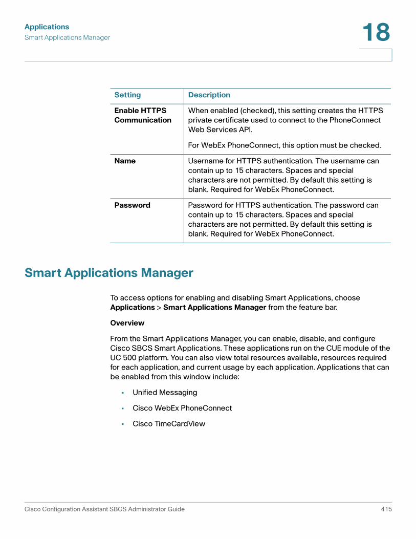
ApplicationsSmart Applications Manager 18
Smart Applications Manager
To access options for enabling and disabling Smart Applications, choose Applications > Smart Applications Manager from the feature bar.
Overview
From the Smart Applications Manager, you can enable, disable, and configure Cisco SBCS Smart Applications. These applications run on the CUE module of the UC 500 platform. You can also view total resources available, resources required for each application, and current usage by each application. Applications that can be enabled from this window include:
• Unified Messaging
• Cisco WebEx PhoneConnect
• Cisco TimeCardView
Setting Description
Enable HTTPS Communication
When enabled (checked), this setting creates the HTTPS private certificate used to connect to the PhoneConnect Web Services API.
For WebEx PhoneConnect, this option must be checked.
Name Username for HTTPS authentication. The username can contain up to 15 characters. Spaces and special characters are not permitted. By default this setting is blank. Required for WebEx PhoneConnect.
Password Password for HTTPS authentication. The password can contain up to 15 characters. Spaces and special characters are not permitted. By default this setting is blank. Required for WebEx PhoneConnect.
Cisco Configuration Assistant SBCS Administrator Guide 415

ApplicationsApplication-Specific Configuration18
System resources in use by an application are indicated by displaying a number of credits. A total of 100 credits are available to the system. The number of credits required for each application is the minimum number of credits needed to run the application, based on CPU, memory, and disk utilization. Some applications such as Video Telephony and Live Record do not require any credits to run. Configuration Assistant displays an error if you attempt to enable an application without the required number of resources.
To enable or disable an application:
STEP 1 In the Applications list on the left, click on the application you wish to enable.
A brief description of the application is displayed,
STEP 2 Click Configure to access options for enabling and configuring the application.
See these sections for information about configuring Cisco SBCS Smart Applications:
• Unified Messaging (IMAP), page 417
• Cisco WebEx PhoneConnect, page 418
• TimeCardView, page 433.
STEP 3 Click OK or Apply when you are finished configuring application settings.
Application-Specific Configuration
The topics in this section provide an overview of each application along with instructions for configuration application-specific setup options.
• Unified Messaging (IMAP)
• Live Record
• Video Telephony
• Cisco WebEx PhoneConnect
• Single Number Reach (SNR)
• TimeCardView
416 Cisco Configuration Assistant SBCS Administrator Guide

ApplicationsApplication-Specific Configuration 18
Unified Messaging (IMAP)
The Unified Messaging Configuration window appears when you select Unified Messaging from the Applications list in the Smart Applications Manager window and click Configure.
Overview
Unified Messaging allows voice mail subscribers to have an integrated view of their e-mails and voice-mail messages from a single e-mail client using IMAP. Subscribers can delete voice-mail messages or mark them as read or unread in a manner similar to e-mail messages. The voice-mail messages are downloaded as attachments to e-mail messages. Subscribers can access voice-mail messages over the network or download them selectively. The default setting for this application is disabled.
Procedures
Enabling or Disabling Unified Messaging
To enable or disable Unified Messaging, click the Enable Unified Messaging checkbox, then click OK to return to the Smart Applications Manager window.
Configuring the IMAP Client
In order for a user to take advantage of this feature, their e-mail client (for example, Microsoft Outlook) must be configured for IMAP. When configuring the client for IMAP:
• Use the Cisco Unity Express (CUE) module IP address (10.1.10.1) for the IMAP server IP address.
• The username and password configured on the IMAP client for authentication must match the username and password of the phone user as it is configured in Cisco Configuration Assistant.
Live Record
This window appears when you choose Applications > Smart Applications > Live Record from the feature bar.
Overview
Live Record enables users to record live conversations and store the recording as a message in their mailbox. They can then play it or forward it to another subscriber or group of subscribers. The default setting for this application is disabled.
Cisco Configuration Assistant SBCS Administrator Guide 417

ApplicationsApplication-Specific Configuration18
Phone users can start a Live Record session by pressing the LiveRcd softkey on their IP phone during a call. The system sets up a conference call between the Live Record pilot number you configure here and the party to be recorded. Periodic tones are played to indicate that the call is being recorded.
The size of Live Record messages is limited only by the amount of space remaining in the subscriber's voice mailbox.
Procedures
To enable and configure Live Record, follow these steps.
STEP 1 Click the Enable Live Record checkbox.
STEP 2 Enter the Live Record pilot extension.
STEP 3 Click OK to apply the changes and return to the Smart Applications Manager window.
Video Telephony
The Cisco Unified Video Advantage (CUVA) solution in SBCS allows users to make desktop-to-desktop video telephony calls between Cisco IP phones that are video enabled.
Video Telephony is enabled by default. To disable this open, uncheck the Enable Video Telephony option and click OK.
Cisco WebEx PhoneConnect
WebEx PhoneConnect is designed for customers who want fast, simple access to WebEx meetings from their IP phone without the need for a desktop PC. WebEx PhoneConnect automates this entire process so that IP phone users can join the audio portion of a WebEx conference by pressing a single softkey on their IP phone. This section covers these topics:
• About Cisco WebEx PhoneConnect
• SBCS Platform Requirements
• Related Documentation
• WebEx Site Administrator Account Information
418 Cisco Configuration Assistant SBCS Administrator Guide

ApplicationsApplication-Specific Configuration 18
• Procedures
About Cisco WebEx PhoneConnect
Once a WebEx user is associated with an IP phone through WebEx PhoneConnect, a simple meeting browser application is installed on their Cisco IP phone display that allows the IP phone user to:
• List WebEx meetings they are hosting
• List WebEx meetings to which they are invited by other IP phone users in their company (users must share same UC 500 router)
• Receive audio and visual alerts on their IP phone when it is time to join a meeting
• Control how far in advance of the meeting they want to receive alerts
• Press a single softkey to join a meeting
WebEx users with access to a WebEx Connect client from a desktop PC can use Click-to-Call with their IP phone to automatically dial someone on their WebEx Connect Buddy List.
SBCS Platform Requirements
Component Version
Cisco Configuration Assistant (CCA)
2.0
UC 500 Software Pack 7.0(3) or later
Cisco IOS 12.4(20)T2 or later
Cisco Unified Communications Manager Express (CME) 7.0 or later
Cisco Unity Express (CUE) CUE 7.0 or later
Cisco Configuration Assistant SBCS Administrator Guide 419

ApplicationsApplication-Specific Configuration18
Related Documentation
For detailed information on configuring and administering WebEx PhoneConnect, see the Cisco WebEx PhoneConnect Administration Guide.
End-user information and instructions are documented in the Cisco WebEx PhoneConnect Quick Reference.
WebEx Site Administrator Account Information
Before you can enable and configure the WebEx PhoneConnect application, your customer must have or obtain a WebEx small business account from WebEx with an administrative user.
• Your customer must provide you with their WebEx service site account information (administrative user ID and password, site ID, and site URL).
CCA uses this information to connect to the customer’s WebEx service site and associate the customer's WebEx user accounts with the WebEx PhoneConnect application.
• Make sure that you know the password policy being used for the site.
When a WebEx site is set up, the site administrator can specify a password policy. The policy defines user password requirements such as the minimum and maximum number of characters, password strength, characters that cannot appear in passwords, and so on. All WebEx user passwords must conform to this policy.
Supported Cisco IP Phones Cisco Unified IP Phone Models 794x, 796x, and 797x
Cisco Unified Wireless Phones Models 7921 and 7925
Cisco Unified IP Phone 7937
Cisco Unified IP Phone 524G
Cisco Unified IP Phone 521G
Cisco IP Phone SPA525G
Cisco IP Communicator (CIPC) softphone client
Component Version
420 Cisco Configuration Assistant SBCS Administrator Guide
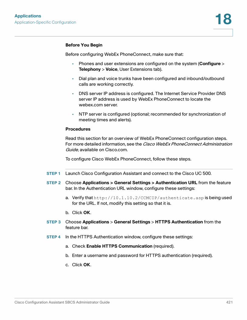
ApplicationsApplication-Specific Configuration 18
Before You Begin
Before configuring WebEx PhoneConnect, make sure that:
• Phones and user extensions are configured on the system (Configure > Telephony > Voice, User Extensions tab).
• Dial plan and voice trunks have been configured and inbound/outbound calls are working correctly.
• DNS server IP address is configured. The Internet Service Provider DNS server IP address is used by WebEx PhoneConnect to locate the webex.com server.
• NTP server is configured (optional; recommended for synchronization of meeting times and alerts).
Procedures
Read this section for an overview of WebEx PhoneConnect configuration steps. For more detailed information, see the Cisco WebEx PhoneConnect Administration Guide, available on Cisco.com.
To configure Cisco WebEx PhoneConnect, follow these steps.
STEP 1 Launch Cisco Configuration Assistant and connect to the Cisco UC 500.
STEP 2 Choose Applications > General Settings > Authentication URL from the feature bar. In the Authentication URL window, configure these settings:
a. Verify that http://10.1.10.2/CCMCIP/authenticate.asp is being used for the URL. If not, modify this setting so that it is.
b. Click OK.
STEP 3 Choose Applications > General Settings > HTTPS Authentication from the feature bar.
STEP 4 In the HTTPS Authentication window, configure these settings:
a. Check Enable HTTPS Communication (required).
b. Enter a username and password for HTTPS authentication (required).
c. Click OK.
Cisco Configuration Assistant SBCS Administrator Guide 421

ApplicationsApplication-Specific Configuration18
CME Service URL settings for WebEx PhoneConnect are filled in automatically after the PhoneConnect application is enabled.
STEP 5 Navigate to Applications > Smart Applications Manager.
STEP 6 Click WebEx Phone Connect to select the application, then click Configure. The PhoneConnect Configuration Login window appears.
STEP 7 In the PhoneConnect Configuration Login window, enter the customer’s WebEx administrator username, password, site ID, and Site URL and click OK. See PhoneConnect Configuration Login Window, page 422.
Once the site login credentials are verified, the PhoneConnect Application Main window appears and displays information for the WebEx site.
STEP 8 In the PhoneConnect Application Main window, click the Enable checkbox at the top of the window and configure site settings. See PhoneConnect Application Main Window, page 423.
STEP 9 Add users and enable WebEx PhoneConnect on their Cisco IP phones as described in the Cisco WebEx Phone Connect Administration Guide. See PhoneConnect Application Main Window, page 423.
STEP 10 Click OK to apply the site settings and close the PhoneConnect Application Main window.
STEP 11 In the Smart Applications Manager window, click OK.
See PhoneConnect Advanced Site Configuration, page 428, for information about additional settings that may need to be configured.
PhoneConnect Configuration Login Window
To configure PhoneConnect, you must first log in with the WebEx site administrator account credentials, as described below.
Setting Description
UserID WebEx site administrator user ID. Also referred to as a WebEx ID.
Password WebEx site administrator password
422 Cisco Configuration Assistant SBCS Administrator Guide

ApplicationsApplication-Specific Configuration 18
Click OK when you are finished entering login credentials.
PhoneConnect Application Main Window
This window appears when you have successfully logged with the WebEx site administrator credentials after clicking Setup Options for WebEx PhoneConnect in the Smart Applications Manager window.
Configure the settings in the PhoneConnect Application Main window as described below. Click OK or Apply when you are finished making changes.
SiteID WebEx site ID number (text characters are not accepted in this field).
SiteName WebEx site name (the first string in the WebEx site URL).For example, if the WebEx site URL is http://acme.webex.com, enter acme for the site name.
Setting Description
Customer Administrator Information
Contact information for the WebEx site administrator.
First Name WebEx site administrator first name
Last Name WebEx site administrator last name
Email WebEx site administrator email address
Company WebEx site administrator company name
Phone WebEx site administrator phone number
Setting Description
Cisco Configuration Assistant SBCS Administrator Guide 423

ApplicationsApplication-Specific Configuration18
WebEx Users Information
UserID Required. This is the WebEx account user ID that the user enters when logging in to the WebEx service site to schedule, attend, and browse meetings.
Recommended format: <phone user ID>@<admindomain>.com
All new WebEx users created through PhoneConnect must use the e-mail address format for their user ID. WebEx user accounts created before PhoneConnect was enabled can continue to use the existing user ID format.
If all of your customer’s users share the same e-mail domain, it is recommended that you add your customer’s e-mail domain after the phone user ID, and use this as the User ID, for example, [email protected].
Password Required. This is the password the user enters when logging in to the WebEx service site to host, attend, or browse meetings.
When a WebEx site is set up, the site administrator can specify a password policy. The policy defines criteria for user passwords such number of characters, passwords that cannot be used, and so on. All user passwords must conform to the password policy for your customer’s WebEx service site.
Be sure to notify users if you change their password.
Email Required. This is the e-mail address to which WebEx meeting invitations and WebEx notices are sent.
If the user does not have an e-mail address (for example, the user is a conference room, this format is recommended:
<phone user ID>@<admindomain>.com
where the <phone user ID> is the phone user ID found in the Associated Phone User field.
Last Name Required. WebEx account user first name.
Setting Description
424 Cisco Configuration Assistant SBCS Administrator Guide

ApplicationsApplication-Specific Configuration 18
First Name Required. WebEx account user last name.
Associated Phone Read only. Displays the current phone user ID associated with this WebEx account. If no phone user ID is associated with the WebEx PhoneConnect user, --None-- is shown.
Select Phone Click Select Phone to open a dialog for choosing a phone user to associate with this WebEx user account and enabling the PhoneConnect application on their phone. See Select Phone, page 427.
If the user has an existing WebEx account and has a phone configured on the system, but does not have PhoneConnect enabled on their phone you can use Select Phone to enable the PhoneConnect application on their phone.
IMPORTANT: If you are editing an existing WebEx user account in order to enable PhoneConnect, you must assign the WebEx user a new password (this is required so that PhoneConnect can authenticate the phone user). Be sure to notify the user of their new WebEx account password.
Add Insert a new row in the WebEx users list for adding a new WebEx user.
Delete Delete the selected WebEx user.
The user is moved to the de-activated state on the WebEx service site. Once a user account is deleted, the user no longer has access to WebEx or WebEx PhoneConnect. The user will no longer receive meeting invitations or alerts, and will not be able to attend or host WebEx meetings from their company’s WebEx service site.
To reinstate a user after they have been deleted (for example, if a user leaves the company but then returns), you can use their old UserID and other account information. However, a new password must be created, as WebEx can be configured to reject a password that is the same as any of the last three passwords previously registered with WebEx.
Setting Description
Cisco Configuration Assistant SBCS Administrator Guide 425

ApplicationsApplication-Specific Configuration18
Copy From Device Copy From Device is an alternative method for adding WebEx users.
Click Copy from Device to open a dialog for choosing existing phone users to associate with this WebEx account. The first name, last name, password, and phone for each selected phone user are copied into the WebEx users list. The WebEx UserID and e-mail address fields are left blank. See Copy From Device, page 428.
Customer Site Configuration Information
Install Language Files
Add a new localized language for your IP phone users’ WebEx PhoneConnect meeting browser and alerts.
Only the WebEx PhoneConnect IP phone screens are affected by this procedure. See Install Language File for WebEx PhoneConnect, page 430.
Advanced Configuration
Access advanced configuration settings. See PhoneConnect Advanced Site Configuration, page 428.
Meeting Call-In Configuration
Call-In Preference Use a Toll-Free or Toll number for WebEx meeting call-in. The default is Toll-Free.
Dial-out Prefix Digit that callers dial to get an outside line. The default value is the access code for external dialing defined on the system. You can edit this setting.
Call-In Number Conversion - Toll Number or Free Number
Depending on where your customer is dialing from, how their outgoing dial plan is set up, and how the WebEx call-in number is formatted, you might need to use these settings to remove or replace initial dialing prefixes such as country codes, area or city codes, or code for international dialing.
WebEx Provided Number
Read-only. Telephone number provided by WebEx for this WebEx site.
Setting Description
426 Cisco Configuration Assistant SBCS Administrator Guide

ApplicationsApplication-Specific Configuration 18
Select Phone
This window appears when you click Select Phone in the WebEx users list on the WebEx PhoneConnect Application Main window.
STEP 1 In the Select Phone window, select a phone from the list that you wish to associate with this WebEx PhoneConnect user.
Only phones that are not currently enabled for PhoneConnect are listed.
STEP 2 Click OK to return to the WebEx PhoneConnect Application Main window.
Remove Num. of Digits from the Front
Number of digits to remove from the beginning of WebEx-provided number. This field is required and cannot be left blank. The default value is zero (0).
Enter the number of digits that must be removed or replaced as required to match the dial-out number.
Add Digits to the Front
Digits to add to the beginning of the WebEx-provided call-in number. This field can contain up to 20 digits. The default value is None (blank).
Enter digits to be added to the front of the number, for example, an area code that differs from the one in the WebEx-provided number. You do not need to add the Dial-Out Prefix (access code) here. The Dial Out Prefix is automatically added to the front of the number.
Resulting Number of Digits to Dial
Dial-out number after adding and removing digits and pre-pending the dial-out prefix. The number displayed is read-only and is generated using the Dial-out Prefix and the values entered in the Dial-Out Prefix and Remove/Add Digits fields.
Verify that the number matches what users manually dial to reach the WebEx service.
Setting Description
Cisco Configuration Assistant SBCS Administrator Guide 427
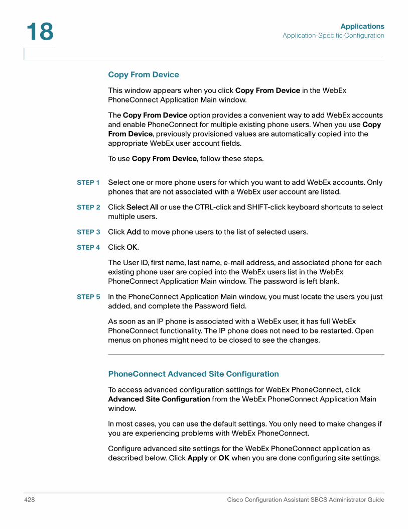
ApplicationsApplication-Specific Configuration18
Copy From Device
This window appears when you click Copy From Device in the WebEx PhoneConnect Application Main window.
The Copy From Device option provides a convenient way to add WebEx accounts and enable PhoneConnect for multiple existing phone users. When you use Copy From Device, previously provisioned values are automatically copied into the appropriate WebEx user account fields.
To use Copy From Device, follow these steps.
STEP 1 Select one or more phone users for which you want to add WebEx accounts. Only phones that are not associated with a WebEx user account are listed.
STEP 2 Click Select All or use the CTRL-click and SHIFT-click keyboard shortcuts to select multiple users.
STEP 3 Click Add to move phone users to the list of selected users.
STEP 4 Click OK.
The User ID, first name, last name, e-mail address, and associated phone for each existing phone user are copied into the WebEx users list in the WebEx PhoneConnect Application Main window. The password is left blank.
STEP 5 In the PhoneConnect Application Main window, you must locate the users you just added, and complete the Password field.
As soon as an IP phone is associated with a WebEx user, it has full WebEx PhoneConnect functionality. The IP phone does not need to be restarted. Open menus on phones might need to be closed to see the changes.
PhoneConnect Advanced Site Configuration
To access advanced configuration settings for WebEx PhoneConnect, click Advanced Site Configuration from the WebEx PhoneConnect Application Main window.
In most cases, you can use the default settings. You only need to make changes if you are experiencing problems with WebEx PhoneConnect.
Configure advanced site settings for the WebEx PhoneConnect application as described below. Click Apply or OK when you are done configuring site settings.
428 Cisco Configuration Assistant SBCS Administrator Guide

ApplicationsApplication-Specific Configuration 18
Setting Description
Application Timing Configuration
Check for new meetings (minutes)
How often to poll WebEx for new meetings. The default value is 4 minutes.
Reducing frequency below 4 minutes can adversely affect Cisco Unity Express (CUE) performance.
Delay before providing the meeting ID (seconds)
Number of seconds the system waits after the Call button on the IP phone is pressed before auto-entering the meeting ID. The default setting of 10 seconds is based on FXO/BRI/PRI trunk connectivity.
This value can be set to 7 seconds if SIP trunks are used. You may need to increase the interval if calling internationally. There are no known performance impacts.
Delay between digits (milliseconds)
The speed with which digits are dialed when auto-entering a meeting ID. The default value is 200 ms.
You may need to increase interval depending on where calling (for example, when calling internationally). There are no known performance impacts.
Clear WebEx Site Data
Click Clear WebEx Site Data to remove all WebEx site data from the UC 500.
This does not affect the WebEx service site or account information; it only removes the WebEx PhoneConnect application settings and site data stored on the Cisco UC 500. The PhoneConnect application is removed from all users phones.
This may be needed, for example, in situations where the wrong site data is imported onto the UC 500, the WebEx site changes, the WebEx site is no longer active, or where demonstration site data must be removed from the system.
Cisco Configuration Assistant SBCS Administrator Guide 429

ApplicationsApplication-Specific Configuration18
Install Language File for WebEx PhoneConnect
To install a new localized language file for WebEx PhoneConnect, click Install Language File from the WebEx PhoneConnect Application Main window.
WebEx PhoneConnect supports localization of IP phone GUI displays for the WebEx PhoneConnect meeting browser and for alerts. Between releases, Cisco adds support for additional languages as they become available. You can update the WebEx PhoneConnect application with a new language using the Install Language File option Once the new language file is installed and the new language is selected in Configuration Assistant, all of the WebEx PhoneConnect IP phone screen menus will use the new language.
Before you begin, you must first localize the UC 500 to the desired region and language (Configure > Telephony > Region), then download the corresponding WebEx localization file for the new language.
NOTE WebEx PhoneConnect does not support the UC 500 phone override localization feature. WebEx PhoneConnect only displays the default language selected.
Follow these steps to add a new language for WebEx PhoneConnect.
STEP 1 In the File to install field, browse to the language file you want to install and click Open.
STEP 2 Click Install. The new language file is moved to the Installed Language File(s) list. You can overwrite an existing language file, but you cannot delete an existing language file.
STEP 3 Click OK to deploy the language file to the CME localization directory and return to the PhoneConnect Application Main window.
You are prompted to restart the CUE module on the UC 500.
STEP 4 To restart the CUE module on the UC 500, open the Topology view, right-click on the UC 500, and select the Restart CUE option from the menu.
The CUE restart can take from 10 to 15 minutes. During that time, voice mail, Auto Attendant, and other applications that require a connection to CUE will be unavailable.
430 Cisco Configuration Assistant SBCS Administrator Guide

ApplicationsApplication-Specific Configuration 18
Single Number Reach (SNR)
This window appears when you choose Applications > Smart Applications > Single Number Reach from the feature bar.
Single number reach (SNR) provides users with the ability to be reached on two numbers: a regular extension on their IP phone, and a PSTN number. BRI, PRI, FXO, and SIP interfaces are supported.
NOTE For SNR numbers going over SIP trunks, the Caller ID may not reflect the Caller ID of the original caller, because the Caller ID is determined by the ITSP. The Caller ID will usually be the station or the main PSTN number configured for SIP trunk. Most ITSPs require Caller IDs that are mapped explicitly to their accounts in order to prevent fraud. If the Caller ID for the original caller is not overridden with the Caller ID required by the ITSP, the call to the SNR number will fail.
• Overview
• Limitations
• SBCS Platform Requirements
• Configuration Procedures and Settings
Overview
The Single Number Reach (SNR) feature allows phone users to answer incoming calls on their desktop IP phone or at a remote destination, such as a mobile phone, and to pick up in-progress calls on the desktop phone or the remote phone without losing the connection. This allows callers to use a single number to reach the phone user. Calls that are not answered can be forwarded to voice mail.
Remote destinations may include these devices:
• Mobile (cellular) phones
• Smart phones
• IP phones not belonging to the same Cisco Unified CME router as the desktop phone
• Home phone numbers in the PSTN
• Supported PSTN interfaces include PRI, BRI, SIP, and FXO.
For incoming calls to the SNR extension, Cisco Unified CME rings the desktop IP phone first. If the IP phone does not answer within the configured amount of time, it rings the configured remote number while continuing to ring the IP phone. Unanswered calls are sent to a configured voice-mail number.
Cisco Configuration Assistant SBCS Administrator Guide 431

ApplicationsApplication-Specific Configuration18
The IP phone user has these options for handling calls to the SNR extension:
• Pull back the call from the remote phone. Manually pull back the call to the SNR extension by pressing the Resume soft key, which disconnects the call from the remote phone.
• Send the call to remote phone. Send the call to the remote phone by using the Mobility softkey. While connected to the call, the phone user can press the Mobility softkey and select “Send call to mobile.” The call is forwarded to the remote phone.
• Enable or disable Single Number Reach. While the IP phone is in the idle state, the user can toggle the SNR feature on and off by using the Mobility softkey. If the user disables SNR, the system does not ring the remote number.
IP phone users can modify their own SNR settings directly from the phone by using the menu available with the services feature button. You must enable the feature on the phone to allow a phone user to access the user interface.
Limitations
The following limitations apply to SNR configuration and features:
• Each IP phone supports only one SNR number.
• You cannot configure SNR on an extension that is a member of a hunt group.
• The SNR feature is not supported for the following:
- SIP phones or SCCP-controlled analog FXS phones
- Video calls
For more information about the SNR feature and limitations, see the Cisco Communications Manager Express System Administrator Guide, available on Cisco.com at the following URL:
www.cisco.com/en/US/docs/voice_ip_comm/cucme/admin/configuration/guide/cmeadm.html
SBCS Platform Requirements
This feature is supported on CME 7.1, available with UC 500 EA software pack version 7.1.1-EA or later.
432 Cisco Configuration Assistant SBCS Administrator Guide

ApplicationsApplication-Specific Configuration 18
Configuration Procedures and Settings
To enable and configure SNR for one or more phone users, follow these steps.
STEP 1 Click the Enable Single Number Reach checkbox.
This step only enables the application. In order for a user to access this feature, you must configure an extension on their phone.
STEP 2 To enable SNR for a phone user:
a. Locate the phone user in the list of users.
b. Click in the Single Number Reach field for the phone button and extension to be used for SNR and enter a PSTN number.
When entering the SNR number, enter the number exactly as you would dial it, including any access codes, long distance dialing code, and any other required dialing digits.
c. Continue selecting users and configuring their SNR extension.
Incoming calls to phones with SNR will simultaneously ring the specified PSTN number and the corresponding DN on the IP phone.
STEP 3 Click OK or Apply.
TimeCardView
This window appears when you select TimeCardView in the Applications list in the Smart Applications Manager window and click Configure.
IMPORTANT This section only covers TimeCardView setup and payroll server settings that can be managed through Configuration Assistant. For more information, see the documentation listed under TimeCardView Documentation, page 434.
TimeCardView is a time and attendance system for Cisco IP phone users connected to Cisco SBCS platforms.
• Overview
• TimeCardView Documentation
• SBCS Platform Requirements
Cisco Configuration Assistant SBCS Administrator Guide 433
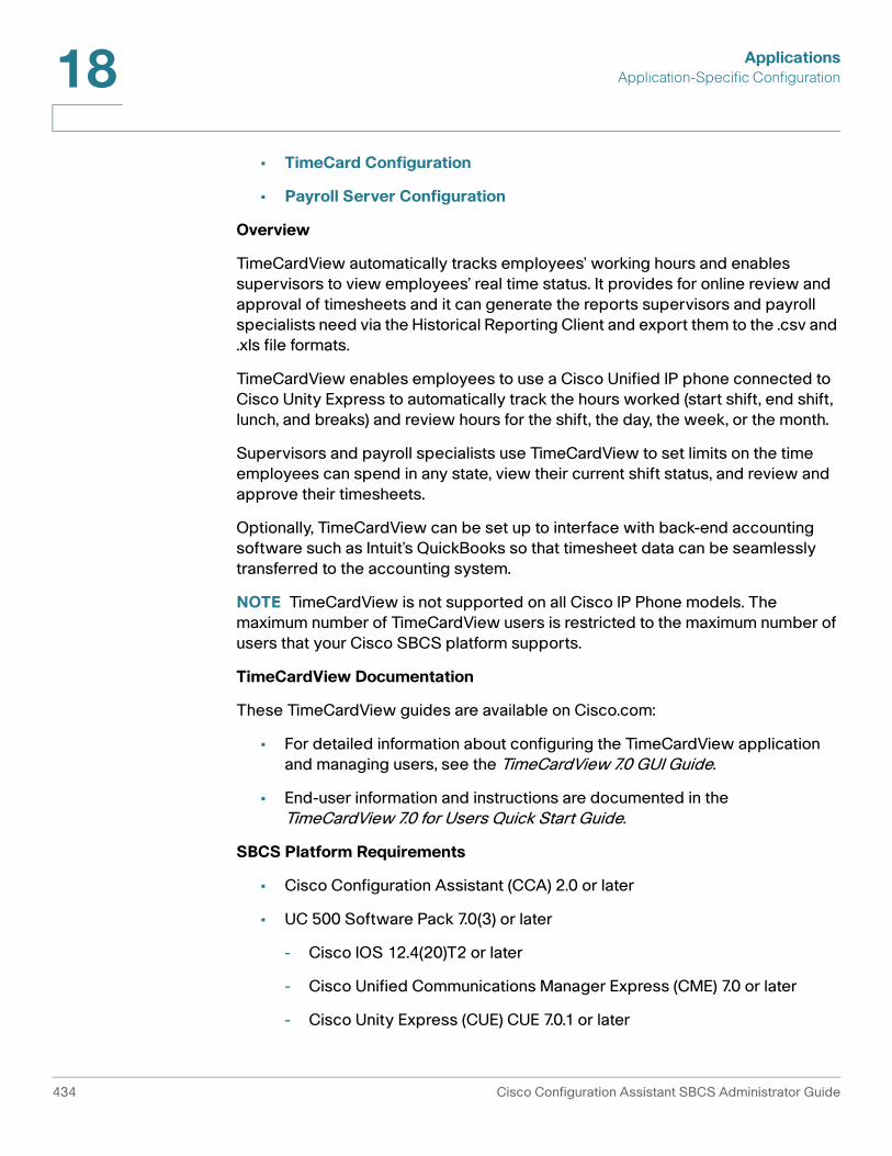
ApplicationsApplication-Specific Configuration18
• TimeCard Configuration
• Payroll Server Configuration
Overview
TimeCardView automatically tracks employees’ working hours and enables supervisors to view employees’ real time status. It provides for online review and approval of timesheets and it can generate the reports supervisors and payroll specialists need via the Historical Reporting Client and export them to the .csv and .xls file formats.
TimeCardView enables employees to use a Cisco Unified IP phone connected to Cisco Unity Express to automatically track the hours worked (start shift, end shift, lunch, and breaks) and review hours for the shift, the day, the week, or the month.
Supervisors and payroll specialists use TimeCardView to set limits on the time employees can spend in any state, view their current shift status, and review and approve their timesheets.
Optionally, TimeCardView can be set up to interface with back-end accounting software such as Intuit’s QuickBooks so that timesheet data can be seamlessly transferred to the accounting system.
NOTE TimeCardView is not supported on all Cisco IP Phone models. The maximum number of TimeCardView users is restricted to the maximum number of users that your Cisco SBCS platform supports.
TimeCardView Documentation
These TimeCardView guides are available on Cisco.com:
• For detailed information about configuring the TimeCardView application and managing users, see the TimeCardView 7.0 GUI Guide.
• End-user information and instructions are documented in the TimeCardView 7.0 for Users Quick Start Guide.
SBCS Platform Requirements
• Cisco Configuration Assistant (CCA) 2.0 or later
• UC 500 Software Pack 7.0(3) or later
- Cisco IOS 12.4(20)T2 or later
- Cisco Unified Communications Manager Express (CME) 7.0 or later
- Cisco Unity Express (CUE) CUE 7.0.1 or later
434 Cisco Configuration Assistant SBCS Administrator Guide

ApplicationsApplication-Specific Configuration 18
TimeCard Configuration
On the Time Card Configuration tab, configure TimeCardView application administration settings as described below. Click OK or Apply when you are finished making changes.
Setting Description
Maximum Sessions Maximum number of TimeCardView sessions, either 2 or 8, depending on the platform.
The default is 2.
Notification E-mail(s) RFC-2822-compliant email address to use for application notification e-mails, for example, [email protected].
Supervisor IP Phone Application Timeout (60 - 600 seconds)
Amount of time, in seconds, that elapses before the system automatically logs out the specified supervisor.
Employee IP Phone Application Timeout (60 - 600 seconds)
Amount of time that elapses before the system automatically logs out the specified employee
Maximum Daily Work Duration (1 - 1440 minutes)
Number of minutes employees can remain in the work state.
Maximum Daily Overtime Duration (0 - 1440 minutes)
Maximum number of overtime minutes per day employees can work. If you change the default, do not forget to limit the number of regular working hours, otherwise employees cannot accrue overtime.
The default is 0.
Maximum Daily In-Shift Work Duration (1 - 1440 minutes)
Number of minutes employees can remain in the work state.
The default is 1440.
Maximum Daily Break Work Duration (1 - 1440 minutes)
Number of minutes employees can remain in the break state.
The default is 1440.
Cisco Configuration Assistant SBCS Administrator Guide 435

ApplicationsApplication-Specific Configuration18
Payroll Server Configuration
On the Payroll Server Configuration tab, complete the fields as described below if you wish to integrate TimeCardView with Intuit Quick Books. Click OK when you are finished configuring server settings.
Maximum Daily In-Shift Lunch Duration (1 - 1440 minutes)
Number of minutes employees can remain in the lunch state. The default is 1440.
Work Starts On Starting day of the work week. The default is Monday.
Setting Description
Quick Books Server Setup
Hostname QuickBooks payroll server. DNS name or IP address of the payroll server.
Port Port number of Quick Books payroll server. The default value is 57343.
Synchronization Schedules
Day of Week Day of week for scheduled synchronization of TimeCardView data with QuickBooks.
Default: Daily
Time of day (HH:MM 24-hr) Time of day for scheduled synchronization.
Default: (none)Example: 23:00
Included Timesheets Whether to include all timesheets or only approved timesheets. Select All or Approved.
Default: All Timesheets
Setting Description
436 Cisco Configuration Assistant SBCS Administrator Guide
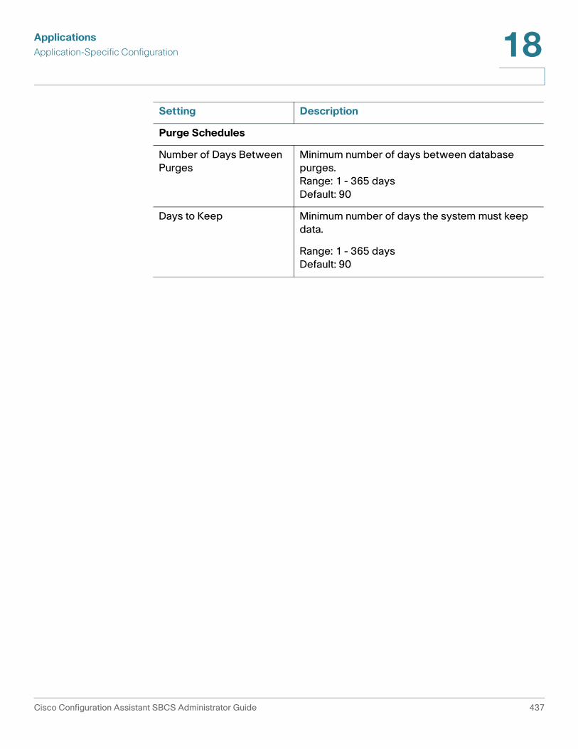
ApplicationsApplication-Specific Configuration 18
Purge Schedules
Number of Days Between Purges
Minimum number of days between database purges.Range: 1 - 365 daysDefault: 90
Days to Keep Minimum number of days the system must keep data.
Range: 1 - 365 daysDefault: 90
Setting Description
Cisco Configuration Assistant SBCS Administrator Guide 437

ApplicationsApplication-Specific Configuration18
438 Cisco Configuration Assistant SBCS Administrator Guide

19
Maintenance
This section covers these maintenance tasks that can be performed using Configuration Assistant:
• Cisco UC 500 Software Package
• View Software Version Information and Device Properties
• Software Upgrades
• Voicemail Upgrade
• File Management
• Restart/Reset Devices
• How to Localize the UC 500 (Non-US/English Locales)
• License Management
• Phone Load Management
See Back Up and Restore Device Configuration, page 105 for instructions on how to use the backup and restore features available from the Maintenance item on the feature bar.
Cisco UC 500 Software Package
The UC 500 Software Packs are large zip files that contain all necessary files for the UC 500 Series platform. Each zip file contains multiple TAR/archive files and other files for the component of the UC 500, including the
• Cisco IOS image for the UC 500 platform
• Cisco IP phone firmware files
• Communications Manager Express (CME) support files
Cisco Configuration Assistant SBCS Administrator Guide 439

MaintenanceCisco UC 500 Software Package19
• Cisco Unity Express (CUE) voice mail software
• Factory default configurations for all SKUs
• Support files such as Basic ACD prompts and scripts, ringtones, and desktop images
NOTE Separate UC 500 software package files are provided for the Model UC 520, UC 540, and UC 560 platforms. You must download the correct file for your UC 500 platform.
See the Release Notes for Cisco Configuration Assistant for compatibility and version information for UC 500 software packages.
To download UC 500 software packages:
• In Configuration Assistant, choose Partners Connection > UC500 Software Downloads from the feature bar.
• Open a Web browser and go to this URL:
www.cisco.com/web/go/uc500swpk
Cisco IP phone localization files, (which provide support for languages, network tones, and cadences) and CUE localization files can also be downloaded from this location.
Users that have a valid Cisco Service Contract are eligible to access current and future versions of software from Cisco (if made available by Cisco). Partners who have not purchased a Service Contract for the Cisco UC 500 are eligible to download the current version of the UC 500 software within 30 days of the product purchase from Cisco or an authorized Cisco Partner. This gives users a way to obtain a current version of software for the UC 500 for the initial deployment of the product.
Access to software for this purpose requires a valid Cisco.com account. Any future software update (if made available by Cisco) beyond the 30-day period of initial purchase from distribution requires a valid service contract.
440 Cisco Configuration Assistant SBCS Administrator Guide

MaintenanceView Software Version Information and Device Properties 19
View Software Version Information and Device Properties
There are several locations where you can view version information for the SBCS software on the UC 500, as well as firmware for connected devices.
• The System Status item on the Dashboard displays the Cisco IOS version.
• Choose Monitor > Reports > Telephony > Software Pack to view version information for the currently installed UC 500 software package, including Cisco IOS, CME, and CUE version, supported phone firmware loads, and CUE status output.
• Right-click on a device in the Topology view to display device properties, including the hostname, IP address, MAC address, and software version (for example, Cisco IOS image) for the device.
When you right-click on an IP phone, you also see the phone type (model), status, phone user first and last name, button types, extensions, and button labels.
Software Upgrades
To open the Software Upgrade window, choose Maintenance > Software Upgrade from the feature bar. This section covers these topics:
• Overview
• Upgrading Software on SR 520-T1 Secure Routers
• Software Upgrade Window Information
• Preparing for a UC 500 Software Upgrade
• Procedures
• Upgrade Status Messages
!CAUTION Cisco does not recommend that you perform software upgrades over a remote
WAN connection. If the connection to the WAN is interrupted, the operation will fail and the system or device may become unusable.
Cisco Configuration Assistant SBCS Administrator Guide 441

MaintenanceSoftware Upgrades19
Overview
From the Software Upgrade window, you can:
• Upgrade all software using a UC 500 software package
This is the preferred way to upgrade the UC 500. When using this method, choose All when choosing upgrade settings. The UC 500 software package includes Cisco IOS, CUE, related CME phoneloads, scripts for Auto Attendant and Basic ACD, and support files. See User Interface, page 20.
• Upgrade the Cisco IOS software only on a single device or on multiple devices.
• Upgrade the CUE software only on Unified Communications 500 Series platforms.
NOTE When downloading CUE or IOS images from Cisco.com, use the tar version of Cisco IOS images and a CUE package file for CUE software.
This window supports upgrading software using the standard or remote TFTP server modes.
• In standard mode if the upgrade images are stored locally.
• In remote TFTP server mode, the CUE or IOS images for the upgrade are stored remotely. To upgrade using remote TFTP server mode, you need a dedicated TFTP server on a UNIX workstation or on another PC. You can run any third-party TFTP application on the server.
You can also drag a Cisco IOS image, an audio file (with a .wav or .au extension), or a SPA 500 Series or SPA 525G phone firmware file from a local drive, mapped drive, or network drive, and drop it on a site member in the Topology view. You do not need a TFTP server.
You cannot use remote TFTP server mode or drag-and-drop upgrade methods if you are using the UC 500 software package for the upgrade.
Upgrading Software on SR 520-T1 Secure Routers
The Cisco SR520-T1 router cannot be upgraded from the Software Upgrade window. To upgrade software on the SR520-T1, use the SR520-T1 Configuration Utility or perform a drag-and-drop upgrade of the router using the current SR 520-T1 software package.
• The software package file is named SR520-T1-<version_number>.tar.
• To perform a drag-and-drop upgrade of the SR 520-T1, drag the software package file from a local drive, mapped drive, or network drive and drop it
442 Cisco Configuration Assistant SBCS Administrator Guide

MaintenanceSoftware Upgrades 19
onto the SR 520-T1 in the Topology view. The SR520-T1 software package is available at www.cisco.com/go/sr500. A cisco.com account login and password is required.
• This software upgrade does not format the flash. The files in the .tar archive are copied to the compact flash on the router. Existing files are overwritten if they have the same file name. The existing IOS image is removed from the flash and replaced with the new IOS image. The startup configuration is updated to boot with the new IOS image.
Software Upgrade Window Information
This table explains the columns in the Software Upgrade window.
Preparing for a UC 500 Software Upgrade
To avoid upgrade failures and other issues, read this section carefully and verify that the system is ready for the upgrade by performing these tasks.
• Verify that your PC meets the requirements for using Configuration Assistant. See System Requirements, page 17.
• If you have a dual NIC (network interface card) on the PC running Configuration Assistant, make sure that only one of the interfaces is enabled.
• Turn off FTP/TFTP services running on your PC.
Column Explanation
Device Displays device icons and hostnames.
Upgrade Indicate whether you want the device to be upgraded when you click Upgrade.
Device Type Displays the device type.
Current Version Displays the Cisco IOS version.
New Image Name Displays the name of the Cisco IOS .bin file that you provided in the Upgrade Settings window. Only the filename appears, not the path.
Upgrade Status Displays the upgrade status and progress messages. See the Upgrade Status Messages table for details.
Cisco Configuration Assistant SBCS Administrator Guide 443

MaintenanceSoftware Upgrades19
Before upgrading, disable any third-party TFTP servers running on your local PC. The embedded TFTP server in Configuration Assistant is used to transfer images and files from your PC to the device to be upgraded. Only one TFTP server can access the TFTP port at a time.
On the PC running Configuration Assistant, open a command window and execute the command netstat -a to see if any FTP or TFTP services are running. You should not see port 21, 69, FTP, or TFTP in the output. If there are, shut down those processes or services.
• Ensure that the PC has obtained a DHCP address from the UC_500 and the default gateway is set correctly.
On the PC running Configuration Assistant, open a command window and execute the command ipconfig /all. The Default Gateway IP address shown in the output should be obtained from the UC 500 (the default value is 192.168.10.1).
• Any firewall software installed on the PC running Configuration Assistant should be configured to allow TFTP and FTP access to and from the UC 500.
A firewall running on your PC can potentially block the connection between the CUE module on the UC 500 and Configuration Assistant, which can result in an upgrade failure.
If you disable the firewall running on the PC while performing an upgrade, be sure to re-enable it after the upgrade.
• Verify the CUE interface status. To do this, choose Monitor > Reports > IOS Exec Commands from the feature bar, enter the command show ip interface brief, and click Run. You should see the line “Integrated-Service-Engine0/0 is up, line protocol is up” in the output if the CUE interface module is running.
Procedures
Follow these steps to upgrade your devices:
STEP 1 Download the UC 500 software package file, CUE package file, or Cisco IOS bin files that you want to use to upgrade the device or devices.
STEP 2 Select one or more devices from the same platform.
STEP 3 Click Upgrade Settings.
444 Cisco Configuration Assistant SBCS Administrator Guide

MaintenanceSoftware Upgrades 19
STEP 4 Complete the settings Upgrade Settings window, and click OK to save your input. See Upgrade Settings, page 445.
STEP 5 If you want to upgrade more than one device type, repeat Steps 2 to 4 for each of the device types.
STEP 6 Check the Upgrade box beside each device that you want to upgrade.
STEP 7 Click Upgrade to start the upgrade process.
STEP 8 Click Status to display the Software Upgrade Status window. This window displays the progress of the upgrade.
When the software upgrade process is completed for all selected devices, a confirmation dialog pops up. The status messages list which devices upgraded successfully and which devices did not. See Upgrade Status Messages , page 448.
STEP 9 Click OK. You are prompted to reload the successfully upgraded devices.
STEP 10 Choose Yes to reload; choose No if you do not want to reload the devices. The devices do not use the update until after it is loaded.
STEP 11 You can also click Reload Upgraded Devices to reload the selected devices after they have been upgraded.
All configuration changes are automatically saved to flash memory. After 1 minute, the devices are restarted, and the new image runs. You can then close the Software Upgrade window.
Notes:
• You can manage the devices in the community as soon as they are restarted.
• You lose connectivity to a device when you restart it.
Upgrade Settings
This window appears when you select one or more devices in the Software Upgrade window and click Upgrade Settings. Use it to enter the upgrade settings for devices of the same platform.
Configure upgrade settings as described in this table. Click OK when you are ready to continue with the upgrade or click Cancel.
Cisco Configuration Assistant SBCS Administrator Guide 445

MaintenanceSoftware Upgrades19
Setting Description
Device Hostname of the device to be upgraded (read-only).
Space available on Flash
Amount of space available on the compact flash in MB, if applicable for the selected device (read-only).
Software Choose what to upgrade.
• Click All to upgrade all software: Cisco IOS, CUE, related CME phoneloads, and support files.
• Click IOS to upgrade Cisco IOS only.
• Click CUE to upgrade CUE software only.
All If you choose to upgrade all software:
• The mode defaults to Standard and the language defaults to US English.
• In the Image File field, enter the full path and filename of the UC 500 software package .zip file with all the necessary software that you downloaded from Cisco.com.
Two other options are also provided when you choose to upgrade all software:
• Auto Disk Cleanup. The Auto Disk Cleanup option removes all files and reformats the flash on the UC 500 before performing the upgrade. This option is useful for ensuring that there is enough space on the flash to complete the upgrade.
• Apply Default Configuration. All configuration is removed and reset to the factory default settings.
CAUTION CUCME and CUE localization files for non-English/US locales are removed when Auto Disk Cleanup is selected. All custom ring tone files, phone desktop images, and Music On Hold files that were uploaded to the UC 500 flash are also removed. The VLAN settings (vlan.dat file) and System Speed dials, however, are retained when Auto Disk Cleanup is selected.
446 Cisco Configuration Assistant SBCS Administrator Guide

MaintenanceSoftware Upgrades 19
IOS only If you choose to upgrade IOS only, select either Standard Mode or Remote TFTP Server.
• If you choose Standard, click Browse to browse to the location of the Cisco IOS image on your local PC.
• If you choose Remote TFTP Server,
- In the Image File field, enter the full path and filename of the Cisco IOS image.
- In the TFTP Server IP Address field, enter the IP address of your TFTP server.
You can select multiple site members and upgrade their Cisco IOS images. To perform group upgrades, your TFTP server must handle multiple requests and sessions simultaneously.
Software: CUE only
If you choose to upgrade CUE only:
• In the Image File field, enter the full path and filename of the package file that contains the upgraded CUE software.
• In the Language list, select the language of the CUE software.
Select Phone Loads to Upload
When you choose to upgrade All software and specify an image file for the UC 500 software package, Configuration Assistant analyzes the phone loads in the new software pack and the ones installed on your system.
When the software package analysis completes, the list of phone loads available in the specified image are displayed. Phone loads that are already in use on your system are checked. These phone loads are updated when the upgrade is applied. Deselect any phone loads that you do not want to upload.
Click the checkbox in the Select column to select or deselect phone loads.
NOTE The 521_524 phone loads for CP 500 phones cannot be deselected. You must upgrade to the latest firmware for these phones to function correctly.
Setting Description
Cisco Configuration Assistant SBCS Administrator Guide 447

MaintenanceSoftware Upgrades19
Software Upgrade Status
This window appears when you select a device and click Status in the Software Upgrade window. The window shows detailed messages as they are generated from the device during an upgrade.
If there is insufficient space on the device to install the new image, a message with a link to the File Management window appears. You can use the File Management window to manage your file systems, and, if necessary, to delete old images to make space for new images.
Click OK when you are done with the window.
Upgrade Status Messages
This table explains upgrade status messages.
Message Explanation
Click the Upgrade Settings button to continue
The Upgrade Settings window must be completed before the device can be upgraded.
Click the Upgrade button to upgrade the device
All the parameters are set for the device to be upgraded.
Reload started for the device
The device is reloading after a successful software upgrade. Even after the reload is completed, this message appears until you refresh the window.
Software upgrade was successful
The upgrade completed successfully.
Software upgrade failed The upgrade failed. See the Status window for more information.
IMPORTANT If the upgrade fails, verify that you have performed all the tasks listed in the Preparing for a UC 500 Software Upgrade, page 443.
Software upgrade in progress
The upgrade for the devices is in process.
Uploading the image The image is being uploaded to the device.
448 Cisco Configuration Assistant SBCS Administrator Guide

MaintenanceVoicemail Upgrade 19
Voicemail Upgrade
This Voicemail Upgrade window is only available for UC 560 platforms.
The UC 560 platform supports upgrade of the Voicemail Compact Flash from the factory default size of 2 GB to 4 GB or 8 GB to increase voice mail storage capacity.
Once the compact flash is replaced and the UC 560 is restarted, you are prompted to install voice mail software and language files on the new Voicemail Compact Flash. If you choose Yes, the Voicemail Upgrade window appears. You can also choose Maintenance > Voicemail Upgrade on the feature bar to open this window.
See these sections for more information:
• Preparing for a Voicemail Upgrade
• Replacing the Voicemail Compact Flash on the UC 560 and Performing a Voicemail Upgrade
Preparing for a Voicemail Upgrade
Before performing a voicemail upgrade on the UC 560:
• If you have a dual NIC (network interface card) on the PC running Configuration Assistant, make sure that only one of the interfaces is enabled.
• Any firewall software installed on the PC running CCA should be configured to allow TFTP and FTP access to and from the UC 560.
• Shut down any third-party TFTP or FTP servers running on the PC running CCA.
• If the UC 500 is not in factory default state, save the running configuration to the startup configuration and back up the current UC 500 configuration using CCA. See Applying and Saving the Configuration, page 46 and Back Up and Restore Device Configuration, page 105.
Verifying the Cisco IOS image
The device is verifying the image.
Message Explanation
Cisco Configuration Assistant SBCS Administrator Guide 449

MaintenanceVoicemail Upgrade19
• Make sure you have downloaded the latest UC 500 software pack for the UC 560 (UC560-8.0.0.zip or later) to the PC running Configuration Assistant.
• If you have customized any CUE Auto Attendant prompts or scripts, log in to the CUE GUI to back up custom CUE Auto Attendant prompts and scripts using the System > Prompts or System > Scripts menu. Select custom files and click Download to copy the files to your PC. By default, the CUE GUI can be accessed from a web browser at http://10.1.10.1.
• If you require a locale other than US/English, you must also download the appropriate voice mail localization files. For information about which files to download and extract, see the steps for localizing the voice mail system under How to Localize the UC 500 (Non-US/English Locales), page 462.
To download this software, go to: www.cisco.com/go/uc500swpk.
Replacing the Voicemail Compact Flash on the UC 560 and Performing a Voicemail Upgrade
A larger capacity Voicemail Compact Flash for the UC 560 can be ordered from Cisco as a spare (UC500-8GB= for the 8-GB flash and UC500-4GB= for the 4-GB flash).
WARNING Before installing a new Voicemail Compact Flash on the UC 560, you must save and back up the configuration on the UC 560 and then power down the UC 560. Failure to do so can cause the system to become inoperable or result in data loss.
To replace the Voicemail Compact Flash on the UC 560 and perform a voicemail upgrade using CCA, perform these steps.
STEP 1 Make sure that you have performed the tasks listed in Preparing for a Voicemail Upgrade, page 449.
STEP 2 Power down the UC 560.
STEP 3 Locate the Voicemail Compact Flash slot and remove the existing Voicemail Compact Flash.
STEP 4 Insert the new compact flash in the Voicemail Compact Flash slot.
STEP 5 Power on the UC 560.
STEP 6 With the PC running CCA connected to the LAN side of the UC 500, launch CCA and connect to the UC 560.
450 Cisco Configuration Assistant SBCS Administrator Guide

MaintenanceVoicemail Upgrade 19
CCA detects that a new Voicemail Compact Flash is installed, displays a message informing you that there is no CUE voice mail software installed, and asks you if you want to install it.
• If you choose Yes, the Voicemail Upgrade window appears.
• If you choose No or close the window, you can always re-open it from the feature bar by choosing Maintenance > Voicemail Upgrade.
Because the new Voicemail Compact Flash does not have any software or data on it, voicemail features are not available on the system until you perform the voice mail upgrade.
STEP 7 Complete the settings in the Voicemail Upgrade window as described in the following table.
STEP 8 Click Upgrade.
Setting Description
Selected Language
Read-only field that displays the currently selected language for voice mail. The default is US/English.
Software Package
Click Browse to navigate to the location of the UC 560 software package on the PC running CCA, for example, UC560-8.0.0.zip.
Optional Language File
Optional. If a locale other than US/English is required and the localization files have been downloaded and extracted to the local PC, click Browse to locate and select the voice mail language and prompt files to install. For example: cue-vm-it_IT-langpack.ise.3.2.1.prt1 is the filename for the Italian voice mail localization file.
Restore Voicemail Data from Backup
Optional; strongly recommended. Check this option to choose a backup archive to restore after the upgrade completes.
When this option is checked, CCA lists available backup archive files, along with the date of the backup and any details you entered. Click on a file in the list to select the backup archive to restore.
If you do not check this option during the voice mail upgrade, you can restore the data manually at a later time.
Cisco Configuration Assistant SBCS Administrator Guide 451
MaintenanceLicense Management19
The upgrade process takes approximately 30 minutes.
STEP 9 If you checked Restore Voicemail Data from Backup, CCA performs a restore after the upgrade completes.
STEP 10 To verify that the voice mail upgrade completed successfully
• Open the Voicemail window (Configure > Telephony > Voicemail) and verify that the available voicemail storage data reflects the increased capacity.
• Make calls, leave voice mail messages, and retrieve messages to verify that the voice mail system functions as expected.
• Retrieve existing voice mail to verify that old voice mails are accessible as expected.
STEP 11 Save the configuration (Configure > Save Configuration).
STEP 12 Back up the new configuration (Maintenance > Configuration Archive, Backup).
.
License Management
To manage licenses, choose Maintenance > License Management from the feature bar.
License management options differ between UC 520 and UC 540 platforms. These options are discussed in more detail in these sections:
• Overview, page 452
• License Types, page 453
• UC 520 License Management, page 454
• UC 540 and UC 560 License Management, page 455
Overview
Cisco Software Licensing is supported on the UC 500 Series platforms so that they can be modified in the field. For example, a system licensed for 8 users that physically supports 16 users can be upgraded to a 16-user license. Licenses can also be downgraded.
452 Cisco Configuration Assistant SBCS Administrator Guide

MaintenanceLicense Management 19
IP phones are registered, based on the availability of a license for each phone. On UC 520 platforms, when a system license is downgraded due to license expiration or by configuration by the user and the number of registered phones exceeds the user license count, the system reloads.
These software licensing features are available:
• For the UC 520 platform, evaluation, extension, permanent, and grace-period licenses are supported.
• For UC 540 and UC 560 platform, evaluation and permanent licenses are supported. The UC 540 and UC 560 platforms support PAK (Product Authorization Key) license upgrades.
• Installation and expiration events are managed by the licensing infrastructure.
License Types
Configuration Assistant supports four types of licenses, which are described in this section.
License Type Description
Evaluation License
Evaluation licenses are non-node locked, metered licenses that are bundled with an IOS image and valid for a limited period of time. The license is used only when there is no permanent, extension, or grace-period licenses for a feature. You must accept the EULA (End User License Agreement) before using this license.
Every time you connect to or refresh the network, Configuration Assistant notifies you of the status of a temporary license by using the Event Notification window. You are also notified if the license for any feature expires within 10 days or less, and the system recommends that you install a permanent license.
Permanent License
Permanent licenses are node-locked licenses with no associated usage period, issued through the Cisco licensing portal. For UC 520 platforms, you must accept the EULA as part of the installation of the license.
Cisco Configuration Assistant SBCS Administrator Guide 453

MaintenanceLicense Management19
UC 520 License Management
To view license information or install a license, choose Maintenance > License Management on the feature bar.
This table lists and describes UC 520 licenses information displayed in this window.
Extension License
UC 520 only. Extension licenses are node-locked metered licenses, issued through the Cisco licensing portal. For UC 520 platforms, you must accept the EULA as part of the installation of the license.
Grace-Period License
UC 520 only. Grace-period licenses are node-locked metered licenses, issued through the Cisco licensing portal as part of the permission ticket to rehost a license. These licenses are installed on the device as part of the rehost operation. You must accept the EULA as part of the rehost operation for this type of license.
License Type Description
Setting Description
Device/Feature Displays available devices and currently installed user licenses.
Device ID Read-only. Displays the unique device identifier for the UC 520. For example: UC520W-FXO-K9:FFH104001MR.
Current Capabilities Current number of user licenses installed on this UC 520.
Maximum Capabilities Maximum number of user licenses supported for this UC 520 SKU.
License Type License can be permanent, evaluation, extension, or grace period.
454 Cisco Configuration Assistant SBCS Administrator Guide

MaintenanceLicense Management 19
To install an evaluation license, follow these steps:
STEP 1 In the License Management window, click on the UC 500 device for which you want to view or install the evaluation license.
STEP 2 From the Action list for the device, select Evaluation License.
STEP 3 Click Apply or OK to install the licenses. The related fields are updated.
To install a permanent or an extension license, follow these steps:
STEP 1 From the Action list for the device, choose Select License File. The Upload License File dialog appears.
STEP 2 Click Browse to navigate to the location of the license file, then click OK. See Upload License File, page 460.
To cancel a license upgrade, click Cancel before you click Apply or OK. The installation is canceled, and the original license status appears.
STEP 3 Click Apply or OK to install the license. The related fields are updated.
When the licenses are successfully installed, the Capabilities column updates to reflect the additional licenses.
UC 540 and UC 560 License Management
Software licensing on the UC 540 and UC 560 platforms supports the Software PAK (Product Authorization Key) mechanism for license upgrades. For details, see the next section, License Management Actions, page 456.
Expiry Period For permanent licenses, Lifetime is always displayed for the Expiry period.
For evaluation Licenses, the Expiry Period is the amount of time remaining until the evaluation license expires.
Action Available options include None or Select License File.
Setting Description
Cisco Configuration Assistant SBCS Administrator Guide 455
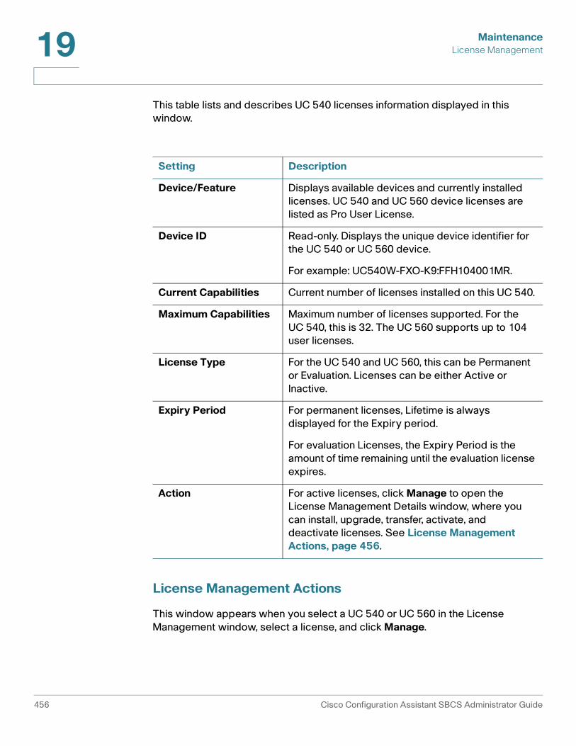
MaintenanceLicense Management19
This table lists and describes UC 540 licenses information displayed in this window.
License Management Actions
This window appears when you select a UC 540 or UC 560 in the License Management window, select a license, and click Manage.
Setting Description
Device/Feature Displays available devices and currently installed licenses. UC 540 and UC 560 device licenses are listed as Pro User License.
Device ID Read-only. Displays the unique device identifier for the UC 540 or UC 560 device.
For example: UC540W-FXO-K9:FFH104001MR.
Current Capabilities Current number of licenses installed on this UC 540.
Maximum Capabilities Maximum number of licenses supported. For the UC 540, this is 32. The UC 560 supports up to 104 user licenses.
License Type For the UC 540 and UC 560, this can be Permanent or Evaluation. Licenses can be either Active or Inactive.
Expiry Period For permanent licenses, Lifetime is always displayed for the Expiry period.
For evaluation Licenses, the Expiry Period is the amount of time remaining until the evaluation license expires.
Action For active licenses, click Manage to open the License Management Details window, where you can install, upgrade, transfer, activate, and deactivate licenses. See License Management Actions, page 456.
456 Cisco Configuration Assistant SBCS Administrator Guide

MaintenanceLicense Management 19
Overview
The UC 540 platform ships from the factory with 8 permanent licenses installed and active; the UC 560 platform ships with 16 permanent licenses installed and active. These factory-installed licenses cannot be transferred, revoked, or modified.
The maximum number of user licenses for the UC 540 platform is 32. For the UC 560, the maximum number of user licenses is 104. Additional licenses can be added in sets of 8 using a Product Authorization Key (PAK) or added through a license file. If the maximum number of licenses are already installed, the upgrade license from a PAK and install license options are disabled.
The configuration fields displayed in this window vary, depending on the license management action you choose. These actions can be performed:
• Upgrade License Using a PAK (Product Authorization Key), page 457
• Transfer License To or From This Device, page 458
• Install License From File, page 460
• Activate or Deactivate Evaluation License, page 460
Upgrade License Using a PAK (Product Authorization Key)
Choose the Upgrade License Using PAK (Product Authorization Key) option if you want to install additional licenses using a PAK. This option is unavailable if the maximum number of licenses are already installed.
The SWIFT (Software Infrastructure and Fulfillment Technology) database is contacted and updated when licenses are upgraded.
To install an upgrade license using a PAK, follow these steps.
STEP 1 In the Actions section of the window, choose Upgrade License Using a PAK (Product Authorization Key).
The Device ID at the top of the window displays the unique ID for this UC 540 device.
STEP 2 In the Action Details section of the window, complete settings as described below.
Cisco Configuration Assistant SBCS Administrator Guide 457
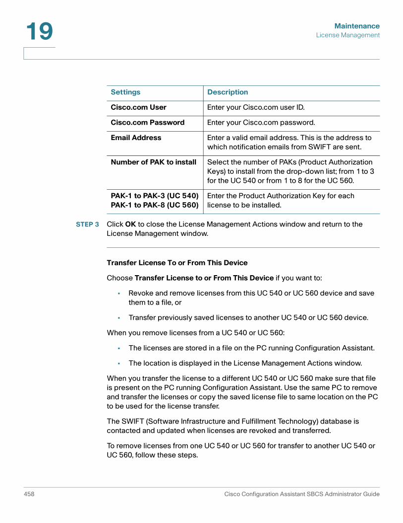
MaintenanceLicense Management19
STEP 3 Click OK to close the License Management Actions window and return to the License Management window.
Transfer License To or From This Device
Choose Transfer License to or From This Device if you want to:
• Revoke and remove licenses from this UC 540 or UC 560 device and save them to a file, or
• Transfer previously saved licenses to another UC 540 or UC 560 device.
When you remove licenses from a UC 540 or UC 560:
• The licenses are stored in a file on the PC running Configuration Assistant.
• The location is displayed in the License Management Actions window.
When you transfer the license to a different UC 540 or UC 560 make sure that file is present on the PC running Configuration Assistant. Use the same PC to remove and transfer the licenses or copy the saved license file to same location on the PC to be used for the license transfer.
The SWIFT (Software Infrastructure and Fulfillment Technology) database is contacted and updated when licenses are revoked and transferred.
To remove licenses from one UC 540 or UC 560 for transfer to another UC 540 or UC 560, follow these steps.
Settings Description
Cisco.com User Enter your Cisco.com user ID.
Cisco.com Password Enter your Cisco.com password.
Email Address Enter a valid email address. This is the address to which notification emails from SWIFT are sent.
Number of PAK to install Select the number of PAKs (Product Authorization Keys) to install from the drop-down list; from 1 to 3 for the UC 540 or from 1 to 8 for the UC 560.
PAK-1 to PAK-3 (UC 540)PAK-1 to PAK-8 (UC 560)
Enter the Product Authorization Key for each license to be installed.
458 Cisco Configuration Assistant SBCS Administrator Guide

MaintenanceLicense Management 19
STEP 1 In the Actions section of the License Management Actions window, choose Transfer License To or From This Device.
STEP 2 In the Action Details section of the window, complete settings as described below.
STEP 3 When you click OK, the system connects to the SWIFT database and revoke the license. The license is removed from the UC 540 or UC 560 and saved to a file on the PC running Configuration Assistant.
The location of the file on the local PC is displayed in the License Management Actions window.
To install a previously saved license transferred from another UC 540 or UC 560, follow these steps.
STEP 1 In the Actions section of the window, choose Transfer License To or From This Device.
STEP 2 In the Action Details section of the window, complete settings as described below.
Settings Description
Cisco.com Username Enter your Cisco.com user ID.
Cisco.com Password Enter your Cisco.com password.
Email Address Enter a valid email address. This is the address to which notification emails from SWIFT (Software Infrastructure and Fulfillment Technology) are sent.
Transfer Type Choose Remove License and Save for Transfer.
Settings Description
Cisco.com Username Enter your Cisco.com user ID.
Cisco.com Password Enter your Cisco.com password.
Cisco Configuration Assistant SBCS Administrator Guide 459
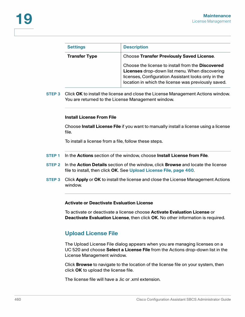
MaintenanceLicense Management19
STEP 3 Click OK to install the license and close the License Management Actions window. You are returned to the License Management window.
Install License From File
Choose Install License File if you want to manually install a license using a license file.
To install a license from a file, follow these steps.
STEP 1 In the Actions section of the window, choose Install License from File.
STEP 2 In the Action Details section of the window, click Browse and locate the license file to install, then click OK. See Upload License File, page 460.
STEP 3 Click Apply or OK to install the license and close the License Management Actions window.
Activate or Deactivate Evaluation License
To activate or deactivate a license choose Activate Evaluation License or Deactivate Evaluation License, then click OK. No other information is required.
Upload License File
The Upload License File dialog appears when you are managing licenses on a UC 520 and choose Select a License File from the Actions drop-down list in the License Management window.
Click Browse to navigate to the location of the license file on your system, then click OK to upload the license file.
The license file will have a .lic or .xml extension.
Transfer Type Choose Transfer Previously Saved License.
Choose the license to install from the Discovered Licenses drop-down list menu. When discovering licenses, Configuration Assistant looks only in the location in which the license was previously saved.
Settings Description
460 Cisco Configuration Assistant SBCS Administrator Guide
MaintenanceRestart/Reset Devices 19
Restart/Reset Devices
To open the Restart/Reset window, choose Maintenance > Restart/Reset from the feature bar.
Overview
You can restart devices in your customer site or reset them to their factory defaults.
Restarting a device saves the active configuration file and starts it again. A device is not accessible while it is being restarted, and connectivity is interrupted briefly between the device and its end stations.
Resetting a device restores the settings that it had when it was new from the factory. After a device is reset to factory default, you can use one of the device setup wizards to establish the configuration or re-configure the device manually.
NOTE When resetting a device, the DHCP server might assign a new IP address to a reset device. If this happens, the CCA Topology view shows that the device is unreachable. Right-click on the device in the Topology view and choose Add to Site to re-add the device to its customer site with its new IP address.
Procedures
To restart or reset a device in your customer site, follow these steps:
STEP 1 In the Restart/Reset window, select the device you want to restart or reset.
STEP 2 Choose one of these steps:
• Check the Restart option.
• Check the Reset to Factory Defaults option.
• Check both options.
STEP 3 Click OK.
Cisco Configuration Assistant SBCS Administrator Guide 461

MaintenanceHow to Localize the UC 500 (Non-US/English Locales)19
To Restart CUE
For the UC 500, you can also choose to restart the Cisco Unity Express module only. Voice mail, Auto Attendant, and other telephony applications run on the CUE module.
!CAUTION You should only restart the CUE module if instructed to by Cisco TAC to address a
specific issue or if required as part of a related operation in Configuration Assistant, for example, forcing a re-read of installed language files for the Cisco WebEx PhoneConnect application.
A CUE restart can take from 10 to 15 minutes. During this time, voice mail, Auto Attendant, and telephony applications such as Cisco WebEx PhoneConnect and TimeCardView are unavailable.
To restart the CUE module, choose Home > Topology to open the Topology view, right-click on the UC 500 icon in the Topology view, and choose Restart CUE from the menu.
TIP To access CUE diagnostic and troubleshooting tools, go to Troubleshoot > Telephony Diagnostics > CUE Diagnostics > CUE Connectivity Diagnostics. For more information, see CUE Connectivity Diagnostics, page 516.
How to Localize the UC 500 (Non-US/English Locales)
The default system locale for the UC 500 is US/English.
To localize the UC 520, phones, and voicemail, you must:
• Download localization files to the PC with Configuration Assistant installed.
• Localize Cisco IP phones and the dial plan. Upload the IP phone localization files to the UC 500 and select the dial plan locale.
• Localize the voice mail system. Extract and upload CUE localization files to the UC 500, then upgrade CUE and select the new language file to install during the upgrade.
462 Cisco Configuration Assistant SBCS Administrator Guide

MaintenanceHow to Localize the UC 500 (Non-US/English Locales) 19
Before You Begin
Before changing the system locale on the UC 500:
• Any firewall software installed on the PC running Configuration Assistant should be configured to allow TFTP and FTP access from UC 500.
• Shut down any third-party TFTP or FTP servers running on your local machine.
• If the UC 500 is not in factory default state, it is highly recommended that you save and back up the current UC 500 configuration using Configuration Assistant.
• If you have customized any CUE Auto Attendant prompts or scripts, log in to the CUE GUI to back up custom CUE Auto Attendant prompts and scripts using the System > Prompts or System > Scripts menu. Select custom files and click Download to copy the files to your PC. By default, the CUE GUI can be accessed from a web browser at http://10.1.10.1.
Procedures
STEP 1 Download localization files to the PC with Configuration Assistant installed.
• Current version of the Cisco UC 500 software pack for the UC 500 platform you are using, UC520-x.x.x.zip, UC540-x.x.x.zip, or UC560-x.x.x.zip, where x.x.x is the UC 500 software pack version. For example: UC520-8.0.2.zip or UC540-.1.3.zip.
• UC 500 IP Phone Localization file, CME-locale-ww_xx-y.y.y.y.tar, where ww is the language code for the language you wish to install, xx is the 2-character country code, and y.y.y.y is the Cisco Unified Call Manager Express (CUCME) version). For example: CME-locale-it_IT-4.1.0.2.tar for the Italian locale.
• UC 500 CUE Localization file, cue-vm-ww_xx-langpack.ise.y.y.y.prt1, where ww is the language code for the language you wish to install, xx is the 2-character country code, and y.y.y. is the Cisco Unity Express (CUE) version. For example: cue-vm-it_IT-langpack.ise.3.2.1.prt1 for Italian language data and prompt files.
• CP-500 Series IP Phone Localization file, CP_521_524_Dictionary.tar.
Cisco Configuration Assistant SBCS Administrator Guide 463

MaintenanceHow to Localize the UC 500 (Non-US/English Locales)19
To download the most current versions of the required files, go to: www.cisco.com/go/uc500swpk.
Log in with your CCO account username and password. Accept all license agreements.
STEP 2 Localize Cisco IP phones and the dial plan.
a. Copy the CME-locale-ww_xx-y.y.y.y.tar file to the following folder on the PC with Configuration Assistant (assuming CCA is installed in the default location).
C:\Program Files\Cisco Systems\CiscoSMB\Cisco Configuration Assistant\appdata\phoneloads
b. Launch CCA and connect to the UC 500.
c. In the Topology View, drag and drop the CP_521_524_Dictionary.tar file on UC 500 icon, then click Upload in the File Upload window.
d. Navigate to Configure > Telephony > Outgoing Dial Plan.
e. In the Default Locale field, select the dial plan for the desired locale and modify the default access code, if needed, then click OK.
f. Go to Configure > Telephony > Region, select the desired Phone Language, then click Apply. An error message may appear if you try to change the Voicemail Language from this page. With the current UC 500 software pack, CUE voice mail prompt localization must be done separately. This is covered in Step 3.
After 15 minutes or less, the IP phone language files are uploaded to the UC 500 and the IP phones are restarted. After restart, the IP phones are localized to the phone language configured on the UC 500.
STEP 3 Localize the voice mail system.
In this step, you install CUE (Cisco Unity Express) with the new language.
a. Using WinZip or similar software, extract the SCUE-UC5x0-x.x.x.zip file from the UC 500 software pack (for example, UC520-x.x.x.zip).
b. Using WinZip or similar software, extract all the contents of SCUE-UC5x0-x.x.x.zip file into any folder on the PC with Configuration Assistant.
c. Copy the CUE localization file (cue-vm-ww_xx-langpack.ise.y.y.y.prt1) that you downloaded to the same folder you copied the contents of the CUE .zip file in step (b) above:
d. Launch CCA and connect to the UC 500.
464 Cisco Configuration Assistant SBCS Administrator Guide

MaintenanceFile Management 19
e. From the feature bar, select Maintenance > Software Upgrade.
f. Select the UC 500 from the list, then click Upgrade Settings.
g. Check the CUE Only radio button so that only CUE is upgraded.
h. Click Browse and navigate to the phoneloads directory that now holds the CUE firmware.
i. Select the cm-vm.ise.x.x.x.pkg file. If you select any other package, the process fails.
j. Select the desired language from the Language drop-down menu in the Upgrade Settings window.
k. Click Upgrade.
CUE localization can take up to 45 minutes or so to complete, but does not require further input.
Once the CUE localization completes, the CUE language should appear in the Configure > Telephony > Region window. You can also try accessing the CUE voice mail from any IP phone to verify the localized prompts.
File Management
To manage the file system on the compact flash for the UC 500 or the file system for other devices, choose Maintenance > File Management from the feature bar.
TIP The Flash Usage item on the Dashboard view provides information about the percentage of used and available storage on the compact flash. To open the Dashboard, choose Home > Dashboard from the feature bar. You can remote phone loads from the flash to free up space, if needed. See Phone Load Management, page 468.
Overview
You can view the file systems of any devices while the devices are connected to a live network. You can perform basic file management operations on these file systems. When performing a software upgrade, you might have insufficient space to install the new image, and therefore you might need to delete the old image to make room for the new image.
Cisco Configuration Assistant SBCS Administrator Guide 465
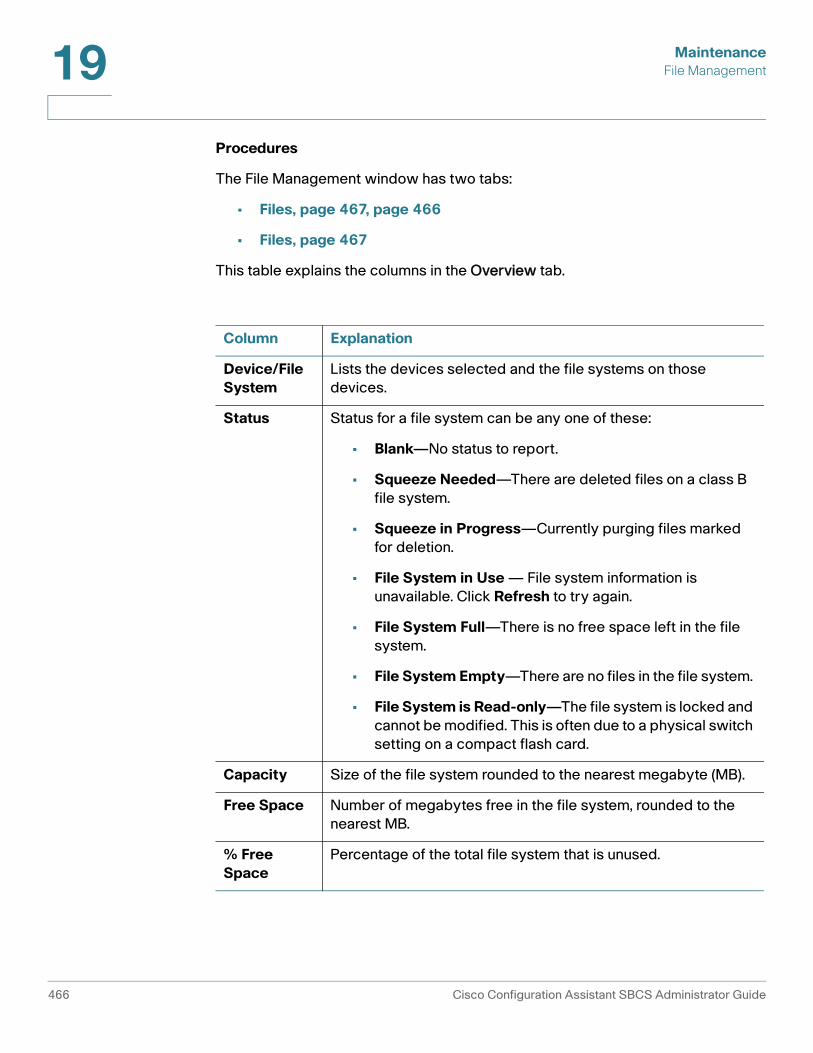
MaintenanceFile Management19
Procedures
The File Management window has two tabs:
• Files, page 467, page 466
• Files, page 467
This table explains the columns in the Overview tab.
Column Explanation
Device/File System
Lists the devices selected and the file systems on those devices.
Status Status for a file system can be any one of these:
• Blank—No status to report.
• Squeeze Needed—There are deleted files on a class B file system.
• Squeeze in Progress—Currently purging files marked for deletion.
• File System in Use — File system information is unavailable. Click Refresh to try again.
• File System Full—There is no free space left in the file system.
• File System Empty—There are no files in the file system.
• File System is Read-only—The file system is locked and cannot be modified. This is often due to a physical switch setting on a compact flash card.
Capacity Size of the file system rounded to the nearest megabyte (MB).
Free Space Number of megabytes free in the file system, rounded to the nearest MB.
% Free Space
Percentage of the total file system that is unused.
466 Cisco Configuration Assistant SBCS Administrator Guide

MaintenanceFile Management 19
Files
This table explains the columns on the Files tab.
Follow these steps to delete a file:
!CAUTION Do not delete the system boot image or any of these files: vlan.dat, config.txt,
env_vars, private_config.txt, and system_env_vars.
Files Number of files on the file system. Directories on Class C file systems and deleted files on Class B file systems are counted as files.
Column Explanation
Device/File System
Lists the devices selected and the file systems on those devices. Below each file system is a list of directories and files.
Squeeze Appears only when there is a deleted file on a device with a Class B file system. Check the box provided to permanently remove deleted files from the file system. The check box is not available if the file system is read-only or if there are no deleted files on the file system.
Size Lists the sizes of individual files in KB.
Type Lists the file type of individual files, if available. Common file types would include System Image, IOS Image, and Configuration.
Modified Lists the file modification date and time.
Delete Check the box for a file to select it for deletion. If the file is in a Class B file system and a file is already marked for deletion, the box is checked.
Restore Appears only for devices that have Class B file systems with deleted files. Check the boxes to select which files to undelete.
Column Explanation
Cisco Configuration Assistant SBCS Administrator Guide 467
MaintenancePhone Load Management19
STEP 1 Check the box in the same row as the file that you want to delete.
STEP 2 Click Apply.
STEP 3 If you want to permanently remove the file from a Class B file system, perform a squeeze operation on the file system where the file exists.
STEP 4 Follow these steps to restore a file that has not been permanently deleted by a squeeze operation:
a. Check the box in the same row as the file that you want to restore.
b. Click Apply.
STEP 5 Follow these steps to squeeze a Class B file system:
a. Check the box in the same row as the file system that you want to squeeze.
b. Click Apply.
When squeezing a file system, if there are files in it marked to be restored, those files are restored before the squeeze operation. Files marked for deletion are removed before the squeeze operation. Squeeze operations can take several minutes.
Related Topics
• Phone Load Management, page 468
Phone Load Management
To access phone load management options, choose Maintenance > Phone Load Management.
• Overview
• Delete Phone Loads
• Upload Phone Loads
• Drag-and-Drop Upgrade (SPA 500 Series, SPA 525G, and SPA 300 Series Phones)
468 Cisco Configuration Assistant SBCS Administrator Guide

MaintenancePhone Load Management 19
Overview
From the tabs on the Phone Load Management window, you can:
• Replace or add phone loads to the UC 500 compact flash by specifying a UC 500 software package. The phone loads are extracted from the software package and uploaded to the UC 500.
• Remove phone loads from the compact flash on the UC 500 to optimize space on the flash
• Replace a specific phone load by deleting the version that is currently on the system and then uploading a newer version.
In order to upload phone load files to the UC 500, make sure that you have disabled any third-party TFTP or FTP servers running on the PC that is running Configuration Assistant.
Delete Phone Loads
When you choose the Delete Phone Loads tab, all phone loads on the UC 500 flash are displayed. in the list.
• A checkbox is displayed in the Select column for all phone loads available on the UC 500 flash.
• Phone loads that are not in use on the system are checked and can be safely deleted.
• Phone loads that are in use are unchecked.
To delete a phone load, follow these steps.
STEP 1 Click on the row in the table for that phone load to highlight it.
STEP 2 Make sure that checkbox in the Select column for that phone load is checked.
Click Delete.
STEP 3 Repeat the above steps to delete additional phone loads.
As you delete phone loads, the Flash space available fields update to reflect flash usage after the deletion.
STEP 4 Click OK when you are finished deleting phone loads.
Cisco Configuration Assistant SBCS Administrator Guide 469

MaintenancePhone Load Management19
Upload Phone Loads
To upload phone loads to the UC 500, follow these steps.
STEP 1 Click Browse and locate the UC 500 software package .zip file that contains the phone loads you want to upload., for example UC520-7.0.3.zip or UC540-7.1.1.zip.
Once you have selected the UC 500 software package file, CCA analyzes the phone loads in the software package and the ones in use on your system.
When the software package analysis completes, the list of phone loads available in the specified image are displayed. Phone loads that are already in use on your system are selected for upload.
Click the checkbox in the Select column to select or deselect phone loads from the list of those to be uploaded.
NOTE The 521_524 phone loads for CP 500 phones cannot be deselected. You must upgrade to the latest firmware for these phones to function correctly.
STEP 2 Click Upload to upload the selected phone loads to the UC 500.
STEP 3 Click OK to close the Phone Load Management window.
Drag-and-Drop Upgrade (SPA 500 Series, SPA 525G, and SPA 300 Series Phones)
The drag-and-drop phone load upgrade method can be used to upgrade firmware for Cisco SPA 525G, SPA 500 Series, and SPA 300 Seires IP phones.
These guidelines and notes apply to drag-and-drop phone load upgrades:
• This upgrade method is supported only for SPA 500 Series, SPA 525G, and SPA 300 Series IP phones. CCA displays a message if it does not recognize the phone load file.
• You cannot drag and drop more than one file at a time.
• Phone loads are copied into the flash:phones/ directory on the UC 500 flash and placed under the appropriate subdirectory for the phone model. For example: flash:phones/525 or flash:phones/5x5.
• Once the upgraded firmware is downloaded, it can be managed through the Phone Load Management window in CCA.
470 Cisco Configuration Assistant SBCS Administrator Guide

MaintenancePhone Load Management 19
To upgrade Cisco SPA 500 Series, SPA 525G, and SPA 300 Series IP phones with updated firmware downloaded from Cisco.com, follow these steps.
STEP 1 Download the phone firmware image from Cisco.com. A Cisco.com login is required.
STEP 2 Launch CCA and connect to the customer site or UC 500 device.
STEP 3 Choose Home > Topology to open the Topology View if it is not already open.
STEP 4 On the PC running CCA, locate the phone firmware file that you downloaded from Cisco.com. For example: spa525g-7-4-3.bin.
STEP 5 In the Topology View, use the mouse to drag the phone load file from your PC and drop it onto the UC 500 icon.
If CCA recognizes the file as a valid phone load, a popup dialog displays and you are prompted to upload the file.
STEP 6 Click Upload. The dialog displays the upload and upgrade progress.
Affected phones are restarted after the upgrade is applied.
Cisco Configuration Assistant SBCS Administrator Guide 471

MaintenancePhone Load Management19
472 Cisco Configuration Assistant SBCS Administrator Guide

20
Monitoring
Read this section to learn about reports and diagnostic information that can be monitored for devices in a customer site. To access system monitoring options, choose Monitor from the feature bar.
These report categories and monitoring tools are available:
• Network
• Security
• Telephony
• Inventory
• Health
• Event Notification
• System Log
• System Messages
• Multisite Status
Cisco Configuration Assistant SBCS Administrator Guide 473

MonitoringNetwork20
Network
To access network status monitoring options, choose Monitor > Network from the feature bar. These network monitoring reports and tools are available:
• Port Statistics
• Bandwidth Graphs
• Link Graphs
• Wireless Usage
• T1/E1/BRI Status
• DNS and Hosts
Port Statistics
To access Port Statistics, choose Monitor > Network > Port Statistics from the feature bar.
Port Statistics are available for Cisco ESW 500 Series switches and Cisco CE 520 switches only.
From the Port Statistics window, you can display port information such as statistics on link performance, dropped packets, and total errors. To see a condensed, graphical view of port statistics, use the Bandwidth Graphs window.
• To see these statistics for the ports on a given device, select the device from the Hostname list.
• To refresh the statistics, click Refresh.
• To clear the statistics for all the ports on the selected device, click Clear Counters.
• To save the report to a local drive, click Save Report. In the window that appears, you select a folder for storing the report.
This table explains the data on each of the tabs: Overview, Transmit Detail, and Receive Detail.
474 Cisco Configuration Assistant SBCS Administrator Guide

MonitoringNetwork 20
Tab Column Explanation
Overview Interface Port interface name (for example, on an ESW-540-8P switch, the interfaces are numbered g1 through g9.
Port Description ESW 500 switches only. Text description for this port, if configured on the switch.
Transmit Rate The current transmit rate in Mbps. It includes the transmission of bad packets and retransmission because of collisions in half-duplex operations.
Receive Rate The current receive rate in Mbps. It includes the data bytes of bad packets, discarded packets, and no-destination packets.
Transmit Bandwidth Usage
The percentage of the bandwidth usage for transmission, based on the current transmit rate and actual speed.
Receive Bandwidth Usage
The percentage of the bandwidth usage for reception, based on the current receive rate and actual speed.
Transmit Packet Rate
The current transmit rate of well-formed packets. It includes unicast, multicast, and broadcast packets.
Receive Packet Rate
The current receive rate of well-formed packets. It includes unicast, multicast, and broadcast packets.
Transmit Multicast/Broadcast Packet Rate
The current transmit rate of well-formed multicast and broadcast packets. It excludes unicast packets.
Receive Multicast/Broadcast Packet Rate
The current receive rate of well-formed multicast and broadcast packets. It excludes unicast packets.
Total Discarded Packets
The total number of packets discarded from both transmission and reception.
Cisco Configuration Assistant SBCS Administrator Guide 475

MonitoringNetwork20
Overview Total Packets with Errors
The total number of packets with errors from both transmission and reception.
Transmit Packets
Interface Port interface name (for example, on an ESW-540-8P switch, the interfaces are numbered g1 through g9.
Port Description ESW 500 switches only. Text description for this port, if configured on the switch.
Unicast The total number of well-formed unicast packets transmitted by a port. It excludes packets transmitted with errors or with multicast or broadcast destination addresses.
Multicast The total number of well-formed multicast packets transmitted by a port. It excludes packets transmitted with errors or with unicast or broadcast destination addresses.
Broadcast The total number of well-formed broadcast packets transmitted by a port. It excludes packets transmitted with errors or with unicast or multicast destination addresses.
Total Collision The total number of packets transmitted without error after having 1 to 15 collisions. It includes packets of all destination address types and excludes packets discarded because of insufficient resources or late collisions.
Excessive Collision
The total number of packets that failed to be transmitted after 16 collisions. It includes packets of all destination address types.
Late Collision The total number of packets discarded because of late collisions detected during transmission. It includes all transmit packets that had a collision after the transmission of the packet's 64th byte. The preamble and SFD are not included in the frame's byte count.
Tab Column Explanation
476 Cisco Configuration Assistant SBCS Administrator Guide

MonitoringNetwork 20
Receive Packets
Interface Port interface name (for example, on an ESW-540-8P switch, the interfaces are numbered g1 through g9.
Port Description ESW 500 switches only. Text description for this port, if configured on the switch.
Unicast The total number of well-formed unicast packets received by a port. It excludes packets received with errors, with multicast or broadcast destination addresses, or with oversized or undersized packets. Also excluded are packets discarded or without a destination.
Multicast The total number of well-formed multicast packets received by a port. It excludes packets received with errors, with unicast or broadcast destination addresses, or with oversized or undersize packets. Also excluded are packets discarded or without a destination.
Broadcast The total number of well-formed broadcast packets received by a port. It excludes packets received with errors, with unicast or multicast destination addresses, or with oversized or undersize packets. Also excluded are packets discarded or without a destination.
Discarded The total number of packets discarded because of insufficient receive bandwidth or receive buffer space, or because the forwarding rules stipulate that they not be forwarded.
Tab Column Explanation
Cisco Configuration Assistant SBCS Administrator Guide 477

MonitoringNetwork20
Bandwidth Graphs
From the Bandwidth Graphs window, you can see an estimate of the traffic flowing through the device you choose from the Hostname list. Bandwidth Graphs are available for CE 520 switches only.
To display a bandwidth graph for a CE 520 switch, take any of these actions:
• Right-click a site member in the Front Panel view and choose Bandwidth Graphs from the popup menu.
• Right-click or double-click a site member in the Topology view and choose Bandwidth Graphs from the popup menu.
• Select a site member in either view, and choose Monitor > Network > Bandwidth Graphs on the feature bar.
Overview
For a selected Catalyst Express 500 switch, a bandwidth graph gives you these estimates:
• How much of its bandwidth is being used, starting at the time the graph appears
Receive Packets
Alignment Errors
The total number of packets received with alignment errors. It includes all the packets received with both an FCS error and a non-integral number of bytes.
FCS Errors The total number of packets received with FCS errors. It excludes undersized packets with FCS errors.
Collision Fragments
The total number of frames of less than 64 bytes that have an integral number of bytes and bad FCS values.
Undersize Packets
The total number of packets received of less than 64 bytes that have good FCS values.
Oversize Packets
The total number of packets received of more than 1518 bytes that have good FCS values.
Tab Column Explanation
478 Cisco Configuration Assistant SBCS Administrator Guide

MonitoringNetwork 20
• How much of its bandwidth was used, in the past minute, hour, day, or 2-week period
Procedures
The window has these tabs:
• Time Series, which shows the percentage of bandwidth utilized, starting at the time the window appears.
• Trends, which shows the percentage of bandwidth utilized in the past minute, hour, day, or 2-week period.
Time Series
You can manipulate the graph on this tab by
• Selecting the type of graph displayed
• Changing the increments on the x-axis
• Changing the polling interval
• Scrolling the x-axis
Selecting the Type of Graph to Display
From the Type list, click Line or Bar to select a type of graph. In a line graph, data points are connected by a line. In a bar graph, data points are denoted by the height of bars.
Changing the Increments on the X-Axis
By default, the time increments on the x-axis are 2 minutes apart. To make them closer together or farther apart, click the Zoom buttons.
Changing the Polling Interval
At a regular interval, Configuration Assistant queries the managed devices to gather device- and link-utilization data. This interval is called the graph polling interval. To set it, open the Preferences window, click the General tab, and choose a value for the Graph Polling Interval field.
Note: When the traffic level on a device drops dramatically, you do not see a change in the graph for at least 15 minutes, regardless of the setting for the graph polling interval.
Cisco Configuration Assistant SBCS Administrator Guide 479

MonitoringNetwork20
Scrolling the X-Axis
You can use the scroll bar at the bottom of the graph to scroll left and review past data points that have moved off the graph. You can then scroll right to return to the most recent data.
Note: The graph is updated each time the device is polled. You can change the polling interval (the frequency for collecting the data) by selecting and using the Preferences window.
Trends
The graph on this tab is about past bandwidth utilization. Therefore, you see historical data when you open this tab-by default, the device's bandwidth data for the past 60 seconds. By clicking the trend buttons on the tab, you can also see data for the past 60 minutes, 24 hours, or 14 days. The data always appears as a bar graph. The intervals on the x-axis are fixed for each trend graph; you can lengthen or shorten them only by clicking a different trend button.
Link Graphs
Link Graphs are available for Cisco ESW 500 Series switches and CE 520 switches only.
To display a link graph, one end of the link must connect to a port on a member device. You cannot display a link graph between candidate devices.
To display a link graph, take either of these actions:
• Choose Monitor > Network > Link Graphs on the feature bar.
• Click a link in the topology view and choose Link Graphs from the popup menu.
NOTE You can change the graph polling interval by selecting and using the Preferences window.
Overview
A link graph shows the:
• Percentage of bandwidth being used
• Number of bytes transmitted and received
• Number of packets transmitted and received (differentiated into broadcast/multicast packets and unicast packets)
480 Cisco Configuration Assistant SBCS Administrator Guide

MonitoringNetwork 20
• Total errors and packets dropped
From the Link Graphs window, you can:
• Select the Type of Data Displayed
• Select the Type of Graph Displayed
• Change the Increments on the Axes
• View a Long Span of Data
Procedures
To select a port other than the one in the Interface field, overtype the port number, use the scroll buttons, or click the port selection icon. If you choose the last option, the Select Interface window opens to show the front panel of the device. Select a port by clicking it; then click OK. See Select Interface, page 483.
Select the Type of Data Displayed
To select a type of data, click % Utilization, Transmitted/Received Packets, Packet-Forwarding Methods, or Packet Drops and Errors in the Data list. The results of each selection are described in this table:
Data Type Results
% Utilization Displays the percentage of bandwidth being used on the port that corresponds to the link. For example, if the bandwidth of the link is 100 Mbps, and 20 Mb is consumed at a time, the graph plots 20% at that instant.
Transmitted/Received Packets
Displays two graphs: Transmitted (red) and Received (blue).
The Bytes Transmitted graph displays the number of bytes transmitted on the port that corresponds to the link.
The Bytes Received graph displays the total number of bytes received on the port that corresponds to the link.
Cisco Configuration Assistant SBCS Administrator Guide 481

MonitoringNetwork20
Select the Type of Graph Displayed
From the Type list, click Line, Bar, Stack Bar, Area, or Stack Area to select a type of graph. The appearance of each type is described in this table.
Packet-Forwarding Methods
Displays two graphs: Broadcast/Multicast Packets (red) and Unicast Packets (blue).
The Broadcast/Multicast Packets graph displays the number of broadcast and multicast packets received on and transmitted to the port that corresponds to the link.
The Unicast Packets graph displays the number of unicast packets received on and transmitted to the port that corresponds to the link.
Packet Drops and Errors
Displays two graphs: Total Errors (blue) and Total Packets Dropped (red).
The Total Errors graph displays the total number of packets with errors that have accumulated on the port since the counters were last reset.
The Total Packets Dropped graph displays the total number of packets that were dropped on the port corresponding to the link. Packets are dropped because of a lack of buffers or bandwidth or because of user-configured packet filtering on the device.
Graph Type Appearance
Line Data points are connected by a line.
Bar Data points are denoted by the height of bars.
Stack Bar Multiple bar graphs, each of a different color, are stacked one upon another.
Area Data points are connected by a line, and the area under the line is filled in.
Data Type Results
482 Cisco Configuration Assistant SBCS Administrator Guide
MonitoringNetwork 20
Change the Increments on the Axes
By default, the time increments on the x-axis are 2 minutes apart. To make them closer together or farther apart, click the Zoom buttons.
Check Log Scaling if you want the increments on the y-axis to scale upward logarithmically rather than arithmetically.
View a Long Span of Data
Use the scroll bar at the bottom of the graph to scroll left and review past data points that have moved off the graph. You can then scroll right to return to the most recent data.
NOTE The graph is updated each time the device is polled. You can change the polling interval (the frequency for collecting the data) from the Preferences window.
Select Interface
This window appears when you click a switchport icon in a Configuration Assistant window. It displays the front panel of a selected switch. Use the window to select an interface on the switch.
Follow these steps:
STEP 1 Click on the interface you want to use.
Interfaces that you cannot select are grayed out.
STEP 2 Click OK. You return to the Configuration Assistant window you were using, and the number of the selected interface appears in the Interface field.
Stack Area Multiple area graphs, each of a different color, are stacked one upon another.
Graph Type Appearance
Cisco Configuration Assistant SBCS Administrator Guide 483

MonitoringNetwork20
Wireless Usage
To view a wireless usage report, choose Monitor > Network > Wireless Usage from the feature bar.
Status information for wireless clients is only available for these devices:
• Cisco UC 500 platforms and Cisco SR 500 Series Secure Routers with an embedded access point
• Cisco AP 521 autonomous access points
• Cisco AP 541N Dual-band Single-radio access points
Wireless LAN controller status is not shown.
Choose a wireless device from the Hostname list menu.
The Wireless Usage report displays the following information for each connected client:
• MAC address
• Name
• IP address
• VLAN number
• SSID (secure site identifier)
• Key management type
• Encryption type
• Data rate, in Mbps
• Signal strength, in dBM, for clients connected to AP 521 and built-in UC 500 access points
• RSSI (received signal strength indication, for AP 541N access points
The RSSI indicates the RF (radio frequency) signal strength for clients connected to AP 541N access points. A value from 1 to 100 is displayed.
• Packets in/out
• Bytes in/out
484 Cisco Configuration Assistant SBCS Administrator Guide

MonitoringSecurity 20
T1/E1/BRI Status
If a T1/E1 or BRI interface is present on the system, choose Monitor > Network > T1/E1/BRI Status from the feature bar to view output of IOS commands such as show isdn status and show controller for bri, t1, or e1, depending on the available interfaces.
DNS and Hosts
Choose DNS and Hosts to view the output of the show hosts command for the customer site. The output includes the DNS hostname and domain of the UC 500 or SR 500 and the IP addresses of the primary and secondary DNS servers.
Security
To access s monitoring options for network security, choose Monitor > Security from the feature bar. Expert mode security reports are listed and described below.
These reports are text-based and are generated from Cisco IOS command output.
NOTE These reports are primarily intended to aid the Small Business Support Center (SBSC) in resolving issues with Cisco SBCS deployments. Expert knowledge of Cisco IOS and the command-line interface is required to effectively interpret the data presented in these reports.
Security Report Description
EZVPN Client and Server Displays output of show crypto commands for obtaining information about current IKE security associations, EasyVPN remote configuration, settings used by current SAs, active VPN sessions, and encryption accelerator statistics.
Site-to-Site VPN Status Displays output of show crypto commands for obtaining current IKE security associations, active VPN sessions, settings used by current SAs, active VPN sessions, and encryption accelerator statistics.
Cisco Configuration Assistant SBCS Administrator Guide 485

MonitoringSecurity20
VPN Status
The VPN status window appears when you choose Monitor > Security > VPN Status from the feature bar.
EasyVPN
From this tab, you can monitor the status of EasyVPN tunnels.
Choose a device to be reported from the Hostname list. The report entries are automatically populated.
SSL VPN Status Displays output of show tcp and show webvpn commands for obtaining information about TCP connection endpoints, SSL VPN user sessions, and SSL VPN tunnel statistics.
To display SSL VPN user session information for a specific user, enter the username and click Query.
Firewall Displays output of show access-list and show ip inspect session commands.
NAT Displays output of show ip nat and show ip route commands for obtaining information about NAT statistics, IP routes, and NAT translations.
VPN Status See VPN Status, page 486.
VPN Status Description
UP-ACTIVE Up and active.
UP-IDLE Up, but there is no activity.
UP-NO-IKE Up, but there is no IKE (Internet Key Exchange).
DOWN-NEGOTIATING Down, but the device is negotiating the connection.
DOWN Down.
Security Report Description
486 Cisco Configuration Assistant SBCS Administrator Guide

MonitoringTelephony 20
SSL VPN
From this tab, you can monitor status of SSL (secure socket layer) VPN tunnels.
Telephony
To access monitoring options for telephony features, choose Monitor > Telephony from the feature bar. Expert mode telephony reports are listed and described below.
These reports are text-based and are generated from Cisco IOS and CUE command output.
NOTE These reports are primarily intended to aid the Small Business Support Center (SBSC) in resolving issues with Cisco SBCS deployments. Expert knowledge of CUE, Cisco IOS, and the command-line interface is required to effectively interpret the data and output presented in these reports.
Telephony Report Description
Phones and Extensions
Phones. Displays read-only internal configuration information and status for phones and extensions, including tag, MAC address, phone type, username, button assignment, phone template in use, IP address, phone load being used, and status.
Extensions. For each extension, displays the DN tag, internal extension number, line type, label, username, COR incoming, trunk type, and channel status. If configured, the intercom number and intercom label are also displayed. Intercom numbers begin with an alphabetic character (for example, A502).
Hunt Groups Displays internal configuration information for hunt groups, including the tag, pilot number, type, members, timeout settings, and destination for No Answer Forward To.
Search Groups by Member. Enter an extension number or a series of numbers separated by a comma to find out which hunt group or groups an extension number belongs to.
Cisco Configuration Assistant SBCS Administrator Guide 487

MonitoringTelephony20
Call Blast Groups Displays internal configuration information for hunt groups, including the tag, pilot number, type, members, timeout settings, and destination for No Answer Forward To.
Search Groups by Member. Enter an extension number or a series of numbers separated by a comma to find out which call blast group or groups an extension number belongs to.
Choose a group and click View Configuration Summary to display CLI summary information for the selected call blast group.
TFTP Server Files Displays filename information for TFTP server files stored on the flash. If applicable, the name of the device that owns the file and the filename alias are also listed.
Dial Peers Displays internal configuration information for POTS and VoIP dial peers configured on the system.
POTS. For POTS dial peers, the information includes the tag number, port, description, destination pattern, incoming destination, translation profile name, forward-digits value, and trunk preference.
VoIP. For VoIP dial peers, the information includes the tag number, description, destination pattern, voice class, session target, DTMF relay, and codec.
Translation Profiles
Displays internal configuration information for translation profiles and translation rules and provides an option for testing translation rules.
SIP Trunk Status Displays output of show sip-ua commands for SIP service status, registration, timers, and statistics.
Phone Template For the selected IP phone template, displays internal template properties for softkeys and button layout.
This information is read-only; templates cannot be edited using Configuration Assistant.
Telephony Report Description
488 Cisco Configuration Assistant SBCS Administrator Guide

MonitoringTelephony 20
Voicemail Status When you select a voicemail status report, Configuration Assistant displays a Progress dialog as the connection to the Voicemail system on the CUE module is opened and command output is collected. These text-based voicemail status reports are available:
System. Displays the output of show commands for obtaining information about clock and time zone statistics, privileges assigned to configured groups, versions of software an applications, purchased licenses for the system, and installed software packages.
Voicemail. Displays the output of show voicemail commands for obtaining information about configured mailboxes and current storage status, default values for all mailboxes, and voicemail usage statistics.
Calendar. Displays schedules and holidays configured for the system in text format.
Others. Displays the output of commands for obtaining information about currently configured applications, configured auto-attendant greeting prompts, script filenames, and currently configured trigger types.
DSP Status The DSP Status report displays detailed show command output for DSP hardware, DSP farm, groups, errors, and active/signaling voice DSP.
Software Pack The Software Pack report displays software package and component version information, compact flash usage, CUE status, and supported phone types for the currently installed UC 500 software package.
Version information for UC 500 software packages prior to 7.0.0 is not available.
Telephony Report Description
Cisco Configuration Assistant SBCS Administrator Guide 489

MonitoringInventory20
Inventory
To display an inventory report for a customer site or a single device, choose Maintenance > Inventory.
The inventory report for a customer site displays device types, serial numbers, IP addresses, and software releases for the site. You can also choose a single device for which you want to view inventory details.
The information in this window is read-only. For each device in the customer site, the inventory contains
• Hostname
• Device type
• Serial number
• Hardware version number (Version ID)
• MAC address
• IP address
• Installed software revision
• System location
• System uptime (length of time that it has been operating)
If you did not assign a hostname to a switch in the site, a hostname ofswitch-<number> is automatically assigned. The number shows the order in which the switch was added to the site.
Click Details to view details for a specific device. See Inventory Details, page 491.
Click Refresh to update the display.
490 Cisco Configuration Assistant SBCS Administrator Guide
MonitoringSystem Log 20
Inventory Details
This window appears when you select a device with routing capability and click Details in the Inventory window.
The window displays information for the device by component, description, part number, hardware revision, PCB (printed circuit board) serial number, and product number. The description gives the details of the component. The part number is the order number of the component.
If you know that a change has occurred and you want to see the change, click Refresh. Configuration Assistant re-samples the components and redisplays the details when components are removed or added.
System Log
The System Log report displays the output of the show log command.
Multisite Status
You must be directly connected to a LAN port on the UC 500 or SR520-T1 secure router to view multisite status.
The Multisite Status report displays the output for the show crypto session detail Cisco IOS command. This command lists all active Virtual Private Network (VPN) sessions and the IKE (Internet Key Exchange) and IPsec SAs (security asso.ciations) for each VPN session.
See Multisite Status Monitoring, page 328.
Health
You can monitor a number of device health measurements to avoid downtime and to ensure that your network is running efficiently. The measurements tell you about the utilization of bandwidth, PoE (Power over Ethernet), the CPU, and memory, and about device temperature and the percentage of packet errors.
To check the health measurements, choose Monitor > Health from the feature bar.
Cisco Configuration Assistant SBCS Administrator Guide 491

MonitoringHealth20
In addition to the health measurements, Configuration Assistant has features that focus on the use of specific resources:
• For information about PoE utilization, choose Configure > Ports > Port Settings.
• For information about bandwidth utilization over time, choose Monitor > Network > Bandwidth Graphs.
• For information about link utilization over time, choose Monitor > Network > Link Graphs.
• For more information about packet errors, choose Monitor > Network > Port Statistics.
Use the window to see up to five devices that have the highest measurements in the categories that you choose to monitor. Click the bars in the window to display additional.
For even more information, click Details to open the Health Details window. See Health Details, page 492.
Health Details
This window appears when you click Details in the System Health window (Monitor > Health). For a graphical display of this information, choose Home > Dashboard.
When you finish with the window, click OK.
The Health Details window has these tabs:
• Overview
• Bandwidth Utilization
• Packet Errors
• PoE Utilization
• Temperature
• CPU Utilization
• Memory Utilization
492 Cisco Configuration Assistant SBCS Administrator Guide

MonitoringHealth 20
Overview
The Overview tab shows the overall measurements for each of the categories that you monitor on all the devices in the network to which the categories apply. This table explains the columns on the tab.
Bandwidth Utilization
The Bandwidth Utilization tab shows the percentage of bandwidth being used to receive packets, the percentage to transmit packets, and the average of the two.
You can open the Bandwidth Graphs window to see how the bandwidth of a device is being used over time. The Link Graphs window shows which ports have the most traffic.
Packet Errors
The Packet Errors tab shows the percentage of device input and output packets that are in error and an overall error percentage.
PoE Utilization
For devices that support PoE (Power over Ethernet), the PoE Utilization tab shows the percentage of PoE wattage in use, the total wattage, used wattage, and available wattage. If you are adding access points and IP phones to your network, connect them to devices that show a low PoE utilization.
Column Explanation
Hostname The hostname of a standalone device or the hostnames of the devices in your community
Bandwidth Utilization The average bandwidth used to receive and transmit packets as of the last polling interval
Packet Errors The overall (input and output) percentage of packets in error
PoE Utilization The percentage of PoE wattage in use
Temperature The temperature in Celsius
CPU Utilization The percentage of CPU utilization in the last 5 seconds
Memory Utilization The percentage of memory being used
Cisco Configuration Assistant SBCS Administrator Guide 493

MonitoringEvent Notification20
Temperature
For devices that can measure temperature precisely, the Temperature tab shows, in Celsius, the current temperature, the overheating threshold, and the critical threshold. For other devices, you see that the temperature is OK, Normal, Faulty, or N/A, indicating that the precise current temperature, overheating threshold, and critical threshold are not sensed.
CPU Utilization
The CPU Utilization tab shows, by device, the percentage of CPU capacity in use in the last 5 seconds, 1 minute, and 5 minutes.
Memory Utilization
The Memory Utilization tab shows the percentage of memory in use and the number of total, used, and free megabytes.
Event Notification
The Event Notification window appears when you take any of these actions:
• Click an event icon on the status bar or in the Topology view.
• Choose Monitor > Event Notifications the feature bar.
• Click the Event Notification icon on the toolbar.
Overview
An event is a condition that Configuration Assistant detects and wants you to know about. These are examples of events:
• A high device temperature
• A device with a broken fan
• An administratively disabled port
• A port with a duplex mismatch
• A port that you can configure with Smartports
• A device in your network that is unknown
• VLAN conflicts
494 Cisco Configuration Assistant SBCS Administrator Guide

MonitoringEvent Notification 20
To make you aware of an event, Configuration Assistant displays a popup message. It also puts a clickable event icon on the status bar and in the Topology view, beside the device on which the event occurred. When your mouse pointer touches an event icon in the Topology view, you see a summary of the event.
The appearance of the icon depends on the type of the event. Event types differ by number; the smaller the type number, the greater the need to take action.
If Configuration Assistant detects multiple events, you see icons for all of them in the Topology view. On the status bar, you see the icon for only the most urgent event.
The Event Notification window gives you a full description of events that were detected in your network. You use the window to:
• Tell Configuration Assistant that you are aware of the event.
• Ask Configuration Assistant to take action, if possible.
• Turn off the Alert LED on switches.
Procedures
The Events tab in the notification window is where you can view descriptions of all the events in your network, acknowledge your awareness of them, and use Configuration Assistant to resolve them (if possible)
To see a subset of event information, click Filter, and use the Notification Filter window. See Notification Filter, page 496.
Click OK when you are done with the window.
This table explains the information on the tab.
Column Explanation
Type Denotes how urgent it is to resolve the event. The lower the type number, the more urgent the need to resolve it.
Time The time when the event occurred.
Event Description
A brief description of what occurred. When you select an event, a longer description appears below the list of events.
Cisco Configuration Assistant SBCS Administrator Guide 495

MonitoringSystem Messages20
Notification Filter
This window appears when you click Filter in the Event Notification window. Use it to limit the types of events that appear in that window.
Follow these steps:
STEP 1 Under Types, uncheck the boxes for the event types to be filtered out. Events of these types do not appear in the Event Notification window.
STEP 2 Click Set Defaults if any box is unchecked and you want all the boxes to be checked again.
Click OK when you finish with the window.
System Messages
From the System Messages window you can view the messages issued by devices in a customer site.
To access the System Messages window, choose Monitor > System Messages from the feature bar.
Procedures
Follow these steps to view and filter system messages.
Resolvable Yes if Configuration Assistant can resolve the event, No if it cannot. You ask Configuration Assistant to resolve an event by highlighting it and clicking Resolve. Configuration Assistant then opens a window for resolving the event.
Acknowledged Boxes that you check to show your awareness of events. If you click Acknowledge All, you acknowledge all the events at once. When an event is acknowledged, its event icon dims.
Device The device involved in the event.
Column Explanation
496 Cisco Configuration Assistant SBCS Administrator Guide
MonitoringSystem Messages 20
STEP 1 From the Hostname list, select a device whose messages you want to view, or select All Devices to see the messages that are issued by all the devices in the community.
STEP 2 Click a column heading of the table to sort the messages according to your interest. By default the messages are sorted by severity.
STEP 3 To see details about a particular message, select its row in the table. The message details appear in the area below the table.
STEP 4 Optional: Click Filter to open the System Messages Filter window, where you can specify criteria for limiting the messages that appear. See System Messages Filter, page 497.
STEP 5 Optional: Click Save Report to save the window contents in a file in comma-delimited format. The default filename has a time stamp to make it unique.
STEP 6 Click OK when you finish with the window.
System Messages Filter
This window appears when you click Filter in the System Messages window. Use it to limit the number of messages that appear in that window.
To filter system messages, follow these steps.
STEP 1 Under Severity Levels, uncheck the boxes for the severity levels to be filtered out. Messages with these severity levels do not appear in the System Messages window.
STEP 2 Click Set Defaults if any box is unchecked and you want all the boxes to be checked again.
Click OK when you finish with the window.
Cisco Configuration Assistant SBCS Administrator Guide 497

MonitoringSystem Messages20
498 Cisco Configuration Assistant SBCS Administrator Guide

21
Troubleshooting
Configuration Assistant provides several tools for troubleshooting your system:
• Circuit Diagnostics (T1 Loopback)
• Network Diagnostics
• Telephony Diagnostics
• CUE Connectivity Diagnostics
• Security Diagnostics
• Generic Debugs
• IOS Exec Commands
• CUE Exec Commands
• Generating a System Troubleshooting Log, page 525
• Links and Connectivity (CE520 Switches)
Circuit Diagnostics (T1 Loopback)
To access the T1 Loopback diagnostic tool for troubleshooting the T1 circuit, choose Troubleshoot > Circuit Diagnostics > T1 Loopback.
This diagnostic is only available on a UC 500 with a T1 voice interface or an SR520-T1 router with a T1 WAN connection.
Overview
Use the T1 Loopback diagnostic to perform a local or remote loopback test on a T1 circuit.
Cisco Configuration Assistant SBCS System Administrator Guide 499

TroubleshootingCircuit Diagnostics (T1 Loopback)21
On UC 500 platforms with a T1 interface, you can also perform a Bit Error-Rate Test (BERT). In order to initiate a BERT, the T1 connection must be up and a far-end loop must be present on the circuit. If it is not, BERT options are unavailable.
During normal operation, the BERT errors (last) field should remain at 0. If bit-rate errors are observed, contact the service provider or Telco who provides the T1 circuit.
The BERT diagnostic is not available for SR520-T1 platforms.
Procedures
To perform a loopback diagnostic, follow these steps.
STEP 1 Select a host from the Hostname list.
STEP 2 Choose the T1 interface. In most cases, only one interface is listed.
STEP 3 Choose a Loopback Type from the drop-down list.
Available loopback types vary, depending on whether you are running the diagnostic on a UC 500 platform or an SR520-T1 secure router and whether or not an FDL (Facilities Data Link) type is set.
On the UC 500, these Loopback types are available:
• Diag
• Local Line
• Local Payload
• Remote IBOC
• Remote ESF Line (if the FDL Type is set to ansi, att, or both)
• Remote ESF Payload (if the FDL Type is set to ansi, att, or both)
On the SR520-T1, these loopback types are supported:
• Local
• Remote
• Payload
STEP 4 Optionally, choose an FDL Type. Available types are ansi (ANSI T1.403), att (AT&T TR54016), both, or none set.
500 Cisco Configuration Assistant SBCS System Administrator Guide

TroubleshootingNetwork Diagnostics 21
The FDL Type setting enables additional remote loop testing capabilities by sending out-of-band signaling information between sites connected over a T1 circuit.
STEP 5 Click Loop Up create the loopback on the circuit.
The Summary message displayed above the output window indicates the loop status (looped at the local end, looped at the remote end, or no loop detected).
You can click Clear Counters to zero out and reset the test counters.
STEP 6 To initiate a BERT while the loop is up, follow these steps.
a. Choose a Pattern. Available options are All 0’s, All 1’s, 2^11-1, Alternating 0’s and 1’s, 2^20 QRSS, 0.151, and 2^15-1 QRW.
b. Set the test interval, from 1 to 14400 minutes.
c. Click Start BERT Test.
d. Click Abort Current BERT Test to stop the test.
Click Refresh to refresh interface and BERT test data.
BERT data, when present, is always displayed at the top of the output window. BERT data remains in the output window until you click Clear Counters.
STEP 7 Click Loop Down to remove the loop.
If the loop is still up when you close this window, you are prompted to remove any existing loops. You should remove the loops unless you need to leave the loop active for extended testing.
Network Diagnostics
Configuration Assistant provides several diagnostic tools:
• Ping
• Trace, page 503
• DHCP Bindings
• System Status
• WAN Debug Log (SR520-T1)
Cisco Configuration Assistant SBCS System Administrator Guide 501

TroubleshootingNetwork Diagnostics21
Ping
To access the Ping diagnostic, choose Troubleshoot > Network Diagnostics > Ping from the feature bar.
The ping diagnostic is a very common method for troubleshooting the accessibility of devices.
Overview
It uses a series of Internet Control Message Protocol (ICMP) echo messages to determine:
• Whether a remote host is active or inactive
• The round-trip delay in communicating with the host
• Packet loss
The ping diagnostic first sends an echo request packet to an address, then waits for a reply. The ping is successful only if:
• The echo request gets to the destination, and
• The destination is able to get an echo reply back to the source within a predetermined time (called a timeout). The default value of this timeout is two seconds on Cisco routers.
Procedures
To run a ping test, follow these steps.
STEP 1 Choose a source interface (either the default WAN interface, or an internal interface/IP address).
To test site-to-site VPN connectivity, choose an internal interface such as VLAN1.
STEP 2 Enter a destination IP address or hostname.
STEP 3 Click Go.
The output of the ping command indicates whether the test was successful (> 50% packets transmitted) and the average, minimum, and maximum round trip times.
502 Cisco Configuration Assistant SBCS System Administrator Guide

TroubleshootingNetwork Diagnostics 21
Trace
To access the Trace diagnostic, choose Troubleshoot > Network Diagnostics > Trace from the feature bar.
Overview
The trace diagnostic (based on the IOS traceroute command) allows you to determine the path a packet takes in order to get to a destination from a given source by returning the sequence of hops the packet has traversed.
The trace terminates when the:
• Destination responds
• Maximum TTL (time-to-live) count is exceeded
• Maximum number of hops (30) is reached
• Trace is cancelled
The results of the trace are displayed in a table. The output for each hop displays the hop counter, the IP address and hostname associated with that hop, and the average latency in milliseconds.
Procedures
To run the trace diagnostic:
STEP 1 Enter the destination hostname or IP address.
STEP 2 Click Go.
DHCP Bindings
To access DHCP diagnostics, choose Troubleshoot > Network Diagnostics > DHCP Bindings from the feature bar.
The DHCP Bindings diagnostic displays the dynamically assigned IP addresses on the system.
Manual bindings cannot be cleared. You can only clear automatic bindings.
The output displays the IP address, hardware address (MAC address), and lease expiration date/time.
Cisco Configuration Assistant SBCS System Administrator Guide 503

TroubleshootingNetwork Diagnostics21
Procedures
STEP 1 Choose one of these options:
• Click Release Selected Binding to clear the selected DHCP binding.
• Click Release All Bindings to clear all DHCP bindings.
• Click Read Bindings to refresh the list.
STEP 2 Click OK to close the window.
System Status
To view system status, choose Troubleshoot > Network Diagnostics > System Status from the feature bar. This information can also be viewed in the System Status window on the Dashboard (Home > Dashboard).
The System Status window displays this information for managed devices at the customer site:
• Hostname
• Device type
• WAN IP address
• Subnet mask
• Gateway
• DNS server IP addresses
• IOS version
• Uptime (time elapsed since last system reset)
• Timestamp of last update
WAN Debug Log (SR520-T1)
The WAN Debug Log window appears when an SR520-T1 secure router is present in the customer site and you choose Troubleshoot > Network Diagnostics > WAN Debug Log from the feature bar.
504 Cisco Configuration Assistant SBCS System Administrator Guide

TroubleshootingNetwork Diagnostics 21
Overview
The WAN Debug Log feature enables you to capture IOS debug information while troubleshooting a T1 WAN connection issue for the SR520-T1 Secure Router. You can also use this tool to gather SR520-T1 WAN configuration and connection status data. The information is collected in text log files and bundled into a .zip archive file. The IOS debug facility and show commands are used to gather the information.
!CAUTION Enabling collection of WAN debug information is resource-intensive and can
significantly degrade performance. Only enable WAN debugging for short periods of time and avoid peak usage periods, if possible.
For this reason, all WAN debugging is disabled when you close the WAN Debug Log window or close Configuration Assistant. If Configuration Assistant closes unexpectedly, WAN debugging is disabled the next time Configuration Assistant is launched.
Procedures
To generate a log of show command output only:
STEP 1 In the WAN Debug Log window, click Browse and choose a log file directory.
STEP 2 Click Generate Troubleshooting Log.
You do not have to choose any WAN debug options or enable debugging.
A text log file is created in the specified directory; no zip file is created. This log includes the output of WAN debug-related show commands. A progress bar displays while the log is generated.
STEP 3 Click OK to close the window when the log is generated.
To enable debug, and collect both show command output and WAN debug data, follow these steps.
STEP 1 In the WAN Debug log window, click Browse and choose a log file directory.
STEP 2 Check the T1 checkbox to collect T1 WAN debug information.
STEP 3 Click Apply Debug to enable debugging.
Cisco Configuration Assistant SBCS System Administrator Guide 505

TroubleshootingTelephony Diagnostics21
STEP 4 Reproduce the issue on your network.
STEP 5 Click Generate Troubleshooting Log.
A .zip file is created in the specified log file directory. This log includes the output of WAN debug-related show commands and all of the WAN debug data. A progress bar displays while the log is generated.
STEP 6 Click OK to close the window when the log is generated.
STEP 7 Turn off (uncheck) all WAN debugging and click OK to close the window.
All WAN debugging is disabled automatically when you close the window.
Telephony Diagnostics
Configuration Assistant provides these voice diagnostic tools:
• Dialplan Test
• SIP Trunk Registration
• Voice Troubleshooting Log
• Phone Debug Log
• PCM Capture
Dialplan Test
To access dial plan test diagnostics, choose Troubleshoot > Telephony Diagnostics > Dialplan Test from the feature bar.
Use the Dialplan Test diagnostic tool to view how the dial plan routes inbound and outbound calls to and from the specified port or extension on the system. You can perform two types of dial plan tests:
• Outbound Dial Plan Test
• Inbound Dial Plan Test
NOTE Dial plan tests do not involve active calls.
506 Cisco Configuration Assistant SBCS System Administrator Guide

TroubleshootingTelephony Diagnostics 21
Outbound Dial Plan Test
The outbound dial plan test shows how outbound calls are handled by the outgoing dial plan.
The test checks the permissions for the source extension (user or shared line), the destination number translations, and the possible routes (the outgoing interfaces on the router) for the call.
Given a user extension and a destination number, the voice configuration on the router is examined and the following call data is displayed:
• Whether the call is allowed
• The actual number forwarded to destination
• All potential interfaces, along with their preference
• The outgoing interfaces shown in the test output include SIP trunks, if any are configured.
• For a SIP trunk, the SIP server IP is displayed.
To perform an outbound dial plan test, follow these steps.
STEP 1 Click the Outbound tab in the Dial Plan Test window.
STEP 2 Choose a User/Shared Extension from the drop-down list.
STEP 3 Enter the destination number for the outbound call.
The destination number can be an internal extension number or an external number (local, long distance, or international). It can contain up to 20 digits.
For external numbers, the number specified must include all necessary access codes such as the PSTN access code for external calls, long distance access code, area code, country code (for example 011) or international dialing code.
STEP 4 Click Get Dial Plan Details.
Cisco Configuration Assistant SBCS System Administrator Guide 507

TroubleshootingTelephony Diagnostics21
Inbound Dial Plan Test
For incoming calls, given an analog FXO port or a DID number, the inbound dial plan test shows how the call is routed and basic information about the destination extension.
The output indicates whether a matching destination was found and displays the destination extension number and extension type (for example, user, analog phone,
To perform an inbound dial plan test, follow these steps.
STEP 1 Click the Inbound tab in the Dialplan Test window.
STEP 2 Select Analog FXO Port or enter a DID Number for the incoming call.The DID number is typically an E.164 format number, for example, 16905552222.
STEP 3 Click Find Destination.
SIP Trunk Registration
The SIP Trunk Registration window displays SIP registration information and provides diagnostic tools for troubleshooting SIP trunk registration problems. When SIP trunk registration fails, the voice system is down and users are not able make and/or receive calls over the trunk. To access this window, choose Troubleshoot > Telephony Diagnostics > SIP Trunk Registration.
For more information, see these topics:
• SIP Registration Information, page 508
• SIP Registration Diagnostics (Ping Registrar, Ping Proxy, Reset Registrar), page 509
SIP Registration Information
The following SIP registration information is displayed:
• Whether or not the SIP trunk is enabled
• Name of the SIP trunk provider configured in the SIP Trunk window. This can be one of the CCA-supported providers or the generic SIP trunk provider.
508 Cisco Configuration Assistant SBCS System Administrator Guide

TroubleshootingTelephony Diagnostics 21
• SIP registration model used for the selected SIP trunk provider. The registration model can be one of the following:
- The service provider registers the main number for the Outgoing Caller ID.
- The service provider registers all DIDs using the same username and password.
- The service provider registers DIDs using different usernames and passwords. User credentials for each DID are entered under Configure > Telephony > Trunks > SIP Trunk.
- The service provider does not register DIDs (registration is not required).
• IP address or hostname of the SIP registrar server, if configured in the SIP Trunk window
• IP address or hostname of the outbound SIP proxy server, if configured in the SIP Trunk window
SIP Registration Diagnostics (Ping Registrar, Ping Proxy, Reset Registrar)
These SIP registration diagnostics are provided.
SIP Diagnostic Description
Ping Registrar Click Ping Registrar to check connectivity with the SIP Registrar server that is configured in the SIP Trunk Window.
Depending on the output returned by the ping test, this could indicate DNS hostname resolution failure, problems with network settings, firewall or ACL issues preventing traffic from reaching the server, or an unreachable host.
Ping Proxy Click Ping Proxy to check connectivity with the outbound SIP proxy server configured in the SIP Trunk window.
Cisco Configuration Assistant SBCS System Administrator Guide 509

TroubleshootingTelephony Diagnostics21
Voice Troubleshooting Log
The Voice Troubleshooting log feature enables you to capture IOS debug information while troubleshooting a specific scenario or issue. You can also use this tool to gather voice-related device configuration data and voice state data. The information is collected in text log files and bundled into a .zip archive file.
Reset Registrar When you click Reset Registrar, the following actions are taken:
• CCA reconfigures and resets the SIP registrar server. When the registrar server is reset, the timers and retry counters for the SIP User Agent in Cisco Unified CME are reset. This also allows SIP registration to be restarted without resetting the UC 500.
• If a domain name is specified for the SIP registrar server, CCA reconfigures the internal voice source group and ACLs for the CBAC firewall on the UC 500. This can resolve problems that occur if the IP address for the registrar server that is added to the ACLs at the time of configuration is different than the IP address of the registrar server at the time of registration.
After you reset the registrar server and allow time for registration with the service provider, you can check SIP registration status by going to the SIP Trunk Status window (Monitor > Telephony > SIP Trunk Status). The registered status in the SIP Register panel of the window should display “yes” if the SIP trunk has registered successfully.
The SIP trunk attempts to register immediately. However, depending on the provider, it may take several hours for calls to start going through again after the SIP trunk has successfully registered.
SIP Diagnostic Description
510 Cisco Configuration Assistant SBCS System Administrator Guide

TroubleshootingTelephony Diagnostics 21
Overview
The IOS debug facility and show commands are used to gather the information. You can specify one or more of these types of voice debug data to collect:
• Dial plan
• Voice ports
• IP phones (SCCP)
• VoIP (SIP)
• VoIP (H323)
!CAUTION Enabling collection of voice debug information is resource-intensive and can
significantly degrade performance. Only enable voice debugging for short periods of time and avoid peak usage periods, if possible.
For this reason, all voice debugging is disabled when you close the Voice Troubleshooting Log window. If Configuration Assistant closes unexpectedly, voice debugging is disabled the next time Configuration Assistant is launched.
Procedures
To generate a log of show command output only:
STEP 1 In the Voice Troubleshooting Log window, click Browse and choose a log file directory.
STEP 2 Click Generate Troubleshooting Log.
You do not have to choose any voice debug options or enable debugging.
A text log file is created in the specified directory; no zip file is created. This log includes the output of voice-related show commands. A progress bar displays while the log is generated.
STEP 3 Click OK to close the window when the log as been generated.
Cisco Configuration Assistant SBCS System Administrator Guide 511

TroubleshootingTelephony Diagnostics21
To enable debug, and collect both show command output and voice debug data:
STEP 1 In the Voice Troubleshooting log window, click Browse and choose a log file directory.
STEP 2 Select one or more types of voice debug data to collect.
STEP 3 Click Apply Debug to begin generating debug information.
STEP 4 Reproduce the issue on your network.
STEP 5 Click Generate Troubleshooting Log.
A .zip file is created in the specified log file directory. This log includes the output of voice-related show commands and all of the voice debug data. A progress bar displays while the log is generated.
STEP 6 Click OK to close the window when the log is generated.
STEP 7 Turn off (uncheck) all voice debugging and click OK to close the window.
All voice debugging is disabled automatically when you close the window.
Phone Debug Log
The Phone Debug Log window appears when you choose Troubleshoot > Telephony Diagnostics > Phone Debug Log.
Overview
The Phone Debug log feature enables you to capture IOS debug information while troubleshooting a scenario or issue on a specific phone or group of phones.
You can also use this tool to gather voice-related device configuration data and voice state data for the selected phone or phones. The information is collected in text log files and bundled into a .zip archive file.
512 Cisco Configuration Assistant SBCS System Administrator Guide

TroubleshootingTelephony Diagnostics 21
!CAUTION The IOS debug facility and show commands are used to gather the information.
Enabling collection of phone debug information is resource-intensive and can significantly degrade performance. Only enable phone debugging for short periods of time and avoid peak usage periods, if possible.
For this reason, all phone debugging is disabled when you close the Phone Debug Log window. If Configuration Assistant closes unexpectedly, voice debugging is disabled the next time Configuration Assistant is launched.
Procedures
To generate a log of show command output only:
STEP 1 In the Phone Debug Log window, click Browse and choose a directory for the log file.
STEP 2 Click Generate Troubleshooting Log.
You do not have to choose any phones or enable debugging.
A text log file is created in the specified directory; no zip file is created. This log includes the output of voice-related show commands. A progress bar displays while the log is generated.
STEP 3 Click OK to close the window when the log as been generated.
To enable debug, and collect both show command output and voice debug data:
STEP 1 In the Phone Debug Log window, check the Enable option for each phone you wish to include in the debug log. This
STEP 2 Click Browse and choose a log file directory.
STEP 3 Select one or more types of voice debug data to collect.
STEP 4 Click Apply Debug to begin generating debug information.
STEP 5 Reproduce the issue on your network.
STEP 6 Click Generate Troubleshooting Log.
Cisco Configuration Assistant SBCS System Administrator Guide 513

TroubleshootingTelephony Diagnostics21
A .zip file is created in the specified log file directory. This log includes the output of voice-related show commands and all of the voice debug data. A progress bar displays while the log is generated.
STEP 7 When the log is generated, turn off (uncheck) debugging for all phones and click OK to close the window.
All phone debugging is disabled automatically when you close the window.
PCM Capture
The PCM Capture window appears when you choose Troubleshoot > Telephony Diagnostics > PCM Capture.
From this window, you can troubleshoot voice quality or audio issues by generating a PCM (pulse code modulation) capture for a specific voice port, as instructed by Cisco support.
Follow these steps to reproduce the problem call scenario.
STEP 1 Make sure that there is enough room on the UC 500 flash to create the PCM capture. To do this, choose Home > Dashboard and look at the Flash Usage window.
STEP 2 Try to reproduce the problem call scenario.
STEP 3 Once you have the call set up, examine the output in the Active Call Table and Voice Port Call Status Summary panels to determine the voice port for the PCM capture, as directed by Cisco Support.
The Active Call Table displays the output of the show call active voice brief command, and the Voice Port Call Status Summary displays the output of the show voice call sum command.
514 Cisco Configuration Assistant SBCS System Administrator Guide

TroubleshootingTelephony Diagnostics 21
For example, if the output in the Active Call Table displays the following for the call set up between extension 201 and extension 209 and extension 201 is experiencing the problem, then voice port 50/0/10 would be used for the PCM capture.
1227 : 26 1118849120ms.1 +2710 pid:20006 Answer 201 activedur 00:00:06 tx:131/31280 rx:130/31200Tele 50/0/10 (26) [50/0/10.0] tx:2620/2620/0ms g711ulawnoise:0 acom:0 i/0:0/0 dBm
1227 : 27 1118849600ms.1 +2220 pid:20034 Originate 209 activedur 00:00:06 tx:130/31200 rx:130/31200Tele 50/0/18 (27) [50/0/18.0] tx:2600/2600/0ms g711ulawnoise:0 acom:0 i/0:0/0 dBm
STEP 4 In the Voice Port field, enter the port identifier that you want to perform the capture on (for example, 50/0/10.
STEP 5 Click Begin.
When you click Begin:
• CCA issues these commands to set the capture buffer and specify the destination file for the capture (the file pcm.dat on the UC 500 flash).
voice hpi capture buffer 5000000voice hpi capture destination flash:pcm.dat
• The system begins writing PCM data to the file pcm.dat on the UC 500 flash.
STEP 6 When you are ready to stop the capture, click End and Save.
STEP 7 Save the pcm.dat capture file.
After you save the file, it is removed from the flash. The size of the capture file varies, depending on the actions performed on the call.
Cisco Configuration Assistant SBCS System Administrator Guide 515

TroubleshootingCUE Connectivity Diagnostics21
CUE Connectivity Diagnostics
The CUE Diagnostics window appears when you choose Troubleshoot > CUE Diagnostics > CUE Connectivity Diagnostics.
Before you run CUE diagnostics:
• Make sure that Telnet is enabled on the UC 500. To verify that Telnet is enabled, go to Configure > Device Properties > Device Access.
• A firewall running on your PC can potentially block the connection between the CUE module on the UC 500 and Configuration Assistant. You may need to temporarily disable the firewall or configure the firewall to permit access to the CUE module while performing CUE diagnostics.
The CUE Connectivity Diagnostics window provides tools for troubleshooting and diagnosing problems related to the CUE module on the UC 500. The Cisco Unity Express (CUE) voice mail system and UC 500 applications such as TimecardView reside on the CUE module on the UC 500.
From this window, you can:
• Check connectivity between the PC running CCA and the CUE module and view the output of CUE exec mode commands in a console window
• Execute one or more of the following Recovery Tasks to put the module in a known state to resolve CUE issues (for example, continuous reboot or software upgrade failures):
- Reload CUE
- Change to boot loader mode
- Boot CUE from image on UC 500 flash
• Generate a CUE logs to troubleshoot low-level problems on the CUE module
To learn more about CUE diagnostic options, see these sections:
• Checking Status, page 517
• Generating Logs, page 517
• Performing Recovery Tasks, page 518
516 Cisco Configuration Assistant SBCS System Administrator Guide

TroubleshootingCUE Connectivity Diagnostics 21
Checking Status
Depending on the current status of the CUE module, when you click Check Status:
When you click Check Status, CCA opens a telnet connection to CUE and checks the general health of the CUE module:
• If CUE is booting when this button is clicked, progress output is shown in the console.
• If CUE is up and in exec mode, the show tech-support command is issued and the output is shown in the console.
• If the CUE is in boot loader mode, the show config command is issued and the output, which includes config parameters, is shown in the console.
• If the CUE session cannot be established, the appropriate error message is displayed in the console.
Generating Logs
The Generate Logs button is only enabled if CUE is up and is in exec or config mode.
When you click Generate Logs, CCA gathers debug information from the CUE module and creates a .zip archive containing all of the generated log files. These logs are collected:
• install.log
• syslog.log
• atrace_save.log
• debug_server.log
• sshd.log
• postgres.log
• klog.log
• messages.log
• shutdown_installer.log
You are prompted to specify a default log directory for the .zip file.
Cisco Configuration Assistant SBCS System Administrator Guide 517

TroubleshootingCUE Connectivity Diagnostics21
Performing Recovery Tasks
Choose a recovery tasks and click OK.
!CAUTION You should only perform Recovery Tasks on the CUE module if instructed to by
Cisco Support to address a specific issue.
A CUE reload can take from 10 to 15 minutes.
When performing CUE recovery tasks, voice mail, Auto Attendant, and telephony applications such as Cisco WebEx PhoneConnect and TimeCardView are unavailable.
Recovery Task Description
Reload CUE The CUE interface is reset and progress is shown as the CUE is booting up in the console.
Put CUE in Bootloader This option attempts to put CUE in boot loader mode. This is useful for putting CUE into a known state so that you can examine the boot configuration and then attempt to boot CUE from the image in the CUE flash.
Boot CUE form Image on Flash This option is only available if CUE is in boot loader mode. The image on the CUE flash is used to boot CUE, and progress is shown in the console.
518 Cisco Configuration Assistant SBCS System Administrator Guide
TroubleshootingSecurity Diagnostics 21
Security Diagnostics
Cisco Configuration Assistant provides these security diagnostic tools:
• Firewall/NAT Debug Log
• VPN Debug Log
Firewall/NAT Debug Log
The Firewall/NAT Debug Log window appears when you choose Troubleshoot > Security Diagnostics > Firewall/NAT Debug Log.
Overview
The Firewall/NAT Debug Log feature enables you to capture IOS debug information while troubleshooting a security scenario or issue for the UC 500 platform and SR 500 Series secure routers. You can also use this tool to gather firewall and NAT (network address translation) configuration and status data. The information is collected in text log files and bundled into a .zip archive file.
The IOS debug facility and show commands are used to gather the information. You can specify one or more of these types of security-related debug data to collect:
• NAT
• Firewall
• URL filtering
!CAUTION Enabling collection of security debug information is resource-intensive and can
significantly degrade performance. Only enable security debugging for short periods of time and avoid peak usage periods, if possible.
For this reason, all security debugging is disabled when you close the Firewall/NAT Debug Log window or close Configuration Assistant. If Configuration Assistant closes unexpectedly, all debugging is disabled the next time Configuration Assistant is launched.
Cisco Configuration Assistant SBCS System Administrator Guide 519

TroubleshootingSecurity Diagnostics21
Procedures
To generate a log of show command output only:
STEP 1 In the Firewall/NAT Debug Log window, click Browse and choose a log file directory.
STEP 2 Click Generate Troubleshooting Log.
You do not have to choose any firewall or NAT debug options or enable debugging.
A text log file is created in the specified directory; no zip file is created. This log includes the output of firewall and NAT-related show commands. A progress bar displays while the log is generated.
STEP 3 Click OK to close the window when the log is generated.
To enable debug, and collect both show command output and security debug data:
STEP 1 In the Firewall/NAT Debug log window, click Browse and choose a log file directory.
STEP 2 Select the type of security debug data to collect.
STEP 3 Click Apply Debug to begin generating debug information.
STEP 4 Reproduce the issue on your network.
STEP 5 Click Generate Troubleshooting Log.
A .zip file is created in the specified log file directory. This log includes the output of firewall and NAT-related show commands and all of the security debug data. A progress bar displays while the log is generated.
STEP 6 Click OK to close the window when the log is generated.
STEP 7 Turn off (uncheck) all firewall and NAT debugging and click OK to close the window.
All firewall and NAT debugging is disabled automatically when you close the window.
520 Cisco Configuration Assistant SBCS System Administrator Guide

TroubleshootingSecurity Diagnostics 21
VPN Debug Log
The VPN Debug Log window appears when you choose Troubleshoot > Security Diagnostics > VPN Debug Log.
Overview
The VPN Debug Log feature enables you to capture IOS debug information while troubleshooting a VPN issue for the UC 500 platform and SR500 Series secure routers. You can also use this tool to gather VPN configuration and status data. The information is collected in text log files and bundled into a .zip archive file.
The IOS debug facility and show commands are used to gather the information. You can specify one or more of these types of VPN-related debug data to collect:
• EZVPN
• Site-to-site VPN (IPsec)
• SSL VPN (CLientless)
• SSL VPN (Full Tunnel)
If SSL VPN (Full Tunnel) is selected, choose an ACL, then enter a Web VPN user name. The ACLs listed are the ones that are configured on the router.
!CAUTION Enabling collection of VPN debug information is resource-intensive and can
significantly degrade performance. Only enable VPN debugging for short periods of time and avoid peak usage periods, if possible.
All VPN debugging is disabled when you close the VPN Debug Log window or close Configuration Assistant. If Configuration Assistant closes unexpectedly, VPN debugging is disabled the next time Configuration Assistant is launched.
Procedures
To generate a log of show command output only:
STEP 1 In the VPN Debug Log window, click Browse and choose a log file directory.
STEP 2 Click Generate Troubleshooting Log. You do not have to choose any VPN debug options or enable debugging.
Cisco Configuration Assistant SBCS System Administrator Guide 521

TroubleshootingSecurity Diagnostics21
A text log file is created in the specified directory; no zip file is created. This log includes the output of firewall and NAT-related show commands. A progress bar displays while the log is generated.
STEP 3 Click OK to close the window when the log is generated.
To enable debug, and collect both show command output and VPN debug data:
STEP 1 In the VPN Debug log window, click Browse and choose a log file directory.Select the type of VPN debug data to collect.
• EZVPN
• Site-to-site VPN (IPsec)
• SSL VPN (Clientless)
• SSL VPN (Full Tunnel). Choose an ACL (access list) from the drop-down menu or enter a Web VPN user name.
STEP 2 Click Apply Debug to begin generating debug information.
STEP 3 Reproduce the issue on your network.
STEP 4 Click Generate Troubleshooting Log.
A .zip file is created in the specified log file directory. This log includes the output of VPN-related show commands and all of the security debug data. A progress bar displays while the log is generated.
STEP 5 Click OK to close the window when the log is generated.
STEP 6 Turn off (uncheck) all VPN debugging and click OK to close the window. All VPN debugging is disabled automatically when you close the window.
522 Cisco Configuration Assistant SBCS System Administrator Guide

TroubleshootingGeneric Debugs 21
Generic Debugs
The Generic Debugs window appears when you choose Troubleshoot > Generic Debugs from the feature bar.
For information about how to view additional command-based diagnostic information, see IOS Exec Commands, page 524 and CUE Exec Commands, page 524.
Overview
From the Generic Debugs window, you can: enter one or more IOS debug commands, one per line, to execute on the device. Once the debug data is collected, you can view the debug output in your default text editor and save it to a file or search the output for specific information.
Certain resource-intensive debug commands are excluded from this window. Configuration Assistant displays a message if you enter any of these commands or if the command you enter is invalid.
The output is stored in a 5 MB ring buffer. When the amount of data exceeds 5 MB, the oldest data is overwritten with the newest data.
To collect generic debug information:
STEP 1 Enter IOS debug commands to execute on the device, one per line.
STEP 2 Click Begin to begin collecting information.
STEP 3 Reproduce the scenario or issue in the network.
STEP 4 Click End to stop collecting debug data.
STEP 5 Once you have collected the data, you can:
• Click Search to search debug output in the output area of the window. The command window displays only the output of each command; it does not echo the commands as they are executed.
• Click Save and Show Debug Output to view collected debug output in your default text editor and save it to a file.
• Click Clear List to reset the debug command list and enter different commands or enter commands in a different order.
Cisco Configuration Assistant SBCS System Administrator Guide 523

TroubleshootingIOS Exec Commands21
STEP 6 Click OK to close the window. All debugging is disabled when you close the window. If Configuration Assistant closes unexpectedly, all debugging is disabled the next time Configuration Assistant is launched.
IOS Exec Commands
To view output of IOS exec mode commands, choose Monitor > Reports > IOS Exec Commands.
From the IOS Exec Command report window, you can simultaneously display the output of up to four IOS exec mode commands. The commands can be selected from a list or entered manually.
• To display output for a single command, choose an IOS exec command from the list or manually enter the command, and click Run.
• To display output for multiple commands, choose the number of panels to display (1, 2, or 4). Enter or select each command and click Run to display the output in a new panel. If all panels are in use, the output for the next command that you run overwrites the output for the oldest command.
• Click Clear Panels to clear all open panels.
• Click Refresh to update the information displayed in each panel.
CUE Exec Commands
To view output of CUE exec mode commands, choose Monitor > Reports > IOS Exec Commands.
From the CUE Exec Command report window, you can simultaneously display the output of up to four CUE exec mode commands. The commands can be selected from a list or entered manually.
• To display output for a single command, manually enter the command and click Run.
• To display output for multiple CUE exec mode commands, choose the number of panels to display (1, 2, or 4). Enter each command and click Run
524 Cisco Configuration Assistant SBCS System Administrator Guide

TroubleshootingGenerating a System Troubleshooting Log 21
to display the output a new panel. If all panels are in use, the output for the next command that you run overwrites the output for the oldest command.
• Click Clear Panels to clear all open panels.
• Click Refresh to update the information displayed in each panel.
Generating a System Troubleshooting Log
Perform these steps to collect troubleshooting information from within Configuration Assistant to assist the Cisco TAC in helping to resolve issues.
You can select either a UC 500 or an SR 500 as the device, if a customer site is configured.
STEP 1 From within Configuration Assistant, select Help > Support Information from the menu at the top of the main window.
STEP 2 In the Support Information window, click Troubleshooting Log.
STEP 3 Click Browse and choose any folder on your PC for the log file directory.
STEP 4 In the Hostname field, select the UC 500 or SR 500 device in the community.
STEP 5 Click Generate Log.
Configuration Assistant collects the required log and configuration files required for troubleshooting.
This process can take up to 5 minutes. The log file is created in the folder specified in step 3.
STEP 6 Attach this log file to your Cisco Technical Assistance Center (TAC) case for technical support.
The log filename and format is UC5x0_MAC address_Date_Time_tac_logs.zip.
Cisco Configuration Assistant SBCS System Administrator Guide 525

TroubleshootingLinks and Connectivity (CE520 Switches)21
Links and Connectivity (CE520 Switches)
To test the links or connectivity problems in a system with a CE520 switch, choose Links and Connectivity from the feature bar.
Overview
From the Links and Connectivity window, you can discover these types of issues in your network:
• No connectivity between a source device and a destination device.
• No cable or a faulty cable connected to the port.
• Mismatch in the port speed settings on a link.
• Network connectivity issues between two devices in the network, for example, a host and a server.
NOTE The connectivity test is only supported on copper Ethernet 10/100/1000 ports.
Procedures
To test a link, follow these steps.
STEP 1 Select Link (Service Disruptive) from the Test Type list.
STEP 2 Select a hostname from the Hostname list.
STEP 3 Select an interface from the Interface list, or click the icon beside the Interface field, and select an interface on the device that is displayed.
STEP 4 Click Start to start the test.
If there are any errors on the link, the error message description and the recommendation appear in the Results area. If there are no errors, a message stating that there are no errors is displayed.
To resolve a link problem, click the Fix It button. You can only fix a speed mismatch problem by using Configuration Assistant.
526 Cisco Configuration Assistant SBCS System Administrator Guide

TroubleshootingLinks and Connectivity (CE520 Switches) 21
To test the network connectivity between two devices, you must provide the source IP address of one device and the destination IP address of the other device. The test results show whether there is connectivity between the devices.
To test the network connectivity between two devices:
STEP 1 Select Connectivity from the Test Type list.
STEP 2 In the Source IP address field, enter the source IP address of one of the devices.
STEP 3 In the Destination IP address field, enter the destination IP address of the other device.
Click Start to start the test. The message description and the recommendation appear in the Results area.
Cisco Configuration Assistant SBCS System Administrator Guide 527

TroubleshootingLinks and Connectivity (CE520 Switches)21
528 Cisco Configuration Assistant SBCS System Administrator Guide

A
Where to Go From Here
Cisco provides a wide range of resources to help you and your customer obtain the full benefits of Cisco Configuration Assistant and the Cisco Smart Business Communications System (SBCS).
Cisco Configuration Assistant
Cisco Configuration Assistant Product Page
www.cisco.com/go/configassist
Cisco Configuration Assistant Technical Documentation
www.cisco.com/en/US/products/ps7287/tsd_products_support_series_home.html
Cisco Configuration Assistant Out-of-Band Configuration Guidelines
http://www.cisco.com/en/US/partner/products/ps7287/prod_installation_guides_list.html
Cisco Small Business
Cisco Partner Central for Small Business (Partner Login Required)
www.cisco.com/web/partners/sell/smb
Cisco Small Business Home www.cisco.com/smb
Cisco Small Business Support
Cisco Small Business Support Community www.cisco.com/go/smallbizsupport
Cisco Small Business Support and Resources
www.cisco.com/go/smallbizhelp
Phone Support Contacts www.cisco.com/en/US/support/tsd_cisco_small_business _support_center_contacts.html
Cisco Small Business Firmware Downloads www.cisco.com/go/smallbizfirmware
Select a link to download firmware for Cisco Small Business Products. No login is required.
Downloads for all other Cisco Small Business products, including Network Storage Systems, are available in the Download area on Cisco.com at www.cisco.com/go/software (registration/login required).
Cisco Configuration Assistant SBCS Administrator Guide 529
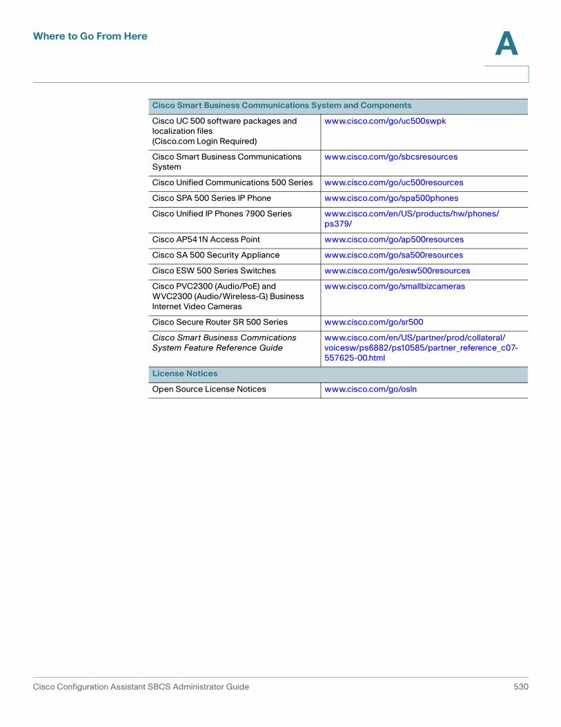
Where to Go From Here A
Cisco Smart Business Communications System and Components
Cisco UC 500 software packages and localization files(Cisco.com Login Required)
www.cisco.com/go/uc500swpk
Cisco Smart Business Communications System
www.cisco.com/go/sbcsresources
Cisco Unified Communications 500 Series www.cisco.com/go/uc500resources
Cisco SPA 500 Series IP Phone www.cisco.com/go/spa500phones
Cisco Unified IP Phones 7900 Series www.cisco.com/en/US/products/hw/phones/ps379/
Cisco AP541N Access Point www.cisco.com/go/ap500resources
Cisco SA 500 Security Appliance www.cisco.com/go/sa500resources
Cisco ESW 500 Series Switches www.cisco.com/go/esw500resources
Cisco PVC2300 (Audio/PoE) and WVC2300 (Audio/Wireless-G) Business Internet Video Cameras
www.cisco.com/go/smallbizcameras
Cisco Secure Router SR 500 Series www.cisco.com/go/sr500
Cisco Smart Business Commications System Feature Reference Guide
www.cisco.com/en/US/partner/prod/collateral/voicesw/ps6882/ps10585/partner_reference_c07-557625-00.html
License Notices
Open Source License Notices www.cisco.com/go/osln
Cisco Configuration Assistant SBCS Administrator Guide 530

Glossary
A
AAA Authentication, authorization and accounting. Pronounced “triple-A.”
ABR Area border router. A router that is located on the border of one or more OSPF areas and that connects the areas to the backbone network. ABRs are considered to be members of both the OSPF backbone and the attached areas. Therefore, they maintain routing tables that describe both the backbone topology and the topology of the areas.
access point A device that serves as a center point in a wireless network or as a connection point between wireless devices and a wired network. See also autonomous access point and LAP (lightweight access point).
access port A port that carries the traffic of one virtual LAN (VLAN). Contrast with trunk port.
access VLAN VLAN that is used by a switch for data traffic. See also native VLAN and voice VLAN.
address aggregation A routing protocol feature that breaks major network addresses into aggregates representing numerically contiguous groups of addresses known as a supernets. This feature automatically suppresses the advertisements of more specific networks on a chosen interface.
advertising The router process of sending routing and service updates at intervals so that other routers can maintain a table of usable routes.
address mask A bit combination used to describe which part of an address refers to the network or the subnet and which part refers to the host. See also IP address and subnet mask.
administrative speed The speed of a link as specified by the administrator. If the administrator specifies auto as the speed, the actual speed is determined through auto-negotiation.
Cisco Configuration Assistant SBCS Administrator Guide 531
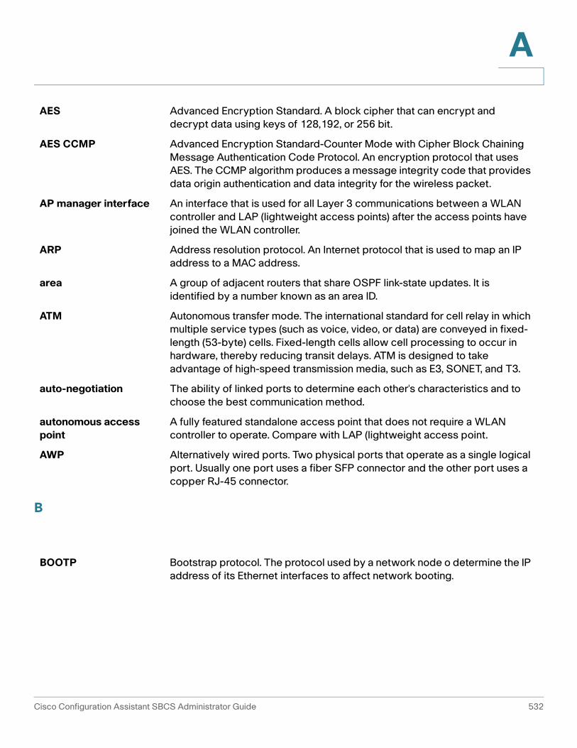
A
B
AES Advanced Encryption Standard. A block cipher that can encrypt and decrypt data using keys of 128,192, or 256 bit.
AES CCMP Advanced Encryption Standard-Counter Mode with Cipher Block Chaining Message Authentication Code Protocol. An encryption protocol that uses AES. The CCMP algorithm produces a message integrity code that provides data origin authentication and data integrity for the wireless packet.
AP manager interface An interface that is used for all Layer 3 communications between a WLAN controller and LAP (lightweight access points) after the access points have joined the WLAN controller.
ARP Address resolution protocol. An Internet protocol that is used to map an IP address to a MAC address.
area A group of adjacent routers that share OSPF link-state updates. It is identified by a number known as an area ID.
ATM Autonomous transfer mode. The international standard for cell relay in which multiple service types (such as voice, video, or data) are conveyed in fixed-length (53-byte) cells. Fixed-length cells allow cell processing to occur in hardware, thereby reducing transit delays. ATM is designed to take advantage of high-speed transmission media, such as E3, SONET, and T3.
auto-negotiation The ability of linked ports to determine each other's characteristics and to choose the best communication method.
autonomous access point
A fully featured standalone access point that does not require a WLAN controller to operate. Compare with LAP (lightweight access point.
AWP Alternatively wired ports. Two physical ports that operate as a single logical port. Usually one port uses a fiber SFP connector and the other port uses a copper RJ-45 connector.
BOOTP Bootstrap protocol. The protocol used by a network node o determine the IP address of its Ethernet interfaces to affect network booting.
Cisco Configuration Assistant SBCS Administrator Guide 532

A
C
CAC Call Admission Control. A process of regulating voice quality by limiting the number of calls that can be active on a particular link at the same time. CAC does not guarantee a particular level of audio quality on the link, but it does allow you to regulate the amount of bandwidth consumed by active calls on the link.
CAS Channel-associated signaling. The transmission of signaling information within the voice channel. CAS signaling often is referred to as robbed-bit signaling because user bandwidth is being robbed by the network for other purposes.
CCKM Cisco Centralized Key Management. A protocol that supports time-sensitive applications such as wireless voice over IP (VoIP). CCKM uses a fast re-keying technique that enables clients to roam from one access point to another without going through the controller.
CDP Cisco Discovery Protocol. A protocol that a device uses to advertise its existence to other devices and to receive information about other devices on the same LAN or on the remote side of a WAN.
CEF Cisco Express Forwarding. An advanced Layer 3 switching technology for IP. CEF optimizes network performance and scalability for networks with large and dynamic traffic patterns, such as those associated with the Internet, web-based applications, and interactive sessions.
CGMP Cisco Group Management Protocol. A protocol that reduces the flooding of IP multicast packets by limiting the transmission of these packets to clients that request them. End stations become clients by sending join messages to join a CGMP group; they send leave messages to leave the group.
clientless mode Provides secure access to private web resources and access to web content.
customer site A group of devices that is managed through the IP addresses of its members. Switches, routers, wireless access controllers, and autonomous access points can be members.
Cisco Configuration Assistant SBCS Administrator Guide 533

A
D
default gateway A node in a network that serves as both an exit point to another network and an entry point from another network.
delay dial he originating end seizes the line and waits 200 ms to see if the far end is on-hook. If so, the originating end then outpulses digits. If the far end is off-hook, the originating end waits until the far end is on-hook before outpulsing digits.
destination-based forwarding
The forwarding of a packet by a port group based on the packet's destination address. Contrast with source-based forwarding.
DHCP Dynamic host configuration protocol. A mechanism for dynamically allocating IP addresses so that addresses can be reused when hosts no longer need them.
DID Direct Inward Dial. A service offered by telephone companies that enables callers to dial directly to an extension on a Private Branch Exchange (PBX) or packet voice system without the assistance of an operator or automated call attendant. This service makes use of DID trunks, which forward only the last three to five digits of a phone number to the PBX or router/gateway.
digest authentication A process for SIP trunks and phones that allows challenge of the identity of a SIP user agent (UA) when the UA sends a request. (A SIP user agent represents a device or application that originates a SIP message.)
DMZ Demilitarized zone. A buffer zone between the Internet, and your private networks. It can be a public network typically used for Web, FTP, and E-Mail servers that are accessed by external clients on the Internet. Placing these public access servers on a separate isolated network provides an extra measure of security for an internal network.
DNS Domain Name Service. An Internet service that translates domain names, which are composed of letters, into IP addresses, which are composed of numbers.
domain name The familiar, easy-to-remember name of a host on the Internet that corresponds to its IP address.
dynamic address A MAC address that is learned on a port. It is stored in the address table and lost when the switch reloads. The first MAC address that is learned when port security is enabled becomes a dynamic secure address. See also static address.
dynamic routing Routing that adjusts automatically to network topology or traffic changes. Also called adaptive routing.
Cisco Configuration Assistant SBCS Administrator Guide 534

A
E
F
EANA Equal Access North American. One of four common forms of CAS signaling; the others are groundstart, loopstart, and E&M.
EAP Extensible Authentication Protocol. An authentication method in which an access point assists a wireless client device and a RADIUS server to perform authentication and to derive a dynamic WEP key.
EIGRP Enhanced Interior Gateway Routing Protocol. A Cisco version of IGRP that provides superior convergence properties and operating efficiency and combines the advantages of link-state protocols with those of distance-vector protocols.
E&M One of four common forms of CAS signaling; the others are loop start, ground start and EANA.
endpoint A SIP terminal or gateway. An endpoint can call and be called. It generates and/or terminates the information stream.
EtherChannel A group of Fast Ethernet or Gigabit Ethernet ports that acts as a single logical port for high-bandwidth connections between switches or between switches and servers. If a port within an EtherChannel fails, traffic previously carried over the failed port transfers to the remaining ports within the EtherChannel.
Ethernet management port
he Ethernet management port is a Layer 3-capable host port to which you can connect a PC. The Ethernet management port can be used instead of the switch console port for network management. This port should be used only to manage the switch. The Ethernet management port supports the Port settings and IP Address features in Cisco Configuration Assistant.
EZVPN Easy VPN. A centralized VPN management solution based on the Cisco Unified Client Framework. A Cisco Easy VPN consists of two components: a Cisco Easy VPN remote client, and a Cisco Easy VPN server.
failover The transfer of responsibilities to a standby switch.
Cisco Configuration Assistant SBCS Administrator Guide 535
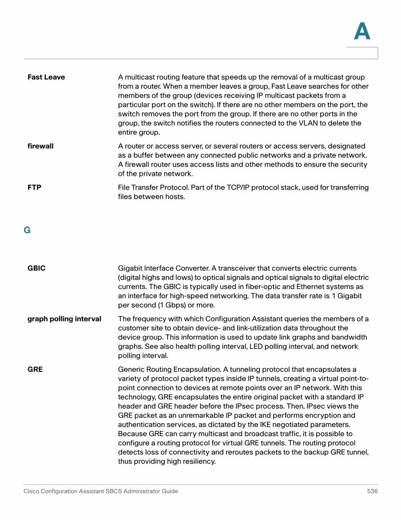
A
G
Fast Leave A multicast routing feature that speeds up the removal of a multicast group from a router. When a member leaves a group, Fast Leave searches for other members of the group (devices receiving IP multicast packets from a particular port on the switch). If there are no other members on the port, the switch removes the port from the group. If there are no other ports in the group, the switch notifies the routers connected to the VLAN to delete the entire group.
firewall A router or access server, or several routers or access servers, designated as a buffer between any connected public networks and a private network. A firewall router uses access lists and other methods to ensure the security of the private network.
FTP File Transfer Protocol. Part of the TCP/IP protocol stack, used for transferring files between hosts.
GBIC Gigabit Interface Converter. A transceiver that converts electric currents (digital highs and lows) to optical signals and optical signals to digital electric currents. The GBIC is typically used in fiber-optic and Ethernet systems as an interface for high-speed networking. The data transfer rate is 1 Gigabit per second (1 Gbps) or more.
graph polling interval The frequency with which Configuration Assistant queries the members of a customer site to obtain device- and link-utilization data throughout the device group. This information is used to update link graphs and bandwidth graphs. See also health polling interval, LED polling interval, and network polling interval.
GRE Generic Routing Encapsulation. A tunneling protocol that encapsulates a variety of protocol packet types inside IP tunnels, creating a virtual point-to-point connection to devices at remote points over an IP network. With this technology, GRE encapsulates the entire original packet with a standard IP header and GRE header before the IPsec process. Then, IPsec views the GRE packet as an unremarkable IP packet and performs encryption and authentication services, as dictated by the IKE negotiated parameters. Because GRE can carry multicast and broadcast traffic, it is possible to configure a routing protocol for virtual GRE tunnels. The routing protocol detects loss of connectivity and reroutes packets to the backup GRE tunnel, thus providing high resiliency.
Cisco Configuration Assistant SBCS Administrator Guide 536

A
H
I
groundstart One of four common forms of T1 CAS signaling. It is primarily an analog signal that can be used on FXS, FXO, or any analog port; the others are EANA, and E&M.
health polling interval he frequency with which Configuration Assistant queries the devices in a customer site to obtain measurements of the utilization of device resources and device temperatures. See also graph polling interval, LED polling interval, and network polling interval.
home network The network on the server side of a VPN tunnel. For example, a guest at a hotel might connect a PC to the hotel network to download a file stored on a server physically located on the guest's corporate network. The connection is established from the hotel network through the Internet to the corporate network by using a VPN tunnel. In this example, the hotel network is the remote network and the corporate network is the home network.
hunt group Number of telephone lines that are associated together by the telephone company central office or a PBX system. When a call comes in to a hunt group, it cycles through the group of lines until it finds one that is not busy, then it rings that phone (or extension, if it is a PBX system).
HSRP Hot Standby Routing Protocol. A protocol that provides high network availability and transparent network topology changes. It creates a device group with a lead device that services all the packets sent to a hot standby address. The lead device is monitored by others in the group; if it fails, one of the other devices inherits the lead position and the hot standby address.
HWIC High-Speed WAN Interface Card. A wireless LAN interface card in the HWIC form-factor that provides integrated access point functionality in Cisco devices with routing capability.
ICMP Internet Control Message Protocol. A network layer Internet protocol that reports errors and provides other information relevant to IP packet processing.
IGMP Internet Group Management Protocol. A protocol used between hosts and routers on the LAN to determine which multicast groups the hosts belong to.
Cisco Configuration Assistant SBCS Administrator Guide 537

A
IGMP snooping The examination by a Layer 2 switch of some Layer 3 information in an IGMP packet sent from a host to a router. The switch determines from its findings whether to add or remove member ports.
IGRP Interior Gateway Routing Protocol. An Interior Gateway Protocol that addresses issues associated with routing in large, heterogeneous networks.
IKE Internet Key Exchange. A key management protocol standard used in conjunction with IPsec and other standards. IPsec can be configured without IKE, but IKE enhances IPsec by providing additional features, flexibility, and ease of configuration for the IPsec standard. IKE provides authentication of the IPsec peers, negotiates IPsec keys, and negotiates IPsec security associations.
Immediate Leave A multicast routing feature that speeds up the removal of a multicast group from a router. When a member indicates that it wants to leave the group, Immediate Leave removes the member port from the group at once.
immediate start The originating end seizes the line by going off-hook and, without waiting for a response, it begins to outpulse digits.
inside interface The first interface that connects the device to your internal, trusted network protected by a security appliance.
IP address A 32-bit address assigned to hosts using TCP/IP. It belongs to one of five classes (A, B, C, D, or E) and is written in four octets separated by periods (dotted decimal format). Each address consists of a network number, an optional subnetwork number, and a host number. The network and subnetwork numbers together are used for routing, and the host number is used to address an individual host within the network or subnetwork. A subnet mask is used to extract network and subnetwork information from the IP address.
IP phone A full-featured telephone that provides voice communication over an IP network.
IPsec A framework of open standards that provides data confidentiality, data integrity, and data authentication between participating peers. IPsec provides these security services at the IP layer. IPsec uses IKE to handle negotiation of protocols and algorithms based on local policy and to generate the encryption and authentication keys to be used by IPsec. IPsec can be used to protect one or more data flows between a pair of hosts, between a pair of security gateways, or between a security gateway and a host.
ISL Inter-Switch Link. A Cisco-proprietary protocol that maintains VLAN information as traffic flows between switches and routers.
Cisco Configuration Assistant SBCS Administrator Guide 538

A
K
L
keysystem A small-scale telephone system designed to handle telephone communications for a small office of 1 to 25 users. Keysystems can be either analog or digital. In a keysystem each phone is able to answer any incoming PSTN call on any line. When multiple calls are present within the system at the same time, each call is visible and can be directly selected by pressing the corresponding line button on an IP phone.
LACP Link Aggregate Control Protocol. The protocol that supports the IEEE 802.3AD specification for bundling physical interfaces together to form a single logical interface.
LED polling interval The frequency with which Configuration Assistant polls the ports in a customer site</a> and displays changes in the LED colors of ports. See also graph polling interval, health polling interval, and network polling interval.
lightweight access point
An access point that cannot act independently of a WLAN controller. The WLAN controller manages the AP configurations and firmware. No individual configuration of these access points is necessary. They handle only real-time MAC functionality and leave non-realtime MAC functionality to be processed by the WLAN controller. This architecture is referred to as the split MAC architecture. Compare with autonomous access point.
link state protocol A type of routing protocol</a> that maintains a map of the internetwork, allowing it to see alternate routes or parallel paths for load balancing. OSPF is an example of this protocol type. Contrast with distance-vector protocol.
LEAP Lightweight Extensible Authentication Protocol. An 802.1X authentication type for wireless LANs that supports strong mutual authentication between the client and a RADIUS server using a logon password as the shared secret. It provides dynamic per-user, per-session encryption keys.
link-state protocol A type of routing protocol that maintains a map of the internetwork, allowing it to see alternate routes or parallel paths for load balancing. OSPF is an example of this protocol type. Contrast with distance-vector protocol.
Cisco Configuration Assistant SBCS Administrator Guide 539

A
M
N
local span A SPAN session in which all the source and destination ports are on the same switch. Contrast with remote SPAN.
loopstart One of four common forms of T1 CAS signaling, but it is primarily an analog signal that can be used on FXS, FXO, or any analog port; the others are groundstart, EANA, and E&M.
MAC Media Access Control. The lower of the two sublayers of the data link layer defined by the IEEE. The MAC sublayer determines access to shared media, such as whether token passing or contention is used.
MAC address The standardized data link layer address that is required for every port or device that connects to a LAN. Other devices in the network use these addresses to locate specific ports in the network and to create and update routing tables and data structures. MAC addresses are 6 bytes long and are controlled by the IEEE.
management interface The default interface for managing a device. Media Access Control. The lower of the two sublayers of the data link layer defined by the IEEE. The MAC sublayer determines access to shared media, such as whether token passing or contention is used.
multicast routing A routing technique that allows copies of a single packet to be passed to a selected subset of all possible destinations. Contrast with unicast routing.
MWI server The SIP MWI (message waiting indicator) server is a proxy server that relays SIP MWI messages.
NAT Network Address Translation. A mechanism for reducing the need for globally unique IP addresses. NAT allows an organization with IP addresses that are not globally unique to connect to the Internet by translating those addresses into globally routable IP addresses.
native VLAN The VLAN that carries untagged packets from an IEEE 802.1Q trunk port. See also access VLAN and voice VLAN.
Cisco Configuration Assistant SBCS Administrator Guide 540

A
O
network EAP An authentication method in which the access point assists a wireless client device and the RADIUS server to perform authentication and to derive a dynamic WEP key.
network polling interval The frequency with which Configuration Assistant polls the members of a customer site to determine the status of the device group and the existence of new members. See also graph polling interval, health polling interval, and LED polling interval.
network port A port to which the switch forwards all VLAN traffic with unknown destination addresses; this process helps to prevent flooding to all the ports in a VLAN.
notification name The name of a collection of information that specifies types of system events and an e-mail address to which notification of these events is sent.
NTP Network time protocol. A protocol that ensures accurate local time-keeping with reference to radio and atomic clocks located on the Internet.
open authentication An authentication method that allows any device to authenticate and then attempts to communicate with the access point.
open authentication with EAP
An authentication method in which the access point forces all client devices to perform EAP authentication before they can join the network.
OSPF Open Shortest Path First. A link-state protocol that imposes no limit on hop count, propagates routing changes instantaneously, supports variable-length subnet masks, and allows for load balancing based on the actual cost of the link. It also compartmentalizes networks into smaller regions called areas, which limits the traffic caused by link-state updates.
outside interface The first interface, usually port 0, that connects to other untrusted networks outside the security appliance; a WAN or the Internet.
Cisco Configuration Assistant SBCS Administrator Guide 541

A
P
PAT Port address translation. Conserves addresses in the global address pool by allowing source ports in TCP connections or UDP conversations to be translated. Different local addresses then map to the same global address, with port translation providing the necessary uniqueness. Global pool addresses are always used before a PAT address is used.
pickup group Allows administrators to associate pickup groups with individual IP phones, making it easier for phone users to answer, or pick up, a call that is ringing on a different extension or telephone number.
PBX Private branch exchange. Digital or analog telephone switchboard located on the subscriber premises and used to connect private and public telephone networks.
PKI public-key infrastructure. A system of certification authorities (CAs) and registration authorities (RAs) that provides support for the use of asymmetric key cryptography in data communication through such functions as certificate management, archive management, key management, and token management. Alternatively, any standard for the exchange of asymmetric keys. This type of exchange allows the recipient of a message to trust the signature in that message, and allows the sender of a message to encrypt it appropriately for the intended recipient. See key management.
PPPoE Point-to-Point Protocol over Ethernet. PPP encapsulated in Ethernet frames. PPPoE enables hosts on an Ethernet network to connect to remote hosts through a broadband modem.
PoE Power over Ethernet. A technology that provides power to connected devices through the data cables rather than by power cords.
polling interval See graph polling interval, LED polling interval, and network polling interval.
preshared key An authentication method offered in IPsec. Preshared keys allow for one or more clients to use individual shared secrets to authenticate encrypted tunnels to a gateway using IKE (Internet Key Exchange). Preshared keys are commonly used in small networks of up to 10 clients. With preshared keys, there is no need to involve a certification authority for security.
privilege level A number that determines the level of Configuration Assistant access that is granted to a user. Level 15 grants read-write access; levels 1 to 14 grant read-only access.
Cisco Configuration Assistant SBCS Administrator Guide 542

A
Q
R
PSTN Public switched telephone network. General term referring to the variety of telephone networks and services in place worldwide.
QoS Quality of Service. Refers to the capability of a network to provide better service to selected network traffic. The primary goal of QoS is to provide priority including dedicated bandwidth, controlled jitter and latency (required by some real-time and interactive traffic), and improved loss characteristics.
RADIUS Remote Authentication Dial-In User Service. A database for authenticating modem and ISDN connections and for tracking connection time.
remote network The network on the client side of a VPN tunnel. For example, a guest at a hotel might connect a PC to the hotel network to download a file stored on a server physically located on the guest's corporate network. The connection is established from the hotel network through the Internet to the corporate network by using a VPN tunnel. In this example, the hotel network is the remote network and the corporate network is the home network.
remote span A SPAN session in which the source ports are located remotely from the switch containing the destination port. Contrast with local SPAN.
RIP Routing Information Protocol. The most common Interior Gateway Protocol in the Internet. It uses a hop count as a routing metric.
root port The switch port with the best path to the root switch.
root switch The switch selected to be the center of a spanning-tree topology. All data flow across the network is from the perspective of this switch.
routable interface A routed port or an SVI.
routing protocol A set of rules and conventions for gathering information about available networks, such as the distance or cost to reach them, and determining the routing path for a packet.
Cisco Configuration Assistant SBCS Administrator Guide 543

A
S
secure address A MAC address that is forwarded to only one port per VLAN. Secure addresses are retained even when the switch reloads. See also dynamic address and static address.
secure port A port for which a user-specified action occurs whenever an address-security violation occurs.
SDP 1. Session Description Protocol. A protocol for defining information needed to establish multimedia transport over IP. SDP transmits information such as session announcement, session invitation, transport addresses, and media types. For example, in a SIP call, SDP messages indicates if NTE is used, which events to send using NTE, and the NTE payload type value.
2. Secure Device Provisioning. Deploys PKI (public key infrastructure) between two end devices, such as a Cisco IOS client and a Cisco IOS certificate server.
SFP Small form-factor pluggable. A field-replaceable laser optical transceiver module. SFP modules provide Gigabit uplink connections to other switches.
SFTP SSH File Transfer Protocol. SFTP is part of SSH and is always enabled on the router. A user with the appropriate level can copy files to and from the router by using SFTP.
shared authentication An authentication method in which the access point sends an unencrypted challenge text string to any device attempting to communicate with it. If the challenge text is correctly encrypted, the access point allows the requesting device to authenticate.
SIP Session Initiation Protocol. Enables call handling sessions, particularly two-party audio conferences. SIP works with Session Description Protocol (SDP) for call signaling. Using SIP, the router can support any SIP Voice over IP (VoIP) gateways and VoIP proxy servers.
SMTP Simple Mail Transfer Protocol. An Internet protocol that provides e-mail services.
SNMP Simple Network Management Protocol. A protocol in TCP/IP networks that provides a means to monitor and control network devices and to manage configurations, statistics collection, performance, and security.
source-based forwarding
The forwarding of a packet by a port group based on the packet source address. Contrast with destination-based forwarding.
Cisco Configuration Assistant SBCS Administrator Guide 544

A
split tunneling Split tunneling allows VPN clients to communicate locally unencrypted. Users send only that traffic which is destined for the home network across the tunnel. All other traffic, such as instant messaging, e-mail, or casual Internet browsing, is sent out to the Internet by using the local LAN of the VPN Client.
SPAN Switched Port Analyzer. A feature that is used to specify a set of ports (or VLANs) to be monitored. A copy of the traffic on these source ports is sent to a specified destination port. Typically, a user connects a network analyzer to the destination port to view the traffic on the source ports. See also local SPAN and remote SPAN.
spanning tree protocol See STP.
static secure address A manually configured secure address that is stored in the address table and added to the running configuration. See also dynamic address</a> and sticky MAC address.
SSH Secure Shell. An application running on top of a reliable transport layer, such as TCP/IP, that provides strong authentication and encryption capabilities.
SSID Service set identifier. A code attached to packets on a wireless network to identify each packet as part of that network. All wireless devices attempting to communicate with each other must associate with the same SSID.
static route A route that is explicitly configured and entered into the routing table. Static routes take precedence over routes chosen by dynamic routing protocols.
STP Spanning Tree Protocol. A standardized technique for maintaining a network of multiple bridges or switches. When a network topology changes, STP prevents the creation of loops by transparently reconfiguring bridges and switches and placing ports in a forwarding or blocking state. Each VLAN is treated as a separate bridge, and a separate instance of STP is applied to each.
subnet mask A 32-bit address mask used in IP to show which bits of an IP address identify the network number, the subnetwork number, and the node number.
switch port A Layer 2-only interface that is associated with a physical port. It can be either an access port or a trunk port.
SVI Switch virtual interface. A VLAN with an assigned IP address that Layer 3 devices use to access the VLAN. An SVI can be configured to route packets from one VLAN to another.
Cisco Configuration Assistant SBCS Administrator Guide 545

A
T
U
V
TCP Transmission Control Protocol. A connection-oriented transport layer protocol that provides reliable full duplex data-transmission. TCP is part of the TCP/IP protocol stack.
TCP/IP The common name for a suite of protocols that support the construction of worldwide internetworks.
Telnet A terminal emulation protocol for TCP/IP networks such as the Internet. Telnet is a common way to control web servers remotely.
TFTP Trivial File Transfer Protocol. A simplified version of FTP that allows files to be transferred from one computer to another over a network, usually without the use of client authentication (for example, username and password).
TKIP Temporal Key Integrity Protocol. An encryption that defends against an attack on WEP in which the intruder uses an unencrypted segment called the initialization vector (IV) in encrypted packets to calculate the WEP key.
trunk port A port that carries the traffic of multiple VLANs. Contrast with access port.
tunnel A virtual channel through a shared medium such as the Internet, used for the exchange of encapsulated data packets.
UDP User Datagram Protocol. A connectionless transport layer protocol in the TCP/IP stack. UDP is a simple protocol that exchanges datagrams without acknowledgments or guaranteed delivery, requiring that error processing and retransmission be handled by other protocols.
unicast routing A routing technique that routes a packet to a single destination and uses a routing protocol to determine the path to that destination. Contrast with multicast routing.
virtual interface An interface that acts as the DHCP server placeholder for wireless clients that obtain their IP address from a DHCP server and that serves as the redirect address for the web authentication login window.
Cisco Configuration Assistant SBCS Administrator Guide 546

A
W
VLAN Virtual LAN. A logical rather than a physical LAN comprising workgroups drawn together for business reasons or for a particular project, irrespective of each member's actual location.
VPN virtual private network. The same network security and privacy over a public infrastructure as would be provided over a private network. VPNs enable IP traffic to travel securely over a public TCP/IP network by encrypting all traffic from one network to another. A VPN uses tunneling to encrypt all information at the IP level.
VTP VLAN Trunking Protocol. A Layer 2 messaging protocol that maintains VLAN configuration consistency by managing the addition, deletion, and renaming of VLANs on a network-wide basis.
VTP pruning The blocking of flooded broadcast, multicast, and unknown unicast traffic to VLANs on trunk ports that are included in the pruning-eligible list.
voice VLAN A VLAN that is used by a switch for voice traffic from IP phones. See also access VLAN and native VLAN.
WEP Wired Equivalent Privacy. An encryption that scrambles the communication between the access point and client devices to keep communication private. Both the access point and the client device use the same WEP key to encrypt and unencrypt radio signals.
wink start The originating end seizes the line by going off-hook. It waits for acknowledgement from the other end before outpulsing digits. This serves as an integrity check that identifies a malfunctioning trunk and allow the network to send a re-order tone to the calling party.
WINS Windows Internet Naming Service. A Windows system that determines the IP address associated with a particular network computer.
WMM Wireless Multimedia. A QOS enhancement for wireless LANs. WMM supports devices that meet the 802.11E QoS Basic Service Set (QBSS) standard. WMM enables differentiated services for voice, video, and best-effort data to allow voice traffic to be handled before other traffic on the network.
Cisco Configuration Assistant SBCS Administrator Guide 547

A
WPA Wi-Fi Protected Access. A standards-based, interoperable security enhancement that increases the level of data protection and access control for wireless LAN systems. Using WPA key management, clients and the authentication server authenticate to each other by using an EAP authentication method, and the client and server generate a pair-wise master key (PMK). WPA uses TKIP for data protection and IEEE 802.1X for authenticated key management.
WPA2 Wi-Fi Protected Access 2. A standards-based, interoperable security enhancement that uses AES CCMP for data protection. WPA2 offers a higher level of security than WPA because AES offers stronger encryption than TKIP.
WPA-PSK Wi-Fi Protected Access-Pre-shared key. An authentication method that supports WPA on a wireless LAN where IEEE 802.1X-based authentication is not available. A pre-shared key is configured on both the client and the access point.
WPA2-PSK Wi-Fi Protected Access 2-Preshared key. An authentication method that supports WPA2 on a wireless LAN where IEEE 802.1X-based authentication is not available. A preshared key is configured on both the client and the access point.
Cisco Configuration Assistant SBCS Administrator Guide 548