
Exam Ref 70-410: Installing and Configuring Windows Server 2012 EBook
Upload
khangminh22Category
view
5download
0
Power Systems
Installing and configuring theHardware Management Console
IBM


Power Systems
Installing and configuring theHardware Management Console
IBM

NoteBefore using this information and the product it supports, read the information in “Safety notices” on page v, “Notices” onpage 85, the IBM Systems Safety Notices manual, G229-9054, and the IBM Environmental Notices and User Guide, Z125–5823.
This edition applies to IBM Hardware Management Console Version 9 Release 9.1.0 Maintenance Level 0 and to allsubsequent releases and modifications until otherwise indicated in new editions.
© Copyright IBM Corporation 2018.US Government Users Restricted Rights – Use, duplication or disclosure restricted by GSA ADP Schedule Contractwith IBM Corp.

Contents
Safety notices . . . . . . . . . . . . . . . . . . . . . . . . . . . . . . . . . v
Installing and configuring the Hardware Management Console . . . . . . . . . . . . 1Installation and configuration tasks . . . . . . . . . . . . . . . . . . . . . . . . . . . . 1
Installing and configuring a new HMC with a new server . . . . . . . . . . . . . . . . . . . 1Updating and upgrading your HMC code . . . . . . . . . . . . . . . . . . . . . . . . 1Adding a second HMC to an existing installation . . . . . . . . . . . . . . . . . . . . . . 2
Setting up the HMC . . . . . . . . . . . . . . . . . . . . . . . . . . . . . . . . . 2Installing the 7042-CR9 HMC into a rack . . . . . . . . . . . . . . . . . . . . . . . . . 3Installing the 7063-CR1 into a rack. . . . . . . . . . . . . . . . . . . . . . . . . . . 11
Prerequisites for installing the rack-mounted 7063-CR1 system . . . . . . . . . . . . . . . . 12Completing inventory for your system . . . . . . . . . . . . . . . . . . . . . . . . 12Determining and marking the location in the rack for the 7063-CR1 system . . . . . . . . . . . . 13Attaching the fixed rails to the system chassis and to the rack . . . . . . . . . . . . . . . . 14Installing the system into the rack and connecting and routing power cables . . . . . . . . . . . 16Cabling the rack-mounted 7063-CR1 HMC . . . . . . . . . . . . . . . . . . . . . . . 17Configuring the 7063-CR1 HMC . . . . . . . . . . . . . . . . . . . . . . . . . . 18
Installing the HMC virtual appliance . . . . . . . . . . . . . . . . . . . . . . . . . . 21Installing the HMC virtual appliance on x86 . . . . . . . . . . . . . . . . . . . . . . 21
Installing the HMC virtual appliance by using the KVM hypervisor . . . . . . . . . . . . . 22Installing the HMC virtual appliance by using the Xen hypervisor . . . . . . . . . . . . . . 22Installing the HMC virtual appliance by using VMware ESXi. . . . . . . . . . . . . . . . 23
Installing the HMC virtual appliance on POWER . . . . . . . . . . . . . . . . . . . . . 24Installing the HMC virtual appliance on PowerVM (logical partition) . . . . . . . . . . . . . 24
Using the Activation Engine for the HMC virtual appliance . . . . . . . . . . . . . . . . . 27Setting up the configuration profile for the Activation Engine . . . . . . . . . . . . . . . 28
Configuring the HMC . . . . . . . . . . . . . . . . . . . . . . . . . . . . . . . . 34Choosing network settings on the HMC . . . . . . . . . . . . . . . . . . . . . . . . . 34
HMC network connections . . . . . . . . . . . . . . . . . . . . . . . . . . . . 34Types of HMC network connections . . . . . . . . . . . . . . . . . . . . . . . . 35Deciding which connectivity method to use for the call-home server . . . . . . . . . . . . . 40Using internet SSL to connect to remote support . . . . . . . . . . . . . . . . . . . . 41Choosing an Internet Protocol . . . . . . . . . . . . . . . . . . . . . . . . . . 42Internet SSL address lists . . . . . . . . . . . . . . . . . . . . . . . . . . . . 42Using multiple call-home servers . . . . . . . . . . . . . . . . . . . . . . . . . 43
Preparing for HMC configuration . . . . . . . . . . . . . . . . . . . . . . . . . . 43Preinstallation configuration worksheet for the HMC . . . . . . . . . . . . . . . . . . . 44
Configuring the HMC . . . . . . . . . . . . . . . . . . . . . . . . . . . . . . . 51Configuring the HMC by using the fast path through the Guided Setup wizard . . . . . . . . . . 51Configuring the HMC by using the menus . . . . . . . . . . . . . . . . . . . . . . . 51
Starting the HMC . . . . . . . . . . . . . . . . . . . . . . . . . . . . . . 52Changing the date and time . . . . . . . . . . . . . . . . . . . . . . . . . . . 53Configuring the HMC network types . . . . . . . . . . . . . . . . . . . . . . . . 53Changing HMC firewall settings . . . . . . . . . . . . . . . . . . . . . . . . . 60Configuring a routing entry as the default gateway . . . . . . . . . . . . . . . . . . . 62Configuring domain name services . . . . . . . . . . . . . . . . . . . . . . . . 62Configuring domain suffixes. . . . . . . . . . . . . . . . . . . . . . . . . . . 62Configuring the HMC so that it uses LDAP remote authentication . . . . . . . . . . . . . . 63Configuring the HMC so that it uses Key Distribution Center servers for Kerberos remote authentication 64Configuring the local console to report errors to service and support . . . . . . . . . . . . . 65Configuring the Events Manager for Call Home . . . . . . . . . . . . . . . . . . . . 68Setting passwords for the managed system . . . . . . . . . . . . . . . . . . . . . . 69Testing the connection between the HMC and the managed system . . . . . . . . . . . . . 70
Postconfiguration steps . . . . . . . . . . . . . . . . . . . . . . . . . . . . . . 71Backing up management console data . . . . . . . . . . . . . . . . . . . . . . . . 71
© Copyright IBM Corp. 2018 iii

Updating, upgrading, and migrating your HMC machine code . . . . . . . . . . . . . . . . . 72Determining your HMC machine code version and release . . . . . . . . . . . . . . . . . 72Obtaining and applying machine code updates for the HMC with an Internet connection . . . . . . . 73
Step 1. Ensure that you have an Internet connection . . . . . . . . . . . . . . . . . . . 73Step 2. View the existing HMC machine code level . . . . . . . . . . . . . . . . . . . 73Step 3. View the available HMC machine code levels . . . . . . . . . . . . . . . . . . 74Step 4. Apply the HMC machine code update . . . . . . . . . . . . . . . . . . . . . 74Step 5. Verify that the HMC machine code update installed successfully . . . . . . . . . . . . 74
Obtaining and applying machine code updates for the HMC using DVD or an FTP server . . . . . . . 75Step 1. View the existing HMC machine code level . . . . . . . . . . . . . . . . . . . 75Step 2. View the available HMC machine code levels . . . . . . . . . . . . . . . . . . 75Step 3. Obtain the HMC machine code update. . . . . . . . . . . . . . . . . . . . . 76Step 4. Apply the HMC machine code update . . . . . . . . . . . . . . . . . . . . . 76Step 5. Verify that the HMC machine code update installed successfully . . . . . . . . . . . . 77
Upgrading your HMC software . . . . . . . . . . . . . . . . . . . . . . . . . . 77Step 1. Obtain the upgrade . . . . . . . . . . . . . . . . . . . . . . . . . . . 77Step 2. View the existing HMC machine code level . . . . . . . . . . . . . . . . . . . 78Step 3. Back up the managed system's profile data . . . . . . . . . . . . . . . . . . . 78Step 4. Back up HMC data . . . . . . . . . . . . . . . . . . . . . . . . . . . 78Step 5. Record the current HMC configuration information . . . . . . . . . . . . . . . . 79Step 6. Record remote command status . . . . . . . . . . . . . . . . . . . . . . . 80Step 7. Save upgrade data . . . . . . . . . . . . . . . . . . . . . . . . . . . 80Step 8. Upgrade the HMC software . . . . . . . . . . . . . . . . . . . . . . . . 81Step 9. Verify that the HMC machine code upgrade installed successfully . . . . . . . . . . . 81
Upgrading HMC from remote location by using network upgrade images . . . . . . . . . . . . 82HMC port locations . . . . . . . . . . . . . . . . . . . . . . . . . . . . . . . . 82
Notices . . . . . . . . . . . . . . . . . . . . . . . . . . . . . . . . . . . 85Accessibility features for IBM Power Systems servers . . . . . . . . . . . . . . . . . . . . . 86Privacy policy considerations . . . . . . . . . . . . . . . . . . . . . . . . . . . . . 87Trademarks . . . . . . . . . . . . . . . . . . . . . . . . . . . . . . . . . . . 88Electronic emission notices . . . . . . . . . . . . . . . . . . . . . . . . . . . . . . 88
Class A Notices . . . . . . . . . . . . . . . . . . . . . . . . . . . . . . . . . 88Class B Notices . . . . . . . . . . . . . . . . . . . . . . . . . . . . . . . . . 92
Terms and conditions . . . . . . . . . . . . . . . . . . . . . . . . . . . . . . . . 95
iv Power Systems: Installing and configuring the Hardware Management Console

Safety notices
Safety notices may be printed throughout this guide:v DANGER notices call attention to a situation that is potentially lethal or extremely hazardous to
people.v CAUTION notices call attention to a situation that is potentially hazardous to people because of some
existing condition.v Attention notices call attention to the possibility of damage to a program, device, system, or data.
World Trade safety information
Several countries require the safety information contained in product publications to be presented in theirnational languages. If this requirement applies to your country, safety information documentation isincluded in the publications package (such as in printed documentation, on DVD, or as part of theproduct) shipped with the product. The documentation contains the safety information in your nationallanguage with references to the U.S. English source. Before using a U.S. English publication to install,operate, or service this product, you must first become familiar with the related safety informationdocumentation. You should also refer to the safety information documentation any time you do notclearly understand any safety information in the U.S. English publications.
Replacement or additional copies of safety information documentation can be obtained by calling the IBMHotline at 1-800-300-8751.
German safety information
Das Produkt ist nicht für den Einsatz an Bildschirmarbeitsplätzen im Sinne § 2 derBildschirmarbeitsverordnung geeignet.
Laser safety information
IBM® servers can use I/O cards or features that are fiber-optic based and that utilize lasers or LEDs.
Laser compliance
IBM servers may be installed inside or outside of an IT equipment rack.
DANGER: When working on or around the system, observe the following precautions:
Electrical voltage and current from power, telephone, and communication cables are hazardous. To avoida shock hazard:v If IBM supplied the power cord(s), connect power to this unit only with the IBM provided power cord.
Do not use the IBM provided power cord for any other product.v Do not open or service any power supply assembly.v Do not connect or disconnect any cables or perform installation, maintenance, or reconfiguration of this
product during an electrical storm.v The product might be equipped with multiple power cords. To remove all hazardous voltages,
disconnect all power cords.– For AC power, disconnect all power cords from their AC power source.– For racks with a DC power distribution panel (PDP), disconnect the customer’s DC power source to
the PDP.v When connecting power to the product ensure all power cables are properly connected.
© Copyright IBM Corp. 2018 v

– For racks with AC power, connect all power cords to a properly wired and grounded electricaloutlet. Ensure that the outlet supplies proper voltage and phase rotation according to the systemrating plate.
– For racks with a DC power distribution panel (PDP), connect the customer’s DC power source tothe PDP. Ensure that the proper polarity is used when attaching the DC power and DC powerreturn wiring.
v Connect any equipment that will be attached to this product to properly wired outlets.v When possible, use one hand only to connect or disconnect signal cables.v Never turn on any equipment when there is evidence of fire, water, or structural damage.v Do not attempt to switch on power to the machine until all possible unsafe conditions are corrected.v Assume that an electrical safety hazard is present. Perform all continuity, grounding, and power checks
specified during the subsystem installation procedures to ensure that the machine meets safetyrequirements.
v Do not continue with the inspection if any unsafe conditions are present.v Before you open the device covers, unless instructed otherwise in the installation and configuration
procedures: Disconnect the attached AC power cords, turn off the applicable circuit breakers located inthe rack power distribution panel (PDP), and disconnect any telecommunications systems, networks,and modems.
DANGER:v Connect and disconnect cables as described in the following procedures when installing, moving, or
opening covers on this product or attached devices.To Disconnect:1. Turn off everything (unless instructed otherwise).2. For AC power, remove the power cords from the outlets.3. For racks with a DC power distribution panel (PDP), turn off the circuit breakers located in the
PDP and remove the power from the Customer's DC power source.4. Remove the signal cables from the connectors.5. Remove all cables from the devices.
To Connect:1. Turn off everything (unless instructed otherwise).2. Attach all cables to the devices.3. Attach the signal cables to the connectors.4. For AC power, attach the power cords to the outlets.5. For racks with a DC power distribution panel (PDP), restore the power from the Customer's DC
power source and turn on the circuit breakers located in the PDP.6. Turn on the devices.
Sharp edges, corners and joints may be present in and around the system. Use care when handlingequipment to avoid cuts, scrapes and pinching. (D005)
(R001 part 1 of 2):
DANGER: Observe the following precautions when working on or around your IT rack system:v Heavy equipment–personal injury or equipment damage might result if mishandled.v Always lower the leveling pads on the rack cabinet.v Always install stabilizer brackets on the rack cabinet.v To avoid hazardous conditions due to uneven mechanical loading, always install the heaviest devices
in the bottom of the rack cabinet. Always install servers and optional devices starting from the bottomof the rack cabinet.
v Rack-mounted devices are not to be used as shelves or work spaces. Do not place objects on top ofrack-mounted devices. In addition, do not lean on rack mounted devices and do not use them tostabilize your body position (for example, when working from a ladder).
vi Power Systems: Installing and configuring the Hardware Management Console

v Each rack cabinet might have more than one power cord.– For AC powered racks, be sure to disconnect all power cords in the rack cabinet when directed to
disconnect power during servicing.– For racks with a DC power distribution panel (PDP), turn off the circuit breaker that controls the
power to the system unit(s), or disconnect the customer’s DC power source, when directed todisconnect power during servicing.
v Connect all devices installed in a rack cabinet to power devices installed in the same rack cabinet. Donot plug a power cord from a device installed in one rack cabinet into a power device installed in adifferent rack cabinet.
v An electrical outlet that is not correctly wired could place hazardous voltage on the metal parts of thesystem or the devices that attach to the system. It is the responsibility of the customer to ensure thatthe outlet is correctly wired and grounded to prevent an electrical shock.
(R001 part 2 of 2):
CAUTION:
v Do not install a unit in a rack where the internal rack ambient temperatures will exceed themanufacturer's recommended ambient temperature for all your rack-mounted devices.
v Do not install a unit in a rack where the air flow is compromised. Ensure that air flow is not blockedor reduced on any side, front, or back of a unit used for air flow through the unit.
v Consideration should be given to the connection of the equipment to the supply circuit so thatoverloading of the circuits does not compromise the supply wiring or overcurrent protection. Toprovide the correct power connection to a rack, refer to the rating labels located on the equipment inthe rack to determine the total power requirement of the supply circuit.
v (For sliding drawers.) Do not pull out or install any drawer or feature if the rack stabilizer brackets arenot attached to the rack. Do not pull out more than one drawer at a time. The rack might becomeunstable if you pull out more than one drawer at a time.
v (For fixed drawers.) This drawer is a fixed drawer and must not be moved for servicing unless specifiedby the manufacturer. Attempting to move the drawer partially or completely out of the rack mightcause the rack to become unstable or cause the drawer to fall out of the rack.
Safety notices vii

CAUTION:Removing components from the upper positions in the rack cabinet improves rack stability duringrelocation. Follow these general guidelines whenever you relocate a populated rack cabinet within aroom or building.
v Reduce the weight of the rack cabinet by removing equipment starting at the top of the rackcabinet. When possible, restore the rack cabinet to the configuration of the rack cabinet as youreceived it. If this configuration is not known, you must observe the following precautions:
– Remove all devices in the 32U position (compliance ID RACK-001 or 22U (compliance ID RR001)and above.
– Ensure that the heaviest devices are installed in the bottom of the rack cabinet.
– Ensure that there are little-to-no empty U-levels between devices installed in the rack cabinetbelow the 32U (compliance ID RACK-001 or 22U (compliance ID RR001) level, unless thereceived configuration specifically allowed it.
v If the rack cabinet you are relocating is part of a suite of rack cabinets, detach the rack cabinet fromthe suite.
v If the rack cabinet you are relocating was supplied with removable outriggers they must bereinstalled before the cabinet is relocated.
v Inspect the route that you plan to take to eliminate potential hazards.
v Verify that the route that you choose can support the weight of the loaded rack cabinet. Refer to thedocumentation that comes with your rack cabinet for the weight of a loaded rack cabinet.
v Verify that all door openings are at least 760 x 230 mm (30 x 80 in.).
v Ensure that all devices, shelves, drawers, doors, and cables are secure.
v Ensure that the four leveling pads are raised to their highest position.
v Ensure that there is no stabilizer bracket installed on the rack cabinet during movement.
v Do not use a ramp inclined at more than 10 degrees.
v When the rack cabinet is in the new location, complete the following steps:
– Lower the four leveling pads.
– Install stabilizer brackets on the rack cabinet.
– If you removed any devices from the rack cabinet, repopulate the rack cabinet from the lowestposition to the highest position.
v If a long-distance relocation is required, restore the rack cabinet to the configuration of the rackcabinet as you received it. Pack the rack cabinet in the original packaging material, or equivalent.Also lower the leveling pads to raise the casters off of the pallet and bolt the rack cabinet to thepallet.
(R002)
(L001)
DANGER: Hazardous voltage, current, or energy levels are present inside any component that has thislabel attached. Do not open any cover or barrier that contains this label. (L001)
(L002)
viii Power Systems: Installing and configuring the Hardware Management Console

DANGER: Rack-mounted devices are not to be used as shelves or work spaces. (L002)
(L003)
1 2
or
!
1
2
or
1 2
3 4
or
Safety notices ix

12
34
or
DANGER: Multiple power cords. The product might be equipped with multiple AC power cords ormultiple DC power cables. To remove all hazardous voltages, disconnect all power cords and powercables. (L003)
(L007)
CAUTION: A hot surface nearby. (L007)
(L008)
x Power Systems: Installing and configuring the Hardware Management Console

CAUTION: Hazardous moving parts nearby. (L008)
All lasers are certified in the U.S. to conform to the requirements of DHHS 21 CFR Subchapter J for class1 laser products. Outside the U.S., they are certified to be in compliance with IEC 60825 as a class 1 laserproduct. Consult the label on each part for laser certification numbers and approval information.
CAUTION:This product might contain one or more of the following devices: CD-ROM drive, DVD-ROM drive,DVD-RAM drive, or laser module, which are Class 1 laser products. Note the following information:
v Do not remove the covers. Removing the covers of the laser product could result in exposure tohazardous laser radiation. There are no serviceable parts inside the device.
v Use of the controls or adjustments or performance of procedures other than those specified hereinmight result in hazardous radiation exposure.
(C026)
CAUTION:Data processing environments can contain equipment transmitting on system links with laser modulesthat operate at greater than Class 1 power levels. For this reason, never look into the end of an opticalfiber cable or open receptacle. Although shining light into one end and looking into the other end ofa disconnected optical fiber to verify the continuity of optic fibers may not injure the eye, thisprocedure is potentially dangerous. Therefore, verifying the continuity of optical fibers by shininglight into one end and looking at the other end is not recommended. To verify continuity of a fiberoptic cable, use an optical light source and power meter. (C027)
CAUTION:This product contains a Class 1M laser. Do not view directly with optical instruments. (C028)
CAUTION:Some laser products contain an embedded Class 3A or Class 3B laser diode. Note the followinginformation: laser radiation when open. Do not stare into the beam, do not view directly with opticalinstruments, and avoid direct exposure to the beam. (C030)
CAUTION:The battery contains lithium. To avoid possible explosion, do not burn or charge the battery.
Do Not:v ___ Throw or immerse into waterv ___ Heat to more than 100°C (212°F)v ___ Repair or disassemble
Exchange only with the IBM-approved part. Recycle or discard the battery as instructed by localregulations. In the United States, IBM has a process for the collection of this battery. For information,call 1-800-426-4333. Have the IBM part number for the battery unit available when you call. (C003)
Safety notices xi

CAUTION:Regarding IBM provided VENDOR LIFT TOOL:v Operation of LIFT TOOL by authorized personnel only.v LIFT TOOL intended for use to assist, lift, install, remove units (load) up into rack elevations. It is
not to be used loaded transporting over major ramps nor as a replacement for such designated toolslike pallet jacks, walkies, fork trucks and such related relocation practices. When this is notpracticable, specially trained persons or services must be used (for instance, riggers or movers).
v Read and completely understand the contents of LIFT TOOL operator's manual before using.Failure to read, understand, obey safety rules, and follow instructions may result in propertydamage and/or personal injury. If there are questions, contact the vendor's service and support.Local paper manual must remain with machine in provided storage sleeve area. Latest revisionmanual available on vendor's web site.
v Test verify stabilizer brake function before each use. Do not over-force moving or rolling the LIFTTOOL with stabilizer brake engaged.
v Do not move LIFT TOOL while platform is raised, except for minor positioning.v Do not exceed rated load capacity. See LOAD CAPACITY CHART regarding maximum loads at
center versus edge of extended platform.v Only raise load if properly centered on platform. Do not place more than 200 lb (91 kg) on edge of
sliding platform shelf also considering the load's center of mass/gravity (CoG).v Do not corner load the platform tilt riser accessory option. Secure platform riser tilt option to main
shelf in all four (4x) locations with provided hardware only, prior to use. Load objects are designedto slide on/off smooth platforms without appreciable force, so take care not to push or lean. Keepriser tilt option flat at all times except for final minor adjustment when needed.
v Do not stand under overhanging load.v Do not use on uneven surface, incline or decline (major ramps).v Do not stack loads.v Do not operate while under the influence of drugs or alcohol.v Do not support ladder against LIFT TOOL.v Tipping hazard. Do not push or lean against load with raised platform.v Do not use as a personnel lifting platform or step. No riders.v Do not stand on any part of lift. Not a step.v Do not climb on mast.v Do not operate a damaged or malfunctioning LIFT TOOL machine.v Crush and pinch point hazard below platform. Only lower load in areas clear of personnel and
obstructions. Keep hands and feet clear during operation.v No Forks. Never lift or move bare LIFT TOOL MACHINE with pallet truck, jack or fork lift.v Mast extends higher than platform. Be aware of ceiling height, cable trays, sprinklers, lights, and
other overhead objects.v Do not leave LIFT TOOL machine unattended with an elevated load.v Watch and keep hands, fingers, and clothing clear when equipment is in motion.v Turn Winch with hand power only. If winch handle cannot be cranked easily with one hand, it is
probably over-loaded. Do not continue to turn winch past top or bottom of platform travel.Excessive unwinding will detach handle and damage cable. Always hold handle when lowering,unwinding. Always assure self that winch is holding load before releasing winch handle.
v A winch accident could cause serious injury. Not for moving humans. Make certain clicking soundis heard as the equipment is being raised. Be sure winch is locked in position before releasinghandle. Read instruction page before operating this winch. Never allow winch to unwind freely.Freewheeling will cause uneven cable wrapping around winch drum, damage cable, and may causeserious injury. (C048)
Power and cabling information for NEBS (Network Equipment-Building System)GR-1089-CORE
The following comments apply to the IBM servers that have been designated as conforming to NEBS(Network Equipment-Building System) GR-1089-CORE:
xii Power Systems: Installing and configuring the Hardware Management Console

The equipment is suitable for installation in the following:v Network telecommunications facilitiesv Locations where the NEC (National Electrical Code) applies
The intrabuilding ports of this equipment are suitable for connection to intrabuilding or unexposedwiring or cabling only. The intrabuilding ports of this equipment must not be metallically connected to theinterfaces that connect to the OSP (outside plant) or its wiring. These interfaces are designed for use asintrabuilding interfaces only (Type 2 or Type 4 ports as described in GR-1089-CORE) and require isolationfrom the exposed OSP cabling. The addition of primary protectors is not sufficient protection to connectthese interfaces metallically to OSP wiring.
Note: All Ethernet cables must be shielded and grounded at both ends.
The ac-powered system does not require the use of an external surge protection device (SPD).
The dc-powered system employs an isolated DC return (DC-I) design. The DC battery return terminalshall not be connected to the chassis or frame ground.
The dc-powered system is intended to be installed in a common bonding network (CBN) as described inGR-1089-CORE.
Safety notices xiii

xiv Power Systems: Installing and configuring the Hardware Management Console

Installing and configuring the Hardware Management Console
Learn how to install the Hardware Management Console (HMC) hardware, connect it to your managedsystem, and configure it for use. You can perform these tasks yourself, or contact a service provider toperform these tasks for you. You might be charged a fee by the service provider for this service.
Installation and configuration tasksLearn about the tasks that are associated with different HMC installation and configuration tasks.
Learn about, at a high level, the tasks you must complete when you install and configure your HMC. Youcan install and configure your HMC in different ways. Find the situation that best matches the task thatyou want to complete.
Note: If you are managing POWER9™ processor-based servers, the HMC must be at Version 9.1.0, orlater. For more information, see “Determining your HMC machine code version and release” on page 72.
Installing and configuring a new HMC with a new serverLearn more about the high-level tasks you must complete when you install and configure a new HMCwith a new server.
Table 1. Tasks that you need to complete when you install and configure a new HMC with a new server
Task Where to find related information
1. Gather information and complete the PreinstallationConfiguration worksheet.
“Preinstallation configuration worksheet for the HMC”on page 44
“Preparing for HMC configuration” on page 43
2. Unpack the hardware.
3. Cable the HMC hardware. “Cabling the rack-mounted 7063-CR1 HMC” on page 17
4. Power on the HMC by pressing the power button.
5. Log in and start the HMC web application.
6. Access the Guided setup wizard or use the HMCmenus to configure the HMC.
“Configuring the HMC by using the fast path throughthe Guided Setup wizard” on page 51
“Configuring the HMC by using the menus” on page 51
7. Attach the server to the HMC.
Updating and upgrading your HMC codeLearn more about the high-level tasks you must complete when you update and upgrade your HMCcode.
If you have an existing HMC and want to update or upgrade your HMC code, you must complete thefollowing high-level tasks:
© Copyright IBM Corp. 2018 1

Table 2. Tasks that you need to complete when you update or upgrade HMC code
Task Where to find related information
1. Obtain the upgrade. “Upgrading your HMC software” on page 77
2. View the existing HMC machine code level.
3. Back up the managed system’s profile data.
4. Back up HMC data.
5. Record the current HMC configuration information.
6. Record remote command status.
7. Save upgrade data.
8. Upgrade the HMC software.
9. Verify that the HMC machine code upgrade installedsuccessfully
Adding a second HMC to an existing installationLearn more about the high-level tasks you must complete when you add a second HMC to yourmanaged system.
If you have an existing HMC and managed system and want to add a second HMC to this configuration,complete the following steps:
Table 3. Tasks that you need to complete when you add a second HMC to an existing installation
Task Where to find related information
1. Ensure that your HMC hardware supports HMCVersion 7 code.
2. Gather information and complete the PreinstallationConfiguration worksheet.
“Preinstallation configuration worksheet for the HMC”on page 44
3. Unpack the hardware.
4. Cable the HMC hardware. “Cabling the rack-mounted 7063-CR1 HMC” on page 17
5. Power on the HMC by pressing the power button.
6. Log in to the HMC.
7. The HMC code levels must match. Change the codeon one of the HMCs to match the code on the other.
“Determining your HMC machine code version andrelease” on page 72
“Upgrading your HMC software” on page 77
8. Access the Guided setup wizard or use the HMCmenus to configure the HMC.
“Configuring the HMC by using the menus” on page 51
9. Configure this HMC for service by using theCall-Home Setup wizard.
“Configuring the HMC so that it can connect to serviceand support by using the call-home setup wizard” onpage 65
10. Attach the server to the HMC.
Setting up the HMCYou must set up the HMC hardware before you configure the HMC software. Learn more about settingup a desk-side HMC or a rack-mounted HMC.
2 Power Systems: Installing and configuring the Hardware Management Console

Installing the 7042-CR9 HMC into a rackLearn how to install the 7042-CR9 Hardware Management Console (HMC) into a rack.
Before you begin
Complete a parts inventory. The following illustrations show the items that you need to install the serverin the rack cabinet. If any items are missing or damaged, contact your place of purchase.
Note: You need both the slide rail box and the cable management arm box for this installation.
About this task
To install a 7042-CR9 HMC into a rack, complete the following steps:
Figure 1. Cable management arm box contents
Figure 2. Rail box contents
Installing and configuring the Hardware Management Console 3

Procedure1. Select an available space (depending on the server you are installing) in your rack to install your
server.
Note: You need one unit (1 U) of space and the slide rails are installed in the bottom unit (U) of theone unit of space.
2. Extend the outer slide member all the way back until you hear an audible click. The rear rack mountbracket is now rotated into the unlocked position.
Note: Each slide rail is marked as R (right) or L (left) on its end.3. Align the rear end of the outer slide member against the holes on the rear of the rack. Line up the
pins and push the slide in so that the pins go into the holes. The two slide pins protrude throughthe top and bottom holes on the EIA flange. Push the slide towards the rear of the rack until the rear
Figure 3. Identifying a rack space
Figure 4. Slide rail and the outer slide member
4 Power Systems: Installing and configuring the Hardware Management Console

rack mount bracket locks into place.
4. Rotate the front latch to the open position and align the front end of the outer slide member againstthe holes on the front of the rack. Line up the pins with holes in the EIA flanges and pull the slideforward so that the pins protrude through the holes. Lock the front of the slide by allowing the frontlatch to rotate to the closed position. Repeat steps 2- 4 for the other outer slide member.
Figure 5. Align the pins with the holes in the rear of the rack
Figure 6. Front slide rail latch
Installing and configuring the Hardware Management Console 5

5. Press on the release latches (1). When you move the rack cabinet, or if you install the rack cabinet ina vibration-prone area, tighten the captive M5 screws (2) in the front of the server.
6. Pull the slide rails forward (1) until they click, twice, into place. Carefully lift the server and tilt itinto position over the slide rails so that the rear nail heads (2) on the server line up with the slots inthe slide rails. Lower the server down until the rear nail heads slide into the two rear slots, and thenslowly lower the front of the server (3) until the other nail heads go into the other slots on the sliderails. Ensure that the front latch covers the front nail head so that the system is secured to the sliderails.
Figure 7. Rack front rail and pins
6 Power Systems: Installing and configuring the Hardware Management Console

Note: Use safe practices while lifting. If you are installing a 1 U server, ensure that you have twopeople when you lift the server. Their hands must be positioned as illustrated in Figure 8.
7. Lift the locking levers (1) on the slide rails and push the server (2) all the way into the rack until itclicks into place.
Figure 8. Slide rails extended, server nail heads aligned with slots in rail, and lift points
Installing and configuring the Hardware Management Console 7

8. The cable-management arm can be installed on either side of the server. Figure 10 shows it beinginstalled on the left side. It is best to install the cable-management arm so that it hinges on the sideopposite to the power supplies to provide access to the power supplies. To install thecable-management arm on the right side, follow the instructions and install the hardware on theopposite side. Place the pin down (1) into the horizontal slot on the rear of the slide rails. Thenrotate the other end of the bar toward the rack (2) toward the rack.
Note: The cable management support bar must be on top of the slide tab to work correctly.9. Install the cable management stop bracket (with capital letter O) on the unattached end of the
support arm. Ensure that the support arm is securely installed.
Figure 9. Release latches and server
Figure 10. Support arm connection
8 Power Systems: Installing and configuring the Hardware Management Console

Note: The capital letter O is marked on cable management arm pins to identify the outside pins.10. Place the cable-management arm on the support arm. Slide the cable management arm tabs into both
the inside and the outside slots of the slide rail. Push the tabs until they snap into place.
11. To make it easier to rotate the cable management arm on and off the cable management support arm,you can open the stop bracket by pushing the tabs above and below the cable management support.
Figure 11. Connecting the stop bracket to the slide rail
Figure 12. Cable-management arm connection
Installing and configuring the Hardware Management Console 9

12. Attach the power cords and other cables to the rear of the server (including keyboard, monitor, andmouse cables, if required). Route the cables and power cords on the cable-management arm andsecure them with cable ties or hook-and-loop fasteners.
Note: The location of the cable straps might be slightly different in different systems. Use the cablestraps that are provided on the rear of the system to retain the cables and prevent them fromsagging.
13. Cables must be bundled with the cable strap for proper movement of the cable management arm.
Figure 13. Cable management support stop bracket
Figure 14. Attaching the Power cord and routing the cable
10 Power Systems: Installing and configuring the Hardware Management Console

Note: Ensure that the cables do not sag below the U space so they do not get caught on the lowersystems. Allow slack in all cables to avoid tension in the cables as the cable-management arm moves.
14. If you are shipping the rack with the system installed or if you are in a vibration-prone area, insertthe M5 screws into the rear of the slides. Use a cable tie to secure the free end of the cablemanagement arm to the rack if needed.
Installing the 7063-CR1 into a rackLearn how to install the 7063-CR1 Hardware Management Console (HMC) into a rack.
You can view the online installation documentation, or you can print the PDF version of the sameinformation. To view or print the PDF version, see Installing and configuring the Hardware ManagementConsole.
Figure 15. Hook-and-loop fastener
Figure 16. Securing the server for shipping
Installing and configuring the Hardware Management Console 11

Prerequisites for installing the rack-mounted 7063-CR1 systemUse the information to understand the prerequisites that are required for installing the system.
About this task
CAUTION:
or
or
The weight of this part or unit is between 18 and 32 kg (39.7 and 70.5 lb). It takes two persons tosafely lift this part or unit. (C009)
You might need to read the following documents before you begin to install the server:v The latest version of this document is maintained online, see Installing the 7063-CR1 into a rack
(http://www.ibm.com/support/knowledgecenter/POWER8/p9hai/p9hai_install7063_kickoff.htm).v To plan your server installation, see Site and hardware planning.
Procedure
Ensure that you have the following items before starting your installation:v Size 2 Phillips screwdriverv Flat-head screwdriverv Box cutterv Electrostatic discharge (ESD) wrist strapv Rack with one Electronic Industries Association (EIA) unit (1U) of space.
Note: If you do not have a rack that is installed, install the rack. For instructions, see Racks and rackfeatures (http://www.ibm.com/support/knowledgecenter/POWER9/p9hbf/p9hbf_9xx_kickoff.htm).
Completing inventory for your systemUse this information to complete inventory for your system.
Procedure1. Verify that you received all the boxes you ordered.2. Unpack the server components as needed.3. Complete a parts inventory and verify that you have received all the parts that you ordered before
you install each server component.
Note:
Your order information is included with your product. You can also obtain order information fromyour marketing representative or the IBM Business Partner.
If you have incorrect, missing, or damaged parts, consult any of the following resources:v Your IBM reseller.v IBM Rochester manufacturing automated information line at 1-800-300-8751 (United States only).
12 Power Systems: Installing and configuring the Hardware Management Console

v The Directory of worldwide contacts website (http://www.ibm.com/planetwide). Select yourlocation to view the service and support contact information.
Determining and marking the location in the rack for the 7063-CR1 systemYou might need to determine where to install the system unit into the rack.
Procedure1. Read the Rack safety notices (http://www.ibm.com/support/knowledgecenter/POWER9/p9hbf/
p9hbf_racksafety.htm).2. Determine where to place the system unit in the rack. As you plan for installing the system unit in a
rack, consider the following information:v Organize larger and heavier units into the lower part of the rack.v Plan to install units into the lower part of the rack first.v Record the Electronic Industries Alliance (EIA) locations in your plan.
3. If necessary, remove the filler panels to allow access to the inside of the rack enclosure where youplan to place the unit, as shown in Figure 17 on page 14.
Installing and configuring the Hardware Management Console 13

4. Determine to place the system in the rack. Record the EIA location.5. Facing the front of the rack and working from the right side, use tape, a marker, or pencil to mark
the lower hole of each EIA unit.6. Repeat step 5 for the corresponding holes located on the left side of the rack.7. Go to the rear of the rack.8. On the right side, find the EIA unit that corresponds to the bottom EIA unit marked on the front of
the rack.9. Mark the bottom EIA unit.
10. Mark the corresponding holes on the left side of the rack.
Attaching the fixed rails to the system chassis and to the rackYou must install the rails onto the chassis and into the rack. Use this procedure to perform this task.
Figure 17. Removing the filler panels
14 Power Systems: Installing and configuring the Hardware Management Console

About this task
Attention: To avoid rail failure and potential danger to yourself and to the unit, ensure that you havethe correct rails and fittings for your rack. If your rack has square support flange holes or screw-threadsupport flange holes, ensure that the rails and fittings match the support flange holes that are used onyour rack. Do not install mismatched hardware by using washers or spacers. If you do not have thecorrect rails and fittings for your rack, contact your IBM reseller.
Note: The system requires 1 EIA rack unit (1U) of space.
Ensure that you have the necessary parts to install the rails. The following parts are included with therail kit:v Slide rail screws, used to attach the two parts of each slide railv Slide rail rack screws, used to secure the rails to the rackv Railsv 10 - 32 x 0.635 cm (0.25 in.) screws, used to attach the rails to system chassis
Procedure1. Remove the rail pieces from the packaging and put them on a work surface.2. Replace the rail rack square pins (A) and (D) with the rail rack round pins.3. Connect the two parts of each rack slide rail. To connect the two parts of the rack slide rail, perform
the following tasks:a. Identify the two pieces of the left rack slide rail. Align the short and long pieces (C). Ensure that
the rack rail pins are pointing in the same direction (A) and (D).
b. The shorter piece of the rack slide rail has a metal pin. Insert the pin into the hole in the longerpiece of the rack slide rail (B). Slide the shorter piece of the rack rail into the longer piece of therack rail.
c. Align the holes in the two pieces of the rack slide rails. Using a Philips-head screwdriver, attachthe two parts by loosely screwing two threaded rail screws through the holes in the rack slide rail.
Note: Do not tighten the rack slide rail screws.d. Repeat these steps for the right slide rail.
4. Install the rack slide rails into the rack.a. Move to the front of the rack.
Installing and configuring the Hardware Management Console 15

b. Select the left rack slide rail, and locate the EIA unit that you previously marked. Each slide rail isalso marked Back, to designate the rear of the rack. Ensure that you are holding the front end ofthe rack slide rail.
c. Extend the rail from the front of the rack to the back of the rack and align the rack slide rail pinswith the holes in the rack flange that you previously marked.
d. Push the rack rail pins into the rear rack flange until the rear rack rail latch clicks into place.e. Pull the front of the rack rail toward the front of the rack rail flange. Align the slide rail pins with
the holes in the rail flange and pull them until the rail latch clicks into place.f. Using a screwdriver, tighten the rail screws that you installed in step 2.
Note: You might need 2U of space to access and tighten the rail screws.g. Repeat steps 4a - 4f for the right slide rail.
Installing the system into the rack and connecting and routing power cablesInstall the system onto the rails and connect and route power cables.
About this task
CAUTION:
or
or
The weight of this part or unit is between 18 and 32 kg (39.7 and 70.5 lb). It takes two persons tosafely lift this part or unit. (C009)
Procedure1. Remove the protective plastic film from the top of the system chassis.2. Move to the front of the rack.3. Using two people, one on each side of the system, lift the system and align the system chassis rails on
each side of the chassis with the rack slide rails.4. Gently push the system toward the rear of the rack.5. Secure the system to the rack by screwing a screw with washer through the handles on each side of
the system chassis.
Note: You must use washers with the screws. Slide a washer onto to each of the two longer screws(1.5 cm (0.59 in.)) that is included with the rail kit. Screw the screw with the washer through the rightand left side of the system in the front.
6. Plug the power cords into the power supplies.
Note: Do not connect the other end of the power cord to the power source now.
16 Power Systems: Installing and configuring the Hardware Management Console

7. Attach all cables to the rear of the system.
Table 4. Input and output ports
Identifier Description
1 USB 2.0 used for keyboard and mouse
2 Ethernet Intelligent Platform Management Interface(IPMI)
3 Serial IPMI
4 Video Graphics Array (VGA) that is used for themonitor. Only the 1024 x 768 at 60 Hz VGA setting issupported. Only up to a 3-meter cable is supported.
Note: The system has two front USB ports that you can use. The front serial port is non-functional.8. Plug the system power cords and the power cords for any other attached devices into the alternating
current (AC) power source.9. Continue with “Configuring the HMC” on page 34.
Cabling the rack-mounted 7063-CR1 HMCLearn how to physically install your rack-mounted Hardware Management Console (HMC).
Figure 18. Plugging the power cords into the power supplies
Figure 19. Rear ports
Installing and configuring the Hardware Management Console 17
Procedure1. Ensure that you position the HMC in the correct location.2. Install the HMC into a rack. For more information, see “Installing the 7063-CR1 into a rack” on page
11. After you install the HMC into a rack, continue with the next step.3. Plug the power cord into the HMC.4. Connect the keyboard, monitor, and mouse.
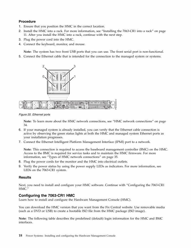
Note: The system has two front USB ports that you can use. The front serial port is non-functional.5. Connect the Ethernet cable that is intended for the connection to the managed system or systems.
Note: To learn more about the HMC network connections, see “HMC network connections” on page34.
6. If your managed system is already installed, you can verify that the Ethernet cable connection isactive by observing the green status lights at both the HMC and managed system Ethernet ports asyour installation progresses.
7. Connect the Ethernet Intelligent Platform Management Interface (IPMI) port to a network.
Note: This connection is required to access the baseboard management controller (BMC) on the HMC.Access to the BMC is required for service tasks and to maintain the HMC firmware. For moreinformation, see “Types of HMC network connections” on page 35.
8. Plug the power cords for the monitor and the HMC into electrical outlets.9. Verify the power status by using the power supply LEDs as indicators. For more information, see
LEDs on the 7063-CR1 system.
Results
Next, you need to install and configure your HMC software. Continue with “Configuring the 7063-CR1HMC.”
Configuring the 7063-CR1 HMCLearn how to install and configure the Hardware Management Console (HMC).
You can download the HMC version that you want from the Fix Central website. Use removable media(such as a DVD or USB) to create a bootable ISO file from the HMC package (ISO image).
Note: The following table describes the predefined (default) login information for the HMC and BMCinterfaces.
Figure 20. Ethernet ports
18 Power Systems: Installing and configuring the Hardware Management Console

Table 5.
Console or Interface Default ID Default Password Description
BMC ADMIN ADMIN The ADMIN user ID andpassword are used to log into the BMC for the firsttime.
HMC hscroot abc123 The hscroot user ID andpassword are used to log into the HMC for the firsttime. They arecase-sensitive and can onlybe used by a member of thesuper administrator role.
HMC root passw0rd The root user ID andpassword are used by theservice provider to performmaintenance procedures.They cannot be used to login to the HMC.
Note: The following installations are shown as examples.
Installing the HMC by using USB flash drive
To install the HMC by using USB flash drive, complete the following steps for Linux systems:1. Download the HMC version that you want from the Fix Central website.2. Run the following command: dd bs=4M if=/path/to/HMC_ISO_FILE.iso of=/dev/sdx status=progress
&& sync (where sdx is the name of the USB drive).
Note: The USB drive must be at least 4 GB. Certain USB drives might be too wide to fit properly intothe USB port at the rear of the system. Test the fit of your USB drive before you proceed.
3. Insert the USB drive, and power on the system.4. When the Petitboot menu is displayed, select the Install Hardware Management Console option that
is located under USB.
Installing the HMC by using remote media from the console viewer
To install the HMC by using remote media from the console viewer, complete the following steps:1. Log in to the BMC web interface (http://<bmc-ip>).2. Select Remote Control.3. Select Console Redirection.4. Click Launch Console.5. In the Java™ iKVM Viewer, select Virtual Media > Virtual Storage.6. Under Logical Drive Type, select ISO File.7. Click Open Image and locate the ISO file on your system.8. Press Plugin to mount the ISO file.9. Power on the system.
10. When the Petitboot menu is displayed, select the Install Hardware Management Console optionthat is located under CD/DVD.
Installing and configuring the Hardware Management Console 19

Installing the HMC by using an external USB attached DVD drive
To install the HMC by using an external USB attached DVD drive, complete the following steps:1. Download the HMC recovery version that you want from the Fix Central website.2. Burn the HMC recovery DVD image to a DVD-R media as an image. Alternatively, you can order the
recovery media on DVD.3. Power off the HMC.4. Connect the external USB DVD drive to the HMC and insert the HMC recovery DVD.
Note: You might need to connect the USB DVD drive to an external power source or use a USB Ycable to connect to an extra USB port to provide sufficient power to the DVD drive.
5. Power on the HMC.
Note: The display monitor might show no signal during startup. The process might take 2 or 3minutes before the display monitor shows any status.
6. When the Petitboot bootloader starts, navigate to stop the automatic boot.
Note: A 10-second timeout is enforced. If no action is taken within 10 seconds, the system attempts toboot from the hard disk drive.
7. Wait until the CD/DVD device appears in the Petitboot menu.
Note: This process can take up to a minute.8. Select the Install Hardware Management Console option that is located under CD/DVD.
Installing the HMC by using remote media that is hosted by an SMB file server
To install the HMC by using remote media that is hosted by a Server Message Block (SMB) file server,complete the following steps:1. Copy the recovery ISO file to a share host on your SMB-compliant file server.
Note: Server Message Block version 3 (SMBv3) is not supported.2. Log in to the BMC web interface (http://<bmc-ip>).3. Select Virtual Media.4. Select CD-ROM Image.5. Complete the following information:
Share host
The IP of the SMB host. If you are using the host name, ensure that the domain name system(DNS) on the BMC is correctly configured.
Path to image
The SMB path to the system. For example: /<share name>/<rest of path>/<name ofiso>.iso
User (optional)
The user name that is used to log in to the SMB host.
Password (optional)
The password for the user.6. Click Save.7. Click Mount.8. Device 1 now shows the following message: There is an iso file mounted.
20 Power Systems: Installing and configuring the Hardware Management Console

Note: If the message does not appear, recheck the information and repeat steps 6 - 8.9. Power on the system.
10. When the Petitboot menu is displayed, select the Install Hardware Management Console optionthat is located under CD/DVD.
Next, you need to configure your HMC software. For instructions, see “Configuring the HMC” on page34.Related concepts:“Configure BMC connectivity” on page 59You can configure or view the network settings on the BMC for the management console.
Installing the HMC virtual applianceLearn how to install the Hardware Management Console (HMC) virtual appliance.
The HMC virtual appliance can be installed in your existing x86 or POWER® virtualized infrastructure.The HMC virtual appliance supports the following x86 virtualization hypervisors:v Kernel-based virtual machine (KVM)v Xenv VMware
The HMC virtual appliance supports the following POWER virtualization hypervisors:v PowerVM®
Minimum requirements for running the HMC virtual appliance:v 8 GB of memory (16 GB recommended)v 4 virtual processorsv 2 network interfaces (maximum of 4 allowed)v 1 disk drive that contains 500 GB of available disk space
Note:
PowerVM virtualization hypervisor requires 160 GB of disk space (500 GB recommended).
The minimum PowerVM processor requirement is 1.0 processing units and four shared virtualprocessors in capped sharing mode.
Notes:
1. The processor on the systems that host the HMC virtual appliance must be either an Intel VT-x or anAMD-V hardware virtualization-enabled processor.
2. The HMC virtual appliance DVDs that you receive are not bootable. You must mount the media firstand then copy the .tgz file from the media. The method to mount the DVD can vary depending onthe operating system that you use.
3. The command syntax that are used in the following examples can vary depending on the operatingsystem that you use.
Related information:HMC V8 network installation images and installation instructions
Installing the HMC virtual appliance on x86Learn how to install the Hardware Management Console (HMC) virtual appliance on a x86 environment.
Installing and configuring the Hardware Management Console 21

Installing the HMC virtual appliance by using the KVM hypervisor:
Learn how to install the Hardware Management Console (HMC) virtual appliance by using thekernel-based virtual machine (KVM) hypervisor.
To install the HMC virtual appliance on KVM, complete the following steps:
Note: The following use the command line interface and require root user authority. The commandsyntax might vary depending on the operating system.1. Verify that virtualization packages are installed on systems with Red Hat Enterprise Linux (RHEL)
version 7.0 or later.2. Download the <KVM vHMC installation filename>.tar.gz file to the host system.3. Run the following command: mkdir -p /var/lib/libvirt/images/vHMC.4. Run the following command: cd /var/lib/libvirt/images/vHMC.5. To extract the virtual disk images, run the following command: tar -zxvf <KVM vHMC installation
filename>.tgz
Note: In this command, specify the full path of your HMC virtual appliance .tar file.6. A domain.xml file is provided in the <KVM vHMC installation filename>.tar.gz file. Complete the
following steps:a. Edit the domain.xml file and verify that the path to your disks is correct. This file contains the
string DISK_PATH.b. Make sure virtio is used in the bus value for your disk device.c. You can choose to have a different name for your VM. The default name in the domain.xml file
is vHMC.d. Verify that the media access control (MAC) address is set in the domain.xml file. This file
contains the string MAC_ADDRESS.
Note: Remove this line if you want a MAC address to be generated automatically for you.e. Verify that your bridges match your Ethernet devices. The default domain.xml file specifies one
Ethernet.f. If you are using the Activation Engine, replace AEDISK with the name of Activation Engine
virtual disk image. Otherwise, remove the disk element.7. To define the VM, run the following command: virsh define <domain>.xml.8. To verify that Virtual HMC was added to the list of defined VMs, run the following command: virsh
list --all.9. To start the VM, run the following command: virsh start vHMC.
10. To determine the Virtual Network Computing (VNC) display number of your console, run thefollowing command: virsh vncdisplay vHMC.
11. To connect to your console with a VNC viewer, run the following command: vncviewerHOSTNAME:ID(Where ID is the display number, for example 0).
Note: If you require remote access, you must drop or configure your firewall to allow access to port5900.
Installing the HMC virtual appliance by using the Xen hypervisor:
Learn how to install the Hardware Management Console (HMC) virtual appliance by using the Xenhypervisor.
The HMC virtual appliance supports Xen version 4.2 or later.
22 Power Systems: Installing and configuring the Hardware Management Console

To install the HMC virtual appliance by using the Xen hypervisor, complete the following steps:
Note: The following steps use the command line interface and require root user authority. The commandsyntax might vary depending on the operating system.1. Verify that virtualization packages are installed on systems with Red Hat Enterprise Linux (RHEL)
version 6.4 or later.2. Download the <XEN vHMC installation filename>.tar.gz file to the host system.3. Run the following command: mkdir -p /var/lib/libvirt/images/vHMC.4. Run the following command: cd /var/lib/libvirt/images/vHMC.5. To extract the virtual disk images, run the following command: tar -zxvf <XEN vHMC installation
filename>.tgz
Note: In this command, specify the full path of your HMC virtual appliance .tar file.6. A vhmc.cfg file is provided in the <XEN vHMC installation filename>.tar.gz file. Open the vhmc.cfg
file in a text editor and edit the following values:a. Change the name of the virtual HMC (optional): Edit the vhmc.cfg file and verify that the path to
your disks is correct. This file contains the string DISK_PATH.b. Replace DISK_PATH with the path for disk1.img:
disk = [ ’file:DISKPATH,hda,w’ ]
c. Replace ethernet adapter and add MAC address (optional):vif = [ ’type=virtio, model=e1000, bridge=eth0’ ]
Optional MAC Address:vif = [ ’type=virtio, mac=MACADDRESS, model=e1000, bridge=eth0’ ]
Note: When the Virtual HMC is rebooted, the Xen hypervisor automatically regenerates a MACaddress. Adding the optional MAC Address solves this issue.
d. Replace FLOPPYPATH (if you are using the Activation Engine):device_model_args = [ "-fda", "FLOPPYPATH" ]
7. To create and start the VM, run the following command: xl create vHMC.cfg.8. To check that the VM was added to the list of defined virtual machines, run the following command:
xl list.9. To access the VM local console, run the following command: vncviewer localhost 0.
Installing the HMC virtual appliance by using VMware ESXi:
Learn how to install the Hardware Management Console (HMC) virtual appliance by using VMwareESXi.
You can install the HMC virtual appliance on VMware ESXi by using the graphical user interface on thevSphere client to deploy the Open Virtualization Format (OVF) template.
Note: You can install the HMC virtual appliance on VMware ESXi version 6.0 or later.
To install the HMC virtual appliance on VMware ESXi by using the vSphere client, complete thefollowing steps:
Note: The command syntax might vary depending on the operating system.1. Obtain the Tar archive file: <VMware vHMC installation file name>.tgz.2. Use the tar command to extract the OVA file from the Tar archive file.3. Start the vSphere client and log in to the ESXi host.4. From the File menu, select Deploy OVF template.
Installing and configuring the Hardware Management Console 23

5. Click Browse and select the OVA file.6. Click Next.7. After the deployment is completed, click Close and select the HMC virtual appliance icon to power
the HMC virtual appliance on.
Installing the HMC virtual appliance on POWERLearn how to install the Hardware Management Console (HMC) virtual appliance on a virtualizedPOWER environment.
Installing the HMC virtual appliance on PowerVM (logical partition):
Learn how to install the Hardware Management Console (HMC) virtual appliance on a PowerVMenvironment.
The HMC virtual appliance supports POWER9 servers on firmware level FW910 or later. For moreinformation, see Supported Linux distributions for POWER8® Linux on Power® systems(https://www.ibm.com/support/knowledgecenter/en/linuxonibm/liaam/liaamdistros.htm).
Note: You cannot manage the server that hosts the HMC virtual appliance.
Create automated HMC installation image (optional)
You can create an automated HMC installation image that automatically installs the HMC virtualappliance without prompting for the HMC Installallation wizard.
Note: The HMC virtual appliance on PowerVM does not provide graphics adapter support for adaptersthat are assigned to the partition. You can use a supported web browser to connect to the HMC for userinterface support.
To create an automated HMC installation image, complete the following steps:1. Create two directories by running the following commands: mkdir -p oldiso and mkdir -p newiso.2. Mount the HMC installation image to the oldiso directory by running the following command: sudo
mount -o loop <image_path> oldiso.3. Copy the contents of the oldiso directory to the newiso directory by running the following command:
cp -r oldiso/* newiso.4. Edit the Grub file for the automated install by running the following command: sed -i
’s/biosdevname=0/biosdevname=0 mode=auto optype=Install/’ newiso/boot/grub/grub.cfg.5. Make the Grub file read-only by running the following command: sudo chown 0444
newiso/boot/grub/grub.cfg.6. Create a new HMC installation ISO by running the following command: mkisofs -o <new_iso_name>
-V <ISO label> -f -r -T -udf --allow-limited-size --netatalk -chrp-boot -iso-level 4 -part-no-desktop -quiet newiso (where ISO label must be HMC-<hmc version release number>, forexample HMC-8.0.870.0).
Note: For more information about setting up the Activation Engine and the configuration file, see “Usingthe Activation Engine for the HMC virtual appliance” on page 27.
Logical volume setup
To set up the logical volume, complete the following steps:1. Select a managed system.2. From the menu pod, select System Actions > Power VM > Virtual Storage.3. Select Manage System VIOS > Action > Manage Virtual Storage.
24 Power Systems: Installing and configuring the Hardware Management Console

4. Select the Virtual Disks tab.5. Click Create virtual disk and enter the following information:v Virtual disk name: The name of the virtual disk.v Storage pool name: The name of the storage pool.v Virtual disk size: The size of the virtual disk.v Assigned partition: The name of the logical partition.
Note: A minimum of 160 GB disk space is required (500 GB disk space is recommended).
Installation media setup - create media library
To create a media library, complete the following steps:1. Select a managed system.2. From the menu pod, select System Actions > Power VM > Virtual Storage.3. Select Manage System VIOS > Action > Manage Virtual Storage.4. Select the Optical Devices tab.5. Click Create Library and enter the following information:v Storage pool: The name of the storage pool.v Media library size: The size of the media library.
6. Click OK.
Installation media setup - upload media to VIOS
To upload media to Virtual I/O Server (VIOS), complete the following steps:1. Log in to VIOS.2. In VIOS root mode, run the following command: oem_setup_env.3. To allow NFS connection, run the following command: nfso -o nfs_use_reserved_ports=1.4. To mount the NFS into the local VIOS folder, run the following command: mount <server_ip>:/
Mountpoint <local_folder>.5. To verify that the NFS mount includes your HMC installation ISO and Activation Engine
configuration image (optional), run the following command: ls.
Installation media setup - link media to media library
To link media to the media library, complete the following steps:1. Navigate back to Manage System VIOS > Action > Manage Virtual Storage and select the Optical
Devices tab.2. From the Virtual Optical Media section, select Add Media from the Actions menu.3. From the Add Virtual Media window, select Add existing file from VIOS filesystem and enter the
following information:v Media name: The name of the media (for example, HMCInstall or AEDrive).v Optical media file name: The file name of the installation ISO file (for example,
01234567-ppc64ie.iso).4. Click OK.5. If you created an Activation Engine configuration image, repeat steps 3 - 4 to add the Activation
Engine configuration image. Otherwise, continue to step 6.6. Verify that the optical media is uploaded to the media library by verifying that the media name is
shown in available Virtual Optical Media list.
Installing and configuring the Hardware Management Console 25

Logical partition setup
To set up the logical partition, complete the following steps:1. Select a managed system.2. From the menu pod, select System Actions > Partitions > Partitions.3. Click Create Partition and enter the following information:v Parititon Name: The name of the partition.v Partition ID: The ID of the partition.v Partition Type: Select the operating system (AIX/Linux or IBM i).
4. Click OK.5. Allocate the number of processors and the amount of memory for the partition.
Note: A minimum of four virtual processors and 8 GB of memory is required.6. From the menu pod, select Partition Actions > Virtual I/O > Virtual Networks.7. Click Manage Network Connections and select the virtual networks for the partition.
Note: A maximum of four virtual network adapters is allowed.8. From the menu pod, select Partition Actions > Virtual I/O > Virtual Storage.9. From the Virtual Optical Device tab, click Add Virtual Optical Device.
10. Enter the Device Name (for example, HMCInstall or AEDrive) and select the wanted Virtual I/OServer from the table.
Note: Installing the AEDrive is optional.11. Click OK.12. Verify that the virtual optical devices that you added from step 10 is now listed in the table.13. From the Action menu, click Load.14. Select the media file to assign to the logical partition and click OK.15. Verify that the virtual optical devices that you loaded from step 13 is now listed in the table.
Starting the HMC virtual appliance
Note: When you install the HMC virtual appliance on a partition by using the HMC ISO image file, youwill not have local graphical console access to the web user interface.
To start the HMC virtual appliance on PowerVM, complete the following steps:1. Select the managed partition.2. Open an active connection to the logical partition by selecting Actions > Console > Open Terminal
Window.3. Activate the logical partition by selecting Actions > Activate.4. Select Activate (Normal) and Current Configuration.5. Click Finish.6. Switch to the terminal window.7. From the Boot menu, select 1 = SMS Menu.8. From the Main menu, select 5 = Select Boot Options.9. From the Multiboot menu, select 1 = Select Install/Boot Device.
10. From the Select Device Type menu, select 5 = List all devices.11. Select the HMCInstall device based on the device location.12. Select 2. Normal Mode Boot.
26 Power Systems: Installing and configuring the Hardware Management Console

13. Select 1. Yes to confirm.14. Follow the onscreen instructions from the HMC Install wizard.
Note: Skip this step if you used an automated HMC installation image.15. After the installation completes and the system starts, you must select a language from the language
selection dialog box.16. Accept the license agreement.
Note: Ensure that the command controller is ready to accept commands before you run anycommands. For example, running the lshmc -V command until it succeeds.
17. Log in as hscroot and use the chhmc command to configure the network.The following example shows the sequence of chhmc commands that can be used to configure thenetwork and enable Secure Shell (SSH) and remote web access on the HMC.chhmc -c network -s modify -i ethX -a <hmc ip address> -nm <hmc network mask> --lparcomm onchhmc -c network -s modify -h <hmc hostname> -d <hmc domain name> -g <gateway ip>chhmc -c network -s add -ns <name server> -ds <domain search>chhmc -c ssh -s enablechhmc -c ssh.name -s add -a <ip address>chhmc -c SecureRemoteAccess.name -s add -a <ip address>chhmc -c remotewebui -s enable -i ethXhmcshutdown -r -t now
v ethX is the network interface name to configure.v hmc ip address is the IP address of your HMC.v hmc network mask is the network mask of your HMC.v hmc hostname is the host name of your HMC.v hmc domain name is the domain name of your HMC.v gateway ip is the IP address of the gateway on your network.v name server is the name server address of your network.v domain search is the names of the domains that you want the HMC to search on.v To allow access on all IP addresses, use -a 0.0.0.0 -nm 0 in place of ip address.
Note: When you use multiple virtual Ethernet adapters, run the command cat /etc/sysconfig/network-scripts/ifcfg-ethX on the HMC virtual appliance on each interface. Compare the mediaaccess control (MAC) address against what the HMC shows in the adapter view of the virtualnetwork of the partition. You can click View Virtual Ethernet Adapter Settings for more informationon the virtual Ethernet adapters. This step helps you determine the correct interface to use.
18. Restart the system.
Using the Activation Engine for the HMC virtual applianceLearn how to use the Activation Engine for the Hardware Management Console (HMC) virtual appliance.
Activation Engine is a framework that allows various components within a virtual machine to beconfigured during system startup. To use the Activation Engine, you need to set up an XMLconfiguration profile to allow the HMC virtual appliance to be in a ready-to-manage state on first start.For more information about configuring the XML configuration profile, see “Setting up the configurationprofile for the Activation Engine” on page 28. The configuration file can be used to configure thefollowing options:v Set Default Keyboard (US)v Default Locale (US)v Disable Keyboard Setupv Disable Display Setupv License Agreement and Machine Code Agreement
Installing and configuring the Hardware Management Console 27

v Disable Setup Wizardv Disable Call Home Wizardv Configure up to four Network Interface Cardsv Configure Firewall Settings for each Interfacev Configure Network interface as IPv4 DHCP Serverv Configure Private and Open Interfacev Configure Default Gateway Interface Device
Note: The number of Ethernet adapters that is defined in the vHMC-Conf.xml configuration file mustcorrelate with the defined Network adapters in the domain.xml, vHMC.cfg, or VMWare configurationfile.
The Activation Engine requires a virtual disk that holds an XML configuration. You can edit theuser_data file with a text editor and use the XML configuration guide that is shown in the followingexample.
To create a virtual ISO disk image with Activation Engine configuration in a Linux environment,complete the following steps:1. Create a directory:
mkdir -p config-drive/openstack/latest
2. Copy the edited user_data file into the directory:cp user_data config-drive/openstack/latest
3. Create a virtual disk image with the Activation Engine configuration:mkisofs -R -V config-2 -o AEdrive.iso config-drive
Setting up the configuration profile for the Activation Engine:
Learn how to set up the Activation Engine configuration file by using XML tags.
Configuration file
Use the following example of the configuration file to learn about the XML tags.<vHMC-Configuration>
<ConfigurationVersion>2.0</ConfigurationVersion><LicenseAgreement></LicenseAgreement><AcceptLicense>Yes</AcceptLicense><Locale>en_US.UTF-8</Locale><SetupWizard>No</SetupWizard><SetupCallHomeWizard>No</SetupCallHomeWizard><SetupKeyboard>No</SetupKeyboard><SetupDisplay>No</SetupDisplay><Ethernet Enable=’Yes’ DefaultGatewayDevice=’Yes’ PrivateInteface=’No’>
<Hostname></Hostname><Domain></Domain><DNSServers></DNSServers><IPV4Config>
<NetworkType></NetworkType><IPAddress></IPAddress><Netmask></Netmask><Gateway></Gateway>
</IPV4Config><IPV6Config>
<NetworkType></NetworkType><IPAddress></IPAddress><Gateway></Gateway>
<IPV6Config><Firewall>
28 Power Systems: Installing and configuring the Hardware Management Console

<PEGASUS>Enabled</PEGASUS><RPD>Enabled</RPD><FCS>Enabled</FCS><I5250>Enabled</I5250><PING>Enabled</PING><L2TP>Disabled</L2TP><SLP>Enabled</SLP><RSCT>Enabled</RSCT><SECUREREMOTEACCESS>Enabled</SECUREREMOTEACCESS><SSH>Enabled</SSH><NTP>Disabled</NTP><SNMPTraps>Disabled</SNMPTraps><SNMPAgents>Disabled</SNMPAgents>
</Firewall></Ethernet><NTPServers>
<ntpparam ntpserver="" ntpversion=""/></NTPServers>
</vHMC-Configuration>
XML tags for the configuration file
XML tags are used in the Activation Engine configuration file to set specific values for various attributes.You can manually set these values in the Activation Engine configuration file. Use the following table tosee a description of each tag and its allowed values:
Table 6. XML tags
Tags Description Acceptable values Notes
ConfigurationVersion Required element thatdefines the configurationversion to use.
2.0
LicenseAgreement Required element thatdisplays the HMC virtualappliance licenseagreement.
AcceptLicense Required element toaccept the HMC virtualappliance licenseagreement.
v Yes: Accepts the HMC license agreement.
v No: Prompts User to Accept HMCLicense Agreement
If an invalid valueis entered, theActivation Engineuses the defaultsetting of No.
Locale Required element todefine locale settings.
en_US.UTF-8 If an invalid valueis entered, theActivation Engineuses the defaultsetting of US.
SetupWizard Required element toenable or disable theHMC Setup wizard.
v Yes: Displays the HMC Setup wizard.
v No: Disables the HMC Setup wizarddisplay.
If an invalid valueis entered, theActivation Engineuses the defaultsetting of Yes.
SetupCallHomeWizard Required element toenable or disable theHMC Call Home wizard.
v Yes: Displays the HMC Call Homewizard.
v No: Disables the HMC Call Homewizard display.
If an invalid valueis entered, theActivation Engineuses the defaultsetting of Yes.
Installing and configuring the Hardware Management Console 29

Table 6. XML tags (continued)
Tags Description Acceptable values Notes
SetupKeyboard Required element todefine the keyboardconfiguration.
v Yes: Prompts the user for keyboardconfiguration.
v No: Accepts default keyboardconfiguration (US).
If an invalid valueis entered, theActivation Engineuses the defaultsetting of Yes.
SetupDisplay Required element toenable or disable thedisplay configuration.
v Yes: Prompts the user for displayconfiguration.
v No: Accepts default displayconfiguration.
If an invalid valueis entered, theActivation Engineuses the defaultsetting of Yes.
Ethernet Required element thatholds values for Ethernetadapter configurations. Amaximum of fourEthernet adapters can beconfigured.
Enable:
v Yes: Configure this adapter.
v No: Do not configure this adapter.
DefaultGatewayDevice:
v Yes: Configure this adapter as the mainnetwork adapter.
v No: Do not configure this adapter as themain network adapter.
PrivateInterface:
v Yes: Configure this adapter as a privateinterface. Yes is required to configureinterface as an IPv4 DHCP Server.
v No: Do not configure this adapter as aprivate interface. No is required toconfigure interface as IPv4 static type.
The ActivationEngine runs thedefaultconfiguration ifany invalid valuesare entered withinthe Ethernetadapter section orif multiple DefaultGateway Devicesare defined.Optional elementscan be omittedfrom theconfiguration. Atleast one IPV4 orIPV6 configurationis required. If youdo not specify anIP configuration,the ActivationEngine uses thedefaultconfiguration.
HostName Optional element todefine the network hostname.
Any valid host name string. If the element isnot defined, theActivation Engineuses the defaultlocal hostHostName value.
Domain Optional element todefine the networkdomain.
Any valid domain value (for example,example.us.com).
If the element isnot defined, theActivation Engineuses the defaultempty Domainvalue.
30 Power Systems: Installing and configuring the Hardware Management Console

Table 6. XML tags (continued)
Tags Description Acceptable values Notes
DNSServers Optional element todefine the network DNSservers.
It is acceptable to have one DNS Servervalue or up to three valid IPv4 or IPv6addresses that are separated by a comma.
v Example 1: IPv4: 8.3.2.1 IPv6:2001:4860:4860::8888
v Example 2: IPv4: 8.3.2.1,8.5.4.1 IPv6:2001:4860:4860::8888,2001:4860:4860::8844
v Example 3: IPv4: 8.3.2.1,8.5.4.1,8.4.3.2IPv6:2001:4860:4860::8888,2001:4860:4860::8844,::ffff:903:201
If the element isnot defined, theActivation Engineuses the defaultemptyDNSServers value.
IP4Config Optional element todefine IPv4 configurationsettings.
IPType: Required element to define IPv4configuration type.
v Static: Configure this adapter by usingstatic configuration.
v DHCP: Configure this adapter by usingDHCP configuration.
v DHCPServer: Configure this adapter tobe IPv4 DHCP server (requiresPrivateInterface to be set to Yes).
IPAddress: Optional element that isrequired only if Static or DHCPServerconfiguration is selected.
v Static Configuration: Any valid IPv4address value.
v DHCPServer Configuration: Any DHCPserver IP within the IP range.
Netmask: Optional element that is requiredonly if Static configuration is selected.
v Any valid IPv4 netmask value.
Gateway: Optional element that is requiredonly if Static configuration is selected.
v Any valid IPv4 netmask value.
Installing and configuring the Hardware Management Console 31

Table 6. XML tags (continued)
Tags Description Acceptable values Notes
IP6Config Optional element todefine IPv6 configurationsettings.
IPType: Required element to define IPv6configuration type.
v Static: Configure this adapter by usingstatic configuration.
v DHCP: Configure this adapter by usingDHCP configuration.
IPAddress: It is acceptable to have long orshort form IPv6 format and long or shortform IPv6 prefix.
v Example 1: IPv6:2001:4860:4860:0000:0000:0000:0000:8888
v Example 2: IPv6: 2001:4860:4860::8888
v Example 3: IPv6: 2001:4860:4860::8888/128
If no prefix is specified, the ActivationEngine uses the default setting of /64prefix.
Gateway:
v Any valid IPv6 address value.
32 Power Systems: Installing and configuring the Hardware Management Console

Table 6. XML tags (continued)
Tags Description Acceptable values Notes
Firewall Optional element todefine firewall settings.
PEGASUS:
v Enabled: Allows the PEGASUS ports tobe open.
v Disabled: Disables PEGASUS ports.
RPD:
v Enabled: Allows the RMC ports to beopen.
v Disabled: Disables RMC ports.
FCS:
v Enabled: Allows the FCS ports to beopen.
v Disabled: Disables FCS ports.
I5250:
v Enabled: Allows the 5250 ports to beopen.
v Disabled: Disables 5250 ports.
PING:
v Enabled: Allows the Ping port to beopen.
v Disabled: Disables Ping port.
L2TP:
v Enabled: Allows the L2TP ports to beopen.
v Disabled: Disables L2TP ports.
SLP:
v Enabled: Allows the SLP ports to beopen.
v Disabled: Disables SLP ports.
RSCT:
v Enabled: Allows the RSCT ports to beopen.
v Disabled: Disables RSCT ports.
SECUREREMOTEACCESS:
v Enabled: Allows the secure remote accessports to be open.
v Disabled: Disables secure remote accessports.
SSH:
v Enabled: Allows the SSH port to beopen.
v Disabled: Disables SSH port.
Installing and configuring the Hardware Management Console 33

Table 6. XML tags (continued)
Tags Description Acceptable values Notes
Firewall Optional element todefine firewall settings.
NTP:
v Enabled: Allows the NTP ports to beopen.
v Disabled: Disables NTP ports.
SMNPTraps:
v Enabled: Allows the SMNP traps ports tobe open.
v Disabled: Disables SMNP traps ports.
SMNPAgents:
v Enabled: Allows the SMNP agents portsto be open.
v Disabled: Disables SMNP agents ports.
NTPServers The NTPServers tag isneeded if you want toconfigure up to five NTPservers within a HMCvirtual appliance.
NTPServers: Accepts <ntpparamntpserver="server"ntpversion="version"/>
ntpparam:
v ntpserver: Accepts any valid IPv4 or IPv6values and valid host names.
v ntpversion: Accepts 1-4 numeric value
Example:
<NTPServers><ntpparam ntpserver="test.austin.ibm.com"ntpversion="2"/><ntpparam ntpserver="192.168.34.1"ntpversion="4"/><ntpparam ntpserver="::ffff:903:201"ntpversion="3"/>`
</NTPServers>
Configuring the HMCLearn how to set up your network connections, configure your HMC, complete postconfiguration steps,and upgrade and update your HMC.
Choosing network settings on the HMCLearn about the network settings that you can use on the Hardware Management Console (HMC).
HMC network connectionsLearn how the Hardware Management Console HMC can be used in a network.
You can use different types of network connections to connect your HMC to managed systems. For moreinformation about how to configure the HMC to connect to a network, see “Configuring the HMC” onpage 51. For more information about using the HMC on a network, see the following information:
34 Power Systems: Installing and configuring the Hardware Management Console

Types of HMC network connections:
Learn how to use the HMC remote management and service functions by using your network.
The HMC supports the following types of logical communications:
HMC to managed systemUsed to perform most of the hardware management functions, in which HMC issues controlfunction requests through the service processor of the managed system. The connection betweenthe HMC and the service processor is sometimes referred to as the service network. Thisconnection is required for managed system management.
HMC to logical partitionUsed to collect platform-related information (hardware error events, hardware inventory) fromthe operating systems that are running on logical partitions, and to coordinate certain platformactivities (dynamic LPAR, concurrent repair) with those operating systems. If you want to useservice and error notification features, you must create this connection.
HMC to BMC
Note: The baseboard management controller (BMC) connection is applicable only to HMC model7063-CR1.Used to perform service and maintenance tasks. The BMC connection is used to load andmaintain the HMC firmware on the system. This connection is required for access to the BMC onthe HMC.
HMC to remote usersProvides remote users with access to HMC functions. Remote users can access the HMC in thefollowing ways:v By using the remote client (if you are using an HMC Version 6 or earlier) or web browser (if
you are using a HMC Version 7 or later) to access all the HMC GUI functions remotely.v By using the web browser to access all the HMC GUI functions remotely.v By using Secure Socket Shell (SSH) to access the HMC command line functions remotely.v By using a virtual terminal server for remote access to virtual logical partition consoles.
HMC to service and supportUsed to transmit data, such as hardware error reports, inventory data, and microcode updates, toand from your service provider. You can use this communications path to make automatic servicecalls.
Your HMC can support up to four separate physical Ethernet interfaces, depending on the model. Thestand-alone version of the HMC supports only three HMC interfaces, by using one integrated Ethernetadapter and up to two plug-in adapters. Use each of these interfaces in the following ways:v One network interface can be used exclusively for HMC-to-managed system communications, which
means that only the HMC and service processors of the managed systems would be on that network.One or more network interfaces can be used exclusively for HMC-to-managed system communications,which means that only the HMC and service processors of the managed systems are on that network.Even though the network interfaces into the service processors are encrypted for the Secure SocketsLayer (SSL) Protocol and password-protected, having a separate dedicated network can provide ahigher level of security for these interfaces.
v An open network interface would typically be used for the network connection between the HMC andthe logical partitions on the managed systems, for the HMC-to-logical partition communications. Youcan also use this open network interface to manage the HMC remotely.
v Optionally, you can use a third interface to connect to logical partitions and manage the HMCremotely. This interface can also be used as a separate HMC connection to different groups of logicalpartitions. For example, you might want to have an administrative LAN that is separate from the LANon which all the usual business transactions are running. Remote administrators can access the HMC
Installing and configuring the Hardware Management Console 35

and other managed units by using this method. Sometimes the logical partitions are in differentNetwork security domains, perhaps behind a firewall, and you might want to have different HMCnetwork connections into each of those two domains.
Web browser requirements for HMC
The Hardware Management Console (HMC) version 9.1.0 is supported by Google Chrome version 57,Microsoft Internet Explorer (IE) version 11.0, Mozilla Firefox versions 45 and 52 Extended SupportRelease (ESR), and Safari version 10.1.
If your browser is configured to use an Internet proxy, a local IP addresses should be included in theexception list. Consult your network administrator for more information on the exception list. If you stillneed to use the proxy to get to the HMC, enable Use HTTP 1.1 through proxy connections under theAdvanced tab in your Internet Options window.
Session cookies need to be enabled in order for ASMI to work when connected to HMC remotely. Theasm proxy code saves session information and uses it. Follow the steps to enable the session cookies.
Enabling session cookies in Internet Explorer.1. Select Tools and Click Internet Options2. Select Privacy and Click Advanced3. Ensure that the Always allow session cookies is checked. If not, select the Override automatic cookie
handling and select Always allow session cookies.4. Select Prompt under First-party Cookies and Third-party Cookies5. Click OK.
Enabling session cookies in Firefox.1. Select Tools and click Options2. Click Cookies3. Select Allow sites to set cookies.4. Select Exceptions and add HMC.5. Click OK.
Private and open networks in the HMC environment:
The Hardware Management Console (HMC) can be configured to use open and private networks. Privatenetworks allow the use of a selected range of nonroutable IP addresses. A public, or "open" networkdescribes a network connection between the HMC to any logical partitions and to other systems on yourregular network.
Private networks
The only devices on the HMC private network are the HMC itself and each of the managed systems towhich that HMC is connected. The HMC is connected to each managed system's Flexible ServiceProcessor (FSP).
On most systems, the FSP provides two Ethernet ports that are labeled HMC1 and HMC2. You toconnect up to two HMCs.
Some systems have a dual-FSP option. In this situation, the second FSP acts as a redundant backup. Thebasic setup requirements for a system with two FSPs are essentially the same as a system without asecond FSP. The HMC must be connected to each FSP, so more network hardware is required (forexample, a LAN switch or hub) when there is more than one FSP or multiple managed systems.
36 Power Systems: Installing and configuring the Hardware Management Console

Note: Each FSP port on the managed system must be connected to only one HMC.
Public networks
The open network can be connected to a firewall or router for connecting to the internet. Connecting tothe internet allows the HMC to call home when any hardware errors need to be reported.
The HMC itself provides its own firewall on each of its network interfaces. A basic firewall isautomatically configured when you run the HMC Guided Setup wizard, but you customize your firewallsettings after the initial HMC installation and configuration.
HMC as a DHCP server:
You can use the Hardware Management Console (HMC) as a Dynamic Host Configuration Protocol(DHCP) server.
If you want to configure the first network interface as a private network, you can select from a range ofIP addresses for the DHCP server to assign to its clients. The selectable address ranges include segmentsfrom the standard nonroutable IP address ranges.
In addition to these standard ranges, a special range of IP addresses is reserved for IP addresses. Thisspecial range can be used to avoid conflicts in cases where the HMC attached open networks are usingone of the nonroutable address ranges. Based on the range that is selected, the HMC network interface onthe private network is automatically assigned the first IP address of that range, and the service processorsare then assigned addresses from the rest of the range.
The DHCP server in the HMC uses automatic allocation, which means that each unique service processorEthernet interface is reassigned the same IP address each time it is started. Each Ethernet interface has aunique identifier that is based on a built-in Media Access Control (MAC) address, which allows theDHCP server to reassign the same IP parameters. You can configure both eth0 and eth1 HMC ports toserve DHCP addresses.You can configure both eth0 and eth1 HMC ports to serve DHCP addresses.
Installing and configuring the Hardware Management Console 37

Note: If you are using IPv6, the discovery process must be done manually. For IPv6, automatic discoveryis not available.
For more information about how to configure the HMC as a DHCP server, see “Configuring the HMC asa DHCP server” on page 58.
Figure 21. Private network with one HMC as a DHCP server
38 Power Systems: Installing and configuring the Hardware Management Console

This figure shows a redundant HMC environment with two managed systems. The first HMC isconnected to the first port on each FSP, and the redundant HMC is connected to the second port on eachHMC. Each HMC is configured as a DHCP server, by using a different range of IP addresses. Theconnections are on separate private networks. As such, it is important to ensure that no FSP port isconnected to more than one HMC.
Each managed system's FSP port that is connected to an HMC requires a unique IP address. To ensurethat each FSP has a unique IP address, use the HMC's built-in DHCP server capability. When the FSPdetects the active network link, it issues a broadcast request to locate a DHCP server. When correctlyconfigured, the HMC responds to that request by allocating one of a selected range of addresses.
If you have multiple FSPs, you must have your own LAN switch or hub for the HMC to FSP privatenetwork. Alternately, this private segment can exist as several ports in a private virtual LAN (VLAN) on alarger managed switch. If you have multiple private VLANs, you must ensure that they are isolated andwithout any crossover traffic.
If you have more than one HMC, you must also connect each HMC to the logical partitions, and to eachother, on the same open network.
Installing and configuring the Hardware Management Console 39

This figure shows two HMCs connected to a single managed server on the private network and to threelogical partitions on the public network. You can have an extra Ethernet adapter for the HMC to havethree network interfaces. You can use this third network as a management network or connect it to theCSM (Cluster Systems Manager) Management Server.
Deciding which connectivity method to use for the call-home server:
Learn more about the connectivity options you have when you use the call-home server.
You can configure the Hardware Management Console (HMC) to send hardware service-relatedinformation to IBM by using a LAN-based internet connection, or a dial-up connection over a modem.
You have two communication choices when you configure the LAN-based internet connection. The firstchoice is to use standard Secure Sockets Layer (SSL). The SSL communication can be enabled to connectto the internet through your proxy server. SSL connectivity is more likely to be compliant with corporatesecurity guidelines.
Note: If your open network interface connection uses only Internet Protocol Version 6 (IPv6), you cannotuse internet VPN to connect to support. For more information about the protocols that are used, see“Choosing an Internet Protocol” on page 42.
The advantages to using an internet connection can include:v Faster transmission speedv Reduced customer expense (for example, the cost of a dedicated analog telephone line)v Greater reliability
The following security characteristics are in effect, regardless of the connectivity method chosen:v Remote Support Facility requests are always initiated from the HMC to IBM. An inbound connection is
never initiated from the IBM Service Support System.v All data that is transferred between the HMC and the IBM Service Support System are encrypted by
using a high-grade encryption. Depending upon the connectivity method that is chosen, it is encryptedby using either SSL or IPSec Encapsulating Security Payload (ESP).
v When you initialize the encrypted connection, the HMC authenticates the target destination as theIBM Service Support System.
Data sent to the IBM Service Support System consists solely of information about hardware problems andconfiguration. No application or customer data is transmitted to IBM.
40 Power Systems: Installing and configuring the Hardware Management Console

Using an indirect internet connection with a proxy server
If your installation requires the HMC to be on a private network, you might be able to connect indirectlyto the internet by using an SSL proxy, which can forward requests to the internet. One of the otherpotential advantages of using an SSL proxy is that the proxy can support logging and audit facilities.
To forward SSL sockets, the proxy server must support the basic proxy header functions (as described inRFC 2616) and the CONNECT method. Optionally, basic proxy authentication (RFC 2617) can beconfigured so that the HMC authenticates before you attempt to forward sockets through the proxyserver.
For the HMC to communicate successfully, the client's proxy server must allow connections to port 443.You can configure your proxy server to limit the specific IP addresses to which the HMC can connect. See“Internet SSL address lists” on page 42 for a list of IP addresses.
Using a direct internet SSL connection
If your HMC can be connected to the internet, and the external firewall can be set up to allow establishedTCP packets to flow outbound to the destinations described in “Internet SSL address lists” on page 42,you can use a direct internet connection.
Using internet SSL to connect to remote support:
All the communications are handled through TCP sockets that are initiated by the HardwareManagement Console (HMC) and use a high-grade SSL to encrypt the data that is transmitted. The
Installing and configuring the Hardware Management Console 41

destination TCP/IP addresses are published (see “Internet SSL address lists”) so that external firewallscan be configured to allow these connections.
Note: The standard HTTPS port 443 is used for all communications.
The HMC can be enabled to connect directly to the internet or to connect indirectly from a proxy serverthat is provided by the customer. The decision about which approach is best for your installation dependson the security and networking requirements of your enterprise. The HMC (directly or through the SSLproxy) uses the following addresses when it is configured to use internet SSL connectivity.
Choosing an Internet Protocol:
Determine the IP address version that is used when the Hardware Management Console (HMC) connectsto your service provider.
Most users use Internet Protocol Version 4 (IPv4) to connect to a service provider. IPv4 addresses appearin the format that represents the 4 bytes of the IPv4 address, which is separated by periods (for example,9.60.12.123) to access the internet. You can also use Internet Protocol Version 6 (IPv6) to connect to aservice provider. IPv6 is often used by network administrators to ensure unique address space. If you areunsure of the Internet Protocol used by your installation, contact your network administrator. For moreinformation about using each version, see “Setting the IPv4 address” on page 59 and “Setting the IPv6address” on page 60.
Internet SSL address lists:
Learn about the addresses that the Hardware Management Console (HMC) uses when the HMC is usinginternet SSL connectivity.
The HMC uses the following IPv4 addresses to contact IBM service and support when it is configured touse internet SSL connectivity.
The following IPv4 addresses are for all locations:v 129.42.26.224v 129.42.42.224v 129.42.50.224v 129.42.56.216v 129.42.58.216v 129.42.60.216v 170.225.15.41
The following IPv4 addresses are for the Americas:v 129.42.160.48v 129.42.160.49v 207.25.252.197v 207.25.252.200v 207.25.252.204
The following IPv4 addresses are for all locations other than the Americas:v 129.42.160.48v 129.42.160.50v 207.25.252.197v 207.25.252.200v 207.25.252.205
42 Power Systems: Installing and configuring the Hardware Management Console

Note: When you configure a firewall to allow an HMC to connect to these servers, only the IP addressesspecific to the geographic region are required.
The HMC uses the following IPv6 addresses to contact IBM service and support when it is configured touse internet SSL connectivity:v 2620:0:6C0:1::1000v 2620:0:6C2:1::1000v 2620:0:6C4:1::1000
Using multiple call-home servers:
Learn about what you need to know when you decide to use more than one call-home server.
To avoid a single point of failure, configure the Hardware Management Console (HMC) to use multiplecall-home servers. The first available call-home server attempts to handle each service event. If theconnection or transmission fails with this call-home server, the service request is retried by using theother available call-home servers until one is successful or all servers are tried.
The connected HMC that is identified by the problem analysis to be the primary analyzing console for agiven managed system that reports the problem. This primary console also replicates the problem reportto any secondary HMC. This secondary HMC must be recognized on the network by the primary HMC.A secondary HMC is recognized by the primary HMC as an extra call-home server when:v The primary HMC is configured to use "discovered" call-home servers and the call-home server is
either on the same subnet as the primary HMC or it manages the same system.v The call-home server is manually added to the list of call-home server consoles available for outbound
connectivity.
Preparing for HMC configurationLearn about the required configuration settings that you need to know before you begin the configurationsteps.
To configure the HMC, you must understand the related concepts, make decisions, and prepareinformation.
Learn about the information that you need to connect your HMC to the following locations:v Service processors in your managed systemsv Logical partitions on those managed systemsv Remote workstationsv IBMService to implement “call-home” functions
Note: Additional connectivity and security information is available. For more information, see the ESAfor HMC Connectivity Security for IBM POWER6®, POWER7®, and POWER8 Processor-Based Systemsand IBM Storage Systems DS8000® white paper available at: IBM Electronic Service Agent™
(http://www-01.ibm.com/support/esa/security.htm).
To prepare for HMC configuration, complete the following steps:1. Obtain and install the latest level of the HMC code version you want to install.2. Determine the physical location of the HMC in relation to the servers it manages. If the HMC is
more than 25 feet from its managed system, you must provide web browser access to the HMC fromthe managed system's location so that service personnel can access the HMC.
3. Identify the servers that the HMC manages.4. Determine whether you use a private or an open network to manage servers. If you decide to use a
private network, use DHCP, unless you are using a Cluster Systems Management (CSM)
Installing and configuring the Hardware Management Console 43

configuration. CSM does not support IPv6. To access CSM, you must have two networks. For moreinformation about CSM, see the documentation that was provided with that feature. For moreinformation about private and open networks, see “Selecting a private or open network” on page 58.
5. If you use an open network to manage an FSP, you must set the FSP's address manually through theAdvanced System Management Interface menus. A private, non-routable network is recommended.
6. If you have two HMCs, designate a primary and secondary HMC. The primary HMC needs bephysically closer to the system, and must be the HMC that is configured to call home.
7. Determine the network settings that you need to connect the HMC to remote workstations, logicalpartitions, and network devices.
8. Define how the HMC calls home. Call home options include either over an outbound-only SecureSocket Layer (SSL) internet connection, a modem, or a Virtual Private Network (VPN) connection.
9. Determine the HMC users that you create and their passwords, as well which roles they are given.You must assign the hscroot and hscpe users a password.
10. Document the following company contact information that is needed when you configure call home:v Company namev Administrator contactv Email addressv Telephone numbersv Fax numbersv The street address of the HMC's physical location
11. If you plan to use email to notify operators or systems administrators when information is sent toIBM Service through call-home, identify the Simple Mail Transfer Protocol (SMTP) server and theemail addresses you use.
12. You must define the following passwords:v The access password that is used to authenticate the HMC to the FSP.v The ASMI password that is used for the admin user.v The ASMI password that is used for the general user.
Create the passwords when you connect from the HMC to a new server for the first time. If theHMC is a redundant or second HMC, obtain the HMC User password and be prepared to enter itwhen you connect the first time to the managed server's FSP.
When you complete these preparation steps, complete the “Preinstallation configuration worksheet for theHMC.”
Preinstallation configuration worksheet for the HMCUse this worksheet to have the installation information you need ready for the installation.
Network Settings
LAN Interface: Choose the available adapters (such as eth0, eth1) that is used by this HMC to connect tomanaged systems, logical partitions, service and support, and remote users. For more information, see“HMC network connections” on page 34. Connectivity from the HMC can either be on a private or opennetwork.
Ethernet Adapter Speed and DuplexEnter the wanted Ethernet adapter speed and duplex mode. The autodetection option determineswhich option is optimal if you are not sure which speed and duplex would produce optimumresults for your hardware. Default = Autodetection Media speed specifies the speed in duplexmode of an Ethernet adapter. Select Autodetection unless you need to specify a fixed mediaspeed. Any device that is connected to the FSP (switches/HMC), must be set to Auto (Speed) /Auto (Duplex) mode, as it is the default FSP setting and cannot be changed.
44 Power Systems: Installing and configuring the Hardware Management Console

eth0 eth1 eth2 eth3
Select speed and duplex mode
Media speed(Autodetection,10/100/1000Full/Half Duplex)
For more information about private and open networks, see “Private and open networks in the HMCenvironment” on page 36.
eth0 eth1 eth2 eth3
Specify Private orOpen network foreach adapter.
Dynamic Host Configuration Protocol (DHCP) provides an automated method for dynamic clientconfiguration. You can specify this HMC as a DHCP server. If this is the first or only HMC on the privatenetwork, enable the HMC as a DHCP server. When you enable the HMC as a DHCP server, the managedsystems on the network are automatically configured and discovered by the HMC.
For Ethernet adapters specified as Private networks, complete the following table:
eth0 eth1
Do you want to specify this HMC asa DHCP server? (yes/no)
If yes, record the IP address rangeyou want to use.
If you are using the 7063-CR1 HMC, you must connect the Ethernet IPMI port to a network to access thebaseboard management controller (BMC) on the HMC. For more information, see “Configure BMCconnectivity” on page 59. Complete the following table for your BMC connection.
Table 7. BMC connection
IPMI
Do you want to configure this connection through DHCPmode? (yes/no)
If no, list the specified static addresses below:
IP address:
Subnet mask:
Gateway:
For Ethernet adapters specified as open networks, complete the following tables. For more informationabout the different Internet Protocol versions, see “Configuring the HMC network types” on page 53.
Using IPv6If you are using IPv6, talk to your network administrator and decide how you want to obtain IPaddresses. Then, complete the following tables:
Installing and configuring the Hardware Management Console 45

eth0 eth1 eth2 eth3
Are you using astatically assigned IPaddress? If yes,record that addresshere.
eth0 eth1 eth2 eth3
Are you getting IPaddresses from aDHCP server?(Yes/No)
eth0 eth1 eth2 eth3
Are you getting IPaddresses from anIPv6 router?
For more information about setting IPv6 addresses, see “Setting the IPv6 address” on page 60.For more information about using only IPv6 addresses, see “Using only IPv6 addresses” on page60.
Using IPv4
Complete the following tables for Ethernet adapters that are specified as open networks by usingIPv4.
eth0 eth1 eth2 eth3
Do you want toobtain an IP addressautomatically?(yes/no)
If no, list the specified address below:
TCP/IP InterfaceAddress:
TCP/IP InterfaceNetwork Mask:
Firewall Settings:
Would you like toconfigure HMCfirewall settings?(yes/no)
If yes, list the applications and IP addresses that must be allowed through the firewall:
46 Power Systems: Installing and configuring the Hardware Management Console

TCP/IP informationA unique TCP/IP address is required for each node, both for Support Element (SE) andHardware Management Console (HMC). The assigned network mask is used to generatea unique address, by default, for the local private LAN. If the nodes are connected into alarger network with an administered TCP/IP address, you can specify the TCP/IPaddress to be used. The default is generated by the system.
Firewall settingsHMC firewall settings create a security barrier that allows or denies access to specificnetwork applications on the HMC. You can specify these control settings individually foreach physical network interface, enabling you control over which HMC networkapplications can be accessed on each network.
If you configure at least one adapter as an Open network adapter, you must provide the followingadditional information to enable your HMC to access the LAN:
Local host information
HMC host name:
Domain name:
Description of HMC:
Gateway information
Gateway Address: (nnn.nnn.nnn.nnn)
Gateway device:
DNS enablement
Do you want to use DNS? (yes/no)
If “yes”, specify DNS Server Search Order below:
1.
2.
Domain suffix search order:
1.
2.
Local Host informationTo identify your Hardware Management Console (HMC) to the network, enter the HMC's hostname and domain name. Unless you are using only short host names on your network, enter afully qualified host name. Domain name example: name.yourcompany.com
Gateway informationTo define a default gateway, complete the TCP/IP address to be used for routing IP packets. Thegateway address informs each computer or network device when to send data if the target stationis not on the same subnet as the source.
DNS EnablementThe Domain Name System (DNS) is used to provide a standard naming convention for locatingIP-based computers. By defining DNS servers, you can use host names to identify servers andHardware Management Consoles (HMCs) rather than IP addresses.
DNS Server Search OrderEnter the IP addresses of DNS servers to be searched for mapping the host names and IPaddresses. This search order is available only when DNS is enabled.
Domain Suffix Search OrderEnter the domain suffixes you are using. The HMC uses domain suffixes to append to
Installing and configuring the Hardware Management Console 47

unqualified names for DNS searches. Suffixes are searched in the order in which they are listed.This search order is available only when DNS is enabled.
Email notification
List email contact information if you want to be notified by email when hardware problem events occuron your system.
Email Addresses:
SMTP server:
Port:
Errors to be notified:
Only call-home problem events
All problem events
SMTP server Type the simple mail transfer Protocol (SMTP) address of the server to be notified of a systemevent. An example of an SMTP server name is relay.us.ibm.com.
SMTP is the Protocol that is used to send email. When you use SMTP, a client sends a messageand communicates with the SMTP server by using the SMTP Protocol.
If you do not know the SMTP address of your server or are not sure, contact your networkadministrator.
Port Type the port number of the server to be notified of a system event, or use the default port.
Email addresses to be notifiedEnter configured email addresses to be notified when a system event occurs.v Select Only call-home problem events to receive notification only when events occur that
create a call-home function.v Select All problem events to receive notification when any events occur.
Service contact information
Company name
Administrator name
Email address
Phone number
Alternative phone number
Fax number
Alternative fax number
Street address
Street address 2
City or locality
State
Postal code
48 Power Systems: Installing and configuring the Hardware Management Console

Country or region
Location of HMC (if same as above administratoraddress, specify “same”):
Street address
Street address 2
City of locality
State
Postal code
Country or region
Service authorization and connectivity
Select the type of connection to contact your service provider. For a description of these methods thatinclude security characteristics and configuration requirements, see “Choosing existing call-home serversto connect to service and support for this HMC” on page 66.
_____ Secure Sockets Layer (SSL) through the internet
_____ Dialup from the local HMC
_____ Virtual private network (VPN) through the internet
Secure Sockets Layer (SSL) through the internet:If you have an existing internet connection from your HMC, you can use it to call your serviceprovider. You can connect directly to your service provider by using encrypted Secure SocketsLayer (SSL) by using the existing internet connection. Select Use SSL Proxy if you want toconfigure the use of encrypted SSL by using an indirect connection that uses an SSL Proxy.
Use SSL proxy? (yes/no)
If yes, list information below:
Address:
Port:
Authenticate with the SSLProxy?
If yes, list information below:
User:
Password:
Internet connection Protocol used
For more information about the different internet Protocols, see “Configuring the HMC networktypes” on page 53.
___ IPv4
___ IPv6
___ IPv4 and IPv6
Dial up from the local HMCEnter the dial-up information to configure your local modem. Specify which telephone numbersto use to dial your service provider. When you are connecting, the telephone numbers are dialedin the order in which they are listed.
Installing and configuring the Hardware Management Console 49

Dial prefix: ________________
Tone: ________________
Pulse: ________________
Wait for dial tone? ________________
Enable speaker? ________________
Virtual Private Network (VPN)If you have an existing internet connection from your HMC, you can use it to call your serviceprovider. You can connect directly to your service provider by virtual private network (VPN) byusing the existing internet connection.
Note: If you select Virtual Private Network (VPN) through the internet, you cannot select anyother options.
Call-home servers
Determine which HMCs you want to configure to connect to service and support as call-home servers.For more information about using multiple call-home servers, see “Using multiple call-home servers” onpage 43.
___ This HMC
___ Another HMC
If you checked Another HMC, list the other HMCs that are configured as call-home servers here:
Table 8. Other HMCs that are configured as call-home servers
List of HMC host names or IP addresses that are configured as call-home servers
Extra Support Benefits
My Systems and Premium Search
List your IBM ID __________________________
List any additional IBMIDs
__________________________
To access valuable, customized support information in the My Systems and Premium Searchsections of the Electronic Services website, Customers must register their IBM ID with thissystem. If you do not already have one, you can register for an IBM ID at: www.ibm.com/account/profile.
Note: IBM provides personalized web functions that use information that is collected by the IBMElectronic Service Agent application. To use these functions, you must first register on the IBMRegistration website at http://www.ibm.com/account/profile.
50 Power Systems: Installing and configuring the Hardware Management Console

To authorize users to use the Electronic Service Agent information to personalize the webfunctions, enter your IBM ID that you registered on the IBM Registration website. Go tohttp://www.ibm.com/support/electronic to see the valuable support information available tocustomers that register an IBM ID with their systems.
Configuring the HMCLearn how to configure network connections, security, service applications, and some user preferences.
Depending on the level of customization you intend to apply to your HMC configuration, you haveseveral options for setting up your HMC to suit your needs. The Guided Setup wizard is a tool on theHMC designed to ease the setup of the HMC. You can choose a fast path through the wizard to quicklycreate the recommended HMC environment, or you can choose to fully explore the available settings thatthe wizard guides you through. You can also perform the configuration steps without the aid of thewizard by Configuring the HMC by using the HMC menus.
Before you start, gather the required configuration information that you need to complete the stepssuccessfully. See “Preparing for HMC configuration” on page 43 for a list of the required information.When you are finished preparing, ensure that you complete the “Preinstallation configuration worksheetfor the HMC” on page 44 and then return to this section.
Configuring the HMC by using the fast path through the Guided Setup wizardIn most cases, the HMC can be set up to operate effectively by using many of the default settings. Usethis fast path checklist to prepare the HMC for service. When you complete these steps, your HMC isconfigured as a Dynamic Host Configuration Protocol (DHCP) server in a private (directly connected)network.
Configuring the HMC by using the menusThis section provides a complete list of all HMC configuration tasks, guiding you through the process ofconfiguring your HMC. Choose this option if you prefer not to use the Guided Setup wizard.
You must restart your HMC for the configuration settings to take effect, so you might want to print thischecklist and keep it with you as you configure your HMC.
This information contains references to tasks that are not included in this document. You can access theIBM Power Systems™ hardware information on the HMC or on the Web. On the HMC, the informationcenter is in the Information Center and Setup Wizard folder. On the Web, the information center is athttp://www.ibm.com/server/library/infocenter. Select a continent, your language preference, andhardware.
This information contains references to tasks that are not included in this PDF. You can access additionalsupport materials by referring to the Additional Resources section on the HMC Welcome page.
Prerequisites
Before you begin configuring the HMC using the HMC menus, be sure to complete the configurationpreparation activity described in “Preparing for HMC configuration” on page 43.
Table 9. Manual HMC configuration tasks and where to find related information
Task Where to find related information
1. Start the HMC. “Starting the HMC” on page 52
2. Set the date and time.
3. Change predefined passwords.
4. Create additional users and return to this checklistwhen you have completed this step.
Installing and configuring the Hardware Management Console 51

Table 9. Manual HMC configuration tasks and where to find related information (continued)
Task Where to find related information
5. Configure network connections. “Configuring the HMC network types” on page 53
6. For HMC model 7063-CR1, you must configure thebaseboard management controller (BMC) IP address.
“Configure BMC connectivity” on page 59
7. If you are using an open network and a fixed IPaddress, set identification information.
8. If you are using an open network and a fixed IPaddress, configure a routing entry as the default gateway.
“Configuring a routing entry as the default gateway” onpage 62
9. If you are using an open network and a fixed IPaddress, configure domain name services.
“Configuring domain name services” on page 62
10. If you are using a fixed IP address and have DNSenabled, configure domain suffixes.
“Configuring domain suffixes” on page 62
11. Configure your server to connect to IBM service andsupport and return to this checklist when you havecompleted this step.
“Configuring the local console to report errors to serviceand support” on page 65
12. Configure the Events Manager for Call Home. “Configuring the Events Manager for Call Home” onpage 68
13. Connect the managed system to a power source.
14. Set passwords for the managed system, and each ofthe ASMI passwords (general and admin)
“Setting passwords for the managed system” on page 69
15. Access ASMI to set the date and time on themanaged system.
16. Start the managed system and return to this checklistwhen you have completed this step.
17. Ensure that you have one logical partition on themanaged system.
18. Optional: add another managed system and return tothis checklist when you have completed this step.
19. Optional: If you are installing a new server with yourHMC, configure the logical partitions and install theoperating system.
20. If you are not installing a new server at this time,perform optional postconfiguration tasks to furthercustomize your configuration.
“Postconfiguration steps” on page 71
Starting the HMC:
You can long in to the HMC and choose which language you want to be displayed in the interface. Usethe default User ID hscroot and password abc123 to log on to the HMC for the first time.
About this task
To start the HMC, do the following procedure:
Procedure
1. Turn on the HMC by pressing the power button.2. If English is your language preference, continue with step 4.
If your language preference is a language other than English, type the number 2 when you areprompted to change the locale.
52 Power Systems: Installing and configuring the Hardware Management Console

Note: This prompt times out in 30 seconds if you do not act.3. Select the locale that you want to display from the list in the Locale Selection window, and click OK.
The locale identifies the language that the HMC interface uses.4. Click Log on and launch the Hardware Management Console web application.5. Log in to the HMC with the following default user ID and password:
ID: hscrootPassword: abc123
HMC EnhancedDisplays the newer enhanced GUI with the enhanced PowerVM features.
HMC ClassicDisplays the standard GUI without the enhanced PowerVM features.
Note: When the HMC is working as a DHCP server, the HMC uses the default password when itconnects to the service processor for the first time.
6. Press Enter.
Changing the date and time:
The battery-operated clock keeps the date and time for the Hardware Management Console (HMC). Youmight need to reset the console date and time if the battery is replaced, or if you physically move yoursystem to a different time zone. Learn how to change the date and time for the HMC.
About this task
If you change the date and time information, the change does not affect the systems and logical partitionsthat the HMC manages.
To change the date and time for the HMC, complete the following steps:
Procedure
1. Ensure that you are a member of one of the following roles:v Super administratorv Service representativev Operatorv Viewer
2. In the navigation area, click the HMC Management icon , and then select Console Settings.3. In the content pane, click Change Date and Time.4. If you select UTC in the Clock field, the time setting adjusts automatically for Daylight Saving Time
in the time zone you select. Enter the date, time, and time zone, and click OK.
Results
Configuring the HMC network types:
Configure your HMC so that it can communicate to the managed system, logical partitions, remote users,and service and support.
Installing and configuring the Hardware Management Console 53

Configuring HMC settings to use an open network to connect to the managed system:
Configure the HMC so that it can connect to and manage a managed system using an open network.
Before you begin
To configure the HMC network settings so that it can connect to the managed system using an opennetwork, do the following:
Table 10. Configuring HMC settings to use an open network to connect to the managed system
Task Where to find related information
1. Decide which interface you want to use for yourmanaged system. eth0 is preferred.
“Preinstallation configuration worksheet for the HMC”on page 44
2. Identify the Ethernet ports for your HMC. “Identifying the Ethernet port that is defined as eth0” onpage 56
3. Configure the Ethernet adapter by performing thefollowing tasks:
a. Set the media speed. “Setting the media speed” on page 57
b. Select the open network type. “Selecting a private or open network” on page 58
c. Set static addresses. “Setting the IPv6 address” on page 60
d. Set the firewall. “Changing HMC firewall settings” on page 60
e. Configure the default gateway. “Configuring a routing entry as the default gateway” onpage 62
f. Configure DNS. “Configuring domain name services” on page 62
4. Configure additional adapters, if you have them.
5. Test the connection between the managed server andthe HMC.
“Testing the connection between the HMC and themanaged system” on page 70
Configuring HMC settings to use a private network to connect to the managed system:
Configure the HMC so that it can connect to and manage a managed system using a private network.
Before you begin
To configure the HMC network settings so that it can connect to the managed system using a privatenetwork, do the following:
Table 11. Configuring HMC settings to use a private network to connect to the managed system
Task Where to find related information
1. Decide which interface you want to use for yourmanaged system.
“Preinstallation configuration worksheet for the HMC”on page 44
2. Identify the Ethernet ports for your HMC. “Identifying the Ethernet port that is defined as eth0” onpage 56
3. Configure the HMC as a DHCP server. “Configuring the HMC as a DHCP server” on page 58
4. Test the connection between the managed server andthe HMC.
“Testing the connection between the HMC and themanaged system” on page 70
Configuring HMC settings to use an open network to connect to logical partitions:
54 Power Systems: Installing and configuring the Hardware Management Console

Before you begin
To configure the HMC network settings so that it can connect to logical partitions using an open network,do the following:
Table 12. Configuring HMC settings to use an open network to connect to logical partitions
Task Where to find related information
1. Decide which interface you want to use for yourmanaged system.
“Preinstallation configuration worksheet for the HMC”on page 44
2. Identify the Ethernet ports for your HMC. “Identifying the Ethernet port that is defined as eth0” onpage 56
3. Configure the Ethernet adapter by performing thefollowing tasks:
a. Set the media speed. “Setting the media speed” on page 57
b. Select the open network type. “Selecting a private or open network” on page 58
c. Set static addresses. “Setting the IPv6 address” on page 60
d. Set the firewall. “Changing HMC firewall settings” on page 60
e. Configure the default gateway. “Configuring a routing entry as the default gateway” onpage 62
f. Configure DNS. “Configuring domain name services” on page 62
4. Configure additional adapters, if you have them.
5. Test the connection between the managed server andthe HMC.
“Testing the connection between the HMC and themanaged system” on page 70
Configuring HMC settings to use an open network to connect to remote users:Before you begin
To configure the HMC network settings so that it can connect to remote users using an open network, dothe following:
Table 13. Configuring HMC settings to use an open network to connect to remote users
Task Where to find related information
1. Decide which interface you want to use for yourmanaged system.
“Preinstallation configuration worksheet for the HMC”on page 44
2. Identify the Ethernet ports for your HMC. “Identifying the Ethernet port that is defined as eth0” onpage 56
3. Configure the Ethernet adapter by performing thefollowing tasks:
a. Set the media speed. “Setting the media speed” on page 57
b. Select the open network type. “Selecting a private or open network” on page 58
c. Set static addresses. “Setting the IPv6 address” on page 60
d. Set the firewall. “Changing HMC firewall settings” on page 60
e. Configure the default gateway. “Configuring a routing entry as the default gateway” onpage 62
f. Configure DNS. “Configuring domain name services” on page 62
g. Configure suffixes. “Configuring domain suffixes” on page 62
4. Configure additional adapters, if you have them.
Installing and configuring the Hardware Management Console 55

Configuring HMC call-home server settings:Before you begin
To configure the HMC call-home server settings so that problems can be reported, do the following:
Table 14. Configuring HMC call-home server settings
Task Where to find related information
1. Be sure you have all the required customerinformation
“Preinstallation configuration worksheet for the HMC”on page 44
2. Configure this HMC to report errors or choose anexisting call-home server to report errors
“Configuring the local console to report errors to serviceand support” on page 65
“Choosing existing call-home servers to connect toservice and support for this HMC” on page 66
3. Verify that your call-home configuration is working “Verifying that your connection to service and support isworking” on page 67
4. Authorize users to view collected system data “Authorizing users to view collected system data” onpage 67
5. Schedule transmission of system data “Transmitting service information” on page 68
Identifying the Ethernet port that is defined as eth0:
Your Ethernet connection to the managed server must be made by using the Ethernet port that is definedas eth0 on your HMC.
If you did not install any additional Ethernet adapters in the PCI slots on your HMC, then theprimary-integrated Ethernet port is always defined as eth0 or eth1 on your HMC, if you intend to usethe HMC as a DHCP server for your managed systems.
If you install extra Ethernet adapters in the PCI slots, then the port that is defined as eth0 depends onthe location and type of Ethernet adapters that are installed.
Note: The following general rules might not apply for all configurations.
The following table describes the rules for Ethernet placement by HMC type.
Table 15. HMC types and associated rules for Ethernet placement
HMC type Rules for Ethernet placement
Rack-mounted HMCs with two integrated Ethernet ports. The HMC supports only one extra Ethernet adapter.
v If an extra Ethernet adapter is installed, then that portis defined as eth0. In this case, the primary-integratedEthernet port is then defined as eth1, and thesecondary integrated Ethernet port is defined as eth2.
v If the Ethernet adapter is a dual port Ethernet adapter,then the port that is labeled Act/Link A is eth0. Theport that is labeled Act/link B is eth1. In this case, theprimary-integrated Ethernet port is then defined aseth2, and the secondary integrated Ethernet port isdefined as eth3.
v If no adapters are installed, then theprimary-integrated Ethernet port is defined as eth0.
56 Power Systems: Installing and configuring the Hardware Management Console

Table 15. HMC types and associated rules for Ethernet placement (continued)
HMC type Rules for Ethernet placement
Stand-alone models with a single integrated Ethernetport.
The definitions depend upon the type of Ethernetadapter that is installed:
v If only one Ethernet adapter is installed, then thatadapter is defined as eth0.
v If the Ethernet adapter is a dual port Ethernet adapter,then the port that is labeled Act/link A is eth0. Theport that is labeled Act/link B would be eth1. In thiscase, the primary-integrated Ethernet port is thendefined as eth2.
v If no adapters are installed, then the integratedEthernet port is defined as eth0.
v If multiple Ethernet adapters are installed, see“Determining the interface name for an Ethernetadapter.”
Determining the interface name for an Ethernet adapter:
If you configure the HMC as a DHCP server, that server can operate only on the network interface card(NIC) connectors that the HMC identifies as eth0 and eth1. You might also need to determine which NICconnector you need to plug the Ethernet cable into. Learn more about determining which NIC connectorsthe HMC identifies as eth0 and eth1.
About this task
To determine the name the HMC has assigned to an Ethernet adapter, complete the following steps:
Procedure
1. In the navigation area, click the HMC Management icon , and then select Console Settings.2. In the content pane, click Change Network Settings.3. From the Change Network Settings window, click the LAN adapters tab. The following example
entry shows that this Ethernet port is identified as eth0: Ethernet eth0 52:54:00:fa:b6:8e (<IPaddress of HMC>).
4. Record your results. If you need to view or change the LAN adapter settings, click Details.5. Click OK.
Setting the media speed:
Learn how to specify the media speed that includes the speed and duplex mode of the Ethernet adapter.
Before you begin
The default for the HMC adapter settings is Autodetection. If this adapter is connected to a LAN switch,you must match the switch port settings. To set the media speed and duplex, complete the followingsteps:
Installing and configuring the Hardware Management Console 57

Procedure
1. In the navigation area, click the HMC Management icon , and then select Console Settings.2. In the content pane, click Change network settings.3. Click the LAN Adapters tab.4. Select the LAN adapter that you want to work with and click Details.5. In the local area network (LAN) information section, select Autodetection or the appropriate media
speed and duplex combination.6. Click OK.
Selecting a private or open network:
A private service network consists of the Hardware Management Console (HMC) and the managed systems.A private service network is restricted to consoles and the systems they manage, and is separate fromyour company network. An open network consists of your private service network and your companynetwork. An open network might contain network endpoints in addition to consoles and managedsystems, and might span across multiple subnets and network devices.
About this task
0
To select a private or public network, complete the following steps:
Procedure
1. In the navigation area, click the HMC Management icon , and then select Console Settings.2. In the content pane, click Change network settings.3. Click the LAN Adapters tab.4. Select the LAN adapter that you want to work with and click Details.5. Click the LAN Adapter tab.6. In the local area network information page, select Private or Open.7. Click OK.
Configuring the HMC as a DHCP server:
Dynamic Host Configuration Protocol (DHCP) provides an automated method for dynamic clientconfiguration.
To configure the Hardware Management Console (HMC) as a DHCP server, complete the following steps:
1. In the navigation area, click the HMC Management icon , and then select Console Settings.2. In the content pane, click Change network settings. The Customize Network Settings window opens.3. Select the LAN adapter that you want to work with and click Details.4. Select Private and then select the network type.5. In the DHCP Server section, select Enable DHCP Server to enable the HMC as a DHCP server.
58 Power Systems: Installing and configuring the Hardware Management Console

Note: You can configure the HMC to be a DHCP server only on a private network. If you use anopen network, the option to select the Enable DHCP is not available.
6. Enter the address range of the DHCP server.7. Click OK.
If you configured your HMC to be a DHCP server on a private network, you must verify that your HMCDHCP private network is configured correctly. For information about connecting your HMC to a privatenetwork, see “Selecting a private or open network” on page 58.
For more information, see “HMC as a DHCP server” on page 37.
Configure BMC connectivity:
You can configure or view the network settings on the BMC for the management console.
Note: This task applies only to the 7063-CR1. This connection is required to access the baseboardmanagement controller (BMC) on the HMC.
To configure the BMC connection, complete the following steps:
1. In the navigation area, click the HMC Management icon , and then select Console Settings.2. In the content pane, click Change BMC/IPMI network settings.3. Select the connection mode (DHCP or Static).
If you select Static mode, complete the following addresses:v IP address
v Subnet mask
v Gateway
4. Click OK.
You can also configure the BMC network connection by using the Petitboot bootloader interface. Formore information, see Configuring the firmware IP address.
Setting the IPv4 address:
Learn how to set your IPv4 address on the HMC.
Procedure
1. In the navigation area, click the HMC Management icon , and then select Console Settings.2. In the content pane, click Change network settings.3. Click the LAN Adapters tab.4. Select the LAN adapter that you want to work with and click Details.5. Click the Basic Settings tab.6. Select an IPv4 address.7. If you selected to specify an IP address, enter the TCP/IP interface address and the TCP/IP interface
network mask.8. Click OK.
Installing and configuring the Hardware Management Console 59

Setting the IPv6 address:
Learn how to set your IPv6 address on the HMC.
Procedure
1. In the navigation area, click the HMC Management icon , and then select Console Settings.2. In the content pane, click Change network settings.3. Click the LAN Adapters tab.4. Select the LAN adapter that you want to work with and click Details.5. Click the IPv6 Settings tab.6. Select an Autoconfig option or add a static IP address.7. If you added an IP address, enter the IPv6 address and the prefix length and click OK.8. Click OK.
Using only IPv6 addresses:
Learn how to configure the HMC so that it uses only IPv6 addresses.
Procedure
1. In the navigation area, click the HMC Management icon , and then select Console Settings.2. In the content pane, click Change network settings.3. Click the LAN Adapters tab.4. Select the LAN adapter that you want to work with and click Details.5. Select No IPv4 address.6. Click the IPv6 Settings tab.7. Select Use DHCPv6 to configure IP settings or add static IP addresses, then click OK.
What to do next
After you click OK, you must restart your HMC for these changes to take effect.
Changing HMC firewall settings:
In an open network, a firewall is used to control outside access to your company network. The HMC alsohas a firewall on each of its Ethernet adapters. To control the HMC remotely or give remote access toothers, modify the firewall settings of the Ethernet adapter on the HMC that is connected to your opennetwork.
About this task
To configure a firewall, use the following steps:
60 Power Systems: Installing and configuring the Hardware Management Console

Procedure
1. In the navigation area, click the HMC Management icon , and then select Console Settings.2. In the content pane, click Change network settings.3. Click the LAN Adapters tab.4. Select the LAN adapter that you want to work with and click Details.5. Click the Firewall tab.6. Using one of the following methods, you can allow any IP address by using a particular application
through the firewall, or you can specify one or more IP addresses:v Allow any IP address by using a particular application through the firewall:
a. From the top box, highlight the application.b. Click Allow Incoming. The application displays in the bottom box to signify that it is selected.
v Specify which IP addresses to allow through the firewall:a. From the top box, highlight an application.b. Click Allow Incoming by IP Address.c. On the Hosts Allowed window, enter the IP address and the network mask.d. Click Add and click OK.
7. Click OK.
Enabling remote restricted shell access:
You can enable remote restricted shell access when you configure a firewall.
About this task
To enable remote restricted shell access, complete the following steps:
Procedure
1. In the navigation area, click HMC Management.2. Click Remote Command Execution.3. Select Enable remote command execution using the ssh facility and then click OK.
What to do next
Now remote restricted shell access is enabled.
Enabling remote web access:
You can enable remote web access to your Hardware Management Console (HMC).
About this task
To enable remote web access, complete the following steps:
Procedure
1. In the navigation area, click HMC Management.2. Click Remote Operation.3. Select Enable and then click OK.
Installing and configuring the Hardware Management Console 61

What to do next
Now remote web access is enabled.
Configuring a routing entry as the default gateway:
Learn how to configure a routing entry as the default gateway. This task is available when you are usingan open network.
Before you begin
To configure a routing entry as the default gateway, complete the following steps:
Procedure
1. In the navigation area, click the HMC Management icon , and then select Console Settings.2. In the content pane, click Change network settings. The Customize Network Settings window opens.3. Click the Routing tab.4. In the Default gateway information section, enter the gateway address and gateway device of the
routing entry you want to set as the default gateway.5. Click OK.
Configuring domain name services:
If you plan to set up an open network, configure domain name services.
About this task
If you plan to set up an open network, configure domain name services. Domain Name System (DNS) isa distributed database system for managing host names and their associated Internet Protocol (IP)addresses. Configuring domain name services includes enabling DNS and specifying the domain suffixsearch order.
Procedure
1. In the navigation area, click the HMC Management icon , and then select Console Settings.2. In the content pane, click Change network settings. The Change Network Settings window opens.3. Click the Name Services tab.4. Select DNS enabled to enable DNS.5. Specify the DNS server and domain suffix search order and click Add.6. Click OK.
Configuring domain suffixes:
The list of domain suffixes is used to resolve an IP address that starts with the first entry in the list.
62 Power Systems: Installing and configuring the Hardware Management Console

About this task
The domain suffix is a string that is appended to a host name that is used to help resolve its IP address.For example, a host name of myname might not be resolved. However, if the string myloc.mycompany.com isan element in the domain suffix table, then an attempt is made to resolve myname.mloc.mycompany.com.
To configure a domain suffix entry, complete the following steps:
Procedure
1. In the navigation area, click the HMC Management icon , and then select Console Settings.2. In the content pane, click Change network settings. The Customize Network Settings window opens.3. Click the Name Services tab.4. Enter a string to be used as a domain suffix entry.5. Click Add to add it to the list.
Configuring the HMC so that it uses LDAP remote authentication:
You can configure your Hardware Management Console (HMC) so that it uses LDAP (LightweightDirectory Access Protocol) remote authentication.
Before you begin
When a user logs in to the HMC, authentication is first performed against a local password file. If a localpassword file is not found, the HMC can contact a remote LDAP server for authentication. You mustconfigure your HMC so that it uses LDAP remote authentication.
Note: Before you configure the HMC so that it uses LDAP authentication, you must ensure that aworking network connection exists between the HMC and the LDAP servers. For more information aboutconfiguring HMC network connections, see “Configuring the HMC network types” on page 53.
About this task
To configure your HMC so that it uses LDAP authentication, complete the following steps:
Procedure
1. In the navigation area, click the Users and Security icon , and then select Systems andConsole Security.
2. In the content pane, select Manage LDAP. The LDAP Server Definition window opens.3. Select Enable LDAP.4. Define an LDAP server to use for authentication.5. Define the LDAP attribute that is used to identify the user that is being authenticated. The default is
uid, but you can use your own attributes.6. Define the distinguished name tree, also known as the search base, for the LDAP server.7. Click OK.8. If a user wants to use LDAP authentication, the user must configure their profile so that it uses LDAP
remote authentication instead of local authentication.
Installing and configuring the Hardware Management Console 63

Configuring the HMC so that it uses Key Distribution Center servers for Kerberos remoteauthentication:
You can configure the HMC so that it uses Key Distribution Center (KDC) servers for Kerberos remoteauthentication.
Before you begin
When a user logs in to the HMC, authentication is first verifies against a local password file. If a localpassword file is not found, the HMC can contact a remote Kerberos server for authentication. You mustconfigure your HMC so that it uses Kerberos remote authentication.
Note: Before you configure the HMC so that it uses KDC servers for Kerberos remote authentication, youmust ensure that a working network connection exists between the HMC and the KDC servers. For moreinformation about configuring HMC network connections, see “Configuring the HMC network types” onpage 53.
About this task
To configure the HMC so that it uses KDC servers for Kerberos remote authentication, complete thefollowing steps:
Procedure
1. Enable the Network Time Protocol (NTP) service on the HMC and set the HMC and the KDC serversto synchronize time with the same NTP server. To enable the NTP service on the HMC, complete thefollowing steps:
a. In the navigation area, click the HMC Management icon , and then select ConsoleSettings.
b. In the content pane, select Change Date and Time.c. Select the NTP Configuration tab.d. Select Enable NTP service on this HMC.e. Click OK.
2. Configure each remote HMC user's profile so that it uses Kerberos remote authentication instead oflocal authentication.
3. Optionally, you can import a service-key file into this HMC. The service-key file contains the hostprincipal that identifies the HMC to the KDC server. Service-key files are also known as keytabs. Toimport a service-key file into this HMC, complete the following steps:
a. In the navigation area, click the Users and Security icon , and then select Systems andConsole Security.
b. In the content pane, select Manage KDC.c. Select Actions > Import Service Key. The Import Service Key window opens.d. Type the location of the service key file.e. Click OK.
4. Add a new KDC server to this HMC. To add a new KDC server to this HMC, complete the followingsteps:
64 Power Systems: Installing and configuring the Hardware Management Console

a. In the navigation area, click the Users and Security icon , and then select Systems andConsole Security.
b. In the content pane, select Manage KDC.c. Select Actions > Add KDC Server. The Import Service Key window opens.d. Type the realm and the host name or IP address of the KDC server.e. Click OK.
Configuring the local console to report errors to service and support:
Configure this HMC so that it can call-home errors by using LAN connectivity.
Configuring the HMC so that it can connect to service and support by using the call-home setup wizard:
Configure the HMC so that it is a call-home server by using the call-home wizard.
Before you begin
This procedure describes how to configure the HMC as a call-home server by using direct (LAN-based)and indirect (SSL) connections to the internet.
Before you begin this task, ensure that:v The network administrator verifies that connectivity is allowed. For more information, see “Preparing
for HMC configuration” on page 43.v If you are configuring internet support through a proxy server, you must also have the following
information:– The IP address and port of the proxy server– The proxy authentication information
v The adapter that is designated as eth1 (the one that is designated as an open network) is used. Formore information, see “Choosing network settings on the HMC” on page 34.
v An Ethernet cable physically connects the HMC to the LAN.
To configure the HMC so that it is a call-home server by using the call-home wizard, complete thefollowing steps:
Procedure
1. In the navigation area, click the Serviceability icon , and then select Service Management.2. In the content pane, click Call-Home Setup Wizard. The Connectivity and Call-Home Servers wizard
opens. Follow the instructions in the wizard to configure call-home.
Configuring the local console to report errors to service and support:
Configure this HMC so that it can call-home errors by using LAN connectivity.
Configuring an HMC to contact service and support by using LAN-based internet and SSL:
Describes how to configure the HMC as a call-home server by using direct (LAN-based) and indirect(SSL) connections to the internet.
Installing and configuring the Hardware Management Console 65

Before you begin
Before you begin this task, ensure that:v The network administrator verifies that connectivity is allowed. For more information, see “Preparing
for HMC configuration” on page 43.v Customer contact information is configured. Verify the contact information by going to the HMC
interface and clicking Serviceability>Service Management > Manage Customer Information.v If you are configuring internet support through a proxy server, you must also have the following
information:– The IP address and port of the proxy server– The proxy authentication information
v You need at least one open network interface configured. For more information, see “Private and opennetworks in the HMC environment” on page 36.
v An Ethernet cable physically connects the HMC to the LAN.
About this task
To configure the HMC as a Call Home server by using LAN-based internet and SSL, complete thefollowing steps:
Procedure
1. In the navigation area, click the Serviceability icon , and then select Service Management.2. In the Connectivity section, click Manage Outbound Connectivity. The Call-home Server Consoles
window opens.3. Click Configure.
4. In the Outbound Connectivity Settings window, check Enable local system as call-home server.5. Accept the agreement.6. In the Outbound Connectivity Settings window, select the Internet page.7. Check the Allow an existing internet connections for service box.8. If you are using an SSL proxy, check the Use SSL proxy box.9. If you are using an SSL proxy, complete the proxy's address and port. Obtain this information from
the network administrator.10. If you checked Use SSL proxy and the proxy requires user ID and password authentication, check
the Authenticate with the SSL proxy box. Type the user ID and password. Obtain the user ID andpassword from the network administrator.
11. Select the Protocol to Internet you want to use.12. On the Internet page, click Test.13. In the Test internet window, click Start.14. Verify that the test completes successfully.15. In the Test internet window, click Cancel.16. In the Outbound Connectivity Settings window, click OK.
Choosing existing call-home servers to connect to service and support for this HMC:
Choose existing Hardware Management Console (HMC) call-home servers that are recognized ordiscovered by the HMC to report errors.
66 Power Systems: Installing and configuring the Hardware Management Console

Before you begin
Discovered HMCs are HMCs that are enabled as call-home servers and are either on the same subnet ormanage the same managed system as this HMC.
To choose a discovered HMC to call home when the HMC reports errors, complete the following steps:
Procedure
1. In the navigation area, click the Serviceability icon , and then select Service Management.2. In the content pane, click Manage Outbound Connectivity. The Call-Home Server Consoles window
opens.3. Click Use discovered call-home server consoles. The HMC displays the IP address or host name of
the HMCs configured for call-home.4. Click OK.
Results
You can also manually add existing HMC call-home servers that are on a different subnet. Select the IPaddress or host name of the HMC that is configured for call home and click Add and then click OK.
Verifying that your connection to service and support is working:
Test problem reporting to ensure that connection to service and support is working.
About this task
To verify that your call-home configuration is working, complete the following steps:
Procedure
1. In the navigation area, click the Serviceability icon , and then select Service Management.2. In the content pane, click Create Event.3. Select Test Automatic problem Reporting and type a comment.4. Click Request Service. Wait a few minutes for the request to be sent.5. In the Service Management window, select Manage Events.6. Select All open problems.7. Verify that a PMH event and number is assigned to the problem number you opened.8. Select that event and click Close.9. On the Close window, type your name and a brief comment.
Authorizing users to view collected system data:
You must authorize users to view data about your systems.
Installing and configuring the Hardware Management Console 67

Before you begin
Before you authorize users to view collected system data, you must obtain an IBM ID. For moreinformation about obtaining an IBM ID, see “Preinstallation configuration worksheet for the HMC” onpage 44.
About this task
To authorize users to view collected system data, complete the following steps:
Procedure
1. In the navigation area, click the Serviceability icon , and then select Service Management.2. In the content pane, select Authorize User.3. Enter your IBM ID.4. Click OK.
Transmitting service information:
You can transmit information to your service provider immediately, or you can schedule the informationto be sent regularly.
Before you begin
IBM provides personalized web functions that use information that is collected by IBM Electronic ServiceAgent. To use these functions, you must first register on the IBM Registration website athttp://www.ibm.com/account/profile. To authorize users to use the Electronic Service Agent informationto personalize the web functions, see “Authorizing users to view collected system data” on page 67. Formore information about the benefits of registering an IBM ID with your systems, seehttp://www.ibm.com/support/electronic.
Note: You must transmit service provider information as soon as the HMC is installed and configured foruse.
About this task
To transmit service information, complete the following steps:
Procedure
1. In the navigation area, click the Serviceability icon , and then select Service Management.2. In the content pane, click Transmit Service Information.
3. Complete the tasks in the Transmit Service Information window, and click OK.
Configuring the Events Manager for Call Home:
Learn how to configure the Events Manager for Call Home task. You can monitor and approve any datathat is being transmitted from an HMC to IBM through this task.
The Events Manager for Call Home mode (enabled or disabled) is set by using the HMC command lineinterface. Enabling the Events Manager for Call Home task blocks the HMC from automatically calling
68 Power Systems: Installing and configuring the Hardware Management Console

home events as they occur. To prevent events that are called home without approval, all HMCs runningin this environment must have the Events Manager for Call Home enabled.
To enable or disable the Events Manager for Call Home task, run the following command:
chhmc -c emch
-s {enable | disable}
[--callhome {enable | disable}]
[--help]
Note: Enabling the Events Manager for Call Home task holds call home events until they are approvedfor the call home task. If you disable the Events Manager for Call Home task, it does not automaticallyenable the call home feature. This setup prevents any unintended call home of data back to IBM. Choosefrom the following command options to set up the required configuration:v To enable the Events Manager for Call Home task: chhmc -c emch -s enablev To disable the Events Manager for Call Home task and to re-enable automatic call home: chhmc -c
emch -s disable --callhome enable
v To disable the Events Manager for Call Home task and not re-enable automatic call home: chhmc -cemch -s disable --callhome disable
Ensure that the HMC can communicate with other HMCs deployed in this environment. The EventsManager for Call Home has a test connection function when an HMC is registered.
You can register the HMC with the Events Manager for Call Home. After you register the HMC, theevents manager queries the registered HMC for any events that are waiting to be called home to IBM.The Events Manager shows what data is being sent back to IBM and approves these events. Afterapproval, the Event Manager notifies the registered HMC that it can proceed with the call homeoperation.
The Events Manager for Call Home task can be run from any HMC or from multiple HMCs. To register amanagement console with the Events Manager for Call Home task, complete the following steps:
1. In the navigation area, click the Serviceability icon , and then select Events Manager forCall Home.
2. From the Events Manager for Call Home pane, click Manage Consoles.3. From the Manage Registered Consoles window, click Add Console to enter information to register a
management console with the Events Manager for Call Home task.4. Click OK to commit the changes to the list of registered management console.
Note: The Events Manager for Call Home can be used with the event manager mode disabled. You canstill register the HMC and view events in the events manager, but Events Manager does not control whenthe events are called home.
Setting passwords for the managed system:
You must set passwords for both your server and Advanced System Management (ASM). Read moreabout how to use the HMC interface to set these passwords.
Installing and configuring the Hardware Management Console 69

Before you begin
If you received the message Authentication Pending, the HMC prompts you to set the passwords for themanaged system.
About this task
If you did not receive the message Authentication Pending, complete the following steps to set thepasswords for the managed system.
Updating your server password:Before you begin
To update your server password, complete the following steps:
Procedure
1. In the navigation area, select the managed system and click the Users and Security icon ,and then select Users and Roles.
2. Click Change Password. The Update Password window opens.3. Type the required information and click OK.
Updating your Advanced System Management (ASM) general password:Before you begin
Note: The default password for the general user ID is general, and the default password for theadministrator ID is admin.
To update your ASM general password, complete the following steps:
Procedure
1. In the navigation area of the HMC, select the managed system.2. In the Tasks area, click Operations.3. Click Advanced System Management (ASM). The Launch ASM Interface window opens.4. Select a Service Processor IP Address and click OK. The ASM interface opens.5. On the ASMI Welcome pane, specify your user ID and password, and click Log In.6. In the navigation area, expand Login Profile.7. Select Change Password.8. Specify the required information, and click Continue.
Resetting the Advanced System Management (ASM) administrator password:Before you begin
To reset the administrator password, contact an authorized service provider.
Testing the connection between the HMC and the managed system:
Learn how to verify that you are properly connected to the network.
70 Power Systems: Installing and configuring the Hardware Management Console

About this task
To test the network connectivity, you must be a member of one of the following roles:v Super administratorv Service representative
To test the connection between the HMC and the managed system, complete the following steps:
Procedure
1. In the navigation area, click the HMC Management icon , and then select Console Settings.2. In the content pane, click Test Network Connectivity.3. In the Ping tab, type the host name or IP address of any system to which you want to connect. To test
an open network, type the gateway. Click Ping.
Results
If you have not created any logical partitions, you cannot ping the addresses. You can use the HMC tocreate logical partitions on your server. For more information, see Logical partitioning.
To understand how the HMC can be used in a network, see “HMC network connections” on page 34.
For more information about configuring the HMC to connect to a network, see “Configuring the HMC byusing the menus” on page 51.
Postconfiguration stepsAfter you install and configure the HMC, back up HMC data as necessary.
Backing up management console dataThis task backs up (or archives) the data that is stored on your HMC hard disk that is critical to supportHMC operations.
Before you begin
Your remote system must have Network File System (NFS) or Secure Shell (ssh) configured, and thisnetwork must be accessible from the HMC. To complete this task, you must shut down and reboot theHMC. Use only the HMC to perform these tasks.
About this task
To back up the HMC hard disk drive to a remote system, you must be a member of one of the followingroles:v Super administratorv Operatorv Service representative
Back up the HMC data after changes have been made to the HMC or information associated with logicalpartitions.
The HMC data stored on the HMC hard drive can be saved to a DVD-RAM on a local system, a remotesystem mounted to the HMC file system (such as NFS), or sent to a remote site using File TransferProtocol (FTP).
Installing and configuring the Hardware Management Console 71

Note: For HMC model 7063-CR1, you can connect an external USB DVD drive.
Using the HMC, you can back up all important data, such as the following:v User-preference filesv User informationv HMC platform-configuration filesv HMC log filesv HMC updates through Install Corrective Service.
To back up the HMC hard drive to a remote system, complete the following steps:
Procedure
1. In the navigation area, click the HMC Management icon , and then select ConsoleManagment.
2. In the content pane, click Backup Management Console Data.3. From the Backup Management Console Data window, select the archive option you want to perform.4. Click Next, then follow the appropriate instructions depending on the option you chose.5. Click OK to continue with the backup process.
Updating, upgrading, and migrating your HMC machine codeUpdates and upgrades are periodically released for the HMC to add new functionality and to improveexisting features. Learn more about the differences between updating, upgrading, and migrating yourHMC machine code. Also learn how to perform an HMC machine code update, upgrade, or migration.
When you are finished with each of these tasks, the HMC reboots but the partitions do not.
Updating HMC codeApplies maintenance to an existing HMC level
Does not require that you perform the Save upgrade data task
Upgrading HMC codeReplaces HMC software with a new release or fix level of the same program
Requires that you boot from recovery media
Migrating HMC codeMoves HMC data from one HMC version to another
A migration is a type of upgrade.
Note: For HMC model 7063-CR1, you can connect an external USB DVD drive.
Determining your HMC machine code version and releaseFind out how to view the HMC machine code version and release.
About this task
The level of machine code on the HMC determines the available features, including concurrent serverfirmware maintenance and enhancements to upgrading to a new release.
To view the HMC machine code version and release, complete the following steps:
72 Power Systems: Installing and configuring the Hardware Management Console

Procedure
1. In the navigation area, click the HMC Management icon , and then select ConsoleManagement.
2. In the content pane, click Update the Hardware Management Console.3. In the new window, view and record the information that appears under the Current HMC Driver
Information heading, including: the HMC version, release, maintenance level, build level, and baseversions.
Obtaining and applying machine code updates for the HMC with an InternetconnectionLearn how to obtain machine code updates for the HMC when the HMC has an Internet connection.
About this task
To obtain machine code updates for the HMC, complete all steps.
Step 1. Ensure that you have an Internet connection:About this task
To download updates from the service and support system or website to your HMC or server, you musthave one of the following connections:v SSL connectivity with or without a SSL proxyv Internet VPN
To ensure that you have an Internet connection, do the following:
Procedure
1. In the navigation area, click the Serviceability icon , and then select Service Management.2. In the content pane, Manage Outbound Connectivity.3. Select the tab for the type of outbound connectivity that you chose for your HMC (Internet VPN or
SSL connectivity).
Note: If a connection to service and support does not exist, set up the service connection beforeproceeding with this procedure. For instructions on how to set up a connection to service andsupport, see Setting up your server to connect to IBM service and support.
4. Click Test.5. Verify that the test completes successfully. If the test is not successful, troubleshoot your connectivity
and correct the problem before proceeding with this procedure. Alternatively, you can obtain theupdate on DVD.
Note: For HMC model 7063-CR1, you can connect an external USB DVD drive.6. Continue with “Step 2. View the existing HMC machine code level.”
Step 2. View the existing HMC machine code level:About this task
To view the existing HMC machine code level, complete the following steps:
Installing and configuring the Hardware Management Console 73

Procedure
1. In the navigation area, click the HMC Management icon , and then select ConsoleManagement.
2. In the content pane, click Update the Hardware Management Console.3. In the new window, view and record the information that appears under the Current HMC Driver
Information heading, including: the HMC version, release, maintenance level, build level, and baseversions.
4. Continue with “Step 3. View the available HMC machine code levels.”
Step 3. View the available HMC machine code levels:About this task
To view the available HMC machine code levels, complete the following steps:
Procedure
1. From a computer or server with an Internet connection, go to http://www.ibm.com/eserver/support/fixes.
2. Select the appropriate family in the Product family list.3. Select Hardware Management Console in the Product or fix type list.4. Click Continue. The Hardware Management Console site is displayed.5. Scroll down to your HMC Version level to view available HMC levels.
Note: If you prefer, you can contact service and support.6. Continue with “Step 4. Apply the HMC machine code update.”
Step 4. Apply the HMC machine code update:About this task
To apply the HMC machine code update, complete the following steps:
Procedure
1. Before you install updates to the HMC machine code, back up critical console information on yourHMC. For instructions, see “Backing up management console data” on page 71. Then continue withthe next step.
2. In the navigation area, click the HMC Management icon , and then select ConsoleManagement.
3. In the content pane, click Update the Hardware Management Console. The Install Corrective ServiceWizard opens.
4. Follow the instructions in the Wizard to install the update.5. Shut down and then restart the HMC for the update to take effect.6. Click Log on and launch the Hardware Management Console web application.7. Log in to the HMC interface.
Step 5. Verify that the HMC machine code update installed successfully:
74 Power Systems: Installing and configuring the Hardware Management Console

About this task
To verify that the HMC machine code update installed correctly, complete the following steps:
Procedure
1. In the navigation area, click the HMC Management icon , and then select ConsoleManagement.
2. In the content pane, click Update the Hardware Management Console.3. In the new window, view and record the information that appears under the Current HMC Driver
Information heading, including: the HMC version, release, maintenance level, build level, and baseversions.
4. Verify that the version and release match the update that you installed.5. If the level of code displayed is not the level that you installed, perform the following steps:
a. Select the network connection on the HMC.b. Retry the firmware update using a different repository.c. If the problem persists, contact your next level of support.
Obtaining and applying machine code updates for the HMC using DVD or an FTPserverLearn how to obtain machine code updates for the Hardware Management Console (HMC) by usingDVD or an FTP server.
About this task
To obtain HMC machine code updates, complete all steps.
Note: For HMC model 7063-CR1, you can connect an external USB DVD drive.
Step 1. View the existing HMC machine code level:Before you begin
To view the existing HMC machine code level, complete the following steps:
Procedure
1. In the navigation area, click the HMC Management icon , and then select ConsoleManagement.
2. In the content pane, click Update the Hardware Management Console.3. In the new window, view and record the information that appears under the Current HMC Driver
Information heading, including: the HMC version, release, maintenance level, build level, and baseversions.
4. Continue with “Step 2. View the available HMC machine code levels.”
Step 2. View the available HMC machine code levels:Before you begin
To view the available HMC machine code levels, complete the following steps:
Installing and configuring the Hardware Management Console 75

About this task
Procedure
1. From a computer or server with an internet connection, go to the Hardware Management Consolewebsite at http://www-933.ibm.com/support/fixcentral/.
2. Scroll down to your HMC Version level to view available HMC levels.
Note: If you prefer, you can contact IBM service and support.3. Continue with “Step 3. Obtain the HMC machine code update.”
Step 3. Obtain the HMC machine code update:Before you begin
To obtain the HMC machine code update, complete the following steps:
About this task
You can order the HMC machine code update through the Fix Central website, contact service andsupport, or download it to an FTP server.
Ordering the HMC machine code update through the Fix Central website
1. From a computer or server with an Internet connection, go to the Hardware ManagementConsole website at http://www-933.ibm.com/support/fixcentral/.
2. Under Supported HMC products, select the latest HMC level.3. Scroll down to the File names / Package area and locate the update that you want to order.4. In the Order column, select Go.5. Click Continue to sign in with your IBM ID.6. Follow the on-screen prompts to submit your order.
Downloading the HMC machine code update to removable media
1. From a computer or server with an Internet connection, go to the Hardware ManagementConsole website at http://www-933.ibm.com/support/fixcentral/.
2. Under Supported HMC products, select the latest HMC level.3. Scroll down to the File names / Package area and locate the update that you want to
download.4. Click the update that you want to download.5. Accept the license agreement, and save the update to your removable media.
What to do next
When you are finished, continue with “Step 4. Apply the HMC machine code update.”
Step 4. Apply the HMC machine code update:Before you begin
To apply the HMC machine code update, complete the following steps:
Procedure
1. Before you install updates to the HMC machine code, back up HMC data. For more information, see“Backing up management console data” on page 71.
2. If you obtained or created the update on DVD-RAM, insert it into the DVD drive on the HMC. If youobtained or created the update on a USB memory device, insert the memory device.
76 Power Systems: Installing and configuring the Hardware Management Console

3. Before you install updates to the HMC machine code, back up critical console information on yourHMC. For instructions, see “Backing up management console data” on page 71. Then continue withthe next step.
4. In the navigation area, click the HMC Management icon , and then select ConsoleManagement.
5. In the content pane, click Update the Hardware Management Console. The Install Corrective ServiceWizard opens.
6. Follow the instructions in the Wizard to install the update.7. Shut down, restart, and log back in to the HMC for the update to take effect.8. Continue with “Step 5. Verify that the HMC machine code update installed successfully.”
Step 5. Verify that the HMC machine code update installed successfully:Before you begin
To verify that the HMC machine code update installed successfully, complete the following steps:
Procedure
1. In the navigation area, click the HMC Management icon , and then select ConsoleManagement.
2. In the content pane, click Update the Hardware Management Console.3. In the new window, view and record the information that appears under the Current HMC Driver
Information heading, including: the HMC version, release, maintenance level, build level, and baseversions.
4. Verify that the version and release match the update that you installed.5. If the level of code that is displayed is not the level that you installed, perform the following steps:
a. Retry the machine code update. If you created a DVD for this procedure, use a new media.b. If the problem persists, contact your next level of support.
Upgrading your HMC softwareLearn how to upgrade the software on an HMC from one release to the next while you maintain yourHMC configuration data.
About this task
To upgrade the machine code on an HMC, complete all steps.
Note: For HMC model 7063-CR1, you can connect an external USB DVD drive.
Step 1. Obtain the upgrade:About this task
You can order the HMC machine code upgrade through the Fix Central website.
To obtain the upgrade through the Fix Central website, complete the following steps:
Installing and configuring the Hardware Management Console 77

Procedure
1. From a computer or server with an internet connection, go to the Hardware Management Consolewebsite at http://www-933.ibm.com/support/fixcentral/.
2. Click Continue. The Hardware Management Console site is displayed.3. Navigate to the HMC version you want to upgrade to.4. Locate the download and ordering section.
Note: If you do not have access to the internet, contact IBM service and support to order the upgradeon DVD.
5. Follow the on-screen prompts to submit your order.6. After you have the upgrade, continue with “Step 2. View the existing HMC machine code level.”
Step 2. View the existing HMC machine code level:About this task
To determine the existing level of machine code on an HMC, follow these steps:
Procedure
1. In the navigation area, click the HMC Management icon , and then select ConsoleManagement. In the navigation area, click Updates.
2. In the content pane, click Update the Hardware Management Console.3. In the new window, view and record the information that appears under the Current HMC Driver
information heading, including the HMC version, release, maintenance level, build level, and baseversions.
4. Continue with “Step 3. Back up the managed system's profile data.”
Step 3. Back up the managed system's profile data:About this task
To back up the managed system's profile data, complete the following steps:
Procedure
1. In the navigation area, select Systems Management.2. Select Servers.3. Select the server and ensure that the state is Operating or Standby.4. Under Tasks, select Configuration > Manage Partition Data > Backup.5. Type a backup file name and record this information.6. Click OK.7. Repeat these steps for each managed system.8. Continue with “Step 4. Back up HMC data.”
Step 4. Back up HMC data:About this task
Back up HMC data before you install a new version of HMC software so that previous levels can berestored in the event of a problem while you upgrade the software. Do not use this critical console dataafter a successful upgrade to a new version of the HMC software.
78 Power Systems: Installing and configuring the Hardware Management Console

Note: To back up to removable media, you need to have that media available.
To back up HMC data, complete the following steps:
Procedure
1. If you plan to back up to media, perform the following steps to format the media:a. Insert the media into the drive.
b. In the navigation area, click the Serviceability icon , and then select ServiceManagement.
c. In the content pane, click Format Media.d. Select the media type.e. Select the format type.f. Click OK.
2. In the navigation area, click the HMC Management icon , and then select ConsoleManagement.
3. In the content pane, click Backup Management Console Data. The Backup Management ConsoleData window opens.
4. Select an archive option. You can back up to media on a local system, a remote system that ismounted to the HMC file system (for example, NFS), or send the backup to a remote site by usingFile Transfer Protocol (FTP).v To back up to a local system, choose Back up to media on local system and follow the instructions.v To back up to a mounted remote system, choose Back up to mounted remote system and follow
the instructions.v To back up to a remote FTP site, choose Send back up critical data to remote site and follow the
instructions.5. Continue with “Step 5. Record the current HMC configuration information.”
Step 5. Record the current HMC configuration information:About this task
Before you upgrade to a new version of HMC software, as a precautionary measure, record HMCconfiguration information.
To record the current HMC configuration, complete the following steps:
Procedure
1. Select a managed system or any partitions that you want to record HMC configuration information.2. From the menu pod, select Actions > Schedule Operations. All scheduled operations for the target
that you selected are displayed.3. Select Sort > By Object.4. Select each object and record the following details:v Object Namev Schedule datev Operation Time (displayed in 24-hour format)v Repetitive (if Yes, complete the following steps):
Installing and configuring the Hardware Management Console 79

a. Select View > Schedule Details.b. Record the interval information.c. Close the scheduled operations window.d. Repeat for each scheduled operation.
5. Close the Customize Scheduled Operations window.6. Continue with “Step 6. Record remote command status.”
Step 6. Record remote command status:About this task
To record remote command status, complete the following steps:
Procedure
1. In the navigation area, click the Users and Security icon , and then select Systems andConsole Security.
2. In the content pane, click Enable Remote Command Execution.3. Record whether the Enable remote command execution using the ssh facility check box is selected.4. Click Cancel.5. Continue with “Step 7. Save upgrade data.”
Step 7. Save upgrade data:About this task
You can save the current HMC configuration in a designated disk partition on the HMC or to localmedia. Save upgrade data only immediately before you upgrade your HMC software to a new release.You can restore the HMC configuration settings after you upgrade.
Note: Only one level of backup data is allowed. Each time that you save upgrade data, the previous levelis overwritten.
To save upgrade data, complete the following steps:
Procedure
1. In the navigation area, click the HMC Management icon , and then select ConsoleManagement.
2. In the content pane, click Save Upgrade Data. The Save Upgrade Data wizard opens.3. Select the media on which you want to save the upgrade data. If you choose to save to removable
media, insert the media now. Click Next.4. Click Finish.5. Wait for the task to complete. If the Save Upgrade Data task fails, contact your next level of support
before proceeding.
Note: If the save upgrade data task fails, do not continue the upgrade process.6. Click OK.7. Continue with “Step 8. Upgrade the HMC software” on page 81.
80 Power Systems: Installing and configuring the Hardware Management Console

Step 8. Upgrade the HMC software:About this task
To upgrade the HMC software, restart the system with the removable media in the DVD drive.
Procedure
1. Insert the HMC Product Installation media into the DVD drive.
2. In the navigation area, click the HMC Management icon , and then select ConsoleManagement.
3. In the content pane, select Shutdown or Restart the Managment Console.4. Ensure Restart the HMC is selected.5. Click OK. The HMC restarts and system information scrolls on the window.6. Select Upgrade and click Next.7. Choose from the following options:v If you saved the upgrade data during the previous task, continue with the next step.v If you did not save the upgrade data previously in this procedure, you must save the upgrade
data now before you continue.8. Select Upgrade from media and click Next.9. Confirm the settings and click Finish.
10. Follow the prompts.
Note:
v If the screen goes blank, press the space bar to view the information.v The first DVD can take approximately 20 minutes to install.
11. At the login prompt, log in using your user ID and password. The HMC code installation iscomplete.
12. Continue with “Step 9. Verify that the HMC machine code upgrade installed successfully.”
Step 9. Verify that the HMC machine code upgrade installed successfully:About this task
To verify that the HMC upgrade is installed successfully, complete the following steps:
Procedure
1. In the navigation area, click the HMC Management icon , and then select ConsoleManagement.
2. In the content pane, click Update the Hardware Management Console.3. In the new window, view and record the information that appears under the Current HMC Driver
information heading, including the HMC version, release, maintenance level, build level, and baseversions.
4. Verify that the version and release match the update that you installed.5. If the level of code that is displayed is not the level that you installed, retry the upgrade task by using
a new DVD. If the problem persists, contact your next level of support.
Installing and configuring the Hardware Management Console 81

Upgrading HMC from remote location by using network upgrade imagesLearn how to upgrade the software on an HMC from a remote location by using network upgradeimages.
About this task
Learn how to upgrade the software on an HMC from a remote location by using network upgradeimages.
Procedure1. From a computer or server with an internet connection, go to the Hardware Management Console
Support and downloads website (http://www14.software.ibm.com/webapp/set2/sas/f/hmcl/home.html).
2. Download the appropriate HMC V9 network images and save them on an FTP server. You cannotdownload these files directly to the HMC. You must download the image files to a server that acceptsFTP requests.
3. Ensure that you download the following files:v img2av img3av base.imgv disk1.imgv hmcnetworkfiles.sum
4. Save the upgrade data on the HMC. Run the following commands to save the upgrade data:v To save data on both DVD and HDD, run the following commands:
mount /media/cdrom
saveupgdata -r diskdvd
v To save data on the HDD, run the following command:saveupgdata -r disk
5. Copy the upgrade files to the bootable disk partition on the HMC. Run the getupgfiles command tocopy the files.Example: getupgfiles -h <ftp server> -u <user id> -d <remote directory>Where,v ftp server is the host name or IP address of the FTP server where you download the HMC
network images.v user id is a valid user ID on the FTP server. If you do not specify the password with the --passwd
argument, you are prompted for a password.v remote directory is the directory on your FTP server where the HMC network images are saved.
6. Restart the HMC to upgrade the code that is copied to the bootable disk partition. Run the chhmc -caltdiskboot -s enable --mode upgrade to restart the HMC.
7. Restart the HMC and start the upgrade. Run the hmcshutdown -r -t now command to start theupgrade.
HMC port locationsYou can find port locations by using location codes. Use the HMC port location illustrations to map alocation code to the HMC port position on the server.
82 Power Systems: Installing and configuring the Hardware Management Console

Model 9008-22L, 9009-22A, and 9223-22H HMC port locations
Use this diagram and table to map the HMC ports on the 9008-22L, 9009-22A, and 9223-22H.
Table 16. 9008-22L, 9009-22A, and 9223-22H HMC port locations
Port Physical location code Identify LED
HMC port 1 Un-P1-C1-T1 No
HMC port 2 Un-P1-C1-T2 No
For more information about HMC port locations on the 9008-22L, 9009-22A, 9009-41A, or 9009-42A, see Part locationand location codes for 9008-22L, 9009-22A, or 9223-22H.
Model 9009-41A, 9009-42A, and 9223-42H HMC port locations
Use this diagram and table to map the HMC ports on the 9009-41A, 9009-42A, and 9223-42H.
Table 17. 9009-41A, 9009-42A, and 9223-42H HMC port locations
Port Physical location code Identify LED
HMC port 1 Un-P1-C1-T1 No
HMC port 2 Un-P1-C1-T2 No
For more information about HMC port locations on the 9009-41A, 9009-42A, and 9223-42H, see Part location andlocation codes for 9009-41A, 9009-42A, or 9223-24H.
Figure 22. 9008-22L, 9009-22A, and 9223-22H HMC port locations
Figure 23. 9009-41A, 9009-42A, and 9223-42H HMC port locations
Installing and configuring the Hardware Management Console 83

84 Power Systems: Installing and configuring the Hardware Management Console

Notices
This information was developed for products and services offered in the US.
IBM may not offer the products, services, or features discussed in this document in other countries.Consult your local IBM representative for information on the products and services currently available inyour area. Any reference to an IBM product, program, or service is not intended to state or imply thatonly that IBM product, program, or service may be used. Any functionally equivalent product, program,or service that does not infringe any IBM intellectual property right may be used instead. However, it isthe user's responsibility to evaluate and verify the operation of any non-IBM product, program, orservice.
IBM may have patents or pending patent applications covering subject matter described in thisdocument. The furnishing of this document does not grant you any license to these patents. You can sendlicense inquiries, in writing, to:
IBM Director of LicensingIBM CorporationNorth Castle Drive, MD-NC119Armonk, NY 10504-1785US
INTERNATIONAL BUSINESS MACHINES CORPORATION PROVIDES THIS PUBLICATION "AS IS"WITHOUT WARRANTY OF ANY KIND, EITHER EXPRESS OR IMPLIED, INCLUDING, BUT NOTLIMITED TO, THE IMPLIED WARRANTIES OF NON-INFRINGEMENT, MERCHANTABILITY ORFITNESS FOR A PARTICULAR PURPOSE. Some jurisdictions do not allow disclaimer of express orimplied warranties in certain transactions, therefore, this statement may not apply to you.
This information could include technical inaccuracies or typographical errors. Changes are periodicallymade to the information herein; these changes will be incorporated in new editions of the publication.IBM may make improvements and/or changes in the product(s) and/or the program(s) described in thispublication at any time without notice.
Any references in this information to non-IBM websites are provided for convenience only and do not inany manner serve as an endorsement of those websites. The materials at those websites are not part ofthe materials for this IBM product and use of those websites is at your own risk.
IBM may use or distribute any of the information you provide in any way it believes appropriate withoutincurring any obligation to you.
The performance data and client examples cited are presented for illustrative purposes only. Actualperformance results may vary depending on specific configurations and operating conditions.
Information concerning non-IBM products was obtained from the suppliers of those products, theirpublished announcements or other publicly available sources. IBM has not tested those products andcannot confirm the accuracy of performance, compatibility or any other claims related to non-IBMproducts. Questions on the capabilities of non-IBM products should be addressed to the suppliers ofthose products.
Statements regarding IBM's future direction or intent are subject to change or withdrawal without notice,and represent goals and objectives only.
© Copyright IBM Corp. 2018 85

All IBM prices shown are IBM's suggested retail prices, are current and are subject to change withoutnotice. Dealer prices may vary.
This information is for planning purposes only. The information herein is subject to change before theproducts described become available.
This information contains examples of data and reports used in daily business operations. To illustratethem as completely as possible, the examples include the names of individuals, companies, brands, andproducts. All of these names are fictitious and any similarity to actual people or business enterprises isentirely coincidental.
If you are viewing this information in softcopy, the photographs and color illustrations may not appear.
The drawings and specifications contained herein shall not be reproduced in whole or in part without thewritten permission of IBM.
IBM has prepared this information for use with the specific machines indicated. IBM makes norepresentations that it is suitable for any other purpose.
IBM's computer systems contain mechanisms designed to reduce the possibility of undetected datacorruption or loss. This risk, however, cannot be eliminated. Users who experience unplanned outages,system failures, power fluctuations or outages, or component failures must verify the accuracy ofoperations performed and data saved or transmitted by the system at or near the time of the outage orfailure. In addition, users must establish procedures to ensure that there is independent data verificationbefore relying on such data in sensitive or critical operations. Users should periodically check IBM'ssupport websites for updated information and fixes applicable to the system and related software.
Homologation statement
This product may not be certified in your country for connection by any means whatsoever to interfacesof public telecommunications networks. Further certification may be required by law prior to making anysuch connection. Contact an IBM representative or reseller for any questions.
Accessibility features for IBM Power Systems serversAccessibility features assist users who have a disability, such as restricted mobility or limited vision, touse information technology content successfully.
Overview
The IBM Power Systems servers include the following major accessibility features:v Keyboard-only operationv Operations that use a screen reader
The IBM Power Systems servers use the latest W3C Standard, WAI-ARIA 1.0 (www.w3.org/TR/wai-aria/), to ensure compliance with US Section 508 (www.access-board.gov/guidelines-and-standards/communications-and-it/about-the-section-508-standards/section-508-standards) and Web ContentAccessibility Guidelines (WCAG) 2.0 (www.w3.org/TR/WCAG20/). To take advantage of accessibilityfeatures, use the latest release of your screen reader and the latest web browser that is supported by theIBM Power Systems servers.
The IBM Power Systems servers online product documentation in IBM Knowledge Center is enabled foraccessibility. The accessibility features of IBM Knowledge Center are described in the Accessibility sectionof the IBM Knowledge Center help (www.ibm.com/support/knowledgecenter/doc/kc_help.html#accessibility).
86 Power Systems: Installing and configuring the Hardware Management Console

Keyboard navigation
This product uses standard navigation keys.
Interface information
The IBM Power Systems servers user interfaces do not have content that flashes 2 - 55 times per second.
The IBM Power Systems servers web user interface relies on cascading style sheets to render contentproperly and to provide a usable experience. The application provides an equivalent way for low-visionusers to use system display settings, including high-contrast mode. You can control font size by using thedevice or web browser settings.
The IBM Power Systems servers web user interface includes WAI-ARIA navigational landmarks that youcan use to quickly navigate to functional areas in the application.
Vendor software
The IBM Power Systems servers include certain vendor software that is not covered under the IBMlicense agreement. IBM makes no representation about the accessibility features of these products. Contactthe vendor for accessibility information about its products.
Related accessibility information
In addition to standard IBM help desk and support websites, IBM has a TTY telephone service for use bydeaf or hard of hearing customers to access sales and support services:
TTY service800-IBM-3383 (800-426-3383)(within North America)
For more information about the commitment that IBM has to accessibility, see IBM Accessibility(www.ibm.com/able).
Privacy policy considerationsIBM Software products, including software as a service solutions, (“Software Offerings”) may use cookiesor other technologies to collect product usage information, to help improve the end user experience, totailor interactions with the end user, or for other purposes. In many cases no personally identifiableinformation is collected by the Software Offerings. Some of our Software Offerings can help enable you tocollect personally identifiable information. If this Software Offering uses cookies to collect personallyidentifiable information, specific information about this offering’s use of cookies is set forth below.
Depending upon the configurations deployed, this Software Offering may use session cookies that collecteach user’s user name and IP address for purposes of session management. These cookies can bedisabled, but disabling them will also eliminate the functionality they enable.
If the configurations deployed for this Software Offering provide you as customer the ability to collectpersonally identifiable information from end users via cookies and other technologies, you should seekyour own legal advice about any laws applicable to such data collection, including any requirements fornotice and consent.
For more information about the use of various technologies, including cookies, for these purposes, seeIBM’s Privacy Policy at http://www.ibm.com/privacy and IBM’s Online Privacy Statement athttp://www.ibm.com/privacy/details the section entitled “Cookies, Web Beacons and Other
Notices 87

Technologies” and the “IBM Software Products and Software-as-a-Service Privacy Statement” athttp://www.ibm.com/software/info/product-privacy.
TrademarksIBM, the IBM logo, and ibm.com are trademarks or registered trademarks of International BusinessMachines Corp., registered in many jurisdictions worldwide. Other product and service names might betrademarks of IBM or other companies. A current list of IBM trademarks is available on the web atCopyright and trademark information at www.ibm.com/legal/copytrade.shtml.
Linux is a registered trademark of Linus Torvalds in the United States, other countries, or both.
Microsoft is a trademarks of Microsoft Corporation in the United States, other countries, or both.
Java and all Java-based trademarks and logos are trademarks or registered trademarks of Oracle and/orits affiliates.
Electronic emission noticesWhen attaching a monitor to the equipment, you must use the designated monitor cable and anyinterference suppression devices supplied with the monitor.
Class A NoticesThe following Class A statements apply to the IBM servers that contain the POWER9 processor and itsfeatures unless designated as electromagnetic compatibility (EMC) Class B in the feature information.
Federal Communications Commission (FCC) Statement
Note: This equipment has been tested and found to comply with the limits for a Class A digital device,pursuant to Part 15 of the FCC Rules. These limits are designed to provide reasonable protection againstharmful interference when the equipment is operated in a commercial environment. This equipmentgenerates, uses, and can radiate radio frequency energy and, if not installed and used in accordance withthe instruction manual, may cause harmful interference to radio communications. Operation of thisequipment in a residential area is likely to cause harmful interference, in which case the user will berequired to correct the interference at his own expense.
Properly shielded and grounded cables and connectors must be used in order to meet FCC emissionlimits. IBM is not responsible for any radio or television interference caused by using other thanrecommended cables and connectors or by unauthorized changes or modifications to this equipment.Unauthorized changes or modifications could void the user's authority to operate the equipment.
This device complies with Part 15 of the FCC rules. Operation is subject to the following two conditions:(1) this device may not cause harmful interference, and (2) this device must accept any interferencereceived, including interference that may cause undesired operation.
Industry Canada Compliance Statement
CAN ICES-3 (A)/NMB-3(A)
European Community Compliance Statement
This product is in conformity with the protection requirements of EU Council Directive 2014/30/EU onthe approximation of the laws of the Member States relating to electromagnetic compatibility. IBM cannotaccept responsibility for any failure to satisfy the protection requirements resulting from anon-recommended modification of the product, including the fitting of non-IBM option cards.
88 Power Systems: Installing and configuring the Hardware Management Console

European Community contact:IBM Deutschland GmbHTechnical Regulations, Abteilung M456IBM-Allee 1, 71139 Ehningen, GermanyTel: +49 800 225 5426email: [email protected]
Warning: This is a Class A product. In a domestic environment, this product may cause radiointerference, in which case the user may be required to take adequate measures.
VCCI Statement - Japan
The following is a summary of the VCCI Japanese statement in the box above:
This is a Class A product based on the standard of the VCCI Council. If this equipment is used in adomestic environment, radio interference may occur, in which case, the user may be required to takecorrective actions.
Japan Electronics and Information Technology Industries Association Statement
This statement explains the Japan JIS C 61000-3-2 product wattage compliance.
This statement explains the Japan Electronics and Information Technology Industries Association (JEITA)statement for products less than or equal to 20 A per phase.
This statement explains the JEITA statement for products greater than 20 A, single phase.
Notices 89

This statement explains the JEITA statement for products greater than 20 A per phase, three-phase.
Electromagnetic Interference (EMI) Statement - People's Republic of China
Declaration: This is a Class A product. In a domestic environment this product may cause radiointerference in which case the user may need to perform practical action.
Electromagnetic Interference (EMI) Statement - Taiwan
The following is a summary of the EMI Taiwan statement above.
90 Power Systems: Installing and configuring the Hardware Management Console

Warning: This is a Class A product. In a domestic environment this product may cause radio interferencein which case the user will be required to take adequate measures.
IBM Taiwan Contact Information:
Electromagnetic Interference (EMI) Statement - Korea
Germany Compliance Statement
Deutschsprachiger EU Hinweis: Hinweis für Geräte der Klasse A EU-Richtlinie zurElektromagnetischen Verträglichkeit
Dieses Produkt entspricht den Schutzanforderungen der EU-Richtlinie 2014/30/EU zur Angleichung derRechtsvorschriften über die elektromagnetische Verträglichkeit in den EU-Mitgliedsstaatenund hält dieGrenzwerte der EN 55022 / EN 55032 Klasse A ein.
Um dieses sicherzustellen, sind die Geräte wie in den Handbüchern beschrieben zu installieren und zubetreiben. Des Weiteren dürfen auch nur von der IBM empfohlene Kabel angeschlossen werden. IBMübernimmt keine Verantwortung für die Einhaltung der Schutzanforderungen, wenn das Produkt ohneZustimmung von IBM verändert bzw. wenn Erweiterungskomponenten von Fremdherstellern ohneEmpfehlung von IBM gesteckt/eingebaut werden.
EN 55022 / EN 55032 Klasse A Geräte müssen mit folgendem Warnhinweis versehen werden:"Warnung: Dieses ist eine Einrichtung der Klasse A. Diese Einrichtung kann im WohnbereichFunk-Störungen verursachen; in diesem Fall kann vom Betreiber verlangt werden, angemesseneMaßnahmen zu ergreifen und dafür aufzukommen."
Deutschland: Einhaltung des Gesetzes über die elektromagnetische Verträglichkeit von Geräten
Dieses Produkt entspricht dem “Gesetz über die elektromagnetische Verträglichkeit von Geräten(EMVG)“. Dies ist die Umsetzung der EU-Richtlinie 2014/30/EU in der Bundesrepublik Deutschland.
Zulassungsbescheinigung laut dem Deutschen Gesetz über die elektromagnetische Verträglichkeit vonGeräten (EMVG) (bzw. der EMC Richtlinie 2014/30/EU) für Geräte der Klasse A
Dieses Gerät ist berechtigt, in Übereinstimmung mit dem Deutschen EMVG das EG-Konformitätszeichen- CE - zu führen.
Verantwortlich für die Einhaltung der EMV Vorschriften ist der Hersteller:International Business Machines Corp.New Orchard Road
Notices 91

Armonk, New York 10504Tel: 914-499-1900
Der verantwortliche Ansprechpartner des Herstellers in der EU ist:IBM Deutschland GmbHTechnical Relations Europe, Abteilung M456IBM-Allee 1, 71139 Ehningen, GermanyTel: +49 (0) 800 225 5426email: [email protected]
Generelle Informationen:
Das Gerät erfüllt die Schutzanforderungen nach EN 55024 und EN 55022 / EN 55032 Klasse A.
Electromagnetic Interference (EMI) Statement - Russia
Class B NoticesThe following Class B statements apply to features designated as electromagnetic compatibility (EMC)Class B in the feature installation information.
Federal Communications Commission (FCC) Statement
This equipment has been tested and found to comply with the limits for a Class B digital device,pursuant to Part 15 of the FCC Rules. These limits are designed to provide reasonable protection againstharmful interference in a residential installation.
This equipment generates, uses, and can radiate radio frequency energy and, if not installed and used inaccordance with the instructions, may cause harmful interference to radio communications. However,there is no guarantee that interference will not occur in a particular installation.
If this equipment does cause harmful interference to radio or television reception, which can bedetermined by turning the equipment off and on, the user is encouraged to try to correct the interferenceby one or more of the following measures:v Reorient or relocate the receiving antenna.v Increase the separation between the equipment and receiver.v Connect the equipment into an outlet on a circuit different from that to which the receiver is
connected.v Consult an IBM-authorized dealer or service representative for help.
Properly shielded and grounded cables and connectors must be used in order to meet FCC emissionlimits. Proper cables and connectors are available from IBM-authorized dealers. IBM is not responsible forany radio or television interference caused by unauthorized changes or modifications to this equipment.Unauthorized changes or modifications could void the user's authority to operate this equipment.
92 Power Systems: Installing and configuring the Hardware Management Console

This device complies with Part 15 of the FCC rules. Operation is subject to the following two conditions:(1) this device may not cause harmful interference, and (2) this device must accept any interferencereceived, including interference that may cause undesired operation.
Industry Canada Compliance Statement
CAN ICES-3 (B)/NMB-3(B)
European Community Compliance Statement
This product is in conformity with the protection requirements of EU Council Directive 2014/30/EU onthe approximation of the laws of the Member States relating to electromagnetic compatibility. IBM cannotaccept responsibility for any failure to satisfy the protection requirements resulting from anon-recommended modification of the product, including the fitting of non-IBM option cards.
European Community contact:IBM Deutschland GmbHTechnical Regulations, Abteilung M456IBM-Allee 1, 71139 Ehningen, GermanyTel: +49 800 225 5426email: [email protected]
VCCI Statement - Japan
Japan Electronics and Information Technology Industries Association Statement
This statement explains the Japan JIS C 61000-3-2 product wattage compliance.
This statement explains the Japan Electronics and Information Technology Industries Association (JEITA)statement for products less than or equal to 20 A per phase.
This statement explains the JEITA statement for products greater than 20 A, single phase.
Notices 93

This statement explains the JEITA statement for products greater than 20 A per phase, three-phase.
IBM Taiwan Contact Information
Germany Compliance Statement
Deutschsprachiger EU Hinweis: Hinweis für Geräte der Klasse B EU-Richtlinie zurElektromagnetischen Verträglichkeit
Dieses Produkt entspricht den Schutzanforderungen der EU-Richtlinie 2014/30/EU zur Angleichung derRechtsvorschriften über die elektromagnetische Verträglichkeit in den EU-Mitgliedsstaatenund hält dieGrenzwerte der EN 55022/ EN 55032 Klasse B ein.
Um dieses sicherzustellen, sind die Geräte wie in den Handbüchern beschrieben zu installieren und zubetreiben. Des Weiteren dürfen auch nur von der IBM empfohlene Kabel angeschlossen werden. IBMübernimmt keine Verantwortung für die Einhaltung der Schutzanforderungen, wenn das Produkt ohneZustimmung von IBM verändert bzw. wenn Erweiterungskomponenten von Fremdherstellern ohneEmpfehlung von IBM gesteckt/eingebaut werden.
Deutschland: Einhaltung des Gesetzes über die elektromagnetische Verträglichkeit von Geräten
94 Power Systems: Installing and configuring the Hardware Management Console

Dieses Produkt entspricht dem “Gesetz über die elektromagnetische Verträglichkeit von Geräten(EMVG)“. Dies ist die Umsetzung der EU-Richtlinie 2014/30/EU in der Bundesrepublik Deutschland.
Zulassungsbescheinigung laut dem Deutschen Gesetz über die elektromagnetische Verträglichkeit vonGeräten (EMVG) (bzw. der EMC Richtlinie 2014/30/EU) für Geräte der Klasse B
Dieses Gerät ist berechtigt, in Übereinstimmung mit dem Deutschen EMVG das EG-Konformitätszeichen- CE - zu führen.
Verantwortlich für die Einhaltung der EMV Vorschriften ist der Hersteller:International Business Machines Corp.New Orchard RoadArmonk, New York 10504Tel: 914-499-1900
Der verantwortliche Ansprechpartner des Herstellers in der EU ist:IBM Deutschland GmbHTechnical Relations Europe, Abteilung M456IBM-Allee 1, 71139 Ehningen, GermanyTel: +49 (0) 800 225 5426email: [email protected]
Generelle Informationen:
Das Gerät erfüllt die Schutzanforderungen nach EN 55024 und EN 55022/ EN 55032 Klasse B.
Terms and conditionsPermissions for the use of these publications are granted subject to the following terms and conditions.
Applicability: These terms and conditions are in addition to any terms of use for the IBM website.
Personal Use: You may reproduce these publications for your personal, noncommercial use provided thatall proprietary notices are preserved. You may not distribute, display or make derivative works of thesepublications, or any portion thereof, without the express consent of IBM.
Commercial Use: You may reproduce, distribute and display these publications solely within yourenterprise provided that all proprietary notices are preserved. You may not make derivative works ofthese publications, or reproduce, distribute or display these publications or any portion thereof outsideyour enterprise, without the express consent of IBM.
Rights: Except as expressly granted in this permission, no other permissions, licenses or rights aregranted, either express or implied, to the publications or any information, data, software or otherintellectual property contained therein.
IBM reserves the right to withdraw the permissions granted herein whenever, in its discretion, the use ofthe publications is detrimental to its interest or, as determined by IBM, the above instructions are notbeing properly followed.
You may not download, export or re-export this information except in full compliance with all applicablelaws and regulations, including all United States export laws and regulations.
IBM MAKES NO GUARANTEE ABOUT THE CONTENT OF THESE PUBLICATIONS. THEPUBLICATIONS ARE PROVIDED "AS-IS" AND WITHOUT WARRANTY OF ANY KIND, EITHEREXPRESSED OR IMPLIED, INCLUDING BUT NOT LIMITED TO IMPLIED WARRANTIES OFMERCHANTABILITY, NON-INFRINGEMENT, AND FITNESS FOR A PARTICULAR PURPOSE.
Notices 95

96 Power Systems: Installing and configuring the Hardware Management Console


IBM®
Printed in USA
Copyright © 2022 FDOKUMEN