
Configuring Ethernet OAM - Cisco
68
Configuring Ethernet OAM This module describes the configuration of Ethernet Operations, Administration, and Maintenance (OAM) . Feature History for Configuring Ethernet OAM Modification Release • Information About Configuring Ethernet OAM, on page 1 • How to Configure Ethernet OAM, on page 16 • CFM Over Bundles, on page 53 • Unidirectional Link Detection Protocol, on page 54 • Y.1731 Performance Monitoring, on page 56 Information About Configuring Ethernet OAM To configure Ethernet OAM, you should understand the following concepts: Ethernet Link OAM Table 1: Feature History Table Ethernet as a Metro Area Network (MAN) or a Wide Area Network (WAN) technology benefits greatly from the implementation of Operations, Administration and Maintenance (OAM) features. Ethernet link OAM features allow Service Providers to monitor the quality of the connections on a MAN or WAN. Service providers can monitor specific events, . Ethernet link OAM operates on a single, physical link and it can be configured to monitor either side or both sides of that link. Ethernet link OAM can be configured in the following ways: • A Link OAM profile can be configured, and this profile can be used to set the parameters for multiple interfaces. • Link OAM can be configured directly on an interface. When an interface is also using a link OAM profile, specific parameters that are set in the profile can be overridden by configuring a different value directly on the interface. Configuring Ethernet OAM 1
-
Upload
khangminh22 -
Category
Documents
-
view
12 -
download
0
Transcript of Configuring Ethernet OAM - Cisco

Configuring Ethernet OAM
This module describes the configuration of Ethernet Operations, Administration, and Maintenance (OAM) .
Feature History for Configuring Ethernet OAM
ModificationRelease
• Information About Configuring Ethernet OAM, on page 1• How to Configure Ethernet OAM, on page 16• CFM Over Bundles, on page 53• Unidirectional Link Detection Protocol, on page 54• Y.1731 Performance Monitoring, on page 56
Information About Configuring Ethernet OAMTo configure Ethernet OAM, you should understand the following concepts:
Ethernet Link OAMTable 1: Feature History Table
Ethernet as a Metro Area Network (MAN) or a Wide Area Network (WAN) technology benefits greatly fromthe implementation of Operations, Administration and Maintenance (OAM) features. Ethernet link OAMfeatures allow Service Providers to monitor the quality of the connections on a MAN or WAN. Serviceproviders can monitor specific events, . Ethernet link OAM operates on a single, physical link and it can beconfigured to monitor either side or both sides of that link.
Ethernet link OAM can be configured in the following ways:
• A Link OAM profile can be configured, and this profile can be used to set the parameters for multipleinterfaces.
• Link OAM can be configured directly on an interface.
When an interface is also using a link OAM profile, specific parameters that are set in the profile can beoverridden by configuring a different value directly on the interface.
Configuring Ethernet OAM1

An Ethernet Link OAM profile simplifies the process of configuring EOAM features on multiple interfaces.An Ethernet OAMprofile, and all of its features, can be referenced by other interfaces, allowing other interfacesto inherit the features of that Ethernet OAM profile.
Individual Ethernet link OAM features can be configured on individual interfaces without being part of aprofile. In these cases, the individually configured features always override the features in the profile.
The preferred method of configuring custom EOAM settings is to create an EOAM profile in Ethernetconfiguration mode and then attach it to an individual interface or to multiple interfaces.
These standard Ethernet Link OAM features are supported on the router:
Neighbor DiscoveryNeighbor discovery enables each end of a link to learn the OAM capabilities of the other end and establishan OAM peer relationship. Each end also can require that the peer have certain capabilities before it willestablish a session. You can configure certain actions to be taken if there is a capabilities conflict or if adiscovery process times out, using the action capabilities-conflict or action discovery-timeout commands.
EFDEthernet Fault Detection (EFD) is a mechanism that allows Ethernet OAM protocols, such as CFM, to controlthe line protocol state of an interface.
Unlike many other interface types, Ethernet interfaces do not have a line protocol, whose state is independentfrom that of the interface. For Ethernet interfaces, this role is handled by the physical-layer Ethernet protocolitself, and therefore if the interface is physically up, then it is available and traffic can flow.
EFD changes this to allow CFM to act as the line protocol for Ethernet interfaces. This allows CFM to controlthe interface state so that if a CFM defect (such as AIS or loss of continuity) is detected with an expected peerMEP, the interface can be shut down. This not only stops traffic flow, but also triggers actions in anyhigher-level protocols to route around the problem. For example, in the case of Layer 2 interfaces, the MACtable would be cleared and MSTP would reconverge. For Layer 3 interfaces, the ARP cache would be clearedand potentially the IGP would reconverge.
EFD can only be used for downMEPs.When EFD is used to shut down the interface, the CFM frames continueto flow. This allows CFM to detect when the problem has been resolved, and thus bring the interface backupautomatically.
Note
This figure shows CFM detection of an error on one of its sessions EFD signaling an error to the correspondingMAC layer for the interface. This triggers the MAC to go to a down state, which further triggers all higherlevel protocols (Layer 2 pseudowires, IP protocols, and so on) to go down and also trigger a reconvergencewhere possible. As soon as CFM detects there is no longer any error, it can signal to EFD and all protocolswill once again go active.
Configuring Ethernet OAM2
Configuring Ethernet OAMNeighbor Discovery

Figure 1: CFM Error Detection and EFD Trigger
MIB RetrievalMIB retrieval enables an OAM peer on one side of an interface to get the MIB variables from the remote sideof the link. The MIB variables that are retrieved from the remote OAM peer are READ ONLY.
SNMP TrapsSNMP traps can be enabled or disabled on an Ethernet OAM interface.
Ethernet CFMTable 2: Feature History Table
Ethernet Connectivity Fault Management (CFM) is a service-level OAM protocol that provides tools formonitoring and troubleshooting end-to-end Ethernet services per VLAN. This includes proactive connectivitymonitoring, fault verification, and fault isolation. CFM uses standard Ethernet frames and can be run on anyphysical media that is capable of transporting Ethernet service frames. Unlike most other Ethernet protocolswhich are restricted to a single physical link, CFM frames can transmit across the entire end-to-end Ethernetnetwork.
Enable a maximum of 32 VLAN ranges per NPU. Else, when you reload the device, all CFM sessions overthe 802.1Q VLAN interface might go down. Also, the corresponding bundle interface might go down. If morethan 32 VLAN ranges exist on an NPU, remove the additional VLAN ranges and reload the device to addressthe issue.
Note
CFM is defined in two standards:
• IEEE 802.1ag—Defines the core features of the CFM protocol.
• ITU-T Y.1731—Redefines, but maintains compatibility with the features of IEEE 802.1ag, and definessome additional features.
Configuring Ethernet OAM3
Configuring Ethernet OAMMIB Retrieval
Ethernet CFM supports these functions of ITU-T Y.1731:
• ETH-CC, ETH-RDI, ETH-LB, ETH-LT—These are equivalent to the corresponding features defined inIEEE 802.1ag.
The Linktrace responder procedures defined in IEEE 802.1ag are used rather thanthe procedures defined in Y.1731; however, these are interoperable.
Note
• ETH-AIS—The reception of ETH-LCK messages is also supported.
To understand how the CFM maintenance model works, you need to understand these concepts and features:
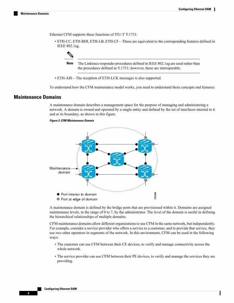
Maintenance DomainsA maintenance domain describes a management space for the purpose of managing and administering anetwork. A domain is owned and operated by a single entity and defined by the set of interfaces internal to itand at its boundary, as shown in this figure.Figure 2: CFM Maintenance Domain
A maintenance domain is defined by the bridge ports that are provisioned within it. Domains are assignedmaintenance levels, in the range of 0 to 7, by the administrator. The level of the domain is useful in definingthe hierarchical relationships of multiple domains.
CFMmaintenance domains allow different organizations to use CFM in the same network, but independently.For example, consider a service provider who offers a service to a customer, and to provide that service, theyuse two other operators in segments of the network. In this environment, CFM can be used in the followingways:
• The customer can use CFM between their CE devices, to verify and manage connectivity across thewhole network.
• The service provider can use CFM between their PE devices, to verify and manage the services they areproviding.
Configuring Ethernet OAM4
Configuring Ethernet OAMMaintenance Domains

• Each operator can use CFM within their operator network, to verify and manage connectivity withintheir network.
Each organization uses a different CFM maintenance domain.
This figure shows an example of the different levels of maintenance domains in a network.
In CFM diagrams, the conventions are that triangles represent MEPs, pointing in the direction that the MEPsends CFM frames, and circles represent MIPs.Figure 3: Different CFM Maintenance Domains Across a Network
Note
To ensure that the CFM frames for each domain do not interfere with each other, each domain is assigned amaintenance level, between 0 and 7. Where domains are nested, as in this example, the encompassing domainmust have a higher level than the domain it encloses. In this case, the domain levels must be negotiated betweenthe organizations involved. The maintenance level is carried in all CFM frames that relate to that domain.
CFM maintenance domains may touch or nest, but cannot intersect. This figure illustrates the supportedstructure for touching and nested domains, and the unsupported intersection of domains.
Configuring Ethernet OAM5
Configuring Ethernet OAMMaintenance Domains

ServicesACFM service allows an organization to partition its CFMmaintenance domain, according to the connectivitywithin the network. For example, if the network is divided into a number of virtual LANs (VLANs), a CFMservice is created for each of these. CFM can then operate independently in each service. It is important thatthe CFM services match the network topology, so that CFM frames relating to one service cannot be receivedin a different service. For example, a service provider may use a separate CFM service for each of theircustomers, to verify and manage connectivity between that customer's end points.
A CFM service is always associated with the maintenance domain that it operates within, and therefore withthat domain's maintenance level. All CFM frames relating to the service carry the maintenance level of thecorresponding domain.
CFMServices are referred to asMaintenance Associations in IEEE 802.1ag and asMaintenance Entity Groupsin ITU-T Y.1731.
Note
Maintenance PointsA CFMMaintenance Point (MP) is an instance of a particular CFM service on a specific interface. CFM onlyoperates on an interface if there is a CFM maintenance point on the interface; otherwise, CFM frames areforwarded transparently through the interface.
A maintenance point is always associated with a particular CFM service, and therefore with a particularmaintenance domain at a particular level. Maintenance points generally only process CFM frames at the samelevel as their associated maintenance domain. Frames at a higher maintenance level are always forwardedtransparently, while frames at a lower maintenance level are normally dropped. This helps enforce themaintenance domain hierarchy, and ensures that CFM frames for a particular domain cannot leak out beyondthe boundary of the domain.
There are two types of MP:
• Maintenance End Points (MEPs)—Created at the edge of the domain. Maintenance end points (MEPs)are members of a particular service within a domain and are responsible for sourcing and sinking CFMframes. They periodically transmit continuity check messages and receive similar messages from otherMEPs within their domain. They also transmit traceroute and loopback messages at the request of theadministrator. MEPs are responsible for confining CFM messages within the domain.
• Maintenance Intermediate Points (MIPs)—Created in the middle of the domain. Unlike MEPS, MIPs doallow CFM frames at their own level to be forwarded.
Configuring Ethernet OAM6
Configuring Ethernet OAMServices

MIP CreationUnlikeMEPs, MIPs are not explicitly configured on each interface. MIPs are created automatically accordingto the algorithm specified in the CFM 802.1ag standard. The algorithm, in brief, operates as follows for eachinterface:
• The bridge-domain or cross-connect for the interface is found, and all services associated with thatbridge-domain or cross-connect are considered for MIP auto-creation.
• The level of the highest-level MEP on the interface is found. From among the services considered above,the service in the domain with the lowest level that is higher than the highest MEP level is selected. Ifthere are no MEPs on the interface, the service in the domain with the lowest level is selected.
• The MIP auto-creation configuration (mip auto-create command) for the selected service is examinedto determine whether a MIP should be created.
Configuring a MIP auto-creation policy for a service does not guarantee that aMIP will automatically be created for that service. The policy is only consideredif that service is selected by the algorithm first.
Note
MEP and CFM Processing OverviewThe boundary of a domain is an interface, rather than a bridge or host. Therefore, MEPs can be sub-dividedinto two categories:
• DownMEPs—Send CFM frames from the interface where they are configured, and process CFM framesreceived on that interface. Down MEPs transmit AIS messages upward (toward the cross-connect).
• Up MEPs—Send frames into the bridge relay function, as if they had been received on the interfacewhere the MEP is configured. They process CFM frames that have been received on other interfaces,and have been switched through the bridge relay function as if they are going to be sent out of the interfacewhere the MEP is configured. Up MEPs transmit AIS messages downward (toward the wire). However,AIS packets are only sent when there is a MIP configured on the same interface as the MEP and at thelevel of the MIP.
• The terms Down MEP and Up MEP are defined in the IEEE 802.1ag and ITU-T Y.1731 standards, andrefer to the direction that CFM frames are sent from the MEP. The terms should not be confused withthe operational status of the MEP.
• The router only supports the “Down MEP level < Up MEP level” configuration.
Note
This figure illustrates the monitored areas for Down and Up MEPs.
Configuring Ethernet OAM7
Configuring Ethernet OAMMIP Creation

Figure 4: Monitored Areas for Down and Up MEPs
This figure shows maintenance points at different levels. Because domains are allowed to nest but not intersect(see ), a MEP at a low level always corresponds with a MEP or MIP at a higher level. In addition, only asingleMIP is allowed on any interface—this is generally created in the lowest domain that exists at the interfaceand that does not have a MEP.
MIPs and Up MEPs can only exist on switched (Layer 2) interfaces, because they send and receive framesfrom the bridge relay function. Down MEPs can be created on switched (Layer 2) interfaces.
MEPs continue to operate normally if the interface they are created on is blocked by the Spanning Tree Protocol(STP); that is, CFM frames at the level of theMEP continue to be sent and received, according to the directionof the MEP. MEPs never allow CFM frames at the level of the MEP to be forwarded, so the STP block ismaintained.
Configuring Ethernet OAM8
Configuring Ethernet OAMMEP and CFM Processing Overview

MIPs also continue to receive CFM frames at their level if the interface is STP blocked, and can respond toany received frames. However, MIPs do not allow CFM frames at the level of the MIP to be forwarded if theinterface is blocked.
A separate set of CFM maintenance levels is created every time a VLAN tag is pushed onto the frame.Therefore, if CFM frames are received on an interface which pushes an additional tag, so as to “tunnel” theframes over part of the network, the CFM frames will not be processed by any MPs within the tunnel, evenif they are at the same level. For example, if a CFM MP is created on an interface with an encapsulation thatmatches a single VLAN tag, any CFM frames that are received at the interface that have two VLAN tags willbe forwarded transparently, regardless of the CFM level.
Note
CFM Protocol MessagesThe CFM protocol consists of a number of different message types, with different purposes. All CFMmessagesuse the CFM EtherType, and carry the CFM maintenance level for the domain to which they apply.
This section describes the following CFM messages:
Continuity Check (IEEE 802.1ag and ITU-T Y.1731)Continuity Check Messages (CCMs) are “heartbeat” messages exchanged periodically between all the MEPsin a service. Each MEP sends out multicast CCMs, and receives CCMs from all the other MEPs in theservice—these are referred to as peer MEPs. This allows each MEP to discover its peer MEPs, and to verifythat there is connectivity between them.
MIPs also receive CCMs. MIPs use the information to build a MAC learning database that is used whenresponding to Linktrace. For more information about Linktrace, see the Linktrace (IEEE 802.1ag and ITU-TY.1731).Figure 5: Continuity Check Message Flow
All the MEPs in a service must transmit CCMs at the same interval. IEEE 802.1ag defines 7 possible intervalsthat can be used:
Configuring Ethernet OAM9
Configuring Ethernet OAMCFM Protocol Messages

• 3.3ms
• 10ms
• 100ms
• 1s
• 10s
• 1 minute
A MEP detects a loss of connectivity with one of its peer MEPs when some number of CCMs have beenmissed. This occurs when sufficient time has passed during which a certain number of CCMs were expected,given the CCM interval. This number is called the loss threshold, and is usually set to 3.
CFM is supported only on interfaces which have Layer 2 transport feature enabled.
CCM messages carry a variety of information that allows different defects to be detected in the service. Thisinformation includes:
• A configured identifier for the domain of the transmitting MEP. This is referred to as the MaintenanceDomain Identifier (MDID).
• A configured identifier for the service of the transmittingMEP. This is referred to as the Short MAName(SMAN). Together, the MDID and the SMANmake up the Maintenance Association Identifier (MAID).The MAID must be configured identically on every MEP in the service.
• These are restrictions on the type of MAID that are supported for sessions with time interval of less than1 minute. The MAID supports two types of formats on offloaded MEPs:
• No Domain Name Format
• MD Name Format = 1-NoDomainName
• Short MA Name Format = 3 - 2 bytes integer value
• Short MA NAme Length = 2 - fixed length
• Short MA Name = 2 bytes of integer
• 1731 Maid Format
• MD Name Format = 1-NoDomainName
• MA Name Format(MEGID Format) = 32
• MEGID Length = 13 - fixed length
• MEGID(ICCCode) = 6 Bytes
• MEGID(UMC) = 7 Bytes
• ITU Carrier Code (ICC) - Number of different configurable ICC code - 15 (for each NPU)
• Unique MEG ID Code (UMC) - 4
Maintenance Association Identifier (MAID) comprises of the Maintenance Domain Identifier (MDID)and Short MA Name (SMAN). MDID only supports null value and SMAN only supports ITU CarrierCode (ICC) or a numerical. No other values are supported.
Configuring Ethernet OAM10
Configuring Ethernet OAMContinuity Check (IEEE 802.1ag and ITU-T Y.1731)

An example for configuring domain ID null is: ethernet cfm domain SMB level 3 id null
An example for configuring SMAN is: ethernet cfm domain SMB level 3 id null service 901234ABxconnect group 99999 p2p 99999 id number 1
The following table summarizes the supported values and parameters for MDID and SMAN. This tableonly details the MAID restriction on the hardware offload feature. There is no MAID restriction forsoftware offload or non-offloaded MEPs.
CommentSupportSMANMDIDFormat
Up to 2000 entriesYes2 byte integerNo
Up to 15 uniqueICC
Up to 4K UMCvalues
Yes13 bytes ICCCode(6 bytes) and UMC(7 bytes)
No
Most commonlyused
No1-48 bytes of MDID and SMAN48 bytes stringbased
• A configured numeric identifier for the MEP (the MEP ID). EachMEP in the service must be configuredwith a different MEP ID.
• Dynamic Remote MEPs are not supported for MEPs with less than 1min interval. You must configureMEP CrossCheck for all such MEPS.
• Sequence numbering is not supported for MEPs with less than 1 minute interval.
• In a Remote Defect Indication (RDI), eachMEP includes this in the CCMs it is sending, if it has detecteda defect relating to the CCMs it is receiving. This notifies all the MEPs in the service that a defect hasbeen detected somewhere in the service.
• The interval at which CCMs are being transmitted.
• CCM Tx/Rx statistics counters are not supported for MEPs with less than1 minute intervals.
• Sender TLV and Cisco Proprietary TLVs are not supported for MEPs with less than 1min intervals.
• The status of the interface where the MEP is operating—for example, whether the interface is up, down,STP blocked, and so on.
The status of the interface (up/down) should not be confused with the directionof any MEPs on the interface (Up MEPs/Down MEPs).
Note
These defects can be detected from received CCMs:
• Interval mismatch—The CCM interval in the received CCM does not match the interval that the MEPis sending CCMs.
• Level mismatch—A MEP has received a CCM carrying a lower maintenance level than the MEPs ownlevel.
Configuring Ethernet OAM11
Configuring Ethernet OAMContinuity Check (IEEE 802.1ag and ITU-T Y.1731)
• Loop—A CCM is received with the source MAC address equal to the MAC address of the interfacewhere the MEP is operating.
• Configuration error—A CCM is received with the same MEP ID as the MEP ID configured for thereceiving MEP.
• Cross-connect—A CCM is received with an MAID that does not match the locally configured MAID.This generally indicates a VLANmisconfiguration within the network, such that CCMs from one serviceare leaking into a different service.
• Peer interface down—A CCM is received that indicates the interface on the peer is down.
• Remote defect indication—A CCM is received carrying a remote defect indication.
This defect does not cause the MEP to include a remote defect indication in theCCMs that it is sending.
Note
Out-of-sequence CCMs can also be detected by monitoring the sequence number in the received CCMs fromeach peer MEP. However, this is not considered a CCM defect.
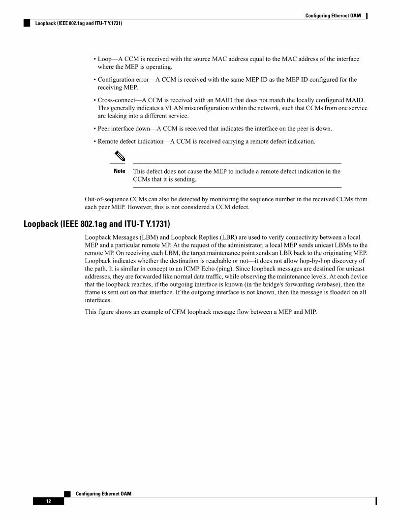
Loopback (IEEE 802.1ag and ITU-T Y.1731)Loopback Messages (LBM) and Loopback Replies (LBR) are used to verify connectivity between a localMEP and a particular remote MP. At the request of the administrator, a local MEP sends unicast LBMs to theremote MP. On receiving each LBM, the target maintenance point sends an LBR back to the originating MEP.Loopback indicates whether the destination is reachable or not—it does not allow hop-by-hop discovery ofthe path. It is similar in concept to an ICMP Echo (ping). Since loopback messages are destined for unicastaddresses, they are forwarded like normal data traffic, while observing the maintenance levels. At each devicethat the loopback reaches, if the outgoing interface is known (in the bridge's forwarding database), then theframe is sent out on that interface. If the outgoing interface is not known, then the message is flooded on allinterfaces.
This figure shows an example of CFM loopback message flow between a MEP and MIP.
Configuring Ethernet OAM12
Configuring Ethernet OAMLoopback (IEEE 802.1ag and ITU-T Y.1731)

Figure 6: Loopback Messages
Loopback messages can be padded with user-specified data. This allows data corruption to be detected in thenetwork. They also carry a sequence number which allows for out-of-order frames to be detected.
Linktrace (IEEE 802.1ag and ITU-T Y.1731)Linktrace Messages (LTM) and Linktrace Replies (LTR) are used to track the path (hop-by-hop) to a unicastdestination MAC address. At the request of the operator, a local MEP sends an LTM. Each hop where thereis a maintenance point sends an LTR back to the originating MEP. This allows the administrator to discoverconnectivity data about the path. It is similar in concept to IP traceroute, although the mechanism is different.In IP traceroute, successive probes are sent, whereas CFM Linktrace uses a single LTM which is forwardedby each MP in the path. LTMs are multicast, and carry the unicast target MAC address as data within theframe. They are intercepted at each hop where there is a maintenance point, and either retransmitted or droppedto discover the unicast path to the target MAC address.
This figure shows an example of CFM linktrace message flow between MEPs and MIPs.
Configuring Ethernet OAM13
Configuring Ethernet OAMLinktrace (IEEE 802.1ag and ITU-T Y.1731)

Figure 7: Linktrace Message Flow
The linktrace mechanism is designed to provide useful information even after a network failure. This allowsit to be used to locate failures, for example after a loss of continuity is detected. To achieve this, each MPmaintains a CCM Learning Database. This maps the source MAC address for each received CCM to theinterface through which the CCMwas received. It is similar to a typical bridgeMAC learning database, exceptthat it is based only on CCMs and it times out much more slowly—on the order of days rather than minutes.
In IEEE 802.1ag, the CCM Learning Database is referred to as the MIP CCM Database. However, it appliesto both MIPs and MEPs.
Note
In IEEE 802.1ag, when an MP receives an LTM message, it determines whether to send a reply using thefollowing steps:
1. The target MAC address in the LTM is looked up in the bridge MAC learning table. If the MAC addressis known, and therefore the egress interface is known, then an LTR is sent.
2. If theMAC address is not found in the bridgeMAC learning table, then it is looked up in the CCM learningdatabase. If it is found, then an LTR is sent.
3. If the MAC address is not found, then no LTR is sent (and the LTM is not forwarded).
If the target MAC has never been seen previously in the network, the linktrace operation will not produce anyresults.
Configuring Ethernet OAM14
Configuring Ethernet OAMLinktrace (IEEE 802.1ag and ITU-T Y.1731)

IEEE 802.1ag and ITU-T Y.1731 define slightly different linktrace mechanisms. In particular, the use of theCCM learning database and the algorithm described above for responding to LTM messages are specific toIEEE 802.1ag. IEEE 802.1ag also specifies additional information that can be included in LTRs. Regardlessof the differences, the two mechanisms are interoperable.
Note
Configurable LoggingCFM supports logging of various conditions to syslog. Logging can be enabled independently for each service,and when the following conditions occur:
• New peer MEPs are detected, or loss of continuity with a peer MEP occurs.
• Changes to the CCM defect conditions are detected.
• Cross-check “missing” or “unexpected” conditions are detected.
• AIS condition detected (AIS messages received) or cleared (AIS messages no longer received).
• EFD used to shut down an interface, or bring it back up.
Flexible VLAN Tagging for CFMThe Flexible VLAN Tagging for CFM feature ensures that CFM packets are sent with the right VLAN tagsso that they are appropriately handled as a CFM packet by the remote device. When packets are received byan edge router, they are treated as either CFM packets or data packets, depending on the number of tags inthe header. The system differentiates between CFM packets and data packets based on the number of tags inthe packet, and forwards the packets to the appropriate paths based on the number of tags in the packet.
CFM frames are normally sent with the same VLAN tags as the corresponding customer data traffic on theinterface, as defined by the configured encapsulation and tag rewrite operations. Likewise, received framesare treated as CFM frames if they have the correct number of tags as defined by the configured encapsulationand tag rewrite configuration, and are treated as data frames (that is, they are forwarded transparently) if theyhave more than this number of tags.
In most cases, this behavior is as desired, since the CFM frames are then treated in exactly the same way asthe data traffic flowing through the same service. However, in a scenario where multiple customer VLANsare multiplexed over a single multipoint provider service (for example, N:1 bundling), a different behaviormight be desirable.
This figure shows an example of a network with multiple VLANS using CFM.
Configuring Ethernet OAM15
Configuring Ethernet OAMConfigurable Logging

Figure 8: Service Provider Network With Multiple VLANs and CFM
This figure shows a provider's access network, where the S-VLAN tag is used as the service delimiter. PE1faces the customer, and PE2 is at the edge of the access network facing the core. N:1 bundling is used, so theinterface encapsulation matches a range of C-VLAN tags. This could potentially be the full range, resultingin all:1 bundling. There is also a use case where only a single C-VLAN is matched, but the S-VLAN isnevertheless used as the service delimiter—this is more in keeping with the IEEEmodel, but limits the providerto 4094 services.
CFM is used in this network with a MEP at each end of the access network, and MIPs on the boxes withinthe network (if it is native Ethernet). In the normal case, CFM frames are sent by the up MEP on PE1 withtwo VLAN tags, matching the customer data traffic. This means that at the core interfaces and at the MEP onPE2, the CFM frames are forwarded as if they were customer data traffic, since these interfaces match onlyon the S-VLAN tag. So, the CFM frames sent by the MEP on PE1 are not seen by any of the other MPs.
Flexible VLAN tagging changes the encapsulation for CFM frames that are sent and received at Up MEPs.Flexible VLAN tagging allows the frames to be sent from the MEP on PE1 with just the S-VLAN tag thatrepresents the provider service. If this is done, the core interfaces will treat the frames as CFM frames andthey will be seen by the MIPs and by the MEP on PE2. Likewise, the MEP on PE1 should handle receivedframes with only one tag, as this is what it will receive from the MEP on PE2.
To ensure that CFM packets from Up MEPs are routed to the appropriate paths successfully, tags may be setto a specific number in a domain service, using the tags command. Currently, tags can only be set to one (1).
How to Configure Ethernet OAMThis section provides these configuration procedures:
Configuring Ethernet Link OAMCustom EOAM settings can be configured and shared on multiple interfaces by creating an EOAM profile inEthernet configuration mode and then attaching the profile to individual interfaces. The profile configurationdoes not take effect until the profile is attached to an interface. After an EOAM profile is attached to aninterface, individual EOAM features can be configured separately on the interface to override the profilesettings when desired.
This section describes how to configure an EOAM profile and attach it to an interface in these procedures:
Configuring Ethernet OAM16
Configuring Ethernet OAMHow to Configure Ethernet OAM

Configuring an Ethernet OAM ProfilePerform these steps to configure an Ethernet OAM profile.
Procedure
PurposeCommand or Action
Enters global configuration mode.configure
Example:
Step 1
RP/0/RP0/CPU0:router# configure terminal
Creates a new Ethernet Operations,Administration and Maintenance (OAM)
ethernet oam profile profile-name
Example:
Step 2
profile and enters Ethernet OAMconfigurationmode.
RP/0/RP0/CPU0:router(config)# ethernetoam profile Profile_1
Enters the Ethernet OAM link monitorconfiguration mode.
link-monitor
Example:
Step 3
RP/0/RP0/CPU0:router(config-eoam)#link-monitor
(Optional) Configures the window size (inmilliseconds) for an Ethernet OAM
symbol-period window window
Example:
Step 4
symbol-period error event. The IEEE 802.3
RP/0/RP0/CPU0:router(config-eoam-lm)#symbol-period window 60000
standard defines the window size as a numberof symbols rather than a time duration. Thesetwo formats can be converted either way byusing a knowledge of the interface speed andencoding.
The range is 1000 to 60000.
The default value is 1000.
(Optional) Configures the thresholds (insymbols) that trigger an Ethernet OAM
symbol-period threshold low threshold highthreshold symbol-period threshold { ppm [
Step 5
symbol-period error event. The high thresholdlow threshold ] [ high threshold ] | symbols [is optional and is configurable only inconjunction with the low threshold.
low threshold [ thousand | million | billion ]][ high threshold [ thousand | million | billion]]} The range is 1 to 1000000.Example: The default low threshold is 1.
RP/0/RP0/CPU0:router(config-eoam-lm)#symbol-period threshold ppm low 1 high1000000
(Optional) Configures the frame window size(inmilliseconds) of anOAM frame error event.
frame window window
Example:
Step 6
Configuring Ethernet OAM17
Configuring Ethernet OAMConfiguring an Ethernet OAM Profile
PurposeCommand or Action
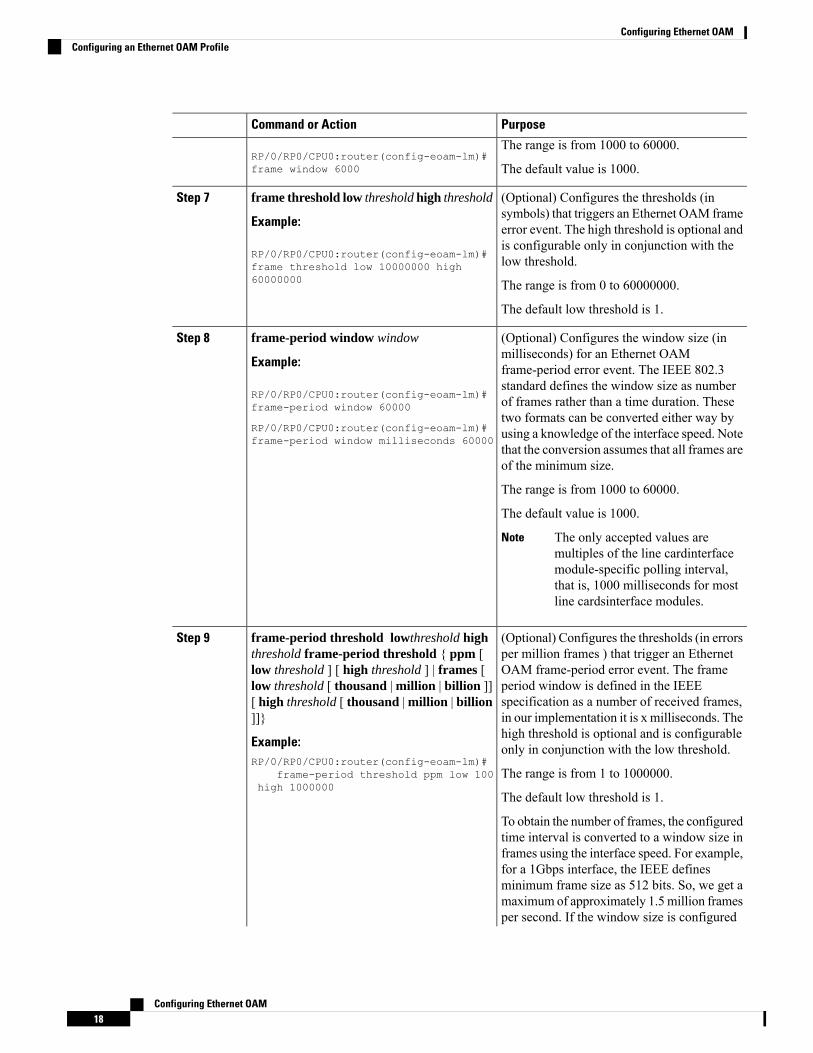
The range is from 1000 to 60000.RP/0/RP0/CPU0:router(config-eoam-lm)#frame window 6000 The default value is 1000.
(Optional) Configures the thresholds (insymbols) that triggers an Ethernet OAM frame
frame threshold low threshold high threshold
Example:
Step 7
error event. The high threshold is optional and
RP/0/RP0/CPU0:router(config-eoam-lm)#is configurable only in conjunction with thelow threshold.frame threshold low 10000000 high
60000000 The range is from 0 to 60000000.
The default low threshold is 1.
(Optional) Configures the window size (inmilliseconds) for an Ethernet OAM
frame-period window window
Example:
Step 8
frame-period error event. The IEEE 802.3
RP/0/RP0/CPU0:router(config-eoam-lm)#frame-period window 60000
standard defines the window size as numberof frames rather than a time duration. Thesetwo formats can be converted either way by
RP/0/RP0/CPU0:router(config-eoam-lm)#frame-period window milliseconds 60000 using a knowledge of the interface speed. Note
that the conversion assumes that all frames areof the minimum size.
The range is from 1000 to 60000.
The default value is 1000.
The only accepted values aremultiples of the line cardinterfacemodule-specific polling interval,that is, 1000 milliseconds for mostline cardsinterface modules.
Note
(Optional) Configures the thresholds (in errorsper million frames ) that trigger an Ethernet
frame-period threshold lowthreshold highthreshold frame-period threshold { ppm [
Step 9
OAM frame-period error event. The framelow threshold ] [ high threshold ] | frames [period window is defined in the IEEElow threshold [ thousand | million | billion ]]specification as a number of received frames,[ high threshold [ thousand | million | billion
]]} in our implementation it is x milliseconds. Thehigh threshold is optional and is configurableonly in conjunction with the low threshold.Example:
RP/0/RP0/CPU0:router(config-eoam-lm)#frame-period threshold ppm low 100
high 1000000The range is from 1 to 1000000.
The default low threshold is 1.
To obtain the number of frames, the configuredtime interval is converted to a window size inframes using the interface speed. For example,for a 1Gbps interface, the IEEE definesminimum frame size as 512 bits. So, we get amaximum of approximately 1.5 million framesper second. If the window size is configured
Configuring Ethernet OAM18
Configuring Ethernet OAMConfiguring an Ethernet OAM Profile
PurposeCommand or Action
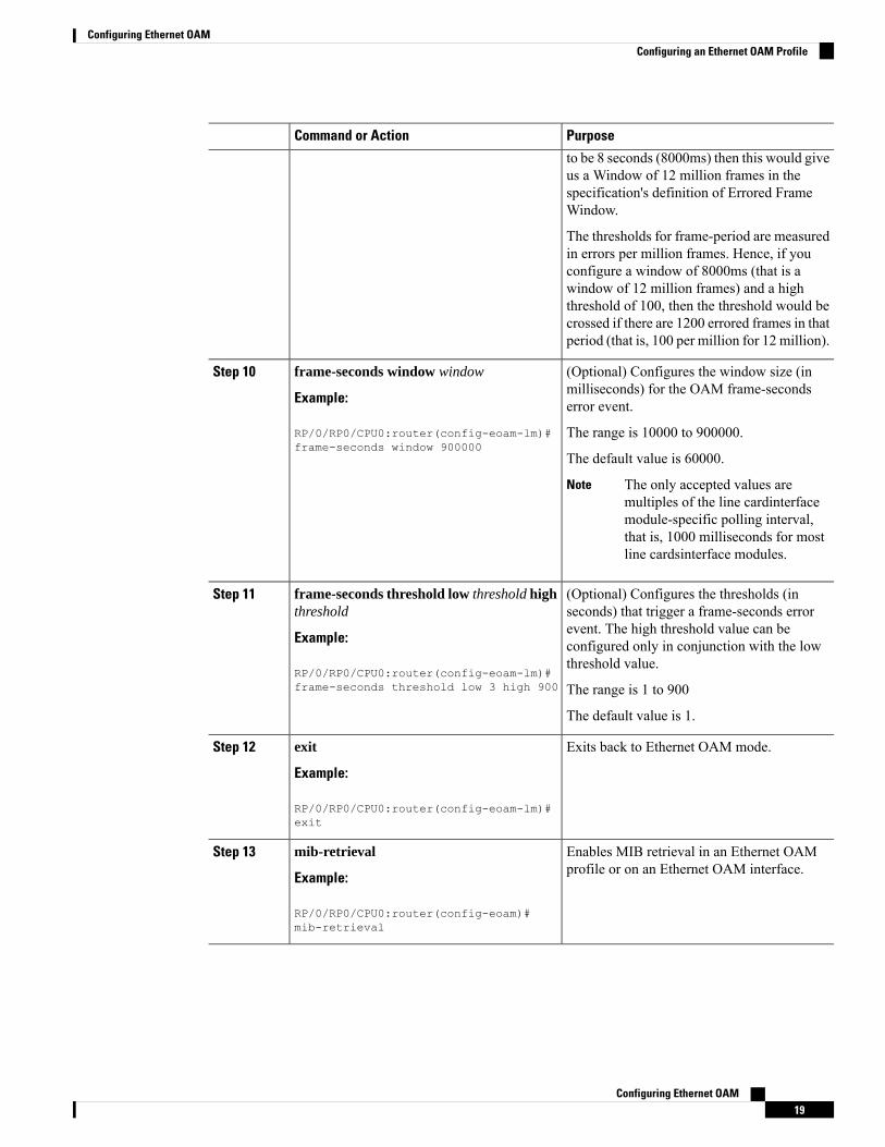
to be 8 seconds (8000ms) then this would giveus a Window of 12 million frames in thespecification's definition of Errored FrameWindow.
The thresholds for frame-period are measuredin errors per million frames. Hence, if youconfigure a window of 8000ms (that is awindow of 12 million frames) and a highthreshold of 100, then the threshold would becrossed if there are 1200 errored frames in thatperiod (that is, 100 per million for 12 million).
(Optional) Configures the window size (inmilliseconds) for the OAM frame-secondserror event.
frame-seconds window window
Example:
RP/0/RP0/CPU0:router(config-eoam-lm)#frame-seconds window 900000
Step 10
The range is 10000 to 900000.
The default value is 60000.
The only accepted values aremultiples of the line cardinterfacemodule-specific polling interval,that is, 1000 milliseconds for mostline cardsinterface modules.
Note
(Optional) Configures the thresholds (inseconds) that trigger a frame-seconds error
frame-seconds threshold low threshold highthreshold
Step 11
event. The high threshold value can beExample: configured only in conjunction with the low
threshold value.RP/0/RP0/CPU0:router(config-eoam-lm)#frame-seconds threshold low 3 high 900 The range is 1 to 900
The default value is 1.
Exits back to Ethernet OAM mode.exit
Example:
Step 12
RP/0/RP0/CPU0:router(config-eoam-lm)#exit
Enables MIB retrieval in an Ethernet OAMprofile or on an Ethernet OAM interface.
mib-retrieval
Example:
Step 13
RP/0/RP0/CPU0:router(config-eoam)#mib-retrieval
Configuring Ethernet OAM19
Configuring Ethernet OAMConfiguring an Ethernet OAM Profile

PurposeCommand or Action
Configures the connection timeout period foran Ethernet OAM session. as a multiple of thehello interval.
connection timeout <timeout>
Example:
RP/0/RP0/CPU0:router(config-eoam)#connection timeout 30
Step 14
The range is 2 to 30.
The default value is 5.
Configures the time interval between hellopackets for an Ethernet OAM session. Thedefault is 1 second (1s).
hello-interval {100ms|1s}
Example:
RP/0/RP0/CPU0:router(config-eoam)#hello-interval 100ms
Step 15
Configures the Ethernet OAM mode. Thedefault is active.
mode {active|passive}
Example:
Step 16
RP/0/RP0/CPU0:router(config-eoam)# modepassive
Requires that active mode or passive mode isconfigured on the remote end before the OAMsession becomes active.
require-remote mode {active|passive}
Example:
RP/0/RP0/CPU0:router(config-eoam)#require-remote mode active
Step 17
Requires that MIB-retrieval is configured onthe remote end before the OAM sessionbecomes active.
require-remote mib-retrieval
Example:
RP/0/RP0/CPU0:router(config-eoam)#require-remote mib-retrieval
Step 18
Specifies the action that is taken on an interfacewhen a capabilities-conflict event occurs. Thedefault action is to create a syslog entry.
action capabilities-conflict {disable | efd |error-disable-interface}
Example:
Step 19
• If you change the default, thelog keyword option isavailable in Interface EthernetOAM configuration mode tooverride the profile setting andlog the event for the interfacewhen it occurs.
NoteRP/0/RP0/CPU0:router(config-eoam)#action capabilities-conflict efd
Specifies the action that is taken on an interfacewhen a critical-event notification is received
action critical-event {disable |error-disable-interface}
Step 20
from the remote Ethernet OAM peer. Thedefault action is to create a syslog entry.Example:
RP/0/RP0/CPU0:router(config-eoam)#
Configuring Ethernet OAM20
Configuring Ethernet OAMConfiguring an Ethernet OAM Profile

PurposeCommand or Actionaction critical-eventerror-disable-interface
• If you change the default, thelog keyword option isavailable in Interface EthernetOAM configuration mode tooverride the profile setting andlog the event for the interfacewhen it occurs.
Note
Specifies the action that is taken on an interfacewhen a connection timeout occurs. The defaultaction is to create a syslog entry.
action discovery-timeout {disable | efd |error-disable-interface}
Example:
Step 21
• If you change the default, thelog keyword option isavailable in Interface EthernetOAM configuration mode tooverride the profile setting andlog the event for the interfacewhen it occurs.
NoteRP/0/RP0/CPU0:router(config-eoam)#action discovery-timeout efd
Specifies the action that is taken on an interfacewhen a dying-gasp notification is received
action dying-gasp {disable |error-disable-interface}
Step 22
from the remote Ethernet OAM peer. Thedefault action is to create a syslog entry.Example:
RP/0/RP0/CPU0:router(config-eoam)# • If you change the default, thelog keyword option isavailable in Interface EthernetOAM configuration mode tooverride the profile setting andlog the event for the interfacewhen it occurs.
Noteaction dying-gasperror-disable-interface
Specifies the action that is taken on an interfacewhen a high threshold is exceeded. The default
action high-threshold{error-disable-interface | log}
Step 23
is to take no action when a high threshold isexceeded.Example:
RP/0/RP0/CPU0:router(config-eoam)# • If you change the default, thedisable keyword option isavailable in Interface EthernetOAM configuration mode tooverride the profile setting andtake no action at the interfacewhen the event occurs.
Noteaction high-thresholderror-disable-interface
Specifies the action that is taken on an interfacewhen an Ethernet OAM session goes down.
action session-down {disable | efd |error-disable-interface}
Step 24
Configuring Ethernet OAM21
Configuring Ethernet OAMConfiguring an Ethernet OAM Profile

PurposeCommand or Action
Example: • If you change the default, thelog keyword option isavailable in Interface EthernetOAM configuration mode tooverride the profile setting andlog the event for the interfacewhen it occurs.
Note
RP/0/RP0/CPU0:router(config-eoam)#action session-down efd
Specifies that no action is taken on an interfacewhen an Ethernet OAM session is established.The default action is to create a syslog entry.
action session-up disable
Example:
RP/0/RP0/CPU0:router(config-eoam)#action session-up disable
Step 25
• If you change the default, thelog keyword option isavailable in Interface EthernetOAM configuration mode tooverride the profile setting andlog the event for the interfacewhen it occurs.
Note
Specifies the action that is taken on an interfacewhen a link-fault notification is received from
action uni-directional link-fault {disable |efd | error-disable-interface}
Step 26
the remote Ethernet OAM peer. The defaultaction is to create a syslog entry.
• If you change the default, thelog keyword option isavailable in Interface EthernetOAM configuration mode tooverride the profile setting andlog the event for the interfacewhen it occurs.
Note
Specifies the action that is taken on an interfacewhen a wiring-conflict event occurs. The
action wiring-conflict {disable | efd | log}
Example:
Step 27
default is to put the interface into error-disablestate.
RP/0/RP0/CPU0:router(config-eoam)#action session-down efd • If you change the default, the
error-disable-interfacekeyword option is available inInterface Ethernet OAMconfigurationmode to overridethe profile setting and put theinterface into error-disablestate when the event occurs.
Note
Configuring Ethernet OAM22
Configuring Ethernet OAMConfiguring an Ethernet OAM Profile

PurposeCommand or Action
Enables detection of a local, unidirectional linkfault and sends notification of that fault to anEthernet OAM peer.
uni-directional link-fault detection
Example:
RP/0/RP0/CPU0:router(config-eoam)#uni-directional link-fault detection
Step 28
Saves the configuration changes to the runningconfiguration file and remains within theconfiguration session.
commit
Example:
RP/0/RP0/CPU0:router(config-if)# commit
Step 29
Ends the configuration session and exits to theEXEC mode.
end
Example:
Step 30
RP/0/RP0/CPU0:router(config-if)# end
Attaching an Ethernet OAM Profile to an InterfacePerform these steps to attach an Ethernet OAM profile to an interface:
Procedure
PurposeCommand or Action
Enters global configuration mode.configure
Example:
Step 1
RP/0/RP0/CPU0:router# configure terminal
Enters interface configuration mode andspecifies the Ethernet interface name andnotation rack/slot/module/port.
interface [ | HundredGigE| TenGigE]interface-path-id
Example:
Step 2
RP/0/RP0/CPU0:router(config)# interfaceTenGigE0/0/0/0
Enables Ethernet OAM and enters interfaceEthernet OAM configuration mode.
ethernet oam
Example:
Step 3
RP/0/RP0/CPU0:router(config-if)# ethernetoam
Configuring Ethernet OAM23
Configuring Ethernet OAMAttaching an Ethernet OAM Profile to an Interface
PurposeCommand or Action
Attaches the specified Ethernet OAM profile(profile-name), and all of its configuration, tothe interface.
profile profile-name
Example:
RP/0/RP0/CPU0:router(config-if-eoam)#profile Profile_1
Step 4
Saves the configuration changes to the runningconfiguration file and remains within theconfiguration session.
commit
Example:
RP/0/RP0/CPU0:router(config-if)# commit
Step 5
Ends the configuration session and exits to theEXEC mode.
end
Example:
Step 6
RP/0/RP0/CPU0:router(config-if)# end
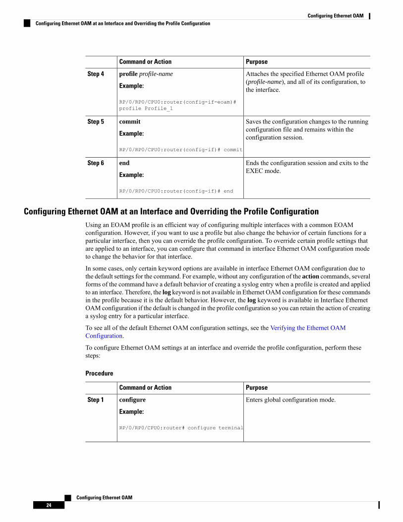
Configuring Ethernet OAM at an Interface and Overriding the Profile ConfigurationUsing an EOAM profile is an efficient way of configuring multiple interfaces with a common EOAMconfiguration. However, if you want to use a profile but also change the behavior of certain functions for aparticular interface, then you can override the profile configuration. To override certain profile settings thatare applied to an interface, you can configure that command in interface Ethernet OAM configuration modeto change the behavior for that interface.
In some cases, only certain keyword options are available in interface Ethernet OAM configuration due tothe default settings for the command. For example, without any configuration of the action commands, severalforms of the command have a default behavior of creating a syslog entry when a profile is created and appliedto an interface. Therefore, the log keyword is not available in Ethernet OAM configuration for these commandsin the profile because it is the default behavior. However, the log keyword is available in Interface EthernetOAM configuration if the default is changed in the profile configuration so you can retain the action of creatinga syslog entry for a particular interface.
To see all of the default Ethernet OAM configuration settings, see the Verifying the Ethernet OAMConfiguration.
To configure Ethernet OAM settings at an interface and override the profile configuration, perform thesesteps:
Procedure
PurposeCommand or Action
Enters global configuration mode.configure
Example:
Step 1
RP/0/RP0/CPU0:router# configure terminal
Configuring Ethernet OAM24
Configuring Ethernet OAMConfiguring Ethernet OAM at an Interface and Overriding the Profile Configuration

PurposeCommand or Action
Enters interface configuration mode andspecifies the Ethernet interface name andnotation rack/slot/module/port.
interface [HundredGigE | TenGigE]interface-path-id
Example:
Step 2
• The example indicates an 8-port10-Gigabit Ethernet interfacein modular services card slot 1.
NoteRP/0/RP0/CPU0:router(config)# interfaceTenGigE0/0/0/0
Enables Ethernet OAM and enters interfaceEthernet OAM configuration mode.
ethernet oam
Example:
Step 3
RP/0/RP0/CPU0:router(config-if)# ethernetoam
Configures a setting for an Ethernet OAMconfiguration command and overrides the
interface-Ethernet-OAM-command
Example:
Step 4
setting for the profile configuration, whereRP/0/RP0/CPU0:router(config-if-eoam)#action capabilities-conflicterror-disable-interface
interface-Ethernet-OAM-command is one ofthe supported commands on the platform ininterface Ethernet OAM configuration mode.
Saves the configuration changes to the runningconfiguration file and remains within theconfiguration session.
commit
Example:
RP/0/RP0/CPU0:router(config-if)# commit
Step 5
Ends the configuration session and exits to theEXEC mode.
end
Example:
Step 6
RP/0/RP0/CPU0:router(config-if)# end
Verifying the Ethernet OAM ConfigurationUse the show ethernet oam configuration command to display the values for the Ethernet OAM configurationfor a particular interface, or for all interfaces. The following example shows the default values for EthernetOAM settings:
RP/0/RP0/CPU0:router# show ethernet oam configurationThu Aug 5 22:07:06.870 DSTGigabitEthernet0/0/0/0:Hello interval: 1sMib retrieval enabled: NUni-directional link-fault detection enabled: NConfigured mode: ActiveConnection timeout: 5Symbol period window: 0Symbol period low threshold: 1Symbol period high threshold: NoneFrame window: 1000Frame low threshold: 1Frame high threshold: None
Configuring Ethernet OAM25
Configuring Ethernet OAMVerifying the Ethernet OAM Configuration

Frame period window: 1000Frame period low threshold: 1Frame period high threshold: NoneFrame seconds window: 60000Frame seconds low threshold: 1Frame seconds high threshold: NoneHigh threshold action: NoneLink fault action: LogDying gasp action: LogCritical event action: LogDiscovery timeout action: LogCapabilities conflict action: LogWiring conflict action: Error-DisableSession up action: LogSession down action: LogRequire remote mode: IgnoreRequire remote MIB retrieval: N
Configuring Ethernet CFM
CFM is not supported for the following:Note
• L3 Interfaces and Sub-Interfaces
• Bundle Member Ports
• EVPN-FXC
• Bridge Domain
• VPLS
Configuring a CFM Maintenance DomainTo configure a CFM maintenance domain, perform the following steps:
Procedure
PurposeCommand or Action
Enters global configuration mode.configure
Example:
Step 1
RP/0/RP0/CPU0:router# configure
Enters Ethernet Connectivity FaultManagement(CFM) configuration mode.
ethernet cfm
Example:
Step 2
RP/0/RP0/CPU0:router(config)# ethernetcfm
Configuring Ethernet OAM26
Configuring Ethernet OAMConfiguring Ethernet CFM

PurposeCommand or Action
(Optional) Sets themaximum limit of traceroutecache entries or the maximum time limit to hold
traceroute cache hold-time minutes sizeentries
Step 3
the traceroute cache entries. The default is 100minutes and 100 entries.Example:
RP/0/RP0/CPU0:router(config-cfm)#traceroute cache hold-time 1 size 3000
Creates and names a container for all domainconfigurations and enters CFM domainconfiguration mode.
domain domain-name level level-value [id[null] [dns DNS-name] [mac H.H.H] [stringstring] ]
Step 4
Example: The level must be specified.
RP/0/RP0/CPU0:router(config-cfm)# domainDomain_One level 1 id string D1
The id is the maintenance domain identifier(MDID) and is used as the first part of themaintenance association identifier (MAID) inCFM frames. If the MDID is not specified, thedomain name is used as the MDID by default.
Saves configuration changes.end or commitStep 5
Example: • When you use the end command, thesystem prompts you to commit changes:
RP/0/RP0/CPU0:router(config-cfm-dmn)#commit Uncommitted changes found, commit
them before exiting(yes/no/cancel)?[cancel]:
• Entering yes saves configuration changesto the running configuration file, exits theconfiguration session, and returns therouter to EXEC mode.
• Entering no exits the configuration sessionand returns the router to EXEC modewithout committing the configurationchanges.
• Entering cancel leaves the router in thecurrent configuration session withoutexiting or committing the configurationchanges.
• Use the commit command to save theconfiguration changes to the runningconfiguration file and remain within theconfiguration session.
Configuring Services for a CFM Maintenance DomainYou can configure up to 2000 CFM services for a maintenance domain. To configure services for a CFMmaintenance domain, perform the following steps:
Configuring Ethernet OAM27
Configuring Ethernet OAMConfiguring Services for a CFM Maintenance Domain

Procedure
PurposeCommand or Action
Enters global configuration mode.configure
Example:
Step 1
RP/0/RP0/CPU0:router# configure
Enters Ethernet CFM configuration mode.ethernet cfm
Example:
Step 2
RP/0/RP0/CPU0:router(config)# ethernetcfm
Creates and names a container for all domainconfigurations at a specified maintenance level,and enters CFM domain configuration mode.
domain domain-name level level-value [id[null] [dns DNS-name] [mac H.H.H] [stringstring] ]
Step 3
Example: The id is the maintenance domain identifier(MDID) and is used as the first part of the
RP/0/RP0/CPU0:router(config-cfm)# domainDomain_One level 1 id string D1
maintenance association identifier (MAID) inCFM frames. If the MDID is not specified, thedomain name is used as the MDID by default.
Configures and associates a service with thedomain and enters CFM domain service
service service-name {down-meps | xconnectgroup xconnect-group-name m2mp |
Step 4
configuration mode. You can specify that thep2p xconnect-name}[id [icc-based icc-stringumc-string] | [ [number number] service is used only for down MEPs, or
associate the service with a bridge domainwhere MIPs and up MEPs will be created.Example:
RP/0/RP0/CPU0:router(config-cfm-dmn)#service ABC xconnect group X1 p2p ADB
The id sets the short MA name.
Saves configuration changes.end or commitStep 5
Example: • When you use the end command, thesystem prompts you to commit changes:
RP/0/RP0/CPU0:router(config-cfm-dmn-svc)#commit Uncommitted changes found, commit
them before exiting(yes/no/cancel)?[cancel]:
• Entering yes saves configuration changesto the running configuration file, exits theconfiguration session, and returns therouter to EXEC mode.
• Entering no exits the configuration sessionand returns the router to EXEC modewithout committing the configurationchanges.
Configuring Ethernet OAM28
Configuring Ethernet OAMConfiguring Services for a CFM Maintenance Domain

PurposeCommand or Action
• Entering cancel leaves the router in thecurrent configuration session withoutexiting or committing the configurationchanges.
• Use the commit command to save theconfiguration changes to the runningconfiguration file and remain within theconfiguration session.
Enabling and Configuring Continuity Check for a CFM ServiceTo configure Continuity Check for a CFM service, complete the following steps:
Procedure
PurposeCommand or Action
Enters global configuration mode.configure
Example:
Step 1
RP/0/RP0/CPU0:router# configure
Enters Ethernet Connectivity FaultManagement(CFM) configuration mode.
ethernet cfm
Example:
Step 2
RP/0/RP0/CPU0:router(config)# ethernetcfm
Creates and names a container for all domainconfigurations and enters the CFM domainconfiguration mode.
domain domain-name level level-value [id[null] [dns DNS-name] [mac H.H.H] [stringstring] ]
Step 3
Example: The level must be specified.
RP/0/RP0/CPU0:router(config-cfm)# domainDomain_One level 1 id string D1
The id is the maintenance domain identifier(MDID) and is used as the first part of themaintenance association identifier (MAID) inCFM frames. If the MDID is not specified, thedomain name is used as the MDID by default.
Configures and associates a service with thedomain and enters CFM domain service
service service-name {down-meps | xconnectgroup xconnect-group-name
Step 4
configuration mode. You can specify that thep2p xconnect-name}[id [icc-based icc-stringumc-string] | [ [number number] service is used only for down MEPs, or
associate the service with a bridge domain orExample: xconnect where MIPs and up MEPs will be
created.RP/0/RP0/CPU0:router(config-cfm-dmn)#service ABC xconnect group X1 p2p ADB The id sets the short MA name.
Configuring Ethernet OAM29
Configuring Ethernet OAMEnabling and Configuring Continuity Check for a CFM Service

PurposeCommand or Action
(Optional) Enables Continuity Check andspecifies the time interval at which CCMs are
continuity-check interval time [loss-thresholdthreshold]
Step 5
transmitted or to set the threshold limit for whena MEP is declared down.Example:
RP/0/RP0/CPU0:router(config-cfm-dmn-svc)#continuity-check interval 100mloss-threshold 10
(Optional) Configures how long informationabout peerMEPs is stored after they have timedout.
continuity-check archive hold-time minutes
Example:
RP/0/RP0/CPU0:router(config-cfm-dmn-svc)#continuity-check archive hold-time 100
Step 6
(Optional) Configures automatic triggering ofa traceroute when a MEP is declared down.
continuity-check loss auto-traceroute
Example:
Step 7
RP/0/RP0/CPU0:router(config-cfm-dmn-svc)#continuity-check loss auto-traceroute
Saves configuration changes.end or commitStep 8
Example: • When you use the end command, thesystem prompts you to commit changes:
RP/0/RP0/CPU0:router(config-cfm-dmn-svc)#commit Uncommitted changes found, commit
them before exiting(yes/no/cancel)?[cancel]:
• Entering yes saves configuration changesto the running configuration file, exits theconfiguration session, and returns therouter to EXEC mode.
• Entering no exits the configuration sessionand returns the router to EXEC modewithout committing the configurationchanges.
• Entering cancel leaves the router in thecurrent configuration session withoutexiting or committing the configurationchanges.
• Use the commit command to save theconfiguration changes to the runningconfiguration file and remain within theconfiguration session.
Configuring Ethernet OAM30
Configuring Ethernet OAMEnabling and Configuring Continuity Check for a CFM Service

Configuring Automatic MIP Creation for a CFM ServiceFor more information about the algorithm for creating MIPs, see the MIP Creation section.
To configure automatic MIP creation for a CFM service, complete the following steps:
Procedure
PurposeCommand or Action
Enters global configuration mode.configure
Example:
Step 1
RP/0/RP0/CPU0:router# configure
Enters the Ethernet Connectivity FaultManagement (CFM) configuration mode.
ethernet cfm
Example:
Step 2
RP/0/RP0/CPU0:router# ethernet cfm
Creates and names a container for all domainconfigurations and enters the CFM domainconfiguration mode.
domain domain-name level level-value [id[null] [dns DNS-name] [mac H.H.H] [stringstring] ]
Step 3
Example: The level must be specified. The only supportedoption is id [null] for less than 1min intervalMEPS.RP/0/RP0/CPU0:router(config-cfm)# domain
Domain_One level 1 id string D1The id is the maintenance domain identifier(MDID) and is used as the first part of themaintenance association identifier (MAID) inCFM frames. If the MDID is not specified, thedomain name is used as the MDID by default.
Configures and associates a service with thedomain and enters CFM domain service
service service-name {down-meps | xconnectgroup xconnect-group-name
Step 4
configuration mode. You can specify that thep2p xconnect-name}[id [icc-basedicc-stringumc-string] | [number number] service is used only for down MEPs, or
associate the service with a bridge domainwhere MIPs and up MEPs will be created.Example:
RP/0/RP0/CPU0:router(config-cfm-dmn)# The id sets the short MA name.service ABC xconnect group X1 p2p ADB
(Optional) Enables the automatic creation ofMIPs in a bridge domain. ccm-learning option
mip auto-create {all | lower-mep-only}{ccm-learning}
Step 5
enables CCM learning for MIPs created in thisExample: service. This must be used only in services with
RP/0/RP0/CPU0:router(config-cfm-dmn-svc)#mip auto-create all ccm-learning
a relatively long CCM interval of at least 100ms. CCM learning at MIPs is disabled bydefault.
Saves configuration changes.end or commitStep 6
Configuring Ethernet OAM31
Configuring Ethernet OAMConfiguring Automatic MIP Creation for a CFM Service

PurposeCommand or Action
Example: • When you use the end command, thesystem prompts you to commit changes:
RP/0/RP0/CPU0:router(config-cfm-dmn-svc)#commit Uncommitted changes found, commit
them before exiting(yes/no/cancel)?[cancel]:
• Entering yes saves configuration changesto the running configuration file, exits theconfiguration session, and returns therouter to EXEC mode.
• Entering no exits the configuration sessionand returns the router to EXEC modewithout committing the configurationchanges.
• Entering cancel leaves the router in thecurrent configuration session withoutexiting or committing the configurationchanges.
• Use the commit command to save theconfiguration changes to the runningconfiguration file and remain within theconfiguration session.
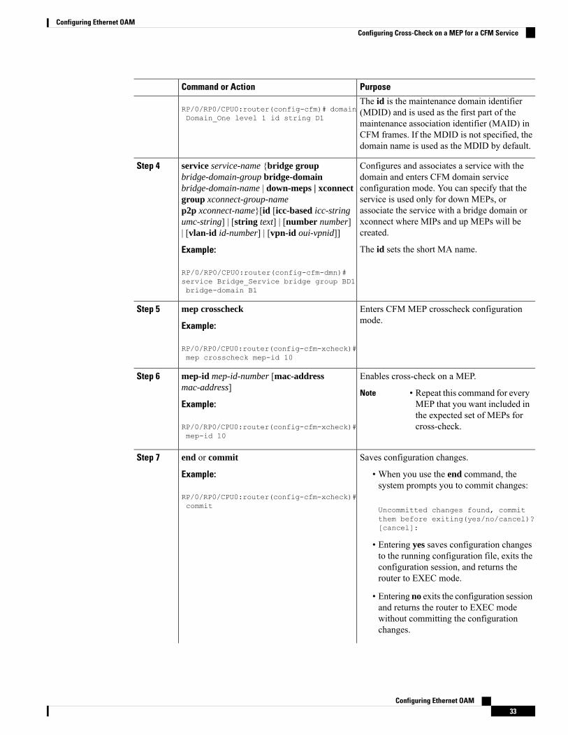
Configuring Cross-Check on a MEP for a CFM ServiceTo configure cross-check on a MEP for a CFM service and specify the expected set of MEPs, complete thefollowing steps:
Procedure
PurposeCommand or Action
Enters global configuration mode.configure
Example:
Step 1
RP/0/RP0/CPU0:router# configure
Enters the Ethernet Connectivity FaultManagement (CFM) configuration mode.
ethernet cfm
Example:
Step 2
RP/0/RP0/CPU0:router# ethernet cfm
Creates and names a container for all domainconfigurations and enters the CFM domainconfiguration mode.
domain domain-name level level-value [id[null] [dns DNS-name] [mac H.H.H] [stringstring] ]
Step 3
Example: The level must be specified.
Configuring Ethernet OAM32
Configuring Ethernet OAMConfiguring Cross-Check on a MEP for a CFM Service
PurposeCommand or Action
RP/0/RP0/CPU0:router(config-cfm)# domainDomain_One level 1 id string D1
The id is the maintenance domain identifier(MDID) and is used as the first part of themaintenance association identifier (MAID) inCFM frames. If the MDID is not specified, thedomain name is used as the MDID by default.
Configures and associates a service with thedomain and enters CFM domain service
service service-name {bridge groupbridge-domain-group bridge-domain
Step 4
configuration mode. You can specify that thebridge-domain-name | down-meps | xconnectservice is used only for down MEPs, orgroup xconnect-group-nameassociate the service with a bridge domain orp2p xconnect-name}[id [icc-based icc-stringxconnect where MIPs and up MEPs will becreated.
umc-string] | [string text] | [number number]| [vlan-id id-number] | [vpn-id oui-vpnid]]
Example: The id sets the short MA name.
RP/0/RP0/CPU0:router(config-cfm-dmn)#service Bridge_Service bridge group BD1bridge-domain B1
Enters CFM MEP crosscheck configurationmode.
mep crosscheck
Example:
Step 5
RP/0/RP0/CPU0:router(config-cfm-xcheck)#mep crosscheck mep-id 10
Enables cross-check on a MEP.mep-id mep-id-number [mac-addressmac-address]
Step 6
• Repeat this command for everyMEP that you want included inthe expected set of MEPs forcross-check.
NoteExample:
RP/0/RP0/CPU0:router(config-cfm-xcheck)#mep-id 10
Saves configuration changes.end or commitStep 7
Example: • When you use the end command, thesystem prompts you to commit changes:
RP/0/RP0/CPU0:router(config-cfm-xcheck)#commit Uncommitted changes found, commit
them before exiting(yes/no/cancel)?[cancel]:
• Entering yes saves configuration changesto the running configuration file, exits theconfiguration session, and returns therouter to EXEC mode.
• Entering no exits the configuration sessionand returns the router to EXEC modewithout committing the configurationchanges.
Configuring Ethernet OAM33
Configuring Ethernet OAMConfiguring Cross-Check on a MEP for a CFM Service

PurposeCommand or Action
• Entering cancel leaves the router in thecurrent configuration session withoutexiting or committing the configurationchanges.
• Use the commit command to save theconfiguration changes to the runningconfiguration file and remain within theconfiguration session.
Configuring Other Options for a CFM ServiceTo configure other options for a CFM service, complete the following steps:
Procedure
PurposeCommand or Action
Enters global configuration mode.configure
Example:
Step 1
RP/0/RP0/CPU0:router# configure
Enters the Ethernet Connectivity FaultManagement (CFM) configuration mode.
ethernet cfm
Example:
Step 2
RP/0/RP0/CPU0:router# ethernet cfm
Creates and names a container for all domainconfigurations and enters the CFM domainconfiguration mode.
domain domain-name level level-value [id[null] [dns DNS-name] [mac H.H.H] [stringstring] ]
Step 3
Example: The level must be specified.
RP/0/RP0/CPU0:router(config-cfm)# domainDomain_One level 1 id string D1
The id is the maintenance domain identifier(MDID) and is used as the first part of themaintenance association identifier (MAID) inCFM frames. If the MDID is not specified, thedomain name is used as the MDID by default.
Configures and associates a service with thedomain and enters CFM domain service
service service-name {bridge groupbridge-domain-group bridge-domain
Step 4
configuration mode. You can specify that thebridge-domain-name | down-meps | xconnectservice is used only for down MEPs, orgroup xconnect-group-nameassociate the service with a bridge domain orp2p xconnect-name}[id [icc-based icc-stringxconnect where MIPs and up MEPs will becreated.
umc-string] | [string text] | [number number]| [vlan-id id-number] | [vpn-id oui-vpnid]]
Example: The id sets the short MA name.
RP/0/RP0/CPU0:router(config-cfm-dmn)#
Configuring Ethernet OAM34
Configuring Ethernet OAMConfiguring Other Options for a CFM Service

PurposeCommand or Actionservice Bridge_Service bridge group BD1bridge-domain B1
(Optional) Configures the maximum number(2 to 8190) of MEPs across the network, which
maximum-meps number
Example:
Step 5
limits the number of peerMEPs recorded in thedatabase.
RP/0/RP0/CPU0:router(config-cfm-dmn-svc)#maximum-meps 1000
(Optional) Enables logging of certain types ofevents.
log {ais|continuity-checkerrors|continuity-check mepchanges|crosscheck errors|efd}
Step 6
Example:
RP/0/RP0/CPU0:router(config-cfm-dmn-svc)#log continuity-check errors
Saves configuration changes.end or commitStep 7
Example: • When you use the end command, thesystem prompts you to commit changes:
RP/0/RP0/CPU0:router(config-cfm-dmn-svc)#commit Uncommitted changes found, commit
them before exiting(yes/no/cancel)?[cancel]:
• Entering yes saves configuration changesto the running configuration file, exits theconfiguration session, and returns therouter to EXEC mode.
• Entering no exits the configuration sessionand returns the router to EXEC modewithout committing the configurationchanges.
• Entering cancel leaves the router in thecurrent configuration session withoutexiting or committing the configurationchanges.
• Use the commit command to save theconfiguration changes to the runningconfiguration file and remain within theconfiguration session.
Configuring Ethernet OAM35
Configuring Ethernet OAMConfiguring Other Options for a CFM Service

Configuring CFM MEPs
Procedure
PurposeCommand or Action
Enters global configuration mode.configure
Example:
Step 1
RP/0/RP0/CPU0:router# configure
Type of Ethernet interface on which you wantto create a MEP. Enter HundredGigE or
interface {HundredGigE | TenGigE}interface-path-id
Step 2
TenGigE and the physical interface or virtualinterface.Example:
RP/0/RP0/CPU0:router(config)# interfaceTenGigE 0/0/0/1
• Use the show interfacescommand to see a list of allinterfaces currently configuredon the router.
Note
Type of Ethernet interface on which you wantto create a MEP. Enter HundredGigE,
interface {HundredGigE | TenGigE |Bundle-Ether} interface-path-id.subinterface
Step 3
TenGigE, or Bundle-Ether and the physicalExample: interface or virtual interface followed by the
subinterface path ID.RP/0/RP0/CPU0:router(config)# interfaceTenGigE 0/0/0/1.1
Naming convention isinterface-path-id.subinterface. The period infront of the subinterface value is required aspart of the notation.
Type of Ethernet interface on which you wantto create a MEP. Enter HundredGigE or
interface {HundredGigE | TenGigE}interface-path-id
Step 4
TenGigE and the physical interface or virtualinterface.Example:
RP/0/RP0/CPU0:router(config)# interfaceTenGigE 0/0/0/1 • Use the show interfaces
command to see a list of allinterfaces currently configuredon the router.
Note
Enters interface Ethernet CFM configurationmode.
ethernet cfm
Example:
Step 5
RP/0/RP0/CPU0:router(config-if)# ethernetcfm
Creates a maintenance end point (MEP) on aninterface and enters interface CFM MEPconfiguration mode.
mep domain domain-name serviceservice-name mep-id id-number
Example:
Step 6
Configuring Ethernet OAM36
Configuring Ethernet OAMConfiguring CFM MEPs

PurposeCommand or Action
RP/0/RP0/CPU0:router(config-if-cfm)# mepdomain Dm1 service Sv1 mep-id 1
(Optional) Configures the class of service (CoS)(from 0 to 7) for all CFM packets generated by
cos cos
Example:
Step 7
the MEP on an interface. If not configured, theCoS is inherited from the Ethernet interface.
RP/0/RP0/CPU0:router(config-if-cfm-mep)#cos 7 For Ethernet interfaces, the CoS is
carried as a field in the VLAN tag.Therefore, CoS only applies tointerfaces where packets are sentwith VLAN tags. If the cos (CFM)command is executed for a MEP onan interface that does not have aVLAN encapsulation configured, itwill be ignored.
Note
Saves configuration changes.end or commitStep 8
Example: • When you use the end command, thesystem prompts you to commit changes:
RP/0/RP0/CPU0:router(config-if-cfm-mep)#commit Uncommitted changes found, commit
them before exiting(yes/no/cancel)?[cancel]:
• Entering yes saves configuration changesto the running configuration file, exits theconfiguration session, and returns therouter to EXEC mode.
• Entering no exits the configuration sessionand returns the router to EXEC modewithout committing the configurationchanges.
• Entering cancel leaves the router in thecurrent configuration session withoutexiting or committing the configurationchanges.
• Use the commit command to save theconfiguration changes to the runningconfiguration file and remain within theconfiguration session.
Configuring Y.1731 AISThis section has the following step procedures:
Configuring Ethernet OAM37
Configuring Ethernet OAMConfiguring Y.1731 AIS

Configuring AIS in a CFM Domain ServiceUse the following procedure to configure Alarm Indication Signal (AIS) transmission for a CFM domainservice and configure AIS logging.
Procedure
PurposeCommand or Action
Enters global configuration mode.configure
Example:
Step 1
RP/0/RP0/CPU0:router# configure
Enters Ethernet CFM global configurationmode.
ethernet cfm
Example:
Step 2
RP/0/RP0/CPU0:router(config)# ethernetcfm
Specifies the domain and domain level.domain name level level
Example:
Step 3
RP/0/RP0/CPU0:router(config-cfm)# domainD1 level 1
Specifies the service, bridge group, and bridgedomain.
service name bridge group namebridge-domain name
Example:
Step 4
RP/0/RP0/CPU0:router(config-cfm-dmn)#service S1 bridge group BG1 bridge-domainBD2
Specifies the service and cross-connect groupand name.
service name xconnect groupxconnect-group-name p2p xconnect-name
Example:
Step 5
RP/0/RP0/CPU0:router(config-cfm-dmn)#service S1 xconnect group XG1 p2p X2
Configures Alarm Indication Signal (AIS)transmission for a Connectivity FaultManagement (CFM) domain service.
ais transmission [interval {1s|1m}][cos cos]
Example:
RP/0/RP0/CPU0:router(config-cfm-dmn-svc)#ais transmission interval 1m cos 7
Step 6
Configuring Ethernet OAM38
Configuring Ethernet OAMConfiguring AIS in a CFM Domain Service
PurposeCommand or Action
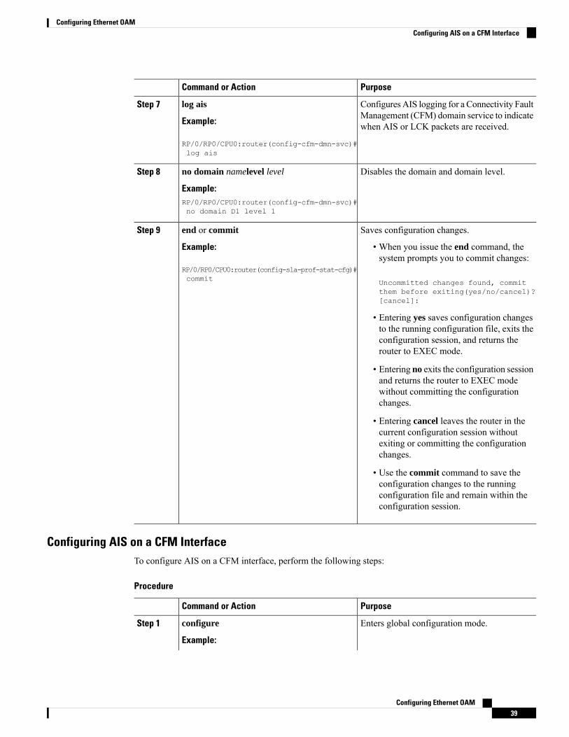
Configures AIS logging for a Connectivity FaultManagement (CFM) domain service to indicatewhen AIS or LCK packets are received.
log ais
Example:
RP/0/RP0/CPU0:router(config-cfm-dmn-svc)#log ais
Step 7
Disables the domain and domain level.no domain namelevel level
Example:
Step 8
RP/0/RP0/CPU0:router(config-cfm-dmn-svc)#no domain D1 level 1
Saves configuration changes.end or commitStep 9
Example: • When you issue the end command, thesystem prompts you to commit changes:
RP/0/RP0/CPU0:router(config-sla-prof-stat-cfg)#commit Uncommitted changes found, commit
them before exiting(yes/no/cancel)?[cancel]:
• Entering yes saves configuration changesto the running configuration file, exits theconfiguration session, and returns therouter to EXEC mode.
• Entering no exits the configuration sessionand returns the router to EXEC modewithout committing the configurationchanges.
• Entering cancel leaves the router in thecurrent configuration session withoutexiting or committing the configurationchanges.
• Use the commit command to save theconfiguration changes to the runningconfiguration file and remain within theconfiguration session.
Configuring AIS on a CFM InterfaceTo configure AIS on a CFM interface, perform the following steps:
Procedure
PurposeCommand or Action
Enters global configuration mode.configure
Example:
Step 1
Configuring Ethernet OAM39
Configuring Ethernet OAMConfiguring AIS on a CFM Interface

PurposeCommand or Action
RP/0/RP0/CPU0:router# configure
Enters interface configuration mode.interface gigabitethernet interface-path-id
Example:
Step 2
RP/0/RP0/CPU0:router# interface TenGigE0/0/0/2
Enters Ethernet CFM interface configurationmode.
ethernet cfm
Example:
Step 3
RP/0/RP0/CPU0:router(config)# ethernetcfm
Configures Alarm Indication Signal (AIS)transmission on a Connectivity FaultManagement (CFM) interface.
ais transmission up interval 1m cos cos
Example:
RP/0/RP0/CPU0:router(config-if-cfm)# aistransmission up interval 1m cos 7
Step 4
Saves configuration changes.end or commitStep 5
Example: • When you issue the end command, thesystem prompts you to commit changes:
RP/0/RP0/CPU0:router(config-sla-prof-stat-cfg)#commit Uncommitted changes found, commit
them before exiting(yes/no/cancel)?[cancel]:
• Entering yes saves configuration changesto the running configuration file, exits theconfiguration session, and returns therouter to EXEC mode.
• Entering no exits the configuration sessionand returns the router to EXEC modewithout committing the configurationchanges.
• Entering cancel leaves the router in thecurrent configuration session withoutexiting or committing the configurationchanges.
• Use the commit command to save theconfiguration changes to the runningconfiguration file and remain within theconfiguration session.
Configuring Ethernet OAM40
Configuring Ethernet OAMConfiguring AIS on a CFM Interface

Configuring Flexible VLAN Tagging for CFMUse this procedure to set the number of tags in CFM packets in a CFM domain service.
Procedure
PurposeCommand or Action
Enters global configuration mode.configure
Example:
Step 1
RP/0/RP0/CPU0:router# configure
Enters Ethernet CFM global configurationmode.
ethernet cfm
Example:
Step 2
RP/0/RP0/CPU0:router(config)# ethernetcfm
Specifies the domain and domain level.domain name level level
Example:
Step 3
RP/0/RP0/CPU0:router(config-cfm)# domainD1 level 1
Specifies the service, bridge group, and bridgedomain.
service name bridge group namebridge-domain name
Example:
Step 4
RP/0/RP0/CPU0:router(config-cfm-dmn)#service S2 bridge group BG1 bridge-domainBD2
Specifies the number of tags in CFM packets.Currently, the only valid value is 1.
tags number
Example:
Step 5
RP/0/RP0/CPU0:router(config-cfm-dmn-svc)#tags 1
Saves configuration changes.end or commitStep 6
Example: • When you issue the end command, thesystem prompts you to commit changes:
RP/0/RP0/CPU0:router(config-cfm-dmn-svc)#commit Uncommitted changes found, commit
them before exiting(yes/no/cancel)?[cancel]:
• Entering yes saves configuration changesto the running configuration file, exits theconfiguration session, and returns therouter to EXEC mode.
Configuring Ethernet OAM41
Configuring Ethernet OAMConfiguring Flexible VLAN Tagging for CFM

PurposeCommand or Action
• Entering no exits the configuration sessionand returns the router to EXEC modewithout committing the configurationchanges.
• Entering cancel leaves the router in thecurrent configuration session withoutexiting or committing the configurationchanges.
• Use the commit command to save theconfiguration changes to the runningconfiguration file and remain within theconfiguration session.
Verifying the CFM ConfigurationTo verify the CFM configuration, use one or more of the following commands:
Displays information about errors that are preventingconfigured CFM operations from becoming active,as well as any warnings that have occurred.
show ethernet cfm configuration-errors [domaindomain-name] [interface interface-path-id ]
Displays a list of local maintenance points.show ethernet cfm local maintenance-pointsdomain name [service name] | interface typeinterface-path-id] [mep | mip]
After you configure CFM, the error message, cfmd[317]: %L2-CFM-5-CCM_ERROR_CCMS_MISSED :Some received CCMs have not been counted by the CCM error counters, may display. This error messagedoes not have any functional impact and does not require any action from you.
Note
Troubleshooting TipsTo troubleshoot problems within the CFM network, perform these steps:
Procedure
Step 1 To verify connectivity to a problematic MEP, use the ping ethernet cfm command as shown in this example:
RP/0/RP0/CPU0:router# ping ethernet cfm domain D1 service S1 mep-id 16 sourceinterface TenGigE 0/0/0/1
Type escape sequence to abort.Sending 5 CFM Loopbacks, timeout is 2 seconds -Domain foo (level 2), Service fooSource: MEP ID 1, interface TenGigE0/0/0/1Target: 0001.0002.0003 (MEP ID 16):
Configuring Ethernet OAM42
Configuring Ethernet OAMVerifying the CFM Configuration

Running (5s) ...Success rate is 60.0 percent (3/5), round-trip min/avg/max = 1251/1349/1402 msOut-of-sequence: 0.0 percent (0/3)Bad data: 0.0 percent (0/3)Received packet rate: 1.4 pps
Step 2 If the results of the ping ethernet cfm command show a problem with connectivity to the peer MEP, use thetraceroute ethernet cfm command to help further isolate the location of the problem as shown in the followingexample:
RP/0/RP0/CPU0:router# traceroute ethernet cfm domain D1 service S1 mep-id 16source interface TenGigE 0/0/0/2
Traceroutes in domain D1 (level 4), service S1Source: MEP-ID 1, interface TenGigE0/0/0/2================================================================================Traceroute at 2009-05-18 12:09:10 to 0001.0203.0402,TTL 64, Trans ID 2:
Hop Hostname/Last Ingress MAC/name Egress MAC/Name Relay--- ------------------------ ---------------------- ---------------------- -----1 ios 0001.0203.0400 [Down] FDB
0000-0001.0203.0400 TenGigE0/0/0/22 abc 0001.0203.0401 [Ok] FDB
ios Not present3 bcd 0001.0203.0402 [Ok] Hit
abc TenGigE0/0Replies dropped: 0
If the target was a MEP, verify that the last hop shows “Hit” in the Relay field to confirm connectivity to thepeer MEP.
If the Relay field contains “MPDB” for any of the hops, then the target MAC address was not found in thebridge MAC learning table at that hop, and the result is relying on CCM learning. This result can occur undernormal conditions, but it can also indicate a problem. If you used the ping ethernet cfm command beforeusing the traceroute ethernet cfm command, then the MAC address should have been learned. If “MPDB”is appearing in that case, then this indicates a problem at that point in the network.
Configuration Examples for Ethernet OAMThis section provides the following configuration examples:
Configuration Examples for EOAM InterfacesThis section provides the following configuration examples:
Configuring an Ethernet OAM Profile Globally: Example
This example shows how to configure an Ethernet OAM profile globally:
configure terminalethernet oam profile Profile_1link-monitorsymbol-period window 60000symbol-period threshold ppm low 10000000 high 60000000
Configuring Ethernet OAM43
Configuring Ethernet OAMConfiguration Examples for Ethernet OAM
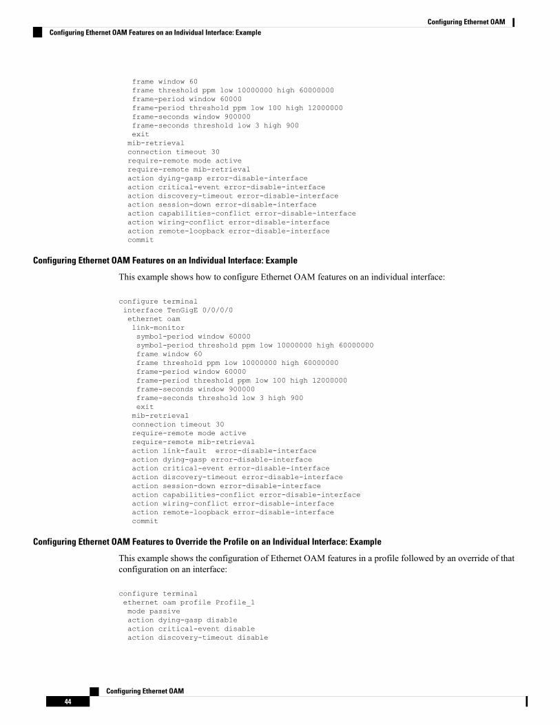
frame window 60frame threshold ppm low 10000000 high 60000000frame-period window 60000frame-period threshold ppm low 100 high 12000000frame-seconds window 900000frame-seconds threshold low 3 high 900exitmib-retrievalconnection timeout 30require-remote mode activerequire-remote mib-retrievalaction dying-gasp error-disable-interfaceaction critical-event error-disable-interfaceaction discovery-timeout error-disable-interfaceaction session-down error-disable-interfaceaction capabilities-conflict error-disable-interfaceaction wiring-conflict error-disable-interfaceaction remote-loopback error-disable-interfacecommit
Configuring Ethernet OAM Features on an Individual Interface: Example
This example shows how to configure Ethernet OAM features on an individual interface:
configure terminalinterface TenGigE 0/0/0/0ethernet oamlink-monitorsymbol-period window 60000symbol-period threshold ppm low 10000000 high 60000000frame window 60frame threshold ppm low 10000000 high 60000000frame-period window 60000frame-period threshold ppm low 100 high 12000000frame-seconds window 900000frame-seconds threshold low 3 high 900exitmib-retrievalconnection timeout 30require-remote mode activerequire-remote mib-retrievalaction link-fault error-disable-interfaceaction dying-gasp error-disable-interfaceaction critical-event error-disable-interfaceaction discovery-timeout error-disable-interfaceaction session-down error-disable-interfaceaction capabilities-conflict error-disable-interfaceaction wiring-conflict error-disable-interfaceaction remote-loopback error-disable-interfacecommit
Configuring Ethernet OAM Features to Override the Profile on an Individual Interface: Example
This example shows the configuration of Ethernet OAM features in a profile followed by an override of thatconfiguration on an interface:
configure terminalethernet oam profile Profile_1mode passiveaction dying-gasp disableaction critical-event disableaction discovery-timeout disable
Configuring Ethernet OAM44
Configuring Ethernet OAMConfiguring Ethernet OAM Features on an Individual Interface: Example

action session-up disableaction session-down disableaction capabilities-conflict disableaction wiring-conflict disableaction remote-loopback disableaction uni-directional link-fault error-disable-interfacecommit
configure terminalinterface TenGigE 0/0/0/0ethernet oamprofile Profile_1mode activeaction dying-gasp logaction critical-event logaction discovery-timeout logaction session-up logaction session-down logaction capabilities-conflict logaction wiring-conflict logaction remote-loopback logaction uni-directional link-fault loguni-directional link-fault detectioncommit
Clearing Ethernet OAM Statistics on an Interface: Example
This example shows how to clear Ethernet OAM statistics on an interface:
RP/0/RP0/CPU0:router# clear ethernet oam statistics interface gigabitethernet 0/0/0/1
Enabling SNMP Server Traps on a Router: Example
This example shows how to enable SNMP server traps on a router:
configure terminalsnmp-server traps ethernet oam events
Configuration Examples for Ethernet CFMThis section includes the following examples:
Ethernet CFM Domain Configuration: Example
This example shows how to configure a basic domain for Ethernet CFM:
configureethernet cfmtraceroute cache hold-time 1 size 3000domain Domain_One level 1 id string D1commit
Ethernet CFM Service Configuration: Example
This example shows how to create a service for an Ethernet CFM domain:
service Bridge_Service bridge group BD1 bridge-domain B1service Cross_Connect_1 xconnect group XG1 p2p X1commit
Configuring Ethernet OAM45
Configuring Ethernet OAMClearing Ethernet OAM Statistics on an Interface: Example

Flexible Tagging for an Ethernet CFM Service Configuration: Example
This example shows how to set the number of tags in CFM packets from down MEPs in a CFM domainservice:
configureethernet cfmdomain D1 level 1service S2 bridge group BG1 bridge-domain BD2tags 1commit
Continuity Check for an Ethernet CFM Service Configuration: Example
This example shows how to configure continuity-check options for an Ethernet CFM service:
continuity-check archive hold-time 100continuity-check loss auto-traceroutecontinuity-check interval 100ms loss-threshold 10commit
MIP Creation for an Ethernet CFM Service Configuration: Example
This example shows how to enable MIP auto-creation for an Ethernet CFM service:
RP/0/RP0/CPU0:router(config-cfm-dmn-svc)# mip auto-create allRP/0/RP0/CPU0:router(config-cfm-dmn-svc)# commit
Cross-check for an Ethernet CFM Service Configuration: Example
This example shows how to configure cross-check for MEPs in an Ethernet CFM service:
mep crosscheckmep-id 10mep-id 20commit
Other Ethernet CFM Service Parameter Configuration: Example
This example shows how to configure other Ethernet CFM service options:
maximum-meps 4000log continuity-check errorscommitexitexitexit
MEP Configuration: Example
This example shows how to configure a MEP for Ethernet CFM on an interface:
interface TenGigE 0/0/0/1ethernet cfmmep domain Dm1 service Sv1 mep-id 1commit
Configuring Ethernet OAM46
Configuring Ethernet OAMFlexible Tagging for an Ethernet CFM Service Configuration: Example

Ethernet CFM Show Command: Examples
These examples show how to verify the configuration of Ethernet Connectivity Fault Management (CFM):
Example 1
This example shows how to display all the maintenance points that have been created on an interface:
RP/0/RP0/CPU0:router# show ethernet cfm local maintenance-points
Domain/Level Service Interface Type ID MAC-------------------- ------------------- ----------------- ------ ---- --------fig/5 bay Gi0/10/0/12 Dn MEP 2 44:55:66fig/5 bay Gi0/0/1/0 MIP 55:66:77fred/3 barney Gi0/1/0/0 Dn MEP 5 66:77:88!
Example 2
This example shows how to display all the CFM configuration errors on all domains:
RP/0/RP0/CPU0:router# show ethernet cfm configuration-errors
Domain fig (level 5), Service bay* MIP creation configured using bridge-domain blort, but bridge-domain blort does not exist.
* An Up MEP is configured for this domain on interface TenGigE0/0/0/3 and an Up MEP isalso configured for domain blort, which is at the same level (5).* A MEP is configured on interface TenGigE0/0/0/1 for this domain/service, which has CCinterval 100ms, but the lowest interval supported on that interface is 1s
Example 3
This example shows how to display operational state for local maintenance end points (MEPs):
RP/0/RP0/CPU0:router# show ethernet cfm local meps
A - AIS received I - Wrong intervalR - Remote Defect received V - Wrong LevelL - Loop (our MAC received) T - Timed out (archived)C - Config (our ID received) M - Missing (cross-check)X - Cross-connect (wrong MAID) U - Unexpected (cross-check)P - Peer port down
Domain foo (level 6), Service barID Interface (State) Dir MEPs/Err RD Defects AIS
----- ------------------------ --- -------- -- ------- ---100 Gi1/1/0/1 (Up) Up 0/0 N A L7
Domain fred (level 5), Service barneyID Interface (State) Dir MEPs/Err RD Defects AIS
----- ------------------------ --- -------- -- ------- ---2 Gi0/1/0/0 (Up) Up 3/2 Y RPC L6
Domain foo (level 6), Service barID Interface (State) Dir MEPs/Err RD Defects AIS
----- ------------------------ --- -------- -- ------- ---100 Gi1/1/0/1 (Up) Up 0/0 N A
Domain fred (level 5), Service barneyID Interface (State) Dir MEPs/Err RD Defects AIS
Configuring Ethernet OAM47
Configuring Ethernet OAMEthernet CFM Show Command: Examples
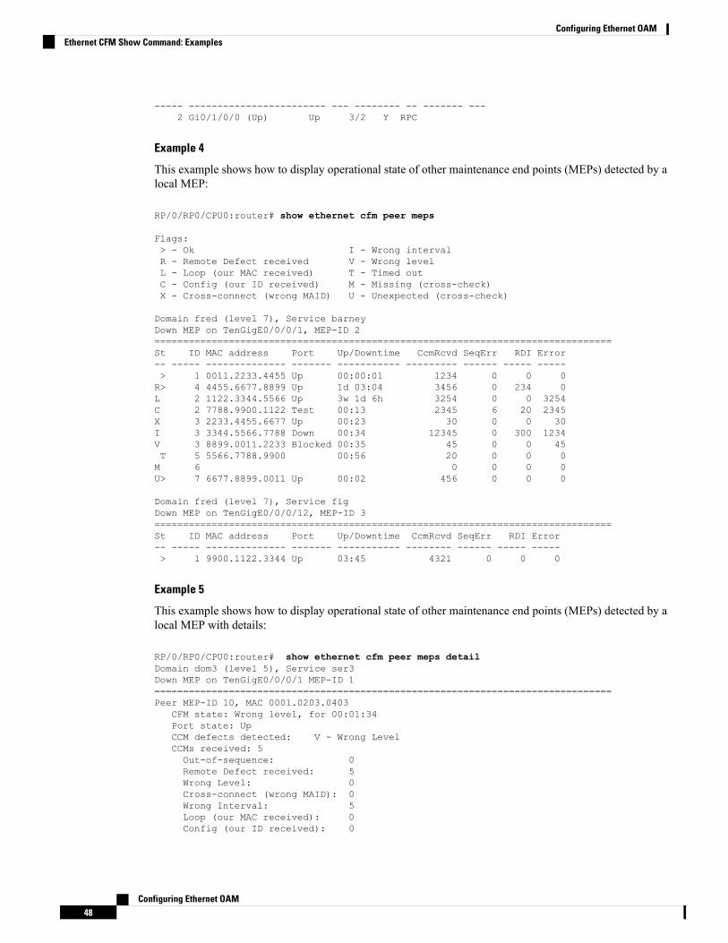
----- ------------------------ --- -------- -- ------- ---2 Gi0/1/0/0 (Up) Up 3/2 Y RPC
Example 4
This example shows how to display operational state of other maintenance end points (MEPs) detected by alocal MEP:
RP/0/RP0/CPU0:router# show ethernet cfm peer meps
Flags:> - Ok I - Wrong intervalR - Remote Defect received V - Wrong levelL - Loop (our MAC received) T - Timed outC - Config (our ID received) M - Missing (cross-check)X - Cross-connect (wrong MAID) U - Unexpected (cross-check)
Domain fred (level 7), Service barneyDown MEP on TenGigE0/0/0/1, MEP-ID 2================================================================================St ID MAC address Port Up/Downtime CcmRcvd SeqErr RDI Error-- ----- -------------- ------- ----------- --------- ------ ----- -----> 1 0011.2233.4455 Up 00:00:01 1234 0 0 0R> 4 4455.6677.8899 Up 1d 03:04 3456 0 234 0L 2 1122.3344.5566 Up 3w 1d 6h 3254 0 0 3254C 2 7788.9900.1122 Test 00:13 2345 6 20 2345X 3 2233.4455.6677 Up 00:23 30 0 0 30I 3 3344.5566.7788 Down 00:34 12345 0 300 1234V 3 8899.0011.2233 Blocked 00:35 45 0 0 45T 5 5566.7788.9900 00:56 20 0 0 0M 6 0 0 0 0U> 7 6677.8899.0011 Up 00:02 456 0 0 0
Domain fred (level 7), Service figDown MEP on TenGigE0/0/0/12, MEP-ID 3================================================================================St ID MAC address Port Up/Downtime CcmRcvd SeqErr RDI Error-- ----- -------------- ------- ----------- -------- ------ ----- -----> 1 9900.1122.3344 Up 03:45 4321 0 0 0
Example 5
This example shows how to display operational state of other maintenance end points (MEPs) detected by alocal MEP with details:
RP/0/RP0/CPU0:router# show ethernet cfm peer meps detailDomain dom3 (level 5), Service ser3Down MEP on TenGigE0/0/0/1 MEP-ID 1================================================================================Peer MEP-ID 10, MAC 0001.0203.0403
CFM state: Wrong level, for 00:01:34Port state: UpCCM defects detected: V - Wrong LevelCCMs received: 5Out-of-sequence: 0Remote Defect received: 5Wrong Level: 0Cross-connect (wrong MAID): 0Wrong Interval: 5Loop (our MAC received): 0Config (our ID received): 0
Configuring Ethernet OAM48
Configuring Ethernet OAMEthernet CFM Show Command: Examples
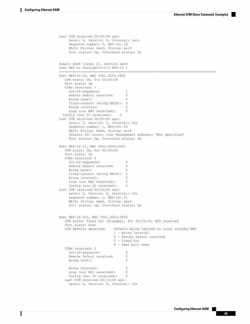
Last CCM received 00:00:06 ago:Level: 4, Version: 0, Interval: 1minSequence number: 5, MEP-ID: 10MAID: String: dom3, String: ser3Port status: Up, Interface status: Up
Domain dom4 (level 2), Service ser4Down MEP on TenGigE0/0/0/2 MEP-ID 1================================================================================Peer MEP-ID 20, MAC 0001.0203.0402
CFM state: Ok, for 00:00:04Port state: UpCCMs received: 7Out-of-sequence: 1Remote Defect received: 0Wrong Level: 0Cross-connect (wrong MAID): 0Wrong Interval: 0Loop (our MAC received): 0
Config (our ID received): 0Last CCM received 00:00:04 ago:
Level: 2, Version: 0, Interval: 10sSequence number: 1, MEP-ID: 20MAID: String: dom4, String: ser4Chassis ID: Local: ios; Management address: 'Not specified'Port status: Up, Interface status: Up
Peer MEP-ID 21, MAC 0001.0203.0403CFM state: Ok, for 00:00:05Port state: UpCCMs received: 6Out-of-sequence: 0Remote Defect received: 0Wrong Level: 0Cross-connect (wrong MAID): 0Wrong Interval: 0Loop (our MAC received): 0Config (our ID received): 0
Last CCM received 00:00:05 ago:Level: 2, Version: 0, Interval: 10sSequence number: 1, MEP-ID: 21MAID: String: dom4, String: ser4Port status: Up, Interface status: Up
Peer MEP-ID 601, MAC 0001.0203.0402CFM state: Timed Out (Standby), for 00:15:14, RDI receivedPort state: DownCCM defects detected: Defects below ignored on local standby MEP
I - Wrong IntervalR - Remote Defect receivedT - Timed OutP - Peer port down
CCMs received: 2Out-of-sequence: 0Remote Defect received: 2Wrong Level: 0
Wrong Interval: 2Loop (our MAC received): 0Config (our ID received): 0
Last CCM received 00:15:49 ago:Level: 2, Version: 0, Interval: 10s
Configuring Ethernet OAM49
Configuring Ethernet OAMEthernet CFM Show Command: Examples

Sequence number: 1, MEP-ID: 600MAID: DNS-like: dom5, String: ser5Chassis ID: Local: ios; Management address: 'Not specified'Port status: Up, Interface status: Down
AIS for CFM Configuration: Examples
Example 1
This example shows how to configure Alarm Indication Signal (AIS) transmission for a CFM domain service:
RP/0/RP0/CPU0:router# configureRP/0/RP0/CPU0:router(config)# ethernet cfmRP/0/RP0/CPU0:router(config-cfm)# domain D1 level 1RP/0/RP0/CPU0:router(config-cfm-dmn)# service S1 bridge group BG1 bridge-domain BD2RP/0/RP0/CPU0:router(config-cfm-dmn-svc)# ais transmission interval 1m cos 7
RP/0/RP0/CPU0:routerconfigureRP/0/RP0/CPU0:router(config)# ethernet cfmRP/0/RP0/CPU0:router(config-cfm)# domain D1 level 1RP/0/RP0/CPU0:router(config-cfm-dmn)# service Cross_Connect_1 xconnect group XG1 p2p X1RP/0/RP0/CPU0:router(config-cfm-dmn-svc)# ais transmission interval 1m cos 7
Example 2
This example shows how to configure AIS logging for a Connectivity Fault Management (CFM) domainservice to indicate when AIS or LCK packets are received:
RP/0/RP0/CPU0:router# configureRP/0/RP0/CPU0:router(config)# ethernet cfmRP/0/RP0/CPU0:router(config-cfm)# domain D1 level 1RP/0/RP0/CPU0:router(config-cfm-dmn)# service S2 bridge group BG1 bridge-domain BD2RP/0/RP0/CPU0:router(config-cfm-dmn-svc)# log ais
RP/0/RP0/CPU0:routerconfigureRP/0/RP0/CPU0:router(config)# ethernet cfmRP/0/RP0/CPU0:router(config-cfm)# domain D1 level 1RP/0/RP0/CPU0:router(config-cfm-dmn)# service Cross_Connect_1 xconnect group XG1 p2p X1RP/0/RP0/CPU0:router(config-cfm-dmn-svc)# log ais
This example shows how to configure AIS transmission on a CFM interface.
RP/0/RP0/CPU0:router# configureRP/0/RP0/CPU0:router(config)# interface TenGigE 0/0/0/2RP/0/RP0/CPU0:router(config-if)# ethernet cfmRP/0/RP0/CPU0:router(config-if-cfm)# ais transmission up interval 1m cos 7
AIS for CFM Show Commands: Examples
This section includes the following examples:
show ethernet cfm interfaces ais Command: Example
This example shows how to display the information published in the Interface AIS table:
RP/0/RP0/CPU0:router# show ethernet cfm interfaces ais
Defects (from at least one peer MEP):
Configuring Ethernet OAM50
Configuring Ethernet OAMAIS for CFM Configuration: Examples

A - AIS received I - Wrong intervalR - Remote Defect received V - Wrong LevelL - Loop (our MAC received) T - Timed out (archived)C - Config (our ID received) M - Missing (cross-check)X - Cross-connect (wrong MAID) U - Unexpected (cross-check)P - Peer port down D - Local port down
Trigger TransmissionAIS --------- Via ---------------------------
Interface (State) Dir L Defects Levels L Int Last started Packets------------------------ --- - ------- ------- - --- ------------ --------TenGigE0/0/0/0 (Up) Dn 5 RPC 6 7 1s 01:32:56 ago 5576TenGigE0/0/0/0 (Up) Up 0 M 2,3 5 1s 00:16:23 ago 983TenGigE0/0/0/1 (Dn) Up D 7 60s 01:02:44 ago 3764TenGigE0/0/0/2 (Up) Dn 0 RX 1!
show ethernet cfm local meps Command: Examples
Example 1: Default
This example shows how to display statistics for local maintenance end points (MEPs):
RP/0/RP0/CPU0:router# show ethernet cfm local meps
A - AIS received I - Wrong intervalR - Remote Defect received V - Wrong LevelL - Loop (our MAC received) T - Timed out (archived)C - Config (our ID received) M - Missing (cross-check)X - Cross-connect (wrong MAID) U - Unexpected (cross-check)P - Peer port down
Domain foo (level 6), Service barID Interface (State) Dir MEPs/Err RD Defects AIS
----- ------------------------ --- -------- -- ------- ---100 Gi1/1/0/1 (Up) Up 0/0 N A 7
Domain fred (level 5), Service barneyID Interface (State) Dir MEPs/Err RD Defects AIS
----- ------------------------ --- -------- -- ------- ---2 Gi0/1/0/0 (Up) Up 3/2 Y RPC 6
Example 2: Domain Service
This example shows how to display statistics for MEPs in a domain service:
RP/0/RP0/CPU0:router# show ethernet cfm local meps domain foo service bar detail
Domain foo (level 6), Service barDown MEP on TenGigE0/0/0/1, MEP-ID 100================================================================================Interface state: Up MAC address: 1122.3344.5566Peer MEPs: 0 up, 0 with errors, 0 timed out (archived)
CCM generation enabled: NoAIS generation enabled: Yes (level: 7, interval: 1s)Sending AIS: Yes (started 01:32:56 ago)Receiving AIS: Yes (from lower MEP, started 01:32:56 ago)
Domain fred (level 5), Service barneyDown MEP on TenGigE0/0/0/1, MEP-ID 2================================================================================
Configuring Ethernet OAM51
Configuring Ethernet OAMshow ethernet cfm local meps Command: Examples
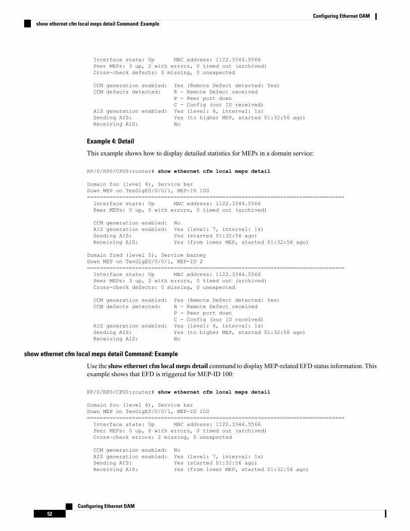
Interface state: Up MAC address: 1122.3344.5566Peer MEPs: 3 up, 2 with errors, 0 timed out (archived)Cross-check defects: 0 missing, 0 unexpected
CCM generation enabled: Yes (Remote Defect detected: Yes)CCM defects detected: R - Remote Defect received
P - Peer port downC - Config (our ID received)
AIS generation enabled: Yes (level: 6, interval: 1s)Sending AIS: Yes (to higher MEP, started 01:32:56 ago)Receiving AIS: No
Example 4: Detail
This example shows how to display detailed statistics for MEPs in a domain service:
RP/0/RP0/CPU0:router# show ethernet cfm local meps detail
Domain foo (level 6), Service barDown MEP on TenGigE0/0/0/1, MEP-ID 100================================================================================Interface state: Up MAC address: 1122.3344.5566Peer MEPs: 0 up, 0 with errors, 0 timed out (archived)
CCM generation enabled: NoAIS generation enabled: Yes (level: 7, interval: 1s)Sending AIS: Yes (started 01:32:56 ago)Receiving AIS: Yes (from lower MEP, started 01:32:56 ago)
Domain fred (level 5), Service barneyDown MEP on TenGigE0/0/0/1, MEP-ID 2================================================================================Interface state: Up MAC address: 1122.3344.5566Peer MEPs: 3 up, 2 with errors, 0 timed out (archived)Cross-check defects: 0 missing, 0 unexpected
CCM generation enabled: Yes (Remote Defect detected: Yes)CCM defects detected: R - Remote Defect received
P - Peer port downC - Config (our ID received)
AIS generation enabled: Yes (level: 6, interval: 1s)Sending AIS: Yes (to higher MEP, started 01:32:56 ago)Receiving AIS: No
show ethernet cfm local meps detail Command: Example
Use the show ethernet cfm local meps detail command to displayMEP-related EFD status information. Thisexample shows that EFD is triggered for MEP-ID 100:
RP/0/RP0/CPU0:router# show ethernet cfm local meps detail
Domain foo (level 6), Service barDown MEP on TenGigE0/0/0/1, MEP-ID 100================================================================================Interface state: Up MAC address: 1122.3344.5566Peer MEPs: 0 up, 0 with errors, 0 timed out (archived)Cross-check errors: 2 missing, 0 unexpected
CCM generation enabled: NoAIS generation enabled: Yes (level: 7, interval: 1s)Sending AIS: Yes (started 01:32:56 ago)Receiving AIS: Yes (from lower MEP, started 01:32:56 ago)
Configuring Ethernet OAM52
Configuring Ethernet OAMshow ethernet cfm local meps detail Command: Example

EFD triggered: Yes
Domain fred (level 5), Service barneyDown MEP on TenGigE0/0/0/1, MEP-ID 2================================================================================Interface state: Up MAC address: 1122.3344.5566Peer MEPs: 3 up, 0 with errors, 0 timed out (archived)Cross-check errors: 0 missing, 0 unexpected
CCM generation enabled: Yes (Remote Defect detected: No)AIS generation enabled: Yes (level: 6, interval: 1s)Sending AIS: NoReceiving AIS: NoEFD triggered: No
You can also verify that EFD has been triggered on an interface using the show interfaces and show interfacesbrief commands. When an EFD trigger has occurred, these commands will show the interface status as upand the line protocol state as down.
Note
CFM Over BundlesCFM over bundle supports the following:
• CFM Maintenance Points — UP MEP, Down MEP, and MIP, which includes L2 bundle main andsub-interfaces.
• CCM interval of 100ms, 1s, 10s, 1min, and 10mins.
• RP OIR/VM reload without impacting learnt CFM peer MEPs.
• Process restart without impacting CFM sessions.
• CFMMEPs on bundle interfaces as software offloadedMEPs, with all possible rewrite and encapsulationcombinations supported by L2 sub-interfaces.
• CCM learning on MIP over bundle interfaces. CCM database learning supports investigation of oneCCM out of 50 that goes over MIP.
• Static and dynamic MEPs.
Restrictions for Configuration of CFM on Bundles
Following are the restrictions for configuring CFM over bundle member interfaces:
• Only Layer 2 bundle Ethernet interfaces and sub-interfaces are supported except for those matchingVLAN tag ‘any’.
• No support for 3.3ms and 10ms CCM interval.
• Supports 5000 pps rates of CCM traffic for bundle interfaces.
• Ethernet Connectivity Fault Management (CFM) is not supported with Maintenance association EndPoints (MEPs) that are configured on default and untagged encapsulated sub-interfaces that are part ofa single physical interface.
Configuring Ethernet OAM53
Configuring Ethernet OAMCFM Over Bundles
Unidirectional Link Detection ProtocolUnidirectional Link Detection (UDLD) is a single-hop physical link protocol for monitoring an ethernet link,including both point-to-point and shared media links. This is a Cisco-proprietary protocol to detect linkproblems, which are not detected at the physical link layer. This protocol is specifically targeted at possiblewiring errors, when using unbundled fiber links, where there can be a mismatch between the transmitting andreceiving connections of a port.
Limitations
• UDLD is not tunneled through L2VPN like other slow protocols.
• UDLD must not be enabled on a Switched Port Analyzer (SPAN) source or a destination port.
• UDLD must not be enabled on a port that acts as a source or destination port for SPAN.
UDLD OperationUDLD works by exchanging protocol packets between the neighboring devices. In order for UDLD to work,both devices on the link must support UDLD and have it enabled on respective ports.
UDLD sends an initial PROBE message on the ports where it is configured. Once UDLD receives a PROBEmessage, it sends periodic ECHO (hello) messages. Both messages identify the sender and its port, and alsocontain some information about the operating parameters of the protocol on that port. They also contain thedevice and port identifiers on the port for any neighbor devices that the local device has heard from. Similarly,each device gets to know where it is connected and where its neighbors are connected. This information canthen be used to detect faults and miswiring conditions.
The protocol operates an aging mechanismwhere information from neighbors that is not periodically refreshedis eventually timed out. This mechanism can also be used to detect fault.
A FLUSH message is used to indicate that UDLD is disabled on a port, which causes the peers to remove thelocal device from their neighbor cache to prevent a time out.
If a problem is detected, UDLD disables the affected interface and also notifies the user. This is to avoidfurther network problems beyond traffic loss, such as loops which are not detected or prevented by SpanningTree Protocol (STP).
Types of Fault DetectionUDLD can detect these types of faults:
• Transmit faults — These are cases where there is a failure in transmitting packets from the local port tothe peer device, but packets are being received from the peer. These faults are caused by failure of thephysical link (where notification at layer 1 of unidirectional link faults is not supported by the media) aswell as packet path faults on the local or peer device.
• Miswiring faults — These are cases where the receiving and transmitting sides of a port on the localdevice are connected to different peer ports (on the same device or on different devices). This can occurwhen using unbundled fibers to connect fiber optic ports.
Configuring Ethernet OAM54
Configuring Ethernet OAMUnidirectional Link Detection Protocol

• Loopback faults — These are cases where the receiving and transmitting sides of a port are connectedto each other, creating a loopback condition. This can be an intentional mode of operation, for certaintypes of testing, but UDLD must not be used in these cases.
• Receive faults — The protocol includes a heartbeat signal that is transmitted at a negotiated periodicinterval to the peer device. Missed heartbeats can therefore be used to detect failures on the receivingside of the link (where they do not result in interface state changes). These could be caused by aunidirectional link with a failure only affecting the receiving side, or by a link which has developed abidirectional fault. This detection depends on reliable, regular packet transmission by the peer device.For this reason, the UDLD protocol has two (configurable) modes of operation which determine thebehavior on a heartbeat timeout. These modes are described in the section UDLD Modes of Operation,on page 55.
UDLD Modes of OperationUDLD can operate in these modes:
• Normal mode: In this mode, if a Receive Fault is detected, the user is informed and no further actionis taken.
• Aggressive mode: In this mode, if a Receive Fault is detected, the user is informed and the affectedport is disabled.
The difference of behavior between normal and aggressive modes is only seenin case of neighbor timeout. In all other cases, irrespective of the normal oraggressive mode, the system error disables a link once a unidirectional link isdetected.
Note
UDLD Aging MechanismThis is a scenario that happens in a Receive Fault condition. Aging of UDLD information happens whenthe port that runs UDLD does not receive UDLD packets from the neighbor port for a duration of the holdtime. The hold time for the port is dictated by the remote port and depends on the message interval at theremote side. The shorter the message interval, the shorter is the hold time and the faster the detection of thefault. The hold time is three times the message interval in Cisco IOS XR Software.
UDLD information can age out due to the high error rate on the port caused by a physical issue or duplexmismatch. Packet drops due to age out does not mean that the link is unidirectional. UDLD in normal modedoes not disable such link.
It is important to choose the right message interval in order to ensure proper detection time. The messageinterval should be fast enough to detect the unidirectional link before the forwarding loop is created. Thedefault message interval is 60 seconds. The detection time is equal to approximately three times the messageinterval. So, when using default UDLD timers, UDLD does not timeout the link faster than the STP agingtime.
Configuring Ethernet OAM55
Configuring Ethernet OAMUDLD Modes of Operation

State MachinesUDLD uses two types of finite state machines (FSMs), generally referred as state machines. The Main FSM
deals with all the phases of operation of the protocol while the Detection FSM handles only the phases thatdetermine the status of a port.
Main FSMThe Main FSM can be in one of these states:
• Init: Protocol is initializing.
• UDLD inactive: Port is down or UDLD is disabled.
• Linkup: Port is up and running, and UDLD is in the process of detecting a neighbor.
• Detection: A hello message from a new neighbor is received and the Detection FSM determines thestatus of the port.
• Advertisement: The Detection FSM concludes that the port is operating correctly, periodic hello messageswill continue to be sent and monitored from neighbors.
• Port shutdown: The Detection FSM detected a fault, or all neighbors were timed out in Aggressivemode, and as a result, the port is disabled.
Detection FSMThe Detection FSM can be in one of these states:
• Unknown: Detection has not yet been performed or UDLD has been disabled.
• Unidirectional detected: A unidirectional link condition has been detected because a neighbor does notsee the local device. The port will be disabled.
• Tx/Rx loop: A loopback condition has been detected by receiving a TLV with the ports own identifiers.The port will be disabled.
• Neighbor mismatch: A miswiring condition has been detected in which a neighbor can identify otherdevices than those the local device can see. The port will be disabled.
• Bidirectional detected: UDLD hello messages are exchanged successfully in both directions. The portis operating correctly.
Y.1731 Performance MonitoringTable 3: Feature History Table
Y.1731 Performance Monitoring (PM) provides a standard Ethernet PM function that includes measurementof Ethernet frame delay, frame delay variation, frame loss, and frame throughput measurements. This isspecified by the ITU-TY-1731 standard and interpreted by theMetro Ethernet Forum (MEF) standards group.
The router supports the following:
Configuring Ethernet OAM56
Configuring Ethernet OAMState Machines

• Delay Measurement (DM)
• Synthetic Loss Measurement (SLM)
Two-Way Delay MeasurementUse the Ethernet frame delay measurement to measure frame delay and frame delay variations. The systemmeasures the Ethernet frame delay by using the Delay Measurement Message (DMM) method.
Restrictions for Configuring Two-Way Delay Measurement
Follow the guidelines and restrictions listed here when you configure two-way delay measurement:
• Y.1731 PM is not supported for One-Way DMM in release prior to XR Release 6.6.25.
Configuring Two-Way Delay MeasurementPerform the following steps to configure two-way delay measurement:
RP/0/RP0/CPU0:router (config) # ethernet sla
profile DMM type cfm-delay-measurementprobesend burst every 5 seconds packet count 5 interval 1 seconds!scheduleevery 1 minutes for 40 seconds!statisticsmeasure round-trip-delaybuckets size 1 probesbuckets archive 5!measure round-trip-jitterbuckets size 1 probesbuckets archive 1!
!!!interface TenGigE0/0/0/10.1 l2transportencapsulation dot1q 1ethernet cfmmep domain DOWN0 service s10 mep-id 2001sla operation profile DMM target mep-id 6001!
Configuring an On-Demand Ethernet SLA Operation for CFM Delay Measurement
To configure an on-demand Ethernet SLA operation for CFM delay measurement, use this command inprivileged EXEC configuration mode:
RP/0/RP0/CPU0:router (config) #ethernet sla on-demand operation type cfm-synthetic-loss-measurement probe domain D1 sourceinterface TenGigE 0/6/1/0 target mac-address 2.3.4
Configuring Ethernet OAM57
Configuring Ethernet OAMTwo-Way Delay Measurement
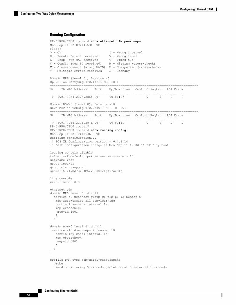
Running Configuration
RP/0/RP0/CPU0:router# show ethernet cfm peer mepsMon Sep 11 12:09:44.534 UTCFlags:> - Ok I - Wrong intervalR - Remote Defect received V - Wrong levelL - Loop (our MAC received) T - Timed outC - Config (our ID received) M - Missing (cross-check)X - Cross-connect (wrong MAID) U - Unexpected (cross-check)* - Multiple errors received S - Standby
Domain UP6 (level 6), Service s6Up MEP on FortyGigE0/0/1/2.1 MEP-ID 1================================================================================St ID MAC Address Port Up/Downtime CcmRcvd SeqErr RDI Error-- ----- -------------- ------- ----------- --------- ------ ----- -----> 4001 70e4.227c.2865 Up 00:01:27 0 0 0 0
Domain DOWN0 (level 0), Service s10Down MEP on TenGigE0/0/0/10.1 MEP-ID 2001================================================================================St ID MAC Address Port Up/Downtime CcmRcvd SeqErr RDI Error-- ----- -------------- ------- ----------- --------- ------ ----- -----> 6001 70e4.227c.287a Up 00:02:11 0 0 0 0RP/0/RP0/CPU0:router#RP/0/RP0/CPU0:router# show running-configMon Sep 11 12:10:18.467 UTCBuilding configuration...!! IOS XR Configuration version = 6.4.1.14!! Last configuration change at Mon Sep 11 12:08:16 2017 by root!logging console disabletelnet vrf default ipv4 server max-servers 10username rootgroup root-lrgroup cisco-supportsecret 5 $1$QJT3$94M5/wK5J0v/lpAu/wz31/!line consoleexec-timeout 0 0!ethernet cfmdomain UP6 level 6 id nullservice s6 xconnect group g1 p2p p1 id number 6mip auto-create all ccm-learningcontinuity-check interval 1smep crosscheckmep-id 4001!!
!domain DOWN0 level 0 id nullservice s10 down-meps id number 10continuity-check interval 1smep crosscheckmep-id 6001!!
!!profile DMM type cfm-delay-measurementprobesend burst every 5 seconds packet count 5 interval 1 seconds
Configuring Ethernet OAM58
Configuring Ethernet OAMConfiguring Two-Way Delay Measurement

!scheduleevery 1 minutes for 40 seconds!statisticsmeasure round-trip-delaybuckets size 1 probesbuckets archive 5!measure round-trip-jitterbuckets size 1 probesbuckets archive 1!
interface MgmtEth0/RP0/CPU0/0shutdown!interface TenGigE0/0/0/0shutdown!interface TenGigE0/0/0/1shutdown!interface TenGigE0/0/0/2shutdown!interface TenGigE0/0/0/3shutdown!interface TenGigE0/0/0/4shutdown!interface TenGigE0/0/0/5shutdown!interface TenGigE0/0/0/6shutdown!interface TenGigE0/0/0/7shutdown!interface TenGigE0/0/0/8shutdown!interface TenGigE0/0/0/9shutdown!interface TenGigE0/0/0/10.1 l2transportencapsulation dot1q 1ethernet cfmmep domain DOWN0 service s10 mep-id 2001sla operation profile DMM target mep-id 6001sla operation profile test-slm target mep-id 6001!
!!interface TenGigE0/0/0/11shutdown!interface TenGigE0/0/0/12shutdown!interface TenGigE0/0/0/13shutdown!
Configuring Ethernet OAM59
Configuring Ethernet OAMConfiguring Two-Way Delay Measurement
interface TenGigE0/0/0/14shutdown!interface TenGigE0/0/0/15shutdown!interface TenGigE0/0/0/16shutdown!interface TenGigE0/0/0/17shutdown!interface TenGigE0/0/0/18shutdown!interface TenGigE0/0/0/19shutdown!interface TenGigE0/0/0/20shutdown!interface TenGigE0/0/0/21shutdown!interface TenGigE0/0/0/22shutdown!interface TenGigE0/0/0/23shutdown!interface TenGigE0/0/0/24shutdown!interface TenGigE0/0/0/25shutdown!interface TenGigE0/0/0/26shutdown!interface TenGigE0/0/0/27shutdown!interface TenGigE0/0/0/28shutdown!interface TenGigE0/0/0/29shutdown!interface TenGigE0/0/0/30shutdown!!interface TenGigE0/0/0/31shutdown!interface TenGigE0/0/0/32shutdown!interface TenGigE0/0/0/33shutdown!interface TenGigE0/0/0/34shutdown!
Configuring Ethernet OAM60
Configuring Ethernet OAMConfiguring Two-Way Delay Measurement

interface TenGigE0/0/0/35shutdown!interface TenGigE0/0/0/36shutdown!interface TenGigE0/0/0/37shutdown!interface TenGigE0/0/0/38shutdown!interface TenGigE0/0/0/39shutdown!interface TenGigE0/0/1/0/1shutdown!interface TenGigE0/0/1/0/2shutdown!interface TenGigE0/0/1/0/3shutdown!controller Optics0/0/1/0breakout 4x10!interface HundredGigE0/0/1/1shutdown!interface FortyGigE0/0/1/2.1 l2transportencapsulation dot1q 1ethernet cfmmep domain UP6 service s6 mep-id 1sla operation profile DMM target mep-id 6001sla operation profile test-slm target mep-id 6001
!!!l2vpnxconnect group g1p2p p1interface TenGigE0/0/0/10.1interface FortyGigE0/0/1/2.1!!!end
Verification
One-way Delay (Source->Dest)~~~~~~~~~~~~~~~~~~~~~~~~~~~~1 probes per bucket
Bucket started at 12:11:19 UTC Mon 11 September 2017 lasting 10sPkts sent: 10; Lost: 0 (0.0%); Corrupt: 0 (0.0%);
Misordered: 0 (0.0%); Duplicates: 0 (0.0%)Result count: 10Min: 1912765.961ms; Max: 1912765.961ms; Mean: 1912765.961ms; StdDev: -2147483.648ms
One-way Delay (Dest->Source)~~~~~~~~~~~~~~~~~~~~~~~~~~~~
Configuring Ethernet OAM61
Configuring Ethernet OAMConfiguring Two-Way Delay Measurement

1 probes per bucket
Bucket started at 12:11:19 UTC Mon 11 September 2017 lasting 10sPkts sent: 10; Lost: 0 (0.0%); Corrupt: 0 (0.0%);
Misordered: 0 (0.0%); Duplicates: 0 (0.0%)Result count: 10Min: -1912765.952ms; Max: -1912765.951ms; Mean: -1912765.951ms; StdDev: -2147483.648ms
Round Trip Jitter~~~~~~~~~~~~~~~~~1 probes per bucket
Bucket started at 12:11:19 UTC Mon 11 September 2017 lasting 10sPkts sent: 10; Lost: 0 (0.0%); Corrupt: 0 (0.0%);
Misordered: 0 (0.0%); Duplicates: 0 (0.0%)Result count: 9Min: 0.000ms; Max: 0.001ms; Mean: 0.000ms; StdDev: 0.000ms
One-way Jitter (Source->Dest)~~~~~~~~~~~~~~~~~~~~~~~~~~~~~1 probes per bucket
Bucket started at 12:11:19 UTC Mon 11 September 2017 lasting 10sPkts sent: 10; Lost: 0 (0.0%); Corrupt: 0 (0.0%);
Misordered: 0 (0.0%); Duplicates: 0 (0.0%)Result count: 9Min: 0.000ms; Max: 0.000ms; Mean: 0.000ms; StdDev: 0.000ms
One-way Jitter (Dest->Source)~~~~~~~~~~~~~~~~~~~~~~~~~~~~~1 probes per bucket
Bucket started at 12:11:19 UTC Mon 11 September 2017 lasting 10sPkts sent: 10; Lost: 0 (0.0%); Corrupt: 0 (0.0%);
Misordered: 0 (0.0%); Duplicates: 0 (0.0%)Result count: 9Min: 0.000ms; Max: 0.001ms; Mean: 0.000ms; StdDev: 0.000ms
RP/0/RP0/CPU0:ios#ethernet sla on-demand operation type cfm-syn probe domain DOWN0 sourceinterface tenGigE 0/0/0/10.1 target mep-id 6001Mon Sep 11 12:12:39.259 UTCWarning: Burst configuration is present and so this profile cannot be represented in theMEF-SOAM-PM-MIB configuration tables. However, the statistics are still collectedOn-demand operation 2 succesfully created/ - Completed - statistics will be displayed shortly.RP/0/RP0/CPU0:ios#show ethernet sla statistics on-demand id 2
Mon Sep 11 12:13:24.825 UTCSource: Interface TenGigE0/0/0/10.1, Domain DOWN0Destination: Target MEP-ID 6001================================================================================On-demand operation ID #2, packet type 'cfm-synthetic-loss-measurement'Started at 12:12:41 UTC Mon 11 September 2017, runs once for 10sFrame Loss Ratio calculated every 10s
One-way Frame Loss (Source->Dest)~~~~~~~~~~~~~~~~~~~~~~~~~~~~~~~~~1 probes per bucket
Bucket started at 12:12:41 UTC Mon 11 September 2017 lasting 10s
Configuring Ethernet OAM62
Configuring Ethernet OAMConfiguring Two-Way Delay Measurement

Pkts sent: 100; Lost: 0 (0.0%); Corrupt: 0 (0.0%);Misordered: 0 (0.0%); Duplicates: 0 (0.0%)
Result count: 1Min: 0.000%; Max: 0.000%; Mean; 0.000%; StdDev: 0.000%; Overall: 0.000%
One-way Frame Loss (Dest->Source)~~~~~~~~~~~~~~~~~~~~~~~~~~~~~~~~~1 probes per bucket
Bucket started at 12:12:41 UTC Mon 11 September 2017 lasting 10sPkts sent: 100; Lost: 0 (0.0%); Corrupt: 0 (0.0%);
Misordered: 0 (0.0%); Duplicates: 0 (0.0%)Result count: 1Min: 0.000%; Max: 0.000%; Mean; 0.000%; StdDev: 0.000%; Overall: 0.000%
RP/0/RP0/CPU0:ios#show ethernet cfm local meps verboseMon Sep 11 12:13:04.461 UTCDomain UP6 (level 6), Service s6Up MEP on FortyGigE0/0/1/2.1 MEP-ID 1================================================================================Interface state: Up MAC address: 008a.960f.c4a8Peer MEPs: 1 up, 0 with errors, 0 timed out (archived)Cross-check errors: 0 missing, 0 unexpected
CCM generation enabled: Yes, 1s (Remote Defect detected: No)CCM processing offloaded to hardware
AIS generation enabled: NoSending AIS: NoReceiving AIS: No
No packets sent/received
Domain DOWN0 (level 0), Service s10Down MEP on TenGigE0/0/0/10.1 MEP-ID 2001================================================================================Interface state: Up MAC address: 008a.960f.c428Peer MEPs: 1 up, 0 with errors, 0 timed out (archived)Cross-check errors: 0 missing, 0 unexpected
CCM generation enabled: Yes, 1s (Remote Defect detected: No)CCM processing offloaded to hardware
AIS generation enabled: NoSending AIS: NoReceiving AIS: No
Packet Sent Received------ ---------- ---------------------------------------------------------DMM 10 0DMR 0 10SLM 100 0SLR 0 100
Synthetic Loss MeasurementThe synthetic loss measurement mechanism defined in Y.1731 can only be used in point-to-point networks,and only works when there is sufficient flow of data traffic. The difficulties with the Y.1731 loss measurementmechanism was recognized across the industry and hence an alternative mechanism has been defined andstandardized for measuring loss of traffic.
This alternative mechanism does not measure the loss of the actual data traffic, but instead injects syntheticCFM frames and measures the loss of these synthetic frames. You can perform a statistical analysis to give
Configuring Ethernet OAM63
Configuring Ethernet OAMSynthetic Loss Measurement

an approximation of the loss of data traffic. This technique is called Synthetic Loss Measurement (SLM).SLM has been included in the latest version of the Y.1731 standard. Use SLA to perform the followingmeasurements:
• One-way loss (Source to Destination)
• One-way loss (Destination to Source)
SLM supports the following:
• All Layer 2 transport interfaces, such as physical, bundle interfaces, Layer2 sub-interfaces, pseudowireHead-end interfaces or attachment circuits. Transport network can be EVPN or BGP-MPLS.
• Up and Down MEPs.
• Transparent passing of the SLM packets through the MIP without punting it to the software.
Configuring Synthetic Loss MeasurementThe following section describes how you can configure Synthetic Loss Measurement:
RP/0/RP0/CPU0:router (config)# ethernet sla
profile test-slm type cfm-synthetic-loss-measurementprobesend packet every 1 secondssynthetic loss calculation packets 24!scheduleevery 3 minutes for 120 seconds!statisticsmeasure one-way-loss-sdbuckets size 1 probesbuckets archive 5!measure one-way-loss-dsbuckets size 1 probesbuckets archive 5
!!!!interface TenGigE0/0/0/10.1 l2transportencapsulation dot1q 1ethernet cfmmep domain DOWN0 service s10 mep-id 2001sla operation profile test-slm target mep-id 6001!
Configuring an On-Demand Ethernet SLA Operation for CFM Synthetic Loss Measurement
To configure an on-demand Ethernet SLA operation for CFM synthetic loss measurement, use this commandin privileged EXEC configuration mode:
RP/0/RP0/CPU0:router (config) # ethernet sla on-demand operation typecfm-synthetic-loss-measurement probe domain D1 source interface TenGigE0/0/0/0 target mac-address 2.3.4
Configuring Ethernet OAM64
Configuring Ethernet OAMConfiguring Synthetic Loss Measurement

Running Configuration
RP/0/RP0/CPU0:router# show ethernet sla statistics on-demand id 1Mon Sep 11 12:12:00.699 UTCSource: Interface TenGigE0/0/0/10.1, Domain DOWN0Destination: Target MEP-ID 6001================================================================================On-demand operation ID #1, packet type 'cfm-delay-measurement'RP/0/RP0/CPU0:router#RP/0/RP0/CPU0:router# show running-configMon Sep 11 12:10:18.467 UTCBuilding configuration...!! IOS XR Configuration version = 6.4.1.14I!! Last configuration change at Mon Sep 11 12:08:16 2017 by root!logging console disabletelnet vrf default ipv4 server max-servers 10username rootgroup root-lrgroup cisco-supportsecret 5 $1$QJT3$94M5/wK5J0v/lpAu/wz31/!line consoleexec-timeout 0 0!ethernet cfmdomain UP6 level 6 id nullservice s6 xconnect group g1 p2p p1 id number 6mip auto-create all ccm-learningcontinuity-check interval 1smep crosscheckmep-id 4001!!
!domain DOWN0 level 0 id nullservice s10 down-meps id number 10continuity-check interval 1smep crosscheckmep-id 6001!!
!!profile test-slm type cfm-synthetic-loss-measurementprobesend packet every 1 secondssynthetic loss calculation packets 24!scheduleevery 3 minutes for 120 seconds!statisticsmeasure one-way-loss-sdbuckets size 1 probesbuckets archive 5!measure one-way-loss-dsbuckets size 1 probesbuckets archive 5
!
interface TenGigE0/0/0/10.1 l2transportencapsulation dot1q 1
Configuring Ethernet OAM65
Configuring Ethernet OAMConfiguring Synthetic Loss Measurement

ethernet cfmmep domain DOWN0 service s10 mep-id 2001sla operation profile DMM target mep-id 6001sla operation profile test-slm target mep-id 6001!
!!
interface FortyGigE0/0/1/2.1 l2transportencapsulation dot1q 1ethernet cfmmep domain UP6 service s6 mep-id 1sla operation profile DMM target mep-id 6001sla operation profile test-slm target mep-id 6001
!!!l2vpnxconnect group g1p2p p1interface TenGigE0/0/0/10.1interface FortyGigE0/0/1/2.1!!!end
Verification
Round Trip Delay~~~~~~~~~~~~~~~~1 probes per bucket
Bucket started at 12:11:19 UTC Mon 11 September 2017 lasting 10sPkts sent: 10; Lost: 0 (0.0%); Corrupt: 0 (0.0%);
Misordered: 0 (0.0%); Duplicates: 0 (0.0%)Result count: 10Min: 0.009ms; Max: 0.010ms; Mean: 0.009ms; StdDev: 0.000ms
One-way Delay (Source->Dest)~~~~~~~~~~~~~~~~~~~~~~~~~~~~1 probes per bucket
Bucket started at 12:11:19 UTC Mon 11 September 2017 lasting 10sPkts sent: 10; Lost: 0 (0.0%); Corrupt: 0 (0.0%);
Misordered: 0 (0.0%); Duplicates: 0 (0.0%)Result count: 10Min: 1912765.961ms; Max: 1912765.961ms; Mean: 1912765.961ms; StdDev: -2147483.648ms
One-way Delay (Dest->Source)~~~~~~~~~~~~~~~~~~~~~~~~~~~~1 probes per bucket
Bucket started at 12:11:19 UTC Mon 11 September 2017 lasting 10sPkts sent: 10; Lost: 0 (0.0%); Corrupt: 0 (0.0%);
Misordered: 0 (0.0%); Duplicates: 0 (0.0%)Result count: 10Min: -1912765.952ms; Max: -1912765.951ms; Mean: -1912765.951ms; StdDev: -2147483.648ms
Round Trip Jitter~~~~~~~~~~~~~~~~~
Configuring Ethernet OAM66
Configuring Ethernet OAMConfiguring Synthetic Loss Measurement

1 probes per bucket
Bucket started at 12:11:19 UTC Mon 11 September 2017 lasting 10sPkts sent: 10; Lost: 0 (0.0%); Corrupt: 0 (0.0%);
Misordered: 0 (0.0%); Duplicates: 0 (0.0%)Result count: 9Min: 0.000ms; Max: 0.001ms; Mean: 0.000ms; StdDev: 0.000ms
One-way Jitter (Source->Dest)~~~~~~~~~~~~~~~~~~~~~~~~~~~~~1 probes per bucket
Bucket started at 12:11:19 UTC Mon 11 September 2017 lasting 10sPkts sent: 10; Lost: 0 (0.0%); Corrupt: 0 (0.0%);
Misordered: 0 (0.0%); Duplicates: 0 (0.0%)Result count: 9Min: 0.000ms; Max: 0.000ms; Mean: 0.000ms; StdDev: 0.000ms
One-way Jitter (Dest->Source)~~~~~~~~~~~~~~~~~~~~~~~~~~~~~1 probes per bucket
Bucket started at 12:11:19 UTC Mon 11 September 2017 lasting 10sPkts sent: 10; Lost: 0 (0.0%); Corrupt: 0 (0.0%);
Misordered: 0 (0.0%); Duplicates: 0 (0.0%)Result count: 9Min: 0.000ms; Max: 0.001ms; Mean: 0.000ms; StdDev: 0.000ms
Configuring Ethernet OAM67
Configuring Ethernet OAMConfiguring Synthetic Loss Measurement

Configuring Ethernet OAM68
Configuring Ethernet OAMConfiguring Synthetic Loss Measurement