
VPGate Ethernet/IP - Procentec
109
VPGate Manual EtherNet/IP™ to Serial Rev. A
-
Upload
khangminh22 -
Category
Documents
-
view
4 -
download
0
Transcript of VPGate Ethernet/IP - Procentec

VPGate Manual
EtherNet/IP™ to Serial Rev. A

VPGate EtherNet/IP™ manual | rev. A | September 2017 | ©PROCENTEC 2/109
1. PROPERTIES ....................................................................... 5
1.1. General properties ..................................................................................................... 5
1.2. Electrical properties ................................................................................................... 7
1.3. Mechanical properties ............................................................................................... 7
2. HARDWARE INSTALLATION ............................................... 8
2.1. Connectors ................................................................................................................. 8
2.1.1. Power connector ................................................................................................ 8
2.1.2. SERIAL connector ............................................................................................... 8
2.1.3. ETHERNET RJ45 connectors P1 and P2 .............................................................. 9
2.1.4. TOR input ............................................................................................................ 9
2.1.5. TOR output ......................................................................................................... 9
2.2. Indicators .................................................................................................................. 10
2.2.1. Front panel indicators ...................................................................................... 10
2.2.2. Indicators on the 2 ETHERNET connectors ...................................................... 10
2.3. DIP switches ............................................................................................................. 11
2.3.1. Default configuration of the IP address ........................................................... 11
2.3.2. Choosing the RS232/RS485 mode .................................................................... 11
2.3.3. Termination resistance ..................................................................................... 12
3. ETHERNET/IP™ ................................................................. 13
3.1. Operating principle ................................................................................................... 13
3.1.1. Implicit messaging ............................................................................................ 13
3.1.2. Explicit messaging ............................................................................................ 13
3.2. List of available EtherNet/IP™ objects ..................................................................... 14
3.2.1. Identity Object .................................................................................................. 14
3.2.1.1. Instance Attributes ........................................................................................... 14
3.2.1.2. Instance Services .............................................................................................. 15
3.2.2. Assembly Object ............................................................................................... 16
3.2.2.1. Class Attributes ................................................................................................ 16
3.2.2.2. Instance list....................................................................................................... 16
3.2.2.3. Instance Attributes ........................................................................................... 17
3.2.3. Connection Manager Object ............................................................................ 18
3.2.3.1. Class Attributes ................................................................................................ 18
3.2.3.2. Class Services .................................................................................................... 18
3.2.3.3. Instance Attributes ........................................................................................... 18
3.2.3.4. Instance Services .............................................................................................. 19
3.2.4. MODBUS Object (Vendor specific) ................................................................... 20
3.2.4.1. Operating principle ........................................................................................... 20
3.2.4.2. Class Attributes ................................................................................................ 21
3.2.4.3. Class Service ..................................................................................................... 21
3.2.4.4. Object-specific Services .................................................................................... 21
3.2.4.4.1. Read_Discrete_Inputs Service .......................................................................... 22
3.2.4.4.2. Read_Coils Service............................................................................................ 22
3.2.4.4.3. Read_Input_Registers Service .......................................................................... 23
3.2.4.4.4. Read_Holding_Registers Service ...................................................................... 23
3.2.4.4.5. Write_Coils Service........................................................................................... 24

VPGate EtherNet/IP™ manual | rev. A | September 2017 | ©PROCENTEC 3/109
3.2.4.4.6. Write_Holding_Registers Service ..................................................................... 25
3.2.4.4.7. Error Checking .................................................................................................. 26
3.2.5. TCP/IP Interface Object .................................................................................... 27
3.2.5.1. Class Attributes ................................................................................................ 27
3.2.5.2. Instance Attributes ........................................................................................... 27
3.2.5.3. Instance Services .............................................................................................. 29
3.2.6. Ethernet Link Object ......................................................................................... 30
3.2.6.1. Class Attributes ................................................................................................ 30
3.2.6.2. Class-Specific Service ........................................................................................ 30
3.2.6.3. Instance list....................................................................................................... 30
3.2.6.4. Instance Attributes ........................................................................................... 30
3.2.6.5. Instance Services .............................................................................................. 31
4. SOFTWARE CONFIGURATION .......................................... 32
4.1. Configuration of the EtherNet/IP™ Scanner ............................................................ 32
4.2. Integrating The VPGATE in a project ........................................................................ 32
4.2.1. Importing an EDS file into the engineering tool............................................... 32
4.2.2. Integrating the VPGATE in a configuration tool ............................................... 33
4.2.2.1. Integration by network detection .................................................................... 33
4.2.2.2. Manual integration ........................................................................................... 36
4.3. General configuration of VPGATE ............................................................................ 40
4.4. Exclusive owner connection for MODBUS Master mode ........................................ 41
4.4.1. Operating principle ........................................................................................... 41
4.4.2. Configuration .................................................................................................... 41
4.4.3. Input assembly (TO) ...................................................................................... 41
4.4.4. Output assembly (OT) ................................................................................... 42
4.4.5. Configuration assembly .................................................................................... 42
4.4.6. Setting MODBUS Master mode in a configuration tool ................................... 45
4.4.7. MODBUS Master behaviour according to EtherNet/IP™ connection status ... 46
4.5. Exclusive owner connection for MODBUS Slave mode ........................................... 47
4.5.1. Operating principle ........................................................................................... 47
4.5.2. Configuration .................................................................................................... 47
4.5.3. Input assembly (TO) ...................................................................................... 47
4.5.4. Output assembly (OT) ................................................................................... 48
4.5.5. Configuration assembly .................................................................................... 48
4.5.6. Setting MODBUS Slave mode in a configuration tool ...................................... 49
4.6. Exclusive owner connection for TRANSPARENT mode ............................................ 52
4.6.1. Operating principle ........................................................................................... 52
4.6.2. Configuration .................................................................................................... 54
4.6.3. Input assembly (TO) ...................................................................................... 55
4.6.4. Output assembly (OT) ................................................................................... 55
4.6.5. Configuration assembly .................................................................................... 55
4.6.6. Setting TRANSPARENT mode in a configuration tool....................................... 59
4.7. Input Only connection .............................................................................................. 60
4.7.1. Input assembly (TO) ...................................................................................... 60
4.7.2. Output assembly (OT) ................................................................................... 61
4.7.3. Configuration assembly .................................................................................... 61
4.8. Listen Only connection ............................................................................................. 62

VPGate EtherNet/IP™ manual | rev. A | September 2017 | ©PROCENTEC 4/109
4.8.1. Input assembly (TO) ...................................................................................... 62
4.8.2. Output assembly (OT) ................................................................................... 62
4.8.3. Configuration assembly .................................................................................... 62
5. DIAGNOSTIC..................................................................... 63
5.1. Diagnostic on the UDP 5628810 port ........................................................................ 63
5.2. Status of Identity Object, with explicit messaging ................................................... 64
5.3. Status in implicit messaging .................................................................................... 64
5.4. Indicators .................................................................................................................. 64
5.5. Using web server for diagnostic ............................................................................... 65
6. DIGITAL INPUTS/OUTPUTS .............................................. 66
6.1. Digital output (DO) .................................................................................................. 66
6.2. Digital output diagnostic .......................................................................................... 66
6.3. Digital input (DI) ....................................................................................................... 67
7. IP ADDRESS CONFIGURATION ......................................... 68
7.1. Configuration via the DCP protocol ......................................................................... 68
7.2. Applying a default IP address using a DIP switch ..................................................... 69
7.3. IP configuration via WEB server ............................................................................... 70
7.4. Configuration via the EtherNet/IP™ 0xF5 TCP/IP object ......................................... 72
8. WEB SERVER .................................................................... 73
8.1. Configuration web page ........................................................................................... 73
8.2. Account management on the web server ................................................................ 74
8.3. System information menu ........................................................................................ 75
8.4. Network settings menu ............................................................................................ 76
8.5. SNMP information menu ......................................................................................... 76
8.6. Ethernet statistics menu .......................................................................................... 77
8.7. EtherNet/IP™ ADAPTER menu ................................................................................. 80
8.8. MODBUS menu ........................................................................................................ 81
8.9. File system menu ...................................................................................................... 82
8.10. Firmware upload menu ............................................................................................ 83
8.11. Reboot menu ............................................................................................................ 84
8.12. Passwords menu ...................................................................................................... 84
8.13. Logout menu ............................................................................................................ 85
9. FTP SERVER ...................................................................... 86
10. SNMP AGENT ................................................................... 88
11. APPENDICES ..................................................................... 90
11.1. APPENDIX A: MODBUS frame formats ..................................................................... 90
11.2. APPENDIX B: MIB2 .................................................................................................. 102

VPGate EtherNet/IP™ manual | rev. A | September 2017 | ©PROCENTEC 5/109
1. PROPERTIES
1.1. General properties
ETHERNET LINK
Bandwidth 10/100 Mbps, auto-negotiation, auto-polarity, auto MDI/MDIX
LEDs Active Link (orange) and activity (green)
Distances Maximum 100 m
Cable Shielded Industrial Ethernet (at least of category 5e)
Connectors 2 RJ45 sockets, with shield connexion
Supported protocols EtherNet/IP™, SNMP V1, HTTP, FTP, LLDP
Switch 2 port integrated switch
Redundancy Not supported
ETHERNET/IP™ ADAPTER
Type Communications Adapter
IP address control DHCP, via web interface, DCP, switch in the front, TCP/IP object
EDS file Configuration file of the device that can be downloaded from the embedded web server or the FTP server.
Max. number of input bytes 500 bytes
Max. number of output bytes
500 bytes
Minimum Requested Packet Interval (RPI)
20 ms
VPGate EtherNet/IP™ manual | rev. A | September 2017 | ©PROCENTEC 6/109
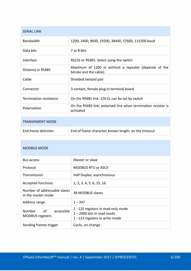
SERIAL LINK
Bandwidth 1200, 2400, 9600, 19200, 38400, 57600, 115200 baud
Data bits 7 or 8 bits
Interface RS232 or RS485. Select using the switch
Distance in RS485 Maximum of 1200 m without a repeater (depends of the bitrate and the cable)
Cable Shielded twisted pair
Connector 3-contact, female plug-in terminal board
Termination resistance On the RS485 link: 120 Ω; can be set by switch
Polarisation On the RS485 link: polarised line when termination resistor is activated
TRANSPARENT MODE
End frame delimiter End of frame character, known length, on the timeout
MODBUS MODE
Bus access Master or slave
Protocol MODBUS RTU or ASCII
Transmission Half Duplex, asynchronous
Accepted functions 1, 2, 3, 4, 5, 6, 15, 16
Number of addressable slaves in the master mode
48 MODBUS slaves
Address range 1 – 247
Number of accessible MODBUS registers
1 - 125 registers in read-only mode 1 – 2000 bits in read mode 1 - 123 registers in write mode
Sending frames trigger Cyclic, on change

VPGate EtherNet/IP™ manual | rev. A | September 2017 | ©PROCENTEC 7/109
LOCAL I/O
Digital input 1 insulated Digital input
Digital output 1 configurable Digital output (output assembly or Alarm output)
FILE SYSTEM
Capacity 9 MB
Access FTP, HTTP
1.2. Electrical properties
POWER SUPPLY
Supply voltage 24V DC ±10%
Consumption 1.7 W
Connector 3-contact (VCC, 0V, EARTH) male plug-in terminal board
Protection from polarity reversals
Yes
Protection from short-circuits Yes
1.3. Mechanical properties
MECHANICAL PROPERTIES
Case type Plastic with a hatch on the front side. IP20 – DIN rail fastening
Dimensions 120 x 100 x 23 mm (l x w x h)
Weight 130 g
Storage temperature -25 °C to +70 °C
Operating temperature 0 °C to +55 °C

VPGate EtherNet/IP™ manual | rev. A | September 2017 | ©PROCENTEC 8/109
2. HARDWARE INSTALLATION
2.1. Connectors
Figure 1: Connectors on top of the body
2.1.1. Power connector
PIN NAME DESCRIPTION
1 24 V DC 24V DC ±10%
2 0 VDC 0 V
3 GND Ground connection
2.1.2. SERIAL connector
Important: The shielding of the SERIAL cable must imperatively have ground connections at both ends in order to ensure correct electromagnetic disturbances protection. The pin 4 of the connector may be used. The ideal situation is to use a shield jumper screw, which is fixed at each end of the serial wire on a ground bus or a cabinet bottom plate.
PIN NAME DESCRIPTION
1 Rx Rx RS232 (VPGate equipment)
2 Tx Tx RS232 (VPGate equipment)
3 GND RS232 ground connection
4 Shield Ground
5 Data - Signal Data - RS485
6 Data + Signal Data + RS485
Power Serial
1 2 3 1 2 3 4 5 6

VPGate EtherNet/IP™ manual | rev. A | September 2017 | ©PROCENTEC 9/109
2.1.3. ETHERNET RJ45 connectors P1 and P2
PIN NAME DESCRIPTION
1 Tx+
2 Tx-
3 Rx+
6 Rx-
Important: The shielding of the ETHERNET cable must have ground connections at both ends in order to ensure correct resistance to electromagnetic disturbances. The body of the connector may be used. Ideally a shield jumper screw, which is fixed at each end of the Ethernet wire on a ground bus or a cabinet bottom plate, must be used.
Figure 2: Connectors at the bottom of the case
2.1.4. TOR input
IEC61131-2 compliant, type 1:
PIN NAME DESCRIPTION
1 IN + Insulated TOR input (15-24V)
2 IN - Insulated TOR input, ground return
2.1.5. TOR output
IEC61131-2 compliant:
PIN NAME DESCRIPTION
1 OUT Relay contact
2 OUT Relay contact
Breaking capacity: 0.5 A (On resistive load)
Maximum permissible current: 1.2 A
OUT 2 1
IN
2 1
+ -
1 2 1 2
TOR OUT TOR IN IN

VPGate EtherNet/IP™ manual | rev. A | September 2017 | ©PROCENTEC 10/109
2.2. Indicators
2.2.1. Front panel indicators
NAME LIT DESCRIPTION BLINKING DESCRIPTION
ON Power supply applied
N/A
ETH
No connection with an EtherNet/IP™ scanner
(1Hz) Communication established with an application error
SERIAL No protocol activated on the serial link
(1Hz) Error with the currently enabled serial link protocol
Until error disappears
MODBUS master
One of the scenarios is in error (timeout, exception answered, CRC error…)
For 10 seconds on error detection
MODBUS slave
Exception answered to a request from a MODBUS master. Invalid frame received (invalid format, bad CRC)
For 10 seconds on error detection
TRANSPARENT
Invalid frame received (frame too long, bad CRC, no end of frame detected until timeout)
RUN (1Hz) Firmware is running
Tx Data sent on the serial link
Rx Data received on the serial link
2.2.2. Indicators on the 2 ETHERNET connectors
Figure 3: ETHERNET socket with indicators built-in
Link status indicator: - Switched off: link down - Switched on: link up
Link activity indicator: - Switched off: no exchanges - Blinking: ongoing Tx/Rx

VPGate EtherNet/IP™ manual | rev. A | September 2017 | ©PROCENTEC 11/109
2.3. DIP switches
DIP switches enable:
- Activating a default IP configuration (192.168.10.20),
- Selecting the physical media for the serial link: RS232 or RS485,
- Activating a terminating resistance and polarity of the serial line.
Figure 4: DIP switches
2.3.1. Default configuration of the IP address
A switch allows the setting of a default IP configuration (@IP 192.168.10.20, mask 255.255.255.0) during the start-up of the VPGate Ethernet. The configuration is carried out in the following manner:
SWITCH POSITION DESCRIPTION
1 ON Default IP configuration
OFF IP configuration defined by the user
Set the DIP switch 1 to ON and power VPGate OFF and ON to ensure that it takes the default IP parameters into account. Important: A user may change the IP address of VPGate via the Web server or via the DCP protocol, when the switch is set to ON. In this case, the new IP address is used immediately, despite the switch being activated. Consider setting the switch to OFF, otherwise the default IP address shall be once again used when the device is restarted.
2.3.2. Choosing the RS232/RS485 mode
There is a switch which allows specifying the operating mode of the serial link from between RS232 or RS485 (VPGate is pre-set to RS485 out of the box):
SWITCH POSITION DESCRIPTION
2 ON RS232
OFF RS485

VPGate EtherNet/IP™ manual | rev. A | September 2017 | ©PROCENTEC 12/109
RS232 mode:
Figure 5: Serial network in RS232 mode
This mode can only be used in case of communication between 2 individual devices (point-to-point connection). The maximum distance in RS232 is 15 meters at 19200 baud.
RS485 mode:
Figure 6: Serial network in RS485 mode
This mode is used more often as it allows connection of several slaves on the bus. It also has other advantages such as immunity to EMC disturbances and a greater inter-device distance than in RS232. The maximum distance in RS485 is 1000 meters.
2.3.3. Termination resistance
If the communication mode used is RS485, there must be a termination resistance of 120Ω at both ends of the segment (refer to the example in paragraph §2.3.2). A termination resistance is connected using DIP switches 3 and 4 (when delivered, the VPGate is pre-set without a termination resistor).
SWITCH POSITION DESCRIPTION
3 – 4 (activation of the terminating resistor + polarisation of the line)
ON Termination + polarisation
OFF No termination and no polarisation
To ensure the proper functioning of the termination, switches 3 and 4 must be in the same position.
VPGate EtherNet/IP™
Serial Device
VPGate EtherNet/IP™
Serial Device

VPGate EtherNet/IP™ manual | rev. A | September 2017 | ©PROCENTEC 13/109
3. EtherNet/IP™
3.1. Operating principle
The VPGate is an EtherNet/IP™ adapter. An EtherNet/IP™ Scanner can access it with implicit (deterministic) or explicit messaging (acyclic and not deterministic).
3.1.1. Implicit messaging
Implicit messaging allows data producing/consuming mechanism. The configuration of the communication (mainly type of communication, data exchanged and cycle time) is sent at the beginning of the communication with the “Forward Open” service.
As the configuration is sent only once, this communication is more efficient than explicit messaging.
The data exchange is stopped with “Forward Close” service.
Figure 7: Data exchange in implicit mode
3.1.2. Explicit messaging
Explicit messaging works as client/server. It’s used for non-real-time data access.
It allows access to specific objects (data) by using its services/attributes.
Figure 8: Data exchange in explicit mode
™ ™
™ ™

VPGate EtherNet/IP™ manual | rev. A | September 2017 | ©PROCENTEC 14/109
3.2. List of available EtherNet/IP™ objects
3.2.1. Identity Object
Identity object (Class code 0x01) has only one instance (instance 1).
3.2.1.1. Instance Attributes
ATTR ID
ACCESS RULE
NAME DATA TYPE DESCRIPTION OF ATTRIBUTE VALUE
01h Get Vendor ID UINT Identification of each vendor by number
8
02h Get Device Type
UINT Indication of general type of product
12 (dec) 0x0C(hex)
03h Get Product Code
UINT Identification of a particular product of an individual vendor
2048
04h Get
Revision STRUCT Revision of the item the Identity Object represents
Major Revision
USINT 1
Minor Revision
USINT 1
05h Get Status WORD Summary status of device See Status description below
06h Get Serial Number
UDINT Serial number of device
07h Get Product Name
SHORT_STR Human readable identification
110-00014A
Focus on Status attribute: This attribute represents the current status of the entire device. Its value changes as the state of the device changes. The Status attribute is a WORD, with the following bit definitions:
Identity Object Status (attr 5)
BIT (S) CALLED DEFINITION
0 Owned
TRUE indicates the device (or an object within the device) has an owner. Within the Master/Slave paradigm the setting of this bit means that the Predefined Master/Slave Connection Set has been allocated to a master. Outside the Master/Slave paradigm the meaning of this bit is TBD.
1 Reserved, shall be 0
2 Configured TRUE indicates the application of the device has been configured to do something different than the “out–of–box” default. This shall not include configuration of the communications.

VPGate EtherNet/IP™ manual | rev. A | September 2017 | ©PROCENTEC 15/109
3 Reserved, shall be 0
4 – 7 Extended Device
Status
Vendor–specific or as defined by Table. The EDS shall indicate if the device follows a vendor-specific definition for these bits by using the DeviceStatusAssembly keyword.
8 Minor
Recoverable Fault
TRUE indicates the device detected a problem with itself, which is thought to be recoverable. The problem does not cause the device to go into one of the faulted states. See Behavior section.
9 Minor
Unrecoverable Fault
TRUE indicates the device detected a problem with itself, which is thought to be unrecoverable. The problem does not cause the device to go into one of the faulted states. See Behavior section.
10 Major
Recoverable Fault
TRUE indicates the device detected a problem with itself, which caused the device to go into the “Major Recoverable Fault” state. See Behavior section.
11 Major
Unrecoverable Fault
TRUE indicates the device detected a problem with itself, which caused the device to go into the “Major Unrecoverable Fault” state. See Behavior section.
12 - 15 Extended Device
Status 2
Reserved - (shall be 0) or vendor-specific. The EDS shall indicate if the device follows a vendor-specific definition for these bits by using the DeviceStatusAssembly2 keyword as defined in Section 7-3.6.3, Device Description Section.
Extended Device Status (Field (bits 4-7) in Status Instance Attribute)
EXTENDED DEVICE STATUS
0 Self-Testing or Unknown
1 Firmware Update in Progress
2 At least one faulted I/O connection
3 No I/O connections established
4 Non-Volatile Configuration bad
5 Major Fault – either bit 10 or bit 11 is true (1)
6 At least one I/O connection in run mode
7 At least one I/O connection established, all in idle mode
8-9 Reserved
10-15 Vendor specific status
3.2.1.2. Instance Services
SERVICE CODE
SERVICE NAME
DESCRIPTION OF SERVICE
01h Get_Attributes_All
Returns a predefined listing of this objects attributes (See the Get_Attributes_All Response definition below)
05h Reset 1 Invokes the Reset service for the device.
0Eh Get_Attribute_Single
Returns the contents of the specified attribute.
1: Only the reset type 0 is supported

VPGate EtherNet/IP™ manual | rev. A | September 2017 | ©PROCENTEC 16/109
3.2.2. Assembly Object
3.2.2.1. Class Attributes
ATTR ID
ACCESS RULE
NAME DATA TYPE
DESCRIPTION OF ATTRIBUTE VALUE
01h Get Revision UINT Revision of this object 2
02h Get Max Instance
UINT
Maximum instance number of an object currently created in this class level of the device.
199
03h Get Number of instances
UINT
Number of object instances currently created at this class level of the device.
9
3.2.2.2. Instance list
INSTANCE ID
NAME DIRECTION COMMENTS
0x65 (101)
INPUT T->O Data from the target to the originator
0x66 (102)
OUTPUT O->T Data from the originator to the target
0x67 (103)
STATUS T->O Status from the target to the originator
0x68 (104)
Configuration MODBUS Master
O->T MODBUS Master configuration assembly
0x69 (105)
Configuration MODBUS Slave
O->T MODBUS Slave configuration assembly
0x6A (106)
Configuration TRANSPARENT
O->T TRANSPARENT configuration assembly
0x6B (107)
Dummy Configuration
O->T Configuration assembly for IO and LO
0xC6 (198)
Heartbeat - Input only
O->T Heartbeat
0xC7 (199)
Heartbeat - Listen only
O->T Heartbeat

VPGate EtherNet/IP™ manual | rev. A | September 2017 | ©PROCENTEC 17/109
3.2.2.3. Instance Attributes
ATTR ID
ACCESS RULE
NAME DATA TYPE DESCRIPTION OF ATTRIBUTE
03h Set Data ARRAY of BYTE
There isn’t any endian conversion on the bytes.

VPGate EtherNet/IP™ manual | rev. A | September 2017 | ©PROCENTEC 18/109
3.2.3. Connection Manager Object
Connection Manager object (Class code 0x06) has only one instance (instance 1)
3.2.3.1. Class Attributes
ATTR ID
ACCESS RULE
NAME DATA TYPE DESCRIPTION OF ATTRIBUTE VALUE
01h Get Revision UINT Revision of this object 1
02h Get Max Instance
UINT Maximum instance number of an object currently created in this class level of the device.
1
03h Get Number of instances
UINT Number of object instances currently created at this class level of the device.
1
3.2.3.2. Class Services
SERVICE CODE
SERVICE NAME SERVICE DESCRIPTION
01hex Get_Attributes_All Returns the contents of all attributes of the class.
0Ehex Get_Attribute_Single Used to read a Connection Manager Class attribute value.
3.2.3.3. Instance Attributes
ATTR ID
ACCESS RULE
ATTRIBUTE NAME
DATA TYPE
DESCRIPTION OF ATTRIBUTE
01h Get Open Requests
UINT Number of Forward Open service requests received.
02h Get Open Format Rejects
UINT Number of Forward Open service requests which were rejected due to bad format.
03h Get Open Resource Rejects
UINT Number of Forward Open service requests which were rejected due to lack of resources.
04h Get Open Other Rejects
UINT Number of Forward Open service requests which were rejected for reasons other than bad format or lack of resources.
05h Get Close Requests
UINT Number of Forward Close service requests received.
06h Get Close Format Requests
UINT Number of Forward Close service requests which were rejected due to bad format.
07h Get Close Other Requests
UINT Number of Forward Close service requests which were rejected for reasons other than bad format.
08h Get Connection Timeouts
UINT Total number of connection timeouts that have occurred in connections controlled by this Connection Manager

VPGate EtherNet/IP™ manual | rev. A | September 2017 | ©PROCENTEC 19/109
3.2.3.4. Instance Services
Common services
SERVICE CODE
SERVICE NAME SERVICE DESCRIPTION
01hex Get_Attributes_All Returns the contents of all attributes of the class.
0Ehex Get_Attribute_Single Used to read a Connection Manager Object instance attribute.
Object specific services
SERVICE CODE
SERVICE NAME
SERVICE DESCRIPTION
4Ehex Forward_Close
Closes a connection
52hex Unconnected_Send
Unconnected Send Service. Only originating devices and devices that route between links need to implement
54hex Forward_Open
Opens a connection, maximum data size is 511 bytes
Forward Open service parameters: Network connection parameters:
Fixed/Variable: only fixed size for the amount of data on the connection.
Priority: Not supported
Redundant owner: Not supported.
Connection Path:
Only path to assembly object is supported.

VPGate EtherNet/IP™ manual | rev. A | September 2017 | ©PROCENTEC 20/109
3.2.4. MODBUS Object (Vendor specific)
The MODBUS object provides an interface to MODBUS equipments connected to the serial port. Services are provided that directly correspond to the most common MODBUS commands. MODBUS object is a “vendor specific” object with a class code 0x64. Only one instance is available in the gateway (instance 0).
Figure 9 - MODBUS device
This object supports the following MODBUS functions as EtherNet/IP™ services:
- 1: Read coils
- 2: Read Discrete Inputs
- 3: Read Holding Registers
- 4: Read Input Registers
- 15: Write Multiple Coils
- 16: Write Multiple Registers
3.2.4.1. Operating principle
By using explicit messaging through the MODBUS Object, the user has access to any data of any MODBUS slave equipment.
VPGate EtherNet/IP™ manual | rev. A | September 2017 | ©PROCENTEC 21/109
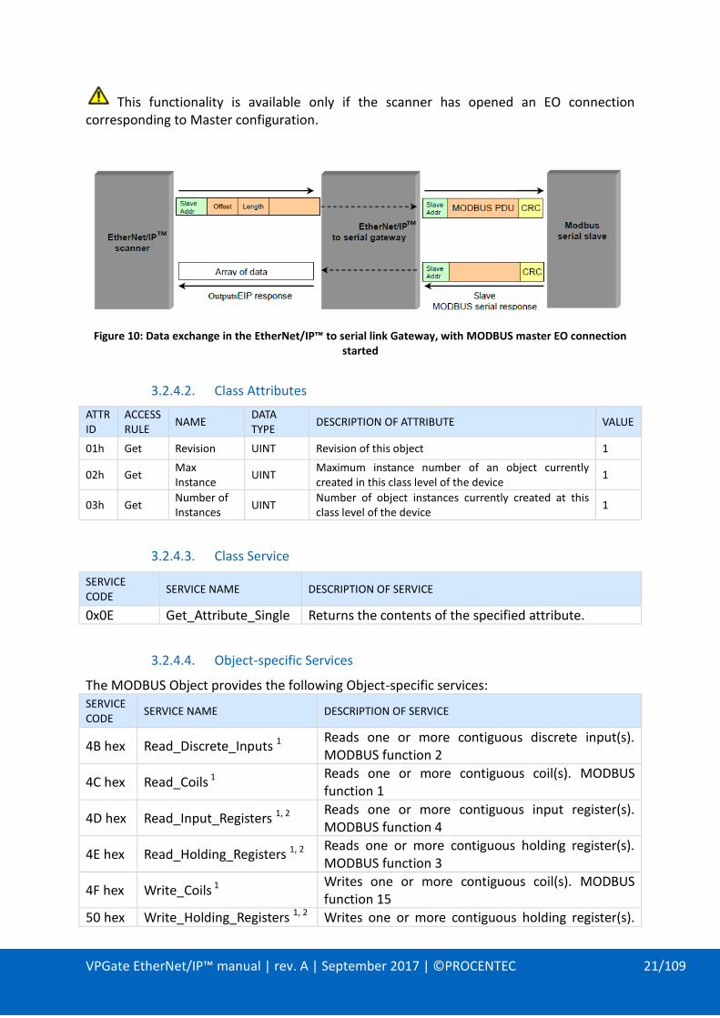
This functionality is available only if the scanner has opened an EO connection corresponding to Master configuration.
Figure 10: Data exchange in the EtherNet/IP™ to serial link Gateway, with MODBUS master EO connection started
3.2.4.2. Class Attributes
ATTR ID
ACCESS RULE
NAME DATA TYPE
DESCRIPTION OF ATTRIBUTE VALUE
01h Get Revision UINT Revision of this object 1
02h Get Max Instance
UINT Maximum instance number of an object currently created in this class level of the device
1
03h Get Number of Instances
UINT Number of object instances currently created at this class level of the device
1
3.2.4.3. Class Service
SERVICE CODE
SERVICE NAME DESCRIPTION OF SERVICE
0x0E Get_Attribute_Single Returns the contents of the specified attribute.
3.2.4.4. Object-specific Services
The MODBUS Object provides the following Object-specific services: SERVICE CODE
SERVICE NAME DESCRIPTION OF SERVICE
4B hex Read_Discrete_Inputs 1 Reads one or more contiguous discrete input(s). MODBUS function 2
4C hex Read_Coils 1 Reads one or more contiguous coil(s). MODBUS function 1
4D hex Read_Input_Registers 1, 2 Reads one or more contiguous input register(s). MODBUS function 4
4E hex Read_Holding_Registers 1, 2 Reads one or more contiguous holding register(s). MODBUS function 3
4F hex Write_Coils 1 Writes one or more contiguous coil(s). MODBUS function 15
50 hex Write_Holding_Registers 1, 2 Writes one or more contiguous holding register(s).
™ ™

VPGate EtherNet/IP™ manual | rev. A | September 2017 | ©PROCENTEC 22/109
MODBUS function 16
Table Footnotes: 1 The parameter data of these services shall be little-endian. Since MODBUS data is big-endian, the MODBUS Object swaps bytes when sending the message to the MODBUS subsystem. 2 The response data of these services shall be little-endian. Since MODBUS data is big-endian, the MODBUS Object swaps bytes after receiving a response from the MODBUS subsystem.
3.2.4.4.1. Read_Discrete_Inputs Service
This service reads one or more discrete inputs from the MODBUS Discrete Inputs table. This service is the equivalent of a Read Discrete Inputs function (function code 0x02) on MODBUS.
Read_Discrete_Inputs Request Service Parameters
NAME DATA TYPE DESCRIPTION OF REQUEST PARAMETER
SEMANTICS OF VALUES
Slave Address UINT Address of the slave device
Starting Address UINT Offset in table to begin reading from.1
Zero based
Quantity of Inputs
UINT Number of inputs to read1
Table Footnotes: 1 The Request Parameter is little endian. The MODBUS protocol is big endian.
Read_Discrete_Inputs Response Service Parameters
NAME DATA TYPE DESCRIPTION OF REQUEST PARAMETER
SEMANTICS OF VALUES
Input Values ARRAY of octet Input values read. Each input is packed as a bit within a byte.
3.2.4.4.2. Read_Coils Service
This service reads one or more coils from the MODBUS Coils table. This service is the equivalent of a Read Coils function (function code 0x01) on MODBUS.
Read_Coils Request Service Parameters
NAME DATA TYPE DESCRIPTION OF REQUEST PARAMETER
SEMANTICS OF VALUES
Slave Address UINT Address of the slave device
Starting Address UINT Offset in table to begin reading from.1
Zero based
Quantity of Coils UINT Number of coils to read 1
Table Footnotes:

VPGate EtherNet/IP™ manual | rev. A | September 2017 | ©PROCENTEC 23/109
1 The Request Parameter is little endian. The MODBUS protocol is big endian. The implementer may have to swap bytes depending on the MODBUS subsystem implementation.
Read_Coils Response Service Parameters
NAME DATA TYPE DESCRIPTION OF REQUEST PARAMETER
SEMANTICS OF VALUES
Coil Status ARRAY of octet Coil values read. Each input is packed as a bit within a byte.
3.2.4.4.3. Read_Input_Registers Service
This service reads one or more input registers from the MODBUS Input Register table. This service is the equivalent of a Read Input Registers function (function code 0x04) on MODBUS.
Read_Input_Registers Request Service Parameters
NAME DATA TYPE DESCRIPTION OF REQUEST PARAMETER
SEMANTICS OF VALUES
Slave Address UINT Address of the slave device
Starting Address UINT Offset in table to begin reading from.1
Zero based
Quantity of Input Registers
UINT Number of input registers to read 1
Table Footnotes: 1 The Request Parameter is little endian. The MODBUS protocol is big endian.
Read_Input_Registers Response Service Parameters
NAME DATA TYPE DESCRIPTION OF REQUEST PARAMETER
SEMANTICS OF VALUES
Input Register Values
ARRAY of 16-bit word1
Input register values read1,2
Table Footnotes: 1 The data is returned as 16 bit entities for each register. The actual data type of the values is unknown. 2 The Response Data is little endian. The MODBUS protocol is big endian.
3.2.4.4.4. Read_Holding_Registers Service
This service reads one or more holding registers from the MODBUS Holding Register table. This service is the equivalent of a Read Holding Registers function (function code 0x03) on MODBUS. The service parameter data shall be received in little-endian format. The response data shall be an array of 16-bit words sent as a little-endian value.

VPGate EtherNet/IP™ manual | rev. A | September 2017 | ©PROCENTEC 24/109
Read_Holding_Registers Request Service Parameters
NAME DATA TYPE DESCRIPTION OF REQUEST PARAMETER
SEMANTICS OF VALUES
Slave Address UINT Address of the slave device
Starting Address UINT Offset in table to begin reading from.1
Zero based
Quantity of Holding Registers
UINT
Number of holding registers to read 1
Table Footnotes: 1 The Request Parameter is little endian. The MODBUS protocol is big endian. The implementer may have to swap bytes depending on the MODBUS subsystem implementation.
Read_Holding_Registers Response Service Parameters
NAME DATA TYPE DESCRIPTION OF REQUEST PARAMETER
SEMANTICS OF VALUES
Holding Register Values
ARRAY of 16-bit word 1
Holding register values read 2
Table Footnotes: 1 The data is returned as 16 bit entities for each register. The actual data type of the values is unknown. 2 The Response Data is little endian. The MODBUS protocol is big endian. The implementer may have to swap bytes depending on the MODBUS subsystem implementation
3.2.4.4.5. Write_Coils Service
This service writes one or more coils to the MODBUS Coils table. This service is the equivalent of a Write Multiple Coils function (function code 0x0F) on MODBUS. If the Quantity of Outputs field is 1, it can be considered a Write Single Coil function (function code 0x05).
Write_Coils Request Service Parameters
NAME DATA TYPE DESCRIPTION OF REQUEST PARAMETER
SEMANTICS OF VALUES
Slave Address UINT Address of the slave device
Starting Address UINT Offset in table to begin writing to 1 Zero based
Quantity of Outputs
UINT Number of output coils to write 1
Output Values ARRAY of octet Output coil values
Table Footnotes: 1 The Request Parameter is little endian. The MODBUS protocol is big endian. The implementer may have to swap bytes depending on the MODBUS subsystem implementation

VPGate EtherNet/IP™ manual | rev. A | September 2017 | ©PROCENTEC 25/109
Write_Coils Response Service Parameters
NAME DATA TYPE DESCRIPTION OF REQUEST PARAMETER
SEMANTICS OF VALUES
Starting Address UINT Offset in table where writing began
1
Zero based
Quantity of Outputs
UINT Number of output coils written 1
Table Footnotes: 1 The Response Parameters are little endian. The MODBUS protocol is big endian. The implementer may have to swap bytes depending on the MODBUS subsystem implementation.
3.2.4.4.6. Write_Holding_Registers Service
This service writes one or more holding registers to the MODBUS Holding Registers table. This service is the equivalent of a Write Multiple Registers function (function code 0x10) on MODBUS. If the Quantity of Outputs field is 1, it can be considered a Write Single Register function (function code 0x06).
Write_Holding_Registers Request Service Parameters
NAME DATA TYPE DESCRIPTION OF REQUEST PARAMETER
SEMANTICS OF VALUES
Slave Address UINT Address of the slave device
Starting Address UINT Offset in table to begin writing to 2 Zero based
Quantity of Outputs
UINT Number of output registers to write 2
Output Values ARRAY of 16-bit word 1
Output register values
Table Footnotes: 1 The data is returned as 16 bit entities for each register. The actual data type of the values is unknown 2 The Request Parameter is little endian. The MODBUS protocol is big endian.
Write_Holding_Registers Response Service Parameters
NAME DATA TYPE DESCRIPTION OF REQUEST PARAMETER SEMANTICS OF VALUES
Starting Address UINT Offset in table where writing began1 Zero based
Quantity of Outputs
UINT Number of output registers written 1
Table Footnotes: 1 The Response Parameters are little endian. The MODBUS protocol is big endian.

VPGate EtherNet/IP™ manual | rev. A | September 2017 | ©PROCENTEC 26/109
3.2.4.4.7. Error Checking
GENERAL ERROR CODE
DESCRIPTION
0x20
Invalid Parameter: Requesting zero (0) quantity of data values Requesting more data values than can be supported by MODBUS;
for example requesting to read 500 holding registers. Any request where combining the start of the data offset with the
quantity of data would cause an overflow, for example requesting to read 100 registers starting at offset hex 0xFFFF.
0x13
Not Enough Data: Write requests where the bytes of attached data do not properly match the quantity of data values being written; for example, requesting to write 4 registers but supplying any number of data bytes other than 8.
0x15
Too Much Data: Write requests where the bytes of attached data do not properly match the quantity of data values being written; for example, requesting to write 4 registers but supplying any number of data bytes other than 8.

VPGate EtherNet/IP™ manual | rev. A | September 2017 | ©PROCENTEC 27/109
3.2.5. TCP/IP Interface Object
TCP/IP Interface object (Class code 0xF5) has only one instance (instance 1).
3.2.5.1. Class Attributes
ATTR ID
ACCESS RULE
NAME DATA TYPE
DESCRIPTION OF ATTRIBUTE VALUE
01h Get Revision UINT 4
02h Get Max Instance
UINT
Maximum instance number of an object currently created in this class level of the device.
1
03h Get Number of Instances
UINT
Number of object instances currently created at this class level of the device.
1
3.2.5.2. Instance Attributes
ATTR ID
ACCESS RULE
NAME DATA TYPE
DESCRIPTION OF ATTRIBUTE VALUE
01 Get Status DWORD
Interface status
02 Get Configuration Capability
DWORD
Interface capability flags See table below
03 Set Configuration Control
DWORD
Interface control flags See table below
04 Get
Physical Link Object
STRUCT Path to physical link object
(20h F6h 24h 01h ) [20] = 8 bit class segment type [F6] = Ethernet Link Object class [24] = 8 bit instance segment type [01] = instance 1.
Path size UINT Size of Path
Path Padded EPATH
Logical segments identifying the physical link object
05 Set
Interface Configuration
STRUCT of:
TCP/IP network interface configuration.
IP Address UDINT The device’s IP address.
Network Mask
UDINT The device’s network mask
Gateway Address
UDINT Default gateway address
Name Server UDINT Primary name server
Name Server 2
UDINT Secondary name server
Domain STRING Default domain name

VPGate EtherNet/IP™ manual | rev. A | September 2017 | ©PROCENTEC 28/109
Name
06 Set Host Name STRING Host name
13 Set
Encapsulation Inactivity Timeout
UINT Number of seconds of inactivity before TCP connection is closed
0 = Disable 1-3600 = timeout in seconds Default = 120
Configuration Capability Instance Attribute (attribute 2)
BIT(S) CALLED DEFINITION VPGATE CAPABILITIES
0 BOOTP Client 1 (TRUE) shall indicate the device is capable of obtaining its network configuration via BOOTP.
TRUE
1 DNS Client 1 (TRUE) shall indicate the device is capable of resolving host names by querying a DNS server.
FALSE (not supported by VPGATE gateway)
2 DHCP Client 1 (TRUE) shall indicate the device is capable of obtaining its network configuration via DHCP.
TRUE
3 DHCP-DNS Update
1 (TRUE) shall indicate the device is capable of sending its host name in the DHCP request as documented in Internet draft <draft-ietf-dhc-dhcp-dns-12.txt>.
FALSE (not supported by VPGATE gateway)
4 Configuration Settable
1 (TRUE) shall indicate the Interface Configuration attribute is settable. Some devices, for example a PC or workstation, may not allow the Interface Configuration to be set via the TCP/IP Interface Object.
TRUE
5-31 Reserved Reserved for future use and shall be set to zero.

VPGate EtherNet/IP™ manual | rev. A | September 2017 | ©PROCENTEC 29/109
Configuration Control Instance Attribute (attribute 3)
BIT(S) CALLED DEFINITION
0-3 Startup Configuration
Determines how the device shall obtain its initial configuration at start up.
0 = The device shall use the interface configuration values previously stored (for example, in non-volatile memory or via hardware switches, etc).
1 = The device shall obtain its interface configuration values via BOOTP.
2 = The device shall obtain its interface configuration values via DHCP upon start-up.
3-15 = Reserved for future use.
4 DNS Enable If 1 (TRUE), the device shall resolve host names by querying a DNS server.
5-31 Reserved Reserved for future use and shall be set to zero.
3.2.5.3. Instance Services
SERVICE CODE
SERVICE NAME DESCRIPTION OF SERVICE
0x01 Get_Attribute_All Returns a predefined listing of this objects attributes
0x0E Get_Attribute_Single
Returns the contents of the specified attribute.
0x10 Set_Attribute_Single
Modifies a single attribute.

VPGate EtherNet/IP™ manual | rev. A | September 2017 | ©PROCENTEC 30/109
3.2.6. Ethernet Link Object
Ethernet Link object (Class code 0xF6) has two instances, one for each physical port (instance 1 for port 1 and instance 2 for port 2).
3.2.6.1. Class Attributes
ATTR ID
ACCESS RULE
NAME DATA TYPE
DESCRIPTION OF ATTRIBUTE VALUE
01h Get Revision UINT Revision of this object 3
02h Get Max Instance UINT Maximum instance number of an object currently created in this class level of the device
2
03h Get Number of Instances
UINT Number of object instances currently created at this class level of the device
2
3.2.6.2. Class-Specific Service
SERVICE CODE
SERVICE NAME DESCRIPTION OF SERVICE
0x4C Get_and_Clear Gets then clears the specified attribute (Interface Counters or Media Counters).
The Get_and_Clear service is a class-specific service. It is only supported for the Interface Counters and Media Counters attributes. The Get_and_Clear response shall be the same as the Get_Attribute_Single response for the specified attribute. After the response is built, the value of the attribute shall be set to zero.
3.2.6.3. Instance list
INSTANCE ID
NAME COMMENTS
1 Ethernet Link Object – Port 1
Port 1
2 Ethernet Link Object – Port 2
Port 2
3.2.6.4. Instance Attributes
ATTR ID
ACCESS RULE
NAME DATA TYPE
DESCRIPTION OF ATTRIBUTE VALUE
01h Get Interface Speed UDINT Interface speed currently in use 10, 100
02h Get Interface Flags DWORD
Interface status flags
03h Get Physical Address ARRAY of 6 USINTs
MAC layer address
04h Get
Interface Counters
STRUCT of:
In Octets UDINT Octets received on the interface
In Ucast Packets UDINT Unicast packets received on the interface
In NUcast Packets
UDINT Non-unicast packets received on the interface
In Discards UDINT Inbound packets received on the interface but

VPGate EtherNet/IP™ manual | rev. A | September 2017 | ©PROCENTEC 31/109
discarded
In Errors UDINT Inbound packets that contain errors (does not include In Discards)
In Unknown Protos
UDINT Inbound packets with unknown protocol
Out Octets UDINT Octets sent on the interface
Out Ucast Packets
UDINT Unicast packets sent on the interface
Out NUcast Packets
UDINT Non-unicast packets sent on the interface
Out Discards UDINT Outbound packets discarded
Out Errors UDINT Outbound packets that contain errors
05h Get
Media Counters STRUCT of:
Media-specific counters
Alignment Errors UDINT Frames received that are not an integral number of octets in length
FCS Errors UDINT Frames received that do not pass the FCS check
Single Collisions UDINT Successfully transmitted frames which experienced exactly one collision
Multiple Collisions
UDINT Successfully transmitted frames which experienced more than one collision
SQE Test Errors UDINT Number of times SQE test error message is generated
Deferred Transmissions
UDINT Frames for which first transmission attempt is delayed because the medium is busy
Late Collisions UDINT Number of times a collision is detected later than 512 bittimes into the transmission of a packet
Excessive Collisions
UDINT Frames for which transmission fails due to excessive collisions
MAC Transmit Errors
UDINT Frames for which transmission fails due to an internal MAC sublayer transmit error
Carrier Sense Errors
UDINT Times that the carrier sense condition was lost or never asserted when attempting to transmit a frame
Frame Too Long UDINT Frames received that exceed the maximum permitted frame size
MAC Receive Errors
UDINT Frames for which reception on an interface fails due to an internal MAC sublayer receive error
07h Get Interface Type USINT Type of interface: twisted pair, fiber, internal, etc
08h Get Interface State USINT Current state of the interface: operational, disabled, etc
10h Get Interface Label SHORT_STRING
Human readable identification
port-001 port-002
3.2.6.5. Instance Services
SERVICE CODE
SERVICE NAME DESCRIPTION OF SERVICE
0x01 Get_Attribute_All Returns a predefined listing of this objects attributes
0x0E Get_Attribute_Single Returns the contents of the specified attribute.
0x10 Set_Attribute_Single Modifies a single attribute.

4. SOFTWARE CONFIGURATION
4.1. Configuration of the EtherNet/IP™ Scanner
The following detailed configuration was carried out using the "Logix Designer" software from Rockwell. The procedure is similar for many configuration softwares.
4.2. Integrating The VPGATE in a project
4.2.1. Importing an EDS file into the engineering tool
The EDS file enables the VPGate to be used as an EtherNet/IP™ Adapter.
This file called PROCENTEC-VPGATE-EDS.eds can be found inside the device. See quick start guide.
The EDS file can also be accessed via the web server of the VPGate (refer to chapter 10).
This EDS file can be imported in Logix Designer in order to speed up the configuration of the gateway.
1) Open the EDS Wizard
ToolsEDS Hardware Installation Tool

VPGate EtherNet/IP™ manual | rev. A | September 2017 | ©PROCENTEC 33/109
2) Follow the procedure
4.2.2. Integrating the VPGATE in a configuration tool
4.2.2.1. Integration by network detection
This is not possible with all scanners. In the example below, the MOLEX EtherNet/IP™ configuration tool is used.
The equipment must be connected to the network and powered up.

VPGate EtherNet/IP™ manual | rev. A | September 2017 | ©PROCENTEC 34/109
1. Turn the scanner “Online”
2. Select Network Detection tab
3. Click on the button “Read Network Configuration”
4. Click OK on the following message
5. Then the detection starts and should discover at least the expected device.
6. Drag and drop the new device to the main window
1
2
3
4

VPGate EtherNet/IP™ manual | rev. A | September 2017 | ©PROCENTEC 35/109
7. The following configuration window will open:

VPGate EtherNet/IP™ manual | rev. A | September 2017 | ©PROCENTEC 36/109
4.2.2.2. Manual integration
Prerequisite: The .eds file of the gateway shall be added in the configuration tool (see 4.2.1).
1. In Logix Designer, right click on the Ethernet Item and Select “New Module…”.
2. Select the Gateway in the Catalog (you can use the filter with VPGATE. Then click on create.

VPGate EtherNet/IP™ manual | rev. A | September 2017 | ©PROCENTEC 37/109
3. The following configuration window will open:
Then fill-in the different tabs:
General (IP address, connections, name)
Choose a connection type. This will define the way the gateway is used (see §4.3). The associated tags will be used to identify the assemblies.

VPGate EtherNet/IP™ manual | rev. A | September 2017 | ©PROCENTEC 38/109
Connection (RPI, Unicast/Multicast, Trigger)
Module Info
Note: Only available if the scanner is “On Line”
Internet Protocol
Note: Only available if the scanner is “On Line”

VPGate EtherNet/IP™ manual | rev. A | September 2017 | ©PROCENTEC 39/109
Port Configuration
Note: Only available if the scanner is “On Line”

VPGate EtherNet/IP™ manual | rev. A | September 2017 | ©PROCENTEC 40/109
4.3. General configuration of VPGATE
The gateway is configured through one Exclusive Owner (EO) connection.
3 EO connections instances are available, each corresponding to a communication mode on the serial link:
- Gateway configured in MODBUS Master mode
- Gateway configured in MODBUS Slave mode
- Gateway configured in Transparent mode
In addition to this EO connection, it is possible to add a Listen Only (LO) and an Input Only (IO) connection.
- Listen Only is used together with an EO connection to consume the same assembly as the EO input assembly.
- Input Only connection can be used to get the Status Assembly (see configuration for Input Only)

VPGate EtherNet/IP™ manual | rev. A | September 2017 | ©PROCENTEC 41/109
4.4. Exclusive owner connection for MODBUS Master mode
4.4.1. Operating principle
Figure 11: Operating principle in the MODBUS Master mode
4.4.2. Configuration
In order to use the VPGATE in the MODBUS Master mode, add the Exclusive Owner – MODBUS Master connection.
The properties of the connection are:
EO MODBUS MASTER
Assembly instance Conf 0x68 (104)
OT 0x66 (102)
TO 0x65 (101)
Default size 400 1 1
Min size 400 1 1
Max size 400 500 500
path 20 04 24 68 2C 66 2C 65
4.4.3. Input assembly (TO)
The input assembly is defined as follows:
0 - 497 BYTES 3 BYTES
MODBUS data (IN) Digital input (1 byte)
General status (2 bytes)
Assembly size: 3 to 500 bytes
In this mode, all informations are mandatory: - The Digital input and General status will always be in the assembly. See 4.7.1 for
General status description. - The size of « MODBUS data (IN) » is directly affected by the assembly size defined by
the user.
EtherNet/IP to serial
gateway
Output
Assembly
Input
Assembly
Master EtherNet/IP Adapter
Modbus slave
MODBUS
registers
EtherNet/IP Scanner
Outputs
Inputs
MODBUS write
request
MODBUS read
request
Respon
se
Respon
se
OUTPUT
INPUT

VPGate EtherNet/IP™ manual | rev. A | September 2017 | ©PROCENTEC 42/109
Warning: According to these rules if the user doesn’t need to use « MODBUS data (IN) » then he will have to set an assembly size of 3 bytes at least else an error will be reported during the «Open Forward response ».
4.4.4. Output assembly (OT)
The output assembly is defined as follows:
0 – 499 BYTES (*) 1 BYTE
« MODBUS data (OUT) » Digital output
Assembly size: 1 to 500 bytes
(*)The size of « MODBUS data (OUT) » is defined by the scenario configuration. If the number of bytes in « MODBUS data (OUT) » is higher than 499, the end of the assembly will be truncated or removed. Note:
Even if it is recommended to match the Assembly’s size with amount of data configured in the scenarios, it is not mandatory. Therefore the “MODBUS data OUT” field will be incomplete and the data for some scenarios not updated.
4.4.5. Configuration assembly
This assembly is used to configure the serial interface, MODBUS protocol, each request/reply (scenario) that the MODBUS master has to manage, and the digital output mode.. It allows configuring up to 48 scenarios.
The configuration assembly is defined as follows:
BYTE OFFSET
0 1 2 … 399
Baudrate Parity Stop bits …
Scen48 : Qty of bits or registers
Assembly size: 400 bytes
Detailed description of the configuration assembly:
CATEGORY NAME TYPE BYTE OFFSET
DEFAULT VALUE
VALUE RANGE
Serial link settings
Baudrate U8 0 5 in bauds : 0 : 600 1 : 1200

VPGate EtherNet/IP™ manual | rev. A | September 2017 | ©PROCENTEC 43/109
2 : 2400 3 : 4800 4 : 9600 5 : 19200 6 : 38400 7 : 57600 8 : 115200
Parity U8 1 1 0 : none 1 : even 2 : odd
Stop bits U8 2 0 0 : 1 stop 1 : 2 stops
Data bits U8 3 0 0 : 8 bits 1 : 7 bits
Inter-char timeout U16 4 0 0 : 1,5 chars time >0 in ms : added to 1,5 chars time
Inter-frame silence1 U16 6 0 0 : 3,5 chars time >0 in ms : added to 1,5 chars time
Timeout U16 8 1000 20 to 65535
Retries U8 10 2 0 to 3
MODBUS settings
Protocol U8 11 0 0 : RTU 1 : ASCII
EtherNet/IP™ settings
Digital output mode U8 12 0
0 : disabled 1 : On EtherNet/IP™ failure 2 : On Serial-link failure 3 : EtherNet/IP™ or Serial-link failure 4 : set by EtherNet/IP™ output assembly
Reserved
Reserved U8 13 0 Not checked
Reserved U8 14 0 Not checked
Reserved U8 15 0 Not checked
Scenario N (1 to 48)
ScenN : MODBUS function
U8 16 + ((N-1) * 8)
0
0 : scenario is not activated 1 : Read Coils (1) 2 : Read Discrete Inputs (2) 3 : Read Holding Registers (3) 4 : Read Input Register (4) 5 : Write Single Coil

VPGate EtherNet/IP™ manual | rev. A | September 2017 | ©PROCENTEC 44/109
(5) 6 : Write Single Register (6) 7 : Write Multiple Coils (15) 8 : Write Multiple Registers (16)
ScenN : Slave address U8 17 + ((N-1) * 8)
1 0 to 247
ScenN : Frame trigger U8 18 + ((N-1) * 8)
0 0 : each cycle 1 : on change
ScenN : Cycle time U8 19 + ((N-1) * 8)
0
0: 100ms 1: 500ms 2: 1s 3: 5s 4: 10s 5: 30s 6: 60s 7: Polling
ScenN : Address of 1st bit or reg
U16 20 + ((N-1) * 8)
0 0 to 65535
ScenN : Qty of bits or registers
U16 22 + ((N-1) * 8)
0 1 to 2000
1: Set the “Interframe silence” parameter to specify the minimum time delay taken into account by VPGATE to send a new MODBUS request to a slave after having received the last response (refer to the figure given below):
Figure 12: Interframe silence in MODBUS Master mode

VPGate EtherNet/IP™ manual | rev. A | September 2017 | ©PROCENTEC 45/109
4.4.6. Setting MODBUS Master mode in a configuration tool
Using the EDS file simplifies dramatically the configuration. Dropdown menus allow a quick choice of the right parameters for your application. However, this is not possible in all configuration tools.
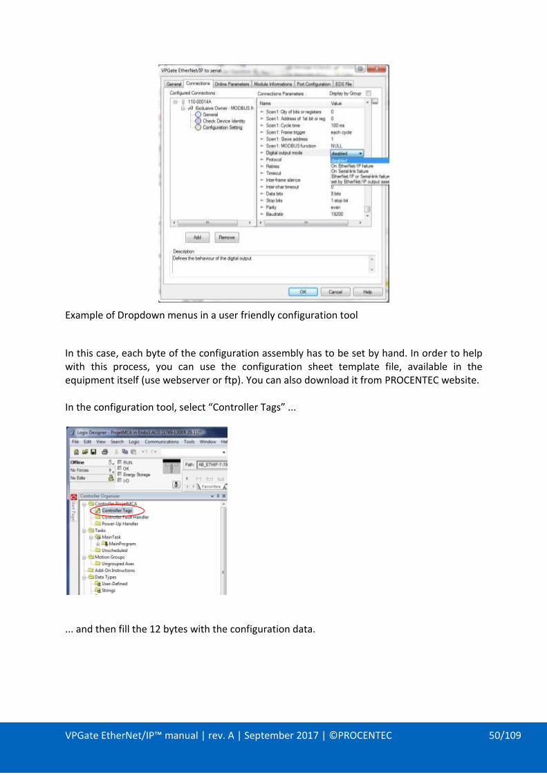
In this case, each byte of the configuration assembly has to be set by hand. In order to help with this process, you can use the configuration sheet template file, available in the equipment itself (use webserver or ftp). You can also download it from PROCENTEC website.
In the configuration tool, select “Controller Tags” ...
... and then fill-in all bytes with the configuration data.
VPGate EtherNet/IP™ manual | rev. A | September 2017 | ©PROCENTEC 46/109
4.4.7. MODBUS Master behaviour according to EtherNet/IP™ connection status
VPGate’s MODBUS Master operates according to the EtherNet/IP™ connection state.
As the configuration is received during the opening of an EO connection, the serial communication is possible only during an opened EO IO connection with valid configuration.
Therefore, if for any reason (Ethernet link-down, scanner shutdown, connection closed...) the communication between the scanner and the gateway fails, the MODBUS master will stop.

VPGate EtherNet/IP™ manual | rev. A | September 2017 | ©PROCENTEC 47/109
4.5. Exclusive owner connection for MODBUS Slave mode
4.5.1. Operating principle
Figure 13: PROCENTEC Gateway operating principle in the MODBUS Slave mode
4.5.2. Configuration
In order to use the PROCENTEC Gateway in the MODBUS slave mode, add the Exclusive Owner – MODBUS Slave connection.
The properties of the connection are:
EO MODBUS MASTER
Assembly instance Conf 0x69 (105)
OT 0x66 (102)
TO 0x65 (101)
Default size 12 1 3
Min size 12 1 3
Max size 12 500 500
path 20 04 24 69 2C 66 2C 65
4.5.3. Input assembly (TO)
The input assembly is defined as follows:
0 – 497 BYTES 3 BYTES
MODBUS data (IN)
Digital input (1 byte)
General status (2 bytes)
Assembly size: 3 to 500 bytes

VPGate EtherNet/IP™ manual | rev. A | September 2017 | ©PROCENTEC 48/109
In this mode, all information’s are mandatory: - The Digital input and General status will always be in the assembly. See 4.7.1 for
General status description. - The size of « MODBUS data (IN) » is directly affected by the assembly size defined by
the user.
Warning: According to these rules if the user doesn’t need to use « MODBUS data (IN) » then he will have to set an assembly size of 3 bytes at least else an error will be reported during the «Open Forward response ».
4.5.4. Output assembly (OT)
The output assembly is defined as follows:
0 – 499 BYTES 1 BYTE
« MODBUS data (OUT) » Digital output
Assembly size: 1 to 500 bytes
In this mode, all informations are mandatory: - The « Digital output » will always be in the assembly. - The size of « MODBUS data (OUT) » is directly affected by the assembly size defined
by the user Warning: According to these rules if the user doesn’t need to use « MODBUS data (OUT) » then he will have to set an assembly size of 1 byte at least else an error will be reported during the «Open Forward response ».
4.5.5. Configuration assembly
This assembly is used to configure the serial interface, and the digital output mode.
The configuration assembly is defined as follows:
BYTE OFFSET
0 1 2 … 11
Baudrate Parity Stop bits … Reserved
Assembly size: 12 bytes
Detailed description of the configuration assembly:
CATEGORY NAME TYPE
BYTE OFFSET
DEFAULT VALUE
VALUE RANGE
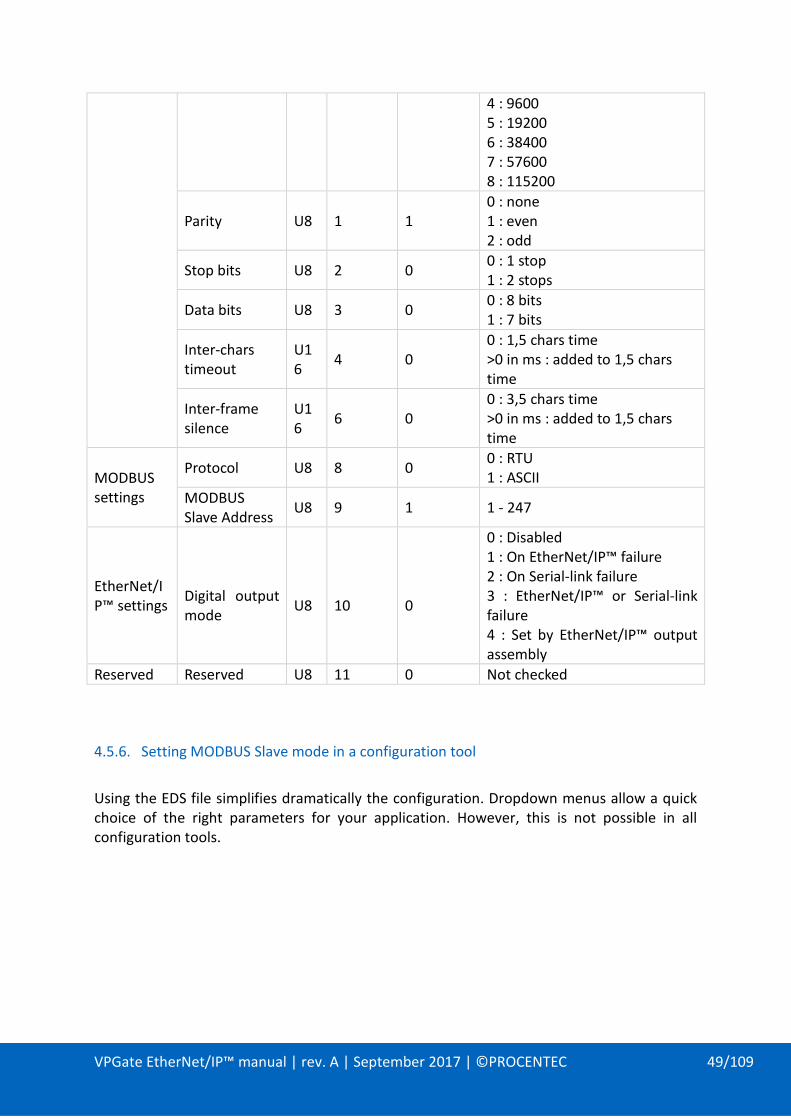
Serial link settings
Baudrate U8 0 5
in bauds : 0 : 600 1 : 1200 2 : 2400 3 : 4800
VPGate EtherNet/IP™ manual | rev. A | September 2017 | ©PROCENTEC 49/109
4 : 9600 5 : 19200 6 : 38400 7 : 57600 8 : 115200
Parity U8 1 1 0 : none 1 : even 2 : odd
Stop bits U8 2 0 0 : 1 stop 1 : 2 stops
Data bits U8 3 0 0 : 8 bits 1 : 7 bits
Inter-chars timeout
U16
4 0 0 : 1,5 chars time >0 in ms : added to 1,5 chars time
Inter-frame silence
U16
6 0 0 : 3,5 chars time >0 in ms : added to 1,5 chars time
MODBUS settings
Protocol U8 8 0 0 : RTU 1 : ASCII
MODBUS Slave Address
U8 9 1 1 - 247
EtherNet/IP™ settings
Digital output mode
U8
10
0
0 : Disabled 1 : On EtherNet/IP™ failure 2 : On Serial-link failure 3 : EtherNet/IP™ or Serial-link failure 4 : Set by EtherNet/IP™ output assembly
Reserved Reserved U8 11 0 Not checked
4.5.6. Setting MODBUS Slave mode in a configuration tool
Using the EDS file simplifies dramatically the configuration. Dropdown menus allow a quick choice of the right parameters for your application. However, this is not possible in all configuration tools.
VPGate EtherNet/IP™ manual | rev. A | September 2017 | ©PROCENTEC 50/109
Example of Dropdown menus in a user friendly configuration tool
In this case, each byte of the configuration assembly has to be set by hand. In order to help with this process, you can use the configuration sheet template file, available in the equipment itself (use webserver or ftp). You can also download it from PROCENTEC website. In the configuration tool, select “Controller Tags” ...
... and then fill the 12 bytes with the configuration data.

VPGate EtherNet/IP™ manual | rev. A | September 2017 | ©PROCENTEC 51/109
VPGate EtherNet/IP™ manual | rev. A | September 2017 | ©PROCENTEC 52/109
4.6. Exclusive owner connection for TRANSPARENT mode
4.6.1. Operating principle
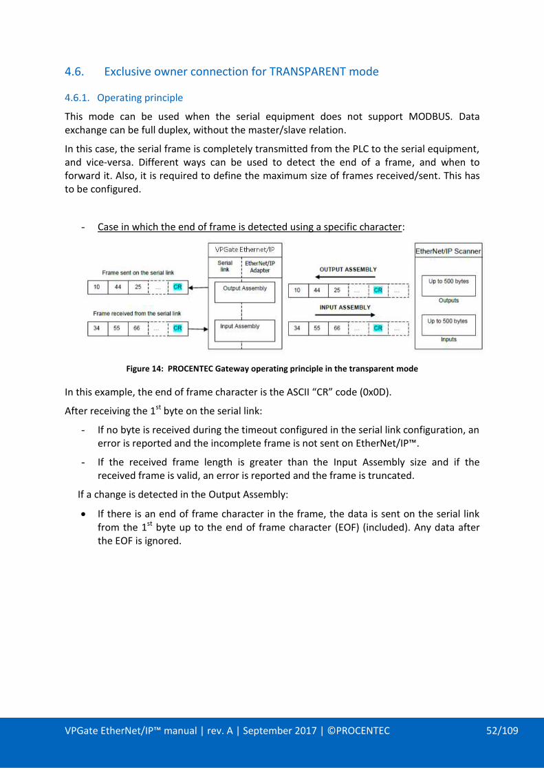
This mode can be used when the serial equipment does not support MODBUS. Data exchange can be full duplex, without the master/slave relation.
In this case, the serial frame is completely transmitted from the PLC to the serial equipment, and vice-versa. Different ways can be used to detect the end of a frame, and when to forward it. Also, it is required to define the maximum size of frames received/sent. This has to be configured.
- Case in which the end of frame is detected using a specific character:
Figure 14: PROCENTEC Gateway operating principle in the transparent mode
In this example, the end of frame character is the ASCII “CR” code (0x0D).
After receiving the 1st byte on the serial link:
- If no byte is received during the timeout configured in the serial link configuration, an error is reported and the incomplete frame is not sent on EtherNet/IP™.
- If the received frame length is greater than the Input Assembly size and if the received frame is valid, an error is reported and the frame is truncated.
If a change is detected in the Output Assembly:
If there is an end of frame character in the frame, the data is sent on the serial link from the 1st byte up to the end of frame character (EOF) (included). Any data after the EOF is ignored.

VPGate EtherNet/IP™ manual | rev. A | September 2017 | ©PROCENTEC 53/109
- Case in which the frame length is known:
Figure 15: data format when frame length is known
The 1st byte must contain the number of bytes that follow.
After receiving the 1st byte on the serial link:
- If the expected bytes are not received after the timeout configured in the serial link configuration, an error is reported and the incomplete frame is not sent on EtherNet/IP™.
- If the received frame length is greater than the number of Input Assembly size and if the received frame is valid, an error is reported and the frame is truncated.
If a change is detected in the Output Assembly:
- If the 1st byte has a length greater than the Output Assembly, an error is reported and no data is sent.
- Case in which the end of frame is detected on timeout:
Figure 16: data format when EOF is detected on timeout
The 1st byte of the Input Assembly indicates the number of bytes received. The 1st byte of the Output Assembly must indicate the number of bytes to be sent.
After receiving the 1st byte on the serial link:
- If no byte is received during the timeout configured in the serial link configuration, the number of received characters is recorded in the 1st byte of the Input Assembly, after which the received data is sent on EtherNet/IP™.

VPGate EtherNet/IP™ manual | rev. A | September 2017 | ©PROCENTEC 54/109
- If the length of the received frame plus a length byte is greater than the size of Input Assembly, an error is reported and the frame is truncated.
If a change is detected in the Output Assembly:
- If the 1st byte has a length greater than the Output Assembly size, an error is reported and no data is sent. Otherwise, a frame is sent on the serial line.
Trigger function of the frame counter:
A frame trigger, when activated, is added at the beginning of the Input and Output Assemblies. This byte is incremented for each new available frame. It is used to report the presence of a new received frame or to detect a new frame to be sent.
Figure 17: data format when trigger function is activated (recommended use)
Ti = input trigger To = output trigger
In this example, the length of the frames is known. The byte encoding the length in the Input and Output Assemblies is located at byte no. 2, after the trigger byte.
4.6.2. Configuration
In order to use the VPGate in Transparent mode, add the Exclusive Owner – Transparent connection.
The properties of the connection are:
EO TRANSPARENT
Assembly instance Conf 0x6A (106)
OT 0x66 (102)
TO 0x65 (101)
Default size 16 1 3
Min size 16 1 3
Max size 16 251 253
path 20 04 24 6A 2C 66 2C 65

VPGate EtherNet/IP™ manual | rev. A | September 2017 | ©PROCENTEC 55/109
4.6.3. Input assembly (TO)
The input assembly is defined as follows:
0 – 250 BYTES 3 BYTES
« SERIAL data (IN) »
Digital input (1 byte)
General status (2 bytes)
Assembly size: 3 to 253 bytes
In this mode all informations are mandatory: - The Digital input and General status will always be in the assembly. See 4.7.1 for
General status description. - The size of « SERIAL data (IN) » is directly affected by the assembly size defined by
the user. Warning: According to these rules, if the user doesn’t need to use « SERIAL data (IN) » then he will have to set an assembly size of 3 bytes at least else an error will be reported during the «Open Forward response ».
4.6.4. Output assembly (OT)
The output assembly is defined as follows:
0 – 250 BYTES 1 BYTE
« SERIAL Data (OUT) » Digital output
Assembly size: 1 to 251 bytes
In this mode all informations are mandatory: - The « Digital output » will always be in the assembly. - The size of « SERIAL data (OUT) » is directly affected by the assembly size defined by
the user. Warning: According to these rules if the user doesn’t need to use « SERIAL data (OUT) » then he will have to set an assembly size of 1 byte at least else an error will be reported during the «Open Forward response ».
4.6.5. Configuration assembly
This assembly is used to configure the serial interface, the transparent mode settings, and the digital output mode.
The configuration assembly is defined as follows:
BYTE OFFSET
0 1 2 … 15
Baudrate Parity Stop bits … Reserved
Assembly size: 16 bytes

VPGate EtherNet/IP™ manual | rev. A | September 2017 | ©PROCENTEC 56/109
Detailed description of the configuration assembly:
CATEGORY NAME TYPE
BYTE OFFSET
DEFAULT VALUE
VALUE RANGE
Serial link settings
Baudrate U8 0 5
in bauds : 0 : 600 1 : 1200 2 : 2400 3 : 4800 4 : 9600 5 : 19200 6 : 38400 7 : 57600 8 : 115200
Parity U8 1 1 0 : none 1 : even 2 : odd
Stop bits U8 2 0 0 : 1 stop 1 : 2 stops
Data bits U8 3 0 0 : 8 bits 1 : 7 bits
Inter-chars timeout
U16
4 0 0 : 1,5 chars time >0 in ms : added to 1,5 chars time
Inter-frame silence
U16
6 0 0 : 3,5 chars time >0 in ms : added to 1,5 chars time
TRANSPARENT mode settings
EOF timeout (in ms)
U16
8 100 0 - 65535
EOF delimiter 1 U8 10 3
0 : NULL (0x00 or '\0') 1 : SPACE (0x20) 2 : LF (0x0A) 3 : CR (0x0D) 4 : CR LF 5 : LF CR 6 : User defined 7 : Length in 1st byte 3 8 : On Timeout 2,3
User defined EOF
U8 11 0 0 - 255
Add frames trigger 4
U8 12 0 0 : disabled 1 : enabled
Add CRC 16
U8
13
0
0 : disabled 1 : enabled
EtherNet/IP™ settings
Digital output mode
U8
14
0
0 : disabled 1 : On EtherNet/IP™ failure 2 : On Serial-link failure

VPGate EtherNet/IP™ manual | rev. A | September 2017 | ©PROCENTEC 57/109
3 : EtherNet/IP™ or Serial-link failure 4 : set by EtherNet/IP™ output assembly
Reserved Reserved U8 15 0 Not checked
(1): If this parameter is set to User defined, the end of frame (EOF) character taken into
account is the one specified by the “User defined EOF” parameter. If it is set to “on timeout”, the reception timeout taken into account is the “EOF timeout”.
(2): If the parameter “EOF delimiter” is set to “on timeout”, only the frames received on the serial link will be detected on timeout. On the EtherNet/IP™ side, a byte has to change to trigger a new frame on the serial line. For this purpose, it can be useful to add a trigger byte in the OUTPUT assembly. The PLC will change the value of the trigger byte, each time it wants a frame to be sent.
(3): If the parameter “EOF delimiter” is set to “length in 1st byte” or to “on timeout”, the padding value is 0x00.
(4): The trigger byte can be used as a counter:
o If this parameter is activated, the 1st byte of the EtherNet/IP™ outputs is used as a trigger that is incremented each time data is available and is to be sent. The usable data starts from the 2nd byte. If there is no counter, the frame is re-copied from the 1st byte as soon as a change in the EtherNet/IP™ outputs is detected.
o If the trigger byte is activated, the 1st byte of the EtherNet/IP™ inputs is incremented each time a new frame is received on the serial link. The usable data is copied after this counter. If there is trigger byte, the received frame is copied from the 1st byte.

VPGate EtherNet/IP™ manual | rev. A | September 2017 | ©PROCENTEC 58/109
The “Interframe Silence” parameter in the TRANSPARENT mode:
The “Interframe silence” parameter allows a waiting period between a reception and the next transmission of a frame:
Figure 18: Interframe Silence in TRANSPARENT mode
If no frame is detected, the VPGate sends frames on the serial link without waiting for an inter-frame time. However if a frame is detected on RX, the VPGate waits for the inter-frame time before sending the next frame.

VPGate EtherNet/IP™ manual | rev. A | September 2017 | ©PROCENTEC 59/109
4.6.6. Setting TRANSPARENT mode in a configuration tool
Using the EDS file simplifies dramatically the configuration. Dropdown menus allow a quick choice of the right parameters for your application. However, this is not possible in all configuration tools.
In this case, each byte of the configuration assembly has to be set by hand. In order to help with this process, you can use the configuration sheet template file, available in the equipment itself (use webserver or ftp). You can also download it from PROCENTEC website.
In the configuration tool, select “Controller Tags” ...
... and then fill the 16 bytes with the configuration data.

VPGate EtherNet/IP™ manual | rev. A | September 2017 | ©PROCENTEC 60/109
4.7. Input Only connection
Input Only connection can be used to get the status information of the equipment. The properties of the connection are:
INPUT ONLY
Assembly instance Conf 0x6B (107)
OT 0xC6 (198)
TO 0x67 (103)
Default size 0 0 1
Min size 0 0 1
Max size 0 0 50
path 20 04 24 6B 2C C6 2C 67
4.7.1. Input assembly (TO)
The input assembly is defined as follows:
2 BYTES 48 BYTES
Scen0 Scen1 … Scen47 Scen48
15 8 7 0
« General status » « Scenario status »
Assembly size: 50 bytes
This assembly can be used to get the status information about the device. The status information is built with: 2 bytes for « General status »: Used for all the configurations, to report general status. 48 bytes for « Scenario status »: Used only in MODBUS master mode, each scenario uses one byte to report its status.
General status bit field:
ERROR BIT MODE
Bit 0 = MODBUS Master: Reception error MODBUS MASTER
Bit 1 = MODBUS Master: Timeout MODBUS MASTER
Bit 2 = MODBUS Master: Exception frame MODBUS MASTER
Bit 3 = Transparent: Reception error TRANSPARENT
Bit 4 = Transparent: Transmission error TRANSPARENT
Bit 5 = Slave: General error SLAVE
Bit 6 to 15 = Reserved
Scenario status value:
ERROR CODE
0 = No error
1 = CRC error
2 = Length error
3 = Exception "Illegal function" received
4 = Exception "Illegal address" received
5 = Exception "Illegal data" received

VPGate EtherNet/IP™ manual | rev. A | September 2017 | ©PROCENTEC 61/109
6 = Exception "Slave failure" received
7 = Exception "Acknowledge" received
8 = Exception "Slave busy" received
9 = Exception "memory parity error" received
10 = Exception "Gateway path unavailable" received
11 = Exception "Gateway target failed" received
12 = Timeout
13 = Not supported MODBUS address
14 = Not supported MODBUS function
15 = Not supported MODBUS data
16 = Other error
4.7.2. Output assembly (OT)
The output assembly of an Input Only connection is a heartbeat and therefore doesn’t embed any data.
4.7.3. Configuration assembly
The configuration assembly doesn’t embed any data.

VPGate EtherNet/IP™ manual | rev. A | September 2017 | ©PROCENTEC 62/109
4.8. Listen Only connection
Listen Only is used to consume the EO input assembly that is already exchanged with another scanner.
The properties of the connection are:
LISTEN ONLY
Assembly instance Conf 0x6B (107)
OT 0xC6 (198)
TO 0x65 (101)
Default size 0 0 1
Min size 0 0 1
Max size 0 0 500
path 20 04 24 6B 2C C6 2C 65
4.8.1. Input assembly (TO)
The input assembly has the same format as defined in corresponding EO connection (Please see sections 4.4.3, 4.5.3 and 4.6.3)
4.8.2. Output assembly (OT)
The output assembly of an Input Only connection is a heartbeat and therefore doesn’t contain any data.
4.8.3. Configuration assembly
The configuration assembly doesn’t contain any data.

VPGate EtherNet/IP™ manual | rev. A | September 2017 | ©PROCENTEC 63/109
5. DIAGNOSTIC
5.1. Diagnostic on the UDP 5628810 port
Information about the configuration, parameterisation and status of the functioning of the VPGATE gateway are sent via the UDP protocol. This information can be viewed using a tool that displays ASCII data received on the UDP 56288 port.
The properties of the UDP link are:
- Port: 5628810 (DBE016)
- Destination IP address: Broadcast on the IP network of PROCENTEC gateway (example: 192.168.10.255 on a 192.168.10.0 network).
When switched on, the following header is sent:
When the gateway connects to EtherNet/IP™, the physical parameters of the MODBUS link are displayed. The configured exchanges are then displayed. In the following example, 1 exchange on MODBUS Master is configured:
Figure 19: Configuration and state of the gateway is sent on UDP
Read 010 registers with MODBUS 03 function on the slave 01 with a cycle time of 100 ms.

VPGate EtherNet/IP™ manual | rev. A | September 2017 | ©PROCENTEC 64/109
If the MODBUS link is correctly established, no additional message is displayed.
Otherwise, a message reports the encountered error. In the following example, the MODBUS slave mentioned in the configuration of scenario 1 no longer responds:
In the above case, the TIMEOUT error message is repeated twice since the “Retries if Timeout” parameter of the PROCENTEC gateway hardware configuration was previously set to 2. When the third error occurs, an additional message is displayed, stating that a fault has occurred.
When the gateway is disconnected from EtherNet/IP™, the following message is displayed.
The PROCENTEC gateway generates status that can be checked to detect communication or equipment problem.
5.2. Status of Identity Object, with explicit messaging
See Identity description in 3.2.1
5.3. Status in implicit messaging
The implicit messaging is started with a Forward_Open service. The answer of the adapter to this request can return some problems (for example, if the size of an assembly is too small).
If the Forward_Open service is successful, then the equipment goes to data exchange. In the input data, whatever is the connection type, a status field gives information on the equipment. (Please see sections 4.4.3, 4.5.3 and 4.6.3)
5.4. Indicators
The indicators on the front panel display errors on the serial link or the EtherNet/IP™ connection. For more details, see chapter 2.2.

VPGate EtherNet/IP™ manual | rev. A | September 2017 | ©PROCENTEC 65/109
5.5. Using web server for diagnostic
Diagnostic information and statistics are available on the web server. For more details, see chapters 8.5 (SNMP), 8.6 (Ethernet), 0 (EtherNet/IP™), 0 (MODBUS).

VPGate EtherNet/IP™ manual | rev. A | September 2017 | ©PROCENTEC 66/109
6. DIGITAL INPUTS/OUTPUTS
6.1. Digital output (DO)
The Digital Output got two possible uses:
- Diagnostic output, controlled by the gateway
- Digital output, controlled by the EtherNet/IP™ scanner
This setting is done through the configuration assembly of the EO connection.
6.2. Digital output diagnostic
If the “Digital Output Mode” parameter is set to one of the following values, the relay contact is activated when a default is detected:
On EtherNet/IP™ failure,
On Serial-link failure,
EtherNet/IP™ or Serial-link failure,
In the “Disabled” mode, the relay is not used if there is a fault.
In the “On EtherNet/IP™ failure” mode, the relay will be closed if communication with the EtherNet/IP™ scanner is lost or if a timeout is detected (ETH indicator lit).
In the “On Serial-link failure” mode, the relay will be closed if a fault is detected (SERIAL indicator blinking) on the serial link (e.g. Timeout of the MODBUS slave, CRC error, MODBUS function not supported by the slave, etc.)
In the “On EtherNet/IP™ or Serial-link failure” mode, the relay will be closed if communication with the scanner is lost or when an error is detected on the serial link.

VPGate EtherNet/IP™ manual | rev. A | September 2017 | ©PROCENTEC 67/109
Digital output
In the “Set by EtherNet/IP™ output assembly” mode, the relay will be closed if the Digital output byte of the OUTPUT Assembly is different from 0.
6.3. Digital input (DI)
The “Digital Input” is readable into the “Digital Input” byte of the Input assembly of the EO connection.
If 24 V is applied on the DI, the digital value in the Input byte is 1.
If 0 V is applied on the DI, the digital value in the Input byte is 0.
This byte exists on each INPUT assembly (MASTER, SLAVE and TRANSPARENT mode).

VPGate EtherNet/IP™ manual | rev. A | September 2017 | ©PROCENTEC 68/109
7. IP ADDRESS CONFIGURATION
The IP address of the PROCENTEC Gateway may be set using:
- the DCP protocol via an online access to the gateway,
- the DIP switches located on the front side of the PROCENTEC gateway,
- EtherNet/IP™ (0xF5 object),
- DHCP protocol,
- Web server.
7.1. Configuration via the DCP protocol
Primary Setup Tool is a Siemens freeware that can be downloaded from
https://support.industry.siemens.com
With the Primary Setup Tool, choose the right NIC card on the Settings menu.
Then, browse the network with the browse icon. When the gateway is found, you can check the IP address configuration.
The selected station is identified by its MAC address, if it doesn’t have an IP address yet.
If more than one equipment appear, select the correct one, change its IP address with the fields on the right of the window. Then, click on the download icon to apply the settings.

VPGate EtherNet/IP™ manual | rev. A | September 2017 | ©PROCENTEC 69/109
7.2. Applying a default IP address using a DIP switch
It is possible to apply a default IP address to the PROCENTEC EtherNet/IP™ to serial gateway.
IP ADDRESS SUB-NET MASK
192.168.10.20 255.255.255.0
Turn off the gateway and set the DIP switch 1 to ON position (to the right):
Figure 20: Position of DIP switch 1 to configure the default IP address
Comment: the position of the other switches (no. 2, 3 and 4) is not relevant.
Power on the gateway and ensure that the green “ON” indicator is steady and that the “RUN” indicator is blinking. The IP address of the gateway is 192.168.10.20. The web browser can be started for further configuration or diagnostic.
POWER OFF
DIP 1 ON

VPGate EtherNet/IP™ manual | rev. A | September 2017 | ©PROCENTEC 70/109
7.3. IP configuration via WEB server
Configure the gateway with the default IP address (192.168.10.20).
Configure the IP parameters of the equipment used (PC, tablet, Smartphone, etc.) to connect to the WEB server using:
THE IP ADDRESS THE SUB-NET MASK
Between 192.168.10.1 and 192.168.10.254 255.255.255.0
Important: make sure the IP address is not used by another equipment.
Open a web browser and type VPGate’s IP address in the address bar:
Enter login and password. The default account configuration is described on chapter 8.2.
Configure a new IP address using the Web server.

VPGate EtherNet/IP™ manual | rev. A | September 2017 | ©PROCENTEC 71/109
In the web browser, type the new expected IP address, subnet mask, and default gateway. Then, click on Apply.

VPGate EtherNet/IP™ manual | rev. A | September 2017 | ©PROCENTEC 72/109
7.4. Configuration via the EtherNet/IP™ 0xF5 TCP/IP object
Using explicit messaging, it is possible to change IP parameters.
The example below shows MOLEX®‘s free EtherNet/IP™ software, “EIP_Tools”. It allows the sending of an explicit message request to set attribute 5, “Interface configuration”, of object 0x0F5 “TCP/IP”.
First, it reads all the information using the “Get_Attribute_All”. Then, it is possible to modify fields named “IP Address”, “Network Mask”, “Gateway Address” with the new IP configuration to apply.
Finally use the “Set_Attribute” button to send an explicit request to force the new IP parameters into the Adapter.

VPGate EtherNet/IP™ manual | rev. A | September 2017 | ©PROCENTEC 73/109
8. WEB SERVER
8.1. Configuration web page
To access the WEB server, a valid IP address must be configured. To configure this address, refer to chapter 7 “IP address configuration”. The homepage is the following one:
The web server of the VPGate EtherNet/IP™ to serial gateway is composed of the following sections accessible through the menu on the left:
- System information: contains general information about the device
- Network settings: provides MAC and IP addresses
- SNMP information: shows a summary of the MIB-2 system group information
- Ethernet statistics: provides statistics of the 2-ports switch embedded in the VPGate EtherNet/IP™ to serial gateway
- MODBUS: provides statistics of MODBUS operating over serial link
- File system: provides a way to explore, download or upload files on the VPGate gateway file system
- Firmware upload: used to upload a new firmware on the PROCENTEC gateway
- Reboot: used to reboot the VPGate gateway
- Passwords: used to change passwords for “user” and “admin” accounts
- Logout: used to switch between accounts
- Custom: link to the customized web pages (to be implemented by end user)
Online monitoring of the VPGate gateway is available on the right of the web page and provides:
- Status of the NET1 and NET2 LEDs
- Status of the RUN LED
- Status of Tx/Rx LEDs on serial line
- DIP switch position for applying the default IP configuration

VPGate EtherNet/IP™ manual | rev. A | September 2017 | ©PROCENTEC 74/109
- DIP switch position for choosing between the RS232 or RS485
The data in the displayed webpage are updated every 1 s. It is possible to disable this (enabled by default) by toggling the refresh button:
8.2. Account management on the web server
The web server is secured with an authentication system that is based on a login and a password:
LOGIN DEFAULT PASSWORD
admin admin
user user
It is possible to change between the accounts by using the “Logout” menu that will pop-up the authentication window.
Logins cannot be altered, but the associated password can, through the “Passwords” menu.
The user account has the following restrictions:
Unable to load files on the file system using the explorer from the “File system” menu
Unable to load a new firmware on the PROCENTEC gateway in the “Firmware upload” menu
Unable to reboot PROCENTEC gateway using in “Reboot” menu
Unable to modify passwords in the “Passwords” menu
Enabled Disabled

VPGate EtherNet/IP™ manual | rev. A | September 2017 | ©PROCENTEC 75/109
8.3. System information menu
This page shows the main information of the VPGate EtherNet/IP™ to serial link:
NAME DESCRIPTION
Device Name Name of the EtherNet/IP™ station name set to the VPGate (empty string if no name set or after a “DCP reset” request)
Manufacturer Name of the manufacturer : PROCENTEC
Order ID Product reference of the VPGate : 110-00014A
Serial Number Serial number of the VPGate (specific for each product)
Firmware version
Defines the specific firmware version embedded in the VPGate
Hardware version
Defines the specific hardware version of the VPGate
Build Build date of the firmware embedded in the VPGate
Up Time Time spent since the last power up of the VPGate
Two links are present under the table of information that are used to download:
The EDS file needed in the engineering tool to import VPGate EtherNet/IP™ to serial gateway into the configuration
The user manual Both documents are stored in archive files (.zip) and could be found on the file system.

VPGate EtherNet/IP™ manual | rev. A | September 2017 | ©PROCENTEC 76/109
8.4. Network settings menu
This menu provides the MAC and IP addresses currently used by the VPGate EtherNet/IP™ to serial gateway:
NAME DESCRIPTION
MAC Address MAC address of the VPGate
IP Address Current IP address
Subnetwork Mask Current subnetwork mask
Gateway Address Current router address
8.5. SNMP information menu
This menu provides a resume of the MIB-2 “system” group:
NAME DESCRIPTION
SysName Name of the equipment : VPGate EtherNet/IP™
SysDescription Description of the system : PROCENTEC VPGate EtherNet/IP™ to serial gateway
SysContact Contact to use for information request.
SysLocation Information on the location of the device in the system.
SysUptime Time spent since the last reboot of EtherNet/IP™ to serial gateway

VPGate EtherNet/IP™ manual | rev. A | September 2017 | ©PROCENTEC 77/109
8.6. Ethernet statistics menu
This menu shows the statistics contained in the 2-ports switch embedded in PROCENTEC gateway. Statistics are shown in tables and a button is used to reset all the statistics:
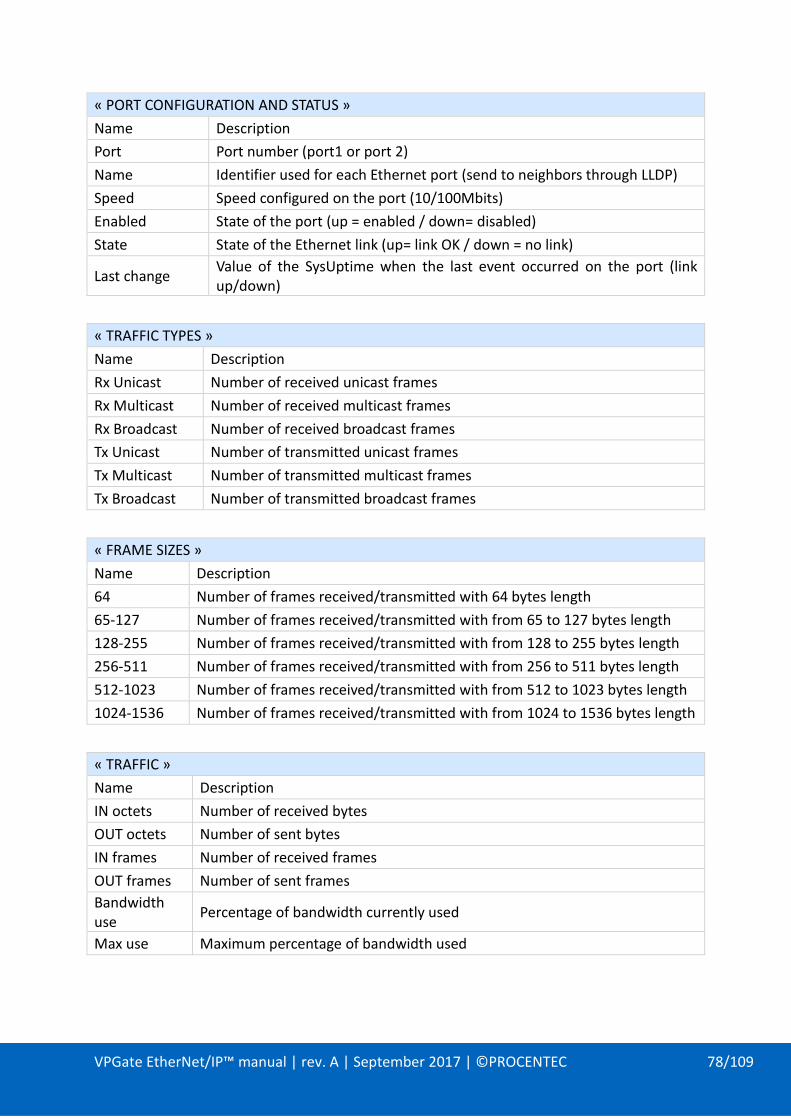
VPGate EtherNet/IP™ manual | rev. A | September 2017 | ©PROCENTEC 78/109
« PORT CONFIGURATION AND STATUS »
Name Description
Port Port number (port1 or port 2)
Name Identifier used for each Ethernet port (send to neighbors through LLDP)
Speed Speed configured on the port (10/100Mbits)
Enabled State of the port (up = enabled / down= disabled)
State State of the Ethernet link (up= link OK / down = no link)
Last change Value of the SysUptime when the last event occurred on the port (link up/down)
« TRAFFIC TYPES »
Name Description
Rx Unicast Number of received unicast frames
Rx Multicast Number of received multicast frames
Rx Broadcast Number of received broadcast frames
Tx Unicast Number of transmitted unicast frames
Tx Multicast Number of transmitted multicast frames
Tx Broadcast Number of transmitted broadcast frames
« FRAME SIZES »
Name Description
64 Number of frames received/transmitted with 64 bytes length
65-127 Number of frames received/transmitted with from 65 to 127 bytes length
128-255 Number of frames received/transmitted with from 128 to 255 bytes length
256-511 Number of frames received/transmitted with from 256 to 511 bytes length
512-1023 Number of frames received/transmitted with from 512 to 1023 bytes length
1024-1536 Number of frames received/transmitted with from 1024 to 1536 bytes length
« TRAFFIC »
Name Description
IN octets Number of received bytes
OUT octets Number of sent bytes
IN frames Number of received frames
OUT frames Number of sent frames
Bandwidth use
Percentage of bandwidth currently used
Max use Maximum percentage of bandwidth used

VPGate EtherNet/IP™ manual | rev. A | September 2017 | ©PROCENTEC 79/109
« FRAMES ERRORS »
Name Description
CRC Number of frames having CRC/FCS (Frame Checksum) errors
Undersize Number of frames having a length smaller than 64 bytes
Oversize Number of frames having a length greater than 1536 bytes
IN frames discarded
Number of received frames discarded due to insufficient resources in the switch (buffer full)
OUT frames discarded
Number of frames to send discarded due to insufficient resources in the switch (buffer full)
Collisions Number of collision detected

VPGate EtherNet/IP™ manual | rev. A | September 2017 | ©PROCENTEC 80/109
8.7. EtherNet/IP™ ADAPTER menu
This window indicates the global status of the adapter. The status can be ONLINE (connected to a scanner) or OFFLINE (not connected to a scanner).
Below are the 2 standard indicators of an EtherNet/IP™ adapter. They can be green, or red, steady or blinking, as explained below:
Network status indicator
INDICATOR STATE SUMMARY DESCRIPTION
Flashing green No connections An IP address is configured, but no CIP connection is established, and an exclusive owner connection has not timed out.
Steady green Connected
An IP address is configured, at least one CIP connection (any transport class) is established, and an exclusive owner connection has not timed out.
Flashing red Connection timeout An IP address is configured and an exclusive owner connection has timed out.
Module status indicator
INDICATOR STATE SUMMARY DESCRIPTION
Flashing green Standby If the device has not been configured. No configuration assembly active.
Steady green Device operational If the device is operating correctly.
Flashing red Major recoverable fault IP lost (DHCP lease)

VPGate EtherNet/IP™ manual | rev. A | September 2017 | ©PROCENTEC 81/109
8.8. MODBUS menu
This menu provides statistics according to the current MODBUS mode selected.
When the MODBUS Master mode is selected, the following information is shown:
When the MODBUS Slave mode is selected, the following information is shown:
The page is empty when the Transparent mode is selected.
These statistics are updated every second by the web server.
It is possible to reset the value of the statistics by clicking on the “Reset” button.

VPGate EtherNet/IP™ manual | rev. A | September 2017 | ©PROCENTEC 82/109
8.9. File system menu
The file system page provides access to the files and directories of PROCENTEC gateway by the way of an embedded file browser on the web page.
The current directory will always begin with “/FLASH0” which is the root directory of PROCENTEC gateway.
The total space and remaining space of the flash file system are shown in kilo-bytes.
File size is indicated in the “size” column while directories are identified by the “DIRECTORY” indicator in the “size” column.
Left-clicking on a directory will allow to browse it. Downloading a file is possible by right-clicking on it and selecting “save link as…”
It is possible to upload file into the file system by using the “upload file” below the file browser.
The current browsed directory will be used as destination. When the upload begins, a new line will show the progress of the operation:
When the file upload is finished, the line will automatically disappears and the file browser will refresh.
Only the “admin” account is able to upload files on the file system.
Note: file browsing and uploading are not compatible with Internet Explorer. Theses functionalities have been tested and validated with Google Chrome (v36.0.1985.143) and Mozilla Firefox (v31.0) web browsers.

VPGate EtherNet/IP™ manual | rev. A | September 2017 | ©PROCENTEC 83/109
8.10. Firmware upload menu
This page will allow the “admin” account to upload a firmware to update PROCENTEC gateway.
The firmware file shall be named “image.bin”. Other file names will be rejected.
It is recommended to stop the EtherNet/IP™ communication during the operation.
The button “Upload firmware” will pop-up a dialog box used to select the file to load.
The firmware upload will start and the page will show the progress of the file upload:
After the file is uploaded (100%), the validation stage will begin. This operation may take 1 to 2 minutes and is indicated with the loading icon:
When validation is finished, a reboot is needed to complete the firmware upload. A dialog box wills pop-up to inform the user that the reboot is required:
The VPGate will reboot and apply the new firmware. This operation may take 1 minute during which the power supply shall not be disconnected.
During this operation, the front panel indicators will remain off until the VPGate restarts. The operation is completed when the RUN indicator blinks at 1Hz.
Uploading file Progress
Validating file

VPGate EtherNet/IP™ manual | rev. A | September 2017 | ©PROCENTEC 84/109
To ensure the firmware has been applied properly, it is possible to check the version in the “System information” web page.
Note: file browsing and uploading are not compatible with Internet Explorer. Theses functionalities have been tested and validated with Google Chrome (v36.0.1985.143) and Mozilla Firefox (v31.0) web browsers.
8.11. Reboot menu
This page allows restarting VPGate EtherNet/IP™ to serial gateway. Only the “admin” account is able to perform this operation.
Clicking on the reboot button will pop up a dialog box to confirm the reboot:
8.12. Passwords menu
Passwords for “admin” or “user” accounts can be modified through this page:

VPGate EtherNet/IP™ manual | rev. A | September 2017 | ©PROCENTEC 85/109
The “admin” password is required to modify any account password (“current admin password” text box)/
The account to modify can be chosen in the drop-down list named “choose a login”.
It is required to enter the new password twice, for validity check.
The new password will be applied after clicking on the “save” button if:
- The current admin password is correct
- The new password has been entered correctly into the two fields
8.13. Logout menu
Changing current user account can be done by clicking on the “Logout” menu. After this action, the authentication window will pop-up.

VPGate EtherNet/IP™ manual | rev. A | September 2017 | ©PROCENTEC 86/109
9. FTP SERVER
An FTP server allows access to the file system. The connection uses the following parameters:
- IP address: Current IP address of the VPGate EtherNet/IP™ to serial gateway
- Port: 21
- Login: admin
- Password: admin (by default)
- FTP mode: passive
- The option for displaying hidden files is activated (-a).
All operations for files and directories are accessible (reading/writing files, creating/deleting directories).
An example of a connection with the FileZilla software (http://filezilla-project.org):
- first, select the option “Show hidden files”:
- then, enter the connection information. An example is given below:

VPGate EtherNet/IP™ manual | rev. A | September 2017 | ©PROCENTEC 87/109
Local file system Remote file system

VPGate EtherNet/IP™ manual | rev. A | September 2017 | ©PROCENTEC 88/109
10. SNMP AGENT
The VPGate EtherNet/IP™ to serial gateway uses SNMP V1 protocol as SNMP agent with the MIB 2 standard database reachable on UDP port 161.
Through SNMP, a supervisor (Network Management Station) can read data from the PROCENTEC MIB 2 database and retrieve:
- General device information (system)
- Time spent since last powering up (system)
- Port states, link status and configured speed (interface)
- Received/send Ethernet frames statistics (interface)
- Received/send IP packets statistics (IP)
Figure 71 : MIB 2 tree
Agent SNMP V1
MIB2
VPGATE
NMS
Read/Write SNMP
Figure 21: Network Management Station (NMS) principle with SNMP

VPGate EtherNet/IP™ manual | rev. A | September 2017 | ©PROCENTEC 89/109
SNMP V1 uses a community key provided with request to authorize their execution. The VPGate uses the default values:
- Public community key for read operations : “public”
- Private community key for read/write operations : “private”
The VPGate also provides an LLDP MIB. This MIB holds topology data sent by nearby devices.
The data can be read by an SNMP client (in this example using “SINEMA Server”) that would be able to show the topology of the network being discovered.
LLDP MIB data could also be directly read by a MIB browser:

11. APPENDICES
11.1. APPENDIX A: MODBUS frame formats
The MODBUS functions 0x01, 0x02, 0x03, 0x04, 0x05, 0x06, 0x07, 0x0F, 0x10 are supported by the VPGate. The format of each function is detailed with the help of an example for the ASCII and RTU mode. The CRC (MODBUS RTU) or LRC (MODBUS ASCII) bytes are mandatory.
MODBUS RTU uses 8 bit data coding. MODBUS ASCII uses 7 bit data coding.

VPGate EtherNet/IP™ manual | rev. A | September 2017 | ©PROCENTEC 91/109
Function 1 (0x01) This function enables reading the status of several Booleans (coils or discrete outputs).
The broadcast is not supported. The number of Booleans to be read simultaneously with PROCENTEC gateway is limited to 2000 (16 bits x 125 registers).
Format of the request:
FIELD NAME VALUE TO BE TRANSMITTED
BYTES SENT IF RTU
BYTES SENT IF ASCII
character Character
ASCII code
Frame header - - ":" 0x3A
Slave address 0x39 0x39 "39" 0x33, 0x39
Function code 0x01 0x01 "01" 0x30, 0x31
1st high-order bit address 0x00 0x00 "00" 0x30, 0x30
1st low-order bit address 0x22 0x22 "22" 0x32, 0x32
Number of high-order bits 0x00 0x00 "00" 0x30, 0x30
Number of low-order bits 0x12 0x12 "12" 0x31, 0x32
Error check (CRC/LRC) - 0x18 0xB5
"92" 0x39, 0x32
End of frame - - CR LF 0xD, 0xA
Format of the response:
FIELD NAME VALUE TO BE RECEIVED
BYTES RECEIVED IF RTU
BYTES RECEIVED IF ASCII
character Character
ASCII code
Frame header - - ":" 0x3A
Slave address 0x39 0x39 "39" 0x33, 0x39
Function code 0x01 0x01 "01" 0x30, 0x31
Number of data bytes 0x03 0x03 "03" 0x30, 0x33
Status of the bits 0x29 to 0x22 0x59 0x59 "59" 0x35, 0x39
Status of the bits 0x32 to 0x2A 0xC4 0xC4 "C4" 0x43, 0x34
Status of the bits 0x34 to 0x33 0x01 0x01 "01" 0x30, 0x31
Error check (CRC/LRC) - 0x7B 0xE5
"A5" 0x41, 0x35
End of frame - - CR LF 0xD, 0xA

VPGate EtherNet/IP™ manual | rev. A | September 2017 | ©PROCENTEC 92/109
Function 2 (0x02) This function enables reading the status of several Booleans (Discrete inputs). The
broadcast is not supported. The number of Booleans to be read simultaneously with PROCENTEC gateway is limited to 2000 (16 bits x 125 registers).
Format of the request:
FIELD NAME VALUE TO BE TRANSMITTED
BYTES SENT IF RTU
BYTES SENT IF ASCII
character Character ASCII code
Frame header - - ":" 0x3A
Slave address 0x39 0x39 "39" 0x33, 0x39
Function code 0x02 0x02 "02" 0x30, 0x32
1st high-order bit address 0x00 0x00 "00" 0x30, 0x30
1st low-order bit address 0x22 0x22 "22" 0x32, 0x32
Number of high-order bits 0x00 0x00 "00" 0x30, 0x30
Number of low-order bits 0x12 0x12 "12" 0x31, 0x32
Error check (CRC/LRC) - 0x5C 0xB5
"91" 0x39, 0x31
End of frame - - CR LF 0xD, 0xA
Format of the response:
FIELD NAME VALUE TO BE RECEIVED
BYTES RECEIVED IF RTU
BYTES RECEIVED IF ASCII
character Character
ASCII code
Frame header - - ":" 0x3A
Slave address 0x39 0x39 "39" 0x33, 0x39
Function code 0x02 0x02 "02" 0x30, 0x32
Number of data bytes 0x03 0x03 "03" 0x30, 0x33
Status of the bits 0x29 to 0x22 0x59 0x59 "59" 0x35, 0x39
Status of the bits 0x32 to 0x2A 0xC4 0xC4 "C4" 0x43, 0x34
Status of the bits 0x34 to 0x33 0x01 0x01 "01" 0x30, 0x31
Error check (CRC/LRC) - 0x3F 0xE5
"A4" 0x41, 0x34
End of frame - - CR LF 0xD, 0xA

VPGate EtherNet/IP™ manual | rev. A | September 2017 | ©PROCENTEC 93/109
Function 3 (0x03) This function enables reading the MODBUS registers (Holding Registers). The broadcast is
not supported. The number of registers to be read simultaneously is limited to 125. Format of the request:
FIELD NAME VALUE TO BE TRANSMITTED
BYTES SENT IF RTU
BYTES SENT IF ASCII
character Character ASCII code
Frame header - - ":" 0x3A
Slave address 0x39 0x39 "39" 0x33, 0x39
Function code 0x03 0x03 "03" 0x30, 0x33
1st high-order register address
0x00 0x00 "00" 0x30, 0x30
1st low-order register address 0x22 0x22 "22" 0x32, 0x32
Number of high-order registers
0x00 0x00 "00" 0x30, 0x30
Number of low-order registers
0x02 0x02 "02" 0x30, 0x32
Error check (CRC/LRC) - 0x60 0xB9
"A0" 0x41, 0x30
End of frame - - CR LF 0xD, 0xA
Format of the response:
FIELD NAME VALUE TO BE RECEIVED
BYTES RECEIVED IF RTU
BYTES RECEIVED IF ASCII
character Character ASCII code
Frame header - - ":" 0x3A
Slave address 0x39 0x39 "39" 0x33, 0x39
Function code 0x03 0x03 "03" 0x30, 0x33
Number of data bytes 0x04 0x04 "04" 0x30, 0x34
1st high-order register value 0x68 0x68 "68" 0x36, 0x38
1st low-order register value 0x31 0x31 "31" 0x36, 0x38
2nd high-order register value 0x47 0x47 "47" 0x36, 0x38
2nd high-order register value 0x59 0x59 "59" 0x36, 0x38
Error check (CRC/LRC) - 0xFD 0x95
"87" 0x38, 0x37
End of frame - - CR LF 0xD, 0xA

VPGate EtherNet/IP™ manual | rev. A | September 2017 | ©PROCENTEC 94/109
Function 4 (0x04) This function enables reading the MODBUS registers (Input Registers). The broadcast is
not supported. The number of registers to be read simultaneously is limited to 125.
Format of the request:
FIELD NAME VALUE TO BE TRANSMITTED
BYTES SENT IF RTU
BYTES SENT IF ASCII
character Character ASCII code
Frame header - - ":" 0x3A
Slave address 0x39 0x39 "39" 0x33, 0x39
Function code 0x04 0x04 "04" 0x30, 0x34
1st high-order register address
0x00 0x00 "00" 0x30, 0x30
1st low-order register address 0x22 0x22 "22" 0x32, 0x32
Number of high-order registers
0x00 0x00 "00" 0x30, 0x30
Number of low-order registers
0x03 0x03 "03" 0x30, 0x33
Error check (CRC/LRC) - 0x14 0xB9
"9E" 0x39, 0x45
End of frame - - CR LF 0xD, 0xA
Format of the response:
FIELD NAME VALUE TO BE RECEIVED
BYTES RECEIVED IF RTU
BYTES RECEIVED IF ASCII
character Character ASCII code
Frame header - - ":" 0x3A
Slave address 0x39 0x39 "39" 0x33, 0x39
Function code 0x04 0x04 "04" 0x30, 0x34
Number of data bytes 0x06 0x06 "06" 0x30, 0x36
1st high-order register value 0x68 0x68 "68" 0x36, 0x38
1st low-order register value 0x31 0x31 "31" 0x33, 0x31
2nd high-order register value 0x47 0x47 "47" 0x34, 0x37
2nd high-order register value 0x59 0x59 "59" 0x35, 0x39
32nd high-order register value 0x00 0x00 "00" 0x30, 0x30
32nd high-order register value 0x00 0x00 "00" 0x30, 0x30
Error check (CRC/LRC) - 0xE2 0xD9
"84" 0x38, 0x34
End of frame - - CR LF 0xD, 0xA

VPGate EtherNet/IP™ manual | rev. A | September 2017 | ©PROCENTEC 95/109
Function 5 (0x05) This function enables writing a Boolean (coil) to ON or OFF. Broadcast is supported. The
Boolean may take either the value 0x0000 (OFF) or the value 0xFF00 (ON).
Format of the request:
FIELD NAME VALUE TO BE TRANSMITTED
BYTES SENT IF RTU
BYTES SENT IF ASCII
character Character ASCII code
Frame header - - ":" 0x3A
Slave address 0x01 0x01 "01" 0x30, 0x31
Function code 0x05 0x05 "05" 0x30, 0x35
High-order register address 0x00 0x00 "00" 0x30, 0x30
Low-order register address 0x22 0x22 "22" 0x32, 0x32
High-order register value 0xFF 0xFF "FF" 0x46, 0x46
Low-order register value 0x00 0x00 "00" 0x30, 0x30
Error check (CRC/LRC) - 0x2C 0x30
"D9" 0x44, 0x39
End of frame - - CR LF 0xD, 0xA
Format of the response:
FIELD NAME VALUE TO BE TRANSMITTED
BYTES SENT IF RTU
BYTES SENT IF ASCII
character Character ASCII code
Frame header - - ":" 0x3A
Slave address 0x01 0x01 "01" 0x30, 0x31
Function code 0x05 0x05 "05" 0x30, 0x35
High-order register address 0x00 0x00 "00" 0x30, 0x30
Low-order register address 0x22 0x22 "22" 0x32, 0x32
High-order register value 0xFF 0xFF "FF" 0x46, 0x46
Low-order register value 0x00 0x00 "00" 0x30, 0x30
Error check (CRC/LRC) - 0x2C 0x30
"D9" 0x44, 0x39
End of frame - - CR LF 0xD, 0xA

VPGate EtherNet/IP™ manual | rev. A | September 2017 | ©PROCENTEC 96/109
Function 6 (0x06) This function enables writing a MODBUS register (Holding Registers). Broadcast is
supported.
Format of the request:
FIELD NAME VALUE TO BE TRANSMITTED
BYTES SENT IF RTU
BYTES SENT IF ASCII
character Character ASCII code
Frame header - - ":" 0x3A
Slave address 0x39 0x39 "39" 0x33, 0x39
Function code 0x06 0x06 "06" 0x30, 0x36
High-order register address 0x00 0x00 "00" 0x30, 0x30
Low-order register address 0x22 0x22 "22" 0x32, 0x32
High-order register value 0x00 0x00 "00" 0x30, 0x30
Low-order register value 0x56 0x56 "56" 0x35, 0x36
Error check (CRC/LRC) - 0xAD 0x46
"49" 0x34, 0x39
End of frame - - CR LF 0xD, 0xA
Format of the response:
FIELD NAME VALUE TO BE TRANSMITTED
BYTES SENT IF RTU
BYTES SENT IF ASCII
character Character ASCII code
Frame header - - ":" 0x3A
Slave address 0x39 0x03 "39" 0x33, 0x39
Function code 0x06 0x06 "06" 0x30, 0x36
High-order register address 0x0
0x00 0x00 "00" 0x30, 0x30
Low-order register address 0x0
0x22 0x22 "22" 0x32, 0x32
High-order register value 0x00 0x00 "00" 0x30, 0x30
Low-order register value 0x56 0x56 "56" 0x35, 0x36
Error check (CRC/LRC) - 0xAD 0x46
"49" 0x34, 0x39
End of frame - - CR LF 0xD, 0xA
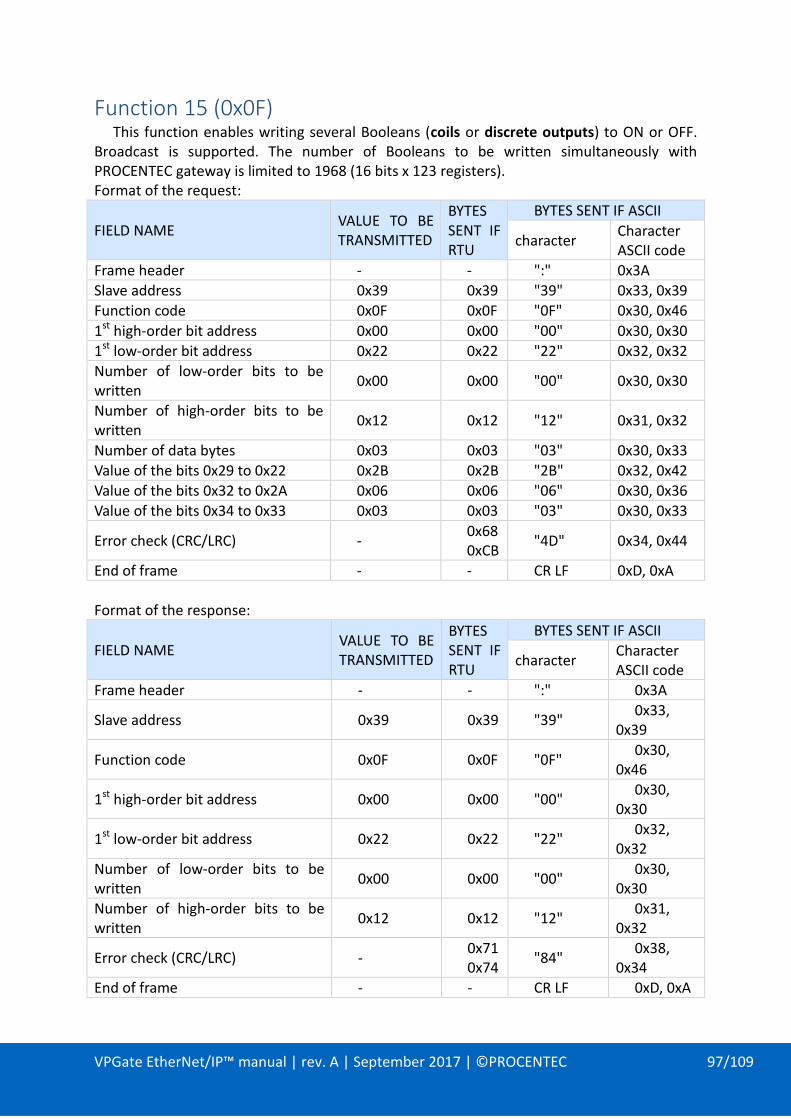
VPGate EtherNet/IP™ manual | rev. A | September 2017 | ©PROCENTEC 97/109
Function 15 (0x0F) This function enables writing several Booleans (coils or discrete outputs) to ON or OFF.
Broadcast is supported. The number of Booleans to be written simultaneously with PROCENTEC gateway is limited to 1968 (16 bits x 123 registers). Format of the request:
FIELD NAME VALUE TO BE TRANSMITTED
BYTES SENT IF RTU
BYTES SENT IF ASCII
character Character ASCII code
Frame header - - ":" 0x3A
Slave address 0x39 0x39 "39" 0x33, 0x39
Function code 0x0F 0x0F "0F" 0x30, 0x46
1st high-order bit address 0x00 0x00 "00" 0x30, 0x30
1st low-order bit address 0x22 0x22 "22" 0x32, 0x32
Number of low-order bits to be written
0x00 0x00 "00" 0x30, 0x30
Number of high-order bits to be written
0x12 0x12 "12" 0x31, 0x32
Number of data bytes 0x03 0x03 "03" 0x30, 0x33
Value of the bits 0x29 to 0x22 0x2B 0x2B "2B" 0x32, 0x42
Value of the bits 0x32 to 0x2A 0x06 0x06 "06" 0x30, 0x36
Value of the bits 0x34 to 0x33 0x03 0x03 "03" 0x30, 0x33
Error check (CRC/LRC) - 0x68 0xCB
"4D" 0x34, 0x44
End of frame - - CR LF 0xD, 0xA
Format of the response:
FIELD NAME VALUE TO BE TRANSMITTED
BYTES SENT IF RTU
BYTES SENT IF ASCII
character Character ASCII code
Frame header - - ":" 0x3A
Slave address 0x39 0x39 "39" 0x33,
0x39
Function code 0x0F 0x0F "0F" 0x30,
0x46
1st high-order bit address 0x00 0x00 "00" 0x30,
0x30
1st low-order bit address 0x22 0x22 "22" 0x32,
0x32
Number of low-order bits to be written
0x00 0x00 "00" 0x30,
0x30
Number of high-order bits to be written
0x12 0x12 "12" 0x31,
0x32
Error check (CRC/LRC) - 0x71 0x74
"84" 0x38,
0x34
End of frame - - CR LF 0xD, 0xA

VPGate EtherNet/IP™ manual | rev. A | September 2017 | ©PROCENTEC 98/109

VPGate EtherNet/IP™ manual | rev. A | September 2017 | ©PROCENTEC 99/109
Function 16 (0x10) This function enables writing MODBUS registers (Holding Registers). Broadcast is
supported. The number of registers to be written simultaneously is limited to 123.
Format of the request:
FIELD NAME VALUE TO BE TRANSMITTED
BYTES SENT IF RTU
BYTES SENT IF ASCII
character Character ASCII code
Frame header - - ":" 0x3A
Slave address 0x39 0x39 "39" 0x33, 0x39
Function code 0x10 0x10 "10" 0x31, 0x30
1st high-order register address 0x00 0x00 "00" 0x30, 0x30
1st low-order register address 0x22 0x22 "22" 0x32, 0x32
Number of high-order registers 0x00 0x00 "00" 0x30, 0x30
Number of low-order registers 0x02 0x02 "02" 0x30, 0x32
Number of data bytes 0x04 0x04 "04" 0x30, 0x34
High-order register value 0x52 0x00 0x00 "00" 0x30, 0x30
Low-order register value 0x52 0x56 0x56 "56" 0x35, 0x36
High-order register value 0x53 0x00 0x00 "00" 0x30, 0x30
Low-order register value 0x53 0x57 0x57 "57" 0x35, 0x37
Error check (CRC/LRC) - 0x04 0xE0
"E2" 0x45, 0x32
End of frame - - CR LF 0xD, 0xA
Format of the response:
FIELD NAME VALUE TO BE RECEIVED
BYTES RECEIVED IF RTU
BYTES RECEIVED IF ASCII
character Character ASCII code
Frame header - - ":" 0x3A
Slave address 0x39 0x39 "39" 0x33, 0x39
Function code 0x10 0x10 "10" 0x31, 0x30
1st high-order register address 0x00 0x00 "00" 0x30, 0x30
1st low-order register address 0x22 0x22 "22" 0x32, 0x32
Number of high-order registers 0x00 0x00 "00" 0x30, 0x30
Number of low-order registers 0x02 0x02 "02" 0x30, 0x32
Error check (CRC/LRC) - 0xE5,
0x7A "93" 0x39, 0x33
End of frame - - CR LF 0xD, 0xA

VPGate EtherNet/IP™ manual | rev. A | September 2017 | ©PROCENTEC 100/109
MODBUS Exception frames An exception frame is generated by the MODBUS slave if the master requests it to carry
out an unauthorised action. The VPGATE gateway manages the following exceptions:
EXCEPTION CODE
NAME DESCRIPTION
01 ILLEGAL FUNCTION
This exception is returned by the slave if the master uses a function that the slave does not recognise. PROCENTEC gateway MODBUS only manages the functions 1, 2, 3, 4, 5, 6, 7, 15, 16 and 23.
02 ILLEGAL DATA ADDRESS
This exception is returned if the master attempts to access an inaccessible MODBUS register. For example, PROCENTEC gateway is configured such that it has 10 registers in read-only mode (address 0 to 9) and 10 registers in write-only mode (address 0 to 9). An error is thus reported if the master tries to access register 20.
This error also occurs if, for example, with a function 3, the master tries to read 20 registers from the register 1 (address 0).
03 ILLEGAL DATA VALUE
This exception is returned if the master attempts to write data that the slave cannot accept. For example, with the function 5, the only possible data is 0x0000 and 0xFF00. In all other cases, the exception function 3 is sent back.
06 SLAVE BUSY This exception is returned by a MODBUS slave when it is
already managing a process and is thus unable to respond to the request.
0A GATEWAY PATH UNAVAILABLE
In the slave mode, this exception is sent in response to any MODBUS request when the EtherNet/IP™ communication has not been established.

VPGate EtherNet/IP™ manual | rev. A | September 2017 | ©PROCENTEC 101/109
Format of the exception frame: This exception frame is an example of a frame received in response to a function 6. The
exception occurred because the master attempted to access an unauthorised register. The MODBUS function codes are 7-bit (codes 1 to 127). The 8th bit is reserved and serves
to report an exception frame when it is set to 1.
FIELD NAME VALUE TO BE RECEIVED
BYTES RECEIVED IF RTU
BYTES RECEIVED IF ASCII
character Character ASCII code
Frame header - - ":" 0x3A
Slave address 0x03 0x03 "03" 0x30, 0x33
Function code + 0x80 0x86 0x86 "86" 0x38, 0x36
Exception code 0x02 0x02 "02" 0x30, 0x32
Error check (CRC/LRC) - 0x31 0x62
"75" 0x37, 0x35
End of frame - - CR LF 0xD, 0xA

VPGate EtherNet/IP™ manual | rev. A | September 2017 | ©PROCENTEC 102/109
11.2. APPENDIX B: MIB2
OID MIB2 = 1.3.6.1.2.1
“System” section: IOD system = 1.3.6.1.2.1.1
OID NAME ACCESS DESCRIPTION
1.3.6.1.2.1.1.1 sysDescr R description of the device
1.3.6.1.2.1.1.2 sysObjectID R identity of the agent
1.3.6.1.2.1.1.3 sysUpTime R Time elapsed since the agent was initiated (hundred seconds)
1.3.6.1.2.1.1.4 sysContact R name of the person to be contacted
1.3.6.1.2.1.1.5 sysName R name of the device
1.3.6.1.2.1.1.6 sysLocation R physical location of the device
1.3.6.1.2.1.1.7 sysServices R services offered by the device

VPGate EtherNet/IP™ manual | rev. A | September 2017 | ©PROCENTEC 103/109
“Interface” section: IOD interface = 1.3.6.1.2.1.2
OID NAME ACCESS DESCRIPTION
1.3.6.1.2.1.2.2.1.12 ifInNUcastPkts R number of broadcast and multicast packets received
1.3.6.1.2.1.2.2.1.13 ifInDiscards R Number of packets rejected because of resource limitations.
1.3.6.1.2.1.2.2.1.14 ifInErrors R Number of packets rejected because of format error.
1.3.6.1.2.1.2.2.1.15 ifInUnkownProtos R number of packets intended for other protocols
1.3.6.1.2.1.2.2.1.16 ifOutOctets R total number of bytes transmitted by the interface
1.3.6.1.2.1.2.2.1.17 ifOutUcatsPckts R number of unicast packets transmitted
1.3.6.1.2.1.2.2.1.18 ifOutNUcastPkts R number of broadcast and multicast packets transmitted
1.3.6.1.2.1.2.2.1.19 ifOutDiscards R number of packets rejected because of resource limitations.
1.3.6.1.2.1.2.2.1.20 ifOutErrors R number of packets rejected because of format error.
1.3.6.1.2.1.2.2.1.21 ifOutQlen R size of the output waiting queue packet size
1.3.6.1.2.1.2.2.1.22 ifSpecific R pointer towards a specific MIB
“At” / “Address Translation” section: OID at = 1.3.6.1.2.1. 3 OBSOLETE

VPGate EtherNet/IP™ manual | rev. A | September 2017 | ©PROCENTEC 104/109
“Ip” / “Internet Protocol” section: OID 1.3.6.1.2.1.4
OID NAME ACCESS DESCRIPTION
1.3.6.1.2.1.4.1 ipForwarding R the node acts as a gateway or host
1.3.6.1.2.1.4.2 ipDefaultTTL R Default TTL (Time To Live) on the IP packets
1.3.6.1.2.1.4.3 ipInReceives R total number of IP packets received (including errors)
1.3.6.1.2.1.4.4 ipInHdrErrors R Number of datagrams ignored because of format error.
1.3.6.1.2.1.4.5 ipInAddrErrors R Number of datagrams ignored because of improper destination.
1.3.6.1.2.1.4.6 ipInForwDatagrams R number of packets retransmitted
1.3.6.1.2.1.4.7 ipInUnkownProtos R number of datagrams intended for another protocol
1.3.6.1.2.1.4.8 ipInDiscards R number of packets ignored because of resource limitations.
1.3.6.1.2.1.4.9 ipInDelivers R number of packets taken into consideration
1.3.6.1.2.1.4.10 ipOutRequest R total number of IP packets transmitted (including errors)
1.3.6.1.2.1.4.11 ipOutNoRoutes R Number of packets not transmitted because of a routing problem.
1.3.6.1.2.1.4.12 ipReasmTimeout R time out value for the waiting queue for datagram reassembly
1.3.6.1.2.1.4.13 ipReasmReqds R number of fragments received that require reassembly
1.3.6.1.2.1.4.14 ipReasmOKs R number of datagrams correctly reassembled
1.3.6.1.2.1.4.15 ipReasmFails R Number of reassembly errors
1.3.6.1.2.1.4.16 ipFragOKs R number of datagrams correctly fragmented
1.3.6.1.2.1.4.17 ipFragFails R number of datagrams requiring fragmentation even though the IP flags do not indicate so
1.3.6.1.2.1.4.18 ipFragCreates R number of fragments created

VPGate EtherNet/IP™ manual | rev. A | September 2017 | ©PROCENTEC 105/109
“ICMP” / “Internet Control Message Protocol” section: OID 1.3.6.1.2.1.5
OID NAME ACCESS DESCRIPTION
1.3.6.1.2.1.5.1 icmpInMsgs R Number of ICMP messages received
1.3.6.1.2.1.5.2 icmpInErrors R Number of ICMP messages received with an error (improper ICMP checksum, improper length)
1.3.6.1.2.1.5.3 icmpInDestUnreachs R ICMP destination number unreachable
1.3.6.1.2.1.5.4 icmpInTimeExcds R Number of SNMP messages received with time exceeded
1.3.6.1.2.1.5.5 icmpInParmProbs R Number of ICMP messages received with parameter problems
1.3.6.1.2.1.5.6 icmpInSrcQuenchs R Number of ICMP messages received from a powered-off source
1.3.6.1.2.1.5.7 icmpInRedirects R Number of redirected ICMP messages received
1.3.6.1.2.1.5.8 icmpInEchos R Number of ICMP request messages received
1.3.6.1.2.1.5.9 icmpInEchoReps R Number of ICMP messages received with an echo
1.3.6.1.2.1.5.10 icmpInTimestamps R Number of ICMP TimeStamp messages received
1.3.6.1.2.1.5.11 icmpInTimestampReps R Number of SNMP response messages received
1.3.6.1.2.1.5.12 icmpInAddrMasks R Number of ICMP address mask request messages received
1.3.6.1.2.1.5.13 icmpInAddrMaskReps R Number of ICMP address mask response messages received
1.3.6.1.2.1.5.14 icmpOutMsgs R Number of ICMP messages ready to be sent
1.3.6.1.2.1.5.15 icmpOutErrors R
Number of ICMP messages not sent because of errors. For example, no resources available in the reception buffer.
1.3.6.1.2.1.5.16 icmpOutDestUnreachs R Number of ICMP messages sent to unreachable destinations.
1.3.6.1.2.1.5.17 icmpOutTimeExcds R Number of ICMP messages with exceeded outtime
1.3.6.1.2.1.5.18 icmpOutParmProbs R Number of ICMP messages with problematic sending parameters
1.3.6.1.2.1.5.19 icmpOutSrcQuenchs R Number of ICMP messages sent to a powered-off source

VPGate EtherNet/IP™ manual | rev. A | September 2017 | ©PROCENTEC 106/109
1.3.6.1.2.1.5.20 icmpOutRedirects R Number of redirected ICMP messages sent
1.3.6.1.2.1.5.21 icmpOutEchos R Number of ICMP Echo messages sent
1.3.6.1.2.1.5.22 icmpOutEchoReps R Number of Echo responses sent
1.3.6.1.2.1.5.23 icmpOutTimestamps R Number of ICMP TimeStamp messages sent
1.3.6.1.2.1.5.24 icmpOutTimestampReps R Number of ICMP TimeStamp responses sent
1.3.6.1.2.1.5.25 icmpOutAddrMasks R Number of ICMP mask request messages sent
1.3.6.1.2.1.5.26 icmpOutAddrMaskReps R Number of ICMP mask response messages sent
“TCP” / “Transmission Control Protocol” section: OID 1.3.6.1.2.1.6
OID NAME ACCESS DESCRIPTION
1.3.6.1.2.1.6.6 tcpPassiveOpens R number of passive connections opened
1.3.6.1.2.1.6.7 tcpAttemptFails R number of failed connection attempts
1.3.6.1.2.1.6.8 tcpEstabResets R number of connection resets
1.3.6.1.2.1.6.9 tcpCurrEstab R number of ongoing connections
1.3.6.1.2.1.6.10 tcpInSegs R number of segments received
1.3.6.1.2.1.6.11 tcpOutSegs R number of segments transmitted
1.3.6.1.2.1.6.12 tcpRetransSegs R number of segments re-transmitted
1.3.6.1.2.1.6.13 TcpConnTable R
A table containing specific information pertaining to connections through TCP connections
1.3.6.1.2.1.6.13.1 TcpConnEntry R Information regarding a particular TCP connection
1.3.6.1.2.1.6.13.1.1 tcpConnState R status of the connection
1.3.6.1.2.1.6.13.1.2 tcpConnLocalAddress R local IP address
1.3.6.1.2.1.6.13.1.3 tcpConnLocalPort R local port number
1.3.6.1.2.1.6.13.1.4 tcpConnRemoteAddress R Remote IP address
1.3.6.1.2.1.6.13.1.5 tcpConnRemotePort R remote port number
1.3.6.1.2.1.6.14 tcpInErrs R number of segments ignored because of format error.
1.3.6.1.2.1.6.15 tcpOutRsts R number of resets generated
1.3.6.1.2.1.6.15 tcpPassiveOpens R number of resets generated

VPGate EtherNet/IP™ manual | rev. A | September 2017 | ©PROCENTEC 107/109
“UDP” / “User Datagram Protocol” section: OID 1.3.6.1.2.1.7
OID NAME ACCESS DESCRIPTION
1.3.6.1.2.1.7.1 udpInDatagrams R number of datagrams transmitted
1.3.6.1.2.1.7.2 udpNoPorts R number of datagrams intended for an unknown protocol
1.3.6.1.2.1.7.3 udpInErrors R Number of datagrams ignored because of format error.
1.3.6.1.2.1.7.4 udpOutDatagrams R number of datagrams transmitted
“SNMP” / “Simple Network Management Protocol” section: OID 1.3.6.1.2.1.11
OID NAME ACCESS DESCRIPTION
1.3.6.1.2.1.10.1 snmpInPkts R Total number of PDUs received from the lower layer
1.3.6.1.2.1.10.2 snmpOutPkts R Total number of PDUs sent to the lower layer
1.3.6.1.2.1.10.3 snmpBadVersions R Total number of PDUs received which have a different version number than the local number
1.3.6.1.2.1.10.4 snmpBadCommunityNames R Total number of PDUs with an unknown community name
1.3.6.1.2.1.10.5 snmpBadCommunityUses R Total number of PDUs that cannot be processed within the context of this community
1.3.6.1.2.1.10.6 snmpInASNParseErrs R Total number of errors at the time of interpretation of an ASN.1 object
1.3.6.1.2.1.10.8 snmpInTooBigs R Number of PDUs received with ErrorStatus 'too big' (the response does not fit in an UDP message)
1.3.6.1.2.1.10.9 snmpInNoSuchNames R Number of PDUs received with ErrorStatus ‘noSuchNames' (name unknown)
1.3.6.1.2.1.10.10 snmpInBadValues R Number of PDUs received with ErrorStatus ‘badValue’
1.3.6.1.2.1.10.11 snmpInReadOnlys R Number of PDUs received with ErrorStatus ‘readOnly’
1.3.6.1.2.1.10.12 snmpInGenErrs R Number of PDUs received with ErrorStatus ‘genErr’
1.3.6.1.2.1.10.13 snmpInTotalReqVars R Number of objects of the MIB which pertain to a Get-Request or Get-Next request

VPGate EtherNet/IP™ manual | rev. A | September 2017 | ©PROCENTEC 108/109
1.3.6.1.2.1.10.14 snmpInTotalSetVars R Number of objects of the MIB which pertain to a Set-Request
1.3.6.1.2.1.10.15 snmpInGetRequests R Total number of PDU Get-Requests processed by the SNMP protocol
1.3.6.1.2.1.10.16 snmpInGetNexts R Total number of PDU Get-Nexts processed by the SNMP protocol
1.3.6.1.2.1.10.17 snmpInSetRequests R Total number of PDU Set-Requests processed by the SNMP protocol
1.3.6.1.2.1.10.18 snmpInGetResponses R Total number of PDU Get-Responses processed by the SNMP protocol
1.3.6.1.2.1.10.19 snmpInTraps R Total number of PDU Traps processed by the SNMP protocol
1.3.6.1.2.1.10.20 snmpOutTooBigs R
Total number of SNMP PDUs which were generated by the SNPM protocol entity and for which the value of the ‘ErrorStatus’ field is “tooBig”
1.3.6.1.2.1.10.21 snmpOutNoSuchNames R
Total number of SNMP PDUs which were generated by the SNPM protocol entity and for which the value of the ‘ErrorStatus’ field is “NoSuchName”
1.3.6.1.2.1.10.22 snmpOutBadValues R
Total number of SNMP PDUs which were generated by the SNPM protocol entity and for which the value of the ‘ErrorStatus’ field is “badValue”
1.3.6.1.2.1.10.24 snmpOutGenErrs R
Total number of SNMP PDUs which were generated by the SNPM protocol entity and for which the value of the ‘ErrorStatus’ field is “genErr”
1.3.6.1.2.1.10.25 snmpOutGetRequests R
Total number of PDUs of the Get-Request type which were generated by the SNPM protocol entity
1.3.6.1.2.1.10.26 snmpOutGetNexts R Total number of PDUs of the Get-Next type which were generated by the SNPM protocol entity
1.3.6.1.2.1.10.27 snmpOutSetRequests R
Total number of PDUs of the Set-Request type which were generated by the SNPM protocol entity

VPGate EtherNet/IP™ manual | rev. A | September 2017 | ©PROCENTEC 109/109
1.3.6.1.2.1.10.28 snmpOutGetResponses R
Total number of PDUs of the Get-Responses type which were generated by the SNPM protocol entity
1.3.6.1.2.1.10.29 snmpOutTraps R Total number of PDUs of the Trap type which were generated by the SNPM protocol entity
1.3.6.1.2.1.10.30 snmpEnableAuthTraps R
Indication about the configuration of the SNMP agent pertaining to the generation of the Authentication Trap