
MC-Link with Ethernet/IP Interface - LinMot
24
MC-Link with Ethernet/IP Interface User Manual This document applies to the following controllers: B8050-ML-IP
-
Upload
khangminh22 -
Category
Documents
-
view
4 -
download
0
Transcript of MC-Link with Ethernet/IP Interface - LinMot
MC-Link with Ethernet/IP Interface
User Manual
This document applies to the following controllers:B8050-ML-IP

MC-Link with Ethernet/IP
© 2014 NTI AGThis work is protected by copyright.Under the copyright laws, this publication may not be reproduced or transmitted in any form, electronic or mechanical, including photocopying,recording, microfilm, storing in an information retrieval system, not even for didactical use, or translating, in whole or inpart, without the prior written consent of NTI AG.LinMot® is a registered trademark of NTI AG.Note:The information in this documentation reflects the stage of development at the time of press and is therefore without obligation.NTI AG reserves itself the right to make changes at any time and without notice to reflect further technical advance or productimprovement.
Document version 4.3.2 / Whp, August 2014
NTI AG / LinMot www.LinMot.com Page 2/24

MC-Link with Ethernet/IP
Table of Content1 SYSTEM OVERVIEW.....................................................................................................................4
1.1 REFERENCES.......................................................................................................................................4
2 CONNECTING TO THE ETHERNET/IP NETWORK................................................................5
2.1 PIN ASSIGNMENT OF THE CONNECTORS X17-X18...................................................................................52.2 DEFAULT IP ADDRESS SETTINGS...........................................................................................................5
3 SETUP IN THE PLC........................................................................................................................6
3.1 RSLINX CLASSIC................................................................................................................................63.2 LINMOT CONFIGURATION IN THE PLC...................................................................................................7
4 ETHERNET/IP PARAMETERS...................................................................................................12
4.1 PARAMETERS ....................................................................................................................................12
5 REALTIME IO DATA MAPPING................................................................................................14
5.1 O ->T AND T->O MAPPING WITH CONFIGURATION MODULE................................................................145.1.1 O → T Mapping of one axis.................................................................................................145.1.2 T → O Mapping of one axis.................................................................................................14
5.2 PLC SETUP WITH DIFFERENT NUMBERS OF AXIS....................................................................................155.2.1 PLC Setup with 1 Axis..........................................................................................................155.2.2 PLC Setup with 2 Axis..........................................................................................................165.2.3 PLC Setup with 3 Axis..........................................................................................................175.2.4 PLC Setup with 4 Axis..........................................................................................................185.2.5 PLC Setup with 5 Axis..........................................................................................................195.2.6 PLC Setup with 6 Axis..........................................................................................................205.2.7 PLC Setup with 7 Axis..........................................................................................................215.2.8 PLC Setup with 8 Axis..........................................................................................................22
6 SPECIAL AXIS ERRORS FOR (M)B8050-ML-IP SYSTEMS..................................................23
7 CONTACT ADDRESSES...............................................................................................................24
NTI AG / LinMot www.LinMot.com Page 3/24
MC-Link with Ethernet/IP
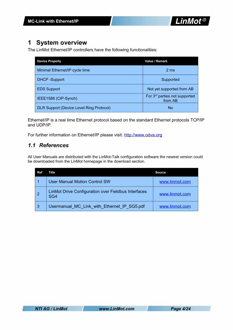
1 System overviewThe LinMot Ethernet/IP controllers have the following functionalities:
Device Property Value / Remark
Minimal Ethernet/IP cycle time 2 ms
DHCP -Support Supported
EDS Support Not yet supported from AB
IEEE1588 (CIP-Synch) For 3rd parties not supported from AB
DLR Support (Device Level Ring Protocol) No
Ethernet/IP is a real time Ethernet protocol based on the standard Ethernet protocols TCP/IP and UDP/IP.
For further information on Ethernet/IP please visit: http://www.odva.org
1.1 References
All User Manuals are distributed with the LinMot-Talk configuration software the newest version could be downloaded from the LinMot homepage in the download section.
Ref Title Source
1 User Manual Motion Control SW www.linmot.com
2 LinMot Drive Configuration over Fieldbus Interfaces SG4 www.linmot.com
3 Usermanual_MC_Link_with_Ethernet_IP_SG5.pdf www.linmot.com
NTI AG / LinMot www.LinMot.com Page 4/24

MC-Link with Ethernet/IP
2 Connecting to the Ethernet/IP Network
2.1 Pin Assignment of the Connectors X17-X18The Ethernet/IP connector is a standard RJ45 female connector with a pin assignment as defined by EIA/TIA T568B:
X17 – X18 RealTime Ethernet Connector
Pin Wire color code Assignment 100BASE-TX
1
2
3
4
5
6
7
8
case
WHT/ORG
ORG
WHT/GRN
BLU
WHT/BLU
GRN
WHT/BRN
BRN
-
Rx+
Rx-
Tx+
-
-
Tx-
-
-
-
RJ-45 Use standard patch cables (twisted pair, S/UTP, AWG26) for wiring. This type of cable is usually referred to as a “Cat5e-Cable”.
2.2 Default IP Address SettingsThe default IP address is 192.168.001.xxx where the last byte xxx is defined via the two Hex-Switches S1 and S2, where S1 sets the high digit and S2 the low digit.
S1, S2: IP Selectors
S1
S2
Bus ID High (0h…Fh)
Bus ID Low (0h…Fh)
IMPORTANT: The switch position S1 = S2 = 0 (factory default setting) defines acquiring IP address via DHCP.
NTI AG / LinMot www.LinMot.com Page 5/24
MC-Link with Ethernet/IP
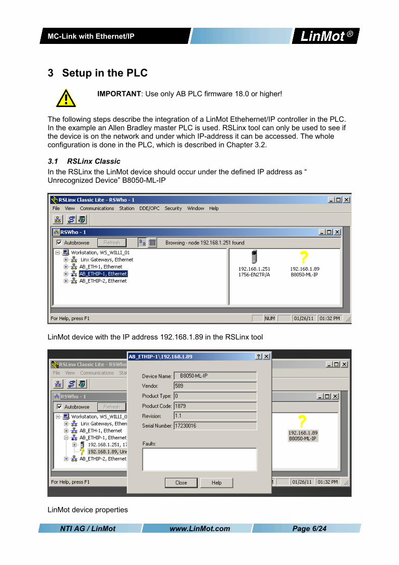
3 Setup in the PLC
IMPORTANT: Use only AB PLC firmware 18.0 or higher!
The following steps describe the integration of a LinMot Ethehernet/IP controller in the PLC. In the example an Allen Bradley master PLC is used. RSLinx tool can only be used to see if the device is on the network and under which IP-address it can be accessed. The whole configuration is done in the PLC, which is described in Chapter 3.2.
3.1 RSLinx ClassicIn the RSLinx the LinMot device should occur under the defined IP address as “ Unrecognized Device” B8050-ML-IP
LinMot device with the IP address 192.168.1.89 in the RSLinx tool
LinMot device properties
NTI AG / LinMot www.LinMot.com Page 6/24

MC-Link with Ethernet/IP
3.2 LinMot Configuration in the PLCThe LinMot can be configured in the I/O configuration section, in the Ethernet section as aNew Module
Then you have to select in the Communications Module the ETHERNET-MODULE
NTI AG / LinMot www.LinMot.com Page 7/24

MC-Link with Ethernet/IP
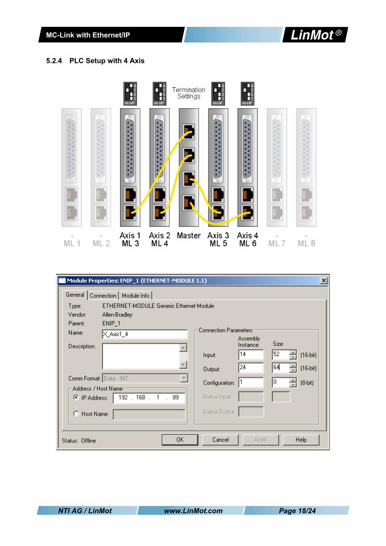
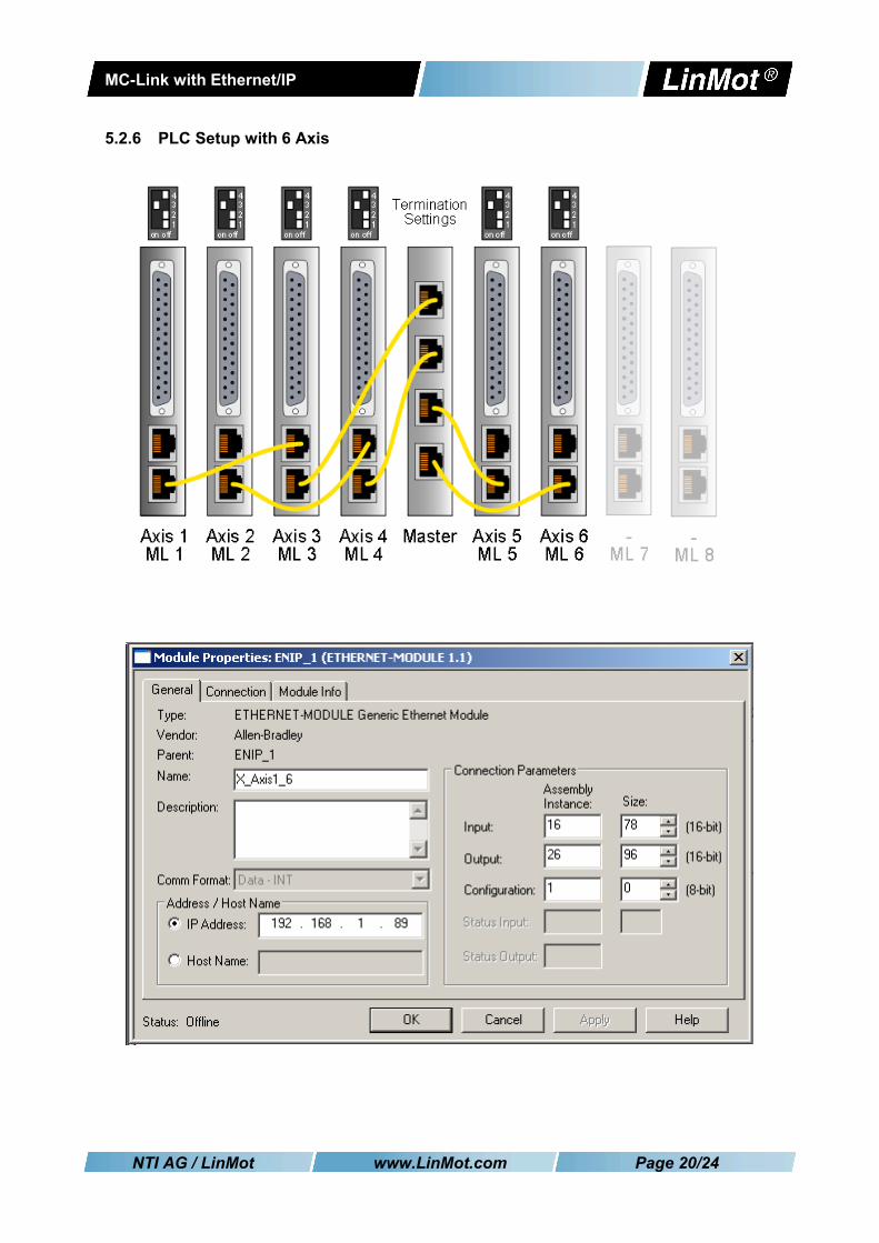
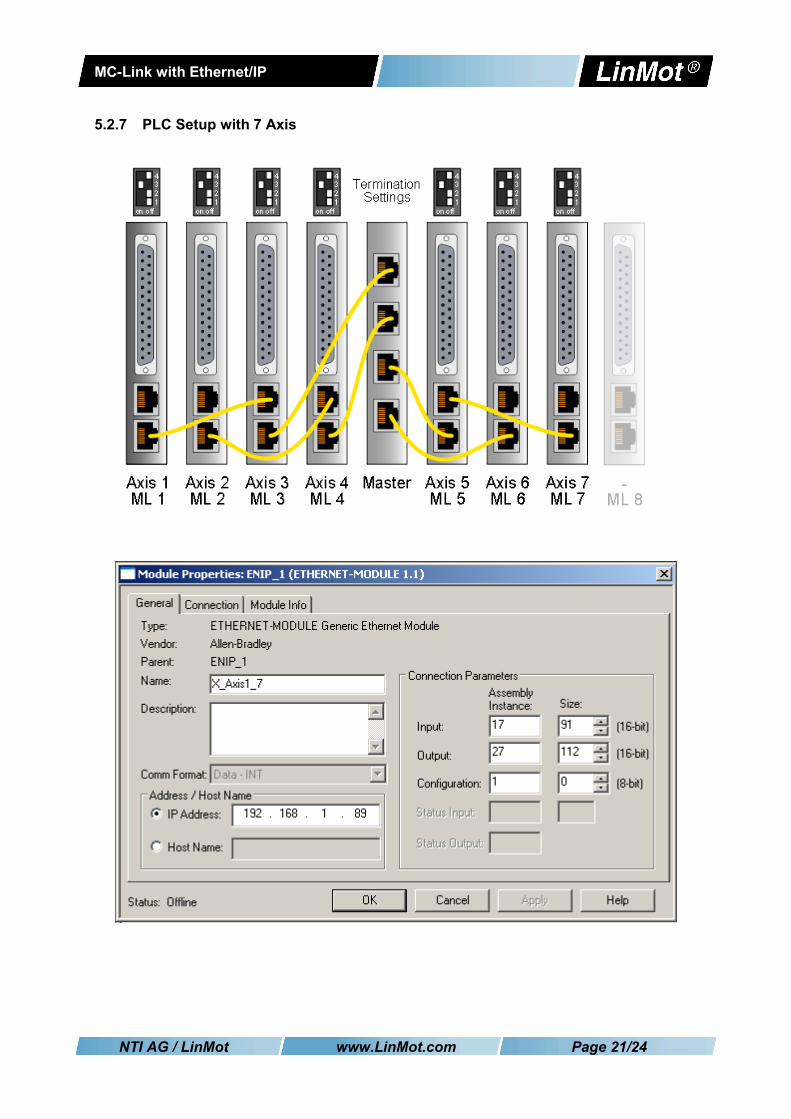
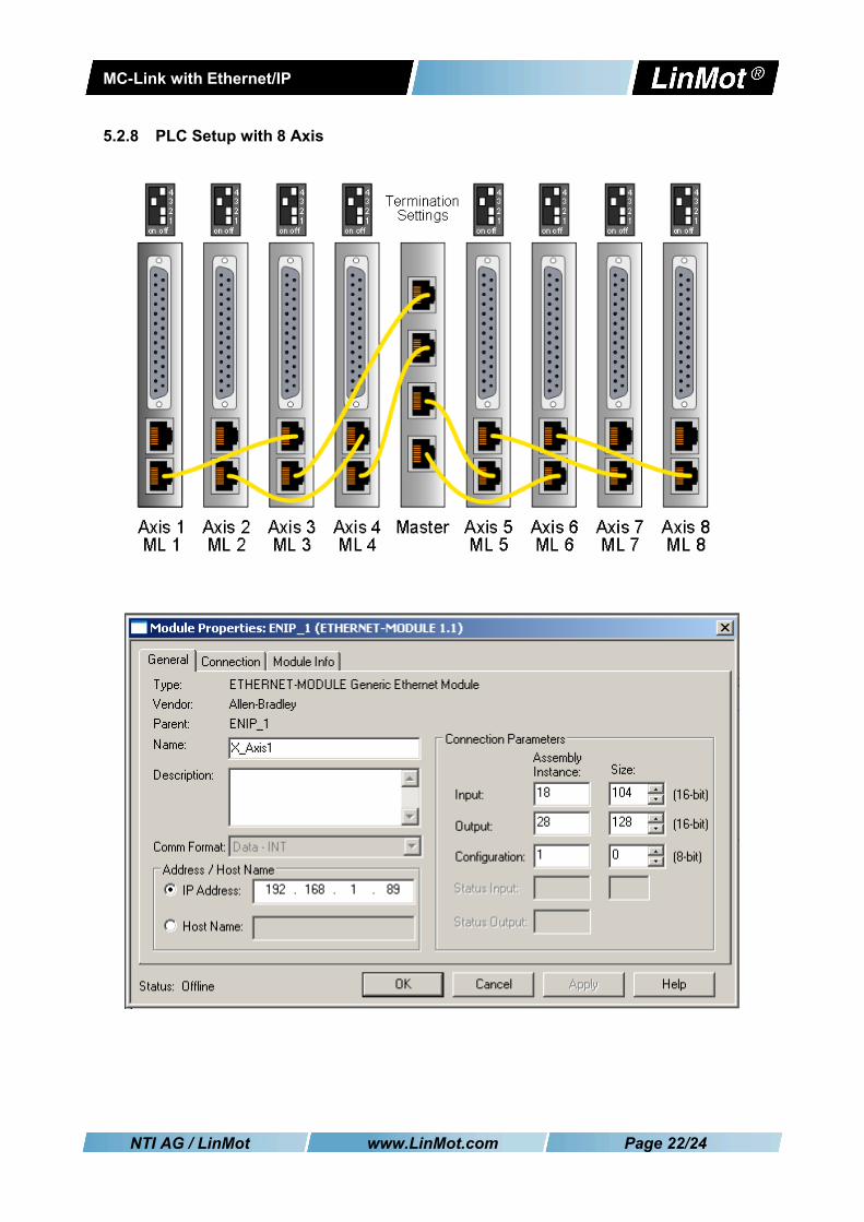
Under the Module Properties you can define the module specific data:• Name• Comm Format in the example a 16 bit Format is chosen!• IP Address• Input Assembly instance and size• Output Assembly Instance and size
Be careful defining theses parameters, because only a correct setting will run in the in the Ethernet/IP network. Only the name can be defined freely.
NTI AG / LinMot www.LinMot.com Page 8/24

MC-Link with Ethernet/IP
In the Connection Tab of the Module Properties the desired cycle time is specified in the range between 2ms and 3200ms.
Then the configuration/program can be downloaded and you can change to the online view.
It is recommended to use Unicast Connection type, with this type no problems were known.
NTI AG / LinMot www.LinMot.com Page 9/24
MC-Link with Ethernet/IP
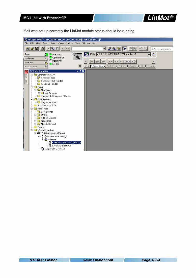
If all was set up correctly the LinMot module status should be running
NTI AG / LinMot www.LinMot.com Page 10/24
MC-Link with Ethernet/IP
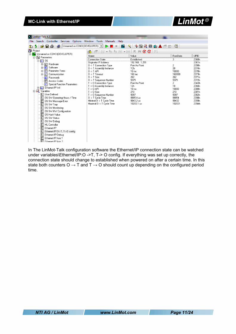
In The LinMot-Talk configuration software the Ethernet/IP connection state can be watched under variables\Ethernet/IP:O ->T, T-> O config. If everything was set up correctly, the connection state should change to established when powered on after a certain time. In this state both counters O → T and T → O should count up depending on the configured period time.
NTI AG / LinMot www.LinMot.com Page 11/24

MC-Link with Ethernet/IP
4 Ethernet/IP Parameters
4.1 Parameters The Ethernet/IP interface has an additional parameter tree branch (Parameters Ethernet/IP Intf), which can be configured with the distributed LinMot-Talk software. With these parameters, the Ethernet/IP communication parameters can be configured. The LinMot-Talk software can be downloaded from http://www.linmot.com under the section download, software & manuals.
Ethernet/IP Intf\ Dis-/Enable With the Dis-/Enable parameter the LinMot controller can be run without the Ethernet Ethernet/IP interface going online. So in a first step the system can be configured and run without any bus connection.
Ethernet/IP\ Dis-/Enable
Disable The controller runs without Ethernet/IP.
Enable The controller runs with Ethernet/IP connection.
IMPORTANT: If the Ethernet/IP interface is disabled, the integrated Ethernet/IP switch is not powered! No messages will be sent to other devices connected to the Ethernet-Network via the LinMot controller.
Ethernet/IP Intf\Ethernet Configuration\ IP Configuration ModeThis parameter defines how the IP address is assigned.
Ethernet/IP Intf\Ethernet Configuration\ IP configuration Mode
DHCP IP address is acquired via DHCP mechanism.
Static by IP Configuration IP address is defined with parameters only.
Static with Hex Switches S1 and S2 (DHCP)
IP address is defined with parameters and the last byte is defined with the value of the HEX switches S1 and S2. The default IP address setting is 192.168.001.xxx ( xxx stands for the value of the Hex switches S1 and S2)
IMPORTANT: The Switch value S1 = 0 and S2 = 0 (factory default setting) acquiring IP address via DHCP is activated instead.
NTI AG / LinMot www.LinMot.com Page 12/24

MC-Link with Ethernet/IP
Ethernet/IP Intf\Ethernet Configuration\ IP ConfigurationIn this section the parameters for the IP address netmask, default gateway and multicast IP address are located.
Ethernet/IP Intf\Ethernet Configuration\ IP Configuration
IP address 1st Byte Highest byte of IP address
IP address 2nd Byte Mid high byte of IP address
IP address 3rd Byte Mid low byte of IP address
IP address 4th Byte Lowest byte of IP address
Netmask 1st Byte Highest byte of Netmask
Netmask 2nd Byte Mid high byte of Netmask
Netmask 3rd Byte Mid low byte of Netmask
Netmask 4th Byte Lowest byte of Netmask
Default Gatway 1st Byte Highest byte of Default Gatway
Default Gatway 2nd Byte Mid high byte of Default Gatway
Default Gatway 3rd Byte Mid low byte of Default Gatway
Default Gatway 4th Byte Lowest byte of Default Gatway
NTI AG / LinMot www.LinMot.com Page 13/24
MC-Link with Ethernet/IP
5 Realtime IO Data MappingFor each axis a container of data is exchanged which allows to control the axis and even to configure it over the exchanged real time data.
5.1 O ->T and T->O Mapping With Configuration ModuleWith this real time IO configuration, an additional configuration module is mapped into the IO data communication. The functionality of this module is same for the different fieldbus interfaces. For this reason, the functionality is described in documentation [2] “Drive Configuration over Fieldbus”.
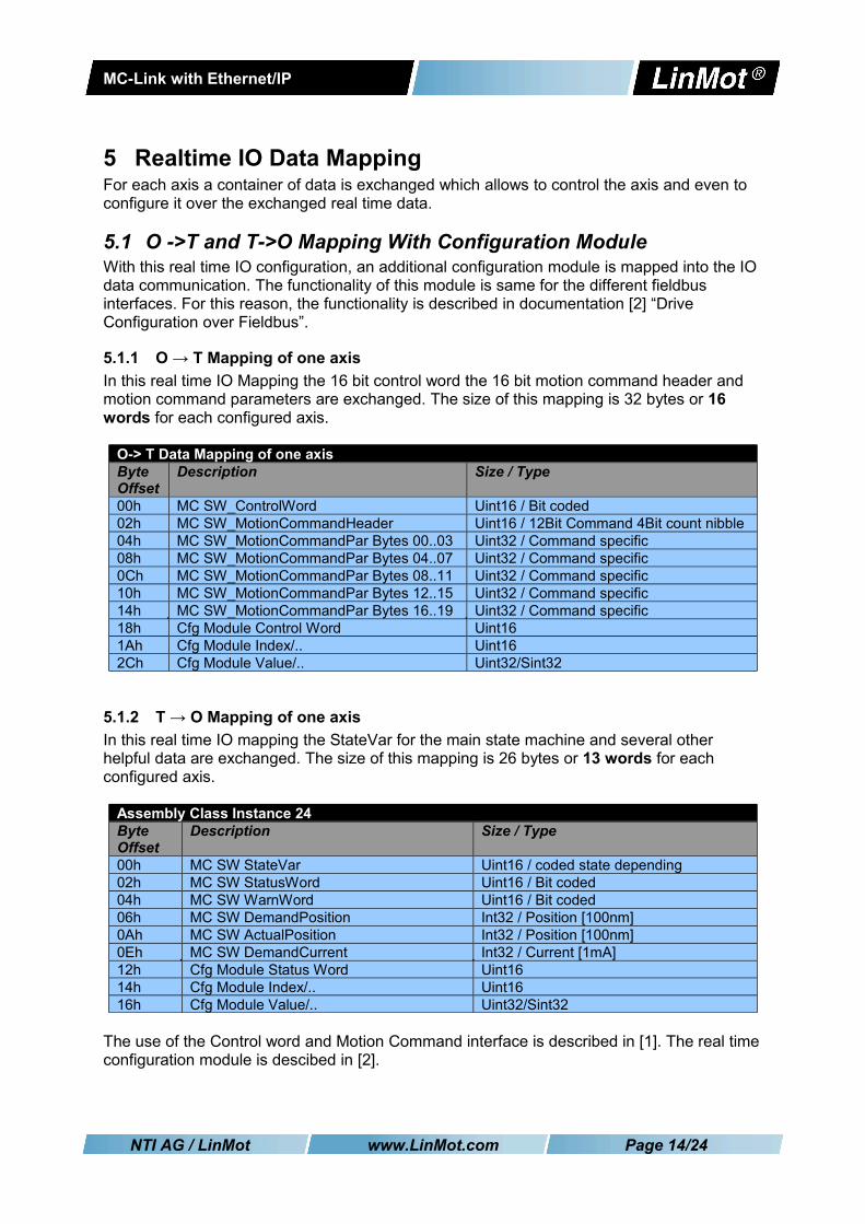
5.1.1 O → T Mapping of one axisIn this real time IO Mapping the 16 bit control word the 16 bit motion command header and motion command parameters are exchanged. The size of this mapping is 32 bytes or 16 words for each configured axis.
O-> T Data Mapping of one axisByte Offset
Description Size / Type
00h MC SW_ControlWord Uint16 / Bit coded02h MC SW_MotionCommandHeader Uint16 / 12Bit Command 4Bit count nibble04h MC SW_MotionCommandPar Bytes 00..03 Uint32 / Command specific08h MC SW_MotionCommandPar Bytes 04..07 Uint32 / Command specific0Ch MC SW_MotionCommandPar Bytes 08..11 Uint32 / Command specific10h MC SW_MotionCommandPar Bytes 12..15 Uint32 / Command specific14h MC SW_MotionCommandPar Bytes 16..19 Uint32 / Command specific18h Cfg Module Control Word Uint16 1Ah Cfg Module Index/.. Uint162Ch Cfg Module Value/.. Uint32/Sint32
5.1.2 T → O Mapping of one axisIn this real time IO mapping the StateVar for the main state machine and several other helpful data are exchanged. The size of this mapping is 26 bytes or 13 words for each configured axis.
Assembly Class Instance 24Byte Offset
Description Size / Type
00h MC SW StateVar Uint16 / coded state depending02h MC SW StatusWord Uint16 / Bit coded04h MC SW WarnWord Uint16 / Bit coded06h MC SW DemandPosition Int32 / Position [100nm]0Ah MC SW ActualPosition Int32 / Position [100nm]0Eh MC SW DemandCurrent Int32 / Current [1mA]12h Cfg Module Status Word Uint16 14h Cfg Module Index/.. Uint1616h Cfg Module Value/.. Uint32/Sint32
The use of the Control word and Motion Command interface is described in [1]. The real time configuration module is descibed in [2].
NTI AG / LinMot www.LinMot.com Page 14/24
MC-Link with Ethernet/IP
5.2 PLC Setup with different numbers of Axis
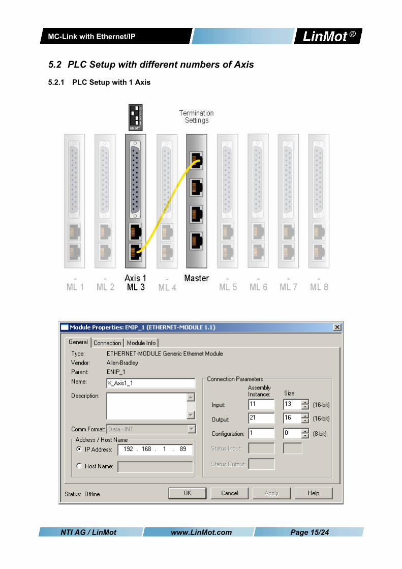
5.2.1 PLC Setup with 1 Axis
NTI AG / LinMot www.LinMot.com Page 15/24
MC-Link with Ethernet/IP
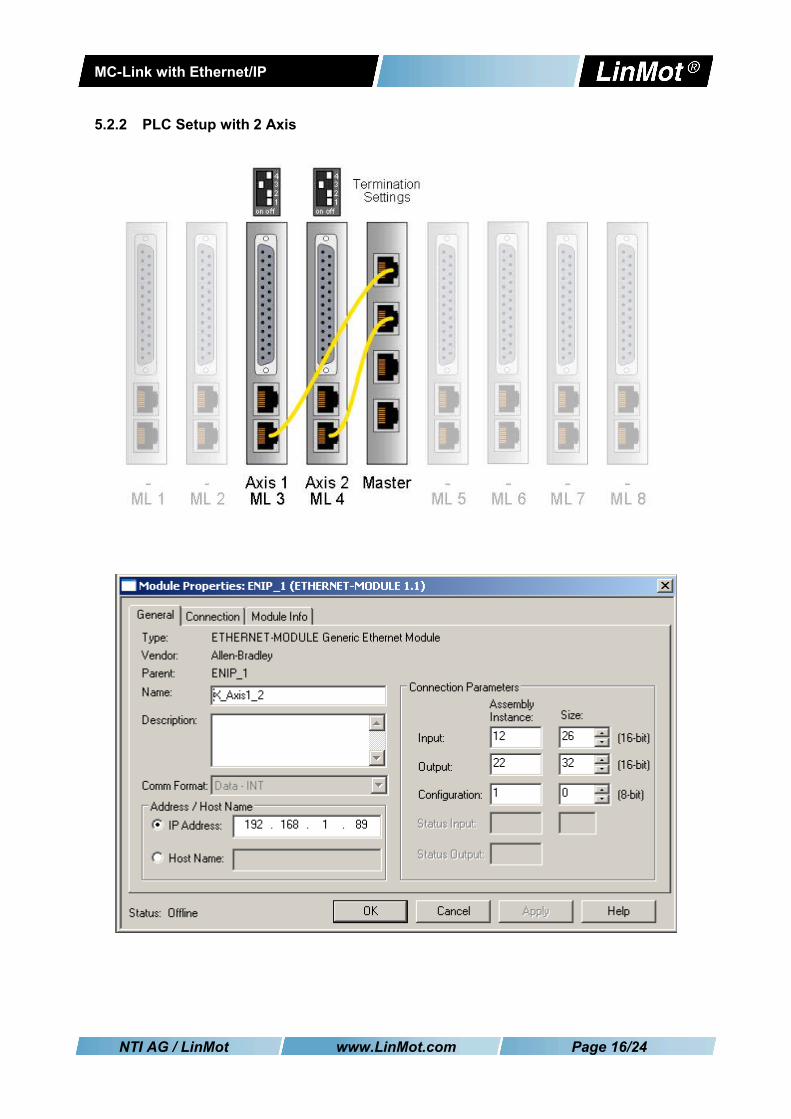
5.2.2 PLC Setup with 2 Axis
NTI AG / LinMot www.LinMot.com Page 16/24

MC-Link with Ethernet/IP
5.2.3 PLC Setup with 3 Axis
NTI AG / LinMot www.LinMot.com Page 17/24
MC-Link with Ethernet/IP
5.2.4 PLC Setup with 4 Axis
NTI AG / LinMot www.LinMot.com Page 18/24

MC-Link with Ethernet/IP
5.2.5 PLC Setup with 5 Axis
NTI AG / LinMot www.LinMot.com Page 19/24
MC-Link with Ethernet/IP
5.2.6 PLC Setup with 6 Axis
NTI AG / LinMot www.LinMot.com Page 20/24
MC-Link with Ethernet/IP
5.2.7 PLC Setup with 7 Axis
NTI AG / LinMot www.LinMot.com Page 21/24
MC-Link with Ethernet/IP
5.2.8 PLC Setup with 8 Axis
NTI AG / LinMot www.LinMot.com Page 22/24

MC-Link with Ethernet/IP
6 Special Axis Errors for (M)B8050-ML-IP Systems
In some special cases the MC-Link controller modifies the status word and error codes in the process data to the PLC:
Error Codes Description0xA0 Axis not present0xA1 Connection to axis has been lost
These errors are not logged in the ErrorLog of the (M)B8050, since they are not errors generated by that device. The (M)B8050 merely modifies the data sent to the PLC to indicate these errors there.
No ConnectionA connection has never been established with the device, e.g. because no device is present or because of faulty cabling.
Process Data from the MC-Link Device to the PLC Value Despcription
Axis_x StateVar 0x04A0 Error 0xA0 is indicatedAxis_x StatusWord 0x0088 Error and warning flags are set
Axis_x Warn Word 0x4080 Not Homed and Intf warning flags are set
Axis_x Demand Current 0x0000 Demand current is indicated as 0
Connection LostA connection has once been established, but the device doesn't communicate anymore.
Process Data from the MC-Link Device to the PLC Value Despcription
Axis_x StateVar 0x04A1 Error 0xA1 is indicated
Axis_x StatusWord 0xXXXX | 0x0008 Last valid value is preserved and error flag is forced
Axis_x Warn Word 0xXXXX | 0x4000 Last valid value is preserved and Intf Warn flag is forced
Axis_x Demand Current 0xXXXX Last valid value is preserved
NTI AG / LinMot www.LinMot.com Page 23/24
MC-Link with Ethernet/IP
7 Contact Addresses---------------------------------------------------------------------------------------------------------------------------
SWITZERLAND NTI AG / LinMotHaerdlistr. 15 CH-8957 Spreitenbach
Sales and Administration: +41-(0)56-419 91 91
Tech. Support: +41-(0)56-544 71 00 [email protected]
Tech. Support (Skype) : skype:support.linmot
Fax: +41-(0)56-419 91 92Web: http://www.linmot.com
--------------------------------------------------------------------------------------------------------------------------
USA LinMot, Inc. 204 E Morrissey Dr.
Elkhorn, WI 53121 Sales and Administration: 877-546-3270 262-743-2555
Tech. Support: 877-804-0718 262-743-1284
Fax: 800-463-8708 262-723-6688
E-Mail: [email protected] Web: http://www.linmot-usa.com
--------------------------------------------------------------------------------------------------------------------------Please visit http://www.linmot.com to find the distributor closest to you.
Smart solutions are…
NTI AG / LinMot www.LinMot.com Page 24/24