
H3C S7500E Series Ethernet Switches
316
H3C S7500E Series Ethernet Switches Layer 2 - LAN Switching Configuration Guide Hangzhou H3C Technologies Co., Ltd. http://www.h3c.com Software version: S7500E Series--Release 6626 and Later S7508E-X------------Release 6826 and Later Document version: 20111130-C-1.01
-
Upload
khangminh22 -
Category
Documents
-
view
3 -
download
0
Transcript of H3C S7500E Series Ethernet Switches

H3C S7500E Series Ethernet Switches Layer 2 - LAN Switching
Configuration Guide
Hangzhou H3C Technologies Co., Ltd. http://www.h3c.com Software version: S7500E Series--Release 6626 and Later S7508E-X------------Release 6826 and Later Document version: 20111130-C-1.01

Copyright © 2011, Hangzhou H3C Technologies Co., Ltd. and its licensors
All rights reserved
No part of this manual may be reproduced or transmitted in any form or by any means without prior written consent of Hangzhou H3C Technologies Co., Ltd.
Trademarks
H3C, , Aolynk, , H3Care,
, TOP G, , IRF, NetPilot, Neocean, NeoVTL, SecPro, SecPoint, SecEngine, SecPath, Comware, Secware, Storware, NQA, VVG, V2G, VnG, PSPT, XGbus, N-Bus, TiGem, InnoVision and HUASAN are trademarks of Hangzhou H3C Technologies Co., Ltd.
All other trademarks that may be mentioned in this manual are the property of their respective owners
Notice
The information in this document is subject to change without notice. Every effort has been made in the preparation of this document to ensure accuracy of the contents, but all statements, information, and recommendations in this document do not constitute the warranty of any kind, express or implied.

Preface
The H3C S7500E documentation set includes 12 configuration guides, which describe the software features for the H3C S7500E Series Ethernet Switches and guide you through the software configuration procedures. These configuration guides also provide configuration examples to help you apply software features to different network scenarios.
The Layer 2 – LAN Switching Configuration Guide describes LAN switching fundamentals and configuration. It describes how to implement flow control and load sharing, isolate uses in the same VLAN, eliminate Layer 2 loops, divide VLANs, transmit customer network packets through the public network, modify VLAN tags for packets, remote manage the ONU device, and so on.
This preface includes:
• Audience
• Conventions
• About the H3C S7500E documentation set
• Obtaining documentation
• Technical support
• Documentation feedback
Audience This documentation is intended for:
• Network planners
• Field technical support and servicing engineers
• Network administrators working with the S7500E series
Conventions This section describes the conventions used in this documentation set.
Command conventions
Convention Description
Boldface Bold text represents commands and keywords that you enter literally as shown.
Italic Italic text represents arguments that you replace with actual values.
[ ] Square brackets enclose syntax choices (keywords or arguments) that are optional.
{ x | y | ... } Braces enclose a set of required syntax choices separated by vertical bars, from which you select one.
[ x | y | ... ] Square brackets enclose a set of optional syntax choices separated by vertical bars, from which you select one or none.
{ x | y | ... } * Asterisk marked braces enclose a set of required syntax choices separated by vertical bars, from which you select at least one.

Convention Description
[ x | y | ... ] * Asterisk marked square brackets enclose optional syntax choices separated by vertical bars, from which you select one choice, multiple choices, or none.
&<1-n> The argument or keyword and argument combination before the ampersand (&) sign can be entered 1 to n times.
# A line that starts with a pound (#) sign is comments.
GUI conventions
Convention Description
Boldface Window names, button names, field names, and menu items are in Boldface. For example, the New User window appears; click OK.
> Multi-level menus are separated by angle brackets. For example, File > Create > Folder.
Convention Description
< > Button names are inside angle brackets. For example, click <OK>.
[ ] Window names, menu items, data table and field names are inside square brackets. For example, pop up the [New User] window.
/ Multi-level menus are separated by forward slashes. For example, [File/Create/Folder].
Symbols
Convention Description
WARNING An alert that calls attention to important information that if not understood or followed can result in personal injury.
CAUTION An alert that calls attention to important information that if not understood or followed can result in data loss, data corruption, or damage to hardware or software.
IMPORTANT An alert that calls attention to essential information.
NOTE An alert that contains additional or supplementary information.
TIP An alert that provides helpful information.
Network topology icons
Represents a generic network device, such as a router, switch, or firewall.
Represents a routing-capable device, such as a router or Layer 3 switch.
Represents a generic switch, such as a Layer 2 or Layer 3 switch, or a router that supports Layer 2 forwarding and other Layer 2 features.
Port numbering in examples
The port numbers in this document are for illustration only and might be unavailable on your device.

About the H3C S7500E documentation set The H3C S7500E documentation set includes:
Category Documents Purposes
Marketing brochures Describe product specifications and benefits.
Technology white papers Provide an in-depth description of software features and technologies.
Product description and specifications
Card datasheets Describe card specifications, features, and standards.
Installation guide Provides a complete guide to hardware installation and hardware specifications.
H3C N68 Cabinet Installation and Remodel Introduction
Guides you through installing and remodeling H3C N68 cabinets.
H3C Pluggable SFP [SFP+][XFP] Transceiver Modules Installation Guide
Guides you through installing SFP/SFP+/XFP transceiver modules.
H3C Mid-Range Series Ethernet Switches Pluggable Modules Manual
Describes the hot-swappable modules available for the Mid-Range Series Ethernet Switches, their external views, and specifications.
H3C PoE DIMM Module Installation Guide
Describes how to install the DIMM (LSBM1POEDIMMH) for PoE master and slave power management.
Hardware installation
Single PoE DIMM Module Installation Guide
Describes how to install the 24-port DIMM (LSQM1POEDIMMS0) for PoE power management.
Configuration guides Describe software features and configuration procedures.
Command references Provide a quick reference to all available commands. Software configuration
Configuration examples Describe typical network scenarios and provide configuration examples and instructions.
Operations and maintenance Release notes
Provide information about the product release, including the version history, hardware and software compatibility matrix, version upgrade information, technical support information, and software upgrading.
H3C PSR320-A[PSR320-D] Power Module User Manual
Describes the appearance, specifications, LEDs, and installation and removal of the H3C PSR320-A/PSR320-D power module.
H3C PSR650-A[PSR650-D] Power Module User Manual
Describes the appearance, specifications, LEDs, and installation and removal of the H3C PSR650-A/PSR650-D power module.
H3C PSR1400-A[PSR1400-D] Power Module User Manual
Describes the appearance, specifications, LEDs, and installation and removal of the H3C PSR1400-A/PSR1400-D power module.
Power configuration
H3C PSR2800-ACV Power Module User Manual
Describes the appearance, specifications, LEDs, and installation and removal of the H3C PSR2800-ACV power module.

Category Documents Purposes
H3C PSR6000-ACV Power Module User Manual
Describes the appearance, specifications, LEDs, and installation and removal of the H3C PSR6000-ACV power module.
H3C PWR-SPA Power Module Adapter User Manual
Describes the functions and appearance of the H3C PWR-SPA power module adapter, and how to use it with the PSR650 power module.
H3C S7500E Power Configuration Guide Guides you to select power modules in various cases.
Optional cards Card manuals
The S7500E series Ethernet switches support various card models. Each model is provided with a card manual that describes: 1. The type, number, and transmission rate of
interfaces 2. Applicable switches of the card 3. Required software version 4. Pluggable modules supported by the card
Obtaining documentation You can access the most up-to-date H3C product documentation on the World Wide Web at http://www.h3c.com.
Click the links on the top navigation bar to obtain different categories of product documentation:
[Technical Support & Documents > Technical Documents] – Provides hardware installation, software upgrading, and software feature configuration and maintenance documentation.
[Products & Solutions] – Provides information about products and technologies, as well as solutions.
[Technical Support & Documents > Software Download] – Provides the documentation released with the software version.
Technical support [email protected]
http://www.h3c.com
Documentation feedback You can e-mail your comments about product documentation to [email protected].
We appreciate your comments.

i
Contents
Ethernet interface configuration ·································································································································· 1 Ethernet interface overview··············································································································································1 Ethernet interface naming conventions ···························································································································1 General configuration ······················································································································································1
Configuring the management Ethernet interface···································································································1 Configuring a combo interface·······························································································································2 Configuring basic settings of an Ethernet interface or subinterface ···································································3 Shutting down an Ethernet interface or subinterface····························································································4 Configuring flow control on an Ethernet interface································································································5 Configuring link state change suppression············································································································5 Configuring loopback testing on an Ethernet interface························································································7 Configuring the link mode of an Ethernet interface······························································································8 Configuring jumbo frame support ··························································································································9
Configuring a Layer 2 Ethernet interface ·······················································································································9 Layer 2 Ethernet interface configuration task list ··································································································9 Configuring a port group ····································································································································· 10 Setting speed options for auto negotiation on an Ethernet interface······························································· 11 Configuring storm suppression ···························································································································· 12 Setting the statistics polling interval····················································································································· 13 Enabling loopback detection on an Ethernet interface ····················································································· 13 Setting the MDI mode of an Ethernet interface ·································································································· 15 Testing the cable connection of an Ethernet interface······················································································· 16 Configuring storm control on an Ethernet interface ··························································································· 17
Setting the MTU for a Layer 3 Ethernet interface or subinterface ············································································· 18 Displaying and maintaining an Ethernet interface or subinterface··········································································· 18
Loopback and null interface configuration···············································································································20 Configuring a loopback interface ································································································································ 20
Introduction to the loopback interface················································································································· 20 Configuration procedure ······································································································································ 20
Configuring the null interface ······································································································································· 21 Introduction to the null interface··························································································································· 21 Configuration procedure ······································································································································ 21
Displaying and maintaining loopback and null interfaces ························································································ 22
MAC address table configuration·····························································································································23 Overview········································································································································································· 23
How a MAC address table entry is created······································································································· 23 Types of MAC address table entries ··················································································································· 23 MAC address table-based frame forwarding ···································································································· 24
Configuring the MAC address table···························································································································· 24 Configuring static, dynamic, and blackhole MAC address table entries ······················································· 24 Disabling MAC address learning ························································································································ 25 Configuring the aging timer for dynamic MAC address entries ······································································ 26 Configuring the MAC learning limit on ports····································································································· 27
Displaying and maintaining MAC address tables ····································································································· 27 MAC address table configuration example ················································································································ 28
MAC Information configuration ································································································································30 Overview········································································································································································· 30

ii
Introduction to MAC Information ························································································································· 30 How MAC Information works ······························································································································ 30
Configuring MAC Information······································································································································ 30 Enabling MAC Information globally ··················································································································· 30 Enabling MAC Information on an interface ······································································································· 30 Configuring MAC Information mode ·················································································································· 31 Configuring the interval for sending Syslog or trap messages········································································· 31 Configuring the MAC Information queue length································································································ 31
MAC Information configuration example···················································································································· 31
Ethernet link aggregation configuration ···················································································································33 Overview········································································································································································· 33
Basic concepts ······················································································································································· 33 Aggregating links in static mode ························································································································· 36 Aggregating links in dynamic mode ··················································································································· 38 Load-sharing criteria for link aggregation groups ····························································································· 40
Ethernet link aggregation configuration task list········································································································· 40 Configuring an aggregation group ····························································································································· 40
Configuration guidelines ······································································································································ 41 Configuring a static aggregation group············································································································· 41 Configuring a dynamic aggregation group ······································································································· 42
Configuring an aggregate interface ···························································································································· 44 Configuring the description of an aggregate interface or subinterface ·························································· 44 Configuring the MTU of a Layer 3 aggregate interface or subinterface························································· 45 Enabling link state traps for an aggregate interface ························································································· 45 Setting the minimum number of Selected ports for an aggregation group ····················································· 46 Shutting down an aggregate interface ··············································································································· 46 Restoring the default settings for an aggregate interface ················································································· 47
Configuring load sharing for link aggregation groups······························································································ 47 Configuring load-sharing criteria for link aggregation groups ········································································ 47 Enabling local-first load sharing for link aggregation ······················································································· 49
Enabling link-aggregation traffic redirection··············································································································· 50 Displaying and maintaining Ethernet link aggregation ····························································································· 50 Ethernet link aggregation configuration examples····································································································· 51
Layer 2 static aggregation configuration example···························································································· 51 Layer 2 dynamic aggregation configuration example······················································································ 53 Layer 3 static aggregation configuration example···························································································· 55 Layer 3 dynamic aggregation configuration example······················································································ 56
Port isolation configuration········································································································································59 Introduction to port isolation ········································································································································· 59 Assigning a port to the isolation group ······················································································································· 59 Displaying and maintaining isolation groups ············································································································· 59 Port isolation configuration example···························································································································· 60
Spanning tree configuration······································································································································61 STP ··················································································································································································· 61
STP protocol packets ············································································································································· 61 Basic concepts in STP············································································································································ 62 Calculation process of the STP algorithm ··········································································································· 63
RSTP················································································································································································· 68 PVST················································································································································································· 69 MSTP················································································································································································ 69
STP, RSTP, and PVST limitations ·························································································································· 69 MSTP features ························································································································································ 69 MSTP basic concepts ············································································································································ 69

iii
How MSTP works ·················································································································································· 73 Implementation of MSTP on devices···················································································································· 74
Protocols and standards ················································································································································ 74 Spanning tree configuration task list ···························································································································· 74 Configuring the spanning tree······································································································································ 78
Setting the spanning tree mode ··························································································································· 78 Configuring an MST region ································································································································· 79 Configuring the root bridge or a secondary root bridge·················································································· 80 Configuring the device priority ···························································································································· 81 Configuring the maximum hops of an MST region ··························································································· 82 Configuring the network diameter of a switched network················································································ 82 Configuring spanning tree timers ························································································································ 83 Configuring the timeout factor ····························································································································· 84 Configuring the maximum port rate ···················································································································· 84 Configuring edge ports········································································································································· 85 Configuring path costs of ports···························································································································· 85 Configuring the port priority ································································································································ 88 Configuring the port link type ······························································································································ 88 Configuring the mode a port uses to recognize/send MSTP packets ····························································· 89 Enabling the output of port state transition information ···················································································· 90 Enabling the spanning tree feature ····················································································································· 90 Performing mCheck ··············································································································································· 91 Configuring Digest Snooping······························································································································· 92 Configuring No Agreement Check······················································································································ 94 Configuring protection functions·························································································································· 96 Remotely configuring MSTP for an ONU············································································································ 99
Displaying and maintaining the spanning tree·········································································································100 Spanning tree configuration examples ······················································································································101
MSTP configuration example ·····························································································································101 PVST configuration example ······························································································································105
BPDU tunneling configuration ································································································································ 109 Introduction to BPDU tunneling ···································································································································109
Background··························································································································································109 BPDU tunneling implementation·························································································································110
Configuring BPDU tunneling ·······································································································································111 Configuration prerequisites ································································································································111 Enabling BPDU tunneling····································································································································112 Configuring destination multicast MAC address for BPDUs ···········································································112
BPDU tunneling configuration examples····················································································································113 BPDU tunneling for STP configuration example ·······························································································113 BPDU tunneling for PVST configuration example·····························································································114
VLAN configuration ················································································································································ 116 Introduction to VLAN ···················································································································································116
VLAN overview····················································································································································116 VLAN fundamentals·············································································································································116 VLAN types ··························································································································································117 Protocols and standards ·····································································································································118
Configuring basic VLAN settings································································································································118 Configuring basic settings of a VLAN interface ·······································································································119
VLAN interface overview····································································································································119 Configuration procedure ····································································································································119 VLAN interface configuration example·············································································································120
Port-based VLAN configuration ··································································································································121

iv
Introduction to port-based VLAN ·······················································································································121 Assigning an access port to a VLAN ················································································································122 Assigning a trunk port to a VLAN······················································································································123 Assigning a hybrid port to a VLAN···················································································································124 Port-based VLAN configuration example··········································································································125
MAC-based VLAN configuration································································································································127 Introduction to MAC-based VLAN ·····················································································································127 Configuring a MAC-based VLAN······················································································································130 MAC-based VLAN configuration example ·······································································································132
Protocol-based VLAN configuration ···························································································································134 Introduction to protocol-based VLAN ················································································································134 Configuring a protocol-based VLAN·················································································································135 Protocol-based VLAN configuration example···································································································136
IP subnet-based VLAN configuration··························································································································138 Introduction ··························································································································································138 Configuring an IP subnet-based VLAN··············································································································138 IP subnet-based VLAN configuration example ·································································································139
Displaying and maintaining VLAN ····························································································································141
Super VLAN configuration······································································································································ 143 Overview·······································································································································································143 Configuring a super VLAN··········································································································································143 Displaying and maintaining super VLAN··················································································································144 Super VLAN configuration example ··························································································································145
Isolate-user-VLAN configuration ····························································································································· 148 Overview·······································································································································································148 Configuring an isolate-user-VLAN ······························································································································148 Displaying and maintaining isolate-user-VLAN·········································································································150 Isolate-user-VLAN configuration example ··················································································································150
Voice VLAN configuration······································································································································ 153 Overview·······································································································································································153
OUI addresses ·····················································································································································153 Voice VLAN assignment modes·························································································································153 Security mode and normal mode of voice VLANs···························································································156
Configuring a voice VLAN··········································································································································156 Configuration prerequisites ································································································································156 Configuring QoS priority settings for voice traffic on an interface································································157 Configuring a port to operate in automatic voice VLAN assignment mode ·················································157 Configuring a port to operate in manual voice VLAN assignment mode ·····················································158
Displaying and maintaining voice VLAN ··················································································································159 Voice VLAN configuration examples ·························································································································159
Automatic voice VLAN mode configuration example ·····················································································159 Manual voice VLAN assignment mode configuration example ·····································································161
GVRP configuration················································································································································· 164 Introduction to GVRP····················································································································································164
GARP ····································································································································································164 GVRP·····································································································································································167 Protocols and standards ·····································································································································167
GVRP configuration task list ········································································································································168 Configuring GVRP functions········································································································································168 Configuring the GARP timers ······································································································································169 Displaying and maintaining GVRP·····························································································································170 GVRP configuration examples ····································································································································170

v
GVRP normal registration mode configuration example·················································································170 GVRP fixed registration mode configuration example ····················································································172 GVRP forbidden registration mode configuration example············································································173
QinQ configuration················································································································································· 175 Introduction to QinQ····················································································································································175
Background and benefits····································································································································175 How QinQ works ················································································································································175 QinQ frame structure ··········································································································································176 Implementations of QinQ ···································································································································177 Modifying the TPID in a VLAN tag ····················································································································177 Protocols and standards ·····································································································································178
QinQ configuration task list ········································································································································179 Configuring basic QinQ ·············································································································································179
Enabling basic QinQ··········································································································································179 Configuring VLAN transparent transmission ····································································································180
Configuring selective QinQ ········································································································································180 Configuring an outer VLAN tagging policy ·····································································································180 Configuring an inner-outer VLAN 802.1p priority mapping··········································································181 Configuring inner VLAN ID substitution ············································································································182
Configuring the TPID value in VLAN tags··················································································································183 QinQ configuration examples ····································································································································184
Basic QinQ configuration example···················································································································184 VLAN transparent transmission configuration example ··················································································186 Simple selective QinQ configuration example·································································································188 Comprehensive selective QinQ configuration example··················································································191
VLAN mapping configuration ································································································································ 195 VLAN mapping overview ············································································································································195
Application scenario of one-to-one and many-to-one VLAN mapping ··························································195 Application scenario of one-to-two and two-to-two VLAN mapping······························································196 Concepts and terms ············································································································································197 VLAN mapping implementations ·······················································································································198
Configuring VLAN mapping ·······································································································································200 Configuring one-to-one VLAN mapping············································································································201 Configuring many-to-one VLAN mapping·········································································································203 Configuring one-to-two VLAN mapping············································································································205 Configuring two-to-two VLAN mapping············································································································207
VLAN mapping configuration examples ···················································································································211 One-to-one and many-to-one VLAN mapping configuration example···························································211 One-to-two and two-to-two VLAN mapping configuration example ······························································217
LLDP configuration··················································································································································· 221 Overview·······································································································································································221
Background··························································································································································221 Basic concepts ·····················································································································································221 How LLDP works ··················································································································································225 Protocols and standards ·····································································································································226
LLDP configuration task list ··········································································································································226 Performing basic LLDP configuration··························································································································227
Enabling LLDP ······················································································································································227 Setting the LLDP operating mode ·······················································································································227 Setting the LLDP re-initialization delay···············································································································227 Enabling LLDP polling··········································································································································228 Configuring the advertisable TLVs ·····················································································································228 Configuring the management address and its encoding format····································································229

vi
Setting other LLDP parameters····························································································································230 Setting an encapsulation format for LLDPDUs···································································································230
Configuring CDP compatibility ···································································································································231 Configuration prerequisites ································································································································231 Configuring CDP compatibility ··························································································································231
Configuring LLDP trapping ··········································································································································232 Displaying and maintaining LLDP·······························································································································233 LLDP configuration examples ······································································································································233
Basic LLDP configuration example ·····················································································································233 CDP-compatible LLDP configuration example···································································································236
Service loopback group configuration ·················································································································· 238 Overview·······································································································································································238
Service types of service loopback groups ········································································································238 Requirements on service loopback ports···········································································································238 States of service loopback ports ························································································································238
Configuring a service loopback group······················································································································239 Displaying and maintaining service loopback groups·····························································································240 Service loopback group configuration example·······································································································240
EPON configuration················································································································································ 242 Introduction to EPON···················································································································································242
EPON architecture···············································································································································242 Benefits of the EPON technology·······················································································································243 EPON application modes···································································································································243
Data transmission in an EPON system·······················································································································244 ONU registration·················································································································································244 Extended OAM connection establishment········································································································245 Bandwidth allocation ··········································································································································245 Data transmission ················································································································································246
EPON system security ··················································································································································246 EPON system reliability ···············································································································································247 S7500E Switch Series and EPON system·················································································································247
Features of an S7500E switch working as an OLT device ·············································································247 Three port types in an EPON system·················································································································248
S7500E OLT configuration task list····························································································································249
OLT configuration···················································································································································· 250 OLT configuration·························································································································································250
OLT configuration task list ··································································································································250 EPON system parameter configuration·············································································································250 Configuring dynamic bandwidth allocation and related parameters ···························································252 Configuring grant filtering on the OLT port ······································································································253 Configuring the link type of an OLT port ··········································································································253 Enabling layer-2 communication between the ONUs attached to an OLT port ···········································254 Configuring fiber backup ···································································································································254
Displaying and maintaining OLT configuration········································································································255 OLT configuration examples ·······································································································································256
OLT Port isolation configuration example·········································································································256 Fiber backup configuration example ················································································································257
ONU remote management configuration·············································································································· 260 ONU configuration ······················································································································································260
ONU configuration task list································································································································260 Creating an ONU port ·······································································································································261 Binding an ONU with an ONU port·················································································································261

vii
Configuring batch ONU binding and automatic ONU binding····································································262 Configuring the management VLAN of the ONU····························································································263 Configuring the ONU bandwidth allocation and related parameters ··························································264 Enabling related protocols on an ONU············································································································265 Configuring the multicast mode of the ONU····································································································266 Configuring the link type of an ONU port ·······································································································269 Enabling FEC ·······················································································································································271 Configuring an ONU to report information to the OLT···················································································271 Configuring traffic encryption ····························································································································272 Testing the link between an ONU and the OLT ·······························································································272 Testing the cable connected to a UNI port·······································································································273 Deregistering an ONU ·······································································································································273 Updating ONUs ··················································································································································273 Restarting an ONU ·············································································································································275
Displaying and maintaining ONU port configuration ·····························································································276 Configuration examples for ONU remote management ·························································································276
Configuration example for binding an ONU port to an ONU······································································276 ONU RSTP configuration example ····················································································································277 Multicast configuration example (in IGMP snooping mode) ··········································································278 Multicast configuration example (in multicast control mode)··········································································279 ONU update configuration example ················································································································281
UNI port configuration············································································································································ 283 UNI port configuration task list ···································································································································283
Basic UNI port configurations····························································································································283 Configuring the VLAN operation mode for a UNI ··························································································284 Configuring fast-leave processing for a UNI····································································································286 Configuring port isolation for a UNI ·················································································································286
Displaying and maintaining UNI port configuration································································································287
Alarm configuration ················································································································································ 288 Introduction to alarm····················································································································································288
Sampling and alarms··········································································································································288 Alarm configuration task list ·······································································································································288
Enabling alarm monitoring·································································································································288 Configuring global alarms ·································································································································289 Configuring alarms on an OLT port ··················································································································292 Configuring alarms on an ONU port················································································································295 Displaying and maintaining alarm configurations···························································································297
Supported switch features and restrictions············································································································ 298 OLT port features and restrictions·······························································································································298 ONU port features and restrictions ····························································································································299
Index ········································································································································································ 302

1
Ethernet interface configuration
Ethernet interface overview Ethernet is the most widespread wired LAN technology due to its flexibility, simplicity, and easy implementation. Your switch supports the following types of Ethernet interfaces:
• Layer 2-Layer 3 Ethernet interfaces: They are physical interfaces that can operate on both the data link layer and the network layer. When operating on the data link layer, a Layer 2-Layer 3 Ethernet interface acts as a Layer 2 Ethernet interface. When operating on the network layer, a Layer 2-Layer 3 Ethernet interface acts as a Layer 3 Ethernet interface.
• Layer 3 Ethernet subinterfaces: They are logical interfaces operating on the network layer. You can assign an IP address to a Layer 3 Ethernet subinterface. By creating subinterfaces on a Layer 3 Ethernet interface, you can enable the interface to carry packets for multiple VLANs, which provides great networking flexibility.
Ethernet interface naming conventions For an S7500E switch in an IRF fabric, its 100-Mbps, GE and 10-GE interfaces are numbered in the format of interface type A/B/C/D; for an S7500E switch not in any IRF fabric, its 100-Mbps, GE and 10-GE interfaces are numbered in the format of interface type B/C/D, where the following definitions apply:
• A—Number of the switch in an IRF fabric
• B—Slot number of the card in the switch
• C—Sub-slot number on a card
• D—Number of an interface on a card
General configuration This section describes the attributes and configurations common to Layer 2-Layer 3 Ethernet interfaces and Layer 3 Ethernet subinterfaces.
• For more information about the attributes and configuration of Layer 2 Ethernet interfaces, see “Configuring a Layer 2 Ethernet interface.”
• For more information about the attributes and configuration of Layer 3 Ethernet interfaces, see “Setting the MTU for a Layer 3 Ethernet interface or subinterface.”
Configuring the management Ethernet interface The switch provides one management Ethernet interface. This interface uses an RJ-45 connector. You can connect it to a PC for software loading and system debugging.
Follow these steps to configure the management Ethernet interface:
To do… Use the command… Remarks
Enter system view system-view —

2
To do… Use the command… Remarks
Enter management Ethernet interface view
• On an S7500E switch:
interface M-Ethernet interface-number • On an S7508E-X switch:
interface M-GigabitEthernet interface-number
Use either command.
Change the description of the interface description text
Optional
By default, the description of the management interface on an S7500E switch is M-Ethernet0/0/0 Interface, and that on an S7500E-X switch is M-GigabitEthernet0/0/0 Interface.
Shut down the interface shutdown Optional
By default, the management Ethernet interface is up.
Restore the default settings for the interface default Optional
Configuring a combo interface Introduction to combo interfaces
A combo interface is a logical interface that comprises one optical (fiber) port and one electrical (copper) port. The two ports share one forwarding interface, so they cannot work simultaneously. When you enable one port, the other is automatically disabled.
The fiber combo port and cooper combo port are Layer 2 Ethernet interfaces. They have their own separate interface views, in which you can activate the fiber or copper combo port and configure other port attributes such as the interface rate and duplex mode.
Configuration prerequisites
Before you configure a combo interface, complete the following tasks:
• Use the display port combo command to identify the combo interfaces on your switch and identify the two physical ports that compose each combo interface.
• Use the display interface command to determine, of the two physical ports that compose a combo interface, which is the fiber combo port and which is the copper combo port. If the current port is the copper port, the output will include “Media type is twisted pair, Port hardware type is 1000_BASE_T”. If the current port is the fiber port, the output will not include the information mentioned above.
Changing the active port of a combo interface
Follow these steps to change the active port of a double combo interface:
To do… Use the command… Remarks
Enter system view system-view —
Enter Ethernet interface view
interface interface-type interface-number —

3
To do… Use the command… Remarks
Activate the current interface undo shutdown
Optional
By default, of the two ports that compose a combo interface, the one with a smaller port ID is active.
NOTE:
• The 1000/100-Mbps SFP port of a combo interface does not support hot swappable SFP-GE-T modules.For more information about hot swappable modules, see the H3C S7500E Switch Series Installation Manual.
• If the active combo port is configured with loopback testing, you cannot activate the other combo portwith the undo shutdown command.
Configuring basic settings of an Ethernet interface or subinterface Configuring an Ethernet interface
You can set an Ethernet interface to operate in one of the following duplex modes:
• Full-duplex mode (full)—Interfaces that operate in this mode can send and receive packets simultaneously.
• Half-duplex mode (half)—Interfaces that operate in this mode cannot send and receive packets simultaneously.
• Auto-negotiation mode (auto)—Interfaces that operate in this mode negotiate a duplex mode with their peers.
You can set the speed of an Ethernet interface or enable it to automatically negotiate a speed with its peer. For a 100-Mbps or 1000-Mbps Layer 2 Ethernet interface, you can also set speed options for auto negotiation. The two ends can select a speed only from the available options. For more information, see “Setting speed options for auto negotiation on an Ethernet interface.”
Follow these steps to configure an Ethernet interface:
To do… Use the command… Remarks
Enter system view system-view —
Enter Ethernet interface view
interface interface-type interface-number —
Set the interface description description text
Optional
By default, the description of an interface is in the format of interface-name Interface. For example, GigabitEthernet1/0/1 Interface.
Set the duplex mode of the interface duplex { auto | full | half }
Optional
By default, the duplex mode is auto for Ethernet interfaces.
The half keyword is not applicable to Ethernet copper ports that are configured with a 1000-Mbps port speed and SFP fiber ports.
This command is not applicable to 10-GE ports.

4
To do… Use the command… Remarks
Set the port speed speed { 10 | 100 | 1000 | auto }
Optional
By default, an Ethernet interface automatically negotiates a speed with the peer.
The 10 keyword is not applicable to fiber ports.
This command is not applicable to 10-GE ports.
Restore the default settings for the interface
default Optional
Configuring an Ethernet subinterface
Follow these steps to configure an Ethernet subinterface:
To do… Use the command… Remarks
Enter system view system-view —
Create an Ethernet subinterface
interface interface-type interface-number.subnumber
Required
This command also leads you to Ethernet subinterface view.
Set the interface description description text
Optional
By default, the description of an Ethernet subinterface is in the format of interface-name Interface. For example, GigabitEthernet 1/0/1.1 Interface.
Restore the default settings for the subinterface default Optional
NOTE:
• You can configure IP- or IPX-related settings on an Ethernet subinterface. For more information, see Layer3—IP Services Configuration Guide.
• For the local and remote Ethernet subinterfaces to transmit traffic correctly, configure them with the samesubinterface number and VLAN ID.
Shutting down an Ethernet interface or subinterface You might need to shut down and then bring up an Ethernet interface or subinterface to activate some configuration changes, for example, the speed or duplex mode changes.
Follow these steps to shut down an Ethernet interface or subinterface, or a group of Ethernet interfaces:
To do… Use the command… Remarks
Enter system view system-view —

5
To do… Use the command… Remarks
Enter Ethernet interface or subinterface view, or port group view
• Enter Ethernet interface view:
interface interface-type interface-number • Enter Ethernet subinterface view:
interface interface-type interface-number.subnumber • Enter port group view:
port-group manual port-group-name
Use any command.
To shut down an Ethernet interface or subinterface, enter Ethernet interface or subinterface view.
To shut down all Ethernet interfaces in a port group, enter port group view.
Shut down the Ethernet interface or subinterface shutdown
Required
By default, Ethernet interfaces and subinterfaces are up.
CAUTION:
Use this command with caution. After you manually shut down an Ethernet interface, the Ethernet interfacecannot forward packets even if it is physically connected.
Configuring flow control on an Ethernet interface To avoid packet drops on a link, you can enable flow control at both ends of the link. When traffic congestion occurs at the receiving end, the receiving end sends a flow control (Pause) frame to ask the sending end to suspend sending packets
With the flow-control command configured, an interface can both send and receive flow control frames: When congested, the interface sends a flow control frame to its peer. Upon receiving a flow control frame from the peer, the interface suspends sending packets.
Follow these steps to enable flow control on an Ethernet interface:
To do… Use the command… Remarks
Enter system view system-view —
Enter Ethernet interface view interface interface-type interface-number —
Enable TxRx flow control flow-control Required
By default, Rx flow control is disabled on an Ethernet interface.
Configuring link state change suppression An Ethernet interface or ONU port has two physical link states: up and down. Each time the physical link of an interface goes up or comes down, the physical layer reports the change to the upper layers, and the upper layers handle the change, resulting in increased overhead.
Configuring link state suppression on an Ethernet interface
To prevent physical link flapping from affecting system performance, configure link state change suppression to delay the reporting of physical link state changes. When the delay expires, the interface reports any detected change.

6
Link state change suppression does not suppress administrative up or down events. When you shut down or bring up an interface by using the shutdown or undo shutdown command, the interface reports the event to the upper layers immediately.
Link-down event suppression enables an interface to suppress link-down events and start a delay timer each time the physical link goes down. During this delay, the interface does not report the link-down event, and the display interface brief or display interface command displays the interface state as UP. If the physical link is still down when the timer expires, the interface reports the link-down event to the upper layers.
Link-up event suppression enables an interface to suppress link-up events and start a delay timer each time the physical link goes up. During this delay, the interface does not report the link-up event, and the display interface brief or display interface command displays the interface state as DOWN. If the physical link is still up when the timer expires, the interface reports the link-up event to the upper layers.
1. Configure link-down event suppression
Follow these steps to enable an Ethernet interface to suppress link-down events:
To do… Use the command… Remarks
Enter system view system-view —
Enter Ethernet interface view interface interface-type interface-number —
Set a link-down event suppression interval
link-delay delay-time Required
Link-down event suppression is disabled by default.
2. Configure link-up event suppression
Follow these steps to configure link-up event suppression on an Ethernet interface:
To do… Use the command… Remarks
Enter system view system-view —
Enter Ethernet interface view interface interface-type interface-number —
Set a link-up event suppression interval link-delay delay-time mode up
Required
Link-up event suppression is disabled by default.
NOTE:
The link-delay mode up command and the link-delay command supersedes each other, and whichever isconfigured last takes effect.
Configuring link state suppression on an ONU port
To prevent physical link flapping from affecting system performance, configure link state change suppression to delay the reporting of physical link state changes. When the delay expires, the ONU port reports any detected change.
Link state change suppression does not suppress administrative up or down events. When you shut down or bring up an ONU port by using the shutdown or undo shutdown command, the ONU port reports the event to the upper layers immediately.

7
Link state change suppression enables an ONU port to suppress link-down and link-up events and start a delay timer each time the physical link goes down or goes up. During this delay, the ONU port does not report the link-down or link-up event. If the physical link still has not recovered when the timer expires, the ONU port reports the link-down or link-up event to the upper layers.
Follow these steps to enable an ONU port to suppress link state changes:
To do… Use the command… Remarks
Enter system view system-view —
Enter ONU port view interface interface-type interface-number —
Set a link state change suppression interval
link-delay delay-time Required
Link state change suppression is disabled by default.
NOTE:
Different from the link-delay command on an Ethernet interface, the link-delay command on an ONU port suppresses both link-up events and link-down events.
Configuring loopback testing on an Ethernet interface You can perform loopback testing on an Ethernet interface to determine whether the interface functions properly. The Ethernet interface cannot forward data packets during the testing. Loopback testing falls into the following categories:
• Internal loopback testing: As shown in Figure 1, an interface in this mode (Port 2) returns a received packet back to the switching chip. This function is used to identify whether a problem has occurred on a network device, such as Switch A in the figure.
Figure 1 Internal loopback testing
• External loopback testing, or called “remote loopback testing.” As shown in Figure 2, an interface in this mode (Port 1) returns a received packet back to the packet sender. This function is used to identify link failures between network devices.

8
Figure 2 External loopback testing
Port 1 Port 2Switching chip
Switch A
Switch B
Receive packets
Loop back packets
Tester
NOTE:
The loopback testing function can be used to test link connectivity and transmission capability in MPLS L2VPN and QinQ networking environments.
Follow these steps to perform loopback testing on an Ethernet interface:
To do… Use the command… Remarks
Enter system view system-view —
Enter Ethernet interface or ONU interface view
interface interface-type interface-number —
Perform loopback testing loopback { external | internal } Required
Disabled by default
NOTE:
• On an interface that is physically down (in the DOWN state), you can only perform internal loopbacktesting. On an interface administratively shut down (in the ADM DOWN state), you cannot perform internal or external loopback testing.
• The speed, duplex, mdi, and shutdown commands are not available on an interface with loopback testing enabled.
• During loopback testing, the Ethernet interface operates in full duplex mode. When you disable loopback testing, the interface returns to its duplex setting.
• 100 Mbps Ethernet interfaces do not support external loopback testing.
Configuring the link mode of an Ethernet interface An Ethernet interface operates either in Layer 2 (bridge) or Layer 3 (route) mode. To meet networking requirements, you can use a command to set the link mode of an Ethernet interface to bridge or route.
Follow these steps to change the link mode of an Ethernet interface:
To do… Use the command… Remarks
Enter system view system-view —

9
To do… Use the command… Remarks
Change the link mode of Ethernet interfaces
• In system view:
port link-mode { bridge | route } interface-list • In Ethernet interface view:
interface interface-type interface-number
port link-mode { bridge | route }
Required
Use either approach.
NOTE:
• After you change the link mode of an Ethernet interface, all the settings of the Ethernet interface are restored to their defaults under the new link mode.
• The link mode configuration for an Ethernet interface in system view and in interface view supersedes each other.
• Combo interfaces cannot operate in Layer 3 mode.
Configuring jumbo frame support An Ethernet interface might receive some frames larger than the standard Ethernet frame size (called "jumbo frames") during high-throughput data exchanges such as file transfers. Usually, an Ethernet interface discards jumbo frames. With jumbo frame support enabled, the interface can process frames larger than the standard Ethernet frame size yet within the specified range.
In interface configuration mode (Ethernet interface view or port group view), you can set the length of jumbo frames that are allowed to pass through the Ethernet interface.
• If you execute the command in Ethernet interface view, the configuration takes effect only on the interface.
• If you execute the command in port group view, the configuration takes effect on all ports in the port group.
Follow these steps to configure jumbo frame support in interface view or port group view:
To do… Use the command… Remarks
Enter system view system-view —
Enter Ethernet interface view
interface interface-type interface-number —
Configure jumbo frame support
jumboframe enable [ value ]
Required
By default, the switch allows jumbo frames within 9216 bytes to pass through Ethernet interfaces.
If you set the value argument multiple times, the latest configuration takes effect.
Configuring a Layer 2 Ethernet interface
Layer 2 Ethernet interface configuration task list Complete these tasks to configure an Ethernet interface operating in bridge mode:

10
Task Remarks
Configuring a port group Optional
Applicable to Layer 2 Ethernet interfaces
Setting speed options for auto negotiation on an Ethernet interface
Optional
Applicable to Layer 2 Ethernet interfaces
Configuring storm suppression Optional
Applicable to Layer 2 Ethernet interfaces
Setting the statistics polling interval Optional
Applicable to Layer 2 Ethernet interfaces
Enabling loopback detection on an Ethernet interface Optional
Applicable to Layer 2 Ethernet interfaces
Setting the MDI mode of an Ethernet interface Optional
Applicable to Layer 2 Ethernet interfaces
Testing the cable connection of an Ethernet interface Optional
Applicable to Layer 2 Ethernet interfaces
Configuring storm control on an Ethernet interface Optional
Applicable to Layer 2 Ethernet interfaces
Configuring a port group Some interfaces on your switch might use the same set of settings. To configure these interfaces in bulk rather than one by one, you can assign them to a port group.
You create port groups manually. All settings made for a port group apply to all the member ports of the group. For example, you can configure a traffic suppression threshold (see “Configuring storm suppression”) for multiple interfaces in bulk by assigning these interfaces to a port group.
Even though the settings are made on the port group, they are saved on each interface basis rather than on a port group basis. You can only view the settings in the view of each interface by using the display current-configuration or display this command.
Follow these steps to configure a manual port group:
To do… Use the command… Remarks
Enter system view system-view —
Create a manual port group and enter manual port group view
port-group manual port-group-name Required
Assign Ethernet interfaces to the manual port group
group-member interface-list
Required
If you use the group-member interface-type interface-start-number to interface-type interface-end-number command to add multiple ports in batch to the specified port group, make sure that all these ports are of the same type and on the same interface card, and the interface-end-number argument must be greater than the interface-start-number argument.

11
To do… Use the command… Remarks
Configure jumbo frame support jumboframe enable [ value ]
Required
By default, the switch allows jumbo frames within 9216 bytes to pass through Ethernet interfaces.
If you set the value argument multiple times, the latest configuration takes effect.
Setting speed options for auto negotiation on an Ethernet interface
Speed auto negotiation enables an Ethernet interface to negotiate with its peer for the highest speed that both ends support by default. You can narrow down the speed option list for negotiation.
Figure 3 Speed auto negotiation application scenario
IP network
Server 1 Server 2 Server 3
Switch A
GE1/0/1
GE1
/0/2
GE1/0/3
GE1/0/4
As shown in Figure 3, all ports on Switch A are operating in speed auto negotiation mode, with the highest speed of 1000 Mbps. If the transmission rate of each server in the server cluster is 1000 Mbps, their total transmission rate will exceed the capability of port GigabitEthernet 1/0/4, the port providing access to the Internet for the servers.
To avoid congestion on GigabitEthernet 1/0/4, set 100 Mbps as the only option available for speed negotiation on port GigabitEthernet 1/0/1, GigabitEthernet 1/0/2, and GigabitEthernet 1/0/3. As a result, the transmission rate on each port connected to a server is limited to 100 Mbps.
Follow these steps to set speed options for auto negotiation on an Ethernet interface:
To do… Use the command… Remarks
Enter system view system-view —
Enter Ethernet interface view interface interface-type interface-number —
Set speed options for auto negotiation speed auto { 10 | 100 | 1000 } * Optional

12
NOTE:
• This function is available only for Layer 2 Ethernet copper ports that support speed auto negotiation.
• The speed and speed auto commands supersede each other, and whichever is configured last takes effect.
Configuring storm suppression You can use the storm suppression function to limit the size of a particular type of traffic (broadcast, multicast, or unknown unicast traffic) as a whole globally in system view or on a per-interface basis in Ethernet interface view or port group view.
In interface or port group view, you set the maximum size of broadcast, multicast or unknown unicast traffic allowed to pass through an interface or each interface in a port group. When the broadcast, multicast, or unknown unicast traffic on the interface exceeds this threshold, the system discards packets until the traffic drops below this threshold.
NOTE:
The storm suppression thresholds configured for an Ethernet interface might become invalid if you enablethe storm control function for the interface. For information about the storm control function, see “Configuring storm control on an Ethernet interface.”
Follow these steps to set storm suppression thresholds on one or multiple Ethernet interfaces:
To do… Use the command… Remarks
Enter system view system-view —
Enter Ethernet interface view or port group view
• Enter Ethernet interface view:
interface interface-type interface-number • Enter port group view:
port-group manual port-group-name
Use either command.
To configure storm suppression on an Ethernet interface, enter Ethernet interface view.
To configure storm suppression on a group of Ethernet interfaces, enter port group view.
Set the broadcast suppression threshold ratio
broadcast-suppression { ratio | pps max-pps | kbps max-kbps }
Optional
By default, all broadcast traffic is allowed to pass through.
Set the multicast suppression threshold ratio
multicast-suppression { ratio | pps max-pps | kbps max-kbps }
Optional
By default, all multicast traffic is allowed to pass through.
Set the unknown unicast suppression threshold ratio
unicast-suppression { ratio | pps max-pps | kbps max-kbps }
Optional
By default, all unknown unicast traffic is allowed to pass through.
NOTE:
For an Ethernet interface that belongs to a port group, if you set a traffic suppression threshold for the interface in both Ethernet interface view and port group view, the threshold configured last takes effect.

13
Setting the statistics polling interval
Follow these steps to set the statistics polling interval globally or on an Ethernet interface:
To do… Use the command… Remarks
Enter system view system-view —
Enter Ethernet interface view interface interface-type interface-number —
Set the statistics polling interval on the Ethernet interface flow-interval interval
Optional
The default interface statistics polling interval is 300 seconds.
To display the interface statistics collected in the last polling interval, use the display interface command.
To clear interface statistics, use the reset counters interface command.
Enabling loopback detection on an Ethernet interface If a switch receives a packet that it sent, a loop has occurred to the switch. Loops might cause broadcast storms, which degrade network performance. You can use this feature to detect whether a loop has occurred.
Depending on whether the receiving interface is the same as the sending interface, loops fall into the following type: single-port loopback and multi-port loopback.
• Single-port loopback occurs when an interface receives a packet that it sent out and the receiving interface is the same as the sending interface, as shown in Figure 4.
• Multi-port loopback occurs when a switch receives a packet that it sent out but the receiving interface might not be the sending interface, as shown in Figure 5.
Figure 4 Single-port loopback

14
Figure 5 Multi-port loopback
You can enable loopback detection to detect loops on an interface and, if the interface supports the loopback-detection action command, configure the protective action to take on the receiving interface when a loop is detected, for example, to shut down the interface. Depending on whether a protective action is configured, the switch takes the actions in Table 1 to alleviate the impact of the loop condition.
Table 1 Actions to take upon detection of a loop condition
Actions Port type
No protective action is configured A protective action is configured
Access port
• Place the receiving interface in controlled mode. The interface does not receive or send packets.
• Generate traps. • Delete all MAC address entries of the interface.
• Perform the configured protective action.
• Generate traps and log messages. • Delete all MAC address entries of the
interface.
Hybrid or trunk port
• Generate traps. • If loopback detection control is enabled, place
the receiving interface in controlled mode. The interface does not receive or send packets.
• Delete all MAC address entries of the interface.
• Create traps and log messages. • If loopback detection control is
enabled, take the configured protective action on the interface.
• Delete all MAC address entries of the interface.
Follow these steps to configure loopback detection:
To do… Use the command… Remarks
Enter system view system-view —
Enable global loopback detection loopback-detection enable
Required
Disabled by default.
Enable multi-port loopback detection
loopback-detection multi-port-mode enable
Optional
By default, multi-port loopback detection is disabled, and the switch can only detect single-port loopback.
Set the loopback detection interval
loopback-detection interval-time time
Optional
30 seconds by default.

15
To do… Use the command… Remarks
Enter Ethernet interface view or port group view
• Enter Ethernet interface view
interface interface-type interface-number • Enter port group view
port-group manual port-group-name
Use either command.
To configure loopback detection on one interface, enter Ethernet interface view.
To configure loopback detection on a group of Ethernet interfaces, enter port group view.
Enable loopback detection on the interface loopback-detection enable
Required
Disabled by default.
Enable loopback detection control on a trunk port or a hybrid port
loopback-detection control enable
Optional
Disabled by default.
Enable loopback detection in all the VLANs on the trunk or hybrid port
loopback-detection per-vlan enable
Optional
By default, a trunk or hybrid port performs loopback detection only in its port VLAN ID (PVID).
Set the protective action to take on the interface when a loop is detected
loopback-detection action { no-learning | semi-block | shutdown }
Optional
By default, a looped interface does not receive or send packets; the system generates traps and deletes all MAC address entries of the looped interface.
With the shutdown keyword specified, the switch shuts down the looped ports and set their physical state to Loop down. When a looped port recovers, you must use the undo shutdown command to restore its forwarding capability.
NOTE:
• To use loopback detection on an Ethernet interface, you must enable the function both globally and onthe interface.
• To disable loopback detection on all interfaces, run the undo loopback-detection enable command insystem view.
• To enable a hybrid or trunk port to take the administratively specified protective action, you must use theloopback-detection control enable command on the port.
• When you change the link type of an Ethernet interface by using the port link-type command, the switchremoves the protective action configured on the interface. For more information about the port link-typecommand, see Layer 2—LAN Switching Command Reference.
Setting the MDI mode of an Ethernet interface
NOTE:
Fiber ports do not support the MDI mode setting.

16
You can use both crossover and straight-through Ethernet cables to connect copper Ethernet interfaces. To accommodate these types of cables, a copper Ethernet interface can operate in one of the following Medium Dependent Interface (MDI) modes:
• Across mode
• Normal mode
• Auto mode
A copper Ethernet interface uses an RJ-45 connector, which comprises eight pins, each playing a dedicated role. For example, pins 1 and 2 transmit signals, and pins 3 and 6 receive signals. The pin role varies by the MDI modes as follows:
• In normal mode, pins 1 and 2 are transmit pins, and pins 3 and 6 are receive pins.
• In across mode, pins 1 and 2 are receive pins, and pins 3 and 6 are transmit pins.
• In auto mode, the interface negotiates pin roles with its peer.
To enable the interface to communicate with its peer, ensure that its transmit pins are connected to the remote receive pins. If the interface can detect the connection cable type, set the interface in auto MDI mode. If not, set its MDI mode by using the following guidelines:
• When a straight-through cable is used, set the interface to work in the MDI mode different than its peer.
• When a crossover cable is used, set the interface to work in the same MDI mode as its peer, or set either end to work in auto mode.
Follow these steps to set the MDI mode of an Ethernet interface:
To do… Use the command… Remarks
Enter system view system-view —
Enter Ethernet interface view
interface interface-type interface-number —
Set the MDI mode of the Ethernet interface
mdi { across | auto | normal }
Optional
By default, a copper Ethernet interface operates in auto mode to negotiate pin roles with its peer.
Testing the cable connection of an Ethernet interface
NOTE:
• Fiber ports do not support this feature.
• If the link of an Ethernet port is up, testing its cable connection will cause the link to come down and thengo up.
You can test the cable connection of an Ethernet interface for a short or open circuit. The switch displays cable test results within five seconds. If any fault is detected, the test results include the length of the faulty cable segment.
Follow these steps to test the cable connection of an Ethernet interface:
To do… Use the command… Remarks
Enter system view system-view —

17
To do… Use the command… Remarks
Enter Ethernet interface view interface interface-type interface-number —
Test the cable connected to the Ethernet interface virtual-cable-test Required
Configuring storm control on an Ethernet interface Storm control compares broadcast, multicast, and unknown unicast traffic regularly with their respective traffic thresholds on an Ethernet interface. For each type of traffic, storm control provides a lower threshold and a higher threshold.
For management purposes, you can configure the interface to send threshold event traps and log messages when monitored traffic exceeds the upper threshold or drops below the lower threshold from the upper threshold.
When a particular type of traffic exceeds its upper threshold, the interface does either of the following, depending on your configuration:
• Blocks this type of traffic, while forwarding other types of traffic. Even though the interface does not forward the blocked traffic, it still counts the traffic. When the blocked traffic drops below the lower threshold, the port begins to forward the traffic.
• Shuts down automatically. The interface shuts down automatically and stops forwarding any traffic. When the blocked traffic drops below the lower threshold, the port does not forward the traffic. To bring up the interface, use the undo shutdown command or disable the storm control function.
CAUTION:
Alternatively, you can configure the storm suppression function to control a specific type of traffic. Do notenable them both on an Ethernet interface at the same time because the storm suppression and storm control functions are mutually exclusive. For example, with an unknown unicast suppression threshold seton an Ethernet interface, do not enable storm control for unknown unicast traffic on the interface. For moreinformation about storm suppression, see “Configuring storm suppression.”
Follow these steps to configure storm control on an Ethernet interface:
To do… Use the command… Remarks
Enter system view system-view —
Set the traffic polling interval of the storm control module storm-constrain interval seconds
Optional
10 seconds by default.
Enter Ethernet interface view interface interface-type interface-number —
Enable storm control, and set the lower and upper thresholds for broadcast, multicast, or unknown unicast traffic
storm-constrain { broadcast | multicast | unicast } { pps | kbps | ratio } max-pps-values min-pps-values
Required
Disabled by default.
Set the control action to take when monitored traffic exceeds the upper threshold
storm-constrain control { block | shutdown }
Optional
Disabled by default.

18
To do… Use the command… Remarks
Enable the interface to send storm control threshold event traps. storm-constrain enable trap
Optional
By default, the interface sends traps when monitored traffic exceeds the upper threshold or drops below the lower threshold from the upper threshold.
Enable the interface to log storm control threshold events. storm-constrain enable log
Optional
By default, the interface outputs log messages when monitored traffic exceeds the upper threshold or drops below the lower threshold from the upper threshold.
NOTE:
• For network stability, use the default or set a higher traffic polling interval.
• Storm control uses a complete polling cycle to collect traffic data, and analyzes the data in the next cycle.It takes a port at least one polling interval and at most two polling intervals to take a storm control action.
• The storm control function allows you to set the upper and lower thresholds for all three types of packetsrespectively on the same interface.
Setting the MTU for a Layer 3 Ethernet interface or subinterface
The value of Maximum Transmission Unit (MTU) affects the fragmentation and re-assembly of IP packets.
Follow these steps to set the MTU for an Ethernet interface or subinterface:
To do… Use the command… Remarks
Enter system view system-view —
Enter Ethernet interface or subinterface view
interface interface-type { interface-number | interface-number.subnumber } —
Set the MTU mtu size Optional
1500 bytes by default.
Displaying and maintaining an Ethernet interface or subinterface
To do… Use the command… Remarks
Display Ethernet interface or subinterface information
display interface [ interface-type ] brief [ down ] [ | { begin | exclude | include } regular-expression ]
display interface interface-type { interface-number | interface-number.subnumber } [ brief ] [ | { begin | exclude | include } regular-expression ]
Available in any view
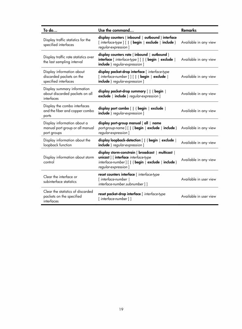
19
To do… Use the command… Remarks
Display traffic statistics for the specified interfaces
display counters { inbound | outbound } interface [ interface-type ] [ | { begin | exclude | include } regular-expression ]
Available in any view
Display traffic rate statistics over the last sampling interval
display counters rate { inbound | outbound } interface [ interface-type ] [ | { begin | exclude | include } regular-expression ]
Available in any view
Display information about discarded packets on the specified interfaces
display packet-drop interface [ interface-type [ interface-number ] ] [ | { begin | exclude | include } regular-expression ]
Available in any view
Display summary information about discarded packets on all interfaces
display packet-drop summary [ | { begin | exclude | include } regular-expression ] Available in any view
Display the combo interfaces and the fiber and copper combo ports
display port combo [ | { begin | exclude | include } regular-expression ] Available in any view
Display information about a manual port group or all manual port groups
display port-group manual [ all | name port-group-name ] [ | { begin | exclude | include } regular-expression ]
Available in any view
Display information about the loopback function
display loopback-detection [ | { begin | exclude | include } regular-expression ] Available in any view
Display information about storm control
display storm-constrain [ broadcast | multicast | unicast ] [ interface interface-type interface-number ] [ | { begin | exclude | include } regular-expression ]
Available in any view
Clear the interface or subinterface statistics
reset counters interface [ interface-type [ interface-number | interface-number.subnumber ] ]
Available in user view
Clear the statistics of discarded packets on the specified interfaces
reset packet-drop interface [ interface-type [ interface-number ] ] Available in user view

20
Loopback and null interface configuration
Configuring a loopback interface
Introduction to the loopback interface A loopback interface is a software-only virtual interface. It delivers the following benefits.
• The physical layer state and link-layer protocols of a loopback interface are always up unless the loopback interface is manually shut down.
• To save IP address resources, you can assign an IP address with an all-F mask to a loopback interface. When you assign an IPv4 address whose mask is not 32-bit, the system automatically changes the mask into a 32-bit mask. When you assign an IPv6 address whose mask is not 128-bit, the system automatically changes the mask into a 128-bit mask.
• You can enable routing protocols on a loopback interface, and a loopback interface can send and receive routing protocol packets.
Because of the benefits mentioned above, loopback interfaces are widely used in the following scenarios.
• You can configure a loopback interface address as the source address of the IP packets that the device generates. Because loopback interface addresses are stable unicast addresses, they are usually used as device identifications. When you configure a rule on an authentication or security server to permit or deny packets generated by a device, you can simplify the rule by configuring it to permit or deny packets that carry the loopback interface address identifying the device. When you use a loopback interface address as the source address of IP packets, be sure to perform any necessary routing configuration to ensure that the route from the loopback interface to the peer is reachable. All data packets sent to the loopback interface are treated as packets sent to the device itself, so the device does not forward these packets.
• Because a loopback interface is always up, it can be used in dynamic routing protocols. For example, if you do not configure a router ID for a dynamic routing protocol, the highest loopback interface IP address is selected as the router ID. In BGP, to prevent physical port failure from interrupting BGP sessions, you can use a loopback interface as the source interface of BGP packets.
Configuration procedure Follow these steps to configure a loopback interface:
To do… Use the command… Remarks
Enter system view system-view —
Create a loopback interface and enter loopback interface view
interface loopback interface-number —
Set the interface description description text Optional
By default, the description of a loopback interface is interface name Interface.

21
To do… Use the command… Remarks
Shut down the loopback interface shutdown Optional
By default, a loopback interface is up.
Restore the default settings for the loopback interface default Optional
NOTE:
You can configure settings such as IP addresses and IP routes on loopback interfaces. For more information, see Layer 3—IP Services Configuration Guide and Layer 3—IP Routing Configuration Guide.
Configuring the null interface
Introduction to the null interface A null interface is a completely software-based logical interface, and is always up. However, you cannot use it to forward data packets or configure an IP address or link-layer protocol on it. With a null interface specified as the next hop of a static route to a specific network segment, any packets routed to the network segment are dropped. The null interface provides a simpler way to filter packets than ACL. You can filter uninteresting traffic by transmitting it to a null interface instead of applying an ACL.
For example, by executing the ip route-static 92.101.0.0 255.255.0.0 null 0 command (which configures a static route that leads to null interface 0), you can have all the packets destined to the network segment 92.101.0.0/16 discarded.
Only one null interface, Null 0, is supported on your switch. You cannot remove or create a null interface.
Configuration procedure Follow these steps to enter null interface view:
To do… Use the command… Remarks
Enter system view system-view —
Enter null interface view interface null 0
Required
The Null 0 interface is the default null interface on your switch. It cannot be manually created or removed.
Set the interface description description text
Optional
By default, the description of a null interface is interface name Interface.
Restore the default settings for the null interface default Optional

22
Displaying and maintaining loopback and null interfaces
To do… Use the command… Remarks
Display information about loopback interfaces
display interface [ loopback ] [ brief [ down ] ] [ | { begin | exclude | include } regular-expression ]
display interface loopback interface-number [ brief ] [ | { begin | exclude | include } regular-expression ]
Available in any view
Display information about the null interface
display interface [ null ] [ brief [ down ] ] [ | { begin | exclude | include } regular-expression ]
display interface null 0 [ brief ] [ | { begin | exclude | include } regular-expression ]
Available in any view
Clear the statistics on a loopback interface
reset counters interface [ loopback [ interface-number ] ] Available in user view
Clear the statistics on the null interface reset counters interface [ null [ 0 ] ] Available in user view

23
MAC address table configuration
Overview An Ethernet device uses a MAC address table for forwarding frames through unicast instead of broadcast. This table describes from which port a MAC address (or host) can be reached. When forwarding a frame, the device first looks up the MAC address of the frame in the MAC address table for a match. If the switch finds an entry, it forwards the frame out of the outgoing port in the entry. If the switch does not find an entry, it broadcasts the frame out of all but the incoming port.
How a MAC address table entry is created The switch automatically obtains entries in the MAC address table, or you can add them manually.
MAC address learning
The device can automatically populate its MAC address table by obtaining the source MAC addresses (called “MAC address learning”) of incoming frames on each port.
When a frame arrives at a port, Port A for example, the device performs the following tasks:
1. Verifies the source MAC address (for example, MAC-SOURCE) of the frame.
2. Looks up the source MAC address in the MAC address table.
If an entry is found, the device updates the entry.
If no entry is found, the device adds an entry for MAC-SOURCE and Port A.
3. After obtaining this source MAC address, when the device receives a frame destined for MAC-SOURCE, the device finds the MAC-SOURCE entry in the MAC address table and forwards the frame out Port A.
The device performs the learning process each time it receives a frame from an unknown source MAC address, until the MAC address table is fully populated.
Manually configuring MAC address entries
With dynamic MAC address learning, a device does not distinguish between illegitimate and legitimate frames, which can invite security hazards. For example, when a hacker sends frames with a forged source MAC address to a port different from the one that the real MAC address is connected, the device creates an entry for the forged MAC address, and forwards frames destined for the legal user to the hacker instead.
To improve port security and prevent hackers from stealing data using forged MAC addresses, you can bind specific user devices to the port by manually adding MAC address entries to the MAC address table of the switch.
Types of MAC address table entries A MAC address table can contain the following types of entries:
• Static entries, which are manually added and never age out.
• Dynamic entries, which can be manually added or dynamically obtained and might age out.

24
• Blackhole entries, which are manually configured and never age out. Blackhole entries are configured for filtering out frames with specific source or destination MAC addresses. For example, to block all packets destined for a specific user for security concerns, you can configure the MAC address of this user as a blackhole MAC address entry.
To adapt to network changes and prevent inactive entries from occupying table space, an aging mechanism is adopted for dynamic MAC address entries. Each time a dynamic MAC address entry is obtained or created, an aging time starts. If the entry has not updated when the aging timer expires, the device deletes the entry. If the entry has updated before the aging timer expires, the aging timer restarts.
NOTE:
A static or blackhole MAC address entry can overwrite a dynamic MAC address entry, but not vice versa.
MAC address table-based frame forwarding When forwarding a frame, the device adopts the following forwarding modes based on the MAC address table:
• Unicast mode: If an entry is available for the destination MAC address, the device forwards the frame out of the outgoing interface indicated by the MAC address table entry.
• Broadcast mode: If the device receives a frame with the destination address as all-ones, or no entry is available for the destination MAC address, the device broadcasts the frame to all the interfaces except the receiving interface.
Configuring the MAC address table The configuration tasks discussed in the following sections are all optional and can be performed in any order.
NOTE:
• The MAC address table can contain only Layer 2 Ethernet ports and Layer 2 aggregate interfaces.
• This document covers the configuration of unicast MAC address table entries, including static, dynamic,and blackhole MAC address table entries. For more information about configuring static multicast MACaddress table entries for IGMP snooping and MLD snooping, see IP Multicast Configuration Guide. Formore information about MAC address table configuration in VPLS, see MPLS Configuration Guide.
Configuring static, dynamic, and blackhole MAC address table entries
To help prevent MAC address spoofing attacks and improve port security, you can manually add MAC address table entries to bind ports with MAC addresses. You can also configure blackhole MAC address entries to filter out packets with certain source or destination MAC addresses.
Adding or modifying a static, dynamic, or blackhole MAC address table entry globally
Follow these steps to add or modify a static, dynamic, or blackhole MAC address table entry in system view:
To do… Use the command… Remarks
Enter system view system-view —

25
To do… Use the command… Remarks
Add or modify a dynamic or static MAC address entry
mac-address { dynamic | static } mac-address interface interface-type interface-number vlan vlan-id
Add or modify a blackhole MAC address entry
mac-address blackhole mac-address vlan vlan-id
Required
Use either command.
Ensure that you have created the VLAN and assign the interface to the VLAN.
Adding or modifying a static or dynamic MAC address table entry on an interface
Follow these steps to add or modify a static or dynamic MAC address table entry in interface view:
To do… Use the command… Remarks
Enter system view system-view —
Enter Layer 2 Ethernet interface view or Layer 2 aggregate interface view
interface interface-type interface-number —
Add or modify a static or dynamic MAC address entry
mac-address { dynamic | static } mac-address vlan vlan-id
Required
Ensure that you have created the VLAN and assign the interface to the VLAN.
Disabling MAC address learning Sometimes, you might need to disable MAC address learning to prevent the MAC address table from being saturated, for example, when your device is being attacked by a large amount of packets with different source MAC addresses.
Disabling global MAC address learning
Disabling global MAC address learning disables the learning function on all ports.
Follow these steps to disable MAC address learning:
To do… Use the command… Remarks
Enter system view system-view —
Disable global MAC address learning mac-address mac-learning disable
Required
Enabled by default.
NOTE:
When MAC address learning is disabled, the obtained MAC addresses remain valid until they age out.
Disabling MAC address learning on ports
After enabling global MAC address learning, you can disable the function on a single port, or on all ports in a port group as needed.
Follow these steps to disable MAC address learning on an interface or a port group:
To do… Use the command… Remarks
Enter system view system-view —

26
To do… Use the command… Remarks
Enable global MAC address learning
undo mac-address mac-learning disable
Optional
Enabled by default.
Enter interface view or port group view
• Enter Layer 2 Ethernet interface view or Layer 2 aggregate interface view:
interface interface-type interface-number • Enter port group view:
port-group manual port-group-name
Required
Use either command.
Settings in Layer 2 Ethernet interface view or Layer 2 aggregate interface view take effect on the interface only. Settings in port group view take effect on all member ports in the port group.
Disable MAC address learning on the interface or all ports in the port group
mac-address mac-learning disable Required
Enabled by default.
NOTE:
• When MAC address learning is disabled, the obtained MAC addresses remain valid until they age out.
• For configuration about port groups, see the chapter “Ethernet interface configuration.”
Disabling MAC address learning on a VLAN
You might disable MAC address learning on a per-VLAN basis.
Follow these steps to disable MAC address learning on a VLAN:
To do… Use the command… Remarks
Enter system view system-view —
Enable global MAC address learning
undo mac-address mac-learning disable
Optional
Enabled by default.
Enter VLAN view vlan vlan-id —
Disable MAC address learning on the VLAN mac-address mac-learning disable
Required
Enabled by default.
NOTE:
When MAC address learning is disabled, the learned MAC addresses remain valid until they age out.
Configuring the aging timer for dynamic MAC address entries The MAC address table uses an aging timer for dynamic MAC address entries for security and efficient use of table space. If a dynamic MAC address entry has failed to update before the aging timer expires, the device deletes the entry. This aging mechanism ensures that the MAC address table can quickly update to accommodate the latest network changes.
Set the aging timer appropriately. Too long an aging interval might cause the MAC address table to retain outdated entries, exhaust the MAC address table resources, and fail to update its entries to accommodate the latest network changes. Too short an interval might result in removal of valid entries, causing unnecessary broadcasts, which might affect device performance.
Follow these steps to configure the aging timer for dynamic MAC address entries:

27
To do… Use the command… Remarks
Enter system view system-view —
Configure the aging timer for dynamic MAC address entries
mac-address timer { aging seconds | no-aging }
Optional
300 seconds by default.
The no-aging keyword disables the aging timer.
You can reduce broadcasts on a stable network by disabling the aging timer to prevent dynamic entries from unnecessarily aging out. By reducing broadcasts, you improve not only network performance, but also security, because you reduce the chances that a data packet will reach unintended destinations.
Configuring the MAC learning limit on ports To prevent the MAC address table from getting too large, you can limit the number of MAC addresses that can a port can obtain.
Follow these steps to configure the MAC learning limit on a Layer 2 Ethernet interface or all ports in a port group:
To do… Use the command… Remarks
Enter system view system-view —
Enter interface view or port group view
• Enter Layer 2 Ethernet interface view:
interface interface-type interface-number • Enter port group view:
port-group manual port-group-name
Required
Use either command.
Settings in Layer 2 Ethernet interface view take effect on the interface only. Settings in port group view take effect on all member ports in the port group.
Configure the MAC learning limit on the interface or port group
mac-address max-mac-count count Required
No MAC learning limit is configured by default.
NOTE:
• Layer 2 aggregate interfaces do not support the mac-address max-mac-count command.
• Do not configure the MAC learning limit on any member ports of an aggregation group. Otherwise, themember ports cannot be selected.
Displaying and maintaining MAC address tables To do… Use the command… Remarks
Display MAC address table information
display mac-address [ mac-address [ vlan vlan-id ] | [ [ dynamic | static ] [ interface interface-type interface-number ] | blackhole ] [ vlan vlan-id ] [ count ] ] [ | { begin | exclude | include } regular-expression ]
Available in any view
Display the aging timer for dynamic MAC address entries
display mac-address aging-time [ | { begin | exclude | include } regular-expression ] Available in any view

28
To do… Use the command… Remarks
Display the system or interface MAC address learning state
display mac-address mac-learning [ interface-type interface-number ] [ | { begin | exclude | include } regular-expression ]
Available in any view
Display MAC address statistics
display mac-address statistics [ | { begin | exclude | include } regular-expression ] Available in any view
MAC address table configuration example Network requirements
As shown in Figure 6:
• The MAC address of Host A is 000f-e235-dc71 and belongs to VLAN 1. It is connected to GigabitEthernet 1/0/1 of the device. To prevent MAC address spoofing, add a static entry for the host in the MAC address table of the device.
• The MAC address of Host B is 000f-e235-abcd and belongs to VLAN 1. For security, because this host once behaved suspiciously on the network, add a blackhole MAC address entry for the host MAC address, so that all packets destined for the host will be dropped.
• Set the aging timer for dynamic MAC address entries to 500 seconds.
Figure 6 Network diagram for MAC address table configuration
Host A000f-e235-dc71
Host B000f-e235-abcd
Device
GE1/0/1VLAN 1
GE1/0/2VLAN 1
Configuration procedure
# Add a static MAC address entry. <Sysname> system-view
[Sysname] mac-address static 000f-e235-dc71 interface gigabitethernet 1/0/1 vlan 1
# Add a blackhole MAC address entry. [Sysname] mac-address blackhole 000f-e235-abcd vlan 1
# Set the aging timer for dynamic MAC address entries to 500 seconds. [Sysname] mac-address timer aging 500
# Display the MAC address entry for port GigabitEthernet 1/0/1. [Sysname] display mac-address interface gigabitethernet 1/0/1
MAC ADDR VLAN ID STATE PORT INDEX AGING TIME(s)
000f-e235-dc71 1 Config static GigabitEthernet 1/0/1 NOAGED

29
--- 1 mac address(es) found ---
# Display information about the blackhole MAC address table. [Sysname] display mac-address blackhole
MAC ADDR VLAN ID STATE PORT INDEX AGING TIME(s)
000f-e235-abcd 1 Blackhole N/A NOAGED
--- 1 mac address(es) found ---
# View the aging time of dynamic MAC address entries. [Sysname] display mac-address aging-time
Mac address aging time: 500s

30
MAC Information configuration
Overview
Introduction to MAC Information To monitor a network, you must monitor users who are joining and leaving the network. Because a MAC address uniquely identifies a network user, you can monitor users who are joining and leaving a network by monitoring their MAC addresses.
With the MAC Information function, Layer 2 Ethernet ports send Syslog or trap messages to the monitor end in the network when they obtain or delete MAC addresses. By analyzing these messages, the monitor end can monitor users who are accessing the network.
How MAC Information works When a new MAC address is obtained or an existing MAC address is deleted on a device, the device writes related information about the MAC address to the buffer area used to store user information. When the timer set for sending MAC address monitoring Syslog or trap messages expires, or when the buffer reaches capacity, the device sends the Syslog or trap messages to the monitor end.
Configuring MAC Information
Enabling MAC Information globally Follow these steps to enable MAC Information globally:
To do… Use the command… Remarks
Enter system view system-view —
Enable MAC Information globally mac-address information enable Required
Disabled by default.
Enabling MAC Information on an interface Follow these steps to enable MAC Information on an interface:
To do… Use the command… Remarks
Enter system view system-view —
Enter Layer 2 Ethernet interface view
interface interface-type interface-number —
Enable MAC Information on the interface
mac-address information enable { added | deleted }
Required
Disabled by default.

31
NOTE:
• To enable MAC Information on an Ethernet port, enable MAC Information globally first.
• This feature is not applicable to SD and EB cards that work in MAC extension mode (bridging) or mixedextension mode (mix-bridging-routing).
• For more information about the working mode of cards, see Fundamentals Configuration Guide.
Configuring MAC Information mode Follow these steps to configure MAC Information mode:
To do… Use the command… Remarks
Enter system view system-view —
Configure MAC Information mode mac-address information mode { syslog | trap }
Optional
trap by default.
Configuring the interval for sending Syslog or trap messages To prevent Syslog or trap messages from being sent too frequently, you can set the interval for sending Syslog or trap messages.
Follow these steps to set the interval for sending Syslog or trap messages:
To do… Use the command… Remarks
Enter system view system-view —
Set the interval for sending Syslog or trap messages
mac-address information interval interval-time
Optional
One second by default.
Configuring the MAC Information queue length To avoid losing user MAC address information, when the buffer that stores user MAC address information reaches capacity, the user MAC address information in the buffer is sent to the monitor end in the network, even if the timer set for sending MAC address monitoring Syslog or trap messages has not expired yet.
Follow these steps to configure the MAC Information queue length:
To do… Use the command… Remarks
Enter system view system-view —
Configure the MAC Information queue length
mac-address information queue-length value
Optional
50 by default.
MAC Information configuration example Network requirements
As shown in Figure 7:
• Host A is connected to a remote server (Server) through Device.

32
• Enable MAC Information on GigabitEthernet 1/0/1 on Device. Device sends MAC address changes in Syslog messages to Host B through GigabitEthernet 1/0/3. Host B analyzes and displays the Syslog messages.
Figure 7 Network diagram for MAC Information configuration
Configuration procedure
1. Configure Device to send Syslog messages to Host B.
For more information, see Network Management and Monitoring Configuration Guide.
2. Enable MAC Information.
# Enable MAC Information on Device. <Device> system-view
[Device] mac-address information enable
# Configure MAC Information mode as Syslog. [Device] mac-address information mode syslog
# Enable MAC Information on GigabitEthernet 1/0/1. [Device] interface gigabitethernet 1/0/1
[Device-GigabitEthernet1/0/1] mac-address information enable added
[Device-GigabitEthernet1/0/1] mac-address information enable deleted
[Device-GigabitEthernet1/0/1] quit
# Set the MAC Information queue length to 100. [Device] mac-address information queue-length 100
# Set the interval for sending Syslog or trap messages to 20 seconds. [Device] mac-address information interval 20

33
Ethernet link aggregation configuration
Overview Ethernet link aggregation, or simply link aggregation, combines multiple physical Ethernet ports into one logical link, called an “aggregate link”. Link aggregation delivers the following benefits:
• Increases bandwidth beyond the limits of any single link. In an aggregate link, traffic is distributed across the member ports.
• Improves link reliability. The member ports dynamically back up one another. When a member port fails, its traffic is automatically switched to other member ports.
As shown in Figure 8, Device A and Device B are connected by three physical Ethernet links. These physical Ethernet links are combined into an aggregate link, Link Aggregation 1. The bandwidth of this aggregate link is as high as the total bandwidth of the three physical Ethernet links. At the same time, the three Ethernet links back up one another.
Figure 8 Diagram for Ethernet link aggregation
Basic concepts Aggregation group, member port, aggregate interface
Link aggregation is implemented through link aggregation groups. An aggregation group is a group of Ethernet interfaces combined together, which are called “member ports” of the aggregation group. For each aggregation group, a logical interface, called an “aggregate interface”, is created. To an upper layer entity that uses the link aggregation service, a link aggregation group appears to be a single logical link and data traffic is transmitted through the aggregate interface.
Aggregate interfaces have the following types: bridge-aggregation (BAGG) interfaces, also called Layer 2 aggregate interfaces, and route-aggregation (RAGG) interfaces, also called Layer 3 aggregate interfaces. When you create an aggregate interface, the switch automatically creates an aggregation group of the same type and number as the aggregate interface. For example, when you create interface Bridge-Aggregation 1, Layer 2 aggregation group 1 is created.
You can assign Layer 2 Ethernet interfaces only to a Layer 2 aggregation group, and Layer 3 Ethernet interfaces only to a Layer 3 aggregation group.
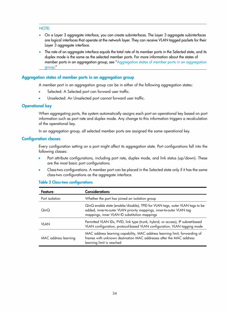
34
NOTE:
• On a Layer 3 aggregate interface, you can create subinterfaces. The Layer 3 aggregate subinterfaces are logical interfaces that operate at the network layer. They can receive VLAN tagged packets for theirLayer 3 aggregate interface.
• The rate of an aggregate interface equals the total rate of its member ports in the Selected state, and itsduplex mode is the same as the selected member ports. For more information about the states of member ports in an aggregation group, see “Aggregation states of member ports in an aggregationgroup.”
Aggregation states of member ports in an aggregation group
A member port in an aggregation group can be in either of the following aggregation states:
• Selected: A Selected port can forward user traffic.
• Unselected: An Unselected port cannot forward user traffic.
Operational key
When aggregating ports, the system automatically assigns each port an operational key based on port information such as port rate and duplex mode. Any change to this information triggers a recalculation of the operational key.
In an aggregation group, all selected member ports are assigned the same operational key.
Configuration classes
Every configuration setting on a port might affect its aggregation state. Port configurations fall into the following classes:
• Port attribute configurations, including port rate, duplex mode, and link status (up/down). These are the most basic port configurations.
• Class-two configurations. A member port can be placed in the Selected state only if it has the same class-two configurations as the aggregate interface.
Table 2 Class-two configurations
Feature Considerations
Port isolation Whether the port has joined an isolation group
QinQ QinQ enable state (enable/disable), TPID for VLAN tags, outer VLAN tags to be added, inner-to-outer VLAN priority mappings, inner-to-outer VLAN tag mappings, inner VLAN ID substitution mappings
VLAN Permitted VLAN IDs, PVID, link type (trunk, hybrid, or access), IP subnet-based VLAN configuration, protocol-based VLAN configuration, VLAN tagging mode
MAC address learning MAC address learning capability, MAC address learning limit, forwarding of frames with unknown destination MAC addresses after the MAC address learning limit is reached

35
NOTE:
• Class-two configurations made on an aggregate interface are automatically synchronized to all member ports of the interface. These configurations are retained on the member ports even after the aggregate interface is removed.
• Any class-two configuration change might affect the aggregation state of link aggregation member ports and ongoing traffic. To be sure that you are aware of the risk, the system displays a warning message every time you attempt to change a class-two configuration setting on a member port.
• Class-one configurations do not affect the aggregation state of the member port even if they are different from those on the aggregate interface. GVRP and MSTP settings are examples of class-one configurations.
NOTE:
The class-one configuration for a member port is effective only when the member port leaves the aggregation group.
Reference port
When setting the aggregation state of the ports in an aggregation group, the system automatically picks a member port as the reference port. A Selected port must have the same port attributes and class-two configurations as the reference port.
LACP
The IEEE 802.3ad Link Aggregation Control Protocol (LACP) enables dynamic aggregation of physical links. It uses link aggregation control protocol data units (LACPDUs) for exchanging aggregation information between LACP-enabled devices.
1. LACP functions
The IEEE 802.3ad LACP offers basic LACP functions and extended LACP functions, as described in Table 3.
Table 3 Basic and extended LACP functions
Category Description
Basic LACP functions
Implemented through the basic LACPDU fields, including the system LACP priority, system MAC address, port aggregation priority, port number, and operational key.
Each member port in a LACP-enabled aggregation group exchanges the preceding information with its peer. When a member port receives an LACPDU, it compares the received information with the information received on the other member ports. In this way, the two systems reach an agreement on which ports should be placed in the Selected state.
Extended LACP functions
Implemented by extending the LACPDU with new Type/Length/Value (TLV) fields. This is how the LACP multi-active detection (MAD) mechanism of the Intelligent Resilient Framework (IRF) feature is implemented. The S7500E Switch Series can participate in LACP MAD as either an IRF member switch or an intermediate device.
NOTE:
For more information about IRF, member switches, intermediate devices, and the LACP MAD mechanism,see IRF Configuration Guide.
2. LACP priorities
LACP priorities have the following types: system LACP priority and port aggregation priority.

36
Table 4 LACP priorities
Type Description Remarks
System LACP priority
Used by two peer devices (or systems) to determine which one is superior in link aggregation.
In dynamic link aggregation, the system that has higher system LACP priority sets the Selected state of member ports on its side first, and then the system that has lower priority sets the port state accordingly.
Port aggregation priority
Determines the likelihood of a member port to be selected on a system. The higher the port aggregation priority, the higher the likelihood.
The smaller the priority value, the higher the priority.
3. LACP timeout interval
The LACP timeout interval specifies how long a member port waits to receive LACPDUs from the peer port. If a local member port fails to receive LACPDUs from the peer within three times the LACP timeout interval, the member port assumes that the peer port has failed. You can configure the LACP timeout interval as either the short timeout interval (1 second) or the long timeout interval (30 seconds).
Link aggregation modes
Link aggregation has the following modes: dynamic and static. Dynamic link aggregation uses LACP and static link aggregation does not. Table 5 compares the two aggregation modes.
Table 5 A comparison between static and dynamic aggregation modes
Aggregation mode
LACP status on member ports Pros Cons
Static Disabled Aggregation is stable. Peers do not affect the aggregation state of the member ports.
The member ports do not adjust the aggregation state according to that of the peer ports. The administrator must manually maintain link aggregations.
Dynamic Enabled
The administrator does not need to maintain link aggregations. The peer systems maintain the aggregation state of the member ports automatically.
Aggregation is unstable. The aggregation state of the member ports is susceptible to network changes.
The following points apply to a dynamic link aggregation group:
• A Selected port can receive and send LACPDUs.
• An Unselected port can receive and send LACPDUs only if it is up and has the same class-two configurations as the aggregate interface.
Aggregating links in static mode LACP is disabled on the member ports in a static aggregation group. You must manually maintain the aggregation state of the member ports.
The static link aggregation process comprises:
• Selecting a reference port
• Setting the aggregation state of each member port

37
Selecting a reference port
The system selects a reference port from the member ports that are:
• Are in the up state and have
• Have the same class-two configurations as the aggregate interface.
The candidate ports are sorted by aggregation priority, duplex, and speed in the following order:
• Lowest aggregation priority value
• Full duplex/high speed
• Full duplex/low speed
• Half duplex/high speed
• Half duplex/low speed
The one at the top is selected as the reference port. If two ports have the same aggregation priority, duplex mode, and speed, the one with the lower port number wins.
Setting the aggregation state of each member port
After selecting the reference port, the static aggregation group sets the aggregation state of each member port.
Figure 9 Setting the aggregation state of a member port in a static aggregation group

38
NOTE:
• To ensure stable aggregation state and service continuity, do not change port attributes or class-two configurations on any member port.
• If a static aggregation group has reached the limit on Selected ports, any port that joins the group is placed in the Unselected state to avoid traffic interruption on the current Selected ports. Avoid this situation, however, because it might cause the aggregation state of a port to change after a reboot.
Aggregating links in dynamic mode LACP is automatically enabled on all member ports in a dynamic aggregation group. The protocol automatically maintains the aggregation state of ports.
The dynamic link aggregation process comprises:
• Selecting a reference port
• Setting the aggregation state of each member port
Selecting a reference port
The local system (the actor) and the remote system (the partner) negotiate a reference port using the following workflow:
1. The systems compare the system ID (which comprises the system LACP priority and the system MAC address). The system with the lower LACP priority value wins. If they are the same, the systems compare the system MAC addresses. The system with the lower MAC address wins.
2. The system with the smaller system ID selects the port with the smallest port ID as the reference port. A port ID comprises a port aggregation priority and a port number. The port with the lower aggregation priority value wins. If two ports have the same aggregation priority, the system compares their port numbers. The port with the smaller port number wins.
Setting the aggregation state of each member port
After the reference port is selected, the system with the lower system ID sets the state of each member port in the dynamic aggregation group on its side.

39
Figure 10 Setting the state of a member port in a dynamic aggregation group
Meanwhile, the system with the higher system ID, which has identified the aggregation state changes on the remote system, sets the aggregation state of local member ports as the same as their peer ports.
NOTE:
• A dynamic link aggregation group preferably sets full-duplex ports as the Selected ports, and will set one, and only one, half-duplex port as a Selected port when none of the full-duplex ports can be selected or only half-duplex ports exist in the group.
• To ensure stable aggregation state and service continuity, do not change port attributes or class-two configurations on any member port.
• In a dynamic aggregation group, when the aggregation state of a local port changes, the aggregationstate of the peer port changes.
• A port that joins a dynamic aggregation group after the Selected port limit has been reached is placedin the Selected state if it is more eligible for being selected than a current member port.

40
Load-sharing criteria for link aggregation groups In a link aggregation group, traffic can be load-shared across the selected member ports based on a set of criteria, depending on your configuration.
You can choose one of the following criteria or any combination for load sharing:
• MAC addresses
• Service port numbers
• Ingress ports
• IP addresses
• IP protocols
• MPLS labels
Alternatively, you can let the system automatically choose link-aggregation load-sharing criteria based on packet types (Layer 2, IPv4, MPLS, or IPv6 for example) or configure the system to perform per-packet load sharing.
Ethernet link aggregation configuration task list Complete the following tasks to configure Ethernet link aggregation:
Task Remarks
Configuring a static aggregation group Configuring an aggregation group Configuring a dynamic aggregation group
Select either task
Configuring the description of an aggregate interface or subinterface Optional
Configuring the MTU of a Layer 3 aggregate interface or subinterface Optional
Enabling link state traps for an aggregate interface Optional
Setting the minimum number of Selected ports for an aggregation group Optional
Shutting down an aggregate interface Optional
Configuring an aggregate interface
Restoring the default settings for an aggregate interface Optional
Configuring load-sharing criteria for link aggregation groups Optional Configuring load sharing for link aggregation groups Enabling local-first load sharing for link aggregation Optional
Enabling link-aggregation traffic redirection Optional
Configuring an aggregation group You can choose to create a Layer 2 or Layer 3 link aggregation group depending on the ports to be aggregated:
• To aggregate Layer 2 Ethernet interfaces, create a Layer 2 link aggregation group.
• To aggregate Layer 3 Ethernet interfaces, create a Layer 3 link aggregation group.

41
Configuration guidelines You cannot assign a port to a Layer 2 aggregation group if any of the features listed in Table 6 is configured on the port.
Table 6 Features incompatible with Layer 2 aggregation groups
Feature Reference
RRPP RRPP in High Availability Configuration Guide
MAC authentication MAC authentication in Security Configuration Guide
Port security Port security in Security Configuration Guide
IP source guard IP source guard in Security Configuration Guide
802.1X 802.1X in Security Configuration Guide
Ports specified as source interfaces in portal-free rules Portal in Security Configuration Guide
You cannot assign a port to a Layer 3 aggregation group if any of the features listed in Table 7 is configured on the port.
Table 7 Interfaces that cannot be assigned to a Layer 3 aggregation group
Interface type Reference
Interfaces configured with IP addresses IP addressing in Layer 3—IP Services Configuration Guide
Interfaces configured as DHCP/BOOTP clients
DHCP in Layer 3—IP Services Configuration Guide
VRRP VRRP in High Availability Configuration Guide
Portal Portal in Security Configuration Guide
NOTE:
• If a port is used as a reflector port for port mirroring, do not assign it to an aggregation group. For moreinformation about reflector ports, see Network Management and Monitoring Configuration Guide.
• You can assign the following ports to an aggregation group: monitor ports for port mirroring, ports configured with static MAC addresses, or ports configured with MAC address learning limit.
CAUTION:
Removing an aggregate interface also removes the corresponding aggregation group. At the same time,all member ports leave the aggregation group.
Configuring a static aggregation group
NOTE:
To guarantee a successful static aggregation, make sure that the ports at both ends of each link are in thesame aggregation state.

42
Configuring a Layer 2 static aggregation group
Follow these steps to configure a Layer 2 static aggregation group:
To do... Use the command... Remarks
Enter system view system-view —
Create a Layer 2 aggregate interface and enter Layer 2 aggregate interface view
interface bridge-aggregation interface-number
Required
When you create a Layer 2 aggregate interface, the system automatically creates a Layer 2 static aggregation group numbered the same.
Exit to system view quit —
Enter Layer 2 Ethernet interface view
interface interface-type interface-number
Assign the Ethernet interface to the aggregation group
port link-aggregation group number
Required
Repeat these two steps to assign more Layer 2 Ethernet interfaces to the aggregation group.
Assign the port an aggregation priority
link-aggregation port-priority port-priority
Optional
By default, the aggregation priority of a port is 32768.
Changing the aggregation priority of a port might affect the aggregation state of the ports in the static aggregation group.
Configuring a Layer 3 static aggregation group
Follow these steps to configure a Layer 3 static aggregation group:
To do... Use the command... Remarks
Enter system view system-view —
Create a Layer 3 aggregate interface and enter Layer 3 aggregate interface view
interface route-aggregation interface-number
Required
When you create a Layer 3 aggregate interface, the system automatically creates a Layer 3 static aggregation group numbered the same.
Exit to system view quit —
Enter Layer 3 Ethernet interface view
interface interface-type interface-number
Assign the Ethernet interface to the aggregation group
port link-aggregation group number
Required
Repeat these two steps to assign more Layer 3 Ethernet interfaces to the aggregation group.
Assign the port an aggregation priority
link-aggregation port-priority port-priority
Optional
By default, the aggregation priority of a port is 32768.
Changing the aggregation priority of a port might affect the aggregation state of the ports in the static aggregation group.
Configuring a dynamic aggregation group

43
NOTE:
To guarantee a successful dynamic aggregation, be sure that the peer ports of the ports aggregated at oneend are also aggregated. The two ends can automatically negotiate the aggregation state of each memberport.
Configuring a Layer 2 dynamic aggregation group
Follow these steps to configure a Layer 2 dynamic aggregation group:
To do... Use the command... Remarks
Enter system view system-view —
Set the system LACP priority
lacp system-priority system-priority
Optional
By default, the system LACP priority is 32768.
Changing the system LACP priority might affect the aggregation state of the ports in a dynamic aggregation group.
Create a Layer 2 aggregate interface and enter Layer 2 aggregate interface view
interface bridge-aggregation interface-number
Required
When you create a Layer 2 aggregate interface, the system automatically creates a Layer 2 static aggregation group numbered the same.
Configure the aggregation group to work in dynamic aggregation mode
link-aggregation mode dynamic
Required
By default, an aggregation group works in static aggregation mode.
Exit to system view quit —
Enter Layer 2 Ethernet interface view
interface interface-type interface-number
Assign the Ethernet interface to the aggregation group
port link-aggregation group number
Required
Repeat these two steps to assign more Layer 2 Ethernet interfaces to the aggregation group.
Assign the port an aggregation priority
link-aggregation port-priority port-priority
Optional
By default, the aggregation priority of a port is 32768.
Changing the aggregation priority of a port might affect the aggregation state of the ports in the dynamic aggregation group.
Set the LACP timeout interval on the port to the short timeout interval (1 second)
lacp period short Optional
By default, the LACP timeout interval on a port is the long timeout interval (30 seconds).
Configuring a Layer 3 dynamic aggregation group
Follow these steps to configure a Layer 3 dynamic aggregation group:
To do... Use the command... Remarks
Enter system view system-view —
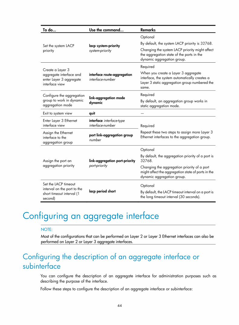
44
To do... Use the command... Remarks
Set the system LACP priority
lacp system-priority system-priority
Optional
By default, the system LACP priority is 32768.
Changing the system LACP priority might affect the aggregation state of the ports in the dynamic aggregation group.
Create a Layer 3 aggregate interface and enter Layer 3 aggregate interface view
interface route-aggregation interface-number
Required
When you create a Layer 3 aggregate interface, the system automatically creates a Layer 3 static aggregation group numbered the same.
Configure the aggregation group to work in dynamic aggregation mode
link-aggregation mode dynamic
Required
By default, an aggregation group works in static aggregation mode.
Exit to system view quit —
Enter Layer 3 Ethernet interface view
interface interface-type interface-number
Assign the Ethernet interface to the aggregation group
port link-aggregation group number
Required
Repeat these two steps to assign more Layer 3 Ethernet interfaces to the aggregation group.
Assign the port an aggregation priority
link-aggregation port-priority port-priority
Optional
By default, the aggregation priority of a port is 32768.
Changing the aggregation priority of a port might affect the aggregation state of ports in the dynamic aggregation group.
Set the LACP timeout interval on the port to the short timeout interval (1 second)
lacp period short Optional
By default, the LACP timeout interval on a port is the long timeout interval (30 seconds).
Configuring an aggregate interface
NOTE:
Most of the configurations that can be performed on Layer 2 or Layer 3 Ethernet interfaces can also be performed on Layer 2 or Layer 3 aggregate interfaces.
Configuring the description of an aggregate interface or subinterface
You can configure the description of an aggregate interface for administration purposes such as describing the purpose of the interface.
Follow these steps to configure the description of an aggregate interface or subinterface:

45
To do... Use the command... Remarks
Enter system view system-view —
Enter Layer 2 aggregate interface view
interface bridge-aggregation interface-number Enter
aggregate interface view
Enter Layer 3 aggregate interface or subinterface view
interface route-aggregation { interface-number | interface-number.subnumber }
Required
Use either command.
Configure the description of the aggregate interface or subinterface
description text
Optional
By default, the description of an interface is in the format of interface-name Interface, such as Bridge-Aggregation1 Interface.
Configuring the MTU of a Layer 3 aggregate interface or subinterface
Maximum transmission unit (MTU) of an interface affects IP packets fragmentation and reassembly on the interface.
Follow these steps to change the MTU of a Layer 3 aggregate interface or subinterface:
To do... Use the command... Remarks
Enter system view system-view —
Enter Layer 3 aggregate interface or subinterface view
interface route-aggregation { interface-number | interface-number.subnumber }
—
Configure the MTU of the Layer 3 aggregate interface or subinterface
mtu size Optional
1500 bytes by default.
Enabling link state traps for an aggregate interface You can configure an aggregate interface to generate linkUp trap messages when its link goes up and linkDown trap messages when its link goes down. For more information, see Network Management and Monitoring Configuration Guide.
Follow these steps to enable link state traps on an aggregate interface:
To do... Use the command... Remarks
Enter system view system-view —
Enable the trap function globally snmp-agent trap enable [ standard [ linkdown | linkup ] * ]
Optional
By default, link state trapping is enabled globally and on all interfaces.

46
To do... Use the command... Remarks
Enter Layer 2 aggregate interface view
interface bridge-aggregation interface-number Enter
aggregate interface view
Enter Layer 3 aggregate interface or subinterface view
interface route-aggregation { interface-number | interface-number.subnumber }
Required
Use either command.
Enable link state traps for the aggregate interface enable snmp trap updown
Optional
Enabled by default.
Setting the minimum number of Selected ports for an aggregation group
The bandwidth of an aggregate link increases along with the number of selected member ports. To avoid congestion caused by insufficient Selected ports on an aggregate link, you can set the minimum number of Selected ports required for bringing up the specific aggregate interface.
This minimum threshold setting affects the aggregation state of both aggregation member ports and the aggregate interface in the following ways:
• All member ports change to the Unselected state and the link of the aggregate interface goes down, when the number of member ports eligible for being selected is smaller than the minimum threshold.
• When the minimum threshold is reached, the eligible member ports change to the Selected state, and the link of the aggregate interface goes up.
Follow these steps to set the minimum number of Selected ports for an aggregation group:
To do... Use the command... Remarks
Enter system view system-view —
Enter Layer 2 aggregate interface view
interface bridge-aggregation interface-number
Enter aggregate interface view
Enter Layer 3 aggregate interface view
interface route-aggregation interface-number
Required
Use either command.
Set the minimum number of Selected ports for the aggregation group
link-aggregation selected-port minimum number
Required
Not specified by default.
CAUTION:
• If you set this minimum threshold for a static aggregation group, you must also make the same setting forits peer aggregation group to guarantee correct aggregation.
• Configuring the minimum number of Selected ports required to bring up an aggregation group might cause all the member ports in the aggregation group to become unselected.
Shutting down an aggregate interface Shutting down or bringing up an aggregate interface affects the aggregation state and link state of ports in the corresponding aggregation group in the following ways:

47
• When an aggregate interface is shut down, all Selected ports in the corresponding aggregation group become unselected and their link state becomes down.
• When an aggregate interface is brought up, the aggregation state of ports in the corresponding aggregation group is recalculated and their link state becomes up.
Follow these steps to shut down an aggregate interface:
To do... Use the command... Remarks
Enter system view system-view —
Enter Layer 2 aggregate interface view
interface bridge-aggregation interface-number Enter
aggregate interface view
Enter Layer 3 aggregate interface or subinterface view
interface route-aggregation { interface-number | interface-number.subnumber }
Required
Use either command.
Shut down the aggregate interface or subinterface
shutdown Required
By default, aggregate interfaces or subinterfaces are up.
NOTE:
Shutting down a Layer 3 aggregate subinterface does not affect any aggregation group, because Layer 3aggregate subinterfaces are not associated with any aggregation groups.
Restoring the default settings for an aggregate interface Follow these steps to restore the default settings for an aggregate interface:
To do... Use the command... Remarks
Enter system view system-view —
Enter Layer 2 aggregate interface view
interface bridge-aggregation interface-number Enter
aggregate interface view
Enter Layer 3 aggregate interface or subinterface view
interface route-aggregation { interface-number | interface-number.subnumber }
Required
Use either command.
Restore the default settings for the aggregate interface or subinterface
default Required
Configuring load sharing for link aggregation groups
Configuring load-sharing criteria for link aggregation groups You can determine how traffic is load-shared in a link aggregation group by configuring load-sharing criteria. The criteria can be MAC addresses, service port numbers, ingress ports, IP addresses, or MPLS labels carried in packets, or any combination. You can also let the system automatically choose

48
link-aggregation load-sharing criteria based on packet types (Layer 2, IPv4, MPLS, or IPv6, for example) or perform per-packet load sharing.
You can configure global or group-specific load-sharing criteria. A link aggregation group preferentially uses the group-specific load-sharing criteria. If no group-specific load-sharing criteria are available, the group uses the global load-sharing criteria.
NOTE:
The load sharing criteria configuration applies to only unicast packets, and can change the load sharingcriteria for unicast packets. Broadcast packets and multicast packets always use the default load sharingcriteria..
Configuring the global link-aggregation load-sharing criteria
Follow these steps to configure the global link-aggregation load-sharing criteria:
To do... Use the command... Remarks
Enter system view system-view —
Configure the global link-aggregation load-sharing criteria
link-aggregation load-sharing mode { { destination-ip | destination-mac | destination-port | ingress-port | source-ip | source-mac | source-port } *
Required
By default, the system selects the global load sharing criteria according to the packet type.
In system view, the switch supports the following load-sharing criteria and combinations:
• Source IP address
• Destination IP address
• Source MAC address
• Destination MAC address
• Source IP address and destination IP address
• Source IP address and source port
• Destination IP address and destination port
• Any combination of incoming port, source MAC address, and destination MAC address
Configuring group-specific load-sharing criteria
Follow these steps to configure load-sharing criteria for a link aggregation group:
To do… Use the command… Remarks
Enter system view system-view —
Enter Layer 2 aggregate interface view
interface bridge-aggregation interface-number Enter
aggregate interface view
Enter Layer 3 aggregate interface view
interface route-aggregation interface-number
Required
Use either command.
Configure the load-sharing criteria for the aggregation group
link-aggregation load-sharing mode { { destination-ip | destination-mac | mpls-label1 | mpls-label2 | source-ip | source-mac } * | flexible }
Required
The default load-sharing criteria are the same as the global load-sharing criteria.

49
In Layer 2 aggregate interface view, the switch supports the following load-sharing criteria and combinations:
• Automatic load-sharing criteria determined based on the packet type
• Source IP address
• Destination IP address
• Source MAC address
• Destination MAC address
• Layer 1 MPLS label
• Destination IP address and source IP address
• Destination MAC address and source MAC address
• Layer 1 MPLS label and Layer 2 MPLS label
Enabling local-first load sharing for link aggregation Use the local-first load sharing mechanism in a cross-card or cross-switch link aggregation scenario to distribute traffic preferentially across member ports on the ingress card or switch rather than all member ports.
When you aggregate ports on different member switches in an IRF fabric, you can use local-first load sharing to reduce traffic on IRF links, as shown in Figure 11. For more information about IRF, see IRF Configuration Guide.
Figure 11 Local-first link-aggregation load sharing
Any member ports on the ingress switch?
Local-first load sharing mechanism enabled?
Yes No
Yes
No
The egress port for a traffic flow is an aggregate interface that has
member ports on different IRF member switches
Packets are load shared only across the member ports on
the ingress switchPackets are load shared across all member ports
Follow these steps to enable local-first load sharing for link aggregation:
To do... Use the command... Remarks
Enter system view system-view —
Enable local-first load-sharing for link aggregation
link-aggregation load-sharing mode local-first
Optional
Enabled by default.

50
Enabling link-aggregation traffic redirection The link-aggregation traffic redirection function can redirect traffic between cards or IRF member switches for a cross-card or cross-device link aggregation group. Link-aggregation traffic redirection prevents traffic interruption when you reboot a card or IRF member switch that contains link aggregation member ports. For more information about IRF, see IRF Configuration Guide.
Follow these steps to enable link-aggregation traffic redirection:
To do... Use the command... Remarks
Enter system view system-view —
Enable link-aggregation traffic redirection
link-aggregation lacp traffic-redirect-notification enable
Optional
Disabled by default.
CAUTION:
• Link-aggregation traffic redirection applies only to dynamic link aggregation groups and only to knownunicast packets.
• To prevent traffic interruption, enable link-aggregation traffic redirection on devices at both ends of theaggregate link.
• To prevent packet loss that might occur at a reboot, disable both MSTP and link-aggregation traffic redirection.
Displaying and maintaining Ethernet link aggregation
To do... Use the command... Remarks
Display information for an aggregate interface or multiple aggregate interfaces
display interface [ bridge-aggregation | route-aggregation ] [ brief [ down ] ] [ | { begin | exclude | include } regular-expression ]
display interface { bridge-aggregation | route-aggregation } interface-number [ brief ] [ | { begin | exclude | include } regular-expression ]
Available in any view
Display the local system ID display lacp system-id [ | { begin | exclude | include } regular-expression ] Available in any view
Display the global or group-specific link-aggregation load-sharing criteria
display link-aggregation load-sharing mode [ interface [ { bridge-aggregation | route-aggregation } interface-number ] ] [ | { begin | exclude | include } regular-expression ]
Available in any view
Display detailed link aggregation information for link aggregation member ports
display link-aggregation member-port [ interface-list ] [ | { begin | exclude | include } regular-expression ]
Available in any view
Display summary information about all aggregation groups
display link-aggregation summary [ | { begin | exclude | include } regular-expression ] Available in any view

51
To do... Use the command... Remarks
Display detailed information about a specific or all aggregation groups
display link-aggregation verbose [ { bridge-aggregation | route-aggregation } [ interface-number ] ] [ | { begin | exclude | include } regular-expression ]
Available in any view
Clear LACP statistics for a specific or all link aggregation member ports
reset lacp statistics [ interface interface-list ] Available in user view
Clear statistics for a specific or all aggregate interfaces
reset counters interface [ { bridge-aggregation | route-aggregation } [ interface-number ] ]
Available in user view
Ethernet link aggregation configuration examples
NOTE:
In an aggregation group, only ports that have the same port attributes and class-two configurations (see“Configuration classes”) as the reference port (see “Reference port”) can operate as Selected ports. Makesure that all member ports have the same port attributes and class-two configurations as the reference port. The other settings only need to be configured on the aggregate interface, not on the member ports.
Layer 2 static aggregation configuration example Network requirements
As shown in Figure 12:
• Device A and Device B are connected through their respective Layer 2 Ethernet interfaces GigabitEthernet 1/0/1 through GigabitEthernet 1/0/3.
• Configure a Layer 2 static aggregation group on Device A and Device B, respectively. Enable VLAN 10 at one end of the aggregate link to communicate with VLAN 10 at the other end, and VLAN 20 at one end to communicate with VLAN 20 at the other end.
• Enable traffic to be load-shared across aggregation group member ports based on the source and destination MAC addresses.
Figure 12 Network diagram for Layer 2 static aggregation

52
Configuration procedure
1. Configure Device A
# Create VLAN 10, and assign port GigabitEthernet 1/0/4 to VLAN 10. <DeviceA> system-view
[DeviceA] vlan 10
[DeviceA-vlan10] port gigabitethernet 1/0/4
[DeviceA-vlan10] quit
# Create VLAN 20, and assign port GigabitEthernet 1/0/5 to VLAN 20. [DeviceA] vlan 20
[DeviceA-vlan20] port gigabitethernet 1/0/5
[DeviceA-vlan20] quit
# Create Layer 2 aggregate interface Bridge-Aggregation 1. [DeviceA] interface bridge-aggregation 1
[DeviceA-Bridge-Aggregation1] quit
# Assign ports GigabitEthernet 1/0/1 through GigabitEthernet 1/0/3 to link aggregation group 1. [DeviceA] interface gigabitethernet 1/0/1
[DeviceA-GigabitEthernet1/0/1] port link-aggregation group 1
[DeviceA-GigabitEthernet1/0/1] quit
[DeviceA] interface gigabitethernet 1/0/2
[DeviceA-GigabitEthernet1/0/2] port link-aggregation group 1
[DeviceA-GigabitEthernet1/0/2] quit
[DeviceA] interface gigabitethernet 1/0/3
[DeviceA-GigabitEthernet1/0/3] port link-aggregation group 1
[DeviceA-GigabitEthernet1/0/3] quit
# Configure Layer 2 aggregate interface Bridge-Aggregation 1 as a trunk port and assign it to VLANs 10 and 20. [DeviceA] interface bridge-aggregation 1
[DeviceA-Bridge-Aggregation1] port link-type trunk
[DeviceA-Bridge-Aggregation1] port trunk permit vlan 10 20
Please wait... Done.
Configuring GigabitEthernet1/0/1... Done.
Configuring GigabitEthernet1/0/2... Done.
Configuring GigabitEthernet1/0/3... Done.
[DeviceA-Bridge-Aggregation1] quit
# Configure Device A to use the source and destination MAC addresses of packets as the global link-aggregation load-sharing criteria. [DeviceA] link-aggregation load-sharing mode source-mac destination-mac
2. Configure Device B
Configure Device B using the same instructions that you used to configure Device A.
3. Verify the configurations
# Display summary information about all aggregation groups on Device A. [DeviceA] display link-aggregation summary
Aggregation Interface Type:
BAGG -- Bridge-Aggregation, RAGG -- Route-Aggregation

53
Aggregation Mode: S -- Static, D -- Dynamic
Loadsharing Type: Shar -- Loadsharing, NonS -- Non-Loadsharing
Actor System ID: 0x8000, 000f-e2ff-0001
AGG AGG Partner ID Select Unselect Share
Interface Mode Ports Ports Type
-------------------------------------------------------------------------------
BAGG1 S none 3 0 Shar
The output shows that link aggregation group 1 is a load-shared Layer 2 static aggregation group and it contains three Selected ports.
# Display the global link-aggregation load-sharing criteria on Device A. [DeviceA] display link-aggregation load-sharing mode
Link-Aggregation Load-Sharing Mode:
destination-mac address, source-mac address
The output shows that all link aggregation groups created on the device perform load sharing based on source and destination MAC addresses.
Layer 2 dynamic aggregation configuration example Network requirements
As shown in Figure 13:
• Device A and Device B are connected through their respective Layer 2 Ethernet interfaces GigabitEthernet 1/0/1 through GigabitEthernet 1/0/3.
• Configure a Layer 2 dynamic aggregation group on Device A and Device B respectively, enable VLAN 10 at one end of the aggregate link to communicate with VLAN 10 at the other end, and VLAN 20 at one end to communicate with VLAN 20 at the other end.
• Enable traffic to be load-shared across aggregation group member ports based on source and destination MAC addresses.
Figure 13 Network diagram for Layer 2 dynamic aggregation
Configuration procedure
1. Configure Device A.

54
# Create VLAN 10, and assign the port GigabitEthernet 1/0/4 to VLAN 10. <DeviceA> system-view
[DeviceA] vlan 10
[DeviceA-vlan10] port gigabitethernet 1/0/4
[DeviceA-vlan10] quit
# Create VLAN 20, and assign the port GigabitEthernet 1/0/5 to VLAN 20. [DeviceA] vlan 20
[DeviceA-vlan20] port gigabitethernet 1/0/5
[DeviceA-vlan20] quit
# Create Layer 2 aggregate interface Bridge-Aggregation 1, and configure the link aggregation mode as dynamic. [DeviceA] interface bridge-aggregation 1
[DeviceA-Bridge-Aggregation1] link-aggregation mode dynamic
# Assign ports GigabitEthernet 1/0/1 through GigabitEthernet 1/0/3 to link aggregation group 1 one at a time. [DeviceA] interface gigabitethernet 1/0/1
[DeviceA-GigabitEthernet1/0/1] port link-aggregation group 1
[DeviceA-GigabitEthernet1/0/1] quit
[DeviceA] interface gigabitethernet 1/0/2
[DeviceA-GigabitEthernet1/0/2] port link-aggregation group 1
[DeviceA-GigabitEthernet1/0/2] quit
[DeviceA] interface gigabitethernet 1/0/3
[DeviceA-GigabitEthernet1/0/3] port link-aggregation group 1
[DeviceA-GigabitEthernet1/0/3] quit
# Configure Layer 2 aggregate interface Bridge-Aggregation 1 as a trunk port and assign it to VLANs 10 and 20. [DeviceA] interface bridge-aggregation 1
[DeviceA-Bridge-Aggregation1] port link-type trunk
[DeviceA-Bridge-Aggregation1] port trunk permit vlan 10 20
Please wait... Done.
Configuring GigabitEthernet1/0/1... Done.
Configuring GigabitEthernet1/0/2... Done.
Configuring GigabitEthernet1/0/3... Done.
[DeviceA-Bridge-Aggregation1] quit
# Configure the device to use the source and destination MAC addresses of packets as the global link-aggregation load-sharing criteria. [DeviceA] link-aggregation load-sharing mode source-mac destination-mac
2. Configure Device B.
Configure Device B using the same instructions that you used to configure Device A.
3. Verify the configurations.
# Display summary information about all aggregation groups on Device A. [DeviceA] display link-aggregation summary
Aggregation Interface Type:
BAGG -- Bridge-Aggregation, RAGG -- Route-Aggregation
Aggregation Mode: S -- Static, D -- Dynamic

55
Loadsharing Type: Shar -- Loadsharing, NonS -- Non-Loadsharing
Actor System ID: 0x8000, 000f-e2ff-0001
AGG AGG Partner ID Select Unselect Share
Interface Mode Ports Ports Type
-------------------------------------------------------------------------------
BAGG1 D 0x8000, 000f-e2ff-0002 3 0 Shar
The output shows that link aggregation group 1 is a load-shared Layer 2 dynamic aggregation group and it contains three Selected ports.
# Display the global link-aggregation load-sharing criteria on Device A. [DeviceA] display link-aggregation load-sharing mode
Link-Aggregation Load-Sharing Mode:
destination-mac address, source-mac address
The output shows that all link aggregation groups created on the device perform load sharing based on source and destination MAC addresses.
Layer 3 static aggregation configuration example Network requirements
As shown in Figure 14:
• Device A and Device B are connected by their Layer 3 Ethernet interfaces GigabitEthernet 1/0/1 through GigabitEthernet 1/0/3.
• Configure a Layer 3 static aggregation group on Device A and Device B, respectively. Configure IP addresses and subnet masks for the corresponding Layer 3 aggregate interfaces.
• Enable traffic to be load-shared across aggregation group member ports based on source and destination IP addresses.
Figure 14 Network diagram for Layer 3 static aggregation
Configuration procedure
1. Configure Device A.
# Create Layer 3 aggregate interface Route-Aggregation 1, and configure an IP address and subnet mask for the aggregate interface. <DeviceA> system-view
[DeviceA] interface route-aggregation 1
[DeviceA-Route-Aggregation1] ip address 192.168.1.1 24
[DeviceA-Route-Aggregation1] quit
# Assign Layer 3 Ethernet interfaces GigabitEthernet 1/0/1 through GigabitEthernet 1/0/3 to aggregation group 1. [DeviceA] interface gigabitethernet 1/0/1
[DeviceA-GigabitEthernet1/0/1] port link-aggregation group 1

56
[DeviceA-GigabitEthernet1/0/1] quit
[DeviceA] interface gigabitethernet 1/0/2
[DeviceA-GigabitEthernet1/0/2] port link-aggregation group 1
[DeviceA-GigabitEthernet1/0/2] quit
[DeviceA] interface gigabitethernet 1/0/3
[DeviceA-GigabitEthernet1/0/3] port link-aggregation group 1
[DeviceA-GigabitEthernet1/0/3] quit
# Configure the global link-aggregation load-sharing criteria as the source and destination IP addresses of packets. [DeviceA] link-aggregation load-sharing mode source-ip destination-ip
2. Configure Device B.
Configure Device B using the same instructions that you used to configure Device A.
3. Verify the configurations.
# Display summary information about all aggregation groups on Device A. [DeviceA] display link-aggregation summary
Aggregation Interface Type:
BAGG -- Bridge-Aggregation, RAGG -- Route-Aggregation
Aggregation Mode: S -- Static, D -- Dynamic
Loadsharing Type: Shar -- Loadsharing, NonS -- Non-Loadsharing
Actor System ID: 0x8000, 000f-e2ff-0001
AGG AGG Partner ID Select Unselect Share
Interface Mode Ports Ports Type
-------------------------------------------------------------------------------
RAGG1 S none 3 0 Shar
The output shows that link aggregation group 1 is a load-sharing-capable Layer 3 static aggregation group that contains three Selected ports.
# Display the global link-aggregation load-sharing criteria on Device A. [DeviceA] display link-aggregation load-sharing mode
Link-Aggregation Load-Sharing Mode:
destination-ip address, source-ip address
The output shows that the global link-aggregation load-sharing criteria are the source and destination IP addresses of packets.
Layer 3 dynamic aggregation configuration example Network requirements
As shown in Figure 15:
• Device A and Device B are connected by their Layer 3 Ethernet interfaces GigabitEthernet 1/0/1 through GigabitEthernet 1/0/3.
• Configure a Layer 3 dynamic aggregation group on Device A and Device B respectively and configure IP addresses and subnet masks for the corresponding Layer 3 aggregate interfaces.

57
• Enable traffic to be load-shared across aggregation group member ports based on source and destination IP addresses.
Figure 15 Network diagram for Layer 3 dynamic aggregation
Configuration procedure
1. Configure Device A.
# Create Layer 3 aggregate interface Route-Aggregation 1, configure the link aggregation mode as dynamic, and configure an IP address and subnet mask for the aggregate interface. <DeviceA> system-view
[DeviceA] interface route-aggregation 1
[DeviceA-Route-Aggregation1] link-aggregation mode dynamic
[DeviceA-Route-Aggregation1] ip address 192.168.1.1 24
[DeviceA-Route-Aggregation1] quit
# Assign Layer 3 Ethernet interfaces GigabitEthernet 1/0/1 through GigabitEthernet 1/0/3 to aggregation group 1. [DeviceA] interface gigabitethernet 1/0/1
[DeviceA-GigabitEthernet1/0/1] port link-aggregation group 1
[DeviceA-GigabitEthernet1/0/1] quit
[DeviceA] interface gigabitethernet 1/0/2
[DeviceA-GigabitEthernet1/0/2] port link-aggregation group 1
[DeviceA-GigabitEthernet1/0/2] quit
[DeviceA] interface gigabitethernet 1/0/3
[DeviceA-GigabitEthernet1/0/3] port link-aggregation group 1
[DeviceA-GigabitEthernet1/0/3] quit
# Configure Device A to use the source and destination IP addresses of packets as the global link-aggregation load-sharing criteria. [DeviceA] link-aggregation load-sharing mode source-ip destination-ip
2. Configure Device B.
Configure Device B using the same instructions that you used to configure Device A.
3. Verify the configurations.
# Display summary information about all aggregation groups on Device A. [DeviceA] display link-aggregation summary
Aggregation Interface Type:
BAGG -- Bridge-Aggregation, RAGG -- Route-Aggregation
Aggregation Mode: S -- Static, D -- Dynamic
Loadsharing Type: Shar -- Loadsharing, NonS -- Non-Loadsharing
Actor System ID: 0x8000, 000f-e2ff-0001
AGG AGG Partner ID Select Unselect Share
Interface Mode Ports Ports Type

58
-------------------------------------------------------------------------------
RAGG1 D 0x8000, 000f-e2ff-0002 3 0 Shar
The output shows that link aggregation group 1 is a load-shared Layer 3 dynamic aggregation group and it contains three Selected ports.
# Display the global link-aggregation load-sharing criteria on Device A. [DeviceA] display link-aggregation load-sharing mode
Link-Aggregation Load-Sharing Mode:
destination-ip address, source-ip address
The output shows that the global link-aggregation load-sharing criteria are the source and destination IP addresses of packets.

59
Port isolation configuration
Introduction to port isolation Port isolation enables isolating Layer 2 traffic for data privacy and security without using VLANs. You can also use this feature to isolate the hosts in a VLAN from one another.
To use the feature, you assign ports to a port isolation group. Ports in an isolation group are called “isolated ports.” One isolated port cannot forward Layer 2 traffic to any other isolated port on the same switch, even if they are in the same VLAN. Still, an isolated port can communicate with any port outside the isolation group if they are in the same VLAN.
The switch series supports only one isolation group: “isolation group 1.” This isolation group is automatically created and cannot be deleted. There is no limit on the number of member ports.
Assigning a port to the isolation group Follow these steps to add a port to the isolation group:
To do… Use the command… Remarks
Enter system view system-view —
Enter Ethernet interface view
interface interface-type interface-number
Enter Layer 2 aggregate interface view
interface bridge-aggregation interface-number
Enter interface view or, port group view
Enter port group view
port-group manual port-group-name
Required
Use one of the commands. • In Ethernet interface view, the subsequent
configurations apply to the current port. • In Layer 2 aggregate interface view, the
subsequent configurations apply to the Layer 2 aggregate interface and all its member ports.
• In port group view, the subsequent configurations apply to all ports in the port group.
Assign the port or ports to the isolation group as an isolated port or ports
port-isolate enable Required
No ports are added to the isolation group by default.
Displaying and maintaining isolation groups To do… Use the command… Remarks
Display isolation group information
display port-isolate group [ | { begin | exclude | include } regular-expression ] Available in any view

60
Port isolation configuration example Network requirements
As shown in Figure 16, Host A, Host B, and Host C are connected to GigabitEthernet 1/0/1, GigabitEthernet 1/0/2, and GigabitEthernet 1/0/3 of Device, and Device is connected to the Internet through GigabitEthernet 1/0/4. All these ports are in the same VLAN.
Configure Device to provide Internet access for all the hosts and isolate them from one another.
Figure 16 Networking diagram for port isolation configuration
Configuration procedure
# Add ports GigabitEthernet 1/0/1, GigabitEthernet 1/0/2, and GigabitEthernet 1/0/3 to the isolation group. <Device> system-view
[Device] interface gigabitethernet 1/0/1
[Device-GigabitEthernet1/0/1] port-isolate enable
[Device-GigabitEthernet1/0/1] quit
[Device] interface gigabitethernet 1/0/2
[Device-GigabitEthernet1/0/2] port-isolate enable
[Device-GigabitEthernet1/0/2] quit
[Device] interface gigabitethernet 1/0/3
[Device-GigabitEthernet1/0/3] port-isolate enable
# Display information about the isolation group. <Device> display port-isolate group
Port-isolate group information:
Uplink port support: NO
Group ID: 1
Group members:
GigabitEthernet 1/0/1 GigabitEthernet 1/0/2 GigabitEthernet 1/0/3
61
Spanning tree configuration
As a Layer 2 management protocol, the Spanning Tree Protocol (STP) eliminates Layer 2 loops by selectively blocking redundant links in a network, putting them in a standby state, which still also allows for link redundancy.
The recent versions of STP include the Rapid Spanning Tree Protocol (RSTP), Per VLAN Spanning Tree (PVST), and the Multiple Spanning Tree Protocol (MSTP).
STP STP was developed based on the 802.1d standard of IEEE to eliminate loops at the data link layer in a local area network (LAN). Networks often have redundant links as backups in case of failures, but loops are a very serious problem. Devices that run STP detect loops in the network by exchanging information with one another, and eliminate loops by selectively blocking certain ports to prune the loop structure into a loop-free tree structure. This avoids proliferation and infinite cycling of packets that would occur in a loop network, and prevents received duplicate packets from decreasing the performance of network devices.
In the narrow sense, STP refers to IEEE 802.1d STP. In the broad sense, STP refers to the IEEE 802.1d STP and various enhanced spanning tree protocols derived from that protocol.
STP protocol packets STP uses bridge protocol data units (BPDUs), also known as configuration messages, as its protocol packets.
STP-enabled network devices exchange BPDUs to establish a spanning tree. BPDUs contain sufficient information for the network devices to complete spanning tree calculation.
STP uses the following types of BPDUs:
• Configuration BPDUs, used by network devices to calculate a spanning tree and maintain the spanning tree topology
• Topology change notification (TCN) BPDUs, which notify network devices of the network topology changes
Configuration BPDUs contain sufficient information for the network devices to complete spanning tree calculation. Important fields in a configuration BPDU include the following:
• Root bridge ID: Consisting of the priority and MAC address of the root bridge.
• Root path cost: Cost of the path to the root bridge denoted by the root identifier from the transmitting bridge.
• Designated bridge ID: Consisting of the priority and MAC address of the designated bridge.
• Designated port ID: Consisting of the priority and global port number of the designated port.
• Message age: Age of the configuration BPDU while it propagates in the network.
• Max age: Maximum age of the configuration BPDU stored on the switch.
• Hello time: Configuration BPDU transmission interval.
• Forward delay: Delay that STP bridges use to transition port state.

62
Basic concepts in STP Root bridge
A tree network must have a root bridge. The entire network contains only one root bridge. The root bridge is not permanent, but can change with changes of the network topology.
Upon initialization of a network, each device generates and periodically sends configuration BPDUs with itself as the root bridge. After network convergence, only the root bridge generates and periodically sends configuration BPDUs, and the other devices forward the BPDUs.
Root port
On a non-root bridge, the port nearest to the root bridge is the root port. The root port communicates with the root bridge. Each non-root bridge has only one root port. The root bridge has no root port.
Designated bridge and designated port
Table 8 Description of designated bridges and designated ports
Classification Designated bridge Designated port
For a device A device directly connected with the local device and responsible for forwarding BPDUs to the local device
The port through which the designated bridge forwards BPDUs to this device
For a LAN The device responsible for forwarding BPDUs to this LAN segment
The port through which the designated bridge forwards BPDUs to this LAN segment
As shown in Figure 17, Device B and Device C are directly connected to a LAN. If Device A forwards BPDUs to Device B through port A1, the designated bridge for Device B is Device A, and the designated port of Device B is port A1 on Device A. If Device B forwards BPDUs to the LAN, the designated bridge for the LAN is Device B, and the designated port for the LAN is port B2 on Device B.
Figure 17 Schematic diagram of designated bridges and designated ports
Path cost
Path cost is a reference value used for link selection in STP. STP calculates path costs to select the most robust links and block redundant links that are less robust, to prune the network into a loop-free tree.
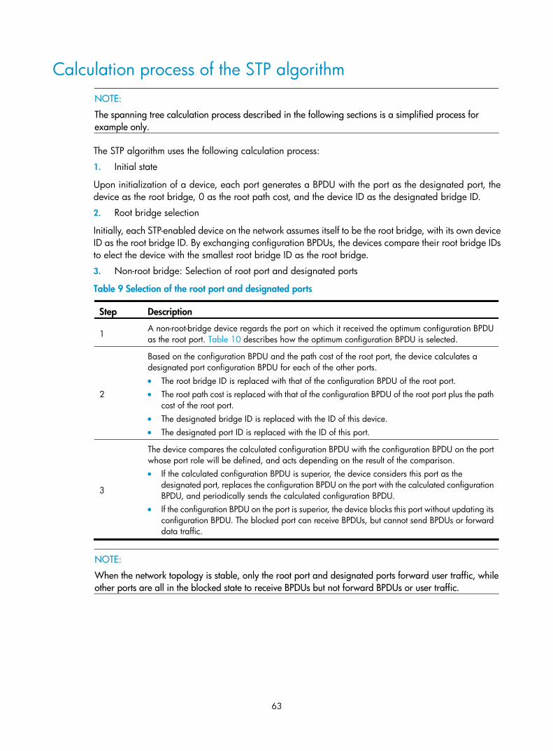
63
Calculation process of the STP algorithm
NOTE:
The spanning tree calculation process described in the following sections is a simplified process for example only.
The STP algorithm uses the following calculation process:
1. Initial state
Upon initialization of a device, each port generates a BPDU with the port as the designated port, the device as the root bridge, 0 as the root path cost, and the device ID as the designated bridge ID.
2. Root bridge selection
Initially, each STP-enabled device on the network assumes itself to be the root bridge, with its own device ID as the root bridge ID. By exchanging configuration BPDUs, the devices compare their root bridge IDs to elect the device with the smallest root bridge ID as the root bridge.
3. Non-root bridge: Selection of root port and designated ports
Table 9 Selection of the root port and designated ports
Step Description
1 A non-root-bridge device regards the port on which it received the optimum configuration BPDU as the root port. Table 10 describes how the optimum configuration BPDU is selected.
2
Based on the configuration BPDU and the path cost of the root port, the device calculates a designated port configuration BPDU for each of the other ports. • The root bridge ID is replaced with that of the configuration BPDU of the root port. • The root path cost is replaced with that of the configuration BPDU of the root port plus the path
cost of the root port. • The designated bridge ID is replaced with the ID of this device. • The designated port ID is replaced with the ID of this port.
3
The device compares the calculated configuration BPDU with the configuration BPDU on the port whose port role will be defined, and acts depending on the result of the comparison. • If the calculated configuration BPDU is superior, the device considers this port as the
designated port, replaces the configuration BPDU on the port with the calculated configuration BPDU, and periodically sends the calculated configuration BPDU.
• If the configuration BPDU on the port is superior, the device blocks this port without updating its configuration BPDU. The blocked port can receive BPDUs, but cannot send BPDUs or forward data traffic.
NOTE:
When the network topology is stable, only the root port and designated ports forward user traffic, while other ports are all in the blocked state to receive BPDUs but not forward BPDUs or user traffic.

64
Table 10 Selection of the optimum configuration BPDU
Step Actions
1
Upon receiving a configuration BPDU on a port, the device compares the priority of the received configuration BPDU with that of the configuration BPDU generated by the port, and: • If the former priority is lower, the device discards the received configuration BPDU and keeps
the configuration BPDU the port generated. • If the former priority is higher, the device replaces the content of the configuration BPDU
generated by the port with the content of the received configuration BPDU.
2 The device compares the configuration BPDUs of all the ports and chooses the optimum configuration BPDU.
NOTE:
The following are the principles of configuration BPDU comparison:
• The configuration BPDU with the lowest root bridge ID has the highest priority.
• If configuration BPDUs have the same root bridge ID, their root path costs are compared. For example,the root path cost in a configuration BPDU plus the path cost of a receiving port is S. The configurationBPDU with the smallest S value has the highest priority.
• If all configuration BPDUs have the same ports value, their designated bridge IDs, designated port IDs,and the IDs of the receiving ports are compared in sequence. The configuration BPDU that contains thesmallest ID wins.
A tree-shape topology forms when the root bridge, root ports, and designated ports are selected.
Figure 18 describes with an example how the STP algorithm works.
Figure 18 Network diagram for the STP algorithm
Path
cos
t = 5
Path cost = 10
As shown in Figure 18, the priority values of Device A, Device B, and Device C are 0, 1, and 2, and the path costs of links among the three devices are 5, 10, and 4 respectively.
4. Initial state of each device

65
Table 11 Initial state of each device
Device Port name Configuration BPDU on the port
Port A1 {0, 0, 0, Port A1} Device A
Port A2 {0, 0, 0, Port A2}
Port B1 {1, 0, 1, Port B1} Device B
Port B2 {1, 0, 1, Port B2}
Port C1 {2, 0, 2, Port C1} Device C
Port C2 {2, 0, 2, Port C2}
NOTE:
In Table 11, each configuration BPDU contains the following fields: root bridge ID, root path cost, designated bridge ID, and designated port ID.
5. Comparison process and result on each device
Table 12 Comparison process and result on each device
Device Comparison process Configuration BPDU on ports after comparison
Device A
• Port A1 receives the configuration BPDU of Port B1 {1, 0, 1, Port B1}, finds that its existing configuration BPDU {0, 0, 0, Port A1} is superior to the received configuration BPDU, and discards the received one.
• Port A2 receives the configuration BPDU of Port C1 {2, 0, 2, Port C1}, finds that its existing configuration BPDU {0, 0, 0, Port A2} is superior to the received configuration BPDU, and discards the received one.
• Device A finds that it is both the root bridge and designated bridge in the configuration BPDUs of all its ports, and considers itself as the root bridge. It does not change the configuration BPDU of any port and starts to periodically send configuration BPDUs.
• Port A1: {0, 0, 0, Port A1}
• Port A2: {0, 0, 0, Port A2}
Device B
• Port B1 receives the configuration BPDU of Port A1 {0, 0, 0, Port A1}, finds that the received configuration BPDU is superior to its existing configuration BPDU {1, 0, 1, Port B1}, and updates its configuration BPDU.
• Port B2 receives the configuration BPDU of Port C2 {2, 0, 2, Port C2}, finds that its existing configuration BPDU {1, 0, 1, Port B2} is superior to the received configuration BPDU, and discards the received one.
• Port B1: {0, 0, 0, Port A1}
• Port B2: {1, 0, 1, Port B2}

66
Device Comparison process Configuration BPDU on ports after comparison
• Device B compares the configuration BPDUs of all its ports, decides that the configuration BPDU of Port B1 is the optimum, and selects Port B1 as the root port with the configuration BPDU unchanged.
• Based on the configuration BPDU and path cost of the root port, Device B calculates a designated port configuration BPDU for Port B2 {0, 5, 1, Port B2}, and compares it with the existing configuration BPDU of Port B2 {1, 0, 1, Port B2}. Device B finds that the calculated one is superior, decides that Port B2 is the designated port, replaces the configuration BPDU on Port B2 with the calculated one, and periodically sends the calculated configuration BPDU.
• Root port (Port B1): {0, 0, 0, Port A1}
• Designated port (Port B2): {0, 5, 1, Port B2}
• Port C1 receives the configuration BPDU of Port A2 {0, 0, 0, Port A2}, finds that the received configuration BPDU is superior to its existing configuration BPDU {2, 0, 2, Port C1}, and updates its configuration BPDU.
• Port C2 receives the original configuration BPDU of Port B2 {1, 0, 1, Port B2}, finds that the received configuration BPDU is superior to the existing configuration BPDU {2, 0, 2, Port C2}, and updates its configuration BPDU.
• Port C1: {0, 0, 0, Port A2}
• Port C2: {1, 0, 1, Port B2}
• Device C compares the configuration BPDUs of all its ports, decides that the configuration BPDU of Port C1 is the optimum, and selects Port C1 as the root port with the configuration BPDU unchanged.
• Based on the configuration BPDU and path cost of the root port, Device C calculates the configuration BPDU of Port C2 {0, 10, 2, Port C2}, and compares it with the existing configuration BPDU of Port C2 {1, 0, 1, Port B2}. Device C finds that the calculated configuration BPDU is superior to the existing one, selects Port C2 as the designated port, and replaces the configuration BPDU of Port C2 with the calculated one.
• Root port (Port C1): {0, 0, 0, Port A2}
• Designated port (Port C2): {0, 10, 2, Port C2}
Device C
• Port C2 receives the updated configuration BPDU of Port B2 {0, 5, 1, Port B2}, finds that the received configuration BPDU is superior to its existing configuration BPDU {0, 10, 2, Port C2}, and updates its configuration BPDU.
• Port C1 receives a periodic configuration BPDU {0, 0, 0, Port A2} from Port A2, finds that it is the same as the existing configuration BPDU, and discards the received one.
• Port C1: {0, 0, 0, Port A2}
• Port C2: {0, 5, 1, Port B2}

67
Device Comparison process Configuration BPDU on ports after comparison
• Device C finds that the root path cost of Port C1 (10) (root path cost of the received configuration BPDU (0) plus path cost of Port C1 (10)) is larger than that of Port C2 (9) (root path cost of the received configuration BPDU (5) plus path cost of Port C2 (4)), decides that the configuration BPDU of Port C2 is the optimum, and selects Port C2 as the root port with the configuration BPDU unchanged.
• Based on the configuration BPDU and path cost of the root port, Device C calculates a designated port configuration BPDU for Port C1 {0, 9, 2, Port C1} and compares it with the existing configuration BPDU of Port C1 {0, 0, 0, Port A2}. Device C finds that the existing configuration BPDU is superior to the calculated one and blocks Port C1 with the configuration BPDU unchanged. Then Port C1 does not forward data until a new event triggers a spanning tree calculation process, for example, the link between Device B and Device C is down.
• Blocked port (Port C1): {0, 0, 0, Port A2}
• Root port (Port C2): {0, 5, 1, Port B2}
NOTE:
In Table 12, each configuration BPDU contains the following fields: root bridge ID, root path cost, designated bridge ID, and designated port ID.
After the comparison processes described in Table 12, a spanning tree with Device A as the root bridge is established, and the topology is shown in Figure 19.
Figure 19 The final calculated spanning tree
NOTE:
This example shows a simplified spanning tree calculation process.
The configuration BPDU forwarding mechanism of STP
The configuration BPDUs of STP are forwarded following these guidelines:
• Upon network initiation, every device regards itself as the root bridge, generates configuration BPDUs with itself as the root, and sends the configuration BPDUs at a regular hello interval.
• If the root port received a configuration BPDU and the received configuration BPDU is superior to the configuration BPDU of the port, the device increases the message age carried in the configuration BPDU following a certain rule and starts a timer to time the configuration BPDU while sending this configuration BPDU through the designated port.

68
• If the configuration BPDU received on a designated port has a lower priority than the configuration BPDU of the local port, the port immediately sends its own configuration BPDU in response.
• If a path becomes faulty, the root port on this path no longer receives new configuration BPDUs and the old configuration BPDUs will be discarded due to timeout. The device generates a configuration BPDU with itself as the root and sends the BPDUs and TCN BPDUs. This triggers a new spanning tree calculation process to establish a new path to restore the network connectivity.
However, the newly calculated configuration BPDU cannot be propagated throughout the network immediately, so the old root ports and designated ports that have not detected the topology change continue forwarding data along the old path. If the new root ports and designated ports begin to forward data as soon as they are elected, a temporary loop might occur.
STP timers
The most important timing parameters in STP calculation are forward delay, hello time, and max age.
• Forward delay
Forward delay is the delay time for port state transition.
A path failure can cause spanning tree re-calculation to adapt the spanning tree structure to the change. However, the resulting new configuration BPDU cannot propagate throughout the network immediately. If the newly elected root ports and designated ports start to forward data immediately, a temporary loop will likely occur.
For this reason, as a mechanism for state transition in STP, the newly elected root ports or designated ports require twice the forward delay time before they transit to the forwarding state to ensure that the new configuration BPDU has propagated throughout the network.
• Hello time
The device sends hello packets at the hello time interval to the neighboring devices to ensure that the paths are fault-free.
• Max age
The device uses the max age to determine whether a stored configuration BPDU has expired and discards it if the max age is exceeded.
RSTP RSTP achieves rapid network convergence by allowing a newly elected root port or designated port to enter the forwarding state much faster under certain conditions than STP.
A newly elected RSTP root port rapidly enters the forwarding state if the old root port on the device has stopped forwarding data and the upstream designated port has started forwarding data.
A newly elected RSTP designated port rapidly enters the forwarding state if it is an edge port (a port that directly connects to a user terminal rather than to another network device or a shared LAN segment) or it connects to a point-to-point link (to another device). Edge ports directly enter the forwarding state. Connecting to a point-to-point link, a designated port enters the forwarding state immediately after the device receives a handshake response from the directly connected device.

69
PVST PVST was introduced to improve link bandwidth usage in network environments where multiple virtual LANs (VLANs) exist. Unlike STP and RSTP whose bridges in a LAN must forward their VLAN packets in the same spanning tree, PVST allows each VLAN to build a separate spanning tree.
PVST uses the following BPDUs:
• STP BPDUs: Sent by access ports according to the VLAN status, or by trunk ports and hybrid ports according to the status of VLAN 1.
• PVST BPDUs: Sent by trunk port and hybrid ports according to the status of permitted VLANs except VLAN 1.
MSTP
STP, RSTP, and PVST limitations STP does not support rapid state transition of ports. A newly elected port must wait twice the forward delay time before it transits to the forwarding state, even if it connects to a point-to-point link or is an edge port.
Although RSTP supports rapid network convergence, it has the same drawback as STP—All bridges within a LAN share the same spanning tree, so redundant links cannot be blocked based on VLAN, and the packets of all VLANs are forwarded along the same spanning tree.
The number of PVST BPDUs generated grows with that of permitted VLANs on trunk ports. When the status of a trunk port transitions, network devices might be overloaded to re-calculate a large number of spanning trees.
MSTP features Developed based on IEEE 802.1s, MSTP overcomes the limitations of STP, RSTP, and PVST. In addition to supporting rapid network convergence, it provides a better load sharing mechanism for redundant links by allowing data flows of different VLANs to be forwarded along separate paths.
MSTP provides the following features:
• MSTP supports mapping VLANs to spanning tree instances by means of a VLAN-to-instance mapping table. MSTP can reduce communication overheads and resource usage by mapping multiple VLANs to one instance.
• MSTP divides a switched network into multiple regions, each of which contains multiple spanning trees that are independent of one another.
• MSTP prunes a loop network into a loop-free tree, which avoids proliferation and endless cycling of packets in a loop network. In addition, it supports load balancing of VLAN data by providing multiple redundant paths for data forwarding.
• MSTP is compatible with STP and RSTP, but is incompatible with PVST.
MSTP basic concepts Figure 20 shows a switched network that comprises four MST regions, each MST region comprising four MSTP devices. Figure 21 shows the networking topology of MST region 3.

70
Figure 20 Basic concepts in MSTP
MST region 1
MST region 2 MST region 3
MST region 4
VLAN 1 MSTI 1VLAN 2 MSTI 2
Other VLANs MSTI 0
VLAN 1 MSTI 1VLAN 2 MSTI 2
Other VLANs MSTI 0
VLAN 1 MSTI 1VLAN 2 MSTI 2
Other VLANs MSTI 0
VLAN 1 MSTI 1VLAN 2&3 MSTI 2
Other VLANs MSTI 0CST
Figure 21 Network diagram and topology of MST region 3
MST region
A multiple spanning tree region (MST region) consists of multiple devices in a switched network and the network segments among them. All these devices have the following characteristics:
• A spanning tree protocol enabled
• Same region name

71
• Same VLAN-to-instance mapping configuration
• Same MSTP revision level
• Physically linked together
Multiple MST regions can exist in a switched network. You can assign multiple devices to the same MST region. In Figure 20, the switched network comprises four MST regions, MST region 1 through MST region 4, and all devices in each MST region have the same MST region configuration.
MSTI
MSTP can generate multiple independent spanning trees in an MST region, and each spanning tree is mapped to the specific VLANs. Each spanning tree is referred to as a multiple spanning tree instance (MSTI).
In Figure 21, MST region 3 comprises three MSTIs, MSTI 1, MSTI 2, and MSTI 0.
VLAN-to-instance mapping table
As an attribute of an MST region, the VLAN-to-instance mapping table describes the mapping relationships between VLANs and MSTIs.
In Figure 21, the VLAN-to-instance mapping table of MST region 3 is: VLAN 1 to MSTI 1, VLAN 2 and VLAN 3 to MSTI 2, and other VLANs to MSTI 0. MSTP achieves load balancing by means of the VLAN-to-instance mapping table.
CST
The common spanning tree (CST) is a single spanning tree that connects all MST regions in a switched network. If you regard each MST region as a device, the CST is a spanning tree calculated by these devices through STP or RSTP.
The blue lines in Figure 20 represent the CST.
IST
An internal spanning tree (IST) is a spanning tree that runs in an MST region. It is also called MSTI 0, a special MSTI to which all VLANs are mapped by default.
In Figure 20, MSTI 0 is the IST in MST region 3.
CIST
The common and internal spanning tree (CIST) is a single spanning tree that connects all devices in a switched network. It consists of the ISTs in all MST regions and the CST.
In Figure 20, the ISTs (MSTI 0) in all MST regions plus the inter-region CST constitute the CIST of the entire network.
Regional root
The root bridge of the IST or an MSTI within an MST region is the regional root of the IST or MSTI. Based on the topology, different spanning trees in an MST region might have different regional roots.
For example, in MST region 3 in Figure 21, the regional root of MSTI 1 is Device B, the regional root of MSTI 2 is Device C, and the regional root of MSTI 0 (also known as the IST) is Device A.
Common root bridge
The common root bridge is the root bridge of the CIST.
In Figure 20, for example, the common root bridge is a device in MST region 1.
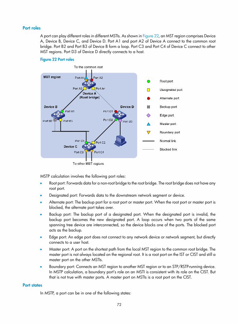
72
Port roles
A port can play different roles in different MSTIs. As shown in Figure 22, an MST region comprises Device A, Device B, Device C, and Device D. Port A1 and port A2 of Device A connect to the common root bridge. Port B2 and Port B3 of Device B form a loop. Port C3 and Port C4 of Device C connect to other MST regions. Port D3 of Device D directly connects to a host.
Figure 22 Port roles
MSTP calculation involves the following port roles:
• Root port: Forwards data for a non-root bridge to the root bridge. The root bridge does not have any root port.
• Designated port: Forwards data to the downstream network segment or device.
• Alternate port: The backup port for a root port or master port. When the root port or master port is blocked, the alternate port takes over.
• Backup port: The backup port of a designated port. When the designated port is invalid, the backup port becomes the new designated port. A loop occurs when two ports of the same spanning tree device are interconnected, so the device blocks one of the ports. The blocked port acts as the backup.
• Edge port: An edge port does not connect to any network device or network segment, but directly connects to a user host.
• Master port: A port on the shortest path from the local MST region to the common root bridge. The master port is not always located on the regional root. It is a root port on the IST or CIST and still a master port on the other MSTIs.
• Boundary port: Connects an MST region to another MST region or to an STP/RSTP-running device. In MSTP calculation, a boundary port’s role on an MSTI is consistent with its role on the CIST. But that is not true with master ports. A master port on MSTIs is a root port on the CIST.
Port states
In MSTP, a port can be in one of the following states:

73
• Forwarding: The port receives and sends BPDUs, obtains MAC addresses, and forwards user traffic.
• Learning: The port receives and sends BPDUs, obtains MAC addresses, but does not forward user traffic. Learning is an intermediate port state.
• Discarding: The port receives and sends BPDUs, but does not obtain MAC addresses or forward user traffic.
NOTE:
When in different MSTIs, a port can be in different states.
A port state is not exclusively associated with a port role. Table 13 lists the port states that each port role supports. (A check mark [√] indicates that the port supports this state, while a dash [—] indicates that the port does not support this state.)
Table 13 Port states that different port roles support
Port role (right)
Port state (below)
Root port/master port Designated port Alternate port Backup port
Forwarding √ √ — —
Learning √ √ — —
Discarding √ √ √ √
How MSTP works MSTP divides an entire Layer 2 network into multiple MST regions, which are connected by a calculated CST. Inside an MST region, multiple spanning trees are calculated. Each spanning tree is an MSTI. Among these MSTIs, MSTI 0 is the IST. Like STP, MSTP uses configuration BPDUs to calculate spanning trees. An important difference is that an MSTP BPDU carries the MSTP configuration of the bridge from which the BPDU is sent.
CIST calculation
The calculation of a CIST tree is also the process of configuration BPDU comparison. During this process, the device with the highest priority is elected as the root bridge of the CIST. MSTP generates an IST within each MST region through calculation. At the same time, MSTP regards each MST region as a single device and generates a CST among these MST regions through calculation. The CST and ISTs constitute the CIST of the entire network.
MSTI calculation
Within an MST region, MSTP generates different MSTIs for different VLANs based on the VLAN-to-instance mappings. For each spanning tree, MSTP performs a separate calculation process similar to spanning tree calculation in STP. For more information, see “Calculation process of the STP algorithm.”
In MSTP, a VLAN packet is forwarded along the following paths:
• Within an MST region, the packet is forwarded along the corresponding MSTI.
• Between two MST regions, the packet is forwarded along the CST.

74
Implementation of MSTP on devices MSTP is compatible with STP and RSTP. Devices that are running MSTP and that are used for spanning tree calculation can identify STP and RSTP protocol packets.
In addition to basic MSTP functions, the following functions are provided for ease of management:
• Root bridge hold
• Root bridge backup
• Root guard
• BPDU guard
• Loop guard
• TC-BPDU guard
• Support for hot swapping of interface cards and active/standby changeover.
Protocols and standards The spanning tree protocols are documented in the following standards:
• IEEE 802.1d, Media Access Control (MAC) Bridges
• IEEE 802.1w, Part 3: Media Access Control (MAC) Bridges—Amendment 2: Rapid Reconfiguration
• IEEE 802.1s, Virtual Bridged Local Area Networks—Amendment 3: Multiple Spanning Trees
Spanning tree configuration task list Before configuring a spanning tree, you must determine the spanning tree protocol to be used (STP, RSTP, PVST, or MSTP) and plan the device roles (the root bridge or leaf node).
Complete the following tasks to configure STP:
Task Remarks
Setting the spanning tree mode Required
Configure the device to work in STP-compatible mode.
Configuring the root bridge or a secondary root bridge Optional
Configuring the device priority Optional
Configuring the network diameter of a switched network Optional
Configuring spanning tree timers Optional
Configuring the timeout factor Optional
Configuring the maximum port rate Optional
Configuring the mode a port uses to recognize/send MSTP packets Optional
Enabling the output of port state transition information Optional
Configuring the root bridge
Enabling the spanning tree feature Required
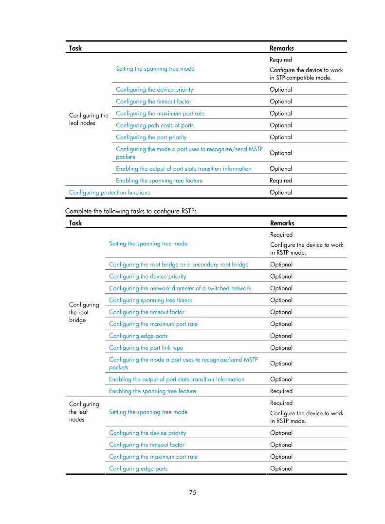
75
Task Remarks
Setting the spanning tree mode Required
Configure the device to work in STP-compatible mode.
Configuring the device priority Optional
Configuring the timeout factor Optional
Configuring the maximum port rate Optional
Configuring path costs of ports Optional
Configuring the port priority Optional
Configuring the mode a port uses to recognize/send MSTP packets Optional
Enabling the output of port state transition information Optional
Configuring the leaf nodes
Enabling the spanning tree feature Required
Configuring protection functions Optional
Complete the following tasks to configure RSTP:
Task Remarks
Setting the spanning tree mode Required
Configure the device to work in RSTP mode.
Configuring the root bridge or a secondary root bridge Optional
Configuring the device priority Optional
Configuring the network diameter of a switched network Optional
Configuring spanning tree timers Optional
Configuring the timeout factor Optional
Configuring the maximum port rate Optional
Configuring edge ports Optional
Configuring the port link type Optional
Configuring the mode a port uses to recognize/send MSTP packets Optional
Enabling the output of port state transition information Optional
Configuring the root bridge
Enabling the spanning tree feature Required
Setting the spanning tree mode Required
Configure the device to work in RSTP mode.
Configuring the device priority Optional
Configuring the timeout factor Optional
Configuring the maximum port rate Optional
Configuring the leaf nodes
Configuring edge ports Optional

76
Task Remarks
Configuring path costs of ports Optional
Configuring the port priority Optional
Configuring the port link type Optional
Configuring the mode a port uses to recognize/send MSTP packets Optional
Enabling the output of port state transition information Optional
Enabling the spanning tree feature Required
Performing mCheck Optional
Configuring protection functions Optional
Complete the following tasks to configure PVST:
Task Remarks
Setting the spanning tree mode Required
Configure the device to work in PVST mode.
Configuring the root bridge or a secondary root bridge Optional
Configuring the device priority Optional
Configuring the network diameter of a switched network Optional
Configuring spanning tree timers Optional
Configuring the timeout factor Optional
Configuring the maximum port rate Optional
Configuring edge ports Optional
Configuring the port link type Optional
Enabling the output of port state transition information Optional
Configuring the root bridge
Enabling the spanning tree feature Required
Setting the spanning tree mode Required
Configure the device to work in PVST mode.
Configuring the device priority Optional
Configuring the timeout factor Optional
Configuring the maximum port rate Optional
Configuring edge ports Optional
Configuring path costs of ports Optional
Configuring the port priority Optional
Configuring the port link type Optional
Configuring the leaf nodes
Enabling the output of port state transition information Optional

77
Task Remarks
Enabling the spanning tree feature Required
Performing mCheck Optional
Configuring protection functions Optional
Complete the following tasks to configure MSTP:
Task Remarks
Setting the spanning tree mode Optional
By default, the device works in MSTP mode.
Configuring an MST region Required
Configuring the root bridge or a secondary root bridge Optional
Configuring the device priority Optional
Configuring the maximum hops of an MST region Optional
Configuring the network diameter of a switched network Optional
Configuring spanning tree timers Optional
Configuring the timeout factor Optional
Configuring the maximum port rate Optional
Configuring edge ports Optional
Configuring the port link type Optional
Configuring the mode a port uses to recognize/send MSTP packets Optional
Enabling the output of port state transition information Optional
Configuring the root bridge
Enabling the spanning tree feature Required
Setting the spanning tree mode Optional
By default, the device works in MSTP mode.
Configuring an MST region Required
Configuring the device priority Optional
Configuring the timeout factor Optional
Configuring the maximum port rate Optional
Configuring edge ports Optional
Configuring path costs of ports Optional
Configuring the port priority Optional
Configuring the port link type Optional
Configuring the mode a port uses to recognize/send MSTP packets Optional
Enabling the output of port state transition information Optional
Configuring the leaf nodes
Enabling the spanning tree feature Required
Performing mCheck Optional

78
Task Remarks
Configuring Digest Snooping Optional
Configuring No Agreement Check Optional
Configuring protection functions Optional
NOTE:
• If GVRP and a spanning tree protocol are enabled on a device at the same time, GVRP packets are forwarded along the CIST. To advertise a certain VLAN within the network through GVRP, be sure thatthis VLAN is mapped to the CIST when you configure the VLAN-to-instance mapping table. For more information about GVRP, see the chapter “GVRP configuration.”
• The spanning tree configurations are mutually exclusive with any of the following functions on a port: service loopback, RRPP, Smart Link, and BPDU tunneling.
• The spanning tree configurations made in system view take effect globally. Configurations made in Layer2 Ethernet interface view take effect on the current interface only. Configurations made in port group view take effect on all member ports in the port group. Configurations made in Layer 2 aggregate interface view take effect only on the aggregate interface. Configurations made on an aggregation member port can take effect only after the port is removed from the aggregation group.
• After you enable a spanning tree protocol on a Layer 2 aggregate interface, the system performs spanning tree calculation on the Layer 2 aggregate interface but not on the aggregation member ports.The spanning tree protocol enable state and forwarding state of each selected member port is consistentwith those of the corresponding Layer 2 aggregate interface.
• Though the member ports of an aggregation group do not participate in spanning tree calculation, theports still reserve their spanning tree configurations for participating in spanning tree calculation after leaving the aggregation group.
An S7500E switch installed with an optical line terminal (OLT) card can work as an Ethernet passive optical network (EPON) OLT. You can remotely configure STP/RSTP/MSTP for optical network units (ONUs) in ONU port view to remove loops between attached ONUs, and you can also remotely configure RSTP for user-network interfaces (UNIs) on an ONU to remove loops between UNIs and terminal users.
Complete the following tasks to configure MSTP:
Task Remarks
Remotely configuring MSTP for an ONU Optional
Remotely configure RSTP for UNIs of an ONU Optional
For more information about the configuration procedure, see the chapter “ONU remote management configuration.”
Configuring the spanning tree
Setting the spanning tree mode The spanning tree modes include:
• STP-compatible mode: The device sends STP BPDUs through all ports.

79
• RSTP mode: The device sends RSTP BPDUs through all ports, and ports that connect to STP devices automatically transitions to the STP-compatible mode.
• MSTP mode: The device sends MSTP BPDUs through all ports, and ports that connect to STP devices automatically transitions to the STP-compatible mode.
• PVST mode: The device sends PVST BPDUs through all ports and maintains a spanning tree for each VLAN. The S7500E Switch Series supports up to 128 VLANs in PVST mode. The maximum number of VLANs (assume that the number is n) for which PVST can maintain instances varies by device model. When configuring PVST on devices of different models in a network, to avoid network failures, be sure that the number of VLANs for which PVST maintains instances does not exceed the lowest n.
Follow these steps to set the spanning tree mode:
To do... Use the command... Remarks
Enter system view system-view —
Set the spanning tree mode stp mode { stp | rstp | mstp | pvst } Required
MSTP mode by default.
NOTE:
Whether you need to specify the MSTI or VLAN for the spanning tree configuration varies with the spanning tree modes.
• In STP-compatible or RSTP mode, do not specify any MSTI or VLAN. Otherwise, the spanning tree configuration is ineffective.
• In MSTP mode, if you specify an MSTI, the spanning tree configuration is effective for the specified MSTI.If you specify a VLAN list, the spanning tree configuration is ineffective. If you do not specify any MSTIor VLAN, the spanning tree configuration is effective for the CIST.
• In PVST mode, if you specify a VLAN list, the spanning tree configuration is effective for the specified VLANs. If you do not specify any VLAN, the spanning tree configuration is ineffective.
Configuring an MST region Follow these steps to configure an MST region:
To do... Use the command... Remarks
Enter system view system-view —
Enter MST region view stp region-configuration —
Configure the MST region name
region-name name Optional
The MST region name is the MAC address by default.
instance instance-id vlan vlan-list Configure the VLAN-to-instance mapping table vlan-mapping modulo modulo
Optional
Use either command.
All VLANs in an MST region are mapped to the CIST (or MSTI 0) by default.
Configure the MSTP revision level of the MST region
revision-level level Optional
0 by default.

80
To do... Use the command... Remarks
Display the MST region configurations that are not activated yet
check region-configuration Optional
Activate MST region configuration manually
active region-configuration Required
Display the activated configuration information of the MST region
display stp region-configuration [ | { begin | exclude | include } regular-expression ]
Optional
Available in any view.
NOTE:
• Two or more spanning tree devices belong to the same MST region only if they are configured to havethe same format selector (0 by default, not configurable), MST region name, MST region revision level,and the same VLAN-to-instance mapping entries in the MST region, and they are connected via a physical link.
• The configuration of MST region–related parameters, especially the VLAN-to-instance mapping table, will result in a new spanning tree calculation. To reduce the possibility of topology instability, the MST region configuration takes effect only after you activate it by using the active region-configuration command, or enable a spanning tree protocol by using the stp enable command in the case that the spanning tree protocol is disabled.
• The device in PVST mode automatically maps VLANs to MSTIs, and supports more MSTIs than in MSTPmode. When you change the spanning tree mode from PVST to MSTP, exceeding VLAN-to-instance mappings (arranged in ascending order of MSTI IDs) are silently deleted and cannot be recovered evenif you change the spanning tree mode back. To prevent loss of mappings, do not manually configure VLAN-to-instance mappings in PVST mode.
Configuring the root bridge or a secondary root bridge You can have MSTP determine the root bridge of a spanning tree through MSTP calculation, or you can specify the current device as the root bridge or as a secondary root bridge using the commands that the system provides.
A device has independent roles in different spanning trees. It can act as the root bridge in one spanning tree and as a secondary root bridge in another. However, one device cannot be the root bridge and a secondary root bridge in the same spanning tree.
A spanning tree can have one root bridge only. If two or more devices are designated as the root bridge in a spanning tree at the same time, the device with the lowest MAC address wins.
When the root bridge of an instance fails or is shut down, the secondary root bridge (if you have specified one) can take over the role of the primary root bridge. However, if you specify a new primary root bridge for the instance then, the one you specify, not the secondary root bridge will become the root bridge. If you have specified multiple secondary root bridges for an instance, when the root bridge fails, the secondary root bridge with the lowest MAC address is selected as the new root bridge.
Configuring the current device as the root bridge of a specific spanning tree
Follow these steps to configure the current device as the root bridge of a specific spanning tree:
To do... Use the command... Remarks
Enter system view system-view —

81
To do... Use the command... Remarks
Configure the current device as the root bridge (in STP/RSTP mode) stp root primary
Configure the current device as the root bridge (in PVST mode) stp vlan vlan-list root primary
Configure the current device as the root bridge (in MSTP mode)
stp [ instance instance-id ] root primary
Required
Use any command.
By default, a device does not function as the root bridge.
Configuring the current device as a secondary root bridge of a specific spanning tree
Follow these steps to configure the current device as a secondary root bridge of a specific spanning tree:
To do... Use the command... Remarks
Enter system view system-view —
Configure the current device as a secondary root bridge (in STP/RSTP mode) stp root secondary
Configure the current device as a secondary root bridge (in PVST mode) stp vlan vlan-list root secondary
Configure the current device as a secondary root bridge (in MSTP mode)
stp [ instance instance-id ] root secondary
Required
Use any command.
By default, a device does not function as a secondary root bridge.
NOTE:
• You can specify one root bridge for each spanning tree, regardless of the device priority settings. Onceyou specify a device as the root bridge or a secondary root bridge, you cannot change its priority.
• You can configure the current device as the root bridge by setting the device priority to 0. For the devicepriority configuration, see “Configuring the device priority.”
Configuring the device priority Device priority is a factor in spanning tree calculation. The priority of a device determines whether the device can be elected as the root bridge of a spanning tree. A lower numeric value indicates a higher priority. You can set the priority of a device to a low value to specify the device as the root bridge of the spanning tree. A spanning tree device can have different priorities in different MSTIs.
Follow these steps to configure the priority of a device in a specified MSTI:
To do... Use the command... Remarks
Enter system view system-view —
Configure the priority of the current device (in STP/RSTP mode) stp priority priority
Configure the priority of the current device (in PVST mode) stp vlan vlan-list priority priority
Configure the priority of the current device (in MSTP mode)
stp [ instance instance-id ] priority priority
Required
Use any command.
32768 by default.

82
CAUTION:
• You cannot change the priority of a device after it is configured as the root bridge or as a secondary rootbridge.
• During root bridge selection, if all devices in a spanning tree have the same priority, the one with the lowest MAC address will be selected as the root bridge of the spanning tree.
Configuring the maximum hops of an MST region By setting the maximum hops of an MST region, you can restrict the region size. The maximum hops configured on the regional root bridge will be used as the maximum hops of the MST region.
Configuration BPDUs sent by the regional root bridge always have a hop count set to the maximum value. When a device receives this configuration BPDU, it decrements the hop count by 1, and uses the new hop count in the BPDUs that it propagates. When the hop count of a BPDU reaches 0, it is discarded by the device that received it. This prevents devices beyond the reach of the maximum hop from participate in spanning tree calculation, so the size of the MST region is limited.
Make this configuration on the root bridge only. All other devices in the MST region use the maximum hop value set for the root bridge.
Follow these steps to configure the maximum number of hops of an MST region:
To do... Use the command... Remarks
Enter system view system-view —
Configure the maximum hops of the MST region
stp max-hops hops Required
20 by default.
Configuring the network diameter of a switched network Any two terminal devices in a switched network are connected through a specific path composed of a series of devices. The network diameter is the number of devices on the path composed of the most devices. The network diameter is a parameter that indicates the network size. A bigger network diameter indicates a larger network size.
Follow these steps to configure the network diameter of a switched network:
To do... Use the command... Remarks
Enter system view system-view —
Configure the network diameter of the switched network (in STP/RSTP/MSTP mode) stp bridge-diameter diameter
Configure the network diameter of the switched network (in PVST mode)
stp vlan vlan-list bridge-diameter diameter
Required
Use either command.
7 by default.
NOTE:
• Based on the network diameter you configured, the system automatically sets an optimal hello time, forward delay, and max age for the device.
• In STP/RSTP/MSTP mode, each MST region is considered as a device and the configured network diameter is effective only for the CIST (or the common root bridge), but not for MSTIs.
• In PVST mode, the network diameter configuration is effective on the root bridge only.

83
Configuring spanning tree timers The following timers are used for spanning tree calculation:
• Forward delay
It is the delay time for port state transition. To prevent temporary loops on a network, the spanning tree sets an intermediate port state, the learning state, before it transitions from the discarding state to the forwarding state, and requires that the port transitions its state after a forward delay timer to ensure that the state transition of the local port keeps synchronized with the peer.
• Hello time
The device detects whether a link failure has occurred with the hello time interval. The spanning tree sends a configuration BPDU every hello time interval. If the device receives no configuration BPDUs within the hello time interval, it recalculates the spanning tree.
• Max age
In the CIST of an MSTP network or each VLAN of a PVST network, the device uses the max age parameter to determine whether a configuration BPDU received by a port has expired. If a port receives a configuration BPDU that has expired, that MSTI must be re-calculated. The max age timer is ineffective for MSTIs.
To avoid frequent network changes, be sure that the settings of the hello time, forward delay and max age timers meet the following formulas:
• 2 × (forward delay – 1 second) ƒ max age
• Max age ƒ 2 × (hello time + 1 second)
H3C does not recommend you to manually set the spanning tree timers. Instead, you can specify the network diameter and let spanning tree protocols automatically calculate the timers based on the network diameter. If the network diameter uses the default value, the timers also use their default values.
Configure the timers on the root bridge only, and the timer settings on the root bridge apply to all devices on the entire switched network.
Follow these steps to configure the spanning tree timers:
To do... Use the command... Remarks
Enter system view system-view —
Configure the forward delay timer (in STP/RSTP/MSTP mode) stp timer forward-delay time
Configure the forward delay timer (in PVST mode)
stp vlan vlan-list timer forward-delay time
Optional
Use either command.
1500 centiseconds by default.
Configure the hello timer (in STP/RSTP/MSTP mode) stp timer hello time
Configure the hello timer (in PVST mode)
stp vlan vlan-list timer hello time
Optional
Use either command.
200 centiseconds by default.
Configure the max age timer (in STP/RSTP/MSTP mode) stp timer max-age time
Configure the max age timer (in PVST mode)
stp vlan vlan-list timer max-age time
Optional
Use either command.
2000 centiseconds by default.

84
NOTE:
• The length of the forward delay timer is related to the network diameter of the switched network. The larger the network diameter is, the longer the forward delay time should be. If the forward delay timeris too short, temporary redundant paths might occur. If the forward delay timer is too long, network convergence might take a long time. H3C recommends you to use the default setting.
• An appropriate hello time setting enables the device to quickly detect link failures on the network withoutusing excessive network resources. If the hello time is too long, the device will mistake packet loss as a link failure and trigger a new spanning tree calculation process. If the hello time is too short, the devicewill frequently send the same configuration BPDUs, which adds the device burden and wastes networkresources. H3C recommends you to use the default setting.
• If the max age timer is too short, the device will frequently begin spanning tree calculation and might mistake network congestion as a link failure. If the max age timer is too long, the device might fail to quickly detect link failures and begin spanning tree calculations, reducing the auto-sensing capability ofthe network. H3C recommends you to use the default setting.
Configuring the timeout factor The timeout factor is a parameter used to decide the timeout time, in the following formula: Timeout time = timeout factor × 3 × hello time.
After the network topology is stabilized, each non-root-bridge device forwards configuration BPDUs to the downstream devices at the interval of hello time to determine whether any link is faulty. If a device does not receive a BPDU from the upstream device within nine times the hello time, it assumes that the upstream device has failed and starts a new spanning tree calculation process.
Sometimes a device might fail to receive a BPDU from the upstream device because the upstream device is busy. If a spanning tree calculation occurs, the calculation can fail and also waste network resources. In a stable network, you can prevent undesired spanning tree calculations by setting the timeout factor to 5, 6, or 7.
Follow these steps to configure the timeout factor:
To do... Use the command... Remarks
Enter system view system-view —
Configure the timeout factor of the device stp timer-factor factor Required
3 by default.
Configuring the maximum port rate The maximum rate of a port refers to the maximum number of BPDUs the port can send within each hello time. The maximum rate of a port is related to the physical status of the port and the network structure.
Follow these steps to configure the maximum rate of a port or a group of ports:
To do... Use the command... Remarks
Enter system view system-view —
Enter interface view or port
Enter Layer 2 Ethernet interface view or Layer 2 aggregate interface view
interface interface-type interface-number
Required
Use either command.

85
To do... Use the command... Remarks group view
Enter port group view port-group manual port-group-name
Configure the maximum rate of the ports stp transmit-limit limit Required
10 by default.
NOTE:
The higher the maximum port rate is, the more BPDUs will be sent within each hello time, and the more system resources will be used. By setting an appropriate maximum port rate, you can limit the rate at which the port sends BPDUs and prevent spanning tree protocols from using excessive network resourceswhen the network becomes unstable. H3C recommends you to use the default setting.
Configuring edge ports If a port directly connects to a user terminal rather than another device or a shared LAN segment, this port is regarded as an edge port. When network topology change occurs, an edge port will not cause a temporary loop. Because a device does not determine whether a port is directly connected to a terminal, you must manually configure the port as an edge port. After that, the port can transition rapidly from the blocked state to the forwarding state.
Follow these steps to specify a port or a group of ports as edge port or ports:
To do... Use the command... Remarks
Enter system view system-view —
Enter Layer 2 Ethernet interface view or Layer 2 aggregate interface view
interface interface-type interface-number
Enter interface view or port group view Enter port group view
port-group manual port-group-name
Required
Use either command.
Configure the current ports as edge ports stp edged-port enable Required
All ports are non-edge ports by default.
NOTE:
• If BPDU guard is disabled, a port set as an edge port will become a non-edge port again if it receivesa BPDU from another port. To restore the edge port, re-enable it.
• If a port directly connects to a user terminal, configure it as an edge port and enable BPDU guard for it.This enables the port to transition to the forwarding state quickly while ensuring network security.
• You cannot configure edge port settings and loop guard on a port at the same time.
Configuring path costs of ports Path cost is a parameter related to the rate of a port. On a spanning tree device, a port can have different path costs in different MSTIs. Setting appropriate path costs allows VLAN traffic flows to be forwarded along different physical links, achieving VLAN-based load balancing.
You can have the device automatically calculate the default path cost, or you can configure the path cost for ports.

86
Specifying a standard for the device to use when it calculates the default path cost
You can specify a standard for the device to use in automatic calculation for the default path cost. The device supports the following standards:
• dot1d-1998—The device calculates the default path cost for ports based on IEEE 802.1d-1998.
• dot1t—The device calculates the default path cost for ports based on IEEE 802.1t.
• legacy—The device calculates the default path cost for ports based on a private standard.
Follow these steps to specify a standard for the device to use when it calculates the default path cost:
To do... Use the command... Remarks
Enter system view system-view —
Specify a standard for the device to use when it calculates the default path costs of its ports
stp pathcost-standard { dot1d-1998 | dot1t | legacy }
Optional
legacy by default.
CAUTION:
If you change the standard that the device uses to calculate the default path costs, you restore the path costs to the default.
NOTE:
When it calculates path cost for an aggregate interface, IEEE 802.1t takes into account the number of Selected ports in its aggregation group, but IEEE 802.1d-1998 does not. The calculation formula of IEEE802.1t is: Path cost = 200,000,000/link speed (in 100 kbps), where link speed is the sum of the link speedvalues of the Selected ports in the aggregation group.
Table 14 Mappings between the link speed and the path cost
Path cost Link speed Port type
IEEE 802.1d-1998 IEEE 802.1t Private standard
0 — 65535 200,000,000 200,000
Single port 2,000,000 2000
Aggregate interface containing 2 Selected ports 1,000,000 1800
Aggregate interface containing 3 Selected ports 666,666 1600
10 Mbps
Aggregate interface containing 4 Selected ports
100
500,000 1400
Single port 200,000 200
Aggregate interface containing 2 Selected ports 100,000 180
Aggregate interface containing 3 Selected ports 66,666 160
100 Mbps
Aggregate interface containing 4 Selected ports
19
50,000 140
1000 Mbps Single port 4 20,000 20

87
Path cost Link speed Port type
IEEE 802.1d-1998 IEEE 802.1t Private standard
Aggregate interface containing 2 Selected ports 10,000 18
Aggregate interface containing 3 Selected ports 6666 16
Aggregate interface containing 4 Selected ports 5000 14
Single port 2000 2
Aggregate interface containing 2 Selected ports 1000 1
Aggregate interface containing 3 Selected ports 666 1
10 Gbps
Aggregate interface containing 4 Selected ports
2
500 1
Configuring path costs of ports
Follow these steps to configure the path cost of ports:
To do... Use the command... Remarks
Enter system view system-view —
Enter Layer 2 Ethernet interface view or Layer 2 aggregate interface view
interface interface-type interface-number
Enter interface view or port group view
Enter port group view port-group manual port-group-name
Required
Use either command.
Configure the path cost of the ports (in STP/RSTP mode)
stp cost cost
Configure the path cost of the ports (in PVST mode) stp vlan vlan-list cost cost
Configure the path cost of the ports (in MSTP mode) stp [ instance instance-id ] cost cost
Required
Use any command.
By default, the system automatically calculates the path cost of each port.
NOTE:
When the path cost of a port changes, the system re-calculates the role of the port and initiates a state transition.
Configuration example
# In MSTP mode, specify the device to calculate the default path costs of its ports by using IEEE 802.1d-1998, and set the path cost of GigabitEthernet 1/0/3 to 200 on MSTI 2. <Sysname> system-view
[Sysname] stp pathcost-standard dot1d-1998
[Sysname] interface gigabitethernet 1/0/3
[Sysname-GigabitEthernet1/0/3] stp instance 2 cost 200

88
# In PVST mode, specify the device to calculate the default path costs of its ports by using IEEE 802.1d-1998, and set the path cost of GigabitEthernet 1/0/3 to 2000 on VLANs 20 through 30. <Sysname> system-view
[Sysname] stp mode pvst
[Sysname] stp pathcost-standard dot1d-1998
[Sysname] interface gigabitethernet 1/0/3
[Sysname-GigabitEthernet1/0/3] stp vlan 20 to 30 cost 2000
Configuring the port priority The priority of a port is an important factor in determining whether the port can be elected as the root port of a device. If all other conditions are the same, the port with the highest priority will be elected as the root port.
On a spanning tree device, a port can have different priorities and play different roles in different spanning trees, so that data of different VLANs can be propagated along different physical paths, implementing per-VLAN load balancing. You can set port priority values based on the actual networking requirements.
Follow these steps to configure the priority of a port or a group of ports:
To do... Use the command... Remarks
Enter system view system-view —
Enter Layer 2 Ethernet interface view or Layer 2 aggregate interface view
interface interface-type interface-number
Enter interface view or port group view Enter port group view port-group manual port-group-name
Required
Use either command.
Configure the port priority (in STP/RSTP mode)
stp port priority priority
Configure the port priority (in PVST mode) stp vlan vlan-list port priority priority
Configure the port priority (in MSTP mode) stp [ instance instance-id ] port priority priority
Required
Use any command.
128 for all ports by default.
NOTE:
When the priority of a port changes, MSTP re-calculates the role of the port and initiates a state transition.
Configuring the port link type A point-to-point link directly connects two devices. If two root ports or designated ports are connected over a point-to-point link, they can rapidly transition to the forwarding state after a proposal-agreement handshake process.
Follow these steps to configure the link type of a port or a group of ports:
To do... Use the command... Remarks
Enter system view system-view —
Enter interface view or port
Enter Layer 2 Ethernet interface view or Layer 2 aggregate interface view
interface interface-type interface-number
Required
Use either command.

89
To do... Use the command... Remarks group view
Enter port group view port-group manual port-group-name
Configure the port link type stp point-to-point { auto | force-false | force-true }
Required
By default, the link type is auto where the port automatically detects the link type.
NOTE:
• You can configure the link type as point-to-point for a Layer 2 aggregate interface or a port that worksin full duplex mode. H3C recommends you to use the default setting and let the device to automaticallydetect the port link type.
• The stp point-to-point force-false or stp point-to-point force-true command configured on a port in MSTP or PVST mode is effective for all MSTIs or VLANs.
• If the physical link to which the port connects is not a point-to-point link but you set it to be one, the configuration might bring a temporary loop.
Configuring the mode a port uses to recognize/send MSTP packets
A port can receive/send MSTP packets in the following formats:
• dot1s—802.1s-compliant standard format
• legacy—Compatible format
By default, the packet format recognition mode of a port is auto. The port automatically distinguishes the two MSTP packet formats, and determines the format of packets that it will send based on the recognized format.
You can configure the MSTP packet format on a port. When working in MSTP mode after the configuration, the port sends and receives only MSTP packets of the format that you have configured to communicate with devices that send packets of the same format.
Follow these steps to configure the MSTP packet format to be supported on a port or a group of ports:
To do... Use the command... Remarks
Enter system view system-view —
Enter Layer 2 Ethernet interface view or Layer 2 aggregate interface view
interface interface-type interface-number
Enter interface view or port group view Enter port group view port-group manual port-group-name
Required
Use either command.
Configure the mode that the port uses to recognize/send MSTP packets
stp compliance { auto | dot1s | legacy }
Required
auto by default.

90
NOTE:
• MSTP provides MSTP packet format incompatibility guard. In MSTP mode, if a port is configured to recognize/send MSTP packets in a mode other than auto, and if it receives a packet in a format differentfrom the specified type, the port becomes a designated port and remains in the discarding state to prevent the occurrence of a loop.
• MSTP provides MSTP packet format frequent change guard. If a port receives MSTP packets of differentformats frequently, the MSTP packet format configuration contains errors. If the port is working in MSTPmode, it will be shut down for protection. Ports disabled in this way can be re-activated after a detectioninterval. For more information about the detection interval, see Fundamentals Configuration Guide.
Enabling the output of port state transition information In a large-scale spanning tree network, you can enable devices to output the port state transition information of all MSTIs or the specified MSTI in order to monitor the port states in real time.
Follow these steps to enable output of port state transition information:
To do... Use the command... Remarks
Enter system view system-view —
Enable output of port state transition information (in STP/RSTP mode) stp port-log instance 0
Enable output of port state transition information (in PVST mode) stp port-log vlan vlan-list
Enable output of port state transition information (in MSTP mode)
stp port-log instance { instance-id | all }
Required
Use any command.
Enabled by default.
Enabling the spanning tree feature You must enable the spanning tree feature for the device before any other spanning tree related configurations can take effect.
Enabling the spanning tree feature (in STP/RSTP/MSTP mode)
In STP/RSTP/MSTP mode, make sure that the spanning tree feature is enabled globally and on the desired ports.
Follow these steps to enable the spanning tree feature in STP/RSTP/MSTP mode:
To do... Use the command... Remarks
Enter system view system-view —
Enable the spanning tree feature globally stp enable
Required
Use either command.
By default, the spanning tree feature is disabled globally.
Enter Layer 2 Ethernet interface view or Layer 2 aggregate interface view
interface interface-type interface-number
Enter interface view or port group view Enter port group view
port-group manual port-group-name
Required
Use either command.

91
To do... Use the command... Remarks
Enable the spanning tree feature for the port or group of ports
stp enable Optional
By default, the spanning tree feature is enabled for all ports.
Enabling the spanning tree feature (in PVST mode)
In PVST mode, make sure that the spanning tree feature is enabled globally and on the desired VLANs and ports.
Follow these steps to enable the spanning tree feature in PVST mode:
To do... Use the command... Remarks
Enter system view system-view —
Globally enable the spanning tree feature stp enable Required
By default, the spanning tree feature is disabled globally.
Enable the spanning tree feature on specific VLANs
stp vlan vlan-list enable Required
By default, the spanning tree feature is enabled on VLANs.
Enter Layer 2 Ethernet interface view or Layer 2 aggregate interface view
interface interface-type interface-number
Enter interface view or port group view Enter port group view
port-group manual port-group-name
Required
Use either command.
Enable the spanning tree feature for the port or group of ports
stp enable Optional
By default, the spanning tree feature is enabled on all ports.
NOTE:
• To globally enable or disable the spanning tree feature (not for VLANs), use the stp enable commandor undo stp enable command in system view. To enable or disable the spanning tree feature for specificVLANs, use the stp vlan enable command or undo stp vlan enable command.
• You can disable the spanning tree feature for certain ports with the undo stp enable command to exclude them from spanning tree calculation and save CPU resources of the device.
• In PVST mode, when you globally enable the spanning tree feature the device automatically enables thespanning tree feature for the first n (which is the number of PVST instances that the switch supports andis 128 for the S7500E switch) of the existing VLANs by default. To enable the spanning tree feature forother VLANs, you must first disable the spanning tree feature for certain VLANs. This guideline does notapply if the number of existing VLANs on the switch does not exceed n.
Performing mCheck If a port on a device that is running MSTP, RSTP, or PVST connects to an STP device, this port automatically transitions to the STP-compatible mode. However, it cannot automatically transition back to the original mode under the following circumstances:
• The STP device is shut down or removed.

92
• The STP device transitions to the MSTP, RSTP, or PVST mode.
To forcibly transition the port to operate in the original mode, you can perform an mCheck operation.
The following methods for performing mCheck produce the same result.
Performing mCheck globally
Follow these steps to perform global mCheck:
To do... Use the command... Remarks
Enter system view system-view —
Perform mCheck stp mcheck Required
Performing mCheck in interface view
Follow these steps to perform mCheck in interface view:
To do... Use the command... Remarks
Enter system view system-view —
Enter Layer 2 Ethernet interface view or Layer 2 aggregate interface view
interface interface-type interface-number —
Perform mCheck stp mcheck Required
NOTE:
An mCheck operation takes effect on a device that operates in MSTP, RSTP, or PVST mode.
Configuring Digest Snooping As defined in IEEE 802.1s, connected devices are in the same region only when their MST region-related configurations (region name, revision level, and VLAN-to-instance mappings) are identical. A spanning tree device identifies devices in the same MST region by determining the configuration ID in BPDU packets. The configuration ID includes the region name, revision level, and configuration digest, which is in 16-byte length and is the result calculated via the HMAC-MD5 algorithm based on VLAN-to-instance mappings.
Spanning tree implementations vary with vendors, and the configuration digests calculated using private keys is different, so devices of different vendors in the same MST region cannot communicate with each other.
To enable communication between an H3C device and a third-party device, enable the Digest Snooping feature on the port that connects the H3C device to the third-party device in the same MST region.
NOTE:
Before you enable Digest Snooping, ensure that associated devices of different vendors are connected andrun spanning tree protocols.
Configuring the Digest Snooping feature
You can enable Digest Snooping only on the H3C device that is connected to a third-party device that uses its private key to calculate the configuration digest.
Follow these steps to configure Digest Snooping:

93
To do... Use the command... Remarks
Enter system view system-view —
Enter Layer 2 Ethernet interface view or Layer 2 aggregate interface view
interface interface-type interface-number Enter interface
view or port group view
Enter port group view port-group manual port-group-name
Required
Use either command.
Enable Digest Snooping on the interface or port group stp config-digest-snooping
Required
Disabled by default.
Return to system view quit —
Enable global Digest Snooping stp config-digest-snooping Required
Disabled by default.
CAUTION:
• With digest snooping enabled, in-the-same-region verification does not require comparison of configuration digest, so the VLAN-to-instance mappings must be the same on associated ports.
• With global Digest Snooping enabled, modification of VLAN-to-instance mappings and removal of thecurrent region configuration via the undo stp region-configuration command are not allowed. You canmodify only the region name and revision level.
• To make Digest Snooping take effect, you must enable it both globally and on associated ports. To makethe configuration effective on all configured ports and while reducing impact on the network, enable Digest Snooping on all associated ports first and then globally.
• To prevent loops, do not enable Digest Snooping on MST region edge ports.
• H3C recommends you to enable Digest Snooping first and then the spanning tree feature. To avoid causing traffic interruption, do not configure Digest Snooping when the network is already working well.
Digest Snooping configuration example
1. Network requirements
As shown in Figure 23:
• Device A and Device B connect to Device C, which is a third-party device. All these devices are in the same region.
• Enable Digest Snooping on the ports of Device A and Device B that connect to Device C, so that the three devices can communicate with one another.

94
Figure 23 Digest Snooping configuration
2. Configuration procedure
# Enable Digest Snooping on GigabitEthernet 1/0/1 of Device A and enable global Digest Snooping on Device A. <DeviceA> system-view
[DeviceA] interface gigabitethernet 1/0/1
[DeviceA-GigabitEthernet1/0/1] stp config-digest-snooping
[DeviceA-GigabitEthernet1/0/1] quit
[DeviceA] stp config-digest-snooping
# Enable Digest Snooping on GigabitEthernet 1/0/1 of Device B and enable global Digest Snooping on Device B. <DeviceB> system-view
[DeviceB] interface gigabitethernet 1/0/1
[DeviceB-GigabitEthernet1/0/1] stp config-digest-snooping
[DeviceB-GigabitEthernet1/0/1] quit
[DeviceB] stp config-digest-snooping
Configuring No Agreement Check In RSTP and MSTP, the following types of messages are used for rapid state transition on designated ports:
• Proposal—Sent by designated ports to request rapid transition
• Agreement—Used to acknowledge rapid transition requests
Both RSTP and MSTP devices can perform rapid transition on a designated port only when the port receives an agreement packet from the downstream device. RSTP and MSTP devices have the following differences:
• For MSTP, the root port of the downstream device sends an agreement packet only after it receives an agreement packet from the upstream device.
• For RSTP, the downstream device sends an agreement packet regardless of whether an agreement packet from the upstream device is received.

95
Figure 24 Rapid state transition of an MSTP designated port
Root port Designated port
Upstream device Downstream device
(1) Proposal for rapid transition
(3) Agreement
The root port blocks non-edge ports.
The root port changes to the forwarding state and sends an Agreement to the upstream device.
(2) Agreement
The designated port changes to the
forwarding state.
Figure 25 Rapid state transition of an RSTP designated port
If the upstream device is a third-party device, the rapid state transition implementation might be limited. For example, when the upstream device uses a rapid transition mechanism similar to that of RSTP, and the downstream device adopts MSTP and does not work in RSTP mode, the root port on the downstream device receives no agreement packet from the upstream device and sends no agreement packets to the upstream device. As a result, the designated port of the upstream device fails to transit rapidly, and can only change to the forwarding state after a period twice the Forward Delay.
You can enable the No Agreement Check feature on the downstream device’s port to enable the designated port of the upstream device to transit its state rapidly.
Configuration Prerequisites
Before you configure the No Agreement Check function, complete the following tasks:
• Connect a device to a third-party upstream device that supports spanning tree protocols via a point-to-point link.
• Configure the same region name, revision level and VLAN-to-instance mappings on the two devices, assigning them to the same region.
Configuring the No Agreement Check function
To make the No Agreement Check feature take effect, enable it on the root port.
Follow these steps to configure No Agreement Check:

96
To do... Use the command... Remarks
Enter system view system-view —
Enter Layer 2 Ethernet interface view or Layer 2 aggregate interface view
interface interface-type interface-number Enter interface
or port group view
Enter port group view port-group manual port-group-name
Required
Use either command.
Enable No Agreement Check stp no-agreement-check Required
Disabled by default.
No Agreement Check configuration example
1. Network requirements
As shown in Figure 26:
• Device A connects to a third-party device that has a different spanning tree implementation. Both devices are in the same region.
• The third-party device (Device B) is the regional root bridge, and Device A is the downstream device.
Figure 26 No Agreement Check configuration
2. Configuration procedure
# Enable No Agreement Check on GigabitEthernet 1/0/1 of Device A. <DeviceA> system-view
[DeviceA] interface gigabitethernet 1/0/1
[DeviceA-GigabitEthernet1/0/1] stp no-agreement-check
Configuring protection functions
A spanning tree device supports the following protection functions:
• BPDU guard
• Root guard
• Loop guard
• TC-BPDU guard
Configuration prerequisites
The spanning tree feature has been correctly configured on the device.

97
Enabling BPDU guard
For access layer devices, the access ports can directly connect to the user terminals (such as PCs) or file servers. The access ports are configured as edge ports to allow rapid transition. When these ports receive configuration BPDUs, the system automatically sets the ports as non-edge ports and starts a new spanning tree calculation process. This causes a change of network topology. Under normal conditions, these ports should not receive configuration BPDUs. However, if someone forges configuration BPDUs maliciously to attack the devices, the network will become unstable.
The spanning tree protocol provides the BPDU guard function to protect the system against such attacks. With the BPDU guard function enabled on the devices, when edge ports receive configuration BPDUs, the system closes these ports and notifies the NMS that these ports have been closed by the spanning tree protocol. The device will reactivate the closed ports after a detection interval. For more information about this detection interval, see Fundamentals Configuration Guide.
Configure BPDU guard on a device with edge ports configured.
Follow these steps to enable BPDU guard:
To do... Use the command... Remarks
Enter system view system-view —
Enable the BPDU guard function for the device
stp bpdu-protection Required
Disabled by default.
NOTE:
BPDU guard does not take effect on loopback-testing-enabled ports. For more information about loopback testing, see the chapter “Ethernet interface configuration.”
Enabling root guard
The root bridge and secondary root bridge of a spanning tree should be located in the same MST region. Especially for the CIST, the root bridge and secondary root bridge are put in a high-bandwidth core region during network design. However, due to possible configuration errors or malicious attacks in the network, the legal root bridge might receive a configuration BPDU with a higher priority. Another device will supersede the current legal root bridge, causing an undesired change of the network topology. The traffic that should go over high-speed links is switched to low-speed links, resulting in network congestion.
To prevent this situation, MSTP provides the root guard function. If the root guard function is enabled on a port of a root bridge, this port plays the role of designated port on all MSTIs. After this port receives a configuration BPDU with a higher priority from an MSTI, it immediately sets that port to the listening state in the MSTI, without forwarding the packet. This is equivalent to disconnecting the link connected with this port in the MSTI. If the port receives no BPDUs with a higher priority within twice the forwarding delay, it reverts to its original state.
Configure root guard on a designated port.
Follow these steps to enable root guard:
To do... Use the command... Remarks
Enter system view system-view —

98
To do... Use the command... Remarks
Enter Layer 2 Ethernet interface view or Layer 2 aggregate interface view
interface interface-type interface-number Enter interface
view or port group view
Enter port group view port-group manual port-group-name
Required
Use either command.
Enable the root guard function for the port(s) stp root-protection Required
Disabled by default.
NOTE:
You cannot configure root guard and loop guard on a port at the same time.
Enabling loop guard
A device that keeps receiving BPDUs from the upstream device can maintain the state of the root port and blocked ports. However, link congestion or unidirectional link failures might cause these ports to fail to receive BPDUs from the upstream devices. The device will reselect the port roles: Those ports in forwarding state that failed to receive upstream BPDUs will become designated ports, and the blocked ports will transition to the forwarding state, resulting in loops in the switched network. The loop guard function can suppress the occurrence of such loops.
The initial state of a loop guard-enabled port is discarding in every MSTI. When the port receives BPDUs, its state transitions normally. Otherwise, it stays in the discarding state to prevent temporary loops.
Configure loop guard on the root port and alternate ports of a device.
Follow these steps to enable loop guard:
To do... Use the command... Remarks
Enter system view system-view —
Enter Layer 2 Ethernet interface view or Layer 2 aggregate interface view
interface interface-type interface-number Enter interface
view or port group view
Enter port group view port-group manual port-group-name
Required
Use either command.
Enable the loop guard function for the ports stp loop-protection Required
Disabled by default.
NOTE:
• Do not enable loop guard on a port that connects user terminals. Otherwise, the port will stay in the discarding state in all MSTIs because it cannot receive BPDUs.
• You cannot configure edge port settings and loop guard, or configure root guard and loop guard on aport at the same time.
Enabling TC-BPDU guard
When a switch receives topology change (TC) BPDUs (the BPDUs that notify devices of topology changes), the switch flushes its forwarding address entries. If someone forges TC-BPDUs to attack the switch, the switch will receive a large number of TC-BPDUs within a short time and be busy with forwarding address entry flushing. This affects network stability.

99
With the TC-BPDU guard function, you can set the maximum number of immediate forwarding address entry flushes that the device can perform every a specified period of time (10 seconds). For TC-BPDUs received in excess of the limit, the device performs a forwarding address entry flush when the time period expires. This prevents frequent flushing of forwarding address entries.
Follow these steps to enable TC-BPDU guard:
To do... Use the command... Remarks
Enter system view system-view —
Enable the TC-BPDU guard function stp tc-protection enable Optional
Enabled by default.
Configure the maximum number of forwarding address entry flushes that the device can perform every 10 seconds
stp tc-protection threshold number
Optional
6 by default.
NOTE:
H3C does not recommend you disable this feature.
Remotely configuring MSTP for an ONU An S7500E switch installed with an OLT card can work as an EPON OLT. You can remotely configure MSTP for an ONU attached to the OLT in ONU port view.
An ONU port supports STP/RSTP/MSTP. However, an ONU port supports only MSTI 0 among all MSTIs.
The STP priority of an ONU port is fixed at 0. To ensure the network operates normally, do not configure the ONU as the STP root bridge.
CAUTION:
• When STP is enabled globally on an OLT switch, you must enable STP on all ONUs.
• STP runs normally only when all attached ONUs are H3C ONUs.
• STP configurations in system view of the OLT switch take effect on all attached ONUs.
• An ONU port supports only MSTI 0 among all MSTIs. The MST region configuration on the OLT switchdoes not take effect on the attached ONUs.
Follow these steps to configure MSTP for an ONU port:
To do… Use the command… Remarks
Enter system view system-view —
Enter ONU port view interface interface-type interface-number
—
Configure the maximum transmission rate of the port stp transmit-limit packet-number
Optional
10 by default.
Configure the port as an edge port stp edged-port enable Required
By default, no port is an edge port.

100
To do… Use the command… Remarks
Configure the path cost of the port stp cost cost
Optional
By default, MSTP automatically calculates the path cost of each port.
Configure the link type of the port stp point-to-point { auto | force-false | force-true }
Optional
By default, the device automatically detects whether an Ethernet port connects to a point-to-point link.
Enable the MSTP feature for the port stp enable
Optional
Enabled by default.
Perform mCheck stp mcheck Required
Enable Digest Snooping on the port stp config-digest-snooping
Required
Disabled by default.
Enable No Agreement Check on the port stp no-agreement-check
Required
Disabled by default.
Enable root guard on the port stp root-protection Required
Disabled by default.
Enable loop guard on the port stp loop-protection Required
Disabled by default.
NOTE:
MSTP configuration commands in ONU port view are the same as those in Ethernet interface view, and are not otherwise described.
Displaying and maintaining the spanning tree To do... Use the command... Remarks
Display information about ports blocked by spanning tree protection functions
display stp abnormal-port [ | { begin | exclude | include } regular-expression ] Available in any view
Display BPDU statistics on ports
display stp bpdu-statistics [ interface interface-type interface-number [ instance instance-id ] ] [ | { begin | exclude | include } regular-expression ]
Available in any view
Display information about ports shut down by spanning tree protection functions
display stp down-port [ | { begin | exclude | include } regular-expression ] Available in any view
Display the historical information of port role calculation for the specified MSTI or all MSTIs (in standalone mode)
display stp [ instance instance-id | vlan vlan-id ] history [ slot slot-number ] [ | { begin | exclude | include } regular-expression ]
Available in any view

101
To do... Use the command... Remarks
Display the historical information of port role calculation for the specified MSTI or all MSTIs (in IRF mode)
display stp [ instance instance-id | vlan vlan-id ] history [ chassis chassis-number slot slot-number ] [ | { begin | exclude | include } regular-expression ]
Available in any view
Display the statistics of TC/TCN BPDUs sent and received by all ports in the specified MSTI or all MSTIs (in standalone mode)
display stp [ instance instance-id | vlan vlan-id ] tc [ slot slot-number ] [ | { begin | exclude | include } regular-expression ]
Available in any view
Display the statistics of TC/TCN BPDUs sent and received by all ports in the specified MSTI or all MSTIs (in IRF mode)
display stp [ instance instance-id | vlan vlan-id ] tc [ chassis chassis-number slot slot-number ] [ | { begin | exclude | include } regular-expression ]
Available in any view
Display the spanning tree status and statistics (in standalone mode)
display stp [ instance instance-id | vlan vlan-id ] [ interface interface-list | slot slot-number ] [ brief ] [ | { begin | exclude | include } regular-expression ]
Available in any view
Display the spanning tree status and statistics (in IRF mode)
display stp [ instance instance-id | vlan vlan-id ] [ interface interface-list | chassis chassis-number slot slot-number ] [ brief ] [ | { begin | exclude | include } regular-expression ]
Available in any view
Display the MST region configuration information that has taken effect
display stp region-configuration [ | { begin | exclude | include } regular-expression ]
Available in any view
Display the root bridge information of all MSTIs
display stp root [ | { begin | exclude | include } regular-expression ] Available in any view
Clear the spanning tree statistics reset stp [ interface interface-list ] Available in user view
Spanning tree configuration examples
MSTP configuration example Network requirements
As shown in Figure 27:
• All devices on the network are in the same MST region. Device A and Device B work at the distribution layer. Device C and Device D work at the access layer.
• Configure MSTP so that packets of different VLANs are forwarded along different spanning trees: Packets of VLAN 10 are forwarded along MSTI 1, those of VLAN 30 are forwarded along MSTI 3, those of VLAN 40 are forwarded along MSTI 4, and those of VLAN 20 are forwarded along MSTI 0.
• VLAN 10 and VLAN 30 are terminated on the distribution layer devices, and VLAN 40 is terminated on the access layer devices. The root bridges of MSTI 1 and MSTI 3 are Device A and Device B respectively, and the root bridge of MSTI 4 is Device C.

102
Figure 27 Network diagram for MSTP configuration
GE1
/0/1
GE1/0/1
GE1
/0/1
GE1/0/1
Configuration procedure
1. Configure VLANs and VLAN member ports (details not shown).
Create VLAN 10, VLAN 20, and VLAN 30 on Device A and Device B respectively, VLAN 10, VLAN 20, and VLAN 40 on Device C, and VLAN 20, VLAN 30, and VLAN 40 on Device D. Configure the ports on these devices as trunk ports and assign them to related VLANs.
2. Configure Device A.
# Enter MST region view; configure the MST region name as example; map VLAN 10, VLAN 30, and VLAN 40 to MSTI 1, MSTI 3, and MSTI 4, respectively; configure the revision level of the MST region as 0. <DeviceA> system-view
[DeviceA] stp region-configuration
[DeviceA-mst-region] region-name example
[DeviceA-mst-region] instance 1 vlan 10
[DeviceA-mst-region] instance 3 vlan 30
[DeviceA-mst-region] instance 4 vlan 40
[DeviceA-mst-region] revision-level 0
# Activate MST region configuration. [DeviceA-mst-region] active region-configuration
[DeviceA-mst-region] quit
# Specify the current device as the root bridge of MSTI 1. [DeviceA] stp instance 1 root primary
# Enable the spanning tree feature globally. [DeviceA] stp enable
3. Configure Device B.
# Enter MST region view, configure the MST region name as example, map VLAN 10, VLAN 30, and VLAN 40 to MSTI 1, MSTI 3, and MSTI 4 respectively, and configure the revision level of the MST region as 0. <DeviceB> system-view
[DeviceB] stp region-configuration

103
[DeviceB-mst-region] region-name example
[DeviceB-mst-region] instance 1 vlan 10
[DeviceB-mst-region] instance 3 vlan 30
[DeviceB-mst-region] instance 4 vlan 40
[DeviceB-mst-region] revision-level 0
# Activate MST region configuration. [DeviceB-mst-region] active region-configuration
[DeviceB-mst-region] quit
# Specify the current device as the root bridge of MSTI 3. [DeviceB] stp instance 3 root primary
# Enable the spanning tree feature globally. [DeviceB] stp enable
4. Configure Device C.
# Enter MST region view, configure the MST region name as example, map VLAN 10, VLAN 30, and VLAN 40 to MSTI 1, MSTI 3, and MSTI 4 respectively, and configure the revision level of the MST region as 0. <DeviceC> system-view
[DeviceC] stp region-configuration
[DeviceC-mst-region] region-name example
[DeviceC-mst-region] instance 1 vlan 10
[DeviceC-mst-region] instance 3 vlan 30
[DeviceC-mst-region] instance 4 vlan 40
[DeviceC-mst-region] revision-level 0
# Activate MST region configuration. [DeviceC-mst-region] active region-configuration
[DeviceC-mst-region] quit
# Specify the current device as the root bridge of MSTI 4. [DeviceC] stp instance 4 root primary
# Enable the spanning tree feature globally. [DeviceC] stp enable
5. Configure Device D.
# Enter MST region view, configure the MST region name as example, map VLAN 10, VLAN 30, and VLAN 40 to MSTI 1, MSTI 3, and MSTI 4 respectively, and configure the revision level of the MST region as 0. <DeviceD> system-view
[DeviceD] stp region-configuration
[DeviceD-mst-region] region-name example
[DeviceD-mst-region] instance 1 vlan 10
[DeviceD-mst-region] instance 3 vlan 30
[DeviceD-mst-region] instance 4 vlan 40
[DeviceD-mst-region] revision-level 0
# Activate MST region configuration. [DeviceD-mst-region] active region-configuration
[DeviceD-mst-region] quit
# Enable the spanning tree feature globally.

104
[DeviceD] stp enable
6. Verify the configurations
You can use the display stp brief command to display brief spanning tree information on each device after the network is stable.
# Display brief spanning tree information on Device A. [DeviceA] display stp brief
MSTID Port Role STP State Protection
0 GigabitEthernet1/0/1 ALTE DISCARDING NONE
0 GigabitEthernet1/0/2 DESI FORWARDING NONE
0 GigabitEthernet1/0/3 ROOT FORWARDING NONE
1 GigabitEthernet1/0/1 DESI FORWARDING NONE
1 GigabitEthernet1/0/3 DESI FORWARDING NONE
3 GigabitEthernet1/0/2 DESI FORWARDING NONE
3 GigabitEthernet1/0/3 ROOT FORWARDING NONE
# Display brief spanning tree information on Device B. [DeviceB] display stp brief
MSTID Port Role STP State Protection
0 GigabitEthernet1/0/1 DESI FORWARDING NONE
0 GigabitEthernet1/0/2 DESI FORWARDING NONE
0 GigabitEthernet1/0/3 DESI FORWARDING NONE
1 GigabitEthernet1/0/2 DESI FORWARDING NONE
1 GigabitEthernet1/0/3 ROOT FORWARDING NONE
3 GigabitEthernet1/0/1 DESI FORWARDING NONE
3 GigabitEthernet1/0/3 DESI FORWARDING NONE
# Display brief spanning tree information on Device C. [DeviceC] display stp brief
MSTID Port Role STP State Protection
0 GigabitEthernet1/0/1 DESI FORWARDING NONE
0 GigabitEthernet1/0/2 ROOT FORWARDING NONE
0 GigabitEthernet1/0/3 DESI FORWARDING NONE
1 GigabitEthernet1/0/1 ROOT FORWARDING NONE
1 GigabitEthernet1/0/2 ALTE DISCARDING NONE
4 GigabitEthernet1/0/3 DESI FORWARDING NONE
# Display brief spanning tree information on Device D. [DeviceD] display stp brief
MSTID Port Role STP State Protection
0 GigabitEthernet1/0/1 ROOT FORWARDING NONE
0 GigabitEthernet1/0/2 ALTE DISCARDING NONE
0 GigabitEthernet1/0/3 ALTE DISCARDING NONE
3 GigabitEthernet1/0/1 ROOT FORWARDING NONE
3 GigabitEthernet1/0/2 ALTE DISCARDING NONE
4 GigabitEthernet1/0/3 ROOT FORWARDING NONE
Based on the output, you can draw the MSTI mapped to each VLAN, as shown in Figure 28.

105
Figure 28 MSTIs mapped to different VLANs
PVST configuration example Network requirements
As shown in Figure 29:
• Device A and Device B work at the distribution layer. Device C and Device D work at the access layer.
• Configure PVST so that packets of different VLANs are forwarded along different spanning trees.
• VLAN 10, VLAN 20, and VLAN 30 are terminated on the distribution layer devices, and VLAN 40 is terminated on the access layer devices. The root bridge of VLAN 10 and VLAN 20 is Device A, that of VLAN 30 is Device B, and that of VLAN 40 is Device C.
Figure 29 Network diagram for PVST configuration

106
Configuration procedure
1. VLAN and VLAN member port configuration
Create VLAN 10, VLAN 20, and VLAN 30 on Device A and Device B respectively, VLAN 10, VLAN 20, and VLAN 40 on Device C, and VLAN 20, VLAN 30, and VLAN 40 on Device D. Configure the ports on these devices as trunk ports and assign them to related VLANs. The detailed configuration procedure is omitted.
2. Configuration on Device A
# Set the spanning tree mode to PVST. <DeviceA> system-view
[DeviceA] stp mode pvst
# Specify the device as the root bridge of VLAN 10 and VLAN 20. [DeviceA] stp vlan 10 20 root primary
# Enable the spanning tree feature globally and for VLANs 10, 20, and 30. [DeviceA] stp enable
[DeviceA] stp vlan 10 20 30 enable
3. Configuration on Device B
# Set the spanning tree mode to PVST. <DeviceB> system-view
[DeviceB] stp mode pvst
# Specify the device as the root bridge of VLAN 30. [DeviceB] stp vlan 30 root primary
# Enable the spanning tree feature globally and for VLANs 10, 20, and 30. [DeviceB] stp enable
[DeviceB] stp vlan 10 20 30 enable
4. Configuration on Device C.
# Set the spanning tree mode to PVST. <DeviceC> system-view
[DeviceC] stp mode pvst
# Specify the current device as the root bridge of VLAN 40. [DeviceC] stp vlan 40 root primary
# Enable the spanning tree feature globally and for VLANs 10, 20, and 40. [DeviceC] stp enable
[DeviceC] stp vlan 10 20 40 enable
5. Configuration on Device D.
# Set the spanning tree mode to PVST. <DeviceD> system-view
[DeviceD] stp mode pvst
# Enable the spanning tree feature globally and for VLANs 20, 30, and 40. [DeviceD] stp enable
[DeviceD] stp vlan 20 30 40 enable
6. Verification

107
You can use the display stp brief command to display brief spanning tree information on each device after the network is stable.
# Display brief spanning tree information on Device A. [DeviceA] display stp brief
VLAN Port Role STP State Protection
10 GigabitEthernet1/0/1 DESI DISCARDING NONE
10 GigabitEthernet1/0/3 DESI FORWARDING NONE
20 GigabitEthernet1/0/1 DESI FORWARDING NONE
20 GigabitEthernet1/0/2 DESI FORWARDING NONE
20 GigabitEthernet1/0/3 DESI FORWARDING NONE
30 GigabitEthernet1/0/2 DESI FORWARDING NONE
30 GigabitEthernet1/0/3 ROOT FORWARDING NONE
# Display brief spanning tree information on Device B. [DeviceB] display stp brief
VLAN Port Role STP State Protection
10 GigabitEthernet1/0/2 DESI FORWARDING NONE
10 GigabitEthernet1/0/3 ROOT FORWARDING NONE
20 GigabitEthernet1/0/1 DESI FORWARDING NONE
20 GigabitEthernet1/0/2 DESI FORWARDING NONE
20 GigabitEthernet1/0/3 ROOT FORWARDING NONE
30 GigabitEthernet1/0/1 DESI FORWARDING NONE
30 GigabitEthernet1/0/3 DESI FORWARDING NONE
# Display brief spanning tree information on Device C. [DeviceC] display stp brief
VLAN Port Role STP State Protection
10 GigabitEthernet1/0/1 ROOT FORWARDING NONE
10 GigabitEthernet1/0/2 ALTE FORWARDING NONE
20 GigabitEthernet1/0/1 ROOT FORWARDING NONE
20 GigabitEthernet1/0/2 ALTE FORWARDING NONE
20 GigabitEthernet1/0/3 DESI DISCARDING NONE
40 GigabitEthernet1/0/3 DESI FORWARDING NONE
# Display brief spanning tree information on Device D. [DeviceD] display stp brief
VLAN Port Role STP State Protection
20 GigabitEthernet1/0/1 ALTE FORWARDING NONE
20 GigabitEthernet1/0/2 ROOT DISCARDING NONE
20 GigabitEthernet1/0/3 ALTE DISCARDING NONE
30 GigabitEthernet1/0/1 ROOT FORWARDING NONE
30 GigabitEthernet1/0/2 ALTE DISCARDING NONE
40 GigabitEthernet1/0/3 ROOT FORWARDING NONE
Based on the output, you can draw the spanning tree mapped to each VLAN, as shown in Figure 30.

108
Figure 30 Spanning trees mapped to different VLANs

109
BPDU tunneling configuration
Introduction to BPDU tunneling As a Layer 2 tunneling technology, BPDU tunneling enables Layer 2 protocol packets from geographically dispersed customer networks to be transparently transmitted over specific tunnels across a service provider network.
Background Dedicated lines are used in a service provider network to build user-specific Layer 2 networks. As a result, a user network consists of parts located at different sides of the service provider network. As shown in Figure 31, the devices for User A are CE 1 and CE 2, both of which belong to VLAN 100. User A’s network is divided into network 1 and network 2, which are connected by the service provider network. When a Layer 2 protocol (for example, STP) runs on both network 1 and network 2, the Layer 2 protocol packets must be transmitted over the service provider network to implement Layer 2 protocol calculation (for example, spanning tree calculation). When receiving a Layer 2 protocol packet, the PEs cannot determine whether the packet is from the user network or the service provider network, and must deliver the packet to the CPU for processing. In this case, the Layer 2 protocol calculation in User A’s network is mixed with that in the service provider network, and the user network cannot implement independent Layer 2 protocol calculation.
Figure 31 BPDU tunneling application scenario
BPDU tunneling addresses this problem. With BPDU tunneling, Layer 2 protocol packets from customer networks can be transparently transmitted over the service provider network in the following workflow:
1. After receiving a Layer 2 protocol packet from CE 1, PE 1 encapsulates the packet, replaces its destination MAC address with a specific multicast MAC address, and forwards the packet to the service provider network.
2. The encapsulated Layer 2 protocol packet (called bridge protocol data unit, BPDU) is forwarded to PE 2 at the other end of the service provider network, which de-encapsulates the packet, restores the original destination MAC address of the packet, and then sends the packet to CE 2.
H3C devices support BPDU tunneling for the following protocols:
• Cisco Discovery Protocol (CDP)
• Device Link Detection Protocol (DLDP)

110
• Ethernet Operation, Administration and Maintenance (EOAM)
• GARP VLAN Registration Protocol (GVRP)
• HW Group Management Protocol (HGMP)
• Link Aggregation Control Protocol (LACP)
• Link Layer Discovery Protocol (LLDP)
• Port Aggregation Protocol (PAGP)
• Per VLAN Spanning Tree (PVST)
• Spanning Tree Protocol (STP)
• Unidirectional Link Direction (UDLD)
• VLAN Trunking Protocol (VTP)
BPDU tunneling implementation The BPDU tunneling implementations for different protocols are all similar. This section uses the Spanning Tree Protocol (STP) as an example to describe how to implement BPDU tunneling.
NOTE:
• This document uses the term STP in a broad sense. It includes STP, RSTP, and MSTP.
• STP calculates the topology of a network by transmitting BPDUs among devices in the network. For moreinformation, see the chapter “Spanning tree configuration.”
To avoid loops in your network, you can enable STP on your devices. When the topology changes at one side of the customer network, devices at that side of the customer network send BPDUs to devices on the other side of the customer network to ensure consistent spanning tree calculation in the entire customer network. However, because BPDUs are Layer 2 multicast frames, all STP-enabled devices, both in the customer network and in the service provider network, can receive and process these BPDUs. In this case, neither the service provider network nor the customer network can correctly calculate its independent spanning tree.
BPDU tunneling allows each network to calculate an independent spanning tree with STP.
BPDU tunneling delivers the following benefits:
• BPDUs can be transparently transmitted. BPDUs of one customer network can be broadcast in a specific VLAN across the service provider network, allowing that customer’s geographically dispersed networks to implement consistent spanning tree calculation across the service provider network.
• BPDUs of different customer networks can be confined within different VLANs for transmission on the service provider network. This enables each customer network to perform independent spanning tree calculation.

111
Figure 32 Network diagram for BPDU tunneling implementation
The upper section of Figure 32 represents the service provider network (ISP network). The lower section, including User A network 1 and User A network 2, represents the customer networks. Enabling BPDU tunneling on edge devices (PE 1 and PE 2) in the service provider network allows BPDUs of User A network 1 and User A network 2 to be transparently transmitted through the service provider network. This ensures consistent spanning tree calculation throughout User A network, without affecting the spanning tree calculation of the service provider network.
Assume that a BPDU is sent from User A network 1 to User A network 2. The BPDU is sent by using the following workflow.
1. At the ingress of the service provider network, PE 1 changes the destination MAC address of the BPDU from 0x0180-C200-0000 to a special multicast MAC address, 0x010F-E200-0003 (the default multicast MAC address), for example. In the service provider network, the modified BPDU is forwarded as a data packet in the VLAN assigned to User A.
2. At the egress of the service provider network, PE 2 recognizes the BPDU with the destination MAC address 0x010F-E200-0003, restores its original destination MAC address 0x0180-C200-0000, and then sends the BPDU to CE 2.
NOTE:
Be sure, through configuration, that the VLAN tags carried in BPDUs are neither changed nor removed during the transparent transmission in the service provider network. Otherwise, the devices in the serviceprovider network will fail to transparently transmit the customer network BPDUs correctly.
Configuring BPDU tunneling
Configuration prerequisites Before configuring BPDU tunneling for a protocol, perform the following tasks:
• Enable the protocol in the customer network.
• Assign the port on which you want to enable BPDU tunneling on the PE device and the connected port on the CE device to the same VLAN.
• Configure ports that connect network devices in the service provider network as trunk ports that allow packets of any VLAN to pass through.

112
Enabling BPDU tunneling You can enable BPDU tunneling for different protocols in different views.
NOTE:
• Settings made in Layer 2 Ethernet interface view or Layer 2 aggregate interface view take effect only onthe current port. Settings made in port group view take effect on all ports in the port group.
• Before you enable BPDU tunneling for DLDP, EOAM, GVRP, HGMP, LLDP, or STP on a port, disable theprotocol on the port first.
• Because PVST is a special STP protocol, you must do two things before you enable BPDU tunneling forPVST on a port: first, disable STP; second, enable BPDU tunneling for STP on the port.
• Do not enable BPDU tunneling for DLDP, EOAM, LACP, LLDP, PAGP, or UDLD on the member port of aLayer 2 aggregation group.
Enabling BPDU tunneling for a protocol in Layer 2 Ethernet interface view or port group view
Follow these steps to enable BPDU tunneling for a protocol in Ethernet interface view or port group view:
To do... Use the command... Remarks
Enter system view system-view —
Enter Layer 2 Ethernet interface view
interface interface-type interface-number
Enter Ethernet interface view or port group view Enter port group view port-group manual port-group-name
Required
Use either command.
Enable BPDU tunneling for a protocol bpdu-tunnel dot1q { cdp | dldp | eoam | gvrp | hgmp | lacp | lldp | pagp | pvst | stp | udld | vtp }
Required
Disabled by default.
Enabling BPDU tunneling for a protocol in Layer 2 aggregate interface view
Follow these steps to enable BPDU tunneling for a protocol in Layer 2 aggregate interface view:
To do… Use the command… Remarks
Enter system view system-view —
Enter Layer 2 aggregate interface view interface bridge-aggregation interface-number —
Enable BPDU tunneling for a protocol on the Layer 2 aggregate interface
bpdu-tunnel dot1q { cdp | gvrp | hgmp | pvst | stp | vtp }
Required
Disabled by default
Configuring destination multicast MAC address for BPDUs By default, the destination multicast MAC address for BPDUs is 0x010F-E200-0003. You can change it to 0x0100-0CCD-CDD0, 0x0100-0CCD-CDD1, or 0x0100-0CCD-CDD2.

113
Follow these steps to configure destination multicast MAC address for BPDUs:
To do… Use the command… Remarks
Enter system view system-view —
Configure the destination multicast MAC address for BPDUs
bpdu-tunnel tunnel-dmac mac-address
Optional
0x010F-E200-0003 by default
NOTE:
For BPDUs to be recognized, the destination multicast MAC addresses configured for BPDU tunneling mustbe the same on the edge devices on the service provider network.
BPDU tunneling configuration examples
BPDU tunneling for STP configuration example Network requirements
As shown in Figure 33:
• CE 1 and CE 2 are edges devices on the geographically dispersed network of User A; PE 1 and PE 2 are edge devices on the service provider network.
• All ports that connect service provider devices and customer devices are access ports and belong to VLAN 2. All ports that interconnect service provider devices are trunk ports and allow packets of any VLAN to pass through.
• MSTP is enabled on User A’s network.
After the configuration, CE 1 and CE 2 must implement consistent spanning tree calculation across the service provider network, and the destination multicast MAC address carried in BPDUs must be 0x0100-0CCD-CDD0.
Figure 33 Network diagram for configuring BPDU tunneling for STP
Configuration procedure
1. Configure PE 1.
# Configure the destination multicast MAC address for BPDUs as 0x0100-0CCD-CDD0. <PE1> system-view
[PE1] bpdu-tunnel tunnel-dmac 0100-0ccd-cdd0
# Create VLAN 2 and assign GigabitEthernet 1/0/1 to VLAN 2.

114
[PE1] vlan 2
[PE1-vlan2] quit
[PE1] interface gigabitethernet 1/0/1
[PE1-GigabitEthernet1/0/1] port access vlan 2
# Disable STP on GigabitEthernet 1/0/1, and then enable BPDU tunneling for STP on it. [PE1-GigabitEthernet1/0/1] undo stp enable
[PE1-GigabitEthernet1/0/1] bpdu-tunnel dot1q stp
2. Configure PE 2.
# Configure the destination multicast MAC address for BPDUs as 0x0100-0CCD-CDD0. <PE2> system-view
[PE2] bpdu-tunnel tunnel-dmac 0100-0ccd-cdd0
# Create VLAN 2 and assign GigabitEthernet 1/0/2 to VLAN 2. [PE2] vlan 2
[PE2-vlan2] quit
[PE2] interface gigabitethernet 1/0/2
[PE2-GigabitEthernet1/0/2] port access vlan 2
# Disable STP on GigabitEthernet 1/0/2, and then enable BPDU tunneling for STP on it. [PE2-GigabitEthernet1/0/2] undo stp enable
[PE2-GigabitEthernet1/0/2] bpdu-tunnel dot1q stp
BPDU tunneling for PVST configuration example Network requirements
As shown in Figure 34:
• CE 1 and CE 2 are edge devices on the geographically dispersed network of User A. PE 1 and PE 2 are edge devices on the service provider network.
• All ports that connect service provider devices and customer devices and those that interconnect service provider devices are trunk ports and allow packets of any VLAN to pass through.
• PVST is enabled for VLANs 1 through 4094 on User A’s network.
After the configuration, CE 1 and CE 2 must implement consistent PVST calculation across the service provider network, and the destination multicast MAC address carried in BPDUs must be 0x0100-0CCD-CDD0.
Figure 34 Network diagram for configuring BPDU tunneling for PVST
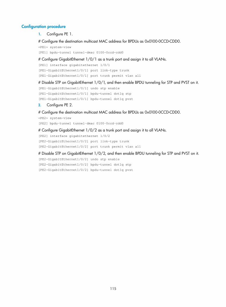
115
Configuration procedure
1. Configure PE 1.
# Configure the destination multicast MAC address for BPDUs as 0x0100-0CCD-CDD0. <PE1> system-view
[PE1] bpdu-tunnel tunnel-dmac 0100-0ccd-cdd0
# Configure GigabitEthernet 1/0/1 as a trunk port and assign it to all VLANs. [PE1] interface gigabitethernet 1/0/1
[PE1-GigabitEthernet1/0/1] port link-type trunk
[PE1-GigabitEthernet1/0/1] port trunk permit vlan all
# Disable STP on GigabitEthernet 1/0/1, and then enable BPDU tunneling for STP and PVST on it. [PE1-GigabitEthernet1/0/1] undo stp enable
[PE1-GigabitEthernet1/0/1] bpdu-tunnel dot1q stp
[PE1-GigabitEthernet1/0/1] bpdu-tunnel dot1q pvst
2. Configure PE 2.
# Configure the destination multicast MAC address for BPDUs as 0x0100-0CCD-CDD0. <PE2> system-view
[PE2] bpdu-tunnel tunnel-dmac 0100-0ccd-cdd0
# Configure GigabitEthernet 1/0/2 as a trunk port and assign it to all VLANs. [PE2] interface gigabitethernet 1/0/2
[PE2-GigabitEthernet1/0/2] port link-type trunk
[PE2-GigabitEthernet1/0/2] port trunk permit vlan all
# Disable STP on GigabitEthernet 1/0/2, and then enable BPDU tunneling for STP and PVST on it. [PE2-GigabitEthernet1/0/2] undo stp enable
[PE2-GigabitEthernet1/0/2] bpdu-tunnel dot1q stp
[PE2-GigabitEthernet1/0/2] bpdu-tunnel dot1q pvst

116
VLAN configuration
Introduction to VLAN
VLAN overview Ethernet is a network technology based on the Carrier Sense Multiple Access/Collision Detect (CSMA/CD) mechanism. Because the medium is shared, collisions and excessive broadcasts are common on Ethernet networks. To address the issue, virtual LAN (VLAN) was introduced to break a LAN down into separate VLANs. VLANs are isolated from each other at Layer 2. A VLAN is a bridging domain, and contains all broadcast traffic within it.
Figure 35 A VLAN diagram
A VLAN is logically divided on an organizational basis rather than on a physical basis. For example, using VLAN, all workstations and servers that a particular workgroup uses can be assigned to the same VLAN, regardless of their physical locations.
VLAN technology delivers the following benefits:
1. Confining broadcast traffic within individual VLANs. This reduces bandwidth waste and improves network performance.
2. Improving LAN security. By assigning user groups to different VLANs, you can isolate them at Layer 2. To enable communication between VLANs, routers or Layer 3 switches are required.
3. Creating flexible virtual workgroups. Because users from the same workgroup can be assigned to the same VLAN regardless of their physical locations, network construction and maintenance are much easier and more flexible.
VLAN fundamentals To enable a network device to identify frames of different VLANs, a VLAN tag field is inserted into the data link layer encapsulation.
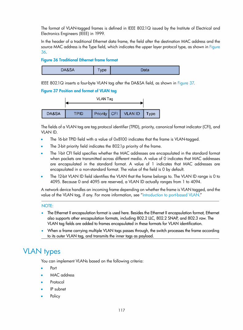
117
The format of VLAN-tagged frames is defined in IEEE 802.1Q issued by the Institute of Electrical and Electronics Engineers (IEEE) in 1999.
In the header of a traditional Ethernet data frame, the field after the destination MAC address and the source MAC address is the Type field, which indicates the upper layer protocol type, as shown in Figure 36.
Figure 36 Traditional Ethernet frame format
IEEE 802.1Q inserts a four-byte VLAN tag after the DA&SA field, as shown in Figure 37.
Figure 37 Position and format of VLAN tag
The fields of a VLAN tag are tag protocol identifier (TPID), priority, canonical format indicator (CFI), and VLAN ID.
• The 16-bit TPID field with a value of 0x8100 indicates that the frame is VLAN-tagged.
• The 3-bit priority field indicates the 802.1p priority of the frame.
• The 1-bit CFI field specifies whether the MAC addresses are encapsulated in the standard format when packets are transmitted across different media. A value of 0 indicates that MAC addresses are encapsulated in the standard format. A value of 1 indicates that MAC addresses are encapsulated in a non-standard format. The value of the field is 0 by default.
• The 12-bit VLAN ID field identifies the VLAN that the frame belongs to. The VLAN ID range is 0 to 4095. Because 0 and 4095 are reserved, a VLAN ID actually ranges from 1 to 4094.
A network device handles an incoming frame depending on whether the frame is VLAN tagged, and the value of the VLAN tag, if any. For more information, see “Introduction to port-based VLAN.”
NOTE:
• The Ethernet II encapsulation format is used here. Besides the Ethernet II encapsulation format, Ethernetalso supports other encapsulation formats, including 802.2 LLC, 802.2 SNAP, and 802.3 raw. The VLAN tag fields are added to frames encapsulated in these formats for VLAN identification.
• When a frame carrying multiple VLAN tags passes through, the switch processes the frame accordingto its outer VLAN tag, and transmits the inner tags as payload.
VLAN types You can implement VLANs based on the following criteria:
• Port
• MAC address
• Protocol
• IP subnet
• Policy

118
• Other criteria
This chapter covers port-based VLAN, MAC-based VLAN, protocol-based VLAN, and IP-based VLAN. The port-based VLAN implementation is the basis of all other VLAN implementations. To use any other VLAN implementations, you must configure port-based VLAN settings.
You can configure all these types of VLANs on a port at the same time. When the switch is determining which VLAN a packet that passes through the port should be assigned to, it looks up the VLANs in the default order of MAC-based VLAN, IP-based VLAN, protocol-based VLAN, and port-based VLAN.
Protocols and standards • IEEE 802.1Q, IEEE Standards for Local and Metropolitan Area Networks: Virtual Bridged Local
Area Networks
Configuring basic VLAN settings Follow these steps to configure basic VLAN settings:
To do… Use the command… Remarks
Enter system view system-view —
Create VLANs vlan { vlan-id1 [ to vlan-id2 ] | all }
Optional
Use this command to create VLANs in bulk.
Enter VLAN view vlan vlan-id
Required
By default, only the default VLAN (VLAN 1) exists in the system.
If the specified VLAN does not exist, this command creates the VLAN first.
Configure a name for the VLAN name text
Optional
By default, the name of a VLAN is its VLAN ID (VLAN 0001, for example).
Configure the description of the VLAN description text
Optional
VLAN ID is used by default (VLAN 0001, for example).
NOTE:
• As the default VLAN, VLAN 1 cannot be created or removed.
• You cannot manually create or remove VLANs reserved for special purposes.
• To remove a protocol reserved VLAN, voice VLAN, management VLAN, dynamic VLAN, VLAN with aQoS policy applied, control VLAN for a smart link group, control VLAN for an RRPP domain, or remoteprobe VLAN for remote port mirroring, remove the configuration from the VLAN first, and execute the undo vlan command.

119
Configuring basic settings of a VLAN interface
VLAN interface overview For hosts of different VLANs to communicate, you must use a router or Layer 3 switch to perform Layer 3 forwarding. You use VLAN interfaces to achieve this.
VLAN interfaces are virtual interfaces used for Layer 3 communication between different VLANs. They do not exist as physical entities on devices. For each VLAN, you can create one VLAN interface. You can assign the VLAN interface an IP address and specify it as the gateway of the VLAN to forward traffic destined for an IP subnet different from that of the VLAN.
Configuration procedure Follow these steps to configure basic settings of a VLAN interface:
To do… Use the command… Remarks
Enter system view system-view —
Create a VLAN interface and enter VLAN interface view
interface vlan-interface vlan-interface-id
Required
If the VLAN interface already exists, you enter its view directly.
Assign an IP address to the VLAN interface
ip address ip-address { mask | mask-length } [ sub ]
Optional
By default, no IP address is assigned to any VLAN interface.
Configure the description of the VLAN interface description text
Optional
By default, the description of a VLAN is the VLAN interface name. For example, Vlan-interface1 Interface.
Set the MTU for the VLAN interface mtu size
Optional
By default, the MTU is 1500 bytes.
Restore the default settings for the VLAN interface default Optional
Shut down the VLAN interface shutdown
Optional
By default, a VLAN interface is in the up state. The VLAN interface is up if one or more ports in the VLAN is up, and goes down if all ports in the VLAN go down.
A VLAN interface shut down with the shutdown command is in the DOWN (Administratively) state until you bring it up, regardless of how the state of the ports in the VLAN changes.
NOTE:
Before you create a VLAN interface for a VLAN, create the VLAN.

120
VLAN interface configuration example Network requirements
As shown in Figure 38, PC A is assigned to VLAN 5. PC B is assigned to VLAN 10. The PCs belong to different IP subnets and cannot communicate with each other.
Configure VLAN interfaces on Switch A and configure the PCs to enable Layer 3 communication between the PCs.
Figure 38 Network diagram for VLAN interface configuration
Configuration procedure
1. Configure Switch A.
# Create VLAN 5 and assign GigabitEthernet 1/0/1 to it. <SwitchA> system-view
[SwitchA] vlan 5
[SwitchA-vlan5] port GigabitEthernet 1/0/1
# Create VLAN 10 and assign GigabitEthernet 1/0/2 to it. [SwitchA-vlan5] quit
[SwitchA] vlan 10
[SwitchA-vlan10] port GigabitEthernet 1/0/2
[SwitchA-vlan10] quit
# Create VLAN-interface 5 and configure its IP address as 192.168.0.10/24. [SwitchA] interface vlan-interface 5
[SwitchA-Vlan-interface5] ip address 192.168.0.10 24
[SwitchA-Vlan-interface5] quit
# Create VLAN-interface 10 and configure its IP address as 192.168.1.20/24. [SwitchA] interface vlan-interface 10
[SwitchA-Vlan-interface10] ip address 192.168.1.20 24
[SwitchA-Vlan-interface10] return
2. Configure PC A.
# Configure the default gateway of the PC as 192.168.0.10.
3. Configure PC B.
# Configure the default gateway of the PC as 192.168.1.20.

121
Verification
1. The PCs can ping each other.
2. Display brief information about Layer 3 interfaces on Switch A to verify the configuration. <SwitchA> display ip interface brief
*down: administratively down
(s): spoofing
Interface Physical Protocol IP Address Description
Vlan-interface5 up up 192.168.0.10 Vlan-inte...
Vlan-interface10 up up 192.168.1.20 Vlan-inte...
Port-based VLAN configuration
Introduction to port-based VLAN Port-based VLANs group VLAN members by port. A port forwards traffic for a VLAN only after it is assigned to the VLAN.
Port link type
You can configure the link type of a port as access, trunk, or hybrid. The link types use the following VLAN tag handling methods:
• An access port belongs to only one VLAN and sends traffic untagged. It is usually used to connect a terminal device unable to identify VLAN tagged-packets or when separating different VLAN members is unnecessary.
• A trunk port can carry multiple VLANs to receive and send traffic for them. Except traffic from the port VLAN ID (PVID), traffic sent through a trunk port will be VLAN tagged. Usually, ports that connect network devices are configured as trunk ports.
• Like a trunk port, a hybrid port can carry multiple VLANs to receive and send traffic for them. Unlike a trunk port, a hybrid port allows traffic of all VLANs to pass through VLAN untagged. You can configure a port connected to a network device or user terminal as a hybrid port.
PVID
By default, VLAN 1 is the PVID for all ports. You can configure the PVID for a port as required.
When configuring the PVID on a port, use the following guidelines:
• An access port can join only one VLAN. The VLAN to which the access port belongs is the PVID of the port. The PVID of the access port changes along with the VLAN to which the port belongs.
• A trunk or hybrid port can join multiple VLANs. You can configure a PVID for the port.
• You can use a nonexistent VLAN as the PVID for a hybrid or trunk port but not for an access port. After you use the undo vlan command to remove the VLAN that an access port resides in, the PVID of the port changes to VLAN 1. The removal of the VLAN specified as the PVID of a trunk or hybrid port, however, does not affect the PVID setting on the port.

122
NOTE:
• Do not set the voice VLAN as the PVID of a port in automatic voice VLAN assignment mode. For information about voice VLAN, see the chapter “Voice VLAN configuration.”
• H3C recommends that you set the same PVID ID for local and remote ports.
• Make sure that a port is assigned to its PVID. Otherwise, when the port receives frames tagged with thePVID or untagged frames (including protocol packets such as MSTP BPDUs), the port filters out these frames.
The following table shows how ports of different link types handle frames:
Actions (in the inbound direction) Port type
Untagged frame Tagged frame Actions (in the outbound direction)
Access Tags the frame with the PVID tag.
• Receives the frame if its VLAN ID is the same as the PVID.
• Drops the frame if its VLAN ID is different from the PVID.
Removes the VLAN tag and sends the frame.
Trunk
• Removes the tag and send the frame if the frame carries the PVID tag and the port belongs to the PVID.
• Sends the frame without removing the tag if its VLAN is carried on the port but is different from the PVID.
Hybrid
Checks whether the PVID is permitted on the port: • If yes, tags the frame
with the PVID tag. • If not, drops the
frame.
• Receives the frame if its VLAN is carried on the port.
• Drops the frame if its VLAN is not carried on the port.
Sends the frame if its VLAN is carried on the port. The frame is sent with the VLAN tag removed or intact depending on your configuration via the port hybrid vlan command. This is true of the PVID.
Assigning an access port to a VLAN You can assign an access port to a VLAN in VLAN view, interface view (including Layer 2 Ethernet interface view, and Layer 2 aggregate interface view), or port group view.
Follow these steps to assign one or multiple access ports to a VLAN in VLAN view:
To do… Use the command… Remarks
Enter system view system-view —
Enter VLAN view vlan vlan-id Required
If the specified VLAN does not exist, this command creates the VLAN first.
Assign one or a group of access ports to the VLAN port interface-list
Required
By default, all ports belong to VLAN 1.

123
Follow these steps to assign an access port (in interface view) or multiple access ports (in port group view) to a VLAN:
To do… Use the command… Remarks
Enter system view system-view —
Enter Layer 2 Ethernet interface view
interface interface-type interface-number
Enter Layer 2 aggregate interface view
interface bridge-aggregation interface-number
Enter interface view or port group view
Enter port group view
port-group manual port-group-name
Required
Use any command. • The configuration made in Layer 2 Ethernet
interface view applies only to the port. • The configuration made in port group view
applies to all ports in the port group. • The configuration made in Layer 2 aggregate
interface view applies to the aggregate interface and its aggregation member ports. If the system fails to apply the configuration to the aggregate interface, it stops applying the configuration to aggregation member ports. If the system fails to apply the configuration to an aggregation member port, it skips the port and moves to the next member port.
Configure the link type of the ports as access port link-type access
Optional
By default, all ports are access ports.
Assign the access ports to a VLAN port access vlan vlan-id
Optional
By default, all access ports belong to VLAN 1.
NOTE:
• Before you assign an access port to a VLAN, create the VLAN.
• In VLAN view, you can assign only Layer 2 Ethernet interfaces to the VLAN.
Assigning a trunk port to a VLAN A trunk port can carry multiple VLANs. You can assign it to a VLAN in interface view (including Layer 2 Ethernet interface view, and Layer 2 aggregate interface view) or port group view.
Follow these steps to assign a trunk port to one or multiple VLANs:
To do… Use the command… Remarks
Enter system view system-view —
Enter Layer 2 Ethernet interface view
interface interface-type interface-number
Enter interface view or port group view
Enter Layer 2 aggregate interface view
interface bridge-aggregation interface-number
Required
Use any command. • The configuration made in Layer 2 Ethernet
interface view applies only to the port. • The configuration made in port group view

124
To do… Use the command… Remarks
Enter port group view
port-group manual port-group-name
applies to all ports in the port group. • The configuration made in Layer 2
aggregate interface view applies to the aggregate interface and its aggregation member ports. If the system fails to apply the configuration to the aggregate interface, it stops applying the configuration to aggregation member ports. If the system fails to apply the configuration to an aggregation member port, it skips the port and moves to the next member port.
Configure the link type of the ports as trunk port link-type trunk
Required
By default, all ports are access ports.
Assign the trunk ports to the specified VLANs
port trunk permit vlan { vlan-id-list | all }
Required
By default, a trunk port carries only VLAN 1.
Configure the PVID of the trunk ports
port trunk pvid vlan vlan-id
Optional
By default, the PVID is VLAN 1.
NOTE:
• To change the link type of a port from trunk to hybrid or vice versa, you must set the link type to accessfirst.
• After configuring the PVID for a trunk port, you must use the port trunk permit vlan command to configure the trunk port to allow packets from the PVID to pass through, so that the egress port can forward packets from the PVID.
Assigning a hybrid port to a VLAN A hybrid port can carry multiple VLANs. You can assign it to a VLAN in interface view (including Ethernet interface view, and Layer 2 aggregate interface view) or port group view.
Follow these steps to assign a hybrid port to one or multiple VLANs:
To do… Use the command… Remarks
Enter system view system-view —

125
To do… Use the command… Remarks
Enter Ethernet interface view
interface interface-type interface-number
Enter Layer 2 aggregate interface view
interface bridge-aggregation interface-number
Enter interface view or port group view
Enter port group view
port-group manual port-group-name
Required
Use any command. • The configuration made in Ethernet
interface view applies only to the port. • The configuration made in port group
view applies to all ports in the port group. • The configuration made in Layer 2
aggregate interface view applies to the aggregate interface and its aggregation member ports. If the system fails to apply the configuration to the aggregate interface, it stops applying the configuration to aggregation member ports. If the system fails to apply the configuration to an aggregation member port, it skips the port and moves to the next member port.
Configure the link type of the ports as hybrid port link-type hybrid
Required
By default, all ports are access ports.
Assign the hybrid ports to the specified VLANs
port hybrid vlan vlan-id-list { tagged | untagged }
Required
By default, a hybrid port allows only packets of VLAN 1 to pass through untagged.
Configure the PVID of the hybrid ports
port hybrid pvid vlan vlan-id
Optional
By default, the PVID is VLAN 1.
NOTE:
• To change the link type of a port from trunk to hybrid or vice versa, you must set the link type to accessfirst.
• Before you assign a hybrid port to a VLAN, create the VLAN.
• After configuring the PVID for a hybrid port, you must use the port hybrid vlan command to configurethe hybrid port to allow packets from the PVID to pass through, so that the egress port can forward packets from the PVID.
Port-based VLAN configuration example Network requirements
As shown in Figure 39:
• Host A and Host C belong to Department A, and access the enterprise network through different devices. Host B and Host D belong to Department B. They also access the enterprise network through different devices.
• To ensure communication security and avoid broadcast storms, VLANs are configured in the enterprise network to isolate Layer 2 traffic of different departments. VLAN 100 is assigned to Department A, and VLAN 200 is assigned to Department B.
• Make sure that hosts within the same VLAN can communicate with each other. Host A can communicate with Host C, and Host B can communicate with Host D.
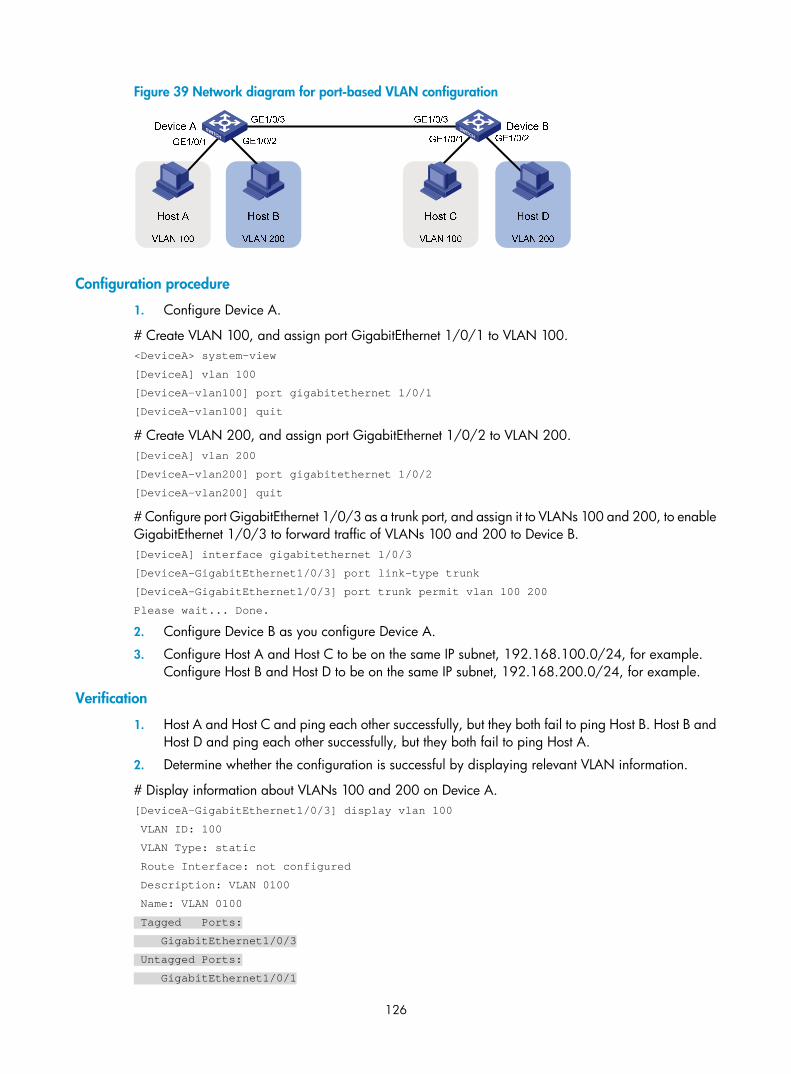
126
Figure 39 Network diagram for port-based VLAN configuration
Configuration procedure
1. Configure Device A.
# Create VLAN 100, and assign port GigabitEthernet 1/0/1 to VLAN 100. <DeviceA> system-view
[DeviceA] vlan 100
[DeviceA-vlan100] port gigabitethernet 1/0/1
[DeviceA-vlan100] quit
# Create VLAN 200, and assign port GigabitEthernet 1/0/2 to VLAN 200. [DeviceA] vlan 200
[DeviceA-vlan200] port gigabitethernet 1/0/2
[DeviceA-vlan200] quit
# Configure port GigabitEthernet 1/0/3 as a trunk port, and assign it to VLANs 100 and 200, to enable GigabitEthernet 1/0/3 to forward traffic of VLANs 100 and 200 to Device B. [DeviceA] interface gigabitethernet 1/0/3
[DeviceA-GigabitEthernet1/0/3] port link-type trunk
[DeviceA-GigabitEthernet1/0/3] port trunk permit vlan 100 200
Please wait... Done.
2. Configure Device B as you configure Device A.
3. Configure Host A and Host C to be on the same IP subnet, 192.168.100.0/24, for example. Configure Host B and Host D to be on the same IP subnet, 192.168.200.0/24, for example.
Verification
1. Host A and Host C and ping each other successfully, but they both fail to ping Host B. Host B and Host D and ping each other successfully, but they both fail to ping Host A.
2. Determine whether the configuration is successful by displaying relevant VLAN information.
# Display information about VLANs 100 and 200 on Device A. [DeviceA-GigabitEthernet1/0/3] display vlan 100
VLAN ID: 100
VLAN Type: static
Route Interface: not configured
Description: VLAN 0100
Name: VLAN 0100
Tagged Ports:
GigabitEthernet1/0/3
Untagged Ports:
GigabitEthernet1/0/1

127
[DeviceA-GigabitEthernet1/0/3] display vlan 200
VLAN ID: 200
VLAN Type: static
Route Interface: not configured
Description: VLAN 0200
Name: VLAN 0200
Tagged Ports:
GigabitEthernet1/0/3
Untagged Ports:
GigabitEthernet1/0/2
MAC-based VLAN configuration
Introduction to MAC-based VLAN The MAC-based VLAN feature assigns hosts to a VLAN based on their MAC addresses. This feature is usually used in conjunction with security technologies such as 802.1X to provide secure, flexible network access for terminal devices.
Static MAC-based VLAN assignment
Static MAC-based VLAN assignment applies to networks containing a small number of VLAN users. In such a network, you can create a MAC address-to-VLAN map containing multiple MAC address-to-VLAN entries on a port, enable the MAC-based VLAN feature on the port, and assign the port to MAC-based VLANs.
With static MAC-based VLAN assignment configured on a port, the switch processes received frames by using the following guidelines:
• When a port on the EB LPU, SC LPU, SD LPU, SRP2XBSLAVE, or SRP12GBSLAVE receives an untagged frame, the switch looks up the MAC address-to-VLAN map based on the source MAC address of the frame for a match. The switch first performs a fuzzy match. In the fuzzy match, the switch searches the MAC address-to-VLAN entries whose masks are not all-Fs and performs a logical AND operation on the source MAC address and each mask. If the result of an AND operation matches the corresponding MAC address, the switch tags the frame with the corresponding VLAN ID. If the fuzzy match fails, the switch performs an exact match. In the exact match, the switch searches the MAC address-to-VLAN entries whose masks are all-Fs. If the MAC address of a MAC address-to-VLAN entry matches the source MAC address of the untagged frame, the switch tags the frame with the corresponding VLAN ID. If no match is found, the switch assigns a VLAN to the frame by using other criteria.
• When a port on the EA or SA LPU receives an untagged frame, the switch looks up the MAC address-to-VLAN map based on the source MAC address of the frame for a match. The switch first performs an exact match. In the exact match, the switch searches the MAC address-to-VLAN entries whose masks are all-Fs. If the MAC address of a MAC address-to-VLAN entry matches the source MAC address of the untagged frame, the switch tags the frame with the corresponding VLAN ID. If the exact match fails, the switch performs a fuzzy match. In the fuzzy match, the switch searches the MAC address-to-VLAN entries whose masks are not all-Fs and performs a logical AND operation on the source MAC address and each mask. If the result of an AND operation matches the corresponding MAC address, the switch tags the frame with the corresponding VLAN ID. If no match is found, the switch assigns a VLAN to the frame by using other criteria.

128
• When the port receives a tagged frame, the port forwards the frame if the VLAN ID of the frame is permitted by the port, or otherwise drops the frame.
Dynamic MAC-based VLAN assignment
When you cannot determine the target MAC-based VLANs of a port, you can use dynamic MAC-based VLAN assignment on the port. To do that, you can create a MAC address-to-VLAN map containing multiple MAC address-to-VLAN entries, and enable the MAC-based VLAN feature and dynamic MAC-based VLAN assignment on the port.
Dynamic MAC-based VLAN assignment uses the following workflows.
1. When the port receives a frame, the port first determines whether the frame is tagged.
• If yes, the port reports the source MAC address of the frame.
• If not, the port selects a VLAN for the frame by tagging the untagged frame with the PVID tag and obtaining the tag, and then reports the source MAC address of the frame.
2. After reporting the source MAC address of the frame, the port looks up the source MAC address in the MAC-to-VLAN map, and processes the frame as follows:
• If the source MAC address of the frame matches a MAC address-to-VLAN entry configured on the port, the port checks whether the VLAN ID of the frame is the same as the VLAN in the MAC-to-VLAN entry.
a. If yes, the port dynamically joins the VLAN and forwards the frame.
b. If not, the port drops the frame.
• If the source MAC address of the frame matches no MAC-to-VLAN entry, the port processes the frame depending on whether the VLAN ID of the frame is the PVID.
c. If yes, the port determines whether it allows PVID: if yes, the port tags the frame with the PVID and forwards the frame; if not, the port drops the frame.
d. If not, the port assigns a VLAN to the frame by using other criteria, such as IP subnet or protocol, and forwards the frame. If no VLAN is available, the port drops the frame.

129
Figure 40 Flowchart for processing a frame in dynamic MAC-based VLAN assignment
NOTE:
• When a port is assigned to the corresponding VLAN in a MAC address-to-VLAN entry, but has not been assigned to the VLAN by using the port hybrid vlan command, the port sends packets from the VLAN with VLAN tags removed.
• If you configure both static and dynamic MAC-based VLAN assignment on the same port, dynamic MAC-based VLAN assignment applies.
• A port forwards frames matching MAC-to-VLAN entries according to the 802.1p priorities of the MAC-based VLANs.
Dynamic MAC-based VLAN
You can use dynamic MAC-based VLAN with access authentication (such as 802.1X authentication based on MAC addresses) to implement secure, flexible terminal access. After configuring dynamic MAC-based VLAN on the device, you must configure the username-to-VLAN entries on the access authentication server.
When a user passes authentication of the access authentication server, the device obtains VLAN information from the server, generates a MAC address-to-VLAN entry by using the source MAC address of the user packet and the VLAN information, and assigns the port to the MAC-based VLAN. When the user goes offline, the device automatically deletes the MAC address-to-VLAN entry, and removes the port from the MAC-based VLAN.
NOTE:
For more information about 802.1X, MAC, and portal authentication, see Security Configuration Guide.

130
Configuring a MAC-based VLAN
NOTE:
• MAC-based VLANs are available only on hybrid ports.
• You cannot configure super VLANs in the MAC address-to-VLAN entries.
• With dynamic MAC-based VLAN assignment enabled, packets are delivered to the CPU for processing.The packet processing mode has the highest priority and overrides the configuration of MAC learning limit and disabling of MAC address learning. When dynamic MAC-based VLAN assignment is enabled, do not configure the MAC learning limit or disable MAC address learning.
• Do not use dynamic MAC-based VLAN assignment together with 802.X and MAC authentication.
• In dynamic MAC-based VLAN assignment, the port that receives a packet with an unknown source MAC address can be successfully assigned to the matched VLAN only when the matched VLAN is a static VLAN.
• The MAC-based VLAN feature is mainly configured on the downlink ports of the user access devices. Donot enable this function together with link aggregation.
• With MSTP enabled, if a port is blocked in the MST instance (MSTI) of the target MAC-based VLAN, theport drops the received packets, instead of delivering them to the CPU. As a result, the receiving port willnot be dynamically assigned to the corresponding VLAN. Do not configure dynamic MAC-based VLANassignment together with MSTP, because the former is mainly configured on the access side.
Follow these steps to configure static MAC-based VLAN assignment:
To do... Use the command... Remarks
Enter system view system-view —
Associate a specific MAC address with a VLAN
mac-vlan mac-address mac-address [ mask mac-mask ] vlan vlan-id [ priority priority ]
Required
Enter Ethernet interface view
interface interface-type interface-number Enter
interface view or port group view
Enter port group view
port-group manual port-group-name
Use either command. • The configuration made in Ethernet
interface view applies only to the port. • The configuration made in port group
view applies to all ports in the port group.
Configure the link type of the ports as hybrid port link-type hybrid
Required
By default, all ports are access ports.
Configure the hybrid ports to permit packets from specific MAC-based VLANs to pass through
port hybrid vlan vlan-id-list { tagged | untagged }
Required
By default, a hybrid port only permits the packets from VLAN 1 to pass through.
Enable the MAC-based VLAN feature mac-vlan enable
Required
Disabled by default.
Configure VLAN matching precedence
vlan precedence { mac-vlan | ip-subnet-vlan }
Optional
By default, VLANs are preferentially matched based on MAC addresses.
Follow these steps to configure dynamic MAC-based VLAN assignment:

131
To do... Use the command... Remarks
Enter system view system-view —
Associate MAC addresses with a VLAN
mac-vlan mac-address mac-address [ mask mac-mask ] vlan vlan-id [ priority priority ]
Required
Enter Ethernet interface view interface interface-type interface-number —
Configure the link type of the port as hybrid port link-type hybrid
Required
By default, all ports are access ports.
Enable the MAC-based VLAN feature mac-vlan enable
Required
Disabled by default.
Enable dynamic MAC-based VLAN assignment mac-vlan trigger enable
Required
By default, dynamic MAC-based VLAN assignment is disabled.
Configure VLAN matching precedence vlan precedence mac-vlan
Optional
By default, VLANs are preferentially matched based on MAC addresses.
Disable the PVID of the port from forwarding packets with unknown source MAC addresses that do not match any MAC address-to-VLAN entry
port pvid disable
Optional
By default, when a port receives a packet with an unknown source MAC address that does not match to any MAC address-to-VLAN entry, it forwards the packet in its PVID.
NOTE:
After you use the mac-vlan trigger enable command to enable dynamic MAC-based VLAN assignment, H3C recommends that you configure the vlan precedence mac-vlan command to preferentially match VLANs based on MAC addresses, and do not configure the vlan precedence ip-subnet-vlan command to preferentially match VLANs based on IP subnet-VLAN entries, because the vlan precedence ip-subnet-vlan command does not take effect in this case.
Follow these steps to configure dynamic MAC-based VLAN:
To do... Use the command... Remarks
Enter system view system-view —
Enter Ethernet interface view
interface interface-type interface-number Enter
interface view or port group view
Enter port group view
port-group manual port-group-name
Use either command. • The configuration made in Ethernet
interface view applies only to the port. • The configuration made in port group
view applies to all ports in the port group.
Configure the link type of the ports as hybrid port link-type hybrid
Required
By default, all ports are access ports.
Configure the hybrid ports to permit packets from specific MAC-based VLANs to pass through
port hybrid vlan vlan-id-list { tagged | untagged }
Required
By default, a hybrid port only permits the packets of VLAN 1 to pass through.

132
To do... Use the command... Remarks
Enable the MAC-based VLAN feature mac-vlan enable
Required
Disabled by default.
Configure 802.1X/MAC/portal authentication or any combination
For more information, see Security Command Reference.
Required
MAC-based VLAN configuration example Network requirements
As shown in Figure 41,
• GigabitEthernet 1/0/1 of Device A and Device C are each connected to a meeting room. Laptop 1 and Laptop 2 are used for meetings and might be used in either of the two meeting rooms.
• Different departments own Laptop 1 and Laptop 2. The two departments use VLAN 100 and VLAN 200 respectively. Each laptop must be able to access only its own department server, no matter which meeting room it is used in.
• The MAC address of Laptop 1 is 000D-88F8-4E71, and that of Laptop 2 is 0014-222C-AA69.
Figure 41 Network diagram for MAC-based VLAN configuration
Device A Device C
Device B
Server1IP: 1.1.1.1/24
Server2 IP: 1.1.2.1/24
GE1/0/1 GE1/0/1
Laptop1IP: 1.1.1.2/24
MAC: 000d-88f8-4e71
Laptop2 IP: 1.1.2.2/24
MAC: 0014-222c-aa69
VLAN 100 VLAN 200
GE1/0/2 GE1/0/2
GE1/0/3 GE1/0/4
GE1/0/14GE1/0/13
VLAN 100 VLAN 200
Configuration consideration
• Create VLANs 100 and 200.
• Configure the uplink ports of Device A and Device C as trunk ports, and assign them to VLANs 100 and 200.
• Configure the downlink ports of Device B as trunk ports, and assign them to VLANs 100 and 200. Assign the uplink ports of Device B to VLANs 100 and 200.

133
• Associate the MAC address of Laptop 1 with VLAN 100, and associate the MAC address of Laptop 2 with VLAN 200.
Configuration procedure
1. Configure Device A.
# Create VLANs 100 and 200. <DeviceA> system-view
[DeviceA] vlan 100
[DeviceA-vlan100] quit
[DeviceA] vlan 200
[DeviceA-vlan200] quit
# Associate the MAC address of Laptop 1 with VLAN 100, and associate the MAC address of Laptop 2 with VLAN 200. [DeviceA] mac-vlan mac-address 000d-88f8-4e71 vlan 100
[DeviceA] mac-vlan mac-address 0014-222c-aa69 vlan 200
# Configure Laptop 1 and Laptop 2 to access the network through GigabitEthernet 1/0/1. Configure GigabitEthernet 1/0/1 as a hybrid port that sends packets of VLANs 100 and 200 untagged, and enable the MAC-based VLAN feature on it. [DeviceA] interface gigabitethernet 1/0/1
[DeviceA-GigabitEthernet1/0/1] port link-type hybrid
[DeviceA-GigabitEthernet1/0/1] port hybrid vlan 100 200 untagged
Please wait... Done.
[DeviceA-GigabitEthernet1/0/1] mac-vlan enable
[DeviceA-GigabitEthernet1/0/1] quit
# To enable the laptops to access Server 1 and Server 2, configure the uplink port GigabitEthernet 1/0/2 as a trunk port, and assign it to VLANs 100 and 200. [DeviceA] interface gigabitethernet 1/0/2
[DeviceA-GigabitEthernet1/0/2] port link-type trunk
[DeviceA-GigabitEthernet1/0/2] port trunk permit vlan 100 200
[DeviceA-GigabitEthernet1/0/2] quit
2. Configure Device B.
# Create VLANs 100 and 200. Assign GigabitEthernet 1/0/13 to VLAN 100, and assign GigabitEthernet 1/0/14 to VLAN 200. <DeviceB> system-view
[DeviceB] vlan 100
[DeviceB-vlan100] port gigabitethernet 1/0/13
[DeviceB-vlan100] quit
[DeviceB] vlan 200
[DeviceB-vlan200] port gigabitethernet 1/0/14
[DeviceB-vlan200] quit
# Configure GigabitEthernet 1/0/3 and GigabitEthernet 1/0/4 as trunk ports, and assign them to VLANs 100 and 200. [DeviceB] interface gigabitethernet 1/0/3
[DeviceB-GigabitEthernet1/0/3] port link-type trunk
[DeviceB-GigabitEthernet1/0/3] port trunk permit vlan 100 200
[DeviceB-GigabitEthernet1/0/3] quit
[DeviceB] interface gigabitethernet 1/0/4

134
[DeviceB-GigabitEthernet1/0/4] port link-type trunk
[DeviceB-GigabitEthernet1/0/4] port trunk permit vlan 100 200
[DeviceB-GigabitEthernet1/0/4] quit
3. Configure Device C.
Configure Device C as you configure Device A.
Verification
1. Laptop 1 can access Server 1 only, and Laptop 2 can access Server 2 only.
2. On Device A and Device C, you can see that VLAN 100 is associated with the MAC address of Laptop 1, and VLAN 200 is associated with the MAC address of Laptop 2.
[DeviceA] display mac-vlan all
The following MAC VLAN addresses exist:
S:Static D:Dynamic
MAC ADDR MASK VLAN ID PRIO STATE
--------------------------------------------------------
000d-88f8-4e71 ffff-ffff-ffff 100 0 S
0014-222c-aa69 ffff-ffff-ffff 200 0 S
Total MAC VLAN address count:2
Configuration guidelines
1. MAC-based VLAN can be configured only on hybrid ports.
2. MAC-based VLAN is usually configured on the downlink ports of access layer devices, and cannot be configured together with the link aggregation function.
Protocol-based VLAN configuration
Introduction to protocol-based VLAN You use the protocol-based VLAN feature to assign packets to VLANs by their application type.
The protocol-based VLAN feature assigns inbound packets to different VLANs based on their protocol type and encapsulation format. The protocols available for VLAN assignment include IP, IPX, and AppleTalk (AT), and the encapsulation formats include Ethernet II, 802.3 raw, 802.2 LLC, and 802.2 SNAP.
A protocol template defines a protocol type and an encapsulation format. A protocol-based VLAN ID and a protocol index, combined, can uniquely identify a protocol template. You can assign multiple protocol templates to a protocol-based VLAN.
Protocol-based VLAN assignment is available only on hybrid ports, and a protocol template applies only to untagged packets.
When an untagged packet arrives, a protocol-based VLAN assignment enabled hybrid port processes the packet by using the following workflow:
• If the protocol type and encapsulation format in the packet matches a protocol template, the packet is tagged with the VLAN tag specific to the protocol template.
• If no protocol template is matched, the packet is tagged with the PVID of the port.
The port processes a tagged packet as it processes tagged packets of a port-based VLAN.

135
• If the port is in the same VLAN as the packet, it forwards the packet.
• If not, the port drops the packet.
Configuring a protocol-based VLAN Follow these steps to configure a protocol-based VLAN:
To do… Use the command… Remarks
Enter system view system-view —
Enter VLAN view vlan vlan-id Required
If the specified VLAN does not exist, this command creates the VLAN first.
Create a protocol template for the VLAN
protocol-vlan [ protocol-index ] { at | ipv4 | ipv6 | ipx { ethernetii | llc | raw | snap } | mode { ethernetii etype etype-id | llc { dsap dsap-id [ ssap ssap-id ] | ssap ssap-id } | snap etype etype-id } }
Required
Not configured by default.
Exit VLAN view quit Required
Enter Layer 2 Ethernet interface view
interface interface-type interface-number
Enter Layer 2 aggregate interface view
interface bridge-aggregation interface-number
Enter interface view or port group view
Enter port group view
port-group manual port-group-name
Required
Use any command. • The configuration made in Ethernet
interface view applies only to the port. • The configuration made in port group
view applies to all ports in the port group. • The configuration made in Layer 2
aggregate interface view applies to the aggregate interface and its aggregation member ports. If the system fails to apply the configuration to the aggregate interface, it stops applying the configuration to aggregation member ports. If the system fails to apply the configuration to an aggregation member port, it skips the port and moves to the next member port.
Configure the port link type as hybrid port link-type hybrid
Required
By default, all ports are access ports.
Assign the hybrid port to the specified protocol-based VLANs
port hybrid vlan vlan-id-list { tagged | untagged }
Required
By default, a hybrid port is only in VLAN 1.
Assign the protocol template you have created to the hybrid port
port hybrid protocol-vlan vlan vlan-id { protocol-index [ to protocol-end ] | all }
Required

136
CAUTION:
A protocol-based VLAN processes only untagged inbound packets, whereas the voice VLAN in automaticmode processes only tagged voice traffic. Do not configure a VLAN as both a protocol-based VLAN anda voice VLAN. For more information, see the chapter “Voice VLAN configuration.”
Protocol-based VLAN configuration example Network requirements
In a lab environment, as shown in Figure 42, most hosts run the IPv4 protocol, and the rest of the hosts run the IPv6 protocol for teaching purposes. To avoid interference, isolate IPv4 traffic and IPv6 traffic at Layer 2.
Figure 42 Network diagram for protocol-based VLAN configuration
Configuration consideration
Create VLANs 100 and 200. Associate VLAN 100 with IPv4, and associate VLAN 200 with IPv6. Configure protocol-based VLANs to isolate IPv4 traffic and IPv6 traffic at Layer 2.
Configuration procedure
1. Configure Device.
# Create VLAN 100, and assign port GigabitEthernet 1/0/11 to VLAN 100. <Device> system-view
[Device] vlan 100
[Device-vlan100] description protocol VLAN for IPv4
[Device-vlan100] port gigabitethernet 1/0/11
[Device-vlan100] quit
# Create VLAN 200, and assign port GigabitEthernet 1/0/12 to VLAN 200. [Device] vlan 200

137
[Device-vlan200] description protocol VLAN for IPv6
[Device-vlan200] port gigabitethernet 1/0/12
# Create an IPv6 protocol template in the view of VLAN 200, and create an IPv4 protocol template in the view of VLAN 100. [Device-vlan200] protocol-vlan 1 ipv6
[Device-vlan200] quit
[Device] vlan 100
[Device-vlan100] protocol-vlan 1 ipv4
[Device-vlan100] quit
# Configure port GigabitEthernet 1/0/1 as a hybrid port that forwards packets of VLANs 100 and 200 untagged. [Device] interface gigabitethernet 1/0/1
[Device-GigabitEthernet1/0/1] port link-type hybrid
[Device-GigabitEthernet1/0/1] port hybrid vlan 100 200 untagged
Please wait... Done.
# Associate port GigabitEthernet 1/0/1 with the IPv4 protocol template of VLAN 100 and the IPv6 protocol template of VLAN 200. [Device-GigabitEthernet1/0/1] port hybrid protocol-vlan vlan 100 1
[Device-GigabitEthernet1/0/1] port hybrid protocol-vlan vlan 200 1
[Device-GigabitEthernet1/0/1] quit
# Configure GigabitEthernet 1/0/2 as a hybrid port that forwards packets of VLANs 100 and 200 untagged, and associate GigabitEthernet 1/0/2 with the IPv4 protocol template of VLAN 100 and the IPv6 protocol template of VLAN 200. [Device] interface gigabitethernet 1/0/2
[Device-GigabitEthernet1/0/2] port link-type hybrid
[Device-GigabitEthernet1/0/2] port hybrid vlan 100 200 untagged
Please wait... Done.
[Device-GigabitEthernet1/0/2] port hybrid protocol-vlan vlan 100 1
[Device-GigabitEthernet1/0/2] port hybrid protocol-vlan vlan 200 1
2. Keep the default settings of L2 Switch A and L2 Switch B.
3. Configure IPv4 Host A, IPv4 Host B, and IPv4 Server to be on the same IP subnet (192.168.100.0/24, for example), and configure IPv6 Host A, IPv6 Host B, and IPv6 Server to be on the same IP subnet (2001::1/64, for example).
Verification
1. The hosts and the server in VLAN 100 can ping one another successfully. The hosts and the server in VLAN 200 can ping one another successfully. The hosts or server in VLAN 100 cannot ping the hosts and server in VLAN 200, and vice versa.
2. Display protocol-based VLAN information on Device to determine whether the configurations have become valid.
# Display protocol-based VLAN configuration on Device. [Device-GigabitEthernet1/0/2] display protocol-vlan vlan all
VLAN ID:100
Protocol Index Protocol Type
======================================================
1 ipv4
VLAN ID:200
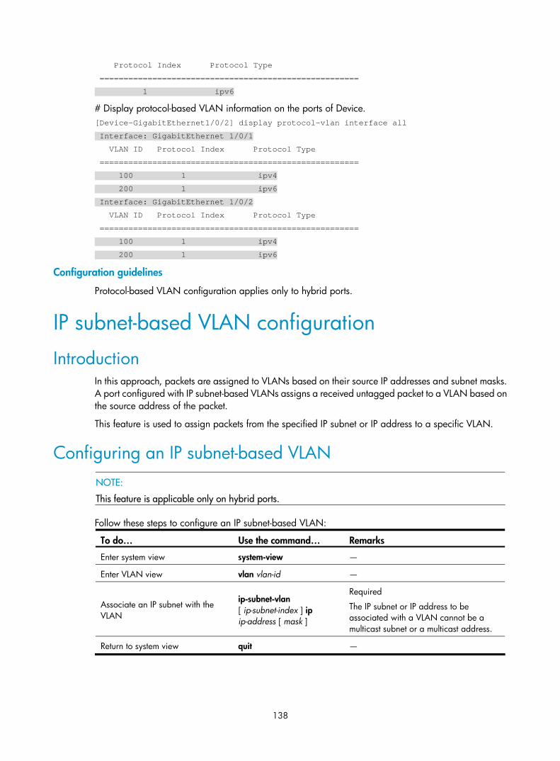
138
Protocol Index Protocol Type
======================================================
1 ipv6
# Display protocol-based VLAN information on the ports of Device. [Device-GigabitEthernet1/0/2] display protocol-vlan interface all
Interface: GigabitEthernet 1/0/1
VLAN ID Protocol Index Protocol Type
======================================================
100 1 ipv4
200 1 ipv6
Interface: GigabitEthernet 1/0/2
VLAN ID Protocol Index Protocol Type
======================================================
100 1 ipv4
200 1 ipv6
Configuration guidelines
Protocol-based VLAN configuration applies only to hybrid ports.
IP subnet-based VLAN configuration
Introduction In this approach, packets are assigned to VLANs based on their source IP addresses and subnet masks. A port configured with IP subnet-based VLANs assigns a received untagged packet to a VLAN based on the source address of the packet.
This feature is used to assign packets from the specified IP subnet or IP address to a specific VLAN.
Configuring an IP subnet-based VLAN
NOTE:
This feature is applicable only on hybrid ports.
Follow these steps to configure an IP subnet-based VLAN:
To do… Use the command… Remarks
Enter system view system-view —
Enter VLAN view vlan vlan-id —
Associate an IP subnet with the VLAN
ip-subnet-vlan [ ip-subnet-index ] ip ip-address [ mask ]
Required
The IP subnet or IP address to be associated with a VLAN cannot be a multicast subnet or a multicast address.
Return to system view quit —

139
To do… Use the command… Remarks
Enter Layer 2 Ethernet interface view
interface interface-type interface-number
Enter Layer 2 aggregate interface view
interface bridge-aggregation interface-number
Enter interface view or port group view
Enter port group view
port-group manual port-group-name
Required
Use any command. • The configuration made in Ethernet
interface view applies only to the port. • The configuration made in port group
view applies to all ports in the port group.
• The configuration made in Layer 2 aggregate interface view applies to the aggregate interface and its aggregation member ports. If the system fails to apply the configuration to the aggregate interface, it stops applying the configuration to aggregation member ports. If the system fails to apply the configuration to an aggregation member port, it skips the port and moves to the next member port.
Configure port link type as hybrid port link-type hybrid Required
By default, all ports are access ports.
Configure the hybrid ports to permit the specified IP subnet-based VLANs to pass through
port hybrid vlan vlan-id-list { tagged | untagged }
Required
By default, a hybrid port allows only packets from VLAN 1 to pass through untagged.
Associate the hybrid ports with the specified IP subnet-based VLAN
port hybrid ip-subnet-vlan vlan vlan-id
Required
Not configured by default.
IP subnet-based VLAN configuration example Network requirements
As shown in Figure 43, the hosts in the office belong to different IP subnets 192.168.5.0/24 and 192.168.50.0/24.
Configure Device C to transmit packets over separate VLANs based on their source IP addresses.
Figure 43 Network diagram for IP subnet-based VLAN configuration
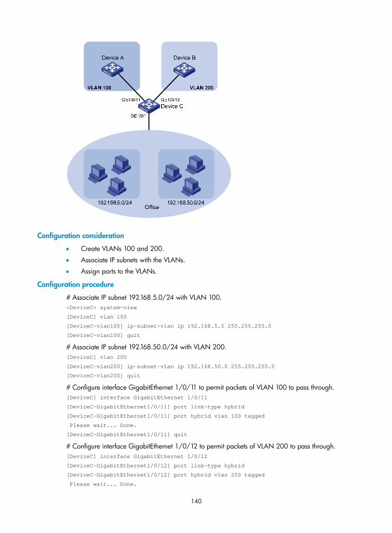
140
Configuration consideration
• Create VLANs 100 and 200.
• Associate IP subnets with the VLANs.
• Assign ports to the VLANs.
Configuration procedure
# Associate IP subnet 192.168.5.0/24 with VLAN 100. <DeviceC> system-view
[DeviceC] vlan 100
[DeviceC-vlan100] ip-subnet-vlan ip 192.168.5.0 255.255.255.0
[DeviceC-vlan100] quit
# Associate IP subnet 192.168.50.0/24 with VLAN 200. [DeviceC] vlan 200
[DeviceC-vlan200] ip-subnet-vlan ip 192.168.50.0 255.255.255.0
[DeviceC-vlan200] quit
# Configure interface GigabitEthernet 1/0/11 to permit packets of VLAN 100 to pass through. [DeviceC] interface GigabitEthernet 1/0/11
[DeviceC-GigabitEthernet1/0/11] port link-type hybrid
[DeviceC-GigabitEthernet1/0/11] port hybrid vlan 100 tagged
Please wait... Done.
[DeviceC-GigabitEthernet1/0/11] quit
# Configure interface GigabitEthernet 1/0/12 to permit packets of VLAN 200 to pass through. [DeviceC] interface GigabitEthernet 1/0/12
[DeviceC-GigabitEthernet1/0/12] port link-type hybrid
[DeviceC-GigabitEthernet1/0/12] port hybrid vlan 200 tagged
Please wait... Done.

141
[DeviceC-GigabitEthernet1/0/12] quit
# Associate interface GigabitEthernet 1/0/1 with IP subnet-based VLANs 100 and 200. [DeviceC] interface GigabitEthernet 1/0/1
[DeviceC-GigabitEthernet1/0/1] port link-type hybrid
[DeviceC-GigabitEthernet1/0/1] port hybrid vlan 100 200 untagged
Please wait... Done.
[DeviceC-GigabitEthernet1/0/1] port hybrid ip-subnet-vlan vlan 100
[DeviceC-GigabitEthernet1/0/1] port hybrid ip-subnet-vlan vlan 200
[DeviceC-GigabitEthernet1/0/1] return
Verification
# Display the IP subnet information for all VLANs. <Device C> display ip-subnet-vlan vlan all
VLAN ID: 100
Subnet Index IP Address Subnet Mask
====================================================
0 192.168.5.0 255.255.255.0
VLAN ID: 200
Subnet Index IP Address Subnet Mask
====================================================
0 192.168.50.0 255.255.255.0
# Display the IP subnet-based VLAN information on GigabitEthernet 1/0/1. <DeviceC> display ip-subnet-vlan interface GigabitEthernet 1/0/1
Interface: GigabitEthernet1/0/1
VLAN ID Subnet-Index IP ADDRESS NET MASK
=======================================================
100 0 192.168.5.0 255.255.255.0
200 0 192.168.50.0 255.255.255.0
Configuration guidelines
The IP subnet-based VLAN configurations are only effective on hybrid ports.
Displaying and maintaining VLAN To do... Use the command… Remarks
Display VLAN information display vlan [ vlan-id1 [ to vlan-id2 ] | all | dynamic | reserved | static ] [ | { begin | exclude | include } regular-expression ]
Available in any view
Display VLAN interface information
display interface [ vlan-interface ] [ brief [ down ] ] [ | { begin | exclude | include } regular-expression ]
display interface vlan-interface vlan-interface-id [ brief ] [ | { begin | exclude | include } regular-expression ]
Available in any view
Display hybrid ports or trunk ports on the device
display port { hybrid | trunk } [ | { begin | exclude | include } regular-expression ]
Available in any view

142
To do... Use the command… Remarks
Display MAC address-to-VLAN entries
display mac-vlan { all | dynamic | mac-address mac-address [ mask mac-mask ] | static | vlan vlan-id } [ | { begin | exclude | include } regular-expression ]
Available in any view
Display all interfaces with MAC-based VLAN enabled
display mac-vlan interface [ | { begin | exclude | include } regular-expression ]
Available in any view
Display protocol information and protocol indexes of the specified VLANs
display protocol-vlan vlan { vlan-id [ to vlan-id ] | all } [ | { begin | exclude | include } regular-expression ]
Available in any view
Display protocol-based VLAN information on specified interfaces
display protocol-vlan interface { interface-type interface-number [ to interface-type interface-number ] | all } [ | { begin | exclude | include } regular-expression ]
Available in any view
Display IP subnet-based VLAN information and IP subnet indexes of specified VLANs
display ip-subnet-vlan vlan { vlan-id [ to vlan-id ] | all } [ | { begin | exclude | include } regular-expression ]
Available in any view
Display the IP subnet-based VLAN information and IP subnet indexes of specified ports
display ip-subnet-vlan interface { interface-list | all } [ | { begin | exclude | include } regular-expression ]
Available in any view
Clear statistics on a port reset counters interface vlan-interface [ vlan-interface-id ]
Available in user view
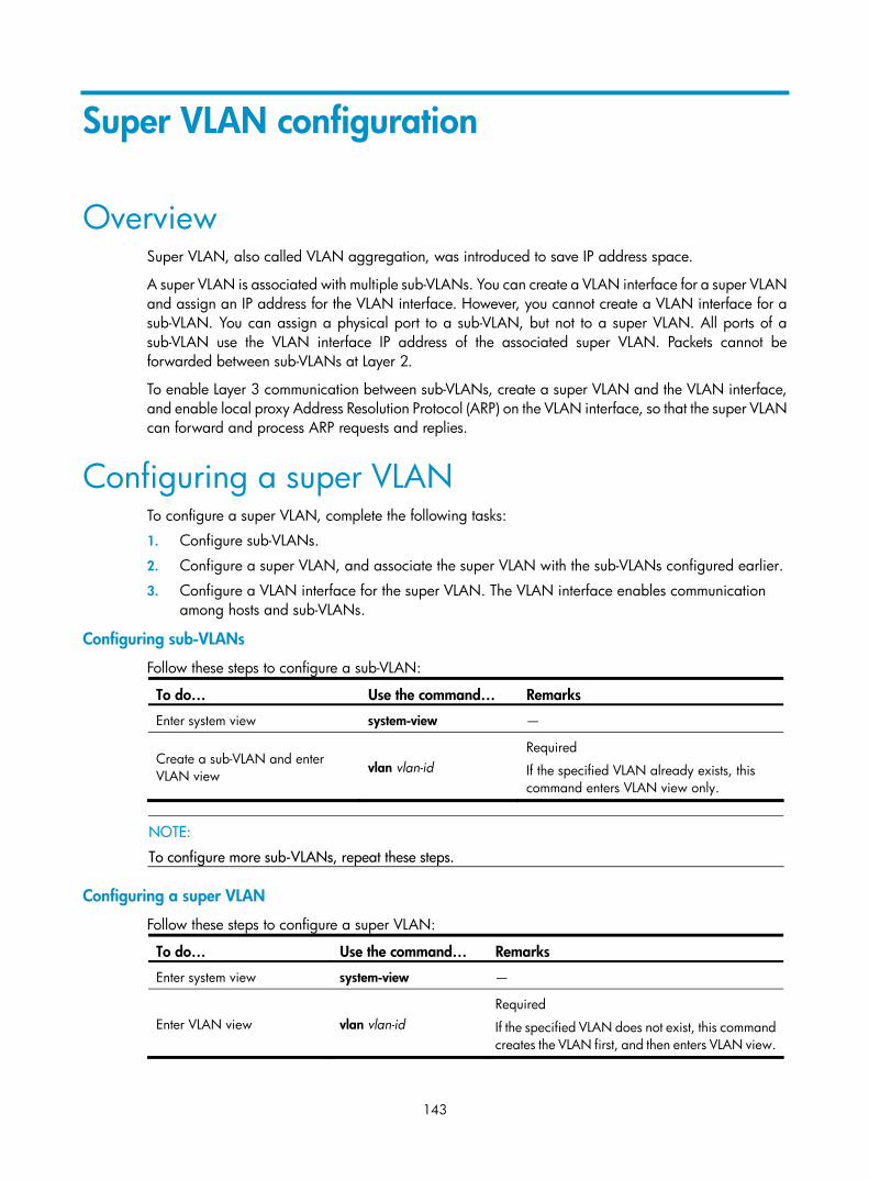
143
Super VLAN configuration
Overview Super VLAN, also called VLAN aggregation, was introduced to save IP address space.
A super VLAN is associated with multiple sub-VLANs. You can create a VLAN interface for a super VLAN and assign an IP address for the VLAN interface. However, you cannot create a VLAN interface for a sub-VLAN. You can assign a physical port to a sub-VLAN, but not to a super VLAN. All ports of a sub-VLAN use the VLAN interface IP address of the associated super VLAN. Packets cannot be forwarded between sub-VLANs at Layer 2.
To enable Layer 3 communication between sub-VLANs, create a super VLAN and the VLAN interface, and enable local proxy Address Resolution Protocol (ARP) on the VLAN interface, so that the super VLAN can forward and process ARP requests and replies.
Configuring a super VLAN To configure a super VLAN, complete the following tasks:
1. Configure sub-VLANs.
2. Configure a super VLAN, and associate the super VLAN with the sub-VLANs configured earlier.
3. Configure a VLAN interface for the super VLAN. The VLAN interface enables communication among hosts and sub-VLANs.
Configuring sub-VLANs
Follow these steps to configure a sub-VLAN:
To do… Use the command… Remarks
Enter system view system-view —
Create a sub-VLAN and enter VLAN view vlan vlan-id
Required
If the specified VLAN already exists, this command enters VLAN view only.
NOTE:
To configure more sub-VLANs, repeat these steps.
Configuring a super VLAN
Follow these steps to configure a super VLAN:
To do… Use the command… Remarks
Enter system view system-view —
Enter VLAN view vlan vlan-id Required
If the specified VLAN does not exist, this command creates the VLAN first, and then enters VLAN view.

144
To do… Use the command… Remarks
Configure the VLAN as a super VLAN supervlan
Required
Not configured by default.
Associate the super VLAN with the specified sub-VLANs subvlan vlan-list
Required
VLANs specified by vlan-list must be the sub-VLANs configured earlier.
NOTE:
When dynamic MAC-based VLAN assignment is enabled on a port, you cannot configure VLANs of theMAC address-to-VLAN entries as super VLANs.
Configure a VLAN interface for the super VLAN
Follow these steps to configure a VLAN interface for the super VLAN:
To do… Use the command… Remarks
Enter system view system-view —
Create a VLAN interface, and enter VLAN interface view interface vlan-interface vlan-interface-id
Required
The value of vlan-interface-id must be the ID of the super VLAN.
Configure the IP address of the VLAN interface
ip address ip-address { mask | mask-length } [ sub ]
Required
By default, the IP address of a VLAN interface is not configured.
Enable local proxy ARP local-proxy-arp enable Required
Disabled by default.
NOTE:
• Configure the IP address of the VLAN interface with that of the corresponding super VLAN.
• For more information about local proxy ARP function, see Layer 3—IP Services Configuration Guide. For more information about local-proxy-arp enable command, see Layer 3—IP Services Command Reference.
• You cannot configure a super VLAN as the guest VLAN for a port, and vice versa. For more informationabout guest VLANs, see Security Configuration Guide.
• You can configure Layer 2 multicast for a super VLAN, but the configuration is ineffective.
• You can configure DHCP, Layer 3 multicast, and dynamic routing for the VLAN interface of a super VLAN. However, only DHCP takes effect.
• H3C does not recommend configuring VRRP for the VLAN interface of a super VLAN, because it affectsnetwork performance. For more information about VRRP, see High Availability Configuration Guide.
Displaying and maintaining super VLAN To do… Use the command… Remarks
Display the mapping between a super VLAN and its sub-VLANs
display supervlan [ supervlan-id ] [ | { begin | exclude | include } regular-expression ] Available in any view
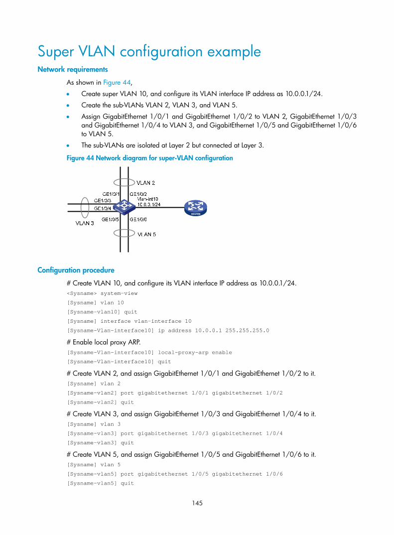
145
Super VLAN configuration example Network requirements
As shown in Figure 44,
• Create super VLAN 10, and configure its VLAN interface IP address as 10.0.0.1/24.
• Create the sub-VLANs VLAN 2, VLAN 3, and VLAN 5.
• Assign GigabitEthernet 1/0/1 and GigabitEthernet 1/0/2 to VLAN 2, GigabitEthernet 1/0/3 and GigabitEthernet 1/0/4 to VLAN 3, and GigabitEthernet 1/0/5 and GigabitEthernet 1/0/6 to VLAN 5.
• The sub-VLANs are isolated at Layer 2 but connected at Layer 3.
Figure 44 Network diagram for super-VLAN configuration
Configuration procedure
# Create VLAN 10, and configure its VLAN interface IP address as 10.0.0.1/24. <Sysname> system-view
[Sysname] vlan 10
[Sysname-vlan10] quit
[Sysname] interface vlan-interface 10
[Sysname-Vlan-interface10] ip address 10.0.0.1 255.255.255.0
# Enable local proxy ARP. [Sysname-Vlan-interface10] local-proxy-arp enable
[Sysname-Vlan-interface10] quit
# Create VLAN 2, and assign GigabitEthernet 1/0/1 and GigabitEthernet 1/0/2 to it. [Sysname] vlan 2
[Sysname-vlan2] port gigabitethernet 1/0/1 gigabitethernet 1/0/2
[Sysname-vlan2] quit
# Create VLAN 3, and assign GigabitEthernet 1/0/3 and GigabitEthernet 1/0/4 to it. [Sysname] vlan 3
[Sysname-vlan3] port gigabitethernet 1/0/3 gigabitethernet 1/0/4
[Sysname-vlan3] quit
# Create VLAN 5, and assign GigabitEthernet 1/0/5 and GigabitEthernet 1/0/6 to it. [Sysname] vlan 5
[Sysname-vlan5] port gigabitethernet 1/0/5 gigabitethernet 1/0/6
[Sysname-vlan5] quit
146
# Configure VLAN 10 as the super VLAN, and configure VLAN 2, VLAN 3, and VLAN 5 as its sub-VLANs. [Sysname] vlan 10
[Sysname-vlan10] supervlan
[Sysname-vlan10] subvlan 2 3 5
[Sysname-vlan10] quit
[Sysname] quit
Verification
# Display information about VLAN 10, the super VLAN, to verify the configuration. <Sysname> display supervlan
SuperVLAN ID : 10
SubVLAN ID : 2-3 5
VLAN ID: 10
VLAN Type: static
It is a Super VLAN.
Route Interface: configured
Ip Address: 10.0.0.1
Subnet Mask: 255.255.255.0
Description: VLAN 0010
Name: VLAN 0010
Tagged Ports: none
Untagged Ports: none
VLAN ID: 2
VLAN Type: static
It is a Sub VLAN.
Route Interface: configured
Ip Address: 10.0.0.1
Subnet Mask: 255.255.255.0
Description: VLAN 0002
Name: VLAN 0002
Tagged Ports: none
Untagged Ports:
GigabitEthernet1/0/1 GigabitEthernet1/0/2
VLAN ID: 3
VLAN Type: static
It is a Sub VLAN.
Route Interface: configured
Ip Address: 10.0.0.1
Subnet Mask: 255.255.255.0
Description: VLAN 0003
Name: VLAN 0003
Tagged Ports: none
Untagged Ports:
GigabitEthernet1/0/3 GigabitEthernet1/0/4

147
VLAN ID: 5
VLAN Type: static
It is a Sub VLAN.
Route Interface: configured
Ip Address: 10.0.0.1
Subnet Mask: 255.255.255.0
Description: VLAN 0005
Name: VLAN 0005
Tagged Ports: none
Untagged Ports:
GigabitEthernet1/0/5 GigabitEthernet1/0/6

148
Isolate-user-VLAN configuration
Overview An isolate-user-VLAN uses a two-tier VLAN structure. In this approach, the following types of VLANs, isolate-user-VLAN and secondary VLAN, are configured on the same device.
The following are the characteristics of the isolate-user-VLAN implementation:
• Isolate-user-VLANs are mainly used for upstream data exchange. An isolate-user-VLAN can be associated with multiple secondary VLANs. As the upstream device identifies only the isolate-user-VLAN and not the secondary VLANs, network configuration is simplified and VLAN resources are saved.
• You can isolate the Layer 2 traffic of different users by assigning the ports connected to them to different secondary VLANs. To enable communication between secondary VLANs associated with the same isolate-user-VLAN, you can enable local proxy ARP on the upstream device (for example, Device A in Figure 45) to realize Layer 3 communication between the secondary VLANs.
As shown in Figure 45, the isolate-user-VLAN function is enabled on Device B. VLAN 10 is the isolate-user-VLAN. VLAN 2, VLAN 5, and VLAN 8 are secondary VLANs associated with VLAN 10 and are invisible to Device A.
Figure 45 An isolate-user-VLAN example
Configuring an isolate-user-VLAN To configure an isolate-user-VLAN, complete the following tasks:
1. Configure the isolate-user-VLAN.
2. Configure the secondary VLANs.
3. Configure uplink and downlink ports:
Configure the uplink ports, for example, the port connecting Device B to Device A in Figure 45, to work in promiscuous mode in the specified VLAN, so that the uplink ports can be added to the specified isolate-user-VLAN and the secondary VLANs associated with the isolate-user-VLAN synchronously.

149
Configure the downlink ports, for example, the ports connecting Device B to hosts in Figure 45, to work in host mode, so that the downlink ports can be added to the isolate-user-VLAN associated with the secondary VLAN synchronously.
For more information about the promiscuous and host mode commands, see Layer 2—LAN Switching Command Reference.
4. Associate the isolate-user-VLAN with the specified secondary VLANs.
Follow these steps to configure an isolate-user-VLAN:
To do... Use the command Remarks
Enter system view system-view —
Create a VLAN and enter VLAN view vlan vlan-id —
Configure the VLAN as an isolate-user-VLAN isolate-user-vlan enable
Required
Not configured by default.
Return to system view quit —
Create secondary VLANs vlan { vlan-id1 [ to vlan-id2 ] | all } Required
Return to system view quit —
Configure the uplink port
1. Enter Layer 2 Ethernet or aggregate interface view:
interface interface-type interface-number
Or
interface bridge-aggregation interface-number 2. Configure the port to operate in
promiscuous mode in a specific VLAN:
port isolate-user-vlan vlan-id promiscuous
Required
Return to system view quit —
Configure the downlink port
1. Enter Layer 2 Ethernet or aggregate interface view:
interface interface-type interface-number
Or
interface bridge-aggregation interface-number 2. Configure the link type of the port
port link-type { access | hybrid } 3. Assign ports to the secondary VLAN • Access port: port access vlan vlan-id • Hybrid port: port hybrid vlan vlan-id-list
{ tagged | untagged } 4. Configure the port to operate in host mode:
port isolate-user-vlan host
Required
Return to system view quit —
Associate the isolate-user-VLAN with the specified secondary VLANs
isolate-user-vlan isolate-user-vlan-id secondary secondary-vlan-id [ to secondary-vlan-id ]
Required
Not configured by default.

150
NOTE:
• After you complete the preceding configurations, make sure that the isolate-user-VLAN is the PVID of theupstream port and the secondary VLAN is the PVID of the downstream port. For hybrid ports that havebeen assigned to the isolate-user-VLAN and secondary VLANs in tagged mode, H3C recommends thatyou assign these ports to these VLANs in untagged mode.
• An isolate-user-VLAN will automatically synchronize the MAC address entries of the associated secondary VLANs.
• You cannot configure the member port of a service loopback group as the uplink or downlink port of anisolate-user-VLAN. For more information about the service loopback group, see the chapter “Service loopback group configuration.”
Displaying and maintaining isolate-user-VLAN To do... Use the command... Remarks
Display the mapping between an isolate-user-VLAN and its secondary VLANs
display isolate-user-vlan [ isolate-user-vlan-id ] [ | { begin | exclude | include } regular-expression ]
Available in any view
Isolate-user-VLAN configuration example Network requirements
As shown in Figure 46,
• Connect Device A to downstream devices Device B and Device C.
• Configure VLAN 5 on Device B as an isolate-user-VLAN, assign the uplink port GigabitEthernet 1/0/5 to VLAN 5, and associate VLAN 5 with secondary VLANs VLAN 2 and VLAN 3. Assign GigabitEthernet 1/0/2 to VLAN 2 and GigabitEthernet 1/0/1 to VLAN 3.
• Configure VLAN 6 on Device C as an isolate-user-VLAN, assign the uplink port GigabitEthernet 1/0/5 to VLAN 6, and associate VLAN 6 with secondary VLANs VLAN 3 and VLAN 4. Assign GigabitEthernet 1/0/3 to VLAN 3 and GigabitEthernet 1/0/4 to VLAN 4.
• As far as Device A is concerned, Device B only has VLAN 5 and Device C only has VLAN 6.
Figure 46 Network diagram

151
Configuration procedure
The following part provides only the configuration on Device B and Device C.
1. Configure Device B
# Configure the isolate-user-VLAN. <DeviceB> system-view
[DeviceB] vlan 5
[DeviceB-vlan5] isolate-user-vlan enable
[DeviceB-vlan5] quit
# Create secondary VLANs. [DeviceB] vlan 2 to 3
# Configure the uplink port GigabitEthernet 1/0/5 to operate in promiscuous mode in VLAN 5. [DeviceB] interface gigabitethernet 1/0/5
[DeviceB-GigabitEthernet1/0/5] port isolate-user-vlan 5 promiscuous
[DeviceB-GigabitEthernet1/0/5] quit
# Assign downlink ports GigabitEthernet 1/0/1 and GigabitEthernet 1/0/2 to VLAN 3 and VLAN 2 respectively, and configure the ports to operate in host mode. [DeviceB] interface gigabitethernet 1/0/1
[DeviceB-GigabitEthernet1/0/1] port access vlan 3
[DeviceB-GigabitEthernet1/0/1] port isolate-user-vlan host
[DeviceB-GigabitEthernet1/0/1] quit
[DeviceB] interface gigabitethernet 1/0/2
[DeviceB-GigabitEthernet1/0/2] port access vlan 2
[DeviceB-GigabitEthernet1/0/2] port isolate-user-vlan host
[DeviceB-GigabitEthernet1/0/2] quit
# Associate the isolate-user-VLAN with the secondary VLANs. [DeviceB] isolate-user-vlan 5 secondary 2 to 3
2. Configure Device C
# Configure the isolate-user-VLAN. <DeviceC> system-view
[DeviceC] vlan 6
[DeviceC-vlan6] isolate-user-vlan enable
[DeviceC-vlan6] quit
# Create secondary VLANs. [DeviceC] vlan 3 to 4
# Configure the uplink port GigabitEthernet 1/0/5 to operate in promiscuous mode in VLAN 6. [DeviceC] interface gigabitethernet 1/0/5
[DeviceC-GigabitEthernet1/0/5] port isolate-user-vlan 6 promiscuous
[DeviceC-GigabitEthernet1/0/5] quit
# Configure downlink ports GigabitEthernet 1/0/3 and GigabitEthernet 1/0/4 to VLAN 3 and VLAN 4 respectively, and configure the ports to operate in host mode. [DeviceC] interface gigabitethernet 1/0/3
[DeviceC-GigabitEthernet1/0/3] port access vlan 3
[DeviceC-GigabitEthernet1/0/3] port isolate-user-vlan host
[DeviceC-GigabitEthernet1/0/3] quit
152
[DeviceC] interface gigabitethernet 1/0/4
[DeviceC-GigabitEthernet1/0/4] port access vlan 4
[DeviceC-GigabitEthernet1/0/4] port isolate-user-vlan host
[DeviceC-GigabitEthernet1/0/4] quit
# Associate the isolate-user-VLAN with the secondary VLANs. [DeviceC] isolate-user-vlan 6 secondary 3 to 4
Verifying the configuration
# Display the isolate-user-VLAN configuration on Device B. [DeviceB] display isolate-user-vlan
Isolate-user-VLAN VLAN ID : 5
Secondary VLAN ID : 2-3
VLAN ID: 5
VLAN Type: static
Isolate-user-VLAN type : isolate-user-VLAN
Route Interface: not configured
Description: VLAN 0005
Name: VLAN 0005
Tagged Ports: none
Untagged Ports:
GigabitEthernet1/0/1 GigabitEthernet1/0/2 GigabitEthernet1/0/5
VLAN ID: 2
VLAN Type: static
Isolate-user-VLAN type : secondary
Route Interface: not configured
Description: VLAN 0002
Name: VLAN 0002
Tagged Ports: none
Untagged Ports:
GigabitEthernet1/0/2 GigabitEthernet1/0/5
VLAN ID: 3
VLAN Type: static
Isolate-user-VLAN type : secondary
Route Interface: not configured
Description: VLAN 0003
Name: VLAN 0003
Tagged Ports: none
Untagged Ports:
GigabitEthernet1/0/1 GigabitEthernet1/0/5

153
Voice VLAN configuration
Overview A voice VLAN is configured for voice traffic. After assigning the ports that connect to voice devices to a voice VLAN, the system automatically configures quality of service (QoS) parameters for voice traffic, to improve the transmission priority of voice traffic and ensure voice quality.
NOTE:
Common voice devices include IP phones and integrated access devices (IADs). Only IP phones are usedin the voice VLAN configuration examples in this document.
OUI addresses A device determines whether a received packet is a voice packet by evaluating its source MAC address. A packet whose source MAC address complies with the Organizationally Unique Identifier (OUI) address of the voice device is regarded as voice traffic.
You can configure the OUI addresses of a device in advance or use the default OUI addresses. Table 15 lists the default OUI address for each vendor’s devices.
Table 15 The default OUI addresses of different vendors
Number OUI address Vendor
1 0001-E300-0000 Siemens phone
2 0003-6B00-0000 Cisco phone
3 0004-0D00-0000 Avaya phone
4 00D0-1E00-0000 Pingtel phone
5 0060-B900-0000 Philips/NEC phone
6 00E0-7500-0000 Polycom phone
7 00E0-BB00-0000 3Com phone
NOTE:
• In general, as the first 24 bits of a MAC address (in binary format), an OUI address is a globally uniqueidentifier that IEEE assigns to a vendor. In this document, however, OUI addresses are addresses that thesystem uses to determine whether a received packet is a voice packet. They are the results of the AND operation of the arguments mac-address and oui-mask in the voice vlan mac-address command.
• You can remove the default OUI address of a device manually and then add new ones manually.
Voice VLAN assignment modes A port can be assigned to a voice VLAN in one of the following modes:

154
• In automatic mode, the system matches the source MAC address carried in the untagged packets sent when an IP phone is powered on against the device’s OUI addresses. If the system finds a match, it automatically assigns the receiving port to the voice VLAN, issues ACL rules, and configures the packet precedence. You can configure a voice VLAN aging time on the device. The system will remove a port from the voice VLAN if no packet is received from the port during the aging time. The system automatically assigns ports to, or removes ports from, a voice VLAN. Automatic mode is suitable for scenarios where PCs and IP phones connected in series access the network through the device and ports on the device transmit both voice traffic and data traffic at the same time, as shown in Figure 47. When the voice VLAN works normally, when the system reboots, the system reassigns ports in automatic voice VLAN assignment mode to the voice VLAN after the reboot, ensuring that existing voice connections can work normally. In this case, voice traffic streams do not trigger port assignment to the voice VLAN.
Figure 47 PCs and IP phones connected in series access the network
• In manual mode, you must manually assign an IP phone accessing port to a voice VLAN. Then, the system matches the source MAC addresses carried in the packets against the device’s OUI addresses. If the system finds a match, it issues ACL rules and configures the packet precedence. In this mode, you must manually assign ports to, or remove ports from, a voice VLAN. Manual mode is suitable for scenarios where only IP phones access the network through the device and ports on the device transmit only voice traffic, as shown in Figure 48. In this mode, ports assigned to a voice VLAN transmit voice traffic exclusively, which prevents the impact of data traffic on the transmission of voice traffic.
Figure 48 Only IP phones access the network
IP Phone
Device
Voice gateway
IP Phone
Both modes forward tagged packets according to their tags.
Table 16 and Table 17 list the configurations required for ports of different link types to support tagged or untagged voice traffic sent from IP phones when different voice VLAN assignment modes are configured.
• IP phones send tagged voice traffic

155
Table 16 Required configurations on ports of different link types for them to support tagged voice traffic
Port link type
Voice VLAN assignment mode
Support for tagged voice traffic Configuration requirements
Automatic Access
Manual No —
Automatic The PVID of the port cannot be the voice VLAN.
Trunk Manual
Yes The PVID of the port cannot be the voice VLAN. Configure the port to permit packets of the voice VLAN to pass through.
Automatic The PVID of the port cannot be the voice VLAN.
Hybrid Manual
Yes The PVID of the port cannot be the voice VLAN. Configure the port to permit packets of the voice VLAN to pass through tagged.
• IP phones send untagged voice traffic
When IP phones send untagged voice traffic, you can only configure the voice traffic receiving ports on the device to operate in manual voice VLAN assignment mode.
Table 17 Required configurations on ports of different link types for them to support tagged voice traffic
Port link type
Voice VLAN assignment mode
Support for untagged voice traffic Configuration requirements
Automatic No — Access
Manual Yes Configure the PVID of the port as the voice VLAN.
Automatic No —
Trunk Manual Yes
Configure the PVID of the port as the voice VLAN and assign the port to the voice VLAN.
Automatic No —
Hybrid Manual Yes
Configure the PVID of the port as the voice VLAN and configure the port to permit packets of the voice VLAN to pass through untagged.
CAUTION:
• If an IP phone sends tagged voice traffic and its accessing port is configured with 802.1X authenticationand guest VLAN, assign different VLAN IDs for the voice VLAN, the PVID of the connecting port, and the 802.1X guest VLAN.
• If an IP phone sends untagged voice traffic, to implement the voice VLAN feature, you must configure thePVID of the IP phone’s accessing port as the voice VLAN. As a result, you cannot implement 802.1X authentication.
NOTE:
• The PVID is VLAN 1 for all ports by default. You can configure the PVID of a port and assign a port tocertain VLANs by using commands. For more information, see the chapter “VLAN configuration.”
• Use the display interface command to display the PVID of a port and the VLANs to which the port is assigned.

156
Security mode and normal mode of voice VLANs Depending on their inbound packet filtering mechanisms, voice VLAN-enabled ports operate in the following modes:
• Normal mode: Voice VLAN-enabled ports receive packets that carry the voice VLAN tag, and forward packets in the voice VLAN without comparing their source MAC addresses against the OUI addresses configured for the device. If the PVID of the port is the voice VLAN and the port works in manual VLAN assignment mode, the port forwards all received untagged packets in the voice VLAN. In normal mode, voice VLANs are vulnerable to traffic attacks. Malicious users might send large quantities of forged voice packets to consume the voice VLAN bandwidth, affecting normal voice communication.
• Security mode: Only voice packets whose source MAC addresses match the recognizable OUI addresses can pass through the voice VLAN-enabled inbound port, but all other packets are dropped.
In a safe network, you can configure the voice VLANs to operate in normal mode, reducing the consumption of system resources due to source MAC addresses checking.
TIP:
H3C does not recommend you transmit both voice traffic and non-voice traffic in a voice VLAN. If you must transmit both voice traffic and nonvoice traffic, ensure that the voice VLAN security mode is disabled.
Table 18 How a voice VLAN-enabled port processes packets in security and normal mode
Voice VLAN mode Packet type Packet processing mode
Untagged packets
Packets that carry the voice VLAN tag
If the source MAC address of a packet matches an OUI address configured for the device, it is forwarded in the voice VLAN; otherwise, it is dropped. Security mode
Packets that carry other tags
Forwarded or dropped depending on whether the port allows packets of these VLANs to pass through
Untagged packets
Packets that carry the voice VLAN tag
The port does not determine the source MAC addresses of inbound packets. In this way, both voice traffic and non-voice traffic can be transmitted in the voice VLAN. Normal mode
Packets that carry other tags
Forwarded or dropped depending on whether the port allows packets of these VLANs to pass through
Configuring a voice VLAN
Configuration prerequisites Before you configure a voice VLAN, complete the following tasks:
• Create a VLAN.
• Configure QoS priority settings for voice VLAN traffic on an interface before you enable voice VLAN on the interface.

157
If the configuration order is reversed, your priority configuration will fail. For more information, see “Configuring QoS priority settings for voice traffic on an interface.”
• Configure the voice VLAN assignment mode.
For more information, see “Configuring a port to operate in automatic voice VLAN assignment mode” and “Configuring a port to operate in manual voice VLAN assignment mode.”
Configuring QoS priority settings for voice traffic on an interface
In voice VLAN applications, you can improve the quality of voice traffic by configuring the appropriate QoS priority settings, including the Class of Service (CoS) and Differentiated Services Code Point (DSCP) values, for voice traffic. Voice traffic carries its own QoS priority settings. You can configure the device either to modify or not to modify the QoS priority settings carried by incoming voice traffic.
Follow these steps to configure QoS priority settings for voice traffic:
To do... Use the command... Remarks
Enter system view system-view —
Enter Layer 2 Ethernet interface view
interface interface-type interface-number —
Configure the interface to trust the QoS priority settings in incoming voice traffic, but not to modify the CoS and DSCP values marked for incoming traffic of the voice VLAN
voice vlan qos trust
Configure the interface to modify the CoS and DSCP values marked for incoming traffic of the voice VLAN into specified values
voice vlan qos cos-value dscp-value
Required
Use either command
By default, an interface modifies the CoS value and the DSCP value marked for voice VLAN traffic into 6 and 46 respectively.
The voice vlan qos command and the voice vlan qos trust command can overwrite each other, whichever is configured last.
NOTE:
Configure the QoS priority settings for voice traffic on an interface before you enable voice VLAN on theinterface. If the configuration order is reversed, your priority trust setting will fail.
Configuring a port to operate in automatic voice VLAN assignment mode
Follow these steps to set a port to operate in automatic voice VLAN assignment mode:
To do... Use the command... Remarks
Enter system view system-view —
Set the voice VLAN aging time voice vlan aging minutes
Optional
By default, the aging time of a voice VLAN is 1440 minutes.
The voice VLAN aging time configuration is only applicable on ports in automatic voice VLAN assignment mode.

158
To do... Use the command... Remarks
Enable the voice VLAN security mode voice vlan security enable
Optional
By default, the voice VLAN security mode is enabled.
Add a recognizable OUI address
voice vlan mac-address oui mask oui-mask [ description text ]
Optional
By default, each voice VLAN has default OUI addresses configured. For the default OUI addresses of different vendors, see Table 15.
Enter Ethernet interface view
interface interface-type interface-number —
Configure the port to operate in automatic voice VLAN assignment mode
voice vlan mode auto
Optional
By default, the automatic voice VLAN assignment mode is enabled.
The voice VLAN assignment modes on different ports are independent of one another.
Enable the voice VLAN feature voice vlan vlan-id enable
Required
By default, the voice VLAN feature is disabled.
NOTE:
A protocol-based VLAN on a hybrid port can process only untagged inbound packets, whereas the voiceVLAN in automatic mode on a hybrid port can process only tagged voice traffic. Do not configure a VLANas both a protocol-based VLAN and a voice VLAN. For more information, see the chapter “VLAN configuration.”
Configuring a port to operate in manual voice VLAN assignment mode
Follow these steps to set a port to operate in manual voice VLAN assignment mode:
To do... Use the command... Remarks
Enter system view system-view —
Enable the voice VLAN security mode voice vlan security enable
Optional
By default, the voice VLAN security mode is enabled.
Add a recognizable OUI address
voice vlan mac-address oui mask oui-mask [ description text ]
Optional
By default, each voice VLAN has default OUI addresses configured. For the default OUI addresses of different vendors, see Table 15.
Enter interface view interface interface-type interface-number —
Configure the port to operate in manual voice VLAN assignment mode
undo voice vlan mode auto Required
By default, the manual voice VLAN assignment mode is disabled.

159
To do... Use the command... Remarks
Assign the access, trunk, or hybrid port in manual voice VLAN assignment mode to the voice VLAN
For the configuration procedure, see the chapter “VLAN configuration.”
Required
After you assign an access port to the voice VLAN, the voice VLAN becomes the PVID of the port automatically.
Configure the voice VLAN as the PVID of the trunk or hybrid port
For the configuration procedure, see the chapter “VLAN configuration.”
Optional
This operation is required for untagged inbound voice traffic and prohibited for tagged inbound voice traffic.
Enable voice VLAN on the port voice vlan vlan-id enable
Required
Disabled by default.
NOTE:
• You can configure different voice VLANs on different ports at the same time. However, you can configure one port with only one voice VLAN, and this voice VLAN must be a static VLAN that alreadyexists on the device.
• You cannot enable voice VLAN on the member ports of a link aggregation group. For more informationabout the member ports, see the chapter “Ethernet link aggregation configuration.”
• To make voice VLAN take effect on a port that is enabled with voice VLAN and operates in manual voiceVLAN assignment mode, you must assign the port to the voice VLAN manually.
Displaying and maintaining voice VLAN To do... Use the command... Remarks
Display the voice VLAN state display voice vlan state [ | { begin | exclude | include } regular-expression ] Available in any view
Display the OUI addresses that the system supports
display voice vlan oui [ | { begin | exclude | include } regular-expression ] Available in any view
Voice VLAN configuration examples
Automatic voice VLAN mode configuration example Network requirements
As shown in Figure 49,
• The MAC address of IP phone A is 0011-1100-0001. The phone connects to a downstream device named PC A whose MAC address is 0022-1100-0002 and to GigabitEthernet 1/0/1 on an upstream device named Device A.
• The MAC address of IP phone B is 0011-2200-0001. The phone connects to a downstream device named PC B whose MAC address is 0022-2200-0002 and to GigabitEthernet 1/0/2 on Device A.
• Device A uses voice VLAN 2 to transmit voice packets for IP phone A and uses voice VLAN 3 to transmit voice packets for IP phone B.

160
• Configure GigabitEthernet 1/0/1 and GigabitEthernet 1/0/2 to work in automatic voice VLAN assignment mode. In addition, if one of them has not received any voice packet in 30 minutes, the port is removed from the corresponding voice VLAN automatically.
Figure 49 Network diagram for automatic voice VLAN assignment mode configuration
Configuration procedure
# Create VLAN 2 and VLAN 3. <DeviceA> system-view
[DeviceA] vlan 2 to 3
Please wait... Done.
# Set the voice VLAN aging time to 30 minutes. [DeviceA] voice vlan aging 30
# Since GigabitEthernet 1/0/1 might receive both voice traffic and data traffic at the same time, to ensure the quality of voice packets and effective bandwidth use, configure voice VLANs to work in security mode. Configure the voice VLANs to transmit only voice packets. By default, voice VLANs work in security mode. (Optional) [DeviceA] voice vlan security enable
# Configure the allowed OUI addresses as MAC addresses prefixed by 0011-1100-0000 or 0011-2200-0000. In this way, Device A identifies packets whose MAC addresses match any of the configured OUI addresses as voice packets. [DeviceA] voice vlan mac-address 0011-1100-0001 mask ffff-ff00-0000 description IP phone A
[DeviceA] voice vlan mac-address 0011-2200-0001 mask ffff-ff00-0000 description IP phone B
# Configure GigabitEthernet 1/0/1 as a hybrid port. [DeviceA] interface gigabitethernet 1/0/1
[DeviceA-GigabitEthernet1/0/1] port link-type hybrid
# Configure GigabitEthernet 1/0/1 to operate in automatic voice VLAN assignment mode. By default, a port operates in automatic voice VLAN assignment mode. (Optional) [DeviceA-GigabitEthernet1/0/1] voice vlan mode auto
# Configure VLAN 2 as the voice VLAN for GigabitEthernet 1/0/1. [DeviceA-GigabitEthernet1/0/1] voice vlan 2 enable
[DeviceA-GigabitEthernet1/0/1] quit

161
# Configure GigabitEthernet 1/0/2. [DeviceA] interface gigabitethernet 1/0/2
[DeviceA-GigabitEthernet1/0/2] port link-type hybrid
[DeviceA-GigabitEthernet1/0/2] voice vlan mode auto
[DeviceA-GigabitEthernet1/0/2] voice vlan 3 enable
Verification
# Display the OUI addresses, OUI address masks, and description strings. <DeviceA> display voice vlan oui
Oui Address Mask Description
0001-e300-0000 ffff-ff00-0000 Siemens phone
0003-6b00-0000 ffff-ff00-0000 Cisco phone
0004-0d00-0000 ffff-ff00-0000 Avaya phone
0011-1100-0000 ffff-ff00-0000 IP phone A
0011-2200-0000 ffff-ff00-0000 IP phone B
0060-b900-0000 ffff-ff00-0000 Philips/NEC phone
00d0-1e00-0000 ffff-ff00-0000 Pingtel phone
00e0-7500-0000 ffff-ff00-0000 Polycom phone
00e0-bb00-0000 ffff-ff00-0000 3com phone
# Display the states of voice VLANs. <DeviceA> display voice vlan state
Maximum of Voice VLANs: 128
Current Voice VLANs: 2
Voice VLAN security mode: Security
Voice VLAN aging time: 30 minutes
Voice VLAN enabled port and its mode:
PORT VLAN MODE COS DSCP
--------------------------------------------------------------------
GigabitEthernet1/0/1 2 AUTO 6 46
GigabitEthernet1/0/2 3 AUTO 6 46
Manual voice VLAN assignment mode configuration example Network requirements
As shown in Figure 50,
• Create VLAN 2 and configure it as a voice VLAN that permits only voice traffic to pass through.
• The IP phones send untagged voice traffic. Configure GigabitEthernet 1/0/1 as a hybrid port.
• Configure GigabitEthernet 1/0/1 to operate in manual voice VLAN assignment mode. Configure GigabitEthernet 1/0/1 to allow voice traffic with an OUI address of 0011-2200-0000, a mask of ffff-ff00-0000, and a description string of test to be forwarded in the voice VLAN.

162
Figure 50 Network diagram for manual voice VLAN assignment mode configuration
Device A Device B
GE1/0/1GE1/0/1VLAN 2
010-1001OUI: 0011-2200-0000Mask: ffff-ff00-0000
0755-2002
Internet
Configuration procedure
# Configure the voice VLAN to operate in security mode. A voice VLAN operates in security mode by default. (Optional) <DeviceA> system-view
[DeviceA] voice vlan security enable
# Add a recognizable OUI address 0011-2200-0000. [DeviceA] voice vlan mac-address 0011-2200-0000 mask ffff-ff00-0000 description test
# Create VLAN 2. [DeviceA] vlan 2
[DeviceA-vlan2] quit
# Configure GigabitEthernet 1/0/1 to operate in manual voice VLAN assignment mode. [DeviceA] interface gigabitethernet 1/0/1
[DeviceA-GigabitEthernet1/0/1] undo voice vlan mode auto
# Configure GigabitEthernet 1/0/1 as a hybrid port. [DeviceA-GigabitEthernet1/0/1] port link-type hybrid
# Configure the voice VLAN (VLAN 2) as the PVID of GigabitEthernet 1/0/1 and configure GigabitEthernet 1/0/1 to permit the voice traffic of VLAN 2 to pass through untagged. [DeviceA-GigabitEthernet1/0/1] port hybrid pvid vlan 2
[DeviceA-GigabitEthernet1/0/1] port hybrid vlan 2 untagged
# Enable voice VLAN on GigabitEthernet 1/0/1. [DeviceA-GigabitEthernet1/0/1] voice vlan 2 enable
Verification
# Display the OUI addresses, OUI address masks, and description strings. <DeviceA> display voice vlan oui
Oui Address Mask Description
0001-e300-0000 ffff-ff00-0000 Siemens phone
0003-6b00-0000 ffff-ff00-0000 Cisco phone
0004-0d00-0000 ffff-ff00-0000 Avaya phone
0011-2200-0000 ffff-ff00-0000 test
00d0-1e00-0000 ffff-ff00-0000 Pingtel phone
0060-b900-0000 ffff-ff00-0000 Philips/NEC phone
00e0-7500-0000 ffff-ff00-0000 Polycom phone
00e0-bb00-0000 ffff-ff00-0000 3com phone

163
# Display the states of voice VLANs. <DeviceA> display voice vlan state
Maximum of Voice VLANs: 128
Current Voice VLANs: 1
Voice VLAN security mode: Security
Voice VLAN aging time: 1440 minutes
Voice VLAN enabled port and its mode:
PORT VLAN MODE COS DSCP
--------------------------------------------------------------------
GigabitEthernet1/0/1 2 MANUAL 6 46

164
GVRP configuration
The Generic Attribute Registration Protocol (GARP) provides a generic framework for devices in a switched LAN, such as end stations and switches, to register and deregister attribute values. The GARP VLAN Registration Protocol (GVRP) is a GARP application that registers and deregisters VLAN attributes. GVRP uses the operating mechanism of GARP to maintain and propagate dynamic VLAN registration information for GVRP devices on the network.
Introduction to GVRP
GARP GARP provides a mechanism that allows participants in a GARP application to distribute, propagate, and register—with other participants in a LAN—the attributes specific to the GARP application, such as VLAN or multicast address attributes.
How GARP works
Each port that participates in a GARP application (GVRP, for example) is a GARP participant.
GARP enables GARP participants to propagate attribute values throughout the switched LAN. As shown in Figure 51, a GARP participant registers and deregisters its attribute values with other GARP participants by sending and withdrawing declarations, and registers and deregisters the attribute values of other participants according to the declarations and withdrawals that it has received.
Figure 51 How GARP works
For example, a GVRP-enabled port registers and deregisters VLAN in the following cases.
• When the port receives a VLAN attribute declaration, it registers the VLAN attribute and joins the VLAN.
• When the port receives a VLAN withdrawal, it deregisters the VLAN and leaves the VLAN.
GARP messages
A GARP participant exchanges information with other GARP participants by sending GARP messages: Join, Leave, and LeaveAll. As a GARP application, GVRP also uses GARP messages for information exchange.
1. Join messages

165
A GARP participant sends Join messages when it wishes to declare its attribute values or receives Join messages from other GARP participants.
Join messages fall into JoinEmpty and JoinIn. A GARP participant sends JoinEmpty messages to declare attribute values that it has not registered. It sends JoinIn messages to declare attribute values that it has registered.
2. Leave messages
A GARP participant sends Leave messages when it wishes to withdraw declarations of its attribute values (because, for example, it has deregistered its attribute values), or receives Leave messages from other participants.
Leave messages fall into LeaveEmpty and LeaveIn. A GARP participant sends LeaveEmpty messages to withdraw declarations of the attribute values that it has not registered. It sends LeaveIn messages to withdraw declarations of the attribute values that it has registered.
3. LeaveAll messages
A GARP participant sends a LeaveAll message when it declares that it is deregistering all attribute values or receives LeaveAll messages from other participants. If any participants want to maintain the registration for a particular attribute value, they must send a Join message.
GARP timers
NOTE:
• The settings of GARP timers apply to all GARP applications, such as GVRP, on a LAN.
• On a GARP-enabled network, each port maintains its own Hold, Join, and Leave timers, but only one LeaveAll timer is maintained on each device. This LeaveAll timer applies to all ports on the device.
• The value ranges for the Hold, Join, Leave, and LeaveAll timers are dependent on one another. See Table 20 for their dependencies.
H3C's implementation of GARP uses the following timers to control GARP message transmission:
1. Hold timer
The Hold timer sets the delay that a GARP participant waits before sending a Join or Leave message.
When an attribute value changes or a Join or Leave message arrives, the GARP participant does not send the message immediately. Rather, it assembles Join and Leave messages in the least number of GARP PDUs, and sends them out when the Hold timer expires. This timer reduces the number of GARP PDUs and saves bandwidth.
2. Join timer
A GARP participant might declare an attribute twice to ensure reliable transmission. The Join timer sets the interval between the two declarations.
A GARP participant starts a Join timer when it declares an attribute value or receives a JoinIn message for the attribute value. If the GARP participant does not receive any declaration for the attribute value when the Join timer expires, it re-declares the attribute value.
NOTE:
Because all attributes of a GARP participant share the same Join timer, you must set the Join timer long enough so that all attributes can be sent out in one declaration.
3. Leave timer

166
A GARP participant starts a Leave timer when it receives a Leave message for an attribute value. If the GARP participant receives no Join message for the attribute value before the timer expires, it deregisters the attribute value.
4. LeaveAll timer
When a GARP application is enabled, a LeaveAll timer starts. The GARP participant sends a LeaveAll message when the timer expires. Then, the LeaveAll timer restarts to begin a new cycle. The LeaveAll timer and all other GARP timers also restart when the GARP participant receives a LeaveAll message.
NOTE:
• Set the LeaveAll timer greater than any Leave timer and not smaller than its default value, 1000 centiseconds. Each time a LeaveAll timer expires, a network-wide re-join occurs.
• A device can send LeaveAll messages at the interval set by its LeaveAll timer or the LeaveAll timer of another device on the network, whichever is smaller. This is because each time a device on the networkreceives a LeaveAll message, it resets its LeaveAll timer.
GARP PDU format
Figure 52 GARP PDU format
As shown in Figure 52, GARP PDUs are encapsulated in IEEE 802.3 Ethernet frames.
Table 19 GARP PDU fields
Field Description Value
Protocol ID Protocol identifier for GARP 0x0001
Message One or multiple messages, each of which contains an attribute type and an attribute list
––
End mark Indicates the end of a GARP PDU 0x00
Attribute type Defined by the GARP application 0x01 for GVRP, which indicates the VLAN ID attribute
Attribute list Contains one or multiple attributes ––

167
Field Description Value
Attribute Consists of an attribute length, an attribute event, and an attribute value
––
Attribute length Length of an attribute, inclusive of the attribute length field
2 to 255 (in bytes)
Attribute event Event that the attribute describes
• 0x00: LeaveAll event • 0x01: JoinEmpty event • 0x02: JoinIn event • 0x03: LeaveEmpty event • 0x04: LeaveIn event • 0x05: Empty event
Attribute value Attribute value
VLAN ID for GVRP
If the value of the attribute event field is 0x00 (LeaveAll event), the attribute value field is invalid.
The destination MAC addresses of GARP messages are multicast MAC addresses, and vary with GARP applications. For example, the destination MAC address of GVRP is 01-80-C2-00-00-21.
GVRP GVRP overview
As a GARP application, GVRP uses the operating mechanism of GARP to maintain and propagate dynamic VLAN registrations throughout a switched LAN.
In a switched LAN, each GVRP-enabled switch sends and receives VLAN declarations and withdrawals from other GVRP-enabled switches, and dynamically updates its local database, including active VLAN members and through which port each VLAN member can be reached. This ensures that all GVRP-enabled switches in a LAN maintain the same VLAN information.
The VLAN information propagated by GVRP includes not only manually configured static VLAN information but also dynamic VLAN information from other switches.
GVRP registration modes
GVRP is available on trunk ports. It provides the following registration modes:
• Normal mode—Performs dynamic VLAN registrations and deregistrations on the trunk port, and sends declarations and withdrawals for dynamic and static VLANs. VLANs manually configured are called static VLANs, and VLANs created by GVRP are called dynamic VLANs.
• Fixed mode—Disables the trunk port to register or withdraw dynamic VLAN information, but allows the port to send declarations for static VLANs. A trunk port in this mode carries only static VLANs, even if it has been assigned to all VLANs.
• Forbidden mode—Disables the trunk port to register or withdraw dynamic VLAN information, and allows the port to send declarations only for VLAN 1. A trunk port in this mode carries only VLAN 1 even if it has been assigned to any other VLANs.
Protocols and standards • IEEE 802.1Q, Virtual Bridged Local Area Networks

168
GVRP configuration task list Complete these tasks to configure GVRP:
Task Remarks
Configuring GVRP functions Required
Configuring the GARP timers Optional
NOTE:
• GVRP configuration made in Ethernet interface view or Layer 2 aggregate interface view takes effect onthe current interface only; GVRP configuration made in port group view takes effect on all the memberports in the group.
• GVRP configuration made on a member port in an aggregation group takes effect only after the port isremoved from the aggregation group.
Configuring GVRP functions Before enabling GVRP on a port, you must enable GVRP globally. In addition, you can configure GVRP only on trunk ports, and you must assign the involved trunk ports to all dynamic VLANs.
Follow these steps to configure GVRP functions on a trunk port:
To do… Use the command… Remarks
Enter system view system-view ––
Enable GVRP globally gvrp Required
Globally disabled by default.
Enter Ethernet interface view or Layer 2 aggregate interface view
interface interface-type interface-number
Enter Ethernet interface view, Layer 2 aggregate interface view, or port group view
Enter port group view port-group manual port-group-name
Required
Use either command.
Configure the link type of the ports as trunk port link-type trunk Required
Access by default.
Assign the trunk ports to all VLANs port trunk permit vlan all Required
By default, a trunk port is assigned to VLAN 1 only.
Enable GVRP on the ports gvrp Required
Disabled by default.
Configure the GVRP registration mode on the port
gvrp registration { fixed | forbidden | normal }
Optional
normal by default.

169
NOTE:
• For more information about the port link-type trunk and port trunk permit vlan all commands, see Layer 2—LAN Switching Command Reference.
• GVRP is mutually exclusive with service loopback.
• GVRP can work with STP, RSTP, or MSTP CIST but not PVST. When GVRP runs on the CIST, blocked portson the CIST cannot receive or send GVRP packets. For more information about STP, RSTP, MSTP CIST, and PVST, see the chapter “Spanning tree configuration.”
• Do not enable both GVRP and remote port mirroring. Otherwise, GVRP may register the remote probeVLAN to unexpected ports, resulting in undesired duplicates to be received by the monitor port. For more information about port mirroring, see Network Management and Monitoring Configuration Guide.
• Enabling GVRP on a Layer 2 aggregate interface enables both the aggregate interface and all selectedmember ports in the corresponding link aggregation group to participate in dynamic VLAN registrationand deregistration.
Configuring the GARP timers Follow these steps to configure the GARP timers:
To do… Use the command… Remarks
Enter system view system-view ––
Configure the GARP LeaveAll timer garp timer leaveall timer-value
Optional
1000 centiseconds by default.
The LeaveAll timer applies to all ports.
Enter Ethernet or Layer 2 aggregate interface view
interface interface-type interface-number
Enter Ethernet interface view, Layer 2 aggregate interface view, or port group view Enter port group
view port-group manual port-group-name
Required
Use either command.
Configure the Hold timer garp timer hold timer-value
Optional
10 centiseconds by default.
Configure the Join timer garp timer join timer-value
Optional
20 centiseconds by default.
Configure the Leave timer garp timer leave timer-value
Optional
60 centiseconds by default.
As shown in Table 20, the value ranges for GARP timers are dependent on one another; use the following guidelines to configure GARP timers:
• If you want to set a value beyond the value range for a timer, you can change the value range by tuning the value of another related timer.
• If you want to restore the default settings of the timers, restore the Hold timer first, followed by the Join, Leave, and LeaveAll timers.

170
Table 20 Dependencies of the GARP timers
Timer Lower limit Upper limit
Hold 10 centiseconds No greater than half of the Join timer
Join No less than twice the Hold timer Less than half of the Leave timer
Leave Greater than twice the Join timer Less than the LeaveAll timer
LeaveAll Greater than the Leave timer 32,765 centiseconds
NOTE:
To keep the dynamic VLANs learned through GVRP stable, do not set the LeaveAll timer smaller than its default value, 1000 centiseconds.
Displaying and maintaining GVRP To do… Use the command… Remarks
Display statistics about GARP on ports
display garp statistics [ interface interface-list ] [ | { begin | exclude | include } regular-expression ]
Available in any view
Display GARP timers on ports display garp timer [ interface interface-list ] [ | { begin | exclude | include } regular-expression ]
Available in any view
Display the local VLAN information that GVRP maintains on ports
display gvrp local-vlan interface interface-type interface-number [ | { begin | exclude | include } regular-expression ]
Available in any view
Display the current GVRP state in the specified VLANs on ports
display gvrp state interface interface-type interface-number vlan vlan-id [ | { begin | exclude | include } regular-expression ]
Available in any view
Display GVRP statistics on ports display gvrp statistics [ interface interface-list ] [ | { begin | exclude | include } regular-expression ]
Available in any view
Display the global GVRP state display gvrp status [ | { begin | exclude | include } regular-expression ]
Available in any view
Display the information about dynamic VLAN operations on ports
display gvrp vlan-operation interface interface-type interface-number [ | { begin | exclude | include } regular-expression ]
Available in any view
Clear the GARP statistics on ports reset garp statistics [ interface interface-list ] Available in user view
GVRP configuration examples
GVRP normal registration mode configuration example Network requirements
As shown in Figure 53:
• Device A and Device B are connected through their ports GigabitEthernet 1/0/1.

171
• Enable GVRP and configure the normal registration mode on ports to enable the registration and deregistration of dynamic and static VLAN information between the two devices.
Figure 53 Network diagram for GVRP normal registration mode configuration
Configuration procedure
1. Configure Device A.
# Enable GVRP globally. <DeviceA> system-view
[DeviceA] gvrp
# Configure port GigabitEthernet 1/0/1 as a trunk port, and assign it to all VLANs. [DeviceA] interface gigabitethernet 1/0/1
[DeviceA-GigabitEthernet1/0/1] port link-type trunk
[DeviceA-GigabitEthernet1/0/1] port trunk permit vlan all
# Enable GVRP on trunk port GigabitEthernet 1/0/1. [DeviceA-GigabitEthernet1/0/1] gvrp
[DeviceA-GigabitEthernet1/0/1] quit
# Create VLAN 2 (a static VLAN). [DeviceA] vlan 2
[DeviceA-vlan2] quit
2. Configure Device B.
# Enable GVRP globally. <DeviceB> system-view
[DeviceB] gvrp
# Configure port GigabitEthernet 1/0/1 as a trunk port, and assign it to all VLANs. [DeviceB] interface gigabitethernet 1/0/1
[DeviceB-GigabitEthernet1/0/1] port link-type trunk
[DeviceB-GigabitEthernet1/0/1] port trunk permit vlan all
# Enable GVRP on trunk port GigabitEthernet 1/0/1. [DeviceB-GigabitEthernet1/0/1] gvrp
[DeviceB-GigabitEthernet1/0/1] quit
# Create VLAN 3 (a static VLAN). [DeviceB] vlan 3
[DeviceB-vlan3] quit
3. Verify the configuration.
Use the display gvrp local-vlan command to display the local VLAN information that GVRP maintains on ports. For example:
# Display the local VLAN information that GVRP maintains on port GigabitEthernet 1/0/1 of Device A. [DeviceA] display gvrp local-vlan interface gigabitethernet 1/0/1
Following VLANs exist in GVRP local database:
1(default),2-3

172
According to the output, information about VLAN 1, static VLAN information of VLAN 2 on the local device, and dynamic VLAN information of VLAN 3 on Device B are all registered through GVRP.
# Display the local VLAN information that GVRP maintains on port GigabitEthernet 1/0/1 of Device B. [DeviceB] display gvrp local-vlan interface gigabitethernet 1/0/1
Following VLANs exist in GVRP local database:
1(default),2-3
According to the output, information about VLAN 1, static VLAN information of VLAN 3 on the local device, and dynamic VLAN information of VLAN 2 on Device A are all registered through GVRP.
GVRP fixed registration mode configuration example Network requirements
As shown in Figure 54:
• Device A and Device B are connected through their ports GigabitEthernet 1/0/1.
• Enable GVRP and configure the fixed registration mode on ports to enable the registration and deregistration of static VLAN information between the two devices.
Figure 54 Network diagram for GVRP fixed registration mode configuration
Configuration procedure
1. Configure Device A.
# Enable GVRP globally. <DeviceA> system-view
[DeviceA] gvrp
# Configure port GigabitEthernet 1/0/1 as a trunk port, and assign it to all VLANs. [DeviceA] interface gigabitethernet 1/0/1
[DeviceA-GigabitEthernet1/0/1] port link-type trunk
[DeviceA-GigabitEthernet1/0/1] port trunk permit vlan all
# Enable GVRP on GigabitEthernet 1/0/1 and set the GVRP registration mode to fixed on the port. [DeviceA-GigabitEthernet1/0/1] gvrp
[DeviceA-GigabitEthernet1/0/1] gvrp registration fixed
[DeviceA-GigabitEthernet1/0/1] quit
# Create VLAN 2 (a static VLAN). [DeviceA] vlan 2
[DeviceA-vlan2] quit
2. Configure Device B.
# Enable GVRP globally. <DeviceB> system-view
[DeviceB] gvrp
# Configure port GigabitEthernet 1/0/1 as a trunk port, and assign it to all VLANs. [DeviceB] interface gigabitethernet 1/0/1

173
[DeviceB-GigabitEthernet1/0/1] port link-type trunk
[DeviceB-GigabitEthernet1/0/1] port trunk permit vlan all
# Enable GVRP on GigabitEthernet 1/0/1, and set the GVRP registration mode to fixed on the port. [DeviceB-GigabitEthernet1/0/1] gvrp
[DeviceB-GigabitEthernet1/0/1] gvrp registration fixed
[DeviceB-GigabitEthernet1/0/1] quit
# Create VLAN 3 (a static VLAN). [DeviceB] vlan 3
[DeviceB-vlan3] quit
3. Verify the configuration.
Use the display gvrp local-vlan command to display the local VLAN information that GVRP maintains on ports. For example:
# Display the local VLAN information that GVRP maintains on port GigabitEthernet 1/0/1 of Device A. [DeviceA] display gvrp local-vlan interface gigabitethernet 1/0/1
Following VLANs exist in GVRP local database:
1(default), 2
According to the output, information about VLAN 1 and static VLAN information of VLAN 2 on the local device are registered through GVRP, but dynamic VLAN information of VLAN 3 on Device B is not.
# Display the local VLAN information that GVRP maintains on port GigabitEthernet 1/0/1 of Device B. [DeviceB] display gvrp local-vlan interface gigabitethernet 1/0/1
Following VLANs exist in GVRP local database:
1(default), 3
According to the output, information about VLAN 1 and static VLAN information of VLAN 3 on the local device are registered through GVRP, but dynamic VLAN information of VLAN 2 on Device A is not.
GVRP forbidden registration mode configuration example Network requirements
As shown in Figure 55:
• Device A and Device B are connected through their ports GigabitEthernet 1/0/1.
• Enable GVRP and configure the forbidden registration mode on ports to prevent the registration and deregistration of all VLANs but VLAN 1 between the two devices.
Figure 55 Network diagram for GVRP forbidden registration mode configuration
Configuration procedure
1. Configure Device A.
# Enable GVRP globally. <DeviceA> system-view
[DeviceA] gvrp
# Configure port GigabitEthernet 1/0/1 as a trunk port, and assign it to all VLANs.

174
[DeviceA] interface gigabitethernet 1/0/1
[DeviceA-GigabitEthernet1/0/1] port link-type trunk
[DeviceA-GigabitEthernet1/0/1] port trunk permit vlan all
# Enable GVRP on GigabitEthernet 1/0/1, and set the GVRP registration mode to forbidden on the port. [DeviceA-GigabitEthernet1/0/1] gvrp
[DeviceA-GigabitEthernet1/0/1] gvrp registration forbidden
[DeviceA-GigabitEthernet1/0/1] quit
# Create VLAN 2 (a static VLAN). [DeviceA] vlan 2
[DeviceA-vlan2] quit
2. Configure Device B.
# Enable GVRP globally. <DeviceB> system-view
[DeviceB] gvrp
# Configure port GigabitEthernet 1/0/1 as a trunk port, and assign it to all VLANs. [DeviceB] interface gigabitethernet 1/0/1
[DeviceB-GigabitEthernet1/0/1] port link-type trunk
[DeviceB-GigabitEthernet1/0/1] port trunk permit vlan all
# Enable GVRP on GigabitEthernet 1/0/1, and set the GVRP registration mode to forbidden on the port. [DeviceB-GigabitEthernet1/0/1] gvrp
[DeviceB-GigabitEthernet1/0/1] gvrp registration forbidden
[DeviceB-GigabitEthernet1/0/1] quit
# Create VLAN 3 (a static VLAN). [DeviceB] vlan 3
[DeviceB-vlan3] quit
3. Verify the configuration.
Use the display gvrp local-vlan command to display the local VLAN information that GVRP maintains on ports. For example:
# Display the local VLAN information that GVRP maintains on port GigabitEthernet 1/0/1 of Device A. [DeviceA] display gvrp local-vlan interface gigabitethernet 1/0/1
Following VLANs exist in GVRP local database:
1(default)
According to the output, information about VLAN 1 is registered through GVRP, but static VLAN information of VLAN 2 on the local device and dynamic VLAN information of VLAN 3 on Device B are not.
# Display the local VLAN information that GVRP maintains on port GigabitEthernet 1/0/1 of Device B. [DeviceB] display gvrp local-vlan interface gigabitethernet 1/0/1
Following VLANs exist in GVRP local database:
1(default)
According to the output, information about VLAN 1 is registered through GVRP, but static VLAN information of VLAN 3 on the local device and dynamic VLAN information of VLAN 2 on Device A are not.

175
QinQ configuration
NOTE:
Throughout this document, customer network VLANs (CVLANs), also called inner VLANs, refer to the VLANs that a customer uses on the private network; and service provider network VLANs (SVLANs), alsocalled outer VLANs, refer to the VLANs that a service provider uses to carry VLAN tagged traffic for customers.
Introduction to QinQ 802.1Q-in-802.1Q (QinQ) is a flexible, easy-to-implement Layer 2 VPN technology based on IEEE 802.1Q. QinQ enables the edge device on a service provider network to insert an outer VLAN tag in the Ethernet frames from customer networks, so that the Ethernet frames travel across the service provider network (public network) with double VLAN tags. QinQ enables a service provider to use a single SVLAN to serve customers who have multiple CVLANs.
Background and benefits The IEEE 802.1Q VLAN tag uses 12 bits for VLAN IDs. A device supports a maximum of 4094 VLANs. This is far from enough for isolating users in actual networks, especially in metropolitan area networks (MANs).
By tagging tagged frames, QinQ expands the available VLAN space from 4094 to 4094 × 4094. QinQ delivers the following benefits:
• Releases the stress on the SVLAN resource.
• Enables customers to plan their CVLANs without conflicting with SVLANs.
• Provides an easy-to-implement Layer 2 VPN solution for small-sized MANs or intranets.
• Enables the customers to keep their VLAN assignment schemes unchanged when the service provider upgrades the service provider network.
How QinQ works The devices in the public network forward a frame only according to its outer VLAN tag and obtain its source MAC address into the MAC address table of the outer VLAN. The inner VLAN tag of the frame is transmitted as the payload.

176
Figure 56 Typical QinQ application scenario
CE 1Customernetwork A
PE 1
Public network
PE 2
CE 2
VLANs 1 to 10
VLANs 1 to 20
CE 3
VLANs 1 to 20
VLANs 1 to 10
CE 4 Customernetwork A
Customernetwork B
Customernetwork B
IP network
VLAN 4
VLAN 4VLAN 3
VLAN 3
As shown in Figure 56, customer network A has CVLANs 1 through 10, and customer network B has CVLANs 1 through 20. The service provider assigns SVLAN 3 for customer network A, and assigns SVLAN 4 for customer network B.
When a tagged Ethernet frame from customer network A arrives at a provider edge device (PE), the PE tags the frame with outer VLAN 3. When a tagged Ethernet frame from customer network B arrives at a PE, the PE tags the frame with outer VLAN 4. There is no overlap of VLAN IDs among customers, and traffic from different customers can be identified separately.
The double-tagged Ethernet frame is then transmitted over the service provider network and arrives at the other PE. The PE removes the SVLAN of the frame before sending it to the target customer edge device (CE).
QinQ frame structure A QinQ frame is transmitted double-tagged over the service provider network. As shown in Figure 57, the inner VLAN tag is the CVLAN tag, and the outer one is the SVLAN tag that the service provider has allocated to the customer.
QinQ uses CVLAN tags to transmit frames over the private network, and uses SVLAN tags to transmit frames over the public network. When a QinQ frame is transmitted over the public network, its CVLAN tag is transmitted as the payload.

177
Figure 57 Single-tagged Ethernet frame header and double-tagged Ethernet frame header
NOTE:
The default maximum transmission unit (MTU) of an interface is 1500 bytes. The size of an outer VLAN tagis 4 bytes. H3C recommends you to increase the MTU of each interface on the service provider network toat least 1504 bytes. For more information about interface MTU configuration, see the chapter “Ethernet interface configuration.”
Implementations of QinQ H3C provides the following QinQ implementations: basic QinQ and selective QinQ.
1. Basic QinQ
Basic QinQ enables a port to tag any incoming frames with its port VLAN ID (PVID) tag, regardless of whether they have been tagged or not. If an incoming frame has been tagged, it becomes a double-tagged frame. If not, it becomes a frame tagged with the PVID tag.
2. Selective QinQ
Selective QinQ is more flexible than basic QinQ. In addition to all the functions of basic QinQ, selective QinQ enables a port to perform the following per-CVLAN actions for incoming frames:
• Tag frames from different CVLANs with different SVLAN tags.
• Mark the outer VLAN 802.1p priority based on the existing inner VLAN 802.1p priority.
• Modify the inner VLAN ID.
Besides being able to separate the service provider network from the customer networks, selective QinQ provides abundant service features and enables more flexible networking.
Modifying the TPID in a VLAN tag A VLAN tag uses the tag protocol identifier (TPID) field to identify the protocol type of the tag. The default value of this field, as defined in IEEE 802.1Q, is 0x8100.
Figure 58 shows the 802.1Q-defined tag structure of an Ethernet frame.

178
Figure 58 VLAN tag structure of an Ethernet frame
The device determines whether a received frame carries an SVLAN or CVLAN tag by checking the TPID value. For example, if a frame carries an SVLAN tag with TPID value 0x9100 and a CVLAN tag with TPID value 0x8100 and the configured TPID value of the SVLAN tag is 0x9100 and that of the CVLAN tag is 0x8200, the device considers that the frame carries only the SVLAN tag but not the CVLAN tag.
Devices of different vendors may set the TPID of the outer VLAN tag of QinQ frames to different values. For compatibility with these devices, modify the TPID value so that the QinQ frames, when sent to the public network, carry the TPID value identical to the value of a particular vendor, allowing interoperability with the devices of that vendor.
The TPID in an Ethernet frame has the same position as the protocol type field in a frame without a VLAN tag. To avoid problems in packet forwarding and handling in the network, do not set the TPID value to any of the reserved values.
Table 21 Reserved protocol type values
Protocol type Value
ARP 0x0806
PUP 0x0200
RARP 0x8035
IP 0x0800
IPv6 0x86DD
PPPoE 0x8863/0x8864
MPLS 0x8847/0x8848
IPX/SPX 0x8137
IS-IS 0x8000
LACP 0x8809
802.1X 0x888E
Cluster 0x88A7
Reserved 0xFFFD/0xFFFE/0xFFFF
Protocols and standards IEEE 802.1Q: IEEE standard for local and metropolitan area networks: Virtual Bridged Local Area Networks

179
QinQ configuration task list Complete the follows tasks to configure QinQ:
Task Remarks
Enabling basic QinQ Required Configuring basic QinQ
Configuring VLAN transparent transmission Optional
Configuring an outer VLAN tagging policy
Configuring an inner-outer VLAN 802.1p priority mapping Configuring selective QinQ
Configuring inner VLAN ID substitution
Required
Perform at least one task.
Configuring the TPID value in VLAN tags Optional
NOTE:
• QinQ requires configurations only on the service provider network.
• QinQ configurations made in Ethernet interface view take effect on the interface only. Those made in Layer 2 aggregate interface view take effect on the aggregate interface and all member ports in the aggregation group. Those made in port group view take effect on all member ports in the port group.
• Do not configure QinQ on a reflector port. For more information about reflector ports, see Network Management and Monitoring Configuration Guide.
• On a port with basic QinQ enabled, you must configure the port to allow packets from its PVID to passthrough. On a port with selective QinQ enabled, you must configure the port to allow packets from theouter VLANs of QinQ packets to pass through.
Configuring basic QinQ
Enabling basic QinQ A basic QinQ-enabled port tags an incoming packet with its PVID tag.
Follow these steps to enable basic QinQ:
To do... Use the command... Remarks
Enter system view system-view —
Enter interface view or port group view
• Enter Layer 2 Ethernet interface view or Layer 2 aggregate interface view:
interface interface-type interface-number • Enter port group view:
port-group manual port-group-name
Required
Use either command.
Enable basic QinQ qinq enable Required
Disabled by default.

180
Configuring VLAN transparent transmission When basic QinQ is enabled on a port, all packets passing through the port are tagged with the port’s PVID tag. However, by configuring the VLAN transparent transmission function on a port, you can specify the port not to add its PVID tag to packets carrying specific inner VLAN tags when they pass through it, so that these packets are transmitted in the service provider network with single tags.
Follow these steps to configure VLAN transparent transmission:
To do... Use the command... Remarks
Enter system view system-view —
Enter interface view or port group view
• Enter Layer 2 Ethernet interface view or Layer 2 aggregate interface view:
interface interface-type interface-number • Enter port group view:
port-group manual port-group-name
Required
Use either command.
Configure the link type of the ports port link-type { hybrid | trunk } —
Configure the ports to allow packets from its PVID and the transparent VLANs to pass through
• When the ports are hybrid ports:
port hybrid vlan vlan-id-list { tagged | untagged } • When the ports are trunk ports:
port trunk permit vlan { vlan-id-list | all }
Required
Use either command.
Enable basic QinQ on the ports qinq enable Required
By default, basic QinQ is disabled on ports.
Configure VLAN transparent transmission on the ports
qinq transparent-vlan vlan-list Required
By default, VLAN transparent transmission is not configured.
NOTE:
• When you are configuring transparent transmission for a VLAN, you must configure all the devices onthe transmission path to permit packets of this VLAN to pass through.
• For VLANs whose packets are to be transparently transmitted through a port, do not configure VLAN mapping for them on the port. For more information about VLAN mapping, see the chapter “VLAN mapping configuration.”
Configuring selective QinQ
Configuring an outer VLAN tagging policy Basic QinQ can only tag received frames with the PVID tag of the receiving port. Selective QinQ allows adding different outer VLAN tags based on different inner VLAN tags.
The S7500E Switch Series achieves the selective QinQ feature through QoS policies. To enable the switch to tag tagged packets based on inner VLAN tags, follow these steps:
• Configure a class to match packets with certain tags.

181
• Configure a traffic behavior to tag packets with an outer VLAN tag.
• Create a QoS policy and associate the class with the behavior in the policy.
• Apply the QoS policy to the port that connects to the user.
Follow these steps to configure selective QinQ:
To do... Use the command... Remarks
Enter system view system-view —
Create a class and enter class view traffic classifier classifier-name [ operator { and | or } ]
Required
By default, the operator of a class is AND.
Specify the inner VLAN IDs of matching frames
if-match customer-vlan-id vlan-id-list Required
Return to system view quit —
Create a traffic behavior and enter traffic behavior view traffic behavior behavior-name Required
Specify an outer VLAN ID nest top-most vlan-id vlan-id Required
Return to system view quit —
Create a QoS policy and enter QoS policy view qos policy policy-name Required
Associate the traffic class with the traffic behavior defined earlier
classifier classifier-name behavior behavior-name Required
Return to system view quit —
Enter Ethernet interface view or port group view of the customer network-side port
• Enter Ethernet interface view:
interface interface-type interface-number • Enter port group view:
port-group manual port-group-name
Required
Use either command.
Enable basic QinQ qinq enable Required
Apply the QoS policy to the incoming traffic
qos apply policy policy-name inbound Required
CAUTION:
• Selective QinQ has higher priority than basic QinQ. A received frame is tagged with an outer VLAN IDbased on basic QinQ only after it fails to match the match criteria defined in the traffic class.
• Selective QinQ is achieved through QoS policies. For more information about QoS policies, see ACL and QoS Configuration Guide.
Configuring an inner-outer VLAN 802.1p priority mapping Through QoS policies, the S7500E Switch Series marks the 802.1p priorities in outer VLAN tags according to the inner VLAN IDs or the 802.1p priorities in the inner VLAN tags:
Follow these steps to mark the 802.1p priorities in outer VLAN tags according to the inner VLAN IDs or the 802.1p priorities in the inner VLAN tags:

182
To do... Use the command... Remarks
Enter system view system-view —
Create a class and enter class view traffic classifier classifier-name [ operator { and | or } ]
Required
By default, the operator of a class is AND.
Configure a match criterion
• Match the specified inner VLAN IDs:
if-match customer-vlan-id vlan-id-list • Match the specified inner VLAN tag
priorities:
if-match customer-dot1p 8021p-list
Required
Use either command.
Return to system view quit —
Create a traffic behavior and enter traffic behavior view traffic behavior behavior-name Required
Configure the action of marking the 802.1p priorities in outer VLAN tags
remark dot1p 8021p Required
Return to system view quit —
Create a QoS policy and enter QoS policy view qos policy policy-name Required
Associate the traffic class with the traffic behavior defined earlier
classifier classifier-name behavior behavior-name Required
Return to system view quit —
Enter Ethernet interface view or port group view of the customer network-side port
• Enter Ethernet interface view:
interface interface-type interface-number • Enter port group view:
port-group manual port-group-name
Required
Use either command.
Enable basic QinQ qinq enable Required
Apply the QoS policy to the incoming traffic qos apply policy policy-name inbound Required
Configuring inner VLAN ID substitution Basic QinQ does not change the inner VLAN ID when tagging the customer VLAN frame with an outer VLAN tag. Selective QinQ can change the inner VLAN ID when tagging the customer VLAN frame with an outer VLAN tag according to the inner VLAN ID substitution function you configured.
NOTE:
Configure inner VLAN ID substitution on the port that connects to the service provider network.
Follow these steps to configure inner VLAN ID substitution:
To do... Use the command... Remarks
Enter system view system-view —

183
To do... Use the command... Remarks
Create a class and enter class view traffic classifier classifier-name [ operator and ]
Required
By default, the operator of a class is AND.
Configure a match criterion to match the specified inner VLAN IDs if-match customer-vlan-id vlan-id-list Required
Configure a match criterion to match the specified outer VLAN IDs if-match service-vlan-id vlan-id Required
Return to system view quit —
Create a traffic behavior and enter traffic behavior view traffic behavior behavior-name Required
Configure the action of marking the inner VLAN IDs remark customer-vlan-id vlan-id Required
Return to system view quit —
Create a QoS policy and enter QoS policy view qos policy policy-name Required
Associate the traffic class with the traffic behavior defined earlier
classifier classifier-name behavior behavior-name Required
Return to system view quit —
Enter Ethernet interface view or port group view of the service provider network-side port
• Enter Ethernet interface view:
interface interface-type interface-number • Enter port group view:
port-group manual port-group-name
Required
Use either command.
Apply the QoS policy to the outgoing traffic
qos apply policy policy-name outbound Required
Configuring the TPID value in VLAN tags Follow these steps to configure the TPID value of a VLAN tag:
To do... Use the command... Remarks
Enter system view system-view —
Configure the TPID in the customer network VLAN tags qinq ethernet-type customer-tag hex-value
Optional
0x8100 by default.
Enter interface view or port group view of the service provider network-side port
• Enter Ethernet interface view or Layer 2 aggregate interface view:
interface interface-type interface-number • Enter port group view:
port-group manual port-group-name
Required
Use either command.
Configure the TPID in the service provider network VLAN tags
qinq ethernet-type service-tag hex-value Optional
0x8100 by default.

184
NOTE:
You cannot configure the SVLAN TPID and QinQ on a port at the same time.
QinQ configuration examples
Basic QinQ configuration example Network requirements
As shown in Figure 59:
• The two branches of Company A, Site 1 and Site 2, are connected through the service provider network and use CVLANs 10 through 70. The two branches of Company B, Site 3 and Site 4, are connected through the service provider network and use CVLANs 30 through 90.
• PE 1 and PE 2 are edge devices on the service provider network and are connected through third-party devices with a TPID value of 0x8200.
• Configure the edge and third-party devices to enable communication between the branches of Company A through SVLAN 100, and communication between the branches of Company B through SVLAN 200.
Figure 59 Network diagram for basic QinQ configuration
Configuration procedure
NOTE:
Be sure that you have configured the switches in the service provider network to allow QinQ packets to pass through.
1. Configure PE 1.
• Configure GigabitEthernet 1/0/1.
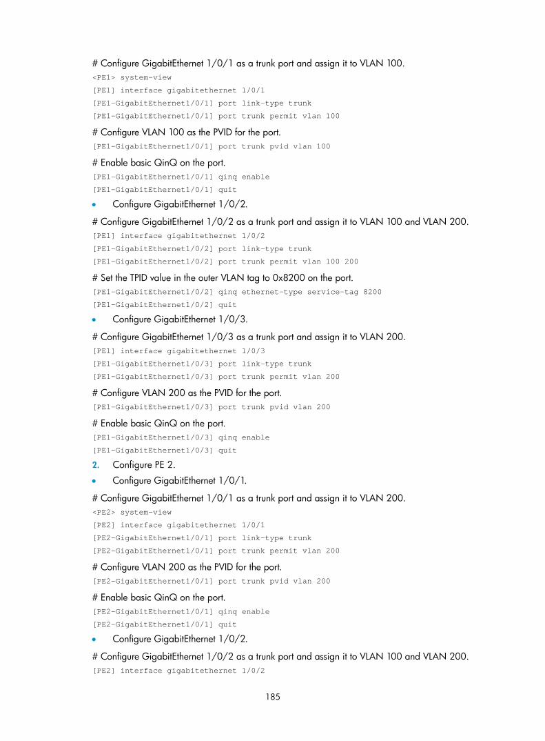
185
# Configure GigabitEthernet 1/0/1 as a trunk port and assign it to VLAN 100. <PE1> system-view
[PE1] interface gigabitethernet 1/0/1
[PE1-GigabitEthernet1/0/1] port link-type trunk
[PE1-GigabitEthernet1/0/1] port trunk permit vlan 100
# Configure VLAN 100 as the PVID for the port. [PE1-GigabitEthernet1/0/1] port trunk pvid vlan 100
# Enable basic QinQ on the port. [PE1-GigabitEthernet1/0/1] qinq enable
[PE1-GigabitEthernet1/0/1] quit
• Configure GigabitEthernet 1/0/2.
# Configure GigabitEthernet 1/0/2 as a trunk port and assign it to VLAN 100 and VLAN 200. [PE1] interface gigabitethernet 1/0/2
[PE1-GigabitEthernet1/0/2] port link-type trunk
[PE1-GigabitEthernet1/0/2] port trunk permit vlan 100 200
# Set the TPID value in the outer VLAN tag to 0x8200 on the port. [PE1-GigabitEthernet1/0/2] qinq ethernet-type service-tag 8200
[PE1-GigabitEthernet1/0/2] quit
• Configure GigabitEthernet 1/0/3.
# Configure GigabitEthernet 1/0/3 as a trunk port and assign it to VLAN 200. [PE1] interface gigabitethernet 1/0/3
[PE1-GigabitEthernet1/0/3] port link-type trunk
[PE1-GigabitEthernet1/0/3] port trunk permit vlan 200
# Configure VLAN 200 as the PVID for the port. [PE1-GigabitEthernet1/0/3] port trunk pvid vlan 200
# Enable basic QinQ on the port. [PE1-GigabitEthernet1/0/3] qinq enable
[PE1-GigabitEthernet1/0/3] quit
2. Configure PE 2.
• Configure GigabitEthernet 1/0/1.
# Configure GigabitEthernet 1/0/1 as a trunk port and assign it to VLAN 200. <PE2> system-view
[PE2] interface gigabitethernet 1/0/1
[PE2-GigabitEthernet1/0/1] port link-type trunk
[PE2-GigabitEthernet1/0/1] port trunk permit vlan 200
# Configure VLAN 200 as the PVID for the port. [PE2-GigabitEthernet1/0/1] port trunk pvid vlan 200
# Enable basic QinQ on the port. [PE2-GigabitEthernet1/0/1] qinq enable
[PE2-GigabitEthernet1/0/1] quit
• Configure GigabitEthernet 1/0/2.
# Configure GigabitEthernet 1/0/2 as a trunk port and assign it to VLAN 100 and VLAN 200. [PE2] interface gigabitethernet 1/0/2

186
[PE2-GigabitEthernet1/0/2] port link-type trunk
[PE2-GigabitEthernet1/0/2] port trunk permit vlan 100 200
# Set the TPID value in the outer VLAN tag to 0x8200 on the port. [PE2-GigabitEthernet1/0/2] qinq ethernet-type service-tag 8200
[PE2-GigabitEthernet1/0/2] quit
• Configure GigabitEthernet 1/0/3.
# Configure GigabitEthernet 1/0/3 as a trunk port and assign it to VLAN 100. [PE2] interface gigabitethernet 1/0/3
[PE2-GigabitEthernet1/0/3] port link-type trunk
[PE2-GigabitEthernet1/0/3] port trunk permit vlan 100
# Configure VLAN 100 as the PVID for the port. [PE2-GigabitEthernet1/0/3] port trunk pvid vlan 100
# Enable basic QinQ on the port. [PE2-GigabitEthernet1/0/3] qinq enable
[PE2-GigabitEthernet1/0/3] quit
3. Configure third-party devices.
On the third-party devices between PE 1 and PE 2, configure the port that connects to PE 1 and that connecting to PE 2 to allow tagged frames of VLAN 100 and VLAN 200 to pass through.
VLAN transparent transmission configuration example Network requirements
As shown in Figure 60:
• The two branches of a company, Site 1 and Site 2, are connected through the service provider network and uses VLANs 10 through 50.
• PE 1 and PE 2 are edge devices on the service provider network and are connected through third-party devices with a TPID value of 0x8200.
• Configure the edge and third-party devices to allow frames of VLANs 10 through 50 to be transmitted between the branches of the company via the service provider network with no outer VLAN tags added.
Figure 60 Network diagram for VLAN transparent transmission configuration

187
Configuration procedure
NOTE:
Be sure that you have configured the switches in the service provider network to allow QinQ packets to pass through.
1. Configure PE 1.
• Configure GigabitEthernet 1/0/1.
# Configure GigabitEthernet 1/0/1 as a trunk port and assign it to VLANs 10 through 50. <PE1> system-view
[PE1] interface gigabitethernet 1/0/1
[PE1-GigabitEthernet1/0/1] port link-type trunk
[PE1-GigabitEthernet1/0/1] port trunk permit vlan 10 to 50
# Enable basic QinQ on the port. [PE1-GigabitEthernet1/0/1] qinq enable
# Configure the port to transparently transmit frames from VLANs 10 through 50. [PE1-GigabitEthernet1/0/1] qinq transparent-vlan 10 to 50
[PE1-GigabitEthernet1/0/1] quit
• Configure GigabitEthernet 1/0/2
# Configure GigabitEthernet 1/0/2 as a trunk port and assign it to VLANs 10 through 50. [PE1] interface gigabitethernet 1/0/2
[PE1-GigabitEthernet1/0/2] port link-type trunk
[PE1-GigabitEthernet1/0/2] port trunk permit vlan 10 to 50
# Set the TPID value in the outer VLAN tag to 0x8200 on the port. [PE1-GigabitEthernet1/0/2] qinq ethernet-type service-tag 8200
[PE1-GigabitEthernet1/0/2] quit
2. Configure PE 2.
• Configure GigabitEthernet 1/0/1.
# Configure GigabitEthernet 1/0/1 as a trunk port and assign it to VLANs 10 through 50. <PE2> system-view
[PE2] interface gigabitethernet 1/0/1
[PE2-GigabitEthernet1/0/1] port link-type trunk
[PE2-GigabitEthernet1/0/1] port trunk permit vlan 10 to 50
# Enable basic QinQ on the port. [PE2-GigabitEthernet1/0/1] qinq enable
# Configure the port to transparently transmit frames from VLANs 10 through 50. [PE2-GigabitEthernet1/0/1] qinq transparent-vlan 10 to 50
[PE2-GigabitEthernet1/0/1] quit
• Configure GigabitEthernet 1/0/2
# Configure GigabitEthernet 1/0/2 as a trunk port and assign it to VLANs 10 through 50. [PE2] interface gigabitethernet 1/0/2
[PE2-GigabitEthernet1/0/2] port link-type trunk
[PE2-GigabitEthernet1/0/2] port trunk permit vlan 10 to 50

188
# Set the TPID value in the outer VLAN tag to 0x8200 on the port. [PE2-GigabitEthernet1/0/2] qinq ethernet-type service-tag 8200
[PE2-GigabitEthernet1/0/2] quit
3. Configure third-party devices.
On the third-party devices between PE 1 and PE 2, configure the port that connects to PE 1 and that connecting to PE 2 to allow tagged frames of VLAN 10 through VLAN 50 to pass through.
Simple selective QinQ configuration example Network requirements
As shown in Figure 61:
• The two branches of a company, Site 1 and Site 2, are connected through the service provider network and use CVLAN 10 and CVLAN 20 to transmit voice traffic and data traffic separately.
• PE 1 and PE 2 are edge devices on the service provider network and are connected through third-party devices with a TPID value of 0x8200.
• Configure the edge and third-party devices to allow frames from CVLAN 10 to be transmitted between the branches via SVLAN 100 and frames from CVLAN 20 to be transmitted between the branches via SVLAN 200.
Figure 61 Network diagram for simple selective QinQ configuration
Configuration procedure
NOTE:
Be sure that you have configured the switches in the service provider network to allow QinQ packets to pass through.
1. Configure PE 1.
• Configure GigabitEthernet 1/0/1.
# Configure GigabitEthernet 1/0/1 as a hybrid port to permit frames of VLAN 100 and VLAN 200 to pass through untagged.

189
<PE1> system-view
[PE1] interface gigabitethernet 1/0/1
[PE1-GigabitEthernet1/0/1] port link-type hybrid
[PE1-GigabitEthernet1/0/1] port hybrid vlan 100 200 untagged
[PE1-GigabitEthernet1/0/1] quit
# Create class A10 and configure the class to match frames from Site 1 with CVLAN 10. [PE1] traffic classifier A10
[PE1-classifier-A10] if-match customer-vlan-id 10
[PE1-classifier-A10] quit
# Create traffic behavior P100 and add the action of inserting outer VLAN tag 100. [PE1] traffic behavior P100
[PE1-behavior-P100] nest top-most vlan-id 100
[PE1-behavior-P100] quit
# Create class A20 and configure the class to match frames with CVLAN 20. Create traffic behavior P200 and add the action of inserting outer VLAN tag 200. [PE1] traffic classifier A20
[PE1-classifier-A20] if-match customer-vlan-id 20
[PE1-classifier-A20] quit
[PE1] traffic behavior P200
[PE1-behavior-P200] nest top-most vlan-id 200
[PE1-behavior-P200] quit
# Create a QoS policy named qinq, associate traffic class A10 with traffic behavior P100, and associate traffic class A20 with traffic behavior P200. [PE1] qos policy qinq
[PE1-qospolicy-qinq] classifier A10 behavior P100
[PE1-qospolicy-qinq] classifier A20 behavior P200
[PE1-qospolicy-qinq] quit
# Enable basic QinQ on the port. [PE1] interface gigabitethernet 1/0/1
[PE1-GigabitEthernet1/0/1] qinq enable
# Apply QoS policy qinq to the incoming traffic on the port. [PE1-GigabitEthernet1/0/1] qos apply policy qinq inbound
• Configure GigabitEthernet 1/0/2.
# Configure GigabitEthernet 1/0/2 as a trunk port and assign it to VLAN 100 and VLAN 200. [PE1] interface gigabitethernet 1/0/2
[PE1-GigabitEthernet1/0/2] port link-type trunk
[PE1-GigabitEthernet1/0/2] port trunk permit vlan 100 200
# Set the TPID in the outer VLAN tags to 0x8200. [PE1-GigabitEthernet1/0/2] qinq ethernet-type service-tag 8200
[PE1-GigabitEthernet1/0/2] quit
2. Configure PE 2.
• Configure GigabitEthernet 1/0/1.
# Configure GigabitEthernet 1/0/1 as a hybrid port to permit frames of VLAN 100 and VLAN 200 to pass through untagged. [PE2] interface gigabitethernet 1/0/1

190
[PE2-GigabitEthernet1/0/1] port link-type hybrid
[PE2-GigabitEthernet1/0/1] port hybrid vlan 100 200 untagged
[PE2-GigabitEthernet1/0/1] quit
# Create class A10 and configure the class to match frames from Site 2 with CVLAN 10. [PE2] traffic classifier A10
[PE2-classifier-A10] if-match customer-vlan-id 10
[PE2-classifier-A10] quit
# Create traffic behavior P100 and add the action of inserting outer VLAN tag 100. [PE2] traffic behavior P100
[PE2-behavior-P100] nest top-most vlan-id 100
[PE2-behavior-P100] quit
# Create class A20 and configure the class to match frames with CVLAN 20. Create traffic behavior P200 and add the action of inserting outer VLAN tag 200. [PE2] traffic classifier A20
[PE2-classifier-A20] if-match customer-vlan-id 20
[PE2-classifier-A20] quit
[PE2] traffic behavior P200
[PE2-behavior-P200] nest top-most vlan-id 200
[PE2-behavior-P200] quit
# Create a QoS policy named qinq, associate traffic class A10 with traffic behavior P100, and associate traffic class A20 with traffic behavior P200. [PE2] qos policy qinq
[PE2-qospolicy-qinq] classifier A10 behavior P100
[PE2-qospolicy-qinq] classifier A20 behavior P200
[PE2-qospolicy-qinq] quit
# Enable basic QinQ on the port. [PE2] interface gigabitethernet 1/0/1
[PE2-GigabitEthernet1/0/1] qinq enable
# Apply QoS policy qinq to the incoming traffic on the port. [PE2-GigabitEthernet1/0/1] qos apply policy qinq inbound
• Configure GigabitEthernet 1/0/2.
# Configure GigabitEthernet 1/0/2 as a trunk port and assign it to VLAN 100 and VLAN 200. [PE2] interface gigabitethernet 1/0/2
[PE2-GigabitEthernet1/0/2] port link-type trunk
[PE2-GigabitEthernet1/0/2] port trunk permit vlan 100 200
# Set the TPID in the outer VLAN tags to 0x8200. [PE2-GigabitEthernet1/0/2] qinq ethernet-type service-tag 8200
[PE2-GigabitEthernet1/0/2] quit
3. Configure third-party devices.
On the third-party devices between PE 1 and PE 2, configure the port that connects to PE 1 and that connecting to PE 2 to allow tagged frames of VLAN 100 and VLAN 200 to pass through.

191
Comprehensive selective QinQ configuration example Network requirements
As shown in Figure 62:
• Company A uses CVLAN 10 and CVLAN 20 to transmit voice traffic and data traffic separately, and Company B uses CVLAN 30 and CVLAN 40 to transmit voice traffic and data traffic separately. The services of the two companies are integrated together.
• PE 1 and PE 2 are edge devices on the service provider network and are connected through third-party devices with a TPID value of 0x8200.
• Configure the edge and third-party devices to allow the voice traffic and data traffic to be transmitted between the two companies via SVLAN 100 SVLAN 200 separately.
Figure 62 Network diagram for comprehensive selective QinQ configuration
Configuration procedure
NOTE:
Be sure that you have configured the switches in the service provider network to allow QinQ packets to pass through.
1. Configure PE 1.
• Configure GigabitEthernet 1/0/1.
# Configure GigabitEthernet 1/0/1 as a hybrid port to permit frames of VLAN 100 and VLAN 200 to pass through untagged. <PE1> system-view
[PE1] interface gigabitethernet 1/0/1
[PE1-GigabitEthernet1/0/1] port link-type hybrid
[PE1-GigabitEthernet1/0/1] port hybrid vlan 100 200 untagged
[PE1-GigabitEthernet1/0/1] quit
# Create class A10 and configure the class to match frames with CVLAN 10. [PE1] traffic classifier A10

192
[PE1-classifier-A10] if-match customer-vlan-id 10
[PE1-classifier-A10] quit
# Create traffic behavior P100 and add the action of inserting outer VLAN tag 100. [PE1] traffic behavior P100
[PE1-behavior-P100] nest top-most vlan-id 100
[PE1-behavior-P100] quit
# Create class A20 and configure the class to match frames with CVLAN 20. Create traffic behavior P200 and add the action of inserting outer VLAN tag 200. [PE1] traffic classifier A20
[PE1-classifier-A20] if-match customer-vlan-id 20
[PE1-classifier-A20] quit
[PE1] traffic behavior P200
[PE1-behavior-P200] nest top-most vlan-id 200
[PE1-behavior-P200] quit
# Create a QoS policy named qinq, associate traffic class A10 with traffic behavior P100, and associate traffic class A20 with traffic behavior P200. [PE1] qos policy qinq
[PE1-qospolicy-qinq] classifier A10 behavior P100
[PE1-qospolicy-qinq] classifier A20 behavior P200
[PE1-qospolicy-qinq] quit
# Enable basic QinQ on the port. [PE1] interface gigabitethernet 1/0/1
[PE1-GigabitEthernet1/0/1] qinq enable
# Apply QoS policy qinq to the incoming traffic on the port. [PE1-GigabitEthernet1/0/1] qos apply policy qinq inbound
• Configure GigabitEthernet 1/0/2.
# Configure GigabitEthernet 1/0/2 as a trunk port and assign it to VLAN 100 and VLAN 200. [PE1] interface gigabitethernet 1/0/2
[PE1-GigabitEthernet1/0/2] port link-type trunk
[PE1-GigabitEthernet1/0/2] port trunk permit vlan 100 200
# Create class A100 and configure the class to match frames with CVLAN 10 and SVLAN 100. [PE1] traffic classifier A100
[PE1-classifier-A100] if-match customer-vlan-id 10
[PE1-classifier-A100] if-match service-vlan-id 100
[PE1-classifier-A100] quit
# Configure traffic behavior T100 to mark matching packets with CVLAN 30. [PE1] traffic behavior T100
[PE1-behavior-T100] remark customer-vlan-id 30
[PE1-behavior-T100] quit
# Create class A200 and configure the class to match frames with CVLAN 20 and SVLAN 200. [PE1] traffic classifier A200
[PE1-classifier-A200] if-match customer-vlan-id 20
[PE1-classifier-A200] if-match service-vlan-id 200
[PE1-classifier-A200] quit
# Configure traffic behavior T200 to mark matching packets with CVLAN 40.

193
[PE1] traffic behavior T200
[PE1-behavior-T200] remark customer-vlan-id 40
[PE1-behavior-T200] quit
# Create a QoS policy named sqinq, associate traffic class A100 with traffic behavior T100, and associate traffic class A200 with traffic behavior T200. [PE1] qos policy sqinq
[PE1-qospolicy-sqinq] classifier A100 behavior T100
[PE1-qospolicy-sqinq] classifier A200 behavior T200
[PE1-qospolicy-sqinq] quit
# Apply QoS policy sqinq to the outgoing traffic on the port. [PE1-GigabitEthernet1/0/2] qos apply policy sqinq outbound
# Set the TPID value in the outer tag to 0x8200. [PE1-GigabitEthernet1/0/2] qinq ethernet-type service-tag 8200
[PE1-GigabitEthernet1/0/2] quit
2. Configure PE 2.
• Configure GigabitEthernet 1/0/1.
# Configure GigabitEthernet 1/0/1 as a hybrid port to permit frames of VLAN 100 and VLAN 200 to pass through untagged. [PE2] interface gigabitethernet 1/0/1
[PE2-GigabitEthernet1/0/1] port link-type hybrid
[PE2-GigabitEthernet1/0/1] port hybrid vlan 100 200 untagged
[PE2-GigabitEthernet1/0/1] quit
# Create class A30 and configure the class to match frames with CVLAN 30. [PE2] traffic classifier A30
[PE2-classifier-A30] if-match customer-vlan-id 30
[PE2-classifier-A30] quit
# Create traffic behavior P100 and add the action of inserting outer VLAN tag 100. [PE2] traffic behavior P100
[PE2-behavior-P100] nest top-most vlan-id 100
[PE2-behavior-P100] quit
# Create class A40 and configure the class to match frames with CVLAN 40. Create traffic behavior P200 and add the action of inserting outer VLAN tag 200. [PE2] traffic classifier A40
[PE2-classifier-A40] if-match customer-vlan-id 40
[PE2-classifier-A40] quit
[PE2] traffic behavior P200
[PE2-behavior-P200] nest top-most vlan-id 200
[PE2-behavior-P200] quit
# Create a QoS policy named qinq, associate traffic class A30 with traffic behavior P100, and associate traffic class A40 with traffic behavior P200. [PE2] qos policy qinq
[PE2-qospolicy-qinq] classifier A30 behavior P100
[PE2-qospolicy-qinq] classifier A40 behavior P200
[PE2-qospolicy-qinq] quit
# Enable basic QinQ on the port.

194
[PE2] interface gigabitethernet 1/0/1
[PE2-GigabitEthernet1/0/1] qinq enable
# Apply QoS policy qinq to the incoming traffic on the port. [PE2-GigabitEthernet1/0/1] qos apply policy qinq inbound
• Configure GigabitEthernet 1/0/2.
# Configure GigabitEthernet 1/0/2 as a trunk port and assign it to VLAN 100 and VLAN 200. [PE2] interface gigabitethernet 1/0/2
[PE2-GigabitEthernet1/0/2] port link-type trunk
[PE2-GigabitEthernet1/0/2] port trunk permit vlan 100 200
# Create class A100 and configure the class to match frames with CVLAN 30 and SVLAN 100. [PE2] traffic classifier A100
[PE2-classifier-A100] if-match customer-vlan-id 30
[PE2-classifier-A100] if-match service-vlan-id 100
[PE2-classifier-A100] quit
# Configure traffic behavior T100 to mark matching packets with CVLAN 10. [PE2] traffic behavior T100
[PE2-behavior-T100] remark customer-vlan-id 10
[PE2-behavior-T100] quit
# Create class A200 and configure the class to match frames with CVLAN 40 and SVLAN 200. [PE2] traffic classifier A200
[PE2-classifier-A200] if-match customer-vlan-id 40
[PE2-classifier-A200] if-match service-vlan-id 200
[PE2-classifier-A200] quit
# Configure traffic behavior T200 to mark matching packets with CVLAN 20. [PE2] traffic behavior T200
[PE2-behavior-T200] remark customer-vlan-id 20
[PE2-behavior-T200] quit
# Create a QoS policy named sqinq, associate traffic class A100 with traffic behavior T100, and associate traffic class A200 with traffic behavior T200. [PE2] qos policy sqinq
[PE2-qospolicy-sqinq] classifier A100 behavior T100
[PE2-qospolicy-sqinq] classifier A200 behavior T200
[PE2-qospolicy-sqinq] quit
# Apply QoS policy sqinq to the outgoing traffic on the port. [PE2] interface gigabitethernet 1/0/2
[PE1-GigabitEthernet1/0/2] qos apply policy sqinq outbound
# Set the TPID value in the outer tag to 0x8200. [PE2-GigabitEthernet1/0/2] qinq ethernet-type service-tag 8200
[PE2-GigabitEthernet1/0/2] quit
3. Configure third-party devices.
On the third-party devices between PE 1 and PE 2, configure the port that connects to PE 1 and that connecting to PE 2 to allow tagged frames of VLAN 100 and VLAN 200 to pass through.

195
VLAN mapping configuration
NOTE:
The SC, SD, and EB cards support one-to-one, many-to-one, one-to-two, and two-to-two VLAN mappings. The SA and EA cards support only one-to-one VLAN mapping. For more information about thecards, see the installation guide for the S7500E Switch Series.
VLAN mapping overview VLAN mapping re-marks VLAN tagged traffic with new VLAN IDs. H3C provides the following types of VLAN mapping:
• One-to-one VLAN mapping—Replaces one VLAN tag with another. You can use one-to-one VLAN mapping to sub-classify traffic from a particular VLAN for granular QoS control.
• Many-to-one VLAN mapping—Replaces multiple VLAN tags with the same VLAN tag. You can use many-to-one VLAN mapping to aggregate traffic from different VLANs to regulate the aggregate traffic as a whole. Many-to-one VLAN mapping is usually used together with one-to-one VLAN mapping.
• One-to-two VLAN mapping—Tags single-tagged packets with an outer VLAN tag. One-to-two VLAN mapping expands the VLAN tag space, and enables a service provider and its customers to assign VLANs independently without the risk of VLAN assignment conflicts.
• Two-to-two VLAN mapping—Replaces the outer and inner VLAN IDs of double tagged traffic with a new pair of VLAN IDs. You can use two-to-two VLAN mapping to enable two remote sites in different VLANs to communicate at Layer 2 across two service provider networks that use different VLAN assignment schemes.
Application scenario of one-to-one and many-to-one VLAN mapping
Figure 63 shows a typical application scenario in which each home gateway uses different VLANs to transmit the PC, VoD, and VoIP services.

196
Figure 63 Application scenario of one-to-one and many-to-one VLAN mapping
VLAN 101 - 102 - > VLAN 501VLAN 201 - 202 - > VLAN 502VLAN 301 - 302 - > VLAN 503
... Campus switch
Distribution network
DHCP client
DHCP server
...
Wiring - closet switch
VLAN 1 - > VLAN 101VLAN 2 - > VLAN 201VLAN 3 - > VLAN 301
VLAN 1 - > VLAN 102VLAN 2 - > VLAN 202VLAN 3 - > VLAN 302
PC
VoD
VoIP
VLAN 2Home gateway
VLAN 1
VLAN 3
PC
VoD
VoIP
VLAN 2
Home gateway
VLAN 1
VLAN 3
Wiring-closet switch
VLAN 1 - > VLAN 199VLAN 2 - > VLAN 299VLAN 3 - > VLAN 399
VLAN 1 -> VLAN 200VLAN 2 -> VLAN 300VLAN 3 -> VLAN 400
PC
VoD
VoIP
VLAN 2Home gateway
VLAN 1
VLAN 3
PC
VoD
VoIP
VLAN 2
Home gateway
VLAN 1
VLAN 3
...
VLAN 199 - 200 - > VLAN 501VLAN 299 - 300 - > VLAN 502VLAN 399 - 400 - > VLAN 503
......
......
To further sub-classify each type of traffic by customer, perform one-to-one VLAN mapping on the wiring-closet switches, and assign a separate VLAN for each type of traffic from each customer. The required total number of VLANs in the network can be large. To prevent the maximum number of VLANs from being exceeded on the distribution layer device, perform many-to-one VLAN mapping on the campus switch to assign the same type of traffic from different customers to the same VLAN.
Application scenario of one-to-two and two-to-two VLAN mapping
Figure 64 shows a typical application scenario in which two remote sites of VPN A, Site 1 and Site 2, must communicate across two SP networks, SP 1 and SP 2.

197
Figure 64 Application scenario of one-to-two and two-to-two VLAN mapping
Site 1 and Site 2 are in VLAN 2 and VLAN 3, respectively. The VLAN assigned for VPN A is VLAN 10 in the SP 1 network and VLAN 20 in the SP 2 network.
If Site 1 sends a packet to Site 2, the packet is processed on the way to its destination using the following workflow:
1. When the packet tagged with VLAN 2 arrives at the edge of network SP 1, PE 1 tags the packet with outer VLAN 10 by using one-to-two VLAN mapping.
2. When the double-tagged packet enters the SP 2 network, PE 3 replaces the outer VLAN tag (VLAN 10) with VLAN 20. Because the packet is destined for Site 2 in VLAN 3, PE 3 also replaces the inner tag (VLAN 2) of the packet with VLAN 3. This process is two-to-two VLAN mapping.
3. When PE4 receives the packet with the new VLAN tag pair, it removes the outer VLAN tag and forwards the packet to VLAN 3.
NOTE:
You can use QinQ to implement one-to-two VLAN mapping. For more information about QinQ, see thechapter “QinQ configuration.”
Concepts and terms Figure 65 shows a simplified network to help explain the concepts and terms that you might encounter when you work with VLAN mapping.

198
Figure 65 Basic concepts of VLAN mapping
• Uplink traffic: Traffic transmitted from the customer network to the service provider network.
• Downlink traffic: Traffic transmitted from the service provider network to the customer network.
• Network-side port: A port connected to the service provider network.
• Customer-side port: A port connected to the customer network.
• Uplink policy: A QoS policy that defines VLAN mapping rules for uplink traffic.
• Downlink policy: A QoS policy that defines VLAN mapping rules for downlink traffic.
• Customer VLANs (CVLANs): VLANs assigned for customers.
• Service provider VLANs (SVLANs): VLANs assigned for transmitting traffic across the service provider network.
NOTE:
For more information about QoS policies, see ACL and QoS Configuration Guide.
VLAN mapping implementations This section describes how VLAN mapping is implemented on your device.
One-to-one VLAN mapping
Implement one-to-one VLAN mapping on the customer-side port through the following configurations, as shown in Figure 66:
• Apply an uplink policy to the incoming traffic, mapping each CVLAN ID to a unique SVLAN ID. When a packet arrives, the switch replaces its CVLAN ID with the matching SVLAN ID.
• Apply a downlink policy to the outgoing traffic, mapping each SVLAN ID back to its corresponding CVLAN ID. When forwarding a packet out of the port, the switch replaces its SVLAN ID with the matching CVLAN ID.

199
Figure 66 One-to-one VLAN mapping implementation
Many-to-one VLAN mapping
Implement many-to-one VLAN mapping through the following configurations, as shown in Figure 67:
• Apply an uplink policy to the incoming traffic on the customer-side port to map different CVLAN IDs to one SVLAN ID. When a packet arrives, the switch replaces its CVLAN tag with the matching SVLAN tag.
• Configure the network-side port as a DHCP snooping trusted port. For downlink traffic, the switch looks through the DHCP snooping table, and replaces the SVLAN ID with the CVLAN ID found in the table.
Figure 67 Many-to-one VLAN mapping implementation ... ...
NOTE:
Each DHCP snooping entry contains information about one DHCP client, including its IP address, MAC address, and CVLAN. For more information about DHCP snooping, see Layer 3—IP Services Configuration Guide.
One-to-two VLAN mapping
Implement one-to-two VLAN mapping through the following configurations, as shown in Figure 68:
• Apply an uplink policy to the incoming traffic on the customer-side port to tag the incoming packets from a certain CVLAN with an outer SVLAN tag.
• Configure the customer-side port as a hybrid port, and assign the port to SVLANs as an untagged member. When the port forwards the packets from these SVLANs, it removes their SVLAN tag.

200
Figure 68 One-to-two VLAN mapping
Two-to-two VLAN mapping
Implement two-to-two VLAN mapping through the following configurations, as shown in Figure 69.
• For uplink traffic, apply an inbound policy on the customer-side port to replace the SVLAN with a new SVLAN, and apply an outbound policy on the network-side port to replace the CVLAN with a new CVLAN.
• For downlink traffic, apply an outbound policy on the customer-side port to replace the double tags with the original VLAN tag pair.
Figure 69 Two-to-two VLAN mapping implementation
NOTE:
In two-to-two VLAN mapping implementations, you can configure VLAN mapping to replace only the outer VLAN tags or inner VLAN tags as needed.
Configuring VLAN mapping Use the VLAN mapping methods as appropriate to the roles of your switches in the network, as described in this table:
Task Switch role
Configuring one-to-one VLAN mapping Wiring-closet switch
Configuring many-to-one VLAN mapping Campus switch
Configuring one-to-two VLAN mapping Edge switch connecting users to SP networks

201
Task Switch role
Configuring two-to-two VLAN mapping Edge switch between SP networks
Configuring one-to-one VLAN mapping Perform one-to-one VLAN mapping on wiring-closet switches (see Figure 63) to isolate traffic by both user and traffic type.
Perform these tasks to configure one-to-one VLAN mapping:
Task Description
Configuring an uplink policy Creates CVLAN-to-SVLAN mappings (required).
Configuring a downlink policy Creates SVLAN-to-CVLAN mappings (required).
Configuring the customer-side port Configures settings required for one-to-one VLAN mapping (required).
Configuring the network-side port Configures VLAN settings required for normal communication (required).
Configuration prerequisites
Create CVLANs and SVLANs, and plan CVLAN-SVLAN mappings.
Configuring an uplink policy
Follow these steps to configure an uplink policy to map each CVLAN to a unique SVLAN:
To do... Use the command... Remarks
Enter system view system-view —
Create a class and enter class view traffic classifier tcl-name [ operator { and | or } ]
Specify a CVLAN as the match criterion
if-match customer-vlan-id vlan-id
Return to system view quit
Required
Repeat these steps to configure one class for each CVLAN.
Create a traffic behavior and enter traffic behavior view
traffic behavior behavior-name
Configure an SVLAN marking action
remark service-vlan-id vlan-id
Return to system view quit
Required
Repeat these steps to configure one behavior for each SVLAN.
Create a QoS policy and enter QoS policy view
qos policy policy-name Required
Associate the class with the behavior to map the CVLAN to the SVLAN
classifier tcl-name behavior behavior-name
Required
Repeat this step to create other CVLAN-to-SVLAN mappings.
Configuring a downlink policy
Follow these steps to configure a downlink policy to map SVLANs back to CVLANs:
To do... Use the command... Remarks
Enter system view system-view —

202
To do... Use the command... Remarks
Create a class and enter class view traffic classifier tcl-name [ operator { and | or } ]
Configure an SVLAN as the match criterion
if-match service-vlan-id vlan-id
Return to system view quit
Required
Repeat these steps to configure one class for each SVLAN.
Create a traffic behavior and enter traffic behavior view
traffic behavior behavior-name
Configure a CVLAN marking action
remark customer-vlan-id vlan-id
Return to system view quit
Required
Repeat these steps to configure a behavior for each CVLAN.
Create a QoS policy and enter QoS policy view
qos policy policy-name Required
Associate the class with the behavior to map the SVLAN to the CVLAN
classifier tcl-name behavior behavior-name
Required
Repeat this step to create other CVLAN-to-SVLAN mappings.
Configuring the customer-side port
Follow these steps to configure the customer-side port:
To do... Use the command... Remarks
Enter system view system-view —
Enter Ethernet interface view interface interface-type interface-number —
Configure the port as a trunk port
port link-type trunk Required
The default link type of an Ethernet port is access.
Assign the port to CVLANs and SVLANs
port trunk permit vlan { vlan-id-list | all }
Required
By default, a trunk port is in only VLAN 1.
Enable basic QinQ qinq enable Required
By default, basic QinQ is disabled.
Apply the uplink policy to the incoming traffic
qos apply policy policy-name inbound Required
Apply the downlink policy to the outgoing traffic
qos apply policy policy-name outbound Required
Configuring the network-side port
Follow these steps to configure the network-side port:
To do... Use the command... Remarks
Enter system view system-view —
Enter Ethernet interface view
interface interface-type interface-number —
Configure the port as a trunk port
port link-type trunk Required
The default link type of ports is access.

203
To do... Use the command... Remarks
Assign the port to SVLANs
port trunk permit vlan { vlan-id-list | all }
Required
By default, a trunk port is in only VLAN 1.
Configuring many-to-one VLAN mapping Perform many-to-one VLAN mapping on campus switches (see Figure 63) to transmit the same type of traffic from different users in one VLAN.
Perform these tasks to configure many-to-one VLAN mapping:
Task Description
Enabling DHCP snooping Enables DHCP snooping globally (required).
Enabling ARP detection in SVLANs Enables ARP detection in all SVLANs (required).
Configuring an uplink policy Configures an uplink policy for the customer-side port (required).
Configuring the customer-side port Configures VLAN and other settings required for many-to-one VLAN mapping (required).
Configuring the network-side port Configures VLAN and other settings required for many-to-one VLAN mapping (required).
CAUTION:
Before changing VLAN mappings on a port, clear all DHCP snooping entries by using the reset dhcp-snooping command (see Layer 3—IP Services Command Reference).
Configuration prerequisites
Before configuring many-to-one VLAN mapping:
• Make sure that all home users obtain IP addresses through DHCP. For how to assign IP addresses through DHCP, see Layer 3—IP Services Configuration Guide.
• Create CVLANs and SVLANs, and plan CVLANs-to-SVLAN mappings.
Enabling DHCP snooping
Follow these steps to enable DHCP snooping:
To do... Use the command... Remarks
Enter system view system-view —
Enable DHCP snooping dhcp-snooping Required
Disabled by default.
Enabling ARP detection in SVLANs
The ARP detection function enables a switch to modify the VLAN attributes of ARP packets, which is impossible under the normal ARP packet processing procedure. For more information about ARP detection, see Security Configuration Guide.
Follow these steps to enable ARP detection in all SVLANs:
To do... Use the command... Remarks
Enter system view system-view —

204
To do... Use the command... Remarks
Enter VLAN view vlan vlan-id ––
Enable ARP detection arp detection enable Required
Disabled by default.
NOTE:
To defend against ARP attacks, enable ARP detection also in all CVLANs.
Configuring an uplink policy
Follow these steps to configure an uplink policy to map a group of CVLANs to one SVLAN:
To do... Use the command... Remarks
Enter system view system-view —
Create a class and enter class view
traffic classifier tcl-name operator or
Configure multiple CVLANs as match criteria
if-match customer-vlan-id { vlan-id-list | vlan-id1 to vlan-id2 }
Return to system view quit
Required
Repeat these steps to configure one class for each group of CVLANs.
Create a traffic behavior and enter traffic behavior view
traffic behavior behavior-name
Configure an SVLAN marking action
remark service-vlan-id vlan-id
Return to system view quit
Required
Repeat these steps to configure one behavior for each SVLAN.
Create a QoS policy and enter QoS policy view
qos policy policy-name Required
Map the CVLANs to the SVLAN by associating the class with the behavior
classifier tcl-name behavior behavior-name mode dot1q-tag-manipulation
Required
Repeat this step to create other CVLANs-to-SVLAN mappings.
Configuring the customer-side port
Follow these steps to configure the customer-side port:
To do... Use the command... Remarks
Enter system view system-view —
Enter Ethernet interface view interface interface-type interface-number —
Configure the port as a trunk port port link-type trunk Required
The default link type of an Ethernet port is access.
Assign the port to CVLANs and SVLANs
port trunk permit vlan { vlan-id-list | all }
Required
By default, a trunk port is in only VLAN 1.

205
To do... Use the command... Remarks
Set the port as a DHCP snooping trusted port and disable the port to record IP-to-MAC bindings for DHCP clients
dhcp-snooping trust no-user-binding
Required
By default, all ports are DHCP snooping untrusted ports.
Enable customer-side QinQ qinq enable downlink Required
By default, customer-side QinQ is disabled on all ports.
Apply the uplink policy to the incoming traffic
qos apply policy policy-name inbound Required
CAUTION:
Before applying a QoS policy to the customer-side port, enable customer-side QinQ on the port. Before disabling customer-side QinQ on the customer-side port, remove the QoS policy from the port first.
Configuring the network-side port
Follow these steps to configure the network-side port:
To do... Use the command... Remarks
Enter system view system-view —
Enter Ethernet interface view interface interface-type interface-number —
Configure the port as a trunk port port link-type trunk Required
The default link type of an Ethernet port is access.
Assign the port to SVLANs port trunk permit vlan { vlan-id-list | all }
Required
By default, a trunk port is in only VLAN 1.
Configure the port as a DHCP snooping trusted port dhcp-snooping trust
Required
By default, all ports are DHCP snooping untrusted ports.
Configure the port as an ARP trusted port arp detection trust
Required
By default, all ports are ARP untrusted ports.
Enable network-side QinQ qinq enable uplink Required
By default, network-side QinQ is disabled on all ports.
Configuring one-to-two VLAN mapping Perform one-to-two VLAN mapping on the edge devices from which customer traffic enters SP networks, on PE 1 and PE 4 in Figure 64 for example. One-to-two VLAN mapping enables the edge devices to insert an outer VLAN tag to each incoming packet.
Perform these tasks to configure one-to-two VLAN mapping:
Task Description
Configuring an uplink policy Configures an uplink policy for the customer-side port (required).
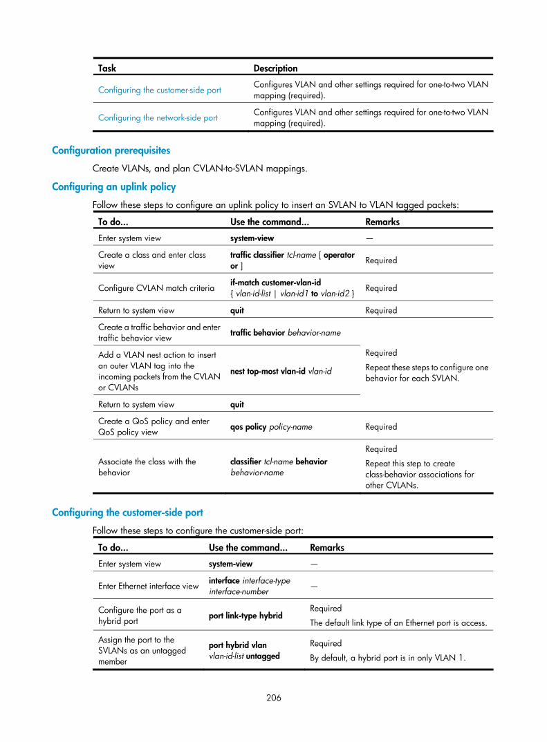
206
Task Description
Configuring the customer-side port Configures VLAN and other settings required for one-to-two VLAN mapping (required).
Configuring the network-side port Configures VLAN and other settings required for one-to-two VLAN mapping (required).
Configuration prerequisites
Create VLANs, and plan CVLAN-to-SVLAN mappings.
Configuring an uplink policy
Follow these steps to configure an uplink policy to insert an SVLAN to VLAN tagged packets:
To do... Use the command... Remarks
Enter system view system-view —
Create a class and enter class view
traffic classifier tcl-name [ operator or ] Required
Configure CVLAN match criteria if-match customer-vlan-id { vlan-id-list | vlan-id1 to vlan-id2 } Required
Return to system view quit Required
Create a traffic behavior and enter traffic behavior view
traffic behavior behavior-name
Add a VLAN nest action to insert an outer VLAN tag into the incoming packets from the CVLAN or CVLANs
nest top-most vlan-id vlan-id
Return to system view quit
Required
Repeat these steps to configure one behavior for each SVLAN.
Create a QoS policy and enter QoS policy view
qos policy policy-name Required
Associate the class with the behavior
classifier tcl-name behavior behavior-name
Required
Repeat this step to create class-behavior associations for other CVLANs.
Configuring the customer-side port
Follow these steps to configure the customer-side port:
To do... Use the command... Remarks
Enter system view system-view —
Enter Ethernet interface view interface interface-type interface-number —
Configure the port as a hybrid port
port link-type hybrid Required
The default link type of an Ethernet port is access.
Assign the port to the SVLANs as an untagged member
port hybrid vlan vlan-id-list untagged
Required
By default, a hybrid port is in only VLAN 1.

207
To do... Use the command... Remarks
Enable basic QinQ qinq enable Required
By default, basic QinQ is disabled on all ports.
Apply the uplink policy to the incoming traffic
qos apply policy policy-name inbound Required
Configuring the network-side port
Follow these steps to configure the network-side port:
To do... Use the command... Remarks
Enter system view system-view —
Enter Ethernet interface view interface interface-type interface-number —
Configure the port as a trunk port port link-type trunk
Required
The default link type of an Ethernet port is access.
Assign the port to all SVLANs port trunk permit vlan { vlan-id-list | all }
Required
By default, a trunk port is in only VLAN 1.
Configuring two-to-two VLAN mapping Perform two-to-two VLAN mapping on an edge device that connects two SP networks, for example, on PE 3 in Figure 64. Two-to-two VLAN mapping enables two remote sites in different VLANs to communicate at Layer 2 across two service provider networks that use different VLAN assignment schemes.
NOTE:
For the ease of description, the VLAN tags of the double-tagged frames that arrive at the customer-side port are called foreign CVLANs and SVLANs, and the VLAN tags marked by the edge device are calledlocal CVLANs and SVLANs.
Perform these tasks to configure two-to-two VLAN mapping:
Task Description
Configuring an uplink policy for the customer-side port
Required
Replace foreign SVLANs with local SVLANs for uplink traffic.
Configuring an uplink policy for the network-side port
Required
Replace foreign CVLANs with local CVLANs for uplink traffic.
Configuring a downlink policy for the customer-side port
Required
Replace local SVLANs and CVLANs with foreign SVLANs and CVLANs.
Configuring the customer-side port Required
Configure VLAN and other settings required for two-to-two VLAN mapping.

208
Task Description
Configuring the network-side port Required
Configure VLAN and other settings required for two-to-two VLAN mapping.
Configuring an uplink policy for the customer-side port
The uplink policy on the customer-side port modifies the SVLAN ID of incoming traffic.
NOTE:
If you do not need to replace the SVLAN tags, skip these steps.
Follow these steps to configure an uplink policy for the customer-side port:
To do... Use the command... Remarks
Enter system view system-view —
Create a class and enter class view
traffic classifier tcl-name [ operator and ]
Specify a foreign CVLAN as a match criterion
if-match customer-vlan-id vlan-id
Specify a foreign SVLAN as a match criterion
if-match service-vlan-id vlan-id
Return to system view quit
Required
Repeat these steps to create one class for each foreign CVLAN and SVLAN pair.
Create a traffic behavior and enter traffic behavior view
traffic behavior behavior-name
Configure an SVLAN marking action to replace the foreign SVLAN ID with a local SVLAN ID
remark service-vlan-id vlan-id
Return to system view quit
Required
Repeat these steps to configure one SVLAN marking action for each CVLAN and SVLAN pair.
Create a QoS policy and enter QoS policy view
qos policy policy-name Required
Associate the class with the behavior
classifier tcl-name behavior behavior-name
Required
Repeat this step to create other class-behavior associations.
Configuring an uplink policy for the network-side port
The uplink policy on the network-side port modifies the CVLAN ID of incoming traffic.
NOTE:
If you do not need to replace the CVLAN tags, skip these steps.
Follow these steps to configure an uplink policy for the network-side port:
To do... Use the command... Remarks
Enter system view system-view —

209
To do... Use the command... Remarks
Create a class and enter class view traffic classifier tcl-name [ operator and ]
Specify a foreign CVLAN as a match criterion
if-match customer-vlan-id vlan-id
Specify a local SVLAN as a match criterion
if-match service-vlan-id vlan-id
Return to system view quit
Required
Repeat these steps to create one class for each local SVLAN and foreign CVLAN pair.
Create a traffic behavior and enter traffic behavior view
traffic behavior behavior-name
Configure a CVLAN marking action to replace the foreign CVLAN ID with a local CVLAN ID
remark customer-vlan-id vlan-id
Return to system view quit
Required
Repeat these steps to configure one CVLAN marking action for each local SVLAN and foreign CVLAN pair.
Create a QoS policy and enter QoS policy view
qos policy policy-name Required
Associate the class with the behavior classifier tcl-name behavior behavior-name
Required
Repeat this step to create other class-behavior associations.
Configuring a downlink policy for the customer-side port
The downlink policy on the customer-side port replaces local SVLAN and CVLAN pairs with foreign SVLAN and CVLAN pairs.
NOTE:
• If the uplink policy only replaces the CVLAN tags, skip the step of SVLAN marking.
• If the uplink policy only replaces the SVLAN tags, skip the step of CVLAN marking.
Follow these steps to configure a downlink policy for the customer-side port:
To do... Use the command... Remarks
Enter system view system-view —
Create a class and enter class view traffic classifier tcl-name [ operator and ]
Specify a local CVLAN as a match criterion if-match customer-vlan-id vlan-id
Specify a local SVLAN as a match criterion if-match service-vlan-id vlan-id
Return to system view quit
Required
Repeat these steps to create one class for each local CVLAN and SVLAN pair.
Create a traffic behavior and enter traffic behavior view traffic behavior behavior-name
Configure a CVLAN marking action to replace the local CVLAN ID with a foreign CVLAN ID
remark customer-vlan-id vlan-id
Required
Repeat these steps to create one VLAN marking behavior for each local CVLAN and SVLAN pair.

210
To do... Use the command... Remarks
Configure an SVLAN marking action to replace the local SVLAN ID with a foreign SVLAN ID
remark service-vlan-id vlan-id
Return to system view quit
Create a QoS policy and enter QoS policy view qos policy policy-name Required
Associate the class with the behavior classifier tcl-name behavior behavior-name
Required
Repeat this step to create other class-behavior associations.
Configuring the customer-side port
Follow these steps to configure the customer-side port:
To do... Use the command... Remarks
Enter system view system-view —
Enter Ethernet interface view interface interface-type interface-number —
Configure the port as a trunk port port link-type trunk Required
The default link type of an Ethernet port is access.
Assign the port to the local SVLANs port trunk permit vlan { vlan-id-list | all }
Required
By default, a trunk port is in only VLAN 1.
Apply the uplink policy configured for the customer-side port to the incoming traffic
qos apply policy policy-name inbound
Required
Skip this step if you have not configured an uplink policy for replacing SVLAN tags.
Apply the downlink policy configured for the customer-side port to the outgoing traffic
qos apply policy policy-name outbound Required
Configuring the network-side port
Follow these steps to configure the network-side port:
To do... Use the command... Remarks
Enter system view system-view —
Enter Ethernet interface view interface interface-type interface-number —
Configure the port as a trunk port port link-type trunk Required
The default link type of an Ethernet port is access.
Assign the port to local SVLANs port trunk permit vlan { vlan-id-list | all }
Required
By default, a trunk port is in only VLAN 1.

211
To do... Use the command... Remarks
Apply the uplink policy for the network-side port to the outgoing traffic
qos apply policy policy-name outbound
Required
Skip this step if you have not configured an uplink policy for replacing CVLAN tags.
VLAN mapping configuration examples
One-to-one and many-to-one VLAN mapping configuration example Network requirements
As shown in Figure 70:
• Each home is offered PC, VoD, and VoIP services, connects to a wiring-closet switch through the home gateway, and obtains the IP address through DHCP.
• Assign VLAN 1 for PC traffic, VLAN 2 for VoD traffic, and VLAN 3 for VoIP service traffic on the home gateways.
• To isolate traffic of the same service type from different homes, assign one VLAN for each type of traffic from each user on the wiring-closet switches.
• To save the VLAN resources, perform many-to-one VLAN mapping on the campus switch (Switch C) to transmit the same type of traffic from different homes in one VLAN: use VLAN 501 for PC traffic, VLAN 502 for VoD traffic, and VLAN 503 for VoIP traffic.

212
Figure 70 Network diagram for one-to-one and many-to-one VLAN mapping configuration
Configuration procedure
1. Configuring Switch A.
# Create the CVLANs and the SVLANs. <SwitchA> system-view
[SwitchA] vlan 2 to 3
[SwitchA] vlan 101 to 102
[SwitchA] vlan 201 to 202
[SwitchA] vlan 301 to 302
# Configure uplink policies p1 and p2 to enable one SVLAN to transmit one service for one customer. [SwitchA] traffic classifier c1
[SwitchA-classifier-c1] if-match customer-vlan-id 1
[SwitchA-classifier-c1] traffic classifier c2

213
[SwitchA-classifier-c2] if-match customer-vlan-id 2
[SwitchA-classifier-c2] traffic classifier c3
[SwitchA-classifier-c3] if-match customer-vlan-id 3
[SwitchA-classifier-c3] quit
[SwitchA] traffic behavior b1
[SwitchA-behavior-b1] remark service-vlan-id 101
[SwitchA-behavior-b1] traffic behavior b2
[SwitchA-behavior-b2] remark service-vlan-id 201
[SwitchA-behavior-b2] traffic behavior b3
[SwitchA-behavior-b3] remark service-vlan-id 301
[SwitchA-behavior-b3] traffic behavior b4
[SwitchA-behavior-b4] remark service-vlan-id 102
[SwitchA-behavior-b4] traffic behavior b5
[SwitchA-behavior-b5] remark service-vlan-id 202
[SwitchA-behavior-b5] traffic behavior b6
[SwitchA-behavior-b6] remark service-vlan-id 302
[SwitchA-behavior-b6] quit
[SwitchA] qos policy p1
[SwitchA-policy-p1] classifier c1 behavior b1
[SwitchA-policy-p1] classifier c2 behavior b2
[SwitchA-policy-p1] classifier c3 behavior b3
[SwitchA-policy-p1] quit
[SwitchA] qos policy p2
[SwitchA-policy-p2] classifier c1 behavior b4
[SwitchA-policy-p2] classifier c2 behavior b5
[SwitchA-policy-p2] classifier c3 behavior b6
[SwitchA-policy-p2] quit
# Configure downlink policies p11 and p22 to map the SVLANs back to the CVLANs. [SwitchA] traffic classifier c11
[SwitchA-classifier-c11] if-match service-vlan-id 101
[SwitchA-classifier-c11] traffic classifier c22
[SwitchA-classifier-c22] if-match service-vlan-id 201
[SwitchA-classifier-c22] traffic classifier c33
[SwitchA-classifier-c33] if-match service-vlan-id 301
[SwitchA-classifier-c33] traffic classifier c44
[SwitchA-classifier-c44] if-match service-vlan-id 102
[SwitchA-classifier-c44] traffic classifier c55
[SwitchA-classifier-c55] if-match service-vlan-id 202
[SwitchA-classifier-c55] traffic classifier c66
[SwitchA-classifier-c66] if-match service-vlan-id 302
[SwitchA-classifier-c66] quit
[SwitchA] traffic behavior b11
[SwitchA-behavior-b11] remark customer-vlan-id 1
[SwitchA-behavior-b11] traffic behavior b22
[SwitchA-behavior-b22] remark customer-vlan-id 2
[SwitchA-behavior-b22] traffic behavior b33
[SwitchA-behavior-b33] remark customer-vlan-id 3
[SwitchA-behavior-b33] quit

214
[SwitchA] qos policy p11
[SwitchA-policy-p11] classifier c11 behavior b11
[SwitchA-policy-p11] classifier c22 behavior b22
[SwitchA-policy-p11] classifier c33 behavior b33
[SwitchA-policy-p11] quit
[SwitchA] qos policy p22
[SwitchA-policy-p22] classifier c44 behavior b11
[SwitchA-policy-p22] classifier c55 behavior b22
[SwitchA-policy-p22] classifier c66 behavior b33
[SwitchA-policy-p22] quit
# Assign customer-side port GigabitEthernet 1/0/1 to CVLANs 1 to 3, and SVLANs 101, 201, and 301, and enable basic QinQ, and apply uplink policy p1 to the incoming traffic and downlink policy p11 to the outgoing traffic. [SwitchA] interface gigabitethernet 1/0/1
[SwitchA-GigabitEthernet1/0/1] port link-type trunk
[SwitchA-GigabitEthernet1/0/1] port trunk permit vlan 1 2 3 101 201 301
[SwitchA-GigabitEthernet1/0/1] qinq enable
[SwitchA-GigabitEthernet1/0/1] qos apply policy p1 inbound
[SwitchA-GigabitEthernet1/0/1] qos apply policy p11 outbound
[SwitchA-GigabitEthernet1/0/1] quit
# Assign customer-side port GigabitEthernet 1/0/2 to CVLANs 1 to 3, and SVLANs 102, 202, and 302, enable basic QinQ, and apply uplink policy p2 to the incoming traffic and downlink policy p22 to the outgoing traffic. [SwitchA] interface gigabitethernet 1/0/2
[SwitchA-GigabitEthernet1/0/2] port link-type trunk
[SwitchA-GigabitEthernet1/0/2] port trunk permit vlan 1 2 3 102 202 302
[SwitchA-GigabitEthernet1/0/2] qinq enable
[SwitchA-GigabitEthernet1/0/2] qos apply policy p2 inbound
[SwitchA-GigabitEthernet1/0/2] qos apply policy p22 outbound
[SwitchA-GigabitEthernet1/0/2] quit
# Assign network-side port GigabitEthernet 1/0/3 to all SVLANs. [SwitchA] interface gigabitethernet 1/0/3
[SwitchA-GigabitEthernet1/0/3] port link-type trunk
[SwitchA-GigabitEthernet1/0/3] port trunk permit vlan 101 201 301 102 202 302
NOTE:
Packets that PCs send are VLAN untagged. If a PC is directly attached to a wiring-closet switch, configurethe port on the switch as an access or trunk port:
• If the port is configured as an access port, assign it to the SVLAN.
• If the port is configured as a trunk port, specify the SVLAN as the PVID.
2. Configuring Switch B.
Configure Switch B by using the same procedure as on Switch A.
3. Configuring Switch C.
# Enable DHCP snooping. <SwitchC> system-view

215
[SwitchC] dhcp-snooping
# Create the CVLANs and SVLANs, and enable ARP detection in each VLAN. [SwitchC] vlan 101
[SwitchC-vlan101] arp detection enable
[SwitchC-vlan101] vlan 201
[SwitchC-vlan201] arp detection enable
[SwitchC-vlan201] vlan 301
[SwitchC-vlan301] arp detection enable
[SwitchC-vlan301] vlan 102
[SwitchC-vlan102] arp detection enable
[SwitchC-vlan102] vlan 202
[SwitchC-vlan202] arp detection enable
[SwitchC-vlan202] vlan 302
[SwitchC-vlan302] arp detection enable
[SwitchC-vlan302] vlan 103
[SwitchC-vlan103] arp detection enable
[SwitchC-vlan103] vlan 203
[SwitchC-vlan203] arp detection enable
[SwitchC-vlan203] vlan 303
[SwitchC-vlan303] arp detection enable
[SwitchC-vlan303] vlan 104
[SwitchC-vlan104] arp detection enable
[SwitchC-vlan104] vlan 204
[SwitchC-vlan204] arp detection enable
[SwitchC-vlan204] vlan 304
[SwitchC-vlan304] arp detection enable
[SwitchC-vlan304] vlan 501
[SwitchC-vlan501] arp detection enable
[SwitchC-vlan501] vlan 502
[SwitchC-vlan502] arp detection enable
[SwitchC-vlan502] vlan 503
[SwitchC-vlan503] arp detection enable
[SwitchC-vlan503] quit
# Configure uplink policies p1 and p2 to enable one SVLAN to transmit the same type of traffic from different customers. [SwitchC] traffic classifier c1
[SwitchC-classifier-c1] if-match customer-vlan-id 101 to 102
[SwitchC-classifier-c1] traffic classifier c2
[SwitchC-classifier-c2] if-match customer-vlan-id 201 to 202
[SwitchC-classifier-c2] traffic classifier c3
[SwitchC-classifier-c3] if-match customer-vlan-id 301 to 302
[SwitchC-classifier-c3] traffic classifier c4
[SwitchC-classifier-c4] if-match customer-vlan-id 103 to 104
[SwitchC-classifier-c4] traffic classifier c5
[SwitchC-classifier-c5] if-match customer-vlan-id 203 to 204
[SwitchC-classifier-c5] traffic classifier c6
[SwitchC-classifier-c6] if-match customer-vlan-id 303 to 304
[SwitchC-classifier-c6] quit

216
[SwitchC] traffic behavior b1
[SwitchC-behavior-b1] remark service-vlan-id 501
[SwitchC-behavior-b1] traffic behavior b2
[SwitchC-behavior-b2] remark service-vlan-id 502
[SwitchC-behavior-b2] traffic behavior b3
[SwitchC-behavior-b3] remark service-vlan-id 503
[SwitchC-behavior-b3] quit
[SwitchC] qos policy p1
[SwitchC-policy-p1] classifier c1 behavior b1 mode dot1q-tag-manipulation
[SwitchC-policy-p1] classifier c2 behavior b2 mode dot1q-tag-manipulation
[SwitchC-policy-p1] classifier c3 behavior b3 mode dot1q-tag-manipulation
[SwitchC-policy-p1] quit
[SwitchC] qos policy p2
[SwitchC-policy-p2] classifier c4 behavior b1 mode dot1q-tag-manipulation
[SwitchC-policy-p2] classifier c5 behavior b2 mode dot1q-tag-manipulation
[SwitchC-policy-p2] classifier c6 behavior b3 mode dot1q-tag-manipulation
[SwitchC-policy-p2] quit
# Assign customer-side port GigabitEthernet 1/0/1 to CVLANs 101, 201, 301, 102, 202, 302, and SVLANs 501 to 503. Set the port as a DHCP snooping trusted port, and disable it to record user bindings. On this port, also enable customer-side QinQ, and apply uplink policy p1 to the incoming traffic. [SwitchC] interface gigabitethernet 1/0/1
[SwitchC-GigabitEthernet1/0/1] port link-type trunk
[SwitchC-GigabitEthernet1/0/1] port trunk permit vlan 101 201 301 102 202 302 501 502 503
[SwitchC-GigabitEthernet1/0/1] dhcp-snooping trust no-user-binding
[SwitchC-GigabitEthernet1/0/1] qinq enable downlink
[SwitchC-GigabitEthernet1/0/1] qos apply policy p1 inbound
[SwitchC-GigabitEthernet1/0/1] quit
# Assign customer-side port GigabitEthernet 1/0/2 to CVLANs 103, 203, 303, 104, 204, 304, and SVLANs 501 to 503. Set the port as a DHCP snooping trusted port, and disable it to record user bindings. On this port, also enable customer-side QinQ, and apply uplink policy p2 to the incoming traffic. [SwitchC] interface gigabitethernet 1/0/2
[SwitchC-GigabitEthernet1/0/2] port link-type trunk
[SwitchC-GigabitEthernet1/0/2] port trunk permit vlan 103 203 303 104 204 304 501 502 503
[SwitchC-GigabitEthernet1/0/2] dhcp-snooping trust no-user-binding
[SwitchC-GigabitEthernet1/0/2] qinq enable downlink
[SwitchC-GigabitEthernet1/0/2] qos apply policy p2 inbound
[SwitchC-GigabitEthernet1/0/2] quit
# Assign network-side GigabitEthernet 1/0/3 to SVLANs 501 to 503, set the port as a DHCP and ARP trusted port, and enable network-side QinQ. [SwitchC] interface gigabitethernet 1/0/3
[SwitchC-GigabitEthernet1/0/3] port link-type trunk
[SwitchC-GigabitEthernet1/0/3] port trunk permit vlan 501 502 503
[SwitchC-GigabitEthernet1/0/3] dhcp-snooping trust
[SwitchC-GigabitEthernet1/0/3] arp detection trust
[SwitchC-GigabitEthernet1/0/3] qinq enable uplink
4. Configuring Switch D.
# Enable DHCP snooping.
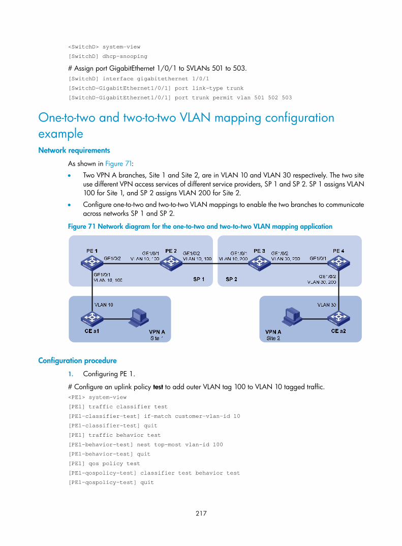
217
<SwitchD> system-view
[SwitchD] dhcp-snooping
# Assign port GigabitEthernet 1/0/1 to SVLANs 501 to 503. [SwitchD] interface gigabitethernet 1/0/1
[SwitchD-GigabitEthernet1/0/1] port link-type trunk
[SwitchD-GigabitEthernet1/0/1] port trunk permit vlan 501 502 503
One-to-two and two-to-two VLAN mapping configuration example Network requirements
As shown in Figure 71:
• Two VPN A branches, Site 1 and Site 2, are in VLAN 10 and VLAN 30 respectively. The two site use different VPN access services of different service providers, SP 1 and SP 2. SP 1 assigns VLAN 100 for Site 1, and SP 2 assigns VLAN 200 for Site 2.
• Configure one-to-two and two-to-two VLAN mappings to enable the two branches to communicate across networks SP 1 and SP 2.
Figure 71 Network diagram for the one-to-two and two-to-two VLAN mapping application
Configuration procedure
1. Configuring PE 1.
# Configure an uplink policy test to add outer VLAN tag 100 to VLAN 10 tagged traffic. <PE1> system-view
[PE1] traffic classifier test
[PE1-classifier-test] if-match customer-vlan-id 10
[PE1-classifier-test] quit
[PE1] traffic behavior test
[PE1-behavior-test] nest top-most vlan-id 100
[PE1-behavior-test] quit
[PE1] qos policy test
[PE1-qospolicy-test] classifier test behavior test
[PE1-qospolicy-test] quit
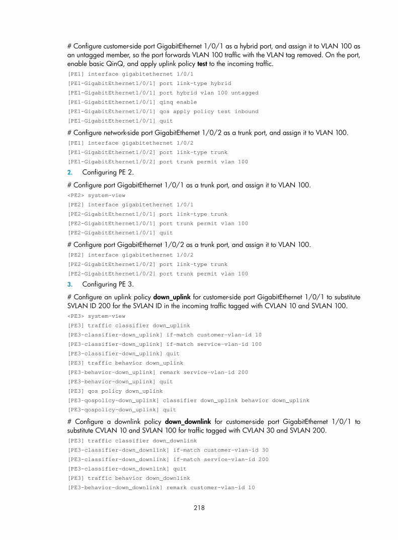
218
# Configure customer-side port GigabitEthernet 1/0/1 as a hybrid port, and assign it to VLAN 100 as an untagged member, so the port forwards VLAN 100 traffic with the VLAN tag removed. On the port, enable basic QinQ, and apply uplink policy test to the incoming traffic. [PE1] interface gigabitethernet 1/0/1
[PE1-GigabitEthernet1/0/1] port link-type hybrid
[PE1-GigabitEthernet1/0/1] port hybrid vlan 100 untagged
[PE1-GigabitEthernet1/0/1] qinq enable
[PE1-GigabitEthernet1/0/1] qos apply policy test inbound
[PE1-GigabitEthernet1/0/1] quit
# Configure network-side port GigabitEthernet 1/0/2 as a trunk port, and assign it to VLAN 100. [PE1] interface gigabitethernet 1/0/2
[PE1-GigabitEthernet1/0/2] port link-type trunk
[PE1-GigabitEthernet1/0/2] port trunk permit vlan 100
2. Configuring PE 2.
# Configure port GigabitEthernet 1/0/1 as a trunk port, and assign it to VLAN 100. <PE2> system-view
[PE2] interface gigabitethernet 1/0/1
[PE2-GigabitEthernet1/0/1] port link-type trunk
[PE2-GigabitEthernet1/0/1] port trunk permit vlan 100
[PE2-GigabitEthernet1/0/1] quit
# Configure port GigabitEthernet 1/0/2 as a trunk port, and assign it to VLAN 100. [PE2] interface gigabitethernet 1/0/2
[PE2-GigabitEthernet1/0/2] port link-type trunk
[PE2-GigabitEthernet1/0/2] port trunk permit vlan 100
3. Configuring PE 3.
# Configure an uplink policy down_uplink for customer-side port GigabitEthernet 1/0/1 to substitute SVLAN ID 200 for the SVLAN ID in the incoming traffic tagged with CVLAN 10 and SVLAN 100. <PE3> system-view
[PE3] traffic classifier down_uplink
[PE3-classifier-down_uplink] if-match customer-vlan-id 10
[PE3-classifier-down_uplink] if-match service-vlan-id 100
[PE3-classifier-down_uplink] quit
[PE3] traffic behavior down_uplink
[PE3-behavior-down_uplink] remark service-vlan-id 200
[PE3-behavior-down_uplink] quit
[PE3] qos policy down_uplink
[PE3-qospolicy-down_uplink] classifier down_uplink behavior down_uplink
[PE3-qospolicy-down_uplink] quit
# Configure a downlink policy down_downlink for customer-side port GigabitEthernet 1/0/1 to substitute CVLAN 10 and SVLAN 100 for traffic tagged with CVLAN 30 and SVLAN 200. [PE3] traffic classifier down_downlink
[PE3-classifier-down_downlink] if-match customer-vlan-id 30
[PE3-classifier-down_downlink] if-match service-vlan-id 200
[PE3-classifier-down_downlink] quit
[PE3] traffic behavior down_downlink
[PE3-behavior-down_downlink] remark customer-vlan-id 10

219
[PE3-behavior-down_downlink] remark service-vlan-id 100
[PE3-behavior-down_downlink] quit
[PE3] qos policy down_downlink
[PE3-qospolicy-down_downlink] classifier down_downlink behavior down_downlink
[PE3-qospolicy-down_downlink] quit
# Configure an uplink policy up_uplink for network-side port GigabitEthernet 1/0/2 to substitute CVLAN 30 for the CVLAN ID of the outgoing traffic tagged with CVLAN 10 and SVLAN 200. [PE3] traffic classifier up_uplink
[PE3-classifier-up_uplink] if-match customer-vlan-id 10
[PE3-classifier-up_uplink] if-match service-vlan-id 200
[PE3-classifier-up_uplink] quit
[PE3] traffic behavior up_uplink
[PE3-behavior-up_uplink] remark customer-vlan-id 30
[PE3-behavior-up_uplink] quit
[PE3] qos policy up_uplink
[PE3-qospolicy-up_uplink] classifier up_uplink behavior up_uplink
[PE3-qospolicy-up_uplink] quit
# Configure customer-side port GigabitEthernet 1/0/1 as a trunk port, assign it to VLAN 200, and apply uplink policy down_uplink to the incoming traffic and downlink policy down_downlink to the outgoing traffic on the port. [PE3] interface gigabitethernet 1/0/1
[PE3-GigabitEthernet1/0/1] port link-type trunk
[PE3-GigabitEthernet1/0/1] port trunk permit vlan 200
[PE3-GigabitEthernet1/0/1] qos apply policy down_uplink inbound
[PE3-GigabitEthernet1/0/1] qos apply policy down_downlink outbound
[PE3-GigabitEthernet1/0/1] quit
# Set network-side port GigabitEthernet 1/0/2 as a trunk port, assign it to VLAN 200, and apply uplink policy up_uplink to the outgoing traffic on the port. [PE3] interface gigabitethernet 1/0/2
[PE3-GigabitEthernet1/0/2] port link-type trunk
[PE3-GigabitEthernet1/0/2] port trunk permit vlan 200
[PE3-GigabitEthernet1/0/2] qos apply policy up_uplink outbound
[PE3-GigabitEthernet1/0/2] quit
4. Configuring PE 4.
# Configure an uplink policy test to add outer VLAN tag 200 to VLAN 30 tagged traffic. <PE4> system-view
[PE4] traffic classifier test
[PE4-classifier-test] if-match customer-vlan-id 30
[PE4-classifier-test] quit
[PE4] traffic behavior test
[PE4-behavior-test] nest top-most vlan-id 200
[PE4-behavior-test] quit
[PE4] qos policy test
[PE4-qospolicy-test] classifier test behavior test
[PE4-qospolicy-test] quit
# Assign port GigabitEthernet 1/0/1 to VLAN 200. [PE4] interface gigabitethernet 1/0/1

220
[PE4-GigabitEthernet1/0/1] port link-type trunk
[PE4-GigabitEthernet1/0/1] port trunk permit vlan 200
# Configure port GigabitEthernet 1/0/2 as a hybrid port, and assign it to VLAN 200 as un untagged member, so the port forwards VLAN 200 traffic with the VLAN tag removed. Enable basic QinQ, and apply uplink policy test to the incoming traffic on the port. [PE4] interface gigabitethernet 1/0/2
[PE4-GigabitEthernet1/0/2] port link-type hybrid
[PE4-GigabitEthernet1/0/2] port hybrid vlan 200 untagged
[PE4-GigabitEthernet1/0/2] qinq enable
[PE4-GigabitEthernet1/0/2] qos apply policy test inbound

221
LLDP configuration
Overview
Background In a heterogeneous network, a standard configuration exchange platform ensures that different types of network devices from different vendors can discover one another and exchange configuration for the sake of interoperability and management.
The IETF drafted the Link Layer Discovery Protocol (LLDP) in IEEE 802.1AB. The protocol operates on the data link layer to exchange device information between directly connected devices. With LLDP, a device sends local device information (including its major functions, management IP address, device ID, and port ID) as TLV (type, length, and value) triplets in LLDP Data Units (LLDPDUs) to the directly connected devices. At the same time, the device stores the device information received in LLDPDUs sent from the LLDP neighbors in a standard management information base (MIB). LLDP enables a network management system to quickly detect and identify Layer 2 network topology changes.
NOTE:
For more information about MIBs, see Network Management and Monitoring Configuration Guide.
Basic concepts LLDPDU formats
LLDP sends device information in LLDPDUs. LLDPDUs are encapsulated in Ethernet II or Subnetwork Access Protocol (SNAP) frames.
1. Ethernet II-encapsulated LLDPDU format
Figure 72 Ethernet II-encapsulated LLDPDU format

222
Table 22 Fields in an Ethernet II-encapsulated LLDPDU
Field Description
Destination MAC address The MAC address to which the LLDPDU is advertised. It is fixed to 0x0180-C200-000E, a multicast MAC address.
Source MAC address The MAC address of the sending port. If the port does not have a MAC address, the MAC address of the sending bridge is used.
Type The Ethernet type for the upper layer protocol. It is 0x88CC for LLDP.
Data LLDPDU
FCS Frame check sequence, a 32-bit CRC value used to determine the validity of the received Ethernet frame
2. SNAP-encapsulated LLDPDU format
Figure 73 SNAP-encapsulated LLDPDU format
Data = LLDPU(n bytes)
0
Destination MAC address
Source MAC address
Type
15 31
FCS
Table 23 Fields in a SNAP-encapsulated LLDPDU
Field Description
Destination MAC address The MAC address to which the LLDPDU is advertised. It is fixed at 0x0180-C200-000E, a multicast MAC address.
Source MAC address The MAC address of the sending port.
Type The SNAP type for the upper layer protocol. It is 0xAAAA-0300-0000-88CC for LLDP.
Data LLDPDU
FCS Frame check sequence, a 32-bit CRC value used to determine the validity of the received Ethernet frame.
LLDPDUs
LLDP uses LLDPDUs to exchange information. An LLDPDU comprises multiple TLV sequences. Each TLV carries a type of device information, as shown in Figure 74.
Figure 74 LLDPDU encapsulation format

223
An LLDPDU can carry up to 28 types of TLVs. Mandatory TLVs include Chassis ID TLV, Port ID TLV, Time To Live TLV, and End of LLDPDU TLV. Other TLVs are optional.
TLVs
TLVs are type, length, and value sequences that carry information elements. The type field identifies the type of information, the length field measures the length of the information field in octets, and the value field contains the information itself.
LLDPDU TLVs fall into the following categories:
• Basic management TLVs
• Organizationally (IEEE 802.1 and IEEE 802.3) specific TLVs
• LLDP-MED (media endpoint discovery) TLVs
Basic management TLVs are essential to device management. Organizationally specific TLVs and LLDP-MED TLVs are used for enhanced device management; they are defined by standardization or other organizations and are optional to LLDPDUs.
1. Basic management TLVs
Table 24 lists the basic management TLV types. Some of them are mandatory to LLDPDUs, that is, must be included in every LLDPDU.
Table 24 Basic management TLVs
Type Description Remarks
Chassis ID Specifies the bridge MAC address of the sending device
Port ID
Specifies the ID of the sending port
If the LLDPDU carries LLDP-MED TLVs, the port ID TLV carries the MAC address of the sending port or the bridge MAC if the port does not have a MAC address. If the LLDPDU carries no LLDP-MED TLVs, the port ID TLV carries the port name.
Time To Live Specifies the life of the transmitted information on the receiving device
End of LLDPDU Marks the end of the TLV sequence in the LLDPDU
Mandatory
Port Description Specifies the port description of the sending port
System Name Specifies the assigned name of the sending device
System Description Specifies the description of the sending device
System Capabilities Identifies the primary functions of the sending device and the enabled primary functions
Management Address Specifies the management address, and the interface number and object identifier (OID) associated with the address
Optional
2. IEEE 802.1 organizationally specific TLVs
Table 25 IEEE 802.1 organizationally specific TLVs
Type Description
Port VLAN ID Specifies the port’s VLAN identifier (PVID). An LLDPDU carries only one TLV of this type.

224
Type Description
Port And Protocol VLAN ID Indicates whether the device supports protocol VLANs and, if so, what VLAN IDs these protocols will be associated with. An LLDPDU can carry multiple different TLVs of this type.
VLAN Name Specifies the textual name of any VLAN to which the port belongs. An LLDPDU can carry multiple different TLVs of this type.
Protocol Identity Indicates protocols supported on the port. An LLDPDU can carry multiple different TLVs of this type.
NOTE:
• H3C devices support only receiving protocol identity TLVs.
• Layer 3 Ethernet ports do not support IEEE 802.1 organizationally specific TLVs.
3. IEEE 802.3 organizationally specific TLVs
Table 26 IEEE 802.3 organizationally specific TLVs
Type Description
MAC/PHY Configuration/Status
Contains the bit-rate and duplex capabilities of the sending port, support for auto negotiation, enabling status of auto negotiation, and the current rate and duplex mode.
Power Via MDI
Contains the power supply capability of the port, including the Power over Ethernet (PoE) type, which can be Power Sourcing Equipment (PSE) or Powered Device (PD), PoE mode, whether PSE power supply is supported, whether PSE power supply is enabled, and whether the PoE mode is controllable.
Link Aggregation Indicates the aggregation capability of the port (whether the link is capable of being aggregated), and the aggregation status (whether the link is in an aggregation).
Maximum Frame Size Indicates the supported maximum frame size. It is now the MTU of the port.
Power Stateful Control Indicates the power state control configured on the sending port, including the power type of the PSE or PD, PoE sourcing and receiving priority, and PoE sourcing and receiving power.
NOTE:
The Power Stateful Control TLV is defined in IEEE P802.3at D1.0. The later versions no longer support thisTLV. H3C devices send this type of TLVs only after receiving them.
LLDP-MED TLVs
LLDP-MED TLVs provide multiple advanced applications for voice over IP (VoIP), such as basic configuration, network policy configuration, and address and directory management. LLDP-MED TLVs provide a cost-effective and easy-to-use solution for deploying voice devices in Ethernet. LLDP-MED TLVs are shown in Table 27.

225
Table 27 LLDP-MED TLVs
Type Description
LLDP-MED Capabilities Allows a network device to advertise the LLDP-MED TLVs that it supports.
Network Policy Allows a network device or terminal device to advertise the VLAN ID of the specific port, the VLAN type, and the Layer 2 and Layer 3 priorities for specific applications.
Extended Power-via-MDI Allows a network device or terminal device to advertise power supply capability. This TLV is an extension of the Power Via MDI TLV.
Hardware Revision Allows a terminal device to advertise its hardware version.
Firmware Revision Allows a terminal device to advertise its firmware version.
Software Revision Allows a terminal device to advertise its software version.
Serial Number Allows a terminal device to advertise its serial number.
Manufacturer Name Allows a terminal device to advertise its vendor name.
Model Name Allows a terminal device to advertise its model name.
Asset ID Allows a terminal device to advertise its asset ID. The typical case is that the user specifies the asset ID for the endpoint to facilitate directory management and asset tracking.
Location Identification Allows a network device to advertise the appropriate location identifier information for a terminal device to use in the context of location-based applications.
Management address
The network management system uses the management address of a device to identify and manage the device for topology maintenance and network management. The management address TLV encapsulates the management address.
How LLDP works Operating modes of LLDP
LLDP can operate in one of the following modes:
• TxRx mode—A port in this mode sends and receives LLDPDUs.
• Tx mode—A port in this mode only sends LLDPDUs.
• Rx mode—A port in this mode only receives LLDPDUs.
• Disable mode—A port in this mode does not send or receive LLDPDUs.
Each time the LLDP operating mode of a port changes, its LLDP protocol state machine re-initializes. A re-initialization delay, which is user configurable, prevents LLDP from being initialized too frequently at times of frequent changes to the operating mode. With this delay configured, before a port can initialize LLDP, it must wait for the specified interval after the LLDP operating mode changes.
Transmitting LLDPDUs
An LLDP-enabled port operating in TxRx mode or Tx mode sends LLDPDUs to its directly connected devices both periodically and when the local configuration changes. To prevent LLDPDUs from

226
overwhelming the network during times of frequent changes to local device information, an interval is introduced between two successive LLDPDUs.
This interval is shortened to 1 second in either of the following cases:
• A new neighbor is discovered. A new LLDPDU is received and carries device information new to the local device.
• The LLDP operating mode of the port changes from Disable or Rx to TxRx or Tx.
This is the fast sending mechanism of LLDP. With this mechanism, a specific number of LLDPDUs are sent successively at 1-second intervals, to help LLDP neighbors discover the local device as soon as possible. Then, the normal LLDPDU transmit interval resumes.
Receiving LLDPDUs
An LLDP-enabled port that is operating in TxRx mode or Rx mode checks the validity of TLVs carried in every received LLDPDU. If valid, the information is saved and an aging timer is set for it based on the time to live (TTL) value in the Time to Live TLV carried in the LLDPDU. If the TTL value is zero, the information ages out immediately.
Protocols and standards • IEEE 802.1AB-2005, Station and Media Access Control Connectivity Discovery
• ANSI/TIA-1057, Link Layer Discovery Protocol for Media Endpoint Devices
LLDP configuration task list Complete these tasks to configure LLDP:
Task Remarks
Enabling LLDP Required
Setting the LLDP operating mode Optional
Setting the LLDP re-initialization delay Optional
Enabling LLDP polling Optional
Configuring the advertisable TLVs Optional
Configuring the management address and its encoding format Optional
Setting other LLDP parameters Optional
Performing basic LLDP configuration
Setting an encapsulation format for LLDPDUs Optional
Configuring CDP compatibility Optional
Configuring LLDP trapping Optional
NOTE:
• LLDP-related configurations made in Layer 2/Layer 3 Ethernet interface view take effect only on the current port, and those made in port group view take effect on all ports in the current port group.
• Layer 3 interfaces refer to route-mode (or Layer 3) Ethernet ports. You can set an Ethernet port to operatein route mode by using the port link-mode route command (see the chapter “Ethernet interface configuration”).
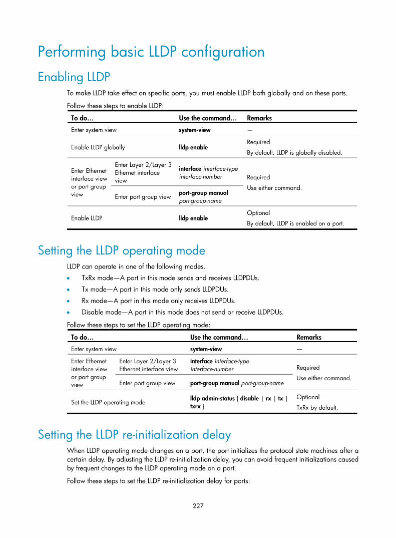
227
Performing basic LLDP configuration
Enabling LLDP To make LLDP take effect on specific ports, you must enable LLDP both globally and on these ports.
Follow these steps to enable LLDP:
To do… Use the command… Remarks
Enter system view system-view —
Enable LLDP globally lldp enable Required
By default, LLDP is globally disabled.
Enter Layer 2/Layer 3 Ethernet interface view
interface interface-type interface-number
Enter Ethernet interface view or port group view Enter port group view
port-group manual port-group-name
Required
Use either command.
Enable LLDP lldp enable Optional
By default, LLDP is enabled on a port.
Setting the LLDP operating mode LLDP can operate in one of the following modes.
• TxRx mode—A port in this mode sends and receives LLDPDUs.
• Tx mode—A port in this mode only sends LLDPDUs.
• Rx mode—A port in this mode only receives LLDPDUs.
• Disable mode—A port in this mode does not send or receive LLDPDUs.
Follow these steps to set the LLDP operating mode:
To do… Use the command… Remarks
Enter system view system-view —
Enter Layer 2/Layer 3 Ethernet interface view
interface interface-type interface-number
Enter Ethernet interface view or port group view Enter port group view port-group manual port-group-name
Required
Use either command.
Set the LLDP operating mode lldp admin-status { disable | rx | tx | txrx }
Optional
TxRx by default.
Setting the LLDP re-initialization delay When LLDP operating mode changes on a port, the port initializes the protocol state machines after a certain delay. By adjusting the LLDP re-initialization delay, you can avoid frequent initializations caused by frequent changes to the LLDP operating mode on a port.
Follow these steps to set the LLDP re-initialization delay for ports:

228
To do… Use the command… Remarks
Enter system view system-view —
Set the LLDP re-initialization delay lldp timer reinit-delay delay Optional
2 seconds by default.
Enabling LLDP polling With LLDP polling enabled, a device periodically searches for local configuration changes. On detecting a configuration change, the device sends LLDPDUs to inform neighboring devices of the change.
Follow these steps to enable LLDP polling:
To do… Use the command… Remarks
Enter system view system-view —
Enter Layer 2/Layer 3 Ethernet interface view
interface interface-type interface-number
Enter Ethernet interface view or port group view Enter port group view port-group manual port-group-name
Required
Use either command.
Enable LLDP polling and set the polling interval lldp check-change-interval interval
Required
Disabled by default.
Configuring the advertisable TLVs Follow these steps to configure the advertisable LLDPDU TLVs on the specified port or ports:
To do… Use the command… Remarks
Enter system view system-view —
Enter Layer 2/Layer 3 Ethernet interface view
interface interface-type interface-number
Enter Ethernet interface view or port group view
Enter port group view port-group manual port-group-name
Required
Use either command.
Configure the advertisable TLVs (Layer 2 Ethernet interface view or port group view)
lldp tlv-enable { basic-tlv { all | port-description | system-capability | system-description | system-name } | dot1-tlv { all | port-vlan-id | protocol-vlan-id [ vlan-id ] | vlan-name [ vlan-id ] } | dot3-tlv { all | link-aggregation | mac-physic | max-frame-size | power } | med-tlv { all | capability | inventory | location-id { civic-address device-type country-code { ca-type ca-value }&<1–10> | elin-address tel-number } | network-policy | power-over-ethernet } }
Optional
By default, all types of LLDP TLVs except location identification TLVs are advertisable on a Layer 2 Ethernet port.

229
To do… Use the command… Remarks
Configure the advertisable TLVs (Layer 3 Ethernet interface view)
lldp tlv-enable { basic-tlv { all | port-description | system-capability | system-description | system-name } | dot3-tlv { all | link-aggregation | mac-physic | max-frame-size | power } | med-tlv { all | capability | inventory | location-id { civic-address device-type country-code { ca-type ca-value }&<1-10> | elin-address tel-number } | power-over-ethernet } }
Optional
By default, all types of LLDP TLVs, except IEEE 802.1 organizationally specific TLVs, network policy TLVs, and location identification TLVs, are advertisable on a Layer 3 Ethernet port.
Configuring the management address and its encoding format LLDP encodes management addresses in numeric or character string format in management address TLVs.
By default, management addresses are encoded in numeric format. If a neighbor encoded its management address in character string format, you must configure the encoding format of the management address as string on the connecting port to guarantee normal communication with the neighbor.
Follow these steps to configure a management address to be advertised and its encoding format on a port or group of ports:
To do… Use the command… Remarks
Enter system view system-view —
Enter Layer 2/Layer 3 Ethernet interface view
interface interface-type interface-number
Enter Ethernet interface view or port group view Enter port group view
port-group manual port-group-name
Required
Use either command.
Allow LLDP to advertise the management address in LLDPDUs and configure the advertised management address
lldp management-address-tlv [ ip-address ]
Optional
By default, the management address is sent through LLDPDUs. • For a Layer 2 Ethernet port, the
management address is the main IP address of the lowest-ID VLAN carried on the port. If none of the carried VLANs is assigned an IP address, no management address will be advertised.
• For a Layer 3 Ethernet port, the management address is its own IP address. If no IP address is configured for the Layer 3 Ethernet port, no management address will be advertised.
Configure the encoding format of the management address as character string
lldp management-address-format string
Optional
By default, the management address is encapsulated in the numeric format.

230
Setting other LLDP parameters The Time to Live TLV carried in an LLDPDU determines how long the device information carried in the LLDPDU can be saved on a recipient device.
By setting the TTL multiplier, you can configure the TTL of locally sent LLDPDUs, which determines how long information about the local device can be saved on a neighboring device. The TTL is expressed by using the following formula:
TTL = Min (65535, (TTL multiplier × LLDPDU transmit interval))
As the expression shows, the TTL can be up to 65535 seconds. TTLs greater than 65535 will be rounded down to 65535 seconds.
Follow these steps to change the TTL multiplier:
To do… Use the command… Remarks
Enter system view system-view —
Set the TTL multiplier lldp hold-multiplier value Optional
4 by default.
Set the LLDPDU transmit interval lldp timer tx-interval interval Optional
30 seconds by default.
Set the LLDPDU transmit delay lldp timer tx-delay delay Optional
2 seconds by default.
Set the number of LLDPDUs sent each time fast LLDPDU transmission is triggered
lldp fast-count count Optional
3 by default.
NOTE:
• To ensure that LLDP neighbors can receive LLDPDUs to update information about the current device before it ages out, configure both the LLDPDU transmit interval and delay to be less than the TTL.
• It is a good practice to set the LLDPDU transmit interval to be no less than four times the LLDPDU transmitdelay.
• If the LLDPDU transmit delay is greater than the LLDPDU transmit interval, the device uses the LLDPDUstransmit delay as the transmit interval.
Setting an encapsulation format for LLDPDUs LLDPDUs can be encapsulated in the following formats: Ethernet II or SNAP frames.
• With Ethernet II encapsulation configured, an LLDP port sends LLDPDUs in Ethernet II frames and processes only incoming, Ethernet II encapsulated LLDPDUs.
• With SNAP encapsulation configured, an LLDP port sends LLDPDUs in SNAP frames and processes only incoming, SNAP encapsulated LLDPDUs.
By default, Ethernet II frames encapsulate LLDPDUs. If the neighbor devices encapsulate LLDPDUs in SNAP frames, configure the encapsulation format for LLDPDUs as SNAP to guarantee normal communication with the neighbors.
Follow these steps to set the encapsulation format for LLDPDUs to SNAP:
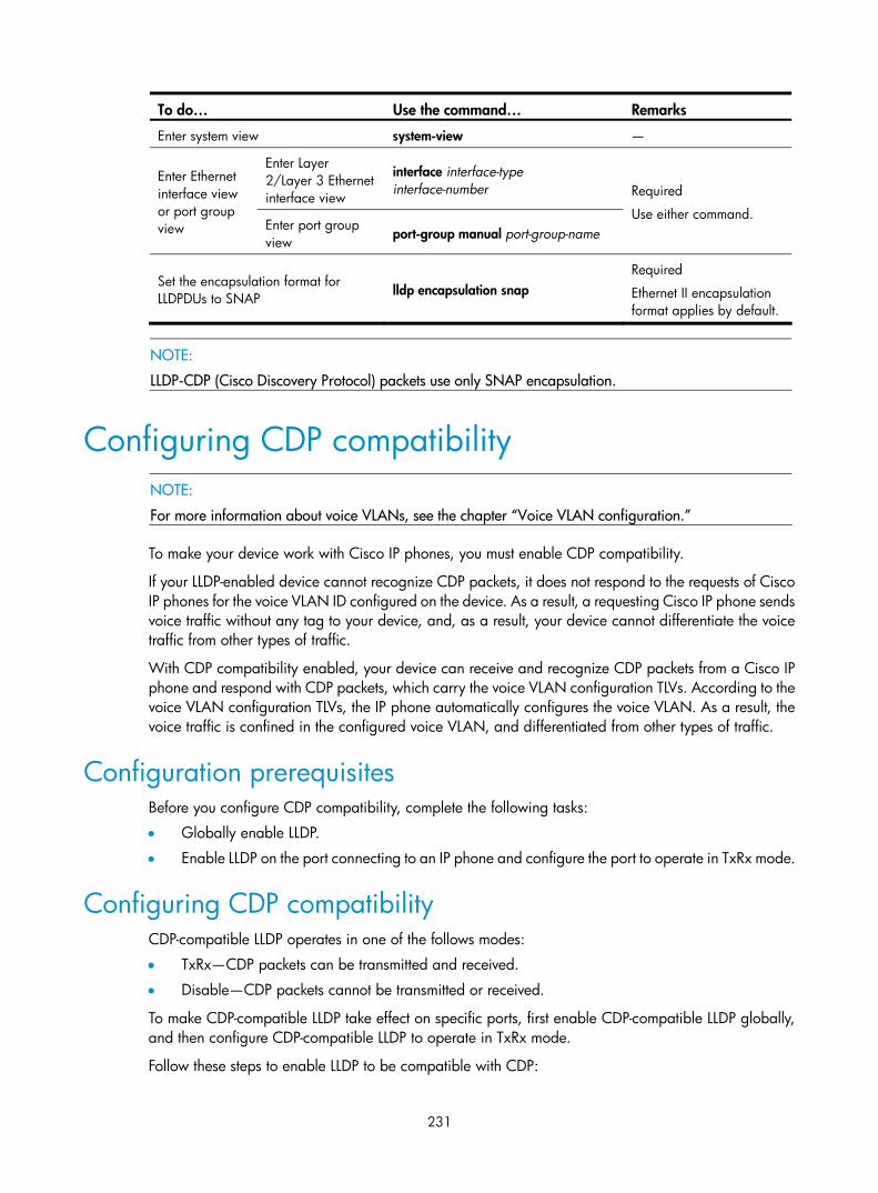
231
To do… Use the command… Remarks
Enter system view system-view —
Enter Layer 2/Layer 3 Ethernet interface view
interface interface-type interface-number
Enter Ethernet interface view or port group view Enter port group
view port-group manual port-group-name
Required
Use either command.
Set the encapsulation format for LLDPDUs to SNAP
lldp encapsulation snap Required
Ethernet II encapsulation format applies by default.
NOTE:
LLDP-CDP (Cisco Discovery Protocol) packets use only SNAP encapsulation.
Configuring CDP compatibility
NOTE:
For more information about voice VLANs, see the chapter “Voice VLAN configuration.”
To make your device work with Cisco IP phones, you must enable CDP compatibility.
If your LLDP-enabled device cannot recognize CDP packets, it does not respond to the requests of Cisco IP phones for the voice VLAN ID configured on the device. As a result, a requesting Cisco IP phone sends voice traffic without any tag to your device, and, as a result, your device cannot differentiate the voice traffic from other types of traffic.
With CDP compatibility enabled, your device can receive and recognize CDP packets from a Cisco IP phone and respond with CDP packets, which carry the voice VLAN configuration TLVs. According to the voice VLAN configuration TLVs, the IP phone automatically configures the voice VLAN. As a result, the voice traffic is confined in the configured voice VLAN, and differentiated from other types of traffic.
Configuration prerequisites Before you configure CDP compatibility, complete the following tasks:
• Globally enable LLDP.
• Enable LLDP on the port connecting to an IP phone and configure the port to operate in TxRx mode.
Configuring CDP compatibility CDP-compatible LLDP operates in one of the follows modes:
• TxRx—CDP packets can be transmitted and received.
• Disable—CDP packets cannot be transmitted or received.
To make CDP-compatible LLDP take effect on specific ports, first enable CDP-compatible LLDP globally, and then configure CDP-compatible LLDP to operate in TxRx mode.
Follow these steps to enable LLDP to be compatible with CDP:

232
To do… Use the command… Remarks
Enter system view system-view —
Enable CDP compatibility globally lldp compliance cdp Required
Disabled by default.
Enter Layer 2/Layer 3 Ethernet interface view
interface interface-type interface-number Enter Ethernet interface view or port group view
Enter port group view port-group manual port-group-name
Required
Use either command.
Configure CDP-compatible LLDP to operate in TxRx mode lldp compliance admin-status cdp txrx
Required
Disable mode by default.
CAUTION:
The maximum TTL value that CDP allows is 255 seconds. To make CDP-compatible LLDP work properly with Cisco IP phones, be sure that the product of the TTL multiplier and the LLDPDU transmit interval is lessthan 255 seconds.
Configuring LLDP trapping LLDP trapping notifies the network management system (NMS) of events such as newly-detected neighboring devices and link malfunctions.
LLDP traps are sent periodically, and the interval is configurable. To prevent excessive LLDP traps from being sent when the topology is unstable, set a trap transmit interval for LLDP.
Follow these steps to configure LLDP trapping:
To do… Use the command… Remarks
Enter system view system-view —
Enter Layer 2/Layer 3 Ethernet interface view interface interface-type interface-number
Enter Ethernet interface view or port group view Enter port group view port-group manual port-group-name
Required
Use either command.
Enable LLDP trapping lldp notification remote-change enable Required
Disabled by default.
Return to system view quit —
Set the LLDP trap transmit interval lldp timer notification-interval interval Optional
5 seconds by default.

233
Displaying and maintaining LLDP To do… Use the command… Remarks
Display the global LLDP information or the information contained in the LLDP TLVs to be sent through a port
display lldp local-information [ global | interface interface-type interface-number ] [ | { begin | exclude | include } regular-expression ]
Available in any view
Display the information contained in the LLDP TLVs sent from neighboring devices
display lldp neighbor-information [ brief | interface interface-type interface-number [ brief ] | list [ system-name system-name ] ] [ | { begin | exclude | include } regular-expression ]
Available in any view
Display LLDP statistics display lldp statistics [ global | interface interface-type interface-number ] [ | { begin | exclude | include } regular-expression ]
Available in any view
Display LLDP status of a port display lldp status [ interface interface-type interface-number ] [ | { begin | exclude | include } regular-expression ]
Available in any view
Display types of advertisable optional LLDP TLVs
display lldp tlv-config [ interface interface-type interface-number ] [ | { begin | exclude | include } regular-expression ]
Available in any view
LLDP configuration examples
Basic LLDP configuration example Network requirements
As shown in Figure 75, the NMS and Switch A are located in the same Ethernet. An MED device and Switch B are connected to GigabitEthernet 1/0/1 and GigabitEthernet 1/0/2 of Switch A.
Enable LLDP on the ports of Switch A and Switch B to monitor the link between Switch A and Switch B and the link between Switch A and the MED device on the NMS.
Figure 75 Network diagram for basic LLDP configuration
Configuration procedure
1. Configure Switch A.
# Enable LLDP globally. <SwitchA> system-view

234
[SwitchA] lldp enable
# Enable LLDP on GigabitEthernet 1/0/1 and GigabitEthernet 1/0/2. (You can skip this step because LLDP is enabled on ports by default.) Set the LLDP operating mode to Rx. [SwitchA] interface gigabitethernet 1/0/1
[SwitchA-GigabitEthernet1/0/1] lldp enable
[SwitchA-GigabitEthernet1/0/1] lldp admin-status rx
[SwitchA-GigabitEthernet1/0/1] quit
[SwitchA] interface gigabitethernet 1/0/2
[SwitchA-GigabitEthernet1/0/2] lldp enable
[SwitchA-GigabitEthernet1/0/2] lldp admin-status rx
[SwitchA-GigabitEthernet1/0/2] quit
2. Configure Switch B.
# Enable LLDP globally. <SwitchB> system-view
[SwitchB] lldp enable
# Enable LLDP on GigabitEthernet1/0/1. (You can skip this step because LLDP is enabled on ports by default.) Set the LLDP operating mode to Tx. [SwitchB] interface gigabitethernet 1/0/1
[SwitchB-GigabitEthernet1/0/1] lldp enable
[SwitchB-GigabitEthernet1/0/1] lldp admin-status tx
[SwitchB-GigabitEthernet1/0/1] quit
3. Verify the configuration
# Display the global LLDP status and port LLDP status on Switch A. [SwitchA] display lldp status
Global status of LLDP: Enable
The current number of LLDP neighbors: 2
The current number of CDP neighbors: 0
LLDP neighbor information last changed time: 0 days,0 hours,4 minutes,40 seconds
Transmit interval : 30s
Hold multiplier : 4
Reinit delay : 2s
Transmit delay : 2s
Trap interval : 5s
Fast start times : 3
Port 1 [GigabitEthernet1/0/1]:
Port status of LLDP : Enable
Admin status : Rx_Only
Trap flag : No
Polling interval : 0s
Number of neighbors: 1
Number of MED neighbors : 1
Number of CDP neighbors : 0
Number of sent optional TLV : 0
Number of received unknown TLV : 0

235
Port 2 [GigabitEthernet1/0/2]:
Port status of LLDP : Enable
Admin status : Rx_Only
Trap flag : No
Polling interval : 0s
Number of neighbors: 1
Number of MED neighbors : 0
Number of CDP neighbors : 0
Number of sent optional TLV : 0
Number of received unknown TLV : 3
As the sample output shows, GigabitEthernet 1/0/1 of Switch A connects to an MED device, and GigabitEthernet 1/0/2 of Switch A connects to a non-MED device. Both ports operate in Rx mode, and they only receive LLDPDUs.
# Remove the link between Switch A and Switch B and then display the global LLDP status and port LLDP status on Switch A. [SwitchA] display lldp status
Global status of LLDP: Enable
The current number of LLDP neighbors: 1
The current number of CDP neighbors: 0
LLDP neighbor information last changed time: 0 days,0 hours,5 minutes,20 seconds
Transmit interval : 30s
Hold multiplier : 4
Reinit delay : 2s
Transmit delay : 2s
Trap interval : 5s
Fast start times : 3
Port 1 [GigabitEthernet1/0/1]:
Port status of LLDP : Enable
Admin status : Rx_Only
Trap flag : No
Polling interval : 0s
Number of neighbors : 1
Number of MED neighbors : 1
Number of CDP neighbors : 0
Number of sent optional TLV : 0
Number of received unknown TLV : 5
Port 2 [GigabitEthernet1/0/2]:
Port status of LLDP : Enable
Admin status : Rx_Only
Trap flag : No
Polling interval : 0s
Number of neighbors : 0
Number of MED neighbors : 0

236
Number of CDP neighbors : 0
Number of sent optional TLV : 0
Number of received unknown TLV : 0
As the sample output shows, GigabitEthernet 1/0/2 of Switch A does not connect to any neighboring devices.
CDP-compatible LLDP configuration example Network requirements
As shown in Figure 76:
• GigabitEthernet 1/0/1 and GigabitEthernet 1/0/2 of Switch A are each connected to a Cisco IP phone.
• Configure voice VLAN 2 on Switch A. Enable CDP compatibility of LLDP on Switch A to allow the Cisco IP phones to automatically configure the voice VLAN, confining their voice traffic within the voice VLAN and isolating the voice traffic from other types of traffic.
Figure 76 Network diagram for CDP-compatible LLDP configuration
Configuration procedure
1. Configure a voice VLAN on Switch A.
# Create VLAN 2. <SwitchA> system-view
[SwitchA] vlan 2
[SwitchA-vlan2] quit
# Set the link type of GigabitEthernet 1/0/1 and GigabitEthernet 1/0/2 to trunk and enable voice VLAN on them. [SwitchA] interface gigabitethernet 1/0/1
[SwitchA-GigabitEthernet1/0/1] port link-type trunk
[SwitchA-GigabitEthernet1/0/1] voice vlan 2 enable
[SwitchA-GigabitEthernet1/0/1] quit
[SwitchA] interface gigabitethernet 1/0/2
[SwitchA-GigabitEthernet1/0/2] port link-type trunk
[SwitchA-GigabitEthernet1/0/2] voice vlan 2 enable
[SwitchA-GigabitEthernet1/0/2] quit
2. Configure CDP-compatible LLDP on Switch A.
# Enable LLDP globally and enable LLDP to be compatible with CDP globally. [SwitchA] lldp enable
[SwitchA] lldp compliance cdp
# Enable LLDP (you can skip this step because LLDP is enabled on ports by default), configure LLDP to operate in TxRx mode, and configure CDP-compatible LLDP to operate in TxRx mode on GigabitEthernet 1/0/1 and GigabitEthernet 1/0/2. [SwitchA] interface gigabitethernet 1/0/1
[SwitchA-GigabitEthernet1/0/1] lldp enable

237
[SwitchA-GigabitEthernet1/0/1] lldp admin-status txrx
[SwitchA-GigabitEthernet1/0/1] lldp compliance admin-status cdp txrx
[SwitchA-GigabitEthernet1/0/1] quit
[SwitchA] interface gigabitethernet 1/0/2
[SwitchA-GigabitEthernet1/0/2] lldp enable
[SwitchA-GigabitEthernet1/0/2] lldp admin-status txrx
[SwitchA-GigabitEthernet1/0/2] lldp compliance admin-status cdp txrx
[SwitchA-GigabitEthernet1/0/2] quit
3. Verify the configuration.
# Display the neighbor information on Switch A. [SwitchA] display lldp neighbor-information
CDP neighbor-information of port 1[GigabitEthernet1/0/1]:
CDP neighbor index : 1
Chassis ID : SEP00141CBCDBFE
Port ID : Port 1
Sofrware version : P0030301MFG2
Platform : Cisco IP Phone 7960
Duplex : Full
CDP neighbor-information of port 2[GigabitEthernet1/0/2]:
CDP neighbor index : 2
Chassis ID : SEP00141CBCDBFF
Port ID : Port 1
Sofrware version : P0030301MFG2
Platform : Cisco IP Phone 7960
Duplex : Full
As the sample output shows, Switch A has discovered the IP phones connected to GigabitEthernet 1/0/1 and GigabitEthernet 1/0/2, and has obtained their LLDP device information.
238
Service loopback group configuration
Overview To increase traffic redirecting throughput, you can bundle multiple Ethernet ports of a device together to increase bandwidth and implement load sharing. These ports that act as a logical link form a service loopback group. A service loopback group must contain at least one Ethernet port as its member port, called a service loopback port.
For example, by assigning three Ethernet ports of the same device to a service loopback group, you can create a logical link whose bandwidth can be as high as the total bandwidth of these three ports. In addition, service traffic is load balanced among these ports.
Service types of service loopback groups A service loopback group is applicable to a specified service type. The service types supported by the service loopback group are:
• Tunnel, which supports unicast tunnel traffic
• Multicast tunnel, which supports multicast tunnel traffic
Requirements on service loopback ports Before you assign a port to a service loopback group, ensure the following:
• The port supports the services type or types of the service loopback group.
• The port is not configured with multiple spanning tree protocol (MSTP), Link Layer Discovery Protocol (LLDP), 802.1X, MAC address authentication, port security mode, or IP source guard, or as the member port of an isolation group.
• The link type of the port is access.
• The port is not a member of any Ethernet link aggregation group or service loopback group.
States of service loopback ports States of service loopback ports
A member port in a service loopback group is a service loopback port, which can be in either of the following states:
• Selected: A selected port can loop back user traffic.
• Unselected: An unselected port cannot loop back user traffic.
The number of selected ports is limited in a service loopback group.
Setting the state of service loopback ports
The system sets the state of each member port in a service loopback group to selected or unselected by using the following workflow.
1. Select the full-duplex port with the highest rate as the reference port. If two ports have the same duplex mode and speed, the one with the lower port number wins.

239
2. Set the state of each member port in the service loopback group.
Figure 77 Set the state of each member port in a service loopback group
NOTE:
Every time a new port is assigned to a service loopback group, the system resets the state of the memberports in the service loopback group according to the process described previously.
Configuring a service loopback group Follow these steps to configure a service loopback group:
To do… Use the command… Remarks
Enter system view system-view —
Create a service loopback group and specify its service type
service-loopback group number type { multicast-tunnel | tunnel } * Required
Enter Layer 2 Ethernet interface view
interface interface-type interface-number —
Assign the Ethernet interface to the specified service loopback group
port service-loopback group number
Required
By default, a port does not belong to any service loopback group.
You can perform this command on different ports to assign multiple ports to a service loopback group.

240
CAUTION:
• A service loopback group may be referenced by multiple features once it is created, and can process service traffic only after it is referenced.
• You can change the service type of an existing service loopback group. For the change to be successful,you must ensure that the service group has not been referenced, the attributes of all member ports (if any) do not conflict with the target service type, and no service loopback group has been created for thetarget service type, because only one service loopback group is allowed for a service type.
• You cannot remove a service loopback group that other features reference.
Displaying and maintaining service loopback groups
To do… Use the command… Remarks
Display information about the specified service loopback group or all service loopback groups
display service-loopback group [ number ] [ | { begin | exclude | include } regular-expression ]
Available in any view
Service loopback group configuration example Network requirements
All the Ethernet ports of Device A support the tunnel service. Assign GigabitEthernet1/0/1 through GigabitEthernet1/0/3 to a service loopback group to increase bandwidth and achieve load sharing for tunnel traffic.
Configuration procedure
# Create service loopback group 1, and specify the service type as tunnel (unicast tunnel service). <DeviceA> system-view
[DeviceA] service-loopback group 1 type tunnel
# Disable MSTP, and LLDP on GigabitEthernet1/0/1 through GigabitEthernet1/0/3 and then assign them to service loopback group 1. [DeviceA] interface gigabitethernet 1/0/1
[DeviceA-GigabitEthernet1/0/1] undo stp enable
[DeviceA-GigabitEthernet1/0/1] undo lldp enable
[DeviceA-GigabitEthernet1/0/1] port service-loopback group 1
[DeviceA-GigabitEthernet1/0/1] quit
[DeviceA] interface gigabitethernet 1/0/2
[DeviceA-GigabitEthernet1/0/2] undo stp enable
[DeviceA-GigabitEthernet1/0/2] undo lldp enable
[DeviceA-GigabitEthernet1/0/2] port service-loopback group 1
[DeviceA-GigabitEthernet1/0/2] quit
[DeviceA] interface gigabitethernet 1/0/3
[DeviceA-GigabitEthernet1/0/3] undo stp enable
[DeviceA-GigabitEthernet1/0/3] undo lldp enable
[DeviceA-GigabitEthernet1/0/3] port service-loopback group 1

241
[DeviceA-GigabitEthernet1/0/3] quit
# Create logical interface Tunnel 1 and reference service loopback group 1 on Tunnel 1. [DeviceA] interface tunnel 1
[DeviceA-Tunnel1] service-loopback-group 1

242
EPON configuration
NOTE:
After an EPON card is installed in an S7500E switch, the switch can work as an OLT device in an EPONsystem.
• When the switch operates in standalone mode (IRF is not enabled on the switch), the OLT function canoperate normally. When the switch operates in stack mode (IRF in enabled on the switch), the OLT function cannot operate normally.
• With IRF enabled on an S7500E switch, the switch cannot operate as an OLT device even if it is installedwith an EPON card, and the related OLT configuration commands cannot take effect.
• On an S7500E switch installed with an EPON card and operating as an OLT device (the switch operatesin standalone mode), if you enable IRF on the switch, the switch will reboot to operate in stack mode. TheIRF function can run normally on the switch, and the OLT function fails.
Introduction to EPON Ethernet Passive Optical Network (EPON) is a Passive Optical Network (PON) that carries Ethernet frames encapsulated in 802.3 standards. EPON is a combination of Ethernet technology and PON technology in compliance with the IEEE 802.3ah standards issued in June 2004.
EPON architecture The components of a typical EPON system are optical line terminal (OLT), optical network unit (ONU), and optical distribution network (ODN).
Figure 78 A typical EPON architecture
ODN
OLT POS
ONU2
ONU1
ONUn
OLT
An OLT, usually an Ethernet switch, router, or multimedia conversion platform, is located at the central office (CO) as a core device of the whole EPON system to provide core data and video-to-telephone network interfaces for EPON and the service provider.
243
ONU
ONUs connect the customer premise equipment, such as PCs, set-top boxes (STBs), and switches. Usually placed at customer's home, corridors, or roadsides, ONUs forward uplink data sent by customer premise equipment (from ONU to OLT) and selectively receive downlink broadcasts forwarded by OLTs (from OLT to ONU).
ODN
An ODN consists of optical fibers, one or more passive optical splitters (POSes), and other passive optical components. ODNs provide optical signal transmission paths between OLTs and ONUs.
A POS can couple uplink data into a single piece of fiber and distribute downlink data to respective ONUs.
Benefits of the EPON technology Lower operation and maintenance costs
Compared with a traditional Ethernet broadband access network, an EPON network greatly lowers operation and maintenance costs. This is because, as passive equipment in an EPON system, POSes are energy-saving (requiring no power supply), highly reliable (not affected in case of a power outage), and easy to install, and save optical fiber resources.
Long distances and higher bandwidth
Compared with an Ethernet broadband access network, an EPON system provides a longer access transmission distance (up to 20 km, or 12.43 miles) and higher bandwidth (1 Gbps) that can adapt to the service status of the ONUs in real time. The dedicated line quality of each ONU is similar to that of Time Division Multiplexing (TDM) with dedicated uplink bandwidth in the grant cycle assigned to it.
EPON application modes Based on where ONUs are deployed, EPON application modes include Fiber To The Curb (FTTC), Fiber To The Building (FTTB), and Fiber To The Home (FTTH).
FTTC
In an FTTC system, ONUs are deployed at roadside or beside the junction boxes of telegraph poles. Usually, twisted-pair copper wires connect the ONUs to each user, and coaxial cables transmit broadband graphic services. One of the main benefits of the FTTC technology is that it allows the existing copper wire infrastructure to continue to be used between the ONUs and customer premises, postponing the investments on optical fibers to the home. Now, the FTTC technology is the most practical and economical Optical Access Network (OAN) solution for providing narrowband services below 2 Mbps. For services that integrate narrowband and broadband services, however, FTTC is not the ideal solution.
FTTB
In an FTTB system, ONUs are deployed within buildings, with the optical fibers led into user homes through ADSL lines, cables, or LANs. Compared with FTTC, FTTB has a higher usage of optical fiber and is more suitable for user communities that are dense or need narrowband/broadband integrated services.

244
FTTH
In an FTTH system, ONUs are deployed in user offices or homes to implement a fully transparent optical network, with the ONUs independent of the transmission mode, bandwidth, wavelength, and transmission technology. FTTH is ideal for the long-term development of optical access networks.
Data transmission in an EPON system An EPON system uses the single-fiber wavelength division multiplexing (WDM) technology (with downlink central wavelength of 1490 nm and uplink central wavelength of 1310 nm) to implement single-fiber bidirectional transmission, which supports a transmission distance of up to 20 km (12.43 miles).
Before an EPON system transmits data, ONU registration (see “ONU registration”), extended OAM connection establishment (see “Extended OAM connection establishment”), and bandwidth allocation (see “Bandwidth allocation”) are required.
Figure 79 Data transmission in an EPON system
ONU registration The following types of Multipoint Control Protocol (MPCP) messages are used in ONU registration: GATE, REGISTER_REQ, REGISTER, and REGISTER_ACK. Each of these messages contains a time stamp field that records the local clock at the time of packet transmission. The following types of GATE messages are available:
• General GATE messages, which allocate bandwidth in unicast mode.
• Discovery GATE messages, which discover ONUs in broadcast mode.
An ONU is registered by using the following workflow:
1. An OLT broadcasts a discovery GATE message to notify the start time and length of the discovery timeslot to all the ONUs.
2. An unregistered ONU responds to the discovery GATE message and modifies its local clock to be consistent with the time stamp contained in the GATE message. When the local clock of the ONU reaches the start time of the discovery timeslot, the ONU waits a random period of delay before sending a REGISTER_REQ message, which contains the MAC address of the ONU and the local time stamp of the ONU when the REGISTER_REQ message is sent.
3. On receiving the REGISTER_REQ message from the unregistered ONU, the OLT obtains the MAC address of the ONU and ONU-OLT round trip time (RTT). For more information about the RTT measurement, see “Configuring the maximum ONU-OLT RTT.” The ONU-OLT RTT is mainly used for the time synchronization between an OLT and ONUs.
4. The OLT parses the received REGISTER_REQ message, and uses the MAC address contained in the message to unicast a REGISTER message to the unregistered ONU. The REGISTER message contains a Logical Link ID (LLID) assigned to the ONU as the unique identifier of the ONU.
5. Immediately after sending a REGISTER message, the OLT sends a general GATE message to the same ONU.

245
6. After receiving the REGISTER message and general GATE message, the ONU sends a REGISTER_ACK message in the timeslot assigned in the GATE message to notify the OLT that the REGISTER message is parsed successfully.
7. The ONU registration is complete.
Extended OAM connection establishment The EPON cards of the S7500E Switch Series support the Operation, Administration and Maintenance (OAM) functions and extended OAM functions. This enables OLTs to remotely operate, manage, and maintain ONUs.
Extended OAM connection establishment includes OAM capability discovery and exchange of additional information. The capability acknowledgement process is required before other extended OAM functions can be completed. Data transmission begins only after the extended OAM connection is established. An extended OAM connection is established by using the following workflow:
1. Standard OAM discovery establishment is complete.
2. The ONU reports the supported Organizationally Unique Identifier (OUI) and extended OAM version number to the OLT.
3. The OLT determines whether the reported OUI and extended OAM version number are in the list of OUIs and extended OAM version numbers that the OLT supports. If yes, the extended OAM connection for the ONU is established successfully. Otherwise, the extended OAM connection for the ONU cannot be established.
NOTE:
For more information about OAM and extended OAM, see High Availability Configuration Guide.
Bandwidth allocation After the extended OAM connection is established, downlink data transmission can begin. Uplink data transmission can begin only after uplink bandwidth is allocated.
In bandwidth allocation, the following types of MPCP messages are used:
• A GATE message is sent by an OLT to assign a transmission timeslot to an ONU.
• A REPORT message is sent by an ONU to feed back the local status information, such as buffer occupancy, to the OLT, which helps the OLT assign timeslots intelligently.
An OLT allocates bandwidth to an ONU by using the following workflow:
1. The OLT sends a GATE message to notify the ONU of the timeslot for sending a REPORT message.
2. The ONU sends a REPORT message within the assigned timeslot to report its local status information to the OLT.
3. On receiving the REPORT message from the ONU, the OLT, based on the current bandwidth of the system, assigns the ONU a data transmission timeslot, which contains the start time and length for transmitting data by the ONU.
4. The ONU receives the GATE message and waits for the arrival of the start time contained in the GATE message. After the start time is reached, data transmission begins.
5. The bandwidth allocation is complete.
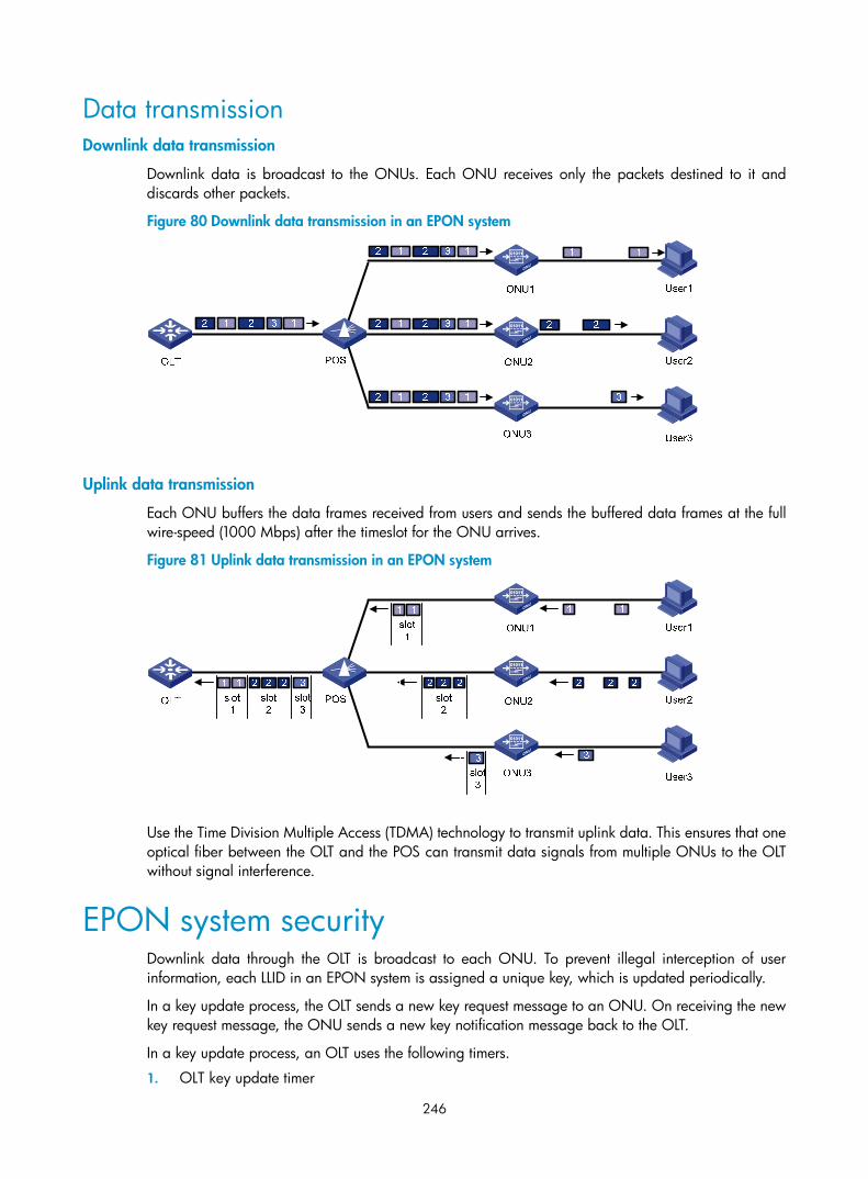
246
Data transmission Downlink data transmission
Downlink data is broadcast to the ONUs. Each ONU receives only the packets destined to it and discards other packets.
Figure 80 Downlink data transmission in an EPON system
Uplink data transmission
Each ONU buffers the data frames received from users and sends the buffered data frames at the full wire-speed (1000 Mbps) after the timeslot for the ONU arrives.
Figure 81 Uplink data transmission in an EPON system
Use the Time Division Multiple Access (TDMA) technology to transmit uplink data. This ensures that one optical fiber between the OLT and the POS can transmit data signals from multiple ONUs to the OLT without signal interference.
EPON system security Downlink data through the OLT is broadcast to each ONU. To prevent illegal interception of user information, each LLID in an EPON system is assigned a unique key, which is updated periodically.
In a key update process, the OLT sends a new key request message to an ONU. On receiving the new key request message, the ONU sends a new key notification message back to the OLT.
In a key update process, an OLT uses the following timers.
1. OLT key update timer

247
This timer controls the key update cycle. When the key update timer expires, the OLT sends another key request message to start another key update process.
2. OLT encryption response timer
This timer starts another key update process when the OLT receives no new key notification message, making the key update more reliable.
On sending a key update request message, the OLT starts the encryption response timer.
• If the OLT receives a correct new key notification message from an ONU before the timer expires, the OLT enables the new key and cancels the timer.
• If the OLT receives no new key notification message before the timer expires, the OLT assumes that the key update process has failed, resets the timer, and sends another key update request message. Before the key update succeeds, an ONU keeps using the original key and the OLT reports the key, update failure information to the network management system.
• If the OLT receives no new key notification message within the encryption response timer duration after sending three new key request messages consecutively, the OLT sends an alarm to the network management system, and the old key continues to be used for downlink data. H3C recommends that you adjust the value of the encryption response timer.
EPON system reliability To ensure high reliability for the trunk fibers and OLTs in an EPON system, add two OLT ports on one EPON card or on two different EPON cards to a fiber backup group. When a system fault occurs—for example, when a trunk fiber is broken or an OLT port becomes abnormal—a switchover is performed automatically between the two OLTs, which act as backup for each other. Alternatively, perform a manual switchover between two OLT ports added to the backup group as needed. Figure 82 shows a fiber backup group, where POS is a 2:N optical splitter.
Figure 82 Network diagram for a fiber backup group
S7500E Switch Series and EPON system
Features of an S7500E switch working as an OLT device With an EPON card installed, an S7500E switch can work as an OLT device in an EPON system, and provides the following features:
• Compliance with EPON interoperation standards: The switch is interoperable with other vendors' ONUs that support China Telecom Technical Requirements for EPON Devices.

248
• Integrating access and convergence: Each EPON card in an S7500E switch has multiple physical OLT ports, and each OLT port has 64 logical ports called “ONU ports”, each of which can correspond with an ONU. One EPON card can work as multiple OLT devices. This reduces users' equipment purchase costs, and the management costs and fault ratio caused by interconnection between multiple device ports.
• Powerful ONU remote management capabilities: Allows you to centrally manage and configure different services on ONUs and ONU UNI (User Network Interface) ports through OLTs. This greatly lowers subsequent maintenance costs.
• Excellent security protection: OLTs can protect network devices in terms of control, management, and forwarding against illegal access or abnormal traffic.
• Powerful access control list (ACL) and QoS functions: OLTs support standard and extended ACLs, and support traffic policing, traffic shaping, packet priority, multiple queue scheduling mechanisms, multiple congestion avoidance mechanisms, and other QoS assurance functions.
Three port types in an EPON system When an S7500E switch works as an OLT device in an EPON system, the port types for the EPON system are OLT, ONU, and UNI, as shown in Figure 83.
Figure 83 An EPON system
OLT port
Each PON port on an EPON card in an S7500E switch is an independent OLT device. For an S7500E switch, a PON port is an OLT port. An OLT port number is in the format EPON card slot number/sub-card slot number/OLT port number, such as OLT 3/0/1, as shown in Figure 83.
ONU port
Each OLT port of an S7500E switch has 64 logical ONU ports. An ONU port becomes a physical port only after an ONU device is bound with it. The configurations performed in ONU port view take effect on the ONU device connected to the ONU port. An ONU port number is in the format EPON card slot number/sub-card slot number/OLT port number: ONU port number, such as ONU 3/0/1:1, as shown in Figure 83.
UNI Port
A UNI port is an ONU device port connected to a user. The UNI port number that an S7500E switch supports is in the range of 1 to 80. The actual numbers vary with ONU devices. For example, when the

249
ONU device connected to ONU 3/0/1:1 in an EPON system is S3100-16C-EPON-EI, the UNI port number is in the range of 1 to 16.
S7500E OLT configuration task list Figure 83 shows an EPON system networking diagram, which assumes that only two ONUs are attached to one OLT port and each ONU is connected to only one user.
Based on the port types (OLT, ONU, and UNI) shown in Figure 83, this document details the functions of an S7500E Ethernet switch that is working as an OLT device and the configurations for the functions.
Complete the following tasks to configure OLT on an S7500E switch:
Task Remarks
OLT configuration • EPON system parameter description and configuration • Description and configuration of the functions of an S7500E
switch working as an OLT device
ONU remote management configuration Description and configuration procedure of ONU remote management through OLT
UNI port configuration • UNI port introduction • Configuration procedure of UNI remote management through
OLT
Alarm configuration Configurations of all the alarms in an EPON system
Supported switch features and restrictions Switch features supported by OLTs and ONUs, related documentation, and cautions

250
OLT configuration
NOTE:
• When working as an OLT device, an S7500E switch supports abundant features. This chapter describesonly the functions of an S7500E switch working as an OLT device. For more information about the otherfeatures, see “OLT port features and restrictions.”
• If the OLT configurations in this document take effect only when the OLT is used together with ONUs manufactured by H3C (hereinafter referred to as “H3C ONUs”), the configuration task list in each chapter will include related descriptions. If no such description appears, the OLT configurations will takeeffect on all the ONUs compliant with China's EPON standards.
OLT configuration
OLT configuration task list Complete the following tasks to configure an OLT:
Task Remarks
Configuring OUI and extended OAM version number list Optional
Configuring the maximum ONU-OLT RTT Optional
Configuring the timeout time of the extended OAM messages Optional
EPON system parameter configuration
Configuring the key update time and encryption reply timeout time of the encryption Optional
Configuring dynamic bandwidth allocation and related parameters Optional
Configuring grant filtering on the OLT port Optional
Configuring the link type of an OLT port Optional
Enabling layer-2 communication between the ONUs attached to an OLT port Optional
Configuring fiber backup Optional
Displaying and maintaining OLT configuration Optional
EPON system parameter configuration Configuring the maximum ONU-OLT RTT
During ONU registration, an OLT obtains the Round Trip Time (RTT) value of an ONU through the exchange of discovery GATE messages and REGISTER_REQ messages between the OLT and the ONU. You can set the coverage range of the EPON system by configuring a maximum RTT at the OLT side. An ONU whose RTT is greater than the RTT configured on the OLT cannot be registered.
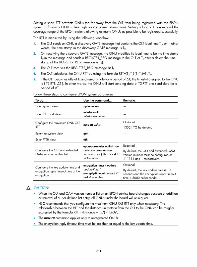
251
Setting a short RTT prevents ONUs too far away from the OLT from being registered with the EPON system (a far-away ONU suffers high optical power attenuation). Setting a long RTT can expand the coverage range of the EPON system, allowing as many ONUs as possible to be registered successfully.
The RTT is measured by using the following workflow:
1. The OLT sends an ONU a discovery GATE message that contains the OLT local time T0, or in other words, the time stamp in the discovery GATE message is T0.
2. On receiving the discovery GATE message, the ONU modifies its local time to be the time stamp T0 in the message and sends a REGISTER_REQ message to the OLT at T1 after a delay (the time stamp of the REGISTER_REQ message is T1).
3. The OLT receives the REGISTER_REQ message at T2.
4. The OLT calculates the ONU RTT by using the formula RTT=(T2-T0)-(T1-T0)=T2-T1.
5. If the OLT becomes idle at T3 and remains idle for a period of ∆T, the timeslot assigned to the ONU is { T3-RTT, ∆T }. In other words, the ONU will start sending data at T3-RTT and send data for a period of ∆T.
Follow these steps to configure EPON system parameters:
To do… Use the command… Remarks
Enter system view system-view —
Enter OLT port view interface olt interface-number —
Configure the maximum ONU-OLT RTT max-rtt value
Optional
13524 TQ by default.
Return to system view quit —
Enter FTTH view ftth —
Configure the OUI and extended OAM version number list
epon-parameter ouilist { oui oui-value oam-version version-value } &<1-9> slot slot-number
Required
By default, the OUI and extended OAM version number must be configured as 111111 and 1 respectively.
Configure the key update time and encryption reply timeout time of the encryption
encryption timer { update update-time | no-reply-timeout timeout }* slot slot-number
Optional
By default, the key update time is 10 seconds and the encryption reply timeout time is 3000 milliseconds.
CAUTION:
• When the OUI and OAM version number list on an EPON service board changes because of additionor removal of a user-defined list entry, all ONUs under the board will re-register.
• H3C recommends that you configure the maximum ONU-OLT RTT only when necessary. The relationship between the RTT and the distance (in meters) from the OLT to the ONU can be roughly expressed by the formula RTT = (Distance + 157) / 1.6393.
• The max-rtt command applies only to unregistered ONUs.
• The encryption reply timeout time must be less than or equal to the key update time.

252
Configuring dynamic bandwidth allocation and related parameters
An OLT uses dynamic bandwidth allocation (DBA) to adjust the uplink bandwidth of individual ONUs in real time according to the traffic status of the ONUs.
DBA is implemented through a request-response mechanism by using the following workflow: An OLT obtains the traffic information of ONUs from the bandwidth requests (REPORT messages) received from ONUs, uses a suitable bandwidth allocation algorithm to calculate the bandwidth to be allocated for this cycle within the specified uplink ONU bandwidth range, and provides the results to the ONUs through bandwidth authorization (GATE messages).
This ensures that uplink data sent by ONUs will not conflict with each other.
Compared with static (fixed) bandwidth allocation, DBA is more suitable for bursty IP/Ethernet services. DBA reduces bandwidth waste and allows for more efficient uplink bandwidth utilization. With DBA adopted, the OLT controls the order and the time for ONUs to send uplink frames.
The following types of DBA algorithms are available:
• Internal DBA algorithm: Implemented internally by a chip.
• External DBA algorithm: Implemented through loading an external DBA algorithm file.
Follow these steps to configure dynamic bandwidth allocation and related parameters
To do... Use the command... Remarks
Enter system view system-view —
Enter OLT port view interface olt interface-number —
Load the specified external DBA algorithm file
dba-algorithm update file-url Use an external DBA algorithm Use the specified
external DBA algorithm
dba-algorithm enable extdba
Use the internal DBA algorithm dba-algorithm enable intdba
Use either internal DBA algorithm or external DBA algorithm.
By default, the internal DBA algorithm is used.
Configure the related parameters of ONU discovery
dba-parameters { discovery-frequency value | discovery-length value | cycle-length value } *
Optional
By default, the discovery-frequency value is 50, the discovery-length value is 41500 TQ, and the cycle-length value is 65535 TQ.
Return to system view quit —
Enter ONU port view interface onu interface-number —
Set the uplink bandwidth limits of the ONU and the delay mode of packet forwarding
upstream-sla { minimum-bandwidth value1 | maximum-bandwidth value2 | delay { low | high } } *
Required
By default, the minimum bandwidth of an ONU is 2048 kbps, the maximum bandwidth is 23552 kbps, and low delay is adopted.
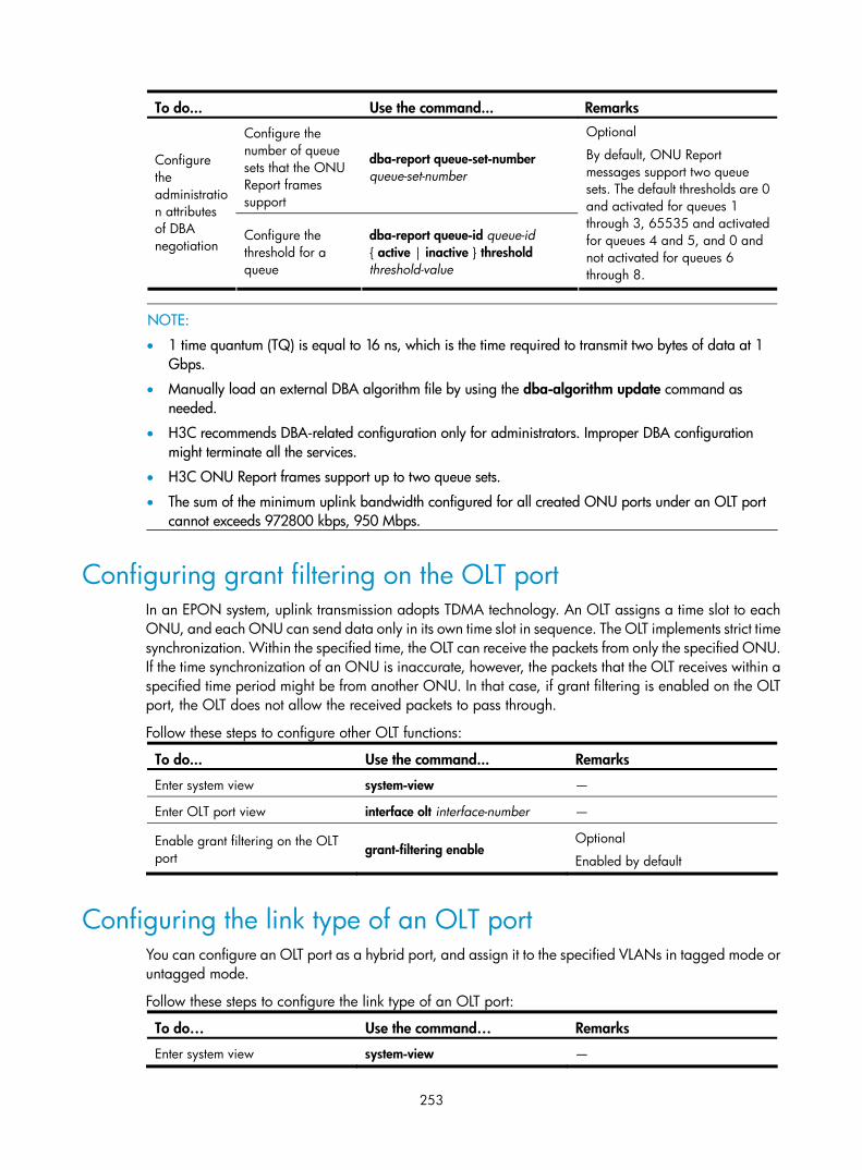
253
To do... Use the command... Remarks
Configure the number of queue sets that the ONU Report frames support
dba-report queue-set-number queue-set-number
Configure the administration attributes of DBA negotiation
Configure the threshold for a queue
dba-report queue-id queue-id { active | inactive } threshold threshold-value
Optional
By default, ONU Report messages support two queue sets. The default thresholds are 0 and activated for queues 1 through 3, 65535 and activated for queues 4 and 5, and 0 and not activated for queues 6 through 8.
NOTE:
• 1 time quantum (TQ) is equal to 16 ns, which is the time required to transmit two bytes of data at 1 Gbps.
• Manually load an external DBA algorithm file by using the dba-algorithm update command as needed.
• H3C recommends DBA-related configuration only for administrators. Improper DBA configuration might terminate all the services.
• H3C ONU Report frames support up to two queue sets.
• The sum of the minimum uplink bandwidth configured for all created ONU ports under an OLT port cannot exceeds 972800 kbps, 950 Mbps.
Configuring grant filtering on the OLT port In an EPON system, uplink transmission adopts TDMA technology. An OLT assigns a time slot to each ONU, and each ONU can send data only in its own time slot in sequence. The OLT implements strict time synchronization. Within the specified time, the OLT can receive the packets from only the specified ONU. If the time synchronization of an ONU is inaccurate, however, the packets that the OLT receives within a specified time period might be from another ONU. In that case, if grant filtering is enabled on the OLT port, the OLT does not allow the received packets to pass through.
Follow these steps to configure other OLT functions:
To do... Use the command... Remarks
Enter system view system-view —
Enter OLT port view interface olt interface-number —
Enable grant filtering on the OLT port grant-filtering enable
Optional
Enabled by default
Configuring the link type of an OLT port You can configure an OLT port as a hybrid port, and assign it to the specified VLANs in tagged mode or untagged mode.
Follow these steps to configure the link type of an OLT port:
To do… Use the command… Remarks
Enter system view system-view —
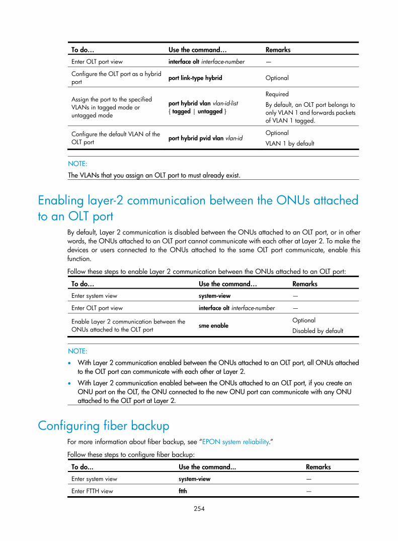
254
To do… Use the command… Remarks
Enter OLT port view interface olt interface-number —
Configure the OLT port as a hybrid port port link-type hybrid Optional
Assign the port to the specified VLANs in tagged mode or untagged mode
port hybrid vlan vlan-id-list { tagged | untagged }
Required
By default, an OLT port belongs to only VLAN 1 and forwards packets of VLAN 1 tagged.
Configure the default VLAN of the OLT port port hybrid pvid vlan vlan-id
Optional
VLAN 1 by default
NOTE:
The VLANs that you assign an OLT port to must already exist.
Enabling layer-2 communication between the ONUs attached to an OLT port
By default, Layer 2 communication is disabled between the ONUs attached to an OLT port, or in other words, the ONUs attached to an OLT port cannot communicate with each other at Layer 2. To make the devices or users connected to the ONUs attached to the same OLT port communicate, enable this function.
Follow these steps to enable Layer 2 communication between the ONUs attached to an OLT port:
To do… Use the command… Remarks
Enter system view system-view —
Enter OLT port view interface olt interface-number —
Enable Layer 2 communication between the ONUs attached to the OLT port sme enable
Optional
Disabled by default
NOTE:
• With Layer 2 communication enabled between the ONUs attached to an OLT port, all ONUs attachedto the OLT port can communicate with each other at Layer 2.
• With Layer 2 communication enabled between the ONUs attached to an OLT port, if you create an ONU port on the OLT, the ONU connected to the new ONU port can communicate with any ONU attached to the OLT port at Layer 2.
Configuring fiber backup For more information about fiber backup, see “EPON system reliability.”
Follow these steps to configure fiber backup:
To do... Use the command... Remarks
Enter system view system-view —
Enter FTTH view ftth —

255
To do... Use the command... Remarks
Create a fiber backup group fiber-backup group group-number Required
In fiber backup group view group member interface-type interface-number
quit
quit
interface interface-type interface-number
port fiber-backup group group-number
quit
ftth
Add an OLT port to a fiber backup group In OLT port view
fiber-backup group group-number
Required
Use either one of the two methods
Perform a master/subordinate switchover between the two OLT ports in the fiber backup group
port switch-over Optional
CAUTION:
• Up to two OLT ports can be added to one backup group. An OLT port can be added to only one backupgroup at a time. The port added to the backup group earlier will be the master port, and the other portwill be the standby port.
• Only one of the two OLT ports in a fiber backup group can be in the forwarding state.
• After the second OLT port is added to a backup group, you must manually synchronize the configurations of the first OLT port and all the ONUs under it to the second OLT port. This ensures normal service operation after a master/standby switchover.
Displaying and maintaining OLT configuration To do... Use the command... Remarks
Display related information of EPON parameters
display epon-parameter slot slot-number
Available in FTTH view only
Display the information about all the ONUs under an OLT port, the ONU port, or the EPON board in the specified slot
display onuinfo { interface interface-type interface-number | slot slot-number }
Available in any view
Display the information about the legal ONU with the specified MAC address
display onuinfo mac-address mac-address Available in any view
Display the information about all the silent ONUs connected to the specified OLT port or to the EPON card seated in the specified slot
display onuinfo silent { interface interface-type interface-number | slot slot-number }
Available in any view
Display the optical parameter information of an OLT port
display optics-parameters interface interface-type interface-number
Available in any view
Display the receive and transmit optical power of the specified OLT
Display transceiver diagnosis interface olt interface-number Available in any view

256
To do... Use the command... Remarks
Display the receive and transmit optical power of the specified ONU
display transceiver diagnosis interface onu interface-number Available in any view
Display port version information display epon-version interface interface-type interface-number Available in any view
Display port capability information display epon-capability interface interface-type interface-number Available in any view
Display the current work mode of a port display epon-workmode interface interface-type interface-number Available in any view
Display the statistics on a port display epon statistics interface interface-type interface-number Available in any view
Display the OAM information about an ONU display epon-oam interface interface-type interface-number Available in any view
Display the master/standby port information of a backup group
display fiber-backup group { all | group-number } Available in any view
Display the registration and deregistration information of an ONU
display onu-event interface interface-type interface-number Available in any view
Display all the configuration information display current-configuration Available in any view
Display the configuration information in the current view display this Available in any view
CAUTION:
• To display the information about an ONU, be sure that the ONU is online. Use the display onuinfo command to determine whether an ONU is online.
• Port statistics data includes average error rate of data bits and data frames transmitted between an OLTand the ONUs. For more information, see Layer 2—LAN Switching Command Reference.
OLT configuration examples
OLT Port isolation configuration example Network requirements
As shown in Figure 84,
• An OLT device is connected to the Internet through the uplink port.
• Configure port isolation between OLT 3/0/1 and OLT 3/0/2 so that the users under OLT 3/0/1 and those under OLT 3/0/2 can access the Internet but cannot communicate with each other at Layer 2.

257
Figure 84 Network diagram for OLT port isolation
Configuration procedure
# Add OLT 3/0/1 and OLT 3/0/2 to an isolation group. <Sysname> system-view
[Sysname] interface olt3/0/1
[Sysname-Olt3/0/1] port-isolate enable
[Sysname-Olt3/0/1] quit
[Sysname] interface olt3/0/2
[Sysname-Olt3/0/2] port-isolate enable
[Sysname-Olt3/0/2] quit
# Display the isolation group information. <Sysname> display port-isolate group
Port-isolate group information:
Uplink port support: NO
Group ID: 1
olt3/0/1 olt3/0/2
Fiber backup configuration example Network requirements
As shown in Figure 85,
• Add two OLT ports of the same EPON board to a fiber backup group, one after the other.
• Perform a manual switchover between the two OLT ports. When the master port is shut down, the subordinate port becomes the new master port.

258
Figure 85 Network diagram for fiber backup group configuration
OLT3/0/1
OLT3/0/2OLT POS
ONU2
ONU1
ONUn
2:N
Configuration procedure
# Create fiber backup group 1. <Sysname> system-view
[Sysname] ftth
[Sysname-ftth] fiber-backup group 1
Create group 1 successfully.
# Add port OLT 3/0/1 and then OLT 3/0/2 to fiber backup group 1, so that OLT 3/0/1 works as the master port and OLT 3/0/2 works as the subordinate port. [Sysname-fiber-group1] group member olt3/0/1
[Sysname-fiber-group1] group member olt3/0/2
[Sysname-fiber-group1] display fiber-backup group 1
fiber backup group 1 information:
Member Role State
-----------------------------------------
Olt3/0/1 MASTER ACTIVE
Olt3/0/2 SLAVE READY
# Perform a master/subordinate switchover between OLT 3/0/1 and OLT 3/0/2. [Sysname-fiber-group1] port switch-over
[Sysname-fiber-group1] display fiber-backup group 1
fiber backup group 1 information:
Member Role State
-----------------------------------------
Olt3/0/2 MASTER ACTIVE
Olt3/0/1 SLAVE READY
# Shut down OLT 3/0/2. The output of the display fiber-backup group command shows that OLT 3/0/1 becomes the new master port. [Sysname-fiber-group1] quit
[Sysname] interface olt3/0/2
[Sysname-Olt3/0/2] shutdown
[Sysname-Olt3/0/2] display fiber-backup group 1
fiber backup group 1 information:
Member Role State
-----------------------------------------
Olt3/0/1 MASTER ACTIVE

259
Olt3/0/2 SLAVE DOWN

260
ONU remote management configuration
NOTE:
When an S7500E switch is working as an OLT device, configure a variety of functions on its ONU portsso that you can manage the connected ONUs remotely. This document describes only the functions and commands developed for ONU ports on such an S7500E switch. Other function configurations of ONU ports are basically the same as those of the Ethernet ports on an S7500E switch. For more information, see“ONU port features and restrictions.”
ONU configuration Multiple types of H3C ONUs are compatible with the S7500E Switch Series. Support for OLT remote management commands varies with ONUs. For more information, see the sections that describe the supported configuration functions in ONU device user guides.
ONU configuration task list Complete the following tasks to configure an ONU:
Task Remarks
Creating an ONU port Required
Binding an ONU with an ONU port Required
Configuring batch ONU binding and automatic ONU binding Optional
Configuring the management VLAN of the ONU Optional
For H3C ONUs only
Configuring the ONU bandwidth allocation and related parameters Optional
For H3C ONUs only
Enabling related protocols on an ONU Optional
For H3C ONUs only
Configuring the multicast mode of the ONU Optional
Configuring the link type of an ONU port Optional

261
Task Remarks
Enabling FEC Optional
Configuring an ONU to report information to the OLT Optional
Configuring traffic encryption Optional
For H3C ONUs only
Testing the link between an ONU and the OLT Optional
Other ONU configurations
Testing the cable connected to a UNI port Optional
Deregistering an ONU Optional
Updating ONUs Optional
For H3C ONUs only ONU device management
Restarting an ONU Optional
Displaying and maintaining ONU port configuration Optional
Creating an ONU port Manually create or delete an ONU port as needed.
Follow these steps to create an ONU port:
To do... Use the command... Remarks
Enter system view system-view —
Enter OLT port view interface olt interface-number —
Create ONU ports using onu { onu-number1 [ to onu-number2 ] } &<1-10>
Required
By default, no ONU port is created when an EPON card is started up.
Binding an ONU with an ONU port An OLT supports ONU authentication based on ONU MAC address and denies illegal ONU access to the system. You can implement ONU authentication by binding the ONU to an ONU port. During the ONU registration, the following process occurs:
• The OLT broadcasts a discovery GATE message. After receiving the discovery GATE message, an unregistered ONU sends a REGISTER_REQ message, whose source MAC address is that of the ONU, at the time granted by the GATE message.
• On receiving the REGISTER_REQ message, the OLT determines whether the source MAC address contained in the message is bound with the ONU port of the local end. If yes, the ONU passes the authentication and the OLT replies with a REGISTER message. Otherwise, the ONU cannot pass the authentication and cannot be registered.
After the ONU port passes the authentication, the ONU port goes up, and the ONU goes online.
Before you bind an ONU to an ONU port, be sure that you have obtained the MAC address of the ONU.
Follow these steps to bind an ONU port to an ONU:

262
To do... Use the command... Remarks
Enter system view system-view —
Enter ONU port view interface onu interface-number —
Bind the ONU port to an ONU bind onuid onuid Required
CAUTION:
• You can bind an ONU port to only one ONU MAC address. Conversely, you can bind an ONU MACaddress to only one ONU port under one OLT port.
• In fiber backup, you can bind an ONU to two ONU ports under two OLT ports that act as backups foreach other.
Configuring batch ONU binding and automatic ONU binding In an EPON network environment, multiple ONUs might be attached to an OLT. Manually binding these ONUs to the OLT one by one will incur tedious binding work and increase the cost and difficulty of network maintenance. To solve this problem, configure batch ONU binding or automatic ONU binding.
Configuring batch ONU binding
With batch ONU binding configured, the device automatically binds the current quiet ONU MAC addresses to the ONU ports and generates the binding configuration on the ONU ports. However, the ONUs that joining subsequently will not be bound.
This binding method applies to a initially set up network environment where all ONUs are valid. This method can save many binding operations. You must use the bind onuid command to bind the subsequently joining ONUs, avoiding automatic registration of invalid ONUs.
Follow these steps to configure batch ONU binding:
To do… Use the command… Remarks
Enter system view system-view —
Enter FTTH view ftth —
Configure batch ONU binding onu bind batch [ slot slot-id ]
Required
By default, batch ONU binding is disabled.
Configure automatic ONU binding
With automatic ONU binding configured, the device automatically binds the current quiet ONU MAC addresses to the ONU ports and generates the binding configuration on the ONU ports, and the ONUs that join subsequently will also be bound automatically.
This binding method applies to occasions where the registration of invalid ONUs is not considered and the ONUs attached to the OLT are completely trusted, and completely ignores the concern about binding. To remove a binding, disable automatic ONU binding first. Otherwise, the removed ONU will be automatically bound again if it goes online.

263
Follow these steps to configure batch ONU binding:
To do… Use the command… Remarks
Enter system view system-view —
Enter FTTH view ftth —
Configure automatic ONU binding onu bind auto [ slot slot-id ]
Required
By default, automatic ONU binding is disabled.
CAUTION:
Neither batch ONU binding nor automatic ONU binding conflicts with the configuration of binding the specified ONU to the specified ONU port. However, batch ONU binding conflicts with automatic ONU binding.
Configuring the management VLAN of the ONU To manage an ONU through Telnet, be sure that the ONU is assigned an IP address. Only the VLAN interface of the management VLAN can be assigned an IP address. Designate the management VLAN through the command line.
The management VLAN interface of an ONU can obtain an IP address in one of the following ways:
• Manual IP address configuration
• DHCP (with the ONU as a DHCP client)
Follow these steps to configure the management VLAN of the ONU
To do... Use the command... Remarks
Enter system view system-view —
Enter ONU port view interface onu interface-number —
Configuring the management VLAN of the ONU
management-vlan vlan-id Optional
By default, the management VLAN of the ONU is VLAN 1.
Bring up the management VLAN interface
undo shutdown management-vlan-interface
Required
By default, a management VLAN interface is down. After you use the undo shutdown management-vlan-interface command, one of the following occurs: • A management VLAN interface is down if
all the Ethernet ports in the management VLAN of the ONU are down.
• A management VLAN interface is up if one or more Ethernet ports in the management VLAN of the ONU are up.
Manual configuration
ip address ip-address mask gateway gateway
Configure IP addresses Automatic
allocation ip address dhcp-alloc
Required
Use either method.
By default, the management VLAN interface has no IP address.

264
Configuring the ONU bandwidth allocation and related parameters
Complete this task to allocate different uplink/downlink bandwidth based on different terminal service requirements to realize efficient bandwidth utilization.
Downlink bandwidth allocation
To improve bandwidth utilization, allocate different downlink bandwidth for ONUs.
Follow these steps to allocate downlink bandwidth for an ONU:
To do… Use the command… Remarks
Enter system view system-view —
Enter ONU port view interface onu interface-number —
Enable the ONU downlink bandwidth allocation policy
bandwidth downstream policy enable
Required
By default, the downlink bandwidth allocation policy is disabled.
Configure the ONU downlink bandwidth limit
bandwidth downstream { max-bandwidth value | max-burstsize value } *
Optional
By default, the maximum bandwidth is 999994 kbps, and the maximum burst buffer is 8388480 bytes.
NOTE:
The downlink bandwidth limit that you configure takes effect only when the downlink bandwidth allocation policy is enabled.
The downlink bandwidth limit that you configure takes effect only on known unicast packets, not on unknown unicast packets, multicasts, or broadcasts.
Uplink bandwidth allocation
To improve bandwidth utilization, allocate different uplink bandwidth for different ONUs. In addition, configure priority-based uplink bandwidth allocation on an ONU to enable the ONU to allocate different bandwidth for queues that transmit packets with different 802.1p priorities within the uplink bandwidth limit. Packets with 802.1p priority 0 or 1 belong to priority queue 0, packets with 802.1p priority 2 or 3 belong to priority queue 1, packets with 802.1p priorities 4 or 5 belong to priority queue 2, and packets with priorities 6 or 7 belong to priority queue 3.
Follow these steps to allocate uplink bandwidth for an ONU:
To do… Use the command… Remarks
Enter system view system-view —
Enter ONU port view interface onu interface-number —
Set the uplink bandwidth range of the ONU and the delay mode of packet forwarding
upstream-sla { minimum-bandwidth value1 | maximum-bandwidth value2 | delay { low | high } } *
Required
By default, the minimum bandwidth of an ONU is 2048 kbps, the maximum bandwidth is 23552 kbps, and low delay is used.

265
To do… Use the command… Remarks
Enable the ONU to allocate uplink bandwidth based on priority queues (each priority queue corresponds to two packet priorities)
upstream-sla service-mode enable Optional
By default, an ONU does not allocate bandwidth based on priority queues.
Configure the uplink bandwidth limit for a priority queue
upstream-sla service service-number { fixed-packet-size fixed-packet-size | fixed-bandwidth fixed-bandwidth | minimum-bandwidth minimum-bandwidth | maximum-bandwidth maximum-bandwidth } *
Optional
By default, the fixed packet size is 0 bytes, the fixed uplink bandwidth is 0, the minimum uplink bandwidth is 0, and the maximum uplink bandwidth is 16000 (in the unit of 64 kbps)
NOTE:
Assume that the total fixed bandwidth configured for priority queues is X, the sum of the minimum bandwidth of priority queues configured with a bandwidth range is Y, and the maximum uplink bandwidth configured for the ONU by using the upstream-sla command is Z. The sum of X and Y must notexceed Z.
Enabling related protocols on an ONU You can use an OLT to remotely enable RSTP, DHCP snooping, DHCP snooping Option82, and PPPoE+ on an ONU through extended OAM packets.
RSTP
Enabling RSTP on an ONU can eliminate the loops between the UNIs or in the user networks by blocking redundant links.
DHCP snooping
After you enable DHCP snooping on an ONU, a DHCP snooping table will be generated on the ONU to record the IP address and user MAC address information that the DHCP client obtains from the DHCP server. In this case, each record will be an entry in the DHCP snooping table.
DHCP snooping Option82
With DHCP snooping Option82 enabled on an ONU, the ONU processes DHCP request messages according to whether the DHCP request messages carry the Option82 field.
• For DHCP request messages with Option82 fields, the ONU replaces the Option82 fields with the local one before broadcasting the DHCP request messages.
• For DHCP request messages without Option82 fields, the ONU adds the Option82 field (which contains ONU MAC addresses, the number of the UNI connected to the DHCP client, and the VLAN to which the UNI belongs) into the request messages when the DHCP client connected to the ONU sends DHCP request messages to the DHCP server. This allows the DHCP client addresses to be recorded in the DHCP server.
PPPoE+
The Point-to-Point Protocol over Ethernet (PPPoE) technology interconnects large numbers of hosts through Ethernet, allowing the hosts to access the Internet through a far-end access device, and implementing

266
control and accounting functions on each connected host. Operating in the client/server mode, PPPoE encapsulates PPP packets into Ethernet frames, and provides PPP connection over Ethernet.
PPPoE+, also called “PPPoE Intermediate Agent”, is designed for broadband users who are using PPPoE mode authentication. PPPoE+ allows for user port identification by adding user port information into the PPPoE packets.
After you enable PPPoE+ on an ONU, when a PPPoE client sends a request packet, the ONU processes the request packet according to whether the request packet carries a PPPoE tag.
• If the request packet carries no PPPoE tag, the ONU adds the tag (which contains the UNI port information) to the request packet and forwards the packet to the OLT side.
• If the request packet carries a PPPoE tag, the ONU directly forwards the request packet to the OLT side without adding any tag.
Follow these steps to enable related protocols on an ONU:
To do... Use the command... Remarks
Enter system view system-view —
Enter ONU port view interface onu interface-number —
Enable related protocols on the ONU
onu-protocol { stp | dhcp-snooping | dhcp-snooping information | pppoe } enable
Optional
By default, RSTP is enabled on the ONU, and DHCP snooping, DHCP snooping Option82, and PPPoE+ are disabled on the ONU.
CAUTION:
When STP is enabled globally on the S7500E switch, enable STP on all ONUs. Additionally, configureSTP correctly to ensure that no ONU can be selected as the STP root bridge. Otherwise, an anomaly might occur on the network.
STP runs normally only when all attached ONUs are H3C ONUs.
Configuring the multicast mode of the ONU Prerequisites for multicast mode configuration
Through extended OAM, an OLT can remotely configure the multicast mode of an ONU as either IGMP snooping mode or multicast control mode.
The configuration of a multicast IP address-to-multicast VLAN map adds multicast addresses to a multicast VLAN. On receiving an IGMP report message, the OLT determines whether the multicast IP address contained in the message belongs to the multicast VLAN. If yes, the OLT generates a multicast forwarding entry in the multicast VLAN of the multicast IP address. Otherwise, the OLT directly discards the message. A multicast IP address can belong to only one multicast VLAN.
Follow these steps to complete the prerequisites for multicast mode configuration:
To do... Use the command... Remarks
Enter system view system-view —
Enter FTTH view ftth —
Add multicast addresses to a multicast VLAN
multicast vlan-id vlan-id dest-ip ip-address-list Required
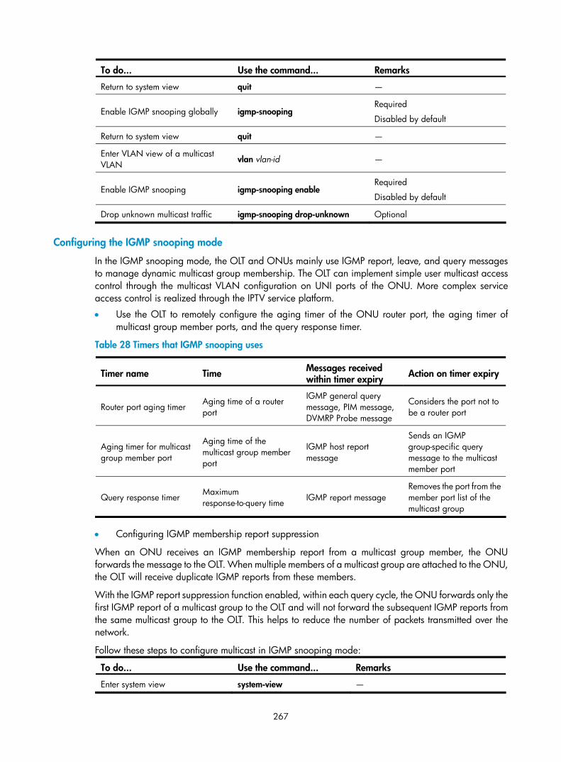
267
To do... Use the command... Remarks
Return to system view quit —
Enable IGMP snooping globally igmp-snooping Required
Disabled by default
Return to system view quit —
Enter VLAN view of a multicast VLAN vlan vlan-id —
Enable IGMP snooping igmp-snooping enable Required
Disabled by default
Drop unknown multicast traffic igmp-snooping drop-unknown Optional
Configuring the IGMP snooping mode
In the IGMP snooping mode, the OLT and ONUs mainly use IGMP report, leave, and query messages to manage dynamic multicast group membership. The OLT can implement simple user multicast access control through the multicast VLAN configuration on UNI ports of the ONU. More complex service access control is realized through the IPTV service platform.
• Use the OLT to remotely configure the aging timer of the ONU router port, the aging timer of multicast group member ports, and the query response timer.
Table 28 Timers that IGMP snooping uses
Timer name Time Messages received within timer expiry Action on timer expiry
Router port aging timer Aging time of a router port
IGMP general query message, PIM message, DVMRP Probe message
Considers the port not to be a router port
Aging timer for multicast group member port
Aging time of the multicast group member port
IGMP host report message
Sends an IGMP group-specific query message to the multicast member port
Query response timer Maximum response-to-query time IGMP report message
Removes the port from the member port list of the multicast group
• Configuring IGMP membership report suppression
When an ONU receives an IGMP membership report from a multicast group member, the ONU forwards the message to the OLT. When multiple members of a multicast group are attached to the ONU, the OLT will receive duplicate IGMP reports from these members.
With the IGMP report suppression function enabled, within each query cycle, the ONU forwards only the first IGMP report of a multicast group to the OLT and will not forward the subsequent IGMP reports from the same multicast group to the OLT. This helps to reduce the number of packets transmitted over the network.
Follow these steps to configure multicast in IGMP snooping mode:
To do... Use the command... Remarks
Enter system view system-view —

268
To do... Use the command... Remarks
Enter ONU port view interface onu interface-number —
Configure the multicast mode of the ONU as IGMP snooping
multicast-mode igmp-snooping
Optional
By default, the multicast mode of the ONU is IGMP snooping.
Add a UNI to the specified multicast VLANs
uni uni-number multicast vlan { vlan-id } & <1-50> Required
Configure the number of multicast channels on the specified UNI
uni uni-number multicast-group-number number
Optional
By default, the users connected to a UNI can access 64 multicast channels at the same time.
Remove the VLAN tag of the downlink multicast flow on the UNI port
uni uni-number multicast-strip-tag enable
Optional
By default, a UNI does not remove the VLAN tag of the downlink multicast flow.
Configure the aging timer of the router port
onu-protocol igmp-snooping router-aging-time seconds
Optional
105 seconds by default
Configure the query-response timer onu-protocol igmp-snooping max-response-time seconds
Optional
By default, the maximum response time of group-specific queries is 1 second.
Configure the aging timer of the multicast member port
onu-protocol igmp-snooping host-aging-time seconds
Optional
260 seconds by default
Enable IGMP membership report suppression
onu-protocol igmp-snooping report-aggregation enable
Optional
Disabled by default
Enable IGMP leave suppression onu-protocol igmp-snooping leave-aggregation enable
Optional
Enabled by default
NOTE:
The max-response-time keyword in the onu-protocol igmp-snooping command sets the maximum response time of the group-specific queries. If the device receives no response at the first timeout of the maximum response time, it resends group-specific queries. If the device still receives no response within the maximum response time, the multicast group on the ONU is deleted.
Multicast control mode
OLT-side functions are as follows:
• The OLT side maintains a user multicast service access control table to centrally manage user multicast service access rights.
• The OLT identifies users through user LLIDs and the VLAN tags (consistent with UNI port numbers) carried in uplink IGMP report messages. It also determines whether a user has the right to access the requested multicast service and, if yes, the related parameters.
• The OLT uses extended multicast control OAM packets to send the ONU the user's access right to the multicast channel, which allows the ONU to forward or shut off the multicast traffic for the user. The network management system at the OLT side centrally manages the multicast access control. The OLT governs, and an ONU executes, multicast right management. Meanwhile, the OLT

269
supports the cooperation between IGMP proxy and upper-layer multicast routers to dynamically request and deliver multicast traffic.
ONU-side functions are as follows:
• The ONU side maintains a table for multicast address filtering and multicast forwarding. It performs flow control only for the current multicast service on the ONU.
• The ONU adds VLAN tags to the IGMP report messages without VLAN tags to identify users, and transparently sends the messages to the OLT. (A UNI port number is used as the VLAN tag. For example, the packets received on UNI 1 are tagged with VLAN 1.) Then, the ONU adds or deletes the group address filtering and multicast forwarding entries on the ONU based on the multicast control OAM packets (which contains a series of multicast control entries) delivered by the OLT, and forwards or shuts off the multicast traffic.
Follow these steps to configure multicast in multicast control mode:
To do... Use the command... Remarks
Enter system view system-view —
Enter ONU port view interface onu interface-number —
Configure the multicast mode of the ONU as the multicast control mode
multicast-mode multicast-control Required
By default, the multicast mode of the ONU is IGMP snooping.
Configure the aging timer of the multicast group members in the multicast control mode
multicast-control host-aging-time host-aging-time
Optional
260 seconds by default
Configure the access to multicast channels on the specified UNI
uni uni-number multicast-control multicast-address { multicast-address [ to multicast-address ] } &<1-10> [ source-ip ip-address [ to ip-address ] ] rule { deny | permit [ channel-limit channel-number ] | preview time-slice preview-time [ preview-interval interval-time | preview-times preview-times [ reset-interval reset-interval-time ] ]* }
Required
Remove the VLAN tag of the downlink multicast flow on the UNI port
uni uni-number multicast-strip-tag enable
Optional
By default, a UNI does not remove the VLAN tag of the downlink multicast flow.
Configuring the link type of an ONU port Configure an ONU port as an access port or trunk port according to the following guidelines.
• When a PC is directly connected to the ONU port, configure the ONU port as an access port, which receives and transmits only untagged packets.
• When a home gateway or Layer 2 switch is connected to the ONU port, configure the ONU port as a trunk port.
Different from Ethernet ports described in the chapter “VLAN configuration”, ONU ports process uplink/downlink packets as described in Table 29.

270
Table 29 The link type of an ONU port and how it processes packets
Port type Traffic direction Processing
Uplink packets Allow only untagged packets to pass through and tag these packets with the default VLAN tag.
Access
Downlink packets Allow only packets with the default VLAN tag to pass through and remove the tag of these packets.
Uplink packets • For untagged packets, tag them with the default VLAN tag and
forward them. • For tagged packets, forward them directly without any processingTrunk
Downlink packets Allow only tagged packets to pass through.
For more information about configuring the link type of an ONU port, see “Setting the link type of an ONU port to access” and “Setting the link type of an ONU port to trunk”.
NOTE:
The access ports described in Table 29 do not include ports in the default state, the access ports in VLAN 1.
The link type of the ONU ports under the same OLT port must be the same (access or trunk). When anONU port under an OLT port is configured as an access port in a VLAN other than VLAN 1, you can only configure the other ONU ports under the same OLT port as access ports or leave them in the defaultstate (access ports in VLAN 1). When the ONU port is configured as a trunk port, you can configure theother ONU ports as trunk ports or leave them in the default state.
The ONU ports in the default state only allow untagged packets to pass through in the uplink directionand tag these packets with VLAN 1 tag. In the downlink direction, they allow only the packets with theVLAN 1 tag to pass through. Such ONU ports remove the VLAN tag of the downlink packets if the otherONU ports under the same OLT are configured as access ports, and do not remove the tag of the downlink packets if the other ONU ports under the same OLT port are configured as trunk ports.
Setting the link type of an ONU port to access
Follow these steps to set the link type of an ONU port to access:
To do… Use the command… Remarks
Enter system view system-view —
Enter ONU port view interface onu interface-number —
Set the link type of the ONU port to access
port link-type access Optional
By default, the link type of an ONU port is access.
Assign the ONU port to the specified VLAN
port access vlan vlan-id Optional
By default, all ONU ports belong to only VLAN 1.

271
CAUTION:
When you are configuring the ONU ports under the same OLT port as access ports, do not assign themto the same VLAN (except VLAN 1). For example, after you configure ONU 3/0/1:1 as an access portand assign it to VLAN 2, you cannot assign the other ONU ports under the same OLT port, ONU 3/0/1:2 for example, to VLAN 2.
When the link type of an ONU port under an OLT port is configured as access, you must configure theOLT port as a hybrid port, and assign it to the specified VLANs by using the port hybrid vlan vlan-id-listtagged command, where the VLANs specified by vlan-id-list can be only the VLANs of the ONU portsunder the OLT port.
Setting the link type of an ONU port to trunk
Follow these steps to set the link type of an ONU port to trunk:
To do… Use the command… Remarks
Enter system view system-view —
Enter ONU port view interface onu interface-number —
Set the link type of an ONU port to trunk
port link-type trunk Required
By default, the link type of an ONU port is access.
Set the default VLAN for the trunk port
port trunk pvid vlan vlan-id
Optional
By default, the default VLAN of a trunk port is VLAN 1.
NOTE:
After an ONU port is configured as a trunk port, the ONU port allows packets of all VLANs to pass through.
Enabling FEC Forward Error Correction (FEC) can implement downlink error correction on the OLT and uplink error correction on the ONU to lower the bit error rate and extend the optical transmission distance. The packets enabled with FEC carry error correction codes. The actual uplink bandwidth of the ONU will be less than that configured.
Follow these steps to enable FEC:
To do... Use the command... Remarks
Enter system view system-view —
Enter ONU port view interface onu interface-number —
Enable the FEC function forward-error-correction enable Optional
Disabled by default
Configuring an ONU to report information to the OLT When an ONU attached to an OLT encounters configuration changes or failures or is being debugged, configure the ONU to report the specified types of information to the OLT.

272
Enabling ONUs to report information to the OLT might generate a large amount of traffic and cause congestion, because a large number of ONUs are attached to an OLT. H3C recommends that you select the reported information type as required.
Follow these steps to configure an ONU to report information to the OLT:
To do… Use the command… Remarks
Enter system view system-view —
Enter ONU port view interface onu interface-number —
Configure the ONU to report the specified types of information to the OLT
onu-event { debug | log | trap } enable level severity
Optional
By default, an ONU reports no information to its OLT.
Configuring traffic encryption Complete this task to configure the encryption of the downlink traffic transmitted from the OLT to ONUs, protecting user information against illegal access.
Follow these steps to configure traffic encryption:
To do... Use the command... Remarks
Enter system view system-view —
Enter ONU port view interface onu interface-number —
Enable traffic encryption encrypt enable Optional
By default, data encryption is enabled for downlink data.
Configure an encryption key encrypt key key-value
Optional
If no encryption key is configured, the system uses the default encryption key.
The encrypt key command is not supported.
Testing the link between an ONU and the OLT Follow these steps to test the optical link between an ONU and the OLT:
To do... Use the command... Remarks
Enter system view system-view —
Enter ONU port view interface onu interface-number —
Test the optical link between the ONU and the OLT
linktest [ frame-number value | frame-size value | delay { on | off } | vlan-tag { on [ vlan-priority value | vlan-id value ] | off } ] *
Required
The default values of the link test parameters are as follows: • Number of test frames: 20 • Frame size: 1000 bytes • VLAN tag: not carried in testing frames • Delay testing state: Off

273
CAUTION:
The link connectivity between an ONU and the OLT can be tested only when the ONU is online.
Testing the cable connected to a UNI port Perform this operation to test the cable connected to the specified UNI port of the ONU once and to display the testing result.
Follow these steps to test the cable connected to a UNI port:
To do… Use the command… Remarks
Enter system view system-view —
Enter ONU port view interface onu interface-number —
Test the cable connected to a UNI port uni uni-number virtual-cable-test Required
Deregistering an ONU After being deregistered, an ONU will try to register again.
Follow these steps to deregister an ONU:
To do... Use the command... Remarks
Enter system view system-view —
Enter ONU port view interface onu interface-number —
Deregister the ONU deregister onu Required
Updating ONUs Introduction to ONU update
Updating ONUs means updating ONU software versions remotely through OLTs.
Updating ONU devices requires a large amount of work because an EPON system has different types of ONU devices, which use different update files. To improve the ONU update efficiency and reduce resources consumed by issuing commands to each ONU, the S7500E switches support batch updating of ONUs by type and OLT port, besides updating of a single ONU. H3C recommends updating ONUs by type because it is efficient and easy-to-use.

274
Table 30 ONU update methods
To do… Use the method… Remarks
Update multiple ONUs by type
In FTTH view, update all the ONUs of the specified type attached to the switch. (You can update different types of ONUs by specifying multiple update files.)
Update one ONU In ONU port view, use the ONU update command for an ONU port
Update multiple ONUs by OLT port
In OLT port view, use the ONU update command for the created ONU ports under the specified OLT port.
• If an ONU is online and matches the specified update file, the ONU is updated directly.
• If the ONU is online but does not match the update file, the update will fail.
• If the ONU is not online (because the ONU port is not bound with any ONU or the extended OAM connection fails on the bound ONU), the OLT waits and automatically starts to update the ONU when the ONU goes online and matches the specified update file. If the update file is wrong, the update will fail.
NOTE:
Before the update, be sure that you upload the ONU update files to the S7500E master SRPU. You cannot use the update files on the subordinate SRPU to complete the software loading.
If the ONU that must go online can be updated automatically, you must upload the update files to the master SRPU and subordinate SRPU. Update files will then be available on the original subordinate SRPU after the switchover. Otherwise, the update will fail.
Update files used vary with ONUs. If ONUs and update files do not match, the update will fail. For example, if you specify to update ET704-A ONUs in OLT port view, updating other types of ONUs attached to the OLT port will fail.
After the update command is issued, the OLT will wait 15 to 20 seconds before it executes the command.This allows for batch updating and saves system resources.
Any power failure during the ONU software upgrade might cause update failure.
After the update file is transferred to the ONU, the ONU restarts automatically to complete the update.
The ONU update commands mentioned in this document are all configuration commands, or in otherwords, after such a command is executed, it will be saved in the configuration file of the device. If the ONU port connecting to an ONU that goes online is created before the update command is used, theONU will be updated directly (if it matches the update files). Otherwise, the ONU will not be updated.To update the current ONUs online but not the offline ONUs or subsequently registered ONUs, executethe update command, and then use the undo form of the command after you make sure that all onlineONUs have been updated.
If an ONU is registered successfully and its port is UP, it can execute the update operation as soon as you configure ONU update.
If an ONU is offline or its port is DOWN, it executes the update operation that you configured after theONU is registered successfully and its port is brought up.
ONU update configuration
Follow these steps to update all the ONUs of the specified type:

275
To do… Use the command… Remarks
Enter system view system-view —
Enter FTTH view ftth —
Update all the ONUs of the specified type under the switch
update onu onu-type onu-type filename file-url Required
NOTE:
After you configure the updating of all the ONUs of the specified type under the switch, if the ONU connected to a newly created ONU port is of the specified type and goes online, the switch will updateit automatically.
The update configuration performed in port view takes precedence over that in FTTH view. For example,assume the ONU connected to ONU port ONU 3/0/1:1 is of type A. If you configure the update file fortype-A ONUs as 1.app in FTTH view and configure the update file as 2.app in ONU 3/0/1:1 port view,2.app will update the ONU. If you cancel the port-level configuration, the update-by-type configurationis not executed until the ONU is registered successfully next time and the port is brought up.
An OLT can update up to 64 types of ONUs at the same time, or in other words, you can specify updatefiles for up to 64 types of ONUs by using the update onu onu-type onu-type filename file-url commandmultiple times.
Follow these steps to update one ONU:
To do… Use the command… Remarks
Enter system view system-view —
Enter ONU port view interface onu interface-number —
Use the update command on the ONU port update onu filename file-url Required
Follow these steps to update all the ONUs under the specified OLT port:
To do… Use the command… Remarks
Enter system view system-view —
Enter OLT port view interface olt interface-number —
Use the update command on all the created ONU ports under the OLT port update onu filename file-url Required
NOTE:
After you configure the updating of the ONUs connected to all the created ONU ports under an OLT port,if the ONU port connecting to an ONU that goes online is created before the update command is used, theONU will be updated directly (if it matches the update files). Otherwise, the ONU will not be updated.
Restarting an ONU Follow these steps to restart an ONU:
To do... Use the command... Remarks
Enter system view system-view —

276
To do... Use the command... Remarks
Enter ONU port view interface onu interface-number —
Restart the ONU reboot onu Required
Displaying and maintaining ONU port configuration
To do... Use the command... Remarks
Display the global information about the ONU
display vendor-specific information
Display the IP address allocation information when the ONU serves as a DHCP client display dhcp-client
Display the information about the protocols supported by the ONU
display onu-protocol [ stp | igmp-snooping | dhcp-snooping information ]
Display multicast control information display epon-multicast information
Available in ONU port view
To display the information of an ONU, be sure that the ONU is online.
Clear the statistics information about the packets on an ONU port
reset counters interface interface-type interface-number Available in user view
Configuration examples for ONU remote management
Configuration example for binding an ONU port to an ONU Network requirements
As shown in Figure 86, bind ONU 3/0/1:1 to ONU 1, whose MAC address is 000f-e200-0031, and ONU 3/0/1:2 to ONU 2, whose MAC address is 000f-e200-3749. ONU 1 and ONU 2 have the same extended OAM version of 2.
Figure 86 Network diagram for ONU port-to-ONU binding configuration

277
Configuration procedure
# Configure the OUI and extended OAM version number list. <Sysname> system-view
System View: return to User View with Ctrl+Z.
[Sysname] ftth
[Sysname-ftth] epon-parameter ouilist oui 000fe2 oam-version 2 slot 3
[Sysname-ftth] quit
# Create ONU ports ONU 3/0/1:1 and ONU 3/0/1:2. Bind ONU 3/0/1:1 to ONU 1 and ONU 3/0/1:2 to ONU 2. [Sysname] interface olt 3/0/1
[Sysname-Olt3/0/1] using onu 1 to 2
[Sysname-Olt3/0/1] quit
[Sysname] interface onu 3/0/1:1
[Sysname-Onu3/0/1:1] bind onuid 000f-e200-0031
[Sysname-Onu3/0/1:1] quit
[Sysname] interface onu 3/0/1:2
[Sysname-Onu3/0/1:2] bind onuid 000f-e200-3749
# When the two ONUs are up, display the binding information of the ONUs. <Sysname> display onuinfo interface Olt 3/0/1
ONU Mac Address LLID Dist(M) Port Board/Ver Sft/Epm State Aging
000f-e200-0031 1 2 Onu3/0/1:1 ET704-A-L/B 110/100 Up N/A
000f-e200-3749 2 20073 Onu3/0/1:2 ET704-A-L/B 110/100 Up N/A
--- 2 entries found ---
ONU RSTP configuration example Network requirements
As shown in Figure 87,
• A user PC is attached to UNI 1. If UNI 2 and UNI 3 are interconnected by mistake when RSTP is disabled on the ONU, a broadcast storm will occur between UNI 2 and UNI 3 when the user pings an IP address for which no ARP entry exists on the PC.
• Enabling RSTP on the ONU can suppress such a problem.
Figure 87 Network diagram for ONU RSTP configuration
Configuration procedure
# Enable RSTP on the ONU to suppress the broadcast storm between UNI 2 and UNI 3. <Sysname> system-view
[Sysname] interface onu 3/0/1:1
[Sysname-Onu3/0/1:1] onu-protocol stp enable
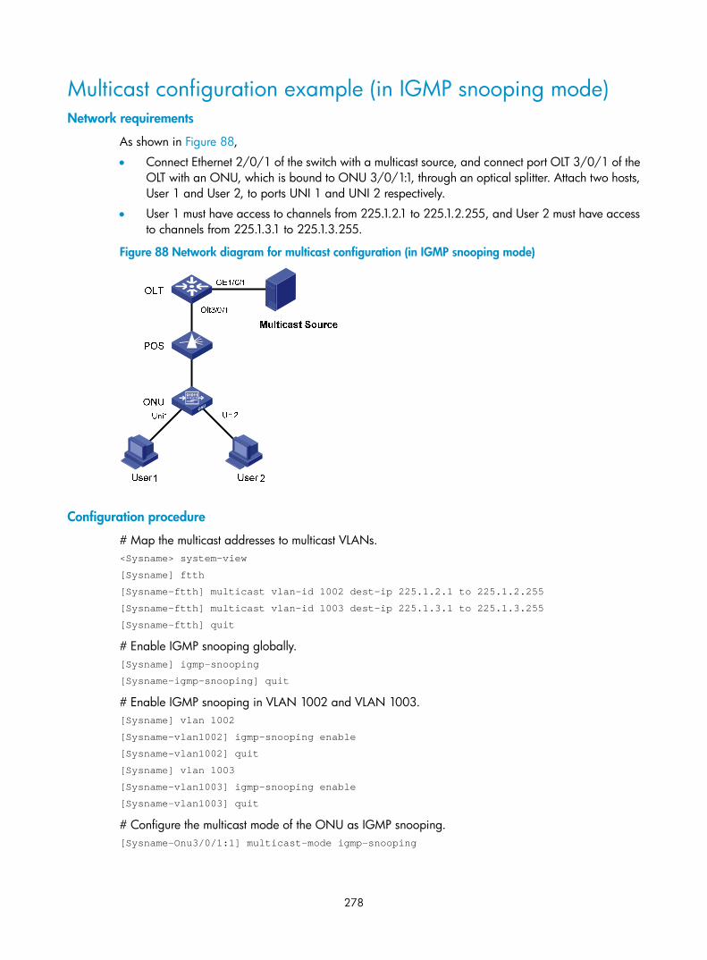
278
Multicast configuration example (in IGMP snooping mode) Network requirements
As shown in Figure 88,
• Connect Ethernet 2/0/1 of the switch with a multicast source, and connect port OLT 3/0/1 of the OLT with an ONU, which is bound to ONU 3/0/1:1, through an optical splitter. Attach two hosts, User 1 and User 2, to ports UNI 1 and UNI 2 respectively.
• User 1 must have access to channels from 225.1.2.1 to 225.1.2.255, and User 2 must have access to channels from 225.1.3.1 to 225.1.3.255.
Figure 88 Network diagram for multicast configuration (in IGMP snooping mode)
Configuration procedure
# Map the multicast addresses to multicast VLANs. <Sysname> system-view
[Sysname] ftth
[Sysname-ftth] multicast vlan-id 1002 dest-ip 225.1.2.1 to 225.1.2.255
[Sysname-ftth] multicast vlan-id 1003 dest-ip 225.1.3.1 to 225.1.3.255
[Sysname-ftth] quit
# Enable IGMP snooping globally. [Sysname] igmp-snooping
[Sysname-igmp-snooping] quit
# Enable IGMP snooping in VLAN 1002 and VLAN 1003. [Sysname] vlan 1002
[Sysname-vlan1002] igmp-snooping enable
[Sysname-vlan1002] quit
[Sysname] vlan 1003
[Sysname-vlan1003] igmp-snooping enable
[Sysname-vlan1003] quit
# Configure the multicast mode of the ONU as IGMP snooping. [Sysname-Onu3/0/1:1] multicast-mode igmp-snooping

279
# Assign UNI 1 to multicast VLAN 1002 and UNI 2 to multicast VLAN 1003, and configure the ONU as a Trunk port (to allow the packets of all the VLANs to pass through the port). [Sysname-Onu3/0/1:1] uni 1 multicast vlan 1002
[Sysname-Onu3/0/1:1] uni 2 multicast vlan 1003
[Sysname-Onu3/0/1:1] port link-type trunk
# Configure UNI 1 and UNI 2 to remove the multicast VLAN tags from downlink multicast packets. [Sysname-Onu3/0/1:1] uni 1 multicast-strip-tag enable
[Sysname-Onu3/0/1:1] uni 2 multicast-strip-tag enable
[Sysname-Onu3/0/1:1] quit
# Configure the link type of OLT 3/0/1 as hybrid, allow the packets of VLAN 1002 and VLAN 1003 to pass through OLT 3/0/1, and add tags to the VLAN 1002 and VLAN 1003 packets sent by OLT 3/0/1. [Sysname] interface olt 3/0/1
[Sysname-Olt3/0/1] port link-type hybrid
[Sysname-Olt3/0/1] port hybrid vlan 1002 1003 tagged
# Configure Ethernet 2/0/1 as a Trunk port, and permit the packets of VLAN 1002 and VLAN 1003 to pass. [Sysname] interface Ethernet2/0/1
[Sysname-Ethernet2/0/1] port link-type trunk
[Sysname-Ethernet2/0/1] port trunk permit vlan 1002 1003
Multicast configuration example (in multicast control mode) Network requirements
As shown in Figure 89, connect Ethernet 2/0/1 of the switch with a multicast source, and connect port OLT 3/0/1 of the OLT with an ONU, which is bound to ONU 3/0/1:1, through an optical splitter. Attach two hosts, User 1 and User 2, to ports UNI 1 and UNI 2 respectively.
User 1 and User 2 must have different access rights to Channel 1 (225.1.1.1) and Channel 1 (225.1.2.1):
• User 1 has full access to Channel 1 and 60-second preview access to Channel 2.
• User 2 has access to Channel 2 only.
Figure 89 Network diagram for multicast configuration (in multicast control mode)
ONU
OLT
OLT3/0/1
POS
User1
UNI1 UNI2
User2
Eth2/0/1
Multicast Source

280
Configuration procedure
# Map the multicast addresses to multicast VLANs. <Sysname> system-view
[Sysname] ftth
[Sysname-ftth] multicast vlan-id 1002 dest-ip 225.1.1.1
[Sysname-ftth] multicast vlan-id 1003 dest-ip 225.1.2.1
[Sysname-ftth] quit
# Enable IGMP snooping globally. [Sysname] igmp-snooping
[Sysname-igmp-snooping] quit
# Enable IGMP snooping in VLAN 1002 and VLAN 1003. [Sysname] vlan 1002
[Sysname-vlan1002] igmp-snooping enable
[Sysname-vlan1002] vlan 1003
[Sysname-vlan1003] igmp-snooping enable
[Sysname-vlan1003] quit
# Configure the multicast mode of the ONU as the multicast control mode. [Sysname-Onu3/0/1:1] multicast-mode multicast-control
# Configure UNI 1 to allow the user attached to it to access Channel 1 and to preview Channel 2 for only 60 seconds, and configure the port to remove the multicast VLAN tags from downlink multicast packets. [Sysname-Onu3/0/1:1] uni 1 multicast-control multicast-address 225.1.1.1 rule permit
[Sysname-Onu3/0/1:1] uni 1 multicast-control multicast-address 225.1.2.1 rule preview time-slice 1
[Sysname-Onu3/0/1:1] uni 1 multicast-strip-tag enable
# Configure UNI 2 to allow the user attached to it to access Channel 2 only, and configure the port to remove the multicast VLAN tags from downlink multicast packets. [Sysname-Onu3/0/1:1] uni 2 multicast-control multicast-address 225.1.1.1 rule deny
[Sysname-Onu3/0/1:1] uni 2 multicast-control multicast-address 225.1.2.1 rule permit
[Sysname-Onu3/0/1:1] uni 2 multicast-strip-tag enable
# Configure the ONU port as a Trunk port (to allow the packets of all the VLANs to pass through the port). [Sysname-Onu3/0/1:1] port link-type trunk
# Configure the link type of OLT 3/0/1 as hybrid, allow the packets of VLAN 1002 and VLAN 1003 to pass through OLT 3/0/1, and add tags to the VLAN 1002 and VLAN 1003 packets sent by OLT 3/0/1. [Sysname] interface olt 3/0/1
[Sysname-Olt3/0/1] port link-type hybrid
[Sysname-Olt3/0/1] port hybrid vlan 1002 1003 tagged
# Configure Ethernet 2/0/1 as a Trunk port, and permit the packets of VLAN 1002 and VLAN 1003 to pass through the port. [Sysname] interface Ethernet2/0/1
[Sysname-Ethernet2/0/1] port link-type trunk
[Sysname-Ethernet2/0/1] port trunk permit vlan 1002 1003

281
ONU update configuration example Network requirements
As shown in Figure 90,
• An S7500E switch at the city TV and broadcasting central office has 12 OLT ports connected to 150 type-A ONUs. All type-A ONUs are of version 108. To satisfy the customer requirements, these ONUs must be upgraded.
• The type-A ONU has two new versions now: version 109 can satisfy most customer requirements, and version 110 provides enhanced software features on the basis of version 109.
• 20 type-A ONUs are attached to OLT 3/0/1, and only these 20 ONUs must be upgraded to version 110. The other type-A ONUs must be upgraded to version 109 only.
Figure 90 Network diagram for ONU update
onu
onu
onu
onu
onu
onu
onu
onuonu
POS
POS
POS
OLT switch in the central office
OLT3/0
/1
OLT3/0/2
OLT3/0/3
NOTE:
For a simplified network diagram, Figure 90 shows only three of the OLT ports.
Configuration procedure
# Upload update files a110.app and a109.app to the master SRPU and subordinate SRPU of the switch.
# Update the type-A ONUs attached to ONU 3/0/1:1 to version 110. [Sysname] interface onu 3/0/1:1
[Sysname-Onu3/0/1:1] update onu filename a110.app
Update flash:/ a110.app?[Y/N]:y
Info: Download file to onu might take a long time, please wait...
Please wait while the firmware is being burnt, and check the software version after re-registration!

282
[Sysname-Onu3/0/1:1] quit
# Update all the type-A ONUs attached to the S7500E switch to version 109. <Sysname> system-view
[Sysname] ftth
[Sysname-ftth] update onu onu-type a filename a109.app
Update flash:/ a109.app?[Y/N]:Y
Info: Download file to onu might take a long time, please wait...
NOTE:
The update command configured in port view takes priority over the update command configured in FTTHview. In other words, if you have configured the update command in the view of ONU3/0/1:1, the update command that you configure in FTTH view does not upgrade the ONUs attached to ONU3/0/1:1.

283
UNI port configuration
UNI port configuration task list
NOTE:
If an H3C EC1001 inserted with a subcard serves as an ONU, a UNI port here refers to the internal portthat connects the subcard to the EC1001, but not the Ethernet port of the EC1001.
Complete these tasks to configure a UNI port:
Task Remarks
Basic UNI port configurations Optional
Configuring the VLAN operation mode for a UNI Optional
Configuring fast-leave processing for a UNI Optional
Configuring port isolation for a UNI Optional
For H3C ONUs only
Displaying and maintaining UNI port configuration Optional
Basic UNI port configurations You can perform the following basic configurations for a UNI port:
• Duplex mode of a UNI: When a UNI works in full duplex mode, it can send and receive packets simultaneously. When a UNI works in half duplex mode, it can either send or receive packets at one time. When a UNI works in auto-negotiation mode, both ends determine the duplex mode of the UNI through negotiation.
• Flow control for UNIs: If the flow control function is enabled for both the UNIs and the remote device, the ONU will send messages to notify the remote device to stop sending packets temporarily when congestion occurs on the ONU, avoiding packet loss.
• MDI mode for UNIs: The MDI mode for UNIs can be crossover or straight-through.
• UNI port rate: Set the UNI port rate. When you set the rate of a UNI to the auto-negotiation mode, the local port and the remote port negotiate the operating rate of the UNI.
• Auto-negotiation on a UNI: Configure auto-negotiation on a UNI to enable both ends to auto-negotiate the duplex mode, cable type, and port rate. After you enable forced auto-negotiation, the UNI port will restart the auto-negotiation.

284
Follow these steps to perform basic configurations for a UNI port:
To do... Use the command... Remarks
Enter system view system-view —
Enter ONU port view interface onu interface-number —
Configure a description for a UNI
uni uni-number description text
Optional
By default, no description is configured for a UNI.
Shut down a UNI uni uni-number shutdown Optional
By default, a UNI port is enabled.
Configure the duplex mode for a UNI
uni uni-number duplex { full | half | auto }
Optional
By default, a UNI port is in the full duplex mode.
Enable flow control for a UNI uni uni-number flow-control
Required
By default, flow control is disabled for a UNI port.
Configure the MDI mode for a UNI port
uni uni-number mdi { across | auto | normal }
Optional
Be default, the MDI mode for a UNI port is auto.
Configure the port rate for a UNI port
uni uni-number speed { 10 | 100 | auto }
Optional
By default, the UNI port rate is 100Mbps.
Enable auto-negotiation for a UNI port
uni uni-number auto-negotiation
Optional
By default, auto-negotiation is enabled on a UNI port.
Force a UNI port to restart auto-negotiation
uni uni-number restart auto-negotiation
Optional
This command takes effect only when auto-negotiation is enabled on the UNI port.
CAUTION:
When auto-negotiation is enabled on a UNI port, do not configure the duplex mode, MDI mode, or rateof the UNI port.
Configuring the VLAN operation mode for a UNI The VLAN operation modes for the Ethernet packets on a UNI include transparent, tag, and translation.
Transparent mode
The transparent mode is suitable for situations where the operator provides and manages the user-end family gateway or switch and the VLAN tags generated by the family gateway or switch are trusted. In transparent mode, an ONU transparently forwards the received uplink Ethernet packets (regardless of whether the Ethernet packets contain VLAN tags or not) to the OLT without changing them. Downlink Ethernet packets are also forwarded transparently.
Tag mode
Tag mode is suitable for situations where the VLAN tags generated by the user-end family gateway or switch are not trusted. To enable the operator to centrally manage and control the VLANs of the service packets that enter the network, network-layer VLAN tags must be added to the packets.

285
Translation mode
In translation mode, an ONU translates the user-added VLAN tag into a unique network-side VLAN tag. (The user's VID might not be for the user only, because some other users in the same EPON system might also use the same VID).
Table 31 Packet processing in the VLAN operation modes
VLAN operation mode Direction With or without
VLAN tag Packet processing
Tagged Uplink
Untagged
Tagged
Transparent mode
Downlink Untagged
The UNI port forwards the frame without changing it.
Tagged The UNI port drops the frame.
Uplink Untagged
The UNI port tags the frame with the PVID tag and then forwards it.
Tagged The ONU forwards the frame to the UNI port according to the VLAN ID in the frame’s VLAN tag and then removes the VLAN tag.
Tag mode
Downlink
Untagged The UNI port drops the frame.
Tagged
• If the VLAN ID in the frame’s VLAN tag matches a VLAN translation entry configured on the UNI port, the UNI port replaces this VLAN ID with the VLAN ID in the matched VLAN translation entry and then forwards the frame.
• If the VLAN ID in the frame’s VLAN tag does not match any VLAN translation entry, the UNI port drops the frame.
Uplink
Untagged The UNI port tags the frame with its PVID tag and then forwards it.
Tagged
• If the VLAN ID in the frame’s VLAN tag matches a VLAN translation entry configured on the UNI port, the UNI port replaces this VLAN ID with the VLAN ID in the matched VLAN translation entry and then forwards the frame.
• If the VLAN ID in the frame’s VLAN tag is the UNI port’s PVID, the UNI port removes the frame’s VLAN tag and then forwards the frame.
• If the VLAN ID in the frame’s VLAN tag does not match any VLAN translation entry, the UNI port drops the frame.
Translation mode
Downlink
Untagged The UNI port drops the frame.
Follow these steps to configure the VLAN operation mode for a UNI:
To do... Use the command... Remarks
Enter system view system-view —
Enter ONU port view interface onu interface-number —
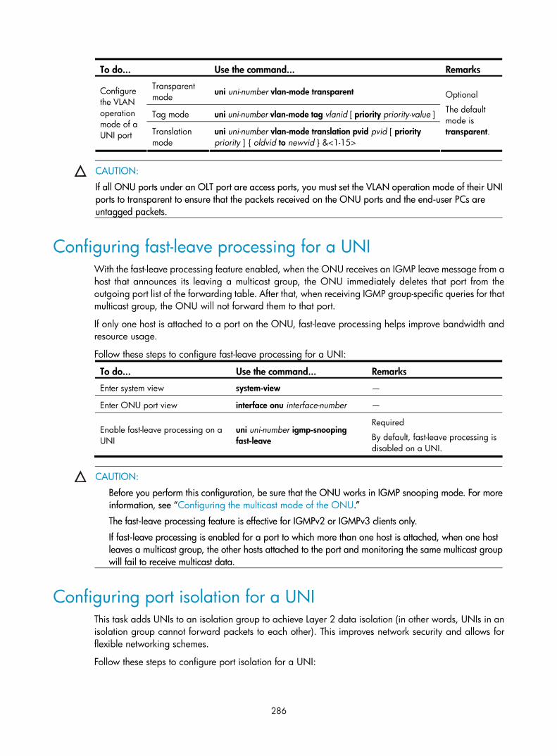
286
To do... Use the command... Remarks
Transparent mode uni uni-number vlan-mode transparent
Tag mode uni uni-number vlan-mode tag vlanid [ priority priority-value ]
Configure the VLAN operation mode of a UNI port Translation
mode uni uni-number vlan-mode translation pvid pvid [ priority priority ] { oldvid to newvid } &<1-15>
Optional
The default mode is transparent.
CAUTION:
If all ONU ports under an OLT port are access ports, you must set the VLAN operation mode of their UNIports to transparent to ensure that the packets received on the ONU ports and the end-user PCs are untagged packets.
Configuring fast-leave processing for a UNI With the fast-leave processing feature enabled, when the ONU receives an IGMP leave message from a host that announces its leaving a multicast group, the ONU immediately deletes that port from the outgoing port list of the forwarding table. After that, when receiving IGMP group-specific queries for that multicast group, the ONU will not forward them to that port.
If only one host is attached to a port on the ONU, fast-leave processing helps improve bandwidth and resource usage.
Follow these steps to configure fast-leave processing for a UNI:
To do... Use the command... Remarks
Enter system view system-view —
Enter ONU port view interface onu interface-number —
Enable fast-leave processing on a UNI
uni uni-number igmp-snooping fast-leave
Required
By default, fast-leave processing is disabled on a UNI.
CAUTION:
Before you perform this configuration, be sure that the ONU works in IGMP snooping mode. For moreinformation, see “Configuring the multicast mode of the ONU.”
The fast-leave processing feature is effective for IGMPv2 or IGMPv3 clients only.
If fast-leave processing is enabled for a port to which more than one host is attached, when one host leaves a multicast group, the other hosts attached to the port and monitoring the same multicast groupwill fail to receive multicast data.
Configuring port isolation for a UNI This task adds UNIs to an isolation group to achieve Layer 2 data isolation (in other words, UNIs in an isolation group cannot forward packets to each other). This improves network security and allows for flexible networking schemes.
Follow these steps to configure port isolation for a UNI:

287
To do... Use the command... Remarks
Enter system view system-view —
Enter ONU port view interface onu interface-number —
Configure port isolation for all UNIs onu port-isolate enable Configure
UNI port isolation Configure port isolation
for the specified UNI uni uni-number port-isolate
Required
Use either command
By default, a UNI port is not in any isolation group.
NOTE:
You can create only one isolation group on an ONU device, but the number of ports in an isolation groupis not limited.
Displaying and maintaining UNI port configuration To do... Use the command... Remarks
Display the information about the current status of a UNI
display uni-information uni-number Available in ONU port view
Clear the packet statistics information for a UNI reset counters uni [ uni-number ] Available in ONU port view
CAUTION:
The preceding commands take effect on H3C ONUs only.
The preceding commands work only when the ONU is online.
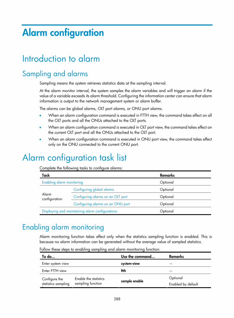
288
Alarm configuration
Introduction to alarm
Sampling and alarms Sampling means the system retrieves statistics data at the sampling interval.
At the alarm monitor interval, the system samples the alarm variables and will trigger an alarm if the value of a variable exceeds its alarm threshold. Configuring the information center can ensure that alarm information is output to the network management system or alarm buffer.
The alarms can be global alarms, OLT port alarms, or ONU port alarms.
• When an alarm configuration command is executed in FTTH view, the command takes effect on all the OLT ports and all the ONUs attached to the OLT ports.
• When an alarm configuration command is executed in OLT port view, the command takes effect on the current OLT port and all the ONUs attached to the OLT port.
• When an alarm configuration command is executed in ONU port view, the command takes effect only on the ONU connected to the current ONU port.
Alarm configuration task list Complete the following tasks to configure alarms:
Task Remarks
Enabling alarm monitoring Optional
Configuring global alarms Optional
Configuring alarms on an OLT port Optional Alarm configuration
Configuring alarms on an ONU port Optional
Displaying and maintaining alarm configurations Optional
Enabling alarm monitoring Alarm monitoring function takes effect only when the statistics sampling function is enabled. This is because no alarm information can be generated without the average value of sampled statistics.
Follow these steps to enabling sampling and alarm monitoring function:
To do... Use the command... Remarks
Enter system view system-view —
Enter FTTH view ftth —
Configure the statistics sampling function
Enable the statistics sampling function sample enable
Optional
Enabled by default

289
To do... Use the command... Remarks
Configure the statistics sampling interval timer sample seconds
Optional
4 seconds by default
Enable alarm monitoring function for the system monitor enable
Optional
Enabled by default Configure the alarm monitoring function Configure the alarm
monitor period timer monitor seconds Optional
80 seconds by default
Configuring global alarms Follow these steps to configure global alarms:
To do... Use the command... Remarks
Enter system view system-view —
Enter FTTH view ftth —
Enable the software error alarm function alarm software-error enable
Optional
The system generates a software error alarm when a signal error, Data Access (DA) error, or memory allocation failure occurs.
By default, this function is enabled.
Enable the bit error rate alarm function alarm bit-error-rate enable
Optional
When the total number of error bits or bit error rate of the data transferred between the OLT and ONUs exceeds the alarm threshold, a bit error rate alarm occurs.
By default, this function is enabled.
Configure the monitor direction and threshold for bit error rate alarms
alarm bit-error-rate { direction { uplink | downlink | up-down-link} | threshold threshold }*
Optional
By default, the monitor direction is up-down-link, and the alarm threshold of bit error rate is 10 (the unit is 10-9).
Enable the port bit error rate alarm function
alarm port bit-error-rate enable
Optional
When both the total number of error bits and bit error rate of the data transferred between the OLT and ONUs exceed the alarm thresholds, a port bit error rate alarm occurs.
By default, this function is enabled.
Enable the device fatal error alarm function alarm device-fatal-error enable
Optional
By default, this function is enabled.
Enable the frame error rate alarm function alarm frame-error-rate enable
Optional
When the total number of error frames or the error frame rate of the data transferred between the OLT and ONUs exceeds the alarm threshold, a frame error rate alarm occurs.
By default, this function is enabled.

290
To do... Use the command... Remarks
Configure the monitor direction and threshold for frame error rate alarms
alarm frame-error-rate { direction { uplink | downlink | up-down-link} | threshold threshold } *
Optional
By default, the monitor direction is up-down-link, and the threshold of frame error rate alarms is 1 (the unit is 10-9).
Enable the LLID mismatch frame alarm function
alarm llid-mismatch enable
Optional
The system generates an LLID mismatch frame alarm when the time slots are used in disorder, or in other words, when an ONU uses the time slot of another ONU to forward data.
By default, this function is disabled.
Configure the threshold for LLID mismatch frame alarms
alarm llid-mismatch threshold threshold
Optional
By default, the threshold of LLID mismatch alarms is 5000 frames.
Enable the local stable alarm function alarm local-stable enable
Optional
The system generates a local stable alarm when an ONU misuse occurs in the system, for example, when an OAM 2.0 ONU and an OAM 3.3 ONU are mixed in the same system. (All ONUs in the same system must adopt the same OAM version.) This alarm is generated at the OLT side.
By default, this function is enabled.
Enable the critical event alarm function alarm oam critical-event enable
Optional
The system generates a critical event alarm when one of the following critical events occurs: local link fault and dying gasp.
Enable the dying gasp alarm function alarm oam dying-gasp enable
Optional
The system generates a dying gasp alarm when a system error, a data loading error, or any other nonreversible error occurs.
Enable the error frame period alarm function
alarm oam error-frame-period enable
Optional
The system generates an error frame period alarm when the number of error frames in a specific period (the window size) exceeds the predefined threshold.
By default, this function is enabled.
Configure the window size and threshold for error frame period alarms
alarm oam error-frame-period { window window | threshold threshold } *
Optional
When the alarm threshold is set to 0, many alarms are generated immediately. Because the OAM packets carry alarm events, many OAM packets are generated. OAM packets might be lost.
By default, the window size is 1 second, and the alarm threshold is 20 frames.

291
To do... Use the command... Remarks
Enable the error frame alarm function alarm oam error-frame enable
Optional
The system generates an error frame alarm when the number of error frames in a specific time period (the window size) exceeds the predefined threshold.
By default, this function is enabled.
Configure the window size and threshold for error frame alarms
alarm oam error-frame { window window | threshold threshold } *
Optional
When the alarm threshold is set to 0, many alarms are generated immediately. Because the OAM packets carry alarm events, many OAM packets are generated. OAM packets might be lost.
By default, the window size is 10 seconds, and the alarm threshold is 20 frames.
Enable the error frame seconds summary alarm function
alarm oam error-frame-seconds-summary enable
Optional
The system generates an error frame seconds summary alarm when the number of error frame seconds (in an error frame second, at least one error frame occurs) in a specific time period (for example, 1 minute) exceeds the predefined threshold.
By default, this function is enabled.
Configure the window size and threshold for error frame seconds summary alarms
alarm oam error-frame-seconds-summary { window window | threshold threshold } *
Optional
By default, the window size is 600 (in units of 100 ms), and the alarm threshold is 1 second.
Enable the error symbol period alarm function
alarm oam error-symbol-period enable
Optional
The system generates an error symbol period alarm when the number of error frames in a specific period (the window size) exceeds the predefined threshold.
By default, this function is enabled.
Configure the window size and thresholds for error symbol period alarms
alarm oam error-symbol-period { window-high windowhigh | window-low windowlow | threshold-high thresholdhigh | threshold-low thresholdlow } *
Optional
When the both the upper limit and lower limit of the alarm threshold are set to 0, many alarms are generated immediately. Because the OAM packets carry alarm events, many OAM packets are generated. OAM packets might be lost.
The window size and threshold values specified in this command comprise two parts, the significant part and the insignificant part, both of which are 16 bits in length.
By default, the window size is 1 second, and the alarm threshold is 20 bytes.
Enable the local link fault alarm function alarm oam local-link-fault enable
Optional
The system generates a local link fault alarm when the inbound direction of the local data terminal becomes faulty.

292
To do... Use the command... Remarks
Enable the registration error alarm function alarm registration-error enable
Optional
The system generates a registration error alarm when an error occurs during the registration of an ONU.
By default, this function is enabled.
Enable the remote stable alarm function alarm remote-stable enable
Optional
The system generates a remote stable alarm when an ONU misuse occurs in the system, for example, when an OAM 2.0 ONU and an OAM 3.3 ONU are mixed in the same system. (All ONUs in the same system must adopt the same OAM version.) This alarm is generated at the ONU side and will be reported to the OLT.
By default, this function is enabled.
Enable the OAM vendor-specific alarm function
alarm oam-vendor-specific enable
Optional
This alarm is customized by vendors.
By default, this function is enabled.
Enable the ONU over limitation alarm function
alarm onu-over-limitation enable
Optional
The system generates an ONU over limitation alarm when the total number of ONUs connected with the OLT exceeds the limit.
By default, this function is enabled.
Configuring alarms on an OLT port Follow these steps to configure alarms on an OLT port:
To do... Use the command... Remarks
Enter system view system-view —
Enter OLT port view interface olt interface-number —
Enable the bit error rate alarm function alarm bit-error-rate enable
Optional
The system generates a bit error rate alarm when the total number of error bits or bit error rate of the data transferred between the OLT and ONUs exceeds the alarm threshold.
By default, this function is enabled.
Configure the monitor direction and threshold for bit error rate alarms
alarm bit-error-rate { direction { uplink | downlink | up-down-link} | threshold threshold }*
Optional
By default, the monitor direction is up-down-link, and the threshold of bit error rate alarms is 10 (the unit is 10-9).

293
To do... Use the command... Remarks
Enable the port bit error rate alarm function
alarm port bit-error-rate enable
Optional
When both the total number of error bits and bit error rate of the data transferred between the OLT and ONUs exceed the alarm thresholds, a port bit error rate alarm occurs.
By default, this function is enabled.
Enable the device fatal error alarm function
alarm device-fatal-error enable
Optional
By default, this function is enabled.
Enable the frame error rate alarm function alarm frame-error-rate enable
Optional
When the total number of error frames or the error frame rate of the data transferred between the OLT and ONUs exceeds the alarm threshold, a frame error rate alarm occurs.
By default, this function is enabled.
Configure the monitor direction and threshold for frame error rate alarms
alarm frame-error-rate { direction { uplink | downlink | up-down-link } | threshold threshold } *
Optional
By default, the monitor direction is up-down-link, and the threshold of frame error rate alarms is 1 (the unit is 10-9).
Enable the LLID mismatch frame alarm function alarm llid-mismatch enable
Optional
The system generates an LLID mismatch frame alarm when the time slots are used in disorder, or in other words, when an ONU uses the time slot of another ONU to forward data.
By default, this function is disabled.
Configure the threshold of LLID mismatch frame alarms
alarm llid-mismatch threshold threshold
Optional
5000 frames by default
Enable the local stable alarm function alarm local-stable enable
Optional
The system generates a local stable alarm when an ONU misuse occurs in the system, for example, when an OAM 2.0 ONU and an OAM 3.3 ONU are mixed in the same system. (All ONUs in the same system must adopt the same OAM version.) The OLT side generates a local stable alarm.
By default, this function is enabled.
Enable the critical event alarm function
alarm oam critical-event enable
Optional
The system generates a critical event alarm when one of the following critical events occurs: local link fault and dying gasp.
Enable the dying gasp alarm function alarm oam dying-gasp enable
Optional
The system generates a dying gasp alarm when a system error, a data loading error, or any other nonreversible error occurs.

294
To do... Use the command... Remarks
Enable the error frame period alarm function
alarm oam error-frame-period enable
Optional
The system generates an error frame period alarm when the number of error frames in a specific period (the window size) exceeds the predefined threshold.
By default, this function is enabled.
Configure the window size and threshold for error frame period alarms
alarm oam error-frame-period { window window | threshold threshold } *
Optional
When the alarm threshold is set to 0, many alarms are generated immediately. Because the OAM packets carry alarm events, many OAM packets are generated. In this case, OAM packets might be lost.
By default, the window size is 1 second, and the alarm threshold is 20 frames.
Enable the error frame alarm function alarm oam error-frame enable
Optional
The system generates an error frame alarm when the number of error frames in a specific time period (the window size) exceeds the predefined threshold.
By default, this function is enabled.
Configure the window size and threshold for error frame alarms
alarm oam error-frame { window window | threshold threshold } *
Optional
When the alarm threshold is set to 0, many alarms are generated immediately. Because the OAM packets carry alarm events, many OAM packets are generated. In this case, OAM packets might be lost.
By default, the window size is 10 seconds, and the alarm threshold is 20 frames.
Enable the error frame seconds summary alarm function
alarm oam error-frame-seconds-summary enable
Optional
The system generates an error frame seconds summary alarm when the number of error frame seconds (in an error frame second, at least one error frame occurs) in a specific time period (for example, 1 minute) exceeds the predefined threshold.
By default, this function is enabled.
Configure the window size and threshold for error frame seconds summary alarms
alarm oam error-frame-seconds-summary { window window | threshold threshold } *
Optional
By default, the window size is 600 (in unit of 100 ms), and the alarm threshold is 1 second.
Enable the error symbol period alarm function
alarm oam error-symbol-period enable
Optional
The system generates an error symbol period alarm when the number of error frames in a specific period (the window size) exceeds the predefined threshold.
By default, this function is enabled.

295
To do... Use the command... Remarks
Configure the window size and thresholds for error symbol period alarms
alarm oam error-symbol-period { window-high windowhigh | window-low windowlow | threshold-high thresholdhigh | threshold-low thresholdlow } *
Optional
When both the upper limit and the lower limit of the alarm threshold are set to 0, many alarms are generated immediately. Because the OAM packets carry alarm events, many OAM packets are generated. In this case, OAM packets might be lost.
The window size and threshold values specified in this command comprise two parts, a significant part and an insignificant part, both 16 bits in length.
By default, the window size is 1 second, and the alarm threshold is 20 bytes.
Enable the local link fault alarm function
alarm oam local-link-fault enable
Optional
The system generates a local link fault alarm when the inbound direction of the local data terminal becomes faulty.
Enable the registration error alarm function
alarm registration-error enable
Optional
The system generates a registration error alarm when an error occurs during the registration of an ONU.
By default, this function is enabled.
Enable the remote stable alarm function alarm remote-stable enable
Optional
The system generates a remote stable alarm when an ONU misuse occurs in the system, for example, when an OAM 2.0 ONU and an OAM 3.3 ONU are mixed in the same system. (All ONUs in the same system must adopt the same OAM version.) This alarm is generated at the ONU side and will be reported to the OLT.
By default, this function is enabled.
Enable the OAM vendor-specific alarm function
alarm oam-vendor-specific enable
Optional
This alarm is customized by vendors.
By default, this function is enabled.
Enable the ONU over limitation alarm function
alarm onu-over-limitation enable
Optional
The system generates an ONU over limitation alarm when the total number of ONUs connected with the OLT exceeds the limit.
By default, this function is enabled.
Configuring alarms on an ONU port Follow these steps to configure alarms on an ONU port:
To do... Use the command... Remarks
Enter system view system-view —
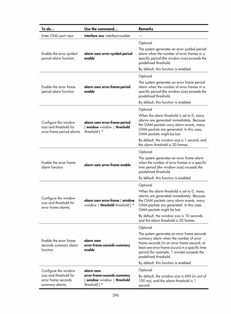
296
To do... Use the command... Remarks
Enter ONU port view interface onu interface-number —
Enable the error symbol period alarm function
alarm oam error-symbol-period enable
Optional
The system generates an error symbol period alarm when the number of error frames in a specific period (the window size) exceeds the predefined threshold.
By default, this function is enabled.
Enable the error frame period alarm function
alarm oam error-frame-period enable
Optional
The system generates an error frame period alarm when the number of error frames in a specific period (the window size) exceeds the predefined threshold.
By default, this function is enabled.
Configure the window size and threshold for error frame period alarms
alarm oam error-frame-period { window window | threshold threshold } *
Optional
When the alarm threshold is set to 0, many alarms are generated immediately. Because the OAM packets carry alarm events, many OAM packets are generated. In this case, OAM packets might be lost.
By default, the window size is 1 second, and the alarm threshold is 20 frames.
Enable the error frame alarm function alarm oam error-frame enable
Optional
The system generates an error frame alarm when the number of error frames in a specific time period (the window size) exceeds the predefined threshold.
By default, this function is enabled.
Configure the window size and threshold for error frame alarms
alarm oam error-frame { window window | threshold threshold } *
Optional
When the alarm threshold is set to 0, many alarms are generated immediately. Because the OAM packets carry alarm events, many OAM packets are generated. In this case, OAM packets might be lost.
By default, the window size is 10 seconds, and the alarm threshold is 20 frames.
Enable the error frame seconds summary alarm function
alarm oam error-frame-seconds-summary enable
Optional
The system generates an error frame seconds summary alarm when the number of error frame seconds (in an error frame second, at least one error frame occurs) in a specific time period (for example, 1 minute) exceeds the predefined threshold.
By default, this function is enabled.
Configure the window size and threshold for error frame seconds summary alarms
alarm oam error-frame-seconds-summary { window window | threshold threshold } *
Optional
By default, the window size is 600 (in unit of 100 ms), and the alarm threshold is 1 second.
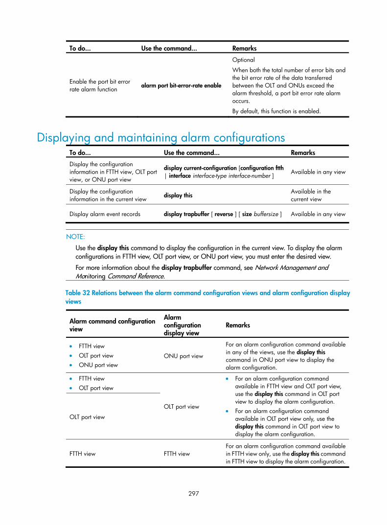
297
To do... Use the command... Remarks
Enable the port bit error rate alarm function alarm port bit-error-rate enable
Optional
When both the total number of error bits and the bit error rate of the data transferred between the OLT and ONUs exceed the alarm threshold, a port bit error rate alarm occurs.
By default, this function is enabled.
Displaying and maintaining alarm configurations To do... Use the command... Remarks
Display the configuration information in FTTH view, OLT port view, or ONU port view
display current-configuration [configuration ftth | interface interface-type interface-number ] Available in any view
Display the configuration information in the current view display this
Available in the current view
Display alarm event records display trapbuffer [ reverse ] [ size buffersize ] Available in any view
NOTE:
Use the display this command to display the configuration in the current view. To display the alarm configurations in FTTH view, OLT port view, or ONU port view, you must enter the desired view.
For more information about the display trapbuffer command, see Network Management and Monitoring Command Reference.
Table 32 Relations between the alarm command configuration views and alarm configuration display views
Alarm command configuration view
Alarm configuration display view
Remarks
• FTTH view • OLT port view • ONU port view
ONU port view
For an alarm configuration command available in any of the views, use the display this command in ONU port view to display the alarm configuration.
• FTTH view • OLT port view
OLT port view
OLT port view
• For an alarm configuration command available in FTTH view and OLT port view, use the display this command in OLT port view to display the alarm configuration.
• For an alarm configuration command available in OLT port view only, use the display this command in OLT port view to display the alarm configuration.
FTTH view FTTH view For an alarm configuration command available in FTTH view only, use the display this command in FTTH view to display the alarm configuration.

298
Supported switch features and restrictions
OLT port features and restrictions Table 33 OLT port features
Feature Remarks Related chapter/book
Basic parameters
• Configuring an OLT port description string • Enabling/disabling an OLT port • Displaying and clearing port statistics
information
The chapter “Ethernet interface configuration”
Flow control Configuring flow control on an OLT port The chapter “Ethernet interface configuration”
Data storm suppression
• Configuring broadcast suppression ratio on an OLT port
• Configuring multicast suppression ratio on an OLT port
• Configuring unknown unicast suppression ratio on an OLT port
The chapter “Ethernet interface configuration”
Port link type
• Setting the link type of an OLT port to Hybrid • Allowing the packets of the specified VLANs to
pass through the current Hybrid port • Setting the default VLAN ID for the Hybrid port
The chapter “VLAN configuration”
Port isolation Configuring OLT port isolation The chapter “Port isolation configuration”
Port trap Configuring OLT port trap Network Management and Monitoring Configuration Guide
IGMP snooping Configuring IPv4 multicast source port filtering on an OLT port IP Multicast Configuration Guide
MLD snooping Configuring IPv6 multicast source port filtering on an OLT port IP Multicast Configuration Guide
QinQ
• Configuring QinQ on an OLT port • Configuring user-side QinQ on an OLT port • Configuring network-side QinQ on an OLT
port • Configure the TPID carried in operator VLAN
tag
The chapter “QinQ configuration”
The chapter “VLAN mapping configuration”
BPDU tunneling Configuring BPDU tunneling on an OLT port The chapter “BPDU tunneling configuration”
Port mirroring Configuring OLT port mirroring Network Management and Monitoring Configuration Guide
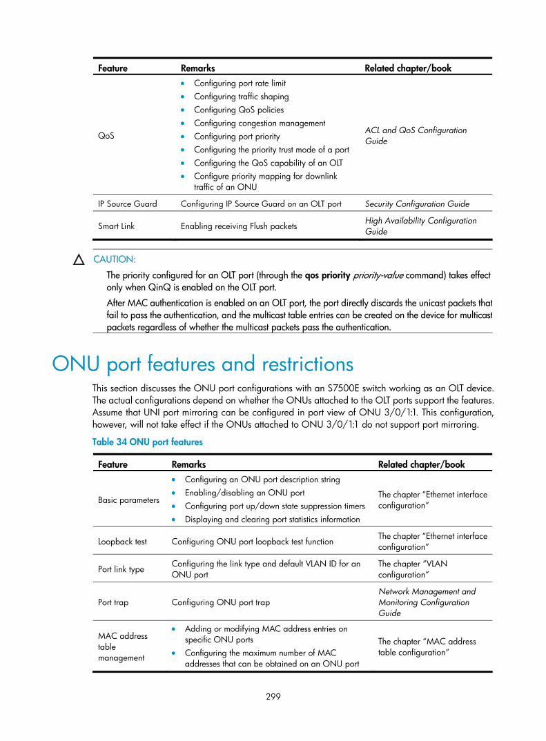
299
Feature Remarks Related chapter/book
QoS
• Configuring port rate limit • Configuring traffic shaping • Configuring QoS policies • Configuring congestion management • Configuring port priority • Configuring the priority trust mode of a port • Configuring the QoS capability of an OLT • Configure priority mapping for downlink
traffic of an ONU
ACL and QoS Configuration Guide
IP Source Guard Configuring IP Source Guard on an OLT port Security Configuration Guide
Smart Link Enabling receiving Flush packets High Availability Configuration Guide
CAUTION:
The priority configured for an OLT port (through the qos priority priority-value command) takes effect only when QinQ is enabled on the OLT port.
After MAC authentication is enabled on an OLT port, the port directly discards the unicast packets thatfail to pass the authentication, and the multicast table entries can be created on the device for multicastpackets regardless of whether the multicast packets pass the authentication.
ONU port features and restrictions This section discusses the ONU port configurations with an S7500E switch working as an OLT device. The actual configurations depend on whether the ONUs attached to the OLT ports support the features. Assume that UNI port mirroring can be configured in port view of ONU 3/0/1:1. This configuration, however, will not take effect if the ONUs attached to ONU 3/0/1:1 do not support port mirroring.
Table 34 ONU port features
Feature Remarks Related chapter/book
Basic parameters
• Configuring an ONU port description string • Enabling/disabling an ONU port • Configuring port up/down state suppression timers • Displaying and clearing port statistics information
The chapter “Ethernet interface configuration”
Loopback test Configuring ONU port loopback test function The chapter “Ethernet interface configuration”
Port link type Configuring the link type and default VLAN ID for an ONU port
The chapter “VLAN configuration”
Port trap Configuring ONU port trap Network Management and Monitoring Configuration Guide
MAC address table management
• Adding or modifying MAC address entries on specific ONU ports
• Configuring the maximum number of MAC addresses that can be obtained on an ONU port
The chapter “MAC address table configuration”

300
Feature Remarks Related chapter/book
DHCP snooping
• Configuring DHCP snooping to support Option82 • Configuring the Option82 padding formats • Configuring a strategy for DHCP snooping to handle
request packets that contain Option82 • Configuring the padding format and contents of
non-custom circuit ID sub-options • Configuring the padding format and contents of
non-custom remote ID sub-options
Layer 3—IP Services Configuration Guide
IGMP snooping
• Enabling fast-leave processing • Configuring the maximum number of IPv4 multicast
groups that can be joined on a port • Configuring IPv4 multicast group filtering • Configuring a port as a simulated host to join a
multicast group • Configuring IPv4 multicast group replacement • Configuring static router/member ports
IP Multicast Configuration Guide
MLD snooping
• Enabling fast-leave processing • Configuring the maximum number of IPv6 multicast
groups that can be joined on a port • Configuring IPv6 multicast group filtering • Configuring a port as a simulated host to join an IPv6
multicast group • Configuring IPv6 multicast group replacement • Configuring static router/member ports
IP Multicast Configuration Guide
Port mirroring Configuring local UNI port mirroring Network Management and Monitoring Configuration Guide
QoS
• Configuring port priority • Configuring QoS policies • Configuring congestion management • Configuring the priority trust mode of a port • Configuring traffic classification and priority marking
for uplink traffic of a UNI • Configure traffic policing for uplink/downlink traffic
of a UNI
ACL and QoS Configuration Guide
Table 35 Restrictions
Feature Restrictions
Loopback test In an ONU remote loopback test, all packets forwarded downlink are untagged. If the VLAN operation mode is set to tag or translation for the UNI port, the test packets will be dropped and the loopback test will fail.

301
Feature Restrictions
QoS
• When an ACL rule is referenced in a QoS policy, the action defined in the ACL rule (deny or permit) does not work. Instead, the traffic behavior defined in the QoS policy determines the action on the packets that match the ACL rule.
• ONU ports support packet filtering based on source MAC address, destination MAC address, Ethernet type, VLAN ID, source IP address, destination IP address, source TCP port, and source UDP port only.
• Source MAC address-based packet filtering on an ONU port works only on the uplink direction and supports a maximum of 32 ACL rules.
• Destination MAC address-based packet filtering on an ONU port works on both uplink and downlink directions and supports a maximum of 32 ACL rules.
• Ethernet type-based packet filtering on an ONU port supports a maximum of 30 ACL rules in the case of single-direction configuration and a maximum of 16 ACL rules for each direction when configured for both uplink and downlink directions.
• VLAN ID-based packet filtering on an ONU port supports a maximum of 6 ACL rules for the uplink direction and a maximum 8 ACL rules for the downlink direction.
• Source/destination IP address-based packet filtering on an ONU port supports a maximum of 24 ACL rules in the case of single-direction configuration and a maximum of 16 ACL rules for each direction when configured for both uplink and downlink directions.
• Source TCP/UDP port-based packet filtering supports a maximum of 24 ACL rules in the case of single-direction configuration and a maximum of 32 ACL rules when configured for both uplink and downlink directions.
NOTE:
When the S7500E switch is configured as a DHCP snooping device, do not connect a DHCP server to theONU port, because ONU ports are used for accessing.

302
Index
A B C D E G I L M O P Q R S U V A
Alarm configuration task list,288 Assigning a port to the isolation group,59
B
BPDU tunneling configuration examples,113
C
Configuration examples for ONU remote management,276 Configuring a Layer 2 Ethernet interface,9 Configuring a loopback interface,20 Configuring a service loopback group,239 Configuring a super VLAN,143 Configuring a voice VLAN,156 Configuring an aggregate interface,44 Configuring an aggregation group,40 Configuring an isolate-user-VLAN,148 Configuring basic QinQ,179 Configuring basic settings of a VLAN interface,119 Configuring basic VLAN settings,118 Configuring BPDU tunneling,111 Configuring CDP compatibility,231 Configuring GVRP functions,168 Configuring LLDP trapping,232 Configuring load sharing for link aggregation groups,47 Configuring MAC Information,30 Configuring selective QinQ,180 Configuring the GARP timers,169 Configuring the MAC address table,24 Configuring the null interface,21 Configuring the spanning tree,78 Configuring the TPID value in VLAN tags,183 Configuring VLAN mapping,200
D
Data transmission in an EPON system,244 Displaying and maintaining an Ethernet interface or subinterface,18
Displaying and maintaining Ethernet link aggregation,50 Displaying and maintaining GVRP,170 Displaying and maintaining isolate-user-VLAN,150 Displaying and maintaining isolation groups,59 Displaying and maintaining LLDP,233 Displaying and maintaining loopback and null interfaces,22 Displaying and maintaining MAC address tables,27 Displaying and maintaining OLT configuration,255 Displaying and maintaining ONU port configuration,276 Displaying and maintaining service loopback groups,240 Displaying and maintaining super VLAN,144 Displaying and maintaining the spanning tree,100 Displaying and maintaining UNI port configuration,287 Displaying and maintaining VLAN,141 Displaying and maintaining voice VLAN,159
E
Enabling link-aggregation traffic redirection,50 EPON system reliability,247 EPON system security,246 Ethernet interface naming conventions,1 Ethernet interface overview,1 Ethernet link aggregation configuration examples,51 Ethernet link aggregation configuration task list,40
G
General configuration,1 GVRP configuration examples,170 GVRP configuration task list,168
I
Introduction to alarm,288 Introduction to BPDU tunneling,109 Introduction to EPON,242 Introduction to GVRP,164 Introduction to port isolation,59

303
Introduction to QinQ,175 Introduction to VLAN,116 IP subnet-based VLAN configuration,138 Isolate-user-VLAN configuration example,150
L
LLDP configuration examples,233 LLDP configuration task list,226
M
MAC address table configuration example,28 MAC Information configuration example,31 MAC-based VLAN configuration,127 MSTP,69
O
OLT configuration,250 OLT configuration examples,256 OLT port features and restrictions,298 ONU configuration,260 ONU port features and restrictions,299 Overview(Ethernet link aggregation),33 Overview(Service loopback group),238 Overview(Super VLAN),143 Overview(Isolate-user-VLAN),148 Overview(MAC address table),23 Overview(MAC Information),30 Overview(Voice VLAN),153 Overview(LLDP),221
P
Performing basic LLDP configuration,227
Port isolation configuration example,60 Port-based VLAN configuration,121 Protocol-based VLAN configuration,134 Protocols and standards,74 PVST,69
Q
QinQ configuration examples,184 QinQ configuration task list,179
R
RSTP,68
S
S7500E OLT configuration task list,249 S7500E Switch Series and EPON system,247 Service loopback group configuration example,240 Setting the MTU for a Layer 3 Ethernet interface or subinterface,18 Spanning tree configuration examples,101 Spanning tree configuration task list,74 STP,61 Super VLAN configuration example,145
U
UNI port configuration task list,283
V
VLAN mapping configuration examples,211 VLAN mapping overview,195 Voice VLAN configuration examples,159