
H3C SR6602 Router
90
H3C SR6602 Router Installation Guide Hangzhou H3C Technologies Co., Ltd. http://www.h3c.com Document version: T2-08040E-20110810-C-1.09
-
Upload
khangminh22 -
Category
Documents
-
view
6 -
download
0
Transcript of H3C SR6602 Router

H3C SR6602 Router Installation Guide
Hangzhou H3C Technologies Co., Ltd. http://www.h3c.com Document version: T2-08040E-20110810-C-1.09

Copyright © 2007-2011, Hangzhou H3C Technologies Co., Ltd. and its licensors
All rights reserved
No part of this manual may be reproduced or transmitted in any form or by any means without prior written consent of Hangzhou H3C Technologies Co., Ltd.
Trademarks
H3C, , Aolynk, , H3Care,
, TOP G, , IRF, NetPilot, Neocean, NeoVTL, SecPro, SecPoint, SecEngine, SecPath, Comware, Secware, Storware, NQA, VVG, V2G, VnG, PSPT, XGbus, N-Bus, TiGem, InnoVision and HUASAN are trademarks of Hangzhou H3C Technologies Co., Ltd.
All other trademarks that may be mentioned in this manual are the property of their respective owners
Notice
The information in this document is subject to change without notice. Every effort has been made in the preparation of this document to ensure accuracy of the contents, but all statements, information, and recommendations in this document do not constitute the warranty of any kind, express or implied.
Environmental protection
This product has been designed to comply with the environmental protection requirements. The storage, use, and disposal of this product must meet the applicable national laws and regulations.

Preface
The H3C SR6602 Router Installation Guide includes seven chapters, which describe the hardware features of the H3C SR6602 Router and provide examples to help you install the router.
This preface includes:
• Audience
• Conventions
• About the H3C SR6600 documentation set
• Obtaining documentation
• Technical support
• Documentation feedback
Audience This documentation is intended for:
• Network planners
• Field technical support and servicing engineers
• Network administrators working with the SR6600 routers
Conventions This section describes the conventions used in this documentation set.
Command conventions
Convention Description
Boldface Bold text represents commands and keywords that you enter literally as shown.
Italic Italic text represents arguments that you replace with actual values.
[ ] Square brackets enclose syntax choices (keywords or arguments) that are optional.
{ x | y | ... } Braces enclose a set of required syntax choices separated by vertical bars, from which you select one.
[ x | y | ... ] Square brackets enclose a set of optional syntax choices separated by vertical bars, from which you select one or none.
{ x | y | ... } * Asterisk marked braces enclose a set of required syntax choices separated by vertical bars, from which you select at least one.
[ x | y | ... ] * Asterisk marked square brackets enclose optional syntax choices separated by vertical bars, from which you select one choice, multiple choices, or none.
&<1-n> The argument or keyword and argument combination before the ampersand (&) sign can be entered 1 to n times.
# A line that starts with a pound (#) sign is comments.

GUI conventions
Convention Description
Boldface Window names, button names, field names, and menu items are in Boldface. For example, the New User window appears; click OK.
> Multi-level menus are separated by angle brackets. For example, File > Create > Folder.
Convention Description
< > Button names are inside angle brackets. For example, click <OK>.
[ ] Window names, menu items, data table and field names are inside square brackets. For example, pop up the [New User] window.
/ Multi-level menus are separated by forward slashes. For example, [File/Create/Folder].
Symbols
Convention Description
WARNING An alert that calls attention to important information that if not understood or followed can result in personal injury.
CAUTION An alert that calls attention to important information that if not understood or followed can result in data loss, data corruption, or damage to hardware or software.
IMPORTANT An alert that calls attention to essential information.
NOTE An alert that contains additional or supplementary information.
TIP An alert that provides helpful information.
Network topology icons
Represents a generic network device, such as a router, switch, or firewall.
Represents a routing-capable device, such as a router or Layer 3 switch.
Represents a generic switch, such as a Layer 2 or Layer 3 switch, or a router that supports Layer 2 forwarding and other Layer 2 features.
Port numbering in examples
The port numbers in this document are for illustration only and might be unavailable on your device.
About the H3C SR6600 documentation set The H3C SR6600 documentation set includes:
Category Documents Purposes
Marketing brochures Describe product specifications and benefits. Product description and specifications
Technology white papers Provide an in-depth description of software features and technologies.

Category Documents Purposes
Card datasheets Describe card specifications, features, and standards.
Compliance and safety manual
Provides regulatory information and the safety instructions that must be followed during installation.
Installation guide Provides a complete guide to hardware installation and hardware specifications.
Card manuals Provide the hardware specifications of cards.
Hardware specifications and installation
H3C N68 Cabinet Installation and Remodel Introduction
Guides you through installing and remodeling H3C N68 cabinets.
Configuration guides Describe software features and configuration procedures.
Software configuration
Command references Provide a quick reference to all available commands.
Operations and maintenance
H3C SR6600 Release notes
Provide information about the product release, including the version history, hardware and software compatibility matrix, version upgrade information, technical support information, and software upgrading.
Obtaining documentation You can access the most up-to-date H3C product documentation on the World Wide Web at http://www.h3c.com.
Click the links on the top navigation bar to obtain different categories of product documentation:
[Technical Support & Documents > Technical Documents] – Provides hardware installation, software upgrading, and software feature configuration and maintenance documentation.
[Products & Solutions] – Provides information about products and technologies, as well as solutions.
[Technical Support & Documents > Software Download] – Provides the documentation released with the software version.
Technical support [email protected]
http://www.h3c.com
Documentation feedback You can e-mail your comments about product documentation to [email protected].
We appreciate your comments.

i
Contents
Product overview·························································································································································· 1 Front panel view································································································································································1 Rear panel view ································································································································································1
Preparing for installation ············································································································································· 2 Safety recommendations ··················································································································································2
Safety symbols ··························································································································································2 General safety recommendations ···························································································································2 Safety with electricity ···············································································································································2 Safety with laser ·······················································································································································2
Examining the installation site ·········································································································································3 Temperature and humidity·······································································································································3 Altitude ······································································································································································3 Cleanness ··································································································································································3 Cooling system ·························································································································································4 ESD prevention ·························································································································································4 EMI·············································································································································································5 Lightning protection··················································································································································6 Rack-mounting···························································································································································6
Installation tools·································································································································································6 Installation accessories ·····················································································································································7 Checklist before installation ·············································································································································7
Installing the router······················································································································································· 9 Installation flow ·································································································································································9 Installing the router in a 19-inch rack ·························································································································· 10
Installing cage nuts and rear mounting brackets to the rack ············································································ 10 Installing front mounting brackets to the router ·································································································· 11 Installing load-bearing screws······························································································································ 11 Installing the router to the rack····························································································································· 12
Grounding the router ····················································································································································· 13 Installing interface modules··········································································································································· 14
Removing a filler panel ········································································································································· 14 Installing a HIM ····················································································································································· 15 Installing a MIM····················································································································································· 15
Installing a CF card························································································································································ 16 Connecting Ethernet cables··········································································································································· 17
Connecting a copper Ethernet cable··················································································································· 17 Connecting a fiber Ethernet cable······················································································································· 17
Installing a port lightning arrestor (optional)··············································································································· 19 Installing a power lightning arrester (lightning protection busbar) (optional) ························································· 20 Installing a signal lightning arrester (optional)············································································································ 22 Connecting an AC power cord ···································································································································· 23
AC power receptacle············································································································································ 23 Connecting the AC power cord··························································································································· 23
Connecting an RPS DC power cord····························································································································· 24 RPS power receptacle ··········································································································································· 24
Verifying the installation ················································································································································ 25

ii
Logging in to the router and configuring basic settings ··························································································26 Login methods································································································································································· 26 Logging in through the console port ···························································································································· 26
Setting up a configuration environment ·············································································································· 26 Creating a hyperterminal connection and setting terminal parameters ·························································· 27
Powering on the router ·················································································································································· 30 Checking before power-on··································································································································· 30 Checking after power-on ······································································································································ 30 Displaying boot information································································································································· 30
Logging in to the router through Telnet ························································································································ 31 Logging to the router through the AUX port ················································································································ 31 Configuring basic settings············································································································································· 32
Hardware management and maintenance ··············································································································33 Displaying hardware information of the router··········································································································· 33
Displaying software and hardware version information of the router····························································· 33 Displaying operational statistics of the router ···································································································· 34 Displaying detailed information about interface modules ················································································ 34 Displaying the electrical label information of the router ··················································································· 35 Displaying the CPU usage of the router·············································································································· 36 Displaying the memory usage of the router········································································································ 36 Displaying the CF card information ···················································································································· 36 Displaying the operational status of the fans ····································································································· 37 Displaying the operational status of a power module······················································································· 37
Displaying the temperature alarm thresholds for an interface module····································································· 38 Configuring a combo interface ···································································································································· 38 Displaying transceiver module information and alarming information ···································································· 39 Solving system faults ······················································································································································ 40
Solving system faults ············································································································································· 40 Viewing the system fault solving method ············································································································ 41
Saving the running configuration of the router ··········································································································· 41 Rebooting the router ······················································································································································ 41
Replacement procedures ···········································································································································43 Safety recommendations ··············································································································································· 43 Replacing a HIM ···························································································································································· 43 Replacing an MIM ························································································································································· 44 Replacing a CF card······················································································································································ 44 Replacing a transceiver module ··································································································································· 45 Replacing a memory module ········································································································································ 46
When to replace a memory module ··················································································································· 46 Replacement procedure ········································································································································ 46 Opening the router chassis cover ························································································································ 47 Memory module structure ····································································································································· 49 Memory module slot·············································································································································· 50 Removing a memory module································································································································ 50 Installing a memory module ································································································································· 50
Troubleshooting··························································································································································52 Power supply system failure ·········································································································································· 52 Fan failure ······································································································································································· 52 Configuration terminal problems·································································································································· 53
No terminal display ·············································································································································· 53 Garbled terminal display······································································································································ 53 No response from the serial port ························································································································· 53
Password loss ································································································································································· 53
iii
User password loss ··············································································································································· 53 Super password loss ············································································································································· 54
Cooling system failure ··················································································································································· 55 Interface module, cable, and connection failure ········································································································ 55
Appendix A Technical specifications························································································································57 Dimensions and weight ················································································································································· 57 Storages ·········································································································································································· 57 AC power supply ··························································································································································· 57 RPS power supply (optional) ········································································································································· 57 Power consumption range············································································································································· 58 Fixed ports specifications ·············································································································································· 58
Port and slot specifications ··································································································································· 58 Console port··························································································································································· 58 AUX port································································································································································· 59 Combo ports ·························································································································································· 59
Port lightning arrester (optional) ··································································································································· 60 Power lightning arrester (optional) ······························································································································· 61 Signal lightning arrester (optional)······························································································································· 61
Appendix B LEDs························································································································································62 Panel LEDs······································································································································································· 62 Interface module LEDs···················································································································································· 63
Appendix C Cables ···················································································································································64 Ethernet twisted pair cable············································································································································ 64
Introduction ···························································································································································· 64 Making an Ethernet twisted pair cable ··············································································································· 68
Optical fiber ··································································································································································· 68 E1 interface cable ·························································································································································· 69 T1 interface cable ·························································································································································· 70 CE3/CT3 interface cable·············································································································································· 71 Serial port cable····························································································································································· 72
Appendix D AC power cables used in different countries or regions ···································································75 10A AC power cables used in different countries or regions··················································································· 75 16A AC power cables used in different countries or regions··················································································· 78
Index ···········································································································································································81

1
Product overview
This chapter describes the H3C SR6602 router and includes these sections:
• Front panel view
• Rear panel view
Front panel view Figure 1 Front panel view
(1) AC-input power receptacle (100 VAC to 240 VAC, 50 or 60 Hz at 2.5 A)
(2) AC power switch (ON/OFF)
(3) RPS DC-input terminal block (RPS) (4) CF card slot (CF CARD) (5) CF card LED (CF) (6) RPS status LED (RPS) (7) Interface module slot 2 LED (SLOT2) (8) Reset button (RESET) (9) System status LED (SYS) (10) Interface module slot 1 LED (SLOT1) (11) AC power supply status LED (PWR) (12) USB 1 LED (USB) (13) USB port 1 (1) (14) USB port 0 (0) (15) Console port (CONSOLE) (16) Auxiliary port (AUX)
Rear panel view Figure 2 Rear panel view
(1) Grounding screw and grounding sign (2) 10/100/1000 Mbps copper Ethernet ports (3) 1000 Mbps SFP fiber ports (4) SFP port LEDs (5) Interface module slots

2
Preparing for installation
This chapter includes these sections:
• Safety recommendations
• Examining the installation site
• Installation tools
• Installation accessories
• Checklist before installation
Safety recommendations
Safety symbols When reading this document, note the following symbols:
WARNING means an alert that calls attention to important information that if not understood or followed can result in personal injury.
CAUTION means an alert that calls attention to important information that if not understood or followed can result in data loss, data corruption, or damage to hardware or software.
General safety recommendations • Keep the chassis and installation tools away from walk areas.
• Make sure that the ground is dry and flat and anti-slip measures are in place.
• Unplug all the external cables (including power cables) before moving the chassis.
Safety with electricity • Locate the emergency power-off switch in the room before installation. Shut the power off at once in
case accident occurs.
• Make sure that the router has been correctly grounded.
• Do not open or close the chassis cover when the router is powered on.
• Connect the interface cables for the router correctly.
• Use an uninterrupted power supply (UPS).
• If there are two power inputs, disconnect the two power inputs to power off the router.
• Do not work alone when the router has power.
• Always check that the power has been disconnected.
Safety with laser • Do not stare into the optical port or fiber connector because the laser light emitted from the optical
fiber may hurt your eyes.

3
• Install a dust plug on the transceiver module to avoid damage to the transceiver module.
Examining the installation site The H3C SR6602 router can only be used indoors. To ensure that the router works properly and to prolong its service lifetime, the installation site must meet the following requirements:
• Temperature and humidity
• Cleanness
• EMI
Temperature and humidity You must maintain a proper temperature and humidity in the equipment room. Long-term high humidity may lead to bad insulation, electricity leakage, mechanical property changes, and metal corrosion. However, if the relative humidity is too low, captive screws may become loose as the result of contraction of insulation washers and static electricity may be produced in a dry environment to jeopardize the circuits on the device. A high temperature is the most undesirable condition, because it accelerates the aging of insulation materials and significantly lowers reliability and service life of the router.
For the temperature and humidity requirements of the router, see Table 1 and Table 2.
Table 1 Temperature requirements
Item Temperature
Operating Temperature 0°C to 45°C (32°F to 113°F)
Storage Temperature -40°C to 70°C(-40°F to 158°F)
Table 2 humidity requirements
Item Humidity
Operating humidity 10% to 95%
Storage humidity 5% to 95%
Altitude Table 3 Altitude requirements
Item Altitude
Operating altitude –60 m (–196.85 ft) to 3 km (1.86 miles)
Storage altitude –60 m (–196.85 ft) to 4.5km(2.8 miles)
Cleanness Dust buildup on the chassis may result in electrostatic adsorption, which causes poor contact of metal components and contact points, especially when indoor relative humidity is low. In the worst case, electrostatic adsorption can cause communication failure.

4
Table 4 Dust concentration limit in the equipment room
Substance Concentration limit (particles/cu m)
Dust particles ≤ 3 x 10⁴
(No visible dust on desk in three days)
NOTE:
Dust particle diameter ≥ 5 μm
The equipment room must also meet strict limits on salts, acids, and sulfides to eliminate corrosion and premature aging of components, as shown in Table 5.
Table 5 Harmful gas limits in an equipment room
Gas Max. (mg/m3)
SO2 0.2
H2S 0.006
NH3 0.05
Cl2 0.01
Cooling system The H3C SR6602 router adopts left to right airflow for heat dissipation.
Figure 3 SR6602 airflow
• Make sure there is enough space (greater than 10 cm (3.94 in)) around the air intake and outlet vents on the router for good ventilation.
• Make sure the installation site has a good cooling system.
ESD prevention To prevent electrostatic discharge (ESD), note the following guidelines:
• Make sure that the router and the floor are well grounded.
• Take dust-proof measures for the equipment room.
• Maintain the humidity and temperature at a proper level.
• Always wear an ESD-preventive wrist strap when touching a circuit board or transceiver module.
• Place the removed memory module, CF card, or HIM/MIM on an antistatic workbench, with the face upward, or put it into an antistatic bag.

5
• Touch only the edges, instead of electronic components when observing or moving a removed memory module, CF card, or HIM/MIM.
To use the ESD-preventive wrist strap, perform the following steps:
Step1 Wear the wrist strap on your wrist.
Step2 Lock the wrist strap tight around your wrist to keep good contact with the skin.
Step3 Insert the ESD-preventive wrist strap into the specially designed hole on the router chassis or attach it to the grounding screw of the chassis with the alligator clips.
Step4 Make sure that the rack is well grounded.
Figure 4 Use an ESD-preventive wrist strap
(1) ESD-preventive wrist strap (2) Lock (3) Alligator clip
CAUTION:
• Check the resistance of the ESD-preventive wrist strap for safety. The resistance reading should be in therange of 1 to 10 megohm (Mohm) between human body and the ground.
• No ESD-preventive wrist strap is provided with the H3C SR6602 router. Prepare it yourself.
EMI All electromagnetic interference (EMI) sources, from outside or inside of the router and application system, adversely affect the router in a conduction pattern of capacitance coupling, inductance coupling, electromagnetic wave radiation, or common impedance (including grounding system) coupling. To prevent EMI, perform the following steps:
• Take measures against interference from the power grid.
• Do not use the router together with the grounding equipment or light-prevention equipment of power equipment, and keep the router far away from them.
• Keep the router far away from high-power radio launchers, radars, and equipment with high frequency or high current.

6
NOTE:
Use electromagnetic shielding when necessary.
Lightning protection To protect the router from lightning better, do as follows:
• Make sure the grounding cable of the chassis is well grounded.
• Make sure the grounding terminal of the AC power receptacle is well grounded.
• Install a lightning arrester at the input end of the power supply to enhance the lightning protection capability of the power supply.
• Install a special lightning arrester at the input end of outdoor signal lines (for example, E1/T1 line) to which interface modules of the router are connected to enhance the lightning protection capability.
Rack-mounting Before mounting the router in a standard 19-inch rack, adhere to the following requirements:
• The rack has a good ventilation system.
• The rack is sturdy enough to support the router and installation accessories.
• Make sure that the size of the rack is appropriate for the router, and that there is enough clearance around the left and right sides of the router for heat dissipation.
• For heat dissipation and device maintenance, make sure the front and rear of the rack should be at least 0.8 m (2.62 ft) away from walls or other devices, and that the headroom in the equipment room should be no less than 3 m (9.84 ft).
Installation tools The tools in the table may be used for installing the routers.
Flat-blade screwdriver Phillips screwdriver Needle-nose pliers
Wire-stripping pliers Diagonal pliers
RJ45 crimping pliers Mark pen Multimeter Network cable
tester

7
Installation accessories
Console cable Grounding cable Rear mounting bracket and
load-bearing screw
Front mounting bracket and M4
screws Rubber pads
M6 screws Cage nuts ESD-preventive
wrist strap Cable tie
Checklist before installation Table 6 Checklist before installation
Item Requirements Result
Ventilation
• There is a minimum clearance of 10 cm (3.9 in) around the inlet and exhaust vents for heat dissipation of the router chassis.
• A ventilation system is available at the installation site.
Temperature 0°C to 45°C (32°F to 113°F)
Relative humidity 10% to 95% (noncondensing)
Cleanness Dust concentration ≤ 3 × 10⁴ particles/m3
ESD prevention
• The equipment and floor are well grounded. • The equipment room is dust-proof. • The humidity and temperature are at a proper level,
respectively. • Wear an ESD-preventive wrist strap and uniform when
touching a circuit board. • Place the removed memory module, CF card, or
HIM/MIM on an antistatic workbench, with the face upward, or put it into an antistatic bag.
• Touch only the edges, instead of electronic components when observing or moving a removed memory module, CF card, or HIM/MIM.
Installation site
EMI prevention
• Take effective measures to protect the power system from the power grid system.
• Separate the protection ground of the router from the grounding device or lightning protection grounding device as far as possible.
• Keep the router far away from radio stations, radar and high-frequency devices working in high current.
• Use electromagnetic shielding when necessary.

8
Item Requirements Result
Lightning protection
• The grounding cable of the chassis is well grounded. • The grounding terminal of the AC power receptacle is well
grounded. • A port lightning arrester is installed. (Optional) • A power lightning arrester is installed. (Optional) • A signal lightning arrester is installed at the input end of
an external signal cable. (Optional)
Electricity safety • Equip an uninterrupted power supply (UPS). • In case of emergency during operation, switch off the
external power switch.
Workbench • The workbench is stable enough • Well grounding
Rack-mounting requirements
• Install the router in an open rack if possible. If you install the router in a closed cabinet, make sure that the cabinet is equipped with a good ventilation system.
• The rack is sturdy enough to support the weight of the router and installation accessories.
• The size of the cabinet is appropriate for the router. • The front and rear of the cabinet are at least 0.8 m (31.50
in) away from walls or other devices.
Safety precautions
• The router is far away from any moist area and heat source. • The emergency power switch in the equipment room is located.
Tools • Installation accessories supplied with the router • User supplied tools
Reference • Documents shipped with the router • Online documents

9
Installing the router
This chapter includes these sections:
• Installation flow
• Installing the router in a 19-inch rack
• Grounding the router
• Installing interface modules
• Installing a CF card
• Connecting Ethernet cables
• Installing a power lightning arrester (lightning protection busbar) (optional)
• Installing a signal lightning arrester (optional)
• Connecting an AC power cord
• Connecting an RPS DC power cord
• Verifying the installation
Installation flow Figure 5 H3C SR6602 router installation flow

10
Installing the router in a 19-inch rack
Installing cage nuts and rear mounting brackets to the rack Follow these steps to install cage nuts to the rack:
Step1 As shown in Figure 6, mark the positions of cage nuts on the front rack posts by using a front mounting bracket, and then mark the positions of cage nuts on the rear rack posts at the same level by using a rear mounting bracket.
Figure 6 Mark the positions of the cage nuts
Step2 As shown in Figure 7, install the cage nuts to the marked positions on the rack posts.
Figure 7 Install cage nuts
Step3 As shown in Figure 8, install the rear mounting brackets to the rear rack posts.

11
Figure 8 Install rear mounting brackets to the rack
Installing front mounting brackets to the router Before installing the router to a rack, install the front mounting brackets to the two sides of the router.
To install the front mounting brackets to the router, align the screw holes on the mounting brackets with the screw holes on the router chassis, and then use a Phillips screwdriver to fasten the screws.
Figure 9 Install the front mounting brackets to the two sides of the router
Installing load-bearing screws As shown in Figure 10, install the load-bearing screws to the appropriate screw holes on the router chassis, fasten the screws with a Phillips screwdriver.

12
Figure 10 Install screws for mounting the router to the rear mounting brackets
Installing the router to the rack Step1 Wear an ESD-preventive wrist strap, and check that the rack is sturdy.
Step2 Supporting the router bottom with one hand, push the router into the rack horizontally, and make sure that the upper edges of the rear mounting brackets make close contact with the load-bearing screws on the router.
Figure 11 Install the router to the rack
Step3 Fix the router horizontally by fastening the mounting brackets to the rack with appropriate pan head screws. The specifications of pan head screws must satisfy the installation requirements, and rustproof treatment has been made to their surfaces.

13
Figure 12 Fix the router to the rack
1
(1) Screws for mounting the router to the rear mounting brackets
Grounding the router
WARNING!
Correctly connecting the router grounding cable is crucial to lightning protection and EMI protection.
The power input end of the router has a noise filter, whose central ground is directly connected to the chassis to form the chassis ground. You must securely connect this chassis ground to the earth so that the faradism and leakage electricity can be safely released to the earth to minimize EMI susceptibility of the router.
Follow these steps to connect the grounding cable:
Step1 Remove the grounding screw from the rear panel of the router chassis.
Step2 Attach the grounding screw to the OT terminal of the grounding cable.
Step3 Use a screwdriver to fasten the grounding screw into the grounding screw hole.

14
Figure 13 Connect the grounding cable to the grounding hole of router
NOTE:
• The resistance reading should be smaller than 5 ohms between router chassis and the ground.
• To guarantee the grounding effect, use the grounding cable provided with the router to connect to the grounding strip in the equipment room as long as possible.
Installing interface modules
Removing a filler panel Follow these steps to remove a filler panel:
Step1 Select the slot to install a HIM or MIM:
• If a HIM is to be installed, remove the two filler panels in slot 1 or slot 2.
• If a MIM is to be installed, remove the filler panel at the bottom of slot 1 or slot 2.
Step2 Remove the captive screws on the filler panel with a Phillips screwdriver.
Step3 Use a flat-blade screwdriver to prize the filler panel to remove it from the router.
Figure 14 Remove a filler panel

15
NOTE:
Keep the removed filler panel and screws for future use.
Installing a HIM Follow these steps to install a HIM:
Step1 Select the slot to install the HIM, and remove the filler panels on the slot. For how to remove a filler panel, see “Removing a filler panel.”
Step2 Push the HIM slowly along the slide rails into the slot, and then pull the levers inward.
Figure 15 Install a HIM
Step3 Use a flat-blade screwdriver to fasten the captive screws on the HIM.
Step4 Power on the router and check the status LED on the front panel. On means the HIM is installed correctly and running properly. Off means the HIM has failed the POST.
NOTE:
HIMs are hot swappable and you must perform the remove slot number command to stop the module before you remove it.
Installing a MIM A MIM can be installed only at the bottom of slot 1 or slot 2.
Follow these steps to install a MIM:
Step1 Select the slot to install the MIM, and remove the filler panels on the slot. For how to remove a filler panel, see “Removing a filler panel.”
Step2 Push the MIM slowly along the slide rails into the slot, and then pull the levers inward.

16
Figure 16 Push the MIM into the slot
Step3 Use a flat-blade screwdriver to fasten the captive screws on the MIM.
Step4 Power on the router and check the status LED on the front panel. On means the MIM is installed correctly and running properly. Off means the MIM has failed the POST.
NOTE:
HIMs are hot swappable and you must perform the remove slot number command to stop the module before you remove it.
Installing a CF card Follow these steps to install a CF card:
Step1 Make sure that the CF card status LED is not flashing.
Step2 Push the CF card eject button all the way into the slot, and make sure that the button does not project from the panel.
Step3 Insert the CF card into the slot following the direction shown in Figure 17, and make sure it does not project from the slot.
Figure 17 Insert the CF card into the slot

17
NOTE:
If the boot file of the router is stored in the CF card, before booting the router, make sure that the CF cardhas been correctly installed. Otherwise, the router cannot be booted.
Connecting Ethernet cables
Connecting a copper Ethernet cable The 10/100/1000Base-T copper ports of the H3C SR6602 router support MDI/MDI-X auto-sensing. They are connected to the network through category-5 or above twisted pairs that are equipped with RJ-45 connectors.
Connection procedure
Follow these steps to connect the router to a network through a 10/100/1000Base-T port:
Step1 Plug one end of an Ethernet twisted pair cable into the copper Ethernet port (RJ-45 port) to be connected on the router.
Step2 Plug the other end of the cable into the RJ-45 port of the peer device.
Step3 Check the status LED of the RJ-45 connector. For more information about the LED status, see “Appendix B LEDs.”
NOTE:
• After connecting Ethernet cables, you can use the ping or tracert command to check the connectivity between router and network. For more information, see the H3C SR6600 Routers Command References.
• For more information about Ethernet twisted pair cables, see the chapter “Appendix C Cables.”
Connecting a fiber Ethernet cable Before connecting Ethernet cables, you must install a transceiver module to the router, and then insert the fiber connector to the transceiver module. The SR6600 Router Series supports LC connectors only.
WARNING!
• To avoid injury to your eyes, do not stare at the optical interfaces and optical fiber connectors when connecting optical fibers.
• Never bend or curve a fiber when connecting it. The bend radius must be not less than 10 cm (3.94 in).
• Ensure the cleanness of the fiber ends.
• Make sure that the fiber connector matches the transceiver module.
Follow these steps to connect your router to the network through optical fibers:
Step1 Remove the dust plug of the transceiver module.

18
Figure 18 Remove the dust cover
Step2 Plug one end of the optical fiber into the transceiver module in the switch, as shown in Figure 19.
Figure 19 Install the transceiver module
Step3 Remove the dust cover on the transceiver module.
Step4 Plug the LC connectors on one end of the fiber cable into the Rx and Tx ports, and plug the LC connectors on the other end to the Tx and Rx ports on the peer device, as shown in Figure 20.
Figure 20 Connect the fiber connectors
Step5 Check whether the LEDs of the optical interfaces are normal. For more information about the LED status, see “Appendix B LEDs.”

19
Installing a port lightning arrestor (optional)
NOTE:
• Only 10/100 Mbps RJ-45 copper Ethernet ports need to be equipped with port lightning arresters.
• No port lightning arrester is shipped with the router unless ordered.
Before connecting an outdoor Ethernet cable to an Ethernet port, install a port lightning arrester to protect the router against lightning strokes.
The following port lightning arrester can be installed on the SR6602. The specifications for the port lightning arrester are as follows: Port protective unit–single port, maximum discharge current (8/20μs waveform): 5 kA, output voltage (10/700μs waveform): core-core < 40 V, core-ground < 600 V.
Installation procedures
Follow these steps to install a port lightning arrestor:
Step1 Use a double-faced adhesive tape to stick the port lightning arrester to the router. The port lightning arrester should be as close to the grounding screw as possible.
Step2 Cut short the grounding cable of the port lightning arrester according to its distance to the grounding screw. Then, fix the grounding cable onto the grounding screw of the router.
Step3 Use a multimeter to check the connection between the grounding cable of the port lightning arrester and the grounding screw of the router.
Step4 Follow the instructions to connect the port lightning arrester with a transit cable. The external cable should be connected to the IN end and the transit cable to the OUT end. Check whether the LED on the interface module is normal.
NOTE:
Read the instructions carefully before installing the port lightning arrester.
Step5 Bundle the cables with a cable tie.
Figure 21 Install a port lightning arrester
1
2
(1) Port lightning arrester (2) Grounding cable

20
Precautions
The performance of the port lightning arrester may be affected in the following cases:
• The IN and OUT ends of the port lightning arrester are connected incorrectly. The IN end should be connected to the external cable, and the OUT end to the Ethernet port of the router.
• The port lightning arrester is not well grounded. Make sure that the grounding cable of the port lightning arrester should be as short as possible and be well connected to the grounding screw of the router. Use a multimeter to check the connection between the port lightening arrester and the grounding screw.
• The installed port lightning arresters are not sufficient. When more than one outdoor Ethernet cable is connected to the router, install a port lightning arrester for each outdoor Ethernet cable.
Installing a power lightning arrester (lightning protection busbar) (optional)
NOTE:
No power lightning arrester is shipped with the router unless ordered.
Before connecting an outdoor AC power supply to the router, install a lightning protection busbar at the AC power input end and then connect the AC power cord to a lightning protection busbar to protect the router against lightning strokes. You can use cable ties and screws to fasten the lightning protection busbar on the rack, the workbench, or the wall in the equipment room.

21
Figure 22 Install a power lightning arrester
1 2 3
4
5
6
N NN NL LL L
(1) Status LED—On means the lightning protection functions properly. Off means the lightning protection has failed. (2) Grounding and polarity detection LED (red)—On means the grounding cable is not well connected or the live and zero wires are connected reversely. Check the power supply line. (3) Power switch (4) IEC-compliant power receptacle—Connects to the power source in the equipment room (5) Overload protector—Resets the lightning arrester (6) Multi-purpose power receptacle—Connects to the power supply of the router
Note the following guidelines when installing a power lightning arrester:
1. Make sure that the protection wire (PE) terminal of the power lightning arrester is well grounded before using it.
2. After the AC power cord of the router is plugged into the multi-purpose socket of the power lightning arrester (lightning protection busbar), if the green LED is ON and the red LED is OFF, the lightning protection can function properly.
3. If the red LED is ON, check whether the grounding cable is not well connected or the live and zero wires are connected reversely. You can use a multimeter to examine the polarity at the multi-purpose socket of the power lightning arrester.
• If the live and zero wires are on the left and right respectively (supposing that you are facing the socket), the PE terminal of the power lightning arrester is not grounded.
• If the live and zero wires are on the right and left respectively (supposing that you are facing the power receptacle), the polarity of the power receptacle of the power lightning arrester is reversed. In this case, open the power receptacle to correct the polarity. If the red LED is still ON, you can be sure that the PE terminal of the power lightning arrester is not grounded.

22
Installing a signal lightning arrester (optional)
NOTE:
No signal lightning arrester is shipped with the router unless ordered.
Generally, you need to connect a signal lightning arrester (a transient over-voltage protection) before connecting a signal cable to the router. This can protect electronic devices against surge over-voltage resulting from lightning strokes and other interferences, and minimize impact on the router.
The signal lightning arrester is serially connected to a signal cable, so the signal lightning arrester must satisfy the requirements of network performance indexes such as data transmission bandwidth, as well as the lightning protection performance requirement. Before installing a signal lightning arrester, consider such performance indexes of the lightning arrester as lightning protection, bandwidth, transmission loss, and port type.
The SR6602 supports the following types of signal lightning arresters:
• Voltage-limiting protection – signal lightning arrester – maximum discharge current 2.5KA/protection voltage 25V--SMB-75J/ SMB-75J-1W-10Mbps
• Voltage-limiting protection – signal lightning arrester – maximum discharge current 2.5KA/protection voltage 25V-BNC-75K/ BNC-75K-10Mbps
• Voltage-limiting protection – signal lightning arrester (U port) - maximum discharge current 3KA/common-mode 400V/differential mode 170V-RJ11
CAUTION:
The signal lightning arrester should be grounded as near as possible. The grounding resistance must be less than 4 ohms. The grounding resistance must be less than 1 ohm if there are special grounding requirements.
Follow these steps to install a signal lightning arrestor:
Step1 Use a double-faced adhesive tape to stick the signal lightning arrester to the router. The signal lightning arrester should be as close to the grounding screw as possible.
Step2 Cut short the grounding cable of the signal lightning arrester according to its distance to the grounding screw. Then, fix the grounding cable onto the grounding screw of the router.
Step3 Use a multimeter to check the connection between the grounding cable of the signal lightning arrester and the grounding screw of the router.
Step4 Follow the instructions to connect the signal lightning arrester with a transit cable. The external cable should be connected to the IN end and the transit cable to the OUT end. Check whether the LED on the interface module is normal.
NOTE:
Read the instructions carefully before installing the signal lightning arrester.
Step5 Bundle the cables with a cable tie.

23
Figure 23 Install a port lightning arrester
Precautions
The performance of the signal lightning arrester may be affected in the following cases:
• The IN and OUT ends of the signal lightning arrester are connected incorrectly. The IN end should be connected to the external cable, and the OUT end to the Ethernet port of the router.
• The signal lightning arrester is not well grounded. Make sure that the grounding cable of the signal lightning arrester should be as short as possible and be well connected to the grounding screw of the router. Use a multimeter to check the connection between the signal lightening arrester and the grounding screw.
The installed signal lightning arresters are not sufficient. When more than one outdoor Ethernet cable is connected to the router, install a signal lightning arrester for each outdoor Ethernet cable.
Connecting an AC power cord
AC power receptacle
Connecting the AC power cord
NOTE:
No AC power cord is provided with the router. Prepare it yourself.
To connect an AC power cord, follow these steps:
Step1 Make sure the router is well grounded, and the power switch on the router is in the OFF position.
Step2 Connect one end of the AC power cord to the AC receptacle on the router, and the other end to the AC power source.
Step3 Use a bail latch to secure the AC power cord.

24
Figure 24 Connect an AC power cord to the router
Connecting an RPS DC power cord
NOTE:
No RPS power cord is provided with the router. Prepare it yourself.
RPS power receptacle The RPS power receptacle locates at the front panel, as shown in Figure 25.
Figure 25 RPS power receptacle
Follow these steps to connect an RPS DC power cord:
Step1 Make sure that the router and the RPS power switch are off.
Step2 Remove the adhesive tape from the protection cover of the RPS power supply.
Step3 Loosen the captive screws on the RPS receptacle protection cover and remove the protection cover from the router, as shown in Figure 26.

25
Figure 26 Remove the protection cover
Step4 Insert the RPS plug in the RPS DC receptacle of the router.
Step5 Use a flat-blade screwdriver to fix the two fastening screws on the RPS plug to secure the plug to the RPS DC receptacle of the router.
Step6 Connect the other end of the RPS power cord to the RPS power source.
Figure 27 Connect an RPS DC power cord to the router
(1) RPS power receptacle (RPS) (2) RPS plug (3) RPS input (4) RPS plug (5) RPS power supply
Step7 Power on the router and RPS.
Step8 Check the RPS status LED.
Verifying the installation Before powering on the router, check the following items:
• The power source matches that required by the router.
• The grounding cable is securely connected.
• The router is correctly to other devices such as configuration terminal.

26
Logging in to the router and configuring basic settings
This chapter includes these sections:
• Login methods
• Logging in through the console port
• Powering on the router
• Logging in to the router through Telnet
• Logging to the router through the AUX port
• Configuring basic settings
Login methods The following logins methods are available for you to log in to the router:
• Logging in through the console port, which is the most common way to log in to a router and also the prerequisite to configuring other login methods.
• Logging in through Telnet or SSH
• Logging in through the AUX port
Logging in through the console port You can log in only through the console port the first time you log in to your router. Prepare a console cable and a configuration terminal.
Setting up a configuration environment Follow these steps to connect a configuration terminal to the router by using the console cable:
Step1 Select a configuration terminal, which can be a character terminal with an RS232 serial port, or a PC. The OS of the configuration terminal can be Windows 95/98/NT/2000/XP.
Step2 Plug the DB-9 female connector to the serial port of the configuration terminal or PC.
Step3 Connect the RJ-45 connector to the console port of the router.

27
Figure 28 Connect the console cable
CAUTION:
When you disconnect a PC from a powered-on router, disconnect the DB-9 connector of the console cablefrom the PC after disconnecting the RJ-45 connector from the router.
Creating a hyperterminal connection and setting terminal parameters
To configure and manage the router, you must run a terminal emulator program on the configuration terminal, for example, a PC. This section uses Windows XP HyperTerminal as an example.
Follow these steps to set terminal parameters on a terminal, for example, Windows XP HyperTerminal:
Step1 Select Start > All Programs > Accessories > Communications > HyperTerminal to enter the HyperTerminal window. The Connection Description dialog box appears, as shown in Figure 29.
Figure 29 Connection description of the HyperTerminal
Step2 Type the name of the new connection in the Name text box and click OK. The following dialog box appears. Select the serial port to be used from the Connect using drop-down list.

28
Figure 30 Set the serial port used by the HyperTerminal connection
Step3 Click OK after selecting a serial port and the following dialog box appears. Set Bits per second to 9600, Data bits to 8, Parity to None, Stop bits to 1, and Flow control to None.
Figure 31 Set the serial port parameters
Step4 Click OK after setting the serial port parameters and the system enters the following interface.

29
Figure 32 HyperTerminal window
Step5 Click Properties in the HyperTerminal window to enter the aaa Properties dialog box. Click the Settings tab, set the emulation to VT100, and then click OK.
Figure 33 Set terminal emulation in aaa Properties dialog box

30
Powering on the router
Checking before power-on Before powering on the router, verify the following items:
• The power cord and grounding cable are properly connected.
• The power supply voltage meets the requirement of the router.
• The console cable is properly connected; the terminal or PC used for configuration has started; and the configuration parameters have been set.
• If a CF card is used, check whether the CF card is in position.
Checking after power-on After powering on the router, check the following items:
• The LEDs on the front panel are normal. For more information about the LED status, see “Appendix B LEDs.”
• The fans work properly, and you can hear fan rotating.
• The buzzer beeps at power-on.
• The configuration terminal displays information normally. You can see the startup window on the local configuration terminal. For more information, see “Displaying boot information.”
• After the POST, the system prompts you to press Enter. When the command line prompt appears, the router is ready to configure.
Displaying boot information After power-on, the following information appears on the terminal screen: System start booting...
Booting Normal Extend BootWare........
****************************************************************************
* *
* H3C SR6602 Router BootWare, Version 1.31 *
* *
****************************************************************************
Copyright (c) 2004-2011 Hangzhou H3C Technologies Co., Ltd.
Compiled Date : Jan 13 2011
CPU Type : XLR732
CPU L1 Cache : 32KB
CPU Clock Speed : 1000MHz
Memory Type : DDR2 SDRAM
Memory Size : 1024MB
Memory Speed : 533MHz
BootWare Size : 1536KB
Flash Size : 4MB
cfa0 Size : 495MB

31
CPLD Version : 135.0
PCB Version : Ver.B
BootWare Validating...
Press Ctrl+B to enter extended boot menu...
Starting to get the main application file--cfa0:/SR6602.bin!..................
......................................................
The main application file is self-decompressing
..........................................................................
..........................................................................
.......
Done!
System is starting.....
User interface con0 is available.
Press ENTER to get started.
Press Enter, and the following prompt appears: <H3C>
You can now configure the router.
Logging in to the router through Telnet Follow these steps to log in to the router through Telnet:
Step1 After powering on the router, log in to the router through the console port. Enable the Telnet function on the router and set user privileges.
Step2 Connect the PC to the management Ethernet interface on the router and specify an IP address for the interface.
Step3 Specify an IP address for the PC, make sure that the PC and the interface are in the same network segment.
NOTE:
For more information about how to log in to the router, see the H3C SR6600 Routers Configuration Guides.
Logging to the router through the AUX port Follow these steps to log in to the router through the AUX port:
Step1 After powering on the router, connect the console cable to the console port, and configure the AUX port as follows:
To do… Use the command…
Enter system view system-view
Enter AUX user interface view user-interface aux 0

32
To do… Use the command…
Set the authentication mode authentication-mode none
Set the user privilege level user privilege level 3
Step2 Connect the AUX port to the configuration terminal by using the console cable. Then you can log in to the router through the AUX port.
NOTE:
For more information about how to log in to the router, see the H3C SR6600 Routers Configuration Guides.
Configuring basic settings Follow these steps to configure basic settings for the router:
To do… Use the command… Remarks
Set the current time and date clock datetime time date Optional
Available in user view
Enter system view system-view Required
Available in user view
Enter Ethernet interface view interface interface-type interface-number —
Specify an IP address for the interface
ip address ip-address { mask-length | mask } [ sub ]
By default, no IP address is assigned to any interface.
Return to system view quit Available in any view
Specify a static route
ip route-static dest-address { mask | mask-length } { next-hop-address | interface-type interface-number [ next-hop-address ] | vpn-instance d-vpn-instance-name next-hop-address } track track-entry-number [ preference preference-value ] [ tag tag-value ] [ description description-text ]
Required
By default, the preference of a static route is 60, tag is 0, and no description is configured.
Do not specify the permanent keyword together with the bfd or track keyword.
Save the current configuration to the root directory of the storage media, and specify it as the boot file to be used at the next boot
save [ safely ] [ backup | main ] [ force ] Available in any view
Display the running configuration display current-configuration Available in any view

33
Hardware management and maintenance
This chapter includes these sections:
• Displaying hardware information of the router
• Displaying the temperature alarm thresholds for an interface module
• Configuring a combo interface
• Displaying transceiver module information and alarming information
• Solving system faults
• Saving the running configuration of the router
• Rebooting the router
NOTE:
The CLI and outputs depend on your router model. For more information about the commands used in thischapter, see the corresponding command references.
Displaying hardware information of the router
Displaying software and hardware version information of the router
Use the display version command to display software and hardware version information of the router. The output includes the following information: the current software version and hardware version, router operating time, and the type and operating time of each interface module. <Sysname> display version
H3C Comware Platform Software
Comware Software, Version 5.20, R0600
Copyright (c) 2010 Hangzhou H3C Technologies Co., Ltd.
H3C SR6602 uptime is 0 week, 0 day, 0 hour, 4 minutes
CPU type: RMI XLR732 1000MHz
1024M bytes DDR2 SDRAM Memory
4M bytes Flash Memory
PCB Version: Ver.B
Logic Version: 135.0
Basic BootWare Version: 1.16
Extend BootWare Version: 1.31
[FIXED PORT] CON (Hardware)Ver.B, (Driver)1.0, (Cpld)135.0
[FIXED PORT] AUX (Hardware)Ver.B, (Driver)1.0, (Cpld)135.0
[FIXED PORT] GE 0/0 (Hardware)Ver.A, (Driver)1.0, (Cpld)132.0
[FIXED PORT] GE 0/1 (Hardware)Ver.A, (Driver)1.0, (Cpld)132.0
[FIXED PORT] GE 0/2 (Hardware)Ver.A, (Driver)1.0, (Cpld)132.0
[FIXED PORT] GE 0/3 (Hardware)Ver.A, (Driver)1.0, (Cpld)132.0

34
[SLOT 1] MIM-4SAE (Hardware)2.0, (Driver)1.0, (Cpld)2.0
[SLOT 2] The SubCard is not present
Displaying operational statistics of the router When you perform routine maintenance or the system fails, you may need to display the operational information of each functional module for locating failures. Generally, you need to run the display commands one by one. To collect more information one time, you can execute the display diagnostic-information command in any view to display or save the operational statistics of multiple functional modules of the router. This command displays the output of the display clock, display version, display device, and display current-configuration commands.
• Save the operational statistics of each functional module of the router. <Sysname> display diagnostic-information
Save or display diagnostic information (Y=save, N=display)? [Y/N]:y
Please input the file name(*.diag)[cfa0:/default.diag]:aa.diag
Diagnostic information is outputting to cfa0:/aa.diag.
Please wait...
Save succeeded.
Execute the more aa.diag command in user view, and then press the Page Up and Page Down keys to view the contents of the file aa.diag.
• Display the operational statistics of each functional module of the router. The output is too much and omitted here.
<Sysname> display diagnostic-information
Save or display diagnostic information (Y=save, N=display)? [Y/N]:n
=================================================
===============display clock===============
=================================================
08:54:16 UTC Fri 11/12/2010
===================================================
===============display version===============
===================================================
Omitted
Displaying detailed information about interface modules Use the display device verbose command to display detailed information of interfaces modules in each slot. <Sysname>display device verbose
System-mode(Current/After Reboot): Normal/Normal
Slot No. Card Type Status Max Ports
--------------------------------------------------------
0 Fixed SubCard Normal 6
1 MIM-4SAE Normal 4
2 N/A Absent N/A
Use the display device slot slot-number command to display detailed information about the interface modules in the specified slot. <Sysname> display device slot 1
System-mode(Current/After Reboot): Normal/Normal

35
Slot No. Card Type Status Max Ports
--------------------------------------------------------
1 MIM-4SAE Normal 4
Table 7 Output description
Field Description
Slot No. Slot number of the interface module
Card Type Interface module model. The value NONE indicates that no interface module is plugged in the slot.
Status
Operational status of the interface module: • Absent—No interface module is present in the slot. • Fault—The interface module in the slot is booting, or the interface module fails
and cannot boot properly. • Normal—The interface module in the slot is operating properly.
Max Ports Maximum number of interfaces that the interface module supports
Displaying the electrical label information of the router Use the display device manuinfo command to display your router’s electrical label information.
Electrical label information is also called permanent configuration data or archive information, which includes the card name, serial number, MAC address, and vendor name. <Sysname> display device manuinfo
DEVICE_NAME:6602
DEVICE_SERIAL_NUMBER:4567
MAC_ADDRESS:000f-e234-4567
MANUFACTURING_DATE:2010-06-29
VENDOR_NAME:H3C
Use the display device manuinfo slot slot-number command to display the electrical label information of the interface module in the specified slot. <Sysname> display device manuinfo slot 0
DEVICE_NAME:6602
DEVICE_SERIAL_NUMBER:4567
MAC_ADDRESS:000f-e234-4567
MANUFACTURING_DATE:2010-06-29
VENDOR_NAME:H3C
Table 8 Output description
Field Description
DEVICE_NAME Device or interface module model
DEVICE_SERIAL_NUMBER Serial number of the interface module
MAC_ADDRESS MAC address of the interface module
When an interface module does not have a MAC address, the field is displayed as NONE.
MANUFACTURING_DATE Manufacturing data of the interface module

36
Field Description
VENDOR_NAME Vendor name
The operation is not supported on the specified board or subslot The display device manuinfo command is not supported.
Displaying the CPU usage of the router Use the display cpu-usage command to display the CPU usage of a router. <Sysname> display cpu-usage
Unit CPU usage:
1% in last 5 seconds
1% in last 1 minute
1% in last 5 minutes
Table 9 Output description
Field Description
Unit CPU usage CPU usage
1% in last 5 seconds Average CPU usage in the last five seconds (after the router boots, the router calculates and records the average CPU usage at the interval of five seconds).
1% in last 1 minute Average CPU usage in the last minute (after the router boots, the router calculates and records the average CPU usage at the interval of one minute).
1% in last 5 minutes Average CPU usage in the last five minutes (after the router boots, the router calculates and records the average CPU usage at the interval of five minutes).
Displaying the memory usage of the router Use the display memory command to display the memory usage of a router. <Sysname> display memory
System Total Memory(bytes): 78303680
Total Used Memory(bytes): 400350220
Used Rate: 16%
Table 10 Output description
Field Description
System Total Memory(bytes) Physical memory size (in bytes) of the router
Total Used Memory(bytes) Used memory size (in bytes) of the router
Used Rate Memory usage of the router
Displaying the CF card information Use the display device cf-card command to display the CF card information.

37
<Sysname> display device cf-card
Slot No. Dev No. Status Size(M)
-----------------------------------------------
0 0 Normal 495
0 1 Absent N/A
Table 11 Output description
Field Description
Slot No Slot number of the CF card
Dev No. Device number of the CF card: • 0 for a built-in CF card • 1 for an external CF card
Status:
Operational status of the CF card: • Absent—No CF card is present in the slot. • Fault—The CF card fails. • Normal—The CF card is operating properly.
Size: Storage capacity of the CF card
Displaying the operational status of the fans Use the display fan command to display the operational status of the fans. <Sysname> display fan
Fan 1 State: Normal
Table 12 Output description
Field Description
Fan 1 Number of the fan
State
The fan state: • Normal—The fan is operating properly. • Absent—The fan is not in position. • Fault—The fan fails.
Displaying the operational status of a power module Use the display power command to display the operational status of a power module. <Sysname> display power
Power 1 State: Normal
Table 13 Output description
Field Description
Power 1 Number of the power module

38
Field Description
State
The power module state: • Normal—The power module is operating properly. • Absent—The power module is not in position. • Fault—The power module fails.
Displaying the temperature alarm thresholds for an interface module
When the router is operating, too high a temperature and too low a temperature will affect the normal operation of the router. When the temperature of an interface module exceeds 80°C (176°F) or drops below 0°C (32°F), the system sends traps to prompt you to solve the problem.
Follow these steps to display the temperature alarm thresholds for an interface module:
To do… Use the command… Remarks
Enter system view system-view —
Display temperature information of interface modules
display environment Optional
Available in any view
Configuring a combo interface Combo interface overview
A combo interface is a logical interface comprising an SFP port of a transceiver module and an RJ-45 Ethernet port. The two ports share one forwarding interface, so they cannot work simultaneously. When you enable either port, the other port is automatically disabled. You can select to activate a port as needed.
Configuration prerequisites
Use the display interface interface-type interface-number command to find out which port is an SFP port and which port is an RJ-45 Ethernet port.
• If the output includes “Media type is not sure, Port hardware type is No connector”, it means that the port is an SFP port. For example, the following output shows that GigabitEthernet 0/1 is an SFP port.
[Sysname] display interface GigabitEthernet 0/1
GigabitEthernet0/1 current state: DOWN
IP Packet Frame Type: PKTFMT_ETHNT_2, Hardware Address: 0000-fc00-7506
Description: GigabitEthernet0/1 Interface
Loopback is not set
Media type is not sure,Port hardware type is No connector
Unknown-speed mode, unknown-duplex mode
Link speed type is autonegotiation, link duplex type is autonegotiation

39
• If the output includes “Media type is twisted pair, Port hardware type is 1000_BASE_T”, it means that the port is an RJ-45 Ethernet port. For example, the following output shows that GigabitEthernet 0/2 is an RJ-45 Ethernet port.
[Sysname] display interface GigabitEthernet 0/2
GigabitEthernet0/2 current state: DOWN ( Administratively )
IP Packet Frame Type: PKTFMT_ETHNT_2, Hardware Address: 0000-fc00-7506
Description: GigabitEthernet0/2 Interface
Loopback is not set
Media type is twisted pair
Port hardware type is 1000_BASE_T
Unknown-speed mode, unknown-duplex mode
Link speed type is autonegotiation, link duplex type is autonegotiation
Configuring a combo interface
Follow these steps to configure a combo interface:
To do… Use the command… Remarks
Enter system view system-view —
Enter view of the SFP port or RJ-45 Ethernet port of the combo interface
interface interface-type interface-number —
Activate the RJ-45 Ethernet port or SFP port combo enable { copper | fiber } Required
NOTE:
• A combo interface comprises an SFP port and a RJ-45 Ethernet port. Only one of them can be active ata time, and the other is inactive. By default, the port with a smaller number is active.
• To use an inactive port of the combo interface, use the undo shutdown command to activate the port. When the port is activated, the previous active port of the combo interface is automatically shut down and becomes inactive.
Displaying transceiver module information and alarming information Introduction to transceiver modules
Table 14 Commonly used transceiver modules
Transceiver module type Application scenarios Whether can be an optical transceiver
Whether can be an electrical transceiver
SFP (Small Form-factor Pluggable)
Generally used for 100M/1000M Ethernet interfaces or POS 155M/622M/2.5G interfaces
Yes Yes

40
Transceiver module type Application scenarios Whether can be an optical transceiver
Whether can be an electrical transceiver
XFP(10-Gigabit small Form-factor Pluggable)
Generally used for 10G interfaces
Yes No
Displaying transceiver module information
To identify transceivers, you can use the following commands to view the key parameters of the transceiver modules, including transceiver module type, connector type, central wavelength of the laser sent, transfer distance and vendor name or name of the vendor who customizes the transceiver modules.
Follow these steps to display transceiver module information:
To do… Use the command… Remarks
Display key parameters of the transceiver module in a specified interface
display transceiver interface [ interface-type interface-number ]
Available for all transceiver modules
Displaying the alarming information or fault detection parameters of a transceiver module
The system outputs alarm information for you to locate and troubleshoot faults of transceiver modules. For the H3C-customized transceiver modules, the system can also monitor the key parameters, such as temperature, voltage, laser bias current, TX power, and RX power. When these parameters are abnormal, you can take corresponding measures to prevent transceiver module faults.
Follow these steps to display the alarming information or fault detection parameters of a transceiver module:
To do… Use the command… Remarks
Display the current alarm information of the transceiver module in a specified interface
display transceiver alarm interface [ interface-type interface-number ]
Available for all transceiver modules
NOTE:
For more information about the transceiver module displaying commands, see the H3C SR6600 RoutersCommand References.
Solving system faults
Solving system faults When the system detects faults (such as system instruction faults, invalid addresses, data overflow, null pointers, and division by zero operations) during the system operation, you can solve the problem by using one of the following methods:
• Rebooting the router so that the router restores to normal operational status.
• Maintaining the current status so that the system does not take any restoration measures. Some software faults are hard to reproduce, and the printed information will be lost after the router reboots. In this case, you can maintain the current status of the router, facilitating fault location.

41
Follow these steps to solve system faults:
To do… Use the command… Remarks
Enter system view system-view —
Specify the system fault solving method system-failure { maintain | reboot }
Optional
reboot by default
Viewing the system fault solving method Use the display system-failure command to display the system fault solving method. <Sysname> display system-failure
System failure handling method: reboot
Saving the running configuration of the router You can save the running configuration of the router in one of the following modes:
• Fast saving: Executing the save command without the safely keyword. This mode saves the file more quickly but is likely to lose the existing configuration file if the device reboots or the power fails during the process. The fast saving mode is suitable for environments where the power supply is stable.
• Safe saving: Executing the save command with the safely keyword. The mode saves the file more slowly but can retain the configuration file in the device even if the device reboots or the power fails during the process. The safe saving mode is preferred in environments where a stable power supply is unavailable or remote maintenance is involved.
Follow these steps to save the current configuration of the router:
To do… Use the command… Remarks
Save the current configuration to the specified file, but the configuration file will not be set as the file for the next startup
save file-url
Save the current configuration to the root directory of the storage medium and specify the file as the startup configuration file that will be used at the next system startup
save [ safely ]
Use either command
Available in any view
NOTE:
• The configuration file must be with extension .cfg.
• During the execution of the save command, the startup configuration file to be used at the next systemstartup may be lost if the device reboots or the power supply fails. In this case, the device will boot withthe factory defaults, and after the device reboots, you need to re-specify a startup configuration file forthe next system startup.
Rebooting the router When upgrading and maintaining the startup configuration file, or configuration file for the router, you need to reboot the router. To reboot a router, use one of the following methods:

42
• Use the reboot command to reboot a router.
• Enable the scheduled reboot function at the CLI. You can set a time at which the router can automatically reboot, or set a delay so that the router can automatically reboot within the delay.
• Power on the router after powering it off, which is also called hard reboot or cold start. Powering off a running router causes data loss and hardware damages, and therefore is not recommended.
Perform the following operation to reboot the router immediately:
To do… Use the command… Remarks
Reboot the router immediately reboot Required
Available in user view
Perform the following operation to enable the scheduled reboot function:
To do… Use the command… Remarks
Enable the scheduled reboot function and specify a specific reboot time and date
schedule reboot at hh:mm [ date ]
Enable the scheduled reboot function and specify a reboot waiting time
schedule reboot delay { hh:mm | mm }
Use either command
The scheduled reboot function is disabled by default.
Available in user view
CAUTION:
• If the main startup configuration file does not exist, do not use the reboot command to reboot the router.In this case, you should specify the main startup configuration file first, and then reboot the router.
• The precision of the rebooting timer is 1 minute. One minute before the rebooting time, the router prompts “REBOOT IN ONE MINUTE” and reboots in one minute.
• If you are performing file operations when the router is to be rebooted, the system does not execute thereboot command for security.

43
Replacement procedures
This chapter includes these sections:
• Safety recommendations
• Replacing a HIM
• Replacing an MIM
• Replacing a CF card
• Replacing a transceiver module
• Replacing a memory module
Safety recommendations 1. Always wear an ESD-preventive wrist strap or ESD-preventive gloves when maintaining the router
hardware.
2. When operating a pluggable module, such as a memory module, CF card, or HIM/MIM, note the following guidelines:
• Ensure good alignment with the slot to avoid damage to the module during installation or removal.
• Before removing a module, make sure that the captive screws are completely loosened. Otherwise, the panel of the module may be deformed.
• Avoid touching any components on the PCB of a module when observing or moving the module.
• Put a removed module on an antistatic workbench with the PCB side up or place it in an antistatic bag.
Replacing a HIM Follow these steps to replace a HIM:
Step1 Use a flat-blade screwdriver to loosen the captive screws of the HIM to be removed.
Step2 Grasping the two ejector levers with both hands, pivot the ejector levers outward, and pull the HIM out of the slot.
Figure 34 Remove a HIM
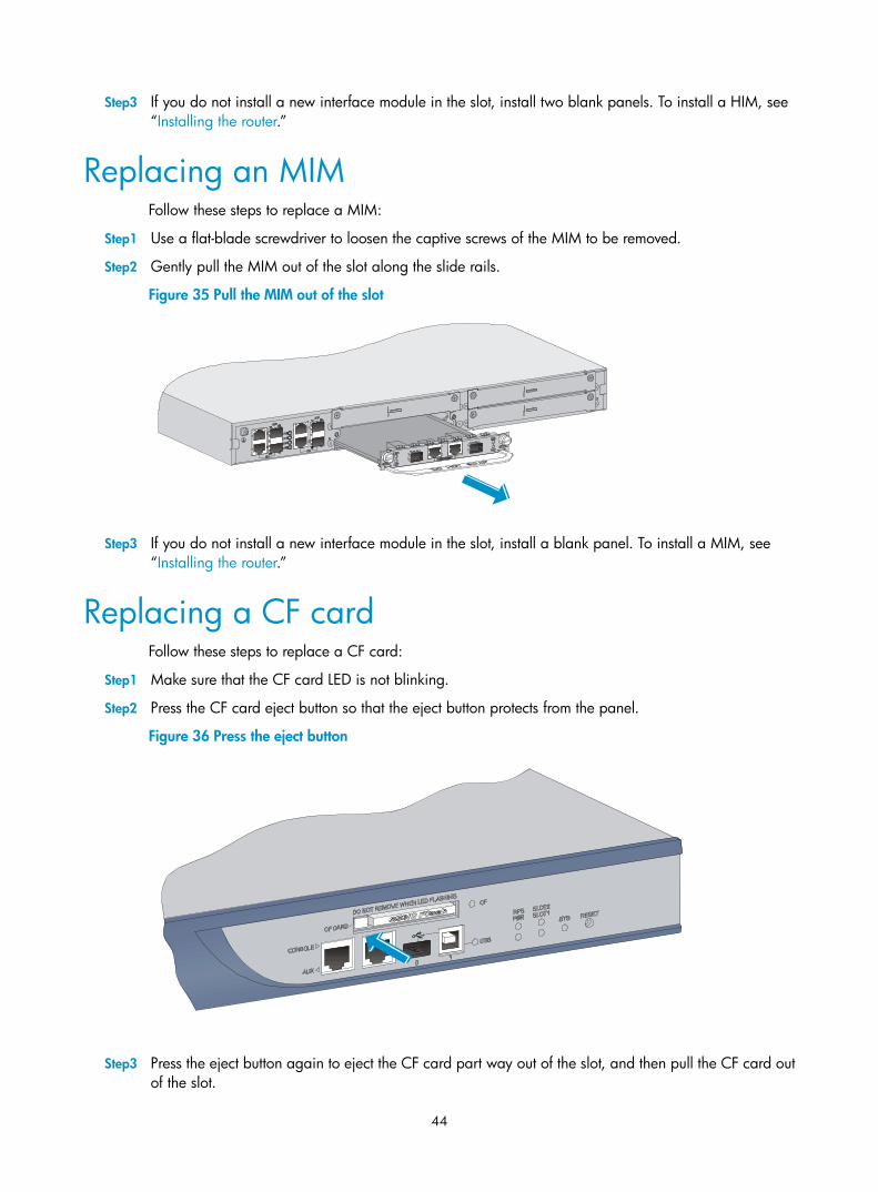
44
Step3 If you do not install a new interface module in the slot, install two blank panels. To install a HIM, see “Installing the router.”
Replacing an MIM Follow these steps to replace a MIM:
Step1 Use a flat-blade screwdriver to loosen the captive screws of the MIM to be removed.
Step2 Gently pull the MIM out of the slot along the slide rails.
Figure 35 Pull the MIM out of the slot
Step3 If you do not install a new interface module in the slot, install a blank panel. To install a MIM, see “Installing the router.”
Replacing a CF card Follow these steps to replace a CF card:
Step1 Make sure that the CF card LED is not blinking.
Step2 Press the CF card eject button so that the eject button protects from the panel.
Figure 36 Press the eject button
Step3 Press the eject button again to eject the CF card part way out of the slot, and then pull the CF card out of the slot.

45
Figure 37 Press the eject button to eject the CF card
Step4 Install a new CF card. For more information, see “Installing the router.”
CAUTION:
• To avoid hardware damage, do not remove the CF card when the router is booting or the CF card LEDis blinking.
• To protect the CF card, place it into an antistatic bag.
Replacing a transceiver module NOTE:
When replacing a transceiver module, make sure that the two transceiver modules connected by the sameoptical fiber have the same wavelength.
WARNING!
• Do not stare into the optical fibers.
• When removing a transceiver module, do not touch the golden finger of the transceiver module.
Follow these steps to replace a transceiver module:
Step1 Remove the optical fibers from the transceiver module.
Step2 Pivot the clasp downward to the horizontal position.
Step3 As shown in Figure 38, holding the handle of the transceiver module, gently pull the transceiver module out.
Step4 Insert the plastic plug to the removed transceiver module, and put the module into its original shipping materials.
Step5 Install a new transceiver module. For more information, see “Connecting Ethernet cables.”

46
Figure 38 Remove a transceiver module
Replacing a memory module
When to replace a memory module Memory modules are removable components of the router.
You need to replace a memory module in the following situations:
• More memory is needed to upgrade the application program.
• The router needs to maintain a larger routing table or support other highly memory consuming operations.
• An existing memory module is damaged.
CAUTION:
• Use the memory modules provided by H3C only. Otherwise, the router may be unable to operate properly.
• Memory modules with the same capacity must be used in pairs, for the specifications of memory modules supported by the H3C SR6602 router, see “Appendix A Technical specifications.”
Replacement procedure Figure 39 shows the memory module replacement flowchart.

47
Figure 39 Memory module replacement flowchart
Opening the router chassis cover
CAUTION:
Keep the tamper-proof seal on a mounting screw on the chassis cover intact, and if you want to open thechassis, contact the local agent of H3C for permission.
Follow these steps to open the router chassis cover:
Step1 Power off the router and unplug the power cables.
Step2 Unplug all cables from the interface modules while keeping the grounding cable connected, and use a screwdriver to remove the fastening screws on both sides and the top of the router.
Figure 40 Remove screws at both sides and on the top of the router
Step3 Insert two flat-blade screwdrivers into the key holes on both sides of the chassis, and gently pry the cover until the top and bottom sections separate slightly.

48
Figure 41 Insert screwdrivers into key holes and pry the cover
Step4 Facing the rear panel of the router, pull the chassis cover backward about 5 cm (1.97 in).
Figure 42 Pull the chassis cover backward about 5 cm (1.97 in)
Step5 Lift the end of the chassis cover and then pull the chassis cover away from the bottom part of the chassis.

49
Figure 43 Remove the chassis cover
Memory module structure
Figure 44 Structure of a memory module
(a ) Front view
(b ) Rear view
1 2 3
1 2 3
(1) Connector edge (2) Polarization notch (3) Latch notch

50
Memory module slot Figure 45 Memory module slot
1 2
(1) Release latch (2) Memory module slot
Removing a memory module Follow these steps to remove a memory module:
Step1 Make sure all power sources to the router are disconnected.
Step2 Pull the release latches away from the memory module at both ends so that the memory module is lifted from the memory module slot.
Step3 Holding the non-conductive edge, remove the memory module.
Figure 46 Remove the memory module
CAUTION:
• Do not touch the surface-mounted components of the memory module directly with your hands to avoiddamaging the memory module. Hold the memory module only at its non-conductive edge.
• To protect the removed memory module, place it in an antistatic bag.
Installing a memory module Follow these steps to install a memory module:
Step1 Make sure all power sources to the router are disconnected.
Step2 Align the polarization notch of the memory module with the key in the memory module slot.

51
Step3 Position the memory module so that it is perpendicular to the memory module slot and insert the memory module into the memory module slot.
Step4 Carefully and firmly press the memory module at both ends until you hear a click, which indicates the memory module is seated in the memory module slot.
Step5 Check that the release latches have firmly locked the memory module in position.
Figure 47 Install the memory module

52
Troubleshooting
This chapter includes these sections:
• Power supply system failure
• Fan failure
• Configuration terminal problems
• Password loss
• Cooling system failure
• Interface module, cable, and connection failure
NOTE:
• The barcode stuck on the router chassis contains production and servicing information. Before you returna faulty router for serving, provide the barcode information of the router to your local sales agent.
• Keep the tamper-proof seal on a mounting screw on the chassis cover intact, and if you want to open thechassis, contact the local agent of H3C for permission. Otherwise, H3C shall not be liable for any consequence caused thereby.
Power supply system failure The router cannot be powered on. The power LED on the front panel is off.
Follow these steps to troubleshoot the power supply system:
Step1 Turn off the power switch.
Step2 Open the chassis cover.
Step3 Check whether the power cord is properly, firmly connected.
Step4 Check whether the power cord is damaged.
If the cause cannot be located in the steps above and the problem persists, contact your local sales agent.
Fan failure After the router is booted, the following information appears: %Jun 22 16:11:37:485 2010 H3C DEV/4/FAN FAILED:
Fan 1 failed.
Follow these steps to troubleshoot the fans:
Step1 Turn off the power switch.
Step2 Open the chassis cover.
Step3 Check whether the fans are in position.
Step4 Check whether any fan has stopped running. If yes, contact your local sales agent to have the fan replaced.

53
If the cause cannot be located in the steps above and the problem persists, contact your local sales agent.
Configuration terminal problems If the configuration environment setup is correct, the configuration terminal displays boot information when the router is powered on. If the setup is incorrect, the configuration terminal displays nothing or garbled text.
No terminal display If the configuration terminal displays nothing when the router is powered on, check the following items:
• The power supply system works properly.
• The console cable is properly connected.
If no problem is found, the following reasons may apply:
• The console cable is connected to an incorrect serial interface (the serial interface in use is not the one set on the terminal).
• The properties of the terminal are incorrect. You must configure the configuration terminal as follows: set Bits per second to 9600, Data bits to 8, Parity to None, Stop bits to 1, Flow control to None, and Terminal Emulation to VT100.
• The console cable is not in good condition.
Garbled terminal display If terminal display is garbled, check that the Data bits field is set to 8 for the configuration terminal.
No response from the serial port If the serial port gives no response, check that the cable is in good condition and the serial port settings are correct.
NOTE:
For more information about the serial port settings, see “Logging in to the router and configuring basicsettings.”
Password loss
User password loss If you lose your password, you cannot enter the system. In this case, you can boot the system by ignoring the system configuration. Follow these steps to solve the user password loss:
Step1 Enter the BootWare main menu, and select 6 to boot the system by ignoring the system configuration.
The system prompts the following: Flag Set Success.
The output indicates that the setting succeeded.

54
Step2 When the BootWare main menu appears again, select 0 to reboot the system. System is rebooting now.
System start booting...
Booting Normal Extend BootWare....
Step3 Set a new password in system view after the system reboots. <H3C> system-view
[H3C] user-interface console 0
[H3C-ui-console0] authentication-mode password
[H3C-ui-console0] set authentication password simple 123456
The output shows that the console port uses password authentication, and the password is set to 123456 and stored in plain text.
When you set the password by using the set authentication password { cipher | simple } password command, follow these guidelines.
• If the cipher keyword is specified, the password is stored in cipher text. You cannot view the password by using the display current-configuration command.
• If the simple keyword is specified, the password is stored in plain text. You can use the display current-configuration command to view the password in the current configuration.
NOTE:
• After the router reboots, the system runs with the initial default configuration, but the previous configuration file is still stored in the storage medium. To restore the previous configuration, use the display saved-configuration command to display the configuration, and then copy and execute the configuration.
• If the password is stored in plain text, you can use the display current-configuration command to viewthe password in the current configuration. If the password 123456 is set with the set authentication password cipher command, the password is stored in cipher text.
Step4 Save the new password. [H3C] save
NOTE:
• To save the new password, execute the save command after modifying the user password.
• H3C recommends saving the modification as the default configuration file.
Super password loss The super password enables you to switch between four super levels. In the case of super password loss, you cannot perform higher level operations.
You can clear the super password by selecting 8 on the BootWare main menu. ========================<EXTEND-BOOTWARE MENU>========================
|<1> Boot System |
|<2> Enter Serial SubMenu |
|<3> Enter Ethernet SubMenu |
|<4> File Control |
|<5> Modify BootWare Password |
|<6> Skip Current System Configuration |

55
|<7> BootWare Operation Menu |
|<8> Clear Super Password |
|<9> Storage Device Operation |
|<0> Reboot |
======================================================================
Enter your choice(0-9):8
The following output indicates that you have successfully cleared the super password. Clear Application Password Success!
NOTE:
• Select option 8, quit the menu, reboot the router, and then you can enter system view directly.
• This setting (password clearing) is valid only for the first reboot of the router. The super password will berestored after a second reboot.
Cooling system failure When the temperature inside the router exceeds 45°C (113°F), the cooling system may have failed.
Follow these steps to troubleshoot the cooling system:
Step1 Check whether the fans are running properly.
Step2 Check whether the working environment of the router is well ventilated.
Step3 If the temperature inside the router exceeds 75°C (167°F), the following information appears on the configuration terminal: %Jun 28 10:27:27:653 2010 H3C DRVMSG/3/Temp2High:
Environment temperature too high in Slot 0, index is 1.
#Jun 28 10:27:28:432 2010 H3C DEV/1/BOARD TEMPERATURE UPPER:
Trap 1.3.6.1.4.1.2011.2.23.1.12.1.16<hwBoaardTemperatureHigher>:frameIndex is
0, slotIndex 0.0
%Jun 28 10:27:28:433 2010 H3C DEV/4/BOARD TEMP TOOHIGH:
Board temperature is too high on Frame 0 Slot 0, type is RPU.
Step4 Use the display environment command to check whether the temperature in the router keeps rising. If the temperature inside the router exceeds 90°C (194°F), power off the router immediately and contact your local sales agent.
NOTE:
For more information about the display environment command, see the H3C SR6600 Routers Fundamentals Command Reference.
Interface module, cable, and connection failure After an HIM/MIM is installed and the router is powered on, the LEDs on the HIM/MIM panel indicate abnormal operation.
Follow these steps to solve this problem:

56
Step1 Check whether the HIM/MIM cable is correctly selected.
Step2 Check whether the HIM/MIM cable is correctly connected.
Step3 Use the display command to check whether the interface has been correctly configured and is working properly.

57
Appendix A Technical specifications
Dimensions and weight Table 15 Dimensions and weight
Item Specification
Height (H) 44 mm (1.73 in), which is approximately one rack unit (RU)
Width (W) 442 mm (17.40 in)
Depth (D) 460 mm (18.11 in)
Weight 7.5 kg (16.53 lb)
Storages Table 16 Processor and storages
Item Specification
Flash 4 MB
Memory type and capacity
DDR2 SDRAM
2 GB (default)
4 GB (maximum)
Memory modules with the same capacity must be used in pairs.
Compact flash (CF) card 256 MB by default for the built-in CF card; 256 MB, 512 MB, or 1 GB for an optional external CF card (CF cards less than 256 MB are not supported)
AC power supply Table 17 AC power specifications
Item Specification
Rated voltage range 100 VAC to 240 VAC; 50 Hz or 60 Hz
Maximum input current 2.5 A
Maximum power 150 W
RPS power supply (optional) The redundancy power supply (RPS) can provide power supply to ensure continuous system operation for a short period when the system power supply fails.

58
The SR6602 supports AC power input and RPS input. They can guarantee the router to continue working when one power supply fails, providing high reliability.
Table 18 RPS power specifications
Item Specification
Rated output voltage 12 V
Maximum output current 14 A
Maximum output power 168 W
Power consumption range Table 19 Power consumption range of the entire system
Item Specification
Power consumption range 63 W to 120 W
Fixed ports specifications
Port and slot specifications Table 20 Port and slot specifications
Item Specifications
Console ports 1, speed 9600 bps (default) to 115200 bps
AUX ports 1, speed 9600 bps (default) to 115200 bps
USB ports 2 (USB 0—host mode, type A, USB 1—device mode, type B)
Combo interfaces 4 (copper ports GE0 to GE3, fiber ports SFP0 to SFP3)
CF card slots 1
Interface module slots 2
Console port The SR6602 provides an RS-232 asynchronous serial console port that can be connected to a computer for system debugging, configuration, maintenance, management, and host software loading.
Table 21 Technical specifications for the console port
Item Specification
Connector RJ-45
Compliant standard RS-232
Baud rate 9600 bps to 115200 bps
9600 bps (default)

59
Item Specification
Transmission distance ≤15 m (49.21 ft)
Services
Provides connection to an ASCII terminal
Provides connection to the serial port of a local PC to run the terminal emulation program
Command line port (CLI)
AUX port The AUX port is an RS-232 asynchronous serial port used for remote configuration or dialup backup. You must connect the local modem to the remote modem through public switched telephone network (PSTN) and then to the remote device for remote system debugging, configuration, maintenance, and management. In the event that the console port fails, the AUX port can be connected to a terminal as a backup port of the console port. For how to connect a terminal through the AUX port, see the chapter “Connecting Ethernet cables.”
Table 22 Technical specifications for the AUX port
Item Specification
Connector RJ-45
Compliant standard RS-232
Baud rate 9600 bps to 115200 bps
9600 bps (default)
Services Used to connect the serial port of a remote PC through a pair of modems to establish a dial-up connection with the PC
Combo ports Technical specifications for copper Ethernet ports
Table 23 Technical specifications for copper Ethernet ports
Item Specification
Connector RJ-45
Port Automatic MDI/MDI-X
Frame format Ethernet_II
Ethernet_SNAP
10 Mbps auto-sensing Half/full-duplex auto-negotiation
100 Mbps auto-sensing Half/full-duplex auto-negotiation Rate and duplex mode
1000 Mbps auto-sensing Full-duplex
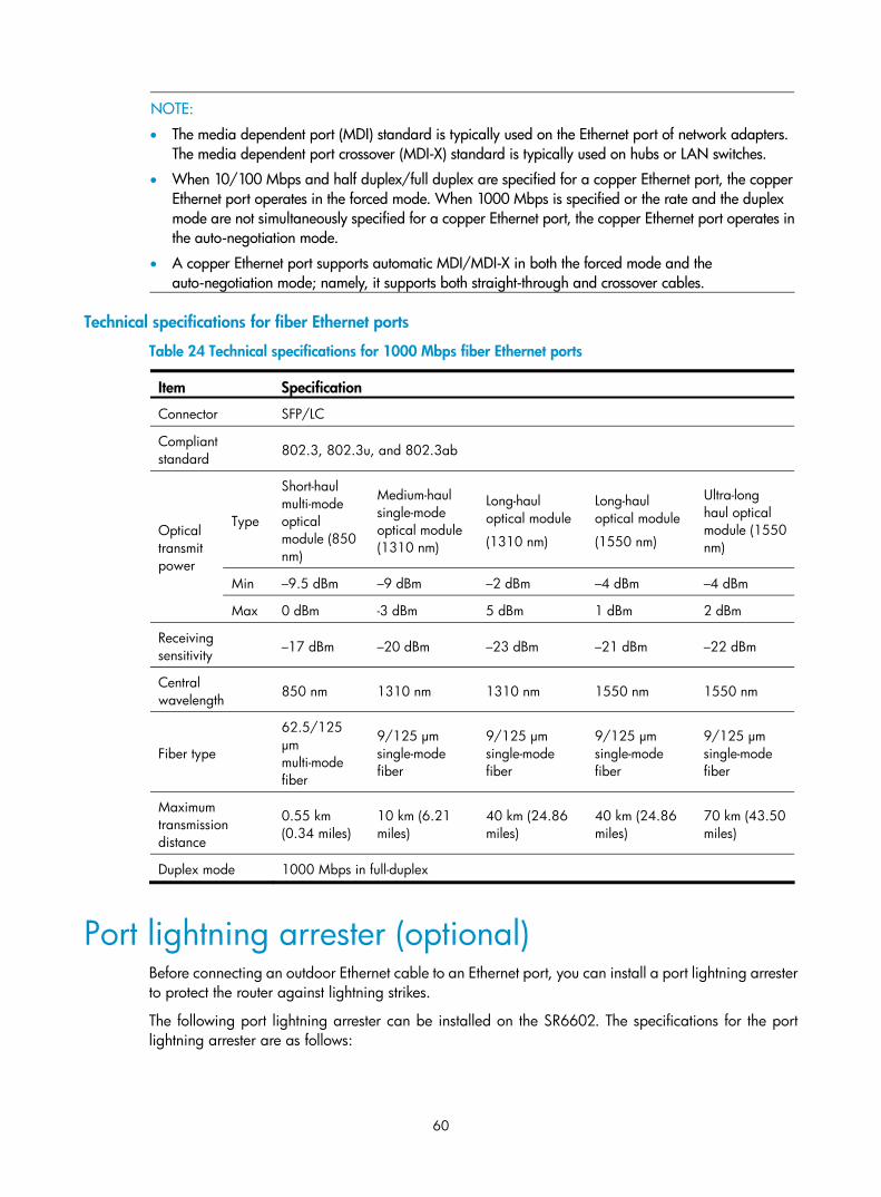
60
NOTE:
• The media dependent port (MDI) standard is typically used on the Ethernet port of network adapters. The media dependent port crossover (MDI-X) standard is typically used on hubs or LAN switches.
• When 10/100 Mbps and half duplex/full duplex are specified for a copper Ethernet port, the copper Ethernet port operates in the forced mode. When 1000 Mbps is specified or the rate and the duplex mode are not simultaneously specified for a copper Ethernet port, the copper Ethernet port operates inthe auto-negotiation mode.
• A copper Ethernet port supports automatic MDI/MDI-X in both the forced mode and the auto-negotiation mode; namely, it supports both straight-through and crossover cables.
Technical specifications for fiber Ethernet ports
Table 24 Technical specifications for 1000 Mbps fiber Ethernet ports
Item Specification
Connector SFP/LC
Compliant standard 802.3, 802.3u, and 802.3ab
Type
Short-haul multi-mode optical module (850 nm)
Medium-haul single-mode optical module (1310 nm)
Long-haul optical module
(1310 nm)
Long-haul optical module
(1550 nm)
Ultra-long haul optical module (1550 nm)
Min –9.5 dBm –9 dBm –2 dBm –4 dBm –4 dBm
Optical transmit power
Max 0 dBm -3 dBm 5 dBm 1 dBm 2 dBm
Receiving sensitivity –17 dBm –20 dBm –23 dBm –21 dBm –22 dBm
Central wavelength 850 nm 1310 nm 1310 nm 1550 nm 1550 nm
Fiber type
62.5/125 μm multi-mode fiber
9/125 μm single-mode fiber
9/125 μm single-mode fiber
9/125 μm single-mode fiber
9/125 μm single-mode fiber
Maximum transmission distance
0.55 km (0.34 miles)
10 km (6.21 miles)
40 km (24.86 miles)
40 km (24.86 miles)
70 km (43.50 miles)
Duplex mode 1000 Mbps in full-duplex
Port lightning arrester (optional) Before connecting an outdoor Ethernet cable to an Ethernet port, you can install a port lightning arrester to protect the router against lightning strikes.
The following port lightning arrester can be installed on the SR6602. The specifications for the port lightning arrester are as follows:

61
Port protective unit–single port, maximum discharge current (8/20 μs waveform): 5 kA; output voltage (10/700 μs waveform): core-core < 40 V, core-ground < 600 V.
NOTE:
For how to install the port lightning arrester, see the chapter “Installing the router.”
Power lightning arrester (optional) Before connecting an outdoor AC power supply to the router, you must install a lightning protection busbar at the AC power input end and then connect the AC power cord to the lightning protection busbar to protect the router against lightning strikes. In a heavy lightning area, H3C recommends installing a power lightning arrester.
The following power lightning arrester can be installed on the SR6602. The specifications for the power lightning arrester are as follows:
Maximum discharge current: 6500 A; protection voltage: 220 VAC to 500 VAC.
NOTE:
For how to install the power lightning arrester, see the chapter “Installing the router.”
Signal lightning arrester (optional) Typically, you must connect a signal lightning arrester—a transient over-voltage protection—before connecting a signal cable to the router. This can protect electronic devices against surge over-voltage resulting from lightning strikes and other interferences, and minimize impact on the router.
The SR6602 supports the following types of signal lightning arresters:
• Voltage-limiting protection-signal lightning arrester-maximum discharge current 2.5KA/protection voltage 25V--SMB-75J/SMB-75J-1W-10Mbps
• Voltage-limiting protection-signal lightning arrester-maximum discharge current 2.5KA/protection voltage 25V-BNC-75K/BNC-75K-10Mbps
• Voltage-limiting protection-signal lightning arrester (U port) -maximum discharge current 3KA/common mode 400 V/differential mode 170V-RJ11.
NOTE:
For how to install the signal lightning arrester, see the chapter “Installing the router.”

62
Appendix B LEDs
Panel LEDs Front panel LEDs
Table 25 Description of front panel LEDs
LED Status Meaning
Off The power module is not supplying power to the system.
PWR (green)
On The power module is supplying power to the system properly.
Off No RPS DC power input.
Solid green Both AC power input and RPS DC input are normal.
RPS (yellow/green)
Solid yellow AC power input is abnormal, and RPS DC input is normal.
Off No interface module is in slot 1 or the interface module is faulty.
SLOT1 (green)
On An interface module is in slot 1 and operates properly.
Off No interface module is in slot 2 or the interface module is faulty.
SLOT2 (green)
On An interface module is in slot 2 and operates properly.
Off The system is powered off or the board is faulty.
Slow blinking (1 Hz) The board operates properly as configured.
SYS (green)
Fast blinking (8 Hz) Software is being loaded or the board does not start working yet.
Off No CF card is in position or the CF card cannot be identified.
On A CF card is in position and the host has detected the CF card. You can remove the card in this state.
CF (green)
Blinking The system is accessing the CF card. Do not remove the card in this state.
Off No host is connected to the USB port.
On A host is connected to the USB port. You can unplug the USB cable in this state.
USB1 (green)
Blinking Data is being transmitted or received. Do not unplug the USB cable in this state.

63
Rear panel LEDs
Table 26 Description of rear panel LEDs
LED Status Meaning
Off No link is present.
Solid green A 1000 Mbps link is present.
Flashing green Data is being received or transmitted at a rate of 1000 Mbps.
Solid yellow A 10/100 Mbps link is present.
GE0 to GE3 (yellow/green)
Flashing yellowData is being received or transmitted at a rate of 10/100 Mbps.
Off No link is present.
Solid green A 1000 Mbps link is present.
Flashing green Data is being received or transmitted at a rate of 1000 Mbps.
SFP0 to SFP3 (yellow/green)
Solid yellow The system fails to detect the SFP port.
Interface module LEDs The H3C SR6602 supports various types of interface modules. The type and quantity of LEDs on the interface modules vary by model.
For more information about the LEDs of interface modules, see the H3C SR6600 Routers Interface Module Guide.

64
Appendix C Cables
The H3C SR6602 supports various types of interface modules. The port types of the interface modules vary by model.
For how to use cables to connect the ports of different interface modules, see the H3C SR6600 Routers Interface Module Guide.
Table 27 Cables
Cable Applicable port type Description
Ethernet twisted pair cable RJ-45 Ethernet port Connects the RJ-45 Ethernet port of the router for data transmission.
Optical fiber SFP port Connects the fiber port of the router for data transmission.
E1 interface cable E1 interface Connects the E1 interface of the router for data transmission.
T1 interface cable T1 interface Connects the T1 interface of the router for data transmission.
CE3/CT3 interface cable CE3/CT3 interface Connects the CE3/CT3 interface of the router for data transmission.
Serial port cable Serial port Connects the serial port of the router for data transmission.
Ethernet twisted pair cable
Introduction An Ethernet twisted pair cable consists of four pairs of insulated copper wires twisted together. Every wire uses a different color, and has a diameter of about 1 mm (0.04 in). A pair of twisted copper cables can cancel the electromagnetic radiation of each other, and reduce interference of external sources. An Ethernet twisted pair cable mainly transmits analog signals and is advantageous in transmitting data over shorter distances. It is the commonly used transmission media of the Ethernet. The maximum transmission distance of the Ethernet twisted pair cable is 100 m (328.08 ft). To extend the transmission distance, you can connect two twisted pair cable segments with a repeater. At most four repeaters can be added, which means five segments can be joined together to provide a transmission distance of 500 m (1640.42 ft).
Ethernet twisted pair cables can be classified into category 3, category 4, category 5, category 5e, category 6, and category 7 cables based on performance. In LANs, category 5, category 5e, and category 6 are commonly used.
Table 28 Description of commonly used Ethernet twisted pair cables
Type Description
Category 5 Suitable for data transmission at a maximum speed of 100 Mbps

65
Type Description
Category 5e Suitable for data transmission at a maximum speed of 1000 Mbps
Category 6 Suitable for data transmission at a speed higher than 1 Gbps
Based on whether a metal shielding is used, Ethernet twisted pair cables can be classified into shielded twisted pair (STP) and unshielded twisted pair (UTP). An STP cable provides a metallic braid between the twisted pairs and the outer jacket. This metallic braid helps reduce radiation, prevent information from being listened, and eliminate external electromagnetic interference (EMI) of external sources. STPs have strict application requirements and are expensive although they provide better EMI prevention performance than UTPs, so in most LANs, UTPs are commonly used.
An Ethernet twisted pair cable connects network devices through the RJ-45 connectors at the two ends. Figure 48 shows the pinouts of an RJ-45 connector.
Figure 48 RJ-45 connector pinout
NOTE:
The RJ-45 Ethernet interfaces of the H3C SR6602 routers use category 5 or higher Ethernet twisted pair cables for connection.
EIA/TIA cabling specifications define two standards, 568A and 568B, for cable pinouts.
• Standard 568A—pin 1: white/green stripe, pin 2: green solid, pin 3: white/orange stripe, pin 4: blue solid, pin 5: white/blue stripe, pin 6: orange solid, pin 7: white/brown stripe, pin 8: brown solid.
• Standard 568B—pin 1: white/orange stripe, pin 2: orange solid, pin 3: white/green stripe, pin 4: blue solid, pin 5: white/blue stripe, pin 6: green solid, pin 7: white/brown stripe, pin 8: brown solid.
Ethernet twisted pair cables can be classified into straight-through and crossover cables based on their pinouts.
• Straight-through: The pinouts at both ends are T568B compliant, as shown in Figure 49.
• Crossover: The pinouts are T568B compliant at one end and T568A compliant at the other end, as shown in Figure 50.

66
Figure 49 Straight-through cable
Straight-through cable
white/orange
orangewhite/green
blue
white/bluegreen
white/brown
brown
12345678
white/orange
orangewhite/green
blue
white/bluegreen
white/brown
brown
12345678
Figure 50 Crossover cable
Crossover cable
white/orange
orange
white/green
green
white/orange
orangewhite/green
blue
white/bluegreen
white/brown
brown
12345678
blue
white/blue
white/brown
brown
12345678
Select an Ethernet twisted pair cable according to the RJ-45 Ethernet port type on your device. An RJ-45 Ethernet port can be MDI (for routers and PCs) or MDIX (for switches). Table 29 and Table 30 show their pinouts.

67
Table 29 RJ-45 MDI port pinouts
10Base-T/100Base-TX 1000Base-T Pin
Signal Function Signal Function
1 Tx+ Sends data BIDA+ Bi-directional data cable A+
2 Tx- Sends data BIDA- Bi-directional data cable A-
3 Rx+ Receives data BIDB+ Bi-directional data cable B+
4 Reserved N/A BIDC+ Bi-directional data cable C+
5 Reserved N/A BIDC- Bi-directional data cable C-
6 Rx- Receives data BIDB- Bi-directional data cable B-
7 Reserved N/A BIDD+ Bi-directional data cable D+
8 Reserved N/A BIDD- Bi-directional data cable D-
Table 30 RJ-45 MDIX port pinouts
10Base-T/100Base-TX 1000Base-T Pin
Signal Function Signal Function
1 Rx+ Receives data BIDB+ Bi-directional data cable B+
2 Rx- Receives data BIDB- Bi-directional data cable B-
3 Tx+ Sends data BIDA+ Bi-directional data cable A+
4 Reserved N/A BIDD+ Bi-directional data cable D+
5 Reserved N/A BIDD- Bi-directional data cable D-
6 Tx- Sends data BIDA- Bi-directional data cable A-
7 Reserved N/A BIDC+ Bi-directional data cable C+
8 Reserved N/A BIDC- Bi-directional data cable C-
To ensure normal communication, the pins for sending data on one port must correspond to the pins for receiving data on the peer port. When both of the ports on the two devices are MDI or MDIX, use a crossover Ethernet cable; when one port is MDI and the other is MDIX, use a straight-through Ethernet cable. To summarize, straight-through and crossover cables connect the following devices:

68
• Straight-through cables connect devices of different types—for example, router to PC and router to switch.
• Crossover cables connect devices of the same type—for example, switch to switch, router to router, and PC to PC.
If an RJ-45 Ethernet port is enabled with MDI/MDIX autosensing, it can automatically negotiate pin roles.
NOTE:
The H3C SR6602 RJ-45 Ethernet interfaces support MDI/MDIX autosensing. By default, MDI/MDIX autosensing is enabled on an interface.
Making an Ethernet twisted pair cable Follow these steps to make an Ethernet twisted pair cable:
Step1 Cut the cable to a proper length with the crimping pliers.
Step2 Strip off an appropriate length of the cable sheath. The length is typically that of the RJ-45 connector.
Step3 Untwist the pairs so that they can lay flat, and arrange the colored wires based on the wiring specifications.
Step4 Cut the top of the wires even with one another. Insert the wires into the RJ-45 end and make sure the wires extend to the front of the RJ-45 end and make good contact with the metal contacts in the RJ-45 end and in the correct order.
Step5 Crimp the RJ-45 connector with the crimping pliers until you hear a click.
Step6 Use a cable tester to verify the proper connectivity of the cable.
Optical fiber You can use an optical fiber to connect the following interface modules: HIM-4GBP/HIM-8GBP, HIM-CL1P/HIM-CL2P, HIM-CLS1P/HIM-CLS2P, HIM-MSP2P/HIM-MSP4P, HIM-PS1P, HIM-AL1P/HIM-AL2P, HIM-RS2P, MIM-2GBE, MIM-1POS, and MIM-1ATM-OC3.
Optical fibers feature low loss and long transmission distance.
Optical fibers can be classified into single mode fibers and multi-mode fibers. A single mode fiber carries only a single ray of light; a multi-mode fiber carries multiple modes of lights.
Table 31 Characteristics of single mode and multi-mode optical fibers
Single mode fiber Multi-mode fiber
Core Small core (10 micrometers or less) Larger core than single mode fiber (50 micrometers, 62.5 micrometers or greater)
Dispersion Less dispersion Allows greater dispersion and therefore, signal loss exists.
Light source and transmission distance
Users lasers as the light source often within campus backbones for distance of several thousand meters
Uses LEDs as the light source often within LANs or distances of a couple hundred meters within a campus network

69
Table 32 Allowed maximum tensile force and crush load
Period of force Tensile load (N) Crush load (N/mm)
Short period 150 500
Long term 80 100
Fiber connectors are indispensable passive components in an optical fiber communication system. They allow the removable connection between optical channels, which makes the optical system debugging and maintenance more convenient. There are multiple types of fiber connectors. Figure 51 shows an LC connector.
Figure 51 Appearance of an LC connector
NOTE:
• Before connecting an optical fiber, make sure that the connector and cable type match the pluggable interface module.
• The H3C SR6602 router uses optical fibers to connect its XFP or SFP ports.
NOTE:
• Some cards of the H3C SR6602 router provide shielded covers for the fiber ports (such as SFP ports). Before using such fiber ports, remove the shielded covers. Keep the shielded covers properly. When thefiber ports are not in use, install the shielded covers.
• Fiber connectors are fitted with dust caps. Keep the dust caps properly when the fiber connectors are inuse. Install dust caps when the fiber connectors are not in use to avoid damage to their end face. Replacethe dust cap if it is loose or polluted.
• Before connecting an optical fiber, use dust free paper and absolute alcohol to clean the end face of thetwo fiber connectors. You can brush the end faces only in one direction.
• After a fiber is installed well, the bend radius must be not less than 10 cm (3.94 in).
• If the fiber has to pass through a metallic board hole, the hole must have a sleek and fully filleted surface(the filleting radius must be not less than 2 mm, or 0.08 in). When passing through a metallic board hole or bending along the acute side of mechanical parts, the fiber must wear jackets or cushions.
• Insert and remove a plug with care. Never exert a fierce force to the fiber or plug; otherwise the plug may be damaged or the fiber may be broken. Never pull, press or extrude the fiber fiercely. For the allowed maximum tensile load and crush load, see Table 32.
E1 interface cable You can use a 4E1 interface cable to connect the MIM-IMA-4E1/MIM-IMA-8E1 module, and 8E1 interface cable to connect the MIM-8E1(75)/MIM-8E1(75)-F module.

70
Figure 52 4E1 conversion cable
Figure 53 8E1 conversion cable
DB68
BNC
NOTE:
The coaxial connector and 75-ohm E1 trunk cable are optional accessories, and must be purchased separately if needed.
T1 interface cable You can use a 4T1 interface cable to connect the MIM-IMA-4T1 module, and 8T1 to connect the MIM-8T1/MIM-8T1-F module.

71
Figure 54 4T1 conversion cable
Figure 55 8T1 conversion cable
CAUTION:
• When connecting the interface cable, pay attention to the mark on the interface to avoid wrong insertion, which may damage the interface card or even the host.
• H3C recommends installing a special lightning arrester at the input end of the 4T1/8T1 cables to protectthem against lightning strikes more efficiently when they are led outdoors.
CE3/CT3 interface cable You can use a CE3/CT3 interface cable to connect the MIM-1CE3 and MIM-1CT3 modules.

72
Figure 56 E3/T3 cable
CAUTION:
H3C recommends installing a special lightning arrester at the input end of the E3/T3 cables to protect them against lightning strikes more efficiently when they are led outdoors.
Serial port cable You can use a serial port cable to connect the MIM-2SAE/MIM-4SAE/MIM-8SAE module. Select a serial port cable according to the link type.
Figure 57 V.24 DTE cable
Figure 58 V.24 DCE cable
A
Pos.25
Pos.1
A
X2
W
X1
BPos.1
Pos.28
B

73
Figure 59 V.35 DTE cable
Figure 60 V.35 DCE cable
Figure 61 X.21 DTE cable
Figure 62 X.21 DCE cable

74
Figure 63 RS449 DTE cable
Figure 64 RS449 DCE cable
Figure 65 RS530 DTE cable
Figure 66 RS530 DCE cable

75
Appendix D AC power cables used in different countries or regions
10A AC power cables used in different countries or regions
Table 33 10A AC power cables used in different countries or regions
1 Connector type Code (Length)
Countries or regions where the type of power cables conforms to local safety regulations and can be used legally
Other countries or regions using this type of power cables
Countries or regions seldom using this type of power cables
I type 04041104 (3 m, i.e., 9.8 ft) Mainland China
Connector outline Power cable outline Connector outline
2 Connector type Code (Length)
Countries or regions where the type of power cables conforms to local safety regulations and can be used legally
Other countries or regions using this type of power cables
Countries or regions seldom using this type of power cables
B type 04020728 (3 m, i.e., 9.8 ft) Canada and U.S.A
Mexico, Argentina, Brazil, Columbia, Venezuela, Thailand, Peru, Philippine, and A6 countries or regions
Connector outline Power cable outline Connector outline

76
3 Connector type Code (Length)
Countries or regions where the type of power cables conforms to local safety regulations and can be used legally
Other countries or regions using this type of power cables
Countries or regions seldom using this type of power cables
F type 04041056 (3 m, i.e., 9.8 ft)
Holland, Denmark, Sweden, Finland, Norway, Germany, France, Austria, Belgium, and Italy
Indonesia, Turkey, Russia, and CIS India
Connector outline Power cable outline Connector outline
4 Connector type Code (Length)
Countries or regions where the type of power cables conforms to local safety regulations and can be used legally
Other countries or regions using this type of power cables
Countries or regions seldom using this type of power cables
G type 04040890 (3 m, i.e., 9.8 ft) U.K.
Malaysia, Singapore, Hong Kong, and Egypt
Connector outline Power cable outline Connector outline
5 Connector type Code (Length)
Countries or regions where the type of power cables conforms to local safety regulations and can be used legally
Other countries or regions using this type of power cables
Countries or regions seldom using this type of power cables
B type 04040887 (3 m, i.e., 9.8 ft) Japan
Connector outline Power cable outline Connector outline

77
6 Connector type Code (Length)
Countries or regions where the type of power cables conforms to local safety regulations and can be used legally
Other countries or regions using this type of power cables
Countries or regions seldom using this type of power cables
D type 04040889 (3 m, i.e., 9.8 ft) Hong Kong South Africa
Connector outline Power cable outline Connector outline
7 Connector type Code (Length)
Countries or regions where the type of power cables conforms to local safety regulations and can be used legally
Other countries or regions using this type of power cables
Countries or regions seldom using this type of power cables
I type 04040888 (3 m, i.e., 9.8 ft) Australia
Connector outline Power cable outline Connector outline
8 Connector type Code (Length)
Countries or regions where the type of power cables conforms to local safety regulations and can be used legally
Other countries or regions using this type of power cables
Countries or regions seldom using this type of power cables
J type 04041119 (3 m, i.e., 9.8 ft) Switzerland
Connector outline Power cable outline Connector outline
9 Connector type Code (Length)
Countries or regions where the type of power cables conforms to local safety regulations and can be used legally
Other countries or regions using this type of power cables
Countries or regions seldom using this type of power cables

78
L type 04041120 (3 m, i.e., 9.8 ft)
Italy
Connector outline Power cable outline Connector outline
16A AC power cables used in different countries or regions
Table 34 16A AC power cables used in different countries or regions
1 Connector type Code (Length)
Countries or regions where the type of power cables conforms to local safety regulations and can be used legally
Other countries or regions using this type of power cables
Countries or regions seldom using this type of power cables
I type 04043396 (3 m, i.e., 9.8 ft) Mainland China
Connector outline Power cable outline Connector outline
2 Connector type Code (Length)
Countries or regions where the type of power cables conforms to local safety regulations and can be used legally
Other countries or regions using this type of power cables
Countries or regions seldom using this type of power cables
B type 0404A063 (3 m, i.e., 9.8 ft) Canada and U.S.A
Mexico, Argentina, Brazil, Columbia, Venezuela, Thailand, Peru, Philippine, and A6 countries or regions
Connector outline Power cable outline Connector outline

79
3 Connector type Code (Length)
Countries or regions where the type of power cables conforms to local safety regulations and can be used legally
Other countries or regions using this type of power cables
Countries or regions seldom using this type of power cables
F type 0404A061 (3 m, i.e., 9.8 ft)
Holland, Denmark, Sweden, Finland, Norway, Germany, France, Austria, Belgium, and Italy
Indonesia, Turkey, Russia, and CIS
Connector outline Power cable outline Connector outline
4 Connector type Code (Length)
Countries or regions where the type of power cables conforms to local safety regulations and can be used legally
Other countries or regions using this type of power cables
Countries or regions seldom using this type of power cables
G type 0404A060 (3 m, i.e., 9.8 ft) U.K.
Malaysia, Singapore, Hong Kong, and Egypt
Connector outline Power cable outline Connector outline
5 Connector type Code (Length)
Countries or regions where the type of power cables conforms to local safety regulations and can be used legally
Other countries or regions using this type of power cables
Countries or regions seldom using this type of power cables
B type 0404A062 (3 m, i.e., 9.8 ft) Japan
Connector outline Power cable outline Connector outline
6 Connector type Code (Length)
Countries or regions where the type of power cables conforms to local safety regulations and can be used legally
Other countries or regions using this type of power cables
Countries or regions seldom using this type of power cables

80
I type 0404A01A (3 m, i.e., 9.8 ft)
Australia
Connector outline Power cable outline Connector outline

81
Index
A C D E F G I L O P R S T V A
AC power supply,57
C
CE3/CT3 interface cable,71 Checklist before installation,7 Configuration terminal problems,53 Configuring a combo interface,38 Configuring basic settings,32 Connecting an AC power cord,23 Connecting an RPS DC power cord,24 Connecting Ethernet cables,17 Cooling system failure,55
D
Dimensions and weight,57 Displaying hardware information of the router,33 Displaying the temperature alarm thresholds for an interface module,38 Displaying transceiver module information and alarming information,39
E
E1 interface cable,69 Ethernet twisted pair cable,64 Examining the installation site,3
F
Fan failure,52 Fixed ports specifications,58 Front panel view,1
G
Grounding the router,13
I
Installation accessories,7 Installation flow,9 Installation tools,6 Installing a CF card,16 Installing a port lightning arrestor (optional),19
Installing a power lightning arrester (lightning protection busbar) (optional),20 Installing a signal lightning arrester (optional),22 Installing interface modules,14 Installing the router in a 19-inch rack,10 Interface module LEDs,63 Interface module, cable, and connection failure,55
L
Logging in through the console port,26 Logging in to the router through Telnet,31 Logging to the router through the AUX port,31 Login methods,26
O
Optical fiber,68
P
Panel LEDs,62 Password loss,53 Port lightning arrester (optional),60 Power consumption range,58 Power lightning arrester (optional),61 Power supply system failure,52 Powering on the router,30
R
Rear panel view,1 Rebooting the router,41 Replacing a CF card,44 Replacing a HIM,43 Replacing a memory module,46 Replacing a transceiver module,45 Replacing an MIM,44 RPS power supply (optional),57
S
Safety recommendations,2 Safety recommendations,43 Saving the running configuration of the router,41 Serial port cable,72

82
Signal lightning arrester (optional),61 Solving system faults,40 Storages,57
T
T1 interface cable,70
V
Verifying the installation,25