H3C MSR Series Routers
288
H3C MSR Series Routers Layer 3 - IP Services Configuration Guide(V7) Hangzhou H3C Technologies Co., Ltd. http://www.h3c.com Software version: MSR-CMW710-R0007 Document version: 6W100-20140320
-
Upload
khangminh22 -
Category
Documents
-
view
0 -
download
0
Transcript of H3C MSR Series Routers

H3C MSR Series RoutersLayer 3 - IP Services Configuration Guide(V7)
Hangzhou H3C Technologies Co., Ltd. http://www.h3c.com Software version: MSR-CMW710-R0007 Document version: 6W100-20140320

Copyright © 2014, Hangzhou H3C Technologies Co., Ltd. and its licensors
All rights reserved
No part of this manual may be reproduced or transmitted in any form or by any means without prior written consent of Hangzhou H3C Technologies Co., Ltd.
Trademarks
H3C, , H3CS, H3CIE, H3CNE, Aolynk, , H3Care, , IRF, NetPilot, Netflow, SecEngine, SecPath, SecCenter, SecBlade, Comware, ITCMM and HUASAN are trademarks of Hangzhou H3C Technologies Co., Ltd.
All other trademarks that may be mentioned in this manual are the property of their respective owners
Notice
The information in this document is subject to change without notice. Every effort has been made in the preparation of this document to ensure accuracy of the contents, but all statements, information, and recommendations in this document do not constitute the warranty of any kind, express or implied.

Preface
The H3C MSR documentation set includes 14 configuration guides, which describe the software features for the H3C MSR Series Routers and guide you through the software configuration procedures. These configuration guides also provide configuration examples to help you apply software features to different network scenarios.
The Layer 3 - IP Services Configuration Guide(V7) describes IPv4/IPv6 fundamentals and configuration, such as IP addressing, ARP, DNS, DHCP, NAT, GRE, and tunneling configuration.
This preface includes:
• Audience
• Conventions
• About the H3C MSR documentation set
• Obtaining documentation
• Technical support
• Documentation feedback
These configuration guides apply to the following models of the H3C MSR series routers:
Model
MSR 2600 • MSR 26-30
MSR 3600
• MSR 36-10 • MSR 36-20 • MSR 36-40 • MSR 36-60 • MSR3600-28 • MSR3600-51
MSR 5600 • MSR 56-60 • MSR 56-80
Audience This documentation is intended for:
• Network planners
• Field technical support and servicing engineers
• Network administrators working with the routers

Conventions
This section describes the conventions used in this documentation set.
Command conventions
Convention Description
Boldface Bold text represents commands and keywords that you enter literally as shown.
Italic Italic text represents arguments that you replace with actual values.
[ ] Square brackets enclose syntax choices (keywords or arguments) that are optional.
{ x | y | ... } Braces enclose a set of required syntax choices separated by vertical bars, from which you select one.
[ x | y | ... ] Square brackets enclose a set of optional syntax choices separated by vertical bars, from which you select one or none.
{ x | y | ... } * Asterisk marked braces enclose a set of required syntax choices separated by vertical bars, from which you select at least one.
[ x | y | ... ] * Asterisk marked square brackets enclose optional syntax choices separated by vertical bars, from which you select one choice, multiple choices, or none.
&<1-n> The argument or keyword and argument combination before the ampersand (&) sign can be entered 1 to n times.
# A line that starts with a pound (#) sign is comments.
Symbols
Convention Description
WARNING An alert that calls attention to important information that if not understood or followed can result in personal injury.
CAUTION An alert that calls attention to important information that if not understood or followed can result in data loss, data corruption, or damage to hardware or software.
IMPORTANT An alert that calls attention to essential information.
NOTE An alert that contains additional or supplementary information.
TIP An alert that provides helpful information.
Network topology icons
Represents a generic network device, such as a router, switch, or firewall.
Represents a routing-capable device, such as a router or Layer 3 switch.
Represents a generic switch, such as a Layer 2 or Layer 3 switch, or a router that supports Layer 2 forwarding and other Layer 2 features.
Port numbering in examples
The port numbers in this document are for illustration only and might be unavailable on your device.

About the H3C MSR documentation set The H3C MSR documentation set includes:
Category Documents Purposes
Product description and specifications Marketing brochures Describe product specifications and benefits.
Hardware specifications and installation
Installation guide Provides a complete guide to hardware installation and hardware specifications.
MSR Series Routers Interface Module Manual Provide the hardware specifications of cards.
Software configuration
MSR Series Routers Configuration guides(v7)
Describe software features and configuration procedures.
MSR Series Routers Command references(v7)
Provide a quick reference to all available commands.
Operations and maintenance Release notes
Provide information about the product release, including the version history, hardware and software compatibility matrix, version upgrade information, technical support information, and software upgrading.
Obtaining documentation You can access the most up-to-date H3C product documentation on the World Wide Web at http://www.h3c.com.
Click the links on the top navigation bar to obtain different categories of product documentation:
[Technical Support & Documents > Technical Documents]—Provides hardware installation, software upgrading, and software feature configuration and maintenance documentation.
[Products & Solutions]—Provides information about products and technologies, as well as solutions.
[Technical Support & Documents > Software Download]—Provides the documentation released with the software version.
Technical support [email protected]
http://www.h3c.com
Documentation feedback You can e-mail your comments about product documentation to [email protected].

We appreciate your comments.

i
Contents
Configuring ARP ··························································································································································· 1 Overview ············································································································································································ 1
ARP message format ················································································································································ 1 ARP operating mechanism ······································································································································ 1 ARP table ··································································································································································· 2
Configuring a static ARP entry ········································································································································· 3 Setting the maximum number of dynamic ARP entries for a device ············································································ 4 Setting the maximum number of dynamic ARP entries for an interface ······································································ 4 Setting the aging timer for dynamic ARP entries ··········································································································· 5 Enabling dynamic ARP entry check ································································································································ 5 Enabling ARP log output ··················································································································································· 5 Displaying and maintaining ARP ····································································································································· 6 Static ARP configuration example ··································································································································· 6
Network requirements ·············································································································································· 6 Configuration procedure ········································································································································· 7
Configuring gratuitous ARP ········································································································································· 8 Overview ············································································································································································ 8
Gratuitous ARP packet learning ······························································································································ 8 Periodic sending of gratuitous ARP packets ·········································································································· 8
Configuration procedure ·················································································································································· 9 Enabling IP conflict notification ···································································································································· 10
Configuring proxy ARP ·············································································································································· 11 Enabling common proxy ARP ······································································································································· 11 Enabling local proxy ARP·············································································································································· 11 Displaying proxy ARP ···················································································································································· 12 Common proxy ARP configuration example ··············································································································· 12
Network requirements ··········································································································································· 12 Configuration procedure ······································································································································ 12
Configuring ARP snooping ········································································································································ 14 Configuration procedure ··············································································································································· 14 Displaying and maintaining ARP snooping ················································································································ 14
Configuring ARP fast-reply ········································································································································· 16 Overview ········································································································································································· 16
Function ·································································································································································· 16 Operation ······························································································································································· 16
Configuration procedure ··············································································································································· 16 ARP fast-reply configuration example ·························································································································· 17
Network requirements ··········································································································································· 17 Configuration procedure ······································································································································ 17
Configuring IP addressing ········································································································································· 19 Overview ········································································································································································· 19
IP address classes ·················································································································································· 19 Special IP addresses ············································································································································· 20 Subnetting and masking ······································································································································· 20
Assigning an IP address to an interface ······················································································································ 21 Configuration guidelines ······································································································································ 21

ii
Configuration procedure ······································································································································ 21 Configuring IP unnumbered ·········································································································································· 21
Configuration guidelines ······································································································································ 22 Configuration prerequisites ·································································································································· 22 Configuration procedure ······································································································································ 22
Displaying and maintaining IP addressing ················································································································· 22 IP address configuration example ································································································································ 23
Network requirements ··········································································································································· 23 Configuration procedure ······································································································································ 23 Verifying the configuration ··································································································································· 23
IP unnumbered configuration example ························································································································ 24 Network requirements ··········································································································································· 24 Configuration procedure ······································································································································ 25 Verifying the configuration ··································································································································· 25
DHCP overview ·························································································································································· 27 DHCP address allocation ·············································································································································· 27
Allocation mechanisms ········································································································································· 27 Dynamic IP address allocation process··············································································································· 28 IP address lease extension···································································································································· 28
DHCP message format ··················································································································································· 29 DHCP options ································································································································································· 30
Common DHCP options ········································································································································ 30 Custom DHCP options ··········································································································································· 30
Protocols and standards ················································································································································ 32
Configuring the DHCP server ···································································································································· 33 Overview ········································································································································································· 33
DHCP address pool ··············································································································································· 33 IP address allocation sequence ···························································································································· 35
DHCP server configuration task list ······························································································································ 35 Configuring an address pool on the DHCP server ····································································································· 35
Configuration task list ··········································································································································· 35 Creating a DHCP address pool ··························································································································· 36 Specifying IP address ranges for a DHCP address pool ·················································································· 36 Specifying gateways for the client······················································································································· 39 Specifying a domain name suffix for the client ·································································································· 40 Specifying DNS servers for the client ·················································································································· 40 Specifying WINS servers and NetBIOS node type for the client ····································································· 41 Specifying BIMS server information for the client ······························································································ 41 Specifying the TFTP server and boot file name for the client ············································································ 42 Specifying a server for the DHCP client ·············································································································· 42 Configuring Option 184 parameters for the client ···························································································· 43 Configuring self-defined DHCP options ·············································································································· 43
Enabling DHCP ······························································································································································ 44 Enabling the DHCP server on an interface ·················································································································· 44 Applying an address pool on an interface ················································································································· 45 Configuring IP address conflict detection ···················································································································· 45 Enabling handling of Option 82 ·································································································································· 46 Configuring DHCP server compatibility ······················································································································· 46
Configuring the DHCP server to broadcast all responses ················································································· 46 Configure the DHCP server to ignore BOOTP requests ···················································································· 46 Configuring the DHCP server to send BOOTP responses in RFC 1048 format·············································· 47
Setting the DSCP value for DHCP packets sent by the DHCP server ········································································ 47 Displaying and maintaining the DHCP server ············································································································ 48

iii
DHCP server configuration examples ·························································································································· 48 Static IP address assignment configuration example························································································· 48 Dynamic IP address assignment configuration example ··················································································· 50 DHCP user class configuration example ············································································································· 51 Self-defined DHCP option configuration example ····························································································· 52
Troubleshooting DHCP server configuration ··············································································································· 53 Symptom ································································································································································· 53 Analysis ·································································································································································· 53 Solution ··································································································································································· 53
Configuring the DHCP relay agent ··························································································································· 55 Overview ········································································································································································· 55
Operation ······························································································································································· 55 DHCP relay agent support for Option 82 ·········································································································· 56
DHCP relay agent configuration task list ····················································································································· 56 Enabling DHCP ······························································································································································ 57 Enabling the DHCP relay agent on an interface ········································································································ 57 Specifying DHCP servers on a relay agent ················································································································· 57 Configuring the DHCP relay agent security functions ································································································ 58
Enabling the DHCP relay agent to record relay entries ···················································································· 58 Enabling periodic refresh of dynamic relay entries ··························································································· 58 Enabling DHCP starvation attack protection ······································································································ 59
Configuring the DHCP relay agent to release an IP address ···················································································· 60 Configuring Option 82 ················································································································································· 60 Setting the DSCP value for DHCP packets sent by the DHCP relay agent ······························································· 61 Displaying and maintaining the DHCP relay agent ··································································································· 61 DHCP relay agent configuration examples ················································································································· 61
DHCP relay agent configuration example ·········································································································· 61 Option 82 configuration example ······················································································································· 62
Troubleshooting DHCP relay agent configuration ······································································································ 63 Symptom ································································································································································· 63 Analysis ·································································································································································· 63 Solution ··································································································································································· 63
Configuring the DHCP client ····································································································································· 64 Enabling the DHCP client on an interface ··················································································································· 64 Configuring a DHCP client ID for an interface ··········································································································· 64 Enabling duplicated address detection ······················································································································· 65 Setting the DSCP value for DHCP packets sent by the DHCP client ········································································· 65 Displaying and maintaining the DHCP client ·············································································································· 66 DHCP client configuration example ····························································································································· 66
Network requirements ··········································································································································· 66 Configuration procedure ······································································································································ 67 Verifying the configuration ··································································································································· 67
Configuring DHCP snooping ····································································································································· 69 Overview ········································································································································································· 69
Application of trusted and untrusted ports ·········································································································· 69 DHCP snooping support for Option 82 ·············································································································· 70
DHCP snooping configuration task list ························································································································ 71 Configuring basic DHCP snooping ······························································································································ 71 Configuring Option 82 ················································································································································· 72 Saving DHCP snooping entries ···································································································································· 73 Enabling DHCP starvation attack protection ··············································································································· 74 Enabling DHCP-REQUEST attack protection ··············································································································· 74 Configuring DHCP packet rate limit ····························································································································· 75

iv
Displaying and maintaining DHCP snooping ············································································································· 75 DHCP snooping configuration examples ····················································································································· 76
Basic DHCP snooping configuration example ··································································································· 76 Option 82 configuration example ······················································································································· 77
Configuring the BOOTP client ··································································································································· 79 BOOTP application ························································································································································ 79 Obtaining an IP address dynamically ························································································································· 79 Protocols and standards ················································································································································ 79 Configuring an interface to use BOOTP for IP address acquisition·········································································· 80 Displaying and maintaining BOOTP client ················································································································· 80 BOOTP client configuration example ·························································································································· 80
Network requirements ··········································································································································· 80 Configuration procedure ······································································································································ 80
Configuring DNS ······················································································································································· 81 Overview ········································································································································································· 81
Static domain name resolution ····························································································································· 81 Dynamic domain name resolution ······················································································································· 81 DNS proxy ····························································································································································· 82 DNS spoofing ························································································································································ 83
DNS configuration task list ············································································································································ 84 Configuring the IPv4 DNS client ·································································································································· 85
Configuring static domain name resolution ········································································································ 85 Configuring dynamic domain name resolution ·································································································· 85
Configuring the IPv6 DNS client ·································································································································· 86 Configuring static domain name resolution ········································································································ 86 Configuring dynamic domain name resolution ·································································································· 87
Configuring the DNS proxy ·········································································································································· 87 Configuring DNS spoofing ··········································································································································· 88 Specifying the source interface for DNS packets ······································································································· 88 Configuring the DNS trusted interface ························································································································· 89 Specifying the DSCP value for outgoing DNS packets ······························································································ 90 Displaying and maintaining IPv4 DNS ························································································································ 90 IPv4 DNS configuration examples ······························································································································· 90
Static domain name resolution configuration example ····················································································· 90 Dynamic domain name resolution configuration example ··············································································· 91 DNS proxy configuration example ······················································································································ 94
IPv6 DNS configuration examples ······························································································································· 96 Static domain name resolution configuration example ····················································································· 96 Dynamic domain name resolution configuration example ··············································································· 96 DNS proxy configuration example ···················································································································· 101
Troubleshooting IPv4 DNS configuration ·················································································································· 102 Symptom ······························································································································································· 102 Solution ································································································································································· 102
Troubleshooting IPv6 DNS configuration ·················································································································· 102 Symptom ······························································································································································· 102 Solution ································································································································································· 102
Configuring DDNS ·················································································································································· 104 Overview ······································································································································································· 104
DDNS application ··············································································································································· 104 DDNS client configuration task list ····························································································································· 105 Configuring a DDNS policy ········································································································································ 105
Configuration prerequisites ································································································································ 106 Configuration procedure ···································································································································· 106
v
Applying the DDNS policy to an interface ················································································································ 107 Specifying the DSCP value for outgoing DDNS packets ························································································· 107 Displaying DDNS ························································································································································· 108 DDNS configuration examples ··································································································································· 108
DDNS configuration example with www.3322.org ······················································································· 108 DDNS configuration example with PeanutHull server ····················································································· 109
Configuring NAT ····················································································································································· 111 Terminology ·································································································································································· 111
NAT device ·························································································································································· 111 NAT interface ······················································································································································ 111 NAT address ························································································································································ 112 NAT entry ····························································································································································· 112
NAT types ····································································································································································· 112 Traditional NAT ··················································································································································· 112 Bidirectional NAT ················································································································································ 112 Twice NAT ··························································································································································· 112 Easy IP ·································································································································································· 112
NAT translation control ··············································································································································· 112 NAT features ································································································································································· 113
Static NAT ···························································································································································· 113 Dynamic NAT ······················································································································································ 113 NAT Server ·························································································································································· 114 NAT hairpin ························································································································································· 115
NAT entries ··································································································································································· 116 NAT session entry················································································································································ 116 EIM entry ······························································································································································ 116 NO-PAT entry ······················································································································································· 116
Using NAT with other features ···································································································································· 116 NAT with MPLS VPNs ········································································································································· 116 NAT with DNS mapping ···································································································································· 117 NAT with ALG ····················································································································································· 117
NAT configuration task list ·········································································································································· 118 Configuring static NAT ················································································································································ 118
Configuration prerequisites ································································································································ 118 Configuring outbound one-to-one static NAT ··································································································· 118 Configuring outbound net-to-net static NAT ····································································································· 119 Configuring inbound one-to-one static NAT ····································································································· 120 Configuring inbound net-to-net static NAT ········································································································ 120
Configuring dynamic NAT ·········································································································································· 121 Configuration restrictions and guidelines ········································································································· 121 Configuration prerequisites ································································································································ 121 Configuring outbound dynamic NAT ················································································································ 121 Configuring inbound dynamic NAT ·················································································································· 122
Configuring NAT Server ·············································································································································· 123 Configuring common NAT Server ····················································································································· 123 Configuring load sharing NAT Server ·············································································································· 124
Configuring NAT with DNS mapping ······················································································································· 125 Configuring NAT hairpin ············································································································································ 125 Configuring NAT with ALG ········································································································································· 125 Configuring NAT logging ··········································································································································· 126 Displaying and maintaining NAT······························································································································· 126 NAT configuration examples ······································································································································ 127
One-to-one static NAT for internal-to-external access ······················································································ 127 Outbound dynamic NAT for internal-to-external access (non-overlapping addresses) ································ 129

vi
Bidirectional NAT for internal-to-external access ····························································································· 131 NAT Server for external-to-internal access ········································································································ 133 NAT Server for external-to-internal access through domain name ································································· 136 Bidirectional NAT for external-to-internal access through NAT Server ·························································· 138 NAT hairpin in C/S mode ································································································································· 141 NAT hairpin in P2P mode for access between internal users ········································································· 144 Twice NAT for access between two VPNs with overlapping addresses ······················································· 146 Load sharing NAT Server configuration example ··························································································· 148 NAT with DNS mapping configuration example ····························································································· 150
Basic IP forwarding on the device ························································································································· 154 FIB table ········································································································································································ 154 Displaying FIB table entries ········································································································································· 154
Configuring fast forwarding ··································································································································· 156 Overview ······································································································································································· 156 Configuration procedure ············································································································································· 156 Displaying and maintaining fast forwarding ············································································································ 156 Fast forwarding configuration example ····················································································································· 157
Network requirements ········································································································································· 157 Configuration procedure ···································································································································· 157 Verifying the configuration ································································································································· 158
Displaying the adjacency table ····························································································································· 159
Optimizing IP performance ···································································································································· 161 Enabling an interface to receive and forward directed broadcasts destined for the directly connected network ······················································································································································································· 161
Configuration procedure ···································································································································· 161 Configuration example ······································································································································· 162
Configuring MTU for an interface ······························································································································ 162 Configuring TCP MSS for an interface ······················································································································ 163 Configuring TCP path MTU discovery ······················································································································· 163 Enabling TCP SYN Cookie ·········································································································································· 164 Configuring the TCP buffer size ·································································································································· 165 Configuring TCP timers ················································································································································ 165 Enabling sending ICMP error packets ······················································································································· 165 Configuring rate limit for ICMP error messages ······································································································· 167 Specifying the source address for ICMP packets ····································································································· 167 Configuring IP virtual fragment reassembly ·············································································································· 168
Configuration guidelines ···································································································································· 168 Configuration procedure ···································································································································· 168 Configuration example ······································································································································· 168
Displaying and maintaining IP performance optimization ······················································································ 169
Configuring UDP helper·········································································································································· 171 Overview ······································································································································································· 171 Configuration guidelines ············································································································································· 171 Configuration procedure ············································································································································· 171 Displaying and maintaining UDP helper ··················································································································· 172 UDP helper configuration example ···························································································································· 172
Network requirements ········································································································································· 172 Configuration procedure ···································································································································· 172 Verifying the configuration ································································································································· 173
Configuring basic IPv6 settings ······························································································································ 174 Overview ······································································································································································· 174

vii
IPv6 features ························································································································································· 174 IPv6 addresses ····················································································································································· 175 IPv6 ND protocol ················································································································································· 178 IPv6 path MTU discovery ···································································································································· 180
IPv6 transition technologies ········································································································································· 180 Dual stack ····························································································································································· 180 Tunneling ······························································································································································ 181 NAT-PT ·································································································································································· 181 6PE ········································································································································································ 181
Protocols and standards ·············································································································································· 181 IPv6 basics configuration task list ······························································································································· 182 Assigning IPv6 addresses to interfaces ······················································································································ 183
Configuring an IPv6 global unicast address ···································································································· 183 Configuring an IPv6 link-local address ············································································································· 185 Configuring an IPv6 anycast address ··············································································································· 186
Configuring IPv6 ND ··················································································································································· 186 Configuring a static neighbor entry ·················································································································· 186 Setting the maximum number of dynamic neighbor entries ············································································ 187 Setting the aging timer for ND entries in stale state ························································································ 187 Minimizing link-local ND entries························································································································ 188 Setting the hop limit ············································································································································ 188 Configuring parameters for RA messages ········································································································ 188 Configuring the maximum number of attempts to send an NS message for DAD ······································· 191 Enabling ND proxy ············································································································································· 191
Configuring path MTU discovery ······························································································································· 193 Configuring the interface MTU ·························································································································· 193 Configuring a static path MTU for a specific IPv6 address ············································································ 193 Configuring the aging time for dynamic path MTUs ······················································································· 193
Controlling sending ICMPv6 packets ························································································································· 194 Configuring the rate limit for ICMPv6 error messages ···················································································· 194 Enabling replying to multicast echo requests ··································································································· 194 Enabling sending ICMPv6 destination unreachable messages ······································································ 194 Enabling sending ICMPv6 time exceeded messages ······················································································ 195 Enabling sending ICMPv6 redirect messages ·································································································· 195
Specifying the source address for ICMPv6 packets ································································································· 196 Displaying and maintaining IPv6 basics ··················································································································· 196 IPv6 basics configuration example ···························································································································· 198
Network requirements ········································································································································· 198 Configuration procedure ···································································································································· 199 Verifying the configuration ································································································································· 199
Troubleshooting IPv6 basics configuration ················································································································ 203 Symptom ······························································································································································· 203 Solution ································································································································································· 203
DHCPv6 overview ··················································································································································· 204 DHCPv6 address/prefix assignment ·························································································································· 204
Rapid assignment involving two messages······································································································· 204 Assignment involving four messages ················································································································· 204
Address/prefix lease renewal ···································································································································· 205 Stateless DHCPv6 ························································································································································· 206 Protocols and standards ·············································································································································· 206
Configuring the DHCPv6 server ····························································································································· 207 Overview ······································································································································································· 207
IPv6 address assignment ···································································································································· 207

viii
IPv6 prefix assignment ········································································································································ 207 Concepts······························································································································································· 208 DHCPv6 address pool ········································································································································ 209 IPv6 address/prefix allocation sequence ········································································································· 210
Configuration task list ·················································································································································· 210 Configuring IPv6 prefix assignment ··························································································································· 210
Configuration guidelines ···································································································································· 211 Configuration procedure ···································································································································· 211
Configuring IPv6 address assignment ························································································································ 212 Configuration guidelines ···································································································································· 212 Configuration procedure ···································································································································· 212
Configuring network parameters assignment ··········································································································· 213 Configuring the DHCPv6 server on an interface ······································································································ 214
Configuration guidelines ···································································································································· 214 Configuration procedure ···································································································································· 214
Setting the DSCP value for DHCPv6 packets sent by the DHCPv6 server ····························································· 215 Displaying and maintaining the DHCPv6 server ······································································································ 215 DHCPv6 server configuration examples ···················································································································· 216
Dynamic IPv6 prefix assignment configuration example ················································································ 216 Dynamic IPv6 address assignment configuration example ············································································· 218
Configuring the DHCPv6 relay agent ···················································································································· 221 Configuration guidelines ············································································································································· 222 Configuration procedure ············································································································································· 222 Displaying and maintaining the DHCPv6 relay agent ····························································································· 223 DHCPv6 relay agent configuration example ············································································································ 223
Network requirements ········································································································································· 223 Configuration procedure ···································································································································· 223 Verifying the configuration ································································································································· 224
Configuring DHCPv6 snooping ····························································································································· 225 Overview ······································································································································································· 225
Application of trusted and untrusted ports ········································································································ 225 H3C implementation of Option 18 and Option 37 ································································································· 226
Option 18 for DHCPv6 snooping ······················································································································ 226 DHCPv6 snooping support for Option 37 ········································································································ 227
DHCPv6 snooping configuration task list ·················································································································· 227 Configuring basic DHCPv6 snooping ························································································································ 228 Configuring Option 18 and Option 37 ···················································································································· 228 Saving DHCPv6 snooping entries ······························································································································ 229 Setting the maximum number of DHCPv6 snooping entries ···················································································· 230 Enabling DHCPv6-REQUEST check ···························································································································· 230 Displaying and maintaining DHCPv6 snooping ······································································································· 231 DHCPv6 snooping configuration example ················································································································ 231
Network requirements ········································································································································· 231 Configuration procedure ···································································································································· 232 Verifying the configuration ································································································································· 232
Configuring IPv6 fast forwarding ··························································································································· 233 Overview ······································································································································································· 233 Configuration procedure ············································································································································· 233 Displaying and maintaining IPv6 fast forwarding ···································································································· 233 IPv6 fast forwarding configuration example ············································································································· 234
Network requirements ········································································································································· 234 Configuration procedure ···································································································································· 234 Verifying the configuration ································································································································· 234

ix
Configuring tunneling ············································································································································· 236 Overview ······································································································································································· 236
IPv6 over IPv4 tunneling ····································································································································· 236 IPv4 over IPv4 tunneling ····································································································································· 239 IPv4 over IPv6 tunneling ····································································································································· 240 IPv6 over IPv6 tunneling ····································································································································· 243 Protocols and standards ····································································································································· 243
Tunneling configuration task list ································································································································· 244 Configuring a tunnel interface ···································································································································· 244 Configuring an IPv6 over IPv4 manual tunnel ··········································································································· 245
Configuration example ······································································································································· 246 Configuring an automatic IPv4-compatible IPv6 tunnel ··························································································· 248
Configuration example ······································································································································· 249 Configuring a 6to4 tunnel ··········································································································································· 250
6to4 tunnel configuration example ··················································································································· 251 6to4 relay configuration example ····················································································································· 253
Configuring an ISATAP tunnel ···································································································································· 254 Configuration example ······································································································································· 255
Configuring an IPv4 over IPv4 tunnel ························································································································ 258 Configuration example ······································································································································· 259
Configuring an IPv4 over IPv6 manual tunnel ··········································································································· 260 Configuration example ······································································································································· 261
Configuring a DS-Lite tunnel ······································································································································· 263 Configuration example ······································································································································· 264
Configuring an IPv6 over IPv6 tunnel ························································································································ 266 Configuration example ······································································································································· 267
Displaying and maintaining tunneling configuration ······························································································· 269 Troubleshooting tunneling configuration ··················································································································· 269
Symptom ······························································································································································· 269 Analysis ································································································································································ 269 Solution ································································································································································· 269
Configuring flow classification ······························································································································· 270 Specifying a flow classification policy ······················································································································· 270
Index ········································································································································································ 271

1
Configuring ARP
This chapter describes how to configure the Address Resolution Protocol (ARP).
Overview ARP resolves IP addresses into MAC addresses on Ethernet networks.
ARP message format ARP uses two types of messages: ARP request and ARP reply. Figure 1 shows the format of ARP request/reply messages. Numbers in the figure refer to field lengths.
Figure 1 ARP message format
• Hardware type—Hardware address type. The value 1 represents Ethernet.
• Protocol type—Type of the protocol address to be mapped. The hexadecimal value 0x0800 represents IP.
• Hardware address length and protocol address length—Length, in bytes, of a hardware address and a protocol address. For an Ethernet address, the value of the hardware address length field is 6. For an IPv4 address, the value of the protocol address length field is 4.
• OP—Operation code, which describes the type of ARP message. Value 1 represents an ARP request, and value 2 represents an ARP reply.
• Sender hardware address—Hardware address of the device sending the message.
• Sender protocol address—Protocol address of the device sending the message.
• Target hardware address—Hardware address of the device to which the message is being sent.
• Target protocol address—Protocol address of the device to which the message is being sent.
ARP operating mechanism As shown in Figure 2, Host A and Host B are on the same subnet. Host A sends a packet to Host B as follows:
1. Host A looks through the ARP table for an ARP entry for Host B. If one entry is found, Host A uses the MAC address in the entry to encapsulate the IP packet into a data link layer frame. Then Host A sends the frame to Host B.
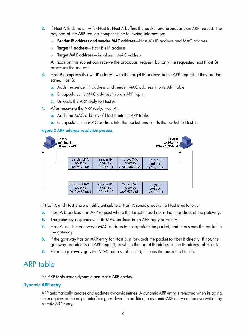
2
2. If Host A finds no entry for Host B, Host A buffers the packet and broadcasts an ARP request. The payload of the ARP request comprises the following information:
Sender IP address and sender MAC address—Host A's IP address and MAC address.
Target IP address—Host B's IP address.
Target MAC address—An all-zero MAC address.
All hosts on this subnet can receive the broadcast request, but only the requested host (Host B) processes the request.
3. Host B compares its own IP address with the target IP address in the ARP request. If they are the same, Host B:
a. Adds the sender IP address and sender MAC address into its ARP table.
b. Encapsulates its MAC address into an ARP reply.
c. Unicasts the ARP reply to Host A.
4. After receiving the ARP reply, Host A:
a. Adds the MAC address of Host B into its ARP table.
b. Encapsulates the MAC address into the packet and sends the packet to Host B.
Figure 2 ARP address resolution process
If Host A and Host B are on different subnets, Host A sends a packet to Host B as follows:
5. Host A broadcasts an ARP request where the target IP address is the IP address of the gateway.
6. The gateway responds with its MAC address in an ARP reply to Host A.
7. Host A uses the gateway's MAC address to encapsulate the packet, and then sends the packet to the gateway.
8. If the gateway has an ARP entry for Host B, it forwards the packet to Host B directly. If not, the gateway broadcasts an ARP request, in which the target IP address is the IP address of Host B.
9. After the gateway gets the MAC address of Host B, it sends the packet to Host B.
ARP table An ARP table stores dynamic and static ARP entries.
Dynamic ARP entry
ARP automatically creates and updates dynamic entries. A dynamic ARP entry is removed when its aging timer expires or the output interface goes down. In addition, a dynamic ARP entry can be overwritten by a static ARP entry.

3
Static ARP entry
A static ARP entry is manually configured and maintained. It does not age out and cannot be overwritten by any dynamic ARP entry.
Static ARP entries protect communication between devices because attack packets cannot modify the IP-to-MAC mapping in a static ARP entry.
Static ARP entries include long and short ARP entries.
• A long static ARP entry comprises the IP address, MAC address, VLAN, and output interface. It is directly used for forwarding packets.
• A short static ARP entry comprises only the IP address and MAC address.
If the output interface is a Layer 3 Ethernet interface, the short ARP entry can be directly used to forward packets.
If the output interface is a VLAN interface, the device first sends an ARP request whose target IP address is the IP address of the short entry. If the sender IP and MAC addresses in the received ARP reply match the IP and MAC addresses of the short static ARP entry, the device adds the interface that received the ARP reply to the short static ARP entry, and uses the resolved short static ARP entry to forward IP packets.
To communicate with a host by using a fixed IP-to-MAC mapping, configure a short static ARP entry on the device. To communicate with a host by using a fixed IP-to-MAC mapping through a specific interface in a specific VLAN, configure a long static ARP entry on the device.
Configuring a static ARP entry A static ARP entry is effective when the device works correctly. If a VLAN or VLAN interface is deleted, any long static ARP entry in the VLAN is deleted, and any resolved short static ARP entry in the VLAN becomes unresolved.
A resolved short static ARP entry becomes unresolved upon certain events. For example, it becomes unresolved when the resolved output interface goes down.
A long static ARP entry is ineffective if the IP address in the entry conflicts with a local IP address, or no local interface has an IP address in the same subnet as the IP address in the ARP entry. An ineffective long static ARP entry cannot be used to forward packets.
Follow these guidelines when you configure a static ARP entry:
• The vlan-id argument must be the ID of an existing VLAN where the ARP entry resides. The specified Ethernet interface must belong to that VLAN. The VLAN interface of the VLAN must be created.
• The IP address of the VLAN interface of the VLAN specified by the vlan-id argument must belong to the same subnet as the IP address specified by the ip-address argument.
To configure a static ARP entry:
Step Command Remarks
1. Enter system view. system-view N/A

4
Step Command Remarks
2. Configure a static ARP entry.
• Configure a long static ARP entry: arp static ip-address mac-address vlan-id interface-type interface-number [ vpn-instance vpn-instance-name ]
• Configure a short static ARP entry: arp static ip-address mac-address [ vpn-instance vpn-instance-name ]
Use either command.
By default, no static ARP entry is configured.
Setting the maximum number of dynamic ARP entries for a device
A device can dynamically learn ARP entries. To prevent a device from holding too many ARP entries, you can set the maximum number of dynamic ARP entries that the device can learn. When the maximum number is reached, the device stops learning ARP entries.
If you set a value lower than the number of existing dynamic ARP entries, the device does not remove the existing entries unless they are aged out, and the device stops learning ARP entries until the number of dynamic ARP entries is below the configured value.
To set the maximum number of dynamic ARP entries for a device:
Step Command Remarks
1. Enter system view. system-view N/A
2. Set the maximum number of dynamic ARP entries for the device.
arp max-learning-number number
If the value for the number argument is set to 0, the device is disabled from learning dynamic ARP entries.
Setting the maximum number of dynamic ARP entries for an interface
An interface can dynamically learn ARP entries. To prevent an interface from holding too many ARP entries, you can set the maximum number of dynamic ARP entries that the interface can learn. When the maximum number is reached, the interface stops learning ARP entries.
The Layer-2 interface can learn an ARP entry only when both its maximum number and the VLAN interface's maximum number are not reached.
To set the maximum number of dynamic ARP entries for an interface:
Step Command Remarks
3. Enter system view. system-view N/A
4. Enter interface view. interface interface-type interface-number N/A

5
Step Command Remarks
5. Set the maximum number of dynamic ARP entries for the interface.
arp max-learning-num number If the value of the number argument is set to 0, the interface is disabled from learning dynamic ARP entries.
Setting the aging timer for dynamic ARP entries Each dynamic ARP entry in the ARP table has a limited lifetime, called an aging timer. The aging timer of a dynamic ARP entry is reset each time the dynamic ARP entry is updated. A dynamic ARP entry that is not updated before its aging timer expires is deleted from the ARP table.
To set the aging timer for dynamic ARP entries:
Step Command Remarks
1. Enter system view. system-view N/A
2. Set the aging timer for dynamic ARP entries. arp timer aging aging-time
By default, the aging time for dynamic ARP entries is 20 minutes.
Enabling dynamic ARP entry check The dynamic ARP entry check function controls whether the device supports dynamic ARP entries containing multicast MAC addresses.
When dynamic ARP entry check is enabled, the device cannot learn dynamic ARP entries containing multicast MAC addresses, and you cannot manually add static ARP entries containing multicast MAC addresses.
When dynamic ARP entry check is disabled, the device can learn dynamic ARP entries containing multicast MAC addresses obtained from the ARP packets sourced from a unicast MAC address. You can also manually add static ARP entries containing multicast MAC addresses.
To enable dynamic ARP entry check:
Step Command Remarks
1. Enter system view. system-view N/A
2. Enable dynamic ARP entry check. arp check enable By default, dynamic ARP entry check is enabled.
Enabling ARP log output This function enables a device to output ARP logs generated in ARP resolution.
To enable ARP log output:

6
Step Command Remarks
1. Enter system view. system-view N/A
2. Enable ARP log output. arp check log enable By default, ARP log output is disabled.
Displaying and maintaining ARP IMPORTANT:
Clearing ARP entries from the ARP table might cause communication failures. Make sure the entries to becleared do not affect current communications.
Execute display commands in any view and reset commands in user view.
Task Command
Display ARP entries (MSR 2600/MSR 3600).
display arp [ [ all | dynamic |multiport | static ] | vlan vlan-id | interface interface-type interface-number ] [ count | verbose ]
Display ARP entries (MSR 5600). display arp [ [ all | dynamic | multiport | static ] [ slot slot-number ] | vlan vlan-id | interface interface-type interface-number ] [ count | verbose ]
Display the ARP entry for a specific IP address (MSR 2600/MSR 3600).
display arp ip-address [ verbose ]
Display the ARP entry for a specific IP address (MSR 5600).
display arp ip-address [ slot slot-number ] [ verbose ]
Display the ARP entries for a specific VPN instance. display arp vpn-instance vpn-instance-name [ count ]
Display the aging timer of dynamic ARP entries. display arp timer aging
Clear ARP entries from the ARP table (MSR 2600/MSR 3600).
reset arp { all | dynamic | interface interface-type interface-number | multiport | static }
Clear ARP entries from the ARP table (MSR 5600).
reset arp { all | dynamic | interface interface-type interface-number | multiport | slot slot-number | static }
Static ARP configuration example
Network requirements As shown in Figure 3, hosts are connected to the switch, which is connected to the router through interface Ethernet 1/1 in VLAN 10.
To ensure secure communications between the router and switch, configure a static ARP entry for the router on the switch.

7
Figure 3 Network diagram
Configuration procedure # Create VLAN 10. <Switch> system-view
[Switch] vlan 10
[Switch-vlan10] quit
# Add interface Ethernet 1/1 to VLAN 10. [Switch] interface ethernet 1/1
[Switch-Ethernet1/1] port access vlan 10
[Switch-Ethernet1/1] quit
# Create VLAN-interface 10 and configure its IP address. [Switch] interface vlan-interface 10
[Switch-vlan-interface10] ip address 192.168.1.2 8
[Switch-vlan-interface10] quit
# Configure a static ARP entry that has IP address 192.168.1.1, MAC address 00e0-fc01-0000, and output interface Ethernet 1/1 in VLAN 10. [Switch] arp static 192.168.1.1 00e0-fc01-0000 10 ethernet 1/1
# Display information about static ARP entries. [Switch] display arp static
Type: S-Static D-Dynamic M-Multiport I-Invalid
IP Address MAC Address VLAN Interface Aging Type
192.168.1.1 00e0-fc01-0000 10 Eth1/1 N/A S

8
Configuring gratuitous ARP
Overview In a gratuitous ARP packet, the sender IP address and the target IP address are the IP address of the sending device.
A device sends a gratuitous ARP packet for either of the following purposes:
• Determine whether its IP address is already used by another device. If the IP address is already used, the device is informed of the conflict by an ARP reply.
• Inform other devices of a MAC address change.
Gratuitous ARP packet learning This feature enables a device to create or update ARP entries by using the sender IP and MAC addresses in received gratuitous ARP packets.
When this feature is disabled, the device uses received gratuitous ARP packets to update existing ARP entries only.
Periodic sending of gratuitous ARP packets Enabling a device to periodically send gratuitous ARP packets helps downstream devices update ARP entries or MAC entries in a timely manner. This feature can be used to prevent gateway spoofing, prevent ARP entries from aging out, and prevent the virtual IP address of a VRRP group from being used by a host.
• Prevent gateway spoofing.
An attacker can use the gateway address to send gratuitous ARP packets to the hosts on a network, so that the traffic destined for the gateway from the hosts is sent to the attacker instead. As a result, the hosts cannot access the external network.
To prevent such gateway spoofing attacks, you can enable the gateway to send gratuitous ARP packets containing its primary IP address and manually configured secondary IP addresses at a specific interval, so hosts can learn correct gateway address information.
• Prevent ARP entries from aging out.
If network traffic is heavy or if the host CPU usage is high, received ARP packets can be discarded or are not promptly processed. Eventually, the dynamic ARP entries on the receiving host age out and the traffic between the host and the corresponding devices is interrupted until the host re-creates the ARP entries.
To prevent this problem, you can enable the gateway to send gratuitous ARP packets periodically. The gratuitous ARP packets contain the gateway's primary IP address or one of its manually configured secondary IP addresses, so the receiving hosts can update ARP entries in time.
• Prevent the virtual IP address of a VRRP group from being used by a host.
The master router of a VRRP group can periodically send gratuitous ARP packets to the hosts on the local network, so that the hosts can update local ARP entries and avoid using the virtual IP address of the VRRP group. For more information about VRRP, see High Availability Configuration Guide.
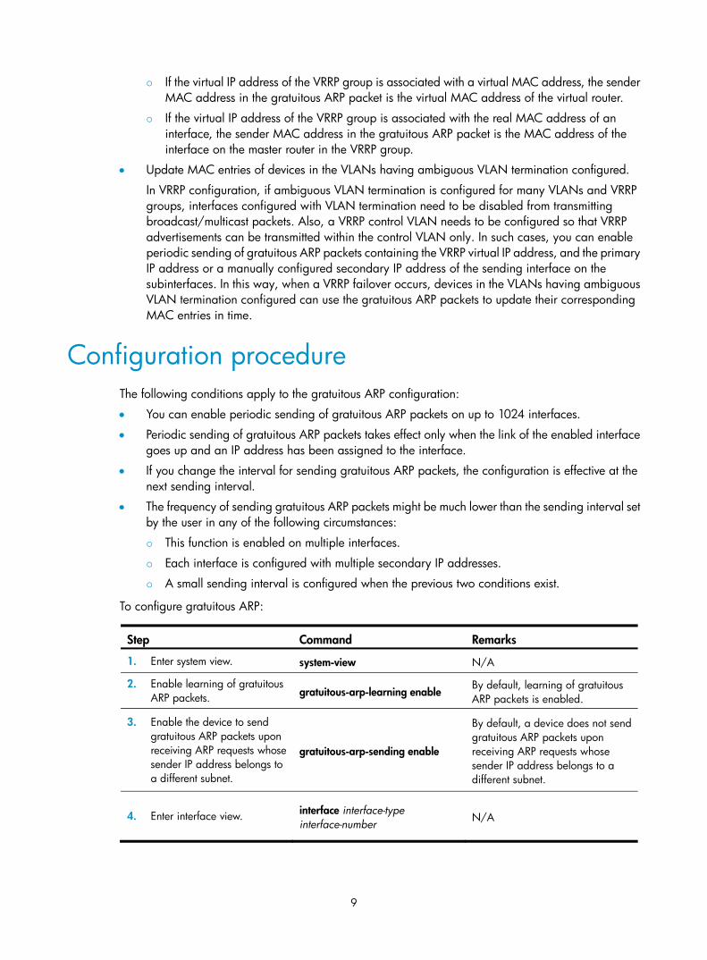
9
If the virtual IP address of the VRRP group is associated with a virtual MAC address, the sender MAC address in the gratuitous ARP packet is the virtual MAC address of the virtual router.
If the virtual IP address of the VRRP group is associated with the real MAC address of an interface, the sender MAC address in the gratuitous ARP packet is the MAC address of the interface on the master router in the VRRP group.
• Update MAC entries of devices in the VLANs having ambiguous VLAN termination configured.
In VRRP configuration, if ambiguous VLAN termination is configured for many VLANs and VRRP groups, interfaces configured with VLAN termination need to be disabled from transmitting broadcast/multicast packets. Also, a VRRP control VLAN needs to be configured so that VRRP advertisements can be transmitted within the control VLAN only. In such cases, you can enable periodic sending of gratuitous ARP packets containing the VRRP virtual IP address, and the primary IP address or a manually configured secondary IP address of the sending interface on the subinterfaces. In this way, when a VRRP failover occurs, devices in the VLANs having ambiguous VLAN termination configured can use the gratuitous ARP packets to update their corresponding MAC entries in time.
Configuration procedure The following conditions apply to the gratuitous ARP configuration:
• You can enable periodic sending of gratuitous ARP packets on up to 1024 interfaces.
• Periodic sending of gratuitous ARP packets takes effect only when the link of the enabled interface goes up and an IP address has been assigned to the interface.
• If you change the interval for sending gratuitous ARP packets, the configuration is effective at the next sending interval.
• The frequency of sending gratuitous ARP packets might be much lower than the sending interval set by the user in any of the following circumstances:
This function is enabled on multiple interfaces.
Each interface is configured with multiple secondary IP addresses.
A small sending interval is configured when the previous two conditions exist.
To configure gratuitous ARP:
Step Command Remarks
1. Enter system view. system-view N/A
2. Enable learning of gratuitous ARP packets. gratuitous-arp-learning enable
By default, learning of gratuitous ARP packets is enabled.
3. Enable the device to send gratuitous ARP packets upon receiving ARP requests whose sender IP address belongs to a different subnet.
gratuitous-arp-sending enable
By default, a device does not send gratuitous ARP packets upon receiving ARP requests whose sender IP address belongs to a different subnet.
4. Enter interface view. interface interface-type interface-number N/A
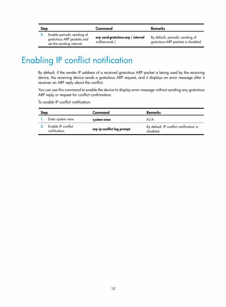
10
Step Command Remarks 5. Enable periodic sending of
gratuitous ARP packets and set the sending interval.
arp send-gratuitous-arp [ interval milliseconds ]
By default, periodic sending of gratuitous ARP packets is disabled.
Enabling IP conflict notification By default, if the sender IP address of a received gratuitous ARP packet is being used by the receiving device, the receiving device sends a gratuitous ARP request, and it displays an error message after it receives an ARP reply about the conflict.
You can use this command to enable the device to display error message without sending any gratuitous ARP reply or request for conflict confirmation.
To enable IP conflict notification:
Step Command Remarks
1. Enter system view. system-view N/A
2. Enable IP conflict notification. arp ip-conflict log prompt
By default, IP conflict notification is disabled.

11
Configuring proxy ARP
Proxy ARP enables a device on one network to answer ARP requests for an IP address on another network. With proxy ARP, hosts on different broadcast domains can communicate with each other as they would on the same broadcast domain.
Proxy ARP includes common proxy ARP and local proxy ARP.
• Common proxy ARP—Allows communication between hosts that connect to different Layer-3 interfaces and reside in different broadcast domains.
• Local proxy ARP—Allows communication between hosts that connect to the same Layer-3 interface and reside in different broadcast domains.
Enabling common proxy ARP You can enable common proxy ARP in VLAN interface view, Layer 3 Ethernet interface view, and Layer 3 Ethernet subinterface view.
To enable common proxy ARP:
Step Command Remarks
1. Enter system view. system-view N/A
2. Enter interface view. interface interface-type interface-number N/A
3. Enable common proxy ARP. proxy-arp enable By default, common proxy ARP is disabled.
Enabling local proxy ARP You can enable local proxy ARP in VLAN interface view, Layer 3 Ethernet interface view, and Layer 3 Ethernet subinterface view.
To enable local proxy ARP:
Step Command Remarks
1. Enter system view. system-view N/A
2. Enter interface view. interface interface-type interface-number
N/A
3. Enable local proxy ARP. local-proxy-arp enable [ ip-range startIP to endIP ]
By default, local proxy ARP is disabled.

12
Displaying proxy ARP Execute display commands in any view.
Task Command
Display common proxy ARP status. display proxy-arp [ interface interface-type interface-number ]
Display local proxy ARP status. display local-proxy-arp [ interface interface-type interface-number ]
Common proxy ARP configuration example
Network requirements As shown in Figure 4, Host A and Host D have the same prefix and mask, but they are located on different subnets. No default gateway is configured on Host A and Host D.
Configure common proxy ARP on the router to enable communication between Host A and Host D.
Figure 4 Network diagram
Configuration procedure # Configure the IP address of interface Ethernet 1/2. <Router> system-view
[Router] interface ethernet 1/2
[Router-Ethernet1/2] ip address 192.168.10.99 255.255.255.0
# Enable common proxy ARP on interface Ethernet 1/2. [Router-Ethernet1/2] proxy-arp enable
[Router-Ethernet1/2] quit

13
# Configure the IP address of interface Ethernet 1/1. [Router] interface ethernet 1/1
[Router-Ethernet1/1] ip address 192.168.20.99 255.255.255.0
# Enable common proxy ARP on interface Ethernet 1/1. [Router-Ethernet1/1] proxy-arp enable
[Router-Ethernet1/1] quit
After the configuration, Host A and Host D can ping each other.

14
Configuring ARP snooping
ARP snooping is not supported in the current release, and it is reserved for future use.
ARP snooping is used in Layer 2 switching networks. It creates ARP snooping entries by using information in ARP packets. ARP fast-reply and manual-mode MFF (MAC–Forced Forwarding) can use the ARP snooping entries. For more information about MFF, see Security Configuration Guide.
If you enable ARP snooping on a VLAN, ARP packets received by any interface in the VLAN are redirected to the CPU. The CPU uses the sender IP and MAC addresses of the ARP packets, and receiving VLAN and port to create ARP snooping entries.
The aging time and valid period of an ARP snooping entry are 25 minutes and 15 minutes. If an ARP snooping entry is not updated in 15 minutes, it becomes invalid and cannot be used. After that, if an ARP packet matching the entry is received, the entry becomes valid, and its aging timer restarts. If the aging timer of an ARP entry expires, the entry is removed.
If the ARP snooping device receives an ARP packet that has the same sender IP address as a valid ARP snooping entry, but with a different sender MAC address, it assumes it has been attacked. The ARP snooping entry becomes invalid, and is removed after 25 minutes.
Configuration procedure To enable ARP snooping:
Step Command Remarks 1. Enter system view. system-view N/A
2. Enable ARP snooping. arp snooping enable By default, ARP snooping is disabled.
To enable ARP snooping for a VLAN:
Step Command Remarks 1. Enter system view. system-view N/A
2. Enter VLAN view. vlan vlan-id N/A
3. Enable ARP snooping arp snooping enable By default, ARP snooping is disabled.
Displaying and maintaining ARP snooping Execute display commands in any view and reset commands in user view.
Task Command
Display ARP snooping entries (MSR 2600/MSR 3600).
display arp snooping [ vlan vlan-id ] [ count ]
display arp snooping ip ip-address

15
Task Command
Display ARP snooping entries (MSR 5600).
display arp snooping [ vlan vlan-id ] [ slot slot-number ] [ count ]
display arp snooping ip ip-address [ slot slot-number ]
Remove ARP snooping entries. reset arp snooping [ ip ip-address | vlan vlan-id ]

16
Configuring ARP fast-reply
ARP fast-reply is not supported in the current release, and it is reserved for future use.
Overview
Function In a wireless network, APs are connected to an AC through tunnels, so that clients can communicate with the AC through APs and can further access the gateway through the AC. If a client broadcasts an ARP request through the associated AP, the AC needs to send the ARP request to all the other APs, wasting tunnel resources and affecting forwarding performance. The ARP fast-reply mechanism can solve this problem.
With ARP fast-reply enabled for a VLAN, the AC can directly answer ARP requests according to the user information in DHCP snooping entries and ARP snooping entries. For more information about DHCP snooping, see "Configuring DHCP snooping."
Operation If the device receives an ARP request with the target IP address being the IP address of the VLAN interface, it processes the packet as a normal ARP packet. If not, it processes the packet in the following steps:
1. Search the DHCP snooping table for a match.
2. If a match is found and the interface of the entry is the Ethernet interface that received the ARP request, the device returns no reply. Otherwise, it returns a reply.
3. If no match is found and ARP snooping is enabled, the device searches the ARP snooping table. If a match is found and the interface of the matching entry is the Ethernet interface that received the ARP request, the device returns no reply. Otherwise, it returns a reply.
4. If no match is found in both the DHCP snooping and ARP snooping tables, the ARP request is forwarded to other interfaces except the receiving interface in the VLAN or delivered to other modules.
Configuration procedure Enabling the ARP fast-reply mechanism also enables DHCP snooping for the VLAN.
To improve the availability of ARP fast-reply, enable ARP snooping at the same time.
To configure ARP fast-reply:
Step Command Remarks 1. Enter system view. system-view N/A
2. Enter VLAN view. vlan vlan-id N/A
3. Enable ARP fast-reply. arp fast-reply enable By default, ARP fast-reply is disabled.

17
ARP fast-reply configuration example
Network requirements As shown in Figure 5, Client 1, Client 2 through Client 100, and Client 101 through Client 200 access the network through AP 1, AP 2 and AP 3, respectively. AP 1, AP 2 and AP 3 are connected to AC through the switch. APs are connected to VLAN 2.
If Client 1 wants to access Client 200, it broadcasts an ARP request and the AC sends it to AP 2 and AP 3. As ARP broadcasts occupy tunnel resources excessively especially when many APs exist on the network, you can enable the ARP fast-reply mechanism for VLAN 1. In the following example, Client 200 has obtained an IP address through DHCP. With ARP fast-reply enabled, the AC, upon receiving an ARP request from Client 1, directly returns an ARP reply without broadcasting the ARP request to other APs.
Figure 5 Network diagram
Configuration procedure 1. Configure basic functions on the AC:
a. Enable WLAN, create a WLAN-ESS interface.
b. Configure a WLAN service template.
c. Bind the WLAN-ESS interface to this service template.
d. Configure the APs on AC.
For more information about the configuration, see WLAN Configuration Guide.
2. Enable ARP snooping on the AC. [AC] arp snooping enable
3. Enable ARP fast-reply for VLAN 1 on the AC. [AC] vlan 1
[AC-vlan1] arp fast-reply enable
AP 1 AP 2 AP 3
DHCP serverAC Switch
…… ……
Client 1 Client 2 ~ Client 100 Client 101 ~ Client 200

18
[AC-vlan1] quit

19
Configuring IP addressing
The IP addresses in this chapter refer to IPv4 addresses unless otherwise specified.
This chapter describes IP addressing basic and manual IP address assignment for interfaces. Dynamic IP address assignment (BOOTP and DHCP) and PPP address negotiation are beyond the scope of this chapter.
Overview This section describes the IP addressing basics.
IP addressing uses a 32-bit address to identify each host on an IPv4 network. To make addresses easier to read, they are written in dotted decimal notation, each address being four octets in length. For example, address 00001010000000010000000100000001 in binary is written as 10.1.1.1.
IP address classes Each IP address breaks down into the following sections:
• Net ID—Identifies a network. The first several bits of a net ID, known as the class field or class bits, identify the class of the IP address.
• Host ID—Identifies a host on a network.
IP addresses are divided into five classes, as shown in Figure 6. The shaded areas represent the address class. The first three classes are most commonly used.
Figure 6 IP address classes
Table 1 IP address classes and ranges
Class Address range Remarks
A 0.0.0.0 to 127.255.255.255
The IP address 0.0.0.0 is used by a host at startup for temporary communication. This address is never a valid destination address.
Addresses starting with 127 are reserved for loopback test. Packets destined to these addresses are processed locally as input packets rather than sent to the link.
B 128.0.0.0 to 191.255.255.255 N/A

20
Class Address range Remarks
C 192.0.0.0 to 223.255.255.255 N/A
D 224.0.0.0 to 239.255.255.255 Multicast addresses.
E 240.0.0.0 to 255.255.255.255 Reserved for future use, except for the broadcast address 255.255.255.255.
Special IP addresses The following IP addresses are for special use and cannot be used as host IP addresses:
• IP address with an all-zero net ID—Identifies a host on the local network. For example, IP address 0.0.0.16 indicates the host with a host ID of 16 on the local network.
• IP address with an all-zero host ID—Identifies a network.
• IP address with an all-one host ID—Identifies a directed broadcast address. For example, a packet with the destination address of 192.168.1.255 will be broadcast to all the hosts on the network 192.168.1.0.
Subnetting and masking Subnetting divides a network into smaller networks called subnets by using some bits of the host ID to create a subnet ID.
Masking identifies the boundary between the host ID and the combination of net ID and subnet ID.
Each subnet mask comprises 32 bits that correspond to the bits in an IP address. In a subnet mask, consecutive ones represent the net ID and subnet ID, and consecutive zeros represent the host ID.
Before being subnetted, Class A, B, and C networks use these default masks (also called natural masks): 255.0.0.0, 255.255.0.0, and 255.255.255.0, respectively.
Figure 7 Subnetting a Class B network
Subnetting increases the number of addresses that cannot be assigned to hosts. Therefore, using subnets means accommodating fewer hosts.
For example, a Class B network without subnetting can accommodate 1022 more hosts than the same network subnetted into 512 subnets.
• Without subnetting—65534 hosts (216 – 2). (The two deducted addresses are the broadcast address, which has an all-one host ID, and the network address, which has an all-zero host ID.)
• With subnetting—Using the first nine bits of the host-id for subnetting provides 512 (29) subnets. However, only seven bits remain available for the host ID. This allows 126 (27 – 2) hosts in each subnet, a total of 64512 hosts (512 × 126).

21
Assigning an IP address to an interface An interface must have an IP address to communicate with other hosts. You can either manually assign an IP address to an interface, or configure the interface to obtain an IP address through BOOTP, DHCP, or PPP address negotiation. If you change the way an interface obtains an IP address, the new IP address will overwrite the previous address.
An interface can have one primary address and multiple secondary addresses.
Typically, you need to configure a primary IP address for an interface. If the interface connects to multiple subnets, configure primary and secondary IP addresses on the interface so the subnets can communicate with each other through the interface.
Configuration guidelines Follow these guidelines when you assign an IP address to an interface:
• An interface can have only one primary IP address. A newly configured primary IP address overwrites the previous one.
• You cannot assign secondary IP addresses to an interface that obtains an IP address through BOOTP, DHCP, PPP address negotiation, or IP unnumbered.
• The primary and secondary IP addresses you assign to the interface can be located on the same network segment, but different interfaces on your device must reside on different network segments.
Configuration procedure To assign an IP address to an interface:
Step Command Remarks
1. Enter system view. system-view N/A
2. Enter interface view. interface interface-type interface-number
N/A
3. Assign an IP address to the interface.
ip address ip-address { mask | mask-length } [ sub ]
By default, no IP address is assigned to the interface.
Configuring IP unnumbered Typically, you assign an IP address to an interface either manually or through DHCP. If the IP addresses are not enough, or the interface is used only occasionally, you can configure an interface to borrow an IP address from other interfaces. This is called IP unnumbered, and the interface borrowing the IP address is called IP unnumbered interface.
You can use IP unnumbered to save IP addresses either when available IP addresses are inadequate or when an interface is brought up only for occasional use.

22
Configuration guidelines Follow these guidelines when you configure IP unnumbered:
• Layer 3 Ethernet interfaces and loopback interfaces cannot borrow IP addresses of other interfaces, but other interfaces can borrow IP addresses of these interfaces.
• Synchronous and asynchronous serial interfaces, and dial-up interfaces can borrow IP addresses of Ethernet interfaces.
• An interface cannot borrow an IP address from an unnumbered interface.
• Multiple interfaces can use the same unnumbered IP address.
• If an interface has multiple manually configured IP addresses, only the manually configured primary IP address can be borrowed.
Configuration prerequisites Assign an IP address to the interface from which you want to borrow the IP address. Alternatively, you can configure the interface to obtain one through BOOTP, DHCP, or PPP address negotiation.
Configuration procedure To configure IP unnumbered on an interface:
Step Command Remarks
1. Enter system view. system-view N/A
2. Enter interface view. interface interface-type interface-number N/A
3. Specify the interface to borrow the IP address of the specified interface.
ip address unnumbered interface interface-type interface-number
By default, the interface does not borrow IP addresses from other interfaces.
A dynamic routing protocol cannot be enabled on the interface where IP unnumbered is configured. To enable the interface to communicate with other devices, configure a static route to the peer device on the interface. For more configuration information, see "IP unnumbered configuration example."
Displaying and maintaining IP addressing Execute display commands in any view.
Task Command
Display IP configuration and statistics for the specified or all Layer 3 interfaces.
display ip interface [ interface-type interface-number ]
Display brief IP configuration information for the specified or all Layer 3 interfaces.
display ip interface [ interface-type [ interface-number ] ] brief

23
IP address configuration example
Network requirements As shown in Figure 8, Ethernet 1/1 on the router is connected to a LAN comprising two segments: 172.16.1.0/24 and 172.16.2.0/24.
To enable the hosts on the two network segments to communicate with the external network through the router, and to enable the hosts on the LAN to communicate with each other:
• Assign a primary IP address and a secondary IP address to Ethernet 1/1 on the router.
• Set the primary IP address of the router as the gateway address of the PCs on subnet 172.16.1.0/24, and set the secondary IP address of the router as the gateway address of the PCs on subnet 172.16.2.0/24.
Figure 8 Network diagram
Configuration procedure # Assign a primary IP address and a secondary IP address to Ethernet 1/1. <Router> system-view
[Router] interface ethernet 1/1
[Router-Ethernet1/1] ip address 172.16.1.1 255.255.255.0
[Router-Ethernet1/1] ip address 172.16.2.1 255.255.255.0 sub
# Set the gateway address to 172.16.1.1 on the PCs attached to subnet 172.16.1.0/24, and to 172.16.2.1 on the PCs attached to subnet 172.16.2.0/24.
Verifying the configuration # Ping a host on subnet 172.16.1.0/24 from the router to check the connectivity. <Router> ping 172.16.1.2
Ping 172.16.1.2 (172.16.1.2): 56 data bytes, press escape sequence to break

24
56 bytes from 172.16.1.2: icmp_seq=0 ttl=254 time=7.000 ms
56 bytes from 172.16.1.2: icmp_seq=1 ttl=254 time=0.000 ms
56 bytes from 172.16.1.2: icmp_seq=2 ttl=254 time=1.000 ms
56 bytes from 172.16.1.2: icmp_seq=3 ttl=254 time=1.000 ms
56 bytes from 172.16.1.2: icmp_seq=4 ttl=254 time=2.000 ms
--- Ping statistics for 172.16.1.2 ---
5 packet(s) transmitted, 5 packet(s) received, 0.0% packet loss
round-trip min/avg/max/std-dev = 0.000/2.200/7.000/2.482 ms
The output shows that the router can communicate with the host on subnet 172.16.1.0/24.
# Ping a host on subnet 172.16.2.0/24 from the router to check the connectivity. <Router> ping 172.16.2.2
Ping 172.16.2.2 (172.16.2.2): 56 data bytes, press escape sequence to break
56 bytes from 172.16.2.2: icmp_seq=0 ttl=255 time=2.000 ms
56 bytes from 172.16.2.2: icmp_seq=1 ttl=255 time=7.000 ms
56 bytes from 172.16.2.2: icmp_seq=2 ttl=255 time=1.000 ms
56 bytes from 172.16.2.2: icmp_seq=3 ttl=255 time=2.000 ms
56 bytes from 172.16.2.2: icmp_seq=4 ttl=255 time=1.000 ms
--- Ping statistics for 172.16.2.2 ---
5 packet(s) transmitted, 5 packet(s) received, 0.0% packet loss
round-trip min/avg/max/std-dev = 1.000/2.600/7.000/2.245 ms
The output shows that the router can communicate with the host on subnet 172.16.2.0/24.
# Ping a host on subnet 172.16.1.0/24 from a host on subnet 172.16.2.0/24 to check the connectivity. Host B can be successfully pinged from Host A.
IP unnumbered configuration example
Network requirements As shown in Figure 9, two routers on an intranet are connected to each other through serial interfaces across a Digital Data Network, and they each connect to a LAN through Ethernet interfaces.
To save IP addresses, configure the serial interfaces to borrow IP addresses from the Ethernet interfaces.

25
Figure 9 Network diagram
Configuration procedure 1. Configure Router A:
# Assign a primary IP address to Ethernet 1/1. <RouterA> system-view
[RouterA] interface ethernet 1/1
[RouterA-Ethernet1/1] ip address 172.16.10.1 255.255.255.0
[RouterA-Ethernet1/1] quit
# Configure Serial 2/1 to borrow an IP address from Ethernet 1/1. [RouterA] interface serial 2/1
[RouterA-Serial2/1] ip address unnumbered interface ethernet 1/1
[RouterA-Serial2/1] quit
# Configure a static route to the subnet attached to Router B, specifying Serial 2/1 as the outgoing interface. [RouterA] ip route-static 172.16.20.0 255.255.255.0 serial 2/1
2. Configure Router B:
# Assign a primary IP address to Ethernet 1/1. <RouterB> system-view
[RouterB] interface ethernet 1/1
[RouterB-Ethernet1/1] ip address 172.16.20.1 255.255.255.0
[RouterB-Ethernet1/1] quit
# Configure interface Serial 2/1 to borrow an IP address from Ethernet 1/1. [RouterB] interface serial 2/1
[RouterB-Serial2/1] ip address unnumbered interface ethernet 1/1
[RouterB-Serial2/1] quit
# Configure a static route to the subnet attached to Router A, specifying Serial 2/1 as the outgoing interface. [RouterB] ip route-static 172.16.10.0 255.255.255.0 serial 2/1
Verifying the configuration # Ping a host attached to Router B from Router A.

26
[RouterA] ping 172.16.20.2
Ping 172.16.20.2 (172.16.20.2): 56 data bytes, press escape sequence to break
56 bytes from 172.16.20.2: icmp_seq=0 ttl=254 time=7.000 ms
56 bytes from 172.16.20.2: icmp_seq=1 ttl=254 time=0.000 ms
56 bytes from 172.16.20.2: icmp_seq=2 ttl=254 time=1.000 ms
56 bytes from 172.16.20.2: icmp_seq=3 ttl=254 time=1.000 ms
56 bytes from 172.16.20.2: icmp_seq=4 ttl=254 time=2.000 ms
--- Ping statistics for 172.16.20.2 ---
5 packet(s) transmitted, 5 packet(s) received, 0.0% packet loss
round-trip min/avg/max/std-dev = 0.000/2.200/7.000/2.482 ms
The output shows that the host can be pinged.

27
DHCP overview
The Dynamic Host Configuration Protocol (DHCP) provides a framework to assign configuration information to network devices.
Figure 10 shows a typical DHCP application scenario where the DHCP clients and the DHCP server reside on the same subnet. The DHCP clients can also obtain configuration parameters from a DHCP server on another subnet through a DHCP relay agent. For more information about the DHCP relay agent, see "Configuring the DHCP relay agent."
Figure 10 A typical DHCP application
DHCP address allocation
Allocation mechanisms DHCP supports the following allocation mechanisms:
• Static allocation—The network administrator assigns an IP address to a client, such as a WWW server, and DHCP conveys the assigned address to the client.
• Automatic allocation—DHCP assigns a permanent IP address to a client.
• Dynamic allocation—DHCP assigns an IP address to a client for a limited period of time, which is called a lease. Most DHCP clients obtain their addresses in this way.

28
Dynamic IP address allocation process Figure 11 Dynamic IP address allocation process
1. The client broadcasts a DHCP-DISCOVER message to locate a DHCP server.
2. Each DHCP server offers configuration parameters such as an IP address to the client in a DHCP-OFFER message. The sending mode of the DHCP-OFFER is determined by the flag field in the DHCP-DISCOVER message. For related information, see "DHCP message format."
3. If several DHCP servers send offers to the client, the client accepts the first received offer, and broadcasts it in a DHCP-REQUEST message to formally request the IP address. (IP addresses offered by other DHCP servers can be assigned to other clients.)
4. All DHCP servers receive the DHCP-REQUEST message, but only the server selected by the client returns a DHCP-ACK message to confirm that the IP address has been allocated to the client, or a DHCP-NAK message to deny the IP address allocation.
After the client receives the DHCP-ACK message, it broadcasts a gratuitous ARP packet to verify whether the IP address assigned by the server is already in use. If the client receives no response within the specified time, the client uses the assigned IP address. Otherwise, the client sends a DHCP-DECLINE message to the server to request an IP address again.
IP address lease extension A dynamically assigned IP address has a lease. When the lease expires, the IP address is reclaimed by the DHCP server. To continue using the IP address, the client must extend the lease duration.
When 1/2 lease duration elapses, the DHCP client unicasts a DHCP-REQUEST to the DHCP server to extend the lease. Depending on the availability of the IP address, the DHCP server returns either a DHCP-ACK unicast confirming that the client's lease duration has been extended, or a DHCP-NAK unicast denying the request.
If the client receives no reply, it broadcasts another DHCP-REQUEST message for lease extension when 7/8 lease duration elapses. Again, depending on the availability of the IP address, the DHCP server returns either a DHCP-ACK unicast confirming that the client's lease duration has been extended, or a DHCP-NAK unicast denying the request.

29
DHCP message format Figure 12 shows the DHCP message format. DHCP uses some of the fields in significantly different ways. The numbers in parentheses indicate the size of each field in bytes.
Figure 12 DHCP message format
• op—Message type defined in options field. 1 = REQUEST, 2 = REPLY
• htype, hlen—Hardware address type and length of the DHCP client.
• hops—Number of relay agents a request message traveled.
• xid—Transaction ID, a random number chosen by the client to identify an IP address allocation.
• secs—Filled in by the client, the number of seconds elapsed since the client began address acquisition or renewal process. This field is reserved and set to 0.
• flags—The leftmost bit is defined as the BROADCAST (B) flag. If this flag is set to 0, the DHCP server sent a reply back by unicast. If this flag is set to 1, the DHCP server sent a reply back by broadcast. The remaining bits of the flags field are reserved for future use.
• ciaddr—Client IP address if the client has an IP address that is valid and usable. Otherwise, set to zero. (The client does not use this field to request a specific IP address to lease.)
• yiaddr—'Your' (client) IP address, assigned by the server.
• siaddr—Server IP address, from which the client obtained configuration parameters.
• giaddr—(Gateway) IP address of the first relay agent a request message traveled.
• chaddr—Client hardware address.
• sname—Server host name, from which the client obtained configuration parameters.
• file—Boot file (also called system software image) name and path information, defined by the server to the client.
• options—Optional parameters field that is variable in length, which includes the message type, lease duration, subnet mask, domain name server IP address, and WINS IP address.

30
DHCP options DHCP uses the same message format as BOOTP, but DHCP uses the options field to carry information for dynamic address allocation and provide additional configuration information to clients.
Figure 13 DHCP option format
Common DHCP options The following are common DHCP options:
• Option 3—Router option. It specifies the gateway address.
• Option 6—DNS server option. It specifies the DNS server's IP address.
• Option 33—Static route option. It specifies a list of classful static routes (the destination network addresses in these static routes are classful) that a client should add into its routing table. If both Option 33 and Option 121 exist, Option 33 is ignored.
• Option 51—IP address lease option.
• Option 53—DHCP message type option. It identifies the type of the DHCP message.
• Option 55—Parameter request list option. It is used by a DHCP client to request specified configuration parameters. The option contains values that correspond to the parameters requested by the client.
• Option 60—Vendor class identifier option. It is used by a DHCP client to identify its vendor, and by a DHCP server to distinguish DHCP clients by vendor class and assign specific IP addresses to the DHCP clients.
• Option 66—TFTP server name option. It specifies a TFTP server to be assigned to the client.
• Option 67—Boot file name option. It specifies the boot file name to be assigned to the client.
• Option 121—Classless route option. It specifies a list of classless static routes (the destination network addresses in these static routes are classless) that the requesting client should add to its routing table. If both Option 33 and Option 121 exist, Option 33 is ignored.
• Option 150—TFTP server IP address option. It specifies the TFTP server IP address to be assigned to the client.
For more information about DHCP options, see RFC 2132 and RFC 3442.
Custom DHCP options Some options, such as Option 43, Option 82, and Option 184, have no standard definitions in RFC 2132.
Vendor-specific option (Option 43)
DHCP servers and clients use Option 43 to exchange vendor-specific configuration information.

31
Through Option 43, the DHCP client can obtain the PXE server address, which is used to obtain the boot file or other control information from the PXE server.
1. Format of Option 43:
Figure 14 Option 43 format
Network configuration parameters are carried in different sub-options of Option 43 as shown in Figure 14.
Sub-option type—The field value can be 0x02 (service provider identifier sub-option) or 0x80 (PXE server address sub-option).
Sub-option length—Excludes the sub-option type and sub-option length fields.
Sub-option value—The value format varies with sub-options.
2. Sub-option value field formats:
Service provider identifier sub-option value field—Contains the service provider identifier.
PXE server address sub-option value field—Contains the PXE server type that can only be 0, the server number that indicates the number of PXE servers contained in the sub-option and server IP addresses, as shown in Figure 15.
Figure 15 PXE server address sub-option value field
Relay agent option (Option 82)
Option 82 is the relay agent option. It records the location information about the DHCP client. When a DHCP relay agent or DHCP snooping device receives a client's request, it adds Option 82 to the request message and sends it to the server.
The administrator can use Option 82 to locate the DHCP client and further implement security control and accounting. The DHCP server can use Option 82 to provide individual configuration policies for the clients.
Option 82 can contain up to 255 sub-options and must have one sub-option at least. Option 82 supports two sub-options: sub-option 1 (Circuit ID) and sub-option 2 (Remote ID).
Option 82 has no standard definition. Its padding formats vary with vendors.
Circuit ID has the following padding formats:
• String padding format—Contains a character string specified by the user.
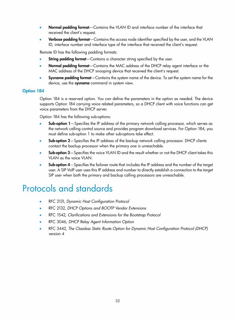
32
• Normal padding format—Contains the VLAN ID and interface number of the interface that received the client's request.
• Verbose padding format—Contains the access node identifier specified by the user, and the VLAN ID, interface number and interface type of the interface that received the client's request.
Remote ID has the following padding formats:
• String padding format—Contains a character string specified by the user.
• Normal padding format—Contains the MAC address of the DHCP relay agent interface or the MAC address of the DHCP snooping device that received the client's request.
• Sysname padding format—Contains the system name of the device. To set the system name for the device, use the sysname command in system view.
Option 184
Option 184 is a reserved option. You can define the parameters in the option as needed. The device supports Option 184 carrying voice related parameters, so a DHCP client with voice functions can get voice parameters from the DHCP server.
Option 184 has the following sub-options:
• Sub-option 1—Specifies the IP address of the primary network calling processor, which serves as the network calling control source and provides program download services. For Option 184, you must define sub-option 1 to make other sub-options take effect.
• Sub-option 2—Specifies the IP address of the backup network calling processor. DHCP clients contact the backup processor when the primary one is unreachable.
• Sub-option 3—Specifies the voice VLAN ID and the result whether or not the DHCP client takes this VLAN as the voice VLAN.
• Sub-option 4—Specifies the failover route that includes the IP address and the number of the target user. A SIP VoIP user uses this IP address and number to directly establish a connection to the target SIP user when both the primary and backup calling processors are unreachable.
Protocols and standards • RFC 2131, Dynamic Host Configuration Protocol
• RFC 2132, DHCP Options and BOOTP Vendor Extensions
• RFC 1542, Clarifications and Extensions for the Bootstrap Protocol
• RFC 3046, DHCP Relay Agent Information Option
• RFC 3442, The Classless Static Route Option for Dynamic Host Configuration Protocol (DHCP) version 4

33
Configuring the DHCP server
Overview The DHCP server is well suited to networks where:
• Manual configuration and centralized management are difficult to implement.
• IP addresses are limited. For example, an ISP limits the number of concurrent online users, and users must acquire IP addresses dynamically.
• Most hosts do not need fixed IP addresses.
In addition to assigning IP addresses to DHCP clients on a public network, an MCE serving as the DHCP server can also assign IP addresses to DHCP clients on private networks. The IP address ranges of public and private networks or those of private networks on the DHCP server cannot overlap each other. For more information about MCE, see MPLS Configuration Guide.
DHCP address pool Each DHCP address pool has a group of assignable IP addresses and network configuration parameters. The DHCP server selects IP addresses and other parameters from the address pool and assigns them to the DHCP clients.
Address assignment mechanisms
Configure the following address assignment mechanisms as needed:
• Static address allocation—Manually bind the MAC address or ID of a client to an IP address in a DHCP address pool. When the client requests an IP address, the DHCP server assigns the IP address in the static binding to the client.
• Dynamic address allocation—Specify IP address ranges in a DHCP address pool. Upon receiving a DHCP request, the DHCP server dynamically selects an IP address from the matching IP address range in the address pool.
There are two methods to specify IP address ranges in an address pool:
• Method 1—Specify a primary subnet in an address pool and divide the subnet into multiple address ranges, which include a common IP address range and IP address ranges for DHCP user classes.
Upon receiving a DHCP request, the DHCP server finds a user class matching the client and selects an IP address in the address range of the user class for the client. A user class can include multiple matching rules, and a client matches the user class as long as it matches any of the rules. In address pool view, you can specify different address ranges for different user classes.
DHCP selects an IP address for a client in the following order:
a. DHCP matches the client against DHCP user classes in the order they are configured.
b. If the client matches a user class, the DHCP server selects an IP address from the address range of the user class.

34
c. If the matching user class has no assignable addresses, the DHCP server matches the client against the next user class. If all the matching user classes have no assignable addresses, the DHCP server selects an IP address from the common address range.
d. If the DHCP client does not match any DHCP user class, the DHCP server selects an address in the IP address range specified by the address range command. If the address range has no assignable IP addresses or it is not configured, the address allocation fails.
NOTE:
All address ranges must belong to the primary subnet. If an address range does not reside in the primarysubnet, DHCP cannot assign the addresses in the address range.
• Method 2—Specify a primary subnet and multiple secondary subnets in an address pool.
The DHCP server selects an IP address from the primary subnet first. If there is no assignable IP address in the primary subnet, the DHCP server selects an IP address from secondary subnets in the order they are configured.
Principles for selecting an address pool
The DHCP server observes the following principles to select an address pool for a client:
1. If there is an address pool where an IP address is statically bound to the MAC address or ID of the client, the DHCP server selects this address pool and assigns the statically bound IP address and other configuration parameters to the client.
2. If the receiving interface has an address pool applied, the DHCP server selects an IP address and other configuration parameters from this address pool.
3. If there is no static address pool and the receiving interface has no address pool applied, the DHCP server selects an address pool in the following way:
If the client and the server reside on the same subnet, the DHCP server matches the IP address of the receiving interface against the primary subnets of all address pools, and selects the address pool with the longest-matching primary subnet. If no matching primary subnet is found, the DHCP server matches the IP address against the secondary subnets of all address pools, and selects the address pool with the longest-matching secondary subnet.
If the client and the server reside on different subnets (a DHCP relay agent is in-between), the DHCP server matches the IP address in the giaddr field of the DHCP request against the primary subnets of all address pools, and selects the address pool with the longest-matching primary subnet. If no matching primary subnet is found, the DHCP server matches the IP address against the secondary subnets of all address pools, and selects the address pool with the longest-matching secondary subnet.
For example, two address pools 1.1.1.0/24 and 1.1.1.0/25 are configured on the DHCP server. If the IP address of the interface receiving DHCP requests is 1.1.1.1/25 and no address pool is applied on the interface, the DHCP server selects IP addresses for clients from the address pool 1.1.1.0/25. If no IP address is available in the address pool, the DHCP server fails to assign addresses. If the IP address of the receiving interface is 1.1.1.130/25, the DHCP server selects IP addresses for clients from the address pool 1.1.1.0/24.
NOTE:
To avoid wrong address allocation, keep the IP addresses used for dynamic allocation in the subnet wherethe interface of the DHCP server or DHCP relay agent resides as possible as you can.

35
IP address allocation sequence The DHCP server selects an IP address for a client in the following sequence:
1. IP address statically bound to the client's MAC address or ID.
2. IP address that was ever assigned to the client.
3. IP address designated by the Option 50 field in the DHCP-DISCOVER message sent by the client.
Option 50 is the Requested IP Address option. The client uses this option to specify the wanted IP address in a DHCP-DISCOVER message. The content of Option 50 is user defined.
4. First assignable IP address found in the way discussed in "DHCP address pool."
5. IP address that was a conflict or passed its lease duration. If no IP address is assignable, the server does not respond.
NOTE:
If a client moves to another subnet, the DHCP server selects an IP address in the address pool matching thenew subnet instead of assigning the IP address that was once assigned to the client.
DHCP server configuration task list Tasks at a glance
(Required.) Configuring an address pool on the DHCP server
(Required.) Enabling DHCP
(Required.) Enabling the DHCP server on an interface
(Optional.) Applying an address pool on an interface
(Optional.) Configuring IP address conflict detection
(Optional.) Enabling handling of Option 82
(Optional.) Configuring DHCP server compatibility
(Optional.) Setting the DSCP value for DHCP packets sent by the DHCP server
Configuring an address pool on the DHCP server
Configuration task list
Tasks at a glance
(Required.) Creating a DHCP address pool

36
Tasks at a glance
Perform at least one of the following tasks: • Specifying IP address ranges for a DHCP address pool • Specifying gateways for the client • Specifying a domain name suffix for the client • Specifying DNS servers for the client • Specifying WINS servers and NetBIOS node type for the client • Specifying BIMS server information for the client • Specifying the TFTP server and boot file name for the client • Specifying a server for the DHCP client • Configuring Option 184 parameters for the client • Configuring self-defined DHCP options
Creating a DHCP address pool
Step Command Remarks 1. Enter system view. system-view N/A
2. Create a DHCP address pool and enter its view. dhcp server ip-pool pool-name
By default, no DHCP address pool is created.
Specifying IP address ranges for a DHCP address pool You can configure both static and dynamic address allocation mechanisms in a DHCP address pool. For dynamic address allocation, you can specify either a primary subnet with multiple address ranges or a primary subnet with multiple secondary subnets for a DHCP address pool, but you cannot configure both.
Specifying a primary subnet and multiple address ranges for a DHCP address pool
Some scenarios need to classify DHCP clients in the same subnet into different address groups. To meet this need, you can configure DHCP user classes and specify different address ranges for the classes so that the clients matching a user class get the IP addresses of a specific address range. In addition, you can specify a common address range for the clients that do not match any user class. If no common address range is specified, such clients fail to obtain IP addresses.
If there is no need to classify clients, you do not need to configure DHCP user classes or their address ranges.
Follow these guidelines when you specify a primary subnet and multiple address ranges for a DHCP address pool:
• If you use the network or address range command multiple times for the same address pool, the most recent configuration takes effect.
• IP addresses specified by the forbidden-ip command are not assignable in the current address pool, but are assignable in other address pools. IP addresses specified by the dhcp server forbidden-ip command are not assignable in any address pool.
To specify a primary subnet and multiple address ranges for a DHCP address pool:

37
Step Command Remarks 1. Enter system view. system-view N/A
2. Create a DHCP user class and enter DHCP user class view. dhcp class class-name
Required for client classification.
By default, no DHCP user class exists.
3. Configure the match rule for the DHCP user class.
if-match option option-code [ hex hex-string [ offset offset length length | mask mask ] ]
Required for client classification.
By default, no match rule is specified for a DHCP user class.
4. Return to system view. quit N/A
5. Enter address pool view. dhcp server ip-pool pool-name N/A
6. Specify the primary subnet for the address pool.
network network-address [ mask-length | mask mask ]
By default, no primary subnet is specified.
7. (Optional.) Specify the common address range.
address range start-address end-address
By default, no IP address range is specified.
8. (Optional.) Specify an IP address range for a DHCP user class.
class class-name range start-address end-address
By default, no IP address range is specified for a user class.
The DHCP user class must already exist.
To specify address ranges for multiple DHCP user classes, repeat this step.
9. (Optional.) Specify the address lease duration.
expired { day day [ hour hour [ minute minute [ second second ] ] ] | unlimited }
The default setting is one day.
10. (Optional.) Exclude the specified IP addresses in the address pool from dynamic allocation.
forbidden-ip ip-address&<1-8>
By default, all the IP addresses in the DHCP address pool are assignable.
To exclude multiple address ranges from dynamic allocation, repeat this step.
11. Return to system view. quit N/A
12. (Optional.) Exclude the specified IP addresses from automatic allocation globally.
dhcp server forbidden-ip start-ip-address [ end-ip-address ]
By default, except for the IP address of the DHCP server interface, all IP addresses in address pools are assignable.
To exclude multiple IP address ranges, repeat this step.
Specifying a primary subnet and multiple secondary subnets for a DHCP address pool
In scenarios where the DHCP server and the DHCP clients reside on the same subnet, the DHCP server needs to assign addresses in different address ranges to the DHCP clients. To meet this need, you can specify a primary subnet and multiple secondary subnets in an address pool. Upon receiving a client

38
request, the DHCP server selects an address from the primary subnet. If no assignable address is found, the server selects an address from the secondary subnets in the order they are configured.
In scenarios where the DHCP server and the DHCP clients reside on different subnets and the DHCP clients obtain IP addresses through a DHCP relay agent, the DHCP server needs to use the same address pool to assign IP addresses to clients in different subnets. To meet this need, you can specify a primary subnet and multiple secondary subnets in a DHCP address pool, which are consistent with the subnets where the relay agent interfaces reside. Upon receiving a DHCP request forwarded by a relay agent, the DHCP server reads the giaddr field in the request to find the corresponding subnet and selects an IP address for the client.
Follow these guidelines when you specify a primary subnet and secondary subnets for a DHCP address pool:
• You can specify only one primary subnet in each address pool. If you use the network command multiple times, the most recent configuration takes effect.
• You can specify a maximum of 32 secondary subnets in each address pool.
• IP addresses specified by the forbidden-ip command are not assignable in the current address pool, but are assignable in other address pools. IP addresses specified by the dhcp server forbidden-ip command are not assignable in any address pool.
To specify a primary subnet and secondary subnets for a DHCP address pool:
Step Command Remarks 1. Enter system view. system-view N/A
2. Enter address pool view. dhcp server ip-pool pool-name N/A
3. Specify the primary subnet. network network-address [ mask-length | mask mask ]
By default, no primary subnet is specified.
4. (Optional.) Specify a secondary subnet.
network network-address [ mask-length | mask mask ] secondary
By default, no secondary subnet is specified.
5. (Optional.) Return to address pool view. quit N/A
6. (Optional.) Specify the address lease duration.
expired { day day [ hour hour [ minute minute [ second second ] ] ] | unlimited }
The default setting is one day.
7. (Optional.) Exclude the specified IP addresses from dynamic allocation.
forbidden-ip ip-address&<1-8>
By default, all the IP addresses in the DHCP address pool can be dynamically allocated.
To exclude multiple address ranges from the address pool, repeat this step.
8. Return to system view. quit N/A
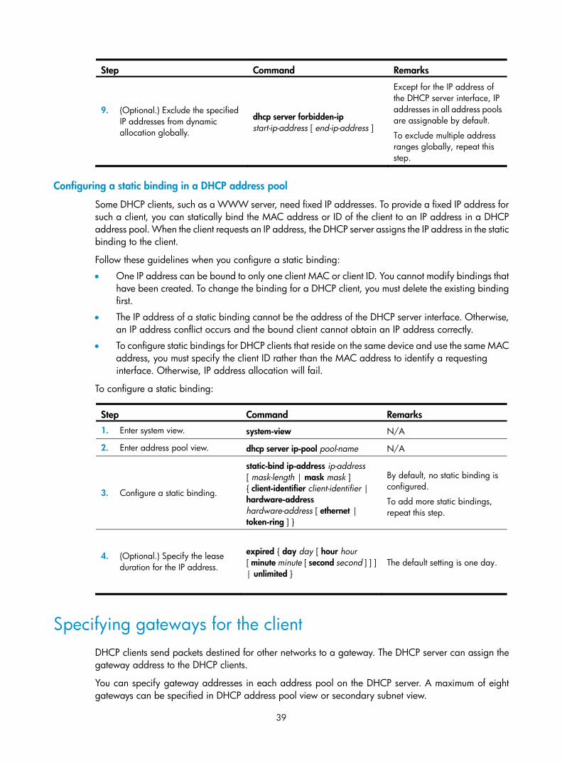
39
Step Command Remarks
9. (Optional.) Exclude the specified IP addresses from dynamic allocation globally.
dhcp server forbidden-ip start-ip-address [ end-ip-address ]
Except for the IP address of the DHCP server interface, IP addresses in all address pools are assignable by default.
To exclude multiple address ranges globally, repeat this step.
Configuring a static binding in a DHCP address pool
Some DHCP clients, such as a WWW server, need fixed IP addresses. To provide a fixed IP address for such a client, you can statically bind the MAC address or ID of the client to an IP address in a DHCP address pool. When the client requests an IP address, the DHCP server assigns the IP address in the static binding to the client.
Follow these guidelines when you configure a static binding:
• One IP address can be bound to only one client MAC or client ID. You cannot modify bindings that have been created. To change the binding for a DHCP client, you must delete the existing binding first.
• The IP address of a static binding cannot be the address of the DHCP server interface. Otherwise, an IP address conflict occurs and the bound client cannot obtain an IP address correctly.
• To configure static bindings for DHCP clients that reside on the same device and use the same MAC address, you must specify the client ID rather than the MAC address to identify a requesting interface. Otherwise, IP address allocation will fail.
To configure a static binding:
Step Command Remarks 1. Enter system view. system-view N/A
2. Enter address pool view. dhcp server ip-pool pool-name N/A
3. Configure a static binding.
static-bind ip-address ip-address [ mask-length | mask mask ] { client-identifier client-identifier | hardware-address hardware-address [ ethernet | token-ring ] }
By default, no static binding is configured.
To add more static bindings, repeat this step.
4. (Optional.) Specify the lease duration for the IP address.
expired { day day [ hour hour [ minute minute [ second second ] ] ] | unlimited }
The default setting is one day.
Specifying gateways for the client DHCP clients send packets destined for other networks to a gateway. The DHCP server can assign the gateway address to the DHCP clients.
You can specify gateway addresses in each address pool on the DHCP server. A maximum of eight gateways can be specified in DHCP address pool view or secondary subnet view.

40
If you specify gateways in both address pool view and secondary subnet view, DHCP assigns the gateway addresses in the secondary subnet view to the clients on the secondary subnet. If you specify gateways in address pool view but not in secondary subnet view, DHCP assigns the gateway addresses in address pool view to the clients on the secondary subnet.
To configure gateways in the DHCP address pool:
Step Command Remarks 1. Enter system view. system-view N/A
2. Enter DHCP address pool view. dhcp server ip-pool pool-name N/A
3. Specify gateways. gateway-list ip-address&<1-8> By default, no gateway is specified.
4. (Optional.) Enter secondary subnet view
network network-address [ mask-length | mask mask ] secondary
N/A
5. (Optional.) Specify gateways. gateway-list ip-address&<1-8> By default, no gateway is specified.
Specifying a domain name suffix for the client You can specify a domain name suffix in a DHCP address pool on the DHCP server. With this suffix assigned, the client only needs to input part of a domain name, and the system adds the domain name suffix for name resolution. For more information about DNS, see "Configuring IPv4 DNS."
To configure a domain name suffix in the DHCP address pool:
Step Command Remarks 1. Enter system view. system-view N/A
2. Enter DHCP address pool view. dhcp server ip-pool pool-name N/A
3. Specify a domain name suffix. domain-name domain-name By default, no domain name is specified.
Specifying DNS servers for the client To access hosts on the Internet through domain names, a DHCP client must contact a DNS server to resolve names. You can specify up to eight DNS servers in a DHCP address pool.
To specify DNS servers in a DHCP address pool:
Step Command Remarks 1. Enter system view. system-view N/A
2. Enter DHCP address pool view. dhcp server ip-pool pool-name N/A
3. Specify DNS servers. dns-list ip-address&<1-8> By default, no DNS server is specified.
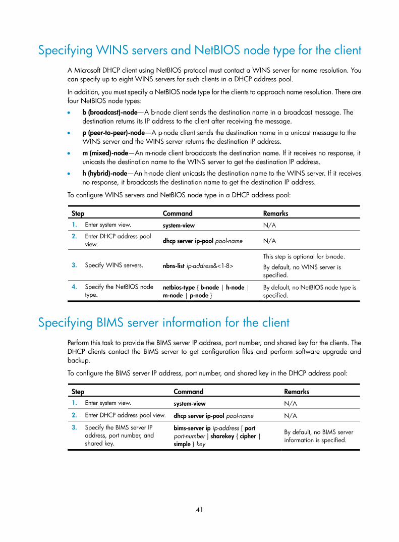
41
Specifying WINS servers and NetBIOS node type for the client A Microsoft DHCP client using NetBIOS protocol must contact a WINS server for name resolution. You can specify up to eight WINS servers for such clients in a DHCP address pool.
In addition, you must specify a NetBIOS node type for the clients to approach name resolution. There are four NetBIOS node types:
• b (broadcast)-node—A b-node client sends the destination name in a broadcast message. The destination returns its IP address to the client after receiving the message.
• p (peer-to-peer)-node—A p-node client sends the destination name in a unicast message to the WINS server and the WINS server returns the destination IP address.
• m (mixed)-node—An m-node client broadcasts the destination name. If it receives no response, it unicasts the destination name to the WINS server to get the destination IP address.
• h (hybrid)-node—An h-node client unicasts the destination name to the WINS server. If it receives no response, it broadcasts the destination name to get the destination IP address.
To configure WINS servers and NetBIOS node type in a DHCP address pool:
Step Command Remarks 1. Enter system view. system-view N/A
2. Enter DHCP address pool view. dhcp server ip-pool pool-name N/A
3. Specify WINS servers. nbns-list ip-address&<1-8> This step is optional for b-node.
By default, no WINS server is specified.
4. Specify the NetBIOS node type.
netbios-type { b-node | h-node | m-node | p-node }
By default, no NetBIOS node type is specified.
Specifying BIMS server information for the client Perform this task to provide the BIMS server IP address, port number, and shared key for the clients. The DHCP clients contact the BIMS server to get configuration files and perform software upgrade and backup.
To configure the BIMS server IP address, port number, and shared key in the DHCP address pool:
Step Command Remarks 1. Enter system view. system-view N/A
2. Enter DHCP address pool view. dhcp server ip-pool pool-name N/A
3. Specify the BIMS server IP address, port number, and shared key.
bims-server ip ip-address [ port port-number ] sharekey { cipher | simple } key
By default, no BIMS server information is specified.

42
Specifying the TFTP server and boot file name for the client To implement client auto-configuration, you must specify the IP address or name of a TFTP server and the boot file name for the clients, and there is no need to perform any configuration on the DHCP clients.
A DHCP client obtains these parameters from the DHCP server, and uses them to contact the TFTP server to get the configuration file used for system initialization. Auto-configuration operates as follows:
1. When a router starts up without loading any configuration file, it sets an active interface (such as the interface of the default VLAN or a Layer 3 Ethernet interface) as the DHCP client to get configuration parameters from the DHCP server, including the IP address or name of a TFTP server, and the boot file name.
2. After getting the parameters, the DHCP client sends a TFTP request to obtain the configuration file from the specified TFTP server for system initialization. If the client cannot get such parameters, it performs system initialization without loading any configuration file.
To configure the IP address of the TFTP server and the boot file name in a DHCP address pool:
Step Command Remarks 1. Enter system view. system-view N/A
2. Enter DHCP address pool view. dhcp server ip-pool pool-name N/A
3. Specify the IP address or the name of a TFTP server.
• Specify the IP address of the TFTP server: tftp-server ip-address ip-address
• Specify the name of the TFTP server: tftp-server domain-name domain-name
By default, no TFTP server is specified.
4. Specify the boot file name. bootfile-name bootfile-name By default, no boot file name is specified.
Specifying a server for the DHCP client Some DHCP clients need to obtain configuration information from a server, such as a TFTP server. You can specify the IP address of that server. The DHCP server sends the server's IP address to DHCP clients along with other configuration information.
To specify the IP address of a server:
Step Command Remarks 1. Enter system view. system-view N/A
2. Enter DHCP address pool view. dhcp server ip-pool pool-name N/A
3. Specify the IP address of a server. next-server ip-address By default, no server is specified.

43
Configuring Option 184 parameters for the client To assign calling parameters to DHCP clients with voice service, you must configure Option 184 on the DHCP server. For more information about Option 184, see "Option 184."
To configure option 184 parameters in a DHCP address pool:
Step Command Remarks 1. Enter system view. system-view N/A
2. Enter DHCP address pool view. dhcp server ip-pool pool-name N/A
3. Specify the IP address of the primary network calling processor. voice-config ncp-ip ip-address
By default, no primary network calling processor is specified.
After you configure this command, the other Option 184 parameters take effect.
4. (Optional.) Specify the IP address for the backup server. voice-config as-ip ip-address
By default, no backup network calling processor is specified.
5. (Optional.) Configure the voice VLAN.
voice-config voice-vlan vlan-id { disable | enable }
By default, no voice VLAN is configured.
6. (Optional.) Specify the failover IP address and dialer string.
voice-config fail-over ip-address dialer-string
By default, no failover IP address or dialer string is specified.
Configuring self-defined DHCP options
IMPORTANT:
Use caution when configuring self-defined DHCP options because the configuration might affect DHCP operation.
You can self-define options for the following purposes:
• Add newly released options.
• Add options for which the vendor defines the contents, for example, Option 43.
• Add options for which the CLI does not provide a dedicated configuration command. For example, you can use the option 4 ip-address 1.1.1.1 command to define the time server address 1.1.1.1 for DHCP clients.
• Add all option values if the actual requirement exceeds the limit for a dedicated option configuration command. For example, the dns-list command can specify up to eight DNS servers. To specify more than eight DNS servers, you must use the option 6 command to define all DNS servers.
To configure a self-defined DHCP option in a DHCP address pool:
Step Command Remarks 1. Enter system view. system-view N/A

44
Step Command Remarks 2. Enter DHCP address pool
view. dhcp server ip-pool pool-name N/A
3. Configure a self-defined DHCP option.
option code { ascii ascii-string | hex hex-string | ip-address ip-address&<1-8> }
By default, no self-defined DHCP option is configured.
Table 2 Common DHCP options
Option Option name Corresponding command
Recommended option command parameters
3 Router Option gateway-list ip-address
6 Domain Name Server Option dns-list ip-address
15 Domain Name domain-name ascii
44 NetBIOS over TCP/IP Name Server Option
nbns-list ip-address
46 NetBIOS over TCP/IP Node Type Option
netbios-type hex
66 TFTP server name tftp-server ascii
67 Boot file name bootfile-name ascii
43 Vendor Specific Information N/A hex
Enabling DHCP You must enable DHCP to validate other DHCP configurations.
To enable DHCP:
Step Command Remarks 1. Enter system view. system-view N/A
2. Enable DHCP. dhcp enable By default, DHCP is disabled.
Enabling the DHCP server on an interface Perform this task to enable the DHCP server on an interface. Upon receiving a DHCP request on the interface, the DHCP server assigns an IP address and other configuration parameters from the DHCP address pool to the DHCP client.
To enable the DHCP server on an interface:
Step Command Remarks 1. Enter system view. system-view N/A
2. Enter interface view. interface interface-type interface-number N/A

45
Step Command Remarks
3. Enable the DHCP server on the interface. dhcp select server
By default, the DHCP server on the interface is enabled.
Applying an address pool on an interface Perform this task to apply a DHCP address pool on an interface. Upon receiving a DHCP request from the interface, the DHCP server assigns the statically bound IP address and configuration parameters from the address pool where the static binding is. If no static binding is found for the requesting client, the DHCP server selects the applied address pool for address and configuration parameter allocation.
To apply an address pool on an interface:
Step Command Remarks 1. Enter system view. system-view N/A
2. Enter interface view. interface interface-type interface-number N/A
3. Apply an address pool on the interface.
dhcp server apply ip-pool pool-name
By default, no address pool is applied on an interface.
If the applied address pool does not exist, the DHCP server fails to perform dynamic address allocation.
Configuring IP address conflict detection Before assigning an IP address, the DHCP server pings that IP address.
• If the server receives a response within the specified period, it selects and pings another IP address.
• If it receives no response, the server continues to ping the IP address until a specific number of ping packets are sent. If still no response is received, the server assigns the IP address to the requesting client. The DHCP client uses gratuitous ARP to perform IP address conflict detection.
To configure IP address conflict detection:
Step Command Remarks 1. Enter system view. system-view N/A
2. (Optional.) Specify the maximum number of ping packets to be sent for conflict detection.
dhcp server ping packets number The default setting is one.
The value 0 disables IP address conflict detection.
3. (Optional.) Configure the ping timeout time.
dhcp server ping timeout milliseconds
The default setting is 500 ms.
The value 0 disables IP address conflict detection.
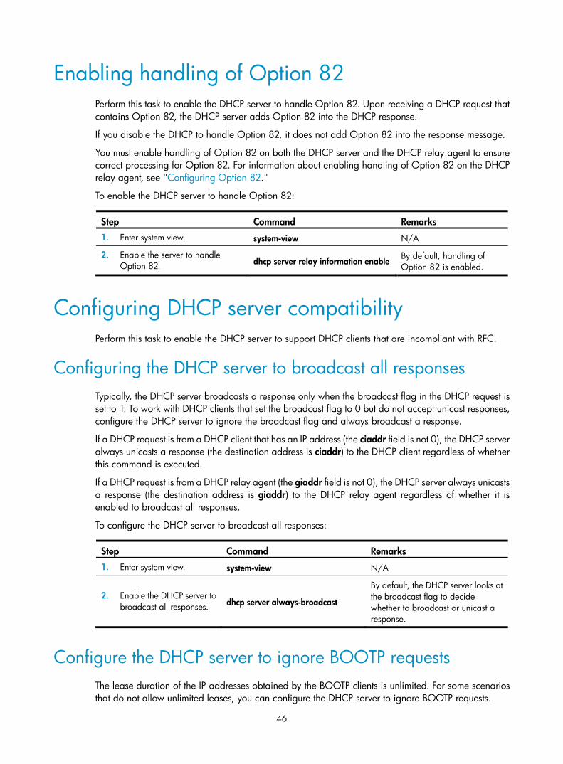
46
Enabling handling of Option 82 Perform this task to enable the DHCP server to handle Option 82. Upon receiving a DHCP request that contains Option 82, the DHCP server adds Option 82 into the DHCP response.
If you disable the DHCP to handle Option 82, it does not add Option 82 into the response message.
You must enable handling of Option 82 on both the DHCP server and the DHCP relay agent to ensure correct processing for Option 82. For information about enabling handling of Option 82 on the DHCP relay agent, see "Configuring Option 82."
To enable the DHCP server to handle Option 82:
Step Command Remarks 1. Enter system view. system-view N/A
2. Enable the server to handle Option 82. dhcp server relay information enable
By default, handling of Option 82 is enabled.
Configuring DHCP server compatibility Perform this task to enable the DHCP server to support DHCP clients that are incompliant with RFC.
Configuring the DHCP server to broadcast all responses Typically, the DHCP server broadcasts a response only when the broadcast flag in the DHCP request is set to 1. To work with DHCP clients that set the broadcast flag to 0 but do not accept unicast responses, configure the DHCP server to ignore the broadcast flag and always broadcast a response.
If a DHCP request is from a DHCP client that has an IP address (the ciaddr field is not 0), the DHCP server always unicasts a response (the destination address is ciaddr) to the DHCP client regardless of whether this command is executed.
If a DHCP request is from a DHCP relay agent (the giaddr field is not 0), the DHCP server always unicasts a response (the destination address is giaddr) to the DHCP relay agent regardless of whether it is enabled to broadcast all responses.
To configure the DHCP server to broadcast all responses:
Step Command Remarks 1. Enter system view. system-view N/A
2. Enable the DHCP server to broadcast all responses. dhcp server always-broadcast
By default, the DHCP server looks at the broadcast flag to decide whether to broadcast or unicast a response.
Configure the DHCP server to ignore BOOTP requests The lease duration of the IP addresses obtained by the BOOTP clients is unlimited. For some scenarios that do not allow unlimited leases, you can configure the DHCP server to ignore BOOTP requests.

47
To configure the DHCP server to ignore BOOTP requests:
Step Command Remarks 1. Enter system view. system-view N/A
2. Configure the DHCP server to ignore BOOTP requests. dhcp server bootp ignore
By default, the DHCP server processes BOOTP requests.
Configuring the DHCP server to send BOOTP responses in RFC 1048 format
Not all BOOTP clients can send requests compatible with RFC 1048. By default, the DHCP server does not process the Vend field of RFC 1048-incompliant requests but copies the Vend field into responses.
This function enables the DHCP server to fill in the Vend field using the RFC 1048-compliant format in DHCP responses to RFC 1048-incompliant requests sent by BOOTP clients that request statically bound addresses.
To configure the DHCP server to send BOOTP responses in RFC 1048 format:
Step Command Remarks 1. Enter system view. system-view N/A
2. Enable the DHCP server to send BOOTP responses in RFC 1048 format to the RFC 1048-incompliant BOOTP requests for statically bound addresses.
dhcp server bootp reply-rfc-1048
By default, the DHCP server directly copies the Vend field of such requests into the responses.
Setting the DSCP value for DHCP packets sent by the DHCP server
The DSCP value of a packet specifies the priority level of the packet and affects the transmission priority of the packet.
To set the DSCP value for DHCP packets sent by the DHCP server:
Step Command Remarks 1. Enter system view. system-view N/A
2. Set the DSCP value for DHCP packets sent by the DHCP server.
dhcp dscp dscp-value By default, the DSCP value in DHCP packets sent by the DHCP server is 56.

48
Displaying and maintaining the DHCP server IMPORTANT:
A restart of the DHCP server or execution of the reset dhcp server ip-in-use command deletes all lease information. The DHCP server denies any DHCP request for lease extension, and the client must request anIP address again.
Execute display commands in any view and reset commands in user view.
Task Command
Display information about IP address conflicts. display dhcp server conflict [ ip ip-address ]
Display information about lease-expired IP addresses.
display dhcp server expired [ ip ip-address | pool pool-name ]
Display information about assignable IP addresses.
display dhcp server free-ip [ pool pool-name ]
Display information about assigned IP addresses.
display dhcp server ip-in-use [ ip ip-address | pool pool-name ]
Display DHCP server statistics. display dhcp server statistics [ pool pool-name ]
Display information about DHCP address pools.
display dhcp server pool [ pool-name ]
Clear information about IP address conflicts. reset dhcp server conflict [ ip ip-address ]
Clear information about lease-expired IP addresses. reset dhcp server expired [ ip ip-address | pool pool-name ]
Clear information about assigned IP addresses. reset dhcp server ip-in-use [ ip ip-address | pool pool-name ]
Clear DHCP server statistics. reset dhcp server statistics
DHCP server configuration examples DHCP networking involves two types:
• The DHCP server and clients reside on the same subnet.
• The DHCP server and clients are not on the same subnet and communicate with each other through a DHCP relay agent.
The DHCP server configuration for the two types is identical.
Static IP address assignment configuration example Network requirements
As shown in Figure 16, Router A (DHCP server) assigns a static IP address, DNS server address, and gateway address to Router B (DHCP client) and Router C (BOOTP client).
The client ID of the interface Ethernet 1/1 on Router B is:

49
0030-3030-662e-6532-3030-2e30-3030-322d-4574-6865-726e-6574-302f-30.
The MAC address of the interface Ethernet 1/1 on Router C is 000f-e200-01c0.
Figure 16 Network diagram
Configuration procedure
1. Specify an IP address for Ethernet 1/1 on Router A: <RouterA> system-view
[RouterA] interface ethernet 1/1
[RouterA-Ethernet1/1] ip address 10.1.1.1 25
[RouterA-Ethernet1/1] quit
2. Configure the DHCP server:
# Enable DHCP. [RouterA] dhcp enable
# Enable the DHCP server on Ethernet 1/1. [RouterA] interface ethernet 1/1
[RouterA-Ethernet1/1] dhcp select server
[RouterA-Ethernet1/1] quit
# Create DHCP address pool 0. [RouterA] dhcp server ip-pool 0
# Configure a static binding for Router B. [RouterA-dhcp-pool-0] static-bind ip-address 10.1.1.5 25 client-identifier 0030-3030-662e-6532-3030-2e30-3030-322d-4574-6865-726e-6574-302f-30
# Configure a static binding for Router C. [RouterA-dhcp-pool-0] static-bind ip-address 10.1.1.6 25 hardware-address 000f-e200-01c0
# Specify the DNS server and gateway. [RouterA-dhcp-pool-0] dns-list 10.1.1.2
[RouterA-dhcp-pool-0] gateway-list 10.1.1.126
Verifying the configuration
After the preceding configuration is complete, Router B can obtain IP address 10.1.1.5 and other network parameters, and Router C can obtain IP address 10.1.1.6 and other network parameters from Router A. You can use the display dhcp server ip-in-use command on the DHCP server to view the IP addresses assigned to the clients.

50
Dynamic IP address assignment configuration example Network requirements
• As shown in Figure 17, the DHCP server (Router A) assigns IP address to clients on subnet 10.1.1.0/24, which is subnetted into 10.1.1.0/25 and 10.1.1.128/25.
• The IP addresses of Ethernet 1/1 and Ethernet 1/2 on Router A are 10.1.1.1/25 and 10.1.1.129/25.
• In subnet 10.1.1.0/25, the address lease duration is ten days and twelve hours, the domain name suffix is aabbcc.com, the DNS server address is 10.1.1.2/25, the WINS server address is 10.1.1.4/25, and the gateway address is 10.1.1.126/25.
• In the subnet 10.1.1.128/25, the address lease duration is five days, the domain name suffix is aabbcc.com, the DNS server address is 10.1.1.2/25, and the gateway address is 10.1.1.254/25 and there is no WINS server address.
Figure 17 Network diagram
Configuration procedure
1. Specify IP addresses for interfaces. (Details not shown.)
2. Configure the DHCP server:
# Enable DHCP. <RouterA> system-view
[RouterA] dhcp enable
# Enable the DHCP server on Ethernet 1/1 and Ethernet 1/2. [RouterA] interface ethernet 1/1
[RouterA-Ethernet1/1] dhcp select server
[RouterA-Ethernet1/1] quit
[RouterA] interface ethernet 1/2
[RouterA-Ethernet1/2] dhcp select server
[RouterA-Ethernet1/2] quit
# Exclude IP addresses from dynamic allocation (addresses of the DNS server, WINS server, and gateways). [RouterA] dhcp server forbidden-ip 10.1.1.2
[RouterA] dhcp server forbidden-ip 10.1.1.4
[RouterA] dhcp server forbidden-ip 10.1.1.126
[RouterA] dhcp server forbidden-ip 10.1.1.254

51
# Configure DHCP address pool 1 to assign IP addresses and other configuration parameters to clients in subnet 10.1.1.0/25. [RouterA] dhcp server ip-pool 1
[RouterA-dhcp-pool-1] network 10.1.1.0 mask 255.255.255.128
[RouterA-dhcp-pool-1] expired day 10 hour 12
[RouterA-dhcp-pool-1] domain-name aabbcc.com
[RouterA-dhcp-pool-1] dns-list 10.1.1.2
[RouterA-dhcp-pool-1] gateway-list 10.1.1.126
[RouterA-dhcp-pool-1] nbns-list 10.1.1.4
[RouterA-dhcp-pool-1] quit
# Configure DHCP address pool 2 to assign IP addresses and other configuration parameters to clients in subnet 10.1.1.128/25. [RouterA] dhcp server ip-pool 2
[RouterA-dhcp-pool-2] network 10.1.1.128 mask 255.255.255.128
[RouterA-dhcp-pool-2] expired day 5
[RouterA-dhcp-pool-2] domain-name aabbcc.com
[RouterA-dhcp-pool-2] dns-list 10.1.1.2
[RouterA-dhcp-pool-2] gateway-list 10.1.1.254
Verifying the configuration
After the preceding configuration is complete, clients on networks 10.1.1.0/25 and 10.1.1.128/25 can obtain correct IP addresses and other network parameters from Router A. You can use the display dhcp server ip-in-use command on the DHCP server to view the IP addresses assigned to the clients.
DHCP user class configuration example Network requirements
• As shown in Figure 18, the DHCP relay agent (Router A) forwards the packets from DHCP clients to the DHCP server. Enable Router A to handle Option 82 so that it can add Option 82 in the DHCP requests from the DHCP clients and convey the packets to the DHCP server.
• The DHCP server (Router B) assigns IP addresses and other configuration parameters to the DHCP clients. If the DHCP requests contain Option 82, the server assigns IP addresses in the range of 10.10.1.2 to 10.10.1.10 to the clients.
• Router B assigns the DNS server address 10.10.1.20/24 and the gateway address 10.10.1.255/24 for clients in subnet 10.10.1.0/24.
Figure 18 Network diagram

52
Configuration procedure
1. Specify IP addresses for the interfaces on DHCP server. (Details not shown.)
2. Configure DHCP:
# Enable DHCP and configure the DHCP server to handle Option 82. <RouterB> system-view
[RouterB] dhcp enable
[RouterB] dhcp server relay information enable
# Enable the DHCP server on the interface Ethernet1/1. [RouterB] interface Ethernet 1/1
[RouterB-Ethernet1/1] dhcp select server
[RouterB-Ethernet1/1] quit
# Create DHCP user class tt to match DHCP requests that contain Option 82. [RouterB] dhcp class tt
[RouterB-dhcp-class-tt] if-match option 82
[RouterB-dhcp-class-tt] quit
# Create DHCP address pool aa, specify the address range of the address pool and the address range of the user class tt, specify the gateway and the DNS server. [RouterB] dhcp server ip-pool aa
[RouterB-dhcp-pool-aa] network 10.10.1.0 mask 255.255.255.0
[RouterB-dhcp-pool-aa] address-range 10.10.1.2 10.10.1.100
[RouterB-dhcp-pool-aa] class tt range 10.10.1.2 10.10.1.10
[RouterB-dhcp-pool-aa] gateway-list 10.10.1.255
[RouterB-dhcp-pool-aa] dns-list 10.10.1.20
Verifying the configuration
After the preceding configuration is complete, clients matching the DHCP user class can obtain IP addresses in the specified range and network configuration parameters from DHCP server (Router B). You can use the display dhcp server ip-in-use command to view the IP addresses assigned to the clients.
Self-defined DHCP option configuration example Network requirements
As shown in Figure 19, the DHCP client (Router B) obtains its IP address and PXE server addresses from the DHCP server (Router A). The client IP address belongs to subnet 10.1.1.0/24. The PXE server addresses are 1.2.3.4 and 2.2.2.2.
The DHCP server assigns PXE server addresses to DHCP clients through Option 43, a self-defined option. The formats of Option 43 and PXE server address sub-option are shown in Figure 14 and Figure 15. The value of Option 43 configured on the DHCP server in this example is 80 0B 00 00 02 01 02 03 04 02 02 02 02. The number 80 is the value of the sub-option type. The number 0B is the value of the sub-option length. The numbers 00 00 are the value of the PXE server type. The number 02 indicates the number of servers. The numbers 01 02 03 04 02 02 02 02 indicate that the PXE server addresses are 1.2.3.4 and 2.2.2.2.

53
Figure 19 Network diagram
Configuration procedure
1. Specify an IP address for interface Ethernet 1/1. (Details not shown.)
2. Configure the DHCP server:
# Enable DHCP. <RouterA> system-view
[RouterA] dhcp enable
# Enable the DHCP server on Ethernet 1/1. [RouterA] interface ethernet 1/1
[RouterA-Ethernet1/1] dhcp select server
[RouterA-Ethernet1/1] quit
# Configure DHCP address pool 0. [RouterA] dhcp server ip-pool 0
[RouterA-dhcp-pool-0] network 10.1.1.0 mask 255.255.255.0
[RouterA-dhcp-pool-0] option 43 hex 800B0000020102030402020202
Verifying the configuration
After the preceding configuration is complete, Router B can obtain an IP address on the subnet 10.1.1.0/24 and the PXE server addresses from Router A. You can use the display dhcp server ip-in-use command on the DHCP server to view the IP addresses assigned to the clients.
Troubleshooting DHCP server configuration
Symptom A client's IP address obtained from the DHCP server conflicts with another IP address.
Analysis Another host on the subnet might have the same IP address.
Solution 1. Disable the client's network adapter or disconnect the client's network cable. Ping the IP address
of the client from another host to check whether there is a host using the same IP address.
2. If a ping response is received, the IP address has been manually configured on a host. Execute the dhcp server forbidden-ip command on the DHCP server to exclude the IP address from dynamic allocation.

54
3. Enable the network adapter or connect the network cable, release the IP address, and obtain another one on the client. For example, to release the IP address and obtain another one on a Windows XP DHCP client:
a. In Windows environment, execute the cmd command to enter the DOS environment.
b. Enter ipconfig /release to relinquish the IP address.
c. Enter ipconfig /renew to obtain another IP address.

55
Configuring the DHCP relay agent
Overview The DHCP relay agent enables clients to get IP addresses from a DHCP server on another subnet. This feature avoids deploying a DHCP server for each subnet to centralize management and reduce investment. Figure 20 shows a typical application of the DHCP relay agent.
Figure 20 DHCP relay agent application
An MCE device serving as the DHCP relay agent can forward DHCP packets not only between a DHCP server and clients on a public network, but also between a DHCP server and clients on a private network. For more information about MCE, see MPLS Configuration Guide.
Operation The DHCP server and client interact with each other in the same way regardless of whether the relay agent exists. For the interaction details, see "Dynamic IP address allocation process." The following only describes steps related to the DHCP relay agent:
1. After receiving a DHCP-DISCOVER or DHCP-REQUEST broadcast message from a DHCP client, the DHCP relay agent fills the giaddr field of the message with its IP address and unicasts the message to the designated DHCP server.
2. Based on the giaddr field, the DHCP server returns an IP address and other configuration parameters in a response.
3. The relay agent conveys the response to the client.

56
Figure 21 DHCP relay agent operation
DHCP relay agent support for Option 82 Option 82 records the location information about the DHCP client. It enables the administrator to locate the DHCP client for security and accounting purposes, and to assign IP addresses in a specific range to clients. For more information, see "Relay agent option (Option 82)."
If the DHCP relay agent supports Option 82, it handles DHCP requests by following the strategies described in Table 3.
If a response returned by the DHCP server contains Option 82, the DHCP relay agent removes the Option 82 before forwarding the response to the client.
Table 3 Handling strategies of the DHCP relay agent
If a DHCP request has…
Handling strategy The DHCP relay agent…
Option 82
Drop Drops the message.
Keep Forwards the message without changing Option 82.
Replace Forwards the message after replacing the original Option 82 with the Option 82 padded according to the configured padding format, padding content, and code type.
No Option 82 N/A Forwards the message after adding Option 82 padded according to the configured padding format, padding content, and code type.
DHCP relay agent configuration task list Tasks at a glance
(Required.) Enabling DHCP
(Required.)Enabling the DHCP relay agent on an interface
(Required.) Specifying DHCP servers on a relay agent
(Optional.) Configuring the DHCP relay agent security functions

57
Tasks at a glance
(Optional.) Configuring the DHCP relay agent to release an IP address
(Optional.) Configuring Option 82
(Optional.) Setting the DSCP value for DHCP packets sent by the DHCP relay agent
Enabling DHCP You must enable DHCP to validate other DHCP relay agent settings.
To enable DHCP:
Step Command Remarks 1. Enter system view. system-view N/A
2. Enable DHCP. dhcp enable By default, DHCP is disabled.
Enabling the DHCP relay agent on an interface With the DHCP relay agent enabled, an interface forwards incoming DHCP requests to a DHCP server.
An IP address pool that contains the IP address of the DHCP relay agent interface must be configured on the DHCP server. Otherwise, the DHCP clients connected to the relay agent cannot obtain correct IP addresses.
To enable the DHCP relay agent on an interface:
Step Command Remarks 1. Enter system view. system-view N/A
2. Enter interface view. interface interface-type interface-number N/A
3. Enable the DHCP relay agent. dhcp select relay By default, when DHCP is enabled, an interface operates in the DHCP server mode.
Specifying DHCP servers on a relay agent To improve availability, you can specify several DHCP servers on the DHCP relay agent. When the interface receives request messages from clients, the relay agent forwards them to all DHCP servers.
Follow these guidelines when you specify a DHCP server address on a relay agent:
• The IP address of any specified DHCP server must not reside on the same subnet as the IP address of the relay agent interface. Otherwise, the clients might fail to obtain IP addresses.
• You can specify a maximum of eight DHCP servers.

58
To specify a DHCP server address on a relay agent:
Step Command Remarks 1. Enter system view. system-view N/A
2. Enter interface view. interface interface-type interface-number N/A
3. Specify a DHCP server address on the relay agent.
dhcp relay server-address ip-address
By default, no DHCP server address is specified on the relay agent.
Configuring the DHCP relay agent security functions
Enabling the DHCP relay agent to record relay entries Perform this task to enable the DHCP relay agent to automatically record clients' IP-to-MAC bindings (relay entries) after they obtain IP addresses through DHCP.
Some security functions, such as ARP address check, authorized ARP, and IP source guard, use the recorded relay entries to check incoming packets and block packets that do not match any entry. In this way, illegal hosts are not able to access external networks through the relay agent.
To enable the DHCP relay agent to record relay entries:
Step Command Remarks 1. Enter system view. system-view N/A
2. Enable the relay agent to record relay entries. dhcp relay client-information record
By default, the relay agent does not record relay entries.
NOTE:
The DHCP relay agent does not record IP-to-MAC bindings for DHCP clients running on synchronous/asynchronous serial interfaces.
Enabling periodic refresh of dynamic relay entries A DHCP client unicasts a DHCP-RELEASE message to the DHCP server to release its IP address. The DHCP relay agent simply conveys the message to the DHCP server and does not remove the IP-to-MAC entry of the client.
With this feature, the DHCP relay agent uses the IP address of a relay entry and the MAC address of the DHCP relay interface to periodically send a DHCP-REQUEST message to the DHCP server.
• If the server returns a DHCP-ACK message or does not return any message within a specific interval, the DHCP relay agent removes the relay entry. In addition, upon receiving the DHCP-ACK message, the relay agent sends a DHCP-RELEASE message to release the IP address.
• If the server returns a DHCP-NAK message, the relay agent keeps the relay entry.

59
To enable periodic refresh of dynamic relay entries:
Step Command Remarks 1. Enter system view. system-view N/A
2. Enable periodic refresh of dynamic relay entries.
dhcp relay client-information refresh enable
By default, periodic refresh of dynamic relay entries is enabled.
3. Configure the refresh interval.
dhcp relay client-information refresh [ auto | interval interval ]
By default, the refresh interval is auto, which is calculated based on the number of total relay entries.
Enabling DHCP starvation attack protection A DHCP starvation attack occurs when an attacker constantly sends forged DHCP requests using different MAC addresses in the chaddr field to a DHCP server. This exhausts the IP address resources of the DHCP server so legitimate DHCP clients cannot obtain IP addresses. The DHCP server might also fail to work because of exhaustion of system resources. The following methods are available to relieve or prevent such attacks.
• To relieve a DHCP starvation attack that uses DHCP packets encapsulated with different source MAC addresses, you can limit the number of ARP entries that a Layer 3 interface can learn or MAC addresses that a Layer 2 port can learn. You can also configure an interface that has learned the maximum MAC addresses to discard packets whose source MAC addresses are not in the MAC address table.
• To prevent a DHCP starvation attack that uses DHCP requests encapsulated with the same source MAC address, you can enable MAC address check on the DHCP relay agent. The DHCP relay agent compares the chaddr field of a received DHCP request with the source MAC address in the frame header. If they are the same, the DHCP relay agent forwards the request to the DHCP server. If not, the relay agent discards the request.
Enable MAC address check only on the DHCP relay agent directly connected to the DHCP clients. A DHCP relay agent changes the source MAC address of DHCP packets before sending them. If you enable this feature on an intermediate relay agent, it might discard valid DHCP packet, and the sending clients will not obtain IP addresses.
To enable MAC address check:
Step Command Remarks 1. Enter system view. system-view N/A
2. Enter the interface view. interface interface-type interface-number
N/A
3. Enable MAC address check. dhcp relay check mac-address By default, MAC address check is disabled.

60
Configuring the DHCP relay agent to release an IP address
Configure the relay agent to release the IP address for a relay entry. The relay agent sends a DHCP-RELEASE message to the server and meanwhile deletes the relay entry. Upon receiving the DHCP-RELEASE message, the DHCP server releases the IP address.
To configure the DHCP relay agent to release an IP address:
Step Command Remarks 1. Enter system view. system-view N/A
2. Configure the DHCP relay agent to release an IP address.
dhcp relay release ip client-ip [ vpn-instance vpn-instance-name ]
This command can release only the IP addresses in the recorded relay entries.
Configuring Option 82 Follow these guidelines when you configure Option 82:
• To support Option 82, you must perform related configuration on both the DHCP server and relay agent. For DHCP server Option 82 configuration, see "Enabling handling of Option 82."
• The system name (sysname) if padded in sub-option 1 (node identifier) of Option 82 must not contain spaces. Otherwise, the DHCP relay agent drops the message.
To configure Option 82:
Step Command Remarks 1. Enter system view. system-view N/A
2. Enter interface view. interface interface-type interface-number N/A
3. Enable the relay agent to handle Option 82. dhcp relay information enable
By default, handling of Option 82 is disabled.
4. (Optional.) Configure the strategy for handling DHCP requests that contain Option 82.
dhcp relay information strategy { drop | keep | replace }
By default, the handling strategy is replace.
5. (Optional.) Configure the padding content and code type for the circuit ID sub-option.
dhcp relay information circuit-id { string circuit-id | { normal | verbose [ node-identifier { mac | sysname | user-defined node-identifier } ] } [ format { ascii | hex } ] }
By default, the padding format for circuit ID sub-option is normal, and the code type is hex.
6. (Optional.) Configure the padding content and code type for the remote ID sub-option.
dhcp relay information remote-id { normal [ format { ascii | hex } ] | string remote-id | sysname }
By default, the padding format for the remote ID sub-option is normal, and the code type is hex.
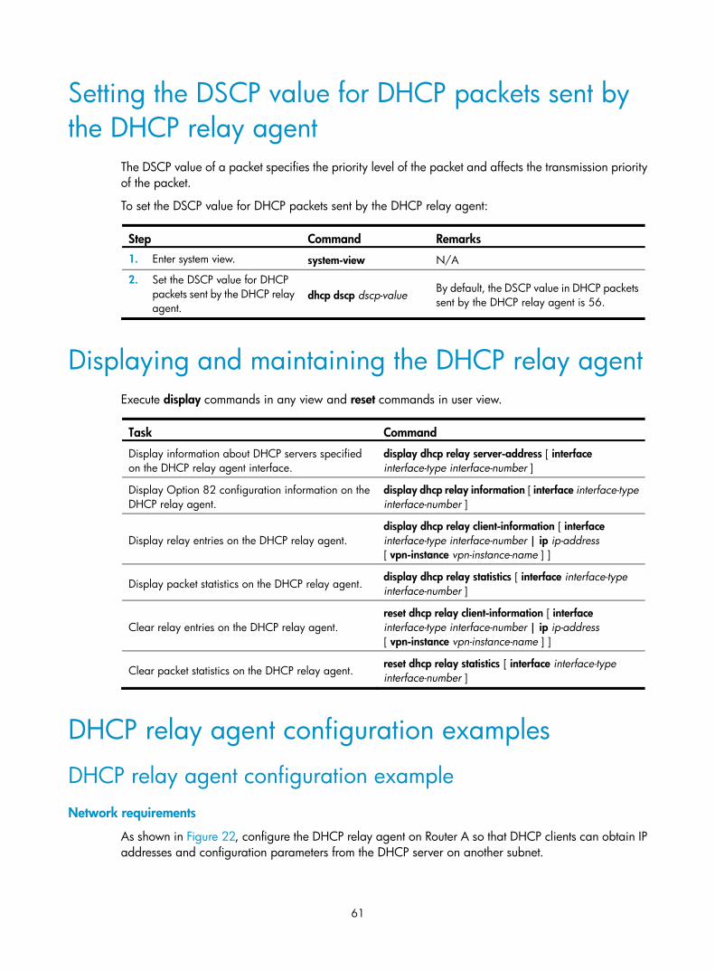
61
Setting the DSCP value for DHCP packets sent by the DHCP relay agent
The DSCP value of a packet specifies the priority level of the packet and affects the transmission priority of the packet.
To set the DSCP value for DHCP packets sent by the DHCP relay agent:
Step Command Remarks 1. Enter system view. system-view N/A
2. Set the DSCP value for DHCP packets sent by the DHCP relay agent.
dhcp dscp dscp-value By default, the DSCP value in DHCP packets sent by the DHCP relay agent is 56.
Displaying and maintaining the DHCP relay agent Execute display commands in any view and reset commands in user view.
Task Command
Display information about DHCP servers specified on the DHCP relay agent interface.
display dhcp relay server-address [ interface interface-type interface-number ]
Display Option 82 configuration information on the DHCP relay agent.
display dhcp relay information [ interface interface-type interface-number ]
Display relay entries on the DHCP relay agent. display dhcp relay client-information [ interface interface-type interface-number | ip ip-address [ vpn-instance vpn-instance-name ] ]
Display packet statistics on the DHCP relay agent. display dhcp relay statistics [ interface interface-type interface-number ]
Clear relay entries on the DHCP relay agent. reset dhcp relay client-information [ interface interface-type interface-number | ip ip-address [ vpn-instance vpn-instance-name ] ]
Clear packet statistics on the DHCP relay agent. reset dhcp relay statistics [ interface interface-type interface-number ]
DHCP relay agent configuration examples
DHCP relay agent configuration example Network requirements
As shown in Figure 22, configure the DHCP relay agent on Router A so that DHCP clients can obtain IP addresses and configuration parameters from the DHCP server on another subnet.

62
Because the DHCP relay agent and server are on different subnets, you need to configure static or dynamic routing to make them reachable to each other.
DHCP server configuration is also required to guarantee the client-server communication through the DHCP relay agent. For DHCP server configuration information, see "DHCP server configuration examples ."
Figure 22 Network diagram
Configuration procedure
# Specify IP addresses for the interfaces. (Details not shown.)
# Enable DHCP. <RouterA> system-view
[RouterA] dhcp enable
# Enable the DHCP relay agent on Ethernet 1/1. [RouterA] interface ethernet 1/1
[RouterA-Ethernet1/1] dhcp select relay
# Specify the IP address of the DHCP server on the relay agent. [RouterA-Ethernet1/1] dhcp relay server-address 10.1.1.1
After the preceding configuration is complete, DHCP clients can obtain IP addresses and other network parameters from the DHCP server through the DHCP relay agent. You can use the display dhcp relay statistics command to view the statistics of DHCP packets forwarded by the DHCP relay agent. If you enable relay entry record on the DHCP relay agent with the dhcp relay client-information record command, you can use the display dhcp relay client-information command to view relay entries.
Option 82 configuration example Network requirements
As shown in Figure 22, the DHCP relay agent (Router A) replaces Option 82 in DHCP requests before forwarding them to the DHCP server (Router B).
• The circuit ID sub-option is company001.
• The remote ID sub-option is device001.
To use Option 82, you must also enable the DHCP server to handle Option 82.
Router BDHCP server
Router ADHCP relay agent
DHCP client DHCP client
DHCP clientDHCP client
Eth1/210.1.1.2/24
Eth1/110.10.1.1/24
Eth1/110.1.1.1/24

63
Configuration procedure
# Specify IP addresses for the interfaces. (Details not shown.)
# Enable DHCP. <RouterA> system-view
[RouterA] dhcp enable
# Enable the DHCP relay agent on Ethernet 1/1. [RouterA] interface ethernet 1/1
[RouterA-Ethernet1/1] dhcp select relay
# Specify the IP address of the DHCP server on the relay agent. [RouterA-Ethernet1/1] dhcp relay server-address 10.1.1.1
# Enable the DHCP relay agent to handle Option 82, and perform Option 82 related configurations. [RouterA-Ethernet1/1] dhcp relay information enable
[RouterA-Ethernet1/1] dhcp relay information strategy replace
[RouterA-Ethernet1/1] dhcp relay information circuit-id string company001
[RouterA-Ethernet1/1] dhcp relay information remote-id string device001
Troubleshooting DHCP relay agent configuration
Symptom DHCP clients cannot obtain configuration parameters through the DHCP relay agent.
Analysis Some problems might occur with the DHCP relay agent or server configuration.
Solution To locate the problem, enable debugging and execute the display command on the DHCP relay agent to view the debugging information and interface state information.
Check that:
• DHCP is enabled on the DHCP server and relay agent.
• The DHCP server has an address pool on the same subnet as the DHCP clients.
• The DHCP server and DHCP relay agent can reach each other.
• The DHCP server address specified on the DHCP relay agent interface connected to the DHCP clients is correct.

64
Configuring the DHCP client
With DHCP client enabled, an interface uses DHCP to obtain configuration parameters from the DHCP server, for example, an IP address.
The DHCP client configuration is supported only on Layer 3 Ethernet interfaces (or subinterfaces) and VLAN interfaces.
When multiple VLAN interfaces with the same MAC address use DHCP for IP address acquisition through a relay agent, the DHCP server cannot be a Windows Server 2000 or Windows Server 2003.
Enabling the DHCP client on an interface Follow these guidelines when you enable the DHCP client on an interface:
• On some device models, if the number of IP address request failures reaches the system-defined amount, the DHCP client-enabled interface uses a default IP address.
• An interface can be configured to acquire an IP address in multiple ways. The new configuration overwrites the old.
• Secondary IP addresses cannot be configured on an interface that is enabled with the DHCP client.
• If the interface obtains an IP address on the same segment as another interface on the device, the interface does not use the assigned address. Instead, it requests a new IP address from the DHCP server.
To enable the DHCP client on an interface:
Step Command Remarks 1. Enter system view. system-view N/A
2. Enter interface view. interface interface-type interface-number N/A
3. Configure an interface to use DHCP for IP address acquisition.
ip address dhcp-alloc By default, an interface does not use DHCP for IP address acquisition.
Configuring a DHCP client ID for an interface A DHCP client ID is added to the DHCP option 61. A DHCP server can specify IP addresses for clients based on the DHCP client ID.
Make sure the IDs for different DHCP clients are unique.
To configure a DHCP client ID for an interface:
Step Command Remarks 1. Enter system view. system-view N/A

65
Step Command Remarks
2. Enter interface view. interface interface-type interface-number N/A
3. Configure a DHCP client ID for the interface.
dhcp client identifier { ascii string | hex string | mac interface-type interface-number }
By default, an interface generates the DHCP client ID based on its MAC address. If the interface has no MAC address, it uses the MAC address of the first Ethernet interface to generate its client ID.
4. Verify the client ID configuration.
display dhcp client [ verbose ] [ interface interface-type interface-number ]
DHCP client ID includes ID type and type value. Each ID type has a fixed type value. You can check the fields for the client ID to verify which type of client ID is used: • If an ASCII string is used as the client ID,
the type value is 00. • If a hex string is used as the client ID, the
type value is the first two characters in the string.
• If the MAC address of a specific interface is used as the client ID, the type value is 01.
Enabling duplicated address detection DHCP client detects IP address conflict through ARP packets. An attacker can act as the IP address owner to send an ARP reply, making the client unable to use the IP address assigned by the server. H3C recommends you to disable duplicate address detection when ARP attacks exist on the network.
To enable duplicated address detection:
Step Command Remarks 1. Enter system view. system-view N/A
2. Enable duplicate address detection. dhcp client dad enable
By default, the duplicate address detection feature is enabled on an interface.
Setting the DSCP value for DHCP packets sent by the DHCP client
The DSCP value of a packet specifies the priority level of the packet and affects the transmission priority of the packet.
To set the DSCP value for DHCP packets sent by the DHCP client:
Step Command Remarks 1. Enter system view. system-view N/A

66
Step Command Remarks 2. Set the DSCP value for DHCP
packets sent by the DHCP client.
dhcp dscp dscp-value By default, the DSCP value in DHCP packets sent by the DHCP client is 56.
Displaying and maintaining the DHCP client Execute display command in any view.
Task Command
Display DHCP client information. display dhcp client [ verbose ] [ interface interface-type interface-number ]
DHCP client configuration example
Network requirements As shown in Figure 24, Router B contacts the DHCP server through Ethernet 1/1 to obtain an IP address, DNS server address, and static route information. The DHCP client IP address resides on network 10.1.1.0/24. The DNS server address is 20.1.1.1. The next hop of the static route to network 20.1.1.0/24 is 10.1.1.2.
The DHCP server uses Option 121 to assign static route information to DHCP clients. Figure 23 shows the Option 121 format. The destination descriptor field contains the following parts: subnet mask length and destination network address, both in hexadecimal notation. In this example, the destination descriptor is 18 14 01 01 (the subnet mask length is 24 and the network address is 20.1.1.0 in dotted decimal notation). The next hop address is 0A 01 01 02 (10.1.1.2 in dotted decimal notation).
Figure 23 Option 121 format
Figure 24 Network diagram

67
Configuration procedure 1. Configure Router A:
# Specify the IP address of Ethernet 1/1. <RouterA> system-view
[RouterA] interface ethernet 1/1
[RouterA-Ethernet1/1] ip address 10.1.1.1 24
[RouterA-Ethernet1/1] quit
# Enable DHCP. [RouterA] dhcp enable
# Exclude an IP address from dynamic allocation. [RouterA] dhcp server forbidden-ip 10.1.1.2
# Configure DHCP address pool 0 and specify the subnet, lease duration, DNS server address, and a static route to subnet 20.1.1.0/24. [RouterA] dhcp server ip-pool 0
[RouterA-dhcp-pool-0] network 10.1.1.0 mask 255.255.255.0
[RouterA-dhcp-pool-0] expired day 10
[RouterA-dhcp-pool-0] dns-list 20.1.1.1
[RouterA-dhcp-pool-0] option 121 hex 181401010A010102
2. Configure Router B:
# Configure Ethernet 1/1 to use DHCP for IP address acquisition. <RouterB> system-view
[RouterB] interface ethernet 1/1
[RouterB-Ethernet1/1] ip address dhcp-alloc
[RouterB-Ethernet1/1] quit
Verifying the configuration # Use the display dhcp client command to display the IP address and other network parameters assigned to Router B. [RouterB] display dhcp client verbose
Ethernet1/1 DHCP client information:
Current machine state: BOUND
Allocated IP: 10.1.1.3 255.255.255.0
Allocated lease: 864000 seconds, T1: 331858 seconds, T2: 756000 seconds
Lease from May 21 19:00:29 2012 to May 31 19:00:29 2012
DHCP server: 10.1.1.1
Transaction ID: 0xcde72232
Classless static route:
Destination: 20.1.1.0, Mask: 255.255.255.0, NextHop: 10.1.1.2
DNS server: 20.1.1.1
Client ID type: acsii(type value=00)
Client ID value: 000c.29d3.8659-Eth1/1
Client ID (with type) hex: 0030-3030-632e-3239-
6433-2e38-3635-392d-
4574-6830-2f30-2f32

68
T1 will timeout in 3 days 19 hours 48 minutes 43 seconds.
# Use the display ip routing-table command to display the route information on Router B. The output shows that a static route to network 20.1.1.0/24 is added to the routing table. [RouterB] display ip routing-table
Destinations : 11 Routes : 11
Destination/Mask Proto Pre Cost NextHop Interface
10.1.1.0/24 Direct 0 0 10.1.1.3 Eth1/1
10.1.1.3/32 Direct 0 0 127.0.0.1 InLoop0
20.1.1.0/24 Static 70 0 10.1.1.2 Eth1/1
10.1.1.255/32 Direct 0 0 10.1.1.3 Eth1/1
127.0.0.0/8 Direct 0 0 127.0.0.1 InLoop0
127.0.0.0/32 Direct 0 0 127.0.0.1 InLoop0
127.0.0.1/32 Direct 0 0 127.0.0.1 InLoop0
127.255.255.255/32 Direct 0 0 127.0.0.1 InLoop0
224.0.0.0/4 Direct 0 0 0.0.0.0 NULL0
224.0.0.0/24 Direct 0 0 0.0.0.0 NULL0
255.255.255.255/32 Direct 0 0 127.0.0.1 InLoop0

69
Configuring DHCP snooping
DHCP snooping works between the DHCP client and server, or between the DHCP client and DHCP relay agent. It guarantees that DHCP clients obtain IP addresses from authorized DHCP servers. Also, it records IP-to-MAC bindings of DHCP clients (called DHCP snooping entries) for security purposes.
DHCP snooping does not work between the DHCP server and DHCP relay agent.
Overview DHCP snooping defines trusted and untrusted ports to make sure clients obtain IP addresses only from authorized DHCP servers.
• Trusted—A trusted port can forward DHCP messages correctly to make sure the clients get IP addresses from authorized DHCP servers.
• Untrusted—An untrusted port discards received DHCP-ACK and DHCP-OFFER messages to prevent unauthorized servers from assigning IP addresses.
DHCP snooping reads DHCP-ACK messages received from trusted ports and DHCP-REQUEST messages to create DHCP snooping entries. A DHCP snooping entry includes the MAC and IP addresses of a client, the port that connects to the DHCP client, and the VLAN.
The following features need to use DHCP snooping entries:
• ARP fast-reply—Uses DHCP snooping entries to reduce ARP broadcast traffic. For more information, see "Configuring ARP fast-reply."
• ARP detection—Uses DHCP snooping entries to filter ARP packets from unauthorized clients. For more information, see Security Configuration Guide.
• MAC-forced forwarding (MFF)—Auto-mode MFF intercepts ARP requests from clients, uses DHCP snooping entries to find the gateway address, and returns the gateway MAC address to the clients. This feature forces the client to send all traffic to the gateway so that the gateway can monitor client traffic to prevent malicious attacks among clients. For more information, see Security Configuration Guide.
• IP source guard—Uses DHCP snooping entries to filter illegal packets on a per-port basis. For more information, see Security Configuration Guide.
• VLAN mapping—Uses DHCP snooping entries to replace service provider VLAN in packets with customer VLAN before sending the packets to clients. For more information, see Layer 2—LAN Switching Configuration Guide.
Application of trusted and untrusted ports Configure ports facing the DHCP server as trusted ports, and configure other ports as untrusted ports.
As shown in Figure 25, configure the DHCP snooping device's port that is connected to the DHCP server as a trusted port. The trusted port forwards response messages from the DHCP server to the client. The untrusted port connected to the unauthorized DHCP server discards incoming DHCP response messages.

70
Figure 25 Trusted and untrusted ports
In a cascaded network as shown in Figure 26, configure each DHCP snooping device's ports connected to other DHCP snooping devices as trusted ports. To save system resources, you can disable the untrusted ports that are not directly connected to DHCP clients from generating DHCP snooping entries.
Figure 26 Trusted and untrusted ports in a cascaded network
DHCP snooping support for Option 82 Option 82 records the location information about the DHCP client so the administrator can locate the DHCP client for security and accounting purposes. For more information about Option 82, see "Relay agent option (Option 82)."
DHCP snooping uses the same strategies as the DHCP relay agent to handle Option 82 for DHCP request messages, as shown in Table 4. If a response returned by the DHCP server contains Option 82, DHCP snooping removes Option 82 before forwarding the response to the client. If the response contains no Option 82, DHCP snooping forwards it directly.

71
Table 4 Handling strategies
If a DHCP request has…
Handling strategy DHCP snooping…
Option 82
Drop Drops the message.
Keep Forwards the message without changing Option 82.
Replace Forwards the message after replacing the original Option 82 with the Option 82 padded according to the configured padding format, padding content, and code type.
No Option 82 N/A Forwards the message after adding the Option 82 padded according to the configured padding format, padding content, and code type.
DHCP snooping configuration task list Tasks at a glance
(Required.) Configuring basic DHCP snooping
(Optional.) Configuring Option 82
(Optional.) Saving DHCP snooping entries
(Optional.) Enabling DHCP starvation attack protection
(Optional.) Enabling DHCP-REQUEST attack protection
(Optional.) Configuring DHCP packet rate limit
Configuring basic DHCP snooping Follow these guidelines when you configure basic DHCP snooping:
• Specify the ports connected to authorized DHCP servers as trusted ports to make sure that DHCP clients can obtain valid IP addresses. The trusted ports and the ports connected to DHCP clients must be in the same VLAN.
• Layer 2 Ethernet interfaces can be specified as trusted ports.
• DHCP snooping can work with QinQ to record VLAN tags for DHCP packets received from clients. For more information about QinQ, see Layer 2—LAN Switching Configuration Guide.
To configure basic DHCP snooping:
Step Command Remarks
1. Enter system view. system-view N/A
2. Enable DHCP snooping. dhcp snooping enable By default, DHCP snooping is disabled.
3. Enter interface view. interface interface-type interface-number
This interface must connect to the DHCP server.

72
Step Command Remarks
4. Specify the port as a trusted port. dhcp snooping trust
By default, all ports are untrusted ports after DHCP snooping is enabled.
5. Return to system view. quit N/A
6. Enter interface view. interface interface-type interface-number
This interface must connect to the DHCP client.
7. (Optional.) Enable recording of DHCP snooping entries. dhcp snooping binding record
By default, after DHCP snooping is enabled, recording of DHCP snooping entries is disabled.
Configuring Option 82 Follow these guidelines when you configure Option 82:
• To support Option 82, you must configure Option 82 on both the DHCP server and the DHCP snooping device. For information about configuring Option 82 on the DHCP server, see "Enabling handling of Option 82."
• If the handling strategy is configured as replace, you must configure a padding format for Option 82. If the handling strategy is keep or drop, there is no need to configure any padding format.
• If Option 82 contains the device name, the device name must contain no spaces. Otherwise, DHCP snooping drops the message. You can use the sysname command to specify the device name. For more information about this command, see Fundamentals Command Reference.
• If DHCP snooping and QinQ work together or DHCP snooping receives a DHCP packet with two VLAN tags, and the verbose padding format is adopted for Option 82, DHCP snooping fills the VLAN ID field of sub-option 1 with outer VLAN tag.inner VLAN tag. For example, if the outer VLAN tag is 10 (a in hexadecimal) and the inner VLAN tag is 20 (14 in hexadecimal), the VLAN ID is 000a.0014.
To configure DHCP snooping to support Option 82:
Step Command Remarks 1. Enter system view. system-view N/A
2. Enter interface view. interface interface-type interface-number N/A
3. Enable DHCP snooping to support Option 82. dhcp snooping information enable
By default, DHCP snooping does not support Option 82.
4. (Optional.) Configure a handling strategy for DHCP requests that contain Option 82.
dhcp snooping information strategy { drop | keep | replace }
By default, the handling strategy is replace.
5. (Optional.) Configure the padding content and code type for the circuit ID sub-option.
dhcp snooping information circuit-id { [ vlan vlan-id ] string circuit-id | { normal | verbose [ node-identifier { mac | sysname | user-defined node-identifier } ] } [ format { ascii | hex } ] }
By default, the padding format is normal and the code type is hex for the circuit ID sub-option.

73
Step Command Remarks
6. (Optional.) Configure the padding content and code type for the remote ID sub-option.
dhcp snooping information remote-id { normal [ format { ascii | hex } ] | [ vlan vlan-id ] string remote-id | sysname }
By default, the padding format is normal and the code type is hex for the remote ID sub-option.
Saving DHCP snooping entries DHCP snooping entries cannot survive a reboot. If the DHCP snooping device is rebooted, security features (such as IP source guard) that use DHCP snooping entries to authenticate users reject requests from clients until new entries are learned.
To avoid this problem, you can save DHCP snooping entries in a file so that DHCP snooping can read DHCP snooping entries from this file during a reboot.
NOTE:
If you disable DHCP snooping with the undo dhcp snooping enable command, the device deletes all DHCP snooping entries, including those stored in the specified file.
To save DHCP snooping entries:
Step Command Remarks 1. Enter system view. system-view N/A
2. Specify a file to save DHCP snooping entries.
dhcp snooping binding database filename { filename | url url [ username username [ password { cipher | simple } key ] ] }
By default, no file is specified.
This command enables the device to immediately save DHCP snooping entries to the specified database file. If the file does not exist, the device automatically creates the file. The device does not update the file for a specified amount of time after a DHCP snooping entry changes. The default period is 300 seconds. To change the value, use the dhcp snooping binding database update interval command.
3. (Optional.) Manually save DHCP snooping entries to the file.
dhcp snooping binding database update now
DHCP snooping entries are saved to the database file each time this command is executed.
4. (Optional.) Set the amount of time to wait after a DHCP snooping entry changes before updating the database file.
dhcp snooping binding database update interval seconds
The default setting is 300 seconds.
When a DHCP snooping entry is learned or removed, the device does not update the database file until after the specified waiting period. All changed entries during that period will be updated.
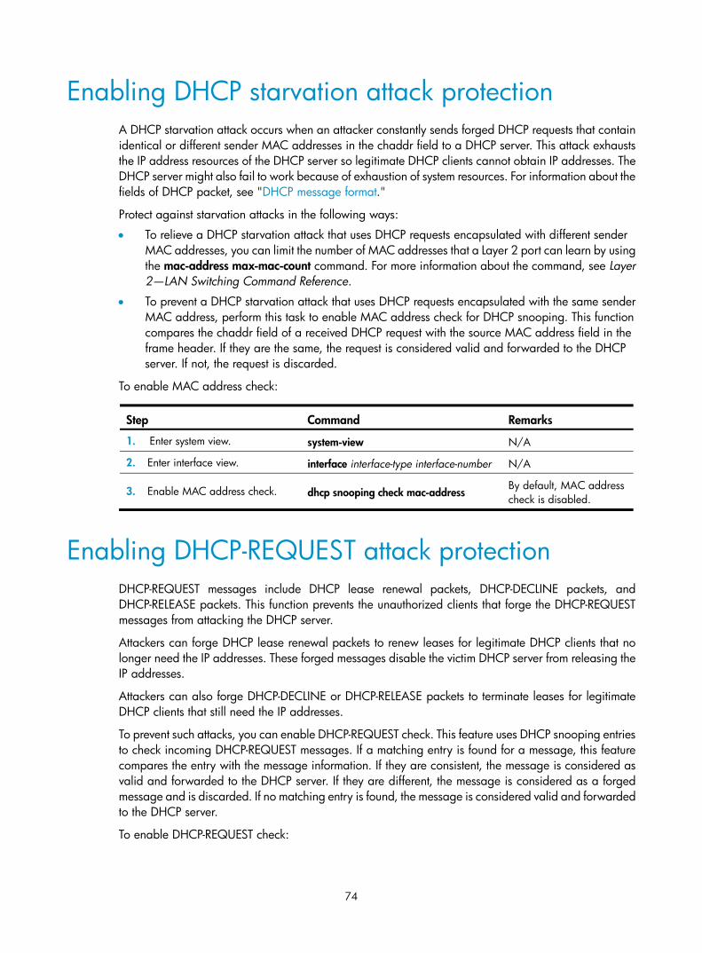
74
Enabling DHCP starvation attack protection A DHCP starvation attack occurs when an attacker constantly sends forged DHCP requests that contain identical or different sender MAC addresses in the chaddr field to a DHCP server. This attack exhausts the IP address resources of the DHCP server so legitimate DHCP clients cannot obtain IP addresses. The DHCP server might also fail to work because of exhaustion of system resources. For information about the fields of DHCP packet, see "DHCP message format."
Protect against starvation attacks in the following ways:
• To relieve a DHCP starvation attack that uses DHCP requests encapsulated with different sender MAC addresses, you can limit the number of MAC addresses that a Layer 2 port can learn by using the mac-address max-mac-count command. For more information about the command, see Layer 2—LAN Switching Command Reference.
• To prevent a DHCP starvation attack that uses DHCP requests encapsulated with the same sender MAC address, perform this task to enable MAC address check for DHCP snooping. This function compares the chaddr field of a received DHCP request with the source MAC address field in the frame header. If they are the same, the request is considered valid and forwarded to the DHCP server. If not, the request is discarded.
To enable MAC address check:
Step Command Remarks
1. Enter system view. system-view N/A
2. Enter interface view. interface interface-type interface-number N/A
3. Enable MAC address check. dhcp snooping check mac-address By default, MAC address check is disabled.
Enabling DHCP-REQUEST attack protection DHCP-REQUEST messages include DHCP lease renewal packets, DHCP-DECLINE packets, and DHCP-RELEASE packets. This function prevents the unauthorized clients that forge the DHCP-REQUEST messages from attacking the DHCP server.
Attackers can forge DHCP lease renewal packets to renew leases for legitimate DHCP clients that no longer need the IP addresses. These forged messages disable the victim DHCP server from releasing the IP addresses.
Attackers can also forge DHCP-DECLINE or DHCP-RELEASE packets to terminate leases for legitimate DHCP clients that still need the IP addresses.
To prevent such attacks, you can enable DHCP-REQUEST check. This feature uses DHCP snooping entries to check incoming DHCP-REQUEST messages. If a matching entry is found for a message, this feature compares the entry with the message information. If they are consistent, the message is considered as valid and forwarded to the DHCP server. If they are different, the message is considered as a forged message and is discarded. If no matching entry is found, the message is considered valid and forwarded to the DHCP server.
To enable DHCP-REQUEST check:

75
Step Command Remarks 1. Enter system view. system-view N/A
2. Enter interface view. interface interface-type interface-number N/A
3. Enable DHCP-REQUEST check. dhcp snooping check request-message
By default, DHCP-REQUEST check is disabled.
You can enable DHCP-REQUEST check only on Layer 2 Ethernet interfaces.
Configuring DHCP packet rate limit Perform this task to configure the maximum rate at which an interface can receive DHCP packets. This feature discards exceeding DHCP packets to prevent attacks that send large numbers of DHCP packets.
To configure DHCP packet rate limit:
Step Command Remarks 1. Enter system view. system-view N/A
2. Enter interface view. interface interface-type interface-number
N/A
3. Configure the maximum rate at which the interface can receive DHCP packets.
dhcp snooping rate-limit rate
By default, incoming DHCP packets are not rate limited.
You can configure this command only on Layer 2 Ethernet interfaces.
Displaying and maintaining DHCP snooping Execute display commands in any view, and reset commands in user view.
Task Command Remarks
Display DHCP snooping entries. display dhcp snooping binding [ ip ip-address [ vlan vlan-id ] ]
Available in any view.
Display Option 82 configuration information on the DHCP snooping device.
display dhcp snooping information { all | interface interface-type interface-number }
Available in any view.
Display DHCP packet statistics on the DHCP snooping device (MSR 2600/MSR 3600).
display dhcp snooping packet statistics Available in any view.
Display DHCP packet statistics on the DHCP snooping device (MSR 5600).
display dhcp snooping packet statistics [ slot slot-number ]
Available in any view.
Display information about trusted ports.
display dhcp snooping trust Available in any view.

76
Task Command Remarks
Display information about the file that stores DHCP snooping entries.
display dhcp snooping binding database Available in any view.
Clear DHCP snooping entries. reset dhcp snooping binding { all | ip ip-address [ vlan vlan-id ] }
Available in user view.
Clear DHCP packet statistics on the DHCP snooping device (MSR 2600/MSR 3600).
reset dhcp snooping packet statistics Available in user view.
Clear DHCP packet statistics on the DHCP snooping device (MSR 5600).
reset dhcp snooping packet statistics [ slot slot-number ]
Available in user view.
DHCP snooping configuration examples
Basic DHCP snooping configuration example Network requirements
As shown in Figure 27, configure the port Ethernet 1/1 connected to the DHCP server as a trusted port and configure other ports as untrusted ports. Enable DHCP snooping to record clients' IP-MAC bindings by reading DHCP-ACK messages received from the trusted port and DHCP-REQUEST messages.
Figure 27 Network diagram
Configuration procedure
# Enable DHCP snooping. <Router> system-view
[Router] dhcp snooping enable
# Configure Ethernet 1/1 as a trusted port. [Router] interface ethernet 1/1
[Router-Ethernet1/1] dhcp snooping trust
[Router-Ethernet1/1] quit
# Enable DHCP snooping to record clients' IP-MAC bindings on Ethernet 1/2. [Router] interface ethernet 1/2

77
[Router-Ethernet1/2] dhcp snooping binding record
[Router-Ethernet1/2] quit
Verifying the configuration
After the preceding configuration is complete, the DHCP client can obtain an IP address and other configuration parameters only from the authorized DHCP server. You can view the DHCP snooping entry recorded for the client with the display dhcp snooping binding command.
Option 82 configuration example Network requirements
As shown in Figure 28, enable DHCP snooping and configure Option 82 on the Router as follows:
• Configure the handling strategy for DHCP requests that contain Option 82 as replace.
• On Ethernet 1/2, configure the padding content for the circuit ID sub-option as company001 and for the remote ID sub-option as device001.
• On Ethernet 1/3, configure the padding format as verbose, access node identifier as sysname, and code type as ascii for Option 82.
Figure 28 Network diagram
Configuration procedure
# Enable DHCP snooping. <Router> system-view
[Router] dhcp snooping enable
# Configure Ethernet 1/1 as a trusted port. [Router] interface ethernet 1/1
[Router-Ethernet1/1] dhcp snooping trust
[Router-Ethernet1/1] quit
# Configure Option 82 on Ethernet 1/2. [Router] interface ethernet 1/2
[Router-Ethernet1/2] dhcp snooping information enable
[Router-Ethernet1/2] dhcp snooping information strategy replace
[Router-Ethernet1/2] dhcp snooping information circuit-id string company001
[Router-Ethernet1/2] dhcp snooping information remote-id string device001
[Router-Ethernet1/2] quit
# Configure Option 82 on Ethernet 1/3.

78
[Router] interface ethernet 1/3
[Router-Ethernet1/3] dhcp snooping information enable
[Router-Ethernet1/3] dhcp snooping information strategy replace
[Router-Ethernet1/3] dhcp snooping information circuit-id verbose node-identifier sysname format ascii
[Router-Ethernet1/3] dhcp snooping information remote-id string device001
Verifying the configuration
Use the display dhcp snooping information command to display Option 82 configuration information on Ethernet 1/2 and Ethernet 1/3 on the DHCP snooping device.

79
Configuring the BOOTP client
BOOTP client configuration only applies to Layer 3 Ethernet interfaces (including subinterfaces) and VLAN interfaces.
If several VLAN interfaces sharing the same MAC address obtain IP addresses through a BOOTP relay agent, the BOOTP server cannot be a Windows Server 2000 or Windows Server 2003.
BOOTP application An interface that acts as a BOOTP client can use BOOTP to obtain information (such as IP address) from the BOOTP server.
To use BOOTP, an administrator must configure a BOOTP parameter file for each BOOTP client on the BOOTP server. The parameter file contains information such as MAC address and IP address of a BOOTP client. When a BOOTP client sends a request to the BOOTP server, the BOOTP server searches for the BOOTP parameter file and returns the corresponding configuration information.
BOOTP is usually used in relatively stable environments. In network environments that change frequently, DHCP is more suitable.
Because a DHCP server can interact with a BOOTP client, you can use the DHCP server to configure an IP address for the BOOTP client, without any BOOTP server.
Obtaining an IP address dynamically A BOOTP client dynamically obtains an IP address from a BOOTP server as follows:
1. The BOOTP client broadcasts a BOOTP request, which contains its own MAC address.
2. The BOOTP server receives the request and searches the configuration file for the IP address and other information according to the MAC address of the BOOTP client.
3. The BOOTP server returns a BOOTP response to the BOOTP client.
4. The BOOTP client obtains the IP address from the received response.
A DHCP server can take the place of the BOOTP server in the following dynamic IP address acquisition.
Protocols and standards • RFC 951, Bootstrap Protocol (BOOTP)
• RFC 2132, DHCP Options and BOOTP Vendor Extensions
• RFC 1542, Clarifications and Extensions for the Bootstrap Protocol

80
Configuring an interface to use BOOTP for IP address acquisition
Step Command Remarks
1. Enter system view. system-view N/A
2. Enter interface view. interface interface-type interface-number N/A
3. Configure an interface to use BOOTP for IP address acquisition. ip address bootp-alloc
By default, an interface does not use BOOTP for IP address acquisition.
Displaying and maintaining BOOTP client Execute display command in any view.
Task Command
Display BOOTP client information. display bootp client [ interface interface-type interface-number ]
BOOTP client configuration example
Network requirements As shown in Figure 17, Ethernet 1/1 of Router B connects to the LAN to obtain an IP address from the DHCP server by using BOOTP.
To make the BOOTP client obtain an IP address from the DHCP server, perform configurations on the DHCP server. For more information, see "DHCP server configuration examples ."
Configuration procedure The following describes only the configuration on Router B serving as a client.
# Configure Ethernet 1/1 to use BOOTP to obtain an IP address. <RouterB> system-view
[RouterB] interface ethernet 1/1
[RouterB-Ethernet1/1] ip address bootp-alloc
# Use the display bootp client command to display the IP address assigned to the BOOTP client.

81
Configuring DNS
Overview Domain Name System (DNS) is a distributed database used by TCP/IP applications to translate domain names into IP addresses. With DNS, you can use easy-to-remember domain names in some applications and let the DNS server translate them into correct IP addresses. The domain name-to-IP address mapping is called a DNS entry.
DNS services can be static or dynamic. After a user specifies a name, the device checks the static name resolution table for an IP address. If no IP address is available, it contacts the DNS server for dynamic name resolution, which takes more time than static name resolution. To improve efficiency, you can put frequently queried name-to-IP address mappings in the local static name resolution table.
Static domain name resolution Static domain name resolution means manually creating mappings between domain names and IP addresses. For example, you can create a static DNS mapping for a device so that you can Telnet to the device by using the domain name.
Dynamic domain name resolution Resolution process
1. A user program sends a name query to the resolver of the DNS client.
2. The DNS resolver looks up the local domain name cache for a match. If the resolver finds a match, it sends the corresponding IP address back. If not, it sends a query to the DNS server.
3. The DNS server looks up the corresponding IP address of the domain name in its DNS database. If no match is found, the server sends a query to other DNS servers. This process continues until a result, whether successful or not, is returned.
4. After receiving a response from the DNS server, the DNS client returns the resolution result to the user program.
Figure 29 Dynamic domain name resolution
Request
Response Response
Request
SaveRead
DNS client
DNS server
Resolver
Cache
User program

82
Figure 29 shows the relationship between the user program, DNS client, and DNS server.
The DNS client is made up of the resolver and cache. The user program and DNS client can run on the same device or different devices, but the DNS server and the DNS client usually run on different devices.
Dynamic domain name resolution allows the DNS client to store latest DNS entries in the dynamic domain name cache. The DNS client does not need to send a request to the DNS server for a repeated query within the aging time. To make sure the entries from the DNS server are up to date, a DNS entry is removed when its aging timer expires. The DNS server determines how long a mapping is valid, and the DNS client obtains the aging information from DNS responses.
DNS suffixes
You can configure a domain name suffix list so that the resolver can use the list to supply the missing part of an incomplete name.
For example, you can configure com as the suffix for aabbcc.com. The user only needs to enter aabbcc to obtain the IP address of aabbcc.com because the resolver adds the suffix and delimiter before passing the name to the DNS server.
The name resolver handles the queries based on the domain names that the user enters:
• If the user enters a domain name without a dot (.) (for example, aabbcc), the resolver considers the domain name a host name and adds a DNS suffix before performing the query operation. If no match is found for the domain names with any configured suffix, the resolver uses the user entered domain name (for example, aabbcc) to query the IP address.
• If the user enters a domain name with a dot (.) among the letters (for example, www.aabbcc), the resolver directly uses this domain name for the query operation. If the query fails, the resolver adds a DNS suffix for another query operation.
• If the user enters a domain name with a dot (.) at the end (for example, aabbcc.com.), the resolver considers the domain name an FQDN and returns the successful or failed query result. The dot at the end of the domain name is considered a terminating symbol.
The device supports static and dynamic DNS client services.
If an alias is configured for a domain name on the DNS server, the device can resolve the alias into the IP address of the host.
DNS proxy A DNS proxy forwards DNS requests and replies between DNS clients and a DNS server.
As shown in Figure 30, a DNS client sends a DNS request to the DNS proxy, which forwards the request to the designated DNS server, and conveys the reply from the DNS server to the client.
The DNS proxy simplifies network management. When the DNS server address is changed, you can change the configuration on only the DNS proxy instead of on each DNS client.

83
Figure 30 DNS proxy application
A DNS proxy operates as follows:
1. A DNS client considers the DNS proxy as the DNS server, and sends a DNS request to the DNS proxy. The destination address of the request is the IP address of the DNS proxy.
2. The DNS proxy searches the local static domain name resolution table and dynamic domain name resolution cache after receiving the request. If the requested information is found, the DNS proxy returns a DNS reply to the client.
3. If the requested information is not found, the DNS proxy sends the request to the designated DNS server for domain name resolution.
4. After receiving a reply from the DNS server, the DNS proxy records the IP address-to-domain name mapping and forwards the reply to the DNS client.
If no DNS server is designated or no route is available to the designated DNS server, the DNS proxy does not forward DNS requests.
DNS spoofing DNS spoofing is applied to the dial-up network, as shown in Figure 31.
• The device connects to a PSTN/ISDN network through a dial-up interface and triggers the establishment of a dial-up connection only when packets are to be forwarded through the dial-up interface.
• The device serves as a DNS proxy and is specified as a DNS server on the hosts. After the dial-up connection is established through the dial-up interface, the device dynamically obtains the DNS server address through DHCP or other autoconfiguration mechanisms.
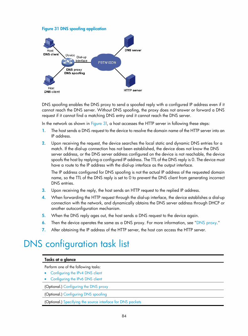
84
Figure 31 DNS spoofing application
DNS spoofing enables the DNS proxy to send a spoofed reply with a configured IP address even if it cannot reach the DNS server. Without DNS spoofing, the proxy does not answer or forward a DNS request if it cannot find a matching DNS entry and it cannot reach the DNS server.
In the network as shown in Figure 31, a host accesses the HTTP server in following these steps:
1. The host sends a DNS request to the device to resolve the domain name of the HTTP server into an IP address.
2. Upon receiving the request, the device searches the local static and dynamic DNS entries for a match. If the dial-up connection has not been established, the device does not know the DNS server address, or the DNS server address configured on the device is not reachable, the device spoofs the host by replying a configured IP address. The TTL of the DNS reply is 0. The device must have a route to the IP address with the dial-up interface as the output interface.
The IP address configured for DNS spoofing is not the actual IP address of the requested domain name, so the TTL of the DNS reply is set to 0 to prevent the DNS client from generating incorrect DNS entries.
3. Upon receiving the reply, the host sends an HTTP request to the replied IP address.
4. When forwarding the HTTP request through the dial-up interface, the device establishes a dial-up connection with the network, and dynamically obtains the DNS server address through DHCP or another autoconfiguration mechanism.
5. When the DNS reply ages out, the host sends a DNS request to the device again.
6. Then the device operates the same as a DNS proxy. For more information, see "DNS proxy."
7. After obtaining the IP address of the HTTP server, the host can access the HTTP server.
DNS configuration task list Tasks at a glance
Perform one of the following tasks: • Configuring the IPv4 DNS client • Configuring the IPv6 DNS client
(Optional.) Configuring the DNS proxy
(Optional.) Configuring DNS spoofing
(Optional.) Specifying the source interface for DNS packets

85
Tasks at a glance
(Optional.) Configuring the DNS trusted interface
(Optional.) Specifying the DSCP value for outgoing DNS packets
Configuring the IPv4 DNS client
Configuring static domain name resolution Static domain name resolution allows applications such as Telnet to contact hosts by using host names instead of IPv4 addresses.
Follow these guidelines when you configure static domain name resolution:
• On the public network or a VPN, each host name maps to only one IPv4 address. The most recent configuration for a host name takes effect.
• You can configure host name-to-IPv4 address mappings for the public network and up to 1024 VPNs, and configure a maximum of 1024 host name-to-IPv4 address mappings for the public network or each VPN.
To configure static domain name resolution:
Step Command Remarks
1. Enter system view. system-view N/A
2. Configure a mapping between a host name and an IPv4 address.
ip host host-name ip-address [ vpn-instance vpn-instance-name ]
By default, no mapping between a host name and an IPv4 address is configured.
Configuring dynamic domain name resolution To use dynamic domain name resolution, configure DNS servers so that DNS queries can be sent to a correct server for resolution. A DNS server manually configured takes precedence over the one dynamically obtained through DHCP, and a DNS server configured earlier takes precedence. A name query is first sent to the DNS server that has the highest priority. If no reply is received, it is sent to the DNS server that has the second highest priority, and thus in turn.
In addition, you can configure a DNS suffix that the system automatically adds to the provided domain name for resolution. A DNS suffix manually configured takes precedence over the one dynamically obtained through DHCP, and a DNS suffix configured earlier takes precedence. The DNS resolver first uses the suffix that has the highest priority. If the name resolution fails, the DNS resolver uses the suffix that has the second highest priority, and thus in turn.
Configuration guidelines
Follow these guidelines when you configure dynamic domain name resolution:
• You can specify DNS server IPv4 addresses for the public network and up to 1024 VPNs, and specify a maximum of six DNS server IPv4 addresses for the public network or each VPN.

86
• You can specify DNS server IPv6 addresses for the public network and up to 1024 VPNs, and specify a maximum of six DNS server IPv6 addresses for the public network or each VPN.
• An IPv4 name query is first sent to the DNS server IPv4 addresses. If no reply is received, it is sent to the DNS server IPv6 addresses.
• You can specify domain name suffixes for the public network and up to 1024 VPNs, and specify a maximum of 16 domain name suffixes for the public network or each VPN.
Configuration procedure
To configure dynamic domain name resolution:
Step Command Remarks
1. Enter system view. system-view N/A
2. Specify a DNS server IP address.
• Specify a DNS server IPv4 address: dns server ip-address [ vpn-instance vpn-instance-name ]
• Specify a DNS server IPv6 address: ipv6 dns server ipv6-address [ interface-type interface-number ] [ vpn-instance vpn-instance-name ]
Use at least one command.
By default, no DNS server IP address is specified.
3. (Optional.) Configure a DNS suffix.
dns domain domain-name [ vpn-instance vpn-instance-name ]
By default, no DNS suffix is configured and only the provided domain name is resolved.
Configuring the IPv6 DNS client
Configuring static domain name resolution Static domain name resolution allows applications such as Telnet to contact hosts by using host names instead of IPv6 addresses.
Follow these guidelines when you configure static domain name resolution:
• For the public network or a VPN, each host name maps to only one IPv6 address. The last configuration for a host name takes effect.
• You can configure host name-to-IPv6 address mappings for the public network and up to 1024 VPNs, and configure a maximum of 1024 host name-to-IPv6 address mappings for the public network or each VPN.
To configure static domain name resolution:
Step Command Remarks 1. Enter system view. system-view N/A
2. Configure a mapping between a host name and an IPv6 address.
ipv6 host host-name ipv6-address [ vpn-instance vpn-instance-name ]
By default, no mapping between a host name and an IPv6 address is configured.

87
Configuring dynamic domain name resolution To send DNS queries to a correct server for resolution, you must enable dynamic domain name resolution and configure DNS servers. A DNS server manually configured takes precedence over the one dynamically obtained through DHCP, and a DNS server configured earlier takes precedence. A name query is first sent to the DNS server that has the highest priority. If no reply is received, it is sent to the DNS server that has the second highest priority, and thus in turn.
In addition, you can configure a DNS suffix that the system automatically adds to the provided domain name for resolution. A DNS suffix manually configured takes precedence over the one dynamically obtained through DHCP, and a DNS suffix configured earlier takes precedence. The DNS resolver first uses the suffix that has the highest priority. If the name resolution fails, the DNS resolver uses the suffix that has the second highest priority, and thus in turn.
Configuration guidelines
Follow these guidelines when you configure dynamic domain name resolution:
• You can specify DNS server IPv4 addresses for the public network and up to 1024 VPNs, and specify a maximum of six DNS server IPv4 addresses for the public network or each VPN.
• You can specify DNS server IPv6 addresses for the public network and up to 1024 VPNs, and specify a maximum of six DNS server IPv6 addresses for the public network or each VPN.
• An IPv6 name query is first sent to the IPv6 DNS servers. If no reply is received, it is sent to the IPv4 DNS servers.
• You can specify domain name suffixes for the public network and up to 1024 VPNs, and specify a maximum of 16 domain name suffixes for the public network or each VPN.
Configuration procedure
To configure dynamic domain name resolution:
Step Command Remarks
1. Enter system view. system-view N/A
2. Specify a DNS server IP address.
• Specify a DNS server IPv4 address: dns server ip-address [ vpn-instance vpn-instance-name ]
• Specify a DNS server IPv6 address: ipv6 dns server ipv6-address [ interface-type interface-number ] [ vpn-instance vpn-instance-name ]
Use at least one command.
By default, no DNS server IP address is specified.
3. (Optional.) Configure a DNS suffix.
dns domain domain-name [ vpn-instance vpn-instance-name ]
By default, no DNS suffix is configured. Only the provided domain name is resolved.
Configuring the DNS proxy You can specify multiple DNS servers. The DNS proxy forwards a request to the DNS server that has the highest priority. If having not received a reply, it forwards the request to a DNS server that has the second highest priority, and thus in turn.

88
A DNS proxy forwards an IPv4 name query first to IPv4 DNS servers, and if no reply is received, it forwards the request to IPv6 DNS servers. The DNS proxy forwards an IPv6 name query first to IPv6 DNS servers, and if no reply is received, it forwards the request to IPv4 DNS servers.
To configure the DNS proxy:
Step Command Remarks 1. Enter system view. system-view N/A
2. Enable DNS proxy. dns proxy enable By default, DNS proxy is disabled.
3. Specify a DNS server IP address.
• Specify a DNS server IPv4 address: dns server ip-address [ vpn-instance vpn-instance-name ]
• Specify a DNS server IPv6 address: ipv6 dns server ipv6-address [ interface-type interface-number ] [ vpn-instance vpn-instance-name ]
Use at least one command.
By default, no DNS server IP address is specified.
Configuring DNS spoofing DNS spoofing is effective only when:
• The DNS proxy is enabled on the device.
• No DNS server or route to any DNS server is specified on the device.
Follow these guidelines when you configure DNS spoofing:
• You can configure only one replied IPv4 address and one replied IPv6 address for the public network or a VPN. If you use the command multiple times, the most recent configuration takes effect.
• You can configure DNS spoofing for the public network and a maximum of 1024 VPNs.
To configure DNS spoofing:
Step Command Remarks 1. Enter system view. system-view N/A
2. Enable DNS proxy. dns proxy enable By default, DNS proxy is disabled.
3. Enable DNS spoofing and specify the translated IP address.
• Specify a translated IPv4 address: dns spoofing ip-address [ vpn-instance vpn-instance-name ]
• Specify a translated IPv6 address: ipv6 dns spoofing ipv6-address [ vpn-instance vpn-instance-name ]
Use at least one command.
By default, no translated IP address is specified.
Specifying the source interface for DNS packets By default, the device uses the primary IP address of the output interface of the matching route as the source IP address of a DNS request. Therefore, the source IP address of the DNS packets might vary with

89
DNS servers. In some scenarios, the DNS server only responds to DNS requests sourced from a specific IP address. In such cases, you must specify the source interface for the DNS packets so that the device can always uses the primary IP address of the specified source interface as the source IP address of DNS packets.
When sending IPv4 DNS request, the device uses the primary IPv4 address of the source interface as the source IP address of the DNS request. When sending IPv6 DNS request, the device selects an IPv6 address from the addresses configured on the source interface as defined in RFC 3484 as the source IP address of the DNS request. If no IP address is configured on the source interface, the DNS packet fails to be delivered.
You can configure only one source interface on the public network or a VPN. When you configure a new source interface, the last configuration takes effect. You can configure the source interface for the public network and a maximum of 1024 VPNs.
To specify the source interface for DNS packets:
Step Command Remarks
1. Enter system view. system-view N/A
2. Specify the source interface for DNS packets.
dns source-interface interface-type interface-number [ vpn-instance vpn-instance-name ]
By default, no source interface for DNS packets is specified.
If you specify the vpn-instance vpn-instance-name option, make sure the source interface is on the specified VPN.
Configuring the DNS trusted interface By default, an interface obtains DNS suffix and domain name server information from DHCP. The network attacker might act as the DHCP server to assign wrong DNS suffix and domain name server address to the device. As a result, the device fails to get the resolved IP address or might get the wrong IP address. With the DNS trusted interface specified, the device only uses the DNS suffix and domain name server information obtained through the trusted interface to avoid attack.
To configure the DNS trusted interface:
Step Command Remarks
1. Enter system view. system-view N/A
2. Specify the DNS trusted interface.
dns trust-interface interface-type interface-number
By default, no DNS trusted interface is specified.
You can configure up to 128 DNS trusted interfaces.
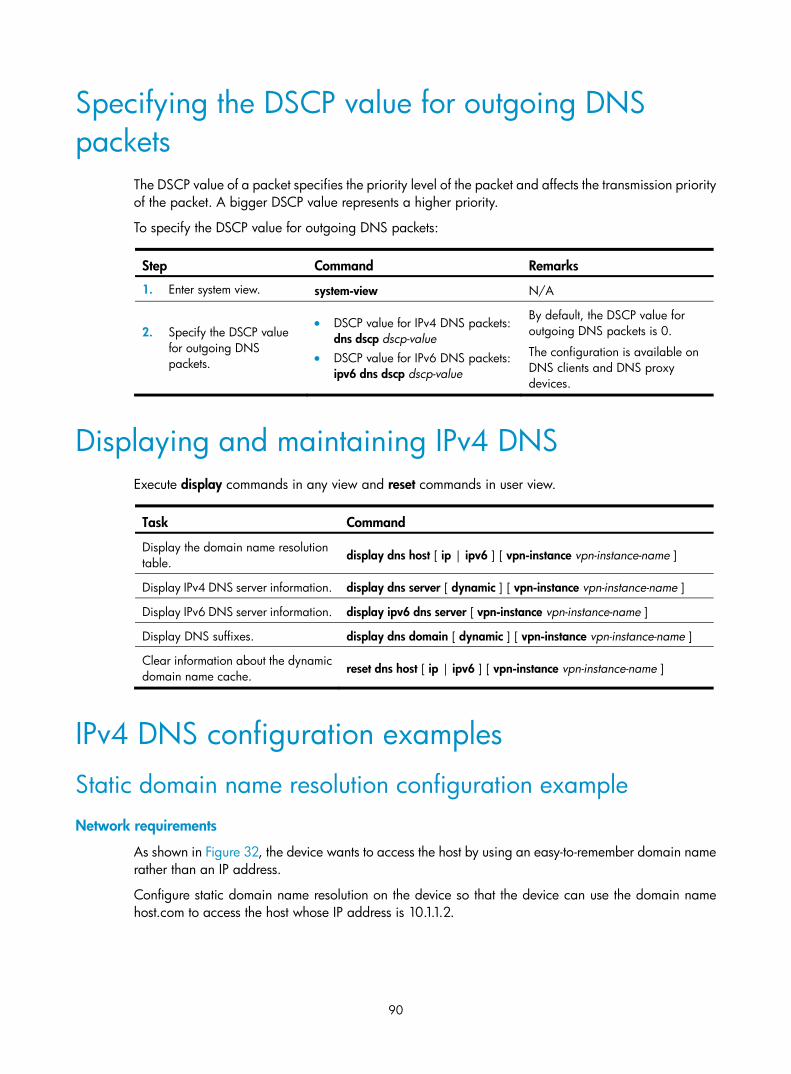
90
Specifying the DSCP value for outgoing DNS packets
The DSCP value of a packet specifies the priority level of the packet and affects the transmission priority of the packet. A bigger DSCP value represents a higher priority.
To specify the DSCP value for outgoing DNS packets:
Step Command Remarks
1. Enter system view. system-view N/A
2. Specify the DSCP value for outgoing DNS packets.
• DSCP value for IPv4 DNS packets: dns dscp dscp-value
• DSCP value for IPv6 DNS packets: ipv6 dns dscp dscp-value
By default, the DSCP value for outgoing DNS packets is 0.
The configuration is available on DNS clients and DNS proxy devices.
Displaying and maintaining IPv4 DNS Execute display commands in any view and reset commands in user view.
Task Command
Display the domain name resolution table. display dns host [ ip | ipv6 ] [ vpn-instance vpn-instance-name ]
Display IPv4 DNS server information. display dns server [ dynamic ] [ vpn-instance vpn-instance-name ]
Display IPv6 DNS server information. display ipv6 dns server [ vpn-instance vpn-instance-name ]
Display DNS suffixes. display dns domain [ dynamic ] [ vpn-instance vpn-instance-name ]
Clear information about the dynamic domain name cache. reset dns host [ ip | ipv6 ] [ vpn-instance vpn-instance-name ]
IPv4 DNS configuration examples
Static domain name resolution configuration example Network requirements
As shown in Figure 32, the device wants to access the host by using an easy-to-remember domain name rather than an IP address.
Configure static domain name resolution on the device so that the device can use the domain name host.com to access the host whose IP address is 10.1.1.2.

91
Figure 32 Network diagram
Configuration procedure
# Configure a mapping between host name host.com and IP address 10.1.1.2. <Sysname> system-view
[Sysname] ip host host.com 10.1.1.2
# Use the ping host.com command to verify that the device can use static domain name resolution to resolve domain name host.com into IP address 10.1.1.2. [Sysname] ping host.com
Ping host.com (10.1.1.2): 56 data bytes, press escape sequence to break
56 bytes from 10.1.1.2: icmp_seq=0 ttl=255 time=1.000 ms
56 bytes from 10.1.1.2: icmp_seq=1 ttl=255 time=1.000 ms
56 bytes from 10.1.1.2: icmp_seq=2 ttl=255 time=1.000 ms
56 bytes from 10.1.1.2: icmp_seq=3 ttl=255 time=1.000 ms
56 bytes from 10.1.1.2: icmp_seq=4 ttl=255 time=2.000 ms
--- Ping statistics for host.com ---
5 packet(s) transmitted, 5 packet(s) received, 0.0% packet loss
round-trip min/avg/max/std-dev = 1.000/1.200/2.000/0.400 ms
Dynamic domain name resolution configuration example Network requirements
As shown in Figure 33, the device wants to access the host by using an easy-to-remember domain name rather than an IP address, and to request the DNS server on the network for an IP address by using dynamic domain name resolution. The IP address of the DNS server is 2.1.1.2/16 and the DNS server has a com domain, which stores the mapping between domain name host and IP address 3.1.1.1/16.
Configure dynamic domain name resolution and the domain name suffix com on the device that serves as a DNS client so that the device can use domain name host to access the host with the domain name host.com and the IP address 3.1.1.1/16.
Figure 33 Network diagram

92
Configuration procedure
Before performing the following configuration, make sure the device and the host can reach each other, and that the IP addresses of the interfaces are configured as shown in Figure 33.
1. Configure the DNS server:
The configuration might vary with DNS servers. The following configuration is performed on a PC running Windows Server 2000.
a. Select Start > Programs > Administrative Tools > DNS.
The DNS server configuration page appears, as shown in Figure 34.
b. Right-click Forward Lookup Zones, select New Zone, and then follow the wizard to create a new zone named com.
Figure 34 Creating a zone
c. On the DNS server configuration page, right-click zone com, and select New Host.

93
Figure 35 Adding a host
d. On the page that appears, enter host name host and IP address 3.1.1.1.
e. Click Add Host.
The mapping between the IP address and host name is created.
Figure 36 Adding a mapping between domain name and IP address
2. Configure the DNS client:

94
# Specify the DNS server 2.1.1.2. <Sysname> system-view
[Sysname] dns server 2.1.1.2
# Specify com as the name suffix. [Sysname] dns domain com
Verifying the configuration
# Use the ping host command on the device to verify that the communication between the device and the host is normal and that the translated destination IP address is 3.1.1.1. [Sysname] ping host
Ping host.com (3.1.1.1): 56 data bytes, press escape sequence to break
56 bytes from 3.1.1.1: icmp_seq=0 ttl=255 time=1.000 ms
56 bytes from 3.1.1.1: icmp_seq=1 ttl=255 time=1.000 ms
56 bytes from 3.1.1.1: icmp_seq=2 ttl=255 time=1.000 ms
56 bytes from 3.1.1.1: icmp_seq=3 ttl=255 time=1.000 ms
56 bytes from 3.1.1.1: icmp_seq=4 ttl=255 time=2.000 ms
--- Ping statistics for host ---
5 packet(s) transmitted, 5 packet(s) received, 0.0% packet loss
round-trip min/avg/max/std-dev = 1.000/1.200/2.000/0.400 ms
DNS proxy configuration example Network requirements
When the IP address of the DNS server changes, you must configure the new IPv6 address of the DNS server on each device on the LAN. To simplify network management, you can use the DNS proxy function.
As shown in Figure 37:
• Specify Device A as the DNS server of Device B (the DNS client). Device A acts as a DNS proxy. The IPv6 address of the real DNS server is 4.1.1.1.
• Configure the IP address of the DNS proxy on Device B. DNS requests of Device B are forwarded to the real DNS server through the DNS proxy.

95
Figure 37 Network diagram
Configuration procedure
Before performing the following configuration, ,make sure Device A, the DNS server, and the host can reach each other and the IPv6 addresses of the interfaces are configured as shown in Figure 37.
1. Configure the DNS server:
The configuration might vary with DNS servers. When a PC running Windows Server 2000 acts as the DNS server, see "Dynamic domain name resolution configuration example" for configuration information.
2. Configure the DNS proxy:
# Specify the DNS server 4.1.1.1. <DeviceA> system-view
[DeviceA] dns server 4.1.1.1
# Enable DNS proxy. [DeviceA] dns proxy enable
3. Configure the DNS client: <DeviceB> system-view
# Specify the DNS server 2.1.1.2. [DeviceB] dns server 2.1.1.2
Verifying the configuration
# Use the ping host.com command on Device B to verify the connection between the device and the host is normal and that the translated destination IP address is 3.1.1.1. [DeviceB] ping host.com
Ping host.com (3.1.1.1): 56 data bytes, press escape sequence to break
56 bytes from 3.1.1.1: icmp_seq=0 ttl=255 time=1.000 ms
56 bytes from 3.1.1.1: icmp_seq=1 ttl=255 time=1.000 ms
56 bytes from 3.1.1.1: icmp_seq=2 ttl=255 time=1.000 ms
56 bytes from 3.1.1.1: icmp_seq=3 ttl=255 time=1.000 ms
56 bytes from 3.1.1.1: icmp_seq=4 ttl=255 time=2.000 ms
--- Ping statistics for host.com ---
5 packet(s) transmitted, 5 packet(s) received, 0.0% packet loss
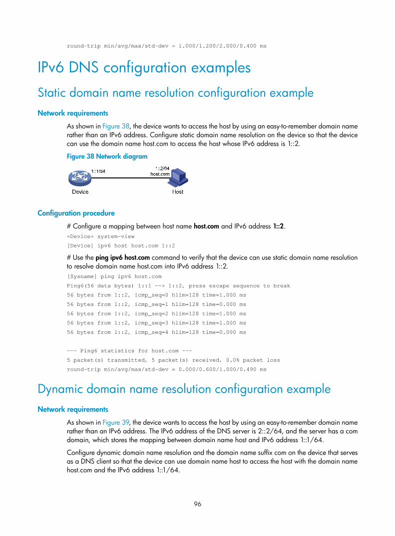
96
round-trip min/avg/max/std-dev = 1.000/1.200/2.000/0.400 ms
IPv6 DNS configuration examples
Static domain name resolution configuration example Network requirements
As shown in Figure 38, the device wants to access the host by using an easy-to-remember domain name rather than an IPv6 address. Configure static domain name resolution on the device so that the device can use the domain name host.com to access the host whose IPv6 address is 1::2.
Figure 38 Network diagram
Configuration procedure
# Configure a mapping between host name host.com and IPv6 address 1::2. <Device> system-view
[Device] ipv6 host host.com 1::2
# Use the ping ipv6 host.com command to verify that the device can use static domain name resolution to resolve domain name host.com into IPv6 address 1::2. [Sysname] ping ipv6 host.com
Ping6(56 data bytes) 1::1 --> 1::2, press escape sequence to break
56 bytes from 1::2, icmp_seq=0 hlim=128 time=1.000 ms
56 bytes from 1::2, icmp_seq=1 hlim=128 time=0.000 ms
56 bytes from 1::2, icmp_seq=2 hlim=128 time=1.000 ms
56 bytes from 1::2, icmp_seq=3 hlim=128 time=1.000 ms
56 bytes from 1::2, icmp_seq=4 hlim=128 time=0.000 ms
--- Ping6 statistics for host.com ---
5 packet(s) transmitted, 5 packet(s) received, 0.0% packet loss
round-trip min/avg/max/std-dev = 0.000/0.600/1.000/0.490 ms
Dynamic domain name resolution configuration example Network requirements
As shown in Figure 39, the device wants to access the host by using an easy-to-remember domain name rather than an IPv6 address. The IPv6 address of the DNS server is 2::2/64, and the server has a com domain, which stores the mapping between domain name host and IPv6 address 1::1/64.
Configure dynamic domain name resolution and the domain name suffix com on the device that serves as a DNS client so that the device can use domain name host to access the host with the domain name host.com and the IPv6 address 1::1/64.

97
Figure 39 Network diagram
Configuration procedure
Before performing the following configuration, make sure the device and the host can reach each other, and the IPv6 addresses of the interfaces are configured, as shown Figure 39.
1. Configure the DNS server:
The configuration might vary with DNS servers. The following configuration is performed on a PC running Windows Server 2003. Make sure that the DNS server supports the IPv6 DNS function so that the server can process IPv6 DNS packets, and the interfaces of the DNS server can forward IPv6 packets.
a. Select Start > Programs > Administrative Tools > DNS.
The DNS server configuration page appears, as shown in Figure 40.
b. Right-click Forward Lookup Zones, select New Zone, and then follow the wizard to create a new zone named com.
Figure 40 Creating a zone
c. On the DNS server configuration page, right-click zone com, and select Other New Records.
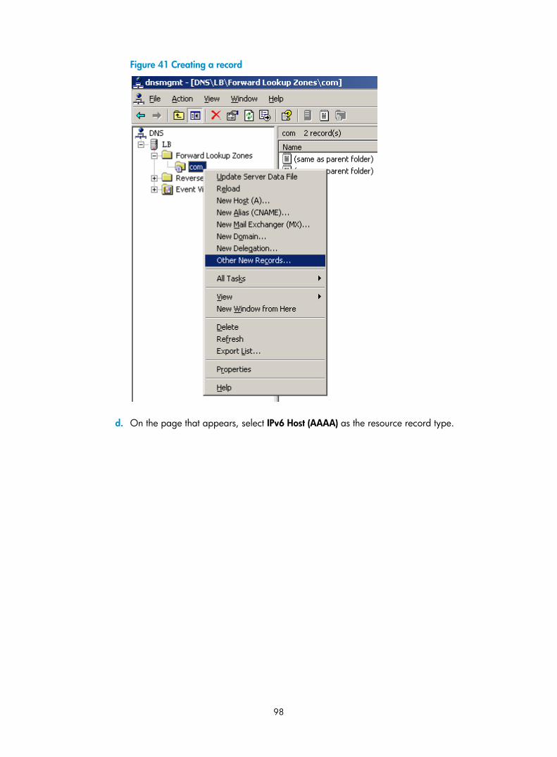
98
Figure 41 Creating a record
d. On the page that appears, select IPv6 Host (AAAA) as the resource record type.

99
Figure 42 Selecting the resource record type
e. Type host name host and IPv6 address 1::1.
f. Click OK.
The mapping between the IPv6 address and host name is created.

100
Figure 43 Adding a mapping between domain name and IPv6 address
2. Configure the DNS client:
# Specify the DNS server 2::2. <Device> system-view
[Device] ipv6 dns server 2::2
# Configure com as the DNS suffix. [Device] dns domain com
Verifying the configuration
# Use the ping ipv6 host command on the device to verify that the communication between the device and the host is normal and that the translated destination IP address is 1::1. [Device] ping ipv6 host
Ping6(56 data bytes) 3::1 --> 1::1, press escape sequence to break
56 bytes from 1::1, icmp_seq=0 hlim=128 time=1.000 ms
56 bytes from 1::1, icmp_seq=1 hlim=128 time=0.000 ms
56 bytes from 1::1, icmp_seq=2 hlim=128 time=1.000 ms
56 bytes from 1::1, icmp_seq=3 hlim=128 time=1.000 ms
56 bytes from 1::1, icmp_seq=4 hlim=128 time=0.000 ms
--- Ping6 statistics for host ---
5 packet(s) transmitted, 5 packet(s) received, 0.0% packet loss
round-trip min/avg/max/std-dev = 0.000/0.600/1.000/0.490 ms

101
DNS proxy configuration example Network requirements
When the IP address of the DNS server changes, you must configure the new IP address of the DNS server on each device on the LAN. To simplify network management, you can use the DNS proxy function.
As shown in Figure 44:
• Specify Device A as the DNS server of Device B (the DNS client). Device A acts as a DNS proxy. The IP address of the real DNS server is 4000::1.
• Configure the IP address of the DNS proxy on Device B. DNS requests of Device B are forwarded to the real DNS server through the DNS proxy.
Figure 44 Network diagram
Configuration procedure
Before performing the following configuration, make sure Device A, the DNS server, and the host are reachable to each other and the IP addresses of the interfaces are configured as shown in Figure 44.
1. Configure the DNS server:
This configuration might vary with DNS servers. When a PC running Windows Server 2003 acts as the DNS server, see "Dynamic domain name resolution configuration example" for configuration information.
2. Configure the DNS proxy:
# Specify the DNS server 4000::1. <DeviceA> system-view
[DeviceA] ipv6 dns server 4000::1
# Enable DNS proxy. [DeviceA] dns proxy enable
3. Configure the DNS client:
# Specify the DNS server 2000::2. <DeviceB> system-view
[DeviceB] ipv6 dns server 2000::2

102
Verifying the configuration
# Use the ping ipv6 host.com command on Device B to verify that the connection between the device and the host is normal and that the translated destination IP address is 3000::1. [DeviceB] ping ipv6 host.com
Ping6(56 data bytes) 2000::1 --> 3000::1, press escape sequence to break
56 bytes from 3000::1, icmp_seq=0 hlim=128 time=1.000 ms
56 bytes from 3000::1, icmp_seq=1 hlim=128 time=0.000 ms
56 bytes from 3000::1, icmp_seq=2 hlim=128 time=1.000 ms
56 bytes from 3000::1, icmp_seq=3 hlim=128 time=1.000 ms
56 bytes from 3000::1, icmp_seq=4 hlim=128 time=0.000 ms
--- Ping6 statistics for host.com ---
5 packet(s) transmitted, 5 packet(s) received, 0.0% packet loss
round-trip min/avg/max/std-dev = 0.000/0.600/1.000/0.490 ms
Troubleshooting IPv4 DNS configuration
Symptom After enabling dynamic domain name resolution, the user cannot get the correct IP address.
Solution 1. Use the display dns host ip command to verify that the specified domain name is in the cache.
2. If the specified domain name does not exist, check that the DNS client can communicate with the DNS server.
3. If the specified domain name is in the cache, but the IP address is incorrect, check that the DNS client has the correct IP address of the DNS server.
4. Verify that the mapping between the domain name and IP address is correct on the DNS server.
Troubleshooting IPv6 DNS configuration
Symptom After enabling dynamic domain name resolution, the user cannot get the correct IPv6 address.
Solution 1. Use the display dns host ipv6 command to verify that the specified domain name is in the cache.
2. If the specified domain name does not exist, check that dynamic domain name resolution is enabled, and that the DNS client can communicate with the DNS server.
3. If the specified domain name is in the cache, but the IPv6 address is incorrect, check that the DNS client has the correct IPv6 address of the DNS server.
4. Verify that the mapping between the domain name and IPv6 address is correct on the DNS server.

103

104
Configuring DDNS
Overview DNS provides only the static mappings between domain names and IP addresses. When the IP address of a node changes, your access to the node fails.
Dynamic Domain Name System (DDNS) can dynamically update the mappings between domain names and IP addresses for DNS servers to direct you to the latest IP address mapping to a domain name.
DDNS is supported by only IPv4 DNS, and is used to update the mappings between domain names and IPv4 addresses.
DDNS application As shown in Figure 45, DDNS works on the client-server model.
• DDNS client—A device that needs to update the mapping between the domain name and the IP address dynamically on the DNS server when the client's IP address changes. An Internet user typically uses the domain name to access an application layer server such as an HTTP server or an FTP server. When its IP address changes, the application layer server runs as a DDNS client that sends a request to the DDNS server for updating the mapping between the domain name and the IP address.
• DDNS server—Informs the DNS server of latest mappings. When receiving the mapping update request from a DDNS client, the DDNS server tells the DNS server to re-map the domain name and the IP address of the DDNS client. Therefore, the Internet users can use the same domain name to access the DDNS client even if the IP address of the DDNS client has changed.
Figure 45 DDNS application
With the DDNS client configured, a device can dynamically update the latest mapping between its domain name and IP address on the DNS server through DDNS servers.
HTTP serverDDNS client
DDNS server
DNS server
IP network
HTTP client
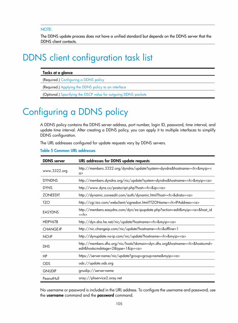
105
NOTE:
The DDNS update process does not have a unified standard but depends on the DDNS server that the DDNS client contacts.
DDNS client configuration task list Tasks at a glance
(Required.) Configuring a DDNS policy
(Required.) Applying the DDNS policy to an interface
(Optional.) Specifying the DSCP value for outgoing DDNS packets
Configuring a DDNS policy A DDNS policy contains the DDNS server address, port number, login ID, password, time interval, and update time interval. After creating a DDNS policy, you can apply it to multiple interfaces to simplify DDNS configuration.
The URL addresses configured for update requests vary by DDNS servers.
Table 5 Common URL addresses
DDNS server URL addresses for DDNS update requests
www.3322.org http://members.3322.org/dyndns/update?system=dyndns&hostname=<h>&myip=<a>
DYNDNS http://members.dyndns.org/nic/update?system=dyndns&hostname=<h>&myip=<a>
DYNS http://www.dyns.cx/postscript.php?host=<h>&ip=<a>
ZONEEDIT http://dynamic.zoneedit.com/auth/dynamic.html?host=<h>&dnsto=<a>
TZO http://cgi.tzo.com/webclient/signedon.html?TZOName=<h>IPAddress=<a>
EASYDNS http://members.easydns.com/dyn/ez-ipupdate.php?action=edit&myip=<a>&host_id=<h>
HEIPV6TB http://dyn.dns.he.net/nic/update?hostname=<h>&myip=<a>
CHANGE-IP http://nic.changeip.com/nic/update?hostname=<h>&offline=1
NO-IP http://dynupdate.no-ip.com/nic/update?hostname=<h>&myip=<a>
DHS http://members.dhs.org/nic/hosts?domain=dyn.dhs.org&hostname=<h>&hostscmd=edit&hostscmdstage=2&type=1&ip=<a>
HP https://server-name/nic/update?group=group-name&myip=<a>
ODS ods://update.ods.org
GNUDIP gnudip://server-name
PeanutHull oray://phservice2.oray.net
No username or password is included in the URL address. To configure the username and password, use the username command and the password command.

106
HP and GNUDIP are common DDNS update protocols. The server-name parameter is the domain name or IP address of the service provider's server using one of the update protocols.
The URL address for an update request can start with:
• http://—The HTTP-based DDNS server.
• https://—The HTTPS-based DDNS server.
• ods://—The TCP-based ODS server.
• gnudip://—The TCP-based GNUDIP server.
• oray://—The TCP-based DDNS server.
members.3322.org and phservice2.oray.net are the domain names of DDNS servers. The domain names of PeanutHull DDNS servers can be phservice2.oray.net, phddns60.oray.net, client.oray.net, ph031.oray.net, and so on. Determine the domain name in the URL according to the actual situation.
The port number in the URL address is optional. If no port is specified, the system uses the default port numbers: port 80 for HTTP, port 443 for HTTPS, and port 6060 for PeanutHull DDNS server.
The system automatically fills <h> with the FQDN upon a DDNS policy application to the interface and automatically fills <a> with the primary IP address of the interface to which the DDNS policy is applied. You can also manually specify an FQDN and an IP address in <h> and <a>. In this case, the FQDN specified upon the DDNS policy application does not take effect. You are not encouraged to manually change the <h> and <a> for your configuration might be incorrect. For more information about applying DDNS policies, see "Applying the DDNS policy to an interface."
No FQDN or IP address can be specified in the URL address for update requests sent to the PeanutHull DDNS server. You can specify the FQDN when applying the DDNS policy to an interface. The IP address is the primary IP address of the interface to which the DDNS policy is applied.
TIP:
The FQDN is the only identification of a node in the network. An FQDN consists of a local host name anda parent domain name and can be translated into an IP address.
Configuration prerequisites Visit the website of a DDNS service provider, register an account, and apply for a domain name for the DDNS client. When the DDNS client updates the mapping between the domain name and the IP address through the DDNS server, the DDNS server checks whether the account information is correct and whether the domain name to be updated belongs to the account.
Configuration procedure To configure a DDNS policy:
Step Command Remarks
1. Enter system view. system-view N/A
2. Create a DDNS policy and enter its view.
ddns policy policy-name By default, no DDNS policy is created.
3. Specify a URL address for DDNS update requests. url request-url
By default, no URL address is specified for DDNS update requests.

107
Step Command Remarks 4. Specify a username to be
included in the URL address. username username By default, no username is specified.
5. Specify a password to be included in the URL address.
password { cipher | simple } password By default, no password is specified.
6. (Optional.) Specify the interval for sending update requests.
interval days [ hours [ minutes ] ] By default, the time interval is one hour.
Applying the DDNS policy to an interface After you apply the DDNS policy to an interface and specify the FQDN for update, the DDNS client sends requests to the DDNS server to update the mapping between the domain name and the primary IP address of the interface at the specified interval.
Before you apply a DDNS policy to an interface, complete the following tasks:
• Specify the primary IP address of the interface and make sure the DDNS server and the interface can reach each other.
• Configure static or dynamic domain name resolution to translate the domain name of the DDNS server into the IPv4 address. For more information, see "Configuring the IPv4 DNS client."
To apply the DDNS policy to an interface:
Step Command Remarks
1. Enter system view. system-view N/A
2. Enter interface view. interface interface-type interface-number N/A
3. Apply the DDNS policy to the interface to update the mapping between the specified FQDN and the primary IP address of the interface, and enable DDNS update.
ddns apply policy policy-name [ fqdn domain-name ]
By default, no DDNS policy is applied to the interface, no FQDN is specified for update, and DDNS update is disabled.
The fqdn domain-name option must be specified for all DDNS servers except the PeanutHull DDNS server.
NOTE:
If no FQDN is specified for the PeanutHull DDNS server, the DDNS server updates all domain names of theDDNS client account. If an FQDN is specified, the DDNS server updates only the mapping between the specified FQDN and the primary IP address.
Specifying the DSCP value for outgoing DDNS packets
The DSCP value of a packet specifies the priority level of the packet and affects the transmission priority of the packet. A bigger DSCP value represents a higher priority.

108
To specify the DSCP value for outgoing DDNS packets:
Step Command Remarks
1. Enter system view. system-view N/A
2. Specify the DSCP value for outgoing DDNS packets.
ddns dscp dscp-value By default, the DSCP value for outgoing DDNS packets is 0.
Displaying DDNS Execute display commands in any view.
Task Command
Display information about the DDNS policy. display ddns policy [ policy-name ]
DDNS configuration examples
DDNS configuration example with www.3322.org Network requirements
As shown in Figure 46, Router is a Web server with the domain name whatever.3322.org.
Router acquires the IP address through DHCP. Through DDNS service provided by www.3322.org, Router informs the DNS server of the latest mapping between its domain name and IP address. Router uses the DNS server to translate www.3322.org into its IP address.
Figure 46 Network diagram
RouterDDNS client
www.3322.orgDDNS server
DNS server
IP networkEth1/1
1.1.1.1

109
Configuration procedure
Before configuring DDNS on Router, register with username steven and password nevets at http://www.3322.org/, add Router's host name-to-IP address mapping to the DNS server, and make sure the devices can reach each other.
# Create a DDNS policy named 3322.org, and enter its view. <Router> system-view
[Router] ddns policy 3322.org
# Specify for DDNS update requests the URL address with the login ID steven and plaintext password nevets. [Router-ddns-policy-3322.org] url http://members.3322.org/dyndns/update?system=dyndns&hostname=<h>&myip=<a>
[Router-ddns-policy-3322.org] username steven
[Router-ddns-policy-3322.org] password simple nevets
# Set the interval for sending DDNS update requests to 15 minutes. [Router-ddns-policy-3322.org] interval 0 0 15
[Router-ddns-policy-3322.org] quit
# Specify the IP address of the DNS server as 1.1.1.1. [Router] dns server 1.1.1.1
# Apply DDNS policy 3322.org to Ethernet 1/1 to enable DDNS update and dynamically update the mapping between domain name whatever.3322.org and the primary IP address of Ethernet 1/1. [Router] interface ethernet 1/1
[Router-Ethernet1/1] ddns apply policy 3322.org fqdn whatever.3322.org
After the preceding configuration is completed, Router notifies the DNS server of its new domain name-to-IP address mapping through the DDNS server provided by www.3322.org, whenever the IP address of Router changes. Therefore, Router can always provide Web service at whatever.3322.org.
DDNS configuration example with PeanutHull server Network requirements
As shown in Figure 47, Router is a Web server with domain name whatever.gicp.cn. Router acquires the IP address through DHCP. Through the PeanutHull server, Router informs the DNS server of the latest mapping between its domain name and IP address. Router uses the DNS server to translate www.oray.cn into its IP address.

110
Figure 47 Network diagram
Configuration procedure
Before configuring DDNS on Router, register with username steven and password nevets at http://www.oray.cn/, add Router's host name-to-IP address mapping to the DNS server, and make sure the devices can reach each other.
# Create a DDNS policy named oray.cn and enter its view. <Router> system-view
[Router] ddns policy oray.cn
# Specify for DDNS update requests the URL address with the login ID steven and plaintext password nevets. [Router-ddns-policy-oray.cn] url oray://phservice2.oray.net
[Router-ddns-policy-oray.cn] username steven
[Router-ddns-policy-oray.cn] password simple nevets
# Set the DDNS update request interval to 12 minutes. [Router-ddns-policy-oray.cn] interval 0 0 12
[Router-ddns-policy-oray.cn] quit
# Specify the IP address of the DNS server as 1.1.1.1. [Router] dns server 1.1.1.1
# Apply the DDNS policy to Ethernet 1/1 to enable DDNS update and dynamically update the mapping between whatever.gicp.cn and the primary IP address of Ethernet 1/1. [Router] interface ethernet 1/1
[Router-Ethernet1/1] ddns apply policy oray.cn fqdn whatever.gicp.cn
After the configuration is completed, Router notifies the DNS server of its new domain name-to-IP address mapping through the PeanutHull server, whenever the IP address of Router changes. Therefore, Router can always provide Web service at whatever.gicp.cn.
RouterDDNS client
www.oray.cnDDNS server
DNS server
IP networkEth1/1
1.1.1.1

111
Configuring NAT
Network Address Translation (NAT) translates an IP address in the IP packet header to another IP address. Typically, NAT is configured on gateways to enable private users to access an external network and to enable external users to access private network resources such as a Web server.
Figure 48 shows how NAT works.
Figure 48 NAT operation
1. The internal host at 192.168.1.3 sends an IP packet to the external server at 1.1.1.2.
2. Upon receiving the packet, the NAT device then translates the private address 192.168.1.3 to the public address 20.1.1.1 and forwards the packet to the server on the external network. Meanwhile, the NAT device adds the mapping of the two addresses to its NAT table.
3. The external server receives the packet and responds.
4. The NAT device receives the reply and performs a NAT table lookup by using the source IP address as the key. The device then translates the destination to the address of the internal host and forwards the packet.
The NAT operation is transparent to the terminals. NAT hides the private network from the external users and shows that the IP address of the internal PC is 20.1.1.1.
Terminology
NAT device A device where NAT is configured. Typically, a gateway functions as a NAT device.
NAT interface An interface with NAT enabled on a NAT device.
192.168.1.3
Src : 192.168.1.3Dst : 1.1.1.2
Src : 20.1.1.1Dst : 1.1.1.2
192.168.1.1 20.1.1.1
Src : 1.1.1.2Dst : 20.1.1.1
Src : 1.1.1.2Dst : 192.168.1.3
1.1.1.2
ServerHost NAT
Intranet Internet
Before NAT
192.168.1.3
After NAT
20.1.1.1
Direction
Outbound
20.1.1.1 192.168.1.3Inbound

112
NAT address An IP address for translation, which can be manually specified or dynamically allocated. The address in the external network must be routable from the NAT address.
NAT entry An entry recording the translation between a private and a public address on a NAT device. For more information, see "NAT entries."
NAT types
Traditional NAT Traditional NAT enables hosts in a private network to access hosts in the external network. Traditional NAT allows outbound sessions from the private network.
NAT is configured on the interface that connects the public network. Source IP addresses of outgoing packets and destination IP addresses of incoming packets are translated on the NAT interface.
Bidirectional NAT NAT translates the source and destination IP addresses of a packet at the same time when the packet passes through the NAT device. Bidirectional NAT is performed on incoming packets on the receiving interface and on outgoing packets on the sending interface.
Bidirectional NAT is applied when source and destination addresses overlap.
Twice NAT Twice NAT translates the destination IP address on the receiving interface, and translates the source IP address on the sending interface. The receiving and sending interfaces are both NAT interfaces.
Twice NAT implements access between VPNs with overlapping address.
Easy IP Easy IP uses the IP address of an interface on the device as the NAT address. The IP address of the interface is obtained through DHCP or PPPoE. To implement Easy IP, you can specify an interface instead of a NAT address.
NAT translation control NAT translation control enables the device to translate only addresses matching a specific rule.
You can configure ACL-based NAT to achieve NAT translation control. NAT uses only the match criteria of the source IP address, source port number, destination IP address, destination port number, transport
113
layer protocol, and VPN instance in an ACL rule for packet matching. Only packets matching an ACL permit rule are processed by NAT.
NAT features
Static NAT Static NAT uses a fixed translation of a real address to a NAT address. Because the NAT address is the same for each consecutive connection, static NAT allows bidirectional access to and from the host. With dynamic NAT, each host uses a different address or port for each subsequent translation, so bidirectional initiation is not supported.
Dynamic NAT Dynamic NAT translates a group of real addresses to a pool of NAT addresses that are routable on the destination network. The NAT address pool includes fewer addresses than the real group. When a host accesses the destination network, NAT assigns the host an IP address from the NAT address pool. The translation is created when the real host initiates a connection, and the translation lasts for the duration of the connection. A user might use different IP address for each translation.
Dynamic NAT supports the modes of Not Port Address Translation (NO-PAT) and Port Address Translation (PAT).
NO-PAT
NO-PAT uses a NAT address to translate one real address and creates a NO-PAT entry for recording the mapping. When the connection between the internal and external is closed, the NAT address is released and can be assigned to other NAT users.
NO-PAT supports IP address translation for all IP protocols.
PAT
PAT maps a group of real addresses to a single NAT address by using different port numbers. PAT supports translating the transport identifiers of TCP and UDP port numbers, and ICMP query identifiers.
PAT improves the use of IP address resources, enabling more internal hosts to access the external network at the same time.
Figure 49 shows how PAT works.

114
Figure 49 PAT operation
See Figure 49 for an example. Packets 1 and 2 with different source ports are from Host A, and Packets 3 with the same source port as packet 1 is from Host B. PAT maps the source IP addresses of the three packets to the same NAT address and uses different port numbers to make each unique. When the NAT device receives a response packet, it translates the destination address and port number of the packet, and forwards it to the target host.
PAT supports the following mapping behaviors:
• Endpoint-Independent Mapping—Uses the same IP and port mapping for packets from the same source address and port to any destination IP and port. An EIM entry is generated to record the IP and port mapping. This behavior allows packets from any external host to access the internal user by using the NAT address and port, which improves communication among hosts that connect to different NAT gateways.
• Address and Port-Dependent Mapping—Uses different IP and port mappings for packets from the same source IP and port to different destination IP addresses and ports. This behavior does not allow packets from an external host to any NAT address and port unless the internal host has previously sent a packet of the same protocol to that external host. This behavior is secure, but it is inconvenient for internal hosts connecting to different NAT gateways to access each other by using the NATed external addresses.
NAT Server The NAT Server feature maps a NAT address and port number to the real IP address and port number of an internal server. This feature allows servers in the private network to provide services to external users.
Figure 50 shows how NAT Server works.
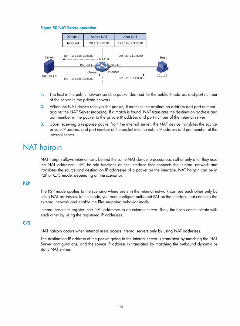
115
Figure 50 NAT Server operation
1. The host in the public network sends a packet destined for the public IP address and port number of the server in the private network.
2. When the NAT device receives the packet, it matches the destination address and port number against the NAT Server mapping. If a match is found, NAT translates the destination address and port number in the packet to the private IP address and port number of the internal server.
3. Upon receiving a response packet from the internal server, the NAT device translates the source private IP address and port number of the packet into the public IP address and port number of the internal server.
NAT hairpin NAT hairpin allows internal hosts behind the same NAT device to access each other only after they uses the NAT addresses. NAT hairpin functions on the interface that connects the internal network and translates the source and destination IP addresses of a packet on the interface. NAT hairpin can be in P2P or C/S mode, depending on the scenarios.
P2P
The P2P mode applies to the scenario where users in the internal network can see each other only by using NAT addresses. In this mode, you must configure outbound PAT on the interface that connects the external network and enable the EIM mapping behavior mode.
Internal hosts first register their NAT addresses to an external server. Then, the hosts communicate with each other by using the registered IP addresses.
C/S
NAT hairpin occurs when internal users access internal servers only by using NAT addresses.
The destination IP address of the packet going to the internal server is translated by matching the NAT Server configurations, and the source IP address is translated by matching the outbound dynamic or static NAT entries.
192.168.1.3
192.168.1.1 20.1.1.1
20.1.1.2
NAT
Intranet Internet
HostServer Dst : 20.1.1.1:8080Dst : 192.168.1.3:8080
Src : 192.168.1.3:8080 Src : 20.1.1.1:8080
Before NAT
20.1.1.1:8080
After NAT
192.168.1.3:8080
Direction
Inbound

116
NAT entries
NAT session entry NAT translates the IP address of the first packet in a session and creates a NAT session entry for recording the mappings. The NAT session entry contains extended NAT information, such as interface and translation method. Subsequent packets of the session are translated by using this entry.
The session management module maintains the updating and aging of NAT session entries. For information about session management, see Security Configuration Guide.
EIM entry A NAT device with the PAT Endpoint-Independent Mapping configured creates a NAT session entry, and then an EIM entry for recording the mapping between an internal address/port and a NAT address/port.
The EIM entry provides the following benefits:
• The same mapping applies to subsequent connections originating from the same source IP and port as the first connection.
• Allows reverse translation for connections originating from external hosts to the NAT address and port based on the EIM entry.
An EIM entry ages out after all related NAT session entries age out.
NO-PAT entry A NAT device with NO-PAT translation method configured creates a NAT session entry, and then creates a NO-PAT entry for recording the mapping between an internal address and a NAT address. A NO-PAT entry can also be created during the ALG process for NAT. For information about NAT with ALG, see "NAT with ALG."
The NO-PAT entry provides the following benefits:
• The same mapping applies to subsequent connections originating from the same source IP as the first connection.
• The reversible keyword allows translating the destination IP address of the first packet of a connection originating from an external host to the NAT address based on the existing NO-PAT entry.
A NO-PAT entry ages out after all related NAT session entries age out.
Using NAT with other features
NAT with MPLS VPNs NAT with MPLS L3VPN allows users from different MPLS VPNs to access external networks and to access each other.

117
1. Upon receiving a request from a user in an MPLS VPN to an external network, NAT translates the private source IP address and port number to a NAT IP address and port number, and records the MPLS VPN information, such as the VPN name.
2. When a response packet arrives, NAT translates the destination IP address and port number to the private IP address and port number, and forwards the packet to the target MPLS VPN.
The NAT Server feature supports NAT with MPLS VPN for external users to access the servers in an MPLS VPN. For example, to enable a host at 10.110.1.1 in MPLS VPN 1 to provide Web services for Internet users, configure NAT Server to use 202.110.10.20 as the public IP address of the Web server.
NAT with DNS mapping NAT with DNS mapping allows an internal host to access an internal server on the same private network by using the domain name of the internal server when the DNS server is on the public network.
NAT with DNS mapping must operate with the NAT Server feature. NAT with DNS mapping maps the domain name of the internal server to the public IP address, public port number, and protocol type of the server. NAT Server maps the public IP and port to the private IP and port of the internal server.
Figure 51 shows the application scenario for NAT with DNS mapping.
Figure 51 NAT with DNS mapping
Configure NAT with DNS mapping to record the mapping of the domain name, public address, public port number, and protocol type of the Web server. Configure NAT Server to map the public address to the private address of the Web server.
1. When a DNS reply arrives on the NAT device, NAT performs a NAT with DNS mapping lookup by using the domain name.
2. If a match is found, the NAT continues to match the public address, public port number, and the protocol type against the NAT Server configuration.
3. If a match is found, NAT translates the public IP address in the reply into the private IP address of the Web server.
4. The internal host can access the internal server.
NAT with ALG Use NAT with ALG to translate the payload information to ensure the establishment of data connections.
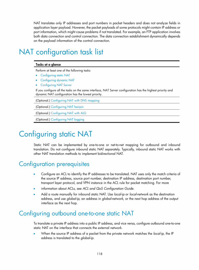
118
NAT translates only IP addresses and port numbers in packet headers and does not analyze fields in application layer payload. However, the packet payloads of some protocols might contain IP address or port information, which might cause problems if not translated. For example, an FTP application involves both data connection and control connection. The data connection establishment dynamically depends on the payload information of the control connection.
NAT configuration task list Tasks at a glance
Perform at least one of the following tasks: • Configuring static NAT • Configuring dynamic NAT • Configuring NAT Server
If you configure all the tasks on the same interface, NAT Server configuration has the highest priority and dynamic NAT configuration has the lowest priority.
(Optional.) Configuring NAT with DNS mapping
(Optional.) Configuring NAT hairpin
(Optional.) Configuring NAT with ALG
(Optional.) Configuring NAT logging
Configuring static NAT Static NAT can be implemented by one-to-one or net-to-net mapping for outbound and inbound translation. Do not configure inbound static NAT separately. Typically, inbound static NAT works with other NAT translation methods to implement bidirectional NAT.
Configuration prerequisites • Configure an ACL to identify the IP addresses to be translated. NAT uses only the match criteria of
the source IP address, source port number, destination IP address, destination port number, transport layer protocol, and VPN instance in the ACL rule for packet matching. For more
• information about ACLs, see ACL and QoS Configuration Guide.
• Add a route manually for inbound static NAT. Use local-ip or local-network as the destination address, and use global-ip, an address in global-network, or the next hop address of the output interface as the next hop.
Configuring outbound one-to-one static NAT To translate a private IP address into a public IP address, and vice versa, configure outbound one-to-one static NAT on the interface that connects the external network.
• When the source IP address of a packet from the private network matches the local-ip, the IP address is translated to the global-ip.

119
• When the destination IP address of a packet from the public matches the global-ip, the destination IP address is translated into the local-ip.
To configure outbound one-to-one static NAT:
Step Command Remarks
1. Enter system view. system-view N/A
2. Configure a one-to-one mapping for outbound static NAT.
nat static outbound local-ip [ vpn-instance local-name ] global-ip [ vpn-instance global-name ] [ acl acl-number [ reversible ] ]
By default, no mappings exist.
If you specify the acl keyword, NAT processes only packets matching the permit statement in the ACL.
3. Return to system view. quit N/A
4. Enter interface view. interface interface-type interface-number N/A
5. Enable static NAT on the interface. nat static enable By default, static NAT is disabled.
Configuring outbound net-to-net static NAT For address translation between a private network and a public network, configure outbound net-to-net static NAT on the interface that connects the external network.
• When the source IP address of a packet from the private network matches the internal NAT address pool, the source IP address is translated into a public address in the external NAT address pool.
• When the destination IP address of a packet from the public network matches the external NAT address pool, the destination IP address is translated into a private address in the internal NAT address pool.
To configure outbound net-to-net static NAT:
Step Command Remarks
1. Enter system view. system-view N/A
2. Configure a net-to-net mapping for outbound static NAT.
nat static outbound net-to-net local-start-address local-end-address [ vpn-instance local -name ] global global-network { mask-length | mask } [ vpn-instance global-name ] [ acl acl-number [ reversible ] ]
By default, no mappings exist.
If you specify the acl keyword, Nat processes only packets matching the permit statement in the ACL.
3. Return to system view. quit N/A
4. Enter interface view. interface interface-type interface-number
N/A
5. Enable static NAT on the interface. nat static enable By default, static NAT is disabled.

120
Configuring inbound one-to-one static NAT Configure inbound one-to-one static NAT for address translation between a private IP address and a public IP address.
• When the source IP address of a packet from the public network to the private network matches the global-ip, the IP address is translated to the local-ip.
• When the destination IP address of a packet from the private matches the local-ip, the source IP address is translated to the global-ip.
To configure inbound one-to-one static NAT:
Step Command Remarks
1. Enter system view. system-view N/A
2. Configure a one-to-one mapping for inbound static NAT.
nat static inbound global-ip [ vpn-instance global-name ] local-ip [ vpn-instance local-name ] [ acl acl-number [ reversible ] ]
By default, no mappings exist.
If you specify the acl keyword, Nat processes only packets matching the permit statement in the ACL.
3. Return to system view. quit N/A
4. Enter interface view. interface interface-type interface-number N/A
5. Enable static NAT on the interface. nat static enable By default, static NAT is disabled.
Configuring inbound net-to-net static NAT Configure inbound net-to-net static NAT for translation between a private network and a public network.
• When the source IP address of a packet from the public network matches the external NAT address pool, the source IP address is translated into a private address in the internal NAT address pool.
• When the destination IP address of a packet from the private network matches the internal NAT address pool, the destination IP address is translated into a public address in the external NAT address pool.
To configure inbound net-to-net static NAT:
Step Command Remarks
1. Enter system view. system-view N/A
2. Configure a net-to-net mapping for inbound static NAT.
nat static inbound net-to-net global-start-address global-end-address [ vpn-instance global -name ] local local-network { mask-length | mask } [ vpn-instance local-name ] [ acl acl-number [ reversible ] ]
By default, no mappings exist.
If you specify the acl keyword, NAT processes only packets matching the permit statement in the ACL.
3. Return to system view. quit N/A
4. Enter interface view. interface interface-type interface-number
N/A
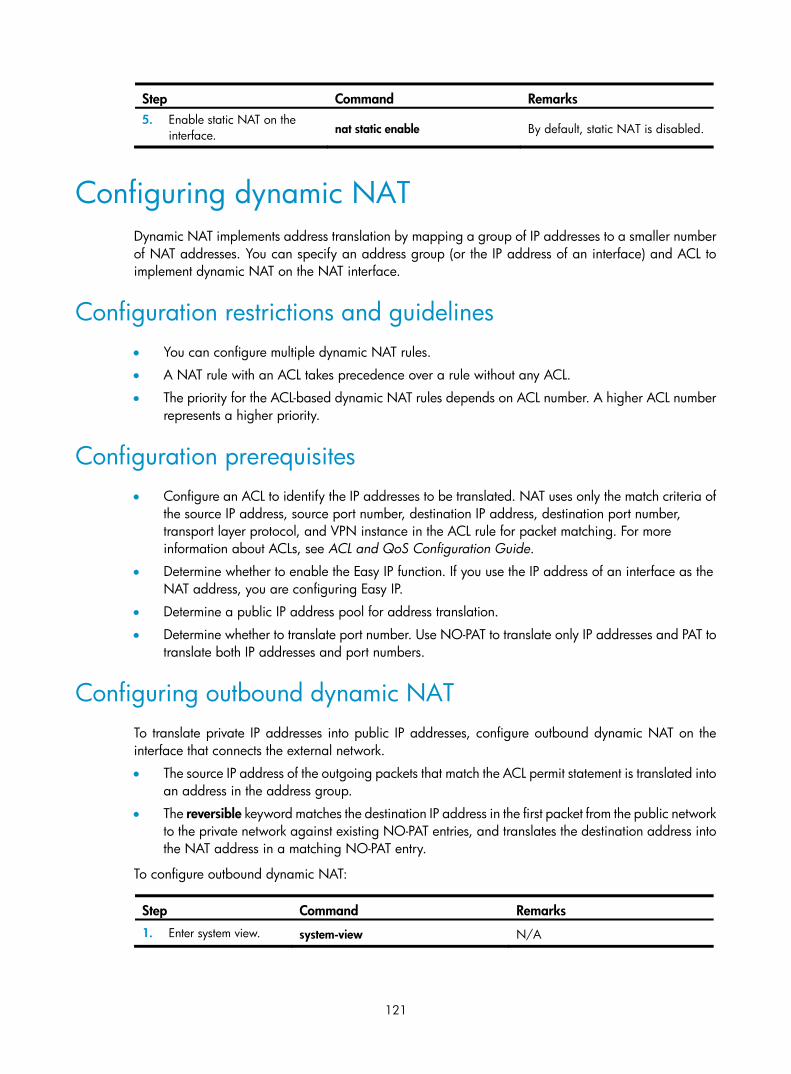
121
Step Command Remarks 5. Enable static NAT on the
interface. nat static enable By default, static NAT is disabled.
Configuring dynamic NAT Dynamic NAT implements address translation by mapping a group of IP addresses to a smaller number of NAT addresses. You can specify an address group (or the IP address of an interface) and ACL to implement dynamic NAT on the NAT interface.
Configuration restrictions and guidelines • You can configure multiple dynamic NAT rules.
• A NAT rule with an ACL takes precedence over a rule without any ACL.
• The priority for the ACL-based dynamic NAT rules depends on ACL number. A higher ACL number represents a higher priority.
Configuration prerequisites • Configure an ACL to identify the IP addresses to be translated. NAT uses only the match criteria of
the source IP address, source port number, destination IP address, destination port number, transport layer protocol, and VPN instance in the ACL rule for packet matching. For more information about ACLs, see ACL and QoS Configuration Guide.
• Determine whether to enable the Easy IP function. If you use the IP address of an interface as the NAT address, you are configuring Easy IP.
• Determine a public IP address pool for address translation.
• Determine whether to translate port number. Use NO-PAT to translate only IP addresses and PAT to translate both IP addresses and port numbers.
Configuring outbound dynamic NAT To translate private IP addresses into public IP addresses, configure outbound dynamic NAT on the interface that connects the external network.
• The source IP address of the outgoing packets that match the ACL permit statement is translated into an address in the address group.
• The reversible keyword matches the destination IP address in the first packet from the public network to the private network against existing NO-PAT entries, and translates the destination address into the NAT address in a matching NO-PAT entry.
To configure outbound dynamic NAT:
Step Command Remarks
1. Enter system view. system-view N/A

122
Step Command Remarks 2. Configure an address
group and enter its view.
nat address-group group-number By default, no address group exists.
3. Add a group member to the address group. address start-address end-address
By default, no group member exists.
You can add multiple members to an address group.
The IP addresses of the members must not overlap.
4. Enter interface view. interface interface-type interface-number N/A
5. Configure outbound dynamic NAT.
• Configure NO-PAT: nat outbound [ acl-number ] address-group group-number [ vpn-instance vpn-instance-name ] no-pat [ reversible ]
• Configure PAT: nat outbound [ acl-number ] [ address-group group-number ] [ vpn-instance vpn-instance-name ] [ port-preserved ]
By default, outbound dynamic NAT is not configured.
You can configure multiple outbound dynamic NAT rules on an interface.
6. (Optional.) Configure the mapping behavior for PAT.
nat mapping-behavior endpoint-independent [ acl acl-number ]
The default mapping behavior is Address and Port-Dependent Mapping.
This command takes effect only on outbound dynamic NAT for PAT.
Configuring inbound dynamic NAT To implement bidirectional NAT, you must use inbound dynamic NAT with outbound dynamic NAT, NAT Server, or outbound static NAT.
• The source IP address of a received packet that matches the ACL permit statement is translated into an address in the address group.
• The keyword add-route enables the device to add a route automatically to the NATed address when a packet matches an inbound dynamic NAT rule. The output interface for the automatically added route is the NAT interface, and the next hop is the source address before translation. If you do not specify this keyword, you must add the route manually. H3C recommends that you manually specify a route because it takes time to add routes automatically.
• The reversible keyword matches the destination IP address in the first packet from the private network to the public network against existing NO-PAT entries, and translates the destination address into the NAT address in a matching NO-PAT entry.
Inbound dynamic NAT does not support Easy IP.
To configure inbound dynamic NAT:
Step Command Remarks
1. Enter system view. system-view N/A

123
Step Command Remarks 2. Configure an address
group and enter its view. nat address-group group-number By default, no address group exists.
3. Add a group member to the address group. address start-address end-address
By default, no group member exists.
You can add multiple members to an address group.
The IP addresses of the members must not overlap.
4. Enter interface view. interface interface-type interface-number N/A
5. Configure inbound dynamic NAT.
nat inbound acl-number address-group group-number [ vpn-instance vpn-instance-name ] [ no-pat [ reversible ] [ add-route ]
By default, inbound dynamic NAT is not configured.
Configuring NAT Server Configuring NAT Server is to map an external IP address and port number to the real IP address and port number of an internal server on the interface that connects the external network.
An internal server can be located in a common private network or an MPLS L3VPN.
If you specify the acl keyword for the NAT Server configuration, only packets matching the ACL permit rule are translated. NAT uses only the match criteria of the source IP address, source port number, destination IP address, destination port number, transport layer protocol, and VPN instance in the ACL rule for packet matching.
Configuring common NAT Server Map the real private IP address and port number of an internal server to a public IP address and port number so that hosts in external networks can access the internal server.
To configure common NAT Server:
Step Command Remarks 1. Enter system
view. system-view N/A
2. Enter interface view. interface interface-type interface-number N/A

124
Step Command Remarks
3. Configure one or more common NAT Server mappings.
• A single global address with a single or no global port: nat server protocol pro-type global { global-address | current-interface | interface interface-type interface-number } [ global-port ] [ vpn-instance global-name ] inside local-address [ local-port ] [ vpn-instance local-name ] [ acl acl-number ]
• A single global address with consecutive global ports: nat server protocol pro-type global { global-address | current-interface | interface interface-type interface-number } global-port1 global-port2 [ vpn-instance global-name ] inside { { local-address | local-address1 local-address2 } local-port | local-address local-port1 local-port2 } [ vpn-instance local-name ] [ acl acl-number ]
• Consecutive global addresses with a single or no global port: nat server protocol pro-type global global-address1 global-address2 [ global-port ] [ vpn-instance global-name ] inside { local-address | local-address1 local-address2 } [ local-port ] [ vpn-instance local-name ] [ acl acl-number ]
• Consecutive global addresses with a single global port: nat server protocol pro-type global global-address1 global-address2 global-port [ vpn-instance global-name ] inside local-address local-port1 local-port2 [ vpn-instance local-name ] [ acl acl-number ]
By default, no NAT Server mapping exists.
You can configure multiple NAT Server mappings on an interface.
Configuring load sharing NAT Server You can add multiple internal servers to an internal server group so that these servers provide the same service to external hosts. The NAT device chooses one internal server as the destination server based on the weight and number of connections of the servers when an external user sends application requests to the external address of the internal server group.
To configure load sharing NAT Server:
Step Command Remarks
1. Enter system view. system-view N/A
2. Configure a NAT Server group and enter its view. nat server-group group-number
By default, no NAT Server group exists.
3. Add an internal server into the group.
inside ip inside-ip port port-number [ weight weight-value ]
By default, no internal server is in the group.
You can add multiple internal servers to a group.
4. Enter interface view. interface interface-type interface-number N/A

125
Step Command Remarks
5. Configure load sharing NAT Server.
nat server protocol pro-type global { { global-address | current-interface | interface interface-type interface-number } { global-port | global-port1 global-port2 } | global-address1 global-address2 global-port } [ vpn-instance global-name ] inside server-group group-number [ vpn-instance local-name ] [ acl acl-number ]
By default, no internal server exists.
You can configure multiple load sharing internal servers on an interface.
Configuring NAT with DNS mapping NAT with DNS mapping must operate together with NAT Server and NAT with ALG.
To configure NAT with DNS mapping:
Step Command Remarks
1. Enter system view. system-view N/A
2. Configure a DNS mapping for NAT.
nat dns-map domain domain-name protocol pro-type { interface interface-type interface-number | ip global-ip } port global-port
By default, no DNS mapping for NAT exists.
You can configure multiple DNS mappings for NAT.
Configuring NAT hairpin NAT hairpin enables an internal host to access an internal server or another internal host by using NAT addresses.
NAT hairpin typically operates with NAT Server, outbound dynamic NAT, or outbound static NAT.
To configure NAT hairpin:
Step Command Remarks
1. Enter system view. system-view N/A
2. Enter interface view. interface interface-type interface-number N/A
3. Enable NAT hairpin. nat hairpin enable By default, NAT hairpin is disabled.
Configuring NAT with ALG Configure NAT with ALG for a specific protocol to analyze and process the payload fields in the application layer packets.
To configure NAT with ALG:

126
Step Command Remarks
1. Enter system view. system-view N/A
2. Configure NAT with ALG for the specified protocol or all protocols.
nat alg { all | dns | ftp | h323 | icmp-error | rtsp | sip | tftp }
By default, NAT with ALG is enabled.
Configuring NAT logging NAT logging records NAT session information, such as IP address and port number translation, user access, and network flows.
A NAT device generates NAT logs when one of the following occurs:
• A NAT session is established.
• A NAT session is removed when you add configurations with higher priority, remove configurations, change ACLs, and when a NAT session ages out or a NAT session is deleted.
• Active NAT flows exist. When the interval for logging active NAT flows is reached, the NAT session is logged.
To enable NAT logging:
Step Command Remarks
1. Enter system view. system-view N/A
2. Enable NAT logging. nat log enable [ acl acl-number ] By default, NAT logging is disabled.
3. Enable NAT logging.
• For NAT session establishment events: nat log flow-begin
• For NAT session removal events: nat log flow-end
• For active NAT flows: nat log flow-active minutes
By default, NAT logging is disabled.
Displaying and maintaining NAT Execute display commands in any view and reset commands in user view.
Task Command
Display all NAT configuration information. display nat all
Display NAT address group information. display nat address-group [ group-number ]
Display NAT with DNS mapping configuration. display nat dns-map
Display information about NAT EIM entries (MSR 2600/MSR 3600). display nat eim
Display information about NAT EIM entries (MSR 5600). display nat eim [ slot slot-number ]

127
Task Command
Display information about inbound dynamic NAT. display nat inbound
Display NAT logging configuration. display nat log
Display information about NAT NO-PAT entries (MSR 2600/MSR 3600). display nat no-pat
Display information about NAT NO-PAT entries (MSR 5600). display nat no-pat [ slot slot-number ]
Display information about outbound dynamic NAT. display nat outbound
Display NAT Server configuration. display nat server
Display internal server group configuration. display nat server-group [ group-number ]
Display sessions that have been NATed (MSR 2600/MSR 3600).
display nat session [ { source-ip source-ip | destination-ip destination-ip } * [ vpn-instance vpn-name ] ] [ verbose ]
Display sessions that have been NATed (MSR 5600).
display nat session [ { source-ip source-ip | destination-ip destination-ip } * [ vpn-instance vpn -name ] ] [ slot slot-number ] [ verbose ]
Display static NAT mappings. display nat static
Display NAT statistics (MSR 2600/MSR 3600). display nat statistics
Display NAT statistics (MSR 5600). display nat statistics [ slot slot-number ]
Clear NAT sessions. reset nat session
NAT configuration examples
One-to-one static NAT for internal-to-external access Network requirements
Configure static NAT to allow the user at 10.110.10.8/24 to access the Internet.
Figure 52 Network diagram
Host10.110.10.8/24
Server
InternetGE1/1
10.110.10.1/24GE1/2202.38.1.1/16
Router

128
Configuration procedure
# Specify IP addresses for the interfaces. (Details not shown.)
# Configure a one-to-one static NAT mapping between internal address 10.110.10.8 and the NAT address 202.38.1.100. <Router> system-view
[Router] nat static 10.110.10.8 202.38.1.100
# Enable static NAT on interface GigabitEthernet 1/2. [Router] interface gigabitethernet 1/2
[Router-GigabitEthernet1/2] nat static enable
[Router-GigabitEthernet1/2] quit
Verifying the configuration
After completing the configurations, the host at 10.110.10.8/24 can access the server on the Internet.
# Display static NAT configuration. [Router] display nat static
Static NAT mappings:
There are 1 outbound static NAT mappings.
IP-to-IP:
Local IP : 10.110.10.8
Global IP : 202.38.1.100
Interfaces enabled with static NAT:
There are 1 interfaces enabled with static NAT.
Interface: GigabitEthernet1/2
# Use the display nat session verbose command to display NAT session information generated when the host accesses an external server. [Router] display nat session verbose
Initiator:
Source IP/port: 10.110.10.8/42496
Destination IP/port: 202.38.1.111/2048
VPN instance/VLAN ID/VLL ID: -/-/-
Protocol: ICMP(1)
Responder:
Source IP/port: 202.38.1.111/42496
Destination IP/port: 202.38.1.100/0
VPN instance/VLAN ID/VLL ID: -/-/-
Protocol: ICMP(1)
State: ICMP_REPLY
Application: INVALID
Start time: 2012-08-16 09:30:49 TTL: 27s
Interface(in) : GigabitEthernet1/1
Interface(out): GigabitEthernet1/2
Initiator->Responder: 5 packets 420 bytes
Responder->Initiator: 5 packets 420 bytes
Total sessions found: 1
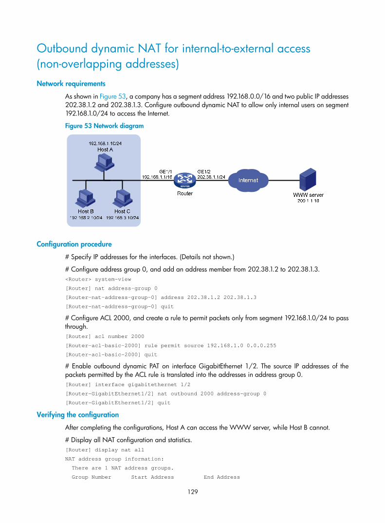
129
Outbound dynamic NAT for internal-to-external access (non-overlapping addresses) Network requirements
As shown in Figure 53, a company has a segment address 192.168.0.0/16 and two public IP addresses 202.38.1.2 and 202.38.1.3. Configure outbound dynamic NAT to allow only internal users on segment 192.168.1.0/24 to access the Internet.
Figure 53 Network diagram
Configuration procedure
# Specify IP addresses for the interfaces. (Details not shown.)
# Configure address group 0, and add an address member from 202.38.1.2 to 202.38.1.3. <Router> system-view
[Router] nat address-group 0
[Router-nat-address-group-0] address 202.38.1.2 202.38.1.3
[Router-nat-address-group-0] quit
# Configure ACL 2000, and create a rule to permit packets only from segment 192.168.1.0/24 to pass through. [Router] acl number 2000
[Router-acl-basic-2000] rule permit source 192.168.1.0 0.0.0.255
[Router-acl-basic-2000] quit
# Enable outbound dynamic PAT on interface GigabitEthernet 1/2. The source IP addresses of the packets permitted by the ACL rule is translated into the addresses in address group 0. [Router] interface gigabitethernet 1/2
[Router-GigabitEthernet1/2] nat outbound 2000 address-group 0
[Router-GigabitEthernet1/2] quit
Verifying the configuration
After completing the configurations, Host A can access the WWW server, while Host B cannot.
# Display all NAT configuration and statistics. [Router] display nat all
NAT address group information:
There are 1 NAT address groups.
Group Number Start Address End Address

130
0 202.38.1.2 202.38.1.3
NAT outbound information:
There are 1 NAT outbound rules.
Interface: GigabitEthernet1/2
ACL: 2000 Address group: 0 Port-preserved: N
NO-PAT: N Reversible: N
NAT logging:
Log enable : Disabled
Flow-begin : Disabled
Flow-end : Disabled
Flow-active: Disabled
NAT mapping behavior:
Mapping mode: Address and Port-Dependent
ACL : ---
NAT ALG:
DNS: Enabled
FTP: Enabled
H323: Enabled
ICMP-ERROR: Enabled
# Use the display nat session verbose command to display NAT session information generated when Host A accesses the WWW server. [Router] display nat session verbose
Initiator:
Source IP/port: 192.168.1.10/52992
Destination IP/port: 200.1.1.10/2048
VPN instance/VLAN ID/VLL ID: -/-/-
Protocol: ICMP(1)
Responder:
Source IP/port: 200.1.1.10/4
Destination IP/port: 202.38.1.3/0
VPN instance/VLAN ID/VLL ID: -/-/-
Protocol: ICMP(1)
State: ICMP_REPLY
Application: INVALID
Start time: 2012-08-15 14:53:29 TTL: 12s
Interface(in) : GigabitEthernet1/1
Interface(out): GigabitEthernet1/2
Initiator->Responder: 1 packets 84 bytes
Responder->Initiator: 1 packets 84 bytes
Total sessions found: 1

131
Bidirectional NAT for internal-to-external access Network requirements
As shown in Figure 54, the IP address of the Web server is 192.168.1.10, and it overlaps with internal network 192.168.1.0/24, where the hosts reside. The company has two public IP addresses 202.38.1.2 and 202.38.1.3. Configure NAT to allow internal users to access the external Web server by using its domain name.
Figure 54 Network diagram
Configuration considerations
This is a typical application of bidirectional NAT.
• When an internal host tries to access the external Web server by using the domain name, a DNS query is sent to the external DNS server. The server sends the internal host a response with the Web server's IP address, which overlaps with that of the internal host. To make sure the internal host reaches the Web server instead of an internal user, configure inbound dynamic NAT with ALG and DNS mapping so that NAT can translate the Web server's address in the payload to a dynamically assigned NAT address.
• The internal host uses the NAT address as the destination address. When a packet from the internal host arrives at the NAT device, the source IP address overlaps with the real address of the Web server. Configure outbound dynamic NAT to translate the source IP address to a dynamically assigned NAT address.
• The NAT device has no route to the NAT address of the external Web server. Add a static route to the NAT address with GigabitEthernet 1/2 as the output interface.
Configuration procedure
# Specify IP addresses for the interfaces. (Details not shown.)
# Enable NAT with ALG and DNS. <Router> system-view
[Router] nat alg dns
# Configure ACL 2000, and create a rule to permit packets only from segment 192.168.1.0/24 to pass through. [Router] acl number 2000
[Router-acl-basic-2000] rule permit source 192.168.1.0 0.0.0.255
[Router-acl-basic-2000] quit
# Create address group 1.

132
[Router] nat address-group 1
# Add address 202.38.1.2 to the group. [Router-nat-address-group-1] address 202.38.1.2 202.38.1.2
[Router-nat-address-group-1] quit
# Create address group 2. [Router] nat address-group 2
# Add address 202.38.1.3 to the group. [Router-nat-address-group-2] address 202.38.1.3 202.38.1.3
[Router-nat-address-group-2] quit
# Enable inbound NO-PAT on interface GigabitEthernet 1/2 to translate the source IP address in the DNS reply payload into the address in address group 1, and allow reversible NAT. [Router] interface gigabitethernet 1/2
[Router-GigabitEthernet1/2] nat inbound 2000 address-group 1 no-pat reversible
# Enable outbound PAT on interface GigabitEthernet 1/2 to translate the source address of outgoing packets into the address in address group 2. [Router-GigabitEthernet1/2] nat outbound 2000 address-group 2
[Router-GigabitEthernet1/2] quit
# Configure a static route to 202.38.1.2 with GigabitEthernet 1/2 as the output interface and 20.2.2.2 as the next hop. (The next hop address varies with network settings.) [Router] ip route-static 202.38.1.2 32 gigabitethernet 1/2 20.2.2.2
Verifying the configuration
After completing the configurations, Host A can access the Web server by using its domain name.
# Display all NAT configuration and statistics. [Router] display nat all
NAT address group information:
There are 2 NAT address groups.
Group Number Start Address End Address
1 202.38.1.2 202.38.1.2
2 202.38.1.3 202.38.1.3
NAT inbound information:
There are 1 NAT inbound rules.
Interface: GigabitEthernet1/2
ACL: 2000 Address group: 1 Add route: N
NO-PAT: Y Reversible: Y
NAT outbound information:
There are 1 NAT outbound rules.
Interface: GigabitEthernet1/2
ACL: 2000 Address group: 2 Port-preserved: N
NO-PAT: N Reversible: N
NAT logging:
Log enable : Disabled
Flow-begin : Disabled

133
Flow-end : Disabled
Flow-active: Disabled
NAT mapping behavior:
Mapping mode: Address and Port-Dependent
ACL : ---
NAT ALG:
DNS: Enabled
FTP: Enabled
H323: Enabled
ICMP-ERROR: Enabled
# Use the display nat session verbose command to display NAT session information generated when Host A accesses the Web server. [Router] display nat session verbose
Initiator:
Source IP/port: 192.168.1.10/1694
Destination IP/port: 202.38.1.2/8080
VPN instance/VLAN ID/VLL ID: -/-/-
Protocol: TCP(6)
Responder:
Source IP/port: 192.168.1.10/8080
Destination IP/port: 202.38.1.3/1025
VPN instance/VLAN ID/VLL ID: -/-/-
Protocol: TCP(6)
State: TCP_ESTABLISHED
Application: HTTP
Start time: 2012-08-15 14:53:29 TTL: 3597s
Interface(in) : GigabitEthernet1/2
Interface(out): GigabitEthernet1/1
Initiator->Responder: 7 packets 308 bytes
Responder->Initiator: 5 packets 312 bytes
Total sessions found: 1
NAT Server for external-to-internal access Network requirements
As shown in Figure 55, two Web servers, one FTP server and one SMTP server are in the internal network to provide services for external users. The internal network address is 10.110.0.0/16. The company has three public IP addresses from 202.38.1.1/24 to 202.38.1.3/24.
Configure the NAT Server feature to allow the external user to access the internal servers with public address 202.38.1.1/24.

134
Figure 55 Network diagram
Configuration procedure
# Specify IP addresses for the interfaces. (Details not shown.)
# Enter interface view of GigabitEthernet 1/2. <Router> system-view
[Router] interface gigabitethernet 1/2
# Configure NAT Server to allow external users to access the FTP server by using the address 202.38.1.1 and port 21. [Router-GigabitEthernet1/2] nat server protocol tcp global 202.38.1.1 21 inside 10.110.10.3 ftp
# Configure NAT Server to allow external users to access the Web server 1 by using the address 202.38.1.1 and port 80. [Router-GigabitEthernet1/2] nat server protocol tcp global 202.38.1.1 80 inside 10.110.10.1 www
# Configure NAT Server to allow external users to access the Web server 2 by using the address 202.38.1.1 and port 8080. [Router-GigabitEthernet1/2] nat server protocol tcp global 202.38.1.1 8080 inside 10.110.10.2 www
# Configure NAT Server to allow external users to access the SMTP server by using the address 202.38.1.1 and port number defined by SMTP. [Router-GigabitEthernet1/2] nat server protocol tcp global 202.38.1.1 smtp inside 10.110.10.4 smtp
[Router-GigabitEthernet1/2] quit
Verifying the configuration
After completing the configurations, Host on the external network can access the internal servers by using the NAT addresses.
# Display all NAT configuration and statistics. [Router] display nat all
NAT internal server information:
There are 4 internal servers.
Interface: GigabitEthernet1/2
Protocol: 6(TCP)
Global IP/port: 202.38.1.1/21
Local IP/port: 10.110.10.3/21
FTP server10.110.10.3/16
Web server 110.110.10.1/16
Web server 210.110.10.2/16
SMTP server10.110.10.4/16
Host
InternetGE1/1
10.110.10.10/16GE1/2202.38.1.1/24
Router

135
Interface: GigabitEthernet1/2
Protocol: 6(TCP)
Global IP/port: 202.38.1.1/25
Local IP/port: 10.110.10.4/25
Interface: GigabitEthernet1/2
Protocol: 6(TCP)
Global IP/port: 202.38.1.1/80
Local IP/port: 10.110.10.1/80
Interface: GigabitEthernet1/2
Protocol: 6(TCP)
Global IP/port: 202.38.1.1/8080
Local IP/port: 10.110.10.2/80
NAT logging:
Log enable : Disabled
Flow-begin : Disabled
Flow-end : Disabled
Flow-active: Disabled
NAT mapping behavior:
Mapping mode: Address and Port-Dependent
ACL : ---
NAT ALG:
DNS: Enabled
FTP: Enabled
H323: Enabled
ICMP-ERROR: Enabled
# Use the display nat session verbose command to display NAT session information generated when Host accesses the FTP server. [Router] display nat session verbose
Initiator:
Source IP/port: 202.38.1.10/1694
Destination IP/port: 202.38.1.1/21
VPN instance/VLAN ID/VLL ID: -/-/-
Protocol: TCP(6)
Responder:
Source IP/port: 10.110.10.3/21
Destination IP/port: 202.38.1.10/1694
VPN instance/VLAN ID/VLL ID: -/-/-
Protocol: TCP(6)
State: TCP_ESTABLISHED
Application: FTP
Start time: 2012-08-15 14:53:29 TTL: 3597s
Interface(in) : GigabitEthernet1/2

136
Interface(out): GigabitEthernet1/1
Initiator->Responder: 7 packets 308 bytes
Responder->Initiator: 5 packets 312 bytes
Total sessions found: 1
NAT Server for external-to-internal access through domain name Network requirements
As shown in Figure 56, Web server at 0.110.10.2/24 in the internal network provides services for external users. A DNS server at 10.110.10.3/24 is used to resolve the domain name of the Web server. The company has two public IP addresses: 202.38.1.2 and 202.38.1.3.
Configure NAT Server to allow external users to access the internal Web server by using the domain name.
Figure 56 Network diagram
Configuration considerations
• To make sure the external host can access the internal DNS server, configure the NAT Server feature to map the internal IP address and port of the DNS server to an external address and port.
• Enable DNS with ALG and configure outbound dynamic NAT to translate the internal IP address of the Web server in the payload of the DNS response packet to an external IP address.
Configuration procedure
# Specify IP addresses for the interfaces. (Details not shown.)
# Enable NAT with ALG and with DNS. <Router> system-view
[Router] nat alg dns
# Configure ACL 2000, and create a rule to permit packets only from 10.110.10.2 to pass through. [Router] acl number 2000
[Router-acl-basic-2000] rule permit source 10.110.10.2 0
[Router-acl-basic-2000] quit
# Create address group 1. [Router] nat address-group 1
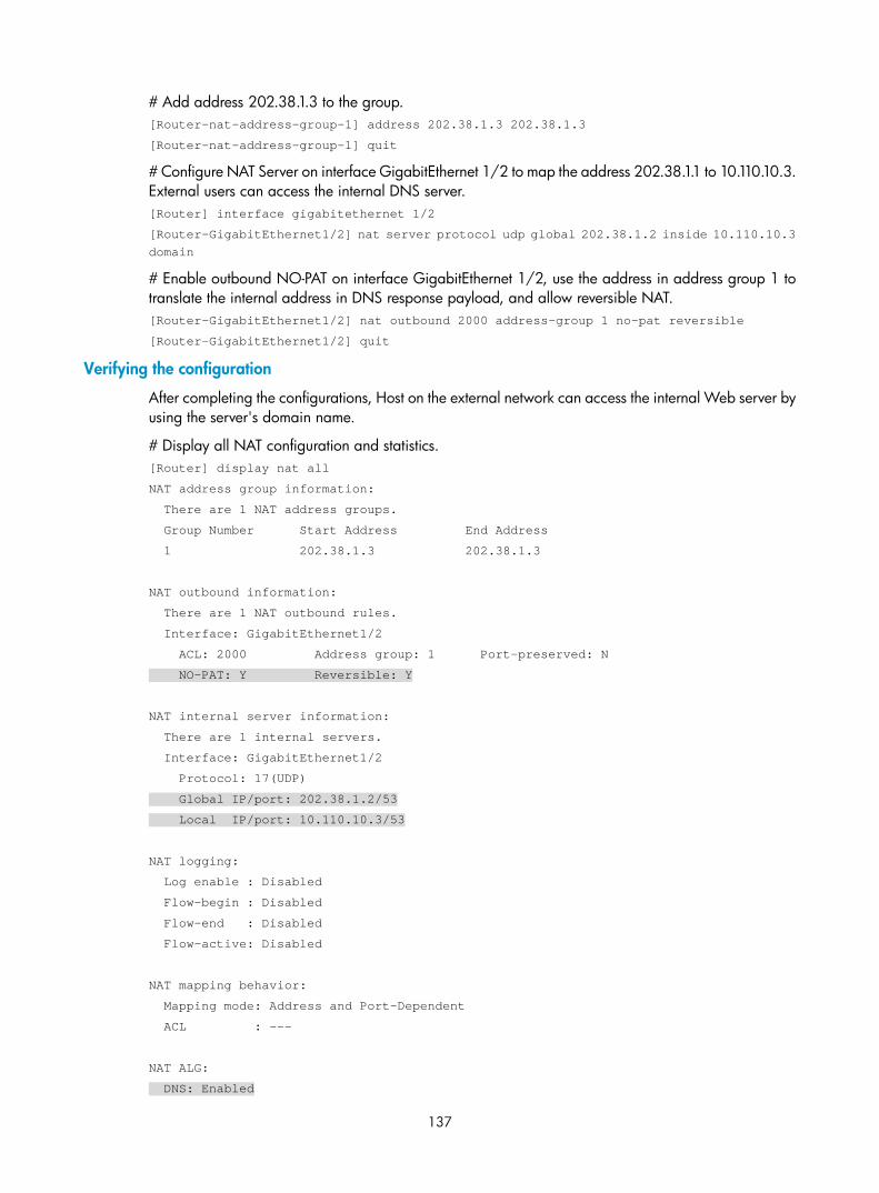
137
# Add address 202.38.1.3 to the group. [Router-nat-address-group-1] address 202.38.1.3 202.38.1.3
[Router-nat-address-group-1] quit
# Configure NAT Server on interface GigabitEthernet 1/2 to map the address 202.38.1.1 to 10.110.10.3. External users can access the internal DNS server. [Router] interface gigabitethernet 1/2
[Router-GigabitEthernet1/2] nat server protocol udp global 202.38.1.2 inside 10.110.10.3 domain
# Enable outbound NO-PAT on interface GigabitEthernet 1/2, use the address in address group 1 to translate the internal address in DNS response payload, and allow reversible NAT. [Router-GigabitEthernet1/2] nat outbound 2000 address-group 1 no-pat reversible
[Router-GigabitEthernet1/2] quit
Verifying the configuration
After completing the configurations, Host on the external network can access the internal Web server by using the server's domain name.
# Display all NAT configuration and statistics. [Router] display nat all
NAT address group information:
There are 1 NAT address groups.
Group Number Start Address End Address
1 202.38.1.3 202.38.1.3
NAT outbound information:
There are 1 NAT outbound rules.
Interface: GigabitEthernet1/2
ACL: 2000 Address group: 1 Port-preserved: N
NO-PAT: Y Reversible: Y
NAT internal server information:
There are 1 internal servers.
Interface: GigabitEthernet1/2
Protocol: 17(UDP)
Global IP/port: 202.38.1.2/53
Local IP/port: 10.110.10.3/53
NAT logging:
Log enable : Disabled
Flow-begin : Disabled
Flow-end : Disabled
Flow-active: Disabled
NAT mapping behavior:
Mapping mode: Address and Port-Dependent
ACL : ---
NAT ALG:
DNS: Enabled

138
FTP: Enabled
H323: Enabled
ICMP-ERROR: Enabled
# Use the display nat session verbose command to display NAT session information generated when Host accesses Web server. [Router] display nat session verbose
Initiator:
Source IP/port: 202.1.1.2/1694
Destination IP/port: 202.38.1.3/8080
VPN instance/VLAN ID/VLL ID: -/-/-
Protocol: TCP(6)
Responder:
Source IP/port: 10.110.10.2/8080
Destination IP/port: 202.1.1.2/1694
VPN instance/VLAN ID/VLL ID: -/-/-
Protocol: TCP(6)
State: TCP_ESTABLISHED
Application: HTTP
Start time: 2012-08-15 14:53:29 TTL: 3597s
Interface(in) : GigabitEthernet1/2
Interface(out): GigabitEthernet1/1
Initiator->Responder: 7 packets 308 bytes
Responder->Initiator: 5 packets 312 bytes
Total sessions found: 1
Bidirectional NAT for external-to-internal access through NAT Server Network requirements
As shown in Figure 57, an intranet uses the segment 192.168.1.0/24. The Web server at 192.168.1.2/24 provides Web services to external users and the DNS server at 192.168.1.3/24 resolves the domain name of the Web server. The company has 3 public addresses 202.38.1.2, 202.38.1.3, and 202.38.1.4.
Configure NAT to allow external host at 192.168.1.2 in the external network to use the domain name to access the internal Web server.

139
Figure 57 Network diagram
Configuration considerations
This is a typical application of bidirectional NAT.
• To make sure the external host to access the internal Web server by using its domain name, configure NAT Server so that the external host can access the internal DNS server to obtain the IP address of the Web server.
• The IP address of the Web server overlaps with the external host and is included in the response sent by the internal DNS server to the external host. To make sure the external host reaches the Web server, configure outbound dynamic NAT with ALG and DNS mapping so that NAT can translate the Web server's address in the payload to a dynamically assigned NAT address.
• The external host uses the NAT address as the destination address. When a packet from the external host arrives at the NAT device, the source IP address overlaps with the real address of the Web server. Configure inbound dynamic NAT to translate the source IP address to a dynamically assigned NAT address.
• The NAT device has no route to the NAT address of the external host. Add a static route to the NAT address with GigabitEthernet 1/2 as the output interface.
Configuration procedure
# Specify IP addresses for the interfaces. (Details not shown.)
# Enable NAT with ALG and DNS. <Router> system-view
[Router] nat alg dns
# Configure ACL 2000, and create a rule to permit packets only from segment 192.168.1.0/24 to pass through. [Router] acl number 2000
[Router-acl-basic-2000] rule permit source 192.168.1.0 0.0.0.255
[Router-acl-basic-2000] quit
# Create address group 1. [Router] nat address-group 1
# Add address 202.38.1.2 to the address group. [Router-nat-address-group-1] address 202.38.1.2 202.38.1.2
[Router-nat-address-group-1] quit
# Create address group 2. [Router] nat address-group 2

140
# Add address 202.38.1.3 to the address group. [Router-nat-address-group-2] address 202.38.1.3 202.38.1.3
[Router-nat-address-group-2] quit
# Configure NAT Server on interface GigabitEthernet 1/2 to allow external hosts to access the internal DNS server by using the address 202.38.1.4. [Router] interface gigabitethernet 1/2
[Router-GigabitEthernet1/2] nat server protocol udp global 202.38.1.4 inside 200.1.1.3 domain
# Enable outbound NO-PAT on interface GigabitEthernet 1/2 to translate IP address of the Web server in the DNS response payload into the address in address group 1, and allow reversible NAT. [Router-GigabitEthernet1/2] nat outbound 2000 address-group 1 no-pat reversible
# Enable inbound PAT on interface GigabitEthernet 1/2 to translate the source address of packets going to the internal network to the address in address group 2. [Router-GigabitEthernet1/2] nat inbound 2000 address-group 2
[Router-GigabitEthernet1/2] quit
# Configure a static route to 202.38.1.3 with GigabitEthernet 1/2 as the output interface and 20.2.2.2 as the next hop. (The next hop address varies with network settings.). [Router] ip route-static 202.38.1.3 32 gigabitethernet1/2 20.2.2.2
Verifying the configuration
After completing the configurations, Host on the external network can use the domain name to access the internal Web server whose address is the same as the host.
# Display all NAT configuration and statistics. [Router] display nat all
NAT address group information:
There are 2 NAT address groups.
Group Number Start Address End Address
1 202.38.1.2 202.38.1.2
2 202.38.1.3 202.38.1.3
NAT inbound information:
There are 1 NAT inbound rules.
Interface: GigabitEthernet1/2
ACL: 2000 Address group: 2 Add route: N
NO-PAT: N Reversible: N
NAT outbound information:
There are 1 NAT outbound rules.
Interface: GigabitEthernet1/2
ACL: 2000 Address group: 1 Port-preserved: N
NO-PAT: Y Reversible: Y
NAT internal server information:
There are 1 internal servers.
Interface: GigabitEthernet1/2
Protocol: 17(UDP)
Global IP/port: 202.38.1.4/53
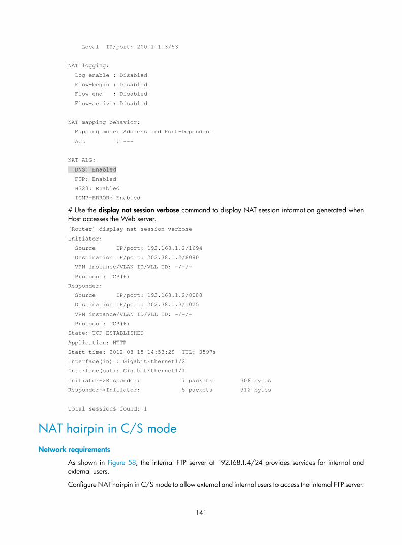
141
Local IP/port: 200.1.1.3/53
NAT logging:
Log enable : Disabled
Flow-begin : Disabled
Flow-end : Disabled
Flow-active: Disabled
NAT mapping behavior:
Mapping mode: Address and Port-Dependent
ACL : ---
NAT ALG:
DNS: Enabled
FTP: Enabled
H323: Enabled
ICMP-ERROR: Enabled
# Use the display nat session verbose command to display NAT session information generated when Host accesses the Web server. [Router] display nat session verbose
Initiator:
Source IP/port: 192.168.1.2/1694
Destination IP/port: 202.38.1.2/8080
VPN instance/VLAN ID/VLL ID: -/-/-
Protocol: TCP(6)
Responder:
Source IP/port: 192.168.1.2/8080
Destination IP/port: 202.38.1.3/1025
VPN instance/VLAN ID/VLL ID: -/-/-
Protocol: TCP(6)
State: TCP_ESTABLISHED
Application: HTTP
Start time: 2012-08-15 14:53:29 TTL: 3597s
Interface(in) : GigabitEthernet1/2
Interface(out): GigabitEthernet1/1
Initiator->Responder: 7 packets 308 bytes
Responder->Initiator: 5 packets 312 bytes
Total sessions found: 1
NAT hairpin in C/S mode Network requirements
As shown in Figure 58, the internal FTP server at 192.168.1.4/24 provides services for internal and external users.
Configure NAT hairpin in C/S mode to allow external and internal users to access the internal FTP server.
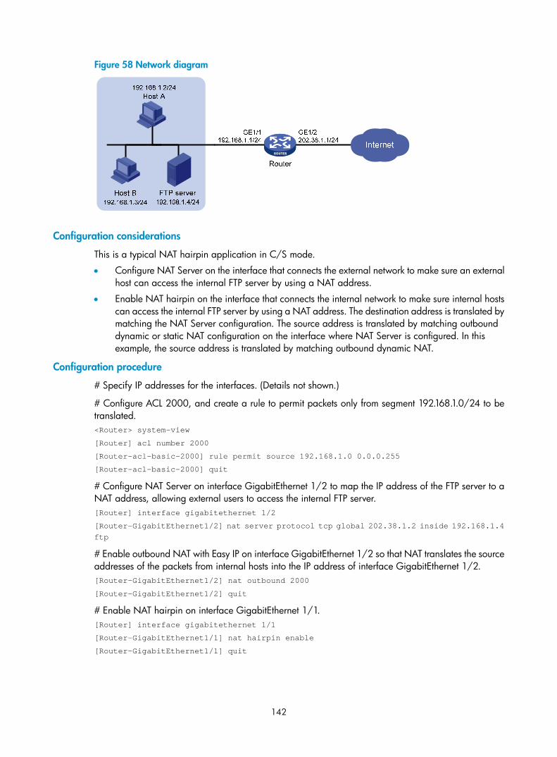
142
Figure 58 Network diagram
Configuration considerations
This is a typical NAT hairpin application in C/S mode.
• Configure NAT Server on the interface that connects the external network to make sure an external host can access the internal FTP server by using a NAT address.
• Enable NAT hairpin on the interface that connects the internal network to make sure internal hosts can access the internal FTP server by using a NAT address. The destination address is translated by matching the NAT Server configuration. The source address is translated by matching outbound dynamic or static NAT configuration on the interface where NAT Server is configured. In this example, the source address is translated by matching outbound dynamic NAT.
Configuration procedure
# Specify IP addresses for the interfaces. (Details not shown.)
# Configure ACL 2000, and create a rule to permit packets only from segment 192.168.1.0/24 to be translated. <Router> system-view
[Router] acl number 2000
[Router-acl-basic-2000] rule permit source 192.168.1.0 0.0.0.255
[Router-acl-basic-2000] quit
# Configure NAT Server on interface GigabitEthernet 1/2 to map the IP address of the FTP server to a NAT address, allowing external users to access the internal FTP server. [Router] interface gigabitethernet 1/2
[Router-GigabitEthernet1/2] nat server protocol tcp global 202.38.1.2 inside 192.168.1.4 ftp
# Enable outbound NAT with Easy IP on interface GigabitEthernet 1/2 so that NAT translates the source addresses of the packets from internal hosts into the IP address of interface GigabitEthernet 1/2. [Router-GigabitEthernet1/2] nat outbound 2000
[Router-GigabitEthernet1/2] quit
# Enable NAT hairpin on interface GigabitEthernet 1/1. [Router] interface gigabitethernet 1/1
[Router-GigabitEthernet1/1] nat hairpin enable
[Router-GigabitEthernet1/1] quit

143
Verifying the configuration
After completing the configurations, both internal and external hosts can access the internal FTP server through the external address.
# Display all NAT configuration and statistics. [Router]display nat all
NAT outbound information:
There are 1 NAT outbound rules.
Interface: GigabitEthernet1/2
ACL: 2000 Address group: --- Port-preserved: N
NO-PAT: N Reversible: N
NAT internal server information:
There are 1 internal servers.
Interface: GigabitEthernet1/2
Protocol: 6(TCP)
Global IP/port: 202.38.1.2/21
Local IP/port: 192.168.1.4/21
NAT logging:
Log enable : Disabled
Flow-begin : Disabled
Flow-end : Disabled
Flow-active: Disabled
NAT hairpinning:
There are 1 interfaces enabled with NAT hairpinning.
Interface: GigabitEthernet1/1
NAT mapping behavior:
Mapping mode: Address and Port-Dependent
ACL : ---
NAT ALG:
DNS: Enabled
FTP: Enabled
H323: Enabled
ICMP-ERROR: Enabled
# Use the display nat session verbose command to display NAT session information generated when Host A accesses the FTP server. [Router] display nat session verbose
Initiator:
Source IP/port: 192.168.1.2/1694
Destination IP/port: 202.38.1.2/21
VPN instance/VLAN ID/VLL ID: -/-/-
Protocol: TCP(6)
Responder:
Source IP/port: 192.168.1.4/21
Destination IP/port: 202.38.1.1/1025

144
VPN instance/VLAN ID/VLL ID: -/-/-
Protocol: TCP(6)
State: TCP_ESTABLISHED
Application: HTTP
Start time: 2012-08-15 14:53:29 TTL: 3597s
Interface(in) : GigabitEthernet1/1
Interface(out): GigabitEthernet1/1
Initiator->Responder: 7 packets 308 bytes
Responder->Initiator: 5 packets 312 bytes
Total sessions found: 1
NAT hairpin in P2P mode for access between internal users Network requirements
In the P2P application, internal clients must register their IP address to the external server and the server records the registered IP addresses and port numbers of the internal clients. An internal client must request the IP address and port number of another client from the external server before accessing the client.
Configure NAT hairpin so that:
• The internal clients can register the same external address to the external server.
• The internal clients can access each other through the IP address and port number obtained from the server.
Figure 59 Network diagram
Configuration considerations
This is a typical application of NAT hairpin in P2P mode.
• Configure outbound dynamic NAT on the interface that connects the external network so that the source address of the clients are translated when they register their IP addresses to the external server.
• Configure PAT of the Endpoint-Independent Mapping mode. The translation of the clients' addresses is endpoint-independent because the registered IP address and port number should be accessible for any source address.
• Enable NAT hairpin on the interface that connects the internal network so that internal clients can access each other through the external address.

145
Configuration procedure
# Specify IP addresses for the interfaces. (Details not shown.)
# Configure ACL 2000, and create a rule to permit packets only from segment 192.168.1.0/24 to be translated. <Router> system-view
[Router] acl number 2000
[Router-acl-basic-2000] rule permit source 192.168.1.0 0.0.0.255
[Router-acl-basic-2000] quit
# Configure outbound dynamic PAT with Easy IP on interface GigabitEthernet 1/2. The IP address of GigabitEthernet 1/2 is used as the NAT address for the source address translation of the packets from internal to external. [Router] interface gigabitethernet 1/2
[Router-GigabitEthernet1/2] nat outbound 2000
[Router-GigabitEthernet1/2] quit
# Configure the Endpoint-Independent Mapping mode for PAT. For packets with the same source address and port number and permitted by ACL 2000, the source address and port number are translated to the same external address and port number. [Router] nat mapping-behavior endpoint-independent acl 2000
# Enable NAT hairpin on interface GigabitEthernet 1/1. [Router] interface gigabitethernet 1/1
[Router-GigabitEthernet1/1] nat hairpin enable
[Router-GigabitEthernet1/1] quit
Verifying the configuration
After completing the configuration, Host A, Host B, and Host C can access each other after they register their IP addresses and port numbers to the external server.
# Display all NAT configuration and statistics. [Router] display nat all
NAT outbound information:
There are 1 NAT outbound rules.
Interface: GigabitEthernet1/2
ACL: 2000 Address group: --- Port-preserved: N
NO-PAT: N Reversible: N
NAT logging:
Log enable : Disabled
Flow-begin : Disabled
Flow-end : Disabled
Flow-active: Disabled
NAT hairpinning:
There are 1 interfaces enabled with NAT hairpinning.
Interface: GigabitEthernet1/1
NAT mapping behavior:
Mapping mode: Endpoint-Independent
ACL : 2000
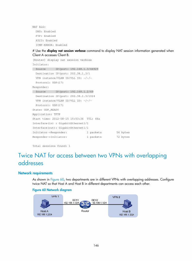
146
NAT ALG:
DNS: Enabled
FTP: Enabled
H323: Enabled
ICMP-ERROR: Enabled
# Use the display nat session verbose command to display NAT session information generated when Client A accesses Client B. [Router] display nat session verbose
Initiator:
Source IP/port: 192.168.1.3/44929
Destination IP/port: 202.38.1.3/1
VPN instance/VLAN ID/VLL ID: -/-/-
Protocol: UDP(17)
Responder:
Source IP/port: 192.168.1.2/69
Destination IP/port: 202.38.1.3/1024
VPN instance/VLAN ID/VLL ID: -/-/-
Protocol: UDP(17)
State: UDP_READY
Application: TFTP
Start time: 2012-08-15 15:53:36 TTL: 46s
Interface(in) : GigabitEthernet1/1
Interface(out): GigabitEthernet1/1
Initiator->Responder: 1 packets 56 bytes
Responder->Initiator: 1 packets 72 bytes
Total sessions found: 1
Twice NAT for access between two VPNs with overlapping addresses Network requirements
As shown in Figure 60, two departments are in different VPNs with overlapping addresses. Configure twice NAT so that Host A and Host B in different departments can access each other.
Figure 60 Network diagram

147
Configuration considerations
This is a typical application of twice NAT. Both the source and destination addresses of packets between the two VPNs need to be translated. Configure static NAT on both interfaces that connects the VPNs on the NAT device.
Configuration procedure
# Specify VPN instances and IP addresses for the interfaces. (Details not shown.)
# Configure a static outbound NAT mapping between 192.168.1.2 in vpn 1 and 172.16.1.2 in vpn 2. <Router> system-view
[Router] nat static outbound 192.168.1.2 vpn-instance vpn1 172.16.1.2 vpn-instance vpn2
# Configure a static outbound NAT mapping between 192.168.1.2 in vpn 2 and 172.16.2.2 in vpn 1. [Router] nat static outbound 192.168.1.2 vpn-instance vpn2 172.16.2.2 vpn-instance vpn1
# Enable static NAT on interface GigabitEthernet 1/2. [Router] interface gigabitethernet 1/2
[Router-GigabitEthernet1/2] nat static enable
[Router-GigabitEthernet1/2] quit
# Enable static NAT on interface GigabitEthernet 1/1. [Router] interface gigabitethernet 1/1
[Router-GigabitEthernet1/1] nat static enable
[Router-GigabitEthernet1/1] quit
Verifying the configuration
After completing the configuration, Host A and Host B can access each other. The NAT address for Host A is 172.16.1.2 and that for Host B is 172.16.2.2.
# Display all NAT configuration and statistics. [Router] display nat all
Static NAT mappings:
There are 2 outbound static NAT mappings.
IP-to-IP:
Local IP : 192.168.1.2
Global IP : 172.16.1.2
Local VPN : vpn1
Global VPN: vpn2
IP-to-IP:
Local IP : 192.168.1.2
Global IP : 172.16.2.2
Local VPN : vpn2
Global VPN: vpn1
Interfaces enabled with static NAT:
There are 2 interfaces enabled with static NAT.
Interface: GigabitEthernet1/1
GigabitEthernet1/2
NAT logging:
Log enable : Disabled

148
Flow-begin : Disabled
Flow-end : Disabled
Flow-active: Disabled
NAT mapping behavior:
Mapping mode: Address and Port-Dependent
ACL : ---
NAT ALG:
DNS: Enabled
FTP: Enabled
H323: Enabled
ICMP-ERROR: Enabled
# Use the display nat session verbose command to display NAT session information generated when Host A accesses Host B. [Router] display nat session verbose
Initiator:
Source IP/port: 192.168.1.2/42496
Destination IP/port: 172.16.2.2/2048
VPN instance/VLAN ID/VLL ID: vpn1/-/-
Protocol: ICMP(1)
Responder:
Source IP/port: 192.168.1.2/42496
Destination IP/port: 172.16.1.2/0
VPN instance/VLAN ID/VLL ID: vpn2/-/-
Protocol: ICMP(1)
State: ICMP_REPLY
Application: INVALID
Start time: 2012-08-16 09:30:49 TTL: 27s
Interface(in) : GigabitEthernet1/1
Interface(out): GigabitEthernet1/2
Initiator->Responder: 5 packets 420 bytes
Responder->Initiator: 5 packets 420 bytes
Total sessions found: 1
Load sharing NAT Server configuration example Network requirements
As shown in Figure 61, three FTP servers are in the intranet to provide FTP services for external users. Configure NAT so that these external users use the address 202.38.1.1/16 to access the servers and the three FTP servers implement load sharing.
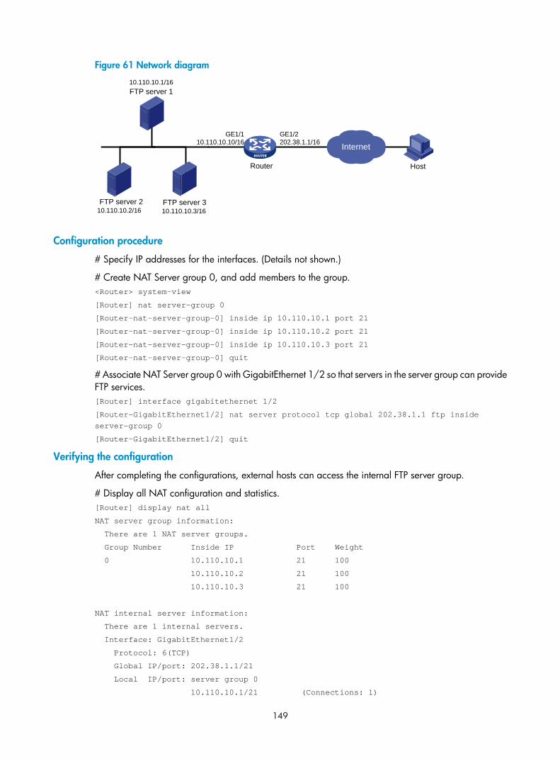
149
Figure 61 Network diagram
Configuration procedure
# Specify IP addresses for the interfaces. (Details not shown.)
# Create NAT Server group 0, and add members to the group. <Router> system-view
[Router] nat server-group 0
[Router-nat-server-group-0] inside ip 10.110.10.1 port 21
[Router-nat-server-group-0] inside ip 10.110.10.2 port 21
[Router-nat-server-group-0] inside ip 10.110.10.3 port 21
[Router-nat-server-group-0] quit
# Associate NAT Server group 0 with GigabitEthernet 1/2 so that servers in the server group can provide FTP services. [Router] interface gigabitethernet 1/2
[Router-GigabitEthernet1/2] nat server protocol tcp global 202.38.1.1 ftp inside server-group 0
[Router-GigabitEthernet1/2] quit
Verifying the configuration
After completing the configurations, external hosts can access the internal FTP server group.
# Display all NAT configuration and statistics. [Router] display nat all
NAT server group information:
There are 1 NAT server groups.
Group Number Inside IP Port Weight
0 10.110.10.1 21 100
10.110.10.2 21 100
10.110.10.3 21 100
NAT internal server information:
There are 1 internal servers.
Interface: GigabitEthernet1/2
Protocol: 6(TCP)
Global IP/port: 202.38.1.1/21
Local IP/port: server group 0
10.110.10.1/21 (Connections: 1)
FTP server 210.110.10.2/16
FTP server 110.110.10.1/16
FTP server 310.110.10.3/16
Host
InternetGE1/1
10.110.10.10/16GE1/2202.38.1.1/16
Router

150
10.110.10.2/21 (Connections: 2)
10.110.10.3/21 (Connections: 2)
NAT logging:
Log enable : Disabled
Flow-begin : Disabled
Flow-end : Disabled
Flow-active: Disabled
NAT mapping behavior:
Mapping mode: Address and Port-Dependent
ACL : ---
NAT ALG:
DNS: Enabled
FTP: Enabled
H323: Enabled
ICMP-ERROR: Enabled
# Use the display nat session verbose command to display NAT session information generated when external hosts access an internal FTP server. [Router] display nat session verbose
Initiator:
Source IP/port: 202.38.1.25/53957
Destination IP/port: 202.38.1.1/21
VPN instance/VLAN ID/VLL ID: -/-/-
Protocol: TCP(6)
Responder:
Source IP/port: 10.110.10.3/21
Destination IP/port: 202.38.1.25/53957
VPN instance/VLAN ID/VLL ID: -/-/-
Protocol: TCP(6)
State: TCP_ESTABLISHED
Application: FTP
Start time: 2012-08-16 11:06:07 TTL: 26s
Interface(in) : GigabitEthernet1/2
Interface(out): GigabitEthernet1/1
Initiator->Responder: 1 packets 60 bytes
Responder->Initiator: 2 packets 120 bytes
Total sessions found: 5
NAT with DNS mapping configuration example Network requirements
As shown in Figure 62, the internal Web server at 10.110.10.1/16 and FTP server at 10.110.10.2/16 provide services for external user. The company has three public addresses 202.38.1.1 through 202.38.1.3. The DNS server at 202.38.1.4 is on the external network.

151
Configure NAT so that:
• The public IP address 202.38.1.2 is used by external users to access the Web and FTP servers.
• External users can use the public address or domain name of internal servers to access them.
• Internal users can access the internal servers by using their domain names.
Figure 62 Network diagram
Configuration considerations
• Configure NAT Server by mapping the internal IP addresses and port numbers of the internal servers to a public address and port numbers so that external users can access the interval servers.
• Configure NAT with DNS mapping and ALG so that the external IP address of the internal server in the payload of the DNS response packet can be translated to the internal IP address.
Configuration procedure
# Specify IP addresses for the interfaces. (Details not shown.)
# Enable NAT with ALG and DNS. <Router> system-view
[Router] nat alg dns
# Enter interface view of GigabitEthernet 1/2. [Router] interface gigabitethernet 1/2
# Configure NAT Server to allow external hosts to access the internal Web server by using the address 202.38.1.2. [Router-GigabitEthernet1/2] nat server protocol tcp global 202.38.1.2 inside 10.110.10.1 www
# Configure NAT Server to allow external hosts to access the internal FTP server by using the address 202.38.1.2. [Router-GigabitEthernet1/2] nat server protocol tcp global 202.38.1.2 inside 10.110.10.2 ftp
# Enable outbound NAT with Easy IP on interface GigabitEthernet 1/2. [Router-GigabitEthernet1/2] nat outbound
[Router-GigabitEthernet1/2] quit
# Configure two DNS mapping entries by mapping the domain name www.server.com of the Web server to 202.38.1.2, and ftp.server.com of the FTP server to 202.38.1.2. [Router] nat dns-map domain www.server.com protocol tcp ip 202.38.1.2 port www
[Router] nat dns-map domain ftp.server.com protocol tcp ip 202.38.1.2 port ftp
[Router] quit
FTP server 10.110.10.2/16
Host A10.110.10.3/16
InternetGE1/1
10.110.10.10/16GE1/2202.38.1.1/24
Router
Web server 10.110.10.1/16
DNS server 202.38.1.4/24
Host B202.38.1.10/24

152
Verifying the configuration
After completing the configurations, both internal and external hosts can access the internal servers by using domain names.
# Display all NAT configuration and statistics. [Router] display nat all
NAT outbound information:
There are 1 NAT outbound rules.
Interface: GigabitEthernet1/2
ACL: --- Address group: --- Port-preserved: N
NO-PAT: N Reversible: N
NAT internal server information:
There are 2 internal servers.
Interface: GigabitEthernet1/2
Protocol: 6(TCP)
Global IP/port: 202.38.1.2/21
Local IP/port: 10.110.10.2/21
Interface: GigabitEthernet1/2
Protocol: 6(TCP)
Global IP/port: 202.38.1.2/80
Local IP/port: 10.110.10.1/80
NAT DNS mapping information:
There are 2 NAT DNS mappings.
Domain name: ftp.server.com
Global IP : 202.38.1.2
Global port: 21
Protocol : TCP(6)
Domain name: www.server.com
Global IP : 202.38.1.2
Global port: 80
Protocol : TCP(6)
NAT logging:
Log enable : Disabled
Flow-begin : Disabled
Flow-end : Disabled
Flow-active: Disabled
NAT mapping behavior:
Mapping mode: Address and Port-Dependent
ACL : ---
NAT ALG:
DNS: Enabled
FTP: Enabled

153
H323: Enabled
ICMP-ERROR: Enabled

154
Basic IP forwarding on the device
Upon receiving a packet, the device uses the destination IP address of the packet to find a match from the forwarding information base (FIB) table, and then uses the matching entry to forward the packet.
FIB table A device selects optimal routes from the routing table, and puts them into the FIB table. Each FIB entry specifies the next hop IP address and output interface for packets destined for a specific subnet or host.
For more information about the routing table, see Layer 3—IP Routing Configuration Guide.
Use the display fib command to display FIB table entries. The following example displays the entire FIB table. <Sysname> display fib
Destination count: 4 FIB entry count: 4
Flag:
U:Useable G:Gateway H:Host B:Blackhole D:Dynamic S:Static
R:Relay F:FRR
Destination/Mask Nexthop Flag OutInterface/Token Label
10.2.0.0/16 10.2.1.1 U GE0/1 Null
10.2.1.1/32 127.0.0.1 UH InLoop0 Null
127.0.0.0/8 127.0.0.1 U InLoop0 Null
127.0.0.1/32 127.0.0.1 UH InLoop0 Null
A FIB entry includes the following items:
• Destination—Destination IP address.
• Mask—Network mask. The mask and the destination address identity the destination network. A logical AND operation between the destination address and the network mask yields the address of the destination network. For example, if the destination address is 192.168.1.40 and the mask 255.255.255.0, the address of the destination network is 192.168.1.0. A network mask comprises a certain number of consecutive 1s. It can be expressed in dotted decimal format or by the number of the 1s.
• Nexthop—IP address of the next hop.
• Flag—Route flag.
• OutInterface—Output interface.
• Token—MPLS Label Switched Path index number.
• Label—Inner label.
Displaying FIB table entries Execute display commands in any view.

155
Task Command
Display FIB entries. display fib [ vpn-instance vpn-instance-name ] [ ip-address [ mask | mask-length ] ]

156
Configuring fast forwarding
Overview Fast forwarding reduces route lookup time and improves packet forwarding efficiency by using a high-speed cache and data-flow-based technology. It identifies a data flow by using five fields: source IP address, source port number, destination IP address, destination port number, and protocol number. After the first packet of a flow is forwarded through the routing table, fast forwarding creates an entry for the flow and uses the entry to forward subsequent packets of the flow.
Fast forwarding can process fragmented IP packets, but it does not fragment IP packets.
Configuration procedure To configure fast forwarding:
Step Command Remarks
1. Enter system view. system-view N/A
2. Enable fast forwarding. ip fast-forwarding By default, fast forwarding is enabled.
3. Configure the aging time of fast forwarding entries.
ip fast-forwarding aging-time aging-time
By default, the aging time is 30 seconds.
Displaying and maintaining fast forwarding Execute display commands in any view and reset commands in user view.
Task Command
Display fast forwarding table information (MSR 2600/MSR 3600).
display ip fast-forwarding cache [ ip-address ]
Display fast forwarding table information (MSR 5600).
display ip fast-forwarding cache [ ip-address ] [ slot slot-number ]
Display fast forwarding table information about fragmented packets (MSR 2600/MSR 3600).
display ip fast-forwarding fragcache [ ip-address ]
Display fast forwarding table information about fragmented packets (MSR 5600).
display ip fast-forwarding fragcache [ ip-address ] [ slot slot-number ]
Display the aging time of fast forwarding entries. display ip fast-forwarding aging-time
Clear fast forwarding table information (MSR 2600/MSR 3600). reset ip fast-forwarding cache
Clear fast forwarding table information (MSR 5600). reset ip fast-forwarding cache [ slot slot-number ]

157
Fast forwarding configuration example
Network requirements Enable fast forwarding on Router B.
Figure 63 Network diagram
Configuration procedure 1. Configure Router A:
# Configure the IP address of interface Ethernet 1/1. <RouterA> system-view
[RouterA] interface ethernet1/1
[RouterA-Ethernet1/1] ip address 11.1.1.1 255.0.0.0
[RouterA-Ethernet1/1] quit
# Configure a static route. [RouterA] ip route-static 22.1.1.0 255.0.0.0 11.1.1.2
2. Configure Router C:
# Configure the IP address of interface Ethernet 1/2. <RouterC> system-view
[RouterC] interface ethernet 1/2
[RouterC-Ethernet1/2] ip address 22.1.1.2 255.0.0.0
[RouterC-Ethernet1/2] quit
# Configure a static route. [RouterC] ip route-static 11.1.1.0 255.0.0.0 22.1.1.1
3. Configure Router B:
# Enable fast forwarding. <RouterB> system-view
[RouterB] ip fast-forwarding
# Configure the IP addresses of interfaces Ethernet 1/1 and Ethernet 1/2. [RouterB] interface ethernet1/1
[RouterB-Ethernet1/1] ip address 11.1.1.2 255.0.0.0
[RouterB-Ethernet1/1] quit
[RouterB] interface ethernet 1/2
[RouterB-Ethernet1/2] ip address 22.1.1.1 255.0.0.0
[RouterB-Ethernet1/2] quit
Router A Router CRouter B
Eth1/111.1.1.1/8
Eth1/111.1.1.2/8
Eth1/222.1.1.1/8
Eth1/222.1.1.2/8
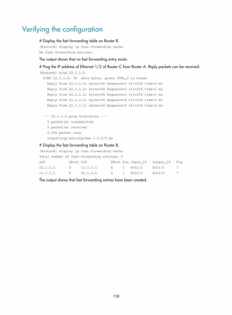
158
Verifying the configuration # Display the fast forwarding table on Router B. [RouterB] display ip fast-forwarding cache
No fast-forwarding entries.
The output shows that no fast forwarding entry exists.
# Ping the IP address of Ethernet 1/2 of Router C from Router A. Reply packets can be received. [RouterA] ping 22.1.1.2
PING 22.1.1.2: 56 data bytes, press CTRL_C to break
Reply from 22.1.1.2: bytes=56 Sequence=1 ttl=254 time=2 ms
Reply from 22.1.1.2: bytes=56 Sequence=2 ttl=254 time=1 ms
Reply from 22.1.1.2: bytes=56 Sequence=3 ttl=254 time=1 ms
Reply from 22.1.1.2: bytes=56 Sequence=4 ttl=254 time=2 ms
Reply from 22.1.1.2: bytes=56 Sequence=5 ttl=254 time=2 ms
--- 22.1.1.2 ping statistics ---
5 packet(s) transmitted
5 packet(s) received
0.00% packet loss
round-trip min/avg/max = 2/2/3 ms
# Display the fast forwarding table on Router B. [RouterB] display ip fast-forwarding cache
Total number of fast-forwarding entries: 2
SIP SPort DIP DPort Pro Input_If Output_If Flg
22.1.1.2 0 11.1.1.1 0 1 Eth1/2 Eth1/1 7
11.1.1.1 8 22.1.1.2 0 1 Eth1/1 Eth1/2 7
The output shows that fast forwarding entries have been created.

159
Displaying the adjacency table
The adjacency table stores information about directly connected neighbors for IP forwarding. The neighbor information in the adjacency table in this chapter refers to non-Ethernet neighbor information.
This table is not user configurable. The neighbor information is generated, updated, and deleted by link layer protocols through negotiation (such as PPP dynamic negotiation) or through manual configuration (such as ATM static configuration). An adjacency entry contains the neighbor network layer address (next hop), output interface, link layer protocol type, and link layer address (PVC for ATM, unavailable for PPP).
When forwarding an IP packet, the device searches the FIB to find the output interface and next hop, and then uses the output interface and next hop address to search the adjacency table for link layer forwarding information that is required for forwarding the packet.
NOTE:
Ethernet neighbor information and non-Ethernet neighbor information are stored and managed together.
The following table shows the items contained in an adjacency table output:
Item Description
IP address IP address of the next hop in FIB table for packet forwarding. This address is used for adjacency table lookup.
Routing interface Output interface in the matching route entry. This interface is used for adjacency table lookup, and it can be logical or physical.
Physical interface
Output physical interface that sends matching packets. If the routing interface is physical, the routing interface and physical interface are the same. If the routing interface is logical, the routing interface and physical interface are different.
Logical interface Logical interface for sending packets, such as a virtual-Ethernet interface for ATM, or a Virtual-Template interface for MP.
Service type Link layer protocol type, such as PPP or HDLC.
Action type Action to be taken on the matching packet: Forwarding or Drop.
Link media type Related to the link layer protocol used by the routing interface. P2P indicates a point-to-point link and NBMA indicates a non-broadcast multi-access link.
Link head information(IP) Link layer header for IP forwarding.
Link head information(IPv6) Link layer header for IPv6 forwarding.
Link head information(MPLS) Link layer header for MPLS forwarding.
To display adjacency table entries, use one of the following commands as appropriate in any view:
Task Command
Display IPv4 adjacency table information.
display adjacent-table { all | physical-interface interface-type interface-number | routing-interface interface-type interface-number | slot slot-number } [ count | verbose ]

160
Task Command
Display IPv6 adjacency table information.
display ipv6 adjacent-table { all | physical-interface interface-type interface-number | routing-interface interface-type interface-number | slot slot-number } [ count | verbose ]

161
Optimizing IP performance
A customized configuration can help optimize overall IP performance. This chapter describes various techniques you can use to customize your installation.
Enabling an interface to receive and forward directed broadcasts destined for the directly connected network
A directed broadcast packet is destined for all hosts on a specific network. In the destination IP address of the directed broadcast, the network ID identifies the target network, and the host ID is made up of all ones.
If an interface is allowed to forward directed broadcasts destined for the directly connected network, hackers can exploit this vulnerability to attack the target network. In some scenarios, however, an interface must receive and send such directed broadcast packets to support UDP helper and Wake on LAN.
This task enables an interface to accept directed broadcast packets that are destined for and received from the directly connected network to support UDP helper, which converts the directed broadcasts to unicasts and forwards them to a specific server.
The task also enables the interface to forward directed broadcast packets that are destined for the directly connected network and are received from another subnet to support Wake on LAN, which sends the directed broadcasts to wake up the hosts on the target network.
Configuration procedure To enable an interface to receive and forward directed broadcasts destined to the directly connected network:
Step Command Remarks 1. Enter system view. system-view N/A
2. Enter interface view. interface interface-type interface-number N/A
3. Enable the interface to receive and forward directed broadcasts destined for the directly connected network.
ip forward-broadcast
By default, an interface cannot receive or forward directed broadcasts destined for the directly connected network.
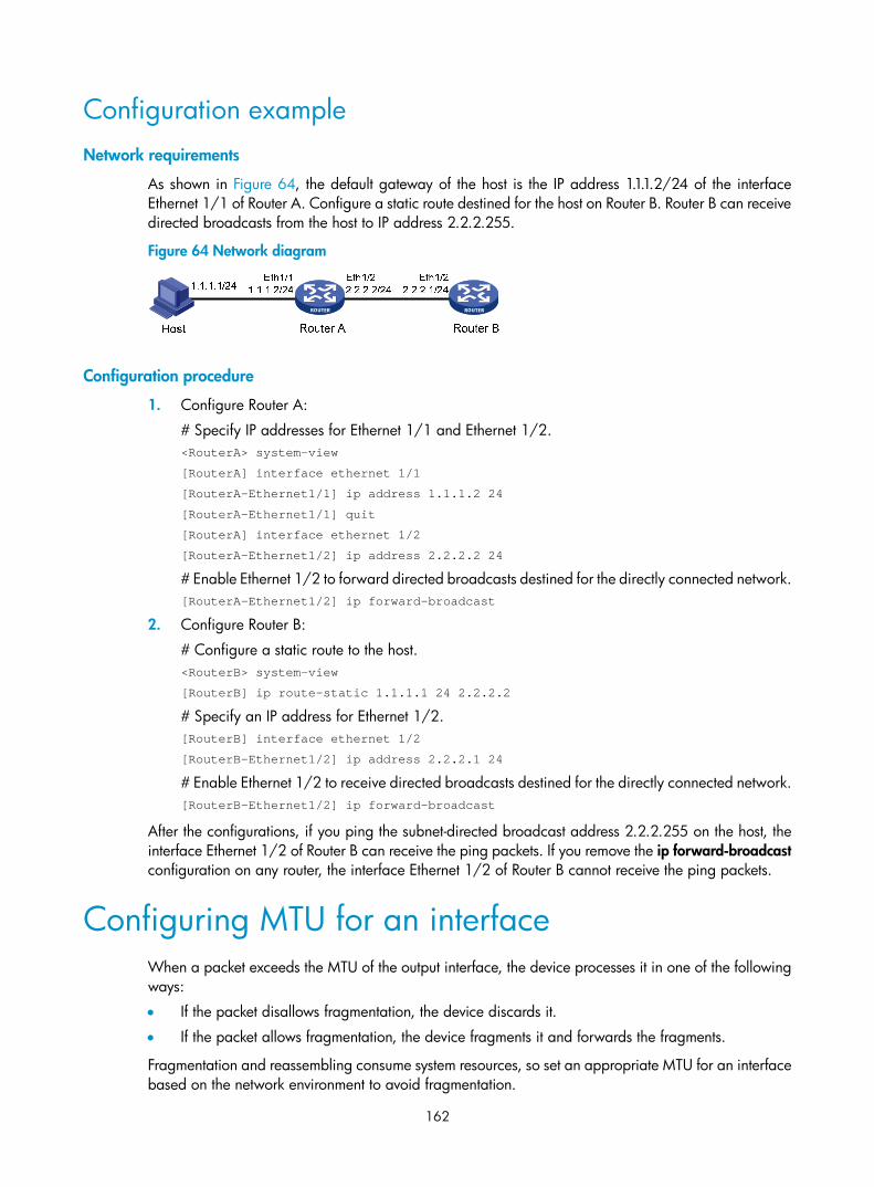
162
Configuration example Network requirements
As shown in Figure 64, the default gateway of the host is the IP address 1.1.1.2/24 of the interface Ethernet 1/1 of Router A. Configure a static route destined for the host on Router B. Router B can receive directed broadcasts from the host to IP address 2.2.2.255.
Figure 64 Network diagram
Configuration procedure
1. Configure Router A:
# Specify IP addresses for Ethernet 1/1 and Ethernet 1/2. <RouterA> system-view
[RouterA] interface ethernet 1/1
[RouterA-Ethernet1/1] ip address 1.1.1.2 24
[RouterA-Ethernet1/1] quit
[RouterA] interface ethernet 1/2
[RouterA-Ethernet1/2] ip address 2.2.2.2 24
# Enable Ethernet 1/2 to forward directed broadcasts destined for the directly connected network. [RouterA-Ethernet1/2] ip forward-broadcast
2. Configure Router B:
# Configure a static route to the host. <RouterB> system-view
[RouterB] ip route-static 1.1.1.1 24 2.2.2.2
# Specify an IP address for Ethernet 1/2. [RouterB] interface ethernet 1/2
[RouterB-Ethernet1/2] ip address 2.2.2.1 24
# Enable Ethernet 1/2 to receive directed broadcasts destined for the directly connected network. [RouterB-Ethernet1/2] ip forward-broadcast
After the configurations, if you ping the subnet-directed broadcast address 2.2.2.255 on the host, the interface Ethernet 1/2 of Router B can receive the ping packets. If you remove the ip forward-broadcast configuration on any router, the interface Ethernet 1/2 of Router B cannot receive the ping packets.
Configuring MTU for an interface When a packet exceeds the MTU of the output interface, the device processes it in one of the following ways:
• If the packet disallows fragmentation, the device discards it.
• If the packet allows fragmentation, the device fragments it and forwards the fragments.
Fragmentation and reassembling consume system resources, so set an appropriate MTU for an interface based on the network environment to avoid fragmentation.

163
To configure an MTU for an interface:
Step Command Remarks
1. Enter system view. system-view N/A
2. Enter interface view. interface interface-type interface-number
N/A
3. Configure an MTU for the interface. ip mtu mtu-size By default, no MTU is configured.
Configuring TCP MSS for an interface The maximum segment size (MSS) option informs the receiver of the largest segment that the sender can accept. Each end announces its MSS during TCP connection establishment. If the size of a TCP segment is smaller than the MSS of the receiver, TCP sends the TCP segment without fragmentation. If not, it fragments the segment according to the receiver's MSS.
If you configure a TCP MSS on an interface, the size of each TCP segment received or sent on the interface cannot exceed the MSS value.
This configuration takes effect only for TCP connections established after the configuration rather than the TCP connections that already exist.
This configuration is effective only for IP packets. If MPLS is enabled on the interface, do not configure the TCP MSS on the interface.
To configure a TCP MSS of the interface:
Step Command Remarks
1. Enter system view. system-view N/A
2. Enter interface view. interface interface-type interface-number N/A
3. Configure a TCP MSS for the interface. tcp mss value By default, no TCP MSS is configured.
Configuring TCP path MTU discovery IMPORTANT:
All the devices on a TCP connection must be enabled to send ICMP error messages by using the ip unreachables enable command.
TCP path MTU discovery (in RFC 1191) discovers the path MTU between the source and destination ends of a TCP connection. It works as follows:
1. A TCP source device sends a packet with the Don't Fragment (DF) bit set.
2. A router that fails to forward the packet because it exceeds the MTU on the outgoing interface discards the packet and returns an ICMP error message, which contains the MTU of the outgoing interface.

164
3. Upon receiving the ICMP message, the TCP source device calculates the current path MTU of the TCP connection.
4. The TCP source device sends subsequent TCP segments that each are smaller than the MSS (MSS = path MTU – IP header length – TCP header length).
If the TCP source device still receives ICMP error messages when the MSS is smaller than 32 bytes, the TCP source device will fragment packets.
An ICMP error message received from a router that does not support RFC 1191 has the MTU of the outgoing interface set to 0. Upon receiving the ICMP message, the TCP source device selects the path MTU smaller than the current path MTU from the MTU table as described in RFC 1191 to calculate the TCP MSS. The MTU table contains MTUs of 68, 296, 508, 1006, 1280, 1492, 2002, 4352, 8166, 17914, 32000, and 65535 bytes. Because the minimum TCP MSS specified by the system is 32 bytes, the actual minimum MTU is 72 bytes.
After you enable TCP path MTU discovery, all new TCP connections will detect the path MTU. The device uses the path MTU to calculate the MSS to avoid IP fragmentation.
The path MTU uses the following aging mechanism to make sure that the source device can increase the path MTU when the minimum link MTU on the path increases.
• When the TCP source device receives an ICMP error message, it reduces the path MTU and starts an age timer for the path MTU.
• After the age timer expires, the source device uses a larger MSS in the MTU table as described in RFC 1191.
• If no ICMP error message is received within two minutes, the source device increases the MSS again until the MSS is as large as the MSS negotiated during TCP three-way handshake.
To enable TCP path MTU discovery:
Step Command Remarks
1. Enter system view. system-view N/A
2. Enable TCP path MTU discovery.
tcp path-mtu-discovery [ aging age-time | no-aging ]
The default setting is disabled.
Enabling TCP SYN Cookie A TCP connection is established through a three-way handshake:
1. The sender sends a SYN packet to the server.
2. The server receives the SYN packet, establishes a TCP semi-connection in SYN_RECEIVED state, and replies with a SYN ACK packet to the sender.
3. The sender receives the SYN ACK packet and replies with an ACK packet. A TCP connection is established.
An attacker can exploit this mechanism to mount SYN Flood attacks. The attacker sends a large number of SYN packets, but does not respond to the SYN ACK packets from the server. As a result, the server establishes a large number of TCP semi-connections and can no longer handle normal services.
SYN Cookie can protect the server from SYN Flood attacks. When the server receives a SYN packet, it responds with a SYN ACK packet without establishing a TCP semi-connection. The server establishes a TCP connection and enters ESTABLISHED state only when it receives an ACK packet from the client.

165
To enable TCP SYN Cookie:
Step Command Remarks
1. Enter system view. system-view N/A
2. Enable SYN Cookie. tcp syn-cookie enable The default setting is disabled.
Configuring the TCP buffer size Step Command Remarks
1. Enter system view. system-view N/A
2. Configure the size of TCP receive/send buffer. tcp window window-size The default buffer size is 64 KB.
Configuring TCP timers You can configure the following TCP timers:
• SYN wait timer—TCP starts the SYN wait timer after sending a SYN packet. If no response packet is received within the SYN wait timer interval, TCP fails to establish the connection.
• FIN wait timer—TCP starts the FIN wait timer when the state changes to FIN_WAIT_2. If no FIN packet is received within the timer interval, TCP terminates the connection. If a FIN packet is received, TCP changes connection state to TIME_WAIT. If a non-FIN packet is received, TCP restarts the timer, and tears down the connection when the timer expires.
To configure TCP timers:
Step Command Remarks
1. Enter system view. system-view N/A
2. Configure TCP timers.
• Configure the TCP SYN wait timer: tcp timer syn-timeout time-value
• Configure the TCP FIN wait timer: tcp timer fin-timeout time-value
By default: • The TCP SYN wait timer is 75
seconds. • The TCP FIN wait timer is 675
seconds.
Enabling sending ICMP error packets Perform this task to enable sending ICMP error packets, including redirect, time-exceeded, and destination unreachable packets.
• ICMP redirect packets
A host that has only one default route sends all packets to the default gateway. The default gateway sends an ICMP redirect packet to inform the host of a correct next hop by following these rules:
The receiving and sending interfaces are the same.
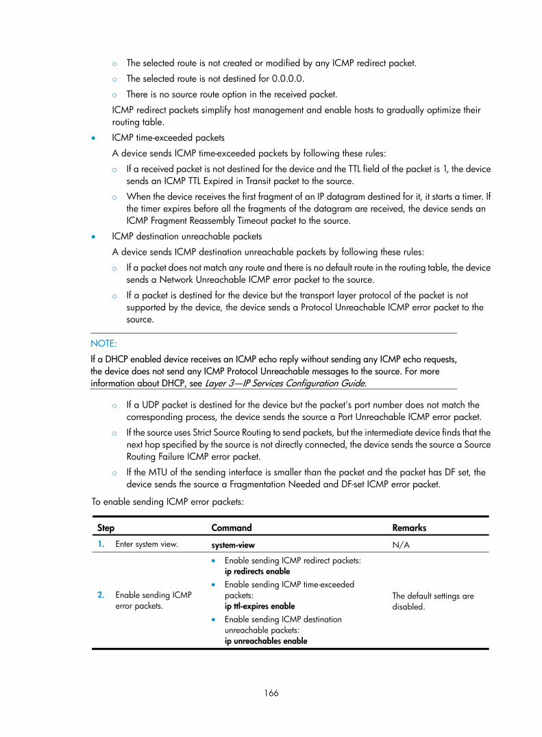
166
The selected route is not created or modified by any ICMP redirect packet.
The selected route is not destined for 0.0.0.0.
There is no source route option in the received packet.
ICMP redirect packets simplify host management and enable hosts to gradually optimize their routing table.
• ICMP time-exceeded packets
A device sends ICMP time-exceeded packets by following these rules:
If a received packet is not destined for the device and the TTL field of the packet is 1, the device sends an ICMP TTL Expired in Transit packet to the source.
When the device receives the first fragment of an IP datagram destined for it, it starts a timer. If the timer expires before all the fragments of the datagram are received, the device sends an ICMP Fragment Reassembly Timeout packet to the source.
• ICMP destination unreachable packets
A device sends ICMP destination unreachable packets by following these rules:
If a packet does not match any route and there is no default route in the routing table, the device sends a Network Unreachable ICMP error packet to the source.
If a packet is destined for the device but the transport layer protocol of the packet is not supported by the device, the device sends a Protocol Unreachable ICMP error packet to the source.
NOTE:
If a DHCP enabled device receives an ICMP echo reply without sending any ICMP echo requests, the device does not send any ICMP Protocol Unreachable messages to the source. For more information about DHCP, see Layer 3—IP Services Configuration Guide.
If a UDP packet is destined for the device but the packet's port number does not match the corresponding process, the device sends the source a Port Unreachable ICMP error packet.
If the source uses Strict Source Routing to send packets, but the intermediate device finds that the next hop specified by the source is not directly connected, the device sends the source a Source Routing Failure ICMP error packet.
If the MTU of the sending interface is smaller than the packet and the packet has DF set, the device sends the source a Fragmentation Needed and DF-set ICMP error packet.
To enable sending ICMP error packets:
Step Command Remarks
1. Enter system view. system-view N/A
2. Enable sending ICMP error packets.
• Enable sending ICMP redirect packets: ip redirects enable
• Enable sending ICMP time-exceeded packets: ip ttl-expires enable
• Enable sending ICMP destination unreachable packets: ip unreachables enable
The default settings are disabled.

167
Sending ICMP error packets facilitates network management, but sending excessive ICMP packets increases network traffic. A device's performance degrades if it receives a lot of malicious ICMP packets that cause it to respond with ICMP error packets.
To prevent such problems, you can disable the device from sending ICMP error packets. A device disabled from sending ICMP time-exceeded packets does not send ICMP TTL Expired packets but can still send ICMP Fragment Reassembly Timeout packets.
Configuring rate limit for ICMP error messages To avoid sending excessive ICMP error messages within a short period that might cause network congestion, you can limit the rate at which ICMP error messages are sent. A token bucket algorithm is used with one token representing one ICMP error message. Tokens are placed in the bucket at a specific interval until the maximum number of tokens that the bucket can hold is reached. Tokens are removed from the bucket when ICMP error messages are sent. When the bucket is empty, ICMP error messages are not sent until a new token is placed in the bucket.
To configure rate limit for ICMP error messages:
Step Command Remarks
1. Enter system view. system-view N/A
2. Set the interval and bucket size for ICMP error messages
ip icmp error-interval milliseconds [ bucketsize ]
By default, the bucket allows a maximum of 10 tokens, and tokens are placed in the bucket at the interval of 100 milliseconds.
To disable the ICMP rate limit, set the interval to 0 milliseconds.
Specifying the source address for ICMP packets Perform this task to specify the source IP address for outgoing ping echo request and ICMP error messages. It is a good practice to specify the IP address of the loopback interface as the source IP address. This feature helps users to locate the sending device easily.
If you specify an IP address in the ping command, ping echo requests use the specified address as the source IP address rather than the IP address specified by the ip icmp source command.
To specify the source IP address for ICMP packets:
Step Command Remarks
1. Enter system view. system-view N/A
2. Specify the source address for outgoing ICMP packets.
ip icmp source [ vpn-instance vpn-instance-name ] ip-address
By default, the device uses the IP address of the sending interface as the source IP address for outgoing ICMP packets.

168
Configuring IP virtual fragment reassembly To make sure fragments arrive at a service module in order, the IP virtual fragment reassembly feature virtually reassembles the fragments of a datagram through sequencing and caching. The IP virtual fragment reassembly feature also prevents some service modules (such as IPsec, NAT, and firewall) from processing packet fragments that do not arrive in order.
For security purposes, the IP virtual fragment reassembly feature can detect the following types of fragment attacks, and discard the attack fragments:
• Tiny fragment attack—If the first fragment of an incoming datagram is smaller than the Layer 4 (such as TCP and UDP) header and the Layer 4 header is placed into the second fragment, a tiny fragment attack occurs.
• Overlapping fragment attack—If two consecutive incoming fragments are identical or overlap each other, an overlapping fragment attack occurs.
• Buffer overflow attack—If the number of concurrent reassemblies or the number of fragments per datagram exceeds the upper limits, a buffer overflow attack occurs.
Configuration guidelines • The IP virtual fragment reassembly feature only applies to incoming packets on an interface.
• The IP virtual fragment reassembly feature does not support load sharing. The fragments of an IP datagram cannot arrive through different interfaces.
Configuration procedure To configure IP virtual fragment reassembly:
Step Command Remarks
1. Enter system view. system-view N/A
2. Enter interface view. interface interface-type interface-number N/A
3. Enable IP virtual fragment reassembly.
ip virtual-reassembly [ drop-fragments | max-fragments number | max-reassemblies number | timeout seconds ] *
By default, the feature is disabled.
Configuration example Network requirements
As shown in Figure 65, configure devices as follows:
• Router A connects to Host and Router B.
• NAT is enabled on Ethernet 1/2 of Router A.
• Configure IP virtual fragment reassembly on Ethernet 1/2 of Router A.

169
Figure 65 Network diagram
Configuration procedure
1. Configure routes so that the Host, Router A, and Router B can communicate with each other. (Details not shown.)
2. On Router A, configure NAT and IP virtual fragment reassembly. <RouterA> system-view
[RouterA] nat static inbound 11.2.2.3 10.1.1.1
[RouterA] interface ethernet 1/2
[RouterA-Ethernet1/2] nat outbound
[RouterA-Ethernet1/2] ip virtual-reassembly
Verifying the configuration
Router A checks, sequences, and caches fragments that do not arrive in order at Ethernet 1/2. You can use the display ip virtual-reassembly command to display related information.
Displaying and maintaining IP performance optimization
Execute display commands in any view and reset commands in user view.
Task Command
Display brief information about RawIP connections (MSR 2600/MSR 3600). display rawip
Display brief information about RawIP connections (MSR 5600). display rawip [ slot slot-number ]
Display detailed information about RawIP connections (MSR 2600/MSR 3600). display rawip verbose [ pcb pcb-index ]
Display detailed information about RawIP connections (MSR 5600).
display rawip verbose [ slot slot-number [ pcb pcb-index ] ]
Display brief information about TCP connections (MSR 2600/MSR 3600). display tcp
Display brief information about TCP connections (MSR 5600). display tcp [ slot slot-number ]
Display detailed information about TCP connections (MSR 2600/MSR 3600).
display tcp verbose [ pcb pcb-index ]
Display detailed information about TCP connections (MSR 5600).
display tcp verbose [ slot slot-number [ pcb pcb-index ] ]
Display brief information about UDP connections (MSR 2600/MSR 3600).
display udp
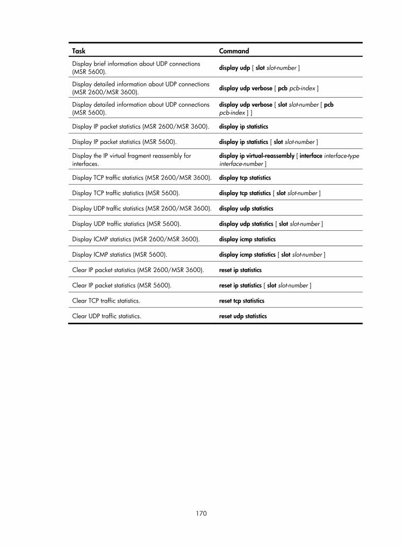
170
Task Command
Display brief information about UDP connections (MSR 5600).
display udp [ slot slot-number ]
Display detailed information about UDP connections (MSR 2600/MSR 3600).
display udp verbose [ pcb pcb-index ]
Display detailed information about UDP connections (MSR 5600).
display udp verbose [ slot slot-number [ pcb pcb-index ] ]
Display IP packet statistics (MSR 2600/MSR 3600). display ip statistics
Display IP packet statistics (MSR 5600). display ip statistics [ slot slot-number ]
Display the IP virtual fragment reassembly for interfaces.
display ip virtual-reassembly [ interface interface-type interface-number ]
Display TCP traffic statistics (MSR 2600/MSR 3600). display tcp statistics
Display TCP traffic statistics (MSR 5600). display tcp statistics [ slot slot-number ]
Display UDP traffic statistics (MSR 2600/MSR 3600). display udp statistics
Display UDP traffic statistics (MSR 5600). display udp statistics [ slot slot-number ]
Display ICMP statistics (MSR 2600/MSR 3600). display icmp statistics
Display ICMP statistics (MSR 5600). display icmp statistics [ slot slot-number ]
Clear IP packet statistics (MSR 2600/MSR 3600). reset ip statistics
Clear IP packet statistics (MSR 5600). reset ip statistics [ slot slot-number ]
Clear TCP traffic statistics. reset tcp statistics
Clear UDP traffic statistics. reset udp statistics

171
Configuring UDP helper
Overview UDP helper enables a device to convert received UDP broadcast packets into unicast packets and forward them to a specific server. UDP helper is suitable for the scenario where hosts cannot obtain configuration information or device names by broadcasting packets because the target server or host resides on another broadcast domain.
Upon receiving a UDP broadcast packet (the destination address is 255.255.255.255 or a directed broadcast address destined for the network directly connected to the receiving interface), UDP helper matches the UDP destination port number of the packet against the configured UDP ports.
• If a match is found, UDP helper modifies the destination IP address of the packet and sends the packet to the specified destination server.
• If no match is found, UDP helper sends the packet to the upper layer protocol.
Configuration guidelines Follow these guidelines when you configure UDP helper:
• By default, an interface does not receive directed broadcasts destined for the directly connected network. To use UDP helper, execute the ip forward-broadcast command in interface view. For more information about receiving directed broadcasts destined for the directly connected network, see "Optimizing IP performance."
• Do not set UDP ports 67 and 68 for UDP helper because UDP helper cannot forward DHCP broadcast packets.
• You can specify up to 256 UDP ports for UDP helper.
• Specify destination servers on the interface that receives broadcast packets. You can specify up to 20 destination servers on an interface.
Configuration procedure Step Command Remarks
1. Enter system view. system-view N/A
2. Enable UDP helper. udp-helper enable By default, UDP helper is disabled.
3. Specify a UDP port. udp-helper port { port-number | dns | netbios-ds | netbios-ns | tacacs | tftp | time }
By default, no UDP port is specified.
4. Enter interface view. interface interface-type interface-number N/A
5. Specify a destination server. udp-helper server ip-address
By default, no destination server is specified.

172
Displaying and maintaining UDP helper Execute display command in any view and reset command in user view.
Task Command
Display information about packets forwarded by UDP helper. display udp-helper interface interface-type interface-number
Clear UDP helper statistics. reset udp-helper statistics
UDP helper configuration example
Network requirements As shown in Figure 66, configure UDP helper on Router A to forward broadcast packets with UDP destination port 55 and destination IP address 255.255.255.255 or 10.110.255.255 to the destination server 10.2.1.1/16.
Figure 66 Network diagram
Configuration procedure Make sure Router A can reach the subnet 10.2.0.0/16.
# Enable UDP helper. <RouterA> system-view
[RouterA] udp-helper enable
# Enable UDP helper to forward broadcast packets with the UDP destination port 55. [RouterA] udp-helper port 55
# Specify the destination server 10.2.1.1 on the interface Ethernet 1/1. [RouterA] interface ethernet 1/1
[RouterA-Ethernet1/1] ip address 10.110.1.1 16
[RouterA-Ethernet1/1] udp-helper server 10.2.1.1

173
Verifying the configuration # Display information about UDP packets forwarded by UDP helper on the interface Ethernet 1/1. [RouterA-Ethernet1/1] display udp-helper interface ethernet 1/1
Interface Server address Packets sent
Ethernet1/1 10.2.1.1 5

174
Configuring basic IPv6 settings
Overview IPv6, also called IP next generation (IPng), was designed by the IETF as the successor to IPv4. One significant difference between IPv6 and IPv4 is that IPv6 increases the IP address size from 32 bits to 128 bits.
IPv6 features Simplified header format
IPv6 removes several IPv4 header fields or moves them to the IPv6 extension headers to reduce the length of the basic IPv6 packet header. The basic IPv6 packet header has a fixed length of 40 bytes to simplify IPv6 packet handling and improve forwarding efficiency. Although the IPv6 address size is four times the IPv4 address size, the basic IPv6 packet header size is only twice the size of the option-less IPv4 packet header.
Figure 67 IPv4 packet header format and basic IPv6 packet header format
Larger address space
IPv6 can provide 3.4 x 1038 addresses to meet the requirements of hierarchical address assignment for both public and private networks.
Hierarchical address structure
IPv6 uses a hierarchical address structure to speed up route lookup and reduce the IPv6 routing table size through route aggregation.
Address autoconfiguration
To simplify host configuration, IPv6 supports stateful and stateless address autoconfiguration.
175
• Stateful address autoconfiguration enables a host to acquire an IPv6 address and other configuration information from a server (for example, a DHCPv6 server). For more information about DHCPv6 server, see "Configuring DHCPv6 server."
• Stateless address autoconfiguration enables a host to automatically generate an IPv6 address and other configuration information by using its link-layer address and the prefix information advertised by a router.
To communicate with other hosts on the same link, a host automatically generates a link-local address based on its link-layer address and the link-local address prefix (FE80::/10).
Built-in security
IPv6 defines extension headers to support IPsec. IPsec provides end-to-end security and enhances interoperability among different IPv6 applications.
QoS support
The Flow Label field in the IPv6 header allows the device to label the packets of a specific flow for special handling.
Enhanced neighbor discovery mechanism
The IPv6 neighbor discovery protocol uses a group of ICMPv6 messages to manage information exchange among neighboring nodes on the same link. The group of ICMPv6 messages replaces ARP messages, ICMPv4 Router Discovery messages, and ICMPv4 Redirect messages and provides a series of other functions.
Flexible extension headers
IPv6 eliminates the Options field in the header and introduces optional extension headers to provide scalability and improve efficiency. The Options field in the IPv4 packet header contains up to 40 bytes, whereas the IPv6 extension headers are restricted to the maximum size of IPv6 packets.
IPv6 addresses IPv6 address formats
An IPv6 address is represented as a set of 16-bit hexadecimals separated by colons (:). An IPv6 address is divided into eight groups, and each 16-bit group is represented by four hexadecimal numbers, for example, 2001:0000:130F:0000:0000:09C0:876A:130B.
To simplify the representation of IPv6 addresses, you can handle zeros in IPv6 addresses by using the following methods:
• The leading zeros in each group can be removed. For example, the above address can be represented in a shorter format as 2001:0:130F:0:0:9C0:876A:130B.
• If an IPv6 address contains two or more consecutive groups of zeros, they can be replaced by a double colon (::). For example, the above address can be represented in the shortest format as 2001:0:130F::9C0:876A:130B.
NOTE:
A double colon can appear once or not at all in an IPv6 address. This limit allows the device to determine how many zeros the double colon represents and correctly convert it to zeros to restore a 128-bit IPv6 address.

176
An IPv6 address consists of an address prefix and an interface ID, which are equivalent to the network ID and the host ID of an IPv4 address.
An IPv6 address prefix is written in IPv6-address/prefix-length notation, where the prefix-length is a decimal number indicating how many leftmost bits of the IPv6 address includes the address prefix.
IPv6 address types
IPv6 addresses include the following types:
• Unicast address—An identifier for a single interface, similar to an IPv4 unicast address. A packet sent to a unicast address is delivered to the interface identified by that address.
• Multicast address—An identifier for a set of interfaces (typically belonging to different nodes), similar to an IPv4 multicast address. A packet sent to a multicast address is delivered to all interfaces identified by that address.
There are no broadcast addresses in IPv6. Their function is replaced by multicast addresses.
• Anycast address—An identifier for a set of interfaces (typically belonging to different nodes). A packet sent to an anycast address is delivered to the nearest interface among the interfaces identified by that address. The nearest interface is chosen according to the routing protocol' measure of distance.
The type of an IPv6 address is designated by the first several bits, called the format prefix. Table 9 lists the mappings between address types and format prefixes.
Table 6 Mappings between address types and format prefixes
Type Format prefix (binary) IPv6 prefix ID
Unicast address
Unspecified address 00...0 (128 bits) ::/128
Loopback address 00...1 (128 bits) ::1/128
Link-local address 1111111010 FE80::/10
Global unicast address Other forms N/A
Multicast address 11111111 FF00::/8
Anycast address Anycast addresses use the unicast address space and have the identical structure of unicast addresses.
Unicast addresses
Unicast addresses include global unicast addresses, link-local unicast addresses, the loopback address, and the unspecified address.
• Global unicast addresses—Equivalent to public IPv4 addresses, are provided for Internet service providers. This type of address allows for prefix aggregation to restrict the number of global routing entries.
• Link-local addresses—Used for communication among link-local nodes for neighbor discovery and stateless autoconfiguration. Packets with link-local source or destination addresses are not forwarded to other links.
• A loopback address—0:0:0:0:0:0:0:1 (or ::1). It has the same function as the loopback address in IPv4. It cannot be assigned to any physical interface. A node uses this address to send an IPv6 packet to itself.
• An unspecified address—0:0:0:0:0:0:0:0 (or ::). It cannot be assigned to any node. Before acquiring a valid IPv6 address, a node fills this address in the source address field of IPv6 packets. The unspecified address cannot be used as a destination IPv6 address.
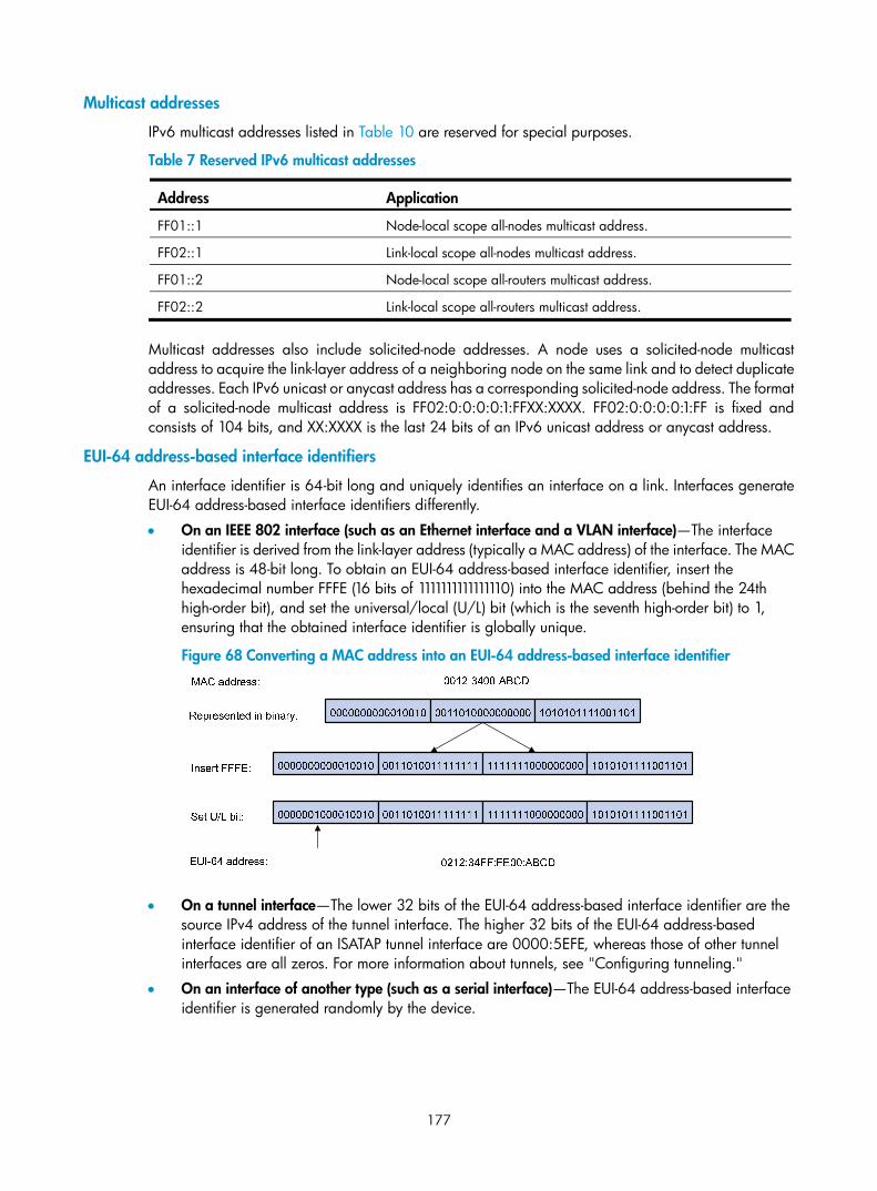
177
Multicast addresses
IPv6 multicast addresses listed in Table 10 are reserved for special purposes.
Table 7 Reserved IPv6 multicast addresses
Address Application
FF01::1 Node-local scope all-nodes multicast address.
FF02::1 Link-local scope all-nodes multicast address.
FF01::2 Node-local scope all-routers multicast address.
FF02::2 Link-local scope all-routers multicast address.
Multicast addresses also include solicited-node addresses. A node uses a solicited-node multicast address to acquire the link-layer address of a neighboring node on the same link and to detect duplicate addresses. Each IPv6 unicast or anycast address has a corresponding solicited-node address. The format of a solicited-node multicast address is FF02:0:0:0:0:1:FFXX:XXXX. FF02:0:0:0:0:1:FF is fixed and consists of 104 bits, and XX:XXXX is the last 24 bits of an IPv6 unicast address or anycast address.
EUI-64 address-based interface identifiers
An interface identifier is 64-bit long and uniquely identifies an interface on a link. Interfaces generate EUI-64 address-based interface identifiers differently.
• On an IEEE 802 interface (such as an Ethernet interface and a VLAN interface)—The interface identifier is derived from the link-layer address (typically a MAC address) of the interface. The MAC address is 48-bit long. To obtain an EUI-64 address-based interface identifier, insert the hexadecimal number FFFE (16 bits of 1111111111111110) into the MAC address (behind the 24th high-order bit), and set the universal/local (U/L) bit (which is the seventh high-order bit) to 1, ensuring that the obtained interface identifier is globally unique.
Figure 68 Converting a MAC address into an EUI-64 address-based interface identifier
• On a tunnel interface—The lower 32 bits of the EUI-64 address-based interface identifier are the source IPv4 address of the tunnel interface. The higher 32 bits of the EUI-64 address-based interface identifier of an ISATAP tunnel interface are 0000:5EFE, whereas those of other tunnel interfaces are all zeros. For more information about tunnels, see "Configuring tunneling."
• On an interface of another type (such as a serial interface)—The EUI-64 address-based interface identifier is generated randomly by the device.
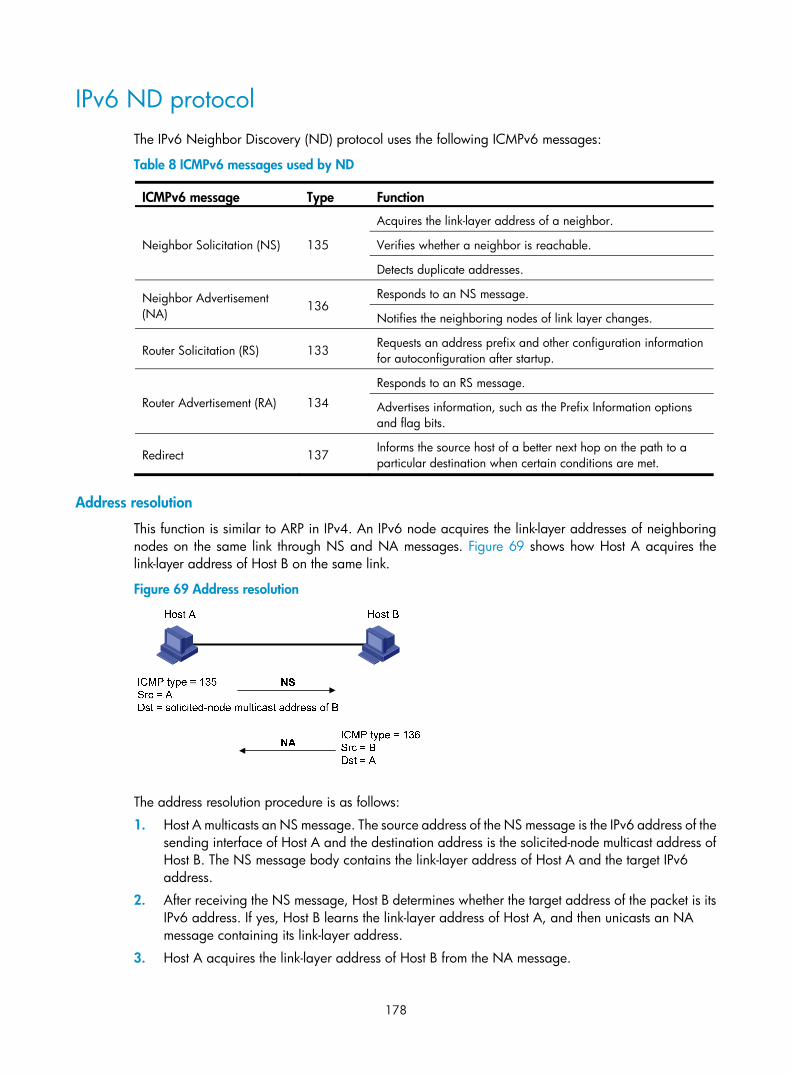
178
IPv6 ND protocol The IPv6 Neighbor Discovery (ND) protocol uses the following ICMPv6 messages:
Table 8 ICMPv6 messages used by ND
ICMPv6 message Type Function
Neighbor Solicitation (NS) 135
Acquires the link-layer address of a neighbor.
Verifies whether a neighbor is reachable.
Detects duplicate addresses.
Neighbor Advertisement (NA) 136
Responds to an NS message.
Notifies the neighboring nodes of link layer changes.
Router Solicitation (RS) 133 Requests an address prefix and other configuration information for autoconfiguration after startup.
Router Advertisement (RA) 134
Responds to an RS message.
Advertises information, such as the Prefix Information options and flag bits.
Redirect 137 Informs the source host of a better next hop on the path to a particular destination when certain conditions are met.
Address resolution
This function is similar to ARP in IPv4. An IPv6 node acquires the link-layer addresses of neighboring nodes on the same link through NS and NA messages. Figure 69 shows how Host A acquires the link-layer address of Host B on the same link.
Figure 69 Address resolution
The address resolution procedure is as follows:
1. Host A multicasts an NS message. The source address of the NS message is the IPv6 address of the sending interface of Host A and the destination address is the solicited-node multicast address of Host B. The NS message body contains the link-layer address of Host A and the target IPv6 address.
2. After receiving the NS message, Host B determines whether the target address of the packet is its IPv6 address. If yes, Host B learns the link-layer address of Host A, and then unicasts an NA message containing its link-layer address.
3. Host A acquires the link-layer address of Host B from the NA message.

179
Neighbor reachability detection
After Host A acquires the link-layer address of its neighbor Host B, Host A can use NS and NA messages to test reachability of Host B as follows:
1. Host A sends an NS message whose destination address is the IPv6 address of Host B.
2. If Host A receives an NA message from Host B, Host A decides that Host B is reachable. Otherwise, Host B is unreachable.
Duplicate address detection
After Host A acquires an IPv6 address, it performs Duplicate Address Detection (DAD) to check whether the address is being used by any other node (similar to gratuitous ARP in IPv4). DAD is accomplished through NS and NA messages.
Figure 70 Duplicate address detection
1. Host A sends an NS message whose source address is the unspecified address and whose destination address is the corresponding solicited-node multicast address of the IPv6 address to be detected. The NS message body contains the detected IPv6 address.
2. If Host B uses this IPv6 address, Host B returns an NA message that contains its IPv6 address.
3. Host A knows that the IPv6 address is being used by Host B after receiving the NA message from Host B. If receiving no NA message, Host A decides that the IPv6 address is not in use and uses this address.
Router/prefix discovery and stateless address autoconfiguration
A node performs router/prefix discovery and stateless address autoconfiguration as follows:
1. At startup, a node sends an RS message to request configuration information from a router.
2. The router returns an RA message containing the Prefix Information option and other configuration information. (The router also periodically sends an RA message.)
3. The node automatically generates an IPv6 address and other configuration parameters according to the configuration information in the RA message.
The Prefix Information option contains an address prefix and the preferred lifetime and valid lifetime of the address prefix. A node updates the preferred lifetime and valid lifetime upon receiving a periodic RA message.
The generated IPv6 address is valid within the valid lifetime and becomes invalid when the valid lifetime expires.
After the preferred lifetime expires, the node cannot use the generated IPv6 address to establish new connections, but can receive packets destined for the IPv6 address. The preferred lifetime cannot be greater than the valid lifetime.

180
Redirection
Upon receiving a packet from a host, the gateway sends an ICMPv6 Redirect message to inform a better next hop to the host when the following conditions are met (similar to the ICMP redirection function in IPv4):
• The interface receiving the packet is the same as the interface forwarding the packet.
• The selected route is not created or modified by an ICMPv6 Redirect message.
• The selected route is not a default route on the device.
• The forwarded IPv6 packet does not contain the routing extension header.
IPv6 path MTU discovery The links that a packet passes from a source to a destination can have different MTUs, among which the minimum MTU is the path MTU. If a packet exceeds path MTU, the source end fragments the packet to reduce the processing pressure on intermediate devices and to use network resources effectively.
A source end uses path MTU discovery to find the path MTU to a destination, as shown in Figure 71.
Figure 71 Path MTU discovery process
1. The source host sends a packet no larger than its MTU to the destination host.
2. If the MTU of a device's output interface is smaller than the packet, the device discards the packet and returns an ICMPv6 error packet containing the interface MTU to the source host.
3. After receiving the ICMPv6 error packet, the source host uses the returned MTU to limit the packet size, performs fragmentation, and sends the packets to the destination host.
4. Step 2 and step 3 are repeated until the destination host receives the packet. In this way, the source host finds the minimum MTU of all links in the path to the destination host.
IPv6 transition technologies IPv6 transition technologies enable communication between IPv4 and IPv6 networks. Several IPv6 transition technologies can be used in different environments and periods, such as dual stack (RFC 2893), tunneling (RFC 2893), NAT-PT (RFC 2766), and IPv6 on the provider edge routers (6PE).
Dual stack Dual stack is the most direct transition approach. A network node that supports both IPv4 and IPv6 is a dual-stack node. A dual-stack node configured with an IPv4 address and an IPv6 address can forward

181
both IPv4 and IPv6 packets. An application that supports both IPv4 and IPv6 prefers IPv6 at the network layer. Dual stack is suitable for communication between IPv4 nodes or between IPv6 nodes. It is the basis of all transition technologies. However, it does not solve the IPv4 address depletion issue because each dual stack node must have a globally unique IPv4 address.
Tunneling Tunneling uses one network protocol to encapsulate the packets of another network protocol and transfers them over the network. For more information about tunneling, see "Configuring tunneling."
NAT-PT Network Address Translation – Protocol Translation (NAT-PT) enables communication between IPv4 and IPv6 nodes by translating between IPv4 and IPv6 packets. It performs IP address translation, and according to different protocols, performs semantic translation for packets. This technology is only suitable for communication between a pure IPv4 node and a pure IPv6 node. For more information about NAT-PT, see "Configuring NAT-PT."
6PE 6PE enables communication between isolated IPv6 networks over an IPv4 backbone network.
6PE adds labels to the IPv6 routing information about customer networks and advertises the information into the IPv4 backbone network over internal Border Gateway Protocol (IBGP) sessions. IPv6 packets are labeled and forwarded over tunnels on the backbone network. The tunnels can be GRE tunnels or MPLS LSPs.
Figure 72 Network diagram
6PE is a highly efficient solution. When an ISP wants to utilize the existing IPv4/MPLS network to provide IPv6 traffic switching, it only needs to upgrade the PE routers. In addition, the operation risk of 6PE is very low. For more information about 6PE, see Layer 3—IP Routing Configuration Guide.
Protocols and standards Protocols and standards related to IPv6 include:
• RFC 1881, IPv6 Address Allocation Management
• RFC 1887, An Architecture for IPv6 Unicast Address Allocation
• RFC 1981, Path MTU Discovery for IP version 6
• RFC 2375, IPv6 Multicast Address Assignments

182
• RFC 2460, Internet Protocol, Version 6 (IPv6) Specification
• RFC 2463, Internet Control Message Protocol (ICMPv6) for the Internet Protocol Version 6 (IPv6) Specification
• RFC 2464, Transmission of IPv6 Packets over Ethernet Networks
• RFC 2526, Reserved IPv6 Subnet Anycast Addresses
• RFC 3307, Allocation Guidelines for IPv6 Multicast Addresses
• RFC 3513, Internet Protocol Version 6 (IPv6) Addressing Architecture
• RFC 4191, Default Router Preferences and More-Specific Routes
• RFC 4861, Neighbor Discovery for IP Version 6 (IPv6)
• RFC 4862, IPv6 Stateless Address Autoconfiguration
IPv6 basics configuration task list Tasks at a glance (Required.) Assigning IPv6 addresses to interfaces: • Configuring an IPv6 global unicast address • Configuring an IPv6 link-local address • Configuring an IPv6 anycast address
(Optional.) Configuring IPv6 ND: • Configuring a static neighbor entry • Setting the maximum number of dynamic neighbor entries • Setting the aging timer for ND entries in stale state • Minimizing link-local ND entries • Setting the hop limit • Configuring parameters for RA messages • Configuring the maximum number of attempts to send an NS message for DAD • Enabling ND proxy
(Optional.) Configuring path MTU discovery: • Configuring the interface MTU • Configuring a static path MTU for a specific IPv6 address • Configuring the aging time for dynamic path MTUs
(Optional.) Controlling sending ICMPv6 packets: • Configuring the rate limit for ICMPv6 error messages • Enabling replying to multicast echo requests • Enabling sending ICMPv6 destination unreachable messages • Enabling sending ICMPv6 time exceeded messages • Enabling sending ICMPv6 redirect messages • Specifying the source address for ICMPv6 packets

183
Assigning IPv6 addresses to interfaces This section describes how to configure an IPv6 global unicast address, an IPv6 link-local address, and an IPv6 anycast address.
Configuring an IPv6 global unicast address Use one of the following methods to configure an IPv6 global unicast address for an interface:
• EUI-64 IPv6 address—The IPv6 address prefix of the interface is manually configured, and the interface identifier is generated automatically by the interface.
• Manual configuration—The IPv6 global unicast address is manually configured.
• Stateless address autoconfiguration—The IPv6 global unicast address is generated automatically based on the address prefix information contained in the RA message.
You can configure multiple IPv6 global unicast addresses on an interface.
Manually configured global unicast addresses (including EUI-64 IPv6 addresses) take precedence over automatically generated ones. If you manually configure a global unicast address with the same address prefix as an existing global unicast address on an interface, the manually configured one takes effect, but it does not overwrite the automatically generated address. If you remove the manually configured global unicast address, the device uses the automatically generated one.
EUI-64 IPv6 address
To configure an interface to generate an EUI-64 IPv6 address:
Step Command Remarks 1. Enter system view. system-view N/A
2. Enter interface view. interface interface-type interface-number
N/A
3. Configure the interface to generate an EUI-64 IPv6 address.
ipv6 address { ipv6-address prefix-length | ipv6-address/prefix-length } eui-64
By default, no IPv6 global unicast address is configured on an interface.
Manual configuration
To configure an IPv6 global unicast address for an interface:
Step Command Remarks 1. Enter system view. system-view N/A
2. Enter interface view. interface interface-type interface-number N/A
3. Configure an IPv6 global unicast address for the interface.
ipv6 address { ipv6-address prefix-length | ipv6-address/prefix-length }
By default, no IPv6 global unicast address is configured on an interface.
Stateless address autoconfiguration
To configure an interface to generate an IPv6 address through stateless address autoconfiguration:

184
Step Command Remarks 1. Enter system view. system-view N/A
2. Enter interface view. interface interface-type interface-number N/A
3. Enable stateless address autoconfiguration. ipv6 address auto
By default, no IPv6 global unicast address is configured on an interface.
Using the undo ipv6 address auto command on an interface removes all IPv6 global unicast addresses automatically generated on the interface.
After this configuration, the interface automatically generates an IPv6 global unicast address by using the address prefix in the received RA message and the interface ID. On an IEEE 802 interface (such as an Ethernet interface or a VLAN interface), the interface ID is generated based on the MAC address of the interface and is globally unique. An attacker can exploit this rule to identify the sending device easily.
To fix the vulnerability, you can configure the temporary address function. With this function, an IEEE 802 interface generates the following addresses:
• Public IPv6 address—Includes the address prefix in the RA message and a fixed interface ID generated based on the MAC address of the interface.
• Temporary IPv6 address—Includes the address prefix in the RA message and a random interface ID generated through MD5.
You can also configure the interface to preferably use the temporary IPv6 address as the source address of sent packets. When the valid lifetime of the temporary IPv6 address expires, the interface removes the address and generates a new one. This function enables the system to send packets with different source addresses through the same interface. If the temporary IPv6 address cannot be used because of a DAD conflict, the public IPv6 address is used.
The preferred lifetime and valid lifetime for a temporary IPv6 address are determined as follows:
• The preferred lifetime of a temporary IPv6 address takes the smaller of the following values:
The preferred lifetime of the address prefix in the RA message.
The preferred lifetime configured for temporary IPv6 addresses minus DESYNC_FACTOR (a random number ranging from 0 to 600 seconds).
• The valid lifetime of a temporary IPv6 address takes the smaller of the following values:
The valid lifetime of the address prefix.
The valid lifetime configured for temporary IPv6 addresses.
To configure the temporary address function:
Step Command Remarks 1. Enter system view. system-view N/A
2. Enable the system to generate a temporary IPv6 address.
ipv6 temporary-address [ valid-lifetime preferred-lifetime ]
By default, the system does not generate any temporary IPv6 address.

185
Step Command Remarks 3. Enable the system to
preferably use the temporary IPv6 address as the source address of the packet.
ipv6 prefer temporary-address
By default, the system does not preferably use the temporary IPv6 address as the source address of the packet.
To generate a temporary address, an interface must be enabled with stateless address autoconfiguration. Temporary IPv6 addresses do not overwrite public IPv6 addresses, so an interface can have multiple IPv6 addresses with the same address prefix but different interface IDs.
If an interface fails to generate a public IPv6 address because of a prefix conflict or other reasons, it does not generate any temporary IPv6 address.
Configuring an IPv6 link-local address Configure IPv6 link-local addresses using one of the following methods:
• Automatic generation—The device automatically generates a link-local address for an interface according to the link-local address prefix (FE80::/10) and the link-layer address of the interface.
• Manual assignment—Manually configure an IPv6 link-local address for an interface.
An interface can have only one link-local address. To avoid link-local address conflicts, use the automatic generation method.
Manual assignment takes precedence over automatic generation. If you first use automatic generation and then manual assignment, the manually assigned link-local address overwrites the automatically generated one. If you first use manual assignment and then automatic generation, the automatically generated link-local address does not take effect and the link-local address is still the manually assigned one. If you delete the manually assigned address, the automatically generated link-local address becomes effective.
Configuring automatic generation of an IPv6 link-local address for an interface
Step Command Remarks 1. Enter system view. system-view N/A
2. Enter interface view. interface interface-type interface-number N/A
3. Configure the interface to automatically generate an IPv6 link-local address.
ipv6 address auto link-local
By default, no link-local address is configured on an interface.
After an IPv6 global unicast address is configured on the interface, a link-local address is generated automatically.
Manually specifying an IPv6 link-local address for an interface
Step Command Remarks 1. Enter system view. system-view N/A
2. Enter interface view. interface interface-type interface-number
N/A

186
Step Command Remarks
3. Manually specify an IPv6 link-local address for the interface.
ipv6 address ipv6-address link-local
By default, no link-local address is configured on an interface.
After an IPv6 global unicast address is configured on the interface, a link-local address is generated automatically.
After you configure an IPv6 global unicast address for an interface, the interface automatically generates a link-local address. The automatically generated link-local address is the same as the one generated by using the ipv6 address auto link-local command. If a link-local address is manually assigned to an interface, this manual link-local address takes effect. If the manually assigned link-local address is removed, the automatically generated link-local address takes effect.
Using the undo ipv6 address auto link-local command on an interface only removes the link-local address generated by the ipv6 address auto link-local command. If the interface has an IPv6 global unicast address, it still has a link-local address. If the interface has no IPv6 global unicast address, it has no link-local address.
Configuring an IPv6 anycast address
Step Command Remarks 1. Enter system view. system-view N/A
2. Enter interface view. interface interface-type interface-number
N/A
3. Configure an IPv6 anycast address.
ipv6 address { ipv6-address prefix-length | ipv6-address/prefix-length } anycast
By default, no IPv6 anycast address is configured on an interface.
Configuring IPv6 ND This section describes how to configure IPv6 ND.
Configuring a static neighbor entry The IPv6 address of a neighboring node can be resolved into a link-layer address dynamically through NS and NA messages or through a manually configured static neighbor entry.
The device uniquely identifies a static neighbor entry by the IPv6 address and the local Layer 3 interface number of the neighbor. You can configure a static neighbor entry by using one of the following methods:
• Method 1—Associate a neighbor's IPv6 address and link-layer address with the local Layer 3 interface.
If you use Method 1, the device automatically finds the Layer 2 port connected to the neighbor.
• Method 2—Associate a neighbor's IPv6 address and link-layer address with a local port in a VLAN.

187
If you use Method 2, make sure the corresponding VLAN interface exists and the Layer 2 port specified by port-type port-number belongs to the VLAN specified by vlan-id. The device associates the VLAN interface with the neighbor IPv6 address to identify the static neighbor entry.
To configure a static neighbor entry:
Step Command Remarks 1. Enter system view. system-view N/A
2. Configure a static neighbor entry.
ipv6 neighbor ipv6-address mac-address { vlan-id port-type port-number | interface interface-type interface-number } [ vpn-instance vpn-instance-name ]
By default, no static neighbor entry exists on the device.
Setting the maximum number of dynamic neighbor entries The device can dynamically acquire the link-layer address of a neighboring node through NS and NA messages and add it into the neighbor table. When the number of dynamic neighbor entries reaches the threshold, the interface stops learning neighbor information. To prevent an interface from occupying too many neighbor table resources, you can set the maximum number of dynamic neighbors that an interface can learn.
To set the maximum number of dynamic neighbor entries:
Step Command Remarks 1. Enter system view. system-view N/A
2. Enter interface view. interface interface-type interface-number
N/A
3. Set the maximum number of dynamic neighbor entries that the interface can learn.
ipv6 neighbors max-learning-num number N/A
Setting the aging timer for ND entries in stale state ND entries in stale state have an aging timer. If an ND entry in stale state is not refreshed before the timer expires, the ND entry changes to the delay state. If it is still not refreshed in 5 seconds, the ND entry changes to the probe state, and the device sends an NS message three times. If no response is received, the device removes the ND entry.
To set the aging timer for ND entries in stale state:
Step Command Remarks 1. Enter system view. system-view N/A
2. Set the aging timer for ND entries in stale state. ipv6 neighbor stale-aging aging-time
The default setting is 240 minutes.

188
Minimizing link-local ND entries Perform this task to minimize link-local ND entries assigned to the driver. Link-local ND entries refer to ND entries comprising link-local addresses.
By default, the device assigns all ND entries to the driver. With this feature enabled, the device does not add newly learned link-local ND entries whose link local addresses are not the next hop of any route into the driver to save driver resources.
This feature affects only newly learned link-local ND entries rather than existing ND entries.
To minimize link-local ND entries:
Step Command Remarks 1. Enter system view. system-view N/A
2. Minimize link-local ND entries.
ipv6 neighbor link-local minimize
By default, the device assigns all ND entries to the driver.
Setting the hop limit Perform this task to implement the following functions:
• Set the value of the Hop Limit field for IPv6 packets sent by the device.
• If you use the undo ipv6 nd ra hop-limit unspecified command, the device sets the hop limit value configured by this task in a sent RA message. A host receiving the RA message fills the value into the Hop Limit field of sent IPv6 packets.
To set the hop limit:
Step Command Remarks 1. Enter system view. system-view N/A
2. Set the Hop Limit field in the IP header. ipv6 hop-limit value The default setting is 64.
Configuring parameters for RA messages You can enable an interface to send RA messages, and configure the interval for sending RA messages and parameters in RA messages. After receiving an RA message, a host can use these parameters to perform corresponding operations. Table 12 describes the configurable parameters in an RA message.
Table 9 Parameters in an RA message and their descriptions
Parameter Description
Hop Limit Maximum number of hops in RA messages. A host receiving the RA message fills the value in the Hop Limit field of sent IPv6 packets.
Prefix information After receiving the prefix information, the hosts on the same link can perform stateless autoconfiguration.
MTU Guarantees that all nodes on the link use the same MTU.

189
Parameter Description
M flag
Determines whether a host uses stateful autoconfiguration to obtain an IPv6 address.
If the M flag is set to 1, the host uses stateful autoconfiguration (for example, from a DHCPv6 server) to obtain an IPv6 address. Otherwise, the host uses stateless autoconfiguration to generate an IPv6 address according to its link-layer address and the prefix information in the RA message.
O flag
Determines whether a host uses stateful autoconfiguration to obtain configuration information other than IPv6 address.
If the O flag is set to 1, the host uses stateful autoconfiguration (for example, from a DHCPv6 server) to obtain configuration information other than IPv6 address. Otherwise, the host uses stateless autoconfiguration.
Router Lifetime Tells the receiving hosts how long the advertising router can live. If the lifetime of a router is 0, the router cannot be used as the default gateway.
Retrans Timer If the device does not receive a response message within the specified time after sending an NS message, it retransmits the NS message.
Reachable Time
If the neighbor reachability detection shows that a neighbor is reachable, the device considers the neighbor reachable within the specified reachable time. If the device needs to send a packet to the neighbor after the specified reachable time expires, the device reconfirms whether the neighbor is reachable.
Router Preference Specifies the router preference in a RA message. A host selects a router as the default gateway according to the router preference. If router preferences are the same, the host selects the router from which the first RA message is received.
The maximum interval for sending RA messages should be less than (or equal to) the router lifetime in RA messages so the router can be updated by an RA message before expiration.
The values of the NS retransmission timer and the reachable time configured for an interface are sent in RA messages to hosts. This interface sends NS messages at the interval of the NS retransmission timer and considers a neighbor reachable within the reachable time.
Enabling sending of RA messages
Step Command Remarks 1. Enter system view. system-view N/A
2. Enter interface view. interface interface-type interface-number
N/A
3. Enable sending of RA messages. undo ipv6 nd ra halt The default setting is disabled.
4. Configure the maximum and minimum intervals for sending RA messages.
ipv6 nd ra interval max-interval-value min-interval-value
By default, the maximum interval for sending RA messages is 600 seconds, and the minimum interval is 200 seconds.
The device sends RA messages at random intervals between the maximum interval and the minimum interval.
The minimum interval should be less than or equal to 0.75 times the maximum interval.

190
Configuring parameters for RA messages
Step Command Remarks 1. Enter system view. system-view N/A
2. Enter interface view. interface interface-type interface-number N/A
3. Configure the prefix information in RA messages.
ipv6 nd ra prefix { ipv6-prefix prefix-length | ipv6-prefix/prefix-length } valid-lifetime preferred-lifetime [ no-autoconfig | off-link ] *
By default, no prefix information is configured for RA messages, and the IPv6 address of the interface sending RA messages is used as the prefix information. If the IPv6 address is manually configured, the prefix uses a fixed valid lifetime of 2592000 seconds (30 days) and a preferred lifetime of 604800 seconds (7 days). If the IPv6 address is automatically obtained, the prefix uses the valid lifetime and preferred lifetime configured for the IPv6 address.
4. Turn off the MTU option in RA messages. ipv6 nd ra no-advlinkmtu
By default, RA messages contain the MTU option.
5. Specify unlimited hops in RA messages. ipv6 nd ra hop-limit unspecified
By default, the maximum number of hops in RA messages is 64.
6. Set the M flag bit to 1. ipv6 nd autoconfig managed-address-flag
By default, the M flag bit is set to 0 and hosts acquire IPv6 addresses through stateless autoconfiguration.
7. Set the O flag bit to 1. ipv6 nd autoconfig other-flag
By default, the O flag bit is set to 0 and hosts acquire other configuration information through stateless autoconfiguration.
8. Configure the router lifetime in RA messages. ipv6 nd ra router-lifetime value
By default, the router lifetime is 1800 seconds.
9. Set the NS retransmission timer. ipv6 nd ns retrans-timer value
By default, an interface sends NS messages every 1000 milliseconds, and the value of the Retrans Timer field in RA messages is 0.
10. Set the router preference in RA messages.
ipv6 nd router-preference { high | low | medium }
By default, the router preference is medium.
11. Set the reachable time. ipv6 nd nud reachable-time value
By default, the neighbor reachable time is 30000 milliseconds, and the value of the Reachable Time field in sent RA messages is 0.

191
Configuring the maximum number of attempts to send an NS message for DAD
An interface sends an NS message for DAD after obtaining an IPv6 address. If the interface does not receive a response within the time specified by the ipv6 nd ns retrans-timer command, it sends an NS message again. If the interface still does not receive a response after the number of attempts reaches the threshold specified by the ipv6 nd dad attempts command, it considers the address is usable.
To configure the attempts to send an NS message for DAD:
Step Command Remarks 1. Enter system view. system-view N/A
2. Enter interface view. interface interface-type interface-number N/A
3. Configure the number of attempts to send an NS message for DAD.
ipv6 nd dad attempts value The default setting is 1. When the value argument is set to 0, DAD is disabled.
Enabling ND proxy About ND proxy
ND proxy enables a device to answer an NS message requesting the hardware address of a host on another network. With ND proxy, hosts on different broadcast domains can communicate with each other as they would on the same network.
ND proxy includes common ND proxy and local ND proxy.
• Common ND proxy
As shown in Figure 73, Ethernet 1/1 with IPv6 address 4:1::99/64 and Ethernet 1/2 with IPv6 address 4:2::99/64 belong to different subnets. Host A and Host B reside on the same network but in different broadcast domains.
Figure 73 Application environment of ND proxy
Because Host A's IPv6 address is on the same subnet as Host B's, Host A directly sends an NS message to obtain Host B's MAC address. However, Host B cannot receive the NS message because they belong to different broadcast domains.
To solve this problem, enable common ND proxy on Ethernet 1/1 and Ethernet 1/2 of the router. The router replies to the NS message from Host A, and forwards packets from other hosts to Host B.
• Local ND proxy
As shown in Figure 74, both Host A and Host B belong to VLAN 2, but they connect to Ethernet 1/3 and Ethernet 1/1 respectively, which are isolated at Layer 2.
4:1::100/16 4:2::100/16
Eth1/14:1::99/64
Eth1/24:2::99/64
Host A Host BRouter
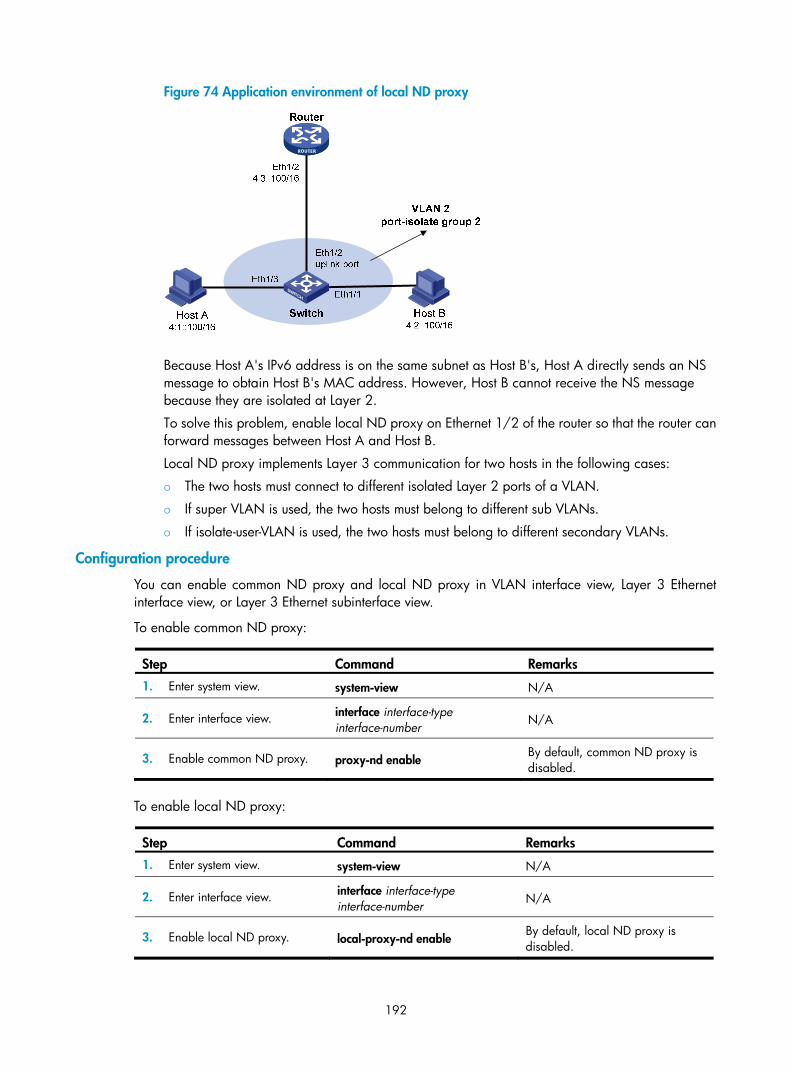
192
Figure 74 Application environment of local ND proxy
Because Host A's IPv6 address is on the same subnet as Host B's, Host A directly sends an NS message to obtain Host B's MAC address. However, Host B cannot receive the NS message because they are isolated at Layer 2.
To solve this problem, enable local ND proxy on Ethernet 1/2 of the router so that the router can forward messages between Host A and Host B.
Local ND proxy implements Layer 3 communication for two hosts in the following cases:
The two hosts must connect to different isolated Layer 2 ports of a VLAN.
If super VLAN is used, the two hosts must belong to different sub VLANs.
If isolate-user-VLAN is used, the two hosts must belong to different secondary VLANs.
Configuration procedure
You can enable common ND proxy and local ND proxy in VLAN interface view, Layer 3 Ethernet interface view, or Layer 3 Ethernet subinterface view.
To enable common ND proxy:
Step Command Remarks 1. Enter system view. system-view N/A
2. Enter interface view. interface interface-type interface-number
N/A
3. Enable common ND proxy. proxy-nd enable By default, common ND proxy is disabled.
To enable local ND proxy:
Step Command Remarks 1. Enter system view. system-view N/A
2. Enter interface view. interface interface-type interface-number N/A
3. Enable local ND proxy. local-proxy-nd enable By default, local ND proxy is disabled.

193
Configuring path MTU discovery
Configuring the interface MTU IPv6 routers do not support packet fragmentation. If the size of a packet exceeds the MTU of the output interface, the router discards the packet and sends a Packet Too Big message to the source host. The source host fragments the packet according to the MTU. To avoid this situation, configure a proper interface MTU.
To configure the interface MTU:
Step Command Remarks 1. Enter system view. system-view N/A
2. Enter interface view. interface interface-type interface-number N/A
3. Configure the interface MTU. ipv6 mtu mtu-size By default, no interface MTU is configured.
Configuring a static path MTU for a specific IPv6 address You can configure a static path MTU for an IPv6 address. Before sending a packet to the IPv6 address, the device compares the MTU of the output interface with the static path MTU. If the packet exceeds the smaller one of the two values, the device fragments the packet according to the smaller value. After sending the fragmented packets, the device dynamically finds the path MTU to a destination host (see "IPv6 path MTU discovery").
To configure a static path MTU for a destination IPv6 address:
Step Command Remarks 1. Enter system view. system-view N/A
2. Configure a static path MTU for a destination IPv6 address.
ipv6 pathmtu [ vpn-instance vpn-instance-name ] ipv6-address value
No path MTU is configured for any IPv6 address by default.
Configuring the aging time for dynamic path MTUs After the device dynamically finds the path MTU to a destination host (see "IPv6 path MTU discovery"), it sends packets to the destination host based on the path MTU and starts an aging timer. When the aging timer expires, the device removes the dynamic path MTU and finds the path MTU again.
The aging time is invalid for a static path MTU.
To configure the aging time for dynamic path MTUs:
Step Command Remarks 1. Enter system view. system-view N/A

194
Step Command Remarks 2. Configure the aging time for
dynamic path MTUs. ipv6 pathmtu age age-time The default setting is 10 minutes.
Controlling sending ICMPv6 packets This section describes how to configure ICMPv6 packet sending.
Configuring the rate limit for ICMPv6 error messages To avoid sending excessive ICMPv6 error messages within a short period that might cause network congestion, you can limit the rate at which ICMPv6 error messages are sent. A token bucket algorithm is used with one token representing one ICMPv6 error message. Tokens are placed in the bucket at a specific interval until the maximum number of tokens that the bucket can hold is reached. Tokens are removed from the bucket when ICMPv6 error messages are sent. When the bucket is empty, ICMPv6 error messages are not sent until a new token is placed in the bucket.
To configure the rate limit for ICMPv6 error messages:
Step Command Remarks 1. Enter system view. system-view N/A
2. Set the interval and bucket size for ICMPv6 error messages
ipv6 icmpv6 error-interval milliseconds [ bucketsize ]
By default, the bucket allows a maximum of 10 tokens, and tokens are placed in the bucket at the interval of 100 milliseconds.
To disable the ICMPv6 rate limit, set the interval to 0 milliseconds.
Enabling replying to multicast echo requests The device does not respond to multicast echo requests by default. In some scenarios, however, you must enable the device to answer multicast echo requests so the source host can obtain needed information.
To enable the device to answer multicast echo requests:
Step Command Remarks 1. Enter system view. system-view N/A
2. Enable replying to multicast echo requests.
ipv6 icmpv6 multicast-echo-reply enable
By default, this function is not enabled.
Enabling sending ICMPv6 destination unreachable messages The device sends ICMPv6 destination unreachable messages as follows:

195
• If a packet does not match any route, the device sends a No Route to Destination ICMPv6 error message to the source.
• If the device fails to forward the packet because of administrative prohibition (such as a firewall filter or an ACL), the device sends the source a Destination Network Administratively Prohibited ICMPv6 error message.
• If the device fails to deliver the packet because the destination is beyond the scope of the source IPv6 address (for example, the source IPv6 address is a link-local address whereas the destination IPv6 address is a global unicast address), the device sends the source a Beyond Scope of Source Address ICMPv6 error message.
• If the device fails to resolve the link layer address for the destination IPv6 address, the device sends the source an Address Unreachable ICMPv6 error message.
• If a UDP packet received is destined for the device but its UDP destination port number does not match any process, the device sends the source a Port Unreachable ICMPv6 error message.
If a device is generating ICMPv6 destination unreachable messages incorrectly, disable the sending of ICMPv6 destination unreachable messages to prevent attack risks.
To enable sending ICMPv6 destination unreachable messages:
Step Command Remarks
1. Enter system view. system-view N/A
2. Enable sending ICMPv6 destination unreachable messages. ipv6 unreachables enable
By default, this function is disabled.
Enabling sending ICMPv6 time exceeded messages The device sends ICMPv6 Time Exceeded messages as follows:
• If a received packet is not destined for the device and its hop limit is 1, the device sends an ICMPv6 Hop Limit Exceeded message to the source.
• Upon receiving the first fragment of an IPv6 datagram destined for the device, the device starts a timer. If the timer expires before all the fragments arrive, the device sends an ICMPv6 Fragment Reassembly Timeout message to the source.
If the device receives large numbers of malicious packets, its performance degrades greatly because it must send back ICMP Time Exceeded messages. To prevent such attacks, disable sending ICMPv6 Time Exceeded messages.
To enable sending ICMPv6 time exceeded messages:
Step Command Remarks 1. Enter system view. system-view N/A
2. Enable sending ICMPv6 time exceeded messages. ipv6 hoplimit-expires enable The default setting is disabled.
Enabling sending ICMPv6 redirect messages Upon receiving a packet from a host, the device sends an ICMPv6 redirect message to inform a better next hop to the host when the following conditions are met:

196
• The interface receiving the packet is the interface forwarding the packet.
• The selected route is not created or modified by any ICMPv6 redirect message.
• The selected route is not a default route.
• The forwarded packet does not contain the routing extension header.
The ICMPv6 redirect function simplifies host management by enabling hosts that hold few routes to gradually optimize their routing table. However, to avoid adding too many routes on hosts, this function is disabled by default.
To enable sending ICMPv6 redirect messages:
Step Command Remarks 1. Enter system view. system-view N/A
2. Enable sending ICMPv6 redirect messages. ipv6 redirects enable
By default, sending ICMPv6 redirect messages is disabled.
Specifying the source address for ICMPv6 packets Perform this task to specify the source IPv6 address for outgoing ping echo request and ICMPv6 error messages. It is a good practice to specify the IPv6 address of the loopback interface as the source IPv6 address. This feature helps users to locate the sending device easily.
If you specify an IP address in the ping command, ping echo requests use the specified address as the source IP address rather than the IP address specified by the ipv6 icmpv6 source command.
To specify the source IPv6 address for ICMPv6 packets:
Step Command Remarks 1. Enter system view. system-view N/A 2. Specify an IPv6 address as the
source address for outgoing ICMPv6 packets.
ipv6 icmpv6 source [ vpn-instance vpn-instance-name ] ipv6-address
By default, the device uses the IPv6 address of the sending interface as the source IPv6 address for outgoing ICMPv6 packets.
Displaying and maintaining IPv6 basics Execute display commands in any view and reset commands in user view.
Task Command
Display IPv6 FIB entries. display ipv6 fib [ vpn-instance vpn-instance-name ] [ ipv6-address [ prefix-length ] ]
Display IPv6 information about the interface. display ipv6 interface [ interface-type [ interface-number ] ] [ brief ]
Display IPv6 prefix information about the interface. display ipv6 interface interface-type interface-number prefix

197
Task Command
Display neighbor information (MSR 2600/MSR 3600).
display ipv6 neighbors { ipv6-address | all | dynamic | interface interface-type interface-number | static | vlan vlan-id } [ verbose ]
Display neighbor information (MSR 5600).
display ipv6 neighbors { { ipv6-address | all | dynamic | static } [ slot slot-number ] | interface interface-type interface-number | vlan vlan-id } [ verbose ]
Display the total number of neighbor entries (MSR 2600/MSR 3600).
display ipv6 neighbors { all | dynamic | interface interface-type interface-number | static | vlan vlan-id } count
Display the total number of neighbor entries (MSR 5600).
display ipv6 neighbors { { all | dynamic | static } [ slot slot-number ] | interface interface-type interface-number | vlan vlan-id } count
Display neighbor information for a specific VPN.
display ipv6 neighbors vpn-instance vpn-instance-name [ count ]
Display the IPv6 path MTU information. display ipv6 pathmtu [ vpn-instance vpn-instance-name ] { ipv6-address | { all | dynamic | static } [ count ] }
Display IPv6 and ICMPv6 packet statistics (MSR 2600/MSR 3600). display ipv6 statistics
Display IPv6 and ICMPv6 statistics (MSR 5600).
display ipv6 statistics [ slot slot-number ]
Display brief information about IPv6 RawIP connections (MSR 2600/MSR 3600).
display ipv6 rawip
Display brief information about IPv6 RawIP connections (MSR 5600). display ipv6 rawip [ slot slot-number ]
Display detailed information about IPv6 RawIP connections (MSR 2600/MSR 3600).
display ipv6 rawip verbose [ pcb pcb-index ]
Display detailed information about IPv6 RawIP connections (MSR 5600).
display ipv6 rawip verbose [ slot slot-number [ pcb pcb-index ] ]
Display brief information about IPv6 TCP connections (MSR 2600/MSR 3600). display ipv6 tcp
Display brief information about IPv6 TCP connections (MSR 5600). display ipv6 tcp [ slot slot-number ]
Display detailed information about IPv6 TCP connections (MSR 2600/MSR 3600).
display ipv6 tcp verbose [ pcb pcb-index ]
Display detailed information about IPv6 TCP connections (MSR 5600).
display ipv6 tcp verbose [ slot slot-number [ pcb pcb-index ] ]
Display brief information about IPv6 UDP connections (MSR 2600/MSR 3600).
display ipv6 udp
Display brief information about IPv6 UDP connections (MSR 5600).
display ipv6 udp [ slot slot-number ]
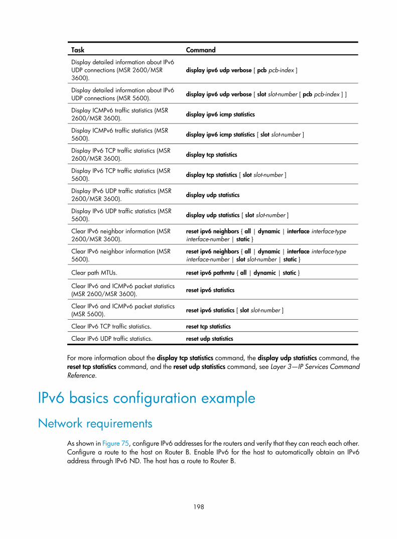
198
Task Command
Display detailed information about IPv6 UDP connections (MSR 2600/MSR 3600).
display ipv6 udp verbose [ pcb pcb-index ]
Display detailed information about IPv6 UDP connections (MSR 5600).
display ipv6 udp verbose [ slot slot-number [ pcb pcb-index ] ]
Display ICMPv6 traffic statistics (MSR 2600/MSR 3600).
display ipv6 icmp statistics
Display ICMPv6 traffic statistics (MSR 5600).
display ipv6 icmp statistics [ slot slot-number ]
Display IPv6 TCP traffic statistics (MSR 2600/MSR 3600). display tcp statistics
Display IPv6 TCP traffic statistics (MSR 5600). display tcp statistics [ slot slot-number ]
Display IPv6 UDP traffic statistics (MSR 2600/MSR 3600). display udp statistics
Display IPv6 UDP traffic statistics (MSR 5600). display udp statistics [ slot slot-number ]
Clear IPv6 neighbor information (MSR 2600/MSR 3600).
reset ipv6 neighbors { all | dynamic | interface interface-type interface-number | static }
Clear IPv6 neighbor information (MSR 5600).
reset ipv6 neighbors { all | dynamic | interface interface-type interface-number | slot slot-number | static }
Clear path MTUs. reset ipv6 pathmtu { all | dynamic | static }
Clear IPv6 and ICMPv6 packet statistics (MSR 2600/MSR 3600).
reset ipv6 statistics
Clear IPv6 and ICMPv6 packet statistics (MSR 5600).
reset ipv6 statistics [ slot slot-number ]
Clear IPv6 TCP traffic statistics. reset tcp statistics
Clear IPv6 UDP traffic statistics. reset udp statistics
For more information about the display tcp statistics command, the display udp statistics command, the reset tcp statistics command, and the reset udp statistics command, see Layer 3—IP Services Command Reference.
IPv6 basics configuration example
Network requirements As shown in Figure 75, configure IPv6 addresses for the routers and verify that they can reach each other. Configure a route to the host on Router B. Enable IPv6 for the host to automatically obtain an IPv6 address through IPv6 ND. The host has a route to Router B.

199
Figure 75 Network diagram
Configuration procedure 1. Configure Router A:
# Configure a global unicast address for interface Ethernet 1/1. <RouterA> system-view
[RouterA] interface ethernet 1/1
[RouterA-Ethernet1/1] ipv6 address 3001::1/64
[RouterA-Ethernet1/1] quit
# Configure a global unicast address for interface Ethernet 1/2 and enable it to advertise RA messages (an interface does not advertises RA messages by default). [RouterA] interface ethernet 1/2
[RouterA-Ethernet1/2] ipv6 address 2001::1/64
[RouterA-Ethernet1/2] undo ipv6 nd ra halt
[RouterA-Ethernet1/2] quit
2. Configure Router B:
# Configure a global unicast address for interface Ethernet 1/1. <RouterB> system-view
[RouterB] interface ethernet 1/1
[RouterB-Ethernet1/1] ipv6 address 3001::2/64
[RouterB-Ethernet1/1] quit
# Configure an IPv6 static route to the host. [RouterB] ipv6 route-static 2001:: 64 3001::1
3. Configure the host:
Enable IPv6 on the host to automatically obtain an IPv6 address through IPv6 ND.
# Display neighbor information for Ethernet 1/2 on Router A. [RouterA] display ipv6 neighbors interface ethernet 1/2
Type: S-Static D-Dynamic I-Invalid
IPv6 Address Link Layer VID Interface State T Age
FE80::215:E9FF:FEA6:7D14 0015-e9a6-7d14 N/A Eth1/2 STALE D 1238
2001::15B:E0EA:3524:E791 0015-e9a6-7d14 N/A Eth1/2 STALE D 1248
The output shows that the IPv6 global unicast address that the host obtained is 2001::15B:E0EA:3524:E791.
Verifying the configuration # Display IPv6 interface information on Router A. [RouterA] display ipv6 interface ethernet 1/1
Ethernet1/1 current state: UP
Line protocol current state: UP
Router A Router BEth1/13001::1/64
Eth1/13001::2/64
Eth1/22001::1/64
Host

200
IPv6 is enabled, link-local address is FE80::20F:E2FF:FE00:2
Global unicast address(es):
3001::1, subnet is 3001::/64
Joined group address(es):
FF02::1
FF02::2
FF02::1:FF00:1
FF02::1:FF00:2
MTU is 1500 bytes
ND DAD is enabled, number of DAD attempts: 1
ND reachable time is 30000 milliseconds
ND retransmit interval is 1000 milliseconds
Hosts use stateless autoconfig for addresses
IPv6 Packet statistics:
InReceives: 25829
InTooShorts: 0
InTruncatedPkts: 0
InHopLimitExceeds: 0
InBadHeaders: 0
InBadOptions: 0
ReasmReqds: 0
ReasmOKs: 0
InFragDrops: 0
InFragTimeouts: 0
OutFragFails: 0
InUnknownProtos: 0
InDelivers: 47
OutRequests: 89
OutForwDatagrams: 48
InNoRoutes: 0
InTooBigErrors: 0
OutFragOKs: 0
OutFragCreates: 0
InMcastPkts: 6
InMcastNotMembers: 25747
OutMcastPkts: 48
InAddrErrors: 0
InDiscards: 0
OutDiscards: 0
[RouterA] display ipv6 interface ethernet 1/2
Ethernet1/2 current state: UP
Line protocol current state: UP
IPv6 is enabled, link-local address is FE80::20F:E2FF:FE00:1C0
Global unicast address(es):
2001::1, subnet is 2001::/64
Joined group address(es):
FF02::1

201
FF02::2
FF02::1:FF00:1
FF02::1:FF00:1C0
MTU is 1500 bytes
ND DAD is enabled, number of DAD attempts: 1
ND reachable time is 30000 milliseconds
ND retransmit interval is 1000 milliseconds
ND advertised reachable time is 0 milliseconds
ND advertised retransmit interval is 0 milliseconds
ND router advertisements are sent every 600 seconds
ND router advertisements live for 1800 seconds
Hosts use stateless autoconfig for addresses
IPv6 Packet statistics:
InReceives: 272
InTooShorts: 0
InTruncatedPkts: 0
InHopLimitExceeds: 0
InBadHeaders: 0
InBadOptions: 0
ReasmReqds: 0
ReasmOKs: 0
InFragDrops: 0
InFragTimeouts: 0
OutFragFails: 0
InUnknownProtos: 0
InDelivers: 159
OutRequests: 1012
OutForwDatagrams: 35
InNoRoutes: 0
InTooBigErrors: 0
OutFragOKs: 0
OutFragCreates: 0
InMcastPkts: 79
InMcastNotMembers: 65
OutMcastPkts: 938
InAddrErrors: 0
InDiscards: 0
OutDiscards: 0
# Display IPv6 interface information on Router B. [RouterB] display ipv6 interface ethernet 1/1
Ethernet1/1 current state: UP
Line protocol current state: UP
IPv6 is enabled, link-local address is FE80::20F:E2FF:FE00:1234
Global unicast address(es):
3001::2, subnet is 3001::/64
Joined group address(es):
FF02::1
FF02::2

202
FF02::1:FF00:1
FF02::1:FF00:1234
MTU is 1500 bytes
ND DAD is enabled, number of DAD attempts: 1
ND reachable time is 30000 milliseconds
ND retransmit interval is 1000 milliseconds
Hosts use stateless autoconfig for addresses
IPv6 Packet statistics:
InReceives: 117
InTooShorts: 0
InTruncatedPkts: 0
InHopLimitExceeds: 0
InBadHeaders: 0
InBadOptions: 0
ReasmReqds: 0
ReasmOKs: 0
InFragDrops: 0
InFragTimeouts: 0
OutFragFails: 0
InUnknownProtos: 0
InDelivers: 117
OutRequests: 83
OutForwDatagrams: 0
InNoRoutes: 0
InTooBigErrors: 0
OutFragOKs: 0
OutFragCreates: 0
InMcastPkts: 28
InMcastNotMembers: 0
OutMcastPkts: 7
InAddrErrors: 0
InDiscards: 0
OutDiscards: 0
# Ping Router A and Router B from the host, and ping Router A and the host from Router B to verify that they can reach each other.
NOTE:
To ping a link-local address, use the –i parameter to specify an interface for the link-local address.
[RouterB] ping ipv6 -c 1 3001::1
Ping6(56 data bytes) 3001::2 --> 3001::1, press escape sequence to break
56 bytes from 3001::1, icmp_seq=0 hlim=64 time=4.404 ms
--- Ping6 statistics for 3001::1 ---
1 packet(s) transmitted, 1 packet(s) received, 0.0% packet loss
round-trip min/avg/max/std-dev = 4.404/4.404/4.404/0.000 ms
[RouterB] ping ipv6 -c 1 2001::15B:E0EA:3524:E791
Ping6(56 data bytes) 3001::2 --> 2001::15B:E0EA:3524:E791, press escape sequence to break

203
56 bytes from 2001::15B:E0EA:3524:E791, icmp_seq=0 hlim=64 time=5.404 ms
--- Ping6 statistics for 2001::15B:E0EA:3524:E791 ---
1 packet(s) transmitted, 1 packet(s) received, 0.0% packet loss
round-trip min/avg/max/std-dev = 5.404/5.404/5.404/0.000 ms
The output shows that Router B can ping Router A and the host. The host can also ping Router B and Router A (output not shown).
Troubleshooting IPv6 basics configuration
Symptom An IPv6 address cannot be pinged.
Solution 1. Use the display ipv6 interface command in any view to verify that the IPv6 address of the output
interface is correct and the interface is up.
2. Use the debugging ipv6 packet command in user view to enable the debugging for IPv6 packets to locate the fault.

204
DHCPv6 overview
DHCPv6 provides a framework to assign IPv6 prefixes, IPv6 addresses, and other configuration parameters to hosts.
DHCPv6 address/prefix assignment An address/prefix assignment process involves two or four messages.
Rapid assignment involving two messages As shown in Figure 76, rapid assignment operates in the following steps:
1. The DHCPv6 client sends a Solicit message that contains a Rapid Commit option to prefer rapid assignment.
2. If the DHCPv6 server supports rapid assignment, it responds with a Reply message containing the assigned IPv6 address/prefix and other configuration parameters. If the DHCPv6 server does not support rapid assignment, Assignment involving four messages is performed.
Figure 76 Rapid assignment involving two messages
Assignment involving four messages As shown in Figure 77, four-message assignment operates in the following steps:
1. The DHCPv6 client sends a Solicit message to request an IPv6 address/prefix and other configuration parameters.
2. If the Solicit message does not contain a Rapid Commit option, or if the DHCPv6 server does not support rapid assignment even though the Solicit message contains a Rapid Commit option, the DHCPv6 server responds with an Advertise message that contains the assignable address/prefix and other configuration parameters.
3. The DHCPv6 client might receive multiple Advertise messages offered by different DHCPv6 servers. It selects an offer according to the receiving sequence and server priority, and sends a Request message to the selected server for confirmation.
4. The DHCPv6 server sends a Reply message to the client, confirming that the address/prefix and other configuration parameters are assigned to the client.

205
Figure 77 Assignment involving four messages
Address/prefix lease renewal An IPv6 address/prefix assigned by a DHCPv6 server has a valid lifetime. After the valid lifetime expires, the DHCPv6 client cannot use the IPv6 address/prefix. To use the IPv6 address/prefix, the DHCPv6 client must renew the lease time.
Figure 78 Using the Renew message for address/prefix lease renewal
As shown in Figure 78, at T1, the DHCPv6 client sends a Renew message to the DHCPv6 server. The recommended value of T1 is half the preferred lifetime. The DHCPv6 server responds with a Reply message, informing the client about whether or not the lease is renewed.
Figure 79 Using the Rebind message for address/prefix lease renewal
As shown in Figure 79, if the DHCPv6 client receives no response from the DHCPv6 server after sending a Renew message at T1, it multicasts a Rebind message to all DHCPv6 servers at T2 (when 80% preferred lifetime elapses). The DHCPv6 server responds with a Reply message, informing the client about whether or not the lease is renewed.
If the DHCPv6 client receives no response from any DHCPv6 server before the valid lifetime expires, the client stops using the address/prefix.
For more information about the valid lifetime and the preferred lifetime, see "Configuring basic IPv6 settings."

206
Stateless DHCPv6 Stateless DHCPv6 enables a device that has obtained an IPv6 address/prefix to get other configuration parameters from a DHCPv6 server.
The device decides whether to perform stateless DHCP according to the managed address configuration flag (M flag) and the other stateful configuration flag (O flag) in the RA message received from the router during stateless address autoconfiguration. If the M flag is set to 0 and the O flag is set to 1, the device performs stateless DHCP to get other configuration parameters.
For more information about stateless address autoconfiguration, see "Configuring IPv6 basics."
Figure 80 Stateless DHCPv6 operation
As shown in Figure 80, stateless DHCPv6 operates in the following steps:
1. The DHCPv6 client sends an Information-request message to the multicast address of all DHCPv6 servers and DHCPv6 relay agents. The Information-request message contains an Option Request option that specifies the requested configuration parameters.
2. The DHCPv6 server returns to the client a Reply message containing the requested configuration parameters.
3. The client checks the Reply message. If the obtained configuration parameters match those requested in the Information-request message, the client uses these parameters to complete configuration. If not, the client ignores the configuration parameters. If the client receives multiple replies, it uses the first received reply.
Protocols and standards • RFC 3736, Stateless Dynamic Host Configuration Protocol (DHCP) Service for IPv6
• RFC 3315, Dynamic Host Configuration Protocol for IPv6 (DHCPv6)
• RFC 2462, IPv6 Stateless Address Autoconfiguration
• RFC 3633, IPv6 Prefix Options for Dynamic Host Configuration Protocol (DHCP) version 6

207
Configuring the DHCPv6 server
Overview A DHCPv6 server can assign IPv6 addresses or IPv6 prefixes to DHCPv6 clients.
IPv6 address assignment As shown in Figure 81, the DHCPv6 server assigns IPv6 addresses, domain name suffixes, DNS server addresses, and other configuration parameters to DHCPv6 clients.
The IPv6 addresses assigned to the clients include the following types:
• Temporary IPv6 addresses—Internally used and frequently changed without lease renewal.
• Non-temporary IPv6 addresses—Correctly used by DHCP clients.
Figure 81 IPv6 address assignment
IPv6 prefix assignment As shown in Figure 82, the DHCPv6 server assigns an IPv6 prefix to the DHCPv6 client. The client advertises the prefix information in an RA message so that hosts on the subnet can automatically configure their IPv6 addresses by using the prefix.

208
Figure 82 IPv6 prefix assignment
Concepts Multicast addresses used by DHCPv6
DHCPv6 uses the multicast address FF05::1:3 to identify all site-local DHCPv6 servers, and uses the multicast address FF02::1:2 to identify all link-local DHCPv6 servers and relay agents.
DUID
A DHCP unique identifier (DUID) uniquely identifies a DHCPv6 device (DHCPv6 client, server, or relay agent). A DHCPv6 device adds its DUID in a sent packet.
Figure 83 DUID-LL format
The device supports the DUID format based on link-layer address (DUID-LL) defined in RFC 3315. Figure 83 shows the DUID-LL format, where:
• DUID type—The device supports the DUID type of DUID-LL with the value of 0x0003.
• Hardware type—The device supports the hardware type of Ethernet with the value of 0x0001.
• Link layer address—Takes the value of the bridge MAC address of the device.
IA
Identified by an IAID, an identity association (IA) provides a construct through which a client manages the obtained addresses, prefixes, and other configuration parameters. A client can have multiple IAs, for example, one for each of its interfaces.
IAID
An IAID uniquely identifies an IA. It is chosen by the client and must be unique on the client.

209
PD
The DHCPv6 server creates a prefix delegation (PD) for each assigned prefix to record the IPv6 prefix, client DUID, IAID, valid lifetime, preferred lifetime, lease expiration time, and IPv6 address of the requesting client.
DHCPv6 address pool The DHCP server selects IPv6 addresses, IPv6 prefixes, and other parameters from an address pool, and assigns them to the DHCP clients.
Address allocation mechanisms
DHCPv6 supports the following address allocation mechanisms:
• Static address allocation—To implement static address allocation for a client, create a DHCPv6 address pool, and manually bind the DUID and IAID of the client to an IPv6 address in the DHCPv6 address pool. When the client requests an IPv6 address, the DHCPv6 server assigns the IPv6 address in the static binding to the client.
• Dynamic address allocation—To implement dynamic address allocation for clients, create a DHCPv6 address pool, specify a subnet for the pool, and divide the subnet into temporary and non-temporary IPv6 address ranges. Upon receiving a DHCP request, the DHCPv6 server selects an IPv6 address from the temporary or non-temporary IPv6 address range based on the address type in the client request.
Prefix allocation mechanisms
DHCPv6 supports the following prefix allocation mechanisms:
• Static prefix allocation—To implement static prefix allocation for a client, create a DHCPv6 address pool, and manually bind the DUID and IAID of the client to an IPv6 prefix in the DHCPv6 address pool. When the client requests an IPv6 prefix, the DHCPv6 server assigns the IPv6 prefix in the static binding to the client.
• Dynamic prefix allocation—To implement dynamic prefix allocation for clients, create a DHCPv6 address pool and a prefix pool, specify a subnet for the address pool, and apply the prefix pool to the address pool. Upon receiving a DHCP request, the DHCPv6 server dynamically selects an IPv6 prefix from the prefix pool in the address pool.
Address pool selection
The DHCPv6 server observes the following principles to select an IPv6 address or prefix for a client:
1. If there is an address pool where an IPv6 address is statically bound to the DUID or IAID of the client, the DHCPv6 server selects this address pool and assigns the statically bound IPv6 address or prefix and other configuration parameters to the client.
2. If the receiving interface has an address pool, the DHCP server selects an IPv6 address or prefix and other configuration parameters from this address pool.
3. If there is no static address pool and the receiving interface has no address pool, the DHCPv6 server selects an address pool in the following way:
If the client and the server reside on the same subnet, the DHCP server matches the IPv6 address of the receiving interface against the subnets of all address pools, and selects the address pool with the longest-matching subnet.
If the client and the server reside on different subnets (a DHCPv6 relay agent is in-between), the DHCPv6 server matches the IPv6 address of the DHCPv6 relay agent interface closest to the

210
client against the subnets of all address pools, and selects the address pool with the longest-matching subnet.
To avoid wrong address allocation, keep the subnet used for dynamic assignment consistent with the subnet where the interface of the DHCPv6 server or DHCPv6 relay agent resides.
IPv6 address/prefix allocation sequence The DHCPv6 server selects an IPv6 address/prefix for a client in the following sequence:
1. IPv6 address/prefix statically bound to the client's DUID and IAID and expected by the client.
2. IPv6 address/prefix statically bound to the client's DUID and IAID.
3. IPv6 address/prefix statically bound to the client's DUID and expected by the client.
4. IPv6 address/prefix statically bound to the client's DUID.
5. IPv6 address/prefix that was ever assigned to the client.
6. Assignable IPv6 address/prefix in the address pool/prefix pool expected by the client.
7. Assignable IPv6 address/prefix in the address pool/prefix pool.
8. IPv6 address/prefix that was a conflict or passed its lease duration. If no IPv6 address/prefix is assignable, the server does not respond.
If a client moves to another subnet, the DHCPv6 server selects an IPv6 address/prefix from the address pool that matches the new subnet.
Configuration task list Tasks at a glance
(Optional.) Perform the following tasks: • Configuring IPv6 prefix assignment • Configuring IPv6 address assignment • Configuring network parameters assignment
(Required.) Configuring the DHCPv6 server on an interface
(Optional.) Setting the DSCP value for DHCPv6 packets sent by the DHCPv6 server
Configuring IPv6 prefix assignment Use the following methods to configure IPv6 prefix assignment:
• Configure a static IPv6 prefix binding in an address pool—If you bind a DUID and an IAID to an IPv6 prefix, the DUID and IAID in a request must match those in the binding before the DHCPv6 server can assign the IPv6 prefix to the DHCPv6 client. If you only bind a DUID to an IPv6 prefix, the DUID in the request must match the DUID in the binding before the DHCPv6 server can assign the IPv6 prefix to the DHCPv6 client.
• Apply a prefix pool to an address pool—The DHCPv6 server dynamically assigns an IPv6 prefix from the prefix pool in the address pool to a DHCPv6 client.

211
Configuration guidelines • An IPv6 prefix can be bound to only one DHCPv6 client. You cannot modify bindings that have
been created. To change the binding for a DHCPv6 client, you must delete the existing binding first.
• Only one prefix pool can be applied to an address pool. You cannot modify prefix pools that have been applied. To change the prefix pool for an address pool, you must remove the prefix pool application first.
• You can apply a prefix pool that has not been created to an address pool. The setting takes effect after the prefix pool is created.
Configuration procedure To configure IPv6 prefix assignment:
Step Command Remarks 1. Enter system view. system-view N/A
2. (Optional.) Specify the IPv6 prefixes excluded from dynamic assignment.
ipv6 dhcp server forbidden-prefix start-prefix/prefix-len [ end-prefix/prefix-len ]
By default, no IPv6 prefixes in the prefix pool are excluded from dynamic assignment.
If the excluded IPv6 prefix is in a static binding, the prefix still can be assigned to the client.
To exclude multiple IPv6 prefix ranges, repeat this step.
3. Create a prefix pool. ipv6 dhcp prefix-pool prefix-pool-number prefix prefix/prefix-len assign-len assign-len
This step is required for dynamic prefix assignment.
By default, no prefix pool is configured.
4. Create a DHCPv6 address pool and enter its view.
ipv6 dhcp pool pool-name By default, no DHCPv6 address pool is configured.
5. Specify an IPv6 subnet for dynamic assignment.
network prefix/prefix-length [ preferred-lifetime preferred-lifetime valid-lifetime valid-lifetime ]
By default, no IPv6 subnet is specified for dynamic assignment.
6. Configure static or dynamic prefix assignment.
• Configure a static prefix binding: static-bind prefix prefix/prefix-len duid duid [ iaid iaid ] [ preferred-lifetime preferred-lifetime valid-lifetime valid-lifetime ]
• Apply the prefix pool to the address pool: prefix-pool prefix-pool-number [ preferred-lifetime preferred-lifetime valid-lifetime valid-lifetime ]
Use at least one command.
By default, no static or dynamic prefix assignment is configured for an address pool.
To add multiple static IPv6 prefix bindings, use the static-bind prefix command.
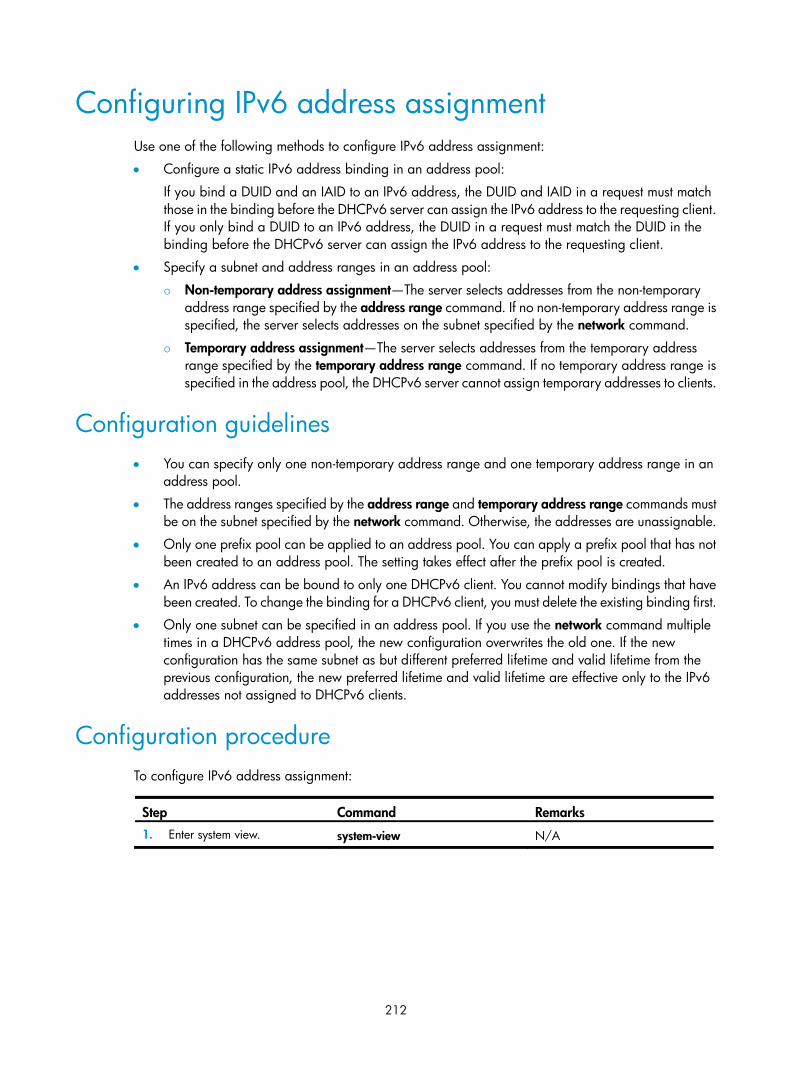
212
Configuring IPv6 address assignment Use one of the following methods to configure IPv6 address assignment:
• Configure a static IPv6 address binding in an address pool:
If you bind a DUID and an IAID to an IPv6 address, the DUID and IAID in a request must match those in the binding before the DHCPv6 server can assign the IPv6 address to the requesting client. If you only bind a DUID to an IPv6 address, the DUID in a request must match the DUID in the binding before the DHCPv6 server can assign the IPv6 address to the requesting client.
• Specify a subnet and address ranges in an address pool:
Non-temporary address assignment—The server selects addresses from the non-temporary address range specified by the address range command. If no non-temporary address range is specified, the server selects addresses on the subnet specified by the network command.
Temporary address assignment—The server selects addresses from the temporary address range specified by the temporary address range command. If no temporary address range is specified in the address pool, the DHCPv6 server cannot assign temporary addresses to clients.
Configuration guidelines • You can specify only one non-temporary address range and one temporary address range in an
address pool.
• The address ranges specified by the address range and temporary address range commands must be on the subnet specified by the network command. Otherwise, the addresses are unassignable.
• Only one prefix pool can be applied to an address pool. You can apply a prefix pool that has not been created to an address pool. The setting takes effect after the prefix pool is created.
• An IPv6 address can be bound to only one DHCPv6 client. You cannot modify bindings that have been created. To change the binding for a DHCPv6 client, you must delete the existing binding first.
• Only one subnet can be specified in an address pool. If you use the network command multiple times in a DHCPv6 address pool, the new configuration overwrites the old one. If the new configuration has the same subnet as but different preferred lifetime and valid lifetime from the previous configuration, the new preferred lifetime and valid lifetime are effective only to the IPv6 addresses not assigned to DHCPv6 clients.
Configuration procedure To configure IPv6 address assignment:
Step Command Remarks 1. Enter system view. system-view N/A

213
Step Command Remarks
2. (Optional.) Specify the IPv6 addresses excluded from dynamic assignment.
ipv6 dhcp server forbidden-address start-ipv6-address [ end-ipv6-address ]
By default, all IPv6 addresses except for the DHCPv6 server's IP address in a DHCPv6 address pool are assignable.
If the excluded IPv6 address is in a static binding, the address still can be assigned to the client.
To exclude multiple IPv6 prefix ranges, repeat this step.
3. Create a DHCPv6 address pool and enter its view. ipv6 dhcp pool pool-name
By default, no DHCPv6 address pool is configured.
4. Specify an IPv6 subnet for dynamic assignment.
network prefix/prefix-length [ preferred-lifetime preferred-lifetime valid-lifetime valid-lifetime ]
By default, no IPv6 address subnet is specified.
You cannot use this command to configure the same subnet in different address pools.
5. (Optional.) Specify a non-temporary IPv6 address range.
address range start-ipv6-address end-ipv6-address [ preferred-lifetime preferred-lifetime valid-lifetime valid-lifetime ]
By default, no non-temporary IPv6 address range is specified, and all unicast addresses on the subnet are assignable.
6. (Optional.) Specify a temporary IPv6 address range.
temporary address range start-ipv6-address end-ipv6-address [ preferred-lifetime preferred-lifetime valid-lifetime valid-lifetime ]
By default, no temporary IPv6 address range is specified, and the DHCPv6 server cannot assign temporary IPv6 addresses.
7. (Optional.) Create a static binding.
static-bind address ipv6-address/addr-prefix-length | duid duid [ iaid iaid ] [ preferred-lifetime preferred-lifetime valid-lifetime valid-lifetime ]
By default, no static binding is configured.
To add more static bindings, repeat this step.
Configuring network parameters assignment In addition to IPv6 prefixes and IPv6 addresses, you can configure up to eight DNS server addresses, one domain name suffix, eight SIP server addresses, and eight SIP server domain names in an address pool.
To configure network parameters assignment:
Step Command Remarks 1. Enter system view. system-view N/A
2. Create a DHCPv6 address pool and enter its view. ipv6 dhcp pool pool-name
By default, no DHCPv6 address pool exists on the DHCPv6 server.

214
Step Command Remarks
3. Specify an IPv6 subnet for dynamic assignment.
network prefix/prefix-length [ preferred-lifetime preferred-lifetime valid-lifetime valid-lifetime ]
By default, no IPv6 subnet is specified.
4. (Optional.) Specify a DNS server address. dns-server ipv6-address
By default, no DNS server address is specified.
5. (Optional.) Specify a domain name suffix. domain-name domain-name
By default, no domain name suffix is specified.
6. (Optional.) Specify a SIP server address or domain name.
sip-server { address ipv6-address | domain-name domain-name }
By default, no SIP server address or domain name is specified.
7. (Optional.) Configure a self-defined DHCPv6 option. option code hex hex-string
By default, no self-defined DHCPv6 option is configured.
Configuring the DHCPv6 server on an interface Enable the DHCP server and configure one of the following address/prefix assignment methods on an interface:
• Apply an address pool on the interface—The DHCPv6 server selects an IPv6 address/prefix from the applied address pool for a requesting client. If there is no assignable IPv6 address/prefix in the address pool, the DHCPv6 server cannot to assign an IPv6 address/prefix to a client.
• Configure global address assignment on the interface—The DHCPv6 server selects an IPv6 address/prefix in the global DHCPv6 address pool that matches the server interface address or the DHCPv6 relay agent address for a requesting client.
If you configure both methods on an interface, the DHCPv6 server uses the specified address pool for address assignment without performing global address assignment.
Configuration guidelines • An interface cannot serve as a DHCPv6 server and DHCPv6 relay agent at the same time.
• Do not enable DHCPv6 server and DHCPv6 client on the same interface.
• If you use the ipv6 dhcp server command multiple times, the most recent configuration takes effect.
• You can apply an address pool that has not been created to an interface. The setting takes effect after the address pool is created.
• Only one address pool can be applied to an interface. If you use the ipv6 dhcp server apply pool command multiple times, the most recent configuration takes effect.
Configuration procedure To configure the DHCPv6 server on an interface:
Step Command Remarks 1. Enter system view. system-view N/A

215
Step Command Remarks 2. Enter interface view. interface interface-type interface-number N/A
3. Enable the DHCPv6 server on the interface. ipv6 dhcp select server
By default, the interface discards DHCPv6 packets from DHCPv6 clients.
4. Configure an address/prefix assignment method.
• Configure global address assignment: ipv6 dhcp server { allow-hint | preference preference-value | rapid-commit } *
• Apply a DHCPv6 address pool to the interface: ipv6 dhcp server apply pool pool-name [ allow-hint | preference preference-value | rapid-commit ] *
Use one of the commands.
By default, desired address/prefix assignment and rapid assignment are disabled, and the default preference is 0.
Setting the DSCP value for DHCPv6 packets sent by the DHCPv6 server
The DSCP value of a packet specifies the priority level of the packet and affects the transmission priority of the packet.
To set the DSCP value for DHCPv6 packets sent by the DHCPv6 server:
Step Command Remarks 1. Enter system view. system-view N/A
2. Set the DSCP value for DHCPv6 packets sent by the DHCPv6 server.
ipv6 dhcp dscp dscp-value By default, the DSCP value in DHCPv6 packets sent by the DHCPv6 server is 56.
Displaying and maintaining the DHCPv6 server Execute display commands in any view and reset commands in user view.
Task Command
Display the DUID of the local device. display ipv6 dhcp duid
Display DHCPv6 address pool information. display ipv6 dhcp pool [ pool-name ]
Display prefix pool information. display ipv6 dhcp prefix-pool [ prefix-pool-number ]
Display DHCPv6 server information on an interface.
display ipv6 dhcp server [ interface interface-type interface-number ]
Display information about IPv6 address conflicts. display ipv6 dhcp server conflict [ address ipv6-address ]
Display information about expired IPv6 addresses.
display ipv6 dhcp server expired [ address ipv6-address | pool pool-name ]
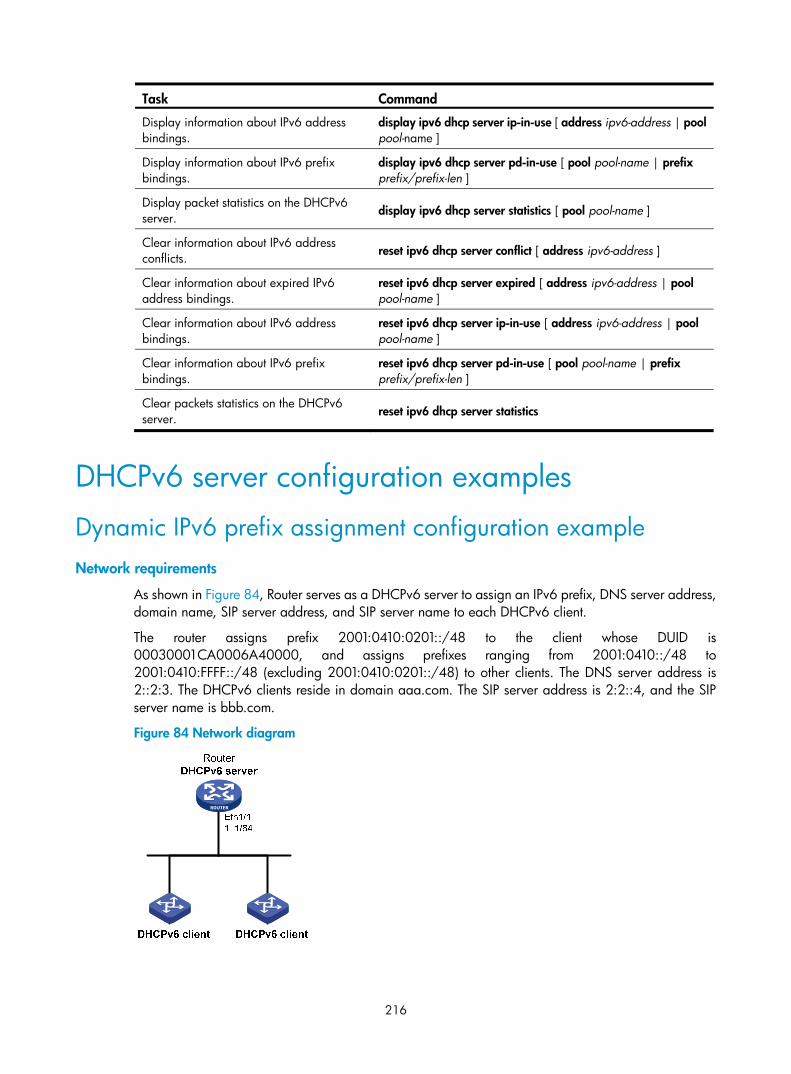
216
Task Command
Display information about IPv6 address bindings.
display ipv6 dhcp server ip-in-use [ address ipv6-address | pool pool-name ]
Display information about IPv6 prefix bindings.
display ipv6 dhcp server pd-in-use [ pool pool-name | prefix prefix/prefix-len ]
Display packet statistics on the DHCPv6 server. display ipv6 dhcp server statistics [ pool pool-name ]
Clear information about IPv6 address conflicts. reset ipv6 dhcp server conflict [ address ipv6-address ]
Clear information about expired IPv6 address bindings.
reset ipv6 dhcp server expired [ address ipv6-address | pool pool-name ]
Clear information about IPv6 address bindings.
reset ipv6 dhcp server ip-in-use [ address ipv6-address | pool pool-name ]
Clear information about IPv6 prefix bindings.
reset ipv6 dhcp server pd-in-use [ pool pool-name | prefix prefix/prefix-len ]
Clear packets statistics on the DHCPv6 server. reset ipv6 dhcp server statistics
DHCPv6 server configuration examples
Dynamic IPv6 prefix assignment configuration example Network requirements
As shown in Figure 84, Router serves as a DHCPv6 server to assign an IPv6 prefix, DNS server address, domain name, SIP server address, and SIP server name to each DHCPv6 client.
The router assigns prefix 2001:0410:0201::/48 to the client whose DUID is 00030001CA0006A40000, and assigns prefixes ranging from 2001:0410::/48 to 2001:0410:FFFF::/48 (excluding 2001:0410:0201::/48) to other clients. The DNS server address is 2::2:3. The DHCPv6 clients reside in domain aaa.com. The SIP server address is 2:2::4, and the SIP server name is bbb.com.
Figure 84 Network diagram

217
Configuration procedure
# Specify an IPv6 address for Ethernet 1/1. <Router> system-view
[Router] interface ethernet 1/1
[Router-Ethernet1/1] ipv6 address 1::1/64
[Router-Ethernet1/1] quit
# Create prefix pool 1, and specify the prefix 2001:0410::/32 with assigned prefix length 48. [Router] ipv6 dhcp prefix-pool 1 prefix 2001:0410::/32 assign-len 48
# Create address pool 1. [Router] ipv6 dhcp pool 1
# In address pool 1, specify subnet 1::/64 where the server interface resides. [Router-dhcp6-pool-1] network 1::/64
# Apply prefix pool 1 to address pool 1, and set the preferred lifetime to one day, and the valid lifetime to three days. [Router-dhcp6-pool-1] prefix-pool 1 preferred-lifetime 86400 valid-lifetime 259200
# In address pool 1, bind prefix 2001:0410:0201::/48 to the client DUID 00030001CA0006A40000, and set the preferred lifetime to one day, and the valid lifetime to three days. [Router-dhcp6-pool-1] static-bind prefix 2001:0410:0201::/48 duid 00030001CA0006A40000 preferred-lifetime 86400 valid-lifetime 259200
# Configure the DNS server address as 2:2::3. [Router-dhcp6-pool-1] dns-server 2:2::3
# Configure the domain name as aaa.com. [Router-dhcp6-pool-1] domain-name aaa.com
# Configure the SIP server address as 2:2::4, and the SIP server name as bbb.com. [Router-dhcp6-pool-1] sip-server address 2:2::4
[Router-dhcp6-pool-1] sip-server domain-name bbb.com
[Router-dhcp6-pool-1] quit
# Enable the DHCPv6 server on interface Ethernet 1/1, enable desired prefix assignment and rapid prefix assignment, and set the preference to the highest. [Router] interface ethernet 1/1
[Router-Ethernet1/1] ipv6 dhcp select server
[Router-Ethernet1/1] ipv6 dhcp server allow-hint preference 255 rapid-commit
Verifying the configuration
# Display the DHCPv6 server configuration on Ethernet 1/1. [Router-Ethernet1/1] display ipv6 dhcp server interface ethernet 1/1
Using pool: global
Preference value: 255
Allow-hint: Enabled
Rapid-commit: Enabled
# Display information about address pool 1. [Router-Ethernet1/1] display ipv6 dhcp pool 1
DHCPv6 pool: 1
Network: 1::/64
Preferred lifetime 604800, valid lifetime 2592000

218
Prefix pool: 1
Preferred lifetime 86400, valid lifetime 259200
Static bindings:
DUID: 00030001ca0006a4
IAID: Not configured
Prefix: 2001:410:201::/48
Preferred lifetime 86400, valid lifetime 259200
DNS server addresses:
2:2::3
Domain name:
aaa.com
SIP server addresses:
2:2::4
SIP server domain names:
bbb.com
# Display information about prefix pool 1. [Router-Ethernet1/1] display ipv6 dhcp prefix-pool 1
Prefix: 2001:410::/32
Assigned length: 48
Total prefix number: 65536
Available: 65535
In-use: 0
Static: 1
# After the client with the DUID 00030001CA0006A40000 obtains an IPv6 prefix, display the binding information on the DHCPv6 server. [Router-Ethernet1/1] display ipv6 dhcp server pd-in-use
Pool: 1
IPv6 prefix Type Lease expiration
2001:410:201::/48 Static(C) Jul 10 19:45:01 2009
# After the other client obtains an IPv6 prefix, display the binding information on the DHCPv6 server. [Router-Ethernet1/1] display ipv6 dhcp server pd-in-use
Pool: 1
IPv6 prefix Type Lease expiration
2001:410:201::/48 Static(C) Jul 10 19:45:01 2009
2001:410::/48 Auto(C) Jul 10 20:44:05 2009
Dynamic IPv6 address assignment configuration example Network requirements
As shown in Figure 85, Router A serves as a DHCPv6 server to assign IPv6 addresses to the clients in subnets 1::1:0:0:0/96 and 1::2:0:0:0/96. On Router A, configure the IPv6 address 1::1:0:0:1/96 for Ethernet 1/1 and 1::2:0:0:1/96 for Ethernet 1/2. The lease duration of the addresses on subnet 1::1:0:0:0/96 is 172800 seconds (two days), the valid time is 345600 seconds (four days), the domain name is aabbcc.com, and the DNS server address is 1::1:0:0:2/96. The lease duration of the addresses on subnet 1::2:0:0:0/96 is 432000 seconds (five days), the valid time is 864000 seconds (ten days), the domain name is aabbcc.com, and the DNS server address is 1::2:0:0:2/96.

219
Figure 85 Network diagram
Configuration procedure
1. Specify IPv6 addresses for interfaces on the DHCPv6 server. (Details not shown.)
2. Enable DHCPv6:
# Enable the DHCPv6 server on the interfaces Ethernet 1/1 and Ethernet 1/2. <RouterA> system-view
[RouterA] interface ethernet 1/1
[RouterA-Ethernet1/1] ipv6 dhcp select server
[RouterA-Ethernet1/1] quit
[RouterA] interface ethernet 1/2
[RouterA-Ethernet1/2] ipv6 dhcp select server
[RouterA-Ethernet1/2] quit
# Exclude the DNS server address from dynamic assignment. [RouterA] ipv6 dhcp server forbidden-address 1::1:0:0:2
[RouterA] ipv6 dhcp server forbidden-address 1::2:0:0:2
# Create DHCPv6 address pool 1 to assign IPv6 addresses and other configuration parameters to clients in subnet 1::1:0:0:0/96. [RouterA] ipv6 dhcp pool 1
[RouterA-dhcp6-pool-1] network 1::1:0:0:0/96 preferred-lifetime 172800 valid-lifetime 345600
[RouterA-dhcp6-pool-1] domain-name aabbcc.com
[RouterA-dhcp6-pool-1] dns-server 1::1:0:0:2
[RouterA-dhcp6-pool-1] quit
# Create DHCPv6 address pool 2 to assign IPv6 addresses and other configuration parameters to clients in subnet 1::2:0:0:0/96. [RouterA] ipv6 dhcp pool 2
[RouterA-dhcp6-pool-2] network 1::2:0:0:0/96 preferred-lifetime 432000 valid-lifetime 864000
[RouterA-dhcp6-pool-2] domain-name aabbcc.com
[RouterA-dhcp6-pool-2] dns-server 1::2:0:0:2
[RouterA-dhcp6-pool-2] quit

220
Verifying the configuration
After the preceding configuration, clients in subnets 1::1:0:0:0/96 and 1::2:0:0:0/96 can obtain IPv6 addresses and other configuration parameters from the DHCPv6 server (Router A). You can use the display ipv6 dhcp server ip-in-use command to display IPv6 addresses assigned to the clients.

221
Configuring the DHCPv6 relay agent
A DHCPv6 client usually uses a multicast address to contact the DHCPv6 server on the local link to obtain an IPv6 address and other configuration parameters. As shown in Figure 86, if the DHCPv6 server resides on another subnet, the DHCPv6 clients need a DHCPv6 relay agent to contact the server. The relay agent feature avoids deploying a DHCP server on each subnet.
Figure 86 Typical DHCPv6 relay agent application
As shown in Figure 87, a DHCPv6 client obtains an IPv6 address and other network configuration parameters from a DHCPv6 server through a DHCPv6 relay agent in the following steps (rapid assignment involving two messages):
• The DHCPv6 client sends a Solicit message containing the Rapid Commit option to the multicast address FF02::1:2 of all the DHCPv6 servers and relay agents.
• After receiving the Solicit message, the DHCPv6 relay agent encapsulates the message into the Relay Message option of a Relay-forward message, and sends the message to the DHCPv6 server.
• After obtaining the Solicit message from the Relay-forward message, the DHCPv6 server selects an IPv6 address and other required parameters, adds them to a reply that is encapsulated within the Relay Message option of a Relay-reply message, and sends the Relay-reply message to the DHCPv6 relay agent.
• The DHCPv6 relay agent obtains the reply from the Relay-reply message and sends the reply to the DHCPv6 client.
• The DHCPv6 client uses the IPv6 address and other network parameters assigned by the DHCPv6 server to complete network configuration.
IPv6 network
DHCPv6 server
DHCPv6 relay agent
DHCPv6 client DHCPv6 client
DHCPv6 clientDHCPv6 client

222
Figure 87 Operating process of a DHCPv6 relay agent
Configuration guidelines • You can use the ipv6 dhcp relay server-address command to specify a maximum of eight DHCPv6
servers on the DHCP relay agent interface. The DHCPv6 relay agent forwards DHCP requests to all the specified DHCPv6 servers.
• If a specific DHCPv6 server address is a link-local address or multicast address, you must specify an outgoing interface by using the interface keyword in the ipv6 dhcp relay server-address command. Otherwise, DHCPv6 packets might fail to reach the DHCPv6 server.
• Do not enable the DHCPv6 relay agent and DHCPv6 client on the same interface.
Configuration procedure To configure the DHCPv6 relay agent:
Step Command Remarks 1. Enter system view. system-view N/A
2. Enter interface view. interface interface-type interface-number
N/A
3. Enable DHCPv6 relay agent on the interface. ipv6 dhcp select relay
By default, the DHCPv6 relay agent is disabled on the interface.
4. Specify a DHCPv6 server. ipv6 dhcp relay server-address ipv6-address [ interface interface-type interface-number ]
By default, no DHCPv6 server is specified.
5. Set the DSCP value for DHCPv6 packets sent by the DHCPv6 relay agent.
ipv6 dhcp dscp dscp-value
By default, the DSCP value for DHCPv6 packets sent by the DHCPv6 relay agent is 56.
The DSCP value of a packet specifies the priority level of the packet and affects the transmission priority of the packet.
(1) Solicit (contains a Rapid Commit option)
(4) Reply
DHCPv6 client DHCPv6 relay agent DHCPv6 server
(2) Relay-forward
(3) Relay-reply

223
Displaying and maintaining the DHCPv6 relay agent
Execute display commands in any view and reset commands in user view.
Task Command
Display the DUID of the local device. display ipv6 dhcp duid
Display DHCPv6 server addresses specified on the DHCPv6 relay agent.
display ipv6 dhcp relay server-address [ interface interface-type interface-number ]
Display packet statistics on the DHCPv6 relay agent.
display ipv6 dhcp relay statistics [ interface interface-type interface-number ]
Clear packets statistics on the DHCPv6 relay agent.
reset ipv6 dhcp relay statistics [ interface interface-type interface-number ]
DHCPv6 relay agent configuration example
Network requirements As shown in Figure 88, configure the DHCPv6 relay agent on Router A to relay DHCP packets between DHCPv6 clients and the DHCPv6 server.
Router A acts as the gateway of network 1::/64. It sends RA messages to notify the hosts to obtain IPv6 addresses and other configuration parameters through DHCPv6. For more information about RA messages, see "Configuring basic IPv6 settings."
Figure 88 Network diagram
Configuration procedure 1. Configure the DHCPv6 relay agent on Router A:
# Specify IPv6 addresses for Ethernet 1/1 and Ethernet 1/2. <RouterA> system-view

224
[RouterA] interface ethernet 1/2
[RouterA-Ethernet1/2] ipv6 address 2::1 64
[RouterA-Ethernet1/2] quit
[RouterA] interface ethernet 1/1
[RouterA-Ethernet1/1] ipv6 address 1::1 64
# Enable the DHCPv6 relay agent on Ethernet 1/1 and specify the DHCPv6 server on the relay agent. [RouterA-Ethernet1/1] ipv6 dhcp select relay
[RouterA-Ethernet1/1] ipv6 dhcp relay server-address 2::2
2. Configure Router A as the gateway, enable Router A to send RA messages, and turn on the M and O flags. [RouterA-Ethernet1/1] undo ipv6 nd ra halt
[RouterA-Ethernet1/1] ipv6 nd autoconfig managed-address-flag
[RouterA-Ethernet1/1] ipv6 nd autoconfig other-flag
Verifying the configuration # Display DHCPv6 server address information on Router A. [RouterA-Ethernet1/1] display ipv6 dhcp relay server-address
Interface: Ethernet1/1
Server address Outgoing Interface
2::2
# Display packet statistics on the DHCPv6 relay agent. [RouterA-Ethernet1/1] display ipv6 dhcp relay statistics
Packets dropped : 0
Packets received : 14
Solicit : 0
Request : 0
Confirm : 0
Renew : 0
Rebind : 0
Release : 0
Decline : 0
Information-request : 7
Relay-forward : 0
Relay-reply : 7
Packets sent : 14
Advertise : 0
Reconfigure : 0
Reply : 7
Relay-forward : 7
Relay-reply : 0

225
Configuring DHCPv6 snooping
NOTE:
The feature is not supported.
DHCPv6 snooping works between the DHCPv6 client and server, or between the DHCPv6 client and DHCPv6 relay agent. It guarantees that DHCPv6 clients obtain IP addresses from authorized DHCPv6 servers. Also, it records IP-to-MAC bindings of DHCPv6 clients (called DHCPv6 snooping entries) for security purposes.
DHCPv6 snooping does not work between the DHCPv6 server and DHCPv6 relay agent.
Overview DHCPv6 snooping defines trusted and untrusted ports to make sure that clients obtain IPv6 addresses only from authorized DHCPv6 servers.
• Trusted—A trusted port can forward DHCPv6 messages correctly to make sure the clients get IPv6 addresses from authorized DHCPv6 servers.
• Untrusted—An untrusted port discards received messages sent by DHCPv6 servers to prevent unauthorized servers from assigning IPv6 addresses.
DHCPv6 snooping reads DHCP-ACK messages received from trusted ports and DHCP-REQUEST messages to create DHCPv6 snooping entries. A DHCPv6 snooping entry includes the MAC and IP addresses of a client, the port that connects to the DHCPv6 client, and the VLAN. You can use the display ipv6 dhcp snooping binding command to display the IP addresses of users for management.
Application of trusted and untrusted ports Configure ports facing the DHCPv6 server as trusted ports, and configure other ports as untrusted ports.
As shown in Figure 89, configure the DHCPv6 snooping device's port that is connected to the DHCPv6 server as a trusted port. The trusted port forwards response messages from the DHCPv6 server to the client. The untrusted port connected to the unauthorized DHCPv6 server discards incoming DHCPv6 response messages.

226
Figure 89 Trusted and untrusted ports
H3C implementation of Option 18 and Option 37
Option 18 for DHCPv6 snooping Option 18, also called the interface-ID option, is used by the DHCPv6 relay agent to determine the interface to use to forward RELAY-REPLY message.
In H3C implementation, the DHCPv6 snooping device adds Option 18 to the received DHCPv6 request message before forwarding it to the DHCPv6 server. The server then assigns IP address to the client based on the client information in Option 18.
Figure 90 Option 18 format
Figure 90 shows the Option 18 fields:
• Option code—Option code.
• Option length—Size of the option data.
• Port index—Port that receives the DHCPv6 request from the client.
• VLAN ID—ID of the outer VLAN.
• Second VLAN ID—ID of the inner VLAN.
• DUID—DUID of the DHCPv6 client.

227
NOTE:
The Second VLAN ID field is optional. If the received DHCPv6 request does not contain a second VLAN, Option 18 also does not contain it.
DHCPv6 snooping support for Option 37 Option 37, also called the remote-ID option, is used to identify the client.
In H3C implementation, the DHCPv6 snooping device adds Option 37 to the received DHCPv6 request message before forwarding it to the DHCPv6 server. This option provides client information about address allocation.
Figure 91 Option 37 format
Figure 91 shows the Option 37 fields:
• Option code—Option code.
• Option length—Size of the option data.
• Enterprise number—Enterprise number.
• Port index—Port that receives the DHCPv6 request from the client.
• VLAN ID—ID of the outer VLAN.
• Second VLAN ID—ID of the inner VLAN.
• DUID—DUID of the DHCPv6 client.
NOTE:
The Second VLAN ID field is optional. If the received DHCPv6 request does not contain a second VLAN, Option 37 also does not contain it.
DHCPv6 snooping configuration task list Tasks at a glance
(Required.) Configuring basic DHCPv6 snooping
(Optional.) Configuring Option 18 and Option 37
(Optional.) Saving DHCPv6 snooping entries
(Optional.) Setting the maximum number of DHCPv6 snooping entries

228
Tasks at a glance
(Optional.) Enabling DHCPv6-REQUEST check
Configuring basic DHCPv6 snooping To make sure DHCPv6 clients can obtain valid IPv6 addresses, specify the ports connected to authorized DHCPv6 servers as trusted ports. The trusted ports and the ports connected to DHCPv6 clients must be in the same VLAN.
To configure basic DHCPv6 snooping:
Step Command Remarks
1. Enter system view. system-view N/A
2. Enable DHCPv6 snooping. ipv6 dhcp snooping enable By default, DHCPv6 snooping is disabled.
3. Enter interface view. interface interface-type interface-number
This interface must connect to the DHCPv6 server.
4. Specify the port as a trusted port. ipv6 dhcp snooping trust
By default, all ports are untrusted ports after DHCPv6 snooping is enabled.
5. Return to system view. quit N/A
6. Enter interface view. interface interface-type interface-number
This interface must connect to the DHCPv6 client.
7. (Optional.) Enable recording of client information in DHCPv6 snooping entries.
ipv6 dhcp snooping binding record By default, DHCPv6 snooping does not record client information.
Configuring Option 18 and Option 37 Step Command Remarks
1. Enter system view. system-view N/A
2. Enter Layer 2 Ethernet interface view.
interface interface-type interface-number N/A
3. Enable support for Option 18. ipv6 dhcp snooping option interface-id enable
By default, Option 18 is not supported.
4. (Optional.) Specify the content as the interface ID.
ipv6 dhcp snooping option interface-id [ vlan vlan-id ] string interface-id
By default, the DHCPv6 snooping device uses its DUID as the content for Option 18.

229
Step Command Remarks
5. Enable support for Option 37. ipv6 dhcp snooping option remote-id enable
By default, Option 37 is not supported.
• (Optional.) Specify the content as the remote ID.
ipv6 dhcp snooping option remote-id [ vlan vlan-id ] string remote-id
By default, the DHCPv6 snooping device uses its DUID as the content for Option 37.
Saving DHCPv6 snooping entries DHCPv6 snooping entries cannot survive a reboot. You can save DHCPv6 snooping entries to a file so that DHCPv6 snooping can read DHCPv6 snooping entries from this file during a reboot. This allows security features (such as IP source guard) that use DHCPv6 snooping entries to continue to use these entries to check the user validity of DHCPv6 clients.
IMPORTANT:
If you disable DHCPv6 snooping with the undo ipv6 dhcp snooping enable command, the device deletesall DHCPv6 snooping entries, including those stored in the specified database file.
To save DHCPv6 snooping entries:
Step Command Remarks 1. Enter system view. system-view N/A
2. Specify a file to store DHCPv6 snooping entries.
ipv6 dhcp snooping binding database filename filename
By default, no file is specified.
This command enables the device to immediately save DHCPv6 snooping entries to the specified database file. If the file does not exist, the device automatically creates the file. The device does not update the file for a specific amount of time after a DHCPv6 snooping entry changes. The default period is 300 seconds. To change the value, use the ipv6 dhcp snooping binding database update interval command.
3. (Optional.) Manually save DHCPv6 snooping entries to the database file.
ipv6 dhcp snooping binding database update now
DHCPv6 snooping entries are saved to the database file each time this command is executed.
4. (Optional.) Set the amount of time to wait to update the database file after DHCPv6 snooping entry changes.
ipv6 dhcp snooping binding database update interval seconds
The default setting is 300 seconds.
When a DHCPv6 snooping entry is learned or removed, the device does not update the database file until after the specified waiting period. All changed entries during that period will be updated.

230
Setting the maximum number of DHCPv6 snooping entries
Perform this task to prevent the system resources from being overused.
To set the maximum number of DHCPv6 snooping entries:
Step Command Remarks
1. Enter system view. system-view N/A
2. Enter interface view. interface interface-type interface-number N/A
3. Set the maximum number of DHCPv6 snooping entries for an interface to learn.
ipv6 dhcp snooping max-learning-num number
By default, the number of DHCPv6 snooping entries for an interface to learn is not limited.
Enabling DHCPv6-REQUEST check Perform this task to use the DHCPv6-REQUEST check function to protect the DHCPv6 server against DHCPv6 client spoofing attacks. Attackers can forge DHCPv6-RENEW messages to renew leases for legitimate DHCPv6 clients that no longer need the IP addresses. The forged messages disable the victim DHCPv6 server from releasing the IP addresses. Attackers can also forge DHCPv6-DECLINE or DHCPv6-RELEASE messages to terminate leases for legitimate DHCPv6 clients that still need the IP addresses.
The DHCPv6-REQUEST check function enables the DHCPv6 snooping device to check every received DHCPv6-RENEW, DHCPv6-DECLINE, or DHCPv6-RELEASE message against DHCPv6 snooping entries.
• If any of the criteria in an entry is matched, the device compares the entry with the message information.
If they are consistent, the device considers the message valid and forwards it to the DHCPv6 server.
If they are different, the device considers the message forged and discards it.
• If no matching entry is found, the device forwards the message to the DHCPv6 server.
To enable DHCPv6-REQUEST check:
Step Command Remarks 1. Enter system view. system-view N/A
2. Enter interface view. interface interface-type interface-number N/A
3. Enable DHCPv6-REQUEST check.
ipv6 dhcp snooping check request-message
By default, DHCPv6-REQUEST check is disabled.
You can enable the function only on Layer 2 Ethernet interfaces.

231
Displaying and maintaining DHCPv6 snooping Execute display commands in any view, and reset commands in user view.
Task Command
Display information about trusted ports. display ipv6 dhcp snooping trust
Display DHCPv6 snooping entries. display ipv6 dhcp snooping binding [ address ipv6-address [ vlan vlan-id ] ]
Display information about the file that stores DHCPv6 snooping entries. display ipv6 dhcp snooping binding database
Display DHCPv6 packet statistics for DHCPv6 snooping (MSR 2600/MSR 3600).
display ipv6 dhcp snooping packet statistics
Display DHCPv6 packet statistics for DHCPv6 snooping (MSR 5600).
display ipv6 dhcp snooping packet statistics [ slot slot-number ]
Clear DHCPv6 snooping entries. reset ipv6 dhcp snooping binding { all | address ipv6-address [ vlan vlan-id ] }
Clear DHCPv6 packet statistics for DHCPv6 snooping (MSR 2600/MSR 3600).
reset ipv6 dhcp snooping packet statistics
Clear DHCPv6 packet statistics for DHCPv6 snooping (MSR 5600).
reset ipv6 dhcp snooping packet statistics [ slot slot-number ]
DHCPv6 snooping configuration example
Network requirements As shown in Figure 92, configure Ethernet 1/1 connecting to the DHCPv6 server as a trusted port. Enable DHCPv6 snooping to record client information in DHCPv6 snooping entries.
Figure 92 Network diagram

232
Configuration procedure # Enable DHCPv6 snooping. <Router> system-view
[Router] ipv6 dhcp snooping enable
# Specify Ethernet 1/1 as a trusted port. [Router] interface ethernet 1/1
[Router-Ethernet1/1] ipv6 dhcp snooping trust
[Router-Ethernet1/1] quit
# Enable recording of client information in DHCPv6 snooping entries. [Router]interface Ethernet 1/2
[Router-Ethernet1/2] ipv6 dhcp snooping binding record
[Router-Ethernet1/2] quit
Verifying the configuration The DHCPv6 client obtains an IPv6 address and other configuration parameters from the authorized DHCPv6 server. You can use the display ipv6 dhcp snooping binding command to display DHCPv6 snooping entries on the authorized DHCPv6 server.
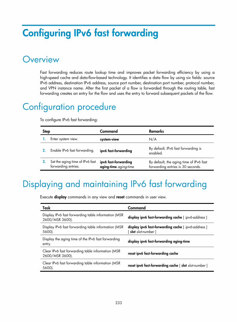
233
Configuring IPv6 fast forwarding
Overview Fast forwarding reduces route lookup time and improves packet forwarding efficiency by using a high-speed cache and data-flow-based technology. It identifies a data flow by using six fields: source IPv6 address, destination IPv6 address, source port number, destination port number, protocol number, and VPN instance name. After the first packet of a flow is forwarded through the routing table, fast forwarding creates an entry for the flow and uses the entry to forward subsequent packets of the flow.
Configuration procedure To configure IPv6 fast forwarding:
Step Command Remarks
1. Enter system view. system-view N/A
2. Enable IPv6 fast forwarding. ipv6 fast-forwarding By default, IPv6 fast forwarding is enabled.
3. Set the aging time of IPv6 fast forwarding entries.
ipv6 fast-forwarding aging-time aging-time
By default, the aging time of IPv6 fast forwarding entries is 30 seconds.
Displaying and maintaining IPv6 fast forwarding Execute display commands in any view and reset commands in user view.
Task Command
Display IPv6 fast forwarding table information (MSR 2600/MSR 3600).
display ipv6 fast-forwarding cache [ ipv6-address ]
Display IPv6 fast forwarding table information (MSR 5600).
display ipv6 fast-forwarding cache [ ipv6-address ] [ slot slot-number ]
Display the aging time of the IPv6 fast forwarding entry.
display ipv6 fast-forwarding aging-time
Clear IPv6 fast forwarding table information (MSR 2600/MSR 3600).
reset ipv6 fast-forwarding cache
Clear IPv6 fast forwarding table information (MSR 5600).
reset ipv6 fast-forwarding cache [ slot slot-number ]

234
IPv6 fast forwarding configuration example
Network requirements As shown in Figure 93, enable IPv6 fast forwarding on Router B.
Figure 93 Network diagram
Configuration procedure 1. Configure Router A:
# Specify the IPv6 address of interface Ethernet 1/1. <RouterA> system-view
[RouterA] interface ethernet 1/1
[RouterA-Ethernet1/1] ipv6 address 2002::1 64
[RouterA-Ethernet1/1] quit
# Configure a static route. [RouterA] ipv6 route-static 2001:: 64 2002::2
2. Configure Router C:
# Specify the IPv6 address of interface Ethernet 1/2. <RouterC> system-view
[RouterC] interface ethernet 1/2
[RouterC-Ethernet1/2] ipv6 address 2001::1 64
[RouterC-Ethernet1/2] quit
# Configure a static route. [RouterC] ipv6 route-static 2002:: 64 2001::2
3. Configure Router B:
# Enable IPv6 fast forwarding. <RouterB> system-view
[RouterB] ipv6 fast-forwarding
# Specify the IPv6 addresses of interface Ethernet 1/1 and interface Ethernet 1/2. [RouterB] interface ethernet 1/1
[RouterB-Ethernet1/1] ipv6 address 2002::2 64
[RouterB-Ethernet1/1] quit
[RouterB] interface ethernet 1/2
[RouterB-Ethernet1/2] ipv6 address 2001::2 64
[RouterB-Ethernet1/2] quit
Verifying the configuration # Display the IPv6 fast forwarding table on Router B.

235
[RouterB] display ipv6 fast-forwarding cache
No IPv6 fast-forwarding entries.
The output shows that no IPv6 fast forwarding entry exists.
# Ping the IPv6 address of Ethernet 1/2 of Router C from Router A. Reply packets can be received. [RouterA] ping ipv6 2001::1
PING 2001::1 : 56 data bytes, press CTRL_C to break
Reply from 2001::1
bytes=56 Sequence=1 hop limit=64 time = 69 ms
Reply from 2001::1
bytes=56 Sequence=2 hop limit=64 time = 1 ms
Reply from 2001::1
bytes=56 Sequence=3 hop limit=64 time = 1 ms
Reply from 2001::1
bytes=56 Sequence=4 hop limit=64 time = 1 ms
Reply from 2001::1
bytes=56 Sequence=5 hop limit=64 time = 1 ms
--- 2001::1 ping statistics ---
5 packet(s) transmitted
5 packet(s) received
0.00% packet loss
round-trip min/avg/max = 1/14/69 ms
# Display the IPv6 fast forwarding table on Router B. [RouterB] display ipv6 fast-forwarding cache
Total number of IPv6 fast-forwarding items: 2
Src IP: 2002::1 Src port: 129
Dst IP: 2001::1 Dst port: 0
Protocol: 58
VPN instance: N/A
Input interface: Eth1/1
Output interface: Eth1/2
Src IP: 2001::1 Src port: 128
Dst IP: 2002::1 Dst port: 0
Protocol: 58
VPN instance: N/A
Input interface: Eth1/2
Output interface: Eth1/1
The output shows that IPv6 fast forwarding entries have been created.

236
Configuring tunneling
Overview Tunneling is an encapsulation technology. One network protocol encapsulates packets of another network protocol and transfers them over a virtual point-to-point connection. The virtual connection is called a tunnel. Packets are encapsulated at the tunnel source end and de-encapsulated at the tunnel destination end. Tunneling refers to the whole process from data encapsulation to data transfer to data de-encapsulation.
Tunneling supports the following technologies:
• Transition techniques, such as IPv6 over IPv4 tunneling, to interconnect IPv4 and IPv6 networks.
• VPN, such as IPv4 over IPv4 tunneling, IPv4/IPv6 over IPv6 tunneling, GRE, DVPN, and IPsec tunneling.
• Traffic engineering, such as MPLS TE to prevent network congestion.
Unless otherwise specified, the term "tunnel" in this document refers to IPv6 over IPv4, IPv4 over IPv4, IPv4 over IPv6, and IPv6 over IPv6 tunnels.
IPv6 over IPv4 tunneling Implementation
IPv6 over IPv4 tunneling enables isolated IPv6 networks to communicate, as shown in Figure 94.
NOTE:
The devices at the ends of an IPv6 over IPv4 tunnel must support the IPv4/IPv6 dual stack.
Figure 94 IPv6 over IPv4 tunnel
The IPv6 over IPv4 tunnel processes packets in the following steps:
1. A host in the IPv6 network sends an IPv6 packet to Device A at the tunnel source.
2. After determining according to the routing table that the packet needs to be forwarded through the tunnel, Device A encapsulates the IPv6 packet with an IPv4 header and forwards it through the

237
physical interface of the tunnel. In the IPv4 header, the source IPv4 address is the IPv4 address of the tunnel source, and the destination IPv4 address is the IPv4 address of the tunnel destination.
3. Upon receiving the packet, Device B de-encapsulates the packet.
4. If the destination address of the IPv6 packet is itself, Device B forwards it to the upper-layer protocol. If not, Device B forwards it according to the routing table.
Tunnel modes
IPv6 over IPv4 tunnels include manually configured tunnels and automatic tunnels, depending on how the IPv4 address of the tunnel destination is acquired.
• Manually configured tunnel—The destination IPv4 address of the tunnel cannot be automatically acquired from the destination IPv6 address of an IPv6 packet at the tunnel source, and must be manually configured.
• Automatic tunnel—The destination IPv4 address of the tunnel can be automatically acquired from the destination IPv6 address (with an IPv4 address embedded) of an IPv6 packet at the tunnel source.
According to the way an IPv6 packet is encapsulated, IPv6 over IPv4 tunnels are divided into the following modes.
Table 10 IPv6 over IPv4 tunnel modes and key parameters
Tunnel type Tunnel mode Tunnel source/destination address
Destination IPv6 address format
Manually configured tunnel
IPv6 over IPv4 manual tunneling
The source and destination IPv4 addresses are manually configured.
Ordinary IPv6 address
Automatic tunnel
Automatic IPv4-compatible IPv6 tunneling
The source IPv4 address is manually configured. The destination IPv4 address is automatically obtained.
IPv4-compatible IPv6 address, in the format of ::IPv4-destination-address/96, where the IPv4-destination-address is the IPv4 address of the tunnel destination.
6to4 tunneling
The source IPv4 address is manually configured. The destination IPv4 address is automatically obtained.
6to4 address, in the format of 2002:IPv4-destination-address::/48, where the IPv4-destination-address is the IPv4 address of the tunnel destination.
ISATAP tunneling
The source IPv4 address is manually configured. The destination IPv4 address is automatically obtained.
ISATAP address, in the format of Prefix:0:5EFE:IPv4-destination-address/64 where the IPv4-destination-address is the IPv4 address of the tunnel destination.
• IPv6 over IPv4 manual tunneling—A point-to-point link and its source and destination IPv4 addresses are manually configured. You can establish an IPv6 over IPv4 manual tunnel to connect isolated IPv6 networks over an IPv4 network, or connect an IPv6 network to an IPv4/IPv6 dual-stack host over an IPv4 network.

238
• Automatic IPv4-compatible IPv6 tunneling—A point-to-multipoint link. Both ends of the tunnel use IPv4-compatible IPv6 addresses. The address format is 0:0:0:0:0:0:a.b.c.d/96, where a.b.c.d is the IPv4 address of the tunnel destination. This mechanism simplifies tunnel establishment.
Automatic IPv4-compatible IPv6 tunnels have limitations because IPv4-compatible IPv6 addresses must use globally unique IPv4 addresses.
• 6to4 tunneling
Ordinary 6to4 tunneling—A point-to-multipoint automatic tunnel. It is used to connect multiple isolated IPv6 networks over an IPv4 network. The destination IPv4 address of a 6to4 tunnel is embedded in the destination 6to4 address of packets. This mechanism enables the device to automatically get the tunnel destination address, simplifying tunnel establishment.
The 6to4 address format is 2002:abcd:efgh:subnet number::interface ID/48, where 2002 is the fixed IPv6 address prefix, and abcd:efgh represents a 32-bit globally unique IPv4 address in hexadecimal notation. For example, 1.1.1.1 can be represented by 0101:0101. The IPv4 address identifies a 6to4 network (an IPv6 network where all hosts use 6to4 addresses). The border router of a 6to4 network must have the IPv4 address abcd:efgh configured on the interface connected to the IPv4 network. The subnet number identifies a subnet in the 6to4 network. The subnet number::interface ID uniquely identifies a host in the 6to4 network.
6to4 tunneling uses an IPv4 address to identify a 6to4 network. This method overcomes the limitations of automatic IPv4-compatible IPv6 tunneling.
6to4 relay—Connects a 6to4 network to an IPv6 network that uses an IP prefix other than 2002::/16. A 6to4 relay router is a gateway that forwards packets from a 6to4 network to an IPv6 network.
As shown in Figure 95, 6to4 network Site 1 communicates with IPv6 network Site 3 over a 6to4 tunnel. Configure a static route on the border router (Device A) in the 6to4 network. The next-hop address must be the 6to4 address of the 6to4 relay router (Device C). Device A forwards all packets destined for the IPv6 network over the 6to4 tunnel, and Device C then forwards them to the IPv6 network.
Figure 95 Principle of 6to4 tunneling and 6to4 relay
• ISATAP tunneling—An ISATAP tunnel is a point-to-multipoint automatic tunnel. It provides a solution to connect an IPv6 host to an IPv6 network over an IPv4 network.
The destination addresses of IPv6 packets are all ISATAP addresses. The ISATAP address format is prefix:0:5EFE:abcd:efgh. The 64-bit prefix is a valid IPv6 unicast address prefix. The abcd:efgh/64 segments represent a 32-bit IPv4 address, which identifies the tunnel destination but does not require global uniqueness.

239
ISATAP tunnels are mainly used for communication between IPv6 routers or between an IPv6 host and an IPv6 router over an IPv4 network.
Figure 96 Principle of ISATAP tunneling
IPv4 over IPv4 tunneling IPv4 over IPv4 tunneling (RFC 1853) enables isolated IPv4 networks to communicate. For example, an IPv4 over IPv4 tunnel can connect isolated private IPv4 networks over a public IPv4 network.
Figure 97 IPv4 over IPv4 tunnel
Packets traveling through a tunnel undergo encapsulation and de-encapsulation, as shown in Figure 97.
• Encapsulation:
a. Device A receives an IP packet from an IPv4 host and submits it to the IP protocol stack.
b. The IPv4 protocol stack determines how to forward the packet according to the destination address in the IP header. If the packet is destined for the IPv4 host connected to Device B, Device A delivers the packet to the tunnel interface.
c. The tunnel interface adds a new IPv4 header to the IPv4 packet and submits it to the IP protocol stack. In the new header, the source IP address specifies the tunnel source, and the destination IP address specifies the tunnel destination. The IP protocol stack uses the destination IP address of the new IP header to look up the routing table, and then sends the packet out.
• De-encapsulation:
d. After receiving the packet, Device B delivers it to the IP protocol stack.
e. If the protocol number is 4 (indicating an IPv4 packet is encapsulated within the packet), the IP protocol stack delivers the packet to the tunnel module for de-encapsulation.
f. The tunnel module de-encapsulates the IP packet and sends it back to the IP protocol stack.
g. The protocol stack forwards the de-encapsulated packet.
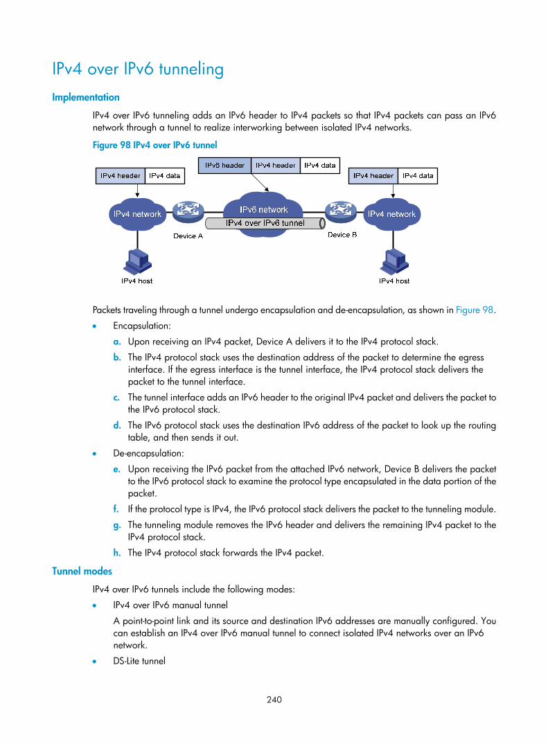
240
IPv4 over IPv6 tunneling Implementation
IPv4 over IPv6 tunneling adds an IPv6 header to IPv4 packets so that IPv4 packets can pass an IPv6 network through a tunnel to realize interworking between isolated IPv4 networks.
Figure 98 IPv4 over IPv6 tunnel
Packets traveling through a tunnel undergo encapsulation and de-encapsulation, as shown in Figure 98.
• Encapsulation:
a. Upon receiving an IPv4 packet, Device A delivers it to the IPv4 protocol stack.
b. The IPv4 protocol stack uses the destination address of the packet to determine the egress interface. If the egress interface is the tunnel interface, the IPv4 protocol stack delivers the packet to the tunnel interface.
c. The tunnel interface adds an IPv6 header to the original IPv4 packet and delivers the packet to the IPv6 protocol stack.
d. The IPv6 protocol stack uses the destination IPv6 address of the packet to look up the routing table, and then sends it out.
• De-encapsulation:
e. Upon receiving the IPv6 packet from the attached IPv6 network, Device B delivers the packet to the IPv6 protocol stack to examine the protocol type encapsulated in the data portion of the packet.
f. If the protocol type is IPv4, the IPv6 protocol stack delivers the packet to the tunneling module.
g. The tunneling module removes the IPv6 header and delivers the remaining IPv4 packet to the IPv4 protocol stack.
h. The IPv4 protocol stack forwards the IPv4 packet.
Tunnel modes
IPv4 over IPv6 tunnels include the following modes:
• IPv4 over IPv6 manual tunnel
A point-to-point link and its source and destination IPv6 addresses are manually configured. You can establish an IPv4 over IPv6 manual tunnel to connect isolated IPv4 networks over an IPv6 network.
• DS-Lite tunnel

241
Dual Stack Lite (DS-Lite) is a combination of the tunneling and NAT technologies. NAT translates the private IPv4 addresses of the IPv4 hosts before the hosts reach the IPv4 public network.
DS-Lite tunnel supports only an IPv4 host in a private network initiating communication with an IPv4 host on the Internet. It does not support an IPv4 host on the Internet initiating communication with an IPv4 host in a private network.
Figure 99 DS-Lite tunnel
As shown in Figure 99, the DS-Lite feature contains the following components:
Basic Bridging BroadBand (B4) element
The B4 element is typically a CPE router that connects end hosts. IPv4 packets entering the B4 router are encapsulated into IPv6 packets and sent to the AFTR. IPv6 packets from the AFTR are de-encapsulated into IPv4 packets and sent to the subscriber's network.
Hosts that can serve as the B4 router are referred to as DS-Lite hosts.
Address Family Transition Router (AFTR)
An AFTR resides in the ISP network and terminates the tunnel from the B4 router. NAT is also implemented on the interface that connects the public IPv4 network.
AFTR de-encapsulates the tunneled packet, translates the network address, and routes the packet to the destination IPv4 network. For IPv4 packets coming from the public IPv4 network, AFTR performs reverse address translation and sends them to the B4 router by using the DS-Lite tunnel.
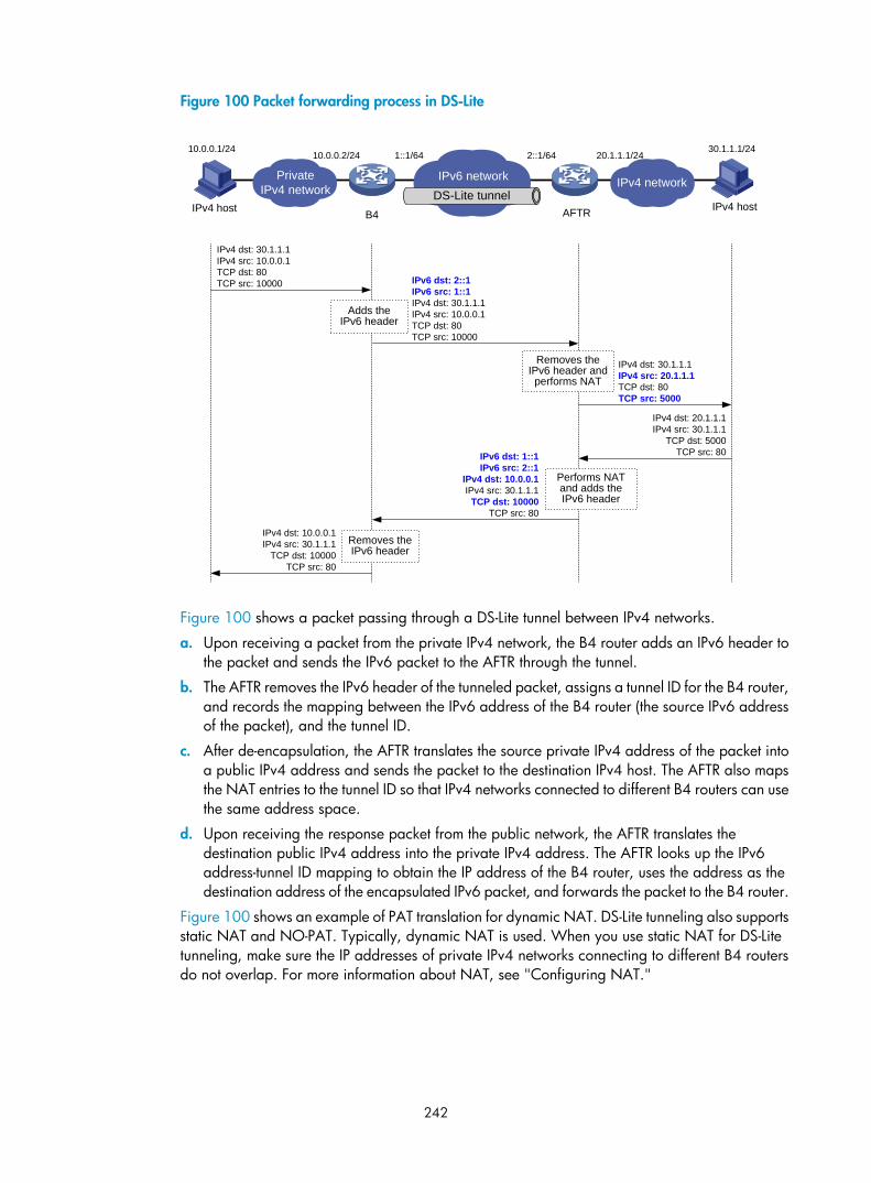
242
Figure 100 Packet forwarding process in DS-Lite
Figure 100 shows a packet passing through a DS-Lite tunnel between IPv4 networks.
a. Upon receiving a packet from the private IPv4 network, the B4 router adds an IPv6 header to the packet and sends the IPv6 packet to the AFTR through the tunnel.
b. The AFTR removes the IPv6 header of the tunneled packet, assigns a tunnel ID for the B4 router, and records the mapping between the IPv6 address of the B4 router (the source IPv6 address of the packet), and the tunnel ID.
c. After de-encapsulation, the AFTR translates the source private IPv4 address of the packet into a public IPv4 address and sends the packet to the destination IPv4 host. The AFTR also maps the NAT entries to the tunnel ID so that IPv4 networks connected to different B4 routers can use the same address space.
d. Upon receiving the response packet from the public network, the AFTR translates the destination public IPv4 address into the private IPv4 address. The AFTR looks up the IPv6 address-tunnel ID mapping to obtain the IP address of the B4 router, uses the address as the destination address of the encapsulated IPv6 packet, and forwards the packet to the B4 router.
Figure 100 shows an example of PAT translation for dynamic NAT. DS-Lite tunneling also supports static NAT and NO-PAT. Typically, dynamic NAT is used. When you use static NAT for DS-Lite tunneling, make sure the IP addresses of private IPv4 networks connecting to different B4 routers do not overlap. For more information about NAT, see "Configuring NAT."
30.1.1.1/2410.0.0.1/24
PrivateIPv4 network IPv4 network
IPv4 host IPv4 hostB4 AFTR
IPv4 dst: 30.1.1.1IPv4 src: 10.0.0.1TCP dst: 80TCP src: 10000
IPv4 dst: 20.1.1.1IPv4 src: 30.1.1.1
TCP dst: 5000TCP src: 80
IPv6 networkDS-Lite tunnel
10.0.0.2/24 1::1/64 2::1/64 20.1.1.1/24
IPv6 dst: 2::1IPv6 src: 1::1IPv4 dst: 30.1.1.1IPv4 src: 10.0.0.1TCP dst: 80TCP src: 10000
IPv4 dst: 30.1.1.1IPv4 src: 20.1.1.1TCP dst: 80TCP src: 5000
IPv6 dst: 1::1IPv6 src: 2::1
IPv4 dst: 10.0.0.1IPv4 src: 30.1.1.1
TCP dst: 10000TCP src: 80
IPv4 dst: 10.0.0.1IPv4 src: 30.1.1.1
TCP dst: 10000TCP src: 80
Removes the IPv6 header and performs NAT
Performs NAT and adds the IPv6 header
Removes the IPv6 header
Adds the IPv6 header

243
IPv6 over IPv6 tunneling IPv6 over IPv6 tunneling (RFC 2473) enables isolated IPv6 networks to communicate with each other over another IPv6 network. For example, two isolated IPv6 networks that do not want to show their addresses to the Internet can use an IPv6 over IPv6 tunnel to communicate with each other.
Figure 101 Principle of IPv6 over IPv6 tunneling
Figure 101 shows the encapsulation and de-encapsulation processes.
• Encapsulation:
a. After receiving an IPv6 packet, Device A submits it to the IPv6 protocol stack.
b. The IPv6 protocol stack uses the destination IPv6 address of the packet to find the egress interface. If the egress interface is the tunnel interface, the stack delivers it to the tunnel interface.
c. After receiving the packet, the tunnel interface adds an IPv6 header to it and submits it to the IPv6 protocol stack.
d. The IPv6 protocol stack forwards the packet according to its destination IPv6 address.
• De-encapsulation:
e. Upon receiving the IPv6 packet, Device B delivers it to the IPv6 protocol stack.
f. The IPv6 protocol stack checks the protocol type of the data portion encapsulated in the IPv6 packet. If the encapsulation protocol is IPv6, the stack delivers the packet to the tunnel module.
g. The tunnel module de-encapsulates the packet and sends it back to the IPv6 protocol stack.
h. The IPv6 protocol stack forwards the IPv6 packet.
Protocols and standards • RFC 1853, IP in IP Tunneling
• RFC 2473, Generic Packet Tunneling in IPv6 Specification
• RFC 2893, Transition Mechanisms for IPv6 Hosts and Routers
• RFC 3056, Connection of IPv6 Domains via IPv4 Clouds
• RFC 4214, Intra-Site Automatic Tunnel Addressing Protocol (ISATAP)
• RFC 6333, Dual-Stack Lite Broadband Deployments Following IPv4 Exhaustion

244
Tunneling configuration task list Tasks at a glance
(Required.) Configuring a tunnel interface
Perform one of the following tasks: • Configuring an IPv6 over IPv4 tunnel:
Configuring an IPv6 over IPv4 manual tunnel Configuring an automatic IPv4-compatible IPv6 tunnel Configuring a 6to4 tunnel Configuring an ISATAP tunnel
• Configuring an IPv4 over IPv4 tunnel • Configuring an IPv4 over IPv6 tunnel:
Configuring an IPv4 over IPv6 manual tunnel Configuring a DS-Lite tunnel Configuring an IPv6 over IPv6 tunnel
Configuring a tunnel interface Configure a Layer 3 virtual tunnel interface on each device on a tunnel so that devices at both ends can send, identify, and process packets from the tunnel.
When an active/standby switchover occurs or the standby card is removed on an MSR 5600 router, the tunnel interfaces configured still exist. To delete a tunnel interface, use the undo interface tunnel command.
To configure a tunnel interface:
Step Command Remarks 1. Enter system view. system-view N/A
2. Create a tunnel interface, specify the tunnel mode, and enter tunnel interface view.
interface tunnel number mode { ds-lite-aftr | gre [ ipv6 ] | ipv4-ipv4 | ipv6 | ipv6-ipv4 [ 6to4 | auto-tunnel | isatap ] | mpls-te }
By default, no tunnel interface is created.
When you create a new tunnel interface, you must specify the tunnel mode. When you enter the view of an existing tunnel interface, you do not need to specify the tunnel mode.
The two ends of a tunnel must use the same tunnel mode. Otherwise, packet tunneling will fail.
3. (Optional.) Configure a description for the interface. description text
By default, the description of a tunnel interface is Tunnel number Interface.
4. Set the MTU of the tunnel interface. mtu mtu-size By default, the MTU is 64000 bytes.
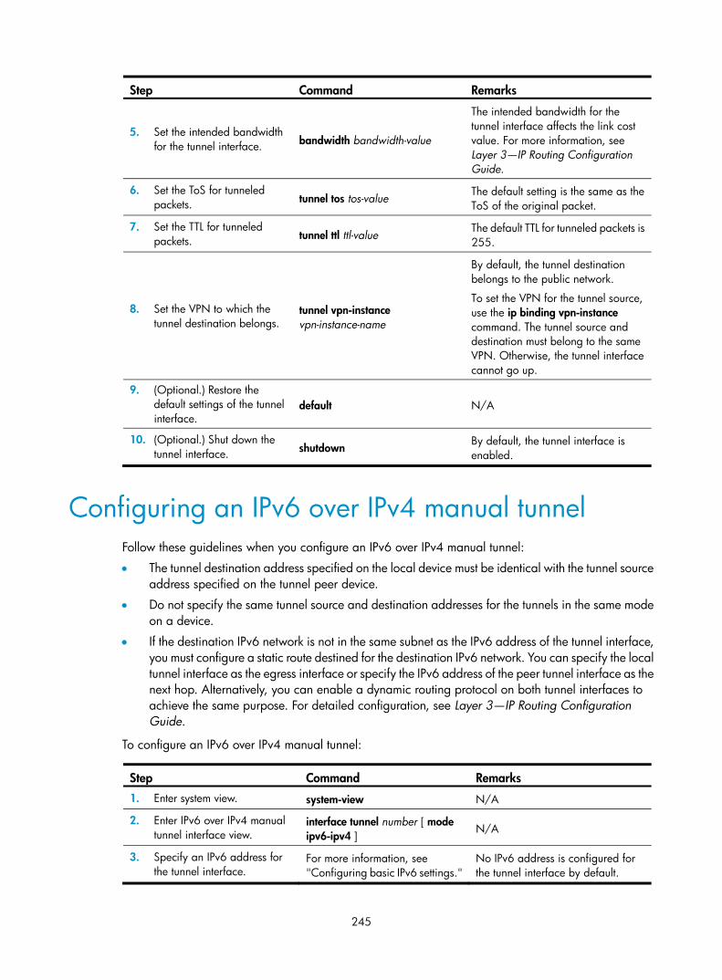
245
Step Command Remarks
5. Set the intended bandwidth for the tunnel interface. bandwidth bandwidth-value
The intended bandwidth for the tunnel interface affects the link cost value. For more information, see Layer 3—IP Routing Configuration Guide.
6. Set the ToS for tunneled packets. tunnel tos tos-value
The default setting is the same as the ToS of the original packet.
7. Set the TTL for tunneled packets. tunnel ttl ttl-value
The default TTL for tunneled packets is 255.
8. Set the VPN to which the tunnel destination belongs.
tunnel vpn-instance vpn-instance-name
By default, the tunnel destination belongs to the public network.
To set the VPN for the tunnel source, use the ip binding vpn-instance command. The tunnel source and destination must belong to the same VPN. Otherwise, the tunnel interface cannot go up.
9. (Optional.) Restore the default settings of the tunnel interface.
default N/A
10. (Optional.) Shut down the tunnel interface. shutdown
By default, the tunnel interface is enabled.
Configuring an IPv6 over IPv4 manual tunnel Follow these guidelines when you configure an IPv6 over IPv4 manual tunnel:
• The tunnel destination address specified on the local device must be identical with the tunnel source address specified on the tunnel peer device.
• Do not specify the same tunnel source and destination addresses for the tunnels in the same mode on a device.
• If the destination IPv6 network is not in the same subnet as the IPv6 address of the tunnel interface, you must configure a static route destined for the destination IPv6 network. You can specify the local tunnel interface as the egress interface or specify the IPv6 address of the peer tunnel interface as the next hop. Alternatively, you can enable a dynamic routing protocol on both tunnel interfaces to achieve the same purpose. For detailed configuration, see Layer 3—IP Routing Configuration Guide.
To configure an IPv6 over IPv4 manual tunnel:
Step Command Remarks 1. Enter system view. system-view N/A
2. Enter IPv6 over IPv4 manual tunnel interface view.
interface tunnel number [ mode ipv6-ipv4 ]
N/A
3. Specify an IPv6 address for the tunnel interface.
For more information, see "Configuring basic IPv6 settings."
No IPv6 address is configured for the tunnel interface by default.

246
Step Command Remarks
4. Configure a source address or source interface for the tunnel interface.
source { ip-address | interface-type interface-number }
By default, no source address or source interface is configured for the tunnel interface.
The specified source address or the primary IP address of the specified source interface is used as the source IP address of tunneled packets.
5. Configure a destination address for the tunnel interface.
destination ip-address
By default, no destination address is configured for the tunnel interface.
The tunnel destination address must be the IP address of the receiving interface on the tunnel peer. It is used as the destination IP address of tunneled packets.
6. (Optional.) Set the DF bit for tunneled packets. tunnel dfbit enable
The DF bit is not set for tunneled packets by default.
7. Return to system view. quit N/A
8. (Optional.) Enable dropping of IPv6 packets using IPv4-compatible IPv6 addresses.
tunnel discard ipv4-compatible-packet This feature is disabled by default.
Configuration example Network requirements
As shown in Figure 102, configure an IPv6 over IPv4 tunnel between Router A and Router B so the two IPv6 networks can reach each other over the IPv4 network. Because the tunnel destination IPv4 address cannot be automatically obtained from the destination IPv6 addresses of packets, configure an IPv6 over IPv4 manual tunnel.
Figure 102 Network diagram
Configuration procedure
Make sure Router A and Router B can reach each other through IPv4.
• Configure Router A:
# Specify an IPv4 address for Ethernet 1/2. <RouterA> system-view

247
[RouterA] interface ethernet 1/2
[RouterA-Ethernet1/2] ip address 192.168.100.1 255.255.255.0
[RouterA-Ethernet1/2] quit
# Specify an IPv6 address for Ethernet 1/1. [RouterA] interface ethernet 1/1
[RouterA-Ethernet1/1] ipv6 address 3002::1 64
[RouterA-Ethernet1/1] quit
# Configure an IPv6 over IPv4 manual tunnel interface tunnel 0. [RouterA] interface tunnel 0 mode ipv6-ipv4
# Specify an IPv6 address for the tunnel interface. [RouterA-Tunnel0] ipv6 address 3001::1/64
# Specify Ethernet1/2 as the source interface of the tunnel interface. [RouterA-Tunnel0] source ethernet 1/2
# Specify the destination address for the tunnel interface as the IP address of Ethernet1/2 on Router B. [RouterA-Tunnel0] destination 192.168.50.1
[RouterA-Tunnel0] quit
# Configure a static route destined for IPv6 network 2 through Tunnel 0 on Router A. [RouterA] ipv6 route-static 3003:: 64 tunnel 0
• Configure Router B:
# Specify an IPv4 address for Ethernet 1/2. <RouterB> system-view
[RouterB] interface ethernet 1/2
[RouterB-Ethernet1/2] ip address 192.168.50.1 255.255.255.0
[RouterB-Ethernet1/2] quit
# Specify an IPv6 address for Ethernet 1/1. [RouterB] interface ethernet 1/1
[RouterB-Ethernet1/1] ipv6 address 3003::1 64
[RouterB-Ethernet1/1] quit
# Configure an IPv6 over IPv4 manual tunnel interface tunnel 0. [RouterB] interface tunnel 0 mode ipv6-ipv4
# Specify an IPv6 address for the tunnel interface. [RouterB-Tunnel0] ipv6 address 3001::2/64
# Specify Ethernet1/2 as the source interface of the tunnel interface. [RouterB-Tunnel0] source ethernet 1/2
# Specify the destination address for the tunnel interface as the IP address of Ethernet1/2 on Router A. [RouterB-Tunnel0] destination 192.168.50.1
[RouterB-Tunnel0] quit
# Configure a static route destined for IPv6 network 1 through Tunnel 0 on Router B. [RouterB] ipv6 route-static 3002:: 64 tunnel 0
Verifying the configuration
# Use the display ipv6 interface command to view tunnel interface status on Router A and Router B. The output shows that the interface tunnel 0 is up. (Details not shown.)

248
# Router B and Router A can ping the IPv6 address of Ethernet 1/1 of each other. For example, ping the IPv6 address of Ethernet 1/1 on Router B from Router A. [RouterA] ping ipv6 3003::1
Ping6(56 data bytes) 3001::1 --> 3003::1, press escape sequence to break
56 bytes from 3003::1, icmp_seq=0 hlim=64 time=45.000 ms
56 bytes from 3003::1, icmp_seq=1 hlim=64 time=10.000 ms
56 bytes from 3003::1, icmp_seq=2 hlim=64 time=4.000 ms
56 bytes from 3003::1, icmp_seq=3 hlim=64 time=10.000 ms
56 bytes from 3003::1, icmp_seq=4 hlim=64 time=11.000 ms
--- Ping6 statistics for 3003::1 ---
5 packet(s) transmitted, 5 packet(s) received, 0.0% packet loss
round-trip min/avg/max/std-dev = 4.000/16.000/45.000/14.711 ms
Configuring an automatic IPv4-compatible IPv6 tunnel
Follow these guidelines when you configure an automatic IPv4-compatible IPv6 tunnel:
• You do not need to configure a destination address for an automatic IPv4-compatible IPv6 tunnel, because the destination address of the tunnel is embedded in the destination IPv4-compatible IPv6 address of packets.
• The source addresses of local tunnels of the same tunnel mode cannot be the same.
To configure an automatic IPv4-compatible IPv6 tunnel:
Step Command Remarks 1. Enter system view. system-view N/A
2. Enter automatic IPv4-compatible IPv6 tunnel interface view.
interface tunnel number [ mode ipv6-ipv4 auto-tunnel ]
N/A
3. Specify an IPv6 address for the tunnel interface.
For more information, see "Configuring basic IPv6 settings."
No IPv6 address is configured for the tunnel interface by default.
4. Configure a source address or source interface for the tunnel interface.
source { ip-address | interface-type interface-number }
By default, no source address or source interface is configured for the tunnel interface.
The specified source address or the primary IP address of the specified source interface is used as the source IP address of tunneled packets.
5. (Optional.) Set the DF bit for tunneled packets. tunnel dfbit enable
The DF bit is not set for tunneled packets by default.

249
Configuration example Network requirements
As shown in Figure 103, dual-stack routers Router A and Router B communicate over an IPv4 network. Configure an automatic IPv4-compatible IPv6 tunnel between the two routers to enable IPv6 communications over the IPv4 network.
Figure 103 Network diagram
Configuration procedure
Before configuring an automatic IPv4-compatible IPv6 tunnel, make sure Router A and Router B can reach each other through IPv4.
• Configure Router A:
# Specify an IPv4 address for Ethernet 1/1. <RouterA> system-view
[RouterA] interface ethernet 1/1
[RouterA-Ethernet1/1] ip address 192.168.100.1 255.255.255.0
[RouterA-Ethernet1/1] quit
# Create an automatic IPv4-compatible IPv6 tunnel. [RouterA] interface tunnel 0 mode ipv6-ipv4 auto-tunnel
# Specify an IPv4-compatible IPv6 address for the tunnel interface. [RouterA-Tunnel0] ipv6 address ::192.168.100.1/96
# Specify Ethernet1/1 as the source interface of the tunnel interface. [RouterA-Tunnel0] source ethernet 1/1
• Configure Router B:
# Specify an IPv4 address for Ethernet 1/1. <RouterB> system-view
[RouterB] interface ethernet 1/1
[RouterB-Ethernet1/1] ip address 192.168.50.1 255.255.255.0
[RouterB-Ethernet1/1] quit
# Configure an automatic IPv4-compatible IPv6 tunnel. [RouterB] interface tunnel 0 mode ipv6-ipv4 auto-tunnel
# Specify an IPv4-compatible IPv6 address for the tunnel interface. [RouterB-Tunnel0] ipv6 address ::192.168.50.1/96
# Specify Ethernet1/1 as the source interface of the tunnel interface. [RouterB-Tunnel0] source ethernet 1/1
Verifying the configuration
# Use the display ipv6 interface command to view tunnel interface status on Router A and Router B. The output shows that the interface tunnel 0 is up. (Details not shown.)

250
# Router B and Router A can ping the IPv4-compatible IPv6 address of each other. For example, ping the IPv4-compatible IPv6 address on Router B from Router A. [RouterA-Tunnel0] ping ipv6 ::192.168.50.1
Ping6(56 data bytes) ::192.168.100.1 --> ::192.168.50.1, press escape sequence to break
56 bytes from ::192.168.50.1, icmp_seq=0 hlim=64 time=17.000 ms
56 bytes from ::192.168.50.1, icmp_seq=1 hlim=64 time=9.000 ms
56 bytes from ::192.168.50.1, icmp_seq=2 hlim=64 time=11.000 ms
56 bytes from ::192.168.50.1, icmp_seq=3 hlim=64 time=9.000 ms
56 bytes from ::192.168.50.1, icmp_seq=4 hlim=64 time=11.000 ms
--- Ping6 statistics for ::192.168.50.1 ---
5 packet(s) transmitted, 5 packet(s) received, 0.0% packet loss
round-trip min/avg/max/std-dev = 9.000/11.400/17.000/2.939 ms
Configuring a 6to4 tunnel Follow these guidelines when you configure a 6to4 tunnel:
• You do not need to configure a destination address for a 6to4 tunnel, because the destination IPv4 address is embedded in the 6to4 IPv6 address.
• The source addresses of local tunnels of the same tunnel mode cannot be the same.
• Because automatic tunnels do not support dynamic routing, you must configure a static route destined for the destination IPv6 network if the destination IPv6 network is not in the same subnet as the IPv6 address of the tunnel interface. You can specify the local tunnel interface as the egress interface of the route or specify the IPv6 address of the peer tunnel interface as the next hop of the route. For the detailed configuration, see Layer 3—IP Routing Configuration Guide.
To configure a 6to4 tunnel:
Step Command Remarks 1. Enter system view. system-view N/A
2. Enter 6to4 tunnel interface view.
interface tunnel number [ mode ipv6-ipv4 6to4 ]
N/A
3. Specify an IPv6 address for the tunnel interface.
For more information, see "Configuring basic IPv6 settings."
No IPv6 address is configured for the tunnel interface by default.
4. Configure a source address or source interface for the tunnel interface.
source { ip-address | interface-type interface-number }
By default, no source address or source interface is configured for the tunnel interface.
The specified source address or the primary IP address of the specified source interface is used as the source IP address of tunneled packets.
5. (Optional.) Set the DF bit for tunneled packets. tunnel dfbit enable
The DF bit is not set for tunneled packets by default.
6. Return to system view. quit N/A

251
Step Command Remarks 7. (Optional.) Enable
dropping of IPv6 packets using IPv4-compatible IPv6 addresses.
tunnel discard ipv4-compatible-packet The default setting is disabled.
6to4 tunnel configuration example Network requirements
As shown in Figure 104, configure a 6to4 tunnel between 6to4 routers Router A and Router B so Host A and Host B can reach each other over the IPv4 network.
Figure 104 Network diagram
Configuration considerations
To enable communication between 6to4 networks, configure 6to4 addresses for 6to4 routers and hosts in the 6to4 networks.
• The IPv4 address of Ethernet 1/2 on Router A is 2.1.1.1/24, and the corresponding 6to4 prefix is 2002:0201:0101::/48. Host A must use this prefix.
• The IPv4 address of Ethernet 1/2 on Router B is 5.1.1.1/24, and the corresponding 6to4 prefix is 2002:0501:0101::/48. Host B must use this prefix.
Configuration procedure
Before configuring a 6to4 tunnel, make sure Router A and Router B can reach each other through IPv4.
• Configure Router A:
# Specify an IPv4 address for Ethernet 1/2. <RouterA> system-view
[RouterA] interface ethernet 1/2
[RouterA-Ethernet1/2] ip address 2.1.1.1 24
[RouterA-Ethernet1/2] quit
# Specify a 6to4 address for Ethernet 1/1. [RouterA] interface ethernet 1/1
[RouterA-Ethernet1/1] ipv6 address 2002:0201:0101:1::1/64
[RouterA-Ethernet1/1] quit
# Create a 6to4 tunnel interface tunnel 0.

252
[RouterB] interface tunnel 0 mode ipv6-ipv4 6to4
# Specify an IPv6 address for the tunnel interface. [RouterA-Tunnel0] ipv6 address 3001::1/64
# Specify the source interface as Ethernet1/2 for the tunnel interface. [RouterA-Tunnel0] source ethernet 1/2
[RouterA-Tunnel0] quit
# Configure a static route destined for 2002::/16 through the tunnel interface. [RouterA] ipv6 route-static 2002:: 16 tunnel 0
• Configure Router B:
# Specify an IPv4 address for Ethernet 1/2. <RouterB> system-view
[RouterB] interface ethernet 1/2
[RouterB-Ethernet1/2] ip address 5.1.1.1 24
[RouterB-Ethernet1/2] quit
# Specify a 6to4 address for Ethernet 1/1. [RouterB] interface ethernet 1/1
[RouterB-Ethernet1/1] ipv6 address 2002:0501:0101:1::1/64
[RouterB-Ethernet1/1] quit
# Create a 6to4 tunnel interface. [RouterB] interface tunnel 0 mode ipv6-ipv4 6to4
# Specify an IPv6 address for the tunnel interface. [RouterB-Tunnel0] ipv6 address 3002::1/64
# Specify the source interface as Ethernet1/2 for the tunnel interface. [RouterB-Tunnel0] source ethernet 1/2
[RouterB-Tunnel0] quit
# Configure a static route destined for 2002::/16 through the tunnel interface. [RouterB] ipv6 route-static 2002:: 16 tunnel 0
Verifying the configuration
# Ping either host from the other, and the ping operation succeeds. D:\>ping6 -s 2002:201:101:1::2 2002:501:101:1::2
Pinging 2002:501:101:1::2
from 2002:201:101:1::2 with 32 bytes of data:
Reply from 2002:501:101:1::2: bytes=32 time=13ms
Reply from 2002:501:101:1::2: bytes=32 time=1ms
Reply from 2002:501:101:1::2: bytes=32 time=1ms
Reply from 2002:501:101:1::2: bytes=32 time<1ms
Ping statistics for 2002:501:101:1::2:
Packets: Sent = 4, Received = 4, Lost = 0 (0% loss),
Approximate round trip times in milli-seconds:
Minimum = 0ms, Maximum = 13ms, Average = 3ms

253
6to4 relay configuration example Network requirements
As shown in Figure 105, Router A is a 6to4 router, and 6to4 addresses are used on the connected IPv6 network. Router B serves as a 6to4 relay router and is connected to an IPv6 network (2001::/16). Configure a 6to4 tunnel between Router A and Router B to make Host A and Host B reachable to each other.
The configuration on a 6to4 relay router is similar to that on a 6to4 router. However, to enable communication between the 6to4 network and the IPv6 network, you must configure a route to the IPv6 network on the 6to4 router. The IPv4 address of Ethernet 1/2 on the relay router is 6.1.1.1/24 and its corresponding 6to4 prefix is 2002:0601:0101::/48. The next hop of the static route must be an address using this prefix.
Figure 105 Network diagram
Configuration procedure
Make sure Router A and Router B can reach each other through IPv4.
• Configure Router A:
# Specify an IPv4 address for Ethernet 1/2. <RouterA> system-view
[RouterA] interface ethernet 1/2
[RouterA-Ethernet1/2] ip address 2.1.1.1 255.255.255.0
[RouterA-Ethernet1/2] quit
# Specify a 6to4 address for Ethernet 1/1. [RouterA] interface ethernet 1/1
[RouterA-Ethernet1/1] ipv6 address 2002:0201:0101:1::1/64
[RouterA-Ethernet1/1] quit
# Configure a 6to4 tunnel interface tunnel 0. [RouterA] interface tunnel 0 mode ipv6-ipv4 6to4
# Specify an IPv6 address for the tunnel interface. [RouterA-Tunnel0] ipv6 address 2002::1/64
# Specify Ethernet 1/2 as the source interface of the tunnel interface. [RouterA-Tunnel0] source ethernet 1/2
[RouterA-Tunnel0] quit
# Configure a static route to the 6to4 relay router.

254
[RouterA] ipv6 route-static 2002:0601:0101:: 64 tunnel 0
# Configure a default route to reach the IPv6 network, which specifies the next hop as the 6to4 address of the relay router. [RouterA] ipv6 route-static :: 0 2002:0601:0101::1
• Configure Router B:
# Specify an IPv4 address for Ethernet 1/2. <RouterB> system-view
[RouterB] interface ethernet 1/2
[RouterB-Ethernet1/2] ip address 6.1.1.1 255.255.255.0
[RouterB-Ethernet1/2] quit
# Specify an IPv6 address for Ethernet 1/1. [RouterB] interface ethernet 1/1
[RouterB-Ethernet1/1] ipv6 address 2001::1/16
[RouterB-Ethernet1/1] quit
# Configure a 6to4 tunnel interface tunnel 0. [RouterB] interface tunnel 0 mode ipv6-ipv4 6to4
# Specify an IPv6 address for the tunnel interface. [RouterB-Tunnel0] ipv6 address 2003::1/64
# Specify Ethernet 1/2 as the source interface of the tunnel interface. [RouterB-Tunnel0] source ethernet 1/2
[RouterB-Tunnel0] quit
# Configure a static route destined for 2002::/16 through the tunnel interface. [RouterB] ipv6 route-static 2002:: 16 tunnel 0
Verifying the configuration
# Ping Host B from Host A or ping Host A from Host B. The ping operation succeeds. D:\>ping6 -s 2002:201:101:1::2 2001::2
Pinging 2001::2
from 2002:201:101:1::2 with 32 bytes of data:
Reply from 2001::2: bytes=32 time=13ms
Reply from 2001::2: bytes=32 time=1ms
Reply from 2001::2: bytes=32 time=1ms
Reply from 2001::2: bytes=32 time<1ms
Ping statistics for 2001::2:
Packets: Sent = 4, Received = 4, Lost = 0 (0% loss),
Approximate round trip times in milli-seconds:
Minimum = 0ms, Maximum = 13ms, Average = 3ms
Configuring an ISATAP tunnel Follow these guidelines when you configure an ISATAP tunnel:
• You do not need to configure a destination address for an ISATAP tunnel, because the destination IPv4 address is embedded in the ISATAP address.

255
• Because automatic tunnels do not support dynamic routing, configure a static route destined for the destination IPv6 network at each tunnel end. You can specify the local tunnel interface as the egress interface of the route or specify the IPv6 address of the peer tunnel interface as the next hop of the route. For the detailed configuration, see Layer 3—IP Routing Configuration Guide.
• The source addresses of local tunnels of the same tunnel mode cannot be the same.
To configure an ISATAP tunnel:
Step Command Remarks 1. Enter system view. system-view N/A
2. Enter ISATAP tunnel interface view. interface tunnel number [ mode ipv6-ipv4 isatap ] N/A
3. Specify an IPv6 address for the tunnel interface.
For more information, see "Configuring basic IPv6 settings."
No IPv6 address is configured for the tunnel interface by default.
4. Configure a source address or source interface for the tunnel interface.
source { ip-address | interface-type interface-number }
By default, no source address or source interface is configured for the tunnel interface.
The specified source address or the primary IP address of the specified source interface is used as the source IP address of tunneled packets.
5. (Optional.) Set the DF bit for tunneled packets. tunnel dfbit enable
The DF bit is not set for tunneled packets by default.
6. Return to system view. quit N/A
7. (Optional.) Enable dropping of IPv6 packets using IPv4-compatible IPv6 addresses.
tunnel discard ipv4-compatible-packet
The default setting is disabled.
Configuration example Network requirements
As shown in Figure 106, configure an ISATAP tunnel between the router and the ISATAP host so the ISATAP host in the IPv4 network can access the IPv6 network.
Figure 106 Network diagram

256
Configuration procedure
• Configure the router:
# Specify an IPv6 address for Ethernet1/2. <Router> system-view
[Router] interface ethernet 1/2
[Router-Ethernet1/2] ipv6 address 3001::1/64
[Router-Ethernet1/2] quit
# Specify an IPv4 address for Ethernet1/1. [Router] interface ethernet 1/1
[Router-Ethernet1/1] ip address 1.1.1.1 255.0.0.0
[Router-Ethernet1/1] quit
# Create an ISATAP tunnel interface tunnel 0. [Router] interface tunnel 0 mode ipv6-ipv4 isatap
# Specify an EUI-64 IPv6 address for the tunnel interface. [Router-Tunnel0] ipv6 address 2001:: 64 eui-64
# Specify Ethernet 1/1 as the source interface of the tunnel interface. [Router-Tunnel0] source ethernet 1/1
# Disable RA suppression so that the ISATAP host can acquire information such as the address prefix from the RA message advertised by the ISATAP router. [Router-Tunnel0] undo ipv6 nd ra halt
[Router-Tunnel0] quit
• Configure the ISATAP host:
Configurations on the ISATAP host vary with the operating systems. The following example is performed on Windows XP:
# Install IPv6. C:\>ipv6 install
# On a host running Windows XP, the ISATAP interface is typically interface 2. Display information about the ISATAP interface. C:\>ipv6 if 2
Interface 2: Automatic Tunneling Pseudo-Interface
Guid {48FCE3FC-EC30-E50E-F1A7-71172AEEE3AE}
does not use Neighbor Discovery
does not use Router Discovery
routing preference 1
EUI-64 embedded IPv4 address: 0.0.0.0
router link-layer address: 0.0.0.0
preferred link-local fe80::5efe:1.1.1.2, life infinite
link MTU 1280 (true link MTU 65515)
current hop limit 128
reachable time 42500ms (base 30000ms)
retransmission interval 1000ms
DAD transmits 0
default site prefix length 48
# Specify an IPv4 address for the ISATAP router. C:\>netsh interface ipv6 isatap set router 1.1.1.1

257
# Display information about the ISATAP interface. C:\>ipv6 if 2
Interface 2: Automatic Tunneling Pseudo-Interface
Guid {48FCE3FC-EC30-E50E-F1A7-71172AEEE3AE}
does not use Neighbor Discovery
uses Router Discovery
routing preference 1
EUI-64 embedded IPv4 address: 1.1.1.2
router link-layer address: 1.1.1.1
preferred global 2001::5efe:1.1.1.2, life 29d23h59m46s/6d23h59m46s (public)
preferred link-local fe80::5efe:1.1.1.2, life infinite
link MTU 1500 (true link MTU 65515)
current hop limit 255
reachable time 42500ms (base 30000ms)
retransmission interval 1000ms
DAD transmits 0
default site prefix length 48
The host has acquired the prefix 2001::/64 and has automatically generated the global unicast address 2001::5efe:1.1.1.2. The message "uses Router Discovery" indicates that the router discovery function is enabled on the host.
# Display information about IPv6 routes on the host. C:\>ipv6 rt
2001::/64 -> 2 pref 1if+8=9 life 29d23h59m43s (autoconf)
::/0 -> 2/fe80::5efe:1.1.1.1 pref 1if+256=257 life 29m43s (autoconf)
• Configure the IPv6 host:
# Configure a route to the boarder router. C:\>netsh interface ipv6 set route 2001::/64 5 3001::1
Verifying the configuration
# Ping the IPv6 host from the ISATAP host. The ping operation succeeds, indicating an ISATAP tunnel has been established. C:\>ping 3001::2
Pinging 3001::2 with 32 bytes of data:
Reply from 3001::2: time=1ms
Reply from 3001::2: time=1ms
Reply from 3001::2: time=1ms
Reply from 3001::2: time=1ms
Ping statistics for 3001::2:
Packets: Sent = 4, Received = 4, Lost = 0 (0% loss),
Approximate round trip times in milli-seconds:
Minimum = 1ms, Maximum = 1ms, Average = 1ms
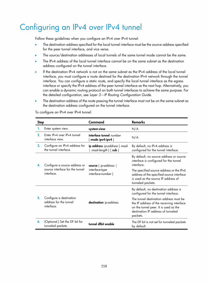
258
Configuring an IPv4 over IPv4 tunnel Follow these guidelines when you configure an IPv4 over IPv4 tunnel:
• The destination address specified for the local tunnel interface must be the source address specified for the peer tunnel interface, and vice versa.
• The source/destination addresses of local tunnels of the same tunnel mode cannot be the same.
• The IPv4 address of the local tunnel interface cannot be on the same subnet as the destination address configured on the tunnel interface.
• If the destination IPv4 network is not on the same subnet as the IPv4 address of the local tunnel interface, you must configure a route destined for the destination IPv4 network through the tunnel interface. You can configure a static route, and specify the local tunnel interface as the egress interface or specify the IPv4 address of the peer tunnel interface as the next hop. Alternatively, you can enable a dynamic routing protocol on both tunnel interfaces to achieve the same purpose. For the detailed configuration, see Layer 3—IP Routing Configuration Guide.
• The destination address of the route passing the tunnel interface must not be on the same subnet as the destination address configured on the tunnel interface.
To configure an IPv4 over IPv4 tunnel:
Step Command Remarks
1. Enter system view. system-view N/A
2. Enter IPv4 over IPv4 tunnel interface view.
interface tunnel number [ mode ipv4-ipv4 ] N/A
3. Configure an IPv4 address for the tunnel interface.
ip address ip-address { mask | mask-length } [ sub ]
By default, no IPv4 address is configured for the tunnel interface.
4. Configure a source address or source interface for the tunnel interface.
source { ip-address | interface-type interface-number }
By default, no source address or source interface is configured for the tunnel interface.
The specified source address or the IPv6 address of the specified source interface is used as the source IP address of tunneled packets.
5. Configure a destination address for the tunnel interface.
destination ip-address
By default, no destination address is configured for the tunnel interface.
The tunnel destination address must be the IP address of the receiving interface on the tunnel peer. It is used as the destination IP address of tunneled packets.
6. (Optional.) Set the DF bit for tunneled packets. tunnel dfbit enable
The DF bit is not set for tunneled packets by default.
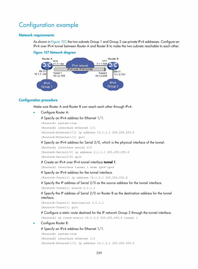
259
Configuration example Network requirements
As shown in Figure 107, the two subnets Group 1 and Group 2 use private IPv4 addresses. Configure an IPv4 over IPv4 tunnel between Router A and Router B to make the two subnets reachable to each other.
Figure 107 Network diagram
Configuration procedure
Make sure Router A and Router B can reach each other through IPv4.
• Configure Router A:
# Specify an IPv4 address for Ethernet 1/1. <RouterA> system-view
[RouterA] interface ethernet 1/1
[RouterA-Ethernet1/1] ip address 10.1.1.1 255.255.255.0
[RouterA-Ethernet1/1] quit
# Specify an IPv4 address for Serial 2/0, which is the physical interface of the tunnel. [RouterA] interface serial 2/0
[RouterA-Serial2/0] ip address 2.1.1.1 255.255.255.0
[RouterA-Serial2/0] quit
# Create an IPv4 over IPv4 tunnel interface tunnel 1. [RouterA] interface tunnel 1 mode ipv4-ipv4
# Specify an IPv4 address for the tunnel interface. [RouterA-Tunnel1] ip address 10.1.2.1 255.255.255.0
# Specify the IP address of Serial 2/0 as the source address for the tunnel interface. [RouterA-Tunnel1] source 2.1.1.1
# Specify the IP address of Serial 2/0 on Router B as the destination address for the tunnel interface. [RouterA-Tunnel1] destination 3.1.1.1
[RouterA-Tunnel1] quit
# Configure a static route destined for the IP network Group 2 through the tunnel interface. [RouterA] ip route-static 10.1.3.0 255.255.255.0 tunnel 1
• Configure Router B:
# Specify an IPv4 address for Ethernet 1/1. <RouterB> system-view
[RouterB] interface ethernet 1/1
[RouterB-Ethernet1/1] ip address 10.1.3.1 255.255.255.0

260
[RouterB-Ethernet1/1] quit
# Specify an IPv4 address for Serial 2/1, which is the physical interface of the tunnel. [RouterB] interface serial 2/1
[RouterB-Serial2/1] ip address 3.1.1.1 255.255.255.0
[RouterB-Serial2/1] quit
# Create an IPv4 over IPv4 tunnel interface tunnel 2. [RouterB] interface tunnel 2 mode ipv4-ipv4
# Specify an IPv4 address for the tunnel interface. [RouterB-Tunnel2] ip address 10.1.2.2 255.255.255.0
# Specify the IP address of Serial 2/1 as the source address for the tunnel interface. [RouterB-Tunnel2] source 3.1.1.1
# Specify the IP address of Serial 2/0 on Router A as a destination address for the tunnel interface. [RouterB-Tunnel2] destination 2.1.1.1
[RouterB-Tunnel2] quit
# Configure a static route destined for the IP network Group 1 through the tunnel interface. [RouterB] ip route-static 10.1.1.0 255.255.255.0 tunnel 2
Verifying the configuration
# Use the display interface tunnel command to display the status of the tunnel interfaces on Router A and Router B. The output shows that the tunnel interfaces are up. (Details not shown.)
# Ping the IPv4 address of the peer interface Ethernet 1/1 from each router. The following shows the output on Router A. [RouterA] ping -a 10.1.1.1 10.1.3.1
Ping 10.1.3.1 (10.1.3.1) from 10.1.1.1: 56 data bytes, press escape sequence to break
56 bytes from 10.1.3.1: icmp_seq=0 ttl=255 time=2.000 ms
56 bytes from 10.1.3.1: icmp_seq=1 ttl=255 time=1.000 ms
56 bytes from 10.1.3.1: icmp_seq=2 ttl=255 time=0.000 ms
56 bytes from 10.1.3.1: icmp_seq=3 ttl=255 time=1.000 ms
56 bytes from 10.1.3.1: icmp_seq=4 ttl=255 time=1.000 ms
--- Ping statistics for 10.1.3.1 ---
5 packet(s) transmitted, 5 packet(s) received, 0.0% packet loss
round-trip min/avg/max/stddev = 0.000/1.000/2.000/0.632 ms
Configuring an IPv4 over IPv6 manual tunnel Follow these guidelines when you configure an IPv4 over IPv6 manual tunnel:
• The destination address specified for the local tunnel interface must be the source address specified for the peer tunnel interface, and vice versa.
• The source/destination addresses of local tunnels of the same tunnel mode cannot be the same.
• If the destination IPv4 network is not on the same subnet as the IPv4 address of the local tunnel interface, you must configure a route destined for the destination IPv4 network through the tunnel interface. You can configure a static route, and specify the local tunnel interface as the egress interface or specify the IPv6 address of the peer tunnel interface as the next hop. Alternatively, you can enable a dynamic routing protocol on both tunnel interfaces to achieve the same purpose. For the detailed configuration, see Layer 3—IP Routing Configuration Guide.

261
To configure an IPv4 over IPv6 manual tunnel:
Step Command Remarks
1. Enter system view. system-view N/A
2. Enter tunnel interface view.
interface tunnel number [ mode ipv6 ] N/A
3. Configure an IPv4 address for the tunnel interface.
ip address ip-address { mask | mask-length } [ sub ]
By default, no IPv4 address is configured for the tunnel interface.
4. Configure the source address or interface for the tunnel interface.
source { ipv6-address | interface-type interface-number }
By default, no source address or interface is configured for the tunnel.
The specified source address or the primary IPv6 address of the specified source interface is used as the source IPv6 address of tunneled packets.
5. Configure the destination address for the tunnel interface.
destination ipv6-address
By default, no destination address is configured for the tunnel.
The tunnel destination address must be the IPv6 address of the receiving interface on the tunnel peer. It is used as the destination IPv6 address of tunneled packets.
Configuration example Network requirements
As shown in Figure 108, configure an IPv4 over IPv6 manual tunnel between Router A and Router B so the two IPv4 networks can reach each other over the IPv6 network.
Figure 108 Network diagram
Configuration procedure
Make sure Router A and Router B can reach each other through IPv6.
• Configure Router A:
# Specify an IPv4 address for Ethernet 1/1. <RouterA> system-view
[RouterA] interface ethernet 1/1
[RouterA-Ethernet1/1] ip address 30.1.1.1 255.255.255.0
[RouterA-Ethernet1/1] quit
S2/02001::1:1/64
Eth1/130.1.3.1/24
Eth1/130.1.1.1/24
Router A
IPv6 network
IPv4network 1
Tunnel130.1.2.1/24
S2/12002::2:1/64
Tunnel230.1.2.2/24
IPv4network 2
Router B
IPv4 over IPv6 tunnel

262
# Specify an IPv6 address for Serial 2/0, which is the physical interface of the tunnel. [RouterA] interface serial 2/0
[RouterA-Serial2/0] ipv6 address 2001::1:1 64
[RouterA-Serial2/0] quit
# Create an IPv6 tunnel interface tunnel 1. [RouterA] interface tunnel 1 mode ipv6
# Specify an IPv4 address for the tunnel interface. [RouterA-Tunnel1] ip address 30.1.2.1 255.255.255.0
# Specify the IP address of Serial 2/0 as the source address for the tunnel interface. [RouterA-Tunnel1] source 2001::1:1
# Specify the IP address of Serial 2/1 on Router B as the destination address for the tunnel interface. [RouterA-Tunnel1] destination 2002::2:1
[RouterA-Tunnel1] quit
# Configure a static route destined for IPv4 network 2 through the tunnel interface. [RouterA] ip route-static 30.1.3.0 255.255.255.0 tunnel 1
• Configure Router B:
# Specify an IPv4 address for Ethernet 1/1. <RouterB> system-view
[RouterB] interface ethernet 1/1
[RouterB-Ethernet1/1] ip address 30.1.3.1 255.255.255.0
[RouterB-Ethernet1/1] quit
# Specify an IPv6 address for Serial 2/1, which is the physical interface of the tunnel. [RouterB] interface serial 2/1
[RouterB-Serial2/1] ipv6 address 2002::2:1 64
[RouterB-Serial2/1] quit
# Create an IPv6 tunnel interface tunnel 2. [RouterB] interface tunnel 2 mode ipv6
# Specify an IPv4 address for the tunnel interface. [RouterB-Tunnel2] ip address 30.1.2.2 255.255.255.0
# Specify the IP address of Serial 2/1 as the source address for the tunnel interface. [RouterB-Tunnel2] source 2002::2:1
# Specify the IP address of Serial 2/0 on Router A as the destination address for the tunnel interface. [RouterB-Tunnel2] destination 2001::1:1
[RouterB-Tunnel2] quit
# Configure a static route destined for IPv4 network 1 through the tunnel interface. [RouterB] ip route-static 30.1.1.0 255.255.255.0 tunnel 2
Verifying the configuration
# Use the display interface tunnel command to display the status of the tunnel interfaces on Router A and Router B. The output shows that the tunnel interfaces are up. (Details not shown.)
# Ping the IPv4 address of the peer interface Ethernet 1/1 from each router. The following shows the output on Router A. [RouterA] ping -a 30.1.1.1 30.1.3.1

263
Ping 30.1.3.1 (30.1.3.1) from 30.1.1.1: 56 data bytes, press escape sequence to break
56 bytes from 30.1.3.1: icmp_seq=0 ttl=255 time=3.000 ms
56 bytes from 30.1.3.1: icmp_seq=1 ttl=255 time=1.000 ms
56 bytes from 30.1.3.1: icmp_seq=2 ttl=255 time=0.000 ms
56 bytes from 30.1.3.1: icmp_seq=3 ttl=255 time=1.000 ms
56 bytes from 30.1.3.1: icmp_seq=4 ttl=255 time=1.000 ms
--- Ping statistics for 30.1.3.1 ---
5 packet(s) transmitted, 5 packet(s) received, 0.0% packet loss
round-trip min/avg/max/stddev = 0.000/1.200/3.000/0.980 ms
Configuring a DS-Lite tunnel A B4 tunnel interface can establish a tunnel with only one AFTR tunnel interface, but an AFTR tunnel interface can establish tunnels with multiple B4 tunnel interfaces.
Follow these guidelines when you configure the B4 router of a DS-Lite tunnel:
• The source addresses of local tunnels of the same tunnel mode cannot be the same.
• The destination address specified for the tunnel interface on the B4 router must be the source address specified for the tunnel interface on the AFTR.
• If the destination IPv4 network is not on the same subnet as the IPv4 address of the local tunnel interface, you must configure a route destined for the destination IPv4 network through the tunnel interface. You can configure a static route, and specify the local tunnel interface as the egress interface or specify the IPv6 address of the peer tunnel interface as the next hop. Alternatively, you can enable a dynamic routing protocol on both tunnel interfaces to achieve the same purpose. For the detailed configuration, see Layer 3—IP Routing Configuration Guide.
Follow these guidelines when you configure the AFTR of a DS-Lite tunnel:
• The source addresses of local tunnels of the same tunnel mode cannot be the same.
• Enable NAT on the interface that connects to the public IPv4 interface.
• The tunnel destination cannot be configured on the AFTR. The AFTR uses the address of the B4 router as the IPv6 address of the tunnel destination.
• It is not necessary to configure a route to the destination IPv4 address for forwarding packets through the tunnel interface.
This section only covers the AFTR configuration. For information about B4 router configuration, see "Configuring an IPv4 over IPv6 manual tunnel."
To configure the AFTR of a DS-Lite tunnel:
Step Command Remarks
1. Enter system view. system-view N/A
2. Enter the view of the tunnel interface on the AFTR.
interface tunnel number [ mode ds-lite-aftr ] N/A
3. Specify an IPv4 address for the tunnel interface.
ip address ip-address { mask | mask-length } [ sub ]
By default, no IPv4 address is specified for the tunnel interface.

264
Step Command Remarks
4. Specify the source address or source interface for the tunnel.
source { ipv6-address | interface-type interface-number }
By default, no source address or interface is specified for the tunnel.
If you specify a source address, it is used as the source address of the encapsulated IPv6 packets.
If you specify a source interface, the address of this interface is used as the source address of the encapsulated IPv6 packets.
5. Exit to system view. quit N/A
6. Enter the view of the interface that connects the IPv4 public network.
interface interface-type interface-number
N/A
7. Enable DS-Lite tunneling on the interface. ds-lite enable
By default, DS-Lite tunneling is disabled.
Only after you use this command, the AFTR can tunnel IPv4 packets from the public IPv4 network to the B4 router.
Configuration example Network requirements
As shown in Figure 109, configure a DS-Lite tunnel between Router A and Router B, and configure NAT on Ethernet 1/1 on the AFTR, so hosts in the private IPv4 network can access the public IPv4 network.
Figure 109 Network diagram
Configuration procedure
Make sure Router A and Router B can reach each other through IPv6.
• Configure Router A:
# Specify an IPv4 address for Ethernet 1/1. <RouterA> system-view
[RouterA] interface ethernet 1/1
[RouterA-Ethernet1/1] ip address 10.0.0.2 255.255.255.0
[RouterA-Ethernet1/1] quit
# Specify an IPv6 address for Ethernet 1/2, which is the physical interface of the tunnel. [RouterA] interface ethernet 1/2

265
[RouterA-Ethernet1/2] ipv6 address 1::1 64
[RouterA-Ethernet1/2] quit
# Create an IPv6 tunnel interface tunnel1. [RouterA] interface tunnel 1 mode ipv6
# Specify an IPv4 address for the tunnel interface. [RouterA-Tunnel1] ip address 30.1.2.1 255.255.255.0
# Specify the IP address of Ethernet 1/2 as the source address for the tunnel interface. [RouterA-Tunnel1] source 1::1
# Specify IP address of Ethernet 1/2 on Router B as the destination address for the tunnel interface. [RouterA-Tunnel1] destination 2::2
[RouterA-Tunnel1] quit
# Configure a static route to the public IPv4 network through the tunnel interface. [RouterA] ip route-static 20.1.1.0 255.255.255.0 tunnel 1
• Configure Router B:
# Specify an IPv4 address for Ethernet 1/1. <RouterB> system-view
[RouterB] interface ethernet 1/1
[RouterB-Ethernet1/1] ip address 20.1.1.1 24
[RouterB-Ethernet1/1] quit
# Specify an IPv6 address for Ethernet 1/2, which is the physical interface of the tunnel. [RouterB] interface ethernet 1/2
[RouterB-Ethernet1/2] ipv6 address 2::2 64
[RouterB-Ethernet1/2] quit
# Configure a DS-Lite tunnel interface tunnel2. [RouterB] interface tunnel 2 mode ds-lite-aftr
# Configure an IPv4 address for the tunnel interface. [RouterB-Tunnel2] ip address 30.1.2.2 255.255.255.0
# Specify Ethernet 1/2 as the source interface of the tunnel interface. [RouterB-Tunnel2] source ethernet 1/2
[RouterB-Tunnel2] quit
# Enable DS-Lite tunneling on Ethernet 1/1. [RouterB] interface ethernet 1/1
[RouterB-Ethernet1/1] ds-lite enable
# Enable NAT on Ethernet 1/1 and use the IP address of Ethernet 1/1 as the translated address. [RouterB-Ethernet1/1] nat outbound
[RouterB-Ethernet1/1] quit
• On host A, specify the IP address for the host as 10.0.0.1 and configure a static route to 20.1.1.0/24 with next hop 10.0.0.2. (Details not shown.)
• On host B, specify the IP address for the host as 20.1.1.2. (Details not shown.)
Verifying the configuration
# Use the display interface tunnel command to display the status of the tunnel interfaces on Router A and Router B. The output shows that the tunnel interfaces are up. (Details not shown.)
# Ping the IPv4 address of host B from host A. The ping operation succeeds. C:\> ping 20.1.1.2

266
Pinging 20.1.1.2 with 32 bytes of data:
Reply from 20.1.1.2: bytes=32 time=51ms TTL=255
Reply from 20.1.1.2: bytes=32 time=44ms TTL=255
Reply from 20.1.1.2: bytes=32 time=1ms TTL=255
Reply from 20.1.1.2: bytes=32 time=1ms TTL=255
Ping statistics for 20.1.1.2:
Packets: Sent = 4, Received = 4, Lost = 0 (0% loss),
Approximate round trip times in milli-seconds:
Minimum = 1ms, Maximum = 51ms, Average = 24ms
Configuring an IPv6 over IPv6 tunnel Follow these guidelines when you configure an IPv6 over IPv6 tunnel:
• The destination address specified for the local tunnel interface must be the source address specified for the peer tunnel interface, and vice versa.
• The source/destination addresses of local tunnels of the same tunnel mode cannot be the same.
• The IPv6 address of the tunnel interface must not be on the same subnet as the destination address configured for the tunnel interface.
• If the destination IPv6 network is not on the same subnet as the IPv6 address of the local tunnel interface, you must configure a route destined for the destination IPv6 network through the tunnel interface. You can configure a static route, and specify the local tunnel interface as the egress interface or specify the IPv6 address of the peer tunnel interface as the next hop. Alternatively, you can enable a dynamic routing protocol on both tunnel interfaces to achieve the same purpose. For the detailed configuration, see Layer 3—IP Routing Configuration Guide.
• The destination address of the route passing the tunnel interface must not be on the same subnet as the destination address configured for the tunnel interface.
To configure an IPv6 over IPv6 tunnel:
Step Command Remarks
1. Enter system view. system-view N/A
2. Enter IPv6 tunnel interface view.
interface tunnel number [ mode ipv6 ] N/A
3. Configure an IPv6 address for the tunnel interface.
For more information, see "Configuring basic IPv6 settings."
No IPv6 address is configured for the tunnel interface by default.
4. Configure the source address or source interface for the tunnel interface.
source { ipv6-address | interface-type interface-number }
By default, no source address or interface is configured for the tunnel.
The specified source address or the IPv6 address of the specified source interface is used as the source IPv6 address of tunneled packets.

267
Step Command Remarks
5. Configure the destination address for the tunnel interface.
destination ipv6-address
By default, no destination address is configured for the tunnel.
The tunnel destination address must be the IPv6 address of the receiving interface on the tunnel peer. It is used as the destination IPv6 address of tunneled packets.
6. (Optional.) Configure the maximum number of nested encapsulations of a packet.
encapsulation-limit number By default, there is no limit to the nested encapsulations of a packet.
7. Return to system view. quit N/A
8. (Optional.) Enable dropping of IPv6 packets using IPv4-compatible IPv6 addresses.
tunnel discard ipv4-compatible-packet
The default setting is disabled.
Configuration example Network requirements
As shown in Figure 110, configure an IPv6 over IPv6 tunnel between Router A and Router B so the two IPv6 networks can reach each other without disclosing their IPv6 addresses.
Figure 110 Network diagram
Configuration procedure
Make sure Router A and Router B can reach each other through IPv6.
• Configure Router A:
# Specify an IPv6 address for Ethernet 1/1. <RouterA> system-view
[RouterA] interface ethernet 1/1
[RouterA-Ethernet1/1] ipv6 address 2002:1::1 64
[RouterA-Ethernet1/1] quit
# Specify an IPv6 address for Serial 2/0, which is the physical interface of the tunnel. [RouterA] interface serial 2/0
[RouterA-Serial2/0] ipv6 address 2001::11:1 64
[RouterA-Serial2/0] quit

268
# Create an IPv6 tunnel interface tunnel 1. [RouterA] interface tunnel 1 mode ipv6
# Specify an IPv6 address for the tunnel interface. [RouterA-Tunnel1] ipv6 address 3001::1:1 64
# Specify the IP address of Serial 2/0 as the source address for the tunnel interface. [RouterA-Tunnel1] source 2001::11:1
# Specify the IP address of Serial 2/1 on Router B as the destination address for the tunnel interface. [RouterA-Tunnel1] destination 2002::22:1
[RouterA-Tunnel1] quit
# Configure a static route destined for the IPv6 network group 2 through the tunnel interface. [RouterA] ipv6 route-static 2002:3:: 64 tunnel 1
• Configure Router B:
# Specify an IPv6 address for Ethernet 1/1. <RouterB> system-view
[RouterB] interface ethernet 1/1
[RouterB-Ethernet1/1] ipv6 address 2002:3::1 64
[RouterB-Ethernet1/1] quit
# Specify an IPv6 address for Serial 2/1, which is the physical interface of the tunnel. [RouterB] interface serial 2/1
[RouterB-Serial2/1] ipv6 address 2002::22:1 64
[RouterB-Serial2/1] quit
# Create an IPv6 tunnel interface tunnel 2. [RouterB] interface tunnel 2 mode ipv6
# Specify an IPv6 address for the tunnel interface. [RouterB-Tunnel2] ipv6 address 3001::1:2 64
# Specify the IP address of Serial 2/1 as the source address for the tunnel interface. [RouterB-Tunnel2] source 2002::22:1
# Specify the IP address of Serial 2/0 on Router A as the destination address for the tunnel interface. [RouterB-Tunnel2] destination 2001::11:1
[RouterB-Tunnel2] quit
# Configure a static route destined for the IPv6 network group 1 through the tunnel interface. [RouterB] ipv6 route-static 2002:1:: 64 tunnel 2
Verifying the configuration
# Use the display ipv6 interface command to display the status of the tunnel interfaces on Router A and Router B. The output shows that the tunnel interfaces are up. (Details not shown.)
# Ping the IPv6 address of the peer interface Ethernet 1/1 from each router. The following shows the output on Router A. [RouterA] ping ipv6 -a 2002:1::1 2002:3::1
Ping6(56 data bytes) 2002:1::1 --> 2002:3::1, press escape sequence to break
56 bytes from 2002:3::1, icmp_seq=0 hlim=64 time=0.000 ms
56 bytes from 2002:3::1, icmp_seq=1 hlim=64 time=0.000 ms
56 bytes from 2002:3::1, icmp_seq=2 hlim=64 time=0.000 ms
56 bytes from 2002:3::1, icmp_seq=3 hlim=64 time=0.000 ms

269
56 bytes from 2002:3::1, icmp_seq=4 hlim=64 time=0.000 ms
--- Ping6 statistics for 2002:3::1 ---
5 packet(s) transmitted, 5 packet(s) received, 0.0% packet loss
round-trip min/avg/max/std-dev = 0.000/0.000/0.000/0.000 ms
Displaying and maintaining tunneling configuration Execute display commands in any view and reset commands in user view.
Task Command
Display information about tunnel interfaces. display interface [ tunnel ] [ brief [ down ] ]
display interface [ tunnel [ number ] ] [ brief [ description ] ]
Display IPv6 information on tunnel interfaces. display ipv6 interface [ tunnel [ number ] ] [ brief ]
Clear statistics on tunnel interfaces. reset counters interface [ tunnel [ number ] ]
Troubleshooting tunneling configuration
Symptom A tunnel interface configured with related parameters such as tunnel source address, tunnel destination address, and tunnel mode cannot go up.
Analysis The physical interface of the tunnel does not go up, or the tunnel destination is unreachable.
Solution 1. Use the display interface or display ipv6 interface commands to check whether the physical
interface of the tunnel is up. If the physical interface is down, check the network connection.
2. Use the display ipv6 routing-table or display ip routing-table command to check whether the tunnel destination is reachable. If the route is not available, configure a route to reach the tunnel destination.

270
Configuring flow classification
The following matrix shows the feature and router compatibility:
Feature MSR 2600 MSR 3600 MSR 5600
Flow classification No Yes Yes
To implement differentiated services, flow classification categorizes packets to be forwarded by a multi-core device according to one of the following flow classification policies:
• Flow-based policy—Forwards packets of a flow to the same CPU. A data flow is defined by using the following fields: source IP address, destination IP address, source port number, destination port number, and protocol number. This policy takes the first-in first-out rule.
• Packet-based policy—Forwards packets in sequence to different CPUs, even though they are the same flow. This policy does not ensure packet order.
Specifying a flow classification policy IMPORTANT:
If a service requires the packets of a flow must be received by the same CPU, use the flow-based policy.
To specify a flow classification policy:
Step Command Remarks
1. Enter system view. system-view N/A
2. Specify a flow classification policy.
forwarding policy { per-flow | per-packet }
By default, the flow-based policy is used.

271
Index
A B C D E F H I N O P S T U A
Address/prefix lease renewal,205 Applying an address pool on an interface,45 Applying the DDNS policy to an interface,107 ARP fast-reply configuration example,17 Assigning an IP address to an interface,21 Assigning IPv6 addresses to interfaces,183
B
BOOTP application,79 BOOTP client configuration example,80
C
Common proxy ARP configuration example,12 Configuration guidelines,171 Configuration guidelines,222 Configuration procedure,156 Configuration procedure,171 Configuration procedure,16 Configuration procedure,233 Configuration procedure,9 Configuration procedure,222 Configuration procedure,14 Configuration task list,210 Configuring a 6to4 tunnel,250 Configuring a DDNS policy,105 Configuring a DHCP client ID for an interface,64 Configuring a DS-Lite tunnel,263 Configuring a static ARP entry,3 Configuring a tunnel interface,244 Configuring an address pool on the DHCP server,35 Configuring an automatic IPv4-compatible IPv6 tunnel,248 Configuring an interface to use BOOTP for IP address acquisition,80 Configuring an IPv4 over IPv4 tunnel,258 Configuring an IPv4 over IPv6 manual tunnel,260 Configuring an IPv6 over IPv4 manual tunnel,245 Configuring an IPv6 over IPv6 tunnel,266
Configuring an ISATAP tunnel,254 Configuring basic DHCP snooping,71 Configuring basic DHCPv6 snooping,228 Configuring DHCP packet rate limit,75 Configuring DHCP server compatibility,46 Configuring DNS spoofing,88 Configuring dynamic NAT,121 Configuring IP address conflict detection,45 Configuring IP unnumbered,21 Configuring IP virtual fragment reassembly,168 Configuring IPv6 address assignment,212 Configuring IPv6 ND,186 Configuring IPv6 prefix assignment,210 Configuring MTU for an interface,162 Configuring NAT hairpin,125 Configuring NAT logging,126 Configuring NAT Server,123 Configuring NAT with ALG,125 Configuring NAT with DNS mapping,125 Configuring network parameters assignment,213 Configuring Option 18 and Option 37,228 Configuring Option 82,60 Configuring Option 82,72 Configuring path MTU discovery,193 Configuring rate limit for ICMP error messages,167 Configuring static NAT,118 Configuring TCP MSS for an interface,163 Configuring TCP path MTU discovery,163 Configuring TCP timers,165 Configuring the DHCP relay agent security functions,58 Configuring the DHCP relay agent to release an IP address,60 Configuring the DHCPv6 server on an interface,214 Configuring the DNS proxy,87 Configuring the DNS trusted interface,89 Configuring the IPv4 DNS client,85 Configuring the IPv6 DNS client,86 Configuring the TCP buffer size,165

272
Controlling sending ICMPv6 packets,194
D
DDNS client configuration task list,105 DDNS configuration examples,108 DHCP address allocation,27 DHCP client configuration example,66 DHCP message format,29 DHCP options,30 DHCP relay agent configuration examples,61 DHCP relay agent configuration task list,56 DHCP server configuration examples,48 DHCP server configuration task list,35 DHCP snooping configuration examples,76 DHCP snooping configuration task list,71 DHCPv6 address/prefix assignment,204 DHCPv6 relay agent configuration example,223 DHCPv6 server configuration examples,216 DHCPv6 snooping configuration example,231 DHCPv6 snooping configuration task list,227 Displaying and maintaining ARP,6 Displaying and maintaining ARP snooping,14 Displaying and maintaining BOOTP client,80 Displaying and maintaining DHCP snooping,75 Displaying and maintaining DHCPv6 snooping,231 Displaying and maintaining fast forwarding,156 Displaying and maintaining IP addressing,22 Displaying and maintaining IP performance optimization,169 Displaying and maintaining IPv4 DNS,90 Displaying and maintaining IPv6 basics,196 Displaying and maintaining IPv6 fast forwarding,233 Displaying and maintaining NAT,126 Displaying and maintaining the DHCP client,66 Displaying and maintaining the DHCP relay agent,61 Displaying and maintaining the DHCP server,48 Displaying and maintaining the DHCPv6 relay agent,223 Displaying and maintaining the DHCPv6 server,215 Displaying and maintaining tunneling configuration,269 Displaying and maintaining UDP helper,172 Displaying DDNS,108 Displaying FIB table entries,154 Displaying proxy ARP,12 DNS configuration task list,84
E
Enabling an interface to receive and forward directed broadcasts destined for the directly connected network,161 Enabling ARP log output,5 Enabling common proxy ARP,11 Enabling DHCP,44 Enabling DHCP,57 Enabling DHCP starvation attack protection,74 Enabling DHCP-REQUEST attack protection,74 Enabling DHCPv6-REQUEST check,230 Enabling duplicated address detection,65 Enabling dynamic ARP entry check,5 Enabling handling of Option 82,46 Enabling IP conflict notification,10 Enabling local proxy ARP,11 Enabling sending ICMP error packets,165 Enabling TCP SYN Cookie,164 Enabling the DHCP client on an interface,64 Enabling the DHCP relay agent on an interface,57 Enabling the DHCP server on an interface,44
F
Fast forwarding configuration example,157 FIB table,154
H
H3C implementation of Option 18 and Option 37,226
I
IP address configuration example,23 IP unnumbered configuration example,24 IPv4 DNS configuration examples,90 IPv6 basics configuration example,198 IPv6 basics configuration task list,182 IPv6 DNS configuration examples,96 IPv6 fast forwarding configuration example,234 IPv6 transition technologies,180
N
NAT configuration examples,127 NAT configuration task list,118 NAT entries,116 NAT features,113 NAT translation control,112 NAT types,112

273
O
Obtaining an IP address dynamically,79 Overview,8 Overview,104 Overview,69 Overview,81 Overview,33 Overview,236 Overview,16 Overview,19 Overview,225 Overview,207 Overview,233 Overview,156 Overview,1 Overview,171 Overview,174 Overview,55
P
Protocols and standards,79 Protocols and standards,206 Protocols and standards,181 Protocols and standards,32
S
Saving DHCP snooping entries,73 Saving DHCPv6 snooping entries,229 Setting the aging timer for dynamic ARP entries,5 Setting the DSCP value for DHCP packets sent by the DHCP client,65 Setting the DSCP value for DHCP packets sent by the DHCP relay agent,61
Setting the DSCP value for DHCP packets sent by the DHCP server,47 Setting the DSCP value for DHCPv6 packets sent by the DHCPv6 server,215 Setting the maximum number of DHCPv6 snooping entries,230 Setting the maximum number of dynamic ARP entries for a device,4 Setting the maximum number of dynamic ARP entries for an interface,4 Specifying a flow classification policy,270 Specifying DHCP servers on a relay agent,57 Specifying the DSCP value for outgoing DDNS packets,107 Specifying the DSCP value for outgoing DNS packets,90 Specifying the source address for ICMP packets,167 Specifying the source address for ICMPv6 packets,196 Specifying the source interface for DNS packets,88 Stateless DHCPv6,206 Static ARP configuration example,6
T
Terminology,111 Troubleshooting DHCP relay agent configuration,63 Troubleshooting DHCP server configuration,53 Troubleshooting IPv4 DNS configuration,102 Troubleshooting IPv6 basics configuration,203 Troubleshooting IPv6 DNS configuration,102 Troubleshooting tunneling configuration,269 Tunneling configuration task list,244
U
UDP helper configuration example,172 Using NAT with other features,116