Cisco 4000 Series Integrated Services Routers - Geizhals ...
Upload
khangminh22Category
view
0download
0
H3C SR6602-X RoutersComware 7 Interface Command Reference
Hangzhou H3C Technologies Co., Ltd. http://www.h3c.com Software version: SR6602X-CMW710-R7607 Document version: 20170401-6W100

Copyright © 2017, Hangzhou H3C Technologies Co., Ltd. and its licensors
All rights reserved
No part of this manual may be reproduced or transmitted in any form or by any means without prior written consent of Hangzhou H3C Technologies Co., Ltd.
Trademarks
H3C, , H3CS, H3CIE, H3CNE, Aolynk, , H3Care, , IRF, NetPilot, Netflow, SecEngine, SecPath, SecCenter, SecBlade, Comware, ITCMM and HUASAN are trademarks of Hangzhou H3C Technologies Co., Ltd.
All other trademarks that may be mentioned in this manual are the property of their respective owners
Notice
The information in this document is subject to change without notice. Every effort has been made in the preparation of this document to ensure accuracy of the contents, but all statements, information, and recommendations in this document do not constitute the warranty of any kind, express or implied.
Preface This command reference covers the interface configuration commands.
This preface includes the following topics about the documentation: • Audience. • Conventions • Obtaining documentation • Technical support • Documentation feedback
Audience This documentation is intended for: • Network planners. • Field technical support and servicing engineers. • Network administrators working with the routers.
Conventions The following information describes the conventions used in the documentation.
Command conventions
Convention Description Boldface Bold text represents commands and keywords that you enter literally as shown.
Italic Italic text represents arguments that you replace with actual values.
[ ] Square brackets enclose syntax choices (keywords or arguments) that are optional.
{ x | y | ... } Braces enclose a set of required syntax choices separated by vertical bars, from which you select one.
[ x | y | ... ] Square brackets enclose a set of optional syntax choices separated by vertical bars, from which you select one or none.
{ x | y | ... } * Asterisk marked braces enclose a set of required syntax choices separated by vertical bars, from which you select a minimum of one.
[ x | y | ... ] * Asterisk marked square brackets enclose optional syntax choices separated by vertical bars, from which you select one choice, multiple choices, or none.
&<1-n> The argument or keyword and argument combination before the ampersand (&) sign can be entered 1 to n times.
# A line that starts with a pound (#) sign is comments.
GUI conventions
Convention Description
Boldface Window names, button names, field names, and menu items are in Boldface. For example, the New User window opens; click OK.
> Multi-level menus are separated by angle brackets. For example, File > Create >
Convention Description Folder.
Symbols
Convention Description
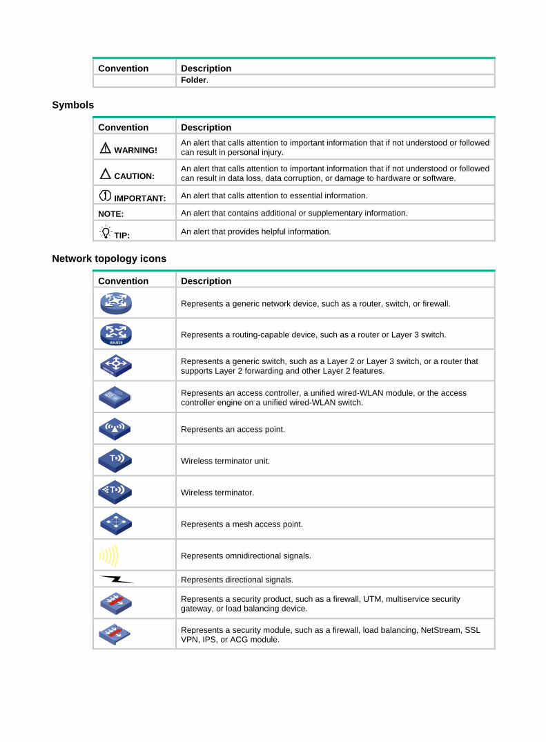
WARNING! An alert that calls attention to important information that if not understood or followed can result in personal injury.
CAUTION: An alert that calls attention to important information that if not understood or followed can result in data loss, data corruption, or damage to hardware or software.
IMPORTANT: An alert that calls attention to essential information.
NOTE: An alert that contains additional or supplementary information.
TIP: An alert that provides helpful information.
Network topology icons
Convention Description
Represents a generic network device, such as a router, switch, or firewall.
Represents a routing-capable device, such as a router or Layer 3 switch.
Represents a generic switch, such as a Layer 2 or Layer 3 switch, or a router that supports Layer 2 forwarding and other Layer 2 features.
Represents an access controller, a unified wired-WLAN module, or the access controller engine on a unified wired-WLAN switch.
Represents an access point.
Wireless terminator unit.
Wireless terminator.
Represents a mesh access point.
Represents omnidirectional signals.
Represents directional signals.
Represents a security product, such as a firewall, UTM, multiservice security gateway, or load balancing device.
Represents a security module, such as a firewall, load balancing, NetStream, SSL VPN, IPS, or ACG module.
TT
TT

Examples provided in this document Examples in this document might use devices that differ from your device in hardware model, configuration, or software version. It is normal that the port numbers, sample output, screenshots, and other information in the examples differ from what you have on your device.
Obtaining documentation To access the most up-to-date H3C product documentation, go to the H3C website at
http://www.h3c.com.hk
To obtain information about installation, configuration, and maintenance, click
http://www.h3c.com.hk/Technical_Documents
To obtain software version information such as release notes, click
http://www.h3c.com.hk/Software_Download
Technical support [email protected]
http://www.h3c.com.hk
Documentation feedback You can e-mail your comments about product documentation to [email protected].
We appreciate your comments.
i
Contents
Bulk interface configuration commands ·························································· 1
display interface range ······························································································································· 1 interface range ··········································································································································· 1 interface range name ································································································································· 3
Ethernet interface commands ········································································· 5
Common Ethernet interface commands ············································································································ 5 bandwidth ··················································································································································· 5 combo enable ············································································································································· 5 dampening ················································································································································· 6 default ························································································································································ 8 description ·················································································································································· 8 display counters ········································································································································· 9 display counters rate ································································································································ 11 display ethernet statistics ························································································································· 12 display interface ······································································································································· 15 duplex ······················································································································································· 25 flag sdh ····················································································································································· 25 flow-interval ·············································································································································· 26 interface ··················································································································································· 27 jumboframe enable ·································································································································· 27 link-delay ·················································································································································· 28 loopback ··················································································································································· 29 port link-mode ·········································································································································· 30 port-mode ················································································································································· 30 reset counters interface ···························································································································· 31 reset ethernet statistics ···························································································································· 32 shutdown ·················································································································································· 33 speed ······················································································································································· 33 sub-interface rate-statistic ························································································································ 34
Layer 3 Ethernet interface or subinterface commands ···················································································· 35 mtu ··························································································································································· 35 port-type switch ········································································································································ 36 traffic-statistic enable ······························································································································· 36
WAN interface commands ············································································ 38
Common WAN interface commands ················································································································ 38 bandwidth ················································································································································· 38 default ······················································································································································ 38 description ················································································································································ 39 shutdown ·················································································································································· 40 timer-hold ················································································································································· 40 timer-hold retry ········································································································································· 41
Synchronous serial interface commands ········································································································· 42 baudrate ··················································································································································· 42 code ························································································································································· 43 crc ···························································································································································· 44 clock ························································································································································· 44 detect dcd ················································································································································· 45 detect dsr-dtr ············································································································································ 46 display interface serial ······························································································································ 47 idle-code ··················································································································································· 51 interface serial ·········································································································································· 52 invert receive-clock ·································································································································· 53 invert transmit-clock ································································································································· 53 itf ······························································································································································ 54 link-protocol ·············································································································································· 54
ii
loopback ··················································································································································· 55 mtu ··························································································································································· 56 reset counters interface ···························································································································· 56 reverse-rts ················································································································································ 57 sub-interface rate-statistic ························································································································ 57 virtualbaudrate ········································································································································· 58
Basic CE1 interface commands ······················································································································· 59 alarm-detect ············································································································································· 59 cable (CE1 interface) ······························································································································· 60 channel-set (CE1 interface) ····················································································································· 60 clock (CE1 interface) ································································································································ 61 clock-change auto ···································································································································· 62 code (CE1 interface) ································································································································ 62 controller e1 ············································································································································· 63 data-coding (CE1 interface) ····················································································································· 64 detect-ais ·················································································································································· 64 display controller e1 ································································································································· 65 frame-format (CE1 interface) ··················································································································· 66 idle-code (CE1 interface) ························································································································· 67 itf (CE1 interface) ····································································································································· 68 loopback (CE1 interface) ·························································································································· 68 reset counters controller e1 ······················································································································ 69 using (CE1 interface) ······························································································································· 70
E1-F interface commands ································································································································ 70 clock-change auto ···································································································································· 70 crc ···························································································································································· 71 display fe1 ················································································································································ 72 fe1 alarm-detect ······································································································································· 73 fe1 cable ··················································································································································· 74 fe1 clock ··················································································································································· 74 fe1 code ··················································································································································· 75 fe1 data-coding ········································································································································ 76 fe1 detect-ais ············································································································································ 76 fe1 frame-format ······································································································································· 77 fe1 idle-code ············································································································································· 78 fe1 itf ························································································································································ 78 fe1 loopback ············································································································································· 79 fe1 timeslot-list ········································································································································· 80 fe1 unframed ············································································································································ 81 mtu ··························································································································································· 81 reset counters interface ···························································································································· 82
CT3 interface commands ································································································································· 83 alarm ························································································································································ 83 cable ························································································································································· 84 clock ························································································································································· 84 controller t3 ·············································································································································· 85 display controller t3 ·································································································································· 85 feac ·························································································································································· 89 frame-format ············································································································································· 90 ft3 ····························································································································································· 91 loopback ··················································································································································· 92 mdl ··························································································································································· 93 reset counters controller t3 ······················································································································· 94 t1 alarm ···················································································································································· 95 t1 channel-set ··········································································································································· 96 t1 clock ····················································································································································· 97 t1 fdl ························································································································································· 97 t1 frame-format ········································································································································· 98 t1 loopback ··············································································································································· 99 t1 sendloopcode ····································································································································· 100 t1 show ··················································································································································· 100 t1 shutdown ············································································································································ 101
iii
t1 unframed ············································································································································ 102 using ······················································································································································· 103
POS interface commands ··········································································· 104
alarm-detect ··········································································································································· 104 bandwidth ··············································································································································· 105 clock ······················································································································································· 105 crc ·························································································································································· 106 dampening ············································································································································· 107 default ···················································································································································· 108 description ·············································································································································· 109 display interface pos ······························································································································ 109 flag c2 ····················································································································································· 114 flag j0 ······················································································································································ 115 flag j1 ······················································································································································ 116 flag j1 ignore ··········································································································································· 117 flow-interval ············································································································································ 117 frame-format ··········································································································································· 118 interface pos ··········································································································································· 118 link-delay ················································································································································ 119 link-protocol ············································································································································ 120 loopback ················································································································································· 121 mtu ························································································································································· 121 port-type switch ······································································································································ 122 reset counters interface ·························································································································· 123 scramble ················································································································································· 123 shutdown ················································································································································ 124 snmp-agent trap enable { b1-tca | b2-tca | b3-tca } ················································································ 125 speed ····················································································································································· 126 sub-interface rate-statistic ······················································································································ 126 threshold ················································································································································ 127 timer-hold ··············································································································································· 128 timer-hold retry ······································································································································· 128
CPOS interface commands ········································································ 130
alarm-detect ··········································································································································· 130 clock ······················································································································································· 130 controller cpos ········································································································································ 131 default ···················································································································································· 132 description ·············································································································································· 132 display controller cpos ···························································································································· 133 display controller cpos e1 ······················································································································· 135 display controller cpos t1 ························································································································ 137 e1 channel-set ········································································································································ 138 e1 clock ·················································································································································· 139 e1 flag ···················································································································································· 140 e1 frame-format ······································································································································ 140 e1 loopback ············································································································································ 141 e1 shutdown ··········································································································································· 142 e1 unframed ··········································································································································· 142 flag ························································································································································· 143 flag vc-3 ·················································································································································· 144 flag vc-4 ·················································································································································· 145 frame-format ··········································································································································· 146 link-delay ················································································································································ 147 loopback ················································································································································· 147 multiplex mode ······································································································································· 148 oc-12 ······················································································································································ 149 oc-3 ························································································································································ 150 reset counters controller cpos ················································································································ 150 shutdown ················································································································································ 151 t1 channel-set ········································································································································· 152
iv
t1 clock ··················································································································································· 153 t1 flag ····················································································································································· 153 t1 frame-format ······································································································································· 154 t1 loopback ············································································································································· 155 t1 shutdown ············································································································································ 155 t1 unframed ············································································································································ 156 threshold ················································································································································ 157 using oc-12/using oc-12c ······················································································································· 158 using oc-3c ············································································································································· 158 using oc-48 ············································································································································· 159
Loopback, null, and inloopback interface commands ································· 160
bandwidth ··············································································································································· 160 default ···················································································································································· 160 description ·············································································································································· 161 display interface inloopback ··················································································································· 162 display interface loopback ······················································································································ 164 display interface null ······························································································································· 167 interface loopback ·································································································································· 168 interface null ··········································································································································· 169 reset counters interface loopback ·········································································································· 169 reset counters interface null ··················································································································· 170 shutdown ················································································································································ 170
Index ··········································································································· 172
1
Bulk interface configuration commands display interface range
Use display interface range to display information about named interface ranges created by using the interface range name command.
Syntax display interface range [ name name ]
Views Any view
Predefined user roles network-admin
network-operator
mdc-admin
mdc-operator
Parameters name name: Specifies an interface range by its name, a case-sensitive string of 1 to 32 characters. If you do not specify an interface range name, the command displays information about all existing interface ranges.
Examples # Display information about the interface ranges created by using the interface range name command. <Sysname> display interface range
Interface range name t2 gigabitethernet1/1/1 gigabitethernet1/1/2
Interface range name test gigabitethernet1/1/4 gigabitethernet1/1/5
The output shows the following: • Interfaces GigabitEthernet 1/1/1 and GigabitEthernet 1/1/2 are added to interface range t2. • Interfaces GigabitEthernet 1/1/4 and GigabitEthernet 1/1/5 are added to interface range test.
Related commands interface range name
interface range Use interface range to create an interface range and enter the interface range view.
Syntax interface range interface-list
Views System view
Predefined user roles network-admin
mdc-admin
2
Parameters interface-list: Specifies a space-separated list of up to 24 interface items. Each item specifies an interface by its type and number or specifies a subrange of interfaces in the form of interface-type interface-number1 to interface-type interface-number2. When you specify a subrange of interfaces, the interfaces must be all fixed interfaces or on the same interface module. The start interface number must be identical to or lower than the end interface number.
Usage guidelines Use this command to bulk configure multiple interfaces with the same feature instead of configuring them one by one. For example, execute the shutdown command in interface range view to shut down a range of interfaces.
The interface range created by using this command is not saved to the running configuration. You cannot use the interface range repeatedly. To create an interface range that can be used repeatedly, use the interface range name command.
In interface range view, only commands supported by the first interface in the specified interface list are available for configuration. To view available commands, enter a question mark (?) in interface range view.
After a command is executed in interface range view, one of the following situations might occur: • The system displays an error message and stays in interface range view. It means that the
execution failed on one or multiple member interfaces. If the execution failed on the first member interface, the command is not executed on any
member interfaces. If the execution failed on a non-first member interface, the command takes effect on the
remaining member interfaces. • The system returns to system view. It means that:
The command is supported in both system view and interface view. The execution failed on a member interface in interface range view and succeeded in
system view. The command is not executed on the subsequent member interfaces.
You can use the display this command to verify the configuration in interface view of each member interface. In addition, if the configuration in system view is not needed, use the undo form of the command to remove the configuration.
To verify the configuration of the first member interface, you can execute the display this command in interface range view.
When you bulk configure interfaces, follow these guidelines: • Before you configure an interface as the first interface in an interface range, make sure you can
enter the view of the interface by using the interface interface-type { interface-number | interface-number.subnumber } command.
• Do not assign both an aggregate interface and any of its member interfaces to an interface range. Some commands, after being executed on both an aggregate interface and its member interfaces, can break up the aggregation.
• Understand that the more interfaces you specify, the longer the command execution time.
Examples # Shut down interfaces GigabitEthernet 1/1/1 through GigabitEthernet 1/1/10. <Sysname> system-view
[Sysname] interface range gigabitethernet 1/1/1 to gigabitethernet 1/1/10
[Sysname-if-range] shutdown
3
interface range name Use interface range name name interface interface-list to create a named interface range and enter the interface range view.
Use interface range name name without the interface keyword to enter the view of a named interface range.
Use undo interface range name to delete the interface range with the specified name.
Syntax interface range name name [ interface interface-list ]
undo interface range name name
Views System view
Predefined user roles network-admin
mdc-admin
Parameters name: Specifies an interface range name, a case-sensitive string of 1 to 32 characters.
interface-list: Specifies a space-separated list of up to 24 interface items. Each item specifies an interface by its type and number or specifies a subrange of interfaces in the form of interface-type interface-number1 to interface-type interface-number2. When you specify a subrange of interfaces, the interfaces must be all fixed interfaces or on the same interface module. The start interface number must be identical to or lower than the end interface number.
Usage guidelines A named interface range is saved in the running configuration and can be used repeatedly to bulk configure its member interfaces.
In interface range view, only commands supported by the first interface in the specified interface list are available for configuration. To view available commands, enter a question mark (?) in interface range view.
After a command is executed in interface range view, one of the following situations might occur: • The system displays an error message and stays in interface range view. It means that the
execution failed on one or multiple member interfaces. If the execution failed on the first member interface, the command is not executed on any
member interfaces. If the execution failed on a non-first member interface, the command takes effect on the
remaining member interfaces. • The system returns to system view. It means that:
The command is supported in both system view and interface view. The execution failed on a member interface in interface range view and succeeded in
system view. The command is not executed on the subsequent member interfaces.
You can use the display this command to verify the configuration in interface view of each member interface. In addition, if the configuration in system view is not needed, use the undo form of the command to remove the configuration.
To verify the configuration of the first member interface, you can execute the display this command in interface range view.
4
To view the member interfaces of a named interface range, use the display interface range command.
When you bulk configure interfaces, follow these guidelines: • Before you configure an interface as the first interface in an interface range, make sure you can
enter the view of the interface by using the interface interface-type { interface-number | interface-number.subnumber } command.
• Do not assign both an aggregate interface and any of its member interfaces to an interface range. Some commands, after being executed on both an aggregate interface and its member interfaces, can break up the aggregation.
• Understand that the more interfaces you specify, the longer the command execution time. • To guarantee bulk interface configuration performance, configure fewer than 1000 interface
range names.
Examples # Add GigabitEthernet 1/1/1 through GigabitEthernet 1/1/10 to interface range myEthPort, and enter the interface range view. <Sysname> system-view
[Sysname] interface range name myEthPort interface gigabitethernet 1/1/1 to gigabitethernet 1/1/10
[Sysname-if-range-myEthPort]
# Enter the view of interface range myEthPort. <Sysname> system-view
[Sysname] interface range name myEthPort
[Sysname-if-range-myEthPort]
Related commands display interface range
5
Ethernet interface commands
Common Ethernet interface commands bandwidth
Use bandwidth to set the expected bandwidth of an interface.
Use undo bandwidth to restore the default.
Syntax bandwidth bandwidth-value
undo bandwidth
Default The expected bandwidth (in kbps) is the interface baud rate divided by 1000.
Views Ethernet interface view
Ethernet subinterface view
Predefined user roles network-admin
mdc-admin
Parameters bandwidth-value: Specifies the expected bandwidth in the range of 1 to 400000000 kbps.
Usage guidelines The expected bandwidth is an informational parameter used only by higher-layer protocols for calculation. You cannot adjust the actual bandwidth of an interface by using this command.
Examples # Set the expected bandwidth of the interface GigabitEthernet 1/1/1 to 1000 kbps. <Sysname> system-view
[Sysname] interface gigabitethernet 1/1/1
[Sysname-GigabitEthernet1/1/1] bandwidth 1000
# Set the expected bandwidth of the subinterface GigabitEthernet 1/1/1.1 to 1000 kbps. <Sysname> system-view
[Sysname] interface gigabitethernet 1/1/1.1
[Sysname-GigabitEthernet1/1/1.1] bandwidth 1000
Related commands speed
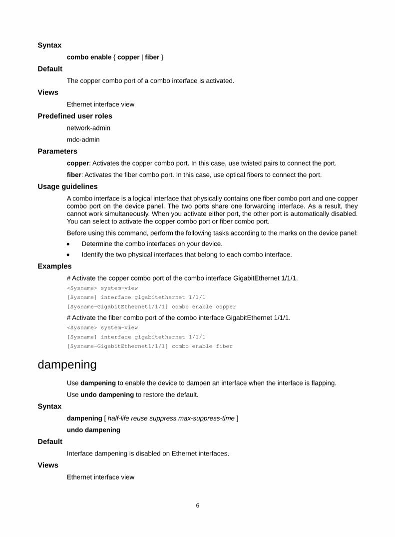
combo enable Use combo enable to activate the copper or fiber combo port of a combo interface.
6
Syntax combo enable { copper | fiber }
Default The copper combo port of a combo interface is activated.
Views Ethernet interface view
Predefined user roles network-admin
mdc-admin
Parameters copper: Activates the copper combo port. In this case, use twisted pairs to connect the port.
fiber: Activates the fiber combo port. In this case, use optical fibers to connect the port.
Usage guidelines A combo interface is a logical interface that physically contains one fiber combo port and one copper combo port on the device panel. The two ports share one forwarding interface. As a result, they cannot work simultaneously. When you activate either port, the other port is automatically disabled. You can select to activate the copper combo port or fiber combo port.
Before using this command, perform the following tasks according to the marks on the device panel: • Determine the combo interfaces on your device. • Identify the two physical interfaces that belong to each combo interface.
Examples # Activate the copper combo port of the combo interface GigabitEthernet 1/1/1. <Sysname> system-view
[Sysname] interface gigabitethernet 1/1/1
[Sysname-GigabitEthernet1/1/1] combo enable copper
# Activate the fiber combo port of the combo interface GigabitEthernet 1/1/1. <Sysname> system-view
[Sysname] interface gigabitethernet 1/1/1
[Sysname-GigabitEthernet1/1/1] combo enable fiber
dampening Use dampening to enable the device to dampen an interface when the interface is flapping.
Use undo dampening to restore the default.
Syntax dampening [ half-life reuse suppress max-suppress-time ]
undo dampening
Default Interface dampening is disabled on Ethernet interfaces.
Views Ethernet interface view
7
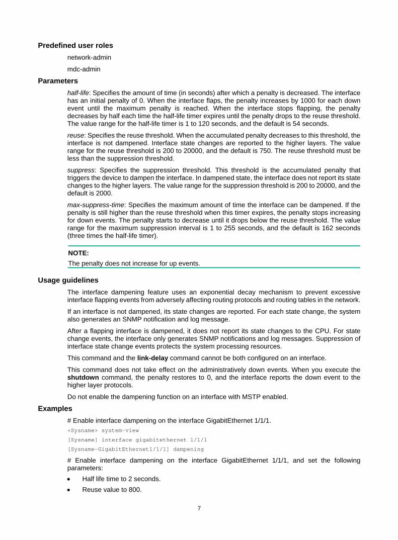
Predefined user roles network-admin
mdc-admin
Parameters half-life: Specifies the amount of time (in seconds) after which a penalty is decreased. The interface has an initial penalty of 0. When the interface flaps, the penalty increases by 1000 for each down event until the maximum penalty is reached. When the interface stops flapping, the penalty decreases by half each time the half-life timer expires until the penalty drops to the reuse threshold. The value range for the half-life timer is 1 to 120 seconds, and the default is 54 seconds.
reuse: Specifies the reuse threshold. When the accumulated penalty decreases to this threshold, the interface is not dampened. Interface state changes are reported to the higher layers. The value range for the reuse threshold is 200 to 20000, and the default is 750. The reuse threshold must be less than the suppression threshold.
suppress: Specifies the suppression threshold. This threshold is the accumulated penalty that triggers the device to dampen the interface. In dampened state, the interface does not report its state changes to the higher layers. The value range for the suppression threshold is 200 to 20000, and the default is 2000.
max-suppress-time: Specifies the maximum amount of time the interface can be dampened. If the penalty is still higher than the reuse threshold when this timer expires, the penalty stops increasing for down events. The penalty starts to decrease until it drops below the reuse threshold. The value range for the maximum suppression interval is 1 to 255 seconds, and the default is 162 seconds (three times the half-life timer).
NOTE: The penalty does not increase for up events.
Usage guidelines The interface dampening feature uses an exponential decay mechanism to prevent excessive interface flapping events from adversely affecting routing protocols and routing tables in the network.
If an interface is not dampened, its state changes are reported. For each state change, the system also generates an SNMP notification and log message.
After a flapping interface is dampened, it does not report its state changes to the CPU. For state change events, the interface only generates SNMP notifications and log messages. Suppression of interface state change events protects the system processing resources.
This command and the link-delay command cannot be both configured on an interface.
This command does not take effect on the administratively down events. When you execute the shutdown command, the penalty restores to 0, and the interface reports the down event to the higher layer protocols.
Do not enable the dampening function on an interface with MSTP enabled.
Examples # Enable interface dampening on the interface GigabitEthernet 1/1/1. <Sysname> system-view
[Sysname] interface gigabitethernet 1/1/1
[Sysname-GigabitEthernet1/1/1] dampening
# Enable interface dampening on the interface GigabitEthernet 1/1/1, and set the following parameters: • Half life time to 2 seconds. • Reuse value to 800.
8
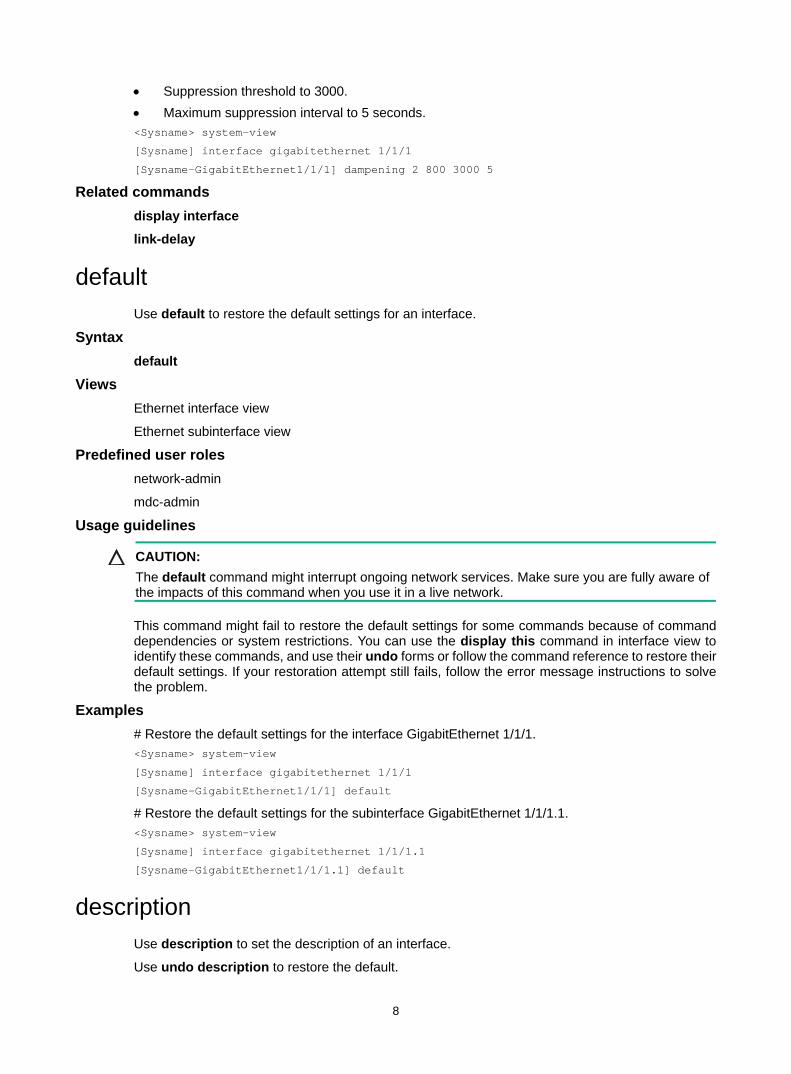
• Suppression threshold to 3000. • Maximum suppression interval to 5 seconds. <Sysname> system-view
[Sysname] interface gigabitethernet 1/1/1
[Sysname-GigabitEthernet1/1/1] dampening 2 800 3000 5
Related commands display interface
link-delay
default Use default to restore the default settings for an interface.
Syntax default
Views Ethernet interface view
Ethernet subinterface view
Predefined user roles network-admin
mdc-admin
Usage guidelines
CAUTION: The default command might interrupt ongoing network services. Make sure you are fully aware of the impacts of this command when you use it in a live network.
This command might fail to restore the default settings for some commands because of command dependencies or system restrictions. You can use the display this command in interface view to identify these commands, and use their undo forms or follow the command reference to restore their default settings. If your restoration attempt still fails, follow the error message instructions to solve the problem.
Examples # Restore the default settings for the interface GigabitEthernet 1/1/1. <Sysname> system-view
[Sysname] interface gigabitethernet 1/1/1
[Sysname-GigabitEthernet1/1/1] default
# Restore the default settings for the subinterface GigabitEthernet 1/1/1.1. <Sysname> system-view
[Sysname] interface gigabitethernet 1/1/1.1
[Sysname-GigabitEthernet1/1/1.1] default
description Use description to set the description of an interface.
Use undo description to restore the default.
9
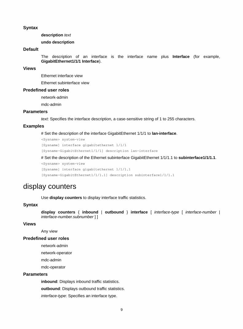
Syntax description text
undo description
Default The description of an interface is the interface name plus Interface (for example, GigabitEthernet1/1/1 Interface).
Views Ethernet interface view
Ethernet subinterface view
Predefined user roles network-admin
mdc-admin
Parameters text: Specifies the interface description, a case-sensitive string of 1 to 255 characters.
Examples # Set the description of the interface GigabitEthernet 1/1/1 to lan-interface. <Sysname> system-view
[Sysname] interface gigabitethernet 1/1/1
[Sysname-GigabitEthernet1/1/1] description lan-interface
# Set the description of the Ethernet subinterface GigabitEthernet 1/1/1.1 to subinterface1/1/1.1. <Sysname> system-view
[Sysname] interface gigabitethernet 1/1/1.1
[Sysname-GigabitEthernet1/1/1.1] description subinterface1/1/1.1
display counters Use display counters to display interface traffic statistics.
Syntax display counters { inbound | outbound } interface [ interface-type [ interface-number | interface-number.subnumber ] ]
Views Any view
Predefined user roles network-admin
network-operator
mdc-admin
mdc-operator
Parameters inbound: Displays inbound traffic statistics.
outbound: Displays outbound traffic statistics.
interface-type: Specifies an interface type.
10
interface-number: Specifies an interface number.
interface-number.subnumber: Specifies a subinterface number. The interface-number argument is an interface number. The subnumber argument is the number of a subinterface created under the interface. The value range for the subnumber argument is 1 to 4094.
Usage guidelines This command displays traffic statistics within a statistics polling interval specified by using the flow-interval command.
To clear the Ethernet interface traffic statistics, use the reset counters interface command.
If you do not specify an interface type, this command displays traffic statistics for all interfaces that have traffic counters.
If you specify an interface type but do not specify an interface number or subinterface number, this command displays traffic statistics for all interfaces of the specified type.
If you specify an interface type and an interface or subinterface number, this command displays traffic statistics for the specified interface or subinterface.
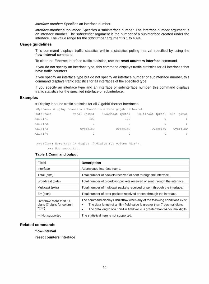
Examples # Display inbound traffic statistics for all GigabitEthernet interfaces. <Sysname> display counters inbound interface gigabitethernet
Interface Total (pkts) Broadcast (pkts) Multicast (pkts) Err (pkts)
GE1/1/1 100 100 0 0
GE1/1/2 0 0 0 0
GE1/1/3 Overflow Overflow Overflow Overflow
GE1/1/4 0 0 0 0
Overflow: More than 14 digits (7 digits for column "Err").
--: Not supported.
Table 1 Command output
Field Description Interface Abbreviated interface name.
Total (pkts) Total number of packets received or sent through the interface.
Broadcast (pkts) Total number of broadcast packets received or sent through the interface.
Multicast (pkts) Total number of multicast packets received or sent through the interface.
Err (pkts) Total number of error packets received or sent through the interface.
Overflow: More than 14 digits (7 digits for column "Err")
The command displays Overflow when any of the following conditions exist: • The data length of an Err field value is greater than 7 decimal digits. • The data length of a non-Err field value is greater than 14 decimal digits.
--: Not supported The statistical item is not supported.
Related commands flow-interval
reset counters interface
11
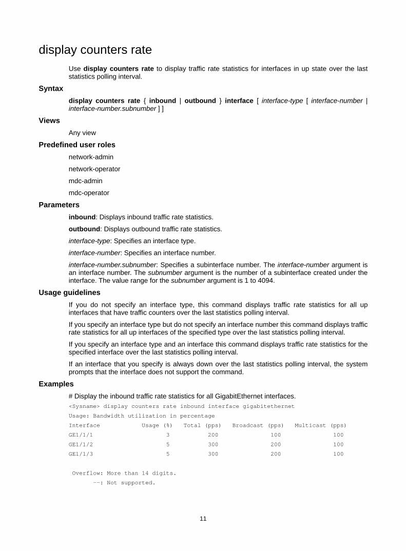
display counters rate Use display counters rate to display traffic rate statistics for interfaces in up state over the last statistics polling interval.
Syntax display counters rate { inbound | outbound } interface [ interface-type [ interface-number | interface-number.subnumber ] ]
Views Any view
Predefined user roles network-admin
network-operator
mdc-admin
mdc-operator
Parameters inbound: Displays inbound traffic rate statistics.
outbound: Displays outbound traffic rate statistics.
interface-type: Specifies an interface type.
interface-number: Specifies an interface number.
interface-number.subnumber: Specifies a subinterface number. The interface-number argument is an interface number. The subnumber argument is the number of a subinterface created under the interface. The value range for the subnumber argument is 1 to 4094.
Usage guidelines If you do not specify an interface type, this command displays traffic rate statistics for all up interfaces that have traffic counters over the last statistics polling interval.
If you specify an interface type but do not specify an interface number this command displays traffic rate statistics for all up interfaces of the specified type over the last statistics polling interval.
If you specify an interface type and an interface this command displays traffic rate statistics for the specified interface over the last statistics polling interval.
If an interface that you specify is always down over the last statistics polling interval, the system prompts that the interface does not support the command.
Examples # Display the inbound traffic rate statistics for all GigabitEthernet interfaces. <Sysname> display counters rate inbound interface gigabitethernet
Usage: Bandwidth utilization in percentage
Interface Usage (%) Total (pps) Broadcast (pps) Multicast (pps)
GE1/1/1 3 200 100 100
GE1/1/2 5 300 200 100
GE1/1/3 5 300 200 100
Overflow: More than 14 digits.
--: Not supported.
12
Table 2 Command output
Field Description Interface Abbreviated interface name.
Usage (%) Bandwidth usage (in percentage) of the interface over the last statistics polling interval.
Total (pkts/sec) Average receiving or sending rate (in pps) for unicast packets over the last statistics polling interval.
Broadcast (pkts/sec) Average receiving or sending rate (in pps) for broadcast packets over the last statistics polling interval.
Multicast (pkts/sec) Average receiving or sending rate (in pps) for multicast packets over the last statistics polling interval.
Overflow: more than 14 decimal digits
The command displays Overflow if the data length of a statistical item is greater than 14 decimal digits.
--: not supported The statistical item is not supported.
Related commands flow-interval
reset counters interface
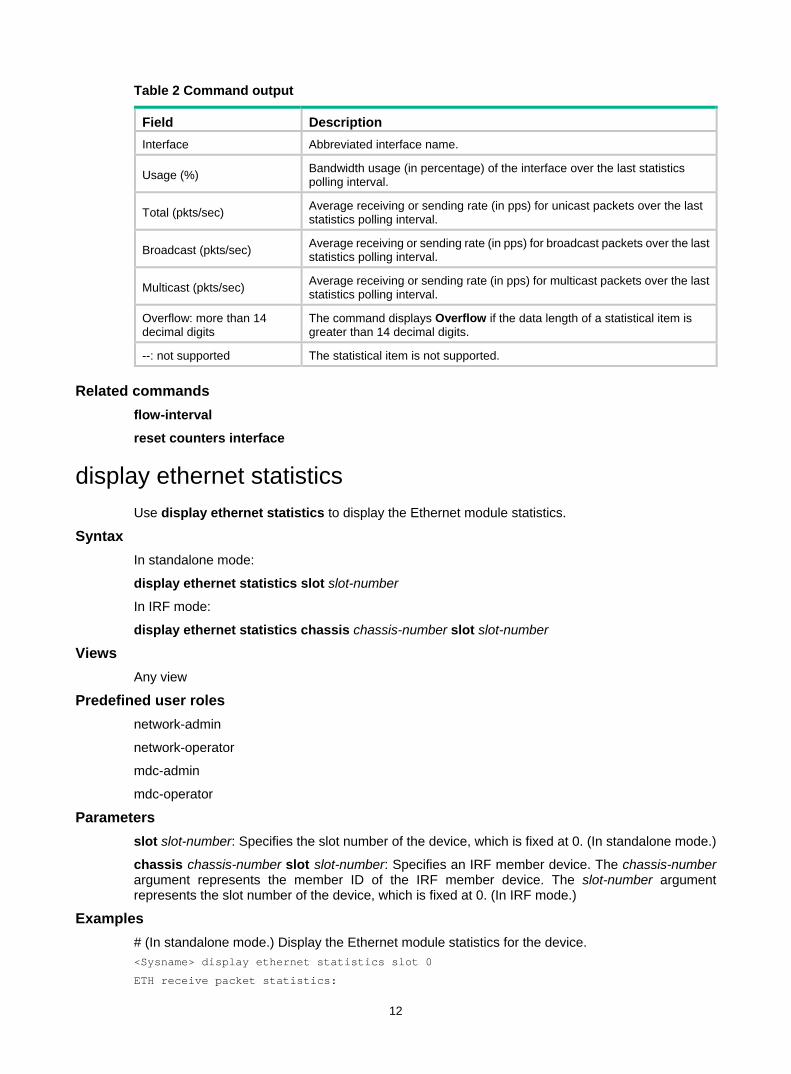
display ethernet statistics Use display ethernet statistics to display the Ethernet module statistics.
Syntax In standalone mode:
display ethernet statistics slot slot-number
In IRF mode:
display ethernet statistics chassis chassis-number slot slot-number
Views Any view
Predefined user roles network-admin
network-operator
mdc-admin
mdc-operator
Parameters slot slot-number: Specifies the slot number of the device, which is fixed at 0. (In standalone mode.)
chassis chassis-number slot slot-number: Specifies an IRF member device. The chassis-number argument represents the member ID of the IRF member device. The slot-number argument represents the slot number of the device, which is fixed at 0. (In IRF mode.)
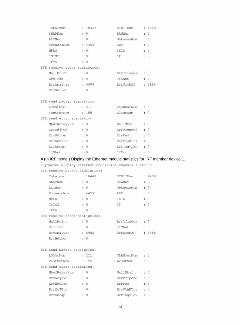
Examples # (In standalone mode.) Display the Ethernet module statistics for the device. <Sysname> display ethernet statistics slot 0
ETH receive packet statistics:
13
Totalnum : 10447 ETHIINum : 4459
SNAPNum : 0 RAWNum : 0
LLCNum : 0 UnknownNum : 0
ForwardNum : 4459 ARP : 0
MPLS : 0 ISIS : 0
ISIS2 : 0 IP : 0
IPV6 : 0
ETH receive error statistics:
NullPoint : 0 ErrIfindex : 0
ErrIfcb : 0 IfShut : 0
ErrAnalyse : 5988 ErrSrcMAC : 5988
ErrHdrLen : 0
ETH send packet statistics:
L3OutNum : 211 VLANOutNum : 0
FastOutNum : 155 L2OutNum : 0
ETH send error statistics:
MbufRelayNum : 0 NullMbuf : 0
ErrAdjFwd : 0 ErrPrepend : 0
ErrHdrLen : 0 ErrPad : 0
ErrQoSTrs : 0 ErrVLANTrs : 0
ErrEncap : 0 ErrTagVLAN : 0
IfShut : 0 IfErr : 0
# (In IRF mode.) Display the Ethernet module statistics for IRF member device 1. <Sysname> display ethernet statistics chassis 1 slot 0
ETH receive packet statistics:
Totalnum : 10447 ETHIINum : 4459
SNAPNum : 0 RAWNum : 0
LLCNum : 0 UnknownNum : 0
ForwardNum : 4459 ARP : 0
MPLS : 0 ISIS : 0
ISIS2 : 0 IP : 0
IPV6 : 0
ETH receive error statistics:
NullPoint : 0 ErrIfindex : 0
ErrIfcb : 0 IfShut : 0
ErrAnalyse : 5988 ErrSrcMAC : 5988
ErrHdrLen : 0
ETH send packet statistics:
L3OutNum : 211 VLANOutNum : 0
FastOutNum : 155 L2OutNum : 0
ETH send error statistics:
MbufRelayNum : 0 NullMbuf : 0
ErrAdjFwd : 0 ErrPrepend : 0
ErrHdrLen : 0 ErrPad : 0
ErrQoSTrs : 0 ErrVLANTrs : 0
ErrEncap : 0 ErrTagVLAN : 0
14
IfShut : 0 IfErr : 0
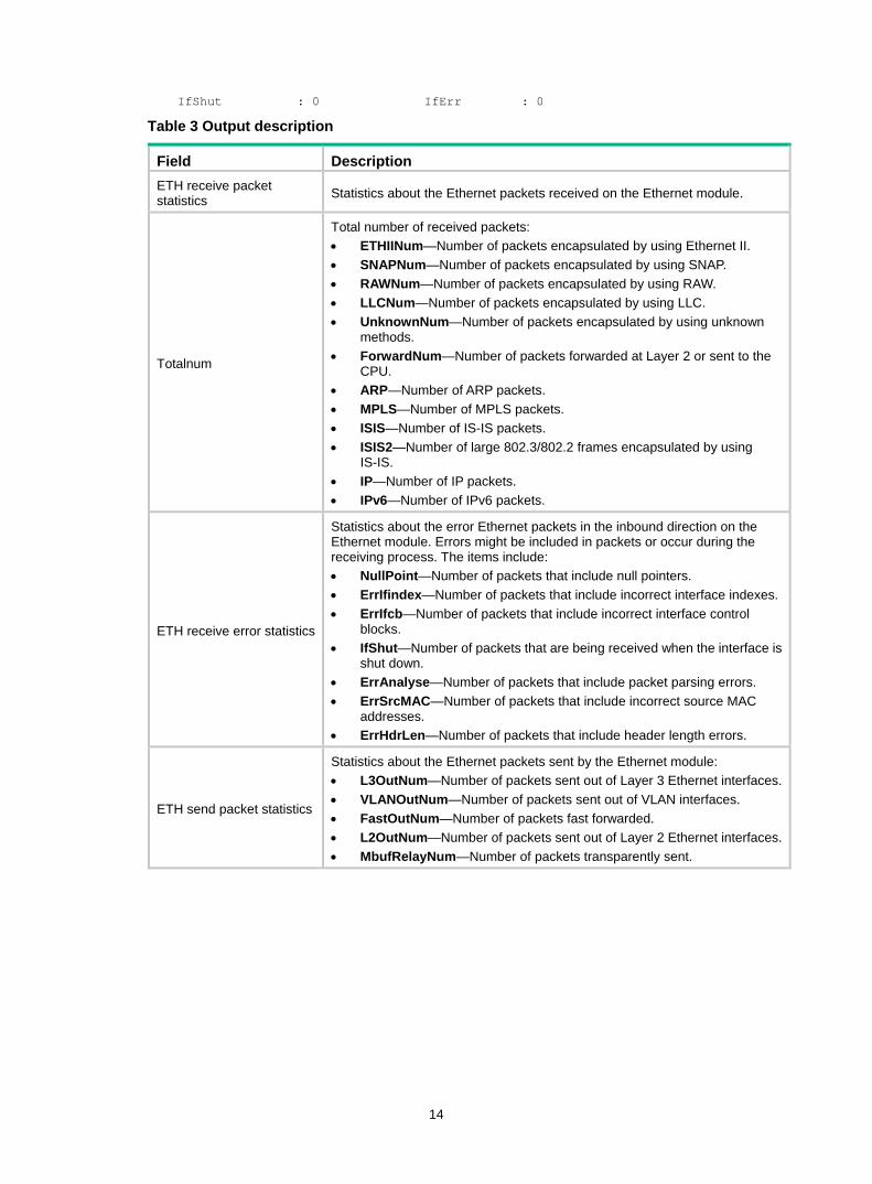
Table 3 Output description
Field Description ETH receive packet statistics Statistics about the Ethernet packets received on the Ethernet module.
Totalnum
Total number of received packets: • ETHIINum—Number of packets encapsulated by using Ethernet II. • SNAPNum—Number of packets encapsulated by using SNAP. • RAWNum—Number of packets encapsulated by using RAW. • LLCNum—Number of packets encapsulated by using LLC. • UnknownNum—Number of packets encapsulated by using unknown
methods. • ForwardNum—Number of packets forwarded at Layer 2 or sent to the
CPU. • ARP—Number of ARP packets. • MPLS—Number of MPLS packets. • ISIS—Number of IS-IS packets. • ISIS2—Number of large 802.3/802.2 frames encapsulated by using
IS-IS. • IP—Number of IP packets. • IPv6—Number of IPv6 packets.
ETH receive error statistics
Statistics about the error Ethernet packets in the inbound direction on the Ethernet module. Errors might be included in packets or occur during the receiving process. The items include: • NullPoint—Number of packets that include null pointers. • ErrIfindex—Number of packets that include incorrect interface indexes.• ErrIfcb—Number of packets that include incorrect interface control
blocks. • IfShut—Number of packets that are being received when the interface is
shut down. • ErrAnalyse—Number of packets that include packet parsing errors. • ErrSrcMAC—Number of packets that include incorrect source MAC
addresses. • ErrHdrLen—Number of packets that include header length errors.
ETH send packet statistics
Statistics about the Ethernet packets sent by the Ethernet module: • L3OutNum—Number of packets sent out of Layer 3 Ethernet interfaces.• VLANOutNum—Number of packets sent out of VLAN interfaces. • FastOutNum—Number of packets fast forwarded. • L2OutNum—Number of packets sent out of Layer 2 Ethernet interfaces. • MbufRelayNum—Number of packets transparently sent.

15
Field Description
ETH send error statistics
Statistics about the error Ethernet packets in the outbound direction on the Ethernet module: • NullMbuf—Number of packets with null pointers. • ErrAdjFwd—Number of packets with adjacency table errors. • ErrPrepend—Number of packets with extension errors. • ErrHdrLen—Number of packets with header length errors. • ErrPad—Number of packets with padding errors. • ErrQoSTrs—Number of packets that failed to be sent by QoS. • ErrVLANTrs—Number of packets that failed to be sent in VLANs. • ErrEncap—Number of packets that failed to be sent due to link header
encapsulation failures. • ErrTagVLAN—Number of packets that failed to be sent due to VLAN tag
encapsulation failures. • IfShut—Number of packets that are being sent when the interface is shut
down. • IfErr—Number of packets with incorrect outgoing interfaces.
Related commands reset ethernet statistics
display interface Use display interface to display interface information.
Syntax display interface [ interface-type [ interface-number | interface-number.subnumber ] ] [ brief [ description | down ] ]
Views Any view
Predefined user roles network-admin
network-operator
mdc-admin
mdc-operator
Parameters interface-type: Specifies an interface type.
interface-number: Specifies an interface number.
interface-number.subnumber: Specifies a subinterface number. The interface-number argument is an interface number. The subnumber argument is the number of a subinterface created under the interface. The value range for the subnumber argument is 1 to 4094.
brief: Displays brief interface information. If you do not specify this keyword, the command displays detailed interface information.
description: Displays complete interface descriptions. If you do not specify this keyword, the command displays only the first 27 characters of each interface description.
down: Displays information about interfaces in down state and the causes. If you do not specify this keyword, the command displays information about interfaces in all states.
16
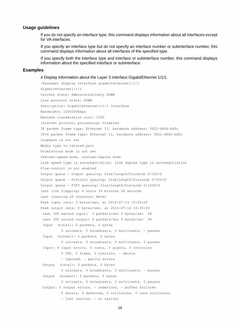
Usage guidelines If you do not specify an interface type, this command displays information about all interfaces except for VA interfaces.
If you specify an interface type but do not specify an interface number or subinterface number, this command displays information about all interfaces of the specified type.
If you specify both the interface type and interface or subinterface number, this command displays information about the specified interface or subinterface.
Examples # Display information about the Layer 3 interface GigabitEthernet 1/1/1. <Sysname> display interface gigabitethernet1/1/1
GigabitEthernet1/1/1
Current state: Administratively DOWN
Line protocol state: DOWN
Description: GigabitEthernet1/1/1 Interface
Bandwidth: 1000000kbps
Maximum transmission unit: 1500
Internet protocol processing: Disabled
IP packet frame type: Ethernet II, hardware address: 3822-d666-bd0c
IPv6 packet frame type: Ethernet II, hardware address: 3822-d666-bd0c
Loopback is not set
Media type is twisted pair
Promiscuous mode is not set
Unknown-speed mode, unknown-duplex mode
Link speed type is autonegotiation, link duplex type is autonegotiation
Flow-control is not enabled
Output queue - Urgent queuing: Size/Length/Discards 0/100/0
Output queue - Protocol queuing: Size/Length/Discards 0/500/0
Output queue - FIFO queuing: Size/Length/Discards 0/1024/0
Last link flapping: 6 hours 39 minutes 28 seconds
Last clearing of counters: Never
Peak input rate: 0 bytes/sec, at 2016-07-14 10:30:00
Peak output rate: 0 bytes/sec, at 2016-07-14 10:30:00
Last 300 second input: 0 packets/sec 0 bytes/sec 0%
Last 300 second output: 0 packets/sec 0 bytes/sec 0%
Input (total): 0 packets, 0 bytes
0 unicasts, 0 broadcasts, 0 multicasts, - pauses
Input (normal): 0 packets, 0 bytes
0 unicasts, 0 broadcasts, 0 multicasts, 0 pauses
Input: 0 input errors, 0 runts, 0 giants, 0 throttles
0 CRC, 0 frame, 0 overruns, - aborts
- ignored, - parity errors
Output (total): 0 packets, 0 bytes
0 unicasts, 0 broadcasts, 0 multicasts, - pauses
Output (normal): 0 packets, 0 bytes
0 unicasts, 0 broadcasts, 0 multicasts, 0 pauses
Output: 0 output errors, - underruns, - buffer failures
0 aborts, 0 deferred, 0 collisions, 0 late collisions
- lost carrier, - no carrier
17
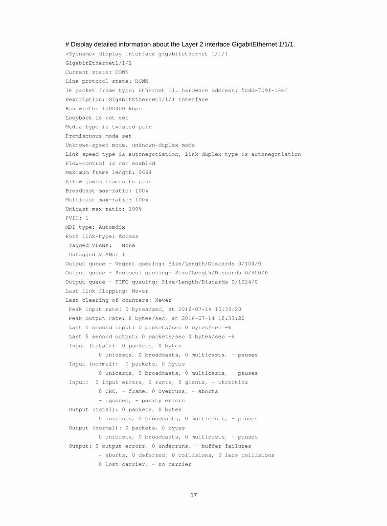
# Display detailed information about the Layer 2 interface GigabitEthernet 1/1/1. <Sysname> display interface gigabitethernet 1/1/1
GigabitEthernet1/1/1
Current state: DOWN
Line protocol state: DOWN
IP packet frame type: Ethernet II, hardware address: 5cdd-709f-14ef
Description: GigabitEthernet1/1/1 Interface
Bandwidth: 1000000 kbps
Loopback is not set
Media type is twisted pair
Promiscuous mode set
Unknown-speed mode, unknown-duplex mode
Link speed type is autonegotiation, link duplex type is autonegotiation
Flow-control is not enabled
Maximum frame length: 9664
Allow jumbo frames to pass
Broadcast max-ratio: 100%
Multicast max-ratio: 100%
Unicast max-ratio: 100%
PVID: 1
MDI type: Automdix
Port link-type: Access
Tagged VLANs: None
Untagged VLANs: 1
Output queue - Urgent queuing: Size/Length/Discards 0/100/0
Output queue - Protocol queuing: Size/Length/Discards 0/500/0
Output queue - FIFO queuing: Size/Length/Discards 0/1024/0
Last link flapping: Never
Last clearing of counters: Never
Peak input rate: 0 bytes/sec, at 2016-07-14 10:33:20
Peak output rate: 0 bytes/sec, at 2016-07-14 10:33:20
Last 5 second input: 0 packets/sec 0 bytes/sec -%
Last 5 second output: 0 packets/sec 0 bytes/sec -%
Input (total): 0 packets, 0 bytes
0 unicasts, 0 broadcasts, 0 multicasts, - pauses
Input (normal): 0 packets, 0 bytes
0 unicasts, 0 broadcasts, 0 multicasts, - pauses
Input: 0 input errors, 0 runts, 0 giants, - throttles
0 CRC, - frame, 0 overruns, - aborts
- ignored, - parity errors
Output (total): 0 packets, 0 bytes
0 unicasts, 0 broadcasts, 0 multicasts, - pauses
Output (normal): 0 packets, 0 bytes
0 unicasts, 0 broadcasts, 0 multicasts, - pauses
Output: 0 output errors, 0 underruns, - buffer failures
- aborts, 0 deferred, 0 collisions, 0 late collisions
0 lost carrier, - no carrier
18
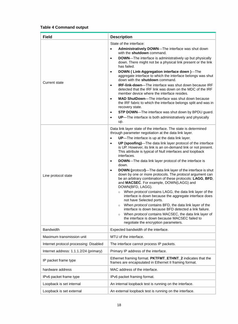
Table 4 Command output
Field Description
Current state
State of the interface: • Administratively DOWN—The interface was shut down
with the shutdown command. • DOWN—The interface is administratively up but physically
down. There might not be a physical link present or the link has failed.
• DOWN ( Link-Aggregation interface down )—The aggregate interface to which the interface belongs was shut down with the shutdown command.
• IRF-link-down—The interface was shut down because IRF detected that the IRF link was down on the MDC of the IRF member device where the interface resides.
• MAD ShutDown—The interface was shut down because the IRF fabric to which the interface belongs split and was in recovery state.
• STP DOWN—The interface was shut down by BPDU guard.• UP—The interface is both administratively and physically
up.
Line protocol state
Data link layer state of the interface. The state is determined through parameter negotiation at the data link layer. • UP—The interface is up at the data link layer. • UP (spoofing)—The data link layer protocol of the interface
is UP. However, its link is an on-demand link or not present. This attribute is typical of Null interfaces and loopback interfaces.
• DOWN—The data link layer protocol of the interface is down.
• DOWN (protocol)—The data link layer of the interface is shut down by one or more protocols. The protocol argument can be an arbitrary combination of these protocols: LAGG, BFD, and MACSEC. For example, DOWN(LAGG) and DOWN(BFD, LAGG).
When protocol contains LAGG, the data link layer of the interface is down because the aggregate interface does not have Selected ports.
When protocol contains BFD, the data link layer of the interface is down because BFD detected a link failure.
When protocol contains MACSEC, the data link layer of the interface is down because MACSEC failed to negotiate the encryption parameters.
Bandwidth Expected bandwidth of the interface.
Maximum transmission unit MTU of the interface.
Internet protocol processing: Disabled The interface cannot process IP packets.
Internet address: 1.1.1.2/24 (primary) Primary IP address of the interface.
IP packet frame type Ethernet framing format. PKTFMT_ETHNT_2 indicates that the frames are encapsulated in Ethernet II framing format.
hardware address MAC address of the interface.
IPv6 packet frame type IPv6 packet framing format.
Loopback is set internal An internal loopback test is running on the interface.
Loopback is set external An external loopback test is running on the interface.
19
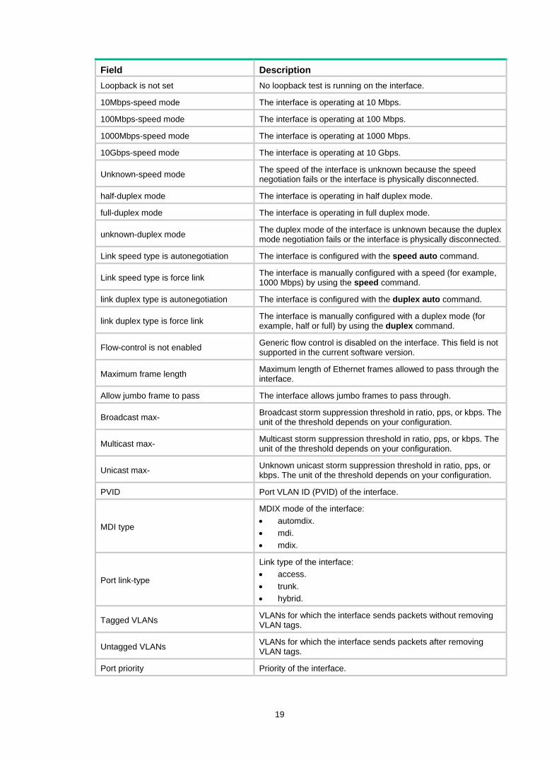
Field Description Loopback is not set No loopback test is running on the interface.
10Mbps-speed mode The interface is operating at 10 Mbps.
100Mbps-speed mode The interface is operating at 100 Mbps.
1000Mbps-speed mode The interface is operating at 1000 Mbps.
10Gbps-speed mode The interface is operating at 10 Gbps.
Unknown-speed mode The speed of the interface is unknown because the speed negotiation fails or the interface is physically disconnected.
half-duplex mode The interface is operating in half duplex mode.
full-duplex mode The interface is operating in full duplex mode.
unknown-duplex mode The duplex mode of the interface is unknown because the duplex mode negotiation fails or the interface is physically disconnected.
Link speed type is autonegotiation The interface is configured with the speed auto command.
Link speed type is force link The interface is manually configured with a speed (for example, 1000 Mbps) by using the speed command.
link duplex type is autonegotiation The interface is configured with the duplex auto command.
link duplex type is force link The interface is manually configured with a duplex mode (for example, half or full) by using the duplex command.
Flow-control is not enabled Generic flow control is disabled on the interface. This field is not supported in the current software version.
Maximum frame length Maximum length of Ethernet frames allowed to pass through the interface.
Allow jumbo frame to pass The interface allows jumbo frames to pass through.
Broadcast max- Broadcast storm suppression threshold in ratio, pps, or kbps. The unit of the threshold depends on your configuration.
Multicast max- Multicast storm suppression threshold in ratio, pps, or kbps. The unit of the threshold depends on your configuration.
Unicast max- Unknown unicast storm suppression threshold in ratio, pps, or kbps. The unit of the threshold depends on your configuration.
PVID Port VLAN ID (PVID) of the interface.
MDI type
MDIX mode of the interface: • automdix. • mdi. • mdix.
Port link-type
Link type of the interface: • access. • trunk. • hybrid.
Tagged VLANs VLANs for which the interface sends packets without removing VLAN tags.
Untagged VLANs VLANs for which the interface sends packets after removing VLAN tags.
Port priority Priority of the interface.
20
Field Description
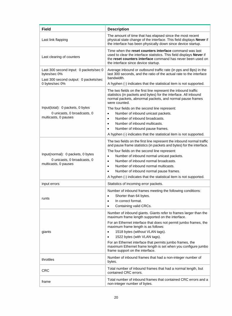
Last link flapping The amount of time that has elapsed since the most recent physical state change of the interface. This field displays Never if the interface has been physically down since device startup.
Last clearing of counters
Time when the reset counters interface command was last used to clear the interface statistics. This field displays Never if the reset counters interface command has never been used on the interface since device startup.
Last 300 second input: 0 packets/sec 0 bytes/sec 0% Last 300 second output: 0 packets/sec 0 bytes/sec 0%
Average inbound or outbound traffic rate (in pps and Bps) in the last 300 seconds, and the ratio of the actual rate to the interface bandwidth. A hyphen (-) indicates that the statistical item is not supported.
Input(total): 0 packets, 0 bytes 0 unicasts, 0 broadcasts, 0 multicasts, 0 pauses
The two fields on the first line represent the inbound traffic statistics (in packets and bytes) for the interface. All inbound normal packets, abnormal packets, and normal pause frames were counted. The four fields on the second line represent: • Number of inbound unicast packets. • Number of inbound broadcasts. • Number of inbound multicasts. • Number of inbound pause frames. A hyphen (-) indicates that the statistical item is not supported.
Input(normal): 0 packets, 0 bytes 0 unicasts, 0 broadcasts, 0 multicasts, 0 pauses
The two fields on the first line represent the inbound normal traffic and pause frame statistics (in packets and bytes) for the interface.The four fields on the second line represent: • Number of inbound normal unicast packets. • Number of inbound normal broadcasts. • Number of inbound normal multicasts. • Number of inbound normal pause frames. A hyphen (-) indicates that the statistical item is not supported.
input errors Statistics of incoming error packets.
runts
Number of inbound frames meeting the following conditions: • Shorter than 64 bytes. • In correct format. • Containing valid CRCs.
giants
Number of inbound giants. Giants refer to frames larger than the maximum frame length supported on the interface. For an Ethernet interface that does not permit jumbo frames, the maximum frame length is as follows: • 1518 bytes (without VLAN tags). • 1522 bytes (with VLAN tags). For an Ethernet interface that permits jumbo frames, the maximum Ethernet frame length is set when you configure jumbo frame support on the interface.
throttles Number of inbound frames that had a non-integer number of bytes.
CRC Total number of inbound frames that had a normal length, but contained CRC errors.
frame Total number of inbound frames that contained CRC errors and a non-integer number of bytes.
21
Field Description
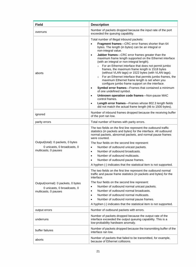
overruns Number of packets dropped because the input rate of the port exceeded the queuing capability.
aborts
Total number of illegal inbound packets: • Fragment frames—CRC error frames shorter than 64
bytes. The length (in bytes) can be an integral or non-integral value.
• Jabber frames—CRC error frames greater than the maximum frame length supported on the Ethernet interface (with an integral or non-integral length).
For an Ethernet interface that does not permit jumbo frames, the maximum frame length is 1518 bytes (without VLAN tags) or 1522 bytes (with VLAN tags).
For an Ethernet interface that permits jumbo frames, the maximum Ethernet frame length is set when you configure jumbo frame support on the interface.
• Symbol error frames—Frames that contained a minimum of one undefined symbol.
• Unknown operation code frames—Non-pause MAC control frames.
• Length error frames—Frames whose 802.3 length fields did not match the actual frame length (46 to 1500 bytes).
ignored Number of inbound frames dropped because the receiving buffer of the port ran low.
parity errors Total number of frames with parity errors.
Output(total): 0 packets, 0 bytes 0 unicasts, 0 broadcasts, 0 multicasts, 0 pauses
The two fields on the first line represent the outbound traffic statistics (in packets and bytes) for the interface. All outbound normal packets, abnormal packets, and normal pause frames were counted. The four fields on the second line represent: • Number of outbound unicast packets. • Number of outbound broadcasts. • Number of outbound multicasts. • Number of outbound pause frames. A hyphen (-) indicates that the statistical item is not supported.
Output(normal): 0 packets, 0 bytes 0 unicasts, 0 broadcasts, 0 multicasts, 0 pauses
The two fields on the first line represent the outbound normal traffic and pause frame statistics (in packets and bytes) for the interface. The four fields on the second line represent: • Number of outbound normal unicast packets. • Number of outbound normal broadcasts. • Number of outbound normal multicasts. • Number of outbound normal pause frames. A hyphen (-) indicates that the statistical item is not supported.
output errors Number of outbound packets with errors.
underruns Number of packets dropped because the output rate of the interface exceeded the output queuing capability. This is a low-probability hardware anomaly.
buffer failures Number of packets dropped because the transmitting buffer of the interface ran low.
aborts Number of packets that failed to be transmitted, for example, because of Ethernet collisions.
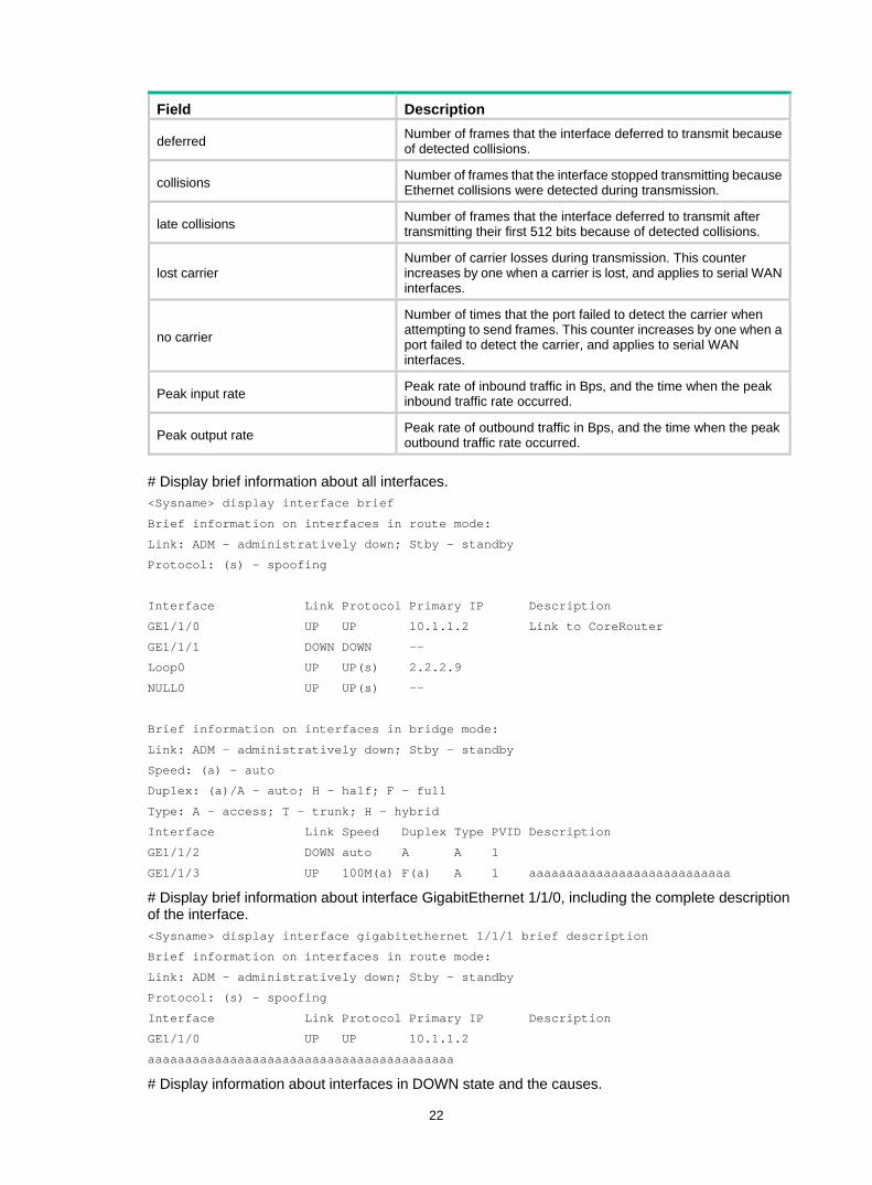
22
Field Description
deferred Number of frames that the interface deferred to transmit because of detected collisions.
collisions Number of frames that the interface stopped transmitting because Ethernet collisions were detected during transmission.
late collisions Number of frames that the interface deferred to transmit after transmitting their first 512 bits because of detected collisions.
lost carrier Number of carrier losses during transmission. This counter increases by one when a carrier is lost, and applies to serial WAN interfaces.
no carrier
Number of times that the port failed to detect the carrier when attempting to send frames. This counter increases by one when a port failed to detect the carrier, and applies to serial WAN interfaces.
Peak input rate Peak rate of inbound traffic in Bps, and the time when the peak inbound traffic rate occurred.
Peak output rate Peak rate of outbound traffic in Bps, and the time when the peak outbound traffic rate occurred.
# Display brief information about all interfaces. <Sysname> display interface brief
Brief information on interfaces in route mode:
Link: ADM - administratively down; Stby - standby
Protocol: (s) – spoofing
Interface Link Protocol Primary IP Description
GE1/1/0 UP UP 10.1.1.2 Link to CoreRouter
GE1/1/1 DOWN DOWN --
Loop0 UP UP(s) 2.2.2.9
NULL0 UP UP(s) --
Brief information on interfaces in bridge mode:
Link: ADM - administratively down; Stby - standby
Speed: (a) - auto
Duplex: (a)/A - auto; H - half; F - full
Type: A - access; T - trunk; H - hybrid
Interface Link Speed Duplex Type PVID Description
GE1/1/2 DOWN auto A A 1
GE1/1/3 UP 100M(a) F(a) A 1 aaaaaaaaaaaaaaaaaaaaaaaaaaa
# Display brief information about interface GigabitEthernet 1/1/0, including the complete description of the interface. <Sysname> display interface gigabitethernet 1/1/1 brief description
Brief information on interfaces in route mode:
Link: ADM - administratively down; Stby - standby
Protocol: (s) - spoofing
Interface Link Protocol Primary IP Description
GE1/1/0 UP UP 10.1.1.2
aaaaaaaaaaaaaaaaaaaaaaaaaaaaaaaaaaaaaaaaa
# Display information about interfaces in DOWN state and the causes.
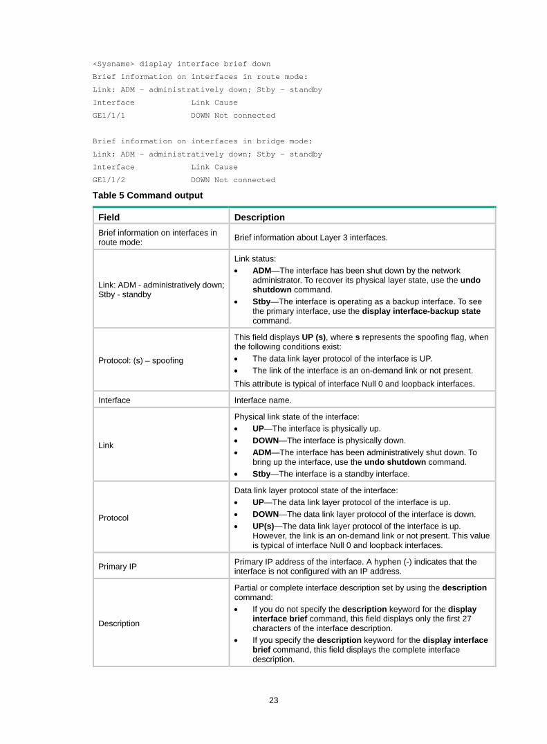
23
<Sysname> display interface brief down
Brief information on interfaces in route mode:
Link: ADM - administratively down; Stby - standby
Interface Link Cause
GE1/1/1 DOWN Not connected
Brief information on interfaces in bridge mode:
Link: ADM - administratively down; Stby - standby
Interface Link Cause
GE1/1/2 DOWN Not connected
Table 5 Command output
Field Description Brief information on interfaces in route mode: Brief information about Layer 3 interfaces.
Link: ADM - administratively down; Stby - standby
Link status: • ADM—The interface has been shut down by the network
administrator. To recover its physical layer state, use the undo shutdown command.
• Stby—The interface is operating as a backup interface. To see the primary interface, use the display interface-backup state command.
Protocol: (s) – spoofing
This field displays UP (s), where s represents the spoofing flag, when the following conditions exist: • The data link layer protocol of the interface is UP. • The link of the interface is an on-demand link or not present. This attribute is typical of interface Null 0 and loopback interfaces.
Interface Interface name.
Link
Physical link state of the interface: • UP—The interface is physically up. • DOWN—The interface is physically down. • ADM—The interface has been administratively shut down. To
bring up the interface, use the undo shutdown command. • Stby—The interface is a standby interface.
Protocol
Data link layer protocol state of the interface: • UP—The data link layer protocol of the interface is up. • DOWN—The data link layer protocol of the interface is down. • UP(s)—The data link layer protocol of the interface is up.
However, the link is an on-demand link or not present. This value is typical of interface Null 0 and loopback interfaces.
Primary IP Primary IP address of the interface. A hyphen (-) indicates that the interface is not configured with an IP address.
Description
Partial or complete interface description set by using the description command: • If you do not specify the description keyword for the display
interface brief command, this field displays only the first 27 characters of the interface description.
• If you specify the description keyword for the display interface brief command, this field displays the complete interface description.
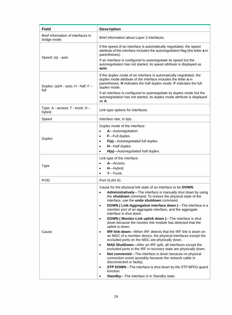
24
Field Description Brief information of interfaces in bridge mode: Brief information about Layer 2 interfaces.
Speed: (a) - auto
If the speed of an interface is automatically negotiated, the speed attribute of the interface includes the autonegotiation flag (the letter a in parentheses). If an interface is configured to autonegotiate its speed but the autonegotiation has not started, its speed attribute is displayed as auto.
Duplex: (a)/A - auto; H - half; F – full
If the duplex mode of an interface is automatically negotiated, the duplex mode attribute of the interface includes the letter a in parentheses. H indicates the half duplex mode. F indicates the full duplex mode. If an interface is configured to autonegotiate its duplex mode but the autonegotiation has not started, its duplex mode attribute is displayed as A.
Type: A - access; T - trunk; H – hybrid Link type options for interfaces.
Speed Interface rate, in bps.
Duplex
Duplex mode of the interface: • A—Autonegotiation. • F—Full duplex. • F(a)—Autonegotiated full duplex. • H—Half duplex. • H(a)—Autonegotiated half duplex.
Type
Link type of the interface: • A—Access. • H—Hybrid. • T—Trunk.
PVID Port VLAN ID.
Cause
Cause for the physical link state of an interface to be DOWN: • Administratively—The interface is manually shut down by using
the shutdown command. To restore the physical state of the interface, use the undo shutdown command.
• DOWN ( Link-Aggregation interface down )—The interface is a member port of an aggregate interface, and the aggregate interface is shut down.
• DOWN ( Monitor-Link uplink down )—The interface is shut down because the monitor link module has detected that the uplink is down.
• IRF-link-down—When IRF detects that the IRF link is down on an MDC of a member device, the physical interfaces except the excluded ports on the MDC are physically down.
• MAD ShutDown—After an IRF split, all interfaces except the excluded ports in the IRF in recovery state are physically down.
• Not connected—The interface is down because no physical connection exists (possibly because the network cable is disconnected or faulty).
• STP DOWN—The interface is shut down by the STP BPDU guard function.
• Standby—The interface is in Standby state.
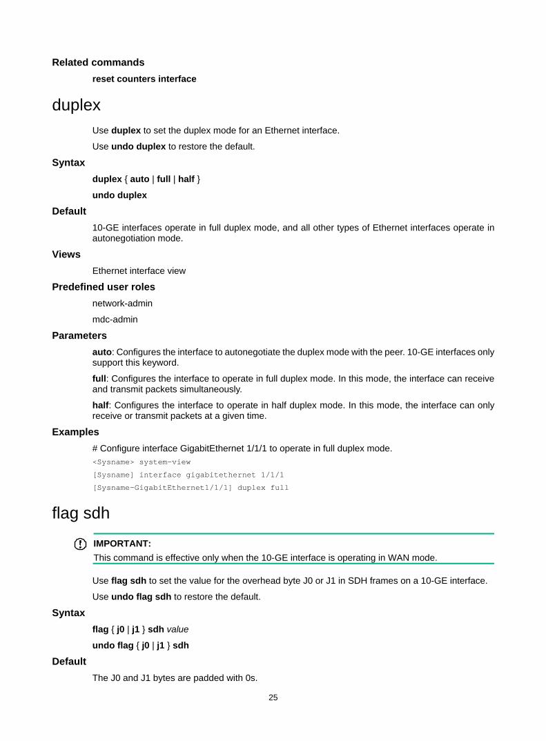
25
Related commands reset counters interface
duplex Use duplex to set the duplex mode for an Ethernet interface.
Use undo duplex to restore the default.
Syntax duplex { auto | full | half }
undo duplex
Default 10-GE interfaces operate in full duplex mode, and all other types of Ethernet interfaces operate in autonegotiation mode.
Views Ethernet interface view
Predefined user roles network-admin
mdc-admin
Parameters auto: Configures the interface to autonegotiate the duplex mode with the peer. 10-GE interfaces only support this keyword.
full: Configures the interface to operate in full duplex mode. In this mode, the interface can receive and transmit packets simultaneously.
half: Configures the interface to operate in half duplex mode. In this mode, the interface can only receive or transmit packets at a given time.
Examples # Configure interface GigabitEthernet 1/1/1 to operate in full duplex mode. <Sysname> system-view
[Sysname] interface gigabitethernet 1/1/1
[Sysname-GigabitEthernet1/1/1] duplex full
flag sdh
IMPORTANT: This command is effective only when the 10-GE interface is operating in WAN mode.
Use flag sdh to set the value for the overhead byte J0 or J1 in SDH frames on a 10-GE interface.
Use undo flag sdh to restore the default.
Syntax flag { j0 | j1 } sdh value
undo flag { j0 | j1 } sdh
Default The J0 and J1 bytes are padded with 0s.
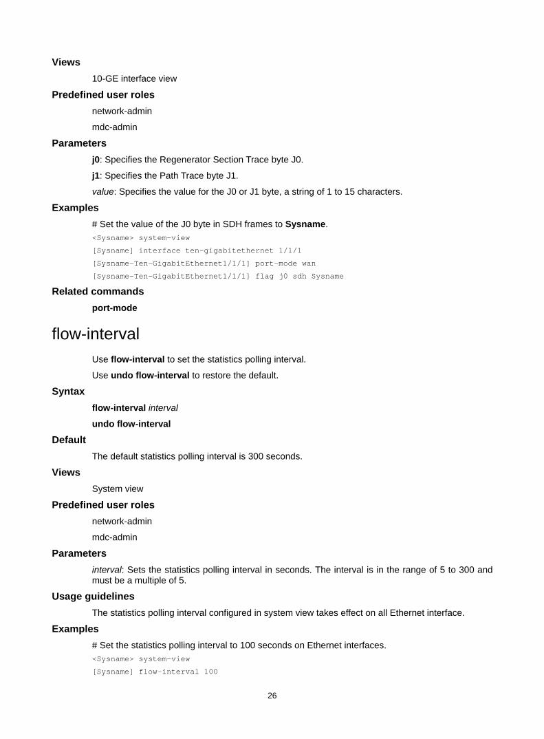
26
Views 10-GE interface view
Predefined user roles network-admin
mdc-admin
Parameters j0: Specifies the Regenerator Section Trace byte J0.
j1: Specifies the Path Trace byte J1.
value: Specifies the value for the J0 or J1 byte, a string of 1 to 15 characters.
Examples # Set the value of the J0 byte in SDH frames to Sysname. <Sysname> system-view
[Sysname] interface ten-gigabitethernet 1/1/1
[Sysname-Ten-GigabitEthernet1/1/1] port-mode wan
[Sysname-Ten-GigabitEthernet1/1/1] flag j0 sdh Sysname
Related commands port-mode
flow-interval Use flow-interval to set the statistics polling interval.
Use undo flow-interval to restore the default.
Syntax flow-interval interval
undo flow-interval
Default The default statistics polling interval is 300 seconds.
Views System view
Predefined user roles network-admin
mdc-admin
Parameters interval: Sets the statistics polling interval in seconds. The interval is in the range of 5 to 300 and must be a multiple of 5.
Usage guidelines The statistics polling interval configured in system view takes effect on all Ethernet interface.
Examples # Set the statistics polling interval to 100 seconds on Ethernet interfaces. <Sysname> system-view
[Sysname] flow-interval 100
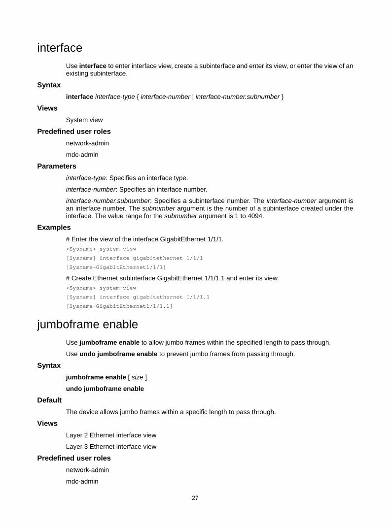
27
interface Use interface to enter interface view, create a subinterface and enter its view, or enter the view of an existing subinterface.
Syntax interface interface-type { interface-number | interface-number.subnumber }
Views System view
Predefined user roles network-admin
mdc-admin
Parameters interface-type: Specifies an interface type.
interface-number: Specifies an interface number.
interface-number.subnumber: Specifies a subinterface number. The interface-number argument is an interface number. The subnumber argument is the number of a subinterface created under the interface. The value range for the subnumber argument is 1 to 4094.
Examples # Enter the view of the interface GigabitEthernet 1/1/1. <Sysname> system-view
[Sysname] interface gigabitethernet 1/1/1
[Sysname-GigabitEthernet1/1/1]
# Create Ethernet subinterface GigabitEthernet 1/1/1.1 and enter its view. <Sysname> system-view
[Sysname] interface gigabitethernet 1/1/1.1
[Sysname-GigabitEthernet1/1/1.1]
jumboframe enable Use jumboframe enable to allow jumbo frames within the specified length to pass through.
Use undo jumboframe enable to prevent jumbo frames from passing through.
Syntax jumboframe enable [ size ]
undo jumboframe enable
Default The device allows jumbo frames within a specific length to pass through.
Views Layer 2 Ethernet interface view
Layer 3 Ethernet interface view
Predefined user roles network-admin
mdc-admin
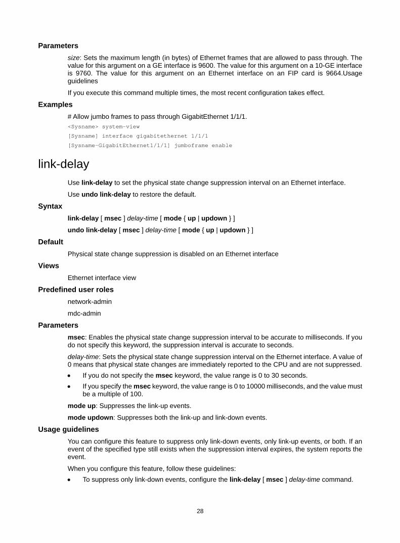
28
Parameters size: Sets the maximum length (in bytes) of Ethernet frames that are allowed to pass through. The value for this argument on a GE interface is 9600. The value for this argument on a 10-GE interface is 9760. The value for this argument on an Ethernet interface on an FIP card is 9664.Usage guidelines
If you execute this command multiple times, the most recent configuration takes effect.
Examples # Allow jumbo frames to pass through GigabitEthernet 1/1/1. <Sysname> system-view
[Sysname] interface gigabitethernet 1/1/1
[Sysname-GigabitEthernet1/1/1] jumboframe enable
link-delay Use link-delay to set the physical state change suppression interval on an Ethernet interface.
Use undo link-delay to restore the default.
Syntax link-delay [ msec ] delay-time [ mode { up | updown } ]
undo link-delay [ msec ] delay-time [ mode { up | updown } ]
Default Physical state change suppression is disabled on an Ethernet interface
Views Ethernet interface view
Predefined user roles network-admin
mdc-admin
Parameters msec: Enables the physical state change suppression interval to be accurate to milliseconds. If you do not specify this keyword, the suppression interval is accurate to seconds.
delay-time: Sets the physical state change suppression interval on the Ethernet interface. A value of 0 means that physical state changes are immediately reported to the CPU and are not suppressed. • If you do not specify the msec keyword, the value range is 0 to 30 seconds. • If you specify the msec keyword, the value range is 0 to 10000 milliseconds, and the value must
be a multiple of 100.
mode up: Suppresses the link-up events.
mode updown: Suppresses both the link-up and link-down events.
Usage guidelines You can configure this feature to suppress only link-down events, only link-up events, or both. If an event of the specified type still exists when the suppression interval expires, the system reports the event.
When you configure this feature, follow these guidelines: • To suppress only link-down events, configure the link-delay [ msec ] delay-time command.

29
• To suppress only link-up events, configure the link-delay [ msec ] delay-time mode up command.
• To suppress both link-down and link-up events, configure the link-delay [ msec ] delay-time mode updown command.
On an interface, you can configure different suppression intervals for link-up and link-down events. If you configure the link-delay command multiple times for link-up or link-down events, the most recent configuration takes effect.
Do not configure this command on an interface with spanning tree protocols.
Examples # Set the link-down event suppression interval to 8 seconds on the interface GigabitEthernet 1/1/1. <Sysname> system-view
[Sysname] interface gigabitethernet 1/1/1
[Sysname-GigabitEthernet1/1/1] link-delay 8
# Set the link-up event suppression interval to 800 milliseconds on the interface GigabitEthernet 1/1/1. <Sysname> system-view
[Sysname] interface gigabitethernet 1/1/1
[Sysname-GigabitEthernet1/1/1] link-delay msec 800 mode up
loopback
CAUTION: After you enable loopback testing on an Ethernet interface, the interface does not forward data traffic.
Use loopback to enable loopback testing on an Ethernet interface.
Use undo loopback to disable loopback testing on an Ethernet interface.
Syntax loopback { external | internal }
undo loopback
Default Loopback testing is disabled on an Ethernet interface.
Views Ethernet interface view
Predefined user roles network-admin
mdc-admin
Parameters external: Enables external loopback testing on the Ethernet interface.
internal: Enables internal loopback testing on the Ethernet interface.
Usage guidelines The shutdown and loopback commands are exclusive with each other.
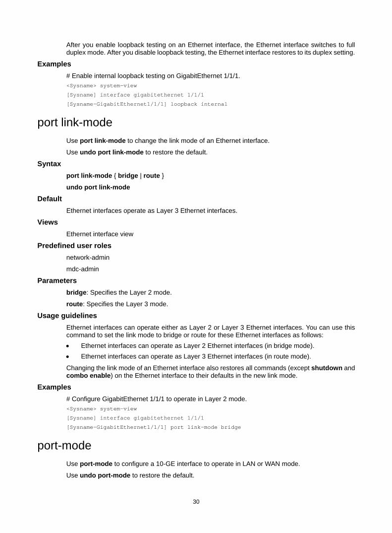
30
After you enable loopback testing on an Ethernet interface, the Ethernet interface switches to full duplex mode. After you disable loopback testing, the Ethernet interface restores to its duplex setting.
Examples # Enable internal loopback testing on GigabitEthernet 1/1/1. <Sysname> system-view
[Sysname] interface gigabitethernet 1/1/1
[Sysname-GigabitEthernet1/1/1] loopback internal
port link-mode Use port link-mode to change the link mode of an Ethernet interface.
Use undo port link-mode to restore the default.
Syntax port link-mode { bridge | route }
undo port link-mode
Default Ethernet interfaces operate as Layer 3 Ethernet interfaces.
Views Ethernet interface view
Predefined user roles network-admin
mdc-admin
Parameters bridge: Specifies the Layer 2 mode.
route: Specifies the Layer 3 mode.
Usage guidelines Ethernet interfaces can operate either as Layer 2 or Layer 3 Ethernet interfaces. You can use this command to set the link mode to bridge or route for these Ethernet interfaces as follows: • Ethernet interfaces can operate as Layer 2 Ethernet interfaces (in bridge mode). • Ethernet interfaces can operate as Layer 3 Ethernet interfaces (in route mode).
Changing the link mode of an Ethernet interface also restores all commands (except shutdown and combo enable) on the Ethernet interface to their defaults in the new link mode.
Examples # Configure GigabitEthernet 1/1/1 to operate in Layer 2 mode. <Sysname> system-view
[Sysname] interface gigabitethernet 1/1/1
[Sysname-GigabitEthernet1/1/1] port link-mode bridge
port-mode Use port-mode to configure a 10-GE interface to operate in LAN or WAN mode.
Use undo port-mode to restore the default.
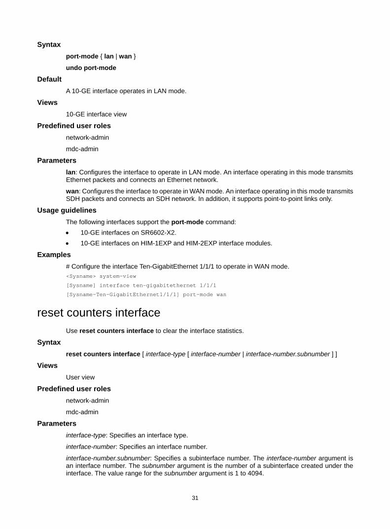
31
Syntax port-mode { lan | wan }
undo port-mode
Default A 10-GE interface operates in LAN mode.
Views 10-GE interface view
Predefined user roles network-admin
mdc-admin
Parameters lan: Configures the interface to operate in LAN mode. An interface operating in this mode transmits Ethernet packets and connects an Ethernet network.
wan: Configures the interface to operate in WAN mode. An interface operating in this mode transmits SDH packets and connects an SDH network. In addition, it supports point-to-point links only.
Usage guidelines The following interfaces support the port-mode command: • 10-GE interfaces on SR6602-X2. • 10-GE interfaces on HIM-1EXP and HIM-2EXP interface modules.
Examples # Configure the interface Ten-GigabitEthernet 1/1/1 to operate in WAN mode. <Sysname> system-view
[Sysname] interface ten-gigabitethernet 1/1/1
[Sysname-Ten-GigabitEthernet1/1/1] port-mode wan
reset counters interface Use reset counters interface to clear the interface statistics.
Syntax reset counters interface [ interface-type [ interface-number | interface-number.subnumber ] ]
Views User view
Predefined user roles network-admin
mdc-admin
Parameters interface-type: Specifies an interface type.
interface-number: Specifies an interface number.
interface-number.subnumber: Specifies a subinterface number. The interface-number argument is an interface number. The subnumber argument is the number of a subinterface created under the interface. The value range for the subnumber argument is 1 to 4094.
32
Usage guidelines Use this command to clear history statistics if you want to collect traffic statistics for a specific time period.
If you do not specify an interface type, this command clears statistics for all interfaces except for VA interfaces.
If you specify an interface type but do not specify an interface number, this command clears statistics for all interfaces of the specified type.
If you specify both the interface type and the interface or subinterface number, this command clears statistics for the specified interface or subinterface.
Examples # Clear the statistics for GigabitEthernet 1/1/1. <Sysname> reset counters interface gigabitethernet 1/1/1
Related commands display interface
display counters interface
display counters rate interface
reset ethernet statistics Use reset ethernet statistics to clear the Ethernet module statistics.
Syntax In standalone mode:
reset ethernet statistics [ slot slot-number ]
In IRF mode:
reset ethernet statistics [ chassis chassis-number slot slot-number ]
Views User view
Predefined user roles network-admin
mdc-admin
Parameters slot slot-number: Specifies the slot number of the device, which is fixed at 0. ( In standalone mode.)
chassis chassis-number slot slot-number: Specifies an IRF member device. The chassis-number argument represents the member ID of the IRF member device. The slot-number argument represents the slot number of the device, which is fixed at 0. (In IRF mode.)
Examples # (In standalone mode.) Clear the Ethernet module statistics for the device. <Sysname> reset ethernet statistics slot 0
# (In IRF mode.) Clear the Ethernet module statistics for IRF member device 1. <Sysname> reset ethernet statistics chassis 1 slot 0
Related commands display ethernet statistics
33
shutdown Use shutdown to shut down an Ethernet interface or subinterface.
Use undo shutdown to bring up an Ethernet interface or subinterface.
Syntax shutdown
undo shutdown
Default Ethernet interfaces or subinterfaces are enabled.
Views Ethernet interface view
Ethernet subinterface view
Predefined user roles network-admin
mdc-admin
Usage guidelines Some interface configurations might require an interface restart before taking effect.
The shutdown and loopback commands are exclusive with each other.
Examples # Shut down and then bring up GigabitEthernet 1/1/1. <Sysname> system-view
[Sysname] interface gigabitethernet 1/1/1
[Sysname-GigabitEthernet1/1/1] shutdown
[Sysname-GigabitEthernet1/1/1] undo shutdown
# Shut down and then bring up GigabitEthernet 1/1/1.1. <Sysname> system-view
[Sysname] interface gigabitethernet 1/1/1.1
[Sysname-GigabitEthernet1/1/1.1] shutdown
[Sysname-GigabitEthernet1/1/1.1] undo shutdown
speed Use speed to set the speed of an Ethernet interface.
Use undo speed to restore the default.
Syntax speed { 10 | 100 | 1000 | auto }
undo speed
Default The default speed of an Ethernet interface is set to auto.
Views Ethernet interface view
34
Predefined user roles network-admin
mdc-admin
Parameters 10: Sets the interface speed to 10 Mbps.
100: Sets the interface speed to 100 Mbps.
1000: Sets the interface speed to 1000 Mbps.
auto: Enables the interface to negotiate a speed with its peer. 10-GE interfaces only support this keyword.
Usage guidelines For a fiber port with SFP-GE-T transceiver module installed, you must set its speed to 1000 Mbps and set the speed of its peer interface to 1000 Mbps or auto.
For an Ethernet copper port, use the speed command to set its speed to match the speed of the peer interface.
For a fiber port, use the speed command to set its speed to match the rate of a transceiver module.
Examples # Configure GigabitEthernet 1/1/1 to autonegotiate the speed. <Sysname> system-view
[Sysname] interface gigabitethernet 1/1/1
[Sysname-GigabitEthernet1/1/1] speed auto
sub-interface rate-statistic Use sub-interface rate-statistic to enable rate statistics collection for the subinterfaces of an Ethernet interface.
Use undo sub-interface rate-statistic to disable rate statistics collection for the subinterfaces of an Ethernet interface.
Syntax sub-interface rate-statistic
undo sub-interface rate-statistic
Default The system does not collect rate statistics for the subinterfaces of an Ethernet interface.
Views Ethernet interface view
Predefined user roles network-admin
mdc-admin
Usage guidelines This command is resource intensive. When you use this command, make sure you fully understand its impact on system performance.
Examples # Enable rate statistics collection for the subinterfaces of GigabitEthernet 1/1/1.
35
<Sysname> system-view
[Sysname] interface gigabitethernet 1/1/1
[Sysname-GigabitEthernet1/1/1] sub-interface rate-statistic
This configuration may make a negative effect on the performance. Are you sure to continue? [Y/N]:y
Layer 3 Ethernet interface or subinterface commands mtu
Use mtu to set the MTU for an Ethernet interface or subinterface.
Use undo mtu to restore the default.
Syntax mtu size
undo mtu
Default The MTU of an Ethernet interface or subinterface is 1500 bytes.
Views Layer 3 Ethernet interface view
Layer 3 Ethernet subinterface view
Predefined user roles network-admin
mdc-admin
Parameters size: Sets the MTU in bytes. The value range for this argument is 46 to 9600.
Usage guidelines A smaller MTU size results in more fragments. When you set the MTU for an interface, consider QoS queue lengths, for example, consider that the default FIFO queue length is 75. To prevent a too small MTU from causing packet drops in QoS queuing, you can perform one of the following configurations: • Tune the MTU with the mtu command. • Tune QoS queue lengths with the qos fifo queue-length command.
For more information about the qos fifo queue-length command, see ACL and QoS Command Reference.
Examples # Set the MTU to 1430 bytes for the Layer 3 Ethernet interface GigabitEthernet 1/1/1. <Sysname> system-view
[Sysname] interface gigabitethernet 1/1/1
[Sysname-GigabitEthernet1/1/1] mtu 1430
# Set the MTU to 1430 bytes for the Layer 3 Ethernet subinterface GigabitEthernet 1/1/1.1. <Sysname> system-view
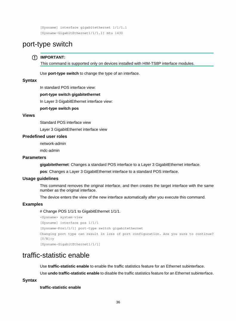
36
[Sysname] interface gigabitethernet 1/1/1.1
[Sysname-GigabitEthernet1/1/1.1] mtu 1430
port-type switch
IMPORTANT: This command is supported only on devices installed with HIM-TS8P interface modules.
Use port-type switch to change the type of an interface.
Syntax In standard POS interface view:
port-type switch gigabitethernet
In Layer 3 GigabitEthernet interface view:
port-type switch pos
Views Standard POS interface view
Layer 3 GigabitEthernet interface view
Predefined user roles network-admin
mdc-admin
Parameters gigabitethernet: Changes a standard POS interface to a Layer 3 GigabitEthernet interface.
pos: Changes a Layer 3 GigabitEthernet interface to a standard POS interface.
Usage guidelines This command removes the original interface, and then creates the target interface with the same number as the original interface.
The device enters the view of the new interface automatically after you execute this command.
Examples # Change POS 1/1/1 to GigabitEthernet 1/1/1. <Sysname> system-view
[Sysname] interface pos 1/1/1
[Sysname-Pos1/1/1] port-type switch gigabitethernet
Changing port type can result in loss of port configuration. Are you sure to continue? [Y/N]:y
[Sysname-GigabitEthernet1/1/1]
traffic-statistic enable Use traffic-statistic enable to enable the traffic statistics feature for an Ethernet subinterface.
Use undo traffic-statistic enable to disable the traffic statistics feature for an Ethernet subinterface.
Syntax traffic-statistic enable
37
undo traffic-statistic enable
Default The traffic statistics feature is disabled for an Ethernet subinterface.
Views Layer 3 Ethernet subinterface view
Predefined user roles network-admin
mdc-admin
Usage guidelines This command is resource intensive. When you use this feature, make sure you fully understand its impact on system performance.
After the traffic statistics feature is enabled for an Ethernet subinterface, you can use the Input and Output fields in the display interface command output or use the display counters command to display the traffic statistics for the Ethernet subinterface.
Examples # Enable the traffic statistics feature for GigabitEthernet 1/1/1.1. <Sysname> system-view
[Sysname] interface gigabitethernet 1/1/1.1
[Sysname-GigabitEthernet1/1/1.1] traffic-statistic enable
Related commands display interface
display counters
38
WAN interface commands
Common WAN interface commands bandwidth
Use bandwidth to configure the expected bandwidth of an interface.
Use undo bandwidth to restore the default.
Syntax bandwidth bandwidth-value
undo bandwidth
Default The expected bandwidth (in kbps) is the interface baud rate divided by 1000.
Views E1-F interface view
Serial interface/subinterface view
Predefined user roles network-admin
mdc-admin
Parameters bandwidth-value: Specifies the expected bandwidth in the range of 1 to 400000000 kbps.
Usage guidelines The expected bandwidth is an informational parameter used only by higher-layer protocols for calculation. You cannot adjust the actual bandwidth of an interface by using this command.
Examples # Set the expected bandwidth to 50 kbps for Serial 1/1/1. <Sysname> system-view
[Sysname] interface serial 1/1/1
[Sysname-Serial1/1/1] bandwidth 50
default Use default to restore the default settings for an interface.
Syntax default
Views CE1 interface/E1-F interface view
CT3 interface interface view
Serial interface/subinterface view
39
Predefined user roles network-admin
mdc-admin
Usage guidelines
CAUTION: The default command might interrupt ongoing network services. Make sure you are fully aware of the impact of this command when you use it on a live network.
This command might fail to restore the default settings for some commands for reasons such as command dependencies and system restrictions. You can use the display this command in interface view to check for these commands, and use their undo forms or follow the command reference to restore their respective default settings. If your restoration attempt still fails, follow the error message instructions to resolve the problem.
Examples # Restore the default settings of Serial 1/1/1. <Sysname> system-view
[Sysname] interface serial 1/1/1
[Sysname-Serial1/1/1] default
description Use description to configure a description for an interface.
Use undo description to restore the default.
Syntax description text
undo description
Default Interface description uses the interface name Interface format, for example, Serial1/1/1 Interface.
Views CE1 interface/E1-F interface view
CT3 interface interface view
Serial interface/subinterface view
Predefined user roles network-admin
mdc-admin
Parameters text: Specifies a description, a case-sensitive string of 1 to 255 characters.
Examples # Configure the description of Serial 1/1/1 as router-interface. <Sysname> system-view
[Sysname] interface serial 1/1/1
[Sysname-Serial1/1/1] description router-interface
40
shutdown Use shutdown to shut down an interface.
Use undo shutdown to restore the default.
Syntax shutdown
undo shutdown
Default A WAN interface is up.
Views CE1 interface/E1-F interface view
CT3 interface interface view
Serial interface/subinterface view
Predefined user roles network-admin
mdc-admin
Examples # Shut down Serial 1/1/1. <Sysname> system-view
[Sysname] interface serial 1/1/1
[Sysname-Serial1/1/1] shutdown
timer-hold Use timer-hold to set the keepalive interval.
Use undo timer-hold to restore the default.
Syntax timer-hold seconds
undo timer-hold
Default The keepalive interval is 10 seconds.
Views E1-F interface view
Serial interface view
Predefined user roles network-admin
mdc-admin
Parameters seconds: Specifies the interval at which an interface sends keepalive packets. The value range is 0 to 32767 seconds.
41
Usage guidelines On an interface encapsulated with PPP, FR, or HDLC, the data link layer sends keepalive packets at keepalive intervals to detect the availability of the remote end. The data link layer determines that the peer end is down if it does not receive a response after the maximum number of keepalive attempts have been made. The data link layer then reports the link down event to the upper-layer protocols.
To set the maximum number of keepalive attempts, use the timer-hold retry command.
On a slow link, increase the keepalive interval to prevent false shutdown of the interface. This situation might occur when keepalive packets are delayed because a large packet is being transmitted on the link.
Examples # Set the keepalive interval to 15 seconds for Serial 1/1/1. <Sysname> system-view
[Sysname] interface serial 1/1/1
[Sysname-Serial1/1/1] timer-hold 15
Related commands timer-hold retry
timer-hold retry Use timer-hold retry to set the maximum number of keepalive attempts.
Use undo timer-hold retry to restore the default.
Syntax timer-hold retry retries
undo timer-hold retry
Default The maximum number of keepalive attempts is 5.
Views E1-F interface view
Serial interface view
Predefined user roles network-admin
mdc-admin
Parameters retries: Specifies the maximum number of keepalive attempts, in the range of 1 to 255.
Usage guidelines The interface determines that the remote end is down if it does not receive a response after the maximum number of keepalive attempts have been made.
This command applies to interfaces encapsulated with PPP, FR, or HDLC. To set the keepalive interval, use the timer-hold command.
On a slow link, increase the maximum number of keepalive attempts to prevent false shutdown of the interface. This situation might occur when keepalive packets are delayed because a large packet is being transmitted on the link.
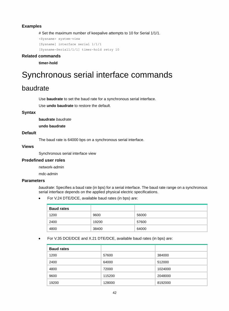
42
Examples # Set the maximum number of keepalive attempts to 10 for Serial 1/1/1. <Sysname> system-view
[Sysname] interface serial 1/1/1
[Sysname-Serial1/1/1] timer-hold retry 10
Related commands timer-hold
Synchronous serial interface commands baudrate
Use baudrate to set the baud rate for a synchronous serial interface.
Use undo baudrate to restore the default.
Syntax baudrate baudrate
undo baudrate
Default The baud rate is 64000 bps on a synchronous serial interface.
Views Synchronous serial interface view
Predefined user roles network-admin
mdc-admin
Parameters baudrate: Specifies a baud rate (in bps) for a serial interface. The baud rate range on a synchronous serial interface depends on the applied physical electric specifications. • For V.24 DTE/DCE, available baud rates (in bps) are:
Baud rates 1200 9600 56000
2400 19200 57600
4800 38400 64000
• For V.35 DCE/DCE and X.21 DTE/DCE, available baud rates (in bps) are:
Baud rates 1200 57600 384000
2400 64000 512000
4800 72000 1024000
9600 115200 2048000
19200 128000 8192000
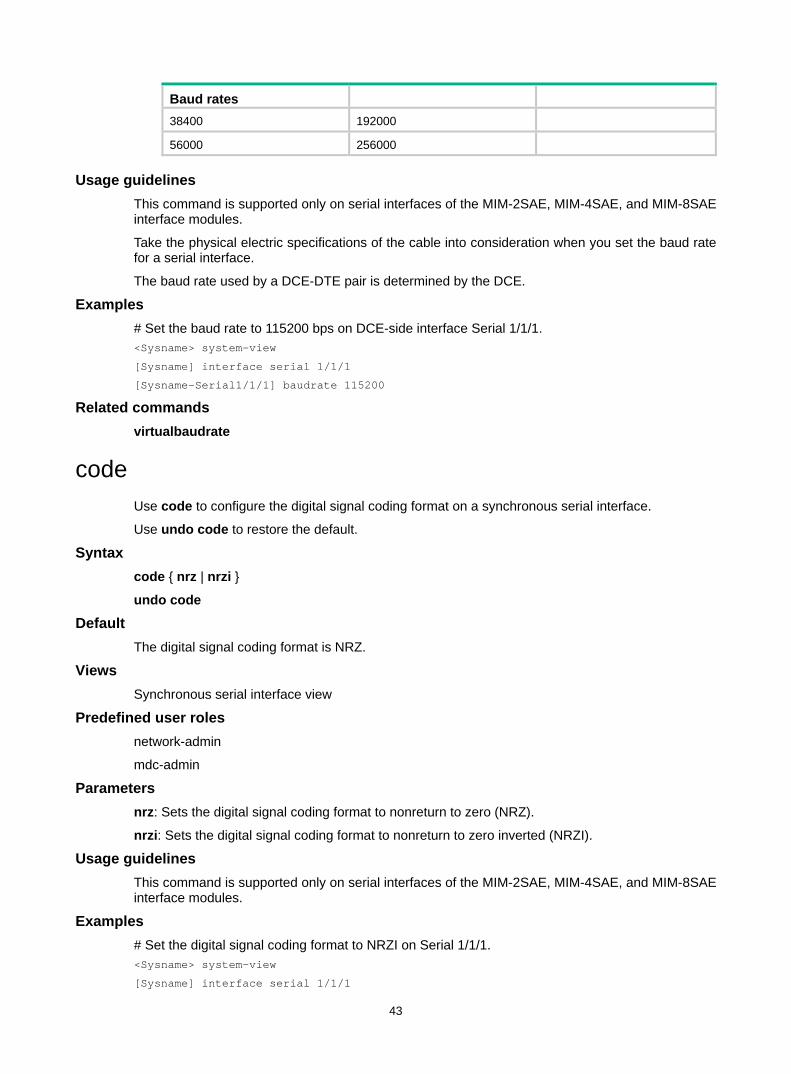
43
Baud rates 38400 192000
56000 256000
Usage guidelines This command is supported only on serial interfaces of the MIM-2SAE, MIM-4SAE, and MIM-8SAE interface modules.
Take the physical electric specifications of the cable into consideration when you set the baud rate for a serial interface.
The baud rate used by a DCE-DTE pair is determined by the DCE.
Examples # Set the baud rate to 115200 bps on DCE-side interface Serial 1/1/1. <Sysname> system-view
[Sysname] interface serial 1/1/1
[Sysname-Serial1/1/1] baudrate 115200
Related commands virtualbaudrate
code Use code to configure the digital signal coding format on a synchronous serial interface.
Use undo code to restore the default.
Syntax code { nrz | nrzi }
undo code
Default The digital signal coding format is NRZ.
Views Synchronous serial interface view
Predefined user roles network-admin
mdc-admin
Parameters nrz: Sets the digital signal coding format to nonreturn to zero (NRZ).
nrzi: Sets the digital signal coding format to nonreturn to zero inverted (NRZI).
Usage guidelines This command is supported only on serial interfaces of the MIM-2SAE, MIM-4SAE, and MIM-8SAE interface modules.
Examples # Set the digital signal coding format to NRZI on Serial 1/1/1. <Sysname> system-view
[Sysname] interface serial 1/1/1
44
[Sysname-Serial1/1/1] code nrzi
crc Use crc to set the CRC mode for a synchronous serial interface.
Use undo crc to restore the default.
Syntax crc { 16 | 32 | none }
undo crc
Default 16-bit CRC is used.
Views Synchronous serial interface view
Predefined user roles network-admin
mdc-admin
Parameters 16: Specifies 16-bit CRC.
32: Specifies 32-bit CRC.
none: Disables CRC.
Examples # Configure Serial 1/1/1 to use 32-bit CRC. <Sysname> system-view
[Sysname] interface serial 1/1/1
[Sysname-Serial1/1/1] crc 32
clock Use clock to set the clock selection mode for a synchronous serial interface.
Use undo clock to restore the default.
Syntax clock { dteclk1 | dteclk2 | dteclk3 | dteclk4 | dteclk5 | dteclkauto }
undo clock
Default The DTE-side clock is dteclk1.
Views Synchronous serial interface view
Predefined user roles network-admin
mdc-admin
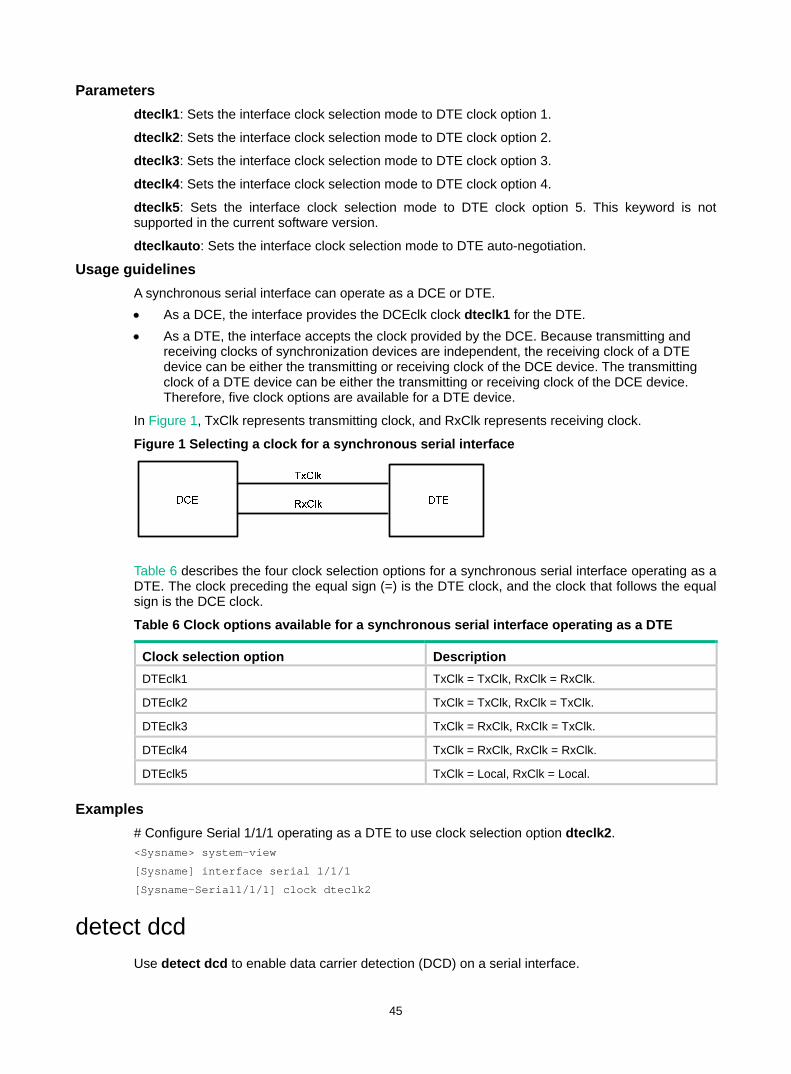
45
Parameters dteclk1: Sets the interface clock selection mode to DTE clock option 1.
dteclk2: Sets the interface clock selection mode to DTE clock option 2.
dteclk3: Sets the interface clock selection mode to DTE clock option 3.
dteclk4: Sets the interface clock selection mode to DTE clock option 4.
dteclk5: Sets the interface clock selection mode to DTE clock option 5. This keyword is not supported in the current software version.
dteclkauto: Sets the interface clock selection mode to DTE auto-negotiation.
Usage guidelines A synchronous serial interface can operate as a DCE or DTE. • As a DCE, the interface provides the DCEclk clock dteclk1 for the DTE. • As a DTE, the interface accepts the clock provided by the DCE. Because transmitting and
receiving clocks of synchronization devices are independent, the receiving clock of a DTE device can be either the transmitting or receiving clock of the DCE device. The transmitting clock of a DTE device can be either the transmitting or receiving clock of the DCE device. Therefore, five clock options are available for a DTE device.
In Figure 1, TxClk represents transmitting clock, and RxClk represents receiving clock.
Figure 1 Selecting a clock for a synchronous serial interface
Table 6 describes the four clock selection options for a synchronous serial interface operating as a DTE. The clock preceding the equal sign (=) is the DTE clock, and the clock that follows the equal sign is the DCE clock.
Table 6 Clock options available for a synchronous serial interface operating as a DTE
Clock selection option Description DTEclk1 TxClk = TxClk, RxClk = RxClk.
DTEclk2 TxClk = TxClk, RxClk = TxClk.
DTEclk3 TxClk = RxClk, RxClk = TxClk.
DTEclk4 TxClk = RxClk, RxClk = RxClk.
DTEclk5 TxClk = Local, RxClk = Local.
Examples # Configure Serial 1/1/1 operating as a DTE to use clock selection option dteclk2. <Sysname> system-view
[Sysname] interface serial 1/1/1
[Sysname-Serial1/1/1] clock dteclk2
detect dcd Use detect dcd to enable data carrier detection (DCD) on a serial interface.
46
Use undo detect dcd to disable DCD on a serial interface.
Syntax detect dcd
undo detect dcd
Default DCD is enabled on a serial interface.
Views Synchronous serial interface view
Predefined user roles network-admin
mdc-admin
Usage guidelines This command is supported only on serial interfaces of the MIM-2SAE, MIM-4SAE, and MIM-8SAE interface modules.
When determining whether a synchronous serial interface is up, the system detects by default the DSR signal, DCD signal, and presence of cable connection. The interface is considered to be up only when the three signals are all valid.
Examples # Enable DCD on Serial 1/1/1. <Sysname> system-view
[Sysname] interface serial 1/1/1
[Sysname-Serial1/1/1] detect dcd
Related commands detect dsr-dtr
detect dsr-dtr Use detect dsr-dtr to enable level detection on a serial interface.
Use undo detect dsr-dtr to disable level detection on a serial interface.
Syntax detect dsr-dtr
undo detect dsr-dtr
Default Level detection is enabled on a serial interface.
Views Synchronous serial interface view
Predefined user roles network-admin
mdc-admin
47
Usage guidelines This command is supported only on serial interfaces of the MIM-2SAE, MIM-4SAE, and MIM-8SAE interface modules.
In level detection, the system detects the following items for the data service unit (DSU) or the channel service unit (CSU): • Data set ready (DSR) signals. • Data terminal ready (DTR) signals.
When determining whether a synchronous serial interface is up, the system detects by default the DSR signal, DCD signal, and presence of a cable connection. The interface is considered to be up only when the three signals are all valid.
If level detection is disabled on a synchronous serial interface, the system considers the interface to be up after detecting the cable connection. The DTR and DSR are also reported as up.
Examples # Enable DCD on Serial 1/1/1. <Sysname> system-view
[Sysname] interface serial 1/1/1
[Sysname-Serial1/1/1] detect dsr-dtr
Related commands detect dcd
display interface serial Use display interface serial to display information about serial interfaces.
Syntax display interface [ serial [ interface-number ] ] [ brief [ description | down ] ]
Views Any view
Predefined user roles network-admin
network-operator
mdc-admin
mdc-operator
Parameters interface-number: Specifies a serial interface by its number.
brief: Displays brief interface information. If you do not specify this keyword, the command displays detailed interface information.
description: Displays complete interface descriptions. If you do not specify this keyword, the command displays only the first 27 characters of interface descriptions.
down: Displays physically down interfaces and their down causes. If you do not specify this keyword, the command displays information about interfaces in all states.
Usage guidelines If you do not specify the serial keyword, this command displays information about all interfaces on the device.
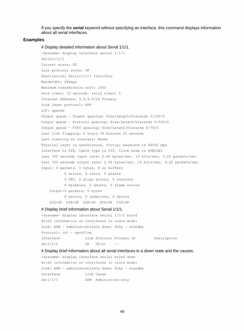
48
If you specify the serial keyword without specifying an interface, this command displays information about all serial interfaces.
Examples # Display detailed information about Serial 1/1/1. <Sysname> display interface serial 1/1/1
Serial1/1/1
Current state: UP
Line protocol state: UP
Description: Serial1/1/1 Interface
Bandwidth: 64kbps
Maximum transmission unit: 1500
Hold timer: 10 seconds, retry times: 5
Internet Address: 9.9.9.6/24 Primary
Link layer protocol: PPP
LCP: opened
Output queue - Urgent queuing: Size/Length/Discards 0/100/0
Output queue - Protocol queuing: Size/Length/Discards 0/500/0
Output queue - FIFO queuing: Size/Length/Discards 0/75/0
Last link flapping: 6 hours 39 minutes 25 seconds
Last clearing of counters: Never
Physical layer is synchronous, Virtual baudrate is 64000 bps
Interface is DTE, Cable type is V35, Clock mode is DTECLK1
Last 300 seconds input rate: 2.40 bytes/sec, 19 bits/sec, 0.20 packets/sec
Last 300 seconds output rate: 2.40 bytes/sec, 19 bits/sec, 0.20 packets/sec
Input: 0 packets, 0 bytes, 0 no buffers
0 errors, 0 runts, 0 giants
0 CRC, 0 align errors, 0 overruns
0 dribbles, 0 aborts, 0 frame errors
Output:0 packets, 0 bytes
0 errors, 0 underruns, 0 aborts
DCD=UP DTR=UP DSR=UP RTS=UP CTS=UP
# Display brief information about Serial 1/1/1. <Sysname> display interface serial 1/1/1 brief
Brief information on interfaces in route mode:
Link: ADM - administratively down; Stby - standby
Protocol: (s) - spoofing
Interface Link Protocol Primary IP Description
Ser1/1/1 UP UP(s) --
# Display brief information about all serial interfaces in a down state and the causes. <Sysname> display interface serial brief down
Brief information on interfaces in route mode:
Link: ADM - administratively down; Stby - standby
Interface Link Cause
Ser1/1/1 ADM Administratively
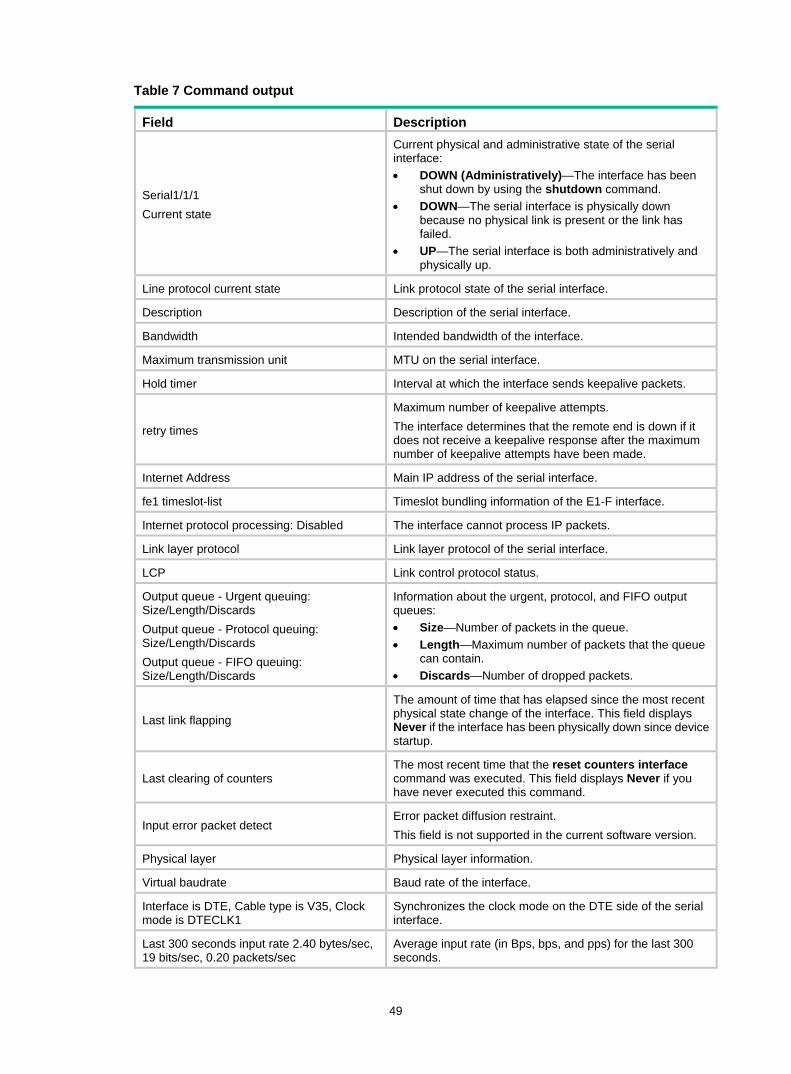
49
Table 7 Command output
Field Description
Serial1/1/1 Current state
Current physical and administrative state of the serial interface: • DOWN (Administratively)—The interface has been
shut down by using the shutdown command. • DOWN—The serial interface is physically down
because no physical link is present or the link has failed.
• UP—The serial interface is both administratively and physically up.
Line protocol current state Link protocol state of the serial interface.
Description Description of the serial interface.
Bandwidth Intended bandwidth of the interface.
Maximum transmission unit MTU on the serial interface.
Hold timer Interval at which the interface sends keepalive packets.
retry times
Maximum number of keepalive attempts. The interface determines that the remote end is down if it does not receive a keepalive response after the maximum number of keepalive attempts have been made.
Internet Address Main IP address of the serial interface.
fe1 timeslot-list Timeslot bundling information of the E1-F interface.
Internet protocol processing: Disabled The interface cannot process IP packets.
Link layer protocol Link layer protocol of the serial interface.
LCP Link control protocol status.
Output queue - Urgent queuing: Size/Length/Discards Output queue - Protocol queuing: Size/Length/Discards Output queue - FIFO queuing: Size/Length/Discards
Information about the urgent, protocol, and FIFO output queues: • Size—Number of packets in the queue. • Length—Maximum number of packets that the queue
can contain. • Discards—Number of dropped packets.
Last link flapping
The amount of time that has elapsed since the most recent physical state change of the interface. This field displays Never if the interface has been physically down since device startup.
Last clearing of counters The most recent time that the reset counters interface command was executed. This field displays Never if you have never executed this command.
Input error packet detect Error packet diffusion restraint. This field is not supported in the current software version.
Physical layer Physical layer information.
Virtual baudrate Baud rate of the interface.
Interface is DTE, Cable type is V35, Clock mode is DTECLK1
Synchronizes the clock mode on the DTE side of the serial interface.
Last 300 seconds input rate 2.40 bytes/sec, 19 bits/sec, 0.20 packets/sec
Average input rate (in Bps, bps, and pps) for the last 300 seconds.
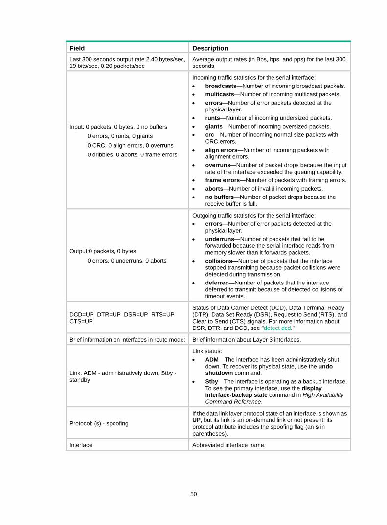
50
Field Description Last 300 seconds output rate 2.40 bytes/sec, 19 bits/sec, 0.20 packets/sec
Average output rates (in Bps, bps, and pps) for the last 300 seconds.
Input: 0 packets, 0 bytes, 0 no buffers 0 errors, 0 runts, 0 giants 0 CRC, 0 align errors, 0 overruns 0 dribbles, 0 aborts, 0 frame errors
Incoming traffic statistics for the serial interface: • broadcasts—Number of incoming broadcast packets. • multicasts—Number of incoming multicast packets. • errors—Number of error packets detected at the
physical layer. • runts—Number of incoming undersized packets. • giants—Number of incoming oversized packets. • crc—Number of incoming normal-size packets with
CRC errors. • align errors—Number of incoming packets with
alignment errors. • overruns—Number of packet drops because the input
rate of the interface exceeded the queuing capability. • frame errors—Number of packets with framing errors.• aborts—Number of invalid incoming packets. • no buffers—Number of packet drops because the
receive buffer is full.
Output:0 packets, 0 bytes 0 errors, 0 underruns, 0 aborts
Outgoing traffic statistics for the serial interface: • errors—Number of error packets detected at the
physical layer. • underruns—Number of packets that fail to be
forwarded because the serial interface reads from memory slower than it forwards packets.
• collisions—Number of packets that the interface stopped transmitting because packet collisions were detected during transmission.
• deferred—Number of packets that the interface deferred to transmit because of detected collisions or timeout events.
DCD=UP DTR=UP DSR=UP RTS=UP CTS=UP
Status of Data Carrier Detect (DCD), Data Terminal Ready (DTR), Data Set Ready (DSR), Request to Send (RTS), and Clear to Send (CTS) signals. For more information about DSR, DTR, and DCD, see "detect dcd."
Brief information on interfaces in route mode: Brief information about Layer 3 interfaces.
Link: ADM - administratively down; Stby - standby
Link status: • ADM—The interface has been administratively shut
down. To recover its physical state, use the undo shutdown command.
• Stby—The interface is operating as a backup interface. To see the primary interface, use the display interface-backup state command in High Availability Command Reference.
Protocol: (s) - spoofing
If the data link layer protocol state of an interface is shown as UP, but its link is an on-demand link or not present, its protocol attribute includes the spoofing flag (an s in parentheses).
Interface Abbreviated interface name.
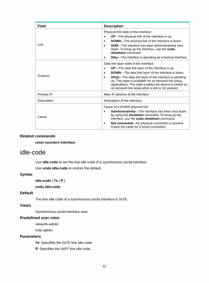
51
Field Description
Link
Physical link state of the interface: • UP—The physical link of the interface is up. • DOWN—The physical link of the interface is down. • ADM—The interface has been administratively shut
down. To bring up the interface, use the undo shutdown command.
• Stby—The interface is operating as a backup interface.
Protocol
Data link layer state of the interface: • UP—The data link layer of the interface is up. • DOWN—The data link layer of the interface is down. • UP(s)—The data link layer of the interface is spoofing
up. This state is available for on-demand link setup applications. This state enables the device to initiate an on-demand link setup when a link is not present.
Primary IP Main IP address of the interface.
Description Description of the interface.
Cause
Cause of a DOWN physical link: • Administratively—The interface has been shut down
by using the shutdown command. To bring up the interface, use the undo shutdown command.
• Not connected—No physical connection is present. Check the cable for a loose connection.
Related commands reset counters interface
idle-code Use idle-code to set the line idle code of a synchronous serial interface.
Use undo idle-code to restore the default.
Syntax idle-code { 7e | ff }
undo idle-code
Default The line idle code of a synchronous serial interface is 0x7E.
Views Synchronous serial interface view
Predefined user roles network-admin
mdc-admin
Parameters 7e: Specifies the 0x7E line idle code.
ff: Specifies the 0xFF line idle code.
52
Usage guidelines In most cases, a synchronous serial interface uses 0x7E to identify the idle state of the line. You might need to set the line idle code to 0xFF to interoperate with devices that use 0xFF as line idle code.
Examples # Set the line idle code to 0xFF for Serial 1/1/1. <Sysname> system-view
[Sysname] interface serial 1/1/1
[Sysname-Serial1/1/1] idle-code ff
interface serial Use interface serial to create a serial subinterface and enter its view, or enter the view of an existing serial interface or serial subinterface.
Use undo interface serial to remove a serial subinterface.
Syntax interface serial { interface-number | interface-number.subnumber [ p2mp | p2p ] }
undo interface serial interface-number.subnumber
Default No serial subinterfaces exist.
Views System view
Predefined user roles network-admin
mdc-admin
Parameters interface-number: Specifies a serial interface by its number.
interface-number.subnumber: Specifies a serial subinterface by its number. The interface-number argument specifies the number of the serial interface. The subnumber argument specifies the subinterface index in the range of 0 to 1023.
p2mp: Sets the subinterface type to point-to-multipoint. By default, a serial subinterface is P2MP type.
p2p: Sets the subinterface type to point-to-point.
Usage guidelines A subinterface can be created only when the upper data link layer protocol of the serial interface is FR.
Examples # Create serial subinterface Serial 1/1/1.1. <Sysname> system-view
[Sysname] interface serial 1/1/1.1
[Sysname-Serial1/1/1.1]
Related commands link-protocol
53
invert receive-clock Use invert receive-clock to invert the receive-clock signal on the DTE-side synchronous serial interface.
Use undo invert receive-clock to restore the default.
Syntax invert receive-clock
undo invert receive-clock
Default Receive-clock signal inversion is disabled on DTE-side synchronous serial interfaces.
Views Synchronous serial interface view
Predefined user roles network-admin
mdc-admin
Usage guidelines This command is supported only on serial interfaces of the MIM-2SAE, MIM-4SAE, and MIM-8SAE interface modules.
You might need to invert the receive-clock signal on a DTE-side serial interface to eliminate the half clock-period delay on the line. This command is necessary only when the DTE-side serial interface is connected to some special DCE devices. In common applications, do not invert the clock.
Examples # Invert the receive-clock on DTE-side synchronous serial interface Serial 1/1/1. <Sysname> system-view
[Sysname] interface serial 1/1/1
[Sysname-Serial1/1/1] invert receive-clock
Related commands invert transmit-clock
invert transmit-clock Use invert transmit-clock to invert the transmit-clock signal on the DTE-side synchronous serial interface.
Use undo invert transmit-clock to restore the default.
Syntax invert transmit-clock
undo invert transmit-clock
Default Transmit-clock signal inversion is disabled on DTE-side synchronous serial interfaces.
Views Serial interface view
54
Predefined user roles network-admin
mdc-admin
Usage guidelines This command is supported only on serial interfaces of the MIM-2SAE, MIM-4SAE, and MIM-8SAE interface modules.
You might need to invert the receive-clock signal on a DTE-side serial interface to eliminate the half clock-period delay on the line. This command is necessary only when the DTE-side serial interface is connected to some special DCE devices. In common applications, do not invert the clock.
Examples # Invert the transmit-clock on DTE-side synchronous serial interface Serial 1/1/1. <Sysname> system-view
[Sysname] interface serial 1/1/1
[Sysname-Serial1/1/1] invert transmit-clock
Related commands invert receive-clock
itf Use itf to set the number of interframe filling tags.
Use undo itf to restore the default.
Syntax itf number number
undo itf number
Default The number of interframe filling tags is 4.
Views Synchronous serial interface view
Predefined user roles network-admin
mdc-admin
Parameters number number: Sets the number of interframe filling tags, in the range of 0 to 14 bytes. An interframe filling tag is one byte in length.
Examples # Set the number of interframe filling tags to 5. <Sysname> system-view
[Sysname] interface serial 1/1/1
[Sysname-Serial1/1/1] itf number 5
link-protocol Use link-protocol to configure the data link layer protocol for an interface.
55
Syntax link-protocol { fr | hdlc | ppp | mfr }
Default A synchronous serial interface uses PPP as the data link layer protocol.
Views Synchronous serial interface view
Predefined user roles network-admin
mdc-admin
Parameters fr: Specifies the FR data link layer protocol.
hdlc: Specifies the HDLC data link layer protocol.
ppp: Specifies the PPP data link layer protocol.
mfr: Specifies the MFR data link layer protocol.
Examples # Specify HDLC as the data link layer protocol of Serial 1/1/1. <Sysname> system-view
[Sysname] interface serial 1/1/1
[Sysname-Serial1/1/1] link-protocol hdlc
loopback Use loopback to enable loopback on a serial interface.
Use undo loopback to disable loopback on a serial interface.
Syntax loopback
undo loopback
Default Loopback is disabled on a serial interface.
Views Serial interface view
Predefined user roles network-admin
mdc-admin
Usage guidelines Loopback is intended for testing only. Disable the feature when the interface is operating correctly.
Examples # Enable loopback on Serial 1/1/1. <Sysname> system-view
[Sysname] interface serial 1/1/1
[Sysname-Serial1/1/1] loopback
56
mtu Use mtu to set the MTU for an interface.
Use undo mtu to restore the default.
Syntax mtu size
undo mtu
Default The MTU of an interface is 1500 bytes.
Views Serial interface view
Serial subinterface view
Predefined user roles network-admin
mdc-admin
Parameters size: Sets the maximum transmission unit (MTU) in bytes. The value range for this argument is 128 to 1500.
Usage guidelines The MTU setting affects IP packet assembly and fragmentation on the interface.
After configuring the MTU for a WAN interface, you must use the shutdown command and then the undo shutdown command on the interface for the modification to take effect.
Examples # Set the MTU to 1430 bytes for Serial 1/1/1. <Sysname> system-view
[Sysname] interface serial 1/1/1
[Sysname-Serial1/1/1] mtu 1430
reset counters interface Use reset counters interface to clear serial interface statistics.
Syntax reset counters interface [ serial [ interface-number ] ]
Views User view
Predefined user roles network-admin
mdc-admin
Parameters serial interface-number: Specifies a serial interface by its number.
57
Usage guidelines Use this command to clear history statistics before you collect traffic statistics for a time period. • If you do not specify the serial keyword, this command clears statistics for all interfaces. • If you specify the serial keyword without specifying an interface, this command clears statistics
for all serial interfaces. • If you specify a serial interface, this command clears statistics for the specified interface.
Examples # Clear statistics for Serial 1/1/1. <Sysname> reset counters interface serial 1/1/1
Related commands display interface serial
reverse-rts Use reverse-rts to reverse RTS signal.
Use undo reverse-rts to restore the default.
Syntax reverse-rts
undo reverse-rts
Default RTS signal reverse is disabled.
Views Synchronous serial interface view
Predefined user roles network-admin
mdc-admin
Usage guidelines This command is supported only on serial interfaces of the MIM-2SAE, MIM-4SAE, and MIM-8SAE interface modules.
When this command is configured, the remote end is not allowed to send data while the local end is sending data.
Use this command only for debugging purposes.
Examples # Reverse the RTS signal. <Sysname> system-view
[Sysname] interface serial 1/1/1
[Sysname-Serial1/1/1] reverse-rts
sub-interface rate-statistic Use sub-interface rate-statistic to enable subinterface rate statistics collection on a serial interface.
58
Use undo sub-interface rate-statistic to disable subinterface rate statistics collection on a serial interface.
Syntax sub-interface rate-statistic
undo sub-interface rate-statistic
Default The system does not collect subinterface rate statistics for a serial interface.
Views Synchronous interface view
Predefined user roles network-admin
mdc-admin
Usage guidelines This command is resource intensive. When you use this command, make sure you fully understand its impact on system performance.
Serial interfaces that support this feature include synchronous serial interfaces and sub-channel serial interfaces.
Examples # Enable subinterface rate statistics collection on Serial 1/1/1. <Sysname> system-view
[Sysname] interface serial 1/1/1
[Sysname-Serial1/1/1] sub-interface rate-statistic
Related commands reset counters interface
virtualbaudrate Use virtualbaudrate to set a virtual baud rate for a DTE-side interface.
Use undo virtualbaudrate to remove the virtual baud rate.
Syntax virtualbaudrate virtualbaudrate
undo virtualbaudrate
Default The virtual baud rate for a synchronous serial interface is 64000 bps.
Views Synchronous serial interface view
Predefined user roles network-admin
mdc-admin
Parameters virtualbaudrate: Specifies a virtual baud rate (in bps). Available values are:
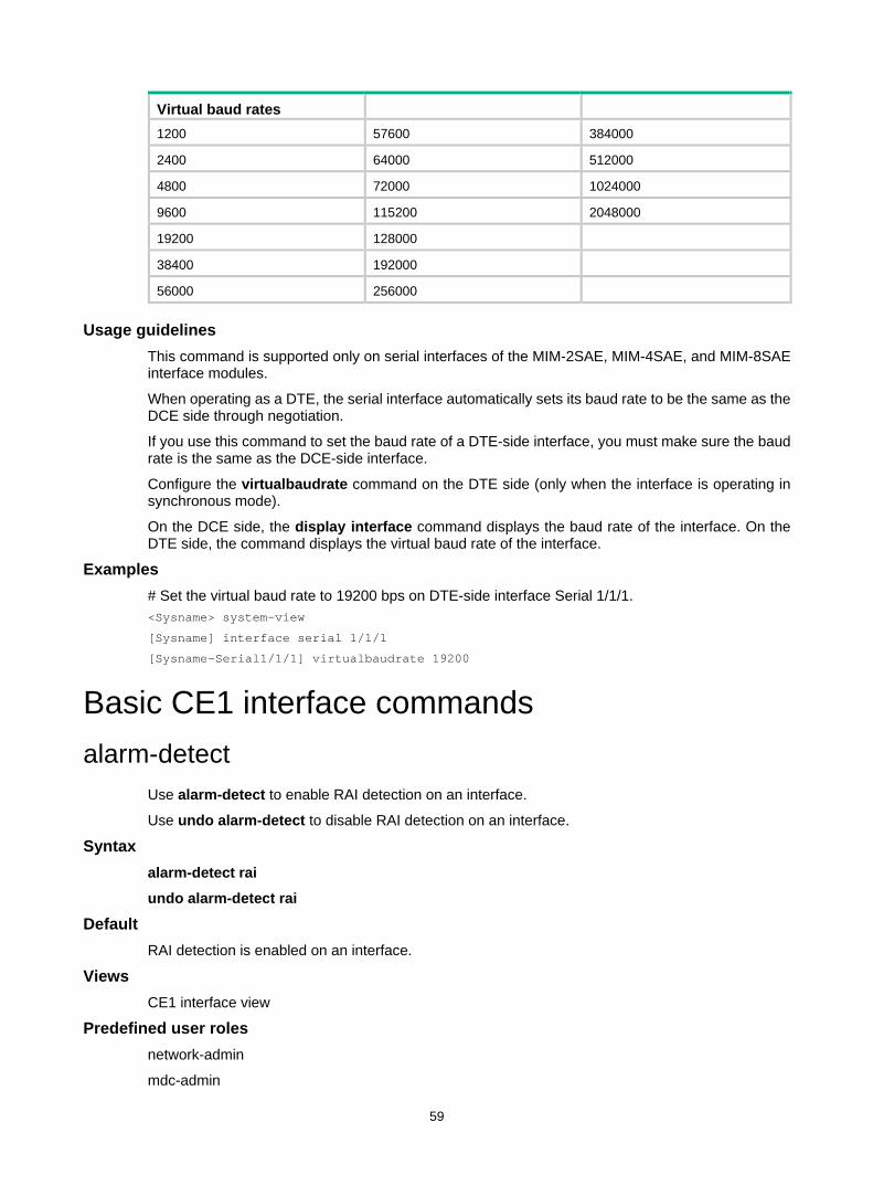
59
Virtual baud rates 1200 57600 384000
2400 64000 512000
4800 72000 1024000
9600 115200 2048000
19200 128000
38400 192000
56000 256000
Usage guidelines This command is supported only on serial interfaces of the MIM-2SAE, MIM-4SAE, and MIM-8SAE interface modules.
When operating as a DTE, the serial interface automatically sets its baud rate to be the same as the DCE side through negotiation.
If you use this command to set the baud rate of a DTE-side interface, you must make sure the baud rate is the same as the DCE-side interface.
Configure the virtualbaudrate command on the DTE side (only when the interface is operating in synchronous mode).
On the DCE side, the display interface command displays the baud rate of the interface. On the DTE side, the command displays the virtual baud rate of the interface.
Examples # Set the virtual baud rate to 19200 bps on DTE-side interface Serial 1/1/1. <Sysname> system-view
[Sysname] interface serial 1/1/1
[Sysname-Serial1/1/1] virtualbaudrate 19200
Basic CE1 interface commands alarm-detect
Use alarm-detect to enable RAI detection on an interface.
Use undo alarm-detect to disable RAI detection on an interface.
Syntax alarm-detect rai
undo alarm-detect rai
Default RAI detection is enabled on an interface.
Views CE1 interface view
Predefined user roles network-admin
mdc-admin
60
Parameters rai: Remote Alarm Indication (RAI).
Usage guidelines This command is applicable when the interface operates in CE1 mode.
Examples # Enable RAI detection on E1 1/1/1. <Sysname> system-view
[Sysname] controller e1 1/1/1
[Sysname-E1 1/1/1] alarm-detect rai
cable (CE1 interface) Use cable to set the cable type for a CE1 interface.
Use undo cable to restore the default.
Syntax cable { long | short }
undo cable
Default The long keyword applies.
Views CE1 interface view
Predefined user roles network-admin
mdc-admin
Parameters long: Specifies the attenuation of the receiver as –43 dB.
short: Specifies the attenuation of the receiver as –10 dB.
Examples # Set the cable length matching E1 1/1/1 to short. <Sysname> system-view
[Sysname] controller e1 1/1/1
[Sysname-E1 1/1/1] cable short
channel-set (CE1 interface) Use channel-set to bundle timeslots on a CE1 interface into a channel set.
Use undo channel-set to cancel the bundling.
Syntax channel-set set-number timeslot-list list
undo channel-set [ set-number ]
61
Default No channel sets exist on a CE1 interface.
Views CE1 interface view
Predefined user roles network-admin
mdc-admin
Parameters set-number: Specifies the number of the channel set for the timeslot bundle. The value range is 0 to 30.
timeslot-list list: Specifies a comma-separated list of timeslot items. An item can be an individual timeslot or a timeslot range. Use a hyphen (-) to separate the start and end timeslot numbers of a range. The value range for the timeslot number is 1 to 31.
Usage guidelines A CE1 interface in CE1 mode is physically divided into 32 timeslots numbered 0 through 31. All the timeslots except timeslot 0 can be bundled into multiple channel sets. For each channel set, the system automatically creates a serial interface that has the same logical features as a standard synchronous serial interface.
The serial interface name uses the serial interface-number:set-number format. The interface-number argument specifies the CE1 interface number. The set-number argument specifies the channel set number.
Examples # Bundle timeslots 1, 2, 5, 10 through 15, and 18 into channel set 0 on E1 1/1/1. <Sysname> system-view
[Sysname] controller e1 1/1/1
[Sysname-E1 1/1/1] channel-set 0 timeslot-list 1,2,5,10-15,18
clock (CE1 interface) Use clock to set the clock mode of a CE1 interface.
Use undo clock to restore the default.
Syntax clock { master | slave }
undo clock
Default The clock mode of a CE1 interface is slave.
Views CE1 interface view
Predefined user roles network-admin
mdc-admin
Parameters master: Sets the clock mode to master.
62
slave: Sets the clock mode to slave.
Examples # Set the clock mode to master for CE1 interface E1 1/1/1. <Sysname> system-view
[Sysname] controller e1 1/1/1
[Sysname-E1 1/1/1] clock master
clock-change auto Use clock-change auto to enable automatic clock mode switchover on an interface.
Use undo clock-change auto to disable automatic clock mode switchover.
Syntax clock-change auto
undo clock-change auto
Default Automatic clock mode switchover is disabled on an interface.
Views CE1 interface view
Predefined user roles network-admin
mdc-admin
Usage guidelines When automatic clock mode switchover is enabled, the interface automatically switches to the master clock mode when both of the following conditions exist: • The interface uses the slave clock mode. • The interface receives an alarm indication signal (AIS), loss of signal (LOS), or loss of frame
(LOF) alarm.
After the alarm is cleared, the interface automatically switches back to the user-configured clock mode.
When automatic clock mode switchover is disabled, the interface uses the user-configured clock mode.
Examples # Enable automatic clock mode switchover for E1 1/1/1. <Sysname> system-view
[Sysname] controller e1 1/1/1
[Sysname-E1 1/1/1] clock-change auto
Related commands clock
code (CE1 interface) Use code to set the line code format for a CE1 interface.
Use undo code to restore the default.
63
Syntax code { ami | hdb3 }
undo code
Default The line code format is HDB3 for the CE1 interface.
Views CE1 interface view
Predefined user roles network-admin
mdc-admin
Parameters ami: Specifies the alternate mark inversion (AMI) line code format.
hdb3: Specifies the high-density bipolar 3 (HDB3) line code format.
Usage guidelines A CE1 interface must use the same line code format as its remote end. For the interface to operate correctly, configure the data-coding inverted command if the AMI format is used.
Examples # Set the line code format to AMI for E1 1/1/1. <Sysname> system-view
[Sysname] controller e1 1/1/1
[Sysname-E1 1/1/1] code ami
Related commands data-coding
controller e1 Use controller e1 to enter CE1 interface view.
Syntax controller e1 interface-number
Views System view
Predefined user roles network-admin
mdc-admin
Parameters interface-number: Specifies a CE1 interface by its number.
Examples # Enter E1 1/1/1 interface view. <Sysname> system-view
[Sysname] controller e1 1/1/1
[Sysname-E1 1/1/1]
64
data-coding (CE1 interface) Use data-coding to enable user data inversion on a CE1 interface.
Use undo data-coding to restore the default.
Syntax data-coding { inverted | normal }
undo data-coding
Default Data inversion is disabled on a CE1 interface.
Views CE1 interface view
Predefined user roles network-admin
mdc-admin
Parameters inverted: Enables user data inversion.
normal: Disables user data inversion.
Usage guidelines To prevent 7e in valid data from being mistaken for padding characters, HDLC inserts a zero after every five consecutive ones in the data stream. In data inversion, each bit one is inverted to bit zero, and each bit zero is inverted to bit one. After the inversion, at least a bit one is present in every eight consecutive bits.
When AMI encoding is used on an E1 interface, data inversion eliminates the presence of multiple consecutive zeros.
The data inversion setting must be the same on the CE1 interfaces at two ends of an E1 line.
Examples # Enable user data inversion on E1 1/1/1. <Sysname> system-view
[Sysname] controller e1 1/1/1
[Sysname-E1 1/1/1] data-coding inverted
detect-ais Use detect-ais to enable alarm indication signal (AIS) detection on an interface.
Use undo detect-ais to disable AIS detection.
Syntax detect-ais
undo detect-ais
Default AIS detection is enabled on an interface.
65
Views CE1 interface view
Predefined user roles network-admin
mdc-admin
Usage guidelines This command takes effect when a CE1 interface operates in E1 mode.
Examples # Enable AIS detection on E1 1/1/1. <Sysname> system-view
[Sysname] controller e1 1/1/1
[Sysname-E1 1/1/1] detect-ais
display controller e1 Use display controller e1 to display information about CE1 interfaces.
Syntax display controller e1 [ interface-number ]
Views Any view
Predefined user roles network-admin
network-operator
mdc-admin
mdc-operator
Parameters interface-number: Specifies a CE1 interface by its number. If you do not specify this argument, the command displays information about all CE1 interfaces.
Examples # Display information about E1 1/1/1. <Sysname> display controller e1 1/1/1
E1 1/1/1
Current state: UP
Description: E1 1/1/1 Interface
Last clearing of counters: Never
Basic Configuration:
Work mode is E1 unframed, Cable type is 75 Ohm unbalanced.
Line code is hdb3, Source clock is slave.
Idle code is 7e, Itf type is 7e, Itf number is 4.
Loop back is not set.
Alarm State:
Receiver alarm state is None.
Historical Statistics:
66
Data in current interval (150 seconds elapsed):
1502 Loss Frame Alignment Secs, 0 Framing Error Secs,
0 CRC Error Secs, 0 Alarm Indication Secs, 1821 Loss-of-signals Secs,
0 Code Violations Secs, 9 Slip Secs, 0 E-Bit error Secs.
Table 8 Command output
Field Description E1 1/1/1 Current state
Interface state.
Description Interface description.
Work mode Operating mode of the interface: E1 or CE1.
Cable type Cable type of the interface.
Frame-format Framing format of the interface.
Source clock Operating mode of the source clock of the interface: master or slave.
Line code Line code: AMI or HDB3.
Idle code Idle code; 7E or FF.
Itf type Interframe filling tag: 7E or FF.
Itf number Number of interframe filling tags between two successive frames.
Loop back Loopback state.
Historical Statistics Statistics for the interface.
Last clearing of counters The most recent time that the reset counters controller e1 command was executed. This field displays Never if you have never executed this command.
Data in current interval (150 seconds elapsed): 1502 Loss Frame Alignment Secs, 0 Framing Error Secs, 0 CRC Error Secs, 0 Alarm Indication Secs, 1821 Loss-of-signals Secs, 0 Code Violations Secs, 9 Slip Secs, 0 E-Bit error Secs
Error statistics for the current interval.
Related commands reset counters controller e1
frame-format (CE1 interface) Use frame-format to set the framing format for a CE1 interface.
Use undo frame-format to restore the default.
Syntax frame-format { crc4 | no-crc4 }
undo frame-format
Default The framing format on a CE1 interface is no-CRC4.

67
Views CE1 interface view
Predefined user roles network-admin
mdc-admin
Parameters crc4: Sets the framing format to CRC4.
no-crc4: Sets the framing format to no-CRC4.
Usage guidelines A CE1 interface in CE1 mode supports both CRC4 and no-CRC4 framing formats. Only CRC4 supports four-bit CRC on physical frames.
Examples # Set the framing format to CRC4 on E1 1/1/1. <Sysname> system-view
[Sysname] controller e1 1/1/1
[Sysname-E1 1/1/1] frame-format crc4
idle-code (CE1 interface) Use idle-code to set the line idle code on a CE1 interface.
Use undo idle-code to restore the default.
Syntax Idle-code { 7e | ff }
undo idle-code
Default The line idle code on a CE1 interface is 0x7E.
Views CE1 interface view
Predefined user roles network-admin
mdc-admin
Parameters 7e: Sets the line idle code to 0x7E.
ff: Sets the line idle code to 0xFF.
Usage guidelines The line idle code is sent in timeslots that are not bundled into logical channels.
Examples # Set the line idle code to 0x7E on E1 1/1/1. <Sysname> system-view
[Sysname] controller e1 1/1/1
[Sysname-E1 1/1/1] idle-code 7e
68
itf (CE1 interface) Use itf to set the type and number of interframe filling tags on a CE1 interface.
Use undo itf to restore the default.
Syntax itf { number number | type { 7e | ff } }
undo itf { number | type }
Default The interframe filling tag is 0x7E. The number of interframe filling tags is 4.
Views CE1 interface view
Predefined user roles network-admin
mdc-admin
Parameters number number: Sets the number of interframe filling tags, in the range of 0 to 14. An interframe filling tag is one byte in length.
type: Specifies the interframe filling tag type.
7e: Specifies the interframe filling tag type 0x7E.
ff: Specifies the interframe filling tag type 0xFF.
Usage guidelines The bundled timeslots on the CE1 interface send interframe filling tags when no service data is present.
If the 0xFF interframe filling tag is used on a CE1 interface in E1 mode, consecutive ones sent when the line is idle might trigger AIS alarms. To prevent false AIS alarms, use the undo detect-ais command to disable AIS detection.
Examples # Set the type of interframe filling tag to 0xFF on E1 1/1/1. <Sysname> system-view
[Sysname] controller e1 1/1/1
[Sysname-E1 1/1/1] itf type ff
# Set the number of interframe filling tags to 5 on E1 1/1/1. <Sysname> system-view
[Sysname] controller e1 1/1/1
[Sysname-E1 1/1/1] itf number 5
loopback (CE1 interface) Use loopback to enable loopback and set the loopback mode on a CE1 interface.
Use undo loopback to disable loopback on a CE1 interface.
Syntax loopback { local | payload | remote }
69
undo loopback
Default Loopback is disabled on a CE1 interface.
Views CE1 interface view
Predefined user roles network-admin
mdc-admin
Parameters local: Sets the interface to operate in local loopback mode.
payload: Sets the interface to operate in external payload loopback mode.
remote: Sets the interface to operate in external loopback mode.
Usage guidelines Loopback is intended for testing only. Disable the feature when the interface is operating correctly.
You can bundle timeslots on the CE1 interface to form a serial interface and encapsulate it with PPP or HDLC. After you enable loopback on this serial interface, it is normal that the state of the link layer protocol is reported as down.
Examples # Set E1 1/1/1 to operate in internal loopback mode. <Sysname> system-view
[Sysname] controller e1 1/1/1
[Sysname-E1 1/1/1] loopback local
reset counters controller e1 Use reset counters controller e1 to clear CE1 interface statistics.
Syntax reset counters controller e1 [ interface-number ]
Views User view
Predefined user roles network-admin
mdc-admin
Parameters interface-number: Specifies a CE1 interface by its number. If you do not specify this argument, the command clears statistics for all CE1 interfaces.
Usage guidelines The reset counters interface command clears statistics for all interfaces.
To display CE1 interface statistics, use the display controller e1 command.
Examples # Clear statistics for CE1 interface E1 1/1/1.
70
<Sysname> reset counters controller e1 1/1/1
Related commands display controller e1
using (CE1 interface) Use using to set the operating mode of a CE1 interface.
Use undo using to restore the default.
Syntax using { ce1 | e1 }
undo using
Default A CE1 interface operates in channelized mode.
Views CE1 interface view
Predefined user roles network-admin
mdc-admin
Parameters ce1: Sets the interface to operate in channelized mode.
e1: Sets the interface to operate in E1 mode.
Usage guidelines A CE1 interface can operate in channelized or unchannelized mode. • The channelized mode is CE1 mode. In CE1 mode, the CE1 interface is physically divided into
32 timeslots numbered 0 through 31. Timeslot 0 is used for FSC. • The unchannelized mode is E1 mode. For a CE1 interface in E1 mode, the system
automatically creates a 2.048 Mbps serial interface. The interface name uses the serial interface-number:0 format. The interface-number argument specifies the CE1 interface number. This interface has the same logical features as a standard synchronous serial interface.
Examples # Set E1 1/1/1 to operate in E1 mode. <Sysname> system-view
[Sysname] controller e1 1/1/1
[Sysname-E1 1/1/1] using e1
E1-F interface commands clock-change auto
Use clock-change auto to enable automatic clock mode switchover on an E1-F interface.
Use undo clock-change auto to disable the automatic clock mode switchover on an E1-F interface.
71
Syntax clock-change auto
undo clock-change auto
Default Automatic clock mode switchover is disabled on an E1-F interface.
Views E1-F interface view
Predefined user roles network-admin
mdc-admin
Usage guidelines When automatic clock mode switchover is enabled, the interface automatically switches to the master clock mode when both of the following conditions exist: • The interface uses the slave clock mode. • The interface receives an alarm indication signal (AIS), loss of signal (LOS), or loss of frame
(LOF) alarm.
After the alarm is cleared, the interface automatically switches back to the user-configured clock mode.
When automatic clock mode switchover is disabled, the interface uses the user-configured clock mode.
Examples # Enable automatic clock mode switchover for E1-F interface Serial 1/1/1. <Sysname> system-view
[Sysname] interface serial 1/1/1
[Sysname-Serial1/1/1] clock-change auto
Related commands fe1 clock
crc Use crc to configure CRC mode for an E1-F interface.
Use undo crc to restore the default.
Syntax crc { 16 | 32 | none }
undo crc
Default The CRC mode for an E1-F interface is 16-bit CRC.
Views E1-F interface view
Predefined user roles network-admin
72
mdc-admin
Parameters 16: Specifies 16-bit CRC.
32: Specifies 32-bit CRC.
none: Disables CRC.
Examples # Specify 32-bit CRC on E1-F interface Serial 1/1/1. <Sysname> system-view
[Sysname] interface serial 1/1/1
[Sysname-Serial1/1/1] crc 32
display fe1 Use display fe1 to display information about E1-F interfaces.
Syntax display fe1 [ serial interface-number ]
Views Any view
Predefined user roles network-admin
network-operator
mdc-admin
mdc-operator
Parameters serial interface-number: Specifies a serial interface by its number. If you do not specify an interface, this command displays information about all E1-F interfaces.
Usage guidelines If the specified interface is a common serial interface rather than an E1-F interface, the system displays a prompt.
Examples # Display information about E1-F interface Serial 1/1/1. <Sysname> display fe1 serial 1/1/1
Serial1/1/1
Basic Configuration:
Work mode is E1 framed, Cable type is non-E1 type.
Frame-format is no-crc4.
Line code is hdb3, Source clock is slave.
Idle code is 7e, Itf type is 7e, Itf number is 4.
Loopback is not set.
Alarm State:
Receiver alarm state is Loss-of-Signal.
Transmitter is sending remote alarm.
Historical Statistics:
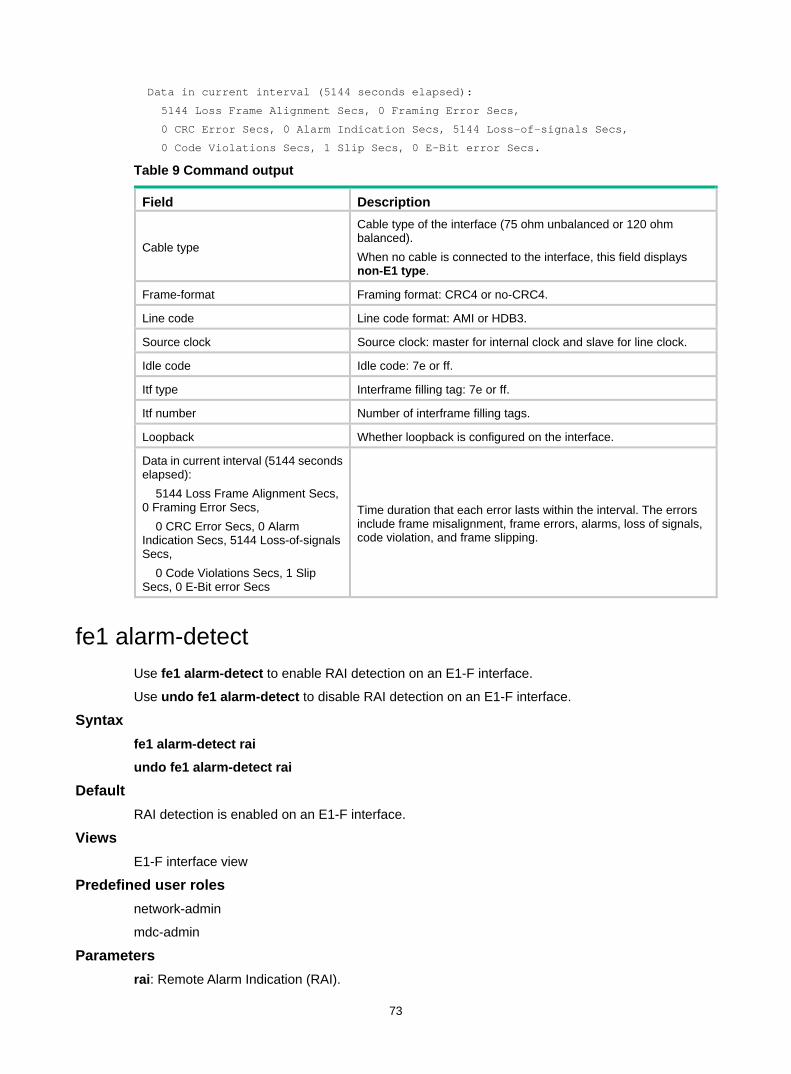
73
Data in current interval (5144 seconds elapsed):
5144 Loss Frame Alignment Secs, 0 Framing Error Secs,
0 CRC Error Secs, 0 Alarm Indication Secs, 5144 Loss-of-signals Secs,
0 Code Violations Secs, 1 Slip Secs, 0 E-Bit error Secs.
Table 9 Command output
Field Description
Cable type
Cable type of the interface (75 ohm unbalanced or 120 ohm balanced). When no cable is connected to the interface, this field displays non-E1 type.
Frame-format Framing format: CRC4 or no-CRC4.
Line code Line code format: AMI or HDB3.
Source clock Source clock: master for internal clock and slave for line clock.
Idle code Idle code: 7e or ff.
Itf type Interframe filling tag: 7e or ff.
Itf number Number of interframe filling tags.
Loopback Whether loopback is configured on the interface.
Data in current interval (5144 seconds elapsed): 5144 Loss Frame Alignment Secs, 0 Framing Error Secs, 0 CRC Error Secs, 0 Alarm Indication Secs, 5144 Loss-of-signals Secs, 0 Code Violations Secs, 1 Slip Secs, 0 E-Bit error Secs
Time duration that each error lasts within the interval. The errors include frame misalignment, frame errors, alarms, loss of signals, code violation, and frame slipping.
fe1 alarm-detect Use fe1 alarm-detect to enable RAI detection on an E1-F interface.
Use undo fe1 alarm-detect to disable RAI detection on an E1-F interface.
Syntax fe1 alarm-detect rai
undo fe1 alarm-detect rai
Default RAI detection is enabled on an E1-F interface.
Views E1-F interface view
Predefined user roles network-admin
mdc-admin
Parameters rai: Remote Alarm Indication (RAI).
74
Usage guidelines This command is applicable when the interface operates in framed mode.
Examples # Disable RAI detection on Serial 1/1/1. <Sysname> system-view
[Sysname] interface serial 1/1/1
[Sysname-Serial1/1/1] undo fe1 alarm-detect rai
Related commands fe1 unframed
fe1 cable Use fe1 cable to set the cable length for an E1-F interface.
Use undo fe1 cable to restore the default.
Syntax fe1 cable { long | short }
undo fe1 cable
Default The long keyword applies.
Views E1-F interface view
Predefined user roles network-admin
mdc-admin
Parameters long: Supports long cables.
short: Supports short cables.
Examples # Set the cable length type to short on E1-F interface Serial 1/1/1. <Sysname> system-view
[Sysname] interface serial 1/1/1
[Sysname-Serial1/1/1] fe1 cable short
fe1 clock Use fe1 clock to set the clock mode of an E1-F interface.
Use undo fe1 clock to restore the default.
Syntax fe1 clock { master | slave }
undo fe1 clock
75
Default The clock mode for an E1-F interface is slave.
Views E1-F interface view
Predefined user roles network-admin
mdc-admin
Parameters master: Sets the clock mode to master.
slave: Sets the clock mode to slave.
Examples # Set the clock mode to master for E1-F interface Serial 1/1/1. <Sysname> system-view
[Sysname] interface serial 1/1/1
[Sysname-Serial1/1/1] fe1 clock master
Related commands clock-change auto
fe1 code Use fe1 code to set the line code format for an E1-F interface.
Use undo fe1 code to restore the default.
Syntax fe1 code { ami | hdb3 }
undo fe1 code
Default The line code format is HDB3 for the E1-F interface.
Views E1-F interface view
Predefined user roles network-admin
mdc-admin
Parameters ami: Specifies the AMI line code format.
hdb3: Specifies the HDB3 line code format.
Usage guidelines An E1-F interface must use the same line code format as its remote end. For the interface to operate correctly, configure the fe1 data-coding inverted command if the AMI format is used.
Examples # Set the line code format to AMI for E1-F interface Serial 1/1/1.
76
<Sysname> system-view
[Sysname] interface serial 1/1/1
[Sysname-Serial1/1/1] fe1 code ami
Related commands fe1 data-coding
fe1 data-coding Use fe1 data-coding to enable or disable user data inversion for an E1-F interface.
Use undo fe1 data-coding to restore the default.
Syntax fe1 data-coding { inverted | normal }
undo fe1 data-coding
Default User data inversion is disabled for an E1-F interface.
Views E1-F interface view
Predefined user roles network-admin
mdc-admin
Parameters inverted: Enables user data inversion.
normal: Disables user data inversion.
Usage guidelines To prevent 7e in valid data from being mistaken for padding characters, HDLC inserts a zero after every five consecutive ones in the data stream. In data inversion, each bit one is inverted to bit zero, and each bit zero is inverted to bit one. After the inversion, at least a bit one is present in every eight consecutive bits.
When AMI encoding is used on an E1-F interface, data inversion eliminates the presence of multiple consecutive zeros.
The data inversion setting must be the same at the two ends of an E1-F line.
Examples # Enable user data inversion on E1-F interface Serial 1/1/1. <Sysname> system-view
[Sysname] interface serial 1/1/1
[Sysname-Serial1/1/1] fe1 data-coding inverted
Related commands fe1 code
fe1 detect-ais Use fe1 detect-ais to enable AIS detection on an E1-F interface.
Use undo fe1 detect-ais to disable AIS detection on an E1-F interface.
77
Syntax fe1 detect-ais
undo fe1 detect-ais
Default AIS detection is enabled on an E1-F interface.
Views E1-F interface view
Predefined user roles network-admin
mdc-admin
Usage guidelines This command is available when the E1-F interface is operating in unframed mode.
Examples # Enable AIS detection on E1-F interface Serial 1/1/1. <Sysname> system-view
[Sysname] interface serial 1/1/1
[Sysname-Serial1/1/1] fe1 detect-ais
Related commands fe1 unframed
fe1 frame-format Use fe1 frame-format to set the framing format for an E1-F interface.
Use undo fe1 frame-format to restore the default.
Syntax fe1 frame-format { crc4 | no-crc4 }
undo fe1 frame-format
Default The framing format of an E1-F interface is no-CRC4.
Views E1-F interface view
Predefined user roles network-admin
mdc-admin
Parameters crc4: Sets framing format to CRC4.
no-crc4: Sets framing format to no-CRC4.
Usage guidelines An E1-F interface in framed mode supports both CRC4 and no-CRC4 framing formats. Only CRC4 supports four-bit CRC on physical frames.
78
Examples # Set the framing format to crc4 for E1-F interface Serial 1/1/1. <Sysname> system-view
[Sysname] interface serial 1/1/1
[Sysname-Serial1/1/1] fe1 frame-format crc4
Related commands fe1 unframed
fe1 idle-code Use fe1 idle-code to set the line idle code on an E1-F interface.
Use undo fe1 idle-code to restore the default.
Syntax fe1 idle-code { 7e | ff }
undo fe1 idle-code
Default The line idle code on an E1-F interface is 0x7E.
Views E1-F interface view
Predefined user roles network-admin
mdc-admin
Parameters 7e: Sets the line idle code to 0x7E.
ff: Sets the line idle code to 0xFF.
Usage guidelines The line idle code is sent in the timeslots that are not bundled into logical channels on the interface.
Examples # Set the line idle code to 0x7E on E1-F interface Serial 1/1/1. <Sysname> system-view
[Sysname] interface serial 1/1/1
[Sysname-Serial1/1/1] fe1 idle-code 7e
fe1 itf Use fe1 itf to set the type and number of interframe filling tags on an E1-F interface.
Use undo fe1 itf to restore the default.
Syntax fe1 itf { number number | type { 7e | ff } }
undo fe1 itf { number | type }
79
Default On an E1-F interface, the interframe filling tag is 0x7E, and the number of interframe filling tags is 4.
Views E1-F interface view
Predefined user roles network-admin
mdc-admin
Parameters number number: Sets the number of interframe filling tags, in the range of 0 to 14. An interframe filling tag is one byte in length.
type: Specifies the type of interframe filling tag type.
7e: Specifies the interframe filling tag type 0x7E.
ff: Specifies the interframe filling tag type 0xFF.
Usage guidelines The bundled timeslots on the E1-F interface send interframe filling tags when no service data is present.
Examples # Set the type of interframe filling tag to 0xFF on E1-F interface Serial 1/1/1. <Sysname> system-view
[Sysname] interface serial 1/1/1
[Sysname-Serial1/1/1] fe1 itf type ff
# Set the number of interframe filling tags to 5 on E1-F interface Serial 1/1/1. <Sysname> system-view
[Sysname] interface serial 1/1/1
[Sysname-Serial1/1/1] fe1 itf number 5
fe1 loopback Use fe1 loopback to enable a type of loopback on an E1-F interface.
Use undo fe1 loopback to disable loopback on an E1-F interface.
Syntax fe1 loopback { local | payload | remote }
undo fe1 loopback
Default Loopback is disabled on an E1-F interface.
Views E1-F interface view
Predefined user roles network-admin
mdc-admin
80
Parameters local: Enables internal loopback.
payload: Enables external payload loopback.
remote: Enables external loopback.
Usage guidelines Loopback is intended for testing only. Disable the feature when the interface is operating correctly.
The three loopback modes cannot be used simultaneously on an E1-F interface.
Examples # Enables internal loopback on E1-F interface Serial 1/1/1. <Sysname> system-view
[Sysname] interface serial 1/1/1
[Sysname-Serial1/1/1] fe1 loopback local
fe1 timeslot-list Use fe1 timeslot-list to bundle timeslots on an E1-F interface.
Use undo fe1 timeslot-list to restore the default.
Syntax fe1 timeslot-list list
undo fe1 timeslot-list
Default All the timeslots on an E1-F interface are bundled to form a 1984 kbps interface.
Views E1-F interface view
Predefined user roles network-admin
mdc-admin
Parameters timeslot-list list: Specifies a comma-separated list of timeslot items. An item can be an individual timeslot or a timeslot range. Use a hyphen (-) to separate the start and end timeslot numbers of a range. The value range for the timeslot number is 1 to 31.
Usage guidelines Timeslot bundling results in interface rate change. For example, if you bundle timeslots 1 through 10, the interface rate is 10 × 64 kbps.
You can create only one channel set on an E1-F interface. For the channel set, the system creates one synchronous serial interface. The number of the serial interface is identical to the number of the E1-F interface.
On a CE1 interface, you can create multiple channel sets. For each set, the system automatically creates a synchronous serial interface.
Timeslot 0 on E1-F interfaces is used for transmitting synchronization information. A bundling operation only involves timeslots 1 through 31.
When the E1-F interface is operating in unframed mode, the fe1 timeslot-list command is invalid.
81
Examples # Bundle timeslots 1, 2, 5, 10 through 15, and 18 on E1-F interface Serial 1/1/1. <Sysname> system-view
[Sysname] interface serial 1/1/1
[Sysname-Serial1/1/1] fe1 timeslot-list 1,2,5,10-15,18
Related commands fe1 unframed
fe1 unframed Use fe1 unframed to configure an E1-F interface to operate in unframed mode.
Use undo fe1 unframed to restore the default.
Syntax fe1 unframed
undo fe1 unframed
Default An E1-F interface operates in framed mode.
Views E1-F interface view
Predefined user roles network-admin
mdc-admin
Usage guidelines In unframed mode, an E1-F interface is a 2048 kbps interface without timeslot division and has the same logical features as a standard synchronous serial interface.
In framed mode, an E1-F interface is physically divided into 32 timeslots numbered 0 through 31, with timeslot 0 for synchronization.
Examples # Set E1-F interface Serial 1/1/1 to operate in unframed mode. <Sysname> system-view
[Sysname] interface serial 1/1/1
[Sysname-Serial1/1/1] fe1 unframed
Related commands fe1 timeslot-list
mtu Use mtu to set the MTU for an E1-F interface.
Use undo mtu to restore the default.
Syntax mtu size
undo mtu

82
Default The MTU of an E1-F interface is 1500 bytes.
Views E1-F interface view
Predefined user roles network-admin
mdc-admin
Parameters size: Sets the MTU in bytes. The value range for this argument is 128 to 2000.
Usage guidelines After configuring the MTU for an E1-F interface, you must use the shutdown command and then the undo shutdown command on the interface for the modification to take effect.
Examples # Set the MTU to 1430 bytes for E1-F interface Serial 1/1/1. <Sysname> system-view
[Sysname] interface serial 1/1/1
[Sysname-Serial1/1/1] mtu 1430
reset counters interface Use reset counters interface to clear serial interface statistics.
Syntax reset counters interface [ serial [ interface-number ] ]
Views User view
Predefined user roles network-admin
mdc-admin
Parameters serial interface-number: Specifies a serial interface by its number.
Usage guidelines Use this command to clear history statistics before you collect traffic statistics for a time period. • If you do not specify the serial keyword, this command clears statistics for all interfaces. • If you specify the serial keyword without specifying an interface, this command clears statistics
for all serial interfaces. • If you specify a serial interface, this command clears statistics for the specified interface.
Examples # Clear statistics for Serial 1/1/1. <Sysname> reset counters interface serial 1/1/1
83
CT3 interface commands alarm
Use alarm to enable a CT3 interface to detect/send alarm signals.
Use undo alarm to remove the alarm signal detection/sending setting.
Syntax alarm { detect | generate { ais | febe | idle | rai } }
undo alarm { detect | generate { ais | febe | idle | rai } }
Default Periodic alarm detection is enabled.
Default Alarm signal sending is disabled.
Views CT3 interface view
Predefined user roles network-admin
mdc-admin
Parameters detect: Enables periodical alarm signal detection.
generate: Sends alarm signals for line state test. • ais: Alarm indication signal. • febe: Far end block error signal. • idle: Idle signal. • rai: Remote alarm indication signal.
Usage guidelines At startup, periodical alarm signal detection is enabled on the CT3 interface. When the interface detects LOS, LOF, or AIS signals, it sends RAI signals to its peer. You can view the real-time alarm state for the interface by using the display controller t3 command.
The supported alarm signals (LOS, LOF, AIS, RAI, FEBE, and idle) are ANSI T1.107-1995 compliant.
You can configure the CT3 interface to send a type of alarm signal. To send another type of signal, you must first remove the previous setting by using the undo alarm command. If a RAI signal is present because an LOS, LOF, or AIS alarm is detected, you must first use the undo alarm detect command to remove the signal.
Examples # Enable periodical alarm signal detection on CT3 interface T3 1/1/0. <Sysname> system-view
[Sysname] controller t3 1/1/0
[Sysname-T3 1/1/0] alarm detect
# Enable CT3 interface T3 1/1/0 to send AIS alarm signals. <Sysname> system-view
84
[Sysname] controller t3 1/1/0
[Sysname-T3 1/1/0] alarm generate ais
cable Use cable to configure the cable length on a CT3 interface.
Use undo cable to restore the default.
Syntax cable feet
undo cable
Default The cable length on a CT3 interface is 49 feet (14.9 meters).
Views CT3 interface view
Predefined user roles network-admin
mdc-admin
Parameters feet: Cable length in the range of 0 to 450 feet (0 to 137.2 meters).
Usage guidelines The cable length in this command refers to the distance between the router and the cable distribution rack.
Examples # Set the cable length to 50 feet (15.24 meters) on T3 1/1/0. <Sysname> system-view
[Sysname] controller t3 1/1/0
[Sysname-T3 1/1/0] cable 50
clock Use clock to set the clock mode of a CT3 interface.
Use undo clock to restore the default.
Syntax clock { master | slave }
undo clock
Default The clock mode for a CT3 interface is slave.
Views CT3 interface view
Predefined user roles network-admin
85
mdc-admin
Parameters master: Sets the clock mode to master.
slave: Sets the clock mode to slave.
Usage guidelines When the clock mode of a CT3 interface is master, it uses the internal clock source.
When the clock mode of a CT3 interface is slave, it uses the line clock source.
When connected to a transmission device, the CT3 interface must use the slave clock. The clock provided by the transmission device is more precise.
When two CT3 interfaces are directly connected, you must configure the two ends with different clock modes.
Examples # Set the clock mode to master for T3 1/1/0. <Sysname> system-view
[Sysname] controller t3 1/1/0
[Sysname-T3 1/1/0] clock master
controller t3 Use controller t3 to enter CT3 interface view.
Syntax controller t3 interface-number
Views System view
Predefined user roles network-admin
mdc-admin
Parameters interface-number: Specifies a CT3 interface by its number.
Examples # Enter the view of T3 1/1/0. <Sysname> system-view
[Sysname] controller t3 1/1/0
[Sysname-T3 1/1/0]
display controller t3 Use display controller t3 to display information about CT3 interfaces or T1 lines.
Syntax display controller t3 [ interface-number ] [ t1 line-number ]
Views Any view
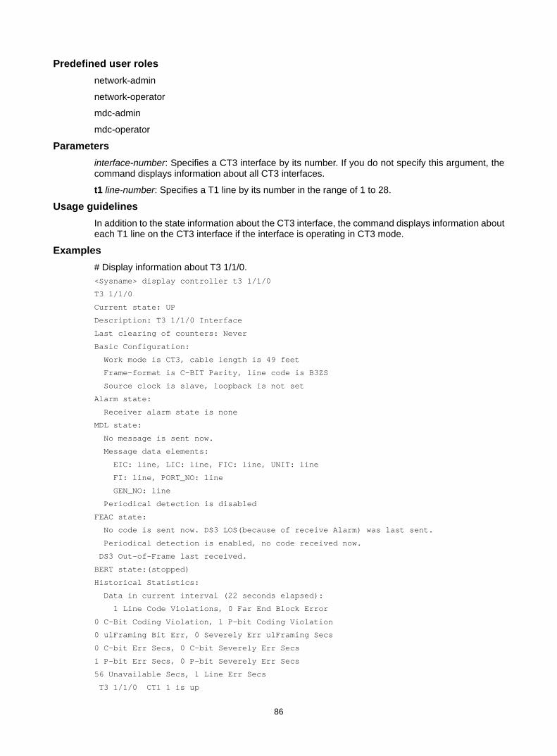
86
Predefined user roles network-admin
network-operator
mdc-admin
mdc-operator
Parameters interface-number: Specifies a CT3 interface by its number. If you do not specify this argument, the command displays information about all CT3 interfaces.
t1 line-number: Specifies a T1 line by its number in the range of 1 to 28.
Usage guidelines In addition to the state information about the CT3 interface, the command displays information about each T1 line on the CT3 interface if the interface is operating in CT3 mode.
Examples # Display information about T3 1/1/0. <Sysname> display controller t3 1/1/0
T3 1/1/0
Current state: UP
Description: T3 1/1/0 Interface
Last clearing of counters: Never
Basic Configuration:
Work mode is CT3, cable length is 49 feet
Frame-format is C-BIT Parity, line code is B3ZS
Source clock is slave, loopback is not set
Alarm state:
Receiver alarm state is none
MDL state:
No message is sent now.
Message data elements:
EIC: line, LIC: line, FIC: line, UNIT: line
FI: line, PORT_NO: line
GEN_NO: line
Periodical detection is disabled
FEAC state:
No code is sent now. DS3 LOS(because of receive Alarm) was last sent.
Periodical detection is enabled, no code received now.
DS3 Out-of-Frame last received.
BERT state:(stopped)
Historical Statistics:
Data in current interval (22 seconds elapsed):
1 Line Code Violations, 0 Far End Block Error
0 C-Bit Coding Violation, 1 P-bit Coding Violation
0 ulFraming Bit Err, 0 Severely Err ulFraming Secs
0 C-bit Err Secs, 0 C-bit Severely Err Secs
1 P-bit Err Secs, 0 P-bit Severely Err Secs
56 Unavailable Secs, 1 Line Err Secs
T3 1/1/0 CT1 1 is up
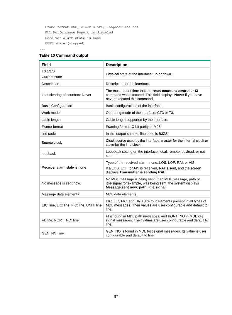
87
Frame-format ESF, clock slave, loopback not set
FDL Performance Report is disabled
Receiver alarm state is none
BERT state:(stopped)
...
Table 10 Command output
Field Description T3 1/1/0 Current state
Physical state of the interface: up or down.
Description Description for the interface.
Last clearing of counters: Never The most recent time that the reset counters controller t3 command was executed. This field displays Never if you have never executed this command.
Basic Configuration Basic configurations of the interface.
Work mode Operating mode of the interface: CT3 or T3.
cable length Cable length supported by the interface.
Frame-format Framing format: C-bit parity or M23.
line code In this output sample, line code is B3ZS.
Source clock Clock source used by the interface: master for the internal clock or slave for the line clock.
loopback Loopback setting on the interface: local, remote, payload, or not set.
Receiver alarm state is none Type of the received alarm: none, LOS, LOF, RAI, or AIS. If a LOS, LOF, or AIS is received, RAI is sent, and the screen displays Transmitter is sending RAI.
No message is sent now. No MDL message is being sent. If an MDL message, path or idle-signal for example, was being sent, the system displays Message sent now: path. idle signal.
Message data elements MDL data elements.
EIC: line, LIC: line, FIC: line, UNIT: lineEIC, LIC, FIC, and UNIT are four elements present in all types of MDL messages. Their values are user configurable and default to line.
FI: line, PORT_NO: line FI is found in MDL path messages, and PORT_NO in MDL idle signal messages. Their values are user configurable and default to line.
GEN_NO: line GEN_NO is found in MDL test signal messages. Its value is user configurable and default to line.
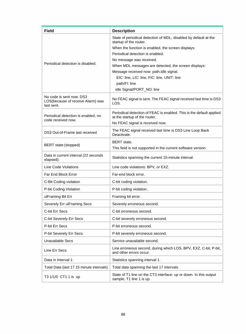
88
Field Description
Periodical detection is disabled.
State of periodical detection of MDL, disabled by default at the startup of the router. When the function is enabled, the screen displays: Periodical detection is enabled. No message was received. When MDL messages are detected, the screen displays: Message received now: path.idle signal. EIC: line, LIC: line, FIC: line, UNIT: line path/FI: line idle Signal/PORT_NO: line
No code is sent now. DS3 LOS(because of receive Alarm) was last sent.
No FEAC signal is sent. The FEAC signal received last time is DS3 LOS.
Periodical detection is enabled, no code received now.
Periodical detection of FEAC is enabled. This is the default applied at the startup of the router. No FEAC signal is received now.
DS3 Out-of-Frame last received The FEAC signal received last time is DS3 Line Loop Back Deactivate.
BERT state:(stopped) BERT state. This field is not supported in the current software version.
Data in current interval (22 seconds elapsed): Statistics spanning the current 15-minute interval.
Line Code Violations Line code violations: BPV, or EXZ.
Far End Block Error Far-end block error.
C-Bit Coding violation C-bit coding violation.
P-bit Coding Violation P-bit coding violation.
ulFraming Bit Err Framing bit error.
Severely Err ulFraming Secs Severely erroneous second.
C-bit Err Secs C-bit erroneous second.
C-bit Severely Err Secs C-bit severely erroneous second.
P-bit Err Secs P-bit erroneous second.
P-bit Severely Err Secs P-bit severely erroneous second.
Unavailable Secs Service unavailable second.
Line Err Secs Line erroneous second, during which LOS, BPV, EXZ, C-bit, P-bit, and other errors occur.
Data in Interval 1: Statistics spanning interval 1.
Total Data (last 17 15 minute intervals) Total data spanning the last 17 intervals.
T3 1/1/0 CT1 1 is up State of T1 line on the CT3 interface: up or down. In this output sample, T1 line 1 is up.
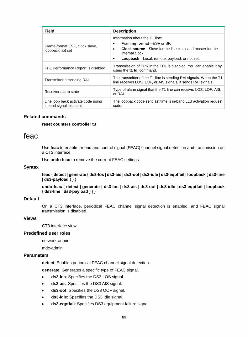
89
Field Description
Frame-format ESF, clock slave, loopback not set
Information about the T1 line: • Framing format—ESF or SF. • Clock source—Slave for the line clock and master for the
internal clock. • Loopback—Local, remote, payload, or not set.
FDL Performance Report is disabled Transmission of PPR in the FDL is disabled. You can enable it by using the t1 fdl command.
Transmitter is sending RAI The transmitter of the T1 line is sending RAI signals. When the T1 line receives LOS, LOF, or AIS signals, it sends RAI signals.
Receiver alarm state Type of alarm signal that the T1 line can receive: LOS, LOF, AIS, or RAI.
Line loop back activate code using inband signal last sent
The loopback code sent last time is in-band LLB activation request code.
Related commands reset counters controller t3
feac Use feac to enable far end and control signal (FEAC) channel signal detection and transmission on a CT3 interface.
Use undo feac to remove the current FEAC settings.
Syntax feac { detect | generate { ds3-los | ds3-ais | ds3-oof | ds3-idle | ds3-eqptfail | loopback { ds3-line | ds3-payload } } }
undo feac { detect | generate { ds3-los | ds3-ais | ds3-oof | ds3-idle | ds3-eqptfail | loopback { ds3-line | ds3-payload } } }
Default On a CT3 interface, periodical FEAC channel signal detection is enabled, and FEAC signal transmission is disabled.
Views CT3 interface view
Predefined user roles network-admin
mdc-admin
Parameters detect: Enables periodical FEAC channel signal detection.
generate: Generates a specific type of FEAC signal. • ds3-los: Specifies the DS3 LOS signal. • ds3-ais: Specifies the DS3 AIS signal. • ds3-oof: Specifies the DS3 OOF signal. • ds3-idle: Specifies the DS3 idle signal. • ds3-eqptfail: Specifies DS3 equipment failure signal.
90
loopback: Sends a specific type of loopback code for activating a specific loopback. • ds3-line: Specifies far-end line loopback. • ds3-payload: Specifies payload loopback.
Usage guidelines FEAC is a channel formed by using the third C-bit in the first subframe in C-bit framing. The channel is used for the following purposes: • Transmits alarm state signals for line test. • Transmits loopback control code to activate or deactivate far-end loopback during a loopback
test.
According to ANSI T1.107a, the framing format of FEAC channels is bit-oriented protocol (BOP).
After far-end loopback is activated by using the feac generate loopback { ds3-line | ds3-payload } command, you can remove it by using the undo form of the command.
Before you configure far-end loopback by using this command, disable FEAC detection on the local end to prevent loopback deadlock. Loopback deadlock occurs when the local end enables loopback after detecting the loopback code sent back by the far end.
To display the transmitting and receiving state of the FEAC channel, use the display controller t3 command.
Examples # Enable FEAC channel signal detection on T3 1/1/0. <Sysname> system-view
[Sysname] controller t3 1/1/0
[Sysname-T3 1/1/0] feac detect
# Send DS3 LOS signal on T3 1/1/0. <Sysname> system-view
[Sysname] controller t3 1/1/0
[Sysname-T3 1/1/0] feac generate ds3-los
# On T3 1/1/0, send loopback code to the far end to place the far end in a line loopback. <Sysname> system-view
[Sysname] controller t3 1/1/0
[Sysname-T3 1/1/0] feac generate loopback ds3-line
frame-format Use frame-format to set the framing format for a CT3 interface.
Use undo frame-format to restore the default.
Syntax frame-format { c-bit | m23 }
undo frame-format
Default The framing format for a CT3 interface is C-bit.
Views CT3 interface view
Predefined user roles network-admin
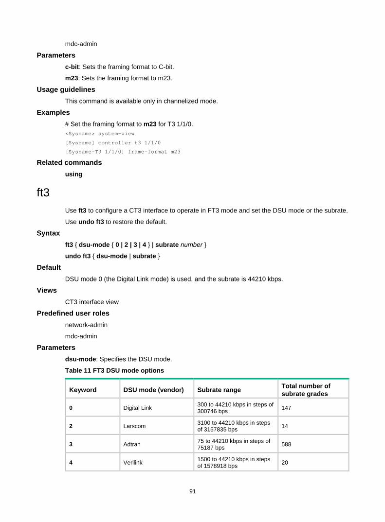
91
mdc-admin
Parameters c-bit: Sets the framing format to C-bit.
m23: Sets the framing format to m23.
Usage guidelines This command is available only in channelized mode.
Examples # Set the framing format to m23 for T3 1/1/0. <Sysname> system-view
[Sysname] controller t3 1/1/0
[Sysname-T3 1/1/0] frame-format m23
Related commands using
ft3 Use ft3 to configure a CT3 interface to operate in FT3 mode and set the DSU mode or the subrate.
Use undo ft3 to restore the default.
Syntax ft3 { dsu-mode { 0 | 2 | 3 | 4 } | subrate number }
undo ft3 { dsu-mode | subrate }
Default DSU mode 0 (the Digital Link mode) is used, and the subrate is 44210 kbps.
Views CT3 interface view
Predefined user roles network-admin
mdc-admin
Parameters dsu-mode: Specifies the DSU mode.
Table 11 FT3 DSU mode options
Keyword DSU mode (vendor) Subrate range Total number of subrate grades
0 Digital Link 300 to 44210 kbps in steps of 300746 bps 147
2 Larscom 3100 to 44210 kbps in steps of 3157835 bps 14
3 Adtran 75 to 44210 kbps in steps of 75187 bps 588
4 Verilink 1500 to 44210 kbps in steps of 1578918 bps 20
92
subrate number: Specifies the subrate for the CT3 interface. The number argument is in the range of 1 to 44210 (in kbps).
Usage guidelines FT3 (Fractional T3 or Subrate T3) mode is a nonstandard E3 application mode. FE3 subrate ranges and the number of subrate grades vary by vendor. You can use the ft3 command to configure the device to be compatible with the FE3 DSU modes listed in Table 11.
This command is only available in CT3 mode.
After you set the subrate by using the ft3 subrate command, the T3 interface searches the subrate levels corresponding to the DSU mode in which it is operating. The T3 interface selects the subrate level that is closest to subrate level set by the ft3 subrate command. The device adjusts the hardware to allow for the subrate.
You can use the display interface serial interface-number:0 command to check the following settings of a CT3 interface: • DSU mode. • Subrate. • Actual rate.
The actual rate does not count in the overhead bits. • Baud rate.
The baud rate is the actual T3 line rate (44736 kbps), with the overhead bits counted in.
Examples # Configure T3 1/1/0 to operate in the FT3 mode. Set the DSU mode to 2 and the subrate to 3000 kbps. <Sysname> system-view
[Sysname] controller t3 1/1/0
[Sysname-T3 1/1/0] using t3
[Sysname-T3 1/1/0] ft3 dsu-mode 2
[Sysname-T3 1/1/0] ft3 subrate 3000
loopback Use loopback to enable a type of loopback on a CT3 interface.
Use undo loopback to disable loopback on a CT3 interface.
Syntax loopback { local | payload | remote }
undo loopback
Default Loopback is disabled on CT3 interfaces.
Views CT3 interface view
Predefined user roles network-admin
mdc-admin
Parameters local: Enables internal loopback.
93
payload: Enables external payload loopback.
remote: Enables external loopback.
Usage guidelines Loopback is intended for testing only. Disable the feature when the interface is operating correctly.
If a CT3 interface encapsulated with PPP or HDLC is placed in a loopback, the state of the link layer protocol is reported as down.
Examples # Enable internal loopback on T3 1/1/0. <Sysname> system-view
[Sysname] controller t3 1/1/0
[Sysname-T3 1/1/0] loopback local
mdl Use mdl to configure MDL message detection and transmission on a CT3 interface.
Use undo mdl to restore the default.
Syntax mdl { data { eic string | fic string | gen-no string | lic string | pfi string | port-no string | unit string } | detect | generate { idle-signal | path | test-signal } }
undo mdl [ data [ eic | fic | gen-no | lic | pfi | port-no | unit ] | detect | generate [ idle-signal | path | test-signal ] ]
Default Periodic MDL detection is disabled. CT3 interfaces do not send MDL messages.
Views CT3 interface view
Predefined user roles network-admin
mdc-admin
Parameters data: Sets MDL message parameters. If you do not specify a parameter, a default string of line is set in the MDL messages. • eic string: Specifies the equipment identification code, a string of 1 to 10 characters. This
parameter is contained in all three types of MDL messages. • fic string: Specifies the frame identification code, a string of 1 to 10 characters. This parameter
is contained in all three types of MDL messages. • gen-no string: Specifies the generator number, a string of 1 to 38 characters. This parameter is
specific to test signal messages. • lic string: Specifies the location identification code, a string of 1 to 11 characters. This
parameter is contained in all three types of MDL messages. • pfi string: Specifies the path facility identification, a string of 1 to 38 characters. This parameter
is specific to path messages. • port-no string: Specifies the port number in idle signal message, a string of 1 to 38 characters.
This parameter is specific to idle signal messages.
94
• unit string: Specifies the unit, a string of 1 to 6 characters. This parameter is contained in all three types of MDL messages.
detect: Enables periodical MDL message detection.
generate: Sends a specific type of MDL message. • idle-signal: Specifies MDL idle signal messages. • path: Specifies MDL path messages. • test-signal: Specifies MDL test signal messages.
Usage guidelines MDL is a channel formed by using the three C-bits in the fifth subframe in C-bit framing. According to ANSI T1.107a, MDL can transmit path, idle signal, and test signal messages. The data framing format is LAPD for MDL messages.
To send idle signal, path, and test signal messages simultaneously, repeat the mdl command to specify the idle-signal, path, and test-signal keywords.
Examples # Enable MDL detection on T3 1/1/0. <Sysname> system-view
[Sysname] controller t3 1/1/0
[Sysname-T3 1/1/0] mdl detect
# Set LIC to hello for CT3 interface T3 1/1/0. <Sysname> system-view
[Sysname] controller t3 1/1/0
[Sysname-T3 1/1/0] mdl data lic hello
# Send path messages on CT3 interface T3 1/1/0. <Sysname> system-view
[Sysname] controller t3 1/1/0
[Sysname-T3 1/1/0] mdl generate path
reset counters controller t3 Use reset counters controller t3 to clear CT3 interface statistics.
Syntax reset counters controller t3 [ interface-number ]
Views User view
Predefined user roles network-admin
mdc-admin
Parameters interface-number: Specifies a CT3 interface by its number. If you do not specify this argument, the command clears statistics for all CT3 interfaces.
Usage guidelines To display CT3 interface statistics, use the display controller t3 command.
95
Examples # Clear statistics for T3 1/1/0. <Sysname> reset counters controller t3 1/1/0
Related commands display controller t3
t1 alarm Use t1 alarm to enable a T1 line on a CT3 interface to detect/send alarm signals.
Use undo t1 alarm to remove the alarm signal detection/sending setting.
Syntax t1 line-number alarm { detect | generate { ais | rai } }
undo t1 line-number alarm { detect | generate { ais | rai } }
Default On a CT3 interface, periodical alarm detection is enabled, and alarm signal sending is disabled.
Views CT3 interface view
Predefined user roles network-admin
mdc-admin
Parameters line-number: Specifies a T1 line number in the range of 1 to 28.
detect: Specifies periodical alarm signal detection.
generate: Sends a specific type of alarm signals. These alarm signals are used for line status test. • ais: Alarm indication signal. • rai: Remote alarm indication signal.
Usage guidelines At startup, periodical alarm signal detection is enabled on all T1 lines on the CT3 interface. When a T1 line detects LOS, LOF, or AIS signals, it sends RAI signals to its peer. You can view the real-time alarm state by using the display controller t3 command.
The supported alarm signals (LOS, LOF, AIS, RAI, FEBE, and idle) are ANSI T1.403 compliant.
Only one type of alarm signal can be sent on a T1 line at a time. To send another type of signal, you must first remove the previous setting by using the undo t1 alarm command. If a RAI signal is present because an LOS, LOF, or AIS alarm is detected, you must first use the undo t1 alarm detect command to remove the signal.
Examples # Enable periodical alarm signal detection on T1 line 1 on T3 1/1/0. <Sysname> system-view
[Sysname] controller t3 1/1/0
[Sysname-T3 1/1/0] t1 1 alarm detect
# Enable T1 line 1 on T3 1/1/0 to send AIS alarm signals. <Sysname> system-view
96
[Sysname] controller t3 1/1/0
[Sysname-T3 1/1/0] t1 1 alarm generate ais
t1 channel-set Use t1 channel-set to bundle timeslots into a channel set on a T1 line.
Use undo t1 channel-set to remove a channel set.
Syntax t1 line-number channel-set set-number timeslot-list list [ speed { 56k | 64k } ]
undo t1 line-number channel-set set-number
Default No timeslots are bundled into channel sets on a T1 line.
Views CT3 interface view
Predefined user roles network-admin
mdc-admin
Parameters line-number: Specifies a T1 line number in the range of 1 to 28.
set-number: Specifies the number of a channel set created by timeslot bundling on a T1 line, in the range of 0 to 23.
timeslot-list list: Specifies a comma-separated list of timeslot items. An item can be an individual timeslot or a timeslot range. Use a hyphen (-) to separate the start and end timeslot numbers of a range. The value range for the timeslot number is 1 to 24.
speed { 56k | 64k }: Speed of the timeslot bundle (the channel set) in kbps. If 56k is selected, the timeslots are bundled into an n × 56 kbps bundle. If 64k, the default, is selected, the timeslots are bundled into an n × 64 kbps bundle.
Usage guidelines When a T1 line is operating in framed (CT1) mode, you can bundle timeslots on it. For each channel set, the system automatically creates a serial interface named serial number/line-number:set-number. This interface operates at n × 64 kbps or n × 56 kbps, where n is the number of bundled timeslots. This interface has the same logical features as a standard synchronous serial interface. You can configure this serial interface in the same way you configure a standard synchronous serial interface.
Examples # Create a 128 kbps serial interface through timeslot bundling on T1 line 1 on T3 1/1/0. <Sysname> system-view
[Sysname] controller t3 1/1/0
[Sysname-T3 1/1/0] t1 1 channel-set 1 timeslot-list 1,2
Related commands t1 unframed
97
t1 clock Use t1 clock to set the clock mode of a T1 line on a CT3 interface.
Use undo t1 clock to restore the default.
Syntax t1 line-number clock { master | slave }
undo t1 line-number clock
Default The clock mode of a T1 line on a CT3 interface is slave.
Views CT3 interface view
Predefined user roles network-admin
mdc-admin
Parameters line-number: Specifies a T1 line number in the range of 1 to 28.
master: Sets the clock mode to master.
slave: Sets the clock mode to slave.
Usage guidelines When the clock mode of a T1 line is master, it uses the internal clock source.
When the clock mode of a T1 line is slave, it uses the line clock source.
When a CT3 interface is operating in channelized mode, its T1 lines might use separate clocks.
Examples # Set the clock mode to slave for T1 line 1 on T3 1/1/0. <Sysname> system-view
[Sysname] controller t3 1/1/0
[Sysname-T3 1/1/0] t1 1 clock slave
t1 fdl Use t1 fdl to set the behavior of a T1 line on the FDL in ESF framing.
Use undo t1 fdl to disable FDL of T1.
Syntax t1 line-number fdl { ansi | att | both | none}
undo t1 line-number fdl
Default FDL is disabled in ESF framing.
Views CT3 interface view
98
Predefined user roles network-admin
mdc-admin
Parameters line-number: Specifies a T1 line number in the range of 1 to 28.
ansi: Specifies ANSI T1.403 for FDL.
att: Specifies AT&T TR 54016 for FDL.
both: Specifies both ANSI T1.403 and AT&T TR 54016 for FDL.
none: Disables the use of FDL on the T1 line.
Usage guidelines FDL is an embedded 4 kbps overhead channel within the ESF format for transmitting periodical performance report (PPR) statistics or loopback code.
According to ANSI T1.403, the format of PPR is LAPD, and the format of loopback code is BOP.
The t1 set fdl command only starts PPR transmission. It cannot enable loopback code transmission or detection.
This command only applies to channelized T1 lines with a T1 framing format of ESF.
Examples # Set the FDL to be ANSI T1.403 compliant for T1 line 1 on T3 1/1/0. <Sysname> system-view
[Sysname] controller t3 1/1/0
[Sysname-T3 1/1/0] t1 1 fdl ansi
Related commands t1 frame-format
t1 frame-format Use t1 frame-format to set the framing format for a T1 line.
Use undo t1 frame-format to restore the default.
Syntax t1 line-number frame-format { esf | sf }
undo t1 line-number frame-format
Default The framing format of a T1 line is ESF.
Views CT3 interface view
Predefined user roles network-admin
mdc-admin
Parameters line-number: Specifies a T1 line number in the range of 1 to 28.
esf: Sets the T1 line to use the ESF format.
99
sf: Sets the T1 line to use the SF format.
Usage guidelines You can configure this command only when the T1 line is operating in framed mode. To configure a T1 line to operate in framed mode, use the undo t1 unframed command.
Examples # Set the framing format to SF for T1 line 1 on T3 1/1/0. <Sysname> system-view
[Sysname] controller t3 1/1/0
[Sysname-T3 1/1/0] t1 1 frame-format sf
Related commands t1 unframed
t1 loopback Use t1 loopback to enable a type of loopback for a T1 line on a CT3 interface.
Use undo t1 loopback to disable loopback for a T1 line on a CT3 interface.
Syntax t1 line-number loopback { local | payload | remote }
undo t1 line-number loopback
Default Loopback is disabled on T1 lines.
Views CT3 interface view
Predefined user roles network-admin
mdc-admin
Parameters line-number: Specifies a T1 line number in the range of 1 to 28.
local: Enables internal loopback.
payload: Enables payload loopback mode.
remote: Enables external loopback.
Usage guidelines Loopback is intended for testing only. Disable the feature when the interface is operating correctly.
If a T1 line encapsulated with PPP or HDLC is in loopback mode, the state of the link layer protocol is reported as down.
Examples # Enable internal loopback on T1 line 1 on T3 1/1/0. <Sysname> system-view
[Sysname] controller t3 1/1/0
[Sysname-T3 1/1/0] t1 1 loopback local
100
t1 sendloopcode Use t1 sendloopcode to set the loopback mode of a far-end T1 line.
Use undo t1 sendloopcode to remove the corresponding setting.
Syntax t1 line-number sendloopcode { fdl-ansi-line-up | fdl-ansi-payload-up | fdl-att-payload-up | inband-line-up }
undo t1 line-number sendloopcode { fdl-ansi-line-up | fdl-ansi-payload-up | fdl-att-payload-up | inband-line-up }
Default No loopback mode is set.
Views CT3 interface view
Predefined user roles network-admin
mdc-admin
Parameters line-number: Specifies a T1 line number, in the range of 1 to 28.
fdl-ansi-line-up: Sends ANSI-compliant LLB activation request code in the FDL to start remote loopback.
fdl-ansi-payload-up: Sends ANSI-compliant PLB activation request code in the FDL to start remote loopback.
fdl-att-payload-up: Sends AT&T-compliant PLB activation request code in the FDL to start remote loopback.
inband-line-up: Sends in-band LLB activation request code compliant with the ANSI and AT&T implementation to start remote loopback.
Usage guidelines Loopback is an effective method of diagnosis. You can place a far-end device into loopback mode either at the command line on it or by sending loopback control code to it. The types and formats of loopback control code supported on T1 interfaces are compliant with ANSI T1.403.
Loopback can be divided into line loopback and payload loopback. They differ in the sense that the data stream is looped back at the framer with line loopback but not with payload loopback.
You can transmit loopback control code by using the in-band signal (the 192 effective bandwidth bits or all 193 bits of T1) or the FDL in ESF frames.
Examples # Send the in-band signal on T1 line 1 on T3 1/1/0 to place the far-end T1 line in line loopback mode. <Sysname> system-view
[Sysname] controller t3 1/1/0
[Sysname-T3 1/1/0] t1 1 sendloopcode inband-line-up
t1 show Use t1 show to have a quick look at the line state of a T1 line on a CT3 interface.
101
Syntax t1 line-number show
Views CT3 interface view
Predefined user roles network-admin
mdc-admin
Parameters line-number: Specifies a T1 line number in the range of 1 to 28.
show: Displays the physical line state of the specified T1 line.
Examples # Display line state of T1 line 1 on T3 1/1/0. <Sysname> system-view
[Sysname] controller t3 1/1/0
[Sysname-T3 1/1/0] t1 1 show
T3 1/1/0 CT1 1: up
Frame-format ESF, clock slave, loopback not set
FDL Performance Report is disabled
Receiver alarm state is none
BERT state:(stopped)
Table 12 Command output
Field Description T3 1/1/0 CT1 1 is up State of T1 line 1 on the CT3 interface: up or down.
Frame-format Framing format of T1: ESF or SF.
clock Clock source used by the T1 line: slave for the line clock or master for the internal clock.
loopback Loopback state or mode: local, remote, payload, or not set.
FDL Performance Report is disabled Transmission of PPR in the FDL is disabled. You can enable it by using the t1 set fdl ansi command.
Transmitter is sending RAI The transmitter of the T1 line is sending RAI signals. When the T1 line receives LOS, LOF, or AIS signals, it sends RAI signals.
Receiver alarm state Type of alarm signal that the T1 line can receive: LOS, LOF, AIS, or RAI.
Line loop back activate code using inband signal last sent
The loopback code sent last time is in-band LLB activation request code.
BERT state BERT test state. This field is not supported in the current software version.
t1 shutdown Use t1 shutdown to shut down a T1 line on a CT3 interface.
Use undo t1 shutdown to bring up a T1 line.
102
Syntax t1 line-number shutdown
undo t1 line-number shutdown
Default T1 lines on a CT3 interface are up.
Views CT3 interface view
Predefined user roles network-admin
mdc-admin
Parameters line-number: Specifies a T1 line number in the range of 1 to 28.
Usage guidelines Shutting down or bringing up a T1 line also shuts down or brings up the serial interface created for it.
Examples # Shut down T1 line 1 on T3 1/1/0. <Sysname> system-view
[Sysname] controller t3 1/1/0
[Sysname-T3 1/1/0] t1 1 shutdown
t1 unframed Use t1 unframed to set a T1 line on a CT3 interface to operate in unframed mode (T1 mode).
Use undo t1 unframed to set a T1 line on a CT3 interface to operate in framed mode (CT1 mode).
Syntax t1 line-number unframed
undo t1 line-number unframed
Default T1 lines on a CT3 interface are operating in framed mode.
Views CT3 interface view
Predefined user roles network-admin
mdc-admin
Parameters line-number: Specifies a T1 line number in the range of 1 to 28.
Usage guidelines A T1 line in unframed mode does not contain frame control information or support timeslot division. The system automatically creates a 1544 kbps serial interface named serial number/line-number:0. This interface has the same logical features as a standard synchronous serial interface. You can configure this serial interface in the same way you configure a standard synchronous serial interface.
103
Examples # Set T1 line 1 on T3 1/1/0 to operate in unframed mode. <Sysname> system-view
[Sysname] controller t3 1/1/0
[Sysname-T3 1/1/0] t1 1 unframed
Related commands t1 channel-set
using Use using to configure the operating mode of a CT3 interface.
Use undo using to restore the default.
Syntax using { ct3 | t3 }
undo using
Default A CT3 interface operates in channelized mode.
Views CT3 interface view
Predefined user roles network-admin
mdc-admin
Parameters ct3: Sets the CT3 interface to operate in channelized mode.
t3: Sets the CT3 interface to operate in unchannelized mode.
Usage guidelines You can only configure T1 lines on CT3 interfaces in channelized mode.
When a CT3 interface operates in unchannelized mode, the system automatically creates a 44.736 Mbps serial interface named serial number/0:0 for it. This interface has the same logical features as a standard synchronous serial interface. You can configure this serial interface in the same way you configure a standard synchronous serial interface.
Examples # Configure T3 1/1/0 to operate in unchannelized mode. <Sysname> system-view
[Sysname] controller t3 1/1/0
[Sysname-T3 1/1/0] using t3
104
POS interface commands This chapter describes configuration commands for POS interfaces, including standard POS interfaces, POS subinterfaces, and POS channel interfaces.
alarm-detect Use alarm-detect to configure the action to take when an RDI, SD, or SF alarm occurs on an interface.
Use undo alarm-detect to restore the default.
Syntax alarm-detect { rdi | sd | sf } action link-down
undo alarm-detect { rdi | sd | sf }
Default The device does not take any actions on the interface when an RDI, SD, or SF alarm occurs.
Views Standard POS interface view
Predefined user roles network-admin
mdc-admin
Parameters rdi: Specifies remote defect indication (RDI) alarms.
sd: Specifies signal degrade (SD) alarms.
sf: Specifies signal fail (SF) alarms.
action: Specifies the action to take when the specified alarm is detected on the interface.
link-down: Places the interface in down state.
Usage guidelines An RDI alarm occurs if the device receives multiplexer section remote defect indication (MS-RDI) signals from the remote end.
An SD or SF alarm occurs if the bit error rate of incoming packets crosses the SD or SF alarm threshold. To set the SD or SF alarm threshold, use the threshold command.
Examples # Configure POS 1/1/1 to go down when an SD alarm occurs. <Sysname> system-view
[Sysname] interface pos 1/1/1
[Sysname-Pos1/1/1] alarm-detect sd action link-down
Related commands threshold
105
bandwidth Use bandwidth to configure the expected bandwidth of an interface.
Use undo bandwidth to restore the default.
Syntax bandwidth bandwidth-value
undo bandwidth
Default The expected bandwidth (in kbps) is the interface baud rate divided by 1000.
Views Standard POS interface view
POS subinterface view
POS channel interface view
Predefined user roles network-admin
mdc-admin
Parameters bandwidth-value: Specifies the expected bandwidth in the range of 1 to 400000000 kbps.
Usage guidelines The expected bandwidth is an informational parameter used only by higher-layer protocols for calculation. You cannot adjust the actual bandwidth of an interface by using this command.
Examples # Set the expected bandwidth to 50 kbps for POS 1/1/1. <Sysname> system-view
[Sysname] interface pos 1/1/1
[Sysname-Pos1/1/1] bandwidth 50
clock Use clock to set the clock mode of a standard POS interface.
Use undo clock to restore the default.
Syntax clock { master | slave }
undo clock
Default The clock mode of a POS interface is slave.
Views Standard POS interface view
Predefined user roles network-admin
106
mdc-admin
Parameters master: Sets the clock mode to master.
slave: Sets the clock mode to slave.
Usage guidelines Standard POS interfaces support the following clock modes: • Master—Uses internal clock signal. • Slave—Uses line clock signal.
If the standard POS interface is connected to another router, set its clock mode to be different from the mode used by the remote end. If the standard POS interface is connected to a SONET/SDH device, which provides higher clock precision, always set its clock mode to slave.
Examples # Set the clock mode to master for POS 1/1/1. <Sysname> system-view
[Sysname] interface pos 1/1/1
[Sysname-Pos1/1/1] clock master
crc Use crc to set the CRC length on an interface.
Use undo crc to restore the default.
Syntax crc { 16 | 32 }
undo crc
Default The CRC length on an interface is 32 bits.
Views Standard POS interface view
POS channel interface view
Predefined user roles network-admin
mdc-admin
Parameters 16: Sets the CRC length to 16 bits.
32: Sets the CRC length to 32 bits.
Usage guidelines The CRC length must be the same at both ends.
Examples # Set the CRC length to 16 bits on POS 1/1/1. <Sysname> system-view
[Sysname] interface pos 1/1/1
107
[Sysname-Pos1/1/1] crc 16
dampening Use dampening to enable the device to dampen an interface when it is flapping.
Use undo dampening to disable interface dampening.
Syntax dampening [ half-life reuse suppress max-suppress-time ]
undo dampening
Default Interface dampening is disabled on POS interfaces.
Views Standard POS interface view
Predefined user roles network-admin
mdc-admin
Parameters half-life: Specifies the amount of time (in seconds) for a penalty to decrease by half of its value. The interface has an initial penalty of 0. When the interface flaps, it is assigned a penalty of 1000 for each down event until the maximum penalty is reached. When the interface stops flapping, the penalty decreases by half each time the half-life timer expires until the penalty drops to the reuse threshold. The value range for the half-life timer is 1 to 120 seconds, and the default is 54 seconds.
reuse: Specifies the reuse threshold. When the accumulated penalty decreases to this threshold, the interface is not dampened. Interface state changes are reported to the higher layers. The value range for the reuse threshold is 200 to 20000, and the default is 750. The reuse threshold must be less than the suppression threshold.
suppress: Specifies the suppression threshold. This threshold is the accumulated penalty that triggers the device to dampen the interface. In dampened state, the interface does not report its state changes to the higher layers. The value range for the suppression threshold is 200 to 20000, and the default is 2000.
max-suppress-time: Specifies the maximum amount of time the interface can be dampened. If the penalty is still higher than the reuse threshold when this timer expires, the penalty stops increasing for down events. The penalty starts to decrease until it drops below the reuse threshold. The value range for the maximum suppression time is 1 to 255 seconds, and the default is 162 seconds (three times the half-life timer).
NOTE: • The maximum penalty is equal to 2(Max-suppress-time/half-life) × reuse threshold. It is not user
configurable. • The penalty does not increase for up events.
Usage guidelines Interface dampening uses an exponential decay mechanism to suppress the effects of excessive interface flapping events on routing protocols and routing tables in the network.
If an interface is not dampened, its state changes are reported. For each state change, the system also generates an SNMP notification and log message.
108
After a flapping interface is dampened, it does not report its state changes to the CPU. For state change events, the interface only generates SNMP notifications and log messages. Suppression of interface state change events protects the system processing resources.
This command and the link-delay command cannot be both configured on an interface.
This command does not take effect on the administratively down events. When you execute the shutdown command, the penalty restores to 0, and the interface reports the down event to the higher layer protocols.
Examples # Configure interface dampening on POS 1/1/1. <Sysname> system-view
[Sysname] interface pos 1/1/1
[Sysname-Pos1/1/1] dampening 2 800 3000 5
Related commands display interface pos link-delay
default Use default to restore the default settings for an interface.
Syntax default
Views Standard POS interface view
POS subinterface view
POS channel interface view
Predefined user roles network-admin
mdc-admin
Usage guidelines
CAUTION: The default command might interrupt ongoing network services. Make sure you are fully aware of the impact of this command when you use it on a live network.
This command might fail to restore the default settings for some commands for reasons such as command dependencies or system restrictions. You can use the display this command in interface view to check for these commands, and use their undo forms or follow the command reference to restore their default settings. If your restoration attempt still fails, follow the error message to resolve the problem.
Examples # Restore the default settings of POS 1/1/1. <Sysname> system-view
[Sysname] interface pos 1/1/1
[Sysname-Pos1/1/1] default
109
description Use description to configure a description for an interface.
Use undo description to restore the default.
Syntax description text
undo description
Default Interface description uses the interface-name Interface format, for example, Pos1/1/1 Interface.
Views Standard POS interface view
POS subinterface view
POS channel interface view
Predefined user roles network-admin
mdc-admin
Parameters text: Specifies a description, a case-sensitive string of 1 to 255 characters.
Examples # Configure the description of POS 1/1/1 as pos-interface. <Sysname> system-view
[Sysname] interface pos 1/1/1
[Sysname-Pos1/1/1] description pos-interface
display interface pos Use display interface pos to display information about POS interfaces.
Syntax display interface [ pos [ interface-number | interface-number.subnumber ] ] [ brief [ description | down ] ]
Views Any view
Predefined user roles network-admin
network-operator
mdc-admin
mdc-operator
Parameters interface-number: Specifies a standard POS interface or POS channel interface by its interface number.
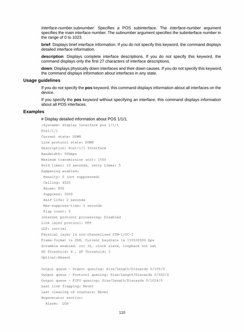
110
interface-number.subnumber: Specifies a POS subinterface. The interface-number argument specifies the main interface number. The subnumber argument specifies the subinterface number in the range of 0 to 1023.
brief: Displays brief interface information. If you do not specify this keyword, the command displays detailed interface information.
description: Displays complete interface descriptions. If you do not specify this keyword, the command displays only the first 27 characters of interface descriptions.
down: Displays physically down interfaces and their down causes. If you do not specify this keyword, the command displays information about interfaces in any state.
Usage guidelines If you do not specify the pos keyword, this command displays information about all interfaces on the device.
If you specify the pos keyword without specifying an interface, this command displays information about all POS interfaces.
Examples # Display detailed information about POS 1/1/1. <Sysname> display interface pos 1/1/1
Pos1/1/1
Current state: DOWN
Line protocol state: DOWN
Description: Pos1/1/1 Interface
Bandwidth: 50kbps
Maximum transmission unit: 1500
Hold timer: 10 seconds, retry times: 5
Dampening enabled:
Penalty: 0 (not suppressed)
Ceiling: 4525
Reuse: 800
Suppress: 3000
Half-life: 2 seconds
Max-suppress-time: 5 seconds
Flap count: 0
Internet protocol processing: Disabled
Link layer protocol: PPP
LCP: initial
Physical layer is non-channelized STM-1/OC-3
Frame-format is SDH, Current baudrate is 155520000 bps
Scramble enabled, crc 32, clock slave, loopback not set
SD Threshold: 6 , SF Threshold: 3
Optical:Absent
Output queue - Urgent queuing: Size/Length/Discards 0/100/0
Output queue - Protocol queuing: Size/Length/Discards 0/500/0
Output queue - FIFO queuing: Size/Length/Discards 0/1024/0
Last link flapping: Never
Last clearing of counters: Never
Regenerator section:
Alarm: LOS
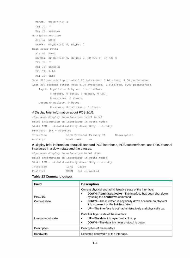
111
ERROR: RS_BIP(B1) 0
Tx: J0: ""
Rx: J0: unknown
Multiplex section:
Alarm: NONE
ERROR: MS_BIP(B2) 0, MS_REI 0
High order Path:
Alarm: NONE
ERROR: HP_BIP(B3) 0, HP_REI 0, HP_PJE 0, HP_NJE 0
TX: J1: ""
RX: J1: unknown
TX: C2: 0x16
RX: C2: 0xff
Last 300 seconds input rate 0.00 bytes/sec, 0 bits/sec, 0.00 packets/sec
Last 300 seconds output rate 0.00 bytes/sec, 0 bits/sec, 0.00 packets/sec
Input: 0 packets, 0 bytes, 0 no buffers
0 errors, 0 runts, 0 giants, 0 CRC,
0 overruns, 0 aborts
Output:0 packets, 0 bytes
0 errors, 0 underruns, 0 aborts
# Display brief information about POS 1/1/1. <Sysname> display interface pos 1/1/1 brief
Brief information on interfaces in route mode:
Link: ADM - administratively down; Stby - standby
Protocol: (s) - spoofing
Interface Link Protocol Primary IP Description
Pos1/1/1 DOWN DOWN --
# Display brief information about all standard POS interfaces, POS subinterfaces, and POS channel interfaces in a down state and the causes. <Sysname> display interface pos brief down
Brief information on interfaces in route mode:
Link: ADM - administratively down; Stby - standby
Interface Link Cause
Pos1/1/1 DOWN Not connected
Table 13 Command output
Field Description
Pos1/1/1 Current state
Current physical and administrative state of the interface: • DOWN (Administratively)—The interface has been shut down
by using the shutdown command. • DOWN—The interface is physically down because no physical
link is present or the link has failed. • UP—The interface is both administratively and physically up.
Line protocol state Data link layer state of the interface: • UP—The data link layer protocol is up. • DOWN—The data link layer protocol is down.
Description Description of the interface.
Bandwidth Expected bandwidth of the interface.
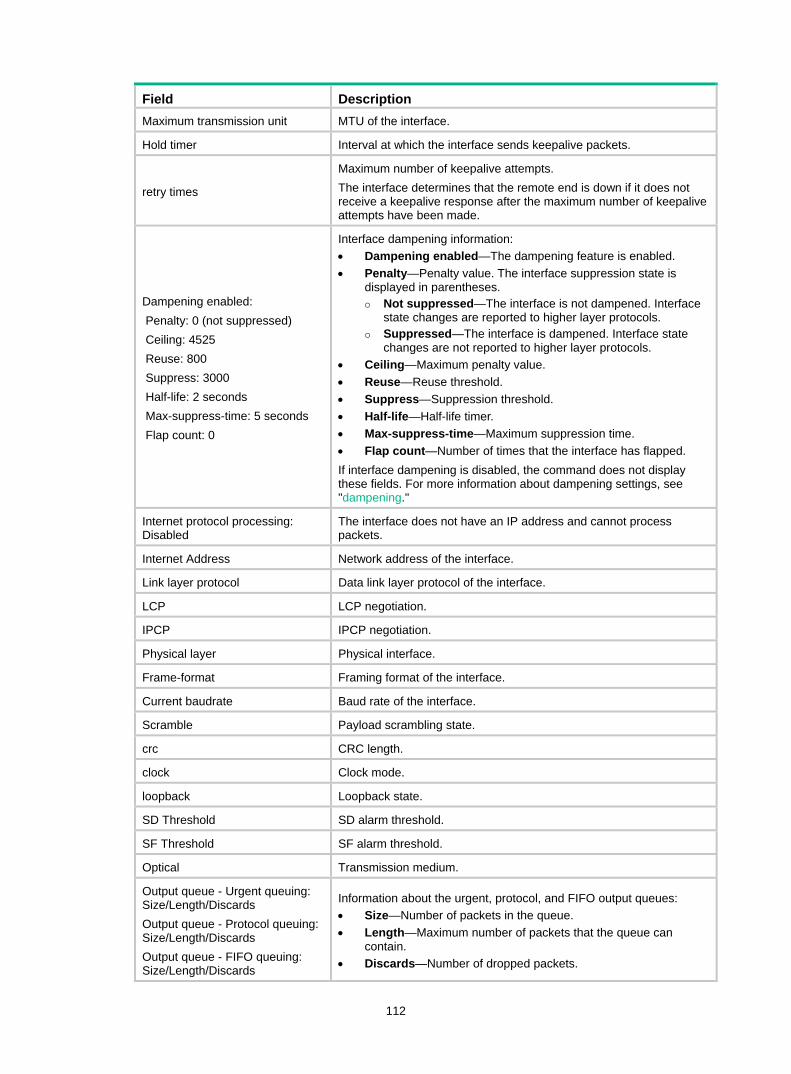
112
Field Description Maximum transmission unit MTU of the interface.
Hold timer Interval at which the interface sends keepalive packets.
retry times
Maximum number of keepalive attempts. The interface determines that the remote end is down if it does not receive a keepalive response after the maximum number of keepalive attempts have been made.
Dampening enabled: Penalty: 0 (not suppressed) Ceiling: 4525 Reuse: 800 Suppress: 3000 Half-life: 2 seconds Max-suppress-time: 5 seconds Flap count: 0
Interface dampening information: • Dampening enabled—The dampening feature is enabled. • Penalty—Penalty value. The interface suppression state is
displayed in parentheses. Not suppressed—The interface is not dampened. Interface
state changes are reported to higher layer protocols. Suppressed—The interface is dampened. Interface state
changes are not reported to higher layer protocols. • Ceiling—Maximum penalty value. • Reuse—Reuse threshold. • Suppress—Suppression threshold. • Half-life—Half-life timer. • Max-suppress-time—Maximum suppression time. • Flap count—Number of times that the interface has flapped. If interface dampening is disabled, the command does not display these fields. For more information about dampening settings, see "dampening."
Internet protocol processing: Disabled
The interface does not have an IP address and cannot process packets.
Internet Address Network address of the interface.
Link layer protocol Data link layer protocol of the interface.
LCP LCP negotiation.
IPCP IPCP negotiation.
Physical layer Physical interface.
Frame-format Framing format of the interface.
Current baudrate Baud rate of the interface.
Scramble Payload scrambling state.
crc CRC length.
clock Clock mode.
loopback Loopback state.
SD Threshold SD alarm threshold.
SF Threshold SF alarm threshold.
Optical Transmission medium.
Output queue - Urgent queuing: Size/Length/Discards Output queue - Protocol queuing: Size/Length/Discards Output queue - FIFO queuing: Size/Length/Discards
Information about the urgent, protocol, and FIFO output queues: • Size—Number of packets in the queue. • Length—Maximum number of packets that the queue can
contain. • Discards—Number of dropped packets.
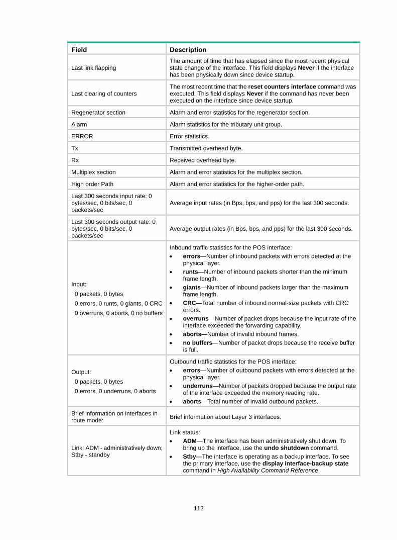
113
Field Description
Last link flapping The amount of time that has elapsed since the most recent physical state change of the interface. This field displays Never if the interface has been physically down since device startup.
Last clearing of counters The most recent time that the reset counters interface command was executed. This field displays Never if the command has never been executed on the interface since device startup.
Regenerator section Alarm and error statistics for the regenerator section.
Alarm Alarm statistics for the tributary unit group.
ERROR Error statistics.
Tx Transmitted overhead byte.
Rx Received overhead byte.
Multiplex section Alarm and error statistics for the multiplex section.
High order Path Alarm and error statistics for the higher-order path.
Last 300 seconds input rate: 0 bytes/sec, 0 bits/sec, 0 packets/sec
Average input rates (in Bps, bps, and pps) for the last 300 seconds.
Last 300 seconds output rate: 0 bytes/sec, 0 bits/sec, 0 packets/sec
Average output rates (in Bps, bps, and pps) for the last 300 seconds.
Input: 0 packets, 0 bytes 0 errors, 0 runts, 0 giants, 0 CRC 0 overruns, 0 aborts, 0 no buffers
Inbound traffic statistics for the POS interface: • errors—Number of inbound packets with errors detected at the
physical layer. • runts—Number of inbound packets shorter than the minimum
frame length. • giants—Number of inbound packets larger than the maximum
frame length. • CRC—Total number of inbound normal-size packets with CRC
errors. • overruns—Number of packet drops because the input rate of the
interface exceeded the forwarding capability. • aborts—Number of invalid inbound frames. • no buffers—Number of packet drops because the receive buffer
is full.
Output: 0 packets, 0 bytes 0 errors, 0 underruns, 0 aborts
Outbound traffic statistics for the POS interface: • errors—Number of outbound packets with errors detected at the
physical layer. • underruns—Number of packets dropped because the output rate
of the interface exceeded the memory reading rate. • aborts—Total number of invalid outbound packets.
Brief information on interfaces in route mode: Brief information about Layer 3 interfaces.
Link: ADM - administratively down; Stby - standby
Link status: • ADM—The interface has been administratively shut down. To
bring up the interface, use the undo shutdown command. • Stby—The interface is operating as a backup interface. To see
the primary interface, use the display interface-backup state command in High Availability Command Reference.
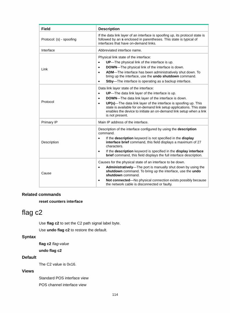
114
Field Description
Protocol: (s) - spoofing If the data link layer of an interface is spoofing up, its protocol state is followed by an s enclosed in parentheses. This state is typical of interfaces that have on-demand links.
Interface Abbreviated interface name.
Link
Physical link state of the interface: • UP—The physical link of the interface is up. • DOWN—The physical link of the interface is down. • ADM—The interface has been administratively shut down. To
bring up the interface, use the undo shutdown command. • Stby—The interface is operating as a backup interface.
Protocol
Data link layer state of the interface: • UP—The data link layer of the interface is up. • DOWN—The data link layer of the interface is down. • UP(s)—The data link layer of the interface is spoofing up. This
state is available for on-demand link setup applications. This state enables the device to initiate an on-demand link setup when a link is not present.
Primary IP Main IP address of the interface.
Description
Description of the interface configured by using the description command. • If the description keyword is not specified in the display
interface brief command, this field displays a maximum of 27 characters.
• If the description keyword is specified in the display interface brief command, this field displays the full interface description.
Cause
Causes for the physical state of an interface to be down. • Administratively—The port is manually shut down by using the
shutdown command. To bring up the interface, use the undo shutdown command.
• Not connected—No physical connection exists possibly because the network cable is disconnected or faulty.
Related commands reset counters interface
flag c2 Use flag c2 to set the C2 path signal label byte.
Use undo flag c2 to restore the default.
Syntax flag c2 flag-value
undo flag c2
Default The C2 value is 0x16.
Views Standard POS interface view
POS channel interface view
115
Predefined user roles network-admin
mdc-admin
Parameters flag-value: Specifies a C2 byte value, a hexadecimal number in the range of 0x00 to 0xFF.
Usage guidelines The C2 byte is a higher-order path overhead byte. It indicates the multiplex structure of virtual container (VC) frames and the property of payload.
The C2 byte must be the same at both ends of a link.
Examples # Set the C2 byte to 0x01 on POS 1/1/1. <Sysname> system-view
[Sysname] interface pos 1/1/1
[Sysname-Pos1/1/1] flag c2 01
Related commands display interface pos
flag j0 Use flag j0 to set the J0 regenerator section trace byte for SONET or SDH frames.
Use undo flag j0 to restore the default.
Syntax flag j0 { sdh | sonet } flag-value
undo flag j0 { sdh | sonet }
Default The device uses the SDH framing format. In SDH frames, the J0 byte is an empty string.
Views Standard POS interface view
Predefined user roles network-admin
mdc-admin
Parameters flag-value: Specifies the J0 byte. It must be a string of 1 to 15 characters for SDH, and a hexadecimal number in the range of 0x00 to 0xFF for SONET.
sdh: Specifies the SDH framing format.
sonet: Specifies the SONET framing format.
Usage guidelines J0 byte is a section overhead byte. SDH and SONET use this byte to test continuity of the connection between two interfaces at the section level.
The J0 byte can be different on devices of the same service provider. On the interfaces between two service providers, the J0 byte must be the same.
116
Examples # Set the J0 byte to 0xFF for SDH on POS 1/1/1. <Sysname> system-view
[Sysname] interface pos 1/1/1
[Sysname-Pos1/1/1] flag j0 sdh ff
Related commands display interface pos
frame-format
flag j1 Use flag j1 to set the J1 path trace byte for SONET or SDH frames.
Use undo flag j1 to restore the default.
Syntax flag j1 { sdh | sonet } flag-value
undo flag j1 { sdh | sonet }
Default The device uses the SDH framing format. In SDH frames, the J1 byte is an empty string.
Views Standard POS interface view
POS channel interface view
Predefined user roles network-admin
mdc-admin
Parameters flag-value: Specifies a J1 byte value. It must be a string of 1 to 15 characters for SDH and a string of 1 to 62 characters for SONET.
sdh: Specifies the SDH framing format.
sonet: Specifies the SONET framing format.
Usage guidelines J1 byte is a higher-order path overhead byte. SDH and SONET use this byte to test continuity of the connection between two interfaces at the path level.
The J1 byte must be the same at both ends of a link.
Examples # Set the J1 byte to aabbcc for SDH on POS 1/1/1. <Sysname> system-view
[Sysname] interface pos 1/1/1
[Sysname-Pos1/1/1] flag j1 sdh aabbcc
Related commands display interface pos
flag j1 ignore
117
frame-format
flag j1 ignore Use flag j1 ignore to ignore CRC of the J1 byte.
Use undo flag j1 ignore to restore the default.
Syntax flag j1 ignore
undo flag j1 ignore
Default CRC is performed for the J1 byte.
Views Standard POS interface view
POS channel interface view
Predefined user roles network-admin
mdc-admin
Examples # Ignore CRC of the J1 byte on POS 1/1/1. <Sysname> system-view
[Sysname] interface pos 1/1/1
[Sysname-Pos1/1/1] flag j1 ignore
Related commands flag j1
flow-interval Use flow-interval to set the packet statistics collection interval for an interface.
Use undo flow-interval to restore the default.
Syntax flow-interval interval
undo flow-interval
Default The packet statistics collection interval is 300 seconds for an interface.
Views System view
Predefined user roles network-admin
mdc-admin
118
Parameters interval: Specifies the packet statistics collection interval in the range of 5 to 300 and in steps of 5, in seconds.
Examples # Set the packet statistics collection interval to 180 seconds. <Sysname> system-view
[Sysname] flow-interval 180
frame-format Use frame-format to set the framing format on a standard POS interface.
Use undo frame-format to restore the default.
Syntax frame-format { sdh | sonet }
undo frame-format
Default The framing format is SDH on a standard POS interface.
Views Standard POS interface view
Predefined user roles network-admin
mdc-admin
Parameters sdh: Specifies the SDH framing format.
sonet: Specifies the SONET framing format.
Examples # Set the framing format to SONET on POS 1/1/1. <Sysname> system-view
[Sysname] interface pos 1/1/1
[Sysname-Pos1/1/1] frame-format sonet
Related commands flag j0
flag j1
interface pos Use interface pos to create a POS subinterface and enter its view, or enter the view of an existing standard POS interface, POS channel interface, or POS subinterface.
Use undo interface pos to delete a POS subinterface.
Syntax interface pos { interface-number | interface-number.subnumber [ p2mp | p2p ] }
undo interface pos interface-number.subnumber
119
Default No POS subinterfaces exist.
Views System view
Predefined user roles network-admin
mdc-admin
Parameters interface-number: Specifies a standard POS interface or POS channel interface by its number.
interface-number.subnumber: Specifies a POS subinterface. The interface-number argument specifies the main interface number. The subnumber argument specifies the subinterface number in the range of 0 to 1023.
p2mp: Sets the subinterface type to point-to-multipoint. By default, a POS subinterface is P2MP type.
p2p: Sets the subinterface type to point-to-point.
Usage guidelines You can create POS subinterfaces only on Frame Relay-enabled standard POS interfaces.
Examples # Create POS subinterface POS 1/1/1.1. <Sysname> system-view
[Sysname] interface pos 1/1/1.1
[Sysname-Pos1/1/1.1]
Related commands link-protocol
link-delay Use link-delay to set the physical state change suppression interval on an interface.
Use undo link-delay to restore the default.
Syntax link-delay msec milliseconds
undo link-delay
Default The physical state change suppression interval is 0 milliseconds on an interface.
Views Standard POS interface view
POS channel interface view
Predefined user roles network-admin
mdc-admin

120
Parameters msec milliseconds: Sets the physical state change suppression interval on an interface, in milliseconds. The value range for this argument is 0 to 10000 in steps of 5.
Usage guidelines When the physical state changes, a POS interface reports the event to the upper-layer modules, and generates log and SNMP notification messages. To reduce system overhead caused by frequent physical state changes, use this command to suppress physical state changes within an interval. The interface will ignore any changes that occur during each suppression interval. When the suppression interval expires, the interface will not report the change event or generate messages if the change is removed.
For example, the suppression interval starts when the interface changes from up to down. The interface reports the change event and generates messages if it is still down when the interval expires. The interface does not report the change event or generate messages if it is up when the interval expires.
This command and the dampening command cannot both be configured on an interface.
Examples # Set the physical state change suppression interval to 100 milliseconds for POS 1/1/1. <Sysname> system-view
[Sysname] interface pos 1/1/1
[Sysname-Pos1/1/1] link-delay msec 100
Related commands dampening
link-protocol Use link-protocol to set the data link layer protocol of an interface.
Syntax link-protocol { fr | hdlc | ppp | mfr }
Default PPP is used.
Views Standard POS interface view
POS channel interface view
Predefined user roles network-admin
mdc-admin
Parameters fr: Specifies Frame Relay as the data link layer protocol of the interface.
hdlc: Specifies HDLC as the data link layer protocol of the interface.
ppp: Specifies PPP as the data link layer protocol of the interface.
mfr: Specifies MFR as the data link layer protocol of the interface.
Examples # Specify HDLC as the data link protocol of POS 1/1/1.

121
<Sysname> system-view
[Sysname] interface pos 1/1/1
[Sysname-Pos1/1/1] link-protocol hdlc
loopback Use loopback to enable loopback for a standard POS interface.
Use undo loopback to disable loopback for a standard POS interface.
Syntax loopback { local | remote }
undo loopback
Default Loopback is disabled on a standard POS interface.
Views Standard POS interface view
Predefined user roles network-admin
mdc-admin
Parameters local: Enables internal loopback.
remote: Enables external loopback.
Usage guidelines Loopback is intended for testing only. Disable the feature when the interface is operating correctly.
When you enable internal loopback on a standard POS interface before the interface is connected to the peer end, the state of the data link layer protocol is reported as up.
Examples # Enable internal loopback on POS 1/1/1. <Sysname> system-view
[Sysname] interface pos 1/1/1
[Sysname-Pos1/1/1] loopback local
Related commands clock
mtu Use mtu to set the MTU size for an interface.
Use undo mtu to restore the default.
Syntax mtu size
undo mtu
122
Default The MTU is 1500 bytes for an interface.
Views Standard POS interface view
POS subinterface view
POS channel interface view
Predefined user roles network-admin
mdc-admin
Parameters size: Sets the maximum transmission unit (MTU) in bytes. The value range for this argument is 128 to 9600.
Usage guidelines The MTU setting affects the assembly and fragmentation of IP packets.
After configuring the MTU for an interface, you must use the shutdown command and then the undo shutdown command on the interface for the modification to take effect.
Examples # Set the MTU to 1430 bytes for POS 1/1/1. <Sysname> system-view
[Sysname] interface pos 1/1/1
[Sysname-Pos1/1/1] mtu 1430
port-type switch Use port-type switch to change the type of an interface.
Syntax In standard POS interface view:
port-type switch gigabitethernet
In Layer 3 GigabitEthernet interface view:
port-type switch pos
Views Standard POS interface view
Layer 3 GigabitEthernet interface view
Predefined user roles 2: System level
Parameters gigabitethernet: Change a standard POS interface to a Layer 3 GigabitEthernet interface.
pos: Change a Layer 3 GigabitEthernet interface to a standard POS interface.
Usage guidelines This command is available only on routers installed with HIM-TS8P interface modules.
When you execute this command, the device performs the following operations:
123
1. Removes the original interface. 2. Creates a new-type interface with the same number as the original interface. 3. Enters the interface view of the new-type interface.
Examples # Change POS 1/1/1 to GigabitEthernet 1/1/1. <Sysname> system-view
[Sysname] interface pos 1/1/1
[Sysname-Pos1/1/1] port-type switch gigabitethernet
Changing port type can result in loss of port configuration. Are you sure to continue? [Y/N]:y
[Sysname-GigabitEthernet1/1/1]
reset counters interface Use reset counters interface to clear interface statistics.
Syntax reset counters interface [ pos [ interface-number | interface-number.subnumber ] ]
Views User view
Predefined user roles network-admin
mdc-admin
Parameters pos: Clears statistics for standard POS interfaces, POS subinterfaces, or POS channel interfaces.
interface-number: Specifies a standard POS interface or POS channel interface by its number.
interface-number.subnumber: Specifies a POS subinterface. The interface-number argument specifies the main interface number. The subnumber argument specifies the subinterface number in the range of 0 to 1023.
Usage guidelines Use this command to clear history statistics before you collect statistics for a time period. • If you do not specify the pos keyword, this command clears statistics for all interfaces. • If you specify the pos keyword without specifying an interface, this command clears statistics
for all standard POS interfaces, POS subinterfaces, and POS channel interfaces. • If you specify a POS interface, this command clears statistics for the specified interface.
Examples # Clear statistics for POS 1/1/1. <Sysname> reset counters interface pos 1/1/1
Related commands display interface pos
scramble Use scramble to enable payload scrambling on an interface.
124
Use undo scramble to disable payload scrambling on an interface.
Syntax scramble
undo scramble
Default Payload scrambling is enabled on standard POS interfaces and POS channel interfaces.
Views Standard POS interface view
POS channel interface view
Predefined user roles network-admin
mdc-admin
Usage guidelines The payload scrambling setting must be the same at both ends of a link.
Payload scrambling enables an interface to scramble outgoing data and unscramble incoming data. Several physical layer protocols rely on transitions between 1s and 0s to maintain clocking. By preventing the presence of long strings of all 1s or all 0s, payload scrambling enables the receiving end to extract the line clock signal correctly.
If payload scrambling is disabled, the interface does not scramble outgoing data or unscramble incoming data.
Examples # Enable payload scrambling on POS 1/1/1. <Sysname> system-view
[Sysname] interface pos 1/1/1
[Sysname-Pos1/1/1]scramble
shutdown Use shutdown to shut down an interface.
Use undo shutdown to bring up an interface.
Syntax shutdown
undo shutdown
Default An interface is up.
Views Standard POS interface view
POS subinterface view
POS channel interface view
Predefined user roles network-admin
125
mdc-admin
Examples # Shut down POS 1/1/1. <Sysname> system-view
[Sysname] interface pos 1/1/1
[Sysname-Pos1/1/1] shutdown
snmp-agent trap enable { b1-tca | b2-tca | b3-tca } Use snmp-agent trap enable { b1-tca | b2-tca | b3-tca } to enable SNMP notifications about signal transmission performance for a standard POS interface.
Use undo snmp-agent trap enable { b1-tca | b2-tca | b3-tca } to disable SNMP notifications about signal transmission performance for a standard POS interface.
Syntax snmp-agent trap enable { b1-tca | b2-tca | b3-tca }
undo snmp-agent trap enable { b1-tca | b2-tca | b3-tca }
Default Signal transmission performance notifications are enabled for the standard POS interface.
Views Standard POS interface view
Predefined user roles network-admin
mdc-admin
Usage guidelines To generate SNMP notifications when a B1, B2, or B3 alarm occurs on a standard POS interface, use this command.
B1, B2, and B3 bytes indicate the signal transmission performance of a line at different levels. • B1 alarm occurs if the bit error rate of a complete STM-N frame exceeds the B1 alarm
threshold. • B2 alarm occurs if the bit error rate of an STM-1 frame exceeds the B2 alarm threshold. • B3 alarm occurs if the bit error rate of a multiplexed signal (VC3 or VC4 frame) in the STM-1
frame exceeds the B3 alarm threshold.
For B1, B2, or B3 alarm SNMP notifications to be sent correctly, you must also configure SNMP on the device. For more information about SNMP configuration, see the network management and monitoring configuration guide for the device.
Examples # Disable B1 alarm notifications on POS 1/1/1. <Sysname> system-view
[Sysname] interface pos 1/1/1
[Sysname-Pos1/1/1] undo snmp-agent trap enable b1-tca
Related commands threshold { b1-tca | b2-tca | b3-tca }
126
speed Use speed to set the rate of a standard POS interface.
Use undo speed to restore the default.
Syntax speed speed-value
undo speed
Default The rate of a standard POS interface is 155 Mbps.
Views Standard POS interface view
Predefined user roles network-admin
mdc-admin
Parameters speed-value: Specifies the rate in Mbps. The value range for this argument can be 155, 622, 2500, and 10000.
Examples # Set the rate to 2.5 Gbps for POS 1/1/1. <Sysname> system-view
[Sysname] interface pos 1/1/1
[Sysname-Pos1/1/1] speed 2500
sub-interface rate-statistic Use sub-interface rate-statistic to enable subinterface rate statistics collection on an interface.
Use undo sub-interface rate-statistic to disable subinterface rate statistics collection on an interface.
Syntax sub-interface rate-statistic
undo sub-interface rate-statistic
Default Subinterface rate statistics collection is disabled on an interface.
Views Standard POS interface view
POS channel interface view
Predefined user roles network-admin
mdc-admin
127
Usage guidelines This command is resource intensive. When you use this command, make sure you fully understand its impact on system performance.
Examples # Enable subinterface rate statistics collection on POS 1/1/1. <Sysname> system-view
[Sysname] interface pos 1/1/1
[Sysname-Pos1/1/1] sub-interface rate-statistic
threshold Use threshold to configure the power for setting the SD or SF alarm threshold on a standard POS interface.
Use undo threshold to restore the default power for setting the SD or SF alarm threshold on a standard POS interface.
Syntax threshold { sd sdvalue | sf sfvalue } *
undo threshold [ sd | sf ]
Default The SD threshold is 10e to the power of negative 6 (10e–6). The SF threshold is 10e to the power of negative 3 (10e–3).
Views Standard POS interface view
Predefined user roles network-admin
mdc-admin
Parameters sd: Specifies the SD alarm threshold.
sdvalue: Specifies the power for setting the SD alarm threshold. The threshold is 10e to the power of negative sdvalue (10e–sdvalue). The value range for this argument is 3 to 9. The greater the value, the lower the SD alarm threshold.
sf: Specifies the SF alarm threshold. The SF alarm threshold must be higher than the SD alarm threshold.
sfvalue: Specifies the power for setting the SF alarm threshold. The threshold is 10e to the power of negative sdvalue (10e–sfvalue). The value range for this argument is 3 to 9. The greater the value, the lower the SF alarm threshold.
Usage guidelines SD and SF alarms indicate line performance. SF alarms are more severe than SD alarms. • An SD alarm occurs if the number of B2 errors reaches the SD alarm threshold. • An SF alarm occurs if the number of B2 errors reaches the SF alarm threshold.
Examples # Set the SD threshold to 10e to the power of negative 4 (10e–4) on POS 1/1/1. <Sysname> system-view
[Sysname] interface pos 1/1/1
128
[Sysname-Pos1/1/1] threshold sd 4
timer-hold Use timer-hold to set the keepalive interval.
Use undo timer-hold to restore the default.
Syntax timer-hold seconds
undo timer-hold
Default The keepalive interval is 10 seconds.
Views Standard POS interface view
POS channel interface view
Predefined user roles network-admin
mdc-admin
Parameters seconds: Specifies the interval at which the interface sends keepalive packets. The value range for this argument is 0 to 32767 seconds.
Usage guidelines On an interface encapsulated with PPP, FR, or HDLC, the data link layer sends keepalive packets at keepalive intervals to detect the availability of the remote end. The data link layer determines that the peer end is down if it does not receive a response after the maximum number of keepalive attempts have been made. The data link layer then reports the link down event to the upper-layer protocols.
To set the maximum number of keepalive attempts, use the timer-hold retry command.
On a slow link, increase the keepalive interval to prevent false shutdown of the interface. This situation might occur when keepalive packets are delayed because a large packet is being transmitted on the link.
Examples # Set the keepalive interval to 15 seconds for POS 1/1/1. <Sysname> system-view
[Sysname] interface pos 1/1/1
[Sysname-Pos1/1/1] timer-hold 15
Related commands timer-hold retry
timer-hold retry Use timer-hold retry to set the maximum number of keepalive attempts.
Use undo timer-hold retry to restore the default.
Syntax timer-hold retry retries
129
undo timer-hold retry
Default The maximum number of keepalive attempts is 5.
Views Standard POS interface view
POS channel interface view
Predefined user roles network-admin
mdc-admin
Parameters retries: Specifies the maximum number of keepalive attempts, in the range of 1 to 255.
Usage guidelines The interface determines that the remote end is down if it does not receive a keepalive response after the maximum number of keepalive attempts have been made.
This command applies to interfaces encapsulated with PPP, FR, or HDLC. To set the keepalive interval, use the timer-hold command.
On a slow link, increase the maximum number of keepalive attempts to prevent false shutdown of the interface. This situation might occur when keepalive packets are delayed because a large packet is being transmitted on the link.
Examples # Set the maximum number of keepalive attempts to 10 for POS 1/1/1. <Sysname> system-view
[Sysname] interface pos 1/1/1
[Sysname-Pos1/1/1] timer-hold retry 10
Related commands timer-hold
130
CPOS interface commands alarm-detect
Use alarm-detect to configure the action to take when an RDI, SD, or SF alarm occurs on an interface.
Use undo alarm-detect to restore the default.
Syntax alarm-detect { rdi | sd | sf } action link-down
undo alarm-detect { rdi | sd | sf }
Default The device does not take any actions on the interface when an RDI, SD, or SF alarm occurs.
Views CPOS interface view
Predefined user roles network-admin
mdc-admin
Parameters rdi: Specifies remote defect indication (RDI) alarms.
sd: Specifies signal degrade (SD) alarms.
sf: Specifies signal fail (SF) alarms.
action: Specifies the action to take when the specified alarm is detected on the interface.
link-down: Places the interface in down state.
Usage guidelines An RDI alarm occurs if the device receives multiplexer section remote defect indication (MS-RDI) signals from the remote end.
An SD or SF alarm occurs if the bit error rate of incoming packets crosses the SD or SF alarm threshold. To set the SD or SF alarm threshold, use the threshold command.
Examples # Configure CPOS 1/1/1 to go down when an SD alarm occurs. <Sysname> system-view
[Sysname] controller cpos 1/1/1
[Sysname-Cpos1/1/1] alarm-detect sd action link-down
Related commands threshold
clock Use clock to set the clock mode of a CPOS interface.
Use undo clock to restore the default.
131
Syntax clock { master | slave }
undo clock
Default The clock mode of a CPOS interface is slave.
Views CPOS interface view
Predefined user roles network-admin
mdc-admin
Parameters master: Sets the clock mode to master.
slave: Sets the clock mode to slave.
Usage guidelines When the clock mode of a CPOS interface is master, it uses the internal clock source.
When the clock mode of a CPOS interface is slave, it uses the line clock source.
When connected to a SONET/SDH device, the CPOS interface must use the slave clock mode. The SONET/SDH network clock is more precise.
When two CPOS interfaces are directly connected, you must configure the two ends with different clock modes.
Examples # Set the clock mode to master for CPOS 1/1/1. <Sysname> system-view
[Sysname] controller cpos 1/1/1
[Sysname-Cpos1/1/1] clock master
controller cpos Use controller cpos to enter CPOS interface view.
Syntax controller cpos cpos-number
Views System view
Predefined user roles network-admin
mdc-admin
Parameters cpos-number: Specifies a CPOS interface by its number.
Examples # Enter the interface view of CPOS 1/1/1. <Sysname> system-view
132
[Sysname] controller cpos 1/1/1
[Sysname-Cpos1/1/1]
default Use default to restore the default settings for a CPOS interface.
Syntax default
Views CPOS interface view
Predefined user roles network-admin
mdc-admin
Usage guidelines
CAUTION: The default command might interrupt ongoing network services. Make sure you are fully aware of the impact of this command when you use it on a live network.
This command might fail to restore the default settings for some commands because of command dependencies or system restrictions. You can use the display this command in interface view to check for these commands and perform their undo forms or follow the command reference to restore their default settings. If your restoration attempt still fails, follow the error message to resolve the problem.
Examples # Restore the default settings for CPOS 1/1/1. <Sysname> system-view
[Sysname] controller cpos 1/1/1
[Sysname-Cpos1/1/1] default
description Use description to configure a description for a CPOS interface.
Use undo description to restore the default.
Syntax description text
undo description
Default The description of a CPOS interface is in interface name Interface format, for example, Cpos1/1/1 Interface.
Views CPOS interface view
Predefined user roles network-admin
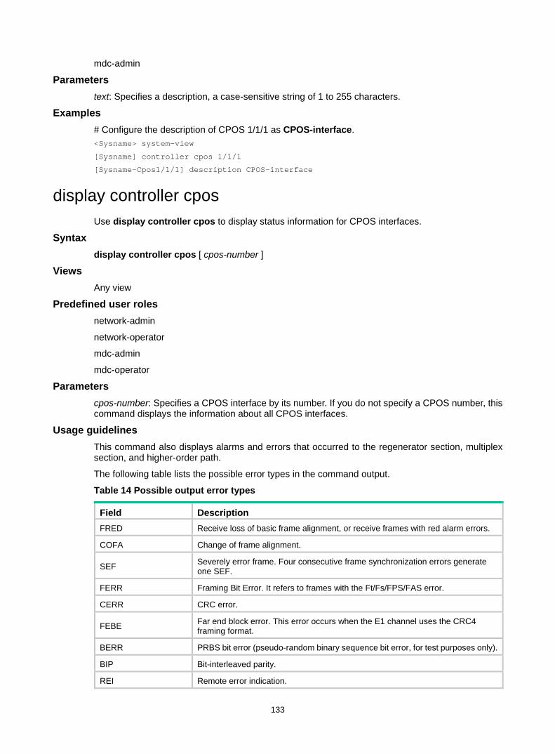
133
mdc-admin
Parameters text: Specifies a description, a case-sensitive string of 1 to 255 characters.
Examples # Configure the description of CPOS 1/1/1 as CPOS-interface. <Sysname> system-view
[Sysname] controller cpos 1/1/1
[Sysname-Cpos1/1/1] description CPOS-interface
display controller cpos Use display controller cpos to display status information for CPOS interfaces.
Syntax display controller cpos [ cpos-number ]
Views Any view
Predefined user roles network-admin
network-operator
mdc-admin
mdc-operator
Parameters cpos-number: Specifies a CPOS interface by its number. If you do not specify a CPOS number, this command displays the information about all CPOS interfaces.
Usage guidelines This command also displays alarms and errors that occurred to the regenerator section, multiplex section, and higher-order path.
The following table lists the possible error types in the command output.
Table 14 Possible output error types
Field Description FRED Receive loss of basic frame alignment, or receive frames with red alarm errors.
COFA Change of frame alignment.
SEF Severely error frame. Four consecutive frame synchronization errors generate one SEF.
FERR Framing Bit Error. It refers to frames with the Ft/Fs/FPS/FAS error.
CERR CRC error.
FEBE Far end block error. This error occurs when the E1 channel uses the CRC4 framing format.
BERR PRBS bit error (pseudo-random binary sequence bit error, for test purposes only).
BIP Bit-interleaved parity.
REI Remote error indication.
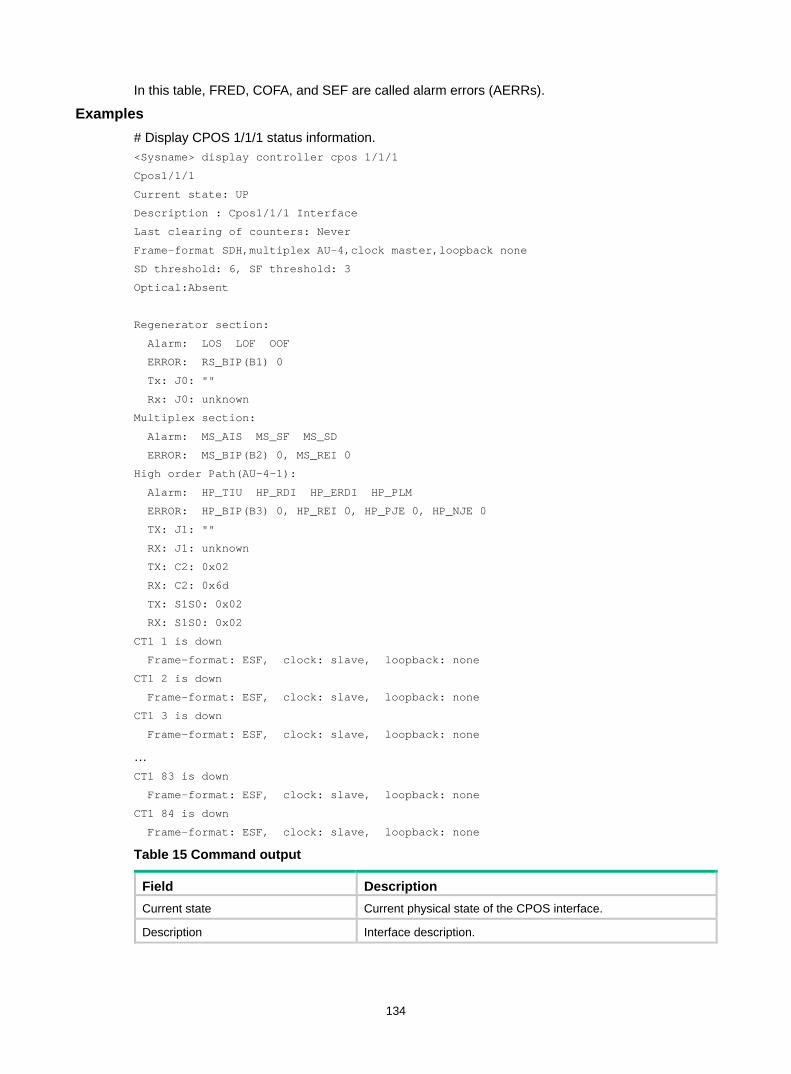
134
In this table, FRED, COFA, and SEF are called alarm errors (AERRs).
Examples # Display CPOS 1/1/1 status information. <Sysname> display controller cpos 1/1/1
Cpos1/1/1
Current state: UP
Description : Cpos1/1/1 Interface
Last clearing of counters: Never
Frame-format SDH,multiplex AU-4,clock master,loopback none
SD threshold: 6, SF threshold: 3
Optical:Absent
Regenerator section:
Alarm: LOS LOF OOF
ERROR: RS_BIP(B1) 0
Tx: J0: ""
Rx: J0: unknown
Multiplex section:
Alarm: MS_AIS MS_SF MS_SD
ERROR: MS_BIP(B2) 0, MS_REI 0
High order Path(AU-4-1):
Alarm: HP_TIU HP_RDI HP_ERDI HP_PLM
ERROR: HP_BIP(B3) 0, HP_REI 0, HP_PJE 0, HP_NJE 0
TX: J1: ""
RX: J1: unknown
TX: C2: 0x02
RX: C2: 0x6d
TX: S1S0: 0x02
RX: S1S0: 0x02
CT1 1 is down
Frame-format: ESF, clock: slave, loopback: none
CT1 2 is down
Frame-format: ESF, clock: slave, loopback: none
CT1 3 is down
Frame-format: ESF, clock: slave, loopback: none
… CT1 83 is down
Frame-format: ESF, clock: slave, loopback: none
CT1 84 is down
Frame-format: ESF, clock: slave, loopback: none
Table 15 Command output
Field Description Current state Current physical state of the CPOS interface.
Description Interface description.
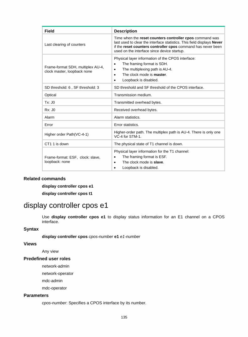
135
Field Description
Last clearing of counters
Time when the reset counters controller cpos command was last used to clear the interface statistics. This field displays Never if the reset counters controller cpos command has never been used on the interface since device startup.
Frame-format SDH, multiplex AU-4, clock master, loopback none
Physical layer information of the CPOS interface: • The framing format is SDH. • The multiplexing path is AU-4. • The clock mode is master. • Loopback is disabled.
SD threshold: 6 , SF threshold: 3 SD threshold and SF threshold of the CPOS interface.
Optical Transmission medium.
Tx: J0 Transmitted overhead bytes.
Rx: J0 Received overhead bytes.
Alarm Alarm statistics.
Error Error statistics.
Higher order Path(VC-4-1) Higher-order path. The multiplex path is AU-4. There is only one VC-4 for STM-1.
CT1 1 is down The physical state of T1 channel is down.
Frame-format: ESF, clock: slave, loopback: none
Physical layer information for the T1 channel: • The framing format is ESF. • The clock mode is slave. • Loopback is disabled.
Related commands display controller cpos e1
display controller cpos t1
display controller cpos e1 Use display controller cpos e1 to display status information for an E1 channel on a CPOS interface.
Syntax display controller cpos cpos-number e1 e1-number
Views Any view
Predefined user roles network-admin
network-operator
mdc-admin
mdc-operator
Parameters cpos-number: Specifies a CPOS interface by its number.
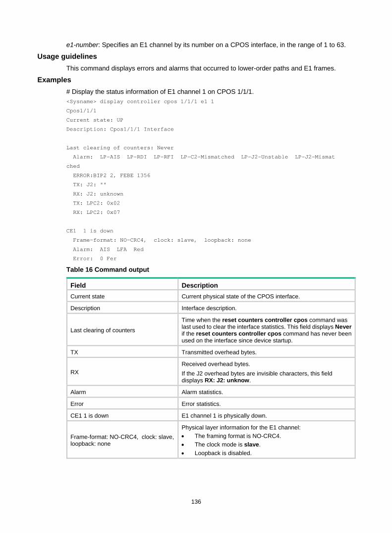
136
e1-number: Specifies an E1 channel by its number on a CPOS interface, in the range of 1 to 63.
Usage guidelines This command displays errors and alarms that occurred to lower-order paths and E1 frames.
Examples # Display the status information of E1 channel 1 on CPOS 1/1/1. <Sysname> display controller cpos 1/1/1 e1 1
Cpos1/1/1
Current state: UP
Description: Cpos1/1/1 Interface
Last clearing of counters: Never
Alarm: LP-AIS LP-RDI LP-RFI LP-C2-Mismatched LP-J2-Unstable LP-J2-Mismat
ched
ERROR:BIP2 2, FEBE 1356
TX: J2: ""
RX: J2: unknown
TX: LPC2: 0x02
RX: LPC2: 0x07
CE1 1 is down
Frame-format: NO-CRC4, clock: slave, loopback: none
Alarm: AIS LFA Red
Error: 0 Fer
Table 16 Command output
Field Description Current state Current physical state of the CPOS interface.
Description Interface description.
Last clearing of counters
Time when the reset counters controller cpos command was last used to clear the interface statistics. This field displays Never if the reset counters controller cpos command has never been used on the interface since device startup.
TX Transmitted overhead bytes.
RX Received overhead bytes. If the J2 overhead bytes are invisible characters, this field displays RX: J2: unknow.
Alarm Alarm statistics.
Error Error statistics.
CE1 1 is down E1 channel 1 is physically down.
Frame-format: NO-CRC4, clock: slave, loopback: none
Physical layer information for the E1 channel: • The framing format is NO-CRC4. • The clock mode is slave. • Loopback is disabled.
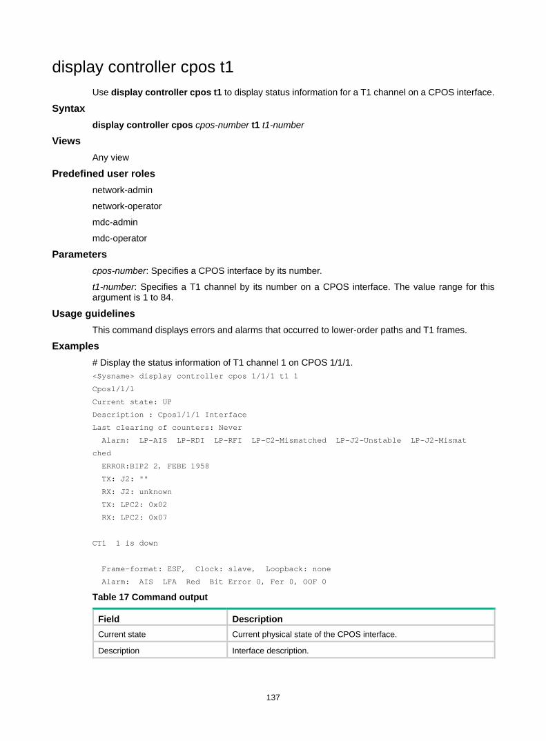
137
display controller cpos t1 Use display controller cpos t1 to display status information for a T1 channel on a CPOS interface.
Syntax display controller cpos cpos-number t1 t1-number
Views Any view
Predefined user roles network-admin
network-operator
mdc-admin
mdc-operator
Parameters cpos-number: Specifies a CPOS interface by its number.
t1-number: Specifies a T1 channel by its number on a CPOS interface. The value range for this argument is 1 to 84.
Usage guidelines This command displays errors and alarms that occurred to lower-order paths and T1 frames.
Examples # Display the status information of T1 channel 1 on CPOS 1/1/1. <Sysname> display controller cpos 1/1/1 t1 1
Cpos1/1/1
Current state: UP
Description : Cpos1/1/1 Interface
Last clearing of counters: Never
Alarm: LP-AIS LP-RDI LP-RFI LP-C2-Mismatched LP-J2-Unstable LP-J2-Mismat
ched
ERROR:BIP2 2, FEBE 1958
TX: J2: ""
RX: J2: unknown
TX: LPC2: 0x02
RX: LPC2: 0x07
CT1 1 is down
Frame-format: ESF, Clock: slave, Loopback: none
Alarm: AIS LFA Red Bit Error 0, Fer 0, OOF 0
Table 17 Command output
Field Description Current state Current physical state of the CPOS interface.
Description Interface description.
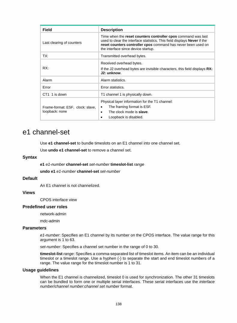
138
Field Description
Last clearing of counters
Time when the reset counters controller cpos command was last used to clear the interface statistics. This field displays Never if the reset counters controller cpos command has never been used on the interface since device startup.
TX: Transmitted overhead bytes.
RX: Received overhead bytes. If the J2 overhead bytes are invisible characters, this field displays RX: J2: unknow.
Alarm Alarm statistics.
Error Error statistics.
CT1 1 is down T1 channel 1 is physically down.
Frame-format: ESF, clock: slave, loopback: none
Physical layer information for the T1 channel: • The framing format is ESF. • The clock mode is slave. • Loopback is disabled.
e1 channel-set Use e1 channel-set to bundle timeslots on an E1 channel into one channel set.
Use undo e1 channel-set to remove a channel set.
Syntax e1 e1-number channel-set set-number timeslot-list range
undo e1 e1-number channel-set set-number
Default An E1 channel is not channelized.
Views CPOS interface view
Predefined user roles network-admin
mdc-admin
Parameters e1-number: Specifies an E1 channel by its number on the CPOS interface. The value range for this argument is 1 to 63.
set-number: Specifies a channel set number in the range of 0 to 30.
timeslot-list range: Specifies a comma-separated list of timeslot items. An item can be an individual timeslot or a timeslot range. Use a hyphen (-) to separate the start and end timeslot numbers of a range. The value range for the timeslot number is 1 to 31.
Usage guidelines When the E1 channel is channelized, timeslot 0 is used for synchronization. The other 31 timeslots can be bundled to form one or multiple serial interfaces. These serial interfaces use the interface number/channel number:channel set number format.
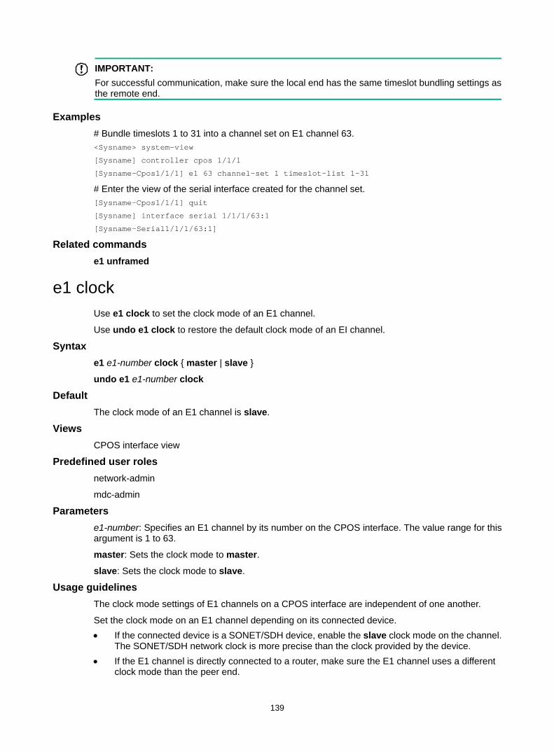
139
IMPORTANT: For successful communication, make sure the local end has the same timeslot bundling settings as the remote end.
Examples # Bundle timeslots 1 to 31 into a channel set on E1 channel 63. <Sysname> system-view
[Sysname] controller cpos 1/1/1
[Sysname-Cpos1/1/1] e1 63 channel-set 1 timeslot-list 1-31
# Enter the view of the serial interface created for the channel set. [Sysname-Cpos1/1/1] quit
[Sysname] interface serial 1/1/1/63:1
[Sysname-Serial1/1/1/63:1]
Related commands e1 unframed
e1 clock Use e1 clock to set the clock mode of an E1 channel.
Use undo e1 clock to restore the default clock mode of an EI channel.
Syntax e1 e1-number clock { master | slave }
undo e1 e1-number clock
Default The clock mode of an E1 channel is slave.
Views CPOS interface view
Predefined user roles network-admin
mdc-admin
Parameters e1-number: Specifies an E1 channel by its number on the CPOS interface. The value range for this argument is 1 to 63.
master: Sets the clock mode to master.
slave: Sets the clock mode to slave.
Usage guidelines The clock mode settings of E1 channels on a CPOS interface are independent of one another.
Set the clock mode on an E1 channel depending on its connected device. • If the connected device is a SONET/SDH device, enable the slave clock mode on the channel.
The SONET/SDH network clock is more precise than the clock provided by the device. • If the E1 channel is directly connected to a router, make sure the E1 channel uses a different
clock mode than the peer end.
140
Examples # Set the clock mode to master on E1 channel 1. <Sysname> system-view
[Sysname] controller cpos 1/1/1
[Sysname-Cpos1/1/1] e1 1 clock master
e1 flag Use e1 flag to set the C2 or J2 overhead byte for an E1 channel.
Use undo e1 flag to restore the default C2 or J2 overhead byte for an E1 channel.
Syntax e1 e1-number flag { c2 c2-value | j2 { sdh | sonet } j2-string }
undo e1 e1-number flag { c2 | j2 { sdh | sonet } }
Default C2 is 02 (hexadecimal) and J2 is cyclic null.
Views CPOS interface view
Predefined user roles network-admin
mdc-admin
Parameters e1-number: Specifies an E1 channel by its number. The value range for this argument is 1 to 63.
c2: Specifies the low-order channel signal tag byte C2.
c2-value: Specifies the value of the low-order channel signal flag byte C2, one byte in length and in the range of 0x0 to 0x7 (except 0x5).
j2: Specifies the low-order channel trace byte J2.
sdh: Specifies the trace byte in SDH format.
sonet: Specifies the trace byte in SONET format.
j2-string: Specifies the low-order channel trace byte J2, a string of 1 to 15 characters for SDH or a string of 1 to 62 characters for SONET.
Examples # Set C2 to 0x7 for E1 channel 3 on CPOS 1/1/1. <Sysname> system-view
[Sysname] controller cpos 1/1/1
[Sysname-Cpos1/1/1] e1 3 flag c2 7
e1 frame-format Use e1 frame-format to set the framing format of an E1 channel.
Use undo e1 frame-format to restore the default framing format of an E1 channel.
Syntax e1 e1-number frame-format { crc4 | no-crc4 }
141
undo e1 e1-number frame-format
Default The framing format of an E1 channel is no-CRC4.
Views CPOS interface view
Predefined user roles network-admin
mdc-admin
Parameters e1-number: Specifies an E1 channel by its number on the CPOS interface. The value range for this argument is 1 to 63.
crc4: Sets the framing format to CRC4.
no-crc4: Sets the framing format to no-CRC4.
Examples # Set the framing format to CRC4 for E1 channel 1. <Sysname> system-view
[Sysname] controller cpos 1/1/1
[Sysname-Cpos1/1/1] e1 1 set frame-format crc4
e1 loopback Use e1 loopback to set the loopback mode for an E1 channel.
Use undo e1 loopback to disable loopback for an EI channel.
Syntax e1 e1-number loopback { local | payload | remote }
undo e1 e1-number loopback
Default Loopback is disabled on an E1 channel.
Views CPOS interface view
Predefined user roles network-admin
mdc-admin
Parameters e1-number: Specifies an E1 channel by its number on the CPOS interface. The value range for this argument is 1 to 63.
local: Enables internal loopback.
payload: Enables external payload loopback.
remote: Enables external loopback.
Usage guidelines You can test E1 channels by using the loopback command with different keywords.
142
• In an internal loopback, the sender's data is directly looped to the receiver. • In an external payload loopback, data received by the receiver is looped back at the E1 framer
as payload. • In an external loopback, data received by the receiver is looped back directly without passing
through the E1 framer.
Examples # Enable external payload loopback on E1 channel 1. <Sysname> system-view
[Sysname] controller cpos 1/1/1
[Sysname-Cpos1/1/1] e1 1 set loopback payload
Related commands display controller cpos e1
e1 shutdown Use e1 shutdown to shut down an E1 channel.
Use undo e1 shutdown to bring up an E1 channel.
Syntax e1 e1-number shutdown
undo e1 e1-number shutdown
Default E1 channels are up.
Views CPOS interface view
Predefined user roles network-admin
mdc-admin
Parameters e1-number: Specifies an E1 channel by its number on the CPOS interface. The value range for this argument is 1 to 63.
Usage guidelines When you shut down an E1 channel, its associated serial interfaces are also shut down.
Examples # Shut down E1 channel 1. <Sysname> system-view
[Sysname] controller cpos 1/1/1
[Sysname-Cpos1/1/1] e1 1 shutdown
e1 unframed Use e1 unframed to configure an E1 channel on a CPOS interface to operate in unframed mode.
Use undo e1 unframed to restore the default operating mode of an EI channel on a CPOS interface.
143
Syntax e1 e1-number unframed
undo e1 e1-number unframed
Default E1 channels on a CPOS interface operate in framed mode.
Views CPOS interface view
Predefined user roles network-admin
mdc-admin
Parameters e1-number: Specifies an E1 channel by its number on a CPOS interface. The value range for this argument is 1 to 63.
Usage guidelines E1 channels on CPOS interfaces support the unframed (clear channel) mode and the framed (channelized) mode. • In unframed mode, an E1 channel can form a 2.048 Mbps serial interface without timeslot
division. It is numbered in the format of Serial interface number/channel number:0. • In framed mode, all timeslots except timeslot 0 on the E1 channel can be bundled randomly to
form serial interfaces.
Examples # Set E1 channel 3 on CPOS 1/1/1 to operate in unframed mode. <Sysname> system-view
[Sysname] controller cpos 1/1/1
[Sysname-Cpos1/1/1] e1 3 unframed
flag Use flag to set an overhead byte for SONET/SDH frames.
Use undo flag to restore the default of the specified overhead byte for SONET/SDH frames.
Syntax flag { c2 path-number c2-value | s1s0 path-number s1s0-value }
undo flag { c2 path-number | s1s0 path-number }
flag { j0 | j1 path-number } { sdh | sonet } flag-value
undo flag { j0 | j1 path-number } { sdh | sonet }
Default • c2 is 0x02. • s1s0 is 0x00 for SONET and 0x02 for SDH. • j0 is 0x01 for SONET and a 16-byte null character for SDH. • j1 is a 64-byte null character for SONET and a 16-byte null character for SDH.
Views CPOS interface view
144
Predefined user roles network-admin
mdc-admin
Parameters c2 path-number c2-value: Specifies the number of a path and the path signal label byte. The value range for the c2-value argument is 0x00 to 0xFF.
s1s0 path-number s1s0-value: Specifies the number of a path and the AU type and TU type. The value range for the s1s0-value argument is 0 to 3.
j0 flag-value: Specifies the regenerator section trace message, which is a section overhead byte used to detect the continuity of the connection between two interfaces at the section layer. In SDH frames, the flag-value argument is a string of 1 to 15 characters. In SONET frames, the flag-value argument is in the range of 0x00 to 0xFF.
j1 path-number: Specifies the path trace message, which is a higher-order path overhead byte used to detect the continuity of the connection between two interfaces at the path layer. In SDH frames, the flag-value argument is a string of 1 to 15 characters. In SONET frames, the flag-value argument is a string of 1 to 62 characters.
sdh: Specifies the SDH framing format.
sonet: Specifies the SONET framing format.
Usage guidelines SONET/SDH frames provide a variety of overhead bytes for operation and maintenance (OAM) such as layered management on transmission networks.
J1, J0 and C2 are used to support interoperability between devices from different countries, areas, and vendors.
J0 is a section overhead byte used for detecting the continuity of the connection between two interfaces at the section layer. J1 and C2 are higher-order path overhead bytes. The J1 byte is used for detecting the continuity of the connection between two interfaces at the path layer. The C2 byte is used for indicating the multiplexing structure of a VC frame and the property of payload.
S1S0 are two bits in the H1 byte. They are used by ITU to indicate the AU-n/TU-n type. S1S0 must be set to 2 for AU-4, AU-3, and TU-3.
Examples # Set J0 to aa on CPOS 1/1/1. <Sysname> system-view
[Sysname] controller cpos 1/1/1
[Sysname-Cpos1/1/1] flag j0 sdh aa
Related commands display controller cpos
flag vc-3 Use flag vc-3 to set an overhead byte for VC-3 frames.
Use undo flag vc-3 to restore the default of the specified overhead byte for VC-3 frames.
Syntax flag vc-3 path-number { c2 c2-value | j1 { sdh sdh-string | sonet sonet-string } | s1s0 s1s0-value }
undo flag vc-3 path-number { c2 | j1 { sdh | sonet } | s1s0 }

145
Default • c2 is 0x02. • j1 is a 64-byte null character for SONET and a 16-byte null character for SDH. • s1s0 is 0 (hexadecimal) for SONET and 2 (hexadecimal) for SDH.
Views CPOS interface view
Predefined user roles network-admin
mdc-admin
Parameters path-number: Specifies a channel by its number in VC-3.
c2 c2-value: Specifies the path signal label byte in the range of 0x00 to 0xFF.
j1 sdh sdh-string: Specifies the higher order path trace byte for SDH frames, a string of 1 to 15 characters.
j1 sonet sonet-string: Specifies the higher order path trace byte for SONET frames, a string of 1 to 62 characters.
s1s0 s1s0-value: Specifies the AU/TU type indicator.
Usage guidelines A large set of overhead bytes are available to implement operation, administration, and maintenance (OAM) functions such as hierarchical management of transmission networks for SONET/SDH frames.
The J1 and C2 bytes are higher-order path overhead bytes. The J1 byte is used for detecting the continuity of the connection between two interfaces at the path layer. The C2 byte is used for indicating the multiplexing structure of a VC frame and the property of payload. The J1 and C2 bytes are mainly used for interoperability between devices from different countries, areas, and vendors.
Examples # Set the C2 overhead byte to 2 for VC-3 frames on channel 2 of VC-3 on CPOS 1/1/1. <Sysname> system-view
[Sysname] controller cpos 1/1/1
[Sysname-Cpos1/1/1] flag vc-3 2 c2 2
flag vc-4 Use flag vc-4 to set an overhead byte for VC-4 frames.
Use undo flag vc-4 to restore the default of the specified overhead byte for VC-4 frames.
Syntax flag vc-4 path-number { c2 c2-value | j1 { sdh sdh-string | sonet sonet-string } | s1s0 s1s0-value }
undo flag vc-4 path-number { c2 | j1 { sdh | sonet } | s1s0 }
Default • c2 is 0x02. • j1 is a 64-byte null character for SONET and a 16-byte null character for SDH. • s1s0 is 0x00 for SONET and 0x02 for SDH.
146
Views CPOS interface view
Predefined user roles network-admin
mdc-admin
Parameters path-number: Specifies a channel by its number in VC-4.
c2 c2-value: Specifies the path signal label byte in the range of 0x00 to 0xFF.
j1 sdh sdh-string: Specifies the higher order path trace byte for SDH frames, a string of 1 to 15 characters.
j1 sonet sonet-string: Specifies the higher order path trace byte for SONET frames, a string of 1 to 62 characters.
s1s0 s1s0-value: Specifies the AU/TU type indicator.
Usage guidelines A large set of overhead bytes are available to implement operation and maintenance (OAM) functions such as hierarchical management of transmission networks for SONET/SDH frames.
The J1 and C2 bytes are higher-order path overhead bytes. The J1 byte is used for detecting the continuity of the connection between two interfaces at the path layer. The C2 byte is used for indicating the multiplexing structure of a VC frame and the property of payload. The J1 and C2 bytes are mainly used for interoperability between devices from different countries, areas, and vendors.
Examples # Set the J1 byte to abcd for VC-4 frames on channel 1 of VC-4 on CPOS 1/1/1 in SDH mode. <Sysname> system-view
[Sysname] controller cpos 1/1/1
[Sysname-Cpos1/1/1] flag vc-4 1 j1 sdh abcd
frame-format Use frame-format to set the framing format on a CPOS interface.
Use undo frame-format to restore the default framing format on a CPOS interface.
Syntax frame-format { sdh | sonet }
undo frame-format
Default The framing format on a CPOS interface is SDH.
Views CPOS interface view
Predefined user roles network-admin
mdc-admin
Parameters sdh: Specifies the SDH framing format.
147
sonet: Specifies the SONET framing format.
Examples # Set the framing format to SONET on CPOS 1/1/1. <Sysname> system-view
[Sysname] controller cpos 1/1/1
[Sysname-Cpos1/1/1] frame-format sonet
link-delay Use link-delay to set the physical state change suppression interval on a CPOS interface.
Use undo link-delay to restore the default.
Syntax link-delay seconds
undo link-delay
Default The physical state change suppression interval is 0 seconds on a CPOS interface.
Views CPOS interface view
Predefined user roles network-admin
mdc-admin
Parameters seconds: Sets the physical state change suppression interval in seconds. The value range for this argument is 0 to 30.
Usage guidelines When the physical state changes, a CPOS interface reports the event to the upper-layer modules, and generates log and SNMP notification messages. To reduce system overhead caused by frequent physical state changes, use this command to suppress physical state changes within an interval. The interface will ignore any changes that occur during each suppression interval. When the suppression interval expires, the interface will not report the change event or generate messages if the change is removed.
For example, the suppression interval starts when the interface changes from up to down. The interface reports the change event and generates messages if it is still down when the interval expires. The interface does not report the change event or generate messages if it is up when the interval expires.
Examples # Set the physical state change suppression interval to 8 seconds on CPOS 1/1/1. <Sysname> system-view
[Sysname] controller cpos 1/1/1
[Sysname-Cpos1/1/1] link-delay 8
loopback Use loopback to enable loopback on a CPOS interface.
Use undo loopback to disable loopback on a CPOS interface.
148
Syntax loopback { local | remote }
undo loopback
Default Loopback is disabled on a CPOS interface.
Views CPOS interface view
Predefined user roles network-admin
mdc-admin
Parameters local: Enables internal loopback to test the physical interface.
remote: Enables external loopback to test the cable connected to the interface.
Usage guidelines Loopback is intended for testing only. Disable the feature when the interface is operating correctly.
Examples # Enable external loopback testing on CPOS 1/1/1. <Sysname> system-view
[Sysname] controller cpos 1/1/1
[Sysname-Cpos1/1/1] loopback remote
multiplex mode Use multiplex mode to set AUG multiplexing mode for a CPOS interface.
Use undo multiplex mode to restore the default AUG multiplexing mode for a CPOS interface.
Syntax multiplex mode { au-3 | au-4 }
undo multiplex mode
Default The AUG multiplexing mode is au-4.
Views CPOS interface view
Predefined user roles network-admin
mdc-admin
Parameters au-3: Gets AUG through AU-3.
au-4: Gets AUG through AU-4.
Usage guidelines SDH provides the following payload mapping/multiplexing solutions:
149
• ANSI—Uses the AU-3 multiplexing scheme. This scheme multiplexes the lower-order payload to the VC-3 higher-order path. VC-3 plus an AU pointer forms AU-3. Three such AU-3s can be synchronized and multiplexed to form one AUG.
• ETSI—Uses the AU-4 multiplexing scheme. This scheme multiplexes the lower-order payload to the VC-4 higher-order path. VC-4 plus an AU pointer forms an AU-4. This AU-4 can be synchronized and multiplexed to form one AUG.
When the CPOS interface is operating in SDH mode, you can multiplex AUG to AU-4 or AU-3 by using the multiplex mode command.
When the CPOS interface is operating in SONET mode, AUG can be multiplexed only to AU-3. The multiplex mode command does not take effect.
Countries and regions use different multiplexing schemes. You must use the same multiplexing scheme as the peer device. For example, the AU-4 multiplexing scheme is used in China.
Examples # In SDH mode, multiplex AUG to AU-3. <Sysname> system-view
[Sysname] controller cpos 1/1/1
[Sysname-Cpos1/1/1] frame-format sdh
[Sysname-Cpos1/1/1] multiplex mode au-3
Related commands frame-format
oc-12 Use oc-12 to create a 622 Mbps channel on a 2.5 Gbps CPOS interface and enter 622 Mbps channel view, or enter the view of an existing 622 Mbps channel.
Use undo oc-12 to delete a 622 Mbps channel.
Syntax oc-12 oc-12-number
undo oc-12 oc-12-number
Default No 622 Mbps channels exist on a 2.5 Gbps CPOS interface.
Views 2.5 Gbps CPOS interface view
Predefined user roles network-admin
mdc-admin
Parameters oc-12-number: Specifies a 622 Mbps channel number in the range of 1 to 4.
Usage guidelines You can create up to four 622 Mbps channels on a 2.5 Gbps CPOS interface operating in channelized mode.
When you delete a 622 Mbps channel, all low-order channels on it and all the related POS channel interfaces are deleted automatically. Low-order channels include 155 Mbps channels.
150
Examples # Create a 622 Mbps channel with a channel number of 2 on 2.5 Gbps CPOS interface CPOS 1/1/1. <Sysname> system-view
[Sysname] controller cpos 1/1/1
[Sysname-Cpos1/1/1] oc-12 2
[Sysname-Cpos1/1/1-oc-12-2]
oc-3 Use oc-3 to create a 155 Mbps channel on a 622 Mbps channel and enter 155 Mbps channel view, or enter the view of an existing 155 Mbps channel.
Use undo oc-3 to delete a 155 Mbps channel.
Syntax oc-3 oc-3-number
undo oc-3 oc-3-number
Default No 155 Mbps channels exist on a 622 Mbps channel.
Views 622 Mbps channel view
Predefined user roles network-admin
mdc-admin
Parameters oc-3-number: Specifies a 155 Mbps channel number in the range of 1 to 4.
Usage guidelines You can create up to four 155 Mbps channels on a 622 Mbps channel operating in channelized mode.
A 155 Mbps channel created on a 2.5 Gbps CPOS interface can only operate in concatenated mode. When you create a 155 Mbps channel, the system automatically sets its operating mode to concatenated.
When you delete a 155 Mbps channel, its POS channel interface is deleted automatically.
Examples # Create a 155 Mbps channel with a channel number of 1 on a 622 Mbps channel on CPOS 1/1/1. <Sysname> system-view
[Sysname] controller cpos 1/1/1
[Sysname-Cpos1/1/1] oc-12 1
[Sysname-Cpos1/1/1-oc-12-1] oc-3 1
[Sysname-Cpos1/1/1-oc-12-1-oc-3-1]
reset counters controller cpos Use reset counters controller cpos to clear CPOS interface statistics.
151
Syntax reset counters controller cpos [ interface-number ]
Views User view
Predefined user roles network-admin
mdc-admin
Parameters interface-number: Specifies an interface by its number. If you do not specify an interface, this command clears statistics for all CPOS interfaces.
Usage guidelines Use this command to clear history statistics before you collect traffic statistics for a time period.
To display CPOS interface statistics, use the display controller cpos command.
Examples # Clear statistics for CPOS 1/1/1. <Sysname> reset counters controller cpos 1/1/1
Related commands display controller cpos
shutdown Use shutdown to shut down a CPOS physical interface.
Use undo shutdown to bring up a CPOS physical interface.
Syntax shutdown
undo shutdown
Default The CPOS physical interface is up.
Views CPOS interface view
Predefined user roles network-admin
mdc-admin
Usage guidelines The shutdown command on the CPOS physical interface shuts down all E1/T1 channels and serial interfaces formed by timeslot bundles. As a result, they stop transmitting and receiving data. To bring them up, use the undo shutdown command on the CPOS physical interface.
Examples # Shut down CPOS 1/1/1. <Sysname> system-view
[Sysname] controller cpos 1/1/1
152
[Sysname-Cpos1/1/1] shutdown
t1 channel-set Use t1 channel-set to bundle timeslots on a T1 channel into one channel set.
Use undo t1 channel-set to remove a channel set.
Syntax t1 t1-number channel-set set-number timeslot-list range [ speed { 56k | 64k } ]
undo t1 t1-number channel-set set-number
Default A T1 channel is not channelized.
Views CPOS interface view
Predefined user roles network-admin
mdc-admin
Parameters t1-number: Specifies a T1 channel by its number on the CPOS interface. The value range for this argument is 1 to 84.
set-number: Specifies a channel set by its number in the range of 0 to 23.
timeslot-list range: Specifies a comma-separated list of timeslot items. An item can be an individual timeslot or a timeslot range. Use a hyphen (-) to separate the start and end timeslot numbers of a range. The value range for the timeslot number is 1 to 24.
speed: Specifies the speed of a timeslot. The default timeslot speed is 64 kbps.
Usage guidelines When you bundle timeslots on a T1 channel, the system automatically creates a serial interface numbered interface number/channel number:channel set number. The interface speed is the number of bundled timeslots multiplying the timeslot speed specified in this command.
IMPORTANT: For successful communication, make sure the local end has the same timeslot bundling settings as the remote end.
Examples # Bundle timeslots 1 through 23 into a channel set on T1 channel 1. <Sysname> system-view
[Sysname] controller cpos 1/1/1
[Sysname-Cpos1/1/1] t1 1 channel-set 1 timeslot-list 1-23
# Enter the view of the serial interface created for the channel set. [Sysname-Cpos1/1/1] quit
[Sysname] interface serial 1/1/1/1:1
[Sysname-Serial1/1/1/1:1]
Related commands t1 unframed
153
t1 clock Use t1 clock to set the clock mode of a T1 channel.
Use undo t1 clock to restore the default clock mode of a T1 channel.
Syntax t1 t1-number clock { master | slave }
undo t1 t1-number clock
Default The clock mode of a T1 channel is slave.
Views CPOS interface view
Predefined user roles network-admin
mdc-admin
Parameters t1-number: Specifies a T1 channel by its number on the CPOS interface. The value range for this argument is 1 to 84.
master: Sets the clock mode to master.
slave: Sets the clock mode to slave.
Usage guidelines The clock mode settings of the T1 channels on a CPOS interface are independent of one another.
Set the clock mode on a T1 channel depending on its connected device. • If the connected device is a SONET/SDH device, enable the slave clock mode on the channel.
The SONET/SDH network clock is more precise than the clock provided by the device. • If the T1 channel is directly connected to a router, make sure the T1 channel uses a different
clock mode than the peer end.
Examples # Set the clock mode to master on T1 channel 1. <Sysname> system-view
[Sysname] controller cpos 1/1/1
[Sysname-Cpos1/1/1] t1 1 clock master
t1 flag Use t1 flag to set the C2 or J2 overhead byte for a T1 channel.
Use undo t1 flag to restore the default C2 or J2 overhead byte for a T1 channel.
Syntax t1 t1-number flag { c2 c2-value | j2 { sdh | sonet } j2-string }
undo t1 t1-number flag { c2 | j2 { sdh | sonet } }
Default C2 is 0x02 and J2 is cyclic null.
154
Views CPOS interface view
Predefined user roles network-admin
mdc-admin
Parameters t1-number: Specifies a T1 channel by its number. The value range for this argument is 1 to 84.
c2: Specifies the low-order channel signal tag byte C2.
c2-value: Specifies the value of the low-order channel signal tag byte C2, one byte in length and in the range of 0x0 to 0x7 (except 0x5).
j2: Specifies the low-order channel trace byte J2.
sdh: Specifies the trace byte in SDH format.
sonet: Specifies the trace byte in SONET format.
j2-string: Specifies the low-order channel trace byte J2, a string of 1 to 15 characters (in SDH format) or of 1 to 62 characters (in SONET format).
Examples # Set C2 to 0x7 for T1 channel 3 on CPOS 1/1/1. <Sysname> system-view
[Sysname] controller cpos 1/1/1
[Sysname-Cpos1/1/1] t1 3 flag c2 7
t1 frame-format Use t1 frame-format to set the framing format for a T1 channel.
Use undo t1 frame-format to restore the default framing format for a T1 channel.
Syntax t1 t1-number frame-format { esf | sf }
undo t1 t1-number frame-format
Default The framing format for a T1 channel is ESF.
Views CPOS interface view
Predefined user roles network-admin
mdc-admin
Parameters t1-number: Specifies a T1 channel by its number on a CPOS interface. The value range for this argument is 1 to 84.
esf: Specifies the extended super frame (ESF) format.
sf: Specifies the super frame (SF) format.
155
Examples # Set the framing format to SF for T1 channel 1. <Sysname> system-view
[Sysname] controller cpos 1/1/1
[Sysname-Cpos1/1/1] t1 1 set frame-format sf
t1 loopback Use t1 loopback to set the loopback mode for a T1 channel.
Use undo t1 loopback to disable loopback for a T1 channel.
Syntax t1 t1-number loopback { local | payload | remote }
undo t1 t1-number loopback
Default Loopback is disabled on T1 channels.
Views CPOS interface view
Predefined user roles network-admin
mdc-admin
Parameters t1-number: Specifies a T1 channel by its number on a CPOS interface. The value range for this argument is 1 to 84.
local: Enables internal loopback.
payload: Enables external payload loopback.
remote: Enables external loopback.
Usage guidelines Loopback is intended for testing only. Disable the feature when the TI channel is operating correctly.
Examples # Enable external loopback on T1 channel 1. <Sysname> system-view
[Sysname] controller cpos 1/1/1
[Sysname-Cpos1/1/1] t1 1 set loopback payload
Related commands display controller cpos t1
t1 shutdown Use t1 shutdown to shut down a T1 channel.
Use undo t1 shutdown to bring up a T1 channel.
Syntax t1 t1-number shutdown
156
undo t1 t1-number shutdown
Default T1 channels are up.
Views CPOS interface view
Predefined user roles network-admin
mdc-admin
Parameters t1-number: Specifies a T1 channel by its number on a CPOS interface. The value range for this argument is 1 to 84.
Usage guidelines When you shut down a T1 channel, its associated serial interfaces are also shut down.
Examples # Shut down T1 channel 1. <Sysname> system-view
[Sysname] controller cpos 1/1/1
[Sysname-Cpos1/1/1] t1 1 shutdown
t1 unframed Use t1 unframed to configure a T1 channel on a CPOS interface to operate in unframed mode.
Use undo t1 unframed to restore the default operating mode of a T1 channel on a CPOS interface.
Syntax t1 t1-number unframed
undo t1 t1-number unframed
Default T1 operates in framed mode.
Views CPOS interface view
Predefined user roles network-admin
mdc-admin
Parameters t1-number: Specifies a T1 channel by its number on a CPOS interface. The value range for this argument is 1 to 84.
Usage guidelines T1 channels on CPOS interfaces support the unframed (clear channel) mode and the framed (channelized) mode. • In unframed mode, a T1 channel can form a 1.544 Mbps serial interface without timeslot
division. This interface is numbered in the format of Serial interface number/channel number:0.
157
• In framed mode, 24 timeslots of a T1 channel can be bound randomly to form serial interfaces.
Examples # Set T1 channel 3 on CPOS 1/1/1 to operate in unframed mode. <Sysname> system-view
[Sysname] controller cpos 1/1/1
[Sysname-Cpos1/1/1] t1 3 unframed
threshold Use threshold to configure the power for setting the SD or SF alarm threshold on a CPOS interface.
Use undo threshold to restore the default power for setting the SD or SF alarm threshold on a CPOS interface.
Syntax threshold { sd sdvalue | sf sfvalue } *
undo threshold [ sd | sf ]
Default The SD threshold is 10e to the power of negative 6 (10e–6). The SF threshold is 10e to the power of negative 3 (10e–3).
Views CPOS interface view
Predefined user roles network-admin
mdc-admin
Parameters sd: Specifies the SD alarm threshold.
sdvalue: Specifies the power for setting the SD alarm threshold. The threshold is 10e to the power of negative sdvalue (10e–sdvalue). The value range for this argument is 3 to 9. The greater the value, the lower the SD alarm threshold.
sf: Specifies the SF alarm threshold. The SF alarm threshold must be higher than the SD alarm threshold.
sfvalue: Specifies the power for setting the SF alarm threshold. The threshold is 10e to the power of negative sdvalue (10e–sfvalue). The value range for this argument is 3 to 9. The greater the value, the lower the SF alarm threshold.
Usage guidelines SD and SF alarms indicate line performance. SF alarms are more severe than SD alarms. • An SD alarm occurs if the number of B2 errors reaches the SD alarm threshold. • An SF alarm occurs if the number of B2 errors reaches the SF alarm threshold.
Examples # Set the SD threshold to 10e to the power of negative 4 (10e–4) on CPOS 1/1/1. <Sysname> system-view
[Sysname] interface cpos 1/1/1
[Sysname-Cpos1/1/1] threshold sd 4
158
using oc-12/using oc-12c Use using oc-12 to set a 622 Mbps channel to channelized mode.
Use using oc-12c to set a 622 Mbps channel to concatenated mode.
Use undo using to restore the default.
Syntax using { oc-12 | oc-12c }
undo using
Default A 622 Mbps channel operates in channelized mode.
Views 622 Mbps channel view
Predefined user roles network-admin
mdc-admin
Usage guidelines When you set a 622 Mbps channel to concatenated mode, the system automatically creates a 622 Mbps POS channel interface for the channel. The POS channel interface uses the POS interface number [/622 Mbps channel number]:0 format.
When you execute the using oc-12 or undo using command to change the 622 Mbps channel mode from concatenated to channelized, the system automatically deletes the POS channel interface.
Examples # Configure 622 Mbps channel 1 on CPOS 1/1/1 to operate in concatenated mode. <Sysname> system-view
[Sysname] controller cpos 1/1/1
[Sysname-Cpos1/1/1] oc-12 1
[Sysname-Cpos1/1/1-oc-12-1] using oc-12c
# Configure 622 Mbps channel 1 on CPOS 1/1/1 to operate in channelized mode. [Sysname-Cpos1/1/1-oc-12-1] undo using
using oc-3c Use using oc-3c to set a 155 Mbps channel to concatenated mode.
Syntax using oc-3c
Default A 155 Mbps channel operates in channelized mode.
Views 155 Mbps channel view
Predefined user roles network-admin
159
mdc-admin
Usage guidelines When you set a 155 Mbps channel to concatenated mode, the system automatically creates a 155 Mbps POS channel interface for the channel. The POS channel interface uses the POS interface number [ [/622 Mbps channel number]/155 Mbps channel number]:0 format.
Examples # Configure 155 Mbps channel 1 on CPOS 1/1/1 to operate in concatenated mode. <Sysname> system-view
[Sysname] controller cpos 1/1/1
[Sysname-Cpos1/1/1] oc-12 1
[Sysname-Cpos1/1/1-oc-12-1] oc-3 1
[Sysname-Cpos1/1/1-oc-12-1-oc-3-1] using oc-3c
using oc-48 Use using oc-48 to set a 2.5 Gbps CPOS interface to channelized mode.
Use undo using to restore the default.
Syntax using oc-48
undo using
Default A 2.5 Gbps CPOS interface operates in channelized mode.
Views 2.5 Gbps CPOS interface view
Predefined user roles network-admin
mdc-admin
Examples # Configure 2.5 Gbps CPOS interface CPOS 1/1/1 to operate in channelized mode. [Sysname-Cpos1/1/1] using oc-48
160
Loopback, null, and inloopback interface commands bandwidth
Use bandwidth to set the expected bandwidth for an interface.
Use undo bandwidth to restore the default.
Syntax bandwidth bandwidth-value
undo bandwidth
Default The expected bandwidth of a loopback interface is 0 kbps.
Views Loopback interface view
Predefined user roles network-admin
mdc-admin
Parameters bandwidth-value: Specifies the expected bandwidth in the range of 1 to 400000000 kbps.
Usage guidelines The expected bandwidth is an informational parameter used only by higher-layer protocols for calculation. You cannot adjust the actual bandwidth of an interface by using this command.
Examples # Set the expected bandwidth of Loopback 1 to 1000 kbps. <Sysname> system-view
[Sysname] interface loopback 1
[Sysname-LoopBack1] bandwidth 1000
default Use default to restore the default settings for a loopback or null interface.
Syntax default
Views Loopback interface view
Null interface view
Predefined user roles network-admin
mdc-admin
161
Usage guidelines
CAUTION: The default command might interrupt ongoing network services. Make sure you are fully aware of the impact of this command before using it on a live network.
This command might fail to restore the default settings for some commands for reasons such as command dependencies and system restrictions. Use the display this command in interface view to identify these commands, and then use their undo forms or follow the command reference to restore their default settings. If your restoration attempt still fails, follow the error message instructions to resolve the problem.
Examples # Restore the default settings for interface loopback 1. <Sysname> system-view
[Sysname] interface loopback 1
[Sysname-LoopBack1] default
description Use description to set a description for an interface.
Use undo description to restore the default.
Syntax description text
undo description
Default The description of a loopback or null interface is in the interface name Interface format, for example, LoopBack1 Interface.
Views Loopback interface view
Null interface view
Predefined user roles network-admin
mdc-admin
Parameters text: Specifies an interface description, a case-sensitive string of 1 to 255 characters.
Usage guidelines Configure a description for an interface for easy identification and management purposes.
You can use the display interface command to view the configured description.
Examples # Set the description to for RouterID for interface loopback 1. <Sysname> system-view
[Sysname] interface loopback 1
[Sysname-LoopBack1] description for RouterID
162
display interface inloopback Use display interface inloopback to display information about the inloopback interface.
Syntax display interface inloopback [ 0 ] [ brief [ description | down ] ]
Views Any view
Predefined user roles network-admin
network-operator
mdc-admin
mdc-operator
Parameters 0: Specifies interface Inloopback 0.
brief: Displays brief interface information. If you do not specify this keyword, the command displays detailed interface information.
description: Displays complete interface descriptions. If you do not specify this keyword, the command displays only the first 27 characters of interface descriptions. The description of an inloopback interface is always InLoopBack0 Interface and cannot be configured.
down: Displays information about interfaces in down state and the causes. If you do not specify this keyword, the command displays information about interfaces in all states.
Usage guidelines If the inloopback keyword is not specified, the command displays information about all interfaces of the device.
If the inloopback keyword is specified but the 0 keyword is not specified, the command displays information about interface Inloopback 0. This is because the device has only one inloopback interface Inloopback 0.
Examples # Display detailed information about interface Inloopback 0. <Sysname> display interface inloopback
InLoopBack0
Current state: UP
Line protocol state: UP(spoofing)
Description: InLoopBack0 Interface
Maximum transmit unit: 1536
Physical: InLoopBack
Last 300 seconds input rate: 0 bytes/sec, 0 bits/sec, 0 packets/sec
Last 300 seconds output rate: 0 bytes/sec, 0 bits/sec, 0 packets/sec
Input: 0 packets, 0 bytes, 0 drops
Output: 0 packets, 0 bytes, 0 drops
163
Table 18 Command output
Field Description
Current state Physical layer state of the interface, which is always UP, meaning that the inloopback interface can receive and transmit packets.
Line protocol state
Data link layer protocol state of the interface, which is always UP(spoofing). UP(spoofing) means that the data link layer protocol state of the interface is up, but the link is an on-demand link or is not present.
Description Description string of the interface, which is always InLoopBack0 Interface and cannot be configured.
Maximum transmit unit MTU of the interface, which is always 1536 and cannot be configured
Physical: InLoopBack The physical type of the interface is inloopback.
Last 300 seconds input rate: 0 bytes/sec, 0 bits/sec, 0 packets/sec
Average input rate during the last 300 seconds: • bytes/sec—Average number of bytes received per second. • bits/sec—Average number of bits received per second. • packets/sec—Average number of packets received per
second.
Last 300 seconds output rate: 0 bytes/sec, 0 bits/sec, 0 packets/sec
Average output rate over the last 300 seconds: • bytes/sec—Average number of bytes sent per second. • bits/sec—Average number of bits sent per second. • packets/sec—Average number of packets sent per second.
Input: 0 packets, 0 bytes, 0 drops Total number and size (in bytes) of incoming packets of the interface and the number of dropped packets.
Output: 0 packets, 0 bytes, 0 drops Total number and size (in bytes) of outgoing packets of the interface and the number of dropped packets.
# Display brief information about interface Inloopback 0. <Sysname> display interface inloopback 0 brief
Brief information on interfaces in route mode:
Link: ADM - administratively down; Stby - standby
Protocol: (s) - spoofing
Interface Link Protocol Primary IP Description
InLoop0 UP UP(s) --
Table 19 Command output
Field Description Brief information on interfaces in route mode: Brief information about the inloopback interface.
Link: ADM - administratively down; Stby - standby
Explains the Link field values: • ADM—The interface has been shut down by the network
administrator. To recover its physical layer state, run the undo shutdown command.
• Stby—The interface is a standby interface. To view the primary interface information, run the display interface-backup state command.
164
Field Description
Protocol: (s) - spoofing
Explains the Protocol field value. (s) represents spoofing. If the data link layer protocol of an interface is up, but its link is an on-demand link or is not present, the Protocol field displays UP(s). This attribute is typical of interface Null 0, Inloopback 0, and loopback interfaces.
Interface Interface name.
Link Physical layer state of the interface, which is always UP, meaning that the link is physically up.
Protocol Data link layer protocol state of the interface, which is always UP(s).
Primary IP IP address of the interface. Because inloopback interfaces do not support CLI configuration, this field does not display a value.
Description Interface description configured by using the description command. Because inloopback interfaces do not support CLI configuration, this field does not display a value.
display interface loopback Use display interface loopback to display information about the specified or all existing loopback interfaces.
Syntax display interface loopback [ interface-number ] [ brief [ description | down ] ]
Views Any view
Predefined user roles network-admin
network-operator
mdc-admin
mdc-operator
Parameters interface-number: Specifies a loopback interface by its number, which can be the number of any existing loopback interface. If you do not specify this argument, the command displays information about all existing loopback interfaces on the device.
brief: Displays brief interface information. If you do not specify this keyword, the command displays detailed interface information.
description: Displays complete interface descriptions. If you do not specify this keyword, the command displays only the first 27 characters of interface descriptions.
down: Displays information about interfaces in down state and the causes. If you do not specify this keyword, the command displays information about interfaces in all states.
Usage guidelines This command is supported only after a loopback interface is created.
If the loopback keyword is not specified, the command displays information about all interfaces of the device.
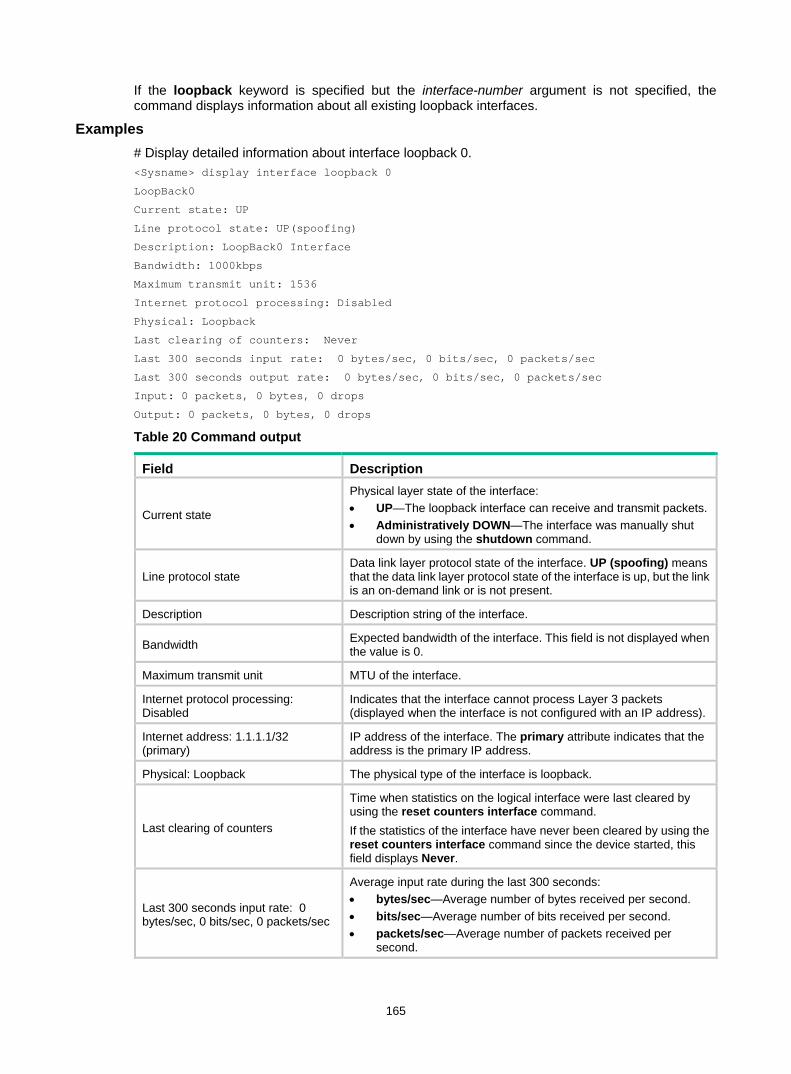
165
If the loopback keyword is specified but the interface-number argument is not specified, the command displays information about all existing loopback interfaces.
Examples # Display detailed information about interface loopback 0. <Sysname> display interface loopback 0
LoopBack0
Current state: UP
Line protocol state: UP(spoofing)
Description: LoopBack0 Interface
Bandwidth: 1000kbps
Maximum transmit unit: 1536
Internet protocol processing: Disabled
Physical: Loopback
Last clearing of counters: Never
Last 300 seconds input rate: 0 bytes/sec, 0 bits/sec, 0 packets/sec
Last 300 seconds output rate: 0 bytes/sec, 0 bits/sec, 0 packets/sec
Input: 0 packets, 0 bytes, 0 drops
Output: 0 packets, 0 bytes, 0 drops
Table 20 Command output
Field Description
Current state
Physical layer state of the interface: • UP—The loopback interface can receive and transmit packets.• Administratively DOWN—The interface was manually shut
down by using the shutdown command.
Line protocol state Data link layer protocol state of the interface. UP (spoofing) means that the data link layer protocol state of the interface is up, but the link is an on-demand link or is not present.
Description Description string of the interface.
Bandwidth Expected bandwidth of the interface. This field is not displayed when the value is 0.
Maximum transmit unit MTU of the interface.
Internet protocol processing: Disabled
Indicates that the interface cannot process Layer 3 packets (displayed when the interface is not configured with an IP address).
Internet address: 1.1.1.1/32 (primary)
IP address of the interface. The primary attribute indicates that the address is the primary IP address.
Physical: Loopback The physical type of the interface is loopback.
Last clearing of counters
Time when statistics on the logical interface were last cleared by using the reset counters interface command. If the statistics of the interface have never been cleared by using the reset counters interface command since the device started, this field displays Never.
Last 300 seconds input rate: 0 bytes/sec, 0 bits/sec, 0 packets/sec
Average input rate during the last 300 seconds: • bytes/sec—Average number of bytes received per second. • bits/sec—Average number of bits received per second. • packets/sec—Average number of packets received per
second.
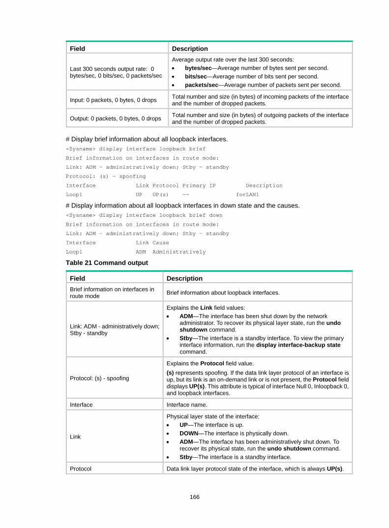
166
Field Description
Last 300 seconds output rate: 0 bytes/sec, 0 bits/sec, 0 packets/sec
Average output rate over the last 300 seconds: • bytes/sec—Average number of bytes sent per second. • bits/sec—Average number of bits sent per second. • packets/sec—Average number of packets sent per second.
Input: 0 packets, 0 bytes, 0 drops Total number and size (in bytes) of incoming packets of the interface and the number of dropped packets.
Output: 0 packets, 0 bytes, 0 drops Total number and size (in bytes) of outgoing packets of the interface and the number of dropped packets.
# Display brief information about all loopback interfaces. <Sysname> display interface loopback brief
Brief information on interfaces in route mode:
Link: ADM - administratively down; Stby - standby
Protocol: (s) - spoofing
Interface Link Protocol Primary IP Description
Loop1 UP UP(s) -- forLAN1
# Display information about all loopback interfaces in down state and the causes. <Sysname> display interface loopback brief down
Brief information on interfaces in route mode:
Link: ADM - administratively down; Stby - standby
Interface Link Cause
Loop1 ADM Administratively
Table 21 Command output
Field Description Brief information on interfaces in route mode Brief information about loopback interfaces.
Link: ADM - administratively down; Stby - standby
Explains the Link field values: • ADM—The interface has been shut down by the network
administrator. To recover its physical layer state, run the undo shutdown command.
• Stby—The interface is a standby interface. To view the primary interface information, run the display interface-backup state command.
Protocol: (s) - spoofing
Explains the Protocol field value. (s) represents spoofing. If the data link layer protocol of an interface is up, but its link is an on-demand link or is not present, the Protocol field displays UP(s). This attribute is typical of interface Null 0, Inloopback 0, and loopback interfaces.
Interface Interface name.
Link
Physical layer state of the interface: • UP—The interface is up. • DOWN—The interface is physically down. • ADM—The interface has been administratively shut down. To
recover its physical state, run the undo shutdown command. • Stby—The interface is a standby interface.
Protocol Data link layer protocol state of the interface, which is always UP(s).
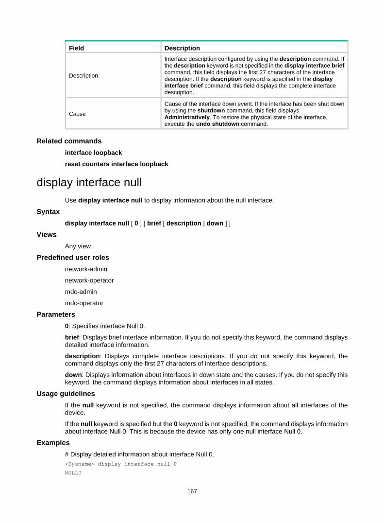
167
Field Description
Description
Interface description configured by using the description command. If the description keyword is not specified in the display interface brief command, this field displays the first 27 characters of the interface description. If the description keyword is specified in the display interface brief command, this field displays the complete interface description.
Cause
Cause of the interface down event. If the interface has been shut down by using the shutdown command, this field displays Administratively. To restore the physical state of the interface, execute the undo shutdown command.
Related commands interface loopback
reset counters interface loopback
display interface null Use display interface null to display information about the null interface.
Syntax display interface null [ 0 ] [ brief [ description | down ] ]
Views Any view
Predefined user roles network-admin
network-operator
mdc-admin
mdc-operator
Parameters 0: Specifies interface Null 0.
brief: Displays brief interface information. If you do not specify this keyword, the command displays detailed interface information.
description: Displays complete interface descriptions. If you do not specify this keyword, the command displays only the first 27 characters of interface descriptions.
down: Displays information about interfaces in down state and the causes. If you do not specify this keyword, the command displays information about interfaces in all states.
Usage guidelines If the null keyword is not specified, the command displays information about all interfaces of the device.
If the null keyword is specified but the 0 keyword is not specified, the command displays information about interface Null 0. This is because the device has only one null interface Null 0.
Examples # Display detailed information about interface Null 0. <Sysname> display interface null 0
NULL0
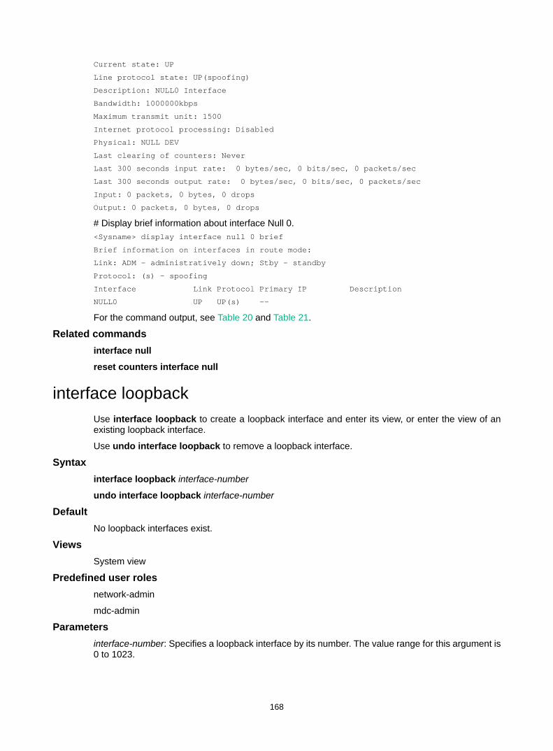
168
Current state: UP
Line protocol state: UP(spoofing)
Description: NULL0 Interface
Bandwidth: 1000000kbps
Maximum transmit unit: 1500
Internet protocol processing: Disabled
Physical: NULL DEV
Last clearing of counters: Never
Last 300 seconds input rate: 0 bytes/sec, 0 bits/sec, 0 packets/sec
Last 300 seconds output rate: 0 bytes/sec, 0 bits/sec, 0 packets/sec
Input: 0 packets, 0 bytes, 0 drops
Output: 0 packets, 0 bytes, 0 drops
# Display brief information about interface Null 0. <Sysname> display interface null 0 brief
Brief information on interfaces in route mode:
Link: ADM - administratively down; Stby - standby
Protocol: (s) - spoofing
Interface Link Protocol Primary IP Description
NULL0 UP UP(s) --
For the command output, see Table 20 and Table 21.
Related commands interface null
reset counters interface null
interface loopback Use interface loopback to create a loopback interface and enter its view, or enter the view of an existing loopback interface.
Use undo interface loopback to remove a loopback interface.
Syntax interface loopback interface-number
undo interface loopback interface-number
Default No loopback interfaces exist.
Views System view
Predefined user roles network-admin
mdc-admin
Parameters interface-number: Specifies a loopback interface by its number. The value range for this argument is 0 to 1023.
169
Usage guidelines The physical layer state and link layer protocols of a loopback interface are always up unless the loopback interface is manually shut down. You can use a loopback interface to achieve the following purposes: • Prevent the connection from being affected by the physical state of the interface. • Improve the reliability of the connection.
For example, you can: • Configure a loopback interface as the source interface for establishing an FTP connection. • Use the loopback interface address as the Router ID in BGP.
Examples # Create interface loopback 1. <Sysname> system-view
[Sysname] interface loopback 1
[Sysname-LoopBack1]
interface null Use interface null to enter null interface view.
Syntax interface null 0
Default A device has only one null interface (Null 0), which cannot be created or deleted.
Views System view
Predefined user roles network-admin
mdc-admin
Parameters 0: Specifies interface Null 0. The null interface number is always 0.
Examples # Enter Null 0 interface view. <Sysname> system-view
[Sysname] interface null 0
[Sysname-NULL0]
reset counters interface loopback Use reset counters interface loopback to clear the statistics on the specified or all loopback interfaces.
Syntax reset counters interface loopback [ interface-number ]
Views User view
170
Predefined user roles network-admin
mdc-admin
Parameters interface-number: Specifies a loopback interface by its number, which can be the number of any existing loopback interface. If you do not specify the interface-number argument, the command clears the statistics on all loopback interfaces.
Usage guidelines To determine whether a loopback interface works correctly within a period by collecting the traffic statistics within that period, first use the reset counters interface [ loopback [ interface-number ] ] command to clear the statistics. Then have the interface automatically collect the statistics.
This command is available only if a minimum of one loopback interface has been created.
Examples # Clear the statistics on loopback interface Loopback 1. <Sysname> reset counters interface loopback 1
Related commands display interface loopback
reset counters interface null Use reset counters interface null to clear the statistics on the null interface.
Syntax reset counters interface null [ 0 ]
Views User view
Predefined user roles network-admin
mdc-admin
Parameters 0: Specifies the number of the null interface, which is always 0.
Usage guidelines To determine whether the null interface works correctly within a period by collecting the traffic statistics within that period, first use the reset counters interface [ null [ 0 ] ] command to clear the statistics. Then have the interface automatically collect the statistics.
Examples # Clear the statistics on interface Null 0. <Sysname> reset counters interface null 0
Related commands display interface null
shutdown Use shutdown to shut down a loopback interface.
171
Use undo shutdown to bring up a loopback interface.
Syntax shutdown
undo shutdown
Default A loopback interface is up.
Views Loopback interface view
Predefined user roles network-admin
mdc-admin
Usage guidelines Use the shutdown command with caution, because the command disconnects the connection of the interface and disables the interface from communicating.
Examples # Shut down interface loopback 1. <Sysname> system-view
[Sysname] interface loopback 1
[Sysname-LoopBack1] shutdown
172
Index A B C D E F I J L M O P R S T U V A
alarm,83 alarm-detect,130 alarm-detect,104 alarm-detect,59
B
bandwidth,160 bandwidth,38 bandwidth,105 bandwidth,5 baudrate,42
C
cable,84 cable (CE1 interface),60 channel-set (CE1 interface),60 clock,130 clock,105 clock,44 clock,84 clock (CE1 interface),61 clock-change auto,62 clock-change auto,70 code,43 code (CE1 interface),62 combo enable,5 controller cpos,131 controller e1,63 controller t3,85 crc,44 crc,71 crc,106
D
dampening,107 dampening,6 data-coding (CE1 interface),64 default,132 default,38 default,108 default,160 default,8 description,8 description,39
description,161 description,132 description,109 detect dcd,45 detect dsr-dtr,46 detect-ais,64 display controller cpos,133 display controller cpos e1,135 display controller cpos t1,137 display controller e1,65 display controller t3,85 display counters,9 display counters rate,11 display ethernet statistics,12 display fe1,72 display interface,15 display interface inloopback,162 display interface loopback,164 display interface null,167 display interface pos,109 display interface range,1 display interface serial,47 duplex,25
E
e1 channel-set,138 e1 clock,139 e1 flag,140 e1 frame-format,140 e1 loopback,141 e1 shutdown,142 e1 unframed,142
F
fe1 alarm-detect,73 fe1 cable,74 fe1 clock,74 fe1 code,75 fe1 data-coding,76 fe1 detect-ais,76 fe1 frame-format,77 fe1 idle-code,78 fe1 itf,78 fe1 loopback,79 fe1 timeslot-list,80 fe1 unframed,81
173
feac,89 flag,143 flag c2,114 flag j0,115 flag j1,116 flag j1 ignore,117 flag sdh,25 flag vc-3,144 flag vc-4,145 flow-interval,117 flow-interval,26 frame-format,90 frame-format,146 frame-format,118 frame-format (CE1 interface),66 ft3,91
I
idle-code,51 idle-code (CE1 interface),67 interface,27 interface loopback,168 interface null,169 interface pos,118 interface range,1 interface range name,3 interface serial,52 invert receive-clock,53 invert transmit-clock,53 itf,54 itf (CE1 interface),68
J
jumboframe enable,27
L
link-delay,147 link-delay,28 link-delay,119 link-protocol,54 link-protocol,120 loopback,121 loopback,29 loopback,147 loopback,92 loopback,55 loopback (CE1 interface),68
M
mdl,93 mtu,35 mtu,56
mtu,81 mtu,121 multiplex mode,148
O
oc-12,149 oc-3,150
P
port link-mode,30 port-mode,30 port-type switch,36 port-type switch,122
R
reset counters controller cpos,150 reset counters controller e1,69 reset counters controller t3,94 reset counters interface,56 reset counters interface,82 reset counters interface,123 reset counters interface,31 reset counters interface loopback,169 reset counters interface null,170 reset ethernet statistics,32 reverse-rts,57
S
scramble,123 shutdown,124 shutdown,170 shutdown,40 shutdown,33 shutdown,151 snmp-agent trap enable { b1-tca | b2-tca | b3-tca },125 speed,33 speed,126 sub-interface rate-statistic,57 sub-interface rate-statistic,34 sub-interface rate-statistic,126
T
t1 alarm,95 t1 channel-set,96 t1 channel-set,152 t1 clock,153 t1 clock,97 t1 fdl,97 t1 flag,153 t1 frame-format,154 t1 frame-format,98

174
t1 loopback,99 t1 loopback,155 t1 sendloopcode,100 t1 show,100 t1 shutdown,101 t1 shutdown,155 t1 unframed,102 t1 unframed,156 threshold,157 threshold,127 timer-hold,40 timer-hold,128
timer-hold retry,128 timer-hold retry,41 traffic-statistic enable,36
U
using,103 using (CE1 interface),70 using oc-12/using oc-12c,158 using oc-3c,158 using oc-48,159
V
virtualbaudrate,58
Copyright © 2022 FDOKUMEN