
H3C MSR Router Series
334
H3C MSR Router Series Comware 5 Interface Command Reference New H3C Technologies Co., Ltd. http://www.h3c.com Software version: MSR-CMW520-R2516 Document version: 20180820-C-1.13
-
Upload
khangminh22 -
Category
Documents
-
view
0 -
download
0
Transcript of H3C MSR Router Series
H3C MSR Router SeriesComware 5 Interface Command Reference
New H3C Technologies Co., Ltd. http://www.h3c.com Software version: MSR-CMW520-R2516 Document version: 20180820-C-1.13

Copyright © 2006-2018, New H3C Technologies Co., Ltd. and its licensors
All rights reserved
No part of this manual may be reproduced or transmitted in any form or by any means without prior written consent of New H3C Technologies Co., Ltd.
Trademarks
H3C, , H3CS, H3CIE, H3CNE, Aolynk, , H3Care, , IRF, NetPilot, Netflow, SecEngine, SecPath, SecCenter, SecBlade, Comware, ITCMM and HUASAN are trademarks of New H3C Technologies Co., Ltd.
All other trademarks that may be mentioned in this manual are the property of their respective owners.
Notice
The information in this document is subject to change without notice. All contents in this document, including statements, information, and recommendations, are believed to be accurate, but they are presented without warranty of any kind, express or implied. H3C shall not be liable for technical or editorial errors or omissions contained herein.
Preface This command reference describes the configuration commands for various interfaces supported by the H3C MSR router series.
This preface includes the following topics about the documentation: • Audience. • Conventions. • Documentation feedback.
Audience This documentation is intended for: • Network planners. • Field technical support and servicing engineers. • Network administrators working with the routers.
Conventions The following information describes the conventions used in the documentation.
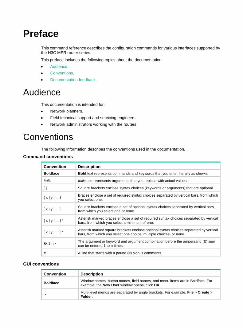
Command conventions
Convention Description Boldface Bold text represents commands and keywords that you enter literally as shown.
Italic Italic text represents arguments that you replace with actual values.
[ ] Square brackets enclose syntax choices (keywords or arguments) that are optional.
{ x | y | ... } Braces enclose a set of required syntax choices separated by vertical bars, from which you select one.
[ x | y | ... ] Square brackets enclose a set of optional syntax choices separated by vertical bars, from which you select one or none.
{ x | y | ... } * Asterisk marked braces enclose a set of required syntax choices separated by vertical bars, from which you select a minimum of one.
[ x | y | ... ] * Asterisk marked square brackets enclose optional syntax choices separated by vertical bars, from which you select one choice, multiple choices, or none.
&<1-n> The argument or keyword and argument combination before the ampersand (&) sign can be entered 1 to n times.
# A line that starts with a pound (#) sign is comments.
GUI conventions
Convention Description
Boldface Window names, button names, field names, and menu items are in Boldface. For example, the New User window opens; click OK.
> Multi-level menus are separated by angle brackets. For example, File > Create > Folder.
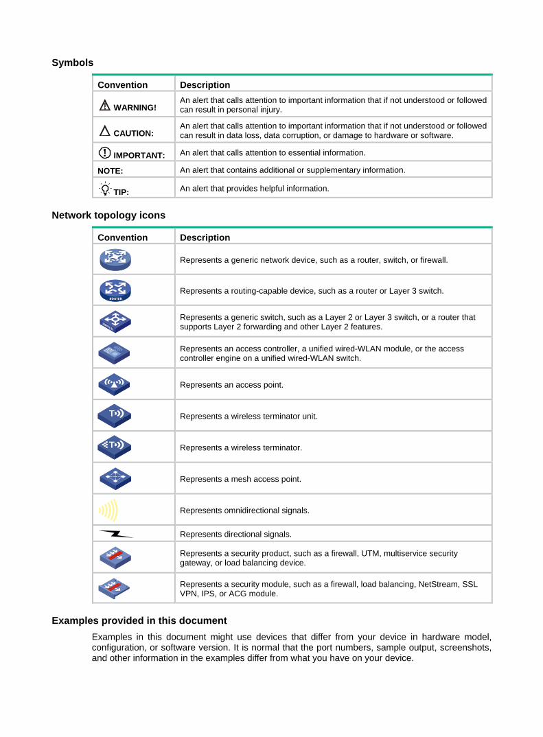
Symbols
Convention Description
WARNING! An alert that calls attention to important information that if not understood or followed can result in personal injury.
CAUTION: An alert that calls attention to important information that if not understood or followed can result in data loss, data corruption, or damage to hardware or software.
IMPORTANT: An alert that calls attention to essential information.
NOTE: An alert that contains additional or supplementary information.
TIP: An alert that provides helpful information.
Network topology icons
Convention Description
Represents a generic network device, such as a router, switch, or firewall.
Represents a routing-capable device, such as a router or Layer 3 switch.
Represents a generic switch, such as a Layer 2 or Layer 3 switch, or a router that supports Layer 2 forwarding and other Layer 2 features.
Represents an access controller, a unified wired-WLAN module, or the access controller engine on a unified wired-WLAN switch.
Represents an access point.
Represents a wireless terminator unit.
Represents a wireless terminator.
Represents a mesh access point.
Represents omnidirectional signals.
Represents directional signals.
Represents a security product, such as a firewall, UTM, multiservice security gateway, or load balancing device.
Represents a security module, such as a firewall, load balancing, NetStream, SSL VPN, IPS, or ACG module.
Examples provided in this document Examples in this document might use devices that differ from your device in hardware model, configuration, or software version. It is normal that the port numbers, sample output, screenshots, and other information in the examples differ from what you have on your device.
TT
TT

Documentation feedback You can e-mail your comments about product documentation to [email protected].
We appreciate your comments.
i
Contents
Ethernet interface configuration commands ··········································· 1
General Ethernet interface and subinterface configuration commands ··················································· 1 bandwidth ·························································································································· 1 combo enable ····················································································································· 1 default ······························································································································· 2 description ························································································································· 3 display interface ·················································································································· 4 duplex ····························································································································· 15 flow-control ······················································································································ 16 flow-interval ······················································································································ 17 interface ·························································································································· 17 link-delay ························································································································· 18 loopback ·························································································································· 19 port link-mode ··················································································································· 20 port link-mode interface-list ·································································································· 21 reset counters interface ······································································································ 21 shutdown ························································································································· 22 speed ····························································································································· 23
Layer 2 Ethernet interface configuration commands ········································································ 24 broadcast-suppression ······································································································· 24 display loopback-detection ·································································································· 25 display counters ················································································································ 26 display counters rate ·········································································································· 27 display port-group manual ··································································································· 28 flow-interval ······················································································································ 29 group-member ·················································································································· 30 jumboframe enable ············································································································ 30 loopback-detection action ···································································································· 32 loopback-detection control enable ························································································· 33 loopback-detection interval-time ··························································································· 33 mdi ································································································································· 34 multicast-suppression ········································································································· 35 port-group manual ············································································································· 36 unicast-suppression ··········································································································· 36
Layer 3 Ethernet interface and subinterface configuration commands ················································· 37 mac-address ···················································································································· 37 mac-address valid-check ···································································································· 38 mtu································································································································· 39 promiscuous ····················································································································· 40 qmtoken ·························································································································· 40
WAN interface configuration commands ·············································· 42
Common WAN interface configuration commands ·········································································· 42 bandwidth ························································································································ 42 default ····························································································································· 43 description ······················································································································· 43 link-delay ························································································································· 44 shutdown ························································································································· 45
Serial, AUX, and AM interface configuration commands ··································································· 45 async mode ····················································································································· 45 baudrate ·························································································································· 46 clock ······························································································································· 47 code ······························································································································· 48 country-code ···················································································································· 49 crc·································································································································· 49 detect ····························································································································· 50 display interface analogmodem ···························································································· 51
ii
display interface aux ·········································································································· 55 display interface serial ········································································································ 59 eliminate-pulse ················································································································· 62 idle-mark ························································································································· 63 invert receive-clock ············································································································ 64 invert transmit-clock ··········································································································· 64 itf ··································································································································· 65 loopback ·························································································································· 65 looptest ··························································································································· 66 mtu································································································································· 67 physical-mode ·················································································································· 68 phy-mru ··························································································································· 68 reset counters interface ······································································································ 69 reset counters interface ······································································································ 69 reset counters interface ······································································································ 70 reverse-rts ······················································································································· 71 timer hold ························································································································ 71 virtualbaudrate ·················································································································· 72
Basic 3G/4G modem configuration commands ··············································································· 72 autodeploy sms enable ······································································································· 72 display cellular ·················································································································· 73 display cellular-ethernet ······································································································ 81 display gps ······················································································································· 85 display interface cellular ······································································································ 87 display interface cellular-ethernet ·························································································· 90 display sms ······················································································································ 94 display sms statistics ·········································································································· 95 dm-port open ···················································································································· 96 gps mode ························································································································ 97 gps nmea ························································································································ 97 ip address cellular-allocated ································································································ 98 lte band ··························································································································· 98 mode cdma ······················································································································ 99 mode td-scdma ··············································································································· 100 mode wcdma ·················································································································· 100 modem auto-recovery enable ····························································································· 101 modem reboot ················································································································ 101 modem response ············································································································ 102 pin modify ······················································································································ 103 pin unlock ······················································································································ 103 pin verification ················································································································ 104 pin verify ························································································································ 104 plmn search ··················································································································· 105 plmn select ···················································································································· 105 profile create ·················································································································· 106 profile main ···················································································································· 107 recovery track ················································································································· 107 reset counters interface cellular ·························································································· 109 reset counters interface cellular-ethernet ·············································································· 109 rssi ······························································································································· 110 sms delete ····················································································································· 111 sms forward ··················································································································· 111 sms send ······················································································································· 112 sms sending-enable ········································································································· 113 snmp-agent trap enable sms ······························································································ 113 standby rssi ···················································································································· 114 trust-imsi ······················································································································· 115
Basic CE1/PRI interface configuration commands ········································································· 115 alarm ···························································································································· 115 cable (CE1/PRI interface) ·································································································· 116 channel-set (CE1/PRI interface) ························································································· 117 clock (CE1/PRI interface) ·································································································· 118

iii
clock-change auto ··········································································································· 118 code (CE1/PRI interface) ·································································································· 119 controller e1 ··················································································································· 120 crc································································································································ 120 data-coding (CE1/PRI interface) ························································································· 121 detect-ais ······················································································································· 121 display controller e1 ········································································································· 122 error-diffusion restraint config ····························································································· 123 error-diffusion restraint enable ···························································································· 124 error-diffusion restraint restart-channel ················································································· 125 frame-format (CE1/PRI interface) ························································································ 126 idlecode (CE1/PRI interface) ······························································································ 127 itf (CE1/PRI interface) ······································································································ 127 loopback (CE1/PRI interface) ····························································································· 128 looptest (CE1/PRI interface) ······························································································ 129 pri-set (CE1/PRI interface) ································································································ 130 reset counters controller e1 ······························································································· 131 using (CE1/PRI interface) ·································································································· 131
Basic CT1/PRI interface configuration commands ········································································· 132 alarm (CT1/PRI interface) ································································································· 132 alarm-threshold ··············································································································· 132 bert (CT1/PRI interface) ···································································································· 133 cable (CT1/PRI interface) ·································································································· 134 channel-set (CT1/PRI interface) ························································································· 135 clock (CT1/PRI interface) ·································································································· 136 code (CT1/PRI interface) ·································································································· 137 controller t1 ···················································································································· 137 crc································································································································ 138 data-coding (CT1/PRI interface) ························································································· 138 display controller t1 ·········································································································· 139 error-diffusion restraint config ····························································································· 142 error-diffusion restraint enable ···························································································· 143 error-diffusion restraint restart-channel ················································································· 144 fdl ································································································································ 145 frame-format (CT1/PRI interface) ························································································ 146 idlecode (CT1/PRI interface) ······························································································ 146 itf (CT1/PRI interface) ······································································································· 147 loopback (CT1/PRI interface) ····························································································· 148 looptest (CT1/PRI interface) ······························································································ 148 pri-set (CT1/PRI interface) ································································································· 150 reset counters controller t1 ································································································ 150 sendloopcode ················································································································· 151
E1-F interface configuration commands ······················································································ 152 clock-change auto ··········································································································· 152 crc································································································································ 153 display fe1 ····················································································································· 153 fe1 alarm ······················································································································· 155 fe1 cable ······················································································································· 155 fe1 clock ························································································································ 156 fe1 code ························································································································ 156 fe1 data-coding ··············································································································· 157 fe1 frame-format ············································································································· 158 fe1 idlecode ··················································································································· 158 fe1 itf ···························································································································· 159 fe1 loopback ··················································································································· 160 fe1 timeslot-list ················································································································ 160 fe1 unframed ·················································································································· 161
T1-F interface configuration commands ······················································································ 162 crc································································································································ 162 display ft1 ······················································································································ 162 ft1 alarm ························································································································ 166 ft1 alarm-threshold ··········································································································· 166
iv
ft1 bert ·························································································································· 168 ft1 cable ························································································································ 168 ft1 clock ························································································································· 169 ft1 code ························································································································· 170 ft1 data-coding ················································································································ 170 ft1 fdl ···························································································································· 171 ft1 frame-format ·············································································································· 172 ft1 idlecode ···················································································································· 172 ft1 itf ····························································································································· 173 ft1 loopback ··················································································································· 174 ft1 sendloopcode ············································································································· 175 ft1 timeslot-list ················································································································ 176
Basic CE3 interface configuration commands ·············································································· 176 bert (CE3 interface) ········································································································· 176 clock (CE3 interface) ········································································································ 177 controller e3 ··················································································································· 178 crc································································································································ 178 display controller e3 ········································································································· 179 e1 bert ·························································································································· 182 e1 channel-set ················································································································ 183 e1 set clock ···················································································································· 184 e1 set frame-format ········································································································· 185 e1 set loopback ··············································································································· 186 e1 shutdown ··················································································································· 186 e1 unframed ··················································································································· 187 fe3 ······························································································································· 188 loopback (CE3 interface) ··································································································· 189 national-bit ····················································································································· 189 reset counters controller e3 ······························································································· 190 using (CE3 interface) ······································································································· 190
Basic CT3 interface configuration commands ··············································································· 191 alarm (CT3 interface) ······································································································· 191 bert (CT3 interface) ·········································································································· 192 cable (CT3 interface) ········································································································ 193 clock (CT3 interface) ········································································································ 194 controller t3 ···················································································································· 194 crc································································································································ 195 display controller t3 ·········································································································· 196 feac ······························································································································ 199 frame-format (CT3 interface) ······························································································ 201 ft3 ································································································································ 201 loopback (CT3 interface) ··································································································· 202 mdl (CT3 interface) ·········································································································· 203 reset counters controller t3 ································································································ 204 t1 alarm ························································································································· 205 t1 bert ··························································································································· 206 t1 channel-set ················································································································· 207 t1 sendloopcode ·············································································································· 208 t1 set clock ····················································································································· 208 t1 set fdl ························································································································ 209 t1 set frame-format ·········································································································· 210 t1 set loopback ··············································································································· 211 t1 show ························································································································· 211 t1 shutdown ··················································································································· 213 t1 unframed ···················································································································· 213 using (CT3 interface) ········································································································ 214
ISDN BRI interface configuration commands ··············································································· 214 display interface bri ·········································································································· 215 loopback (ISDN BRI interface) ··························································································· 218 mtu (ISDN BRI interface) ·································································································· 219 reset counters interface ···································································································· 219

v
ATM and DSL interface configuration commands ································ 221
Common ATM and DSL interface configuration commands ····························································· 221 bandwidth ······················································································································ 221 default ··························································································································· 221 description ····················································································································· 222 display interface atm ········································································································ 223 interface atm ·················································································································· 225 reset atm interface ··········································································································· 226 reset counters interface ···································································································· 226 shutdown ······················································································································· 227
IMA-E1/T1 interface configuration commands ·············································································· 227 cable (ATM E1 interface) ·································································································· 228 cable (ATM T1 interface) ··································································································· 229 clock ····························································································································· 229 clock-change auto ··········································································································· 230 code ····························································································································· 231 differential-delay ·············································································································· 231 display interface ima-group ································································································ 232 frame-format ·················································································································· 235 frame-length ··················································································································· 235 ima ima-group ················································································································ 236 ima-clock ······················································································································· 237 ima-standard ·················································································································· 237 ima-test ························································································································· 238 interface ima-group ·········································································································· 239 loopback ························································································································ 239 min-active-links ··············································································································· 240 scramble ······················································································································· 240
ATM E3/T3 interface configuration commands ············································································· 241 cable ···························································································································· 241 clock ····························································································································· 242 frame-format ·················································································································· 243 loopback ························································································································ 243 scramble ······················································································································· 244
ATM OC-3c/STM-1 interface configuration commands ··································································· 245 clock ····························································································································· 245 flag ······························································································································· 246 frame-format ·················································································································· 247 loopback ························································································································ 247 scramble ······················································································································· 248
ADSL interface configuration commands ····················································································· 249 activate ························································································································· 249 adsl standard ·················································································································· 250 adsl tx-attenuation ··········································································································· 251 bootrom update file ·········································································································· 251 display dsl configuration ···································································································· 252 display dsl status ············································································································· 253 display dsl version ··········································································································· 255
G.SHDSL interface configuration commands ··············································································· 256 activate ························································································································· 257 display dsl configuration ···································································································· 258 display dsl status ············································································································· 259 display dsl version ··········································································································· 263 shdsl annex ···················································································································· 264 shdsl capability ··············································································································· 265 shdsl line-probing ············································································································ 265 shdsl mode ···················································································································· 266 shdsl pam ······················································································································ 266 shdsl pbo ······················································································································· 267 shdsl psd ······················································································································· 268 shdsl rate ······················································································································· 268
vi
shdsl snr-margin ············································································································· 269 shdsl wire ······················································································································ 270
EFM interface configuration commands ······················································································ 271 interface efm ·················································································································· 272
POS interface configuration commands ············································ 273
bandwidth ······················································································································ 273 clock ····························································································································· 274 crc································································································································ 274 default ··························································································································· 275 description ····················································································································· 275 display interface pos ········································································································ 276 flag ······························································································································· 279 frame-format ·················································································································· 281 link-protocol ··················································································································· 281 loopback ························································································································ 282 mtu······························································································································· 282 reset counters interface ···································································································· 283 scramble ······················································································································· 284 shutdown ······················································································································· 284
CPOS interface configuration commands ·········································· 286
bandwidth ······················································································································ 286 clock ····························································································································· 287 controller cpos ················································································································ 287 default ··························································································································· 288 description ····················································································································· 288 display controller cpos ······································································································ 289 display controller cpos e1 ·································································································· 291 display controller cpos t1 ··································································································· 293 e1 channel-set ················································································································ 294 e1 set clock ···················································································································· 295 e1 set flag ······················································································································ 295 e1 set frame-format ········································································································· 296 e1 set loopback ··············································································································· 297 e1 shutdown ··················································································································· 298 e1 unframed ··················································································································· 298 flag ······························································································································· 299 frame-format ·················································································································· 300 loopback ························································································································ 300 multiplex mode ··············································································································· 301 reset counters controller cpos ···························································································· 302 shutdown ······················································································································· 302 t1 channel-set ················································································································· 303 t1 set clock ····················································································································· 304 t1 set flag ······················································································································· 304 t1 set frame-format ·········································································································· 305 t1 set loopback ··············································································································· 306 t1 shutdown ··················································································································· 306 t1 unframed ···················································································································· 307
Loopback and null interface configuration commands ·························· 309
bandwidth ······················································································································ 309 default ··························································································································· 309 description ····················································································································· 310 display interface loopback ································································································· 311 display interface null ········································································································ 314 interface loopback ··········································································································· 315 interface null ··················································································································· 316 reset counters interface loopback ······················································································· 316 reset counters interface null ······························································································· 317 shutdown ······················································································································· 317

vii
Index ························································································· 319

1
Ethernet interface configuration commands General Ethernet interface and subinterface configuration commands bandwidth
Use bandwidth to set the intended bandwidth for an Ethernet interface.
Use undo bandwidth to cancel the configuration.
Syntax bandwidth bandwidth-value
undo bandwidth
Views Ethernet interface/subinterface view
Default command level 2: System level
Parameters bandwidth-value: Sets the intended bandwidth in the range of 1 to 4294967295 kbps.
Usage guidelines You can obtain the intended bandwidth of an interface by querying the ifspeed value of the MIB node with third-party software.
The intended bandwidth is used by network management systems for monitoring bandwidth, but does not affect the actual bandwidth of the interface.
Examples # Set the intended bandwidth to 10,000 kbps for interface Ethernet 1/1. <Sysname> system-view
[Sysname] interface ethernet 1/1
[Sysname-Ethernet1/1] bandwidth 10000
combo enable Use combo enable to activate the copper or fiber combo port.
Syntax combo enable { copper | fiber }
Default The copper combo port is activated.
Views Ethernet interface view (combo interface)
2
Default command level 2: System level
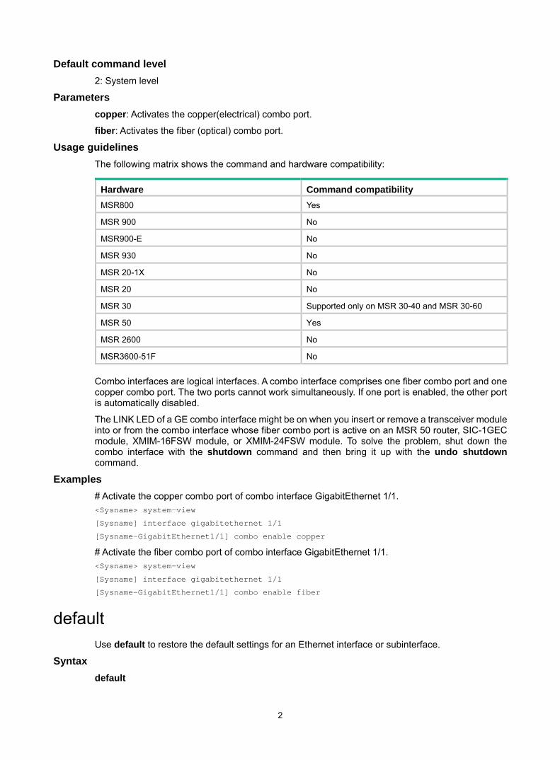
Parameters copper: Activates the copper(electrical) combo port. fiber: Activates the fiber (optical) combo port.
Usage guidelines The following matrix shows the command and hardware compatibility:
Hardware Command compatibility MSR800 Yes
MSR 900 No
MSR900-E No
MSR 930 No
MSR 20-1X No
MSR 20 No
MSR 30 Supported only on MSR 30-40 and MSR 30-60
MSR 50 Yes
MSR 2600 No
MSR3600-51F No
Combo interfaces are logical interfaces. A combo interface comprises one fiber combo port and one copper combo port. The two ports cannot work simultaneously. If one port is enabled, the other port is automatically disabled.
The LINK LED of a GE combo interface might be on when you insert or remove a transceiver module into or from the combo interface whose fiber combo port is active on an MSR 50 router, SIC-1GEC module, XMIM-16FSW module, or XMIM-24FSW module. To solve the problem, shut down the combo interface with the shutdown command and then bring it up with the undo shutdown command.
Examples # Activate the copper combo port of combo interface GigabitEthernet 1/1. <Sysname> system-view
[Sysname] interface gigabitethernet 1/1
[Sysname-GigabitEthernet1/1] combo enable copper
# Activate the fiber combo port of combo interface GigabitEthernet 1/1. <Sysname> system-view
[Sysname] interface gigabitethernet 1/1
[Sysname-GigabitEthernet1/1] combo enable fiber
default Use default to restore the default settings for an Ethernet interface or subinterface.
Syntax default
3
Views Ethernet interface view, Ethernet subinterface view
Default command level 2: System level
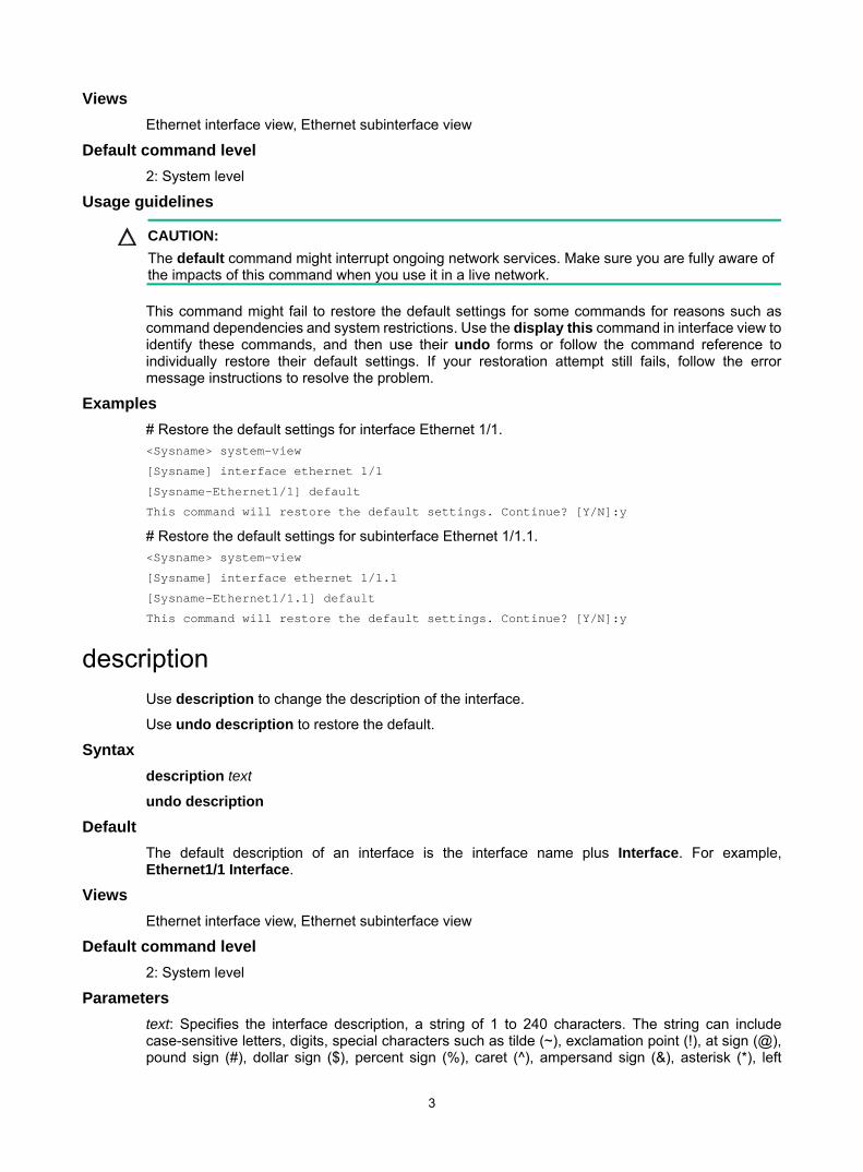
Usage guidelines
CAUTION: The default command might interrupt ongoing network services. Make sure you are fully aware of the impacts of this command when you use it in a live network.
This command might fail to restore the default settings for some commands for reasons such as command dependencies and system restrictions. Use the display this command in interface view to identify these commands, and then use their undo forms or follow the command reference to individually restore their default settings. If your restoration attempt still fails, follow the error message instructions to resolve the problem.
Examples # Restore the default settings for interface Ethernet 1/1. <Sysname> system-view
[Sysname] interface ethernet 1/1
[Sysname-Ethernet1/1] default
This command will restore the default settings. Continue? [Y/N]:y
# Restore the default settings for subinterface Ethernet 1/1.1. <Sysname> system-view
[Sysname] interface ethernet 1/1.1
[Sysname-Ethernet1/1.1] default
This command will restore the default settings. Continue? [Y/N]:y
description Use description to change the description of the interface.
Use undo description to restore the default.
Syntax description text
undo description
Default The default description of an interface is the interface name plus Interface. For example, Ethernet1/1 Interface.
Views Ethernet interface view, Ethernet subinterface view
Default command level 2: System level
Parameters text: Specifies the interface description, a string of 1 to 240 characters. The string can include case-sensitive letters, digits, special characters such as tilde (~), exclamation point (!), at sign (@), pound sign (#), dollar sign ($), percent sign (%), caret (^), ampersand sign (&), asterisk (*), left
4
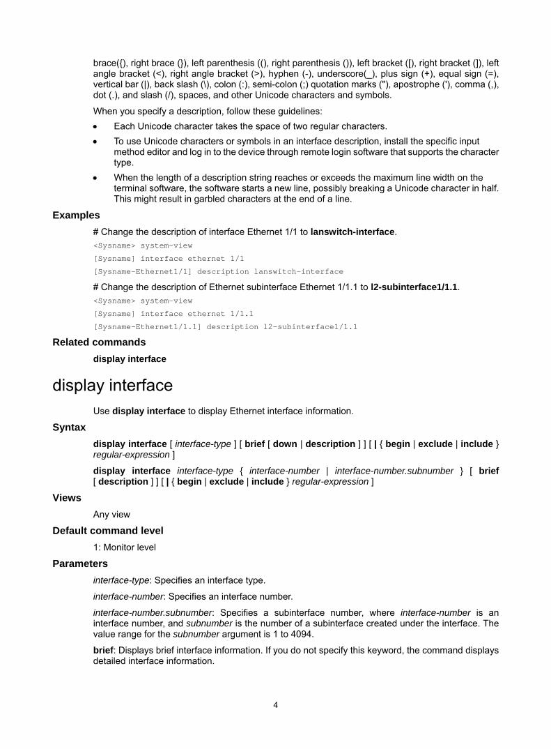
brace({), right brace (}), left parenthesis ((), right parenthesis ()), left bracket ([), right bracket (]), left angle bracket (<), right angle bracket (>), hyphen (-), underscore(_), plus sign (+), equal sign (=), vertical bar (|), back slash (\), colon (:), semi-colon (;) quotation marks ("), apostrophe ('), comma (,), dot (.), and slash (/), spaces, and other Unicode characters and symbols.
When you specify a description, follow these guidelines: • Each Unicode character takes the space of two regular characters. • To use Unicode characters or symbols in an interface description, install the specific input
method editor and log in to the device through remote login software that supports the character type.
• When the length of a description string reaches or exceeds the maximum line width on the terminal software, the software starts a new line, possibly breaking a Unicode character in half. This might result in garbled characters at the end of a line.
Examples # Change the description of interface Ethernet 1/1 to lanswitch-interface. <Sysname> system-view
[Sysname] interface ethernet 1/1
[Sysname-Ethernet1/1] description lanswitch-interface
# Change the description of Ethernet subinterface Ethernet 1/1.1 to l2-subinterface1/1.1. <Sysname> system-view
[Sysname] interface ethernet 1/1.1
[Sysname-Ethernet1/1.1] description l2-subinterface1/1.1
Related commands display interface
display interface Use display interface to display Ethernet interface information.
Syntax display interface [ interface-type ] [ brief [ down | description ] ] [ | { begin | exclude | include } regular-expression ]
display interface interface-type { interface-number | interface-number.subnumber } [ brief [ description ] ] [ | { begin | exclude | include } regular-expression ]
Views Any view
Default command level 1: Monitor level
Parameters interface-type: Specifies an interface type.
interface-number: Specifies an interface number.
interface-number.subnumber: Specifies a subinterface number, where interface-number is an interface number, and subnumber is the number of a subinterface created under the interface. The value range for the subnumber argument is 1 to 4094.
brief: Displays brief interface information. If you do not specify this keyword, the command displays detailed interface information.
5
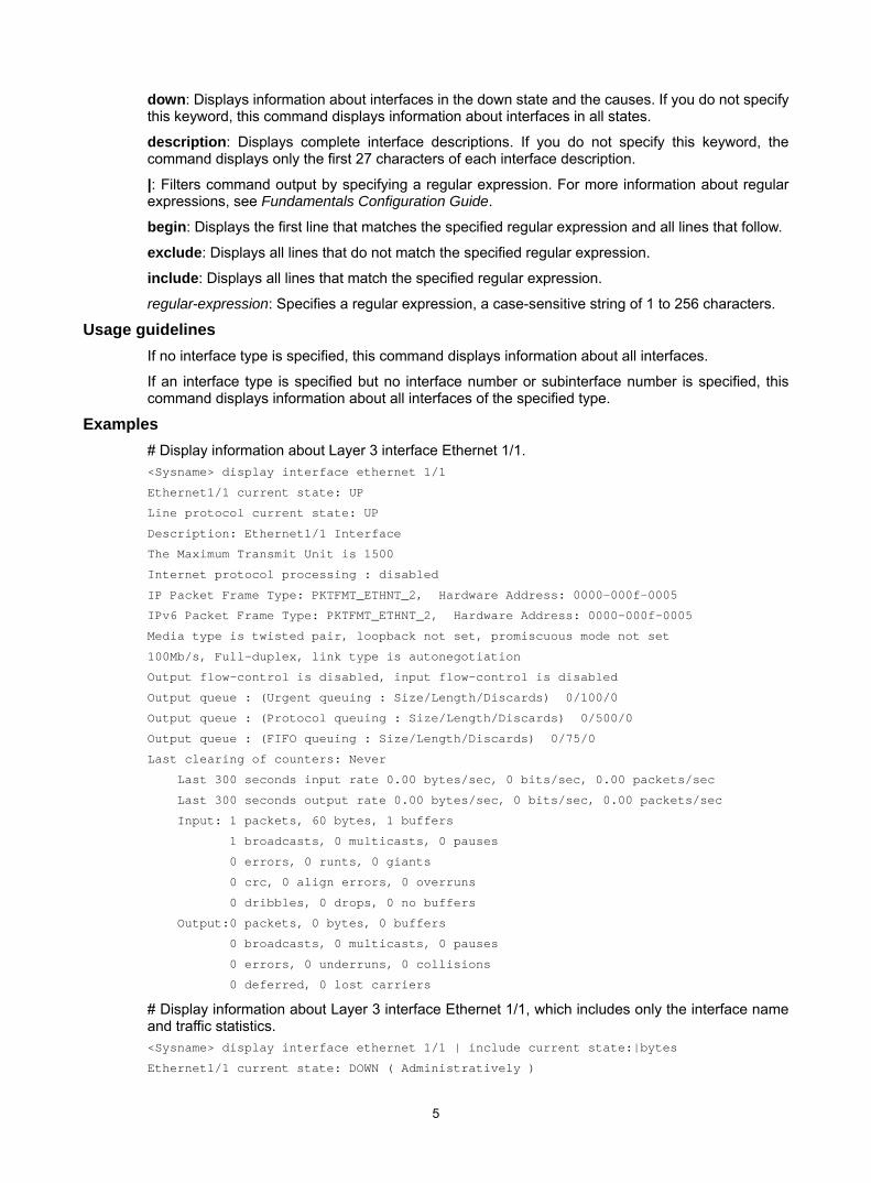
down: Displays information about interfaces in the down state and the causes. If you do not specify this keyword, this command displays information about interfaces in all states.
description: Displays complete interface descriptions. If you do not specify this keyword, the command displays only the first 27 characters of each interface description.
|: Filters command output by specifying a regular expression. For more information about regular expressions, see Fundamentals Configuration Guide.
begin: Displays the first line that matches the specified regular expression and all lines that follow.
exclude: Displays all lines that do not match the specified regular expression.
include: Displays all lines that match the specified regular expression.
regular-expression: Specifies a regular expression, a case-sensitive string of 1 to 256 characters.
Usage guidelines If no interface type is specified, this command displays information about all interfaces.
If an interface type is specified but no interface number or subinterface number is specified, this command displays information about all interfaces of the specified type.
Examples # Display information about Layer 3 interface Ethernet 1/1. <Sysname> display interface ethernet 1/1
Ethernet1/1 current state: UP
Line protocol current state: UP
Description: Ethernet1/1 Interface
The Maximum Transmit Unit is 1500
Internet protocol processing : disabled
IP Packet Frame Type: PKTFMT_ETHNT_2, Hardware Address: 0000-000f-0005
IPv6 Packet Frame Type: PKTFMT_ETHNT_2, Hardware Address: 0000-000f-0005
Media type is twisted pair, loopback not set, promiscuous mode not set
100Mb/s, Full-duplex, link type is autonegotiation
Output flow-control is disabled, input flow-control is disabled
Output queue : (Urgent queuing : Size/Length/Discards) 0/100/0
Output queue : (Protocol queuing : Size/Length/Discards) 0/500/0
Output queue : (FIFO queuing : Size/Length/Discards) 0/75/0
Last clearing of counters: Never
Last 300 seconds input rate 0.00 bytes/sec, 0 bits/sec, 0.00 packets/sec
Last 300 seconds output rate 0.00 bytes/sec, 0 bits/sec, 0.00 packets/sec
Input: 1 packets, 60 bytes, 1 buffers
1 broadcasts, 0 multicasts, 0 pauses
0 errors, 0 runts, 0 giants
0 crc, 0 align errors, 0 overruns
0 dribbles, 0 drops, 0 no buffers
Output:0 packets, 0 bytes, 0 buffers
0 broadcasts, 0 multicasts, 0 pauses
0 errors, 0 underruns, 0 collisions
0 deferred, 0 lost carriers
# Display information about Layer 3 interface Ethernet 1/1, which includes only the interface name and traffic statistics. <Sysname> display interface ethernet 1/1 | include current state:|bytes
Ethernet1/1 current state: DOWN ( Administratively )

6
Line protocol current state: DOWN
Last 300 seconds input rate 0.00 bytes/sec, 0 bits/sec, 0.00 packets/sec
Last 300 seconds output rate 0.00 bytes/sec, 0 bits/sec, 0.00 packets/sec
Input: 0 packets, 0 bytes, 0 buffers
Output:0 packets, 0 bytes, 0 buffers
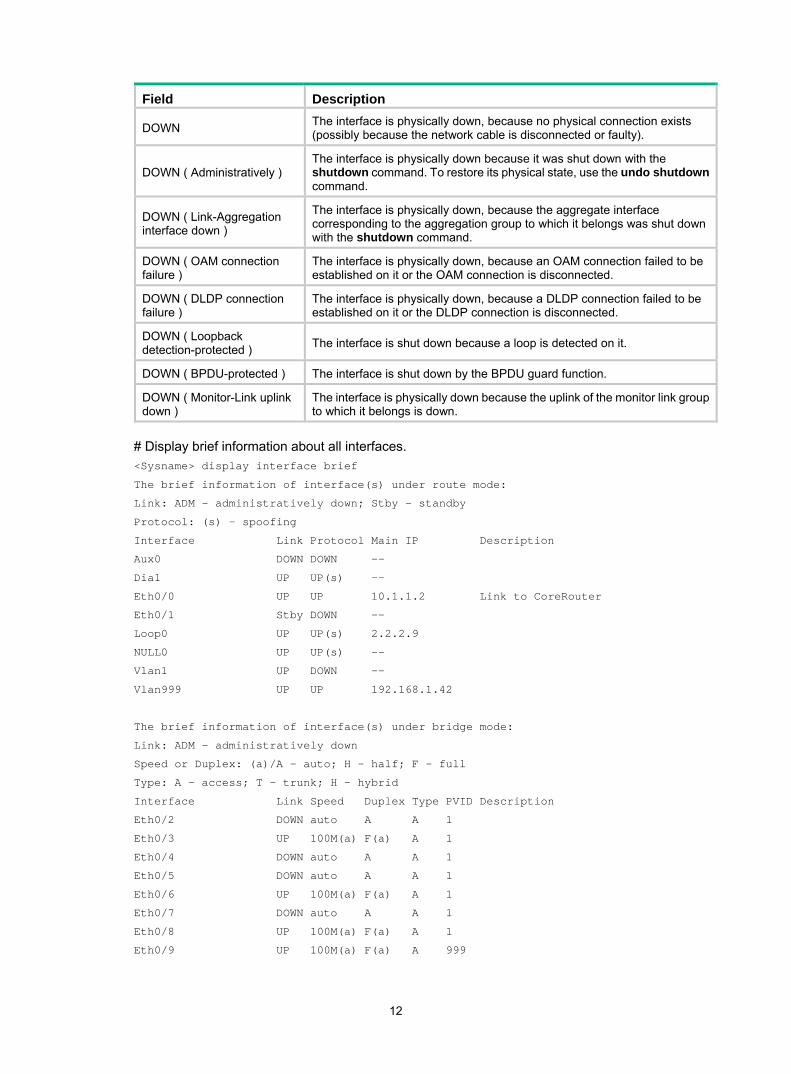
# Display brief information about all interfaces. <Sysname> display interface brief description
The brief information of interface(s) under route mode:
Link: ADM - administratively down; Stby - standby
Protocol: (s) - spoofing
Interface Link Protocol Main IP Description
Aux0 UP UP --
Cellular0/0 DOWN DOWN --
GE0/0 UP UP 192.168.100.1 The interface for connecting RouterA.
Loop0 UP UP(s) -- --
MP0 DOWN DOWN --
NULL0 UP UP(s) -- --
Vlan1 DOWN DOWN 192.168.1.1
The brief information of interface(s) under bridge mode:
Link: ADM - administratively down; Stby - standby
Speed or Duplex: (a)/A - auto; H - half; F - full
Type: A - access; T - trunk; H - hybrid
Interface Link Speed Duplex Type PVID Description
GE0/1 DOWN auto A A 1
GE0/2 DOWN auto A A 1
GE0/3 DOWN auto A A 1
GE0/4 DOWN auto A A 1
Table 1 Command output
Field Description
Ethernet1/1 current state
State of the Ethernet interface: • DOWN ( Administratively )—The Ethernet interface was shut down
with the shutdown command. The interface is administratively down.
• DOWN ( Link-Aggregation interface down )—The Ethernet interface is physically down because the aggregate interface corresponding to the aggregation group to which the Ethernet interface belongs was shut down with the shutdown command.
• DOWN—The Ethernet interface is administratively up but physically down (possibly because no physical link is present or the link has failed).
• UP—The Ethernet interface is both administratively and physically up.
Line protocol current state Link layer state of the interface: • DOWN—The interface is physically down. • UP—The interface is physically up.
Internet protocol processing Disabled indicates that IP packets cannot be processed. For an interface configured with an IP address, this field changes to Internet Address is.
7
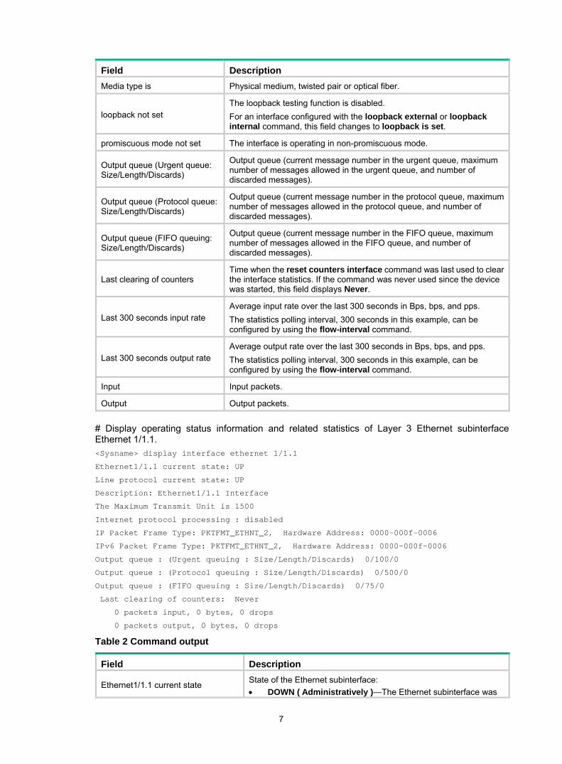
Field Description Media type is Physical medium, twisted pair or optical fiber.
loopback not set The loopback testing function is disabled. For an interface configured with the loopback external or loopback internal command, this field changes to loopback is set.
promiscuous mode not set The interface is operating in non-promiscuous mode.
Output queue (Urgent queue: Size/Length/Discards)
Output queue (current message number in the urgent queue, maximum number of messages allowed in the urgent queue, and number of discarded messages).
Output queue (Protocol queue: Size/Length/Discards)
Output queue (current message number in the protocol queue, maximum number of messages allowed in the protocol queue, and number of discarded messages).
Output queue (FIFO queuing: Size/Length/Discards)
Output queue (current message number in the FIFO queue, maximum number of messages allowed in the FIFO queue, and number of discarded messages).
Last clearing of counters Time when the reset counters interface command was last used to clear the interface statistics. If the command was never used since the device was started, this field displays Never.
Last 300 seconds input rate Average input rate over the last 300 seconds in Bps, bps, and pps. The statistics polling interval, 300 seconds in this example, can be configured by using the flow-interval command.
Last 300 seconds output rate Average output rate over the last 300 seconds in Bps, bps, and pps. The statistics polling interval, 300 seconds in this example, can be configured by using the flow-interval command.
Input Input packets.
Output Output packets.
# Display operating status information and related statistics of Layer 3 Ethernet subinterface Ethernet 1/1.1. <Sysname> display interface ethernet 1/1.1
Ethernet1/1.1 current state: UP
Line protocol current state: UP
Description: Ethernet1/1.1 Interface
The Maximum Transmit Unit is 1500
Internet protocol processing : disabled
IP Packet Frame Type: PKTFMT_ETHNT_2, Hardware Address: 0000-000f-0006
IPv6 Packet Frame Type: PKTFMT_ETHNT_2, Hardware Address: 0000-000f-0006
Output queue : (Urgent queuing : Size/Length/Discards) 0/100/0
Output queue : (Protocol queuing : Size/Length/Discards) 0/500/0
Output queue : (FIFO queuing : Size/Length/Discards) 0/75/0
Last clearing of counters: Never
0 packets input, 0 bytes, 0 drops
0 packets output, 0 bytes, 0 drops
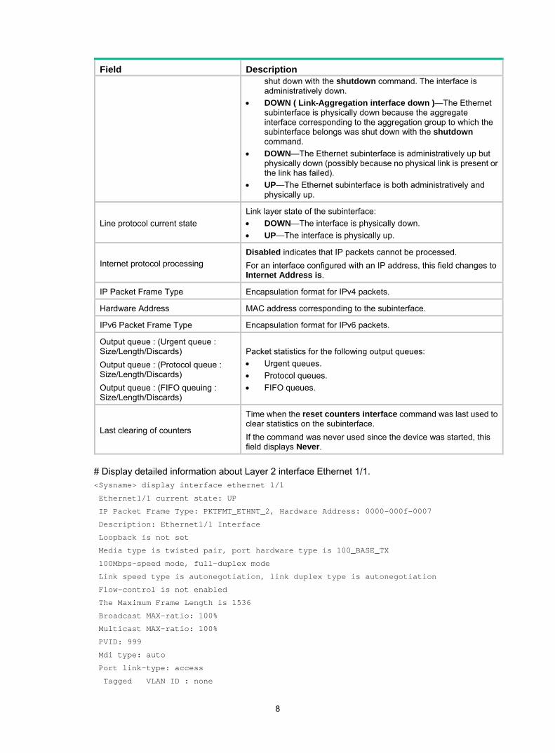
Table 2 Command output
Field Description
Ethernet1/1.1 current state State of the Ethernet subinterface: • DOWN ( Administratively )—The Ethernet subinterface was
8
Field Description shut down with the shutdown command. The interface is administratively down.
• DOWN ( Link-Aggregation interface down )—The Ethernet subinterface is physically down because the aggregate interface corresponding to the aggregation group to which the subinterface belongs was shut down with the shutdown command.
• DOWN—The Ethernet subinterface is administratively up but physically down (possibly because no physical link is present or the link has failed).
• UP—The Ethernet subinterface is both administratively and physically up.
Line protocol current state Link layer state of the subinterface: • DOWN—The interface is physically down. • UP—The interface is physically up.
Internet protocol processing Disabled indicates that IP packets cannot be processed. For an interface configured with an IP address, this field changes to Internet Address is.
IP Packet Frame Type Encapsulation format for IPv4 packets.
Hardware Address MAC address corresponding to the subinterface.
IPv6 Packet Frame Type Encapsulation format for IPv6 packets.
Output queue : (Urgent queue : Size/Length/Discards) Output queue : (Protocol queue : Size/Length/Discards) Output queue : (FIFO queuing : Size/Length/Discards)
Packet statistics for the following output queues: • Urgent queues. • Protocol queues. • FIFO queues.
Last clearing of counters
Time when the reset counters interface command was last used to clear statistics on the subinterface. If the command was never used since the device was started, this field displays Never.
# Display detailed information about Layer 2 interface Ethernet 1/1. <Sysname> display interface ethernet 1/1
Ethernet1/1 current state: UP
IP Packet Frame Type: PKTFMT_ETHNT_2, Hardware Address: 0000-000f-0007
Description: Ethernet1/1 Interface
Loopback is not set
Media type is twisted pair, port hardware type is 100_BASE_TX
100Mbps-speed mode, full-duplex mode
Link speed type is autonegotiation, link duplex type is autonegotiation
Flow-control is not enabled
The Maximum Frame Length is 1536
Broadcast MAX-ratio: 100%
Multicast MAX-ratio: 100%
PVID: 999
Mdi type: auto
Port link-type: access
Tagged VLAN ID : none
9
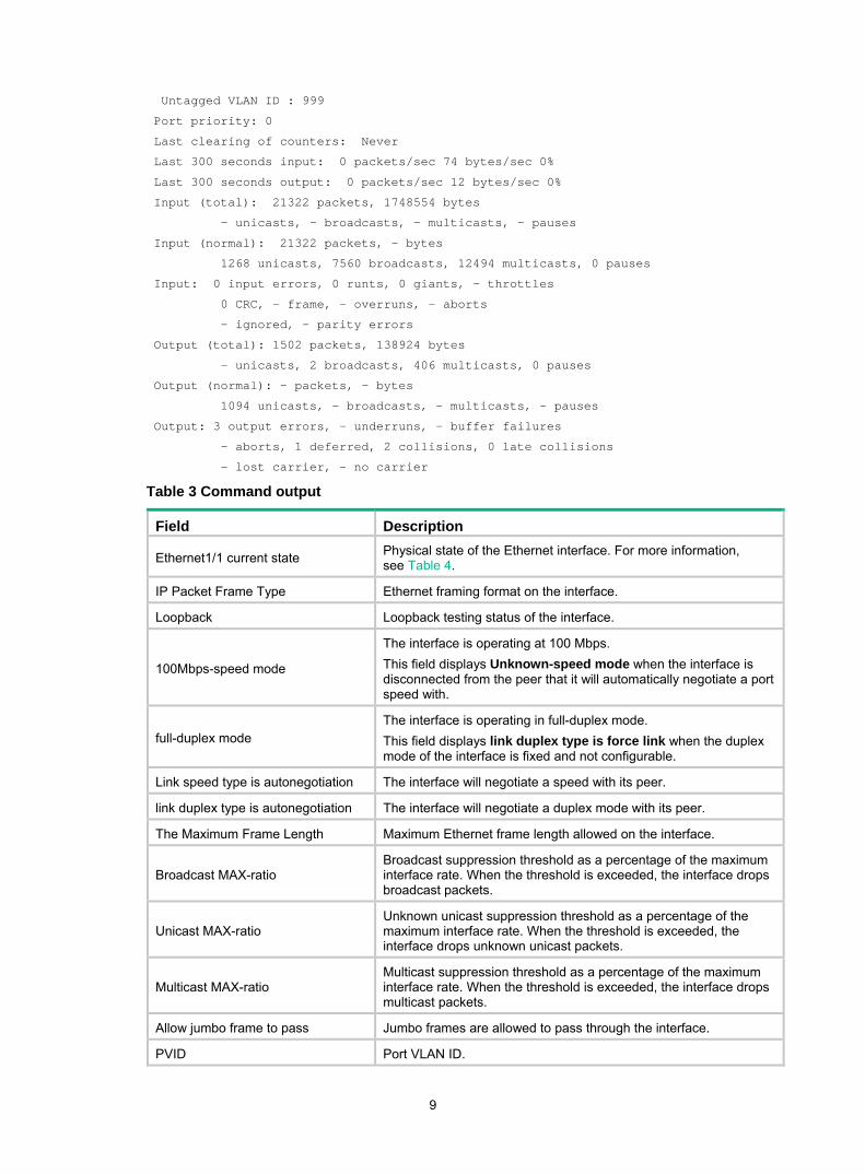
Untagged VLAN ID : 999
Port priority: 0
Last clearing of counters: Never
Last 300 seconds input: 0 packets/sec 74 bytes/sec 0%
Last 300 seconds output: 0 packets/sec 12 bytes/sec 0%
Input (total): 21322 packets, 1748554 bytes
- unicasts, - broadcasts, - multicasts, - pauses
Input (normal): 21322 packets, - bytes
1268 unicasts, 7560 broadcasts, 12494 multicasts, 0 pauses
Input: 0 input errors, 0 runts, 0 giants, - throttles
0 CRC, - frame, - overruns, - aborts
- ignored, - parity errors
Output (total): 1502 packets, 138924 bytes
- unicasts, 2 broadcasts, 406 multicasts, 0 pauses
Output (normal): - packets, - bytes
1094 unicasts, - broadcasts, - multicasts, - pauses
Output: 3 output errors, - underruns, - buffer failures
- aborts, 1 deferred, 2 collisions, 0 late collisions
- lost carrier, - no carrier
Table 3 Command output
Field Description
Ethernet1/1 current state Physical state of the Ethernet interface. For more information, see Table 4.
IP Packet Frame Type Ethernet framing format on the interface.
Loopback Loopback testing status of the interface.
100Mbps-speed mode
The interface is operating at 100 Mbps. This field displays Unknown-speed mode when the interface is disconnected from the peer that it will automatically negotiate a port speed with.
full-duplex mode The interface is operating in full-duplex mode. This field displays link duplex type is force link when the duplex mode of the interface is fixed and not configurable.
Link speed type is autonegotiation The interface will negotiate a speed with its peer.
link duplex type is autonegotiation The interface will negotiate a duplex mode with its peer.
The Maximum Frame Length Maximum Ethernet frame length allowed on the interface.
Broadcast MAX-ratio Broadcast suppression threshold as a percentage of the maximum interface rate. When the threshold is exceeded, the interface drops broadcast packets.
Unicast MAX-ratio Unknown unicast suppression threshold as a percentage of the maximum interface rate. When the threshold is exceeded, the interface drops unknown unicast packets.
Multicast MAX-ratio Multicast suppression threshold as a percentage of the maximum interface rate. When the threshold is exceeded, the interface drops multicast packets.
Allow jumbo frame to pass Jumbo frames are allowed to pass through the interface.
PVID Port VLAN ID.
10
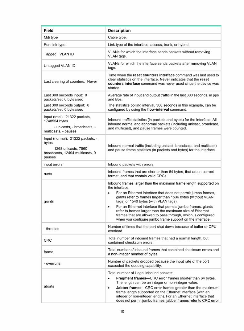
Field Description Mdi type Cable type.
Port link-type Link type of the interface: access, trunk, or hybrid.
Tagged VLAN ID VLANs for which the interface sends packets without removing VLAN tags.
Untagged VLAN ID VLANs for which the interface sends packets after removing VLAN tags.
Last clearing of counters: Never
Time when the reset counters interface command was last used to clear statistics on the interface. Never indicates that the reset counters interface command was never used since the device was started.
Last 300 seconds input: 0 packets/sec 0 bytes/sec Last 300 seconds output: 0 packets/sec 0 bytes/sec
Average rate of input and output traffic in the last 300 seconds, in pps and Bps. The statistics polling interval, 300 seconds in this example, can be configured by using the flow-interval command.
Input (total): 21322 packets, 1748554 bytes - unicasts, - broadcasts, - multicasts, - pauses
Inbound traffic statistics (in packets and bytes) for the interface. All inbound normal and abnormal packets (including unicast, broadcast, and multicast), and pause frames were counted.
Input (normal): 21322 packets, - bytes 1268 unicasts, 7560 broadcasts, 12494 multicasts, 0 pauses
Inbound normal traffic (including unicast, broadcast, and multicast) and pause frame statistics (in packets and bytes) for the interface.
input errors Inbound packets with errors.
runts Inbound frames that are shorter than 64 bytes, that are in correct format, and that contain valid CRCs.
giants
Inbound frames larger than the maximum frame length supported on the interface. • For an Ethernet interface that does not permit jumbo frames,
giants refer to frames larger than 1536 bytes (without VLAN tags) or 1540 bytes (with VLAN tags).
• For an Ethernet interface that permits jumbo frames, giants refer to frames larger than the maximum size of Ethernet frames that are allowed to pass through, which is configured when you configure jumbo frame support on the interface.
- throttles Number of times that the port shut down because of buffer or CPU overload.
CRC Total number of inbound frames that had a normal length, but contained checksum errors.
frame Total number of inbound frames that contained checksum errors and a non-integer number of bytes.
- overruns Number of packets dropped because the input rate of the port exceeded the queuing capability.
aborts
Total number of illegal inbound packets: • Fragment frames—CRC error frames shorter than 64 bytes.
The length can be an integer or non-integer value. • Jabber frames—CRC error frames greater than the maximum
frame length supported on the Ethernet interface (with an integer or non-integer length). For an Ethernet interface that does not permit jumbo frames, jabber frames refer to CRC error
11
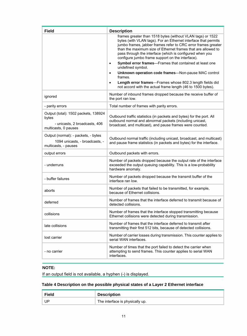
Field Description frames greater than 1518 bytes (without VLAN tags) or 1522 bytes (with VLAN tags). For an Ethernet interface that permits jumbo frames, jabber frames refer to CRC error frames greater than the maximum size of Ethernet frames that are allowed to pass through the interface (which is configured when you configure jumbo frame support on the interface).
• Symbol error frames—Frames that contained at least one undefined symbol.
• Unknown operation code frames—Non-pause MAC control frames.
• Length error frames—Frames whose 802.3 length fields did not accord with the actual frame length (46 to 1500 bytes).
ignored Number of inbound frames dropped because the receive buffer of the port ran low.
- parity errors Total number of frames with parity errors.
Output (total): 1502 packets, 138924 bytes - unicasts, 2 broadcasts, 406 multicasts, 0 pauses
Outbound traffic statistics (in packets and bytes) for the port. All outbound normal and abnormal packets (including unicast, broadcast, and multicast), and pause frames were counted.
Output (normal): - packets, - bytes 1094 unicasts, - broadcasts, - multicasts, - pauses
Outbound normal traffic (including unicast, broadcast, and multicast) and pause frame statistics (in packets and bytes) for the interface.
output errors Outbound packets with errors.
- underruns Number of packets dropped because the output rate of the interface exceeded the output queuing capability. This is a low-probability hardware anomaly.
- buffer failures Number of packets dropped because the transmit buffer of the interface ran low.
aborts Number of packets that failed to be transmitted, for example, because of Ethernet collisions.
deferred Number of frames that the interface deferred to transmit because of detected collisions.
collisions Number of frames that the interface stopped transmitting because Ethernet collisions were detected during transmission.
late collisions Number of frames that the interface deferred to transmit after transmitting their first 512 bits, because of detected collisions.
lost carrier Number of carrier losses during transmission. This counter applies to serial WAN interfaces.
- no carrier Number of times that the port failed to detect the carrier when attempting to send frames. This counter applies to serial WAN interfaces.
NOTE: If an output field is not available, a hyphen (-) is displayed.
Table 4 Description on the possible physical states of a Layer 2 Ethernet interface
Field Description UP The interface is physically up.
12
Field Description
DOWN The interface is physically down, because no physical connection exists (possibly because the network cable is disconnected or faulty).
DOWN ( Administratively ) The interface is physically down because it was shut down with the shutdown command. To restore its physical state, use the undo shutdown command.
DOWN ( Link-Aggregation interface down )
The interface is physically down, because the aggregate interface corresponding to the aggregation group to which it belongs was shut down with the shutdown command.
DOWN ( OAM connection failure )
The interface is physically down, because an OAM connection failed to be established on it or the OAM connection is disconnected.
DOWN ( DLDP connection failure )
The interface is physically down, because a DLDP connection failed to be established on it or the DLDP connection is disconnected.
DOWN ( Loopback detection-protected ) The interface is shut down because a loop is detected on it.
DOWN ( BPDU-protected ) The interface is shut down by the BPDU guard function.
DOWN ( Monitor-Link uplink down )
The interface is physically down because the uplink of the monitor link group to which it belongs is down.
# Display brief information about all interfaces. <Sysname> display interface brief
The brief information of interface(s) under route mode:
Link: ADM - administratively down; Stby - standby
Protocol: (s) - spoofing
Interface Link Protocol Main IP Description
Aux0 DOWN DOWN --
Dia1 UP UP(s) --
Eth0/0 UP UP 10.1.1.2 Link to CoreRouter
Eth0/1 Stby DOWN --
Loop0 UP UP(s) 2.2.2.9
NULL0 UP UP(s) --
Vlan1 UP DOWN --
Vlan999 UP UP 192.168.1.42
The brief information of interface(s) under bridge mode:
Link: ADM - administratively down
Speed or Duplex: (a)/A - auto; H - half; F - full
Type: A - access; T - trunk; H - hybrid
Interface Link Speed Duplex Type PVID Description
Eth0/2 DOWN auto A A 1
Eth0/3 UP 100M(a) F(a) A 1
Eth0/4 DOWN auto A A 1
Eth0/5 DOWN auto A A 1
Eth0/6 UP 100M(a) F(a) A 1
Eth0/7 DOWN auto A A 1
Eth0/8 UP 100M(a) F(a) A 1
Eth0/9 UP 100M(a) F(a) A 999
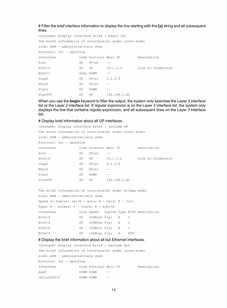
13
# Filter the brief interface information to display the line starting with the (s) string and all subsequent lines. <Sysname> display interface brief | begin (s)
The brief information of interface(s) under route mode:
Link: ADM - administratively down
Protocol: (s) - spoofing
Interface Link Protocol Main IP Description
Dia1 UP UP(s) --
Eth0/0 UP UP 10.1.1.2 Link to CoreRouter
Eth0/1 Stby DOWN --
Loop0 UP UP(s) 2.2.2.9
NULL0 UP UP(s) --
Vlan1 UP DOWN --
Vlan999 UP UP 192.168.1.42
When you use the begin keyword to filter the output, the system only searches the Layer 3 interface list or the Layer 2 interface list. If regular-expression is on the Layer 3 interface list, the system only displays the line that contains regular-expression, and all subsequent lines on the Layer 3 interface list.
# Display brief information about all UP interfaces. <Sysname> display interface brief | include UP
The brief information of interface(s) under route mode:
Link: ADM - administratively down
Protocol: (s) - spoofing
Interface Link Protocol Main IP Description
Dia1 UP UP(s) --
Eth0/0 UP UP 10.1.1.2 Link to CoreRouter
Loop0 UP UP(s) 2.2.2.9
NULL0 UP UP(s) --
Vlan1 UP DOWN --
Vlan999 UP UP 192.168.1.42
The brief information of interface(s) under bridge mode:
Link: ADM - administratively down
Speed or Duplex: (a)/A - auto; H - half; F - full
Type: A - access; T - trunk; H - hybrid
Interface Link Speed Duplex Type PVID Description
Eth0/3 UP 100M(a) F(a) A 1
Eth0/6 UP 100M(a) F(a) A 1
Eth0/8 UP 100M(a) F(a) A 1
Eth0/9 UP 100M(a) F(a) A 999
# Display the brief information about all but Ethernet interfaces. <Sysname> display interface brief | exclude Eth
The brief information of interface(s) under route mode:
Link: ADM - administratively down
Protocol: (s) - spoofing
Interface Link Protocol Main IP Description
Aux0 DOWN DOWN --
Cellular0/0 DOWN DOWN --
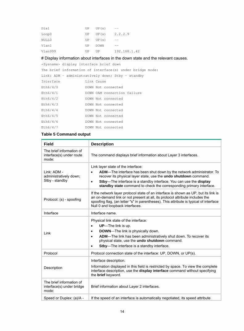
14
Dia1 UP UP(s) --
Loop0 UP UP(s) 2.2.2.9
NULL0 UP UP(s) --
Vlan1 UP DOWN --
Vlan999 UP UP 192.168.1.42
# Display information about interfaces in the down state and the relevant causes. <Sysname> display interface brief down
The brief information of interface(s) under bridge mode:
Link: ADM - administratively down; Stby - standby
Interface Link Cause
Eth6/4/0 DOWN Not connected
Eth6/4/1 DOWN OAM connection failure
Eth6/4/2 DOWN Not connected
Eth6/4/3 DOWN Not connected
Eth6/4/4 DOWN Not connected
Eth6/4/5 DOWN Not connected
Eth6/4/6 DOWN Not connected
Eth6/4/7 DOWN Not connected
Table 5 Command output
Field Description The brief information of interface(s) under route mode:
The command displays brief information about Layer 3 interfaces.
Link: ADM - administratively down; Stby - standby
Link layer state of the interface: • ADM—The interface has been shut down by the network administrator. To
recover its physical layer state, use the undo shutdown command. • Stby—The interface is a standby interface. You can use the display
standby state command to check the corresponding primary interface.
Protocol: (s) - spoofing
If the network layer protocol state of an interface is shown as UP, but its link is an on-demand link or not present at all, its protocol attribute includes the spoofing flag, (an letter "s" in parentheses). This attribute is typical of interface Null 0 and loopback interfaces.
Interface Interface name.
Link
Physical link state of the interface: • UP—The link is up. • DOWN—The link is physically down. • ADM—The link has been administratively shut down. To recover its
physical state, use the undo shutdown command. • Stby—The interface is a standby interface.
Protocol Protocol connection state of the interface: UP, DOWN, or UP(s).
Description
Interface description. Information displayed in this field is restricted by space. To view the complete interface description, use the display interface command without specifying the brief keyword.
The brief information of interface(s) under bridge mode:
Brief information about Layer 2 interfaces.
Speed or Duplex: (a)/A - If the speed of an interface is automatically negotiated, its speed attribute
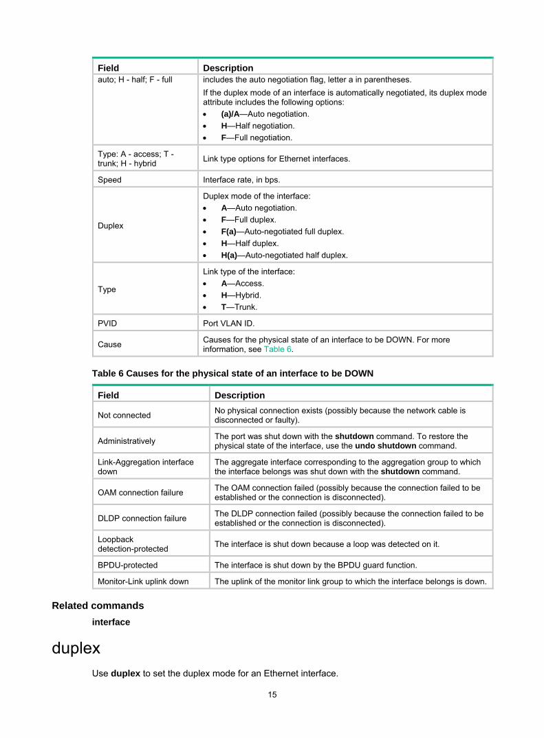
15
Field Description auto; H - half; F - full includes the auto negotiation flag, letter a in parentheses.
If the duplex mode of an interface is automatically negotiated, its duplex mode attribute includes the following options: • (a)/A—Auto negotiation. • H—Half negotiation. • F—Full negotiation.
Type: A - access; T - trunk; H - hybrid Link type options for Ethernet interfaces.
Speed Interface rate, in bps.
Duplex
Duplex mode of the interface: • A—Auto negotiation. • F—Full duplex. • F(a)—Auto-negotiated full duplex. • H—Half duplex. • H(a)—Auto-negotiated half duplex.
Type
Link type of the interface: • A—Access. • H—Hybrid. • T—Trunk.
PVID Port VLAN ID.
Cause Causes for the physical state of an interface to be DOWN. For more information, see Table 6.
Table 6 Causes for the physical state of an interface to be DOWN
Field Description
Not connected No physical connection exists (possibly because the network cable is disconnected or faulty).
Administratively The port was shut down with the shutdown command. To restore the physical state of the interface, use the undo shutdown command.
Link-Aggregation interface down
The aggregate interface corresponding to the aggregation group to which the interface belongs was shut down with the shutdown command.
OAM connection failure The OAM connection failed (possibly because the connection failed to be established or the connection is disconnected).
DLDP connection failure The DLDP connection failed (possibly because the connection failed to be established or the connection is disconnected).
Loopback detection-protected The interface is shut down because a loop was detected on it.
BPDU-protected The interface is shut down by the BPDU guard function.
Monitor-Link uplink down The uplink of the monitor link group to which the interface belongs is down.
Related commands interface
duplex Use duplex to set the duplex mode for an Ethernet interface.
16
Use undo duplex to restore the default duplex mode of the Ethernet interface.
Syntax duplex { auto | full | half }
undo duplex
Default An Ethernet interface operates in auto negotiation mode.
Views Ethernet interface view
Default command level 2: System level
Parameters auto: Sets the interface to operate in auto negotiation mode.
full: Sets the interface to operate in full duplex mode.
half: Sets the interface to operate in half-duplex mode. This keyword is not available for the fiber combo ports.
Examples # Configure interface Ethernet 1/1 to operate in full duplex mode. <Sysname> system-view
[Sysname] interface ethernet 1/1
[Sysname-Ethernet1/1] duplex full
flow-control Use flow-control to enable TxRx mode generic flow control on an Ethernet interface.
Use undo flow-control to disable generic flow control on the Ethernet interface.
Syntax flow-control undo flow-control
Default Generic flow control on an Ethernet interface is disabled.
Views Ethernet interface view
Default command level 2: System level
Usage guidelines TxRx mode flow control allows an Ethernet interface to receive common pause frames from its peer, and send common pause frames to notify its peer of congestion.
With the flow-control command configured, an interface can both send and receive flow control frames: • When congested, the interface sends a flow control frame to its peer. • Upon receiving a flow control frame from its peer, the interface suspends sending packets.

17
To implement flow control on a link, enable the generic flow control function at both ends of the link.
Examples # Enable TxRx mode generic flow control on the interface Ethernet 1/1. <Sysname> system-view
[Sysname] interface ethernet 1/1
[Sysname-Ethernet1/1] flow-control
flow-interval Use flow-interval to set the interface statistics polling interval.
Use undo flow-interval to restore the default interval.
Syntax flow-interval interval
undo flow-interval
Views System view
Default command level 2: System level
Parameters interval: Sets the statistics polling interval, in seconds. The interval is in the range of 5 to 300 and must be a multiple of 5.
Usage guidelines The flow-interval command configured in system view sets the statistics polling interval for all interfaces.
Examples # Set the statistics polling interval to 100 seconds for all Ethernet interfaces. <Sysname> system-view
[Sysname] flow-interval 100
interface Use interface to enter interface or subinterface view. If you specify the interface-number.subnumber argument and the subinterface does not exist, this command first creates the subinterface, and then enters subinterface view.
Syntax interface interface-type { interface-number | interface-number.subnumber }
Views System view
Default command level 2: System level
Parameters interface-type: Specifies an interface type.
interface-number: Specifies an interface number.
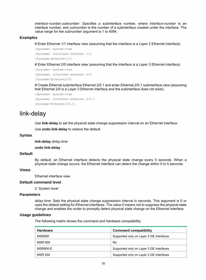
18
interface-number.subnumber: Specifies a subinterface number, where interface-number is an interface number, and subnumber is the number of a subinterface created under the interface. The value range for the subnumber argument is 1 to 4094.
Examples # Enter Ethernet 1/1 interface view (assuming that the interface is a Layer 2 Ethernet interface). <Sysname> system-view
[Sysname] interface ethernet 1/1
[Sysname-Ethernet1/1]
# Enter Ethernet 2/0 interface view (assuming that the interface is a Layer 3 Ethernet interface). <Sysname> system-view
[Sysname] interface ethernet 2/0
[Sysname-Ethernet2/0]
# Create Ethernet subinterface Ethernet 2/0.1 and enter Ethernet 2/0.1 subinterface view (assuming that Ethernet 2/0 is a Layer 3 Ethernet interface and the subinterface does not exist). <Sysname> system-view
[Sysname] interface ethernet 2/0.1
[Sysname-Ethernet2/0.1]
link-delay Use link-delay to set the physical state change suppression interval on an Ethernet interface.
Use undo link-delay to restore the default.
Syntax link-delay delay-time
undo link-delay
Default By default, an Ethernet interface detects the physical state change every 5 seconds. When a physical state change occurs, the Ethernet interface can detect the change within 0 to 5 seconds.
Views Ethernet interface view
Default command level 2: System level
Parameters delay-time: Sets the physical state change suppression interval in seconds. This argument is 0 or uses the default setting for Ethernet interfaces. The value 0 means not to suppress the physical state change and enables the router to promptly detect physical state change on the Ethernet interface.
Usage guidelines The following matrix shows the command and hardware compatibility:
Hardware Command compatibility MSR800 Supported only on Layer 3 GE interfaces
MSR 900 No
MSR900-E Supported only on Layer 3 GE interfaces
MSR 930 Supported only on Layer 3 GE interfaces
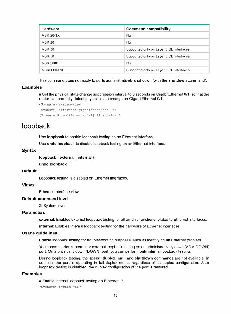
19
Hardware Command compatibility MSR 20-1X No
MSR 20 No
MSR 30 Supported only on Layer 3 GE interfaces
MSR 50 Supported only on Layer 3 GE interfaces
MSR 2600 No
MSR3600-51F Supported only on Layer 3 GE interfaces
This command does not apply to ports administratively shut down (with the shutdown command).
Examples # Set the physical state change suppression interval to 0 seconds on GigabitEthernet 0/1, so that the router can promptly detect physical state change on GigabitEthernet 0/1. <Sysname> system-view
[Sysname] interface gigabitethernet 0/1
[Sysname-GigabitEthernet0/1] link-delay 0
loopback Use loopback to enable loopback testing on an Ethernet interface.
Use undo loopback to disable loopback testing on an Ethernet interface.
Syntax loopback { external | internal }
undo loopback
Default Loopback testing is disabled on Ethernet interfaces.
Views Ethernet interface view
Default command level 2: System level
Parameters external: Enables external loopback testing for all on-chip functions related to Ethernet interfaces. internal: Enables internal loopback testing for the hardware of Ethernet interfaces.
Usage guidelines Enable loopback testing for troubleshooting purposes, such as identifying an Ethernet problem.
You cannot perform internal or external loopback testing on an administratively down (ADM DOWN) port. On a physically down (DOWN) port, you can perform only internal loopback testing.
During loopback testing, the speed, duplex, mdi, and shutdown commands are not available. In addition, the port is operating in full duplex mode, regardless of its duplex configuration. After loopback testing is disabled, the duplex configuration of the port is restored.
Examples # Enable internal loopback testing on Ethernet 1/1. <Sysname> system-view
20
[Sysname] interface ethernet 1/1
[Sysname-Ethernet1/1] loopback internal
port link-mode Use port link-mode to change the link mode of an Ethernet interface.
Use undo port link-mode to restore the default.
Syntax port link-mode { bridge | route }
undo port link-mode
Views Ethernet interface view
Default command level 2: System level
Parameters bridge: Specifies the Layer 2 mode.
route: Specifies the Layer 3 mode.
Usage guidelines Depending on the hardware structure of interface cards, some interfaces can operate only as Layer 2 Ethernet interfaces (in bridge mode), some can operate only as Layer 3 Ethernet interfaces (in route mode), and others can operate as either Layer 2 or Layer 3 Ethernet interfaces (you can set the link mode to bridge or route).
After you change the link mode of an Ethernet interface, all settings are restored to their default values in the new link mode.
Examples # Configure Ethernet 1/1 to operate in Layer 2 mode. <Sysname> system-view
[Sysname] interface ethernet 1/1
[Sysname-Ethernet1/1] display this
#
interface Ethernet1/1
port link-mode route
#
Return
The output shows that Ethernet 1/1 operates in route mode. [Sysname-Ethernet1/1] port link-mode bridge
[Sysname-Ethernet1/1] display this
#
interface Ethernet1/1
port link-mode bridge
#
Return
The output shows that Ethernet 1/1 is now operating in bridge mode.
21
NOTE: The display this command displays the configuration that takes effect in the current view.
Related commands port link-mode interface-list
port link-mode interface-list Use port link-mode interface-list to change the link mode of Ethernet interfaces.
Syntax port link-mode { bridge | route } interface-list
Views System view
Default command level 2: System level
Parameters bridge: Specifies the Layer 2 mode.
route: Specifies the Layer 3 mode.
interface-list: Specifies an Ethernet interface list, which can contain two Ethernet interfaces.
Usage guidelines Depending on the hardware structure of interface cards, some interfaces can operate only as Layer 2 Ethernet interfaces (in bridge mode), some can operate only as Layer 3 Ethernet interfaces (in route mode), and others can operate as either Layer 2 or Layer 3 Ethernet interfaces (you can set the link mode to bridge or route).
Configuring the port link-mode interface-list command in system view and configuring the port link-mode command in Ethernet interface view lead to the same result. The difference is that the former changes the link mode of two Ethernet interfaces in batch, and the latter changes the link mode of one Ethernet interface at a time.
After you change the link mode of an Ethernet interface, all the settings of the Ethernet interface are restored to their defaults under the new link mode.
The link mode configuration for an Ethernet interface in system view and that in interface view supersede each other, and the one configured last takes effect.
Examples # Configure Ethernet 1/1 and Ethernet 1/2 to operate in Layer 2 mode. <Sysname> system-view
[Sysname] port link-mode bridge ethernet 1/1 to ethernet 1/2
# Configure Ethernet 1/1 and Ethernet 1/2 to operate in Layer 3 mode. <Sysname> system-view
[Sysname] port link-mode route ethernet 1/1 to ethernet 1/2
reset counters interface Use reset counters interface to clear the Ethernet interface or subinterface statistics.
22
Syntax reset counters interface [ interface-type [ interface-number | interface-number.subnumber ] ]
Views User view
Default command level 2: System level
Parameters interface-type: Specifies an interface type.
interface-number: Specifies an interface number.
interface-number.subnumber: Specifies a subinterface number, where interface-number is an interface number and subnumber is the number of a subinterface created under the interface. The value range for the subnumber argument is 1 to 4094.
Usage guidelines Clear old statistics on the interface or subinterface before collecting new traffic statistics for a specific period of time. • If no interface type is specified, this command clears statistics for all interfaces on the device. • If only the interface type is specified, this command clears statistics for all interfaces of the
specified type. • If both the interface type and number are specified, this command only clears statistics for the
specified interface or subinterface.
Examples # Clear the statistics of Ethernet 1/1. <Sysname> reset counters interface ethernet 1/1
# Clear the statistics of subinterface Ethernet 1/1.1. <Sysname> reset counters interface ethernet 1/1.1
shutdown Use shutdown to shut down an Ethernet interface or subinterface.
Use undo shutdown to bring up an Ethernet interface or subinterface.
Syntax shutdown
undo shutdown
Default Ethernet interfaces and subinterfaces are up.
Views Ethernet interface view, Ethernet subinterface view, port group view
Default command level 2: System level
Usage guidelines You might need to shut down and then bring up an Ethernet interface to activate configuration changes such as speed or duplex mode changes.
23
Examples # Shut down and then bring up Ethernet 1/1. <Sysname> system-view
[Sysname] interface ethernet 1/1
[Sysname-Ethernet1/1] shutdown
[Sysname-Ethernet1/1] undo shutdown
# Shut down and then bring up Ethernet 1/1.1. <Sysname> system-view
[Sysname] interface ethernet 1/1.1
[Sysname-Ethernet1/1.1] shutdown
[Sysname-Ethernet1/1.1] undo shutdown
# Shut down all member ports in the port group named group1. <Sysname> system-view
[Sysname] port-group manual group1
[Sysname-port-group-manual-group1] shutdown
speed Use speed to set the speed of an Ethernet interface.
Use undo speed to restore the default.
Syntax speed { 10 | 100 | 1000 | auto }
undo speed
Views Ethernet interface view
Default The default value of this command is auto.
Default command level 2: System level
Parameters 10: Sets the interface speed to 10 Mbps. This keyword is not available on fiber combo ports
100: Sets the interface speed to 100 Mbps. This keyword is not available on fiber combo ports.
1000: Sets the interface speed to 1000 Mbps. Support for this keyword depends on your interface card model.
auto: Enables the interface to negotiate a speed with its peer.
Usage guidelines For an Ethernet copper port, use the speed command to set its speed to match the speed of the peer interface.
For a fiber port, use the speed command to set its speed to match the rate of a pluggable transceiver.
Examples # Configure Ethernet 1/1 to operate at 100 Mbps. <Sysname> system-view
24
[Sysname] interface ethernet 1/1
[Sysname-Ethernet1/1] speed 100
Related commands speed auto
Layer 2 Ethernet interface configuration commands broadcast-suppression
Use broadcast-suppression to set the broadcast suppression threshold on an Ethernet interface, a subinterface, or a group of Ethernet interfaces.
Use undo broadcast-suppression to restore the default broadcast suppression threshold.
Syntax broadcast-suppression { ratio | pps max-pps }
undo broadcast-suppression
Default Ethernet interfaces do not suppress broadcast traffic.
Views Layer 2 Ethernet interface view, port group view
Default command level 2: System level
Parameters ratio: Sets the broadcast suppression threshold as a percentage of the maximum interface rate. The smaller the percentage, the less broadcast traffic is allowed to be received.
pps max-pps: Specifies the maximum number of broadcast packets that the Ethernet interface can receive per second. The value range for the max-pps argument is 1 to 1488100 pps. Support of MSR routers for this option varies by router model. For more information, see the usage guidelines for this command.
Usage guidelines In Ethernet interface view, the configuration takes effect only on the interface. In port group view, the configuration takes effect on all the ports in the port group.
When the received broadcast traffic exceeds the broadcast suppression threshold, the interface discards broadcast packets until broadcast traffic drops below the threshold.
If you set different broadcast suppression thresholds in Ethernet interface view or port group view multiple times, the one configured last takes effect.
On the XMIM-16FSW, XMIM-24FSW, SIC-4FSW, SIC-4FSW-POE, DSIC-9FSW, and DSIC-9FSW-POE switching fabric modules and the and the fixed Layer 2 ports of MSR900, MSR930, MSR20-21, and MSR20-1X routers, the broadcast suppression threshold is 8 Mbps by default, and the ratio argument is not supported. The available values of the max-pps argument include only 190 pps, 380 pps, 760 pps, 1488 pps, 2976 pps, 5952 pps, and 11904 pps.
Examples # Set the broadcast suppression threshold to 20% on Ethernet 1/1.
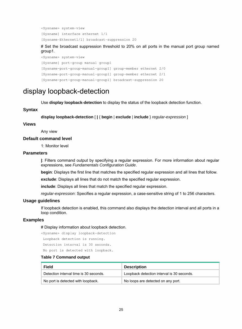
25
<Sysname> system-view
[Sysname] interface ethernet 1/1
[Sysname-Ethernet1/1] broadcast-suppression 20
# Set the broadcast suppression threshold to 20% on all ports in the manual port group named group1. <Sysname> system-view
[Sysname] port-group manual group1
[Sysname-port-group-manual-group1] group-member ethernet 2/0
[Sysname-port-group-manual-group1] group-member ethernet 2/1
[Sysname-port-group-manual-group1] broadcast-suppression 20
display loopback-detection Use display loopback-detection to display the status of the loopback detection function.
Syntax display loopback-detection [ | { begin | exclude | include } regular-expression ]
Views Any view
Default command level 1: Monitor level
Parameters |: Filters command output by specifying a regular expression. For more information about regular expressions, see Fundamentals Configuration Guide.
begin: Displays the first line that matches the specified regular expression and all lines that follow.
exclude: Displays all lines that do not match the specified regular expression.
include: Displays all lines that match the specified regular expression.
regular-expression: Specifies a regular expression, a case-sensitive string of 1 to 256 characters.
Usage guidelines If loopback detection is enabled, this command also displays the detection interval and all ports in a loop condition.
Examples # Display information about loopback detection. <Sysname> display loopback-detection
Loopback detection is running.
Detection interval is 30 seconds.
No port is detected with loopback.
Table 7 Command output
Field Description Detection interval time is 30 seconds. Loopback detection interval is 30 seconds.
No port is detected with loopback. No loops are detected on any port.
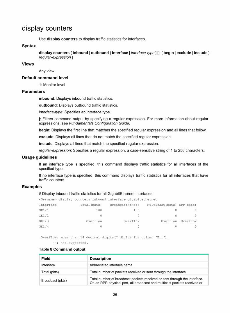
26
display counters Use display counters to display traffic statistics for interfaces.
Syntax display counters { inbound | outbound } interface [ interface-type ] [ | { begin | exclude | include } regular-expression ]
Views Any view
Default command level 1: Monitor level
Parameters inbound: Displays inbound traffic statistics.
outbound: Displays outbound traffic statistics.
interface-type: Specifies an interface type.
|: Filters command output by specifying a regular expression. For more information about regular expressions, see Fundamentals Configuration Guide.
begin: Displays the first line that matches the specified regular expression and all lines that follow.
exclude: Displays all lines that do not match the specified regular expression.
include: Displays all lines that match the specified regular expression.
regular-expression: Specifies a regular expression, a case-sensitive string of 1 to 256 characters.
Usage guidelines If an interface type is specified, this command displays traffic statistics for all interfaces of the specified type.
If no interface type is specified, this command displays traffic statistics for all interfaces that have traffic counters.
Examples # Display inbound traffic statistics for all GigabitEthernet interfaces. <Sysname> display counters inbound interface gigabitethernet
Interface Total(pkts) Broadcast(pkts) Multicast(pkts) Err(pkts)
GE1/1 100 100 0 0
GE1/2 0 0 0 0
GE1/3 Overflow Overflow Overflow Overflow
GE1/4 0 0 0 0
Overflow: more than 14 decimal digits(7 digits for column "Err").
--: not supported.
Table 8 Command output
Field Description Interface Abbreviated interface name.
Total (pkts) Total number of packets received or sent through the interface.
Broadcast (pkts) Total number of broadcast packets received or sent through the interface. On an RPR physical port, all broadcast and multicast packets received or
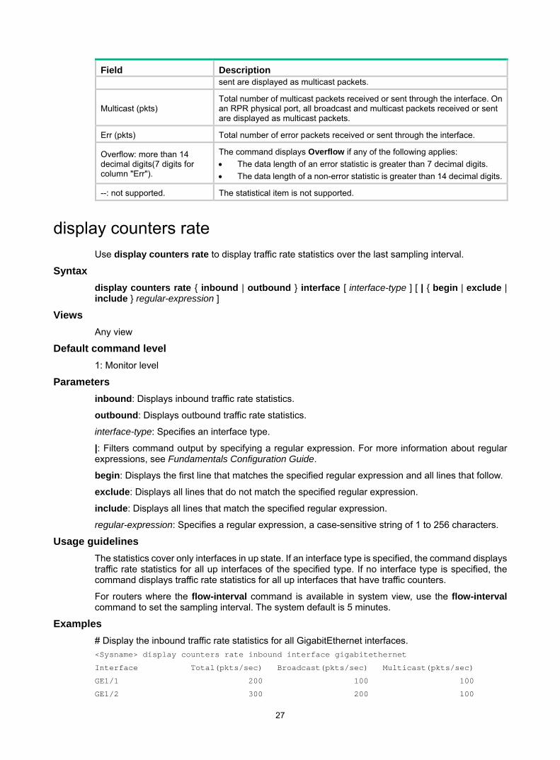
27
Field Description sent are displayed as multicast packets.
Multicast (pkts) Total number of multicast packets received or sent through the interface. On an RPR physical port, all broadcast and multicast packets received or sent are displayed as multicast packets.
Err (pkts) Total number of error packets received or sent through the interface.
Overflow: more than 14 decimal digits(7 digits for column "Err").
The command displays Overflow if any of the following applies: • The data length of an error statistic is greater than 7 decimal digits. • The data length of a non-error statistic is greater than 14 decimal digits.
--: not supported. The statistical item is not supported.
display counters rate Use display counters rate to display traffic rate statistics over the last sampling interval.
Syntax display counters rate { inbound | outbound } interface [ interface-type ] [ | { begin | exclude | include } regular-expression ]
Views Any view
Default command level 1: Monitor level
Parameters inbound: Displays inbound traffic rate statistics.
outbound: Displays outbound traffic rate statistics.
interface-type: Specifies an interface type.
|: Filters command output by specifying a regular expression. For more information about regular expressions, see Fundamentals Configuration Guide.
begin: Displays the first line that matches the specified regular expression and all lines that follow.
exclude: Displays all lines that do not match the specified regular expression.
include: Displays all lines that match the specified regular expression.
regular-expression: Specifies a regular expression, a case-sensitive string of 1 to 256 characters.
Usage guidelines The statistics cover only interfaces in up state. If an interface type is specified, the command displays traffic rate statistics for all up interfaces of the specified type. If no interface type is specified, the command displays traffic rate statistics for all up interfaces that have traffic counters.
For routers where the flow-interval command is available in system view, use the flow-interval command to set the sampling interval. The system default is 5 minutes.
Examples # Display the inbound traffic rate statistics for all GigabitEthernet interfaces. <Sysname> display counters rate inbound interface gigabitethernet
Interface Total(pkts/sec) Broadcast(pkts/sec) Multicast(pkts/sec)
GE1/1 200 100 100
GE1/2 300 200 100
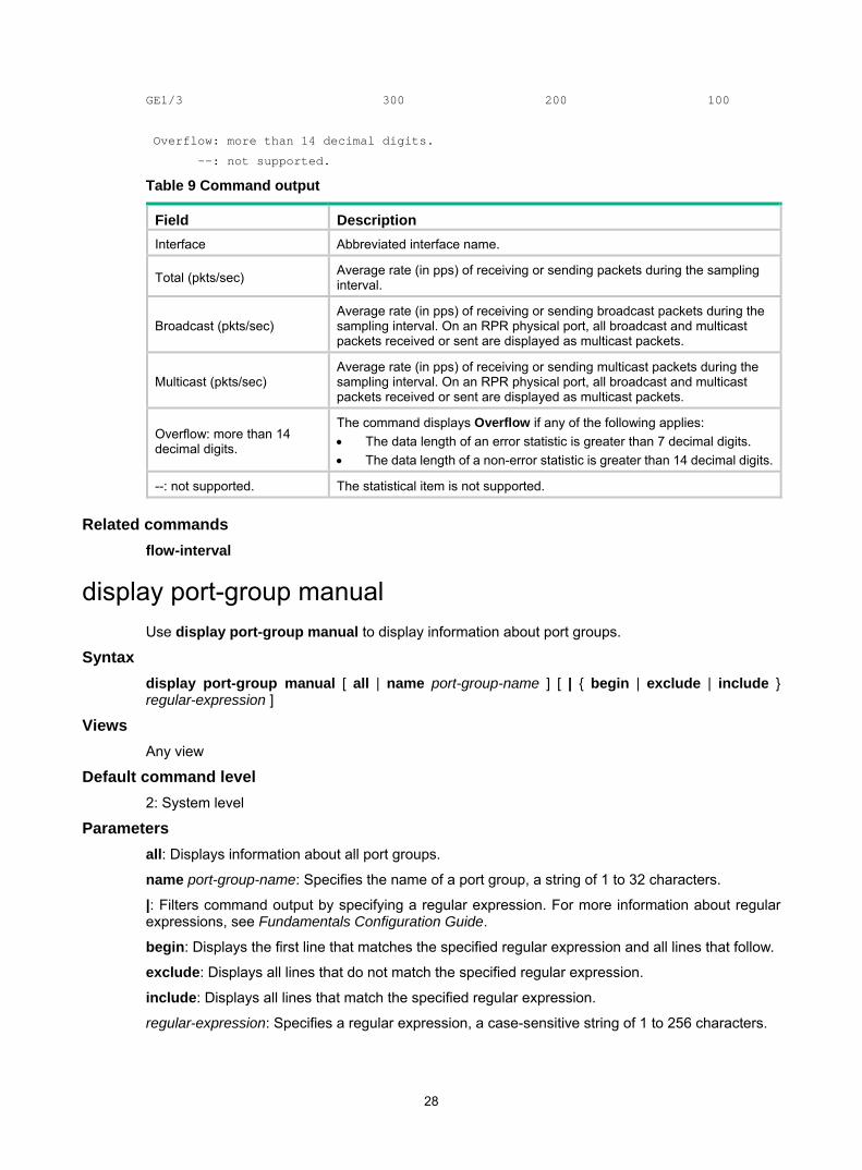
28
GE1/3 300 200 100
Overflow: more than 14 decimal digits.
--: not supported.
Table 9 Command output
Field Description Interface Abbreviated interface name.
Total (pkts/sec) Average rate (in pps) of receiving or sending packets during the sampling interval.
Broadcast (pkts/sec) Average rate (in pps) of receiving or sending broadcast packets during the sampling interval. On an RPR physical port, all broadcast and multicast packets received or sent are displayed as multicast packets.
Multicast (pkts/sec) Average rate (in pps) of receiving or sending multicast packets during the sampling interval. On an RPR physical port, all broadcast and multicast packets received or sent are displayed as multicast packets.
Overflow: more than 14 decimal digits.
The command displays Overflow if any of the following applies: • The data length of an error statistic is greater than 7 decimal digits. • The data length of a non-error statistic is greater than 14 decimal digits.
--: not supported. The statistical item is not supported.
Related commands flow-interval
display port-group manual Use display port-group manual to display information about port groups.
Syntax display port-group manual [ all | name port-group-name ] [ | { begin | exclude | include } regular-expression ]
Views Any view
Default command level 2: System level
Parameters all: Displays information about all port groups.
name port-group-name: Specifies the name of a port group, a string of 1 to 32 characters.
|: Filters command output by specifying a regular expression. For more information about regular expressions, see Fundamentals Configuration Guide.
begin: Displays the first line that matches the specified regular expression and all lines that follow.
exclude: Displays all lines that do not match the specified regular expression.
include: Displays all lines that match the specified regular expression.
regular-expression: Specifies a regular expression, a case-sensitive string of 1 to 256 characters.
29
Usage guidelines If the all keyword is specified, this command displays the name and member Ethernet interfaces of each port group on the device.
If a port group is specified, this command displays its name and member Ethernet interfaces.
If you do not specify the all keyword or any port group name, the command displays the name of each port group on the device.
Examples # Display the names of all port groups. <Sysname> display port-group manual
The following manual port group exist(s):
group1 group2
# Display detailed information about all port groups. <Sysname> display port-group manual all
Member of group1:
Ethernet1/3 Ethernet1/4 Ethernet1/5
Ethernet1/6 Ethernet1/7 Ethernet2/0
Ethernet2/1
Member of group2:
None
# Display detailed information about the port group named group1. <Sysname> display port-group manual name group1
Member of group1:
Ethernet1/3 Ethernet1/4 Ethernet1/5
Ethernet1/6 Ethernet1/7 Ethernet2/0
flow-interval Use flow-interval to set the interface statistics polling interval.
Use undo flow-interval to restore the default interval.
Syntax flow-interval interval
undo flow-interval
Default The interface statistics polling interval is 300 seconds.
Views System view
Default command level 2: System level
Parameters interval: Sets the statistics polling interval, in seconds. The interval is in the range of 5 to 300 and must be a multiple of 5.
30
Usage guidelines The flow-interval command configured in system view sets the statistics polling interval for all interfaces.
Examples # Set the statistics polling interval to 100 seconds for all Ethernet interfaces. <Sysname> system-view
[Sysname] flow-interval 100
group-member Use group-member to assign Ethernet interfaces to a port group.
Use undo group-member to remove Ethernet interfaces from the port group.
Syntax group-member interface-list
undo group-member interface-list
Default A port group does not contain any member ports.
Views Port group view
Default command level 2: System level
Parameters interface-list: Specifies an Ethernet interface list, in the form of interface-type interface-number [ to interface-type interface-number ] &<1-10>, where &<1-10> indicates that you can specify up to 10 interfaces or interface ranges.
Usage guidelines If you use the group-member interface-type interface-start-number to interface-type interface-end-number command to add multiple ports in batch to the specified port group, make sure that all these ports are of the same type and on the same interface card, and the interface-end-number argument must be greater than the interface-start-number argument.
Examples # Assign Ethernet 1/1 to the port group named group1. <Sysname> system-view
[Sysname] port-group manual group1
[Sysname-port-group-manual-group1] group-member ethernet 1/1
jumboframe enable Use jumboframe enable to allow jumbo frames within the specified length to pass through an Ethernet interface or a group of Ethernet interfaces.
Use undo jumboframe enable to prevent jumbo frames from passing through an Ethernet interface or a group of Ethernet interfaces.
Syntax jumboframe enable [ value ]
31
undo jumboframe enable
Default The router allows jumbo frames within a specified length to pass through Layer 2 Ethernet interfaces.
Views Layer 2 Ethernet interface view, port group view
Default command level 2: System level
Parameters value: Sets the maximum size of Ethernet frames that are allowed to pass through.
Usage guidelines The following matrix shows the command and hardware compatibility:
Hardware Command compatibility MSR800 No
MSR 900 No
MSR900-E No
MSR 930 No
MSR 20-1X No
MSR 20 No
MSR 30 Supported on modules except SIC-4FSW and DSIC-9FSW modules
MSR 50 Supported on modules except SIC-4FSW and DSIC-9FSW modules
MSR 2600 No
MSR3600-51F Supported on modules except SIC-4FSW and DSIC-9FSW modules
The router supports either the interface or port group configuration mode, depending on the router model.
In Ethernet interface view, this command applies only to the Ethernet interface.
In port group view, this command applies to the Ethernet interfaces in the port group.
Examples # Enable jumbo frames to pass through all Ethernet interfaces in port group group1. <Sysname> system-view
[Sysname] port-group manual group1
[Sysname-port-group-manual-group1] group-member ethernet 2/0
[Sysname-port-group-manual-group1] jumboframe enable
# Enable jumbo frames to pass through Ethernet 1/1. <Sysname> system-view
[Sysname] interface ethernet 1/1
[Sysname-Ethernet1/1] jumboframe enable

32
loopback-detection action Use loopback-detection action to configure the action for loop protection on Ethernet interfaces.
Use undo loopback-detection action to restore the default.
Syntax loopback-detection action { block | shutdown }
undo loopback-detection action
Default The action for loop protection on an Ethernet interface is block.
Views Layer 2 Ethernet interface view, port group view
Default command level 2: System level
Parameters block: Blocks all packets.
shutdown: Shuts down the Ethernet interface. To bring up the interface again, use the undo shutdown command.
Usage guidelines The following matrix shows the command and hardware compatibility:
Hardware Command compatibility MSR800 No
MSR 900 No
MSR900-E No
MSR 930 No
MSR 20-1X No
MSR 20 No
MSR 30 Supported only on MSR3011E/F
MSR 50 No
MSR 2600 No
MSR3600-51F Yes
When you change the link type of an Ethernet interface with the port link-type command, the device removes the protective action configured on the interface. For more information about the port link-type command, see Layer 2—LAN Switching Command Reference.
Examples # Configure the access port Ethernet 1/1 to shut down when a loop is detected. <Sysname> system-view
[Sysname] loopback-detection enable
[Sysname] interface ethernet 1/1
[Sysname-Ethernet1/1] loopback-detection enable
[Sysname-Ethernet1/1] loopback-detection action shutdown
33
# Configure the trunk port Ethernet 1/2 to shut down when a loop is detected. <Sysname> system-view
[Sysname] loopback-detection enable
[Sysname] interface ethernet 1/2
[Sysname-Ethernet1/2] port link-type trunk
[Sysname-Ethernet1/2] loopback-detection enable
[Sysname-Ethernet1/2] loopback-detection control enable
[Sysname-Ethernet1/2] loopback-detection action shutdown
loopback-detection control enable Use loopback-detection control enable to enable loopback detection control on trunk or hybrid ports.
Use undo loopback-detection control enable to restore the default.
Syntax loopback-detection control enable
undo loopback-detection control enable
Default Loopback detection control is disabled on trunk and hybrid ports.
Views Layer 2 Ethernet interface view
Default command level 2: System level
Usage guidelines When a hybrid or trunk port detects a loop condition, it sends traps, whether loopback detection control is enabled or not. However, the port performs the protective action that you configure with the loopback-detection action command only after loopback detection control is enabled.
This command is not applicable to access ports.
Examples # Enable loopback detection control on the trunk port Ethernet 1/1. <Sysname> system-view
[Sysname] loopback-detection enable
[Sysname] interface ethernet 1/1
[Sysname-Ethernet1/1] port link-type trunk
[Sysname-Ethernet1/1] loopback-detection enable
[Sysname-Ethernet1/1] loopback-detection control enable
loopback-detection interval-time Use loopback-detection interval-time to set the loopback detection interval.
Use undo loopback-detection interval-time to restore the default loopback detection interval.
Syntax loopback-detection interval-time time
undo loopback-detection interval-time
34
Default The loopback detection interval is 30 seconds.
Views System view
Default command level 2: System level
Parameters time: Specifies the loopback detection interval in the range of 5 to 300 seconds.
Examples # Set the loopback detection interval to 10 seconds. <Sysname> system-view
[Sysname] loopback-detection interval-time 10
Related commands display loopback-detection
mdi
NOTE: This command is not applicable to fiber ports.
Use mdi to configure the MDI mode of an Ethernet copper interface.
Use undo mdi to restore the default.
Syntax mdi { across | auto | normal }
undo mdi
Default Ethernet interfaces operate in auto MDI mode.
Views Layer 2 Ethernet interface view
Default command level 2: System level
Parameters across: Sets the MDI mode to across. In this mode, pins 1 and 2 are receive pins, and pins 3 and 6 are transmit pins.
auto: Sets the MDI mode to auto. In this mode, the port negotiates pin roles with its peer.
normal: Sets the MDI mode to normal. In normal mode, pins 1 and 2 are transmit pins, and pins 3 and 6 are receive pins.
Examples # Set Ethernet 1/1 to operate in across MDI mode. <Sysname> system-view
[Sysname] interface ethernet 1/1
35
[Sysname-Ethernet1/1] mdi across
multicast-suppression Use multicast-suppression to set the multicast suppression threshold on an Ethernet interface, a subinterface, or a group of Ethernet interfaces.
Use undo multicast-suppression to restore the default multicast suppression threshold.
Syntax multicast-suppression { ratio | pps max-pps }
undo multicast-suppression
Default Ethernet interfaces do not suppress multicast traffic.
Views Layer 2 Ethernet interface view, port group view
Default command level 2: System level
Parameters ratio: Sets the multicast suppression threshold as a percentage of the maximum interface rate. The value range is 1 to 100. The smaller the percentage, the less multicast traffic is allowed to be received.
pps max-pps: Specifies the maximum number of multicast packets that the Ethernet interface can receive per second. The value range for the max-pps argument is 1 to 1488100 pps. Support of MSR routers for this option varies by router model. For more information, see the usage guidelines for this command.
Usage guidelines In Ethernet interface view, the configurations take effect only on the interface. In port group view, the configurations take effect on all ports in the port group.
When the received multicast traffic exceeds the threshold, the system discards multicast packets until multicast traffic drops below the threshold.
If you set different multicast suppression thresholds in Ethernet interface view or port group view multiple times, the one configured last takes effect.
On the XMIM-16FSW, XMIM-24FSW, SIC-4FSW, SIC-4FSW-POE, DSIC-9FSW, and DSIC-9FSW-POE switching fabric modules and the and the fixed Layer 2 ports of MSR900, MSR930, MSR20-21, and MSR20-1X routers, the broadcast suppression threshold is 8 Mbps by default, and the ratio argument is not supported. The available values of the max-pps argument include only 190 pps, 380 pps, 760 pps, 1488 pps, 2976 pps, 5952 pps, and 11904 pps.
MSR800, MSR900-E, and MSR930 routers do not support multicast traffic suppression.
Examples # Set the multicast threshold to 20% on Ethernet 1/1. <Sysname> system-view
[Sysname] interface ethernet 1/1
[Sysname-Ethernet1/1] multicast-suppression 20
# Set the multicast threshold to 20% on all ports in the port group named group1. <Sysname> system-view
[Sysname] port-group manual group1
36
[Sysname-port-group-manual-group1] group-member ethernet 2/0
[Sysname-port-group-manual-group1] group-member ethernet 2/1
[Sysname-port-group-manual-group1] multicast-suppression 20
port-group manual Use port-group manual to create a port group and enter port group view.
Use undo port-group manual to remove a port group.
Syntax port-group manual port-group-name
undo port-group manual port-group-name
Default No port groups exist.
Views System view
Default command level 2: System level
Parameters port-group-name: Sets the port group name, a string of 1 to 32 characters.
Examples # Create port group group1. <Sysname> system-view
[Sysname] port-group manual group1
[Sysname-port-group-manual-group1]
unicast-suppression Use unicast-suppression to set the unknown unicast suppression threshold on an Ethernet interface, a subinterface, or a group of Ethernet interfaces.
Use undo unicast-suppression to restore the default.
Syntax unicast-suppression { ratio | pps max-pps }
undo unicast-suppression
Default Ethernet interfaces do not suppress unknown unicast traffic.
Views Layer 2 Ethernet interface view, port group view
Default command level 2: System level
37
Parameters ratio: Sets the unknown unicast suppression threshold as a percentage of the maximum interface rate. The value range is 1 to 100. The smaller the percentage, the less unknown unicast traffic is allowed to be received.
pps max-pps: Specifies the maximum number of unknown unicast packets that the Ethernet interface can receive per second. The value range for the max-pps argument is 1 to 1488100 pps. Support of MSR routers for this option varies by router model. For more information, see the usage guidelines for this command.
Usage guidelines In Ethernet interface, the configuration will take effect only on the interface. In port group view, the configuration will take effect on all ports in the port group.
When the received unknown unicast traffic exceeds the threshold, the system discards unknown unicast packets until unknown unicast traffic drops below the threshold.
If you set different unknown unicast suppression thresholds in Ethernet interface view or port group view multiple times, the one configured last takes effect.
On the XMIM-16FSW, XMIM-24FSW, SIC-4FSW, SIC-4FSW-POE, DSIC-9FSW, and DSIC-9FSW-POE switching fabric modules and the and the fixed Layer 2 ports of MSR800, MSR900, MSR900-E, MSR930, MSR20-21, and MSR20-1X routers, the broadcast suppression threshold is 8 Mbps by default, and the ratio argument is not supported. The available values of the max-pps argument include only 190 pps, 380 pps, 760 pps, 1488 pps, 2976 pps, 5952 pps, and 11904 pps.
Examples # Set the unknown unicast threshold to 20% on Ethernet 1/1. <Sysname> system-view
[Sysname] interface ethernet 1/1
[Sysname-Ethernet1/1] unicast-suppression 20
# Set the unknown unicast threshold to 20% on all ports of port group group1. <Sysname> system-view
[Sysname] port-group manual group1
[Sysname-port-group-manual-group1] group-member ethernet 2/0
[Sysname-port-group-manual-group1] group-member ethernet 2/1
[Sysname-port-group-manual-group1] unicast-suppression 20
Layer 3 Ethernet interface and subinterface configuration commands mac-address
Use mac-address to configure the MAC address of a Layer 3 Ethernet interface or subinterface.
Use undo mac-address to restore the default.
Syntax mac-address mac-address
undo mac address
Default The MAC address of a Layer 3 Ethernet interface depends on the device model.
38
Views Layer 3 Ethernet interface view, Layer 3 Ethernet subinterface view
Default command level 2: System level
Parameters mac-address: Specifies a MAC address, in the format of H-H-H.
Usage guidelines When you configure the MAC address of a Layer 3 Ethernet subinterface with the mac-address command, select a MAC address different from that of the host interface.
H3C recommends not configuring a MAC address in the VRRP-reserved MAC address range for a Layer 3 Ethernet subinterface.
You can use the display interface command to display the MAC address of a Layer 3 Ethernet interface or subinterface.
Examples # Configure the MAC address of Layer 3 Ethernet interface Ethernet 1/1 as 0001-0001-0001. <Sysname> system-view
[Sysname] interface ethernet 1/1
[Sysname-Ethernet1/1] mac-address 1-1-1
mac-address valid-check Use mac-address valid-check to enable a Layer 3 VE interface to check the destination MAC addresses of incoming IP packets.
Use undo mac-address valid-check to restore the default.
Syntax mac-address valid-check enable undo mac-address valid-check enable
Default A Layer 3 VE interface does not check the destination MAC addresses of incoming IP packets.
Views Layer 3 VE interface view
Default command level 2: System level
Parameters None
Description • If the destination MAC address of an incoming IP packet is a unicast MAC address other than
the MAC address of the interface, the IP packet is dropped. • If the destination MAC address of an incoming IP packet is a broadcast or multicast MAC
address, the destination MAC address of the packet is not checked. • With this feature enabled, some protocol packets that need to be sent to the CPU might fail to
be sent to the corresponding module. Therefore, use this command in only the special network conditions.

39
Examples # Enable Layer 3 VE interface Virtual-Ethernet 1 to check the destination MAC addresses of incoming IP packets. <Sysname> system-view
[Sysname] interface Virtual-Ethernet 1
[Sysname-Virtual-Ethernet1] mac-address valid-check enable
mtu Use mtu to set the MTU for an Ethernet interface or subinterface.
Use undo mtu to restore the default.
Syntax mtu size
undo mtu
Default The MTU of an Ethernet interface or subinterface is 1500 bytes.
Views Layer 3 Ethernet interface view, Layer 3 Ethernet subinterface view
Default command level 2: System level
Parameters size: Sets the maximum transmission unit (MTU) in bytes. The value range for this argument varies by router model.
The following matrix shows the value ranges for the size argument:
Hardware Value range MSR800 46 to 1650
MSR 900 46 to 1650
MSR900-E 46 to 1650
MSR 930 46 to 1650
MSR 20-1X 46 to 1500
MSR 20 46 to 1500
MSR 30 46 to 1650
MSR 50 46 to 1650
MSR 2600 46 to 1650
MSR3600-51F 46 to 1650
Usage guidelines As the size of MTU decreases, the number of fragments grows. When setting MTU for an interface, you should consider QoS queue lengths (for example, the default FIFO queue length is 75) to avoid a too small MTU causing packet drop in QoS queuing. To achieve the best result, you can tune MTU with the mtu command or QoS queue lengths with the qos fifo queue-length command. For more information, see ACL and QoS Command Reference.
40
Examples # Set the MTU to 1430 bytes for the Layer 3 Ethernet interface Ethernet 2/0. <Sysname> system-view
[Sysname] interface ethernet 2/0
[Sysname-Ethernet2/0] mtu 1430
# Set the MTU to 1400 bytes for the Layer 3 Ethernet subinterface Ethernet 2/0.1. <Sysname> system-view
[Sysname] interface ethernet 2/0.1
[Sysname-Ethernet2/0.1] mtu 1400
promiscuous Use promiscuous to configure a Layer 3 Ethernet interface to operate in promiscuous mode.
Use undo promiscuous to cancel the promiscuous operating mode.
Syntax promiscuous undo promiscuous
Default A Layer 3 Ethernet interface does not operate in promiscuous mode.
Views Layer 3 Ethernet interface view
Examples # Configure Ethernet 2/0 to operate in promiscuous mode. <Sysname> system-view
[Sysname] interface ethernet 2/0
[Sysname-Ethernet2/0] promiscuous
qmtoken Use qmtoken to configure the maximum number of tokens that the QoS token function assigns to a Layer 3 Ethernet interface.
Use undo qmtoken to restore the default.
Syntax qmtoken number
undo qmtoken
Default The maximum number of tokens that the QoS token function assigns to a Layer 3 Ethernet interface is 512.
Views Layer 3 Ethernet interface view
41
Parameters number: Sets the maximum number of tokens that the QoS token function assigns to the Layer 3 Ethernet interface. The token count represents the maximum number of packets that the bottom layer queue can hold for the interface. This argument must be a power of 2 in the range of 4 to 1024.
The following matrix shows the number argument and hardware compatibility:
Hardware Argument compatibility Value range Default
MSR800 No N/A N/A
MSR 900 No N/A N/A
MSR900-E No N/A N/A
MSR 930 No N/A N/A
MSR 20-1X Yes 4 to 1024 512
MSR 20 Yes 4 to 1024 512
MSR 30 Yes 4 to 1024 • MSR 30-11:
1024 • Other: 512
MSR 50 Yes 4 to 1024 512
MSR 2600 No N/A N/A
MSR3600-51F Yes 4 to 1024 1024
Usage guidelines The following matrix shows the command and hardware compatibility:
Hardware Command compatibility MSR800 No
MSR 900 No
MSR900-E No
MSR 930 No
MSR 20-1X Supported on MSR 20-1X routers except MSR 20-12
MSR 20 Yes
MSR 30 Yes
MSR 50 Yes
MSR 2600 No
MSR3600-51F Yes
The qos qmtoken command can cause an Ethernet interface to automatically shut down and go up.
Examples # Set the maximum number of tokens to 8 on interface GigabitEthernet 0/0. <Sysname> system-view
[Sysname] interface gigabitethernet 0/0
[Sysname-GigabitEthernet0/0] qmtoken 8
42
WAN interface configuration commands The following matrix shows the hardware and interface compatibility:
Hardware Support for interfaces
CE3 and CT3 interface modules The modules do not support subrate configuration if the module hardware version is earlier than Hardware 2.2.
MSR 30-11 The router does not support USB interfaces.
MSR800 series Supports only the USB 3G/4G modem interfaces.
MSR 900 series Supports only the AUX and USB 3G/4G modem interfaces.
MSR900-E series Supports only the USB 3G/4G modem interfaces.
MSR 930 series Supports the AUX and 3G/4G modem interfaces. The MSR 930-SA also supports serial interfaces.
Common WAN interface configuration commands bandwidth
Use bandwidth to set the expected bandwidth for the interface.
Use undo bandwidth to restore the default.
Syntax bandwidth bandwidth-value
undo bandwidth
Views Serial interface view, AUX interface view, AM interface view, Cellular interface view, E1-F interface view, T1-F interface view, ISDN BRI interface view, CE3 interface view, CT3 interface view, CE1/PRI interface view, CT1/PRI interface view
Default command level 2: System level
Parameters bandwidth-value: Expected bandwidth for the interface, in the range of 1 to 4294967295 kbps.
Usage guidelines You can obtain the expected bandwidth of an interface by querying the ifspeed value of the MIB node with third-party software.
The expected bandwidth is used for bandwidth monitoring of the network management, but does not affect the actual bandwidth of the interface.
Examples # Set the expected bandwidth to 50 kbps for interface Serial 2/0. <Sysname> system-view
[Sysname] interface serial 2/0
[Sysname-Serial2/0] bandwidth 50
43
default Use default to restore the default settings for the interface.
Syntax default
Views Serial interface view, AUX interface view, AM interface view, Cellular interface view, E1-F interface view, T1-F interface view, ISDN BRI interface view, CE3 interface view, CT3 interface view, CE1/PRI interface view, CT1/PRI interface view
Default command level 2: System level
Usage guidelines
CAUTION: The default command might interrupt ongoing network services. Make sure you are fully aware of the impacts of this command when you use it on a live network.
This command might fail to restore the default settings for some commands for reasons such as command dependencies and system restrictions. Use the display this command in interface view to identify these commands, and then use their undo forms or follow the command reference to individually restore their default settings. If your restoration attempt still fails, follow the error message instructions to resolve the problem.
Examples # Restore the default settings of serial interface serial 2/0. <Sysname> system-view
[Sysname] interface serial 2/0
[Sysname-Serial2/0] default
This command will restore the default settings. Continue? [Y/N]:y
description Use description to set the description for the interface.
Use undo description to restore the default.
Syntax description text
undo description
Default The description of a WAN interface is interface name Interface, for example, Serial2/0 Interface.
Views Serial interface view, AUX interface view, AM interface view, Cellular interface view, E1-F interface view, T1-F interface view, ISDN BRI interface view, CE3 interface view, CT3 interface view, CE1/PRI interface view, CT1/PRI interface view
Default command level 2: System level
44
Parameters text: Interface description, a case-sensitive character string of 1 to 240 characters. The string can include case-sensitive letters, digits, special characters, and other Unicode characters and symbols. Special characters include tilde (~), exclamation point (!), at sign (@), pound sign (#), dollar sign ($), percent sign (%), caret (^), ampersand sign (&), asterisk (*), left brace({), right brace (}), left parenthesis ((), right parenthesis ()), left bracket ([), right bracket (]), left angle bracket (<), right angle bracket (>), hyphen (-), underscore(_), plus sign (+), equal sign (=), vertical bar (|), back slash (\), colon (:), semi-colon (;) quotation marks ("), apostrophe ('), comma (,), dot (.), and slash (/), and spaces.
Examples # Set the description to router-interface for serial interface Serial 2/0. <Sysname> system-view
[Sysname] interface serial 2/0
[Sysname-Serial2/0] description router-interface
link-delay Use link-delay to set the physical state change suppression interval on a WAN interface.
Use undo link-delay to restore the default.
Syntax link-delay delay-time
undo link-delay
Default Physical state change suppression is disabled on a WAN interface. The system detects the physical state changes of interfaces every 5 seconds. When a physical state change occurs, the system detects the change within 5 seconds and immediately reports the detected change.
Views E1-F interface view, T1-F interface view, CE3 interface view, CT3 interface view, CE1/PRI interface view, CT1/PRI interface view, cellular interface view
Default command level 2: System level
Parameters delay-time: Sets the physical state change suppression interval in seconds, in the range of 0 to 10. A value of 0 disables physical state change suppression.
Usage guidelines Suppose you set the delay-time argument to a value in the range of 1 to 10, for example, 2, for an interface. When a physical state change occurs to the interface, the system detects the change within 5 seconds after the change and reports the change 2 seconds after detecting the change. In other words, the system reports the change 2 to 7 seconds after the change.
For a CE3, CT3, CE1/PRI, or CT1/PRI interface, you must configure this command in controller view.
For an E1-F or T1-F interface, you must configure this command in the view of the corresponding serial interface.
For a 3G/4G modem module, you must configure this command in the view of the corresponding cellular interface.
In the view of a serial interface corresponding to any other synchronous/asynchronous interface, this command is not available.
45
NOTE: This command does not apply to ports administratively shut down (with the shutdown command).
Examples # Set the physical state change suppression interval to 2 seconds on CE1/PRI interface E1 2/0, so that the system detects a physical state change on the interface and reports the change 2 to 7 seconds after the change. <Sysname> system-view
[Sysname] controller e1 2/0
[Sysname-E1 2/0] link-delay 2
shutdown Use shutdown to shut down an interface.
Use undo shutdown to bring up an interface.
Syntax shutdown
undo shutdown
Default A WAN interface is up.
Views Serial interface view, AUX interface view, AM interface view, Cellular interface view, E1-F interface view, T1-F interface view, ISDN BRI interface view, CE3 interface view, CT3 interface view, CE1/PRI interface view, CT1/PRI interface view
Default command level 2: System level
Usage guidelines When you modify parameters on a WAN interface, execute the shutdown command, and then the undo shutdown command to make your modifications take effect.
Examples # Shut down serial interface Serial 2/0. <Sysname> system-view
[Sysname] interface serial 2/0
[Sysname-Serial2/0] shutdown
Serial, AUX, and AM interface configuration commands async mode
Use async mode to set the operating mode of the current interface.
Use undo async mode to restore the default.

46
Syntax async mode { flow | protocol }
undo async mode
Default An asynchronous serial interface operates in protocol mode and an AUX interface operates in flow mode.
Views Asynchronous serial interface view, AUX interface view, AM interface view
Default command level 2: System level
Parameters flow: Configures the interface to operate in flow mode, or named interactive mode. In this mode, the two ends interact attempting to set up a link after the physical link is set up. During this process, the calling party sends configuration commands to the called party (this is equal to the operation of manually inputting configuration commands at the remote end), sets the link layer protocol operating parameters of the called party, and then sets up the link. This approach applies to man-machine interactions such as dial-in access.
protocol: Configures the interface to operate in protocol mode. In protocol mode, the interface uses configured link layer protocol parameters to set up a link with the remote end after its physical link is established.
Usage guidelines You can configure PPP when the asynchronous serial interface is operating in flow mode, but the configuration does not take effect. The PPP configuration takes effect only after you change the operating mode of the interface to protocol.
Examples # Configure asynchronous serial interface 1/0 to operate in flow mode. <Sysname> system-view
[Sysname] interface async 1/0
[Sysname-async1/0] async mode flow
baudrate Use baudrate to set the baud rate for a serial interface.
Use undo baudrate to restore the default.
Syntax baudrate baudrate
undo baudrate
Default The baud rate is 64000 bps on a synchronous serial interface.
Views Synchronous serial interface view
Default command level 2: System level
47
Parameters baudrate: Baud rate (in bps) to be set for a serial interface.
Usage guidelines The following are the baud rates (in bps) available for synchronous serial interfaces:
1200, 2400, 4800, 9600, 19200, 38400, 56000, 57600, 64000, 72000, 115200, 128000, 192000, 256000, 384000, 512000, 1024000, 2048000, and 4096000.
When you specify a baud rate for a synchronous serial interface, you must make sure the baud rate matches the cable type. • For V.24 DTE/DCE, set the baud rate in the range of 1200 bps to 64000 bps. • For V.35 DCE/DCE, X.21 DTE/DCE, EIA/TIA-449 DTE/DCE, and EIA-530 DTE/DCE, set the
baud rate in the range of 1200 bps to 4096000 bps.
The baud rate adopted by a DCE-DTE pair is determined by the DCE.
Examples # Set the baud rate of synchronous serial interface 2/0 at DCE side to 115200 bps. <Sysname> system-view
[Sysname] interface serial 2/0
[Sysname-Serial2/0] baudrate 115200
clock Use clock to set clock selection mode for the synchronous serial interface on DTE side.
Use undo clock to restore the default.
Syntax clock { dteclk1 | dteclk2 | dteclk3 | dteclk4 | dteclk5 | dteclkauto }
undo clock
Default The DTE-side clock on a synchronous serial interface dteclk1.
Views Synchronous serial interface view
Default command level 2: System level
Parameters dteclk1: Sets the interface clock selection mode to DTE clock option 1. dteclk2: Sets the interface clock selection mode to DTE clock option 2.
dteclk3: Sets the interface clock selection mode to DTE clock option 3.
dteclk4: Sets the interface clock selection mode to DTE clock option 4.
dteclk5: Sets the interface clock selection mode to DTE clock option 5.
dteclkauto: Sets the interface clock selection mode to DTE auto-negotiation.
Usage guidelines As DTE, the interface accepts the clock provided by the DCE. Because transmitting and receiving clocks of synchronization devices are independent, the receiving clock of a DTE device can be either
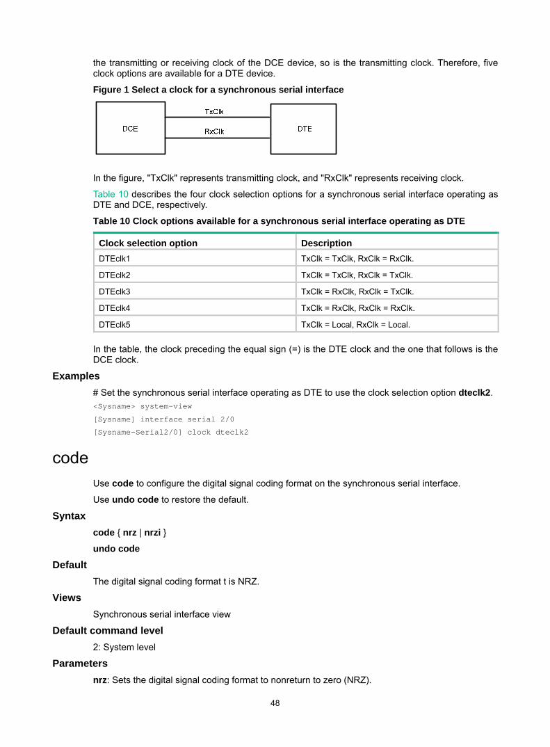
48
the transmitting or receiving clock of the DCE device, so is the transmitting clock. Therefore, five clock options are available for a DTE device.
Figure 1 Select a clock for a synchronous serial interface
In the figure, "TxClk" represents transmitting clock, and "RxClk" represents receiving clock.
Table 10 describes the four clock selection options for a synchronous serial interface operating as DTE and DCE, respectively.
Table 10 Clock options available for a synchronous serial interface operating as DTE
Clock selection option Description DTEclk1 TxClk = TxClk, RxClk = RxClk.
DTEclk2 TxClk = TxClk, RxClk = TxClk.
DTEclk3 TxClk = RxClk, RxClk = TxClk.
DTEclk4 TxClk = RxClk, RxClk = RxClk.
DTEclk5 TxClk = Local, RxClk = Local.
In the table, the clock preceding the equal sign (=) is the DTE clock and the one that follows is the DCE clock.
Examples # Set the synchronous serial interface operating as DTE to use the clock selection option dteclk2. <Sysname> system-view
[Sysname] interface serial 2/0
[Sysname-Serial2/0] clock dteclk2
code Use code to configure the digital signal coding format on the synchronous serial interface.
Use undo code to restore the default.
Syntax code { nrz | nrzi }
undo code
Default The digital signal coding format t is NRZ.
Views Synchronous serial interface view
Default command level 2: System level
Parameters nrz: Sets the digital signal coding format to nonreturn to zero (NRZ).
49
nrzi: Sets the digital signal coding format to nonreturn to zero inverted (NRZI).
Examples # Set the digital signal coding format to NRZI on synchronous serial interface 2/0. <Sysname> system-view
[Sysname] interface serial 2/0
[Sysname-Serial2/0] code nrzi
country-code Use country-code to set the coding format of the modem connected to the AM interface.
Use undo country-code to restore the default.
Syntax country-code area-name
undo country-code
Default The coding format of the modem connected to the AM is united-states.
Views AM interface view
Default command level 2: System level
Parameters area-name: Area name, which can be australia, austria, belgium, brazil, bulgaria, canada, china, czechoslovakia, denmark, finland, france, germany, greece, hongkong, hungary, india, ireland, israel, italy, japan, korea, luxembourg, malaysia, mexico, netherlands, new-zealand, norway, philippines, poland, portugal, russia, singapore, southafrica, spain, sweden, switzerland, taiwan, united-kingdom, and united-states.
Usage guidelines You can use this command to adapt to the modem coding formats in different countries and areas.
Examples # Set the coding format of the AM interface to china. <Sysname> system-view
[Sysname] interface analogmodem 2/0
[Sysname-Analogmodem2/0] country-code china
crc Use crc to set the CRC mode for a synchronous serial interface.
Use undo crc to restore the default.
Syntax crc { 16 | 32 | none }
undo crc
Default 16-bit CRC is adopted.
50
Views Synchronous serial interface view
Default command level 2: System level
Parameters 16: Specifies 16-bit CRC.
32: Specifies 32-bit CRC.
none: Disables CRC.
Examples # Configure synchronous serial interface Serial 2/0 to adopt 32-bit CRC. <Sysname> system-view
[Sysname] interface serial 2/0
[Sysname-Serial2/0] crc 32
detect Use detect to enable data carrier detection and level detection on the serial interface.
Use undo detect to disable data carrier detection and level detection on the serial interface.
Syntax Asynchronous serial interface:
detect dsr-dtr
undo detect dsr-dtr Synchronous serial interface:
detect { dcd | dsr-dtr }
undo detect { dcd | dsr-dtr }
Default Data carrier and level detection is enabled on serial interfaces.
Views Synchronous serial interface view, asynchronous serial interface view
Default command level 2: System level
Parameters dsr-dtr: Detects the data set ready (DSR) and data terminal ready (DTR) signals of the DSU/CSU.
dcd: Detects the data carrier detect (DCD) signal of the DSU/CSU on the serial interface.
Usage guidelines If level detection is disabled on an asynchronous serial interface, the system automatically reports that the state of the serial interface is up with both DTR and DSR being up without detecting whether a cable is connected. If level detection is enabled on the interface, the system detects the DSR signal in addition to the external cable. The interface is regarded as up only when the detected DSR signal is valid. Otherwise, it is regarded down.
By default, the system places a synchronous serial interface in up state only when it detects the correct DSR signal, DCD signal, and cable connection. The system shuts down the interface if it fails
51
to detect any of these items. If level detection is disabled, the system places the interface, DTR, and DSR in up state when it detects a cable connection.
Examples # Enable data carrier detection on synchronous serial interface 2/0. <Sysname> system-view
[Sysname] interface serial 2/0
[Sysname-Serial2/0] detect dcd
display interface analogmodem Use display interface analogmodem to display information about an AM interface.
Syntax display interface [ analogmodem ] [ brief [ down | description ] ] [ | { begin | exclude | include } regular-expression ]
display interface analogmodem interface-number [ brief [ description ] ] [ | { begin | exclude | include } regular-expression ]
Views Any view
Default command level 1: Monitor level
Parameters interface-number: Displays information about a specified AM interface.
brief: Displays brief interface information. If you do not specify this keyword, the command displays detailed interface information.
down: Displays information about interfaces in the DOWN state and the causes. If you do not specify this keyword, the command displays information about interfaces in all states.
description: Displays complete interface descriptions. If you do not specify this keyword, the command displays only the first 27 characters of interface descriptions. |: Filters command output by specifying a regular expression. For more information about regular expressions, see Fundamentals Configuration Guide.
begin: Displays the first line that matches the specified regular expression and all lines that follow.
exclude: Displays all lines that do not match the specified regular expression.
include: Displays all lines that match the specified regular expression.
regular-expression: Specifies a regular expression, a case-sensitive string of 1 to 256 characters.
Usage guidelines If you do not specify the analogmodem keyword, this command displays information about all interfaces on the device. If you specify the analogmodem keyword without the interface-number argument, this command displays information about all existing AM interface.
Examples # Display detailed information about interface AM 2/0. <Sysname> display interface analogmodem 2/0
Analogmodem2/0 current state: UP
Line protocol current state: UP

52
Description: Analogmodem2/0 Interface
The Maximum Transmit Unit is 1500, Hold timer is 10(sec)
Internet Address is 6.6.5.5/24 Primary
Link layer protocol is PPP
LCP opened, IPCP opened
Physical is Analogmodem2/0, baudrate: 64000
Output queue : (Urgent queuing : Size/Length/Discards) 0/100/0
Output queue : (Protocol queuing : Size/Length/Discards) 0/500/0
Output queue : (FIFO queuing : Size/Length/Discards) 0/75/0
Physical layer is asynchronous, Baudrate is 57600 bps
Phy-mru is 1700
Last clearing of counters: Never
Last 300 seconds input rate 0.00 bytes/sec, 0 bits/sec, 0.00 packets/sec
Last 300 seconds output rate 0.00 bytes/sec, 0 bits/sec, 0.00 packets/sec
Input: 0 packets, 0 bytes
0 broadcasts, 0 multicasts
0 errors, 0 runts, 0 giants
0 CRC, 0 align errors, 0 overruns
0 dribbles, 0 aborts, 0 no buffers
0 frame errors
Output:0 packets, 0 bytes
0 errors, 0 underruns, 0 collisions
0 deferred
DCD=DOWN DTR=UP DSR=UP RTS=UP CTS=UP
# Display brief information about interface AM 2/0. <Sysname> display interface analogmodem 2/0 brief
The brief information of interface(s) under route mode:
Link: ADM - administratively down; Stby - standby
Protocol: (s) - spoofing
Interface Link Protocol Main IP Description
analogmodem2/0 DOWN DOWN --
# Display brief information about all AM interfaces in the DOWN state. <Sysname> display interface analogmodem brief down
The brief information of interface(s) under route mode:
Link: ADM - administratively down; Stby - standby
Interface Link Cause
analogmodem2/0 DOWN Not connected
# Display brief information about AM interfaces, including their complete interface descriptions. <Sysname> display interface analogmodem brief description
The brief information of interface(s) under route mode:
Link: ADM - administratively down; Stby - standby
Protocol: (s) - spoofing
Interface Link Protocol Main IP Description
analogmodem2/0 DOWN DOWN -- The interface for Analog Modem.
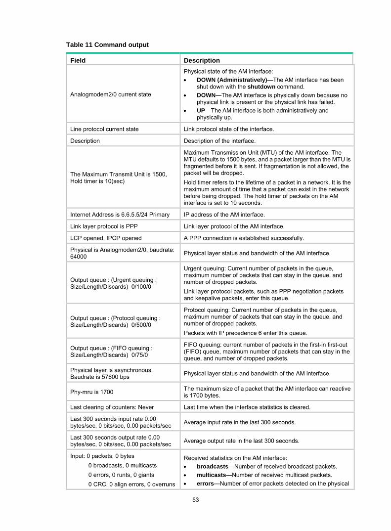
53
Table 11 Command output
Field Description
Analogmodem2/0 current state
Physical state of the AM interface: • DOWN (Administratively)—The AM interface has been
shut down with the shutdown command. • DOWN—The AM interface is physically down because no
physical link is present or the physical link has failed. • UP—The AM interface is both administratively and
physically up.
Line protocol current state Link protocol state of the interface.
Description Description of the interface.
The Maximum Transmit Unit is 1500, Hold timer is 10(sec)
Maximum Transmission Unit (MTU) of the AM interface. The MTU defaults to 1500 bytes, and a packet larger than the MTU is fragmented before it is sent. If fragmentation is not allowed, the packet will be dropped. Hold timer refers to the lifetime of a packet in a network. It is the maximum amount of time that a packet can exist in the network before being dropped. The hold timer of packets on the AM interface is set to 10 seconds.
Internet Address is 6.6.5.5/24 Primary IP address of the AM interface.
Link layer protocol is PPP Link layer protocol of the AM interface.
LCP opened, IPCP opened A PPP connection is established successfully.
Physical is Analogmodem2/0, baudrate: 64000 Physical layer status and bandwidth of the AM interface.
Output queue : (Urgent queuing : Size/Length/Discards) 0/100/0
Urgent queuing: Current number of packets in the queue, maximum number of packets that can stay in the queue, and number of dropped packets. Link layer protocol packets, such as PPP negotiation packets and keepalive packets, enter this queue.
Output queue : (Protocol queuing : Size/Length/Discards) 0/500/0
Protocol queuing: Current number of packets in the queue, maximum number of packets that can stay in the queue, and number of dropped packets. Packets with IP precedence 6 enter this queue.
Output queue : (FIFO queuing : Size/Length/Discards) 0/75/0
FIFO queuing: current number of packets in the first-in first-out (FIFO) queue, maximum number of packets that can stay in the queue, and number of dropped packets.
Physical layer is asynchronous, Baudrate is 57600 bps Physical layer status and bandwidth of the AM interface.
Phy-mru is 1700 The maximum size of a packet that the AM interface can reactive is 1700 bytes.
Last clearing of counters: Never Last time when the interface statistics is cleared.
Last 300 seconds input rate 0.00 bytes/sec, 0 bits/sec, 0.00 packets/sec Average input rate in the last 300 seconds.
Last 300 seconds output rate 0.00 bytes/sec, 0 bits/sec, 0.00 packets/sec Average output rate in the last 300 seconds.
Input: 0 packets, 0 bytes 0 broadcasts, 0 multicasts 0 errors, 0 runts, 0 giants 0 CRC, 0 align errors, 0 overruns
Received statistics on the AM interface: • broadcasts—Number of received broadcast packets. • multicasts—Number of received multicast packets. • errors—Number of error packets detected on the physical
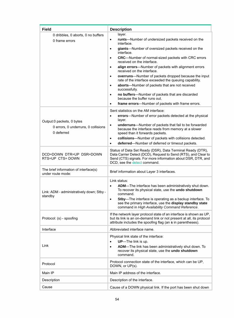
54
Field Description 0 dribbles, 0 aborts, 0 no buffers 0 frame errors
layer. • runts—Number of undersized packets received on the
interface. • giants—Number of oversized packets received on the
interface. • CRC—Number of normal-sized packets with CRC errors
received on the interface. • align errors—Number of packets with alignment errors
received on the interface. • overruns—Number of packets dropped because the input
rate of the interface exceeded the queuing capability. • aborts—Number of packets that are not received
successfully. • no buffers—Number of packets that are discarded
because the buffer runs out. • frame errors—Number of packets with frame errors.
Output:0 packets, 0 bytes 0 errors, 0 underruns, 0 collisions 0 deferred
Sent statistics on the AM interface: • errors—Number of error packets detected at the physical
layer. • underruns—Number of packets that fail to be forwarded
because the interface reads from memory at a slower speed than it forwards packets.
• collisions—Number of packets with collisions detected. • deferred—Number of deferred or timeout packets.
DCD=DOWN DTR=UP DSR=DOWN RTS=UP CTS= DOWN
Status of Data Set Ready (DSR), Data Terminal Ready (DTR), Data Carrier Detect (DCD), Request to Send (RTS), and Clear to Send (CTS) signals. For more information about DSR, DTR, and DCD, see the detect command.
The brief information of interface(s) under route mode: Brief information about Layer 3 interfaces.
Link: ADM - administratively down; Stby - standby
Link status: • ADM—The interface has been administratively shut down.
To recover its physical state, use the undo shutdown command.
• Stby—The interface is operating as a backup interface. To see the primary interface, use the display standby state command in High Availability Command Reference.
Protocol: (s) - spoofing If the network layer protocol state of an interface is shown as UP, but its link is an on-demand link or not present at all, its protocol attribute includes the spoofing flag (an s in parentheses).
Interface Abbreviated interface name.
Link
Physical link state of the interface: • UP—The link is up. • ADM—The link has been administratively shut down. To
recover its physical state, use the undo shutdown command.
Protocol Protocol connection state of the interface, which can be UP, DOWN, or UP(s).
Main IP Main IP address of the interface.
Description Description of the interface.
Cause Cause of a DOWN physical link. If the port has been shut down

55
Field Description with the shutdown command, this field displays Administratively. To restore the physical state of the interface, use the undo shutdown command.
display interface aux Use display interface aux to display information about AUX interfaces.
Syntax display interface [ aux ] [ brief [ down | description ] ] [ | { begin | exclude | include } regular-expression ]
display interface aux interface-number [ brief [ description ] ] [ | { begin | exclude | include } regular-expression ]
Views Any view
Default command level 1: Monitor level
Parameters interface-number: Displays information about a specified AUX interface.
brief: Displays brief interface information. If you do not specify this keyword, the command displays detailed interface information.
down: Displays information about interfaces in the DOWN state and the causes. If you do not specify this keyword, this command displays information about interfaces in all states.
description: Displays complete interface descriptions. If you do not specify this keyword, the command displays only the first 27 characters of interface descriptions. |: Filters command output by specifying a regular expression. For more information about regular expressions, see Fundamentals Configuration Guide.
begin: Displays the first line that matches the specified regular expression and all lines that follow.
exclude: Displays all lines that do not match the specified regular expression.
include: Displays all lines that match the specified regular expression.
regular-expression: Specifies a regular expression, a case-sensitive string of 1 to 256 characters.
Usage guidelines If you do not specify the aux keyword, this command displays information about all interfaces on the device.
If you specify the aux keyword without the interface-number argument, this command displays information about all existing AUX interfaces.
Examples # Display detailed information about interface AUX 0. <Sysname> display interface aux 0
Aux0 current state: UP
Line protocol current state: UP
Description: Aux0 Interface
The Maximum Transmit Unit is 1500, Hold timer is 10(sec)
Internet Address is 6.6.5.5/24 Primary

56
Link layer protocol is PPP
LCP opened, IPCP opened
Output queue : (Urgent queuing : Size/Length/Discards) 0/100/0
Output queue : (Protocol queuing : Size/Length/Discards) 0/500/0
Output queue : (FIFO queuing : Size/Length/Discards) 0/75/0
Physical layer is asynchronous, Baudrate is 9600 bps
Phy-mru is 1700
Last clearing of counters: Never
Last 300 seconds input rate 0.00 bytes/sec, 0 bits/sec, 0.00 packets/sec
Last 300 seconds output rate 0.00 bytes/sec, 0 bits/sec, 0.00 packets/sec
Input: 0 packets, 0 bytes
0 broadcasts, 0 multicasts
0 errors, 0 runts, 0 giants
0 CRC, 0 align errors, 0 overruns
0 dribbles, 0 aborts, 0 no buffers
0 frame errors
Output:0 packets, 0 bytes
0 errors, 0 underruns, 0 collisions
0 deferred
DCD=DOWN DTR=UP DSR=DOWN RTS=UP CTS=DOWN
# Display brief information about interface AUX 0. <Sysname> display interface aux 0 brief
The brief information of interface(s) under route mode:
Link: ADM - administratively down; Stby - standby
Protocol: (s) - spoofing
Interface Link Protocol Main IP Description
Aux0 DOWN DOWN --
# Display brief information about all AUX interfaces in the DOWN state. <Sysname> display interface aux brief down
The brief information of interface(s) under route mode:
Link: ADM - administratively down; Stby - standby
Interface Link Cause
Aux0 DOWN Not connected
# Display brief information about the AUX interface, including its complete interface description. <Sysname> display interface aux brief description
The brief information of interface(s) under route mode:
Link: ADM - administratively down; Stby - standby
Protocol: (s) - spoofing
Interface Link Protocol Main IP Description
Aux0 DOWN DOWN -- The interface for Administer.
Table 12 Command output
Field Description
Aux0 current state
Current physical state of the AUX interface: • DOWN (Administratively)—The AUX interface has
been shut down with the shutdown command. • DOWN—The AUX interface is physically down because
no physical link is present or the physical link has failed.
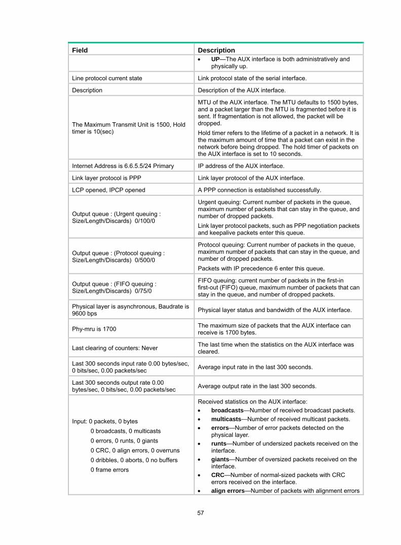
57
Field Description • UP—The AUX interface is both administratively and
physically up.
Line protocol current state Link protocol state of the serial interface.
Description Description of the AUX interface.
The Maximum Transmit Unit is 1500, Hold timer is 10(sec)
MTU of the AUX interface. The MTU defaults to 1500 bytes, and a packet larger than the MTU is fragmented before it is sent. If fragmentation is not allowed, the packet will be dropped. Hold timer refers to the lifetime of a packet in a network. It is the maximum amount of time that a packet can exist in the network before being dropped. The hold timer of packets on the AUX interface is set to 10 seconds.
Internet Address is 6.6.5.5/24 Primary IP address of the AUX interface.
Link layer protocol is PPP Link layer protocol of the AUX interface.
LCP opened, IPCP opened A PPP connection is established successfully.
Output queue : (Urgent queuing : Size/Length/Discards) 0/100/0
Urgent queuing: Current number of packets in the queue, maximum number of packets that can stay in the queue, and number of dropped packets. Link layer protocol packets, such as PPP negotiation packets and keepalive packets enter this queue.
Output queue : (Protocol queuing : Size/Length/Discards) 0/500/0
Protocol queuing: Current number of packets in the queue, maximum number of packets that can stay in the queue, and number of dropped packets. Packets with IP precedence 6 enter this queue.
Output queue : (FIFO queuing : Size/Length/Discards) 0/75/0
FIFO queuing: current number of packets in the first-in first-out (FIFO) queue, maximum number of packets that can stay in the queue, and number of dropped packets.
Physical layer is asynchronous, Baudrate is 9600 bps Physical layer status and bandwidth of the AUX interface.
Phy-mru is 1700 The maximum size of packets that the AUX interface can receive is 1700 bytes.
Last clearing of counters: Never The last time when the statistics on the AUX interface was cleared.
Last 300 seconds input rate 0.00 bytes/sec, 0 bits/sec, 0.00 packets/sec Average input rate in the last 300 seconds.
Last 300 seconds output rate 0.00 bytes/sec, 0 bits/sec, 0.00 packets/sec Average output rate in the last 300 seconds.
Input: 0 packets, 0 bytes 0 broadcasts, 0 multicasts 0 errors, 0 runts, 0 giants 0 CRC, 0 align errors, 0 overruns 0 dribbles, 0 aborts, 0 no buffers 0 frame errors
Received statistics on the AUX interface: • broadcasts—Number of received broadcast packets. • multicasts—Number of received multicast packets. • errors—Number of error packets detected on the
physical layer. • runts—Number of undersized packets received on the
interface. • giants—Number of oversized packets received on the
interface. • CRC—Number of normal-sized packets with CRC
errors received on the interface. • align errors—Number of packets with alignment errors
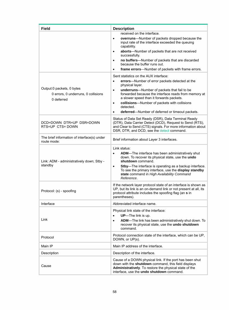
58
Field Description received on the interface.
• overruns—Number of packets dropped because the input rate of the interface exceeded the queuing capability.
• aborts—Number of packets that are not received successfully.
• no buffers—Number of packets that are discarded because the buffer runs out.
• frame errors—Number of packets with frame errors.
Output:0 packets, 0 bytes 0 errors, 0 underruns, 0 collisions 0 deferred
Sent statistics on the AUX interface: • errors—Number of error packets detected at the
physical layer. • underruns—Number of packets that fail to be
forwarded because the interface reads from memory at a slower speed than it forwards packets.
• collisions—Number of packets with collisions detected.
• deferred—Number of deferred or timeout packets.
DCD=DOWN DTR=UP DSR=DOWN RTS=UP CTS= DOWN
Status of Data Set Ready (DSR), Data Terminal Ready (DTR), Data Carrier Detect (DCD), Request to Send (RTS), and Clear to Send (CTS) signals. For more information about DSR, DTR, and DCD, see the detect command.
The brief information of interface(s) under route mode: Brief information about Layer 3 interfaces.
Link: ADM - administratively down; Stby - standby
Link status: • ADM—The interface has been administratively shut
down. To recover its physical state, use the undo shutdown command.
• Stby—The interface is operating as a backup interface. To see the primary interface, use the display standby state command in High Availability Command Reference.
Protocol: (s) - spoofing
If the network layer protocol state of an interface is shown as UP, but its link is an on-demand link or not present at all, its protocol attribute includes the spoofing flag (an s in parentheses).
Interface Abbreviated interface name.
Link
Physical link state of the interface: • UP—The link is up. • ADM—The link has been administratively shut down. To
recover its physical state, use the undo shutdown command.
Protocol Protocol connection state of the interface, which can be UP, DOWN, or UP(s).
Main IP Main IP address of the interface.
Description Description of the interface.
Cause
Cause of a DOWN physical link. If the port has been shut down with the shutdown command, this field displays Administratively. To restore the physical state of the interface, use the undo shutdown command.

59
display interface serial Use display interface serial to display information about serial interfaces.
Syntax display interface [ serial ] [ brief [ down | description ] ] [ | { begin | exclude | include } regular-expression ]
display interface serial interface-number [ brief [ description ] ] [ | { begin | exclude | include } regular-expression ]
Views Any view
Default command level 1: Monitor level
Parameters interface-number: Displays information about a specified serial interface.
brief: Displays brief interface information. If you do not specify this keyword, the command displays detailed interface information.
down: Displays information about interfaces in the DOWN state and the causes. If you do not specify this keyword, this command displays information about interfaces in all states.
description: Displays complete interface descriptions. If you do not specify this keyword, the command displays only the first 27 characters of interface descriptions. |: Filters command output by specifying a regular expression. For more information about regular expressions, see Fundamentals Configuration Guide.
begin: Displays the first line that matches the specified regular expression and all lines that follow.
exclude: Displays all lines that do not match the specified regular expression.
include: Displays all lines that match the specified regular expression.
regular-expression: Specifies a regular expression, a case-sensitive string of 1 to 256 characters.
Usage guidelines If you do not specify the serial keyword, this command displays information about all interfaces on the device.
If you specify the serial keyword without the interface-number argument, this command displays information about all existing serial interfaces.
Examples # Display detailed information about serial interface Serial 7/1. <Sysname> display interface serial 7/1
Serial7/1 current state: UP
Line protocol current state: UP
Description: Serial7/1 Interface
The Maximum Transmit Unit is 1500, Hold timer is 10(sec)
Internet Address is 9.9.9.6/24 Primary
Link layer protocol is PPP
LCP opened, IPCP opened
Output queue : (Urgent queuing : Size/Length/Discards) 0/100/0
Output queue : (Protocol queuing : Size/Length/Discards) 0/500/0
Output queue : (FIFO queuing : Size/Length/Discards) 0/75/0
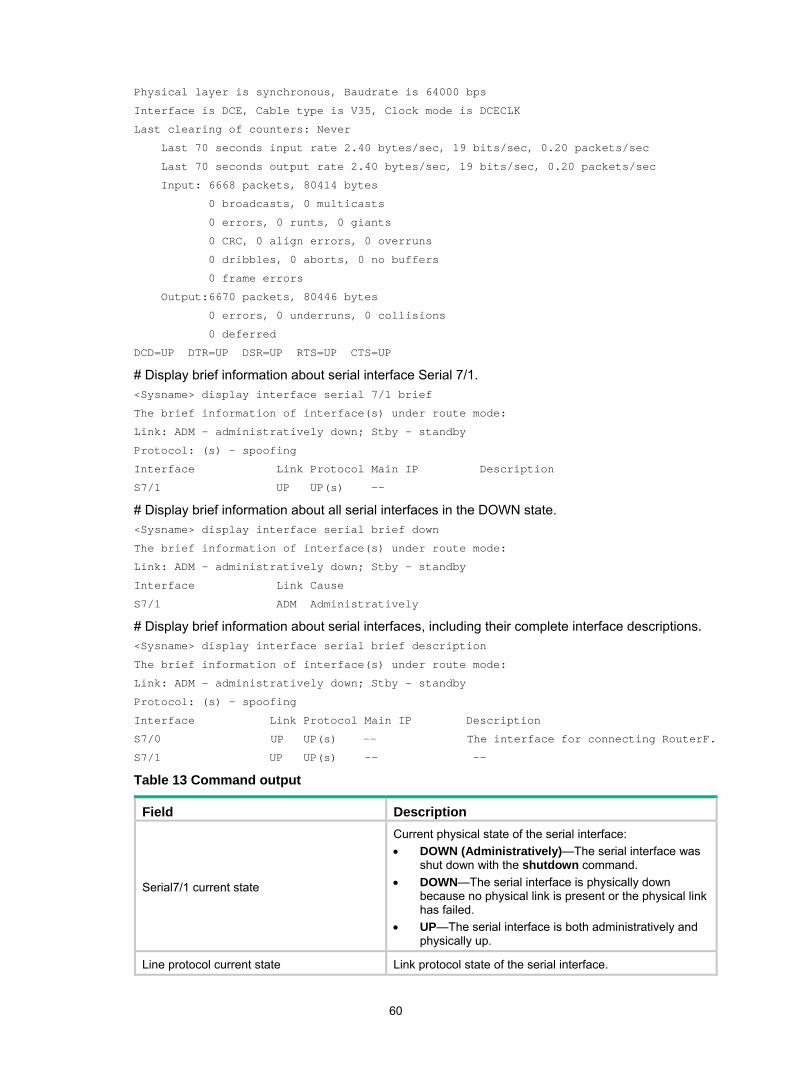
60
Physical layer is synchronous, Baudrate is 64000 bps
Interface is DCE, Cable type is V35, Clock mode is DCECLK
Last clearing of counters: Never
Last 70 seconds input rate 2.40 bytes/sec, 19 bits/sec, 0.20 packets/sec
Last 70 seconds output rate 2.40 bytes/sec, 19 bits/sec, 0.20 packets/sec
Input: 6668 packets, 80414 bytes
0 broadcasts, 0 multicasts
0 errors, 0 runts, 0 giants
0 CRC, 0 align errors, 0 overruns
0 dribbles, 0 aborts, 0 no buffers
0 frame errors
Output:6670 packets, 80446 bytes
0 errors, 0 underruns, 0 collisions
0 deferred
DCD=UP DTR=UP DSR=UP RTS=UP CTS=UP
# Display brief information about serial interface Serial 7/1. <Sysname> display interface serial 7/1 brief
The brief information of interface(s) under route mode:
Link: ADM - administratively down; Stby - standby
Protocol: (s) - spoofing
Interface Link Protocol Main IP Description
S7/1 UP UP(s) --
# Display brief information about all serial interfaces in the DOWN state. <Sysname> display interface serial brief down
The brief information of interface(s) under route mode:
Link: ADM - administratively down; Stby - standby
Interface Link Cause
S7/1 ADM Administratively
# Display brief information about serial interfaces, including their complete interface descriptions. <Sysname> display interface serial brief description
The brief information of interface(s) under route mode:
Link: ADM - administratively down; Stby - standby
Protocol: (s) - spoofing
Interface Link Protocol Main IP Description
S7/0 UP UP(s) -- The interface for connecting RouterF.
S7/1 UP UP(s) -- --
Table 13 Command output
Field Description
Serial7/1 current state
Current physical state of the serial interface: • DOWN (Administratively)—The serial interface was
shut down with the shutdown command. • DOWN—The serial interface is physically down
because no physical link is present or the physical link has failed.
• UP—The serial interface is both administratively and physically up.
Line protocol current state Link protocol state of the serial interface.
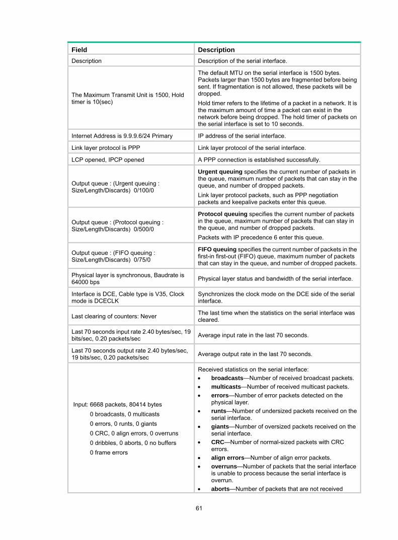
61
Field Description Description Description of the serial interface.
The Maximum Transmit Unit is 1500, Hold timer is 10(sec)
The default MTU on the serial interface is 1500 bytes. Packets larger than 1500 bytes are fragmented before being sent. If fragmentation is not allowed, these packets will be dropped. Hold timer refers to the lifetime of a packet in a network. It is the maximum amount of time a packet can exist in the network before being dropped. The hold timer of packets on the serial interface is set to 10 seconds.
Internet Address is 9.9.9.6/24 Primary IP address of the serial interface.
Link layer protocol is PPP Link layer protocol of the serial interface.
LCP opened, IPCP opened A PPP connection is established successfully.
Output queue : (Urgent queuing : Size/Length/Discards) 0/100/0
Urgent queuing specifies the current number of packets in the queue, maximum number of packets that can stay in the queue, and number of dropped packets. Link layer protocol packets, such as PPP negotiation packets and keepalive packets enter this queue.
Output queue : (Protocol queuing : Size/Length/Discards) 0/500/0
Protocol queuing specifies the current number of packets in the queue, maximum number of packets that can stay in the queue, and number of dropped packets. Packets with IP precedence 6 enter this queue.
Output queue : (FIFO queuing : Size/Length/Discards) 0/75/0
FIFO queuing specifies the current number of packets in the first-in first-out (FIFO) queue, maximum number of packets that can stay in the queue, and number of dropped packets.
Physical layer is synchronous, Baudrate is 64000 bps Physical layer status and bandwidth of the serial interface.
Interface is DCE, Cable type is V35, Clock mode is DCECLK
Synchronizes the clock mode on the DCE side of the serial interface.
Last clearing of counters: Never The last time when the statistics on the serial interface was cleared.
Last 70 seconds input rate 2.40 bytes/sec, 19 bits/sec, 0.20 packets/sec Average input rate in the last 70 seconds.
Last 70 seconds output rate 2.40 bytes/sec, 19 bits/sec, 0.20 packets/sec Average output rate in the last 70 seconds.
Input: 6668 packets, 80414 bytes 0 broadcasts, 0 multicasts 0 errors, 0 runts, 0 giants 0 CRC, 0 align errors, 0 overruns 0 dribbles, 0 aborts, 0 no buffers 0 frame errors
Received statistics on the serial interface: • broadcasts—Number of received broadcast packets. • multicasts—Number of received multicast packets. • errors—Number of error packets detected on the
physical layer. • runts—Number of undersized packets received on the
serial interface. • giants—Number of oversized packets received on the
serial interface. • CRC—Number of normal-sized packets with CRC
errors. • align errors—Number of align error packets. • overruns—Number of packets that the serial interface
is unable to process because the serial interface is overrun.
• aborts—Number of packets that are not received
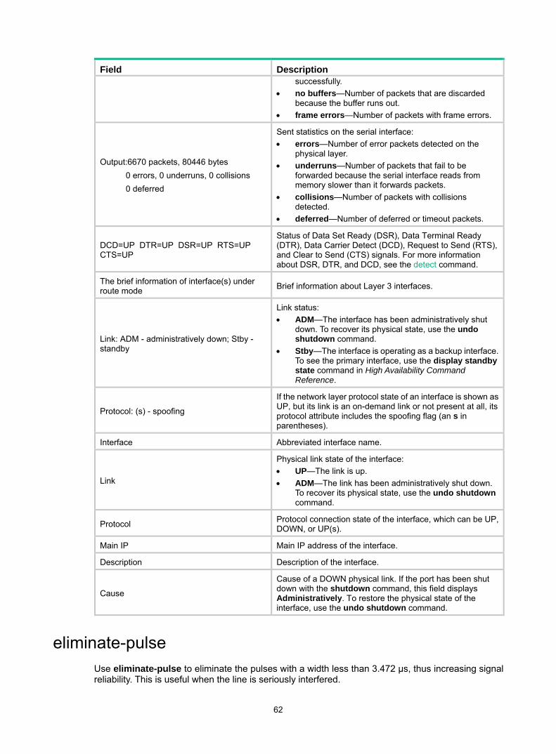
62
Field Description successfully.
• no buffers—Number of packets that are discarded because the buffer runs out.
• frame errors—Number of packets with frame errors.
Output:6670 packets, 80446 bytes 0 errors, 0 underruns, 0 collisions 0 deferred
Sent statistics on the serial interface: • errors—Number of error packets detected on the
physical layer. • underruns—Number of packets that fail to be
forwarded because the serial interface reads from memory slower than it forwards packets.
• collisions—Number of packets with collisions detected.
• deferred—Number of deferred or timeout packets.
DCD=UP DTR=UP DSR=UP RTS=UP CTS=UP
Status of Data Set Ready (DSR), Data Terminal Ready (DTR), Data Carrier Detect (DCD), Request to Send (RTS), and Clear to Send (CTS) signals. For more information about DSR, DTR, and DCD, see the detect command.
The brief information of interface(s) under route mode Brief information about Layer 3 interfaces.
Link: ADM - administratively down; Stby - standby
Link status: • ADM—The interface has been administratively shut
down. To recover its physical state, use the undo shutdown command.
• Stby—The interface is operating as a backup interface. To see the primary interface, use the display standby state command in High Availability Command Reference.
Protocol: (s) - spoofing
If the network layer protocol state of an interface is shown as UP, but its link is an on-demand link or not present at all, its protocol attribute includes the spoofing flag (an s in parentheses).
Interface Abbreviated interface name.
Link
Physical link state of the interface: • UP—The link is up. • ADM—The link has been administratively shut down.
To recover its physical state, use the undo shutdown command.
Protocol Protocol connection state of the interface, which can be UP, DOWN, or UP(s).
Main IP Main IP address of the interface.
Description Description of the interface.
Cause
Cause of a DOWN physical link. If the port has been shut down with the shutdown command, this field displays Administratively. To restore the physical state of the interface, use the undo shutdown command.
eliminate-pulse Use eliminate-pulse to eliminate the pulses with a width less than 3.472 μs, thus increasing signal reliability. This is useful when the line is seriously interfered.
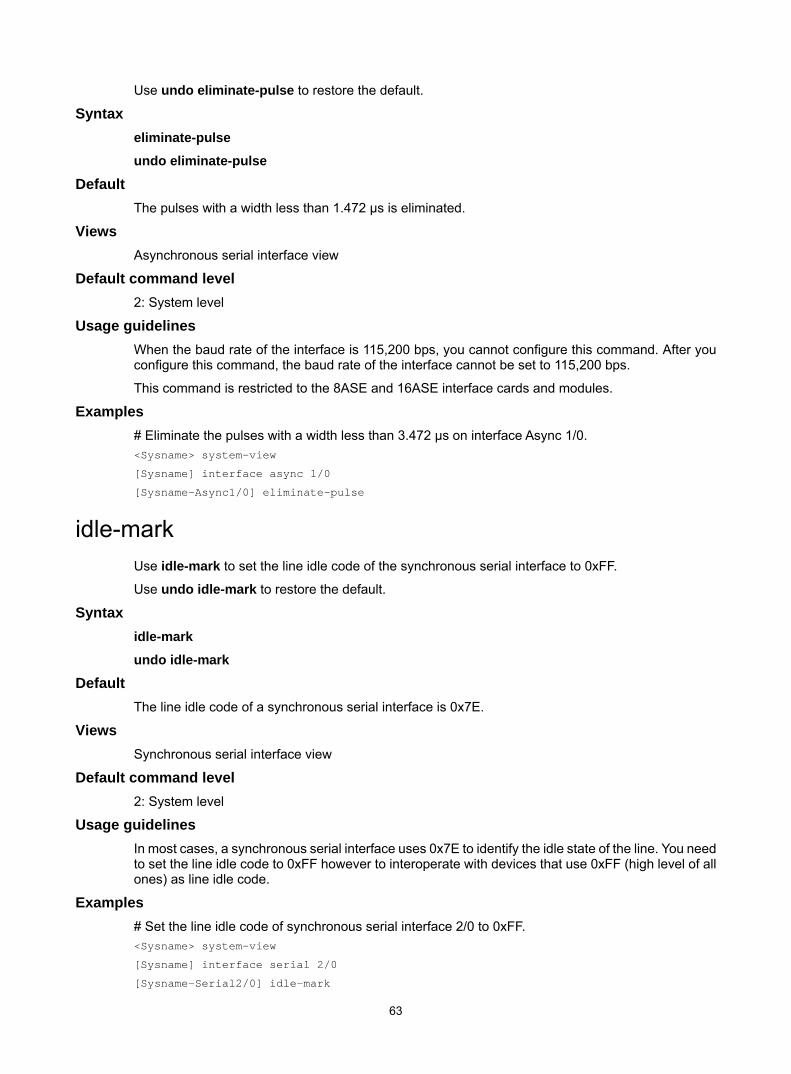
63
Use undo eliminate-pulse to restore the default.
Syntax eliminate-pulse undo eliminate-pulse
Default The pulses with a width less than 1.472 μs is eliminated.
Views Asynchronous serial interface view
Default command level 2: System level
Usage guidelines When the baud rate of the interface is 115,200 bps, you cannot configure this command. After you configure this command, the baud rate of the interface cannot be set to 115,200 bps.
This command is restricted to the 8ASE and 16ASE interface cards and modules.
Examples # Eliminate the pulses with a width less than 3.472 μs on interface Async 1/0. <Sysname> system-view
[Sysname] interface async 1/0
[Sysname-Async1/0] eliminate-pulse
idle-mark Use idle-mark to set the line idle code of the synchronous serial interface to 0xFF.
Use undo idle-mark to restore the default.
Syntax idle-mark
undo idle-mark
Default The line idle code of a synchronous serial interface is 0x7E.
Views Synchronous serial interface view
Default command level 2: System level
Usage guidelines In most cases, a synchronous serial interface uses 0x7E to identify the idle state of the line. You need to set the line idle code to 0xFF however to interoperate with devices that use 0xFF (high level of all ones) as line idle code.
Examples # Set the line idle code of synchronous serial interface 2/0 to 0xFF. <Sysname> system-view
[Sysname] interface serial 2/0
[Sysname-Serial2/0] idle-mark
64
invert receive-clock Use invert receive-clock to invert the receive-clock signal on the DTE-side synchronous serial interface.
Use undo invert receive-clock to restore the default.
Syntax invert receive-clock
undo invert receive-clock
Default Receive-clock signal inversion is disabled on DTE-side synchronous serial interfaces.
Views Synchronous serial interface view
Default command level 2: System level
Usage guidelines Sometimes, you need to invert the receive-clock signal on a DTE-side serial interface to eliminate the half clock-period delay on the line. This command is necessary only for some special DCE devices. In common applications, do not invert the clock.
Examples # Invert the receive-clock on DTE-side synchronous serial interface 2/0. <Sysname> system-view
[Sysname] interface serial 2/0
[Sysname-Serial2/0] invert receive-clock
Related commands • physical-mode • invert transmit-clock • clock
invert transmit-clock Use invert transmit-clock to invert the transmit-clock signal on the DTE-side synchronous serial interface.
Use undo invert transmit-clock to restore the default.
Syntax invert transmit-clock undo invert transmit-clock
Default Transmit-clock signal inversion is disabled on DTE-side synchronous serial interfaces.
Views Serial interface view
Default command level 2: System level
65
Usage guidelines Sometimes, you need to invert the receive-clock signal on a DTE-side serial interface to eliminate the half clock-period delay on the line. This command is necessary only for some special DCE devices. In common applications, do not invert the clock.
Examples # Invert the transmit-clock on DTE-side synchronous serial interface 2/0. <Sysname> system-view
[Sysname] interface serial 2/0
[Sysname-Serial2/0] invert transmit-clock
Related commands • physical-mode • invert receive-clock • clock
itf Use itf to set the number of interframe filling tags.
Syntax itf number number
undo itf number
Default The number of interframe filling tags is four.
Views Synchronous serial interface view
Default command level 2: System level
Parameters number number: Sets the number of interframe filling tags. (An interframe filling tag is one byte in length.) The value range is 0 to 14 bytes.
Examples # Set the number of interframe filling tags to five. <Sysname> system-view
[Sysname] interface serial 2/0
[Sysname-Serial2/0] itf number 5
loopback Use loopback to enable loopback on the serial interface.
Use undo loopback to restore the default.
Syntax loopback undo loopback
66
Default Loopback is disabled.
Views Serial interface view, AUX interface view, AM interface view
Default command level 2: System level
Usage guidelines Loopback is intended for test use. Disable loopback in other cases.
Examples # Enable loopback on interface Serial 2/0. <Sysname> system-view
[Sysname] interface serial 2/0
[Sysname-Serial2/0] loopback
looptest Use looptest to perform a loop test on a synchronous serial interface created for E1, T1, E1-F, or T1-F.
Syntax looptest [ -c count | -p { pattern | special { ascending | descending | random } } | -s packetsize | -t timeout ] * interface type number
Views Any view
Parameters -c count: Sets the number of test packets, in the range of 1 to 1 to 4294967295. The default number is 5.
-p pattern: Sets the padding content for test packets, which is a hexadecimal number in the range of 0 to FFFFFFFF. For example, -p ff pads FF to all test packets. By default, 0x55 and 0xAA are padded alternately.
ascending: Pads test packets with a hexadecimal number from 0x00 to 0xff in turn.
descending: Pads test packets with a hexadecimal number from 0xff to 0x00 in turn.
random: Pads test packets with a hexadecimal number from 0xff to 0x00 at random.
-s packetsize: Sets the size of test packets (excluding the 12-byte packet header), in the range of 0 to 1688 bytes. The default size is 52 bytes.
-t timeout: Sets the timeout time for receiving looped-back test packets, in the range of 0 to 65535 milliseconds. The default timeout time is 2000 milliseconds.
interface type number: Specifies an interface.
Usage guidelines Use looptest to detect loops on interfaces. The system returns the following line quality information: • Information about each test packet. If a test packet is looped back, the number of bytes,
sequence number, and delay are displayed for the test packet. If a test packet is not looped back before the timeout timer expires, the system displays " Wait time out."
• Statistics for all test packets, including the numbers of sent, received, lost, and error packets, percentages for error and lost packets, and the conclusion.
67
If the line speed is slow, increase the timeout time.
Examples # Perform a loop test on Serial 1/0/0. <Sysname> looptest interface serial 1/0/0
LOOPTEST Serial1/0/0: 52 data bytes, press CTRL_C to break
Receive from Serial1/0/0: bytes=52 sequence=1 time=1 ms
Receive from Serial1/0/0: bytes=52 sequence=2 time=1 ms
Receive from Serial1/0/0: bytes=52 sequence=3 time=1 ms
Receive from Serial1/0/0: bytes=52 sequence=4 time=1 ms
Receive from Serial1/0/0: bytes=52 sequence=5 time=1 ms
--- Serial1/0/0 looptest statistics ---
5 packet(s) transmitted
5 packet(s) received
0 packet(s) lost
0 packet(s) error
0.00% packet lost
0.00% packet error
round-trip min/avg/max = 1/1/1 ms
conclusion: loopback
Related commands • fe1 loopback • ft1 loopback • loopback
mtu Use mtu to set the MTU for an interface.
Use undo mtu to restore the default.
Syntax mtu size
undo mtu
Default The MTU of an interface is 1500 bytes.
Views Serial interface view, AUX interface view, AM interface view, Cellular interface view, E1-F interface view, T1-F interface view
Default command level 2: System level
Parameters size: Maximum transmission unit (MTU) in bytes, in the range of 128 to 1500 bytes.
Usage guidelines Due to the length of QoS queue, a packet might be discarded if the MTU is relatively small and the packet is segmented into too many fragments. To avoid this situation, you can increase the QoS
68
queue length by using the qos fifo queue-length command in interface view. For more information, see ACL and QoS Configuration Guide.
The MTU setting can affect IP packets assembly and fragmentation on the interface.
When you use the mtu command on a WAN interface, execute the shutdown command, and then the undo shutdown command to make your configuration take effect.
Examples # Set the MTU of interface Serial 2/0 to 1200 bytes. <Sysname> system-view
[Sysname] interface serial 2/0
[Sysname-Serial2/0] mtu 1200
physical-mode Use physical-mode to set the operating mode of the synchronous/asynchronous serial interface.
Syntax physical-mode { async | sync }
Default Synchronous/asynchronous serial interfaces are operating in synchronous mode.
Views Synchronous/asynchronous serial interface view
Default command level 2: System level
Parameters async: Sets the synchronous/asynchronous serial interface to operate in asynchronous mode.
sync: Sets the synchronous/asynchronous serial interface to operate in synchronous mode.
Examples # Set synchronous/asynchronous serial interface 2/0 to operate in asynchronous mode. <Sysname> system-view
[Sysname] interface serial 2/0
[Sysname-Serial2/0] physical-mode async
phy-mru Use phy-mru to set the MRU for an asynchronous serial interface operating in flow mode.
Use undo phy-mru to restore the default.
Syntax phy-mru size
undo phy-mru
Default The MRU of an asynchronous serial interface is 1700 bytes.
Views Asynchronous serial interface view, AUX interface view, AM interface view
69
Default command level 2: System level
Parameters size: Maximum receive unit (MRU) to be set, in the range of 4 to 1700 bytes.
Usage guidelines This command applies to only interfaces operating in the asynchronous flow mode.
Examples # Set the MRU of interface serial 2/0 to 1500 bytes (assuming that the interface is an asynchronous serial interface and operates in flow mode). <Sysname> system-view
[Sysname] interface serial 2/0
[Sysname-Serial2/0] physical-mode async
[Sysname-Serial2/0] async mode flow
[Sysname-Serial2/0] phy-mru 1500
reset counters interface Use reset counters interface to clear the statistics for cellular interfaces.
Syntax reset counters interface [ analogmodem [ interface-number ] ]
Views Use view
Default command level 2: System level
Parameters analogmodem interface-number: Specifies an AM interface.
Usage guidelines When you collect traffic statistics for a specific period of time on an AM interface, clear the existing statistics on the interface. • If you do not specify the analogmodem keyword, this command clears statistics on all
interfaces. • If you specify the analogmodem keyword without the interface-number argument, this
command clears statistics on all AM interfaces. • If you specify both the analogmodem keyword and the interface-number argument, this
command clears statistics on a specified AM interface.
Examples # Clear statistics on interface AM 2/0. <Sysname> reset counters interface analogmodem 2/0
reset counters interface Use reset counters interface to clear statistics on the specified AUX interface.
70
Syntax reset counters interface [ aux [ interface-number ] ]
Views Use view
Default command level 2: System level
Parameters aux interface-number: Specifies an AUX interface.
Usage guidelines When you collect traffic statistics for a specific period of time on an AUX interface, clear the existing statistics on the interface first. • If you do not specify the aux keyword, this command clears statistics on all interfaces. • If you specify the aux keyword without the interface-number argument, this command clears
statistics on all AUX interfaces. • If you specify both the aux keyword and the interface-number argument, this command clears
statistics on a specified AUX interface.
Examples # Clear statistics on interface AUX 2/0. <Sysname> reset counters interface aux 2/0
reset counters interface Use reset counters interface to clear statistics on the specified AM interface.
Syntax reset counters interface [ serial [ interface-number ] ]
Views Use view
Default command level 2: System level
Parameters serial interface-number: Specifies a serial interface.
Usage guidelines When you collect traffic statistics for a specific period of time on a serial interface, clear the existing statistics on the interface first. • If you do not specify the serial keyword, this command clears statistics on all interfaces. • If you specify the serial keyword without the interface-number argument, this command clears
statistics on all serial interfaces. • If you specify both the serial keyword and the interface-number argument, this command
clears statistics on a specified serial interface.
Examples # Clear statistics on interface Serial 2/0. <Sysname> reset counters interface serial 2/0
71
reverse-rts Use reverse-rts to reverse RTS signal in synchronous mode for debugging purpose.
Use undo reverse-rts to restore the default.
Syntax reverse-rts
undo reverse-rts
Default RTS signal reverse is disabled.
Views Synchronous serial interface view
Default command level 2: System level
Usage guidelines The remote is not allowed to send data when the local end is doing that.
Examples # Reverse the RTS signal. <Sysname> system-view
[Sysname] interface serial 2/0
[Sysname-Serial2/0] reverse-rts
timer hold Use timer hold to set the polling interval, the interval at which the interface sends keepalive packets.
Use undo timer hold to restore the default.
Syntax timer hold seconds
undo timer hold
Default The polling interval is 10 seconds.
Views Serial interface view, AUX interface view, AM interface view, Cellular interface view
Default command level 2: System level
Parameters seconds: Interval at which an interface sends keepalive packets, in the range of 0 to 32767 seconds.
Examples # Set the polling interval to 20 seconds for interface serial 2/0. <Sysname> system-view
[Sysname] interface serial 2/0
[Sysname-Serial2/0] timer hold 20
72
virtualbaudrate Use virtualbaudrate to set a virtual baud rate for the DTE-side interface.
Use undo virtualbaudrate to remove the specified virtual baud rate.
Syntax virtualbaudrate virtualbaudrate
undo virtualbaudrate
Views Synchronous serial interface view
Default command level 2: System level
Parameters virtualbaudrate: Baud rate (in bps) to be set, which must be consistent with the one configured at the DCE side. It can be 1200, 2400, 4800, 9600, 19200, 38400, 56000, 57600, 64000, 72000, 115200, 128000, 192000, 256000, 384000, 512000, 768000, 1024000, 2048000, or 4096000.
Usage guidelines When operating as DTE, the serial interface determines its baud rate through negotiation with the DCE side. The virtualbaudrate command, however, allows you to configure DTE-side baudrate manually, but the configured value must be the same as the one set at the DCE side.
If the clock selection mode of the serial interface is dteclk5, the virtual baud rate you configure here is the line rate.
Configure the baudrate command at DCE side and the virtualbaudrate command at DTE side (only when the interface is operating in synchronous mode). Avoid configuring the two commands at the same end of a link.
At DCE side, the display interface command displays the baud rate of the interface; whereas at the DTE end, the command displays the virtual baud rate of the interface.
Examples # Set the virtual baudrate of DTE interface Serial 2/0 to 19200 bps. <Sysname> system-view
[Sysname] interface serial 2/0
[Sysname-Serial2/0] virtualbaudrate 19200
Related commands • baudrate • clock
Basic 3G/4G modem configuration commands autodeploy sms enable
Use autodeploy sms enable to enable the SMS method of deploying configuration on the device.
Use undo autodeploy sms enable to disable SMS method of deploying configuration on the device.
73
Syntax autodeploy sms enable
undo autodeploy sms enable
Default SMS method of configuration deployment is enabled.
Views System view
Default command level 2: System level
Usage guidelines SMS method of configuration deployment is available only on 3G modem embedded routers. The feature enables an administrator to deploy initial configuration on the device by sending short messages through a 3G network.
This command is not supported on SIC-4G-LTE modem embedded routers.
Examples # Enable SMS method of configuration deployment. [Sysname]undo autodeploy sms enable
display cellular Use display cellular to display the call connection information of a 3G modem in PPP mode.
Syntax display cellular interface-number all [ | { begin | exclude | include } regular-expression ]
Views Any view
Default command level 1: Monitor level
Parameters all: Displays all the call connection information for the 3G modem.
|: Filters command output by specifying a regular expression. For more information about regular expressions, see Fundamentals Configuration Guide.
begin: Displays the first line that matches the specified regular expression and all lines that follow.
exclude: Displays all lines that do not match the specified regular expression.
include: Displays all lines that match the specified regular expression.
regular-expression: Specifies a regular expression, a case-sensitive string of 1 to 256 characters.
Usage guidelines This command is not supported on SIC-4G-LTE modem embedded routers.
Examples # Display call connection information on interface Cellular 0/0 (WCDMA mode). <Sysname> display cellular 0/0 all
Modem State:
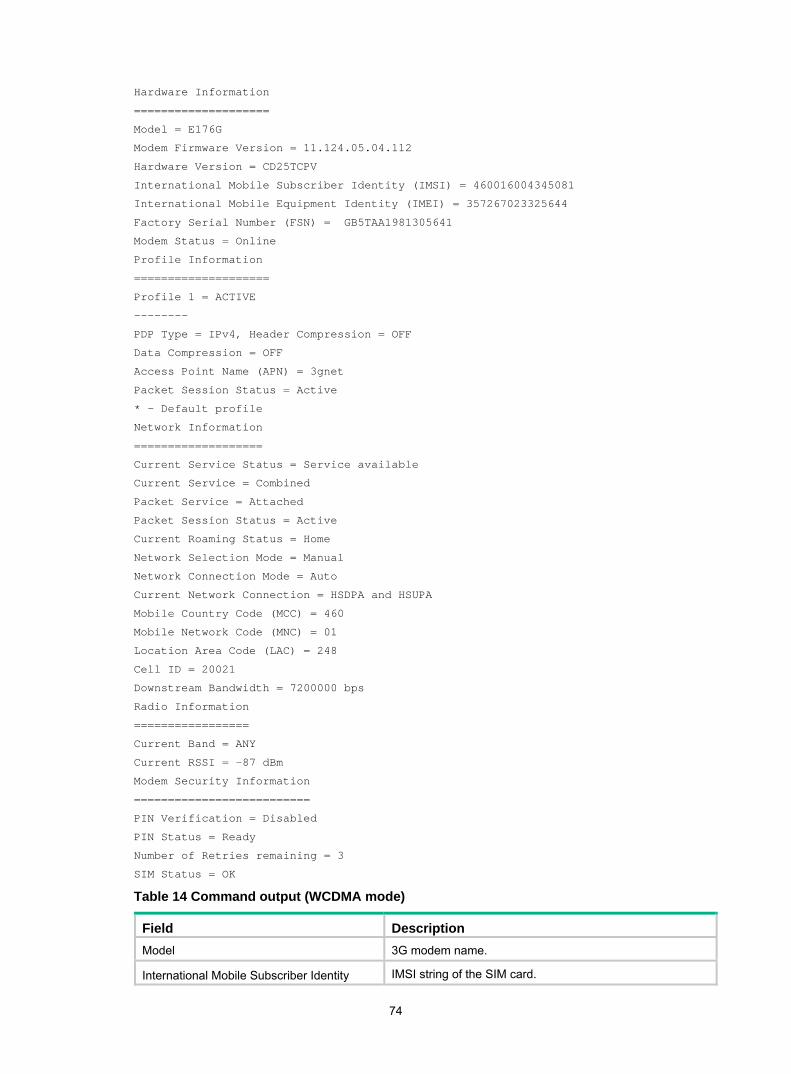
74
Hardware Information
====================
Model = E176G
Modem Firmware Version = 11.124.05.04.112
Hardware Version = CD25TCPV
International Mobile Subscriber Identity (IMSI) = 460016004345081
International Mobile Equipment Identity (IMEI) = 357267023325644
Factory Serial Number (FSN) = GB5TAA1981305641
Modem Status = Online
Profile Information
====================
Profile 1 = ACTIVE
--------
PDP Type = IPv4, Header Compression = OFF
Data Compression = OFF
Access Point Name (APN) = 3gnet
Packet Session Status = Active
* - Default profile
Network Information
===================
Current Service Status = Service available
Current Service = Combined
Packet Service = Attached
Packet Session Status = Active
Current Roaming Status = Home
Network Selection Mode = Manual
Network Connection Mode = Auto
Current Network Connection = HSDPA and HSUPA
Mobile Country Code (MCC) = 460
Mobile Network Code (MNC) = 01
Location Area Code (LAC) = 248
Cell ID = 20021
Downstream Bandwidth = 7200000 bps
Radio Information
=================
Current Band = ANY
Current RSSI = -87 dBm
Modem Security Information
==========================
PIN Verification = Disabled
PIN Status = Ready
Number of Retries remaining = 3
SIM Status = OK
Table 14 Command output (WCDMA mode)
Field Description Model 3G modem name.
International Mobile Subscriber Identity IMSI string of the SIM card.
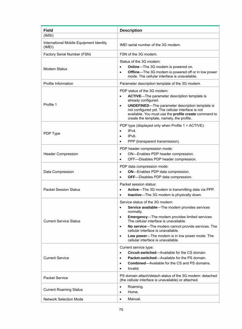
75
Field Description (IMSI)
International Mobile Equipment Identity (IMEI) IMEI serial number of the 3G modem.
Factory Serial Number (FSN) FSN of the 3G modem.
Modem Status
Status of the 3G modem: • Online—The 3G modem is powered on. • Offline—The 3G modem is powered off or in low power
mode. The cellular interface is unavailable.
Profile Information Parameter description template of the 3G modem.
Profile 1
PDP status of the 3G modem: • ACTIVE—The parameter description template is
already configured. • UNDEFINED—The parameter description template is
not configured yet. The cellular interface is not available. You must use the profile create command to create the template, namely, the profile.
PDP Type
PDP type (displayed only when Profile 1 = ACTIVE): • IPv4. • IPv6. • PPP (transparent transmission).
Header Compression PDP header compression mode: • ON—Enables PDP header compression. • OFF—Disables PDP header compression.
Data Compression PDP data compression mode: • ON—Enables PDP data compression. • OFF—Disables PDP data compression.
Packet Session Status Packet session status: • Active—The 3G modem is transmitting data via PPP. • Inactive—The 3G modem is physically down.
Current Service Status
Service status of the 3G modem: • Service available—The modem provides services
normally. • Emergency—The modem provides limited services.
The cellular interface is unavailable. • No service—The modem cannot provide services. The
cellular interface is unavailable. • Low power—The modem is in low power mode. The
cellular interface is unavailable.
Current Service
Current service type: • Circuit-switched—Available for the CS domain. • Packet-switched—Available for the PS domain. • Combined—Available for the CS and PS domains. • Invalid.
Packet Service PS domain attach/detach status of the 3G modem: detached (the cellular interface is unavailable) or attached.
Current Roaming Status • Roaming. • Home.
Network Selection Mode • Manual.
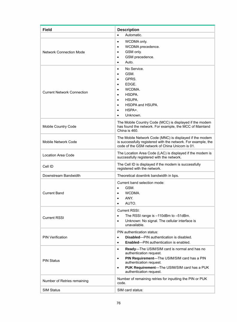
76
Field Description • Automatic.
Network Connection Mode
• WCDMA only. • WCDMA precedence. • GSM only. • GSM precedence. • Auto.
Current Network Connection
• No Service. • GSM. • GPRS. • EDGE. • WCDMA. • HSDPA. • HSUPA. • HSDPA and HSUPA. • HSPA+. • Unknown.
Mobile Country Code The Mobile Country Code (MCC) is displayed if the modem has found the network. For example, the MCC of Mainland China is 460.
Mobile Network Code The Mobile Network Code (MNC) is displayed if the modem is successfully registered with the network. For example, the code of the GSM network of China Unicom is 01.
Location Area Code The Location Area Code (LAC) is displayed if the modem is successfully registered with the network.
Cell ID The Cell ID is displayed if the modem is successfully registered with the network.
Downstream Bandwidth Theoretical downlink bandwidth in bps.
Current Band
Current band selection mode: • GSM. • WCDMA. • ANY. • AUTO.
Current RSSI
Current RSSI: • The RSSI range is –110dBm to –51dBm. • Unknown: No signal. The cellular interface is
unavailable.
PIN Verification PIN authentication status: • Disabled—PIN authentication is disabled. • Enabled—PIN authentication is enabled.
PIN Status
• Ready—The USIM/SIM card is normal and has no authentication request.
• PIN Requirement—The USIM/SIM card has a PIN authentication request.
• PUK Requirement—The USIM/SIM card has a PUK authentication request.
Number of Retries remaining Number of remaining retries for inputting the PIN or PUK code.
SIM Status SIM card status:
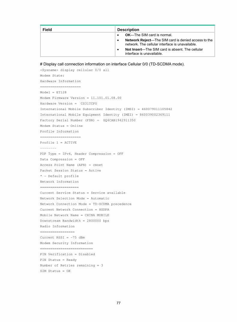
77
Field Description • OK—The SIM card is normal. • Network Reject—The SIM card is denied access to the
network. The cellular interface is unavailable. • Not Insert—The SIM card is absent. The cellular
interface is unavailable.
# Display call connection information on interface Cellular 0/0 (TD-SCDMA mode). <Sysname> display cellular 0/0 all
Modem State:
Hardware Information
====================
Model = ET128
Modem Firmware Version = 11.101.01.08.00
Hardware Version = CS31TCPU
International Mobile Subscriber Identity (IMSI) = 460079011105842
International Mobile Equipment Identity (IMEI) = 860039002369111
Factory Serial Number (FSN) = GQ4CAB1942911350
Modem Status = Online
Profile Information
====================
Profile 1 = ACTIVE
--------
PDP Type = IPv4, Header Compression = OFF
Data Compression = OFF
Access Point Name (APN) = cmnet
Packet Session Status = Active
* - Default profile
Network Information
===================
Current Service Status = Service available
Network Selection Mode = Automatic
Network Connection Mode = TD-SCDMA precedence
Current Network Connection = HSDPA
Mobile Network Name = CHINA MOBILE
Downstream Bandwidth = 2800000 bps
Radio Information
=================
Current RSSI = -75 dBm
Modem Security Information
==========================
PIN Verification = Disabled
PIN Status = Ready
Number of Retries remaining = 3
SIM Status = OK
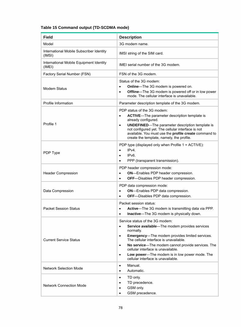
78
Table 15 Command output (TD-SCDMA mode)
Field Description Model 3G modem name.
International Mobile Subscriber Identity (IMSI) IMSI string of the SIM card.
International Mobile Equipment Identity (IMEI) IMEI serial number of the 3G modem.
Factory Serial Number (FSN) FSN of the 3G modem.
Modem Status
Status of the 3G modem: • Online—The 3G modem is powered on. • Offline—The 3G modem is powered off or in low power
mode. The cellular interface is unavailable.
Profile Information Parameter description template of the 3G modem.
Profile 1
PDP status of the 3G modem: • ACTIVE—The parameter description template is
already configured. • UNDEFINED—The parameter description template is
not configured yet. The cellular interface is not available. You must use the profile create command to create the template, namely, the profile.
PDP Type
PDP type (displayed only when Profile 1 = ACTIVE): • IPv4. • IPv6. • PPP (transparent transmission).
Header Compression PDP header compression mode: • ON—Enables PDP header compression. • OFF—Disables PDP header compression.
Data Compression PDP data compression mode: • ON—Enables PDP data compression. • OFF—Disables PDP data compression.
Packet Session Status Packet session status: • Active—The 3G modem is transmitting data via PPP. • Inactive—The 3G modem is physically down.
Current Service Status
Service status of the 3G modem: • Service available—The modem provides services
normally. • Emergency—The modem provides limited services.
The cellular interface is unavailable. • No service—The modem cannot provide services. The
cellular interface is unavailable. • Low power—The modem is in low power mode. The
cellular interface is unavailable.
Network Selection Mode • Manual. • Automatic.
Network Connection Mode
• TD only. • TD precedence. • GSM only. • GSM precedence.
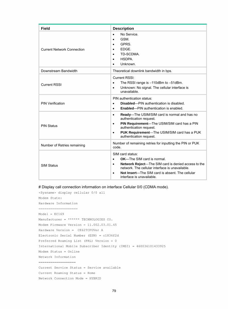
79
Field Description
Current Network Connection
• No Service. • GSM. • GPRS. • EDGE. • TD-SCDMA. • HSDPA. • Unknown.
Downstream Bandwidth Theoretical downlink bandwidth in bps.
Current RSSI
Current RSSI: • The RSSI range is –110dBm to –51dBm. • Unknown: No signal. The cellular interface is
unavailable.
PIN Verification PIN authentication status: • Disabled—PIN authentication is disabled. • Enabled—PIN authentication is enabled.
PIN Status
• Ready—The USIM/SIM card is normal and has no authentication request.
• PIN Requirement—The USIM/SIM card has a PIN authentication request.
• PUK Requirement—The USIM/SIM card has a PUK authentication request.
Number of Retries remaining Number of remaining retries for inputting the PIN or PUK code.
SIM Status
SIM card status: • OK—The SIM card is normal. • Network Reject—The SIM card is denied access to the
network. The cellular interface is unavailable. • Not Insert—The SIM card is absent. The cellular
interface is unavailable.
# Display call connection information on interface Cellular 0/0 (CDMA mode). <Sysname> display cellular 0/0 all
Modem State:
Hardware Information
====================
Model = EC169
Manufacturer = ****** TECHNOLOGIES CO.
Modem Firmware Version = 11.002.03.01.45
Hardware Version = CE62TCPUVer A
Electronic Serial Number (ESN) = c1836f2d
Preferred Roaming List (PRL) Version = 0
International Mobile Subscriber Identity (IMSI) = 460036101433925
Modem Status = Online
Network Information
===================
Current Service Status = Service available
Current Roaming Status = Home
Network Connection Mode = HYBRID

80
Current Network Connection = 1xRTT/EVDO HYBRID
Base Station ID = 57554
System ID = 13824
Network ID = 1
Sub-net ID of EVDO = 00A8C0006080000081090A1111E44207
Downstream Bandwidth = 3100000 bps
Radio Information
=================
Current RSSI(1xRTT) = -93 dBm
Current RSSI(EVDO) = -75 dBm
Current Voltage = 3336 mV
Modem Security Information
==========================
PIN Verification = Disabled
PIN Status = Ready
Number of Retries remaining = 3
UIM Status = OK
Table 16 Command output (CDMA mode)
Field Description Model 3G modem name.
International Mobile Subscriber Identity (IMSI) IMSI string of the SIM card.
Modem Status
Status of the 3G modem: • Online—The 3G modem is powered on. • Offline—The 3G modem is powered off or in low power
mode. The cellular interface is unavailable.
Current Service Status
Service status of the 3G modem: • Service available—The modem provides services
normally. • Emergency—The modem provides limited services.
The cellular interface is unavailable. • No service—The modem cannot provide services. The
cellular interface is unavailable. • Low power—The modem is in low power mode. The
cellular interface is unavailable.
Current Roaming Status • Roaming. • Home.
Network Selection Mode • Manual. • Automatic.
Current Network Connection
• No Service. • 1xRTT/EVDO HYBRID. • EVDO. • 1xRTT. • Unknown.
System ID System ID, available only when the modem is registered with a 1xRTT network.
Network ID Network ID, available only when the modem is registered with a 1xRTT network.
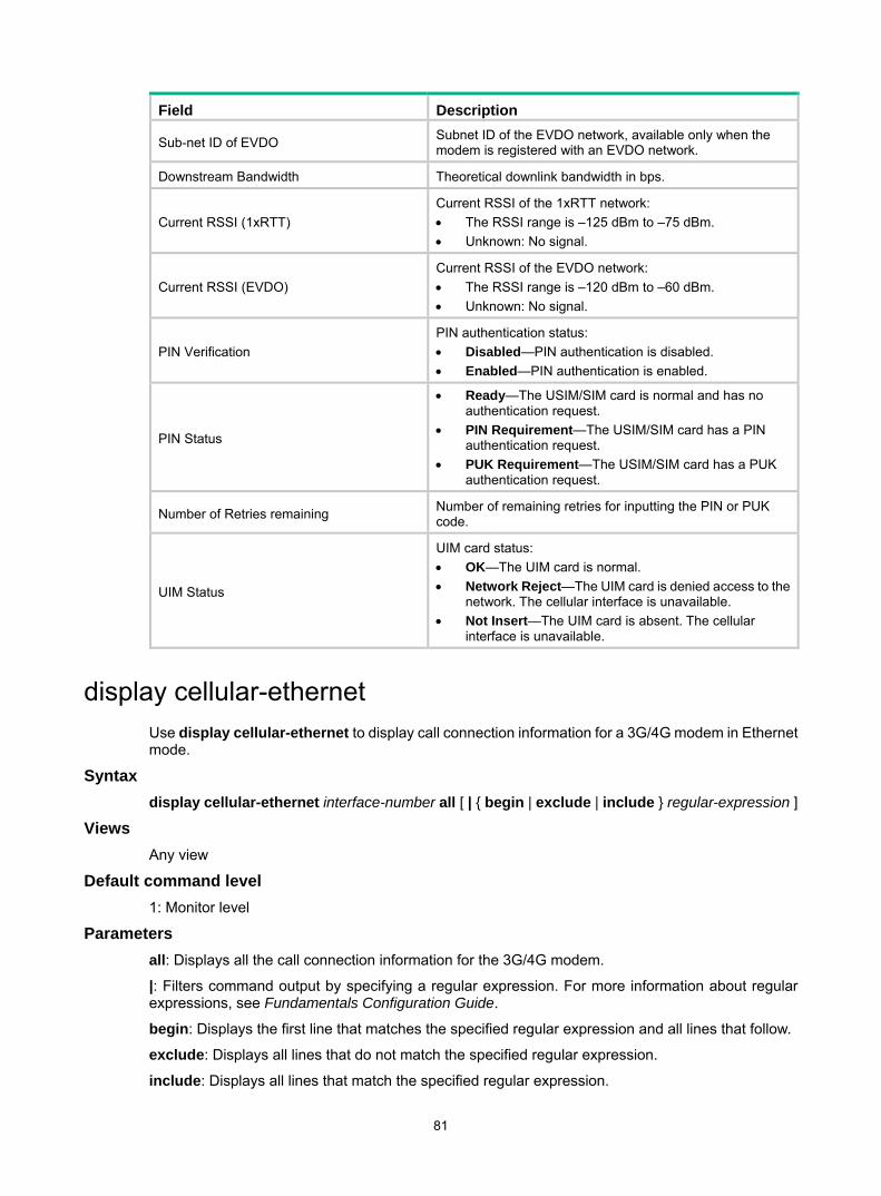
81
Field Description
Sub-net ID of EVDO Subnet ID of the EVDO network, available only when the modem is registered with an EVDO network.
Downstream Bandwidth Theoretical downlink bandwidth in bps.
Current RSSI (1xRTT) Current RSSI of the 1xRTT network: • The RSSI range is –125 dBm to –75 dBm. • Unknown: No signal.
Current RSSI (EVDO) Current RSSI of the EVDO network: • The RSSI range is –120 dBm to –60 dBm. • Unknown: No signal.
PIN Verification PIN authentication status: • Disabled—PIN authentication is disabled. • Enabled—PIN authentication is enabled.
PIN Status
• Ready—The USIM/SIM card is normal and has no authentication request.
• PIN Requirement—The USIM/SIM card has a PIN authentication request.
• PUK Requirement—The USIM/SIM card has a PUK authentication request.
Number of Retries remaining Number of remaining retries for inputting the PIN or PUK code.
UIM Status
UIM card status: • OK—The UIM card is normal. • Network Reject—The UIM card is denied access to the
network. The cellular interface is unavailable. • Not Insert—The UIM card is absent. The cellular
interface is unavailable.
display cellular-ethernet Use display cellular-ethernet to display call connection information for a 3G/4G modem in Ethernet mode.
Syntax display cellular-ethernet interface-number all [ | { begin | exclude | include } regular-expression ]
Views Any view
Default command level 1: Monitor level
Parameters all: Displays all the call connection information for the 3G/4G modem.
|: Filters command output by specifying a regular expression. For more information about regular expressions, see Fundamentals Configuration Guide.
begin: Displays the first line that matches the specified regular expression and all lines that follow.
exclude: Displays all lines that do not match the specified regular expression.
include: Displays all lines that match the specified regular expression.
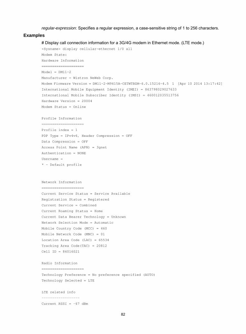
82
regular-expression: Specifies a regular expression, a case-sensitive string of 1 to 256 characters.
Examples # Display call connection information for a 3G/4G modem in Ethernet mode. (LTE mode.) <Sysname> display cellular-ethernet 1/0 all
Modem State:
Hardware Information
====================
Model = DM11-2
Manufacturer = Wistron NeWeb Corp.
Modem Firmware Version = DM11-2-M9615A-CETWTBZM-6.0.15216-4.5 1 [Apr 10 2014 13:17:42]
International Mobile Equipment Identity (IMEI) = 863798029027633
International Mobile Subscriber Identity (IMSI) = 460012035513756
Hardware Version = 20004
Modem Status = Online
Profile Information
====================
Profile index = 1
PDP Type = IPv4v6, Header Compression = OFF
Data Compression = OFF
Access Point Name (APN) = 3gnet
Authentication = NONE
Username =
* - Default profile
Network Information
====================
Current Service Status = Service Available
Registration Status = Registered
Current Service = Combined
Current Roaming Status = Home
Current Data Bearer Technology = Unknown
Network Selection Mode = Automatic
Mobile Country Code (MCC) = 460
Mobile Network Code (MNC) = 01
Location Area Code (LAC) = 65534
Tracking Area Code(TAC) = 20812
Cell ID = 86016021
Radio Information
====================
Technology Preference = No preference specified (AUTO)
Technology Selected = LTE
LTE related info
------------------
Current RSSI = -67 dBm
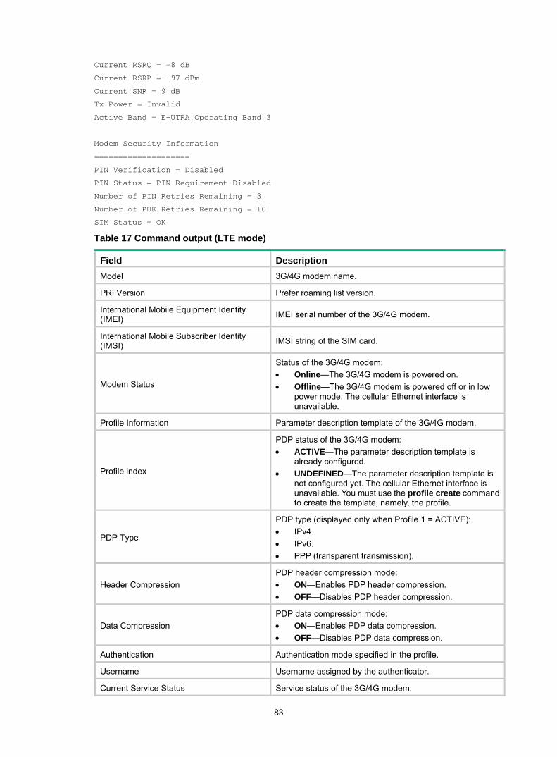
83
Current RSRQ = -8 dB
Current RSRP = -97 dBm
Current SNR = 9 dB
Tx Power = Invalid
Active Band = E-UTRA Operating Band 3
Modem Security Information
====================
PIN Verification = Disabled
PIN Status = PIN Requirement Disabled
Number of PIN Retries Remaining = 3
Number of PUK Retries Remaining = 10
SIM Status = OK
Table 17 Command output (LTE mode)
Field Description Model 3G/4G modem name.
PRI Version Prefer roaming list version.
International Mobile Equipment Identity (IMEI) IMEI serial number of the 3G/4G modem.
International Mobile Subscriber Identity (IMSI) IMSI string of the SIM card.
Modem Status
Status of the 3G/4G modem: • Online—The 3G/4G modem is powered on. • Offline—The 3G/4G modem is powered off or in low
power mode. The cellular Ethernet interface is unavailable.
Profile Information Parameter description template of the 3G/4G modem.
Profile index
PDP status of the 3G/4G modem: • ACTIVE—The parameter description template is
already configured. • UNDEFINED—The parameter description template is
not configured yet. The cellular Ethernet interface is unavailable. You must use the profile create command to create the template, namely, the profile.
PDP Type
PDP type (displayed only when Profile 1 = ACTIVE): • IPv4. • IPv6. • PPP (transparent transmission).
Header Compression PDP header compression mode: • ON—Enables PDP header compression. • OFF—Disables PDP header compression.
Data Compression PDP data compression mode: • ON—Enables PDP data compression. • OFF—Disables PDP data compression.
Authentication Authentication mode specified in the profile.
Username Username assigned by the authenticator.
Current Service Status Service status of the 3G/4G modem:
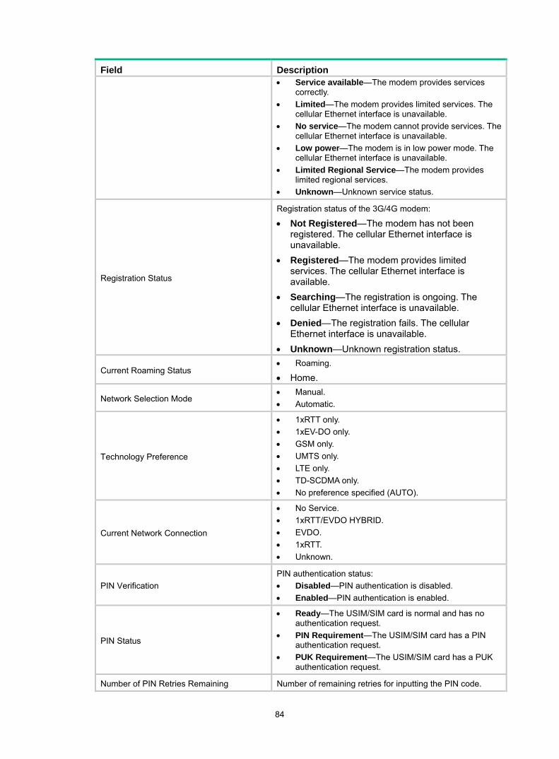
84
Field Description • Service available—The modem provides services
correctly. • Limited—The modem provides limited services. The
cellular Ethernet interface is unavailable. • No service—The modem cannot provide services. The
cellular Ethernet interface is unavailable. • Low power—The modem is in low power mode. The
cellular Ethernet interface is unavailable. • Limited Regional Service—The modem provides
limited regional services. • Unknown—Unknown service status.
Registration Status
Registration status of the 3G/4G modem:
• Not Registered—The modem has not been registered. The cellular Ethernet interface is unavailable.
• Registered—The modem provides limited services. The cellular Ethernet interface is available.
• Searching—The registration is ongoing. The cellular Ethernet interface is unavailable.
• Denied—The registration fails. The cellular Ethernet interface is unavailable.
• Unknown—Unknown registration status.
Current Roaming Status • Roaming.
• Home.
Network Selection Mode • Manual. • Automatic.
Technology Preference
• 1xRTT only. • 1xEV-DO only. • GSM only. • UMTS only. • LTE only. • TD-SCDMA only. • No preference specified (AUTO).
Current Network Connection
• No Service. • 1xRTT/EVDO HYBRID. • EVDO. • 1xRTT. • Unknown.
PIN Verification PIN authentication status: • Disabled—PIN authentication is disabled. • Enabled—PIN authentication is enabled.
PIN Status
• Ready—The USIM/SIM card is normal and has no authentication request.
• PIN Requirement—The USIM/SIM card has a PIN authentication request.
• PUK Requirement—The USIM/SIM card has a PUK authentication request.
Number of PIN Retries Remaining Number of remaining retries for inputting the PIN code.

85
Field Description Number of PUK Retries Remaining Number of remaining retries for inputting the PUK code.
SIM Status
SIM card status: • OK—The SIM/UIM card is normal. • Network Reject—The SIM/UIM card is denied access
to the network. The cellular interface is unavailable. • Not Insert—The SIM/UIM card is absent. The cellular
interface is unavailable.
LTE related info LTE network related information.
Current RSSI
Current Received Signal Strength Indicator: • The RSSI range is –110dBm to –51dBm. • Unknown: No signal. The cellular interface is
unavailable.
Current RSRQ Current Reference Signal Received Quality.
Current RSRP Current Reference Signal Received Power.
Current SNR Current Signal-to-Noise Ratio.
Tx Power Transmit power.
display gps Use display gps to display GPS information for an interface.
Syntax display gps interface interface-type interface-number
Views Any view
Default command level 1: Monitor level
Parameters interface-type interface-number: Specifies an interface by its type and number.
Usage guidelines This command is available only on the following routers: • MSR 930-LM. • MSR 930-W-LM. • MSR routers with the SIC-4G-LTE module.
Examples # Display GPS information for Cellular-Ethernet 1/0. <Sysname>display gps interface Cellular-Ethernet 1/0
GPS info
------------------
GPS State: Enabled
GPS Mode Configured: Standalone
Latitude: 40 Deg 4 Min 43 Sec North

86
Longitude: 116 Deg 21 Min 32 Sec East
Timestamp (UTC): 08/20/2013 07:15:48
Local time: 08/20/2013 15:15:48
Heading: 270.35, Velocity Horiz: 0.00, Velocity Vert: 0.00
Height (MSL): 34.00 m
Satellite Info
------------------
Satellite ID: #4
Elevation: 51.00, Azimuth: 227.00, SNR: 34.70, Processing Status: track
Satellite ID: #8
Elevation: 18.00, Azimuth: 206.00, SNR: 26.20, Processing Status: track
Satellite ID: #9
Elevation: 14.00, Azimuth: 209.00, SNR: 30.00, Processing Status: track
Satellite ID: #1
Elevation: 47.00, Azimuth: 47.00, SNR: 0.00, Processing Status: search
Satellite ID: #7
Elevation: 47.00, Azimuth: 47.00, SNR: 0.00, Processing Status: search
Satellite ID: #10
Elevation: 10.00, Azimuth: 174.00, SNR: 0.00, Processing Status: search
Satellite ID: #17
Elevation: 35.00, Azimuth: 289.00, SNR: 0.00, Processing Status: search
Satellite ID: #20
Elevation: 35.00, Azimuth: 144.00, SNR: 0.00, Processing Status: search
Satellite ID: #24
Table 18 Command output
Field Description GPS State GPS state: Enabled or Disabled.
GPS Mode Configured GPS mode.
Timestamp (UTC) UTC time.
Local time Local time: UTC + time zone.
Heading Heading direction.
Velocity Horiz Horizontal velocity.
Velocity Vert Vertical velocity.
Height (MSL) Mean sea level.
SNR Signal-to-noise ratio.
Processing Status
Satellite status: • unknown. • idle. • search. • track.
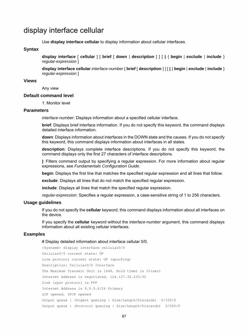
87
display interface cellular Use display interface cellular to display information about cellular interfaces.
Syntax display interface [ cellular ] [ brief [ down | description ] ] [ | { begin | exclude | include } regular-expression ]
display interface cellular interface-number [ brief [ description ] ] [ | { begin | exclude | include } regular-expression ]
Views Any view
Default command level 1: Monitor level
Parameters interface-number: Displays information about a specified cellular interface.
brief: Displays brief interface information. If you do not specify this keyword, the command displays detailed interface information.
down: Displays information about interfaces in the DOWN state and the causes. If you do not specify this keyword, this command displays information about interfaces in all states.
description: Displays complete interface descriptions. If you do not specify this keyword, the command displays only the first 27 characters of interface descriptions. |: Filters command output by specifying a regular expression. For more information about regular expressions, see Fundamentals Configuration Guide.
begin: Displays the first line that matches the specified regular expression and all lines that follow.
exclude: Displays all lines that do not match the specified regular expression.
include: Displays all lines that match the specified regular expression.
regular-expression: Specifies a regular expression, a case-sensitive string of 1 to 256 characters.
Usage guidelines If you do not specify the cellular keyword, this command displays information about all interfaces on the device.
If you specify the cellular keyword without the interface-number argument, this command displays information about all existing cellular interfaces.
Examples # Display detailed information about interface cellular 0/0. <Sysname> display interface cellular0/0
Cellular0/0 current state: UP
Line protocol current state: UP (spoofing)
Description: Cellular0/0 Interface
The Maximum Transmit Unit is 1448, Hold timer is 10(sec)
Internet Address is negotiated, 124.127.32.235/32
Link layer protocol is PPP
Internet Address is 9.9.9.6/24 Primary
LCP opened, IPCP opened
Output queue : (Urgent queuing : Size/Length/Discards) 0/100/0
Output queue : (Protocol queuing : Size/Length/Discards) 0/500/0
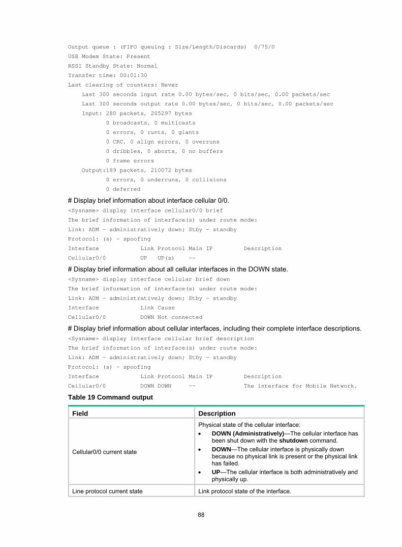
88
Output queue : (FIFO queuing : Size/Length/Discards) 0/75/0
USB Modem State: Present
RSSI Standby State: Normal
Transfer time: 00:01:30
Last clearing of counters: Never
Last 300 seconds input rate 0.00 bytes/sec, 0 bits/sec, 0.00 packets/sec
Last 300 seconds output rate 0.00 bytes/sec, 0 bits/sec, 0.00 packets/sec
Input: 280 packets, 205297 bytes
0 broadcasts, 0 multicasts
0 errors, 0 runts, 0 giants
0 CRC, 0 align errors, 0 overruns
0 dribbles, 0 aborts, 0 no buffers
0 frame errors
Output:189 packets, 210072 bytes
0 errors, 0 underruns, 0 collisions
0 deferred
# Display brief information about interface cellular 0/0. <Sysname> display interface cellular0/0 brief
The brief information of interface(s) under route mode:
Link: ADM - administratively down; Stby - standby
Protocol: (s) - spoofing
Interface Link Protocol Main IP Description
Cellular0/0 UP UP(s) --
# Display brief information about all cellular interfaces in the DOWN state. <Sysname> display interface cellular brief down
The brief information of interface(s) under route mode:
Link: ADM - administratively down; Stby - standby
Interface Link Cause
Cellular0/0 DOWN Not connected
# Display brief information about cellular interfaces, including their complete interface descriptions. <Sysname> display interface cellular brief description
The brief information of interface(s) under route mode:
Link: ADM - administratively down; Stby - standby
Protocol: (s) - spoofing
Interface Link Protocol Main IP Description
Cellular0/0 DOWN DOWN -- The interface for Mobile Network.
Table 19 Command output
Field Description
Cellular0/0 current state
Physical state of the cellular interface: • DOWN (Administratively)—The cellular interface has
been shut down with the shutdown command. • DOWN—The cellular interface is physically down
because no physical link is present or the physical link has failed.
• UP—The cellular interface is both administratively and physically up.
Line protocol current state Link protocol state of the interface.
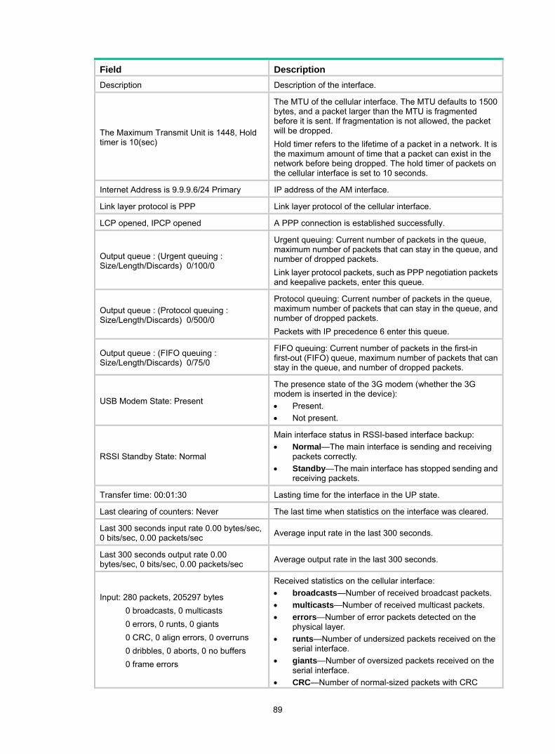
89
Field Description Description Description of the interface.
The Maximum Transmit Unit is 1448, Hold timer is 10(sec)
The MTU of the cellular interface. The MTU defaults to 1500 bytes, and a packet larger than the MTU is fragmented before it is sent. If fragmentation is not allowed, the packet will be dropped. Hold timer refers to the lifetime of a packet in a network. It is the maximum amount of time that a packet can exist in the network before being dropped. The hold timer of packets on the cellular interface is set to 10 seconds.
Internet Address is 9.9.9.6/24 Primary IP address of the AM interface.
Link layer protocol is PPP Link layer protocol of the cellular interface.
LCP opened, IPCP opened A PPP connection is established successfully.
Output queue : (Urgent queuing : Size/Length/Discards) 0/100/0
Urgent queuing: Current number of packets in the queue, maximum number of packets that can stay in the queue, and number of dropped packets. Link layer protocol packets, such as PPP negotiation packets and keepalive packets, enter this queue.
Output queue : (Protocol queuing : Size/Length/Discards) 0/500/0
Protocol queuing: Current number of packets in the queue, maximum number of packets that can stay in the queue, and number of dropped packets. Packets with IP precedence 6 enter this queue.
Output queue : (FIFO queuing : Size/Length/Discards) 0/75/0
FIFO queuing: Current number of packets in the first-in first-out (FIFO) queue, maximum number of packets that can stay in the queue, and number of dropped packets.
USB Modem State: Present
The presence state of the 3G modem (whether the 3G modem is inserted in the device): • Present. • Not present.
RSSI Standby State: Normal
Main interface status in RSSI-based interface backup: • Normal—The main interface is sending and receiving
packets correctly. • Standby—The main interface has stopped sending and
receiving packets.
Transfer time: 00:01:30 Lasting time for the interface in the UP state.
Last clearing of counters: Never The last time when statistics on the interface was cleared.
Last 300 seconds input rate 0.00 bytes/sec, 0 bits/sec, 0.00 packets/sec Average input rate in the last 300 seconds.
Last 300 seconds output rate 0.00 bytes/sec, 0 bits/sec, 0.00 packets/sec Average output rate in the last 300 seconds.
Input: 280 packets, 205297 bytes 0 broadcasts, 0 multicasts 0 errors, 0 runts, 0 giants 0 CRC, 0 align errors, 0 overruns 0 dribbles, 0 aborts, 0 no buffers 0 frame errors
Received statistics on the cellular interface: • broadcasts—Number of received broadcast packets. • multicasts—Number of received multicast packets. • errors—Number of error packets detected on the
physical layer. • runts—Number of undersized packets received on the
serial interface. • giants—Number of oversized packets received on the
serial interface. • CRC—Number of normal-sized packets with CRC
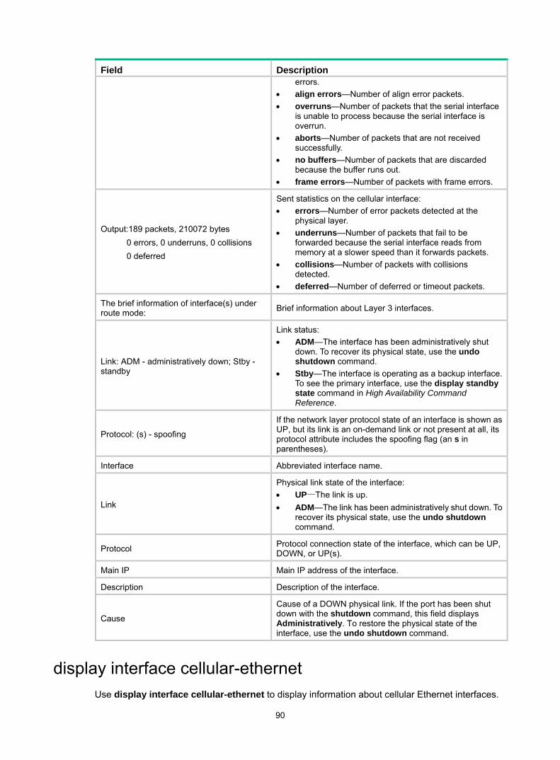
90
Field Description errors.
• align errors—Number of align error packets. • overruns—Number of packets that the serial interface
is unable to process because the serial interface is overrun.
• aborts—Number of packets that are not received successfully.
• no buffers—Number of packets that are discarded because the buffer runs out.
• frame errors—Number of packets with frame errors.
Output:189 packets, 210072 bytes 0 errors, 0 underruns, 0 collisions 0 deferred
Sent statistics on the cellular interface: • errors—Number of error packets detected at the
physical layer. • underruns—Number of packets that fail to be
forwarded because the serial interface reads from memory at a slower speed than it forwards packets.
• collisions—Number of packets with collisions detected.
• deferred—Number of deferred or timeout packets.
The brief information of interface(s) under route mode: Brief information about Layer 3 interfaces.
Link: ADM - administratively down; Stby - standby
Link status: • ADM—The interface has been administratively shut
down. To recover its physical state, use the undo shutdown command.
• Stby—The interface is operating as a backup interface. To see the primary interface, use the display standby state command in High Availability Command Reference.
Protocol: (s) - spoofing
If the network layer protocol state of an interface is shown as UP, but its link is an on-demand link or not present at all, its protocol attribute includes the spoofing flag (an s in parentheses).
Interface Abbreviated interface name.
Link
Physical link state of the interface: • UP—The link is up. • ADM—The link has been administratively shut down. To
recover its physical state, use the undo shutdown command.
Protocol Protocol connection state of the interface, which can be UP, DOWN, or UP(s).
Main IP Main IP address of the interface.
Description Description of the interface.
Cause
Cause of a DOWN physical link. If the port has been shut down with the shutdown command, this field displays Administratively. To restore the physical state of the interface, use the undo shutdown command.
display interface cellular-ethernet Use display interface cellular-ethernet to display information about cellular Ethernet interfaces.
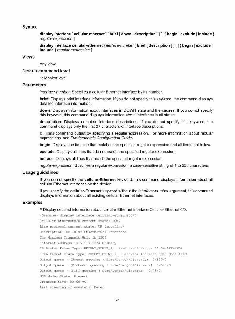
91
Syntax display interface [ cellular-ethernet ] [ brief [ down | description ] ] [ | { begin | exclude | include } regular-expression ]
display interface cellular-ethernet interface-number [ brief [ description ] ] [ | { begin | exclude | include } regular-expression ]
Views Any view
Default command level 1: Monitor level
Parameters interface-number: Specifies a cellular Ethernet interface by its number.
brief: Displays brief interface information. If you do not specify this keyword, the command displays detailed interface information.
down: Displays information about interfaces in DOWN state and the causes. If you do not specify this keyword, this command displays information about interfaces in all states.
description: Displays complete interface descriptions. If you do not specify this keyword, the command displays only the first 27 characters of interface descriptions.
|: Filters command output by specifying a regular expression. For more information about regular expressions, see Fundamentals Configuration Guide.
begin: Displays the first line that matches the specified regular expression and all lines that follow.
exclude: Displays all lines that do not match the specified regular expression.
include: Displays all lines that match the specified regular expression.
regular-expression: Specifies a regular expression, a case-sensitive string of 1 to 256 characters.
Usage guidelines If you do not specify the cellular-Ethernet keyword, this command displays information about all cellular Ethernet interfaces on the device.
If you specify the cellular-Ethernet keyword without the interface-number argument, this command displays information about all existing cellular Ethernet interfaces.
Examples # Display detailed information about cellular Ethernet interface Cellular-Ethernet 0/0. <Sysname> display interface cellular-ethernet0/0
Cellular-Ethernet0/0 current state: DOWN
Line protocol current state: UP (spoofing)
Description: Cellular-Ethernet0/0 Interface
The Maximum Transmit Unit is 1500
Internet Address is 5.5.5.5/24 Primary
IP Packet Frame Type: PKTFMT_ETHNT_2, Hardware Address: 00a0-d5ff-ff00
IPv6 Packet Frame Type: PKTFMT_ETHNT_2, Hardware Address: 00a0-d5ff-ff00
Output queue : (Urgent queuing : Size/Length/Discards) 0/100/0
Output queue : (Protocol queuing : Size/Length/Discards) 0/500/0
Output queue : (FIFO queuing : Size/Length/Discards) 0/75/0
USB Modem State: Present
Transfer time: 00:00:00
Last clearing of counters: Never
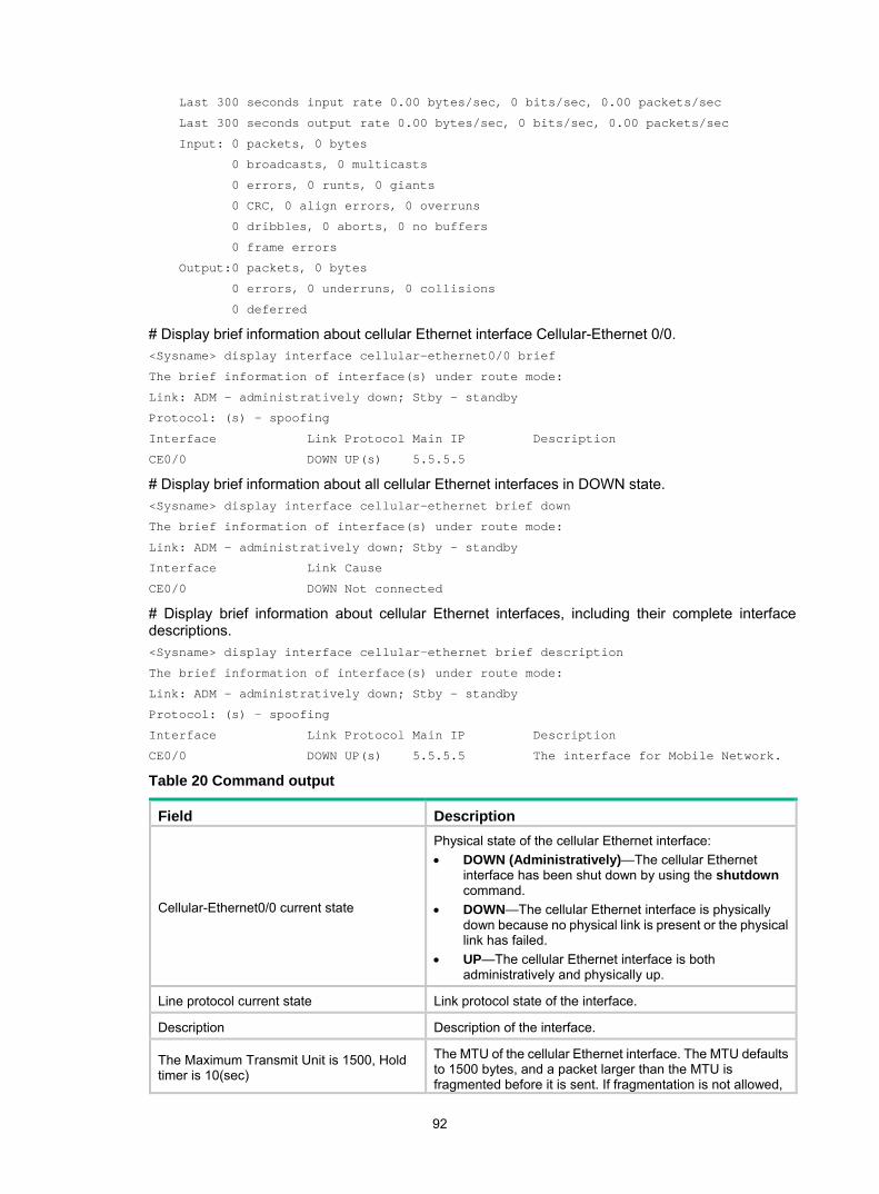
92
Last 300 seconds input rate 0.00 bytes/sec, 0 bits/sec, 0.00 packets/sec
Last 300 seconds output rate 0.00 bytes/sec, 0 bits/sec, 0.00 packets/sec
Input: 0 packets, 0 bytes
0 broadcasts, 0 multicasts
0 errors, 0 runts, 0 giants
0 CRC, 0 align errors, 0 overruns
0 dribbles, 0 aborts, 0 no buffers
0 frame errors
Output:0 packets, 0 bytes
0 errors, 0 underruns, 0 collisions
0 deferred
# Display brief information about cellular Ethernet interface Cellular-Ethernet 0/0. <Sysname> display interface cellular-ethernet0/0 brief
The brief information of interface(s) under route mode:
Link: ADM - administratively down; Stby - standby
Protocol: (s) - spoofing
Interface Link Protocol Main IP Description
CE0/0 DOWN UP(s) 5.5.5.5
# Display brief information about all cellular Ethernet interfaces in DOWN state. <Sysname> display interface cellular-ethernet brief down
The brief information of interface(s) under route mode:
Link: ADM - administratively down; Stby - standby
Interface Link Cause
CE0/0 DOWN Not connected
# Display brief information about cellular Ethernet interfaces, including their complete interface descriptions. <Sysname> display interface cellular-ethernet brief description
The brief information of interface(s) under route mode:
Link: ADM - administratively down; Stby - standby
Protocol: (s) - spoofing
Interface Link Protocol Main IP Description
CE0/0 DOWN UP(s) 5.5.5.5 The interface for Mobile Network.
Table 20 Command output
Field Description
Cellular-Ethernet0/0 current state
Physical state of the cellular Ethernet interface: • DOWN (Administratively)—The cellular Ethernet
interface has been shut down by using the shutdown command.
• DOWN—The cellular Ethernet interface is physically down because no physical link is present or the physical link has failed.
• UP—The cellular Ethernet interface is both administratively and physically up.
Line protocol current state Link protocol state of the interface.
Description Description of the interface.
The Maximum Transmit Unit is 1500, Hold timer is 10(sec)
The MTU of the cellular Ethernet interface. The MTU defaults to 1500 bytes, and a packet larger than the MTU is fragmented before it is sent. If fragmentation is not allowed,
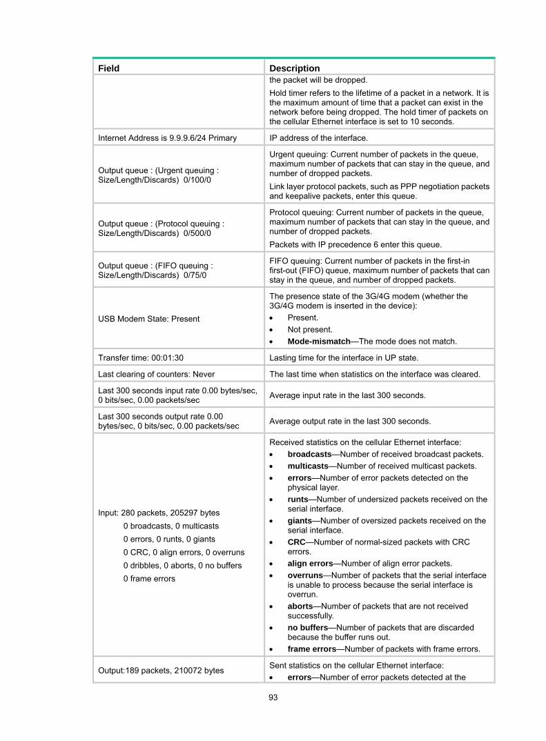
93
Field Description the packet will be dropped. Hold timer refers to the lifetime of a packet in a network. It is the maximum amount of time that a packet can exist in the network before being dropped. The hold timer of packets on the cellular Ethernet interface is set to 10 seconds.
Internet Address is 9.9.9.6/24 Primary IP address of the interface.
Output queue : (Urgent queuing : Size/Length/Discards) 0/100/0
Urgent queuing: Current number of packets in the queue, maximum number of packets that can stay in the queue, and number of dropped packets. Link layer protocol packets, such as PPP negotiation packets and keepalive packets, enter this queue.
Output queue : (Protocol queuing : Size/Length/Discards) 0/500/0
Protocol queuing: Current number of packets in the queue, maximum number of packets that can stay in the queue, and number of dropped packets. Packets with IP precedence 6 enter this queue.
Output queue : (FIFO queuing : Size/Length/Discards) 0/75/0
FIFO queuing: Current number of packets in the first-in first-out (FIFO) queue, maximum number of packets that can stay in the queue, and number of dropped packets.
USB Modem State: Present
The presence state of the 3G/4G modem (whether the 3G/4G modem is inserted in the device): • Present. • Not present. • Mode-mismatch—The mode does not match.
Transfer time: 00:01:30 Lasting time for the interface in UP state.
Last clearing of counters: Never The last time when statistics on the interface was cleared.
Last 300 seconds input rate 0.00 bytes/sec, 0 bits/sec, 0.00 packets/sec Average input rate in the last 300 seconds.
Last 300 seconds output rate 0.00 bytes/sec, 0 bits/sec, 0.00 packets/sec Average output rate in the last 300 seconds.
Input: 280 packets, 205297 bytes 0 broadcasts, 0 multicasts 0 errors, 0 runts, 0 giants 0 CRC, 0 align errors, 0 overruns 0 dribbles, 0 aborts, 0 no buffers 0 frame errors
Received statistics on the cellular Ethernet interface: • broadcasts—Number of received broadcast packets. • multicasts—Number of received multicast packets. • errors—Number of error packets detected on the
physical layer. • runts—Number of undersized packets received on the
serial interface. • giants—Number of oversized packets received on the
serial interface. • CRC—Number of normal-sized packets with CRC
errors. • align errors—Number of align error packets. • overruns—Number of packets that the serial interface
is unable to process because the serial interface is overrun.
• aborts—Number of packets that are not received successfully.
• no buffers—Number of packets that are discarded because the buffer runs out.
• frame errors—Number of packets with frame errors.
Output:189 packets, 210072 bytes Sent statistics on the cellular Ethernet interface: • errors—Number of error packets detected at the
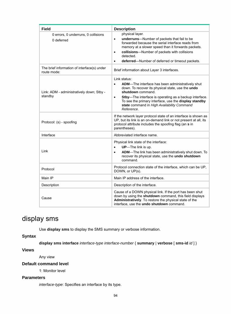
94
Field Description 0 errors, 0 underruns, 0 collisions 0 deferred
physical layer. • underruns—Number of packets that fail to be
forwarded because the serial interface reads from memory at a slower speed than it forwards packets.
• collisions—Number of packets with collisions detected.
• deferred—Number of deferred or timeout packets.
The brief information of interface(s) under route mode: Brief information about Layer 3 interfaces.
Link: ADM - administratively down; Stby - standby
Link status: • ADM—The interface has been administratively shut
down. To recover its physical state, use the undo shutdown command.
• Stby—The interface is operating as a backup interface. To see the primary interface, use the display standby state command in High Availability Command Reference.
Protocol: (s) - spoofing
If the network layer protocol state of an interface is shown as UP, but its link is an on-demand link or not present at all, its protocol attribute includes the spoofing flag (an s in parentheses).
Interface Abbreviated interface name.
Link
Physical link state of the interface: • UP—The link is up. • ADM—The link has been administratively shut down. To
recover its physical state, use the undo shutdown command.
Protocol Protocol connection state of the interface, which can be UP, DOWN, or UP(s).
Main IP Main IP address of the interface.
Description Description of the interface.
Cause
Cause of a DOWN physical link. If the port has been shut down by using the shutdown command, this field displays Administratively. To restore the physical state of the interface, use the undo shutdown command.
display sms Use display sms to display the SMS summary or verbose information.
Syntax display sms interface interface-type interface-number { summary | verbose [ sms-id id ] }
Views Any view
Default command level 1: Monitor level
Parameters interface-type: Specifies an interface by its type.
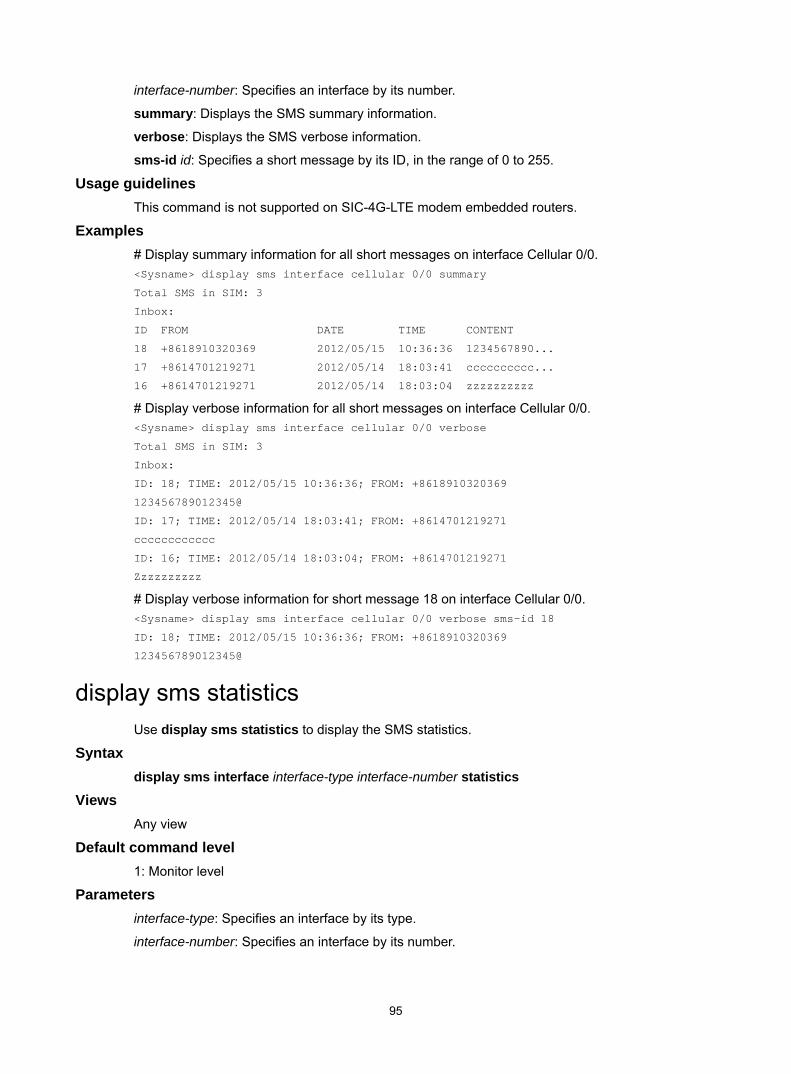
95
interface-number: Specifies an interface by its number.
summary: Displays the SMS summary information.
verbose: Displays the SMS verbose information.
sms-id id: Specifies a short message by its ID, in the range of 0 to 255.
Usage guidelines This command is not supported on SIC-4G-LTE modem embedded routers.
Examples # Display summary information for all short messages on interface Cellular 0/0. <Sysname> display sms interface cellular 0/0 summary
Total SMS in SIM: 3
Inbox:
ID FROM DATE TIME CONTENT
18 +8618910320369 2012/05/15 10:36:36 1234567890...
17 +8614701219271 2012/05/14 18:03:41 cccccccccc...
16 +8614701219271 2012/05/14 18:03:04 zzzzzzzzzz
# Display verbose information for all short messages on interface Cellular 0/0. <Sysname> display sms interface cellular 0/0 verbose
Total SMS in SIM: 3
Inbox:
ID: 18; TIME: 2012/05/15 10:36:36; FROM: +8618910320369
123456789012345@
ID: 17; TIME: 2012/05/14 18:03:41; FROM: +8614701219271
cccccccccccc
ID: 16; TIME: 2012/05/14 18:03:04; FROM: +8614701219271
Zzzzzzzzzz
# Display verbose information for short message 18 on interface Cellular 0/0. <Sysname> display sms interface cellular 0/0 verbose sms-id 18
ID: 18; TIME: 2012/05/15 10:36:36; FROM: +8618910320369
123456789012345@
display sms statistics Use display sms statistics to display the SMS statistics.
Syntax display sms interface interface-type interface-number statistics
Views Any view
Default command level 1: Monitor level
Parameters interface-type: Specifies an interface by its type.
interface-number: Specifies an interface by its number.
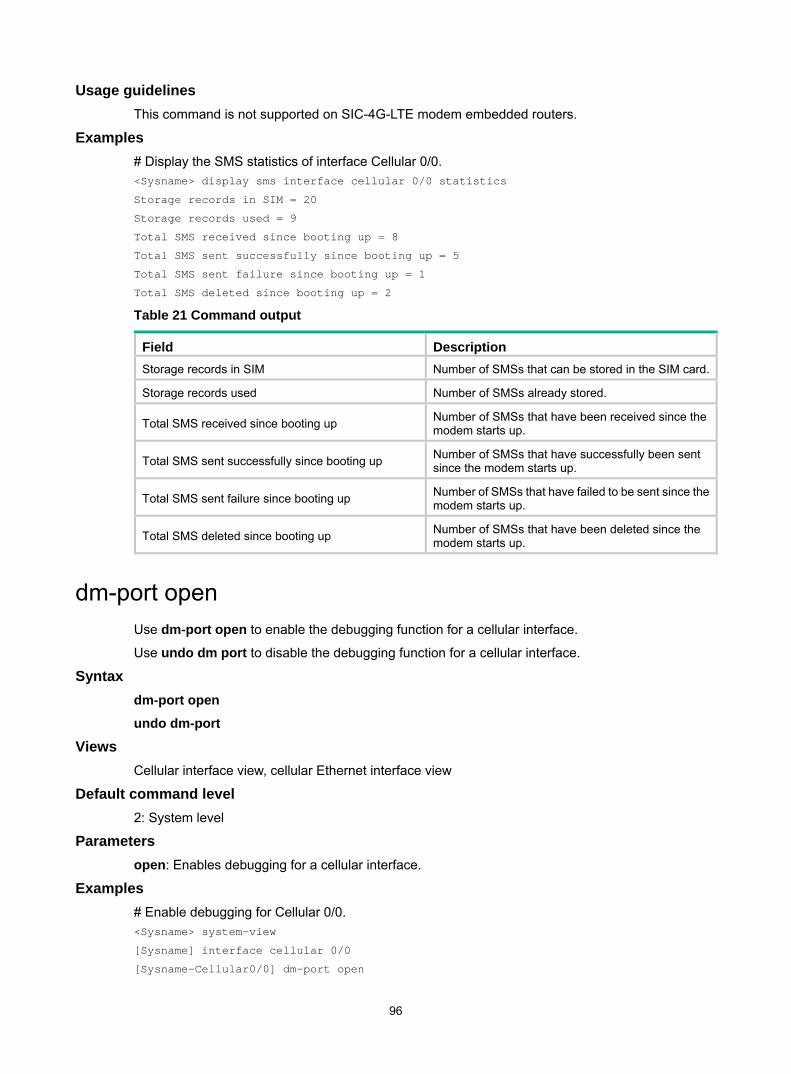
96
Usage guidelines This command is not supported on SIC-4G-LTE modem embedded routers.
Examples # Display the SMS statistics of interface Cellular 0/0. <Sysname> display sms interface cellular 0/0 statistics
Storage records in SIM = 20
Storage records used = 9
Total SMS received since booting up = 8
Total SMS sent successfully since booting up = 5
Total SMS sent failure since booting up = 1
Total SMS deleted since booting up = 2
Table 21 Command output
Field Description Storage records in SIM Number of SMSs that can be stored in the SIM card.
Storage records used Number of SMSs already stored.
Total SMS received since booting up Number of SMSs that have been received since the modem starts up.
Total SMS sent successfully since booting up Number of SMSs that have successfully been sent since the modem starts up.
Total SMS sent failure since booting up Number of SMSs that have failed to be sent since the modem starts up.
Total SMS deleted since booting up Number of SMSs that have been deleted since the modem starts up.
dm-port open Use dm-port open to enable the debugging function for a cellular interface.
Use undo dm port to disable the debugging function for a cellular interface.
Syntax dm-port open undo dm-port
Views Cellular interface view, cellular Ethernet interface view
Default command level 2: System level
Parameters open: Enables debugging for a cellular interface.
Examples # Enable debugging for Cellular 0/0. <Sysname> system-view
[Sysname] interface cellular 0/0
[Sysname-Cellular0/0] dm-port open
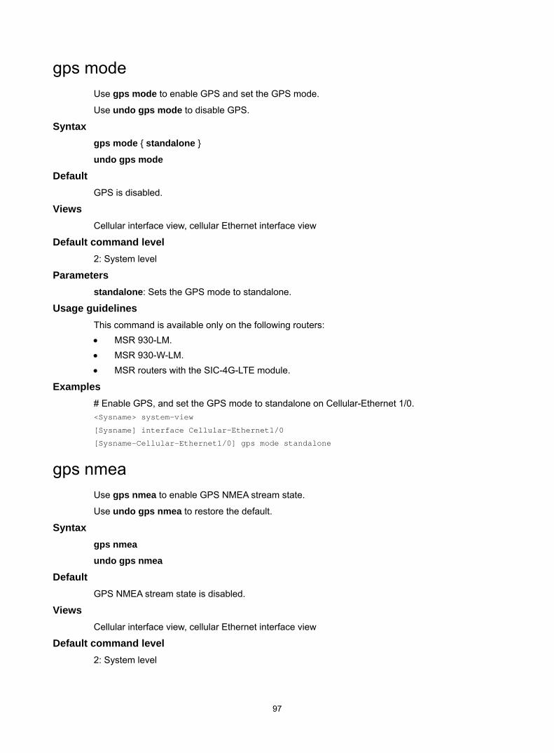
97
gps mode Use gps mode to enable GPS and set the GPS mode.
Use undo gps mode to disable GPS.
Syntax gps mode { standalone }
undo gps mode
Default GPS is disabled.
Views Cellular interface view, cellular Ethernet interface view
Default command level 2: System level
Parameters standalone: Sets the GPS mode to standalone.
Usage guidelines This command is available only on the following routers: • MSR 930-LM. • MSR 930-W-LM. • MSR routers with the SIC-4G-LTE module.
Examples # Enable GPS, and set the GPS mode to standalone on Cellular-Ethernet 1/0. <Sysname> system-view
[Sysname] interface Cellular-Ethernet1/0
[Sysname-Cellular-Ethernet1/0] gps mode standalone
gps nmea Use gps nmea to enable GPS NMEA stream state.
Use undo gps nmea to restore the default.
Syntax gps nmea undo gps nmea
Default GPS NMEA stream state is disabled.
Views Cellular interface view, cellular Ethernet interface view
Default command level 2: System level

98
Parameters N/A
Usage guidelines This command is available only on the following routers: • MSR 930-LM. • MSR 930-W-LM. • MSR routers with the SIC-4G-LTE module.
Examples # Enable GPS NMEA stream state on Cellular-Ethernet 1/0. <Sysname> system-view
[Sysname] interface Cellular-Ethernet1/0
[Sysname-Cellular-Ethernet1/0] gps mode standalone
ip address cellular-allocated Use ip address cellular-allocated to enable the interface to accept the IP address allocated by the peer through 4G modem negotiation.
Use undo ip address cellular-allocated to disable the interface from accepting the IP address allocated by the peer through 4G modem negotiation.
Syntax ip address cellular-allocated
undo ip address cellular-allocated
Default An interface does not accept the IP address allocated by the peer through 4G modem negotiation.
Views Interface view
Default command level 2: System level
Examples # Enable Cellular-Ethernet 1/0 to accept the IP address allocated by the peer through 4G modem negotiation. <Sysname> system-view
[Sysname] interface cellular-ethernet 1/0
[Sysname-Cellular-Ethernet1/0] ip address cellular-allocated
lte band Use lte band to specify an LTE band on a cellular or cellular Ethernet interface.
Use undo lte band to restore the default.
Syntax lte band band-number
undo lte band

99
Default All supported LTE bands are available.
Views Cellular interface view, cellular-Ethernet interface view
Default command level 2: System level
Parameters band-number: Specifies a LTE band for the 3G/4G modem.
Usage guidelines This command is available only on the following routers: • MSR 930-LM. • MSR 930-W-LM. • MSR routers with the SIC-4G-LTE module.
Examples # Specify LTE band 13 for Cellular-Ethernet 1/0. <Sysname> system-view
[Sysname] interface Cellular-Ethernet 1/0
[Sysname-Cellular-Ethernet1/0] lte band 13
mode cdma Use mode cdma to select a CDMA network connection mode.
Syntax mode cdma { 1xrtt-only | evdo-only | hybrid | lte-only | auto }
Views Cellular interface view, cellular Ethernet interface view
Default command level 2: System level
Parameters 1xrtt-only: Specifies that the 3G modem connect to 1x RTT networks only.
evdo-only: Specifies that the 3G modem connect to EVDO networks only.
hybrid: Specifies that the 3G modem connect to 1x RTT networks a EVDO networks.
lte-only: Configures the 4G modem to only connect to LTE networks.
auto: Configures the 4G modem to connect to EVDO networks, 1xRTT networks, and LTE networks.
Examples # Specify that the 3G/4G modem connect to EVDO networks only. <Sysname> system-view
[Sysname] interface cellular 0/0
[Sysname-Cellular0/0] mode cdma evdo-only
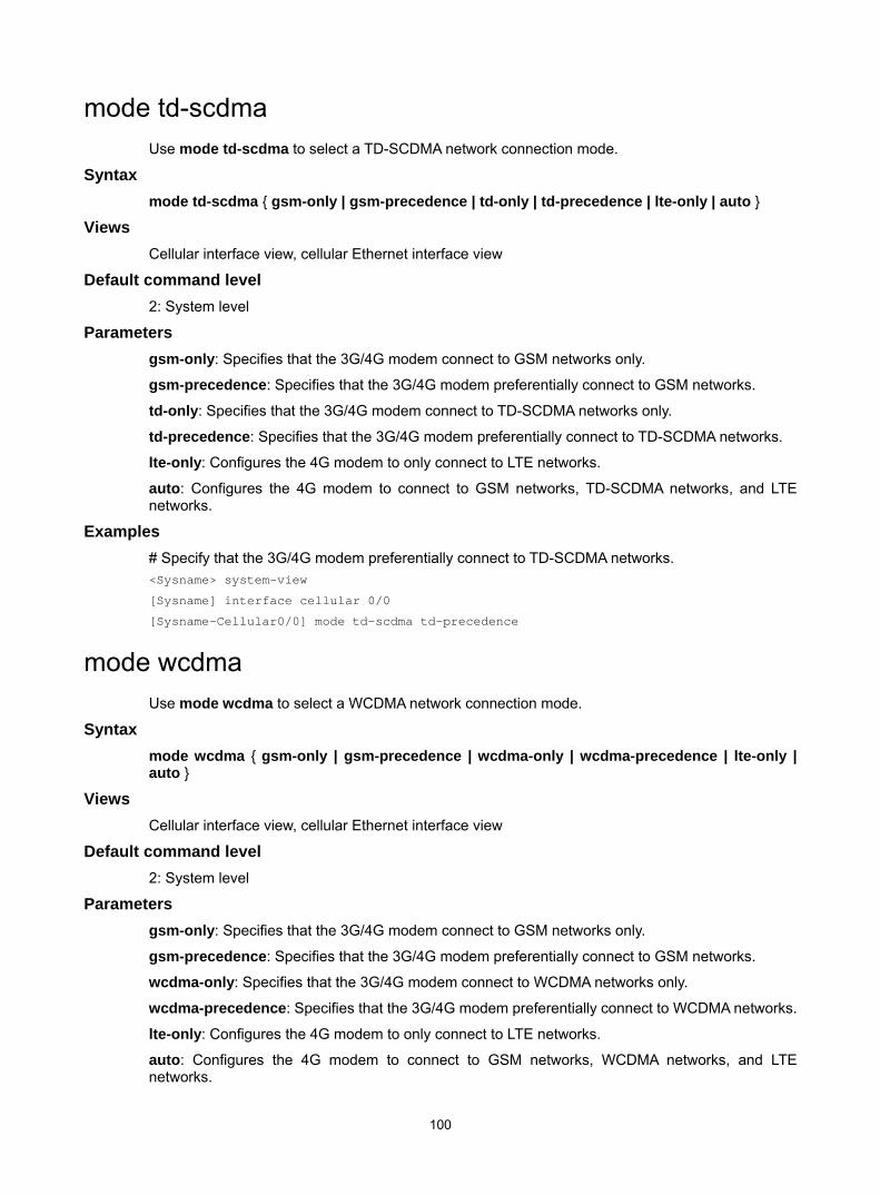
100
mode td-scdma Use mode td-scdma to select a TD-SCDMA network connection mode.
Syntax mode td-scdma { gsm-only | gsm-precedence | td-only | td-precedence | lte-only | auto }
Views Cellular interface view, cellular Ethernet interface view
Default command level 2: System level
Parameters gsm-only: Specifies that the 3G/4G modem connect to GSM networks only. gsm-precedence: Specifies that the 3G/4G modem preferentially connect to GSM networks.
td-only: Specifies that the 3G/4G modem connect to TD-SCDMA networks only.
td-precedence: Specifies that the 3G/4G modem preferentially connect to TD-SCDMA networks.
lte-only: Configures the 4G modem to only connect to LTE networks.
auto: Configures the 4G modem to connect to GSM networks, TD-SCDMA networks, and LTE networks.
Examples # Specify that the 3G/4G modem preferentially connect to TD-SCDMA networks. <Sysname> system-view
[Sysname] interface cellular 0/0
[Sysname-Cellular0/0] mode td-scdma td-precedence
mode wcdma Use mode wcdma to select a WCDMA network connection mode.
Syntax mode wcdma { gsm-only | gsm-precedence | wcdma-only | wcdma-precedence | lte-only | auto }
Views Cellular interface view, cellular Ethernet interface view
Default command level 2: System level
Parameters gsm-only: Specifies that the 3G/4G modem connect to GSM networks only.
gsm-precedence: Specifies that the 3G/4G modem preferentially connect to GSM networks.
wcdma-only: Specifies that the 3G/4G modem connect to WCDMA networks only.
wcdma-precedence: Specifies that the 3G/4G modem preferentially connect to WCDMA networks.
lte-only: Configures the 4G modem to only connect to LTE networks.
auto: Configures the 4G modem to connect to GSM networks, WCDMA networks, and LTE networks.

101
Examples # Specify that the 3G/4G modem preferentially connect to WCDMA networks. <Sysname> system-view
[Sysname] interface cellular 0/0
[Sysname-Cellular0/0] mode cdma wcdma-precedence
modem auto-recovery enable Use modem auto-recovery enable to enable auto-recovery.
Use undo modem auto-recovery enable to restore the default.
Syntax modem auto-recovery enable
undo modem auto-recovery enable
Default Auto-recovery is disabled.
Views Cellular interface view, cellular Ethernet interface view
Default command level 2: System level
Parameters None
Usage guidelines This function enables the 3G/4G modem to reset automatically if the number of consecutive dialup failures reaches the threshold set with the modem response command.
With this function disabled, the system automatically resets the modem only if the following conditions are met: • The 3G/4G modem has a successful dialup record after the last modem reset. • The number of consecutive dialup failure reaches the threshold set with the modem response
command.
This function avoids the failures to restore links caused by an abnormal 3G/4G network.
When you enable this function, make sure other configurations are correct. Incorrect configurations might cause undesirable modem reset.
Examples # Enable auto-recovery for interface Cellular 1/0. <Sysname> system-view
[Sysname]interface cellular 1/0
[Sysname-Cellular0/0] modem auto-recovery enable
Related commands modem response
modem reboot Use modem reboot to manually reboot a 3G modem.
102
Syntax modem reboot
Views Cellular interface view, cellular Ethernet interface view
Default command level 2: System level
Usage guidelines A 3G/4G modem can automatically detect running errors and reboot. If the 3G/4G modem fails to reboot by itself, you can use this command to manually reboot it.
Examples # Manually reboot an attached 3G/4G modem. <Sysname> system-view
[Sysname] interface cellular 0/0
[Sysname-Cellular0/0] modem reboot
modem response Use modem response to set the interval of waiting for the response from the 3G/4G modem after the system sends an AT command and the maximum times that the 3G/4G modem does not respond. When the threshold is reached, the system automatically resets the 3G/4G modem.
Use undo modem response to restore the default.
Syntax modem response timer time auto-recovery threshold
undo modem response
Views Cellular interface view, cellular Ethernet interface view
Default command level 2: System level
Parameters time: Interval of waiting for the response from the 3G/4G mode, in the range of 1 to 300 seconds. The default is 10 seconds.
threshold: Maximum times that the 3G/4G modem does not respond AT commands, in the range of 0 to 10. The default is 3. When the threshold is set to 0, the automatic resetting function is disabled.
Examples # Set the interval of waiting for the response from the 3G/4G modem to 20 seconds and a maximum of four times that the 3G/4G modem does not respond. <Sysname> system-view
[Sysname] interface cellular 0/0
[Sysname-Cellular0/0] modem response timer 20 auto-recovery 4
Related commands modem auto-recovery enable
103
pin modify Use pin modify to change the PIN of the SIM/UIM card. The new PIN is saved on the SIM/UIM card.
Syntax pin modify current-pin new-pin
Views Cellular interface view, cellular Ethernet interface view
Default command level 2: System level
Parameters current-pin: Personal Identification Number (PIN) of the SIM/UIM card inserted into the modem, comprising four to eight digits.
new-pin: New PIN to be set, comprising four to eight digits.
Examples # Change the PIN. <Sysname> system-view
[Sysname] interface cellular 0/0
[Sysname-Cellular0/0]pin modify 1234 4321
Warning: PIN will be changed to "4321". Continue? [Y/N]:y
PIN has been changed successfully.
pin unlock Use pin unlock to unlock the PIN of the SIM/UIM card inserted into the modem and set a new PIN.
Syntax pin unlock puk new-pin
Views Cellular interface view, cellular Ethernet interface view
Default command level 2: System level
Parameters puk: Personal Unblocking Code (PUK) of the SIM/UIM card inserted into the modem. A PUK has eight digits and is provided by the service provider.
new-pin: New Personal Identification Number (PIN) to be set, comprising four to eight digits.
Usage guidelines During a PIN verification, if the wrong PIN is typed three times in a row, the SIM/UIM card will be locked. In this case, you need to enter the PUK to unlock the SIM/UIM card, thus restoring the data communications functions of the 3G/4G modem.
Examples # Use the PUK code to unlock the PIN of the SIM/UIM card, and set a new PIN. <Sysname> system-view
[Sysname] interface cellular 0/0
104
[Sysname-Cellular0/0] pin unlock 87654321 1234
Warning: PIN will be unlocked and changed to "1234". Continue? [Y/N]:y
PIN has been unlocked changed successfully.
pin verification Use pin verification to enable or disable PIN verification for the 3G modem.
Syntax pin verification { enable | disable } pin
Views Cellular interface view, cellular Ethernet interface view
Default command level 2: System level
Parameters enable: Enables PIN verification.
disable: Disables PIN verification.
pin: PIN of the SIM/UIM card inserted into the modem, comprising four to eight digits.
Examples # Enable PIN verification. <Sysname> system-view
[Sysname] interface cellular 0/0
[Sysname-Cellular0/0] pin verification enable 1234
pin verify Use pin verify to perform PIN verification for the 3G modem.
Syntax pin verify [ cipher | simple ] pin
Default No PIN is configured for the SIM/UIM card on the 3G modem.
Views Cellular interface view, cellular Ethernet interface view
Default command level 2: System level
Parameters simple: Specifies the plaintext PIN, a string of four to eight digits, for the SIM/UIM card on the 3G/4G modem.
cipher: Specifies the ciphertext PIN for the SIM/UIM card on the 3G/4G modem. The ciphertext PIN is a string of 37 to 41 case-sensitive characters.
pin: Plaintext PIN of the SIM/UIM card on the modem if neither simple or cipher is specified, comprising four to eight digits.
105
Usage guidelines With PIN verification enabled on a 3G/4G modem, you will be required to type the correct PIN to recover the data communications functions of the modem when the modem resets. The modem resets when the router is rebooted, when you use the modem reboot command to reboot it, or when it is hot-swapped. For an SIC-3G-CDMA module, PIN verification is required only when the router is cold booted.
Examples # Perform PIN verification. <Sysname> system-view
[Sysname] interface cellular 0/0
[Sysname-Cellular0/0] pin verify 1234
plmn search Use plmn search to search for mobile networks.
Syntax plmn search
Views Cellular interface view, cellular Ethernet interface view
Default command level 2: System level
Usage guidelines This command is not a configuration command, but a network probe command. It takes a few minutes for the modem to search for mobile networks. After the search is complete, the CLI displays the mobile networks found.
Examples # Search for mobile networks on Cellular 0/0. <Sysname> system-view
[Sysname] interface cellular 0/0
[Sysname-Cellular0/0] plmn search
plmn select Use plmn select to configure the mobile network searching mode.
Syntax plmn select { auto | manual mcc mnc }
Default The mobile network searching mode is auto.
Views Cellular interface view, cellular Ethernet interface view
Default command level 2: System level
106
Parameters auto: Specifies that the interface automatically selects a public land mobile network (PLMN).
manual: Manually selects a PLMN for the modem.
mcc: Mobile country code. Its value range is 0 to 65535.
mnc: Mobile network code. Its value range is 0 to 65535.
Examples # Configure the mobile network searching mode to manual. <Sysname> system-view
[Sysname] interface cellular 0/0
[Sysname-Cellular0/0] plmn select manual 65524 65524
profile create Use profile create to create a parameter description profile for the USB 3G or 4G modem.
Use profile delete to delete a profile.
Syntax profile create profile-number { dynamic | static apn } authentication-mode { none | { chap | pap | pap-chap } user username [ password password ] }
profile delete profile-number
Default No parameter description profiles exist.
Views Cellular interface view, cellular Ethernet interface view
Default command level 2: System level
Parameters profile-number: Specifies a profile number. The value range is 1 to 255.
dynamic: Enables the operator to dynamically assign an access point name based on the CHAP/PAP username and password.
static apn: Specifies a static access point name assigned by the operator. It is a string of up to 100 characters.
authentication-mode: Specifies the authentication mode, which can be none, pap, chap, and pap-chap.
user username: Username assigned by the operator. It is a case-sensitive string of 1 to 80 characters.
password password: Authentication password assigned by the operator. It is a case-sensitive string of 1 to 32 characters.
Examples # Create a parameter description profile for Cellular 0/0, specify the access point name as cmnet, and select PAP as the authentication mode. <Sysname> system-view
[Sysname] interface cellular 0/0
107
[Sysname-Cellular0/0] profile create 1 static cmnet authentication-mode pap user abc password abc
profile main Use profile main to specify the primary and backup profiles for 3G or 4G modem dialup.
Use undo profile main to restore the default.
Syntax profile main profile-M-number backup profile-B-number
undo profile main
Default Profile 1 is used for 3G or 4G modem dialup.
Views Cellular interface view
Default command level 2: System level
Parameters main profile-M-number: Specifies the primary profile by its number.
backup profile-B-number: Specifies the backup profile by its number.
Usage guidelines The primary profile always has priority over the backup profile. For each dialup connection establishment, the 3G or 4G modem uses the backup profile only when it has failed to dial up using the primary profile.
This command takes effect only on dialup connections initiated after the command is configured. It does not take effect on the dialup connection that has been established.
Examples # Specify the profiles numbered 1 and 2 as the primary and backup profiles, respectively. <sysname>system-view
[sysname]interface Cellular 0/0
[sysname-Cellular0/0]profile main 1 backup 2
recovery track Use recovery track to associate a cellular interface with a track entry and configure auto-recovery parameters of the 3G modem.
Use undo recovery track to remove the association.
Syntax recovery track track-entry-number delay delay-time consecutive times
undo recovery track
Default A cellular interface is not associated with a track entry.
108
Views Cellular interface view, cellular Ethernet interface view
Default command level 2: System level
Parameters track-entry-number: Specifies a track entry ID in the range of 1 to 1024.
delay delay-time: Specifies the delay time a 3G/4G modem waits for a positive event from the track module. The delay timer starts when the 3G/4G modem starts auto-recovery. The value range is 1 to 1440 minutes. If the interface does not receive a positive event before the timer expires, the 3G/4G modem attempts to recover repeatedly until the interface receives a positive event or the maximum number of auto-recovery attempts is reached. The delay timer must be longer than the maximum amount of time required for an auto-recovery plus the maximum amount of time for the detection module to detect a link recovery event and report the positive event.
consecutive times: Specifies the maximum number of auto-recovery attempts for the 3G/4G modem. The value range is 0 to 10. A value of 0 places no limit on auto-recovery attempts. When the interface receives a positive event, the system clears this counter.
Usage guidelines With this function, the system determines whether a cellular interface has received a positive event after the interface receives a negative event. • If yes, the 3G/4G modem automatically recovers. If the interface receives no positive event
within the specified delay time, the 3G/4G modem recovers repeatedly. • If not, the 3G/4G modem fails possibly because of configuration errors. In this case, the system
performs no action.
You can associate a nonexistent track entry, but the detection function takes effect only after you create the track entry by using the track command.
The maximum time that the detection module detects a link recovery event and reports the positive event depends on the detection module configuration. For example, when NQA ICMP echo requests are used to ping a host, the frequency command defines the interval between tests and determines how long a link change can be detected.
In a stable 3G/4G network, a 3G/4G modem automatically recovers within one minute.
After the recovery track command is configured, a positive event is required to validate auto-recovery of 3G/4G modems. After a cellular interface is brought up by using the undo shutdown command, a positive event is required to validate auto-recovery of 3G/4G modems.
Examples # Create an ICMP-echo NQA operation with the administrator as admin and operation label as test. <Sysname> system-view
[Sysname] nqa entry admin test
[Sysname-nqa-admin-test] type icmp-echo
[Sysname-nqa-admin-test-icmp-echo] destination ip 172.31.21.1
# Configure the sending interval for ICMP echo requests as five minutes. [Sysname-nqa-admin-test-icmp-echo] frequency 300000
# Create reaction entry 1. After three consecutive failures, collaboration is triggered. [Sysname-nqa-admin-test-icmp-echo] reaction 1 checked-element probe-fail threshold-type consecutive 3 action-type trigger-only
# Start the ICMP-echo operation immediately.
109
[Sysname-nqa-admin-test-icmp-echo] nqa schedule admin test start-time now lifetime forever
# Create track entry 1 and associate it with reaction entry 1 of the NQA operation. [Sysname] track 1 nqa entry admin test reaction 1
# On interface Cellular 2/0, associate 3G modem auto-recovery with track entry 1, and set the delay time to wait for a positive event to 15 minutes and the maximum auto-recovery times to 0. [Sysname] interface cellular 2/0
[Sysname-Cellular2/0]recovery track 1 delay 15 consecutive 0
reset counters interface cellular Use reset counters interface cellular to clear statistic on the specified serial interface.
Syntax reset counters interface [ cellular [ interface-number ] ]
Views User view
Default command level 2: System level
Parameters cellular interface-number: Specifies a cellular interface.
Usage guidelines Before collecting traffic statistics within a specific period of time on an interface, you need to clear the existing statistics. • If you execute this command without specifying the cellular keyword, this command clears the
statistics of all interfaces. • If you execute this command specifying the cellular keyword but not the value of the
interface-number argument, this command clears the statistics of all cellular interfaces. • If you execute this command specifying both the cellular keyword and the value of the
interface-number argument, this command clears the statistics of the specified cellular interface.
Examples # Clear the statistics of interface Cellular 1/0. <Sysname> reset counters interface cellular 0/0
reset counters interface cellular-ethernet Use reset counters interface cellular-ethernet to clear traffic statistics for a cellular Ethernet interface.
Syntax reset counters interface [ cellular-ethernet [ interface-number ] ]
Views User view
Default command level 2: System level
110
Parameters cellular-ethernet interface-number: Specifies a cellular Ethernet interface by its number.
Usage guidelines To collect traffic statistics from an interface for a period of time, first clear the existing statistics on the interface.
If the cellular-ethernet keyword is specified but the interface-number argument is not specified, the command clears traffic statistics on all cellular Ethernet interfaces.
If both the cellular-ethernet keyword and the interface-number argument are specified, the command clears statistics on the specified cellular Ethernet interface.
Examples # Clear traffic statistics on Cellular-Ethernet 0/0. <Sysname> reset counters interface cellular-ethernet 0/0
rssi Use rssi to configure the RSSI monitoring thresholds. You can obtain the signal strength through monitoring the RSSI values. The value of the mediumthreshold argument must be no less than the lowthreshold argument.
Use undo rssi to restore the default.
Syntax rssi { gsm | 1xrtt | evdo } { low lowthreshold | medium mediumthreshold }*
undo rssi { gsm | 1xrtt | evdo } [ low | medium ]
Views Cellular interface view, cellular Ethernet interface view
Default command level 2: System level
Parameters gsm: Specifies the GSM network.
1xrtt: Specifies the 1xRTT network.
evdo: Specifies the EVDO network.
low: Specifies the lower threshold.
medium: Specifies the medium threshold.
lowthreshold: Lower RSSI monitoring threshold value in dBm, in the range of –150 to 0. The default is –150 dBm.
mediumthreshold: Medium RSSI monitoring threshold value in dBm, in the range of –150 to 0. The default is 0 dBm.
Usage guidelines In the same environment, the RSSI value varies with the signal strength: • If the RSSI value is greater than the mediumthreshold value, a trap showing strong signal
strength is sent. • If the RSSI value is no less than the mediumthreshold value and greater than the lowthreshold
value, a trap showing normal signal strength is sent.
111
• If the RSSI value is no greater than the lowthreshold value, a trap showing weak signal strength is sent. After that, if the RSSI value does not come above the lowthreshold value, a trap showing weak signal strength is sent every 10 minutes.
Examples # Set the lower RSSI monitoring threshold of the GSM network to –110 dBm. <Sysname> system-view
[Sysname] interface cellular 0/0
[Sysname-Cellular0/0] rssi gsm low -110
sms delete Use sms delete to delete a short message from the SIM card.
Syntax sms delete { all | sms-id id }
Views Cellular interface view, cellular Ethernet interface view
Default command level 2: System level
Parameters all: Deletes all short messages.
sms-id id: Specifies a short message by its ID, in the range of 0 to 255.
Usage guidelines This command is not supported on SIC-4G-LTE modem embedded routers.
Examples # Deletes all SMS on interface Cellular 0/0 <Sysname> system-view
[Sysname] interface cellular 0/0
[Sysname-Cellular0/0] sms delete all
sms forward Use sms forward to configure a short message forwarding rule.
Use undo sms forward to delete the short message forwarding rule.
Syntax sms forward source-number source-number destination-number destination-number
undo sms forward [ source-number source-number [ destination-number destination-number ] ]
Default No short message forwarding rule is configured.
Views Cellular interface view, cellular Ethernet interface view
Default command level 2: System level
112
Parameters source-number source-number: Forwards short messages sent from the specified number. The source-number argument is a character string, which can contain plus sign (+), asterisk (*), pound sign (#), digits (0 to 9), dot (.), and letter t. The plus sign (+) can appear only at the start of the number and can appear only once. A number can have up to 21 characters if it starts with a plus sign (+), and can have up to 20 characters if it starts with another character.
The source number supports fuzzy match. The match rule is as follows: • Dot (.) represents a valid number. • Enter a letter t to omit the following characters, which represents all numbers starting with the
characters before t. Letter t must have at least one character before it and allows no character after it. For example, 138t means all numbers starting with 138.
• Character combination .t matches any number. • Character combination +t is an illegal character string. • If the source number contains a country code (for example, +86), you must enter +86 for the
source-number argument in the short message forwarding rule. Otherwise, a match failure occurs.
destination-number destination-number: Forwards matching short messages to the specified number. The destination-number argument is a character string, which can contain plus sign (+), asterisk (*), pound sign (#), and digits (0 to 9). The plus sign (+) can appear only at the start of the number and can appear only once. A number can have up to 21 characters if it starts with a plus sign (+), and can have up to 20 characters if it starts with another character. The destination number does not support fuzzy match. You can enter multiple destination numbers separated by spaces, for example, destination-number 13612345678 13566667777.
Usage guidelines You can configure up to 10 short message forwarding rules. The one configured earlier is matched first. Once a match is found, the following rules are not matched.
Examples # On interface Cellular 0/0, configure a short message forwarding rule that forwards short messages from the number starting with 0108277 to destination numbers 13612345678 and 13566667777. <Sysname> system-view
[Sysname] interface cellular 0/0
[Sysname-Cellular0/0] sms forward source-number 0108277t destination-number 13612345678 13566667777
sms send Use sms send to send a short message through the 3G modem to the specified destination number.
Syntax sms send destination-number
Views Cellular interface view, cellular Ethernet interface view
Default command level 2: System level
Parameters destination-number: Specifies the destination number, which can contain digits (0 to 9), plus sign (+), asterisk (*), and pound sign (#). The plus sign (+) can appear only at the start of the number and can
113
appear only once. A number can have up to 21 characters if it starts with a plus sign (+), and can have up to 20 characters if it starts with another character.
Usage guidelines After you execute the command, enter the short message content according to the prompt. The short message content supports only the English language, can have up to 160 characters. The short message content must ends with a percentage sign (%), which does not belong to the short message. You can enter a line break in the short message, which takes two characters.
This command is not supported for the SIC-4G-LTE module.
Examples # Send short message Hello world! to 13612345678 on interface Cellular 0/0. <Sysname> system-view
[Sysname] interface cellular 0/0
[Sysname-Cellular0/0] sms send 13612345678
Please input SMS content, and quit with the character '%'.
Hello world!%
sms sending-enable Use sms sending-enable to enable SMS on a cellular interface.
Use undo sms sending-enable to restore the default.
Syntax sms sending-enable
undo sms sending-enable
Default The device cannot send any short messages except configuration deployment responses and forwarded short messages.
Views Cellular interface view, cellular Ethernet interface view
Default command level 2: System level
Usage guidelines This command is not available for the USB 3G modem and the SIC-4G-LTE module.
Examples # Disable the device to send any short messages except configuration deployment responses and forwarded short messages on Cellular 0/0. <Sysname> system-view
[Sysname] interface Cellular 0/0
[Sysname-Cellular0/0] undo sms sending-enable
snmp-agent trap enable sms Use snmp-agent trap enable sms to enable the device to send the content of incoming short messages in SNMP traps.
Use undo snmp-agent trap enable sms to disable the device to send the content of incoming short messages in SNMP traps.
114
Syntax snmp-agent trap enable sms
undo snmp-agent trap enable sms
Default The device can send the content of incoming short messages in SNMP traps.
Views System view
Default command level 2: System level
Usage guidelines This command enables you to audit the content of all incoming short messages from an NMS, including the configuration deployed through SMS.
This command is not supported on SIC-4G-LTE modem embedded routers.
Examples # Disable the SNMP trap for incoming short messages. [Sysname] undo snmp trap enable sms
standby rssi Use standby rssi to enable RSSI-based interface backup.
Use undo standby rssi to restore the default.
Syntax standby rssi rssi-threshold interface interface-type interface-number [ delay delay-time ]
undo standby rssi
Default RSSI-based interface backup is disabled.
Views Cellular interface view, cellular Ethernet interface view
Default command level 2: System level
Parameters rssi-threshold: Specifies the RSSI threshold value for the main interface, in dBm, in the range of –150 to –70.
interface-type interface-number: Specifies a backup interface by its type and number.
delay-time: Delay time after which the system takes corresponding actions when detecting the RSSI of the main interface exceeds the RSSI threshold, in the range of 10 to 600 seconds. The default is 30 seconds.
Usage guidelines This command only takes effect on cellular interfaces and cellular Ethernet interfaces.
When this command is enabled, the system waits for the delay time after it detects the RSSI of the main interface falls below the threshold and the RSSI of the backup interface exceeds the threshold. When the delay time is reached, the system disables the main interface from dialing up and
115
transmitting data. The backup interface takes over. When the system detects that the RSSI of the main interface exceeds the threshold, the system switches dial-up and data transmission to the main interface after the delay time.
If the wireless network to which the cellular interface or cellular Ethernet interface is unavailable, the system considers the RSSI as –150dBm.
Examples # Enable RSSI-based interface backup on Cellular 1/0. Set the RSSI threshold of the main interface to –95 dBm, the delay time to 50 seconds. Specify Cellular 2/0 as the backup interface. <Sysname> system
[Sysname] interface cellular 1/0
[Sysname-Cellular1/0] standby rssi -95 interface cellular 2/0 delay 50
trust-imsi Use trust-imsi to configure the trusted IMSIs for the 3G modem and enable the local IMSI binding function.
Use undo trust-imsi to restore the default. The undo trust-imsi command with IMSI-string specified deletes the specified IMSI.
Syntax trust-imsi IMSI-string
undo trust-imsi [ IMSI-string ]
Default The 3G modem is not bound to the local IMSI.
Views Cellular interface view, cellular Ethernet interface view
Default command level 2: System level
Parameters IMSI-string: Specifies the IMSI to be bound, a string of 1 to 32 characters.
Usage guidelines A cellular interface allows the 3G/4G modem to bind up to 16 IMSIs.
Examples # Configure the trusted IMSI for the 3G/4G modem. <Sysname> system-view
[Sysname] interface Cellular 0/0
[Sysname] trust-imsi 657800192784765
Basic CE1/PRI interface configuration commands alarm
Use alarm to enable RAI detection on the interface.
Use undo alarm to disable RAI detection on the interface.
116
Syntax alarm detect rai
undo alarm detect rai
Default RAI detection is enabled on an interface.
Views CE1/PRI interface view
Default command level 2: System level
Parameters detect: Enables periodical detection on the interface.
rai: Remote Alarm Indication (RAI).
Usage guidelines This command is applicable when the interface operates in CE1 mode.
Examples # Disable RAI detection on CE1/PR1 interface E1 2/0. <Sysname> system-view
[Sysname] controller e1 2/0
[Sysname-E1 2/0] undo alarm detect ais
cable (CE1/PRI interface) Use cable to set the cable type for a CE1/PRI interface.
Use undo cable to restore the default.
Syntax cable { long | short }
undo cable
Default The long keyword applies.
Views CE1/PRI interface view
Default command level 2: System level
Parameters long: Specifies the attenuation of receiver to be –43 dB.
short: Specifies the attenuation of receiver to be –10 dB.
Examples # Set the cable length matching CE1/PRI interface E1 2/0 to short. <Sysname> system-view
[Sysname] controller e1 2/0
[Sysname-E1 2/0] cable short
117
channel-set (CE1/PRI interface) Use channel-set to bundle timeslots on the CE1/PRI interface into a channel-set.
Use undo channel-set to cancel the bundling.
Syntax channel-set set-number timeslot-list list undo channel-set [ set-number ]
Default No timeslots are bundled into channel sets.
Views CE1/PRI interface view
Default command level 2: System level
Parameters set-number: The number of the channel set formed by bundling timeslots on the interface, in the range of 0 to 30.
timeslot-list list: Specifies the timeslots to be bundled. The list argument can contain multiple timeslot numbers, each of which is in the range of 1 to 31. You can specify a single timeslot by specifying a timeslot number, a range of timeslots by providing this argument in the form of { number1-number2 }, or multiple timeslots by providing this argument in the form of { number1, number2-number3 }.
Usage guidelines A CE1/PRI interface in CE1/PRI mode is physically divided into 32 timeslots numbered 0 through 31.
In actual applications, all the timeslots except timeslot 0 can be bundled into multiple channel sets. For each channel set, the system automatically creates a serial interface which is logically equivalent to a synchronous serial interface.
The serial interface is numbered in the form of serial interface-number:set-number, where, interface-number is the number of the CE1/PRI interface, and set-number is the number of the channel set.
A CE1/PRI interface supports only one timeslot bundling mode at a time. You cannot configure this command together with the pri-set command.
IMPORTANT: Make sure the local end has the same timeslot bundling settings as the remote end for successful communication.
Examples # Bundle timeslots 1, 2, 5, 10 through 15, and 18 on CE1/PRI interface E1 2/0 into channel set 0. <Sysname> system-view
[Sysname] controller e1 2/0
[Sysname-E1 2/0] channel-set 0 timeslot-list 1,2,5,10-15,18
Related commands pri-set
118
clock (CE1/PRI interface) Use clock to configure clock source for the CE1/PRI interface.
Use undo clock to restore the default.
Syntax clock { master | slave }
undo clock
Default The clock source is line clock (slave).
Views CE1/PRI interface view
Default command level 2: System level
Parameters master: Adopts the internal clock as the clock source. slave: Adopts the line clock as the clock source.
Usage guidelines When the CE1/PRI interface is operating as DCE, choose the internal clock (master) for it. When it is operating as DTE, choose the line clock for it.
Examples # Use the internal clock as the clock source on CE1/PRI interface E1 2/0. <Sysname> system-view
[Sysname] controller e1 2/0
[Sysname-E1 2/0] clock master
clock-change auto Use clock-change auto to enable the automatic clock mode change function on the interface, in other words, configure the interface that uses the slave clock mode to switch to the master clock mode automatically when receiving an alarm indication signal (AIS)/loss of signal (LOS)/loss of frame (LOF) alarm. After the alarm is cleared, the interface automatically switches back to the user-configured clock mode.
Use undo clock-change auto to disable the automatic clock mode change function. If the interface has already switched its clock mode, this command restores the user-configured clock mode for the interface.
Syntax clock-change auto
undo clock-change auto
Default Automatic clock mode change is disabled.
Views CE1/PRI interface view
119
Default command level 2: System level
Parameters auto: Enables automatic clock mode change for the interface.
Examples # Enable automatic clock mode change for interface E1 2/0. <Sysname> system-view
[Sysname] controller e1 2/0
[Sysname-E1 2/0] clock-change auto
Related commands clock
code (CE1/PRI interface) Use code to set the line code format for a CE1/PRI interface.
Use undo code to restore the default.
Syntax code { ami | hdb3 }
undo code
Default The line code format for a CE1/PRI interface is HDB3
Views CE1/PRI interface view
Default command level 2: System level
Parameters ami: Adopts alternate mark inversion (AMI) line code format.
hdb3: Adopts high density bipolar 3 (HDB3) line code format.
Usage guidelines Keep the line code format of the interface in consistency with that used by the remote device.
To ensure normal operation of the interface, configure the data-coding inverted command on it when its line code format is set to AMI.
Examples # Set the line code format of interface E1 2/0 to AMI. <Sysname> system-view
[Sysname] controller e1 2/0
[Sysname-E1 2/0] code ami
Related commands data-coding

120
controller e1 Use controller e1 to enter CE1/PRI interface view.
Syntax controller e1 number
Views System view
Default command level 2: System level
Parameters number: CE1/PRI interface number.
Examples # Enter E1 2/0 interface view. <Sysname> system-view
[Sysname] controller e1 2/0
[Sysname-E1 2/0]
crc Use crc to configure CRC mode for a synchronous serial interface formed on a CE1/PRI interface.
Use undo crc to restore the default.
Syntax crc { 16 | 32 | none }
undo crc
Default The CRC mode or a synchronous serial interface formed on a CE1/PRI interface is 16-bit CRC.
Views Synchronous serial interface view
Default command level 2: System level
Parameters 16: Adopts 16-bit cyclic redundancy check (CRC).
32: Adopts 32-bit CRC.
none: Disables CRC.
Examples # Apply 32-bit CRC to a serial interface formed on interface CE1 interface 2/0 in unchannelized mode. <Sysname> system-view
[Sysname] controller e1 2/0
[Sysname-E1 2/0] using e1
[Sysname-E1 2/0] quit
121
[Sysname] interface serial 2/0:0
[Sysname-Serial2/0:0] crc 32
data-coding (CE1/PRI interface) Use data-coding inverted to enable user data inversion on a CE1/PRI interface.
Use data-coding normal to disable user data inversion on a CE1/PRI interface.
Use undo data-coding to restore the default.
Syntax data-coding { inverted | normal }
undo data-coding
Default Data inversion is disabled.
Views CE1/PRI interface view
Default command level 2: System level
Parameters inverted: Enables user data inversion. normal: Disables user data inversion.
Usage guidelines To prevent 7e in valid data from being taken for stuffing characters, HDLC inserts a zero after every five ones in the data stream, then inverts every one bit into a zero and every zero bit into a one. This ensures that at least one out of every eight bits is a one. When AMI encoding is adopted on an E1 interface, the use of data inversion can eliminate the presence of multiple consecutive zeros.
On the CE1/PRI interfaces at two ends of an E1 line, use the same data inversion setting.
Examples # Enable user data inversion on CE1/PRI interface E1 2/0. <Sysname> system-view
[Sysname] controller e1 2/0
[Sysname-E1 2/0] data-coding inverted
detect-ais Use detect-ais to enable alarm indication signal (AIS ) test on an interface.
Use undo detect-ais to disable AIS test.
Syntax detect-ais
undo detect-ais
Default AIS test is performed.
122
Views CE1 interface view, PRI interface view
Default command level 2: System level
Examples # Enable AIS test on E1 2/0 interface. <Sysname> system-view
[Sysname] controller e1 2/0
[Sysname-E1 2/0] detect-ais
display controller e1 Use display controller e1 to display information about one or all the CE1/PRI interfaces.
Syntax display controller e1 [ interface-number ] [ | { begin | exclude | include } regular-expression ]
Views Any view
Default command level 1: Monitor level
Parameters interface-number: Interface number. In conjunction with the e1 keyword, it specifies a CE1/PRI interface.
|: Filters command output by specifying a regular expression. For more information about regular expressions, see Fundamentals Configuration Guide.
begin: Displays the first line that matches the specified regular expression and all lines that follow.
exclude: Displays all lines that do not match the specified regular expression.
include: Displays all lines that match the specified regular expression.
regular-expression: Specifies a regular expression, a case-sensitive string of 1 to 256 characters.
Examples # Display information about interface E1 2/0. <Sysname> display controller e1 2/0
E1 2/0 current state: UP
Description : E1 2/0 Interface
Basic Configuration:
Work mode is E1 framed, Cable type is 75 Ohm unbalanced.
Frame-format is no-crc4.
Line code is hdb3, Source clock is slave.
Idle code is 7e, Itf type is 7e, Itf number is 4.
Loop back is not set.
Alarm State:
Receiver alarm state is None.
Historical Statistics:
Last clearing of counters: Never
Data in current interval (150 seconds elapsed):
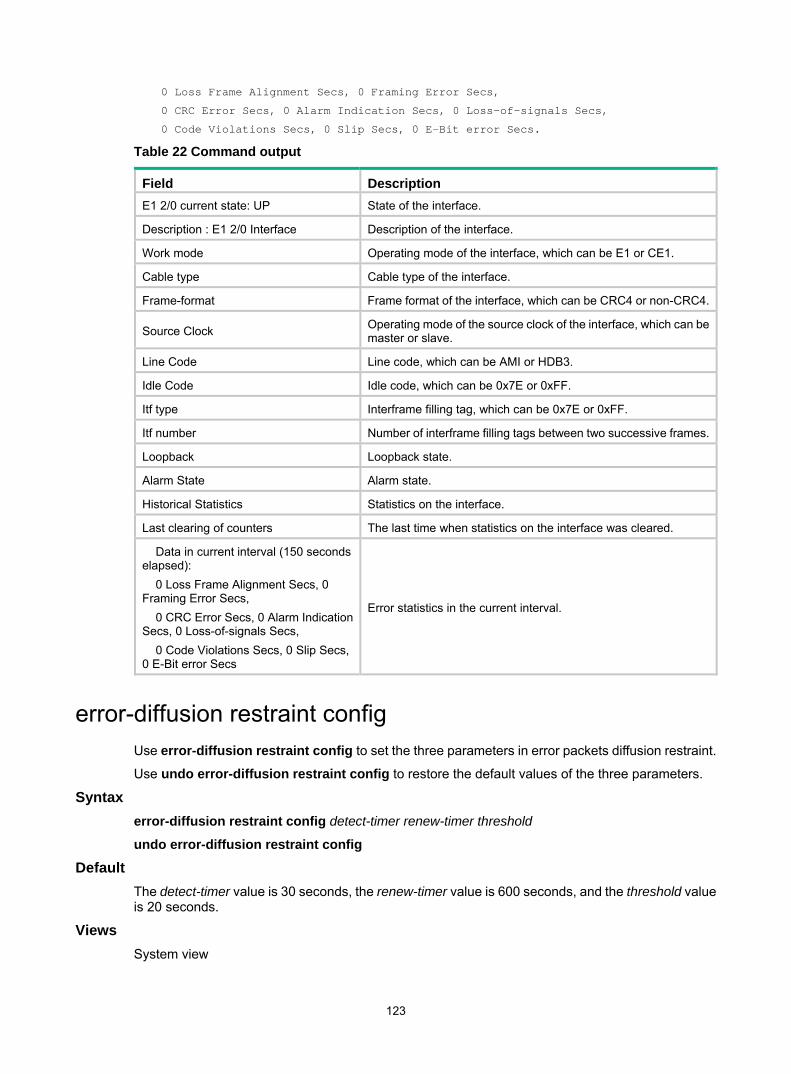
123
0 Loss Frame Alignment Secs, 0 Framing Error Secs,
0 CRC Error Secs, 0 Alarm Indication Secs, 0 Loss-of-signals Secs,
0 Code Violations Secs, 0 Slip Secs, 0 E-Bit error Secs.
Table 22 Command output
Field Description E1 2/0 current state: UP State of the interface.
Description : E1 2/0 Interface Description of the interface.
Work mode Operating mode of the interface, which can be E1 or CE1.
Cable type Cable type of the interface.
Frame-format Frame format of the interface, which can be CRC4 or non-CRC4.
Source Clock Operating mode of the source clock of the interface, which can be master or slave.
Line Code Line code, which can be AMI or HDB3.
Idle Code Idle code, which can be 0x7E or 0xFF.
Itf type Interframe filling tag, which can be 0x7E or 0xFF.
Itf number Number of interframe filling tags between two successive frames.
Loopback Loopback state.
Alarm State Alarm state.
Historical Statistics Statistics on the interface.
Last clearing of counters The last time when statistics on the interface was cleared.
Data in current interval (150 seconds elapsed): 0 Loss Frame Alignment Secs, 0 Framing Error Secs, 0 CRC Error Secs, 0 Alarm Indication Secs, 0 Loss-of-signals Secs, 0 Code Violations Secs, 0 Slip Secs, 0 E-Bit error Secs
Error statistics in the current interval.
error-diffusion restraint config Use error-diffusion restraint config to set the three parameters in error packets diffusion restraint.
Use undo error-diffusion restraint config to restore the default values of the three parameters.
Syntax error-diffusion restraint config detect-timer renew-timer threshold
undo error-diffusion restraint config
Default The detect-timer value is 30 seconds, the renew-timer value is 600 seconds, and the threshold value is 20 seconds.
Views System view
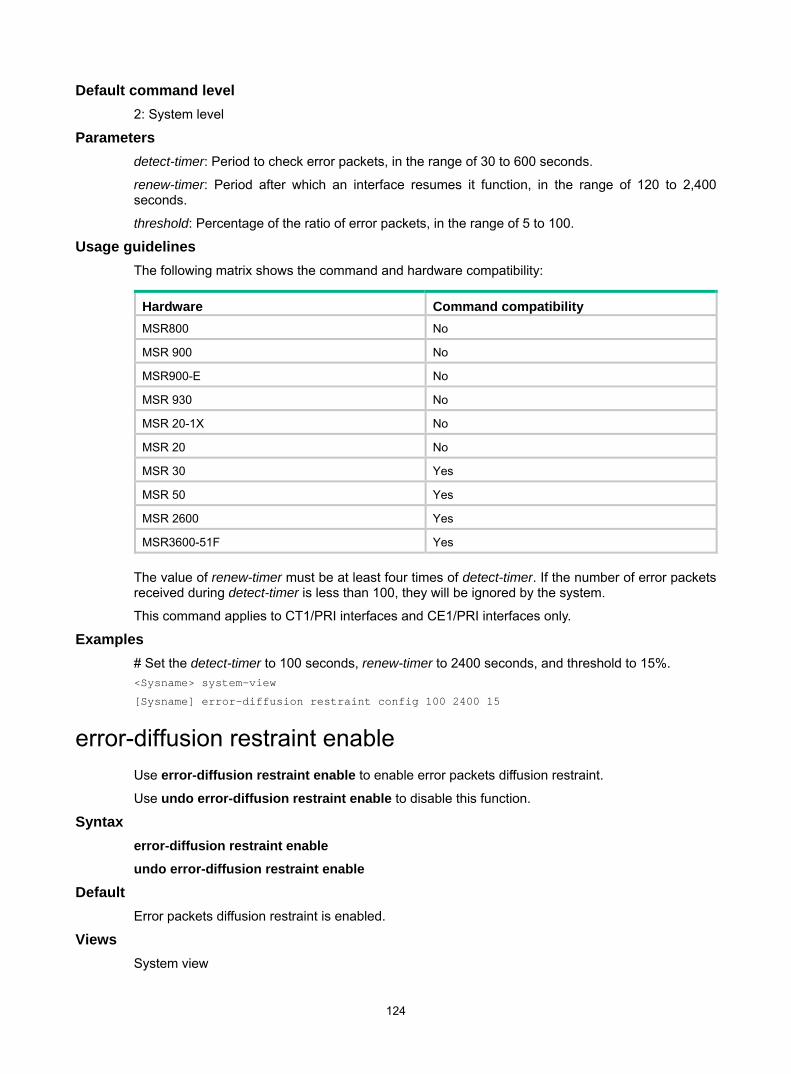
124
Default command level 2: System level
Parameters detect-timer: Period to check error packets, in the range of 30 to 600 seconds.
renew-timer: Period after which an interface resumes it function, in the range of 120 to 2,400 seconds.
threshold: Percentage of the ratio of error packets, in the range of 5 to 100.
Usage guidelines The following matrix shows the command and hardware compatibility:
Hardware Command compatibility MSR800 No
MSR 900 No
MSR900-E No
MSR 930 No
MSR 20-1X No
MSR 20 No
MSR 30 Yes
MSR 50 Yes
MSR 2600 Yes
MSR3600-51F Yes
The value of renew-timer must be at least four times of detect-timer. If the number of error packets received during detect-timer is less than 100, they will be ignored by the system.
This command applies to CT1/PRI interfaces and CE1/PRI interfaces only.
Examples # Set the detect-timer to 100 seconds, renew-timer to 2400 seconds, and threshold to 15%. <Sysname> system-view
[Sysname] error-diffusion restraint config 100 2400 15
error-diffusion restraint enable Use error-diffusion restraint enable to enable error packets diffusion restraint.
Use undo error-diffusion restraint enable to disable this function.
Syntax error-diffusion restraint enable undo error-diffusion restraint enable
Default Error packets diffusion restraint is enabled.
Views System view
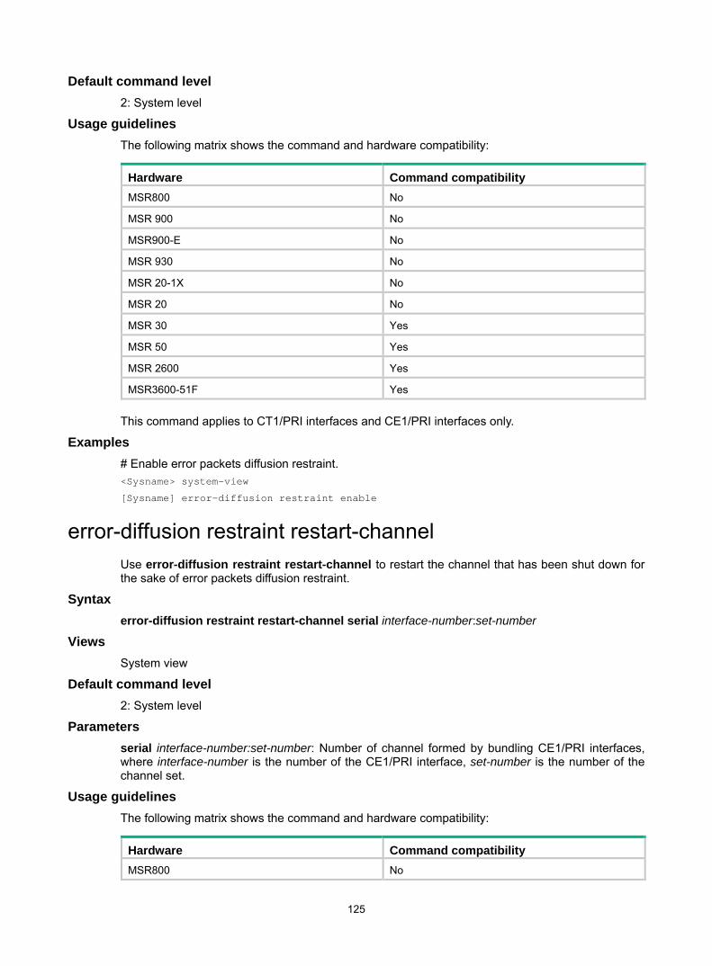
125
Default command level 2: System level
Usage guidelines The following matrix shows the command and hardware compatibility:
Hardware Command compatibility MSR800 No
MSR 900 No
MSR900-E No
MSR 930 No
MSR 20-1X No
MSR 20 No
MSR 30 Yes
MSR 50 Yes
MSR 2600 Yes
MSR3600-51F Yes
This command applies to CT1/PRI interfaces and CE1/PRI interfaces only.
Examples # Enable error packets diffusion restraint. <Sysname> system-view
[Sysname] error-diffusion restraint enable
error-diffusion restraint restart-channel Use error-diffusion restraint restart-channel to restart the channel that has been shut down for the sake of error packets diffusion restraint.
Syntax error-diffusion restraint restart-channel serial interface-number:set-number
Views System view
Default command level 2: System level
Parameters serial interface-number:set-number: Number of channel formed by bundling CE1/PRI interfaces, where interface-number is the number of the CE1/PRI interface, set-number is the number of the channel set.
Usage guidelines The following matrix shows the command and hardware compatibility:
Hardware Command compatibility MSR800 No
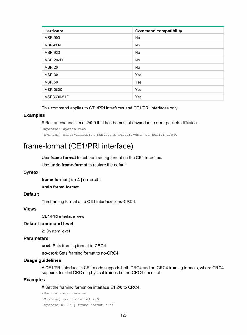
126
Hardware Command compatibility MSR 900 No
MSR900-E No
MSR 930 No
MSR 20-1X No
MSR 20 No
MSR 30 Yes
MSR 50 Yes
MSR 2600 Yes
MSR3600-51F Yes
This command applies to CT1/PRI interfaces and CE1/PRI interfaces only.
Examples # Restart channel serial 2/0:0 that has been shut down due to error packets diffusion. <Sysname> system-view
[Sysname] error-diffusion restraint restart-channel serial 2/0:0
frame-format (CE1/PRI interface) Use frame-format to set the framing format on the CE1 interface.
Use undo frame-format to restore the default.
Syntax frame-format { crc4 | no-crc4 }
undo frame-format
Default The framing format on a CE1 interface is no-CRC4.
Views CE1/PRI interface view
Default command level 2: System level
Parameters crc4: Sets framing format to CRC4.
no-crc4: Sets framing format to no-CRC4.
Usage guidelines A CE1/PRI interface in CE1 mode supports both CRC4 and no-CRC4 framing formats, where CRC4 supports four-bit CRC on physical frames but no-CRC4 does not.
Examples # Set the framing format on interface E1 2/0 to CRC4. <Sysname> system-view
[Sysname] controller e1 2/0
[Sysname-E1 2/0] frame-format crc4
127
idlecode (CE1/PRI interface) Use idlecode to set the line idle code on the CE1/PRI interface. Two types of line idle code are available: 0x7E and 0xFF.
Use undo idlecode to restore the default.
Syntax idlecode { 7e | ff }
undo idlecode
Default The line idle code is 0x7E.
Views CE1/PRI interface view
Default command level 2: System level
Parameters 7e: Sets line idle code to 0x7E.
ff: Sets line idle code to 0xFF.
Usage guidelines The line idle code is sent in timeslots that are not bundled with logical channels.
Examples # Set the line idle code to 0x7E on interface E1 2/0. <Sysname> system-view
[Sysname] controller e1 2/0
[Sysname-E1 2/0] idlecode 7e
itf (CE1/PRI interface) Use itf to set the type of and the number of interframe filling tags on the CE1/PRI interface. Two types of interframe filling tag are available: 0x7E and 0xFF.
Use undo itf to restore the default.
Syntax itf { number number | type { 7e | ff } }
undo itf { number | type }
Default Interframe filling tag is 0x7E and the number of interframe filling tags is 4.
Views CE1/PRI interface view
Default command level 2: System level
128
Parameters number number: Sets the number of interframe filling tags (an interframe filling tag is one byte in length). The value range is 0 to 14. type { 7e | ff }: Sets the type of interframe filling tag to 0x7E by specifying the 7e argument or to 0xFF by specifying the ff keyword.
Usage guidelines Interframe filling tags are sent when no service data is sent on the timeslots bundled into logical channels on the CE1/PRI interface.
Examples # Set the type of interframe filling tag to 0xFF on interface E1 2/0. <Sysname> system-view
[Sysname] controller e1 2/0
[Sysname-E1 2/0] itf type ff
# Set the number of interframe filling tags to five on interface E1 2/0. <Sysname> system-view
[Sysname] controller e1 2/0
[Sysname-E1 2/0] itf number 5
loopback (CE1/PRI interface) Use loopback to enable loopback and set the loopback mode.
Use undo loopback to restore the default.
Syntax loopback { local | payload | remote }
undo loopback
Default Loopback is disabled.
Views CE1/PRI interface view
Default command level 2: System level
Parameters local: Sets the interface in local loopback mode.
remote: Sets the interface in external loopback mode.
payload: Sets the interface in external payload loopback mode.
Usage guidelines Loopback is mainly used to check the condition of interfaces or cables. Disable loopback in other cases.
You can bundle timeslots on the CE1/PRI interface to form a serial interface and encapsulate it with PPP. After you enable loopback on this serial interface, it is normal that the state of the link layer protocol is reported as down.
Examples # Set interface E1 2/0 in internal loopback mode.
129
<Sysname> system-view
[Sysname] controller e1 2/0
[Sysname-E1 2/0] loopback local
looptest (CE1/PRI interface) Use looptest to perform a loop test on a synchronous serial interface created for E1 or E1-F.
Syntax looptest [ -c count | -p { pattern | special { ascending | descending | random } } | -s packetsize | -t timeout ] * interface type number
Views Any view
Parameters -c count: Sets the number of test packets, in the range of 1 to 1 to 4294967295. The default number is 5.
-p pattern: Sets the padding content for test packets, which is a hexadecimal number in the range of 0 to FFFFFFFF. For example, -p ff pads FF to all test packets. By default, 0x55 and 0xAA are padded alternately.
ascending: Pads test packets with a hexadecimal number from 0x00 to 0xff in turn.
descending: Pads test packets with a hexadecimal number from 0xff to 0x00 in turn.
random: Pads test packets with a hexadecimal number from 0xff to 0x00 at random.
-s packetsize: Sets the size of test packets (excluding the 12-byte packet header), in the range of 0 to 1688 bytes. The default size is 52 bytes.
-t timeout: Sets the timeout time for receiving looped-back test packets, in the range of 0 to 65535 milliseconds. The default timeout time is 2000 milliseconds.
interface type number: Specifies an interface.
Usage guidelines Use this command to detect loops on interfaces. The system returns the following line quality information: • Information about each test packet. If a test packet is looped back, the number of bytes,
sequence number, and delay are displayed for the test packet. If a test packet is not looped back before the timeout timer expires, the system displays " Wait time out."
• Statistics for all test packets, including the numbers of sent, received, lost, and error packets, percentages for error and lost packets, and the conclusion.
If the line speed is slow, increase the timeout time.
Examples # Perform a loop test on Serial 1/0/0. <Sysname> looptest interface serial 1/0/0
LOOPTEST Serial1/0/0: 52 data bytes, press CTRL_C to break
Receive from Serial1/0/0: bytes=52 sequence=1 time=1 ms
Receive from Serial1/0/0: bytes=52 sequence=2 time=1 ms
Receive from Serial1/0/0: bytes=52 sequence=3 time=1 ms
Receive from Serial1/0/0: bytes=52 sequence=4 time=1 ms
Receive from Serial1/0/0: bytes=52 sequence=5 time=1 ms
130
--- Serial1/0/0 looptest statistics ---
5 packet(s) transmitted
5 packet(s) received
0 packet(s) lost
0 packet(s) error
0.00% packet lost
0.00% packet error
round-trip min/avg/max = 1/1/1 ms
conclusion: loopback
Related commands • fe1 loopback • ft1 loopback • loopback
pri-set (CE1/PRI interface) Use pri-set to bundle timeslots on the CE1/PRI interface into a PRI set.
Use undo pri-set to remove the bundle.
Syntax pri-set [ timeslot-list list ]
undo pri-set
Default No PRI set is created.
Views CE1/PRI interface view
Default command level 2: System level
Parameters timeslot-list list: Specifies the timeslots to be bundled. The list argument can contain multiple timeslot numbers, each of which is in the range of 1 to 31. You can specify a single timeslot by specifying a timeslot number, a range of timeslots by providing this argument in the form of { number1-number2 }, or multiple timeslots by providing this argument in the form of { number1, number2-number3 }.
Usage guidelines On a CE1/PRI interface in PRI mode, timeslot 0 is used for frame synchronization control (FSC), timeslot 16 as the D channel for signaling transmission, and other timeslots as B channels for data transmission.
You can create only one PRI set on a CE1/PRI interface. This PRI set can include any timeslots except timeslot 0, and must include timeslot 16. Timeslot 16 cannot form a bundle that includes itself only. The attempt to bundle only timeslot 16 will fail.
If no timeslot is specified in this command, all timeslots except timeslot 0 are bundled into an interface in the form of 30B + D.
Upon creation of the PRI set, the system creates a serial interface that is logically equivalent to an ISDN PRI interface. The serial interface is named in the form of serial number:15, where number represents the number of the CE1/PRI interface where the serial interface is created.
131
Because a channel set and a PRI set cannot coexist on a CE1/PRI interface, your PRI set creation attempt will fail if the channel-set command is configured.
Examples # Bundle timeslots 1, 2, and 8 through 12 into a PRI set on CE1/PRI interface E1 2/0. <Sysname> system-view
[Sysname] controller e1 2/0
[Sysname-E1 2/0] pri-set timeslot-list 1,2,8-12
reset counters controller e1 Use reset counters controller e1 to clear the controller counter for a CE1/PRI interface.
Syntax reset counters controller e1 interface-number
Views User view
Default command level 2: System level
Parameters interface-number: Interface number.
Usage guidelines To display the information of the controller counter, use the display controller e1 command.
The reset counters interface command clears the counters of all interfaces. To clear the controller counter of individual CE1/PRI interfaces, use the reset counters controller e1 command.
Examples # Clear the controller counter for CE1/PRI interface E1 2/0. <Sysname> reset counters controller e1 2/0
using (CE1/PRI interface) Syntax
using { ce1 | e1 }
undo using
Views CE1/PRI interface view
Default command level 2: System level
Parameters ce1: Sets the interface to operate in CE1/PRI mode. e1: Sets the interface to operate in E1 mode.
Usage guidelines A CE1/PRI interface can operate in either E1 mode (non-channelized mode) or CE1/PRI mode (channelized mode).
132
In E1 mode, the interface equals a 2.048 Mbps interface without timeslot division and has the same logical features as a synchronous serial interface. In CE1/PRI mode, the CE1/PRI interface is physically divided into 32 timeslots numbered 0 through 31, where timeslot 0 is used for FSC. This interface can operate as either a CE1 interface or a PRI interface.
After you set the CE1/PRI interface to operate in E1 mode, the system automatically creates a serial interface numbered serial interface-number:0, where interface-number represents the number of the CE1/PRI interface.
Examples # Set CE1/PRI interface E1 2/0 to operate in E1 mode. <Sysname> system-view
[Sysname] controller e1 2/0
[Sysname-E1 2/0] using e1
Basic CT1/PRI interface configuration commands alarm (CT1/PRI interface)
Use alarm to enable RAI detection on the interface.
Use undo alarm to disable RAI detection on the interface.
Syntax alarm detect rai
undo alarm detect rai
Default RAI detection is enabled on an interface.
Views CT1/PRI interface view
Default command level 2: System level
Parameters detect: Enables periodical detection on the interface.
rai: Remote Alarm Indication (RAI).
Usage guidelines This command is applicable when the framing format used on the interface is ESF.
Examples # Disable RAI detection on CT1/PR1 interface T1 2/0. <Sysname> system-view
[Sysname] controller t1 2/0
[Sysname-T1 2/0] undo alarm detect rai
alarm-threshold Use alarm-threshold to set LOS, AIS, or LFA alarm thresholds on the CT1/PRI interface.
Use undo alarm-threshold to restore the default.
133
Syntax alarm-threshold { ais { level-1 | level-2 } | lfa { level-1 | level-2 | level-3 | level-4 } | los { pulse-detection | pulse-recovery } value }
undo alarm-threshold { ais | lfa | los { pulse-detection | pulse-recovery } }
Views CT1/PRI interface view
Default command level 2: System level
Parameters ais: Sets the alarm threshold of alarm indication signal (AIS), which can be level-1 and level-2. • The level-1 keyword specifies generating an AIS alarm when the number of 0s in the bit stream
of an SF or ESF frame is less than or equal to 2. • The level-2 keyword specifies generating an AIS alarm when the number of 0s is less than or
equal to 3 in the bit stream of an SF frame or less than or equal to 5 in the bit stream of an ESP frame. Level-1 AIS alarm threshold applies.
lfa: Sets the loss of frame align (LFA) alarm threshold, which can be level-1, level-2, level-3, and level-4. • The level-1 keyword specifies generating an LFA alarm when two of four frame alignment bits
are lost. • The level-2 keyword specifies generating an LFA alarm when two of five frame alignment bits
are lost. • The level-3 keyword specifies generating an LFA alarm when two of six frame alignment bits
are lost. • The level-4 keyword applies only to ESF frames. It specifies generating an LFA alarm when
errors are detected in four consecutive ESF frames. Level-1 LFA alarm threshold applies.
los: Sets a loss of signal (LOS) alarm threshold, which can be pulse-detection (for the pulse detection duration threshold with LOS) and pulse-recovery (for the pulse threshold with LOS).
The threshold of pulse-detection is in the range of 16 to 4,096, in units of pulse intervals. The default is 176.
The threshold of pulse-recovery is in the range of 1 to 256. The default is 22.
If the number of the pulses detected during the total length of the specified pulse detection intervals is smaller than the pulse-recovery threshold, a LOS alarm occurs. For example, if the two thresholds take their defaults, a LOS alarm is created if the number of pulses detected within 176 pulse intervals is less than 22.
Examples # Set the number of detection intervals to 300 for the pulse detection duration threshold. <Sysname> system-view
[Sysname] controller t1 2/0
[Sysname-T1 2/0] alarm-threshold los pulse-detection 300
bert (CT1/PRI interface) Use bert to start a BERT test on a CT1/PRI interface.
Use undo bert to stop the BERT test running on the CT1/PRI interface.
134
Syntax bert pattern { 2^15 | 2^20 } time minutes [ unframed ]
undo bert
Default No BERT test is performed.
Views CT1/PRI interface view
Default command level 2: System level
Parameters pattern: Sets a bit error rate test (BERT) pattern, which could be 2^15 or 2^20.
2^15: Specifies the length of transmitted BERT pattern, in bits, as two to the fifteenth power.
2^20: Specifies the length of transmitted BERT pattern, in bits, as two to the twentieth power.
time minutes: Sets the duration (in minutes) of a BERT test. The minutes argument is in the range of 1 to 1440.
unframed: Sets the test pattern to cover the overhead bits of the frame.
Usage guidelines ITU O.151, ITU O.153, and ANSI T1.403-1999 define many BERT patterns, among which, the CT1/PRI interface supports only 2^15 and 2^20.
When running a BERT test, the local end sends out a pattern, which is to be looped over somewhere on the line and back to the local end. The local end then examines the received pattern for bit error rate to help you identify the condition of the line. You must configure loopback to allow the transmitted pattern to loop back from somewhere on the line, for example, from the far-end interface by placing the interface in a far-end loopback.
To view the state and result of the BERT test, use the display controller t1 command.
Examples # Run a 10-minute 2^20 BERT test on CT1/PRI interface t1 2/0. <Sysname> system-view
[Sysname] controller t1 2/0
[Sysname-T1 2/0] bert pattern 2^20 time 10
cable (CT1/PRI interface) Use cable to set the cable attenuation and length on the CT1/PRI interface.
Use undo cable to restore the default.
Syntax cable { long { 0db | -7.5db | -15db | -22.5db } | short { 133ft | 266ft | 399ft | 533ft | 655ft } }
undo cable
Default The cable length is long 0db.
Views CT1/PRI interface view
135
Default command level 2: System level
Parameters long: Matches 199.6-meter (655-feet) and longer cable length. The options for this parameter include 0db, -7.5db, -15db and -22.5db. The attenuation parameter is selected depending on the signal quality received at the receiving end. No external CSU is needed.
short: Matches a cable length shorter than 199.6 meters (655 feet). The options for this parameter include 133ft, 266ft, 399ft, 533ft and 655ft. The length parameter is selected depending on the actual transmission distance.
Usage guidelines You can use this command to adapt signal waveform to different transmission conditions such as the quality of the signal received by the receiver. If the signal quality is good, you can use the default setting. The CT1/PRI interface does not need an external CSU device.
Examples # Set the cable length to 40.5 meter (133 feet) on CT1/PRI interface T1 2/0. <Sysname> system-view
[Sysname] controller t1 2/0
[Sysname-T1 2/0] cable short 133ft
channel-set (CT1/PRI interface) Use channel-set to bundle timeslots on the CT1/PRI interface into a channel set.
Use undo channel-set to remove a specified or all channel sets.
Syntax channel-set set-number timeslot-list list [ speed { 56k | 64k } ] undo channel-set [ set-number ]
Default No timeslots are bundled into channel sets.
Views CT1/PRI interface view
Default command level 2: System level
Parameters set-number: Number of the channel set formed by timeslot bundling on the interface, in the range of 0 to 23.
timeslot-list list: Specifies the timeslots to be bundled. The list argument can contain multiple timeslot numbers, each of which is in the range of 1 to 24. You can specify a single timeslot by specifying a timeslot number, a range of timeslots by providing this argument in the form of { number1-number2 }, or multiple timeslots by providing this argument in the form of { number1, number2-number3 }.
speed { 56k | 64k }: Speed of the timeslot bundle (the channel set) in kbps. If 56k is selected, the timeslots are bundled into N × 56 kbps bundles. If 64k, the default, is selected, the timeslots are bundled into N × 64 kbps bundles.
136
Usage guidelines A CT1/PRI interface is divided into 24 timeslots numbered 1 through 24. In actual applications, all the timeslots can be bundled into multiple channel sets. For each channel set, the system automatically creates a serial interface that is logically equivalent to a synchronous serial interface.
The serial interface is named in the form of serial interface-number:set-number, where interface-number starts from the maximum serial interface number plus 1, and set-number represents the number of the channel set.
A CT1/PRI interface supports only one timeslot bundling mode at a time. You cannot use this command together with the pri-set command.
IMPORTANT: Make sure the local end has the same timeslot bundling settings as the remote end for successful communication.
Examples # Bundle timeslots 1, 2, 5, 10 through 15, and 18 into channel set 0 on CT1/PRI interface T1 2/0. <Sysname> system-view
[Sysname] controller t1 2/0
[Sysname-T1 2/0] channel-set 0 timeslot-list 1,2,5,10-15,18
clock (CT1/PRI interface) Use clock to configure clock source for the CT1/PRI interface.
Use undo clock to restore the default.
Syntax clock { master | slave }
undo clock
Default The clock mode is line clock (slave).
Views CT1/PRI interface view
Default command level 2: System level
Parameters master: Adopts the internal clock as the clock source. slave: Adopts the line clock as the clock source.
Usage guidelines When the CT1/PRI interface is operating as DCE, choose the internal clock for it. When it is operating as DTE, choose the line clock for it.
Examples # Use the internal clock as the clock source on CT1/PRI interface T1 2/0. <Sysname> system-view
[Sysname] controller t1 2/0
[Sysname-T1 2/0] clock master
137
code (CT1/PRI interface) Use code to set the line code format for a CT1/PRI interface.
Use undo code to restore the default.
Syntax code { ami | b8zs }
undo code
Default The line code format for a CT1/PRI interface is B8ZS.
Views CT1/PRI interface view
Default command level 2: System level
Parameters ami: Adopts AMI line code format. b8zs: Adopts bipolar 8-zero substitution (B8ZS) line code format.
Usage guidelines Keep the line code format of the interface in consistency with the one used on the remote device.
To ensure the normal operation of the interface, configure the data-coding inverted command on it when its line code format is set to AMI.
Examples # Set the line code format of the interface T1 2/0 to AMI. <Sysname> system-view
[Sysname] controller t1 2/0
[Sysname-T1 2/0] code ami
Related commands data-coding
controller t1 Use controller t1 to enter CT1/PRI interface view.
Syntax controller t1 number
Views System view
Default command level 2: System level
Parameters number: CT1/PRI interface number.
138
Examples # Enter the view of interface T1 2/0. <Sysname> system-view
[Sysname] controller t1 2/0
[Sysname-T1 2/0]
crc Use crc to configure CRC mode for a synchronous serial interface formed on a CT1/PRI interface.
Use undo crc to restore the default.
Syntax crc { 16 | 32 | none }
undo crc
Default The CRC mode for a synchronous serial interface formed on a CT1/PRI interface is 16-bit CRC.
Views Synchronous serial interface view
Default command level 2: System level
Parameters 16: Adopts 16-bit CRC.
32: Adopts 32-bit CRC.
none: Disables CRC.
Examples # Apply 32-bit CRC to a serial interface formed on interface CT1 interface 2/0. <Sysname> system-view
[Sysname] controller t1 2/0
[Sysname-T1 2/0] channel-set 1 timeslot-list 2-6
[Sysname-T1 2/0] quit
[Sysname] interface serial 2/0:1
[Sysname-Serial2/0:1] crc 32
data-coding (CT1/PRI interface) Use data-coding inverted to enable user data inversion on the CT1/PRI interface.
Use data-coding normal to disable user data inversion on the CT1/PRI interface.
Use undo data-coding to restore the default.
Syntax data-coding { inverted | normal }
undo data-coding
Default Data inversion is disabled.
139
Views CT1/PRI interface view
Default command level 2: System level
Parameters inverted: Enables user data inversion.
normal: Disables user data inversion.
Usage guidelines To prevent 7e in valid data from being taken for stuffing characters, HDLC inserts a zero after every five ones in the data stream. Then, HDLC inverts every one bit into a zero and every zero bit into a one. This ensures that at least one out of every eight bits is a one. When AMI encoding is adopted on a T1 interface, the use of data inversion can eliminate the presence of multiple consecutive zeros.
On the CT1/PRI interfaces at two ends of a T1 line, you must use the same data inversion setting.
Examples # Enable user data inversion on CT1/PRI interface T1 2/0. <Sysname> system-view
[Sysname] controller t1 2/0
[Sysname-T1 2/0] data-coding inverted
display controller t1 Use display controller t1 to display information about one specified or all CT1/PRI interfaces.
Syntax display controller t1 [ interface-number ] [ | { begin | exclude | include } regular-expression ]
Views Any view
Default command level 2: System level
Parameters interface-number: Interface number. In conjunction with the t1 keyword, it specifies a CT1/PRI interface.
|: Filters command output by specifying a regular expression. For more information about regular expressions, see Fundamentals Configuration Guide.
begin: Displays the first line that matches the specified regular expression and all lines that follow.
exclude: Displays all lines that do not match the specified regular expression.
include: Displays all lines that match the specified regular expression.
regular-expression: Specifies a regular expression, a case-sensitive string of 1 to 256 characters.
Examples # Display information about interface T1 2/0. <Sysname> display controller t1 2/0
T1 2/0 current state :DOWN
Description : T1 2/0 Interface
Basic Configuration:

140
Work mode is T1 framed, Cable type is 100 Ohm balanced.
Frame-format is esf, fdl is none, Line code is b8zs.
Source clock is slave, Data-coding is normal.
Idle code is ff, Itf type is ff, Itf number is 2.
Loop back is not set.
Alarm State:
Receiver alarm state is Loss-of-Signal.
Transmitter is sending remote alarm.
Pulse density violation detected.
SendLoopCode History:
inband-llb-up:0 times, inband-llb-down:0 times.
fdl-ansi-llb-up:0 times, fdl-ansi-llb-down:0 times.
fdl-ansi-plb-up:0 times, fdl-ansi-plb-down:0 times.
BERT state:(stopped, not completed)
Test pattern: 2^15, Status: Not Sync, Sync Detected: 0
Time: 0 minute(s), Time past: 0 minute(s)
Bit Errors (since test started): 0 bits
Bits Received (since test started): 0 Kbits
Bit Errors (since latest sync): 0 bits
Bits Received (since latest sync): 0 Kbits
Historical Statistics:
Last clearing of counters: Never
Data in current interval (285 seconds elapsed):
0 Line Code Violations, 0 Path Code Violations
0 Ais Alarm Secs, 286 Los Alarm Secs
7 Slip Secs, 286 Fr Loss Secs, 0 Line Err Secs, 0 Degraded Mins
0 Errored Secs, 0 Bursty Err Secs, 0 Severely Err Secs, 286 Unavail Secs
Data in Interval 1:
0 Line Code Violations, 0 Path Code Violations
0 Ais Alarm Secs, 901 Los Alarm Secs
22 Slip Secs, 901 Fr Loss Secs, 0 Line Err Secs, 0 Degraded Mins
0 Errored Secs, 0 Bursty Err Secs, 0 Severely Err Secs, 901 Unavail Secs
Data in Interval 2:
0 Line Code Violations, 0 Path Code Violations
0 Ais Alarm Secs, 900 Los Alarm Secs
23 Slip Secs, 900 Fr Loss Secs, 0 Line Err Secs, 0 Degraded Mins
0 Errored Secs, 0 Bursty Err Secs, 0 Severely Err Secs, 900 Unavail Secs
Total Data (last 2 15 minute intervals):
0 Line Code Violations, 0 Path Code Violations
0 Ais Alarm Secs, 2087 Los Alarm Secs
52 Slip Secs, 2087 Fr Loss Secs, 0 Line Err Secs, 0 Degraded Mins
0 Errored Secs, 0 Bursty Err Secs, 0 Severely Err Secs, 2087 Unavail Secs
Table 23 Command output
Field Description T1 2/0 current state Physical state of the interface: up or down.
Description Description about the T1 interface.
Basic Configuration Basic configurations of the interface.
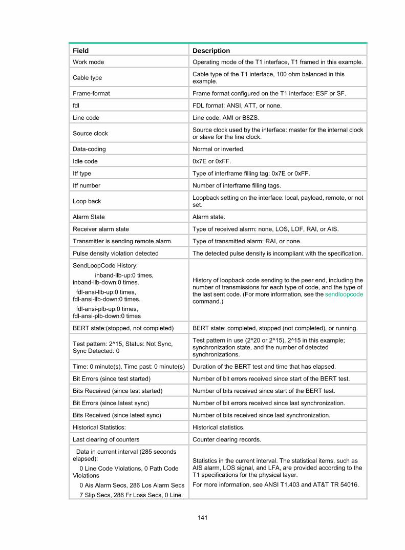
141
Field Description Work mode Operating mode of the T1 interface, T1 framed in this example.
Cable type Cable type of the T1 interface, 100 ohm balanced in this example.
Frame-format Frame format configured on the T1 interface: ESF or SF.
fdl FDL format: ANSI, ATT, or none.
Line code Line code: AMI or B8ZS.
Source clock Source clock used by the interface: master for the internal clock or slave for the line clock.
Data-coding Normal or inverted.
Idle code 0x7E or 0xFF.
Itf type Type of interframe filling tag: 0x7E or 0xFF.
Itf number Number of interframe filling tags.
Loop back Loopback setting on the interface: local, payload, remote, or not set.
Alarm State Alarm state.
Receiver alarm state Type of received alarm: none, LOS, LOF, RAI, or AIS.
Transmitter is sending remote alarm. Type of transmitted alarm: RAI, or none.
Pulse density violation detected The detected pulse density is incompliant with the specification.
SendLoopCode History: inband-llb-up:0 times, inband-llb-down:0 times. fdl-ansi-llb-up:0 times, fdl-ansi-llb-down:0 times. fdl-ansi-plb-up:0 times, fdl-ansi-plb-down:0 times
History of loopback code sending to the peer end, including the number of transmissions for each type of code, and the type of the last sent code. (For more information, see the sendloopcode command.)
BERT state:(stopped, not completed) BERT state: completed, stopped (not completed), or running.
Test pattern: 2^15, Status: Not Sync, Sync Detected: 0
Test pattern in use (2^20 or 2^15), 2^15 in this example; synchronization state, and the number of detected synchronizations.
Time: 0 minute(s), Time past: 0 minute(s) Duration of the BERT test and time that has elapsed.
Bit Errors (since test started) Number of bit errors received since start of the BERT test.
Bits Received (since test started) Number of bits received since start of the BERT test.
Bit Errors (since latest sync) Number of bit errors received since last synchronization.
Bits Received (since latest sync) Number of bits received since last synchronization.
Historical Statistics: Historical statistics.
Last clearing of counters Counter clearing records.
Data in current interval (285 seconds elapsed): 0 Line Code Violations, 0 Path Code Violations 0 Ais Alarm Secs, 286 Los Alarm Secs 7 Slip Secs, 286 Fr Loss Secs, 0 Line
Statistics in the current interval. The statistical items, such as AIS alarm, LOS signal, and LFA, are provided according to the T1 specifications for the physical layer. For more information, see ANSI T1.403 and AT&T TR 54016.
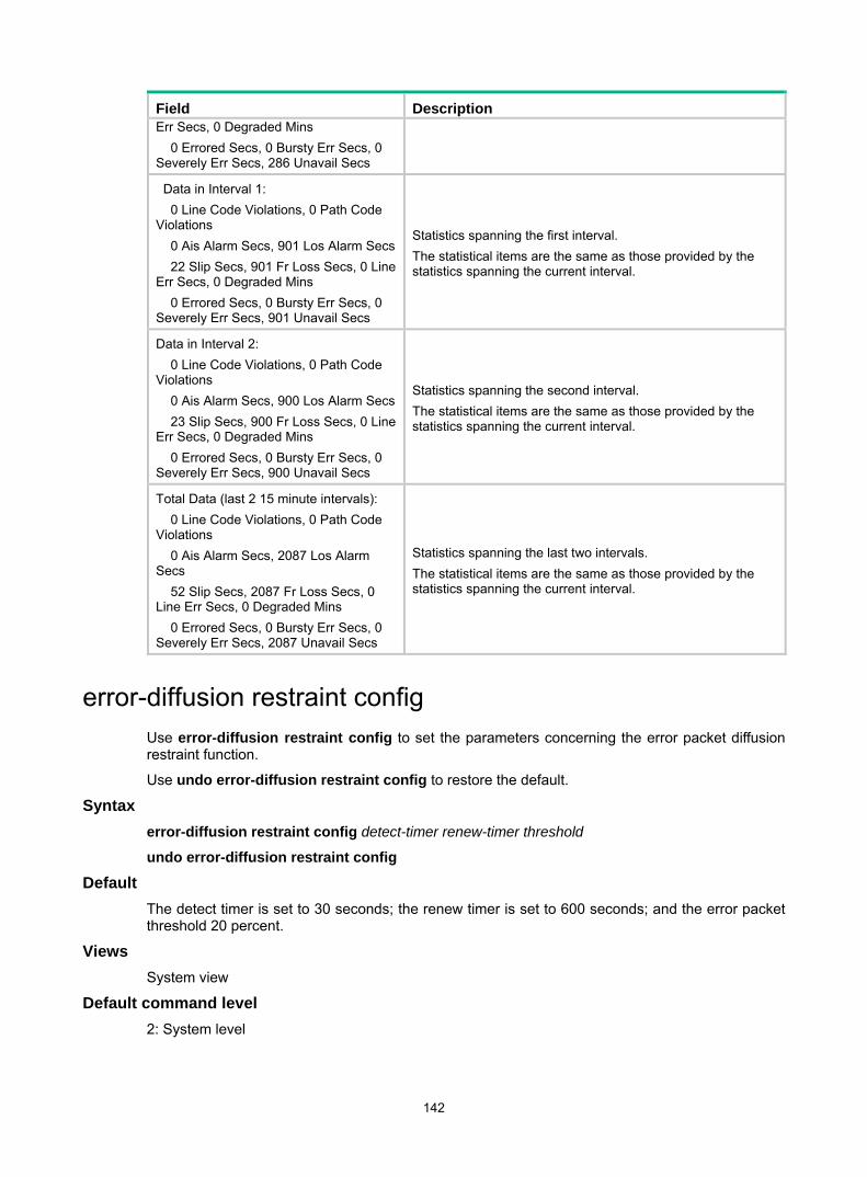
142
Field Description Err Secs, 0 Degraded Mins 0 Errored Secs, 0 Bursty Err Secs, 0 Severely Err Secs, 286 Unavail Secs
Data in Interval 1: 0 Line Code Violations, 0 Path Code Violations 0 Ais Alarm Secs, 901 Los Alarm Secs 22 Slip Secs, 901 Fr Loss Secs, 0 Line Err Secs, 0 Degraded Mins 0 Errored Secs, 0 Bursty Err Secs, 0 Severely Err Secs, 901 Unavail Secs
Statistics spanning the first interval. The statistical items are the same as those provided by the statistics spanning the current interval.
Data in Interval 2: 0 Line Code Violations, 0 Path Code Violations 0 Ais Alarm Secs, 900 Los Alarm Secs 23 Slip Secs, 900 Fr Loss Secs, 0 Line Err Secs, 0 Degraded Mins 0 Errored Secs, 0 Bursty Err Secs, 0 Severely Err Secs, 900 Unavail Secs
Statistics spanning the second interval. The statistical items are the same as those provided by the statistics spanning the current interval.
Total Data (last 2 15 minute intervals): 0 Line Code Violations, 0 Path Code Violations 0 Ais Alarm Secs, 2087 Los Alarm Secs 52 Slip Secs, 2087 Fr Loss Secs, 0 Line Err Secs, 0 Degraded Mins 0 Errored Secs, 0 Bursty Err Secs, 0 Severely Err Secs, 2087 Unavail Secs
Statistics spanning the last two intervals. The statistical items are the same as those provided by the statistics spanning the current interval.
error-diffusion restraint config Use error-diffusion restraint config to set the parameters concerning the error packet diffusion restraint function.
Use undo error-diffusion restraint config to restore the default.
Syntax error-diffusion restraint config detect-timer renew-timer threshold
undo error-diffusion restraint config
Default The detect timer is set to 30 seconds; the renew timer is set to 600 seconds; and the error packet threshold 20 percent.
Views System view
Default command level 2: System level
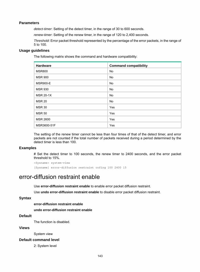
143
Parameters detect-timer: Setting of the detect timer, in the range of 30 to 600 seconds.
renew-timer: Setting of the renew timer, in the range of 120 to 2,400 seconds.
Threshold: Error packet threshold represented by the percentage of the error packets, in the range of 5 to 100.
Usage guidelines The following matrix shows the command and hardware compatibility:
Hardware Command compatibility MSR800 No
MSR 900 No
MSR900-E No
MSR 930 No
MSR 20-1X No
MSR 20 No
MSR 30 Yes
MSR 50 Yes
MSR 2600 Yes
MSR3600-51F Yes
The setting of the renew timer cannot be less than four times of that of the detect timer, and error packets are not counted if the total number of packets received during a period determined by the detect timer is less than 100.
Examples # Set the detect timer to 100 seconds, the renew timer to 2400 seconds, and the error packet threshold to 15%. <Sysname> system-view
[Sysname] error-diffusion restraint cofing 100 2400 15
error-diffusion restraint enable Use error-diffusion restraint enable to enable error packet diffusion restraint.
Use undo error-diffusion restraint enable to disable error packet diffusion restraint.
Syntax error-diffusion restraint enable undo error-diffusion restraint enable
Default The function is disabled.
Views System view
Default command level 2: System level
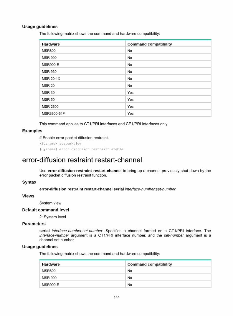
144
Usage guidelines The following matrix shows the command and hardware compatibility:
Hardware Command compatibility MSR800 No
MSR 900 No
MSR900-E No
MSR 930 No
MSR 20-1X No
MSR 20 No
MSR 30 Yes
MSR 50 Yes
MSR 2600 Yes
MSR3600-51F Yes
This command applies to CT1/PRI interfaces and CE1/PRI interfaces only.
Examples # Enable error packet diffusion restraint. <Sysname> system-view
[Sysname] error-diffusion restraint enable
error-diffusion restraint restart-channel Use error-diffusion restraint restart-channel to bring up a channel previously shut down by the error packet diffusion restraint function.
Syntax error-diffusion restraint restart-channel serial interface-number:set-number
Views System view
Default command level 2: System level
Parameters serial interface-number:set-number: Specifies a channel formed on a CT1/PRI interface. The interface-number argument is a CT1/PRI interface number, and the set-number argument is a channel set number.
Usage guidelines The following matrix shows the command and hardware compatibility:
Hardware Command compatibility MSR800 No
MSR 900 No
MSR900-E No
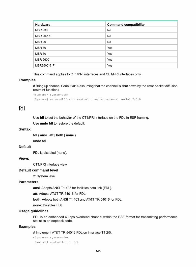
145
Hardware Command compatibility MSR 930 No
MSR 20-1X No
MSR 20 No
MSR 30 Yes
MSR 50 Yes
MSR 2600 Yes
MSR3600-51F Yes
This command applies to CT1/PRI interfaces and CE1/PRI interfaces only.
Examples # Bring up channel Serial 2/0:0 (assuming that the channel is shut down by the error packet diffusion restraint function). <Sysname> system-view
[Sysname] error-diffusion restraint restart-channel serial 2/0:0
fdl Use fdl to set the behavior of the CT1/PRI interface on the FDL in ESF framing.
Use undo fdl to restore the default.
Syntax fdl { ansi | att | both | none }
undo fdl
Default FDL is disabled (none).
Views CT1/PRI interface view
Default command level 2: System level
Parameters ansi: Adopts ANSI T1.403 for facilities data link (FDL).
att: Adopts AT&T TR 54016 for FDL.
both: Adopts both ANSI T1.403 and AT&T TR 54016 for FDL.
none: Disables FDL.
Usage guidelines FDL is an embedded 4 kbps overhead channel within the ESF format for transmitting performance statistics or loopback code.
Examples # Implement AT&T TR 54016 FDL on interface T1 2/0. <Sysname> system-view
[Sysname] controller t1 2/0
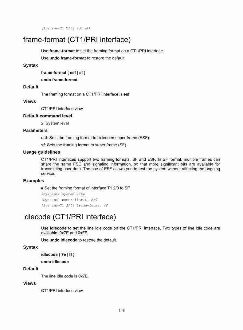
146
[Sysname-T1 2/0] fdl att
frame-format (CT1/PRI interface) Use frame-format to set the framing format on a CT1/PRI interface.
Use undo frame-format to restore the default.
Syntax frame-format { esf | sf }
undo frame-format
Default The framing format on a CT1/PRI interface is esf
Views CT1/PRI interface view
Default command level 2: System level
Parameters esf: Sets the framing format to extended super frame (ESF).
sf: Sets the framing format to super frame (SF).
Usage guidelines CT1/PRI interfaces support two framing formats, SF and ESF. In SF format, multiple frames can share the same FSC and signaling information, so that more significant bits are available for transmitting user data. The use of ESF allows you to test the system without affecting the ongoing service.
Examples # Set the framing format of interface T1 2/0 to SF. <Sysname> system-view
[Sysname] controller t1 2/0
[Sysname-T1 2/0] frame-format sf
idlecode (CT1/PRI interface) Use idlecode to set the line idle code on the CT1/PRI interface. Two types of line idle code are available: 0x7E and 0xFF.
Use undo idlecode to restore the default.
Syntax idlecode { 7e | ff }
undo idlecode
Default The line idle code is 0x7E.
Views CT1/PRI interface view
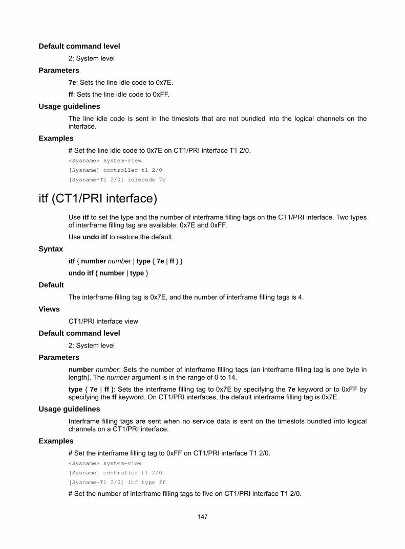
147
Default command level 2: System level
Parameters 7e: Sets the line idle code to 0x7E. ff: Sets the line idle code to 0xFF.
Usage guidelines The line idle code is sent in the timeslots that are not bundled into the logical channels on the interface.
Examples # Set the line idle code to 0x7E on CT1/PRI interface T1 2/0. <Sysname> system-view
[Sysname] controller t1 2/0
[Sysname-T1 2/0] idlecode 7e
itf (CT1/PRI interface) Use itf to set the type and the number of interframe filling tags on the CT1/PRI interface. Two types of interframe filling tag are available: 0x7E and 0xFF.
Use undo itf to restore the default.
Syntax itf { number number | type { 7e | ff } }
undo itf { number | type }
Default The interframe filling tag is 0x7E, and the number of interframe filling tags is 4.
Views CT1/PRI interface view
Default command level 2: System level
Parameters number number: Sets the number of interframe filling tags (an interframe filling tag is one byte in length). The number argument is in the range of 0 to 14.
type { 7e | ff }: Sets the interframe filling tag to 0x7E by specifying the 7e keyword or to 0xFF by specifying the ff keyword. On CT1/PRI interfaces, the default interframe filling tag is 0x7E.
Usage guidelines Interframe filling tags are sent when no service data is sent on the timeslots bundled into logical channels on a CT1/PRI interface.
Examples # Set the interframe filling tag to 0xFF on CT1/PRI interface T1 2/0. <Sysname> system-view
[Sysname] controller t1 2/0
[Sysname-T1 2/0] itf type ff
# Set the number of interframe filling tags to five on CT1/PRI interface T1 2/0.
148
<Sysname> system-view
[Sysname] controller t1 2/0
[Sysname-T1 2/0] itf number 5
loopback (CT1/PRI interface) Use loopback to enable local, remote, or external payload loopback on the CT1/PRI interface.
Use undo loopback to restore the default.
Syntax loopback { local | payload | remote }
undo loopback
Default Loopback is disabled.
Views CT1/PRI interface view
Default command level 2: System level
Parameters local: Enables the CT1/PRI interface to perform local loopback.
payload: Enables the interface to perform external payload loopback.
remote: Enables the interface to perform remote loopback.
Usage guidelines Loopback is mainly used to check the condition of interfaces or cables. Disable loopback in other cases.
You can bundle timeslots on a CT1/PRI interface to form a serial interface and encapsulate it with PPP. After you enable loopback on this serial interface, it is normal that the state of the link layer protocol is reported down.
Examples # Enabled remote loopback on interface T1 2/0. <Sysname> system-view
[Sysname] controller t1 2/0
[Sysname-T1 2/0] loopback remote
looptest (CT1/PRI interface) Use looptest to perform a loop test on a synchronous serial interface created for T1 or T1-F.
Syntax looptest [ -c count | -p { pattern | special { ascending | descending | random } } | -s packetsize | -t timeout ] * interface type number
Views Any view
149
Parameters -c count: Sets the number of test packets, in the range of 1 to 1 to 4294967295. The default number is 5.
-p pattern: Sets the padding content for test packets, which is a hexadecimal number in the range of 0 to FFFFFFFF. For example, -p ff pads FF to all test packets. By default, 0x55 and 0xAA are padded alternately.
ascending: Pads test packets with a hexadecimal number from 0x00 to 0xff in turn.
descending: Pads test packets with a hexadecimal number from 0xff to 0x00 in turn.
random: Pads test packets with a hexadecimal number from 0xff to 0x00 at random.
-s packetsize: Sets the size of test packets (excluding the 12-byte packet header), in the range of 0 to 1688 bytes. The default size is 52 bytes.
-t timeout: Sets the timeout time for receiving looped-back test packets, in the range of 0 to 65535 milliseconds. The default timeout time is 2000 milliseconds.
interface type number: Specifies an interface.
Usage guidelines Use looptest to detect loops on interfaces. The system returns the following line quality information: • Information about each test packet. If a test packet is looped back, the number of bytes,
sequence number, and delay are displayed for the test packet. If a test packet is not looped back before the timeout timer expires, the system displays " Wait time out."
• Statistics for all test packets, including the numbers of sent, received, lost, and error packets, percentages for error and lost packets, and the conclusion.
If the line speed is slow, increase the timeout time.
Examples # Perform a loop test on Serial 1/0/0. <Sysname> looptest interface serial 1/0/0
LOOPTEST Serial1/0/0: 52 data bytes, press CTRL_C to break
Receive from Serial1/0/0: bytes=52 sequence=1 time=1 ms
Receive from Serial1/0/0: bytes=52 sequence=2 time=1 ms
Receive from Serial1/0/0: bytes=52 sequence=3 time=1 ms
Receive from Serial1/0/0: bytes=52 sequence=4 time=1 ms
Receive from Serial1/0/0: bytes=52 sequence=5 time=1 ms
--- Serial1/0/0 looptest statistics ---
5 packet(s) transmitted
5 packet(s) received
0 packet(s) lost
0 packet(s) error
0.00% packet lost
0.00% packet error
round-trip min/avg/max = 1/1/1 ms
conclusion: loopback
Related commands • fe1 loopback • ft1 loopback • loopback
150
pri-set (CT1/PRI interface) Use pri-set to bundle timeslots into a PRI set on the CT1/PRI interface.
Use undo pri-set to remove the timeslot bundle.
Syntax pri-set [ timeslot-list list ]
undo pri-set
Default No PRI set is created.
Views CT1/PRI interface view
Default command level 2: System level
Parameters list: Specifies timeslots to be bundled. Timeslots are numbered 1 through 24. You can specify a single timeslot by specifying a number, a range of timeslots by specifying a range in the form of number1-number2, or several discrete timeslots by specifying number1, number2-number3.
Usage guidelines When you create a PRI set on a CT1/PRI interface, timeslot 24 is the D channel for transmitting signaling, and it cannot form a bundle that includes itself only. The attempts to bundle only timeslot 24 will fail.
In the created PRI set, timeslot 24 is used as D channel for signaling transmission, and the other timeslots as B channels for data transmission. You can randomly bundle these timeslots into a PRI set (as the D channel, timeslot 24 is automatically bundled). If no timeslot is specified, all timeslots are bundled into an interface similar to an ISDN PRI interface in the form of 23B+D.
For the PRI set, the system automatically creates a serial interface that is logically equivalent to an ISDN PRI interface. The serial interface is named in the form of serial number:23, where number is the number of the CT1/PRI interface on which the serial interface is created.
Because a channel set and a PRI set cannot coexist on a CT1/PRI interface, your PRI set creation attempt will fail if the channel-set command is configured.
Examples # Bundle timeslots 1, 2, and 8 through 12 into a PRI set on CT1/PRI interface T1 2/0. <Sysname> system-view
[Sysname] controller t1 2/0
[Sysname-T1 2/0] pri-set timeslot-list 1,2,8-12
reset counters controller t1 Use reset counters controller t1 to clear the controller counter for a CT1/PRI interface.
Syntax reset counters controller t1 interface-number
Views User view
151
Default command level 2: System level
Parameters interface-number: Interface number.
Usage guidelines To display the value of the controller counter, use the display controller t1 command.
The reset counters interface command clears the counters of all interfaces. To clear the controller counter of individual CT1/PRI interfaces, use the reset counters controller t1 command.
Examples # Clear the controller counter for CT1/PRI interface T1 2/0. <Sysname> reset counters controller t1 2/0
sendloopcode Use sendloopcode to send remote loopback control code.
Syntax sendloopcode { fdl-ansi-llb-down | fdl-ansi-llb-up | fdl-ansi-plb-down | fdl-ansi-plb-up | fdl-att-plb-down | fdl-att-plb-up | inband-llb-down | inband-llb-up }
Default No remote loopback control code is sent.
Views CT1/PRI interface view
Default command level 2: System level
Parameters fdl-ansi-llb-down: Sends ANSI-compliant LLB deactivation request code in the FDL to remove loopback.
fdl-ansi-llb-up: Sends ANSI-compliant line loopback (LLB) activation request code in the FDL to start remote loopback.
fdl-ansi-plb-down: Sends ANSI-compliant PLB deactivation request code in the FDL to remove loopback. fdl-ansi-plb-up: Sends ANSI-compliant payload loopback (PLB) activation request code in the FDL to start remote loopback.
fdl-att-plb-down: Sends AT&T-complaint PLB deactivation request code in the FDL to remove loopback.
fdl-att-plb-up: Sends AT&T-complaint PLB activation request code in the FDL to start remote loopback.
inband-llb-down: Sends in-band LLB deactivation request code in compliance with the ANSI or AT&T implementation to remove loopback.
inband-llb-up: Sends in-band line loopback (LLB) activation request code compliant with the ANSI and AT&T implementation to start remote loopback.
Usage guidelines You can configure loopback on the remote CT1/PRI interface by sending loopback request code.
152
In LLB mode, all 193 bits (one synchronization bit and 192 effective bandwidth bits) in a T1 PCM frame are looped back. In PLB mode, however, only 192 effective bandwidth bits are looped back.
The format of loopback code is compliant with ANSI T1.403 or AT&T TR 54016.
In SF framing, LLB code is sent using the effective bandwidth. In ESF framing, both LLB code and PLB code are sent and received in the FDL.
Use this command in conjunction with the far-end T1 device. The far-end device must be able to set loopback mode depending on the detected loopback code. The sending of remote loopback control code lasts five minutes without affecting the operation of other interfaces.
Examples # Send in-band LLB activation request code. <Sysname> system-view
[Sysname] controller t1 2/0
[Sysname-T1 2/0] sendloopcode inband-llb-up
E1-F interface configuration commands clock-change auto
Use clock-change auto to enable the automatic clock mode change function on the interface, in other words, configure the interface that uses the slave clock mode to switch to the master clock mode automatically when receiving an alarm indication signal (AIS)/loss of signal (LOS)/loss of frame (LOF) alarm. After the alarm is cleared, the interface automatically switches back to the user-configured clock mode.
Use undo clock-change auto to disable the automatic clock mode change function. If the interface has already switched its clock mode, this command restores the user-configured clock mode for the interface.
Syntax clock-change auto undo clock-change auto
Default Automatic clock mode change is disabled.
Views E1-F interface view
Default command level 2: System level
Parameters auto: Enables automatic clock mode change for the interface.
Examples # Enable automatic clock mode change for E1-F interface Serial 2/0. <Sysname> system-view
[Sysname] interface serial 2/0
[Sysname-Serial2/0] clock-change auto
Related commands fe1 clock

153
crc Use crc to configure CRC mode for an E1-F interface.
Use undo crc to restore the default.
Syntax crc { 16 | 32 | none }
undo crc
Default The CRC mode f for an E1-F interface is 16-bit CRC.
Views Synchronous serial interface view
Default command level 2: System level
Parameters 16: Adopts 16-bit CRC.
32: Adopts 32-bit CRC.
none: Disables CRC.
Examples # Adopt 32-bit CRC on E1-F interface Serial 2/0. <Sysname> system-view
[Sysname] interface serial 2/0
[Sysname-Serial2/0] crc 32
display fe1 Use display fe1 to display the configuration and state information about the specified or all E1-F interfaces.
Syntax display fe1 [ serial interface-number ] [ | { begin | exclude | include } regular-expression ]
Views Any view
Default command level 1: Monitor level
Parameters serial interface-number: Specifies a serial interface by its number. If no interface is specified, this command displays information about all the E1-F interfaces.
|: Filters command output by specifying a regular expression. For more information about regular expressions, see Fundamentals Configuration Guide.
begin: Displays the first line that matches the specified regular expression and all lines that follow.
exclude: Displays all lines that do not match the specified regular expression.
include: Displays all lines that match the specified regular expression.
154
regular-expression: Specifies a regular expression, a case-sensitive string of 1 to 256 characters.
Usage guidelines If the specified interface is a common serial interface rather than an E1-F interface, the system displays the prompt.
Examples # Display the information about an E1-F interface. <Sysname> display fe1 serial 2/0
Serial2/0
Basic Configuration:
Work mode is E1 framed, Cable type is 75 Ohm unbalanced.
Frame-format is no-crc4.
Line code is hdb3, Source clock is slave.
Idle code is 7e, Itf type is 7e, Itf number is 4.
Loopback is not set.
Alarm State:
Receiver alarm state is Loss-of-Signal.
Transmitter is sending remote alarm.
Historical Statistics:
Last clearing of counters: Never
Data in current interval (430546 seconds elapsed):
430546 Loss Frame Alignment Secs, 0 Framing Error Secs,
0 CRC Error Secs, 0 Alarm Indication Secs, 430546 Loss-of-signals Secs,
0 Code Violations Secs, 1 Slip Secs, 0 E-Bit error Secs.
Table 24 Command output
Field Description Cable type Cable type of the interface(75-ohm unbalanced/120-ohm balanced).
Frame-format Framing format (CRC4/no-CRC4).
Line Code Line code format: AMI or HDB3.
Source Clock Source clock: master for internal clock and slave for line clock.
Idle code Idle code (7e/ff).
Itf type Interframe filling tag (7e/ff)
Itf number Number of Interframe filling tags.
Loopback Whether loopback is configured on the interface.
Alarm State: Receiver alarm state is None Alarm status.
Last clearing of counters Last time when the interface statistics is cleared.
Data in current interval (19349 seconds elapsed): 129 Loss Frame Alignment Secs, 0 Framing Error Secs, 0 CRC Error Secs, 0 Alarm Indication Secs, 129 Loss-of-signals Secs, 0 Code Violations Secs,
Time duration that each error lasts within the interval. The errors include frame misalignment, frame errors, alarms, loss of signals, code violation, and frame slipping.
155
Field Description 0 Slip Secs, 0 E-Bit error Secs.
fe1 alarm Use fe1 alarm to enable RAI detection on the interface.
Use undo fe1 alarm to disable RAI detection on the interface.
Syntax fe1 alarm detect rai
undo fe1 alarm detect rai
Default RAI detection is enabled on an E1-F interface.
Views E1-F interface view
Default command level 2: System level
Parameters detect: Enables periodical detection on an interface.
rai: Remote Alarm Indication (RAI).
Usage guidelines This command is applicable when the interface operates in framed mode.
Examples # Disable RAI detection on interface Serial 2/0. <Sysname> system-view
[Sysname] interface serial 2/0
[Sysname-Serial2/0] undo fe1 alarm detect rai
fe1 cable Use fe1 cable to set the cable length for an E1-F interface.
Use undo fe1 cable to restore the default.
Syntax fe1 cable { long | short }
undo fe1 cable
Default The long keyword applies.
Views E1-F interface view
Default command level 2: System level
156
Parameters long: Supports long cables.
short: Supports short cables.
Examples # Set the cable length type on E1-F interface Serial 2/0 to short. <Sysname> system-view
[Sysname] interface serial 2/0
[Sysname-Serial2/0] fe1 cable short
fe1 clock Use fe1 clock to configure clock source for the E1-F interface.
Use undo fe1 clock to restore the default.
Syntax fe1 clock { master | slave }
undo fe1 clock
Default The clock source for the E1-F interface is line clock.
Views E1-F interface view
Default command level 2: System level
Parameters master: Adopts the internal clock as the clock source.
slave: Adopts the line clock as the clock source.
Usage guidelines When the E1-F interface is operating as DCE, choose the internal clock (master) for it. When it is operating as DTE, choose the line clock for it.
Examples # Use the internal clock as the clock source on E1-F interface Serial 2/0. <Sysname> system-view
[Sysname] interface serial 2/0
[Sysname-Serial2/0] fe1 clock master
fe1 code Use fe1 code to set the line code format for the E1-F interface.
Use undo fe1 code to restore the default.
Syntax fe1 code { ami | hdb3 }
undo fe1 code
157
Default The line code format for the E1-F interface is HDB3.
Views E1-F interface view
Default command level 2: System level
Parameters ami: Adopts AMI line code format.
hdb3: Adopts HDB3 line code format.
Usage guidelines Keep the line code format of the interface in consistency with the one used on the remote device.
To ensure the normal operation of the interface, configure the fe1 data-coding inverted command on it when its line code format is set to AMI.
Examples # Set the line code format of E1-F interface Serial 2/0 to AMI. <Sysname> system-view
[Sysname] interface serial 2/0
[Sysname-Serial2/0] fe1 code ami
Related commands fe1 data-coding
fe1 data-coding Use fe1 data-coding normal to disable user data inversion for an E1-F interface.
Use fe1 data-coding inverted to enable user data inversion for an E1-F interface.
Use undo fe1 data-coding to restore the default.
Syntax fe1 data-coding { inverted | normal }
undo fe1 data-coding
Default Data inversion is disabled.
Views E1-F interface view
Default command level 2: System level
Parameters inverted: Enables user data inversion. normal: Disables user data inversion.
Usage guidelines To prevent 7e in valid data from being taken for stuffing characters, HDLC inserts a zero after every five ones in the data stream. Then, HDLC inverts every one bit into a zero and every zero bit into a
158
one. This ensures that at least at least one out of every eight bits is a one. When AMI encoding is adopted on an E1-F interface, the use of data inversion can eliminate presence of multiple consecutive zeros.
At the two ends of an E1-F line, the same data inversion setting must be adopted.
Examples # Enable user data inversion on E1-F interface Serial 2/0. <Sysname> system-view
[Sysname] interface serial 2/0
[Sysname-Serial2/0] fe1 data-coding inverted
fe1 frame-format Use fe1 frame-format to configure the framing format of the E1-F interface.
Use undo fe1 frame-format to restore the default.
Syntax fe1 frame-format { crc4 | no-crc4 }
undo fe1 frame-format
Default The framing format of the E1-F interface is no-CRC4.
Views E1-F interface view
Default command level 2: System level
Parameters crc4: Sets framing format to CRC4.
no-crc4: Sets framing format to no-CRC4.
Usage guidelines An E1-F interface in framed mode supports both CRC4 and no-CRC4 framing formats, where CRC4 supports four-bit CRC on physical frames but no-CRC4 does not.
Examples # Set the framing format of E1-F interface Serial 2/0 to CRC4. <Sysname> system-view
[Sysname] interface serial 2/0
[Sysname-Serial2/0] fe1 frame-format crc4
fe1 idlecode Use fe1 idlecode to set the line idle code on the E1-F interface. Two types of line idle code are available: 0x7E and 0xFF.
Use undo fe1 idlecode to restore the default.
Syntax fe1 idlecode { 7e | ff }
undo fe1 idlecode
159
Default The line idle code on the E1-F interface is 0x7E.
Views E1-F interface view
Default command level 2: System level
Parameters 7e: Sets the line idle code to 0x7E.
ff: Sets the line idle code to 0xFF.
Usage guidelines The line idle code is sent in the timeslots that are not bundled into the logical channels on the interface.
Examples # Set the line idle code to 0x7E on E1-F interface Serial 2/0. <Sysname> system-view
[Sysname] interface serial 2/0
[Sysname-Serial2/0] fe1 idlecode 7e
fe1 itf Use fe1 itf to set the type of and the number of interframe filling tags on the E1-F interface. Two types of interframe filling tag are available: 0x7E and 0xFF.
Use undo fe1 itf to restore the default.
Syntax fe1 itf { number number | type { 7e | ff } }
undo fe1 itf { number | type }
Default The interframe filling tag is 0x7E and the number of interframe filling tags is 4.
Views E1-F interface view
Default command level 2: System level
Parameters number number: Sets the number of interframe filling tags (an interframe filling tag is one byte in length). The number argument is in the range of 0 to 14.
type { 7e | ff }: Sets the type of interframe filling tag to 0x7E by specifying the 7e keyword or to 0xFF by specifying the ff keyword. The default is 0x7E.
Usage guidelines Interframe filling tags are sent when no service data is sent on the timeslots bundled into the logical channel on the E1-F interface.
Examples # Set the type of interframe filling tag to 0xFF on E1-F interface Serial 2/0.
160
<Sysname> system-view
[Sysname] interface serial 2/0
[Sysname-Serial2/0] fe1 itf type ff
# Set the number of interframe filling tags to five on E1-F interface Serial 2/0. <Sysname> system-view
[Sysname] interface serial 2/0
[Sysname-Serial2/0] fe1 itf number 5
fe1 loopback Use fe1 loopback to set the E1-F interface in a loopback mode.
Use undo fe1 loopback to restore the default.
Syntax fe1 loopback { local | payload | remote }
undo fe1 loopback
Default Loopback is disabled.
Views E1-F interface view
Default command level 2: System level
Parameters local: Sets the interface in internal loopback mode.
payload: Sets the interface in external payload loopback mode.
remote: Sets the interface in external loopback mode.
Usage guidelines Loopback is mainly used to check the condition of interfaces or cables. Disable loopback in other cases.
The three loopback modes cannot be used at the same time on an E1-F interface.
Examples # Set E1-F interface Serial 2/0 in internal loopback mode. <Sysname> system-view
[Sysname] interface serial 2/0
[Sysname-Serial2/0] fe1 loopback local
fe1 timeslot-list Use fe1 timeslot-list to bundle timeslots on the E1-F interface.
Use undo fe1 timeslot-list to restore the default.
Syntax fe1 timeslot-list list
undo fe1 timeslot-list
161
Default All the timeslots on the E1-F interface are bundled to form a 1984 kbps interface.
Views E1-F interface view
Default command level 2: System level
Parameters list: Specifies timeslots to be bundled. They are numbered 1 through 31. You can specify a single timeslot by specifying its number, a range of timeslots by specifying a range in the form of number1-number2, or several discrete timeslots by specifying number1, number2-number3.
Usage guidelines Timeslot bundling results in interface rate change. For example, after you bundle timeslots 1 through 10 on the interface, the interface rate becomes 10 × 64 kbps.
Only one channel set can be created on an E1-F interface, and this channel set is associated with the current synchronous serial interface. On a CE1/PRI interface, however, you can create multiple channel sets; for each of them, the system automatically creates a synchronous serial interface.
Timeslot 0 on E1-F interfaces is used for transmitting synchronization information. A bundling operation only involves timeslots 1 through 31.
When the E1-F interface is operating in unframed mode, the fe1 timeslot-list command is invalid.
Examples # Bundle timeslots 1, 2, 5, 10 through 15, and 18 on E1-F interface Serial 2/0. <Sysname> system-view
[Sysname] interface serial 2/0
[Sysname-Serial2/0] fe1 timeslot-list 1,2,5,10-15,18
Related commands fe1 unframed
fe1 unframed Use fe1 unframed to configure the E1-F interface to operate in unframed mode.
Use undo fe1 unframed to configure the E1-F interface to operate in framed mode.
Syntax fe1 unframed undo fe1 unframed
Default The E1-F interface operates in framed mode.
Views E1-F interface view
Default command level 2: System level
162
Usage guidelines When the E1-F interface is operating in unframed mode, it is a 2048 kbps interface without timeslot division and is logically equivalent to a synchronous serial interface.
When it is operating in framed mode, it is physically divided into 32 timeslots numbered 0 through 31, where timeslot 0 is used for synchronization.
Examples # Set E1-F interface Serial 2/0 to operate in unframed mode. <Sysname> system-view
[Sysname] interface serial 2/0
[Sysname-Serial2/0] fe1 unframed
Related commands fe1 timeslot-list
T1-F interface configuration commands crc
Use crc to configure CRC mode for a synchronous serial interface formed on a CT1/PRI interface.
Use undo crc to restore the default.
Syntax crc { 16 | 32 | none }
undo crc
Default The CRC mode for a synchronous serial interface formed on a CT1/PRI interface is 16-bit CRC.
Views Synchronous serial interface view
Default command level 2: System level
Parameters 16: Adopts 16-bit CRC.
32: Adopts 32-bit CRC.
none: Disables CRC.
Examples # Adopt 32-bit CRC on T1-F interface Serial 2/0. <Sysname> system-view
[Sysname] interface serial 2/0
[Sysname-Serial2/0] crc 32
display ft1 Use display ft1 to display the configuration and state information about a T1-F interface.
163
Syntax display ft1 [ serial interface-number ] [ | { begin | exclude | include } regular-expression ]
Views Any view
Default command level 1: Monitor level
Parameters serial interface-number: Specifies a serial interface by its number. If no interface is specified, this command displays the information about all the T1-F interfaces.
|: Filters command output by specifying a regular expression. For more information about regular expressions, see Fundamentals Configuration Guide.
begin: Displays the first line that matches the specified regular expression and all lines that follow.
exclude: Displays all lines that do not match the specified regular expression.
include: Displays all lines that match the specified regular expression.
regular-expression: Specifies a regular expression, a case-sensitive string of 1 to 256 characters.
Usage guidelines If the specified interface is a common serial interface rather than a T1-F interface, the system will display the prompt.
Examples # Display information about T1-F interface Serial 2/0. <Sysname> display ft1 serial 2/0
Serial2/0
Input: 0 packets, 0 bytes
0 broadcasts, 0 multicasts
0 errors, 0 runts, 0 giants
0 CRC, 0 align errors, 0 overruns
0 dribbles, 0 aborts, 0 no buffers
0 frame errors
Output:0 packets, 0 bytes
0 errors, 0 underruns, 0 collisions
0 deferred
Basic Configuration:
Work mode is T1 framed, Cable type is 100 Ohm balanced.
Frame-format is esf, fdl is none, Line code is b8zs.
Source clock is slave, Data-coding is normal.
Idle code is ff, Itf type is ff, Itf number is 2
Loop back is not set.
Alarm State:
Receiver alarm state is Loss-of-Signal.
Transmitter is sending remote alarm.
Pulse density violation detected.
SendLoopCode History:
inband-llb-up:0 times, inband-llb-down:0 times.
fdl-ansi-llb-up:0 times, fdl-ansi-llb-down:0 times.
fdl-ansi-plb-up:0 times, fdl-ansi-plb-down:0 times.
164
BERT state:(stopped, not completed)
Test pattern: 2^15, Status: Not Sync, Sync Detected: 0
Time: 0 minute(s), Time past: 0 minute(s)
Bit Errors (since test started): 0 bits
Bits Received (since test started): 0 Kbits
Bit Errors (since latest sync): 0 bits
Bits Received (since latest sync): 0 Kbits
Historical Statistics:
Last clearing of counters: Never
Data in current interval (285 seconds elapsed):
0 Line Code Violations, 0 Path Code Violations
0 Ais Alarm Secs, 286 Los Alarm Secs
7 Slip Secs, 286 Fr Loss Secs, 0 Line Err Secs, 0 Degraded Mins
0 Errored Secs, 0 Bursty Err Secs, 0 Severely Err Secs, 286 Unavail Secs
Data in Interval 1:
0 Line Code Violations, 0 Path Code Violations
0 Ais Alarm Secs, 901 Los Alarm Secs
22 Slip Secs, 901 Fr Loss Secs, 0 Line Err Secs, 0 Degraded Mins
0 Errored Secs, 0 Bursty Err Secs, 0 Severely Err Secs, 901 Unavail Secs
Data in Interval 2:
0 Line Code Violations, 0 Path Code Violations
0 Ais Alarm Secs, 900 Los Alarm Secs
23 Slip Secs, 900 Fr Loss Secs, 0 Line Err Secs, 0 Degraded Mins
0 Errored Secs, 0 Bursty Err Secs, 0 Severely Err Secs, 900 Unavail Secs
Total Data (last 2 15 minute intervals):
0 Line Code Violations, 0 Path Code Violations
0 Ais Alarm Secs, 2087 Los Alarm Secs
52 Slip Secs, 2087 Fr Loss Secs, 0 Line Err Secs, 0 Degraded Mins
0 Errored Secs, 0 Bursty Err Secs, 0 Severely Err Secs, 2087 Unavail Secs
Table 25 Command output
Field Description Serial2/0 Interface type and number.
Basic Configuration Basic configurations for the interface.
Input Output
Statistics about the input and output.
Work mode T1 interface operating mode, T1 framed in this sample output.
Cable type Cable type of the interface, 100 ohm balanced in this sample output.
Frame-format Frame format configured on the interface: ESF or SF.
fdl FDL format: ANSI, ATT, or none.
Line code AMI or B8ZS.
Source Clock Source clock used by the interface: master for the internal clock or slave for the line clock.
Data-coding Normal or inverted.
Idle code Idle code, 0x7E or 0xFF.
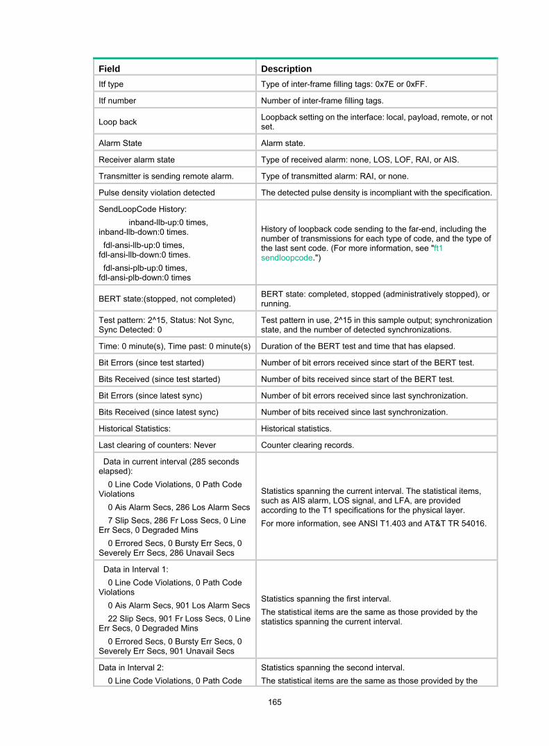
165
Field Description Itf type Type of inter-frame filling tags: 0x7E or 0xFF.
Itf number Number of inter-frame filling tags.
Loop back Loopback setting on the interface: local, payload, remote, or not set.
Alarm State Alarm state.
Receiver alarm state Type of received alarm: none, LOS, LOF, RAI, or AIS.
Transmitter is sending remote alarm. Type of transmitted alarm: RAI, or none.
Pulse density violation detected The detected pulse density is incompliant with the specification.
SendLoopCode History: inband-llb-up:0 times, inband-llb-down:0 times. fdl-ansi-llb-up:0 times, fdl-ansi-llb-down:0 times. fdl-ansi-plb-up:0 times, fdl-ansi-plb-down:0 times
History of loopback code sending to the far-end, including the number of transmissions for each type of code, and the type of the last sent code. (For more information, see "ft1 sendloopcode.")
BERT state:(stopped, not completed) BERT state: completed, stopped (administratively stopped), or running.
Test pattern: 2^15, Status: Not Sync, Sync Detected: 0
Test pattern in use, 2^15 in this sample output; synchronization state, and the number of detected synchronizations.
Time: 0 minute(s), Time past: 0 minute(s) Duration of the BERT test and time that has elapsed.
Bit Errors (since test started) Number of bit errors received since start of the BERT test.
Bits Received (since test started) Number of bits received since start of the BERT test.
Bit Errors (since latest sync) Number of bit errors received since last synchronization.
Bits Received (since latest sync) Number of bits received since last synchronization.
Historical Statistics: Historical statistics.
Last clearing of counters: Never Counter clearing records.
Data in current interval (285 seconds elapsed): 0 Line Code Violations, 0 Path Code Violations 0 Ais Alarm Secs, 286 Los Alarm Secs 7 Slip Secs, 286 Fr Loss Secs, 0 Line Err Secs, 0 Degraded Mins 0 Errored Secs, 0 Bursty Err Secs, 0 Severely Err Secs, 286 Unavail Secs
Statistics spanning the current interval. The statistical items, such as AIS alarm, LOS signal, and LFA, are provided according to the T1 specifications for the physical layer. For more information, see ANSI T1.403 and AT&T TR 54016.
Data in Interval 1: 0 Line Code Violations, 0 Path Code Violations 0 Ais Alarm Secs, 901 Los Alarm Secs 22 Slip Secs, 901 Fr Loss Secs, 0 Line Err Secs, 0 Degraded Mins 0 Errored Secs, 0 Bursty Err Secs, 0 Severely Err Secs, 901 Unavail Secs
Statistics spanning the first interval. The statistical items are the same as those provided by the statistics spanning the current interval.
Data in Interval 2: 0 Line Code Violations, 0 Path Code
Statistics spanning the second interval. The statistical items are the same as those provided by the
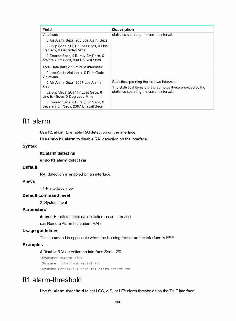
166
Field Description Violations 0 Ais Alarm Secs, 900 Los Alarm Secs 23 Slip Secs, 900 Fr Loss Secs, 0 Line Err Secs, 0 Degraded Mins 0 Errored Secs, 0 Bursty Err Secs, 0 Severely Err Secs, 900 Unavail Secs
statistics spanning the current interval.
Total Data (last 2 15 minute intervals): 0 Line Code Violations, 0 Path Code Violations 0 Ais Alarm Secs, 2087 Los Alarm Secs 52 Slip Secs, 2087 Fr Loss Secs, 0 Line Err Secs, 0 Degraded Mins 0 Errored Secs, 0 Bursty Err Secs, 0 Severely Err Secs, 2087 Unavail Secs
Statistics spanning the last two intervals. The statistical items are the same as those provided by the statistics spanning the current interval.
ft1 alarm Use ft1 alarm to enable RAI detection on the interface.
Use undo ft1 alarm to disable RAI detection on the interface.
Syntax ft1 alarm detect rai
undo ft1 alarm detect rai
Default RAI detection is enabled on an interface.
Views T1-F interface view
Default command level 2: System level
Parameters detect: Enables periodical detection on an interface.
rai: Remote Alarm Indication (RAI).
Usage guidelines This command is applicable when the framing format on the interface is ESF.
Examples # Disable RAI detection on interface Serial 2/0. <Sysname> system-view
[Sysname] interface serial 2/0
[Sysname-Serial2/0] undo ft1 alarm detect rai
ft1 alarm-threshold Use ft1 alarm-threshold to set LOS, AIS, or LFA alarm thresholds on the T1-F interface.

167
Use undo ft1 alarm-threshold to restore the default.
Syntax ft1 alarm-threshold { ais { level-1 | level-2 } | lfa { level-1 | level-2 | level-3 | level-4 } | los { pulse-detection | pulse-recovery } value }
undo ft1 alarm-threshold { ais | lfa | los { pulse-detection | pulse-recovery } }
Views T1-F interface view
Default command level 2: System level
Parameters ais: Sets the alarm threshold of alarm indication signal (AIS), which can be level-1 and level-2. • The level-1 keyword specifies generating an AIS alarm when the number of 0s in the bit stream
of an SF or ESF frame is less than or equal to 2. • The level-2 keyword specifies generating an AIS alarm when the number of 0s is less than or
equal to 3 in the bit stream of an SF frame or less than or equal to 5 in the bit stream of an ESP frame.
By default, level-1 AIS alarm threshold applies.
lfa: Sets the loss of frame align (LFA) alarm threshold, which can be level-1, level-2, level-3, and level-4. • The level-1 keyword specifies generating an LFA alarm when two of four frame alignment bits
are lost. • The level-2 keyword specifies generating an LFA alarm when two of five frame alignment bits
are lost. • The level-3 keyword specifies generating an LFA alarm when two of six frame alignment bits
are lost. • The level-4 keyword applies only to ESF frames. It specifies generating an LFA alarm when
errors are detected in four consecutive ESF frames.
By default, level-1 LFA alarm threshold applies. los: Sets a loss of signal (LOS) alarm threshold, which can be pulse-detection (for the pulse detection duration threshold with LOS) and pulse-recovery (for the pulse threshold with LOS).
The threshold of pulse-detection, in units of pulse intervals, in the range of 16 to 4,096. The default is 176.
The threshold of pulse-recovery is in the range of 1 to 256. The default is 22.
If the number of the pulses detected during the total length of the specified pulse detection intervals is smaller than the pulse-recovery threshold, a LOS alarm occurs. For example, if the two thresholds take their defaults, a LOS alarm is created if the number of pulses detected within 176 pulse intervals is less than 22.
Examples # Set the number of detection intervals to 300 for the pulse detection duration threshold. <Sysname> system-view
[Sysname] interface serial 2/0
[Sysname-Serial2/0] ft1 alarm-threshold los pulse-detection 300
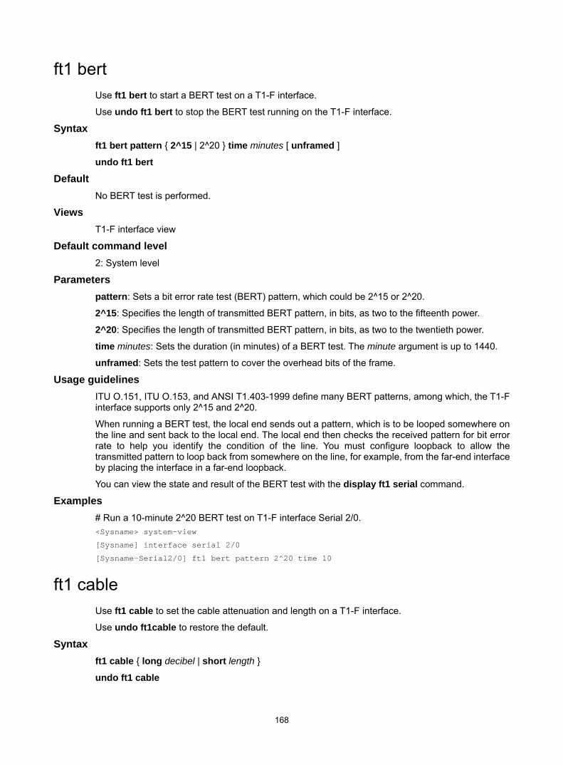
168
ft1 bert Use ft1 bert to start a BERT test on a T1-F interface.
Use undo ft1 bert to stop the BERT test running on the T1-F interface.
Syntax ft1 bert pattern { 2^15 | 2^20 } time minutes [ unframed ]
undo ft1 bert
Default No BERT test is performed.
Views T1-F interface view
Default command level 2: System level
Parameters pattern: Sets a bit error rate test (BERT) pattern, which could be 2^15 or 2^20.
2^15: Specifies the length of transmitted BERT pattern, in bits, as two to the fifteenth power.
2^20: Specifies the length of transmitted BERT pattern, in bits, as two to the twentieth power.
time minutes: Sets the duration (in minutes) of a BERT test. The minute argument is up to 1440.
unframed: Sets the test pattern to cover the overhead bits of the frame.
Usage guidelines ITU O.151, ITU O.153, and ANSI T1.403-1999 define many BERT patterns, among which, the T1-F interface supports only 2^15 and 2^20.
When running a BERT test, the local end sends out a pattern, which is to be looped somewhere on the line and sent back to the local end. The local end then checks the received pattern for bit error rate to help you identify the condition of the line. You must configure loopback to allow the transmitted pattern to loop back from somewhere on the line, for example, from the far-end interface by placing the interface in a far-end loopback.
You can view the state and result of the BERT test with the display ft1 serial command.
Examples # Run a 10-minute 2^20 BERT test on T1-F interface Serial 2/0. <Sysname> system-view
[Sysname] interface serial 2/0
[Sysname-Serial2/0] ft1 bert pattern 2^20 time 10
ft1 cable Use ft1 cable to set the cable attenuation and length on a T1-F interface.
Use undo ft1cable to restore the default.
Syntax ft1 cable { long decibel | short length }
undo ft1 cable
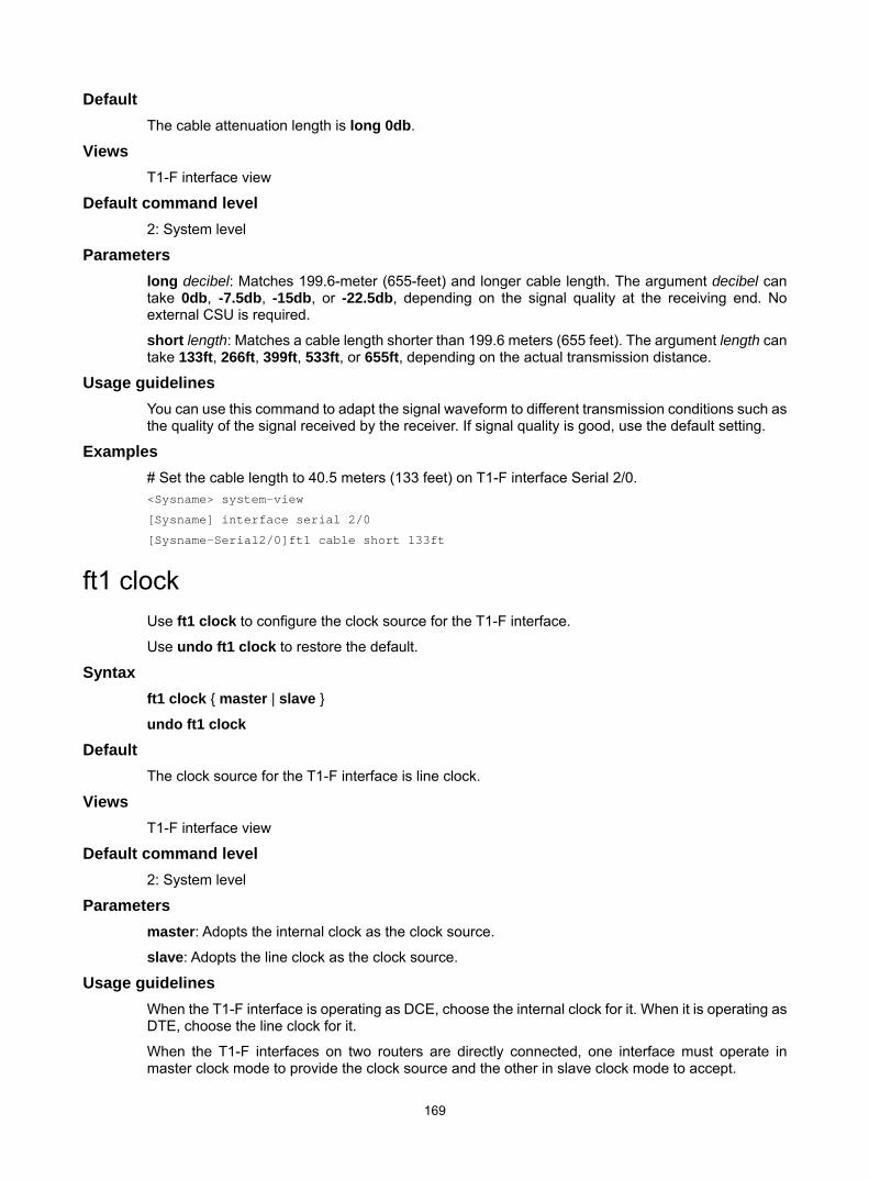
169
Default The cable attenuation length is long 0db.
Views T1-F interface view
Default command level 2: System level
Parameters long decibel: Matches 199.6-meter (655-feet) and longer cable length. The argument decibel can take 0db, -7.5db, -15db, or -22.5db, depending on the signal quality at the receiving end. No external CSU is required.
short length: Matches a cable length shorter than 199.6 meters (655 feet). The argument length can take 133ft, 266ft, 399ft, 533ft, or 655ft, depending on the actual transmission distance.
Usage guidelines You can use this command to adapt the signal waveform to different transmission conditions such as the quality of the signal received by the receiver. If signal quality is good, use the default setting.
Examples # Set the cable length to 40.5 meters (133 feet) on T1-F interface Serial 2/0. <Sysname> system-view
[Sysname] interface serial 2/0
[Sysname-Serial2/0]ft1 cable short 133ft
ft1 clock Use ft1 clock to configure the clock source for the T1-F interface.
Use undo ft1 clock to restore the default.
Syntax ft1 clock { master | slave }
undo ft1 clock
Default The clock source for the T1-F interface is line clock.
Views T1-F interface view
Default command level 2: System level
Parameters master: Adopts the internal clock as the clock source. slave: Adopts the line clock as the clock source.
Usage guidelines When the T1-F interface is operating as DCE, choose the internal clock for it. When it is operating as DTE, choose the line clock for it.
When the T1-F interfaces on two routers are directly connected, one interface must operate in master clock mode to provide the clock source and the other in slave clock mode to accept.
170
When the T1-F interface on your router is connected to a switch, it is operating as DTE and therefore must be configured with the slave clock mode to accept the line clock provided by the switch operating as DCE.
Examples # Use the internal clock as the clock source on T1-F interface Serial 2/0. <Sysname> system-view
[Sysname] interface serial 2/0
[Sysname-Serial2/0] ft1 clock master
ft1 code Use ft1 code to set the line code format for the T1-F interface.
Use undo ft1 code to restore the default.
Syntax ft1 code { ami | b8zs }
undo ft1 code
Default The line code format for the T1-F interface is B8ZS.
Views T1-F interface view
Default command level 2: System level
Parameters ami: Adopts AMI line code format.
b8zs: Adopts B8ZS line code format.
Usage guidelines Keep the line code format of the interface in consistency with the one used on the remote device.
To ensure the normal operation of the interface, configure the ft1 data-coding inverted command on it when its line code format is set to AMI.
Examples # Set the line code format of T1-F interface Serial 2/0 to AMI. <Sysname> system-view
[Sysname] interface serial 2/0
[Sysname-Serial2/0] ft1 code ami
Related commands ft1 data-coding
ft1 data-coding Use ft1 data-coding normal to disable user data inversion for a T1-F interface.
Use ft1 data-coding inverted to enable user data inversion for a T1-F interface.
Use undo ft1 data-coding to restore the default.
171
Syntax ft1 data-coding { inverted | normal }
undo ft1 data-coding
Default Data inversion is disabled.
Views T1-F interface view
Default command level 2: System level
Parameters inverted: Enables user data inversion.
normal: Disables user data inversion.
Usage guidelines To prevent 7e in valid data from being taken for stuffing characters, HDLC inserts a zero after every five ones in the data stream. Then, HDLC inverts every one bit into a zero and every zero bit into a one. This ensures that at least at least one out of every eight bits is a one. When AMI encoding is adopted on a T1-F interface, the use of data inversion can eliminate the presence of multiple consecutive zeros.
At the two ends of a T1-F line, the same data inversion setting must be adopted.
Examples # Enable user data inversion on T1-F interface Serial 2/0. <Sysname> system-view
[Sysname] interface serial 2/0
[Sysname-Serial2/0] ft1 data-coding inverted
ft1 fdl Use ft1 fdl to set the behavior of the T1-F interface on the FDL in ESF framing.
Use undo ft1 fdl to restore the default.
Syntax ft1 fdl { ansi | att | both | none }
undo ft1 fdl
Default FDL is disabled.
Views T1-F interface view
Default command level 2: System level
Parameters ansi: Adopts ANSI T1.403 for FDL.
att: Adopts AT&T TR 54016 for FDL.
172
both: Adopts both ANSI T1.403 and AT&T TR 54016 for FDL.
none: Disables FDL.
Usage guidelines FDL is an embedded 4 kbps overhead channel within the ESF format for transmitting performance statistics or loopback code.
You can however change the setting depending on the setting at the far end.
Examples # Set ANSI T1.403 FDL on T1-F interface Serial 2/0. <Sysname> system-view
[Sysname] interface serial 2/0
[Sysname-Serial2/0] ft1 fdl ansi
ft1 frame-format Use ft1 frame-format to set the framing format on the T1-F interface.
Use undo ft1 frame-format to restore the default.
Syntax ft1 frame-format { esf | sf }
undo ft1 frame-format
Default The framing format on the T1-F interface is esf.
Views T1-F interface view
Default command level 2: System level
Parameters esf: Sets the framing format on the T1-F interface to ESF. sf: Sets the framing format on the T1-F interface to SF.
Usage guidelines T1-F interfaces support two framing formats, SF and ESF. In SF format, multiple frames can share the same FSC and signaling information, so that more significant bits are available for transmitting user data. The use of ESF allows you to test the system without affecting the ongoing service.
Examples # Set the framing format of T1-F interface Serial 2/0 to SF. <Sysname> system-view
[Sysname] interface serial 2/0
[Sysname-Serial2/0] ft1 frame-format sf
ft1 idlecode Use ft1 idlecode to set the line idle code on the T1-F interface. Two types of line idle code are available: 0x7E and 0xFF.
Use undo ft1 idlecode to restore the default.
173
Syntax ft1 idlecode { 7e | ff }
undo ft1 idlecode
Default The line idle code on the T1-F interface is 0x7E.
Views T1-F interface view
Default command level 2: System level
Parameters 7e: Sets the line idle code to 0x7E.
ff: Sets the line idle code to 0xFF.
Usage guidelines The line idle code is sent in the timeslots that are not bundled into the logical channels on the interface.
Examples # Set the line idle code to 0x7E on T1-F interface Serial 2/0. <Sysname> system-view
[Sysname] interface serial 2/0
[Sysname-Serial2/0] ft1 idlecode 7e
ft1 itf Use ft1 itf to set the type and the number of interframe filling tags on a T1-F interface. Two types of interframe filling tag are available: 0x7E and 0xFF.
Use undo ft1 itf to restore the default.
Syntax ft1 itf { number number | type { 7e | ff } } undo ft1 itf { type | number }
Default The interframe filling tag is 0x7E, and the number of interframe filling tags is four.
Views T1-F interface view
Default command level 2: System level
Parameters number number: Sets the number of interframe filling tags (a interframe filling tag is one byte in length). The number argument is in the range of 0 to 14.
type { 7e | ff }: Sets the interframe filling tag to 0x7E by specifying the 7e keyword or to 0xFF by specifying the ff keyword. On a T1-F interface, the default interframe filling tag is 0x7E.
174
Usage guidelines Interframe filling tags are sent when no service data is sent on the timeslots bundled into logical channels on a T1-F interface.
Do not use the ft1 itf type ff command if both the ft1 code ami command and the ft1 data-coding inverted command are configured so that the T1-F interface can function normally.
Examples # Set the interframe filling tag to 0xFF on T1-F interface Serial 2/0. <Sysname> system-view
[Sysname] interface serial 2/0
[Sysname-Serial2/0] ft1 itf type ff
# Set the number of interframe filling tags to five on T1-F interface Serial 2/0. <Sysname> system-view
[Sysname] interface serial 2/0
[Sysname-Serial2/0] ft1 itf number 5
ft1 loopback Use ft1 loopback to set the T1-F interface in a loopback mode.
Use undo ft1 loopback to restore the default.
Syntax ft1 loopback { local | payload | remote }
undo ft1 loopback
Default Loopback is disabled.
Views T1-F interface view
Default command level 2: System level
Parameters local: Sets the interface in internal loopback mode.
payload: Sets the interface in external payload loopback mode.
remote: Sets the interface in external loopback mode.
Usage guidelines Loopback is mainly used to check the condition of interfaces or cables. Disable loopback in other cases.
The three loopback modes cannot be used at the same time on a T1-F interface.
Examples # Set T1-F interface Serial 2/0 in local loopback mode. <Sysname> system-view
[Sysname] interface serial 2/0
[Sysname-Serial2/0] ft1 loopback local
175
ft1 sendloopcode Use ft1 sendloopcode to send remote loopback control code.
Syntax ft1 sendloopcode { fdl-ansi-llb-down | fdl-ansi-llb-up | fdl-ansi-plb-down | fdl-ansi-plb-up | fdl-att-plb-down | fdl-att-plb-up | inband-llb-down | inband-llb-up }
Default No remote loopback control code is sent.
Views T1-F interface view
Default command level 2: System level
Parameters fdl-ansi-llb-down: Sends ANSI-compliant LLB deactivation request code in the FDL to removes loopback. fdl-ansi-llb-up: Sends ANSI-compliant line loopback (LLB) activation request code in the FDL to start remote loopback.
fdl-ansi-plb-down: Sends ANSI-compliant PLB deactivation request code in the FDL to remove loopback.
fdl-ansi-plb-up: Sends ANSI-compliant payload loopback (PLB) activation request code in the FDL to start remote loopback.
fdl-att-plb-down: Sends AT&T-complaint PLB deactivation request code in the FDL to remove loopback.
fdl-att-plb-up: Sends AT&T-complaint PLB activation request code in the FDL to start remote loopback.
inband-llb-down: Sends in-band LLB deactivation request code compliant with the ANSI or AT&T implementation to remove loopback.
inband-llb-up: Sends in-band line loopback (LLB) activation request code compliant with the ANSI or AT&T implementation to start remote loopback.
Usage guidelines You can configure loopback on the remote T1-F interface by sending loopback request code.
In LLB mode, all 193 bits (one synchronization bit and 192 effective bandwidth bits) in a T1 PCM frame are looped back. In PLB mode, however, only 192 effective bandwidth bits are looped back.
The format of loopback code is compliant with ANSI T1.403 or AT&T TR 54016.
In SF framing, LLB code is sent using the effective bandwidth (slots 1 through 24). In ESF framing, both LLB code and PLB code are sent/received in the FDL in ESF frames.
You can use this command only when the remote T1-F interface can automatically detect loopback request code from the network.
Examples # Send in-band LLB activation request code. <Sysname> system-view
[Sysname] interface serial 2/0
[Sysname-Serial2/0] ft1 sendloopcode inband-llb-up
176
ft1 timeslot-list Use ft1 timeslot-list to bundle timeslots on a T1-F interface.
Use undo ft1 timeslot-list to restore the default.
Syntax ft1 timeslot-list list [ speed { 56k | 64k } ]
undo ft1 timeslot-list
Default All the timeslots on the T1-F interface are bundled to form a 1536 kbps interface.
Views T1-F interface view
Default command level 2: System level
Parameters list: Specifies timeslots to be bundled. They are numbered 1 through 24. You can specify a single timeslot by specifying its number, a range of timeslots by specifying a range in the form of number1-number2, or several discrete timeslots by specifying number1, number2-number3.
speed { 56k | 64k }: Time slot bundling speed in kbps. If 56k applies, timeslots are bundled into an N × 56 kbps bundle. If 64k (the default) applies, timeslots are bundled into an N × 64 kbps bundle.
Usage guidelines Timeslot bundling results in interface rate change. For example, after you bundle timeslots 1 through 10 on the interface, the interface rate becomes 10 × 64 kbps or 10 × 56 kbps.
Only one channel set can be created on a T1-F interface, and this channel set is associated with the current synchronous serial interface. On a CT1/PRI interface, however, you can create multiple channel sets; for each of them, the system automatically creates a synchronous serial interface.
Examples # Bundle timeslots 1, 2, 5, 10 through 15, and 18 on T1-F interface Serial 2/0. <Sysname> system-view
[Sysname] interface serial 2/0
[Sysname-Serial2/0] ft1 timeslot-list 1,2,5,10-15,18
Basic CE3 interface configuration commands bert (CE3 interface)
Use bert to enable BERT test.
Use undo bert to disable BERT test.
Syntax bert pattern { 2^7 | 2^11 | 2^15 | qrss } time number [ unframed ]
undo bert
Default No BERT test is performed.
177
Views CE3 interface view
Default command level 2: System level
Parameters pattern: Specifies BERT test mode, which can be 2^7, 2^11, 2^15, and QRSS.
2^7: Specifies the code stream transmitted is the 7th power of 2 bits in length.
2^11: Specifies the code stream transmitted is the 11th power of 2 bits in length.
2^15: Specifies the code stream transmitted is the 15th power of 2 bits in length.
qrss: Specifies the code stream transmitted is the 20th power of 2 bits in length and the number of successive 0s in the code stream is no more than 14.
time number: Sets the duration (in minutes) of a BERT teat. The number argument is in the range of 1 to 1,440.
unframed: Sets the overhead bits of the padding frames for BERT test.
Usage guidelines Multiple BERT test modes exist, as defined in ITU O.151, ITU O.153, and ANSI T1.403-1999. 2^7, 2^11, 2^15, and QRSS are available on a CE3 interface.
To perform a BERT test, the local end transmits test data stream, which is returned after reaching specific nodes. The local end then checks for the bit error rate by comparing the returned data stream with the original, through which the state of the link can be determined. BERT test requires that data stream can be looped back on specific nodes. You can achieve this by enabling remote loop back on the peer.
You can use the bert command to set the test mode and the test duration. During the process of a BERT test, you can check the state and the result of the test. For more information, see the command that displays information about a CE3 interface.
Examples # Perform BERT test in QRSS mode on CE3 2/0 interface, setting the duration to ten minutes. <Sysname> system-view
[Sysname] interface e3 2/0
[Sysname-E3 2/0] bert pattern qrss time 10
clock (CE3 interface) Use clock to configure clock source for a CE3 interface.
Use undo clock to restore the default.
Syntax clock { master | slave }
undo clock
Default The clock source for a CE3 interface is line clock.
Views CE3 interface view
178
Default command level 2: System level
Parameters master: Adopts the internal clock as the clock source. slave: Adopts the line clock as the clock source.
Usage guidelines The clock source is selected depending on the connected remote device. If connected to a transmission device, the local end uses the line clock. If connected to a CE3 interface on another router, the local end can use whichever clock so long as it is different from the one adopted at the remote end.
Examples # Use the internal clock as the clock source on CE3 interface E3 2/0. <Sysname> system-view
[Sysname] controller e3 2/0
[Sysname-E3 2/0] clock master
controller e3 Use controller e3 to enter CE3 interface view.
Syntax controller e3 interface-number
Views System view
Default command level 2: System level
Parameters interface-number: CE3 interface number.
Examples # Enter the view of interface E3 2/0. <Sysname> system-view
[Sysname] controller e3 2/0
[Sysname-E3 2/0]
Related commands display controller e3
crc Use crc to configure CRC mode for a synchronous serial interface formed by CE3 interfaces.
Use undo crc to restore the default.
Syntax crc { 16 | 32 | none }
undo crc

179
Default The CRC mode for synchronous serial interface formed by CE3 interfaces is 16-bit CRC.
Views Synchronous serial interface view
Default command level 2: System level
Parameters 16: Adopts 16-bit CRC.
32: Adopts 32-bit CRC.
none: Adopts no CRC.
Examples # Apply 32-bit CRC to a serial interface formed on interface E3 2/0 in unchannelized mode. <Sysname> system-view
[Sysname] controller e3 2/0
[Sysname-E3 2/0] using e3
[Sysname-E3 2/0] quit
[Sysname] interface serial 2/0/0:0
[Sysname-Serial2/0/0:0] crc 32
# Apply 16-bit CRC to a serial interface formed on interface E3 2/0 in unchannelized mode. <Sysname> system-view
[Sysname] controller e3 2/0
[Sysname-E3 2/0] e1 3 channel-set 5 timeslot-list 1-20
[Sysname-E3 2/0] quit
[Sysname] interface serial 2/0/3:5
[Sysname-Serial2/0/3:5] crc 16
Related commands • e1 channel-set • e1 unframed • using
display controller e3 Use display controller e3 to display state information about a specific or all CE3 interfaces.
Syntax display controller e3 [ interface-number ] [ | { begin | exclude | include } regular-expression ]
Views Any view
Default command level 1: Monitor level
Parameters interface-number: CE3 interface number. In conjunction with the e3 keyword, it specifies a CE3 interface.
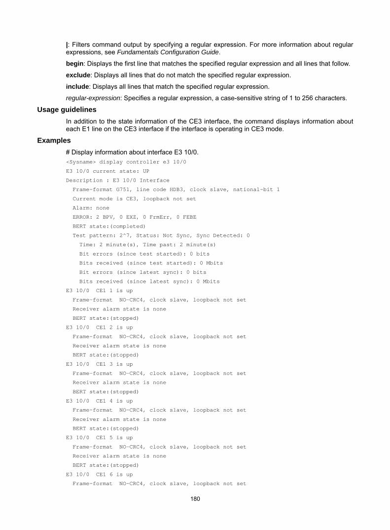
180
|: Filters command output by specifying a regular expression. For more information about regular expressions, see Fundamentals Configuration Guide.
begin: Displays the first line that matches the specified regular expression and all lines that follow.
exclude: Displays all lines that do not match the specified regular expression.
include: Displays all lines that match the specified regular expression.
regular-expression: Specifies a regular expression, a case-sensitive string of 1 to 256 characters.
Usage guidelines In addition to the state information of the CE3 interface, the command displays information about each E1 line on the CE3 interface if the interface is operating in CE3 mode.
Examples # Display information about interface E3 10/0. <Sysname> display controller e3 10/0
E3 10/0 current state: UP
Description : E3 10/0 Interface
Frame-format G751, line code HDB3, clock slave, national-bit 1
Current mode is CE3, loopback not set
Alarm: none
ERROR: 2 BPV, 0 EXZ, 0 FrmErr, 0 FEBE
BERT state:(completed)
Test pattern: 2^7, Status: Not Sync, Sync Detected: 0
Time: 2 minute(s), Time past: 2 minute(s)
Bit errors (since test started): 0 bits
Bits received (since test started): 0 Mbits
Bit errors (since latest sync): 0 bits
Bits received (since latest sync): 0 Mbits
E3 10/0 CE1 1 is up
Frame-format NO-CRC4, clock slave, loopback not set
Receiver alarm state is none
BERT state:(stopped)
E3 10/0 CE1 2 is up
Frame-format NO-CRC4, clock slave, loopback not set
Receiver alarm state is none
BERT state:(stopped)
E3 10/0 CE1 3 is up
Frame-format NO-CRC4, clock slave, loopback not set
Receiver alarm state is none
BERT state:(stopped)
E3 10/0 CE1 4 is up
Frame-format NO-CRC4, clock slave, loopback not set
Receiver alarm state is none
BERT state:(stopped)
E3 10/0 CE1 5 is up
Frame-format NO-CRC4, clock slave, loopback not set
Receiver alarm state is none
BERT state:(stopped)
E3 10/0 CE1 6 is up
Frame-format NO-CRC4, clock slave, loopback not set
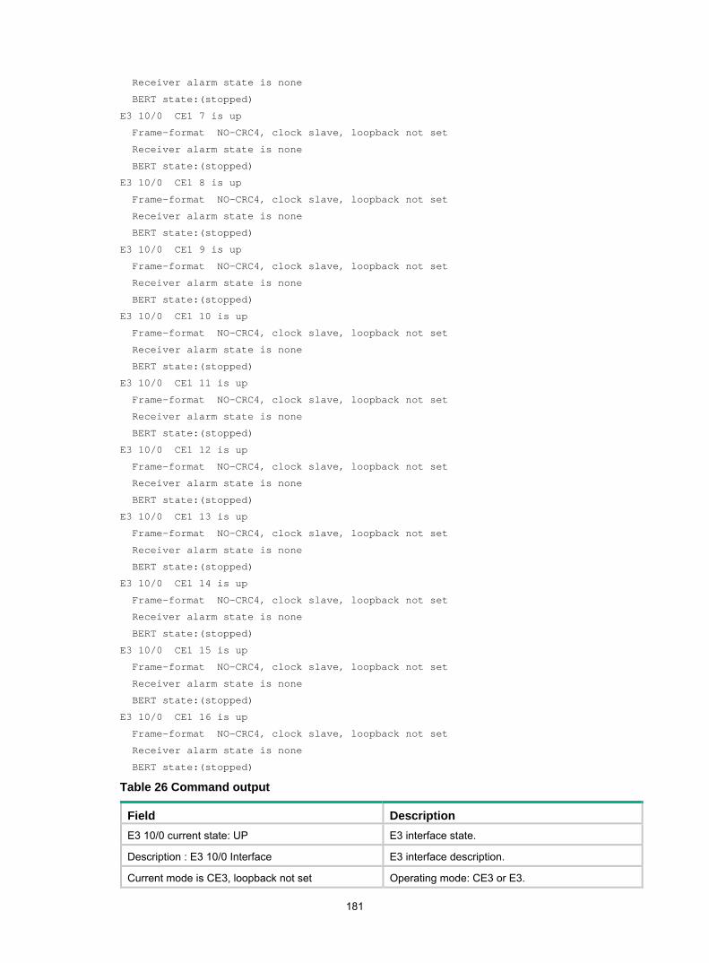
181
Receiver alarm state is none
BERT state:(stopped)
E3 10/0 CE1 7 is up
Frame-format NO-CRC4, clock slave, loopback not set
Receiver alarm state is none
BERT state:(stopped)
E3 10/0 CE1 8 is up
Frame-format NO-CRC4, clock slave, loopback not set
Receiver alarm state is none
BERT state:(stopped)
E3 10/0 CE1 9 is up
Frame-format NO-CRC4, clock slave, loopback not set
Receiver alarm state is none
BERT state:(stopped)
E3 10/0 CE1 10 is up
Frame-format NO-CRC4, clock slave, loopback not set
Receiver alarm state is none
BERT state:(stopped)
E3 10/0 CE1 11 is up
Frame-format NO-CRC4, clock slave, loopback not set
Receiver alarm state is none
BERT state:(stopped)
E3 10/0 CE1 12 is up
Frame-format NO-CRC4, clock slave, loopback not set
Receiver alarm state is none
BERT state:(stopped)
E3 10/0 CE1 13 is up
Frame-format NO-CRC4, clock slave, loopback not set
Receiver alarm state is none
BERT state:(stopped)
E3 10/0 CE1 14 is up
Frame-format NO-CRC4, clock slave, loopback not set
Receiver alarm state is none
BERT state:(stopped)
E3 10/0 CE1 15 is up
Frame-format NO-CRC4, clock slave, loopback not set
Receiver alarm state is none
BERT state:(stopped)
E3 10/0 CE1 16 is up
Frame-format NO-CRC4, clock slave, loopback not set
Receiver alarm state is none
BERT state:(stopped)
Table 26 Command output
Field Description E3 10/0 current state: UP E3 interface state.
Description : E3 10/0 Interface E3 interface description.
Current mode is CE3, loopback not set Operating mode: CE3 or E3.
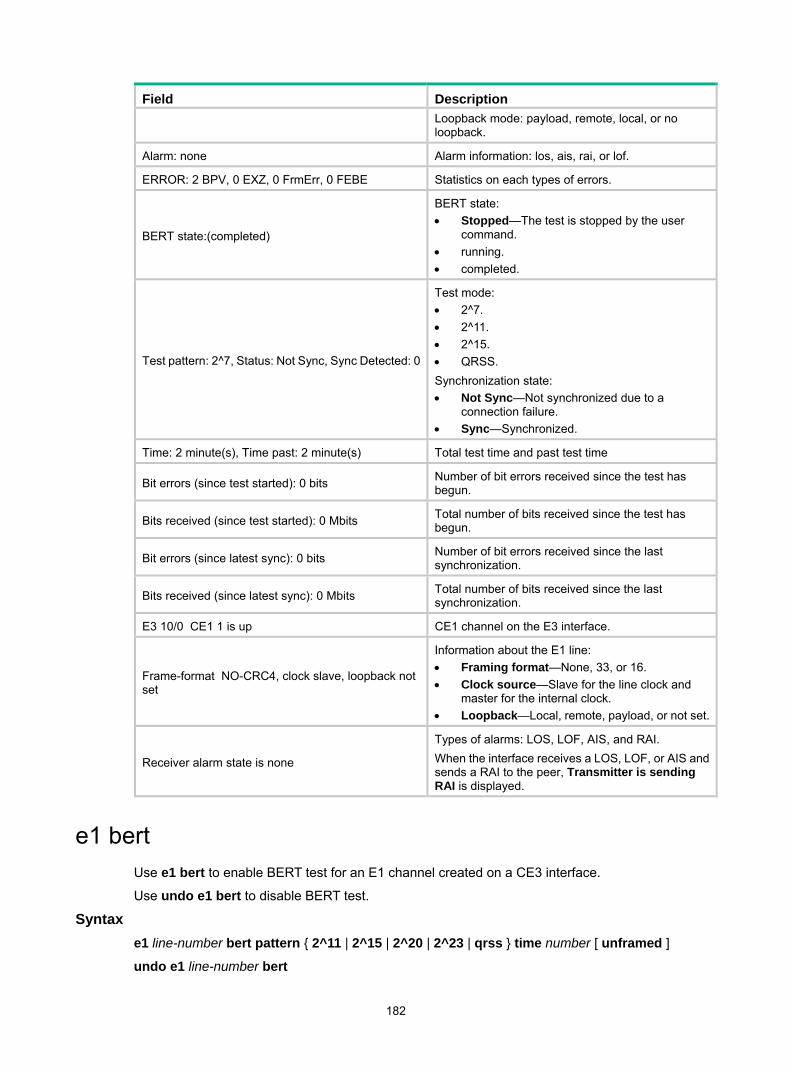
182
Field Description Loopback mode: payload, remote, local, or no loopback.
Alarm: none Alarm information: los, ais, rai, or lof.
ERROR: 2 BPV, 0 EXZ, 0 FrmErr, 0 FEBE Statistics on each types of errors.
BERT state:(completed)
BERT state: • Stopped—The test is stopped by the user
command. • running. • completed.
Test pattern: 2^7, Status: Not Sync, Sync Detected: 0
Test mode: • 2^7. • 2^11. • 2^15. • QRSS. Synchronization state: • Not Sync—Not synchronized due to a
connection failure. • Sync—Synchronized.
Time: 2 minute(s), Time past: 2 minute(s) Total test time and past test time
Bit errors (since test started): 0 bits Number of bit errors received since the test has begun.
Bits received (since test started): 0 Mbits Total number of bits received since the test has begun.
Bit errors (since latest sync): 0 bits Number of bit errors received since the last synchronization.
Bits received (since latest sync): 0 Mbits Total number of bits received since the last synchronization.
E3 10/0 CE1 1 is up CE1 channel on the E3 interface.
Frame-format NO-CRC4, clock slave, loopback not set
Information about the E1 line: • Framing format—None, 33, or 16. • Clock source—Slave for the line clock and
master for the internal clock. • Loopback—Local, remote, payload, or not set.
Receiver alarm state is none
Types of alarms: LOS, LOF, AIS, and RAI. When the interface receives a LOS, LOF, or AIS and sends a RAI to the peer, Transmitter is sending RAI is displayed.
e1 bert Use e1 bert to enable BERT test for an E1 channel created on a CE3 interface.
Use undo e1 bert to disable BERT test.
Syntax e1 line-number bert pattern { 2^11 | 2^15 | 2^20 | 2^23 | qrss } time number [ unframed ]
undo e1 line-number bert
183
Default No BERT test is performed.
Views CE3 interface view
Default command level 2: System level
Parameters line-number: E1 channel number in the range of 1 to 28.
pattern: Specifies BERT test mode, which can be 2^11, 2^15, 2^20, 2^23, and QRSS.
2^11: Specifies the code stream transmitted is the 11th power of 2 bits in length.
2^15: Specifies the code stream transmitted is the 15th power of 2 bits in length.
2^20: Specifies the code stream transmitted is the 20th power of 2 bits in length.
2^23: Specifies the code stream transmitted is the 23rd power of 2 bits in length.
qrss: Specifies the code stream transmitted is the 20th power of 2 bits in length and the number of successive 0s in the code stream is no more than 14.
time number: Sets the duration (in minutes) of a BERT teat. The number argument is in the range of 1 to 1,440.
unframed: Sets the overhead bits of the padding frames for BERT test.
Usage guidelines Multiple BERT test modes exist, as defined in ITU O.151, ITU O.153, and ANSI T1.403-1999. 2^11, 2^15, 2^20, 2^23, and QRSS are available on E1 channels created on CE3 interfaces.
To perform a BERT test, the local end transmits test data stream, which is returned after reaching specific nodes. The local end then checks for the bit error rate by comparing the returned data stream with the original, through which the state of the link can be determined. BERT test requires that data stream can be looped back on specific nodes. You can achieve this by enabling remote loop back on the peer.
You can use the bert command to set the test mode and the test duration. During the process of a BERT test, you can check the state and the result of the test. For more information, see the command that displays information about a CE3 interface.
Examples # Perform BERT test in QRSS mode on E1 channel 1 created on CE3 2/0 interface, setting the duration to ten minutes. <Sysname> system-view
[Sysname] interface e3 2/0
[Sysname-E3 2/0] e1 1 bert pattern qrss time 10
e1 channel-set Use e1 channel-set to bundle timeslots on an E1 line.
Use undo e1 channel-set to remove a timeslot bundle.
Syntax e1 line-number channel-set set-number timeslot-list list
undo e1 line-number channel-set set-number
184
Default No timeslots are bundled into channel sets.
Views CE3 interface view
Default command level 2: System level
Parameters line-number: E1 line number in the range of 1 to 16.
set-number: Number of the channel set formed by a timeslot bundle on the E1 line. It is in the range of 0 to 30.
timeslot-list list: Specifies the timeslots to be bundled. The list argument can contain multiple timeslot numbers, each of in the range of 1 to 31. You can specify a single timeslot by specifying a timeslot number, a range of timeslots by providing this argument in the form of { number1-number2 }, or multiple timeslots by providing this argument in the form of { number1, number2-number3 }.
Usage guidelines A CE3 interface can be channelized into 64 kbps lines and the timeslots on each E1 line can be bundled into up to 31 channels.
When an E1 line operates in framed (CE1) mode, you can bundle timeslots on it into channel sets. For each channel set, the system automatically creates a serial interface numbered serial number/line-number:set-number. For example, the serial interface formed by channel set 0 on the first E1 line on E3 1/0 is numbered 1/0/1:0. This interface can operate at N × 64 kbps, and is logically equivalent to a synchronous serial interface on which you can make other configurations.
Examples # Create a 128 kbps serial interface on the first E1 channel on interface E3 2/0. <Sysname> system-view
[Sysname] controller e3 2/0
[Sysname-E3 2/0] e1 1 channel-set 1 timeslot-list 1,2
Related commands e1 unframed
e1 set clock Use e1 set clock to configure clock source for an E1 line on the CE3 interface.
Use undo e1 set clock to restore the default.
Syntax e1 line-number set clock { master | slave }
undo e1 line-number set clock
Default The clock source for an E1 line on the CE3 interface is line clock.
Views CE3 interface view
Default command level 2: System level
185
Parameters line-number: E1 line number in the range of 1 to 16.
master: Adopts the internal clock as the clock source. slave: Adopts the line clock as the clock source.
Usage guidelines When the CE3 interface is operating in channelized mode, you can set separate clock for each E1 line on it.
Examples # Use the internal clock as the clock source on the first E1 line on interface E3 2/0. <Sysname> system-view
[Sysname] controller e3 2/0
[Sysname-E3 2/0] e1 1 set clock slave
e1 set frame-format Use e1 set frame-format to set framing format for an E1 line.
Use undo e1 set frame-format to restore the default.
Syntax e1 line-number set frame-format { crc4 | no-crc4 }
undo e1 line-number set frame-format
Default The framing format for an E1 line is no-CRC4.
Views CE3 interface view
Default command level 2: System level
Parameters line-number: E1 line number in the range of 1 to 16.
crc4: Sets the frame format to CRC4.
no-crc4: Sets the frame format to no-CRC4.
Usage guidelines Configure this command only when the specified E1 line is operating in framed format (which can be set using the undo e1 unframed command).
Examples # Set the framing format to CRC4 for the first E1 line on interface E3 2/0. <Sysname> system-view
[Sysname] controller e3 2/0
[Sysname-E3 2/0] e1 1 set frame-format crc4
Related commands e1 unframed
186
e1 set loopback Use e1 set loopback to set an E1 line in a loopback mode on the E3 interface.
Use undo e1 set loopback to restore the default.
Syntax e1 line-number set loopback { local | payload | remote }
undo e1 line-number set loopback
Default Loopback is disabled on E1 lines.
Views CE3 interface view
Default command level 2: System level
Parameters line-number: E1 line number in the range of 1 to 16.
local: Sets the E1 line in internal loopback mode.
payload: Sets the E1 line in payload loopback mode.
remote: Sets the E1 line in external loopback mode.
Usage guidelines If an E1 line encapsulated with PPP is in loopback mode, it is normal that the state of the link layer protocol is reported down.
Examples # Set the first E1 line on interface E3 2/0 in internal loopback mode. <Sysname> system-view
[Sysname] controller e3 2/0
[Sysname-E3 2/0] e1 1 set loopback local
e1 shutdown Use e1 shutdown to shut down an E1 line on the CE3 interface.
Use undo e1 shutdown to restore the default.
Syntax e1 line-number shutdown undo e1 line-number shutdown
Default E1 lines are up.
Views CE3 interface view
Default command level 2: System level
187
Parameters line-number: E1 line number in the range of 1 to 16.
Usage guidelines This command affects not only the specified E1 line but also the serial interfaces formed by E1 line bundling. Performing the e1 shutdown command on the specified E1 line shuts down all these serial interfaces. Data transmission and receiving stop as a result. Likewise, performing the undo e1 shutdown command restarts all these serial interfaces.
Examples # Shut down the first E1 line on interface E3 2/0. <Sysname> system-view
[Sysname] controller e3 2/0
[Sysname-E3 2/0] e1 1 shutdown
e1 unframed Use e1 unframed to set an E1 line on the CE3 interface to operate in unframed mode (E1 mode).
Use undo e1 unframed to restore the default.
Syntax e1 line-number unframed
undo e1 line-number unframed
Default An E1 line operates in framed mode (CE1 mode).
Views CE3 interface view
Default command level 2: System level
Parameters line-number: E1 line number in the range of 1 to 16.
Usage guidelines An E1 line in unframed mode does not contain the frame control information; it cannot be divided into timeslots. The system automatically creates a serial interface numbered serial number/line-number:0 for it. This interface operates at 2048 kbps and is logically equivalent to a synchronous serial interface on which you can make other configurations.
Examples # Set the first E1 line on interface E3 2/0 to operate in unframed mode. <Sysname> system-view
[Sysname] controller e3 2/0
[Sysname-E3 2/0] e1 1 unframed
Related commands e1 channel-set
188
fe3 Use fe3 to configure a CE3 interface to operate in the FE3 mode and set the DSU mode or the subrate.
Use undo fe3 to restore the default.
Syntax fe3 { dsu-mode { 0 | 1 } | subrate number }
undo fe3 { dsu-mode | subrate }
Default DSU mode 1 (the Kentrox mode) is adopted, and the subrate is 34010 kbps.
Views CE3 interface (in FE3 mode) view
Default command level 2: System level
Parameters dsu-mode: Specifies the FE3 (Fractional E3) DSU mode for a CE3 interface operating in FE3 mode. This keyword can be followed by 0 or 1.
0: Specifies the Digital Link mode, where the subrate is a multiple of 358 kbps. The subrate is in the range of 358 to 34010 kbps. Up to 95 rate levels are available.
1: Specifies the Kentrox mode, where the subrate is a multiple of 500 kbps. The subrate is in the range of 500 to 24500 kbps. In this mode, the subrate can also be 34010 kbps (making a total of 50 rate levels).
subrate number: Specifies a subrate for the CE3 interface. The number argument is in the range of 1 to 34010 (in kbps).
Usage guidelines FE3 mode is a non-standard E3 application mode. In this mode, the subrate level setting varies with vendors. You can use the fe3 command to make the device to be compatible with devices of other vendors operating in specific FE3 DSU modes.
This command is only applicable to CE3 modules that support FE3.
This command is available only in E3 mode.
As for the fe3 subrate command, the actual subrate usually is not exactly the one set by the command. After you set the subrate by using the fe3 subrate command, the CE3 interface searches the subrate levels corresponding to the DSU mode it is operating in and selects the one that is closest to that set by the command as its subrate. The device then adjusts the hardware to allow for the subrate.
You can use the display interface serial interface-number:0 command to check the DSU mode setting, the subrate, the actual rate, and the baudrate of a CE3 interface. The actual rate does not include the overhead bits, and the baudrate is the actual E3 line rate (34368 kbps), with the overhead bits counted in.
Examples # Configure E3 2/0 interface to operate in the FE3 mode, setting the DSU mode to 1 and the subrate to 3000 kbps. <Sysname> system-view
[Sysname] controller e3 2/0
[Sysname-E3 2/0] using e3
189
[Sysname-E3 2/0] fe3 dsu-mode 1
[Sysname-E3 2/0] fe3 subrate 3000
loopback (CE3 interface) Use loopback to configure the loopback mode of the CE3 interface.
Use undo loopback to restore the default.
Syntax loopback { local | payload | remote }
undo loopback
Default Loopback is disabled on the CE3 interface.
Views CE3 interface view
Default command level 2: System level
Parameters local: Enables internal loopback on the CE3 interface.
payload: Enables external payload loopback on the CE3 interface.
remote: Enables external loopback on the CE3 interface.
Usage guidelines Loopback is intended for test use. Disable loopback in other cases.
If a CE3 interface encapsulated with PPP is placed in a loopback, it is normal that the state of the link layer protocol is reported as down.
Examples # Enable internal loopback on interface E3 2/0. <Sysname> system-view
[Sysname] controller e3 2/0
[Sysname-E3 2/0] loopback local
national-bit Use national-bit to configure the national bit on the CE3 interface.
Use undo national-bit to restore the default.
Syntax national-bit { 0 | 1 }
undo national-bit
Default The national bit on the CE3 interface is 1.
Views CE3 interface view
190
Default command level 2: System level
Parameters 0: Sets the national bit to 0 for national communication.
1: Sets the national bit to 1 for international communication.
Usage guidelines You need to set the national bit to 0 on an E3 interface only in some special circumstances.
Examples # Set the national bit to 0 on interface E3 2/0. <Sysname> system-view
[Sysname] controller e3 2/0
[Sysname-E3 2/0] national-bit 0
Related commands controller e3
reset counters controller e3 Use reset counters controller e3 to clear the controller counter of a CE3 interface.
Syntax reset counters controller e3 interface-number
Views User view
Default command level 2: System level
Parameters interface-number: Interface number.
Usage guidelines You can use the display controller e3 command to display the statistics collected by the controller counters of CE3 interfaces.
The reset counters interface command clears the counters of all interfaces. To clear the controller counter of individual CE3 interfaces, use the reset counters controller e3 command.
Examples # Clear the controller counter of the CE3 interface E3 2/0. <Sysname> reset counters controller e3 2/0
using (CE3 interface) Use using to configure the operating mode of the CE3 interface.
Use undo using to restore the default.
Syntax using { ce3 | e3 }
undo using
191
Default The operating mode is channelized mode.
Views CE3 interface view
Default command level 2: System level
Parameters ce3: Sets the CE3 interface to operate in channelized mode.
e3: Sets the CE3 interface to operate in unchannelized mode.
Usage guidelines Only when the CE3 interface is operating in channelized mode can you configure E1 lines.
When the CE3 interface is operating in unchannelized mode, the system automatically creates a serial interface numbered serial number/0:0 for it. This interface operates at 34.368 Mbps and is logically equivalent to a synchronous serial interface on which you can make other configurations.
Examples # Configure interface E3 2/0 to operate in unchannelized mode. <Sysname> system-view
[Sysname] controller e3 2/0
[Sysname-E3 2/0] using e3
Related commands controller e3
Basic CT3 interface configuration commands alarm (CT3 interface)
Use alarm to enable the CT3 interface to detect/send alarm signals.
Use undo alarm to remove the alarm signal detection/sending setting.
Syntax alarm { detect | generate { ais | febe | idle | rai } }
undo alarm { detect | generate { ais | febe | idle | rai } }
Default Periodical alarm detection is enabled.
Default Alarm signal sending is disabled.
Views CT3 interface view
Default command level 2: System level
192
Parameters detect: Enables/disables periodical alarm signal detection.
generate: Sends alarm signals, which can be AIS, RAI, idle, or FEBE for line state test.
ais: Alarm indication signal.
febe: Far end block error signal.
idle: Idle signal.
rai: Remote alarm indication signal.
Usage guidelines At the startup of your device, periodical alarm signal detection is enabled on the CT3 interface. When detecting LOS, LOF, or AIS signals, the interface sends RAI signals to its peer. Alarm state report for the interface is real time; you can view that by performing the display controller t3 command.
The supported alarm signals, LOS, LOF, AIS, RAI, FEBE, and idle, are ANSI T1.107-1995 compliant.
You can only configure the CT3 interface to send a type of alarm signal. To have the interface send another type of signal, use the undo alarm command to remove the previous setting first. In addition, when the RAI signal generated upon detection of the LOS, LOF, or AIS signal is present, the CT3 interface cannot send another type of signal. To do that, use the undo alarm detect command to disable the CT3 interface from sending the RAI signal generated upon detecting an alarm first.
You can view the alarm state information by using the display controller t3 command.
Examples # Enable periodical alarm signal detection on CT3 interface T3 2/0. <Sysname> system-view
[Sysname] controller t3 2/0
[Sysname-T3 2/0] alarm detect
# Enable CT3 interface T3 2/0 to send AIS alarm signals. <Sysname> system-view
[Sysname] controller t3 2/0
[Sysname-T3 2/0] alarm generate ais
bert (CT3 interface) Use bert to start a BERT test on the CT3 interface.
Use undo bert to stop the BERT test running on the CT3 interface.
Syntax bert pattern { 2^7 | 2^11 | 2^15 | qrss } time number [ unframed ]
undo bert
Default No BERT test is performed.
Views CT3 interface view
Default command level 2: System level
Parameters pattern: Sets a bit error rate test (BERT) pattern, which could be 2^7, 2^11, 2^15, or QRSS.
193
2^7: Specifies the length of transmitted BERT pattern, in bits, as two to the seventh power.
2^11: Specifies the length of transmitted BERT pattern, in bits, as two to the eleventh power.
2^15: Specifies the length of transmitted BERT pattern, in bits, as two to the fifteenth power.
qrss: Specifies the length of transmitted BERT pattern, in bits, as two to the twentieth power. In this pattern, the presence of 14 consecutive zeros is not allowed.
time number: Sets the duration of a BERT test, in the range of 1 to 1440 minutes.
unframed: Sets the test pattern to cover the overhead bits of the frame.
Usage guidelines ITU O.151, ITU O.153, and ANSI T1.403-1999 define many BERT patterns, among which, the CT3 interface supports only 2^7, 2^11, 2^15, and QRSS.
When running a BERT test, the local end sends out a pattern, which is to be looped over somewhere on the line and back to the local end. The local end then examines the received pattern for bit error rate to help you identify whether the condition of the line is good. You must configure loopback to allow the transmitted pattern to loop back from somewhere on the line, for example, from the far-end interface by placing the interface in far-end loopback.
You can view the state and result of the BERT test with the display controller t3 command.
Examples # Run a 10-minute QRSS BERT test on CT3 interface T3 2/0. <Sysname> system-view
[Sysname] controller t3 2/0
[Sysname-T3 2/0] bert pattern qrss time 10
cable (CT3 interface) Use cable to configure the cable length on the CT3 interface.
Use undo cable to restore the default.
Syntax cable feet
undo cable
Default The cable length is 49 feet (14.9 meters).
Views CT3 interface view
Default command level 2: System level
Parameters feet: Cable length in the range of 0 to 450 feet (0 to 137.2 meters).
Usage guidelines The cable length in this command refers to the distance between the router and the cable distribution rack.
Examples # Set the cable length to 50 feet (15.2 meters) on interface T3 2/0. <Sysname> system-view
194
[Sysname] controller t3 2/0
[Sysname-T3 2/0] cable 50
clock (CT3 interface) Use clock to configure clock source for the CT3 interface.
Use undo clock to restore the default.
Syntax clock { master | slave }
undo clock
Default The clock source for the CT3 interface is line clock.
Views CT3 interface view
Default command level 2: System level
Parameters master: Adopts the internal clock as the clock source.
slave: Adopts the line clock as the clock source.
Usage guidelines The clock source is selected depending on the connected remote device. If connected to a transmission device, the local end uses the line clock. If connected to a CT3 interface on another router, the local end can use either clock, as long as it is different from the one adopted at the remote end.
Examples # Use the internal clock as the clock source on CT3 interface T3 2/0. <Sysname> system-view
[Sysname] controller t3 2/0
[Sysname-T3 2/0] clock master
controller t3 Use controller t3 to enter CT3 interface view.
Syntax controller t3 interface-number
Views System view
Default command level 2: System level
Parameters interface-number: CT3 interface number.
195
Examples # Enter the view of interface T3 2/0. <Sysname> system-view
[Sysname] controller t3 2/0
[Sysname-T3 2/0]
Related commands display controller t3
crc Use crc to configure CRC mode for the serial interface formed on CT3 interfaces.
Use undo crc to restore the default
Syntax crc { 16 | 32 | none }
undo crc
Default The CRC mode for the serial interface formed on CT3 interfaces is 16-bit CRC.
Views Synchronous serial interface view
Default command level 2: System level
Parameters 16: Adopts 16-bit CRC.
32: Adopts 32-bit CRC.
none: Adopts no CRC.
Examples # Apply 32-bit CRC to a serial interface formed on interface T3 2/0 in unchannelized mode. <Sysname> system-view
[Sysname] controller t3 2/0
[Sysname-T3 2/0] using t3
[Sysname-T3 2/0] quit
[Sysname] interface serial 2/0/0:0
[Sysname-Serial2/0/0:0] crc 32
# Apply 16-bit CRC to a serial interface formed on interface CT3 2/0 in channelized mode. <Sysname> system-view
[Sysname] controller t3 2/0
[Sysname-T3 2/0] t1 2 channel-set 4 timeslot-list 5-11
[Sysname-T3 2/0] quit
[Sysname] interface serial 2/0/2:4
[Sysname-Serial2/0/2:4] crc 16
Related commands • t1 channel-set
196
• t1 unframed • using
display controller t3 Use display controller t3 to display state information about one specified or all CT3 interfaces.
Syntax display controller t3 [ interface-number ] [ | { begin | exclude | include } regular-expression ]
Views Any view
Default command level 1: Monitor level
Parameters interface-number: CT3 interface number. In conjunction with the t3 keyword, it specifies a CT3 interface.
|: Filters command output by specifying a regular expression. For more information about regular expressions, see Fundamentals Configuration Guide.
begin: Displays the first line that matches the specified regular expression and all lines that follow.
exclude: Displays all lines that do not match the specified regular expression.
include: Displays all lines that match the specified regular expression.
regular-expression: Specifies a regular expression, a case-sensitive string of 1 to 256 characters.
Usage guidelines In addition to the state information about the CT3 interface, the command displays information about each T1 line on the CT3 interface if the interface is operating in CT3 mode.
Examples # Display information about interface T3 2/0. <Sysname> display controller t3 2/0
T3 2/0 current state :UP
Description : T3 2/0 Interface
Basic Configuration:
Work mode is CT3, cable length is 49 feet.
Frame-format is C-BIT Parity, line code is B3ZS.
Source clock is slave, loopback is not set.
Alarm state:
Receiver alarm state is none.
MDL state:
No message is sent now.
Message data elements:
EIC: line, LIC: line, FIC: line, UNIT: line
FI: line, PORT_NO: line, GEN_NO: line
Periodical detection is disabled.
FEAC state:
No code is sent now.
Periodical detection is enabled, no code received now.
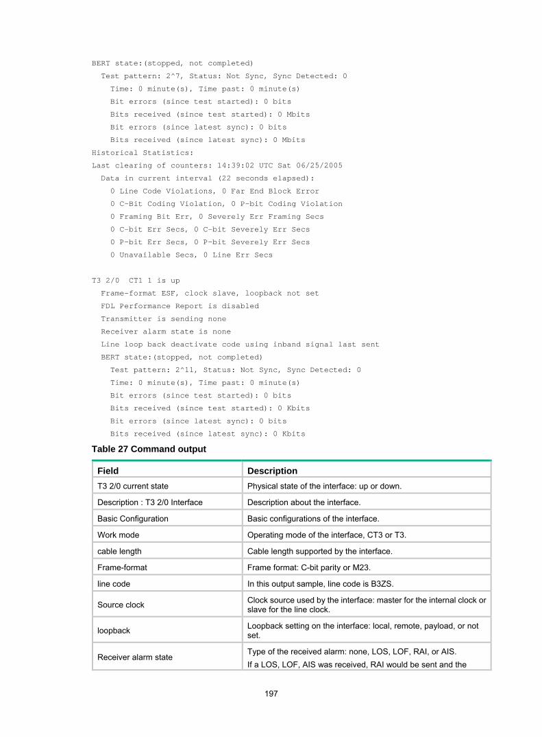
197
BERT state:(stopped, not completed)
Test pattern: 2^7, Status: Not Sync, Sync Detected: 0
Time: 0 minute(s), Time past: 0 minute(s)
Bit errors (since test started): 0 bits
Bits received (since test started): 0 Mbits
Bit errors (since latest sync): 0 bits
Bits received (since latest sync): 0 Mbits
Historical Statistics:
Last clearing of counters: 14:39:02 UTC Sat 06/25/2005
Data in current interval (22 seconds elapsed):
0 Line Code Violations, 0 Far End Block Error
0 C-Bit Coding Violation, 0 P-bit Coding Violation
0 Framing Bit Err, 0 Severely Err Framing Secs
0 C-bit Err Secs, 0 C-bit Severely Err Secs
0 P-bit Err Secs, 0 P-bit Severely Err Secs
0 Unavailable Secs, 0 Line Err Secs
T3 2/0 CT1 1 is up
Frame-format ESF, clock slave, loopback not set
FDL Performance Report is disabled
Transmitter is sending none
Receiver alarm state is none
Line loop back deactivate code using inband signal last sent
BERT state:(stopped, not completed)
Test pattern: 2^11, Status: Not Sync, Sync Detected: 0
Time: 0 minute(s), Time past: 0 minute(s)
Bit errors (since test started): 0 bits
Bits received (since test started): 0 Kbits
Bit errors (since latest sync): 0 bits
Bits received (since latest sync): 0 Kbits
Table 27 Command output
Field Description T3 2/0 current state Physical state of the interface: up or down.
Description : T3 2/0 Interface Description about the interface.
Basic Configuration Basic configurations of the interface.
Work mode Operating mode of the interface, CT3 or T3.
cable length Cable length supported by the interface.
Frame-format Frame format: C-bit parity or M23.
line code In this output sample, line code is B3ZS.
Source clock Clock source used by the interface: master for the internal clock or slave for the line clock.
loopback Loopback setting on the interface: local, remote, payload, or not set.
Receiver alarm state Type of the received alarm: none, LOS, LOF, RAI, or AIS. If a LOS, LOF, AIS was received, RAI would be sent and the
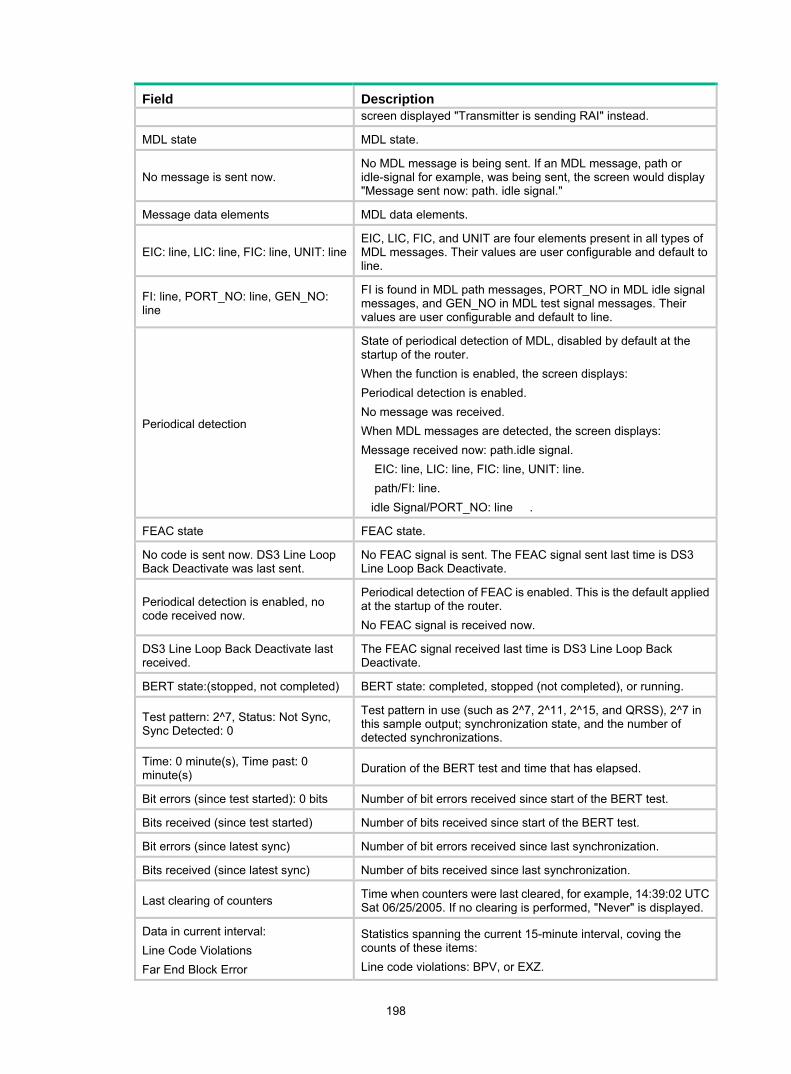
198
Field Description screen displayed "Transmitter is sending RAI" instead.
MDL state MDL state.
No message is sent now. No MDL message is being sent. If an MDL message, path or idle-signal for example, was being sent, the screen would display "Message sent now: path. idle signal."
Message data elements MDL data elements.
EIC: line, LIC: line, FIC: line, UNIT: lineEIC, LIC, FIC, and UNIT are four elements present in all types of MDL messages. Their values are user configurable and default to line.
FI: line, PORT_NO: line, GEN_NO: line
FI is found in MDL path messages, PORT_NO in MDL idle signal messages, and GEN_NO in MDL test signal messages. Their values are user configurable and default to line.
Periodical detection
State of periodical detection of MDL, disabled by default at the startup of the router. When the function is enabled, the screen displays: Periodical detection is enabled. No message was received. When MDL messages are detected, the screen displays: Message received now: path.idle signal. EIC: line, LIC: line, FIC: line, UNIT: line. path/FI: line. idle Signal/PORT_NO: line .
FEAC state FEAC state.
No code is sent now. DS3 Line Loop Back Deactivate was last sent.
No FEAC signal is sent. The FEAC signal sent last time is DS3 Line Loop Back Deactivate.
Periodical detection is enabled, no code received now.
Periodical detection of FEAC is enabled. This is the default applied at the startup of the router. No FEAC signal is received now.
DS3 Line Loop Back Deactivate last received.
The FEAC signal received last time is DS3 Line Loop Back Deactivate.
BERT state:(stopped, not completed) BERT state: completed, stopped (not completed), or running.
Test pattern: 2^7, Status: Not Sync, Sync Detected: 0
Test pattern in use (such as 2^7, 2^11, 2^15, and QRSS), 2^7 in this sample output; synchronization state, and the number of detected synchronizations.
Time: 0 minute(s), Time past: 0 minute(s) Duration of the BERT test and time that has elapsed.
Bit errors (since test started): 0 bits Number of bit errors received since start of the BERT test.
Bits received (since test started) Number of bits received since start of the BERT test.
Bit errors (since latest sync) Number of bit errors received since last synchronization.
Bits received (since latest sync) Number of bits received since last synchronization.
Last clearing of counters Time when counters were last cleared, for example, 14:39:02 UTC Sat 06/25/2005. If no clearing is performed, "Never" is displayed.
Data in current interval: Line Code Violations Far End Block Error
Statistics spanning the current 15-minute interval, coving the counts of these items: Line code violations: BPV, or EXZ.

199
Field Description C-Bit Coding Violation P-bit Coding Violation Framing Bit Err Severely Err Framing Secs C-bit Err Secs C-bit Severely Err Secs P-bit Err Secs P-bit Severely Err Secs Unavailable Secs Line Err Secs
Far-end block error. C-bit coding violation. P-bit coding violation. Framing bit error. C-bit erroneous second. C-bit severely erroneous second, the second during which 44 C-bit errors occur. P-bit erroneous second. P-bit severely erroneous second, the second during which 44 P-bit errors occur. Service unavailable second. Line erroneous second, during which LOS, BPV, EXZ, C-bit, P-bit, and other errors occur.
Total Data (last 17 15 minute intervals) Total data spanning the last 17 intervals.
T3 2/0 CT1 1 is up State of T1 line on the CT3 interface: up or down. In this output sample, T1 line 1 is up.
Frame-format ESF, clock slave, loopback not set
Information about the T1 line: • Framing format—ESF or SF. • Clock source—slave for the line clock and master for the
internal clock. • Loopback—Local, remote, payload, or not set.
FDL Performance Report is disabled Transmission of PPR in the FDL is disabled. You can enable that with the t1 set fdl ansi command.
Transmitter is sending RAI The transmitter of the T1 line is sending RAI signals. When the T1 line receives LOS, LOF, or AIS signals, it sends RAI signals.
Receiver alarm state is LOF Type of alarm signal that the T1 line can receive: LOS, LOF, AIS, or RAI.
Line loop back activate code using inband signal last sent
The loopback code sent last time is in-band LLB activation request code.
BERT state BERT test state: running, complete, or stopped (not completed).
Test pattern Status Sync Detected
Test pattern in use, 2^11 in this sample output; synchronization state, and the number of detected synchronizations.
Time Time past
Duration of the BERT test and time that has elapsed.
Bit errors (since test started) Number of bit errors received since start of the BERT test.
Bits received (since test started) Number of bits received since start of the BERT test.
Bit errors (since latest sync) Number of bit errors received since last synchronization.
Bits received (since latest sync) Number of bits received since last synchronization.
feac Use feac to enable FEAC channel signal detection and sending on the CT3 interface.
Use undo feac to remove the current FEAC settings.
200
Syntax feac { detect | generate { ds3-los | ds3-ais | ds3-oof | ds3-idle | ds3-eqptfail | loopback { ds3-line | ds3-payload } } }
undo feac { detect | generate { ds3-los | ds3-ais | ds3-oof | ds3-idle | ds3-eqptfail | loopback { ds3-line | ds3-payload } } }
Default Periodical FEAC channel signal detection is enabled.
Default FEAC signal sending is disabled.
Default Loopback code sending is disabled.
Views CT3 interface view
Default command level 2: System level
Parameters detect: Enables periodical far end and control signal (FEAC) channel signal detection. generate: Sends FEAC signals. Specify ds3-los for DS3 LOS, ds3-ais for DS3 AIS, ds3-oof for DS3 out of frame (OOF), ds3-idle for DS3 idle, and ds3-eqptfail for DS3 equipment failure. loopback: Sends loopback code for activating far-end line loopback with the ds3-line keyword or payload loopback with the ds3-payload keyword.
Usage guidelines FEAC is a channel formed by using the third C-bit in the first subframe in C-bit framing. It is used to transmit alarm state signals for line test purposes, or to transmit loopback control code for activating or deactivating far-end loopback during a loopback test.
According to ANSI T1.107a, the frame format used by FEAC channels is bit oriented protocol (BOP).
At the startup of your router, FEAC channel signal detection is enabled on the CT3 interface with FEAC signal sending disabled.
After far-end loopback is activated with the feac generate loopback { ds3-line | ds3-payload } command, you can remove it with the undo form of the command.
Disable FEAC detection before you configure far-end loopback to prevent loopback deadlock, which might happen when the local end enables loopback after detecting the loopback code sent back by the far end.
You can view the transmitting/receiving state of the FEAC channel by using the display controller t3 command.
Examples # Enable FEAC channel signal detection on CT3 interface T3 2/0. <Sysname> system-view
[Sysname] controller t3 2/0
[Sysname-T3 2/0] feac detect
# Send DS3 LOS signal on CT3 interface T3 2/0. <Sysname> system-view
[Sysname] controller t3 2/0
[Sysname-T3 2/0] feac generate ds3-los
201
# On CT3 interface T3 2/0, send loopback code to the far end to place the far end in a line loopback. <Sysname> system-view
[Sysname] controller t3 2/0
[Sysname-T3 2/0] feac generate loopback ds3-line
frame-format (CT3 interface) Use frame-format to configure the framing format used by the CT3 interface.
Use undo frame-format to restore the default.
Syntax frame-format { c-bit | m23 }
undo frame-format
Default The framing format is C-bit.
Views CT3 interface view
Default command level 2: System level
Parameters c-bit: Sets the framing format to C-bit.
m23: Sets the framing format to m23.
Examples # Set the framing format of interface T3 2/0 to m23. <Sysname> system-view
[Sysname] controller t3 2/0
[Sysname-T3 2/0] frame-format m23
ft3 Use ft3 to configure a CT3 interface to operate in the FT3 mode and set the DSU mode or the subrate.
Use undo ft3 to restore the default.
Syntax ft3 { dsu-mode { 0 | 1 | 2 | 3 | 4 } | subrate number }
undo ft3 { dsu-mode | subrate }
Default DSU mode 0 (the Digital Link mode) is adopted, and the subrate is 44210 kbps.
Views CT3 interface (in FT3 mode) view
Default command level 2: System level
202
Parameters dsu-mode: Specifies the FT3 (Fractional T3) DSU mode for a CT3 interface operating in FT3 mode. This keyword can be followed by 0, 1, 2, 3, and 4.
0: Specifies the Digital Link mode, where the subrate is a multiple of 300746 bps. The subrate is in the range of 300 to 44210 kbps. Up to 147 rate levels are available.
1: Specifies the Kentrox mode, where the subrate is a multiple of 1500000 bps. The subrate is in the range of 1500 to 35000 kbps. In this mode, the subrate can also be 44210 kbps (making a total of 57 subrate levels).
2: Specifies the Larscom mode, where the subrate is a multiple of 3157835 bps. The subrate is in the range of 3100 to 44210 kbps. Up to 14 subrate levels are available.
3: Specifies the Adtran mode, where the subrate is a multiple of 75187 bps. The subrate is in the range of 75 to 44210 kbps. Up to 588 subrate levels are available.
4: Specifies the Verilink mode, where the subrate is a multiple of 1578918 bps. The subrate is in the range of 1500 to 44210 kbps. Up to 20 subrate levels are available.
subrate number: Specifies the subrate for the CT3 interface. The number argument is in the range of 1 to 44210 (in kbps).
Usage guidelines FT3 (Fractional T3 or Subrate T3) mode is a non-standard E3 application mode. In this mode, the subrate level setting varies with vendors. You can use the ft3 command to make the device to be compatible with devices of other vendors operating in specific FT3 DSU modes.
This command is only applicable to CT3 modules that support FT3.
This command is only available in CT3 mode.
As for the ft3 subrate command, the actual subrate usually is not exactly the one set by the command. After you set the subrate by using the ft3 subrate command, the T3 interface searches the subrate levels corresponding to the DSU mode it is operating in and selects the one that is closest to that set by the command as its subrate. The device then adjusts the hardware to allow for the subrate.
You can use the display interface serial interface-number:0 command to check the DSU mode setting, the subrate, the actual rate, and the baudrate of a CT3 interface. The actual rate does not count in the overhead bits, and the baudrate is the actual T3 line rate (44736 kbps), with the overhead bits counted in.
Examples # Configure T3 2/0 interface to operate in the FT3 mode, setting the DSU mode to 1 and the subrate to 3000 kbps. <Sysname> system-view
[Sysname] controller t3 2/0
[Sysname-T3 2/0] using t3
[Sysname-T3 2/0] ft3 dsu-mode 1
[Sysname-T3 2/0] ft3 subrate 3000
loopback (CT3 interface) Use loopback to configure the loopback mode for a CT3 interface.
Use undo loopback to disable loopback.
Syntax loopback { local | payload | remote }
undo loopback
203
Default Loopback is disabled on CT3 interfaces.
Views CT3 interface view
Default command level 2: System level
Parameters local: Enables internal loopback on the CT3 interface.
payload: Enables external payload loopback on the CT3 interface.
remote: Enables external loopback on the CT3 interface.
Usage guidelines Loopback is intended for test use. Disable loopback in other cases.
If a CT3 interface encapsulated with PPP is placed in a loopback, it is normal that the state of the link layer protocol is reported as down.
Examples # Enable internal loopback on interface T3 2/0. <Sysname> system-view
[Sysname] controller t3 2/0
[Sysname-T3 2/0] loopback local
mdl (CT3 interface) Use mdl to configure MDL message detection/sending on the CT3 interface.
Use undo mdl to remove the MDL settings.
Use undo mdl detect to disable the CT3 interface from detecting MDL messages.
Use undo mdl generate to disable the CT3 interface from sending MDL messages.
Use undo mdl data to restore the default.
Syntax mdl { data { eic string | fic string | gen-no string | lic string | pfi string | port-no string | unit string } | detect | generate { idle-signal | path | test-signal } } undo mdl [ data [ eic | fic | gen-no | lic | pfi | port-no | unit ] | detect | generate [ idle-signal | path | test-signal ] ]
Views CT3 interface view
Default command level 2: System level
Parameters detect: Enables/disables periodical maintenance data link (MDL) message detection.
data: Specifies the information included in MDL messages. Among all types of information, EIC, LIC, FIC, and unit are defined for all types of MDL messages; PFI is only for path MDL messages; port number is only for idle signal messages; and generator number is only for test signal messages.

204
eic string: Specifies the equipment identification code, a string of 1 to 10 characters. The system default is line.
lic string: Specifies the location identification code, a string of 1 to 11 characters. The system default is line.
fic string: Specifies the frame identification code, a string of 1 to 10 characters. The system default is line.
unit string: Specifies the unit, a string of 1 to 6 characters. The system default is line.
pfi string: Specifies the path facility identification, a string of 1 to 38 characters. The system default is line.
port-no string: Specifies the port number in idle signal message, a string of 1 to 38 characters. The system default is line. gen-no string: Specifies the generator number, a string of 1 to 38 characters. The system default is line.
generate: Sends specified information with MDL messages, which can be path, idle signal, or test signal, or all of them regularly.
Usage guidelines MDL is a channel formed by using the three C-bits in the fifth subframe in C-bit framing. According to ANSI T1.107a, it is used to transmit three types of maintenance messages, path, idle signal, and test signal, and its data frame format is LAPD.
At the startup of your router, MDL message detection and sending are disabled on CT3 interfaces, and the default MDL message information applies.
Examples # Enable MDL detection on CT3 interface T3 2/0. <Sysname> system-view
[Sysname] controller t3 2/0
[Sysname-T3 2/0] mdl detect
# Set LIC to "hello" for CT3 interface T3 2/0. <Sysname> system-view
[Sysname] controller t3 2/0
[Sysname-T3 2/0] mdl data lic hello
# Send path messages on CT3 interface T3 2/0. <Sysname> system-view
[Sysname] controller t3 2/0
[Sysname-T3 2/0] mdl generate path
reset counters controller t3 Use reset counters controller t3 to clear the controller counter of the specified CT3 interface.
Syntax reset counters controller t3 interface-number
Views User view
Default command level 2: System level
205
Parameters interface-number: Interface number.
Usage guidelines You can use the display controller t3 command to display the statistics collected by the controller counters of CT3 interfaces.
The reset counters interface command clears the counters of all interfaces. To clear the controller counter of individual CT3 interfaces, use the reset counters controller t3 command.
Examples # Clear the controller counter of the CT3 interface E3 2/0. <Sysname> reset counters controller t3 2/0
t1 alarm Use t1 alarm to enable the specified T1 line on the CT3 interface to detect/send alarm signals.
Use undo t1 alarm to remove the alarm signal detection/sending setting.
Syntax t1 line-number alarm { detect | generate { ais | rai } } undo t1 line-number alarm { detect | generate { ais | rai } }
Default Periodical alarm detection is enabled.
Default Alarm signal sending is disabled.
Views CT3 interface view
Default command level 2: System level
Parameters line-number: T1 line number in the range of 1 to 28. detect: Enables/disables periodical alarm signal detection.
generate: Sends alarm signals, AIS or RAI, for line state test.
ais: Alarm indication signal.
rai: Remote alarm indication signal.
Usage guidelines At the startup of the router, periodical alarm signal detection is enabled on all T1 lines on the CT3 interface. When a T1 line detects LOS, LOF, or AIS signals, it sends RAI signals to its peer. Alarm state report for the interface is real time; you can view that with the display controller t3 command.
The supported alarm signals, LOS, LOF, AIS, RAI, FEBE, and idle, are ANSI T1.403 compliant.
You can configure a T1 line to send only a type of alarm signal. To have the channel send another type of signal, use the undo t1 alarm command to remove the previous setting first. In addition, when the RAI signal generated upon detection of the LOS, LOF, or AIS signal is present, the T1 line cannot send another type of signal. To do that, use the undo t1 alarm detect command to disable the T1 line to send the RAI signal generated after detecting an alarm first.
206
Examples # Enable periodical alarm signal detection on T1 line 1 on CT3 interface T3 2/0. <Sysname> system-view
[Sysname] controller t3 2/0
[Sysname-T3 2/0] t1 1 alarm detect
# Enable T1 line 1 on CT3 interface T3 2/0 to send AIS alarm signals. <Sysname> system-view
[Sysname] controller t3 2/0
[Sysname-T3 2/0] t1 1 alarm generate ais
t1 bert Use t1 bert to start a BERT test on the specified T1 line on the CT3 interface.
Use undo t1 bert to stop the BERT test running on the specified T1 line on the CT3 interface.
Syntax t1 line-number bert pattern { 2^11 | 2^15 | 2^20 | 2^23 | qrss } time number [ unframed ]
undo t1 line-number bert
Default No BERT test is performed.
Views CT3 interface view
Default command level 2: System level
Parameters line-number: T1 line number in the range of 1 to 28.
pattern: Sets a BERT pattern, which could be 2^11, 2^15, 2^20, 2^23, or QRSS.
2^11: Specifies the length of transmitted BERT pattern, in bits, as two to the eleventh power.
2^15: Specifies the length of transmitted BERT pattern, in bits, as two to the fifteenth power.
2^20: Specifies the length of transmitted BERT pattern, in bits, as two to the twentieth power.
2^23: Specifies the length of transmitted BERT pattern, in bits, as two to the twenty third powers.
qrss: Specifies the length of transmitted BERT pattern, in bits, as two to the twentieth power. In this pattern, the presence of 14 or more consecutive zeros is not allowed.
time number: Sets the duration of a BERT test, in the range of 1 to 1440 minutes.
unframed: Sets the test pattern to cover the overhead bits of the frame.
Usage guidelines ITU O.151, ITU O.153, and ANSI T1.403-1999 define many BERT patterns, among which, T1 lines on CT3 interfaces support only 2^11, 2^15, 2^20, 2^23, and QRSS.
When running a BERT test, the local end sends out a pattern, which is to be looped over somewhere on the line and back to the local end. The local end then examines the received pattern for the bit error rate to help you determine whether the condition of the line is good. You must configure loopback to allow the transmitted pattern to loop back from somewhere on the line, for example, from the far-end interface by placing the interface in far-end loopback.
You can view the state and result of the BERT test with the display controller t3 command.
207
Examples # Run a 10-minute QRSS BERT test on T1 line 1 on CT3 interface T3 2/0. <Sysname> system-view
[Sysname] controller t3 2/0
[Sysname-T3 2/0] t1 1 bert pattern qrss time 10
t1 channel-set Use t1 channel-set to bundle specified timeslots into a channel set on a T1 line.
Use undo t1 channel-set to remove the specified channel set.
Syntax t1 line-number channel-set set-number timeslot-list list [ speed { 56k | 64k } ]
undo t1 line-number channel-set set-number
Default No channel set is created.
Views CT3 interface view
Default command level 2: System level
Parameters line-number: T1 line number in the range of 1 to 28.
set-number: Number of a channel set formed from a timeslot bundle on the T1 line. It is in the range of 0 to 23.
timeslot-list list: Specifies the timeslots to be bundled. The list argument can contain multiple timeslot numbers, each of which is in the range of 1 to 24. You can specify a single timeslot by specifying a timeslot number, a range of timeslots by providing this argument in the form of { number1-number2 }, or multiple timeslots by providing this argument in the form of { number1, number2-number3 }.
speed { 56k | 64k }: Speed of the timeslot bundle (the channel set) in kbps. If 56k is selected, the timeslots is bundled into an N × 56 kbps bundle. If 64k, the default, is selected, the timeslots is bundled into an N × 64 kbps bundle.
Usage guidelines When a T1 line is operating in framed (CT1) mode, you can bundle timeslots on it. For each channel set thus formed, the system automatically creates a serial interface numbered serial number/line-number:set-number. This interface operates at N × 64 kbps (or N × 56 kbps) and is logically equivalent to a synchronous serial interface on which you can make other configurations.
Examples # Create a 128 kbps serial interface through timeslot bundling on the first T1 line on interface T3 2/0. <Sysname> system-view
[Sysname] controller t3 2/0
[Sysname-T3 2/0] t1 1 channel-set 1 timeslot-list 1,2
Related commands t1 unframed
208
t1 sendloopcode Use t1 sendloopcode to set the loopback mode of the specified far-end T1 line.
Use undo t1 sendloopcode to remove the corresponding setting.
Syntax t1 line-number sendloopcode { fdl-ansi-line-up | fdl-ansi-payload-up | fdl-att-payload-up | inband-line-up }
undo t1 line-number sendloopcode { fdl-ansi-line-up | fdl-ansi-payload-up | fdl-att-payload-up | inband-line-up }
Views CT3 interface view
Default command level 2: System level
Parameters line-number: T1 line number in the range of 1 to 28.
fdl-ansi-line-up: Sends ANSI-compliant LLB activation request code in the FDL to start remote loopback.
fdl-ansi-payload-up: Sends ANSI-compliant PLB activation request code in the FDL to start remote loopback.
fdl-att-payload-up: Sends AT&T-compliant PLB activation request code in the FDL to start remote loopback.
inband-line-up: Sends in-band LLB activation request code compliant with the ANSI and AT&T implementation to start remote loopback.
Usage guidelines Loopback is an effective way of diagnosis. You can place a far-end device into loopback mode either at command line on it or by sending loopback control code to it. The types and formats of loopback control code supported on T1 interfaces are compliant with ANSI T1.403.
Loopback can be divided into line loopback and payload loopback. They differ in the sense that the data stream is looped back at the framer with line loopback but not with payload loopback.
You can transmit loopback control code by using the in-band signal (the 192 effective bandwidth bits or all 193 bits of T1) or the FDL in ESF frames.
Examples # Send the in-band signal on T1 line 1 on CT3 interface T3 2/0 to place the far-end T1 line in line loopback mode. <Sysname> system-view
[Sysname] controller t3 2/0
[Sysname-T3 2/0] t1 1 sendloopcode inband-line-up
t1 set clock Use t1 set clock to configure the clock source for a T1 line on the CT3 interface.
Use undo t1 set clock to restore the default.
Syntax t1 line-number set clock { master | slave }
209
undo t1 line-number set clock
Default The clock source for a T1 line on the CT3 interface is line clock.
Views CT3 interface view
Default command level 2: System level
Parameters line-number: T1 line number in the range of 1 to 28. master: Adopts the internal clock as the clock source on the T1 line.
slave: Adopts the line clock as the clock source on the T1 line.
Usage guidelines When a CT3 interface is operating in channelized mode, its T1 lines might use separate clocks.
Examples # Use the internal clock as the clock source on the first T1 line on interface T3 2/0. <Sysname> system-view
[Sysname] controller t3 2/0
[Sysname-T3 2/0] t1 1 set clock slave
t1 set fdl Use t1 set fdl to set the behavior of the specified T1 line on the FDL in ESF framing.
Use undo t1 set fdl to disable FDL of T1.
Syntax t1 line-number set fdl { ansi | att | both | none}
undo t1 line-number set fdl
Default FDL is disabled.
Views CT3 interface view
Default command level 2: System level
Parameters line-number: T1 line number in the range of 1 to 28. fdl: Sets the FDL format of T1.
ansi: Adopts ANSI T1.403 for FDL.
att: Adopts AT&T TR 54016 for FDL.
both: Adopts both ANSI T1.403 and AT&T TR 54016 for FDL.
none: Disables the use of FDL on the T1 line.

210
Usage guidelines FDL is an embedded 4 kbps overhead channel within the ESF format for transmitting periodical performance report (PPR) statistics or loopback code.
According to ANSI T1.403, the format of PPR is LAPD, and the format of loopback code is BOP.
The t1 set fdl command only starts PPR transmission. It cannot enable loopback code transmission or detection.
This command only applies to channelized T1 lines with a T1 frame format of ESF.
Examples # Set the FDL to be ANSI T1.403 compliant for T1 line 1 on CT3 interface T3 2/0. <Sysname> system-view
[Sysname] controller t3 2/0
[Sysname-T3 2/0] t1 1 set fdl ansi
t1 set frame-format Use t1 set frame-format to configure the framing format of a T1 line.
Use undo t1 set frame-format to restore the default.
Syntax t1 line-number set frame-format { esf | sf }
undo t1 line-number set frame-format
Default The framing format of a T1 line is ESF.
Views CT3 interface view
Default command level 2: System level
Parameters line-number: T1 line number in the range of 1 to 28.
esf: Set the T1 line to use the ESF format.
sf: Set the T1 line to use the SF format.
Usage guidelines You can configure this command only when the T1 line is operating in framed format (which can be set by using the undo t1 unframed command).
Examples # Set the framing format to SF for the first T1 line on interface T3 2/0. <Sysname> system-view
[Sysname] controller t3 2/0
[Sysname-T3 2/0] t1 1 set frame-format sf
Related commands t1 unframed
211
t1 set loopback Use t1 set loopback to set the loopback mode of a T1 line on the T3 interface.
Use undo t1 set loopback to disable the T1 line to loop back.
Syntax t1 line-number set loopback { local | remote | payload }
undo t1 line-number set loopback
Default Loopback is disabled on T1 lines.
Views CT3 interface view
Default command level 2: System level
Parameters line-number: T1 line number in the range of 1 to 28.
local: Sets the T1 line in internal loopback mode.
remote: Sets the T1 line in external loopback mode.
remote: Sets the T1 line in payload loopback mode.
Usage guidelines Loopback is intended for test use. Disable loopback in other cases.
If a T1 line encapsulated with PPP is placed in loopback mode, it is normal that the state of the link layer protocol is reported as down.
Examples # Enable internal loopback on the first T1 line on interface T3 2/0. <Sysname> system-view
[Sysname] controller t3 2/0
[Sysname-T3 2/0] t1 1 set loopback local
t1 show Use t1 show to have a quick look at the line state of the specified T1 line on the CT3 interface.
Syntax t1 line-number show
Views CT3 interface view
Default command level 2: System level
Parameters line-number: T1 line number in the range of 1 to 28.
show: Displays the physical line state of the specified T1 line.
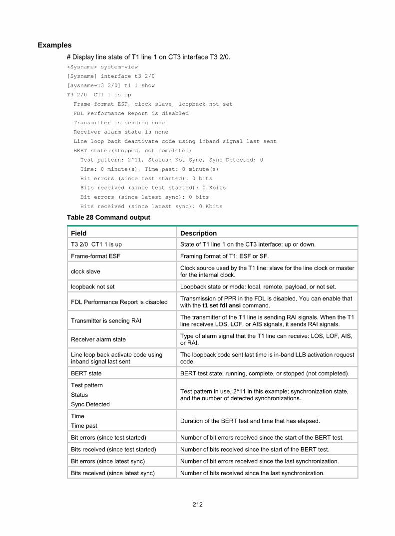
212
Examples # Display line state of T1 line 1 on CT3 interface T3 2/0. <Sysname> system-view
[Sysname] interface t3 2/0
[Sysname-T3 2/0] t1 1 show
T3 2/0 CT1 1 is up
Frame-format ESF, clock slave, loopback not set
FDL Performance Report is disabled
Transmitter is sending none
Receiver alarm state is none
Line loop back deactivate code using inband signal last sent
BERT state:(stopped, not completed)
Test pattern: 2^11, Status: Not Sync, Sync Detected: 0
Time: 0 minute(s), Time past: 0 minute(s)
Bit errors (since test started): 0 bits
Bits received (since test started): 0 Kbits
Bit errors (since latest sync): 0 bits
Bits received (since latest sync): 0 Kbits
Table 28 Command output
Field Description T3 2/0 CT1 1 is up State of T1 line 1 on the CT3 interface: up or down.
Frame-format ESF Framing format of T1: ESF or SF.
clock slave Clock source used by the T1 line: slave for the line clock or master for the internal clock.
loopback not set Loopback state or mode: local, remote, payload, or not set.
FDL Performance Report is disabled Transmission of PPR in the FDL is disabled. You can enable that with the t1 set fdl ansi command.
Transmitter is sending RAI The transmitter of the T1 line is sending RAI signals. When the T1 line receives LOS, LOF, or AIS signals, it sends RAI signals.
Receiver alarm state Type of alarm signal that the T1 line can receive: LOS, LOF, AIS, or RAI.
Line loop back activate code using inband signal last sent
The loopback code sent last time is in-band LLB activation request code.
BERT state BERT test state: running, complete, or stopped (not completed).
Test pattern Status Sync Detected
Test pattern in use, 2^11 in this example; synchronization state, and the number of detected synchronizations.
Time Time past
Duration of the BERT test and time that has elapsed.
Bit errors (since test started) Number of bit errors received since the start of the BERT test.
Bits received (since test started) Number of bits received since the start of the BERT test.
Bit errors (since latest sync) Number of bit errors received since the last synchronization.
Bits received (since latest sync) Number of bits received since the last synchronization.
213
t1 shutdown Use t1 shutdown to shut down a T1 line on the CT3 interface.
Use undo t1 shutdown to bring up a T1 line.
Syntax t1 line-number shutdown
undo t1 line-number shutdown
Default T1 lines are up.
Views CT3 interface view
Default command level 2: System level
Parameters line-number: T1 line number in the range of 1 to 28.
Usage guidelines This command shuts down not only the specified T1 line but also the serial interfaces formed on it. Data transmission and receiving will stop as a result. Likewise, the undo t1 shutdown command can bring up all these serial interfaces.
Examples # Shut down the first T1 line on interface T3 2/0. <Sysname> system-view
[Sysname] controller t3 2/0
[Sysname-T3 2/0] t1 1 shutdown
t1 unframed Use t1 unframed to set a T1 line on the CT3 interface to operate in unframed mode (T1 mode).
Use undo t1 unframed to set the T1 line on the CT3 interface to operate in framed mode (CT1 mode).
Syntax t1 line-number unframed
undo t1 line-number unframed
Default T1 lines are operating in framed mode.
Views CT3 interface view
Default command level 2: System level
Parameters line-number: T1 line number in the range of 1 to 28.
214
Usage guidelines A T1 line in unframed mode does not contain the frame control information; it cannot be divided into timeslots. For it, the system automatically creates a serial interface numbered serial number/line-number:0. This interface operates at 1544 kbps and is logically equivalent to a synchronous serial interface on which you can make other configurations.
Examples # Set the first T1 line on interface T3 2/0 to operate in unframed mode. <Sysname> system-view
[Sysname] controller t3 2/0
[Sysname-T3 2/0] t1 1 unframed
Related commands t1 channel-set
using (CT3 interface) Use using to configure the operating mode of a CT3 interface.
Use undo using to restore the default.
Syntax using { ct3 | t3 }
undo using
Default The operating mode of a CT3 interface is channelized mode.
Views CT3 interface view
Default command level 2: System level
Parameters ct3: Sets the CT3 interface to operate in channelized mode. t3: Sets the CT3 interface to operate in unchannelized mode.
Usage guidelines You can configure T1 lines on CT3 interfaces operating in channelized mode only.
When a CT3 interface operates in unchannelized mode, the system automatically creates a serial interface numbered serial number/0:0 for it. This interface operates at 44.736 Mbps and is logically equivalent to a synchronous serial interface on which you can make other configurations.
Examples # Configure interface T3 2/0 to operate in unchannelized mode. <Sysname> system-view
[Sysname] controller t3 2/0
[Sysname-T3 2/0] using t3
ISDN BRI interface configuration commands
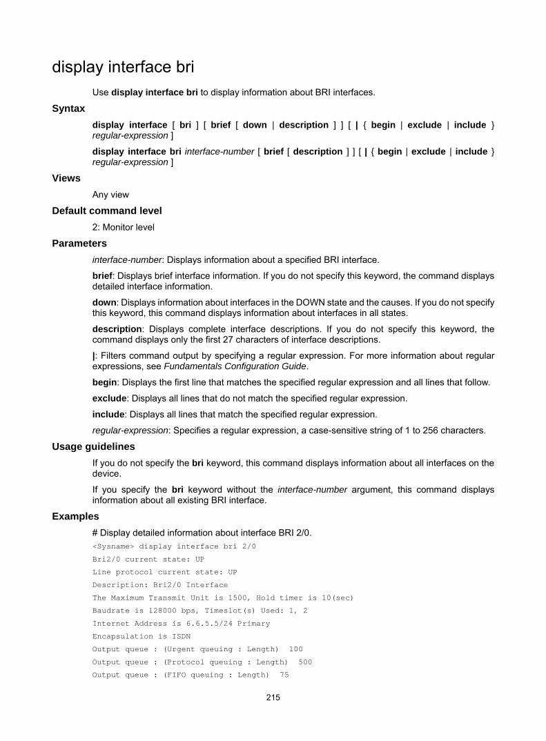
215
display interface bri Use display interface bri to display information about BRI interfaces.
Syntax display interface [ bri ] [ brief [ down | description ] ] [ | { begin | exclude | include } regular-expression ]
display interface bri interface-number [ brief [ description ] ] [ | { begin | exclude | include } regular-expression ]
Views Any view
Default command level 2: Monitor level
Parameters interface-number: Displays information about a specified BRI interface.
brief: Displays brief interface information. If you do not specify this keyword, the command displays detailed interface information.
down: Displays information about interfaces in the DOWN state and the causes. If you do not specify this keyword, this command displays information about interfaces in all states.
description: Displays complete interface descriptions. If you do not specify this keyword, the command displays only the first 27 characters of interface descriptions. |: Filters command output by specifying a regular expression. For more information about regular expressions, see Fundamentals Configuration Guide.
begin: Displays the first line that matches the specified regular expression and all lines that follow.
exclude: Displays all lines that do not match the specified regular expression.
include: Displays all lines that match the specified regular expression.
regular-expression: Specifies a regular expression, a case-sensitive string of 1 to 256 characters.
Usage guidelines If you do not specify the bri keyword, this command displays information about all interfaces on the device. If you specify the bri keyword without the interface-number argument, this command displays information about all existing BRI interface.
Examples # Display detailed information about interface BRI 2/0. <Sysname> display interface bri 2/0
Bri2/0 current state: UP
Line protocol current state: UP
Description: Bri2/0 Interface
The Maximum Transmit Unit is 1500, Hold timer is 10(sec)
Baudrate is 128000 bps, Timeslot(s) Used: 1, 2
Internet Address is 6.6.5.5/24 Primary
Encapsulation is ISDN
Output queue : (Urgent queuing : Length) 100
Output queue : (Protocol queuing : Length) 500
Output queue : (FIFO queuing : Length) 75
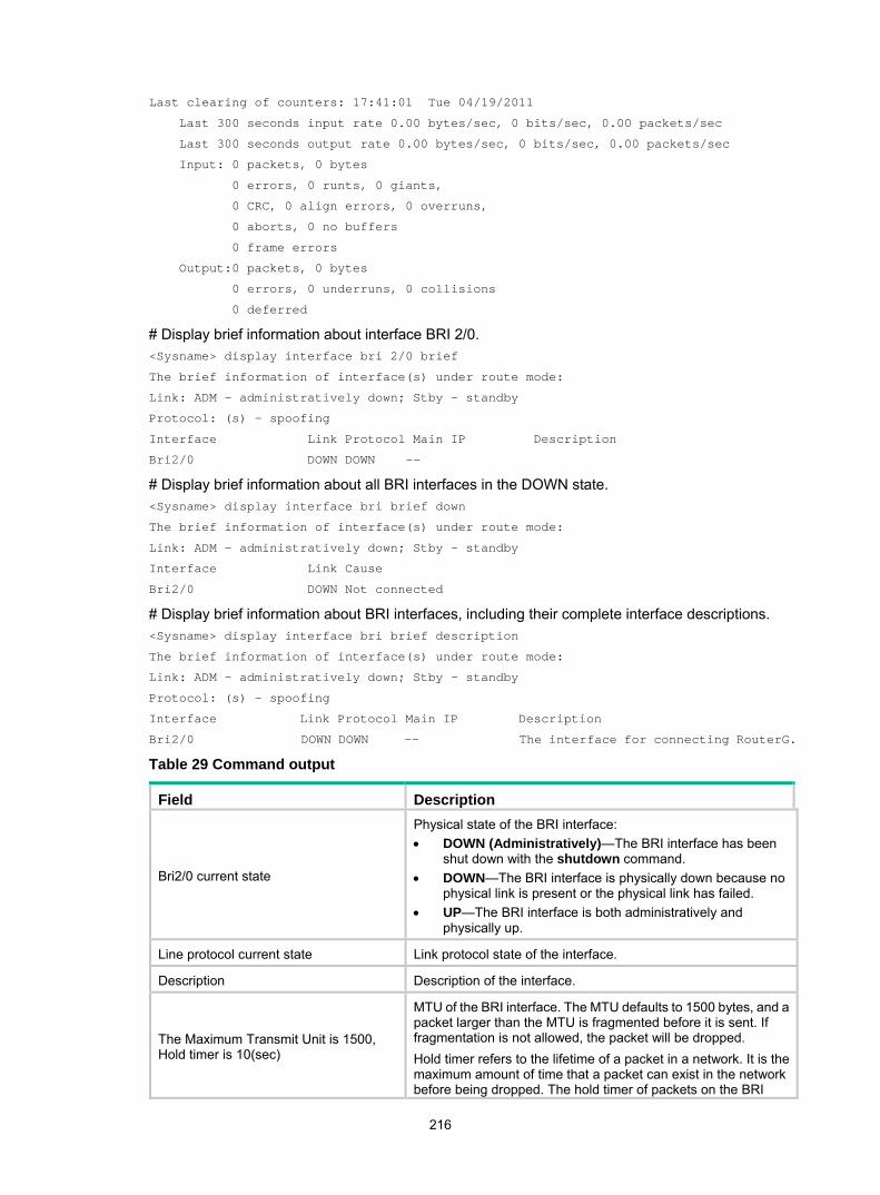
216
Last clearing of counters: 17:41:01 Tue 04/19/2011
Last 300 seconds input rate 0.00 bytes/sec, 0 bits/sec, 0.00 packets/sec
Last 300 seconds output rate 0.00 bytes/sec, 0 bits/sec, 0.00 packets/sec
Input: 0 packets, 0 bytes
0 errors, 0 runts, 0 giants,
0 CRC, 0 align errors, 0 overruns,
0 aborts, 0 no buffers
0 frame errors
Output:0 packets, 0 bytes
0 errors, 0 underruns, 0 collisions
0 deferred
# Display brief information about interface BRI 2/0. <Sysname> display interface bri 2/0 brief
The brief information of interface(s) under route mode:
Link: ADM - administratively down; Stby - standby
Protocol: (s) - spoofing
Interface Link Protocol Main IP Description
Bri2/0 DOWN DOWN --
# Display brief information about all BRI interfaces in the DOWN state. <Sysname> display interface bri brief down
The brief information of interface(s) under route mode:
Link: ADM - administratively down; Stby - standby
Interface Link Cause
Bri2/0 DOWN Not connected
# Display brief information about BRI interfaces, including their complete interface descriptions. <Sysname> display interface bri brief description
The brief information of interface(s) under route mode:
Link: ADM - administratively down; Stby - standby
Protocol: (s) - spoofing
Interface Link Protocol Main IP Description
Bri2/0 DOWN DOWN -- The interface for connecting RouterG.
Table 29 Command output
Field Description
Bri2/0 current state
Physical state of the BRI interface: • DOWN (Administratively)—The BRI interface has been
shut down with the shutdown command. • DOWN—The BRI interface is physically down because no
physical link is present or the physical link has failed. • UP—The BRI interface is both administratively and
physically up.
Line protocol current state Link protocol state of the interface.
Description Description of the interface.
The Maximum Transmit Unit is 1500, Hold timer is 10(sec)
MTU of the BRI interface. The MTU defaults to 1500 bytes, and a packet larger than the MTU is fragmented before it is sent. If fragmentation is not allowed, the packet will be dropped. Hold timer refers to the lifetime of a packet in a network. It is the maximum amount of time that a packet can exist in the network before being dropped. The hold timer of packets on the BRI
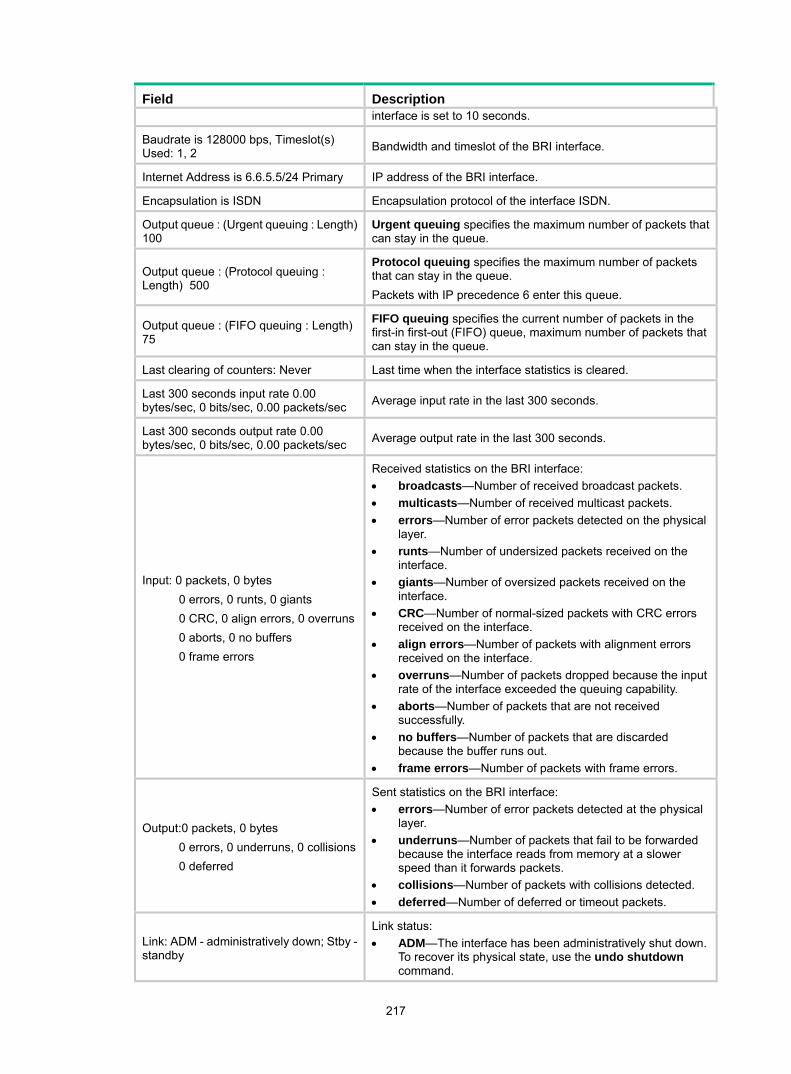
217
Field Description interface is set to 10 seconds.
Baudrate is 128000 bps, Timeslot(s) Used: 1, 2 Bandwidth and timeslot of the BRI interface.
Internet Address is 6.6.5.5/24 Primary IP address of the BRI interface.
Encapsulation is ISDN Encapsulation protocol of the interface ISDN.
Output queue : (Urgent queuing : Length) 100
Urgent queuing specifies the maximum number of packets that can stay in the queue.
Output queue : (Protocol queuing : Length) 500
Protocol queuing specifies the maximum number of packets that can stay in the queue. Packets with IP precedence 6 enter this queue.
Output queue : (FIFO queuing : Length) 75
FIFO queuing specifies the current number of packets in the first-in first-out (FIFO) queue, maximum number of packets that can stay in the queue.
Last clearing of counters: Never Last time when the interface statistics is cleared.
Last 300 seconds input rate 0.00 bytes/sec, 0 bits/sec, 0.00 packets/sec Average input rate in the last 300 seconds.
Last 300 seconds output rate 0.00 bytes/sec, 0 bits/sec, 0.00 packets/sec Average output rate in the last 300 seconds.
Input: 0 packets, 0 bytes 0 errors, 0 runts, 0 giants 0 CRC, 0 align errors, 0 overruns 0 aborts, 0 no buffers 0 frame errors
Received statistics on the BRI interface: • broadcasts—Number of received broadcast packets. • multicasts—Number of received multicast packets. • errors—Number of error packets detected on the physical
layer. • runts—Number of undersized packets received on the
interface. • giants—Number of oversized packets received on the
interface. • CRC—Number of normal-sized packets with CRC errors
received on the interface. • align errors—Number of packets with alignment errors
received on the interface. • overruns—Number of packets dropped because the input
rate of the interface exceeded the queuing capability. • aborts—Number of packets that are not received
successfully. • no buffers—Number of packets that are discarded
because the buffer runs out. • frame errors—Number of packets with frame errors.
Output:0 packets, 0 bytes 0 errors, 0 underruns, 0 collisions 0 deferred
Sent statistics on the BRI interface: • errors—Number of error packets detected at the physical
layer. • underruns—Number of packets that fail to be forwarded
because the interface reads from memory at a slower speed than it forwards packets.
• collisions—Number of packets with collisions detected. • deferred—Number of deferred or timeout packets.
Link: ADM - administratively down; Stby - standby
Link status: • ADM—The interface has been administratively shut down.
To recover its physical state, use the undo shutdown command.
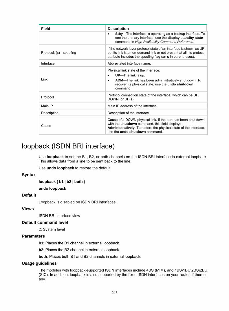
218
Field Description • Stby—The interface is operating as a backup interface. To
see the primary interface, use the display standby state command in High Availability Command Reference.
Protocol: (s) - spoofing If the network layer protocol state of an interface is shown as UP, but its link is an on-demand link or not present at all, its protocol attribute includes the spoofing flag (an s in parentheses).
Interface Abbreviated interface name.
Link
Physical link state of the interface: • UP—The link is up. • ADM—The link has been administratively shut down. To
recover its physical state, use the undo shutdown command.
Protocol Protocol connection state of the interface, which can be UP, DOWN, or UP(s).
Main IP Main IP address of the interface.
Description Description of the interface.
Cause
Cause of a DOWN physical link. If the port has been shut down with the shutdown command, this field displays Administratively. To restore the physical state of the interface, use the undo shutdown command.
loopback (ISDN BRI interface) Use loopback to set the B1, B2, or both channels on the ISDN BRI interface in external loopback. This allows data from a line to be sent back to the line.
Use undo loopback to restore the default.
Syntax loopback { b1 | b2 | both }
undo loopback
Default Loopback is disabled on ISDN BRI interfaces.
Views ISDN BRI interface view
Default command level 2: System level
Parameters b1: Places the B1 channel in external loopback.
b2: Places the B2 channel in external loopback.
both: Places both B1 and B2 channels in external loopback.
Usage guidelines The modules with loopback-supported ISDN interfaces include 4BS (MIM), and 1BS\1BU\2BS\2BU (SIC). In addition, loopback is also supported by the fixed ISDN interfaces on your router, if there is any.
219
Examples # Place the B1 and B2 channels on interface BRI 1/0 in external loopback. <Sysname> system-view
[Sysname] interface bri 1/0
[Sysname-Bri1/0] loopback both
mtu (ISDN BRI interface) Use mtu to set the MTU of a BRI interface.
Use undo mtu to restore the default.
Syntax mtu size
undo mtu
Default The MTU of a BRI interface is 1500 bytes.
Views ISDN BRI interface view
Default command level 2: System level
Parameters size: Maximum transmission unit (MTU) of the current interface, in the range of 128 to 1500 bytes.
Usage guidelines For your MTU setting to take effect, shut down and then bring up the interface with the shutdown and undo shutdown commands.
Examples # Set the MTU of the BRI interface BRI 1/0 to 1200 bytes. <Sysname> system-view
[Sysname] interface bri 1/0
[Sysname-Bri1/0] mtu 1200
reset counters interface Use reset counters interface to clear statistics on the specified BRI interface.
Syntax reset counters interface [ bri [ interface-number ] ]
Views Use view
Default command level 2: System level
Parameters bri interface-number: Specifies a BRI interface.
220
Usage guidelines When you collect traffic statistics for a specific period of time on a BRI interface, clear the existing statistics on the interface. • If you do not specify the bri keyword, this command clears statistics on all interfaces. • If you specify the bri keyword without the interface-number argument, this command clears
statistics on all BRI interfaces. • If you specify both the bri keyword and the interface-number argument, this command clears
statistics on a specified BRI interface.
Examples # Clear statistics on interface BRI 2/0. <Sysname> reset counters interface bri 2/0
221
ATM and DSL interface configuration commands Common ATM and DSL interface configuration commands bandwidth
Use bandwidth to set the intended bandwidth for an ATM interface.
Use undo bandwidth to restore the default.
Syntax bandwidth bandwidth-value
undo bandwidth
Views ATM E1 interface view, ATM T1 interface view, ATM E3 interface view, ATM T3 interface view, ATM OC-3c interface view, ATM STM-1 interface view, ATM (ADSL) interface view, ATM (G.SHDSL) interface view, EFM interface view
Default command level 2: System level
Parameters bandwidth-value: Intended bandwidth for the interface, in the range of 1 to 4,294,967,295 kbps.
Usage guidelines You can obtain the intended bandwidth of an interface by querying the ifspeed value of the MIB node with third-party software.
The intended bandwidth is used for bandwidth monitoring of the network management, but does not affect the actual bandwidth of the interface.
Examples # Set the intended bandwidth to 1000 kbps for interface ATM 1/0. <Sysname> system-view
[Sysname] interface atm 1/0
[Sysname-Atm1/0] bandwidth 1000
default Use default to restore the default settings for an ATM or a DSL interface.
Syntax default

222
Views ATM E1 interface view, ATM T1 interface view, ATM E3 interface view, ATM T3 interface view, ATM OC-3c interface view, ATM STM-1 interface view, ATM (ADSL) interface view, ATM (G.SHDSL) interface view, EFM interface view
Default command level 2: System level
Usage guidelines
CAUTION: The default command might interrupt ongoing network services. Make sure you are fully aware of the impacts of this command when you perform it on a live network.
This command might fail to restore the default settings for some commands for reasons such as command dependencies and system restrictions. Use the display this command in interface view to identify these commands, and then use their undo forms or follow the command reference to individually restore their default settings. If your restoration attempt still fails, follow the error message instructions to resolve the problem.
Examples # Restore the default settings of interface ATM 1/0. <Sysname> system-view
[Sysname] interface atm 1/0
[Sysname-Atm1/0] default
This command will restore the default settings. Continue? [Y/N]:y
description Use description to set a description for the interface.
Use undo description to restore the default.
Syntax description text
undo description
Default The description of an interface is interface name Interface, for example, ATM 2/0 Interface.
Views ATM E1 interface view, ATM T1 interface view, ATM E3 interface view, ATM T3 interface view, ATM OC-3c interface view, ATM STM-1 interface view, ATM (ADSL) interface view, ATM (G.SHDSL) interface view, EFM interface view
Default command level 2: System level
Parameters text: Interface description, a case-sensitive string of 1 to 240 characters. The description can contain letters, digits, special characters such as tilde (~), exclamation mark (!), at sign (@), number sign (#), dollar sign ($), percent (%), caret (^), ampersand (&), asterisk (*), brackets ({ }, ( ),[ ], < >), hyphen (-), underscore (_), plus (+), equal sign (=), vertical bar (|), backslash (\), colon (:), semicolon (;), quotation marks (", '), comma (,), period (.), slash (/), spaces, and Unicode characters and symbols.
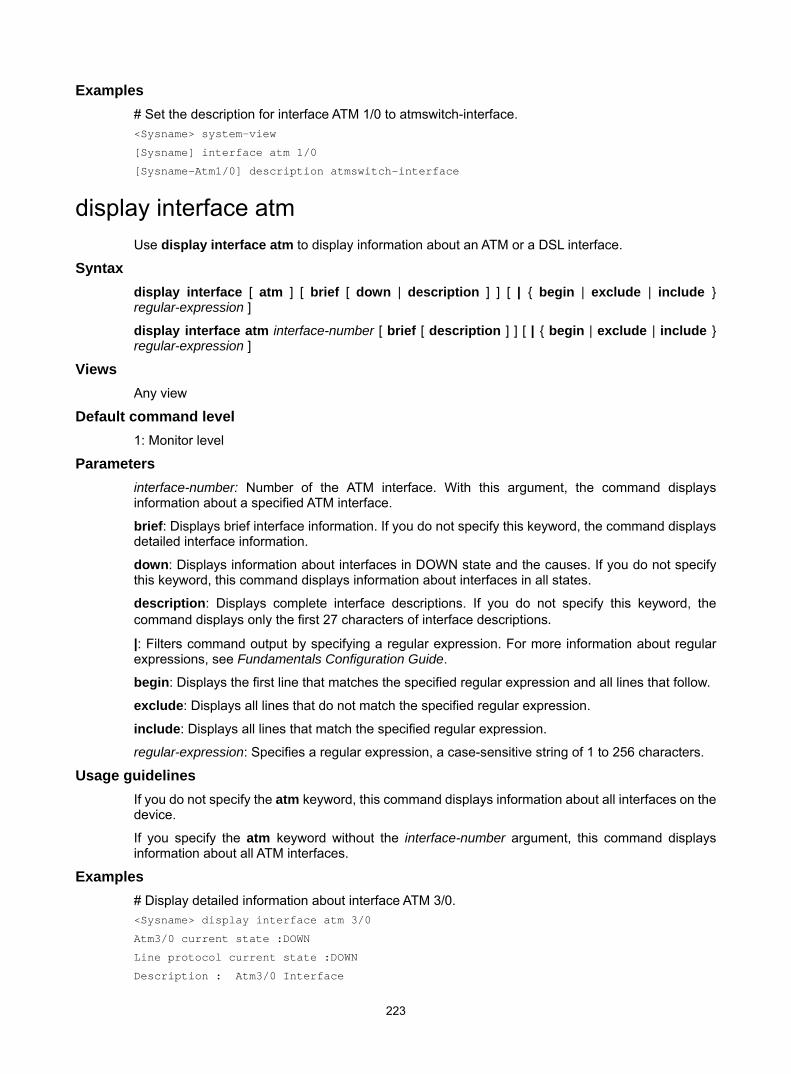
223
Examples # Set the description for interface ATM 1/0 to atmswitch-interface. <Sysname> system-view
[Sysname] interface atm 1/0
[Sysname-Atm1/0] description atmswitch-interface
display interface atm Use display interface atm to display information about an ATM or a DSL interface.
Syntax display interface [ atm ] [ brief [ down | description ] ] [ | { begin | exclude | include } regular-expression ]
display interface atm interface-number [ brief [ description ] ] [ | { begin | exclude | include } regular-expression ]
Views Any view
Default command level 1: Monitor level
Parameters interface-number: Number of the ATM interface. With this argument, the command displays information about a specified ATM interface.
brief: Displays brief interface information. If you do not specify this keyword, the command displays detailed interface information.
down: Displays information about interfaces in DOWN state and the causes. If you do not specify this keyword, this command displays information about interfaces in all states.
description: Displays complete interface descriptions. If you do not specify this keyword, the command displays only the first 27 characters of interface descriptions.
|: Filters command output by specifying a regular expression. For more information about regular expressions, see Fundamentals Configuration Guide.
begin: Displays the first line that matches the specified regular expression and all lines that follow.
exclude: Displays all lines that do not match the specified regular expression.
include: Displays all lines that match the specified regular expression.
regular-expression: Specifies a regular expression, a case-sensitive string of 1 to 256 characters.
Usage guidelines If you do not specify the atm keyword, this command displays information about all interfaces on the device.
If you specify the atm keyword without the interface-number argument, this command displays information about all ATM interfaces.
Examples # Display detailed information about interface ATM 3/0. <Sysname> display interface atm 3/0
Atm3/0 current state :DOWN
Line protocol current state :DOWN
Description : Atm3/0 Interface
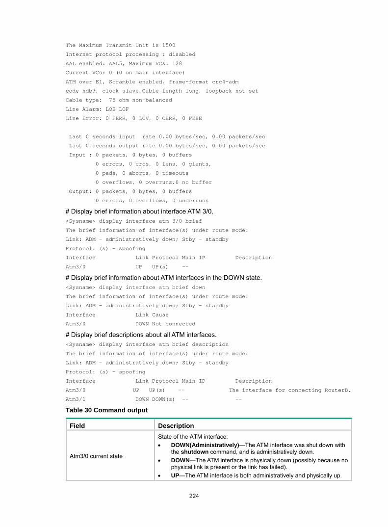
224
The Maximum Transmit Unit is 1500
Internet protocol processing : disabled
AAL enabled: AAL5, Maximum VCs: 128
Current VCs: 0 (0 on main interface)
ATM over E1, Scramble enabled, frame-format crc4-adm
code hdb3, clock slave,Cable-length long, loopback not set
Cable type: 75 ohm non-balanced
Line Alarm: LOS LOF
Line Error: 0 FERR, 0 LCV, 0 CERR, 0 FEBE
Last 0 seconds input rate 0.00 bytes/sec, 0.00 packets/sec
Last 0 seconds output rate 0.00 bytes/sec, 0.00 packets/sec
Input : 0 packets, 0 bytes, 0 buffers
0 errors, 0 crcs, 0 lens, 0 giants,
0 pads, 0 aborts, 0 timeouts
0 overflows, 0 overruns,0 no buffer
Output: 0 packets, 0 bytes, 0 buffers
0 errors, 0 overflows, 0 underruns
# Display brief information about interface ATM 3/0. <Sysname> display interface atm 3/0 brief
The brief information of interface(s) under route mode:
Link: ADM - administratively down; Stby - standby
Protocol: (s) - spoofing
Interface Link Protocol Main IP Description
Atm3/0 UP UP(s) --
# Display brief information about ATM interfaces in the DOWN state. <Sysname> display interface atm brief down
The brief information of interface(s) under route mode:
Link: ADM - administratively down; Stby - standby
Interface Link Cause
Atm3/0 DOWN Not connected
# Display brief descriptions about all ATM interfaces. <Sysname> display interface atm brief description
The brief information of interface(s) under route mode:
Link: ADM - administratively down; Stby - standby
Protocol: (s) - spoofing
Interface Link Protocol Main IP Description
Atm3/0 UP UP(s) -- The interface for connecting RouterB.
Atm3/1 DOWN DOWN(s) -- --
Table 30 Command output
Field Description
Atm3/0 current state
State of the ATM interface: • DOWN(Administratively)—The ATM interface was shut down with
the shutdown command, and is administratively down. • DOWN—The ATM interface is physically down (possibly because no
physical link is present or the link has failed). • UP—The ATM interface is both administratively and physically up.
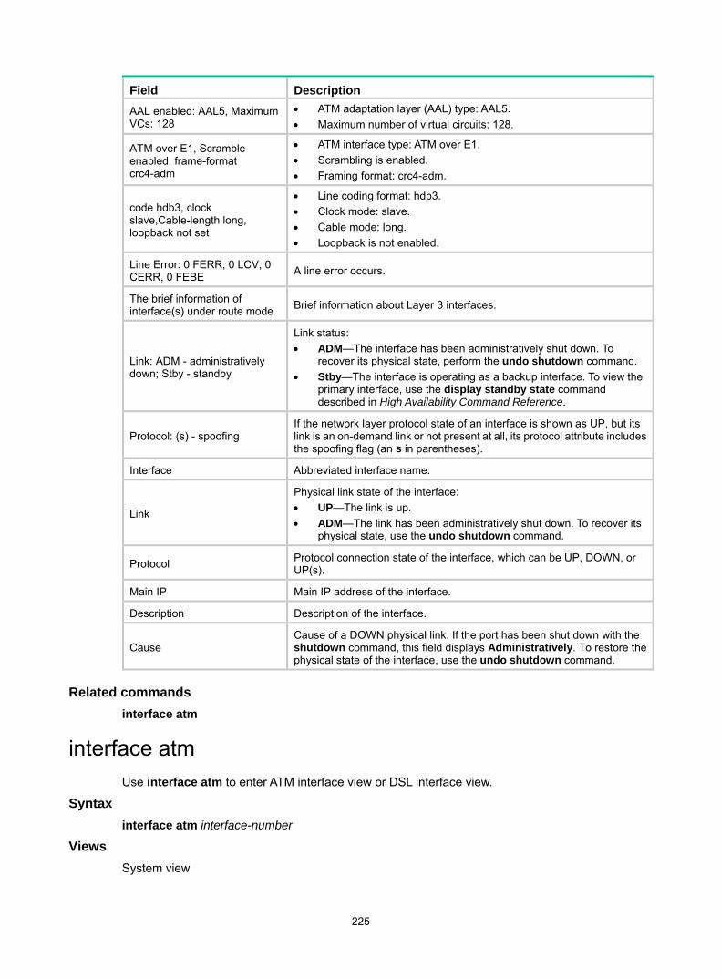
225
Field Description AAL enabled: AAL5, Maximum VCs: 128
• ATM adaptation layer (AAL) type: AAL5. • Maximum number of virtual circuits: 128.
ATM over E1, Scramble enabled, frame-format crc4-adm
• ATM interface type: ATM over E1. • Scrambling is enabled. • Framing format: crc4-adm.
code hdb3, clock slave,Cable-length long, loopback not set
• Line coding format: hdb3. • Clock mode: slave. • Cable mode: long. • Loopback is not enabled.
Line Error: 0 FERR, 0 LCV, 0 CERR, 0 FEBE A line error occurs.
The brief information of interface(s) under route mode Brief information about Layer 3 interfaces.
Link: ADM - administratively down; Stby - standby
Link status: • ADM—The interface has been administratively shut down. To
recover its physical state, perform the undo shutdown command. • Stby—The interface is operating as a backup interface. To view the
primary interface, use the display standby state command described in High Availability Command Reference.
Protocol: (s) - spoofing If the network layer protocol state of an interface is shown as UP, but its link is an on-demand link or not present at all, its protocol attribute includes the spoofing flag (an s in parentheses).
Interface Abbreviated interface name.
Link
Physical link state of the interface: • UP—The link is up. • ADM—The link has been administratively shut down. To recover its
physical state, use the undo shutdown command.
Protocol Protocol connection state of the interface, which can be UP, DOWN, or UP(s).
Main IP Main IP address of the interface.
Description Description of the interface.
Cause Cause of a DOWN physical link. If the port has been shut down with the shutdown command, this field displays Administratively. To restore the physical state of the interface, use the undo shutdown command.
Related commands interface atm
interface atm Use interface atm to enter ATM interface view or DSL interface view.
Syntax interface atm interface-number
Views System view
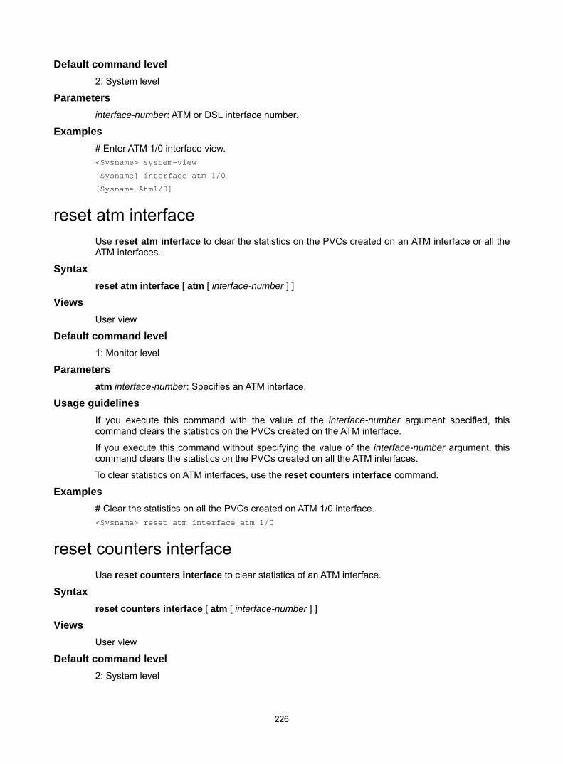
226
Default command level 2: System level
Parameters interface-number: ATM or DSL interface number.
Examples # Enter ATM 1/0 interface view. <Sysname> system-view
[Sysname] interface atm 1/0
[Sysname-Atm1/0]
reset atm interface Use reset atm interface to clear the statistics on the PVCs created on an ATM interface or all the ATM interfaces.
Syntax reset atm interface [ atm [ interface-number ] ]
Views User view
Default command level 1: Monitor level
Parameters atm interface-number: Specifies an ATM interface.
Usage guidelines If you execute this command with the value of the interface-number argument specified, this command clears the statistics on the PVCs created on the ATM interface.
If you execute this command without specifying the value of the interface-number argument, this command clears the statistics on the PVCs created on all the ATM interfaces.
To clear statistics on ATM interfaces, use the reset counters interface command.
Examples # Clear the statistics on all the PVCs created on ATM 1/0 interface. <Sysname> reset atm interface atm 1/0
reset counters interface Use reset counters interface to clear statistics of an ATM interface.
Syntax reset counters interface [ atm [ interface-number ] ]
Views User view
Default command level 2: System level

227
Parameters interface-number: Interface number.
Usage guidelines Before collecting traffic statistics within a specific period of time on an interface, you need to clear the existing statistics.
If you do not specify the atm keyword, this command clears the statistics of all interfaces.
If you specify atm but not interface-number, this command clears the statistics of the PVCs of all ATM interfaces.
If you specify both atm and interface-number, this command clears the statistics of the PVCs of the specified ATM interface.
Examples # Clear the statistics of ATM interface ATM 1/0. <Sysname> reset counters interface atm 1/0
shutdown Use shutdown to shut down the interface.
Use undo shutdown to bring up the interface.
Syntax shutdown undo shutdown
Default ATM and DSL interfaces are up.
Views ATM E1 interface view, ATM T1 interface view, ATM E3 interface view, ATM T3 interface view, ATM OC-3c interface view, ATM STM-1 interface view, ATM (ADSL) interface view, ATM (G.SHDSL) interface view, EFM interface view
Default command level 2: System level
Usage guidelines When you modify parameters on an ATM or a DSL interface, execute the shutdown command, and then the undo shutdown command to make your modifications take effect.
Examples # Shut down interface ATM 1/0. <Sysname> system-view
[Sysname] interface atm 1/0
[Sysname-Atm1/0] shutdown
IMA-E1/T1 interface configuration commands The following matrix shows the IMA-E1/T1 interface and hardware compatibility:
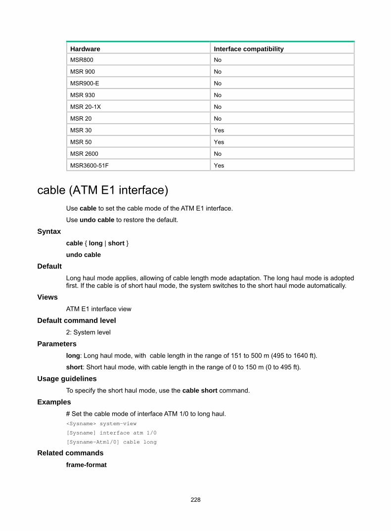
228
Hardware Interface compatibility MSR800 No
MSR 900 No
MSR900-E No
MSR 930 No
MSR 20-1X No
MSR 20 No
MSR 30 Yes
MSR 50 Yes
MSR 2600 No
MSR3600-51F Yes
cable (ATM E1 interface) Use cable to set the cable mode of the ATM E1 interface.
Use undo cable to restore the default.
Syntax cable { long | short }
undo cable
Default Long haul mode applies, allowing of cable length mode adaptation. The long haul mode is adopted first. If the cable is of short haul mode, the system switches to the short haul mode automatically.
Views ATM E1 interface view
Default command level 2: System level
Parameters long: Long haul mode, with cable length in the range of 151 to 500 m (495 to 1640 ft).
short: Short haul mode, with cable length in the range of 0 to 150 m (0 to 495 ft).
Usage guidelines To specify the short haul mode, use the cable short command.
Examples # Set the cable mode of interface ATM 1/0 to long haul. <Sysname> system-view
[Sysname] interface atm 1/0
[Sysname-Atm1/0] cable long
Related commands frame-format
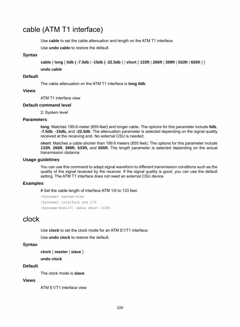
229
cable (ATM T1 interface) Use cable to set the cable attenuation and length on the ATM T1 interface.
Use undo cable to restore the default.
Syntax cable { long { 0db | -7.5db | -15db | -22.5db } | short { 133ft | 266ft | 399ft | 533ft | 655ft } }
undo cable
Default The cable attenuation on the ATM T1 interface is long 0db.
Views ATM T1 interface view
Default command level 2: System level
Parameters long: Matches 199.6-meter (655-feet) and longer cable. The options for this parameter include 0db, -7.5db, -15db, and -22.5db. The attenuation parameter is selected depending on the signal quality received at the receiving end. No external CSU is needed.
short: Matches a cable shorter than 199.6 meters (655 feet). The options for this parameter include 133ft, 266ft, 399ft, 533ft, and 655ft. The length parameter is selected depending on the actual transmission distance.
Usage guidelines You can use this command to adapt signal waveform to different transmission conditions such as the quality of the signal received by the receiver. If the signal quality is good, you can use the default setting. The ATM T1 interface does not need an external CSU device.
Examples # Set the cable length of interface ATM 1/0 to 133 feet. <Sysname> system-view
[Sysname] interface atm 1/0
[Sysname-Atm1/0] cable short 133ft
clock Use clock to set the clock mode for an ATM E1/T1 interface.
Use undo clock to restore the default.
Syntax clock { master | slave }
undo clock
Default The clock mode is slave.
Views ATM E1/T1 interface view

230
Default command level 2: System level
Parameters master: Sets the clock mode as master.
slave: Sets the clock mode as slave.
Usage guidelines When ATM E1/T1 interfaces are operating as DCEs, set the clock mode to master. When interfaces are operating as DTEs, set the clock mode to slave.
When the ATM interfaces on two routers are connected directly through a fiber-optic cable, set the clock mode to master at one end and to slave at the other end.
Examples # Set the clock mode of ATM E1/T1 interface 1/0 to master. <Sysname> system-view
[Sysname] interface atm 1/0
[Sysname-Atm1/0] clock master
clock-change auto Use clock-change auto to enable the automatic clock mode change function on the interface. This is to configure the interface that uses the slave clock mode to automatically switch to the master clock mode when receiving an alarm indication signal (AIS)/loss of signal (LOS)/loss of frame (LOF) alarm. After the alarm is cleared, the interface automatically switches back to the user-configured clock mode.
Use undo clock-change auto to disable the automatic clock mode change function. If the interface has already switched its clock mode, this command restores the user-configured clock mode for the interface.
Syntax clock-change auto undo clock-change auto
Default Automatic clock mode change is disabled.
Views ATM E1 interface view
Default command level 2: System level
Parameters auto: Enables automatic clock mode change for the interface.
Examples # Enable automatic clock mode change for ATM E1 interface ATM 2/0. <Sysname> system-view
[Sysname] interface atm 2/0
[Sysname-Atm2/0] clock-change auto
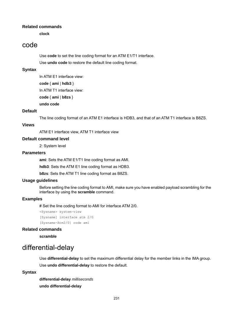
231
Related commands clock
code Use code to set the line coding format for an ATM E1/T1 interface.
Use undo code to restore the default line coding format.
Syntax In ATM E1 interface view:
code { ami | hdb3 }
In ATM T1 interface view:
code { ami | b8zs }
undo code
Default The line coding format of an ATM E1 interface is HDB3, and that of an ATM T1 interface is B8ZS.
Views ATM E1 interface view, ATM T1 interface view
Default command level 2: System level
Parameters ami: Sets the ATM E1/T1 line coding format as AMI.
hdb3: Sets the ATM E1 line coding format as HDB3.
b8zs: Sets the ATM T1 line coding format as B8ZS.
Usage guidelines Before setting the line coding format to AMI, make sure you have enabled payload scrambling for the interface by using the scramble command.
Examples # Set the line coding format to AMI for interface ATM 2/0. <Sysname> system-view
[Sysname] interface atm 2/0
[Sysname-Atm2/0] code ami
Related commands scramble
differential-delay Use differential-delay to set the maximum differential delay for the member links in the IMA group.
Use undo differential-delay to restore the default.
Syntax differential-delay milliseconds
undo differential-delay
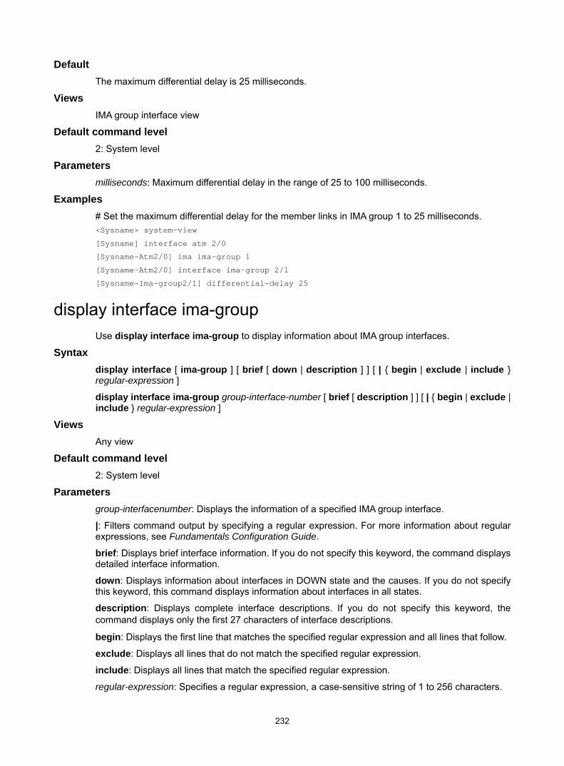
232
Default The maximum differential delay is 25 milliseconds.
Views IMA group interface view
Default command level 2: System level
Parameters milliseconds: Maximum differential delay in the range of 25 to 100 milliseconds.
Examples # Set the maximum differential delay for the member links in IMA group 1 to 25 milliseconds. <Sysname> system-view
[Sysname] interface atm 2/0
[Sysname-Atm2/0] ima ima-group 1
[Sysname-Atm2/0] interface ima-group 2/1
[Sysname-Ima-group2/1] differential-delay 25
display interface ima-group Use display interface ima-group to display information about IMA group interfaces.
Syntax display interface [ ima-group ] [ brief [ down | description ] ] [ | { begin | exclude | include } regular-expression ]
display interface ima-group group-interface-number [ brief [ description ] ] [ | { begin | exclude | include } regular-expression ]
Views Any view
Default command level 2: System level
Parameters group-interfacenumber: Displays the information of a specified IMA group interface.
|: Filters command output by specifying a regular expression. For more information about regular expressions, see Fundamentals Configuration Guide.
brief: Displays brief interface information. If you do not specify this keyword, the command displays detailed interface information.
down: Displays information about interfaces in DOWN state and the causes. If you do not specify this keyword, this command displays information about interfaces in all states.
description: Displays complete interface descriptions. If you do not specify this keyword, the command displays only the first 27 characters of interface descriptions.
begin: Displays the first line that matches the specified regular expression and all lines that follow.
exclude: Displays all lines that do not match the specified regular expression.
include: Displays all lines that match the specified regular expression.
regular-expression: Specifies a regular expression, a case-sensitive string of 1 to 256 characters.
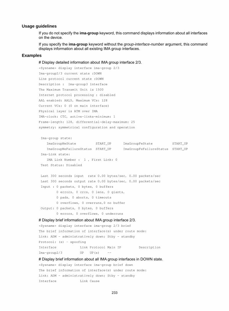
233
Usage guidelines If you do not specify the ima-group keyword, this command displays information about all interfaces on the device.
If you specify the ima-group keyword without the group-interface-number argument, this command displays information about all existing IMA group interfaces.
Examples # Display detailed information about IMA group interface 2/3. <Sysname> display interface ima-group 2/3
Ima-group2/3 current state :DOWN
Line protocol current state :DOWN
Description : Ima-group3 Interface
The Maximum Transmit Unit is 1500
Internet protocol processing : disabled
AAL enabled: AAL5, Maximum VCs: 128
Current VCs: 0 (0 on main interface)
Physical layer is ATM over IMA
IMA-clock: CTC, active-links-minimum: 1
Frame-length: 128, differential-delay-maximum: 25
symmetry: symmetrical configuration and operation
Ima-group state:
ImaGroupNeState START_UP ImaGroupFeState START_UP
ImaGroupNeFailureStatus START_UP ImaGroupFeFailureStatus START_UP
Ima-Link state:
IMA Link Number : 1 , First Link: 0
Test Status: Disabled
Last 300 seconds input rate 0.00 bytes/sec, 0.00 packets/sec
Last 300 seconds output rate 0.00 bytes/sec, 0.00 packets/sec
Input : 0 packets, 0 bytes, 0 buffers
0 errors, 0 crcs, 0 lens, 0 giants,
0 pads, 0 aborts, 0 timeouts
0 overflows, 0 overruns,0 no buffer
Output: 0 packets, 0 bytes, 0 buffers
0 errors, 0 overflows, 0 underruns
# Display brief information about IMA group interface 2/3. <Sysname> display interface ima-group 2/3 brief
The brief information of interface(s) under route mode:
Link: ADM - administratively down; Stby - standby
Protocol: (s) - spoofing
Interface Link Protocol Main IP Description
Ima-group2/3 UP UP(s) --
# Display brief information about all IMA group interfaces in DOWN state. <Sysname> display interface ima-group brief down
The brief information of interface(s) under route mode:
Link: ADM - administratively down; Stby - standby
Interface Link Cause
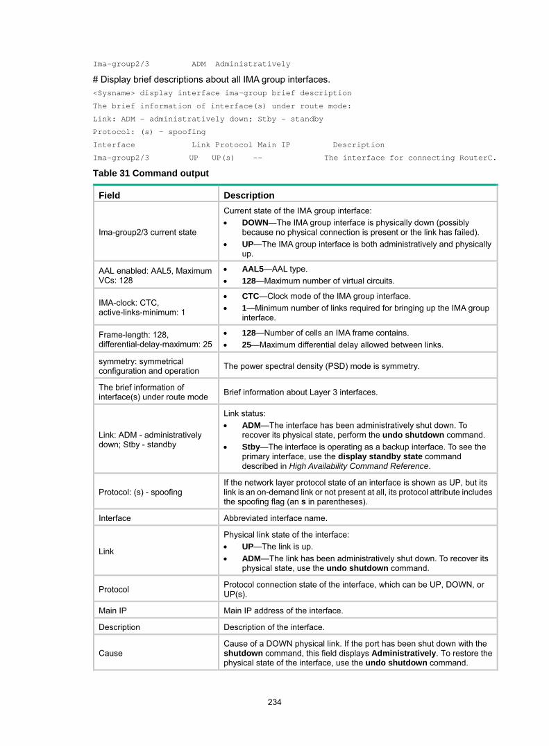
234
Ima-group2/3 ADM Administratively
# Display brief descriptions about all IMA group interfaces. <Sysname> display interface ima-group brief description
The brief information of interface(s) under route mode:
Link: ADM - administratively down; Stby - standby
Protocol: (s) - spoofing
Interface Link Protocol Main IP Description
Ima-group2/3 UP UP(s) -- The interface for connecting RouterC.
Table 31 Command output
Field Description
Ima-group2/3 current state
Current state of the IMA group interface: • DOWN—The IMA group interface is physically down (possibly
because no physical connection is present or the link has failed). • UP—The IMA group interface is both administratively and physically
up.
AAL enabled: AAL5, Maximum VCs: 128
• AAL5—AAL type. • 128—Maximum number of virtual circuits.
IMA-clock: CTC, active-links-minimum: 1
• CTC—Clock mode of the IMA group interface. • 1—Minimum number of links required for bringing up the IMA group
interface.
Frame-length: 128, differential-delay-maximum: 25
• 128—Number of cells an IMA frame contains. • 25—Maximum differential delay allowed between links.
symmetry: symmetrical configuration and operation The power spectral density (PSD) mode is symmetry.
The brief information of interface(s) under route mode Brief information about Layer 3 interfaces.
Link: ADM - administratively down; Stby - standby
Link status: • ADM—The interface has been administratively shut down. To
recover its physical state, perform the undo shutdown command. • Stby—The interface is operating as a backup interface. To see the
primary interface, use the display standby state command described in High Availability Command Reference.
Protocol: (s) - spoofing If the network layer protocol state of an interface is shown as UP, but its link is an on-demand link or not present at all, its protocol attribute includes the spoofing flag (an s in parentheses).
Interface Abbreviated interface name.
Link
Physical link state of the interface: • UP—The link is up. • ADM—The link has been administratively shut down. To recover its
physical state, use the undo shutdown command.
Protocol Protocol connection state of the interface, which can be UP, DOWN, or UP(s).
Main IP Main IP address of the interface.
Description Description of the interface.
Cause Cause of a DOWN physical link. If the port has been shut down with the shutdown command, this field displays Administratively. To restore the physical state of the interface, use the undo shutdown command.

235
Related commands interface ima-group
frame-format Use frame-format to configure the ATM over E1/T1 framing format.
Use undo frame-format to restore the default.
Syntax In ATM E1 interface view:
frame-format { crc4-adm | no-crc4-adm }
In ATM T1 interface view:
frame-format { esf-adm | sf-adm }
undo frame-format
Default The framing format is CRC4 ADM for ATM E1 interfaces and ESF ADM for ATM T1 interfaces.
Views ATM E1 interface view, ATM T1 interface view
Default command level 2: System level
Parameters crc4-adm: Sets the ATM over E1 framing format to 4-bit cyclic redundancy check ATM direct mapping (CRC4 ADM).
no-crc4-adm: Sets the ATM over E1 framing format to no-CRC4 ADM.
esf-adm: Sets the ATM over T1 framing format to extended super frame ADM (ESF ADM).
sf-adm: Sets the ATM over T1 framing format to super frame ADM (SF ADM).
Usage guidelines ATM Direct Mapping (ADM) directly maps ATM cells transmitted over the E1/T1 line into E1/T1 frames. This process is defined by ITU-T G.804 and ATM forum.
Examples # Configure no-CRC4 ADM framing on ATM E1 interface 2/0. <Sysname> system-view
[Sysname] interface atm 2/0
[Sysname-Atm2/0] frame-format no-crc4-adm
frame-length Use frame-length to configure the number of ATM cells in an IMA frame.
Use undo frame-length to restore the default.
Syntax frame-length { 32 | 64 | 128 | 256 }
undo frame-length
236
Default An IMA frame has 128 ATM cells.
Views IMA group interface view
Default command level 2: System level
Parameters 32, 64, 128, 256: Specifies the number of ATM cells in an IMA frame.
Examples # Set the number of ATM cells in an IMA frame to 64 on IMA group interface 1. <Sysname> system-view
[Sysname] interface atm 2/0
[Sysname-Atm2/0] ima ima-group 1
[Sysname-Atm2/0] interface ima-group 2/1
[Sysname-Ima-group2/1] frame-length 64
ima ima-group Use ima ima-group to add an ATM E1/T1 interface to an IMA group. If the specified IMA group does not exist, the command creates it first.
Use undo ima ima-group to remove an interface from an IMA group.
Syntax ima ima-group group-number
undo ima ima-group
Default No IMA group is created.
Views ATM E1 interface view, ATM T1 interface view
Default command level 2: System level
Parameters group-number: IMA group number in the range of 1 to 8.
Usage guidelines Before adding an ATM E1/T1 interface to an IMA group by using the ima ima-group command, remove network layer service-related configurations on the interface. For example, remove the IP address assigned to the interface by using the undo ip address command.
You can remove the first link assigned to an IMA group only after all the other links in the IMA group are removed. Removing this link also removes the IMA group.
Examples # Add ATM E1 interface 1/0 to IMA group 1. <Sysname> system-view
[Sysname] interface atm 1/0
237
[Sysname-Atm1/0] ima ima-group 1
ima-clock Use ima-clock to configure the clock mode of the IMA group.
Use undo ima-clock to restore the default.
Syntax ima-clock { ctc [ link-number number ] | itc }
undo ima-clock
Default The clock mode is CTC.
Views IMA group interface view
Default command level 2: System level
Parameters ctc: Specifies the common transmit clock mode. In this mode, all links in the IMA group share the same clock source, which can be an external clock or the one extracted from a member link.
link-number number: Specifies the number of an E1/T1 link that provides the clock source. The value range for the number argument is 0 to 7.
itc: Specifies the independent transmit clock mode. In this mode, the links in the IMA group use at least two clock sources.
Usage guidelines When the IMA group adopts ITC mode, you must set the clock mode of each member ATM E1/T1 link to slave with the clock slave command.
When the IMA group adopts CTC mode, you must set the clock mode of each member ATM E1/T1 link to master with the clock master command.
Examples # Set the clock mode to ITC on IMA group 1. <Sysname> system-view
[Sysname] interface atm 2/0
[Sysname-Atm2/0] ima ima-group 1
[Sysname-Atm2/0] interface ima-group 2/1
[Sysname-Ima-group2/1] ima-clock itc
ima-standard Use ima-standard to set the standard to be adopted by an IMA group interface.
Use undo ima-standard to restore the default.
Syntax ima-standard { alternate-v10 | normal | standard-v10 | standard-v11 }
undo ima-standard

238
Default The normal standard is adopted.
Views IMA group interface view
Default command level 2: System level
Parameters alternate-v10: Uses the V1.0 (other implementation) standard.
normal: Uses the normal standard. An IMA group interface adopting this standard changes to adopt V1.0 standard (standard implementation) if its peer interface adopts V1.0 (standard implementation).
standard-v10: Uses the V1.0 (standard implementation) standard.
standard-v11: Uses the V1.1 standard.
Examples # Configure to adopt the V1.1 standard. <Sysname> system-view
[Sysname] interface atm 2/0
[Sysname-Atm2/0] ima ima-group 1
[Sysname-Atm2/0] interface ima-group 2/1
[Sysname-Ima-group2/1] ima-standard standard-v11
ima-test Use ima-test to specify the E1/T1 link to be tested and the test mode for IMA group interface test.
Use undo ima-test to cancel the test.
Syntax ima-test [ link-number number ] [ pattern-id id ]
undo ima-test
Default IMA group interface test is disabled.
Views IMA group interface view
Default command level 2: System level
Parameters link-number number: Specifies the number of the E1/T1 link to be tested.
pattern-id id: Specifies the test mode, a hexadecimal number in the range of 0x00 to 0xFE.
Usage guidelines If you do not specify the number argument, the ima-test command specifies to test the link that is the first to be added to the IMA group interface.
If you do not specify the id argument when executing the ima-test command, the 0xAA test mode is adopted.
239
You can use this command to test the connectivity of a link to the rest of the IMA group by sending a test pattern over the link. This test mode is looped over all the active links at the far end and sent back to the transmitter. To display the connectivity test results, use the display interface ima-group command.
E1/T1 links are bidirectional. This command tests only the connectivity of a link in its transmit direction to the other links in the IMA group in their receive direction.
Examples # Send test mode 0xAB over link 0 in IMA group interface 1. <Sysname> system-view
[Sysname] interface atm 2/0
[Sysname-Atm2/0] ima ima-group 1
[Sysname-Atm2/0] interface ima-group 2/1
[Sysname-Ima-group2/1] ima-test link-number 0 pattern-id ab
interface ima-group Use interface ima-group to enter IMA group interface view.
Syntax interface ima-group group-interface-number
Views System view
Default command level 2: System level
Parameters group-interface-number: IMA group interface number.
Examples # Enter IMA group interface 1 view. <Sysname> system-view
[Sysname] interface atm 2/0
[Sysname-Atm2/0] ima ima-group 1
[Sysname-Atm2/0] quit
[Sysname] interface ima-group 2/1
[Sysname-Ima-group2/1]
loopback Use loopback to enable a specific type of loopback testing on an ATM E1/T1 interface.
Use undo loopback to disable the loopback testing that is being performed.
Syntax loopback { cell | local | payload | remote }
undo loopback
Default No loopback testing is enabled.
240
Views ATM E1 interface view, ATM T1 interface view
Default command level 2: System level
Parameters cell: Enables internal cell loopback testing (to check physical chips on the local side).
local: Enables internal loopback testing (to check service chips on the local side).
payload: Enables external payload loopback testing (to check payload framing).
remote: Enables external line loopback testing (to check the remote end).
Examples # Enable external payload loopback testing on ATM E1/T1 interface 1/0. <Sysname> system-view
[Sysname] interface atm 1/0
[Sysname-Atm1/0] loopback payload
min-active-links Use min-active-links to configure the minimum number of links required for the IMA group to work.
Use undo min-active-links to restore the default
Syntax min-active-links number
undo min-active-links
Default The minimum number of links is 1.
Views IMA group interface view
Default command level 2: System level
Parameters number: Number of links, in the range of 1 to 8.
Examples # Set the minimum number of links required for IMA group 1 to operate to 2. <Sysname> system-view
[Sysname] interface atm 2/0
[Sysname-Atm2/0] ima ima-group 1
[Sysname-Atm2/0] interface ima-group 2/1
[Sysname-Ima-group2/1] min-active-links 2
scramble Use scramble to enable payload scrambling on the ATM E1/T1 interface. This, however, does not affect cell headers.

241
Use undo scramble to disable payload scrambling.
Syntax scramble undo scramble
Default Payload scrambling is enabled on an ATM E1/T1 interface.
Views ATM E1 interface view, ATM T1 interface view
Default command level 2: System level
Usage guidelines With payload scrambling enabled, the interface performs payload scrambling when transmitting data, and payload descrambling when receiving data. Payload scrambling prevents consecutive 0s and 1s in the payload.
Disabling payload scrambling disables both payload scrambling during data transmission and payload descrambling during data receiving.
Examples # Enable payload scrambling on ATM interface 1/0. <Sysname> system-view
[Sysname] interface atm 1/0
[Sysname-Atm1/0] scramble
ATM E3/T3 interface configuration commands The following matrix shows the ATM E3/T3 interface and hardware compatibility:
Hardware Interface compatibility MSR800 No
MSR 900 No
MSR900-E No
MSR 930 No
MSR 20-1X No
MSR 20 No
MSR 30 Yes
MSR 50 Yes
MSR 2600 No
MSR3600-51F Yes
cable Use cable to configure the cable mode of the ATM T3 interface.
242
Use undo cable to restore the default.
Syntax cable { long | short }
undo cable
Default Short haul mode applies.
Views ATM T3 interface view
Default command level 2: System level
Parameters long: Long haul mode, with cable length in the range of 151 to 500 m (495 to 1640 ft).
short: Short haul mode, with cable length in the range of 0 to 150 m (0 to 495 ft).
Examples # Set the cable mode of ATM T3 interface 1/0 to long haul. <Sysname> system-view
[Sysname] interface atm 1/0
[Sysname-Atm1/0] cable long
clock Use clock to set the clock mode of the ATM E3/T3 interface.
Use undo clock to restore the default.
Syntax clock { master | slave }
undo clock
Default The clock mode is slave.
Views ATM E3 interface view, ATM T3 interface view
Default command level 2: System level
Parameters master: Sets the clock mode as master.
slave: Sets the clock mode as slave.
Examples # Set the clock mode of ATM E3/T3 interface 2/0 to master. <Sysname> system-view
[Sysname] interface atm 2/0
[Sysname-Atm2/0] clock master
243
frame-format Use frame-format to configure the framing format of an ATM E3/T3 interface.
Use undo frame-format to restore the default, which is G.751 PLCP (for ATM E3 interfaces) or C-bit PLCP (for ATM T3 interfaces).
Syntax In ATM E3 interface view:
frame-format { g751-adm | g751-plcp | g832-adm } In ATM T3 interface view:
frame-format { cbit-adm | cbit-plcp | m23-adm | m23-plcp }
undo frame-format
Views ATM E3 interface view, ATM T3 interface view
Default command level 2: System level
Parameters g751-adm: Sets the framing format of the ATM E3 interface to G.751 ATM direct mapping (G.751 ADM).
g751-plcp: Sets the framing format of the ATM E3 interface to G.751 physical layer convergence protocol (G.751 PLCP).
g832-adm: Sets the framing format of the ATM E3 interface to G.832 ADM.
cbit-adm: Sets the framing format of the ATM T3 interface to C-bit ADM.
cbit-plcp: Sets the framing format of the ATM T3 interface to C-bit PLCP.
m23-adm: Sets the framing format of the ATM T3 interface to M23 ADM.
m23-plcp: Sets the framing format of the ATM T3 interface to M23 PLCP.
Examples # Set the framing format of ATM E3 interface 1/0 to G.832 ADM. <Sysname> system-view
[Sysname] interface atm 1/0
[Sysname-Atm1/0] frame-format g832-adm
loopback Use loopback to enable a specific type of loopback testing on an ATM E3/T3 interface.
Use undo loopback to disable the loopback testing that is being performed.
Syntax loopback { cell | local | payload | remote }
undo loopback
Default Loopback testing is disabled.
244
Views ATM E3 interface view, ATM T3 interface view
Default command level 2: System level
Parameters cell: Enables internal cell loopback testing (to check physical chips on the local side).
local: Enables internal loopback testing (to check service chips on the local side).
payload: Enables external payload loopback testing (to check payload framing).
remote: Enables external line loopback (to check the remote end).
Examples # Enable external payload loopback testing on ATM E3/T3 interface 2/0. <Sysname> system-view
[Sysname] interface atm 2/0
[Sysname-Atm2/0] loopback payload
scramble Use scramble to enable payload scrambling on the ATM E3/T3 interface. This, however, does not affect cell headers.
Use undo scramble to disable payload scrambling.
Syntax scramble undo scramble
Default Payload scrambling is enabled on an ATM E3/T3 interface.
Views ATM E3/T3 interface view
Default command level 2: System level
Usage guidelines With payload scrambling enabled, the interface performs payload scrambling when transmitting data, and payload descrambling when receiving data. Payload scrambling prevents consecutive 0s and 1s in the payload.
Disabling payload scrambling disables both payload scrambling during data transmission and payload descrambling during data receiving.
Examples # Disable payload scrambling on ATM interface 2/0. <Sysname> system-view
[Sysname] interface atm 2/0
[Sysname-Atm2/0] undo scramble
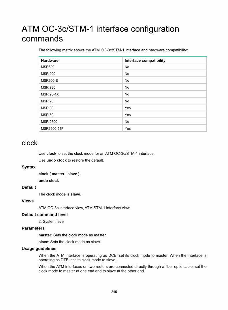
245
ATM OC-3c/STM-1 interface configuration commands
The following matrix shows the ATM OC-3c/STM-1 interface and hardware compatibility:
Hardware Interface compatibility MSR800 No
MSR 900 No
MSR900-E No
MSR 930 No
MSR 20-1X No
MSR 20 No
MSR 30 Yes
MSR 50 Yes
MSR 2600 No
MSR3600-51F Yes
clock Use clock to set the clock mode for an ATM OC-3c/STM-1 interface.
Use undo clock to restore the default.
Syntax clock { master | slave }
undo clock
Default The clock mode is slave.
Views ATM OC-3c interface view, ATM STM-1 interface view
Default command level 2: System level
Parameters master: Sets the clock mode as master.
slave: Sets the clock mode as slave.
Usage guidelines When the ATM interface is operating as DCE, set its clock mode to master. When the interface is operating as DTE, set its clock mode to slave.
When the ATM interfaces on two routers are connected directly through a fiber-optic cable, set the clock mode to master at one end and to slave at the other end.
246
Examples # Set the clock mode of ATM interface 4/0 to master. <Sysname> system-view
[Sysname] interface atm 4/0
[Sysname-Atm4/0] clock master
flag Use flag to set the SONET/SDH overhead bytes.
Use undo flag to restore the default SONET/SDH overhead bytes.
Syntax flag c2 flag-value
undo flag c2 flag { j0 | j1 } { sdh | sonet } flag-value
undo flag { j0 | j1 } { sdh | sonet }
Default The default SDH overhead bytes are used.
Views ATM OC-3c interface view, ATM STM-1 interface view
Default command level 2: System level
Parameters c2 flag-value: Path signal flag byte, a higher-order path overhead byte used to indicate the multiplex structure of virtual container (VC) frames and property of payload. It is a hexadecimal number in the range of 0x00 to 0xFF.
j0 flag-value: Regeneration section trace message, a section overhead byte used to test continuity of the connection between two interfaces at the section level. If the sdh keyword is configured, the flag-value argument is a string of 1 to 15 hexadecimal digits. If the sonet keyword is configured, the argument is a hexadecimal number in the range of 0x00 to 0xFF.
j1 flag-value: Path trace message, a higher-order path overhead byte used to test continuity of the connection between two interfaces at the path level. If the sdh keyword is configured, the flag-value argument is a string of 1 to 15 hexadecimal digits. If the sonet keyword is configured, the argument is a string of 1 to 62 characters.
sdh: Sets framing format to Synchronous Digital Hierarchy (SDH).
sonet: Sets framing format to Synchronous Optical Network (SONET).
Usage guidelines The default overhead bytes are as follows: • c2—0x13
• j0 (SDH)—Null
• j1 (SDH)—Null
Inconsistency between the c2 and j1 settings on the sending and receiving ends causes alarms.
The J0 byte can be any character in the network of the same carrier. If networks of two carriers are involved, however, the sending and receiving devices at network borders must use the same J0 byte.

247
Examples # Set the SDH overhead byte J0 of ATM interface ATM 4/0. <Sysname> system-view
[Sysname] interface atm 4/0
[Sysname-Atm4/0] flag j0 sdh ff
Related commands display interface pos
frame-format Use frame-format to set the framing format for an ATM OC-3c/STM-1 interface.
Use undo frame-format to restore the default
Syntax frame-format { sdh | sonet }
undo frame-format
Default The framing format is SDH STM-1.
Views ATM OC-3c interface view, ATM STM-1 interface view
Default command level 2: System level
Parameters sdh: Sets the framing format to SDH STM-1, the synchronous transport module-level 1 (STM-1) of synchronous digital hierarchy (SDH).
sonet: Sets the framing format to SONET OC-3, the optical carrier level three (OC-3) of synchronous optical network (SONET).
Examples # Set the framing format to SDH STM-1 on an ATM OC-3c/STM-1 interface. <Sysname> system-view
[Sysname] interface atm 4/0
[Sysname-Atm4/0] frame-format sdh
loopback Use loopback to configure the loopback mode on the ATM OC-3c/STM-1 interface.
Use undo loopback to disable loopback.
Syntax loopback { cell | local | remote }
undo loopback
Default Loopback is disabled.
248
Views ATM OC-3c interface view, ATM STM-1 interface view
Default command level 2: System level
Parameters cell: Enables internal cell loopback.
local: Enables internal loopback.
remote: Enables external loopback.
Usage guidelines Loopback is intended for test use. Disable it otherwise.
Examples # Enable internal loopback on ATM interface 4/0. <Sysname> system-view
[Sysname] interface atm 4/0
[Sysname-Atm4/0] loopback local
scramble Use scramble to enable payload scrambling on the ATM OC-3c/STM-1 interface. This, however, does not affect cell headers.
Use undo scramble to disable payload scrambling.
Syntax scramble undo scramble
Default Payload scrambling is enabled on the ATM OC-3c/STM-1 interface.
Views ATM OC-3c interface view, STM-1 interface view
Default command level 2: System level
Usage guidelines With payload scrambling enabled, the interface performs payload scrambling when transmitting data, and payload descrambling when receiving data. Payload scrambling prevents consecutive 0s and 1s in the payload.
Disabling payload scrambling disables both payload scrambling during data transmission and payload descrambling during data receiving.
Examples # Enable payload scrambling on ATM interface 4/0. <Sysname> system-view
[Sysname] interface atm 4/0
[Sysname-Atm4/0] scramble
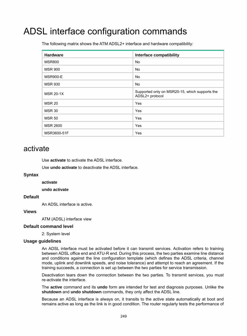
249
ADSL interface configuration commands The following matrix shows the ATM ADSL2+ interface and hardware compatibility:
Hardware Interface compatibility MSR800 No
MSR 900 No
MSR900-E No
MSR 930 No
MSR 20-1X Supported only on MSR20-15, which supports the ADSL2+ protocol
MSR 20 Yes
MSR 30 Yes
MSR 50 Yes
MSR 2600 Yes
MSR3600-51F Yes
activate Use activate to activate the ADSL interface.
Use undo activate to deactivate the ADSL interface.
Syntax activate
undo activate
Default An ADSL interface is active.
Views ATM (ADSL) interface view
Default command level 2: System level
Usage guidelines An ADSL interface must be activated before it can transmit services. Activation refers to training between ADSL office end and ATU-R end. During this process, the two parties examine line distance and conditions against the line configuration template (which defines the ADSL criteria, channel mode, uplink and downlink speeds, and noise tolerance) and attempt to reach an agreement. If the training succeeds, a connection is set up between the two parties for service transmission.
Deactivation tears down the connection between the two parties. To transmit services, you must re-activate the interface.
The active command and its undo form are intended for test and diagnosis purposes. Unlike the shutdown and undo shutdown commands, they only affect the ADSL line.
Because an ADSL interface is always on, it transits to the active state automatically at boot and remains active as long as the link is in good condition. The router regularly tests the performance of
250
the line. If it finds that the line performance is deteriorating, it automatically deactivates, retrains, and then reactivates the line.
Examples # Activate ADSL interface 1/0. <Sysname> system-view
[Sysname] interface atm 1/0
[Sysname-Atm1/0] activate
adsl standard Use adsl standard to set the standard to be applied to an ADSL interface.
Use undo adsl standard to restore the default.
Syntax adsl standard { auto | g9923 | g9925 | gdmt | glite | t1413 }
undo adsl standard
Default The standard is auto-negotiation.
Views ATM (ADSL) interface view
Default command level 2: System level
Parameters auto: Specifies the auto-negotiation mode.
g9923: Specifies the ADSL2 (G992.3) standard.
g9925: Specifies the ADSL2+ (G992.5) standard.
gdmt: Specifies the G.DMT (G992.1) standard.
glite: Specifies the G.Lite (G992.2) standard.
t1413: Specifies the T1.413 standard.
Usage guidelines ADSL-I module does not support G.Lite (G992.2) standard and T1.413 standard.
To apply the standard configured by the adsl standard command immediately, re-activate the interface by either the shutdown and undo shutdown commands or the activate and undo activate commands.
Examples # Apply the standard T1.413 to ATM interface 1/0. <Sysname> system-view
[Sysname] interface atm 1/0
[Sysname-Atm1/0]adsl standard t1413
[Sysname-Atm1/0] shutdown
[Sysname-Atm1/0]undo shutdown
251
adsl tx-attenuation Use adsl tx-attenuation to set a transmit power attenuation for the ADSL interface.
Use undo adsl tx-attenuation to restore the default.
Syntax adsl tx-attenuation attenuation
undo adsl tx-attenuation
Default The transmit power attenuation is 1.
Views ATM (ADSL) interface view
Default command level 2: System level
Parameters attenuation: Transmit power attenuation in the range of 0 to 12.
Examples # Set the transmit power attenuation to 10 for ATM ADSL interface 1/0. <Sysname> system-view
[Sysname] interface atm 1/0
[Sysname-Atm1/0] adsl tx-attenuation 10
bootrom update file Use bootrom update file to upgrade software on an ADSL2+ card.
Syntax bootrom update file file-url [ slot slot-no-list ] [ all | part ]
Default The entire Boot ROM is upgraded.
Views User view
Default command level 2: System level
Parameters file-url: File name (including the path) of the software to be upgraded, a string of 1 to 135 characters.
slot slot-no-list: List of slot numbers, representing multiple cards. The argument slot-no-list appears in the form of { slot-no [ to slot-no ] }&<1-7>, where slot-no is the slot number of a card, in the range of 1 to the maximum slot number, and &<1-7> means that you can specify up to 7 slot numbers or slot number ranges for this argument.
part: Upgrades only the extension part of the Boot ROM.
all: Upgrades the entire Boot ROM.

252
Usage guidelines This feature is only valid for ADSL2+ cards with CPUs.
The upgradable software includes Boot ROM and ADSL2+ card software. Before you upgrade, load the new software file by FTP or other means to the Flash or CF card on your device and save it. Before upgrading, shut down the interface with the shutdown command if the interface is up. After upgrading, bring the interface up with the undo shutdown command.
Use the all keyword with caution. In case failure occurs, recovery is difficult and troublesome.
Example # Upgrade software for an ADSL2+ card. <Sysname> system-view
[Sysname]interface atm 2/0
[Sysname-Atm2/0]shutdown
[Sysname-Atm2/0] quit
[Sysname] quit
<Sysname> bootrom update file flash:/bcm6348.bin slot 1 part
This command will update BootRom file on board 2, Continue? [Y/N]y
Board 2 upgrading BOOTROM, please wait...
<Sysname> system-view
[Sysname]interface atm 2/0
[Sysname-Atm2/0]undo shutdown
display dsl configuration Use display dsl configuration to display the actual configurations of a DSL interface.
Syntax display dsl configuration interface atm interface-number [ | { begin | exclude | include } regular-expression ]
Views Any view
Default command level 1: Monitor level
Parameters interface-number: DSL interface number.
|: Filters command output by specifying a regular expression. For more information about regular expressions, see Fundamentals Configuration Guide.
begin: Displays the first line that matches the specified regular expression and all lines that follow.
exclude: Displays all lines that do not match the specified regular expression.
include: Displays all lines that match the specified regular expression.
regular-expression: Specifies a regular expression, a case-sensitive string of 1 to 256 characters.
Example # Display the actual configurations of ADSL interface ATM 1/0. <Sysname> display dsl configuration interface atm 1/0
Line Params Set by User
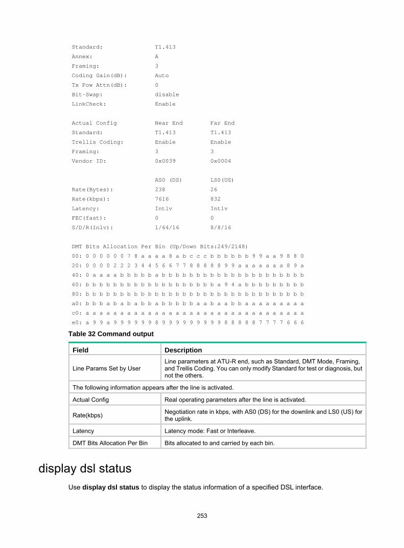
253
Standard: T1.413
Annex: A
Framing: 3
Coding Gain(dB): Auto
Tx Pow Attn(dB): 0
Bit-Swap: disable
LinkCheck: Enable
Actual Config Near End Far End
Standard: T1.413 T1.413
Trellis Coding: Enable Enable
Framing: 3 3
Vendor ID: 0x0039 0x0004
AS0 (DS) LS0(US)
Rate(Bytes): 238 26
Rate(kbps): 7616 832
Latency: Intlv Intlv
FEC(fast): 0 0
S/D/R(Inlv): 1/64/16 8/8/16
DMT Bits Allocation Per Bin (Up/Down Bits:249/2148)
00: 0 0 0 0 0 0 7 8 a a a a 8 a b c c c b b b b b b 9 9 a a 9 8 8 0
20: 0 0 0 0 2 2 2 3 4 4 5 6 6 7 7 8 8 8 8 8 9 9 a a a a a a a 8 9 a
40: 0 a a a a b b b b b a b b b b b b b b b b b b b b b b b b b b b
60: b b b b b b b b b b b b b b b b b b b a 9 4 a b b b b b b b b b
80: b b b b b b b b b b b b b b b b b b b b b b b b b b b b b b b b
a0: b b b a b a b a b b a b b b b b a a b a a b b a a a a a a a a a
c0: a a a a a a a a a a a a a a a a a a a a a a a a a a a a a a a a
e0: a 9 9 a 9 9 9 9 9 9 8 9 9 9 9 9 9 9 9 9 8 8 8 8 8 7 7 7 7 6 6 6
Table 32 Command output
Field Description
Line Params Set by User Line parameters at ATU-R end, such as Standard, DMT Mode, Framing, and Trellis Coding. You can only modify Standard for test or diagnosis, but not the others.
The following information appears after the line is activated.
Actual Config Real operating parameters after the line is activated.
Rate(kbps) Negotiation rate in kbps, with AS0 (DS) for the downlink and LS0 (US) for the uplink.
Latency Latency mode: Fast or Interleave.
DMT Bits Allocation Per Bin Bits allocated to and carried by each bin.
display dsl status Use display dsl status to display the status information of a specified DSL interface.
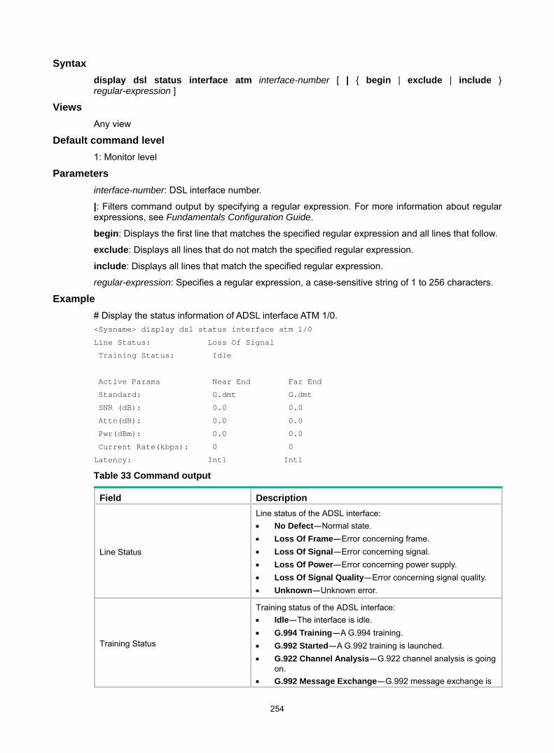
254
Syntax display dsl status interface atm interface-number [ | { begin | exclude | include } regular-expression ]
Views Any view
Default command level 1: Monitor level
Parameters interface-number: DSL interface number.
|: Filters command output by specifying a regular expression. For more information about regular expressions, see Fundamentals Configuration Guide.
begin: Displays the first line that matches the specified regular expression and all lines that follow.
exclude: Displays all lines that do not match the specified regular expression.
include: Displays all lines that match the specified regular expression.
regular-expression: Specifies a regular expression, a case-sensitive string of 1 to 256 characters.
Example # Display the status information of ADSL interface ATM 1/0. <Sysname> display dsl status interface atm 1/0
Line Status: Loss Of Signal
Training Status: Idle
Active Params Near End Far End
Standard: G.dmt G.dmt
SNR (dB): 0.0 0.0
Attn(dB): 0.0 0.0
Pwr(dBm): 0.0 0.0
Current Rate(kbps): 0 0
Latency: Intl Intl
Table 33 Command output
Field Description
Line Status
Line status of the ADSL interface: • No Defect—Normal state. • Loss Of Frame—Error concerning frame. • Loss Of Signal—Error concerning signal. • Loss Of Power—Error concerning power supply. • Loss Of Signal Quality—Error concerning signal quality. • Unknown—Unknown error.
Training Status
Training status of the ADSL interface: • Idle—The interface is idle. • G.994 Training—A G.994 training. • G.992 Started—A G.992 training is launched. • G.922 Channel Analysis—G.922 channel analysis is going
on. • G.992 Message Exchange—G.992 message exchange is
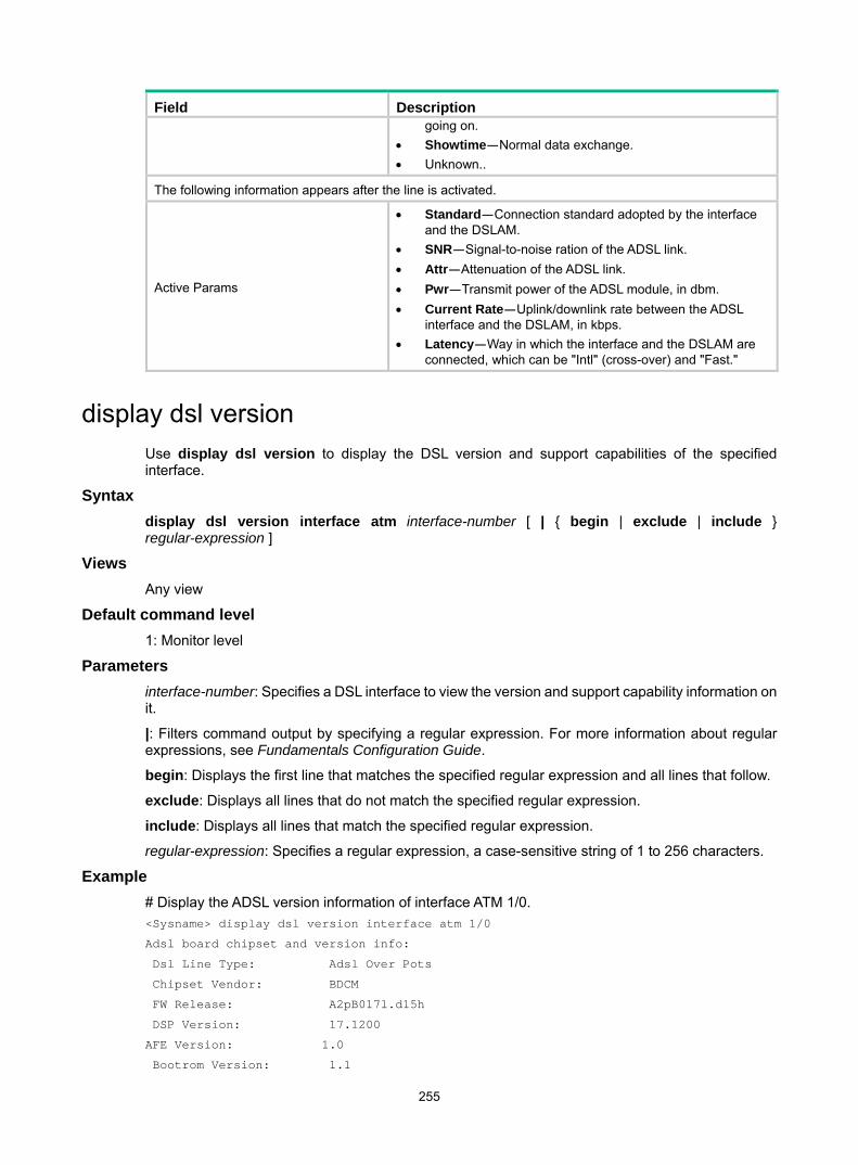
255
Field Description going on.
• Showtime—Normal data exchange. • Unknown..
The following information appears after the line is activated.
Active Params
• Standard—Connection standard adopted by the interface and the DSLAM.
• SNR—Signal-to-noise ration of the ADSL link. • Attr—Attenuation of the ADSL link. • Pwr—Transmit power of the ADSL module, in dbm. • Current Rate—Uplink/downlink rate between the ADSL
interface and the DSLAM, in kbps. • Latency—Way in which the interface and the DSLAM are
connected, which can be "Intl" (cross-over) and "Fast."
display dsl version Use display dsl version to display the DSL version and support capabilities of the specified interface.
Syntax display dsl version interface atm interface-number [ | { begin | exclude | include } regular-expression ]
Views Any view
Default command level 1: Monitor level
Parameters interface-number: Specifies a DSL interface to view the version and support capability information on it.
|: Filters command output by specifying a regular expression. For more information about regular expressions, see Fundamentals Configuration Guide.
begin: Displays the first line that matches the specified regular expression and all lines that follow.
exclude: Displays all lines that do not match the specified regular expression.
include: Displays all lines that match the specified regular expression.
regular-expression: Specifies a regular expression, a case-sensitive string of 1 to 256 characters.
Example # Display the ADSL version information of interface ATM 1/0. <Sysname> display dsl version interface atm 1/0
Adsl board chipset and version info:
Dsl Line Type: Adsl Over Pots
Chipset Vendor: BDCM
FW Release: A2pB017l.d15h
DSP Version: 17.1200
AFE Version: 1.0
Bootrom Version: 1.1
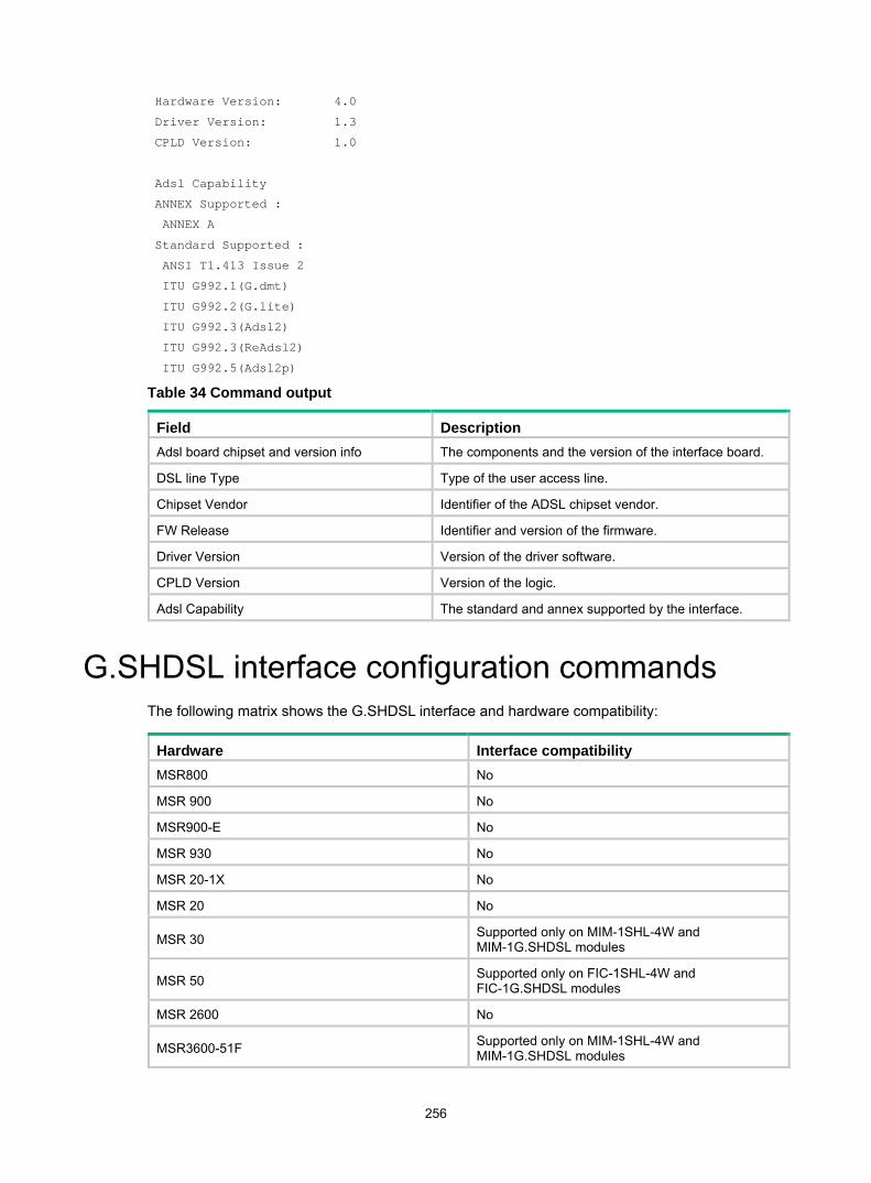
256
Hardware Version: 4.0
Driver Version: 1.3
CPLD Version: 1.0
Adsl Capability
ANNEX Supported :
ANNEX A
Standard Supported :
ANSI T1.413 Issue 2
ITU G992.1(G.dmt)
ITU G992.2(G.lite)
ITU G992.3(Adsl2)
ITU G992.3(ReAdsl2)
ITU G992.5(Adsl2p)
Table 34 Command output
Field Description Adsl board chipset and version info The components and the version of the interface board.
DSL line Type Type of the user access line.
Chipset Vendor Identifier of the ADSL chipset vendor.
FW Release Identifier and version of the firmware.
Driver Version Version of the driver software.
CPLD Version Version of the logic.
Adsl Capability The standard and annex supported by the interface.
G.SHDSL interface configuration commands The following matrix shows the G.SHDSL interface and hardware compatibility:
Hardware Interface compatibility MSR800 No
MSR 900 No
MSR900-E No
MSR 930 No
MSR 20-1X No
MSR 20 No
MSR 30 Supported only on MIM-1SHL-4W and MIM-1G.SHDSL modules
MSR 50 Supported only on FIC-1SHL-4W and FIC-1G.SHDSL modules
MSR 2600 No
MSR3600-51F Supported only on MIM-1SHL-4W and MIM-1G.SHDSL modules
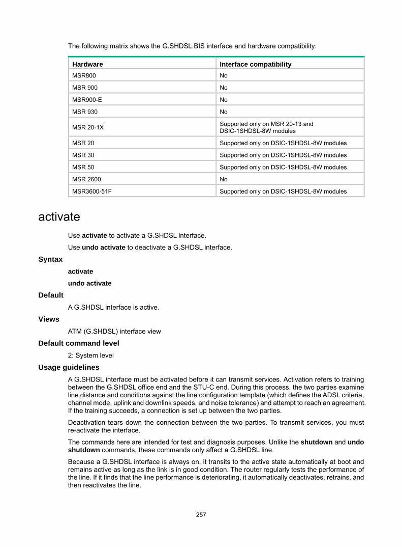
257
The following matrix shows the G.SHDSL.BIS interface and hardware compatibility:
Hardware Interface compatibility MSR800 No
MSR 900 No
MSR900-E No
MSR 930 No
MSR 20-1X Supported only on MSR 20-13 and DSIC-1SHDSL-8W modules
MSR 20 Supported only on DSIC-1SHDSL-8W modules
MSR 30 Supported only on DSIC-1SHDSL-8W modules
MSR 50 Supported only on DSIC-1SHDSL-8W modules
MSR 2600 No
MSR3600-51F Supported only on DSIC-1SHDSL-8W modules
activate Use activate to activate a G.SHDSL interface.
Use undo activate to deactivate a G.SHDSL interface.
Syntax activate undo activate
Default A G.SHDSL interface is active.
Views ATM (G.SHDSL) interface view
Default command level 2: System level
Usage guidelines A G.SHDSL interface must be activated before it can transmit services. Activation refers to training between the G.SHDSL office end and the STU-C end. During this process, the two parties examine line distance and conditions against the line configuration template (which defines the ADSL criteria, channel mode, uplink and downlink speeds, and noise tolerance) and attempt to reach an agreement. If the training succeeds, a connection is set up between the two parties.
Deactivation tears down the connection between the two parties. To transmit services, you must re-activate the interface.
The commands here are intended for test and diagnosis purposes. Unlike the shutdown and undo shutdown commands, these commands only affect a G.SHDSL line.
Because a G.SHDSL interface is always on, it transits to the active state automatically at boot and remains active as long as the link is in good condition. The router regularly tests the performance of the line. If it finds that the line performance is deteriorating, it automatically deactivates, retrains, and then reactivates the line.
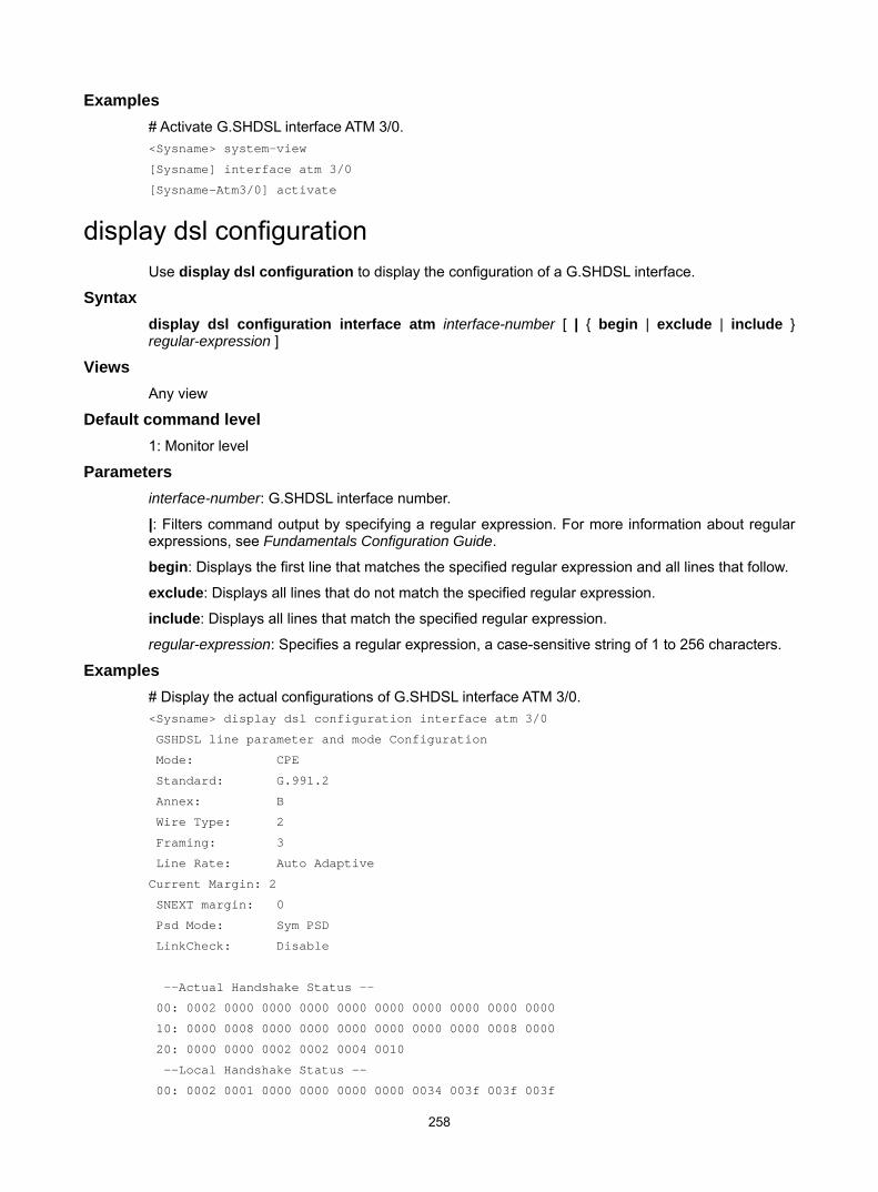
258
Examples # Activate G.SHDSL interface ATM 3/0. <Sysname> system-view
[Sysname] interface atm 3/0
[Sysname-Atm3/0] activate
display dsl configuration Use display dsl configuration to display the configuration of a G.SHDSL interface.
Syntax display dsl configuration interface atm interface-number [ | { begin | exclude | include } regular-expression ]
Views Any view
Default command level 1: Monitor level
Parameters interface-number: G.SHDSL interface number.
|: Filters command output by specifying a regular expression. For more information about regular expressions, see Fundamentals Configuration Guide.
begin: Displays the first line that matches the specified regular expression and all lines that follow.
exclude: Displays all lines that do not match the specified regular expression.
include: Displays all lines that match the specified regular expression.
regular-expression: Specifies a regular expression, a case-sensitive string of 1 to 256 characters.
Examples # Display the actual configurations of G.SHDSL interface ATM 3/0. <Sysname> display dsl configuration interface atm 3/0
GSHDSL line parameter and mode Configuration
Mode: CPE
Standard: G.991.2
Annex: B
Wire Type: 2
Framing: 3
Line Rate: Auto Adaptive
Current Margin: 2
SNEXT margin: 0
Psd Mode: Sym PSD
LinkCheck: Disable
--Actual Handshake Status --
00: 0002 0000 0000 0000 0000 0000 0000 0000 0000 0000
10: 0000 0008 0000 0000 0000 0000 0000 0000 0008 0000
20: 0000 0000 0002 0002 0004 0010
--Local Handshake Status --
00: 0002 0001 0000 0000 0000 0000 0034 003f 003f 003f
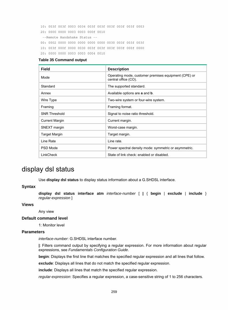
259
10: 003f 003f 0003 0034 003f 003f 003f 003f 003f 0003
20: 0000 0000 0003 0003 000f 0010
--Remote Handshake Status --
00: 0002 0000 0000 0000 0000 0000 0030 003f 003f 003f
10: 003f 000f 0000 0030 003f 003f 003f 003f 000f 0000
20: 0000 0000 0003 0003 0004 0010
Table 35 Command output
Field Description
Mode Operating mode, customer premises equipment (CPE) or central office (CO).
Standard The supported standard.
Annex Available options are a and b.
Wire Type Two-wire system or four-wire system.
Framing Framing format.
SNR Threshold Signal to noise ratio threshold.
Current Margin Current margin.
SNEXT margin Worst-case margin.
Target Margin Target margin.
Line Rate Line rate.
PSD Mode Power spectral density mode: symmetric or asymmetric.
LinkCheck State of link check: enabled or disabled.
display dsl status Use display dsl status to display status information about a G.SHDSL interface.
Syntax display dsl status interface atm interface-number [ | { begin | exclude | include } regular-expression ]
Views Any view
Default command level 1: Monitor level
Parameters interface-number: G.SHDSL interface number.
|: Filters command output by specifying a regular expression. For more information about regular expressions, see Fundamentals Configuration Guide.
begin: Displays the first line that matches the specified regular expression and all lines that follow.
exclude: Displays all lines that do not match the specified regular expression.
include: Displays all lines that match the specified regular expression.
regular-expression: Specifies a regular expression, a case-sensitive string of 1 to 256 characters.
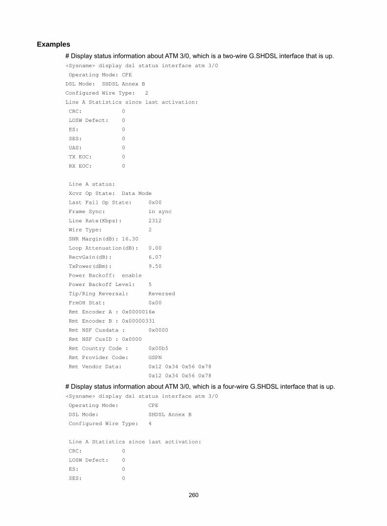
260
Examples # Display status information about ATM 3/0, which is a two-wire G.SHDSL interface that is up. <Sysname> display dsl status interface atm 3/0
Operating Mode: CPE
DSL Mode: SHDSL Annex B
Configured Wire Type: 2
Line A Statistics since last activation:
CRC: 0
LOSW Defect: 0
ES: 0
SES: 0
UAS: 0
TX EOC: 0
RX EOC: 0
Line A status:
Xcvr Op State: Data Mode
Last Fail Op State: 0x00
Frame Sync: in sync
Line Rate(Kbps): 2312
Wire Type: 2
SNR Margin(dB): 16.30
Loop Attenuation(dB): 0.00
RecvGain(dB): 6.07
TxPower(dBm): 9.50
Power Backoff: enable
Power Backoff Level: 5
Tip/Ring Reversal: Reversed
FrmOH Stat: 0x00
Rmt Encoder A : 0x0000016e
Rmt Encoder B : 0x00000331
Rmt NSF Cusdata : 0x0000
Rmt NSF CusID : 0x0000
Rmt Country Code : 0x00b5
Rmt Provider Code: GSPN
Rmt Vendor Data: 0x12 0x34 0x56 0x78
0x12 0x34 0x56 0x78
# Display status information about ATM 3/0, which is a four-wire G.SHDSL interface that is up. <Sysname> display dsl status interface atm 3/0
Operating Mode: CPE
DSL Mode: SHDSL Annex B
Configured Wire Type: 4
Line A Statistics since last activation:
CRC: 0
LOSW Defect: 0
ES: 0
SES: 0
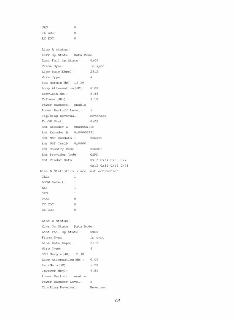
261
UAS: 0
TX EOC: 0
RX EOC: 0
Line A status:
Xcvr Op State: Data Mode
Last Fail Op State: 0x00
Frame Sync: in sync
Line Rate(Kbps): 2312
Wire Type: 4
SNR Margin(dB): 13.30
Loop Attenuation(dB): 0.00
RecvGain(dB): 5.86
TxPower(dBm): 9.50
Power Backoff: enable
Power Backoff Level: 5
Tip/Ring Reversal: Reversed
FrmOH Stat: 0x00
Rmt Encoder A : 0x0000016e
Rmt Encoder B : 0x00000331
Rmt NSF Cusdata : 0x0000
Rmt NSF CusID : 0x0000
Rmt Country Code : 0x00b5
Rmt Provider Code: GSPN
Rmt Vendor Data: 0x12 0x34 0x56 0x78
0x12 0x34 0x56 0x78
Line B Statistics since last activation:
CRC: 1
LOSW Defect: 1
ES: 1
SES: 1
UAS: 0
TX EOC: 0
RX EOC: 0
Line B status:
Xcvr Op State: Data Mode
Last Fail Op State: 0x00
Frame Sync: in sync
Line Rate(Kbps): 2312
Wire Type: 4
SNR Margin(dB): 12.30
Loop Attenuation(dB): 0.00
RecvGain(dB): 5.28
TxPower(dBm): 9.50
Power Backoff: enable
Power Backoff Level: 5
Tip/Ring Reversal: Reversed
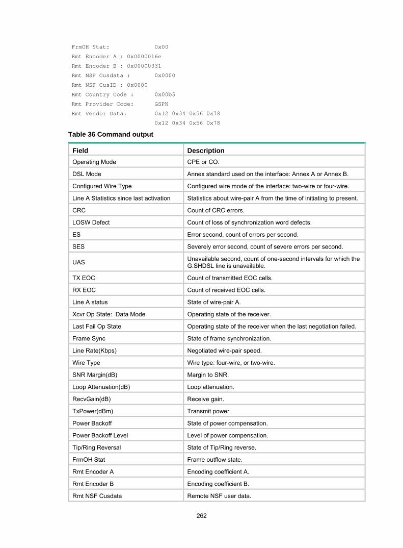
262
FrmOH Stat: 0x00
Rmt Encoder A : 0x0000016e
Rmt Encoder B : 0x00000331
Rmt NSF Cusdata : 0x0000
Rmt NSF CusID : 0x0000
Rmt Country Code : 0x00b5
Rmt Provider Code: GSPN
Rmt Vendor Data: 0x12 0x34 0x56 0x78
0x12 0x34 0x56 0x78
Table 36 Command output
Field Description Operating Mode CPE or CO.
DSL Mode Annex standard used on the interface: Annex A or Annex B.
Configured Wire Type Configured wire mode of the interface: two-wire or four-wire.
Line A Statistics since last activation Statistics about wire-pair A from the time of initiating to present.
CRC Count of CRC errors.
LOSW Defect Count of loss of synchronization word defects.
ES Error second, count of errors per second.
SES Severely error second, count of severe errors per second.
UAS Unavailable second, count of one-second intervals for which the G.SHDSL line is unavailable.
TX EOC Count of transmitted EOC cells.
RX EOC Count of received EOC cells.
Line A status State of wire-pair A.
Xcvr Op State: Data Mode Operating state of the receiver.
Last Fail Op State Operating state of the receiver when the last negotiation failed.
Frame Sync State of frame synchronization.
Line Rate(Kbps) Negotiated wire-pair speed.
Wire Type Wire type: four-wire, or two-wire.
SNR Margin(dB) Margin to SNR.
Loop Attenuation(dB) Loop attenuation.
RecvGain(dB) Receive gain.
TxPower(dBm) Transmit power.
Power Backoff State of power compensation.
Power Backoff Level Level of power compensation.
Tip/Ring Reversal State of Tip/Ring reverse.
FrmOH Stat Frame outflow state.
Rmt Encoder A Encoding coefficient A.
Rmt Encoder B Encoding coefficient B.
Rmt NSF Cusdata Remote NSF user data.
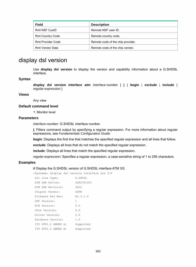
263
Field Description Rmt NSF CusID Remote NSF user ID.
Rmt Country Code Remote country code.
Rmt Provider Code Remote code of the chip provider.
Rmt Vendor Data Remote code of the chip vendor.
display dsl version Use display dsl version to display the version and capability information about a G.SHDSL interface.
Syntax display dsl version interface atm interface-number [ | { begin | exclude | include } regular-expression ]
Views Any view
Default command level 1: Monitor level
Parameters interface-number: G.SHDSL interface number.
|: Filters command output by specifying a regular expression. For more information about regular expressions, see Fundamentals Configuration Guide.
begin: Displays the first line that matches the specified regular expression and all lines that follow.
exclude: Displays all lines that do not match the specified regular expression.
include: Displays all lines that match the specified regular expression.
regular-expression: Specifies a regular expression, a case-sensitive string of 1 to 256 characters.
Examples # Display the G.SHDSL version of G.SHDSL interface ATM 3/0. <Sysname> display dsl version interface atm 3/0
Dsl Line Type: G.SHDSL
ATM SAR Device: 0x823614f1
ATM SAR Revision: 0x02
Chipset Vendor: GSPN
Firmware Rel-Rev: R2.3.1-0
DSP Version: 1
PCB Version: 0.0
CPLD Version: 0.0
Driver Version: 2.0
Hardware Version: 1.0
ITU G991.2 ANNEX A: Supported
ITU G991.2 ANNEX B: Supported
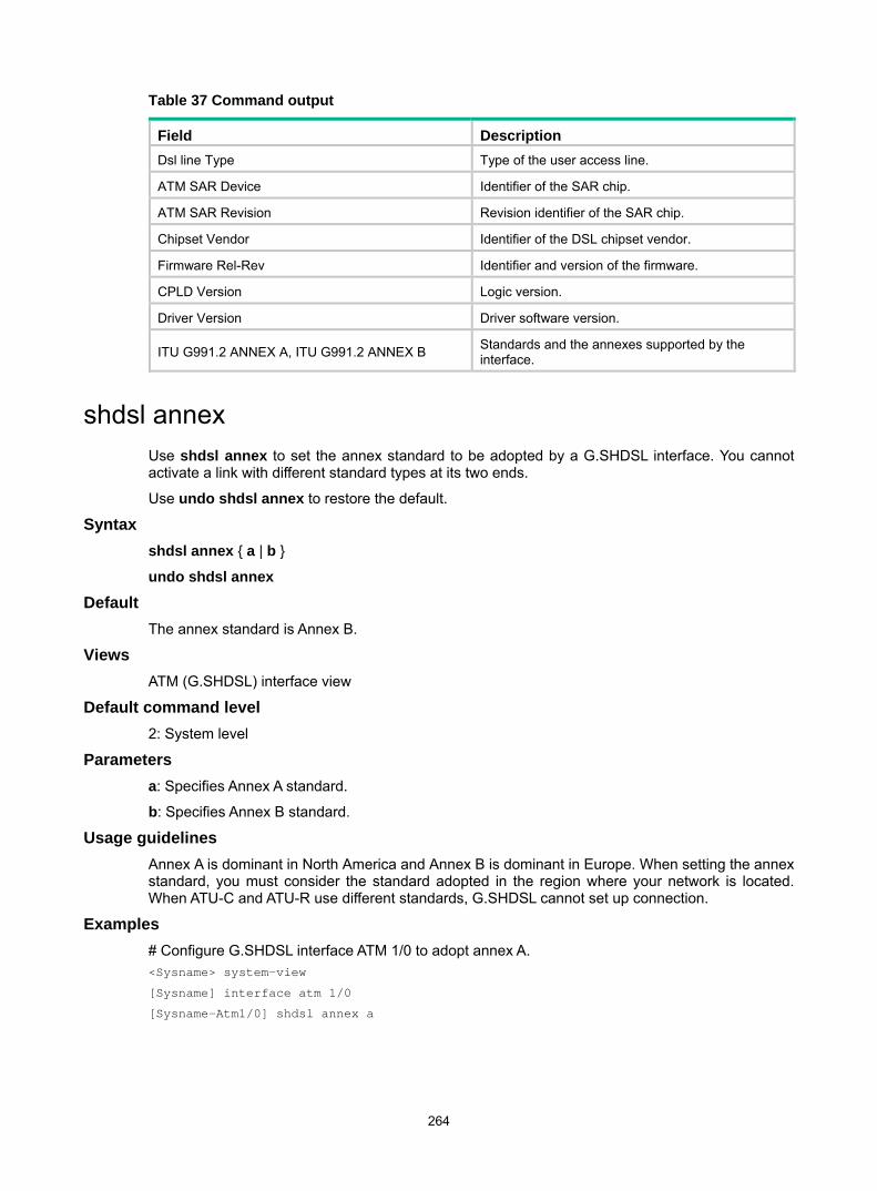
264
Table 37 Command output
Field Description Dsl line Type Type of the user access line.
ATM SAR Device Identifier of the SAR chip.
ATM SAR Revision Revision identifier of the SAR chip.
Chipset Vendor Identifier of the DSL chipset vendor.
Firmware Rel-Rev Identifier and version of the firmware.
CPLD Version Logic version.
Driver Version Driver software version.
ITU G991.2 ANNEX A, ITU G991.2 ANNEX B Standards and the annexes supported by the interface.
shdsl annex Use shdsl annex to set the annex standard to be adopted by a G.SHDSL interface. You cannot activate a link with different standard types at its two ends.
Use undo shdsl annex to restore the default.
Syntax shdsl annex { a | b }
undo shdsl annex
Default The annex standard is Annex B.
Views ATM (G.SHDSL) interface view
Default command level 2: System level
Parameters a: Specifies Annex A standard.
b: Specifies Annex B standard.
Usage guidelines Annex A is dominant in North America and Annex B is dominant in Europe. When setting the annex standard, you must consider the standard adopted in the region where your network is located. When ATU-C and ATU-R use different standards, G.SHDSL cannot set up connection.
Examples # Configure G.SHDSL interface ATM 1/0 to adopt annex A. <Sysname> system-view
[Sysname] interface atm 1/0
[Sysname-Atm1/0] shdsl annex a
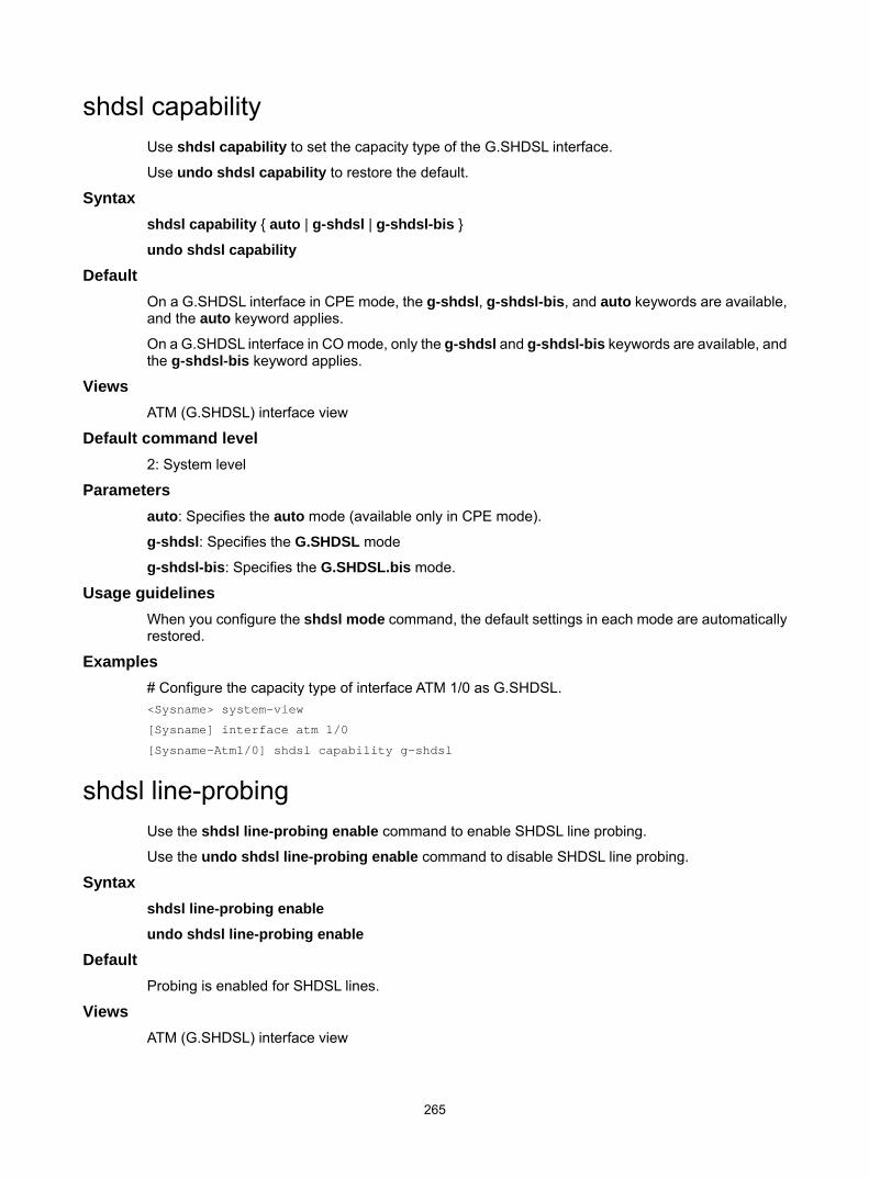
265
shdsl capability Use shdsl capability to set the capacity type of the G.SHDSL interface.
Use undo shdsl capability to restore the default.
Syntax shdsl capability { auto | g-shdsl | g-shdsl-bis }
undo shdsl capability
Default On a G.SHDSL interface in CPE mode, the g-shdsl, g-shdsl-bis, and auto keywords are available, and the auto keyword applies.
On a G.SHDSL interface in CO mode, only the g-shdsl and g-shdsl-bis keywords are available, and the g-shdsl-bis keyword applies.
Views ATM (G.SHDSL) interface view
Default command level 2: System level
Parameters auto: Specifies the auto mode (available only in CPE mode).
g-shdsl: Specifies the G.SHDSL mode
g-shdsl-bis: Specifies the G.SHDSL.bis mode.
Usage guidelines When you configure the shdsl mode command, the default settings in each mode are automatically restored.
Examples # Configure the capacity type of interface ATM 1/0 as G.SHDSL. <Sysname> system-view
[Sysname] interface atm 1/0
[Sysname-Atm1/0] shdsl capability g-shdsl
shdsl line-probing Use the shdsl line-probing enable command to enable SHDSL line probing.
Use the undo shdsl line-probing enable command to disable SHDSL line probing.
Syntax shdsl line-probing enable undo shdsl line-probing enable
Default Probing is enabled for SHDSL lines.
Views ATM (G.SHDSL) interface view
266
Default command level 2: System level
Usage guidelines With line probing enabled, the system performs the line probing function to find the highest possible data transmission rate during line activation. With line probing disabled, the system chooses the highest data transmission rate from the data transmission rates supported by both the CPE and CO. In the latter case, because the line rate adaptation process is skipped, the time for activating the SHDSL lines is reduced.
Examples # Disable SHDSL line probing on interface ATM 1/0. <Sysname> system-view
[Sysname] interface atm 1/0
[Sysname-Atm1/0] undo shdsl line-probing enable
shdsl mode Use shdsl mode to set the operating mode for a G.SHDSL interface.
Use undo shdsl mode to restore the default.
Syntax shdsl mode { co | cpe }
undo shdsl mode
Default A G.SHDSL interface operates in CPE mode.
Views ATM (G.SHDSL) interface view
Default command level 2: System level
Parameters co: Specifies the central office (CO) mode.
cpe: Specifies the Customer Premises Equipment (CPE) mode.
Usage guidelines For a back-to-back connection, configure one end to CO mode and the other end to CPE mode.
Examples # Set the operating mode of interface ATM 1/0 to CO. <Sysname> system-view
[Sysname] interface atm 1/0
[Sysname-Atm1/0] shdsl mode co
shdsl pam Use shdsl pam to set the PAM constellation for the G.SHDSL interface.
Use undo shdsl pam to restore the default.
267
Syntax shdsl pam { 16 | 32 | auto }
undo shdsl pam
Views ATM (G.SHDSL) interface view
Default command level 2: System level
Parameters 16: Specifies the interface to use 16-Pulse Amplitude Modulation (16-PAM) constellation, where the rate range is 192 to 3840 kbps.
32: Specifies the interface to use 32-PAM constellation, where the rate range is 768 to 5696 in kbps.
auto: Specifies the interface to select its PAM automatically.
Usage guidelines On G.SHDSL interfaces, the 16 and auto keywords are available, and the auto keyword applies by default.
On G.SHDSL.bis interfaces, the 16, 32, and auto keywords are available, and the auto keyword applies by default.
When both the shdsl mode cpe command and the shdsl capability auto command are configured, if the current interface is a G.SHDSL.bis interface, the shdsl pam 32 command can be configured on the interface. If the current interface is a G.SHDSL interface, the configured shdsl pam 32 command does not take effect.
Examples # Configure interface ATM 1/0 to use 16-PAM constellation. <Sysname> system-view
[Sysname] interface atm 1/0
[Sysname-Atm1/0] shdsl pam 16
shdsl pbo Use shdsl pbo to set the PBO value.
Use undo shdsl pbo to restore the default.
Syntax shdsl pbo { value | auto }
undo shdsl pbo
Default Keyword auto is selected.
Views ATM (G.SHDSL) interface view
Default command level 2: System level
Parameters auto: Automatically tunes the transmit power.
268
value: Power backoff (PBO) value (in dB), which restricts the transmit power. The value range for this argument is 0 to 6.
Usage guidelines A G.SHDSL interface automatically tunes its transmission power according to the line noise to ensure an appropriate signal-to-noise ratio. However, when the line noise is known, or when the automatically-tuned value is inaccurate, use this command to manually tune the transmission power.
Examples # Set the tunable value of G.SHDSL interface ATM 1/0’s transmission power to 20 dB. <Sysname> system-view
[Sysname] interface atm 1/0
[Sysname-Atm1/0] shdsl pbo 20
shdsl psd Use shdsl psd to set PSD of the G.SHDSL interface working as CPE.
Use undo shdsl psd to restore the default.
Syntax shdsl psd { asymmetry | symmetry }
undo shdsl psd
Default The PSD of the G.SHDSL interface is in symmetric mode.
Views ATM (G.SHDSL) interface view
Default command level 2: System level
Parameters asymmetry: Specifies the asymmetric mode, where different power spectral densities (PSD) are set for the central office (CO) and the Customer Premises Equipment (CPE).
symmetry: Specifies the symmetric mode, where the same PSD is set for the CO and CPE.
Usage guidelines PSD is the amount of power per unit (density) of frequency (spectral) as a function of the frequency. PSD describes how the power of a time series is distributed with frequency.
Examples # Set the PSD of G.SHDSL interface ATM 1/0 to asymmetric mode. <Sysname> system-view
[Sysname] interface atm 1/0
[Sysname-Atm1/0] shdsl psd asymmetry
shdsl rate Use shdsl rate to set the single-pair interface rate of the SHDSL interface.
Use undo shdsl rate to restore the default.
269
Syntax shdsl rate { auto | rate }
undo shdsl rate
Default Auto applies.
Default The rate of two-wire G.SHDSL interface is set to auto-negotiation mode; the single-pair interface rate of four-wire G.SHDSL interface is set to 2,312 kbps (four-wire G.SHDSL interface rate is 4,624 kbps); the rate of two-wire and four-wire G.SHDSL.bis interfaces is set to auto-negotiation mode.
Views ATM (G.SHDSL) interface view
Default command level 2: System level
Parameters auto: Auto-negotiation mode.
rate: Maximum single-pair rate of the G.SHDSL interface, in the range of 64 to 2,312, in units of kbps.
Usage guidelines For four-wire (dual-pair) G.SHDSL, the interface rate is two times single-pair rate. For example, if you set single-pair rate to 2,312 kbps, four-wire interface rate is 4,624 kbps.
Because four-wire G.SHDSL interfaces cannot negotiate rate, do not set their single-pair interface rate to auto mode.
The value range for the single-pair interface rate of the G.SHDSL.bis interface is 192 to 5696 kbps.
In actual applications, the maximum downlink rate is not likely to reach the specified rate as restricted by ATU-C and line conditions. If you select the auto mode, CPE and CO can negotiate a rate commensurate with the current line condition during the activation process. If fixed rates are set at both ends, the two parties negotiate a rate. In case the lower rate between them cannot be provided, the line cannot be activated.
Examples # Configure ATM 1/0 to operate in the auto-negotiation mode. <Sysname> system-view
[Sysname] interface atm 1/0
[Sysname-Atm1/0] shdsl rate auto
shdsl snr-margin Use shdsl snr-margin to set a target margin to signal-to-noise ratio (SNR).
Use undo shdsl snr-margin to restore the default.
Syntax shdsl snr-margin [ current current-margin-value ] [ snext snext-margin-value ]
undo shdsl snr-margin
Default Current-margin-value is set to 2 and snext-margin-value is set to 0.
270
Views ATM (G.SHDSL) interface view
Default command level 2: System level
Parameters current current-margin-value: Sets a target margin in the range of 0 to 10. During SHDSL line training, this target margin is considered in addition to the signal-to-noise ratio (SNR) threshold. A larger margin value means increased link stability and noise suppression ability.
snext snext-margin-value: Sets a target margin in the range of 0 to 10. During SHDSL line training, this target margin is considered in addition to the SNEXT threshold. A larger margin value means increased link stability and noise suppression ability.
Usage guidelines Setting the margin can affect the maximum rate of the line. When the line condition is good, you can set a small margin to obtain higher rates. When the line is noisy, a small margin might cause disconnections.
Examples # Set the SNR target margin to 5 on interface ATM 1/0. <Sysname> system-view
[Sysname] interface atm 1/0
[Sysname-Atm1/0] shdsl snr-margin current 5
shdsl wire Use shdsl wire to set the operating mode of the current G.SHDSL interface.
Use undo shdsl wire to restore the default.
Syntax shdsl wire { 2 | 4-auto-enhanced | 4-enhanced | 4-standard | 6 | 8 | auto }
undo shdsl wire
Default Four-wire G.SHDSL interfaces (interfaces on MIM-1SHL-4W and FIC-1SHL-4W modules) operate in four-wire enhanced mode, four-wire G.SHDSL.BIS interfaces (fixed G.SHDSL.BIS interfaces on MSR 20-13) operate in four-wire standard mode, and eight-wire G.SHDSL.BIS interfaces (interfaces on DSIC-1SHDSL-8W modules) operate in eight-wire mode.
Views ATM (G. SHDSL) interface view
Default command level 2: System level
Parameters 2: Specifies two-wire mode.
4-auto-enhanced: Specifies four-wire automatic mode. The four-wire enhanced mode is used first when the local end negotiates with the remote end. If the remote end is not operating in four-wire enhanced mode, the local end uses the four-wire standard mode for negotiation.
4-enhanced: Specifies four-wire enhanced mode. In this mode, one pair of the four wires starts negotiation with the remote end first, and then the other pair starts negotiation with the remote end.
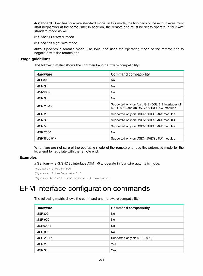
271
4-standard: Specifies four-wire standard mode. In this mode, the two pairs of these four wires must start negotiation at the same time; in addition, the remote end must be set to operate in four-wire standard mode as well.
6: Specifies six-wire mode.
8: Specifies eight-wire mode.
auto: Specifies automatic mode. The local end uses the operating mode of the remote end to negotiate with the remote end.
Usage guidelines The following matrix shows the command and hardware compatibility:
Hardware Command compatibility MSR800 No
MSR 900 No
MSR900-E No
MSR 930 No
MSR 20-1X Supported only on fixed G.SHDSL.BIS interfaces of MSR 20-13 and on DSIC-1SHDSL-8W modules
MSR 20 Supported only on DSIC-1SHDSL-8W modules
MSR 30 Supported only on DSIC-1SHDSL-8W modules
MSR 50 Supported only on DSIC-1SHDSL-8W modules
MSR 2600 No
MSR3600-51F Supported only on DSIC-1SHDSL-8W modules
When you are not sure of the operating mode of the remote end, use the automatic mode for the local end to negotiate with the remote end.
Examples # Set four-wire G.SHDSL interface ATM 1/0 to operate in four-wire automatic mode. <Sysname> system-view
[Sysname] interface atm 1/0
[Sysname-Atm1/0] shdsl wire 4-auto-enhanced
EFM interface configuration commands The following matrix shows the command and hardware compatibility:
Hardware Command compatibility MSR800 No
MSR 900 No
MSR900-E No
MSR 930 No
MSR 20-1X Supported only on MSR 20-13
MSR 20 Yes
MSR 30 Yes
272
Hardware Command compatibility MSR 50 Yes
MSR 2600 No
MSR3600-51F Yes
interface efm Use interface efm to enter the view of an EFM interface.
Syntax interface efm interface-number
Views System view
Default command level 2: System level
Parameters interface-number: Interface number of an EFM interface
Examples # Enter the view of EFM interface EFM 0/0. <Sysname> system-view
[Sysname] interface efm 0/0
[Sysname-Efm0/0]
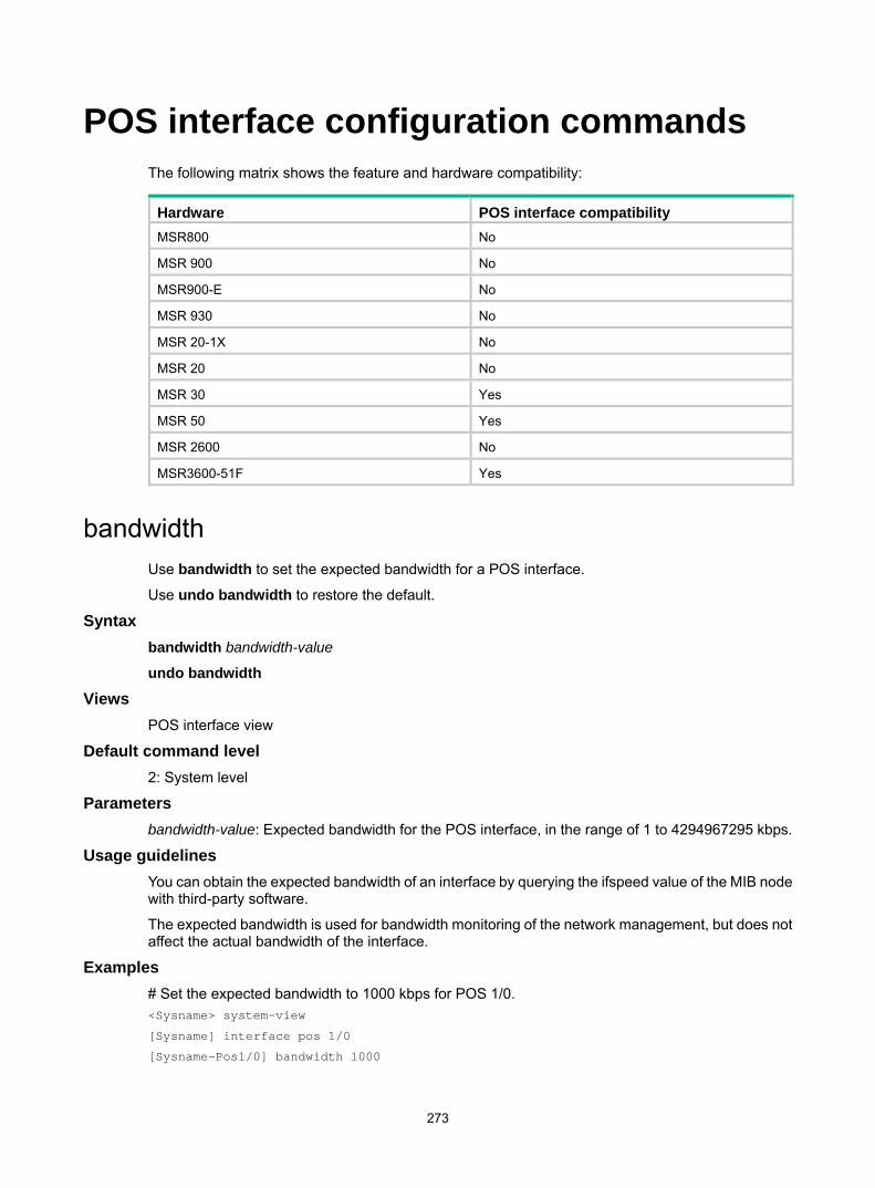
273
POS interface configuration commands The following matrix shows the feature and hardware compatibility:
Hardware POS interface compatibility MSR800 No
MSR 900 No
MSR900-E No
MSR 930 No
MSR 20-1X No
MSR 20 No
MSR 30 Yes
MSR 50 Yes
MSR 2600 No
MSR3600-51F Yes
bandwidth Use bandwidth to set the expected bandwidth for a POS interface.
Use undo bandwidth to restore the default.
Syntax bandwidth bandwidth-value
undo bandwidth
Views POS interface view
Default command level 2: System level
Parameters bandwidth-value: Expected bandwidth for the POS interface, in the range of 1 to 4294967295 kbps.
Usage guidelines You can obtain the expected bandwidth of an interface by querying the ifspeed value of the MIB node with third-party software.
The expected bandwidth is used for bandwidth monitoring of the network management, but does not affect the actual bandwidth of the interface.
Examples # Set the expected bandwidth to 1000 kbps for POS 1/0. <Sysname> system-view
[Sysname] interface pos 1/0
[Sysname-Pos1/0] bandwidth 1000
274
clock Use clock to set the clock mode of a POS interface.
Use undo clock to restore the default.
Syntax clock { master | slave }
undo clock
Default The clock mode is slave.
Views POS interface view
Default command level 2: System level
Parameters master: Sets the clock mode to master.
slave: Sets the clock mode to slave.
Usage guidelines POS interfaces support the following clock modes: • Master—Uses internal clock signal. • Slave—Uses line clock signal.
When two POS interfaces are directly connected, you must configure the two ends with different clock modes.
When connected to a SONET/SDH device, the POS interface must use the slave clock. The SONET/SDH network clock is more precise than the internal clock source of the POS interface.
Examples # Set the clock mode of POS 1/0 to master. <Sysname> system-view
[Sysname] interface pos 1/0
[Sysname-Pos1/0] clock master
crc Use crc to set the CRC length on a POS interface.
Use undo crc to restore the default.
Syntax crc { 16 | 32 }
undo crc
Default The CRC length is 32 bits.
Views POS interface view
275
Default command level 2: System level
Parameters 16: Sets the cyclic redundancy check (CRC) length to 16 bits.
32: Sets the CRC length to 32 bits.
Usage guidelines The CRC length must be the same on both ends.
Examples # Set the CRC length on Pos 1/0 to 16 bits. <Sysname> system-view
[Sysname] interface pos 1/0
[Sysname-Pos1/0] crc 16
default Use default to restore the default settings for a POS interface.
Syntax default
Views POS interface view
Default command level 2: System level
Usage guidelines
CAUTION: The default command might interrupt ongoing network services. Make sure you are fully aware of the impacts of this command when you use it on a live network.
This command might fail to restore the default settings for some commands for reasons such as command dependencies and system restrictions. Use the display this command in interface view to identify these commands, and then use their undo forms or follow the command reference to individually restore their default settings. If your restoration attempt still fails, follow the error message instructions to resolve the problem.
Examples # Restore the default settings of POS 2/0. <Sysname> system-view
[Sysname] interface pos 1/0
[Sysname-Pos1/0] default
This command will restore the default settings. Continue? [Y/N]:y
description Use description to set the description for a POS interface.
Use undo description to restore the default.
276
Syntax description text
undo description
Default The description of a POS interface is interface name Interface, for example, Pos2/0 Interface.
Views POS interface view
Default command level 2: System level
Parameters text: Interface description, a case-sensitive character string of 1 to 240 characters. The string can include case-sensitive letters, digits, special characters such as tilde (~), exclamation point (!), at sign (@), pound sign (#), dollar sign ($), percent sign (%), caret (^), ampersand sign (&), asterisk (*), left brace({), right brace (}), left parenthesis ((), right parenthesis ()), left bracket ([), right bracket (]), left angle bracket (<), right angle bracket (>), hyphen (-), underscore(_), plus sign (+), equal sign (=), vertical bar (|), back slash (\), colon (:), semi-colon (;) quotation marks ("), apostrophe ('), comma (,), dot (.), and slash (/), spaces, and other Unicode characters and symbols.
Examples # Set the description for POS 1/0 to pos-interface. <Sysname> system-view
[Sysname] interface pos 1/0
[Sysname-Pos1/0] description pos-interface
display interface pos Use display interface pos to display information about POS interfaces.
Syntax display interface [ pos ] [ brief [ down | description ] ] [ | { begin | exclude | include } regular-expression ]
display interface pos interface-number [ brief [ description ] ] [ | { begin | exclude | include } regular-expression ]
Views Any view
Default command level 1: Monitor level
Parameters interface-number: Specifies a POS interface by its number.
brief: Displays brief interface information. If you do not specify this keyword, the command displays detailed interface information.
down: Displays information about interfaces in the DOWN state and the causes. If you do not specify this keyword, this command displays information about interfaces in all states.
description: Displays complete interface descriptions. If you do not specify this keyword, the command displays only the first 27 characters of interface descriptions.
277
|: Filters command output by specifying a regular expression. For more information about regular expressions, see Fundamentals Configuration Guide.
begin: Displays the first line that matches the specified regular expression and all lines that follow.
exclude: Displays all lines that do not match the specified regular expression.
include: Displays all lines that match the specified regular expression.
regular-expression: Specifies a regular expression, a case-sensitive string of 1 to 256 characters.
Usage guidelines If you do not specify the pos keyword, this command displays information about all interfaces on the device.
If you specify the pos keyword without the interface-number argument, this command displays information about all existing POS interfaces.
Examples # Display detailed information about POS 8/0. <Sysname> display interface pos 8/0
Pos8/0 current state: DOWN
Line protocol current state: DOWN
Description: Pos8/0 Interface
The Maximum Transmit Unit is 1500, Hold timer is 10(sec)
Internet Address is 5.5.5.2/24 Primary
Link layer protocol is PPP
LCP initial
Physical layer is Packet Over SONET, Baudrate is 155520000 bps
Scramble enabled, crc 32, clock slave, loopback not set
Output queue : (Urgent queuing : Size/Length/Discards) 0/100/0
Output queue : (Protocol queuing : Size/Length/Discards) 0/500/0
Output queue : (FIFO queuing : Size/Length/Discards) 0/75/0
SDH alarm:
section layer: OOF LOF LOS
line layer: AIS
path layer: AIS RDI
C2(Rx): 0xff C2(Tx): 0x16
Rx: J0: unknown
Tx: J0: ""
Rx: J1: unknown
Tx: J1: ""
SDH error:
section layer: B1 65535
line layer: B2 0 M1 0
path layer: B3 0 G1 0
Last clearing of counters: Never
Last 300 seconds input rate 0 bytes/sec, 0 bits/sec, 0 packets/sec
Last 300 seconds output rate 0 bytes/sec, 0 bits/sec, 0 packets/sec
Input: 0 packets, 0 bytes
0 errors, 0 runts, 0 giants, 0 CRC,
0 overruns, 0 aborts, 0 no buffers
Output:0 packets, 0 bytes
0 errors, 0 underruns, 0 aborts
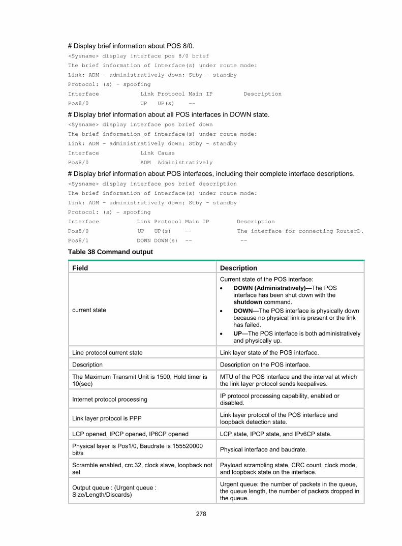
278
# Display brief information about POS 8/0. <Sysname> display interface pos 8/0 brief
The brief information of interface(s) under route mode:
Link: ADM - administratively down; Stby - standby
Protocol: (s) - spoofing
Interface Link Protocol Main IP Description
Pos8/0 UP UP(s) --
# Display brief information about all POS interfaces in DOWN state. <Sysname> display interface pos brief down
The brief information of interface(s) under route mode:
Link: ADM - administratively down; Stby - standby
Interface Link Cause
Pos8/0 ADM Administratively
# Display brief information about POS interfaces, including their complete interface descriptions. <Sysname> display interface pos brief description
The brief information of interface(s) under route mode:
Link: ADM - administratively down; Stby - standby
Protocol: (s) - spoofing
Interface Link Protocol Main IP Description
Pos8/0 UP UP(s) -- The interface for connecting RouterD.
Pos8/1 DOWN DOWN(s) -- --
Table 38 Command output
Field Description
current state
Current state of the POS interface: • DOWN (Administratively)—The POS
interface has been shut down with the shutdown command.
• DOWN—The POS interface is physically down because no physical link is present or the link has failed.
• UP—The POS interface is both administratively and physically up.
Line protocol current state Link layer state of the POS interface.
Description Description on the POS interface.
The Maximum Transmit Unit is 1500, Hold timer is 10(sec)
MTU of the POS interface and the interval at which the link layer protocol sends keepalives.
Internet protocol processing IP protocol processing capability, enabled or disabled.
Link layer protocol is PPP Link layer protocol of the POS interface and loopback detection state.
LCP opened, IPCP opened, IP6CP opened LCP state, IPCP state, and IPv6CP state.
Physical layer is Pos1/0, Baudrate is 155520000 bit/s Physical interface and baudrate.
Scramble enabled, crc 32, clock slave, loopback not set
Payload scrambling state, CRC count, clock mode, and loopback state on the interface.
Output queue : (Urgent queue : Size/Length/Discards)
Urgent queue: the number of packets in the queue, the queue length, the number of packets dropped in the queue.
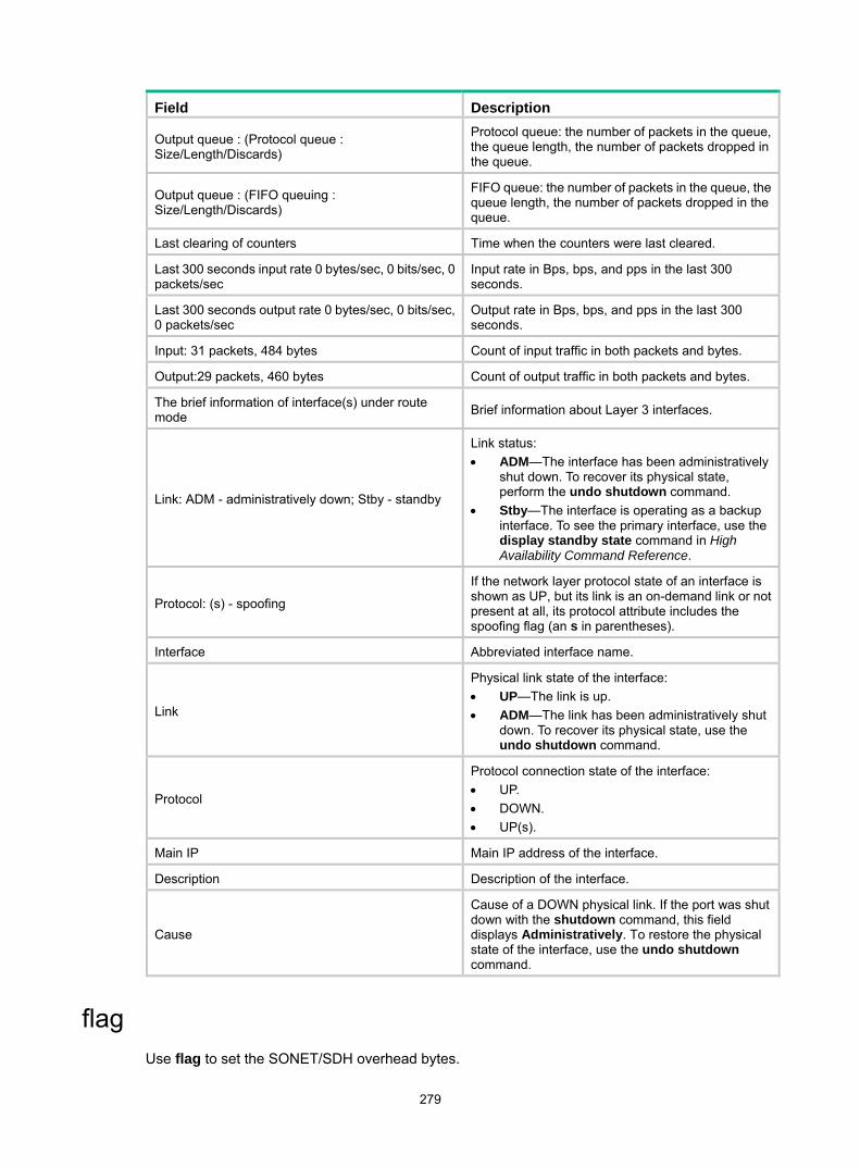
279
Field Description
Output queue : (Protocol queue : Size/Length/Discards)
Protocol queue: the number of packets in the queue, the queue length, the number of packets dropped in the queue.
Output queue : (FIFO queuing : Size/Length/Discards)
FIFO queue: the number of packets in the queue, the queue length, the number of packets dropped in the queue.
Last clearing of counters Time when the counters were last cleared.
Last 300 seconds input rate 0 bytes/sec, 0 bits/sec, 0 packets/sec
Input rate in Bps, bps, and pps in the last 300 seconds.
Last 300 seconds output rate 0 bytes/sec, 0 bits/sec, 0 packets/sec
Output rate in Bps, bps, and pps in the last 300 seconds.
Input: 31 packets, 484 bytes Count of input traffic in both packets and bytes.
Output:29 packets, 460 bytes Count of output traffic in both packets and bytes.
The brief information of interface(s) under route mode Brief information about Layer 3 interfaces.
Link: ADM - administratively down; Stby - standby
Link status: • ADM—The interface has been administratively
shut down. To recover its physical state, perform the undo shutdown command.
• Stby—The interface is operating as a backup interface. To see the primary interface, use the display standby state command in High Availability Command Reference.
Protocol: (s) - spoofing
If the network layer protocol state of an interface is shown as UP, but its link is an on-demand link or not present at all, its protocol attribute includes the spoofing flag (an s in parentheses).
Interface Abbreviated interface name.
Link
Physical link state of the interface: • UP—The link is up. • ADM—The link has been administratively shut
down. To recover its physical state, use the undo shutdown command.
Protocol
Protocol connection state of the interface: • UP. • DOWN. • UP(s).
Main IP Main IP address of the interface.
Description Description of the interface.
Cause
Cause of a DOWN physical link. If the port was shut down with the shutdown command, this field displays Administratively. To restore the physical state of the interface, use the undo shutdown command.
flag Use flag to set the SONET/SDH overhead bytes.
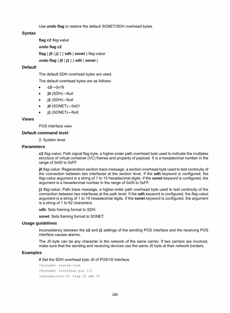
280
Use undo flag to restore the default SONET/SDH overhead bytes.
Syntax flag c2 flag-value
undo flag c2 flag { j0 | j1 } { sdh | sonet } flag-value
undo flag { j0 | j1 } { sdh | sonet }
Default The default SDH overhead bytes are used.
The default overhead bytes are as follows: • c2—0x16 • j0 (SDH)—Null • j1 (SDH)—Null • j0 (SONET)—0x01 • j1 (SONET)—Null
Views POS interface view
Default command level 2: System level
Parameters c2 flag-value: Path signal flag byte, a higher-order path overhead byte used to indicate the multiplex structure of virtual container (VC) frames and property of payload. It is a hexadecimal number in the range of 0x00 to 0xFF.
j0 flag-value: Regeneration section trace message, a section overhead byte used to test continuity of the connection between two interfaces at the section level. If the sdh keyword is configured, the flag-value argument is a string of 1 to 15 hexadecimal digits. If the sonet keyword is configured, the argument is a hexadecimal number in the range of 0x00 to 0xFF.
j1 flag-value: Path trace message, a higher-order path overhead byte used to test continuity of the connection between two interfaces at the path level. If the sdh keyword is configured, the flag-value argument is a string of 1 to 15 hexadecimal digits. If the sonet keyword is configured, the argument is a string of 1 to 62 characters.
sdh: Sets framing format to SDH.
sonet: Sets framing format to SONET.
Usage guidelines Inconsistency between the c2 and j1 settings of the sending POS interface and the receiving POS interface causes alarms.
The J0 byte can be any character in the network of the same carrier. If two carriers are involved, make sure that the sending and receiving devices use the same J0 byte at their network borders.
Examples # Set the SDH overhead byte J0 of POS1/0 interface. <Sysname> system-view
[Sysname] interface pos 1/0
[Sysname-Pos1/0] flag j0 sdh ff
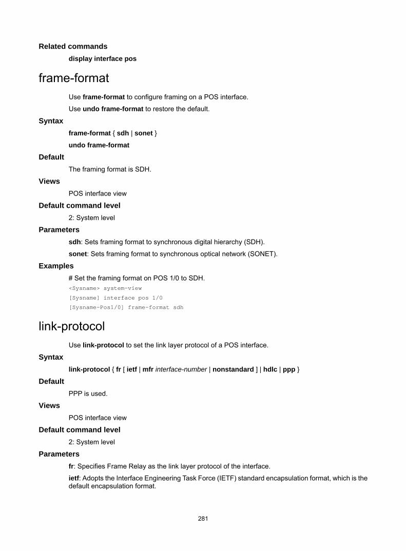
281
Related commands display interface pos
frame-format Use frame-format to configure framing on a POS interface.
Use undo frame-format to restore the default.
Syntax frame-format { sdh | sonet }
undo frame-format
Default The framing format is SDH.
Views POS interface view
Default command level 2: System level
Parameters sdh: Sets framing format to synchronous digital hierarchy (SDH).
sonet: Sets framing format to synchronous optical network (SONET).
Examples # Set the framing format on POS 1/0 to SDH. <Sysname> system-view
[Sysname] interface pos 1/0
[Sysname-Pos1/0] frame-format sdh
link-protocol Use link-protocol to set the link layer protocol of a POS interface.
Syntax link-protocol { fr [ ietf | mfr interface-number | nonstandard ] | hdlc | ppp }
Default PPP is used.
Views POS interface view
Default command level 2: System level
Parameters fr: Specifies Frame Relay as the link layer protocol of the interface.
ietf: Adopts the Interface Engineering Task Force (IETF) standard encapsulation format, which is the default encapsulation format.
282
mfr interface-number: MFR interface or subinterface number. The specified interface must be one that already exists.
nonstandard: Adopts non-IETF standard compatible encapsulation format.
hdlc: Specifies High-level Data Link Control (HDLC) as the link layer protocol of the interface.
ppp: Specifies the Point-to-Point protocol (PPP) as the link layer protocol of the interface.
Examples # Specify HDLC as the link protocol of POS 1/0. <Sysname> system-view
[Sysname] interface pos 1/0
[Sysname-Pos1/0] link-protocol hdlc
loopback Use loopback to enable loopback for a POS interface.
Use undo loopback to disable loopback.
Syntax loopback { local | remote }
undo loopback
Default Loopback is disabled.
Views POS interface view
Default command level 2: System level
Parameters local: Enables internal loopback.
remote: Enables external loopback.
Usage guidelines Loopback is intended for test use. Disable it otherwise.
If you enable loopback on a POS interface encapsulated with PPP, it is normal that the state of the link layer protocol is reported up.
Loopback and clock slave cannot be set at the same time. Otherwise, POS interfaces cannot be connected successfully.
Examples # Enable internal loopback on POS 1/0. <Sysname> system-view
[Sysname] interface pos 1/0
[Sysname-Pos1/0] loopback local
mtu Use mtu to set the MTU size of a POS interface.
283
Use undo mtu to restore the default.
Syntax mtu size
undo mtu
Views POS interface view
Default command level 2: System level
Parameters size: Specifies the size of the maximum transmission unit (MTU) in the range of 128 to 1650 bytes.
Usage guidelines The MTU setting affects the assembly and fragmentation of IP packets.
In QoS, the length of queues is limited. If the MTU of the interface is too small, a large packet might be fragmented into so many fragments that the queue cannot hold them and discard them. To avoid this situation, extend the queue length by using the qos fifo queue-length command in interface view. The default queuing mechanism on the interface is FIFO. For more information about queuing configuration, see ACL and QoS Configuration Guide.
Examples # Set the MTU of POS 1/0 to 1492. <Sysname> system-view
[Sysname] interface pos 1/0
[Sysname-Pos1/0] mtu 1492
Related commands display interface pos
reset counters interface Use reset counters interface to clear POS interface statistics.
Syntax reset counters interface [ pos [ interface-number ] ]
Views User view
Default command level 2: System level
Parameters pos interface-number: Specifies a POS interface by its number.
Usage guidelines Before collecting statistics for an interface within a specific period, you need to clear the existing statistics of the interface. • If you do not specify the pos keyword, this command clears the statistics of all interfaces. • If you specify the pos keyword but not the interface-number argument, this command clears the
statistics of all POS interfaces.

284
• If you specify both the pos keyword and the interface-number argument, this command clears the statistics of the specified POS interface.
Examples # Clear statistics for POS 8/0. <Sysname> reset counters interface pos 8/0
scramble Use scramble to enable payload scrambling on a POS interface.
Use undo scramble to disable payload scrambling.
Syntax scramble
undo scramble
Default Payload scrambling is enabled.
Views POS interface view
Default command level 2: System level
Usage guidelines You can configure payload scrambling to prevent the presence of too many consecutive 1s or 0s, to facilitate line clock signal extraction at the receiving end.
To connect POS interfaces, enable payload scrambling on both ends.
Examples # Enable payload scrambling on POS 1/0. <Sysname> system-view
[Sysname] interface pos 1/0
[Sysname-Pos1/0]scramble
shutdown Use shutdown to shut down a POS interface.
Use undo shutdown to bring up a POS interface.
Syntax shutdown
undo shutdown
Default A POS interface is up.
Views POS interface view
Default command level 2: System level

285
Usage guidelines When you modify parameters on a POS interface, execute the shutdown command, and then the undo shutdown command for the modification to take effect.
Examples # Shut down POS 1/0. <Sysname> system-view
[Sysname] interface pos 1/0
[Sysname-Pos1/0] shutdown
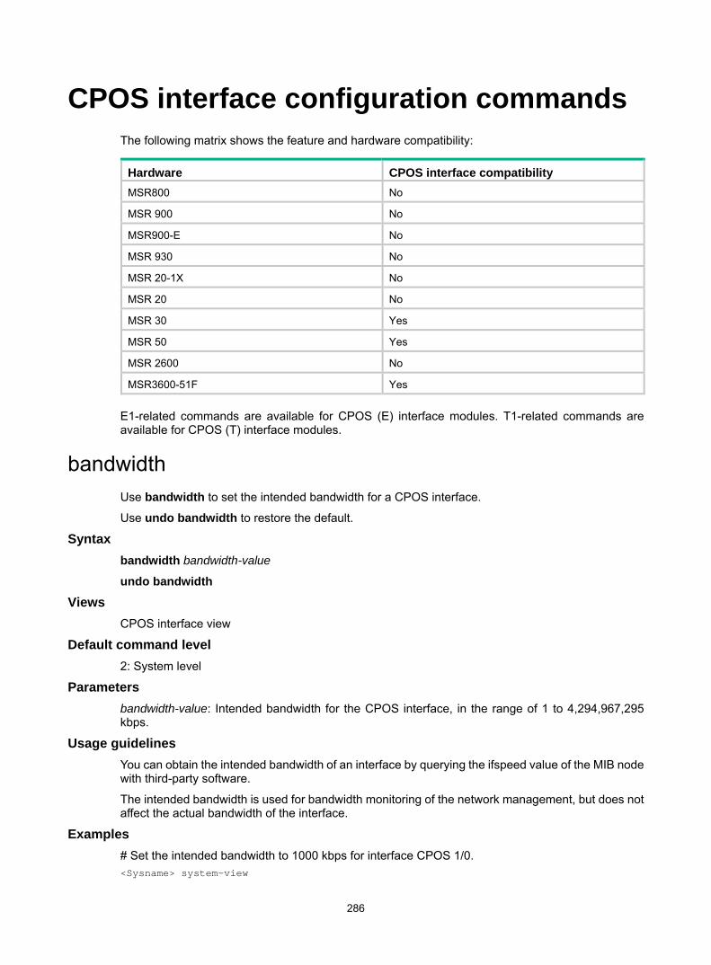
286
CPOS interface configuration commands The following matrix shows the feature and hardware compatibility:
Hardware CPOS interface compatibility MSR800 No
MSR 900 No
MSR900-E No
MSR 930 No
MSR 20-1X No
MSR 20 No
MSR 30 Yes
MSR 50 Yes
MSR 2600 No
MSR3600-51F Yes
E1-related commands are available for CPOS (E) interface modules. T1-related commands are available for CPOS (T) interface modules.
bandwidth Use bandwidth to set the intended bandwidth for a CPOS interface.
Use undo bandwidth to restore the default.
Syntax bandwidth bandwidth-value
undo bandwidth
Views CPOS interface view
Default command level 2: System level
Parameters bandwidth-value: Intended bandwidth for the CPOS interface, in the range of 1 to 4,294,967,295 kbps.
Usage guidelines You can obtain the intended bandwidth of an interface by querying the ifspeed value of the MIB node with third-party software.
The intended bandwidth is used for bandwidth monitoring of the network management, but does not affect the actual bandwidth of the interface.
Examples # Set the intended bandwidth to 1000 kbps for interface CPOS 1/0. <Sysname> system-view
287
[Sysname] controller cpos 1/0
[Sysname-Cpos1/0] bandwidth 1000
clock Use clock to set the clock mode of a CPOS interface.
Use undo clock to restore the default.
Syntax clock { master | slave }
undo clock
Default The clock mode of a CPOS interface is slave.
Views CPOS interface view
Default command level 2: System level
Parameters master: Sets the clock mode to master.
slave: Sets the clock mode to slave.
Usage guidelines When the clock mode of a CPOS interface is master, it uses the internal clock source.
When the clock mode of a CPOS interface is slave, it uses the line clock source.
When connected to a SONET/SDH device, the CPOS interface must use the slave clock. The SONET/SDH network clock is more precise than the clock provided by the device.
When two CPOS interfaces are directly connected, you must configure the two ends with different clock modes.
Examples # Set the clock mode of CPOS 1/0 to master. <Sysname> system-view
[Sysname] controller cpos 1/0
[Sysname-Cpos1/0] clock master
controller cpos Use controller cpos to enter CPOS interface view.
Syntax controller cpos cpos-number
Views System view
Default command level 2: System level
288
Parameters cpos-number: CPOS interface number.
Examples # Enter the interface view of CPOS 1/0. <Sysname> system-view
[Sysname] controller cpos 1/0
[Sysname-Cpos1/0]
default Use default to restore the default settings for a CPOS interface.
Syntax default
Views CPOS interface view
Default command level 2: System level
Usage guidelines
CAUTION: The default command might interrupt ongoing network services. Make sure you are fully aware of the impacts of this command when you use it on a live network.
This command might fail to restore the default settings for some commands for reasons such as command dependencies and system restrictions. Use the display this command in interface view to identify these commands, and then use their undo forms or follow the command reference to individually restore their default settings. If your restoration attempt still fails, follow the error message instructions to resolve the problem.
Examples # Restore the default settings of CPOS 1/0. <Sysname> system-view
[Sysname] controller cpos 1/0
[Sysname-Cpos1/0] default
This command will restore the default settings. Continue? [Y/N]:y
description Use description to set the description for a CPOS interface.
Use undo description to restore the default.
Syntax description text
undo description
Default The description of a CPOS interface is interface name Interface, for example, Cpos2/0 Interface.
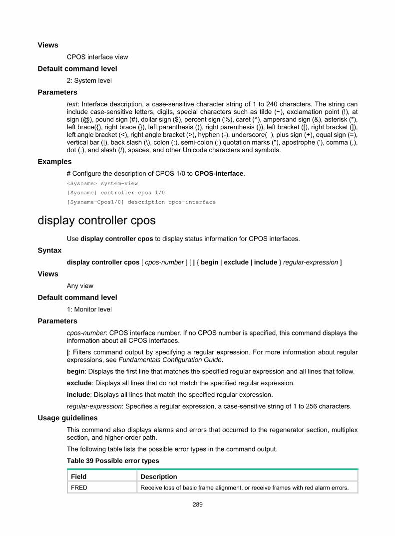
289
Views CPOS interface view
Default command level 2: System level
Parameters text: Interface description, a case-sensitive character string of 1 to 240 characters. The string can include case-sensitive letters, digits, special characters such as tilde (~), exclamation point (!), at sign (@), pound sign (#), dollar sign ($), percent sign (%), caret (^), ampersand sign (&), asterisk (*), left brace({), right brace (}), left parenthesis ((), right parenthesis ()), left bracket ([), right bracket (]), left angle bracket (<), right angle bracket (>), hyphen (-), underscore(_), plus sign (+), equal sign (=), vertical bar (|), back slash (\), colon (:), semi-colon (;) quotation marks ("), apostrophe ('), comma (,), dot (.), and slash (/), spaces, and other Unicode characters and symbols.
Examples # Configure the description of CPOS 1/0 to CPOS-interface. <Sysname> system-view
[Sysname] controller cpos 1/0
[Sysname-Cpos1/0] description cpos-interface
display controller cpos Use display controller cpos to display status information for CPOS interfaces.
Syntax display controller cpos [ cpos-number ] [ | { begin | exclude | include } regular-expression ]
Views Any view
Default command level 1: Monitor level
Parameters cpos-number: CPOS interface number. If no CPOS number is specified, this command displays the information about all CPOS interfaces.
|: Filters command output by specifying a regular expression. For more information about regular expressions, see Fundamentals Configuration Guide.
begin: Displays the first line that matches the specified regular expression and all lines that follow.
exclude: Displays all lines that do not match the specified regular expression.
include: Displays all lines that match the specified regular expression.
regular-expression: Specifies a regular expression, a case-sensitive string of 1 to 256 characters.
Usage guidelines This command also displays alarms and errors that occurred to the regenerator section, multiplex section, and higher-order path.
The following table lists the possible error types in the command output.
Table 39 Possible error types
Field Description FRED Receive loss of basic frame alignment, or receive frames with red alarm errors.
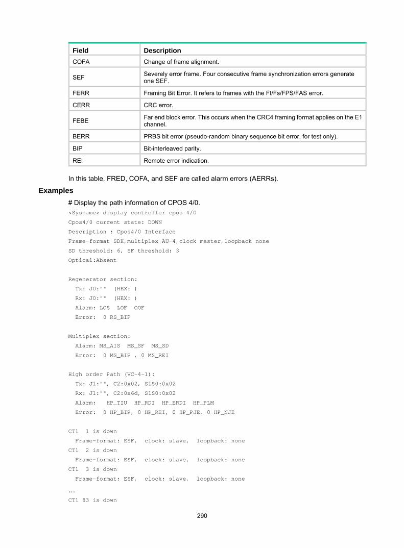
290
Field Description COFA Change of frame alignment.
SEF Severely error frame. Four consecutive frame synchronization errors generate one SEF.
FERR Framing Bit Error. It refers to frames with the Ft/Fs/FPS/FAS error.
CERR CRC error.
FEBE Far end block error. This occurs when the CRC4 framing format applies on the E1 channel.
BERR PRBS bit error (pseudo-random binary sequence bit error, for test only).
BIP Bit-interleaved parity.
REI Remote error indication.
In this table, FRED, COFA, and SEF are called alarm errors (AERRs).
Examples # Display the path information of CPOS 4/0. <Sysname> display controller cpos 4/0
Cpos4/0 current state: DOWN
Description : Cpos4/0 Interface
Frame-format SDH,multiplex AU-4,clock master,loopback none
SD threshold: 6, SF threshold: 3
Optical:Absent
Regenerator section:
Tx: J0:"" (HEX: )
Rx: J0:"" (HEX: )
Alarm: LOS LOF OOF
Error: 0 RS_BIP
Multiplex section:
Alarm: MS_AIS MS_SF MS_SD
Error: 0 MS_BIP , 0 MS_REI
High order Path (VC-4-1):
Tx: J1:"", C2:0x02, S1S0:0x02
Rx: J1:"", C2:0x6d, S1S0:0x02
Alarm: HP_TIU HP_RDI HP_ERDI HP_PLM
Error: 0 HP_BIP, 0 HP_REI, 0 HP_PJE, 0 HP_NJE
CT1 1 is down
Frame-format: ESF, clock: slave, loopback: none
CT1 2 is down
Frame-format: ESF, clock: slave, loopback: none
CT1 3 is down
Frame-format: ESF, clock: slave, loopback: none
… CT1 83 is down
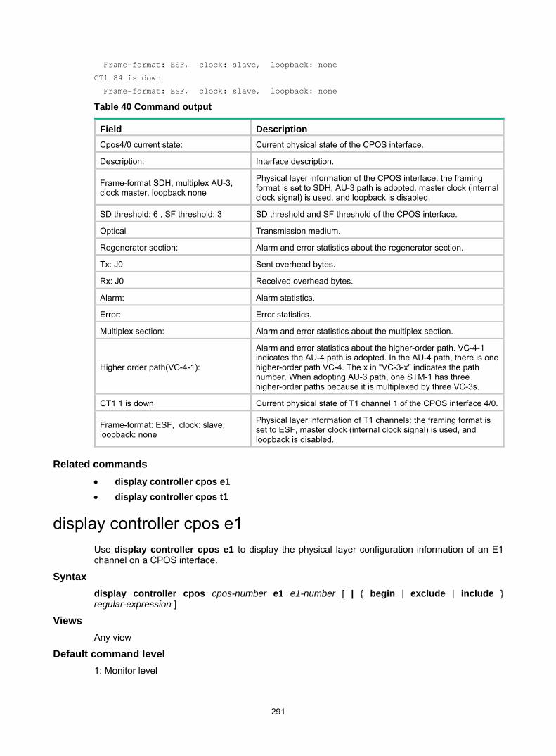
291
Frame-format: ESF, clock: slave, loopback: none
CT1 84 is down
Frame-format: ESF, clock: slave, loopback: none
Table 40 Command output
Field Description Cpos4/0 current state: Current physical state of the CPOS interface.
Description: Interface description.
Frame-format SDH, multiplex AU-3, clock master, loopback none
Physical layer information of the CPOS interface: the framing format is set to SDH, AU-3 path is adopted, master clock (internal clock signal) is used, and loopback is disabled.
SD threshold: 6 , SF threshold: 3 SD threshold and SF threshold of the CPOS interface.
Optical Transmission medium.
Regenerator section: Alarm and error statistics about the regenerator section.
Tx: J0 Sent overhead bytes.
Rx: J0 Received overhead bytes.
Alarm: Alarm statistics.
Error: Error statistics.
Multiplex section: Alarm and error statistics about the multiplex section.
Higher order path(VC-4-1):
Alarm and error statistics about the higher-order path. VC-4-1 indicates the AU-4 path is adopted. In the AU-4 path, there is one higher-order path VC-4. The x in "VC-3-x" indicates the path number. When adopting AU-3 path, one STM-1 has three higher-order paths because it is multiplexed by three VC-3s.
CT1 1 is down Current physical state of T1 channel 1 of the CPOS interface 4/0.
Frame-format: ESF, clock: slave, loopback: none
Physical layer information of T1 channels: the framing format is set to ESF, master clock (internal clock signal) is used, and loopback is disabled.
Related commands • display controller cpos e1 • display controller cpos t1
display controller cpos e1 Use display controller cpos e1 to display the physical layer configuration information of an E1 channel on a CPOS interface.
Syntax display controller cpos cpos-number e1 e1-number [ | { begin | exclude | include } regular-expression ]
Views Any view
Default command level 1: Monitor level
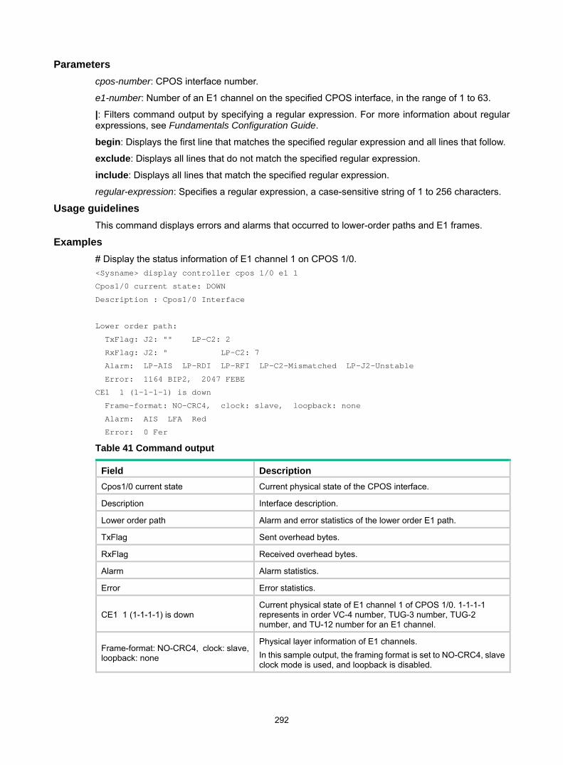
292
Parameters cpos-number: CPOS interface number.
e1-number: Number of an E1 channel on the specified CPOS interface, in the range of 1 to 63.
|: Filters command output by specifying a regular expression. For more information about regular expressions, see Fundamentals Configuration Guide.
begin: Displays the first line that matches the specified regular expression and all lines that follow.
exclude: Displays all lines that do not match the specified regular expression.
include: Displays all lines that match the specified regular expression.
regular-expression: Specifies a regular expression, a case-sensitive string of 1 to 256 characters.
Usage guidelines This command displays errors and alarms that occurred to lower-order paths and E1 frames.
Examples # Display the status information of E1 channel 1 on CPOS 1/0. <Sysname> display controller cpos 1/0 e1 1
Cpos1/0 current state: DOWN
Description : Cpos1/0 Interface
Lower order path:
TxFlag: J2: "" LP-C2: 2
RxFlag: J2: " LP -C2: 7
Alarm: LP-AIS LP-RDI LP-RFI LP-C2-Mismatched LP-J2-Unstable
Error: 1164 BIP2, 2047 FEBE
CE1 1 (1-1-1-1) is down
Frame-format: NO-CRC4, clock: slave, loopback: none
Alarm: AIS LFA Red
Error: 0 Fer
Table 41 Command output
Field Description Cpos1/0 current state Current physical state of the CPOS interface.
Description Interface description.
Lower order path Alarm and error statistics of the lower order E1 path.
TxFlag Sent overhead bytes.
RxFlag Received overhead bytes.
Alarm Alarm statistics.
Error Error statistics.
CE1 1 (1-1-1-1) is down Current physical state of E1 channel 1 of CPOS 1/0. 1-1-1-1 represents in order VC-4 number, TUG-3 number, TUG-2 number, and TU-12 number for an E1 channel.
Frame-format: NO-CRC4, clock: slave, loopback: none
Physical layer information of E1 channels. In this sample output, the framing format is set to NO-CRC4, slave clock mode is used, and loopback is disabled.
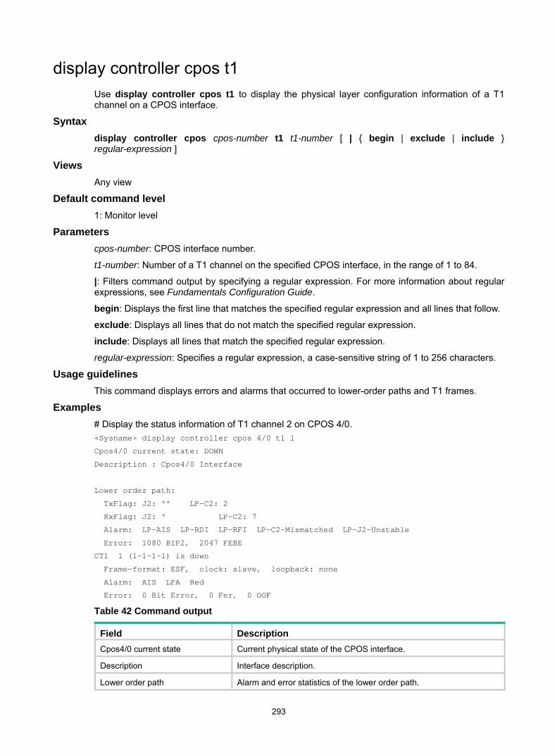
293
display controller cpos t1 Use display controller cpos t1 to display the physical layer configuration information of a T1 channel on a CPOS interface.
Syntax display controller cpos cpos-number t1 t1-number [ | { begin | exclude | include } regular-expression ]
Views Any view
Default command level 1: Monitor level
Parameters cpos-number: CPOS interface number.
t1-number: Number of a T1 channel on the specified CPOS interface, in the range of 1 to 84.
|: Filters command output by specifying a regular expression. For more information about regular expressions, see Fundamentals Configuration Guide.
begin: Displays the first line that matches the specified regular expression and all lines that follow.
exclude: Displays all lines that do not match the specified regular expression.
include: Displays all lines that match the specified regular expression.
regular-expression: Specifies a regular expression, a case-sensitive string of 1 to 256 characters.
Usage guidelines This command displays errors and alarms that occurred to lower-order paths and T1 frames.
Examples # Display the status information of T1 channel 2 on CPOS 4/0. <Sysname> display controller cpos 4/0 t1 1
Cpos4/0 current state: DOWN
Description : Cpos4/0 Interface
Lower order path:
TxFlag: J2: "" LP-C2: 2
RxFlag: J2: " LP-C2: 7
Alarm: LP-AIS LP-RDI LP-RFI LP-C2-Mismatched LP-J2-Unstable
Error: 1080 BIP2, 2047 FEBE
CT1 1 (1-1-1-1) is down
Frame-format: ESF, clock: slave, loopback: none
Alarm: AIS LFA Red
Error: 0 Bit Error, 0 Fer, 0 OOF
Table 42 Command output
Field Description Cpos4/0 current state Current physical state of the CPOS interface.
Description Interface description.
Lower order path Alarm and error statistics of the lower order path.
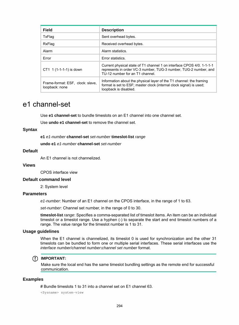
294
Field Description TxFlag Sent overhead bytes.
RxFlag Received overhead bytes.
Alarm Alarm statistics.
Error Error statistics.
CT1 1 (1-1-1-1) is down Current physical state of T1 channel 1 on interface CPOS 4/0. 1-1-1-1 represents in order VC-3 number, TUG-3 number, TUG-2 number, and TU-12 number for an T1 channel.
Frame-format: ESF, clock: slave, loopback: none
Information about the physical layer of the T1 channel: the framing format is set to ESF; master clock (internal clock signal) is used; loopback is disabled.
e1 channel-set Use e1 channel-set to bundle timeslots on an E1 channel into one channel set.
Use undo e1 channel-set to remove the channel set.
Syntax e1 e1-number channel-set set-number timeslot-list range
undo e1 e1-number channel-set set-number
Default An E1 channel is not channelized.
Views CPOS interface view
Default command level 2: System level
Parameters e1-number: Number of an E1 channel on the CPOS interface, in the range of 1 to 63.
set-number: Channel set number, in the range of 0 to 30.
timeslot-list range: Specifies a comma-separated list of timeslot items. An item can be an individual timeslot or a timeslot range. Use a hyphen (-) to separate the start and end timeslot numbers of a range. The value range for the timeslot number is 1 to 31.
Usage guidelines When the E1 channel is channelized, its timeslot 0 is used for synchronization and the other 31 timeslots can be bundled to form one or multiple serial interfaces. These serial interfaces use the interface number/channel number:channel set number format.
IMPORTANT: Make sure the local end has the same timeslot bundling settings as the remote end for successful communication.
Examples # Bundle timeslots 1 to 31 into a channel set on E1 channel 63. <Sysname> system-view
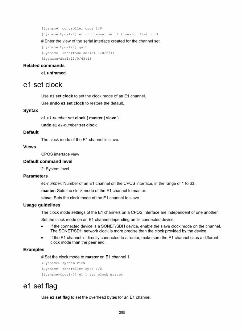
295
[Sysname] controller cpos 1/0
[Sysname-Cpos1/0] e1 63 channel-set 1 timeslot-list 1-31
# Enter the view of the serial interface created for the channel set. [Sysname-Cpos1/0] quit
[Sysname] interface serial 1/0/63:1
[Sysname-Serial1/0/63:1]
Related commands e1 unframed
e1 set clock Use e1 set clock to set the clock mode of an E1 channel.
Use undo e1 set clock to restore the default.
Syntax e1 e1-number set clock { master | slave }
undo e1 e1-number set clock
Default The clock mode of the E1 channel is slave.
Views CPOS interface view
Default command level 2: System level
Parameters e1-number: Number of an E1 channel on the CPOS interface, in the range of 1 to 63.
master: Sets the clock mode of the E1 channel to master.
slave: Sets the clock mode of the E1 channel to slave.
Usage guidelines The clock mode settings of the E1 channels on a CPOS interface are independent of one another.
Set the clock mode on an E1 channel depending on its connected device. • If the connected device is a SONET/SDH device, enable the slave clock mode on the channel.
The SONET/SDH network clock is more precise than the clock provided by the device. • If the E1 channel is directly connected to a router, make sure the E1 channel uses a different
clock mode than the peer end.
Examples # Set the clock mode to master on E1 channel 1. <Sysname> system-view
[Sysname] controller cpos 1/0
[Sysname-Cpos1/0] e1 1 set clock master
e1 set flag Use e1 set flag to set the overhead bytes for an E1 channel.

296
Use undo e1 set flag to restore the default E1 channel overhead bytes.
Syntax e1 e1-number set flag c2 c2-value undo e1 e1-number set flag c2 e1 e1-number set flag j2 { sdh | sonet } j2-string
undo e1 e1-number set flag j2 { sdh | sonet }
Default C2 is 0x02 and J2 is cyclic null.
Views CPOS interface view
Default command level 2: System level
Parameters e1-number: E1 channel number, in the range of 1 to 63.
c2: Specifies the low-order channel signal tag byte (C2).
c2-value: Low-order channel signal flag byte (C2) to be set, 1 byte in length and in the range of 0x0 to 0x7 (except 0x5).
j2: Specifies the low-order channel trace byte (J2).
sdh: Specifies the trace byte in SDH format.
sonet: Specifies the trace byte in SONET format.
j2-string: Low-order channel trace byte to be set, a string of 1 to 15 characters (in SDH format) or of 1 to 62 characters (in SONET format).
Examples # Set C2 to 0x7 for the E1 channel numbered 3 of CPOS 1/0. <Sysname> system-view
[Sysname] controller cpos 1/0
[Sysname-Cpos1/0] e1 3 set flag c2 7
e1 set frame-format Use e1 set frame-format to set the framing format of an E1 channel.
Use undo e1 set frame-format to restore the default.
Syntax e1 e1-number set frame-format { crc4 | no-crc4 }
undo e1 e1-number set frame-format
Default The framing format of an E1 channel is no-CRC4.
Views CPOS interface view
Default command level 2: System level
297
Parameters e1-number: Number of an E1 channel on the CPOS interface, in the range of 1 to 63.
crc4: Sets the framing format to CRC4.
no-crc4: Sets the framing format to no-CRC4.
Examples # Set E1 channel 1 to use the framing format CRC4. <Sysname> system-view
[Sysname] controller cpos 1/0
[Sysname-Cpos1/0] e1 1 set frame-format crc4
e1 set loopback Use e1 set loopback to set the loopback mode of the E1 channel.
Use undo e1 set loopback to disable loopback.
Syntax e1 e1-number set loopback { local | payload | remote }
undo e1 e1-number set loopback
Default Loopback is disabled.
Views CPOS interface view
Default command level 2: System level
Parameters e1-number: Number of an E1 channel on the CPOS interface, in the range of 1 to 63.
local: Enables internal loopback on the E1 channel.
payload: Enables external payload loopback on the E1 channel.
remote: Enables external loopback on the E1 channel.
Usage guidelines You can test E1 channels by using the loopback command with different keywords.
In an internal loopback, data of the sender is directly looped to the receiver.
In an external payload loopback, data received by the receiver is looped back at the E1 framer as payload.
In an external loopback, data received by the receiver is looped back directly without passing through the E1 framer.
Examples # Enable external payload loopback on E1 channel 1. <Sysname> system-view
[Sysname] controller cpos 1/0
[Sysname-Cpos1/0] e1 1 set loopback payload
298
Related commands display controller cpos e1
e1 shutdown Use e1 shutdown to shut down an E1 channel.
Use undo e1 shutdown to bring up an E1 channel.
Syntax e1 e1-number shutdown
undo e1 e1-number shutdown
Default E1 channels are up.
Views CPOS interface view
Default command level 2: System level
Parameters e1-number: Number of an E1 channel on the CPOS interface, in the range of 1 to 63.
Usage guidelines Shutting down an E1 channel also shuts down the serial interfaces that are formed on it.
Examples # Shut down E1 channel 1. <Sysname> system-view
[Sysname] controller cpos 1/0
[Sysname-Cpos1/0] e1 1 shutdown
e1 unframed Use e1 unframed to set an E1 channel on a CPOS interface to operate in unframed mode.
Use undo e1 unframed to restore the default.
Syntax e1 e1-number unframed undo e1 e1-number unframed
Default An E1 channel operates in framed mode.
Views CPOS interface view
Default command level 2: System level
Parameters e1-number: Number of an E1 channel on the CPOS interface, in the range of 1 to 63.
299
Usage guidelines So far, E1 channels on CPOS interfaces support two operating modes: clear channel (or unframed) and channelized (or framed). • In unframed mode, an E1 channel can form a 2.048 Mbps serial interface without timeslot
division. This interface uses the serial slot/port/e1-number:0 format. • In framed mode, all timeslots except timeslot 0 on the E1 channel can be bundled arbitrarily to
form serial interfaces.
Examples # Set E1 channel 3 on CPOS 1/0 to operate in unframed mode. <Sysname> system-view
[Sysname] controller cpos 1/0
[Sysname-Cpos1/0] e1 3 unframed
flag Use flag to set the overhead bytes of SONET/SDH frames.
Use undo flag to restore the default.
Syntax flag c2 path-number c2-value
undo flag c2 path-number
flag { j0 | j1 path-number } { sdh | sonet } flag-value
undo flag { j0 | j1 path-number } { sdh | sonet }
Views CPOS interface view
Default command level 2: System level
Parameters j0 flag-value: Specifies the regenerator section trace message, which is a section overhead byte used to detect the continuity of the connection between two interfaces at the section layer. With SDH frames, flag-value is a string of 1 to 15 characters; with SONET frames, flag-value is in the range of 0x00 to 0xFF. j1 path-number: Specifies the path trace message, which is a higher-order path overhead byte used to detect the continuity of the connection between two interfaces at the path layer. With SDH frames, flag-value is a string of 1 to 15 characters; with SONET frames, flag-value is a string of 1 to 62 characters.
sdh: Specifies the framing format as Synchronous Digital Hierarchy (SDH).
sonet: Specifies the framing format as Synchronous Optical Network (SONET). c2 path-number c2-value: The path-number argument is the number of a path. The c2-value argument specifies the path signal label byte. It is in the range of 0x00 to 0xFF and defaults to 0x02.
Usage guidelines SONET/SDH frames provide a variety of overhead bytes for operation and maintenance (OAM) such as layered management on transmission networks.
J1, J0 and C2 are used to support interoperability between devices from different countries, areas, and vendors.
300
J0 is a section overhead byte used for detecting the continuity of the connection between two interfaces at the section layer. J1 and C2 are higher-order path overhead bytes. The J1 byte is used for detecting the continuity of the connection between two interfaces at the path layer. The C2 byte is used for indicating the multiplexing structure of a VC frame and the property of payload.
Examples # Set J0 to aa on CPOS 1/0. <Sysname> system-view
[Sysname] controller cpos 1/0
[Sysname-Cpos1/0] flag j0 sdh aa
Related commands display controller cpos
frame-format Use frame-format to configure the framing format on a CPOS interface.
Use undo frame-format to restore the default.
Syntax frame-format { sdh | sonet }
undo frame-format
Default The framing format on the CPOS interface is SDH.
Views CPOS interface view
Default command level 2: System level
Parameters sdh: Sets framing format to synchronous digital hierarchy (SDH).
sonet: Sets framing format to synchronous optical network (SONET).
Examples # Set the framing format to SONET on CPOS 1/0. <Sysname> system-view
[Sysname] controller cpos 1/0
[Sysname-Cpos1/0] frame-format sonet
loopback Use loopback to configure the loopback mode on a CPOS interface.
Use undo loopback to disable loopback.
Syntax loopback { local | remote }
undo loopback
301
Default Loopback is disabled.
Views CPOS interface view
Default command level 2: System level
Parameters local: Internal loopback to test the physical interface.
remote: External loopback to test the cable connected to the interface.
Usage guidelines Loopback is intended for test only. Disable the feature when the interface is operating correctly.
Examples # Enable external loopback testing on CPOS 1/0. <Sysname> system-view
[Sysname] controller cpos 1/0
[Sysname-Cpos1/0] loopback remote
multiplex mode Use multiplex mode to set AUG multiplexing mode.
Use undo multiplex mode to restore the default.
Syntax multiplex mode { au-3 | au-4 }
undo multiplex mode
Default The AUG multiplexing mode is au-4.
Views CPOS interface view
Default command level 2: System level
Parameters au-3: Gets AUG through AU-3.
au-4: Gets AUG through AU-4.
Usage guidelines SDH provides two payload mapping/multiplexing solutions: ANSI and ETSI. • ANSI uses the AU-3 multiplexing scheme, where the lower-order payload is aggregated into the
VC-3 higher-order path. VC-3 plus an AU pointer forms AU-3. Three such AU-3s can be synchronized and multiplexed to form one AUG.
• ETSI uses the AU-4 multiplexing scheme, where the lower-order payload is aggregated into the VC-4 higher-order path. VC-4 plus an AU pointer forms an AU-4. This AU-4 can be synchronized and multiplexed to form one AUG.
302
When the CPOS interface is operating in SDH mode, you can choose to multiplex AUG to AU-4 or AU-3 by using the multiplex mode command. When the CPOS interface is operating in SONET mode, AUG can be multiplexed only to AU-3 and the multiplex mode command is invalid.
Examples # In SDH mode, multiplex AUG to AU-3. <Sysname> system-view
[Sysname] controller cpos 1/0
[Sysname-Cpos1/0] frame-format sdh
[Sysname-Cpos1/0] multiplex mode au-3
Related commands frame-format
reset counters controller cpos Use reset counters controller cpos to clear the controller counter of a CPOS interface.
Syntax reset counters controller cpos interface-number
Views User view
Default command level 2: System level
Parameters interface-number: Interface number.
Usage guidelines You can use the display controller cpos command to display the controller counter.
The reset counters interface command clears the controller counters of all interfaces. To clear the controller counters of individual CPOS interfaces, use the reset counters controller cpos command.
Examples # Clear the controller counter of CPOS 2/0. <Sysname> reset counters controller cpos 2/0
shutdown Use shutdown to shut down a CPOS physical interface.
Use undo shutdown to bring up a CPOS physical interface.
Syntax shutdown undo shutdown
Default The CPOS physical interface is up.
Views CPOS interface view
303
Default command level 2: System level
Usage guidelines The shutdown command on the CPOS physical interface shuts down all E1/T1 channels and serial interfaces formed by timeslot bundles. They stop transmitting and receiving data as a result. To bring up them, use the undo shutdown command on the CPOS physical interface.
Examples # Shut down CPOS 1/0. <Sysname> system-view
[Sysname] controller cpos 1/0
[Sysname-Cpos1/0] shutdown
t1 channel-set Use t1 channel-set to bundle timeslots on a T1 channel.
Use undo t1 channel-set to remove the bundle.
Syntax t1 t1-number channel-set set-number timeslot-list range [ speed { 56k | 64k } ]
undo t1 t1-number channel-set set-number
Default A T1 channel is not channelized.
Views CPOS interface view
Default command level 2: System level
Parameters t1-number: Number of a T1 channel on the CPOS interface, in the range of 1 to 84.
set-number: Channel set number, in the range of 0 to 23.
timeslot-list range: Specifies a comma-separated list of timeslot items. An item can be an individual timeslot or a timeslot range. Use a hyphen (-) to separate the start and end timeslot numbers of a range. The value range for the timeslot number is 1 to 24.
speed: Specifies how timeslots are bundled. If the 56k keyword applies, timeslots form an N × 56 kbps bundle. If 64k applies, timeslots form an N × 64 kbps bundle. If the speed is not specified, the default 64 kbps applies.
Usage guidelines The serial interface formed by a timeslot bundle uses the interface number/channel number:channel set number format.
IMPORTANT: Make sure the local end has the same timeslot bundling settings as the remote end for successful communication.
Examples # Bundle timeslots 1 through 23 into a channel set on T1 channel 1.
304
<Sysname> system-view
[Sysname] controller cpos 1/0
[Sysname-Cpos1/0] t1 1 channel-set 1 timeslot-list 1-23
# Enter the view the serial interface created for the channel set. [Sysname-Cpos1/0] quit
[Sysname] interface serial 1/0/1:1
[Sysname-Serial1/0/1:1]
Related commands t1 unframed
t1 set clock Use t1 set clock to set the clock mode of a T1 channel.
Use undo t1 set clock to restore the default.
Syntax t1 t1-number set clock { master | slave }
undo t1 t1-number set clock
Default The clock mode of the T1 channel is slave.
Views CPOS interface view
Default command level 2: System level
Parameters t1-number: Number of a T1 channel on the CPOS interface, in the range of 1 to 84.
master: Sets the clock mode of the T1 channel to master.
slave: Sets the clock mode of the T1 channel to slave.
Usage guidelines The clock mode settings of the T1 channels on a CPOS interface are independent of one another.
Set the clock mode on a T1 channel depending on its connected device. • If the connected device is a SONET/SDH device, enable the slave clock mode on the channel.
The SONET/SDH network clock is more precise than the clock provided by the device. • If the T1 channel is directly connected to a router, make sure the T1 channel uses a different
clock mode than the peer end.
Examples # Set the clock mode to master on T1 channel 1. <Sysname> system-view
[Sysname] controller cpos 1/0
[Sysname-Cpos1/0] t1 1 set clock master
t1 set flag Use t1 set flag to set the overhead bytes for a T1 channel.
305
Use undo t1 set flag to restore the default T1 channel overhead bytes.
Syntax t1 t1-number set flag c2 c2-value undo t1 t1-number set flag c2 t1 t1-number set flag j2 { sdh | sonet } j2-string
undo t1 t1-number set flag j2 { sdh | sonet }
Default C2 is 0x02 and J2 is cyclic null.
Views CPOS interface view
Default command level 2: System level
Parameters t1-number: T1 channel number, in the range of 1 to 84.
c2: Specifies the low-order channel signal tag byte (C2).
c2-value: Low-order channel signal tag byte (C2) to be set, 1 byte in length and in the range of 0x0 to 0x7 (except 0x5).
j2: Specifies the low-order channel trace byte (J2).
sdh: Specifies the trace byte in SDH format.
sonet: Specifies the trace byte in SONET format.
j2-string: Low-order channel trace byte (J2) to be set, a string of 1 to 15 characters (in SDH format) or of 1 to 62 characters (in SONET format).
Examples # Set C2 to 0x7 for the T1 channel 3 of CPOS 1/0. <Sysname> system-view
[Sysname] controller cpos 1/0
[Sysname-Cpos1/0] t1 3 set flag c2 7
t1 set frame-format Use t1 set frame-format to set the framing format for a T1 channel.
Use undo t1 set frame-format to restore the default.
Syntax t1 t1-number set frame-format { esf | sf }
undo t1 t1-number set frame-format
Default The framing format for a T1 channel is ESF.
Views CPOS interface view
Default command level 2: System level

306
Parameters t1-number: Number of a T1 channel on the CPOS interface, in the range of 1 to 84.
esf: Sets the T1 channel to use the extended super frame (ESF) format. sf: Sets the T1 channel to use the super frame (SF) format.
Examples # Set the framing format of T1 channel 1 to SF. <Sysname> system-view
[Sysname] controller cpos 1/0
[Sysname-Cpos1/0] t1 1 set frame-format sf
t1 set loopback Use t1 set loopback to configure the loopback mode of a T1 channel.
Use undo t1 set loopback to disable loopback.
Syntax t1 t1-number set loopback { local | payload | remote }
undo t1 t1-number set loopback
Default Loopback is disabled.
Views CPOS interface view
Default command level 2: System level
Parameters t1-number: Number of a T1 channel on the CPOS interface, in the range of 1 to 84.
local: Enables internal loopback.
payload: Enables external payload loopback.
remote: Enables external loopback.
Usage guidelines Loopback is intended for test use. Disable it otherwise.
Examples # Enable external loopback on T1 channel 1. <Sysname> system-view
[Sysname] controller cpos 1/0
[Sysname-Cpos1/0] t1 1 set loopback payload
Related commands display controller cpos t1
t1 shutdown Use t1 shutdown to shut down a T1 channel.
307
Use undo t1 shutdown to bring up a T1 channel.
Syntax t1 t1-number shutdown
undo t1 t1-number shutdown
Default T1 channels are up.
Views CPOS interface view
Default command level 2: System level
Parameters t1-number: Number of a T1 channel on the CPOS interface, in the range of 1 to 84.
Usage guidelines When you shut down a T1 channel, its associated serial interfaces are also shut down.
Examples # Shut down T1 channel 1. <Sysname> system-view
[Sysname] controller cpos 1/0
[Sysname-Cpos1/0] t1 1 shutdown
t1 unframed Use t1 unframed to set a T1 channel on a CPOS interface to operate in unframed mode.
Use undo t1 unframed to restore the default.
Syntax t1 t1-number unframed
undo t1 t1-number unframed
Default T1 operates in framed mode.
Views CPOS interface view
Default command level 2: System level
Parameters t1-number: Number of a T1 channel on the CPOS interface, in the range of 1 to 84.
Usage guidelines Like E1 channels, T1 channels on CPOS interfaces support unframed (clear channel) mode and framed (channelized) mode. • In unframed mode, a T1 channel can form a 1.544 Mbps serial interface without timeslot
division. This interface uses the serial slot/card/t1-number:0 format. • In framed mode, 24 timeslots of a T1 channel can be bound randomly to form serial interfaces.

308
Examples # Set T1 channel 3 on CPOS 1/0 to operate in unframed mode. <Sysname> system-view
[Sysname] controller cpos 1/0
[Sysname-Cpos1/0] t1 3 unframed
309
Loopback and null interface configuration commands bandwidth
Use bandwidth to set the intended bandwidth for an interface.
Use undo bandwidth to restore the default.
Syntax bandwidth bandwidth-value
undo bandwidth
Views Loopback interface view, null interface view
Default command level 2: System level
Parameters bandwidth-value: Sets the intended bandwidth in the range of 1 to 4294967295 kbps.
Usage guidelines You can check the intended bandwidth of an interface by querying the ifspeed value of the MIB node with third-party software.
The intended bandwidth is used by the network administrator for bandwidth monitoring, and does not affect the actual bandwidth of the interface.
Examples # Set the intended bandwidth to 10000 kbps for interface Loopback 1. <Sysname> system-view
[Sysname] interface loopback 1
[Sysname-LoopBack1] bandwidth 10000
default Use default to restore the default settings for the loopback or null interface.
Syntax default
Views Loopback interface view, null interface view
Default command level 2: System level
310
Usage guidelines
CAUTION: The default command might interrupt ongoing network services. Make sure you are fully aware of the impacts of this command when you use it in a live network.
This command might fail to restore the default settings for some commands for reasons such as command dependencies and system restrictions. Use the display this command in interface view to identify these commands, and then use their undo forms or follow the command reference to individually restore their default settings. If your restoration attempt still fails, follow the error message instructions to resolve the problem.
Examples # Restore the default settings of interface loopback 1. <Sysname> system-view
[Sysname] interface loopback 1
[Sysname-loopback1] default
This command will restore the default settings. Continue? [Y/N]:y
description Use description to change the text description for the current interface.
Use undo description to restore the default description.
Syntax description text
undo description
Default The description of a loopback or null interface is interface name Interface, for example, Loopback1 Interface.
Views Loopback interface view, null interface view
Default command level 2: System level
Parameters text: Interface description, a case-sensitive string of 1 to 240 characters. The description can include letters, digits, special characters, spaces, and other Unicode characters and symbols.
When you specify an interface description, follow these guidelines: • An interface description can be a mixture of English characters and other Unicode characters.
The mixed description cannot exceed the specified string length. • To use Unicode characters or symbols in an interface description, install the corresponding IME
and log in to the device through remote login software that supports the character type. • Each non-English Unicode character or symbol (non-English characters) takes the space of two
regular characters. When the length of a description string reaches or exceeds the maximum line width on the terminal software, the software starts a new line. This might break a Unicode character into two parts and create garbled characters at the end of a line.
311
Examples # Set the description for interface loopback 1 to loopback1. <Sysname> system-view
[Sysname] interface loopback 1
[Sysname- loopback1] description loopback1
Related commands display interface
display interface loopback Use display interface loopback to display information about a loopback interface.
Syntax display interface [ loopback ] [ brief [ down | description ] ] [ | { begin | exclude | include } regular-expression ]
display interface loopback interface-number [ brief [ description ] ] [ | { begin | exclude | include } regular-expression ]
Views Any view
Default command level 1: Monitor level
Parameters interface-number: Loopback interface number, which can be the number of any existing loopback interface. With this argument, this command displays information about a specified loopback interface.
brief: Displays brief interface information. If you do not specify this keyword, the command displays detailed interface information.
down: Displays information about interfaces in DOWN state and the causes. If you do not specify this keyword, the command displays information about interfaces in all states.
description: Displays complete interface descriptions. If you do not specify this keyword, the command displays only the first 27 characters of interface descriptions.
|: Filters command output by specifying a regular expression. For more information about regular expressions, see Fundamentals Configuration Guide.
begin: Displays the first line that matches the specified regular expression and all lines that follow.
exclude: Displays all lines that do not match the specified regular expression.
include: Displays all lines that match the specified regular expression.
regular-expression: Specifies a regular expression, a case-sensitive string of 1 to 256 characters.
Usage guidelines If you do not specify the loopback keyword, this command displays information about all interfaces on the device.
If you specify the loopback keyword without the interface-number argument, this command displays information about all existing loopback interfaces.
Examples # Display detailed information about interface loopback 0. (Suppose the loopback interface supports traffic accounting.)
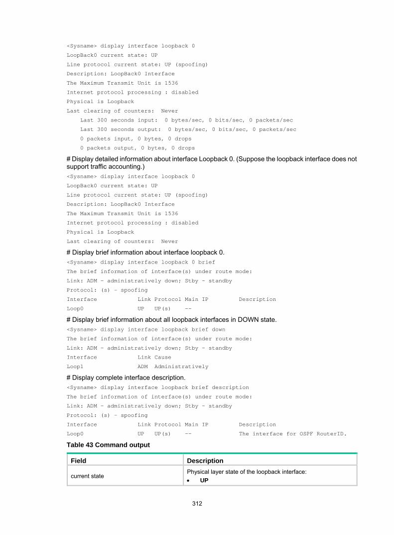
312
<Sysname> display interface loopback 0
LoopBack0 current state: UP
Line protocol current state: UP (spoofing)
Description: LoopBack0 Interface
The Maximum Transmit Unit is 1536
Internet protocol processing : disabled
Physical is Loopback
Last clearing of counters: Never
Last 300 seconds input: 0 bytes/sec, 0 bits/sec, 0 packets/sec
Last 300 seconds output: 0 bytes/sec, 0 bits/sec, 0 packets/sec
0 packets input, 0 bytes, 0 drops
0 packets output, 0 bytes, 0 drops
# Display detailed information about interface Loopback 0. (Suppose the loopback interface does not support traffic accounting.) <Sysname> display interface loopback 0
LoopBack0 current state: UP
Line protocol current state: UP (spoofing)
Description: LoopBack0 Interface
The Maximum Transmit Unit is 1536
Internet protocol processing : disabled
Physical is Loopback
Last clearing of counters: Never
# Display brief information about interface loopback 0. <Sysname> display interface loopback 0 brief
The brief information of interface(s) under route mode:
Link: ADM - administratively down; Stby - standby
Protocol: (s) - spoofing
Interface Link Protocol Main IP Description
Loop0 UP UP(s) --
# Display brief information about all loopback interfaces in DOWN state. <Sysname> display interface loopback brief down
The brief information of interface(s) under route mode:
Link: ADM - administratively down; Stby - standby
Interface Link Cause
Loop1 ADM Administratively
# Display complete interface description. <Sysname> display interface loopback brief description
The brief information of interface(s) under route mode:
Link: ADM - administratively down; Stby - standby
Protocol: (s) - spoofing
Interface Link Protocol Main IP Description
Loop0 UP UP(s) -- The interface for OSPF RouterID.
Table 43 Command output
Field Description
current state Physical layer state of the loopback interface: • UP
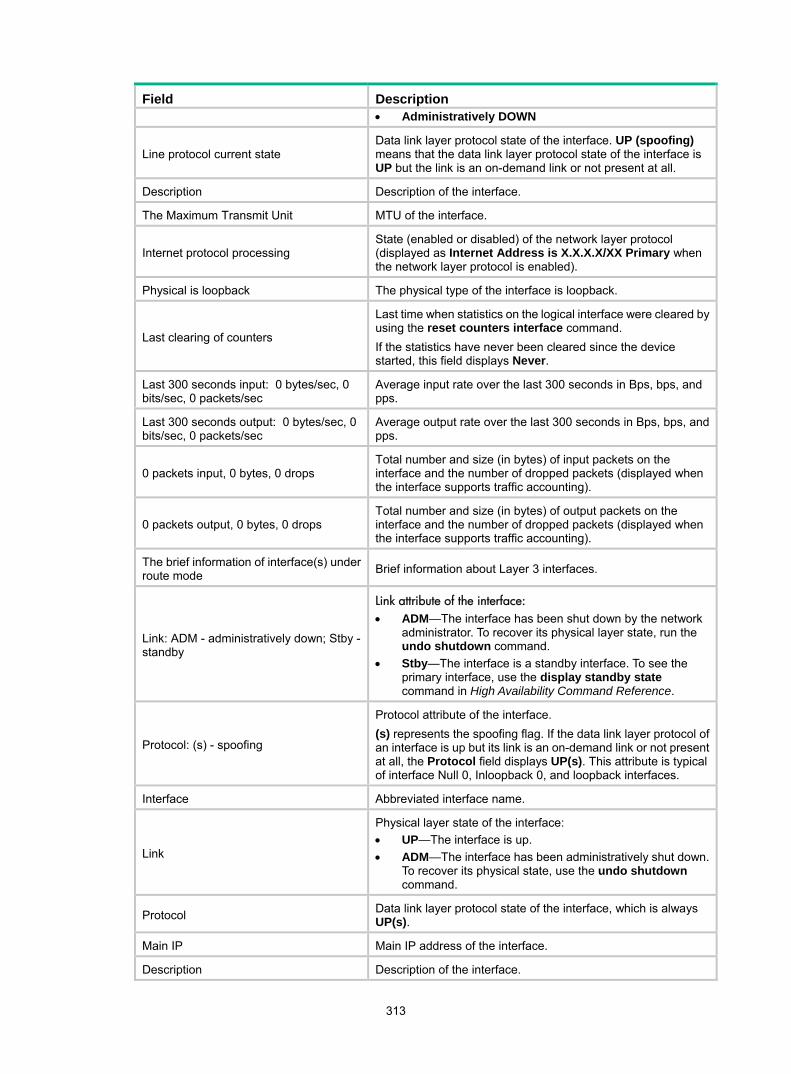
313
Field Description • Administratively DOWN
Line protocol current state Data link layer protocol state of the interface. UP (spoofing) means that the data link layer protocol state of the interface is UP but the link is an on-demand link or not present at all.
Description Description of the interface.
The Maximum Transmit Unit MTU of the interface.
Internet protocol processing State (enabled or disabled) of the network layer protocol (displayed as Internet Address is X.X.X.X/XX Primary when the network layer protocol is enabled).
Physical is loopback The physical type of the interface is loopback.
Last clearing of counters
Last time when statistics on the logical interface were cleared by using the reset counters interface command. If the statistics have never been cleared since the device started, this field displays Never.
Last 300 seconds input: 0 bytes/sec, 0 bits/sec, 0 packets/sec
Average input rate over the last 300 seconds in Bps, bps, and pps.
Last 300 seconds output: 0 bytes/sec, 0 bits/sec, 0 packets/sec
Average output rate over the last 300 seconds in Bps, bps, and pps.
0 packets input, 0 bytes, 0 drops Total number and size (in bytes) of input packets on the interface and the number of dropped packets (displayed when the interface supports traffic accounting).
0 packets output, 0 bytes, 0 drops Total number and size (in bytes) of output packets on the interface and the number of dropped packets (displayed when the interface supports traffic accounting).
The brief information of interface(s) under route mode Brief information about Layer 3 interfaces.
Link: ADM - administratively down; Stby - standby
Link attribute of the interface: • ADM—The interface has been shut down by the network
administrator. To recover its physical layer state, run the undo shutdown command.
• Stby—The interface is a standby interface. To see the primary interface, use the display standby state command in High Availability Command Reference.
Protocol: (s) - spoofing
Protocol attribute of the interface. (s) represents the spoofing flag. If the data link layer protocol of an interface is up but its link is an on-demand link or not present at all, the Protocol field displays UP(s). This attribute is typical of interface Null 0, Inloopback 0, and loopback interfaces.
Interface Abbreviated interface name.
Link
Physical layer state of the interface: • UP—The interface is up. • ADM—The interface has been administratively shut down.
To recover its physical state, use the undo shutdown command.
Protocol Data link layer protocol state of the interface, which is always UP(s).
Main IP Main IP address of the interface.
Description Description of the interface.
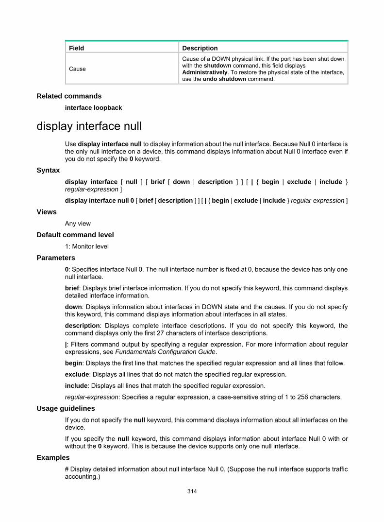
314
Field Description
Cause
Cause of a DOWN physical link. If the port has been shut down with the shutdown command, this field displays Administratively. To restore the physical state of the interface, use the undo shutdown command.
Related commands interface loopback
display interface null Use display interface null to display information about the null interface. Because Null 0 interface is the only null interface on a device, this command displays information about Null 0 interface even if you do not specify the 0 keyword.
Syntax display interface [ null ] [ brief [ down | description ] ] [ | { begin | exclude | include } regular-expression ]
display interface null 0 [ brief [ description ] ] [ | { begin | exclude | include } regular-expression ]
Views Any view
Default command level 1: Monitor level
Parameters 0: Specifies interface Null 0. The null interface number is fixed at 0, because the device has only one null interface.
brief: Displays brief interface information. If you do not specify this keyword, this command displays detailed interface information.
down: Displays information about interfaces in DOWN state and the causes. If you do not specify this keyword, this command displays information about interfaces in all states.
description: Displays complete interface descriptions. If you do not specify this keyword, the command displays only the first 27 characters of interface descriptions.
|: Filters command output by specifying a regular expression. For more information about regular expressions, see Fundamentals Configuration Guide.
begin: Displays the first line that matches the specified regular expression and all lines that follow.
exclude: Displays all lines that do not match the specified regular expression.
include: Displays all lines that match the specified regular expression.
regular-expression: Specifies a regular expression, a case-sensitive string of 1 to 256 characters.
Usage guidelines If you do not specify the null keyword, this command displays information about all interfaces on the device.
If you specify the null keyword, this command displays information about interface Null 0 with or without the 0 keyword. This is because the device supports only one null interface.
Examples # Display detailed information about null interface Null 0. (Suppose the null interface supports traffic accounting.)
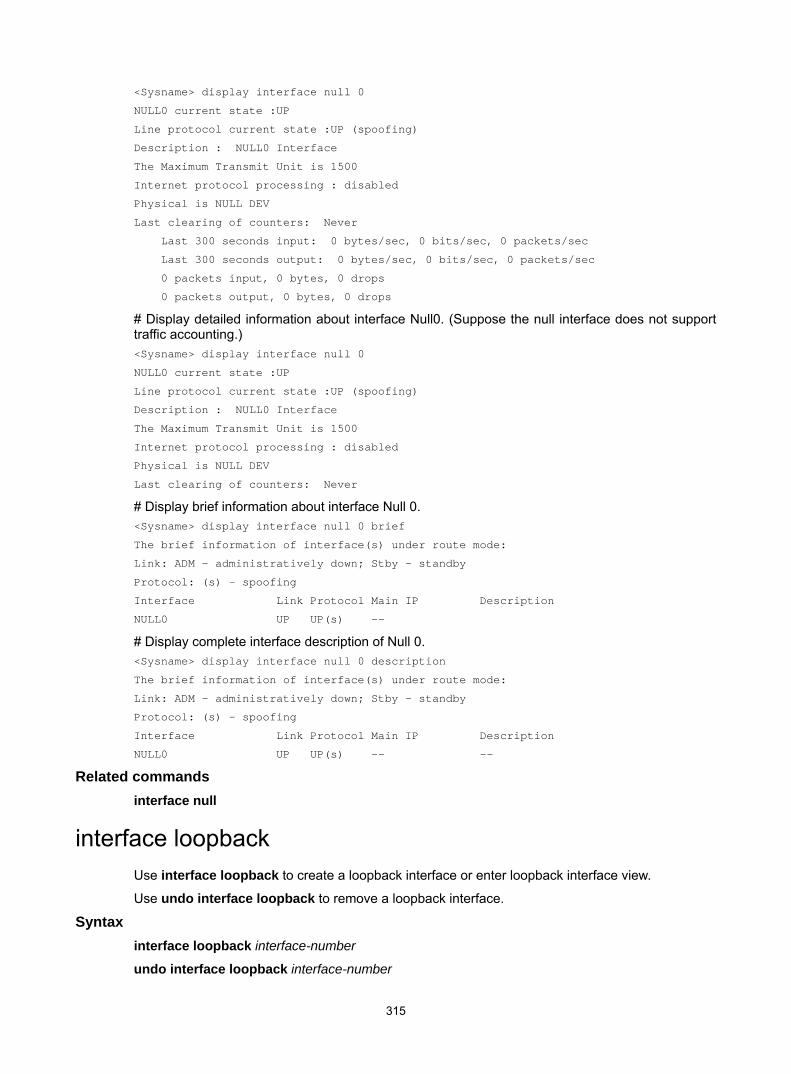
315
<Sysname> display interface null 0
NULL0 current state :UP
Line protocol current state :UP (spoofing)
Description : NULL0 Interface
The Maximum Transmit Unit is 1500
Internet protocol processing : disabled
Physical is NULL DEV
Last clearing of counters: Never
Last 300 seconds input: 0 bytes/sec, 0 bits/sec, 0 packets/sec
Last 300 seconds output: 0 bytes/sec, 0 bits/sec, 0 packets/sec
0 packets input, 0 bytes, 0 drops
0 packets output, 0 bytes, 0 drops
# Display detailed information about interface Null0. (Suppose the null interface does not support traffic accounting.) <Sysname> display interface null 0
NULL0 current state :UP
Line protocol current state :UP (spoofing)
Description : NULL0 Interface
The Maximum Transmit Unit is 1500
Internet protocol processing : disabled
Physical is NULL DEV
Last clearing of counters: Never
# Display brief information about interface Null 0. <Sysname> display interface null 0 brief
The brief information of interface(s) under route mode:
Link: ADM - administratively down; Stby - standby
Protocol: (s) - spoofing
Interface Link Protocol Main IP Description
NULL0 UP UP(s) --
# Display complete interface description of Null 0. <Sysname> display interface null 0 description
The brief information of interface(s) under route mode:
Link: ADM - administratively down; Stby - standby
Protocol: (s) - spoofing
Interface Link Protocol Main IP Description
NULL0 UP UP(s) -- --
Related commands interface null
interface loopback Use interface loopback to create a loopback interface or enter loopback interface view.
Use undo interface loopback to remove a loopback interface.
Syntax interface loopback interface-number
undo interface loopback interface-number
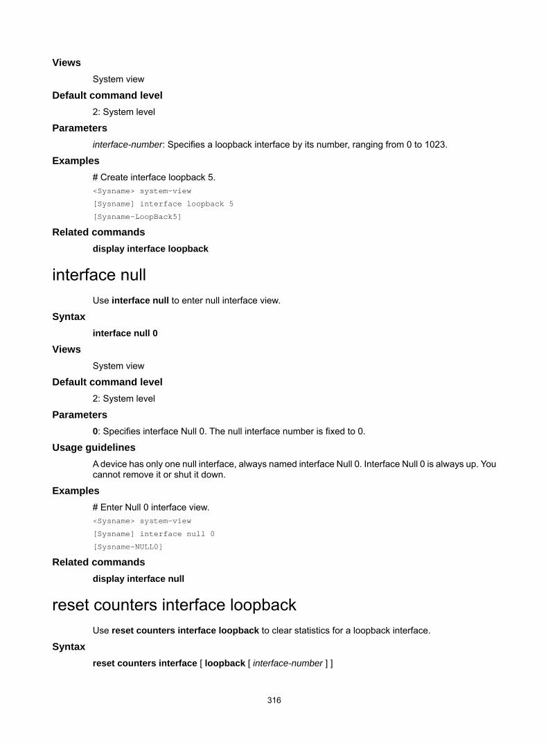
316
Views System view
Default command level 2: System level
Parameters interface-number: Specifies a loopback interface by its number, ranging from 0 to 1023.
Examples # Create interface loopback 5. <Sysname> system-view
[Sysname] interface loopback 5
[Sysname-LoopBack5]
Related commands display interface loopback
interface null Use interface null to enter null interface view.
Syntax interface null 0
Views System view
Default command level 2: System level
Parameters 0: Specifies interface Null 0. The null interface number is fixed to 0.
Usage guidelines A device has only one null interface, always named interface Null 0. Interface Null 0 is always up. You cannot remove it or shut it down.
Examples # Enter Null 0 interface view. <Sysname> system-view
[Sysname] interface null 0
[Sysname-NULL0]
Related commands display interface null
reset counters interface loopback Use reset counters interface loopback to clear statistics for a loopback interface.
Syntax reset counters interface [ loopback [ interface-number ] ]
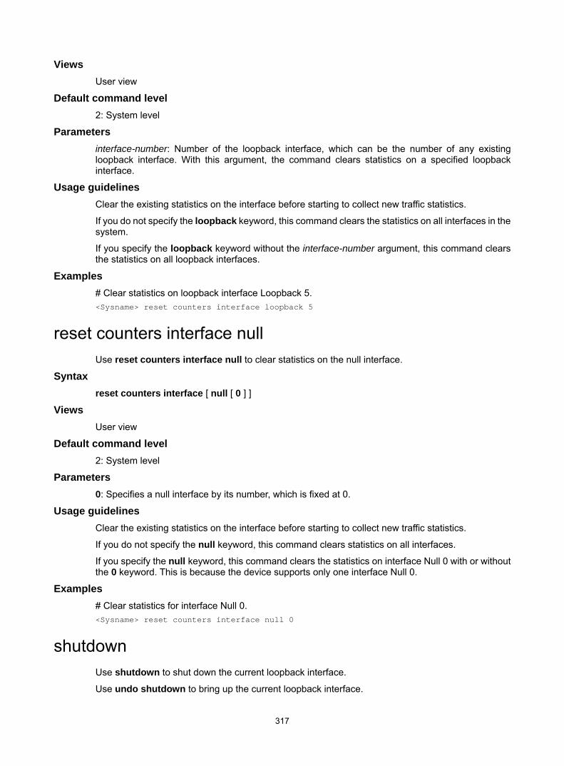
317
Views User view
Default command level 2: System level
Parameters interface-number: Number of the loopback interface, which can be the number of any existing loopback interface. With this argument, the command clears statistics on a specified loopback interface.
Usage guidelines Clear the existing statistics on the interface before starting to collect new traffic statistics.
If you do not specify the loopback keyword, this command clears the statistics on all interfaces in the system.
If you specify the loopback keyword without the interface-number argument, this command clears the statistics on all loopback interfaces.
Examples # Clear statistics on loopback interface Loopback 5. <Sysname> reset counters interface loopback 5
reset counters interface null Use reset counters interface null to clear statistics on the null interface.
Syntax reset counters interface [ null [ 0 ] ]
Views User view
Default command level 2: System level
Parameters 0: Specifies a null interface by its number, which is fixed at 0.
Usage guidelines Clear the existing statistics on the interface before starting to collect new traffic statistics.
If you do not specify the null keyword, this command clears statistics on all interfaces.
If you specify the null keyword, this command clears the statistics on interface Null 0 with or without the 0 keyword. This is because the device supports only one interface Null 0.
Examples # Clear statistics for interface Null 0. <Sysname> reset counters interface null 0
shutdown Use shutdown to shut down the current loopback interface.
Use undo shutdown to bring up the current loopback interface.
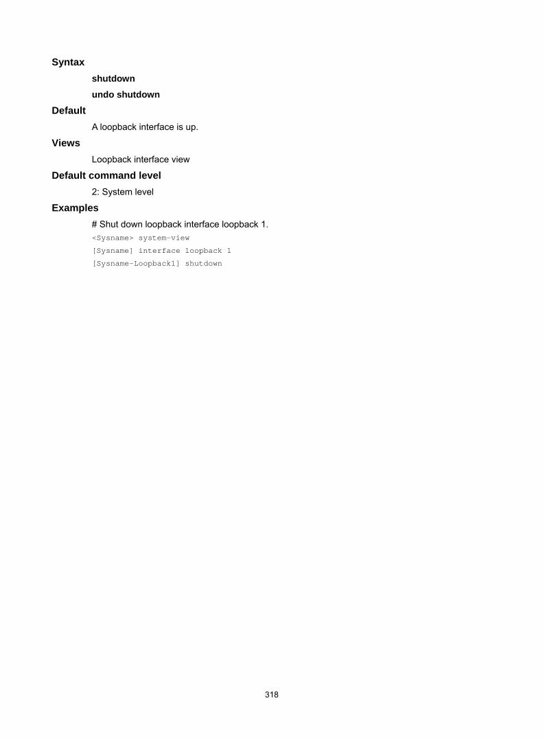
318
Syntax shutdown
undo shutdown
Default A loopback interface is up.
Views Loopback interface view
Default command level 2: System level
Examples # Shut down loopback interface loopback 1. <Sysname> system-view
[Sysname] interface loopback 1
[Sysname-Loopback1] shutdown
319
Index A B C D E F G I J L M N P Q R S T U V A activate,249 activate,257 adsl standard,250 adsl tx-attenuation,251 alarm,115 alarm (CT1/PRI interface),132 alarm (CT3 interface),191 alarm-threshold,132 async mode,45 autodeploy sms enable,72
B bandwidth,1 bandwidth,221 bandwidth,42 bandwidth,309 bandwidth,273 bandwidth,286 baudrate,46 bert (CE3 interface),176 bert (CT1/PRI interface),133 bert (CT3 interface),192 bootrom update file,251 broadcast-suppression,24
C cable,241 cable (ATM E1 interface),228 cable (ATM T1 interface),229 cable (CE1/PRI interface),116 cable (CT1/PRI interface),134 cable (CT3 interface),193 channel-set (CE1/PRI interface),117 channel-set (CT1/PRI interface),135 clock,229 clock,47 clock,242 clock,245 clock,287 clock,274 clock (CE1/PRI interface),118 clock (CE3 interface),177 clock (CT1/PRI interface),136 clock (CT3 interface),194
clock-change auto,118 clock-change auto,152 clock-change auto,230 code,48 code,231 code (CE1/PRI interface),119 code (CT1/PRI interface),137 combo enable,1 controller cpos,287 controller e1,120 controller e3,178 controller t1,137 controller t3,194 country-code,49 crc,274 crc,153 crc,120 crc,195 crc,162 crc,138 crc,178 crc,49
D data-coding (CE1/PRI interface),121 data-coding (CT1/PRI interface),138 default,309 default,2 default,43 default,221 default,288 default,275 description,43 description,288 description,222 description,3 description,275 description,310 detect,50 detect-ais,121 differential-delay,231 display cellular,73 display cellular-ethernet,81 display controller cpos,289 display controller cpos e1,291
320
display controller cpos t1,293 display controller e1,122 display controller e3,179 display controller t1,139 display controller t3,196 display counters,26 display counters rate,27 display dsl configuration,258 display dsl configuration,252 display dsl status,259 display dsl status,253 display dsl version,263 display dsl version,255 display fe1,153 display ft1,162 display gps,85 display interface,4 display interface analogmodem,51 display interface atm,223 display interface aux,55 display interface bri,215 display interface cellular,87 display interface cellular-ethernet,90 display interface ima-group,232 display interface loopback,311 display interface null,314 display interface pos,276 display interface serial,59 display loopback-detection,25 display port-group manual,28 display sms,94 display sms statistics,95 dm-port open,96 duplex,15
E e1 bert,182 e1 channel-set,294 e1 channel-set,183 e1 set clock,184 e1 set clock,295 e1 set flag,295 e1 set frame-format,185 e1 set frame-format,296 e1 set loopback,297 e1 set loopback,186 e1 shutdown,298 e1 shutdown,186 e1 unframed,298 e1 unframed,187 eliminate-pulse,62
error-diffusion restraint config,142 error-diffusion restraint config,123 error-diffusion restraint enable,124 error-diffusion restraint enable,143 error-diffusion restraint restart-channel,125 error-diffusion restraint restart-channel,144
F fdl,145 fe1 alarm,155 fe1 cable,155 fe1 clock,156 fe1 code,156 fe1 data-coding,157 fe1 frame-format,158 fe1 idlecode,158 fe1 itf,159 fe1 loopback,160 fe1 timeslot-list,160 fe1 unframed,161 fe3,188 feac,199 flag,246 flag,279 flag,299 flow-control,16 flow-interval,17 flow-interval,29 frame-format,281 frame-format,243 frame-format,300 frame-format,247 frame-format,235 frame-format (CE1/PRI interface),126 frame-format (CT1/PRI interface),146 frame-format (CT3 interface),201 frame-length,235 ft1 alarm,166 ft1 alarm-threshold,166 ft1 bert,168 ft1 cable,168 ft1 clock,169 ft1 code,170 ft1 data-coding,170 ft1 fdl,171 ft1 frame-format,172 ft1 idlecode,172 ft1 itf,173 ft1 loopback,174 ft1 sendloopcode,175 ft1 timeslot-list,176
321
ft3,201
G gps mode,97 gps nmea,97 group-member,30
I idlecode (CE1/PRI interface),127 idlecode (CT1/PRI interface),146 idle-mark,63 ima ima-group,236 ima-clock,237 ima-standard,237 ima-test,238 interface,17 interface atm,225 interface efm,272 interface ima-group,239 interface loopback,315 interface null,316 invert receive-clock,64 invert transmit-clock,64 ip address cellular-allocated,98 itf,65 itf (CE1/PRI interface),127 itf (CT1/PRI interface),147
J jumboframe enable,30
L link-delay,44 link-delay,18 link-protocol,281 loopback,19 loopback,65 loopback,282 loopback,247 loopback,300 loopback,239 loopback,243 loopback (CE1/PRI interface),128 loopback (CE3 interface),189 loopback (CT1/PRI interface),148 loopback (CT3 interface),202 loopback (ISDN BRI interface),218 loopback-detection action,32 loopback-detection control enable,33 loopback-detection interval-time,33 looptest,66 looptest (CE1/PRI interface),129
looptest (CT1/PRI interface),148 lte band,98
M mac-address,37 mac-address valid-check,38 mdi,34 mdl (CT3 interface),203 min-active-links,240 mode cdma,99 mode td-scdma,100 mode wcdma,100 modem auto-recovery enable,101 modem reboot,101 modem response,102 mtu,39 mtu,67 mtu,282 mtu (ISDN BRI interface),219 multicast-suppression,35 multiplex mode,301
N national-bit,189
P phy-mru,68 physical-mode,68 pin modify,103 pin unlock,103 pin verification,104 pin verify,104 plmn search,105 plmn select,105 port link-mode,20 port link-mode interface-list,21 port-group manual,36 pri-set (CE1/PRI interface),130 pri-set (CT1/PRI interface),150 profile create,106 profile main,107 promiscuous,40
Q qmtoken,40
R recovery track,107 reset atm interface,226 reset counters controller cpos,302 reset counters controller e1,131 reset counters controller e3,190
322
reset counters controller t1,150 reset counters controller t3,204 reset counters interface,70 reset counters interface,69 reset counters interface,21 reset counters interface,69 reset counters interface,283 reset counters interface,226 reset counters interface,219 reset counters interface cellular,109 reset counters interface cellular-ethernet,109 reset counters interface loopback,316 reset counters interface null,317 reverse-rts,71 rssi,110
S scramble,284 scramble,240 scramble,244 scramble,248 sendloopcode,151 shdsl annex,264 shdsl capability,265 shdsl line-probing,265 shdsl mode,266 shdsl pam,266 shdsl pbo,267 shdsl psd,268 shdsl rate,268 shdsl snr-margin,269 shdsl wire,270 shutdown,284 shutdown,22 shutdown,317 shutdown,227 shutdown,45 shutdown,302
sms delete,111 sms forward,111 sms send,112 sms sending-enable,113 snmp-agent trap enable sms,113 speed,23 standby rssi,114
T t1 alarm,205 t1 bert,206 t1 channel-set,207 t1 channel-set,303 t1 sendloopcode,208 t1 set clock,208 t1 set clock,304 t1 set fdl,209 t1 set flag,304 t1 set frame-format,210 t1 set frame-format,305 t1 set loopback,306 t1 set loopback,211 t1 show,211 t1 shutdown,306 t1 shutdown,213 t1 unframed,307 t1 unframed,213 timer hold,71 trust-imsi,115
U unicast-suppression,36 using (CE1/PRI interface),131 using (CE3 interface),190 using (CT3 interface),214
V virtualbaudrate,72