RS Switch Router RapidOS User Guide
1214
RS Switch Router RapidOS User Guide Release 9.4 36-177-01 Rev 0B
-
Upload
khangminh22 -
Category
Documents
-
view
2 -
download
0
Transcript of RS Switch Router RapidOS User Guide

RS Switch Router RapidOS User Guide
Release 9.4
36-177-01 Rev 0B
ii Riverstone RapidOS Message Reference Manual
COPYRIGHT NOTICES© 2006 by Riverstone Networks, Inc. All rights reserved.
Riverstone Networks, Inc.5200 Great America ParkwaySanta Clara, CA 95054Printed in the United States of America
This product includes software developed by the University of California, Berkeley, and its contributors.
© 1979 – 1994 by The Regents of the University of California. All rights reserved.
THE FOREGOING SOFTWARE IS PROVIDED BY THE AUTHORS AND RIVERSTONE ``AS IS'' AND ANY EXPRESS OR IMPLIED WARRANTIES, INCLUDING, BUT NOT LIMITED TO, THE IMPLIED WARRANTIES OF MERCHANTABILITY AND FITNESS FOR A PARTICULAR PURPOSE ARE DISCLAIMED IN NO EVENT SHALL THE AUTHORS OR RIVERSTONE BE LIABLE FOR ANY DIRECT, INDIRECT, INCIDENTAL, SPECIAL, EXEM-PLARY, OR CONSEQUENTIAL DAMAGES (INCLUDING, BUT NOT LIMITED TO, PROCUREMENT OF SUBSTITUTE GOODS OR SERVICES; LOSS OF USE, DATA, OR PROFITS; OR BUSINESS INTERRUPTION) HOWEVER CAUSED AND ON ANY THEORY OF LIABILITY, WHETHER IN CONTRACT, STRICT LIABILITY, OR TORT (INCLUDING NEGLIGENCE OR OTHERWISE) ARISING IN ANY WAY OUT OF THE USE OF THIS SOFTWARE, EVEN IF ADVISED OF THE POSSIBILITY OF SUCH DAMAGE.
ChangesRiverstone Networks, Inc., and its licensors reserve the right to make changes in specifications and other information contained in this document without prior notice. The reader should in all cases consult Riverstone Networks, Inc., to determine whether any such changes have been made. The hardware, firmware, or software described in this manual is subject to change without notice.
DisclaimerIN NO EVENT SHALL RIVERSTONE NETWORKS BE LIABLE FOR ANY INCIDENTAL, INDIRECT, SPECIAL, OR CONSEQUENTIAL DAMAGES WHATSOEVER (INCLUDING BUT NOT LIMITED TO LOST PROFITS) ARISING OUT OF OR RELATED TO THIS MANUAL OR THE INFORMATION CONTAINED IN IT, EVEN IF RIVERSTONE NETWORKS HAS BEEN ADVISED, KNOWN, OR SHOULD HAVE KNOWN, OF THE POSSIBILITY OF SUCH DAMAGES.
TrademarksRiverstone Networks, Riverstone, RapidOS, RS, and IA are trademarks of Riverstone Networks, Inc.All other product names mentioned in this manual may be trademarks or registered trademarks of their respective companies.
Riverstone Networks Inc. Standard License Agreementhttp://www.riverstonenet.com/support/sw_downloads.shtml
TABLE OF CONTENTS
1 Introduction. . . . . . . . . . . . . . . . . . . . . . . . . . . . . . . . . . . . . . . . . . . . . . . . . . . . . . . . 1-11.1 Related Documentation . . . . . . . . . . . . . . . . . . . . . . . . . . . . . . . . . . . . . . . . . . . . . . . . . . . . . . . . . . . . . 1-1
1.2 Document Conventions . . . . . . . . . . . . . . . . . . . . . . . . . . . . . . . . . . . . . . . . . . . . . . . . . . . . . . . . . . . . . 1-1
2 Maintaining Configuration Files. . . . . . . . . . . . . . . . . . . . . . . . . . . . . . . . . . . . . . . . 2-12.1 Configuration Files . . . . . . . . . . . . . . . . . . . . . . . . . . . . . . . . . . . . . . . . . . . . . . . . . . . . . . . . . . . . . . . . 2-12.1.1 Changing Configuration Information. . . . . . . . . . . . . . . . . . . . . . . . . . . . . . . . . . . . . . . . . . . . . . . 2-22.1.2 Displaying Configuration Information. . . . . . . . . . . . . . . . . . . . . . . . . . . . . . . . . . . . . . . . . . . . . . 2-22.1.3 Activating the Configuration Commands in the Scratchpad . . . . . . . . . . . . . . . . . . . . . . . . . . . . . 2-32.1.4 Saving the Active Configuration to the Startup Configuration File . . . . . . . . . . . . . . . . . . . . . . . 2-42.1.5 Viewing the Current Configuration . . . . . . . . . . . . . . . . . . . . . . . . . . . . . . . . . . . . . . . . . . . . . . . . 2-42.1.6 Backing Up and Restoring Configuration Files . . . . . . . . . . . . . . . . . . . . . . . . . . . . . . . . . . . . . . . 2-52.1.7 Specifying Primary and Backup Configuration Files . . . . . . . . . . . . . . . . . . . . . . . . . . . . . . . . . . 2-6
2.2 Backing Up and Restoring System Image Files . . . . . . . . . . . . . . . . . . . . . . . . . . . . . . . . . . . . . . . . . . 2-7
2.3 Configuring System Settings. . . . . . . . . . . . . . . . . . . . . . . . . . . . . . . . . . . . . . . . . . . . . . . . . . . . . . . . 2-102.3.1 Setting Daylight Saving Time . . . . . . . . . . . . . . . . . . . . . . . . . . . . . . . . . . . . . . . . . . . . . . . . . . . 2-102.3.2 Configuring a Log-in Banner . . . . . . . . . . . . . . . . . . . . . . . . . . . . . . . . . . . . . . . . . . . . . . . . . . . . 2-112.3.3 Setting the BootPROM Escape Character . . . . . . . . . . . . . . . . . . . . . . . . . . . . . . . . . . . . . . . . . . 2-11
3 Using the CLI . . . . . . . . . . . . . . . . . . . . . . . . . . . . . . . . . . . . . . . . . . . . . . . . . . . . . . 3-13.1 Command Modes . . . . . . . . . . . . . . . . . . . . . . . . . . . . . . . . . . . . . . . . . . . . . . . . . . . . . . . . . . . . . . . . . 3-13.1.1 User Mode . . . . . . . . . . . . . . . . . . . . . . . . . . . . . . . . . . . . . . . . . . . . . . . . . . . . . . . . . . . . . . . . . . . 3-13.1.2 Enable Mode . . . . . . . . . . . . . . . . . . . . . . . . . . . . . . . . . . . . . . . . . . . . . . . . . . . . . . . . . . . . . . . . . 3-13.1.3 Configure Mode . . . . . . . . . . . . . . . . . . . . . . . . . . . . . . . . . . . . . . . . . . . . . . . . . . . . . . . . . . . . . . . 3-23.1.4 Boot PROM Mode . . . . . . . . . . . . . . . . . . . . . . . . . . . . . . . . . . . . . . . . . . . . . . . . . . . . . . . . . . . . . 3-2
3.2 Establishing Telnet Sessions . . . . . . . . . . . . . . . . . . . . . . . . . . . . . . . . . . . . . . . . . . . . . . . . . . . . . . . . . 3-23.2.1 Telnet Sessions with a Backup Control Module . . . . . . . . . . . . . . . . . . . . . . . . . . . . . . . . . . . . . . 3-3
3.3 Setting CLI Parameters . . . . . . . . . . . . . . . . . . . . . . . . . . . . . . . . . . . . . . . . . . . . . . . . . . . . . . . . . . . . . 3-5
3.4 Getting Help with CLI Commands . . . . . . . . . . . . . . . . . . . . . . . . . . . . . . . . . . . . . . . . . . . . . . . . . . . . 3-6
3.5 Line Editing Commands . . . . . . . . . . . . . . . . . . . . . . . . . . . . . . . . . . . . . . . . . . . . . . . . . . . . . . . . . . . . 3-8
3.6 Naming RS Ethernet Router Ports . . . . . . . . . . . . . . . . . . . . . . . . . . . . . . . . . . . . . . . . . . . . . . . . . . . 3-103.6.1 Channel Numbers. . . . . . . . . . . . . . . . . . . . . . . . . . . . . . . . . . . . . . . . . . . . . . . . . . . . . . . . . . . . . 3-12
3.7 Multi-User Mode. . . . . . . . . . . . . . . . . . . . . . . . . . . . . . . . . . . . . . . . . . . . . . . . . . . . . . . . . . . . . . . . . 3-133.7.1 Setting Up Multi-User Access . . . . . . . . . . . . . . . . . . . . . . . . . . . . . . . . . . . . . . . . . . . . . . . . . . . 3-133.7.2 Wildcard Option. . . . . . . . . . . . . . . . . . . . . . . . . . . . . . . . . . . . . . . . . . . . . . . . . . . . . . . . . . . . . . 3-153.7.3 Configuring Multi-User Mode RADIUS Authentication . . . . . . . . . . . . . . . . . . . . . . . . . . . . . . 3-16
4 Hot Swapping Line Cards and Control Modules . . . . . . . . . . . . . . . . . . . . . . . . . . . 4-14.1 Hot Swapping Overview . . . . . . . . . . . . . . . . . . . . . . . . . . . . . . . . . . . . . . . . . . . . . . . . . . . . . . . . . . . . 4-1
Riverstone Networks RS Switch Router User Guide Release 9.3 iii
4.2 Hot Swapping Line Cards . . . . . . . . . . . . . . . . . . . . . . . . . . . . . . . . . . . . . . . . . . . . . . . . . . . . . . . . . . . 4-14.2.1 Deactivating the Line Card. . . . . . . . . . . . . . . . . . . . . . . . . . . . . . . . . . . . . . . . . . . . . . . . . . . . . . . 4-24.2.2 Removing the Line Card . . . . . . . . . . . . . . . . . . . . . . . . . . . . . . . . . . . . . . . . . . . . . . . . . . . . . . . . 4-24.2.3 Installing a New Line Card. . . . . . . . . . . . . . . . . . . . . . . . . . . . . . . . . . . . . . . . . . . . . . . . . . . . . . . 4-3
4.3 Hot Swapping One Type of Line Card With Another. . . . . . . . . . . . . . . . . . . . . . . . . . . . . . . . . . . . . . 4-3
4.4 Hot Swapping a Secondary Control Module . . . . . . . . . . . . . . . . . . . . . . . . . . . . . . . . . . . . . . . . . . . . . 4-44.4.1 Deactivating the Control Module . . . . . . . . . . . . . . . . . . . . . . . . . . . . . . . . . . . . . . . . . . . . . . . . . . 4-44.4.2 Removing the Control Module. . . . . . . . . . . . . . . . . . . . . . . . . . . . . . . . . . . . . . . . . . . . . . . . . . . . 4-54.4.3 Installing a Control Module . . . . . . . . . . . . . . . . . . . . . . . . . . . . . . . . . . . . . . . . . . . . . . . . . . . . . . 4-5
4.5 Hot Swapping a Switching Fabric Module (RS 8600 only) . . . . . . . . . . . . . . . . . . . . . . . . . . . . . . . . . 4-64.5.1 Removing the Switching Fabric Module . . . . . . . . . . . . . . . . . . . . . . . . . . . . . . . . . . . . . . . . . . . . 4-74.5.2 Installing a Switching Fabric Module . . . . . . . . . . . . . . . . . . . . . . . . . . . . . . . . . . . . . . . . . . . . . . 4-7
4.6 Hot Swapping A GBIC (RS 32000 and RS 38000 only) . . . . . . . . . . . . . . . . . . . . . . . . . . . . . . . . . . . 4-74.6.1 Removing a GBIC from the Line Card . . . . . . . . . . . . . . . . . . . . . . . . . . . . . . . . . . . . . . . . . . . . . 4-74.6.2 Installing a GBIC into the Line Card . . . . . . . . . . . . . . . . . . . . . . . . . . . . . . . . . . . . . . . . . . . . . . . 4-8
4.7 Hot Swapping a WIC. . . . . . . . . . . . . . . . . . . . . . . . . . . . . . . . . . . . . . . . . . . . . . . . . . . . . . . . . . . . . . . 4-9
5 SmartTRUNK Configuration Guide . . . . . . . . . . . . . . . . . . . . . . . . . . . . . . . . . . . . . 5-15.1 Configuring SmartTRUNKS . . . . . . . . . . . . . . . . . . . . . . . . . . . . . . . . . . . . . . . . . . . . . . . . . . . . . . . . . 5-15.1.1 Creating a SmartTRUNK . . . . . . . . . . . . . . . . . . . . . . . . . . . . . . . . . . . . . . . . . . . . . . . . . . . . . . . . 5-25.1.2 Adding Physical Ports to the SmartTRUNK . . . . . . . . . . . . . . . . . . . . . . . . . . . . . . . . . . . . . . . . . 5-25.1.3 Specifying Traffic Load Policy . . . . . . . . . . . . . . . . . . . . . . . . . . . . . . . . . . . . . . . . . . . . . . . . . . . 5-3
5.2 SmartTRUNK Example Configuration . . . . . . . . . . . . . . . . . . . . . . . . . . . . . . . . . . . . . . . . . . . . . . . . . 5-3
5.3 Configuring the Link Aggregation Control Protocol (LACP). . . . . . . . . . . . . . . . . . . . . . . . . . . . . . . . 5-55.3.1 Configuring SmartTRUNKs for LACP . . . . . . . . . . . . . . . . . . . . . . . . . . . . . . . . . . . . . . . . . . . . . 5-65.3.2 LACP Configuration Example . . . . . . . . . . . . . . . . . . . . . . . . . . . . . . . . . . . . . . . . . . . . . . . . . . . . 5-6
5.4 SmartTRUNK Load Redistribution. . . . . . . . . . . . . . . . . . . . . . . . . . . . . . . . . . . . . . . . . . . . . . . . . . . 5-105.4.1 SLR Water-marks. . . . . . . . . . . . . . . . . . . . . . . . . . . . . . . . . . . . . . . . . . . . . . . . . . . . . . . . . . . . . 5-105.4.2 Polling intervals . . . . . . . . . . . . . . . . . . . . . . . . . . . . . . . . . . . . . . . . . . . . . . . . . . . . . . . . . . . . . . 5-105.4.3 Additional Controls Provided by SLR . . . . . . . . . . . . . . . . . . . . . . . . . . . . . . . . . . . . . . . . . . . . . 5-13
6 Bridging Configuration Guide . . . . . . . . . . . . . . . . . . . . . . . . . . . . . . . . . . . . . . . . . 6-16.1 Spanning Tree (IEEE 802.1d) . . . . . . . . . . . . . . . . . . . . . . . . . . . . . . . . . . . . . . . . . . . . . . . . . . . . . . . . 6-1
6.2 VLAN Tagging (IEEE 802.1Q). . . . . . . . . . . . . . . . . . . . . . . . . . . . . . . . . . . . . . . . . . . . . . . . . . . . . . . 6-1
6.3 Bridging Modes (Flow-Based and Address-Based) . . . . . . . . . . . . . . . . . . . . . . . . . . . . . . . . . . . . . . . 6-1
6.4 VLAN Overview . . . . . . . . . . . . . . . . . . . . . . . . . . . . . . . . . . . . . . . . . . . . . . . . . . . . . . . . . . . . . . . . . . 6-26.4.1 RS Ethernet Router VLAN Support . . . . . . . . . . . . . . . . . . . . . . . . . . . . . . . . . . . . . . . . . . . . . . . . 6-2
6.5 Access Ports and Trunk Ports (802.1P and 802.1Q support) . . . . . . . . . . . . . . . . . . . . . . . . . . . . . . . . 6-4
6.6 Configuring RS Ethernet Router Bridging Functions . . . . . . . . . . . . . . . . . . . . . . . . . . . . . . . . . . . . . . 6-46.6.1 Configuring Address-based or Flow-based Bridging. . . . . . . . . . . . . . . . . . . . . . . . . . . . . . . . . . . 6-46.6.2 Configuring MAC Address Limits on Ports. . . . . . . . . . . . . . . . . . . . . . . . . . . . . . . . . . . . . . . . . . 6-6
6.7 Configuring Spanning Tree . . . . . . . . . . . . . . . . . . . . . . . . . . . . . . . . . . . . . . . . . . . . . . . . . . . . . . . . . . 6-76.7.1 Using Rapid STP . . . . . . . . . . . . . . . . . . . . . . . . . . . . . . . . . . . . . . . . . . . . . . . . . . . . . . . . . . . . . . 6-76.7.2 Adjusting Spanning-Tree Parameters. . . . . . . . . . . . . . . . . . . . . . . . . . . . . . . . . . . . . . . . . . . . . . . 6-86.7.3 STP Dampening . . . . . . . . . . . . . . . . . . . . . . . . . . . . . . . . . . . . . . . . . . . . . . . . . . . . . . . . . . . . . . 6-116.7.4 Tunneling STP . . . . . . . . . . . . . . . . . . . . . . . . . . . . . . . . . . . . . . . . . . . . . . . . . . . . . . . . . . . . . . . 6-11
iv Riverstone Networks RS Switch Router User Guide Release 9.4
6.7.5 Rapid Ring STP . . . . . . . . . . . . . . . . . . . . . . . . . . . . . . . . . . . . . . . . . . . . . . . . . . . . . . . . . . . . . . 6-12
6.8 Port-VLAN Loop Detection . . . . . . . . . . . . . . . . . . . . . . . . . . . . . . . . . . . . . . . . . . . . . . . . . . . . . . . . 6-166.8.1 Configuring Loop Detection . . . . . . . . . . . . . . . . . . . . . . . . . . . . . . . . . . . . . . . . . . . . . . . . . . . . 6-176.8.2 Physically Disabling Ports . . . . . . . . . . . . . . . . . . . . . . . . . . . . . . . . . . . . . . . . . . . . . . . . . . . . . . 6-21
6.9 Configuring a Port- or Protocol-Based VLAN . . . . . . . . . . . . . . . . . . . . . . . . . . . . . . . . . . . . . . . . . . 6-266.9.1 Creating a Port or Protocol Based VLAN . . . . . . . . . . . . . . . . . . . . . . . . . . . . . . . . . . . . . . . . . . 6-266.9.2 Adding Ports to a VLAN . . . . . . . . . . . . . . . . . . . . . . . . . . . . . . . . . . . . . . . . . . . . . . . . . . . . . . . 6-266.9.3 Configuration Examples . . . . . . . . . . . . . . . . . . . . . . . . . . . . . . . . . . . . . . . . . . . . . . . . . . . . . . . 6-266.9.4 Configuring VLAN Trunk Ports . . . . . . . . . . . . . . . . . . . . . . . . . . . . . . . . . . . . . . . . . . . . . . . . . 6-276.9.5 Configuring Native VLANs. . . . . . . . . . . . . . . . . . . . . . . . . . . . . . . . . . . . . . . . . . . . . . . . . . . . . 6-286.9.6 Configuring a Range of VLAN IDs. . . . . . . . . . . . . . . . . . . . . . . . . . . . . . . . . . . . . . . . . . . . . . . 6-30
6.10 VLAN Translation. . . . . . . . . . . . . . . . . . . . . . . . . . . . . . . . . . . . . . . . . . . . . . . . . . . . . . . . . . . . . . . . 6-32
6.11 Configuration Examples . . . . . . . . . . . . . . . . . . . . . . . . . . . . . . . . . . . . . . . . . . . . . . . . . . . . . . . . . . . 6-326.11.1 Restrictions. . . . . . . . . . . . . . . . . . . . . . . . . . . . . . . . . . . . . . . . . . . . . . . . . . . . . . . . . . . . . . . . . . 6-34
6.12 DHCP Relay Agent for Flat Layer-4 Bridged VLANs . . . . . . . . . . . . . . . . . . . . . . . . . . . . . . . . . . . . 6-35
6.13 Configuring Layer-2 Filters . . . . . . . . . . . . . . . . . . . . . . . . . . . . . . . . . . . . . . . . . . . . . . . . . . . . . . . . 6-35
6.14 Monitoring Bridging . . . . . . . . . . . . . . . . . . . . . . . . . . . . . . . . . . . . . . . . . . . . . . . . . . . . . . . . . . . . . . 6-36
6.15 GARP/GVRP . . . . . . . . . . . . . . . . . . . . . . . . . . . . . . . . . . . . . . . . . . . . . . . . . . . . . . . . . . . . . . . . . . . 6-376.15.1 Running GARP/GVRP with STP . . . . . . . . . . . . . . . . . . . . . . . . . . . . . . . . . . . . . . . . . . . . . . . . 6-376.15.2 Configuring GARP/GVRP. . . . . . . . . . . . . . . . . . . . . . . . . . . . . . . . . . . . . . . . . . . . . . . . . . . . . . 6-386.15.3 Configuration Example . . . . . . . . . . . . . . . . . . . . . . . . . . . . . . . . . . . . . . . . . . . . . . . . . . . . . . . . 6-39
6.16 Tunneling VLAN packets across MANs . . . . . . . . . . . . . . . . . . . . . . . . . . . . . . . . . . . . . . . . . . . . . . 6-416.16.1 Stackable VLAN Components. . . . . . . . . . . . . . . . . . . . . . . . . . . . . . . . . . . . . . . . . . . . . . . . . . . 6-416.16.2 Configuration Examples . . . . . . . . . . . . . . . . . . . . . . . . . . . . . . . . . . . . . . . . . . . . . . . . . . . . . . . 6-426.16.3 Sending Untagged Packets over Stackable VLANs . . . . . . . . . . . . . . . . . . . . . . . . . . . . . . . . . . 6-576.16.4 Displaying Stackable VLAN Information . . . . . . . . . . . . . . . . . . . . . . . . . . . . . . . . . . . . . . . . . . 6-63
6.17 VLAN Aggregation. . . . . . . . . . . . . . . . . . . . . . . . . . . . . . . . . . . . . . . . . . . . . . . . . . . . . . . . . . . . . . . 6-656.17.1 Configuring VLAN Aggregation . . . . . . . . . . . . . . . . . . . . . . . . . . . . . . . . . . . . . . . . . . . . . . . . . 6-676.17.2 Multicast. . . . . . . . . . . . . . . . . . . . . . . . . . . . . . . . . . . . . . . . . . . . . . . . . . . . . . . . . . . . . . . . . . . . 6-726.17.3 Restrictions. . . . . . . . . . . . . . . . . . . . . . . . . . . . . . . . . . . . . . . . . . . . . . . . . . . . . . . . . . . . . . . . . . 6-72
7 ATM Configuration Guide . . . . . . . . . . . . . . . . . . . . . . . . . . . . . . . . . . . . . . . . . . . . 7-17.1 Configuring ATM Ports . . . . . . . . . . . . . . . . . . . . . . . . . . . . . . . . . . . . . . . . . . . . . . . . . . . . . . . . . . . . 7-27.1.1 Configuring SONET Parameters . . . . . . . . . . . . . . . . . . . . . . . . . . . . . . . . . . . . . . . . . . . . . . . . . . 7-27.1.2 Setting Parameters for the Multi-Rate Line Card . . . . . . . . . . . . . . . . . . . . . . . . . . . . . . . . . . . . . 7-37.1.3 Displaying Port Information . . . . . . . . . . . . . . . . . . . . . . . . . . . . . . . . . . . . . . . . . . . . . . . . . . . . . 7-4
7.2 Configuring Virtual Channels . . . . . . . . . . . . . . . . . . . . . . . . . . . . . . . . . . . . . . . . . . . . . . . . . . . . . . . . 7-57.2.1 Gathering Traffic Statistics (OC-12) . . . . . . . . . . . . . . . . . . . . . . . . . . . . . . . . . . . . . . . . . . . . . . . 7-5
7.3 Traffic Shaping . . . . . . . . . . . . . . . . . . . . . . . . . . . . . . . . . . . . . . . . . . . . . . . . . . . . . . . . . . . . . . . . . . . 7-6
7.4 Traffic Management . . . . . . . . . . . . . . . . . . . . . . . . . . . . . . . . . . . . . . . . . . . . . . . . . . . . . . . . . . . . . . . 7-87.4.1 Configuring QoS (Multi-Rate Line Card) . . . . . . . . . . . . . . . . . . . . . . . . . . . . . . . . . . . . . . . . . . . 7-87.4.2 Configuring Virtual Channel Groups (OC-12) . . . . . . . . . . . . . . . . . . . . . . . . . . . . . . . . . . . . . . . 7-97.4.3 Traffic Management Configuration Example . . . . . . . . . . . . . . . . . . . . . . . . . . . . . . . . . . . . . . . 7-10
7.5 Bridging ATM Traffic. . . . . . . . . . . . . . . . . . . . . . . . . . . . . . . . . . . . . . . . . . . . . . . . . . . . . . . . . . . . . 7-157.5.1 Limiting MAC Addresses Learned on a VC . . . . . . . . . . . . . . . . . . . . . . . . . . . . . . . . . . . . . . . . 7-17
7.6 Routing ATM Traffic . . . . . . . . . . . . . . . . . . . . . . . . . . . . . . . . . . . . . . . . . . . . . . . . . . . . . . . . . . . . . 7-18
Riverstone Networks RS Switch Router User Guide Release 9.3 v

7.6.1 Peer Address Mapping . . . . . . . . . . . . . . . . . . . . . . . . . . . . . . . . . . . . . . . . . . . . . . . . . . . . . . . . . 7-21
7.7 Operation, Administration and Management (OAM) . . . . . . . . . . . . . . . . . . . . . . . . . . . . . . . . . . . . . 7-247.7.1 Connection Verification . . . . . . . . . . . . . . . . . . . . . . . . . . . . . . . . . . . . . . . . . . . . . . . . . . . . . . . . 7-24
8 Packet-over-SONET Configuration Guide . . . . . . . . . . . . . . . . . . . . . . . . . . . . . . . . 8-18.1 Configuring IP Interfaces for PoS Links . . . . . . . . . . . . . . . . . . . . . . . . . . . . . . . . . . . . . . . . . . . . . . . . 8-1
8.2 Configuring Packet-over-SONET Links . . . . . . . . . . . . . . . . . . . . . . . . . . . . . . . . . . . . . . . . . . . . . . . . 8-2
8.3 Configuring Automatic Protection Switching . . . . . . . . . . . . . . . . . . . . . . . . . . . . . . . . . . . . . . . . . . . . 8-38.3.1 Configuring Working and Protecting Ports . . . . . . . . . . . . . . . . . . . . . . . . . . . . . . . . . . . . . . . . . . 8-4
8.4 Specifying Bit Error Rate Thresholds . . . . . . . . . . . . . . . . . . . . . . . . . . . . . . . . . . . . . . . . . . . . . . . . . . 8-5
8.5 Monitoring PoS Ports . . . . . . . . . . . . . . . . . . . . . . . . . . . . . . . . . . . . . . . . . . . . . . . . . . . . . . . . . . . . . . 8-6
8.6 Example Configurations . . . . . . . . . . . . . . . . . . . . . . . . . . . . . . . . . . . . . . . . . . . . . . . . . . . . . . . . . . . . 8-68.6.1 APS PoS Links Between RS Ethernet Router’s . . . . . . . . . . . . . . . . . . . . . . . . . . . . . . . . . . . . . . . 8-78.6.2 PoS Link Between the RS Ethernet Router and a Cisco Router . . . . . . . . . . . . . . . . . . . . . . . . . . 8-78.6.3 PoS Link Between the RS Ethernet Router and a Juniper Router . . . . . . . . . . . . . . . . . . . . . . . . . 8-88.6.4 Bridging and Routing Traffic Over a PoS Link . . . . . . . . . . . . . . . . . . . . . . . . . . . . . . . . . . . . . . . 8-98.6.5 PoS Link Through a Layer 2 Cloud . . . . . . . . . . . . . . . . . . . . . . . . . . . . . . . . . . . . . . . . . . . . . . . . 8-9
9 DHCP Configuration Guide . . . . . . . . . . . . . . . . . . . . . . . . . . . . . . . . . . . . . . . . . . . 9-19.1 Configuring DHCP Server. . . . . . . . . . . . . . . . . . . . . . . . . . . . . . . . . . . . . . . . . . . . . . . . . . . . . . . . . . . 9-19.1.1 Configuring an IP Address Pool. . . . . . . . . . . . . . . . . . . . . . . . . . . . . . . . . . . . . . . . . . . . . . . . . . . 9-29.1.2 Configuring Client Parameters . . . . . . . . . . . . . . . . . . . . . . . . . . . . . . . . . . . . . . . . . . . . . . . . . . . . 9-29.1.3 Configuring a Static IP Address . . . . . . . . . . . . . . . . . . . . . . . . . . . . . . . . . . . . . . . . . . . . . . . . . . . 9-39.1.4 Grouping Scopes with a Common Interface . . . . . . . . . . . . . . . . . . . . . . . . . . . . . . . . . . . . . . . . . 9-39.1.5 Configuring DHCP Server Parameters. . . . . . . . . . . . . . . . . . . . . . . . . . . . . . . . . . . . . . . . . . . . . . 9-39.1.6 Updating the Lease Database . . . . . . . . . . . . . . . . . . . . . . . . . . . . . . . . . . . . . . . . . . . . . . . . . . . . . 9-49.1.7 Monitoring the DHCP Server. . . . . . . . . . . . . . . . . . . . . . . . . . . . . . . . . . . . . . . . . . . . . . . . . . . . . 9-49.1.8 DHCP Server Configuration Examples . . . . . . . . . . . . . . . . . . . . . . . . . . . . . . . . . . . . . . . . . . . . . 9-4
9.2 Configuring Secondary Subnets . . . . . . . . . . . . . . . . . . . . . . . . . . . . . . . . . . . . . . . . . . . . . . . . . . . . . . 9-59.2.1 Secondary Subnets and Directly-Connected Clients . . . . . . . . . . . . . . . . . . . . . . . . . . . . . . . . . . . 9-6
9.3 Interacting with Relay Agents . . . . . . . . . . . . . . . . . . . . . . . . . . . . . . . . . . . . . . . . . . . . . . . . . . . . . . . . 9-7
9.4 Enabling DHCP Client . . . . . . . . . . . . . . . . . . . . . . . . . . . . . . . . . . . . . . . . . . . . . . . . . . . . . . . . . . . . . 9-89.4.1 Enabling DHCP Client on VLAN Interfaces . . . . . . . . . . . . . . . . . . . . . . . . . . . . . . . . . . . . . . . . . 9-89.4.2 Enabling DHCP Client on a Port Interface. . . . . . . . . . . . . . . . . . . . . . . . . . . . . . . . . . . . . . . . . . . 9-99.4.3 Enabling DHCP Client on the Management Port. . . . . . . . . . . . . . . . . . . . . . . . . . . . . . . . . . . . . . 9-9
10 IP Routing Configuration Guide. . . . . . . . . . . . . . . . . . . . . . . . . . . . . . . . . . . . . . . 10-110.1 IP Routing Protocols . . . . . . . . . . . . . . . . . . . . . . . . . . . . . . . . . . . . . . . . . . . . . . . . . . . . . . . . . . . . . . 10-110.1.1 Unicast Routing Protocols . . . . . . . . . . . . . . . . . . . . . . . . . . . . . . . . . . . . . . . . . . . . . . . . . . . . . . 10-110.1.2 Multicast Routing Protocols . . . . . . . . . . . . . . . . . . . . . . . . . . . . . . . . . . . . . . . . . . . . . . . . . . . . . 10-2
10.2 Configuring IP Interfaces and Parameters. . . . . . . . . . . . . . . . . . . . . . . . . . . . . . . . . . . . . . . . . . . . . . 10-210.2.1 Configuring IP Interfaces to Ports . . . . . . . . . . . . . . . . . . . . . . . . . . . . . . . . . . . . . . . . . . . . . . . . 10-210.2.2 Configuring IP Interfaces for a VLAN. . . . . . . . . . . . . . . . . . . . . . . . . . . . . . . . . . . . . . . . . . . . . 10-310.2.3 Specifying Ethernet Encapsulation Method . . . . . . . . . . . . . . . . . . . . . . . . . . . . . . . . . . . . . . . . . 10-310.2.4 Unnumbered Interfaces . . . . . . . . . . . . . . . . . . . . . . . . . . . . . . . . . . . . . . . . . . . . . . . . . . . . . . . . 10-310.2.5 Using 31-Bit Prefixes on Point-to-Point Links . . . . . . . . . . . . . . . . . . . . . . . . . . . . . . . . . . . . . . 10-4
vi Riverstone Networks RS Switch Router User Guide Release 9.4

10.3 Configuring Jumbo Frames. . . . . . . . . . . . . . . . . . . . . . . . . . . . . . . . . . . . . . . . . . . . . . . . . . . . . . . . . 10-6
10.4 Configuring Address Resolution Protocol (ARP). . . . . . . . . . . . . . . . . . . . . . . . . . . . . . . . . . . . . . . . 10-610.4.1 Configuring ARP Cache Entries . . . . . . . . . . . . . . . . . . . . . . . . . . . . . . . . . . . . . . . . . . . . . . . . . 10-710.4.2 Unresolved MAC Addresses for ARP Entries . . . . . . . . . . . . . . . . . . . . . . . . . . . . . . . . . . . . . . . 10-710.4.3 Configuring Proxy ARP. . . . . . . . . . . . . . . . . . . . . . . . . . . . . . . . . . . . . . . . . . . . . . . . . . . . . . . . 10-810.4.4 Using DHCP to Install ARP Entries . . . . . . . . . . . . . . . . . . . . . . . . . . . . . . . . . . . . . . . . . . . . . . 10-8
10.5 Configuring Reverse Address Resolution Protocol (RARP) . . . . . . . . . . . . . . . . . . . . . . . . . . . . . . . 10-910.5.1 Specifying IP Interfaces for RARP . . . . . . . . . . . . . . . . . . . . . . . . . . . . . . . . . . . . . . . . . . . . . . . 10-910.5.2 Defining MAC-to-IP Address Mappings. . . . . . . . . . . . . . . . . . . . . . . . . . . . . . . . . . . . . . . . . . . 10-910.5.3 Monitoring RARP . . . . . . . . . . . . . . . . . . . . . . . . . . . . . . . . . . . . . . . . . . . . . . . . . . . . . . . . . . . 10-10
10.6 Configuring DNS Parameters . . . . . . . . . . . . . . . . . . . . . . . . . . . . . . . . . . . . . . . . . . . . . . . . . . . . . . 10-10
10.7 Configuring IP Services (ICMP). . . . . . . . . . . . . . . . . . . . . . . . . . . . . . . . . . . . . . . . . . . . . . . . . . . . 10-10
10.8 Configuring IP Helper. . . . . . . . . . . . . . . . . . . . . . . . . . . . . . . . . . . . . . . . . . . . . . . . . . . . . . . . . . . . 10-10
10.9 Configuring Direct Broadcast . . . . . . . . . . . . . . . . . . . . . . . . . . . . . . . . . . . . . . . . . . . . . . . . . . . . . . 10-11
10.10 Configuring Denial of Service (DOS) Protection Features. . . . . . . . . . . . . . . . . . . . . . . . . . . . . . . . 10-11
10.11 Monitoring IP Parameters . . . . . . . . . . . . . . . . . . . . . . . . . . . . . . . . . . . . . . . . . . . . . . . . . . . . . . . . . 10-13
10.12 L3 Forwarding Modes. . . . . . . . . . . . . . . . . . . . . . . . . . . . . . . . . . . . . . . . . . . . . . . . . . . . . . . . . . . . 10-1510.12.1 Configuring Forwarding Modes. . . . . . . . . . . . . . . . . . . . . . . . . . . . . . . . . . . . . . . . . . . . . . . . . 10-1510.12.2 Application-Based Forwarding . . . . . . . . . . . . . . . . . . . . . . . . . . . . . . . . . . . . . . . . . . . . . . . . . 10-1710.12.3 Hardware Routing Table (HRT) . . . . . . . . . . . . . . . . . . . . . . . . . . . . . . . . . . . . . . . . . . . . . . . . 10-1710.12.4 Destination-Based Forwarding . . . . . . . . . . . . . . . . . . . . . . . . . . . . . . . . . . . . . . . . . . . . . . . . . 10-2510.12.5 Host-Flow-Based Forwarding . . . . . . . . . . . . . . . . . . . . . . . . . . . . . . . . . . . . . . . . . . . . . . . . . . 10-2510.12.6 Custom Forwarding . . . . . . . . . . . . . . . . . . . . . . . . . . . . . . . . . . . . . . . . . . . . . . . . . . . . . . . . . . 10-25
10.13 Installing MPLS LSP Routes In the FIB. . . . . . . . . . . . . . . . . . . . . . . . . . . . . . . . . . . . . . . . . . . . . . 10-2810.13.1 Basic Functionality . . . . . . . . . . . . . . . . . . . . . . . . . . . . . . . . . . . . . . . . . . . . . . . . . . . . . . . . . . 10-2810.13.2 Configuration . . . . . . . . . . . . . . . . . . . . . . . . . . . . . . . . . . . . . . . . . . . . . . . . . . . . . . . . . . . . . . . 10-2810.13.3 Usage Notes, Rules, and Restrictions . . . . . . . . . . . . . . . . . . . . . . . . . . . . . . . . . . . . . . . . . . . . 10-29
10.14 Configuring Router Discovery . . . . . . . . . . . . . . . . . . . . . . . . . . . . . . . . . . . . . . . . . . . . . . . . . . . . . 10-29
10.15 Setting Memory Thresholds . . . . . . . . . . . . . . . . . . . . . . . . . . . . . . . . . . . . . . . . . . . . . . . . . . . . . . . 10-31
10.16 Configuration Examples . . . . . . . . . . . . . . . . . . . . . . . . . . . . . . . . . . . . . . . . . . . . . . . . . . . . . . . . . . 10-3310.16.1 Assigning IP Interfaces . . . . . . . . . . . . . . . . . . . . . . . . . . . . . . . . . . . . . . . . . . . . . . . . . . . . . . . 10-33
11 VRRP Configuration Guide . . . . . . . . . . . . . . . . . . . . . . . . . . . . . . . . . . . . . . . . . . 11-111.1 Configuring VRRP . . . . . . . . . . . . . . . . . . . . . . . . . . . . . . . . . . . . . . . . . . . . . . . . . . . . . . . . . . . . . . . 11-111.1.1 Basic VRRP Configuration . . . . . . . . . . . . . . . . . . . . . . . . . . . . . . . . . . . . . . . . . . . . . . . . . . . . . 11-211.1.2 Symmetrical Configuration . . . . . . . . . . . . . . . . . . . . . . . . . . . . . . . . . . . . . . . . . . . . . . . . . . . . . 11-311.1.3 Multi-Backup Configuration . . . . . . . . . . . . . . . . . . . . . . . . . . . . . . . . . . . . . . . . . . . . . . . . . . . . 11-5
11.2 Additional Configuration . . . . . . . . . . . . . . . . . . . . . . . . . . . . . . . . . . . . . . . . . . . . . . . . . . . . . . . . . . 11-911.2.1 Setting the Backup Priority . . . . . . . . . . . . . . . . . . . . . . . . . . . . . . . . . . . . . . . . . . . . . . . . . . . . . 11-911.2.2 Setting the Warmup Period . . . . . . . . . . . . . . . . . . . . . . . . . . . . . . . . . . . . . . . . . . . . . . . . . . . . . 11-911.2.3 Setting the Advertisement Interval . . . . . . . . . . . . . . . . . . . . . . . . . . . . . . . . . . . . . . . . . . . . . . . 11-911.2.4 Setting Pre-empt Mode . . . . . . . . . . . . . . . . . . . . . . . . . . . . . . . . . . . . . . . . . . . . . . . . . . . . . . . 11-1011.2.5 Setting an Authentication Key . . . . . . . . . . . . . . . . . . . . . . . . . . . . . . . . . . . . . . . . . . . . . . . . . . 11-10
11.3 Monitoring VRRP . . . . . . . . . . . . . . . . . . . . . . . . . . . . . . . . . . . . . . . . . . . . . . . . . . . . . . . . . . . . . . . 11-1011.3.1 ip-redundancy trace . . . . . . . . . . . . . . . . . . . . . . . . . . . . . . . . . . . . . . . . . . . . . . . . . . . . . . . . . . 11-1111.3.2 ip-redundancy show . . . . . . . . . . . . . . . . . . . . . . . . . . . . . . . . . . . . . . . . . . . . . . . . . . . . . . . . . . 11-11
Riverstone Networks RS Switch Router User Guide Release 9.3 vii

11.4 VRRP Configuration Notes . . . . . . . . . . . . . . . . . . . . . . . . . . . . . . . . . . . . . . . . . . . . . . . . . . . . . . . . 11-13
12 RIP Configuration Guide . . . . . . . . . . . . . . . . . . . . . . . . . . . . . . . . . . . . . . . . . . . . 12-112.1 Configuring RIP . . . . . . . . . . . . . . . . . . . . . . . . . . . . . . . . . . . . . . . . . . . . . . . . . . . . . . . . . . . . . . . . . 12-112.1.1 Enabling and Disabling RIP . . . . . . . . . . . . . . . . . . . . . . . . . . . . . . . . . . . . . . . . . . . . . . . . . . . . . 12-112.1.2 Configuring RIP Interfaces. . . . . . . . . . . . . . . . . . . . . . . . . . . . . . . . . . . . . . . . . . . . . . . . . . . . . . 12-1
12.2 Configuring RIP Parameters . . . . . . . . . . . . . . . . . . . . . . . . . . . . . . . . . . . . . . . . . . . . . . . . . . . . . . . . 12-212.2.1 Configuring RIP Route Default-Metric . . . . . . . . . . . . . . . . . . . . . . . . . . . . . . . . . . . . . . . . . . . . 12-4
12.3 Monitoring RIP . . . . . . . . . . . . . . . . . . . . . . . . . . . . . . . . . . . . . . . . . . . . . . . . . . . . . . . . . . . . . . . . . . 12-4
12.4 Configuration Example . . . . . . . . . . . . . . . . . . . . . . . . . . . . . . . . . . . . . . . . . . . . . . . . . . . . . . . . . . . . 12-5
13 OSPF Configuration Guide. . . . . . . . . . . . . . . . . . . . . . . . . . . . . . . . . . . . . . . . . . . 13-113.1 Configuring OSPF . . . . . . . . . . . . . . . . . . . . . . . . . . . . . . . . . . . . . . . . . . . . . . . . . . . . . . . . . . . . . . . . 13-2
13.2 Setting the Router ID. . . . . . . . . . . . . . . . . . . . . . . . . . . . . . . . . . . . . . . . . . . . . . . . . . . . . . . . . . . . . . 13-2
13.3 Enabling OSPF . . . . . . . . . . . . . . . . . . . . . . . . . . . . . . . . . . . . . . . . . . . . . . . . . . . . . . . . . . . . . . . . . . 13-2
13.4 Configuring OSPF Areas. . . . . . . . . . . . . . . . . . . . . . . . . . . . . . . . . . . . . . . . . . . . . . . . . . . . . . . . . . . 13-313.4.1 Configuring Summary Ranges . . . . . . . . . . . . . . . . . . . . . . . . . . . . . . . . . . . . . . . . . . . . . . . . . . . 13-313.4.2 Configuring Stub Areas . . . . . . . . . . . . . . . . . . . . . . . . . . . . . . . . . . . . . . . . . . . . . . . . . . . . . . . . 13-413.4.3 Configuring Not-So-Stubby Areas (NSSA) . . . . . . . . . . . . . . . . . . . . . . . . . . . . . . . . . . . . . . . . . 13-4
13.5 Configuring OSPF Interfaces . . . . . . . . . . . . . . . . . . . . . . . . . . . . . . . . . . . . . . . . . . . . . . . . . . . . . . . 13-513.5.1 Configuring Interfaces for NBMA Networks. . . . . . . . . . . . . . . . . . . . . . . . . . . . . . . . . . . . . . . . 13-613.5.2 Configuring Interfaces for Point-to-Multipoint Networks . . . . . . . . . . . . . . . . . . . . . . . . . . . . . . 13-613.5.3 Configuring Interfaces for Point-to-Point Networks . . . . . . . . . . . . . . . . . . . . . . . . . . . . . . . . . . 13-7
13.6 Configuring OSPF Interface Parameters . . . . . . . . . . . . . . . . . . . . . . . . . . . . . . . . . . . . . . . . . . . . . . . 13-713.6.1 Setting the Interface State. . . . . . . . . . . . . . . . . . . . . . . . . . . . . . . . . . . . . . . . . . . . . . . . . . . . . . . 13-713.6.2 Setting the Default Cost of an OSPF Interface. . . . . . . . . . . . . . . . . . . . . . . . . . . . . . . . . . . . . . . 13-7
13.7 Creating Virtual Links . . . . . . . . . . . . . . . . . . . . . . . . . . . . . . . . . . . . . . . . . . . . . . . . . . . . . . . . . . . . . 13-8
13.8 Configuring OSPF Parameters . . . . . . . . . . . . . . . . . . . . . . . . . . . . . . . . . . . . . . . . . . . . . . . . . . . . . . 13-913.8.1 Configuring OSPF Global Parameters . . . . . . . . . . . . . . . . . . . . . . . . . . . . . . . . . . . . . . . . . . . . . 13-9
13.9 Multipath . . . . . . . . . . . . . . . . . . . . . . . . . . . . . . . . . . . . . . . . . . . . . . . . . . . . . . . . . . . . . . . . . . . . . . 13-13
13.10 OSPF Graceful Restart . . . . . . . . . . . . . . . . . . . . . . . . . . . . . . . . . . . . . . . . . . . . . . . . . . . . . . . . . . . 13-1313.10.1 Basic Functionality. . . . . . . . . . . . . . . . . . . . . . . . . . . . . . . . . . . . . . . . . . . . . . . . . . . . . . . . . . . 13-1313.10.2 Timers and Flags . . . . . . . . . . . . . . . . . . . . . . . . . . . . . . . . . . . . . . . . . . . . . . . . . . . . . . . . . . . . 13-1713.10.3 Configuration . . . . . . . . . . . . . . . . . . . . . . . . . . . . . . . . . . . . . . . . . . . . . . . . . . . . . . . . . . . . . . . 13-1813.10.4 Example . . . . . . . . . . . . . . . . . . . . . . . . . . . . . . . . . . . . . . . . . . . . . . . . . . . . . . . . . . . . . . . . . . . 13-2213.10.5 Usage Notes, Rules, and Restrictions. . . . . . . . . . . . . . . . . . . . . . . . . . . . . . . . . . . . . . . . . . . . . 13-24
13.11 Alternative Area Border Router (ABR). . . . . . . . . . . . . . . . . . . . . . . . . . . . . . . . . . . . . . . . . . . . . . . 13-27
13.12 OSPF Configuration Examples . . . . . . . . . . . . . . . . . . . . . . . . . . . . . . . . . . . . . . . . . . . . . . . . . . . . . 13-2713.12.1 Exporting All Interface & Static Routes to OSPF . . . . . . . . . . . . . . . . . . . . . . . . . . . . . . . . . . . 13-2913.12.2 Exporting All RIP, Interface & Static Routes to OSPF . . . . . . . . . . . . . . . . . . . . . . . . . . . . . . . 13-29
14 IS-IS Configuration Guide . . . . . . . . . . . . . . . . . . . . . . . . . . . . . . . . . . . . . . . . . . . 14-114.1 Defining an IS-IS Area . . . . . . . . . . . . . . . . . . . . . . . . . . . . . . . . . . . . . . . . . . . . . . . . . . . . . . . . . . . . 14-1
14.2 Configuring IS-IS Interfaces . . . . . . . . . . . . . . . . . . . . . . . . . . . . . . . . . . . . . . . . . . . . . . . . . . . . . . . . 14-1
viii Riverstone Networks RS Switch Router User Guide Release 9.4
14.3 Enabling IS-IS on the RS Ethernet Router . . . . . . . . . . . . . . . . . . . . . . . . . . . . . . . . . . . . . . . . . . . . . 14-2
14.4 Setting IS-IS Global Parameters . . . . . . . . . . . . . . . . . . . . . . . . . . . . . . . . . . . . . . . . . . . . . . . . . . . . . 14-214.4.1 Setting the IS Operating Level. . . . . . . . . . . . . . . . . . . . . . . . . . . . . . . . . . . . . . . . . . . . . . . . . . . 14-214.4.2 Setting the PSN Interval. . . . . . . . . . . . . . . . . . . . . . . . . . . . . . . . . . . . . . . . . . . . . . . . . . . . . . . . 14-214.4.3 Setting the System ID . . . . . . . . . . . . . . . . . . . . . . . . . . . . . . . . . . . . . . . . . . . . . . . . . . . . . . . . . 14-314.4.4 Setting the SPF Interval . . . . . . . . . . . . . . . . . . . . . . . . . . . . . . . . . . . . . . . . . . . . . . . . . . . . . . . . 14-414.4.5 Setting the LSP Generation Interval . . . . . . . . . . . . . . . . . . . . . . . . . . . . . . . . . . . . . . . . . . . . . . 14-514.4.6 Setting the Overload Bit. . . . . . . . . . . . . . . . . . . . . . . . . . . . . . . . . . . . . . . . . . . . . . . . . . . . . . . . 14-514.4.7 Setting IS-IS Authentication . . . . . . . . . . . . . . . . . . . . . . . . . . . . . . . . . . . . . . . . . . . . . . . . . . . . 14-614.4.8 Configuring IS-IS Graceful Shutdown . . . . . . . . . . . . . . . . . . . . . . . . . . . . . . . . . . . . . . . . . . . . 14-7
14.5 Setting IS-IS Interface Parameters . . . . . . . . . . . . . . . . . . . . . . . . . . . . . . . . . . . . . . . . . . . . . . . . . . . 14-714.5.1 Setting the Interface Operating Level . . . . . . . . . . . . . . . . . . . . . . . . . . . . . . . . . . . . . . . . . . . . . 14-814.5.2 Setting Interface Parameters for a Designated Intermediate System (DIS). . . . . . . . . . . . . . . . . 14-814.5.3 Setting IS-IS Interface Timers . . . . . . . . . . . . . . . . . . . . . . . . . . . . . . . . . . . . . . . . . . . . . . . . . . . 14-914.5.4 Setting Mesh Group Membership . . . . . . . . . . . . . . . . . . . . . . . . . . . . . . . . . . . . . . . . . . . . . . . . 14-9
14.6 Displaying IS-IS Information . . . . . . . . . . . . . . . . . . . . . . . . . . . . . . . . . . . . . . . . . . . . . . . . . . . . . . . 14-914.6.1 IS-IS Sample Configuration. . . . . . . . . . . . . . . . . . . . . . . . . . . . . . . . . . . . . . . . . . . . . . . . . . . . 14-11
15 BFD Configuration Guide . . . . . . . . . . . . . . . . . . . . . . . . . . . . . . . . . . . . . . . . . . . 15-115.0.1 Conditions When the Port is Blocked by BFD: . . . . . . . . . . . . . . . . . . . . . . . . . . . . . . . . . . . . . . 15-115.0.2 Conditions that do not Block Ports because of BFD: . . . . . . . . . . . . . . . . . . . . . . . . . . . . . . . . . 15-215.0.3 Time Interval & Detection Multiplier changes . . . . . . . . . . . . . . . . . . . . . . . . . . . . . . . . . . . . . . 15-215.0.4 Configuring BFD . . . . . . . . . . . . . . . . . . . . . . . . . . . . . . . . . . . . . . . . . . . . . . . . . . . . . . . . . . . . . 15-215.0.5 Displaying BFD Session Information . . . . . . . . . . . . . . . . . . . . . . . . . . . . . . . . . . . . . . . . . . . . . 15-315.0.6 Clearing the BFD State . . . . . . . . . . . . . . . . . . . . . . . . . . . . . . . . . . . . . . . . . . . . . . . . . . . . . . . . 15-4
16 BGP Configuration Guide . . . . . . . . . . . . . . . . . . . . . . . . . . . . . . . . . . . . . . . . . . . 16-116.1 The RS Ethernet Router BGP Implementation . . . . . . . . . . . . . . . . . . . . . . . . . . . . . . . . . . . . . . . . . . 16-1
16.2 Basic BGP Tasks. . . . . . . . . . . . . . . . . . . . . . . . . . . . . . . . . . . . . . . . . . . . . . . . . . . . . . . . . . . . . . . . . 16-216.2.1 Setting the Autonomous System Number . . . . . . . . . . . . . . . . . . . . . . . . . . . . . . . . . . . . . . . . . . 16-216.2.2 Setting the Router ID . . . . . . . . . . . . . . . . . . . . . . . . . . . . . . . . . . . . . . . . . . . . . . . . . . . . . . . . . . 16-316.2.3 Configuring a BGP Peer Group . . . . . . . . . . . . . . . . . . . . . . . . . . . . . . . . . . . . . . . . . . . . . . . . . . 16-316.2.4 Adding a BGP Peer . . . . . . . . . . . . . . . . . . . . . . . . . . . . . . . . . . . . . . . . . . . . . . . . . . . . . . . . . . . 16-516.2.5 Starting BGP . . . . . . . . . . . . . . . . . . . . . . . . . . . . . . . . . . . . . . . . . . . . . . . . . . . . . . . . . . . . . . . . 16-516.2.6 Configuring BGP Graceful Restart . . . . . . . . . . . . . . . . . . . . . . . . . . . . . . . . . . . . . . . . . . . . . . . 16-516.2.7 Propagating Routes to Peers . . . . . . . . . . . . . . . . . . . . . . . . . . . . . . . . . . . . . . . . . . . . . . . . . . . 16-2016.2.8 Route Selection . . . . . . . . . . . . . . . . . . . . . . . . . . . . . . . . . . . . . . . . . . . . . . . . . . . . . . . . . . . . . 16-2116.2.9 Using AS-Path Regular Expressions . . . . . . . . . . . . . . . . . . . . . . . . . . . . . . . . . . . . . . . . . . . . . 16-2216.2.10 Using the AS Path Prepend Feature . . . . . . . . . . . . . . . . . . . . . . . . . . . . . . . . . . . . . . . . . . . . . . 16-2316.2.11 Creating BGP Confederations . . . . . . . . . . . . . . . . . . . . . . . . . . . . . . . . . . . . . . . . . . . . . . . . . . 16-2416.2.12 Removing Private Autonomous System Numbers. . . . . . . . . . . . . . . . . . . . . . . . . . . . . . . . . . . 16-2616.2.13 Creating Community Lists . . . . . . . . . . . . . . . . . . . . . . . . . . . . . . . . . . . . . . . . . . . . . . . . . . . . . 16-2916.2.14 Using Route Maps . . . . . . . . . . . . . . . . . . . . . . . . . . . . . . . . . . . . . . . . . . . . . . . . . . . . . . . . . . . 16-3016.2.15 Using MPLS LSPs To Resolve BGP Next Hop . . . . . . . . . . . . . . . . . . . . . . . . . . . . . . . . . . . . 16-3216.2.16 BGP QoS . . . . . . . . . . . . . . . . . . . . . . . . . . . . . . . . . . . . . . . . . . . . . . . . . . . . . . . . . . . . . . . . . . 16-3416.2.17 Using BGP Accounting . . . . . . . . . . . . . . . . . . . . . . . . . . . . . . . . . . . . . . . . . . . . . . . . . . . . . . . 16-35
16.3 BGP Configuration Examples. . . . . . . . . . . . . . . . . . . . . . . . . . . . . . . . . . . . . . . . . . . . . . . . . . . . . . 16-3716.3.1 BGP Peering Session Example . . . . . . . . . . . . . . . . . . . . . . . . . . . . . . . . . . . . . . . . . . . . . . . . . 16-3716.3.2 IBGP Configuration Example . . . . . . . . . . . . . . . . . . . . . . . . . . . . . . . . . . . . . . . . . . . . . . . . . . 16-39
Riverstone Networks RS Switch Router User Guide Release 9.3 ix

16.3.3 EBGP Multihop Configuration Example . . . . . . . . . . . . . . . . . . . . . . . . . . . . . . . . . . . . . . . . . . 16-4216.3.4 Community Attribute Example . . . . . . . . . . . . . . . . . . . . . . . . . . . . . . . . . . . . . . . . . . . . . . . . . 16-4316.3.5 Local Preference Examples . . . . . . . . . . . . . . . . . . . . . . . . . . . . . . . . . . . . . . . . . . . . . . . . . . . . 16-4916.3.6 Multi-Exit Discriminator Attribute Example . . . . . . . . . . . . . . . . . . . . . . . . . . . . . . . . . . . . . . . 16-5216.3.7 EBGP Aggregation Example . . . . . . . . . . . . . . . . . . . . . . . . . . . . . . . . . . . . . . . . . . . . . . . . . . . 16-5316.3.8 Route Reflection Example . . . . . . . . . . . . . . . . . . . . . . . . . . . . . . . . . . . . . . . . . . . . . . . . . . . . . 16-5416.3.9 BGP Confederation Example . . . . . . . . . . . . . . . . . . . . . . . . . . . . . . . . . . . . . . . . . . . . . . . . . . . 16-5716.3.10 Route Map Example . . . . . . . . . . . . . . . . . . . . . . . . . . . . . . . . . . . . . . . . . . . . . . . . . . . . . . . . . . 16-6116.3.11 BGP Accounting Examples . . . . . . . . . . . . . . . . . . . . . . . . . . . . . . . . . . . . . . . . . . . . . . . . . . . . 16-62
17 Layer-3 VPNs . . . . . . . . . . . . . . . . . . . . . . . . . . . . . . . . . . . . . . . . . . . . . . . . . . . . . 17-117.1 RFCs and Drafts . . . . . . . . . . . . . . . . . . . . . . . . . . . . . . . . . . . . . . . . . . . . . . . . . . . . . . . . . . . . . . . . . 17-2
17.2 Network Components . . . . . . . . . . . . . . . . . . . . . . . . . . . . . . . . . . . . . . . . . . . . . . . . . . . . . . . . . . . . . 17-417.2.1 PE Routers . . . . . . . . . . . . . . . . . . . . . . . . . . . . . . . . . . . . . . . . . . . . . . . . . . . . . . . . . . . . . . . . . . 17-417.2.2 P Routers . . . . . . . . . . . . . . . . . . . . . . . . . . . . . . . . . . . . . . . . . . . . . . . . . . . . . . . . . . . . . . . . . . . 17-417.2.3 CE Router . . . . . . . . . . . . . . . . . . . . . . . . . . . . . . . . . . . . . . . . . . . . . . . . . . . . . . . . . . . . . . . . . . . 17-4
17.3 Basic BGP/MPLS VPN Network Overview . . . . . . . . . . . . . . . . . . . . . . . . . . . . . . . . . . . . . . . . . . . . 17-5
17.4 Basic BGP/MPLS VPN Network Configuration. . . . . . . . . . . . . . . . . . . . . . . . . . . . . . . . . . . . . . . . . 17-817.4.1 Basic BGP/MPLS VPN Network Starting Configurations . . . . . . . . . . . . . . . . . . . . . . . . . . . . . 17-817.4.2 Setting Up Signaling Protocols and MPLS LSPs Between PE Routers. . . . . . . . . . . . . . . . . . . 17-1617.4.3 Configuring MP-BGP Between PE Routers for Customer Route Distribution . . . . . . . . . . . . . 17-2317.4.4 Configuring Routing Instances. . . . . . . . . . . . . . . . . . . . . . . . . . . . . . . . . . . . . . . . . . . . . . . . . . 17-2917.4.5 Configuring Static and OSPF Route Distribution Between CE and PE Routers . . . . . . . . . . . . 17-48
17.5 Basic BGP/MPLS VPN Network Operation . . . . . . . . . . . . . . . . . . . . . . . . . . . . . . . . . . . . . . . . . . . 17-6417.5.1 Routing Exchange . . . . . . . . . . . . . . . . . . . . . . . . . . . . . . . . . . . . . . . . . . . . . . . . . . . . . . . . . . . 17-6517.5.2 Case Study: Learning Routes . . . . . . . . . . . . . . . . . . . . . . . . . . . . . . . . . . . . . . . . . . . . . . . . . . . 17-7917.5.3 Case Study: Using Routes . . . . . . . . . . . . . . . . . . . . . . . . . . . . . . . . . . . . . . . . . . . . . . . . . . . . . 17-8017.5.4 Basic BGP/MPLS VPN Network Complete Configurations . . . . . . . . . . . . . . . . . . . . . . . . . . . 17-81
17.6 Configuring RIP and BGP Route Distribution Between CE and PE Routers . . . . . . . . . . . . . . . . . . 17-9017.6.1 Configuring RIP Route Distribution Between CE and PE Routers . . . . . . . . . . . . . . . . . . . . . . 17-9217.6.2 Configuring BGP Route Distribution Between CE and PE Routers . . . . . . . . . . . . . . . . . . . . . 17-94
17.7 Troubleshooting the Basic BGP/MPLS VPN Network. . . . . . . . . . . . . . . . . . . . . . . . . . . . . . . . . . . 17-9717.7.1 General Troubleshooting . . . . . . . . . . . . . . . . . . . . . . . . . . . . . . . . . . . . . . . . . . . . . . . . . . . . . . 17-9917.7.2 Verify Basic BGP/MPLS VPN Network Functionality by Pinging Between the CE Routers 17-10117.7.3 Verify Local CE-PE Connectivity and Routing Exchange by Pinging Between the CE Router and
the Local PE Router17-10517.7.4 Troubleshoot the Provider Network . . . . . . . . . . . . . . . . . . . . . . . . . . . . . . . . . . . . . . . . . . . . . 17-12417.7.5 Troubleshoot Routing Instances on PE Routers . . . . . . . . . . . . . . . . . . . . . . . . . . . . . . . . . . . 17-13317.7.6 Use Traceroute To Determine the Last Hop of Connectivity. . . . . . . . . . . . . . . . . . . . . . . . . . 17-149
17.8 Trunk Port With Multiple CE Routers Example . . . . . . . . . . . . . . . . . . . . . . . . . . . . . . . . . . . . . . . 17-154
17.9 Dual-Homing CE Router Example . . . . . . . . . . . . . . . . . . . . . . . . . . . . . . . . . . . . . . . . . . . . . . . . . 17-158
17.10 Route Reflector Example. . . . . . . . . . . . . . . . . . . . . . . . . . . . . . . . . . . . . . . . . . . . . . . . . . . . . . . . . 17-163
17.11 Internet Access Example . . . . . . . . . . . . . . . . . . . . . . . . . . . . . . . . . . . . . . . . . . . . . . . . . . . . . . . . . 17-17017.11.1 Internet Access Using Static Routes. . . . . . . . . . . . . . . . . . . . . . . . . . . . . . . . . . . . . . . . . . . . . 17-17017.11.2 Internet Access Using Network Address Translation (NAT). . . . . . . . . . . . . . . . . . . . . . . . . . 17-178
17.12 Hub and Spoke Example . . . . . . . . . . . . . . . . . . . . . . . . . . . . . . . . . . . . . . . . . . . . . . . . . . . . . . . . . 17-18317.12.1 OSPF as the Hub CE-PE Protocol . . . . . . . . . . . . . . . . . . . . . . . . . . . . . . . . . . . . . . . . . . . . . . 17-18517.12.2 BGP as the Hub CE-PE Protocol . . . . . . . . . . . . . . . . . . . . . . . . . . . . . . . . . . . . . . . . . . . . . . . 17-188
x Riverstone Networks RS Switch Router User Guide Release 9.4

17.12.3 Configuring the Spoke PE Router . . . . . . . . . . . . . . . . . . . . . . . . . . . . . . . . . . . . . . . . . . . . . . 17-191
17.13 Multiple-Autonomous System Example . . . . . . . . . . . . . . . . . . . . . . . . . . . . . . . . . . . . . . . . . . . . . 17-193
17.14 QoS for BGP/MPLS VPNs . . . . . . . . . . . . . . . . . . . . . . . . . . . . . . . . . . . . . . . . . . . . . . . . . . . . . . . 17-20817.14.1 MPLS Experimental Bits . . . . . . . . . . . . . . . . . . . . . . . . . . . . . . . . . . . . . . . . . . . . . . . . . . . . . 17-20817.14.2 Setting the MPLS Experimental Bits . . . . . . . . . . . . . . . . . . . . . . . . . . . . . . . . . . . . . . . . . . . . 17-20817.14.3 Creating Exp Mapping Tables . . . . . . . . . . . . . . . . . . . . . . . . . . . . . . . . . . . . . . . . . . . . . . . . . 17-212
18 MPLS Configuration. . . . . . . . . . . . . . . . . . . . . . . . . . . . . . . . . . . . . . . . . . . . . . . . 18-118.1 MPLS Architecture Overview. . . . . . . . . . . . . . . . . . . . . . . . . . . . . . . . . . . . . . . . . . . . . . . . . . . . . . . 18-218.1.1 Labels . . . . . . . . . . . . . . . . . . . . . . . . . . . . . . . . . . . . . . . . . . . . . . . . . . . . . . . . . . . . . . . . . . . . . . 18-318.1.2 Label Binding. . . . . . . . . . . . . . . . . . . . . . . . . . . . . . . . . . . . . . . . . . . . . . . . . . . . . . . . . . . . . . . . 18-518.1.3 Label Distribution and Management . . . . . . . . . . . . . . . . . . . . . . . . . . . . . . . . . . . . . . . . . . . . . . 18-618.1.4 Penultimate Hop Popping . . . . . . . . . . . . . . . . . . . . . . . . . . . . . . . . . . . . . . . . . . . . . . . . . . . . . . 18-818.1.5 MPLS Tunnels . . . . . . . . . . . . . . . . . . . . . . . . . . . . . . . . . . . . . . . . . . . . . . . . . . . . . . . . . . . . . . . 18-818.1.6 Using SmartTRUNKS with MPLS . . . . . . . . . . . . . . . . . . . . . . . . . . . . . . . . . . . . . . . . . . . . . . . 18-918.1.7 MPLS Table Information . . . . . . . . . . . . . . . . . . . . . . . . . . . . . . . . . . . . . . . . . . . . . . . . . . . . . . 18-10
18.2 Enabling and Starting MPLS on the RS Ethernet Router . . . . . . . . . . . . . . . . . . . . . . . . . . . . . . . . . 18-13
18.3 RSVP Configuration . . . . . . . . . . . . . . . . . . . . . . . . . . . . . . . . . . . . . . . . . . . . . . . . . . . . . . . . . . . . . 18-1518.3.1 Establishing RSVP Sessions . . . . . . . . . . . . . . . . . . . . . . . . . . . . . . . . . . . . . . . . . . . . . . . . . . . 18-1518.3.2 RSVP Refresh Intervals . . . . . . . . . . . . . . . . . . . . . . . . . . . . . . . . . . . . . . . . . . . . . . . . . . . . . . . 18-1718.3.3 RSVP Hello Packets. . . . . . . . . . . . . . . . . . . . . . . . . . . . . . . . . . . . . . . . . . . . . . . . . . . . . . . . . . 18-1818.3.4 Authentication . . . . . . . . . . . . . . . . . . . . . . . . . . . . . . . . . . . . . . . . . . . . . . . . . . . . . . . . . . . . . . 18-1918.3.5 Blockade Aging Interval . . . . . . . . . . . . . . . . . . . . . . . . . . . . . . . . . . . . . . . . . . . . . . . . . . . . . . 18-1918.3.6 RSVP Refresh Reduction. . . . . . . . . . . . . . . . . . . . . . . . . . . . . . . . . . . . . . . . . . . . . . . . . . . . . . 18-2018.3.7 LSP Preemption . . . . . . . . . . . . . . . . . . . . . . . . . . . . . . . . . . . . . . . . . . . . . . . . . . . . . . . . . . . . . 18-2118.3.8 Displaying RSVP Information . . . . . . . . . . . . . . . . . . . . . . . . . . . . . . . . . . . . . . . . . . . . . . . . . . 18-22
18.4 LDP Configuration . . . . . . . . . . . . . . . . . . . . . . . . . . . . . . . . . . . . . . . . . . . . . . . . . . . . . . . . . . . . . . 18-2318.4.1 Establishing LDP Sessions. . . . . . . . . . . . . . . . . . . . . . . . . . . . . . . . . . . . . . . . . . . . . . . . . . . . . 18-2318.4.2 Monitoring LDP Sessions . . . . . . . . . . . . . . . . . . . . . . . . . . . . . . . . . . . . . . . . . . . . . . . . . . . . . 18-2418.4.3 Remote Peers . . . . . . . . . . . . . . . . . . . . . . . . . . . . . . . . . . . . . . . . . . . . . . . . . . . . . . . . . . . . . . . 18-2518.4.4 Loop Detection. . . . . . . . . . . . . . . . . . . . . . . . . . . . . . . . . . . . . . . . . . . . . . . . . . . . . . . . . . . . . . 18-2518.4.5 MD5 Password Protection . . . . . . . . . . . . . . . . . . . . . . . . . . . . . . . . . . . . . . . . . . . . . . . . . . . . . 18-2618.4.6 Using LDP Filters . . . . . . . . . . . . . . . . . . . . . . . . . . . . . . . . . . . . . . . . . . . . . . . . . . . . . . . . . . . 18-2618.4.7 Displaying LDP Information . . . . . . . . . . . . . . . . . . . . . . . . . . . . . . . . . . . . . . . . . . . . . . . . . . . 18-28
18.5 Configuring L3 Label Switched Paths . . . . . . . . . . . . . . . . . . . . . . . . . . . . . . . . . . . . . . . . . . . . . . . 18-2918.5.1 Configuring L3 Static LSPs . . . . . . . . . . . . . . . . . . . . . . . . . . . . . . . . . . . . . . . . . . . . . . . . . . . . 18-2918.5.2 Configuring L3 Dynamic LSPs . . . . . . . . . . . . . . . . . . . . . . . . . . . . . . . . . . . . . . . . . . . . . . . . . 18-3318.5.3 Configuring an Explicit LSP . . . . . . . . . . . . . . . . . . . . . . . . . . . . . . . . . . . . . . . . . . . . . . . . . . . 18-34
18.6 Configuring L2 Tunnels . . . . . . . . . . . . . . . . . . . . . . . . . . . . . . . . . . . . . . . . . . . . . . . . . . . . . . . . . . 18-5818.6.1 Configuring Dynamic L2 Labels . . . . . . . . . . . . . . . . . . . . . . . . . . . . . . . . . . . . . . . . . . . . . . . . 18-5918.6.2 Configuring Point-to-Point L2 LSPs . . . . . . . . . . . . . . . . . . . . . . . . . . . . . . . . . . . . . . . . . . . . . 18-6018.6.3 Configuring Point-to-Multipoint L2 LSPs (TLS) . . . . . . . . . . . . . . . . . . . . . . . . . . . . . . . . . . . 18-96
18.7 Traffic Engineering . . . . . . . . . . . . . . . . . . . . . . . . . . . . . . . . . . . . . . . . . . . . . . . . . . . . . . . . . . . . . 18-12118.7.1 Administrative Groups. . . . . . . . . . . . . . . . . . . . . . . . . . . . . . . . . . . . . . . . . . . . . . . . . . . . . . . 18-12118.7.2 Constrained Shortest Path First . . . . . . . . . . . . . . . . . . . . . . . . . . . . . . . . . . . . . . . . . . . . . . . . 18-12318.7.3 IGP Shortcuts . . . . . . . . . . . . . . . . . . . . . . . . . . . . . . . . . . . . . . . . . . . . . . . . . . . . . . . . . . . . . . 18-138
18.8 QoS For MPLS . . . . . . . . . . . . . . . . . . . . . . . . . . . . . . . . . . . . . . . . . . . . . . . . . . . . . . . . . . . . . . . . 18-14318.8.1 MPLS Experimental Bits . . . . . . . . . . . . . . . . . . . . . . . . . . . . . . . . . . . . . . . . . . . . . . . . . . . . . 18-143
Riverstone Networks RS Switch Router User Guide Release 9.3 xi

18.8.2 Creating Ingress and Egress Policies . . . . . . . . . . . . . . . . . . . . . . . . . . . . . . . . . . . . . . . . . . . . 18-147
18.9 Setting the MPLS Table Size. . . . . . . . . . . . . . . . . . . . . . . . . . . . . . . . . . . . . . . . . . . . . . . . . . . . . . 18-150
19 MSDP Configuration Guide . . . . . . . . . . . . . . . . . . . . . . . . . . . . . . . . . . . . . . . . . . 19-119.1 MSDP Overview . . . . . . . . . . . . . . . . . . . . . . . . . . . . . . . . . . . . . . . . . . . . . . . . . . . . . . . . . . . . . . . . . 19-219.1.1 Flooding SA-Messages. . . . . . . . . . . . . . . . . . . . . . . . . . . . . . . . . . . . . . . . . . . . . . . . . . . . . . . . . 19-219.1.2 Peer RPF Check . . . . . . . . . . . . . . . . . . . . . . . . . . . . . . . . . . . . . . . . . . . . . . . . . . . . . . . . . . . . . . 19-219.1.3 Joining the Distribution Tree . . . . . . . . . . . . . . . . . . . . . . . . . . . . . . . . . . . . . . . . . . . . . . . . . . . . 19-219.1.4 Sending SA-Requests . . . . . . . . . . . . . . . . . . . . . . . . . . . . . . . . . . . . . . . . . . . . . . . . . . . . . . . . . . 19-3
19.2 Configuring MSDP . . . . . . . . . . . . . . . . . . . . . . . . . . . . . . . . . . . . . . . . . . . . . . . . . . . . . . . . . . . . . . . 19-419.2.1 Running BGP with MSDP . . . . . . . . . . . . . . . . . . . . . . . . . . . . . . . . . . . . . . . . . . . . . . . . . . . . . . 19-419.2.2 MSDP Configuration Example. . . . . . . . . . . . . . . . . . . . . . . . . . . . . . . . . . . . . . . . . . . . . . . . . . . 19-4
19.3 Defining Peers . . . . . . . . . . . . . . . . . . . . . . . . . . . . . . . . . . . . . . . . . . . . . . . . . . . . . . . . . . . . . . . . . . . 19-819.3.1 Defining a Default Peer . . . . . . . . . . . . . . . . . . . . . . . . . . . . . . . . . . . . . . . . . . . . . . . . . . . . . . . . 19-819.3.2 Defining a Static Peer. . . . . . . . . . . . . . . . . . . . . . . . . . . . . . . . . . . . . . . . . . . . . . . . . . . . . . . . . . 19-8
19.4 Configuring an MSDP Mesh Group . . . . . . . . . . . . . . . . . . . . . . . . . . . . . . . . . . . . . . . . . . . . . . . . . . 19-9
19.5 Setting MSDP Timers . . . . . . . . . . . . . . . . . . . . . . . . . . . . . . . . . . . . . . . . . . . . . . . . . . . . . . . . . . . . 19-10
19.6 Filtering SA-Messages. . . . . . . . . . . . . . . . . . . . . . . . . . . . . . . . . . . . . . . . . . . . . . . . . . . . . . . . . . . . 19-1119.6.1 Using PIM Filters . . . . . . . . . . . . . . . . . . . . . . . . . . . . . . . . . . . . . . . . . . . . . . . . . . . . . . . . . . . . 19-1119.6.2 Using Incoming SA-Message Filters . . . . . . . . . . . . . . . . . . . . . . . . . . . . . . . . . . . . . . . . . . . . . 19-1119.6.3 Using Outgoing SA-Message Filters . . . . . . . . . . . . . . . . . . . . . . . . . . . . . . . . . . . . . . . . . . . . . 19-12
20 Routing Policy Configuration. . . . . . . . . . . . . . . . . . . . . . . . . . . . . . . . . . . . . . . . . 20-120.1 Preference . . . . . . . . . . . . . . . . . . . . . . . . . . . . . . . . . . . . . . . . . . . . . . . . . . . . . . . . . . . . . . . . . . . . . . 20-120.1.1 Import Policies . . . . . . . . . . . . . . . . . . . . . . . . . . . . . . . . . . . . . . . . . . . . . . . . . . . . . . . . . . . . . . . 20-220.1.2 Export Policies . . . . . . . . . . . . . . . . . . . . . . . . . . . . . . . . . . . . . . . . . . . . . . . . . . . . . . . . . . . . . . . 20-320.1.3 Specifying a Route Filter . . . . . . . . . . . . . . . . . . . . . . . . . . . . . . . . . . . . . . . . . . . . . . . . . . . . . . . 20-420.1.4 Aggregates and Generates . . . . . . . . . . . . . . . . . . . . . . . . . . . . . . . . . . . . . . . . . . . . . . . . . . . . . . 20-520.1.5 Authentication . . . . . . . . . . . . . . . . . . . . . . . . . . . . . . . . . . . . . . . . . . . . . . . . . . . . . . . . . . . . . . . 20-6
20.2 Configuring Simple Routing Policies . . . . . . . . . . . . . . . . . . . . . . . . . . . . . . . . . . . . . . . . . . . . . . . . . 20-720.2.1 Redistributing Static Routes . . . . . . . . . . . . . . . . . . . . . . . . . . . . . . . . . . . . . . . . . . . . . . . . . . . . . 20-820.2.2 Redistributing Directly Attached Networks . . . . . . . . . . . . . . . . . . . . . . . . . . . . . . . . . . . . . . . . . 20-820.2.3 Redistributing RIP into RIP . . . . . . . . . . . . . . . . . . . . . . . . . . . . . . . . . . . . . . . . . . . . . . . . . . . . . 20-920.2.4 Redistributing RIP into OSPF . . . . . . . . . . . . . . . . . . . . . . . . . . . . . . . . . . . . . . . . . . . . . . . . . . . 20-920.2.5 Redistributing OSPF to RIP . . . . . . . . . . . . . . . . . . . . . . . . . . . . . . . . . . . . . . . . . . . . . . . . . . . . . 20-920.2.6 Redistributing Aggregate Routes . . . . . . . . . . . . . . . . . . . . . . . . . . . . . . . . . . . . . . . . . . . . . . . . 20-1020.2.7 Simple Route Redistribution Example: Redistribution into RIP . . . . . . . . . . . . . . . . . . . . . . . . 20-1020.2.8 Simple Route Redistribution Example: Redistribution into OSPF . . . . . . . . . . . . . . . . . . . . . . 20-11
20.3 Configuring Advanced Routing Policies . . . . . . . . . . . . . . . . . . . . . . . . . . . . . . . . . . . . . . . . . . . . . . 20-1320.3.1 Export Policies . . . . . . . . . . . . . . . . . . . . . . . . . . . . . . . . . . . . . . . . . . . . . . . . . . . . . . . . . . . . . . 20-1320.3.2 Creating an Export Destination . . . . . . . . . . . . . . . . . . . . . . . . . . . . . . . . . . . . . . . . . . . . . . . . . 20-1520.3.3 Creating an Export Source . . . . . . . . . . . . . . . . . . . . . . . . . . . . . . . . . . . . . . . . . . . . . . . . . . . . . 20-1520.3.4 Import Policies . . . . . . . . . . . . . . . . . . . . . . . . . . . . . . . . . . . . . . . . . . . . . . . . . . . . . . . . . . . . . . 20-1520.3.5 Creating an Import Source . . . . . . . . . . . . . . . . . . . . . . . . . . . . . . . . . . . . . . . . . . . . . . . . . . . . . 20-1620.3.6 Creating a Route Filter . . . . . . . . . . . . . . . . . . . . . . . . . . . . . . . . . . . . . . . . . . . . . . . . . . . . . . . . 20-1620.3.7 Creating an Aggregate Route . . . . . . . . . . . . . . . . . . . . . . . . . . . . . . . . . . . . . . . . . . . . . . . . . . . 20-1620.3.8 Creating an Aggregate Destination . . . . . . . . . . . . . . . . . . . . . . . . . . . . . . . . . . . . . . . . . . . . . . 20-1720.3.9 Creating an Aggregate Source . . . . . . . . . . . . . . . . . . . . . . . . . . . . . . . . . . . . . . . . . . . . . . . . . . 20-18
xii Riverstone Networks RS Switch Router User Guide Release 9.4

20.3.10 Import Policies Example: Importing from RIP . . . . . . . . . . . . . . . . . . . . . . . . . . . . . . . . . . . . . 20-1820.3.11 Import Policies Example: Importing from OSPF . . . . . . . . . . . . . . . . . . . . . . . . . . . . . . . . . . . 20-2120.3.12 Export Policies Example: Exporting to RIP . . . . . . . . . . . . . . . . . . . . . . . . . . . . . . . . . . . . . . . 20-2420.3.13 Export Policies Example: Exporting to OSPF . . . . . . . . . . . . . . . . . . . . . . . . . . . . . . . . . . . . . . 20-29
21 Multicast Routing Configuration . . . . . . . . . . . . . . . . . . . . . . . . . . . . . . . . . . . . . . 21-121.1 Multicast Routing Overview . . . . . . . . . . . . . . . . . . . . . . . . . . . . . . . . . . . . . . . . . . . . . . . . . . . . . . . . 21-221.1.1 IP Multicast Addresses. . . . . . . . . . . . . . . . . . . . . . . . . . . . . . . . . . . . . . . . . . . . . . . . . . . . . . . . . 21-221.1.2 Multicast Protocols . . . . . . . . . . . . . . . . . . . . . . . . . . . . . . . . . . . . . . . . . . . . . . . . . . . . . . . . . . . 21-221.1.3 Distribution Trees . . . . . . . . . . . . . . . . . . . . . . . . . . . . . . . . . . . . . . . . . . . . . . . . . . . . . . . . . . . . 21-321.1.4 Multicast Forwarding. . . . . . . . . . . . . . . . . . . . . . . . . . . . . . . . . . . . . . . . . . . . . . . . . . . . . . . . . . 21-3
21.2 Configuring IGMP . . . . . . . . . . . . . . . . . . . . . . . . . . . . . . . . . . . . . . . . . . . . . . . . . . . . . . . . . . . . . . . 21-421.2.1 IGMP Overview. . . . . . . . . . . . . . . . . . . . . . . . . . . . . . . . . . . . . . . . . . . . . . . . . . . . . . . . . . . . . . 21-421.2.2 Starting IGMP . . . . . . . . . . . . . . . . . . . . . . . . . . . . . . . . . . . . . . . . . . . . . . . . . . . . . . . . . . . . . . . 21-421.2.3 Configuring the Robustness Variable . . . . . . . . . . . . . . . . . . . . . . . . . . . . . . . . . . . . . . . . . . . . . 21-621.2.4 Configuring IGMP Interface Parameters . . . . . . . . . . . . . . . . . . . . . . . . . . . . . . . . . . . . . . . . . . . 21-621.2.5 Configuring Static IGMP Groups . . . . . . . . . . . . . . . . . . . . . . . . . . . . . . . . . . . . . . . . . . . . . . . . 21-721.2.6 Configuring IGMP Implicit Leave. . . . . . . . . . . . . . . . . . . . . . . . . . . . . . . . . . . . . . . . . . . . . . . . 21-721.2.7 Configuring IGMP Host-Group Filters . . . . . . . . . . . . . . . . . . . . . . . . . . . . . . . . . . . . . . . . . . . . 21-7
21.3 IGMP Snooping. . . . . . . . . . . . . . . . . . . . . . . . . . . . . . . . . . . . . . . . . . . . . . . . . . . . . . . . . . . . . . . . . . 21-921.3.1 Configuring IGMP Snooping. . . . . . . . . . . . . . . . . . . . . . . . . . . . . . . . . . . . . . . . . . . . . . . . . . . . 21-921.3.2 IGMP Snooping support for VPLS . . . . . . . . . . . . . . . . . . . . . . . . . . . . . . . . . . . . . . . . . . . . . . . 21-9
21.4 IGMP Proxy . . . . . . . . . . . . . . . . . . . . . . . . . . . . . . . . . . . . . . . . . . . . . . . . . . . . . . . . . . . . . . . . . . . 21-10
21.5 Multicast Replication . . . . . . . . . . . . . . . . . . . . . . . . . . . . . . . . . . . . . . . . . . . . . . . . . . . . . . . . . . . . 21-1121.5.1 Configuration Example . . . . . . . . . . . . . . . . . . . . . . . . . . . . . . . . . . . . . . . . . . . . . . . . . . . . . . . 21-13
21.6 Using TTL Values and Administratively Scoped Groups . . . . . . . . . . . . . . . . . . . . . . . . . . . . . . . . 21-18
21.7 Monitoring Multicast. . . . . . . . . . . . . . . . . . . . . . . . . . . . . . . . . . . . . . . . . . . . . . . . . . . . . . . . . . . . . 21-19
22 DVMRP Routing Configuration. . . . . . . . . . . . . . . . . . . . . . . . . . . . . . . . . . . . . . . 22-122.1 DVMRP Overview . . . . . . . . . . . . . . . . . . . . . . . . . . . . . . . . . . . . . . . . . . . . . . . . . . . . . . . . . . . . . . . 22-2
22.2 Starting DVMRP. . . . . . . . . . . . . . . . . . . . . . . . . . . . . . . . . . . . . . . . . . . . . . . . . . . . . . . . . . . . . . . . . 22-3
22.3 Setting the DVMRP Routing Metric . . . . . . . . . . . . . . . . . . . . . . . . . . . . . . . . . . . . . . . . . . . . . . . . . . 22-4
22.4 Configuring a DVMRP Tunnel . . . . . . . . . . . . . . . . . . . . . . . . . . . . . . . . . . . . . . . . . . . . . . . . . . . . . . 22-4
22.5 Configuration Example . . . . . . . . . . . . . . . . . . . . . . . . . . . . . . . . . . . . . . . . . . . . . . . . . . . . . . . . . . . . 22-5
23 PIM-SM Routing Configuration. . . . . . . . . . . . . . . . . . . . . . . . . . . . . . . . . . . . . . . 23-123.1 PIM-SM Overview . . . . . . . . . . . . . . . . . . . . . . . . . . . . . . . . . . . . . . . . . . . . . . . . . . . . . . . . . . . . . . . 23-223.1.1 Neighbor Discovery . . . . . . . . . . . . . . . . . . . . . . . . . . . . . . . . . . . . . . . . . . . . . . . . . . . . . . . . . . . 23-223.1.2 Registering Sources . . . . . . . . . . . . . . . . . . . . . . . . . . . . . . . . . . . . . . . . . . . . . . . . . . . . . . . . . . . 23-223.1.3 Joining a Multicast Group . . . . . . . . . . . . . . . . . . . . . . . . . . . . . . . . . . . . . . . . . . . . . . . . . . . . . . 23-223.1.4 Multicast Forwarding. . . . . . . . . . . . . . . . . . . . . . . . . . . . . . . . . . . . . . . . . . . . . . . . . . . . . . . . . . 23-223.1.5 Obtaining RP Information . . . . . . . . . . . . . . . . . . . . . . . . . . . . . . . . . . . . . . . . . . . . . . . . . . . . . . 23-323.1.6 Switching from a Shared to a Source Distribution Tree . . . . . . . . . . . . . . . . . . . . . . . . . . . . . . . 23-323.1.7 Multi-Access LANs . . . . . . . . . . . . . . . . . . . . . . . . . . . . . . . . . . . . . . . . . . . . . . . . . . . . . . . . . . . 23-3
23.2 Enabling PIM-SM . . . . . . . . . . . . . . . . . . . . . . . . . . . . . . . . . . . . . . . . . . . . . . . . . . . . . . . . . . . . . . . . 23-423.2.1 Installing Routes in the MRIB . . . . . . . . . . . . . . . . . . . . . . . . . . . . . . . . . . . . . . . . . . . . . . . . . . . 23-4
Riverstone Networks RS Switch Router User Guide Release 9.3 xiii

23.2.2 Starting PIM-SM . . . . . . . . . . . . . . . . . . . . . . . . . . . . . . . . . . . . . . . . . . . . . . . . . . . . . . . . . . . . . 23-4
23.3 Configuring Candidate BSR (C-BSR) Parameters . . . . . . . . . . . . . . . . . . . . . . . . . . . . . . . . . . . . . . . 23-5
23.4 Configuring Candidate RP (C-RP) Parameters . . . . . . . . . . . . . . . . . . . . . . . . . . . . . . . . . . . . . . . . . . 23-623.4.1 Specifying Multicast Groups . . . . . . . . . . . . . . . . . . . . . . . . . . . . . . . . . . . . . . . . . . . . . . . . . . . . 23-623.4.2 Configuring a Static RP . . . . . . . . . . . . . . . . . . . . . . . . . . . . . . . . . . . . . . . . . . . . . . . . . . . . . . . . 23-7
23.5 Setting PIM Global Parameters . . . . . . . . . . . . . . . . . . . . . . . . . . . . . . . . . . . . . . . . . . . . . . . . . . . . . . 23-823.5.1 Switching to the Source Tree . . . . . . . . . . . . . . . . . . . . . . . . . . . . . . . . . . . . . . . . . . . . . . . . . . . . 23-823.5.2 Setting the DR Priority . . . . . . . . . . . . . . . . . . . . . . . . . . . . . . . . . . . . . . . . . . . . . . . . . . . . . . . . . 23-823.5.3 Setting PIM Timers . . . . . . . . . . . . . . . . . . . . . . . . . . . . . . . . . . . . . . . . . . . . . . . . . . . . . . . . . . . 23-9
23.6 Setting PIM Interface Parameters . . . . . . . . . . . . . . . . . . . . . . . . . . . . . . . . . . . . . . . . . . . . . . . . . . . 23-11
23.7 Configuration Example . . . . . . . . . . . . . . . . . . . . . . . . . . . . . . . . . . . . . . . . . . . . . . . . . . . . . . . . . . . 23-12
24 IP Policy-Based Forwarding Configuration . . . . . . . . . . . . . . . . . . . . . . . . . . . . . . 24-124.1 Configuring IP Policies . . . . . . . . . . . . . . . . . . . . . . . . . . . . . . . . . . . . . . . . . . . . . . . . . . . . . . . . . . . . 24-124.1.1 Defining an ACL Profile . . . . . . . . . . . . . . . . . . . . . . . . . . . . . . . . . . . . . . . . . . . . . . . . . . . . . . . 24-224.1.2 Associating the Profile with an IP Policy. . . . . . . . . . . . . . . . . . . . . . . . . . . . . . . . . . . . . . . . . . . 24-224.1.3 Applying an IP Policy to an Interface . . . . . . . . . . . . . . . . . . . . . . . . . . . . . . . . . . . . . . . . . . . . . 24-5
24.2 IP Policy Configuration Examples . . . . . . . . . . . . . . . . . . . . . . . . . . . . . . . . . . . . . . . . . . . . . . . . . . . 24-524.2.1 Routing Traffic to Different ISPs . . . . . . . . . . . . . . . . . . . . . . . . . . . . . . . . . . . . . . . . . . . . . . . . . 24-624.2.2 Prioritizing Service to Customers. . . . . . . . . . . . . . . . . . . . . . . . . . . . . . . . . . . . . . . . . . . . . . . . . 24-724.2.3 Authenticating Users through a Firewall . . . . . . . . . . . . . . . . . . . . . . . . . . . . . . . . . . . . . . . . . . . 24-824.2.4 Firewall Load Balancing . . . . . . . . . . . . . . . . . . . . . . . . . . . . . . . . . . . . . . . . . . . . . . . . . . . . . . . 24-9
24.3 Monitoring IP Policies. . . . . . . . . . . . . . . . . . . . . . . . . . . . . . . . . . . . . . . . . . . . . . . . . . . . . . . . . . . . 24-11
25 Network Address Translation Configuration . . . . . . . . . . . . . . . . . . . . . . . . . . . . . 25-125.1 Configuring NAT. . . . . . . . . . . . . . . . . . . . . . . . . . . . . . . . . . . . . . . . . . . . . . . . . . . . . . . . . . . . . . . . . 25-125.1.1 Setting Inside and Outside Interfaces . . . . . . . . . . . . . . . . . . . . . . . . . . . . . . . . . . . . . . . . . . . . . . 25-225.1.2 Setting NAT Rules . . . . . . . . . . . . . . . . . . . . . . . . . . . . . . . . . . . . . . . . . . . . . . . . . . . . . . . . . . . . 25-2
25.2 Forcing Flows through NAT . . . . . . . . . . . . . . . . . . . . . . . . . . . . . . . . . . . . . . . . . . . . . . . . . . . . . . . . 25-2
25.3 Managing Dynamic Bindings . . . . . . . . . . . . . . . . . . . . . . . . . . . . . . . . . . . . . . . . . . . . . . . . . . . . . . . 25-3
25.4 NAT and DNS . . . . . . . . . . . . . . . . . . . . . . . . . . . . . . . . . . . . . . . . . . . . . . . . . . . . . . . . . . . . . . . . . . . 25-3
25.5 NAT and ICMP Packets . . . . . . . . . . . . . . . . . . . . . . . . . . . . . . . . . . . . . . . . . . . . . . . . . . . . . . . . . . . 25-4
25.6 NAT and FTP . . . . . . . . . . . . . . . . . . . . . . . . . . . . . . . . . . . . . . . . . . . . . . . . . . . . . . . . . . . . . . . . . . . 25-4
25.7 Monitoring NAT . . . . . . . . . . . . . . . . . . . . . . . . . . . . . . . . . . . . . . . . . . . . . . . . . . . . . . . . . . . . . . . . . 25-5
25.8 Configuration Examples . . . . . . . . . . . . . . . . . . . . . . . . . . . . . . . . . . . . . . . . . . . . . . . . . . . . . . . . . . . 25-525.8.1 Static Configuration . . . . . . . . . . . . . . . . . . . . . . . . . . . . . . . . . . . . . . . . . . . . . . . . . . . . . . . . . . . 25-525.8.2 Dynamic Configuration . . . . . . . . . . . . . . . . . . . . . . . . . . . . . . . . . . . . . . . . . . . . . . . . . . . . . . . . 25-725.8.3 Dynamic NAT with IP Overload (PAT) Configuration . . . . . . . . . . . . . . . . . . . . . . . . . . . . . . . . 25-825.8.4 Dynamic NAT with DNS . . . . . . . . . . . . . . . . . . . . . . . . . . . . . . . . . . . . . . . . . . . . . . . . . . . . . . 25-1025.8.5 Dynamic NAT with Outside Interface Redundancy . . . . . . . . . . . . . . . . . . . . . . . . . . . . . . . . . 25-11
26 Access Control List Configuration . . . . . . . . . . . . . . . . . . . . . . . . . . . . . . . . . . . . . 26-126.1 ACL Basics . . . . . . . . . . . . . . . . . . . . . . . . . . . . . . . . . . . . . . . . . . . . . . . . . . . . . . . . . . . . . . . . . . . . . 26-126.1.1 Match Criteria and Creating Rules for ACLs. . . . . . . . . . . . . . . . . . . . . . . . . . . . . . . . . . . . . . . . 26-226.1.2 How Multiple ACL Rules are Evaluated . . . . . . . . . . . . . . . . . . . . . . . . . . . . . . . . . . . . . . . . . . . 26-4
xiv Riverstone Networks RS Switch Router User Guide Release 9.4

26.2 Editing ACLs. . . . . . . . . . . . . . . . . . . . . . . . . . . . . . . . . . . . . . . . . . . . . . . . . . . . . . . . . . . . . . . . . . . . 26-626.2.1 Editing ACLs on a Remote Workstation . . . . . . . . . . . . . . . . . . . . . . . . . . . . . . . . . . . . . . . . . . . 26-626.2.2 Using the RS Ethernet Router ACL Editor . . . . . . . . . . . . . . . . . . . . . . . . . . . . . . . . . . . . . . . . . 26-726.2.3 Editing ACLs by SNMP . . . . . . . . . . . . . . . . . . . . . . . . . . . . . . . . . . . . . . . . . . . . . . . . . . . . . . . 26-8
26.3 Using the ACL Apply Command . . . . . . . . . . . . . . . . . . . . . . . . . . . . . . . . . . . . . . . . . . . . . . . . . . . . 26-926.3.1 Applying ACLs to Interfaces . . . . . . . . . . . . . . . . . . . . . . . . . . . . . . . . . . . . . . . . . . . . . . . . . . . 26-1026.3.2 Applying ACLs to Layer-4 Bridging Ports . . . . . . . . . . . . . . . . . . . . . . . . . . . . . . . . . . . . . . . . 26-1026.3.3 Applying ACLs to Services . . . . . . . . . . . . . . . . . . . . . . . . . . . . . . . . . . . . . . . . . . . . . . . . . . . . 26-1126.3.4 Using ACLs as Profiles . . . . . . . . . . . . . . . . . . . . . . . . . . . . . . . . . . . . . . . . . . . . . . . . . . . . . . . 26-11
26.4 ACL Logging and Viewing. . . . . . . . . . . . . . . . . . . . . . . . . . . . . . . . . . . . . . . . . . . . . . . . . . . . . . . . 26-1626.4.1 Enabling ACL Logging . . . . . . . . . . . . . . . . . . . . . . . . . . . . . . . . . . . . . . . . . . . . . . . . . . . . . . . 26-1626.4.2 Viewing ACLs . . . . . . . . . . . . . . . . . . . . . . . . . . . . . . . . . . . . . . . . . . . . . . . . . . . . . . . . . . . . . . 26-17
26.5 ACLs Stored in Hardware . . . . . . . . . . . . . . . . . . . . . . . . . . . . . . . . . . . . . . . . . . . . . . . . . . . . . . . . . 26-18
27 Security Configuration . . . . . . . . . . . . . . . . . . . . . . . . . . . . . . . . . . . . . . . . . . . . . . 27-127.1 Configuring RS Ethernet Router Access Security . . . . . . . . . . . . . . . . . . . . . . . . . . . . . . . . . . . . . . . 27-127.1.1 Configuring RADIUS . . . . . . . . . . . . . . . . . . . . . . . . . . . . . . . . . . . . . . . . . . . . . . . . . . . . . . . . . 27-227.1.2 Configuring RADIUS Attributes . . . . . . . . . . . . . . . . . . . . . . . . . . . . . . . . . . . . . . . . . . . . . . . . . 27-427.1.3 Configuring TACACS . . . . . . . . . . . . . . . . . . . . . . . . . . . . . . . . . . . . . . . . . . . . . . . . . . . . . . . . . 27-527.1.4 Configuring TACACS+ . . . . . . . . . . . . . . . . . . . . . . . . . . . . . . . . . . . . . . . . . . . . . . . . . . . . . . . . 27-527.1.5 Configuring Passwords . . . . . . . . . . . . . . . . . . . . . . . . . . . . . . . . . . . . . . . . . . . . . . . . . . . . . . . . 27-627.1.6 Configuring SSH . . . . . . . . . . . . . . . . . . . . . . . . . . . . . . . . . . . . . . . . . . . . . . . . . . . . . . . . . . . . . 27-7
27.2 Port-Based Authentication . . . . . . . . . . . . . . . . . . . . . . . . . . . . . . . . . . . . . . . . . . . . . . . . . . . . . . . . 27-1227.2.1 Port-Based Network Access Control on the RS Ethernet Router (802.1x) . . . . . . . . . . . . . . . . 27-1227.2.2 Authenticating 802.1x-Unaware Devices . . . . . . . . . . . . . . . . . . . . . . . . . . . . . . . . . . . . . . . . . 27-19
27.3 Layer-2 Security Filters. . . . . . . . . . . . . . . . . . . . . . . . . . . . . . . . . . . . . . . . . . . . . . . . . . . . . . . . . . . 27-2227.3.1 Configuring Layer-2 Address Filters . . . . . . . . . . . . . . . . . . . . . . . . . . . . . . . . . . . . . . . . . . . . . 27-2227.3.2 Configuring Layer-2 Port-to-Address Lock Filters . . . . . . . . . . . . . . . . . . . . . . . . . . . . . . . . . . 27-2327.3.3 Configuring Layer-2 Static Entry Filters . . . . . . . . . . . . . . . . . . . . . . . . . . . . . . . . . . . . . . . . . . 27-2327.3.4 Configuring Layer-2 Secure Port Filters . . . . . . . . . . . . . . . . . . . . . . . . . . . . . . . . . . . . . . . . . . 27-2327.3.5 Monitoring Layer-2 Security Filters . . . . . . . . . . . . . . . . . . . . . . . . . . . . . . . . . . . . . . . . . . . . . 27-2427.3.6 Layer-2 Filter Examples. . . . . . . . . . . . . . . . . . . . . . . . . . . . . . . . . . . . . . . . . . . . . . . . . . . . . . . 27-25
27.4 Layer-3 Access Control Lists (ACLs). . . . . . . . . . . . . . . . . . . . . . . . . . . . . . . . . . . . . . . . . . . . . . . . 27-28
27.5 Layer-4 Bridging and Filtering . . . . . . . . . . . . . . . . . . . . . . . . . . . . . . . . . . . . . . . . . . . . . . . . . . . . . 27-2827.5.1 Creating an IP VLAN for Layer-4 Bridging . . . . . . . . . . . . . . . . . . . . . . . . . . . . . . . . . . . . . . . 27-2927.5.2 Placing the Ports on the Same VLAN . . . . . . . . . . . . . . . . . . . . . . . . . . . . . . . . . . . . . . . . . . . . 27-2927.5.3 Enabling Layer-4 Bridging on the VLAN . . . . . . . . . . . . . . . . . . . . . . . . . . . . . . . . . . . . . . . . . 27-2927.5.4 Creating ACLs to Specify Selection Criteria for Layer-4 Bridging . . . . . . . . . . . . . . . . . . . . . 27-3027.5.5 Applying a Layer-4 Bridging ACL to a Port . . . . . . . . . . . . . . . . . . . . . . . . . . . . . . . . . . . . . . . 27-3027.5.6 Notes . . . . . . . . . . . . . . . . . . . . . . . . . . . . . . . . . . . . . . . . . . . . . . . . . . . . . . . . . . . . . . . . . . . . . 27-31
28 QoS Configuration . . . . . . . . . . . . . . . . . . . . . . . . . . . . . . . . . . . . . . . . . . . . . . . . . 28-128.1 Layer-2, Layer-3 and Layer-4 Flow Specification . . . . . . . . . . . . . . . . . . . . . . . . . . . . . . . . . . . . . . . 28-2
28.2 Precedence for Layer-3 Flows. . . . . . . . . . . . . . . . . . . . . . . . . . . . . . . . . . . . . . . . . . . . . . . . . . . . . . . 28-2
28.3 RS Ethernet Router Queuing Policies . . . . . . . . . . . . . . . . . . . . . . . . . . . . . . . . . . . . . . . . . . . . . . . . . 28-3
28.4 Traffic Prioritization for Layer-2 Flows . . . . . . . . . . . . . . . . . . . . . . . . . . . . . . . . . . . . . . . . . . . . . . . 28-328.4.1 Configuring Layer-2 QoS . . . . . . . . . . . . . . . . . . . . . . . . . . . . . . . . . . . . . . . . . . . . . . . . . . . . . . 28-3
Riverstone Networks RS Switch Router User Guide Release 9.3 xv

28.4.2 802.1p Class of Service Priority Mapping . . . . . . . . . . . . . . . . . . . . . . . . . . . . . . . . . . . . . . . . . . 28-4
28.5 Traffic Prioritization for Layer-3 & Layer-4 Flows . . . . . . . . . . . . . . . . . . . . . . . . . . . . . . . . . . . . . . 28-628.5.1 Configuring IP QoS Policies . . . . . . . . . . . . . . . . . . . . . . . . . . . . . . . . . . . . . . . . . . . . . . . . . . . . 28-6
28.6 Configuring Weighted fair Queueing . . . . . . . . . . . . . . . . . . . . . . . . . . . . . . . . . . . . . . . . . . . . . . . . . 28-728.6.1 Allocating Bandwidth. . . . . . . . . . . . . . . . . . . . . . . . . . . . . . . . . . . . . . . . . . . . . . . . . . . . . . . . . . 28-728.6.2 Running different queueing algorithms . . . . . . . . . . . . . . . . . . . . . . . . . . . . . . . . . . . . . . . . . . . . 28-8
28.7 Weighted Random Early Detection (WRED) . . . . . . . . . . . . . . . . . . . . . . . . . . . . . . . . . . . . . . . . . . . 28-928.7.1 WRED’s Effect on the Network. . . . . . . . . . . . . . . . . . . . . . . . . . . . . . . . . . . . . . . . . . . . . . . . . . 28-928.7.2 Weighting Algorithms in WRED . . . . . . . . . . . . . . . . . . . . . . . . . . . . . . . . . . . . . . . . . . . . . . . . . 28-9
28.8 ToS Rewrite . . . . . . . . . . . . . . . . . . . . . . . . . . . . . . . . . . . . . . . . . . . . . . . . . . . . . . . . . . . . . . . . . . . . 28-1128.8.1 Configuring ToS Rewrite for IP Packets . . . . . . . . . . . . . . . . . . . . . . . . . . . . . . . . . . . . . . . . . . 28-12
28.9 Monitoring QoS. . . . . . . . . . . . . . . . . . . . . . . . . . . . . . . . . . . . . . . . . . . . . . . . . . . . . . . . . . . . . . . . . 28-13
29 Performance Monitoring. . . . . . . . . . . . . . . . . . . . . . . . . . . . . . . . . . . . . . . . . . . . . 29-129.1 Configuring the RS Ethernet Router for Port Mirroring . . . . . . . . . . . . . . . . . . . . . . . . . . . . . . . . . . . 29-2
29.2 Monitoring Broadcast Traffic . . . . . . . . . . . . . . . . . . . . . . . . . . . . . . . . . . . . . . . . . . . . . . . . . . . . . . . 29-3
30 RMON Configuration . . . . . . . . . . . . . . . . . . . . . . . . . . . . . . . . . . . . . . . . . . . . . . . 30-130.1 RMON Groups. . . . . . . . . . . . . . . . . . . . . . . . . . . . . . . . . . . . . . . . . . . . . . . . . . . . . . . . . . . . . . . . . . . 30-2
30.2 Enabling RMON . . . . . . . . . . . . . . . . . . . . . . . . . . . . . . . . . . . . . . . . . . . . . . . . . . . . . . . . . . . . . . . . . 30-430.2.1 Enabling RMON Groups . . . . . . . . . . . . . . . . . . . . . . . . . . . . . . . . . . . . . . . . . . . . . . . . . . . . . . . 30-430.2.2 Starting and Stopping RMON . . . . . . . . . . . . . . . . . . . . . . . . . . . . . . . . . . . . . . . . . . . . . . . . . . . 30-530.2.3 Enabling RMON on Ports . . . . . . . . . . . . . . . . . . . . . . . . . . . . . . . . . . . . . . . . . . . . . . . . . . . . . . 30-7
30.3 Configuring RMON Groups . . . . . . . . . . . . . . . . . . . . . . . . . . . . . . . . . . . . . . . . . . . . . . . . . . . . . . . . 30-930.3.1 Lite RMON Groups . . . . . . . . . . . . . . . . . . . . . . . . . . . . . . . . . . . . . . . . . . . . . . . . . . . . . . . . . . . 30-930.3.2 Standard RMON Groups . . . . . . . . . . . . . . . . . . . . . . . . . . . . . . . . . . . . . . . . . . . . . . . . . . . . . . 30-1330.3.3 Professional RMON Groups. . . . . . . . . . . . . . . . . . . . . . . . . . . . . . . . . . . . . . . . . . . . . . . . . . . . 30-20
30.4 Allocating Memory to RMON. . . . . . . . . . . . . . . . . . . . . . . . . . . . . . . . . . . . . . . . . . . . . . . . . . . . . . 30-28
30.5 Setting RMON CLI Filters . . . . . . . . . . . . . . . . . . . . . . . . . . . . . . . . . . . . . . . . . . . . . . . . . . . . . . . . 30-30
30.6 Troubleshooting RMON . . . . . . . . . . . . . . . . . . . . . . . . . . . . . . . . . . . . . . . . . . . . . . . . . . . . . . . . . . 30-32
31 LFAP Configuration Guide . . . . . . . . . . . . . . . . . . . . . . . . . . . . . . . . . . . . . . . . . . 31-131.1 LFAP Overview. . . . . . . . . . . . . . . . . . . . . . . . . . . . . . . . . . . . . . . . . . . . . . . . . . . . . . . . . . . . . . . . . . 31-1
31.2 LFAP Structure . . . . . . . . . . . . . . . . . . . . . . . . . . . . . . . . . . . . . . . . . . . . . . . . . . . . . . . . . . . . . . . . . . 31-2
31.3 Configuring LFAP. . . . . . . . . . . . . . . . . . . . . . . . . . . . . . . . . . . . . . . . . . . . . . . . . . . . . . . . . . . . . . . . 31-331.3.1 Specifying Accounting Server(s) . . . . . . . . . . . . . . . . . . . . . . . . . . . . . . . . . . . . . . . . . . . . . . . . . 31-431.3.2 Specifying Information Sent by LFAP. . . . . . . . . . . . . . . . . . . . . . . . . . . . . . . . . . . . . . . . . . . . . 31-431.3.3 Creating Accounting ACLs . . . . . . . . . . . . . . . . . . . . . . . . . . . . . . . . . . . . . . . . . . . . . . . . . . . . . 31-531.3.4 Starting the LFAP Process . . . . . . . . . . . . . . . . . . . . . . . . . . . . . . . . . . . . . . . . . . . . . . . . . . . . . . 31-631.3.5 Configuration Examples. . . . . . . . . . . . . . . . . . . . . . . . . . . . . . . . . . . . . . . . . . . . . . . . . . . . . . . . 31-6
31.4 Network Accounting . . . . . . . . . . . . . . . . . . . . . . . . . . . . . . . . . . . . . . . . . . . . . . . . . . . . . . . . . . . . . . 31-831.4.1 Tier One: Simple Flow Accounting Server . . . . . . . . . . . . . . . . . . . . . . . . . . . . . . . . . . . . . . . . . 31-831.4.2 Tier Two: APIs for Accounting and Monitoring Software Development . . . . . . . . . . . . . . . . . 31-1031.4.3 Tier Three: Carrier Class Accounting . . . . . . . . . . . . . . . . . . . . . . . . . . . . . . . . . . . . . . . . . . . . 31-13
xvi Riverstone Networks RS Switch Router User Guide Release 9.4

32 WAN Configuration . . . . . . . . . . . . . . . . . . . . . . . . . . . . . . . . . . . . . . . . . . . . . . . . 32-132.1 High-Speed Serial Interface (HSSI) and Standard Serial Interfaces. . . . . . . . . . . . . . . . . . . . . . . . . . 32-1
32.2 Configuring WAN Interfaces . . . . . . . . . . . . . . . . . . . . . . . . . . . . . . . . . . . . . . . . . . . . . . . . . . . . . . . 32-232.2.1 Primary and Secondary Addresses. . . . . . . . . . . . . . . . . . . . . . . . . . . . . . . . . . . . . . . . . . . . . . . . 32-232.2.2 Static, Mapped, and Dynamic Peer IP Addresses . . . . . . . . . . . . . . . . . . . . . . . . . . . . . . . . . . . . 32-232.2.3 Forcing Bridged Encapsulation . . . . . . . . . . . . . . . . . . . . . . . . . . . . . . . . . . . . . . . . . . . . . . . . . . 32-332.2.4 WAN Quality of Service . . . . . . . . . . . . . . . . . . . . . . . . . . . . . . . . . . . . . . . . . . . . . . . . . . . . . . . 32-4
32.3 Frame Relay Overview . . . . . . . . . . . . . . . . . . . . . . . . . . . . . . . . . . . . . . . . . . . . . . . . . . . . . . . . . . . . 32-632.3.1 Virtual Circuits. . . . . . . . . . . . . . . . . . . . . . . . . . . . . . . . . . . . . . . . . . . . . . . . . . . . . . . . . . . . . . . 32-632.3.2 Permanent Virtual Circuits (PVCs) . . . . . . . . . . . . . . . . . . . . . . . . . . . . . . . . . . . . . . . . . . . . . . . 32-632.3.3 Configuring Frame Relay Interfaces for the RS Ethernet Router . . . . . . . . . . . . . . . . . . . . . . . . 32-632.3.4 Monitoring Frame Relay WAN Ports . . . . . . . . . . . . . . . . . . . . . . . . . . . . . . . . . . . . . . . . . . . . . 32-832.3.5 Tracing Frame Relay Connections. . . . . . . . . . . . . . . . . . . . . . . . . . . . . . . . . . . . . . . . . . . . . . . . 32-832.3.6 Frame Relay Port Configuration . . . . . . . . . . . . . . . . . . . . . . . . . . . . . . . . . . . . . . . . . . . . . . . . . 32-9
32.4 Point-to-Point Protocol (PPP) Overview. . . . . . . . . . . . . . . . . . . . . . . . . . . . . . . . . . . . . . . . . . . . . . 32-1032.4.1 Use of LCP Magic Numbers . . . . . . . . . . . . . . . . . . . . . . . . . . . . . . . . . . . . . . . . . . . . . . . . . . . 32-1032.4.2 Configuring PPP Interfaces . . . . . . . . . . . . . . . . . . . . . . . . . . . . . . . . . . . . . . . . . . . . . . . . . . . . 32-1132.4.3 Setting up a PPP Service Profile . . . . . . . . . . . . . . . . . . . . . . . . . . . . . . . . . . . . . . . . . . . . . . . . 32-1132.4.4 Configuring Multi-Link PPP Bundles . . . . . . . . . . . . . . . . . . . . . . . . . . . . . . . . . . . . . . . . . . . . 32-1232.4.5 Compression on MLP Bundles or Links . . . . . . . . . . . . . . . . . . . . . . . . . . . . . . . . . . . . . . . . . . 32-1332.4.6 Monitoring PPP WAN Ports . . . . . . . . . . . . . . . . . . . . . . . . . . . . . . . . . . . . . . . . . . . . . . . . . . . 32-1332.4.7 PPP Port Configuration . . . . . . . . . . . . . . . . . . . . . . . . . . . . . . . . . . . . . . . . . . . . . . . . . . . . . . . 32-13
32.5 Cisco HDLC WAN Port Configuration . . . . . . . . . . . . . . . . . . . . . . . . . . . . . . . . . . . . . . . . . . . . . . 32-1432.5.1 Setting up a Cisco HDLC Service Profile . . . . . . . . . . . . . . . . . . . . . . . . . . . . . . . . . . . . . . . . . 32-1432.5.2 Applying a Service Profile to an Active Cisco HDLC WAN Port . . . . . . . . . . . . . . . . . . . . . . 32-1532.5.3 Assigning IP Addresses to a Cisco HDLC WAN Port . . . . . . . . . . . . . . . . . . . . . . . . . . . . . . . 32-1532.5.4 Monitoring Cisco HDLC Port Configuration . . . . . . . . . . . . . . . . . . . . . . . . . . . . . . . . . . . . . . 32-1632.5.5 Cisco HDLC Configuration Example . . . . . . . . . . . . . . . . . . . . . . . . . . . . . . . . . . . . . . . . . . . . 32-16
32.6 WAN Rate Shaping. . . . . . . . . . . . . . . . . . . . . . . . . . . . . . . . . . . . . . . . . . . . . . . . . . . . . . . . . . . . . . 32-1632.6.1 Configuring WAN Rate Shaping . . . . . . . . . . . . . . . . . . . . . . . . . . . . . . . . . . . . . . . . . . . . . . . . 32-1732.6.2 The WAN Rate Shaping Algorithm. . . . . . . . . . . . . . . . . . . . . . . . . . . . . . . . . . . . . . . . . . . . . . 32-1832.6.3 WAN Rate Shaping Example . . . . . . . . . . . . . . . . . . . . . . . . . . . . . . . . . . . . . . . . . . . . . . . . . . 32-2032.6.4 Using WAN Rate Shaping . . . . . . . . . . . . . . . . . . . . . . . . . . . . . . . . . . . . . . . . . . . . . . . . . . . . . 32-2132.6.5 Collective Rate Shaping. . . . . . . . . . . . . . . . . . . . . . . . . . . . . . . . . . . . . . . . . . . . . . . . . . . . . . . 32-22
32.7 WAN Configuration Examples . . . . . . . . . . . . . . . . . . . . . . . . . . . . . . . . . . . . . . . . . . . . . . . . . . . . . 32-2332.7.1 Simple Configuration File . . . . . . . . . . . . . . . . . . . . . . . . . . . . . . . . . . . . . . . . . . . . . . . . . . . . . 32-2332.7.2 Multi-Router WAN Configuration. . . . . . . . . . . . . . . . . . . . . . . . . . . . . . . . . . . . . . . . . . . . . . . 32-23
32.8 Clear Channel T3 and E3 Services Overview. . . . . . . . . . . . . . . . . . . . . . . . . . . . . . . . . . . . . . . . . . 32-2832.8.1 Clear Channel T3 and E3 WAN Interface Cards. . . . . . . . . . . . . . . . . . . . . . . . . . . . . . . . . . . . 32-28
32.9 Channelized T1, E1, and T3 Services Overview . . . . . . . . . . . . . . . . . . . . . . . . . . . . . . . . . . . . . . . 32-2832.9.1 Channelized T1 and E1 WAN Interface Cards . . . . . . . . . . . . . . . . . . . . . . . . . . . . . . . . . . . . . 32-2932.9.2 Dedicated Channelized T3 Line Cards . . . . . . . . . . . . . . . . . . . . . . . . . . . . . . . . . . . . . . . . . . . 32-2932.9.3 Configuring Channelized T1, E1 and T3 Interfaces . . . . . . . . . . . . . . . . . . . . . . . . . . . . . . . . . 32-3032.9.4 Configuring Frame Relay over Channelized T1, E1 and T3 Interfaces. . . . . . . . . . . . . . . . . . . 32-3432.9.5 Displaying MAC Addresses Stored on WAN Line Cards. . . . . . . . . . . . . . . . . . . . . . . . . . . . . 32-3432.9.6 Bit Error Rate Testing . . . . . . . . . . . . . . . . . . . . . . . . . . . . . . . . . . . . . . . . . . . . . . . . . . . . . . . . 32-3432.9.7 Configuring a Test using External Test Equipment. . . . . . . . . . . . . . . . . . . . . . . . . . . . . . . . . . 32-39
32.10 Scenarios for Deploying Channelized T1, E1 and T3. . . . . . . . . . . . . . . . . . . . . . . . . . . . . . . . . . . . 32-4032.10.1 Scenario 1: Bridged MSP MTU/MDU Aggregation . . . . . . . . . . . . . . . . . . . . . . . . . . . . . . . . . 32-40
Riverstone Networks RS Switch Router User Guide Release 9.3 xvii

32.10.2 Scenario 2: Routed Inter-Office Connections with Only T1 on RS Ethernet Router 8x00 . . . . 32-4432.10.3 Scenario 3: Routed Inter-Office Connections with T1 and T3 on RS 8x00. . . . . . . . . . . . . . . . 32-5132.10.4 Scenario 4: Routed Metropolitan Backbone with Only T1 on RS 8x00 . . . . . . . . . . . . . . . . . . 32-5932.10.5 Scenario 5: Routed Metropolitan Backbone with T1 and T3 on RS 8x00. . . . . . . . . . . . . . . . . 32-6732.10.6 Scenario 6: Routed Inter-Office Connections with E1 on RS8x00 . . . . . . . . . . . . . . . . . . . . . . 32-7632.10.7 Scenario 7: Transatlantic Connection using T1 and E1 on RS 8x00 . . . . . . . . . . . . . . . . . . . . . 32-8132.10.8 Scenario 8: Configuring Frame Relay over Channelized T1 Interfaces. . . . . . . . . . . . . . . . . . . 32-84
32.11 Scenarios for Deploying Clear Channel T3 and E3. . . . . . . . . . . . . . . . . . . . . . . . . . . . . . . . . . . . . . 32-8932.11.1 Scenario 1: Routed Inter-Office Connections through and ISP . . . . . . . . . . . . . . . . . . . . . . . . . 32-8932.11.2 Scenario 2: Routed Metropolitan Backbone. . . . . . . . . . . . . . . . . . . . . . . . . . . . . . . . . . . . . . . . 32-97
33 Service Configuration . . . . . . . . . . . . . . . . . . . . . . . . . . . . . . . . . . . . . . . . . . . . . . . 33-133.0.1 Rate Limiting and Rate Shaping. . . . . . . . . . . . . . . . . . . . . . . . . . . . . . . . . . . . . . . . . . . . . . . . . . 33-133.0.2 Rate Limiting and Rate Shaping Capabilities . . . . . . . . . . . . . . . . . . . . . . . . . . . . . . . . . . . . . . . 33-1
33.1 Rate Limiting Services . . . . . . . . . . . . . . . . . . . . . . . . . . . . . . . . . . . . . . . . . . . . . . . . . . . . . . . . . . . . 33-2
33.2 Applying Rate Limiting Services . . . . . . . . . . . . . . . . . . . . . . . . . . . . . . . . . . . . . . . . . . . . . . . . . . . . 33-233.2.1 Applying Aggregate and Port-Level Rate Limiting . . . . . . . . . . . . . . . . . . . . . . . . . . . . . . . . . . . 33-333.2.2 Applying Burst Safe Rate Limiting . . . . . . . . . . . . . . . . . . . . . . . . . . . . . . . . . . . . . . . . . . . . . . . 33-633.2.3 Applying Layer-2 Rate Limiting . . . . . . . . . . . . . . . . . . . . . . . . . . . . . . . . . . . . . . . . . . . . . . . . . 33-833.2.4 Rate Limiting Compatibility. . . . . . . . . . . . . . . . . . . . . . . . . . . . . . . . . . . . . . . . . . . . . . . . . . . . 33-12
33.3 Rate Shaping Services . . . . . . . . . . . . . . . . . . . . . . . . . . . . . . . . . . . . . . . . . . . . . . . . . . . . . . . . . . . . 33-14
33.4 Applying Rate Shaping Services . . . . . . . . . . . . . . . . . . . . . . . . . . . . . . . . . . . . . . . . . . . . . . . . . . . . 33-1433.4.1 Associating a Rate Shaping Service with a QoS Profile . . . . . . . . . . . . . . . . . . . . . . . . . . . . . . 33-1433.4.2 Filter Parameters supported by QoS Profiles . . . . . . . . . . . . . . . . . . . . . . . . . . . . . . . . . . . . . . . 33-15
33.5 Advanced Rate Shaping. . . . . . . . . . . . . . . . . . . . . . . . . . . . . . . . . . . . . . . . . . . . . . . . . . . . . . . . . . . 33-1833.5.1 Configuring ASM Rate-shapers . . . . . . . . . . . . . . . . . . . . . . . . . . . . . . . . . . . . . . . . . . . . . . . . . 33-19
33.6 Using The DiffServ MIB Module to Configure Services . . . . . . . . . . . . . . . . . . . . . . . . . . . . . . . . . 33-3533.6.1 Configuration Example . . . . . . . . . . . . . . . . . . . . . . . . . . . . . . . . . . . . . . . . . . . . . . . . . . . . . . . 33-36
34 Collecting System Data . . . . . . . . . . . . . . . . . . . . . . . . . . . . . . . . . . . . . . . . . . . . . 34-1
35 Time and Task Scheduling Configuration . . . . . . . . . . . . . . . . . . . . . . . . . . . . . . . 35-135.1 Setting Time on the RS Ethernet Router . . . . . . . . . . . . . . . . . . . . . . . . . . . . . . . . . . . . . . . . . . . . . . . 35-135.1.1 Setting the Time and Date . . . . . . . . . . . . . . . . . . . . . . . . . . . . . . . . . . . . . . . . . . . . . . . . . . . . . . 35-135.1.2 Setting the Local Time Zone . . . . . . . . . . . . . . . . . . . . . . . . . . . . . . . . . . . . . . . . . . . . . . . . . . . . 35-235.1.3 Setting Daylight Saving Time . . . . . . . . . . . . . . . . . . . . . . . . . . . . . . . . . . . . . . . . . . . . . . . . . . . 35-3
35.2 Synchronizing Time to an NTP Server . . . . . . . . . . . . . . . . . . . . . . . . . . . . . . . . . . . . . . . . . . . . . . . . 35-535.2.1 Periodic Clock Synchronization . . . . . . . . . . . . . . . . . . . . . . . . . . . . . . . . . . . . . . . . . . . . . . . . . . 35-535.2.2 Immediate Clock Synchronization . . . . . . . . . . . . . . . . . . . . . . . . . . . . . . . . . . . . . . . . . . . . . . . . 35-6
35.3 Scheduling Tasks on the RS Ethernet Router . . . . . . . . . . . . . . . . . . . . . . . . . . . . . . . . . . . . . . . . . . . 35-735.3.1 Scheduling a One-Time Task Execution . . . . . . . . . . . . . . . . . . . . . . . . . . . . . . . . . . . . . . . . . . . 35-735.3.2 Scheduling Tasks for Recurring Dates and Times . . . . . . . . . . . . . . . . . . . . . . . . . . . . . . . . . . . . 35-835.3.3 Scheduling Tasks for Recurring Intervals . . . . . . . . . . . . . . . . . . . . . . . . . . . . . . . . . . . . . . . . . . 35-935.3.4 Using the schedTable MIB. . . . . . . . . . . . . . . . . . . . . . . . . . . . . . . . . . . . . . . . . . . . . . . . . . . . . 35-10
36 SNMP Configuration . . . . . . . . . . . . . . . . . . . . . . . . . . . . . . . . . . . . . . . . . . . . . . . 36-1
xviii Riverstone Networks RS Switch Router User Guide Release 9.4

36.1 Configuring Access to MIB Objects . . . . . . . . . . . . . . . . . . . . . . . . . . . . . . . . . . . . . . . . . . . . . . . . . . 36-236.1.1 SNMPv1 and v2c . . . . . . . . . . . . . . . . . . . . . . . . . . . . . . . . . . . . . . . . . . . . . . . . . . . . . . . . . . . . . 36-236.1.2 SNMP v3 . . . . . . . . . . . . . . . . . . . . . . . . . . . . . . . . . . . . . . . . . . . . . . . . . . . . . . . . . . . . . . . . . . . 36-5
36.2 Configuring SNMP Notifications . . . . . . . . . . . . . . . . . . . . . . . . . . . . . . . . . . . . . . . . . . . . . . . . . . . . 36-836.2.1 Specifying the Targets . . . . . . . . . . . . . . . . . . . . . . . . . . . . . . . . . . . . . . . . . . . . . . . . . . . . . . . . . 36-836.2.2 Enabling/Disabling Notifications. . . . . . . . . . . . . . . . . . . . . . . . . . . . . . . . . . . . . . . . . . . . . . . . . 36-936.2.3 Filtering Notifications . . . . . . . . . . . . . . . . . . . . . . . . . . . . . . . . . . . . . . . . . . . . . . . . . . . . . . . . 36-1036.2.4 Testing Notifications . . . . . . . . . . . . . . . . . . . . . . . . . . . . . . . . . . . . . . . . . . . . . . . . . . . . . . . . . 36-1136.2.5 Configuring the Notification Source Address . . . . . . . . . . . . . . . . . . . . . . . . . . . . . . . . . . . . . . 36-1136.2.6 How the RS Ethernet Router Agent Limits the Rate at which Notifications are Sent. . . . . . . . 36-1236.2.7 Logging SNMP Notifications . . . . . . . . . . . . . . . . . . . . . . . . . . . . . . . . . . . . . . . . . . . . . . . . . . 36-15
36.3 MIB Modules . . . . . . . . . . . . . . . . . . . . . . . . . . . . . . . . . . . . . . . . . . . . . . . . . . . . . . . . . . . . . . . . . . 36-2436.3.1 Enabling/Disabling MIB Modules . . . . . . . . . . . . . . . . . . . . . . . . . . . . . . . . . . . . . . . . . . . . . . . 36-2636.3.2 SNMPv3 MIB Table Entries . . . . . . . . . . . . . . . . . . . . . . . . . . . . . . . . . . . . . . . . . . . . . . . . . . . 36-27
37 WDM Configuration. . . . . . . . . . . . . . . . . . . . . . . . . . . . . . . . . . . . . . . . . . . . . . . . 37-137.1 Enabling WDM Channels . . . . . . . . . . . . . . . . . . . . . . . . . . . . . . . . . . . . . . . . . . . . . . . . . . . . . . . . . . 37-1
37.2 WDM Sample COnfigurations . . . . . . . . . . . . . . . . . . . . . . . . . . . . . . . . . . . . . . . . . . . . . . . . . . . . . . 37-237.2.1 Example One: Layer-2 Port-by-Port Connection. . . . . . . . . . . . . . . . . . . . . . . . . . . . . . . . . . . . . 37-237.2.2 Example Two: Assigning WDM ports to a SmartTRUNK . . . . . . . . . . . . . . . . . . . . . . . . . . . . . 37-337.2.3 Example Three: Back-to-Back Layer-3 WDM Connection . . . . . . . . . . . . . . . . . . . . . . . . . . . . 37-437.2.4 Example Four: Layer-3 WDM Connection through Single Interface . . . . . . . . . . . . . . . . . . . . . 37-4
38 RTR Configuration . . . . . . . . . . . . . . . . . . . . . . . . . . . . . . . . . . . . . . . . . . . . . . . . . 38-138.1 Example of RTR Scheduled PING test . . . . . . . . . . . . . . . . . . . . . . . . . . . . . . . . . . . . . . . . . . . . . . . . 38-238.1.1 Configuring an RTR Scheduled Ping test . . . . . . . . . . . . . . . . . . . . . . . . . . . . . . . . . . . . . . . . . . 38-238.1.2 Running an RTR Scheduled Ping Test . . . . . . . . . . . . . . . . . . . . . . . . . . . . . . . . . . . . . . . . . . . . 38-338.1.3 Configuring an RTR Ping Operation to Execute at a Recurring Interval . . . . . . . . . . . . . . . . . . 38-438.1.4 Stopping a Running RTR Ping Test Operation . . . . . . . . . . . . . . . . . . . . . . . . . . . . . . . . . . . . . . 38-438.1.5 Viewing the Parameters and Results of an RTR Scheduled Ping Test . . . . . . . . . . . . . . . . . . . . 38-538.1.6 Using the RTR ATM OAM Ping facility. . . . . . . . . . . . . . . . . . . . . . . . . . . . . . . . . . . . . . . . . . . 38-8
38.2 Example of RTR Scheduled TRACEROUTE test . . . . . . . . . . . . . . . . . . . . . . . . . . . . . . . . . . . . . . 38-1038.2.1 Configuring an RTR Scheduled Traceroute Test Operation . . . . . . . . . . . . . . . . . . . . . . . . . . . 38-1038.2.2 Running an RTR Scheduled Traceroute Test . . . . . . . . . . . . . . . . . . . . . . . . . . . . . . . . . . . . . . 38-1238.2.3 Configuring an RTR Traceroute Operation to Execute at a Recurring Interval . . . . . . . . . . . . 38-1238.2.4 Stopping a Running RTR Traceroute Test Operation . . . . . . . . . . . . . . . . . . . . . . . . . . . . . . . . 38-1338.2.5 Viewing the Parameters and Results of an RTR Scheduled Traceroute Test . . . . . . . . . . . . . . 38-1338.2.6 Viewing the Parameters and Results of an RTR Scheduled Traceroute Test . . . . . . . . . . . . . . 38-13
39 Layer-2 Mac-ping and Trace (Ethernet OAM)Configuration Guide39-1
39.0.1 Setting an Authentication Key . . . . . . . . . . . . . . . . . . . . . . . . . . . . . . . . . . . . . . . . . . . . . . . . . . . 39-139.0.2 Confirming a Layer-2 Connection . . . . . . . . . . . . . . . . . . . . . . . . . . . . . . . . . . . . . . . . . . . . . . . . 39-439.0.3 Sending a MAC Ping Tracepath Packet. . . . . . . . . . . . . . . . . . . . . . . . . . . . . . . . . . . . . . . . . . . . 39-639.0.4 Managing the name-mac-list Table . . . . . . . . . . . . . . . . . . . . . . . . . . . . . . . . . . . . . . . . . . . . . . . 39-839.0.5 Displaying mac-ping Statistics. . . . . . . . . . . . . . . . . . . . . . . . . . . . . . . . . . . . . . . . . . . . . . . . . . 39-1239.0.6 Enabling the Tracing Function. . . . . . . . . . . . . . . . . . . . . . . . . . . . . . . . . . . . . . . . . . . . . . . . . . 39-13
Riverstone Networks RS Switch Router User Guide Release 9.3 xix

xx Riverstone Networks RS Switch Router User Guide Release 9.4

LIST OF FIGURES
Figure 2-1 Commands to save configurations . . . . . . . . . . . . . . . . . . . . . . . . . . . . . . . . . . . . . . . . . . . . . . . . . . . . 2-2
Figure 3-1 1000-Base-SX line card . . . . . . . . . . . . . . . . . . . . . . . . . . . . . . . . . . . . . . . . . . . . . . . . . . . . . . . . . . . 3-10
Figure 4-1 Location of offline LED and hot swap button on a 1000Base-SX line card. . . . . . . . . . . . . . . . . . . . . 4-2
Figure 4-2 Location of offline LED and hot swap button on a control module . . . . . . . . . . . . . . . . . . . . . . . . . . . 4-5
Figure 4-3 Location of offline LED and hot swap button on a switching fabric module. . . . . . . . . . . . . . . . . . . . 4-6
Figure 4-4 Installing and removing a GBIC. . . . . . . . . . . . . . . . . . . . . . . . . . . . . . . . . . . . . . . . . . . . . . . . . . . . . . 4-8
Figure 5-1 SmartTRUNK configuration example . . . . . . . . . . . . . . . . . . . . . . . . . . . . . . . . . . . . . . . . . . . . . . . . . 5-4
Figure 5-2 LACP configuration example . . . . . . . . . . . . . . . . . . . . . . . . . . . . . . . . . . . . . . . . . . . . . . . . . . . . . . . . 5-7
Figure 6-1 Router traffic going to different ports . . . . . . . . . . . . . . . . . . . . . . . . . . . . . . . . . . . . . . . . . . . . . . . . . . 6-5
Figure 6-2 Tunneling STP through MPLS LSP . . . . . . . . . . . . . . . . . . . . . . . . . . . . . . . . . . . . . . . . . . . . . . . . . . 6-12
Figure 6-3 Tunneling STP through a VLAN backbone . . . . . . . . . . . . . . . . . . . . . . . . . . . . . . . . . . . . . . . . . . . . 6-12
Figure 6-4 Single VLAN with two rings . . . . . . . . . . . . . . . . . . . . . . . . . . . . . . . . . . . . . . . . . . . . . . . . . . . . . . . 6-13
Figure 6-5 Rings on same port (Rapid Ring STP cannot be applied). . . . . . . . . . . . . . . . . . . . . . . . . . . . . . . . . . 6-14
Figure 6-6 Redundant links topology (Rapid Ring STP cannot be applied) . . . . . . . . . . . . . . . . . . . . . . . . . . . . 6-15
Figure 6-7 Loop detection on a VLAN. . . . . . . . . . . . . . . . . . . . . . . . . . . . . . . . . . . . . . . . . . . . . . . . . . . . . . . . . 6-16
Figure 6-8 Potential Loop Situation . . . . . . . . . . . . . . . . . . . . . . . . . . . . . . . . . . . . . . . . . . . . . . . . . . . . . . . . . . . 6-18
Figure 6-9 Loop Detection for Multiple CPEs . . . . . . . . . . . . . . . . . . . . . . . . . . . . . . . . . . . . . . . . . . . . . . . . . . . 6-20
Figure 6-10 MAN Configuration . . . . . . . . . . . . . . . . . . . . . . . . . . . . . . . . . . . . . . . . . . . . . . . . . . . . . . . . . . . . . . 6-23
Figure 6-11 Using GARP/GVRP on a network . . . . . . . . . . . . . . . . . . . . . . . . . . . . . . . . . . . . . . . . . . . . . . . . . . . 6-39
Figure 6-12 Stackable VLAN components. . . . . . . . . . . . . . . . . . . . . . . . . . . . . . . . . . . . . . . . . . . . . . . . . . . . . . . 6-41
Figure 6-13 Multiple customers with different VLANs . . . . . . . . . . . . . . . . . . . . . . . . . . . . . . . . . . . . . . . . . . . . . 6-43
Figure 6-14 Multiple customers with common VLANs . . . . . . . . . . . . . . . . . . . . . . . . . . . . . . . . . . . . . . . . . . . . . 6-44
Figure 6-15 Multiple customers with common VLANs across multiple routers . . . . . . . . . . . . . . . . . . . . . . . . . . 6-46
Figure 6-16 Customer VLAN with multiple tunnel entry/exit ports . . . . . . . . . . . . . . . . . . . . . . . . . . . . . . . . . . . 6-48
Figure 6-17 Customer VLAN with multiple tunnel entry ports across multiple routers . . . . . . . . . . . . . . . . . . . . 6-50
Figure 6-18 STP enabled in customer VLANs . . . . . . . . . . . . . . . . . . . . . . . . . . . . . . . . . . . . . . . . . . . . . . . . . . . . 6-52
Figure 6-19 Multiple VLANs on single tunnel entry port . . . . . . . . . . . . . . . . . . . . . . . . . . . . . . . . . . . . . . . . . . . 6-55
Figure 6-20 Tagged and untagged VLAN traffic . . . . . . . . . . . . . . . . . . . . . . . . . . . . . . . . . . . . . . . . . . . . . . . . . . 6-58
Figure 6-21 Multiple customers in a ring . . . . . . . . . . . . . . . . . . . . . . . . . . . . . . . . . . . . . . . . . . . . . . . . . . . . . . . . 6-60
Figure 6-22 IP address allocation in customer VLANs . . . . . . . . . . . . . . . . . . . . . . . . . . . . . . . . . . . . . . . . . . . . . 6-65
Figure 6-23 Super-VLAN and sub-VLANs . . . . . . . . . . . . . . . . . . . . . . . . . . . . . . . . . . . . . . . . . . . . . . . . . . . . . . 6-68
Figure 6-24 Super-VLAN and sub-VLANs with RS Ethernet Router switches. . . . . . . . . . . . . . . . . . . . . . . . . . . 6-71
Figure 7-1 Traffic management sample configuration . . . . . . . . . . . . . . . . . . . . . . . . . . . . . . . . . . . . . . . . . . . . . 7-11
Figure 7-2 Bridging ATM traffic configuration example. . . . . . . . . . . . . . . . . . . . . . . . . . . . . . . . . . . . . . . . . . . 7-16
Riverstone Networks RS Switch Router User Guide xxi

Figure 7-3 Routing ATM traffic configuration example. . . . . . . . . . . . . . . . . . . . . . . . . . . . . . . . . . . . . . . . . . . . 7-19
Figure 7-4 Peer address mapping configuration example . . . . . . . . . . . . . . . . . . . . . . . . . . . . . . . . . . . . . . . . . . . 7-22
Figure 8-1 Configuring PoS links . . . . . . . . . . . . . . . . . . . . . . . . . . . . . . . . . . . . . . . . . . . . . . . . . . . . . . . . . . . . . . 8-2
Figure 8-2 Automatic protection switching between two routers . . . . . . . . . . . . . . . . . . . . . . . . . . . . . . . . . . . . . . 8-7
Figure 8-3 PoS link between the RS Ethernet Router and a CISCO router . . . . . . . . . . . . . . . . . . . . . . . . . . . . . . 8-7
Figure 8-4 VLAN with PoS links . . . . . . . . . . . . . . . . . . . . . . . . . . . . . . . . . . . . . . . . . . . . . . . . . . . . . . . . . . . . . . 8-9
Figure 11-1 Basic VRRP configuration . . . . . . . . . . . . . . . . . . . . . . . . . . . . . . . . . . . . . . . . . . . . . . . . . . . . . . . . . 11-2
Figure 11-2 Symmetrical VRRP configuration. . . . . . . . . . . . . . . . . . . . . . . . . . . . . . . . . . . . . . . . . . . . . . . . . . . . 11-4
Figure 11-3 Multi-Backup VRRP configuration. . . . . . . . . . . . . . . . . . . . . . . . . . . . . . . . . . . . . . . . . . . . . . . . . . . 11-5
Figure 13-1 Exporting to OSPF. . . . . . . . . . . . . . . . . . . . . . . . . . . . . . . . . . . . . . . . . . . . . . . . . . . . . . . . . . . . . . . 13-32
Figure 14-1 Network overview . . . . . . . . . . . . . . . . . . . . . . . . . . . . . . . . . . . . . . . . . . . . . . . . . . . . . . . . . . . . . . . 14-11
Figure 14-2 Area 1 detailed view . . . . . . . . . . . . . . . . . . . . . . . . . . . . . . . . . . . . . . . . . . . . . . . . . . . . . . . . . . . . . 14-12
Figure 14-3 Area 2 detailed view . . . . . . . . . . . . . . . . . . . . . . . . . . . . . . . . . . . . . . . . . . . . . . . . . . . . . . . . . . . . . 14-13
Figure 14-4 Area 3 detailed view . . . . . . . . . . . . . . . . . . . . . . . . . . . . . . . . . . . . . . . . . . . . . . . . . . . . . . . . . . . . . 14-14
Figure 14-5 Area 4 detailed view . . . . . . . . . . . . . . . . . . . . . . . . . . . . . . . . . . . . . . . . . . . . . . . . . . . . . . . . . . . . . 14-15
Figure 15-1 Topology applicable for BFD protection. . . . . . . . . . . . . . . . . . . . . . . . . . . . . . . . . . . . . . . . . . . . . . . 15-1
Figure 16-1 BGP Graceful Restart . . . . . . . . . . . . . . . . . . . . . . . . . . . . . . . . . . . . . . . . . . . . . . . . . . . . . . . . . . . . . 16-9
Figure 16-2 BGP confederation. . . . . . . . . . . . . . . . . . . . . . . . . . . . . . . . . . . . . . . . . . . . . . . . . . . . . . . . . . . . . . . 16-25
Figure 16-3 Sample BGP private AS number stripping example . . . . . . . . . . . . . . . . . . . . . . . . . . . . . . . . . . . . . 16-27
Figure 16-4 Sample BGP peering session . . . . . . . . . . . . . . . . . . . . . . . . . . . . . . . . . . . . . . . . . . . . . . . . . . . . . . . 16-38
Figure 16-5 Sample IBGP configuration (routing group type) . . . . . . . . . . . . . . . . . . . . . . . . . . . . . . . . . . . . . . . 16-40
Figure 16-6 Sample EBGP configuration (multihop) . . . . . . . . . . . . . . . . . . . . . . . . . . . . . . . . . . . . . . . . . . . . . . 16-42
Figure 16-7 Sample BGP configuration (specific community). . . . . . . . . . . . . . . . . . . . . . . . . . . . . . . . . . . . . . . 16-44
Figure 16-8 Sample BGP configuration (well-known community) . . . . . . . . . . . . . . . . . . . . . . . . . . . . . . . . . . . 16-45
Figure 16-9 Sample BGP configuration (local preference). . . . . . . . . . . . . . . . . . . . . . . . . . . . . . . . . . . . . . . . . . 16-50
Figure 16-10 Sample BGP configuration (MED attribute) . . . . . . . . . . . . . . . . . . . . . . . . . . . . . . . . . . . . . . . . . . . 16-52
Figure 16-11 Sample BGP configuration (route . . . . . . . . . . . . . . . . . . . . . . . . . . . . . . . . . . . . . . . . . . . . . . . . . . . 16-53
Figure 16-12 Sample BGP configuration (route reflection) . . . . . . . . . . . . . . . . . . . . . . . . . . . . . . . . . . . . . . . . . . 16-55
Figure 16-13 Sample BGP confederation . . . . . . . . . . . . . . . . . . . . . . . . . . . . . . . . . . . . . . . . . . . . . . . . . . . . . . . . 16-57
Figure 16-14 Sample BGP configuration (route map) . . . . . . . . . . . . . . . . . . . . . . . . . . . . . . . . . . . . . . . . . . . . . . 16-61
Figure 16-15 Sample BGP configuration (accounting). . . . . . . . . . . . . . . . . . . . . . . . . . . . . . . . . . . . . . . . . . . . . . 16-64
Figure 16-16 Sample BGP configuration (DSCP accounting) . . . . . . . . . . . . . . . . . . . . . . . . . . . . . . . . . . . . . . . . 16-66
Figure 17-1 Basic BGP/MPLS VPN Network components . . . . . . . . . . . . . . . . . . . . . . . . . . . . . . . . . . . . . . . . . . 17-6
Figure 17-2 Basic BGP/MPLS VPN Network after configuring RSVP and MPLS LSPs in the provider network. . . 17-21
Figure 17-3 Basic BGP/MPLS VPN Network after configuring MP-IBGP between PE routers. . . . . . . . . . . . . 17-28
Figure 17-4 VPN-IPv4 address format . . . . . . . . . . . . . . . . . . . . . . . . . . . . . . . . . . . . . . . . . . . . . . . . . . . . . . . . . 17-31
Figure 17-5 Type-0 Route Distinguisher Format . . . . . . . . . . . . . . . . . . . . . . . . . . . . . . . . . . . . . . . . . . . . . . . . . 17-32
Figure 17-6 Type-1 Route Distinguisher Format . . . . . . . . . . . . . . . . . . . . . . . . . . . . . . . . . . . . . . . . . . . . . . . . . 17-32
Figure 17-7 Basic BGP/MPLS VPN Network after configuring RED and PINK VRFs on PE routers. . . . . . . . 17-47
xxii Riverstone Networks RS Switch Router User Guide

Figure 17-8 Complete Basic BGP/MPLS VPN Network . . . . . . . . . . . . . . . . . . . . . . . . . . . . . . . . . . . . . . . . . . . 17-65
Figure 17-9 Complete Basic BGP/MPLS VPN Network with RIP and BGP for PE-CE routing exchange . . . . 17-91
Figure 17-10 Basic BGP/MPLS VPN Troubleshooting Network . . . . . . . . . . . . . . . . . . . . . . . . . . . . . . . . . . . . . 17-98
Figure 17-11 Error command example . . . . . . . . . . . . . . . . . . . . . . . . . . . . . . . . . . . . . . . . . . . . . . . . . . . . . . . . . 17-100
Figure 17-12 Ping from CE3 to CE4 . . . . . . . . . . . . . . . . . . . . . . . . . . . . . . . . . . . . . . . . . . . . . . . . . . . . . . . . . . 17-103
Figure 17-13 Ping from CE4 to CE3 . . . . . . . . . . . . . . . . . . . . . . . . . . . . . . . . . . . . . . . . . . . . . . . . . . . . . . . . . . 17-104
Figure 17-14 Ping from CE3 to PE1. . . . . . . . . . . . . . . . . . . . . . . . . . . . . . . . . . . . . . . . . . . . . . . . . . . . . . . . . . . 17-106
Figure 17-15 Ping from PE1 to CE3. . . . . . . . . . . . . . . . . . . . . . . . . . . . . . . . . . . . . . . . . . . . . . . . . . . . . . . . . . . 17-107
Figure 17-16 Ping from CE4 to PE2. . . . . . . . . . . . . . . . . . . . . . . . . . . . . . . . . . . . . . . . . . . . . . . . . . . . . . . . . . . 17-108
Figure 17-17 Ping from PE2 to CE4. . . . . . . . . . . . . . . . . . . . . . . . . . . . . . . . . . . . . . . . . . . . . . . . . . . . . . . . . . . 17-109
Figure 17-18 Unicast FIB on CE3 and PINK Instance FIB on PE1—Verify routing exchange . . . . . . . . . . . . . 17-110
Figure 17-19 Unicast FIB on CE4 and PINK Instance FIB on PE2—Verify routing exchange . . . . . . . . . . . . . 17-111
Figure 17-20 Successful Pings to Remote PE and CE . . . . . . . . . . . . . . . . . . . . . . . . . . . . . . . . . . . . . . . . . . . . . 17-112
Figure 17-21 OSPF neighbors on CE4 . . . . . . . . . . . . . . . . . . . . . . . . . . . . . . . . . . . . . . . . . . . . . . . . . . . . . . . . . 17-114
Figure 17-22 PINK Instance OSPF neighbors on PE2 . . . . . . . . . . . . . . . . . . . . . . . . . . . . . . . . . . . . . . . . . . . . . 17-114
Figure 17-23 PE-Facing OSPF interface on CE4 . . . . . . . . . . . . . . . . . . . . . . . . . . . . . . . . . . . . . . . . . . . . . . . . . 17-114
Figure 17-24 PINK Instance OSPF interfaces on PE2 . . . . . . . . . . . . . . . . . . . . . . . . . . . . . . . . . . . . . . . . . . . . . 17-115
Figure 17-25 OSPF link-state database on CE4 . . . . . . . . . . . . . . . . . . . . . . . . . . . . . . . . . . . . . . . . . . . . . . . . . . 17-116
Figure 17-26 PINK Instance OSPF link-state database on PE2 . . . . . . . . . . . . . . . . . . . . . . . . . . . . . . . . . . . . . . 17-117
Figure 17-27 PINK Instance BGP neighbor (CE3) on PE1 . . . . . . . . . . . . . . . . . . . . . . . . . . . . . . . . . . . . . . . . . 17-119
Figure 17-28 BGP neighbors on CE3 . . . . . . . . . . . . . . . . . . . . . . . . . . . . . . . . . . . . . . . . . . . . . . . . . . . . . . . . . . 17-120
Figure 17-29 BGP advertisements on CE3 and PE1. . . . . . . . . . . . . . . . . . . . . . . . . . . . . . . . . . . . . . . . . . . . . . . 17-121
Figure 17-30 All received BGP routes on CE3 and PE1 . . . . . . . . . . . . . . . . . . . . . . . . . . . . . . . . . . . . . . . . . . . 17-122
Figure 17-31 Received BGP routes with Valid Next Hops on CE3 and PE1. . . . . . . . . . . . . . . . . . . . . . . . . . . . 17-123
Figure 17-32 Unicast FIB on PE1. . . . . . . . . . . . . . . . . . . . . . . . . . . . . . . . . . . . . . . . . . . . . . . . . . . . . . . . . . . . . 17-126
Figure 17-33 Unicast FIB on P . . . . . . . . . . . . . . . . . . . . . . . . . . . . . . . . . . . . . . . . . . . . . . . . . . . . . . . . . . . . . . . 17-126
Figure 17-34 Unicast FIB on PE2. . . . . . . . . . . . . . . . . . . . . . . . . . . . . . . . . . . . . . . . . . . . . . . . . . . . . . . . . . . . . 17-126
Figure 17-35 Provider network BGP neighbor (PE2) on PE1 . . . . . . . . . . . . . . . . . . . . . . . . . . . . . . . . . . . . . . . 17-129
Figure 17-36 Provider network BGP neighbor (PE1) on PE2 . . . . . . . . . . . . . . . . . . . . . . . . . . . . . . . . . . . . . . . 17-130
Figure 17-37 Routes that PE1 is advertising to and receiving from PE2 . . . . . . . . . . . . . . . . . . . . . . . . . . . . . . . 17-131
Figure 17-38 Routes that PE2 is advertising to and receiving from PE1 . . . . . . . . . . . . . . . . . . . . . . . . . . . . . . . 17-132
Figure 17-39 PINK routing instance properties on PE1 . . . . . . . . . . . . . . . . . . . . . . . . . . . . . . . . . . . . . . . . . . . . 17-134
Figure 17-40 PINK routing instance properties on PE2 . . . . . . . . . . . . . . . . . . . . . . . . . . . . . . . . . . . . . . . . . . . . 17-135
Figure 17-41 VPN-IPv4 RIB on PE1 . . . . . . . . . . . . . . . . . . . . . . . . . . . . . . . . . . . . . . . . . . . . . . . . . . . . . . . . . . 17-136
Figure 17-42 VPN-IPv4 RIB on PE2 . . . . . . . . . . . . . . . . . . . . . . . . . . . . . . . . . . . . . . . . . . . . . . . . . . . . . . . . . . 17-137
Figure 17-43 PINK RIB and FIB on PE1 . . . . . . . . . . . . . . . . . . . . . . . . . . . . . . . . . . . . . . . . . . . . . . . . . . . . . . . 17-138
Figure 17-44 PINK RIB and FIB on PE2 . . . . . . . . . . . . . . . . . . . . . . . . . . . . . . . . . . . . . . . . . . . . . . . . . . . . . . . 17-139
Figure 17-45 BGP synchronization tree on PE1. . . . . . . . . . . . . . . . . . . . . . . . . . . . . . . . . . . . . . . . . . . . . . . . . . 17-143
Figure 17-46 PINK RIB and FIB on PE1 . . . . . . . . . . . . . . . . . . . . . . . . . . . . . . . . . . . . . . . . . . . . . . . . . . . . . . . 17-144
Riverstone Networks RS Switch Router User Guide xxiii

Figure 17-47 FIB on CE3 . . . . . . . . . . . . . . . . . . . . . . . . . . . . . . . . . . . . . . . . . . . . . . . . . . . . . . . . . . . . . . . . . . . 17-145
Figure 17-48 BGP synchronization tree on PE2 . . . . . . . . . . . . . . . . . . . . . . . . . . . . . . . . . . . . . . . . . . . . . . . . . . 17-146
Figure 17-49 PINK RIB and FIB on PE2 . . . . . . . . . . . . . . . . . . . . . . . . . . . . . . . . . . . . . . . . . . . . . . . . . . . . . . . 17-147
Figure 17-50 FIB on CE4 . . . . . . . . . . . . . . . . . . . . . . . . . . . . . . . . . . . . . . . . . . . . . . . . . . . . . . . . . . . . . . . . . . . 17-148
Figure 17-51 Traceroute from CE3 to CE4. . . . . . . . . . . . . . . . . . . . . . . . . . . . . . . . . . . . . . . . . . . . . . . . . . . . . . 17-150
Figure 17-52 Traceroute from CE4 to CE3. . . . . . . . . . . . . . . . . . . . . . . . . . . . . . . . . . . . . . . . . . . . . . . . . . . . . . 17-151
Figure 17-53 Traceroute from PE1 to CE4 . . . . . . . . . . . . . . . . . . . . . . . . . . . . . . . . . . . . . . . . . . . . . . . . . . . . . . 17-152
Figure 17-54 Traceroute from PE2 to CE3 . . . . . . . . . . . . . . . . . . . . . . . . . . . . . . . . . . . . . . . . . . . . . . . . . . . . . . 17-153
Figure 17-55 Trunk port with multiple CE routers . . . . . . . . . . . . . . . . . . . . . . . . . . . . . . . . . . . . . . . . . . . . . . . . 17-154
Figure 17-56 Dual-homing CE router . . . . . . . . . . . . . . . . . . . . . . . . . . . . . . . . . . . . . . . . . . . . . . . . . . . . . . . . . . 17-158
Figure 17-57 Route reflector in provider network . . . . . . . . . . . . . . . . . . . . . . . . . . . . . . . . . . . . . . . . . . . . . . . . 17-164
Figure 17-58 Internet access using static routes . . . . . . . . . . . . . . . . . . . . . . . . . . . . . . . . . . . . . . . . . . . . . . . . . . 17-172
Figure 17-59 Internet access using NAT. . . . . . . . . . . . . . . . . . . . . . . . . . . . . . . . . . . . . . . . . . . . . . . . . . . . . . . . 17-180
Figure 17-60 Hub and spoke . . . . . . . . . . . . . . . . . . . . . . . . . . . . . . . . . . . . . . . . . . . . . . . . . . . . . . . . . . . . . . . . . 17-184
Figure 17-61 Multiple Autonomous Systems . . . . . . . . . . . . . . . . . . . . . . . . . . . . . . . . . . . . . . . . . . . . . . . . . . . . 17-193
Figure 17-62 Comparison of ToS precedence bits to DSCP bits . . . . . . . . . . . . . . . . . . . . . . . . . . . . . . . . . . . . . 17-209
Figure 17-63 Copying bits directly to and from packets. . . . . . . . . . . . . . . . . . . . . . . . . . . . . . . . . . . . . . . . . . . . 17-210
Figure 17-64 Setting the Exp bits using a mapping table. . . . . . . . . . . . . . . . . . . . . . . . . . . . . . . . . . . . . . . . . . . 17-211
Figure 18-1 MPLS label switched path . . . . . . . . . . . . . . . . . . . . . . . . . . . . . . . . . . . . . . . . . . . . . . . . . . . . . . . . . . 18-2
Figure 18-2 Encoding of an MPLS label. . . . . . . . . . . . . . . . . . . . . . . . . . . . . . . . . . . . . . . . . . . . . . . . . . . . . . . . . 18-3
Figure 18-3 MPLS label stack. . . . . . . . . . . . . . . . . . . . . . . . . . . . . . . . . . . . . . . . . . . . . . . . . . . . . . . . . . . . . . . . . 18-4
Figure 18-4 Label binding distribution . . . . . . . . . . . . . . . . . . . . . . . . . . . . . . . . . . . . . . . . . . . . . . . . . . . . . . . . . . 18-6
Figure 18-5 LSP creation and packet forwarding . . . . . . . . . . . . . . . . . . . . . . . . . . . . . . . . . . . . . . . . . . . . . . . . . . 18-7
Figure 18-6 LSP tunneling . . . . . . . . . . . . . . . . . . . . . . . . . . . . . . . . . . . . . . . . . . . . . . . . . . . . . . . . . . . . . . . . . . . 18-9
Figure 18-7 LSPs over SmartTRUNKs. . . . . . . . . . . . . . . . . . . . . . . . . . . . . . . . . . . . . . . . . . . . . . . . . . . . . . . . . 18-10
Figure 18-8 RSVP Path and Resv messages . . . . . . . . . . . . . . . . . . . . . . . . . . . . . . . . . . . . . . . . . . . . . . . . . . . . . 18-16
Figure 18-9 L3 static label switched path . . . . . . . . . . . . . . . . . . . . . . . . . . . . . . . . . . . . . . . . . . . . . . . . . . . . . . . 18-31
Figure 18-10 Detour paths for an LSP . . . . . . . . . . . . . . . . . . . . . . . . . . . . . . . . . . . . . . . . . . . . . . . . . . . . . . . . . . 18-41
Figure 18-11 Detour paths for an LSP when router does not support fast reroute . . . . . . . . . . . . . . . . . . . . . . . . . 18-42
Figure 18-12 Link protection diagram . . . . . . . . . . . . . . . . . . . . . . . . . . . . . . . . . . . . . . . . . . . . . . . . . . . . . . . . . . 18-42
Figure 18-13 Node protection diagram . . . . . . . . . . . . . . . . . . . . . . . . . . . . . . . . . . . . . . . . . . . . . . . . . . . . . . . . . . 18-43
Figure 18-14 Dynamic L3 LSP paths . . . . . . . . . . . . . . . . . . . . . . . . . . . . . . . . . . . . . . . . . . . . . . . . . . . . . . . . . . . 18-44
Figure 18-15 Static and dynamic L3 LSP example . . . . . . . . . . . . . . . . . . . . . . . . . . . . . . . . . . . . . . . . . . . . . . . . 18-47
Figure 18-16 BGP traffic over an MPLS LSP . . . . . . . . . . . . . . . . . . . . . . . . . . . . . . . . . . . . . . . . . . . . . . . . . . . . 18-54
Figure 18-17 Transport of layer 2 frames across an MPLS network . . . . . . . . . . . . . . . . . . . . . . . . . . . . . . . . . . . 18-59
Figure 18-18 Tunneling of multiple virtual circuits based on VLAN ID . . . . . . . . . . . . . . . . . . . . . . . . . . . . . . . 18-62
Figure 18-19 Tunneling of virtual circuits based on VLAN ID (RSVP tunnel) . . . . . . . . . . . . . . . . . . . . . . . . . . 18-66
Figure 18-20 Tunneling of multiple virtual circuits based on ports (untagged frames). . . . . . . . . . . . . . . . . . . . . 18-74
Figure 18-21 Tunneling of virtual circuits based on ports (RSVP tunnel) . . . . . . . . . . . . . . . . . . . . . . . . . . . . . . 18-78
xxiv Riverstone Networks RS Switch Router User Guide

Figure 18-22 Tunneling of multiple virtual circuits based on port and VLAN ID . . . . . . . . . . . . . . . . . . . . . . . . 18-85
Figure 18-23 Tunneling of virtual circuits based on VLAN ID and port (RSVP tunnel). . . . . . . . . . . . . . . . . . . 18-89
Figure 18-24 VPLS topology for configuration examples . . . . . . . . . . . . . . . . . . . . . . . . . . . . . . . . . . . . . . . . . . 18-100
Figure 18-25 VLAN re-mapping on a TLS connection . . . . . . . . . . . . . . . . . . . . . . . . . . . . . . . . . . . . . . . . . . . . 18-113
Figure 18-26 MTU-s in an H-VPLS Network Architecture . . . . . . . . . . . . . . . . . . . . . . . . . . . . . . . . . . . . . . . . . 18-116
Figure 18-27 Constrained path selection by administrative group . . . . . . . . . . . . . . . . . . . . . . . . . . . . . . . . . . . 18-124
Figure 18-28 Traffic engineering with IS-IS . . . . . . . . . . . . . . . . . . . . . . . . . . . . . . . . . . . . . . . . . . . . . . . . . . . . 18-128
Figure 18-29 Comparison of ToS precedence bits to DSCP bits . . . . . . . . . . . . . . . . . . . . . . . . . . . . . . . . . . . . . 18-144
Figure 18-30 Copying bits directly to and from packets traversing the LSP . . . . . . . . . . . . . . . . . . . . . . . . . . . . 18-145
Figure 18-31 Setting the Exp bits using a mapping table . . . . . . . . . . . . . . . . . . . . . . . . . . . . . . . . . . . . . . . . . . 18-146
Figure 19-1 MSDP Configuration Example . . . . . . . . . . . . . . . . . . . . . . . . . . . . . . . . . . . . . . . . . . . . . . . . . . . . . . 19-4
Figure 19-2 Flooding SA messages in mesh groups. . . . . . . . . . . . . . . . . . . . . . . . . . . . . . . . . . . . . . . . . . . . . . . . 19-9
Figure 20-1 Exporting to RIP . . . . . . . . . . . . . . . . . . . . . . . . . . . . . . . . . . . . . . . . . . . . . . . . . . . . . . . . . . . . . . . . 20-19
Figure 20-2 Exporting to OSPF . . . . . . . . . . . . . . . . . . . . . . . . . . . . . . . . . . . . . . . . . . . . . . . . . . . . . . . . . . . . . . 20-22
Figure 24-1 Using an IP policy to route traffic to two different ISPs. . . . . . . . . . . . . . . . . . . . . . . . . . . . . . . . . . . 24-6
Figure 24-2 Using an IP policy to prioritize service to customers . . . . . . . . . . . . . . . . . . . . . . . . . . . . . . . . . . . . . 24-7
Figure 24-3 Using an IP policy to authenticate users through a firewall . . . . . . . . . . . . . . . . . . . . . . . . . . . . . . . . 24-8
Figure 24-4 Firewall load balancing example. . . . . . . . . . . . . . . . . . . . . . . . . . . . . . . . . . . . . . . . . . . . . . . . . . . . . 24-9
Figure 25-1 Static address binding configuration . . . . . . . . . . . . . . . . . . . . . . . . . . . . . . . . . . . . . . . . . . . . . . . . . . 25-5
Figure 25-2 Dynamic address binding configuration . . . . . . . . . . . . . . . . . . . . . . . . . . . . . . . . . . . . . . . . . . . . . . . 25-7
Figure 25-3 Dynamic address binding with PAT . . . . . . . . . . . . . . . . . . . . . . . . . . . . . . . . . . . . . . . . . . . . . . . . . . 25-8
Figure 25-4 Dynamic address binding with DNS. . . . . . . . . . . . . . . . . . . . . . . . . . . . . . . . . . . . . . . . . . . . . . . . . 25-10
Figure 25-5 Dynamic address binding with outside interface redundancy. . . . . . . . . . . . . . . . . . . . . . . . . . . . . . 25-11
Figure 26-1 Basic components of an ACL . . . . . . . . . . . . . . . . . . . . . . . . . . . . . . . . . . . . . . . . . . . . . . . . . . . . . . . 26-2
Figure 26-2 Relationship between match criteria and rules . . . . . . . . . . . . . . . . . . . . . . . . . . . . . . . . . . . . . . . . . . 26-2
Figure 27-1 SSH client server interactions . . . . . . . . . . . . . . . . . . . . . . . . . . . . . . . . . . . . . . . . . . . . . . . . . . . . . . . 27-8
Figure 27-2 Authenticating an 802.1x-aware client . . . . . . . . . . . . . . . . . . . . . . . . . . . . . . . . . . . . . . . . . . . . . . . 27-17
Figure 27-3 Authenticating an 802.1x-unaware client . . . . . . . . . . . . . . . . . . . . . . . . . . . . . . . . . . . . . . . . . . . . . 27-20
Figure 27-4 Source filter example . . . . . . . . . . . . . . . . . . . . . . . . . . . . . . . . . . . . . . . . . . . . . . . . . . . . . . . . . . . . 27-25
Figure 27-5 Sample VLAN for layer-4 bridging . . . . . . . . . . . . . . . . . . . . . . . . . . . . . . . . . . . . . . . . . . . . . . . . . 27-28
Figure 28-1 Average queue size and bursty traffic . . . . . . . . . . . . . . . . . . . . . . . . . . . . . . . . . . . . . . . . . . . . . . . . 28-10
Figure 28-2 ToS fields . . . . . . . . . . . . . . . . . . . . . . . . . . . . . . . . . . . . . . . . . . . . . . . . . . . . . . . . . . . . . . . . . . . . . 28-11
Figure 28-3 ToS rewrite . . . . . . . . . . . . . . . . . . . . . . . . . . . . . . . . . . . . . . . . . . . . . . . . . . . . . . . . . . . . . . . . . . . . 28-12
Figure 28-4 ToS rewrite example . . . . . . . . . . . . . . . . . . . . . . . . . . . . . . . . . . . . . . . . . . . . . . . . . . . . . . . . . . . . . 28-13
Figure 31-1 Topology of LFAP to servers and applications. . . . . . . . . . . . . . . . . . . . . . . . . . . . . . . . . . . . . . . . . . 31-3
Figure 31-2 Graphic display of flows by FlowScan . . . . . . . . . . . . . . . . . . . . . . . . . . . . . . . . . . . . . . . . . . . . . . . 31-11
Figure 31-3 FlowScan graphic representation of AS to AS flows . . . . . . . . . . . . . . . . . . . . . . . . . . . . . . . . . . . . 31-13
Figure 32-1 WAN rate shaping example . . . . . . . . . . . . . . . . . . . . . . . . . . . . . . . . . . . . . . . . . . . . . . . . . . . . . . . 32-19
Figure 32-2 Rate shaping on destination IP address . . . . . . . . . . . . . . . . . . . . . . . . . . . . . . . . . . . . . . . . . . . . . . . 32-20
Riverstone Networks RS Switch Router User Guide xxv

Figure 32-3 Multi-router WAN configuration . . . . . . . . . . . . . . . . . . . . . . . . . . . . . . . . . . . . . . . . . . . . . . . . . . . 32-24
Figure 32-4 Bridged MSP MTU/MDU Aggregation . . . . . . . . . . . . . . . . . . . . . . . . . . . . . . . . . . . . . . . . . . . . . . 32-41
Figure 32-5 Routed Inter-Office Connections with Only T1 on RS 8x00 . . . . . . . . . . . . . . . . . . . . . . . . . . . . . . 32-46
Figure 32-6 Routed Inter-Office Connections with T1 and T3 on RS 8x00 . . . . . . . . . . . . . . . . . . . . . . . . . . . . . 32-53
Figure 32-7 Routed Metropolitan Backbone with Only T1 on RS 8x00 . . . . . . . . . . . . . . . . . . . . . . . . . . . . . . . 32-61
Figure 32-8 Routed Metropolitan Backbone with T1 and T3 on RS 8x00 . . . . . . . . . . . . . . . . . . . . . . . . . . . . . . 32-69
Figure 32-9 Routed Inter-Office Connections with E1 on RS 8x00 . . . . . . . . . . . . . . . . . . . . . . . . . . . . . . . . . . . 32-78
Figure 32-10 Transatlantic Connection Using a T1 and E1 Link . . . . . . . . . . . . . . . . . . . . . . . . . . . . . . . . . . . . . . 32-82
Figure 32-11 Frame Relay over Channelized T1 . . . . . . . . . . . . . . . . . . . . . . . . . . . . . . . . . . . . . . . . . . . . . . . . . . 32-85
Figure 32-12 Routed Inter-Office Connections through an ISP . . . . . . . . . . . . . . . . . . . . . . . . . . . . . . . . . . . . . . . 32-91
Figure 32-13 Routed Metropolitan Backbone. . . . . . . . . . . . . . . . . . . . . . . . . . . . . . . . . . . . . . . . . . . . . . . . . . . . . 32-99
Figure 33-1 Applying aggregate and port-level rate limiting . . . . . . . . . . . . . . . . . . . . . . . . . . . . . . . . . . . . . . . . . 33-3
Figure 33-2 Burst-Safe configuration example . . . . . . . . . . . . . . . . . . . . . . . . . . . . . . . . . . . . . . . . . . . . . . . . . . . . 33-7
Figure 33-3 Traffic classifiers and memory . . . . . . . . . . . . . . . . . . . . . . . . . . . . . . . . . . . . . . . . . . . . . . . . . . . . . 33-25
Figure 33-4 Priorities and rate-shaper behavior . . . . . . . . . . . . . . . . . . . . . . . . . . . . . . . . . . . . . . . . . . . . . . . . . . 33-30
Figure 37-1 Physical setup for configuration examples . . . . . . . . . . . . . . . . . . . . . . . . . . . . . . . . . . . . . . . . . . . . . 37-2
Figure 38-1 Configuring a RTR scheduled ping test. . . . . . . . . . . . . . . . . . . . . . . . . . . . . . . . . . . . . . . . . . . . . . . . 38-2
Figure 38-2 Configuring an RTR Scheduled Traceroute Test . . . . . . . . . . . . . . . . . . . . . . . . . . . . . . . . . . . . . . . 38-10
Figure 39-1 MAC Ping Example. . . . . . . . . . . . . . . . . . . . . . . . . . . . . . . . . . . . . . . . . . . . . . . . . . . . . . . . . . . . . . . 39-2
Figure 39-2 MAC Ping example with Traceroute. . . . . . . . . . . . . . . . . . . . . . . . . . . . . . . . . . . . . . . . . . . . . . . . . . 39-3
Figure 39-3 Mac Ping Example. . . . . . . . . . . . . . . . . . . . . . . . . . . . . . . . . . . . . . . . . . . . . . . . . . . . . . . . . . . . . . . . 39-4
Figure 39-4 Mac Ping Tracepath Example . . . . . . . . . . . . . . . . . . . . . . . . . . . . . . . . . . . . . . . . . . . . . . . . . . . . . . . 39-6
Figure 39-5 name-mac-list example . . . . . . . . . . . . . . . . . . . . . . . . . . . . . . . . . . . . . . . . . . . . . . . . . . . . . . . . . . . . 39-9
xxvi Riverstone Networks RS Switch Router User Guide

LIST OF TABLES
Table 2-1 Commands to change configuration information . . . . . . . . . . . . . . . . . . . . . . . . . . . . . . . . . . . . . . . . . 2-2Table 2-2 Commands to display configuration information . . . . . . . . . . . . . . . . . . . . . . . . . . . . . . . . . . . . . . . . . 2-3Table 2-3 File commands . . . . . . . . . . . . . . . . . . . . . . . . . . . . . . . . . . . . . . . . . . . . . . . . . . . . . . . . . . . . . . . . . . . 2-6Table 2-4 System image commands . . . . . . . . . . . . . . . . . . . . . . . . . . . . . . . . . . . . . . . . . . . . . . . . . . . . . . . . . . 2-10Table 3-1 Telnet commands . . . . . . . . . . . . . . . . . . . . . . . . . . . . . . . . . . . . . . . . . . . . . . . . . . . . . . . . . . . . . . . . . 3-3Table 3-2 CLI line editing commands . . . . . . . . . . . . . . . . . . . . . . . . . . . . . . . . . . . . . . . . . . . . . . . . . . . . . . . . . . 3-8Table 3-3 Port numbers for line cards . . . . . . . . . . . . . . . . . . . . . . . . . . . . . . . . . . . . . . . . . . . . . . . . . . . . . . . . . 3-11Table 3-4 Channelized T1, E1 and T3 channel ranges . . . . . . . . . . . . . . . . . . . . . . . . . . . . . . . . . . . . . . . . . . . . 3-12Table 5-1 Aggregator – RS Ethernet Router – port relationship . . . . . . . . . . . . . . . . . . . . . . . . . . . . . . . . . . . . . 5-7Table 6-1 Field Description for vlan show stackable-vlan . . . . . . . . . . . . . . . . . . . . . . . . . . . . . . . . . . . . . . . . . 6-63Table 6-2 Customer IP address allocation without VLAN aggregation . . . . . . . . . . . . . . . . . . . . . . . . . . . . . . . 6-66Table 6-3 Customer IP address allocation with VLAN aggregation. . . . . . . . . . . . . . . . . . . . . . . . . . . . . . . . . . 6-67Table 8-1 PoS optional operating parameters . . . . . . . . . . . . . . . . . . . . . . . . . . . . . . . . . . . . . . . . . . . . . . . . . . . . 8-3Table 9-1 Client parameters. . . . . . . . . . . . . . . . . . . . . . . . . . . . . . . . . . . . . . . . . . . . . . . . . . . . . . . . . . . . . . . . . . 9-2Table 10-1 Binary and Dotted Decimal Formats. . . . . . . . . . . . . . . . . . . . . . . . . . . . . . . . . . . . . . . . . . . . . . . . . . 10-4Table 10-2 Thirty-one Bit Network Prefix . . . . . . . . . . . . . . . . . . . . . . . . . . . . . . . . . . . . . . . . . . . . . . . . . . . . . . 10-4Table 10-3 Rate limited objects to prevent DOS attacks. . . . . . . . . . . . . . . . . . . . . . . . . . . . . . . . . . . . . . . . . . . 10-12Table 10-4 Differences between HRT versions. . . . . . . . . . . . . . . . . . . . . . . . . . . . . . . . . . . . . . . . . . . . . . . . . . 10-18Table 10-5 Default Memory Thresholds . . . . . . . . . . . . . . . . . . . . . . . . . . . . . . . . . . . . . . . . . . . . . . . . . . . . . . . 10-32Table 10-6 RIB Updates When Memory Threshold is Reached . . . . . . . . . . . . . . . . . . . . . . . . . . . . . . . . . . . . . 10-32Table 13-1 OSPF default cost per port type . . . . . . . . . . . . . . . . . . . . . . . . . . . . . . . . . . . . . . . . . . . . . . . . . . . . . 13-8Table 13-2 OSPF Grace LSA Fields . . . . . . . . . . . . . . . . . . . . . . . . . . . . . . . . . . . . . . . . . . . . . . . . . . . . . . . . . . 13-14Table 13-3 Helper Capability Settings . . . . . . . . . . . . . . . . . . . . . . . . . . . . . . . . . . . . . . . . . . . . . . . . . . . . . . . . 13-19Table 16-1 BGP graceful restart timers . . . . . . . . . . . . . . . . . . . . . . . . . . . . . . . . . . . . . . . . . . . . . . . . . . . . . . . . 16-10Table 16-2 BGP graceful restart flags . . . . . . . . . . . . . . . . . . . . . . . . . . . . . . . . . . . . . . . . . . . . . . . . . . . . . . . . . 16-10Table 16-3 Keywords for well-known communities defined in RFC 1997 . . . . . . . . . . . . . . . . . . . . . . . . . . . . 16-30Table 16-4 DSCP bit layout. . . . . . . . . . . . . . . . . . . . . . . . . . . . . . . . . . . . . . . . . . . . . . . . . . . . . . . . . . . . . . . . . 16-34Table 16-5 DSCP bit example . . . . . . . . . . . . . . . . . . . . . . . . . . . . . . . . . . . . . . . . . . . . . . . . . . . . . . . . . . . . . . . 16-34Table 17-1 Multiple RIBs on the RS Ethernet Router. . . . . . . . . . . . . . . . . . . . . . . . . . . . . . . . . . . . . . . . . . . . . 17-71Table 17-2 Multiple FIBs on the RS Ethernet Router . . . . . . . . . . . . . . . . . . . . . . . . . . . . . . . . . . . . . . . . . . . . . 17-72Table 17-3 Possible causes of missing VRF routes on PE routers . . . . . . . . . . . . . . . . . . . . . . . . . . . . . . . . . . 17-140Table 18-1 Reserved label values . . . . . . . . . . . . . . . . . . . . . . . . . . . . . . . . . . . . . . . . . . . . . . . . . . . . . . . . . . . . . 18-4Table 18-2 MPLS label operations supported on the RS Ethernet Router . . . . . . . . . . . . . . . . . . . . . . . . . . . . . . 18-5Table 18-3 RSVP parameters on the RS Ethernet Router . . . . . . . . . . . . . . . . . . . . . . . . . . . . . . . . . . . . . . . . . . 18-17
Riverstone Networks RS Switch Router User Guide xxvii

Table 18-4 RSVP session information. . . . . . . . . . . . . . . . . . . . . . . . . . . . . . . . . . . . . . . . . . . . . . . . . . . . . . . . . 18-22Table 18-5 Default LDP session monitoring parameters. . . . . . . . . . . . . . . . . . . . . . . . . . . . . . . . . . . . . . . . . . . 18-24Table 18-6 LDP peer and session information. . . . . . . . . . . . . . . . . . . . . . . . . . . . . . . . . . . . . . . . . . . . . . . . . . . 18-28Table 18-7 LSP and explicit path parameters . . . . . . . . . . . . . . . . . . . . . . . . . . . . . . . . . . . . . . . . . . . . . . . . . . . 18-35Table 18-8 VPN types and their descriptions . . . . . . . . . . . . . . . . . . . . . . . . . . . . . . . . . . . . . . . . . . . . . . . . . . . 18-97Table 18-9 When VPLS uses 802.1Q tagging . . . . . . . . . . . . . . . . . . . . . . . . . . . . . . . . . . . . . . . . . . . . . . . . . . . 18-98Table 18-10 Default OTT table percentage per block-size . . . . . . . . . . . . . . . . . . . . . . . . . . . . . . . . . . . . . . . . . 18-150Table 20-1 Default preference values . . . . . . . . . . . . . . . . . . . . . . . . . . . . . . . . . . . . . . . . . . . . . . . . . . . . . . . . . . 20-2Table 21-1 Replication Table. . . . . . . . . . . . . . . . . . . . . . . . . . . . . . . . . . . . . . . . . . . . . . . . . . . . . . . . . . . . . . . . 21-11Table 21-2 TTL values and their corresponding thresholds on the RS Ethernet Router . . . . . . . . . . . . . . . . . . . 21-18Table 26-1 ACL protocol types and match criteria . . . . . . . . . . . . . . . . . . . . . . . . . . . . . . . . . . . . . . . . . . . . . . . . 26-3Table 26-2 Features that use ACL profiles . . . . . . . . . . . . . . . . . . . . . . . . . . . . . . . . . . . . . . . . . . . . . . . . . . . . . 26-11Table 26-3 ACL and route map rule interactions. . . . . . . . . . . . . . . . . . . . . . . . . . . . . . . . . . . . . . . . . . . . . . . . . 26-16Table 26-4 ACL show commands supported by the RS Ethernet Router . . . . . . . . . . . . . . . . . . . . . . . . . . . . . . 26-17Table 28-1 802.1p default priority mappings. . . . . . . . . . . . . . . . . . . . . . . . . . . . . . . . . . . . . . . . . . . . . . . . . . . . . 28-4Table 30-1 Lite RMON groups . . . . . . . . . . . . . . . . . . . . . . . . . . . . . . . . . . . . . . . . . . . . . . . . . . . . . . . . . . . . . . . 30-2Table 30-2 Standard RMON groups . . . . . . . . . . . . . . . . . . . . . . . . . . . . . . . . . . . . . . . . . . . . . . . . . . . . . . . . . . . 30-3Table 30-3 Professional RMON groups. . . . . . . . . . . . . . . . . . . . . . . . . . . . . . . . . . . . . . . . . . . . . . . . . . . . . . . . . 30-3Table 30-4 Maximum memory allocations to RMON. . . . . . . . . . . . . . . . . . . . . . . . . . . . . . . . . . . . . . . . . . . . . 30-29Table 31-1 Top 10 origin ASNs for five minute sample . . . . . . . . . . . . . . . . . . . . . . . . . . . . . . . . . . . . . . . . . . . 31-11Table 31-2 Top 10 destination ASNs for five minute sample . . . . . . . . . . . . . . . . . . . . . . . . . . . . . . . . . . . . . . . 31-12Table 32-1 Clear Channel T3 and E3 Interface Rates . . . . . . . . . . . . . . . . . . . . . . . . . . . . . . . . . . . . . . . . . . . . . 32-28Table 32-2 Channelized DS1, E1 and DS3 Interfaces . . . . . . . . . . . . . . . . . . . . . . . . . . . . . . . . . . . . . . . . . . . . . 32-29Table 32-3 Loopback types supported . . . . . . . . . . . . . . . . . . . . . . . . . . . . . . . . . . . . . . . . . . . . . . . . . . . . . . . . . 32-35Table 32-4 Bit error rate tests (BERT) supported . . . . . . . . . . . . . . . . . . . . . . . . . . . . . . . . . . . . . . . . . . . . . . . . 32-36Table 32-5 Timeslot and CIR Assignments . . . . . . . . . . . . . . . . . . . . . . . . . . . . . . . . . . . . . . . . . . . . . . . . . . . . . 32-84Table 33-1 Rate limit inter-operability table . . . . . . . . . . . . . . . . . . . . . . . . . . . . . . . . . . . . . . . . . . . . . . . . . . . . 33-12Table 33-2 QoS profile filter parameters . . . . . . . . . . . . . . . . . . . . . . . . . . . . . . . . . . . . . . . . . . . . . . . . . . . . . . . 33-15Table 33-3 Packet rewrite capabilities . . . . . . . . . . . . . . . . . . . . . . . . . . . . . . . . . . . . . . . . . . . . . . . . . . . . . . . . . 33-21Table 33-4 Left-most DiffServ bits and their precedence . . . . . . . . . . . . . . . . . . . . . . . . . . . . . . . . . . . . . . . . . . 33-22Table 33-5 Right-most DiffServ bits . . . . . . . . . . . . . . . . . . . . . . . . . . . . . . . . . . . . . . . . . . . . . . . . . . . . . . . . . . 33-22Table 33-6 PHB code point values. . . . . . . . . . . . . . . . . . . . . . . . . . . . . . . . . . . . . . . . . . . . . . . . . . . . . . . . . . . . 33-23Table 33-7 ASM rate-shaper traffic classifiers . . . . . . . . . . . . . . . . . . . . . . . . . . . . . . . . . . . . . . . . . . . . . . . . . . 33-26Table 33-8 Rate limit tables and their corresponding service commands . . . . . . . . . . . . . . . . . . . . . . . . . . . . . . 33-35Table 36-1 Supported MIBs. . . . . . . . . . . . . . . . . . . . . . . . . . . . . . . . . . . . . . . . . . . . . . . . . . . . . . . . . . . . . . . . . 36-24Table 36-2 SNMPv3 Tables. . . . . . . . . . . . . . . . . . . . . . . . . . . . . . . . . . . . . . . . . . . . . . . . . . . . . . . . . . . . . . . . . 36-27Table 37-1 WDM channel, wavelength, and port . . . . . . . . . . . . . . . . . . . . . . . . . . . . . . . . . . . . . . . . . . . . . . . . . 37-1
xxviiiRiverstone Networks RS Switch Router User Guide

1 INTRODUCTION
This manual provides information for configuring the Riverstone RS Switch Router software. It details the procedures and provides configuration examples. If you have not yet installed the RS Ethernet Router, use the instructions in the Riverstone RS Switch Router Getting Started Guide to install the chassis and perform basic setup tasks, then return to this manual for more detailed configuration information.
1.1 RELATED DOCUMENTATIONThe Riverstone RS Switch Router documentation set includes the following items. Refer to these other documents to learn more about your product.
1.2 DOCUMENT CONVENTIONSCommands shown in this manual use the following conventions:
For Information About See
Installing and setting up the RS Ethernet Router Riverstone RS Switch Router Getting Started Guide
Syntax for CLI commands Riverstone RS Switch Router Command Line Interface Reference Manual
Convention Description
boldface Indicates commands and keywords that you enter as shown.
<italics> Indicates arguments for which you supply values.
[x] or[<italics>] or[x <italics>]
Keywords and arguments within a set of square brackets are optional.
x|y|z|<italics> or[x|y|z|<italics>]
Keywords or arguments separated by vertical bars indicate a choice. Select one keyword or argument.
{x|y|z|<italics>} Braces group required choices. Select one keyword or argument.
Riverstone Networks RS Switch Router User Guide 1-1

Document Conventions Introduction
1-2 Riverstone Networks RS Switch Router User Guide
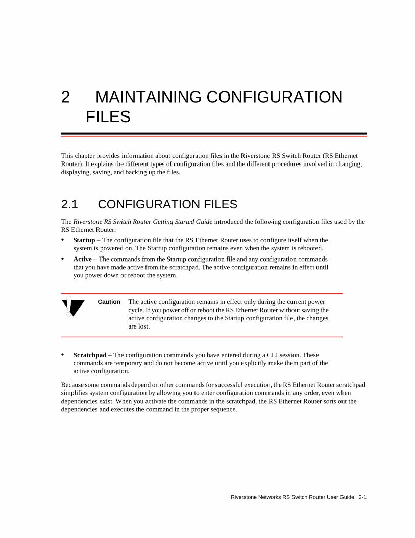
2 MAINTAINING CONFIGURATION FILES
This chapter provides information about configuration files in the Riverstone RS Switch Router (RS Ethernet Router). It explains the different types of configuration files and the different procedures involved in changing, displaying, saving, and backing up the files.
2.1 CONFIGURATION FILESThe Riverstone RS Switch Router Getting Started Guide introduced the following configuration files used by the RS Ethernet Router:• Startup – The configuration file that the RS Ethernet Router uses to configure itself when the
system is powered on. The Startup configuration remains even when the system is rebooted.• Active – The commands from the Startup configuration file and any configuration commands
that you have made active from the scratchpad. The active configuration remains in effect until you power down or reboot the system.
Caution The active configuration remains in effect only during the current power cycle. If you power off or reboot the RS Ethernet Router without saving the active configuration changes to the Startup configuration file, the changes are lost.
• Scratchpad – The configuration commands you have entered during a CLI session. These commands are temporary and do not become active until you explicitly make them part of the active configuration.
Because some commands depend on other commands for successful execution, the RS Ethernet Router scratchpad simplifies system configuration by allowing you to enter configuration commands in any order, even when dependencies exist. When you activate the commands in the scratchpad, the RS Ethernet Router sorts out the dependencies and executes the command in the proper sequence.
Riverstone Networks RS Switch Router User Guide 2-1

Configuration Files Maintaining Configuration Files
The following figure illustrates the configuration files and the commands you can use to save your configuration:
Figure 2-1 Commands to save configurations
2.1.1 Changing Configuration Information
The RS Ethernet Router provides many commands for changing configuration information.
Use the negate command on a specific line of the active configuration to “disable” a feature or function which has been enabled.
2.1.2 Displaying Configuration Information
The following table lists the commands that are useful for displaying RS Ethernet Router configuration information.
Table 2-1 Commands to change configuration information
Task Command
Enable Mode:
Copy between scratchpad, active configuration, startup configuration, TFTP server, RCP server, or URL.
copy <source> to <destination>
Configure Mode:
Erase commands in scratchpad. erase scratchpad
Erase startup configuration. erase startup
Negate one or more commands by line numbers. negate <line number>
Negate commands that match a specified command string. no <string>
Save scratchpad to active configuration. save active
Save active configuration to startup. save startup
StartupActiveScratchpad
(config)# save active (config)# save startup
temporarylocation;contents lostat reboot
in effectuntil reboot
remainsthrough reboot
2-2 Riverstone Networks RS Switch Router User Guide

Maintaining Configuration Files Configuration Files
The show and system show commands display the commands in the order they were executed. You can change this sequence to alphabetical order by using the system set show-config command.
2.1.3 Activating the Configuration Commands in the Scratchpad
The configuration commands you have entered using procedures in this chapter are in the Scratchpad but have not yet been activated. Use the following procedure to activate the configuration commands in the scratchpad.1. Ensure that you are in Enable mode by entering the enable command in the CLI.2. Ensure that you are in Configure mode by entering the configure command in the CLI.3. Enter the following command:
The CLI displays the following message:
4. Type y to activate the changes.
Table 2-2 Commands to display configuration information
Task Command
Enable Mode:
Show active configuration of the system. system show active
Show the non-activated configuration changes in the scratchpad.
system show scratchpad
Show the startup configuration for the next reboot. system show startup
Configure Mode:
Show active configuration of the system. show active
Show the non-activated configuration changes in the scratchpad.
show scratchpad
Show the startup configuration for the next reboot. show startup
Show the running system configuration, followed by the non-activated changes in the scratchpad.
show
Compare activated commands with the startup configuration file.
diff <filename> | startup
save active
Do you want to make the changes Active? [y]
Riverstone Networks RS Switch Router User Guide 2-3

Configuration Files Maintaining Configuration Files
Note If you exit the Configure mode (by entering the exit command or pressing Ctrl+Z), the CLI will ask you whether you want to make the changes in the scratchpad active.
2.1.4 Saving the Active Configuration to the Startup Configuration File
After you save the configuration commands in the scratchpad, the control module executes the commands and makes the corresponding configuration changes to the RS Ethernet Router. However, if you power off or reboot the RS Ethernet Router, the new changes are lost. Use the following procedure to save the changes into the Startup configuration file so that the RS Ethernet Router reinstates the changes when you reboot the software.1. Ensure that you are in Enable mode by entering the enable command in the CLI.2. Enter the following command to copy the configuration changes in the Active configuration to the
Startup configuration:
3. When the CLI displays the following message, enter yes to save the changes.
Note You also can save active changes to the Startup configuration file from within Configure mode by entering the save startup command.
The new configuration changes are added to the Startup configuration file stored in the control module’s boot flash.
2.1.5 Viewing the Current Configuration
To view the current configuration:1. Ensure that you are in Enable mode by entering the enable command in the CLI. 2. Enter the following command to display the status of each command line:
The CLI displays the active configuration file with the following possible annotations:- Commands without errors are displayed without any annotation.- Commands with errors are annotated with an “E.”
copy active to startup
Are you sure you want to overwrite the Startup configuration? [n]
system show active-config
2-4 Riverstone Networks RS Switch Router User Guide
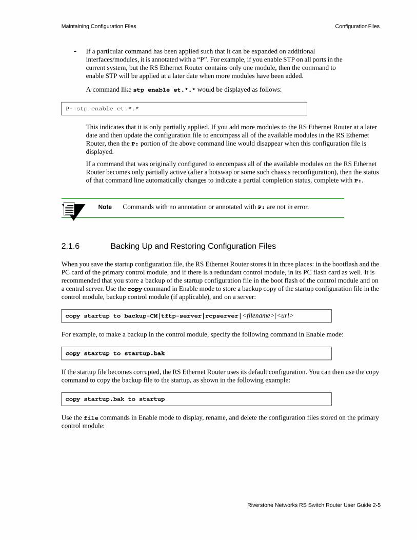
Maintaining Configuration Files Configuration Files
- If a particular command has been applied such that it can be expanded on additional interfaces/modules, it is annotated with a “P”. For example, if you enable STP on all ports in the current system, but the RS Ethernet Router contains only one module, then the command to enable STP will be applied at a later date when more modules have been added.
A command like stp enable et.*.* would be displayed as follows:
This indicates that it is only partially applied. If you add more modules to the RS Ethernet Router at a later date and then update the configuration file to encompass all of the available modules in the RS Ethernet Router, then the P: portion of the above command line would disappear when this configuration file is displayed.
If a command that was originally configured to encompass all of the available modules on the RS Ethernet Router becomes only partially active (after a hotswap or some such chassis reconfiguration), then the status of that command line automatically changes to indicate a partial completion status, complete with P:.
Note Commands with no annotation or annotated with P: are not in error.
2.1.6 Backing Up and Restoring Configuration Files
When you save the startup configuration file, the RS Ethernet Router stores it in three places: in the bootflash and the PC card of the primary control module, and if there is a redundant control module, in its PC flash card as well. It is recommended that you store a backup of the startup configuration file in the boot flash of the control module and on a central server. Use the copy command in Enable mode to store a backup copy of the startup configuration file in the control module, backup control module (if applicable), and on a server:
For example, to make a backup in the control module, specify the following command in Enable mode:
If the startup file becomes corrupted, the RS Ethernet Router uses its default configuration. You can then use the copy command to copy the backup file to the startup, as shown in the following example:
Use the file commands in Enable mode to display, rename, and delete the configuration files stored on the primary control module:
P: stp enable et.*.*
copy startup to backup-CM|tftp-server|rcpserver|<filename>|<url>
copy startup to startup.bak
copy startup.bak to startup
Riverstone Networks RS Switch Router User Guide 2-5

Configuration Files Maintaining Configuration Files
Note The file commands apply to devices and files in the primary Control Module. You cannot display, delete, or rename files in the backup Control Module. You can, however, use the CLI copy command to copy configuration files from the primary Control Module to the backup Control Module.
2.1.7 Specifying Primary and Backup Configuration Files
When the RS Ethernet Router boots up, it uses the startup configuration file to configure itself. Use the system set sys-config command in Enable mode to specify both a primary and secondary configuration file. When the RS Ethernet Router boots, it will try to use the primary configuration file. If for some reason the RS Ethernet Router cannot use the file, then it automatically uses the secondary configuration file. Following is an example:
Table 2-3 File commands
Display a directory of the files in the bootflash or in the PC card.
file dir <device>
Display the contents of a file in the bootflash. file type [<device>:]<filename>
Delete the specified file. file delete [<device>:]<filename>
Copy a file to a different device and/or filename. file copy [<device1>:]<source-filename> [<device2>:]<dest-filename>
Erase all files on the specified device. file reformat <device-name>
Rename a file. file rename [<device>:]<source-filename> <dest-filename>
rs# system set sys-config primary config_a secondary config_b
2-6 Riverstone Networks RS Switch Router User Guide
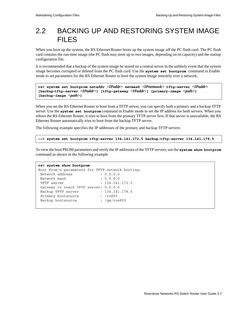
Maintaining Configuration Files Backing Up and Restoring System Image Files
2.2 BACKING UP AND RESTORING SYSTEM IMAGE FILES
When you boot up the system, the RS Ethernet Router boots up the system image off the PC flash card. The PC flash card contains the run-time image (the PC flash may store up to two images, depending on its capacity) and the startup configuration file.
It is recommended that a backup of the system image be stored on a central server in the unlikely event that the system image becomes corrupted or deleted from the PC flash card. Use the system set bootprom command in Enable mode to set parameters for the RS Ethernet Router to boot the system image remotely over a network.
When you set the RS Ethernet Router to boot from a TFTP server, you can specify both a primary and a backup TFTP server. Use the system set bootprom command in Enable mode to set the IP address for both servers. When you reboot the RS Ethernet Router, it tries to boot from the primary TFTP server first. If that server is unavailable, the RS Ethernet Router automatically tries to boot from the backup TFTP server.
The following example specifies the IP addresses of the primary and backup TFTP servers:
To view the boot PROM parameters and verify the IP addresses of the TFTP servers, use the system show bootprom command as shown in the following example
rs# system set bootprom netaddr <IPaddr> netmask <IPnetmask> tftp-server <IPaddr> [backup-tftp-server <IPaddr>] [tftp-gateway <IPaddr>] [primary-image <path>] [backup-image <path>]
rs# system set bootprom tftp-server 134.141.172.5 backup-tftp-server 134.141.178.5
rs# system show bootpromBoot Prom's parameters for TFTP network booting: Network address : 0.0.0.0 Network mask : 0.0.0.0 TFTP server : 134.141.172.5 Gateway to reach TFTP server: 0.0.0.0 Backup TFTP server : 134.141.178.5 Primary bootsource : /rs803 Backup bootsource : /qa/ros803
Riverstone Networks RS Switch Router User Guide 2-7

Backing Up and Restoring System Image Files Maintaining Configuration Files
The following example shows the messages displayed on the console as the RS Ethernet Router boots up. It tries to boot from the primary TFTP server (134.141.172.5) and when it is unable to do so, it boots from the backup TFTP server (134.141.178.5).
For even greater redundancy, you can specify a primary and backup system image. Use the system set bootprom command in Enable mode to specify both the primary and secondary system image files. When you reboot the RS Ethernet Router, it tries to boot the primary system image from the primary TFTP server and from the backup TFTP server. If that fails, then the RS Ethernet Router tries to boot the backup system image from the primary TFTP server, and then from the backup TFTP server.
The following example specifies the primary and backup system images:
Use the system show bootprom command to display your settings:
.
.
.Autoboot in 2 seconds - press RETURN to abort and enter prom
primary source: tftp://134.141.172.5/qa/ros803couldn't open 134.141.172.5:qa/ros803 for reading Kernel not found or lost in transmissionsecondary source: tftp://134.141.178.5/qa/ros803 File: version (874 bytes) Build location: host 'cmbuild0' by 'mhaydt' Version: 8.0.3.0-A06...
rs# system set bootprom primary image rs803 backup-image /qa/ros803
rs# system show bootpromBoot Prom's parameters for TFTP network booting: Network address : 0.0.0.0 Network mask : 0.0.0.0 TFTP server : 134.141.123.3 Gateway to reach TFTP server: 0.0.0.0 Backup TFTP server : 134.141.178.5 Primary bootsource : /rs803 Backup bootsource : /qa/ros803
2-8 Riverstone Networks RS Switch Router User Guide

Maintaining Configuration Files Backing Up and Restoring System Image Files
The following example shows the messages the RS Ethernet Router displays on the console as it tries to boot the system image software.
As shown in the example, the RS Ethernet Router tried to boot the primary system image (rs803) from the primary TFTP server (134.141.123.3), and then from the backup TFTP server (134.141.178.5). When the RS Ethernet Router was unable to boot the primary image, it tried to boot the backup system image (qa/ros803) from the primary TFTP server, and then from the backup TFTP server.
Note If the RS Ethernet Router has a backup Control Module (CM), changes made to the primary CM using the system set bootprom command are not automatically propagated to the backup CM. You must specify this command on the backup CM as well.
If the RS Ethernet Router boots up from the PC flash card and cannot find a valid image, it goes into boot prom mode. If the en0 interface is configured and connected to a network, you can download an image to the PC flash by using the system image add command in Enable mode. If the en0 interface has not been configured, then you will need to configure it by specifying the following: IP address and netmask of the RS Ethernet Router, IP address of the TFTP server, and IP address of the default gateway. Use the following commands in boot mode:
Then, boot the RS Ethernet Router by specifying the following command:
.
.
.Autoboot in 2 seconds - press RETURN to abort and enter promprimary source: tftp://134.141.123.3/rs803couldn't open 134.141.123.3:rs803 for reading Kernel not found or lost in transmissionsecondary source: tftp://134.141.178.5/rs803couldn't open 134.141.178.5:rs803 for reading Kernel not found or lost in transmissionprimary source: tftp://134.141.123.3/qa/ros803couldn't open 134.141.123.3:qa/ros803 for reading Kernel not found or lost in transmissionsecondary source: tftp://134.141.178.5/qa/ros803 File: version (874 bytes) Build location: host 'cmbuild0' by 'mhaydt' Version: 8.0.3.0-A06...
set net-addr <IP-address>set netmask <netmask>set boot-addr <tftp-server address>set gateway <IP-address of default gateway>
boot <directory/filename of the image file to boot from>
Riverstone Networks RS Switch Router User Guide 2-9

Configuring System Settings Maintaining Configuration Files
Alternatively, you can use the set boot source command:
Once the RS Ethernet Router has booted from the TFTP server image through en0, you can add the new image to the PC card by using the system image add command.
Additionally, you can use the following commands to display, add, and delete system images:
2.3 CONFIGURING SYSTEM SETTINGSIn addition to the initial settings described in the Getting Started Guide, there are additional system features which you can set on the RS Ethernet Router.
2.3.1 Setting Daylight Saving Time
Daylight saving time (DST) on the RS Ethernet Router can be set three different ways:• According to specific days. For example, from the first Sunday of April to the last Saturday of
October.• According to specific dates. For example, from April 1st to October 31st.• Setting the time on the RS Ethernet Router forward by an hour.
set boot source <filename>
Table 2-4 System image commands
Copy a system software image to the RS Ethernet Router.
system image add <IPaddr-or-hostname> <filename>[primary-cm|backup-cm] [slot0|slot1]
Select a system software image for booting. system image choose <filename>|none [primary-cm|backup-cm] [slot0|slot1]
Select a secondary system software image for booting.
system image secondary-choose <filename>|none [primary-cm|backup-cm] [slot0|slot1]
Copy a system software image from one PC card to another.
system image copy slot0|slot1 <filename> slot0|slot1 [<filename>]
List system software images on the PC flash card. system image list primary-cm|backup-cm|all
Delete a system software image file from the PC flash card.
system image delete <filename> primary-cm|backup-cm slot0|slot
2-10 Riverstone Networks RS Switch Router User Guide
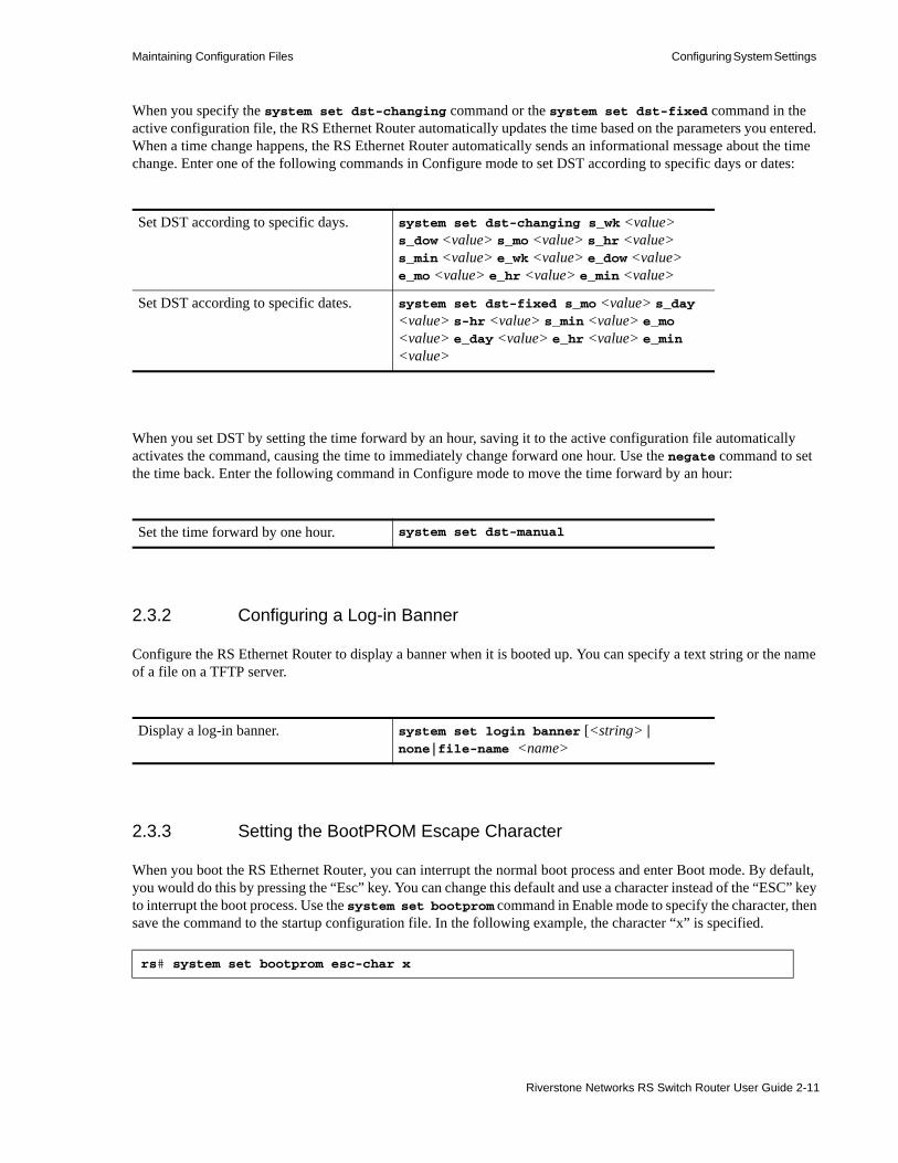
Maintaining Configuration Files Configuring System Settings
When you specify the system set dst-changing command or the system set dst-fixed command in the active configuration file, the RS Ethernet Router automatically updates the time based on the parameters you entered. When a time change happens, the RS Ethernet Router automatically sends an informational message about the time change. Enter one of the following commands in Configure mode to set DST according to specific days or dates:
When you set DST by setting the time forward by an hour, saving it to the active configuration file automatically activates the command, causing the time to immediately change forward one hour. Use the negate command to set the time back. Enter the following command in Configure mode to move the time forward by an hour:
2.3.2 Configuring a Log-in Banner
Configure the RS Ethernet Router to display a banner when it is booted up. You can specify a text string or the name of a file on a TFTP server.
2.3.3 Setting the BootPROM Escape Character
When you boot the RS Ethernet Router, you can interrupt the normal boot process and enter Boot mode. By default, you would do this by pressing the “Esc” key. You can change this default and use a character instead of the “ESC” key to interrupt the boot process. Use the system set bootprom command in Enable mode to specify the character, then save the command to the startup configuration file. In the following example, the character “x” is specified.
Set DST according to specific days. system set dst-changing s_wk <value> s_dow <value> s_mo <value> s_hr <value> s_min <value> e_wk <value> e_dow <value> e_mo <value> e_hr <value> e_min <value>
Set DST according to specific dates. system set dst-fixed s_mo <value> s_day <value> s-hr <value> s_min <value> e_mo <value> e_day <value> e_hr <value> e_min <value>
Set the time forward by one hour. system set dst-manual
Display a log-in banner. system set login banner [<string> | none|file-name <name>
rs# system set bootprom esc-char x
Riverstone Networks RS Switch Router User Guide 2-11

Configuring System Settings Maintaining Configuration Files
Therefore, when the RS Ethernet Router reboots and the character “x” is typed, the RS Ethernet Router will interrupt its boot process and enter Boot mode. To change back to the default, enter the system set bootprom command with the keyword ESC as shown in the following example:
rs# system set bootprom esc-char ESC
2-12 Riverstone Networks RS Switch Router User Guide
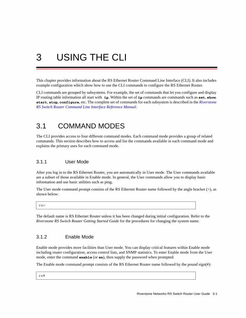
3 USING THE CLI
This chapter provides information about the RS Ethernet Router Command Line Interface (CLI). It also includes example configuration which show how to use the CLI commands to configure the RS Ethernet Router.
CLI commands are grouped by subsystems. For example, the set of commands that let you configure and display IP routing table information all start with ip. Within the set of ip commands are commands such as set, show, start, stop, configure, etc. The complete set of commands for each subsystem is described in the Riverstone RS Switch Router Command Line Interface Reference Manual.
3.1 COMMAND MODESThe CLI provides access to four different command modes. Each command mode provides a group of related commands. This section describes how to access and list the commands available in each command mode and explains the primary uses for each command mode.
3.1.1 User Mode
After you log in to the RS Ethernet Router, you are automatically in User mode. The User commands available are a subset of those available in Enable mode. In general, the User commands allow you to display basic information and use basic utilities such as ping.
The User mode command prompt consists of the RS Ethernet Router name followed by the angle bracket (>), as shown below:
The default name is RS Ethernet Router unless it has been changed during initial configuration. Refer to the Riverstone RS Switch Router Getting Started Guide for the procedures for changing the system name.
3.1.2 Enable Mode
Enable mode provides more facilities than User mode. You can display critical features within Enable mode including router configuration, access control lists, and SNMP statistics. To enter Enable mode from the User mode, enter the command enable (or en), then supply the password when prompted.
The Enable mode command prompt consists of the RS Ethernet Router name followed by the pound sign(#):
rs>
rs#
Riverstone Networks RS Switch Router User Guide 3-1

Establishing Telnet Sessions Using the CLI
To exit Enable mode and return to User mode, either type exit and press Return, or press Ctrl+Z.
3.1.3 Configure Mode
Configure mode provides the capabilities to configure all features and functions on the RS Ethernet Router. These include router configuration, access control lists and spanning tree. To enter Configure mode, enter the command config from Enable mode.
Note As mentioned previously, up to four Telnet sessions can be run simultaneously on the RS Ethernet Router. All four sessions can be in Configure mode at the same time, so you should consider limiting access to the RS Ethernet Router to authorized users.
The Configure mode command prompt consists of the RS Ethernet Router name followed by (config) and a pound sign (#):
To exit Configure mode and return to Enable mode, either type exit and press Return, or press Ctrl+Z.
3.1.4 Boot PROM Mode
If your RS Ethernet Router does not find a valid system image on the external PC flash, the system might enter programmable read-only memory (PROM) mode. You should then reboot the RS Ethernet Router (enter the command reboot at the boot PROM prompt) to restart the system. If the system fails to reboot successfully, please call Technical Support to resolve the problem.
For information on how to upgrade the boot PROM software and boot using the upgraded image, see the Riverstone RS Switch Router Getting Started Guide.
3.2 ESTABLISHING TELNET SESSIONSYou can establish a management connection to the RS Ethernet Router by connecting a terminal to the management port of the RS Ethernet Router and by establishing a telnet connection to a remote host. To establish a telnet connection, connect your network to the 10/100 MDI port on the RS Ethernet Router.
Note The RS Ethernet Router allows up to four simultaneous telnet or secure shell (SSH) sessions. For more information about using SSH sessions, see Chapter 27, "Security Configuration."
rs(config)#
3-2 Riverstone Networks RS Switch Router User Guide
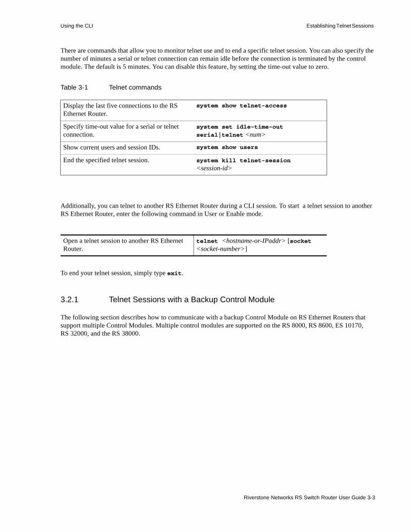
Using the CLI Establishing Telnet Sessions
There are commands that allow you to monitor telnet use and to end a specific telnet session. You can also specify the number of minutes a serial or telnet connection can remain idle before the connection is terminated by the control module. The default is 5 minutes. You can disable this feature, by setting the time-out value to zero.
Additionally, you can telnet to another RS Ethernet Router during a CLI session. To start a telnet session to another RS Ethernet Router, enter the following command in User or Enable mode.
To end your telnet session, simply type exit.
3.2.1 Telnet Sessions with a Backup Control Module
The following section describes how to communicate with a backup Control Module on RS Ethernet Routers that support multiple Control Modules. Multiple control modules are supported on the RS 8000, RS 8600, ES 10170, RS 32000, and the RS 38000.
Table 3-1 Telnet commands
Display the last five connections to the RS Ethernet Router.
system show telnet-access
Specify time-out value for a serial or telnet connection.
system set idle-time-out
serial|telnet <num>
Show current users and session IDs. system show users
End the specified telnet session. system kill telnet-session <session-id>
Open a telnet session to another RS Ethernet Router.
telnet <hostname-or-IPaddr> [socket <socket-number>]
Riverstone Networks RS Switch Router User Guide 3-3
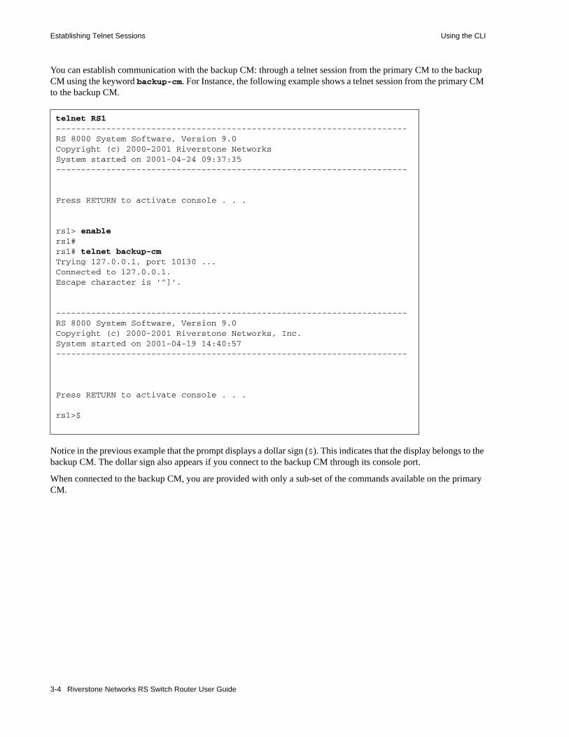
Establishing Telnet Sessions Using the CLI
You can establish communication with the backup CM: through a telnet session from the primary CM to the backup CM using the keyword backup-cm. For Instance, the following example shows a telnet session from the primary CM to the backup CM.
Notice in the previous example that the prompt displays a dollar sign ($). This indicates that the display belongs to the backup CM. The dollar sign also appears if you connect to the backup CM through its console port.
When connected to the backup CM, you are provided with only a sub-set of the commands available on the primary CM.
telnet RS1----------------------------------------------------------------------RS 8000 System Software, Version 9.0Copyright (c) 2000-2001 Riverstone NetworksSystem started on 2001-04-24 09:37:35----------------------------------------------------------------------
Press RETURN to activate console . . .
rs1> enablers1#rs1# telnet backup-cmTrying 127.0.0.1, port 10130 ...Connected to 127.0.0.1.Escape character is '^]'.
----------------------------------------------------------------------RS 8000 System Software, Version 9.0Copyright (c) 2000-2001 Riverstone Networks, Inc.System started on 2001-04-19 14:40:57----------------------------------------------------------------------
Press RETURN to activate console . . .
rs1>$
3-4 Riverstone Networks RS Switch Router User Guide

Using the CLI Setting CLI Parameters
For example, enter Enable mode on the backup CM, and then enter the help command (?). This produces the following output:
Notice that most of the Enable mode functionality is missing and there is no access to Configure mode. However, the backup CM does provide access to both the file and system facilities. These facilities allow you to do the following on the backup-CM:• Copy files• Delete files• Rename files• Reformat the file system• List system images• Choose system images
Note Also, you can enter the reboot command from the backup CM, however, the command reboots only the backup CM – the primary CM is not affected.
3.3 SETTING CLI PARAMETERSThe RS Ethernet Router provides various commands for controlling the behavior and display of the CLI. The cli set command completion command controls the behavior of the CLI when you enter commands. When you turn on command completion, the CLI attempts to automatically complete a command that is partially entered. Typing enough characters of a command keyword to uniquely identify it and pressing the space bar to move to the next word, causes the CLI to complete the command word and move on.
To set command completion, enter the following command in either Configure mode or Enable mode. In Configure mode, the command turns on or off command completion for the entire system. In Enable mode, the command affects the current login session of the user issuing the command.
rs1>$enable
rs1#$? cli - Modify the command line interface behavior enable - Enable privileged user mode exit - Exit current mode file - File manipulation commands logout - Log off the system reboot - Reboot the system system - Show system global parametersrs1#$
Turn on or turn off command completion. cli set command completion on|off
Riverstone Networks RS Switch Router User Guide 3-5
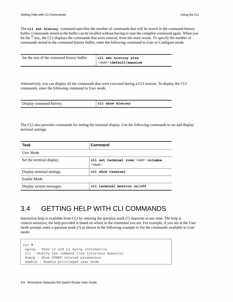
Getting Help with CLI Commands Using the CLI
The cli set history command specifies the number of commands that will be stored in the command history buffer. Commands stored in the buffer can be recalled without having to type the complete command again. When you hit the ↑ key, the CLI displays the commands that were entered, from the most recent. To specify the number of commands stored in the command history buffer, enter the following command in User or Configure mode.
Alternatively, you can display all the commands that were executed during a CLI session. To display the CLI commands, enter the following command in User mode.
The CLI also provides commands for setting the terminal display. Use the following commands to set and display terminal settings.
3.4 GETTING HELP WITH CLI COMMANDSInteractive help is available from CLI by entering the question mark (?) character at any time. The help is context-sensitive; the help provided is based on where in the command you are. For example, if you are at the User mode prompt, enter a question mark (?) as shown in the following example to list the commands available in User mode:
Set the size of the command history buffer. cli set history size <num>|default|maxsize
Display command history. cli show history
Task Command
User Mode
Set the terminal display. cli set terminal rows <num> columns <num>
Display terminal settings. cli show terminal
Enable Mode
Display system messages. cli terminal monitor on|off
rs> ? aging - Show L2 and L3 Aging information cli - Modify the command line interface behavior dvmrp - Show DVMRP related parameters enable - Enable privileged user mode
3-6 Riverstone Networks RS Switch Router User Guide
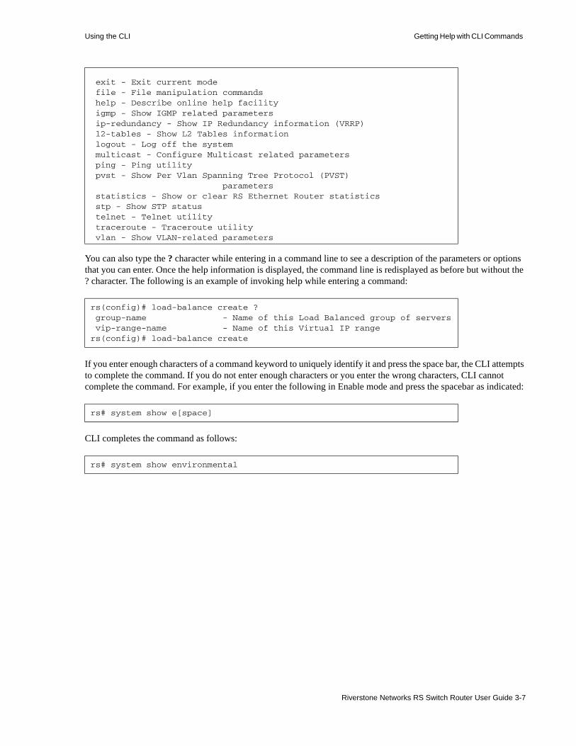
Using the CLI Getting Help with CLI Commands
You can also type the ? character while entering in a command line to see a description of the parameters or options that you can enter. Once the help information is displayed, the command line is redisplayed as before but without the ? character. The following is an example of invoking help while entering a command:
If you enter enough characters of a command keyword to uniquely identify it and press the space bar, the CLI attempts to complete the command. If you do not enter enough characters or you enter the wrong characters, CLI cannot complete the command. For example, if you enter the following in Enable mode and press the spacebar as indicated:
CLI completes the command as follows:
exit - Exit current mode file - File manipulation commands help - Describe online help facility igmp - Show IGMP related parameters ip-redundancy - Show IP Redundancy information (VRRP) l2-tables - Show L2 Tables information logout - Log off the system multicast - Configure Multicast related parameters ping - Ping utility pvst - Show Per Vlan Spanning Tree Protocol (PVST) parameters statistics - Show or clear RS Ethernet Router statistics stp - Show STP status telnet - Telnet utility traceroute - Traceroute utility vlan - Show VLAN-related parameters
rs(config)# load-balance create ? group-name - Name of this Load Balanced group of servers vip-range-name - Name of this Virtual IP rangers(config)# load-balance create
rs# system show e[space]
rs# system show environmental
Riverstone Networks RS Switch Router User Guide 3-7
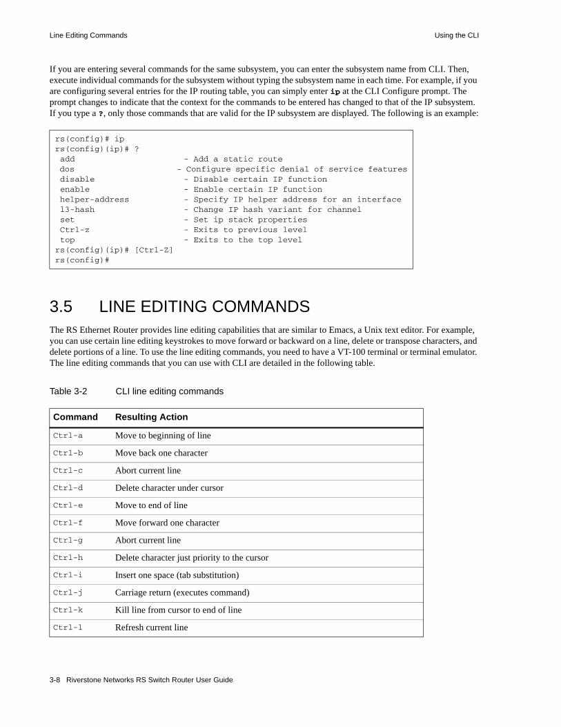
Line Editing Commands Using the CLI
If you are entering several commands for the same subsystem, you can enter the subsystem name from CLI. Then, execute individual commands for the subsystem without typing the subsystem name in each time. For example, if you are configuring several entries for the IP routing table, you can simply enter ip at the CLI Configure prompt. The prompt changes to indicate that the context for the commands to be entered has changed to that of the IP subsystem. If you type a ?, only those commands that are valid for the IP subsystem are displayed. The following is an example:
3.5 LINE EDITING COMMANDSThe RS Ethernet Router provides line editing capabilities that are similar to Emacs, a Unix text editor. For example, you can use certain line editing keystrokes to move forward or backward on a line, delete or transpose characters, and delete portions of a line. To use the line editing commands, you need to have a VT-100 terminal or terminal emulator. The line editing commands that you can use with CLI are detailed in the following table.
rs(config)# iprs(config)(ip)# ? add - Add a static route dos - Configure specific denial of service features disable - Disable certain IP function enable - Enable certain IP function helper-address - Specify IP helper address for an interface l3-hash - Change IP hash variant for channel set - Set ip stack properties Ctrl-z - Exits to previous level top - Exits to the top level rs(config)(ip)# [Ctrl-Z]rs(config)#
Table 3-2 CLI line editing commands
Command Resulting Action
Ctrl-a Move to beginning of line
Ctrl-b Move back one character
Ctrl-c Abort current line
Ctrl-d Delete character under cursor
Ctrl-e Move to end of line
Ctrl-f Move forward one character
Ctrl-g Abort current line
Ctrl-h Delete character just priority to the cursor
Ctrl-i Insert one space (tab substitution)
Ctrl-j Carriage return (executes command)
Ctrl-k Kill line from cursor to end of line
Ctrl-l Refresh current line
3-8 Riverstone Networks RS Switch Router User Guide

Using the CLI Line Editing Commands
Ctrl-m Carriage return (executes command)
Ctrl-n Next command from history buffer
Ctrl-o None
Ctrl-p Previous command from history buffer
Ctrl-q None
Ctrl-r Refresh current line
Ctrl-s None
Ctrl-t Transpose character under cursor with the character just prior to the cursor
Ctrl-u Delete line from the beginning of line to cursor
Ctrl-v None
Ctrl-w None
Ctrl-x Move forward one word
Ctrl-y Paste back what was deleted by the previous Ctrl-k or Ctrl-w command. Text is pasted back at the cursor location
Ctrl-z If inside a subsystem, it exits back to the top level. If in Enable mode, it exits back to User mode. If in Configure mode, it exits back to Enable mode.
ESC-b Move backward one word
ESC-d Kill word from cursor’s current location until the first white space.
ESC-f Move forward one word
ESC-BackSpace
Delete backwards from cursor to the previous space (essentially a delete-word-backward command)
SPACE Attempts to complete command keyword. If word is not expected to be a keyword, the space character is inserted.
!* Show all commands currently stored in the history buffer.
!# Recall a specific history command. ‘#’ is the number of the history command to be recalled as shown via the ‘!*’ command.
“<string>” Opaque strings may be specified using double quotes. This prevents interpretation of otherwise special CLI characters.
Table 3-2 CLI line editing commands (Continued)
Command Resulting Action
Riverstone Networks RS Switch Router User Guide 3-9

Naming RS Ethernet Router Ports Using the CLI
3.6 NAMING RS ETHERNET ROUTER PORTSThe term port refers to a physical connector on a line card installed in the RS Ethernet Router. The figure below shows to 1000base-SX ports on a line card.
Figure 3-1 1000-Base-SX line card
At the CLI, each port is referred to RS Ethernet Router in the following manner:• Channelized WAN ports:
<type>.<slot-number>.<port-number>[:<channel-number>][.<vc>]
• All other ports, including unchannelized T1/E1:
<type>.<slot-number>.<port-number>[.<vc>]
Where:
<type> is the type of line card and is one of the following:
at – Asynchronous Transfer Mode (ATM)
cm – Cable Modem Termination System (CMTS)
e1 – Channelized E1
e3 – Clear Channel E3
et – 10 Base-X/100 Base-X Ethernet
gi – 1000 Base-X Gigabit Ethernet
hs – Dual HSSI WAN
se – Serial WAN
so – Packet-over-SONET (POS)
t1 – Channelized T1
t3 – Channelized T3 or Clear Channel T3
<slot-number> is determined by the RS Ethernet Router model and the physical slot in which the line card is installed. On the RS 1000 and RS 3000 the slot number is printed on the side of each slot. On the RS 8000, RS 8600, RS 32000, and RS 38000 a legend on the fan tray shows slot number of each slot.
<port-number> is the number assigned to the physical connector on the line card. The range and assignment of port numbers varies by chassis and the type of line card.
Hot
Swap
21
Online
Offline
Rx
Tx Link
ANRx
Tx Link
AN
Gigabit port Gigabit port
1000BASE-SXG8M-GSXB1-02
3-10 Riverstone Networks RS Switch Router User Guide
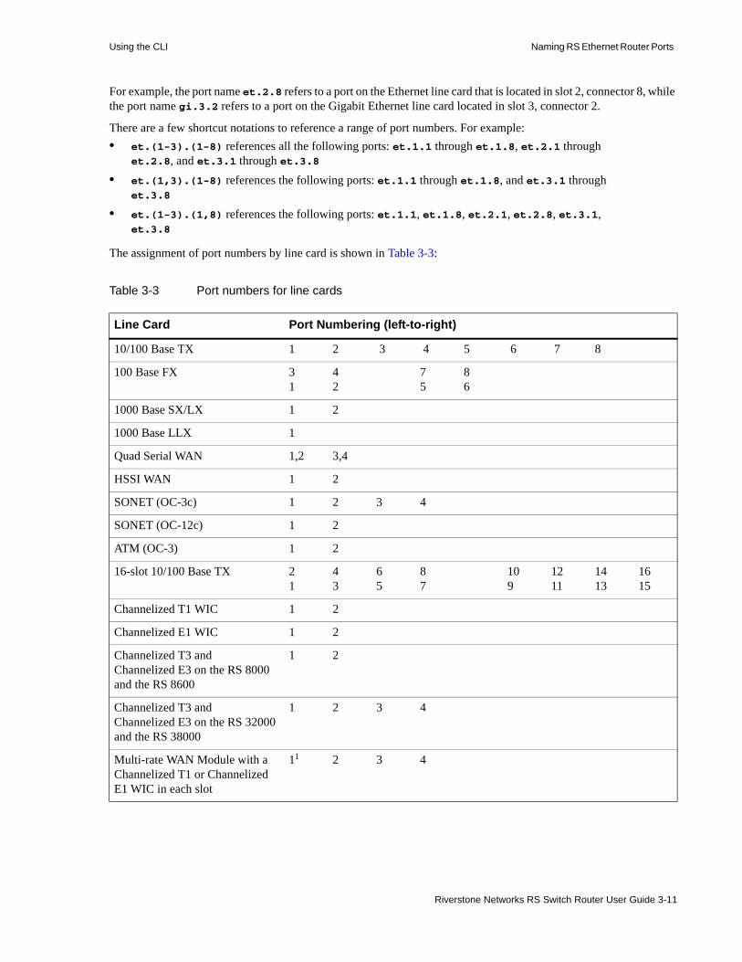
Using the CLI Naming RS Ethernet Router Ports
For example, the port name et.2.8 refers to a port on the Ethernet line card that is located in slot 2, connector 8, while the port name gi.3.2 refers to a port on the Gigabit Ethernet line card located in slot 3, connector 2.
There are a few shortcut notations to reference a range of port numbers. For example:• et.(1-3).(1-8) references all the following ports: et.1.1 through et.1.8, et.2.1 through
et.2.8, and et.3.1 through et.3.8• et.(1,3).(1-8) references the following ports: et.1.1 through et.1.8, and et.3.1 through
et.3.8
• et.(1-3).(1,8) references the following ports: et.1.1, et.1.8, et.2.1, et.2.8, et.3.1, et.3.8
The assignment of port numbers by line card is shown in Table 3-3:
Table 3-3 Port numbers for line cards
Line Card Port Numbering (left-to-right)
10/100 Base TX 1 2 3 4 5 6 7 8
100 Base FX 31
42
75
86
1000 Base SX/LX 1 2
1000 Base LLX 1
Quad Serial WAN 1,2 3,4
HSSI WAN 1 2
SONET (OC-3c) 1 2 3 4
SONET (OC-12c) 1 2
ATM (OC-3) 1 2
16-slot 10/100 Base TX 21
43
65
87
109
1211
1413
1615
Channelized T1 WIC 1 2
Channelized E1 WIC 1 2
Channelized T3 andChannelized E3 on the RS 8000 and the RS 8600
1 2
Channelized T3 andChannelized E3 on the RS 32000 and the RS 38000
1 2 3 4
Multi-rate WAN Module with a Channelized T1 or Channelized E1 WIC in each slot
11 2 3 4
Riverstone Networks RS Switch Router User Guide 3-11

Naming RS Ethernet Router Ports Using the CLI
3.6.1 Channel Numbers
A channel number is the number assigned to the timeslots on a T1/E1 line card connector or the T1/E1 channels on a T3/E3 line card connector. For Channelized T1 and E1, and fractional T1 and E1 line cards, a channel always refers to a timeslot.
Channels can be specified by a single channel number, a comma-separated list of channel numbers, or a range of channel numbers. For a channel range, specify a start-channel and an end-channel – the end-channel value must be greater than the start-channel value.
For other port types, including unchannelized T1 and E1, omit the <channel-number> and the preceding colon (:). The <vc> parameter is still permitted for Frame Relay encapsulation. See Table 3-4.
The following examples show the different channel specifications for T1:
t1.3.2:5-8 – T1 line card in slot 3, port 2, and timeslots 5 through 8
t1.3.1:(1-4,6,7) – T1 line card in slot 3, port 1, and timeslots 1 through 4 and timeslots 6 and 7
t3.4.2.3:1-16 – T3 line card in slot 4, port 2, T1 channel 3, and timeslots 1 through 16
Multi-rate WAN Module with a Clear Channel T3 or Clear Channel E3 WIC in each slot
11 3 1 3
DOCSIS/EuroDOCSIS CMTS 1 US2 2 US 3 US 4 US 1 DS-IF3
DOCSIS/EuroDOCSIS CMTS 1 US 2 US 3 US 4 US 5 US 6 US 1 DS-IF
1 – The port numbering, when using a Clear Channel T3 or E3 WIC with a Channelized T1 or E1 WIC depends on the slot in which the WIC is placed. For example, if a Clear Channel WIC is in the first slot, and a Channelized WIC in the second, then the port numbers will be 1, 3, and 4. If the position of the WICs are reversed, then the numbering will be 1, 2, and 3.
2 – Upstream port
3 – Downstream-Intermediate Frequency port
Table 3-4 Channelized T1, E1 and T3 channel ranges
Range WAN Module
1 to 24 Channelized T1
1 to 31 Channelized E1
1 to 28* Channelized T3
* Each of these T1 lines contain 24 timeslots, where each timeslot can be considered a channel.
Table 3-3 Port numbers for line cards (Continued)
Line Card Port Numbering (left-to-right)
3-12 Riverstone Networks RS Switch Router User Guide

Using the CLI Multi-User Mode
3.7 MULTI-USER MODEMulti-user mode provides the ability to give several users access to the RS Ethernet Router CLI and control which commands each user can access. For example, if you are setting up a multi-tiered customer support organization, you may want to restrict CLI command capabilities of your first-level personnel. Second-level personnel may require more CLI command capabilities. Ultimately, you may want one or more high-level personnel to have full access to the RS Ethernet Router CLI.
User access is configured by placing the RS Ethernet Router into multi-user mode, assigning privilege levels to users, and defining which commands each privilege level can execute. There are 16 privilege levels: 0 through 15. Privilege level 15 (super user) has access to all CLI commands, while all other privilege levels must have their CLI commands explicitly defined.
The following three commands are used to start multi-user access and to define CLI capabilities:
system set access-mode – Changes the access mode from single-user to multi-user.
system set user – Defines user names, their passwords, and their privilege level.
privilege – Defines which CLI commands can be accessed by each privilege level.
3.7.1 Setting Up Multi-User Access
The following is a step-by-step example of setting up a user with minimal CLI access capabilities.1. Place the RS Ethernet Router into multi-user mode by entering the following command from
Configuration mode:
2. Set up a level 15 access account (super user) for yourself. This provides you access to all CLI commands. Enter the following:
Caution Even if you later plan to give no one super user privileges, it is a good idea to set up an initial account with privilege level 15. When first working with the multi-user mode and privileges, it is possible to lock yourself out of your own RS Ethernet Router. Having a super user account keep a lockout from occurring.
3. Create a minimum access level user named tier1 by entering the following:
rs(config)# system set access-mode multi-user
rs(config)# system set user root password abc123 privilege 15
rs(config)# system set user tier1 password junior privilege 1
Riverstone Networks RS Switch Router User Guide 3-13

Multi-User Mode Using the CLI
Note When entering passwords using the system set user command, passwords are not hashed on the screen. However, within the configuration file, these passwords appear as encrypted strings.
4. Use the privilege command to set up the minimum set of commands for level 1 users. Notice that the mode (either Enable or Configure) must be set, and that the command is entered as a string within quotes:
The four commands above allow a level 1 user to enter and exit both the Enable and Configure mode. However, they do not allow the level 1 user to execute any commands within either of these modes. For any user below level 15, each command accessible to them must be entered using the privilege command.
5. Continuing with this example, use the privilege command to add additional commands to the level 1 set:
The commands above, allow level 1 users to execute the CMTS Enable an Configure mode commands displayed within the quotes.
Note Higher privilege levels inherit all command capabilities of all lower privilege levels. For instance, if a second privilege level (level 2) is defined, level 2 users automatically inherits all of the capabilities of level 1 users.
Note when using multi-user mode, use the enforce-system-passwords option of the system set access-mode multi-user command to use system passwords for the Enable and Diag modes.
rs(config)# privilege enable level 1 command “enable”rs(config)# privilege enable level 1 command “exit”rs(config)# privilege enable level 1 command “configure”rs(config)# privilege configuration level 1 command “exit”
rs(config)# privilege enable level 1 command “cmts show modems all-ports”rs(config)# privilege enable level 1 command “cmts show event-log local”rs(config)# privilege configuration level 1 command “cmts set event-log alert local-log”rs(config)# privilege configuration level 1 command “cmts set event-log warning local-log”rs(config)# privilege configuration level 1 command “cmts set event-log error local-log”
3-14 Riverstone Networks RS Switch Router User Guide
Using the CLI Multi-User Mode
3.7.2 Wildcard Option
From the example above, it should be apparent that whatever privilege level you assign, an extensive number of configuration commands need to be entered to define exactly what each privilege level is allowed to do.
For example, entering the following command line allows privilege level 1 users the ability to ping a particular IP address:
However, the RS Ethernet Router allows for the use of a wildcard symbol (*) to represent values within command lines. The wildcard is used to represent variables and keywords. For instance, considering the ping example above, level 1 users can be given the ability to ping any IP address by entering the following:
Because the IP address is a variable within the command line, it can be replaced by the wildcard symbol. As a result, level 1 users can now ping all IP addresses.
Suppose the next level of customer support (tier2) is allowed to create IP VLANs and apply interfaces to VLANs. The following example shows how the wildcard option is used to provide the flexibility to add VLANs and interfaces of any name and IP address:
In the example above, the first line created the level 2 privilege group, tier2. The second line gives level 2 users the ability to create an IP VLAN with any name. The third line gives level 2 users the ability to create an interface with any name, to specify any address/subnet mask pair, and to assign the interface to any valid VLAN.
The following is a list the variable objects for which the wildcard (*) can be substituted.• VLAN name• Number – Decimal, hexadecimal, floating-point, binary, 1 or 0 used as a switch• Numerical range• String (user, interface name, port name, password, and so on)• Keyword – where a keyword is the only valid entry, such as enable or disable• IP address or IP address list• Subnet mask• MAC address or MAC address list• Conditional expressions• Module number• Slot number• Time – Hour, minute, second, and date• List of logical port names
rs(config)# privilege enable level 1 command “ping 124.141.56.72”
rs(config)# privilege enable level 1 command “ping *”
rs(config)# system set user tier2 password midkid privilege 2rs(config)# privilege configuration level 2 command “vlan create * ip”rs(config)# privilege configuration level 2 command “interface create ip * address-netmask * vlan *”
Riverstone Networks RS Switch Router User Guide 3-15

Multi-User Mode Using the CLI
Note When negating configuration commands from within multi-user mode, not only do you need sufficient permission to use the negate command, but you must also have sufficient permission to run the commands you are negating
3.7.3 Configuring Multi-User Mode RADIUS Authentication
Setting the RS Ethernet Router to multi-user mode allows multiple users to access the RS Ethernet Router and provides the ability to control which commands each user can access. (For information on configuring the RS Ethernet Router for multi-user mode, refer to Section 3.7.1, "Setting Up Multi-User Access.") When the RS Ethernet Router is in multi-user mode, you can configure a RADIUS server to authenticate each user and to indicate the user’s privilege level. To accomplish this, the RADIUS servers' user database must be configured to return the Riverstone-User-Level attribute along with an Access-Accept response. The Riverstone-User-Level is a Riverstone vendor-specific attribute defined in the dictionary file. (The latest revision of the dictionary file can be found on Riverstone's website.) The value of this attribute is an integer from 0 to 15 that indicates the desired privilege level.
If the RADIUS server does not include a Riverstone-User-Level attribute in the Access-Accept response, the RS Ethernet Router will look for the standard RADIUS Service-Type attribute. If the value of this attribute is 6 (Administrative), the RS Ethernet Router treats this as if the user has level 15 privileges, providing full access to the system. Any other value will be the same as if the attribute is not there; RapidOS will place the user at access level 1. Whenever both Riverstone-User-Level and Service-Type attributes are present in an Access-Accept response, the Riverstone-User-Level always takes precedence.
3-16 Riverstone Networks RS Switch Router User Guide

4 HOT SWAPPING LINE CARDS AND CONTROL MODULES
4.1 HOT SWAPPING OVERVIEWHot swapping is the ability to replace a line card, Control Module, or GBIC (in the RS 32000 and RS 38000 only) while the RS Ethernet Router is operating. Hot swapping allows you to remove or install line cards without switching off or rebooting the RS Ethernet Router. Swapped-in line cards are recognized by the RS Ethernet Router and begin functioning immediately after they are installed.
On the RS 8000 and RS 8600, you can hot swap line cards and secondary control modules. On the RS 8600, you can also hot swap the secondary switching fabric module. On the RS 32000 and RS 38000, you can hot swap the GBICs, in addition to the line cards and secondary control modules.
Caution Take appropriate care when removing line cards from the RS Ethernet Router. They may be hot to the touch.
Warning The RS Ethernet Router and its components are sensitive to static discharge. Use an antistatic wrist strap and observe all static precautions when hot swapping the RS Ethernet Router components.
This chapter provides instructions for the following tasks:• Hot swapping line cards• Hot swapping secondary Control Modules• Hot swapping the secondary Switching Fabric Module (RS 8600 only)• Hot swapping the GBIC (RS 32000 and RS 38000 only)
4.2 HOT SWAPPING LINE CARDSThe procedure for hot swapping a line card consists of deactivating the line card, removing it from its slot in the RS Ethernet Router chassis, and installing a new line card in the slot.
Riverstone Networks RS Switch Router User Guide 4-1
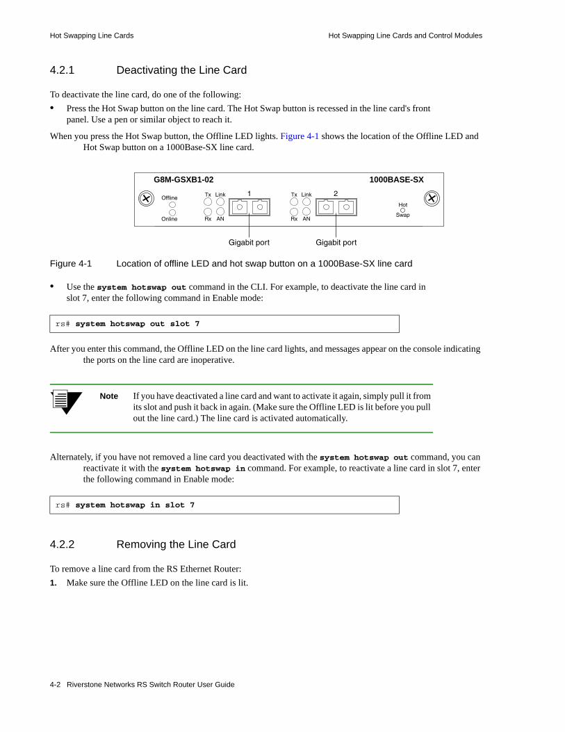
Hot Swapping Line Cards Hot Swapping Line Cards and Control Modules
4.2.1 Deactivating the Line Card
To deactivate the line card, do one of the following: • Press the Hot Swap button on the line card. The Hot Swap button is recessed in the line card's front
panel. Use a pen or similar object to reach it.
When you press the Hot Swap button, the Offline LED lights. Figure 4-1 shows the location of the Offline LED and Hot Swap button on a 1000Base-SX line card.
Figure 4-1 Location of offline LED and hot swap button on a 1000Base-SX line card
• Use the system hotswap out command in the CLI. For example, to deactivate the line card in slot 7, enter the following command in Enable mode:
After you enter this command, the Offline LED on the line card lights, and messages appear on the console indicating the ports on the line card are inoperative.
Note If you have deactivated a line card and want to activate it again, simply pull it from its slot and push it back in again. (Make sure the Offline LED is lit before you pull out the line card.) The line card is activated automatically.
Alternately, if you have not removed a line card you deactivated with the system hotswap out command, you can reactivate it with the system hotswap in command. For example, to reactivate a line card in slot 7, enter the following command in Enable mode:
4.2.2 Removing the Line Card
To remove a line card from the RS Ethernet Router:1. Make sure the Offline LED on the line card is lit.
rs# system hotswap out slot 7
rs# system hotswap in slot 7
Hot
Swap
21
Online
Offline
Rx
Tx Link
ANRx
Tx Link
AN
Gigabit port Gigabit port
1000BASE-SXG8M-GSXB1-02
4-2 Riverstone Networks RS Switch Router User Guide

Hot Swapping Line Cards and Control Modules Hot Swapping One Type of Line Card With Another
Warning Do not remove the line card unless the Offline LED is lit. Doing so can cause the RS Ethernet Router to crash.
2. Loosen the captive screws on each side of the line card.3. Carefully remove the line card from its slot in the RS Ethernet Router chassis.
4.2.3 Installing a New Line Card
To install a new line card:1. Slide the line card all the way into the slot, firmly but gently pressing the line card fully in place to
ensure that the pins on the back of the line card are completely seated in the backplane.
Note Make sure the circuit card (and not the metal plate) is between the card guides. Check both the upper and lower tracks.
2. Tighten the captive screws on each side of the line card to secure it to the chassis.
Once the line card is installed, the RS Ethernet Router recognizes and activates it. The Online LED button lights.
4.3 HOT SWAPPING ONE TYPE OF LINE CARD WITH ANOTHER
You can hot swap one type of line card with another type. For example, you can replace a 10/100Base-TX line card with a 1000Base-SX line card. The RS Ethernet Router can be configured to accommodate whichever line card is installed in the slot. When one line card is installed, configuration statements for that line card are used; when you remove the line card from the slot and replace it with a different type, configuration statements for the new line card take effect.
To set this up, you must include configuration statements for both line cards in the RS Ethernet Router configuration file. The RS Ethernet Router determines which line card is installed in the slot and uses the appropriate configuration statements.
For example, you may have an RS Ethernet Router with a 10/100Base-TX line card in slot 7 and want to hot swap it with a 1000Base-SX line card. If you include statements for both line cards in the RS Ethernet Router configuration file, the statements for the 1000Base-SX take effect immediately after you install it in slot 7.
Riverstone Networks RS Switch Router User Guide 4-3
Hot Swapping a Secondary Control Module Hot Swapping Line Cards and Control Modules
4.4 HOT SWAPPING A SECONDARY CONTROL MODULE
If you have a secondary Control Module installed on the RS Ethernet Router, you can hot swap it with another Control Module or line card.
Warning You can only hot swap an inactive Control Module. You should never remove the active Control Module from the RS Ethernet Router. Doing so will crash the system.
The procedure for hot swapping a Control Module is similar to the procedure for hot swapping a line card. You must deactivate the Control Module, remove it from the RS Ethernet Router, and insert another Control Module or line card in the slot.
4.4.1 Deactivating the Control Module
To deactivate the Control Module:1. Determine which is the secondary Control Module.
Control Modules can reside in slot CM or slot CM/1 on the RS Ethernet Router. Usually slot CM contains the primary Control Module, and slot CM/1 contains the secondary Control Module. On the primary Control Module, the Online LED is lit, and on the secondary Control Module, the Offline LED is lit.
Note The Offline LED on the Control Module has a different function from the Offline LED on a line card. On a line card, it means that the line card has been deactivated. On a Control Module, a lit Offline LED means that it is standing by to take over as the primary Control Module if necessary; it does not mean that the Control Module has been deactivated.
2. Press the Hot Swap button on the secondary Control Module.
4-4 Riverstone Networks RS Switch Router User Guide
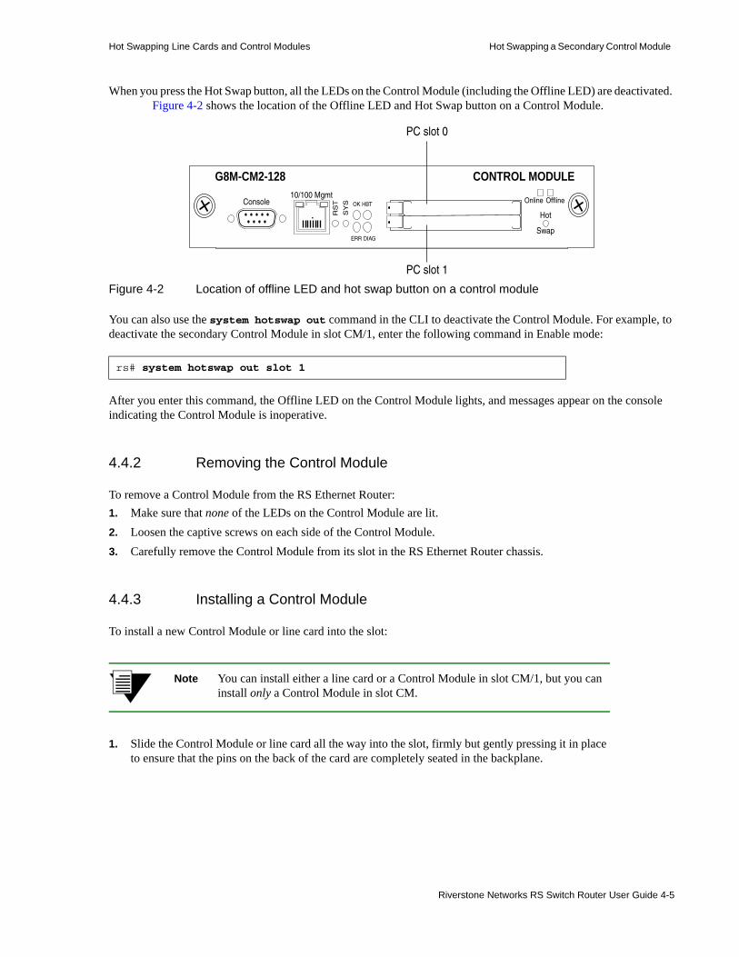
Hot Swapping Line Cards and Control Modules Hot Swapping a Secondary Control Module
When you press the Hot Swap button, all the LEDs on the Control Module (including the Offline LED) are deactivated. Figure 4-2 shows the location of the Offline LED and Hot Swap button on a Control Module.
Figure 4-2 Location of offline LED and hot swap button on a control module
You can also use the system hotswap out command in the CLI to deactivate the Control Module. For example, to deactivate the secondary Control Module in slot CM/1, enter the following command in Enable mode:
After you enter this command, the Offline LED on the Control Module lights, and messages appear on the console indicating the Control Module is inoperative.
4.4.2 Removing the Control Module
To remove a Control Module from the RS Ethernet Router:1. Make sure that none of the LEDs on the Control Module are lit.2. Loosen the captive screws on each side of the Control Module.3. Carefully remove the Control Module from its slot in the RS Ethernet Router chassis.
4.4.3 Installing a Control Module
To install a new Control Module or line card into the slot:
Note You can install either a line card or a Control Module in slot CM/1, but you can install only a Control Module in slot CM.
1. Slide the Control Module or line card all the way into the slot, firmly but gently pressing it in place to ensure that the pins on the back of the card are completely seated in the backplane.
rs# system hotswap out slot 1
10/100 MgmtConsole
RS
T
SY
S OK
ERR DIAG
HBT
Hot
Swap
Online Offline
PC slot 1
G8M-CM2-128 CONTROL MODULE
PC slot 0
Riverstone Networks RS Switch Router User Guide 4-5

Hot Swapping a Switching Fabric Module (RS 8600 only) Hot Swapping Line Cards and Control Modules
Note Make sure the circuit card (and not the metal plate) is between the card guides. Check both the upper and lower tracks.
2. Tighten the captive screws on each side of the Control Module or line card to secure it to the chassis.
- On a line card, the Online LED lights, indicating it is now active.- On a secondary Control Module, the Offline LED lights, indicating it is standing by to take over
as the primary Control Module if necessary.
4.5 HOT SWAPPING A SWITCHING FABRIC MODULE (RS 8600 ONLY)
The RS 8600 has slots for two Switching Fabric Modules. While the RS 8600 is operating, you can install a second Switching Fabric Module. If two Switching Fabric Modules are installed, you can hot swap one of them.
When you remove one of the Switching Fabric Modules, the other goes online and stays online until it is removed or the RS 8600 is powered off. When the RS 8600 is powered on again, the Switching Fabric Module in slot “Fabric 1,” if one is installed there, becomes the active Switching Fabric Module.
Warning You can only hot swap a Switching Fabric Module if two are installed on the RS 8600. If only one Switching Fabric Module is installed, and you remove it, the RS 8600 will crash.
The procedure for hot swapping a Switching Fabric Module is similar to the procedure for hot swapping a line card or Control Module. You deactivate the Switching Fabric Module, remove it from the RS Ethernet Router, and insert another Switching Fabric Module in the slot.
Note You cannot deactivate the Switching Fabric Module with the system hotswap command.
To deactivate the Switching Fabric Module:1. Press the Hot Swap button on the Switching Fabric Module you want to deactivate.
The Online LED goes out and the Offline LED lights. Figure 4-3 shows the location of the Offline LED and Hot Swap button on a Switching Fabric Module.
Figure 4-3 Location of offline LED and hot swap button on a switching fabric module
G86-SWF Switching Fabric
Active
Online
Swap
HotOffline
4-6 Riverstone Networks RS Switch Router User Guide

Hot Swapping Line Cards and Control Modules Hot Swapping A GBIC (RS 32000 and RS 38000 only)
4.5.1 Removing the Switching Fabric Module
To remove the Switching Fabric Module:1. Loosen the captive screws on each side of the Switching Fabric Module.2. Pull the metal tabs on the Switching Fabric Module to free it from the connectors holding it in place
in the chassis.3. Carefully remove the Switching Fabric Module from its slot.
4.5.2 Installing a Switching Fabric Module
To install a Switching Fabric Module:1. Slide the Switching Fabric Module all the way into the slot, firmly but gently pressing to ensure that
the pins on the back of the module are completely seated in the backplane.
Note Make sure the circuit card (and not the metal plate) is between the card guides. Check both the upper and lower tracks.
2. Tighten the captive screws on each side of the Switching Fabric Module to secure it to the chassis.
4.6 HOT SWAPPING A GBIC (RS 32000 AND RS 38000 ONLY)
The Gigabit Ethernet line cards have slots for GBICs that can be installed at any time. You can hot swap the GBICs installed in the line cards, as well as the line cards themselves. (For information on hot swapping line cards, see Section 4.2, "Hot Swapping Line Cards.")
Warning The GBIC and the host gigabit Ethernet line cards are sensitive to static discharge. Use an antistatic wrist strap and observe all static precautions when you remove or install a GBIC. Failure to do so could result in damage to the GBIC and the host line card. Always leave the GBIC in the antistatic bag or an equivalent antistatic container until it is ready to be installed.
4.6.1 Removing a GBIC from the Line Card
To remove a GBIC from its slot on the line card:1. Remove any cables connected to the GBIC.2. Locate the extractor tabs on either side of the GBIC.
Riverstone Networks RS Switch Router User Guide 4-7
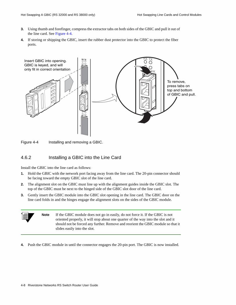
Hot Swapping A GBIC (RS 32000 and RS 38000 only) Hot Swapping Line Cards and Control Modules
3. Using thumb and forefinger, compress the extractor tabs on both sides of the GBIC and pull it out of the line card. See Figure 4-4.
4. If storing or shipping the GBIC, insert the rubber dust protector into the GBIC to protect the fiber ports.
Figure 4-4 Installing and removing a GBIC.
4.6.2 Installing a GBIC into the Line Card
Install the GBIC into the line card as follows:1. Hold the GBIC with the network port facing away from the line card. The 20-pin connector should
be facing toward the empty GBIC slot of the line card.2. The alignment slot on the GBIC must line up with the alignment guides inside the GBIC slot. The
top of the GBIC must be next to the hinged side of the GBIC slot door of the line card.3. Gently insert the GBIC module into the GBIC slot opening in the line card. The GBIC door on the
line card folds in and the hinges engage the alignment slots on the sides of the GBIC module.
Note If the GBIC module does not go in easily, do not force it. If the GBIC is not oriented properly, it will stop about one quarter of the way into the slot and it should not be forced any further. Remove and reorient the GBIC module so that it slides easily into the slot.
4. Push the GBIC module in until the connector engages the 20-pin port. The GBIC is now installed.
Insert GBIC into opening.GBIC is keyed, and willonly fit in correct orientation
To remove,press tabs ontop and bottomof GBIC and pull.
4-8 Riverstone Networks RS Switch Router User Guide

Hot Swapping Line Cards and Control Modules Hot Swapping a WIC
4.7 HOT SWAPPING A WIC
Note Hot swapping WICs is not yet supported.
Riverstone Networks RS Switch Router User Guide 4-9

Hot Swapping a WIC Hot Swapping Line Cards and Control Modules
4-10 Riverstone Networks RS Switch Router User Guide

5 SMARTTRUNK CONFIGURATION GUIDE
This chapter explains how to configure SmartTRUNKs on the RS Ethernet Router. A SmartTRUNK is Riverstone’s technology for load balancing and load sharing across a number of ports. SmartTRUNKs are used for building high-performance, high-bandwidth links between Riverstone’s switching platforms. A SmartTRUNK is a group of two or more physical ports that have been combined into a single logical port. Multiple physical connections between devices are aggregated into a single, logical, high-speed path that acts as a single link. As flows are set up on the SmartTRUNK, traffic is balanced across all ports in the combined link, balancing overall available bandwidth.
SmartTRUNKs can also interoperate with switches, routers, and servers from other vendors. SmartTRUNKs allow administrators the ability to increase bandwidth at congestion points in the network, eliminating potential traffic bottlenecks. SmartTRUNKs also provide improved data link resiliency – if one link in a SmartTRUNK fails, its flows are distributed among the remaining links.
Note For detailed descriptions of the SmartTRUNK commands, see the “SmartTRUNK commands” section of the Riverstone RS Switch Router Command Line Interface Reference Manual.
SmartTRUNKs are compatible with all RS Ethernet Router features, including VLANs, STP, VRRP, and so on. SmartTRUNK operation is supported over different media types and a variety of technologies including 10/100 Mbps Ethernet, Gigabit Ethernet, and Packet over Sonet (PoS).
Note SmartTRUNKs are not supported on Advanced Services Module (ASM) ports where rate shaping features are enabled.
5.1 CONFIGURING SMARTTRUNKSSteps for creating and configuring a SmartTRUNK:1. Create a SmartTRUNK and specify its control protocol.2. Add physical ports to the SmartTRUNK.3. Specify the policy for how flows are allocated on the SmartTRUNK’s ports. This step is
optional, and two flow set up policies are supported:
Riverstone Networks RS Switch Router User Guide 5-1

Configuring SmartTRUNKS SmartTRUNK Configuration Guide
- Round-robin – Flows are set up on ports sequentially.- Link-utilization – A new flow is established on the port that is currently the least utilized (the
default).
4. Specify whether the SmartTRUNK uses SmartTRUNK Load Redistribution (SLR). This step is optional. SLR allows the SmartTRUNK to dynamically move flows from port-to-port to take the best advantage of each link’s current bandwidth.
5.1.1 Creating a SmartTRUNK
When creating a SmartTRUNK, assign a name to the SmartTRUNK and then select its control protocol. The choices for control protocol are Link Aggregation Control Protocol (LACP) or no control protocol:
LACP – If you are configuring the SmartTRUNK for 802.3ad link aggregation, specify the Link Aggregation Control protocol (LACP). LACP is limited to SmartTRUNKs comprised of Ethernet ports only, and all ports within the SmartTRUNK must have the same bandwidth, i.e., either all 10/100 Mbps Ethernet ports or all Gigabit Ethernet ports.
No Control Protocol – Can be used to connect the SmartTRUNK to another RS Ethernet Router. Also, if you are connecting the SmartTRUNK to a device that does not support LACP control protocols, such as those that support Cisco’s EtherChannel technology, specify no control protocol. Only link failures are detected in this mode.
Here is an example of creating a SmartTRUNK named st.1, which uses no control protocol:
5.1.2 Adding Physical Ports to the SmartTRUNK
You can add any number of 10/100 Ethernet, Gigabit Ethernet, or PoS ports to a SmartTRUNK, and ports can span across any number of line cards. If one link should go down, traffic is redirected seamlessly to the remaining operational links.
5.1.2.1 SmartTRUNK Port Limitations
Ports added to a SmartTRUNK must meet the following criteria:• Running in full duplex mode• Be a member of the default VLAN• If using LACP as the control protocol, ports must be all Ethernet and their bandwidth must be the
same (either all 10/100 Mbps Ethernet or Gigabit Ethernet, but not both).
Here is an example of adding ports et.3.1 through et.3.8 to a SmartTRUNK:
rs(config)#smarttrunk create st.1 protocol no-protocol
rs(config)#smarttrunk add ports et.3.1-8 to st.1
5-2 Riverstone Networks RS Switch Router User Guide

SmartTRUNK Configuration Guide SmartTRUNK Example Configuration
5.1.3 Specifying Traffic Load Policy
The default policy for assigning flows on the ports of a SmartTRUNK is “link-utilization,” where flows are assigned to the least-used ports in the SmartTRUNK. The other policy for assigning flows to ports is “round-robin,” where flows are assigned to ports on a sequential basis.
The traffic distribution policy only affects the initial assignment of L2 and L3 flows to a given port. If a link in the SmartTRUNK goes down, the flows are remapped to a different port in the same SmartTRUNK. If the flows assigned to a particular port in the SmartTRUNK exceed the bandwidth of the port, packets are dropped even if there is bandwidth available on other ports in the SmartTRUNK, unless SmartTRUNK Load Redistribution (SLR) is used. See Section 5.4, "SmartTRUNK Load Redistribution" for information about configuring SLR.
5.2 SMARTTRUNK EXAMPLE CONFIGURATIONFigure 5-1 shows a network design based on SmartTRUNKs. R1 is an RS Ethernet Router operating as a router, while R2 and R3 are RS Ethernet Routers operating as switches.
Timesaver To view the configuration of any device in the example below, click on that device’s image.
Riverstone Networks RS Switch Router User Guide 5-3
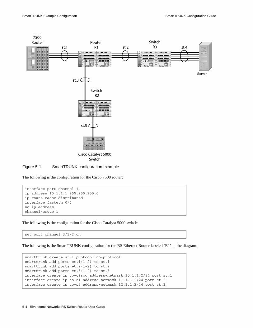
SmartTRUNK Example Configuration SmartTRUNK Configuration Guide
Figure 5-1 SmartTRUNK configuration example
The following is the configuration for the Cisco 7500 router:
The following is the configuration for the Cisco Catalyst 5000 switch:
The following is the SmartTRUNK configuration for the RS Ethernet Router labeled ‘R1’ in the diagram:
interface port-channel 1ip address 10.1.1.1 255.255.255.0ip route-cache distributedinterface fasteth 0/0no ip addresschannel-group 1
set port channel 3/1-2 on
smarttrunk create st.1 protocol no-protocolsmarttrunk add ports et.1(1-2) to st.1smarttrunk add ports et.2(1-2) to st.2smarttrunk add ports et.3(1-2) to st.3interface create ip to-cisco address-netmask 10.1.1.2/24 port st.1interface create ip to-s1 address-netmask 11.1.1.2/24 port st.2interface create ip to-s2 address-netmask 12.1.1.2/24 port st.3
Server
Cisco7500
Router Router R1
Switch R2
SwitchR3
Cisco Catalyst 5000Switch
st.1 st.2 st.4
st.3
st.5
5-4 Riverstone Networks RS Switch Router User Guide
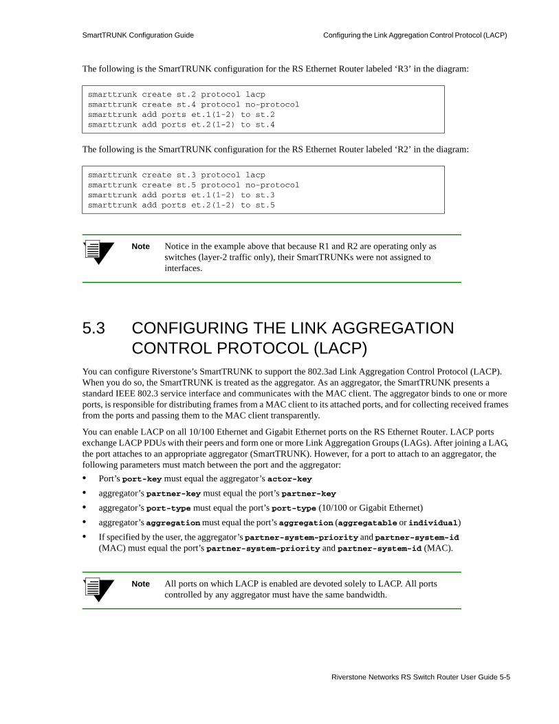
SmartTRUNK Configuration Guide Configuring the Link Aggregation Control Protocol (LACP)
The following is the SmartTRUNK configuration for the RS Ethernet Router labeled ‘R3’ in the diagram:
The following is the SmartTRUNK configuration for the RS Ethernet Router labeled ‘R2’ in the diagram:
Note Notice in the example above that because R1 and R2 are operating only as switches (layer-2 traffic only), their SmartTRUNKs were not assigned to interfaces.
5.3 CONFIGURING THE LINK AGGREGATION CONTROL PROTOCOL (LACP)
You can configure Riverstone’s SmartTRUNK to support the 802.3ad Link Aggregation Control Protocol (LACP). When you do so, the SmartTRUNK is treated as the aggregator. As an aggregator, the SmartTRUNK presents a standard IEEE 802.3 service interface and communicates with the MAC client. The aggregator binds to one or more ports, is responsible for distributing frames from a MAC client to its attached ports, and for collecting received frames from the ports and passing them to the MAC client transparently.
You can enable LACP on all 10/100 Ethernet and Gigabit Ethernet ports on the RS Ethernet Router. LACP ports exchange LACP PDUs with their peers and form one or more Link Aggregation Groups (LAGs). After joining a LAG, the port attaches to an appropriate aggregator (SmartTRUNK). However, for a port to attach to an aggregator, the following parameters must match between the port and the aggregator:• Port’s port-key must equal the aggregator’s actor-key• aggregator’s partner-key must equal the port’s partner-key• aggregator’s port-type must equal the port’s port-type (10/100 or Gigabit Ethernet)• aggregator’s aggregation must equal the port’s aggregation (aggregatable or individual)• If specified by the user, the aggregator’s partner-system-priority and partner-system-id
(MAC) must equal the port’s partner-system-priority and partner-system-id (MAC).
Note All ports on which LACP is enabled are devoted solely to LACP. All ports controlled by any aggregator must have the same bandwidth.
smarttrunk create st.2 protocol lacpsmarttrunk create st.4 protocol no-protocolsmarttrunk add ports et.1(1-2) to st.2smarttrunk add ports et.2(1-2) to st.4
smarttrunk create st.3 protocol lacpsmarttrunk create st.5 protocol no-protocolsmarttrunk add ports et.1(1-2) to st.3smarttrunk add ports et.2(1-2) to st.5
Riverstone Networks RS Switch Router User Guide 5-5

Configuring the Link Aggregation Control Protocol (LACP) SmartTRUNK Configuration Guide
5.3.1 Configuring SmartTRUNKs for LACP
Note For a complete description of all parameters associated with the following LACP commands, see the Riverstone Networks Command Line Interface Reference Manual.
Caution Do not use the smarttrunk add ports command to add ports when using LACP.
1. Create a SmartTRUNK and specify the LACP control protocol.:
2. Enable the LACP protocol on the SmartTRUNK’s ports and specify a port key number using the lacp set port command. Here is an example:
Configure the aggregator’s (SmartTRUNK’s) LACP properties using the lacp set aggregator command. Here is an example:
Note that the following parameters must be specified when using the lacp set aggregator command:
port-type – Specifies whether the ports associated with the aggregator are 10/100 Ethernet ports or Gigabit Ethernet ports.
actor-key – Specifies the administrative key of the aggregator.
partner-key – Specifies the administrative key of its partner system.
5.3.2 LACP Configuration Example
Consider the following full-mesh topology: Each RS Ethernet Router is connected to the other RS Ethernet Routers by aggregators. For the sake of simplicity, each Link Aggregation Group (LAG) consists of just two links. Each link consists of either 10/100 Ethernet or Gigabit Ethernet. Notice the LACP restriction that each LAG must contain links of identical bandwidth only (either all 10/100 Ethernet or Gigabit Ethernet, but not both).
rs(config)#smarttrunk create st.1 protocol LACP
rs(config)#lacp set port gi.1.1,gi.2.1 enable port-key 10 partner-key 20
rs(config)#lacp set aggregator st.1 port-type gigabit-Ethernet actor-key 10 partner-key 20
5-6 Riverstone Networks RS Switch Router User Guide

SmartTRUNK Configuration Guide Configuring the Link Aggregation Control Protocol (LACP)
Timesaver To view the configuration of any of the RSs in the example below, click on that switch’s image.
Figure 5-2 LACP configuration example
R1, R2, R3, and R4 are connected by aggregators (SmartTRUNKs) st.12, st13, st.14, st.23, st.24, and st.34. Notice that st.12, st.13, st.24, and st.34 consist of Gigabit Ethernet links, while st.14 and st.23 consist of 10/100 Ethernet links. Table 5-1 shows the relationship between the aggregators, the RS Ethernet Router switches, and the ports contained within the LAGs that bind to their respective aggregator.
Table 5-1 Aggregator – RS Ethernet Router – port relationship
AGGREGATOR RS SWITCHES PORTS
st.12 R1 gi.1.1, gi.1.2
R2 gi.1.1, gi.1.2
st.13 R1 gi.3.1, gi.4.1
R3 gi.3.1, gi.4.1
st.14 R1 et.5.1, et.5.2
R4 et.5.1, et.5.2
st.23 R2 et.5.1, et.5.2
st.12
st.13
st.34
st.24
st.14 st.23
gi.1.1 gi.1.1
gi.2.1 gi.2.1
gi.3.1
gi.3.1
gi.3.1
gi.3.1gi.4.1
gi.4.1 gi.4.1
gi.4.1
et.5.1et.5.2
et.5.2
et.5.1
et.5.1
et.5.1
et.5.2
et.5.2
R1 R2
R3 R4
gi.1.1 gi.1.1
gi.2.1 gi.2.1
Riverstone Networks RS Switch Router User Guide 5-7

Configuring the Link Aggregation Control Protocol (LACP) SmartTRUNK Configuration Guide
Configuration for R1:
Configuration for R2:
R3 et.5.1, et.5.2
st.24 R2 gi.3.1, gi.4.1
R4 gi.3.1, gi.4.1
st.34 R3 gi.1.1, gi.1.2
R4 gi.1.1, gi.1.2
smarttrunk create st.12 protocol lacpsmarttrunk create st.13 protocol lacpsmarttrunk create st.14 protocol lacplacp set aggregator st.12 port-type gigabit-Ethernet actor-key 10 partner-key 20lacp set aggregator st.13 port-type gigabit-Ethernet actor-key 10 partner-key 30lacp set aggregator st.14 port-type 10-100-Ethernet actor-key 11 partner-key 41lacp set port gi.1.1,gi.2.1 enable port-key 10 partner-key 20lacp set port gi.3.1,gi.4.1 enable port-key 10 partner-key 30lacp set port et.5.1,et.5.2 enable port-key 11 partner-key 41stp set protocol-version rstpstp enable port st.(12,13,14)
smarttrunk create st.12 protocol lacpsmarttrunk create st.23 protocol lacpsmarttrunk create st.24 protocol lacplacp set aggregator st.12 port-type gigabit-Ethernet actor-key 20 partner-key 10lacp set aggregator st.23 port-type 10-100-Ethernet actor-key 21 partner-key 31lacp set aggregator st.24 port-type gigabit-Ethernet actor-key 20 partner-key 40lacp set port gi.1.1,gi.2.1 enable port-key 20 partner-key 10lacp set port gi.3.1,gi.4.1 enable port-key 20 partner-key 31lacp set port et.5.1,et.5.2 enable port-key 21 partner-key 40stp set protocol-version rstpstp enable port st.(12,23,24)
Table 5-1 Aggregator – RS Ethernet Router – port relationship (Continued)
AGGREGATOR RS SWITCHES PORTS
5-8 Riverstone Networks RS Switch Router User Guide

SmartTRUNK Configuration Guide Configuring the Link Aggregation Control Protocol (LACP)
Configuration for R3:
Configuration for R4:
Note Notice that the partner-key specified in each configuration is the port-key of the corresponding ports on the RS Ethernet Router at the other end of the SmartTRUNK.
smarttrunk create st.13 protocol lacpsmarttrunk create st.23 protocol lacpsmarttrunk create st.34 protocol lacplacp set aggregator st.13 port-type gigabit-Ethernet actor-key 30 partner-key 10lacp set aggregator st.23 port-type 10-100-Ethernet actor-key 31 partner-key 21lacp set aggregator st.34 port-type gigabit-Ethernet actor-key 30 partner-key 40lacp set port gi.1.1,gi.2.1 enable port-key 30 partner-key 10lacp set port gi.3.1,gi.4.1 enable port-key 30 partner-key 21lacp set port et.5.1,et.5.2 enable port-key 31 partner-key 40stp set protocol-version rstpstp enable port st.(13,23,34)
smarttrunk create st.14 protocol lacpsmarttrunk create st.24 protocol lacpsmarttrunk create st.34 protocol lacplacp set aggregator st.14 port-type 10-100-Ethernet actor-key 41 partner-key 11lacp set aggregator st.24 port-type gigabit-Ethernet actor-key 40 partner-key 20lacp set aggregator st.34 port-type gigabit-Ethernet actor-key 40 partner-key 30lacp set port gi.1.1,gi.2.1 enable port-key 40 partner-key 11lacp set port gi.3.1,gi.4.1 enable port-key 40 partner-key 20lacp set port et.5.1,et.5.2 enable port-key 41 partner-key 30stp set protocol-version rstpstp enable port st.(14,24,34)
Riverstone Networks RS Switch Router User Guide 5-9

SmartTRUNK Load Redistribution SmartTRUNK Configuration Guide
5.4 SMARTTRUNK LOAD REDISTRIBUTIONSmartTRUNK Load Redistribution (SLR) monitors all ports within a SmartTRUNK for utilization. If a port begins to become overloaded, SLR automatically moves some of the port’s flows to other, less utilized ports within the SmartTRUNK. SLR is enabled for the entire SmartTRUNK, and can be used in unison with any control protocol or load policy (see Section 5.1.3, "Specifying Traffic Load Policy" and Section 5.3.1, "Configuring SmartTRUNKs for LACP").
Note When a SmartTRUNK is created, one of the ports is elected for sending and receiving layer-2 multicast and broadcast traffic. SLR leaves these layer-2 multicast or broadcast flows unaffected.
Note Each time a redistribution is performed by SLR, an SNMP trap is generated.
5.4.1 SLR Water-marks
SLR uses “water-marks,” based on percentage port utilization, to determine whether flows on a port need to be redistributed to other ports within the SmartTRUNK.
SLR uses the three following user-defined water-marks:• Low water-mark (lwm) – Used by SLR to detect whether a port is under utilized; the default is 20%
of bandwidth• Medium water-mark (mwm) – Used by SLR as a baseline of normal port utilization; the default is 50%
of bandwidth• High water-mark (hwm) – Used by SLR to detect whether a port is over utilized; the default is 80%
of bandwidth
Note Water-marks are set on a per-SmartTRUNK basis, i.e., water-marks cannot be set on a per-port basis.
5.4.2 Polling intervals
SLR uses two intervals to perform load redistribution:
Status Interval – Interval in which port utilization information is gathered; the default is one second.
Redistribution Interval – Interval in which SLR considers flows for redistribution. The Redistribution Interval is the number of Status Intervals that must pass before flows are considered for redistribution.The Redistribution Interval relates to a number of Status Intervals, as opposed to being a measure of time; the default is 5 Status Intervals.
5-10 Riverstone Networks RS Switch Router User Guide

SmartTRUNK Configuration Guide SmartTRUNK Load Redistribution
To determine the length of time in seconds for one Redistribution Interval, multiply the Status Interval by the Redistribution Interval value. For example, using the defaults,
Status Interval = 1 second
Redistribution Interval = 5 Status Intervals
then
1 * 5 = 5 seconds per Redistribution Interval.
Note To avoid flows “bouncing” back and forth between ports, SLR uses the rule that no moved flow can be returned to the port from which it was moved until at least one Redistribution Interval has passed.
5.4.2.1 Creating an SLR Enabled SmartTRUNK
The following is an example of creating a SmartTRUNK that uses SLR:
1. Create a SmartTRUNK (st.4) — the control protocol is irrelevant to this example:
2. Assign ports et.4.1 through et.4.4 to the SmartTRUNK:
3. Accept SLR’s defaults and enable SLR on the SmartTRUNK.
To show the SmartTRUNK SLR configuration on st.4, enter the following command from Enable mode:
rs(config)# smarttrunk create st.4 protocol no-protocol
rs(config)# smarttrunk add ports et.4.1-4 to st.4
rs(config)# smarttrunk set load-redistribution-params st.4
Riverstone Networks RS Switch Router User Guide 5-11
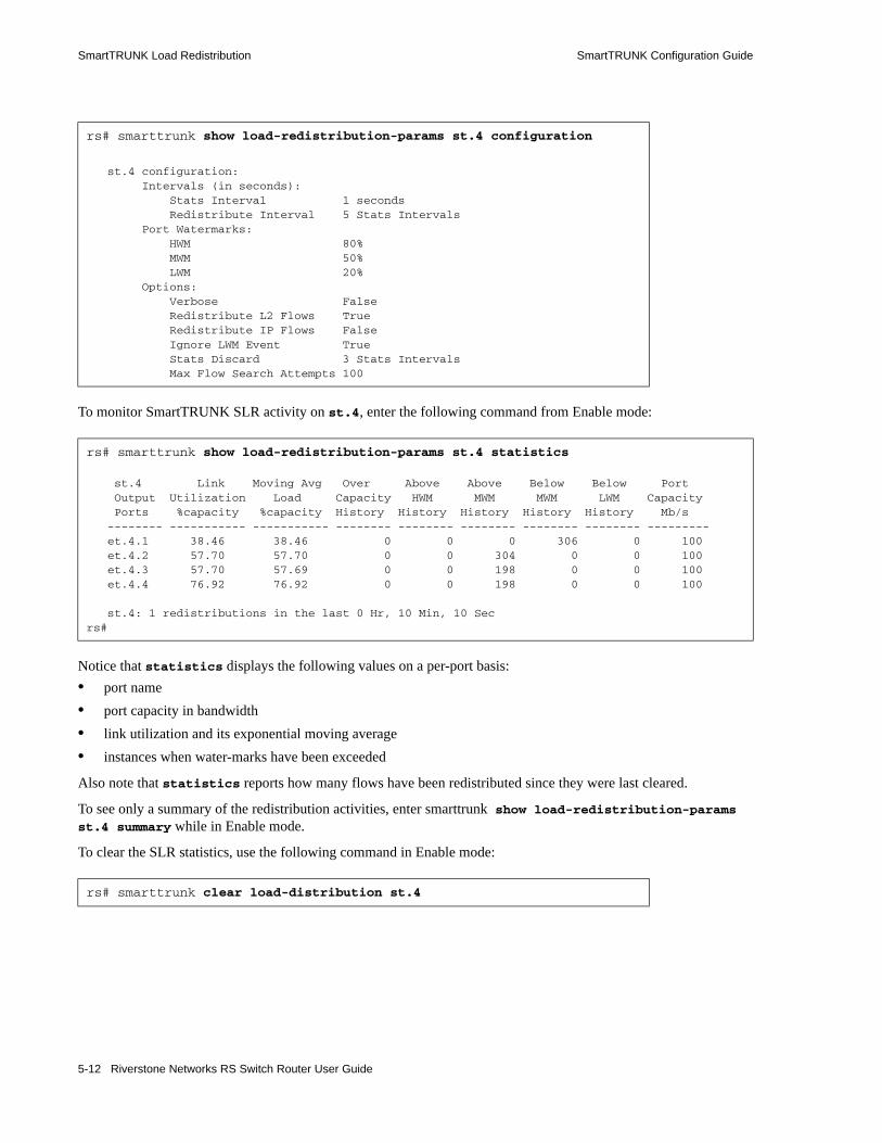
SmartTRUNK Load Redistribution SmartTRUNK Configuration Guide
To monitor SmartTRUNK SLR activity on st.4, enter the following command from Enable mode:
Notice that statistics displays the following values on a per-port basis:• port name• port capacity in bandwidth• link utilization and its exponential moving average• instances when water-marks have been exceeded
Also note that statistics reports how many flows have been redistributed since they were last cleared.
To see only a summary of the redistribution activities, enter smarttrunk show load-redistribution-params st.4 summary while in Enable mode.
To clear the SLR statistics, use the following command in Enable mode:
rs# smarttrunk show load-redistribution-params st.4 configuration
st.4 configuration: Intervals (in seconds): Stats Interval 1 seconds Redistribute Interval 5 Stats Intervals Port Watermarks: HWM 80% MWM 50% LWM 20% Options: Verbose False Redistribute L2 Flows True Redistribute IP Flows False Ignore LWM Event True Stats Discard 3 Stats Intervals Max Flow Search Attempts 100
rs# smarttrunk show load-redistribution-params st.4 statistics
st.4 Link Moving Avg Over Above Above Below Below Port Output Utilization Load Capacity HWM MWM MWM LWM Capacity Ports %capacity %capacity History History History History History Mb/s -------- ----------- ----------- -------- -------- -------- -------- -------- --------- et.4.1 38.46 38.46 0 0 0 306 0 100 et.4.2 57.70 57.70 0 0 304 0 0 100 et.4.3 57.70 57.69 0 0 198 0 0 100 et.4.4 76.92 76.92 0 0 198 0 0 100
st.4: 1 redistributions in the last 0 Hr, 10 Min, 10 Secrs#
rs# smarttrunk clear load-distribution st.4
5-12 Riverstone Networks RS Switch Router User Guide
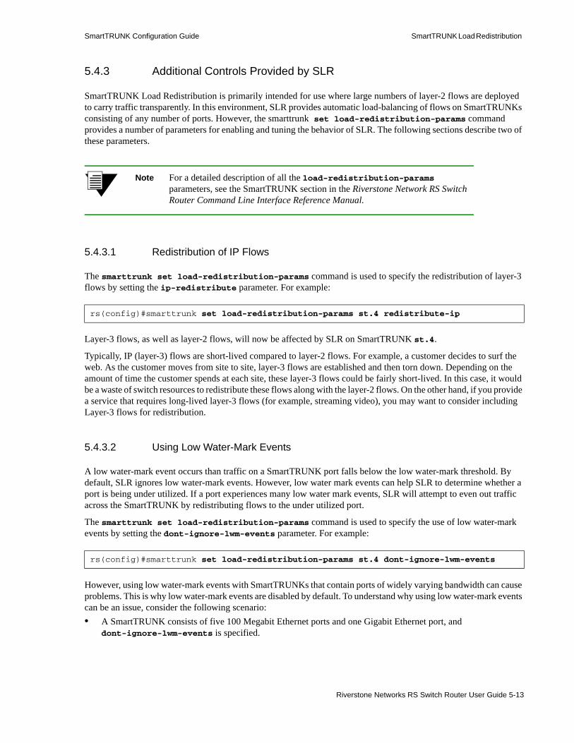
SmartTRUNK Configuration Guide SmartTRUNK Load Redistribution
5.4.3 Additional Controls Provided by SLR
SmartTRUNK Load Redistribution is primarily intended for use where large numbers of layer-2 flows are deployed to carry traffic transparently. In this environment, SLR provides automatic load-balancing of flows on SmartTRUNKs consisting of any number of ports. However, the smarttrunk set load-redistribution-params command provides a number of parameters for enabling and tuning the behavior of SLR. The following sections describe two of these parameters.
Note For a detailed description of all the load-redistribution-params parameters, see the SmartTRUNK section in the Riverstone Network RS Switch Router Command Line Interface Reference Manual.
5.4.3.1 Redistribution of IP Flows
The smarttrunk set load-redistribution-params command is used to specify the redistribution of layer-3 flows by setting the ip-redistribute parameter. For example:
Layer-3 flows, as well as layer-2 flows, will now be affected by SLR on SmartTRUNK st.4.
Typically, IP (layer-3) flows are short-lived compared to layer-2 flows. For example, a customer decides to surf the web. As the customer moves from site to site, layer-3 flows are established and then torn down. Depending on the amount of time the customer spends at each site, these layer-3 flows could be fairly short-lived. In this case, it would be a waste of switch resources to redistribute these flows along with the layer-2 flows. On the other hand, if you provide a service that requires long-lived layer-3 flows (for example, streaming video), you may want to consider including Layer-3 flows for redistribution.
5.4.3.2 Using Low Water-Mark Events
A low water-mark event occurs than traffic on a SmartTRUNK port falls below the low water-mark threshold. By default, SLR ignores low water-mark events. However, low water mark events can help SLR to determine whether a port is being under utilized. If a port experiences many low water mark events, SLR will attempt to even out traffic across the SmartTRUNK by redistributing flows to the under utilized port.
The smarttrunk set load-redistribution-params command is used to specify the use of low water-mark events by setting the dont-ignore-lwm-events parameter. For example:
However, using low water-mark events with SmartTRUNKs that contain ports of widely varying bandwidth can cause problems. This is why low water-mark events are disabled by default. To understand why using low water-mark events can be an issue, consider the following scenario:• A SmartTRUNK consists of five 100 Megabit Ethernet ports and one Gigabit Ethernet port, and
dont-ignore-lwm-events is specified.
rs(config)#smarttrunk set load-redistribution-params st.4 redistribute-ip
rs(config)#smarttrunk set load-redistribution-params st.4 dont-ignore-lwm-events
Riverstone Networks RS Switch Router User Guide 5-13

SmartTRUNK Load Redistribution SmartTRUNK Configuration Guide
• By default, the low water-mark is set at 20%. This means that on the 100 Megabit ports 20% of bandwidth is 20 Megabits/sec, while on the Gigabit Ethernet port, 20% of bandwidth is 200 Megabits/sec.
• The large bandwidth of the Gigabit Ethernet port causes it to trigger many low water-mark events, which indicate to SLR that the Gigabit Ethernet link is vastly under utilized. As a result, most flows are moved to the Gigabit Ethernet port, while the remaining links go under utilized.
The best use for low water-mark events is with SmartTRUNKs that are made up of links that have equal bandwidth. In such configurations, low water-mark events combine with high water-mark events to increase the efficiency of SLR’s redistribution process.
5-14 Riverstone Networks RS Switch Router User Guide

6 BRIDGING CONFIGURATION GUIDE
The Riverstone RS Switch Router provides the following bridging functions:• Compliance with the IEEE 802.1D standard• Compliance with the IEEE 802.1w standard (Rapid STP)• Compliance with the IEEE 802.1Q standard• Compliance with the IGMP multicast bridging standard• Wire-speed address-based bridging or flow-based bridging• Ability to logically segment a transparently bridged network into virtual local-area networks
(VLANs), based on physical ports or protocol (IP or IPX or bridged protocols like Appletalk)• Frame filtering based on MAC address for bridged and multicast traffic • Integrated routing and bridging, which supports bridging of intra-VLAN traffic and routing of
inter-VLAN traffic
6.1 SPANNING TREE (IEEE 802.1D)Spanning tree (IEEE 802.1d) allows bridges to dynamically discover a subset of the topology that is loop-free. In addition, the loop-free tree that is discovered contains paths to every LAN segment.
6.2 VLAN TAGGING (IEEE 802.1Q)VLAN tagging (IEEE 802.1Q) allows more than one VLAN over a link, called a trunk port. The 802.1Q tagging process keeps traffic from each VLAN separate. 802.1p also is supported with 802.1Q, providing the ability to identify the traffic priority of each flow.
6.3 BRIDGING MODES (FLOW-BASED AND ADDRESS-BASED)
The RS Ethernet Router provides the following types of wire-speed bridging:
Riverstone Networks RS Switch Router User Guide 6-1

VLAN Overview Bridging Configuration Guide
Address-based bridging - The RS Ethernet Router performs this type of bridging by looking up the destination address in an L2 lookup table on the line card that receives the bridge packet from the network. The L2 lookup table indicates the exit port(s) for the bridged packet. If the packet is addressed to the RS Ethernet Router' own MAC address, the packet is routed rather than bridged.
Flow-based bridging - The RS Ethernet Router performs this type of bridging by looking up an entry in the L2 lookup table containing both the source and destination addresses of the received packet in order to determine how the packet is to be handled.
The RS Ethernet Router ports perform address-based bridging by default but can be configured to perform flow-based bridging instead, on a per-port basis. A port cannot be configured to perform both types of bridging at the same time.
The RS Ethernet Router performance is equivalent when performing flow-based bridging or address-based bridging. However, address-based bridging is more efficient because it requires fewer table entries while flow-based bridging provides tighter management and control over bridged traffic.
Note Flow bridging mode is not supported for MPLS LSRs.
6.4 VLAN OVERVIEWVirtual LANs (VLANs) are a means of dividing a physical network into several logical (virtual) LANs. The division can be done on the basis of various criteria, giving rise to different types of VLANs. For example, the simplest type of VLAN is the port-based VLAN. Port-based VLANs divide a network into a number of VLANs by assigning a VLAN to each port of a switching device. Then, any traffic received on a given port of a switch belongs to the VLAN associated with that port.
VLANs are primarily used for broadcast containment. A layer-2 (L2) broadcast frame is normally transmitted all over a bridged network. By dividing the network into VLANs, the range of a broadcast is limited, i.e., the broadcast frame is transmitted only to the VLAN to which it belongs. This reduces the broadcast traffic on a network by an appreciable factor.
6.4.1 RS Ethernet Router VLAN Support
The RS Ethernet Router supports the following type of VLANs:• Port-based VLANs• Protocol-based VLANs
6.4.1.1 Port-based VLANs
Ports of L2 devices (switches, bridges) are assigned to VLANs. Any traffic received by a port is classified as belonging to the VLAN to which the port belongs. For example, if ports 1, 2, and 3 belong to the VLAN named “Marketing”, then a broadcast frame received by port 1 is transmitted on ports 2 and 3. It is not transmitted on any other port.
6-2 Riverstone Networks RS Switch Router User Guide

Bridging Configuration Guide VLAN Overview
6.4.1.2 Protocol-based VLANs
Protocol-based VLANs divide the physical network into logical VLANs based on protocol. When a frame is received at a port, its VLAN is determined by the protocol of the packet. For example, there could be separate VLANs for IP, IPX and Appletalk. An IP broadcast frame will only be sent to all ports in the IP VLAN.
6.4.1.3 VLANs and the RS Ethernet Router
VLANs are an integral part of the RS Ethernet Router family of switching routers. The RS Ethernet Router switching routers can function as layer-2 (L2) switches as well as fully-functional layer-3 (L3) routers. Hence they can be viewed as a switch and a router in one box. To provide maximum performance and functionality, the L2 and L3 aspects of the RS Ethernet Router switching routers are tightly coupled.
The RS Ethernet Router can be used purely as an L2 switch. Frames arriving at any port are bridged and not routed. In this case, setting up VLANs and associating ports with VLANs is all that is required. You can set up the RS Ethernet Router switching router to use port-based VLANs, protocol-based VLANs, or a mixture of the two types.
The RS Ethernet Router can also be used purely as a router, i.e., each physical port of the RS Ethernet Router is a separate routing interface. Packets received at any interface are routed and not bridged. In this case, no VLAN configuration is required. Note that VLANs are still created implicitly by the RS Ethernet Router as a result of creating L3 interfaces for IP. However, these implicit VLANs do not need to be created or configured manually.
Most commonly, an RS Ethernet Router is used as a combined switch and router. For example, it may be connected to two subnets S1 and S2. Ports 1-8 belong to S1 and ports 9-16 belong to S2. The required behavior of the RS Ethernet Router is that intra-subnet frames be bridged and inter-subnet packets be routed. In other words, traffic between two workstations that belong to the same subnet should be bridged, and traffic between two workstations that belong to different subnets should be routed.
The RS Ethernet Router switching routers use VLANs to achieve this behavior. This means that a L3 subnet (i.e., an IP subnet) is mapped to a VLAN. A given subnet maps to exactly one and only one VLAN. With this definition, the terms VLAN and subnet are almost interchangeable.
To configure an RS Ethernet Router as a combined switch and router, the administrator must create VLANs whenever multiple ports of the RS Ethernet Router are to belong to a particular VLAN/subnet. Then the VLAN must be bound to an L3 interface so that the RS Ethernet Router knows which VLAN maps to which IP subnet.
6.4.1.4 Ports, VLANs, and L3 Interfaces
The term port refers to a physical connector on the RS Ethernet Router, such as an ethernet port. Each port must belong to at least one VLAN. When the RS Ethernet Router is unconfigured, each port belongs to a VLAN called the “default VLAN.” By creating VLANs and adding ports to the created VLANs, the ports are moved from the default VLAN to the newly created VLANs.
Unlike traditional routers, the RS Ethernet Router has the concept of logical interfaces rather than physical interfaces. An L3 interface is a logical entity created by the administrator. It can contain more than one physical port. When an L3 interface contains exactly one physical port, it is equivalent to an interface on a traditional router. When an L3 interface contains several ports, it is equivalent to an interface of a traditional router which is connected to a layer-2 device such as a switch or bridge.
Riverstone Networks RS Switch Router User Guide 6-3

Access Ports and Trunk Ports (802.1P and 802.1Q support) Bridging Configuration Guide
6.4.1.5 Explicit and Implicit VLANs
As mentioned earlier, VLANs can either be created explicitly by the administrator (explicit VLANs) or are created implicitly by the RS Ethernet Router when L3 interfaces are created (implicit VLANs).
6.5 ACCESS PORTS AND TRUNK PORTS (802.1P AND 802.1Q SUPPORT)
The ports of an RS Ethernet Router can be classified into two types, based on VLAN functionality: access ports and trunk ports. By default, a port is an access port. An access port can belong to at most one VLAN of the following types: IP, IPX or bridged protocols. The RS Ethernet Router can automatically determine whether a received frame is an IP frame, an IPX frame or neither. Based on this, it selects a VLAN for the frame. Frames transmitted out of an access port contain no special information about the VLAN to which they belong. These frames are classified as belonging to a particular VLAN based on the protocol of the frame and the VLAN configured on the receiving port for that protocol.
For example, if port 1 belongs to VLAN IPX_VLAN for IPX, VLAN IP_VLAN for IP and VLAN OTHER_VLAN for any other protocol, then an IP frame received by port 1 is classified as belonging to VLAN IP_VLAN.
You can use the port enable 8021p command to tag frames transmitted from access ports with a one-byte, 802.1p class of service (CoS) value. The CoS value indicates the frame’s priority. There are 8 CoS values, 0 is the lowest priority and 7 is the highest.
Trunk ports (802.1Q) are usually used to connect one VLAN-aware switch to another. They carry traffic belonging to several VLANs. For example, suppose that RS Ethernet Router A and B are both configured with VLANs V1 and V2.
Then a frame arriving at a port on RS Ethernet Router A must be sent to RS Ethernet Router B, if the frame belongs to VLAN V1 or to VLAN V2. Thus the ports on RS Ethernet Router A and B which connect the two RS Ethernet Router’s together must belong to both VLAN V1 and VLAN V2. Also, when these ports receive a frame, they must be able to determine whether the frame belongs to V1 or to V2. This is accomplished by “tagging” the frames, i.e., by prepending information to the frame in order to identify the VLAN to which the frame belongs. In the RS Ethernet Router switching routers, trunk ports normally transmit and receive tagged frames only. (The format of the tag is specified by the IEEE 802.1Q standard.) If you configure Spanning Tree Protocol, frames are transmitted as untagged frames. You can also configure native VLANs to enable 802.1Q trunk ports to receive and transmit untagged frames. For additional information, see Section 6.9.5, "Configuring Native VLANs."
6.6 CONFIGURING RS ETHERNET ROUTER BRIDGING FUNCTIONS
6.6.1 Configuring Address-based or Flow-based Bridging
The RS Ethernet Router ports perform address-based bridging by default but can be configured to perform flow-based bridging instead of address-based bridging, on a per-port basis. A port cannot be configured to perform both types of bridging at the same time.
6-4 Riverstone Networks RS Switch Router User Guide

Bridging Configuration Guide Configuring RS Ethernet Router Bridging Functions
The RS Ethernet Router performance is equivalent when performing flow-based bridging or address-based bridging. However, address-based bridging is more efficient because it requires fewer table entries while flow-based bridging provides tighter management and control over bridged traffic.
For example, the following illustration shows a router with traffic being sent from port A to port B, port B to port A, port B to port C, and port A to port C.
Figure 6-1 Router traffic going to different ports
The corresponding bridge tables for address-based and flow-based bridging are shown below. As shown, the bridge table contains more information on the traffic patterns when flow-based bridging is enabled compared to address-based bridging.
With the RS Ethernet Router configured in flow-based bridging mode, the network manager has “per flow” control of layer-2 traffic. The network manager can then apply Quality of Service (QoS) policies or security filters based on layer-2 traffic flows.
To enable flow-based bridging on a port, enter the following command in Configure mode.
To change a port from flow-based bridging to address-based bridging, enter the following command in Configure mode:
Address-Based Bridge Table Flow-Based Bridge Table
A (source) A Õ B
B (source) B Õ A
C (destination) B Õ C
A Õ C
Configure a port for flow-based bridging. port flow-bridging <port-list>|all-ports
Change a port from flow-based bridging to address-based bridging.
negate <line-number of active config containing command>: port flow-bridging <port-list>|all-ports
A B C
Router
Riverstone Networks RS Switch Router User Guide 6-5
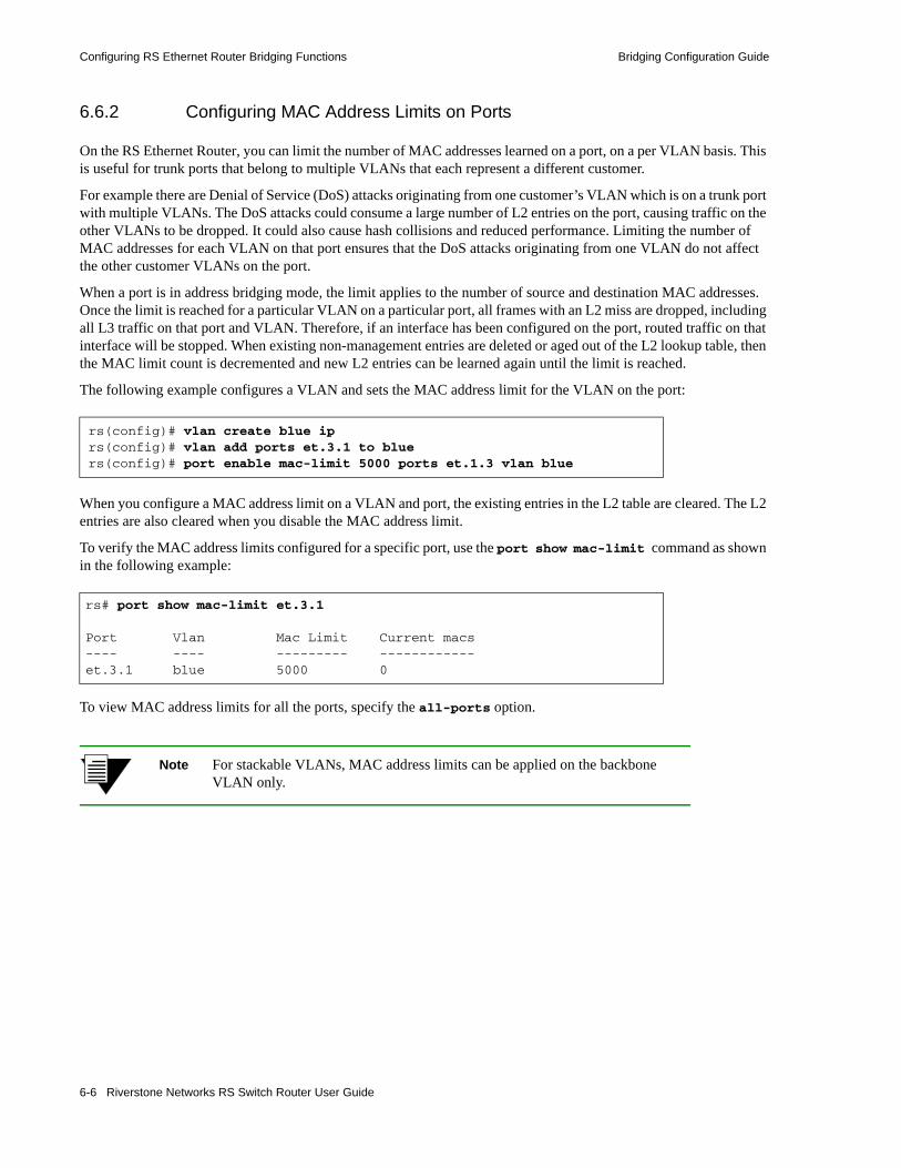
Configuring RS Ethernet Router Bridging Functions Bridging Configuration Guide
6.6.2 Configuring MAC Address Limits on Ports
On the RS Ethernet Router, you can limit the number of MAC addresses learned on a port, on a per VLAN basis. This is useful for trunk ports that belong to multiple VLANs that each represent a different customer.
For example there are Denial of Service (DoS) attacks originating from one customer’s VLAN which is on a trunk port with multiple VLANs. The DoS attacks could consume a large number of L2 entries on the port, causing traffic on the other VLANs to be dropped. It could also cause hash collisions and reduced performance. Limiting the number of MAC addresses for each VLAN on that port ensures that the DoS attacks originating from one VLAN do not affect the other customer VLANs on the port.
When a port is in address bridging mode, the limit applies to the number of source and destination MAC addresses. Once the limit is reached for a particular VLAN on a particular port, all frames with an L2 miss are dropped, including all L3 traffic on that port and VLAN. Therefore, if an interface has been configured on the port, routed traffic on that interface will be stopped. When existing non-management entries are deleted or aged out of the L2 lookup table, then the MAC limit count is decremented and new L2 entries can be learned again until the limit is reached.
The following example configures a VLAN and sets the MAC address limit for the VLAN on the port:
When you configure a MAC address limit on a VLAN and port, the existing entries in the L2 table are cleared. The L2 entries are also cleared when you disable the MAC address limit.
To verify the MAC address limits configured for a specific port, use the port show mac-limit command as shown in the following example:
To view MAC address limits for all the ports, specify the all-ports option.
Note For stackable VLANs, MAC address limits can be applied on the backbone VLAN only.
rs(config)# vlan create blue iprs(config)# vlan add ports et.3.1 to bluers(config)# port enable mac-limit 5000 ports et.1.3 vlan blue
rs# port show mac-limit et.3.1
Port Vlan Mac Limit Current macs---- ---- --------- ------------et.3.1 blue 5000 0
6-6 Riverstone Networks RS Switch Router User Guide

Bridging Configuration Guide Configuring Spanning Tree
6.7 CONFIGURING SPANNING TREEThe RS Ethernet Router supports per VLAN spanning tree (PVST). By default, all the VLANs defined belong to the default spanning tree. You can create a separate instance of spanning tree using the following command:
By default, spanning tree is disabled on the RS Ethernet Router. To enable spanning tree on the RS Ethernet Router, perform the following tasks on the ports where you want spanning tree enabled.
Note For WAN and ATM, there is a limit to the number of VCs on which STP or PVST can run. For the RS 8000/8600, the limit is 128 VCs; for the RS 38000, the limit is 64 VCs.
6.7.1 Using Rapid STP
You can specify the use of “rapid” STP, defined by IEEE 802.1w. This protocol, also known as Fast Spanning Tree, is designed to reduce network recovery time.
Note RSTP works only on ports where STP is already enabled (with the stp enable port command).
To enable rapid STP, enter the following command in Configure mode:
Note This command is not supported with per-VLAN spanning tree.
Create spanning tree for a VLAN. pvst create spanningtree vlan-name <string>
Enable spanning tree on one or more ports for default spanning tree.
stp enable port <port-list>
Enable spanning tree on one or more ports for a particular VLAN.
pvst enable port <port-list> spanning-tree <string>
Enable rapid STP stp set protocol-version rstp
Riverstone Networks RS Switch Router User Guide 6-7
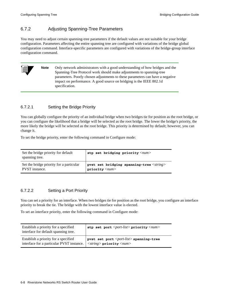
Configuring Spanning Tree Bridging Configuration Guide
6.7.2 Adjusting Spanning-Tree Parameters
You may need to adjust certain spanning-tree parameters if the default values are not suitable for your bridge configuration. Parameters affecting the entire spanning tree are configured with variations of the bridge global configuration command. Interface-specific parameters are configured with variations of the bridge-group interface configuration command.
Note Only network administrators with a good understanding of how bridges and the Spanning-Tree Protocol work should make adjustments to spanning-tree parameters. Poorly chosen adjustments to these parameters can have a negative impact on performance. A good source on bridging is the IEEE 802.1d specification.
6.7.2.1 Setting the Bridge Priority
You can globally configure the priority of an individual bridge when two bridges tie for position as the root bridge, or you can configure the likelihood that a bridge will be selected as the root bridge. The lower the bridge's priority, the more likely the bridge will be selected as the root bridge. This priority is determined by default; however, you can change it.
To set the bridge priority, enter the following command in Configure mode:
6.7.2.2 Setting a Port Priority
You can set a priority for an interface. When two bridges tie for position as the root bridge, you configure an interface priority to break the tie. The bridge with the lowest interface value is elected.
To set an interface priority, enter the following command in Configure mode:
Set the bridge priority for default spanning tree.
stp set bridging priority <num>
Set the bridge priority for a particular PVST instance.
pvst set bridging spanning-tree <string> priority <num>
Establish a priority for a specified interface for default spanning tree.
stp set port <port-list> priority <num>
Establish a priority for a specified interface for a particular PVST instance.
pvst set port <port-list> spanning-tree <string> priority <num>
6-8 Riverstone Networks RS Switch Router User Guide
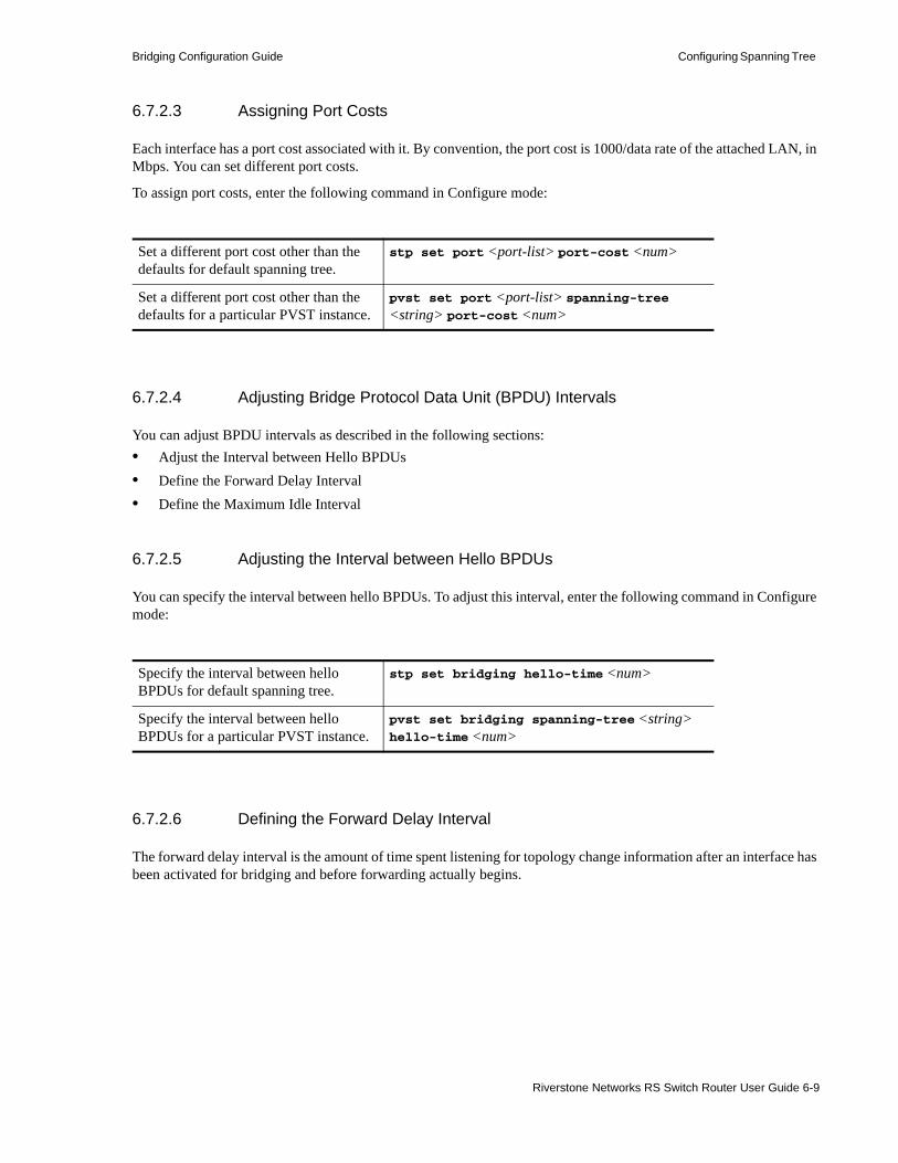
Bridging Configuration Guide Configuring Spanning Tree
6.7.2.3 Assigning Port Costs
Each interface has a port cost associated with it. By convention, the port cost is 1000/data rate of the attached LAN, in Mbps. You can set different port costs.
To assign port costs, enter the following command in Configure mode:
6.7.2.4 Adjusting Bridge Protocol Data Unit (BPDU) Intervals
You can adjust BPDU intervals as described in the following sections: • Adjust the Interval between Hello BPDUs • Define the Forward Delay Interval • Define the Maximum Idle Interval
6.7.2.5 Adjusting the Interval between Hello BPDUs
You can specify the interval between hello BPDUs. To adjust this interval, enter the following command in Configure mode:
6.7.2.6 Defining the Forward Delay Interval
The forward delay interval is the amount of time spent listening for topology change information after an interface has been activated for bridging and before forwarding actually begins.
Set a different port cost other than the defaults for default spanning tree.
stp set port <port-list> port-cost <num>
Set a different port cost other than the defaults for a particular PVST instance.
pvst set port <port-list> spanning-tree <string> port-cost <num>
Specify the interval between hello BPDUs for default spanning tree.
stp set bridging hello-time <num>
Specify the interval between hello BPDUs for a particular PVST instance.
pvst set bridging spanning-tree <string> hello-time <num>
Riverstone Networks RS Switch Router User Guide 6-9

Configuring Spanning Tree Bridging Configuration Guide
To change the default interval setting, enter the following command in Configure mode:
6.7.2.7 Defining the Maximum Age
If a bridge does not hear BPDUs from the root bridge within a specified interval, it assumes that the network has changed and recomputes the spanning-tree topology.
To change the default interval setting, enter the following command in Configure mode:
6.7.2.8 Changing the STP State of VLAN Ports
When STP is enabled, RS Ethernet Router ports move from initalization state at power-up to blocking, listening, learning, and then forwarding states. Ports in forwarding state forward frames received from an attached segment or from another port. Ports in blocking state discard frames received from an attached segment or from another port. You can change the STP state of a port for a particular VLAN. To do this, use the stp force port command. In the following example, the first command adds the ports et.1.5 and et.4.7 to the SmartTRUNK st.1. The second command changes the STP state of the ports to blocking.
Use the stp show vlan-port-state command to display the STP state of a VLAN port. The following example shows the STP states of the ports that were changed to blocking state with the stp force port command.
Set the default of the forward delay interval for default spanning tree.
stp set bridging forward-delay <num>
Set the default of the forward delay interval for a particular PVST instance.
pvst set bridging spanning-tree <string> forward-delay <num>
Change the amount of time a bridge will wait to hear BPDUs from the root bridge for default spanning tree.
stp set bridging max-age <num>
Change the amount of time a bridge will wait to hear BPDUs from the root bridge for a particular PVST instance.
pvst set bridging spanning-tree <string> max-age <num>
rs(config)# smarttrunk add ports et.1.5,et.4.7 to st.1
rs(config)# stp force port st.1 state blocking vlan-name default
rs# stp show vlan-port-state st.1 vlan-name default Port State ---- ----- et.1.5 Forced-Blocking et.4.7 Forced-Blocking
6-10 Riverstone Networks RS Switch Router User Guide

Bridging Configuration Guide Configuring Spanning Tree
6.7.3 STP Dampening
STP creates a loop free, active topology in a network by placing ports in a forwarding or blocking state. When a port moves to the forwarding state, it transitions from listening, to learning, and then to forwarding. Whenever this transition happens, there is a chance that some traffic may be lost. If this port state transition happens rarely, the traffic loss is insignificant. On the other hand, if this happens frequently, it can adversely affect the network. STP dampening addresses this issue.
When a root port stops receiving BPDUs from the root bridge, a new root port is selected. If the original root port starts receiving BPDUs from the root bridge once again and STP dampening is enabled on the port, traffic is not immediately switched back to it. Instead, the port is monitored until it satisfies a stability condition, which is that it receives a certain number of STP configuration BPDUs during a specified period of time. If the port satisfies this condition, then it is considered stable and traffic is switched back to it. Otherwise, it remains in an unstable state and is continuously monitored until it satisfies the stability condition. This feature ensures that ports are stable before they move to a forwarding state and traffic is switched back to them.
Note that dampening will not occur if the port on which STP dampening is enabled goes down and comes up again. Instead, traditional STP configuration occurs.
To enable STP dampening on a port, enter the following command in Configure mode:
Note STP dampening cannot be used in conjunction with RSTP.
The RS Ethernet Router has defaults for the period of time a port will be monitored (10 seconds) and the number of BPDUs that need to be received (10) during this period. You can change these defaults by entering the following command in Configure mode:
6.7.4 Tunneling STP
The RS Ethernet Router provides the ability to tunnel STP BPDUs across MPLS or VLAN backbones. This allows customers within VPNs to enable Spanning Tree for their equipment without the STP BPDUs being interpreted or interfering with the provider’s equipment.
Use the stp tunnel mpls command to tunnel STP BPDUs across an LSP, and use the stp tunnel vlan-encapsulated command to tunnel STP BPDUs through a specified VLAN backbone (see Figure 6-2 and Figure 6-3).
For detailed parameter descriptions of STP tunneling commands, see the “Riverstone Networks Command Line Interface Manual.”
Enable STP dampening on a port. stp set port <port-list> dampening enable
Set parameters for STP dampening. stp set bridging damp-monitor-time
<seconds> damp-bpdu-count <number>
Riverstone Networks RS Switch Router User Guide 6-11

Configuring Spanning Tree Bridging Configuration Guide
Figure 6-2 Tunneling STP through MPLS LSP
Figure 6-3 Tunneling STP through a VLAN backbone
6.7.5 Rapid Ring STP
Rapid STP (RSTP) and STP normally operate between switches over ports on VLANs. When a VLAN extends across a core network, there can be substantial convergence delays with RSTP when network changes occur. You can use the Rapid Ring STP (RRSTP) feature to define an RSTP domain based on topology—i.e., specified ports on the RS Ethernet Router—instead of based on VLANs. While Rapid Ring STP limits the exchange of BPDU messages to specific ports, data traffic is not limited to the ring.
In Figure 6-4, four ports on S1 belong to the same VLAN, however two of the ports belong to one ring and the other two ports belong to another ring.
CE CEPE PEMPLS Cloud
STP BPDUs STP BPDUs
MPLS tunnelstarts on Provider
equipment.
CE CEPE PE
CE CE
VLAN V1
VLAN V2 VLAN V2
VLAN V1
Entry Port
Exit Port
VLAN Backbone
STP BPDUs appearonly on customer
equipment
STP BPDUs STP BPDUs
6-12 Riverstone Networks RS Switch Router User Guide

Bridging Configuration Guide Configuring Spanning Tree
Figure 6-4 Single VLAN with two rings
To configure Rapid Ring STP on S1, do the following:1. Enable rapid STP:
2. Create the rings (ring IDs 546 and 523) for rapid STP:
3. Add ports to each ring. The ports can be in different VLANs, but each port can only be in one ring.
rs(config)# stp set protocol-version rstp
rs(config)# stp rer-create ring ring_id 546
rs(config)# stp rer-create ring ring_id 523
rs(config)# stp rer-add ports et.1.1,et.1.2 to 546
rs(config)# stp rer-add ports et.2.1,et.2.2 to 523
S1
A
B
Ring ID 546
Ring ID 523
et.1.1 et.1.2et.2.1 et.2.2
Riverstone Networks RS Switch Router User Guide 6-13

Configuring Spanning Tree Bridging Configuration Guide
4. Enable the rings. The following command enables all STP rings configured on the RS Ethernet Router:
You can also enable a specific ring ID with the stp rer-enable ring ring_id <id> command.
Ports on a router cannot belong to more than one ring. Therefore, you cannot apply ring STP to the topology shown in Figure 6-5.
Figure 6-5 Rings on same port (Rapid Ring STP cannot be applied)
You cannot apply Rapid Ring STP in topologies in which there would be redundant routers between access and core rings (also known as “redundant links”). In Figure 6-6, S1 and S2 are redundant routers between the ring on which A resides and the ring on which B resides. (Note that if S1 fails, traffic can still pass between A and B via S2.) Rapid Ring STP cannot be enabled in this topology, as a loop would still exist between the links between S1 and S2.
rs(config)# stp rer-enable
S1
A
B
6-14 Riverstone Networks RS Switch Router User Guide

Bridging Configuration Guide Configuring Spanning Tree
Figure 6-6 Redundant links topology (Rapid Ring STP cannot be applied)
Use the stp show ring-port-info command in Enable mode to display STP bridge and port information for a ring:
rs# stp show ring-port-info ring_id 546 Status for Spanning Tree Instance 546 Bridge ID : 8000:00e063343b8e Root bridge : 8000:00e063343b8e To Root via port : n/a Ports in bridge : 0 Max age : 20 secs Hello time : 2 secs Forward delay : 15 secs Topology changes : 0 Last Topology Chg: 6 days 19 hours 44 min 15 secs ago DesignatedPort Priority Cost STP State Designated-Bridge Port ---- -------- ---- --- ----- ----------------- ---------- et.1.1 001 00010 Enabled Forwarding 8000:00e063343b8e 00 00 et.1.2 001 00010 Enabled Forwarding 8000:00e063343b8e 00 00
S1 S2
A
B
Riverstone Networks RS Switch Router User Guide 6-15
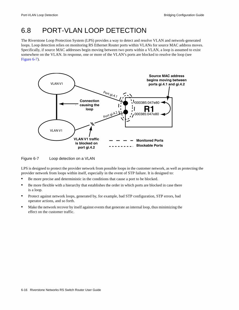
Port-VLAN Loop Detection Bridging Configuration Guide
6.8 PORT-VLAN LOOP DETECTIONThe Riverstone Loop Protection System (LPS) provides a way to detect and resolve VLAN and network-generated loops. Loop detection relies on monitoring RS Ethernet Router ports within VLANs for source MAC address moves. Specifically, if source MAC addresses begin moving between two ports within a VLAN, a loop is assumed to exist somewhere on the VLAN. In response, one or more of the VLAN’s ports are blocked to resolve the loop (see Figure 6-7).
Figure 6-7 Loop detection on a VLAN
LPS is designed to protect the provider network from possible loops in the customer network, as well as protecting the provider network from loops within itself, especially in the event of STP failure. It is designed to:• Be more precise and deterministic in the conditions that cause a port to be blocked. • Be more flexible with a hierarchy that establishes the order in which ports are blocked in case there
is a loop. • Protect against network loops, generated by, for example, bad STP configuration, STP errors, bad
operator actions, and so forth. • Make the network recover by itself against events that generate an internal loop, thus minimizing the
effect on the customer traffic.
Port gi.4.1
Port gi.4.2
VLAN V1
VLAN V1
Connectioncausing the
loop
Monitored PortsBlockable Ports
R1000385:047e80
000385:047e80
Source MAC addressbegins moving betweenports gi.4.1 and gi.4.2
VLAN V1 trafficis blocked on
port gi.4.2
6-16 Riverstone Networks RS Switch Router User Guide

Bridging Configuration Guide Port-VLAN Loop Detection
6.8.0.1 Ports Available to Loop Detection
Loop detection can be enabled only on the following ports types:• Ethernet• Gigabit Ethernet• SONET• SmartTRUNKS
Loop detection cannot be enabled on the following ports: Frame Relay, channelized or unchannelized T1/E1/T3/E3, or serial such as HSSI.
6.8.1 Configuring Loop Detection
Use the port enable loop-detection command to configure LDS on the RS. When setting up loop detection you must specify a name for the loop detection service
The ports for which MAC moves are monitored shall be classified into the following lists:• Primary port list • Secondary port list • Uplink primary port list • Uplink secondary port list
For these ports, there are three different MAC move thresholds that can be specified: • Secondary move frequency threshold • Primary move frequency threshold • Uplink move frequency threshold
These thresholds are configurable, but they must follow the condition:
Secondary threshold < Primary threshold < Uplink threshold
There is great flexibility in how the different lists of ports should be used for detecting and protecting against loops, but in general: • Primary and secondary ports are intended to be the customer facing ports. • Uplink ports are intended to be the network facing ports of an access network device.
In order to provide even more flexibility in the way which service providers can deal with loops, there are also two retry timeouts:• retry-timeout for the primary and secondary ports• uplink-retry-timeout for the uplinks ports
Use the additional parameters to control the blocked traffic at ports:• block-direction specifies the direction in which to block traffic. By default, traffic is blocked
in both directions.• block-untagged blocks both the VLAN and the native VLAN for the port, in order to block a
any untagged traffic (for example, STP BPDUs).• disable-port physically disables the port. See “Physically Disabling Ports” on page 21 for more
information.
Riverstone Networks RS Switch Router User Guide 6-17

Port-VLAN Loop Detection Bridging Configuration Guide
The following examples show the flexibility of LDS.
Figure 6-8 Potential Loop Situation
Figure 6-8: shows a situation where a loop is possible on a Metropolitan Area Network (MAN). In this example, if CPE1 was forwarding traffic on both links to the network for the same VLAN there would clearly be a loop. The following CLI examples show how to configure LPS on AC1 and AC2 to both protect the network from that CPE’s loop and maintain as much as possible the service for that CPE.
In this example, the customer facing port is on AC1 in the primary-port-list and on AC2 on the secondary port list. There are different MAC move thresholds for the primary and secondary ports. Additionally, both SmartTrunk st.1 and st.2 are in the uplink-primary port list.
In this configuration, once a loop is created, the traffic will begin to flow in both directions and MAC moves are detected. Once the MAC moves rate for VLAN 91 reaches the secondary threshold (10, in this case), port et.1.1 will be blocked (for 60 seconds). The loop is eliminated, and the CPE maintains service because the port on AC1 is still open for traffic, as displayed in the following CLI message output:
AC1(config)# port enable loop-detection vlan91 vlan 91 primary-port-list et.1.1 primary-move-frequency-threshold 100 secondary-move-frequency-threshold 10 uplink-primary-port-list st.1,st.2 uplink-move-frequency-threshold 200 retry-timeout 60
AC2(config)# port enable loop-detection vlan91 vlan 91 secondary-port-list et.1.1 primary-move-frequency-threshold 100 secondary-move-frequency-threshold 10 uplink-primary-port-list st.1,st.2 uplink-move-frequency-threshold 200 retry-timeout 60
6-18 Riverstone Networks RS Switch Router User Guide
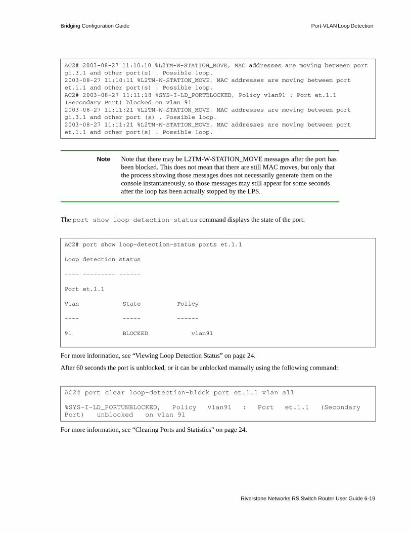
Bridging Configuration Guide Port-VLAN Loop Detection
Note Note that there may be L2TM-W-STATION_MOVE messages after the port has been blocked. This does not mean that there are still MAC moves, but only that the process showing those messages does not necessarily generate them on the console instantaneously, so those messages may still appear for some seconds after the loop has been actually stopped by the LPS.
The port show loop-detection-status command displays the state of the port:
For more information, see “Viewing Loop Detection Status” on page 24.
After 60 seconds the port is unblocked, or it can be unblocked manually using the following command:
For more information, see “Clearing Ports and Statistics” on page 24.
AC2# 2003-08-27 11:10:10 %L2TM-W-STATION_MOVE, MAC addresses are moving between port gi.3.1 and other port(s) . Possible loop. 2003-08-27 11:10:11 %L2TM-W-STATION_MOVE, MAC addresses are moving between port et.1.1 and other port(s) . Possible loop. AC2# 2003-08-27 11:11:18 %SYS-I-LD_PORTBLOCKED, Policy vlan91 : Port et.1.1 (Secondary Port) blocked on vlan 91 2003-08-27 11:11:21 %L2TM-W-STATION_MOVE, MAC addresses are moving between port gi.3.1 and other port (s) . Possible loop. 2003-08-27 11:11:21 %L2TM-W-STATION_MOVE, MAC addresses are moving between port et.1.1 and other port(s) . Possible loop.
AC2# port show loop-detection-status ports et.1.1
Loop detection status
---- --------- ------
Port et.1.1
Vlan State Policy
---- ----- ------
91 BLOCKED vlan91
AC2# port clear loop-detection-block port et.1.1 vlan all
%SYS-I-LD_PORTUNBLOCKED, Policy vlan91 : Port et.1.1 (Secondary Port) unblocked on vlan 91
Riverstone Networks RS Switch Router User Guide 6-19

Port-VLAN Loop Detection Bridging Configuration Guide
If the loop is created for another reason and blocking the secondary port does not stop the problem, the loop will continue to grow until the primary threshold is reached. At that time, the primary port would be blocked as well.
For example on AC1,
Figure 6-9 and the following CLI examples show how to configure LPS on AC1 and AC2 when using more CPEs for the same customer.
Figure 6-9 Loop Detection for Multiple CPEs
2003-08-27 11:28:12 %SYS-I-LD_PORTBLOCKED, Policy vlan91 : Port et.1.1 (Primary Port) blocked on vlan 91
AC2# port show loop-detection-status policies vlan91Loop detection status---- --------- ------
Policy - vlan 91 ------ Primary Ports - Secondary Ports - et.1.1 Uplink Primary Ports - st.(1-2) Uplink Secondary Ports - Blockable Ports - et.1.1,st.(1-2) Vlans - 91 Primary Move Frequency - Secondary Move Frequency - 10 Retry Timeout - 60 Uplink Move Frequency - 100 Uplink Retry Timeout - 60
6-20 Riverstone Networks RS Switch Router User Guide
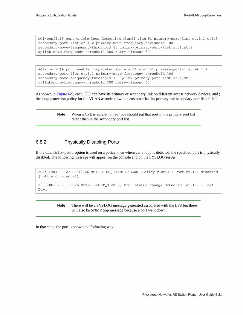
Bridging Configuration Guide Port-VLAN Loop Detection
As shown in Figure 6-9, each CPE can have its primary or secondary link on different access network devices, and ; the loop protection policy for the VLAN associated with a customer has its primary and secondary port lists filled.
Note When a CPE is single-homed, you should put that port in the primary prot list rather than in the secondary port list.
6.8.2 Physically Disabling Ports
If the disable-port option is used on a policy, then whenever a loop is detected, the specified port is physically disabled. The following message will appear on the console and on the SYSLOG server:
Note There will be a SYSLOG message generated associated with the LPS but there will also be SNMP trap message because a port went down.
In that state, the port is shown the following way:
AC1(config)# port enable loop-detection vlan91 vlan 91 primary-port-list et.1.1,et1.3 secondary-port-list et.1.2 primary-move-frequency-threshold 100 secondary-move-frequency-threshold 10 uplink-primary-port-list st.1,st.2 uplink-move-frequency-threshold 200 retry-timeout 60
AC2(config)# port enable loop-detection vlan91 vlan 91 primary-port-list et.1.2 secondary-port-list et.1.1 primary-move-frequency-threshold 100 secondary-move-frequency-threshold 10 uplink-primary-port-list st.1,st.2 uplink-move-frequency-threshold 200 retry-timeout 60
AC2# 2003-08-27 11:12:26 @SYS-I-LD_PORTDISABLED, Policy vlan91 : Port et.1.1 disabled (policy on vlan 91)
2003-08-27 11:12:26 %STP-I-PORT_STATUS, Prot status change detected: et.1.1 - Port Down
Riverstone Networks RS Switch Router User Guide 6-21
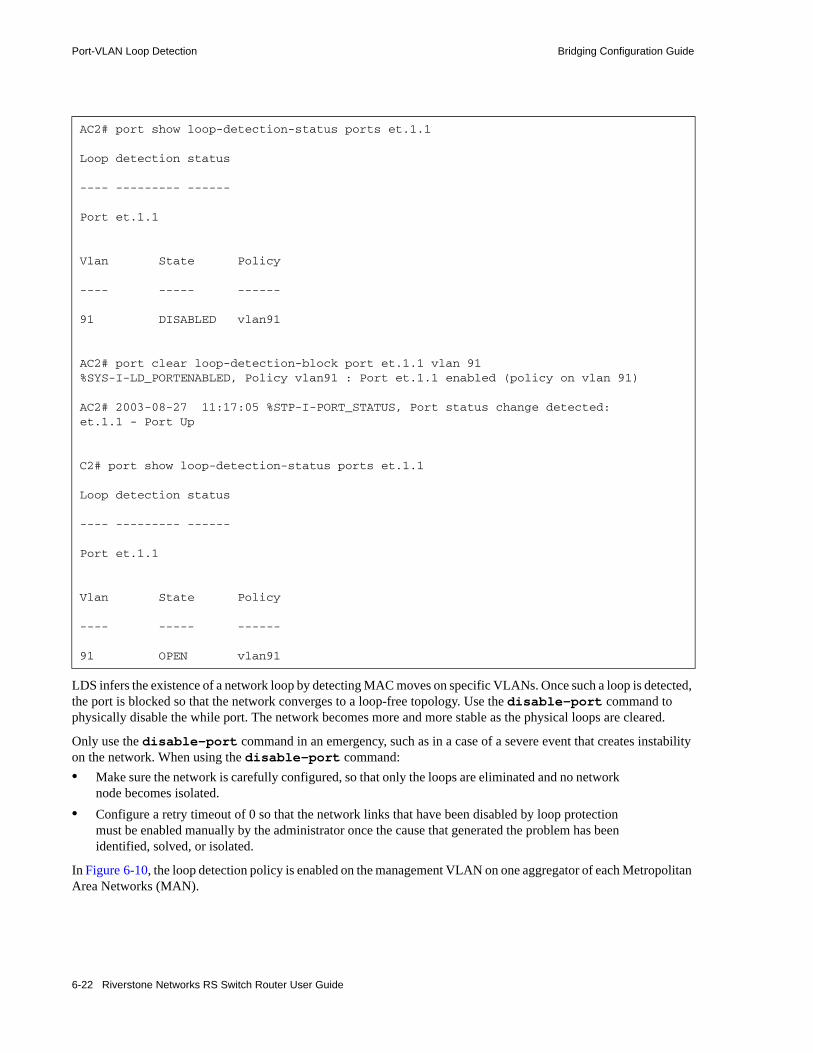
Port-VLAN Loop Detection Bridging Configuration Guide
LDS infers the existence of a network loop by detecting MAC moves on specific VLANs. Once such a loop is detected, the port is blocked so that the network converges to a loop-free topology. Use the disable-port command to physically disable the while port. The network becomes more and more stable as the physical loops are cleared.
Only use the disable-port command in an emergency, such as in a case of a severe event that creates instability on the network. When using the disable-port command: • Make sure the network is carefully configured, so that only the loops are eliminated and no network
node becomes isolated.• Configure a retry timeout of 0 so that the network links that have been disabled by loop protection
must be enabled manually by the administrator once the cause that generated the problem has been identified, solved, or isolated.
In Figure 6-10, the loop detection policy is enabled on the management VLAN on one aggregator of each Metropolitan Area Networks (MAN).
AC2# port show loop-detection-status ports et.1.1
Loop detection status
---- --------- ------
Port et.1.1
Vlan State Policy
---- ----- ------
91 DISABLED vlan91
AC2# port clear loop-detection-block port et.1.1 vlan 91%SYS-I-LD_PORTENABLED, Policy vlan91 : Port et.1.1 enabled (policy on vlan 91)
AC2# 2003-08-27 11:17:05 %STP-I-PORT_STATUS, Port status change detected: et.1.1 - Port Up
C2# port show loop-detection-status ports et.1.1
Loop detection status
---- --------- ------
Port et.1.1
Vlan State Policy
---- ----- ------
91 OPEN vlan91
6-22 Riverstone Networks RS Switch Router User Guide
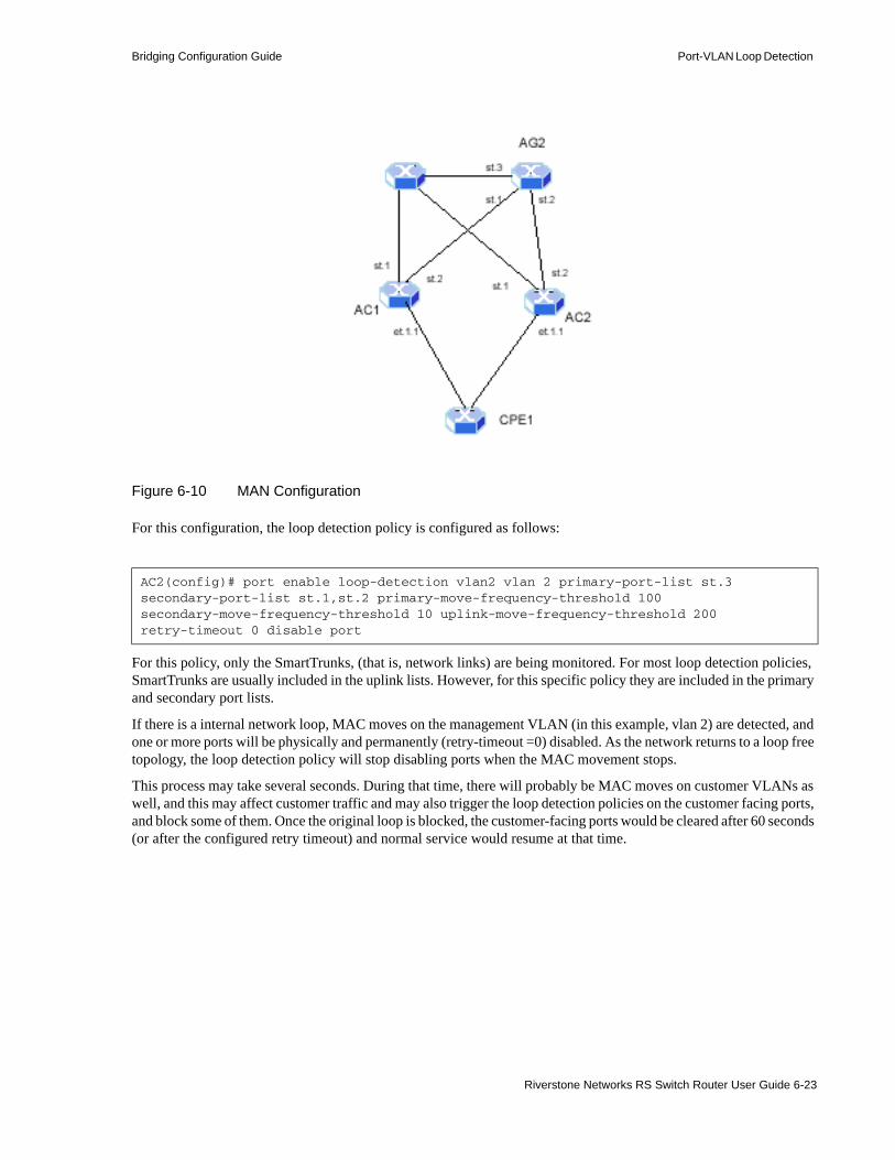
Bridging Configuration Guide Port-VLAN Loop Detection
Figure 6-10 MAN Configuration
For this configuration, the loop detection policy is configured as follows:
For this policy, only the SmartTrunks, (that is, network links) are being monitored. For most loop detection policies, SmartTrunks are usually included in the uplink lists. However, for this specific policy they are included in the primary and secondary port lists.
If there is a internal network loop, MAC moves on the management VLAN (in this example, vlan 2) are detected, and one or more ports will be physically and permanently (retry-timeout =0) disabled. As the network returns to a loop free topology, the loop detection policy will stop disabling ports when the MAC movement stops.
This process may take several seconds. During that time, there will probably be MAC moves on customer VLANs as well, and this may affect customer traffic and may also trigger the loop detection policies on the customer facing ports, and block some of them. Once the original loop is blocked, the customer-facing ports would be cleared after 60 seconds (or after the configured retry timeout) and normal service would resume at that time.
AC2(config)# port enable loop-detection vlan2 vlan 2 primary-port-list st.3 secondary-port-list st.1,st.2 primary-move-frequency-threshold 100 secondary-move-frequency-threshold 10 uplink-move-frequency-threshold 200 retry-timeout 0 disable port
Riverstone Networks RS Switch Router User Guide 6-23

Port-VLAN Loop Detection Bridging Configuration Guide
6.8.2.1 Clearing Ports and Statistics
Use the port clear loop-detection-block command from the Enable mode to clear blocked port VLAN associations.
For example, the following clears the blocked port gi.4.1 belonging to VLAN V1:
6.8.2.2 Viewing Loop Detection Status
Use the port show loop-detection-status command from Enable mode to view the status of loop detection. Information within the display can be arranged in different ways depending on which of the viewing options (policies, port, or vlan) is selected.
rs# port clear loop-detection-block port gi.4.1 vlan v1
6-24 Riverstone Networks RS Switch Router User Guide

Bridging Configuration Guide Port-VLAN Loop Detection
The following is an example of the use of the port show loop-detection-status command.
rs# port show loop-detection-status policies pol-1Loop detection status---- --------- ------ Policy - pol-1 ------
Primary Ports - et.2.1 Secondary Ports - Blockable Ports - et.2.1 Vlans - 100 Primary Move Frequency - 1 Secondary Move Frequency - Retry Timeout - 60 Options - BlockInOut
rs# port show loop-detection-status vlan V1Loop detection status---- --------- ------Vlan V1
Port State Policy ---- ----- ------ et.2.1 OPEN pol-1 et.2.2 OPEN pol-1
rs# port show loop-detection-status ports all-portsLoop detection status---- --------- ------Port et.2.1
Vlan State Policy---- ----- ------V1 OPEN pol-1
Port et.2.2
Vlan State Policy---- ----- ------V1 OPEN pol-1
Riverstone Networks RS Switch Router User Guide 6-25
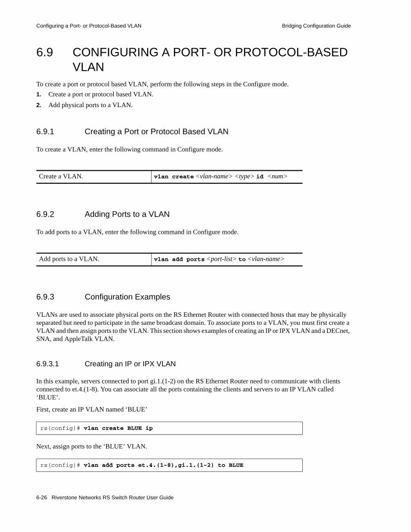
Configuring a Port- or Protocol-Based VLAN Bridging Configuration Guide
6.9 CONFIGURING A PORT- OR PROTOCOL-BASED VLAN
To create a port or protocol based VLAN, perform the following steps in the Configure mode.1. Create a port or protocol based VLAN.2. Add physical ports to a VLAN.
6.9.1 Creating a Port or Protocol Based VLAN
To create a VLAN, enter the following command in Configure mode.
6.9.2 Adding Ports to a VLAN
To add ports to a VLAN, enter the following command in Configure mode.
6.9.3 Configuration Examples
VLANs are used to associate physical ports on the RS Ethernet Router with connected hosts that may be physically separated but need to participate in the same broadcast domain. To associate ports to a VLAN, you must first create a VLAN and then assign ports to the VLAN. This section shows examples of creating an IP or IPX VLAN and a DECnet, SNA, and AppleTalk VLAN.
6.9.3.1 Creating an IP or IPX VLAN
In this example, servers connected to port gi.1.(1-2) on the RS Ethernet Router need to communicate with clients connected to et.4.(1-8). You can associate all the ports containing the clients and servers to an IP VLAN called ‘BLUE’.
First, create an IP VLAN named ‘BLUE’
Next, assign ports to the ‘BLUE’ VLAN.
Create a VLAN. vlan create <vlan-name> <type> id <num>
Add ports to a VLAN. vlan add ports <port-list> to <vlan-name>
rs(config)# vlan create BLUE ip
rs(config)# vlan add ports et.4.(1-8),gi.1.(1-2) to BLUE
6-26 Riverstone Networks RS Switch Router User Guide

Bridging Configuration Guide Configuring a Port- or Protocol-Based VLAN
6.9.3.2 Creating a non-IP/non-IPX VLAN
In this example, SNA, DECnet, and AppleTalk hosts are connected to et.1.1 and et.2.(1-4). You can associate all the ports containing these hosts to a VLAN called ‘RED’ with the VLAN ID 5.
First, create a VLAN named ‘RED’
Next, assign ports to the ‘RED’ VLAN.
6.9.4 Configuring VLAN Trunk Ports
The RS Ethernet Router supports standards-based VLAN trunking between multiple RS Ethernet Router’s as defined by IEEE 802.1Q. 802.1Q adds a header to a standard Ethernet frame which includes a unique VLAN ID per trunk between two RS Ethernet Router’s. These VLAN IDs extend the VLAN broadcast domain to more than one RS Ethernet Router.
To configure a VLAN trunk, enter the following command in the Configure mode.
You can enable the collection of VLAN statistics on 10/100 and Gigabit Ethernet ports configured as 802.1Q trunk ports. To do so, use the port enable per-vlan-stats command. Then, you can display the statistics by using the port show per-vlan-stats command as illustrated in the following example:
rs(config)# vlan create RED sna dec appletalk id 5
rs(config)# vlan add ports et.1.1, et.2.(1-4) to RED
Configure 802.1Q VLAN trunks. vlan make <port-type> <port-list>
rs# port show per-vlan-stats port et.10.4 Traffic Statistics for Port et.10.4, VLAN red (VLAN ID 2):Inbound Octets: 107,196,271 octets Frames: 134,940 frames
Outbound Octets: 105,965,469 octets Frames: 133,549 frames
Traffic Statistics for Port et.10.4, VLAN blue (VLAN ID 3):Inbound Octets: 354,072,575 octets Frames: 446,763 frames
Outbound Octets: 347,463,892 octets Frames: 435,218 frames
Riverstone Networks RS Switch Router User Guide 6-27

Configuring a Port- or Protocol-Based VLAN Bridging Configuration Guide
6.9.5 Configuring Native VLANs
On the RS Ethernet Router, trunk ports normally transmit and receive tagged frames only. To enable a trunk port to receive and transmit untagged frames, use the vlan set native-vlan command to configure a “native VLAN.” A native VLAN is the VLAN that is assigned to receive and transmit untagged frames. You can use native VLANs when you use trunk ports on the RS Ethernet Router to connect to VLAN-unaware devices. When the RS Ethernet Router receives untagged frames from the VLAN-unaware devices, it assigns them to the native VLAN.
You can specify one native VLAN for each protocol type supported by the RS Ethernet Router. All untagged frames of a particular protocol received on the trunk port are assigned to the protocol’s native VLAN. You can also use the all option of the vlan set native-vlan command to set the native VLAN for all protocols, or use the auto option to specify the native VLAN for all protocols supported by the specified VLAN.
Consider the following example:
The trunk port et.2.1 belongs to five VLANs, three are three IP VLANs and two are IPX VLANs. VLAN RED is the native IP VLAN, and VLAN YELLOW is the native IPX VLAN. Therefore, when the RS Ethernet Router receives untagged IP frames on port et.2.1, it will assign them to VLAN RED. If the RS Ethernet Router receives untagged IPX frames on port et.2.1, it will assign them to VLAN YELLOW. When frames from VLAN RED or YELLOW are transmitted out of et.2.1, the frames will be untagged.
To use the all or auto option the VLAN being made the native VLAN should be a port-based VLAN. By using a port-based VLAN, the RS Ethernet Router is not restricted to accepting untagged frames from a particular protocol.
!Configure the trunk portvlan make trunk-port et.2.1
!Create the VLANs and add the trunk portvlan create red ipvlan create blue ipvlan create white ipvlan create green ipxvlan create yellow ipxvlan add ports et.2.1 to redvlan add ports et.2.1 to bluevlan add ports et.2.1 to greenvlan add ports et.2.1 to whitevlan add ports et.2.1 to yellow
!Specify the native VLANvlan set native-vlan et.2.1 ip redvlan set native-vlan et.2.1 ipx yellow
6-28 Riverstone Networks RS Switch Router User Guide

Bridging Configuration Guide Configuring a Port- or Protocol-Based VLAN
Consider the following example:
By creating a port-based VLAN (ORANGE), that VLAN can be assigned as the native VLAN for all protocols.
If the VLAN specified to be the native VLAN is associated with a particular protocol, and if the auto option is specified for the native VLAN, the native VLAN will accept untagged frames from only the native VLAN’s protocol.
Consider the following example:
The native VLAN (RED) will accept untagged frames from only IP packets. All other protocol types will be dropped.
Note Native VLANs cannot be set on trunk ports configured with the untagged option of the vlan make trunk-port command.
Note Native VLANs cannot be set on ports that are running MPLS. MPLS internally creates a native VLAN for its signalling purposes.
!Configure the trunk portvlan make trunk-port et.2.1
!Create the VLANs and add the trunk portvlan create orange port-basedvlan create red ipvlan create blue ipvlan create white ipvlan create green ipxvlan create yellow ipxvlan add ports et.2.1 to redvlan add ports et.2.1 to bluevlan add ports et.2.1 to greenvlan add ports et.2.1 to whitevlan add ports et.2.1 to yellow
!Specify the native VLANvlan set native-vlan et.2.1 all orange
!Configure the trunk portvlan make trunk-port et.2.1
!Create the VLANs and add the trunk portvlan create red ipvlan create blue ipvlan create yellow ipxvlan add ports et.2.1 to redvlan add ports et.2.1 to bluevlan add ports et.2.1 to yellow
!Specify the native VLANvlan set native-vlan et.2.1 auto red
Riverstone Networks RS Switch Router User Guide 6-29
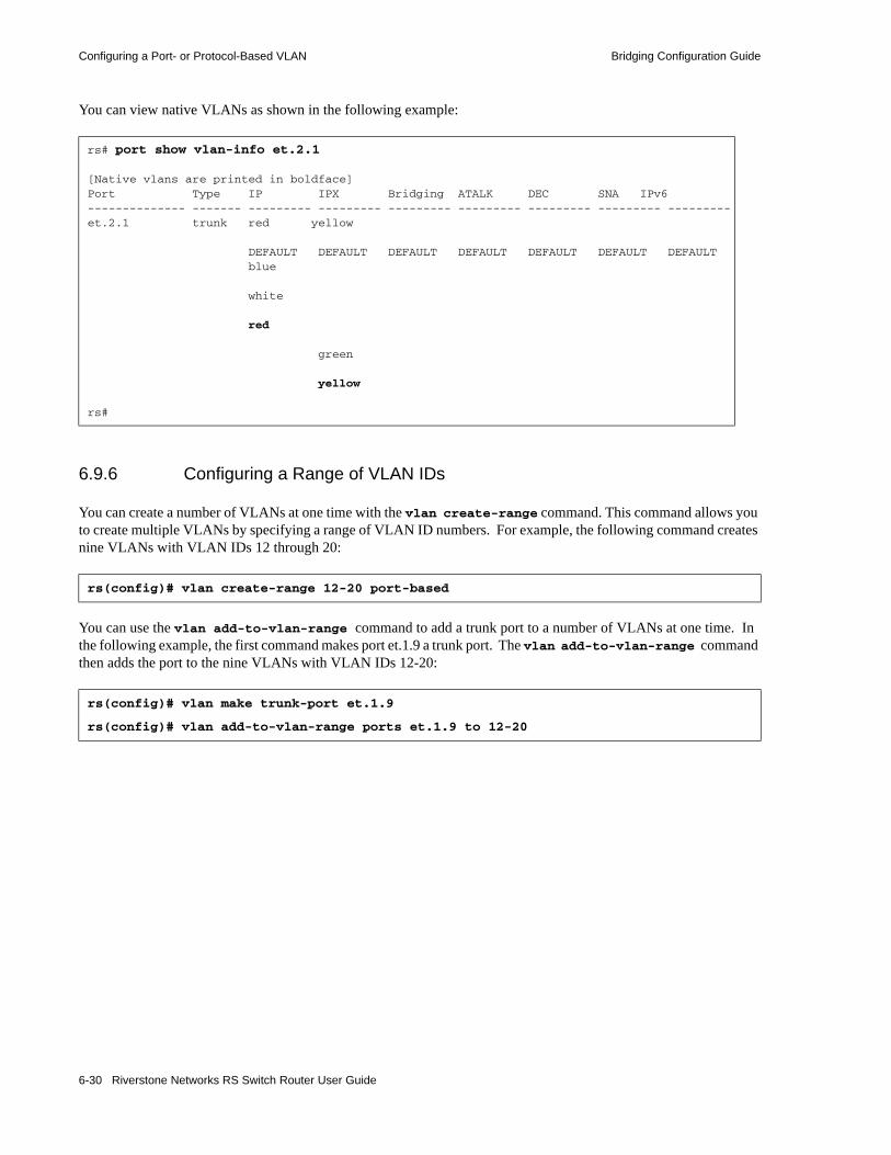
Configuring a Port- or Protocol-Based VLAN Bridging Configuration Guide
You can view native VLANs as shown in the following example:
6.9.6 Configuring a Range of VLAN IDs
You can create a number of VLANs at one time with the vlan create-range command. This command allows you to create multiple VLANs by specifying a range of VLAN ID numbers. For example, the following command creates nine VLANs with VLAN IDs 12 through 20:
You can use the vlan add-to-vlan-range command to add a trunk port to a number of VLANs at one time. In the following example, the first command makes port et.1.9 a trunk port. The vlan add-to-vlan-range command then adds the port to the nine VLANs with VLAN IDs 12-20:
rs# port show vlan-info et.2.1
[Native vlans are printed in boldface]Port Type IP IPX Bridging ATALK DEC SNA IPv6-------------- ------- --------- --------- --------- --------- --------- --------- ---------et.2.1 trunk red yellow
DEFAULT DEFAULT DEFAULT DEFAULT DEFAULT DEFAULT DEFAULT blue
white
red
green
yellow
rs#
rs(config)# vlan create-range 12-20 port-based
rs(config)# vlan make trunk-port et.1.9
rs(config)# vlan add-to-vlan-range ports et.1.9 to 12-20
6-30 Riverstone Networks RS Switch Router User Guide

Bridging Configuration Guide Configuring a Port- or Protocol-Based VLAN
The vlan show command shows that the port et.1.9 has been added to VLANs 12 through 20:
Note that you can also specify a VLAN ID or VLAN name with the vlan show command to display information about a specific VLAN:
rs# vlan show
VID VLAN Name Used for Ports
--- --------- -------- -----
1 DEFAULT IP,IPX,ATALK,DEC,SNA,IPv6,L2 et.1.(1-16)
2 SYS_L3_et.1.1 IP et.1.1
3 SYS_L3_t1port- IP t1.2.1:1
4 SYS_L3_t1port- IP t1.2.1:2
12 12 IP,IPX,ATALK,DEC,SNA,IPv6,L2 et.1.9
13 13 IP,IPX,ATALK,DEC,SNA,IPv6,L2 et.1.9
14 14 IP,IPX,ATALK,DEC,SNA,IPv6,L2 et.1.9
15 15 IP,IPX,ATALK,DEC,SNA,IPv6,L2 et.1.9
16 16 IP,IPX,ATALK,DEC,SNA,IPv6,L2 et.1.9
17 17 IP,IPX,ATALK,DEC,SNA,IPv6,L2 et.1.9
18 18 IP,IPX,ATALK,DEC,SNA,IPv6,L2 et.1.9
19 19 IP,IPX,ATALK,DEC,SNA,IPv6,L2 et.1.9
20 20 IP,IPX,ATALK,DEC,SNA,IPv6,L2 et.1.9
rs# vlan show id 20
VID VLAN Name Used for Ports
--- --------- -------- -----
20 20 IP,IPX,ATALK,DEC,SNA,IPv6,L2 et.1.9
Riverstone Networks RS Switch Router User Guide 6-31
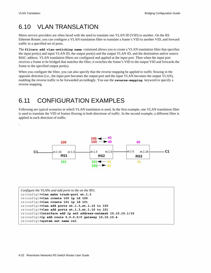
VLAN Translation Bridging Configuration Guide
6.10 VLAN TRANSLATIONMetro service providers are often faced with the need to translate one VLAN ID (VID) to another. On the RS Ethernet Router, you can configure a VLAN translation filter to translate a frame’s VID to another VID, and forward traffic to a specified set of ports.
The filters add vlan-switching name command allows you to create a VLAN translation filter that specifies the input port(s) and input VLAN ID, the output port(s) and the output VLAN ID, and the destination and/or source MAC address. VLAN translation filters are configured and applied at the input port. Then when the input port receives a frame to be bridged that matches the filter, it switches the frame’s VID to the output VID and forwards the frame to the specified output port(s).
When you configure the filter, you can also specify that the reverse mapping be applied to traffic flowing in the opposite direction (i.e., the input port becomes the output port and the input VLAN becomes the output VLAN), enabling the reverse traffic to be forwarded accordingly. You use the reverse-mapping keyword to specify a reverse mapping.
6.11 CONFIGURATION EXAMPLESFollowing are typical scenarios in which VLAN translation is used. In the first example, one VLAN translation filter is used to translate the VID of frames flowing in both directions of traffic. In the second example, a different filter is applied in each direction of traffic.
.
Configure the VLANs and add ports to the on the RS1.rs(config)#vlan make trunk-port et.1.3rs(config)#vlan create 100 ip id 100rs(config)#vlan create 101 ip id 101rs(config)#vlan add ports et.1.3,et.1.16 to 100rs(config)#vlan add ports et.1.3,et.1.16 to 101rs(config)#interface add ip en0 address-netmask 10.10.10.1/16rs(config)#ip add route 0.0.0.0/0 gateway 10.10.10.4rs(config)#system set name rs1
40
101 41
100 40
101
100
RS1 RS2 RS3et.1.3 et.1.5
101 41
100 40
et.1.5
41
et.1.16C1 C1et.1.16et.1.3
6-32 Riverstone Networks RS Switch Router User Guide

Bridging Configuration Guide Configuration Examples
Configure the VLANs and add ports to the on the RS2.rs(config)#vlan make trunk-port et.1.3rs(config)#vlan make trunk-port et.1.5rs(config)#vlan create 40 ip id 40rs(config)#vlan create 100 ip id 100rs(config)#vlan create 41 ip id 41rs(config)#vlan create 101 ip id 101rs(config)#vlan add ports et.1.5 to 40rs(config)#vlan add ports et.1.3 to 100rs(config)#vlan add ports et.1.5 to 41rs(config)#vlan add ports et.1.3 to 101rs(config)#interface add ip en0 address-netmask 10.10.10.2/16rs(config)#ip add route 0.0.0.0/0 gateway 10.10.10.4rs(config)#system set name rs2
Configure the VLAN translation filter.rs(config)#filters add vlan-switching name Translation_002 in-port-list et.1.3 in-vlan 101 out-port-list et.1.5 out-vlan 41 dest-mac any reverse-mapping policy-id 1100rs(config)#filters add vlan-switching name Test_001 in-port-list et.1.3 in-vlan 100 out-port-list et.1.5 out-vlan 40 dest-mac any reverse-mapping policy-id 2000
Configure the VLANs and add ports to the on the RS3.rs(config)#vlan make trunk-port et.1.5rs(config)#vlan create 40 ip id 40rs(config)#vlan create 41 ip id 41rs(config)#vlan add ports et.1.5,et.1.16 to 40rs(config)#vlan add ports et.1.5,et.1.16 to 41rs(config)#interface add ip en0 address-netmask 10.10.10.3/16rs(config)#ip add route 0.0.0.0/0 gateway 10.10.10.4rs(config)#system set name rs3
Riverstone Networks RS Switch Router User Guide 6-33

Configuration Examples Bridging Configuration Guide
In the following example, the VIDs are treated similar to MPLS transport labels. On RS1, ports et.1.1 and et.1.2 belong to VLAN RED, which has a VID of 20. The VID of incoming frames on these ports is translated from 20 to 30, while the VID of the reverse traffic coming in on port et.2.1 is translated from 70 to 20.
.
In the example, a different VLAN translation filter is applied to each direction of traffic; traffic flowing in one direction uses a VLAN translation scheme that is different from the one used in the reverse direction. Following is the configuration for RS1:
.
6.11.1 Restrictions
Note the following restrictions on configuring and using VLAN translation:• VLAN translation and VLAN stacking cannot be implemented on the same ports.• You cannot enable L4 bridging on a VLAN to which a VLAN translation filter is applied.• VLAN translation is not supported on ports that are running MPLS.• When used with other L2 filters, the L2 filters are applied to the input VID only, and not to the
translated VID. • Vlan translation filters can translate customer BPDUs if the STP forwarder is enabled, using the stp
set forward-tagged-bpdu command.
Configure the VLANs and add ports to them.rs(config)# vlan make trunk port et.2.1rs(config)# vlan create red ip id 20rs(config)# vlan add ports et.1.(1,2),et.2.1 to redrs(config)# vlan create blue ip id 30rs(config)# vlan add ports et.2.1 to bluers(config)# vlan create green ip id 70rs(config)# vlan add ports et.2.1 to green
Configure the VLAN translation filters; one for each direction of traffic. In this case, the reverse-mapping parameter is not specified.rs(config)# filters add vlan-switching name c100a in-port-list et.1.(1,2) out-port-list et.2.1 input-vlan 20 output-vlan 30 policy-id 100rs(config)# filters add vlan-switching name c100b in-port-list et.2.1 out-port-list et.1.(1,2) input-vlan 70 output-vlan 20 policy-id 200
60 50
40 50
70 60
30 40
20 70
20 30
C1C1
et.1.1
et.1.2RS1 RS2 RS3C1
et.2.1VLAN REDVID = 20
6-34 Riverstone Networks RS Switch Router User Guide

Bridging Configuration Guide DHCP Relay Agent for Flat Layer-4 Bridged VLANs
• VLAN translation is supported on Ethernet line cards only.• You cannot apply to the same input port two or more VLAN translation filters mapped to the same
translated VLAN.
6.12 DHCP RELAY AGENT FOR FLAT LAYER-4 BRIDGED VLANS
The RS Ethernet Router support DHCP relay agent (also known as Option 82) functionality across layer-2 bridged VLANs, which are also running layer-4 bridging.
On a VLAN where the relay agent is enabled, a circuit ID is attached to the packets. The circuit ID consists of the RS Ethernet Router’s base MAC address, the port number on which the packet was received, and the VLAN on which the packet was received.
When the relay agent is enabled, packets that already contains relay agent information are dropped on the assumption that the information was fabricated by the DHCP client. Also, if the packet will become too large if the relay agent information is added, the packet is forwarded without adding the relay agent information.
Relay agent information contained within DHCPOFFER and DHCPACK packets is stripped off to keep the DHCP client from seeing it.
The following is an example of activating the DHCP relay agent on a newly created VLAN:
Note Notice that layer-4 bridging must be enabled on the VLAN for the relay agent to work.
6.13 CONFIGURING LAYER-2 FILTERSLayer-2 security filters on the RS Ethernet Router allow you to configure ports to filter specific MAC addresses. When defining a Layer-2 security filter, you specify to which ports you want the filter to apply. For details on configuring Layer-2 filters, refer to Chapter 27, "Security Configuration." You can specify the following security filters:• Address filters
These filters block traffic based on the frame's source MAC address, destination MAC address, or both source and destination MAC addresses in flow bridging mode. Address filters are always configured and applied to the input port.
• Port-to-address lock filters
These filters prohibit a user connected to a locked port or set of ports from using another port.• Static entry filters
rs(config)# vlan create op82 iprs(config)# vlan add port et.5.1 to op82rs(config)# vlan enable l4-bridging on op82rs(config)# ip helper-address relay-agent-info circuit-id mac-port-vlan vlan op82
Riverstone Networks RS Switch Router User Guide 6-35

Monitoring Bridging Bridging Configuration Guide
These filters allow or force traffic to go to a set of destination ports based on a frame's source MAC address, destination MAC address, or both source and destination MAC addresses in flow bridging mode. Static entries are always configured and applied at the input port.
• Secure port filters
A secure filter shuts down access to the RS Ethernet Router based on MAC addresses. All packets received by a port are dropped. When combined with static entries, however, these filters can be used to drop all received traffic but allow some frames to go through.
• Authorization filters
An authorization filter authenticates client based on their MAC address. It contains a list of end-station MAC addresses that are authorized to transmit traffic through the port. For additional information on this feature, refer to Section 27.2, "Port-Based Authentication."
6.14 MONITORING BRIDGINGThe RS Ethernet Router displays bridging statistics and configurations contained in the RS Ethernet Router.
To display bridging information, enter the following commands in Enable mode.
Show IP routing table. ip show routes
Show all MAC addresses currently in the l2 tables.
l2-tables show all-macs
Show l2 table information on a specific port.
l2-tables show port-macs
Show information the master MAC table. l2-tables show mac-table-stats
Show information on a specific MAC address.
l2-tables show mac
Show information on MACs registered. l2-table show bridge-management
Show all VLANs. vlan show
6-36 Riverstone Networks RS Switch Router User Guide
Bridging Configuration Guide GARP/GVRP
6.15 GARP/GVRPThe Generic Attribute Registration Protocol (GARP) is a generic attribute dissemination mechanism. In the case of the GARP VLAN Registration Protocol (GVRP), the attribute is the VLAN ID (VID).
GVRP uses GARP Protocol Data Units (PDUs) to register and de-register VLAN IDs on ports. When you enable GVRP on the RS Ethernet Router and one of its ports receives a GVRP request for an existing VLAN to which it does not belong, GVRP registers the VLAN ID on the port, effectively adding the port to the VLAN. For example, VLAN RED is configured on ports et.1.1 and et.1.2 of the RS Ethernet Router. Port et.1.3 receives a GVRP request for VLAN RED, of which it is not a member. If GVRP is enabled on port et.1.3, it will automatically become a member of VLAN RED and pass traffic for this VLAN. But if GVRP is not enabled on port et.1.3, VLAN registration will not occur, and traffic for VLAN RED will never reach port et.1.3.
GVRP also provides a mechanism for dynamically creating and removing VLANs. When you turn on dynamic VLAN creation and the RS Ethernet Router receives a request for a VLAN that does not exist on the RS Ethernet Router, GVRP dynamically creates that VLAN and adds the port that received the request.
GVRP propagates this VLAN information throughout the active topology, enabling all GVRP-aware devices to dynamically establish and update their knowledge of VLANS and their members, including the ports through which those members can be reached. (For details on GARP refer to IEEE 802.1d. For details on GVRP, refer to IEEE 802.1q.)
Note GVRP will only add a port to a VLAN if the port is an 802.1q trunk port.
GARP/GVRP provides the following benefits:• The administrator is not required to know ahead of time which VLANS should be configured on the
network. • The administrator does not have to manually configure all VLANS on the network. • It prunes unnecessary traffic if a VLAN goes down.
6.15.1 Running GARP/GVRP with STP
Anytime GARP /GVRP configures a VLAN or adds ports to a VLAN, this information needs to be propagated on all other ports that are part of the active topology. If STP is disabled, this includes all ports, except the input port. If STP is enabled, this includes all ports that are in the forwarding mode, except the input port.
Riverstone Networks RS Switch Router User Guide 6-37
GARP/GVRP Bridging Configuration Guide
6.15.2 Configuring GARP/GVRP
To configure GARP/GVRP on the RS Ethernet Router, you should do the following:1. Enable GVRP functionality on the RS Ethernet Router. (GVRP is disabled on the RS Ethernet
Router by default.)2. Enable GVRP on individual ports. (GVRP is disabled on all ports on the RS Ethernet Router by
default.)
You can optionally set the following features by using the garp and gvrp commands described in the Riverstone RS Switch Router Command Line Interface Reference Manual:• Enable dynamic VLAN creation. (This feature is disabled by default.) When you enable this feature,
VLANs will be created dynamically when there is a GVRP request for a VLAN that does not exist on the RS Ethernet Router. In addition, you will still be able to configure VLANs manually through the CLI.
• Set a port’s registration mode to forbidden. Registration modes refer to whether VLAN IDs can be dynamically registered or de-registered on a port. You can set a port’s mode to forbidden to prevent it from being dynamically added to a VLAN. Setting a port to “forbidden registration” de-registers all VLANS (except VLAN 1) and prevents further VLAN registration on the port.
• Set a port’s status to non-participating. When you do so, the specified ports will not send GARP PDUs.
• Change the default values for the following GARP timers: - leaveall timer default is 10,000 ms- leave timer default is 600 ms (When configuring the leave timer, its value should be three times
that of the join timer.)- join timer default is 200 ms
Note For GARP to operate properly, all layer-2 connected devices should have the same GARP timer values.
6-38 Riverstone Networks RS Switch Router User Guide

Bridging Configuration Guide GARP/GVRP
6.15.3 Configuration Example
Consider the following configuration example.
Figure 6-11 Using GARP/GVRP on a network
Routers R4 and R5 pass traffic between two networks. The administrator used the CLI to configure the following VLANs:• VLAN RED on ports et.1.1- 1.3 on R1, and on et.4.1 - 4.3 on R6.• VLAN GREEN on ports et.2.1- 2.3 on R2, and on et.5.1 - 5.3 on R7.• VLAN BLUE on ports et.3.1- 3.3 on R3, and on et.6.1 - 6.3 on R8.
No VLANs were configured on R4 and R5. Instead, dynamic VLAN creation was enabled. So when any of the edge routers (R1, R2, R3, R6, R7, or R8) send a request for a VLAN to the core routers (R4 and R5), and the VLAN does not exist on the core routers, that VLAN is dynamically created on the port of the router that received the request.
For example, R4 receives a receives a request for VLAN RED on port 7.1. VLAN RED is created dynamically on port 7.1 of R4. This is then propagated across the bridged LAN to all the other routers. If dynamic VLAN creation was not enabled on R4, it would have dropped the traffic for VLAN RED.
R1
et.1.2et.1.3.
R2et.2.1
R3
st.1
et.4.2et.4.3
R6
et.4.1
8.1et.5.1
R7
et.6.1
R8
R5
et.2.2et.2.3
et.3.1et.3.2et.3.3
et.5.2
et.5.3
et.6.2et.6.3
et.1.1
8.38.2
st.17.1
R47.37.2
Riverstone Networks RS Switch Router User Guide 6-39

GARP/GVRP Bridging Configuration Guide
The following is the configuration for R1:
The following is the configuration for R4:
Note that because dynamic VLAN creation was enabled on R4, we did not have to manually configure any VLAN on R4.
Create VLAN RED as a port-based VLAN and add ports to it.vlan create red port-based
vlan add ports et.1.1-3 to vlan red
Enable GVRPgvrp start
Enable GVRP on ports et.1.1-3.
gvrp enable ports et.1.1-3
Ports et.1.2 and 1.3 do not need to send GARP PDUs because they are connected to devices that are not running GVRP. Therefore, we should set their status to non-participating.
gvrp set applicant status non-participant et.1.2-3
Create the SmartTRUNK.smarttrunk create st.1 protocol no-protocol
Add ports to the SmartTRUNK.
smarttrunk add ports et.1.1-3 to st.1
Enable GVRPgvrp start
Enable GVRP on ports st.1, and et.7.1-3.
gvrp enable ports st.1, et.7.1-3
Enable dynamic VLAN creation so when R1, R2, or R3 sends a request for a VLAN, it will dynamically be created on R4.
gvrp enable dynamic vlan-creation
6-40 Riverstone Networks RS Switch Router User Guide

Bridging Configuration Guide Tunneling VLAN packets across MANs
6.16 TUNNELING VLAN PACKETS ACROSS MANSThe “stackable” VLAN feature on the RS Ethernet Router allows you to tunnel multiple VLANs through a metropolitan area network (MAN) over a single backbone VLAN. This feature provides the following benefits:• Traffic for multiple VLANs, or traffic for multiple customers, can be aggregated to run through a
MAN over a single backbone VLAN. The RS Ethernet Router supports a maximum of 4094 customers or VLANs and up to 4094 backbone VLANs.
• Spanning tree and rapid spanning tree protocols can be run in customer-specific VLANs; no reconfiguration of customer-specific VLANs is needed.
• Per-VLAN spanning tree can be run in the backbone VLAN.
6.16.1 Stackable VLAN Components
The following figure illustrates the basic components of the stackable VLAN. Routers R1 and R2 switch traffic for customers C1 and C2 through the MAN. Ports et.2.1 on R1 and et.6.1 on R2 belong to customer C1’s VLAN, “BLUE” while ports et.3.1 on R1 and et. 7.1 on R2 belong to customer C2’s VLAN, “GREEN.” Traffic entering any of these four ports are tagged with the appropriate customer VLAN ID (BLUE or GREEN) in an IEEE 802.1q header.
Figure 6-12 Stackable VLAN components
• The VLAN RED is the backbone VLAN, which allows traffic from various VLANs to be tunneled through the MAN.
• Ports et.4.1 on R1 and et.5.1 on R2 are tunnel backbone ports, which are trunk ports through which the VLAN traffic is tunneled. Tunnel backbone ports must be configured as trunk ports so that they maintain the encapsulated 802.1q header. You configure these ports as both trunk ports and tunnel backbone ports with the stackable-vlan option of the vlan make trunk-port CLI command.
• Ports et.2.1 and et.3.1 on R1 are tunnel entry ports, which are access ports on which the VLAN traffic to be tunneled enters R1. Ports et. 6.1 and et.7.1 on R2 are tunnel exit ports, which are access ports on which the tunneled traffic exits R2. You configure the mapping of the tunnel entry and tunnel exit ports to the backbone VLAN with the vlan enable stackable-vlan CLI command.
et.2.1
et.3.1et.4.1 et.5.1
et.6.1
et.7.1R1 R2MAN
RED VLAN (backbone)
BLUE VLAN
GREEN VLAN
C1
C2
C1
C2
Riverstone Networks RS Switch Router User Guide 6-41

Tunneling VLAN packets across MANs Bridging Configuration Guide
Note Tunnel entry and exit port are configured as access ports. These ports can receive 802.1q-tagged traffic.
In Figure 6-12, customer C1 tags outgoing traffic with the VLAN ID BLUE in the 802.1q headers. Customer C1’s traffic enters the tunnel entry port et.2.1 on R1. On R1, the tunnel entry port et.2.1 is mapped to the backbone VLAN RED. The BLUE-tagged packet received on port et.2.1 is encapsulated with an 802.1q header with VLAN RED’s tag before it is bridged out on the tunnel backbone port et.4.1. (The original 802.1q header with the VLAN BLUE ID is now part of the data portion of the packet.) On R2, the RED 802.1q header is stripped off before the packet is sent out on et.6.1. The packet is sent out the tunnel exit port as a tagged packet with the original BLUE 802.1q header.
If an untagged packet arrives on a tunnel entry port, normal layer 2 processing takes place. If the packet needs to be flooded, it will be flooded on all ports in the customer VLAN.
If a broadcast or multicast packet arrives on a tunnel entry port, the packet is flooded on all ports that belong to the backbone VLAN as well as any other ports that belong to that VLAN. If a unicast packet arrives on a tunnel entry port, the packet is sent out a particular backbone VLAN port.
The 802.1p priority of a packet is preserved throughout the MAN. The RS Ethernet Router hardware uses the control priority in the L2 table entry. If there is no L2 table entry for the packet, the 802.1p priority contained in the 802.1q header is used.
Normally, access ports can belong to only one VLAN of a particular protocol type, such as IP. The RS Ethernet Router allows tunnel entry and exit ports to be added to multiple VLANs. Note, however, that only ports that are configured with the stackable-vlan option of the vlan make access-port command can be added to more than one VLAN of the same protocol type.
GARP and/or GVRP can be enabled on tunnel backbone ports.
Note You cannot enable L4 bridging on stackable VLANs. Also, do not use the stp set vlan-disable command on routers where you are configuring stackable VLANs.
6.16.2 Configuration Examples
This section contains configuration examples for the following scenarios:• Multiple customers, with each customer having its own VLAN• Multiple customers sharing a common VLAN• Single VLAN with multiple tunnel entry ports• STP or GVRP in customer VLANs tunneled over the backbone VLAN• Multiple VLANs on a single tunnel entry/exit port• Sending untagged packets over stackable VLANs
6-42 Riverstone Networks RS Switch Router User Guide

Bridging Configuration Guide Tunneling VLAN packets across MANs
6.16.2.1 Multiple Customer VLANs
In Figure 6-13, traffic for customer C1’s VLAN (BLUE) and for customer C2’s VLAN (GREEN) is tunneled through the backbone VLAN (RED).
Figure 6-13 Multiple customers with different VLANs
The following is the configuration for R1:
! Create 1 backbone VLAN and 2 customer VLANs
vlan create RED port-based
vlan create GREEN port-based
vlan create BLUE port-based
! Add port to each VLAN
vlan add ports et.2.1 to BLUE
vlan add ports et.3.1 to GREEN
vlan add ports et.4.1 to RED
! Make et.4.1 both a trunk port and a tunnel backbone port
vlan make trunk-port et.4.1 stackable-vlan
! Map tunnel entry ports to backbone VLANvlan enable stackable-vlan on et.2.1 backbone-vlan RED
vlan enable stackable-vlan on et.3.1 backbone-vlan RED
et.2.1
et.3.1et.4.1 et.5.1
et.6.1
et.7.1MAN
RED VLAN (backbone)
BLUE VLAN
GREEN VLAN
C1
C2
C1
C2R1 R2
Riverstone Networks RS Switch Router User Guide 6-43

Tunneling VLAN packets across MANs Bridging Configuration Guide
The following is the configuration for R2:
6.16.2.2 Multiple Customers with Common VLANs
In Figure 6-14, customers C1 and C2 are connected to the MAN, with both customers using the same VLAN (BLUE). To ensure that traffic for C1 is not sent to C2 and vice versa, the backbone VLAN for each customer must be different. Therefore, traffic for customer C1 will be sent on the backbone VLAN RED, while traffic for customer C2 will be sent on the backbone VLAN GREEN. Note that the trunk port on each router is part of both backbone VLAN RED and backbone VLAN GREEN.
Figure 6-14 Multiple customers with common VLANs
! Create 1 backbone VLAN and 2 customer VLANsvlan create RED port-based
vlan create GREEN port-based
vlan create BLUE port-based
! Add port to each VLANvlan add ports et.6.1 to BLUE
vlan add ports et.7.1 to GREEN
vlan add ports et.5.1 to RED
! Make et.5.1 both a trunk port and a tunnel backbone portvlan make trunk-port et.5.1 stackable-vlan
! Map tunnel exit ports to backbone VLANvlan enable stackable-vlan on et.6.1 backbone-vlan RED
vlan enable stackable-vlan on et.7.1 backbone-vlan RED
BLUE VLAN
et.2.1
et.3.1
et.6.1
et.7.1
C1
C2
C1
C2et.4.1 et.5.1MAN
RED VLAN
GREEN VLAN
R1 R2
6-44 Riverstone Networks RS Switch Router User Guide

Bridging Configuration Guide Tunneling VLAN packets across MANs
The following is the configuration for R1:
The following is the configuration for R2:
! Create 2 backbone VLANs and 1 customer VLANvlan create RED port-based
vlan create GREEN port-based
vlan create BLUE port-based
! Add ports to BLUE VLANvlan add ports et.2.1, et.3.1 to BLUE
! Make et.4.1 both a trunk port and a tunnel backbone portvlan make trunk-port et.4.1 stackable-vlan
! Add et.4.1 to both RED and GREEN backbone VLANs
vlan add ports et.4.1 to RED
vlan add ports et.4.1 to GREEN
! Map tunnel entry ports to backbone VLANvlan enable stackable-vlan on et.2.1 backbone-vlan RED
vlan enable stackable-vlan on et.3.1 backbone-vlan GREEN
! Create 2 backbone VLANs and 1 customer VLAN
vlan create RED port-based
vlan create GREEN port-based
vlan create BLUE port-based
! Add ports to BLUE VLAN
vlan add ports et.6.1, et.7.1 to BLUE
! Make et.5.1 both a trunk port and a tunnel backbone portvlan make trunk-port et.5.1 stackable-vlan
! Add et.5.1 to both RED and GREEN backbone VLANsvlan add ports et.5.1 to RED
vlan add ports et.5.1 to GREEN
! Map tunnel exit ports to backbone VLANvlan enable stackable-vlan on et.6.1 backbone-vlan RED
vlan enable stackable-vlan on et.7.1 backbone-vlan GREEN
Riverstone Networks RS Switch Router User Guide 6-45
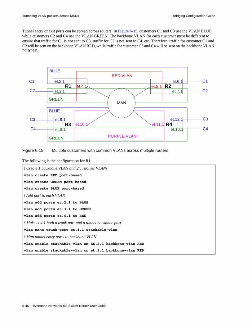
Tunneling VLAN packets across MANs Bridging Configuration Guide
Tunnel entry or exit ports can be spread across routers. In Figure 6-15, customers C1 and C3 use the VLAN BLUE, while customers C2 and C4 use the VLAN GREEN. The backbone VLAN for each customer must be different to ensure that traffic for C1 is not sent to C3, traffic for C2 is not sent to C4, etc. Therefore, traffic for customer C1 and C2 will be sent on the backbone VLAN RED, while traffic for customer C3 and C4 will be sent on the backbone VLAN PURPLE.
Figure 6-15 Multiple customers with common VLANs across multiple routers
The following is the configuration for R1:
! Create 1 backbone VLAN and 2 customer VLANsvlan create RED port-based
vlan create GREEN port-based
vlan create BLUE port-based
! Add port to each VLANvlan add ports et.2.1 to BLUE
vlan add ports et.3.1 to GREEN
vlan add ports et.4.1 to RED
! Make et.4.1 both a trunk port and a tunnel backbone portvlan make trunk-port et.4.1 stackable-vlan
! Map tunnel entry ports to backbone VLANvlan enable stackable-vlan on et.2.1 backbone-vlan RED
vlan enable stackable-vlan on et.3.1 backbone-vlan RED
et.8.1
et.9.1
et.12.1
et.13.1
C3
C4
C3
C4et.10.1 et.11.1
RED VLAN
PURPLE VLAN
et.2.1
et.3.1
C1
C2et.4.1
et.6.1
et.7.1
C1
C2et.5.1
BLUE
BLUE
GREEN
GREEN
MAN
R2R1
R3 R4
6-46 Riverstone Networks RS Switch Router User Guide

Bridging Configuration Guide Tunneling VLAN packets across MANs
The following is the configuration for R2:
The following is the configuration for R3:
! Create 1 backbone VLAN and 2 customer VLANsvlan create RED port-based
vlan create GREEN port-based
vlan create BLUE port-based
! Add port to each VLANvlan add ports et.6.1 to BLUE
vlan add ports et.5.1 to RED
vlan add ports et.7.1 to GREEN
! Make et.5.1 both a trunk port and a tunnel backbone portvlan make trunk-port et.5.1 stackable-vlan
! Map tunnel exit ports to backbone VLANvlan enable stackable-vlan on et.6.1 backbone-vlan RED
vlan enable stackable-vlan on et.7.1 backbone-vlan RED
! Create 1 backbone VLAN and 2 customer VLANs
vlan create PURPLE port-based
vlan create GREEN port-based
vlan create BLUE port-based
! Add port to each VLAN
vlan add ports et.8.1 to BLUE
vlan add ports et.9.1 to GREEN
vlan add ports et.10.1 to PURPLE
! Make et.10.1 both a trunk port and a tunnel backbone portvlan make trunk-port et.10.1 stackable-vlan
! Map tunnel entry ports to backbone VLANvlan enable stackable-vlan on et.8.1 backbone-vlan PURPLE
vlan enable stackable-vlan on et.9.1 backbone-vlan PURPLE
Riverstone Networks RS Switch Router User Guide 6-47

Tunneling VLAN packets across MANs Bridging Configuration Guide
The following is the configuration for R4:
6.16.2.3 Single VLAN with Multiple Tunnel Entry Ports
In Figure 6-16, customer C1 has a VLAN BLUE with multiple tunnel entry ports (et.2.1 and et.3.1 on R1) and multiple tunnel exit ports (et.6.1 and et.7.1 on R2).
Figure 6-16 Customer VLAN with multiple tunnel entry/exit ports
! Create 1 backbone VLAN and 2 customer VLANsvlan create PURPLE port-based
vlan create GREEN port-based
vlan create BLUE port-based
! Add port to each VLANvlan add ports et.11.1 to PURPLE
vlan add ports et.12.1 to BLUE
vlan add ports et.13.1 to GREEN
! Make et.11.1 both a trunk port and a tunnel backbone portvlan make trunk-port et.11.1 stackable-vlan
! Map tunnel exit ports to backbone VLANvlan enable stackable-vlan on et.12.1 backbone-vlan PURPLE
vlan enable stackable-vlan on et.13.1 backbone-vlan PURPLE
et.2.1
et.3.1et.4.1 et.5.1
et.6.1
et.7.1MAN
RED VLAN (backbone)
BLUE VLAN
C1
C1
C1
C1R2R1
6-48 Riverstone Networks RS Switch Router User Guide

Bridging Configuration Guide Tunneling VLAN packets across MANs
The following is the configuration for R1:
The following is the configuration for R2:
The following is an example where a customer VLAN has multiple tunnel entry or exit ports spread across routers. Figure 6-17 shows customers C1 and C2 sharing the VLAN BLUE. Traffic for customer C1 can arrive on tunnel entry ports on routers R1, R2, or R3. Broadcast or multicast traffic arriving on et.2.1 on R1 is tunneled on backbone VLAN RED and will be seen by C1 users on R2 and R3. C2 users on R4 will not see the C1 traffic since the tunnel backbone port on R4 belongs to the backbone VLAN PURPLE.
! Create backbone VLAN and customer VLANvlan create RED port-based
vlan create BLUE port-based
! Add ports to VLANs
vlan add ports et.2.1, et.3.1 to BLUE
vlan add ports et.4.1 to RED
! Make et.4.1 both a trunk port and a tunnel backbone portvlan make trunk-port et.4.1 stackable-vlan
! Map tunnel entry ports to backbone VLAN
vlan enable stackable-vlan on et.2.1 backbone-vlan RED
vlan enable stackable-vlan on et.3.1 backbone-vlan RED
! Create backbone VLAN and customer VLANvlan create RED port-based
vlan create BLUE port-based
! Add ports to VLANs
vlan add ports et.6.1, et.7.1 to BLUE
vlan add ports et.5.1 to RED
! Make et.5.1 both a trunk port and a tunnel backbone portvlan make trunk-port et.5.1 stackable-vlan
! Map tunnel exit ports to backbone VLAN
vlan enable stackable-vlan on et.6.1 backbone-vlan RED
vlan enable stackable-vlan on et.7.1 backbone-vlan RED
Riverstone Networks RS Switch Router User Guide 6-49

Tunneling VLAN packets across MANs Bridging Configuration Guide
Figure 6-17 Customer VLAN with multiple tunnel entry ports across multiple routers
The following is the configuration for R1:
! Create 1 backbone VLAN and 1 customer VLANvlan create PURPLE port-based
vlan create BLUE port-based
! Add port to each VLANvlan add ports et.2.1 to BLUE
vlan add ports et.3.1 to PURPLE
! Make et.3.1 both a trunk port and a tunnel backbone port
vlan make trunk-port et.3.1 stackable-vlan
! Map tunnel entry port to backbone VLANvlan enable stackable-vlan on et.2.1 backbone-vlan PURPLE
et.6.1 et.9.1C1 C2et.7.1 et.8.1
PURPLE VLAN
et.2.1C1et.3.1
et.5.1 C1et.4.1
BLUE VLANRED VLAN
MAN
R2R1
R3 R4
PURPLE VLAN RED VLAN
6-50 Riverstone Networks RS Switch Router User Guide

Bridging Configuration Guide Tunneling VLAN packets across MANs
The following is the configuration for R2:
The following is the configuration for R3:
The following is the configuration for R4:
! Create 1 backbone VLAN and 1 customer VLANvlan create RED port-based
vlan create BLUE port-based
! Add port to each VLAN
vlan add ports et.4.1 to RED
vlan add ports et.5.1 to BLUE
! Make et.4.1 both a trunk port and a tunnel backbone portvlan make trunk-port et.4.1 stackable-vlan
! Map tunnel exit ports to backbone VLAN
vlan enable stackable-vlan on et.5.1 backbone-vlan RED
! Create 1 backbone VLAN and 1 customer VLAN
vlan create RED port-based
vlan create BLUE port-based
! Add port to each VLANvlan add ports et.6.1 to BLUE
vlan add ports et.7.1 to RED
! Make et.7.1 both a trunk port and a tunnel backbone portvlan make trunk-port et.7.1 stackable-vlan
! Map tunnel entry ports to backbone VLANvlan enable stackable-vlan on et.6.1 backbone-vlan RED
! Create 1 backbone VLAN and 1 customer VLANvlan create PURPLE port-based
vlan create BLUE port-based
! Add port to each VLANvlan add ports et.8.1 to PURPLE
vlan add ports et.9.1 to BLUE
! Make et.8.1 both a trunk port and a tunnel backbone portvlan make trunk-port et.8.1 stackable-vlan
! Map tunnel exit ports to backbone VLAN
vlan enable stackable-vlan on et.9.1 backbone-vlan PURPLE
Riverstone Networks RS Switch Router User Guide 6-51

Tunneling VLAN packets across MANs Bridging Configuration Guide
Note If you do not want multicast or broadcast traffic from C1 on R1 to be seen by C1 on R3, then configure a different backbone VLAN on R3.
6.16.2.4 STP/GVRP in Customer VLANs Tunneled over Backbone VLAN
STP, RSTP, or GARP/GVRP can be run in the customer VLANs which are tunneled over the backbone VLAN. The customer VLAN does not need to be reconfigured in order to be tunneled.
In Figure 6-18, traffic for customer C1’s VLAN (BLUE) and for customer C2’s VLAN (GREEN) is tunneled through the backbone VLAN (RED). STP is enabled in the customer VLAN BLUE on the customer routers C1R1 and C1R2 for customer C1.
Figure 6-18 STP enabled in customer VLANs
The following configuration statements on C1R1 enable STP on port et.1.1, the port that is connected to the tunnel entry port.
! Create customer VLAN
vlan create BLUE port-based
! Add port to VLAN
vlan add ports et.1.1 to BLUE
! Make port et.1.1 a trunk port
vlan make trunk-port et.1.1
! Enable STP on et.1.1stp enable port et.1.1
! Optional STP configurations
stp set bridging hello-time 3
et.2.1
et.3.1et.4.1 et.5.1
et.6.1
et.7.1MAN
RED VLAN (backbone)
BLUE VLAN
GREEN VLAN
C1
C2
C1
C2
et.1.1 et.8.1
R2R1
C1R1 C1R2
6-52 Riverstone Networks RS Switch Router User Guide

Bridging Configuration Guide Tunneling VLAN packets across MANs
The following configuration statements on C1R2 enable STP on port et.8.1, the port that is connected to the tunnel exit port.
The configuration of the tunnel entry/exit ports and tunnel backbone ports on R1 and R2 are identical to those shown in the earlier example in Figure 6-13:
The following is the configuration for R1:
! Create customer VLANvlan create BLUE port-based
! Add port to VLAN
vlan add ports et.8.1 to BLUE
! Make port et.8.1 a trunk port
vlan make trunk-port et.8.1
! Enable STP on et.8.1stp enable port et.8.1
! Create 1 backbone VLAN and 2 customer VLANsvlan create RED port-based
vlan create GREEN port-based
vlan create BLUE port-based
! Add port to each VLANvlan add ports et.2.1 to BLUE
vlan add ports et.3.1 to GREEN
vlan add ports et.4.1 to RED
! Make et.4.1 both a trunk port and a tunnel backbone portvlan make trunk-port et.4.1 stackable-vlan
! Map tunnel entry ports to backbone VLANvlan enable stackable-vlan on et.2.1 backbone-vlan RED
vlan enable stackable-vlan on et.3.1 backbone-vlan RED
Riverstone Networks RS Switch Router User Guide 6-53

Tunneling VLAN packets across MANs Bridging Configuration Guide
The following is the configuration for R2:
6.16.2.5 Multiple VLANs on a Single Tunnel Entry Port
Tunnel entry and exit ports are access ports. Normally, access ports can belong to only one VLAN of a particular protocol type. With stackable VLANs, traffic for multiple VLANs can enter a tunnel entry port to be tunneled over the backbone VLAN. In this case, the tunnel entry port must belong to all the VLANs that are to be tunneled. Use the stackable-vlan option of the vlan make access-port command to allow the tunnel entry port to be added to any number of VLANs.
In Figure 6-19, customers C1, C2, C3, C4, and C5 each have a VLAN that will use port et.2.1 on R1 as the tunnel entry port. On R2, port et.6.1 will be the tunnel exit port for traffic for all five VLANs.
! Create 1 backbone VLAN and 2 customer VLANsvlan create RED port-based
vlan create GREEN port-based
vlan create BLUE port-based
! Add port to each VLANvlan add ports et.6.1 to BLUE
vlan add ports et.7.1 to GREEN
vlan add ports et.5.1 to RED
! Make et.5.1 both a trunk port and a tunnel backbone portvlan make trunk-port et.5.1 stackable-vlan
! Map tunnel exit ports to backbone VLANvlan enable stackable-vlan on et.6.1 backbone-vlan RED
vlan enable stackable-vlan on et.7.1 backbone-vlan RED
6-54 Riverstone Networks RS Switch Router User Guide
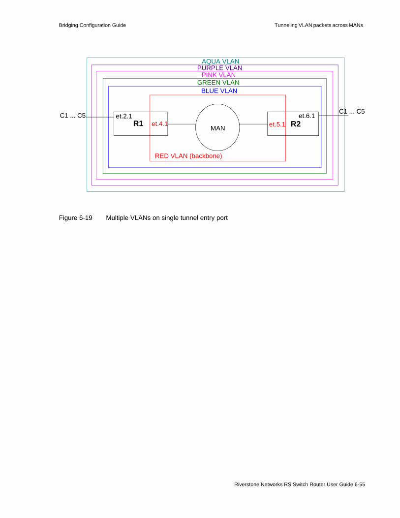
Bridging Configuration Guide Tunneling VLAN packets across MANs
Figure 6-19 Multiple VLANs on single tunnel entry port
et.2.1et.4.1 et.5.1
et.6.1
MAN
RED VLAN (backbone)
C1 ... C5R2R1
C1 ... C5
BLUE VLANGREEN VLAN
PINK VLANPURPLE VLAN
AQUA VLAN
Riverstone Networks RS Switch Router User Guide 6-55
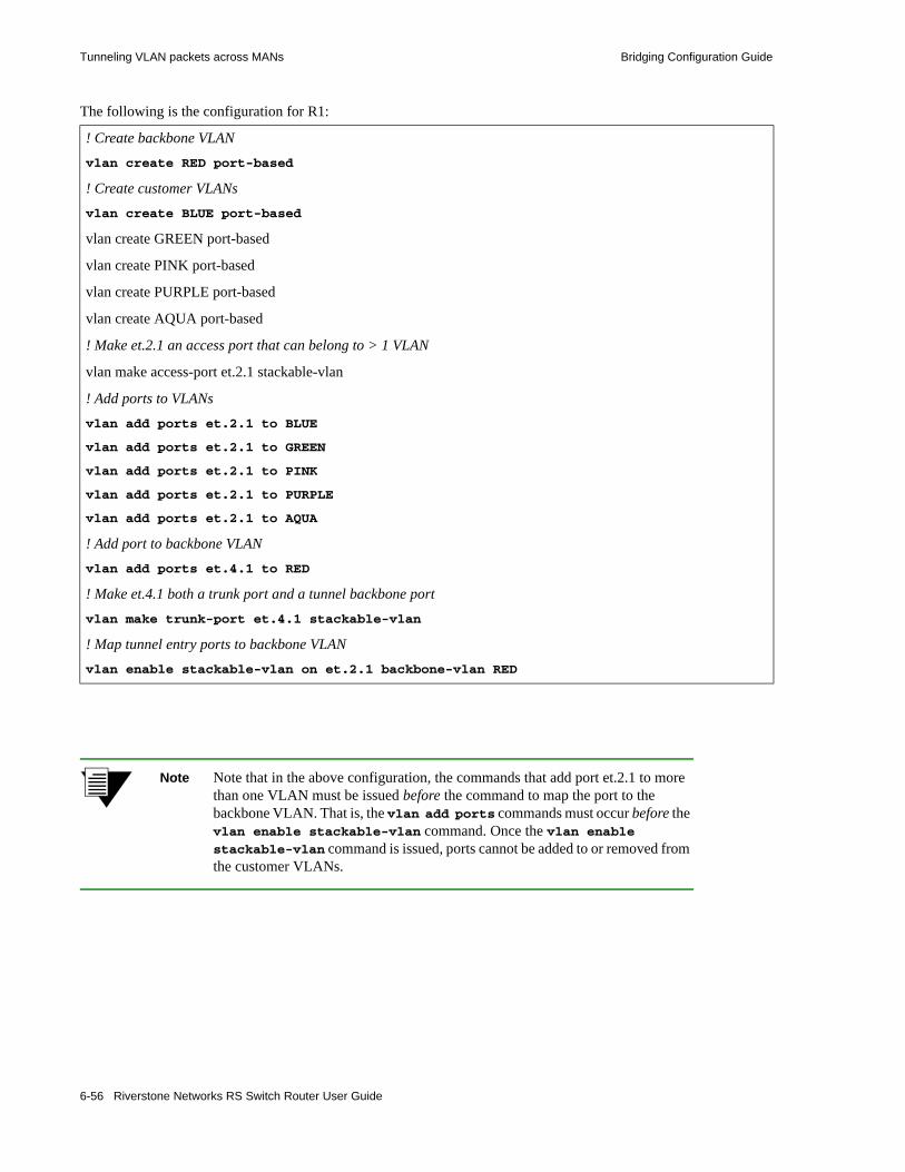
Tunneling VLAN packets across MANs Bridging Configuration Guide
The following is the configuration for R1:
Note Note that in the above configuration, the commands that add port et.2.1 to more than one VLAN must be issued before the command to map the port to the backbone VLAN. That is, the vlan add ports commands must occur before the vlan enable stackable-vlan command. Once the vlan enable stackable-vlan command is issued, ports cannot be added to or removed from the customer VLANs.
! Create backbone VLANvlan create RED port-based
! Create customer VLANsvlan create BLUE port-based
vlan create GREEN port-based
vlan create PINK port-based
vlan create PURPLE port-based
vlan create AQUA port-based
! Make et.2.1 an access port that can belong to > 1 VLAN
vlan make access-port et.2.1 stackable-vlan
! Add ports to VLANs
vlan add ports et.2.1 to BLUE
vlan add ports et.2.1 to GREEN
vlan add ports et.2.1 to PINK
vlan add ports et.2.1 to PURPLE
vlan add ports et.2.1 to AQUA
! Add port to backbone VLANvlan add ports et.4.1 to RED
! Make et.4.1 both a trunk port and a tunnel backbone port
vlan make trunk-port et.4.1 stackable-vlan
! Map tunnel entry ports to backbone VLANvlan enable stackable-vlan on et.2.1 backbone-vlan RED
6-56 Riverstone Networks RS Switch Router User Guide

Bridging Configuration Guide Tunneling VLAN packets across MANs
The following is the configuration for R2:
6.16.3 Sending Untagged Packets over Stackable VLANs
You can transport either untagged or 802.1q tagged packets across stackable VLANs. Both tagged and untagged traffic can use the same tunnel entry port to be transported across a backbone VLAN.
To transport tagged or untagged packets over a backbone VLAN:1. Tunnel entry and exit ports must be configured as stackable VLAN access ports. To do this, use the
command vlan make access-port <port> stackable-vlan.2. The tunnel entry/exit port and the tunnel backbone port on the router need to belong to the same
customer VLAN. The tunnel backbone port is a trunk port that will belong to both the backbone VLAN and the customer VLAN.
3. When mapping the tunnel entry and exit ports to the backbone VLAN with the vlan enable stackable-vlan command, specify the untagged-vlan <vlan> option.
! Create backbone VLANvlan create RED port-based
! Create customer VLANsvlan create BLUE port-based
vlan create GREEN port-based
vlan create PINK port-based
vlan create PURPLE port-based
vlan create AQUA port-based
! Make et.6.1 an access port that can belong to > 1 VLAN
vlan make access-port et.6.1 stackable-vlan
! Add ports to VLANs
vlan add ports et.6.1 to BLUE
vlan add ports et.6.1 to GREEN
vlan add ports et.6.1 to PINK
vlan add ports et.6.1 to PURPLE
vlan add ports et.6.1 to AQUA
! Add port to backbone VLANvlan add ports et.5.1 to RED
! Make et.5.1 both a trunk port and a tunnel backbone port
vlan make trunk-port et.5.1 stackable-vlan
! Map tunnel entry ports to backbone VLANvlan enable stackable-vlan on et.6.1 backbone-vlan RED
Riverstone Networks RS Switch Router User Guide 6-57
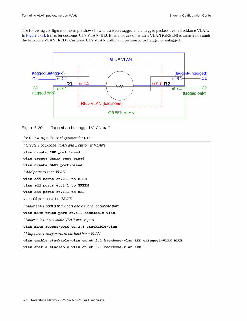
Tunneling VLAN packets across MANs Bridging Configuration Guide
The following configuration example shows how to transport tagged and untagged packets over a backbone VLAN. In Figure 6-13, traffic for customer C1’s VLAN (BLUE) and for customer C2’s VLAN (GREEN) is tunneled through the backbone VLAN (RED). Customer C1’s VLAN traffic will be transported tagged or untagged.
Figure 6-20 Tagged and untagged VLAN traffic
The following is the configuration for R1:
! Create 1 backbone VLAN and 2 customer VLANsvlan create RED port-based
vlan create GREEN port-based
vlan create BLUE port-based
! Add ports to each VLANvlan add ports et.2.1 to BLUE
vlan add ports et.3.1 to GREEN
vlan add ports et.4.1 to RED
vlan add ports et.4.1 to BLUE
! Make et.4.1 both a trunk port and a tunnel backbone portvlan make trunk-port et.4.1 stackable-vlan
! Make et.2.1 a stackable VLAN access portvlan make access-port et.2.1 stackable-vlan
! Map tunnel entry ports to the backbone VLAN
vlan enable stackable-vlan on et.2.1 backbone-vlan RED untagged-VLAN BLUE
vlan enable stackable-vlan on et.3.1 backbone-vlan RED
et.2.1
et.3.1et.4.1 et.5.1
et.6.1
et.7.1MAN
RED VLAN (backbone)
BLUE VLAN
GREEN VLAN
C1
C2
C1
C2R1 R2
(tagged/untagged) (tagged/untagged)
(tagged only) (tagged only)
6-58 Riverstone Networks RS Switch Router User Guide

Bridging Configuration Guide Tunneling VLAN packets across MANs
The following is the configuration for R2:
! Create 1 backbone VLAN and 2 customer VLANsvlan create RED port-based
vlan create GREEN port-based
vlan create BLUE port-based
! Add ports to each VLANvlan add ports et.6.1 to BLUE
vlan add ports et.7.1 to GREEN
vlan add ports et.5.1 to RED
vlan add ports et.5.1 to BLUE
! Make et.5.1 both a trunk port and a tunnel backbone portvlan make trunk-port et.5.1 stackable-vlan
! Make et.6.1 a stackable VLAN access portvlan make access-port et.6.1 stackable-vlan
! Map tunnel exit ports to the backbone VLAN
vlan enable stackable-vlan on et.6.1 backbone-vlan RED untagged-vlan BLUE
vlan enable stackable-vlan on et.7.1 backbone-vlan RED
Riverstone Networks RS Switch Router User Guide 6-59

Tunneling VLAN packets across MANs Bridging Configuration Guide
6.16.3.1 Multiple Customers in a Ring Topology
The vlan make trunk port stackable-vlan command has a transit option that enables a trunk port to bridge packets based on the backbone VLAN when there is no mapping between the original VLAN and the backbone VLAN or when the packet’s destination is not known.
Figure 6-21 illustrates a ring topology wherein all the trunk ports are also tagged as transit ports. On R1, the access port et.2.1 is in Customer 1’s VLAN (VLAN BLUE) and is mapped to the backbone VLAN RED. Customer C1’s traffic is encapsulated with VLAN RED’s tag before it is forwarded out the tunnel backbone port et.3.1.
Port et.4.1 on R2 is a trunk port that is also tagged as a transit port. Therefore when it receives the packet from R1, port et.4.1 bridges the packet based on the backbone VLAN (VLAN RED) to the trunk port et.3.1 on R2.
If port et.4.1 on R2 had not been a transit port, then the RED 802.1q header would have been stripped off and the packet would have been dropped because there is no VLAN BLUE on R2.
Figure 6-21 Multiple customers in a ring
et.3.1 et.4.1C1 C2
R1 R2
et.2.1et.4.1 et.3.1
C2 C1R4 R3
et.2.1
et.2.1et.2.1
et.3.1
et.4.1
et.4.1
et.3.1
BLUE VLAN
RED VLAN (backbone)
GREEN VLAN
BLUE VLANGREEN VLAN
RED VLAN (backbone)
6-60 Riverstone Networks RS Switch Router User Guide

Bridging Configuration Guide Tunneling VLAN packets across MANs
The following is the configuration for R1:
The following is the configuration for R2:
! Create 1 backbone VLAN and 1 customer VLANvlan create RED port-based
vlan create BLUE port-based
! Add ports to each VLANvlan add ports et.2.1 to BLUE
vlan add ports et.3.1,et.4.1 to RED
! Make et.3.1 and et.4.1 both trunk ports and tunnel backbone ports. Specify the transit option.
vlan make trunk-port et.3.1,et.4.1 stackable-vlan transit
! Make et.2.1 a stackable VLAN access portvlan make access-port et.2.1 stackable-vlan
! Map the tunnel entry port to the backbone VLANvlan enable stackable-vlan on et.2.1 backbone-vlan RED
! Create 1 backbone VLAN and 1 customer VLANvlan create RED port-based
vlan create GREEN port-based
! Add ports to each VLANvlan add ports et.2.1 to GREEN
vlan add ports et.3.1,et.4.1 to RED
! Make et.3.1 and et.4.1 both trunk ports and tunnel backbone ports. Specify the transit option.
vlan make trunk-port et.3.1,et.4.1 stackable-vlan transit
! Make et.2.1 a stackable VLAN access portvlan make access-port et.2.1 stackable-vlan
! Map the tunnel entry port to the backbone VLANvlan enable stackable-vlan on et.2.1 backbone-vlan RED
Riverstone Networks RS Switch Router User Guide 6-61

Tunneling VLAN packets across MANs Bridging Configuration Guide
The following is the configuration for R3:
The following is the configuration for R4:
! Create 1 backbone VLAN and 1 customer VLANvlan create RED port-based
vlan create BLUE port-based
! Add ports to each VLAN
vlan add ports et.2.1 to BLUE
vlan add ports et.3.1,et.4.1 to RED
! Make et.3.1 and et.4.1 both trunk ports and tunnel backbone ports. Specify the transit option.vlan make trunk-port et.3.1,et.4.1 stackable-vlan transit
! Make et.2.1 a stackable VLAN access port
vlan make access-port et.2.1 stackable-vlan
! Map the tunnel entry port to the backbone VLANvlan enable stackable-vlan on et.2.1 backbone-vlan RED
! Create 1 backbone VLAN and 1 customer VLANvlan create RED port-based
vlan create GREEN port-based
! Add ports to each VLAN
vlan add ports et.2.1 to GREEN
vlan add ports et.3.1,et.4.1 to RED
! Make et.3.1 and et.4.1 both trunk ports and tunnel backbone ports. Specify the transit option.vlan make trunk-port et.3.1,et.4.1 stackable-vlan transit
! Make et.2.1 a stackable VLAN access portvlan make access-port et.2.1 stackable-vlan
! Map the tunnel entry port to the backbone VLANvlan enable stackable-vlan on et.2.1 backbone-vlan RED
6-62 Riverstone Networks RS Switch Router User Guide

Bridging Configuration Guide Tunneling VLAN packets across MANs
6.16.4 Displaying Stackable VLAN Information
Use the vlan show stackable-vlan command to display the configuration of stackable VLANs on the RS Ethernet Router. For example,
rs# vlan show stackable-vlan Stackable VLAN Information========================== (14 10): 4385 Applied On: et.4.2 Flooded On: Trunk Ports: et.4.1Untagged Vlan: none (13 10): 4386 Applied On: et.4.3 Flooded On: Trunk Ports: et.4.1Untagged Vlan: none Stackable VLAN Trunk Ports: et.4.1Stackable VLAN Access Ports: Stackable VLAN Transit Ports:
Table 6-1 Field Description for vlan show stackable-vlan
FIELD DESCRIPTION
Numbers in parenthesis The ID number of the VLAN followed by the ID number of the backbone VLAN.
Applied on: The tunnel entry/exit port that were configured with the vlan enable stackable-vlan command.
Flooded on: The ports on which multicast, broadcast, or unknown unicast packets are flooded.
Trunk Ports: The trunk ports, configured with the vlan make trunk-port command for that VLAN.
Untagged VLAN: VLANs that are not using 802.1Q tagging.
Stackable VLAN Trunk Ports The tunnel backbone ports, configured with the stackable-vlan option of the vlan make trunk-port command.
Riverstone Networks RS Switch Router User Guide 6-63

Tunneling VLAN packets across MANs Bridging Configuration Guide
Stackable VLAN Access Ports: Tunnel entry ports configured by the stackable-vlan option of the vlan make access-port command. These access ports can belong to more than one VLAN of the same protocol type. This allows multiple VLANs to use the same tunnel entry port.
Stackable VLAN Transit Ports: Ports configured by the The transit option of the vlan make trunk port stackable-vlan command. Enables a trunk port to bridge packets based on the backbone VLAN when there is no mapping between the original VLAN and the backbone VLAN or when the packet’s destination is not known.
Table 6-1 Field Description for vlan show stackable-vlan (Continued)
FIELD DESCRIPTION
6-64 Riverstone Networks RS Switch Router User Guide

Bridging Configuration Guide VLAN Aggregation
6.17 VLAN AGGREGATIONIn traditional ISP networks, each customer is allocated an IP subnet based on initial and projected needs for IP addresses. This can lead to problems with IP address consumption. For each allocated subnet, three IP addresses are used: one for the subnet number, one for the directed broadcast address, and one for the default gateway address. A customer who reaches the maximum number of addresses allowed by its IP subnet must be allocated another subnet; as IP addresses that are unused by one customer cannot be used by any other customer.
The VLAN aggregation feature allows multiple VLANs to use the same IP subnet and default gateway address. This feature conserves IPv4 addresses while allowing hosts to remain in separate virtual broadcast domains. With VLAN aggregation, customers are assigned to sub-VLANs, which belong to a super-VLAN. While each sub-VLAN is a separate broadcast domain, all sub-VLANs use the default gateway IP address of the super-VLAN. IP traffic between sub-VLANs are routed through the super-VLAN. Hosts in the sub-VLAN are allocated IP addresses from the super-VLAN subnet. When a customer needs an additional IP address, the next available IP address within the super-VLAN subnet is allocated; the default gateway address remains the same.
Figure 6-22 shows a network with three VLANs, each of which belongs to a different customer. Both actual and future (represented by shaded boxes) host deployments are shown. For example, customer A currently has hosts A1 and A2 in VLAN A, but customer A will also need an additional eight IP addresses for future host connections. Customer B currently has hosts B1 and B2 in VLAN B, and will need three additional host IP addresses. Customer C has only one host in VLAN C and will not need any additional hosts.
Figure 6-22 IP address allocation in customer VLANs
Router
Ethernet Switch
A1 A2 B1 C1B2
VLAN A VLAN B VLAN C
Future Hosts
A TOTAL OF 16 HOST IP ADDRESSES ARE NEEDED BY CUSTOMERS
Riverstone Networks RS Switch Router User Guide 6-65

VLAN Aggregation Bridging Configuration Guide
In the traditional per-VLAN IP subnet allocation, customer A would be assigned an IP subnet of 10.1.1.0/28 that provides 16 IP addresses (even though the customer requires only 10 addresses). See Table 6-2 for subnet allocations without VLAN aggregation. Because the first IP address in the subnet is used for the subnet number and the last IP address in the subnet is used for the directed broadcast address, the number of usable IP addresses for each customer is reduced by 2, as shown by the “Number of Usable IP Addresses” column in Table 6-2. In addition, one IP address of each subnet is used for the router as the default gateway address for the subnet. Therefore, the number of IP addresses for use by each customer is reduced by 3, as shown by the “Number of Available Host IP Addresses” column.
In the above example, the optimal subnet allocation provides for 28 IP addresses, while the total number of host IP addresses needed by all customers is only 16 addresses. And any unused IP addresses that are allocated to one customer cannot be used by another customer.
Another problem is that even though a total of 28 IP addresses are allocated to the customers, only 19 addresses are available for use as host addresses. A total of 9 IP addresses are consumed for the subnet number, directed broadcast, and default gateway. Further, customer C would not be able to add any additional host addresses without being allocated a new subnet, with a different subnet number, directed broadcast, and default gateway address.
With the VLAN aggregation feature, hosts in the customers’ sub-VLANs are allocated IP addresses from the super-VLAN subnet 10.1.1.0/24. Since there is only one subnet, the first IP address in the subnet, 10.1.1.0, is used for the subnet number, while the last IP address, 10.1.1.255, is used for the directed broadcast address. And all sub-VLANs use the default gateway IP address of 10.1.1.1. See Table 6-3 for address allocations with VLAN aggregation.
Table 6-2 Customer IP address allocation without VLAN aggregation
Customer Allocated IP Subnet
Number of Allocated IP Addresses
Number of Usable IP Addresses a
a. The first allocated IP address is used for the subnet number. The last allocated IP address is usedfor the directed broadcast address.
Gateway IP Address b
b. One IP address is assigned to the router and is used as the default gateway address for the subnet.In this example, the first usable IP address is assigned to the router.
Number of Available Host IP Addresses
A 10.1.1.0/28 16 14 10.1.1.1 13
B 10.1.1.16/29 8 6 10.1.1.17 5
C 10.1.1.24/30 4 2 10.1.1.25 1
Total IP Addresses: 28 22 19
6-66 Riverstone Networks RS Switch Router User Guide
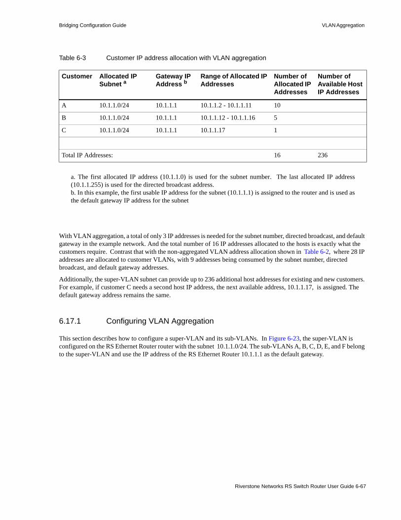
Bridging Configuration Guide VLAN Aggregation
With VLAN aggregation, a total of only 3 IP addresses is needed for the subnet number, directed broadcast, and default gateway in the example network. And the total number of 16 IP addresses allocated to the hosts is exactly what the customers require. Contrast that with the non-aggregated VLAN address allocation shown in Table 6-2, where 28 IP addresses are allocated to customer VLANs, with 9 addresses being consumed by the subnet number, directed broadcast, and default gateway addresses.
Additionally, the super-VLAN subnet can provide up to 236 additional host addresses for existing and new customers. For example, if customer C needs a second host IP address, the next available address, 10.1.1.17, is assigned. The default gateway address remains the same.
6.17.1 Configuring VLAN Aggregation
This section describes how to configure a super-VLAN and its sub-VLANs. In Figure 6-23, the super-VLAN is configured on the RS Ethernet Router router with the subnet 10.1.1.0/24. The sub-VLANs A, B, C, D, E, and F belong to the super-VLAN and use the IP address of the RS Ethernet Router 10.1.1.1 as the default gateway.
Table 6-3 Customer IP address allocation with VLAN aggregation
Customer Allocated IP Subnet a
a. The first allocated IP address (10.1.1.0) is used for the subnet number. The last allocated IP address(10.1.1.255) is used for the directed broadcast address.
Gateway IP Address b
b. In this example, the first usable IP address for the subnet (10.1.1.1) is assigned to the router and is used asthe default gateway IP address for the subnet
Range of Allocated IP Addresses
Number of Allocated IP Addresses
Number of Available Host IP Addresses
A 10.1.1.0/24 10.1.1.1 10.1.1.2 - 10.1.1.11 10
B 10.1.1.0/24 10.1.1.1 10.1.1.12 - 10.1.1.16 5
C 10.1.1.0/24 10.1.1.1 10.1.1.17 1
Total IP Addresses: 16 236
Riverstone Networks RS Switch Router User Guide 6-67

VLAN Aggregation Bridging Configuration Guide
Figure 6-23 Super-VLAN and sub-VLANs
6.17.1.1 Router Configuration
Note IP traffic between sub-VLANs is routed through the super-VLAN. Configure IP forwarding and the appropriate routing protocols on the RS Ethernet Router on which the super-VLAN is configured.
To configure the VLAN aggregation feature on an RS Ethernet Router router, do the following:1. Create the super-VLAN and assign the IP subnet range to it. The super-VLAN cannot be a
port-based VLAN. For example, the following commands create the super-VLAN ‘super1’ with the subnet 10.1.1.1/24:
rs(config)# vlan create super1 ip id 100
rs(config)# interface create ip sup-int vlan super1 address-netmask 10.1.1.1/24
RS
Ethernet Switch Ethernet Switch
Super-VLAN10.1.1.0/24
802.1Q trunk ports802.1Q trunk ports
10.1.1.2 10.1.1.3 10.1.1.4 10.1.1.5 10.1.1.6 10.1.1.7
Sub-VLANs
A1 B1 C1 D1 E1 F1
10.1.1.1
VLAN A VLAN B VLAN C
gi.2.1 gi.2.2
VLAN D VLAN E VLAN F
6-68 Riverstone Networks RS Switch Router User Guide

Bridging Configuration Guide VLAN Aggregation
2. Create each sub-VLAN. Configure the ports that connect to the Ethernet Switches as 802.1Q trunk ports and add the appropriate trunk port to each sub-VLAN. For example, the following commands create the sub-VLANs ‘subA,’ ‘subB,’ ‘subC,’ ‘subD,’ ‘subE,’ and ‘subF.’ The 802.1Q port gi.2.1 is added to subA, subB, and subC and port gi.2.2 is added to subD, subE, and subF.
Note Make sure that the VLAN ID that you configure for the super-VLAN is different from the VLAN IDs configured for the sub-VLANs.
3. Add the 802.1Q trunk ports to the super-VLAN. For example:
rs(config)# vlan create subA port-based id 10
rs(config)# vlan create subB port-based id 20
rs(config)# vlan create subC port-based id 30
rs(config)# vlan create subD port-based id 40
rs(config)# vlan create subE port-based id 50
rs(config)# vlan create subF port-based id 60
rs(config)# vlan make trunk-port gi.2.1
rs(config)# vlan make trunk-port gi.2.2
rs(config)# vlan add ports gi.2.1 to subA
rs(config)# vlan add ports gi.2.1 to subB
rs(config)# vlan add ports gi.2.1 to subC
rs(config)# vlan add ports gi.2.2 to subD
rs(config)# vlan add ports gi.2.2 to subE
rs(config)# vlan add ports gi.2.2 to subF
rs(config)# vlan add ports gi.2.1 to super1
rs(config)# vlan add ports gi.2.2 to super1
Riverstone Networks RS Switch Router User Guide 6-69

VLAN Aggregation Bridging Configuration Guide
4. Bind the super-VLAN to the sub-VLANs. For example:
Note Routing between sub-VLANs is disabled by default. To enable routing between sub-VLANs, issue the vlan enable inter-subvlan-routing command on the router.
6.17.1.2 Ethernet Switch Configuration
On the Ethernet Switch, configure the following:• Assign each host an IP address from the super-VLAN subnet. For each host, configure the address
of the RS Ethernet Router as the gateway address. (Host IP and default gateway addresses can be provided by DHCP.)
• Configure a port-based VLAN for each customer who will be connected to the switch.• Add an access (non-802.1Q) port for each host connection to each customer VLAN.• Configure the port that will provide the connection to the RS Ethernet Router as an 802.1Q trunk
port. Add this port to each customer VLAN. This port must be configured as a trunk port, as it will used to transport all customer VLAN information to and from the RS Ethernet Router.
Figure 6-24 shows the sub-VLANs on RS Ethernet Router switches ‘RS1’ and ‘RS2.’ Example commands to configure the sub-VLANs on RS1 and RS2 follow.
rs(config)# vlan bind super-vlan super1 to subA
rs(config)# vlan bind super-vlan super1 to subB
rs(config)# vlan bind super-vlan super1 to subC
rs(config)# vlan bind super-vlan super1 to subD
rs(config)# vlan bind super-vlan super1 to subE
rs(config)# vlan bind super-vlan super1 to subF
6-70 Riverstone Networks RS Switch Router User Guide

Bridging Configuration Guide VLAN Aggregation
Figure 6-24 Super-VLAN and sub-VLANs with RS Ethernet Router switches
The following commands configure the sub-VLANs subA, subB, and subC on RS1:
rs(config)# vlan create subA port-based id 10
rs(config)# vlan create subB port-based id 20
rs(config)# vlan create subC port-based id 30
rs(config)# vlan make trunk-port gi.3.1
rs(config)# vlan add ports gi.3.1,et.2.1 to subA
rs(config)# vlan add ports gi.3.1,et.2.2 to subB
rs(config)# vlan add ports gi.3.1,et.2.3 to subC
RS
RS1 RS2
Super-VLAN10.1.1.0/24
802.1Q trunk ports802.1Q trunk ports
Sub-VLANs
10.1.1.1
gi.2.1 gi.2.2
et.2.1 et.2.2 et.2.3
gi.3.1 gi.4.1
et.5.1 et.5.2 et.5.3
10.1.1.2 10.1.1.3 10.1.1.4 10.1.1.5 10.1.1.6 10.1.1.7
A1 B1 C1 D1 E1 F1
VLAN A VLAN B VLAN C VLAN D VLAN E VLAN F
Riverstone Networks RS Switch Router User Guide 6-71

VLAN Aggregation Bridging Configuration Guide
The following commands configure the sub-VLANs subD, subE, and subF on RS2:
6.17.2 Multicast
By default, multicast is sub-VLAN aware and processes group subscriptions on a per-sub-VLAN basis.
6.17.3 Restrictions
Note the following restrictions on configuring and using the VLAN aggregation feature: • L4 bridging is not supported. • Features such as ACLs and rate-limiting can only be specified on a per-IP address basis.
rs(config)# vlan create subD port-based id 40
rs(config)# vlan create subE port-based id 50
rs(config)# vlan create subF port-based id 60
rs(config)# vlan make trunk-port gi.4.1
rs(config)# vlan add ports gi.4.1,et.5.1 to subD
rs(config)# vlan add ports gi.4.1,et.5.2 to subE
rs(config)# vlan add ports gi.4.1,et.5.3 to subF
6-72 Riverstone Networks RS Switch Router User Guide

7 ATM CONFIGURATION GUIDE
This chapter provides an overview of the Asynchronous Transfer Mode (ATM) features available for the Riverstone RS Switch Router. ATM is a cell switching technology used to establish multiple connections over a physical link. In addition, you can configure each of these connections with its own traffic parameters, providing more control over specific connections within a network.
The ATM line card provides an ATM interface, allowing integration of ATM with Ethernet and other interfaces within a network topology supported by the Riverstone RS Switch Router. This chapter discusses the following tasks:• Configuring ATM ports• Configuring virtual channels• Traffic shaping• Managing traffic• Bridging ATM traffic• Routing ATM traffic• Configuring point-to-point connections (PPP) • Operations, Administration, and Management (OAM)
Riverstone Networks RS Switch Router User Guide 7-1

Configuring ATM Ports ATM Configuration Guide
7.1 CONFIGURING ATM PORTSYou can use two different ATM line cards on the RS Ethernet Router, the ATM multi-rate line card and the ATM-OC12 line card. The multi-rate line card has two available slots for various Physical Layer (PHY) interface cards. These PHY cards provide the media-specific portion of an ATM interface. The ATM-OC12 line card provides one logical connection through two physical ports (Link1 and Link 2). For additional information on these modules, refer to the Riverstone RS Switch Router Getting Started Guide.
This section describes the various commands you can use to control the functionality of the ports on the ATM line cards. Use the “at” prefix when specifying an ATM port in the CLI commands. For example, the first port on slot 5 would be “at.5.1.”
7.1.1 Configuring SONET Parameters
ATM utilizes synchronous optical network (SONET) encapsulation to transmit cells through a link. You can configure the following SONET features on the ATM line cards:• Set the Circuit-ID• Set SONET/SDH Framing• Set Loopback Mode• Enable Path Tracing• Enable Payload Scrambling• Enable Stream Scrambling
Note For a complete description of the SONET features, refer to Section 8, "Packet-over-SONET Configuration Guide." Refer to the SONET chapter in the Riverstone RS Switch Router Command Line Interface Reference Manual for a description of the SONET commands.
7.1.1.1 Configuring Automatic Protection Switching (APS) on the ATM OC-12 Line Card
You can configure APS on the ATM OC-12 line card. This allows for redundancy for the ATM port in case there is an interruption or failure on a link. APS specifies a working port (primary) and a protecting port (backup).
The ATM OC-12 line card has two physical ports: Link1 and Link2. However, there is only one logical port. The Link1 port is the working port (primary port), and Link2 is the protecting port (backup port). Note that you cannot configure a connection on the Link2 port that is different from the Link 1 port. The Link2 port operates identically to the Link1 port, acting solely as the backup port in the case of link interruption or failure.
Note Refer to the SONET Chapter in the Riverstone RS Switch Router Command Line Interface Reference Manual for a complete description of the APS commands available on the Riverstone RS Switch Router.
7-2 Riverstone Networks RS Switch Router User Guide

ATM Configuration Guide Configuring ATM Ports
7.1.2 Setting Parameters for the Multi-Rate Line Card
On the multi-rate line card you can do the following:• Enable cell scrambling for the PDH (plesiochronous digital hierarchy) physical (PHY) interfaces
available on the ATM line card, such as the T3 and E3 PHYs.• Select the format for mapping ATM cells into PDH (plesiochronous digital hierarchy) T3 and E3
frames.• Change the default number of bits allocated for the Virtual Path Identifier (VPI).
7.1.2.1 Cell Scrambling
Cell scrambling is useful for optimizing the transmission density of the data stream. Since all transmissions use the same source clock for timing, scrambling the cell using a random number generator converts the data stream to a more random sequence. This ensures optimal transmission density of the data stream.
Note Refer to the SONET Chapter in the Riverstone RS Switch Router Command Line Interface Reference Manual for information about cell scrambling on SONET PHY interfaces.
In the following example, cell scrambling is enabled on port at.5.1:
7.1.2.2 Cell Mapping
The ATM cells are mapped into a PDH (E3, T3) frame using two different mapping formats. The default mapping format for the ATM multi-rate line card is direct ATM cell mapping (default). For compatibility purposes, you can change the mapping format to physical layer convergence protocol (PLCP) as shown in the following example:
7.1.2.3 VPI Bit Allocation
The VPI defines a virtual path. A virtual path is a bundling of virtual channels transversing across the same physical connection. The actual number of virtual paths and virtual channels available on an ATM port depends upon how many bits are allocated for the VPI and VCI, respectively.
The number of bits allocated define the number of VPI and VCI values available for that port. The following equations define the number of virtual paths and virtual channels:
# of virtual paths = 2n; where n is the number of bits allocated for VPI
# of virtual channels = 2(12-n); where (12-n) is the number of bits allocated for VCI, and n is the number of bits allocated for VPI
rs(config)# atm set port at.5.1 pdh-cell-scramble on
rs(config)# atm set port at.5.1 cell-mapping plcp
Riverstone Networks RS Switch Router User Guide 7-3

Configuring ATM Ports ATM Configuration Guide
The ATM OC-12 line card has a preset bit allocation scheme for the VPI/VCI pair which cannot be changed: 4 bits set for VPI and 12 bits set for VCI. The ATM multi-rate line card has a default bit allocation of 1 bit allocated for the VPI and 11 bits allocated for the VCI. This default bit allocation scheme provides a VPI range=(0,1) and # of virtual channels=2n=211=2048. If you require more VPIs, you will need to set your VPI bits to some number higher than 1. But because there are only 12 bits available for VPI/VCI pairs on an ATM port, the more bits you allocate for VPI, the fewer bits remain for VCI.
The bit allocation command allows you to set the number of bits allocated for the VPI on the ATM multi-rate line card; the remaining number of bits are allocated for VCI. In the following example, the VPI bit allocation for port at.5.1 is set to 2:
7.1.3 Displaying Port Information
You can display the parameters set for an ATM port. The following is an example of the information that is displayed with the atm show port-settings command for a PDH PHY interface:
The following is an example of the information that is displayed with the atm show port-settings command for a SONET PHY interface:
rs(config)# atm set port at.5.1 vpi-bits 2
rs(atm-show)# port-settings at.9.1Port information for Slot 9, Port 1: Port Type: T3 ATM coaxial cable Xmt Clock Source: Local Scramble Mode: Payload Line Coding: B3ZS Cell Mapping: Direct Framing Cbit-Parity VC Mode: 1 bit of VPI, 11 bits of VCI Service Definition: user-default-OC3 Service Class: UBR Peak Bit Rate: Best Effort Sustained Bit Rate: 0 Kbits/sec (0 cps) Maximum Burst Size: 0 cells Encapsulation Type: VC-MUX F5-OAM: Requests & Responses
rs(atm-show)# atm show port-settings at.7.1Port information for at.7.1: Port Type: SONET STS-3c MMF Media Type: SONET Xmt Clock Source: Local VC Mode: 1 bit of VPI, 11 bits of VCI Reservable Bandwidth: 309057 CPS, 131040168 bits/sec OAM Timers: Detect Up: 15, Down: 15 Service Definition: default-OC3 Service Class: UBR Peak Bit Rate: Best Effort Encapsulation Type: LLC Multiplexing Traffic Type: RFC-1483, multi-protocol F5-OAM: Responses Only
7-4 Riverstone Networks RS Switch Router User Guide
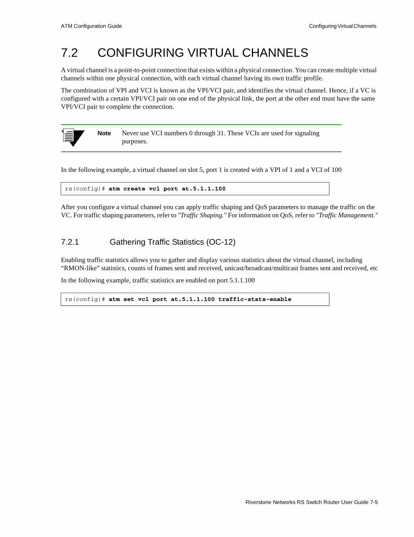
ATM Configuration Guide Configuring Virtual Channels
7.2 CONFIGURING VIRTUAL CHANNELSA virtual channel is a point-to-point connection that exists within a physical connection. You can create multiple virtual channels within one physical connection, with each virtual channel having its own traffic profile.
The combination of VPI and VCI is known as the VPI/VCI pair, and identifies the virtual channel. Hence, if a VC is configured with a certain VPI/VCI pair on one end of the physical link, the port at the other end must have the same VPI/VCI pair to complete the connection.
Note Never use VCI numbers 0 through 31. These VCIs are used for signaling purposes.
In the following example, a virtual channel on slot 5, port 1 is created with a VPI of 1 and a VCI of 100
After you configure a virtual channel you can apply traffic shaping and QoS parameters to manage the traffic on the VC. For traffic shaping parameters, refer to "Traffic Shaping." For information on QoS, refer to "Traffic Management."
7.2.1 Gathering Traffic Statistics (OC-12)
Enabling traffic statistics allows you to gather and display various statistics about the virtual channel, including “RMON-like” statistics, counts of frames sent and received, unicast/broadcast/multicast frames sent and received, etc
In the following example, traffic statistics are enabled on port 5.1.1.100
rs(config)# atm create vcl port at.5.1.1.100
rs(config)# atm set vcl port at.5.1.1.100 traffic-stats-enable
Riverstone Networks RS Switch Router User Guide 7-5

Traffic Shaping ATM Configuration Guide
To display traffic statistics for a virtual channel, use the atm show port-stats command as shown in the following example:
Note that the last line of the example shows that the statistics were never cleared. You can clear traffic statistics on a port by using the atm clear stats command.
7.3 TRAFFIC SHAPINGYou can set traffic parameters for a virtual channel by specifying a service category. A service category defines bandwidth characteristics and delay guarantees. You can then apply a different service category to each virtual channel. This gives you more control of your network resources, and more options to accommodate different user needs.
You can define the following service categories:
Unspecified Bit Rate (UBR) This service category is strictly best effort and runs at the available bandwidth. Users may limit the bandwidth by specifying a PCR value. The SCR and MBS are ignored. This service class is intended for applications that do not require specific traffic guarantees. UBR is the default.
rs# atm show port-stats port at.5.1.1.100
PORT = 1, VPI = 1, VCI = 100
Received Transmitted
-------- -----------
SAR statistics:
Packets discarded 0 0
Packets Reassembled/Segmented 119 119
Received cells 119 119
AMAC statistics:
Unicast 0 0
Multicast 0 0
Broadcast 0 0
Discarded 0 0 (includes sent to ACPU)
<64 bytes 0 0
63< <256 0 0
255< <1519 0 0
>1518 0 0
Enabled Up/Down
------- -------
OAM status No N/A
Statistics Cleared * Never Cleared *
7-6 Riverstone Networks RS Switch Router User Guide

ATM Configuration Guide Traffic Shaping
Constant Bit Rate (CBR)This service category provides a guaranteed constant bandwidth specified by the Peak Cell Rate (PCR). This service requires only the PCR value. The Sustainable Cell Rate (SCR) and Maximum Burst Size (MBS) values are ignored. This service category is intended for applications that require constant cell rate guarantees such as uncompressed voice or video transmission.
Non Real-Time Variable Bit RateThis service category provides a guaranteed constant bandwidth (specified by the SCR), but also provides for peak bandwidth requirements (specified by the PCR). This service category requires the PCR, SCR, and MBS options and is intended for applications that can accommodate bursty traffic with no need for real-time guarantees.
Real-Time Variable Bit RateThis service category provides a guaranteed constant bandwidth (specified by the SCR), but also provides for peak bandwidth requirements (specified by the PCR). This service category requires the PCR, SCR, and MBS options and is intended for applications that can accommodate bursty real-time traffic such as compressed voice or video.
Available Bit Rate (ABR) This service category guarantees a minimum cell rate only, intended for best effort applications. This service category is currently unsupported.
After you define a service category, you apply it to a VC. An important concept when applying service profiles is the concept of inheritance. Since a service profile can be applied to a virtual channel, virtual path, or an ATM port, the actual connection can inherit the service profile from any one of the three. The virtual channel will inherit the service profile that is directly applied on it. If no service profile was applied to the virtual channel, the connection will inherit the service profile applied to the virtual path. If no service profile was applied to the virtual path, then the connection will inherit the service profile applied to the ATM port. If no service profile was applied to the port, then the default service class UBR is applied.
The following example defines a service profile named ‘cbr1m’ where CBR is the service category and peak cell rate is set to 10000 kcells/second. The service profile is then applied to the VC (VPI=0, VCI=100) on ATM port at.1.1:
To display information about the service you configured, use the atm show service command as shown in the following example:
rs(config)# atm define service cbr1m srv-cat cbr pcr 10000rs(config)# atm apply service cbr1m port at.1.1.0.100
rs# atm show service cbr1mcbr1m Service Class: CBR Peak Bit Rate: 10000 Kbits/sec (23584 CPS) Encapsulation Type: LLC Multiplexing Traffic Type: RFC-1483, multi-protocol F5-OAM: Responses Only
Riverstone Networks RS Switch Router User Guide 7-7

Traffic Management ATM Configuration Guide
7.4 TRAFFIC MANAGEMENTThe ATM line cards provide different methods for managing traffic. On the ATM multi-rate line card you can use the following QoS policies to control ATM traffic: Strict Priority, Weighted Fair Queueing (WFQ), or WFQ with Strict Priority.
On the ATM OC-12 line card you can prioritize traffic by configuring virtual channel (VC) groups. Each VC within a VC group can be assigned one (or more) of four internal levels: low, medium, high, and control. These levels prioritize the separate VCs, and as a result prioritize the traffic passing through the separate VCs within the VC group.
7.4.1 Configuring QoS (Multi-Rate Line Card)
You can use the QoS parameters ((qos-control, qos-low, qos-medium, qos-high) of the atm define service command to set the following QoS policies on the ATM multi-rate line card:• Strict Priority (Default)
Separate buffer space is allocated to each of the following four queues: control, high, medium and low. Buffered traffic is forwarded in the following order: traffic in the control queue is forwarded first, followed by traffic in the high queue, medium queue, and finally, the low queue. When using strict priority, no control packets are dropped if the rate of the control packets is less then the VC's rate. But if the rate of control packets exceeds the VC's rate, then some control packets must be dropped.
This policy ensures that critical traffic reaches its destination even if the exit ports for the traffic are experiencing greater-than-maximum utilization. To prevent traffic from queues that are forwarded first from starving traffic from other queues, you can apply the WFQ queuing policy to set a minimum bandwidth for each queue.
• Weighted Fair Queuing
When you use WFQ, you divide the VC’s bandwidth and assign percentages to each queue (control, high, medium and low). These percentages must be at least 10%, and must total 100%. This queueing policy is set on a per-port basis.• Weighted Fair Queuing with Strict Priority
With this combination of Strict Priority and WFQ, the control queue gets potentially all of the link bandwidth. The remaining bandwidth is shared among the other priorities, according to the user-specified percentages. With this policy, you specify percentages for the high, medium, and low queues only.
Note Currently, QoS only supports packets of Ethernet size 1514 and smaller. For packets larger than this, the accuracy of QoS cannot be guaranteed.
QoS is triggered only when there is congestion on the link (i.e., the transmit queue for any VC reaches a pre-determined depth). Until congestion occurs, the traffic is transmitted on a first-come-first-serve basis, and may not match the requested percentages.
7-8 Riverstone Networks RS Switch Router User Guide

ATM Configuration Guide Traffic Management
7.4.1.1 Relative Latency
Use the qos-relative-latency parameter of the atm define service command to set a value for relative latency. Increasing relative latency can increase the accuracy of the achieved rates. This is because each queue has a quota of bytes to transmit, and the packets that are sent may not exactly equal that quota. Therefore there is going to be either excess bytes sent, or a shortage of bytes sent. When a packet to transmit exceeds the quota, an implementation could choose to send the packet and go over the quota, or not send it and go under the quota. This feature allows an excess number to be sent, so up to 1499 extra bytes can be sent during a period. This is a significant number when the byte count for a queue is around 1500; however, its affect decreases as the byte count increases.
Increasing the relative latency also increases the amount of time that a queue waits to transmit a packet after it has used up its quota. For example, if a queue with weight 10 used up its quota before the other queues had transmitted, it would potentially have to wait for the other 90 percent of the total byte count to be sent before it could send again. The time is dependent upon the VC's rate.
For configurations in which a latency sensitive application has a low percentage of a slow link speed, it is best to put that application on the control queue and use "WFQ with strict priority." Optionally, you can set the relative latency to 1, as long as the achieved rates are accurate.
Additionally, when increasing relative latency values, you should also consider increasing the size of the buffers. This is because packets may be held off for longer times.
Decreasing relative latency has the effect of:• Decreasing worst case latency seen by a bursty flow.• Decreasing buffer requirements for the VC.• Possibly decreasing the achievable accuracy of the selected weights.
7.4.1.2 Controlling Buffers for Each VC
When VCs queue data, they consume memory resources on the ATM card. By default, the hardware limits the number of internal buffers that each VC can use (21 * 240 bytes) for each queue. Generally, you should not have to set the number of internal buffers. However, if a bursty application is suffering loss (i.e., jumpy video), then you can increase the buffers for that queue by using the QoS buffering parameters (qos-buffering-control, qos-buffering-low, qos-buffering-medium, qos-buffering-high) of the atm define service command. The best way to determine the correct setting is to use a network analyzer to find the maximum burst, or to determine the correct settings through experimentation.
7.4.2 Configuring Virtual Channel Groups (OC-12)
A virtual channel group is a grouping of up to four separate virtual channels. This grouping of virtual channels is treated as one large virtual circuit. This is due to the fact that the VC group is seen as one virtual interface by the IP layer. For example, OSPF will see a point-to-point connection instead of multiple connections for all the virtual channels within the VC group.
Each VC within a virtual channel group can be assigned one (or more) of four internal priority levels: low, medium, high, and control. These internal priority levels apply to IP packets.
In addition to assigning an internal priority level for a VC, you can also designate a VC within the VC group to carry broadcast/multicast traffic.
Riverstone Networks RS Switch Router User Guide 7-9
Traffic Management ATM Configuration Guide
This feature is advantageous in the case where different priority traffic needs to travel between two end devices. The end devices can essentially share one logical connection (through the VC group) while still prioritizing data up to four different levels. If a connection becomes oversubscribed and packets start dropping, using a VC group ensures that the data traffic passing between the two end devices are ranked by importance.
7.4.2.1 Creating a Virtual Channel Group
To configure a VC group, you should:1. Create the VCs using the atm create vcl command.2. Create the VC group using the atm create group command.3. Add up to four separate virtual channels to the group using the atm add vcl command. You can also
set a priority level for each VC within the VC group, as well as designate one of the VCs to handle broadcast-multicast traffic.
If you add less than four virtual channels to a VC group, the next lower priority virtual channel will handle the traffic that lacks a particular VC for its priority. For example, you add two VCs (one low priority and one high priority) to a VC group. If a medium priority packet comes in, then the next lower priority VC, the VC low, will handle the packet.
7.4.2.2 Applying Service Profiles to VC Groups
Either the virtual channel or the VC group may have a service profile applied, but not both. You must first negate the separate service profiles from each virtual channel before trying to apply a service profile to the whole VC group, and vice versa.
It is recommended that you pay special attention when selecting the ATM service parameters for the VCs with different IP priorities. For example, control priority needs to have some dedicated bandwidth allocated while the low priority VC could have UBR defined with no dedicated bandwidth.
7.4.3 Traffic Management Configuration Example
The examples in this section show how you can manage traffic using QoS policies on the ATM multi-rate line card, and using VC groups on the ATM OC-12 line card.
Suppose you are a network administrator in charge of managing a network with three Client workstations (Client1, Client2, Client3) and a server. You are using two RS Ethernet Router’s to connect and manage traffic between the server and the clients.
Your network requirements are as follows:• Traffic from the Server heading to Client1 is assigned high priority in the event that the connection
becomes oversubscribed.• Traffic from the Server heading to Client2 is assigned medium priority in the event that the
connection becomes oversubscribed.• Traffic from the Server heading to Client3 is assigned low priority in the event that the connection
becomes oversubscribed.• All routing protocol control packets are assigned control priority.
7-10 Riverstone Networks RS Switch Router User Guide

ATM Configuration Guide Traffic Management
Figure 7-1 Traffic management sample configuration
The following sections illustrate how to accommodate the network requirements if the RS Ethernet Router’s are connected through ATM multi-rate line cards, and if the RS Ethernet Router’s are connected through ATM OC-12 line cards.
7.4.3.1 Configuring QoS Policies (Multi-Rate Line Card)
If the routers in Figure 7-1 were connected through ATM multi-rate line cards, then you would use QoS policies to manage the traffic.
RS1 RS2
Client1
at.1.1at.1.1
100.0.0.1/24 100.0.0.2/24
et.1.1 et.1.1
et.1.2
Client2
202.0.0.1/24
Client3
Server
200.0.0.1/24
et.1.3
201.0.0.1/24
203.0.0.1/24
Riverstone Networks RS Switch Router User Guide 7-11
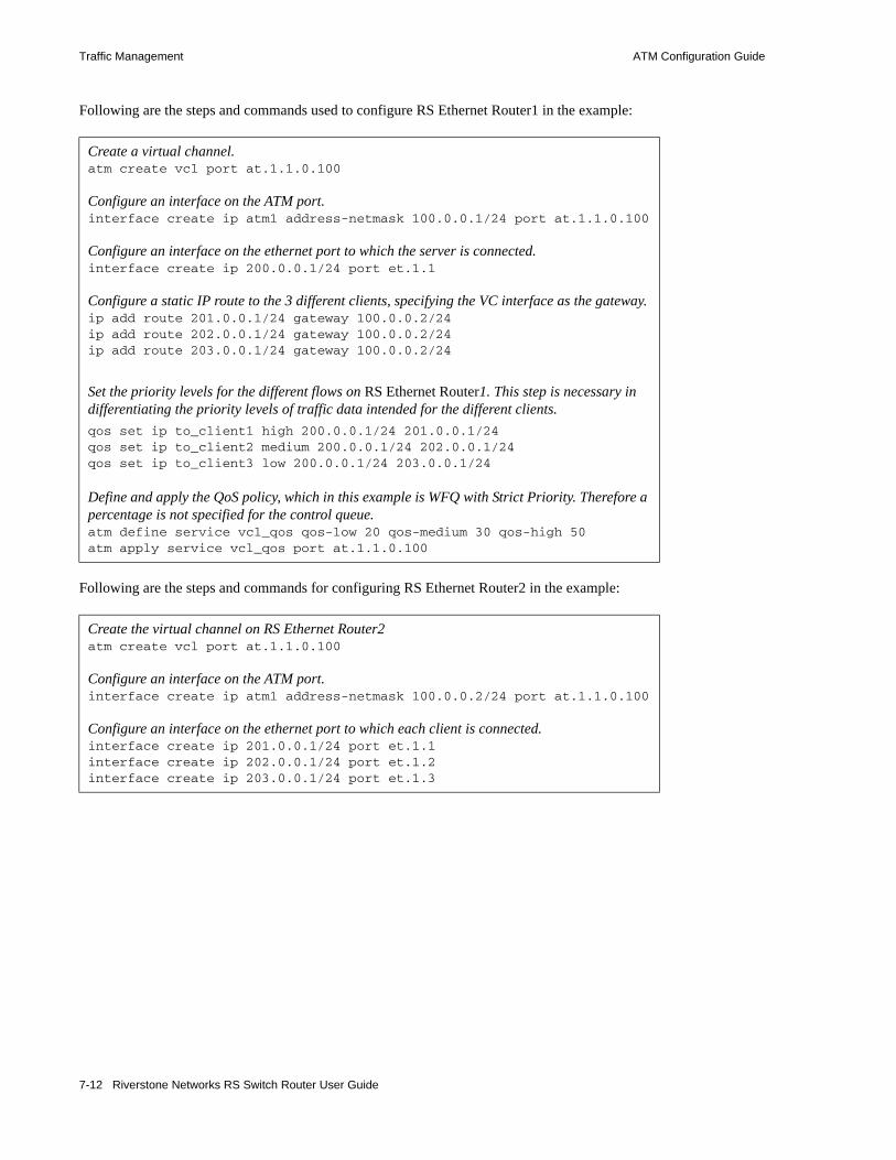
Traffic Management ATM Configuration Guide
Following are the steps and commands used to configure RS Ethernet Router1 in the example:
Following are the steps and commands for configuring RS Ethernet Router2 in the example:
Create a virtual channel.atm create vcl port at.1.1.0.100
Configure an interface on the ATM port.interface create ip atm1 address-netmask 100.0.0.1/24 port at.1.1.0.100
Configure an interface on the ethernet port to which the server is connected.interface create ip 200.0.0.1/24 port et.1.1
Configure a static IP route to the 3 different clients, specifying the VC interface as the gateway.ip add route 201.0.0.1/24 gateway 100.0.0.2/24ip add route 202.0.0.1/24 gateway 100.0.0.2/24ip add route 203.0.0.1/24 gateway 100.0.0.2/24
Set the priority levels for the different flows on RS Ethernet Router1. This step is necessary in differentiating the priority levels of traffic data intended for the different clients.qos set ip to_client1 high 200.0.0.1/24 201.0.0.1/24qos set ip to_client2 medium 200.0.0.1/24 202.0.0.1/24qos set ip to_client3 low 200.0.0.1/24 203.0.0.1/24
Define and apply the QoS policy, which in this example is WFQ with Strict Priority. Therefore a percentage is not specified for the control queue.atm define service vcl_qos qos-low 20 qos-medium 30 qos-high 50 atm apply service vcl_qos port at.1.1.0.100
Create the virtual channel on RS Ethernet Router2atm create vcl port at.1.1.0.100
Configure an interface on the ATM port.interface create ip atm1 address-netmask 100.0.0.2/24 port at.1.1.0.100
Configure an interface on the ethernet port to which each client is connected.interface create ip 201.0.0.1/24 port et.1.1interface create ip 202.0.0.1/24 port et.1.2interface create ip 203.0.0.1/24 port et.1.3
7-12 Riverstone Networks RS Switch Router User Guide

ATM Configuration Guide Traffic Management
7.4.3.2 Configuring Virtual Channels Groups (OC-12)
If the RS Ethernet Router’s in Figure 7-1 were connected through ATM OC-12 line cards, you would use VC groups to manage the traffic. Following are the steps and commands for configuring RS Ethernet Router1 in the example:
Create the virtual channels.atm create vcl port at.1.1.0.100atm create vcl port at.1.1.0.101atm create vcl port at.1.1.0.102atm create vcl port at.1.1.0.103
Create a virtual channel group ‘vg.1’ on slot number 1 of RS Ethernet Router1.atm create group vg.1 slot 1
Add the 4 virtual channels into the VC group. This step also identifies the priority level for each of the 4 virtual channels within the group.atm add vcl at.1.1.0.100 to vg.1 priority lowatm add vcl at.1.1.0.101 to vg.1 priority mediumatm add vcl at.1.1.0.102 to vg.1 priority highatm add vcl at.1.1.0.103 to vg.1 priority control
Configure an IP address for the VC group.interface create ip vcg1 address-netmask 100.0.0.1/24 port vg.1
Configure a static IP route to the 3 different clients, specifying the VC group interface as the gateway.ip add route 201.0.0.1/24 gateway 100.0.0.2/24ip add route 202.0.0.1/24 gateway 100.0.0.2/24ip add route 203.0.0.1/24 gateway 100.0.0.2/24
Set the priority levels for the different flows on RS Ethernet Router1. This step is necessary in differentiating the priority levels of traffic data intended for the different clients. Note that control packets are assigned to control priority levels by default.qos set ip to_client1 high 200.0.0.1/24 201.0.0.1/24qos set ip to_client2 medium 200.0.0.1/24 202.0.0.1/24qos set ip to_client3 low 200.0.0.1/24 203.0.0.1/24
Riverstone Networks RS Switch Router User Guide 7-13

Traffic Management ATM Configuration Guide
Following are the steps and commands for configuring RS Ethernet Router2:
Use the atm show vcgroup command to display information about a virtual channel group:
Create the same virtual channels on RS Ethernet Router2.rs2(config)# atm create vcl port at.1.1.0.100atm create vcl port at.1.1.0.101atm create vcl port at.1.1.0.102atm create vcl port at.1.1.0.103
Create the virtual channel group ‘vg.1’ on slot number 1 of RS Ethernet Router2.atm create group vg.1 slot 1
Add the virtual channels to the VC group created on RS Ethernet Router2.atm add vcl at.1.1.0.100 to vg.1 priority lowatm add vcl at.1.1.0.101 to vg.1 priority mediumatm add vcl at.1.1.0.102 to vg.1 priority highatm add vcl at.1.1.0.103 to vg.1 priority control
Configure an IP address for the VC group.interface create ip vcg1 address-netmask 100.0.0.2/24 port vg.1
rs# atm show vcgroup port vg.1Port Control High Medium Low Bcast Vpi Vci Vpi Vci Vpi Vci Vpi Vcivg.1 Conf 1 103 1 102 1 101 1 100 LOWvg.1 Actv 0 0 0 0 0 0 0 0rs#
7-14 Riverstone Networks RS Switch Router User Guide

ATM Configuration Guide Bridging ATM Traffic
7.5 BRIDGING ATM TRAFFICThe ATM modules support both flow-based and address-based bridging. Like all the other RS Ethernet Router modules, the ATM modules perform address-based bridging by default, but can be configured to perform flow-based bridging. The ATM multi-rate line card supports IP-based VLANs, and the ATM OC-12 line card supports IP and IPX-based VLANs. You can configure an ATM port as an 802.1Q trunk port, enabling it to carry traffic for multiple VLANs. For additional information on the RS Ethernet Router bridging functions, refer to Section 6, "Bridging Configuration Guide."
Note The ATM modules do not support the Spanning Tree Protocol.
The following example illustrates how you can use bridging and VLANs to accommodate different networking requirements on an ATM module. In the network diagram, there are two client groups, VLAN A and VLAN B. These two client groups have very different needs and requirements for their users. VLAN A consists of users who need access to a high bandwidth connection able to support video conferencing. VLAN B consists of users who require less bandwidth and are mainly concerned with email and server backup traffic.
There are two separate VLANs in this network, VLAN A and VLAN B. VLAN A is connected to ethernet port et.5.1, and VLAN B is connected to ethernet port et.6.2.
Riverstone Networks RS Switch Router User Guide 7-15

Bridging ATM Traffic ATM Configuration Guide
Figure 7-2 Bridging ATM traffic configuration example
RS
et.5.1
at.4.3
VLAN A
VLAN B
et.6.2
WAN
7-16 Riverstone Networks RS Switch Router User Guide

ATM Configuration Guide Bridging ATM Traffic
Following are the configuration steps for the example:
7.5.1 Limiting MAC Addresses Learned on a VC
You can limit the number of MAC addresses learned on a VC. This security feature prevents users from purposely filling the L2 tables. You can set the limit between 0 and 127. However, at least one MAC address should be allowed on each VC.
When you specify a limit for the number of MAC addresses learned, that limit applies only to the additional MAC addresses that will be learned after the command was entered. If you specify a limit of 10 MAC addresses and the RS Ethernet Router has already learned 3, then the total number of MAC addresses that can be learned on the VC is 13. But once enough MAC addresses have aged out to bring the number of addresses learned to below the limit you set, then the maximum number of MAC addresses learned will not exceed the limit.
Use the atm define service command to configure a service that specifies a MAC address limit. Then, apply the service to the VC. The following example limits the number of MAC addresses learned on at.1.1.0.100.
Apply an interface on both ethernet ports.rs(config)# interface create ip subnetA address-netmask 11.1.1.1/24 port et.5.1 uprs(config)# interface create ip subnetB address-netmask 11.1.2.1/24 port et.6.2 up
Create two virtual channels, one for each type of traffic.rs(config)# atm create vcl port at.4.3.0.100rs(config)# atm create vcl port at.4.3.0.101
Create the VLANs: VLAN A with ID number 1, and VLAN B with ID number 2.rs(config)# vlan create VLAN_A ip id 1rs(config)# vlan create VLAN_B ip id 2
Add the virtual channels to each VLAN.rs(config)# vlan add ports et.5.1,at.4.3.0.100 to VLAN_Ars(config)# vlan add ports et.6.2,at.4.3.0.101 to VLAN_B
Define a service class for VLAN A where CBR is the service category and peak cell rate is set to 100000 kcells/second to ensure proper support for video conferencing.rs(config)# atm define service vlanA srv-cat cbr pcr 100000
Define a service class for VLAN B where UBR is the service category.rs(config)# atm define service vlanB srv-cat ubr
Apply the appropriate service category to each VC.rs(config)# atm apply service vlanA port at.4.3.0.100rs(config)# atm apply service vlanB port at.4.3.0.101
atm define service mac1 mac-addr-limit 10atm apply service mac1 port at.1.1.0.100
Riverstone Networks RS Switch Router User Guide 7-17

Routing ATM Traffic ATM Configuration Guide
7.6 ROUTING ATM TRAFFICConfiguring IP interfaces for ATM modules is generally the same as for WANs and LANs. You assign an IP address to each interface and configure routing protocols such as OSPF or BGP. You can configure the IP interface on a physical port or as part of a VLAN. The ATM multi-rate line card supports IP-based VLANs, and the ATM OC-12 line card supports IP and IPX-based VLANs.
Creating an interface on an ATM port assigns a network IP address and submask on that port, and assigns it to a specified VC (VPI/VCI pair). Since a VC is a connection in the ATM Layer only, creating an interface for an ATM port is necessary to establish a connection in the IP network layer.
The following example illustrates how you can use routing on an ATM module to accommodate different requirements from two client groups using only one ATM physical connection. This is accomplished by setting up two VCs on the ATM port, each with its own service profiles and bandwidth.
7-18 Riverstone Networks RS Switch Router User Guide

ATM Configuration Guide Routing ATM Traffic
Figure 7-3 Routing ATM traffic configuration example
Suppose you are a network administrator in charge of managing a network with two client groups: Subnet A and Subnet B. These two client groups have very different bandwidth needs and requirements for their respective users. Subnet A consists of users who need access to a high bandwidth connection, able to support video conferencing. Subnet B consists of users who require less stringent requirements and are mainly concerned with email and server backup type traffic.
Configuration is done in two steps. The first step is to configure the network for traffic from Subnet A and Subnet B to Subnet C. The second step is to configure the network for traffic from Subnet C to Subnet A and Subnet B and assign ACLs to place subnets on correct VCLs. Now all traffic between Subnet A and Subnet C travels over the 20 Mbit VCL, while all traffic between Subnet B and Subnet C travels over the 100 Mbit VCL.
Subnet A Subnet B20.1.1.X/2410.1.1.X/24
ATM Network
et 2.3et 2.4
at 4.2
30.1.1.127/2440.1.1.127/24VPI = 0, VCI =100VPI = 0, VCi = 101
40.1.1.128/24VPI = 0, VCi = 101
30.1.1.128/24VPI = 0, VCI =100
Subnet C50.1.1.X/24
CBR, 100 MbitUBR, 20 Mbit
RS1
RS2
at 3.1
et 5.1
UBR, 20 Mbit CBR, 100 Mbit
10.1.1.130/24
50.1.1.130/24
20.1.1.130/24
Riverstone Networks RS Switch Router User Guide 7-19

Routing ATM Traffic ATM Configuration Guide
Following is the configuration for RS Ethernet Router1:
Configure an interface on each ethernet port.rs1(config)# interface create ip subnetA address-netmask 10.1.1.130/24 port et.2.4 uprs1(config)# interface create ip subnetB address-netmask 20.1.1.130/24 port et.2.3 up
Create the virtual channels.rs1(config)# atm create vcl port at.4.2.0.100rs1(config)# atm create vcl port at.4.2.0.101
Configure an interface on each ATM port.rs1(config)# interface create ip ubrservice address-netmask 40.1.1.127/24 peer-address 40.1.1.128/24 port at.4.2.0.101 uprs1(config)# interface create ip cbrservice address-netmask 30.1.1.127/24 peer-address 30.1.1.128/24 port at.4.2.0.100 up
Define the ATM service profiles.rs1(config)# atm define service ubrservice srv-cat ubr pcr-kbits 20000rs1(config)# atm define service cbrservice srv-cat cbr pcr-kbits 100000
Apply the ATM service profiles.rs1(config)# atm apply service ubrservice port at.4.2.0.101rs1(config)# atm apply service cbrservice port at.4.2.0.100
Create IP ACLs.RS Ethernet Router1(config)# acl subnetAtoCacl permit 10.1.1.0/24 any any anyrs1(config)# acl subnetBtoCacl permit 20.1.1.0/24 any any any
Specify a gateway for each IP policy.rs1(config)# ip-policy subnetAtoCpolicy permit acl subnetAtoCacl next-hop-list 40.1.1.128/24 action policy-firstrs1(config)# ip-policy subnetBtoCpolicy permit acl subnetBtoCacl next-hop-list 30.1.1.128/24 action policy-first
Apply the IP policies to the ethernet ports.rs1(config)# ip-policy subnetAtoCpolicy apply interface subnetArs1(config)# ip-policy subnetBtoCpolicy apply interface subnetB
7-20 Riverstone Networks RS Switch Router User Guide

ATM Configuration Guide Routing ATM Traffic
Following is the configuration for RS Ethernet Router2:
7.6.1 Peer Address Mapping
You can map a peer address to a specific virtual channel. This allows you to set the destination address for a virtual channel using the atm set peer-addr command. This way, a virtual channel can be dedicated to handle traffic between two specific devices.
Mapped addresses are useful when you do not want to specify the peer address for the ATM port using the interface create command. This would be the case if the interface is created for a VLAN and there are many peer addresses on the VLAN. If any of the peers on the VLAN do not support InArp or IPCP/IPXCP, then a mapped address must be configured to determine the destination address.
Configure an interface on the ethernet port that leads to Subnet C.rs2(config)# interface create ip subnetC address-netmask 50.1.1.130/24 port et.5.1 up
Create the virtual channels on port at.4.2.rs2(config)# atm create vcl port at.3.1.0.100rs2(config)# atm create vcl port at.3.1.0.101
Configure an interface for each VC.rs2(config)# interface create ip ubrservice address-netmask 40.1.1.128/24 peer-address 40.1.1.127/24 port at.3.1.0.101 uprs2(config)# interface create ip cbrservice address-netmask 30.1.1.128/24 peer-address 30.1.1.127/24 port at.3.1.0.100 up
Define the ATM service profiles.rs2(config)# atm define service ubrservice srv-cat ubr pcr-kbits 20000rs2(config)# atm define service cbrservice srv-cat cbr pcr-kbits 100000
Apply the ATM service profiles.rs2(config)# atm apply service ubrservice port at.3.1.0.101rs2(config)# atm apply service cbrservice port at.3.1.0.100
For traffic from subnet C to subnets A and B, create IP ACLs.rs2(config)# acl subnetCtoAacl permit 50.1.1.0/24 10.1.1.0/24 any anyrs2(config)# acl subnetCtoBacl permit 50.1.1.0/24 20.1.1.0/24 any any
Specify a gateway for each IP policy.rs2(config)# ip-policy subnetCtoApolicy permit acl subnetCtoAacl next-hop-list 40.1.1.127/24 action policy-firstrs2(config)# ip-policy subnetCtoBpolicy permit acl subnetCtoBacl next-hop-list 30.1.1.127/24 action policy-first
Apply IP policies to the Ethernet ports.rs2(config)# ip-policy subnetCtoApolicy apply interface subnetCrs2(config)# ip-policy subnetCtoBpolicy apply interface subnetC
Riverstone Networks RS Switch Router User Guide 7-21

Routing ATM Traffic ATM Configuration Guide
Note Specify a peer address if the RS Ethernet Router is handling VC-mux encapsulated traffic.
In the following example, a connection is established between a video server and three video clients (Video Client 1, Video Client 2, and Video Client 3). The video server routes data through the RS Ethernet Router to the video clients. Traffic passes to the video clients through three separate virtual channels. Each virtual channel has a unique service profile.
In addition, the RS Ethernet Router is transmitting VC-mux encapsulation traffic. Peer address mapping is used to associate a particular destination address with each VC. This allows the RS Ethernet Router to route traffic to a specific client without multicasting to every virtual channel.
Figure 7-4 Peer address mapping configuration example
RS Routerto video server
Video Client 2
Video Client 3
Video Client 1
0,101
0,102
0,103
0,103
0,102
0,101
at.2.1
120.131.0.2/24
134.141.0.1/24
154.15.0.5/24
114.111.1.1/24
ATM Cloud
7-22 Riverstone Networks RS Switch Router User Guide
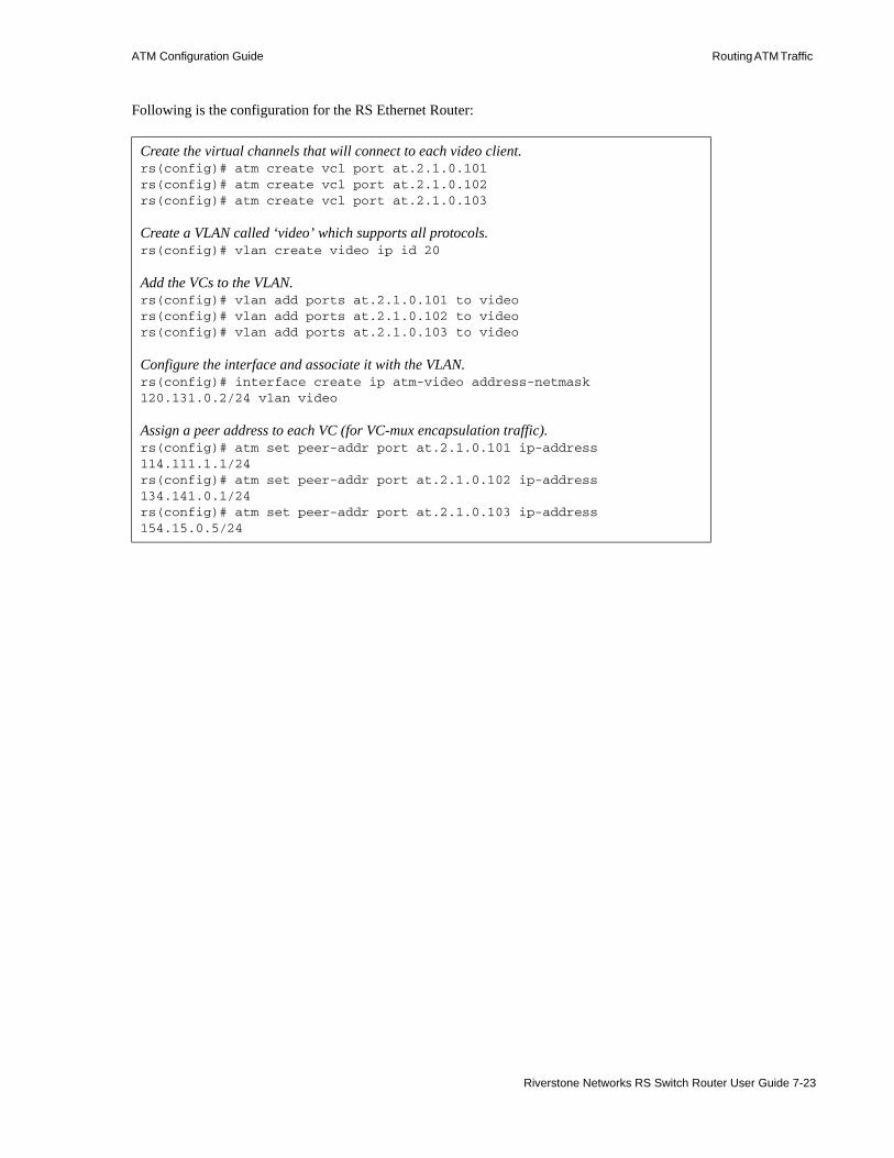
ATM Configuration Guide Routing ATM Traffic
Following is the configuration for the RS Ethernet Router:
Create the virtual channels that will connect to each video client. rs(config)# atm create vcl port at.2.1.0.101rs(config)# atm create vcl port at.2.1.0.102rs(config)# atm create vcl port at.2.1.0.103
Create a VLAN called ‘video’ which supports all protocols.rs(config)# vlan create video ip id 20
Add the VCs to the VLAN.rs(config)# vlan add ports at.2.1.0.101 to videors(config)# vlan add ports at.2.1.0.102 to videors(config)# vlan add ports at.2.1.0.103 to video
Configure the interface and associate it with the VLAN.rs(config)# interface create ip atm-video address-netmask 120.131.0.2/24 vlan video
Assign a peer address to each VC (for VC-mux encapsulation traffic).rs(config)# atm set peer-addr port at.2.1.0.101 ip-address 114.111.1.1/24rs(config)# atm set peer-addr port at.2.1.0.102 ip-address 134.141.0.1/24rs(config)# atm set peer-addr port at.2.1.0.103 ip-address 154.15.0.5/24
Riverstone Networks RS Switch Router User Guide 7-23
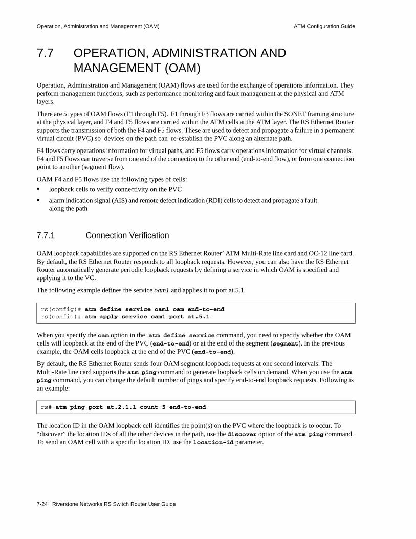
Operation, Administration and Management (OAM) ATM Configuration Guide
7.7 OPERATION, ADMINISTRATION AND MANAGEMENT (OAM)
Operation, Administration and Management (OAM) flows are used for the exchange of operations information. They perform management functions, such as performance monitoring and fault management at the physical and ATM layers.
There are 5 types of OAM flows (F1 through F5). F1 through F3 flows are carried within the SONET framing structure at the physical layer, and F4 and F5 flows are carried within the ATM cells at the ATM layer. The RS Ethernet Router supports the transmission of both the F4 and F5 flows. These are used to detect and propagate a failure in a permanent virtual circuit (PVC) so devices on the path can re-establish the PVC along an alternate path.
F4 flows carry operations information for virtual paths, and F5 flows carry operations information for virtual channels. F4 and F5 flows can traverse from one end of the connection to the other end (end-to-end flow), or from one connection point to another (segment flow).
OAM F4 and F5 flows use the following types of cells: • loopback cells to verify connectivity on the PVC • alarm indication signal (AIS) and remote defect indication (RDI) cells to detect and propagate a fault
along the path
7.7.1 Connection Verification
OAM loopback capabilities are supported on the RS Ethernet Router’ ATM Multi-Rate line card and OC-12 line card. By default, the RS Ethernet Router responds to all loopback requests. However, you can also have the RS Ethernet Router automatically generate periodic loopback requests by defining a service in which OAM is specified and applying it to the VC.
The following example defines the service oam1 and applies it to port at.5.1.
When you specify the oam option in the atm define service command, you need to specify whether the OAM cells will loopback at the end of the PVC (end-to-end) or at the end of the segment (segment). In the previous example, the OAM cells loopback at the end of the PVC (end-to-end).
By default, the RS Ethernet Router sends four OAM segment loopback requests at one second intervals. The Multi-Rate line card supports the atm ping command to generate loopback cells on demand. When you use the atm ping command, you can change the default number of pings and specify end-to-end loopback requests. Following is an example:
The location ID in the OAM loopback cell identifies the point(s) on the PVC where the loopback is to occur. To “discover” the location IDs of all the other devices in the path, use the discover option of the atm ping command. To send an OAM cell with a specific location ID, use the location-id parameter.
rs(config)# atm define service oam1 oam end-to-end rs(config)# atm apply service oam1 port at.5.1
rs# atm ping port at.2.1.1 count 5 end-to-end
7-24 Riverstone Networks RS Switch Router User Guide

ATM Configuration Guide Operation, Administration and Management (OAM)
Use the atm set port command to specify a location ID. When you do so, it enables the RS Ethernet Router to be “discovered” and to be specified in loopback requests from other devices along the path.
rs(config)# atm set port location-id
Riverstone Networks RS Switch Router User Guide 7-25

Operation, Administration and Management (OAM) ATM Configuration Guide
7-26 Riverstone Networks RS Switch Router User Guide

8 PACKET-OVER-SONET CONFIGURATION GUIDE
This chapter explains how to configure and monitor Packet-over-SONET (PoS) on the RS Ethernet Router. See the sonet commands section of the Riverstone RS Switch Router Command Line Interface Reference Manual for a description of each command.
PoS requires installation of the OC-3c or OC-12c PoS line cards in an RS 8000 or an RS 8600. The OC-3c line card has four PoS ports, while the OC-12c line card has two PoS ports. You must use the “so” prefix for PoS interface ports. For example, you would specify the first PoS port located at router slot 13, port 1 as “so.13.1.”
By default, PoS ports are set for point-to-point protocol (PPP) encapsulation. The only other supported encapsulation type is bridged Ethernet over PPP.
Note While PoS ports use PPP encapsulation, other PPP characteristics such as service profiles, encryption, compression, and MLP bundles are not supported for PoS ports.
By default, PoS ports are configured to receive a maximum transmission unit (MTU) size of 1522 octets. The actual MTU size used for transmissions over a PoS link is a result of PPP negotiation. For transmission of “jumbo frames” (MTUs up to 65535 octets), you can increase the MTU size of the PoS port. The MTU must be set at the port level.
8.1 CONFIGURING IP INTERFACES FOR POS LINKS
Configuring IP interfaces for PoS links is generally the same as for WANs and for LANs. You assign an IP address to each interface and define routing mechanisms such as OSPF or RIP as with any IP network. You can configure the IP interface on the physical port or you can configure the interface as part of a VLAN for PoS links. You can also configure multiple IP addresses for each interface, as described in Section 10.2, "Configuring IP Interfaces and Parameters".
When creating the IP interface for a PoS link, you can either specify the peer address if it is known (static address), or allow the peer address to be automatically discovered via IPCP negotiation (dynamic address). If the peer address is specified, any address supplied by the peer during IPCP negotiation is ignored.
IP interfaces for PoS links can have primary and secondary IP addresses. The primary addresses may be either dynamic or static, but the secondary address must be static. This is because only the primary addresses of both the local and peer devices are exchanged during IP Control Protocol (IPCP) negotiation.
Riverstone Networks RS Switch Router User Guide 8-1

Configuring Packet-over-SONET Links Packet-over-SONET Configuration Guide
Source filtering and ACLs can be applied to an IP interface for a PoS link. Unlike WAN ports, the applied filter or ACL presents no limitation. Different filters can be configured on different PoS ports.
8.2 CONFIGURING PACKET-OVER-SONET LINKSTo configure a Packet-over-SONET link:1. On the RS Ethernet Router, assign an interface to the PoS port to which you will connect via fiber
cable in a point-to-point link. Assign an IP address and netmask to the interface. If possible, determine the peer address of the interface at the other end of the point-to-point link. In the following example, the port so.13.1 on the RS Ethernet Router will be associated with the interface pos11:
Figure 8-1 Configuring PoS links
2. Create a PPP interface with the interface create command, specifying the IP address and netmask for the interface on the RS Ethernet Router:
When you create the point-to-point interface as shown above, the RS Ethernet Router creates an implicit VLAN called “SYS_L3_<interface-name>.” In the above example, the RS Ethernet Router creates the VLAN ‘SYS_L3_pos11.’
3. Specify the peer address of the other end of the connection. This is optional.4. If you want to increase the MTU size on a port, specify the parameter mtu with the port set
command and define a value up to 65535 (octets). See Section 10.3, "Configuring Jumbo Frames" for more information.
5. Specify the bit error rate thresholds, if necessary. For more information, see Section 8.4, "Specifying Bit Error Rate Thresholds"
6. Modify any other PoS operating parameters, as needed. The following table lists the operating parameters that you can modify and the configuration commands that you use.
rs(config)# interface create ip pos11 address-netmask 20.11.11.20/24 port so.13.1
Router A Router Bpos11so.13.120.11.11.20/24
pos2120.11.11.21/24
8-2 Riverstone Networks RS Switch Router User Guide

Packet-over-SONET Configuration Guide Configuring Automatic Protection Switching
8.3 CONFIGURING AUTOMATIC PROTECTION SWITCHING
Automatic protection switching (APS) provides a mechanism to support redundant transmission circuits between SONET devices. The RS Ethernet Router supports the following APS features:• Linear network topology. Ring topologies are not supported.• 1+1 switching. Each working line is protected by one protecting line and the same signal is
transmitted on both the working and protecting lines. The two transmission copies that arrive at the receiving end are compared, and the best copy is used. If there is a line failure or line degradation, the end node switches the connection over to the protecting line.
Note In APS terminology, bridge means to transmit identical traffic on both the working and protecting lines, while switch means to select traffic from either the protecting line or the working line.
• Unidirectional switching, where one set of line terminating equipment (LTE) can switch the line independent of the other LTE. Bidirectional switching (where both sets of LTEs perform a coordinated switch) is not supported.
• Revertive switching. You can enable automatic switchover from the protecting line to the working line after the working line becomes available.
If the working circuit is disrupted or the bit error rates on the working circuit exceed the configured thresholds, traffic is automatically switched over to the protecting circuit. Any physical or logical characteristics configured for the working port are automatically applied to the protecting port. This includes the IP address and netmask configured for the interface, spanning tree protocol (STP), per-VLAN spanning tree (PVST), etc. Therefore, there is no need to configure the protecting port separately. Any command applied to the PoS working port is mirrored onto the protecting port automatically.
Table 8-1 PoS optional operating parameters
Parameter Default Value Configuration Command
Framing SONET sonet set <port> framing sdh|sonet
Loopback Disabled sonet set <port> loopback
Path tracing (none) sonet set <port> pathtrace
Circuit identifier (none) sonet set <port> circuit-id
Frame Check Sequence 32-bit sonet set <port> fcs-16-bit
Scrambling Enabled sonet set <port> no-scramble
Riverstone Networks RS Switch Router User Guide 8-3
Configuring Automatic Protection Switching Packet-over-SONET Configuration Guide
8.3.1 Configuring Working and Protecting Ports
APS on the RS Ethernet Router requires configuration of a working port and a corresponding protecting port. You can configure any number of pairs of PoS ports for APS. The limit is the number of PoS ports on the RS Ethernet Router. If one module should go down, the remaining ports on other modules will remain operational.
Note The protecting port can be on the same slot or located on a different slot as the working port, but they must reside on the same RS Ethernet Router. You cannot configure APS operation for working and protecting ports on two different RS Ethernet Router’s.
The working and protecting port must support identical optical carrier rates. For example, if the working port operates at OC-12, the protecting port must also be OC-12.
The protecting port must not have been used in an active configuration. After being configured as the protecting port, it cannot be explicitly configured except for the APS properties. The protecting port automatically inherits the configuration of the working port.
To configure a working and a protecting PoS port, enter the following command in Configure mode:
To manage the working and protecting PoS interfaces, enter the following commands in Configure mode:
Note You can only specify one option, lockoutprot, forced or manual, for a port. Also, an option can be applied to either the working port or the protecting port, but not both working and protecting ports at the same time.
Configure working and protecting PoS ports. sonet set <working-port> protection 1+1 protected-by <protecting-port>
Prevent a working port from switching to a protecting port. This command can only be applied to a port configured as a protecting port.
sonet set <port> protection-switch lockoutprot
Force a switch to the specified port. This command can be applied to either the working or protecting port.
sonet set <port> protection-switch forced
Manually switch the line to the specified port. This command can be applied to either the working or protecting port.
sonet set <port> protection-switch manual
8-4 Riverstone Networks RS Switch Router User Guide

Packet-over-SONET Configuration Guide Specifying Bit Error Rate Thresholds
To return the circuit to the working interface after the working interface becomes available, enter the following commands in Configure mode:
8.4 SPECIFYING BIT ERROR RATE THRESHOLDSIf the bit error rate (BER) on the working line exceeds that of the configured thresholds, the receiver automatically switches over to the protecting line.
BER is calculated with the following:
BER = errored bits received/total bits received
The default BER thresholds are:• Signal degrade BER threshold of 10-6 (1 out of 1,000,000 bits transmitted is in error). Signal degrade
is associated with a “soft” failure. Signal degrade is determined when the BER exceeds the configured rate.
• Signal failure BER threshold of 10-3 (1 out of 1,000 bits transmitted is in error). Signal failure is associated with a “hard” failure. Signal fail is determined when any of the following conditions are detected: loss of signal (LOS), loss of frame (LOF), line alarm indication bridge and selector signal (AIS-L), or the BER threshold exceeds the configured rate.
To specify different BER thresholds, enter the following commands in Enable mode:
Enable automatic switchover from the protecting interface to the working interface after the working interface becomes available. This command can only be applied to a protecting port.
sonet set <port> revertive on|off
Sets the number of minutes after the working interface becomes available that automatic switchover from the protecting interface to the working interface takes place. The default value is 5 minutes.
sonet set <port> WTR-timer <minutes>
Specify signal degrade BER threshold.
sonet set <port> sd-ber <number>
Specify signal failure BER threshold.
sonet set <port> sf-ber <number>
Riverstone Networks RS Switch Router User Guide 8-5

Monitoring PoS Ports Packet-over-SONET Configuration Guide
8.5 MONITORING POS PORTSTo display PoS port configuration information, enter one of the following commands in Enable mode:
Note The RS Ethernet Router supports graceful PPP failover as a part of the Hitless Protection System (HPS), which allows the RS Ethernet Router to continue providing services even if it has to restart. PPP failover is on by default. This feature prevents PPP sessions on PoS from flapping and causing momentary interruptions to data traffic when the RS Ethernet Router reboots.
The following table describes additional monitoring commands for IP interfaces for PoS links, designed to be used in Enable mode:
8.6 EXAMPLE CONFIGURATIONSThis section shows example configurations for PoS links.
Show framing status, line type, and circuit ID of the optical link.
sonet show medium <port list>
Show working or protecting line, direction, and switch status.
sonet show aps <port list>
Show received path trace. sonet show pathtrace <port list>
Show loopback status. sonet show loopback <port list>
Show alarms and errors on SONET ports. sonet show alarms <port list>
Display bridge NCP statistics for specified PoS port.
ppp show stats ports <port name> bridge-ncp
Display IP NCP statistics for specified PoS port.
ppp show stats ports <port name> ip-ncp
Display link-status statistics for specified PoS port.
ppp show stats ports <port name> link-status
Display summary information for specified PoS port.
ppp show stats ports <port name> summary
8-6 Riverstone Networks RS Switch Router User Guide

Packet-over-SONET Configuration Guide Example Configurations
8.6.1 APS PoS Links Between RS Ethernet Router’s
The following example shows APS PoS links between two RS Ethernet Router’s, router A and router B.
Figure 8-2 Automatic protection switching between two routers
The following is the configuration for router A:
The following is the configuration for router B:
8.6.2 PoS Link Between the RS Ethernet Router and a Cisco Router
The following example shows a PoS link between an RS Ethernet Router, router A, and a Cisco 12000 series Gigabit Switch Router, router B.
Figure 8-3 PoS link between the RS Ethernet Router and a CISCO router
The following is the configuration for router A:
interface create ip pos21 address-netmask 20.11.11.21/24 port so.5.1sonet set so.7.1 protection 1+1 protected-by so.7.2
interface create ip pos11 address-netmask 20.11.11.20/24 port so.13.1sonet set so.13.1 protection 1+1 protected-by so.13.2
interface create ip so-1 address-netmask 40.1.1.1/16 port so.6.1
Router A
Router B
so.5.1
so.7.2
so.13.1
so.13.2
(working)
(protecting)
pos2120.11.11.21/24
pos1120.11.11.20/24
Router A
Router B
so.6.1
so-140.1.1.1/16
POS1/040.1.1.2/16
Riverstone Networks RS Switch Router User Guide 8-7

Example Configurations Packet-over-SONET Configuration Guide
The following is the configuration for router B:
8.6.3 PoS Link Between the RS Ethernet Router and a Juniper Router
The following example shows a PoS link between an RS Ethernet Router, router A, and a Juniper router, router B.
The following is the configuration for router A:
Note When you create an IP interface on the RS Ethernet Router for a PoS link with a Juniper router, you must specify the peer-address parameter. Otherwise, IP Control Protocol (IPCP) negotiations will fail.
The following is the configuration for router B:
interface POS1/0 ip address 40.1.1.2 255.255.0.0 no ip directed-broadcast encapsulation ppp crc 32 pos scramble-atm pos flag c2 22
interface create ip so-1 address-netmask 40.1.1.1/16 port so.6.1 peer-address 40.1.1.2
root# set interfaces so-0/1/0 unit 0 family inet address 40.1.1.2/16root# set interfaces so-0/1/0 encapsulation ppproot# set interfaces so-0/1/0 sonet-options fcs 32
Router A
Router B
so.6.1
so-140.1.1.1/16
so-0/1/040.1.1.2/16
8-8 Riverstone Networks RS Switch Router User Guide
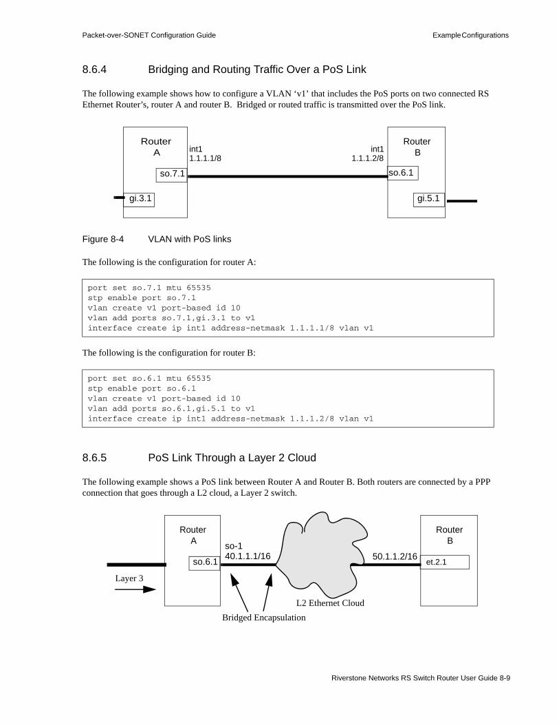
Packet-over-SONET Configuration Guide Example Configurations
8.6.4 Bridging and Routing Traffic Over a PoS Link
The following example shows how to configure a VLAN ‘v1’ that includes the PoS ports on two connected RS Ethernet Router’s, router A and router B. Bridged or routed traffic is transmitted over the PoS link.
Figure 8-4 VLAN with PoS links
The following is the configuration for router A:
The following is the configuration for router B:
8.6.5 PoS Link Through a Layer 2 Cloud
The following example shows a PoS link between Router A and Router B. Both routers are connected by a PPP connection that goes through a L2 cloud, a Layer 2 switch.
port set so.7.1 mtu 65535stp enable port so.7.1vlan create v1 port-based id 10vlan add ports so.7.1,gi.3.1 to v1interface create ip int1 address-netmask 1.1.1.1/8 vlan v1
port set so.6.1 mtu 65535stp enable port so.6.1vlan create v1 port-based id 10vlan add ports so.6.1,gi.5.1 to v1interface create ip int1 address-netmask 1.1.1.2/8 vlan v1
Router A
Router B
so.7.1 so.6.1
int11.1.1.1/8
int11.1.1.2/8
gi.3.1 gi.5.1
Router A
Router B
so.6.1
so-140.1.1.1/16
et.2.150.1.1.2/16
L2 Ethernet Cloud
Layer 3
Bridged Encapsulation
Riverstone Networks RS Switch Router User Guide 8-9

Example Configurations Packet-over-SONET Configuration Guide
The packets forwarded across the L2 Ethernet cloud must contain certain Ethernet MAC headers. Otherwise, the packets will be dropped at the edge of the cloud, in this case a L2 switch.
To encapsulate an Ethernet MAC header in the PPP frames, the port ‘so.6.1’ PoS port and its peer at the edge of the cloud must be set in the Ethernet bridged encapsulation mode.
To enable Ethernet bridged encapsulation on port ‘so.6.1’ for PPP traffic:
Note PoS ports that will be trunk ports (i.e., support the 802.1q protocol) must be configured for bridged encapsulation. See the documentation for the ppp set ppp-encaps-bgd command in the Riverstone RS Switch Router Command Line Interface Reference Manual.
ppp set ppp-encaps-bgd ports so.6.1
8-10 Riverstone Networks RS Switch Router User Guide

9 DHCP CONFIGURATION GUIDE
The Dynamic Host Configuration Protocol (DHCP) server on the RS Ethernet Router provides dynamic address assignment and configuration to DHCP capable end-user systems, such as Windows 95/98/NT and Apple Macintosh systems. You can configure the server to provide a dynamic IP address from a pre-allocated pool of IP addresses or a static IP address. You can also configure parameters for use by the clients, such as default gateway and network masks, and system-specific parameters, such as NetBIOS Name Server and NetBIOS node type of the client.
The amount of time that a particular IP address is valid for a system is called a lease. The RS Ethernet Router maintains a lease database which contains information about each assigned IP address, the MAC address to which it is assigned, the lease expiration, and whether the address assignment is dynamic or static. The DHCP lease database is stored in flash memory and can be backed up on a remote TFTP or RCP server. You can configure the intervals at which updates to the lease database (and backup) are done. Upon system reboot, the lease database will be loaded either from flash memory or from the TFTP or RCP server.
Note The RS Ethernet Router DHCP server is not designed to work as the primary DHCP server in an enterprise environment with hundreds or thousands of clients that are constantly seeking IP address assignment or reassignment. A standalone DHCP server with a redundant backup server may be more suitable for this enterprise environment.
If you are using a DHCP server to provide IP addresses to user systems, you can also use DHCP to install entries in the Address Resolution Protocol (ARP) table on the RS Ethernet Router. Using DHCP to install ARP entries helps prevent spoofing of ARP requests by unauthorized users. For more information about using DHCP to install ARP entries on the RS Ethernet Router, see Section 10.4.4, "Using DHCP to Install ARP Entries."
9.1 CONFIGURING DHCP SERVERBy default, the DHCP server is not enabled on the RS Ethernet Router. You can selectively enable DHCP service on particular interfaces and not others. To enable DHCP service on an interface, you must first define a DHCP scope. A scope consists of a pool of IP addresses and a set of parameters for a DHCP client. The parameters are used by the client to configure its network environment, for example, the default gateway and DNS domain name.
To configure DHCP on the RS Ethernet Router, you must configure an IP address pool, client parameters, and optional static IP address for a specified scope. Where several subnets are accessed through a single port, you can also define multiple scopes on the same interface and group the scopes together into a “superscope.”
Riverstone Networks RS Switch Router User Guide 9-1

Configuring DHCP Server DHCP Configuration Guide
9.1.1 Configuring an IP Address Pool
To define a pool of IP addresses that the DHCP server can assign to a client, enter the following command in Configure mode:
9.1.2 Configuring Client Parameters
You can configure the client parameters shown in the table below.
To define the parameters that the DHCP server gives the clients, enter the following command in Configure mode:
Define pool of IP addresses to be used by clients.
dhcp <scope> define pool <ip-range>
Table 9-1 Client parameters
Parameter Value
address-mask Address/netmask of the scope’s subnet (This parameter is required and must be defined before any other client parameters are specified.)
broadcast Broadcast address
bootfile Client boot file name
dns-domain DNS domain name
dns-server IP address of DNS server
gateway IP address of default gateway
lease-time Amount of time the assigned IP address is valid for the system
netbios-name-server IP address of NetBIOS Name Server (WINS server)
netbios-node-type NetBIOS node type of the client
netbios-scope NetBIOS scope of the client
Define client parameters. dhcp <scope> define parameters <parameter> <value>...
9-2 Riverstone Networks RS Switch Router User Guide
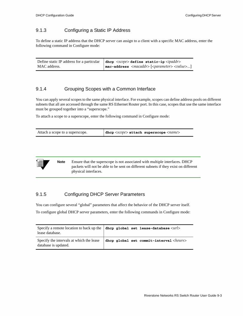
DHCP Configuration Guide Configuring DHCP Server
9.1.3 Configuring a Static IP Address
To define a static IP address that the DHCP server can assign to a client with a specific MAC address, enter the following command in Configure mode:
9.1.4 Grouping Scopes with a Common Interface
You can apply several scopes to the same physical interface. For example, scopes can define address pools on different subnets that all are accessed through the same RS Ethernet Router port. In this case, scopes that use the same interface must be grouped together into a “superscope.”
To attach a scope to a superscope, enter the following command in Configure mode:
Note Ensure that the superscope is not associated with multiple interfaces. DHCP packets will not be able to be sent on different subnets if they exist on different physical interfaces.
9.1.5 Configuring DHCP Server Parameters
You can configure several “global” parameters that affect the behavior of the DHCP server itself.
To configure global DHCP server parameters, enter the following commands in Configure mode:
Define static IP address for a particular MAC address.
dhcp <scope> define static-ip <ipaddr> mac-address <macaddr> [<parameter> <value>...]
Attach a scope to a superscope. dhcp <scope> attach superscope <name>
Specify a remote location to back up the lease database.
dhcp global set lease-database <url>
Specify the intervals at which the lease database is updated.
dhcp global set commit-interval <hours>
Riverstone Networks RS Switch Router User Guide 9-3

Configuring DHCP Server DHCP Configuration Guide
9.1.6 Updating the Lease Database
After each client transaction, the DHCP server does not immediately update the information in the lease database. Lease update information is stored in flash memory and flushed to the database at certain intervals. You can use the dhcp global set commit-interval command to specify this interval; the default is one hour.
To force the DHCP server to immediately update its lease database, enter the following command in Enable mode:
9.1.7 Monitoring the DHCP Server
To display information from the lease database:
To display the number of allocated bindings for the DHCP server and the maximum number allowed:
9.1.8 DHCP Server Configuration Examples
The following configuration describes DHCP server configuration for a simple network with just one interface on which DHCP service is enabled to provide both dynamic and static IP addresses.1. Create an IP VLAN called ‘client_vlan’.
2. Add all Fast Ethernet ports in the RS Ethernet Router to the VLAN ‘client_vlan’.
Force the server to update its lease database.
dhcp flush
Show lease database information. dhcp show binding [active|expired|static]
Show the number of allocated bindings for the DHCP server.
dhcp show num-clients
vlan create client_vlan ip
vlan add port et.*.* to client_vlan
9-4 Riverstone Networks RS Switch Router User Guide
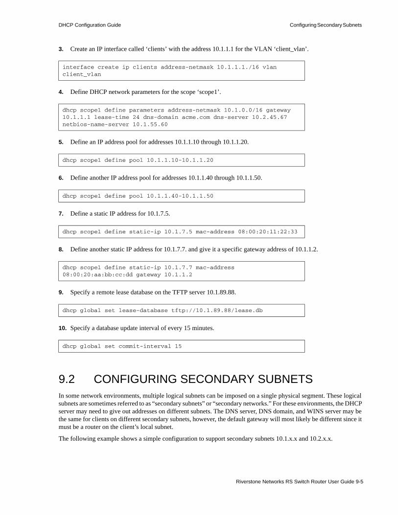
DHCP Configuration Guide Configuring Secondary Subnets
3. Create an IP interface called ‘clients’ with the address 10.1.1.1 for the VLAN ‘client_vlan’.
4. Define DHCP network parameters for the scope ‘scope1’.
5. Define an IP address pool for addresses 10.1.1.10 through 10.1.1.20.
6. Define another IP address pool for addresses 10.1.1.40 through 10.1.1.50.
7. Define a static IP address for 10.1.7.5.
8. Define another static IP address for 10.1.7.7. and give it a specific gateway address of 10.1.1.2.
9. Specify a remote lease database on the TFTP server 10.1.89.88.
10. Specify a database update interval of every 15 minutes.
9.2 CONFIGURING SECONDARY SUBNETSIn some network environments, multiple logical subnets can be imposed on a single physical segment. These logical subnets are sometimes referred to as “secondary subnets” or “secondary networks.” For these environments, the DHCP server may need to give out addresses on different subnets. The DNS server, DNS domain, and WINS server may be the same for clients on different secondary subnets, however, the default gateway will most likely be different since it must be a router on the client’s local subnet.
The following example shows a simple configuration to support secondary subnets 10.1.x.x and 10.2.x.x.
interface create ip clients address-netmask 10.1.1.1./16 vlan client_vlan
dhcp scope1 define parameters address-netmask 10.1.0.0/16 gateway 10.1.1.1 lease-time 24 dns-domain acme.com dns-server 10.2.45.67 netbios-name-server 10.1.55.60
dhcp scope1 define pool 10.1.1.10-10.1.1.20
dhcp scope1 define pool 10.1.1.40-10.1.1.50
dhcp scope1 define static-ip 10.1.7.5 mac-address 08:00:20:11:22:33
dhcp scope1 define static-ip 10.1.7.7 mac-address 08:00:20:aa:bb:cc:dd gateway 10.1.1.2
dhcp global set lease-database tftp://10.1.89.88/lease.db
dhcp global set commit-interval 15
Riverstone Networks RS Switch Router User Guide 9-5

Configuring Secondary Subnets DHCP Configuration Guide
1. Define the network parameters for ‘scope1’ with the default gateway 10.1.1.1.
2. Define the address pool for ‘scope1’.
3. Define the network parameters for ‘scope2’ with the default gateway 10.2.1.1.
4. Define the address pool for ‘scope2’.
5. Create a superscope ‘super1’ that includes ‘scope1’.
6. Include ‘scope2’ in the superscope ‘super1’.
Since there are multiple pools of IP addresses, the pool associated with ‘scope1’ is used first since ‘scope1’ is applied to the interface before ‘scope2’. Clients that are given an address from ‘scope1’ will also be given parameters from ‘scope1,’ which includes the default gateway 10.1.1.1 that resides on the 10.1.x.x subnet. When all the addresses for ‘scope1’ are assigned, the server will start giving out addresses from ‘scope2’ which will include the default gateway parameter 10.2.1.1 on subnet 10.2.x.x.
9.2.1 Secondary Subnets and Directly-Connected Clients
A directly-connected client is a system that resides on the same physical network as the DHCP server and does not have to go through a router or relay agent to communicate with the server. If you configure the DHCP server on the RS Ethernet Router to service directly-connected clients on a secondary subnet, you must configure the secondary subnet using the interface add ip command. The interface add ip command configures a secondary address for an interface that was previously created with the interface create ip command.
The following example shows a simple configuration to support directly-connected clients on a secondary subnet.1. Create an interface ‘clients’ with the primary address 10.1.1.1.
dhcp scope1 define parameters address-netmask 10.1.0.0/16 gateway 10.1.1.1 dns-domain acme.com dns-server 10.1.44.55
dhcp scope1 define pool 10.1.1.10-10.1.1.20
dhcp scope2 define parameters address-netmask 10.2.0.0/16 gateway 10.2.1.1 dns-domain acme.com dns-server 10.1.77.88
dhcp scope2 define pool 10.2.1.40-10.2.1.50
dhcp scope1 attach superscope super1
dhcp scope2 attach superscope super1
interface create ip clients address-mask 10.1.1.1/16 port et.1.1
9-6 Riverstone Networks RS Switch Router User Guide

DHCP Configuration Guide Interacting with Relay Agents
2. Assign a secondary address 10.2.1.1 to the interface ‘clients’.
3. Define the network parameters for ‘scope1’ with the default gateway 10.1.1.1.
4. Define the address pool for ‘scope1’.
5. Define the network parameters for ‘scope2’ with the default gateway 10.2.1.1.
6. Define the address pool for ‘scope2’.
7. Create a superscope ‘super1’ that includes ‘scope1’.
8. Include ‘scope2’ in the superscope ‘super1’.
For clients on the secondary subnet, the default gateway is 10.2.1.1, which is also the secondary address for the interface ‘clients’.
9.3 INTERACTING WITH RELAY AGENTSFor clients that are not directly connected to the DHCP server, a relay agent (typically a router) is needed to communicate between the client and the server. The relay agent is usually only needed during the initial leasing of an IP address. Once the client obtains an IP address and can connect to the network, the renewal of the lease is performed between the client and server without the help of the relay agent.
The default gateway for the client must be capable of reaching the RS Ethernet Router’s DHCP server. The RS Ethernet Router must also be capable of reaching the client’s network. The route must be configured (with static routes, for example) or learned (with RIP or OSPF, for example) so that the DHCP server can reach the client.
The following example shows a simple configuration to support clients across a relay agent.
interface add ip clients address-mask 10.2.1.1/16
dhcp scope1 define parameters address-netmask 10.1.0.0/16 gateway 10.1.1.1 dns-domain acme.com dns-server 10.1.44.55
dhcp scope1 define pool 10.1.1.10-10.1.1.20
dhcp scope2 define parameters address-netmask 10.2.0.0/16 gateway 10.2.1.1 dns-domain acme.com dns-server 10.1.77.88
dhcp scope2 define pool 10.2.1.40-10.2.1.50
dhcp scope1 attach superscope super1
dhcp scope2 attach superscope super1
Riverstone Networks RS Switch Router User Guide 9-7
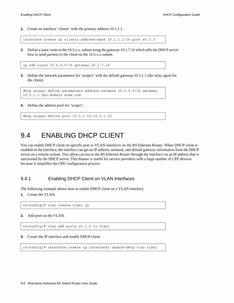
Enabling DHCP Client DHCP Configuration Guide
1. Create an interface ‘clients’ with the primary address 10.1.1.1.
2. Define a static route to the 10.5.x.x. subnet using the gateway 10.1.7.10 which tells the DHCP server how to send packets to the client on the 10.5.x.x subnet.
3. Define the network parameters for ‘scope1’ with the default gateway 10.5.1.1 (the relay agent for the client).
4. Define the address pool for ‘scope1’.
9.4 ENABLING DHCP CLIENTYou can enable DHCP client on specific port or VLAN interfaces on the RS Ethernet Router. When DHCP client is enabled on the interface, the interface can get an IP address, netmask, and default gateway information from the DHCP server on a remote system. This allows access to the RS Ethernet Router through the interface via an IP address that is sanctioned by the DHCP server. This feature is useful for service providers with a large number of CPE devices because it simplifies the CPE configuration process.
9.4.1 Enabling DHCP Client on VLAN Interfaces
The following example shows how to enable DHCP client on a VLAN interface.1. Create the VLAN.
2. Add ports to the VLAN.
3. Create the IP interface and enable DHCP client.
interface create ip clients address-mask 10.1.1.1/16 port et.3.3
ip add route 10.5.0.0/16 gateway 10.1.7.10
dhcp scope1 define parameters address-netmask 10.5.0.0/16 gateway 10.5.1.1 dns-domain acme.com
dhcp scope1 define pool 10.5.1.10-10.5.1.20
rs(config)# vlan create vlan1 ip
rs(config)# vlan add ports et.1.5 to vlan1
rs(config)# interface create ip interface1 enable-dhcp vlan vlan1
9-8 Riverstone Networks RS Switch Router User Guide
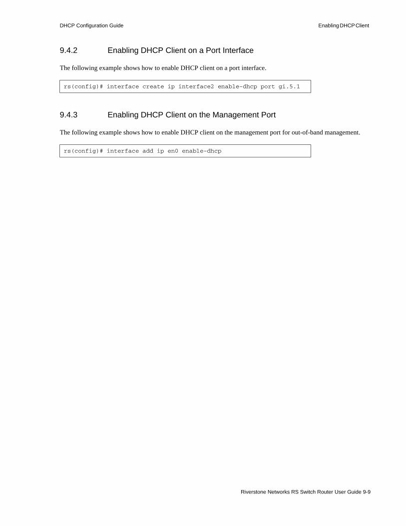
DHCP Configuration Guide Enabling DHCP Client
9.4.2 Enabling DHCP Client on a Port Interface
The following example shows how to enable DHCP client on a port interface.
9.4.3 Enabling DHCP Client on the Management Port
The following example shows how to enable DHCP client on the management port for out-of-band management.
rs(config)# interface create ip interface2 enable-dhcp port gi.5.1
rs(config)# interface add ip en0 enable-dhcp
Riverstone Networks RS Switch Router User Guide 9-9

Enabling DHCP Client DHCP Configuration Guide
9-10 Riverstone Networks RS Switch Router User Guide

10 IP ROUTING CONFIGURATION GUIDE
The RS Ethernet Router supports standards-based TCP, UDP, and IP. This chapter describes how to configure IP interfaces and general non-protocol-specific routing parameters.
10.1 IP ROUTING PROTOCOLSThe RS Ethernet Router supports standards-based unicast and multicast routing. Unicast routing protocol support includes Interior Gateway Protocols and Exterior Gateway Protocols. Multicast routing protocols are used to determine how multicast data is transferred in a routed environment.
10.1.1 Unicast Routing Protocols
Interior Gateway Protocols are used for routing networks that are within an “autonomous system,” a network of relatively limited size. All IP interior gateway protocols must be specified with a list of associated networks before routing activities can begin. A routing process listens to updates from other routers on these networks and broadcasts its own routing information on those same networks. The RS Ethernet Router supports the following Interior Gateway Protocols:• Routing Information Protocol (RIP) Version 1, 2 (RFC 1058, 1723). Configuring RIP for the RS
Ethernet Router is described in Chapter 12, "RIP Configuration Guide."• Open Shortest Path First (OSPF) Version 2 (RFC 1583). Configuring OSPF for the RS Ethernet
Router is described in Chapter 13, "OSPF Configuration Guide."
• Intermediate System-Intermediate System (IS-IS) (RFC 1142). Configuring IS-IS for the RS Ethernet Router is described in Chapter 14, "IS-IS Configuration Guide.".
Exterior Gateway Protocols are used to transfer information between different “autonomous systems”. The RS Ethernet Router supports the following Exterior Gateway Protocol:• Border Gateway Protocol (BGP) Version 3, 4 (RFC 1267, 1771). Configuring BGP for the RS
Ethernet Router is described in Chapter 16, "BGP Configuration Guide."
Note Riverstone’s implementation of the above routing protocols is based on GateD. In these routing protocols, a newer issuance of a command overwrites all existing version(s) of the same command, even if they are not negated from the configuration.
Riverstone Networks RS Switch Router User Guide 10-1

Configuring IP Interfaces and Parameters IP Routing Configuration Guide
10.1.2 Multicast Routing Protocols
IP multicasting allows a host to send traffic to a subset of all hosts. These hosts subscribe to group membership, thus notifying the RS Ethernet Router of participation in a multicast transmission.
Multicast routing protocols are used to determine which routers have directly attached hosts, as specified by IGMP, that have membership to a multicast session. Once host memberships are determined, routers use multicast routing protocols, such as DVMRP, to forward multicast traffic between routers.
The RS Ethernet Router supports the following multicast routing protocols:• Distance Vector Multicast Routing Protocol (DVMRP) RFC 1075• Internet Group Management Protocol (IGMP) as described in RFC 2236
The RS Ethernet Router also supports the latest DVMRP Version 3.0 draft specification, which includes mtrace, Generation ID and Pruning/Grafting. Configuring multicast routing for the RS Ethernet Router is described in Chapter 20, "Routing Policy Configuration."
10.2 CONFIGURING IP INTERFACES AND PARAMETERS
You can configure an IP interface to a single port or to a VLAN. This section provides an overview of configuring IP interfaces.
Interfaces on the RS Ethernet Router are logical interfaces. Therefore, you can associate an interface with a single port or with multiple ports:• To associate an interface with a single port, use the port option with the interface create
command. • To associate an interface with multiple ports, first create an IP VLAN and add ports to it, then use
the vlan option with the interface create command.
The interface create ip command creates and configures an IP interface. Configuration of an IP interface can include information such as the interface’s name, IP address, netmask, broadcast address, and so on. You can also create an interface in a disabled (down) state instead of the default enabled (up) state.
Note You must use either the port option or the vlan option with the interface create command.
10.2.1 Configuring IP Interfaces to Ports
You can configure an IP interface directly to a physical port. Each port can be assigned multiple IP addresses representing multiple subnets connected to the physical port. For example, to assign an IP interface ‘RED’ to physical port et.3.4, enter the following:
rs(config)# interface create ip RED address-netmask 10.50.0.0/255.255.0.0 port et.3.4
10-2 Riverstone Networks RS Switch Router User Guide

IP Routing Configuration Guide Configuring IP Interfaces and Parameters
To configure a secondary address of 10.23.4.36 with a 24-bit netmask (255.255.255.0) on the IP interface int4:
10.2.2 Configuring IP Interfaces for a VLAN
You can configure one IP interface per VLAN. Once an IP interface has been assigned to a VLAN, you can add a secondary IP address to the VLAN. To create a VLAN called IP3, add ports et.3.1 through et.3.4 to the VLAN, then create an IP interface on the VLAN:
To configure a secondary address of 10.23.4.36 with a 24-bit netmask (255.255.255.0) on the IP interface int4:
10.2.3 Specifying Ethernet Encapsulation Method
The Riverstone RS Switch Router supports two encapsulation types for IP. Use the interface create ip command to configure one of the following encapsulation types on a per-interface basis:• Ethernet II: The standard ARPA Ethernet Version 2.0 encapsulation, which uses a 16-bit protocol
type code (the default encapsulation method).• 802.3 SNAP: SNAP IEEE 802.3 encapsulation, in which the type code becomes the frame length for
the IEEE 802.2 LLC encapsulation (destination and source Service Access Points, and a control byte).
10.2.4 Unnumbered Interfaces
The Riverstone RS Switch Router allows you to create unnumbered IP interfaces. In the case where an interface is one end of a point-to-point connection, it is not necessary to associate a particular IP address to that interface. This is because in a point-to-point connection, packet traffic is going to the other end (or peer) only, and are not routed to any other destination. Therefore, assigning a unique IP address to that interface wastes addresses within the address pool allocated by the netmask.
Unnumbered interfaces allows you to use another interface’s IP address instead. In essence, you are configuring the unnumbered interface to borrow the IP address from another interface. This way, the unnumbered interface is not using a unique IP address only for itself, thus you are conserving addresses within the address pool.
To configure the unnumbered interface ‘int3’ and borrow the IP address from IP interface ‘int1’:
rs(config)# interface add ip int4 address-netmask 10.23.4.36/24
rs(config)# vlan create IP3 ip
rs(config)# vlan add ports et.3.1-4 to IP3
rs(config)# interface create ip int3 address-netmask 10.20.3.42/24 vlan IP3
rs(config)# interface add ip int3 address-netmask 10.23.4.36/24 vlan IP3
rs(config)# interface create ip int3 unnumbered int1
Riverstone Networks RS Switch Router User Guide 10-3
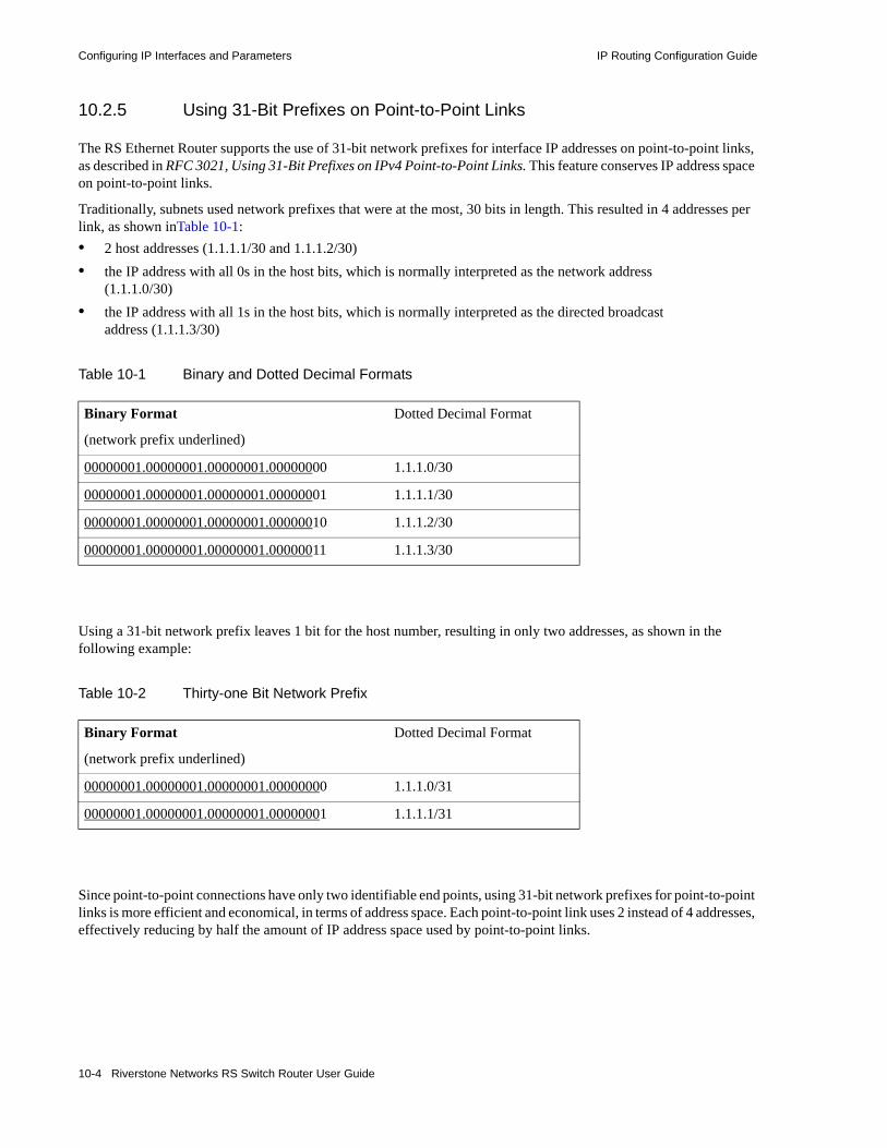
Configuring IP Interfaces and Parameters IP Routing Configuration Guide
10.2.5 Using 31-Bit Prefixes on Point-to-Point Links
The RS Ethernet Router supports the use of 31-bit network prefixes for interface IP addresses on point-to-point links, as described in RFC 3021, Using 31-Bit Prefixes on IPv4 Point-to-Point Links. This feature conserves IP address space on point-to-point links.
Traditionally, subnets used network prefixes that were at the most, 30 bits in length. This resulted in 4 addresses per link, as shown inTable 10-1: • 2 host addresses (1.1.1.1/30 and 1.1.1.2/30)• the IP address with all 0s in the host bits, which is normally interpreted as the network address
(1.1.1.0/30)• the IP address with all 1s in the host bits, which is normally interpreted as the directed broadcast
address (1.1.1.3/30)
Using a 31-bit network prefix leaves 1 bit for the host number, resulting in only two addresses, as shown in the following example:
Since point-to-point connections have only two identifiable end points, using 31-bit network prefixes for point-to-point links is more efficient and economical, in terms of address space. Each point-to-point link uses 2 instead of 4 addresses, effectively reducing by half the amount of IP address space used by point-to-point links.
Table 10-1 Binary and Dotted Decimal Formats
Binary Format
(network prefix underlined)
Dotted Decimal Format
00000001.00000001.00000001.00000000 1.1.1.0/30
00000001.00000001.00000001.00000001 1.1.1.1/30
00000001.00000001.00000001.00000010 1.1.1.2/30
00000001.00000001.00000001.00000011 1.1.1.3/30
Table 10-2 Thirty-one Bit Network Prefix
Binary Format
(network prefix underlined)
Dotted Decimal Format
00000001.00000001.00000001.00000000 1.1.1.0/31
00000001.00000001.00000001.00000001 1.1.1.1/31
10-4 Riverstone Networks RS Switch Router User Guide

IP Routing Configuration Guide Configuring IP Interfaces and Parameters
The following example configures an interface on one end of a point-to-point link. Note that the IP address has a 31-bit network prefix.
You can view the interface information, as shown in the following example:.
Note the peer addresses and broadcast address of the interface. Using 31-bit network prefixes leaves only two possible values for the host bit: 0 and 1, which are traditionally used for the network and broadcast address respectively. On point-to-point links with 31-bit network prefixes, the RS Ethernet Router will interpret these as host addresses instead. In addition, because the directed broadcast address is used as a host address, only limited broadcast (255.255.255.255) will be allowed on 31-bit IP network prefixes.
Note On the RS Ethernet Router, you can configure an IP interface to a single port or to a VLAN. You can use the 31-bit prefix IP address on an interface configured for a single port only. You cannot use this feature for an interface configured on a VLAN.
rs1(config)# interface create ip eth1 address-netmask 1.1.1.0/31 port et.4.13rs1(config)# save active%VLAN-I-ADDSUCCESS, 1 port et.4.13 successfully added to VLAN SYS_L3_eth1%INTERFACE-I-CREATEDIF, Interface eth1 was successfully created.
rs1# interface show ip eth1Interface eth1: Admin State: up Operational State: lower layer down Capabilities: <BROADCAST,SIMPLEX,MULTICAST> Configuration: VLAN: SYS_L3_eth1 Ports: et.4.13 MTU: 1500 MAC Encapsulation: ETHERNET_II MAC Address: 00:E0:63:04:08:C0 IP Address: 1.1.1.0/31 --> 1.1.1.1 (broadcast: 255.255.255.255)
Riverstone Networks RS Switch Router User Guide 10-5

Configuring Jumbo Frames IP Routing Configuration Guide
10.3 CONFIGURING JUMBO FRAMESCertain RS Ethernet Router line cards support jumbo frames (frames larger than the standard Ethernet frame size of 1518 bytes).
To transmit frames of up to 65535 octets, you increase the maximum transmission unit (MTU) size from the default of 1522. You must set the MTU at the port level with the port set mtu command. You can also set the MTU at the IP interface level; if you set the MTU at the IP interface level, the MTU size must be less than the size configured for each port in the interface. Note that the interface MTU only determines the size of the packets that are forwarded in software.
In the following example, the ports gi.3.1 through gi.3.8 are configured with an MTU size of 65535 octets. Ports gi.3.1 through gi.3.4 are configured to be part of the interface ‘int3,’ with an MTU size of 50000 octets.
If you do not set the MTU at the interface level, the actual MTU of the interface is the lowest MTU configured for a port in the interface. In the following example, port gi.3.1 is configured with an MTU size of 50022 octets while ports gi.3.2-8 are configured with an MTU size of 65535 octets. The interface MTU will be 50000 octets (50022 octets minus 22 octets of link layer overhead).
10.4 CONFIGURING ADDRESS RESOLUTION PROTOCOL (ARP)
The RS Ethernet Router allows you to configure Address Resolution Protocol (ARP) table entries and parameters. ARP is used to associate IP addresses with media or MAC addresses. Taking an IP address as input, ARP determines the associated MAC address. Once a media or MAC address is determined, the IP address/media address association is stored in an ARP cache for rapid retrieval. Then the IP datagram is encapsulated in a link-layer frame and sent over the network.
rs(config)# port set gi.3.1-8 mtu 65535
rs(config)# vlan create JUMBO1 ip
rs(config)# vlan add ports gi.3.1-4 to JUMBO1
rs(config)# interface create ip int3 mtu 50000 address-netmask 10.20.3.42/24 vlan JUMBO1
rs(config)# port set gi.3.1 mtu 50022
rs(config)# port set gi.3.2-8 mtu 65535
rs(config)# vlan create JUMBO1 ip
rs(config)# vlan add ports gi.3.1-4 to JUMBO1
rs(config)# interface create ip int3 address-netmask 10.20.3.42/24 vlan JUMBO1
10-6 Riverstone Networks RS Switch Router User Guide

IP Routing Configuration Guide Configuring Address Resolution Protocol (ARP)
10.4.1 Configuring ARP Cache Entries
To create an ARP entry for the IP address 10.8.1.2 at port et.4.7 for 15 seconds:
To create a permanent ARP entry for the host nfs2 at port et.3.1:
To remove the ARP entry for the host 10.8.1.2 from the ARP table:.
To clear the entire ARP table.
If the Startup configuration file contains arp add commands, the Control Module re-adds the ARP entries even if you have cleared them using the arp clear command. To permanently remove an ARP entry, use the negate command or no command to remove the entry.
10.4.2 Unresolved MAC Addresses for ARP Entries
When the RS Ethernet Router receives a packet for a host whose MAC address it has not resolved, the RS Ethernet Router tries to resolve the next-hop MAC address by sending ARP requests. Five requests are sent initially for each host, one every second.
You can configure the RS Ethernet Router to drop packets for hosts whose MAC addresses the RS Ethernet Router has been unable to resolve. To enable dropping of packets for hosts with unresolved MAC addresses:
When you enable packets to be dropped for hosts with unresolved MAC addresses, the RS Ethernet Router will still attempt to periodically resolve these MAC addresses. By default, the RS Ethernet Router sends ARP requests at 5-second intervals to try to resolve dropped entries.
To change the interval for sending ARP requests for unresolved entries to 45 seconds:
To change the number of unresolved entries that the RS Ethernet Router attempts to resolve to 75:
rs# arp add 10.8.1.2 mac-addr 08:00:20:a2:f3:49 exit-port et.4.7 keep-time 15
rs(config)# arp add nfs2 mac-addr 080020:13a09f exit-port et.3.1
rs# arp clear 10.8.1.2
rs# arp clear all
rs# arp set drop-unresolved enabled
rs# arp set unresolve-timer 45
rs# arp set unresolve-threshold 75
Riverstone Networks RS Switch Router User Guide 10-7

Configuring Address Resolution Protocol (ARP) IP Routing Configuration Guide
10.4.3 Configuring Proxy ARP
The RS Ethernet Router can be configured for proxy ARP. The RS Ethernet Router uses proxy ARP (as defined in RFC 1027) to help hosts with no knowledge of routing determine the MAC address of hosts on other networks or subnets. Through proxy ARP, the RS Ethernet Router will respond to ARP requests from a host with a ARP reply packet containing the RS Ethernet Router MAC address. Proxy ARP is enabled by default on the RS Ethernet Router. The following example disables proxy ARP on all interfaces:
10.4.4 Using DHCP to Install ARP Entries
If you are using a Dynamic Host Configuration Protocol (DHCP) server to provide IP addresses to user systems, you can also use DHCP to install entries in the Address Resolution Protocol (ARP) table on the RS Ethernet Router. Using DHCP to install ARP entries helps prevent spoofing of ARP requests by unauthorized users.
To use DHCP to install ARP entries, specify the snoop-l2-l3-info parameter with the ip helper-address command. This parameter causes the RS Ethernet Router to examine DHCP acknowledgement packets sent from the DHCP server to the client on the specified interface. The information in the DHCP acknowledgement packet is used to resolve MAC addresses (layer 2) to IP addresses (layer 3) for the ARP entries. Note that when DHCP is used to install ARP entries, client ARP requests that contain different MAC addresses than those in the DHCP-installed entries are dropped. You can still use all arp and rarpd commands, and proxy ARP will operate as usual.
The following example command causes DHCP packets on the interface ‘int1’ from the DHCP server at 10.1.4.5 to be examined for ARP information:
As shown in the above example, you do not need to specify the DHCP port number as an option; only DHCP packets are examined. The age-out of the DHCP client’s ARP entry is set to the DHCP lease period for that client. DHCP renewal requests and acknowledgements are also examined. Thus, if an ARP entry already exists for a client, the age-out is replaced with the new DHCP lease period.
Note If the RS Ethernet Router is rebooted while this feature is enabled, ARP entries are lost but DHCP clients will still have valid leases. Until the DHCP clients renew and the RS Ethernet Router is again able to examine acknowledgements from the server, unicast traffic from the clients cannot be returned. Therefore, Riverstone recommends that you only use this feature on routers with redundant CMs installed, or where DHCP clients have very short renewal intervals.
rs(config)# ip disable-proxy-arp interface all
rs(config)# ip helper-address interface int1 10.1.4.5 snoop-l2-l3-info
10-8 Riverstone Networks RS Switch Router User Guide

IP Routing Configuration Guide Configuring Reverse Address Resolution Protocol (RARP)
10.5 CONFIGURING REVERSE ADDRESS RESOLUTION PROTOCOL (RARP)
Reverse Address Resolution Protocol (RARP) works exactly the opposite of ARP. Taking a MAC address as input, RARP determines the associated IP address. RARP is useful for X-terminals and diskless workstations that may not have an IP address when they boot. They can submit their MAC address to a RARP server on the RS Ethernet Router, which returns an IP address.
Configuring RARP on the RS Ethernet Router consists of two steps:
1. Letting the RS Ethernet Router know which IP interfaces to respond to
2. Defining the mappings of MAC addresses to IP addresses
10.5.1 Specifying IP Interfaces for RARP
The rarpd set interface command allows you to specify which interfaces the RS Ethernet Router’s RARP server responds to when sent RARP requests. You can specify individual interfaces or all interfaces. To cause the RS Ethernet Router’s RARP server to respond to RARP requests from interface int1:
10.5.2 Defining MAC-to-IP Address Mappings
The rarpd add command allows you to map a MAC address to an IP address for use with RARP. When a host makes a RARP request on the RS Ethernet Router, and its MAC address has been mapped to an IP address with the rarp add command, the RARP server on the RS Ethernet Router responds with the IP address that corresponds to the host’s MAC address. To map MAC address 00:C0:4F:65:18:E0 to IP address 10.10.10.10:
There is no limit to the number of address mappings you can configure.
Optionally, you can create a list of mappings with a text editor and then use TFTP to upload the text file to the RS Ethernet Router. The format of the text file must be as follows:
Then place the text file on a TFTP server that the RS Ethernet Router can access and enter the following command in Enable mode:
rs(config)# rarpd set interface int1
rs(config)# rarpd add hardware-address 00:C0:4F:65:18:E0 ip-address 10.10.10.10
MAC-address1 IP-address1MAC-address2 IP-address2...MAC-addressn IP-addressn
rs# copy tftp-server to ethersTFTP server? <IPaddr-of-TFTP-server>Source filename? <filename>
Riverstone Networks RS Switch Router User Guide 10-9
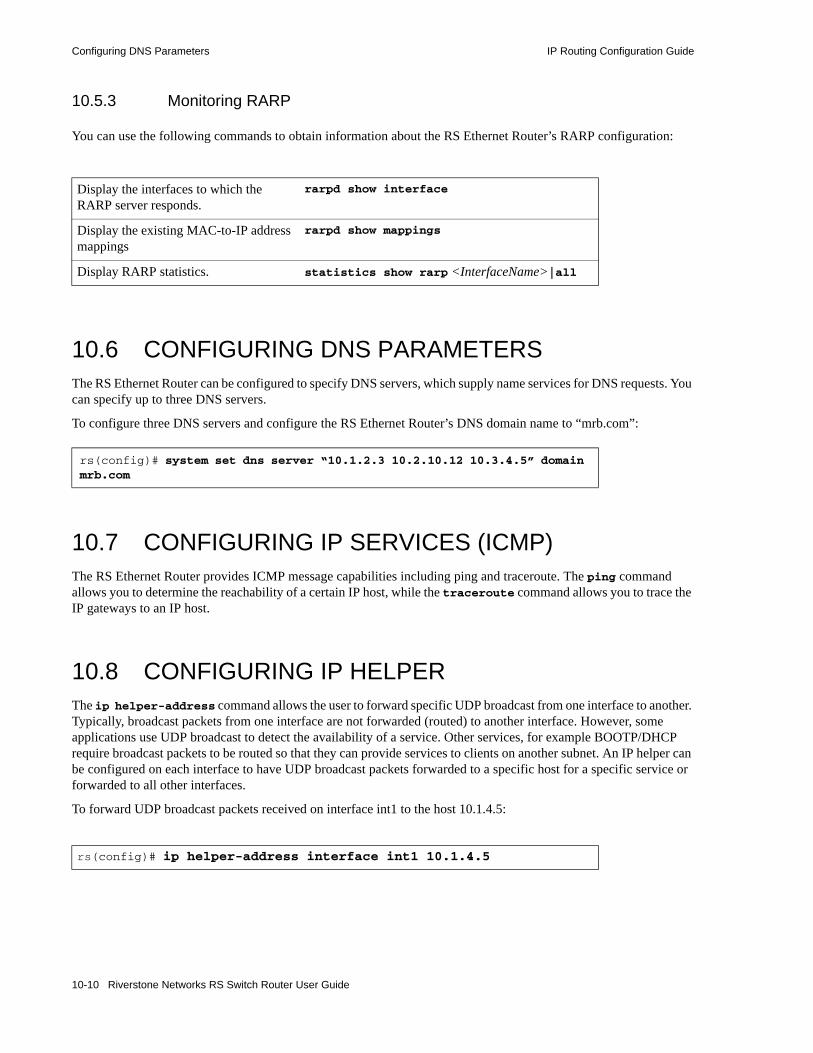
Configuring DNS Parameters IP Routing Configuration Guide
10.5.3 Monitoring RARP
You can use the following commands to obtain information about the RS Ethernet Router’s RARP configuration:
10.6 CONFIGURING DNS PARAMETERSThe RS Ethernet Router can be configured to specify DNS servers, which supply name services for DNS requests. You can specify up to three DNS servers.
To configure three DNS servers and configure the RS Ethernet Router’s DNS domain name to “mrb.com”:
10.7 CONFIGURING IP SERVICES (ICMP)The RS Ethernet Router provides ICMP message capabilities including ping and traceroute. The ping command allows you to determine the reachability of a certain IP host, while the traceroute command allows you to trace the IP gateways to an IP host.
10.8 CONFIGURING IP HELPERThe ip helper-address command allows the user to forward specific UDP broadcast from one interface to another. Typically, broadcast packets from one interface are not forwarded (routed) to another interface. However, some applications use UDP broadcast to detect the availability of a service. Other services, for example BOOTP/DHCP require broadcast packets to be routed so that they can provide services to clients on another subnet. An IP helper can be configured on each interface to have UDP broadcast packets forwarded to a specific host for a specific service or forwarded to all other interfaces.
To forward UDP broadcast packets received on interface int1 to the host 10.1.4.5:
Display the interfaces to which the RARP server responds.
rarpd show interface
Display the existing MAC-to-IP address mappings
rarpd show mappings
Display RARP statistics. statistics show rarp <InterfaceName>|all
rs(config)# system set dns server “10.1.2.3 10.2.10.12 10.3.4.5” domain mrb.com
rs(config)# ip helper-address interface int1 10.1.4.5
10-10 Riverstone Networks RS Switch Router User Guide

IP Routing Configuration Guide Configuring Direct Broadcast
By default, the DHCP relay agent uses the outgoing interface IP address as the source address when sending a request to a DHCP server. However, if there is a firewall in between the server and the relay agent, the firewall may block the packet because the outgoing address is not a private IP address. To prevent this, you can use the use-relay-ip parameter to configure the relay agent to use the IP address of the interface on which the DHCP request was received instead of using the outgoing interface IP address as follows:
10.9 CONFIGURING DIRECT BROADCASTDirected broadcast packets are network or subnet broadcast packets which are sent to a router to be forwarded as broadcast packets. They can be misused to create Denial Of Service attacks. The RS Ethernet Router protects against this possibility by not forwarding directed broadcasts, by default. To enable the forwarding of directed broadcasts, use the ip enable directed-broadcast command.
You can configure the RS Ethernet Router to forward all directed broadcast traffic from the local subnet to a specified IP address or all associated IP addresses. This is a more efficient method than defining only one local interface and remote IP address destination at a time with the ip-helper command when you are forwarding traffic from more than one interface in the local subnet to a remote destination IP address.
To enable directed broadcast forwarding on the “int4” network interface:
10.10 CONFIGURING DENIAL OF SERVICE (DOS) PROTECTION FEATURES
By default, the RS Ethernet Router installs flows in the hardware so that packets sent as directed broadcasts are dropped in hardware if directed broadcast is not enabled on the interface where the packet is received. You can disable this feature, causing directed broadcast packets to be processed on the RS Ethernet Router even if directed broadcast is not enabled on the interface receiving the packet.
Similarly, the RS Ethernet Router installs flows to drop packets destined for the RS Ethernet Router for which service is not provided by the RS Ethernet Router. This prevents packets for unknown services from slowing the CPU. You can disable this behavior, causing these packets to be processed by the CPU.
Enter the following to cause directed broadcast packets to be processed on the RS Ethernet Router, even if directed broadcast is not enabled on the interface receiving the packet:
Enter the following to allow packets destined for the RS Ethernet Router (that do not have a service defined for them on the RS Ethernet Router), to be processed by the RS Ethernet Router’s CPU:
rs(config)# ip helper-address interface int4 10.1.4.6 use-relay-ip
rs(config)# ip enable directed-broadcast interface int4
rs(config)# ip dos disable directed-broadcast-protection
rs(config)# ip dos disable port-attack-protection
Riverstone Networks RS Switch Router User Guide 10-11

Configuring Denial of Service (DOS) Protection Features IP Routing Configuration Guide
Denial of Service (DOS) attacks can take the form of flooding packets of various types over the RS Ethernet Router. Because of this, the RS Ethernet Router provides the ability to rate limit the traffic on specific ports as well as rate limit specific packet types. Table 10-3 lists those objects on which the RS Ethernet Router allows rate limiting:
Table 10-3 Rate limited objects to prevent DOS attacks
Parameter Value Meaning
bgp <num> <num> is the rate limit in bps. The range of values for this field is 3000 to 10000000. The default is no rate limiting.
icmp <num> <num> is the rate limit in bps. The range of values for this field is 3000 to 10000000. This value is required.
igmp <num> <num> is the rate limit in bps. The range of values for this field is 3000 to 10000000. This value is required.
ospf <num> <num> is the rate limit in bps. The range of values for this field is 3000 to 10000000. The default is no rate limiting.
port <port-list> Specifies a port or list of ports on which to enable rate limiting.
l2-miss <num> Specifies the traffic to rate limit as layer-2 address misses. Numerical value is between 3000 and 1000000000.
l3-miss <num> Specifies the traffic to rate limit as layer-3 address misses. Numerical value is between 3000 and 1000000000.
tcp-sfr <num> Specifies the traffic to rate limit as TCP three-way handshaking traffic. Numerical value is between 3000 and 1000000000.
ttl-expired <num> Specifies the traffic to rate limit as packets with expired Time to Live counts. Numerical value is between 3000 and 1000000000.
unknown-route <num> Specifies the traffic to rate limit as packets containing unknown routes. Numerical value is between 3000 and 1000000000.
rip <num> <num> is the rate limit in bps. The range of values for this field is 30000 to 10000000.
vrrp <num> <num> is the rate limit in bps. The range of values for this field is 3000 to 10000000.
ldp-hello <num> <num> is the rate limit in bps. The range of values for this field is 3000 to 10000000.
ldp-session <num> <num> is the rate limit in bps. The range of values for this field is 3000 to 10000000.
rsvp <num> <num> is the rate limit in bps. The range of values for this field is 3000 to 10000000.
snmp <num> <num> is the rate limit in bps. The range of values for this field is 3000 to 10000000.
10-12 Riverstone Networks RS Switch Router User Guide

IP Routing Configuration Guide Monitoring IP Parameters
For example, to rate limit TCP-SFR traffic to 10000 bits-per-second, which comes through port gi.4.1, enter the following:
Rate limiting not only restricts traffic through the switch-fabric, but can also protects the RS Ethernet Router’ CPU from DOS attacks. Notice in Table 10-3 that l2-misses, l3-misses, and unknown-routes are all traffic that would normally be bound for the CPU. However, rate limiting can keep these objects from flooding the CPU.
10.11 MONITORING IP PARAMETERSThe RS Ethernet Router provides display of IP statistics and configurations contained in the routing table. Information displayed provides routing and performance information.
The ip show commands display IP information, such as routing tables, TCP/UDP connections, and IP interface configuration, on the RS Ethernet Router. The following example displays all established connections and services of the RS Ethernet Router.
ssh <num> <num> is the rate limit in bps. The range of values for this field is 3000 to 10000000.
telnet <num> <num> is the rate limit in bps. The range of values for this field is 3000 to 10000000.
rs(config)# ip dos rate-limit port gi.4.1 tcp-sfr 10000
rs# ip show connectionsActive Internet connections (including servers)Proto Recv-Q Send-Q Local Address Foreign Address (state)tcp 0 0 *:gated-gii *:* LISTENtcp 0 0 *:http *:* LISTENtcp 0 0 *:telnet *:* LISTENudp 0 0 127.0.0.1:1025 127.0.0.1:162udp 0 0 *:snmp *:*udp 0 0 *:snmp-trap *:*udp 0 0 *:bootp-relay *:*udp 0 0 *:route *:*udp 0 0 *:* *:*
Table 10-3 Rate limited objects to prevent DOS attacks
Parameter Value Meaning
Riverstone Networks RS Switch Router User Guide 10-13

Monitoring IP Parameters IP Routing Configuration Guide
The following example displays the contents of the routing table. It shows that some of the route entries are for locally connected interfaces (“directly connected”), while some of the other routes are learned from RIP.
To display additional IP information, enter the following command in Enable mode:
rs# ip show routesDestination Gateway Owner Netif----------- ------- ----- -----10.1.0.0/16 50.1.1.2 RIP to-linux210.2.0.0/16 50.1.1.2 RIP to-linux210.3.0.0/16 50.1.1.2 RIP to-linux210.4.0.0/16 50.1.1.2 RIP to-linux214.3.2.1 61.1.4.32 Static int6121.0.0.0/8 50.1.1.2 RIP to-linux230.1.0.0/16 directly connected - to-goya50.1.0.0/16 directly connected - to-linux261.1.0.0/16 directly connected - int6162.1.0.0/16 50.1.1.2 RIP to-linux268.1.0.0/16 directly connected - int6869.1.0.0/16 50.1.1.2 RIP to-linux2127.0.0.0/8 127.0.0.1 Static lo127.0.0.1 127.0.0.1 - lo210.11.99.0/24 directly connected - int41
Show ARP table entries. arp show all
Show IP interface configuration. interface show ip
Show DNS parameters. system show dns
10-14 Riverstone Networks RS Switch Router User Guide

IP Routing Configuration Guide L3 Forwarding Modes
10.12 L3 FORWARDING MODESWhen an RS Ethernet Router port receives a packet for routing, it matches the packet’s flow against those found in the L3 flow table. • If a match is found, the packet is forwarded to the exit port and transmitted. • If a match is not found, the packet is forwarded to the CPU and the destination is looked up in the
Forwarding Information Base (FIB).- If the destination is found in the FIB, then the packet is forwarded to the next hop. In addition,
the CPU updates the L3 flow table so subsequent packets with the same flow are automatically forwarded without being sent to the CPU.
- If the destination is not found in the FIB, the RS Ethernet Router drops the packet.
A port’s forwarding mode determines which fields make up a packet’s flow. Each forwarding mode defines a flow differently. The RS Ethernet Router ports can operate in any one of the following forwarding modes:• application-based forwarding (default)• hardware routing table (HRT)• destination-based forwarding• host-flow-based forwarding• custom forwarding
10.12.1 Configuring Forwarding Modes
The RS Ethernet Router operates in application-based forwarding mode by default. Except for HRT, which is configured by slot, you can set forwarding modes by port. To see which mode a port is in, use the ip show mode command, as shown in the following example:
Riverstone Networks RS Switch Router User Guide 10-15

L3 Forwarding Modes IP Routing Configuration Guide
rs1# ip show mode port all-portsPort Mode---- ----so.3.1 Flow (Default) + HRTso.3.2 Flow (Default)et.4.1 Destet.4.2 Flow (Default)et.4.3 Flow (Default)et.4.4 Flow (Default)et.4.5 Hostet.4.6 Flow (Default)et.4.7 Flow (Default)et.4.8 Flow (Default)et.4.9 Flow (Default)et.4.10 Flow (Default)et.4.11 Flow (Default)et.4.12 Flow (Default)et.4.13 Flow (Default)et.4.14 Flow (Default)et.4.15 Flow (Default)et.4.16 Flow (Default)gi.9.1 Flow (Default) + HRTgi.9.2 Flow (Default) + HRT
10-16 Riverstone Networks RS Switch Router User Guide

IP Routing Configuration Guide L3 Forwarding Modes
10.12.2 Application-Based Forwarding
By default, all the RS Ethernet Router ports use application-based forwarding, where a flow is defined by the following fields:• Source IP address• Destination IP address• Source Socket• Destination Socket• ToS• Port of Entry• Protocol
Application-based forwarding is compatible with all the RS Ethernet Router features and provides the most granularity when defining ACLs and QoS parameters. Additionally, it enables you to track Layer-3 statistics on the type of traffic travelling through the network.
10.12.3 Hardware Routing Table (HRT)
The Hardware Routing Table (HRT) facility speeds the forwarding of packets and reduces potential bottlenecks to the CPU. When HRT is enabled, each line card stores a copy of the FIB on its own memory. When the software FIB is updated, the FIBs in the hardware are updated, as well. If a packet enters a line card with HRT enabled, and that packet does not have an entry in the line card’s hardware FIB, the packet is dropped.
Note HRT is not supported on the following modules: HSSI, Serial.
The advantage of HRT routing is that with the exception of management protocols (such as SSH), packets almost never get sent to the CPU, saving considerable cycle time. The exception to this is when traffic performs an operation that is incompatible with HRT. If this occurs, HRT is suspended and traffic is placed into flow-mode until the incompatible operation ceases – once ceased, the port is returned to HRT mode.
The following is a list of HRT-incompatible facilities: • LFAP• rate limiting• NAT/LS-NAT• QoS• MPLS• Port Mirroring• Web Cache Redirect• Trunking• SmartTRUNKs• L4 Bridging• Ingress WRED
Riverstone Networks RS Switch Router User Guide 10-17

L3 Forwarding Modes IP Routing Configuration Guide
10.12.3.1 HRT Version Selection
Three versions of HRT are supported on RS Ethernet Router platforms: HRT version 1, HRT version 2, and HRT version 2-enhanced. Table 10-4 describes the difference between HRT versions.
Note that Multipath support allows traffic to flow on one of four paths. A hashing algorithm is used to assign traffic to its path. This hashing algorithm basically ensures that the distribution of traffic on the paths is random.
Note Only four multi-paths are supported. If more than four multi-paths are configured, only the first four will be used.
Enhanced FIB support indicates that the line card can store a larger number of routes in HRT memory.
By default, the RS Ethernet Router is configured to use HRT version 1. However, the HRT version used by the RS Ethernet Router can be changed using the hrt set version command from Configure mode. Note that the HRT version is a global parameter. In other words, all line cards use whichever version of HRT is set in the RS Ethernet Router’ configuration by the hrt set version command.
The following is an example of changing the HRT version to HRT v2:
Note The ES 10170 and RS Ethernet Router 38000 always operate in HRT v2-enhanced mode – the above command has no effect on these platforms.
Table 10-4 Differences between HRT versions
HRT Version Multipath Support Enhanced FIB Support Supported Line Cards
HRT v1 NO NO All generation 2 and 3 ASIC based line cards.
HRT v2* YES NO All generation 4 and 5 ASIC RS 8000 and RS 8600 line cards.
HRT v2-enhanced YES YES All generation 5 line cards with extended memory.
* Several hrt show commands use M and E to identify HRT v2 and v2-enhanced. The M appears for HRT v2, and stands for “Multipath.” Both the M and E appear for HRT v2-enhanced, where the E stands for “Enhanced FIB Support.”
rs(config)# hrt set version v2
10-18 Riverstone Networks RS Switch Router User Guide

IP Routing Configuration Guide L3 Forwarding Modes
To view the compatibility of line cards with versions of HRT, enter the hrt show ports all-ports command in Enable mode. The following is an example:
Notice the versions displayed under the “Supported HRT Version” column. This indicates what version of HRT can be set on the RS Ethernet Router. For example, if the Supported HRT Version column contained only “HRT v1,” HRT v2 and v2-enhanced could not be used.
10.12.3.2 HRT Traffic Priority
By default, HRT forwards all traffic using the “low” internal priority. However, the priority HRT uses to forward traffic can be set using the hrt set priority-level command to use any of the internal priorities – low, medium, high, or control. Note that “control” is the highest priority, and it typically reserved for forwarding traffic consisting of routing PDUs and control information.
The following is an example of setting the HRT traffic priority to high:
Keep in mind that the HRT traffic priority is a global command, and cannot be set on a per-slot or per-port basis.
rs# hrt show ports all-ports
HRT Port Information:---------------------Legend: M : Multipath, E: Enhanced FIB NA: Current HRT version is not supported
Current HRT version on this platform is: HRT v2 (M) Current internal priority for HRT forwarded traffic is: High HRT is administratively enabled on slots: 9
Supported Version Admin OperationalPort HRT Version Active Status Status---- ----------- ---------- ------ -----------so.3.1 HRT v2 (E M) HRT v2 (M) Disabled Disabled (Administratively)so.3.2 HRT v2 (E M) HRT v2 (M) Disabled Disabled (Administratively)et.4.1 --NA-- - - -et.4.2 --NA-- - - -et.4.3 --NA-- - - -et.4.4 --NA-- - - -et.4.5 --NA-- - - -et.4.6 --NA-- - - -et.4.7 --NA-- - - -NP.7.3 HRT v1 --NA-- Disabled Disabled (Administratively)NP.7.4 HRT v1 --NA-- Disabled Disabled (Administratively)gi.8.1 --NA-- - - -gi.8.2 --NA-- - - -gi.9.1 HRT v2 (M) HRT v2 (M) Enabled Enabledgi.9.2 HRT v2 (M) HRT v2 (M) Enabled Disabled (Port has no IP Interface)
rs(config)# hrt set priority-level high
Riverstone Networks RS Switch Router User Guide 10-19
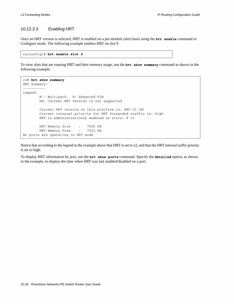
L3 Forwarding Modes IP Routing Configuration Guide
10.12.3.3 Enabling HRT
Once an HRT version is selected, HRT is enabled on a per-module (slot) basis using the hrt enable command in Configure mode. The following example enables HRT on slot 9.
To view slots that are running HRT and their memory usage, use the hrt show summary command as shown in the following example:
Notice that according to the legend in the example above that HRT is set to v2, and that the HRT internal traffic priority is set to high.
To display HRT information by port, use the hrt show ports command. Specify the detailed option, as shown in the example, to display the time when HRT was last enabled/disabled on a port.
rs(config)# hrt enable slot 9
rs# hrt show summaryHRT Summary:-----------Legend: M : Multipath, E: Enhanced FIB NA: Current HRT version is not supported
Current HRT version on this platform is: HRT v2 (M) Current internal priority for HRT forwarded traffic is: high HRT is administratively enabled on slots: 9 11
HRT Memory Size : 7936 KB HRT Memory Free : 7921 KBNo ports are operating in HRT mode
10-20 Riverstone Networks RS Switch Router User Guide
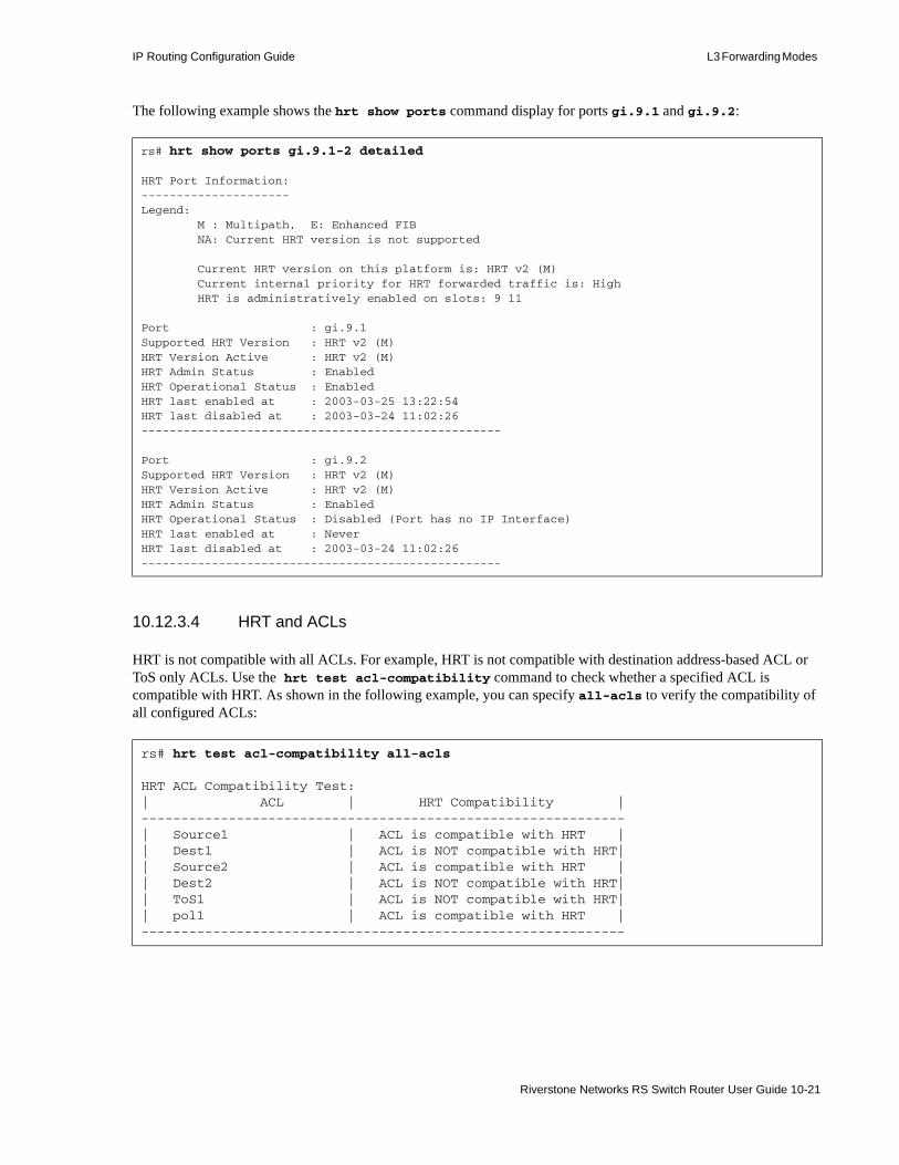
IP Routing Configuration Guide L3 Forwarding Modes
The following example shows the hrt show ports command display for ports gi.9.1 and gi.9.2:
10.12.3.4 HRT and ACLs
HRT is not compatible with all ACLs. For example, HRT is not compatible with destination address-based ACL or ToS only ACLs. Use the hrt test acl-compatibility command to check whether a specified ACL is compatible with HRT. As shown in the following example, you can specify all-acls to verify the compatibility of all configured ACLs:
rs# hrt show ports gi.9.1-2 detailed
HRT Port Information:---------------------Legend: M : Multipath, E: Enhanced FIB NA: Current HRT version is not supported
Current HRT version on this platform is: HRT v2 (M) Current internal priority for HRT forwarded traffic is: High HRT is administratively enabled on slots: 9 11
Port : gi.9.1Supported HRT Version : HRT v2 (M)HRT Version Active : HRT v2 (M)HRT Admin Status : EnabledHRT Operational Status : EnabledHRT last enabled at : 2003-03-25 13:22:54HRT last disabled at : 2003-03-24 11:02:26---------------------------------------------------
Port : gi.9.2Supported HRT Version : HRT v2 (M)HRT Version Active : HRT v2 (M)HRT Admin Status : EnabledHRT Operational Status : Disabled (Port has no IP Interface)HRT last enabled at : NeverHRT last disabled at : 2003-03-24 11:02:26---------------------------------------------------
rs# hrt test acl-compatibility all-acls
HRT ACL Compatibility Test:| ACL | HRT Compatibility |-------------------------------------------------------------| Source1 | ACL is compatible with HRT || Dest1 | ACL is NOT compatible with HRT|| Source2 | ACL is compatible with HRT || Dest2 | ACL is NOT compatible with HRT|| ToS1 | ACL is NOT compatible with HRT|| pol1 | ACL is compatible with HRT |-------------------------------------------------------------
Riverstone Networks RS Switch Router User Guide 10-21

L3 Forwarding Modes IP Routing Configuration Guide
If the specified ACL does not exist, the information in the following example is displayed:
If an ACL is compatible with the HRT, that ACL is automatically written into hardware.
10.12.3.5 Finding a Route in HRT
Use the hrt find route command to check whether a route to a specified destination is in the hardware FIB. This command is similar to the ip find route command. The only difference is when you use ip find route, the RS Ethernet Router tries to find the route in the software FIB only. When you use the hrt find route command, the RS Ethernet Router first looks for the route in the software FIB. If this lookup fails, the RS Ethernet Router stops looking. If this lookup succeeds, the RS Ethernet Router looks for the route in the hardware FIB of the specified module.
If a route to the specified destination exists in the hardware FIB, the RS Ethernet Router will display the route information, as shown in the following example. It displays the details for the route to the destination, 21.1.1.10:
10.12.3.6 Configuring ICMP Redirect
The RS Ethernet Router sends ICMP redirect messages when it receives packets that have the same entry and exit ports. When HRT is enabled, you can set a threshold for these types of packets. The following example sets the threshold to 10.
Once the number of packets received by the RS Ethernet Router reaches the specified threshold (10 in this example), the RS Ethernet Router sends one ICMP redirect message to the originating device. As a rule, one redirect message is sent each time the redirect count reaches its set value.
rs# hrt test acl-compatibility acl100
HRT ACL Compatibility Test:| ACL | HRT Compatibility |-------------------------------------------------------------| acl100 | ACL does not exist |-------------------------------------------------------------
rs# hrt find route 21.1.1.10 slot 3 Software FIB details for destination: 21.1.1.10 Uses Route : 21.1.1.0 Netmask : 255.255.255.0 Gateways : 100.1.1.2 101.1.1.2 HRT details for destination: 21.1.1.10 Use of HRT entry :Always use this HRT entry to forward packets Number of Next Hops :2 Next Hop Information 1) Exit Port : at.2.1 Next Hop MAC Address : 02e063:201064 2) Exit Port : at.2.1 Next Hop MAC Address : 02e063:2010c8
rs1(config)# hrt set icmp icmp-redirect-count 10
10-22 Riverstone Networks RS Switch Router User Guide
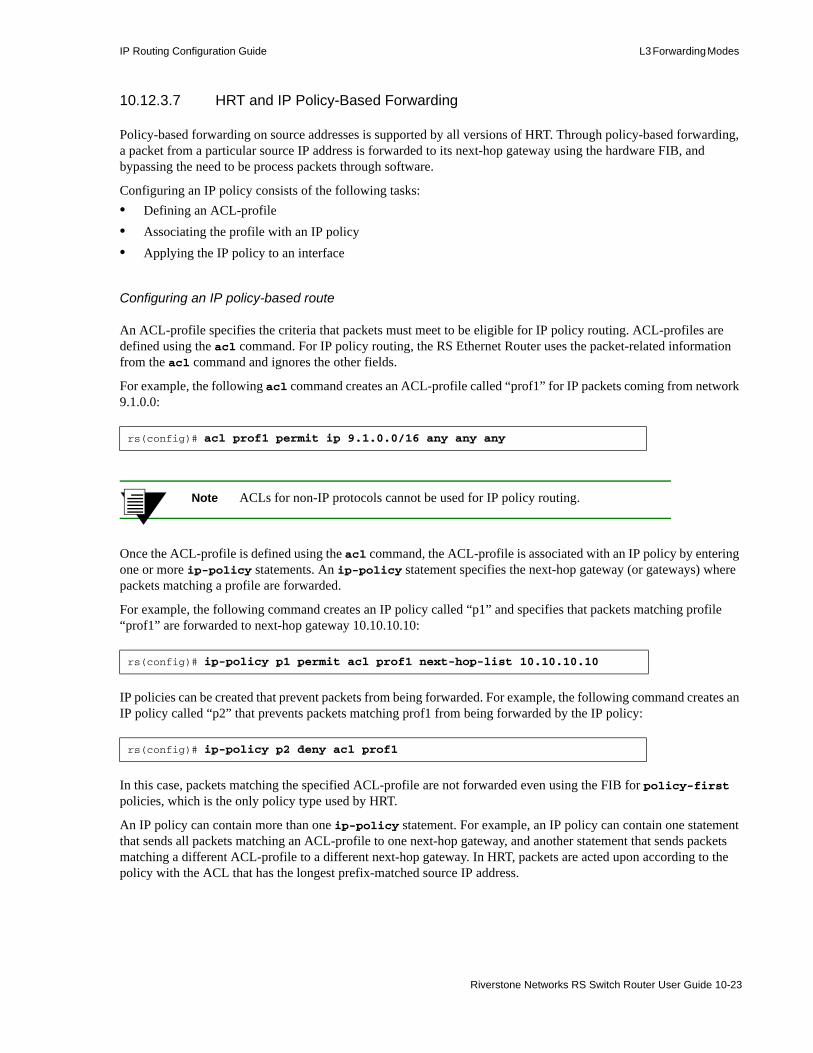
IP Routing Configuration Guide L3 Forwarding Modes
10.12.3.7 HRT and IP Policy-Based Forwarding
Policy-based forwarding on source addresses is supported by all versions of HRT. Through policy-based forwarding, a packet from a particular source IP address is forwarded to its next-hop gateway using the hardware FIB, and bypassing the need to be process packets through software.
Configuring an IP policy consists of the following tasks:• Defining an ACL-profile • Associating the profile with an IP policy• Applying the IP policy to an interface
Configuring an IP policy-based route
An ACL-profile specifies the criteria that packets must meet to be eligible for IP policy routing. ACL-profiles are defined using the acl command. For IP policy routing, the RS Ethernet Router uses the packet-related information from the acl command and ignores the other fields.
For example, the following acl command creates an ACL-profile called “prof1” for IP packets coming from network 9.1.0.0:
Note ACLs for non-IP protocols cannot be used for IP policy routing.
Once the ACL-profile is defined using the acl command, the ACL-profile is associated with an IP policy by entering one or more ip-policy statements. An ip-policy statement specifies the next-hop gateway (or gateways) where packets matching a profile are forwarded.
For example, the following command creates an IP policy called “p1” and specifies that packets matching profile “prof1” are forwarded to next-hop gateway 10.10.10.10:
IP policies can be created that prevent packets from being forwarded. For example, the following command creates an IP policy called “p2” that prevents packets matching prof1 from being forwarded by the IP policy:
In this case, packets matching the specified ACL-profile are not forwarded even using the FIB for policy-first policies, which is the only policy type used by HRT.
An IP policy can contain more than one ip-policy statement. For example, an IP policy can contain one statement that sends all packets matching an ACL-profile to one next-hop gateway, and another statement that sends packets matching a different ACL-profile to a different next-hop gateway. In HRT, packets are acted upon according to the policy with the ACL that has the longest prefix-matched source IP address.
rs(config)# acl prof1 permit ip 9.1.0.0/16 any any any
rs(config)# ip-policy p1 permit acl prof1 next-hop-list 10.10.10.10
rs(config)# ip-policy p2 deny acl prof1
Riverstone Networks RS Switch Router User Guide 10-23

L3 Forwarding Modes IP Routing Configuration Guide
For example, consider the following example:
Packets with the source address of 10.1.1.10 are forwarded to 30.1.1.10, while packets with source address of 10.1.12.10 are forwarded to 20.1.1.10.
The forwarding occurs because the next-hop is based on the longest prefix match. Notice that 10.1.1.10 matches 24-bits within ACL prof2, while the best the 10.1.12.10 can do is match 16-bits within ACL prof1.
HRT IP Policy-Based Forwarding Limitations
There are several limitations with HRT policy-based forwarding t keep in mind when using this feature. The following is a list of these limitations.• ACLs and IP policy-based forwarding are not supported on the same interface at the same time. For
example, if there are two interfaces on a slot, you cannot configure ACLs on one interface and policy-based forwarding on the other. If this is done, HRT is disabled on the ports of the interface on which the later command is applied.
• An ACL that passes the hrt test acl-compatibility command may still be illegal to use with HRT policy-based routing.
• HRT is disabled if ACLs and IP policies are applied together on an interface at the same time.• Only source IP-based IP Policies are supported.• Only Policy-First type IP policies are supported.• It is possible that some IP policies can disable HRT on an interface, especially if there are conflicting
IP policies on the same interface.• Only directly connected next-hops are supported when running IP policies in HRT mode. If a
next-hop is not directly connected, the HRT policy-based route entry is removed from the HRT.• Configuring IP policies on an interface does not result in HRT being disabled on other interfaces on
the same slot. This means that if policy-based routing is configured on one interface of a slot, packets arriving on any other ports on the same slot (and possibly belonging to another interface) will be forwarded according to the policy-based routing rules.
• The Pinger option must be configured for all IP policies.• If there is more than one interface on a slot, and different IP Policies are configured on the interfaces,
the union of the IP Policies will be applied to the entire slot.
Note See Chapter 24, "IP Policy-Based Forwarding Configuration" for detailed information regarding IP policies. Also, see Chapter 26, "Access Control List Configuration" for detailed information regarding ACLs.
rs(config)# acl prof1 permit ip 10.1.0.0/16rs(config)# acl prof2 permit ip 10.1.1.0/24rs(config)# ip-policy p3 permit acl prof1 next-hop-list 20.1.1.10rs(config)# ip-policy p3 permit acl [rpf2 next-hop-list 30.1.1.10
10-24 Riverstone Networks RS Switch Router User Guide

IP Routing Configuration Guide L3 Forwarding Modes
10.12.4 Destination-Based Forwarding
When an RS Ethernet Router port is in destination-based forwarding mode, it installs a new flow for each new destination. It uses the following flow information from IP unicast packets:• Destination IP address• ToS • Port of Entry• Protocol
For multicast packets, the RS Ethernet Router uses the source IP address in addition to the fields it uses to define a flow in unicast packets.
The following example sets port et.4.1 to destination-based forwarding mode:
10.12.5 Host-Flow-Based Forwarding
When an RS Ethernet Router port is in host-flow-based forwarding mode, it uses the following flow information to make its forwarding decisions:• Source IP address• Destination IP address• ToS • Port of Entry• Protocol
The following example sets port et.4.3 to host-flow-based forwarding mode:
When you set a port to host-flow-based forwarding, you can use ACLs that use both the source and destination IP addresses. In addition, you can track statistics between two hosts.
10.12.6 Custom Forwarding
You can configure the RS Ethernet Router to use a custom forwarding profile to identify a packet’s flow. A custom forwarding profile is used to wildcard specific fields in the IP header.
Define the custom forwarding profile, apply it to a slot, then enable it on a per port basis. The ports on which the custom forwarding profile is not enabled will use the default forwarding mode.
The fields that can be wildcarded are as follows:• Source IP Address (SIP)• Destination IP Address (DIP)
rs(config)# ip set port et.4.1 forwarding mode destination-based
rs(config)# ip set port et.4.3 forwarding mode host-flow-based
Riverstone Networks RS Switch Router User Guide 10-25

L3 Forwarding Modes IP Routing Configuration Guide
• Protocol• Source Socket• Destination Socket• Type of Service (TOS)
10.12.6.1 Configuring a Profile
To configure a custom forwarding profile:• define the profile, with the ip define custom-forwarding-profile command• apply the profile to a slot, with the ip apply custom-forwarding-profile command• enable the profile on a specific port, with the ip enable custom-forwarding-mode command
The following example configures the custom forwarding profile a100 and enables it on port gi.9.1:
In the example, only port gi.9.1 will use the custom forwarding profile to forward packets. All other ports in slot 9 will use the default forwarding mode.
Use the ip show custom-forwarding-profile command to view the configured profiles, as shown in the following example:
10.12.6.2 Using Custom Forwarding with Other RS Ethernet Router Features
Custom forwarding profiles are used to wildcard certain fields in the IP header. This can cause incompatibility with various RS Ethernet Router features that require that these fields not be wildcarded. Whenever custom forwarding is enabled on a port, the RS Ethernet Router checks for compatibility with other features that the port supports. Conversely, when a feature is applied to an interface or VLAN with ports in custom forwarding mode, the RS Ethernet Router also checks for compatibility.
Access Control Lists (ACLs)
An ACL specifies various fields on the IP header which it uses to filter packets. When an ACL is applied to an interface, the RS Ethernet Router checks to see if any of the ports on the interface have custom forwarding enabled. For any port in which custom forwarding is enabled, the RS Ethernet Router makes an additional check that the fields
rs(config)# ip define custom-forwarding-profile a100 dip-host-wildcard dst-sock-wildcard sip-host-wildcard src-sock-wildcardrs(config)# ip apply custom-forwarding-profile a100 slot 9rs(config)# ip enable custom-forwarding-mode port gi.9.1
rs# ip show custom-forwarding-profile all
Profile a100:protocol wildcarding is disabledsip wildcarding is enableddip wildcarding is enabledsrc socket wildcarding is enableddest socket wildcarding is enabledTOS wildcarding is disabled
10-26 Riverstone Networks RS Switch Router User Guide

IP Routing Configuration Guide L3 Forwarding Modes
specified in the ACL are not wildcarded by the custom forwarding profile. If this happens, the RS Ethernet Router generates an error. Conversely, when a port in custom forwarding mode is added to an interface, VLAN or SmartTRUNK, the RS Ethernet Router checks for compatibility between the custom profile and the existing ACLs.
Network Address Translation (NAT)
NAT requires the source IP address and sometimes the source socket for address translation. Thus, whenever NAT is enabled, the RS Ethernet Router checks if the source IP and source socket are wildcarded on an interface or if a custom forwarding profile is applied to a NAT enabled interface.
Rate Limiting
Rate limiting uses ACLs to limit traffic rate. Thus, the RS Ethernet Router performs a compatibility check when a port is configured to support both custom forwarding and rate limiting.
Quality of Service (QoS)
QoS policies applied at L3, require certain fields in the IP header, such as source IP and destination IP. The RS Ethernet Router performs a compatibility check when a QoS policy is applied to a port in forwarding mode.
L4 Bridging
L4 bridging is incompatible with custom forwarding profiles. Therefore a port cannot support l4 bridging and custom forwarding at the same time.
Riverstone Networks RS Switch Router User Guide 10-27

Installing MPLS LSP Routes In the FIB IP Routing Configuration Guide
10.13 INSTALLING MPLS LSP ROUTES IN THE FIB
10.13.1 Basic Functionality
Normally, MPLS LSPs are not installed in the RIB or FIB, which makes them inaccessible for routing.
Using the ip-router global set install-lsp-routes command, you can• Install LSP routes in the Internet Unicast RIB and permit all routing protocols to utilize these routes.
Due to their default preference, installing LSP routes in the Internet Unicast RIB usually means that they are also selected to be installed in the Unicast FIB.
• Install LSP routes in the LSP RIB and grant BGP exclusive access to LSP routes, allowing BGP only to use MPLS paths in resolving next hops. Under this scheme, other routing protocols are not permitted to use LSP routes and LSP routes are not installed in the Internet Unicast RIB.
• Install LSP routes into both the Internet Unicast FIB and LSP FIB.
MPLS LSP routes contain the host address for each LSP’s egress router. Using these tunnels, an ingress router can forward packets to the destination egress router.
Without this capability, routing protocols must rely on conventional routes in the FIB for routing. With this capability, if a next hop happens to be the egress point on a pre-defined MPLS tunnel, the routing protocol can utilize this tunnel to forward to the next hop.
10.13.2 Configuration
By default, routing protocols must rely on conventional routes in the FIB for routing. Use the ip-router global set install-lsp-routes on command to install LSP routes in the Internet Unicast RIB and permit all routing protocols to utilize these routes for calculating IGP shortcuts. Due to their default preference, installing LSP routes in the Internet Unicast RIB usually means that they are also selected to be installed in the Unicast FIB.
Use the ip-router global set install-lsp-routes bgp command to grant BGP exclusive access to LSP routes, allowing BGP to use MPLS paths, in addition to other routes in the FIB, in resolving next hops. Under this scheme, MPLS routes are only installed in the LSP RIB and other routing protocols are not permitted to use them.
RS Ethernet Router(config)# ip-router global set install-lsp routes on
RS Ethernet Router(config)# ip-router global set install-lsp routes bgp
10-28 Riverstone Networks RS Switch Router User Guide

IP Routing Configuration Guide Configuring Router Discovery
10.13.3 Usage Notes, Rules, and Restrictions
10.13.3.1 Choosing Between Conventional FIB Routes and LSP Routes
• When routing protocols have a choice between conventional FIB routes and LSP routes, the route with the highest preference is chosen. You can affect this choice by using the <protocol> set preference command to specify desired IGP preferences and the mpls set label-switch-path preference command to specify preferences for MPLS LSPs.
Caution Using these commands overrides default preferences and may alter the normal routing process.
• If multiple paths with identical preferences exist between conventional routes and LSP routes, routing protocols prefer LSP routes over conventional routes by default.
10.13.3.2 LSP Removed or Fails
• When a routing protocol selects an LSP to use, it installs that LSP into its forwarding engine as the transport method of choice for the associated next hop. If the LSP is removed or fails, the path is removed from the FIB and all RIBs, as well as from that protocol’s forwarding engine. This forces the routing protocol to select another path to the next hop from all available routes, including other LSP routes.
10.14 CONFIGURING ROUTER DISCOVERYThe router discovery server on the RS Ethernet Router periodically sends out router advertisements to announce the existence of the RS Ethernet Router to other hosts. The router advertisements are multicast or broadcast to each interface on the RS Ethernet Router on which it is enabled and contain a list of the addresses on the interface and the preference of each address for use as a default route for the interface. A host can also send a router solicitation, to which the router discovery server on the RS Ethernet Router will respond with a unicast router advertisement.
On systems that support IP multicasting, router advertisements are sent to the ‘all-hosts’ multicast address 224.0.0.1 by default. You can specify that broadcast be used, even if IP multicasting is available. When router advertisements are sent to the all-hosts multicast address or an interface is configured for the limited broadcast address 255.255.255.255, the router advertisement includes all IP addresses configured on the physical interface. When router advertisements are sent to a net or subnet broadcast, then only the address associated with the net or subnet is included.
To start router discovery on the RS Ethernet Router, enter the following command in Configure mode:
The rdisc start command lets you start router discovery on the RS Ethernet Router. When router discovery is started, the RS Ethernet Router multicasts or broadcasts periodic router advertisements on each configured interface. The router advertisements contain a list of addresses on a given interface and the preference of each address for use as the default route on the interface. By default, router discovery is disabled.
rs(config)# rdisc start
Riverstone Networks RS Switch Router User Guide 10-29

Configuring Router Discovery IP Routing Configuration Guide
The rdisc add address command lets you define addresses to be included in router advertisements. If you configure this command, only the specified hostname(s) or IP address(es) are included in the router advertisements. For example:
By default, all addresses on the interface are included in router advertisements sent by the RS Ethernet Router. The rdisc add interface command lets you enable router advertisement on an interface. For example:
If you want to have only specific addresses included in router advertisements, use the rdisc add address command to specify those addresses.
The rdisc set address command lets you specify the type of router advertisement in which the address is included and the preference of the address for use as a default route. For example, to specify that an address be included only in broadcast router advertisements and that the address is ineligible to be a default route:
The rdisc set interface command lets you specify the intervals between the sending of router advertisements and the lifetime of addresses sent in a router advertisement. To specify the maximum time between the sending of router advertisements on an interface:
rs(config)# rdisc add address 10.10.5.254
rs(config)# rdisc add interface rs4
rs#(config) rdisc set address 10.20.36.0 type broadcast preference ineligible
rs#(config) rdisc set interface rs4 max-adv-interval 1200
10-30 Riverstone Networks RS Switch Router User Guide

IP Routing Configuration Guide Setting Memory Thresholds
To display router discovery information:
Legend:1. Information about the RDISC task.2. Shows when the last router advertisement was sent and when the next advertisement will be sent.3. The interface on which router advertisement is enabled.4. Multicast address.5. Current values for the intervals between the sending of router advertisements and the lifetime of
addresses sent in a router advertisement.6. IP address that is included in router advertisement. The preference of this address as a default route
is 0, the default value.7. Shows configured values for the specified interface.
10.15 SETTING MEMORY THRESHOLDSThe routing information base (RIB) is stored in memory in the RS Ethernet Router. There are four configurable thresholds that represent the percentages of the available memory that is used for storing RIB entries.
rs# rdisc show all
Task State: <Foreground NoResolv NoDetach>
Send buffer size 2048 at 812C68F8 Recv buffer size 2048 at 812C60D0
Timers:
RouterDiscoveryServer Priority 30
RouterDiscoveryServer_RS2_RS3_IP <OneShot> last: 10:17:21 next: 10:25:05
Task RouterDiscoveryServer: Interfaces: Interface RS2_RS3_IP: Group 224.0.0.1: minadvint 7:30 maxadvint 10:00 lifetime 30:00
Address 10.10.5.254: Preference: 0
Interface policy: Interface RS2_RS3_IP* MaxAdvInt 10:00
1
2
3
4
5
6
7
Riverstone Networks RS Switch Router User Guide 10-31

Setting Memory Thresholds IP Routing Configuration Guide
The default memory thresholds are shown in Table 10-5. You can use the ip-router global set memory-threshold command to change the thresholds.
When a level-1, level-2, or level-3 threshold is reached, the RS Ethernet Router may delete routes in the RIB or not add new routes to the RIB, depending upon the routing protocol. When threshold level-4 is reached (by default, 80% of available memory used by the RIB), no new routes are added.
Table 10-6 shows what actions the RS Ethernet Router takes in updating the RIB when each threshold is reached.
Table 10-5 Default Memory Thresholds
Threshold Level Percentage of Memory
level-1 70
level-2 73
level-3 76
level-4 80
Table 10-6 RIB Updates When Memory Threshold is Reached
RouteProtocol
Threshold Action
OSPF/IS-IS
level-1level-2level-3level-4
Updates are processed as usual.
RIP level-1 • A new RIP route is added only if it is the only RIP route to the given destination.
• Maximum of 2 routes allowed to a given destination. If there are more than 2 routes to a given destination, the least preferred route(s) are deleted.
level-2 • A new RIP route is added only if is an active RIP route to the given destination.
level-3 • Only one route is allowed to a given destination. If there is more than one route to a given destination, the least preferred route is deleted.
level-4 No new routes are added.
10-32 Riverstone Networks RS Switch Router User Guide

IP Routing Configuration Guide Configuration Examples
The ip-router show summary drops command shows information about routes that were deleted or not added due to low memory, as well as the current threshold settings.
10.16 CONFIGURATION EXAMPLES
10.16.1 Assigning IP Interfaces
To enable routing on the RS Ethernet Router, you must assign an IP interface to a VLAN. To assign an IP interface named ‘RED’ to the ‘BLUE’ VLAN, enter the following command:
You can also assign an IP interface directly to a physical port.
BGP level-1level-2
• A new BGP route is added only if it is the only BGP route to the given destination.
• Maximum of 3 routes allowed to a given destination. If there are more than 3 routes to a given destination, a new route replaces an existing route.
level-3 • Maximum of 2 routes allowed to a given destination. If there are more than 2 routes to a given destination, a new route replaces an existing route.
level-4 No new routes are added.
rs(config)# interface create ip RED address-netmask 10.50.0.1/255.255.0.0 vlan BLUE
Table 10-6 RIB Updates When Memory Threshold is Reached
RouteProtocol
Threshold Action
Riverstone Networks RS Switch Router User Guide 10-33

Configuration Examples IP Routing Configuration Guide
10-34 Riverstone Networks RS Switch Router User Guide

11 VRRP CONFIGURATION GUIDE
This chapter explains how to set up and monitor the Virtual Router Redundancy Protocol (VRRP) on the RS Ethernet Router. VRRP is defined in RFC 2338.
End host systems on a LAN are often configured to send packets to a statically configured default router. If this default router becomes unavailable, all the hosts that use it as their first hop router become isolated on the network. VRRP provides a way to ensure the availability of an end host’s default router.
This is done by assigning IP addresses that end hosts use as their default route to a “virtual router.” A Master router is assigned to forward traffic designated for the virtual router. If the Master router should become unavailable, a backup router takes over and begins forwarding traffic for the virtual router. As long as one of the routers in a VRRP configuration is up, the IP addresses assigned to the virtual router are always available, and the end hosts can send packets to these IP addresses without interruption.
11.1 CONFIGURING VRRPThis section presents three sample VRRP configurations:• A basic VRRP configuration with one virtual router• A symmetrical VRRP configuration with two virtual routers• A multi-backup VRRP configuration with three virtual routers
Riverstone Networks RS Switch Router User Guide 11-1

Configuring VRRP VRRP Configuration Guide
11.1.1 Basic VRRP Configuration
Figure 11-1 shows a basic VRRP configuration with a single virtual router. Routers R1 and R2 are both configured with one virtual router (VRID=1). Router R1 serves as the Master and Router R2 serves as the Backup. The four end hosts are configured to use 10.0.0.1/16 as the default route. IP address 10.0.0.1/16 is associated with virtual router VRID=1.
Figure 11-1 Basic VRRP configuration
If Router R1 should become unavailable, Router R2 would take over virtual router VRID=1 and its associated IP addresses. Packets sent to 10.0.0.1/16 would go to Router R2. When Router R1 comes up again, it would take over as Master, and Router R2 would revert to Backup.
11.1.1.1 Configuration of Router R1
The following is the configuration file for Router R1 in Figure 11-1.
Line 1 adds IP address 10.0.0.1/16 to interface test, making Router R1 the owner of this IP address. Line 2 creates virtual router VRID=1 on interface test. Line 3 associates IP address 10.0.0.1/16 with virtual router VRID=1. Line 4 starts VRRP on interface test.
In VRRP, the router that owns the IP address associated with the virtual router is the Master. Any other routers that participate in this virtual router are Backups. In this configuration, Router R1 is the Master for virtual router VRID=1 because it owns 10.0.0.1/16, the IP address associated with virtual router VRID=1.
1: interface create ip test address-netmask 10.0.0.1/16 port et.1.12: ip-redundancy create vrrp 1 interface test3: ip-redundancy associate vrrp 1 interface test address 10.0.0.1/164: ip-redundancy start vrrp 1 interface test
R1 R2
H1 H2 H3 H4
Default Route = 10.0.0.1/16
Master Backup
VRID=1
10.0.0.1/16
Interface Addr. = 10.0.0.1/16VRID=1; Addr. = 10.0.0.1/16
Interface Addr. = 10.0.0.2/16VRID=1; Addr. = 10.0.0.1/16
11-2 Riverstone Networks RS Switch Router User Guide

VRRP Configuration Guide Configuring VRRP
11.1.1.2 Configuration for Router R2
The following is the configuration file for Router R2 in Figure 11-1.
The configuration for Router R2 is nearly identical to Router R1. The difference is that Router R2 does not own IP address 10.0.0.1/16. Since Router R2 does not own this IP address, it is the Backup. It will take over from the Master if it should become unavailable.
11.1.2 Symmetrical Configuration
Figure 11-2 shows a VRRP configuration with two routers and two virtual routers. Routers R1 and R2 are both configured with two virtual routers (VRID=1 and VRID=2).
Router R1 serves as:• Master for VRID=1• Backup for VRID=2
Router R2 serves as:• Master for VRID=2• Backup for VRID=1
This configuration allows you to load-balance traffic coming from the hosts on the 10.0.0.0/16 subnet and provides a redundant path to either virtual router.
Note This is the recommended configuration on a network using VRRP.
1: interface create ip test address-netmask 10.0.0.2/16 port et.1.12: ip-redundancy create vrrp 1 interface test3: ip-redundancy associate vrrp 1 interface test address 10.0.0.1/164: ip-redundancy start vrrp 1 interface test
Riverstone Networks RS Switch Router User Guide 11-3

Configuring VRRP VRRP Configuration Guide
Figure 11-2 Symmetrical VRRP configuration
In this configuration, half the hosts use 10.0.0.1/16 as their default route, and half use 10.0.0.2/16. IP address 10.0.0.1/16 is associated with virtual router VRID=1, and IP address 10.0.0.2/16 is associated with virtual router VRID=2.
If Router R1, the Master for virtual router VRID=1, goes down, Router R2 would take over the IP address 10.0.0.1/16. Similarly, if Router R2, the Master for virtual router VRID=2, goes down, Router R1 would take over the IP address 10.0.0.2/16.
11.1.2.1 Configuration of Router R1
The following is the configuration file for Router R1 in Figure 11-2.
Router R1 is the owner of IP address 10.0.0.1/16. Line 4 associates this IP address with virtual router VRID=1, so Router R1 is the Master for virtual router VRID=1.
On line 5, Router R1 associates IP address 10.0.0.2/16 with virtual router VRID=2. However, since Router R1 does not own IP address 10.0.0.2/16, it is not the default Master for virtual router VRID=2.
1: interface create ip test address-netmask 10.0.0.1/16 port et.1.1 !2: ip-redundancy create vrrp 1 interface test3: ip-redundancy create vrrp 2 interface test !4: ip-redundancy associate vrrp 1 interface test address 10.0.0.1/165: ip-redundancy associate vrrp 2 interface test address 10.0.0.2/16 !6: ip-redundancy start vrrp 1 interface test7: ip-redundancy start vrrp 2 interface test
R1 R2
H1 H2 H3 H4
Default Route = 10.0.0.1/16
Master for VRID=1
Default Route = 10.0.0.2/16
Backup for VRID=2Master for VRID=2Backup for VRID=1
Interface Addr. = 10.0.0.1/16VRID=1; Addr. = 10.0.0.1/16VRID=2; Addr. = 10.0.0.2/16
VRID=1
10.0.0.1/16
Interface Addr. = 10.0.0.2/16VRID=1; Addr. = 10.0.0.1/16VRID=2; Addr. = 10.0.0.2/16
VRID=2
10.0.0.2/16
11-4 Riverstone Networks RS Switch Router User Guide

VRRP Configuration Guide Configuring VRRP
11.1.2.2 Configuration of Router R2
The following is the configuration file for Router R2 in Figure 11-2.
On line 1, Router R2 is made owner of IP address 10.0.0.2/16. Line 5 associates this IP address with virtual router VRID=2, so Router R2 is the Master for virtual router VRID=2. Line 4 associates IP address 10.0.0.1/16 with virtual router VRID=1, making Router R2 the Backup for virtual router VRID=1.
11.1.3 Multi-Backup Configuration
Figure 11-3 shows a VRRP configuration with three routers and three virtual routers. Each router serves as a Master for one virtual router and as a Backup for each of the others. When a Master router goes down, one of the Backups takes over the IP addresses of its virtual router.
In a VRRP configuration where more than one router is backing up a Master, you can specify which Backup router takes over when the Master goes down by setting the priority for the Backup routers.
Figure 11-3 Multi-Backup VRRP configuration
1: interface create ip test address-netmask 10.0.0.2/16 port et.1.1 !2: ip-redundancy create vrrp 1 interface test3: ip-redundancy create vrrp 2 interface test !4: ip-redundancy associate vrrp 1 interface test address 10.0.0.1/165: ip-redundancy associate vrrp 2 interface test address 10.0.0.2/16 !6: ip-redundancy start vrrp 1 interface test7: ip-redundancy start vrrp 2 interface test
R1 R2
H1 H2 H3 H4
Default Route = 10.0.0.1/16
Master for VRID=1
Default Route = 10.0.0.2/16
1st Backup for VRID=2
R3
H5 H6
Default Route = 10.0.0.3/16
1st Backup for VRID=3
Master for VRID=21st Backup for VRID=12nd Backup for VRID=3
Master for VRID=32nd Backup for VRID=12nd Backup for VRID=2
VRID=1
10.0.0.1/16
VRID=2
10.0.0.2/16
VRID=3
10.0.0.3/16
Riverstone Networks RS Switch Router User Guide 11-5
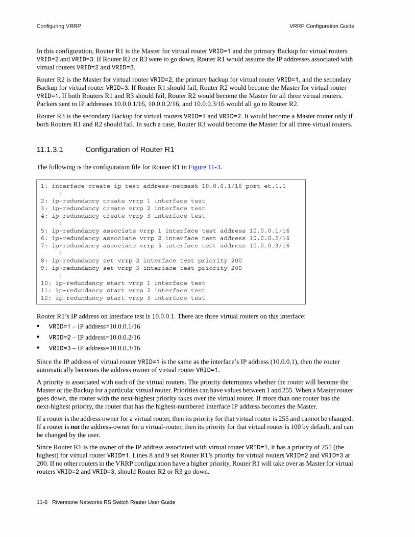
Configuring VRRP VRRP Configuration Guide
In this configuration, Router R1 is the Master for virtual router VRID=1 and the primary Backup for virtual routers VRID=2 and VRID=3. If Router R2 or R3 were to go down, Router R1 would assume the IP addresses associated with virtual routers VRID=2 and VRID=3.
Router R2 is the Master for virtual router VRID=2, the primary backup for virtual router VRID=1, and the secondary Backup for virtual router VRID=3. If Router R1 should fail, Router R2 would become the Master for virtual router VRID=1. If both Routers R1 and R3 should fail, Router R2 would become the Master for all three virtual routers. Packets sent to IP addresses 10.0.0.1/16, 10.0.0.2/16, and 10.0.0.3/16 would all go to Router R2.
Router R3 is the secondary Backup for virtual routers VRID=1 and VRID=2. It would become a Master router only if both Routers R1 and R2 should fail. In such a case, Router R3 would become the Master for all three virtual routers.
11.1.3.1 Configuration of Router R1
The following is the configuration file for Router R1 in Figure 11-3.
Router R1’s IP address on interface test is 10.0.0.1. There are three virtual routers on this interface:• VRID=1 – IP address=10.0.0.1/16 • VRID=2 – IP address=10.0.0.2/16• VRID=3 – IP address=10.0.0.3/16
Since the IP address of virtual router VRID=1 is the same as the interface’s IP address (10.0.0.1), then the router automatically becomes the address owner of virtual router VRID=1.
A priority is associated with each of the virtual routers. The priority determines whether the router will become the Master or the Backup for a particular virtual router. Priorities can have values between 1 and 255. When a Master router goes down, the router with the next-highest priority takes over the virtual router. If more than one router has the next-highest priority, the router that has the highest-numbered interface IP address becomes the Master.
If a router is the address owner for a virtual router, then its priority for that virtual router is 255 and cannot be changed. If a router is not the address-owner for a virtual-router, then its priority for that virtual router is 100 by default, and can be changed by the user.
Since Router R1 is the owner of the IP address associated with virtual router VRID=1, it has a priority of 255 (the highest) for virtual router VRID=1. Lines 8 and 9 set Router R1’s priority for virtual routers VRID=2 and VRID=3 at 200. If no other routers in the VRRP configuration have a higher priority, Router R1 will take over as Master for virtual routers VRID=2 and VRID=3, should Router R2 or R3 go down.
1: interface create ip test address-netmask 10.0.0.1/16 port et.1.1 !2: ip-redundancy create vrrp 1 interface test3: ip-redundancy create vrrp 2 interface test4: ip-redundancy create vrrp 3 interface test !5: ip-redundancy associate vrrp 1 interface test address 10.0.0.1/166: ip-redundancy associate vrrp 2 interface test address 10.0.0.2/167: ip-redundancy associate vrrp 3 interface test address 10.0.0.3/16 !8: ip-redundancy set vrrp 2 interface test priority 2009: ip-redundancy set vrrp 3 interface test priority 200 !10: ip-redundancy start vrrp 1 interface test11: ip-redundancy start vrrp 2 interface test12: ip-redundancy start vrrp 3 interface test
11-6 Riverstone Networks RS Switch Router User Guide
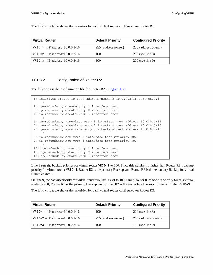
VRRP Configuration Guide Configuring VRRP
The following table shows the priorities for each virtual router configured on Router R1.
11.1.3.2 Configuration of Router R2
The following is the configuration file for Router R2 in Figure 11-3.
Line 8 sets the backup priority for virtual router VRID=1 to 200. Since this number is higher than Router R3’s backup priority for virtual router VRID=1, Router R2 is the primary Backup, and Router R3 is the secondary Backup for virtual router VRID=1.
On line 9, the backup priority for virtual router VRID=3 is set to 100. Since Router R1’s backup priority for this virtual router is 200, Router R1 is the primary Backup, and Router R2 is the secondary Backup for virtual router VRID=3.
The following table shows the priorities for each virtual router configured on Router R2.
Virtual Router Default Priority Configured Priority
VRID=1 – IP address=10.0.0.1/16 255 (address owner) 255 (address owner)
VRID=2 – IP address=10.0.0.2/16 100 200 (see line 8)
VRID=3 – IP address=10.0.0.3/16 100 200 (see line 9)
1: interface create ip test address-netmask 10.0.0.2/16 port et.1.1 !2: ip-redundancy create vrrp 1 interface test3: ip-redundancy create vrrp 2 interface test4: ip-redundancy create vrrp 3 interface test !5: ip-redundancy associate vrrp 1 interface test address 10.0.0.1/166: ip-redundancy associate vrrp 2 interface test address 10.0.0.2/167: ip-redundancy associate vrrp 3 interface test address 10.0.0.3/16 !8: ip-redundancy set vrrp 1 interface test priority 2009: ip-redundancy set vrrp 3 interface test priority 100 !10: ip-redundancy start vrrp 1 interface test11: ip-redundancy start vrrp 2 interface test12: ip-redundancy start vrrp 3 interface test
Virtual Router Default Priority Configured Priority
VRID=1 – IP address=10.0.0.1/16 100 200 (see line 8)
VRID=2 – IP address=10.0.0.2/16 255 (address owner) 255 (address owner)
VRID=3 – IP address=10.0.0.3/16 100 100 (see line 9)
Riverstone Networks RS Switch Router User Guide 11-7

Configuring VRRP VRRP Configuration Guide
Note Since 100 is the default priority, line 9, which sets the priority to 100, is actually unnecessary. It is included for illustration purposes only.
11.1.3.3 Configuration of Router R3
The following is the configuration file for Router R3 in Figure 11-3.
Lines 8 and 9 set the backup priority for Router R3 at 100 for virtual routers VRID=1 and VRID=2. Since Router R1 has a priority of 200 for backing up virtual router VRID=2, and Router R2 has a priority of 200 for backing up virtual router VRID=1, Router R3 is the secondary Backup for both virtual routers VRID=1 and VRID=2.
The following table shows the priorities for each virtual router configured on Router R3.
Note Since 100 is the default priority, lines 8 and 9, which set the priority to 100, are actually unnecessary. They are included for illustration purposes only.
1: interface create ip test address-netmask 10.0.0.3/16 port et.1.1 !2: ip-redundancy create vrrp 1 interface test3: ip-redundancy create vrrp 2 interface test4: ip-redundancy create vrrp 3 interface test !5: ip-redundancy associate vrrp 1 interface test address 10.0.0.1/166: ip-redundancy associate vrrp 2 interface test address 10.0.0.2/167: ip-redundancy associate vrrp 3 interface test address 10.0.0.3/16 !8: ip-redundancy set vrrp 1 interface test priority 1009: ip-redundancy set vrrp 2 interface test priority 100 !10: ip-redundancy start vrrp 1 interface test11: ip-redundancy start vrrp 2 interface test12: ip-redundancy start vrrp 3 interface test
Virtual Router Default Priority Configured Priority
VRID=1 – IP address=10.0.0.1/16 100 100 (see line 8)
VRID=2 – IP address=10.0.0.2/16 100 100 (see line 9)
VRID=3 – IP address=10.0.0.3/16 255 (address owner) 255 (address owner)
11-8 Riverstone Networks RS Switch Router User Guide
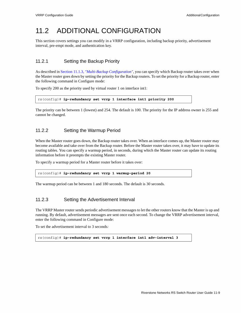
VRRP Configuration Guide Additional Configuration
11.2 ADDITIONAL CONFIGURATIONThis section covers settings you can modify in a VRRP configuration, including backup priority, advertisement interval, pre-empt mode, and authentication key.
11.2.1 Setting the Backup Priority
As described in Section 11.1.3, "Multi-Backup Configuration", you can specify which Backup router takes over when the Master router goes down by setting the priority for the Backup routers. To set the priority for a Backup router, enter the following command in Configure mode:
To specify 200 as the priority used by virtual router 1 on interface int1:
The priority can be between 1 (lowest) and 254. The default is 100. The priority for the IP address owner is 255 and cannot be changed.
11.2.2 Setting the Warmup Period
When the Master router goes down, the Backup router takes over. When an interface comes up, the Master router may become available and take over from the Backup router. Before the Master router takes over, it may have to update its routing tables. You can specify a warmup period, in seconds, during which the Master router can update its routing information before it preempts the existing Master router.
To specify a warmup period for a Master router before it takes over:
The warmup period can be between 1 and 180 seconds. The default is 30 seconds.
11.2.3 Setting the Advertisement Interval
The VRRP Master router sends periodic advertisement messages to let the other routers know that the Master is up and running. By default, advertisement messages are sent once each second. To change the VRRP advertisement interval, enter the following command in Configure mode:
To set the advertisement interval to 3 seconds:
rs(config)# ip-redundancy set vrrp 1 interface int1 priority 200
rs(config)# ip-redundancy set vrrp 1 warmup-period 20
rs(config)# ip-redundancy set vrrp 1 interface int1 adv-interval 3
Riverstone Networks RS Switch Router User Guide 11-9

Monitoring VRRP VRRP Configuration Guide
11.2.4 Setting Pre-empt Mode
When a Master router goes down, the Backup with the highest priority takes over the IP addresses associated with the Master. By default, when the original Master comes back up again, it takes over from the Backup router that assumed its role as Master. When a VRRP router does this, it is said to be in pre-empt mode. Pre-empt mode is enabled by default on the RS Ethernet Router. You can prevent a VRRP router from taking over from a lower-priority Master by disabling pre-empt mode. To do this, enter the following command in Configure mode:
To prevent a Backup router from taking over as Master from a Master router that has a lower priority:
Note If the IP address owner is available, then it will always take over as the Master, regardless of whether pre-empt mode is on or off.
11.2.5 Setting an Authentication Key
By default, no authentication of VRRP packets is performed on the RS Ethernet Router. You can specify a clear-text password to be used to authenticate VRRP exchanges. To enable authentication, enter the following command in Configure mode
To authenticate VRRP exchanges on virtual router 1 on interface int1 with a password of ‘yago’:
Note The RS Ethernet Router does not currently support the IP Authentication Header method of authentication.
11.3 MONITORING VRRPThe RS Ethernet Router provides two commands for monitoring a VRRP configuration: ip-redundancy trace, which displays messages when VRRP events occur, and ip-redundancy show, which reports statistics about virtual routers.
rs(config)# ip-redundancy set vrrp 1 interface int1 preempt-mode disabled
rs(config)# ip-redundancy set vrrp 1 interface int1 auth-type text auth-key yago
11-10 Riverstone Networks RS Switch Router User Guide

VRRP Configuration Guide Monitoring VRRP
11.3.1 ip-redundancy trace
The ip-redundancy trace command is used for troubleshooting purposes. This command causes messages to be displayed when certain VRRP events occur on the RS Ethernet Router. To trace VRRP events, enter the following commands in Enable mode:
11.3.2 ip-redundancy show
The ip-redundancy show command reports information about a VRRP configuration.
Display a message when any VRRP event occurs. (Disabled by default.)
ip-redundancy trace vrrp events enabled
Display a message when a VRRP router changes from one state to another; for example Backup to Master. (Enabled by default.)
ip-redundancy trace vrrp state-transitions enabled
Display a message when a VRRP packet error is detected. (Enabled by default.)
ip-redundancy trace vrrp packet-errors enabled
Enable all VRRP tracing. ip-redundancy trace vrrp all enabled
Riverstone Networks RS Switch Router User Guide 11-11

Monitoring VRRP VRRP Configuration Guide
To display information about all virtual routers on interface int1:
rs# ip-redundancy show vrrp interface int1
VRRP Virtual Router 100 - Interface int1------------------------------------------Uptime 0 days, 0 hours, 0 minutes, 17 seconds.State BackupPriority 100 (default value)Virtual MAC address 00005E:000164Advertise Interval 1 sec(s) (default value)Preempt Mode Enabled (default value)Authentication None (default value)Primary Address 10.8.0.2Associated Addresses 10.8.0.1 100.0.0.1
VRRP Virtual Router 200 - Interface int1------------------------------------------Uptime 0 days, 0 hours, 0 minutes, 17 seconds.State MasterPriority 255 (default value)Virtual MAC address 00005E:0001C8Advertise Interval 1 sec(s) (default value)Preempt Mode Enabled (default value)Authentication None (default value)Primary Address 10.8.0.2Associated Addresses 10.8.0.2
11-12 Riverstone Networks RS Switch Router User Guide

VRRP Configuration Guide VRRP Configuration Notes
To display VRRP statistics for virtual router 100 on interface int1:
To display VRRP information, enter the following commands in Enable mode.
11.4 VRRP CONFIGURATION NOTES• The Master router sends keep-alive advertisements. The frequency of these keep-alive
advertisements is determined by setting the Advertisement interval parameter. The default value is 1 second.
• If a Backup router doesn’t receive a keep-alive advertisement from the current Master within a certain period of time, it will transition to the Master state and start sending advertisements itself. The amount of time that a Backup router will wait before it becomes the new Master is based on the following equation:
Master-down-interval = (3 * advertisement-interval) + skew-time
The skew-time depends on the Backup router's configured priority:
rs# ip-redundancy show vrrp 1 interface int1 verbose
VRRP Virtual Router 100 - Interface int1------------------------------------------Uptime 0 days, 0 hours, 0 minutes, 17 seconds.State BackupPriority 100 (default value)Virtual MAC address 00005E:000164Advertise Interval 1 sec(s) (default value)Preempt Mode Enabled (default value)Authentication None (default value)Primary Address 10.8.0.2Associated Addresses 10.8.0.1 100.0.0.1
Stats: Number of transitions to master state 2 VRRP advertisements rcvd 0 VRRP packets sent with 0 priority 1 VRRP packets rcvd with 0 priority 0 VRRP packets rcvd with IP-address list mismatch 0 VRRP packets rcvd with auth-type mismatch 0 VRRP packets rcvd with checksum error 0 VRRP packets rcvd with invalid version 0 VRRP packets rcvd with invalid VR-Id 0 VRRP packets rcvd with invalid adv-interval 0 VRRP packets rcvd with invalid TTL 0 VRRP packets rcvd with invalid 'type' field 0 VRRP packets rcvd with invalid auth-type 0 VRRP packets rcvd with invalid auth-key 0
Display information about all virtual routers.
ip-redundancy show vrrp
Riverstone Networks RS Switch Router User Guide 11-13

VRRP Configuration Notes VRRP Configuration Guide
Skew-time = ((256 - Priority) / 256)
Therefore, the higher the priority, the faster a Backup router will detect that the Master is down. For example:- Default advertisement-interval = 1 second- Default Backup router priority = 100- Master-down-interval = time it takes a Backup to detect the Master is down
= (3 * adv-interval) + skew-time
= (3 * 1 second) + ((256 - 100) / 256)
= 3.6 seconds• If a Master router is manually rebooted, or if its interface is manually brought down, it will send a
special keep-alive advertisement that lets the Backup routers know that a new Master is needed immediately.
• A virtual router will respond to ARP requests with a virtual MAC address. This virtual MAC depends on the virtual router ID:
virtual MAC address = 00005E:0001XX
where XX is the virtual router ID
This virtual MAC address is also used as the source MAC address of the keep-alive Advertisements transmitted by the Master router.
• If multiple virtual routers are created on a single interface, the virtual routers must have unique identifiers. If virtual routers are created on different interfaces, you can reuse virtual router IDs.
For example, the following configuration is valid:
• As specified in RFC 2338, a Backup router that has transitioned to Master will not accept telnet sessions or field SNMP requests directed at the virtual router's IP address.
Not responding allows network management to notice that the original Master router (i.e., the IP address owner) is down
Note A Backup router that has transitioned to Master will not respond to pings unless the ip-redundancy set vrrp <vrrp number> interface <interface name> respond-to-ping enabled command is entered into the RS Ethernet Router’s configuration.
ip-redundancy create vrrp 1 interface test-Aip-redundancy create vrrp 1 interface test-B
11-14 Riverstone Networks RS Switch Router User Guide

12 RIP CONFIGURATION GUIDE
This chapter describes how to configure the Routing Information Protocol (RIP) on the Riverstone RS Switch Router. RIP is a distance-vector routing protocol for use in small networks. A router running RIP broadcasts updates at set intervals. Each update contains paired values where each pair consists of an IP network address and an integer distance to that network. RIP uses a hop count metric to measure the distance to a destination. RIP selects the route with the lowest metric as the best route. The metric is a hop count representing the number of gateways through which data must pass in order to reach its destination. The longest path that RIP accepts is 15 hops. If the metric is greater than 15, a destination is considered unreachable and the RS Ethernet Router discards the route. RIP assumes that the best route is the one that uses the fewest gateways, that is, the shortest path.
The Riverstone RS Switch Router provides support for RIP Version 1 (described in RFC 1058) and Version 2 (described in RFC 1723). The RS Ethernet Router implements plain text and MD5 authentication methods for RIP Version 2.
The protocol independent features that apply to RIP are described in Chapter 10, "IP Routing Configuration Guide."
12.1 CONFIGURING RIPBy default, RIP is disabled on the RS Ethernet Router and on each of the attached interfaces. To configure RIP on the RS Ethernet Router, follow these steps:1. Start the RIP process by entering the rip start command.2. Use the rip add interface command to inform RIP about the attached interfaces.
12.1.1 Enabling and Disabling RIP
To enable or disable RIP, enter one of the following commands in Configure mode.
12.1.2 Configuring RIP Interfaces
To configure RIP in the RS Ethernet Router, you must first add interfaces to inform RIP about attached interfaces.
Enable RIP. rip start
Disable RIP. rip stop
Riverstone Networks RS Switch Router User Guide 12-1
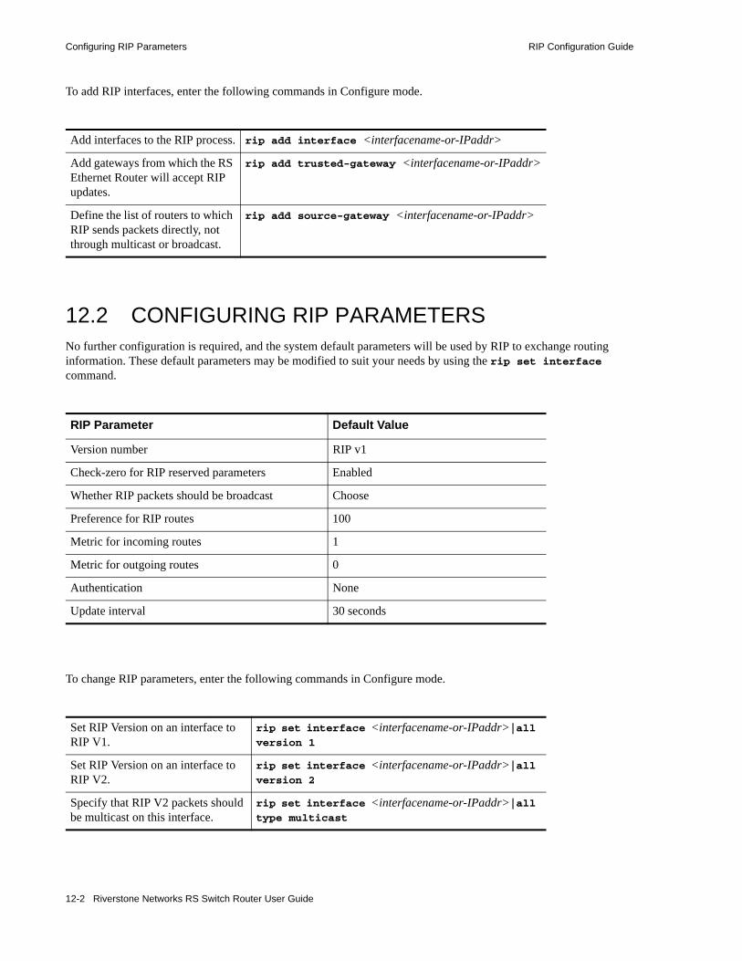
Configuring RIP Parameters RIP Configuration Guide
To add RIP interfaces, enter the following commands in Configure mode.
12.2 CONFIGURING RIP PARAMETERSNo further configuration is required, and the system default parameters will be used by RIP to exchange routing information. These default parameters may be modified to suit your needs by using the rip set interface command.
To change RIP parameters, enter the following commands in Configure mode.
Add interfaces to the RIP process. rip add interface <interfacename-or-IPaddr>
Add gateways from which the RS Ethernet Router will accept RIP updates.
rip add trusted-gateway <interfacename-or-IPaddr>
Define the list of routers to which RIP sends packets directly, not through multicast or broadcast.
rip add source-gateway <interfacename-or-IPaddr>
RIP Parameter Default Value
Version number RIP v1
Check-zero for RIP reserved parameters Enabled
Whether RIP packets should be broadcast Choose
Preference for RIP routes 100
Metric for incoming routes 1
Metric for outgoing routes 0
Authentication None
Update interval 30 seconds
Set RIP Version on an interface to RIP V1.
rip set interface <interfacename-or-IPaddr>|all version 1
Set RIP Version on an interface to RIP V2.
rip set interface <interfacename-or-IPaddr>|all version 2
Specify that RIP V2 packets should be multicast on this interface.
rip set interface <interfacename-or-IPaddr>|all type multicast
12-2 Riverstone Networks RS Switch Router User Guide

RIP Configuration Guide Configuring RIP Parameters
Configuring RIP Route Preference
You can set the preference of routes learned from RIP.
To configure RIP route preference, enter the following command in Configure mode.
Specify that RIP V2 packets that are RIP V1-compatible should be broadcast on this interface.
rip set interface <interfacename-or-IPaddr>|all type broadcast
Change the metric on incoming RIP routes.
rip set interface <interfacename-or-IPaddr>|all metric-in <num>
Change the metric on outgoing RIP routes.
rip set interface <interfacename-or-IPaddr>|all metric-out <num>
Set the authentication method to simple text up to 8 characters.
rip set interface <interfacename-or-IPaddr>|all authentication-method simple
Set the authentication method to MD5.
rip set interface <interfacename-or-IPaddr>|all authentication-method md5
Specify the metric to be used when advertising routes that were learned from other protocols.
rip set default-metric <num>
Enable automatic summarization and redistribution of RIP routes.
rip set auto-summary disable|enable
Specify broadcast of RIP packets regardless of number of interfaces present.
rip set broadcast-state always|choose|never
Check that reserved fields in incoming RIP V1 packets are zero.
rip set check-zero disable|enable
Enable acceptance of RIP routes that have a metric of zero.
rip set check-zero-metric disable|enable
Enable poison revers, as specified by RFC 1058.
rip set poison-reverse disable|enable
Specify the maximum number of RIP routes maintained in the routing information base (RIB). The default is 4.
rip set max-routes <number>
Disable multipath route calculation for RIP routes.
rip set multipath off
Set the preference of routes learned from RIP. rip set preference <num>
Riverstone Networks RS Switch Router User Guide 12-3

Monitoring RIP RIP Configuration Guide
12.2.1 Configuring RIP Route Default-Metric
You can define the metric used when advertising routes via RIP that were learned from other protocols. The default value for this parameter is 16 (unreachable). To export routes from other protocols into RIP, you must explicitly specify a value for the default-metric parameter. The metric specified by the default-metric parameter may be overridden by a metric specified in the export command.
To configure default-metric, enter the following command in Configure mode.
For <num>, you must specify a number between 1 and 16.
12.3 MONITORING RIP The rip trace command can be used to trace all rip request and response packets.
To monitor RIP information, enter the following commands in Enable mode.
Define the metric used when advertising routes via RIP that were learned from other protocols.
rip set default-metric <num>
Show all RIP information. rip show all
Show RIP export policies. rip show export-policy
Show RIP global information. rip show globals
Show RIP import policies. rip show import-policy
Show RIP information on the specified interface.
rip show interface <Name or IP-addr>
Show RIP interface policy information. rip show interface-policy
Show detailed information of all RIP packets. rip trace packets detail
Show detailed information of all packets received by the router.
rip trace packets receive
Show detailed information of all packets sent by the router.
rip trace packets send
Show detailed information of all request received by the router.
rip trace request receive
Show detailed information of all response received by the router.
rip trace response receive
Show detailed information of response packets sent by the router.
rip trace response send
12-4 Riverstone Networks RS Switch Router User Guide

RIP Configuration Guide Configuration Example
12.4 CONFIGURATION EXAMPLE
Show detailed information of request packets sent by the router.
rip trace send request
Show RIP timer information. rip show timers
! Example configuration !! Create interface R1-if1 with ip address 1.1.1.1/16 on port et.1.1 on R-1interface create ip R1-if1 address-netmask 1.1.1.1/16 port et.1.1 !! Configure rip on R-1rip add interface R1-if1rip set interface R1-if1 version 2rip start!!! Set authentication method to md5rip set interface R1-if1 authentication-method md5!! Change default metric-in rip set interface R1-if1 metric-in 2!! Change default metric-outrip set interface R1-if1 metric-out 3
Interface 1.1.1.1 Interface 3.2.1.1
R1 R2
Riverstone Networks RS Switch Router User Guide 12-5

Configuration Example RIP Configuration Guide
12-6 Riverstone Networks RS Switch Router User Guide

13 OSPF CONFIGURATION GUIDE
Open Shortest Path First Routing (OSPF) is a shortest path first or link-state protocol. The RS Ethernet Router supports OSPF Version 2.0, as defined in RFC 2328. OSPF is an interior gateway protocol that distributes routing information between routers in a single autonomous system. OSPF chooses the least-cost path as the best path. OSPF is suitable for complex networks with a large number of routers because it provides equal-cost multi-path routing where packets to a single destination can be sent via more than one interface simultaneously.
In a link-state protocol, each router maintains a database that describes the entire AS topology, which it builds out of the collected link state advertisements of all routers. Each participating router distributes its local state (i.e., the router's usable interfaces and reachable neighbors) throughout the AS by flooding. Each multi-access network that has at least two attached routers has a designated router and a backup designated router. The designated router floods a link state advertisement for the multi-access network and has other special responsibilities. The designated router concept reduces the number of adjacencies required on a multi-access network.
OSPF allows networks to be grouped into areas. Routing information passed between areas is abstracted, potentially allowing a significant reduction in routing traffic. OSPF uses four different types of routes, listed in order of preference: • Intra-area• Inter-area• Type 1 ASE• Type 2 ASE
Intra-area paths have destinations within the same area. Inter-area paths have destinations in other OSPF areas. Both types of Autonomous System External (ASE) routes are routes to destinations external to OSPF (and usually external to the AS). Routes exported into OSPF ASE as type 1 ASE routes are supposed to be from interior gateway protocols (e.g., RIP) whose external metrics are directly comparable to OSPF metrics. When a routing decision is being made, OSPF will add the internal cost to the AS border router to the external metric. Type 2 ASEs are used for exterior gateway protocols whose metrics are not comparable to OSPF metrics. In this case, the external cost from the AS border router to the destination is used in the routing decision.
The RS Ethernet Router supports the following OSPF functions:• Definition of areas, including stub areas and NSSAs (RFC 1587).• Opaque LSAs (RFC 2370)• Authentication: Simple password and MD5 authentication methods are supported within an
area.• Configuration of virtual links• Configuration of parameters at the area, interface or global level. Parameters that can be
configured include retransmission interval, interface transmit delay, router priority, router dead and hello intervals, and authentication key.
Riverstone Networks RS Switch Router User Guide 13-1

Configuring OSPF OSPF Configuration Guide
• Route Redistribution: Routes learned via RIP, BGP, or any other sources can be redistributed into OSPF. OSPF routes can be redistributed into RIP or BGP. For information on Route Redistribution, refer to Chapter 20, "Routing Policy Configuration.".
13.1 CONFIGURING OSPFTo configure OSPF on the RS Ethernet Router, perform the following tasks:• Set the router ID.• Enable OSPF• Create the OSPF area• Add interfaces to the area• If necessary, configure virtual links• Optionally, configure parameters at the global, area, and/or interface level.
• Optionally, enable OSPF graceful restart.
13.2 SETTING THE ROUTER IDThe router ID uniquely identifies the RS Ethernet Router. To set the router ID to be used by OSPF, enter the following command in Configure mode.
If you do not explicitly specify the router ID, then an ID is chosen implicitly by the RS Ethernet Router. A secondary address on the loopback interface (the primary address being 127.0.0.1) is the most preferred candidate for selection as the RS Ethernet Router’ router ID. If there are no secondary addresses on the loopback interface, then the default router ID is set to the address of the first interface that is in the up state that the RS Ethernet Router encounters (except the interface en0, which is the Control Module’s interface). The address of a non point-to-point interface is preferred over the local address of a point-to-point interface. If the router ID is implicitly chosen to be the address of a non-loopback interface, and if that interface were to go down, then the router ID is changed. When the router ID changes, an OSPF router has to flush all its LSAs from the routing domain.
If you explicitly specify a router ID, then it would not change, even if all interfaces were to go down.
13.3 ENABLING OSPFOSPF is disabled by default on the RS Ethernet Router.
Set the RS Ethernet Router’ router ID.
ip-router global set router-id <hostname-or-IPaddr>
13-2 Riverstone Networks RS Switch Router User Guide

OSPF Configuration Guide Configuring OSPF Areas
To enable or disable OSPF, enter one of the following commands in Configure mode.
13.4 CONFIGURING OSPF AREASOSPF areas are a collection of subnets that are grouped in a logical fashion. Each area maintains its own link state database. The area topology is known only within the area. A router maintains a separate link state database for each area to which it is connected.
The RS Ethernet Router supports the configuration of multiple OSPF areas, as well as three special types of areas: • backbone - The backbone is responsible for distributing routing information between non-backbone
areas. OSPF areas communicate with other areas via the backbone area. The OSPF area backbone contains all area border routers (ABRs).
• stub - A stub area is not used as a transit area. Routers within a stub area route internal traffic only.• not-so-stubby area (NSSA) - NSSAs are similar to stub areas, except that certain AS external routes
may be imported into NSSAs in a limited fashion.
On the RS Ethernet Router, you can create multiple OSPF areas, but at least one of them should be an area backbone. To configure an OSPF area, including a stub area or an NSSA, enter the following command in Configure mode. To configure a backbone area, use the backbone keyword with the following command.
After you create an area, you can set its parameters as described in Section 13.8, "Configuring OSPF Parameters." To define a stub area, refer to Section 13.4.2, "Configuring Stub Areas." To define NSSAs, refer to Section 13.4.3, "Configuring Not-So-Stubby Areas (NSSA)."
13.4.1 Configuring Summary Ranges
To reduce the amount of routing information propagated between areas, you can configure summary-ranges on Area Border Routers (ABRs). On the RS Ethernet Router, summary-ranges are created using the ospf add summary-range command – the networks specified using this command describe the scope of an area. Intra-area Link State Advertisements (LSAs) that fall within the specified ranges are not advertised into other areas as inter-area routes. Instead, the specified ranges are advertised as summary network LSAs.
Enable OSPF. ospf start
Disable OSPF. ospf stop
Create an OSPF area. ospf create area <area-num>|backbone
Add a network to an OSPF area for summarization.
ospf add network|summary-range
<IPaddr-mask> to-area <area-addr>|backbone [restrict] [host-net]
Riverstone Networks RS Switch Router User Guide 13-3
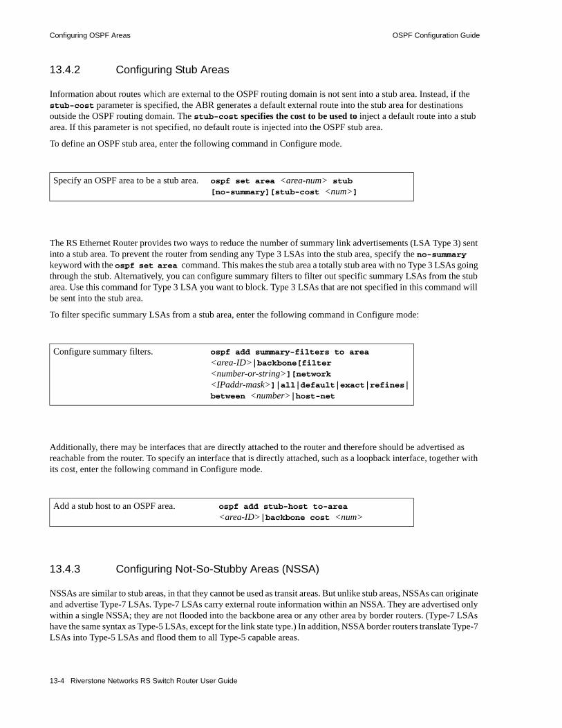
Configuring OSPF Areas OSPF Configuration Guide
13.4.2 Configuring Stub Areas
Information about routes which are external to the OSPF routing domain is not sent into a stub area. Instead, if the stub-cost parameter is specified, the ABR generates a default external route into the stub area for destinations outside the OSPF routing domain. The stub-cost specifies the cost to be used to inject a default route into a stub area. If this parameter is not specified, no default route is injected into the OSPF stub area.
To define an OSPF stub area, enter the following command in Configure mode.
The RS Ethernet Router provides two ways to reduce the number of summary link advertisements (LSA Type 3) sent into a stub area. To prevent the router from sending any Type 3 LSAs into the stub area, specify the no-summary keyword with the ospf set area command. This makes the stub area a totally stub area with no Type 3 LSAs going through the stub. Alternatively, you can configure summary filters to filter out specific summary LSAs from the stub area. Use this command for Type 3 LSA you want to block. Type 3 LSAs that are not specified in this command will be sent into the stub area.
To filter specific summary LSAs from a stub area, enter the following command in Configure mode:
Additionally, there may be interfaces that are directly attached to the router and therefore should be advertised as reachable from the router. To specify an interface that is directly attached, such as a loopback interface, together with its cost, enter the following command in Configure mode.
13.4.3 Configuring Not-So-Stubby Areas (NSSA)
NSSAs are similar to stub areas, in that they cannot be used as transit areas. But unlike stub areas, NSSAs can originate and advertise Type-7 LSAs. Type-7 LSAs carry external route information within an NSSA. They are advertised only within a single NSSA; they are not flooded into the backbone area or any other area by border routers. (Type-7 LSAs have the same syntax as Type-5 LSAs, except for the link state type.) In addition, NSSA border routers translate Type-7 LSAs into Type-5 LSAs and flood them to all Type-5 capable areas.
Specify an OSPF area to be a stub area. ospf set area <area-num> stub [no-summary][stub-cost <num>]
Configure summary filters. ospf add summary-filters to area
<area-ID>|backbone[filter <number-or-string>][network <IPaddr-mask>]|all|default|exact|refines|between <number>|host-net
Add a stub host to an OSPF area. ospf add stub-host to-area
<area-ID>|backbone cost <num>
13-4 Riverstone Networks RS Switch Router User Guide

OSPF Configuration Guide Configuring OSPF Interfaces
The RS Ethernet Router supports the configuration of NSSAs and the ability to add networks to an NSSA. To define an area as an NSSA, enter the following command in Configure mode:
• The nssa-cost parameter specifies the cost used to inject a default route into an NSSA area. If this parameter is not specified, no default route is injected into the NSSA area.
To add a network to an NSSA area, enter the following command in Configure mode:
• The restrict keyword is used to prevent the network from being advertised in Type 7 LSAs.
13.5 CONFIGURING OSPF INTERFACESTo configure an interface for OSPF, first configure an IP interface using the interface create command, then add the interface to an OSPF area. To add an IP interface to an area enter the following command in Configure mode:
When adding the interface to an area, you have the option of specifying the interface type. The Riverstone RS Switch Router can run OSPF over a variety of physical connections: serial connections, LAN interfaces, ATM, or Frame Relay. The OSPF configuration supports four different types of interfaces.• LAN. An example of a LAN interface is an Ethernet. The RS Ethernet Router will use multicast
packets on LAN interfaces to reach other OSPF routers. By default, an IP interface attached to a VLAN that contains LAN ports is treated as an OSPF broadcast network. To add this type of interface to an area, use the type broadcast option with the ospf add interface command.
Configures an NSSA. ospf set area <area-number> nssa nssa-cost <number>
Adds an NSSA network to an NSSA. ospf add nssa-network <IPaddr-mask> to area <area-addr> [restrict][host-net]
Add an interface to an OSPF area. ospf add interface <name-or-IPaddr> to-area <area-addr> |backbone [type broadcast|non-broadcast|
point-to-multipoint]
Riverstone Networks RS Switch Router User Guide 13-5
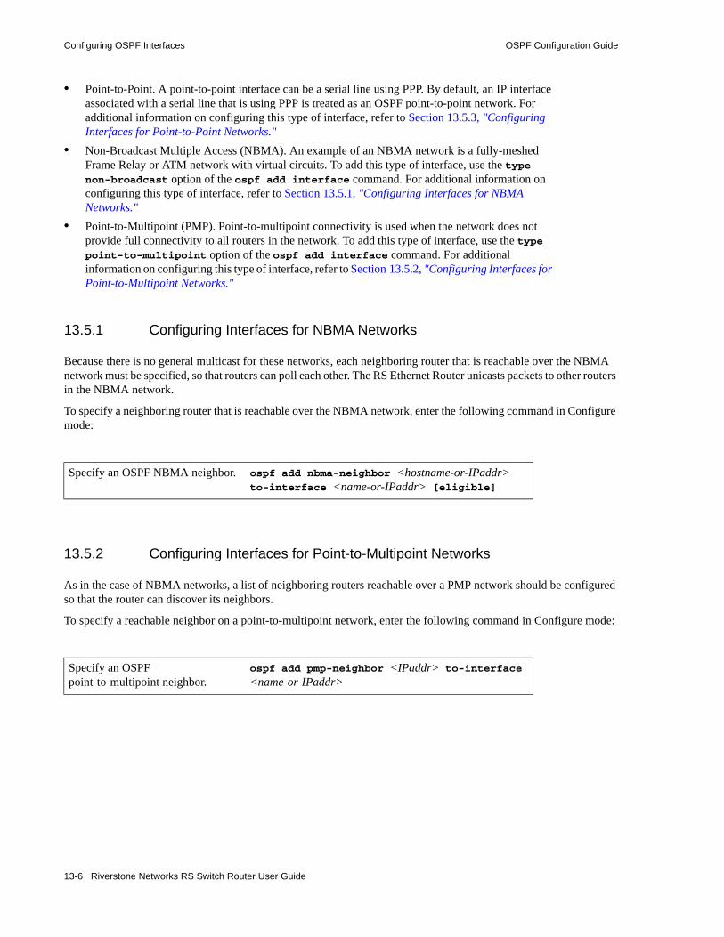
Configuring OSPF Interfaces OSPF Configuration Guide
• Point-to-Point. A point-to-point interface can be a serial line using PPP. By default, an IP interface associated with a serial line that is using PPP is treated as an OSPF point-to-point network. For additional information on configuring this type of interface, refer to Section 13.5.3, "Configuring Interfaces for Point-to-Point Networks."
• Non-Broadcast Multiple Access (NBMA). An example of an NBMA network is a fully-meshed Frame Relay or ATM network with virtual circuits. To add this type of interface, use the type non-broadcast option of the ospf add interface command. For additional information on configuring this type of interface, refer to Section 13.5.1, "Configuring Interfaces for NBMA Networks."
• Point-to-Multipoint (PMP). Point-to-multipoint connectivity is used when the network does not provide full connectivity to all routers in the network. To add this type of interface, use the type point-to-multipoint option of the ospf add interface command. For additional information on configuring this type of interface, refer to Section 13.5.2, "Configuring Interfaces for Point-to-Multipoint Networks."
13.5.1 Configuring Interfaces for NBMA Networks
Because there is no general multicast for these networks, each neighboring router that is reachable over the NBMA network must be specified, so that routers can poll each other. The RS Ethernet Router unicasts packets to other routers in the NBMA network.
To specify a neighboring router that is reachable over the NBMA network, enter the following command in Configure mode:
13.5.2 Configuring Interfaces for Point-to-Multipoint Networks
As in the case of NBMA networks, a list of neighboring routers reachable over a PMP network should be configured so that the router can discover its neighbors.
To specify a reachable neighbor on a point-to-multipoint network, enter the following command in Configure mode:
Specify an OSPF NBMA neighbor. ospf add nbma-neighbor <hostname-or-IPaddr> to-interface <name-or-IPaddr> [eligible]
Specify an OSPF point-to-multipoint neighbor.
ospf add pmp-neighbor <IPaddr> to-interface <name-or-IPaddr>
13-6 Riverstone Networks RS Switch Router User Guide

OSPF Configuration Guide Configuring OSPF Interface Parameters
13.5.3 Configuring Interfaces for Point-to-Point Networks
By default, OSPF packets are multicast to neighbors on an OSP point-to-point network. If an IP interface that is using PPP is to be treated as an OSPF broadcast network, then use the type broadcast option of the ospf add interface command. But if a remote neighbor does not support multicasting and you would like to unicast OSPF packets, enter the following command in Configure mode:
13.6 CONFIGURING OSPF INTERFACE PARAMETERS
The RS Ethernet Router provides a number of parameters that are set at the interface level. To set OSPF interface parameters, enter the following command in Configure mode:
This section describes parameters that are of special significance to interfaces. For information about parameters that can be set globally, refer to Section 13.8, "Configuring OSPF Parameters."
13.6.1 Setting the Interface State
OSPF interfaces that are added to an area are enabled by default. You can disable them by using the state disable option with the ospf set interface command.
13.6.2 Setting the Default Cost of an OSPF Interface
The RS Ethernet Router calculates the default cost of an OSPF interface using the reference bandwidth and the interface bandwidth. The default reference bandwidth is 1000. It can be changed by using the ospf set ref-bwdth command.
Force point-to-point interfaces to unicast OSPF packets.
ospf set interface <name-or-IPaddr> no-multicast
Set OSPF interface parameters. ospf set interface <name-or-IPaddr> |all [state disable|enable][cost <num>][no-multicast] [retransmit-interval <num>][transit delay <num>] [priority <num>][hello-interval<num>] [router-dead-interval<num>][poll-interval<num>] [key-chain <num>][authentication-method none|simple|md5][advertise subnet on|off] [passive]
Riverstone Networks RS Switch Router User Guide 13-7

Creating Virtual Links OSPF Configuration Guide
A VLAN that is attached to an interface could have several ports of differing speeds. The bandwidth of an interface is represented by the highest bandwidth port that is part of the associated VLAN. The cost of an OSPF interface is inversely proportional to this bandwidth. The cost is calculated using the following formula:
Cost = reference bandwidth * 1,000,000/ interface bandwidth (in bps)
The following is a table of the port types and the OSPF default cost associated with each type:
13.7 CREATING VIRTUAL LINKS In OSPF, virtual links can be established:• To connect an area via a transit area to the backbone• To create a redundant backbone connection via another area
Each ABR must be configured with the same virtual link. Note that virtual links cannot be configured through a stub area.
To configure virtual links, enter the following commands in the Configure mode.
Table 13-1 OSPF default cost per port type
Port Media Type Speed OSPF Default Cost
Ethernet 1000 1000 Mbps 2
Ethernet 10/100 100 Mbps 20
Ethernet 10/100 10 Mbps 200
WAN (T1) 1.5 Mbps 1333
WAN (T3) 45 Mbps 44
Create a virtual link.
ospf add virtual-link <number-or-string> neighbor <IPaddr> transit-area <area-id>
Set virtual link parameters.
ospf set virtual-link <number-or-string> [state disable|enable] [cost <num>] [retransmit-interval <num>] [transit-delay <num>] [priority <num>] [hello-interval <num>] [router-dead-interval <num>] [poll-interval <num>] [key-chain <num>] [authentication-method none|simple|md5] [no-multicast]
13-8 Riverstone Networks RS Switch Router User Guide
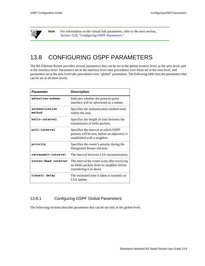
OSPF Configuration Guide Configuring OSPF Parameters
Note For information on the virtual link parameters, refer to the next section, Section 13.8, "Configuring OSPF Parameters."
13.8 CONFIGURING OSPF PARAMETERSThe RS Ethernet Router provides several parameters that can be set at the global (router) level, at the area level, and at the interface level. Parameters set at the interface level take precedence over those set at the area level, and parameters set at the area level take precedence over “global” parameters. The following table lists the parameters that can be set at all three levels.
13.8.1 Configuring OSPF Global Parameters
The following sections describe parameters that can be set only at the global level.
Parameter Description
advertise-subnet Indicates whether the point-to-point interface will be advertised as a subnet.
authentication method
Specifies the authentication method used within the area.
hello-interval Specifies the length of time between the transmission of hello packets.
poll-interval Specifies the interval at which OSPF packets will be sent, before an adjacency is established with a neighbor.
priority Specifies the router’s priority during the Designated Router election.
retransmit-interval The interval between LSA retransmissions.
router-dead interval The interval the router waits after receiving no Hello packets from its neighbor before considering it as down.
transit delay The estimated time it takes to transmit an LSA update.
Riverstone Networks RS Switch Router User Guide 13-9
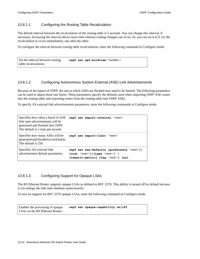
Configuring OSPF Parameters OSPF Configuration Guide
13.8.1.1 Configuring the Routing Table Recalculation
The default interval between the recalculation of the routing table is 5 seconds. You can change this interval, if necessary. Increasing the interval allows more time wherein routing changes can occur. Or, you can set it to 0, for the recalculation to occur immediately, one after the other.
To configure the interval between routing table recalculations, enter the following command in Configure mode:
13.8.1.2 Configuring Autonomous System External (ASE) Link Advertisements
Because of the nature of OSPF, the rate at which ASEs are flooded may need to be limited. The following parameters can be used to adjust those rate limits. These parameters specify the defaults used when importing OSPF ASE routes into the routing table and exporting routes from the routing table into OSPF ASEs.
To specify AS external link advertisements parameters, enter the following commands in Configure mode:
13.8.1.3 Configuring Support for Opaque LSAs
The RS Ethernet Router supports opaque LSAs as defined in RFC 2370. This ability is turned off by default because it can enlarge the link state database unnecessarily.
To turn on support for RFC 2370 opaque LSAs, enter the following command in Configure mode:
Set the interval between routing table recalculations.
ospf set spf-holdtime <number>
Specifies how often a batch of ASE link state advertisements will be generated and flooded into OSPF. The default is 1 time per second.
ospf set export-interval <num>
Specifies how many ASEs will be generated and flooded in each batch. The default is 250.
ospf set export-limit <num>
Specifies AS external link advertisement default parameters.
ospf set ase-defaults [preference <num>]| [cost <num>]|[type <num>] |[inherit-metric] [tag <num>] [as}
Enables the processing of opaque LSAs on the RS Ethernet Router.
ospf set opaque-capability on|off
13-10 Riverstone Networks RS Switch Router User Guide
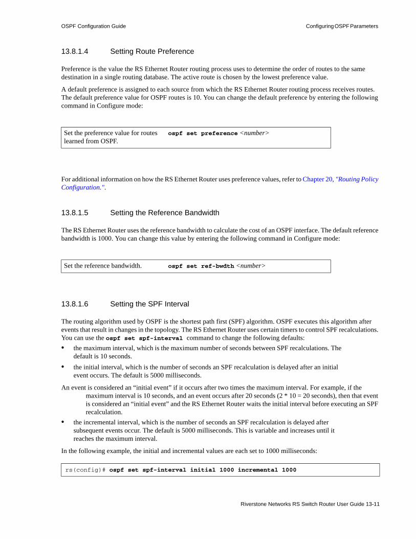
OSPF Configuration Guide Configuring OSPF Parameters
13.8.1.4 Setting Route Preference
Preference is the value the RS Ethernet Router routing process uses to determine the order of routes to the same destination in a single routing database. The active route is chosen by the lowest preference value.
A default preference is assigned to each source from which the RS Ethernet Router routing process receives routes. The default preference value for OSPF routes is 10. You can change the default preference by entering the following command in Configure mode:
For additional information on how the RS Ethernet Router uses preference values, refer to Chapter 20, "Routing Policy Configuration.".
13.8.1.5 Setting the Reference Bandwidth
The RS Ethernet Router uses the reference bandwidth to calculate the cost of an OSPF interface. The default reference bandwidth is 1000. You can change this value by entering the following command in Configure mode:
13.8.1.6 Setting the SPF Interval
The routing algorithm used by OSPF is the shortest path first (SPF) algorithm. OSPF executes this algorithm after events that result in changes in the topology. The RS Ethernet Router uses certain timers to control SPF recalculations. You can use the ospf set spf-interval command to change the following defaults:• the maximum interval, which is the maximum number of seconds between SPF recalculations. The
default is 10 seconds. • the initial interval, which is the number of seconds an SPF recalculation is delayed after an initial
event occurs. The default is 5000 milliseconds.
An event is considered an “initial event” if it occurs after two times the maximum interval. For example, if the maximum interval is 10 seconds, and an event occurs after 20 seconds (2 * 10 = 20 seconds), then that event is considered an “initial event” and the RS Ethernet Router waits the initial interval before executing an SPF recalculation.
• the incremental interval, which is the number of seconds an SPF recalculation is delayed after subsequent events occur. The default is 5000 milliseconds. This is variable and increases until it reaches the maximum interval.
In the following example, the initial and incremental values are each set to 1000 milliseconds:
Set the preference value for routes learned from OSPF.
ospf set preference <number>
Set the reference bandwidth. ospf set ref-bwdth <number>
rs(config)# ospf set spf-interval initial 1000 incremental 1000
Riverstone Networks RS Switch Router User Guide 13-11

Configuring OSPF Parameters OSPF Configuration Guide
Based on the example, the RS Ethernet Router executes an SPF recalculation as follows:• after the first trigger event, the RS Ethernet Router waits the initial interval, which is 1000
milliseconds, to execute the SPF recalculation• after the second event, the RS Ethernet Router waits the incremental interval, which is 1000
milliseconds, to execute the SPF recalculation • after the third and each succeeding event, the RS Ethernet Router waits 2 times the previous interval
to execute the SPF recalculation. Therefore: - after the third event, the RS Ethernet Router waits 2000 milliseconds (2 seconds)- after the fourth event, the RS Ethernet Router waits 4000 milliseconds (4 seconds) - after the fifth event, the RS Ethernet Router waits 8000 milliseconds (8 seconds)- after the sixth and any succeeding events, the RS Ethernet Router waits 10 seconds only (the
maximum interval).
Once the network calms down, if no trigger event occurs within 20 seconds ( 2 * maximum interval = 20 seconds), then the RS Ethernet Router treats the next event as an initial event.
13.8.1.7 Configuring OSPF Graceful Shutdown
OSPF graceful shutdown enables a router that is shutting down to help neighboring routers route around it. It does so by instructing its neighbors to bypass its links when charting paths in the network. The neighbors begin ignoring the presence of the router that is shutting down before it actually shuts down, thus avoiding network interruptions. With this feature enabled, the RS Ethernet Router sets the metrics on each of its links to the maximum metric and floods this information to all of its neighbors. When the neighbors recompute the shortest-path first algorithm using the new metric, they will prefer any link with a lower metric to the links on the router that is shutting down.
Note Assigning the maximum metric to a link renders the link highly undesirable, but still usable. A path may still utilize the link if no substitutable links with a lower metric are available.
Configure OSPF graceful shutdown globally using the ospf set max-metric-rtr command and on a per-routing instance basis using the routing-instance ospf set max-metric-rtr command. As long as either of these commands is in effect, the RS Ethernet Router will continue to advertise the maximum metric to its neighbors on a global or on a per-routing instance basis. To restore normal metric advertisements, remove the relevant command from the active configuration using the negate or no command.
13.8.1.8 OSPF LSA Pacing
By default, OSPF refreshes the self-originated LSAs that it generates to its neighbors every 30 seconds. This can lead to network congestion. The OSPF LSA pacing feature prevents this type of network congestion by refreshing LSAs in groups rather than all at once. The RS Ethernet Router implements OSPF LSA pacing by setting the LSA Age to a random value at the time it generates the LSA. This random value is chosen so that the LSAs are grouped into five groups for refresh purposes. This feature is on by default.
13-12 Riverstone Networks RS Switch Router User Guide
OSPF Configuration Guide Multipath
13.9 MULTIPATHThe RS Ethernet Router also supports OSPF and static Multi-path. If multiple equal-cost OSPF or static routes have been defined for any destination, then the RS Ethernet Router “discovers” and uses all of them. The RS Ethernet Router will automatically learn up to four equal-cost OSPF or static routes and retain them in its forwarding information base (FIB). The forwarding module then installs flows for these destinations in a round-robin fashion.
13.10 OSPF GRACEFUL RESTARTOSPF graceful restart is one of a set of protocol-based graceful restart features on the ROS developed with the goal of making the RS Ethernet Router "hitless," which means that the service performed by the RS Ethernet Router continues to function even if it has to restart. This feature is defined in the IETF “Hitless OSPF Restart” Internet Working Draft.
Note In both the Riverstone documentation and the RS Ethernet Router command-line interface (CLI), the terms “hitless restart” and “graceful restart” are used interchangeably.
Without graceful restart capabilities, OSPF restarts are costly for network resources. Neighbor after neighbor within the network have to be told that the restarting router’s routes are unreachable, which causes recalculation of routes and sub-optimal routes to be used, only to be told seconds later that the restarted router’s routes are back.
To prevent this temporary route flapping across the network, OSPF graceful restart relies on the Forwarding Information Base (FIB) of the restarting router being preserved across a restart, which allows the router to continue forwarding traffic during the restart.
The following section outlines the basic functionality of OSPF graceful restart.
13.10.1 Basic Functionality
The basic functionality of OSPF graceful restart is described in this section. Important restrictions, exceptions, and corner-case considerations are presented later, in section 13.10.5, "Usage Notes, Rules, and Restrictions."
In order to accomplish an OSPF graceful restart, the restarting router must have OSPF graceful restart enabled. Its neighbors (helpers) must be sufficiently configured to support OSPF graceful restart. In addition, the restarting router must be a dual control module system. Section 13.10.3, "Configuration." covers the configurations needed. The following assumes that these conditions are met on both the restarting router and its neighbors.
13.10.1.1 OSPF Graceful Restart Capability Advertisement
OSPF routers use a new link-local Opaque LSA, called the Grace LSA, to signal a restart to neighbors. This LSA includes the following fields, which are used to convey information during a restart. These fields are described in detail later.
Riverstone Networks RS Switch Router User Guide 13-13

OSPF Graceful Restart OSPF Configuration Guide
Table 13-2 OSPF Grace LSA Fields
13.10.1.2 The Restart Process
This section describes the restart process.
Successful Failover
In dual control module systems, the FIB is mirrored between the primary and backup control modules. During normal system operation, the FIB on the backup control modules is incrementally updated to reflect ongoing changes to the FIB on the primary control module.
In OSPF graceful restart, while the primary control module restarts, the backup control module takes over and uses this learned FIB to maintain existing flows and permit new flows to be established. Copies of the Router and Network LSAs are also mirrored. However, since the whole OSPF LSA database is not mirrored between the two modules, the RS Ethernet Router needs to resynchronize its LSA database with neighbors. To allow time to do this, it must signal its restart to neighbors.
During the Restart: The Restarter
To signal the restart, the router transmits a Grace LSA out each OSPF interface. This Grace LSA includes an LS Age of 0 and the Grace Period that the router is requesting in seconds. The Grace Period is a user-set value (in seconds) that communicates to neighbors how long they should shield the restart from the rest of the network.
During the restart, the restarting router attempts to reestablish all of its former adjacencies by exchanging LSAs with helper neighbors. In addition to synchronizing its link-state database with neighbors, the restarter also does the following:• It does not originate LSAs with LS types 1-5 or 7. This forces other routers in the OSPF domain to
calculate routes based on the LSAs that the restarter originated prior to the restart.• It does not modify or flush received self-originated LSAs. It accepts them as valid for the time being,
waiting until after the restart to deal with them.• It runs the SPF algorithm to return virtual links to operation and makes changes in the RIB based on
SPF calculations. However, it does not make any changes to the FIB based on the calculations. Instead, it routes using the forwarding entries installed before the restart.
OSPF Grace LSA Fields (Partial List)
Advertising Router
LS Age
Grace Period (in seconds)
Reason for Hitless Restart
IP Interface Address of Restarting Router
13-14 Riverstone Networks RS Switch Router User Guide

OSPF Configuration Guide OSPF Graceful Restart
• If the restarter was the Designated Router (DR) on a segment before the restart, it elects itself as the DR again.
In all other aspects, the restarter follows standard OSPF operating procedures. It forwards traffic, discovers neighbors using Hellos, elects DRs and Backup Designated Routers (BDRs), and synchronizes its link-state database (LSDB) with its neighbors.
Periodically, the restarter builds (without installing or flooding) its Router LSAs (Type 1) and compares them to the Router LSAs that it generated prior to the restart. On the segments where the restarter is a DR, it also builds and compares Network LSAs (Type 2) to those received. If the built and received LSAs are the same, the restarter considers all adjacencies to be reestablished and successfully exits graceful restart.
The following events can cause the restarter to unsuccessfully terminate graceful restart. • It receives inconsistent LSAs
During the course of database updates, receiving an LSA from a neighbor that is inconsistent with pre-restart LSAs signals one of the following:
- The neighbor does not support OSPF graceful restart- The neighbor never received the restarter’s Grace LSA- For whatever reason, the neighbor terminated its helper mode
Without neighbor support, the restarter cannot shield the restart from the rest of the network. Therefore, the restarter aborts graceful restart.• Network topology changes
If an unrelated network topology change occurs during the restart, a network disruption becomes unavoidable. This causes helpers to abort helper mode and makes it pointless for the restarter to shield its own restart from the rest of the network.
This situation is a subset of the “receiving inconsistent LSAs” event. The restarter is alerted about a potential network topology change when it receives an inconsistent LSA. • Grace period expires
Helper neighbors only support and shield the restart for the duration of the grace period that the restarter requests in its Grace LSA. If this time elapses without the restarter achieving database synchronization, it must abort graceful restart.
During the Restart: The Helpers
Upon receiving the restarter’s Grace LSA, all of helpers (the restarter’s neighbors that support OSPF graceful restart) check to make sure that the following required conditions are met. • The helper neighbor must be in a full adjacency with the restarter.• No changes to the link-state database in LS types 1-5 or 7 must have occurred since the beginning
of the grace period specified by the Grace LSA. This ensures that the rest of the network has not changed since the restart. The helper uses the LS Age of the Grace LSA to tell how long ago the restart occurred. This is possible because the restarter zeroed the LS Age field before sending out the Grace LSA.
• The helper must be user configured to act as a helper for the restarter. See section 13.10.3, "Configuration." for the various levels of helper support that you can configure on a router.
As long as these conditions hold true, the neighbor enters helper mode for the restarter on the associated network segment and performs the following tasks:
Riverstone Networks RS Switch Router User Guide 13-15

OSPF Graceful Restart OSPF Configuration Guide
• Continue to monitor the network for other topology changes. As long as there are none, shield the restart from the rest of the network by continuing to announce the restarting router and the link as valid in its LSAs. This avoids triggering disruptive SPF runs throughout the domain. Since the forwarding state is preserved in the restarter’s backup control module and traffic can continue through it, shielding the restart is acceptable.
• If the restarter was the DR on a network segment, continue to maintain the restarter as the DR on that segment until helper mode ends.
Exiting Restart: The Restarter
If all goes well, the restarter achieves a synchronized database and can successfully exit graceful restart. It determines whether this condition is met by building its Router LSAs (Type 1) and any Network LSAs (Type 2) based on the information that it has exchanged with its neighbors during the restart. If the built and received LSAs are the same, the restarter considers all adjacencies to be reestablished and successfully exits graceful restart.
Whether successful or unsuccessful, before exiting graceful restart, the restarter performs several tasks: • Reoriginates all of the Router LSAs (Type 1) for its attached areas.• If the restarter was the DR on a segment, it reoriginates all Network LSAs (Type 2) for that segment
as well.• The restarter reruns SPF calculations and installs the results into the FIB and RIB, originating
additional LSAs as needed. Recall that earlier, when the restarter ran SPF calculations to restore virtual links, it did not install or flush any results.
• The restarter cleans up the RIB and FIB, removing LSAs and routes that are no longer valid, as well as flushing the Grace LSAs that it originated to indicate the restart.
On exiting graceful restart, the router reverts back to normal OSPF operation.
Exiting Restart: The Helpers
A helper successfully exits helper mode for a restarter when that restarter flushes its Grace LSAs, indicating successful termination of graceful restart.
Other events can cause the helper to prematurely abort helper operations:• The grace period requested by the restarter in the Grace LSA expires.• The helper receives an LSA of LS types 1-5 or 7 whose content has changed. A change in LSA
content indicates a network topology change, which forces termination of graceful restart on both the restarter and helpers.
When the helper exits helper mode, it recalculates the DR for the segment. If it is the DR, it reoriginates Network LSAs (Type 2) for that segment. It reoriginates Router LSAs (Type 1) for the segment’s OSPF areas, and if the segment is a virtual link, for the virtual link’s transit area as well.
Summary
Provided that the network topology remains unchanged and the restarting router is able to synchronize its database within the grace period, OSPF graceful restart permits the restarter to remain on the forwarding path and ensures that the restart does not interrupt the network.
If network topology changes are detected during OSPF graceful restart, all routers abort graceful restart and revert back to standard OSPF operation for safety.
13-16 Riverstone Networks RS Switch Router User Guide

OSPF Configuration Guide OSPF Graceful Restart
13.10.2 Timers and Flags
The following is a summary of the timers that OSPF graceful restart uses:
13.10.2.1 Grace Period
LS Age
Description The restarter transmits this timer in its Grace LSA. This timer tells neighbors how long they should shield the restart from the rest of the network.
Instantiation This is a global timer.
Set By Use the ospf set hitless-grace-period command to set this timer.
Default When not specified in the configuration, the default of 60 seconds is used.
Cancellation The RS Ethernet Router cancels the Grace timer once it has achieved database synchronization and can successfully exit graceful restart.
Expiration Helper neighbors only support and shield the restart for the duration of the Grace period that the restarter requests in its Grace LSA. If this time elapses without the restarter achieving database synchronization, it must abort graceful restart and resume normal OSPF operation.
When the Grace timer expires, helpers exit helper mode for the associated restarter and resume normal OSPF operation.
Description This field in the Grace LSA allows helpers to tell whether the requested Grace period has expired.
Instantiation The LS Age is a field included in every Grace LSA transmitted by the restarter.
Set By The restarter sets the LS Age to 0 before transmitting a Grace LSA.
Usage The helper compares the requested Grace period to the LS Age to tell if the Grace period has expired. Since the LS Age is set to 0 before the restarter transmits the Grace LSA, it indicates the amount of time that has elapsed since the restart began. The Grace period expires when the LS Age becomes greater than the Grace period.
Riverstone Networks RS Switch Router User Guide 13-17

OSPF Graceful Restart OSPF Configuration Guide
13.10.3 Configuration
By default, OSPF graceful restart and helper capabilities are both disabled. Both of these must be enabled for graceful restart.
Since the Grace LSA is an Opaque LSA, Opaque-capability support for RFC 2370 Opaque LSAs must also be enabled. By default, this capability is enabled. If it has been disabled, you must reenable it for graceful restart. Routers that do not support Opaque-LSAs should continue to interoperate with those that do support them.
Use the following procedures to enable these capabilities.
13.10.3.1 Configuring the Restarter
To configure OSPF graceful restart on a router, you must do three things:1. Reenable Opaque-capability support for RFC 2370 Opaque LSAs if it has been disabled.2. Enable the OSPF graceful restart capability. When not specified in the configuration, this capability
is disabled by default.3. Set the Grace period. The Grace period is communicated to neighbors in the Grace LSA. It tells
helper neighbors how long to allot the restarter for recovery after a graceful restart. Even though a Grace LSA is sent out each OSPF interface, the Grace period is configured globally for the router. If no value is specified, the default is 30 seconds.
13.10.3.2 Configuring the Helper
To configure helper support for the OSPF graceful restart capability on a router, you must do three things:1. Reenable Opaque-capability support for RFC 2370 Opaque LSAs if it has been disabled.2. Enable helper capability for OSPF graceful restart using the ospf set ... hitless-helper
commands. You can enable this capability globally, on a per-area, or per-interface basis. When not specified in the configuration, this capability is not applied by default. The following table summarizes the helper status of an interface based on the user-set (or default) helper status on the router, that interface, and the area of that interface. In the table,- ‘Default’ means no explicit configuration - ‘Disabled’ means that the user has disabled helper capability for this interface/area/router using
the disable keyword- ‘Enabled’ means that the user has enabled helper capability for this interface/area/router using
the enable keyword
13-18 Riverstone Networks RS Switch Router User Guide

OSPF Configuration Guide OSPF Graceful Restart
Table 13-3 Helper Capability Settings
3. Specify the Grace interval to wait. The restarter communicates the Grace period to neighbors in the Grace LSA. It tells helper neighbors how long to allot the restarter for recovery after a graceful restart. You can specify the maximum and minimum Grace periods for which to lend helper support.
The RS Ethernet Router waits for, at most, the lower of the restarter’s requested time and the user-set maximum. If the restarter requests 150 seconds and the user-set maximum is 150 seconds, the RS Ethernet Router waits for 150 seconds. If the restarter requests 151 seconds and the user-set maximum is 150 seconds, the RS Ethernet Router only waits for 150 seconds.
If the requested time is less than the user-set minimum, the RS Ethernet Router does not help in the restart.
If no value is specified, the default is no maximum and no minimum.
These configuration tasks are discussed in detail below.
Global Area Interface Helps ? Default Default Default No Default Default Disable No Default Default Enable Yes Default Disable Default No Default Disable Disable No Default Disable Enable Yes Default Enable Default Yes Default Enable Disable No Default Enable Enable Yes Disable Default Default No Disable Default Disable Yes Disable Default Enable No Disable Disable Default No Disable Disable Disable No Disable Disable Enable Yes Disable Enable Default Yes Disable Enable Disable No Disable Enable Enable Yes Enable Default Default Yes Enable Default Disable Yes Enable Default Enable No Enable Disable Default No Enable Disable Disable No Enable Disable Enable Yes Enable Enable Default Yes Enable Enable Disable No Enable Enable Enable Yes
Riverstone Networks RS Switch Router User Guide 13-19

OSPF Graceful Restart OSPF Configuration Guide
Both: Enable Opaque-LSA Support (Optional: This capability is on by default.)
The following example enables Opaque-capability support for RFC 2370 Opaque LSAs on the RS Ethernet Router. When not specified in the configuration, this capability is enabled by default:
Restarter: Enable OSPF Graceful Restart
The following example enables OSPF graceful restart capabilities on the RS Ethernet Router. When not specified in the configuration, this capability is disabled by default:
Restarter: Set Grace Period
The following example sets the OSPF graceful restart Grace period on the RS Ethernet Router to 90 seconds. If no value is specified, the default is 60 seconds:
Helper: Enable Helper Support
The following example globally enables helper support for OSPF graceful restart on the RS Ethernet Router. When not specified in the configuration, this capability is not applied:
The following example enables helper support for OSPF graceful restart on the area backbone. When not specified in the configuration, this capability is not applied:
RS Ethernet Router(config)# ospf set opaque-capability on
RS Ethernet Router(config)# ospf set hitless-restart enable
RS Ethernet Router(config)# ospf set hitless-grace-period 90
RS Ethernet Router(config)# ospf set hitless-helper enable
13-20 Riverstone Networks RS Switch Router User Guide
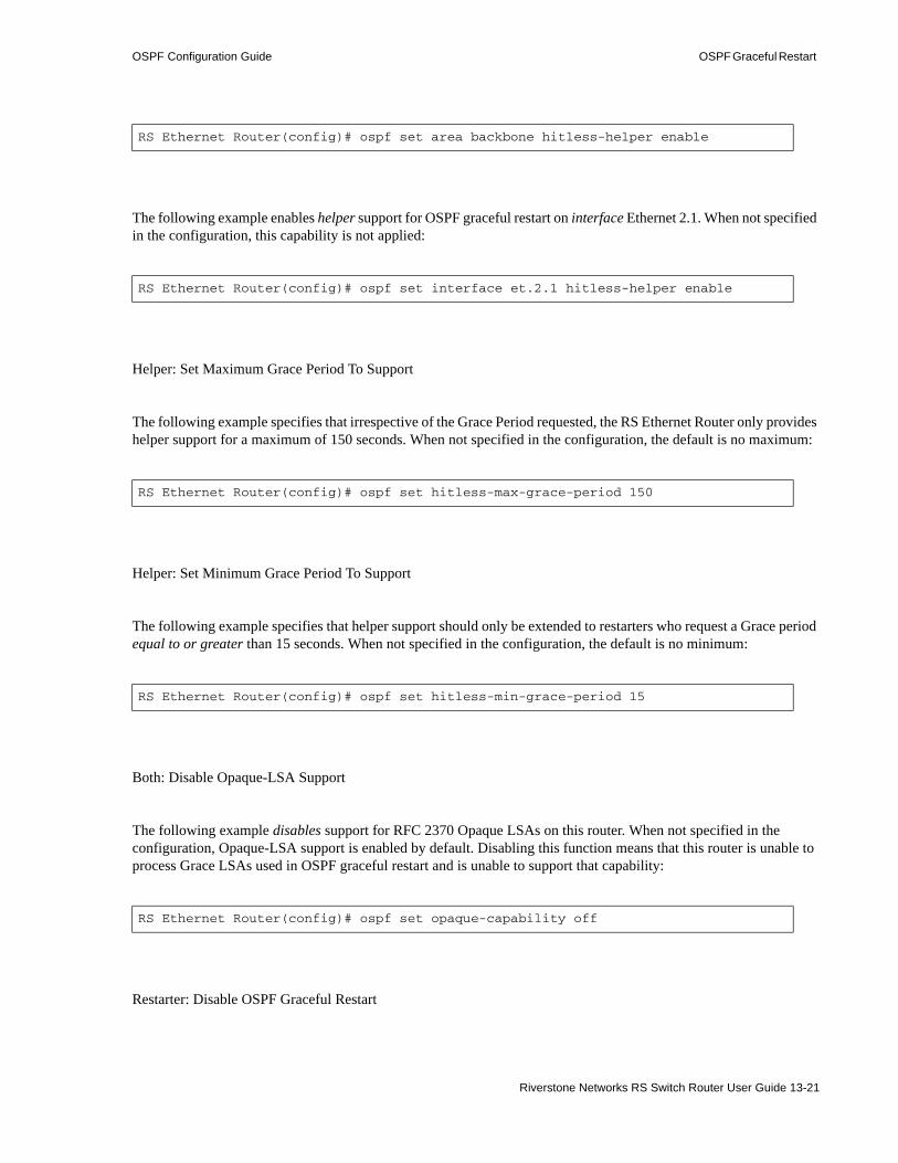
OSPF Configuration Guide OSPF Graceful Restart
The following example enables helper support for OSPF graceful restart on interface Ethernet 2.1. When not specified in the configuration, this capability is not applied:
Helper: Set Maximum Grace Period To Support
The following example specifies that irrespective of the Grace Period requested, the RS Ethernet Router only provides helper support for a maximum of 150 seconds. When not specified in the configuration, the default is no maximum:
Helper: Set Minimum Grace Period To Support
The following example specifies that helper support should only be extended to restarters who request a Grace period equal to or greater than 15 seconds. When not specified in the configuration, the default is no minimum:
Both: Disable Opaque-LSA Support
The following example disables support for RFC 2370 Opaque LSAs on this router. When not specified in the configuration, Opaque-LSA support is enabled by default. Disabling this function means that this router is unable to process Grace LSAs used in OSPF graceful restart and is unable to support that capability:
Restarter: Disable OSPF Graceful Restart
RS Ethernet Router(config)# ospf set area backbone hitless-helper enable
RS Ethernet Router(config)# ospf set interface et.2.1 hitless-helper enable
RS Ethernet Router(config)# ospf set hitless-max-grace-period 150
RS Ethernet Router(config)# ospf set hitless-min-grace-period 15
RS Ethernet Router(config)# ospf set opaque-capability off
Riverstone Networks RS Switch Router User Guide 13-21

OSPF Graceful Restart OSPF Configuration Guide
The following example disables the OSPF graceful restart capability on this router. When not specified in the configuration, OSPF graceful restart is off by default:
Helper: Disable Helper Support
The following example globally disables the ability of this router to help a remote restarting router. When not specified in the configuration, helper support is off by default. Disabling helper support means that this router does not shield any restarts from the rest of the network:
The following example disables helper support for OSPF graceful restart on area backbone. When not specified in the configuration, helper support is off by default. Disabling helper support on the backbone means that this router does not shield a restart occurring in the backbone from the rest of the network:
The following example disables helper support for OSPF graceful restart on interface Ethernet 2.1. When not specified in the configuration, helper support is off by default. Disabling helper support on an interface means that this router does not shield a restart occurring on that interface from the rest of the network:
13.10.4 Example
13.10.4.1 Sample Configuration
In the following sample configuration,• OSPF graceful restart is enabled.• OSPF graceful restart helper capability is enabled.• Opaque LSA-processing capability is enabled.
RS Ethernet Router(config)# ospf set hitless-restart disable
RS Ethernet Router(config)# ospf set hitless-helper disable
RS Ethernet Router(config)# ospf set area backbone hitless-helper disable
RS Ethernet Router(config)# ospf set interface et.2.1 hitless-helper disable
13-22 Riverstone Networks RS Switch Router User Guide

OSPF Configuration Guide OSPF Graceful Restart
• The Grace period is set to 90 seconds.• The maximum Grace period to assist in an OSPF graceful restart is 149. (Only Grace periods less
than the set maximum are assisted.)• The minimum Grace period to assist in an OSPF graceful restart is 16. (Only Grace periods more
than the set minimum are assisted.)
13.10.4.2 Viewing the Graceful Restart Process
You can use the ospf trace mohr-restart and ospf trace mohr-helper commands to enable tracing and observe the active OSPF-specific code-path tracing messages that show the progress of OSPF graceful restart during a restart.
Caution Be careful when you turn on tracing, because the amount of messages that result can overwhelm your screen output. To turn off tracing, simply negate the command.
After turning on tracing using the ip-router global set trace-state on command, you can use the ospf trace mohr-restart command to view OSPF graceful restart in action on a restarting router.
In the trace output below, standard console logs display details about how the restart process is progressing. OSPF graceful restart and helper capabilities are enabled on both the restarter and its neighbors. The relevant OSPF graceful restart messages are in bold.
Running system configuration: ! ! Last modified from Console on 2002-03-20 03:45:39 ! 1 : interface create ip et.7.1 address-netmask 172.20.216.180/22 port et.7.1 up 2 : interface add ip et.7.1 address-netmask 10.110.0.180/16 3 : interface add ip lo0 address-netmask 12.23.34.45/24 ! 4 : ip-router global set trace-state on 5 : ip-router global set router-id 12.23.34.45 ! 6 : ospf create area backbone 7 : ospf add interface et.7.1 to-area backbone 8 : ospf set opaque-capability on 9 : ospf set hitless-restart enable 10 : ospf set hitless-helper enable 11 : ospf set hitless-grace-period 90 12 : ospf set hitless-max-grace-period 150 13 : ospf set hitless-min-grace-period 15 14 : ospf start !...
Riverstone Networks RS Switch Router User Guide 13-23

OSPF Graceful Restart OSPF Configuration Guide
Using the ospf trace mohr-helper command, you can view a helper router entering and leaving helper mode. OSPF graceful restart and helper capabilities are enabled on both the restarter and the neighbor.
The relevant OSPF graceful restart messages are in bold.
13.10.5 Usage Notes, Rules, and Restrictions
The following items are required for OSPF graceful restart:
2002-03-21 11:54:59 %HBT-W-HBTTAKEOVER, Taking over mastership from peer CM
2002-03-21 11:54:59 %HBT-I-MASTERCPUFAIL, active 'Control Module (CM2)' in slot CM/1 has failed
2002-03-21 11:54:59 %SYS-I-SANITY_CHECK, Failover Sanity Check on modules: 0x0.
2002-03-21 11:54:59 %SYS-I-SANITY_CHECK, Failover Sanity Check on modules: 0x0.
2002-03-21 11:55:01 %SYS-I-MULTICPU, additional CPU Module(s) detected in slot CM/1
2002-03-21 11:55:03 %HBT-I-FAILOVERCOMPLETE, CPU failover completed
2002-03-21 11:55:07 %OSPF-I-MOHRENTERED, Entering OSPF hitless restart learning phase.
2002-03-21 11:55:07 %OSPF-I-MOHRSNDGRACE, Sending grace LSAs
2002-03-21 11:55:17 %SNMP-I-ENABLED, SNMP Agent enabled
2002-03-21 11:55:17 %SNMP-I-SENT_TRAP, Sending notification coldStart to management station
2002-03-21 11:55:33 %OSPF-I-MOHREXITED, Exiting OSPF hitless restart learning phase (reason: Success)
2002-03-21 11:55:33 %OSPF-I-MOHRRUNSPF, Schedule an spf run
2002-03-21 11:55:37 %OSPF-I-MOHRREPLAYSO, Replaying saved self orig. LSAs (to fix seq nums)
2002-03-21 11:55:37 %OSPF-I-MOHRTRANSSO, Transmitting all self orig. LSAs
2002-03-21 11:55:37 %OSPF-I-MOHRREPLAYSO, Replaying saved self orig. LSAs (to flush any stale info.)
2002-03-21 11:55:37 %OSPF-I-MOHRFLSHGRACE, Flushing grace LSAs
2002-03-21 11:56:00 %SYS-I-ACTIVECFGTOBACKUP, active configuration updated on Backup CM
2002-03-21 11:56:00 %OSPF-I-MOHRTIDYUP, Freeing up shadow data structures on MASTER
2002-03-21 11:56:00 %SYS-I-ACTIVECFGTOBACKUP, active configuration updated on Backup CM
2002-03-21 11:56:00 %OSPF-I-MOHRSENDSTOSLAVE, Begin sending OSPF data from MASTER to SLAVE
2002-02-21 17:30:00 %OSPF-I-MOHRSTARTHELPING, Start OSPF hitless help for rtid=38.38.38.38, if=201.135.89.195, reason=CPU
2002-02-21 17:30:11 %OSPF-I-MOHRSTOPHELPING, Stop OSPF hitless help for rtid=38.38.38.38, if=201.135.89.195, reason=Success
13-24 Riverstone Networks RS Switch Router User Guide

OSPF Configuration Guide OSPF Graceful Restart
13.10.5.1 Enable Graceful Restart On Other Relevant Protocols
• As the Internet Engineering Task Force (IETF) points out in its working draft on BGP graceful restart, there is little benefit deploying any IGP Graceful Restart in an AS whose IGPs and EGP are tightly coupled (i.e., EGP and IGPs would both restart), and EGPs have no similar graceful restart capability. To reap the full benefits of OSPF graceful restart, make sure that you also enable graceful restart on all collaborating routing protocols.
13.10.5.2 Dual Control Module System
• Since OSPF graceful restart relies on the FIB being preserved from the primary control module to the secondary control module, the restarting router must be a dual control module system.
Note Observe the following usage notes on dual control module systems:
1. Failure on the secondary control module while the primary control module is running has no impact on the OSPF sessions running on the primary.
2. When setting the IP address that the RS Ethernet Router uses during boot exchange with the trivial file transfer protocol (TFTP) boot server, avoid using the same address on any of the IP interfaces configured in the CLI. On a dual control module system, this can cause ARP/IP-reuse issues as the secondary takes over. (This IP address is set using the system set bootprom command.)
The following additional notes, rules, and restrictions apply to the OSPF graceful restart feature:
13.10.5.3 Single Control Module Systems
• Single control module systems can be helpers, but cannot gracefully restart themselves because they lack the capability of preserving the FIB across a restart.
13.10.5.4 No Helper Neighbor
• Some OSPF routers are not capable of supporting or have been configured not to support OSPF graceful restart. Other routers are configured not to support OSPF graceful restart within certain parameters. Neighbors that cannot support a restart do not hide the restart from the rest of the network. They begin routing around the restarter and cease to advertise the newly down adjacencies. The restarter is alerted to this when it receives an LSA that is inconsistent with its pre-start Router LSAs. Since a topology changes makes a network disruption unavoidable, the restarter (and all other active helpers) abort graceful restart and resume normal OSPF operations.
Riverstone Networks RS Switch Router User Guide 13-25

OSPF Graceful Restart OSPF Configuration Guide
13.10.5.5 Partial Helpers
• You can configure a router to only support graceful restart on certain interfaces/areas. This may lead to a situation where a router is configured to help a restarter on some network segments but not on others. In practice, this leads to unsuccessful termination of graceful restart since the partial-helper will not continue to advertise adjacencies on segments where it is not helping.
Note Be sure to avoid this situation in configurations by extending a consistent level of support to any particular neighbor across all of the router’s interfaces/areas.
13.10.5.6 Two-Way Neighbors
• Note that only fully-adjacent neighbors enter Helper mode for the restarter. Two-way neighbors ignore the Grace LSA and do not enter Helper mode. This is correct behavior for the following reasons:- In legal network topologies, two-way neighbors only occur in broadcast networks where a DR
and BDR already exist. In this case, the DR acts as Helper for the restarter and assumes responsibility for alerting the network if graceful restart must be unsuccessfully aborted.
- In the rare and illegal network where the only two neighbors are both ineligible for DR/BDR election, the two-way neighbor still does not alert the network to any changes except those occurring on the physical level—i.e., the interface going down. In a successful graceful restart, the transfer of control between primary and secondary modules ensures that the interface remains in the Up state while the router continues forwarding traffic and maintaining flows. Since physical connectivity remains intact, the two-way neighbor does nothing by default.
13.10.5.7 Supporting Multiple Simultaneous Restarts
• A single router is allowed to simultaneously support multiple restarting neighbors.
13.10.5.8 Manual Reboots
• Manually rebooting or clearing OSPF connections does not activate OSPF graceful restart. On a dual control module system, if the primary is rebooted via the CLI, control is not transferred to the secondary. Only spontaneous crashes or reloads will activate the OSPF graceful restart feature. (The exception to this occurs when the user manually forces a control module mastership change using the system redundancy change-mastership command.)
13.10.5.9 Routing Instances
• The RS Ethernet Router supports OSPF graceful restart on a per-routing instance basis. The commands in this section configure OSPF graceful restart on the main instance only. Configure routing instance graceful restart exactly as you would the main instance, but identify the routing instance by prefacing each commands with the string ‘routing-instance <name>’.
13-26 Riverstone Networks RS Switch Router User Guide

OSPF Configuration Guide Alternative Area Border Router (ABR)
13.11 ALTERNATIVE AREA BORDER ROUTER (ABR)The RS Ethernet Router automatically supports the alternative ABR implementation, as defined in the IETF “Alternative OSPF ABR Implementations” Internet Working Draft. This feature improves the behavior of a router connected to multiple areas without a backbone attachment. Behavior modifications allow the alternative ABR to successfully forward routes to the backbone and other areas despite not being actively attached to the backbone.
Note The RS Ethernet Router implements the alternative ABR feature automatically. No configuration changes are necessary.
Riverstone's OSPF implementation considers a router to be an ABR if it satisfies three requirements:• Has one or more non-backbone areas actively attached. As defined in the IETF working draft, “An
area is considered actively attached if the router has at least one interface in that area in the state other than Down.”
• Has Area 0 configured.• Has an interface in the Up state in Area 0. This requirement is satisfied even if the adjacent interface
on the Area 0 peer is in the Down state, as long as the ABR's interface in Area 0 has not been administratively shut down (ex. using the interface down or port disable command), it will continue to function as an ABR.
If an ABR that is actively attached to more than one non-backbone area ceases to satisfy the above Area 0 requirements (configured and an interface in the Up state), it begins to function as an Alternative ABR, provided that its non-backbone areas are connected to the backbone themselves.
Note For meaningful routing to occur, the areas that the Alternative ABR connects must be connected to the backbone themselves. As the IETF draft reiterates, “[This feature does] not obviate the need of virtual link configuration in case an area has no physical backbone connection at all. The methods described here improve the behavior of a router connecting two or more backbone-attached areas.”
13.12 OSPF CONFIGURATION EXAMPLESFor all examples in this section, refer to the configuration shown in Figure 13-1.
The following configuration commands for router R1: • Determine the IP address for each interface• Specify the static routes configured on the router• Determine its OSPF configuration
!++++++++++++++++++++++++++++++++++++++++++++++++++++++++++++++++++++ ! Create the various IP interfaces.!++++++++++++++++++++++++++++++++++++++++++++++++++++++++++++++++++++ interface create ip to-r2 address-netmask 120.190.1.1/16 port et.1.2
Riverstone Networks RS Switch Router User Guide 13-27

OSPF Configuration Examples OSPF Configuration Guide
interface create ip to-r3 address-netmask 130.1.1.1/16 port et.1.3 interface create ip to-r41 address-netmask 140.1.1.1/24 port et.1.4 interface create ip to-r42 address-netmask 140.1.2.1/24 port et.1.5 interface create ip to-r6 address-netmask 140.1.3.1/24 port et.1.6!+++++++++++++++++++++++++++++++++++++++++++++++++++++++++++++++++++++ ! Configure default routes to the other subnets reachable through R2.!+++++++++++++++++++++++++++++++++++++++++++++++++++++++++++++++++++++ ip add route 202.1.0.0/16 gateway 120.90.1.2 ip add route 160.1.5.0/24 gateway 120.90.1.2!++++++++++++++++++++++++++++++++++++++++++++++++++++++++++++++++++++ ! OSPF Box Level Configuration!++++++++++++++++++++++++++++++++++++++++++++++++++++++++++++++++++++ ospf start ospf create area 140.1.0.0 ospf create area backbone ospf set ase-defaults cost 4!++++++++++++++++++++++++++++++++++++++++++++++++++++++++++++++++++++ ! OSPF Interface Configuration!++++++++++++++++++++++++++++++++++++++++++++++++++++++++++++++++++++ ospf add interface 140.1.1.1 to-area 140.1.0.0 ospf add interface 140.1.2.1 to-area 140.1.0.0 ospf add interface 140.1.3.1 to-area 140.1.0.0 ospf add interface 130.1.1.1 to-area backbone
13-28 Riverstone Networks RS Switch Router User Guide

OSPF Configuration Guide OSPF Configuration Examples
13.12.1 Exporting All Interface & Static Routes to OSPF
Router R1 has several static routes. We will export these static routes as type-2 OSPF routes. The interface routes will be redistributed as type-1 OSPF routes. 1. Create an OSPF export destination for type-1 routes to redistribute certain routes into OSPF as type
1 OSPF-ASE routes.
2. Create an OSPF export destination for type-2 routes to redistribute certain routes into OSPF as type 2 OSPF-ASE routes.
3. Create a Static export source to export static routes.
4. Create a Direct export source to export interface/direct routes.
5. Create the Export-Policy for redistributing all interface routes and static routes into OSPF.
13.12.2 Exporting All RIP, Interface & Static Routes to OSPF
We will also export interface, static, RIP, OSPF, and OSPF-ASE routes into RIP.
In the configuration shown in Figure 13-1, RIP Version 2 is configured on the interfaces of routers R1 and R2, which are attached to the sub-network 120.190.0.0/16.
We will redistribute these RIP routes as OSPF type-2 routes and associate the tag 100 with them. Router R1 will also redistribute its static routes as type 2 OSPF routes. The interface routes will be redistributed as type 1 OSPF routes.
Router R1 will redistribute its OSPF, OSPF-ASE, RIP, Static and Interface/Direct routes into RIP.1. Enable RIP on interface 120.190.1.1/16.
2. Create an OSPF export destination for type-1 routes.
ip-router policy create ospf-export-destination ospfExpDstType1 type 1 metric 1
ip-router policy create ospf-export-destination ospfExpDstType2 type 2 metric 4
ip-router policy create static-export-source statExpSrc
ip-router policy create direct-export-source directExpSrc
ip-router policy export destination ospfExpDstType1 source directExpSrc network allip-router policy export destination ospfExpDstType2 source statExpSrc network all
rip add interface 120.190.1.1rip set interface 120.190.1.1 version 2 type multicast
ip-router policy create ospf-export-destination ospfExpDstType1 type 1 metric 1
Riverstone Networks RS Switch Router User Guide 13-29

OSPF Configuration Examples OSPF Configuration Guide
3. Create an OSPF export destination for type-2 routes.
4. Create an OSPF export destination for type-2 routes with a tag of 100.
5. Create a RIP export source.
6. Create a Static export source.
7. Create a Direct export source.
8. Create the Export-Policy for redistributing all interface, RIP and static routes into OSPF.
9. Create a RIP export destination.
10. Create OSPF export source.
11. Create OSPF-ASE export source.
ip-router policy create ospf-export-destination ospfExpDstType2 type 2 metric 4
ip-router policy create ospf-export-destination ospfExpDstType2t100 type 2 tag 100 metric 4
ip-router policy create rip-export-source ripExpSrc
ip-router policy create static-export-source statExpSrc
ip-router policy create direct-export-source directExpSrc
ip-router policy export destination ospfExpDstType1 source directExpSrc network allip-router policy export destination ospfExpDstType2 source statExpSrc network allip-router policy export destination ospfExpDstType2t100 source ripExpSrc network all
ip-router policy create rip-export-destination ripExpDst
ip-router policy create ospf-export-source ospfExpSrc type OSPF
ip-router policy create ospf-export-source ospfAseExpSrc type OSPF-ASE
13-30 Riverstone Networks RS Switch Router User Guide

OSPF Configuration Guide OSPF Configuration Examples
12. Create the Export-Policy for redistributing all interface, RIP, static, OSPF and OSPF-ASE routes into RIP.
ip-router policy export destination ripExpDst source statExpSrc network allip-router policy export destination ripExpDst source ripExpSrc network allip-router policy export destination ripExpDst source directExpSrc network allip-router policy export destination ripExpDst source ospfExpSrc network allip-router policy export destination ripExpDst source ospfAseExpSrc network all
Riverstone Networks RS Switch Router User Guide 13-31
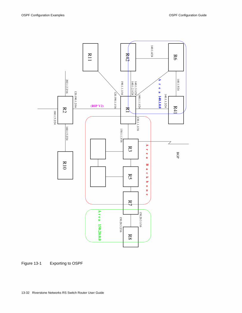
OSPF Configuration Examples OSPF Configuration Guide
Figure 13-1 Exporting to OSPF
BG
P
R1
R2
R3
R41
R42
R6
R11
A r e a B
a c k b o n e
A r e a 140.1.0.0(RIP V2)
140.1.1.1/24
140.1.2.1/24
140.1.5/24
140.1.4/24
190.1.1.1/16
120.190.1.1/16
160.1.5.2/24R
10
R5
R7
202.1.2.2/16
140.1.3.1/24130.1.1.1/16
R8
A r e a 150.20.0.0
150.20.3.1/16
150.20.3.2/16
140.1.1.2/24
130.1.1.3/16
120.190.1.2/16
160.1.5.2/24
13-32 Riverstone Networks RS Switch Router User Guide

14 IS-IS CONFIGURATION GUIDE
This chapter provides an overview of the Intermediate System-Intermediate System (IS-IS) routing protocol features available for the Riverstone RS Switch Router.
IS-IS is a link state hierarchical routing protocol. In IS-IS, a router is an Intermediate System (IS), and a routing sub domain is an area. An IS-IS area can contain a number of routers and end devices. Routing within an area is handled by Level 1 routers, and routing between different areas is handled by Level 2 routers. An IS can route Level 1 and/or Level 2 traffic.
The IS-IS routing protocol is based on “shortest path first” calculations, similar to the OSPF routing protocol. Intermediate Systems exchange link state information by transmitting Link State Protocol Data Units (LSPs). (LSPs are exchanged between same level routers only.) Each IS maintains its own LSP database.
To configure the RS Ethernet Router to run IS-IS, you should perform the following tasks:• Define the area to which the router will belong.• Configure IS-IS interfaces.• Start IS-IS.
Optionally, you can modify the default IS-IS parameters that are set globally and on a per-interface basis.
14.1 DEFINING AN IS-IS AREAAn IS-IS area is a network sub domain that consists of routers and the end devices connected to them. All routers in an area maintain detailed routing information about destinations within the area. When you define the area of the RS Ethernet Router, all its interfaces belong to that area. Interfaces on an RS Ethernet Router cannot belong to separate areas.
To define the IS-IS area to which the RS Ethernet Router will belong, enter the following command in Configure mode:
14.2 CONFIGURING IS-IS INTERFACESIS-IS is disabled on all RS Ethernet Router interfaces by default. To enable IS-IS on an interface, first configure an IP interface using the interface create command. Then, enable IS-IS on the interface. You can enable IS-IS on all IP interfaces by specifying the all keyword.
Defines an IS-IS area. isis add area <string>
Riverstone Networks RS Switch Router User Guide 14-1

Enabling IS-IS on the RS Ethernet Router IS-IS Configuration Guide
To enable IS-IS on an interface, enter the following command in Configure mode:
14.3 ENABLING IS-IS ON THE RS ETHERNET ROUTER
IS-IS is disabled on the RS Ethernet Router by default. To enable IS-IS on the RS Ethernet Router, enter the following command in Configure mode:
14.4 SETTING IS-IS GLOBAL PARAMETERSThe RS Ethernet Router provides global IS-IS parameters which control the router’s operating level, timers, authentication, and other IS-IS functions. The following sections discuss the global IS-IS parameters that you can modify to better suit your routing environment.
14.4.1 Setting the IS Operating Level
An IS can be configured to route Level 1 and/or Level 2 traffic. Level 1 routing handles all intra-domain traffic, (all traffic within an IS-IS area). Level 2 routing handles all inter-domain traffic (all traffic between different IS-IS areas).
On the RS Ethernet Router, you can set the operating level for the router and on a per-interface basis. The default level for both the router and its interfaces is Level 1- and-2. You may change the default for either or both. If you do so, keep in mind that the operating level of the interfaces must agree with the operating level of the RS Ethernet Router. Therefore if a router’s operating level is set to Level 1 or to Level 2, its interfaces should be set to the same level. But if the interfaces will be routing both Level 1 and Level 2 traffic, then you should set the router’s level to Level 1-and-2.
To set the router’s operating level, enter the following command in Configure mode:
14.4.2 Setting the PSN Interval
On point-to-point subnetworks, an IS sends a Partial Sequence Number PDU (PSNP) to acknowledge each LSP it receives. PSNPs contain the following information: LSP ID, the LSP’s sequence number, the LSP’s Checksum and the LSP’s Remaining Lifetime.
Creates an IS-IS interface on a router. isis add interface <string>|all
Enables IS-IS on the router. isis start
Sets the IS-IS level for a router. isis set level 1|2|1-and-2
14-2 Riverstone Networks RS Switch Router User Guide

IS-IS Configuration Guide Setting IS-IS Global Parameters
To set the time interval between PSNP transmissions, enter the following command in Configure mode:
14.4.3 Setting the System ID
A system ID is a unique 12 hexadecimal number that uniquely identifies the IS in the routing domain. A system ID is assigned to the IS by default, but can be overwritten using the following command.
To set the system ID for an IS, enter the following command in Configure mode:
Note that once the system ID is set, it cannot be changed without disabling and reenabling IS-IS.
Sets the PSNP interval. isis set psn-interval <number>
Sets the system ID for a router. isis set system-id <string>
Riverstone Networks RS Switch Router User Guide 14-3

Setting IS-IS Global Parameters IS-IS Configuration Guide
14.4.4 Setting the SPF Interval
The routing algorithm used by IS-IS is the shortest path first (SPF) algorithm. IS-IS executes this algorithm after events that result in changes in the topology. The RS Ethernet Router uses certain timers to control SPF recalculations. You can use the isis set spf-interval command to change the following defaults for each level:• the maximum interval, which is the maximum number of seconds between SPF recalculations. The
default is 10 seconds. • the initial interval, which is the number of seconds an SPF recalculation is delayed after an initial
event occurs. The default is 5500 milliseconds.
An event is considered an “initial event” if it occurs after two times the maximum interval. For example, if the maximum interval is 10 seconds, and an event occurs after 20 seconds (2 * 10 = 20 seconds), then that event is considered an “initial event” and the RS Ethernet Router waits the initial interval before executing an SPF recalculation.
• the incremental interval, which is the number of seconds an SPF recalculation is delayed after subsequent events occur. The default is 5500 milliseconds. This is variable and increases until it reaches the maximum interval.
In the following example, the initial and incremental values are each set to 1000 milliseconds for Level 1 and Level 2:
Based on the example, the RS Ethernet Router executes an SPF recalculation as follows:• after the first trigger event, the RS Ethernet Router waits the initial interval, which is 1000
milliseconds, to execute the SPF recalculation• after the second event, the RS Ethernet Router waits the incremental interval, which is 1000
milliseconds, to execute the SPF recalculation• after the third and each succeeding event, the RS Ethernet Router waits 2 times the previous interval
to execute the SPF recalculation. Therefore: - after the third event, the RS Ethernet Router waits 2000 milliseconds (2 seconds)- after the fourth event, the RS Ethernet Router waits 4000 milliseconds (4 seconds) - after the fifth event, the RS Ethernet Router waits 8000 milliseconds (8 seconds)- after the sixth and succeeding events, the RS Ethernet Router waits 10 seconds only (the
maximum interval).
Once the network calms down, if no trigger event occurs within 20 seconds ( 2 * maximum interval = 20 seconds), then the RS Ethernet Router treats the next event as an initial event.
rs(config)# isis set spf-interval level 1-and-2 initial 1000 incremental 1000
14-4 Riverstone Networks RS Switch Router User Guide

IS-IS Configuration Guide Setting IS-IS Global Parameters
14.4.5 Setting the LSP Generation Interval
By default, the IS periodically generates an LSP. In addition, an LSP is also generated when certain events result in topological changes, for example an adjacency or circuit up/down event or a change in circuit metrics. When such events occur, IS-IS generates updated LSPs. You can use the isis set lsp-gen-interval command to control various intervals that affect the generation of LSPs. They are as follows:• the maximum interval, which is the maximum number of seconds between the generation of LSPs.
Decreasing this interval could result in faster convergence, but may also affect CPU performance. The default is 5 seconds.
• the initial interval, which is the number of seconds the RS Ethernet Router waits to generate updated LSPs after an initial event occurs. The default is 50 milliseconds.
• the incremental interval, which is the number of seconds the RS Ethernet Router waits to generate updated LSPs after subsequent events occur. The default is 5000 milliseconds.
In the following example, the initial and incremental intervals are set to 1000 milliseconds for Level 1 and Level 2:
Based on the preceding example, the RS Ethernet Router generates LSPs as follows:• after the first trigger event, the RS Ethernet Router waits the initial interval, which is 1000
milliseconds, to generate updated LSPs• after the second event, the RS Ethernet Router waits the incremental interval, which is 1000
milliseconds, to generate updated LSPs• after the third and each succeeding event, the RS Ethernet Router waits 2 times the previous interval.
Therefore: - after the third event, the RS Ethernet Router waits 2000 milliseconds (2 seconds)- after the fourth event, the RS Ethernet Router waits 4000 milliseconds (4 seconds) - after the fifth event, the RS Ethernet Router waits 8000 milliseconds (8 seconds)- after the sixth and succeeding events, the RS Ethernet Router waits up to 10 seconds only (the
maximum interval).
Once the network calms down, if no trigger events occur within 20 seconds ( 2 * maximum interval = 20 seconds), then the RS Ethernet Router treats the next event as an initial event.
14.4.6 Setting the Overload Bit
The IS-IS protocol provides a feature for routers to signal each other when they cannot record the complete LSP database. (This occurs when a router has run out of memory.) When a router experiences memory overload, it sets its overload bit in its LSPs. The other routers will then route packets to that router’s directly connected networks, but will not use it to route transit traffic until its overload bit is cleared. In the RS Ethernet Router, you can manually set the router’s overload bit so it functions only as an end system.
To set the router’s overload bit, enter the following command in Configure mode:
rs(config)# isis set lsp-gen-interval level 1-and-2 initial 1000 incremental 1000
Sets the overload bit. isis set overload-bit
Riverstone Networks RS Switch Router User Guide 14-5
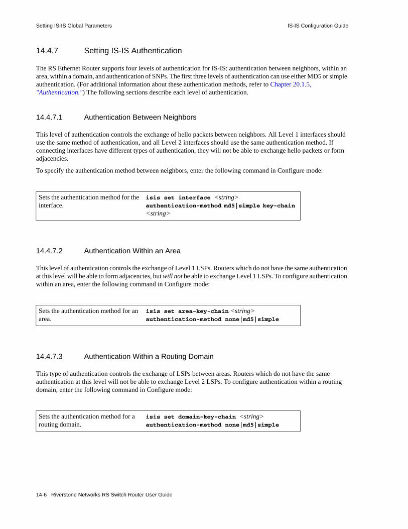
Setting IS-IS Global Parameters IS-IS Configuration Guide
14.4.7 Setting IS-IS Authentication
The RS Ethernet Router supports four levels of authentication for IS-IS: authentication between neighbors, within an area, within a domain, and authentication of SNPs. The first three levels of authentication can use either MD5 or simple authentication. (For additional information about these authentication methods, refer to Chapter 20.1.5, "Authentication.") The following sections describe each level of authentication.
14.4.7.1 Authentication Between Neighbors
This level of authentication controls the exchange of hello packets between neighbors. All Level 1 interfaces should use the same method of authentication, and all Level 2 interfaces should use the same authentication method. If connecting interfaces have different types of authentication, they will not be able to exchange hello packets or form adjacencies.
To specify the authentication method between neighbors, enter the following command in Configure mode:
14.4.7.2 Authentication Within an Area
This level of authentication controls the exchange of Level 1 LSPs. Routers which do not have the same authentication at this level will be able to form adjacencies, but will not be able to exchange Level 1 LSPs. To configure authentication within an area, enter the following command in Configure mode:
14.4.7.3 Authentication Within a Routing Domain
This type of authentication controls the exchange of LSPs between areas. Routers which do not have the same authentication at this level will not be able to exchange Level 2 LSPs. To configure authentication within a routing domain, enter the following command in Configure mode:
Sets the authentication method for the interface.
isis set interface <string> authentication-method md5|simple key-chain
<string>
Sets the authentication method for an area.
isis set area-key-chain <string> authentication-method none|md5|simple
Sets the authentication method for a routing domain.
isis set domain-key-chain <string> authentication-method none|md5|simple
14-6 Riverstone Networks RS Switch Router User Guide

IS-IS Configuration Guide Setting IS-IS Interface Parameters
14.4.7.4 SNP Authentication
This type of authentication controls the processing of SNPs (both CSNPs and PSNPs). When the router receives an SNP, it authenticates it by checking the password (which is the same as the password set using the isis set interface password command).
To configure SNP authentication, enter the following command in Configure mode:
14.4.8 Configuring IS-IS Graceful Shutdown
IS-IS graceful shutdown enables a router that is shutting down to help neighboring routers route around it. It does so by instructing its neighbors to bypass its links when charting paths in the network. The neighbors begin ignoring the presence of the router that is shutting down before it actually shuts down, thus avoiding network interruptions. With this feature enabled, the RS Ethernet Router sets the metrics on each of its links to the maximum metric and floods this information to all of its neighbors. When the neighbors recompute the shortest-path first algorithm using the new metric, they will prefer any link with a lower metric to the links on the router that is shutting down.
Note Assigning the maximum metric to links is not equivalent to setting the overload bit. The overload bit signals that a router’s databases may be corrupted. Assigning the maximum metric to a link renders the link highly undesirable, but still usable. A path may still utilize the link if no substitutable links with a lower metric are available.
Configure IS-IS graceful shutdown globally using the isis set max-metric command. As long as this command is in effect, the RS Ethernet Router will continue to advertise the maximum metric to all of its neighbors. To restore normal metric advertisements, remove this command from the active configuration using the negate or no command.
14.5 SETTING IS-IS INTERFACE PARAMETERSThe interfaces on the RS Ethernet Router have default IS-IS parameter values. These parameters control various IS-IS functions and features on the interfaces, such as their operating level, metrics, and timers.
Sets authentication for SNPs. isis set require-snp-auth
Riverstone Networks RS Switch Router User Guide 14-7

Setting IS-IS Interface Parameters IS-IS Configuration Guide
To set parameters for an IS-IS interface, enter the following command in Configure mode:
The following sections describe some of the parameters used by the IS-IS interfaces. For a detailed description of this command and its parameters, refer to the isis commands chapter in the Riverstone RS Switch Router Command Line Interface Reference Manual.
14.5.1 Setting the Interface Operating Level
The default operating level for the router and its interfaces is Level 1-and-2. If you change the default, note that the operating level of the router’s IS-IS interfaces should be synchronized with the operating level of the router. (For additional information, refer to Section 14.4.1, "Setting the IS Operating Level,".)
14.5.2 Setting Interface Parameters for a Designated Intermediate System (DIS)
On a broadcast network, routers elect a DIS, which advertises all links to the attached routers. The following parameters are used during DIS election and by the interface, if it is elected as the DIS. These parameters can be set globally, or for Level-1 or Level-2 interfaces only. • Priority
The router’s priority for the Designated Intermediate System (DIS) election. The router with the highest priority becomes the DIS. To ensure that a router does not become the DIS, set this parameter to 0. To increase a router’s chance of becoming a DIS, set this parameter to the highest value, which is 127. In case of a tie, the router with the highest System ID becomes the DIS. The default priority is 64.
• DIS Hello Interval
The hello-interval used if the router becomes the DIS. The default hello-interval is 3.• CSN Interval
The interval at which the router will multicast Complete Sequence Number PDUs (CSNPs), if the router becomes the DIS. CSNPs contain a list of all LSPs in the database in addition to information used by the other routers to determine whether they have synchronized LSP databases. The default csn-interval is 10.
Configures an IS-IS interface on a router.
isis set interface <interface-name-or IPaddr> [level 1|2|1-and-2] [metric <number>] [priority <number>] [hello-interval <number>] [dis-hello-interval <number>]
[hello-multipler <number>] [csn-interval <number>] [lsp-interval<number>] [max-burst <number>] [passive] [retransmit-interval <number>] [authentication-method none|md5|simple] [key-chain <string>] [l1-csn-interval <number>] [l1-dis-hello-interval<number>] [l1-hello-interval <number>] [l1-hello-multipler <number>] [l1-metric <number>] [l1-priority <number>] [l2-csn-interval <number>] [l2-dis-hello-interval<number>] [l2-hello-interval <number>] [l2-hello-multipler <number>] [l2-metric <number>] [l2-priority <number>][mesh-group]<number>
14-8 Riverstone Networks RS Switch Router User Guide
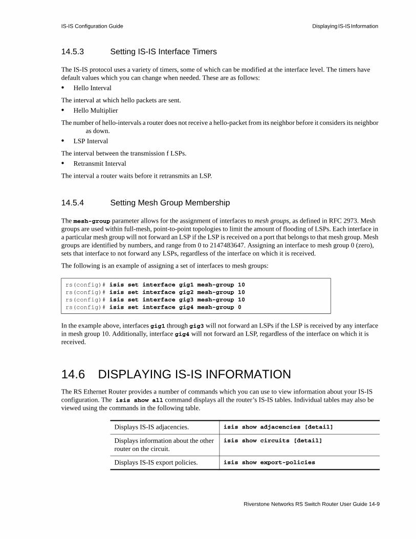
IS-IS Configuration Guide Displaying IS-IS Information
14.5.3 Setting IS-IS Interface Timers
The IS-IS protocol uses a variety of timers, some of which can be modified at the interface level. The timers have default values which you can change when needed. These are as follows:• Hello Interval
The interval at which hello packets are sent.• Hello Multiplier
The number of hello-intervals a router does not receive a hello-packet from its neighbor before it considers its neighbor as down.
• LSP Interval
The interval between the transmission f LSPs.• Retransmit Interval
The interval a router waits before it retransmits an LSP.
14.5.4 Setting Mesh Group Membership
The mesh-group parameter allows for the assignment of interfaces to mesh groups, as defined in RFC 2973. Mesh groups are used within full-mesh, point-to-point topologies to limit the amount of flooding of LSPs. Each interface in a particular mesh group will not forward an LSP if the LSP is received on a port that belongs to that mesh group. Mesh groups are identified by numbers, and range from 0 to 2147483647. Assigning an interface to mesh group 0 (zero), sets that interface to not forward any LSPs, regardless of the interface on which it is received.
The following is an example of assigning a set of interfaces to mesh groups:
In the example above, interfaces gig1 through gig3 will not forward an LSPs if the LSP is received by any interface in mesh group 10. Additionally, interface gig4 will not forward an LSP, regardless of the interface on which it is received.
14.6 DISPLAYING IS-IS INFORMATIONThe RS Ethernet Router provides a number of commands which you can use to view information about your IS-IS configuration. The isis show all command displays all the router’s IS-IS tables. Individual tables may also be viewed using the commands in the following table.
rs(config)# isis set interface gig1 mesh-group 10rs(config)# isis set interface gig2 mesh-group 10rs(config)# isis set interface gig3 mesh-group 10rs(config)# isis set interface gig4 mesh-group 0
Displays IS-IS adjacencies. isis show adjacencies [detail]
Displays information about the other router on the circuit.
isis show circuits [detail]
Displays IS-IS export policies. isis show export-policies
Riverstone Networks RS Switch Router User Guide 14-9

Displaying IS-IS Information IS-IS Configuration Guide
Note For additional information about the isis show commands, their parameters, or the fields in the output, refer to the Riverstone RS Switch Router Command Line Interface Reference Manual.
Displays IS-IS global parameters. isis show globals
Displays Link State PDU (LSP) database information.
isis show lsp-database level1|2
[detail][id<string>][summary]
Displays IS-IS timers. isis show timers
14-10 Riverstone Networks RS Switch Router User Guide
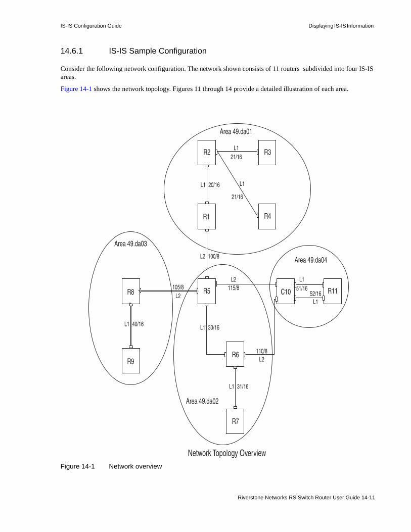
IS-IS Configuration Guide Displaying IS-IS Information
14.6.1 IS-IS Sample Configuration
Consider the following network configuration. The network shown consists of 11 routers subdivided into four IS-IS areas.
Figure 14-1 shows the network topology. Figures 11 through 14 provide a detailed illustration of each area.
Figure 14-1 Network overview
Area 49.da03
R8
R9
L1 40/16
R2
R1
R3
R4
105/8L2
L1
L1
L1
L2
21/16
21/16
20/16
100/8
Area 49.da01
R5 C10 R11
R6
R7
Area 49.da02
Area 49.da04
L2
L2
115/8
110/8
L1
L1
51/1652/16
L1 30/16
L1 31/16
Network Topology Overview
Riverstone Networks RS Switch Router User Guide 14-11

Displaying IS-IS Information IS-IS Configuration Guide
Figure 14-2 Area 1 detailed view
R2
R1
R3
R4
L1
L1
L1
21/16
21/1620/16
Area 49.da01
20.1.1.2/16
20.1.1.1/16
100.1.1.1/8
21.1.1.1/16 21.1.1.2/16 24.1.1.1/16
21.1.1.3/16 25.1.1.1/16
L2100/8
23.1.1.1/16
22.1.1.1/16
et.1.1 vlan 21net
et.1.2
et.1.2
hs.5.1
et.1.1
et.1.3 et.1.1
et.1.4
et.1.1
IS-IS Area 1
14-12 Riverstone Networks RS Switch Router User Guide

IS-IS Configuration Guide Displaying IS-IS Information
Figure 14-3 Area 2 detailed view
105/8
L2 R5
R6
R7
Area 49.da02
L2
L2
115/8
110/8
L1 30/16
L131/16
L2100/8
IS-IS Area 2
100.1.1.2/8 hs.5.1
115.1.1.1/8
et.1.8
110.1.1.1/8
et.1.4
et.1.230.1.1.1/16
105.1.1.2/8
et.1.3
30.1.1.2/16
et.1.2
et.1.331.1.1.1/16
et.1.331.1.1.2/16
Riverstone Networks RS Switch Router User Guide 14-13
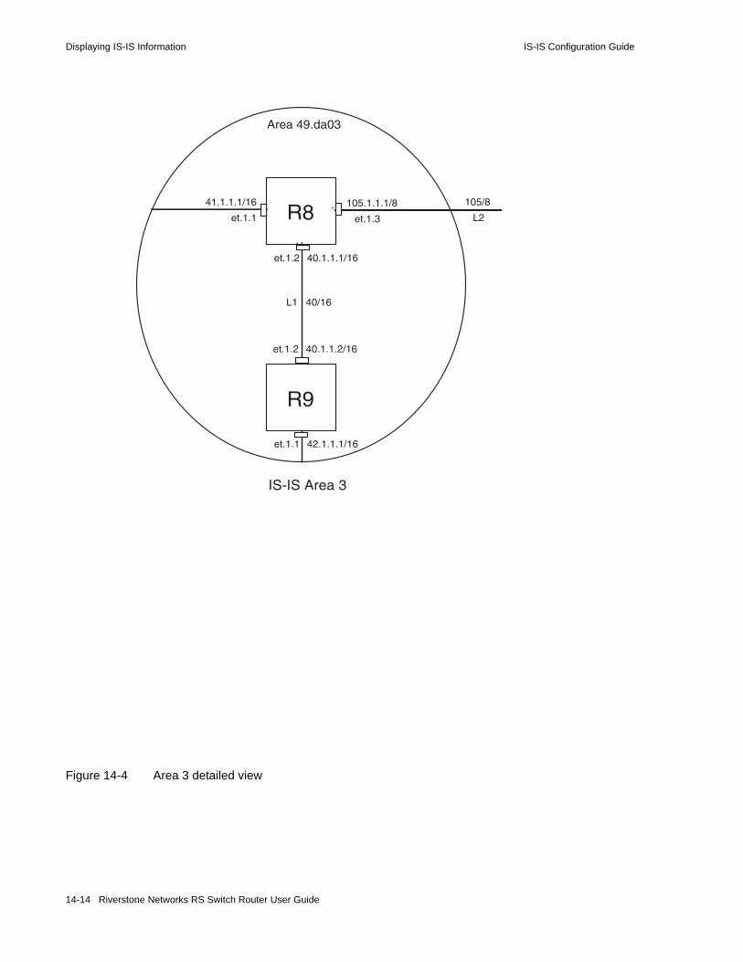
Displaying IS-IS Information IS-IS Configuration Guide
Figure 14-4 Area 3 detailed view
Area 49.da03
R8
R9
L1 40/16
105/8
L2
105.1.1.1/8
et.1.3
et.1.2 40.1.1.2/16
et.1.2 40.1.1.1/16
41.1.1.1/16
et.1.1
et.1.1 42.1.1.1/16
IS-IS Area 3
14-14 Riverstone Networks RS Switch Router User Guide

IS-IS Configuration Guide Displaying IS-IS Information
Figure 14-5 Area 4 detailed view
The following sections show the configuration for each router within this network. Note that explanations (in italics) precede each command or set of commands.
C10 R11
Area 49.da04
L2
L2
115/8
110/8
L1
L1
51/16
52/16
51.1.1.1/16
52.1.1.1/16
et.1.2
se.4.3
51.1.1.2/16
52.1.1.2/16
115.1.1.2/8
110.1.1.2/8
IS-IS Area 4
Riverstone Networks RS Switch Router User Guide 14-15

Displaying IS-IS Information IS-IS Configuration Guide
14.6.1.1 R1 Configuration
The following is the configuration for R1 in Area 1. R1 has a Level 1 IS-IS interface and a Level 2 IS-IS interface.
R1(config)# shRunning system configuration: ! ! Last modified from Console on 2000-06-29 12:13:03 !
To configure the WAN port hs.5.1: 1 : port set hs.5.1 wan-encapsulation ppp speed 45000000 clock internal-clock-51mhz !
To configure IP interfaces: 2 : interface create ip 20net address-netmask 20.1.1.1/16 port et.1.2 3 : interface create ip 22net address-netmask 22.1.1.1/16 port et.1.1 4 : interface create ip 100net address-netmask 100.1.1.1/8 port hs.5.1 !
To configure router R1’s area: 5 : isis add area 49.da01
To enable IS-IS on each interface: 6 : isis add interface 20net 7 : isis add interface 22net 8 : isis add interface 100net
To set IS-IS parameters for each interface: 9 : isis set interface 20net encap iso priority 10 metric 10 level 110 : isis set interface 22net encap iso priority 10 metric 10 level 111 : isis set interface 100net encap iso priority 10 metric 10 level 2
To set the IS-IS level of router R1:12 : isis set level 1-and-2
To start IS-IS on router R1:13 : isis start !
14-16 Riverstone Networks RS Switch Router User Guide

IS-IS Configuration Guide Displaying IS-IS Information
14.6.1.2 R2 Configuration
The following is the configuration for router R2 in Area 1:
R2(config)# shRunning system configuration:
To configure the IP VLAN, 21net: 1 : vlan create 21net ip 2 : vlan add ports et.1.3,et.1.4 to 21net !
To configure ports et.1.1 and et.1.2, and VLAN 21net as separate IP interfaces: 3 : interface create ip 23net address-netmask 23.1.1.1/16 port et.1.1 4 : interface create ip 21net address-netmask 21.1.1.1/16 vlan 21netvlan 5 : interface create ip 20net address-netmask 20.1.1.2/16 port et.1.2 !
To configure router R2’s area: 6 : isis add area 49.da01
To enable IS-IS on each IP interface: 7 : isis add interface 23net 8 : isis add interface 21net 9 : isis add interface 20net
To set IS-IS parameters for each interface:10 : isis set interface 23net encap iso priority 10 metric 10 level 111 : isis set interface 21netvlan encap iso priority 10 metric 10 level 1
To set the IS-IS level of router R2:12 : isis set level 113 : isis set interface 20net encap iso level 1 priority 10 metric 10
To start IS-IS on router R2:14 : isis start !
Riverstone Networks RS Switch Router User Guide 14-17

Displaying IS-IS Information IS-IS Configuration Guide
14.6.1.3 R3 Configuration
The following is the configuration for router R3 in Area 1:
R3(config)# shRunning system configuration: ! ! Last modified from Console on 2000-06-28 22:48:47 !
To configure IP interfaces: 1 : interface create ip 21net address-netmask 21.1.1.2/16 port et.1.3 2 : interface create ip 24net address-netmask 24.1.1.1/16 port et.1.1 !
To configure router R3’s area: 3 : isis add area 49.da01
To enable IS-IS on each interface: 4 : isis add interface 21net 5 : isis add interface 24net
To set parameters for each interface: 6 : isis set interface 21net encap iso priority 10 metric 10 level 1 7 : isis set interface 24net encap iso priority 10 metric 10 level 1
To set the IS-IS level of router R3: 8 : isis set level 1-and-2
To start IS-IS on router R3: 9 : isis start
!
14-18 Riverstone Networks RS Switch Router User Guide
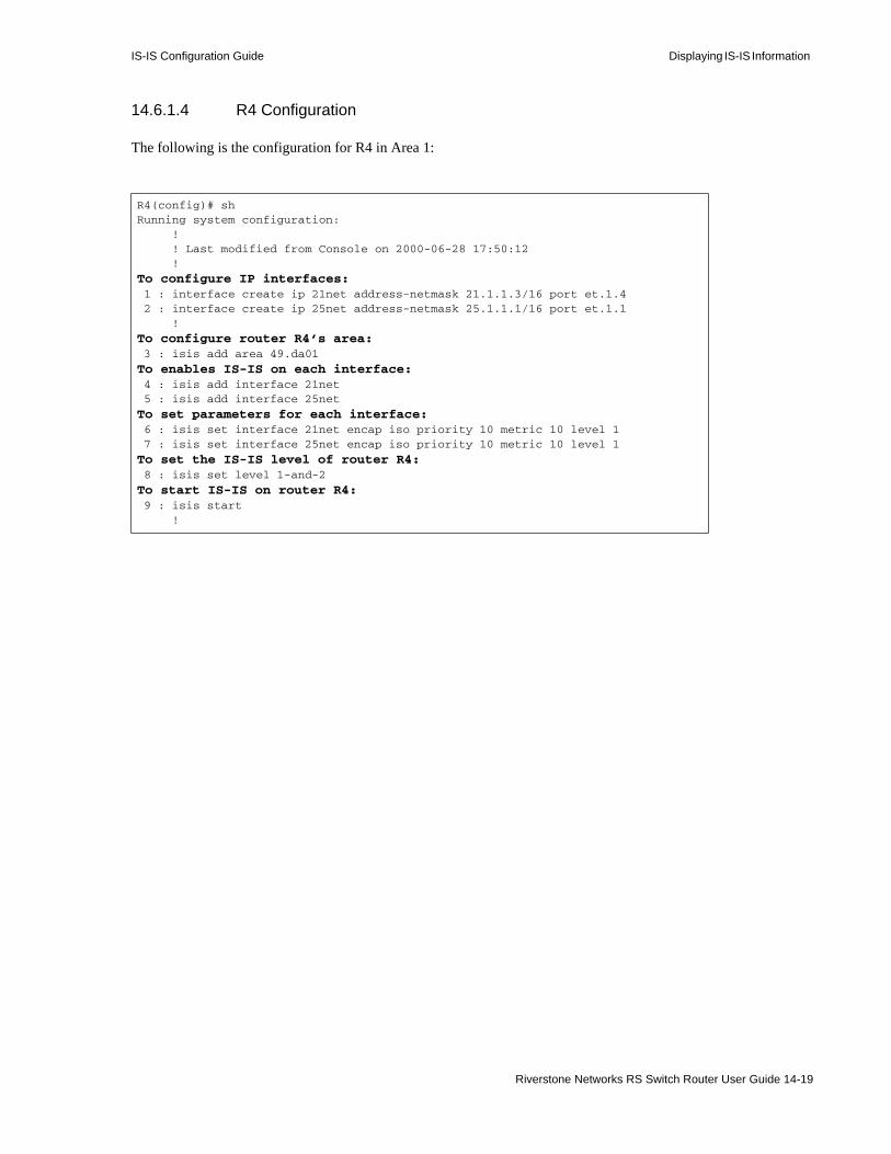
IS-IS Configuration Guide Displaying IS-IS Information
14.6.1.4 R4 Configuration
The following is the configuration for R4 in Area 1:
R4(config)# shRunning system configuration: ! ! Last modified from Console on 2000-06-28 17:50:12 !
To configure IP interfaces: 1 : interface create ip 21net address-netmask 21.1.1.3/16 port et.1.4 2 : interface create ip 25net address-netmask 25.1.1.1/16 port et.1.1 !
To configure router R4’s area: 3 : isis add area 49.da01
To enables IS-IS on each interface: 4 : isis add interface 21net 5 : isis add interface 25net
To set parameters for each interface: 6 : isis set interface 21net encap iso priority 10 metric 10 level 1 7 : isis set interface 25net encap iso priority 10 metric 10 level 1
To set the IS-IS level of router R4: 8 : isis set level 1-and-2
To start IS-IS on router R4: 9 : isis start !
Riverstone Networks RS Switch Router User Guide 14-19
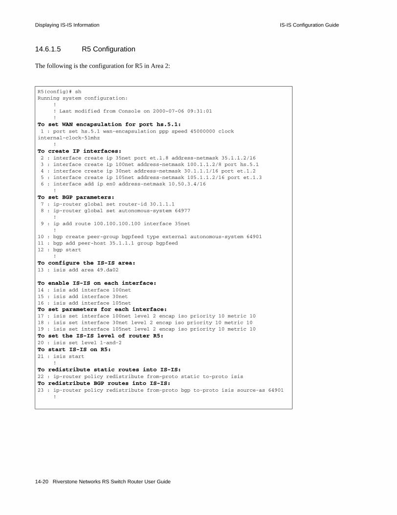
Displaying IS-IS Information IS-IS Configuration Guide
14.6.1.5 R5 Configuration
The following is the configuration for R5 in Area 2:
R5(config)# shRunning system configuration: ! ! Last modified from Console on 2000-07-06 09:31:01 !
To set WAN encapsulation for port hs.5.1: 1 : port set hs.5.1 wan-encapsulation ppp speed 45000000 clockinternal-clock-51mhz !
To create IP interfaces: 2 : interface create ip 35net port et.1.8 address-netmask 35.1.1.2/16 3 : interface create ip 100net address-netmask 100.1.1.2/8 port hs.5.1 4 : interface create ip 30net address-netmask 30.1.1.1/16 port et.1.2 5 : interface create ip 105net address-netmask 105.1.1.2/16 port et.1.3 6 : interface add ip en0 address-netmask 10.50.3.4/16 !
To set BGP parameters: 7 : ip-router global set router-id 30.1.1.1 8 : ip-router global set autonomous-system 64977 ! 9 : ip add route 100.100.100.100 interface 35net !10 : bgp create peer-group bgpfeed type external autonomous-system 6490111 : bgp add peer-host 35.1.1.1 group bgpfeed12 : bgp start !
To configure the IS-IS area:13 : isis add area 49.da02
To enable IS-IS on each interface:14 : isis add interface 100net15 : isis add interface 30net16 : isis add interface 105net To set parameters for each interface: 17 : isis set interface 100net level 2 encap iso priority 10 metric 1018 : isis set interface 30net level 2 encap iso priority 10 metric 1019 : isis set interface 105net level 2 encap iso priority 10 metric 10
To set the IS-IS level of router R5:20 : isis set level 1-and-2
To start IS-IS on R5:21 : isis start !
To redistribute static routes into IS-IS:22 : ip-router policy redistribute from-proto static to-proto isis
To redistribute BGP routes into IS-IS:23 : ip-router policy redistribute from-proto bgp to-proto isis source-as 64901 !
14-20 Riverstone Networks RS Switch Router User Guide
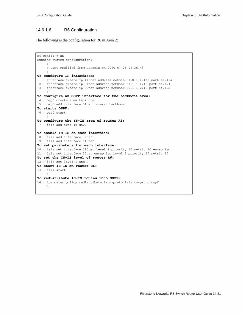
IS-IS Configuration Guide Displaying IS-IS Information
14.6.1.6 R6 Configuration
The following is the configuration for R6 in Area 2:
R6(config)# shRunning system configuration: ! ! Last modified from Console on 2000-07-06 08:36:43 !
To configure IP interfaces: 1 : interface create ip 110net address-netmask 110.1.1.1/8 port et.1.4 2 : interface create ip 31net address-netmask 31.1.1.1/16 port et.1.3 3 : interface create ip 30net address-netmask 30.1.1.2/16 port et.1.2 !
To configure an OSPF interface for the backbone area: 4 : ospf create area backbone 5 : ospf add interface 31net to-area backbone
To starts OSPF: 6 : ospf start !
To configure the IS-IS area of router R6: 7 : isis add area 49.da02
To enable IS-IS on each interface: 8 : isis add interface 30net 9 : isis add interface 110net
To set parameters for each interface:10 : isis set interface 110net level 2 priority 10 metric 10 encap iso11 : isis set interface 30net encap iso level 2 priority 10 metric 10
To set the IS-IS level of router R6:12 : isis set level 1-and-2
To start IS-IS on router R6:13 : isis start !
To redistribute IS-IS routes into OSPF:14 : ip-router policy redistribute from-proto isis to-proto ospf !
Riverstone Networks RS Switch Router User Guide 14-21

Displaying IS-IS Information IS-IS Configuration Guide
14.6.1.7 R7 Configuration
The following is the configuration for R7 in Area 2:
14.6.1.8 R8 Configuration
The following is the configuration for R8 in Area 3:
R7(config)# shRunning system configuration: ! ! Last modified from Console on 2000-07-04 15:18:34 !
To configure an IP interface: 1 : interface create ip 31net address-netmask 31.1.1.2/16 port et.1.3 !
To configure and start OSPF: 2 : ospf create area backbone 3 : ospf add interface 31net to-area backbone 4 : ospf start !
R8(config)# shRunning system configuration: ! ! Last modified from Console on 2000-07-06 09:33:34 !
To configure IP interfaces: 1 : interface create ip 40net address-netmask 40.1.1.1/16 port et.1.2 2 : interface create ip 41net address-netmask 41.1.1.1/16 port et.1.1 3 : interface create ip 105net address-netmask 105.1.1.1/8 port et.1.3 !
To configure the IS-IS area of R8: 4 : isis add area 49.da03
To enable IS-IS on each interface: 5 : isis add interface 40net 6 : isis add interface 41net 7 : isis add interface 105net
To set the IS-IS level of router R8: 8 : isis set level 1-and-2
To set the parameters of each interface: 9 : isis set interface 40net encap iso level 1 priority 10 metric 1010 : isis set interface 41net encap iso level 1 priority 10 metric 1011 : isis set interface 105net encap iso level 2 priority 10 metric 10
To start IS-IS on router R8:12 : isis start !
14-22 Riverstone Networks RS Switch Router User Guide
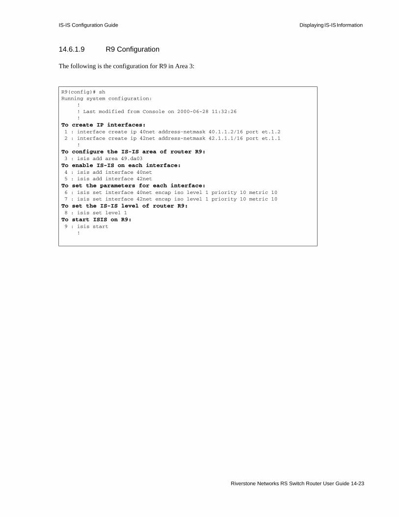
IS-IS Configuration Guide Displaying IS-IS Information
14.6.1.9 R9 Configuration
The following is the configuration for R9 in Area 3:
R9(config)# shRunning system configuration: ! ! Last modified from Console on 2000-06-28 11:32:26 !
To create IP interfaces: 1 : interface create ip 40net address-netmask 40.1.1.2/16 port et.1.2 2 : interface create ip 42net address-netmask 42.1.1.1/16 port et.1.1 !
To configure the IS-IS area of router R9: 3 : isis add area 49.da03
To enable IS-IS on each interface: 4 : isis add interface 40net 5 : isis add interface 42net
To set the parameters for each interface: 6 : isis set interface 40net encap iso level 1 priority 10 metric 10 7 : isis set interface 42net encap iso level 1 priority 10 metric 10
To set the IS-IS level of router R9: 8 : isis set level 1
To start ISIS on R9: 9 : isis start !
Riverstone Networks RS Switch Router User Guide 14-23

Displaying IS-IS Information IS-IS Configuration Guide
14.6.1.10 C10 Configuration
The following is the configuration for the C10 Cisco router in Area 4:
Router#sh ruBuilding configuration...
Current configuration:!version 11.2no service password-encryptionno service udp-small-serversno service tcp-small-servers!hostname Router!!clns routing!interface Serial0/0 ip address 52.1.1.1 255.255.0.0 ip router isis 49.0004 encapsulation ppp no keepalive no peer default ip address isis circuit-type level-1 isis priority 10 level-1!interface Serial0/1 no ip address shutdown!interface Serial0/2 no ip address shutdown!interface Serial0/3 no ip address shutdown!interface Ethernet1/0 ip address 51.1.1.1 255.255.0.0 ip router isis 49.0004 isis circuit-type level-1 isis priority 10 level-1!
14-24 Riverstone Networks RS Switch Router User Guide

IS-IS Configuration Guide Displaying IS-IS Information
14.6.1.11 C10 Configuration (continued)
interface Ethernet1/1 ip address 110.1.1.2 255.0.0.0 ip router isis 49.0004 isis circuit-type level-2-only isis priority 10 level-1!interface Ethernet1/2 ip address 111.1.1.2 255.0.0.0 ip router isis 49.0004 isis circuit-type level-2-only isis priority 10 level-1!interface Ethernet1/3 no ip address shutdown!interface Ethernet1/4 no ip address shutdown!interface Ethernet1/5 no ip address shutdown!router isis 49.0004 net 49.0004.0200.3301.0101.00!router bgp 5 neighbor 198.92.70.24 remote-as 10 neighbor 198.92.70.24 route-map in5 in!no ip classless!!line con 0line aux 0line vty 0 4 login!end
Riverstone Networks RS Switch Router User Guide 14-25
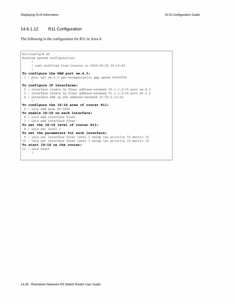
Displaying IS-IS Information IS-IS Configuration Guide
14.6.1.12 R11 Configuration
The following is the configuration for R11 in Area 4:
R11(config)# shRunning system configuration: ! ! Last modified from Console on 2000-06-28 10:19:40 !
To configure the WAN port se.4.3: 1 : port set se.4.3 wan-encapsulation ppp speed 45000000 !
To configure IP interfaces: 2 : interface create ip 52net address-netmask 52.1.1.2/16 port se.4.3 3 : interface create ip 51net address-netmask 51.1.1.2/16 port et.1.2 4 : interface add ip en0 address-netmask 10.50.3.11/16 !
To configure the IS-IS area of router R11: 5 : isis add area 49.0004
To enable IS-IS on each interface: 6 : isis add interface 51net 7 : isis add interface 52net
To set the IS-IS level of router R11: 8 : isis set level 1
To set the parameters for each interface: 9 : isis set interface 51net level 1 encap iso priority 10 metric 1010 : isis set interface 52net level 1 encap iso priority 10 metric 10
To start IS-IS on the router:11 : isis start !
14-26 Riverstone Networks RS Switch Router User Guide

15 BFD CONFIGURATION GUIDE
In Ethernet networks, services such as Voice over IP are very time sensitive. For these services, one of the critical requirements is to detect link failures very quickly so that corrective failover action can be taken. Many of the service provider networks have optical elements such as DWDMs. Ethernet routers are typically connected through a number of these optical elements. When there is a fiber cut or link failure on a link between these optical elements, each optical node may take multiple seconds to propagate this link failure. For time-sensitive applications, this may not acceptable. These failures can be detected at the higher-level protocols, but, because of the signaling overheads, the failure detection may not be as efficient. Bi-directional Forwarding Deadness Detection (BFD) provides a simple way of detecting failure on links between routers. Once the failure is detected, the link is brought down quickly so that the higher-level protocols can take appropriate corrective action.
Figure 15-1 Topology applicable for BFD protection
BFD is a simple point to point failure detection mechanism using keep-alive messages, which is enabled at a per-port level. When ports on two routers are connected, a two way handshake occurs and the BFD communication is established. From this point on, each end of the BFD expects a specified number of messages in the specified period of time. The intervals for transmit and receive for the messages can be specified separately. Also, a multiplier is used, which indicates the number of messages that can be missed before the link is brought down. When the link is brought down, the higher level protocols (such as MPLS) act on the link and start their failover operations.
15.0.1 Conditions When the Port is Blocked by BFD:
When a control packet for that session has not been received for the detection time interval:• The Session State will go to “FAILING,” with diag state “Control Detection Timer Expired”• Protocol Data Units (PDUs) are sent with the default transmit interval• The port is blocked for all VLANs.
Once a PDU corresponding to the session is received and the session reaches the “Up” state:• The port is unblocked
Physical Interconnect network
(such as WDM) Metro-Router
1
Metro-Router 2
Metro-Router 3 Optical
Riverstone Networks RS Switch Router User Guide 15-1
BFD Configuration Guide
• The port going down, because of BFD, is advertised to all other tasks that have registered for the link state notification
PDUs are not received because of any of the following reasons:• One of the ends is not able to transmit PDUs (due to software or hardware issues)• CM failover occurs on one end (failover this takes longer than the detection time)• The Control detection timer is active for a session only after the session goes to the “Up” or “INIT”
state. So if the session is in “FAILING” state because of admin-down on a peer, the receive age timer is stopped
15.0.2 Conditions that do not Block Ports because of BFD:
• When the BFD CLI command is negated on one end• A PDU with “I HEAR YOU” not set is transmitted so that the neighbor BFD goes to the “FAILING”
state. This prevents the neighbor from timing out. (It is not guaranteed that the sent PDU is received by the peer. Hence, it is important to make sure that when negating the CLI commands from the RS Ethernet Router configuration, it is done on both ends of the BFD link)
• When the port is in the link down state, BFD on both ends will go to “Down” state and diag state “PathDown”
• When a session is administratively down, local BFD will go into the admin down state with diag state “AdminDown.” The peer BFD goes to the “Failing” state with, the diag state “NeighborSignaledSessionDown”
15.0.3 Time Interval & Detection Multiplier changes
The BFD CLI commands need not be negated and re-added to the configuration to modify the time intervals or detection multiplier. Based on the peer MAC and the port, the CLI commands will get merged. Note: the detection multiplier can be set to 0. This is used to bring the peer session to a “FAILING” state, and block the peer session port. (PDUs received with detection multiplier 0 will be dropped by BFD).
BFD time interval and detection multiplier changes can be made dynamically. However, whenever there are timer changes the following occurs:• The protocol signals a Poll sequence for the new time to be updated by both systems• After this, the new Detection Time take effects
15.0.4 Configuring BFD
Enabling BFD only requires that you set a name and a port. All other parameters have default values and are optional. You will learn about enabling BFD and setting options in the following sections:• "Enabling BFD"• "Customizing BFD Failure Detection"
15-2 Riverstone Networks RS Switch Router User Guide

BFD Configuration Guide
15.0.4.1 Enabling BFD
Use the bfd set detectlinkstate command to enable BFD on a per-port basis. For example to enable a BFD session called “bfd-6-1” on ethernet port 6.1, enter the following command:
router(config)# bfd set detectlinkstate name bfd-6-1 port et.6.1
15.0.4.2 Customizing BFD Failure Detection
The BFD failure detection parameters (detection-multiplier, min-receive-interval, and min-transmit-interval) all take on default values once BFD is enabled on a port. These parameters can be optionally customized, as shown below.• Use the detection-multiplier parameter to set the number of control PDUs missed before
the BFD session is considered to be failing. The range is from 1 to 255. The default is 3.• Use the min-receive-interval parameter to specify the minimum receive interval for failure
detection. This is the minimum time interval (expressed as a multiple of 200 milliseconds) that the system expects between received packets. The range is from 1 to 1275???. The default is 2 (400 ms).
• Use the min-transmit-interval parameter to specify the minimum transmit interval for failure detection. This is the time between transmitted BFD control packets, expressed as a multiple of 200 milliseconds. The range is from 1 to 1275???. The default is 2 (400 ms).
The following example sets the detection multiplier to 15, the minimum receive interval to 4 (800 ms), and the minimum transmit interval to 5 (1000 ms).
router(config)# bfd set detectlinkstate name bfd-6-1 port et.6.1 detection-multiplier 15 min-receive-interval 4 min-transmit-interval 5
15.0.5 Displaying BFD Session Information
The bfd show session-name command shows the BFD policy parameters for the specific policy referred to by “name,” the current state of this BFD session, and the discriminators used by this session. There are several peer and local protocol variables displayed along with the transmit and receive statistics.
For example:enable# bfd show session-name bfd-6-1
BFD Session Info:Session Name : bfd-6-1Session Parameter : NextHopMac 0002:0844:5566Session Parameter : Port et.6.1 (UNBLOCKED)Session State FAILINGState Reason NODIAGLocal Descriptor 1Remote Descriptor 0Desired min Tx Interval 400 msRequired min Rx Interval 400 msPeer Required min Rx Interval 0 msPeer Desired min Tx Interval 0 msNegotiated Tx Interval 0 msActual Tx Interval 1000 msLocal Detection Multiplier 3
Riverstone Networks RS Switch Router User Guide 15-3

BFD Configuration Guide
Remote Detection Multiplier 0Detection Time 0 msTx Fsm State 7Rx Fsm State 6Session Pdus transmitted 0Session Pdus received 0Invalid LS Pdus 0
15.0.6 Clearing the BFD State
The bfd clear session-name command resets the BFD state for the policy. If the port was blocked by BFD before, it will be brought back up (unless it is admin disabled or the port is down).
15.0.6.1 BFD Interaction with Other Functions
The following section describes the BFD interaction with other functions on RS Ethernet Routers.
The link status can change whenever the link goes up or down.• Fiber cut• Link pull or admin down
In all these cases, BFD would go down, because of the Path Down state. Once the link comes up again, BFD is in the FAILING state until the session is re-established. If the BFD session was FAILING and the link was blocked by BFD before the port went down, once the port comes up, the link would still continue to be in BLOCKING state and the session remains in FAILING state.
15.0.6.2 Using BFD with SmartTrunk
BFD sessions are enabled per-port and not per-SmartTrunk. BFD sessions on LACP SmartTrunks are not as useful as they are for no-protocol SmartTrunks. It is considered a mis-configuration to enable BFD on a subset of the ports within a SmartTrunk. However, the SmartTrunk membership for ports can be modified even when BFD is enabled on a specific port.
15-4 Riverstone Networks RS Switch Router User Guide

16 BGP CONFIGURATION GUIDE
The Border Gateway Protocol (BGP) is an exterior gateway protocol that allows IP routers to exchange network reachability information. BGP became an internet standard in 1989 (RFC 1105) and the current version, BGP-4, was established in 1994 (RFC 1771). BGP is typically run between Internet Service Providers (ISPs). It is also frequently used by multi-homed ISP customers, as well as in large commercial networks.
Autonomous systems (ASs) that wish to connect their networks together must agree on a method of exchanging routing information. Interior gateway protocols (IGPs) such as RIP and OSPF may be inadequate for this task since they were not designed to handle multi-AS, policy, and security issues. Similarly, using static routes may not be the best choice for exchanging AS-AS routing information because there may be a large number of routes, or the routes may change often.
Note This chapter uses the term Autonomous System throughout. An AS is defined as a set of routers under a central technical administration that has a coherent interior routing plan and accurately portrays to other ASs what routing destinations are reachable by way of it.
In an environment where using static routes is not feasible, BGP is often the best choice for an AS-AS routing protocol. BGP prevents the introduction of routing loops created by multi-homed and meshed AS topologies. BGP also provides the ability to create and enforce policies at the AS level, such as selectively determining which AS routes are to accept and advertise to BGP peers.
16.1 THE RS ETHERNET ROUTER BGP IMPLEMENTATION
The RS Ethernet Router routing protocol implementation, ROSRD, is a modular software program that consists of core services, a routing database, and protocol modules that support multiple routing protocols (Routing Information Protocol (RIP) versions 1 and 2, Open Shortest Path First (OSPF) version 2, BGP version 4, and Integrated Intermediate System-to-Intermediate System (IS-IS) routing protocol.)
BGP can be configured with the RS Ethernet Router command line interface (CLI).
Riverstone Networks RS Switch Router User Guide 16-1
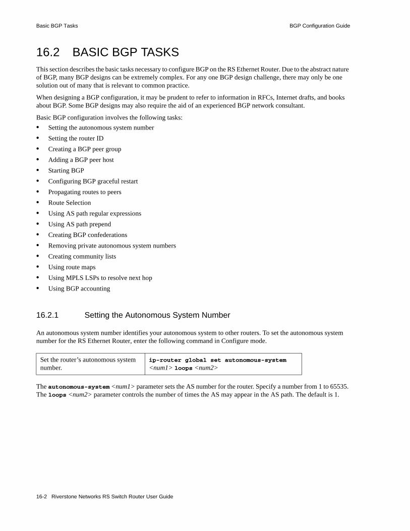
Basic BGP Tasks BGP Configuration Guide
16.2 BASIC BGP TASKSThis section describes the basic tasks necessary to configure BGP on the RS Ethernet Router. Due to the abstract nature of BGP, many BGP designs can be extremely complex. For any one BGP design challenge, there may only be one solution out of many that is relevant to common practice.
When designing a BGP configuration, it may be prudent to refer to information in RFCs, Internet drafts, and books about BGP. Some BGP designs may also require the aid of an experienced BGP network consultant.
Basic BGP configuration involves the following tasks:• Setting the autonomous system number• Setting the router ID• Creating a BGP peer group• Adding a BGP peer host• Starting BGP• Configuring BGP graceful restart• Propagating routes to peers• Route Selection• Using AS path regular expressions• Using AS path prepend• Creating BGP confederations• Removing private autonomous system numbers• Creating community lists• Using route maps• Using MPLS LSPs to resolve next hop• Using BGP accounting
16.2.1 Setting the Autonomous System Number
An autonomous system number identifies your autonomous system to other routers. To set the autonomous system number for the RS Ethernet Router, enter the following command in Configure mode.
The autonomous-system <num1> parameter sets the AS number for the router. Specify a number from 1 to 65535. The loops <num2> parameter controls the number of times the AS may appear in the AS path. The default is 1.
Set the router’s autonomous system number.
ip-router global set autonomous-system <num1> loops <num2>
16-2 Riverstone Networks RS Switch Router User Guide
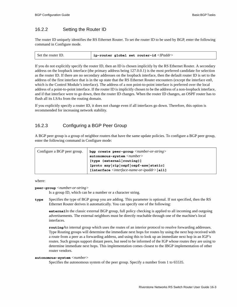
BGP Configuration Guide Basic BGP Tasks
16.2.2 Setting the Router ID
The router ID uniquely identifies the RS Ethernet Router. To set the router ID to be used by BGP, enter the following command in Configure mode.
If you do not explicitly specify the router ID, then an ID is chosen implicitly by the RS Ethernet Router. A secondary address on the loopback interface (the primary address being 127.0.0.1) is the most preferred candidate for selection as the router ID. If there are no secondary addresses on the loopback interface, then the default router ID is set to the address of the first interface that is in the up state that the RS Ethernet Router encounters (except the interface en0, which is the Control Module’s interface). The address of a non point-to-point interface is preferred over the local address of a point-to-point interface. If the router ID is implicitly chosen to be the address of a non-loopback interface, and if that interface were to go down, then the router ID changes. When the router ID changes, an OSPF router has to flush all its LSAs from the routing domain.
If you explicitly specify a router ID, it does not change even if all interfaces go down. Therefore, this option is recommended for increasing network stability.
16.2.3 Configuring a BGP Peer Group
A BGP peer group is a group of neighbor routers that have the same update policies. To configure a BGP peer group, enter the following command in Configure mode:
where:
peer-group <number-or-string>Is a group ID, which can be a number or a character string.
type Specifies the type of BGP group you are adding. This parameter is optional. If not specified, then the RS Ethernet Router derives it automatically. You can specify one of the following:
externalIn the classic external BGP group, full policy checking is applied to all incoming and outgoing advertisements. The external neighbors must be directly reachable through one of the machine's local interfaces.
routingAn internal group which uses the routes of an interior protocol to resolve forwarding addresses. Type Routing groups will determine the immediate next hops for routes by using the next hop received with a route from a peer as a forwarding address, and using this to look up an immediate next hop in an IGP’s routes. Such groups support distant peers, but need to be informed of the IGP whose routes they are using to determine immediate next hops. This implementation comes closest to the IBGP implementation of other router vendors.
autonomous-system <number>Specifies the autonomous system of the peer group. Specify a number from 1 to 65535.
Set the router ID. ip-router global set router-id <IPaddr>
Configure a BGP peer group. bgp create peer-group <number-or-string> autonomous-system <number>[type {external|routing}]
[proto any|rip|ospf|ospf-ase|static]
[interface <interface-name-or-ipaddr>|all]
Riverstone Networks RS Switch Router User Guide 16-3

Basic BGP Tasks BGP Configuration Guide
This defines the autonomous system of the peer group. For each peer host that you add to the group, you can either adopt the peer group’s autonomous system number or specify a different remote AS using the bgp set peer-host remote-as command.
proto Specifies the interior gateway protocol (IGP) to use in resolving BGP next hops.
interface <name-or-IPaddr> | allInterfaces whose routes are carried via the IGP for which third-party next hops may be used instead. Use only for type Routing group. Specify the interface or all for all interfaces.
Due to memory limitations, the RS Ethernet Router restricts the number of peers that a router can have by assigning each type of peer a point value and requiring that the total points for peers not exceed 175. Point values are as follows:
For example, a router that has only one type of peer can have a maximum of 87 external-gateway peers, 175 external peers, or 175 internal peers. A router with multiple peer types must have a point total that does not exceed 175. A router that already has 50 external-gateway peers configured (for a total of 100 points), for example, can have 75 more external or internal peers.
Caution Despite the theoretical maximum of 87 allowable external-gateway peers, for safer operation, do not exceed 85.
Note The maximum of 175 external or internal peers assumes that the peers are in relatively few peer groups. More peer groups require more memory and pose further limits.
The available memory also limits the number of BGP routes that can be stored in the forwarding information base.
Peer Type Point Value
External Peer 1
Internal Peer 1
External-Gateway Peer 2
Total points for all peers must not exceed 175
Memory Size Number of 1-Gateway BGP Routes that Can Be Stored In FIB
150 megabits 150 K routes
500 megabits 500 K routes
16-4 Riverstone Networks RS Switch Router User Guide

BGP Configuration Guide Basic BGP Tasks
Note The above limits apply to BGP routes with one gateway. BGP routes with more than one gateway are more memory intensive. Having a large number of multi-gateway BGP routes decreases the total number of routes that can be stored in the FIB.
16.2.4 Adding a BGP Peer
To add BGP peers to existing BGP peer groups, enter the following command in Configure mode.
You can specify either a peer group identifier or a peer host IP address when creating an export destination for BGP routes (with the ip-router policy create bgp-export-destination command), a source for exporting BGP routes into other protocols (with the ip-router policy create bgp-export-source command), or a source for importing BGP routes (with the ip-router policy create bgp-import-source command).
16.2.4.1 Setting BGP Peer Attributes
To set or change parameters for a BGP peer, enter the following command in Configure mode.
For example, for each peer host, you can either adopt its peer group’s autonomous system number or specify a different remote AS using the bgp set peer-host remote-as command.
16.2.5 Starting BGP
BGP is disabled by default. To start BGP, enter the following command in Configure mode.
16.2.6 Configuring BGP Graceful Restart
BGP graceful restart is one of a set of protocol-based graceful restart features on the ROS developed with the goal of making the RS Ethernet Router "hitless," which means that the service performed by the RS Ethernet Router continues to function even if it has to restart. This feature is defined in the IETF “Graceful Restart Mechanism for BGP” Internet Working Draft.
Without graceful restart capabilities, BGP restarts are costly for network resources. Peer after peer within the network have to be told that the restarting router’s routes are unreachable, which causes recalculation of routes and sub-optimal routes to be used, only to be told seconds later that the restarted router’s routes are back.
Add a host to a BGP peer group. bgp add peer-host <ipaddr> group <number-or-string>
Set or change attributes for a BGP peer.
bgp set peer-host <ipaddr> <option>
Start BGP. bgp start
Riverstone Networks RS Switch Router User Guide 16-5
Basic BGP Tasks BGP Configuration Guide
To prevent this temporary route flapping across the network, BGP graceful restart relies on the Forwarding Information Base (FIB) of the restarting router being preserved across a restart, which allows the router to continue forwarding traffic during the restart.
The following section outlines the basic functionality of BGP graceful restart.
16.2.6.1 Basic Functionality
The basic functionality of BGP graceful restart is described in this section and illustrated in Figure 16-1, "BGP Graceful Restart." Important restrictions, exceptions, and corner-case considerations are presented later. It is worth noting now that in order to accomplish a BGP graceful restart, both the restarting router and its peers must have BGP graceful restart configured. In addition, the restarting router must be a dual control module system. The following assumes that these conditions are met on both the restarting router and its peers.
BGP Graceful Restart Capability Advertisement
When BGP initializes, an RS Ethernet Router with BGP graceful restart configured advertises its graceful restart capability in the BGP ‘Open’ messages that it sends to establish peering. This advertisement includes an estimate of how long it expects to take before fully recovering upon a restart (restart-time) and the restart-flag, described later. If both peers support the capability, then a graceful restart can be accomplished.
During the Restart
In dual control module systems, the FIB is mirrored between the primary and backup control modules. During normal system operation, the FIB on the backup control modules is incrementally updated to reflect ongoing changes to the FIB on the primary control module.
In BGP graceful restart, while the primary control module restarts, the backup control module takes over and uses this learned FIB to maintain existing flows and permit new flows to be established. At this point, the RS Ethernet Router sends an ‘Open’ message to its peers. Two flags are set in this ‘Open’ message, the restart-flag to indicate that it has restarted, and the forwarding-flag to indicate that it has preserved the FIB over the restart.
TCP connections cannot be maintained during a restart. Because of this, other applications that rely on TCP for reliable transport, like telnet and BGP sessions, also terminate during a restart. While the restart is taking place, the restarting router’s peers hide the restart from the rest of the network by not withdrawing the routes learned via the restarting router. The peers mark these routes as ‘stale’ but continue forwarding traffic as though the routes were valid. Since the forwarding state is preserved in the restarting router’s backup control module and traffic can continue through it, shielding the restart is acceptable.
Note When the underlying datalink is lost, the TCP connection remains up until it times out.
After the Restart: The Restarted Router
Once the RS Ethernet Router restarts, it must re-establish a new BGP session with its peers.
It first listens to routing updates sent by its peers. While receiving these updates, the restarted router looks for the End-of-RIB marker. The End-of-RIB marker is an empty update message that is sent by all BGP speakers to indicate the end of routing updates. The restarted router uses the End-of-RIB marker to tell when a peer has finished sending it updates.
16-6 Riverstone Networks RS Switch Router User Guide

BGP Configuration Guide Basic BGP Tasks
Only after it receives all updates from its peers does the restarted router perform route selection and send new updates for all of its existing routes to refresh its peers’ stale routes. This waiting ensures that the first updates sent out by a router after it restarts reflect the current network state as completely as possible.
If a peer never sends an End-of-RIB marker, however, the restarted router does not need to wait indefinitely to start route selection. The resync-time timer is used to put an upper bound on the amount of time the restarted router must wait. This timer is started as the primary control module initializes, is deleted if the number of outstanding End-of-RIBs reaches zero, and expires if any of the participating peers fail to send an End-of-RIB within resync-time seconds. If this timer expires, a route flush occurs on the restarted router, as in a normal BGP restart.
After the Restart: The Peers
After the restart, peers first send routing updates to refresh the restarted router’s routing table. Then they wait for routing updates from the restarted router to renew their stale routes. However, some of the restarted router’s former routes may have disappeared during the restart. Since the restarted router only sends explicit updates on its current routes, how can its peers determine if a stale route has disappeared and should be flushed from their routing tables?
The peers look for the End-of-RIB marker from the restarted router. This marker tells them when the restarted router is finished sending updates, and when it is safe to delete any remaining stale routes from the restarted router.
Just like the restarted router, a peer also limits the time that it will wait for the End-of-RIB from the restarted router with the resync-time timer. It starts this timer when the BGP session is re-established (reaches Established state) after a failure. It deletes this timer when an End-of-RIB marker is received from the failed peer. If the timer expires before the End-of-RIB is received from the restarted router, any remaining stale routes from that remote peer are deleted.
Summary
In summary, the network is unaffected and no route flapping occurs if a BGP router recovers after a restart by:• reaching Established state on a new BGP session with its peers within restart-time, and• sends updates on its current routes within resync-time.
If the restarting router fails to restart or does not resend updates on its current routes on time, its peers delete all stale routes and communicate the changes to the rest of the network.
The following illustrates this process in a successful BGP graceful restart.
Riverstone Networks RS Switch Router User Guide 16-7

Basic BGP Tasks BGP Configuration Guide
Internet
Internet
Internet
16-8 Riverstone Networks RS Switch Router User Guide

BGP Configuration Guide Basic BGP Tasks
Figure 16-1 BGP Graceful Restart
16.2.6.2 Timers and Flags
Below is a summary of the timers and flags that BGP graceful restart uses.
Internet
Internet
Internet
Internet
Riverstone Networks RS Switch Router User Guide 16-9

Basic BGP Tasks BGP Configuration Guide
Table 16-1 BGP graceful restart timers
Timer Description
restart-time This is a user set worst-case estimate of how long it will take the restarting router to recover from a system failure. The RS Ethernet Router communicates this to its peers in its own BGP ‘Open’ message. BGP graceful restart depends on the restarting router being able to recover and reach Established state on a new BGP session with its peers within this time limit.
Use the bgp set peer-group restart-time and bgp set peer-host restart-time commands to set this timer for the peer group or host. When not set, the default value is the Holdtime.
resync-time This is a global timer set for the BGP routing process on a router. Once the restarted router has established a new BGP session with its peers, the peers use this user-set timer to limit how long they wait for the restarted router to refresh all of its routes before deleting any remaining stale routes from the restarted router.
The restarted router also uses this timer to limit how long it waits for the End-of-RIB marker from its peers before sending its own routing updates.
Use the bgp set resync-time command to set this timer globally for the BGP routing process. The minimum value for this timer is 20 seconds. The default is 60 seconds. The maximum is 300 seconds.
Table 16-2 BGP graceful restart flags
Flag Description
restart-flag The restarted router sets this flag in its BGP ‘Open’ message when it is restarted by any means other than user reboot. (The exception to this is when the user manually forces a control-module mastership change using the system redundancy change-mastership command.)
16-10 Riverstone Networks RS Switch Router User Guide

BGP Configuration Guide Basic BGP Tasks
16.2.6.3 Configuration
By default, BGP graceful restart is off. To configure BGP graceful restart on a router, you must do three things:
For each host or peer group:1. Turn on BGP graceful restart.2. Set the desired restart-time.
For the BGP routing process:3. Set the desired resync-time.
Note After configuring BGP graceful restart, you must reset the peer relationship in order for changes to take effect. Resetting the peer also updates the output of show commands, such as bgp show neighbor, to reflect the change in capabilities.
The following example turns on BGP graceful restart for BGP peer group 20:
The following example turns on BGP graceful restart for BGP peer host 6.1.2.2, which is in peer group 30:
forwarding-flag The restarted router sets this flag in its BGP ‘Open’ message to indicate that the FIB has been preserved over a restart.
End-of-RIB An empty update message that is sent by all BGP speakers to indicate the end of routing updates. Both the restarted router and its peers use this marker to determine when the other has completed routing updates after the restart.
The restarted router does not commence sending its own updates until it has received this marker from all of its peers, unless the resync-time timer expires.
The restarted router’s peers delete any remaining stale routes from the restarted router when they receive this marker from the restarted router.
RS Ethernet Router(config)# bgp set peer-group 20 graceful-restart
RS Ethernet Router(config)# bgp set peer-host 6.1.2.2 group 30 graceful-restart
Table 16-2 BGP graceful restart flags (Continued)
Flag Description
Riverstone Networks RS Switch Router User Guide 16-11

Basic BGP Tasks BGP Configuration Guide
The following example sets the restart-time for BGP peer group 20 to 180 seconds:
The following example sets the restart-time for BGP peer host 6.1.2.2 to 10 seconds:
Finally, the following example sets the resync-time for the global BGP routing process to 150 seconds:
16.2.6.4 Example
Viewing the Graceful Restart Process
After turning on tracing using the ip-router global set trace-state on command, you can use the bgp trace local-options normal command to observe active BGP-specific code-path tracing messages that show the progress of BGP graceful restart during a restart. You can also view BGP graceful restart capability advertisements sent in BGP ‘Open’ messages using the bgp trace packet details command.
Caution Be careful when you turn on tracing, because the amount of messages that result can overwhelm your screen output. To turn off tracing, simply negate the command.
In the above examples, you configured BGP graceful restart on host 6.1.2.2. You also configured the restart-time timer for host 6.1.2.2 to 10 seconds and its global BGP resync-time timer to 150 seconds.
The following trace output shows BGP graceful restart in action on host 6.1.2.2. The relevant BGP graceful restart messages are in bold. Annotated text in italics highlight the process.
RS Ethernet Router(config)# bgp set peer-group 20 restart-time 180
RS Ethernet Router(config)# bgp set peer-host 6.1.2.2 group 30 restart-time 10
RS Ethernet Router(config)# bgp set resync-time 150
-11-19 09:54:48 bgp_connect_start: peer 6.1.2.1 (External AS 65186)
-11-19 09:54:48 bgp_peer_connected: connection established with 6.1.2.1 (External AS 65186)
-11-19 09:54:48 bgp_set_gr_resync_timer: Start resync timer (failover side)
[We start our global resync timer.]
-11-19 09:54:48 bgp_gr_set_resync_peer: peer 6.1.2.1 (External AS 65186) - waiting for resync. Now waiting for 1 peers
16-12 Riverstone Networks RS Switch Router User Guide

BGP Configuration Guide Basic BGP Tasks
[So far, we are waiting for an EOR from 1 peer, host 6.1.2.1.]
-11-19 09:54:48 bgp_send: sending 47 bytes to 6.1.2.1 (External AS 65186)-11-19 09:54:48-11-19 09:54:48 BGP SEND 6.1.2.2+1031 -> 6.1.2.1+179-11-19 09:54:48 BGP SEND message type 1 (Open) length 47-11-19 09:54:48 BGP SEND version 4 as 150 holdtime 180 id 1.1.1.2 optional parameter length 18-11-19 09:54:48 BGP SEND Optional parameter capabilities (18 bytes): MPCap: Inet Uni, Route Refresh:, Graceful Restart:Restart timer = 10, restarting. Uni-IP was saved.
[We send an OPEN message indicating that we have restarted, preserved IP Unicast routes, and that it should take us less than 10 seconds to reach Established state with our peers again.]
-11-19 09:54:48-11-19 09:54:49 bgp_recv_open: called for peer 6.1.2.1 (External AS 65186)-11-19 09:54:49-11-19 09:54:49 BGP RECV 6.1.2.1+179 -> 6.1.2.2+1031-11-19 09:54:49 BGP RECV message type 1 (Open) length 41-11-19 09:54:49 BGP RECV version 4 as 65186 holdtime 180 id 1.1.1.1 optional parameter length 12-11-19 09:54:49 BGP RECV Optional parameter capabilities (12 bytes): MPCap: Inet Uni, Graceful Restart:Restart timer = 180, not restarting.
[We receive an OPEN message from our peer, 6.1.2.1, saying that it did not restart, but will cooperate with our BGP graceful restart by shielding this knowledge from the rest of network.]
-11-19 09:54:49 bgp_send: sending 19 bytes to 6.1.2.1 (External AS 65186)-11-19 09:54:49 bgp_read_message: 6.1.2.1 (External AS 65186): 0 bytes buffered-11-19 09:54:49 bgp_recv_open: called for peer 6.1.2.1 (External AS 65186)-11-19 09:54:49 bgp_set_flash: setting flash/new policy routines for BGP_65186-11-19 09:54:49 bgp_set_reinit: setting reinit routine for BGP_65186
Riverstone Networks RS Switch Router User Guide 16-13

Basic BGP Tasks BGP Configuration Guide
-11-19 09:54:49 bgp_recv_change: peer 6.1.2.1 (External AS 65186) receiver changed to bgp_recv_v4_update-11-19 09:54:49 bgp_recv_v4_update: receiving updates from 6.1.2.1 (External AS 65186)-11-19 09:54:49 bgp_recv_v4_update: done with 6.1.2.1 (External AS 65186) received 0 octets 0 updates 0 routes-11-19 09:54:49 bgp_send: sending 19 bytes to 6.1.2.1 (External AS 65186)-11-19 09:54:50 bgp_recv_v4_update: receiving updates from 6.1.2.1 (External AS 65186)-11-19 09:54:50 bgp_recv_v4_update: done with 6.1.2.1 (External AS 65186) received 45 octets 1 update 1 route-11-19 09:54:50 bgp_rt_policy_peer: flash update 6.1.2.1 (External AS 65186)-11-19 09:54:50 bgp_rt_policy_peer: 6.1.2.1 (External AS 65186) 0 routes ready 0 deferred-11-19 09:54:50 bgp_recv_v4_update: receiving updates from 6.1.2.1 (External AS 65186)-11-19 09:54:50 bgp_recv_v4_update: done with 6.1.2.1 (External AS 65186) received 53 octets 1 update 3 routes-11-19 09:54:50 bgp_rt_policy_peer: flash update 6.1.2.1 (External AS 65186)-11-19 09:54:50 bgp_rt_policy_peer: 6.1.2.1 (External AS 65186) 0 routes ready 0 deferred-11-19 09:54:50 bgp_recv_v4_update: receiving updates from 6.1.2.1 (External AS 65186)-11-19 09:54:50 bgp_recv_v4_update: done with 6.1.2.1 (External AS 65186) received 50 octets 1 update 3 routes-11-19 09:54:50 bgp_rt_policy_peer: flash update 6.1.2.1 (External AS 65186)-11-19 09:54:50 bgp_rt_policy_peer: 6.1.2.1 (External AS 65186) 0 routes ready 0 deferred-11-19 09:54:50 bgp_recv_v4_update: receiving updates from 6.1.2.1 (External AS 65186)-11-19 09:54:50 bgp_recv_v4_update: done with 6.1.2.1 (External AS 65186) received 49 octets 1 update 2 routes-11-19 09:54:50 bgp_rt_policy_peer: flash update 6.1.2.1 (External AS 65186)-11-19 09:54:50 bgp_rt_policy_peer: 6.1.2.1 (External AS 65186) 0 routes ready 0 deferred-11-19 09:54:50 bgp_recv_v4_update: receiving updates from 6.1.2.1 (External AS 65186)2001-11-19 09:54:49 %SNMP-I-SENT_TRAP, Sending notification bgpEstablished to management station-11-19 09:54:50 bgp_recv_v4_update: peer 6.1.2.1 (External AS 65186) received an End of RIB
[Remote peer, host 6.1.2.1, finishes sending us its initial routes.]
-11-19 09:54:50 bgp_recv_v4_update: Resync now waiting for 0 peers
[With this, our count of outstanding EORs now reaches zero, so we stop the resync timer and flush our outbound routes. We can now send our peer, 6.1.2.1, our Routing Information Base (RIB).]
-11-19 09:54:50 bgp_gr_rt_flush: Flushing active routes on recovering node-11-19 09:54:50 bgp_delete_gr_resync_timer: Deleting system-wide Graceful Restart resync timer-11-19 09:54:50 bgp_rt_policy_peer: initial update 6.1.2.1 (External AS 65186)-11-19 09:54:50 bgp_rt_policy_peer: 6.1.2.1 (External AS 65186) 1 route ready 0 deferred-11-19 09:54:50 bgp_set_write: initiating write routine for peer 6.1.2.1 (External AS 65186)-11-19 09:54:50 bgp_send_set: setting task write routine for peer 6.1.2.1 (External AS 65186)-11-19 09:54:50 bgp_recv_v4_update: done with 6.1.2.1 (External AS 65186) received 93 octets 2 updates 2 routes-11-19 09:54:50 bgp_write_ready: write ready for peer 6.1.2.1 (External AS 65186)-11-19 09:54:50 bgp_rt_send_peer: sending to 6.1.2.1 (External AS 65186)-11-19 09:54:50 bgp_send: sending 45 bytes to 6.1.2.1 (External AS 65186)-11-19 09:54:50 bgp_rt_send_v4_eor: peer 6.1.2.1 (External AS 65186), sending End of RIB
[We have finished sending our RIB to peer 6.1.2.1. We conclude our update by sending an EOR.]
-11-19 09:54:50 bgp_send: sending 23 bytes to 6.1.2.1 (External AS 65186)-11-19 09:54:50 bgp_rt_send_peer: peer 6.1.2.1 (External AS 65186) sent 1 route no routes deferred-11-19 09:54:50 bgp_send: sending 19 bytes to 6.1.2.1 (External AS 65186)-11-19 09:54:50 bgp_set_send: removing task write routine from peer 6.1.2.1 (External AS 65186)-11-19 09:54:51 bgp_rt_policy_peer: flash update 6.1.2.1 (External AS 65186)-11-19 09:54:51 bgp_rt_policy_peer: 6.1.2.1 (External AS 65186) 0 routes ready 0 deferred
16-14 Riverstone Networks RS Switch Router User Guide
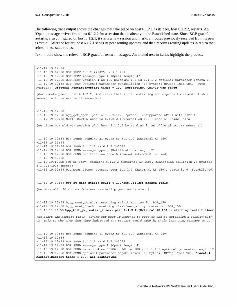
BGP Configuration Guide Basic BGP Tasks
The following trace output shows the changes that take place on host 6.1.2.1 as its peer, host 6.1.2.2, restarts. An ‘Open’ message arrives from host 6.1.2.2 for a session that is already in the Established state. Since BGP graceful restart is also configured on host 6.1.2.1, it starts a new session and marks all routes previously received from its peer as ‘stale’. After the restart, host 6.1.2.1 sends its peer routing updates, and then receives routing updates in return that refresh these stale routes.
Text in bold show the relevant BGP graceful-restart messages. Annotated text in italics highlight the process.
-11-19 19:12:58-11-19 19:12:58 BGP RECV 6.1.2.2+1025 -> 6.1.2.1-11-19 19:12:58 BGP RECV message type 1 (Open) length 47-11-19 19:12:58 BGP RECV version 4 as 150 holdtime 180 id 1.1.1.2 optional parameter length 18-11-19 19:12:58 BGP RECV Optional parameter capabilities (18 bytes): MPCap: Inet Uni, Route Refresh:, Graceful Restart:Restart timer = 10, restarting. Uni-IP was saved.
[Our remote peer, host 6.1.2.2, indicates that it is restarting and expects to re-establish a session with us within 10 seconds.]
-11-19 19:12:58-11-19 19:12:58 bgp_get_open: peer 6.1.2.2+1025 (proto): unsupported AFI 1 with SAFI 1-11-19 19:12:58 NOTIFICATION sent to 6.1.2.2 (External AS 150): code 6 (Cease) data
[We close our old BGP session with host 6.1.2.2 by sending it an official NOTIFY message.]
-11-19 19:12:58 bgp_send: sending 21 bytes to 6.1.2.2 (External AS 150)-11-19 19:12:58-11-19 19:12:58 BGP SEND 6.1.2.1 -> 6.1.2.2+1035-11-19 19:12:58 BGP SEND message type 3 (Notification) length 21-11-19 19:12:58 BGP SEND Notification code 6 (Cease) subcode 0 (unused)-11-19 19:12:58-11-19 19:12:58 bgp_pp_recv: dropping 6.1.2.2 (External AS 150), connection collision(2) prefers 6.1.2.2+1025 (proto)-11-19 19:12:58 bgp_peer_close: closing peer 6.1.2.2 (External AS 150), state is 6 (Established)
-11-19 19:12:58 bgp_rt_mark_stale: Route 6.1.2/255.255.255 marked stale
[We mark all old routes from our restarting peer as ‘stale’.]
-11-19 19:12:58 bgp_reset_reinit: resetting reinit routine for BGP_150-11-19 19:12:58 bgp_reset_flash: resetting flash/new policy routes for BGP_150-11-19 19:12:58 bgp_init_gr_restart_timer: peer 6.1.2.2 (External AS 150) - starting restart timer
[We start the restart timer, giving our peer 10 seconds to recover and re-establish a session with us. This is the time that they indicated the restart would take in their last OPEN message to us.]
-11-19 19:12:58 bgp_send: sending 41 bytes to 6.1.2.2 (External AS 150)-11-19 19:12:58-11-19 19:12:58 BGP SEND 6.1.2.1 -> 6.1.2.2+1025-11-19 19:12:58 BGP SEND message type 1 (Open) length 41-11-19 19:12:58 BGP SEND version 4 as 65186 holdtime 180 id 1.1.1.1 optional parameter length 12-11-19 19:12:58 BGP SEND Optional parameter capabilities (12 bytes): MPCap: Inet Uni, Graceful Restart:Restart timer = 180, not restarting.
Riverstone Networks RS Switch Router User Guide 16-15

Basic BGP Tasks BGP Configuration Guide
[We indicate to our peer that we do support BGP graceful restart and our restart timer is 180 seconds. But we will not be restarting at this time. Since we support BGP graceful restart, our peer knows that we will continue to monitor their status and withhold knowledge of their restart from the rest of the network until the restart timer expires.]
-11-19 19:12:58-11-19 19:12:58 bgp_send: sending 19 bytes to 6.1.2.2 (External AS 150)-11-19 19:12:58 bgp_recv_change: peer 6.1.2.2 (External AS 150) receiver changed to bgp_recv_open-11-19 19:12:58 bgp_recv_open: called for peer 6.1.2.2 (External AS 150)-11-19 19:12:58 bgp_delete_gr_restart_timer: peer 6.1.2.2 (External AS 150) - deleting restart timer
[Since our peer, host 6.1.2.2, has sent us an OPEN message to initiate another BGP session, we no longer need the restart timer. So we delete it.]
-11-19 19:12:58 bgp_init_peer_resync_timer: peer 6.1.2.2 (External AS 150) - starting resync timer
[Now we start a resync timer for this peer, giving them time to finish sending us new updates for their existing routes. If the resync timer expires, we will flush any remaining stale routes from this peer.]
-11-19 19:12:58 bgp_set_flash: setting flash/new policy routines for BGP_150-11-19 19:12:58 bgp_set_reinit: setting reinit routine for BGP_150-11-19 19:12:58 bgp_recv_change: peer 6.1.2.2 (External AS 150) receiver changed to bgp_recv_v4_update-11-19 19:12:58 bgp_recv_v4_update: receiving updates from 6.1.2.2 (External AS 150)-11-19 19:12:58 bgp_recv_v4_update: done with 6.1.2.2 (External AS 150) received 19 octets 0 updates 0 routes-11-19 19:12:58 bgp_rt_policy_peer: initial update 6.1.2.2 (External AS 150)-11-19 19:12:58 bgp_rt_policy_peer: 6.1.2.2 (External AS 150) 11 routes ready 0 deferred-11-19 19:12:58 bgp_set_write: initiating write routine for peer 6.1.2.2 (External AS 150)-11-19 19:12:58 bgp_send_set: setting task write routine for peer 6.1.2.2 (External AS 150)-11-19 19:12:59 bgp_write_ready: write ready for peer 6.1.2.2 (External AS 150)-11-19 19:12:59 bgp_rt_send_peer: sending to 6.1.2.2 (External AS 150)-11-19 19:12:59 bgp_send: sending 45 bytes to 6.1.2.2 (External AS 150)-11-19 19:12:59 bgp_send: sending 53 bytes to 6.1.2.2 (External AS 150)-11-19 19:12:59 bgp_send: sending 50 bytes to 6.1.2.2 (External AS 150)-11-19 19:12:59 bgp_send: sending 49 bytes to 6.1.2.2 (External AS 150)-11-19 19:12:59 bgp_send: sending 51 bytes to 6.1.2.2 (External AS 150)-11-19 19:12:59 bgp_rt_send_v4_eor: peer 6.1.2.2 (External AS 150), sending End of RIB
[First, we send updates for our routes to our peer. This ensures that they have the most current network knowledge before they send us updates. We indicate that we are finished by sending an End-of-RIB.]
-11-19 19:13:00 bgp_send: sending 23 bytes to 6.1.2.2 (External AS 150)-11-19 19:13:00 bgp_rt_send_peer: peer 6.1.2.2 (External AS 150) sent 11 routes no routes deferred-11-19 19:13:00 bgp_send: sending 19 bytes to 6.1.2.2 (External AS 150)-11-19 19:13:00 bgp_set_send: removing task write routine from peer 6.1.2.2 (External AS 150)-11-19 19:13:00 bgp_recv_v4_update: receiving updates from 6.1.2.2 (External AS 150)-11-19 19:13:00 bgp_recv_v4_update: - Stale Route 6.1.2/255.255.255 refreshed-11-19 19:13:00 bgp_recv_v4_update: done with 6.1.2.2 (External AS 150) received 45 octets 1 update 1 route
[Now our peer sends us their updates, which allow us to refresh the stale route in our RIB.]
16-16 Riverstone Networks RS Switch Router User Guide

BGP Configuration Guide Basic BGP Tasks
Viewing Stale Routes
You can see how many and which routes are stale on the RS Ethernet Router by viewing the summary or detail of routes in the RIB.
View the summary of routes in the RIB with the ip-router show summary command. The following is a sample display output that shows three stale BGP routes in the RIB:
View detailed information on routes in the RIB with the ip-router show rib detail command. The following is a sample display output of the details on a stale BGP route in the RIB:
-11-19 19:13:00 bgp_recv_v4_update: receiving updates from 6.1.2.2 (External AS 150)-11-19 19:13:00 bgp_recv_v4_update: peer 6.1.2.2 (External AS 150) received an End or RIB-11-19 19:13:00 bgp_delete_peer_resync_timer: peer 6.1.2.2 (External AS 150) - deleting resync timer
[When we receive an End-of-RIB from our restarted peer, we know that they are done sending us updates, and we can delete the resync timer for this peer. We delete any remaining stale routes.]
-11-19 19:13:00 bgp_recv_v4_update: done with 6.1.2.2 (External AS 150) received 23 octets 1 update 0 routes-11-19 19:13:01 bgp_recv_v4_update: receiving updates from 6.1.2.2 (External AS 150)-11-19 19:13:01 bgp_recv_v4_update: done with 6.1.2.2 (External AS 150) received 19 octets 0 updates 0 routes
Summary of routes in RIB------- -- ------ -- ---Number of Unique routes : 5021Number of routes : 5040Kernel routes : 0Direct routes : 8Static routes : 4RIP routes : 5000OSPF routes : 13OSPF ASE routes : 0ISIS level 1 routes : 8ISIS level 2 routes : 7BGP routes : 6Stale BGP routes : 3Other Protocol routes : 0Hidden routes : 10Install LSP routes : disabled
Riverstone Networks RS Switch Router User Guide 16-17
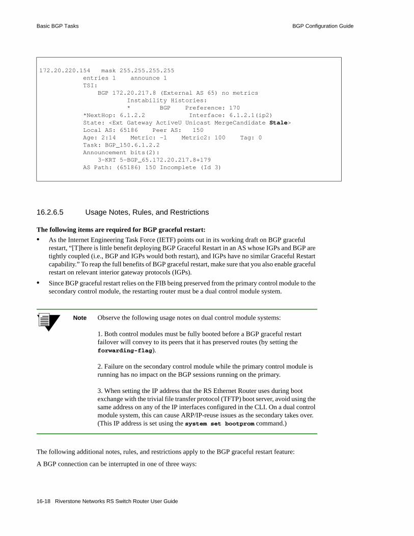
Basic BGP Tasks BGP Configuration Guide
16.2.6.5 Usage Notes, Rules, and Restrictions
The following items are required for BGP graceful restart: • As the Internet Engineering Task Force (IETF) points out in its working draft on BGP graceful
restart, “[T]here is little benefit deploying BGP Graceful Restart in an AS whose IGPs and BGP are tightly coupled (i.e., BGP and IGPs would both restart), and IGPs have no similar Graceful Restart capability.” To reap the full benefits of BGP graceful restart, make sure that you also enable graceful restart on relevant interior gateway protocols (IGPs).
• Since BGP graceful restart relies on the FIB being preserved from the primary control module to the secondary control module, the restarting router must be a dual control module system.
Note Observe the following usage notes on dual control module systems:
1. Both control modules must be fully booted before a BGP graceful restart failover will convey to its peers that it has preserved routes (by setting the forwarding-flag).
2. Failure on the secondary control module while the primary control module is running has no impact on the BGP sessions running on the primary.
3. When setting the IP address that the RS Ethernet Router uses during boot exchange with the trivial file transfer protocol (TFTP) boot server, avoid using the same address on any of the IP interfaces configured in the CLI. On a dual control module system, this can cause ARP/IP-reuse issues as the secondary takes over. (This IP address is set using the system set bootprom command.)
The following additional notes, rules, and restrictions apply to the BGP graceful restart feature:
A BGP connection can be interrupted in one of three ways:
172.20.220.154 mask 255.255.255.255 entries 1 announce 1 TSI: BGP 172.20.217.8 (External AS 65) no metrics Instability Histories: * BGP Preference: 170 *NextHop: 6.1.2.2 Interface: 6.1.2.1(ip2) State: <Ext Gateway ActiveU Unicast MergeCandidate Stale> Local AS: 65186 Peer AS: 150 Age: 2:14 Metric: -1 Metric2: 100 Tag: 0 Task: BGP_150.6.1.2.2 Announcement bits(2): 3-KRT 5-BGP_65.172.20.217.8+179 AS Path: (65186) 150 Incomplete (Id 3)
16-18 Riverstone Networks RS Switch Router User Guide

BGP Configuration Guide Basic BGP Tasks
- manual reboot,- spontaneous (non-user) reboot, or- interface going down.
The BGP graceful restart feature is designed primarily to handle the spontaneous reboot. In this case, as discussed before, the restarting router sends an ‘Open’ message to alert its peers that it is initiating a graceful restart. Upon receiving this message, the peers terminate the BGP connection with the restarting router and start the restart-time timer.
BGP behaves differently, however, when the BGP connection is terminated by a manual reboot or interface going down. These two cases are discussed below.
Manual Reboots• Manually rebooting or clearing BGP connections does not activate BGP graceful restart. On a dual
control module system, if the primary is rebooted via the CLI, control is not transferred to the secondary. Only spontaneous crashes or reloads will activate the BGP graceful restart feature. (The exception to this is when the user manually forces a control module mastership change using the system redundancy change-mastership command.)
Interface Down• When the BGP connection is interrupted by an interface going down, unlike in the case of a
spontaneous reboot, the peers do not immediately treat the event as indication of a BGP graceful restart. In this situation, the default BGP behavior is to start the holdtime timer and wait for the remote peer to re-establish the connection within holdtime seconds. Only if this fails to happen and the holdtime timer expires do the remote peers recognize a failover and start the restart-time timer. So in the case of an interface going down, the restarting router potentially has holdtime plus restart-time seconds in which to reinitiate a connection after completing a restart.
Single Control Module Systems• BGP peers send the BGP graceful restart capability advertisement in the ‘Open’ message to indicate
how much of the BGP graceful restart feature the peer supports. Even on a single control module system, this capability is communicated if BGP graceful restart is enabled (either on the host itself or for its peer group). For a single control module system, this advertisement conveys that the RS Ethernet Router is unable to preserve peer routes if it crashes, a behavior that conforms to the recommended minimum functionality in the IETF draft, but it will shield the rest of the network in a peer’s graceful restart.
Systems Incompatible with BGP Graceful Restart• If a remote peer does not recognize or understand the BGP graceful restart capability, it may send a
BGP ‘Notify’ message complaining about it, and then terminate the session. The router will disable the graceful restart capability and reattempt to connect.
Simultaneous Restarts• Recall that the restarted router does not send any routing updates of its own until it has finished
listening to the routing updates sent by its peers. It knows when a peer is finished sending updates when it sees a End-of-RIB marker from the peer. This waiting ensures that the first updates sent out by a router after it restarts reflect the current network state as completely as possible.
If two peers restart at the same time, the above rule would not cause them to enter a deadlock situation where both peers are waiting for the other to send an End-of-RIB marker before sending its own updates. In this case, the BGP graceful restart capability advertisement sent in the ‘Open’ message by each restarted router when they try to re-establish a BGP session will have the
Riverstone Networks RS Switch Router User Guide 16-19

Basic BGP Tasks BGP Configuration Guide
restart-flag set. The restart-flag indicates to each peer that the other has also restarted. This causes them not to wait for the other’s End-of-RIB marker before sending their own updates, thus avoiding a deadlock.
No Dynamic Renegotiation of BGP Graceful Restart Capabilities• Currently, BGP peers do not dynamically renegotiate graceful restart capabilities. If any peer is
configured with BGP graceful restart after it has established BGP session(s), those session(s) must be re-established before the graceful restart configuration will take affect on all of the configured router’s peers. This is because peers rely on BGP ‘Open’ messages to advertise their graceful restart capabilities. ‘Open’ messages are only sent to establish or re-establish sessions.
• For the same reason, changes made to a peer’s BGP graceful restart capabilities after it has established BGP session(s) are not dynamically propagated to its peers. For those changes to take, you must reset all established BGP peering relationships after making any changes to the BGP graceful restart capabilities of either peer.
• Resetting the peer also updates the output of show commands, such as bgp show neighbor, to reflect changes in capabilities.
16.2.6.6 Routing Instances
• The RS Ethernet Router does not supports BGP graceful restart on a per-routing instance basis. The RS Ethernet Router only supports BGP graceful restart on the main instance. The commands in this section configure BGP graceful restart on the main instance only.
16.2.6.7 Multiprotocol-BGP
• The RS Ethernet Router does not supports Multiprotocol-BGP (MP-BGP) graceful restart.
16.2.7 Propagating Routes to Peers
The RS Ethernet Router allows you to control which routes the BGP routing process propagates to a BGP peer using the bgp advertise network command.
By default, this command creates and propagates aggregate routes. To propagate non-aggregate routes, use the no-aggregate option in this command.
16.2.7.1 Usage Notes, Rules, and Restrictions
In addition to the aggregated routes, if the BGP routes are also required to be advertised, then the following command must be executed at the CLI: ip-router policy redistribute from-proto bgp source-as <as-num> to-proto bgp target-as all
16-20 Riverstone Networks RS Switch Router User Guide

BGP Configuration Guide Basic BGP Tasks
16.2.7.2 Configuration Examples
The following example configures the BGP routing process to create and advertise an aggregate route of 1.2.0.0/16 to its peers.
The following example configures the BGP routing process to create and advertise a non-aggregate (exact) route of 1.2.0.0/16 to its peers.
16.2.7.3 Usage Notes, Rules, and Restrictions
Observe the following usage guidelines when using this feature:
• The route you wish to propagate must exist in the routing table (either as a static route or a route learned from an interior gateway protocol (IGP).)
• If you provide no mask, you must specify the address as a natural network. The BGP process does not perform automatic truncation.
For example, if you wish to propagate network 10.1.1.0/24, but you do not specify a mask, as the following illustrates, a route for 10.0.0.0/8, the natural network of 10.1.1.0, would be propagated.
To propagate network 10.1.1.0/24 instead of 10.0.0.0/8, you must specify the mask, as the following illustrates.
The next two rules only apply to IGP routes. Routes learned via BGP are not influenced by the bgp advertise network command.• If you do specify a mask, that mask must match the IGP route mask exactly. For example, if you have
a static route for network 11.1.1.0/24, a bgp advertise network command for 11.1.0.0/16 would not result in any route propagation. The bgp advertise network command must be for network 11.1.1.0/24 as well.
• As a corollary of the above, when natural masks are enforced for IGP and static routes, the address you supply to the bgp advertise network command must be consistent with the IGP masks.
16.2.8 Route Selection
When one BGP route has multiple gateways (sources), the RS Ethernet Router uses the following selection criteria, in the order presented, to select among them. The chosen route is installed in the FIB, and the remaining backup routes are installed in the RIB.
RS Ethernet Router(config)# bgp advertise network 1.2.0.0/16
RS Ethernet Router(config)# bgp advertise network 1.2.0.0/16 no-aggregate
RS Ethernet Router(config)# bgp advertise network 10.1.1.0
RS Ethernet Router(config)# bgp advertise network 10.1.1.0/24
Riverstone Networks RS Switch Router User Guide 16-21

Basic BGP Tasks BGP Configuration Guide
16.2.8.1 BGP Route Selection Rules
1. Prefer the route with the smallest preference number. 2. Prefer the route with the highest BGP local preference number (Local_Pref).3. Prefer the route with the shortest AS path.4. Compare the AS path Origin value. Prefer the route with an ‘IGP’ origin, then an ‘EGP’ origin, and
finally, an ‘incomplete’ origin. 5. Prefer the route with the smallest multi-exit discriminator (MED). This step is only performed if the
candidate routes all originated from the same neighboring AS.6. Prefer the route whose next_hop is closer, with respect to the IGP distance.7. Prefer the route from an EBGP source over one from an IBGP source.8. For EBGP prefer the older route over a newly learned route.9. For IBGP, all the remaining routes will be installed as multipath routes, unless multipath is disabled
in the CLI.
If the routes are learned at more or less the same time, and there is no active route present, then the Router ID is considered.10. The route with the lower Originator ID/Router ID is selected.11. If the Router ID is the same, then the path with the lower cluster length, if present, is selected.12. The route from the lower neighbor IP address is selected.
16.2.9 Using AS-Path Regular Expressions
AS path regular expressions are used as one of the parameters for determining which routes are accepted and which routes are advertised. An AS path regular expression is a regular expression where the alphabet is the set of AS numbers from 1 through 65535.
The following wildcards and operators can be used to build a regular expression:
“ “(quotation marks)Encloses an AS path regular expression
()(parentheses)Used to group expressions within the AS path regular expression
.(period)Matches any AS number
*(asteriskMatches zero or more repetitions of the preceding expression
+(plus sign)Matches one or more repetitions of the preceding expression
?(question mark)Matches zero or one repetition of the preceding expression
(space)And
|(vertical line)Or
A set of AS numbers is delimited by the [] (square bracket) symbols. The set can be a list of AS numbers separated by a space or a range of AS numbers separated by a - (dash). A ^ (circumflex) prepended to a list of AS numbers means that valid members are those AS numbers that are not in the list. Note that a null or empty string is not an instance in the alphabet, therefore the set [^700] does not match an empty string.
For example:
“.”Matches any single AS number as the AS path.
16-22 Riverstone Networks RS Switch Router User Guide

BGP Configuration Guide Basic BGP Tasks
“700.*”Matches all AS paths coming from an AS that starts with 700.
“.* [^700 800]”Matches all paths that do not end with AS numbers 700 and 800 and have at least one AS.
“[1-64999]*”Matches a path that has only valid exterior AS numbers.
“700 800 [^100]”Matches AS numbers 700 and 800 and any other AS number except 100.
“700 800 [^100]?”Matches AS numbers 700 and 800 and any other AS number except 100, or no additional AS numbers in the path.
“700|800”Matches either 700 or 800 with no additional AS numbers in the path.
16.2.9.1 AS Path Regular Expression Examples
In the following example, routes from AS 61972 and 61678 that have traversed AS 3561 are imported. The first command creates an AS path regular expression with the identifier ‘mciAspath’ to match AS paths that include AS 3561. The next two commands specify the AS path regular expression identifier to match routes imported from AS 61972 and 61678.
To import all routes (.* matches all AS paths) with the default preference:
To export all active routes from 284 or 813 or 814 or 815 or 816 or 3369 or 3561 to autonomous system 64800.
16.2.10 Using the AS Path Prepend Feature
When BGP compares two advertisements of the same prefix that have differing AS paths, the default action is to prefer the path with the lowest number of transit AS hops; in other words, the preference is for the shorter AS path length. The AS path prepend feature is a way to manipulate AS path attributes to influence downstream route selection. AS path prepend involves inserting the originating AS into the beginning of the AS prior to announcing the route to the exterior neighbor.
ip-router policy create aspath-regular-expression mciAspath ".* 3561 .*"ip-router policy create bgp-import-source bisrc61972 aspath-regular-expression mciAspath autonomous-system 61972 origin anyip-router policy create bgp-import-source bisrc61678 aspath-regular-expression mciAspath autonomous-system 61678 origin anyip-router policy import source bisrc61972 network all preference 160ip-router policy import source bisrc61678 network all preference 170
ip-router policy create aspath-regular-expression allAspaths “.*”ip-router policy create bgp-import-source allOthers aspath-regular-expression allAspaths origin any sequence-number 20 ip-router policy import source allOthers network all
ip-router policy create aspath-regular-expression someAspath ".*(284|813|814|815|816|3369|3561) .*"ip-router policy create bgp-export-destination to-64800 autonomous-system 64800 ip-router policy create aspath-export-source allRoutes aspath-regular-expression someAspath origin any protocol all ip-router policy export destination to-64800 source allRoutes network all
Riverstone Networks RS Switch Router User Guide 16-23
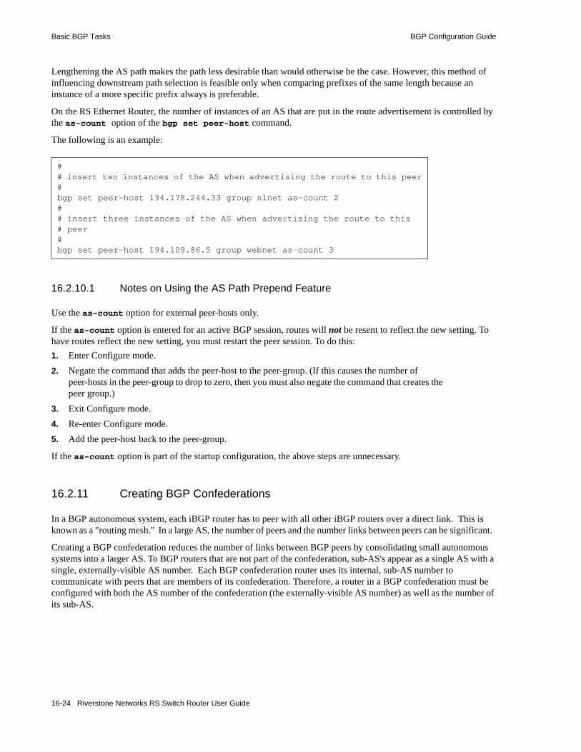
Basic BGP Tasks BGP Configuration Guide
Lengthening the AS path makes the path less desirable than would otherwise be the case. However, this method of influencing downstream path selection is feasible only when comparing prefixes of the same length because an instance of a more specific prefix always is preferable.
On the RS Ethernet Router, the number of instances of an AS that are put in the route advertisement is controlled by the as-count option of the bgp set peer-host command.
The following is an example:
16.2.10.1 Notes on Using the AS Path Prepend Feature
Use the as-count option for external peer-hosts only.
If the as-count option is entered for an active BGP session, routes will not be resent to reflect the new setting. To have routes reflect the new setting, you must restart the peer session. To do this:1. Enter Configure mode.2. Negate the command that adds the peer-host to the peer-group. (If this causes the number of
peer-hosts in the peer-group to drop to zero, then you must also negate the command that creates the peer group.)
3. Exit Configure mode.4. Re-enter Configure mode.5. Add the peer-host back to the peer-group.
If the as-count option is part of the startup configuration, the above steps are unnecessary.
16.2.11 Creating BGP Confederations
In a BGP autonomous system, each iBGP router has to peer with all other iBGP routers over a direct link. This is known as a "routing mesh." In a large AS, the number of peers and the number links between peers can be significant.
Creating a BGP confederation reduces the number of links between BGP peers by consolidating small autonomous systems into a larger AS. To BGP routers that are not part of the confederation, sub-AS's appear as a single AS with a single, externally-visible AS number. Each BGP confederation router uses its internal, sub-AS number to communicate with peers that are members of its confederation. Therefore, a router in a BGP confederation must be configured with both the AS number of the confederation (the externally-visible AS number) as well as the number of its sub-AS.
## insert two instances of the AS when advertising the route to this peer#bgp set peer-host 194.178.244.33 group nlnet as-count 2 ## insert three instances of the AS when advertising the route to this# peer#bgp set peer-host 194.109.86.5 group webnet as-count 3
16-24 Riverstone Networks RS Switch Router User Guide

BGP Configuration Guide Basic BGP Tasks
Note Confederation AS numbers are not exchanged in BGP ‘Open’ messages. This means that if two routers are meant to be in the same confederation but one of them is configured with an incorrect confederation AS number, BGP still establishes peering between them.
To avoid this errant behavior when configuring confederations, make sure that the correct confederation AS number is configured on all routers.
In Figure 16-2, a BGP confederation with the AS number 64801 consists of sub-AS’s 100, 101, 102, and 103. BGP routers outside the confederation see only AS 64801; they cannot see the sub-AS’s. For example, R2 resides in AS 1000. When R2 communicates with R1, it sees R1 as part of AS 64801; R2 does not know that R1 is a member of AS 102.
Figure 16-2 BGP confederation
BGP confederations assume that a single IGP runs across the entire confederation. BGP sessions between routers that are in the same confederation but in different sub-AS’s are also known as EIBGP sessions. EIBGP sessions are similar to EBGP sessions with the following differences:• Local preference attributes in learned routes are allowed to traverse sub-AS’s instead of being
ignored. For example, in Figure 16-2, R1 establishes a local preference value for a route advertised by R2. AS 102 must be allowed to advertise the local preference value to the other sub-AS’s in the confederation.
• The next hop attribute is set by the first-hop router in the confederation and is then allowed to traverse sub-AS’s without being changed.
• To prevent looping of routing announcements within the confederation, the AS-path attribute uses two new path segment types: as-confed-set and as-confed-sequence are similar to the as-set and as-sequence attributes, except they are only used within a confederation.
The confederation structure is hidden whenever an EBGP session takes place between a router in a sub-AS and a router outside the confederation. In Figure 16-2, when R1 advertises a route to R2, R1 strips any as-confed-sequence and as-confed-set path segments from the AS-path attribute and adds AS 64801 to the AS-path attribute. When R1 learns a route from R2 and advertises the route via EBGP to a router in another member AS, R1 adds the as-confed-sequence path segment to the AS-path attribute and includes its sub-AS number (102) in the new path segment.
R1 R2
AS 100 AS 102
AS 101 AS 103
AS 1000AS 64801
BGP Confederation
Riverstone Networks RS Switch Router User Guide 16-25

Basic BGP Tasks BGP Configuration Guide
16.2.12 Removing Private Autonomous System Numbers
Private autonomous system numbers are those in the range 64512 to 65535. They are frequently assigned by ISPs to conserve AS numbers. When private AS’s are used, private AS numbers must be stripped from the AS Path of routes before those routes are exported to EBGP peers.
16.2.12.1 Configuration
You can configure the RS Ethernet Router to strip private AS numbers from updates sent by EBGP peers.
The following example turns on private AS stripping for an EBGP peer group:
The following example turns on private AS stripping for EBGP peer host 1.1.1.1 in peer group 30:
16.2.12.2 Usage Notes, Rules, and Restrictions
The following notes, rules, and restrictions apply to these commands and the private AS stripping feature:• If the option is set for the group, it applies to all group members. If set for a peer host, it only applies
to that peer. When the option is set for the group, you cannot override with a different peer-host setting.
• These commands are only permitted on EBGP peers or groups. Private AS’s cannot be removed for IBGP peers.
• With this feature enabled, when an outbound update contains a sequence of only private AS numbers, the sequence is dropped before sending, allowing you to hide private AS’s from external, public AS BGP listeners.
• When an outbound update contains both private and public AS numbers, BGP considers this to be a configuration error and does nothing.
• Private AS numbers are only removed from the portion of the AS path that the EBGP peer receives. After stripping the private AS numbers, as usual, the EBGP peer prepends its own AS number to the AS path, regardless of whether its own AS is public or private.
• When using this feature with confederations, BGP removes the private AS numbers only if they follow the confederation portion of the AS path. AS numbers are never stripped from the confederation portion of the AS path, which is treated according to the above rules.
16.2.12.3 Example
In the following example, two EBGP peering relationships exist: R1 with R2, and R2 with R3. R1 is in private AS 64550, while R2 and R3 belong to public AS’s 222 and 150.
RS Ethernet Router(config)# bgp set peer-group 20 remove-private-as
RS Ethernet Router(config)# bgp set peer-host 1.1.1.1 group 30 remove-private-as
16-26 Riverstone Networks RS Switch Router User Guide

BGP Configuration Guide Basic BGP Tasks
Figure 16-3 Sample BGP private AS number stripping example
To enable private AS stripping, the CLI configuration for router R2 contains the following line:
In this example, R1 redistributes one static route for the 182.1.1/24 network to BGP, which announces the route to R2:
bgp set peer-host 23.1.1.1 group A remote-private-as
R1# bgp show peer-host 40.1.1.1 advertised-routes BGP table : Local router ID is 159.1.1.5Status codes: s suppressed, d damped, h history, * valid, > best, i - internalOrigin codes: i - IGP, e - EGP, ? - incomplete Network Next Hop Metric LocPrf Path ------- -------- ------ ------ ----*> 182.1.1/24 40.1.1.2 64550 ?
Physical Link
Legend:
Peering Relationship
AS-222
R140.1.1.140.1.1.2
R2
AS-64550
23.1.1.2
R3
AS-150
EBGP 40.1
EBGP 23.1
23.1.1.1
Riverstone Networks RS Switch Router User Guide 16-27

Basic BGP Tasks BGP Configuration Guide
As the following two show commands display, R2 receives the route containing R1’s private AS number and prepends its own AS, 200, to the route:
R2 then propagates this route to R3. With the private AS stripping feature disabled, R2 would forward this route to R3 with an AS path of ‘222 64550’. However, with private AS stripping enabled, R2 forwards this route to R3 with an AS path of ‘222’.
Note While R2 strips R1’s AS number, it prepends its own AS to the AS path it is preparing to send. In this case, R2 belongs to a public AS. But even if R2 belonged to a private AS, the AS path it advertises would still contain its own AS number because BGP does not advertise routes with empty AS paths.
Finally, as the following two show commands display, the route that R3 receives from R2 does not contain R1’s private AS number, only R2’s.
R2# bgp show peer-host 40.1.1.2 all-received-routes BGP table : Local router ID is 159.1.1.15Status codes: s suppressed, d damped, h history, * valid, > best, i - internalOrigin codes: i - IGP, e - EGP, ? - incomplete Network Next Hop Metric LocPrf Path ------- -------- ------ ------ ----*> 182.1.1/24 40.1.1.2 (222) 64550 ?
R2# bgp show routes allBGP table : Local router ID is 159.1.1.15Status codes: s suppressed, d damped, h history, * valid, > best, i - internalOrigin codes: i - IGP, e - EGP, ? - incomplete Network Next Hop Metric LocPrf Path ------- -------- ------ ------ ----*> 182.1.1/24 40.1.1.2 100 (222) 64550 ?
R2# bgp show peer-host 23.1.1.2 advertised-routes BGP table : Local router ID is 159.1.1.15Status codes: s suppressed, d damped, h history, * valid, > best, i -internalOrigin codes: i - IGP, e - EGP, ? - incomplete Network Next Hop Metric LocPrf Path ------- -------- ------ ------ ----*> 182.1.1/24 23.1.1.1 222 ?
16-28 Riverstone Networks RS Switch Router User Guide

BGP Configuration Guide Basic BGP Tasks
As mentioned above, even if R2 belongs to a private AS, the route the R3 receives from R2 would still contain R2’s private AS number, just not R1’s.
16.2.13 Creating Community Lists
A community is a group of destinations that share a common property. A community is defined by the administrator of the autonomous system and can be used as a way of filtering BGP routes.
To create and define community lists on an RS Ethernet Router, enter the following commands in Configure mode:
Community lists can be specified in route maps. Communities in a BGP route can be compared to the community list. The communities in the route can either be a superset of the specified communities or they can exactly match the specified communities. Route map actions can include removing the community attribute from a route, setting the value of the community attribute, adding communities to the route, or deleting communities from the route. With route maps, you can also specify keywords for certain well-known communities, listed below.
The bgp show routes command shows communities associated with a BGP route.
16.2.13.1 Standard Communities
For standard communities, the <community-string> is in the form "<AS-identifier>:<community-identifier>,” where:
R3# bgp show peer-host 23.1.1.1 all-received-routes BGP table : Local router ID is 159.1.1.30Status codes: s suppressed, d damped, h history, * valid, > best, i - internalOrigin codes: i - IGP, e - EGP, ? - incomplete Network Next Hop Metric LocPrf Path ------- -------- ------ ------ ----*> 182.1.1/24 23.1.1.1 (150) 222 ?
R3# bgp show routes allBGP table : Local router ID is 159.1.1.30Status codes: s suppressed, d damped, h history, * valid, > best, i - internalOrigin codes: i - IGP, e - EGP, ? - incomplete Network Next Hop Metric LocPrf Path ------- -------- ------ ------ ----*> 182.1.1/24 23.1.1.1 100 (150) 222 ?
Create a community list. ip-router policy create community-list <identifier> <community-string>
Add communities to a community list.
ip-router policy add community-list <identifier> <community-string>
Riverstone Networks RS Switch Router User Guide 16-29
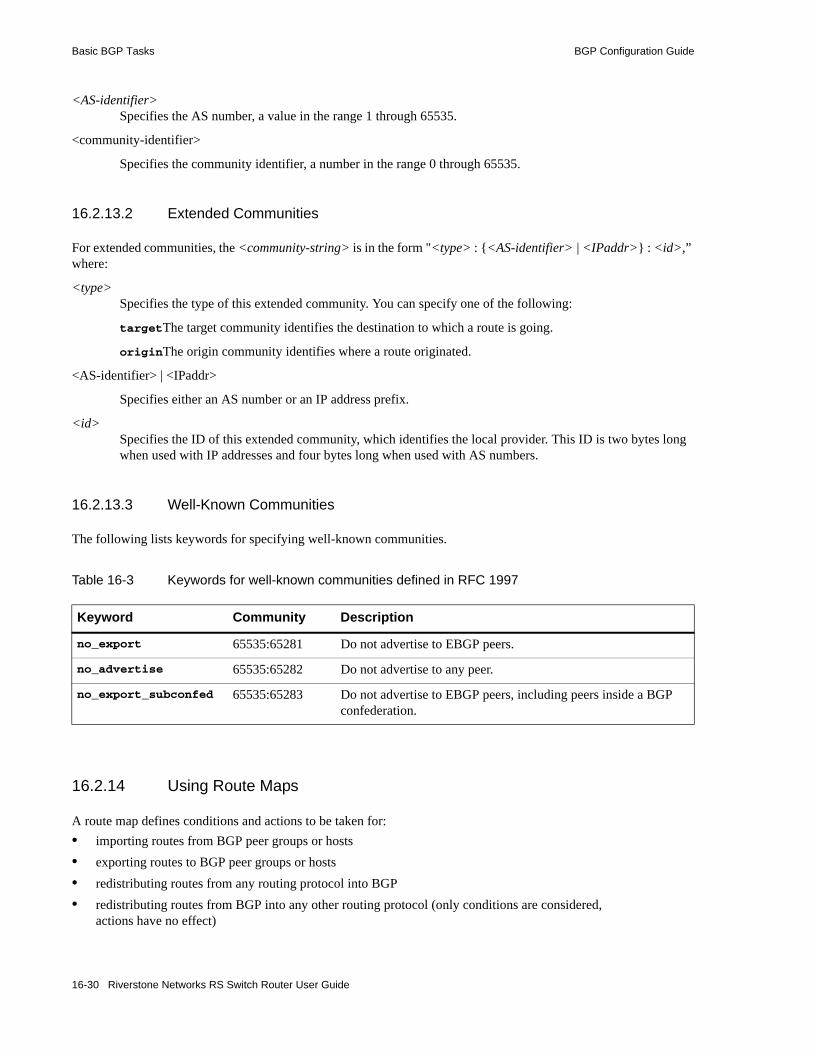
Basic BGP Tasks BGP Configuration Guide
<AS-identifier>Specifies the AS number, a value in the range 1 through 65535.
<community-identifier>
Specifies the community identifier, a number in the range 0 through 65535.
16.2.13.2 Extended Communities
For extended communities, the <community-string> is in the form "<type> : {<AS-identifier> | <IPaddr>} : <id>,” where:
<type>Specifies the type of this extended community. You can specify one of the following:
targetThe target community identifies the destination to which a route is going.
originThe origin community identifies where a route originated.
<AS-identifier> | <IPaddr>
Specifies either an AS number or an IP address prefix.
<id>Specifies the ID of this extended community, which identifies the local provider. This ID is two bytes long when used with IP addresses and four bytes long when used with AS numbers.
16.2.13.3 Well-Known Communities
The following lists keywords for specifying well-known communities.
16.2.14 Using Route Maps
A route map defines conditions and actions to be taken for:• importing routes from BGP peer groups or hosts• exporting routes to BGP peer groups or hosts• redistributing routes from any routing protocol into BGP• redistributing routes from BGP into any other routing protocol (only conditions are considered,
actions have no effect)
Table 16-3 Keywords for well-known communities defined in RFC 1997
Keyword Community Description
no_export 65535:65281 Do not advertise to EBGP peers.
no_advertise 65535:65282 Do not advertise to any peer.
no_export_subconfed 65535:65283 Do not advertise to EBGP peers, including peers inside a BGP confederation.
16-30 Riverstone Networks RS Switch Router User Guide
BGP Configuration Guide Basic BGP Tasks
A route map consists of one or more conditions that define BGP information and the action to be taken when the condition is met. Each condition tells the RS Ethernet Router to either permit or deny route that matches the criteria specified in the route map. To be imported, exported, or redistributed, a route needs to meet the conditions of a configured route map. Note that a route can meet the conditions of a route map where the keyword deny is explicitly specified; in this case, the route will not be imported, exported, or redistributed.
Note For route maps to take effect, the RS Ethernet Router must be selecting BGP for the route. Make sure that BGP preference is set lower than the preference of other protocols on the RS Ethernet Router.
To create a route map, enter the following command in Configure mode:
In the following example, when the prefix of a route matches the network address 15.4.0.0, the route is redistributed with a next hop of 12.10.4.13.
You can specify the configured route map for an export, import, or redistribution policy (with the ip-router policy export, ip-router policy import, or ip-router policy redistribute command). You can also specify the route map when exporting routes to or importing routes from a peer group or a peer host; this is done with the route-map-in (import) or route-map-out (export) option of the bgp set peer-group or bgp set peer-host commands. For example, the following commands apply the route map with the identifier ’1’ for routes that are exported to the peer group ’pub1’:
For EBGP, route maps can be applied to either a peer group or a peer host. For IBGP, the route-map-out option cannot be used to set a value for a peer host. If you need to control the export of routes to specific IBGP peers, create a peer group for each peer and define a group-specific policy. This restriction does not apply to the route-map-in option.
16.2.14.1 Defining Match Criteria in Route Map Conditions
Match criteria in a route map condition describes the BGP route information that is to be filtered. The following match criteria can be specified:• Route prefix, as specified by a previously-defined route filter or network specification• Source protocol of the route• Next hop for the route, as specified by a previously-defined route filter• BGP local preference value
Create a route map. route-map <number-or-string> permit <sequence-number> <match-criteria> <action>
route-map <number-or-string> deny <sequence-number> <match-criteria>
route-map 1 permit 1 match-prefix network 15.4.0.0/16 set-next-hop 12.10.4.13
bgp create peer-group pub1 type external autonomous-system 3937bgp add peer-host 14.2.3.23 group pub1bgp set peer-group pub1 route-map-out 1
Riverstone Networks RS Switch Router User Guide 16-31
Basic BGP Tasks BGP Configuration Guide
• BGP Multi Exit Discriminator (MED) value• BGP origin attribute• aspath regular expression• Communities in route are either part of or exactly the same as previously-defined community list
When you create a route map, you specify a route map identifier. You can create multiple conditions with the same identifier. The sequence number in the route map definition specifies the order of a particular condition in relation to other conditions with the same route map identifier. The condition with the lowest sequence number is applied first. If the specified condition is not met, the condition with the next-lowest sequence number is applied. A route is checked against conditions in this manner until a set of route map conditions is met or there are no more conditions. If a route does not meet any configured route map conditions, the route is not imported, exported, or redistributed.
If a route matches a condition, it is imported, exported, or redistributed, or not, based on the permit or deny keyword. All subsequent conditions are ignored. Consequently, conditions that are more specific should always have lower sequence numbers than conditions that are less specific. In the following example, when the prefix of a route matches the network address 15.4.0.0, the route is redistributed with a next hop of 12.10.4.13. But when the prefix of a route matches the network address 13.0.0.0/16, the route is not imported, exported, or distributed.
16.2.14.2 Defining Actions in Route Map Conditions
When a route matches a condition configured with the permit keyword, the specified action is taken. The following actions can be specified:• Set the next hop for the route• Set the local preference for the route• Set the MED for the route• Set the original for the route• Prepend the AS number to the AS path for the route• Remove or add communities to the route• Set the preference for the route• Specify the traffic bucket number for the route (see Section 16.3.11, "BGP Accounting Examples,"
for more information)
16.2.15 Using MPLS LSPs To Resolve BGP Next Hop
16.2.15.1 Basic Functionality
The RS Ethernet Router allows you to use MPLS LSPs to resolve BGP next hops.
Normally, MPLS LSPs are not installed in the RIB or FIB, which makes MPLS LSPs inaccessible for routing.
route-map 1 permit 1 match-prefix network 15.4.0.0/16 set-next-hop 12.10.4.13route-map 1 deny 2 match-prefix network 15.0.0.0/8
16-32 Riverstone Networks RS Switch Router User Guide

BGP Configuration Guide Basic BGP Tasks
Using the ip-router global set install-lsp-routes bgp command, you can grant BGP exclusive access to these LSP routes, allowing BGP to use MPLS paths, in addition to other routes in the FIB, in resolving next hops. Under this scheme, MPLS routes are only installed in the LSP RIB and other routing protocols are not permitted to use them.
MPLS LSP routes contain the host address for each LSP’s egress router. Using these tunnels, an ingress router can forward packets to the destination egress router.
Without this capability, BGP must rely on conventional routes in the FIB for transport to its next hop. With this capability, if a BGP next hop happens to be the egress point on a pre-defined MPLS tunnel, BGP can utilize this tunnel to forward to the next hop.
16.2.15.2 Configuration
By default, routing protocols must rely on conventional routes in the FIB for routing. Use the ip-router global set install-lsp-routes on command to install LSP routes in the Internet Unicast RIB and permit all routing protocols to utilize these routes for calculating IGP shortcuts. Due to their default preference, installing LSP routes in the Internet Unicast RIB usually means that they are also selected to be installed in the Unicast FIB.
Use the ip-router global set install-lsp-routes bgp command to grant BGP exclusive access to LSP routes, allowing BGP to use MPLS paths, in addition to other routes in the FIB, in resolving next hops. Under this scheme, MPLS routes are only installed in the LSP RIB and other routing protocols are not permitted to use them.
16.2.15.3 Usage Notes, Rules, and Restrictions
Choosing Between Conventional FIB Routes and LSP Routes• When BGP has a choice between conventional routes and LSP routes, the route with the highest
preference is chosen. You can affect this choice by using the <igp> set preference command to specify desired IGP preferences and the mpls set label-switch-path preference command to specify preferences for MPLS LSPs.
Caution Using these commands overrides default preferences and may alter the normal routing process.
• If multiple paths with identical preferences exist between conventional routes and LSP routes, BGP prefers LSP routes over conventional routes.
LSP Removed or Fails• When BGP selects an LSP to use, it installs that LSP into its forwarding engine as the transport
method of choice for the associated next hop. If the LSP is removed or fails, the path is removed from the LSP RIB and from BGP’s forwarding engine. This forces BGP to select another path to the next hop from all available routes, including other LSP routes.
RS Ethernet Router(config)# ip-router global set install-lsp routes on
RS Ethernet Router(config)# ip-router global set install-lsp routes bgp
Riverstone Networks RS Switch Router User Guide 16-33

Basic BGP Tasks BGP Configuration Guide
16.2.16 BGP QoS
16.2.16.1 Basic Functionality
The RS Ethernet Router allows you to set the Differentiated Services Code Point (DSCP) values based on route-map matching conditions.
Used in Quality of Service (QoS), Differentiated Services is a new model where you can specify the relative priority with which traffic should be treated by intermediate systems. Defined in RFCs 2474 and 2475, Differentiated Services increases the number of priority levels you can specify by allocating 4 additional bits from the IP header for marking priority.
Eight bits comprise the expanded priority field in the IP header, but only six bits (bits 2 to 7) are used for Differentiated Services, allowing for a DSCP range of 0 to 63. The six DSCP bits and two Additional bits are summarized below:
16.2.16.2 Configuration
Use the route-map command to set DSCP values based on matching conditions. The following example sets the DSCP bits for all traffic from the well-known community ‘no-export’ to 29.
A DSCP decimal value of 29 is represented by the following binary configuration in DSCP bits
:
Table 16-4 DSCP bit layout
Bit Purpose Usage
0 Reserved Other
1 Cost
2 Reliability
DSCP Bits3 Throughput
4 Delay
5 Precedence
6
7
Table 16-5 DSCP bit example
Binary Value
0 1 1 1 0 1
Bit 7 6 5 4 3 2
Purpose Precedence Delay Throughput Reliability
16-34 Riverstone Networks RS Switch Router User Guide

BGP Configuration Guide Basic BGP Tasks
16.2.16.3 Usage Notes, Rules, and Restrictions
Note Currently, the DSCP feature only works with route-map in, not route-map out.
16.2.17 Using BGP Accounting
BGP accounting allows you to differentiate and tally IP traffic by assigning traffic indexes based on route map specifications to an input interface. Using BGP accounting, you can collect statistics (and apply billing) according to route-specific traffic. For example, domestic, international, terrestrial, satellite, and other traffic can be identified and accounted for on a per-customer basis.
You can also choose to count route-specific traffic according to Differentiated Services Code Point (DSCP) values (previously known as Type of Service values) in the packets. This allows you to collect and bill on a service level for each customer.
16.2.17.1 Enabling BGP Accounting
In the following example, BGP packets with the standard community value “11:11” are forwarded from router R1 to router R2. On router R2, a traffic index is set up to keep the counts of these packets.
On the router R1, create a standard community list for the community value “11:11.” For example, the following commands create a route-map for the community value “11:11”:
On the router R2, do the following:1. Create a standard community list to match the community value “11:11” and define a route-map that
matches the community with a specific traffic index. For example, the following commands create a standard community list with the community value “11:11” and define a route map to match the community list with the traffic index ’1’:
RS Ethernet Router(config)# route-map 1 permit 10 match-community-list no-export set-dscp 29
route-map 1 permit 1 set-community-list “11:11”bgp set peer-group r2 route-map-out 1 out-sequence 1
ip-router policy create community-list list1 "11:11"route-map 1 permit 1 match-community-list list1 set-traffic-index 1
Riverstone Networks RS Switch Router User Guide 16-35

Basic BGP Tasks BGP Configuration Guide
2. Enable the route-map on incoming traffic from router R1. For example, the following command applies the route-map ’1’ to routes imported from the peer group ’r1’:
3. Add the interface name to the BGP accounting table. For example, the following command enables BGP accounting on the interface ’customerA’:
4. Start BGP accounting. For example, to start collecting statistics for the service levels (DSCP values) of specific traffic routes:
To start collecting BGP traffic statistics for specific traffic routes:
Refer to Section 16.3.11, "BGP Accounting Examples," to see detailed example configurations.
16.2.17.2 Displaying BGP Accounting Information
Use the bgp-actg option with the ip show interfaces command to display BGP accounting information on a per-interface basis. For example:
The example output shown above displays the number of packets and bytes sent at the interface 'int1'. The user has sent 111 packets of size 130 bytes that fell into bucket 1 (traffic index 1). For example, a ping request (with a data size of 84 bytes) was sent 111 times.
Use the ip clear bgp-actg command to clear BGP accounting statistics. For example:
bgp set peer-group r1 route-map-in 1 in-sequence 1
ip enable bgp-actg-on customerA
ip bgp-accounting start dscp-accounting
ip bgp-accounting start accounting
rs# ip show interfaces int1 bgp-actg
Interface:int1Bucket Packets Bytes0 0 01 111 14430
rs# ip clear bgp-actg
rs# ip show interfaces int1 bgp-actg
Interface:int1Bucket Packets Bytes0 0 01 0 0
16-36 Riverstone Networks RS Switch Router User Guide

BGP Configuration Guide BGP Configuration Examples
If you need to see which traffic index is assigned to a route, run the following Diagnostic mode command:
16.2.17.3 Usage Notes, Rules, and Restrictions
Note Do not use BGP accounting with the hardware routing table (HRT) feature. BGP accounting only tracks usage statistics of routes in memory, not those in the HRT.
16.3 BGP CONFIGURATION EXAMPLESThis section presents sample configurations illustrating BGP features. The following features are demonstrated:• BGP peering• Internal BGP (IBGP)• External BGP (EBGP) multihop• BGP community attribute• BGP local preference (local_pref) attribute• BGP Multi-Exit Discriminator (MED) attribute• EBGP aggregation• Route reflection• BGP confederation• Route map• BGP accounting
16.3.1 BGP Peering Session Example
The router process used for a specific BGP peering session is known as a BGP speaker. A single router can have several BGP speakers. Successful BGP peering depends on the establishment of a neighbor relationship between BGP speakers. The first step in creating a BGP neighbor relationship is the establishment of a TCP connection (using TCP port 179) between peers.
rs# diagrs? ip find route 14.1.0.0 route to: 14.1.0.0 mask: (255) ffff ffff interface: toRTR2 gateway: 12.1.1.2 aspath info: Next Hop - 0, Origin - 0traffic index: 1 flags: <UP,GATEWAY>recvpipe sendpipe ssthresh rtt,msec rttvar hopcount mtu 16384 16384 0 0 e
Riverstone Networks RS Switch Router User Guide 16-37

BGP Configuration Examples BGP Configuration Guide
A BGP ‘Open’ message can then be sent between peers across the TCP connection to establish various BGP variables (BGP Version, AS number (ASN), Holdtime, BGP identifier, and optional parameters). Upon successful completion of the BGP Open negotiations, BGP Update messages containing the BGP routing table can be sent between peers.
BGP does not require a periodic refresh of the entire BGP routing table between peers. Only incremental routing changes are exchanged. Therefore, each BGP speaker is required to retain the entire BGP routing table of their peer for the duration of the peer’s connection.
Note To request route database refreshes from peer-hosts, first add bgp set peer-host/peer-group route refresh to the active configuration. Then, use the bgp clear peer-host soft-inbound command. The soft-inbound option causes the peer-host to re-send it routing information without breaking and then re-establishing the connection to the peer-host.
BGP “keepalive” messages are sent between peers periodically to ensure that the peers stay connected. If one of the routers encounters a fatal error condition, a BGP notification message is sent to its BGP peer, and the TCP connection is closed.
Figure 16-4 illustrates a sample BGP peering session:
Figure 16-4 Sample BGP peering session
Physical Link
Legend:
Peering Relationship
AS-2
R110.0.0.2/1610.0.0.1/16
R2
AS-1
1.1 1.1
16-38 Riverstone Networks RS Switch Router User Guide

BGP Configuration Guide BGP Configuration Examples
The CLI configuration for router R1 is as follows:
The CLI configuration for router R2 is as follows:
16.3.2 IBGP Configuration Example
Connections between BGP speakers within the same AS are referred to as internal links. A peer in the same AS is an internal peer. Internal BGP is commonly abbreviated IBGP; external BGP is EBGP.
An AS that has two or more EBGP peers is referred to as a multihomed AS. A multihomed AS can “transit” traffic between two ASs by advertising to one AS routes that it learned from the other AS. To successfully provide transit services, all EBGP speakers in the transit AS must have a consistent view of all of the routes reachable through their AS.
Multihomed transit ASs can use IBGP between EBGP-speaking routers in the AS to synchronize their routing tables. IBGP requires a full-mesh configuration; all EBGP speaking routers must have an IBGP peering session with every other EBGP speaking router in the AS.
An IGP, like OSPF, could possibly be used instead of IBGP to exchange routing information between EBGP speakers within an AS. However, injecting full Internet routes (50,000+ routes) into an IGP puts an expensive burden on the IGP routers. Additionally, IGPs cannot communicate all of the BGP attributes for a given route. It is, therefore, recommended that an IGP not be used to propagate full Internet routes between EBGP speakers. IBGP should be used instead.
interface create ip et.1.1 address-netmask 10.0.0.1/16 port et.1.1## Set the AS of the router#ip-router global set autonomous-system 1## Set the router ID#ip-router global set router-id 10.0.0.1## Create EBGP peer group pg1w2 for peering with AS 2#bgp create peer-group pg1w2 type external autonomous-system 2## Add peer host 10.0.0.2 to group pg1w2#bgp add peer-host 10.0.0.2 group pg1w2bgp start
interface create ip et.1.1 address-netmask 10.0.0.2/16 port et.1.1ip-router global set autonomous-system 2ip-router global set router-id 10.0.0.2bgp create peer-group pg2w1 type external autonomous-system 1bgp add peer-host 10.0.0.1 group pg2w1bgp start
Riverstone Networks RS Switch Router User Guide 16-39

BGP Configuration Examples BGP Configuration Guide
16.3.2.1 IBGP Routing Group Example
An IBGP routing group uses the routes of an interior protocol to resolve forwarding addresses. An IBGP routing group will determine the immediate next hops for routes by using the next hop received with a route from a peer as a forwarding address, and using this to look up an immediate next hop in an IGP’s routes. Such groups support distant peers, but need to be informed of the IGP whose routes they are using to determine immediate next hops. This implementation comes closest to the IBGP implementation of other router vendors.
You should use the IBGP routing group as the mechanism to configure the RS Ethernet Router for IBGP. If the peers are directly connected, then IBGP using group-type Internal can also be used. Note that for running IBGP using group-type routing you must run an IGP such as OSPF to resolve the next hops that come with external routes. You could also use protocol any so that all protocols are eligible to resolve the BGP forwarding address.
Figure 16-5 shows a sample BGP configuration that uses the routing group type.
Figure 16-5 Sample IBGP configuration (routing group type)
R6
R1
Cisco
R4
lo0 172.23.1.25/30
10.12.1.6/30
10.12.1.5/30
172.23.1.10/30
172.23.1.9/30172.23.1.6/30
lo0 172.23.1.26/30
172.23.1.5/30
10.12.1.2/30
10.12.1.1/30
AS-64801
IBGP
OSPF
16-40 Riverstone Networks RS Switch Router User Guide

BGP Configuration Guide BGP Configuration Examples
In this example, OSPF is configured as the IGP in the autonomous system. The following lines in the router R6 configuration file configure OSPF:
The following lines in the Cisco router configure OSPF:
The following lines in the R6 set up peering with the Cisco router using the routing group type.
## Create a secondary address for the loopback interface# interface add ip lo0 address-netmask 172.23.1.26/30 ospf create area backboneospf add interface to-R4 to-area backboneospf add interface to-R1 to-area backbone## This line is necessary because we want CISCO to peer with our loopback# address.This will make sure that the loopback address gets announced# into OSPF domain#ospf add stub-host 172.23.1.26 to-area backbone cost 1ospf set interface to-R4 priority 2ospf set interface to-R1 priority 2ospf set interface to-R4 cost 2ospf start
The following lines on the CISCO 4500 configures it for OSPF.router ospf 1 network 10.12.1.1 0.0.0.0 area 0 network 10.12.1.6 0.0.0.0 area 0 network 172.23.1.14 0.0.0.0 area 0
# Create a internal routing group.bgp create peer-group ibgp1 type routing autonomous-system 64801 proto any interface all# Add CISCO to the above groupbgp add peer-host 172.23.1.25 group ibgp1# Set our local address. This line is necessary because we want CISCO to# peer with our loopbackbgp set peer-group ibgp1 local-address 172.23.1.26# Start BGPbgp start
Riverstone Networks RS Switch Router User Guide 16-41

BGP Configuration Examples BGP Configuration Guide
The following lines on the Cisco router set up IBGP peering with router R6.
16.3.3 EBGP Multihop Configuration Example
EBGP Multihop refers to a configuration where external BGP neighbors are not connected to the same subnet. Such neighbors are logically, but not physically connected. For example, BGP can be run between external neighbors across non-BGP routers. Some additional configuration is required to indicate that the external peers are not physically attached.
This sample configuration shows External BGP peers, R1 and R4, which are not connected to the same subnet.
Figure 16-6 Sample EBGP configuration (multihop)
router bgp 64801! ! Disable synchronization between BGP and IGP! no synchronizationneighbor 172.23.1.26 remote-as 64801!! Allow internal BGP sessions to use any operational interface for TCP! connections! neighbor 172.23.1.26 update-source Loopback0
Physical Link
Legend:
Peering Relationship
R116.122.128.1/16
R3
AS-64800
AS-64801
R4
R216.122.128.3/16
17.122.128.3/16
17.122.128.4/16
18.122.128.3/16
18.122.128.2/16
16-42 Riverstone Networks RS Switch Router User Guide
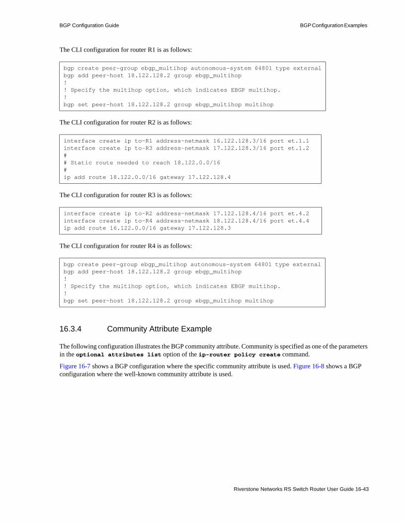
BGP Configuration Guide BGP Configuration Examples
The CLI configuration for router R1 is as follows:
The CLI configuration for router R2 is as follows:
The CLI configuration for router R3 is as follows:
The CLI configuration for router R4 is as follows:
16.3.4 Community Attribute Example
The following configuration illustrates the BGP community attribute. Community is specified as one of the parameters in the optional attributes list option of the ip-router policy create command.
Figure 16-7 shows a BGP configuration where the specific community attribute is used. Figure 16-8 shows a BGP configuration where the well-known community attribute is used.
bgp create peer-group ebgp_multihop autonomous-system 64801 type externalbgp add peer-host 18.122.128.2 group ebgp_multihop!! Specify the multihop option, which indicates EBGP multihop.!bgp set peer-host 18.122.128.2 group ebgp_multihop multihop
interface create ip to-R1 address-netmask 16.122.128.3/16 port et.1.1interface create ip to-R3 address-netmask 17.122.128.3/16 port et.1.2## Static route needed to reach 18.122.0.0/16#ip add route 18.122.0.0/16 gateway 17.122.128.4
interface create ip to-R2 address-netmask 17.122.128.4/16 port et.4.2interface create ip to-R4 address-netmask 18.122.128.4/16 port et.4.4ip add route 16.122.0.0/16 gateway 17.122.128.3
bgp create peer-group ebgp_multihop autonomous-system 64801 type externalbgp add peer-host 18.122.128.2 group ebgp_multihop!! Specify the multihop option, which indicates EBGP multihop. !bgp set peer-host 18.122.128.2 group ebgp_multihop multihop
Riverstone Networks RS Switch Router User Guide 16-43

BGP Configuration Examples BGP Configuration Guide
Figure 16-7 Sample BGP configuration (specific community)
AS-64902
R11
172.26.1.2/16
172.25.1.2/16
192.168.20.2/16
172.25.1.1/161.1
R131.6
R10192.169.20.1/16 192.169.20.2/16
100.200.13.1/24 10.200.15.1/24
1.6
R14
AS-64901
AS-64900 AS-64899
1.6 1.1
1.1
1.31.8
ISP1 ISP2
1.81.1
1.31.6
CS1 CS2
10.200.14.1/24100.200.12.1/24
192.168.20.1/16 172.26.1.1/16
Physical Link
Legend:
Peering Relationship
Information Flow
16-44 Riverstone Networks RS Switch Router User Guide
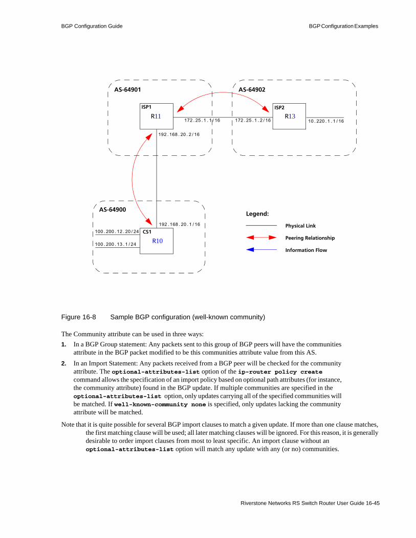
BGP Configuration Guide BGP Configuration Examples
Figure 16-8 Sample BGP configuration (well-known community)
The Community attribute can be used in three ways:1. In a BGP Group statement: Any packets sent to this group of BGP peers will have the communities
attribute in the BGP packet modified to be this communities attribute value from this AS.2. In an Import Statement: Any packets received from a BGP peer will be checked for the community
attribute. The optional-attributes-list option of the ip-router policy create command allows the specification of an import policy based on optional path attributes (for instance, the community attribute) found in the BGP update. If multiple communities are specified in the optional-attributes-list option, only updates carrying all of the specified communities will be matched. If well-known-community none is specified, only updates lacking the community attribute will be matched.
Note that it is quite possible for several BGP import clauses to match a given update. If more than one clause matches, the first matching clause will be used; all later matching clauses will be ignored. For this reason, it is generally desirable to order import clauses from most to least specific. An import clause without an optional-attributes-list option will match any update with any (or no) communities.
AS-64902
Physical Link
Legend:
Peering Relationship
R11
Information Flow
172.25.1.2/16
192.168.20.2/16
172.25.1.1/16R13
R10
192.168.20.1/16
100.200.13.1/24
AS-64901
AS-64900
ISP2
100.200.12.20/24
ISP1
CS1
10.220.1.1/16
Riverstone Networks RS Switch Router User Guide 16-45

BGP Configuration Examples BGP Configuration Guide
In Figure 16-7, router R11 has the following configuration:
In Figure 16-7, router R13 has the following configuration:
## Create an optional attribute list with identifier color1 for a community# attribute (community-id 160 AS 64901)#ip-router policy create optional-attributes-list color1 community-id 160 autonomous-system 64901## Create an optional attribute list with identifier color2 for a community# attribute (community-id 155 AS 64901)#ip-router policy create optional-attributes-list color2 community-id 155 autonomous-system 64901## Create a BGP import source for importing routes from AS 64900 containing the# community attribute (community-id 160 AS 64901). This import source is given an# identifier 901color1 and sequence-number 1.#ip-router policy create bgp-import-source 901color1 optional-attributes-list color1 autonomous-system 64900 sequence-number 1ip-router policy create bgp-import-source 901color2 optional-attributes-list color2 autonomous-system 64900 sequence-number 2ip-router policy create bgp-import-source 901color3 optional-attributes-list color1 autonomous-system 64902 sequence-number 3ip-router policy create bgp-import-source 901color4 optional-attributes-list color2 autonomous-system 64902 sequence-number 4## Import all routes matching BGP import source 901color1 (from AS 64900 having# community attribute with ID 160 AS 64901) with a preference of 160#ip-router policy import source 901color1 network all preference 160ip-router policy import source 901color2 network all preference 155ip-router policy import source 901color3 network all preference 160ip-router policy import source 901color4 network all preference 155
ip-router policy create optional-attributes-list color1 community-id 160 autonomous-system 64902ip-router policy create optional-attributes-list color2 community-id 155 autonomous-system 64902ip-router policy create bgp-import-source 902color1 optional-attributes-list color1 autonomous-system 64899 sequence-number 1ip-router policy create bgp-import-source 902color2 optional-attributes-list color2 autonomous-system 64899 sequence-number 2ip-router policy create bgp-import-source 902color3 optional-attributes-list color1 autonomous-system 64901 sequence-number 3ip-router policy create bgp-import-source 902color4 optional-attributes-list color2 autonomous-system 64901 sequence-number 4ip-router policy import source 902color1 network all preference 160ip-router policy import source 902color2 network all preference 155ip-router policy import source 902color3 network all preference 160ip-router policy import source 902color4 network all preference 155
16-46 Riverstone Networks RS Switch Router User Guide

BGP Configuration Guide BGP Configuration Examples
3. In an Export Statement: The optional-attributes-list option of the ip-router policy create bgp-export-destination command may be used to send the BGP community attribute. Any communities specified with the optional-attributes-list option are sent in addition to any received in the route or specified with the group.
In Figure 16-7, router R10 has the following configuration:
In Figure 16-7, router R14 has the following configuration:
## Create an optional attribute list with identifier color1 for a community# attribute (community-id 160 AS 64902)#ip-router policy create optional-attributes-list color1 community-id 160 autonomous-system 64902## Create an optional attribute list with identifier color2 for a community# attribute (community-id 155 AS 64902)#ip-router policy create optional-attributes-list color2 community-id 155 autonomous-system 64902## Create a direct export source#ip-router policy create direct-export-source 900toanydir metric 10## Create BGP export-destination for exporting routes to AS 64899 containing the# community attribute (community-id 160 AS 64902). This export-destination has an# identifier 900to899dest #ip-router policy create bgp-export-destination 900to899dest autonomous-system 64899 optional-attributes-list color1ip-router policy create bgp-export-destination 900to901dest autonomous-system 64901 optional-attributes-list color2## Export routes to AS 64899 with the community attribute (community-id 160 AS# 64902)#ip-router policy export destination 900to899dest source 900toanydir network allip-router policy export destination 900to901dest source 900toanydir network all
ip-router policy create bgp-export-destination 899to900dest autonomous-system 64900 optional-attributes-list color1ip-router policy create bgp-export-destination 899to902dest autonomous-system 64902 optional-attributes-list color2ip-router policy create bgp-export-source 900toany autonomous-system 64900 metric 10ip-router policy create optional-attributes-list color1 community-id 160 autonomous-system 64901ip-router policy create optional-attributes-list color2 community-id 155 autonomous-system 64901ip-router policy export destination 899to900dest source 899toanydir network allip-router policy export destination 899to902dest source 899toanydir network all
Riverstone Networks RS Switch Router User Guide 16-47

BGP Configuration Examples BGP Configuration Guide
Any communities specified with the optional-attributes-list option are sent in addition to any received with the route or associated with a BGP export destination.
The community attribute may be a single community or a set of communities. A maximum of 10 communities may be specified.
The community attribute can take any of the following forms:• Specific community
The specific community consists of the combination of the AS-value and community ID.• Well-known-community no-export
Well-known-community no-export is a special community which indicates that the routes associated with this attribute must not be advertised outside a BGP confederation boundary.
For example, router R10 in Figure 16-8 has the following configuration:
• Well-known-community no-advertise
Well-known-community no-advertise is a special community indicating that the routes associated with this attribute must not be advertised to other bgp peers. A packet can be modified to contain this attribute and passed to its neighbor. However, if a packet is received with this attribute, it cannot be transmitted to another BGP peer.
• Well-known-community no-export-subconfed
Well-known-community no-export-subconfed is a special community indicating the routes associated with this attribute must not be advertised to external BGP peers. (This includes peers in other members’ autonomous systems inside a BGP confederation.)
A packet can be modified to contain this attribute and passed to its neighbor. However, if a packet is received with this attribute, the routes (prefix-attribute pair) cannot be advertised to an external BGP peer.
• Well-known-community none
This is not actually a community, but rather a keyword that specifies that a received BGP update is only to be matched if no communities are present. It has no effect when originating communities.
16.3.4.1 Notes on Using Communities
When originating BGP communities, the set of communities that is actually sent is the union of the communities received with the route (if any), those specified in group policy (if any), and those specified in export policy (if any).
When receiving BGP communities, the update is only matched if all communities specified in the optional-attributes-list option of the ip-router policy create command are present in the BGP update. (If additional communities are also present in the update, it will still be matched.)
ip-router policy create optional-attributes-list noexport well-known-community no-exportip-router policy create bgp-export-destination 900to901dest autonomous-system 64901 optional-attributes-list noexportip-router policy export destination 900to901dest source 900to901src network allip-router policy export destination 900to901dest source 900to901dir network all
16-48 Riverstone Networks RS Switch Router User Guide

BGP Configuration Guide BGP Configuration Examples
16.3.5 Local Preference Examples
There are two methods of specifying the local preference with the bgp set peer-group command:• Setting the local-pref option. This option can only be used for the internal, routing, and IGP
group types and is not designed to be sent outside of the AS.• Setting the set-pref option, which allows the RS Ethernet Router IP routing code (ROSRD) to set
the local preference to reflect ROSRD’s own internal preference for the route, as given by the global protocol preference value. Note that in this case, local preference is a function of the ROSRD preference and set-pref options.
Figure 16-9 shows a BGP configuration that uses the BGP local preference attribute in a sample BGP configuration with two autonomous systems. All traffic exits Autonomous System 64901 through the link between router R13 and router R11. This is accomplished by configuring a higher local preference on router R13 than on router S12. Because local preference is exchanged between the routers within the AS, all traffic from AS 64901 is sent to R13 as the exit point.
Riverstone Networks RS Switch Router User Guide 16-49

BGP Configuration Examples BGP Configuration Guide
Figure 16-9 Sample BGP configuration (local preference)
The following sections explain how to configure the local preference using the local-pref and the set-pref options.
AS-64900
Physical Link
Legend:
Peering Relationship
AS-64901
R10
Information Flow
10.200.12.1/24 10.200.13.1/24 10.200.14.1/24 10.200.15.1/24
192.169.20.1/16 192.169.20.2/16
192.168.20.1/16 172.28.1.1/16
EBGP EBGP
192.168.20.2/16
172.25.1.1/16
1.6
1.1 1.3
R11
R12 R13
R14
1.3172.25.1.2/16
172.28.1.2/16
172.26.1.1/16 172.27.1.1/16
172.26.1.2/16
172.27.1.2/16
1.1 1.3
1.6
1.6
1.1
1.6
1.1
1.3
1.3 1.1
16-50 Riverstone Networks RS Switch Router User Guide
BGP Configuration Guide BGP Configuration Examples
16.3.5.1 Using the local-pref Option
For router R12’s CLI configuration file, local-pref is set to 194:
For router R13, local-pref is set to 204.
16.3.5.2 Using the set-pref Option
The formula used to compute the local preference is as follows:
Local_Pref = 254 – (global protocol preference for this route) + set-pref metric
Note A value greater than 254 will be reset to 254. ROSRD will only send Local_Pref values between 0 and 254.
In a mixed ROSRD and non-ROSRD (or non-GateD) network, the non-ROSRD IBGP implementation may send Local_Pref values that are greater than 254. When operating a mixed network of this type, you should make sure that all routers are restricted to sending Local_Pref values in the range metric to 254.
In router R12’s CLI configuration file, the import preference is set to 160:
Using the formula for local preference [Local_Pref = 254 - (global protocol preference for this route) + metric], the Local_Pref value put out by router R12 is 254 - 160+100 = 194.
For router R13, the import preference is set to 150. The Local_Pref value put out by router R13 is 254 - 150+100 = 204.
Note the following when using the set-pref option:• All routers in the same network that are running ROSRD and participating in IBGP should use the
set-pref option, and the set-pref metric should be set to the same value.
For example, in Figure 16-9, routers R12, R13, and R14 have the following line in their CLI configuration files:
bgp set peer-group as901 local-pref 194
bgp set peer-group as901 local-pref 204
## Set the set-pref metric for the IBGP peer group# bgp set peer-group as901 set-pref 100ip-router policy create bgp-import-source as900 autonomous-system 64900 preference 160
ip-router policy create bgp-import-source as900 autonomous-system 64900 preference 150
bgp set peer-group as901 set-pref 100
Riverstone Networks RS Switch Router User Guide 16-51
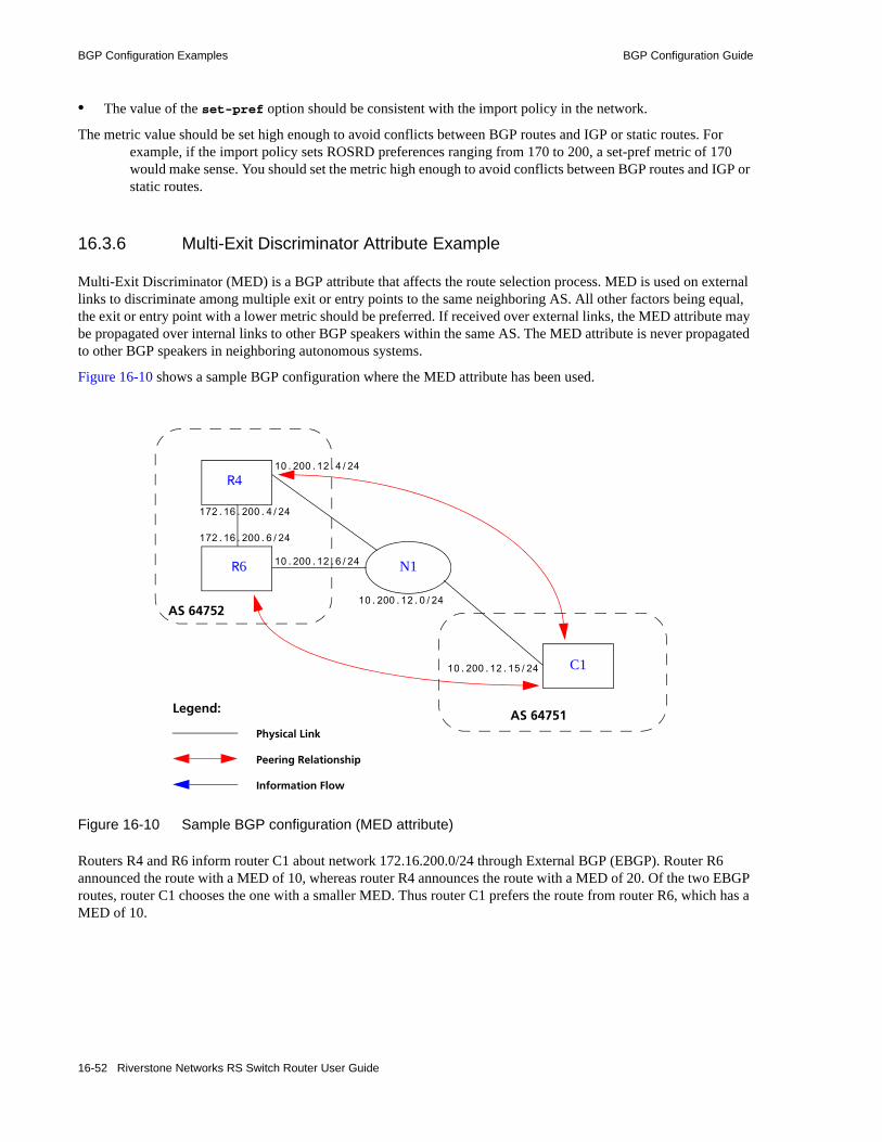
BGP Configuration Examples BGP Configuration Guide
• The value of the set-pref option should be consistent with the import policy in the network.
The metric value should be set high enough to avoid conflicts between BGP routes and IGP or static routes. For example, if the import policy sets ROSRD preferences ranging from 170 to 200, a set-pref metric of 170 would make sense. You should set the metric high enough to avoid conflicts between BGP routes and IGP or static routes.
16.3.6 Multi-Exit Discriminator Attribute Example
Multi-Exit Discriminator (MED) is a BGP attribute that affects the route selection process. MED is used on external links to discriminate among multiple exit or entry points to the same neighboring AS. All other factors being equal, the exit or entry point with a lower metric should be preferred. If received over external links, the MED attribute may be propagated over internal links to other BGP speakers within the same AS. The MED attribute is never propagated to other BGP speakers in neighboring autonomous systems.
Figure 16-10 shows a sample BGP configuration where the MED attribute has been used.
Figure 16-10 Sample BGP configuration (MED attribute)
Routers R4 and R6 inform router C1 about network 172.16.200.0/24 through External BGP (EBGP). Router R6 announced the route with a MED of 10, whereas router R4 announces the route with a MED of 20. Of the two EBGP routes, router C1 chooses the one with a smaller MED. Thus router C1 prefers the route from router R6, which has a MED of 10.
Physical Link
Legend:
Peering Relationship
Information Flow
C1
AS 64752
N1
10.200.12.15/24
10.200.12.4/24
10.200.12.0/24
10.200.12.6/24
AS 64751
172.16.200.4/24
172.16.200.6/24
R4
R6
16-52 Riverstone Networks RS Switch Router User Guide
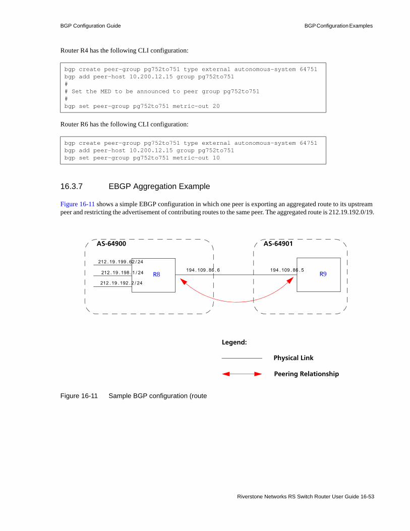
BGP Configuration Guide BGP Configuration Examples
Router R4 has the following CLI configuration:
Router R6 has the following CLI configuration:
16.3.7 EBGP Aggregation Example
Figure 16-11 shows a simple EBGP configuration in which one peer is exporting an aggregated route to its upstream peer and restricting the advertisement of contributing routes to the same peer. The aggregated route is 212.19.192.0/19.
Figure 16-11 Sample BGP configuration (route
bgp create peer-group pg752to751 type external autonomous-system 64751bgp add peer-host 10.200.12.15 group pg752to751# # Set the MED to be announced to peer group pg752to751#bgp set peer-group pg752to751 metric-out 20
bgp create peer-group pg752to751 type external autonomous-system 64751bgp add peer-host 10.200.12.15 group pg752to751bgp set peer-group pg752to751 metric-out 10
Physical Link
Legend:
Peering Relationship
AS-64901
R8
212.19.199.62/24
R9
AS-64900
212.19.198.1/24
212.19.192.2/24
194.109.86.6 194.109.86.5
Riverstone Networks RS Switch Router User Guide 16-53

BGP Configuration Examples BGP Configuration Guide
Router R8 has the following CLI configuration:
Router R9 has the following CLI configuration:
16.3.8 Route Reflection Example
In some ISP networks, the internal BGP mesh becomes quite large, and the IBGP full mesh does not scale well. For such situations, route reflection provides a way to alleviate the need for a full IBGP mesh. In route reflection, the clients peer with the route reflector and exchange routing information with it. In turn, the route reflector passes on (reflects) information between clients.
The IBGP peers of the route reflector fall under two categories: clients and non-clients. A route reflector and its clients form a cluster. All peers of the route reflector that are not part of the cluster are non-clients. The RS Ethernet Router supports client peers as well as non-client peers of a route reflector.
Figure 16-12 shows a sample configuration that uses route reflection.
interface add ip xleapnl address-netmask 212.19.192.2/24interface create ip hobbygate address-netmask 212.19.199.62/24 port et.1.2interface create ip xenosite address-netmask 212.19.198.1/24 port et.1.7interface add ip lo0 address-netmask 212.19.192.1/30bgp create peer-group webnet type external autonomous system 64901bgp add peer-host 194.109.86.5 group webnet# # Create an aggregate route for 212.19.192.0/19 with all its subnets as# contributing routes#ip-router policy summarize route 212.19.192.0/19ip-router policy redistribute from-proto aggregate to-proto bgp target-as 64901 network 212.19.192.0/19ip-router policy redistribute from-proto direct to-proto bgp target-as 64901 network all restrict
bgp create peer-group rtr8 type external autonomous system 64900bgp add peer-host 194.109.86.6 group rtr8
16-54 Riverstone Networks RS Switch Router User Guide

BGP Configuration Guide BGP Configuration Examples
Figure 16-12 Sample BGP configuration (route reflection)
In this example, there are two clusters. Router R10 is the route reflector for the first cluster and router R11 is the route reflector for the second cluster. Router R10 has router R9 as a client peer and router R11 as a non-client peer.
The following line in router R10’s configuration file causes it to be a route reflector.
Router R11 has router R12 and router R13 as client peers and router R10 as non-client peer. The following line in router R11’s configuration file specifies it to be a route reflector
bgp set peer-group R9 reflector-client
bgp set peer-group rtr11 reflector-client
AS-64902AS-64900
R11
R8
R13R12R9
R10
AS-64901
IBGPClusterClient
IBGPClusterClient
IBGPNon-ClusterClient
IBGPClusterClient
EBGPPeer
EBGPPeer
R14
192.68.222.1
192.68.20.2
192.68.20.1
172.16.30.2
Riverstone Networks RS Switch Router User Guide 16-55

BGP Configuration Examples BGP Configuration Guide
Even though the IBGP Peers are not fully meshed in AS 64901, the direct routes of router R14, that is, 192.68.222.0/24 in AS 64902 (which are redistributed in BGP) do show up in the route table of router R8 in AS64900, as shown below:
The direct routes of router R8, i.e. 192.68.11.0/24 in AS64900 (which are redistributed in BGP), do show up in the route table of router R14 in AS64902, as shown below:
16.3.8.1 Notes on Using Route Reflection
• Two types of route reflection are supported:- By default, all routes received by the route reflector from a client are sent to all internal peers
(including the client’s group, but not the client itself). - If the no-client-reflect option is enabled, routes received from a route reflection client are
sent only to internal peers that are not members of the client's group. In this case, the client's group must itself be fully meshed.
In either case, all routes received from a non-client internal peer are sent to all route reflection clients.
********************************************** Route Table (FIB) of Router 8 **********************************************rtr-8# ip show routes
Destination Gateway Owner Netif----------- ------- ----- -----10.50.0.0/16 directly connected - en127.0.0.0/8 127.0.0.1 Static lo127.0.0.1 127.0.0.1 - lo172.16.20.0/24 directly connected - mls1172.16.70.0/24 172.16.20.2 BGP mls1172.16.220.0/24 172.16.20.2 BGP mls1192.68.11.0/24 directly connected - mls0192.68.20.0/24 172.16.20.2 BGP mls1192.68.222.0/24 172.16.20.2 BGP mls1
*********************************************************** Route Table (FIB) of Router 14 ***********************************************************rtr-14# ip show routes
Destination Gateway Owner Netif----------- ------- ----- -----10.50.0.0/16 directly connected - en0127.0.0.0/8 127.0.0.1 Static lo0127.0.0.1 127.0.0.1 - lo0172.16.20.0/24 192.68.20.1 BGP mls1172.16.30.0/24 192.68.20.1 BGP mls1172.16.90.0/24 192.68.20.1 BGP mls1192.68.11.0/24 192.68.20.1 BGP mls1192.68.20.0/24 directly connected - mls1192.68.222.0/24 directly connected - mls0
16-56 Riverstone Networks RS Switch Router User Guide

BGP Configuration Guide BGP Configuration Examples
• Typically, a single router acts as the reflector for a cluster of clients. However, for redundancy, two or more may also be configured to be reflectors for the same cluster. In this case, a cluster ID should be selected to identify all reflectors serving the cluster, using the clusterid option. Gratuitous use of multiple redundant reflectors is not advised, since it can lead to an increase in the memory required to store routes on the redundant reflectors’ peers.
• No special configuration is required on the route reflection clients. From a client's perspective, a route reflector is simply a normal IBGP peer. Any BGP version 4 speaker can be a reflector client.
• If the configurations routers R10 and R11 contain export policies configured using the route-map-out option or the bgp advertise network command or an ip-router policy redistribute command, then routers R10 and R11 must have the following line in their configuration files
• If the cluster ID is changed, all BGP sessions with reflector clients will be dropped and restarted.
16.3.9 BGP Confederation Example
Figure 16-13 shows a BGP configuration where a single AS (AS number 64705) is split into two sub-AS’s (64706 and 64707).
Figure 16-13 Sample BGP confederation
ip-router policy redistribute from-proto bgp source-as 64901 to-proto bgp target-as 64901
AS 64705
AS 64902AS 64707AS 64706AS 64901
BGP Confederation
R9R8 R10 R11 R12 R13
Riverstone Networks RS Switch Router User Guide 16-57

BGP Configuration Examples BGP Configuration Guide
In Figure 16-13, R9 and R10 are included in AS 64706, which is a sub-AS of the confederation with the AS number 64705. R9 has the following CLI configuration:
R10 has the following CLI configuration:
ip-router global set router-id 182.1.1.1ip-router global set trace-state onip-router global set confederation-id 64705ip-router global set autonomous-system 64706
ospf create area backboneospf add interface all to-area backboneospf start
bgp create peer-group ebgp type external autonomous-system 64901bgp create peer-group rtr10 type routing autonomous-system 64706bgp add peer-host 172.16.220.2 group ebgpbgp add peer-host 172.16.222.2 group rtr10bgp set peer-host 172.16.220.2 route-map-in 1 group ebgpbgp set peer-group rtr10 confederationbgp set peer-group ebgp bgp start
route-map 1 permit 1 set-metric 50 set-local-preference 1000 set-community "65000:6500 64000:6000"
ip-router policy redistribute from-proto bgp source-as 64901 to-proto bgp target-as 64706
ip-router global set router-id 172.16.222.2ip-router global set autonomous-system 64706ip-router global set confederation-id 64705ip-router global set trace-state on
ospf create area backboneospf add interface all to-area backboneospf start
bgp create peer-group rtr9 type routing interface all proto any autonomous-system 64706bgp create peer-group rtr11 type external autonomous-system 64707bgp add peer-host 172.16.222.1 group rtr9bgp add peer-host 172.16.223.2 group rtr11bgp set peer-group rtr9 confederation bgp set peer-group rtr11 confederationbgp start
ip-router policy redistribute from-proto bgp source-as 64706 to-proto bgp target-as 64707
16-58 Riverstone Networks RS Switch Router User Guide
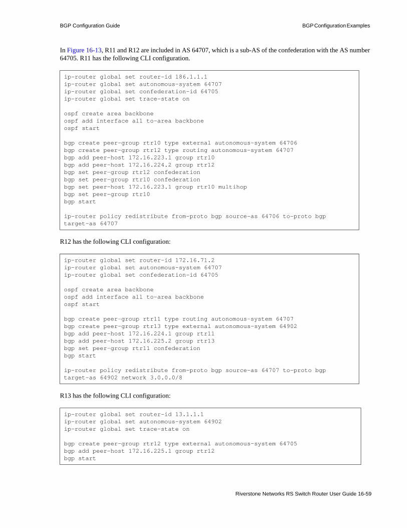
BGP Configuration Guide BGP Configuration Examples
In Figure 16-13, R11 and R12 are included in AS 64707, which is a sub-AS of the confederation with the AS number 64705. R11 has the following CLI configuration.
R12 has the following CLI configuration:
R13 has the following CLI configuration:
ip-router global set router-id 186.1.1.1ip-router global set autonomous-system 64707ip-router global set confederation-id 64705ip-router global set trace-state on
ospf create area backboneospf add interface all to-area backboneospf start
bgp create peer-group rtr10 type external autonomous-system 64706bgp create peer-group rtr12 type routing autonomous-system 64707bgp add peer-host 172.16.223.1 group rtr10bgp add peer-host 172.16.224.2 group rtr12 bgp set peer-group rtr12 confederationbgp set peer-group rtr10 confederationbgp set peer-host 172.16.223.1 group rtr10 multihopbgp set peer-group rtr10 bgp start
ip-router policy redistribute from-proto bgp source-as 64706 to-proto bgp target-as 64707
ip-router global set router-id 172.16.71.2ip-router global set autonomous-system 64707ip-router global set confederation-id 64705
ospf create area backboneospf add interface all to-area backboneospf start
bgp create peer-group rtr11 type routing autonomous-system 64707bgp create peer-group rtr13 type external autonomous-system 64902bgp add peer-host 172.16.224.1 group rtr11bgp add peer-host 172.16.225.2 group rtr13bgp set peer-group rtr11 confederationbgp start
ip-router policy redistribute from-proto bgp source-as 64707 to-proto bgp target-as 64902 network 3.0.0.0/8
ip-router global set router-id 13.1.1.1ip-router global set autonomous-system 64902ip-router global set trace-state on
bgp create peer-group rtr12 type external autonomous-system 64705bgp add peer-host 172.16.225.1 group rtr12bgp start
Riverstone Networks RS Switch Router User Guide 16-59

BGP Configuration Examples BGP Configuration Guide
R8 has the following CLI configuration:
The following examples of the bgp show routes command show how the AS-path attribute is modified as the route is passed through the routers in the BGP confederation.
On R9, the route advertised by R8 is shown with R8’s AS number (64901) prepended to the path:
On R11, the same route is prepended with the sub-AS (64706) to which R10 belongs:
Note that R11, while in a different sub-AS, is in the same confederation as R10. Within a confederation, routers can “see” other sub-AS’s and the sub-AS numbers appear in curly braces ({}) in the path display.
ip-router global set autonomous-system 64901ip-router global set router-id 134.141.178.48
ip-router policy create bgp-export-destination rtr9 autonomous-system 64705ip-router policy create aspath-export-source abc aspath-regular-expression "(.* 701 .*)" origin any protocol allip-router policy redistribute from-proto bgp source-as 64751 to-proto bgp target-as 64705 network 3.0.0.0/8
bgp create peer-group rtr9 type external autonomous-system 64705bgp add peer-host 182.1.1.1 group rtr9bgp add peer-host 172.16.220.1 group rtr9bgp start
r9# bgp show routes allBGP table : Local router ID is 182.1.1.1Status codes: s suppressed, d damped, h history, * valid, > bestOrigin codes: i - IGP, e - EGP, ? - incomplete Network Next Hop Metric LocPrf Path ------- -------- ------ ------ ----*>3/8 172.16.220.2 50 1000 64901 64751 6379 1 701 80 i 172.16.222/24 172.16.222.2 100 i* 172.16.223/24 172.16.222.2 100 i
r11# bgp show routes allBGP table : Local router ID is 186.1.1.1Status codes: s suppressed, d damped, h history, * valid, > bestOrigin codes: i - IGP, e - EGP, ? - incomplete Network Next Hop Metric LocPrf Path ------- -------- ------ ------ ----*>3/8 172.16.220.2 50 1000 {64706}64901 64751 6379 1 701 80 i 172.16.224/24 172.16.224.2 100 i* 172.16.225/24 172.16.224.2 100 i
16-60 Riverstone Networks RS Switch Router User Guide

BGP Configuration Guide BGP Configuration Examples
On R13, which is not part of the confederation, the AS path now shows only the AS number of the confederation:
Note As shown in the example outputs for R9 and R11, the next hop, local pref and MED values are passed unchanged through routers in the confederation. The peer-group configuration must include the multihop parameter so that the next hop value is passed through the routers. In the above BGP confederation example, the multihop parameter should be specified for R11.
16.3.10 Route Map Example
Figure 16-14 shows a simple BGP configuration in which routes received on R2 for the networks 15.4.0.0/16 and 15.5.0.0/16 are set with community IDs 1:1 and 1:2, respectively. The routes are exported to R8 with these community IDs. On R8, BGP routes with the specified community IDs are to be monitored via BGP accounting (see Section 16.3.11, "BGP Accounting Examples," for more information).
Figure 16-14 Sample BGP configuration (route map)
r13# bgp show routes allBGP table : Local router ID is 13.1.1.1Status codes: s suppressed, d damped, h history, * valid, > best Origin codes: i - IGP, e - EGP, ? - incomplete Network Next Hop Metric LocPrf Path ------- -------- ------ ------ ----*>3/8 172.16.225.1 64705 64901 64751 6379 1 701 80 i
R2
15.4.0.0/16
AS-2
15.5.0.0/16
15.6.0.0/16
R8
12.10.0.0/16
AS-65100
12.11.0.0/16
12.12.0.0/16
15.2.1.1
15.2.1.3
12.13.0.0/16
Riverstone Networks RS Switch Router User Guide 16-61

BGP Configuration Examples BGP Configuration Guide
Router R2 has the following CLI configuration:
Router R8 has the following CLI configuration:
On R8, the bgp show routes command for the network interface 15.4.0.0/16 shows the following output:
Note the standard community list for this network (1:1), as set with the route-map command on R2.
16.3.11 BGP Accounting Examples
BGP accounting allows you to collect statistics on specified IP routes. To use BGP accounting, routes must be learned through BGP and be selected routes. In other words, the routes must appear in the routing tables (displayed with the ip show route command) and BGP must be the routing protocol for the routes.
Then use the route-map command to define route-maps and set up the buckets for collecting the BGP traffic information. (If you are matching communities in the route-map definition, you will need to create the community lists.) Then apply the route-map to the BGP group or peer. Enable BGP accounting on the interface with the ip enable bgp-actg-on command, then start accounting with the ip bgp-accounting start command.
ip-router global set autonomous-system 2 route-map 1 permit 1 match-prefix network 15.4.0.0/16 set-community "1:1"route-map 1 permit 2 match-prefix network 15.5.0.0/16 set-community "1:2"bgp create peer-group tored type external autonomous-system 65100bgp add peer-host 15.2.1.3 group toredbgp set preference 99bgp set peer-group tored route-map-out 1bgp start
ip-router global set autonomous-system 65100ip-router policy create community-list 11 "1:1"ip-router policy create community-list 12 "1:2"route-map 11 permit 1 match-community-list 11 set-traffic-index 1route-map 11 permit 2 match-community-list 12 set-traffic-index 2bgp create peer-group ebgp autonomous-system 2 type externalbgp add peer-host 15.2.1.1 group ebgpbgp set preference 9bgp set peer-group ebgp route-map-in 11bgp start
BGP routing table entry for 15.4/16Path: BestSource: 15.2.1.1Advertised to(Tasks):None:Local AS: 65100 Peer AS: 2 Age: 1:18:20NextHop: 15.2.1.1 MED: -1 Local Preference: -1AS Path: (65100) 2 IGP (Id 38)Community: 1:1
16-62 Riverstone Networks RS Switch Router User Guide

BGP Configuration Guide BGP Configuration Examples
16.3.11.1 EBGP Accounting Example
The set-traffic-index option of the route-map command allows buckets to be set up in which BGP traffic information is collected. In the configuration for R8 shown in Figure 16-14, the routing updates that match the route-map configurations are set to traffic indexes 1, and 2.
To enable BGP accounting on an interface, enter CLI commands like the following:
To see the BGP accounting information:
Note For BGP accounting to take effect, the RS Ethernet Router must be selecting BGP for the route. Make sure that the preference for BGP is set lower than the preference of other protocols on the RS Ethernet Router.
16.3.11.2 IBGP Accounting Example
In the example below, routers R1 and R2 are running IBGP/RIP, so they exchange routes automatically. Customer traffic from 13.1.1.5 is being routed to the destination 14.1.1.1/16. The customer is connected to router R1 through the interface ’customerA.’ The route to 14.1.0.0/16 is a direct route on router R2 and is learned by R1, which sets the traffic index to 1.
ip enable bgp-actg-on int1ip bgp-accounting start accounting
rs8# ip show interfaces all bgp-actgInterface:gitoyBucket Packets Bytes0 0 01 33760 21606402 33760 2160640
Riverstone Networks RS Switch Router User Guide 16-63

BGP Configuration Examples BGP Configuration Guide
Figure 16-15 Sample BGP configuration (accounting)
The following configurations enable BGP accounting on interface ’customerA’ to tally the number of bytes and packets sent by the customer.
R1 has the following configuration:
interface create ip toR2 address-netmask 12.1.1.1/16 port et.3.2interface create ip customerA address-netmask 13.1.1.1/16 port et.3.1
ip enable bgp-actg-on customerA,ip bgp-accounting start accounting
ip-router global set autonomous-system 1ip-router global set router-id 10.50.7.1
bgp create peer-group ibgp type routing autonomous-system 1bgp add peer-host 12.1.1.2 group ibgpbgp set peer-group ibgp route-map-in 1bgp set preference 99bgp start
ip-router policy create community-list list1 "11:11"
route-map 1 permit 1 match-community-list list1 set-traffic-index 1
arp add 12.1.1.2 mac-addr 001122:334455 exit-port et.3.2arp add 13.1.1.5 mac-addr 00:00:00:00:13:01
R113.1.1.1/16
R2 14.1.0.0/16
12.1.1.1/16et.3.2
et.3.1Customer
AS-1
et.14.5
13.1.1.5
12.1.1.2/16et.14.8
Enable accounting on this interface
16-64 Riverstone Networks RS Switch Router User Guide
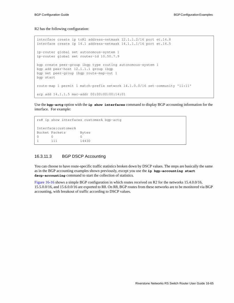
BGP Configuration Guide BGP Configuration Examples
R2 has the following configuration:
Use the bgp-actg option with the ip show interfaces command to display BGP accounting information for the interface. For example:
16.3.11.3 BGP DSCP Accounting
You can choose to have route-specific traffic statistics broken down by DSCP values. The steps are basically the same as in the BGP accounting examples shown previously, except you use the ip bgp-accounting start dscp-accounting command to start the collection of statistics.
Figure 16-16 shows a simple BGP configuration in which routes received on R2 for the networks 15.4.0.0/16, 15.5.0.0/16, and 15.6.0.0/16 are exported to R8. On R8, BGP routes from these networks are to be monitored via BGP accounting, with breakout of traffic according to DSCP values.
interface create ip toR1 address-netmask 12.1.1.2/16 port et.14.8interface create ip 14.1 address-netmask 14.1.1.1/16 port et.14.5
ip-router global set autonomous-system 1ip-router global set router-id 10.50.7.9
bgp create peer-group ibgp type routing autonomous-system 1bgp add peer-host 12.1.1.1 group ibgpbgp set peer-group ibgp route-map-out 1bgp start
route-map 1 permit 1 match-prefix network 14.1.0.0/16 set-community "11:11"
arp add 14.1.1.5 mac-addr 00:00:00:00:14:01
rs# ip show interfaces customerA bgp-actg
Interface:customerABucket Packets Bytes0 0 01 111 14430
Riverstone Networks RS Switch Router User Guide 16-65

BGP Configuration Examples BGP Configuration Guide
Figure 16-16 Sample BGP configuration (DSCP accounting)
Router R2 has the following CLI configuration:
Router R8 has the following CLI configuration:
To enable BGP accounting on the interface ‘int1’ on R8:
ip-router global set autonomous-system 2 bgp create peer-group tored type external autonomous-system 65100bgp add peer-host 15.2.1.3 group toredbgp set preference 99bgp start
ip-router global set autonomous-system 65100route-map 1 permit 1 match-prefix network 15.4.0.0/16 set-traffic-index 10route-map 1 permit 2 match-prefix network 15.5.0.0/16 set-traffic-index 11route-map 1 permit 3 match-prefix network 15.6.0.0/16 set-traffic-index 12bgp create peer-group tor2 autonomous system 2 type externalbgp add peer-host 15.2.1.1 group tor2bgp set preference 9bgp set peer-group tor2 route-map-in 1 in-sequence 1bgp start
ip enable bgp-actg-on int1ip bgp-accounting start dscp-accounting
R2
15.4.0.0/16
AS-2
15.5.0.0/16
15.6.0.0/16
R8
12.10.0.0/16
AS-65100
12.11.0.0/16
12.12.0.0/16
15.2.1.1
15.2.1.3
12.13.0.0/16
Customerint1
16-66 Riverstone Networks RS Switch Router User Guide
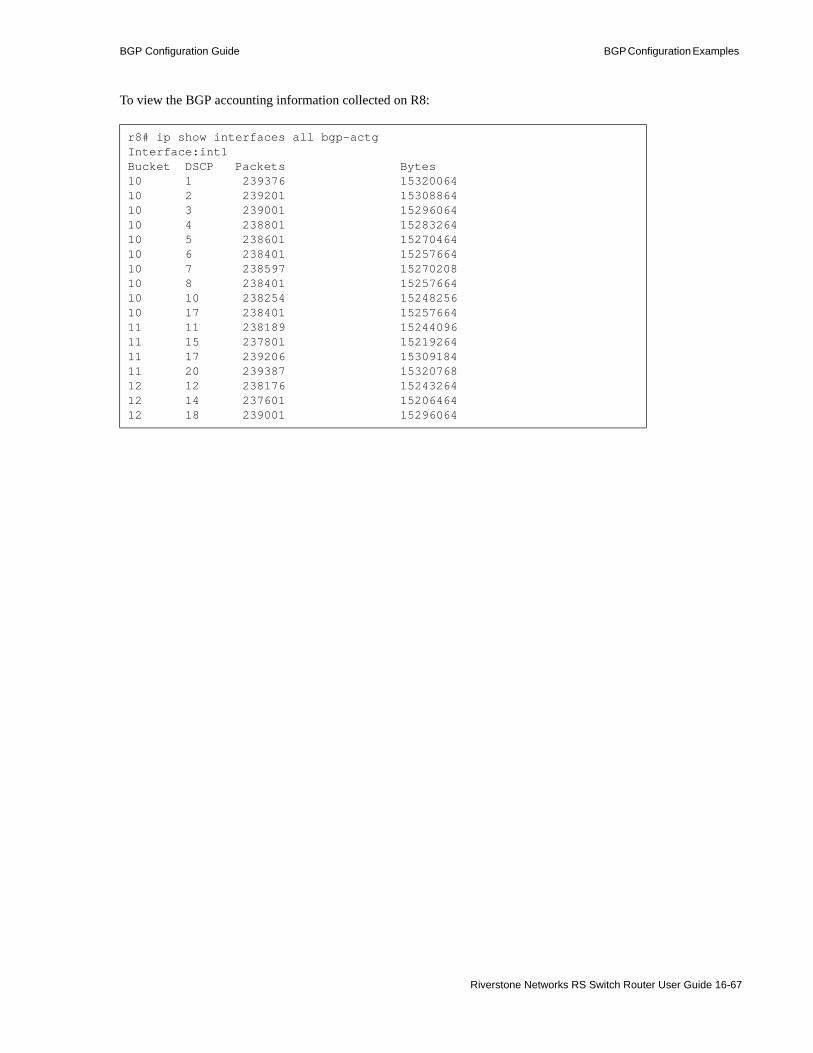
BGP Configuration Guide BGP Configuration Examples
To view the BGP accounting information collected on R8:
r8# ip show interfaces all bgp-actgInterface:int1Bucket DSCP Packets Bytes10 1 239376 1532006410 2 239201 1530886410 3 239001 1529606410 4 238801 1528326410 5 238601 1527046410 6 238401 1525766410 7 238597 1527020810 8 238401 1525766410 10 238254 1524825610 17 238401 1525766411 11 238189 1524409611 15 237801 1521926411 17 239206 1530918411 20 239387 1532076812 12 238176 1524326412 14 237601 1520646412 18 239001 15296064
Riverstone Networks RS Switch Router User Guide 16-67

BGP Configuration Examples BGP Configuration Guide
16-68 Riverstone Networks RS Switch Router User Guide
17 LAYER-3 VPNS
Layer-3 virtual private networks (VPNs), also known as Border Gateway Protocol/Multiprotocol Label Switching Virtual Private Networks (BGP/MPLS VPNs), is a method that allows service providers to provide customers VPN services using an IP backbone.
By using MPLS for forwarding VPN traffic and BGP for distributing VPN routes, this mechanism increases scalability and flexibility for the service provider while removing the need for customers to build and run their own IP backbone. This frees customers from having to deal with inter-site connectivity issues.
By removing the restriction that customers must use globally unique IPv4 addresses, this method enhances both customer and service provider convenience. Provider routers do not have to administer a separate backbone for each customer VPN, nor do they require management access to customer routers.
Layer-3 VPNs differ significantly from Layer-2 VPNs. Layer-2 VPNs constrain customer traffic arriving on a certain port or VLAN to a set destination. Layer-3 VPNs enable PE routers to make intelligent routing decisions based on customer IP addresses.
Note Throughout this document, the terms ‘Layer-3 VPN’ and ‘BGP/MPLS VPN’ are used interchangeably.
This chapter discusses Layer-3 VPNs, provides step-by-step configuration guidelines to help you enable the feature, and presents a complete configuration example to reference in your own configurations.
We recommend that the first-time user of BGP/MPLS VPNs read this chapter straight through. Advanced users can use the following sectional abstract to seek selective instructions on enabling the feature:• For IETF references on the standard and its components, see Section 17.1 "RFCs and Drafts."• For an overview of BGP/MPLS VPN network components, see Section 17.2 "Network
Components."• For an overview of the Basic BGP/MPLS VPN Network, which uses OSPF and static route
distribution, see Section 17.3 "Basic BGP/MPLS VPN Network Overview."• To configure the Basic BGP/MPLS VPN Network, see Section 17.4 "Basic BGP/MPLS VPN
Network Configuration."- To set up MPLS label-switched paths (LSPs) in the provider network, see Section 17.4.2
"Setting Up Signaling Protocols and MPLS LSPs Between PE Routers."- To configure MP-BGP between Provider Edge routers for customer route exchange, see
Section 17.4.3 "Configuring MP-BGP Between PE Routers for Customer Route Distribution."
- To configure multiple routing instances and VPN Routing and Forwarding tables (VRFs), see Section 17.4.4 "Configuring Routing Instances."
Riverstone Networks RS Switch Router User Guide 17-1

RFCs and Drafts Layer-3 VPNs
- For information on VPN-IPv4 addresses and configuring Route Distinguishers, see Section 17-31 "Configuring Route Distinguishers and VPN-IPv4 Addresses."
- To add interface(s) to routing instances, see the Section 17.4.4.3 "Adding Interfaces to VRFs."- To set import and export policies using BGP Extended Community Attributes, see the
Section 17.4.4.4 "Configuring VRF Import and Export Policies."- To configure static and OSPF route distribution between Customer Edge and Provider Edge
routers, see Section 17.4.5 "Configuring Static and OSPF Route Distribution Between CE and PE Routers."
• For an operational model of the Basic BGP/MPLS VPN Network, see Section 17.5 "Basic BGP/MPLS VPN Network Operation."
• To configure RIP and BGP route distribution between Customer Edge and Provider Edge routers, see Section 17.6 "Configuring RIP and BGP Route Distribution Between CE and PE Routers."
• To troubleshoot the Basic BGP/MPLS VPN Network, see Section 17.7 "Troubleshooting the Basic BGP/MPLS VPN Network."
• For an example of configuring trunk ports with multiple Customer Edge routers, see Section 17.8 "Trunk Port With Multiple CE Routers Example."
• For an example of configuring dual-homing Customer Edge routers, see Section 17.9 "Dual-Homing CE Router Example."
• For an example of configuring route reflectors in the BGP/MPLS VPN Network, see Section 17.10 "Route Reflector Example."
• For an example of configuring internet access in the BGP/MPLS VPN Network, see Section 17.11 "Internet Access Example."- For an example of configuring internet access using static routes, see Section 17.11.1 "Internet
Access Using Static Routes."- For an example of configuring internet access using Network Address Translation (NAT), see
Section 17.11 "Internet Access Example."• For an example of configuring a hub-and-spoke topology in the BGP/MPLS VPN Network, see
Section 17.12 "Hub and Spoke Example."• For an example of configuring a BGP/MPLS VPN Network across multiple autonomous systems,
see Section 17.13 "Multiple-Autonomous System Example."• To use Quality of Service (QoS) with BGP/MPLS VPNs, see Section 17.14 "QoS for BGP/MPLS
VPNs."
Timesaver Titles shown in blue represent hypertext links to the sections. Click on one of the section titles above to go immediately to that section.
17.1 RFCS AND DRAFTSRequest for Comments (RFC) 2547bis BGP/MPLS VPNs, by Rosen, Rekhter, et al., defines the core functionality of Layer-3 VPNs. It also defines the VPN-IPv4 address family and Route Distinguishers.
17-2 Riverstone Networks RS Switch Router User Guide

Layer-3 VPNs RFCs and Drafts
Additional components support BGP/MPLS VPNs. Refer to the following IETF RFCs and working drafts for definitions of these features:
Feature Definition
Multiprotocol BGP (MP-BGP) RFC 2858 Multiprotocol Extensions for BGP4. Bates, Chandra, Katz, and Rekhter.
Using OSPF to route between CE and PE routers
IETF draft OSPF As the PE/CE Protocol In BGP/MPLS VPNs. Rosen and Psenak.
BGP Extended Community Attributes IETF draft BGP Extended Communities Attribute. Ramachandra, Tappan, and Rekhter.
BGP Route Refresh RFC 2918 Route Refresh Capability for BGP-4. Chen.
BGP Outbound Route Filtering (ORF) IETF draft Cooperative Route Filtering Capability for BGP4.Chen and Rekhter.
Riverstone Networks RS Switch Router User Guide 17-3

Network Components Layer-3 VPNs
17.2 NETWORK COMPONENTSThree types of devices exist in the BGP/MPLS VPN network:• Provider Edge (PE) routers• Provider (P) routers• Customer Edge (CE) routers
17.2.1 PE Routers
PE routers are on the edge of the provider network. Their main function is to peer with and exchange customer routing information with CE routers.
RFC 2547bis BGP/MPLS VPNs by Rosen, Rekhter, et al. states the following: “a PE router is attached to a particular VPN if it is attached to a CE device which is in that VPN. Similarly, . . . a PE router is attached to a particular site if it is attached to a CE device which is in that site.”
Given this definition, a PE router only maintains routes for those VPNs to which it is directly attached. It learns these routes from CE routers and keeps them in VPN Routing and Forwarding tables (VRFs).
Customer routes are distributed across the provider network when PE routers exchange VRF routes with other PE routers. Extended Community Attribute ‘Route Targets’ define which routes a PE router advertises and which routes it receives for a particular VRF during routing updates.
PE routers use MP-BGP to distribute customer routes only to other PE routers, never to the provider’s internal routers (P Routers). This separation helps ensure that customer routes are kept separate from the provider’s own routes. This, along with the fact that PE routers only maintain VRFs for directly-connected sites, enhance the scalability of BGP/MPLS VPNs.
An MPLS LSP exists between any two PE routers within the same VPN. PE routers use these LSPs to forward customer traffic across the provider network.
17.2.2 P Routers
P routers are provider internal routers. They do not interface with customer routers or maintain customer routes.
P routers provide connectivity between PE routers using interior gateway protocols (IGPs). P routers also help establish and maintain MPLS LSPs between PE routers. PE routers use these LSPs to forward customer traffic across the provider network. As label switch routers (LSRs), P routers participate in this forwarding. However, they only pass MPLS traffic, and have no knowledge of the underlying customer route information.
17.2.3 CE Router
CE devices are on the edge of customer networks. They exchange routes from their local site with PE routers, who in turn exchange those routes with CE routers in other customer sites according to policies that you define.
CE routers only peer with PE routers. They do not peer with CE routers in remote sites. They learn routes for those remote sites from their local PE router.
The CE device may be a single host or a switch. In general, however, the CE device is an IP router, which we call the CE router.
17-4 Riverstone Networks RS Switch Router User Guide
Layer-3 VPNs Basic BGP/MPLS VPN Network Overview
Note As a network administrator, note that, as RFC 2547bis BGP/MPLS VPNs states, “With respect to the management of the edge devices, clear administrative boundaries are maintained between the [service provider] and its customers. Customers are not required to access the PE or P routers for management purposes, nor is the [service provider] required to access the CE devices for management purposes.”
Figure 17-1 illustrates how these components make up the Basic BGP/MPLS VPN Network topology.
17.3 BASIC BGP/MPLS VPN NETWORK OVERVIEWFigure 17-1 illustrates an example of a Basic BGP/MPLS VPN Network. In this network, a single provider supplies connectivity to two customers, A and B. The connectivity has these constraints:• The two sites of Customer A can communicate with each other. They form VPN RED• The two sites of Customer B can communicate with each other. They form VPN PINK• Customer A sites cannot communicate with Customer B sites.
Riverstone Networks RS Switch Router User Guide 17-5

Basic BGP/MPLS VPN Network Overview Layer-3 VPNs
Figure 17-1 Basic BGP/MPLS VPN Network components
To achieve the desired connectivity scheme, network administrators for the customer and provider networks must perform the following configuration tasks. Subsequent sections provide detailed explanations and step-by-step instructions for each task:
In the provider network, network administrators must complete the following tasks:• Set up the three provider routers (PE1, PE2, and P) with Interior Gateway Protocols (IGPs) for
routing within the provider network. In our example, OSPF is already running in the provider network. For OSPF configuration commands, see Section 17.4.1 "Basic BGP/MPLS VPN Network Starting Configurations."
Basic BGP/MPLS VPNNetwork
CE2192.168.100.1
P10.2.2.1
PE210.3.3.1
CE4192.168.101.1
et.10.1
gi.7.1gi.4.2 gi.4.1et.3.1
et.3.2
et.2.1
et.2.8
et.10.8
PE110.1.1.1
CE3172.20.2.1
et.6.2
gi.7.1et.6.1
et.3.1
et.3.8
CE1172.20.1.1
et.2.1
et.2.8
.1
.1
.1
.1
.1
.1
.1
.1.1
.1
.2.2
.2
.2.2
172.17.1.0/30
172.17.2.0/24
172.17.8.0/30
172.17.2.0/24
10.0.2.0/3010.0.1.0/30
192.168.8.0/30
.2
192.168.1.0/30
192.168.9.0/24
192.168.2.0/24
Customer ASite 1
Customer ASite 2
Customer BSite 1
Customer BSite 2
Provider Network
OSPF area backbone
Initial Configurations
17-6 Riverstone Networks RS Switch Router User Guide

Layer-3 VPNs Basic BGP/MPLS VPN Network Overview
• Configure two MPLS LSPs between PE1 and PE2 to create bidirectional flows that allow them to transport VPN traffic. (For details and commands, see Section 17.4.2 "Setting Up Signaling Protocols and MPLS LSPs Between PE Routers.")
• Configure MP-BGP between PE1 and PE2. These two routers use MP-BGP to exchange learned customer routes without injecting them into the provider’s IGP. Note that the P router only functions as a transit router in this exchange. It does not learn customer routes, nor does it run MP-BGP. (For details and commands, see Section 17.4.3 "Configuring MP-BGP Between PE Routers for Customer Route Distribution.")
Caution Keeping customer routes segregated from provider routes is extremely important. BGP/MPLS VPNs uses the following mechanisms to achieve this:
1. Separate routing instances and routing tables ensure that routes learned from customers are not injected into the provider network.
2. Using MP-BGP to exchange VPN routes and MPLS to carry VPN traffic ensures that only ingress and egress PE routers need to maintain customer routing information and interface with customer routers. P routers only need to forward MPLS traffic.
• Configure routing instances and VRFs. Separate routing instances and VRFs enable PE routers to prevent routes learned from Customer A from being leaked to Customer B. (For details and commands, see Section 17.4.4 "Configuring Routing Instances.") The power of BGP/MPLS VPNs lies in the following elements of routing instances:- Configure Route Distinguishers to create routing instances. Through the use of VPN-IPv4
addresses and Route Distinguishers, PE routers can correctly handle and route overlapping IP addresses in different VPNs. In the Basic BGP/MPLS VPN Network, PE1 can distinguish and route between the same route, 172.17.2.0/24, learned from two different connected sites (through CE1 and CE3). (For details and commands, see the Section 17.4.4.2 "Configuring Route Distinguishers and VPN-IPv4 Addresses.")
- Configure import and export policies that instruct each PE router on what to do with the routes it learns from its connected sites (through the CEs). Through the use of the Extended Community Attribute Route Targets, network administrators can associate each connected site on a PE with one or more import and export targets. Using these targets and routing policies, network administrators can specify which category of routes a PE router should accept for a site, and which category it should use to advertise routes learned from a site. This set of tags and policies define the VPNs. (For details and commands, see the Section 17.4.4.4 "Configuring VRF Import and Export Policies.")
Both the customer and provider network administrators must configure CE and PE routers to exchange routes. In this example, for VPN RED, CE1 and PE1 set up static routes for the 172.17.2.0/24 network. Likewise, CE2 and PE2 using OSPF to exchange routes for the 192.168.2.0/24 network. (For details and commands, see Section 17.4.5 "Configuring Static and OSPF Route Distribution Between CE and PE Routers.")
Riverstone Networks RS Switch Router User Guide 17-7

Basic BGP/MPLS VPN Network Configuration Layer-3 VPNs
17.4 BASIC BGP/MPLS VPN NETWORK CONFIGURATION
This section examines in detail how to configure each of the network components for the Basic BGP/MPLS VPN Network (The Basic BGP/MPLS VPN Network topology, connectivity scheme, and configuration tasks are outlined in Section 17.3 "Basic BGP/MPLS VPN Network Overview.") Although the configurations in this section are based on the example in Figure 17-1, the guidelines will enable you to achieve any connectivity scheme in your BGP/MPLS VPN network.
Progress boxes like the following list the Basic BGP/MPLS VPN Network configuration steps at the beginning of each section. The current configuration task is highlighted. In each section, you should always check that the configuration steps before the highlighted task are complete.
17.4.1 Basic BGP/MPLS VPN Network Starting Configurations
The following are the starting configurations for all the routers in the Basic BGP/MPLS VPN Network. Note that OSPF has already been configured as the IGP between the routers in the provider network (PE1, PE2, and P).
Basic BGP/MPLS VPN Network configuration steps:- IGP in the provider network (included in initial configurations)- MPLS LSPs in the provider network- MP-IBGP between PE routers- RED and PINK routing instances on the PE routers- Static and OSPF PE-CE route distribution
17-8 Riverstone Networks RS Switch Router User Guide

Layer-3 VPNs Basic BGP/MPLS VPN Network Configuration
17.4.1.1 CE1 Starting Configuration
CE1# show runRunning system configuration: ! ! Last modified from Telnet (172.16.13.69) on 2002-05-15 11:06:40 ! // Create VLANs and add them to interfaces 1 : vlan create ToCustomerASite1 ip id 100 2 : vlan create ToPE1 ip id 200 3 : vlan add ports et.2.8 to ToCustomerASite1 4 : vlan add ports et.2.1 to ToPE1 ! 5 : interface create ip ToCustomerASite1 address-netmask 172.17.2.1/24 vlan
ToCustomerASite1 6 : interface create ip ToPE1 address-netmask 172.17.1.2/30 vlan ToPE1
// Assign the loopback address and set it as the router ID 7 : interface add ip lo0 address-netmask 172.20.1.1/32 ! 8 : ip-router global set router-id 172.20.1.1 ! // Set the system name 9 : system set name CE1
Riverstone Networks RS Switch Router User Guide 17-9

Basic BGP/MPLS VPN Network Configuration Layer-3 VPNs
17.4.1.2 CE2 Starting Configuration
CE2# show runRunning system configuration: ! ! Last modified from Telnet (172.16.13.69) on 2002-05-15 10:32:21 ! // Create VLANs and add them to interfaces 1 : vlan create ToCustomerASite2 ip id 100 2 : vlan create ToPE2 ip id 200 3 : vlan add ports et.2.8 to ToCustomerASite2 4 : vlan add ports et.2.1 to ToPE2 ! 5 : interface create ip ToCustomerASite2 address-netmask 192.168.2.1/24 vlan
ToCustomerASite2 6 : interface create ip ToPE2 address-netmask 192.168.1.2/30 vlan ToPE2
// Assign the loopback address and set it as the router ID 7 : interface add ip lo0 address-netmask 192.168.100.1/32 ! 8 : ip-router global set router-id 192.168.100.1 ! // Set the system name 9 : system set name CE2
17-10 Riverstone Networks RS Switch Router User Guide
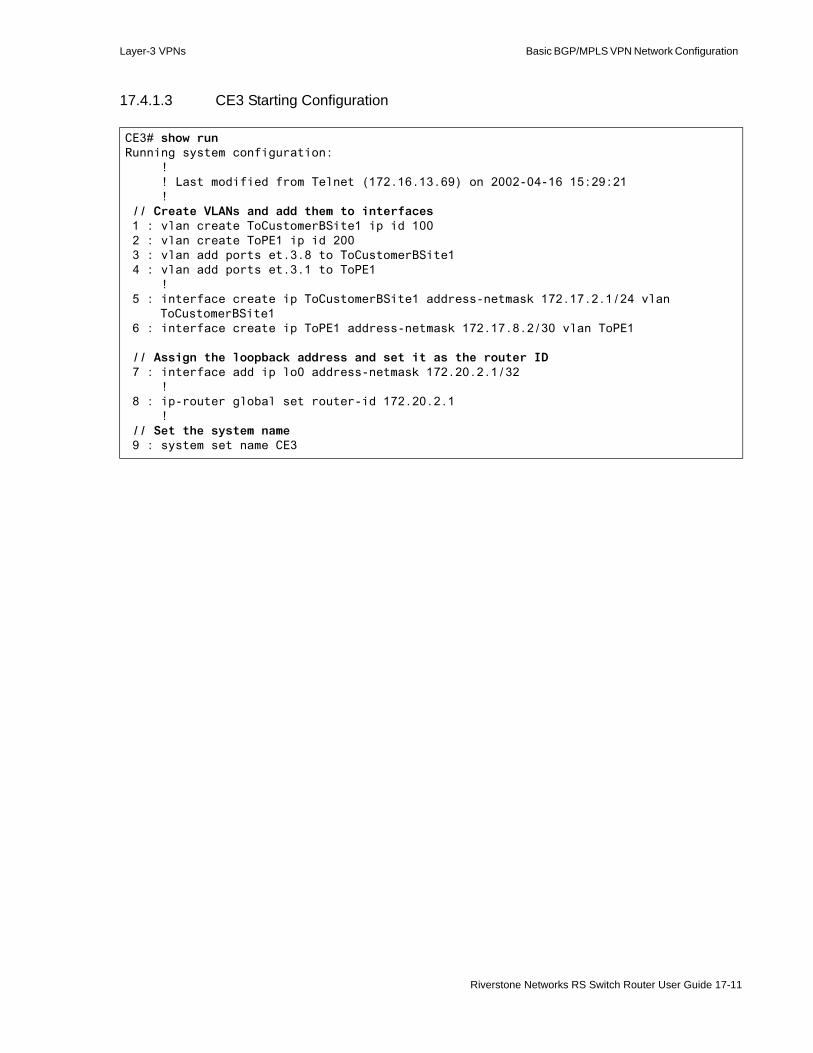
Layer-3 VPNs Basic BGP/MPLS VPN Network Configuration
17.4.1.3 CE3 Starting Configuration
CE3# show runRunning system configuration: ! ! Last modified from Telnet (172.16.13.69) on 2002-04-16 15:29:21 ! // Create VLANs and add them to interfaces 1 : vlan create ToCustomerBSite1 ip id 100 2 : vlan create ToPE1 ip id 200 3 : vlan add ports et.3.8 to ToCustomerBSite1 4 : vlan add ports et.3.1 to ToPE1 ! 5 : interface create ip ToCustomerBSite1 address-netmask 172.17.2.1/24 vlan
ToCustomerBSite1 6 : interface create ip ToPE1 address-netmask 172.17.8.2/30 vlan ToPE1
// Assign the loopback address and set it as the router ID 7 : interface add ip lo0 address-netmask 172.20.2.1/32 ! 8 : ip-router global set router-id 172.20.2.1 ! // Set the system name 9 : system set name CE3
Riverstone Networks RS Switch Router User Guide 17-11

Basic BGP/MPLS VPN Network Configuration Layer-3 VPNs
17.4.1.4 CE4 Starting Configuration
CE4# show runRunning system configuration: ! ! Last modified from Telnet (172.16.13.69) on 2002-05-15 12:30:13 ! // Create VLANs and add them to interfaces 1 : vlan create ToCustomerBSite2 ip id 100 2 : vlan create ToPE2 ip id 200 3 : vlan add ports et.10.8 to ToCustomerBSite2 4 : vlan add ports et.10.1 to ToPE2 ! 5 : interface create ip ToCustomerBSite2 address-netmask 192.168.9.1/24 vlan
ToCustomerBSite2 6 : interface create ip ToPE2 address-netmask 192.168.8.2/30 vlan ToPE2
// Assign the loopback address and set it as the router ID 7 : interface add ip lo0 address-netmask 192.168.101.1/32 ! 8 : ip-router global set router-id 192.168.101.1 ! // Set the system name 9 : system set name CE4
17-12 Riverstone Networks RS Switch Router User Guide

Layer-3 VPNs Basic BGP/MPLS VPN Network Configuration
17.4.1.5 PE1 Starting Configuration
Note OSPF is already configured as the IGP in the provider network. For information on configuring OSPF, see Section 13 "OSPF Configuration Guide."
PE1# show runRunning system configuration: ! ! Last modified from Telnet (172.16.13.69) on 2002-05-14 15:26:54 ! // Create VLANs and add them to interfaces 1 : vlan create ToCE1 ip id 100 2 : vlan create ToP ip id 200 3 : vlan create ToCE3 ip id 300 4 : vlan add ports et.6.1 to ToCE1 5 : vlan add ports et.6.2 to ToCE3 6 : vlan add ports gi.4.1 to ToP ! 7 : interface create ip ToCE1 address-netmask 172.17.1.1/30 vlan ToCE1 8 : interface create ip ToCE3 address-netmask 172.17.8.1/30 vlan ToCE3 9 : interface create ip ToP address-netmask 10.0.1.1/30 vlan ToP
// Assign the loopback address and set it as the router ID10 : interface add ip lo0 address-netmask 10.1.1.1/32 !11 : ip-router global set router-id 10.1.1.1
// Configure OSPF to route across the provider network 12 : ospf create area backbone13 : ospf add stub-host 10.1.1.1 to-area backbone cost 114 : ospf add interface ToP to-area backbone15 : ospf start ! // Set the system name16 : system set name PE1
Riverstone Networks RS Switch Router User Guide 17-13
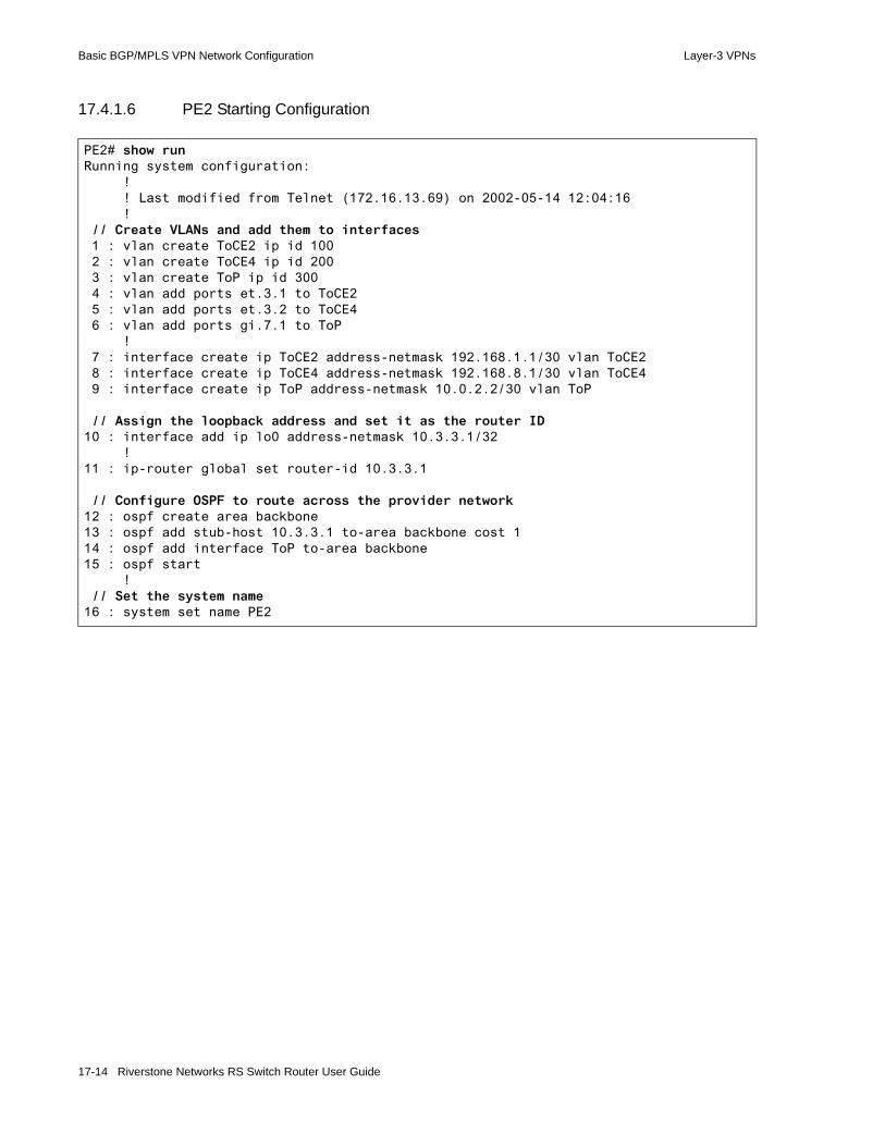
Basic BGP/MPLS VPN Network Configuration Layer-3 VPNs
17.4.1.6 PE2 Starting Configuration
PE2# show runRunning system configuration: ! ! Last modified from Telnet (172.16.13.69) on 2002-05-14 12:04:16 ! // Create VLANs and add them to interfaces 1 : vlan create ToCE2 ip id 100 2 : vlan create ToCE4 ip id 200 3 : vlan create ToP ip id 300 4 : vlan add ports et.3.1 to ToCE2 5 : vlan add ports et.3.2 to ToCE4 6 : vlan add ports gi.7.1 to ToP ! 7 : interface create ip ToCE2 address-netmask 192.168.1.1/30 vlan ToCE2 8 : interface create ip ToCE4 address-netmask 192.168.8.1/30 vlan ToCE4 9 : interface create ip ToP address-netmask 10.0.2.2/30 vlan ToP
// Assign the loopback address and set it as the router ID10 : interface add ip lo0 address-netmask 10.3.3.1/32 !11 : ip-router global set router-id 10.3.3.1
// Configure OSPF to route across the provider network12 : ospf create area backbone13 : ospf add stub-host 10.3.3.1 to-area backbone cost 114 : ospf add interface ToP to-area backbone15 : ospf start ! // Set the system name16 : system set name PE2
17-14 Riverstone Networks RS Switch Router User Guide

Layer-3 VPNs Basic BGP/MPLS VPN Network Configuration
17.4.1.7 P Starting Configuration
P# show runRunning system configuration: ! ! Last modified from Telnet (172.16.13.69) on 2002-05-11 03:04:49 ! // Create VLANs and add them to interfaces 1 : vlan create ToPE1 ip id 100 2 : vlan create ToPE2 ip id 200 3 : vlan add ports gi.4.2 to ToPE1 4 : vlan add ports gi.4.1 to ToPE2 ! 5 : interface create ip ToPE1 address-netmask 10.0.1.2/30 vlan ToPE1 6 : interface create ip ToPE2 address-netmask 10.0.2.1/30 vlan ToPE2
// Assign the loopback address and set it as the router ID 7 : interface add ip lo0 address-netmask 10.2.2.1/32 ! 8 : ip-router global set router-id 10.2.2.1 ! // Configure OSPF to route across the provider network 9 : ospf create area backbone10 : ospf add stub-host 10.2.2.1 to-area backbone cost 111 : ospf add interface ToPE1 to-area backbone12 : ospf add interface ToPE2 to-area backbone13 : ospf start ! // Set the system name14 : system set name P
Riverstone Networks RS Switch Router User Guide 17-15

Basic BGP/MPLS VPN Network Configuration Layer-3 VPNs
17.4.2 Setting Up Signaling Protocols and MPLS LSPs Between PE Routers
PE routers forward customer traffic across the provider network using MPLS. When customer traffic is encapsulated and sent through MPLS, P routers only need to swap labels and forward the traffic. If customer traffic is sent through a routing protocol instead of MPLS, P routers would need to know customer routes in order to forward them. Therefore, encapsulating and sending customer traffic via MPLS reduces core router workload and enhances overall network scalability. It requires that only ingress and egress PE routers maintain customer routing information and interface with customer routers. P routers only need to forward MPLS traffic and do not need to route customer prefixes directly.
You may use either Label Distribution Protocol (LDP) or Resource Reservation Protocol (RSVP) to establish and maintain LSPs across the provider network. Use LDP to establish best-effort LSPs between two PE routers. Use RSVP for bandwidth reservation or traffic engineering in selecting an LSP path.
Note Remember that LSPs are unidirectional. Two LSPs must be established (from point X to Y and Y to X) to allow bidirectional communication.
To ensure route distribution, a pair of LSPs must exist between the PE router that learns a route and the PE router that advertises the route.
For more information on LDP, RSVP, traffic engineering, and MPLS, see Section 18 "MPLS Configuration."
To create LSPs, first ensure that an IGP is running (for LDP) and an IGP with traffic engineering capabilities is running (for RSVP explicit end-to-end paths). The appropriate IGP must be running before you can configure a signaling protocol.
In our example, OSPF is already running in the provider network. For OSPF configuration commands, see Section 17.4.1 "Basic BGP/MPLS VPN Network Starting Configurations."
The following sections describe how to configure RSVP and LDP for signalling.
17.4.2.1 Configuring RSVP for Signaling
To implement the Basic BGP/MPLS VPN Network (Figure 17-1), RSVP is configured for signaling in the provider network and MPLS to establish bidirectional LSPs between PE1 and PE2. For more information on configuring RSVP and MPLS, see Section 18.5 "Configuring L3 Label Switched Paths."
Basic BGP/MPLS VPN Network configuration steps:- IGP in the provider network (included in initial configurations)- Configure MPLS LSPs in the provider network- MP-IBGP between PE routers- RED and PINK routing instances on the PE routers- Static and OSPF PE-CE route distribution
17-16 Riverstone Networks RS Switch Router User Guide
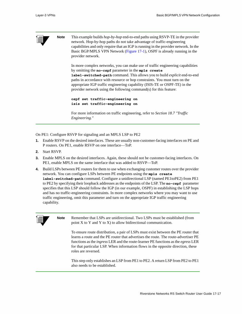
Layer-3 VPNs Basic BGP/MPLS VPN Network Configuration
Note This example builds hop-by-hop end-to-end paths using RSVP-TE in the provider network. Hop-by-hop paths do not take advantage of traffic-engineering capabilities and only require that an IGP is running in the provider network. In the Basic BGP/MPLS VPN Network (Figure 17-1), OSPF is already running in the provider network.
In more complex networks, you can make use of traffic engineering capabilities by omitting the no-cspf parameter in the mpls create label-switched-path command. This allows you to build explicit end-to-end paths in accordance with resource or hop constraints. You must turn on the appropriate IGP traffic engineering capability (ISIS-TE or OSPF-TE) in the provider network using the following command(s) for this feature:
ospf set traffic-engineering on
isis set traffic-engineering on
For more information on traffic engineering, refer to Section 18.7 "Traffic Engineering."
On PE1: Configure RSVP for signaling and an MPLS LSP to PE21. Enable RSVP on the desired interfaces. These are usually non-customer-facing interfaces on PE and
P routers. On PE1, enable RSVP on one interface—ToP.2. Start RSVP.3. Enable MPLS on the desired interfaces. Again, these should not be customer-facing interfaces. On
PE1, enable MPLS on the same interface that was added to RSVP—ToP.4. Build LSPs between PE routers for them to use when exchanging customer routes over the provider
network. You can configure LSPs between PE endpoints using the mpls create label-switched-path command. Configure a unidirectional LSP (named PE1toPE2) from PE1 to PE2 by specifying their loopback addresses as the endpoints of the LSP. The no-cspf parameter specifies that this LSP should follow the IGP (in our example, OSPF) in establishing the LSP hops and has no traffic-engineering constraints. In more complex networks where you may want to use traffic engineering, omit this parameter and turn on the appropriate IGP traffic engineering capability.
Note Remember that LSPs are unidirectional. Two LSPs must be established (from point X to Y and Y to X) to allow bidirectional communication.
To ensure route distribution, a pair of LSPs must exist between the PE router that learns a route and the PE router that advertises the route. The route-advertiser PE functions as the ingress LER and the route-learner PE functions as the egress LER for that particular LSP. When information flows in the opposite direction, these roles are reversed.
This step only establishes an LSP from PE1 to PE2. A return LSP from PE2 to PE1 also needs to be established.
Riverstone Networks RS Switch Router User Guide 17-17
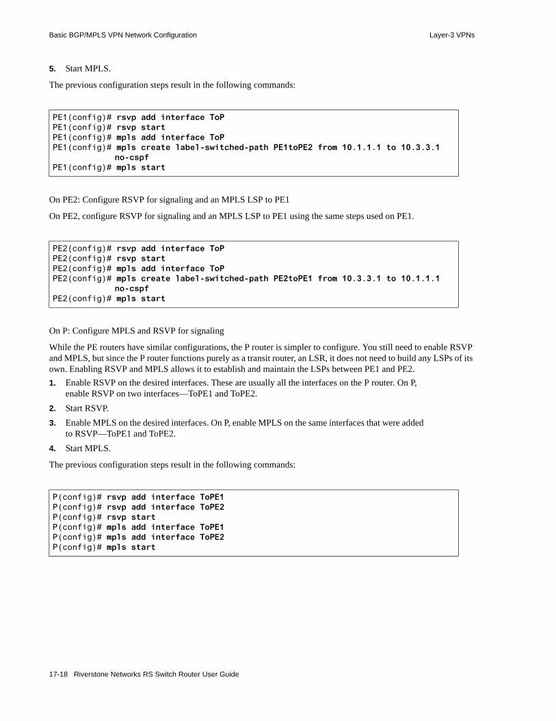
Basic BGP/MPLS VPN Network Configuration Layer-3 VPNs
5. Start MPLS.
The previous configuration steps result in the following commands:
On PE2: Configure RSVP for signaling and an MPLS LSP to PE1
On PE2, configure RSVP for signaling and an MPLS LSP to PE1 using the same steps used on PE1.
On P: Configure MPLS and RSVP for signaling
While the PE routers have similar configurations, the P router is simpler to configure. You still need to enable RSVP and MPLS, but since the P router functions purely as a transit router, an LSR, it does not need to build any LSPs of its own. Enabling RSVP and MPLS allows it to establish and maintain the LSPs between PE1 and PE2.1. Enable RSVP on the desired interfaces. These are usually all the interfaces on the P router. On P,
enable RSVP on two interfaces—ToPE1 and ToPE2.2. Start RSVP.3. Enable MPLS on the desired interfaces. On P, enable MPLS on the same interfaces that were added
to RSVP—ToPE1 and ToPE2.4. Start MPLS.
The previous configuration steps result in the following commands:
PE1(config)# rsvp add interface ToPPE1(config)# rsvp startPE1(config)# mpls add interface ToPPE1(config)# mpls create label-switched-path PE1toPE2 from 10.1.1.1 to 10.3.3.1
no-cspfPE1(config)# mpls start
PE2(config)# rsvp add interface ToPPE2(config)# rsvp startPE2(config)# mpls add interface ToPPE2(config)# mpls create label-switched-path PE2toPE1 from 10.3.3.1 to 10.1.1.1
no-cspfPE2(config)# mpls start
P(config)# rsvp add interface ToPE1P(config)# rsvp add interface ToPE2P(config)# rsvp startP(config)# mpls add interface ToPE1P(config)# mpls add interface ToPE2P(config)# mpls start
17-18 Riverstone Networks RS Switch Router User Guide

Layer-3 VPNs Basic BGP/MPLS VPN Network Configuration
17.4.2.2 Viewing LSPs
After configuring LSPs, use the mpls show label-switched-path command to verify that labels are established, up, and running.
On PE1, this command output shows that the two LSPs, PE1toPE2 and PE2toPE1, are in the up state. PE1 functions as the ingress router for the PE1toPE2 LSP and as the egress router for the PE2toPE1 LSP.
Outputs from the same command on the PE2 and P routers verify this. Notice that PE2’s ingress/egress functions for these LSPs are the reverse of PE1’s:
The P router acts as a transit router for both LSPs, as shown in the following output:
PE1# mpls show label-switched-path all
Ingress LSP:LSPname To From State LabelIn LabelOutPE1toPE2 10.3.3.1 10.1.1.1 Up - 4097
Transit LSP:LSPname To From State LabelIn LabelOut
Egress LSP:LSPname To From State LabelIn LabelOutPE2toPE1 10.1.1.1 10.3.3.1 Up 3 -
PE2# mpls show label-switched-path all
Ingress LSP:LSPname To From State LabelIn LabelOutPE2toPE1 10.1.1.1 10.3.3.1 Up - 4097
Transit LSP:LSPname To From State LabelIn LabelOut
Egress LSP:LSPname To From State LabelIn LabelOutPE1toPE2 10.3.3.1 10.1.1.1 Up 3 -
Riverstone Networks RS Switch Router User Guide 17-19
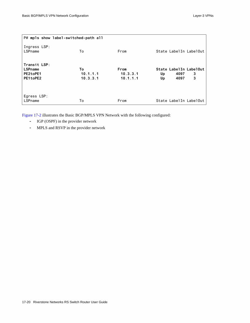
Basic BGP/MPLS VPN Network Configuration Layer-3 VPNs
Figure 17-2 illustrates the Basic BGP/MPLS VPN Network with the following configured:- IGP (OSPF) in the provider network- MPLS and RSVP in the provider network
P# mpls show label-switched-path all
Ingress LSP:LSPname To From State LabelIn LabelOut
Transit LSP:LSPname To From State LabelIn LabelOutPE2toPE1 10.1.1.1 10.3.3.1 Up 4097 3PE1toPE2 10.3.3.1 10.1.1.1 Up 4097 3
Egress LSP:LSPname To From State LabelIn LabelOut
17-20 Riverstone Networks RS Switch Router User Guide

Layer-3 VPNs Basic BGP/MPLS VPN Network Configuration
Figure 17-2 Basic BGP/MPLS VPN Network after configuring RSVP and MPLS LSPs in the provider network
After Configuring RSVP and MPLSLSPs In the Provider Network
LSP PE1toPE2
Basic BGP/MPLS VPNNetwork
CE2192.168.100.1
P10.2.2.1
PE210.3.3.1
CE4192.168.101.1
et.10.1
gi.7.1gi.4.2 gi.4.1et.3.1
et.3.2
et.2.1
et.2.8
et.10.8
PE110.1.1.1
CE3172.20.2.1
et.6.2
gi.7.1et.6.1
et.3.1
et.3.8
CE1172.20.1.1
et.2.1
et.2.8
.1
.1
.1
.1
.1
.1
.1
.1.1
.1
.2.2
.2
.2.2
172.17.2.0/24
172.17.2.0/24
10.0.2.0/3010.0.1.0/30 .2
192.168.9.0/24
192.168.2.0/24
Customer ASite 1
Customer ASite 2
Customer BSite 1
Customer BSite 2
Provider Network
OSPF area backbone
LSP PE2toPE1
192.168.1.0/30
192.168.8.0/30
172.17.1.0/30
172.17.8.0/30
Riverstone Networks RS Switch Router User Guide 17-21

Basic BGP/MPLS VPN Network Configuration Layer-3 VPNs
17.4.2.3 Configuring LDP for Signaling
Alternatively, you can use LDP instead of RSVP to create LSPs. To use LDP, configure LDP on all the routers in the provider network. In the Basic BGP/MPLS VPN Network example, you would need to configure LDP on the PE1, PE2, and P routers. To configure LDP in your own networks, follow these steps. For more information on configuring LDP, see Section 18.4 "LDP Configuration."
Note LDP requires that an IGP is running.
1. Enable LDP on the desired interfaces. These are usually non-customer-facing interfaces on PE and P routers. When started, LDP discovers local peers automatically by sending Hellos on all LDP-enabled interfaces using the “all routers on this subnet” multicast address. Unlike RSVP, this exchange allows LDP to build a full mesh of bidirectional LSPs to every LDP neighbor’s loopback address. Given this capability, no additional configurations are necessary to establish PE-PE LSPs once LDP is enabled on all the provider routers. In this example, two interfaces are added to LDP—Provider-Facing-Interfaces 1 and 2.
2. Start LDP. 3. Enable MPLS on the desired interfaces. In this example, MPLS is enabled on the same interfaces
that were added to RSVP—Provider-Facing-Interfaces 1 and 2.4. Start MPLS.
The following are examples of the commands used to configure LDP on all provider routers:
After configuring LDP, use the ldp show database command to verify LSP establishment. You should see an LSP to the loopback interface of every router on which LDP is enabled.
AnyPEorP(config)# ldp add interface Provider-Facing-Interface1AnyPEorP(config)# ldp add interface Provider-Facing-Interface2AnyPEorP(config)# ldp startAnyPEorP(config)# mpls add interface Provider-Facing-Interface1AnyPEorP(config)# mpls add interface Provider-Facing Interface2AnyPEorP(config)# mpls start
17-22 Riverstone Networks RS Switch Router User Guide

Layer-3 VPNs Basic BGP/MPLS VPN Network Configuration
17.4.3 Configuring MP-BGP Between PE Routers for Customer Route Distribution
PE routers use multiprotocol BGP (MP-BGP) to distribute learned customer routes across the provider network. PE routers logically peer with each other in MP-BGP sessions that do not include P routers. PE routers also use LSPs for resolving next hops. These two features allow PE routers to distribute customer routes across the provider network while keeping them segregated from provider IGP routes.
When distributing VPN-IPv4 routes via MP-BGP, a PE router sets the BGP next hop as itself. Remote PE routers resolve this BGP next hop to an LSP, which it uses for transport on that route.
One of the key features of BGP/MPLS VPN is that each VPN can have its own address space. This is enormously beneficial because VPN customers may use RFC 1918 private address spaces. Therefore, two routes for the same IPv4 prefix may be to different systems. It is important that BGP does not treat the two routes as comparable and install one but not the other, resulting in one of the two systems being unreachable.
BGP4 does not have this capability. MP-BGP is a multiprotocol extension of BGP4 that can translate globally non-unique IPv4 addresses into globally unique VPN-IPv4 addresses by prepending a unique Route Distinguisher value. RFC 2858, Multiprotocol Extensions for BGP4, by Bates, Chandra, Katz, and Rekhter defines this standard and the address translation mechanism. The RFC explains, “If two VPNs use the same IPv4 address prefix, the PE routers translate these into unique VPN-IPv4 address prefixes. This ensures that if the same address is used in two different VPNs, it is possible to install two completely different routes to that address, one for each VPN.” For more information on VPN-IPv4 addresses and Route Distinguishers, see the RFC or the Section 17.4.4.2 "Configuring Route Distinguishers and VPN-IPv4 Addresses."
To deploy BGP/MPLS VPNS, PE routes must support MP-BGP in addition to BGP4. Before exchanging VPN-IPv4 routes, BGP peers negotiate to make sure that both are capable of supporting VPN-IPv4 addresses.
MP-BGP is backward compatible with BGP4. A router that supports MP-BGP extensions can still interoperate with a router that only supports conventional BGP4.
17.4.3.1 Configuring MP-BGP Between PE Routers
MP-BGP and conventional BGP4 configurations only differ in two commands:• bgp set peer-group <name> vpnv4-unicast ipv4-unicast
• ip-router global set install-lsp-routes bgp
The bgp set peer-group <name> vpnv4-unicast ipv4-unicast command enables the BGP process to support both conventional IPv4 and VPN-IPv4 addresses. BGP peers negotiate this capability in OPEN messages. By default, BGP supports IPv4 addresses. Unilateral support for VPN-IPv4 addresses means that these address cannot be sent in that peering session.
Basic BGP/MPLS VPN Network configuration steps:- IGP in the provider network (included in initial configurations)- MPLS LSPs in the provider network- Configure MP-IBGP between PE routers- RED and PINK routing instances on the PE routers- Static and OSPF PE-CE route distribution
Riverstone Networks RS Switch Router User Guide 17-23

Basic BGP/MPLS VPN Network Configuration Layer-3 VPNs
Note When using the ipv4-unicast option in the bgp set peer-group or peer-host commands, BGP peers must be running ROS 9.2 or later for IPv4 addresses to be exchanged.
For more information on VPN-IPv4 addresses and Route Distinguishers, see the Section 17.4.4.2 "Configuring Route Distinguishers and VPN-IPv4 Addresses."
Note By default, BGP sends encapsulated VPN-IPv4 routes with the next hop set to ‘self’.
The ip-router global set install-lsp-routes bgp command enables BGP to use MPLS LSPs for resolving next hops. Normally, MPLS LSPs are not installed in the RIB or FIB, which makes them inaccessible for routing. This command grants BGP exclusive access to these LSP routes, allowing BGP to use MPLS paths, in addition to other routes in the FIB, in resolving next hops. Under this scheme, BGP prefers MPLS paths over IGP paths. So if a pair of MPLS LSPs exist between PEs, BGP will prefer and use these LSPs for transporting customer traffic. This is desirable because when customer traffic is encapsulated and sent through MPLS, P routers only need to swap labels and forward the traffic. If customer traffic is sent through a routing protocol instead of MPLS, P routers would need to know customer routes in order to forward them. Therefore, encapsulating and sending customer traffic via MPLS is essential to reducing core router workload and enhancing overall network scalability. It requires that only ingress and egress PE routers maintain customer routing information and interface with customer routers. P routers only need to forward MPLS traffic and do not need to route customer prefixes directly.
For more information on the ip-router global set install-lsp-routes bgp command, see Section 16.2.15 "Using MPLS LSPs To Resolve BGP Next Hop."
For more information on configuring conventional BGP, see Section 16 "BGP Configuration Guide."
To implement the Basic BGP/MPLS VPN Network (Figure 17-2), MP-IBGP is configured between PE1 and PE2. IBGP is used instead of EBGP because PE1 and PE2 are within the same autonomous system, 65001.
Configuring PE1 and PE2 to route using MP-IBGP
The following examples configure PE1 and PE2 to route using MP-IBGP in AS 65001. 1. Configure both routers to be in AS 65001.2. Create a peer group named PROVIDER on both routers for their AS 65001 peers. Since it is also in
AS 65001, each router recognizes PROVIDER as an IBGP peer group and uses the ‘routing’ type by default.
3. Add PE1 and PE2 as peer hosts in the PROVIDER group.- Add PE2 as a peer host in the PROVIDER group by specifying its loopback address, 10.3.3.1,
which is also its router ID.- Add PE1 as a peer host in the PROVIDER group by specifying its loopback address, 10.1.1.1,
which is also its router ID.4. Unlike EBGP peers, IBGP peers are not required to be directly attached. IBGP peers often peer
logically but are not physically connected, as in our network example. Setting all IBGP peers to peer using their loopback addresses is a good practice.
17-24 Riverstone Networks RS Switch Router User Guide

Layer-3 VPNs Basic BGP/MPLS VPN Network Configuration
- Configure PE1 to peer using its loopback address with all hosts in the PROVIDER group by specifying 10.1.1.1 as its local address.
- Configure PE2 to peer using its loopback address with all hosts in the PROVIDER group by specifying 10.3.3.1 as its local address.
5. [Differs from configuring BGP4] Specify that both routers should use MP-BGP by enabling support for both conventional IPv4 addresses and VPN-IPv4 unicast addresses. This informs the BGP process that it will be dealing with conventional IPv4 addresses from the unicast RIB and customer VPN-IPv4 addresses from Routing Instance RIB(s). By default, BGP sends all active Routing Instance routes (customer VPN-IPv4 routes) with the next hop set to itself.
6. [Differs from configuring BGPv4] Enable BGP on both routers to use MPLS LSPs for resolving next hops by granting BGP exclusive access to these LSP routes. Under this scheme, BGP prefers MPLS paths over IGP paths. So if a pair of MPLS LSPs exist between PE1 and PE2, the BGP processes on both routers will prefer these LSPs over IGP routes for transporting customer traffic. This forces PE routers to encapsulate customer traffic as MPLS packets before sending them, which relieves P routers from having to learn or route customer prefixes. Only ingress and egress PE routers maintain customer routing information and interface with customer routers. P routers only need to forward MPLS traffic. Encapsulating and sending customer traffic via MPLS is essential to reducing core router workload and enhancing overall network scalability.
7. Start BGP.The previous configuration steps result in the following commands on PE1:
The previous configuration steps result in the following commands on PE2:
PE1(config)# ip-router global set autonomous-system 65001PE1(config)# bgp create peer-group PROVIDER autonomous-system 65001PE1(config)# bgp add peer-host 10.3.3.1 group PROVIDERPE1(config)# bgp set peer-group PROVIDER local-address 10.1.1.1PE1(config)# bgp set peer-group PROVIDER vpnv4-unicast ipv4-unicastPE1(config)# ip-router global set install-lsp-routes bgpPE1(config)# bgp start
PE2(config)# ip-router global set autonomous-system 65001PE2(config)# bgp create peer-group PROVIDER autonomous-system 65001PE2(config)# bgp add peer-host 10.1.1.1 group PROVIDERPE2(config)# bgp set peer-group PROVIDER local-address 10.3.3.1PE2(config)# bgp set peer-group PROVIDER vpnv4-unicast ipv4-unicastPE2(config)# ip-router global set install-lsp-routes bgpPE2(config)# bgp start
Riverstone Networks RS Switch Router User Guide 17-25
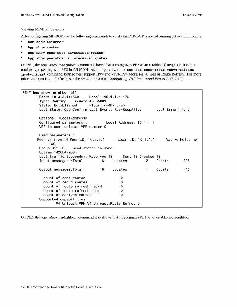
Basic BGP/MPLS VPN Network Configuration Layer-3 VPNs
Viewing MP-BGP Sessions
After configuring MP-BGP, use the following commands to verify that MP-BGP is up and running between PE routers:• bgp show neighbor
• bgp show routes
• bgp show peer-host advertised-routes
• bgp show peer-host all-received routes
On PE1, the bgp show neighbor command shows that it recognizes PE2 as an established neighbor. It is in a routing-type peering with PE2 in AS 65001. As configured with the bgp set peer-group vpnv4-unicast ipv4-unicast command, both routers support IPv4 and VPN-IPv4 addresses, as well as Route Refresh. (For more information on Route Refresh, see the Section 17.4.4.4 "Configuring VRF Import and Export Policies.")
On PE2, the bgp show neighbor command also shows that it recognizes PE1 as an established neighbor.
PE1# bgp show neighbor all Peer: 10.3.3.1+1560 Local: 10.1.1.1+179 Type: Routing remote AS 65001 State: Established Flags: <v4MP v4u> Last State: OpenConfirm Last Event: RecvKeepAlive Last Error: None
Options: <LocalAddress> Configured parameters : Local Address: 10.1.1.1 VRF in use unicast VRF number 0
Used parameters : Peer Version: 4 Peer ID: 10.3.3.1 Local ID: 10.1.1.1 Active Holdtime:
180 Group Bit: 0 Send state: in sync Uptime 1d20h47m39s Last traffic (seconds): Received 18 Sent 18 Checked 18 Input messages :Total 18 Updates 2 Octets 396
Output messages:Total 18 Updates 1 Octets 415
count of sent routes 0 count of recvd routes 0 count of route refresh recvd 0 count of route refresh sent 0 count of derived routes 0 Supported capabilities V4 Unicast;VPN-V4 Unicast;Route Refresh;
17-26 Riverstone Networks RS Switch Router User Guide
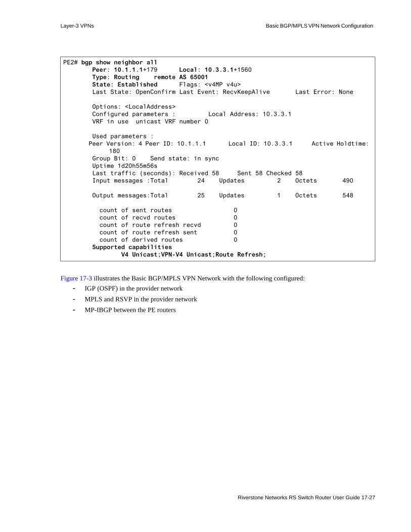
Layer-3 VPNs Basic BGP/MPLS VPN Network Configuration
Figure 17-3 illustrates the Basic BGP/MPLS VPN Network with the following configured:- IGP (OSPF) in the provider network- MPLS and RSVP in the provider network- MP-IBGP between the PE routers
PE2# bgp show neighbor all Peer: 10.1.1.1+179 Local: 10.3.3.1+1560 Type: Routing remote AS 65001 State: Established Flags: <v4MP v4u> Last State: OpenConfirm Last Event: RecvKeepAlive Last Error: None
Options: <LocalAddress> Configured parameters : Local Address: 10.3.3.1 VRF in use unicast VRF number 0
Used parameters : Peer Version: 4 Peer ID: 10.1.1.1 Local ID: 10.3.3.1 Active Holdtime:
180 Group Bit: 0 Send state: in sync Uptime 1d20h55m56s Last traffic (seconds): Received 58 Sent 58 Checked 58 Input messages :Total 24 Updates 2 Octets 490
Output messages:Total 25 Updates 1 Octets 548
count of sent routes 0 count of recvd routes 0 count of route refresh recvd 0 count of route refresh sent 0 count of derived routes 0 Supported capabilities V4 Unicast;VPN-V4 Unicast;Route Refresh;
Riverstone Networks RS Switch Router User Guide 17-27

Basic BGP/MPLS VPN Network Configuration Layer-3 VPNs
Figure 17-3 Basic BGP/MPLS VPN Network after configuring MP-IBGP between PE routers
After Configuring MP-IBGPBetween PE Routers
LSP PE1toPE2
Basic BGP/MPLS VPNNetwork
CE2192.168.100.1
P10.2.2.1
PE210.3.3.1
CE4192.168.101.1
et.10.1
gi.7.1gi.4.2 gi.4.1et.3.1
et.3.2
et.2.1
et.2.8
et.10.8
PE110.1.1.1
CE3172.20.2.1
et.6.2
gi.7.1et.6.1
et.3.1
et.3.8
CE1172.20.1.1
et.2.1
et.2.8
.1
.1
.1
.1
.1
.1
.1
.1.1
.1
.2.2
.2
.2.2
172.17.2.0/24
172.17.2.0/24
10.0.2.0/3010.0.1.0/30 .2
192.168.9.0/24
192.168.2.0/24
Customer ASite 1
Customer ASite 2
Customer BSite 1
Customer BSite 2
Provider Network
OSPF area backbone
LSP PE2toPE1
MP-IBGP
192.168.1.0/30
192.168.8.0/30
172.17.1.0/30
172.17.8.0/30
17-28 Riverstone Networks RS Switch Router User Guide
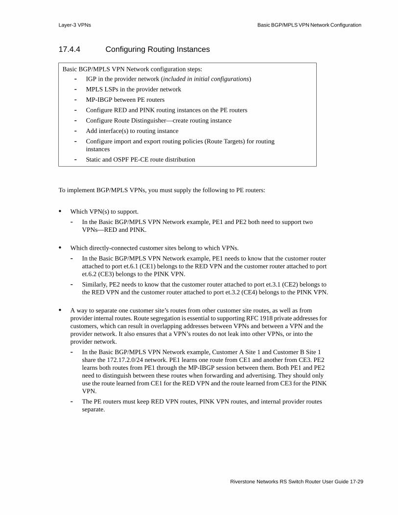
Layer-3 VPNs Basic BGP/MPLS VPN Network Configuration
17.4.4 Configuring Routing Instances
To implement BGP/MPLS VPNs, you must supply the following to PE routers:
• Which VPN(s) to support.- In the Basic BGP/MPLS VPN Network example, PE1 and PE2 both need to support two
VPNs—RED and PINK.
• Which directly-connected customer sites belong to which VPNs.- In the Basic BGP/MPLS VPN Network example, PE1 needs to know that the customer router
attached to port et.6.1 (CE1) belongs to the RED VPN and the customer router attached to port et.6.2 (CE3) belongs to the PINK VPN.
- Similarly, PE2 needs to know that the customer router attached to port et.3.1 (CE2) belongs to the RED VPN and the customer router attached to port et.3.2 (CE4) belongs to the PINK VPN.
• A way to separate one customer site’s routes from other customer site routes, as well as from provider internal routes. Route segregation is essential to supporting RFC 1918 private addresses for customers, which can result in overlapping addresses between VPNs and between a VPN and the provider network. It also ensures that a VPN’s routes do not leak into other VPNs, or into the provider network.- In the Basic BGP/MPLS VPN Network example, Customer A Site 1 and Customer B Site 1
share the 172.17.2.0/24 network. PE1 learns one route from CE1 and another from CE3. PE2 learns both routes from PE1 through the MP-IBGP session between them. Both PE1 and PE2 need to distinguish between these routes when forwarding and advertising. They should only use the route learned from CE1 for the RED VPN and the route learned from CE3 for the PINK VPN.
- The PE routers must keep RED VPN routes, PINK VPN routes, and internal provider routes separate.
Basic BGP/MPLS VPN Network configuration steps:- IGP in the provider network (included in initial configurations)- MPLS LSPs in the provider network- MP-IBGP between PE routers- Configure RED and PINK routing instances on the PE routers- Configure Route Distinguisher—create routing instance- Add interface(s) to routing instance- Configure import and export routing policies (Route Targets) for routing
instances- Static and OSPF PE-CE route distribution
Riverstone Networks RS Switch Router User Guide 17-29

Basic BGP/MPLS VPN Network Configuration Layer-3 VPNs
17.4.4.1 VRFs and Routing Instances
RFC 2547bis, BGP/MPLS VPNs, in defining the BGP/MPLS VPN standard, fulfills these requirements by mandating that PE routers maintain multiple, per-site routing and forwarding tables (VRFs):
Each PE router maintains a number of separate forwarding tables. Every site to which the PE router is attached must be mapped to one of those forwarding tables. When a packet is received from a particular site, the forwarding table associated with that site is consulted in order to determine how to route the packet. The forwarding table associated with a particular site S is populated ONLY with routes that lead to other sites which have at least one VPN in common with S. This prevents communication between sites which have no VPN in common.
When a PE router receives a packet from a CE device, it knows the interface or sub-interface over which the packet arrived, and this determines the forwarding table used for processing that packet. The choice of forwarding table is NOT determined by the user content of the packet.
The fact that sites in different VPNs are mapped to different forwarding tables makes it possible for different VPNs to have overlapping address spaces, without creating any ambiguity.
Note While this usually means that the PE router associates one VRF for each customer-connected port, multiple ports/sites can be associated with the same VRF if they have all their VPNs in common. This allows PE routers to conserve router resources.
If sites contain hosts that are members of multiple VPNs, the VRF associated with that site contains routes for all VPNs of which that site is a member.
The PE router maintains a VRF for each directly-connected site. Multiple forwarding tables prevent sites that have no VPNs in common from communicating. This enhances scalability by not requiring PE routers to maintain a dedicated VRF for all of the VPNs supported by the provider network. Each PE router only needs to maintain VRFs for its directly-connected sites.
In addition to per-site VRFs, the PE router also maintains the default global routing and forwarding tables (RIB and FIB) for non-VPN routes.
On the RS Ethernet Router, you do not define VRFs. You define routing instances, which generate VRFs. Each VRF is associated with a routing instance, which runs between PE and CE routers. The routing instance learns and manages routes for that VRF. Each VRF, like the global forwarding tables, consists of a routing information base (RIB) and a forwarding information base (FIB). The PE router first learns routes from its customer(s) and installs them in the Routing Instance RIB. Then, routing instances perform route selection and choose active routes from the Routing Instance RIB to install in the Routing Instance FIB. Using the Routing Instance FIB, routing instances forwards packets to and from customer(s). Since each VRF has its own routing instance to learn, process, and forward routes, a VRF’s routes never accidentally mixes with other VRF routes.
To configure a routing instance, you must configure four required elements:1. Create unique VPN-IPv4 addresses by configuring a Route Distinguisher2. Specify which directly-connected customer site(s) belong to this VRF by adding interface(s)3. Specify which categor(ies) of routes the VRF’s customer site(s) should learn by configuring import
polic(ies)4. Specify which categor(ies) to use in advertising the VRF’s customer site routes by configuring
export polic(ies)
17-30 Riverstone Networks RS Switch Router User Guide

Layer-3 VPNs Basic BGP/MPLS VPN Network Configuration
17.4.4.2 Configuring Route Distinguishers and VPN-IPv4 Addresses
To support overlapping customer addresses, PE routers create globally unique VPN-IPv4 addresses by prepending Route Distinguishers to globally non-unique IPv4 addresses. RFC 2547bis, BGP/MPLS VPNs, defines the VPN-IPv4 address family and the address translation mechanism.
Route Distinguisher and VPN-IPv4 Address Usage Notes
Note The Route Distinguisher does not, by itself, contain information about the origin of a route or the customer site(s) to which it should be distributed. It is merely used to create IPv4 addresses. Route Distinguishers are not the same as BGP Extended Community Attributes, which define a route’s import and export properties.
VPN-IPv4 addresses are used only within the provider network. Customers are not aware of VPN-IPv4 addresses. PE routers convert customer IPv4 routes into VPN-IPv4 format before sending them through the provider network and out of VPN-IPv4 into IPv4 format before sending them to customers.
Prepending a unique Route Distinguisher to an IPv4 address creates a unique VPN-IPv4 address of the following format:
Figure 17-4 VPN-IPv4 address format
The eight-byte Route Distinguisher consists of a 2-byte Type field and a 6-byte Value field. The Value Field contains two subfields, the Administrator subfield and the Assigned Number subfield. The Administrator subfield is meant to hold a globally unique value—either the service provider’s IPv4 address or autonomous system (AS) number. The Assigned Number subfield is meant to hold a provider-assigned value that is unique within the provider. Together, they create a unique string that distinguishes the customer site’s IPv4 addresses from other IPv4 addresses.
Basic BGP/MPLS VPN Network configuration steps:- IGP in the provider network (included in initial configurations)- MPLS LSPs in the provider network- MP-IBGP between PE routers- Configure RED and PINK routing instances on the PE routers- Configure Route Distinguisher—create routing instance- Add interface(s) to routing instances- Configure import and export routing policies (Route Targets) for routing
instances- Static and OSPF PE-CE route distribution
8-Byte Route Distinguisher 4-Byte IPv4Address
Unique 12-ByteVPN-IPv4 Address
Riverstone Networks RS Switch Router User Guide 17-31

Basic BGP/MPLS VPN Network Configuration Layer-3 VPNs
Note To ensure that the Route Distinguisher is unique, use only AS numbers or IP address that you own for the Administrator subfield. Using private IPv4 addresses or AS numbers can easily result in duplicate Route Distinguishers. For this reason, the RFC strongly discourages the use of private AS numbers or IP addresses in the Route Distinguisher.
Depending on what you use in the Administrator subfield, the Route Distinguisher can take on one of two formats:
Figure 17-5 Type-0 Route Distinguisher Format
Figure 17-6 Type-1 Route Distinguisher Format
When configuring Route Distinguishers, you do not need to specify the Type field. The RS Ethernet Router automatically detects the Route Distinguisher format based on whether your configuration uses an IPv4 address or AS number.
Note Configuring a routing instance with a Route Distinguisher creates that routing instance and should be the first step in a routing instance configuration.
Note Routing instance names are case sensitive.
To implement the Basic BGP/MPLS VPN Network (Figure 17-3), each PE router’s loopback address is used for the Administrator value. All RED instances are assigned a unique identifier of ‘1’ and all PINK instances a unique identifier of ‘2’. Even though this example uses RFC 1918 private addresses, you should, in general, only use publicly unique IP addresses or AS numbers in the Route Distinguisher.
2-ByteType Field
0
2-ByteAdministrator
Subfield
Unique AS#
4-ByteAssigned Number Subfield
Provider-Assigned Unique #
8-Byte RouteDistinguisher
2-ByteType Field
1
2-Byte AssignedNumber Subfield
Provider-AssignedUnique #
4-ByteAdministrator Subfield
Unique IPv4 Address
8-Byte RouteDistinguisher
17-32 Riverstone Networks RS Switch Router User Guide
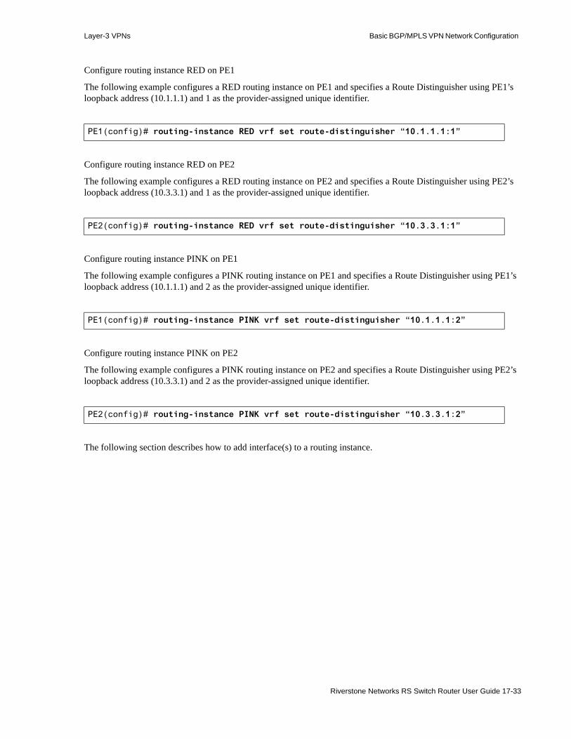
Layer-3 VPNs Basic BGP/MPLS VPN Network Configuration
Configure routing instance RED on PE1
The following example configures a RED routing instance on PE1 and specifies a Route Distinguisher using PE1’s loopback address (10.1.1.1) and 1 as the provider-assigned unique identifier.
Configure routing instance RED on PE2
The following example configures a RED routing instance on PE2 and specifies a Route Distinguisher using PE2’s loopback address (10.3.3.1) and 1 as the provider-assigned unique identifier.
Configure routing instance PINK on PE1
The following example configures a PINK routing instance on PE1 and specifies a Route Distinguisher using PE1’s loopback address (10.1.1.1) and 2 as the provider-assigned unique identifier.
Configure routing instance PINK on PE2
The following example configures a PINK routing instance on PE2 and specifies a Route Distinguisher using PE2’s loopback address (10.3.3.1) and 2 as the provider-assigned unique identifier.
The following section describes how to add interface(s) to a routing instance.
PE1(config)# routing-instance RED vrf set route-distinguisher “10.1.1.1:1”
PE2(config)# routing-instance RED vrf set route-distinguisher “10.3.3.1:1”
PE1(config)# routing-instance PINK vrf set route-distinguisher “10.1.1.1:2”
PE2(config)# routing-instance PINK vrf set route-distinguisher “10.3.3.1:2”
Riverstone Networks RS Switch Router User Guide 17-33

Basic BGP/MPLS VPN Network Configuration Layer-3 VPNs
17.4.4.3 Adding Interfaces to VRFs
Before you can configures a routing instance to route between PE and CE routers, you must add the appropriate interfaces to it. By adding interface(s) to a routing instance, you tell the RS Ethernet Router which directly-connected site(s) to associate with that VRF.
Note Routing instance names are case sensitive.
You can associate multiple interfaces with a VRF.
The routing protocol you use for CE-PE route distribution determines which interfaces you add to each VRF. For static routes, adding the directly-connected VRF interface to the routing instance is usually sufficient. For routing protocols that use the loopback interface, you should also add the loopback interface to the routing instance and set the loopback to be the router ID in the routing instance.
To implement the Basic BGP/MPLS VPN Network (Figure 17-3), on PE1, Customer A Site 1 is associated with the RED VRF and Customer B Site 1 is associated with the PINK VRF. On PE2, Customer A Site 2 is associated with the RED VRF and Customer B Site 2 with the PINK VRF. Customer A is using static routes with the PE routers, and only requires that directly-connected VRF interface be added to the routing instance. Customer B is using OSPF with the PE routers, which requires that the loopback be added and set as the router ID.
Basic BGP/MPLS VPN Network configuration steps:- IGP in the provider network (included in initial configurations)- MPLS LSPs in the provider network- MP-IBGP between PE routers- Configure RED and PINK routing instances on the PE routers- Configure Route Distinguisher—create routing instance- Add interface(s) to routing instances- Configure import and export routing policies (Route Targets) for routing
instances- Static and OSPF PE-CE route distribution
17-34 Riverstone Networks RS Switch Router User Guide

Layer-3 VPNs Basic BGP/MPLS VPN Network Configuration
Associate Customer A Site 1 with the RED VRF on PE1
The following example associates Customer A Site 1 with the RED VRF on PE1 by adding the interface ‘ToCE1’ to the RED routing instance.
Associate Customer B Site 1 with the PINK VRF on PE1
The following example associates Customer B Site 1 with the PINK VRF on PE1 by adding the interface ‘ToCE3’ to the PINK routing instance. Since PE1 and CE3 will route using OSPF, also add PE1’s loopback as an interface and set its address as the router ID in the PINK VRF.
Associate Customer A Site 2 with the RED VRF on PE2
The following example associates Customer A Site 2 with the RED VRF on PE2 by adding the interface ‘ToCE2’ to the RED routing instance.
Associate Customer B Site 2 with the PINK VRF on PE2
The following example associates Customer B Site 2 with the PINK VRF on PE2 by adding the interface ‘ToCE4’ to the PINK routing instance. Since PE2 and CE4 will route using OSPF, also add PE2’s loopback as an interface and set its address as the router ID in the PINK VRF.
The following section describes how to configure import and export Route Targets for routing instances.
PE1(config)# routing-instance RED vrf add interface ToCE1
PE1(config)# routing-instance PINK vrf add interface ToCE3PE1(config)# routing-instance PINK vrf add interface lo0PE1(config)# routing-instance PINK vrf set router-id 10.1.1.1
PE2(config)# routing-instance RED vrf add interface ToCE2
PE2(config)# routing-instance PINK vrf add interface ToCE4PE2(config)# routing-instance PINK vrf add interface lo0PE2(config)# routing-instance PINK vrf set router-id 10.3.3.1
Riverstone Networks RS Switch Router User Guide 17-35
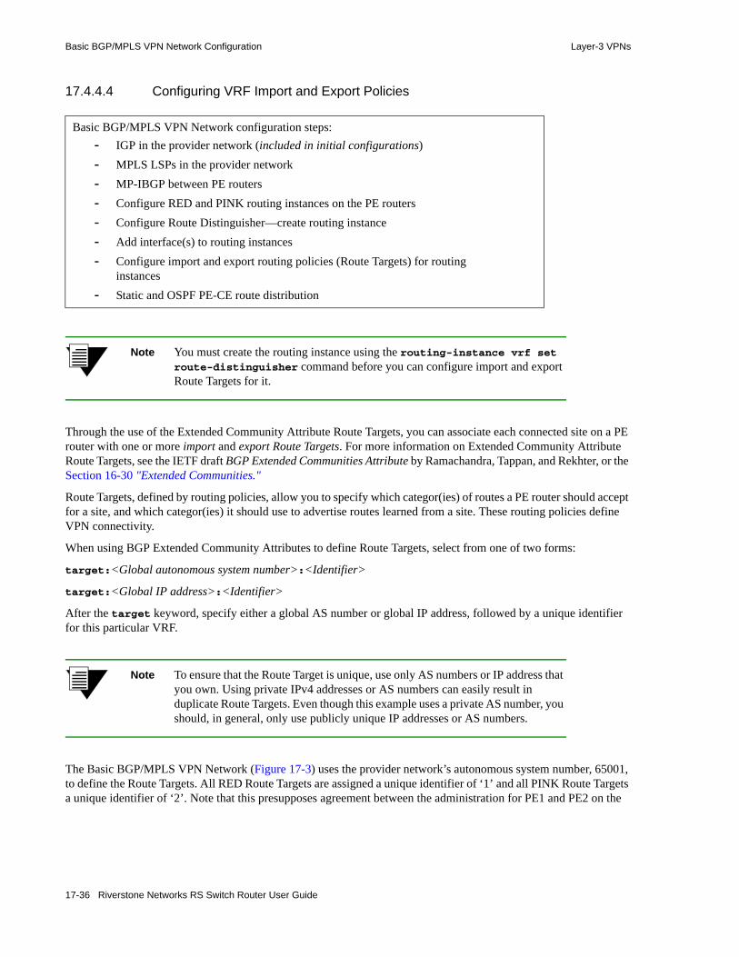
Basic BGP/MPLS VPN Network Configuration Layer-3 VPNs
17.4.4.4 Configuring VRF Import and Export Policies
Note You must create the routing instance using the routing-instance vrf set route-distinguisher command before you can configure import and export Route Targets for it.
Through the use of the Extended Community Attribute Route Targets, you can associate each connected site on a PE router with one or more import and export Route Targets. For more information on Extended Community Attribute Route Targets, see the IETF draft BGP Extended Communities Attribute by Ramachandra, Tappan, and Rekhter, or the Section 16-30 "Extended Communities."
Route Targets, defined by routing policies, allow you to specify which categor(ies) of routes a PE router should accept for a site, and which categor(ies) it should use to advertise routes learned from a site. These routing policies define VPN connectivity.
When using BGP Extended Community Attributes to define Route Targets, select from one of two forms:
target:<Global autonomous system number>:<Identifier>
target:<Global IP address>:<Identifier>
After the target keyword, specify either a global AS number or global IP address, followed by a unique identifier for this particular VRF.
Note To ensure that the Route Target is unique, use only AS numbers or IP address that you own. Using private IPv4 addresses or AS numbers can easily result in duplicate Route Targets. Even though this example uses a private AS number, you should, in general, only use publicly unique IP addresses or AS numbers.
The Basic BGP/MPLS VPN Network (Figure 17-3) uses the provider network’s autonomous system number, 65001, to define the Route Targets. All RED Route Targets are assigned a unique identifier of ‘1’ and all PINK Route Targets a unique identifier of ‘2’. Note that this presupposes agreement between the administration for PE1 and PE2 on the
Basic BGP/MPLS VPN Network configuration steps:- IGP in the provider network (included in initial configurations)- MPLS LSPs in the provider network- MP-IBGP between PE routers- Configure RED and PINK routing instances on the PE routers- Configure Route Distinguisher—create routing instance- Add interface(s) to routing instances- Configure import and export routing policies (Route Targets) for routing
instances- Static and OSPF PE-CE route distribution
17-36 Riverstone Networks RS Switch Router User Guide

Layer-3 VPNs Basic BGP/MPLS VPN Network Configuration
identifier assignment scheme. PE1 and PE2 must both agree that a Route Target from AS 65001 with an identifier of ‘1’ means ‘RED” and ‘2’ means ‘PINK’. Since the AS number is used, the identifier must be unique in this provider network.
If such an agreement is impossible due to preexisting routing policies or inconsistent administration, Route Targets should use PE router loopback addresses instead. Since PE routers have distinct loopback addresses, identifiers only needs to be locally unique in this scheme. As long as you assign different identifiers to different VRFs, other PE routers need to know what identifier you assign to ‘RED’, but are not constrained to making the same assignment themselves. A centrally available and up-to-date mapping of per-PE router identifier assignments can be helpful in maintaining network consistency in this case, which offers network administrators greater flexibility at the cost of higher complexity.
VRF Import and Export Policy Usage Notes
PE routers filter all routes received from remote PE routers through MP-BGP based on the Route Target(s) that you configure. It discards routes that do not match any import targets on the VRFs that it supports. It installs the remaining routes into the VPN-IPv4 RIB. The VPN-IPv4 RIB contains all routes that satisfy the import policy of at least one of the PE router’s VRFs. Since this is the only table that contains all of the routes from all of the VPNs directly connected to the PE router, it is the only table that relies on Route Distinguishers to keep routes with identical IPv4 prefixes distinct.
Standard BGP route selection occurs in this table. Selected routes that match VRF import target(s) are installed into the RIB for that VRF.
Then, the routing instance associated with that VRF selects optimal and active routes from the Routing Instance RIB to install into the Routing Instance FIB.
Note When a PE router receives a route advertisement, it determines whether it should install that route into any VRFs by performing route filtering based on the route’s import target. A route is only eligible to be installed in the VRF tables for a routing instance if at least one of its Route Target(s) match the import target(s) for that VRF.
Note Route Targets, which are BGP Extended Community Attributes, are not the same as Route Distinguishers. Route Distinguishers do not, by themselves, contain information about the origin of a route or the customer site(s) to which it should be distributed. They are merely used to create VPN-IPv4 addresses. A route can only have one Route Distinguisher, but it can have multiple Route Targets.
You can associate multiple import and export Route Targets on a VRF. Import and export targets need not be the same.
BGP Route Refresh
During routing exchange, BGP routers only keep routes received from peers that pass configured routing policies. When you configure a new policy or change an existing policy, the RS Ethernet Router needs to reacquire routes that may have been previously discarded before configuration changes can take effect.
Riverstone Networks RS Switch Router User Guide 17-37

Basic BGP/MPLS VPN Network Configuration Layer-3 VPNs
Without the Route Refresh capability, since BGP sends all routes only at the beginning of peering, clearing all established BGP peering sessions was the only way to prompt BGP peers to resend routes.
RFC 2918, Route Refresh Capability for BGP-4 by Chen defines a mechanism whereby BGP peers can prompt for a retransmission of routes without clearing established peering sessions.
The Route Refresh mechanism is non-disruptive and turned on by default. BGP peers negotiate this capability at the beginning of peering to make sure that both are capable of supporting Route Refresh. A router that supports Route Refresh can still interoperate with a router that does not. In this case, however, you must manually clear the BGP session before configured routing policy changes can take effect. When both peers support Route Refresh, the router automatically requests routes upon a policy configuration change.
Import and Export Route Target Configuration Overview
Routing policies do not take effect until PE routers learn routes from CE routers. For more information on configuring static and OSPF route distribution between CE and PE routers, see Section 17.4.5 "Configuring Static and OSPF Route Distribution Between CE and PE Routers."
To implement the Basic BGP/MPLS VPN Network (Figure 17-3), import and export routing policies are configured as follows:
For Customer A, PE1 is configured to tag routes learned from CE1 as RED. It passes these routes to PE2 tagged with a RED Route Target. PE1 is also configured to only learn routes tagged RED for CE1 through a routing policy that sets the import target for this site to RED. The same holds true for routes that PE2 learns and advertises to CE2.
Similarly, for Customer B, PE1 is configured to tag routes learned from CE3 as PINK. It passes these routes to PE2 tagged with a PINK Route Target. PE1 is also configured to only learn routes tagged PINK from PE2 for CE3 through a routing policy that sets the import target for this site to PINK. The same holds true for routes that PE2 learns and advertises to CE4.
These configurations ensure that CE1 and CE2 have full connectivity. CE3 and CE4 also have full connectivity. But the Route Targets configured on PE1 and PE2 ensure that VPN RED and VPN PINK have no connectivity.
- PE1 passes Customer A Site 2 routes (learned through PE2) to Customer A Site 1 through CE1. PE2 passes Customer A Site 1 routes (learned through PE1) to Customer A Site 2 through CE2.
- PE1 passes Customer B Site 2 routes (learned through PE2) to Customer B Site 1 through CE3. PE2 passes Customer B Site 1 routes (learned through PE1) to Customer B Site 2 through CE4.
- But routes learned from Customer B sites are not passed to Customer A sites, and vice versa.
Note You must configure export targets as routing policies using the ip-router policy create command.
The following configuration steps define the Route Targets using the provider network’s autonomous system number, 65001. It assigns all RED Route Targets a unique identifier of ‘1’ and all PINK Route Targets a unique identifier of ‘2’ on both PE1 and PE2. Even though this example uses a private AS number, you should, in general, only use publicly unique IP addresses or AS numbers in defining Route Targets.
Configure RED import and export Route Targets on PE1
The following example configures PE1 to only learn routes tagged with a Route Target of “target:65001:1” for the RED VRF—“target:65001:1” is the RED VRF import target on PE1. These routes, once learned, enter the Routing Instance RIB and FIB managed by the RED routing instance.
17-38 Riverstone Networks RS Switch Router User Guide

Layer-3 VPNs Basic BGP/MPLS VPN Network Configuration
This example also configures PE1 to tag all routes from the RED VRF with a Route Target of “target:65001:1” before distributing them. Remote PE routers only learn these routes if they have a VRF import target of “target:65001:1” configured.1. Configure a community list named “RED-import” that only permits routes tagged with the
“target:65001:1” community string. This community list is used to define the RED VRF import route map.
2. Create a routing policy named “RED-export” that matches routes tagged with the “target:65001:1” community string. This routing policy is used to define the RED VRF export route map.
Note Community list, routing policy, and routing instance names are all case sensitive.
3. Create a route map named “RED-import” that permits all routes matching the ‘RED-import’ community list. This route map is used as the RED VRF import target.
4. Create a route map named “RED-export” that sets all routes using the ‘RED-export’ routing policy you defined. This route map is used as the RED VRF export target.
5. Apply the ‘RED-import’ route map as the RED VRF import target with a sequence number of 1. You can specify multiple VRF import targets with sequence numbers to set the order in which they should be matched.
6. Apply the ‘RED-export’ route map as the RED VRF export target with a sequence number of 1. You can specify multiple VRF export targets with sequence numbers to set the order in which they should be evaluated.
The previous configuration steps result in the following commands on PE1:
Configure RED import and export Route Targets on PE2
On PE2, configure RED import and export Route Targets using the same steps used on PE1.
PE1(config)# community-list RED-import permit 10 target:65001:1PE1(config)# ip-router policy create community-list RED-export target:65001:1PE1(config)# route-map RED-import permit 10 match-community-list RED-importPE1(config)# route-map RED-export permit 10 set-community-list RED-exportPE1(config)# routing-instance RED vrf set vrf-import RED-import in-sequence 1PE1(config)# routing-instance RED vrf set vrf-export RED-export out-sequence 1
PE2(config)# community-list RED-import permit 10 target:65001:1PE2(config)# ip-router policy create community-list RED-export target:65001:1PE2(config)# route-map RED-import permit 10 match-community-list RED-importPE2(config)# route-map RED-export permit 10 set-community-list RED-exportPE2(config)# routing-instance RED vrf set vrf-import RED-import in-sequence 1PE2(config)# routing-instance RED vrf set vrf-export RED-export out-sequence 1
Riverstone Networks RS Switch Router User Guide 17-39
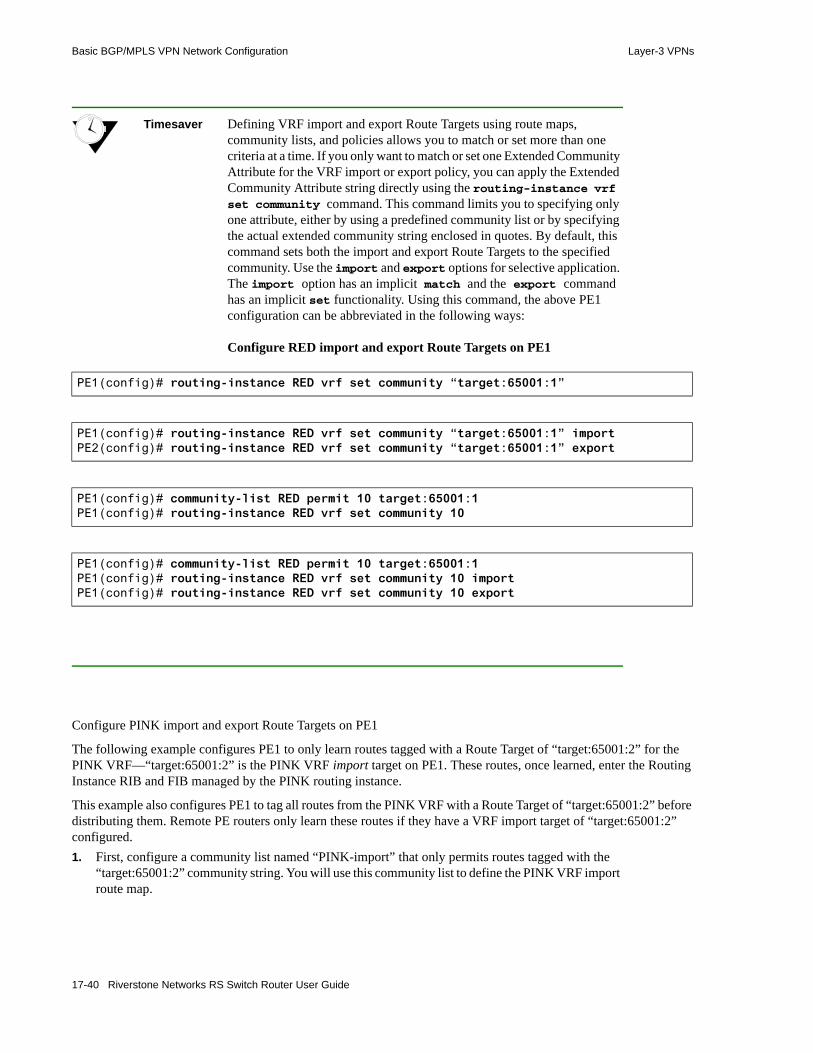
Basic BGP/MPLS VPN Network Configuration Layer-3 VPNs
Timesaver Defining VRF import and export Route Targets using route maps, community lists, and policies allows you to match or set more than one criteria at a time. If you only want to match or set one Extended Community Attribute for the VRF import or export policy, you can apply the Extended Community Attribute string directly using the routing-instance vrf set community command. This command limits you to specifying only one attribute, either by using a predefined community list or by specifying the actual extended community string enclosed in quotes. By default, this command sets both the import and export Route Targets to the specified community. Use the import and export options for selective application. The import option has an implicit match and the export command has an implicit set functionality. Using this command, the above PE1 configuration can be abbreviated in the following ways:
Configure RED import and export Route Targets on PE1
Configure PINK import and export Route Targets on PE1
The following example configures PE1 to only learn routes tagged with a Route Target of “target:65001:2” for the PINK VRF—“target:65001:2” is the PINK VRF import target on PE1. These routes, once learned, enter the Routing Instance RIB and FIB managed by the PINK routing instance.
This example also configures PE1 to tag all routes from the PINK VRF with a Route Target of “target:65001:2” before distributing them. Remote PE routers only learn these routes if they have a VRF import target of “target:65001:2” configured.1. First, configure a community list named “PINK-import” that only permits routes tagged with the
“target:65001:2” community string. You will use this community list to define the PINK VRF import route map.
PE1(config)# routing-instance RED vrf set community “target:65001:1”
PE1(config)# routing-instance RED vrf set community “target:65001:1” importPE2(config)# routing-instance RED vrf set community “target:65001:1” export
PE1(config)# community-list RED permit 10 target:65001:1PE1(config)# routing-instance RED vrf set community 10
PE1(config)# community-list RED permit 10 target:65001:1PE1(config)# routing-instance RED vrf set community 10 importPE1(config)# routing-instance RED vrf set community 10 export
17-40 Riverstone Networks RS Switch Router User Guide
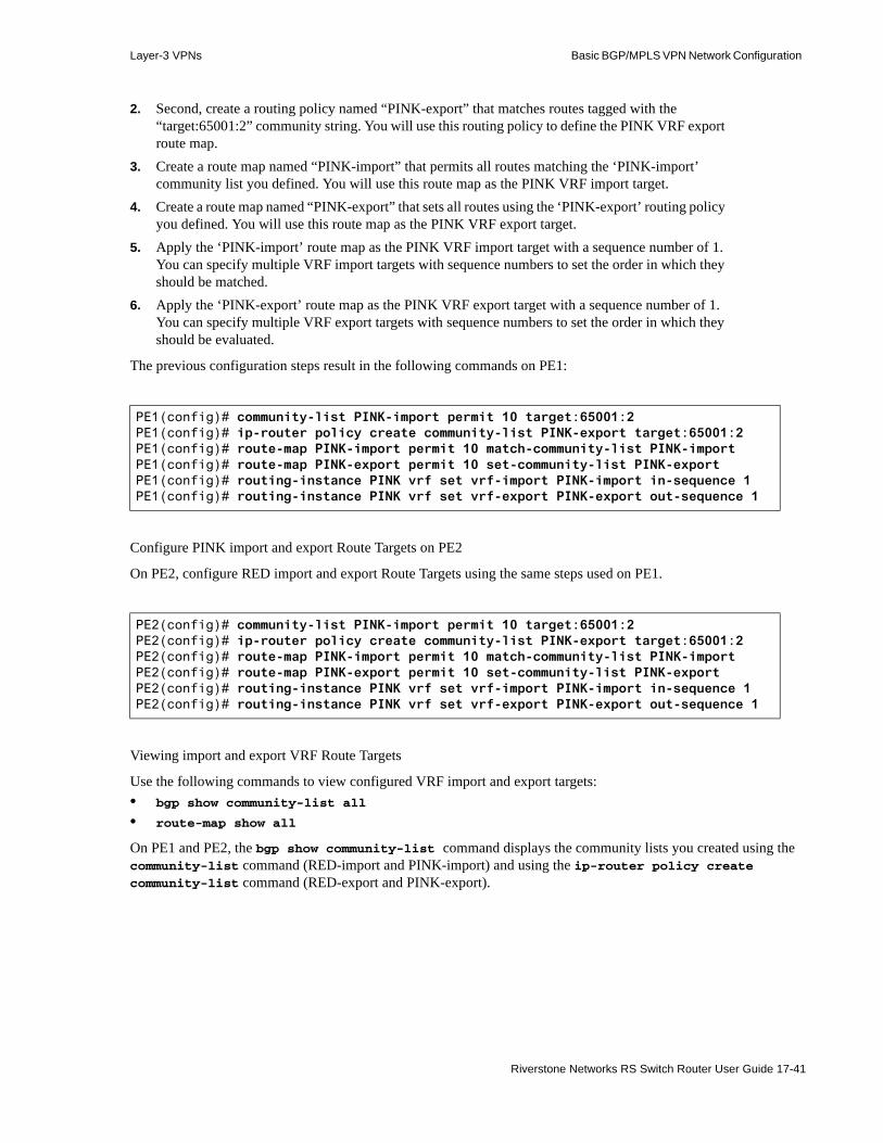
Layer-3 VPNs Basic BGP/MPLS VPN Network Configuration
2. Second, create a routing policy named “PINK-export” that matches routes tagged with the “target:65001:2” community string. You will use this routing policy to define the PINK VRF export route map.
3. Create a route map named “PINK-import” that permits all routes matching the ‘PINK-import’ community list you defined. You will use this route map as the PINK VRF import target.
4. Create a route map named “PINK-export” that sets all routes using the ‘PINK-export’ routing policy you defined. You will use this route map as the PINK VRF export target.
5. Apply the ‘PINK-import’ route map as the PINK VRF import target with a sequence number of 1. You can specify multiple VRF import targets with sequence numbers to set the order in which they should be matched.
6. Apply the ‘PINK-export’ route map as the PINK VRF export target with a sequence number of 1. You can specify multiple VRF export targets with sequence numbers to set the order in which they should be evaluated.
The previous configuration steps result in the following commands on PE1:
Configure PINK import and export Route Targets on PE2
On PE2, configure RED import and export Route Targets using the same steps used on PE1.
Viewing import and export VRF Route Targets
Use the following commands to view configured VRF import and export targets:• bgp show community-list all
• route-map show all
On PE1 and PE2, the bgp show community-list command displays the community lists you created using the community-list command (RED-import and PINK-import) and using the ip-router policy create community-list command (RED-export and PINK-export).
PE1(config)# community-list PINK-import permit 10 target:65001:2PE1(config)# ip-router policy create community-list PINK-export target:65001:2PE1(config)# route-map PINK-import permit 10 match-community-list PINK-importPE1(config)# route-map PINK-export permit 10 set-community-list PINK-exportPE1(config)# routing-instance PINK vrf set vrf-import PINK-import in-sequence 1PE1(config)# routing-instance PINK vrf set vrf-export PINK-export out-sequence 1
PE2(config)# community-list PINK-import permit 10 target:65001:2PE2(config)# ip-router policy create community-list PINK-export target:65001:2PE2(config)# route-map PINK-import permit 10 match-community-list PINK-importPE2(config)# route-map PINK-export permit 10 set-community-list PINK-exportPE2(config)# routing-instance PINK vrf set vrf-import PINK-import in-sequence 1PE2(config)# routing-instance PINK vrf set vrf-export PINK-export out-sequence 1
Riverstone Networks RS Switch Router User Guide 17-41
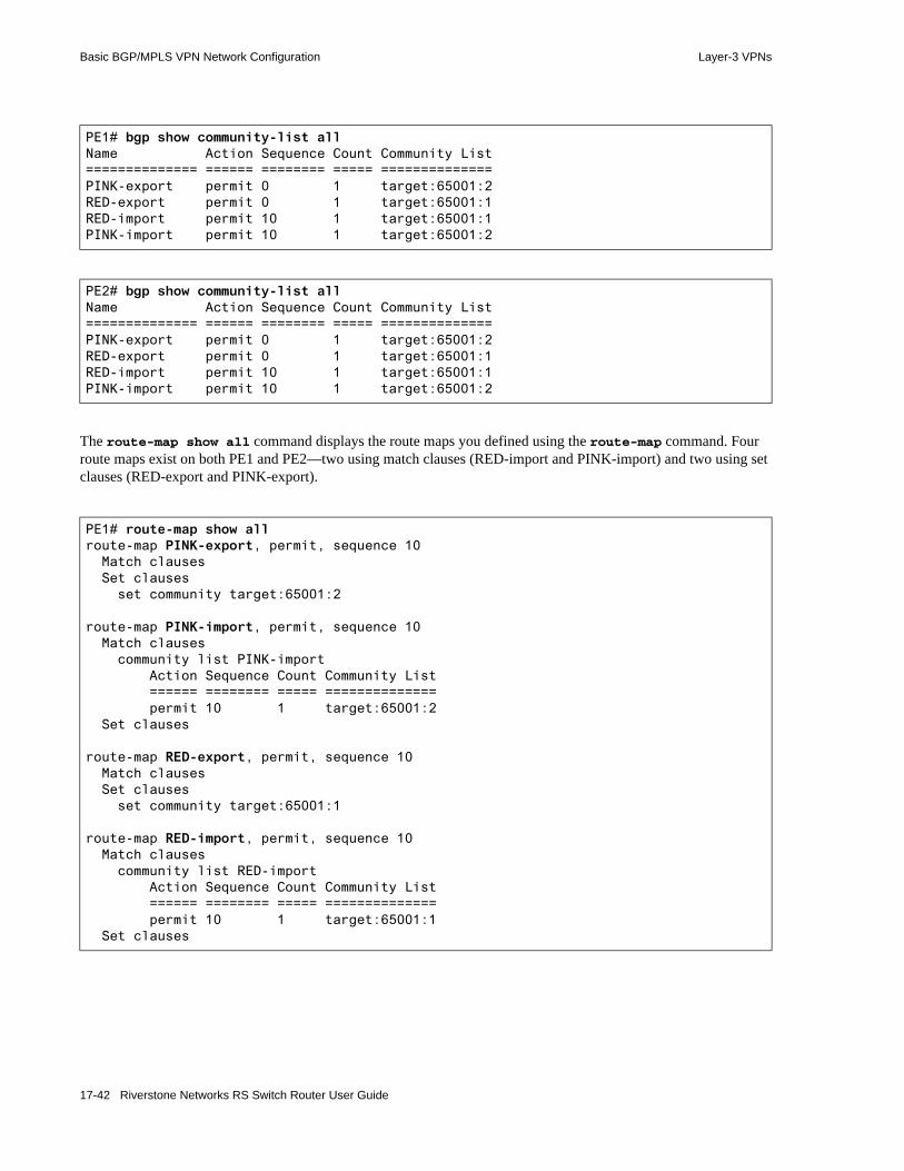
Basic BGP/MPLS VPN Network Configuration Layer-3 VPNs
The route-map show all command displays the route maps you defined using the route-map command. Four route maps exist on both PE1 and PE2—two using match clauses (RED-import and PINK-import) and two using set clauses (RED-export and PINK-export).
PE1# bgp show community-list allName Action Sequence Count Community List============== ====== ======== ===== ==============PINK-export permit 0 1 target:65001:2RED-export permit 0 1 target:65001:1RED-import permit 10 1 target:65001:1PINK-import permit 10 1 target:65001:2
PE2# bgp show community-list allName Action Sequence Count Community List============== ====== ======== ===== ==============PINK-export permit 0 1 target:65001:2RED-export permit 0 1 target:65001:1RED-import permit 10 1 target:65001:1PINK-import permit 10 1 target:65001:2
PE1# route-map show allroute-map PINK-export, permit, sequence 10 Match clauses Set clauses set community target:65001:2
route-map PINK-import, permit, sequence 10 Match clauses community list PINK-import Action Sequence Count Community List ====== ======== ===== ============== permit 10 1 target:65001:2 Set clauses
route-map RED-export, permit, sequence 10 Match clauses Set clauses set community target:65001:1
route-map RED-import, permit, sequence 10 Match clauses community list RED-import Action Sequence Count Community List ====== ======== ===== ============== permit 10 1 target:65001:1 Set clauses
17-42 Riverstone Networks RS Switch Router User Guide

Layer-3 VPNs Basic BGP/MPLS VPN Network Configuration
Viewing VRFs
Use the following commands to view basic VRF configurations:• routing-instance show instance
• routing-instance show interface
On PE1 and PE2, the routing-instance show instance all command displays the type, Route Distinguisher, and associated interface(s) for all configured routing instances. It also displays the import and export policies, as well as any default routes, configured for each routing instance.
PE2# route-map show allroute-map PINK-export, permit, sequence 10 Match clauses Set clauses set community target:65001:2
route-map PINK-import, permit, sequence 10 Match clauses community list PINK-import Action Sequence Count Community List ====== ======== ===== ============== permit 10 1 target:65001:2 Set clauses
route-map RED-export, permit, sequence 10 Match clauses Set clauses set community target:65001:1
route-map RED-import, permit, sequence 10 Match clauses community list RED-import Action Sequence Count Community List ====== ======== ===== ============== permit 10 1 target:65001:1 Set clauses
Riverstone Networks RS Switch Router User Guide 17-43

Basic BGP/MPLS VPN Network Configuration Layer-3 VPNs
PE1# routing-instance show instance all
PINKType : vrfRoute-Distinguisher : 10.1.1.1:2Router-ID : 10.1.1.1Interfaces : ToCE3 lo0vrf-import : PINK-import, sequence 1 permit, sequence 10 Match clauses community list PINK-import Action Sequence Count Community List ====== ======== ===== ============== permit 10 1 target:65001:2 Set clauses
vrf-export : PINK-export, sequence 1 permit, sequence 10 Match clauses Set clauses set community target:65001:2
Default route : not presentDefault route active : 0
REDType : vrfRoute-Distinguisher : 10.1.1.1:1Router-ID : 172.17.1.1Interfaces : ToCE1vrf-import : RED-import, sequence 1 permit, sequence 10 Match clauses community list RED-import Action Sequence Count Community List ====== ======== ===== ============== permit 10 1 target:65001:1 Set clauses
vrf-export : RED-export, sequence 1 permit, sequence 10 Match clauses Set clauses set community target:65001:1
Default route : not presentDefault route active : 0
17-44 Riverstone Networks RS Switch Router User Guide
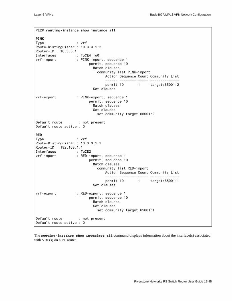
Layer-3 VPNs Basic BGP/MPLS VPN Network Configuration
The routing-instance show interface all command displays information about the interface(s) associated with VRF(s) on a PE router.
PE2# routing-instance show instance all
PINKType : vrfRoute-Distinguisher : 10.3.3.1:2Router-ID : 10.3.3.1Interfaces : ToCE4 lo0vrf-import : PINK-import, sequence 1 permit, sequence 10 Match clauses community list PINK-import Action Sequence Count Community List ====== ======== ===== ============== permit 10 1 target:65001:2 Set clauses
vrf-export : PINK-export, sequence 1 permit, sequence 10 Match clauses Set clauses set community target:65001:2
Default route : not presentDefault route active : 0
REDType : vrfRoute-Distinguisher : 10.3.3.1:1Router-ID : 192.168.1.1Interfaces : ToCE2vrf-import : RED-import, sequence 1 permit, sequence 10 Match clauses community list RED-import Action Sequence Count Community List ====== ======== ===== ============== permit 10 1 target:65001:1 Set clauses
vrf-export : RED-export, sequence 1 permit, sequence 10 Match clauses Set clauses set community target:65001:1
Default route : not presentDefault route active : 0
Riverstone Networks RS Switch Router User Guide 17-45

Basic BGP/MPLS VPN Network Configuration Layer-3 VPNs
Figure 17-7 illustrates the Basic BGP/MPLS VPN Network with the following configured:- IGP (OSPF) in the provider network- MPLS and RSVP in the provider network- MP-IBGP between the PE routers- RED and PINK routing instances on the PE routers
PE1# routing-instance show interface allInterface IP address Routing Instance
ToCE3 172.17.8.1 PINKToCE1 172.17.1.1 RED
PE2# routing-instance show interface allInterface IP address Routing Instance
ToCE4 192.168.8.1 PINKToCE2 192.168.1.1 RED
17-46 Riverstone Networks RS Switch Router User Guide
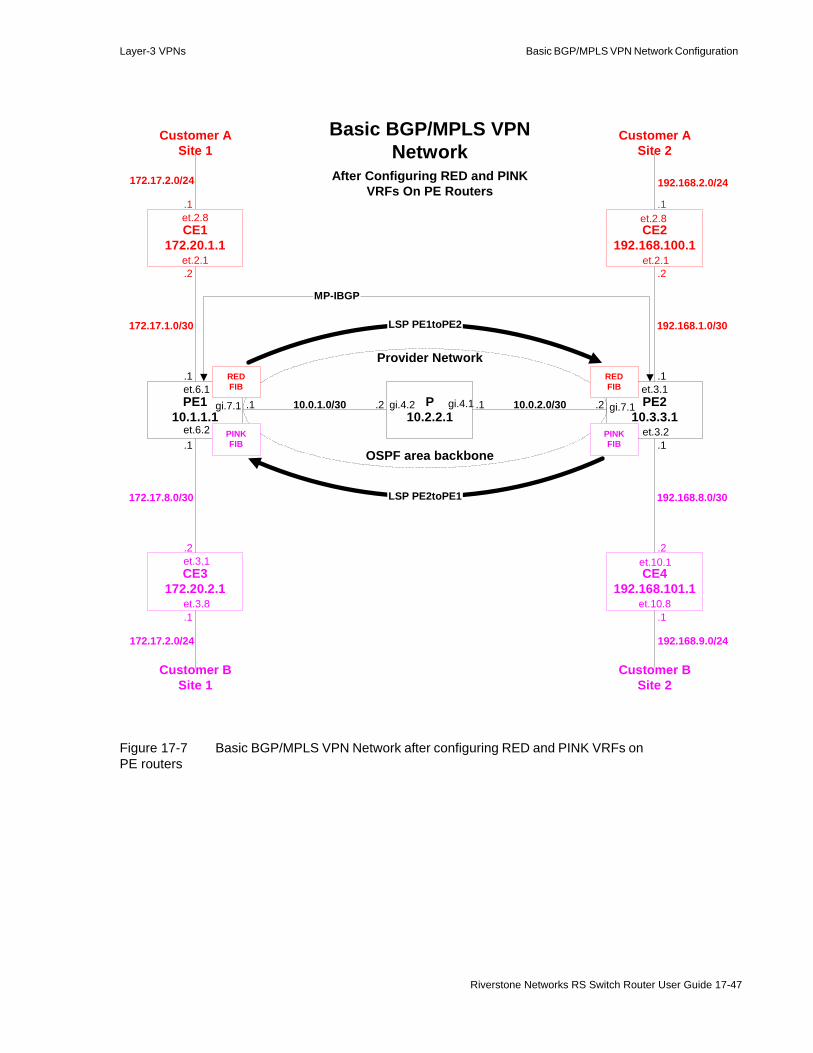
Layer-3 VPNs Basic BGP/MPLS VPN Network Configuration
Figure 17-7 Basic BGP/MPLS VPN Network after configuring RED and PINK VRFs on PE routers
After Configuring RED and PINKVRFs On PE Routers
LSP PE1toPE2
Basic BGP/MPLS VPNNetwork
CE2192.168.100.1
P10.2.2.1
PE210.3.3.1
CE4192.168.101.1
et.10.1
gi.7.1gi.4.2 gi.4.1et.3.1
et.3.2
et.2.1
et.2.8
et.10.8
PE110.1.1.1
CE3172.20.2.1
et.6.2
gi.7.1et.6.1
et.3.1
et.3.8
CE1172.20.1.1
et.2.1
et.2.8
.1
.1
.1
.1
.1
.1
.1
.1.1
.1
.2.2
.2
.2.2
172.17.2.0/24
172.17.2.0/24
10.0.2.0/3010.0.1.0/30 .2
192.168.9.0/24
192.168.2.0/24
Customer ASite 1
Customer ASite 2
Customer BSite 1
Customer BSite 2
Provider Network
OSPF area backbone
LSP PE2toPE1
MP-IBGP
REDFIB
PINKFIB
REDFIB
PINKFIB
192.168.1.0/30
192.168.8.0/30172.17.8.0/30
172.17.1.0/30
Riverstone Networks RS Switch Router User Guide 17-47

Basic BGP/MPLS VPN Network Configuration Layer-3 VPNs
17.4.5 Configuring Static and OSPF Route Distribution Between CE and PE Routers
Before PE routers can forward traffic and announce customer routes, they must first learn those routes from CE routers. The customer and provider network administrators must cooperatively configure CE and PE routers to exchange routes.
In the Basic BGP/MPLS VPN Network (Figure 17-7), • For VPN RED, CE1 and PE1 must exchange routes for the 172.17.2.0/24 network. Likewise, CE2
and PE2 must exchange routes for the 192.168.2.0/24 network.• For VPN PINK, CE3 and PE1 must exchange routes for the 172.17.2.0/24 network. Likewise, CE4
and PE2 must exchange routes for the 192.168.9.0/24 network.
The RS Ethernet Router supports the following routing schemes between CE and PE routers.• Static routes• Open Shortest Path First (OSPF)• Routing Information Protocol (RIP)• Border Gateway Protocol (BGP)
The following sections illustrate how to configure CE-PE route distribution using static routes and OSPF.
For instructions on configuring CE-PE route distribution using RIP and BGP, refer to the Section 17-90 "Configuring RIP and BGP Route Distribution Between CE and PE Routers."
Basic BGP/MPLS VPN Network configuration steps:- IGP in the provider network (included in initial configurations)- MPLS LSPs in the provider network- MP-IBGP between PE routers- RED and PINK routing instances on the PE routers- Configure static and OSPF PE-CE route distribution- Configure Static routing between CE1 and PE1 and CE2 and PE2- Configure OSPF between CE3 and PE1 and CE4 and PE2
17-48 Riverstone Networks RS Switch Router User Guide

Layer-3 VPNs Basic BGP/MPLS VPN Network Configuration
17.4.5.1 Configuring Static Routes Between CE and PE Routers
Configuring Static Routes On CE Routers
To use static routing between CE and PE routers, first configure static routes on the CE router pointing to the PE router. Alternatively, you may configure the CE router to use the PE router as a default gateway. This example configures the CE router to use the PE router as a default gateway. For finer routing control, configure specific static routes on CE routers.
To implement the Basic BGP/MPLS VPN Network (Figure 17-7), static routing is configured between CE1 and PE1 and between CE2 and PE2.
Configure CE1 to route statically with PE1 using a default gateway
The following example configures CE1 to use PE1 as a default gateway.
Configure CE2 to route statically with PE2 using a default gateway
The following example configures CE2 to use PE2 as a default gateway.
Basic BGP/MPLS VPN Network configuration steps:- IGP in the provider network (included in initial configurations)- MPLS LSPs in the provider network- MP-IBGP between PE routers- RED and PINK routing instances on the PE routers- Configure static and OSPF PE-CE route distribution- Configure Static routing between CE1 and PE1 and CE2 and PE2- Configure OSPF between CE3 and PE1 and CE4 and PE2
CE1(config)# ip add route default gateway 172.17.1.1
CE2(config)# ip add route default gateway 192.168.1.1
Riverstone Networks RS Switch Router User Guide 17-49

Basic BGP/MPLS VPN Network Configuration Layer-3 VPNs
Configuring Static Routes On PE Routers
For a PE router to distribute VPN routes to and from CE routers, you must configure it to route within a routing instance. For more information on configuring routing instances, see Section 17.4.4 "Configuring Routing Instances."
In the Basic BGP/MPLS VPN Network (Figure 17-7), there are two VRFs—RED and PINK. On the PE router, each routing instance maintains the routes that it learns and advertises in its own VRF.
Use the routing-instance <name> ip add route command to configure VPN-related static routing on PE routers. This command assumes that you have already created a routing instance identified by <name>.
Within a routing instance, this command functions identically to the ip add route command.
Note Routing instance names are case sensitive.
To implement the Basic BGP/MPLS VPN Network (Figure 17-7), PE1 is configured to route with CE1 statically and PE2 is configured to route with CE2 statically.
Configure PE1 to route statically with CE1
The following example configures the predefined RED routing instance on PE1 to route statically to the Customer A Site 1 network, 172.17.2.0/24, through CE1’s directly-connected interface.
Add CE1’s loopback address, 172.20.1.1, as a static route on PE1 in the RED routing instance to provide CE3 a route to CE1’s loopback address. If this is not desirable, skip this step.
Configure PE2 to route statically with CE2
The following example configures the predefined RED static routing instance on PE2 to route statically to the Customer A Site 2 network, 172.17.2.0/24, through CE1’s directly-connected interface.
Add CE2’s loopback address, 192.168.100.1, as a static route on PE2 in the RED routing instance to provide CE1 a route to CE2’s loopback address. If this is not desirable, skip this step.
PE1(config)# routing-instance RED ip add route 172.17.2.0/24 gateway 172.17.1.2
PE1(config)# routing-instance RED ip add route 172.20.1.1/32 gateway 172.17.1.2
PE2(config)# routing-instance RED ip add route 192.168.2.0/24 gateway 192.168.1.2
PE2(config)# routing-instance RED ip add route 192.168.100.1/32 gateway 192.168.1.2
17-50 Riverstone Networks RS Switch Router User Guide

Layer-3 VPNs Basic BGP/MPLS VPN Network Configuration
17.4.5.2 Configuring OSPF Between CE and PE Routers
For additional details on the implementation mechanisms of this feature, refer to the IETF draft OSPF as the PE/CE Protocol in BGP/MPLS VPNs by Rosen and Psenak. (The RS Ethernet Router does not support the sham links described in section 4.2.3 of the draft.)
Configuring OSPF On CE Routers
To run OSPF between CE and PE routers, you must first configure OSPF on CE routers. CE routers need not be BGP/MPLS VPN-capable and do not need to be configured with multiple routing instances. Configure them as you would any non-BGP/MPLS VPN-capable router. For more information on configuring OSPF, seeChapter 13, "OSPF Configuration Guide."
To implement the Basic BGP/MPLS VPN Network (Figure 17-7), PE1 is configured to route with CE3 using OSPF and PE2 is configured to route with CE4 using OSPF.
Configure CE3 to route with PE1 and CE4 to route with PE2 using OSPF1. Create the backbone area on both CE routers.
Note You do not have to use the backbone area. You may configure any OSPF area between CE and PE routers.
2. Add each CE router’s loopback interface and any other interfaces that should participate in OSPF with the PE router to the backbone area. Adding interfaces to an area distributes the networks configured on those interface into that area through OSPF. For example, adding the loopback interface allows each CE router to learn the other CE router’s loopback address through PE-CE route distribution. Adding a customer site-facing interface distributes OSPF routes learned on that interface to the PE router and remote CE router. If you do not want particular networks to be exchanged with remote sites, do not add the associated interfaces into OSPF.- On CE3, add the loopback interface, 172.20.2.1, and two other interfaces: ToCustomerBSite1
and ToPE1- On CE4, add the loopback interface, 192.168.101.1, and two other interfaces:
ToCustomerBSite2 and ToPE23. Start OSPF.
The previous configuration steps result in the following commands on CE3:
Basic BGP/MPLS VPN Network configuration steps:- IGP in the provider network (included in initial configurations)- MPLS LSPs in the provider network- MP-IBGP between PE routers- RED and PINK routing instances on the PE routers- Configure static and OSPF PE-CE route distribution- Configure Static routing between CE1 and PE1 and CE2 and PE2- Configure OSPF between CE3 and PE1 and CE4 and PE2
Riverstone Networks RS Switch Router User Guide 17-51

Basic BGP/MPLS VPN Network Configuration Layer-3 VPNs
The previous configuration steps result in the following commands on CE4:
CE3(config)# ospf create area backboneCE3(config)# ospf add stub-host 172.20.2.1 to-area backbone cost 1CE3(config)# ospf add interface ToCustomerBSite1 to-area backboneCE3(config)# ospf add interface ToPE1 to-area backboneCE3(config)# ospf start
CE4(config)# ospf create area backboneCE4(config)# ospf add stub-host 192.168.101.1 to-area backbone cost 1CE4(config)# ospf add interface ToCustomerBSite2 to-area backboneCE4(config)# ospf add interface ToPE2 to-area backboneCE4(config)# ospf start
17-52 Riverstone Networks RS Switch Router User Guide

Layer-3 VPNs Basic BGP/MPLS VPN Network Configuration
Configuring OSPF On PE Routers
PE Router OSPF Routing Instance Usage Guidelines
For a PE router to distribute VPN routes to and from CE routers, you must configure it to route within a VRF routing instance. For more information on configuring routing instances, see Section 17.4.4 "Configuring Routing Instances."
The Basic BGP/MPLS VPN network (Figure 17-7) contains two VRFs—RED and PINK. On the PE router, each routing instance maintains the routes that it learns and advertises in its own VRF.
After a PE router learns a route, it distributes that route to other PE routers as a VPN-IPv4 route using MP-BGP. (For more information on VPN-IPv4 addresses, see the Section 17.4.4.2 "Configuring Route Distinguishers and VPN-IPv4 Addresses." For more information on MP-BGP, see Section 17.4.3 "Configuring MP-BGP Between PE Routers for Customer Route Distribution.") The RS Ethernet Router supports multiple OSPF domains within one VPN. In order for a PE router receiving a route to correctly import that route into a particular VRF, it must be able to tell whether the route comes from the same OSPF domain and area as the CE routers to which it is attached.
To accomplish this, PE routers use the user-specified OSPF Domain Identifier. The Domain Identifier is a 4-byte value specified in IP address format. It is encoded as an Extended Community Attribute in VPN-IPv4 routes, which are distributed across the PE backbone in MP-BGP advertisements. Each OSPF domain is associated with a Domain Identifier. When not specified in the configuration, the Domain Identifier is set to 0.0.0.0 by default and not carried with the VPN-IPv4 route.
Note You must ensure that all the VRFs which correspond to the same OSPF domain share the same Domain Identifier. You can either configure them to be the same or elect to use the default Domain Identifier.
Assign unique non-zero Domain Identifiers to avoid importing routes from different OSPF domains into the same VRF.
When a PE router sends OSPF routes to other PE routers, it sends them as BGP VPN-IPv4 routes. To preserve the OSPF attributes of those routes, PE routers encode them as BGP Extended Community Attributes in the VPN-IPv4 routing advertisements. The Domain Identifier is one such attribute. The RS Ethernet Router supports both current and older encoding schemes. For interoperability purposes, select the appropriate encoding scheme using the routing-instance ospf set extended-community command.
The following is a summary of OSPF attributes and their Extended Community encoding:
This encoding ensures that OSPF routes can be converted to BGP, distributed across the provider backbone, and converted back to OSPF transparently, as if BGP is not involved.
OSPF Route Attribute Encoded As
Domain Identifier BGP Extended Community Attribute
LSA Type OSPF-Route-Type Extended Community Attribute
OSPF Router ID (of the system identified in the BGP next hop for this route)
OSPF-Router-ID Extended Community Attribute
Riverstone Networks RS Switch Router User Guide 17-53

Basic BGP/MPLS VPN Network Configuration Layer-3 VPNs
After a PE router learns a remote-site route from its PE peer, it distributes that route to its CE routers according to the policies that you configure. These policies enforce the customer connectivity scheme. (For more information on configuring import and export Route Targets, see the Section 17.4.4.4 "Configuring VRF Import and Export Policies.") PE routers also respect the following rules when processing and announcing OSPF remote-site routes to customers:• Routes originating from a different OSPF domain or from outside of the OSPF protocol
- PE routers announce all routes received from a remote site belonging to a different OSPF domain or learned from a different protocol to directly-connected CE routers as Type-5 LSAs.
- In this situation, the ingress PE router acts as an Autonomous System Border Router (ASBR) and sets the VPN Route Tag of these routes to a user-defined value that indicates the customer site’s VPN. Setting the VPN Route Tag ensures that these Type-5 LSAs are not redistributed through the OSPF area to another PE router, possibly creating a loop within the same VPN.
- It follows from the above that a PE router ignores received Type-5 LSAs with a VPN Route Tag set to the value you define for its customer site’s VPN.
When not specified in the configuration, the PE router sets the VPN Route Tag automatically to a value based on the autonomous system to which it belongs.
Note When setting the VPN Route Tag manually, you must ensure that it is set to a distinct value for each OSPF domain.
• Routes originating from the same OSPF domain- Within the same OSPF domain, PE routers announce routes received as Type-5 LSAs as Type-5
LSAs and all others as Type-3 LSAs.- The IETF draft states that “[w]hen the PE/CE link is an area 0 link, the high-order bit of the LSA
Options field (previously unused) is used to distinguish type 3 LSAs which report routes across the VPN backbone from other VPN sites.” This is the DN bit. A PE router sets this bit when sending a Type-3 LSA to a CE router across an area 0 link.
- It follows from the above that PE routers ignore routes received as Type-3 LSAs from CE routers which have the DN bit set. This mechanism prevents routes sent to a CE router by a PE router from being flooded through several OSPF routers and then sent to another PE router, thus avoiding a loop.
Otherwise, PE routers process remote-site routes in normal OSPF fashion and follow user-set policies in distributing routes to OSPF instances.
You can configure any OSPF area for the CE-PE link. However, as the IETF drafts states, every PE router running an OSPF routing instance must also be an area 0 router and an ABR.
17-54 Riverstone Networks RS Switch Router User Guide

Layer-3 VPNs Basic BGP/MPLS VPN Network Configuration
Note Regardless of what OSPF area is configured for a PE-CE link, every RS Ethernet Router that acts as a PE router in a CE-PE adjacency must have area 0 configured and active in that routing instance. Being active means that an area must have at least one interface added. The loopback interface can be added to area 0 as a stub host for this purpose.
Being an area 0 router and an ABR allows the PE router to distribute inter-area routes to the CE router as Type-3 LSAs. (In OSPF, all traditional ABRs must be attached to area 0. Only ABRs can generate Type-3 LSAs.) The CE router might or might not be an area 0 router, and the PE-CE link might or might not be an area 0 link.
The IETF draft further states “[i]f the OSPF network contains area 0 routers (other than the PE routers), at least one PE router must have an area 0 link to a non-PE area 0 router in that OSPF network. (The non-PE area 0 router functions as a CE router.) This ensures that inter-area routes and AS-external routes can be leaked between the PE routers and the non-PE OSPF backbone.
To configure OSPF routing instances on PE routers, use the routing-instance <name> ospf... series of commands. These commands assume that you have already created a routing instance identified by <name>. For more information on configuring routing instances, see Section 17.4.4 "Configuring Routing Instances."
Within a routing instance, these commands function identically to their non-routing instance counterparts. For more information on configuring OSPF, seeChapter 13, "OSPF Configuration Guide."
Note Routing instance names are case sensitive.
To implement the Basic BGP/MPLS VPN Network (Figure 17-7), PE1 is configured to route with CE3 using OSPF and PE2 is configured to route with CE4 using OSPF.
Configure PE1 to route with CE3 and PE2 to route with CE4 using OSPF1. Create the backbone area on both PE routers in routing-instance PINK.2. Add each PE router’s loopback interface and any other interfaces that should participate in OSPF
with the CE router to the backbone area. - On PE1, add the loopback interface, 10.1.1.1, and one other interface—ToCE3.- On PE2, add the loopback interface, 10.3.3.1, and one other interface—ToCE4.
3. Set the Domain Identifier for this OSPF domain to 0.0.0.0. When not specified in the configuration, all domains are assigned a Domain Identifier of 0.0.0.0 by default. Assign the same Domain Identifier to the links between PE1 and CE3 and between PE2 and CE4 because Customer B Site 1 and Site 2 are in the same VPN.
4. Set the VPN Route Tag for this customer to an arbitrary value, ‘1001’. The VPN Route Tag must be unique for each OSPF domain.
5. Specify which routes the PE router should learn for this VRF using a route map. The example specifies that all BGP routes should be learned. In practice, you should limit the set of routes advertised using route maps.
Riverstone Networks RS Switch Router User Guide 17-55

Basic BGP/MPLS VPN Network Configuration Layer-3 VPNs
6. Start OSPF.
The previous configuration steps result in the following commands on PE1:
The previous configuration steps result in the following commands on PE2:
Viewing OSPF adjacencies between CE and PE routers
Use the following commands to view OSPF adjacencies between CE and PE routers• ospf show neighbor [instance]
• ospf show interfaces [instance]
• ospf show database [instance]
To view interface-related information on the PE-CE OSPF adjacency, use these commands without the instance options on CE routers and with the instance option on PE routers.
On CE3 and CE4, the ospf show neighbor command displays information about the OSPF adjacency such as the adjacency area and neighboring router. On PE1 and PE2, the ospf show neighbor instance PINK command displays identical information about the PINK OSPF routing instance. The following output show that CE3 and PE1 recognize each other as full neighbors. CE4 and PE2 are also in a full adjacency. When troubleshooting OSPF adjacencies, watch for the State to be Full in this command output.
PE1(config)# routing-instance PINK ospf create area backbonePE1(config)# routing-instance PINK ospf add stub-host 10.1.1.1 to-area backbone
cost 1PE1(config)# routing-instance PINK ospf add interface ToCE3 to-area backbonePE1(config)# routing-instance PINK ospf set domain-id 0.0.0.0PE1(config)# routing-instance PINK ospf set vpn-route-tag 1001PE1(config)# route-map BGPROUTES permit 1 match-route-type bgpPE1(config)# routing-instance PINK ospf set route-map-vpn BGPROUTESPE1(config)# routing-instance PINK ospf start
PE2(config)# routing-instance PINK ospf create area backbonePE2(config)# routing-instance PINK ospf add stub-host 10.3.3.1 to-area backbone
cost 1PE2(config)# routing-instance PINK ospf add interface ToCE4 to-area backbonePE2(config)# routing-instance PINK ospf set domain-id 0.0.0.0PE2(config)# routing-instance PINK ospf set vpn-route-tag 1001PE2(config)# route-map BGPROUTES permit 1 match-route-type bgpPE2(config)# routing-instance PINK ospf set route-map-vpn BGPROUTESPE2(config)# routing-instance PINK ospf start
CE3# ospf show neighborNeighbor 10.1.1.1, interface address 172.17.8.1 [mem: 82bc2000] In the area 0.0.0.0 via interface address 172.17.8.2 Neighbor priority is 1, State is Full Options 1 Dead timer due in 12:35:54 Hitless Helper: not active
17-56 Riverstone Networks RS Switch Router User Guide

Layer-3 VPNs Basic BGP/MPLS VPN Network Configuration
The ospf show interfaces command displays the interfaces that are participating in OSPF, with the exception of the loopback interface. Routes for directly-attached networks on these interfaces are distributed into OSPF. This command also displays the number of neighbors, designated router (DR), and backup designated router (BDR) for each network segment.
PE1# ospf show neighbor instance PINKNeighbor 172.20.2.1, interface address 172.17.8.2 [mem: 82be8000] In the area 0.0.0.0 via interface address 172.17.8.1 Neighbor priority is 1, State is Full Options 0 Dead timer due in 11:56:20 Hitless Helper: not active
CE4# ospf show neighborNeighbor 10.3.3.1, interface address 192.168.8.1 [mem: 82bce000] In the area 0.0.0.0 via interface address 192.168.8.2 Neighbor priority is 1, State is Full Options 1 Dead timer due in 13:54:45 Hitless Helper: not active
PE2# ospf show neighbor instance PINKNeighbor 192.168.101.1, interface address 192.168.8.2 [mem: 82bc6800] In the area 0.0.0.0 via interface address 192.168.8.1 Neighbor priority is 1, State is Full Options 0 Dead timer due in 12:46:10 Hitless Helper: not active
CE3# ospf show interfacesInternet Address 172.17.8.2/30, Area 0.0.0.0 Router ID 172.20.2.1, Network Type Broadcast, Cost: 20 Transmit Delay is 1 sec, State DR, Priority 1 Designated Router (ID) 172.20.2.1, Interface address 172.17.8.2 Backup Designated Router 10.1.1.1 Timer intervals configured, Hello 10, Dead 40, Wait 40, Retransmit 5 Hello due in 12:11:53 Neighbor Count is 1 Authentication not enabled Hitless Helper Mode is disabled
Internet Address 172.17.2.1/24, Area 0.0.0.0 Router ID 172.20.2.1, Network Type Broadcast, Cost: 20 Transmit Delay is 1 sec, State DR, Priority 1 Designated Router (ID) 172.20.2.1, Interface address 172.17.2.1 No backup designated router on this network Timer intervals configured, Hello 10, Dead 40, Wait 40, Retransmit 5 Hello due in 12:11:53 Neighbor Count is 0 Authentication not enabled Hitless Helper Mode is disabled
Riverstone Networks RS Switch Router User Guide 17-57

Basic BGP/MPLS VPN Network Configuration Layer-3 VPNs
PE1# ospf show interfaces instance PINKInternet Address 172.17.8.1/30, Area 0.0.0.0 Router ID 10.1.1.1, Network Type Broadcast, Cost: 20 Transmit Delay is 1 sec, State Back DR, Priority 1 Designated Router (ID) 172.20.2.1, Interface address 172.17.8.1 Backup Designated Router 10.1.1.1 Timer intervals configured, Hello 10, Dead 40, Wait 40, Retransmit 5 Hello due in 13:16:27 Neighbor Count is 1 Authentication not enabled Hitless Helper Mode is disabled
17-58 Riverstone Networks RS Switch Router User Guide

Layer-3 VPNs Basic BGP/MPLS VPN Network Configuration
The ospf show database command displays the OSPF link-state database. Note that on both sides of the VPN, the remote PE-CE network is distributed as an AS external route. Although the PE router has an OSPF route to this network, it advertises the network as directly-connected, which becomes AS external when received by the remote PE.
CE4# ospf show interfacesInternet Address 192.168.8.2/30, Area 0.0.0.0 Router ID 192.168.101.1, Network Type Broadcast, Cost: 20 Transmit Delay is 1 sec, State DR, Priority 1 Designated Router (ID) 192.168.101.1, Interface address 192.168.8.2 Backup Designated Router 10.3.3.1 Timer intervals configured, Hello 10, Dead 40, Wait 40, Retransmit 5 Hello due in 13:26:34 Neighbor Count is 1 Authentication not enabled Hitless Helper Mode is disabled
Internet Address 192.168.9.1/24, Area 0.0.0.0 Router ID 192.168.101.1, Network Type Broadcast, Cost: 20 Transmit Delay is 1 sec, State DR, Priority 1 Designated Router (ID) 192.168.101.1, Interface address 192.168.9.1 No backup designated router on this network Timer intervals configured, Hello 10, Dead 40, Wait 40, Retransmit 5 Hello due in 13:26:34 Neighbor Count is 0 Authentication not enabled Hitless Helper Mode is disabled
PE2# ospf show interfaces instance PINKInternet Address 192.168.8.1/30, Area 0.0.0.0 Router ID 10.3.3.1, Network Type Broadcast, Cost: 20 Transmit Delay is 1 sec, State Back DR, Priority 1 Designated Router (ID) 192.168.101.1, Interface address 192.168.8.1 Backup Designated Router 10.3.3.1 Timer intervals configured, Hello 10, Dead 40, Wait 40, Retransmit 5 Hello due in 12:26:54 Neighbor Count is 1 Authentication not enabled Hitless Helper Mode is disabled
Riverstone Networks RS Switch Router User Guide 17-59

Basic BGP/MPLS VPN Network Configuration Layer-3 VPNs
CE3# ospf show database OSPF Router with ID (172.20.2.1)
ROUTER LSA Router Link States (Area: 0.0.0.0)
Link ID ADV Router Age Seq# Checksum Cost---------------------------------------------------------------10.1.1.1 10.1.1.1 1301 800004c4 5f4f 20
172.20.2.1 172.20.2.1 1325 800003dd c7c8 0
NETWORK LSA Net Link States (Area: 0.0.0.0)
Link ID ADV Router Age Seq# Checksum Cost---------------------------------------------------------------172.17.8.2 172.20.2.1 1325 8000002e 5b78 20
SUMMARY LSA Summary Net Link States (Area: 0.0.0.0)
Link ID ADV Router Age Seq# Checksum Cost---------------------------------------------------------------192.168.9 10.1.1.1 1361 8000002d 2a5e 41
192.168.101.1 10.1.1.1 1361 8000002d 69d4 22
ASBR SUMMARY LSA
NSSA EXTERNAL LSA
LINK OPQ LSA
AREA OPQ LSA
AS OPQ LSA
AS External Link StatesLink ID ADV Router Age Seq# Checksum Cost---------------------------------------------------------------192.168.8 10.1.1.1 1361 8000002d 921 1
17-60 Riverstone Networks RS Switch Router User Guide
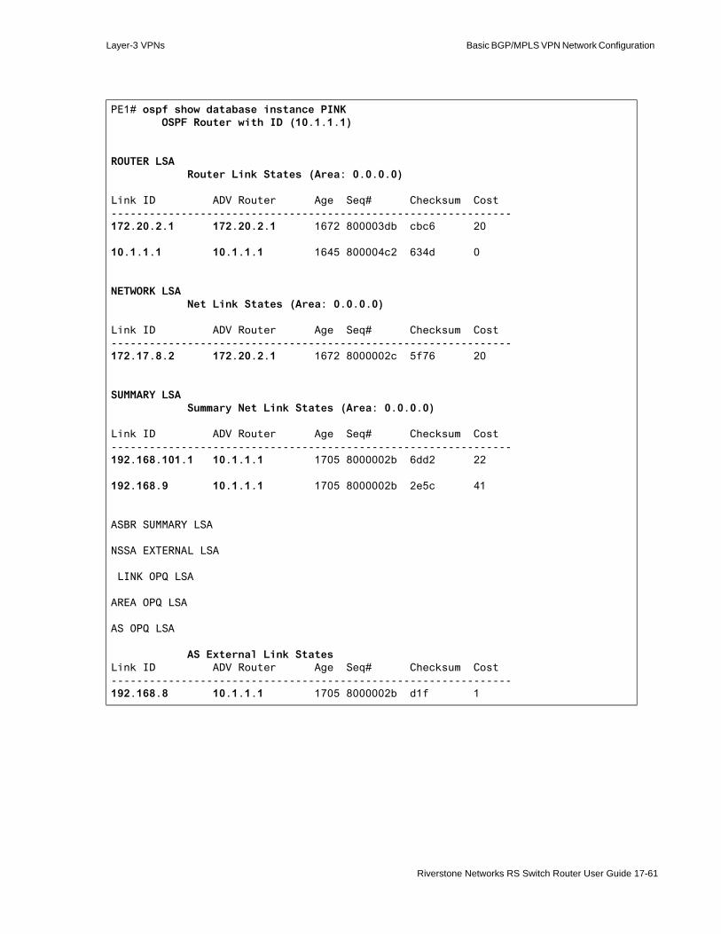
Layer-3 VPNs Basic BGP/MPLS VPN Network Configuration
PE1# ospf show database instance PINK OSPF Router with ID (10.1.1.1)
ROUTER LSA Router Link States (Area: 0.0.0.0)
Link ID ADV Router Age Seq# Checksum Cost---------------------------------------------------------------172.20.2.1 172.20.2.1 1672 800003db cbc6 20
10.1.1.1 10.1.1.1 1645 800004c2 634d 0
NETWORK LSA Net Link States (Area: 0.0.0.0)
Link ID ADV Router Age Seq# Checksum Cost---------------------------------------------------------------172.17.8.2 172.20.2.1 1672 8000002c 5f76 20
SUMMARY LSA Summary Net Link States (Area: 0.0.0.0)
Link ID ADV Router Age Seq# Checksum Cost---------------------------------------------------------------192.168.101.1 10.1.1.1 1705 8000002b 6dd2 22
192.168.9 10.1.1.1 1705 8000002b 2e5c 41
ASBR SUMMARY LSA
NSSA EXTERNAL LSA
LINK OPQ LSA
AREA OPQ LSA
AS OPQ LSA
AS External Link StatesLink ID ADV Router Age Seq# Checksum Cost---------------------------------------------------------------192.168.8 10.1.1.1 1705 8000002b d1f 1
Riverstone Networks RS Switch Router User Guide 17-61

Basic BGP/MPLS VPN Network Configuration Layer-3 VPNs
CE4# ospf show database OSPF Router with ID (192.168.101.1)
ROUTER LSA Router Link States (Area: 0.0.0.0)
Link ID ADV Router Age Seq# Checksum Cost---------------------------------------------------------------10.3.3.1 10.3.3.1 200 80000032 d70a 20
192.168.101.1 192.168.101.1 180 80000033 ce41 0
NETWORK LSA Net Link States (Area: 0.0.0.0)
Link ID ADV Router Age Seq# Checksum Cost---------------------------------------------------------------192.168.8.2 192.168.101.1 180 80000031 603 20
SUMMARY LSA Summary Net Link States (Area: 0.0.0.0)
Link ID ADV Router Age Seq# Checksum Cost---------------------------------------------------------------172.17.2 10.3.3.1 1700 8000002d 79bd 41
172.20.2.1 10.3.3.1 1700 8000002d 8cb9 22
ASBR SUMMARY LSA
NSSA EXTERNAL LSA
LINK OPQ LSA
AREA OPQ LSA
AS OPQ LSA
AS External Link StatesLink ID ADV Router Age Seq# Checksum Cost---------------------------------------------------------------172.17.8 10.3.3.1 1700 8000002d bc6 1
17-62 Riverstone Networks RS Switch Router User Guide

Layer-3 VPNs Basic BGP/MPLS VPN Network Configuration
PE2# ospf show database instance PINK OSPF Router with ID (10.3.3.1)
ROUTER LSA Router Link States (Area: 0.0.0.0)
Link ID ADV Router Age Seq# Checksum Cost---------------------------------------------------------------192.168.101.1 192.168.101.1 411 80000033 ce41 20
10.3.3.1 10.3.3.1 429 80000032 d70a 0
NETWORK LSA Net Link States (Area: 0.0.0.0)
Link ID ADV Router Age Seq# Checksum Cost---------------------------------------------------------------192.168.8.2 192.168.101.1 411 80000031 603 20
SUMMARY LSA Summary Net Link States (Area: 0.0.0.0)
Link ID ADV Router Age Seq# Checksum Cost---------------------------------------------------------------172.20.2.1 10.3.3.1 69 8000002e 8aba 22
172.17.2 10.3.3.1 69 8000002e 77be 41
ASBR SUMMARY LSA
NSSA EXTERNAL LSA
LINK OPQ LSA
AREA OPQ LSA
AS OPQ LSA
AS External Link StatesLink ID ADV Router Age Seq# Checksum Cost---------------------------------------------------------------172.17.8 10.3.3.1 69 8000002e 9c7 1
Riverstone Networks RS Switch Router User Guide 17-63

Basic BGP/MPLS VPN Network Operation Layer-3 VPNs
17.5 BASIC BGP/MPLS VPN NETWORK OPERATIONFigure 17-8 illustrates the completed Basic BGP/MPLS VPN Network. It contains the following configurations:
- IGP in the provider network (included in initial configurations)- MPLS LSPs in the provider network- MP-IBGP between PE routers- RED and PINK routing instances on the PE routers- Route Distinguisher and routing instance created- Interface(s) added to routing instances- Import and export routing policies (Route Targets) for routing instances- Static and OSPF PE-CE route distribution- Static routing between CE1 and PE1 and CE2 and PE2- OSPF between CE3 and PE1 and CE4 and PE2
17-64 Riverstone Networks RS Switch Router User Guide

Layer-3 VPNs Basic BGP/MPLS VPN Network Operation
Figure 17-8 Complete Basic BGP/MPLS VPN Network
17.5.1 Routing Exchange
In BGP/MPLS VPNs, PE routers exchange customer routes through MP-BGP. You can monitor this routing exchange using the bgp show peer-host series of commands.
The following display output shows that on PE1 and PE2, MP-IBGP is not advertising any global routes.
After Configuring RED and PINKVRFs On PE Routers
LSP PE1toPE2
Basic BGP/MPLS VPNNetwork
CE2192.168.100.1
P10.2.2.1
PE210.3.3.1
CE4192.168.101.1
et.10.1
gi.7.1gi.4.2 gi.4.1et.3.1
et.3.2
et.2.1
et.2.8
et.10.8
PE110.1.1.1
CE3172.20.2.1
et.6.2
gi.7.1et.6.1
et.3.1
et.3.8
CE1172.20.1.1
et.2.1
et.2.8
.1
.1
.1
.1
.1
.1
.1
.1.1
.1
.2.2
.2
.2.2
172.17.2.0/24
172.17.2.0/24
10.0.2.0/3010.0.1.0/30 .2
192.168.9.0/24
192.168.2.0/24
Customer ASite 1
Customer ASite 2
Customer BSite 1
Customer BSite 2
Provider Network
OSPF area backbone
LSP PE2toPE1
MP-IBGP
REDFIB
PINKFIB
REDFIB
PINKFIB
StaticR
outing
StaticR
outing
OSPF
OSPF
RED Routing Exchange
PINK Routing Exchange
192.168.1.0/30172.17.1.0/30
172.17.8.0/30 192.168.8.0/30
Riverstone Networks RS Switch Router User Guide 17-65

Basic BGP/MPLS VPN Network Operation Layer-3 VPNs
However, MP-IBGP is advertising routes for each routing instance. PE1 is advertising routes learned from CE1 through the RED routing instance to PE2. The example output shows that PE2 receives these routes.
PE1# bgp show peer-host 10.3.3.1 advertised-routesLocal router ID is 10.1.1.1Status codes: > - best, * - valid, i - internal, t - stale s - suppressed, d - dampedOrigin codes: i - IGP, e - EGP, ? - incomplete
Network Next Hop Metric LocPrf Label Path ------- -------- ------ ------ ----------- ----
PE2# bgp show peer-host 10.1.1.1 advertised-routesLocal router ID is 10.3.3.1Status codes: > - best, * - valid, i - internal, t - stale s - suppressed, d - dampedOrigin codes: i - IGP, e - EGP, ? - incomplete
Network Next Hop Metric LocPrf Label Path ------- -------- ------ ------ ----------- ----
PE1# bgp show peer-host 10.3.3.1 instance RED advertised-routesLocal router ID is 10.1.1.1Status codes: > - best, * - valid, i - internal, t - stale s - suppressed, d - dampedOrigin codes: i - IGP, e - EGP, ? - incomplete
Network Next Hop Metric LocPrf Label Path ------- -------- ------ ------ ----------- ----*> i172.17.1/30 172.17.1.1 1 100 17 i*> i172.17.2/24 10.1.1.1 100 19 ?*> i172.20.1.1/32 10.1.1.1 100 19 ?
PE2# bgp show peer-host 10.1.1.1 instance RED all-received-routesLocal router ID is 10.3.3.1Status codes: > - best, * - valid, i - internal, t - stale s - suppressed, d - dampedOrigin codes: i - IGP, e - EGP, ? - incomplete
Network Next Hop Metric LocPrf Label Path ------- -------- ------ ------ ----------- ----*> i172.17.1/30 10.1.1.1 100 17 i*> i172.17.2/24 10.1.1.1 100 19 ?*> i172.20.1.1/32 10.1.1.1 100 19 ?
17-66 Riverstone Networks RS Switch Router User Guide
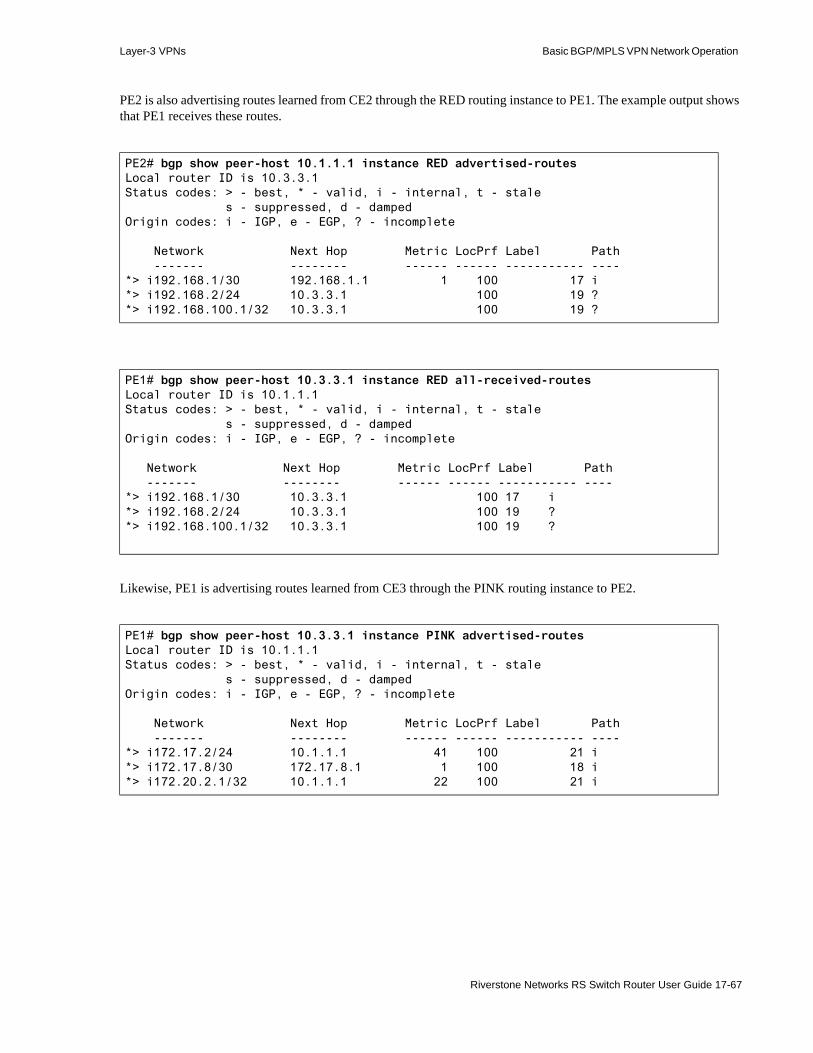
Layer-3 VPNs Basic BGP/MPLS VPN Network Operation
PE2 is also advertising routes learned from CE2 through the RED routing instance to PE1. The example output shows that PE1 receives these routes.
Likewise, PE1 is advertising routes learned from CE3 through the PINK routing instance to PE2.
PE2# bgp show peer-host 10.1.1.1 instance RED advertised-routesLocal router ID is 10.3.3.1Status codes: > - best, * - valid, i - internal, t - stale s - suppressed, d - dampedOrigin codes: i - IGP, e - EGP, ? - incomplete
Network Next Hop Metric LocPrf Label Path ------- -------- ------ ------ ----------- ----*> i192.168.1/30 192.168.1.1 1 100 17 i*> i192.168.2/24 10.3.3.1 100 19 ?*> i192.168.100.1/32 10.3.3.1 100 19 ?
PE1# bgp show peer-host 10.3.3.1 instance RED all-received-routesLocal router ID is 10.1.1.1Status codes: > - best, * - valid, i - internal, t - stale s - suppressed, d - dampedOrigin codes: i - IGP, e - EGP, ? - incomplete
Network Next Hop Metric LocPrf Label Path ------- -------- ------ ------ ----------- ----*> i192.168.1/30 10.3.3.1 100 17 i*> i192.168.2/24 10.3.3.1 100 19 ?*> i192.168.100.1/32 10.3.3.1 100 19 ?
PE1# bgp show peer-host 10.3.3.1 instance PINK advertised-routesLocal router ID is 10.1.1.1Status codes: > - best, * - valid, i - internal, t - stale s - suppressed, d - dampedOrigin codes: i - IGP, e - EGP, ? - incomplete
Network Next Hop Metric LocPrf Label Path ------- -------- ------ ------ ----------- ----*> i172.17.2/24 10.1.1.1 41 100 21 i*> i172.17.8/30 172.17.8.1 1 100 18 i*> i172.20.2.1/32 10.1.1.1 22 100 21 i
Riverstone Networks RS Switch Router User Guide 17-67

Basic BGP/MPLS VPN Network Operation Layer-3 VPNs
PE2 is advertising routes learned from CE4 through the PINK routing instance to PE1.
You can also view all of the VRF routes being advertised or received by MP-BGP by specifying the all option in the bgp show peer-host instance command.
PE2# bgp show peer-host 10.1.1.1 instance PINK all-received-routesLocal router ID is 10.3.3.1Status codes: > - best, * - valid, i - internal, t - stale s - suppressed, d - dampedOrigin codes: i - IGP, e - EGP, ? - incomplete
Network Next Hop Metric LocPrf Label Path ------- -------- ------ ------ ----------- ----*> i172.17.2/24 10.1.1.1 41 100 21 i*> i172.17.8/30 10.1.1.1 100 18 i*> i172.20.2.1/32 10.1.1.1 22 100 21 i
PE2# bgp show peer-host 10.1.1.1 instance PINK advertised-routesLocal router ID is 10.3.3.1Status codes: > - best, * - valid, i - internal, t - stale s - suppressed, d - dampedOrigin codes: i - IGP, e - EGP, ? - incomplete
Network Next Hop Metric LocPrf Label Path ------- -------- ------ ------ ----------- ----*> i192.168.8/30 192.168.8.1 1 100 18 i*> i192.168.9/24 10.3.3.1 41 100 21 i*> i192.168.101.1/32 10.3.3.1 22 100 21 i
PE1# bgp show peer-host 10.3.3.1 instance PINK all-received-routesLocal router ID is 10.1.1.1Status codes: > - best, * - valid, i - internal, t - stale s - suppressed, d - dampedOrigin codes: i - IGP, e - EGP, ? - incomplete
Network Next Hop Metric LocPrf Label Path ------- -------- ------ ------ ----------- ----*> i192.168.8/30 10.3.3.1 100 18 i*> i192.168.9/24 10.3.3.1 41 100 21 i*> i192.168.101.1/32 10.3.3.1 22 100 21 i
17-68 Riverstone Networks RS Switch Router User Guide

Layer-3 VPNs Basic BGP/MPLS VPN Network Operation
The bgp show peer-host all-received-routes command shows all of the BGP routes received by PE1 and PE2, including VRF routes.
PE1# bgp show peer-host 10.3.3.1 instance all advertised-routesLocal router ID is 10.1.1.1Status codes: > - best, * - valid, i - internal, t - stale s - suppressed, d - dampedOrigin codes: i - IGP, e - EGP, ? - incomplete
Network Next Hop Metric LocPrf Label Path ------- -------- ------ ------ ----------- ----*> i172.17.1/30 172.17.1.1 1 100 17 i*> i172.17.2/24 10.1.1.1 100 19 ?*> i172.17.2/24 10.1.1.1 41 100 21 i*> i172.17.8/30 172.17.8.1 1 100 18 i*> i172.20.1.1/32 10.1.1.1 100 19 ?*> i172.20.2.1/32 10.1.1.1 22 100 21 i
PE2# bgp show peer-host 10.1.1.1 instance all advertised-routesLocal router ID is 10.3.3.1Status codes: > - best, * - valid, i - internal, t - stale s - suppressed, d - dampedOrigin codes: i - IGP, e - EGP, ? - incomplete
Network Next Hop Metric LocPrf Label Path ------- -------- ------ ------ ----------- ----*> i192.168.1/30 192.168.1.1 1 100 17 i*> i192.168.2/24 10.3.3.1 100 19 ?*> i192.168.8/30 192.168.8.1 1 100 18 i*> i192.168.9/24 10.3.3.1 41 100 21 i*> i192.168.100.1/32 10.3.3.1 100 19 ?*> i192.168.101.1/32 10.3.3.1 22 100 21 i
PE1# bgp show peer-host 10.3.3.1 all-received-routesLocal router ID is 10.1.1.1Status codes: > - best, * - valid, i - internal, t - stale s - suppressed, d - dampedOrigin codes: i - IGP, e - EGP, ? - incomplete
Network Next Hop Metric LocPrf Label Path ------- -------- ------ ------ ----------- ----*> i192.168.1/30 10.3.3.1 0 0 17 i*> i192.168.8/30 10.3.3.1 0 0 18 i*> i192.168.9/24 10.3.3.1 0 0 21 i*> i192.168.101.1/32 10.3.3.1 0 0 21 i*> i192.168.2/24 10.3.3.1 0 0 19 ?*> i192.168.100.1/32 10.3.3.1 0 0 19 ?
Riverstone Networks RS Switch Router User Guide 17-69
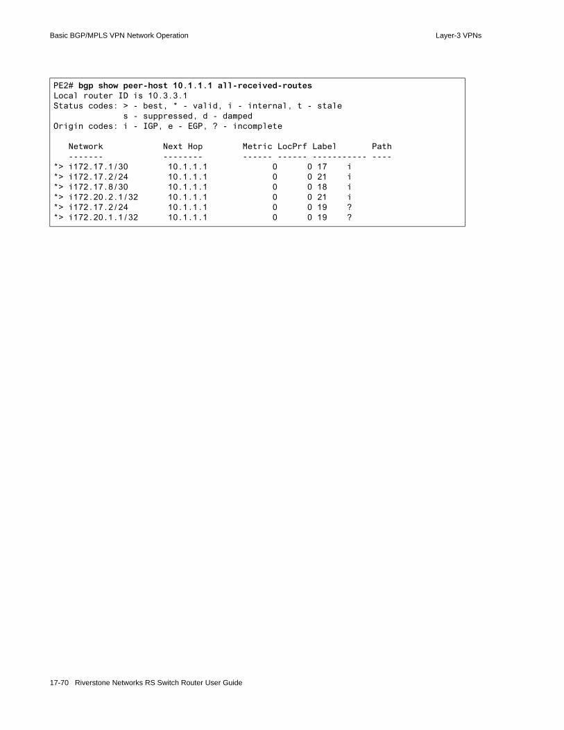
Basic BGP/MPLS VPN Network Operation Layer-3 VPNs
PE2# bgp show peer-host 10.1.1.1 all-received-routesLocal router ID is 10.3.3.1Status codes: > - best, * - valid, i - internal, t - stale s - suppressed, d - dampedOrigin codes: i - IGP, e - EGP, ? - incomplete
Network Next Hop Metric LocPrf Label Path ------- -------- ------ ------ ----------- ----*> i172.17.1/30 10.1.1.1 0 0 17 i*> i172.17.2/24 10.1.1.1 0 0 21 i*> i172.17.8/30 10.1.1.1 0 0 18 i*> i172.20.2.1/32 10.1.1.1 0 0 21 i*> i172.17.2/24 10.1.1.1 0 0 19 ?*> i172.20.1.1/32 10.1.1.1 0 0 19 ?
17-70 Riverstone Networks RS Switch Router User Guide

Layer-3 VPNs Basic BGP/MPLS VPN Network Operation
17.5.1.1 Multiple Routing and Forwarding Tables
PE routers do not differentiate between VRF or other routes when receiving BGP routes. A PE router filters all BGP routes received from remote PE routers through the Route Target(s) that you configure. It discards routes that do not match any import targets on the VRFs that it supports. It installs remaining routes into the VPN-IPv4 Unicast RIB. The VPN-IPv4 Unicast RIB contains all routes that satisfy the import policy of at least one of the PE router’s VRFs. Since this is the only table that contains all of the routes from all of the VPNs directly connected to the PE router, it is the only table that relies on Route Distinguishers to keep routes with identical IPv4 prefixes distinct.
BGP first installs all routes matching at least one import Route Target on the PE router in this table. From this table, routes are then installed into the Routing Instance RIB for particular VRFs based on the VRF import target(s).
Then, the routing instance associated with that VRF selects optimal and active routes from the Routing Instance RIB to install into the Routing Instance FIB. PE routers distribute these routes to directly-connected customer sites through interface(s) that have been added to the routing instance. PE routers also use Routing Instance FIBs to forward traffic for that VRF and advertise these routes to remote PE routers.
Table 17-1 summarizes the RIBs and Table 17-2 summarizes the FIBs that exist on the RS Ethernet Router.
Table 17-1 Multiple RIBs on the RS Ethernet Router
RIB Purpose Command To View
Internet Unicast Contains global unicast routes used by the provider network.
ip-router show rib internet unicast-only
Internet Multicast Contains global multicast routes used by the provider network.
ip-router show rib internet multicast-only
VPN/IPv4 Unicast Contains all VPN routes received from remote PE routers via MP-BGP in VPN-IPv4 format. Since VPNs can have overlapping addresses, this RIB relies on the Route Distinguisher in the VPN-IPv4 address to disambiguate between routes to identical IPv4 addresses. Routes are listed by Route Distinguisher.
ip-router show rib vpn-ipv4
To view routes for a specific Route Distinguisher:
ip-router show rib route-distinguisher <RD> vpn-ipv4
LSP Contains MPLS LSP routes. You can enable routing protocols to use LSP routes in resolving next hops using the ip-router global set install-lsp-routes command.
ip-router show rib lsp-route-only
Routing Instance Unicast Contains VRF routes for a specific routing instance. ip-router show rib instance
Riverstone Networks RS Switch Router User Guide 17-71

Basic BGP/MPLS VPN Network Operation Layer-3 VPNs
Table 17-2 Multiple FIBs on the RS Ethernet Router
Viewing RIBs
Use the ip-router show rib command to view all of the RIBs on the RS Ethernet Router. The following shows the RIBs on PE1.
FIB Purpose Command To View
Unicast Contains global unicast routes used by the provider network.
ip show routes
Routing Instance Unicast Contains VRF routes for a specific routing instance. ip show routes show-vrf
PE1# ip-router show rib
Routing Tables:
Generate Default: no
Destinations: 20 Routes: 25
Holddown: 0 Delete: 3 Hidden: 4
Codes: Network - Destination Network Address
S - Status + = Best Route, - = Last Active, * = Both
Src - Source of the route :
Ag - Aggregate, B - BGP derived, C - Connected
DVM - DVMRP derived, R - RIP derived, St - Static, O - OSPF derived
OE - OSPF ASE derived, D - Default
i - IS-IS, L1 - IS-IS level-1, L2 - IS-IS level-2
Next hop - Gateway for the route ; Next hops in use: 4
Netif - Next hop interface
Prf1 - Preference of the route, Prf2 - Second Preference of the route
Metrc1 - Metric1 of the route, Metrc2 - Metric2 of the route
Network/Mask S Src Next hop Netif Prf1 Metrc1 Metrc2
------------ - --- -------- ----- ---- ------ ------
Internet Unicast
0.0.0.6/32 * C 10.1.1.1 lo0 7 1 0
10.0.1/30 * C 10.0.1.1 ToP 1 1 0
10.0.1/30 O 10.0.1.1 ToP 10 2 0
10.0.2/30 * O 10.0.1.2 ToP 10 4 0
10.1.1.1/32 * C 10.1.1.1 lo0 1 1 0
10.1.1.1/32 O -10 1 0
10.2.2.1/32 * O 10.0.1.2 ToP 10 3 0
10.2.2.1/32 O 10.0.1.2 ToP -10 2 0
10.3.3.1/32 * O 10.0.1.2 ToP 10 5 0
10.3.3.1/32 O 10.0.1.2 ToP -10 4 0
127/8 * St 127.0.0.1 lo0 1 0 0
127.0.0.1/32 * C 127.0.0.1 lo0 1 1 0
172.17.1/30 * C 172.17.1.1 ToCE1 1 1 0
17-72 Riverstone Networks RS Switch Router User Guide

Layer-3 VPNs Basic BGP/MPLS VPN Network Operation
172.17.8/30 * C 172.17.8.1 ToCE3 1 1 0
Internet Multicast
0.0.0.6/32 * C 10.1.1.1 lo0 7 1 0
10.0.1/30 * C 10.0.1.1 ToP 1 1 0
10.1.1.1/32 * C 10.1.1.1 lo0 1 1 0
127.0.0.1/32 C 127.0.0.1 lo0 -1 1 0
VPN/IPV4 Unicast
Route Distinguisher 10.3.3.1:1
192.168.1/30 * B 0.0.0.6 PE1toPE2 170 100
192.168.2/24 * B 0.0.0.6 PE1toPE2 170 100
192.168.100.1/32 * B 0.0.0.6 PE1toPE2 170 100
Route Distinguisher 10.3.3.1:2
192.168.8/30 * B 0.0.0.6 PE1toPE2 170 100
192.168.9/24 * B 0.0.0.6 PE1toPE2 170 41 100
192.168.101.1/32 * B 0.0.0.6 PE1toPE2 170 22 100
LSP route table
10.3.3.1/32 * C 0.0.0.6 PE1toPE2 7 1 0
Routing-instance PINK Unicast
10.1.1.1/32 O -10 1 0
172.17.2/24 * O 172.17.8.2 ToCE3 10 40 0
172.17.8/30 * C 172.17.8.1 ToCE3 1 1 0
172.17.8/30 O 172.17.8.1 ToCE3 10 20 0
172.20.2.1/32 * O 172.17.8.2 ToCE3 10 21 0
172.20.2.1/32 O 172.17.8.2 ToCE3 -10 20 0
192.168.8/30 * B 0.0.0.6 PE1toPE2 170 100
192.168.9/24 * B 0.0.0.6 PE1toPE2 170 41 100
192.168.101.1/32 * B 0.0.0.6 PE1toPE2 170 22 100
Routing-instance RED Unicast
172.17.1/30 * C 172.17.1.1 ToCE1 1 1 0
172.17.2/24 * St 172.17.1.2 ToCE1 5 0 0
172.20.1.1/32 * St 172.17.1.2 ToCE1 5 0 0
192.168.1/30 * B 0.0.0.6 PE1toPE2 170 100
Riverstone Networks RS Switch Router User Guide 17-73

Basic BGP/MPLS VPN Network Operation Layer-3 VPNs
The following shows the RIBs on PE2.
192.168.2/24 * B 0.0.0.6 PE1toPE2 170 100
192.168.100.1/32 * B 0.0.0.6 PE1toPE2 170 100
PE2# ip-router show rib
Routing Tables:
Generate Default: no
Destinations: 20 Routes: 25
Holddown: 0 Delete: 2 Hidden: 4
Codes: Network - Destination Network Address
S - Status + = Best Route, - = Last Active, * = Both
Src - Source of the route :
Ag - Aggregate, B - BGP derived, C - Connected
DVM - DVMRP derived, R - RIP derived, St - Static, O - OSPF derived
OE - OSPF ASE derived, D - Default
i - IS-IS, L1 - IS-IS level-1, L2 - IS-IS level-2
Next hop - Gateway for the route ; Next hops in use: 4
Netif - Next hop interface
Prf1 - Preference of the route, Prf2 - Second Preference of the route
Metrc1 - Metric1 of the route, Metrc2 - Metric2 of the route
Network/Mask S Src Next hop Netif Prf1 Metrc1 Metrc2
------------ - --- -------- ----- ---- ------ ------
Internet Unicast
0.0.0.6/32 * C 10.3.3.1 lo0 7 1 0
10.0.1/30 * O 10.0.2.1 ToP 10 4 0
10.0.2/30 * C 10.0.2.2 ToP 1 1 0
10.0.2/30 O 10.0.2.2 ToP 10 2 0
10.1.1.1/32 * O 10.0.2.1 ToP 10 5 0
10.1.1.1/32 O 10.0.2.1 ToP -10 4 0
10.2.2.1/32 * O 10.0.2.1 ToP 10 3 0
10.2.2.1/32 O 10.0.2.1 ToP -10 2 0
10.3.3.1/32 * C 10.3.3.1 lo0 1 1 0
10.3.3.1/32 O -10 1 0
127/8 * St 127.0.0.1 lo0 1 0 0
127.0.0.1/32 * C 127.0.0.1 lo0 1 1 0
192.168.1/30 * C 192.168.1.1 ToCE2 1 1 0
192.168.8/30 * C 192.168.8.1 ToCE4 1 1 0
Internet Multicast
0.0.0.6/32 * C 10.3.3.1 lo0 7 1 0
10.0.2/30 * C 10.0.2.2 ToP 1 1 0
10.3.3.1/32 * C 10.3.3.1 lo0 1 1 0
127.0.0.1/32 C 127.0.0.1 lo0 -1 1 0
17-74 Riverstone Networks RS Switch Router User Guide

Layer-3 VPNs Basic BGP/MPLS VPN Network Operation
Viewing FIBs
The following show the Unicast FIBs on PE1 and PE2. The Unicast FIB does not contain any VRF routes.
VPN/IPV4 Unicast
Route Distinguisher 10.1.1.1:1
172.17.1/30 * B 0.0.0.6 PE2toPE1 170 100
172.17.2/24 * B 0.0.0.6 PE2toPE1 170 100
172.20.1.1/32 * B 0.0.0.6 PE2toPE1 170 100
Route Distinguisher 10.1.1.1:2
172.17.2/24 * B 0.0.0.6 PE2toPE1 170 41 100
172.17.8/30 * B 0.0.0.6 PE2toPE1 170 100
172.20.2.1/32 * B 0.0.0.6 PE2toPE1 170 22 100
LSP route table
10.1.1.1/32 * C 0.0.0.6 PE2toPE1 7 1 0
Routing-instance PINK Unicast
10.3.3.1/32 O -10 1 0
172.17.2/24 * B 0.0.0.6 PE2toPE1 170 41 100
172.17.8/30 * B 0.0.0.6 PE2toPE1 170 100
172.20.2.1/32 * B 0.0.0.6 PE2toPE1 170 22 100
192.168.8/30 * C 192.168.8.1 ToCE4 1 1 0
192.168.8/30 O 192.168.8.1 ToCE4 10 20 0
192.168.9/24 * O 192.168.8.2 ToCE4 10 40 0
192.168.101.1/32 * O 192.168.8.2 ToCE4 10 21 0
192.168.101.1/32 O 192.168.8.2 ToCE4 -10 20 0
Routing-instance RED Unicast
172.17.1/30 * B 0.0.0.6 PE2toPE1 170 100
172.17.2/24 * B 0.0.0.6 PE2toPE1 170 100
172.20.1.1/32 * B 0.0.0.6 PE2toPE1 170 100
192.168.1/30 * C 192.168.1.1 ToCE2 1 1 0
192.168.2/24 * St 192.168.1.2 ToCE2 5 0 0
192.168.100.1/32 * St 192.168.1.2 ToCE2 5 0 0
Riverstone Networks RS Switch Router User Guide 17-75

Basic BGP/MPLS VPN Network Operation Layer-3 VPNs
The following show the RED and PINK Routing Instance FIBs on PE1 and PE2.
PE1# ip show routes
Destination Gateway Owner Netif----------- ------- ----- -----10.0.1.0/30 directly connected - ToP10.0.2.0/30 10.0.1.2 OSPF ToP10.1.1.1 10.1.1.1 - lo010.2.2.1 10.0.1.2 OSPF ToP10.3.3.1 10.0.1.2 OSPF ToP127.0.0.1 127.0.0.1 - lo0172.17.1.0/30 directly connected - ToCE1172.17.8.0/30 directly connected - ToCE3
PE2# ip show routes
Destination Gateway Owner Netif----------- ------- ----- -----10.0.1.0/30 10.0.2.1 OSPF ToP10.0.2.0/30 directly connected - ToP10.1.1.1 10.0.2.1 OSPF ToP10.2.2.1 10.0.2.1 OSPF ToP10.3.3.1 10.3.3.1 - lo0127.0.0.1 127.0.0.1 - lo0192.168.1.0/30 directly connected - ToCE2192.168.8.0/30 directly connected - ToCE4
PE1# ip show routes show-vrf RED
Destination Gateway Owner Netif----------- ------- ----- -----172.17.1.0/30 directly connected - ToCE1172.17.2.0/24 172.17.1.2 Static ToCE1172.20.1.1 172.17.1.2 Static ToCE1192.168.1.0/30 10.0.1.2 BGP PE1toPE2192.168.2.0/24 10.0.1.2 BGP PE1toPE2192.168.100.1 10.0.1.2 BGP PE1toPE2
PE1# ip show routes show-vrf PINK
Destination Gateway Owner Netif----------- ------- ----- -----172.17.2.0/24 172.17.8.2 OSPF ToCE3172.17.8.0/30 directly connected - ToCE3172.20.2.1 172.17.8.2 OSPF ToCE3192.168.8.0/30 10.0.1.2 BGP PE1toPE2192.168.9.0/24 10.0.1.2 BGP PE1toPE2192.168.101.1 10.0.1.2 BGP PE1toPE2
17-76 Riverstone Networks RS Switch Router User Guide

Layer-3 VPNs Basic BGP/MPLS VPN Network Operation
The following show the configured default route in the Unicast FIBs on CE1 and CE2.
Viewing the Unicast FIBs on CE3 and CE4 confirm that they are receiving remote-site routes for the PINK VRF from PE1 and PE2.
PE2# ip show routes show-vrf RED
Destination Gateway Owner Netif----------- ------- ----- -----172.17.1.0/30 10.0.2.1 BGP PE2toPE1172.17.2.0/24 10.0.2.1 BGP PE2toPE1172.20.1.1 10.0.2.1 BGP PE2toPE1192.168.1.0/30 directly connected - ToCE2192.168.2.0/24 192.168.1.2 Static ToCE2192.168.100.1 192.168.1.2 Static ToCE2
PE2# ip show routes show-vrf PINK
Destination Gateway Owner Netif----------- ------- ----- -----172.17.2.0/24 10.0.2.1 BGP PE2toPE1172.17.8.0/30 10.0.2.1 BGP PE2toPE1172.20.2.1 10.0.2.1 BGP PE2toPE1192.168.8.0/30 directly connected - ToCE4192.168.9.0/24 192.168.8.2 OSPF ToCE4192.168.101.1 192.168.8.2 OSPF ToCE4
CE1# ip show routes
Destination Gateway Owner Netif----------- ------- ----- -----default 172.17.1.1 Static ToPE1127.0.0.1 127.0.0.1 - lo0172.17.1.0/30 directly connected - ToPE1172.17.2.0/24 directly connected - ToCustomerASite172.20.1.1 172.20.1.1 - lo0
CE2# ip show routes
Destination Gateway Owner Netif----------- ------- ----- -----default 192.168.1.1 Static ToPE2127.0.0.1 127.0.0.1 - lo0192.168.1.0/30 directly connected - ToPE2192.168.2.0/24 directly connected - ToCustomerASite192.168.100.1 192.168.100.1 - lo0
Riverstone Networks RS Switch Router User Guide 17-77

Basic BGP/MPLS VPN Network Operation Layer-3 VPNs
CE3# ip show routes
Destination Gateway Owner Netif----------- ------- ----- -----10.1.1.1 172.17.8.1 OSPF ToPE1127.0.0.1 127.0.0.1 - lo0172.17.2.0/24 directly connected - ToCustomerBSite172.17.8.0/30 directly connected - ToPE1172.20.2.1 172.20.2.1 - lo0192.168.8.0/30 172.17.8.1 OSPF_ASE ToPE1192.168.9.0/24 172.17.8.1 OSPF_IA ToPE1192.168.101.1 172.17.8.1 OSPF_IA ToPE1
CE4# ip show routes
Destination Gateway Owner Netif----------- ------- ----- -----10.3.3.1 192.168.8.1 OSPF ToPE2127.0.0.1 127.0.0.1 - lo0172.17.2.0/24 192.168.8.1 OSPF_IA ToPE2172.17.8.0/30 192.168.8.1 OSPF_ASE ToPE2172.20.2.1 192.168.8.1 OSPF_IA ToPE2192.168.8.0/30 directly connected - ToPE2192.168.9.0/24 directly connected - ToCustomerBSite192.168.101.1 192.168.101.1 - lo0
17-78 Riverstone Networks RS Switch Router User Guide
Layer-3 VPNs Basic BGP/MPLS VPN Network Operation
17.5.2 Case Study: Learning Routes
The following describes the operation of the Basic BGP/MPLS VPN Network when CE3 advertises the 172.17.2.0/24 network for Customer B Site 1.
17.5.2.1 On PE1
PE1 learns this IPv4 route through the PINK OSPF routing instance. It places the route into the VRF tables associated with the advertising site, PINK FIB and PINK RIB, based on the incoming interface, ToCE3.
Note PE1 also learns a different route to the same prefix (172.17.2.0/24) through CE1, but because CE1 is associated with the RED routing instance, PE1 keeps that route separate in the RED VRF and assigns a different Route Distinguisher to that route.
Next, PE1 assigns a label to this route for remote PE routers to use when sending to this route. It creates an entry in the MPLS forwarding table to specify that all MPLS packets bearing this label should be forwarded directly out the ToCE3 interface with no labels.
Then, PE1 creates a VPN-IPv4 route by prepending the Route Distinguisher for the PINK routing instance (10.1.1.1:2) to this IPv4 route.
Finally, PE1 sets the VPN-IPv4 route’s Route Target to target:65001:2, assigns its own loopback address as the BGP next hop for the route, and advertises the route to PE2 using MP-IBGP.
17.5.2.2 On PE2
PE2 receives the VPN-IPv4 route into its VPN-IPv4 RIB, where the route’s Route Distinguisher (10.1.1.1:2) disambiguates this route from one to an identical prefix in Customer A Site 1, which bears a different Route Distinguisher (10.1.1.1:1).
The MP-IBGP process on PE2 compares the Route Target of this route, target:65001:2, to the import targets for its configured VRFs. PE2 has two import targets, one for each configured VRF. The Route Target of this route matches the import target for the PINK VRF, target:65001:2. PE2 strips the VPN-IPv4 route of its Route Distinguisher, creating an IPv4 route, which it installs into the PINK RIB.
The PINK OSPF routing instance on PE2 performs route selection and installs the IPv4 route into the PINK FIB.
Finally, PE2 advertises the IPv4 route to CE4.
17.5.2.3 On CE4
CE4 receives the IPv4 route for the 172.17.2.0/24 network, which it places in its global RIB. The OSPF process on CE4 performs route selection, installs this route into CE4’s Unicast FIB, and announces this route to Customer B Site 2.
Riverstone Networks RS Switch Router User Guide 17-79

Basic BGP/MPLS VPN Network Operation Layer-3 VPNs
17.5.3 Case Study: Using Routes
The following describes the operation of the Basic BGP/MPLS VPN Network when CE4 tries to send a packet to the 172.17.2.0/24 network in Customer B Site 1.
17.5.3.1 On CE4
CE4 receives a packet destined for 172.17.2.1 from Customer B Site 2. CE4 performs a longest-match lookup in its FIB and sees that the next hop for this address is PE2. CE4 sends the IPv4 packet to PE2 through its directly-connected interface.
17.5.3.2 On PE2
PE2 receives CE4’s IPv4 packet and performs a longest-match lookup in the Routing Instance FIB associated with this site, PINK FIB, based on the packet’s incoming interface. In the PINK FIB, the next hop for the BGP route to 172.17.2.0/24 is PE1. Since PE2 is configured to use MPLS LSPs to resolve BGP next hops, it associates the route’s BGP next hop, PE1, with the MPLS LSP PE2toPE1. Two labels were also installed for this route when PE2 received PE1’s MP-IBGP advertisement, the PE1-assigned label (for the 172.17.2.0/24 route) and the label associated with the MPLS LSP to PE1.
PE2 forwards the IPv4 packet as an MPLS packet with the PE1-assigned label as the bottom (or inner) label and the label associated with the MPLS LSP to PE1 as the top (or outer) label.
17.5.3.3 On P
Router P receives and switches the MPLS packet along the PE2toPE1 LSP based on the top label. If additional P routers were present along the path from PE2 to PE1, they would also switch the packet based on the top label only.
Since it is also the penultimate router to PE1, router P pops the top label, exposing the bottom label, before forwarding the packet to PE1.
Note P routers do not examine the MPLS packet contents. They merely forward packets based on the top label.
17.5.3.4 On PE1
PE1 receives the MPLS packet. Since penultimate router P already popped the top label, PE1 only sees the bottom (or inner) label, which it assigned when advertising the 172.17.2.0/24 route. PE1 does a lookup in its MPLS forwarding table based on this label. The action associated with this label is to forward the packet directly out the ToCE3 interface without attaching any labels.
Based on this, PE1 strips the bottom label from the MPLS packet, creating a native IPv4 packet, which it sends out the ToCE3 interface.
17-80 Riverstone Networks RS Switch Router User Guide

Layer-3 VPNs Basic BGP/MPLS VPN Network Operation
17.5.3.5 On CE3
CE3 receives the native IPv4 packet, performs a traditional longest-match lookup in its FIB, and sees that it is the packet’s destination, 172.17.2.1. CE3 consumes the packet.
Note Only the outbound PE router consults the Routing Instance FIB, not the inbound PE router. The outbound PE router needs to route an IPv4 packet using the Routing Instance FIB. The inbound PE router only needs to forward an MPLS packet, and therefore, only does lookups in the MPLS forwarding table.
17.5.4 Basic BGP/MPLS VPN Network Complete Configurations
The following are complete configurations for the Basic BGP/MPLS VPN Network, as illustrated in Figure 17-8.
17.5.4.1 CE1 Complete Configuration
CE1# show runRunning system configuration: ! ! Last modified from Console on 2002-06-03 12:28:51 ! // Create VLANs and add them to interfaces 1 : vlan create ToPE1 ip id 200 2 : vlan create ToCustomerASite1 ip id 100 3 : vlan add ports et.2.1 to ToPE1 4 : vlan add ports et.2.8 to ToCustomerASite1 ! 5 : interface create ip ToPE1 address-netmask 172.17.1.2/30 vlan ToPE1 6 : interface create ip ToCustomerASite1 address-netmask 172.17.2.1/24 vlan
ToCustomerASite1
// Assign the loopback address and set it as the router ID 7 : interface add ip lo0 address-netmask 172.20.1.1/32 ! 8 : ip-router global set router-id 172.20.1.1 ! // Configure PE1 as a default gateway for static PE-CE routing 9 : ip add route default gateway 172.17.1.1 ! // Set the system name10 : system set name CE1
Riverstone Networks RS Switch Router User Guide 17-81

Basic BGP/MPLS VPN Network Operation Layer-3 VPNs
17.5.4.2 CE2 Complete Configuration
CE2# show runRunning system configuration: ! ! Last modified from Console on 2002-06-03 13:07:19 ! // Create VLANs and add them to interfaces 1 : vlan create ToPE2 ip id 200 2 : vlan create ToCustomerASite2 ip id 100 3 : vlan add ports et.2.1 to ToPE2 4 : vlan add ports et.2.8 to ToCustomerASite2 ! 5 : interface create ip ToPE2 address-netmask 192.168.1.2/30 vlan ToPE2 6 : interface create ip ToCustomerASite2 address-netmask 192.168.2.1/24 vlan
ToCustomerASite2
// Assign the loopback address and set it as the router ID 7 : interface add ip lo0 address-netmask 192.168.100.1/32 ! 8 : ip-router global set router-id 192.168.100.1 ! // Configure PE1 as a default gateway for static PE-CE routing 9 : ip add route default gateway 192.168.1.1 ! // Set the system name10 : system set name CE2
17-82 Riverstone Networks RS Switch Router User Guide

Layer-3 VPNs Basic BGP/MPLS VPN Network Operation
17.5.4.3 CE3 Complete Configuration
CE3# show runRunning system configuration: ! ! Last modified from Console on 2002-05-06 12:11:46 ! // Create VLANs and add them to interfaces 1 : vlan create ToPE1 ip id 200 2 : vlan create ToCustomerBSite1 ip id 100 3 : vlan add ports et.3.1 to ToPE1 4 : vlan add ports et.3.8 to ToCustomerBSite1 ! 5 : interface create ip ToPE1 address-netmask 172.17.8.2/30 vlan ToPE1 6 : interface create ip ToCustomerBSite1 address-netmask 172.17.2.1/24 vlan
ToCustomerBSite1
// Assign the loopback address and set it as the router ID 7 : interface add ip lo0 address-netmask 172.20.2.1/32 ! 8 : ip-router global set router-id 172.20.2.1 ! // Configure OSPF to be the CE-PE protocol between CE1 and PE1 9 : ospf create area backbone10 : ospf add stub-host 172.20.2.1 to-area backbone cost 111 : ospf add interface ToPE1 to-area backbone12 : ospf add interface ToCustomerBSite1 to-area backbone13 : ospf start ! // Set the system name14 : system set name CE3
Riverstone Networks RS Switch Router User Guide 17-83

Basic BGP/MPLS VPN Network Operation Layer-3 VPNs
17.5.4.4 CE4 Complete Configuration
CE4# show runRunning system configuration: ! ! Last modified from Console on 2002-06-03 13:26:27 ! // Create VLANs and add them to interfaces 1 : vlan create ToPE2 ip id 200 2 : vlan create ToCustomerBSite2 ip id 100 3 : vlan add ports et.10.1 to ToPE2 4 : vlan add ports et.10.8 to ToCustomerBSite2 ! 5 : interface create ip ToPE2 address-netmask 192.168.8.2/30 vlan ToPE2 6 : interface create ip ToCustomerBSite2 address-netmask 192.168.9.1/24 vlan
ToCustomerBSite2
// Assign the loopback address and set it as the router ID 7 : interface add ip lo0 address-netmask 192.168.101.1/32 ! 8 : ip-router global set router-id 192.168.101.1 ! // Configure OSPF to be the CE-PE protocol between CE4 and PE2 9 : ospf create area backbone10 : ospf add stub-host 192.168.101.1 to-area backbone cost 111 : ospf add interface ToPE2 to-area backbone12 : ospf add interface ToCustomerBSite2 to-area backbone13 : ospf start ! // Set the system name14 : system set name CE4
17-84 Riverstone Networks RS Switch Router User Guide

Layer-3 VPNs Basic BGP/MPLS VPN Network Operation
PE1# show runRunning system configuration: ! ! Last modified from Console on 2002-06-03 13:16:20 ! // Create VLANs and add them to interfaces 1 : vlan create ToCE1 ip id 100 2 : vlan create ToP ip id 200 3 : vlan create ToCE3 ip id 300 4 : vlan add ports et.6.1 to ToCE1 5 : vlan add ports et.6.2 to ToCE3 6 : vlan add ports gi.4.1 to ToP ! 7 : interface create ip ToCE1 address-netmask 172.17.1.1/30 vlan ToCE1 8 : interface create ip ToCE3 address-netmask 172.17.8.1/30 vlan ToCE3 9 : interface create ip ToP address-netmask 10.0.1.1/30 vlan ToP
// Assign the loopback address and set it as the router ID10 : interface add ip lo0 address-netmask 10.1.1.1/32 !11 : ip-router global set router-id 10.1.1.1
// Configure AS 65001 for the provider network 12 : ip-router global set autonomous-system 65001
// Configure BGP only to use MPLS LSPs in resolving next hops13 : ip-router global set install-lsp-routes bgp ! // Create import and export target route maps using community lists and routing policies14 : community-list PINK-import permit 10 target:65001:215 : community-list RED-import permit 10 target:65001:1 !16 : ip-router policy create community-list RED-export target:65001:117 : ip-router policy create community-list PINK-export target:65001:2 !18 : route-map BGPROUTES permit 1 match-route-type bgp19 : route-map PINK-export permit 10 set-community-list PINK-export20 : route-map PINK-import permit 10 match-community-list PINK-import21 : route-map RED-export permit 10 set-community-list RED-export22 : route-map RED-import permit 10 match-community-list RED-import ! // Configure OSPF for routing across the provider network 23 : ospf create area backbone24 : ospf add stub-host 10.1.1.1 to-area backbone cost 1
Riverstone Networks RS Switch Router User Guide 17-85

Basic BGP/MPLS VPN Network Operation Layer-3 VPNs
25 : ospf add interface ToP to-area backbone26 : ospf start ! // Configure MP-IBGP peering with PE227 : bgp create peer-group PROVIDER autonomous-system 6500128 : bgp add peer-host 10.3.3.1 group PROVIDER29 : bgp set peer-group PROVIDER local-address 10.1.1.130 : bgp set peer-group PROVIDER vpnv4-unicast ipv4-unicast31 : bgp start ! // Configure an MPLS LSP to PE232 : mpls add interface ToP33 : mpls create label-switched-path PE1toPE2 from 10.1.1.1 to 10.3.3.1 no-cspf34 : mpls start !35 : rsvp add interface ToP36 : rsvp start ! // Set system name37 : system set name PE1 ! // Configure PINK OSPF routing instance to CE338 : routing-instance PINK vrf set route-distinguisher "10.1.1.1:2"39 : routing-instance PINK vrf add interface ToCE340 : routing-instance PINK vrf add interface lo041 : routing-instance PINK vrf set router-id 10.1.1.142 : routing-instance PINK vrf set vrf-import PINK-import in-sequence 143 : routing-instance PINK vrf set vrf-export PINK-export out-sequence 144 : routing-instance PINK ospf create area backbone45 : routing-instance PINK ospf add stub-host 10.1.1.1 to-area backbone cost 146 : routing-instance PINK ospf add interface ToCE3 to-area backbone47 : routing-instance PINK ospf set domain-id 0.0.0.048 : routing-instance PINK ospf set vpn-route-tag 100149 : routing-instance PINK ospf set route-map-vpn BGPROUTES50 : routing-instance PINK ospf start
// Configure RED static routing instance to CE151 : routing-instance RED vrf set route-distinguisher "10.1.1.1:1"52 : routing-instance RED vrf add interface ToCE153 : routing-instance RED vrf set vrf-import RED-import in-sequence 154 : routing-instance RED vrf set vrf-export RED-export out-sequence 155 : routing-instance RED ip add route 172.17.2.0/24 gateway 172.17.1.256 : routing-instance RED ip add route 172.20.1.1/32 gateway 172.17.1.2
17-86 Riverstone Networks RS Switch Router User Guide

Layer-3 VPNs Basic BGP/MPLS VPN Network Operation
PE2# show runRunning system configuration: ! ! Last modified from Console on 2002-06-03 12:26:47 ! // Create VLANs and add them to interfaces 1 : vlan create ToCE2 ip id 100 2 : vlan create ToCE4 ip id 200 3 : vlan create ToP ip id 300 4 : vlan add ports et.3.1 to ToCE2 5 : vlan add ports et.3.2 to ToCE4 6 : vlan add ports gi.7.1 to ToP ! 7 : interface create ip ToCE2 address-netmask 192.168.1.1/30 vlan ToCE2 8 : interface create ip ToCE4 address-netmask 192.168.8.1/30 vlan ToCE4 9 : interface create ip ToP address-netmask 10.0.2.2/30 vlan ToP
// Assign the loopback address and set it as the router ID10 : interface add ip lo0 address-netmask 10.3.3.1/32 !11 : ip-router global set router-id 10.3.3.1
// Configure AS 65001 for the provider network12 : ip-router global set autonomous-system 65001
// Configure BGP only to use MPLS LSPs in resolving next hops13 : ip-router global set install-lsp-routes bgp ! // Create import and export target route maps using community lists and routing policies14 : community-list PINK-import permit 10 target:65001:215 : community-list RED-import permit 10 target:65001:1 !16 : ip-router policy create community-list RED-export target:65001:117 : ip-router policy create community-list PINK-export target:65001:2 !18 : route-map BGPROUTES permit 1 match-route-type bgp19 : route-map PINK-export permit 10 set-community-list PINK-export20 : route-map PINK-import permit 10 match-community-list PINK-import21 : route-map RED-export permit 10 set-community-list RED-export22 : route-map RED-import permit 10 match-community-list RED-import ! // Configure OSPF for routing across the provider network23 : ospf create area backbone24 : ospf add stub-host 10.3.3.1 to-area backbone cost 1
Riverstone Networks RS Switch Router User Guide 17-87

Basic BGP/MPLS VPN Network Operation Layer-3 VPNs
25 : ospf add interface ToP to-area backbone26 : ospf start ! // Configure MP-IBGP peering with PE127 : bgp create peer-group PROVIDER autonomous-system 6500128 : bgp add peer-host 10.1.1.1 group PROVIDER29 : bgp set peer-group PROVIDER local-address 10.3.3.130 : bgp set peer-group PROVIDER vpnv4-unicast ipv4-unicast31 : bgp start ! // Configure an MPLS LSP to PE132 : mpls add interface ToP33 : mpls create label-switched-path PE2toPE1 from 10.3.3.1 to 10.1.1.1 no-cspf34 : mpls start !35 : rsvp add interface ToP36 : rsvp start ! // Set system name37 : system set name PE2 ! // Configure PINK OSPF routing instance to CE438 : routing-instance PINK vrf set route-distinguisher "10.3.3.1:2"39 : routing-instance PINK vrf add interface ToCE440 : routing-instance PINK vrf add interface lo041 : routing-instance PINK vrf set router-id 10.3.3.142 : routing-instance PINK vrf set vrf-import PINK-import in-sequence 143 : routing-instance PINK vrf set vrf-export PINK-export out-sequence 144 : routing-instance PINK ospf create area backbone45 : routing-instance PINK ospf add stub-host 10.3.3.1 to-area backbone cost 146 : routing-instance PINK ospf add interface ToCE4 to-area backbone47 : routing-instance PINK ospf set domain-id 0.0.0.048 : routing-instance PINK ospf set vpn-route-tag 100149 : routing-instance PINK ospf set route-map-vpn BGPROUTES50 : routing-instance PINK ospf start
// Configure RED static routing instance to CE251 : routing-instance RED vrf set route-distinguisher "10.3.3.1:1"52 : routing-instance RED vrf add interface ToCE253 : routing-instance RED vrf set vrf-import RED-import in-sequence 154 : routing-instance RED vrf set vrf-export RED-export out-sequence 155 : routing-instance RED ip add route 192.168.2.0/24 gateway 192.168.1.256 : routing-instance RED ip add route 192.168.100.1/32 gateway 192.168.1.2
17-88 Riverstone Networks RS Switch Router User Guide
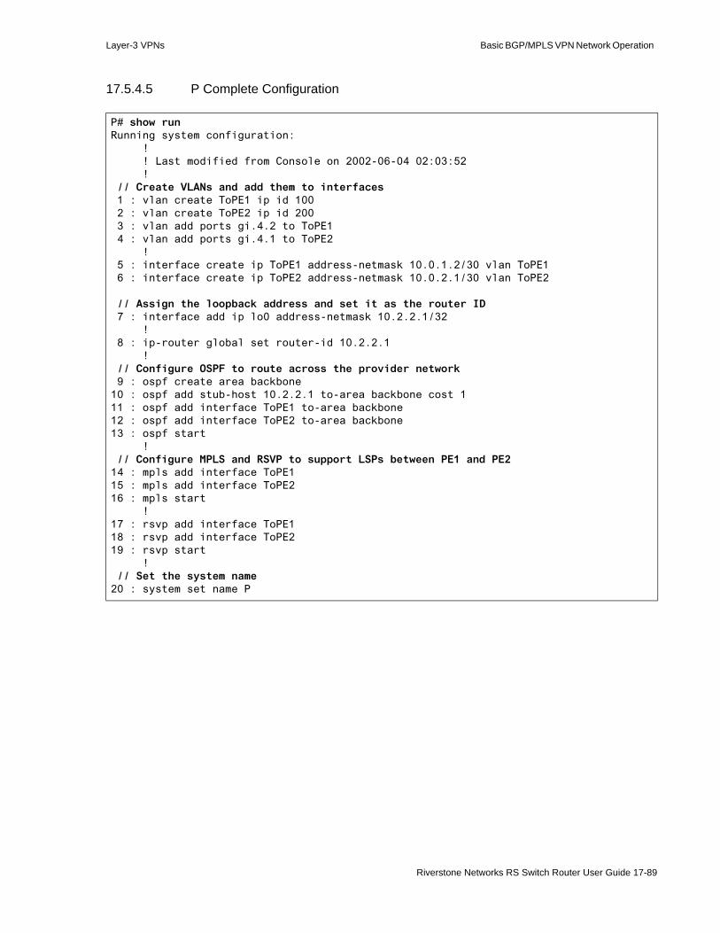
Layer-3 VPNs Basic BGP/MPLS VPN Network Operation
17.5.4.5 P Complete Configuration
P# show runRunning system configuration: ! ! Last modified from Console on 2002-06-04 02:03:52 ! // Create VLANs and add them to interfaces 1 : vlan create ToPE1 ip id 100 2 : vlan create ToPE2 ip id 200 3 : vlan add ports gi.4.2 to ToPE1 4 : vlan add ports gi.4.1 to ToPE2 ! 5 : interface create ip ToPE1 address-netmask 10.0.1.2/30 vlan ToPE1 6 : interface create ip ToPE2 address-netmask 10.0.2.1/30 vlan ToPE2
// Assign the loopback address and set it as the router ID 7 : interface add ip lo0 address-netmask 10.2.2.1/32 ! 8 : ip-router global set router-id 10.2.2.1 ! // Configure OSPF to route across the provider network 9 : ospf create area backbone10 : ospf add stub-host 10.2.2.1 to-area backbone cost 111 : ospf add interface ToPE1 to-area backbone12 : ospf add interface ToPE2 to-area backbone13 : ospf start ! // Configure MPLS and RSVP to support LSPs between PE1 and PE214 : mpls add interface ToPE115 : mpls add interface ToPE216 : mpls start !17 : rsvp add interface ToPE118 : rsvp add interface ToPE219 : rsvp start ! // Set the system name20 : system set name P
Riverstone Networks RS Switch Router User Guide 17-89

Configuring RIP and BGP Route Distribution Between CE and PE Routers Layer-3 VPNs
17.6 CONFIGURING RIP AND BGP ROUTE DISTRIBUTION BETWEEN CE AND PE ROUTERS
The RS Ethernet Router supports the following routing schemes between CE and PE routers.• Static routes• Open Shortest Path First (OSPF)• Routing Information Protocol (RIP)• Border Gateway Protocol (BGP)
For an example of configuring CE-PE route distribution using static routes and OSPF, refer to the Section 17-48 "Configuring Static and OSPF Route Distribution Between CE and PE Routers."
Using the Basic BGP/MPLS VPN Network (Figure 17-7) example, the following sections illustrate how to configure CE-PE route distribution using RIP and BGP. In this section, the OSPF and static routes configured in the routing instance configurations on all of the PE and CE routers from previous sections have been removed. Only the following configurations remain:
- IGP (OSPF) in the provider network- MPLS and RSVP in the provider network- MP-IBGP between the PE routers- RED and PINK routing instances on the PE routers
In the Basic BGP/MPLS VPN Network, • For VPN RED, CE1 and PE1 must exchange routes for the 172.17.2.0/24 network. Likewise, CE2
and PE2 must exchange routes for the 192.168.2.0/24 network. In the following sections, this is done using RIP.
• For VPN PINK, CE3 and PE1 must exchange routes for the 172.17.2.0/24 network. Likewise, CE4 and PE2 must exchange routes for the 192.168.9.0/24 network. In the following sections, this is done using BGP.
Figure 17-9 illustrates this.
17-90 Riverstone Networks RS Switch Router User Guide
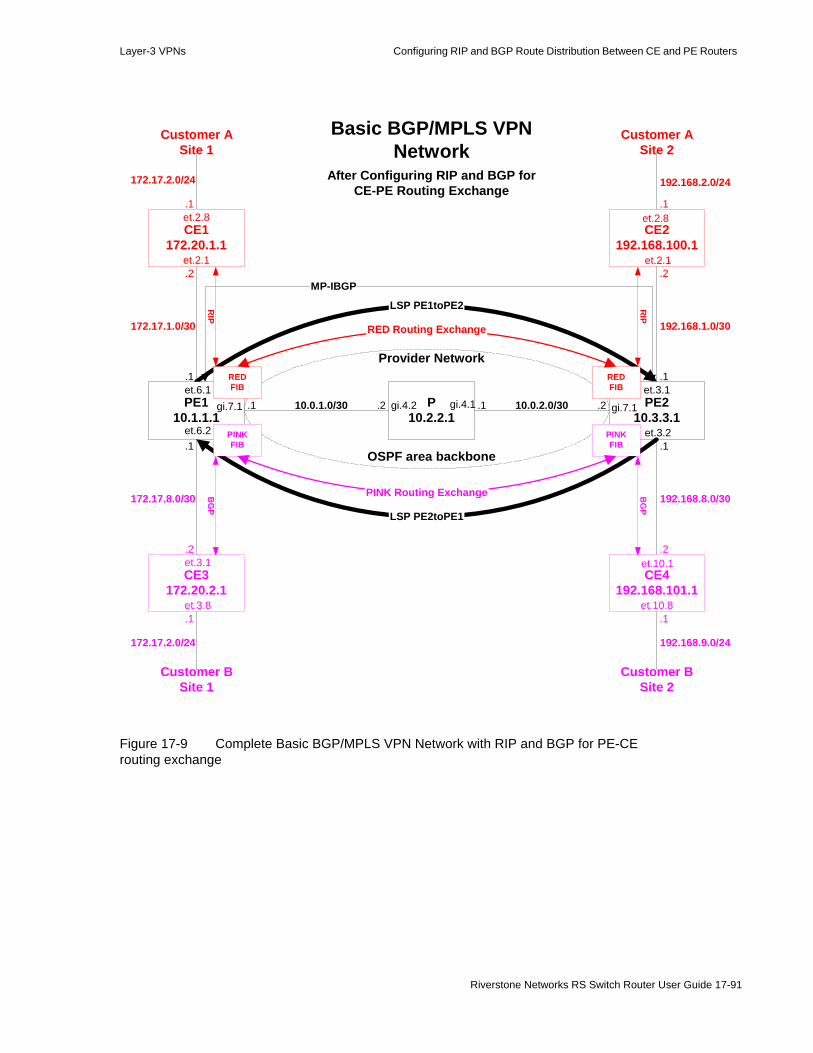
Layer-3 VPNs Configuring RIP and BGP Route Distribution Between CE and PE Routers
Figure 17-9 Complete Basic BGP/MPLS VPN Network with RIP and BGP for PE-CE routing exchange
After Configuring RIP and BGP forCE-PE Routing Exchange
LSP PE1toPE2
Basic BGP/MPLS VPNNetwork
CE2192.168.100.1
P10.2.2.1
PE210.3.3.1
CE4192.168.101.1
et.10.1
gi.7.1gi.4.2 gi.4.1et.3.1
et.3.2
et.2.1
et.2.8
et.10.8
PE110.1.1.1
CE3172.20.2.1
et.6.2
gi.7.1et.6.1
et.3.1
et.3.8
CE1172.20.1.1
et.2.1
et.2.8
.1
.1
.1
.1
.1
.1
.1
.1.1
.1
.2.2
.2
.2.2
172.17.1.0/30
172.17.2.0/24
172.17.8.0/30
172.17.2.0/24
10.0.2.0/3010.0.1.0/30
192.168.8.0/30
.2
192.168.1.0/30
192.168.9.0/24
192.168.2.0/24
Customer ASite 1
Customer ASite 2
Customer BSite 1
Customer BSite 2
Provider Network
OSPF area backbone
LSP PE2toPE1
MP-IBGP
REDFIB
PINKFIB
REDFIB
PINKFIB
RIP
RIP
BG
P
BG
P
RED Routing Exchange
PINK Routing Exchange
Riverstone Networks RS Switch Router User Guide 17-91

Configuring RIP and BGP Route Distribution Between CE and PE Routers Layer-3 VPNs
17.6.1 Configuring RIP Route Distribution Between CE and PE Routers
17.6.1.1 Configuring RIP On CE Routers
To run RIP between CE and PE routers, you must first configure RIP on CE routers. CE routers need not be BGP/MPLS VPN-capable and do not need to be configured with multiple routing instances. Configure them as you would any non-BGP/MPLS VPN-capable router. For more information on configuring RIP, seeChapter 12, "RIP Configuration Guide."
To implement the Basic BGP/MPLS VPN Network (Figure 17-9), PE1 is configured to route with CE1 using RIP and PE2 is configured to route with CE2 using RIP.
Configure CE1 to route with PE1 and CE2 to route with PE2 using RIP
1. Enable RIP on all the interface(s) that should participate in routing with the PE router by adding them to RIP. - On CE1, add the interface ToPE1- On CE2, add the interface ToPE2
2. Optionally, if you would like to use classless routing, set the participating interfaces to use RIP version 2.
3. Start RIP.
The previous configuration steps result in the following commands on CE1:
The previous configuration steps result in the following commands on CE2:
Basic BGP/MPLS VPN Network configuration steps:- IGP in the provider network (included in initial configurations)- MPLS LSPs in the provider network- MP-IBGP between PE routers- RED and PINK routing instances on the PE routers- Configure RIP and BGP PE-CE route distribution- Configure RIP between CE1 and PE1 and CE2 and PE2- Configure BGP between CE3 and PE1 and CE4 and PE2
CE1(config)# rip add interface ToPE1CE1(config)# rip set interface ToPE1 version 2CE1(config)# rip start
CE2(config)# rip add interface ToPE2CE2(config)# rip set interface ToPE2 version 2CE2(config)# rip start
17-92 Riverstone Networks RS Switch Router User Guide

Layer-3 VPNs Configuring RIP and BGP Route Distribution Between CE and PE Routers
17.6.1.2 Configuring RIP On PE Routers
For a PE router to distribute VPN routes to and from CE routers, you must configure it to route within a routing instance. For more information on configuring routing instances, see Section 17.4.4 "Configuring Routing Instances."
In the Basic BGP/MPLS VPN Network (Figure 17-9), there are two VRFs—RED and PINK. On the PE router, each routing instance maintains the routes that it learns and advertises in its own VRF.
Use the routing-instance <name> rip series of commands to configure VPN-related RIP routing on PE routers. These commands assume that you have already created a routing instance identified by <name>.
Within a routing instance, these commands function identically to the rip commands. For more information on configuring RIP, seeChapter 12, "RIP Configuration Guide."
Note Routing instance names are case sensitive.
Configure PE1 to route with CE1 and PE2 to route with CE2 using RIP1. Enable RIP on all the interface(s) that should participate in routing with the CE router by adding
them to RIP. - On PE1, add the interface ToCE1- On PE2, add the interface ToCE2
2. Optionally, if you would like to use classless routing, set the participating interfaces to use RIP version 2.
3. Specify which routes the PE router should learn for this VRF using a route map. The example specifies that all BGP routes should be learned.
4. Start RIP.
The previous configuration steps result in the following commands on PE1:
The previous configuration steps result in the following commands on PE2:
PE1(config)# routing-instance RED rip add interface ToCE1PE1(config)# routing-instance RED rip set interface ToCE1 version 2PE1(config)# route-map BGPROUTES permit 1 match-route-type bgpPE1(config)# routing-instance RED rip set route-map-out BGPROUTESPE1(config)# routing-instance RED rip start
PE2(config)# routing-instance RED rip add interface ToCE2PE2(config)# routing-instance RED rip set interface ToCE2 version 2PE1(config)# route-map BGPROUTES permit 1 match-route-type bgpPE1(config)# routing-instance RED rip set route-map-out BGPROUTESPE2(config)# routing-instance RED rip start
Riverstone Networks RS Switch Router User Guide 17-93

Configuring RIP and BGP Route Distribution Between CE and PE Routers Layer-3 VPNs
17.6.2 Configuring BGP Route Distribution Between CE and PE Routers
17.6.2.1 Configuring BGP On CE Routers
To run BGP between CE and PE routers, you must first configure BGP on CE routers. CE routers need not be BGP/MPLS VPN-capable and do not need to be configured with multiple routing instances. Configure them as you would any non-BGP/MPLS VPN-capable router. For more information on configuring BGP, seeChapter 16, "BGP Configuration Guide."
To implement the Basic BGP/MPLS VPN Network (Figure 17-9), PE1 is configured to route with CE3 using BGP and PE2 is configured to route with CE4 using BGP.
Configure CE3 to route with PE1 and CE4 to route with PE2 using BGP1. Configure both routers to be in AS 65002. You can configure the same or different autonomous
systems for two sites of the same customer. 2. Create a peer group named TOPROVIDER on both routers for their PE peers and assign it to AS
65001, the provider AS. Since the peer group is assigned to an AS that differs from the CE routers’ AS, 65002, each router recognizes TOPROVIDER as an EBGP peer group and uses the ‘external’ type by default.
3. Add PE1 and PE2 as peer hosts in the TOPROVIDER group. Unlike IBGP, peer over physical interfaces for EBGP.- On CE3, add PE1 as a peer host in the TOPROVIDER group by specifying the address of its
directly-connected interface, 172.17.8.1.- On CE4, add PE1 as a peer host in the TOPROVIDER group by specifying the address of its
directly-connected interface, 192.168.8.1.4. By default, in the absence of routing policies, EBGP advertises all BGP routes. In the Basic
BGP/MPLS VPN Network (Figure 17-9), if CE3 or CE4 learn any customer site routes via BGP, EBGP would automatically distribute those routes to the PE routers. If you want additional routes, such as to the CE router’s loopback address, to be distributed, you must define a route map to permit the routes and apply the route map to the PE peer host. For simplicity, our example configures the CE routers to advertise all routes via EBGP to PE neighbors. In practice, you should limit the set of routes advertised using route maps.
5. Start BGP.
The previous configuration steps result in the following commands on CE3:
Basic BGP/MPLS VPN Network configuration steps:- IGP in the provider network (included in initial configurations)- MPLS LSPs in the provider network- MP-IBGP between PE routers- RED and PINK routing instances on the PE routers- Configure static and OSPF PE-CE route distribution- Configure RIP between CE1 and PE1 and CE2 and PE2- Configure BGP between CE3 and PE1 and CE4 and PE2
17-94 Riverstone Networks RS Switch Router User Guide

Layer-3 VPNs Configuring RIP and BGP Route Distribution Between CE and PE Routers
The previous configuration steps result in the following commands on CE4:
17.6.2.2 Configuring BGP On PE Routers
For a PE router to distribute VPN routes to and from CE routers, you must configure it to route within a routing instance. For more information on configuring routing instances, see Section 17.4.4 "Configuring Routing Instances."
In the Basic BGP/MPLS VPN Network (Figure 17-9), there are two VRFs—RED and PINK. On the PE router, each routing instance maintains the routes that it learns and advertises in its own VRF.
Use the routing-instance <name> bgp series of commands to configure VPN-related BGP routing on PE routers. These commands assume that you have already created a routing instance identified by <name>. For more information on configuring routing instances, see Section 17.4.4 "Configuring Routing Instances."
Within a routing instance, these commands function identically to bgp commands. For more information on configuring BGP, seeChapter 16, "BGP Configuration Guide."
Note Routing instance names are case sensitive.
Configure PE1 to route with CE3 and PE2 to route with CE4 using BGP1. Create a peer group named TOCUSTOMER on both routers for their CE peers and assign it to AS
65002, the customer AS. Since the peer group is assigned to an AS that differs from the PE routers’ AS, 65001, each router recognizes TOCUSTOMER as an EBGP peer group and uses the ‘external’ type by default.
2. Add CE3 and CE4 as peer hosts in the TOCUSTOMER group.- On PE1, add CE3 as a peer host in the TOCUSTOMER group by specifying the address of its
directly-connected interface, 172.17.8.2.- On PE2, add CE4 as a peer host in the TOPROVIDER group by specifying the address of its
directly-connected interface, 192.168.8.2.
CE3(config)# ip-router global set autonomous-system 65002CE3(config)# bgp create peer-group TOPROVIDER autonomous-system 65001CE3(config)# bgp add peer-host 172.17.8.1 group TOPROVIDERCE3(config)# route-map ALLROUTES permit 1CE3(config)# bgp set peer-host 172.17.8.1 route-map-out ALLROUTES out-sequence 1CE3(config)# bgp start
CE4(config)# ip-router global set autonomous-system 65002CE4(config)# bgp create peer-group TOPROVIDER autonomous-system 65001CE4(config)# bgp add peer-host 192.168.8.1 group TOPROVIDERCE4(config)# route-map ALLROUTES permit 1CE4(config)# bgp set peer-host 172.17.8.1 route-map-out ALLROUTES out-sequence 1CE4(config)# bgp start
Riverstone Networks RS Switch Router User Guide 17-95
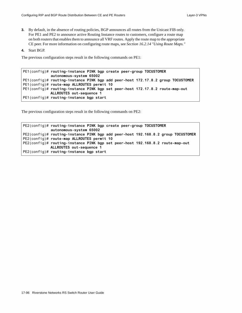
Configuring RIP and BGP Route Distribution Between CE and PE Routers Layer-3 VPNs
3. By default, in the absence of routing policies, BGP announces all routes from the Unicast FIB only. For PE1 and PE2 to announce active Routing Instance routes to customers, configure a route map on both routers that enables them to announce all VRF routes. Apply the route map to the appropriate CE peer. For more information on configuring route maps, see Section 16.2.14 "Using Route Maps."
4. Start BGP.
The previous configuration steps result in the following commands on PE1:
The previous configuration steps result in the following commands on PE2:
PE1(config)# routing-instance PINK bgp create peer-group TOCUSTOMER autonomous-system 65002
PE1(config)# routing-instance PINK bgp add peer-host 172.17.8.2 group TOCUSTOMERPE1(config)# route-map ALLROUTES permit 10PE1(config)# routing-instance PINK bgp set peer-host 172.17.8.2 route-map-out
ALLROUTES out-sequence 1PE1(config)# routing-instance bgp start
PE2(config)# routing-instance PINK bgp create peer-group TOCUSTOMER autonomous-system 65002
PE2(config)# routing-instance PINK bgp add peer-host 192.168.8.2 group TOCUSTOMERPE2(config)# route-map ALLROUTES permit 10PE2(config)# routing-instance PINK bgp set peer-host 192.168.8.2 route-map-out
ALLROUTES out-sequence 1PE2(config)# routing-instance bgp start
17-96 Riverstone Networks RS Switch Router User Guide

Layer-3 VPNs Troubleshooting the Basic BGP/MPLS VPN Network
17.7 TROUBLESHOOTING THE BASIC BGP/MPLS VPN NETWORK
When one customer site has no connectivity to a remote customer site in the same VRF, a problem exists in the BGP/MPLS VPN network. This section presents troubleshooting guidelines to help you step through the network and identify the problem. These steps reference the sample troubleshooting network in Figure 17-10. Progress boxes like the following appear at the beginning of each step to guide you. The current step is highlighted. In each section, you should always check that you have completed the steps before the highlighted task.
Basic BGP/MPLS VPN network troubleshooting steps:• General troubleshooting
- Verify physical connectivity- Eliminate error commands from the active configuration- Verify the correct spelling of all names and references in the active configuration
• Verify basic BGP/MPLS VPN network functionality by pinging between the CE routers- Verify local CE-PE connectivity and routing exchange by pinging between the CE
router and the local PE router- Verify remote connectivity and routing exchange by pinging between the local PE
and remote PE and CE routers- Troubleshoot routing exchange between CE and PE Routers- Verify remote PE-PE connectivity and routing exchange by pinging between the
local PE router and remote PE and CE routers- Verify provider connectivity and VRF routing exchange- Troubleshoot provider network IGP configuration- Troubleshoot provider network MP-BGP configuration - Troubleshoot PE router routing instance configuration - Verify MPLS LSPs and MP-BGP LSP usage- Use traceroute to determine the last hop of connectivity
Riverstone Networks RS Switch Router User Guide 17-97

Troubleshooting the Basic BGP/MPLS VPN Network Layer-3 VPNs
Figure 17-10 Basic BGP/MPLS VPN Troubleshooting Network
LSP PE1toPE2
Basic BGP/MPLS VPNTroubleshooting Network
P10.2.2.1
PE210.3.3.1
CE4192.168.101.1
et.10.1
gi.7.1gi.4.2 gi.4.1
et.3.2
et.10.8
PE110.1.1.1
CE3172.20.2.1
et.6.2
gi.7.1
et.3.1
et.3.8
.1
.1 .1
.1
.1.1
.2.2
.2
172.17.2.0/24
172.17.8.0/30
10.0.2.0/3010.0.1.0/30
192.168.8.0/30
.2
192.168.9.0/24
CustomerSite 1
CustomerSite 2
Provider Network
OSPF area backbone
LSP PE2toPE1
MP-IBGP
PINKFIB
PINKFIB
EBG
P
OSPF
PINK Routing Exchange
17-98 Riverstone Networks RS Switch Router User Guide

Layer-3 VPNs Troubleshooting the Basic BGP/MPLS VPN Network
17.7.1 General Troubleshooting
When one customer site has no connectivity to a remote customer site in the same VRF, non-BGP/MPLS VPN-related problems may be the cause. Begin by performing general troubleshooting tasks, which are described in the following sections.
Basic BGP/MPLS VPN network troubleshooting steps:• General troubleshooting
- Verify physical connectivity- Eliminate error commands from the active configuration- Verify the correct spelling of all names and references in the active configuration
• Verify basic BGP/MPLS VPN network functionality by pinging between the CE routers- Verify local CE-PE connectivity and routing exchange by pinging between the CE
router and the local PE router- Verify remote connectivity and routing exchange by pinging between the local PE and
remote PE and CE routers- Troubleshoot routing exchange between CE and PE Routers- Verify provider connectivity and VRF routing exchange- Troubleshoot provider network IGP configuration- Troubleshoot provider network MP-BGP configuration - Troubleshoot PE router routing instance configuration - Verify MPLS LSPs and MP-BGP LSP usage- Use traceroute to determine the last hop of connectivity
Riverstone Networks RS Switch Router User Guide 17-99
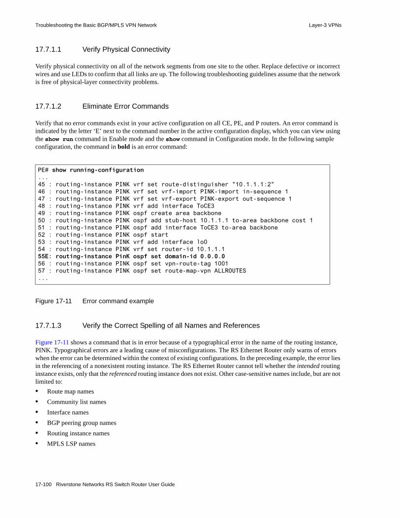
Troubleshooting the Basic BGP/MPLS VPN Network Layer-3 VPNs
17.7.1.1 Verify Physical Connectivity
Verify physical connectivity on all of the network segments from one site to the other. Replace defective or incorrect wires and use LEDs to confirm that all links are up. The following troubleshooting guidelines assume that the network is free of physical-layer connectivity problems.
17.7.1.2 Eliminate Error Commands
Verify that no error commands exist in your active configuration on all CE, PE, and P routers. An error command is indicated by the letter ‘E’ next to the command number in the active configuration display, which you can view using the show run command in Enable mode and the show command in Configuration mode. In the following sample configuration, the command in bold is an error command:
Figure 17-11 Error command example
17.7.1.3 Verify the Correct Spelling of all Names and References
Figure 17-11 shows a command that is in error because of a typographical error in the name of the routing instance, PINK. Typographical errors are a leading cause of misconfigurations. The RS Ethernet Router only warns of errors when the error can be determined within the context of existing configurations. In the preceding example, the error lies in the referencing of a nonexistent routing instance. The RS Ethernet Router cannot tell whether the intended routing instance exists, only that the referenced routing instance does not exist. Other case-sensitive names include, but are not limited to:• Route map names• Community list names• Interface names• BGP peering group names• Routing instance names• MPLS LSP names
PE# show running-configuration...45 : routing-instance PINK vrf set route-distinguisher "10.1.1.1:2"46 : routing-instance PINK vrf set vrf-import PINK-import in-sequence 147 : routing-instance PINK vrf set vrf-export PINK-export out-sequence 148 : routing-instance PINK vrf add interface ToCE349 : routing-instance PINK ospf create area backbone50 : routing-instance PINK ospf add stub-host 10.1.1.1 to-area backbone cost 151 : routing-instance PINK ospf add interface ToCE3 to-area backbone52 : routing-instance PINK ospf start53 : routing-instance PINK vrf add interface lo054 : routing-instance PINK vrf set router-id 10.1.1.155E: routing-instance PinK ospf set domain-id 0.0.0.056 : routing-instance PINK ospf set vpn-route-tag 100157 : routing-instance PINK ospf set route-map-vpn ALLROUTES...
17-100 Riverstone Networks RS Switch Router User Guide
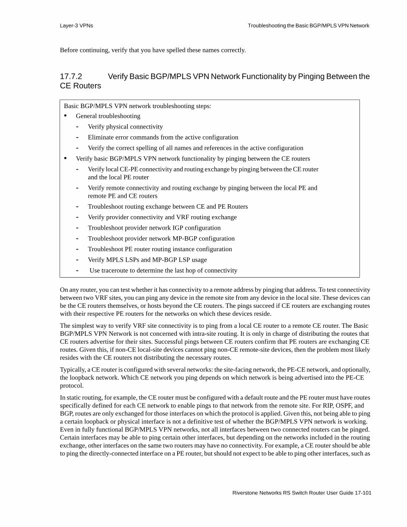
Layer-3 VPNs Troubleshooting the Basic BGP/MPLS VPN Network
Before continuing, verify that you have spelled these names correctly.
17.7.2 Verify Basic BGP/MPLS VPN Network Functionality by Pinging Between the CE Routers
On any router, you can test whether it has connectivity to a remote address by pinging that address. To test connectivity between two VRF sites, you can ping any device in the remote site from any device in the local site. These devices can be the CE routers themselves, or hosts beyond the CE routers. The pings succeed if CE routers are exchanging routes with their respective PE routers for the networks on which these devices reside.
The simplest way to verify VRF site connectivity is to ping from a local CE router to a remote CE router. The Basic BGP/MPLS VPN Network is not concerned with intra-site routing. It is only in charge of distributing the routes that CE routers advertise for their sites. Successful pings between CE routers confirm that PE routers are exchanging CE routes. Given this, if non-CE local-site devices cannot ping non-CE remote-site devices, then the problem most likely resides with the CE routers not distributing the necessary routes.
Typically, a CE router is configured with several networks: the site-facing network, the PE-CE network, and optionally, the loopback network. Which CE network you ping depends on which network is being advertised into the PE-CE protocol.
In static routing, for example, the CE router must be configured with a default route and the PE router must have routes specifically defined for each CE network to enable pings to that network from the remote site. For RIP, OSPF, and BGP, routes are only exchanged for those interfaces on which the protocol is applied. Given this, not being able to ping a certain loopback or physical interface is not a definitive test of whether the BGP/MPLS VPN network is working. Even in fully functional BGP/MPLS VPN networks, not all interfaces between two connected routers can be pinged. Certain interfaces may be able to ping certain other interfaces, but depending on the networks included in the routing exchange, other interfaces on the same two routers may have no connectivity. For example, a CE router should be able to ping the directly-connected interface on a PE router, but should not expect to be able to ping other interfaces, such as
Basic BGP/MPLS VPN network troubleshooting steps:• General troubleshooting
- Verify physical connectivity- Eliminate error commands from the active configuration- Verify the correct spelling of all names and references in the active configuration
• Verify basic BGP/MPLS VPN network functionality by pinging between the CE routers- Verify local CE-PE connectivity and routing exchange by pinging between the CE router
and the local PE router- Verify remote connectivity and routing exchange by pinging between the local PE and
remote PE and CE routers- Troubleshoot routing exchange between CE and PE Routers- Verify provider connectivity and VRF routing exchange- Troubleshoot provider network IGP configuration- Troubleshoot provider network MP-BGP configuration - Troubleshoot PE router routing instance configuration - Verify MPLS LSPs and MP-BGP LSP usage- Use traceroute to determine the last hop of connectivity
Riverstone Networks RS Switch Router User Guide 17-101

Troubleshooting the Basic BGP/MPLS VPN Network Layer-3 VPNs
• customer-facing interfaces in other VRFs• provider-facing interfaces• loopback interfaces (unless it has been specifically added to the CE-PE protocol)
To determine whether a ping should work, first determine whether routes for both the destination and source addresses of the ping should be exchanged. The following troubleshooting sections illustrate pings that both should and should not be successful in the Basic BGP/MPLS VPN Network.
Note A ping can succeed only if both the destination and source addresses of the ping are being exchanged. For example, for A to successfully ping B, A’s routing table must have a route to B and B’s routing table must have a return route to A.
In the sample troubleshooting network (Figure 17-10), CE3 is advertising the following networks to PE1 via EBGP:• Customer-facing network: 172.17.2/24• Provider-facing network: 172.17.8/30• Loopback network: 172.20.2.1/32
Similarly, CE4 is advertising the following networks to PE2 via OSPF:• Customer-facing network: 192.168.9/24• Provider-facing network: 192.168.8/30• Loopback network: 192.168.101.1/32
To verify basic BGP/MPLS VPN functionality, ping between the CE routers.
The following demonstrates successful pings from CE3 to the announced interfaces on CE4:
17-102 Riverstone Networks RS Switch Router User Guide

Layer-3 VPNs Troubleshooting the Basic BGP/MPLS VPN Network
Figure 17-12 Ping from CE3 to CE4
The following demonstrates successful pings from CE4 to the announced interfaces on CE3:
CE3# ping 192.168.101.1PING 192.168.101.1: 36 bytes of data5 second timeout, 1 repetition36 bytes from 192.168.101.1: icmp_seq=0 ttl=253 time=2.786 ms
--- 192.168.101.1 ping statistics ---1 packets transmitted, 1 packets received, 0.00% packet lossround-trip min/avg/max/dev = 2.786/2.786/2.786/0.000 ms
CE3# ping 192.168.9.1PING 192.168.9.1: 36 bytes of data5 second timeout, 1 repetition36 bytes from 192.168.9.1: icmp_seq=0 ttl=253 time=2.792 ms
--- 192.168.9.1 ping statistics ---1 packets transmitted, 1 packets received, 0.00% packet lossround-trip min/avg/max/dev = 2.792/2.792/2.792/0.000 ms
CE3# ping 192.168.8.2PING 192.168.8.2: 36 bytes of data5 second timeout, 1 repetition36 bytes from 192.168.8.2: icmp_seq=0 ttl=253 time=2.634 ms
--- 192.168.8.2 ping statistics ---1 packets transmitted, 1 packets received, 0.00% packet lossround-trip min/avg/max/dev = 2.634/2.634/2.634/0.000 ms
Riverstone Networks RS Switch Router User Guide 17-103
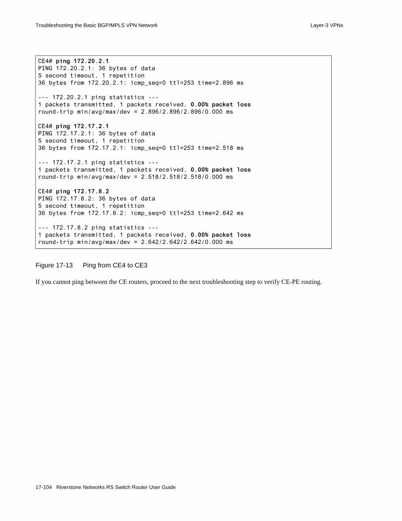
Troubleshooting the Basic BGP/MPLS VPN Network Layer-3 VPNs
Figure 17-13 Ping from CE4 to CE3
If you cannot ping between the CE routers, proceed to the next troubleshooting step to verify CE-PE routing.
CE4# ping 172.20.2.1PING 172.20.2.1: 36 bytes of data5 second timeout, 1 repetition36 bytes from 172.20.2.1: icmp_seq=0 ttl=253 time=2.896 ms
--- 172.20.2.1 ping statistics ---1 packets transmitted, 1 packets received, 0.00% packet lossround-trip min/avg/max/dev = 2.896/2.896/2.896/0.000 ms
CE4# ping 172.17.2.1PING 172.17.2.1: 36 bytes of data5 second timeout, 1 repetition36 bytes from 172.17.2.1: icmp_seq=0 ttl=253 time=2.518 ms
--- 172.17.2.1 ping statistics ---1 packets transmitted, 1 packets received, 0.00% packet lossround-trip min/avg/max/dev = 2.518/2.518/2.518/0.000 ms
CE4# ping 172.17.8.2PING 172.17.8.2: 36 bytes of data5 second timeout, 1 repetition36 bytes from 172.17.8.2: icmp_seq=0 ttl=253 time=2.642 ms
--- 172.17.8.2 ping statistics ---1 packets transmitted, 1 packets received, 0.00% packet lossround-trip min/avg/max/dev = 2.642/2.642/2.642/0.000 ms
17-104 Riverstone Networks RS Switch Router User Guide

Layer-3 VPNs Troubleshooting the Basic BGP/MPLS VPN Network
17.7.3 Verify Local CE-PE Connectivity and Routing Exchange by Pinging Between the CE Router and the Local PE Router
To verify local CE-PE connectivity and routing exchange, ping between the CE router and the local PE router. Use the ping command on CE routers and the ping command with the vrf option on PE routers. You must use the vrf option because without it, the ping command resolves the destination address using routes in the Global Unicast FIB. PE and CE routers peer through a VRF, so all of the routes the CE router announces are stored in the Routing Instance Unicast FIB on the PE router, not in the Global Unicast FIB. (The exceptions are routes to networks that are directly connected to the PE router, which are stored in both the Routing Instance Unicast FIB and the Global Unicast FIB.)
The following demonstrate successful pings from CE3 to the directly-connected PE1 interface (172.17.8.1) and from PE1 to all of CE3’s interfaces.
Note that CE3 cannot ping all of PE1’s interfaces, such as PE1’s loopback interface (10.1.1.1) and provider-facing interface (10.0.1.1). This is expected because PE1 is not configured to exchange routes for those interfaces with CE3.
Basic BGP/MPLS VPN network troubleshooting steps:• General troubleshooting
- Verify physical connectivity- Eliminate error commands from the active configuration- Verify the correct spelling of all names and references in the active configuration
• Verify basic BGP/MPLS VPN network functionality by pinging between the CE routers- Verify local CE-PE connectivity and routing exchange by pinging between the CE
router and the local PE router- Verify remote connectivity and routing exchange by pinging between the local PE
and remote PE and CE routers- Troubleshoot routing exchange between CE and PE Routers- Verify provider connectivity and VRF routing exchange- Troubleshoot provider network IGP configuration- Troubleshoot provider network MP-BGP configuration - Troubleshoot PE router routing instance configuration - Verify MPLS LSPs and MP-BGP LSP usage- Use traceroute to determine the last hop of connectivity
Riverstone Networks RS Switch Router User Guide 17-105

Troubleshooting the Basic BGP/MPLS VPN Network Layer-3 VPNs
Figure 17-14 Ping from CE3 to PE1
CE3 is announcing all of its interfaces to PE1.
The following demonstrates successful pings from PE1 to the announced interfaces on CE3. Note that PE1 can ping 172.17.8.2 using both the Global Unicast FIB and the Routing Instance PINK Unicast FIB. The 172.17.8.0/30 network is directly connected to PE1, so PE1 learns of it both as a direct route and through routing announcements from CE3. This causes a route to the 172.17.8.0/30 network to exist in both FIBs.
CE3# ping 172.17.8.1PING 172.17.8.1: 36 bytes of data5 second timeout, 1 repetition36 bytes from 172.17.8.1: icmp_seq=0 ttl=255 time=1.288 ms
--- 172.17.8.1 ping statistics ---1 packets transmitted, 1 packets received, 0.00% packet lossround-trip min/avg/max/dev = 1.288/1.288/1.288/0.000 ms
CE3# ping 10.1.1.1PING 10.1.1.1: 36 bytes of data5 second timeout, 1 repetitionFrom localhost: Destination Host Unreachable
--- 10.1.1.1 ping statistics ---1 packets transmitted, 0 packets received, 100.00% packet lossround-trip min/avg/max/dev = 0.000/0.000/0.000/0.000 ms
CE3# ping 10.0.1.1PING 10.0.1.1: 36 bytes of data5 second timeout, 1 repetitionFrom localhost: Destination Host Unreachable
--- 10.0.1.1 ping statistics ---1 packets transmitted, 0 packets received, 100.00% packet lossround-trip min/avg/max/dev = 0.000/0.000/0.000/0.000 ms
17-106 Riverstone Networks RS Switch Router User Guide

Layer-3 VPNs Troubleshooting the Basic BGP/MPLS VPN Network
Figure 17-15 Ping from PE1 to CE3
The following demonstrate successful pings from CE4 to two PE2 interfaces (192.168.8.1 and 10.3.3.1) and from PE2 to all of CE4’s interfaces.
Note that CE4 cannot ping all of PE2’s interfaces, but CE4 is able to ping PE2’s loopback interface (10.3.3.1) because that interface participates in OSPF with CE4. CE4 cannot ping PE2’s provider-facing interface (10.0.2.2) because PE2 is not configured to exchange routes for it with CE4.
PE1# ping 172.17.8.2PING 172.17.8.2: 36 bytes of data5 second timeout, 1 repetition36 bytes from 172.17.8.2: icmp_seq=0 ttl=255 time=1.248 ms
--- 172.17.8.2 ping statistics ---1 packets transmitted, 1 packets received, 0.00% packet lossround-trip min/avg/max/dev = 1.248/1.248/1.248/0.000 ms
PE1# ping 172.17.8.2 vrf PINKPING 172.17.8.2: Using VRF PINK36 bytes of data5 second timeout, 1 repetition36 bytes from 172.17.8.2: icmp_seq=0 ttl=255 time=1.290 ms
--- 172.17.8.2 ping statistics ---1 packets transmitted, 1 packets received, 0.00% packet lossround-trip min/avg/max/dev = 1.290/1.290/1.290/0.000 ms
PE1# ping 172.20.2.1 vrf PINKPING 172.20.2.1: Using VRF PINK36 bytes of data5 second timeout, 1 repetition36 bytes from 172.20.2.1: icmp_seq=0 ttl=255 time=2.064 ms
--- 172.20.2.1 ping statistics ---1 packets transmitted, 1 packets received, 0.00% packet lossround-trip min/avg/max/dev = 2.064/2.064/2.064/0.000 ms
PE1# ping 172.17.2.1 vrf PINKPING 172.17.2.1: Using VRF PINK36 bytes of data5 second timeout, 1 repetition36 bytes from 172.17.2.1: icmp_seq=0 ttl=255 time=1.284 ms
--- 172.17.2.1 ping statistics ---1 packets transmitted, 1 packets received, 0.00% packet lossround-trip min/avg/max/dev = 1.284/1.284/1.284/0.000 ms
Riverstone Networks RS Switch Router User Guide 17-107
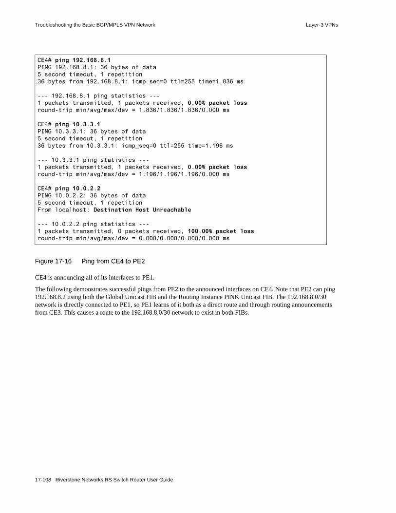
Troubleshooting the Basic BGP/MPLS VPN Network Layer-3 VPNs
Figure 17-16 Ping from CE4 to PE2
CE4 is announcing all of its interfaces to PE1.
The following demonstrates successful pings from PE2 to the announced interfaces on CE4. Note that PE2 can ping 192.168.8.2 using both the Global Unicast FIB and the Routing Instance PINK Unicast FIB. The 192.168.8.0/30 network is directly connected to PE1, so PE1 learns of it both as a direct route and through routing announcements from CE3. This causes a route to the 192.168.8.0/30 network to exist in both FIBs.
CE4# ping 192.168.8.1PING 192.168.8.1: 36 bytes of data5 second timeout, 1 repetition36 bytes from 192.168.8.1: icmp_seq=0 ttl=255 time=1.836 ms
--- 192.168.8.1 ping statistics ---1 packets transmitted, 1 packets received, 0.00% packet lossround-trip min/avg/max/dev = 1.836/1.836/1.836/0.000 ms
CE4# ping 10.3.3.1PING 10.3.3.1: 36 bytes of data5 second timeout, 1 repetition36 bytes from 10.3.3.1: icmp_seq=0 ttl=255 time=1.196 ms
--- 10.3.3.1 ping statistics ---1 packets transmitted, 1 packets received, 0.00% packet lossround-trip min/avg/max/dev = 1.196/1.196/1.196/0.000 ms
CE4# ping 10.0.2.2PING 10.0.2.2: 36 bytes of data5 second timeout, 1 repetitionFrom localhost: Destination Host Unreachable
--- 10.0.2.2 ping statistics ---1 packets transmitted, 0 packets received, 100.00% packet lossround-trip min/avg/max/dev = 0.000/0.000/0.000/0.000 ms
17-108 Riverstone Networks RS Switch Router User Guide

Layer-3 VPNs Troubleshooting the Basic BGP/MPLS VPN Network
Figure 17-17 Ping from PE2 to CE4
If the desired pings are not successful, examine the relevant FIBs on both the CE and PE routers to determine if the appropriate VRF routes are being exchanged. Use the ip show route command on the CE router and the ip show route show-vrf <instance> command on the PE router. You must specify an instance on the PE router because unlike the CE router, the PE router installs the routes that it learns during CE-PE exchange in the Routing Instance Unicast FIB, not the Global Unicast FIB.
For a ping to succeed, the CE router must have a route to the PE address it is pinging, and the PE router must have a route back to the CE router. The following demonstrate this between CE3 and PE1 and between CE4 and PE2. In this step, we are only concerned with the local VRF routes, which are highlighted.
PE2# ping 192.168.8.2PING 192.168.8.2: 36 bytes of data5 second timeout, 1 repetition36 bytes from 192.168.8.2: icmp_seq=0 ttl=255 time=1.200 ms
--- 192.168.8.2 ping statistics ---1 packets transmitted, 1 packets received, 0.00% packet lossround-trip min/avg/max/dev = 1.200/1.200/1.200/0.000 ms
PE2# ping 192.168.8.2 vrf PINKPING 192.168.8.2: Using VRF PINK36 bytes of data5 second timeout, 1 repetition36 bytes from 192.168.8.2: icmp_seq=0 ttl=255 time=0.990 ms
--- 192.168.8.2 ping statistics ---1 packets transmitted, 1 packets received, 0.00% packet lossround-trip min/avg/max/dev = 0.990/0.990/0.990/0.000 ms
PE2# ping 192.168.9.1 vrf PINKPING 192.168.9.1: Using VRF PINK36 bytes of data5 second timeout, 1 repetition36 bytes from 192.168.9.1: icmp_seq=0 ttl=255 time=1.210 ms
--- 192.168.9.1 ping statistics ---1 packets transmitted, 1 packets received, 0.00% packet lossround-trip min/avg/max/dev = 1.210/1.210/1.210/0.000 ms
PE2# ping 192.168.101.1 vrf PINKPING 192.168.101.1: Using VRF PINK36 bytes of data5 second timeout, 1 repetition36 bytes from 192.168.101.1: icmp_seq=0 ttl=255 time=1.218 ms
--- 192.168.101.1 ping statistics ---1 packets transmitted, 1 packets received, 0.00% packet lossround-trip min/avg/max/dev = 1.218/1.218/1.218/0.000 ms
Riverstone Networks RS Switch Router User Guide 17-109

Troubleshooting the Basic BGP/MPLS VPN Network Layer-3 VPNs
Figure 17-18 Unicast FIB on CE3 and PINK Instance FIB on PE1—Verify routing exchange
CE3# ip show routes
Destination Gateway Owner Netif----------- ------- ----- -----127.0.0.1 127.0.0.1 - lo0172.17.2.0/24 directly connected - ToCustomerBSite172.17.8.0/30 directly connected - ToPE1172.20.2.1 172.20.2.1 - lo0192.168.8.0/30 172.17.8.1 BGP ToPE1192.168.9.0/24 172.17.8.1 BGP ToPE1192.168.101.1 172.17.8.1 BGP ToPE1
PE1# ip show routes show-vrf PINK
Destination Gateway Owner Netif----------- ------- ----- -----127.0.0.1 127.0.0.1 - lo0172.17.2.0/24 172.17.8.2 BGP ToCE3172.17.8.0/30 directly connected - ToCE3172.20.2.1 172.17.8.2 BGP ToCE3192.168.8.0/30 10.0.1.2 BGP PE1toPE2192.168.9.0/24 10.0.1.2 BGP PE1toPE2192.168.101.1 10.0.1.2 BGP PE1toPE2
CE4# ip show routes
Destination Gateway Owner Netif----------- ------- ----- -----10.3.3.1 192.168.8.1 OSPF ToPE2127.0.0.1 127.0.0.1 - lo0172.17.2.0/24 192.168.8.1 OSPF_ASE ToPE2172.17.8.0/30 192.168.8.1 OSPF_ASE ToPE2172.20.2.1 192.168.8.1 OSPF_ASE ToPE2192.168.8.0/30 directly connected - ToPE2192.168.9.0/24 directly connected - ToCustomerBSite192.168.101.1 192.168.101.1 - lo0
17-110 Riverstone Networks RS Switch Router User Guide

Layer-3 VPNs Troubleshooting the Basic BGP/MPLS VPN Network
Figure 17-19 Unicast FIB on CE4 and PINK Instance FIB on PE2—Verify routing exchange
If the routes that you expect to see are not in the FIBs, the CE-PE routing exchange may be misconfigured.• If you are using static routing, add the appropriate static routes and return to the beginning of this
troubleshooting step. • If you are using RIP, add the interfaces for those routes into RIP and return to the beginning of this
troubleshooting step.• If you are using OSPF or BGP for CE-PE route distribution, continue with the next troubleshooting
step.
PE2# ip show routes show-vrf PINK
Destination Gateway Owner Netif----------- ------- ----- -----127.0.0.1 127.0.0.1 - lo0172.17.2.0/24 10.0.2.1 BGP PE2toPE1172.17.8.0/30 10.0.2.1 BGP PE2toPE1172.20.2.1 10.0.2.1 BGP PE2toPE1192.168.8.0/30 directly connected - ToCE4192.168.9.0/24 192.168.8.2 OSPF ToCE4192.168.101.1 192.168.8.2 OSPF ToCE4
Riverstone Networks RS Switch Router User Guide 17-111

Troubleshooting the Basic BGP/MPLS VPN Network Layer-3 VPNs
17.7.3.1 Verify Remote Connectivity Between PEs and CEs
The following demonstrates successful pings from PE1 to the remotely-connected PE2 interface (10.3.3.1) and from PE1 to CE4 (192.168.101.1):
Figure 17-20 Successful Pings to Remote PE and CE
Notice that when PE1 sends pings across the MPLS Provider Network, PE1 must include its source address in the ping command. The source address provides the remote MPLS interface router (PE2) with the address necessary to send the reply back to the correct interface on PE1.
Basic BGP/MPLS VPN network troubleshooting steps:• General troubleshooting
- Verify physical connectivity- Eliminate error commands from the active configuration- Verify the correct spelling of all names and references in the active configuration
• Verify basic BGP/MPLS VPN network functionality by pinging between the CE routers- Verify local CE-PE connectivity and routing exchange by pinging between the CE
router and the local PE router- Verify remote connectivity and routing exchange by pinging between the local PE
and remote PE and CE routers- Troubleshoot routing exchange between CE and PE Routers- Verify provider connectivity and VRF routing exchange- Troubleshoot provider network IGP configuration- Troubleshoot provider network MP-BGP configuration - Troubleshoot PE router routing instance configuration - Verify MPLS LSPs and MP-BGP LSP usage- Use traceroute to determine the last hop of connectivity
PE2# ping 10.3.3.1 source 10.1.1.1PING 10.3.3.1: 36 bytes of data5 second timeout, 1 repetition36 bytes from 10.3.3.1: icmp_seq=0 ttl=255 time=1.200 ms
--- 10.3.3.1 ping statistics ---1 packets transmitted, 1 packets received, 0.00% packet lossround-trip min/avg/max/dev = 1.200/1.200/1.200/0.000 ms
PE2# ping 192.168.101.1 vrf PINK source 10.1.1.1PING 192.168.101.1: Using VRF PINK36 bytes of data5 second timeout, 1 repetition36 bytes from 192.168.101.1: icmp_seq=0 ttl=255 time=0.990 ms
--- 192.168.101.1 ping statistics ---1 packets transmitted, 1 packets received, 0.00% packet lossround-trip min/avg/max/dev = 0.990/0.990/0.990/0.000 ms
17-112 Riverstone Networks RS Switch Router User Guide

Layer-3 VPNs Troubleshooting the Basic BGP/MPLS VPN Network
17.7.3.2 Troubleshoot OSPF Between CE and PE Routers
For more information on configuring OSPF between CE and PE routers, refer to the Section 17-48 "Configuring Static and OSPF Route Distribution Between CE and PE Routers."
Troubleshoot an OSPF connection between CE and PE routers using the following show commands:• ospf show neighbor [instance]
- ospf show adjacency-down-reason [instance]
• ospf show interface [instance]
• ospf show database [instance]
- ospf show export-policy [instance]
- ospf show import-policy [instance]
To view instance-related information on the PE-CE OSPF adjacency, use these commands without the instance option on CE routers and with the instance option on PE routers.
On CE4, the ospf show neighbor command displays information about the OSPF adjacency such as the adjacency area and neighboring router. On PE2, the ospf show neighbor instance PINK command displays similar information about the PINK OSPF routing instance.
The following demonstrate that CE4 and PE2 recognize each other as full neighbors. When troubleshooting OSPF adjacencies, watch for the State to be Full in this command output and verify the neighbor’s loopback and interface addresses. If the state is not full, use the ospf show adjacency-down-reason [instance] command for more information.
Basic BGP/MPLS VPN network troubleshooting steps:• General troubleshooting
- Verify physical connectivity- Eliminate error commands from the active configuration- Verify the correct spelling of all names and references in the active configuration
• Verify basic BGP/MPLS VPN network functionality by pinging between the CE routers- Verify local CE-PE connectivity and routing exchange by pinging between the CE
router and the local PE router- Verify remote connectivity and routing exchange by pinging between the local PE
and remote PE and CE routers- Troubleshoot routing exchange between CE and PE Routers- Verify provider connectivity and VRF routing exchange- Troubleshoot provider network IGP configuration- Troubleshoot provider network MP-BGP configuration - Troubleshoot PE router routing instance configuration - Verify MPLS LSPs and MP-BGP LSP usage- Use traceroute to determine the last hop of connectivity
Riverstone Networks RS Switch Router User Guide 17-113
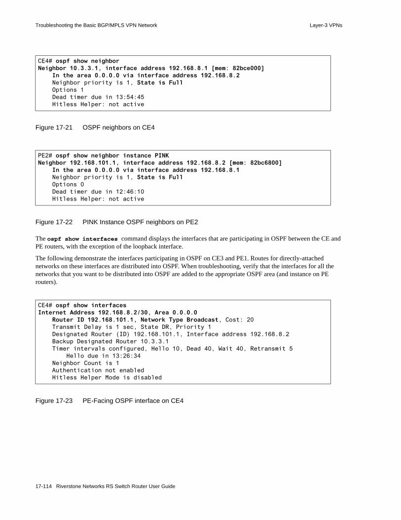
Troubleshooting the Basic BGP/MPLS VPN Network Layer-3 VPNs
Figure 17-21 OSPF neighbors on CE4
Figure 17-22 PINK Instance OSPF neighbors on PE2
The ospf show interfaces command displays the interfaces that are participating in OSPF between the CE and PE routers, with the exception of the loopback interface.
The following demonstrate the interfaces participating in OSPF on CE3 and PE1. Routes for directly-attached networks on these interfaces are distributed into OSPF. When troubleshooting, verify that the interfaces for all the networks that you want to be distributed into OSPF are added to the appropriate OSPF area (and instance on PE routers).
Figure 17-23 PE-Facing OSPF interface on CE4
CE4# ospf show neighborNeighbor 10.3.3.1, interface address 192.168.8.1 [mem: 82bce000] In the area 0.0.0.0 via interface address 192.168.8.2 Neighbor priority is 1, State is Full Options 1 Dead timer due in 13:54:45 Hitless Helper: not active
PE2# ospf show neighbor instance PINKNeighbor 192.168.101.1, interface address 192.168.8.2 [mem: 82bc6800] In the area 0.0.0.0 via interface address 192.168.8.1 Neighbor priority is 1, State is Full Options 0 Dead timer due in 12:46:10 Hitless Helper: not active
CE4# ospf show interfacesInternet Address 192.168.8.2/30, Area 0.0.0.0 Router ID 192.168.101.1, Network Type Broadcast, Cost: 20 Transmit Delay is 1 sec, State DR, Priority 1 Designated Router (ID) 192.168.101.1, Interface address 192.168.8.2 Backup Designated Router 10.3.3.1 Timer intervals configured, Hello 10, Dead 40, Wait 40, Retransmit 5 Hello due in 13:26:34 Neighbor Count is 1 Authentication not enabled Hitless Helper Mode is disabled
17-114 Riverstone Networks RS Switch Router User Guide

Layer-3 VPNs Troubleshooting the Basic BGP/MPLS VPN Network
Figure 17-24 PINK Instance OSPF interfaces on PE2
The ospf show database command displays the OSPF link-state database. Note that on both sides of the VPN, the remote PE-CE network is distributed as an AS external route. Although the PE router has an OSPF route to this network, it advertises the network as directly-connected, which becomes AS external when received by the remote PE.
When troubleshooting, first look to see if the routes to which you have no connectivity are missing from this database. If so, use the ospf show export-policy [instance] and ospf show import-policy [instance] commands to determine if any routing policies controlling route distribution are misconfigured. (On PE routers, the VPN export route map that is applied using the routing-instance ospf set route-map-vpn command is not displayed as an export policy.)
If local PE-CE routing is misconfigured, most likely you will see indications of no local routing exchange:• local-site routes are in the OSPF database of the CE router but are not in the local PE router• remote-site routes are in the OSPF database of the local PE router but are not in the CE router
If remote PE-CE routing is misconfigured, most likely you will not see remote-site routes in the local PE and CE routers.
If the provider network is misconfigured (IGP, MP-BGP, or MPLS), you will also most likely not see remote-site routes in the local PE and CE routers.
When inspecting the OSPF database for remote-site routes, note that a route’s LSA type does not positively identify it as remote. Do not assume that all remote-site routes are Type-5 LSAs. With the exception of the PE-CE network, remote-site routes of a pure OSPF origin from the same OSPF Domain are distributed as Type-3 LSAs. All other remote-site routes, including the PE-CE network, non-OSPF routes distributed into OSPF, and OSPF-originated routes from a different OSPF Domain, are distributed as Type-5 LSAs.
The following demonstrate local VRF routes in the OSPF link-state databases of CE4 and PE2.
PE2# ospf show interfaces instance PINKInternet Address 192.168.8.1/30, Area 0.0.0.0 Router ID 10.3.3.1, Network Type Broadcast, Cost: 20 Transmit Delay is 1 sec, State Back DR, Priority 1 Designated Router (ID) 192.168.101.1, Interface address 192.168.8.1 Backup Designated Router 10.3.3.1 Timer intervals configured, Hello 10, Dead 40, Wait 40, Retransmit 5 Hello due in 12:26:54 Neighbor Count is 1 Authentication not enabled Hitless Helper Mode is disabled
Riverstone Networks RS Switch Router User Guide 17-115
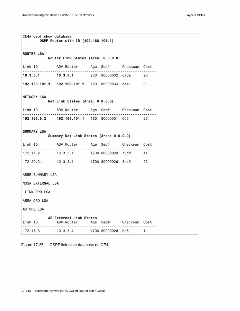
Troubleshooting the Basic BGP/MPLS VPN Network Layer-3 VPNs
Figure 17-25 OSPF link-state database on CE4
CE4# ospf show database OSPF Router with ID (192.168.101.1)
ROUTER LSA Router Link States (Area: 0.0.0.0)
Link ID ADV Router Age Seq# Checksum Cost---------------------------------------------------------------10.3.3.1 10.3.3.1 200 80000032 d70a 20
192.168.101.1 192.168.101.1 180 80000033 ce41 0
NETWORK LSA Net Link States (Area: 0.0.0.0)
Link ID ADV Router Age Seq# Checksum Cost---------------------------------------------------------------192.168.8.2 192.168.101.1 180 80000031 603 20
SUMMARY LSA Summary Net Link States (Area: 0.0.0.0)
Link ID ADV Router Age Seq# Checksum Cost---------------------------------------------------------------172.17.2 10.3.3.1 1700 8000002d 79bd 41
172.20.2.1 10.3.3.1 1700 8000002d 8cb9 22
ASBR SUMMARY LSA
NSSA EXTERNAL LSA
LINK OPQ LSA
AREA OPQ LSA
AS OPQ LSA
AS External Link StatesLink ID ADV Router Age Seq# Checksum Cost---------------------------------------------------------------172.17.8 10.3.3.1 1700 8000002d bc6 1
17-116 Riverstone Networks RS Switch Router User Guide

Layer-3 VPNs Troubleshooting the Basic BGP/MPLS VPN Network
Figure 17-26 PINK Instance OSPF link-state database on PE2
PE2# ospf show database instance PINK OSPF Router with ID (10.3.3.1)
ROUTER LSA Router Link States (Area: 0.0.0.0)
Link ID ADV Router Age Seq# Checksum Cost---------------------------------------------------------------192.168.101.1 192.168.101.1 411 80000033 ce41 20
10.3.3.1 10.3.3.1 429 80000032 d70a 0
NETWORK LSA Net Link States (Area: 0.0.0.0)
Link ID ADV Router Age Seq# Checksum Cost---------------------------------------------------------------192.168.8.2 192.168.101.1 411 80000031 603 20
SUMMARY LSA Summary Net Link States (Area: 0.0.0.0)
Link ID ADV Router Age Seq# Checksum Cost---------------------------------------------------------------172.20.2.1 10.3.3.1 69 8000002e 8aba 22
172.17.2 10.3.3.1 69 8000002e 77be 41
ASBR SUMMARY LSA
NSSA EXTERNAL LSA
LINK OPQ LSA
AREA OPQ LSA
AS OPQ LSA
AS External Link StatesLink ID ADV Router Age Seq# Checksum Cost---------------------------------------------------------------172.17.8 10.3.3.1 69 8000002e 9c7 1
Riverstone Networks RS Switch Router User Guide 17-117

Troubleshooting the Basic BGP/MPLS VPN Network Layer-3 VPNs
17.7.3.3 Troubleshoot BGP Between CE and PE Routers
For more information on configuring BGP between CE and PE routers, refer to Chapter 17.6.2, "Configuring BGP Route Distribution Between CE and PE Routers."
Troubleshoot a BGP session between CE and PE routers using the following show commands:• bgp show neighbor
• bgp show peer-host [instance] advertised-routes
• bgp show peer-host [instance] all-received-routes
• bgp show peer-host [instance] received-routes
To view instance-related information on the PE-CE OSPF adjacency, use these commands without the instance options on CE routers and with the instance option on PE routers.
The bgp show neighbor command displays information about the BGP peering, such as the peer’s address, router ID, the state and type of peering, the BGP version, traffic statistics, and any inbound or outbound route maps in effect.
The following output show that CE4 and PE2 recognize each other as established neighbors. When troubleshooting BGP adjacencies:• Watch for the State to be Established in this command output and verify the neighbor’s router
ID and interface address. If the State is not Established, execute this command several times in quick succession to determine if the BGP adjacency is cycling through certain states. If it is, refer to BGP protocol specifications for information on the possible causes of adjacency state toggling.
• Confirm that the correct autonomous system number is configured on both the PE and CE routers. • When configuring BGP peer groups, you do not need to specify the type of peering (external or
routing). The router automatically determine the type by comparing the peer group’s autonomous system to its own. Type ‘routing’ is used for IBGP peering. Type ‘external’ is used for EBGP peering. A common BGP problem is misconfigured peering type. If this is the case, either select the right peering type or remove all type specifications and allow the router to use the default type.
Basic BGP/MPLS VPN network troubleshooting steps:• General troubleshooting
- Verify physical connectivity- Eliminate error commands from the active configuration- Verify the correct spelling of all names and references in the active configuration
• Verify basic BGP/MPLS VPN network functionality by pinging between the CE routers- Verify local CE-PE connectivity and routing exchange by pinging between the CE
router and the local PE router- Verify remote connectivity and routing exchange by pinging between the local PE
and remote PE and CE routers- Troubleshoot routing exchange between CE and PE Routers- Verify provider connectivity and VRF routing exchange- Troubleshoot provider network IGP configuration- Troubleshoot provider network MP-BGP configuration - Troubleshoot PE router routing instance configuration - Verify MPLS LSPs and MP-BGP LSP usage- Use traceroute to determine the last hop of connectivity
17-118 Riverstone Networks RS Switch Router User Guide

Layer-3 VPNs Troubleshooting the Basic BGP/MPLS VPN Network
• Check to see that the BGP peers are passing traffic. • If expected routes are not being distributed, confirm the logic in any route maps applied.
The following demonstrate correct peering between PE1 and CE3. On PE routers, limit the bgp show neighbor view by specifying the appropriate CE peer. If you choose to view all neighbors, the view displays all PE and CE neighbors.
Figure 17-27 PINK Instance BGP neighbor (CE3) on PE1
PE1# bgp show neighbor 172.17.8.2Peer: 172.17.8.2+179 Local: 172.17.8.1+1033 Type: External remote AS 65002 State: Established Flags: <v4MP GenDefault> Last State: OpenConfirm Last Event: RecvKeepAlive Last Error: None
Options: <> Configured parameters : VRF in use PINK VRF number 4
Used parameters : Peer Version: 4 Peer ID: 172.20.2.1 Local ID: 10.1.1.1 Active Holdtime:
180 Uptime 2d23h6m44s Last traffic (seconds): Received 58 Sent 11 Checked 178 Input messages :Total 4268 Updates 2 Octets 81132
Output messages:Total 4277 Updates 8 Octets 81650
count of sent routes 4 count of recvd routes 3 count of route refresh recvd 0 count of route refresh sent 0 count of derived routes 0 Supported capabilities Route Refresh; Outbound policy configured : Routemaps for outgoing advertisements : Route Map Sequence ================================ ALLROUTES 1
Riverstone Networks RS Switch Router User Guide 17-119

Troubleshooting the Basic BGP/MPLS VPN Network Layer-3 VPNs
Figure 17-28 BGP neighbors on CE3
The bgp show peer-host [instance] advertised-routes command displays the routes that a peer is sending to a neighbor. If an expected route is missing, verify that the sending peer is announcing the route. Then verify that the receiving peer is receiving the route using the bgp show peer-host [instance] all-received-routes command.
If local PE-CE routing is misconfigured, you will not see routes being advertised or received on the CE and PE routers.
If remote PE-CE routing is misconfigured, most likely you will not see remote-site routes in the local PE and CE routers.
If the provider network is misconfigured (IGP, MP-BGP, or MPLS), you will also most likely not see remote-site routes in the local PE and CE routers.
The following demonstrate that CE3 is sending a route for each of its configured networks to PE1. PE1 is sending CE3 remote PINK VRF routes learned from CE4 via PE2. PE1 is also sending CE3 its directly-connected route in the PINK VRF. Both routers are receiving each other’s advertised routes.
Notice that you must use the instance option on PE routers with the bgp show peer-host command to view VRF-related advertisements. It is possible for a PE router to be sending multiple VRF routes to the same peer, in which case the advertisements are sorted by instance. In the sample troubleshooting network (Figure 17-10), PE1 is only peering with CE3 via the PINK routing instance.
CE3# bgp show neighbor all Peer: 172.17.8.1+1033 Local: 172.17.8.2+179 Type: External remote AS 65001 State: Established Flags: <v4MP GenDefault> Last State: OpenConfirm Last Event: RecvKeepAlive Last Error: None
Options: <> Configured parameters : VRF in use unicast VRF number 0
Used parameters : Peer Version: 4 Peer ID: 10.1.1.1 Local ID: 172.20.2.1 Active Holdtime:
180 Uptime 2d23h26m57s Last traffic (seconds): Received 27 Sent 14 Checked 147 Input messages :Total 4297 Updates 9 Octets 82011
Output messages:Total 4290 Updates 1 Octets 81589
count of sent routes 3 count of recvd routes 4 count of route refresh recvd 0 count of route refresh sent 0 count of derived routes 0 Supported capabilities Route Refresh; Outbound policy configured : Routemaps for outgoing advertisements : Route Map Sequence ================================ ALLROUTES 1
17-120 Riverstone Networks RS Switch Router User Guide
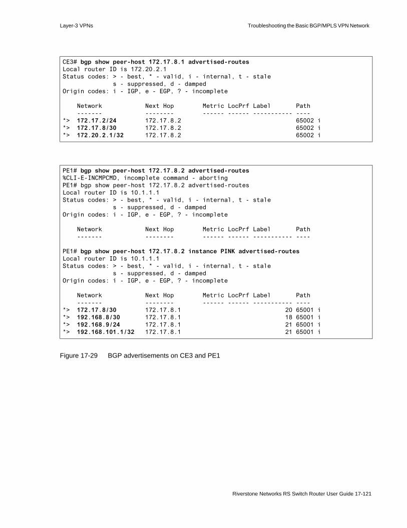
Layer-3 VPNs Troubleshooting the Basic BGP/MPLS VPN Network
Figure 17-29 BGP advertisements on CE3 and PE1
CE3# bgp show peer-host 172.17.8.1 advertised-routesLocal router ID is 172.20.2.1Status codes: > - best, * - valid, i - internal, t - stale s - suppressed, d - dampedOrigin codes: i - IGP, e - EGP, ? - incomplete
Network Next Hop Metric LocPrf Label Path ------- -------- ------ ------ ----------- ----*> 172.17.2/24 172.17.8.2 65002 i*> 172.17.8/30 172.17.8.2 65002 i*> 172.20.2.1/32 172.17.8.2 65002 i
PE1# bgp show peer-host 172.17.8.2 advertised-routes%CLI-E-INCMPCMD, incomplete command - abortingPE1# bgp show peer-host 172.17.8.2 advertised-routesLocal router ID is 10.1.1.1Status codes: > - best, * - valid, i - internal, t - stale s - suppressed, d - dampedOrigin codes: i - IGP, e - EGP, ? - incomplete
Network Next Hop Metric LocPrf Label Path ------- -------- ------ ------ ----------- ----
PE1# bgp show peer-host 172.17.8.2 instance PINK advertised-routesLocal router ID is 10.1.1.1Status codes: > - best, * - valid, i - internal, t - stale s - suppressed, d - dampedOrigin codes: i - IGP, e - EGP, ? - incomplete
Network Next Hop Metric LocPrf Label Path ------- -------- ------ ------ ----------- ----*> 172.17.8/30 172.17.8.1 20 65001 i*> 192.168.8/30 172.17.8.1 18 65001 i*> 192.168.9/24 172.17.8.1 21 65001 i*> 192.168.101.1/32 172.17.8.1 21 65001 i
Riverstone Networks RS Switch Router User Guide 17-121
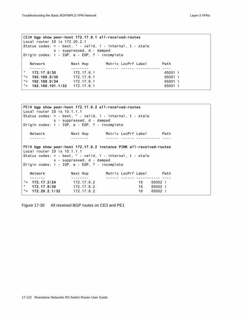
Troubleshooting the Basic BGP/MPLS VPN Network Layer-3 VPNs
Figure 17-30 All received BGP routes on CE3 and PE1
CE3# bgp show peer-host 172.17.8.1 all-received-routesLocal router ID is 172.20.2.1Status codes: > - best, * - valid, i - internal, t - stale s - suppressed, d - dampedOrigin codes: i - IGP, e - EGP, ? - incomplete
Network Next Hop Metric LocPrf Label Path ------- -------- ------ ------ ----------- ----* 172.17.8/30 172.17.8.1 65001 i*> 192.168.8/30 172.17.8.1 65001 i*> 192.168.9/24 172.17.8.1 65001 i*> 192.168.101.1/32 172.17.8.1 65001 i
PE1# bgp show peer-host 172.17.8.2 all-received-routesLocal router ID is 10.1.1.1Status codes: > - best, * - valid, i - internal, t - stale s - suppressed, d - dampedOrigin codes: i - IGP, e - EGP, ? - incomplete
Network Next Hop Metric LocPrf Label Path ------- -------- ------ ------ ----------- ----
PE1# bgp show peer-host 172.17.8.2 instance PINK all-received-routesLocal router ID is 10.1.1.1Status codes: > - best, * - valid, i - internal, t - stale s - suppressed, d - dampedOrigin codes: i - IGP, e - EGP, ? - incomplete
Network Next Hop Metric LocPrf Label Path ------- -------- ------ ------ ----------- ----*> 172.17.2/24 172.17.8.2 18 65002 i* 172.17.8/30 172.17.8.2 18 65002 i*> 172.20.2.1/32 172.17.8.2 18 65002 i
17-122 Riverstone Networks RS Switch Router User Guide

Layer-3 VPNs Troubleshooting the Basic BGP/MPLS VPN Network
If a route is being advertised and received, but you cannot ping to it, look for the route in the bgp show peer-host [instance] received-routes display output. The bgp show peer-host received-routes command differs from the bgp show peer-host all-received-routes command in that the latter displays all received routes, while the former only displays those routes that have a valid next hop and that have not been denied by a routing policy. If you see a route in the all-received-routes display but not in the received-routes display, check to make sure that no routing policies deny this route and that a route exists to its BGP next hop in the routing tables.
By comparing the bgp show peer-host received-routes displays to the bgp show peer-host all-received-routes displays, you see that the respective received-routes and all-received-routes displays are identical. This confirms that all of the PINK VRF-related received routes on both CE3 and PE1 have valid next hops.
Figure 17-31 Received BGP routes with Valid Next Hops on CE3 and PE1
If you are still not able to ping between the CE routers after confirming that CE-PE routing is properly configured and working, continue with the next troubleshooting step to verify the provider network configuration.
PE1# bgp show peer-host 172.17.8.2 received-routesLocal router ID is 10.1.1.1Status codes: > - best, * - valid, i - internal, t - stale s - suppressed, d - dampedOrigin codes: i - IGP, e - EGP, ? - incomplete
Network Next Hop Metric LocPrf Label Path ------- -------- ------ ------ ----------- ----
PE1# bgp show peer-host 172.17.8.2 instance PINK received-routesLocal router ID is 10.1.1.1Status codes: > - best, * - valid, i - internal, t - stale s - suppressed, d - dampedOrigin codes: i - IGP, e - EGP, ? - incomplete
Network Next Hop Metric LocPrf Label Path ------- -------- ------ ------ ----------- ----*> 172.17.2/24 172.17.8.2 18 65002 i* 172.17.8/30 172.17.8.2 18 65002 i*> 172.20.2.1/32 172.17.8.2 18 65002 i
CE3# bgp show peer-host 172.17.8.1 received-routesLocal router ID is 172.20.2.1Status codes: > - best, * - valid, i - internal, t - stale s - suppressed, d - dampedOrigin codes: i - IGP, e - EGP, ? - incomplete
Network Next Hop Metric LocPrf Label Path ------- -------- ------ ------ ----------- ----* 172.17.8/30 172.17.8.1 65001 i*> 192.168.8/30 172.17.8.1 65001 i*> 192.168.9/24 172.17.8.1 65001 i*> 192.168.101.1/32 172.17.8.1 65001 i
Riverstone Networks RS Switch Router User Guide 17-123

Troubleshooting the Basic BGP/MPLS VPN Network Layer-3 VPNs
17.7.4 Troubleshoot the Provider Network
If you are still not able to ping between the CE routers after confirming that CE-PE routing is properly configured and working, the problem most likely exists within the provider network configuration. Within the provider network, several things can be wrong:• IGP may be misconfigured• MP-BGP may be misconfigured• Routing instances may be misconfigured• MPLS LSPs may be misconfigured
Basic BGP/MPLS VPN network troubleshooting steps:• General troubleshooting
- Verify physical connectivity- Eliminate error commands from the active configuration- Verify the correct spelling of all names and references in the active configuration
• Verify basic BGP/MPLS VPN network functionality by pinging between the CE routers- Verify local CE-PE connectivity and routing exchange by pinging between the CE
router and the local PE route- Verify remote connectivity and routing exchange by pinging between the local PE
and remote PE and CE routers- Troubleshoot routing exchange between CE and PE Routers- Verify provider connectivity and VRF routing exchange- Troubleshoot provider network IGP configuration- Troubleshoot provider network MP-BGP configuration - Troubleshoot PE router routing instance configuration - Verify MPLS LSPs and MP-BGP LSP usage- Use traceroute to determine the last hop of connectivity
17-124 Riverstone Networks RS Switch Router User Guide

Layer-3 VPNs Troubleshooting the Basic BGP/MPLS VPN Network
17.7.4.1 Troubleshoot the Provider Network IGP
Unless PE routers are peering over directly-connected links (i.e., without any P routers in between), an IGP or static routes must be in place for MP-BGP to work. A PE router must be able to resolve MP-BGP next hops using existing IGP routes.
OSPF is the IGP running in the sample troubleshooting network (Figure 17-10). Each provider router must have a route to the following provider networks:10.0.1.0/30 10.0.2.0/30 10.1.1.1/3210.2.2.1/3210.3.3.1/32
Each provider router learns the networks that are not directly connected, as well as the router IDs of other provider routers, through OSPF. Use the ip show routes command to view the FIBs on PE routers.
The following demonstrate successful OSPF route distribution within the provider network.
Basic BGP/MPLS VPN network troubleshooting steps:• General troubleshooting
- Verify physical connectivity- Eliminate error commands from the active configuration- Verify the correct spelling of all names and references in the active configuration
• Verify basic BGP/MPLS VPN network functionality by pinging between the CE routers- Verify local CE-PE connectivity and routing exchange by pinging between the CE
router and the local PE router- Verify remote connectivity and routing exchange by pinging between the local PE
and remote PE and CE routers- Troubleshoot routing exchange between CE and PE Routers- Verify provider connectivity and VRF routing exchange- Troubleshoot provider network IGP configuration- Troubleshoot provider network MP-BGP configuration - Troubleshoot PE router routing instance configuration - Verify MPLS LSPs and MP-BGP LSP usage- Use traceroute to determine the last hop of connectivity
Riverstone Networks RS Switch Router User Guide 17-125

Troubleshooting the Basic BGP/MPLS VPN Network Layer-3 VPNs
Figure 17-32 Unicast FIB on PE1
Figure 17-33 Unicast FIB on P
Figure 17-34 Unicast FIB on PE2
If you do not see all of the necessary provider routes in each of the provider routers, use pings and protocol-related show commands to verify that the IGP is working. The provider IGP must be operational before you can verify MP-BGP.
PE1# ip show routes
Destination Gateway Owner Netif----------- ------- ----- -----10.0.1.0/30 directly connected - ToP10.0.2.0/30 10.0.1.2 OSPF ToP10.1.1.1 10.1.1.1 - lo010.2.2.1 10.0.1.2 OSPF ToP10.3.3.1 10.0.1.2 OSPF ToP127.0.0.1 127.0.0.1 - lo0172.17.1.0/30 directly connected - ToCE1172.17.8.0/30 directly connected - ToCE3
P# ip show routes
Destination Gateway Owner Netif----------- ------- ----- -----10.0.1.0/30 directly connected - ToPE110.0.2.0/30 directly connected - ToPE210.1.1.1 10.0.1.1 OSPF ToPE110.2.2.1 10.2.2.1 - lo010.3.3.1 10.0.2.2 OSPF ToPE2127.0.0.1 127.0.0.1 - lo0
PE2# ip show routes
Destination Gateway Owner Netif----------- ------- ----- -----10.0.1.0/30 10.0.2.1 OSPF ToP10.0.2.0/30 directly connected - ToP10.1.1.1 10.0.2.1 OSPF ToP10.2.2.1 10.0.2.1 OSPF ToP10.3.3.1 10.3.3.1 - lo0127.0.0.1 127.0.0.1 - lo0192.168.1.0/30 directly connected - ToCE2192.168.8.0/30 directly connected - ToCE4
17-126 Riverstone Networks RS Switch Router User Guide
Layer-3 VPNs Troubleshooting the Basic BGP/MPLS VPN Network
Note that although MP-BGP is running, no BGP routes exist in the provider router FIBs. This is the case if you are running any IGP protocol that is, by default, preferred over BGP. Table 20-1 lists the default preferences values on the RS Ethernet Router.
If you are still not able to ping between the CE routers after confirming that the provider network IGP is properly configured and working, continue with the next troubleshooting step to verify the provider network MP-BGP configuration.
17.7.4.2 Troubleshoot the Provider Network MP-BGP
If you are still not able to ping between the CE routers after confirming that the provider network IGP is properly configured and working, you should troubleshoot the provider network MP-BGP configuration.
For more information on configuring MP-BGP between CE and PE routers, refer to Chapter 17.4.3, "Configuring MP-BGP Between PE Routers for Customer Route Distribution."
Troubleshoot a BGP connection using the following show commands:• bgp show neighbor
• bgp show peer-host advertised-routes
• bgp show peer-host all-received-routes
• bgp show peer-host received-routes
The bgp show neighbor command displays information about the BGP peering session, such as the peer’s address, router ID, the state and type of peering, the BGP version, traffic statistics, and any inbound or outbound route maps in effect.
The following demonstrate that PE1 and PE2 recognize each other as established neighbors. When troubleshooting BGP adjacencies:
Basic BGP/MPLS VPN network troubleshooting steps:• General troubleshooting
- Verify physical connectivity- Eliminate error commands from the active configuration- Verify the correct spelling of all names and references in the active configuration
• Verify basic BGP/MPLS VPN network functionality by pinging between the CE routers- Verify local CE-PE connectivity and routing exchange by pinging between the CE
router and the local PE router- Verify remote connectivity and routing exchange by pinging between the local PE
and remote PE and CE routers- Troubleshoot routing exchange between CE and PE Routers- Verify provider connectivity and VRF routing exchange- Troubleshoot provider network IGP configuration- Troubleshoot provider network MP-BGP configuration - Troubleshoot PE router routing instance configuration - Verify MPLS LSPs and MP-BGP LSP usage- Use traceroute to determine the last hop of connectivity
Riverstone Networks RS Switch Router User Guide 17-127

Troubleshooting the Basic BGP/MPLS VPN Network Layer-3 VPNs
• Watch for the State to be Established in this command output and verify the neighbor’s router ID and interface address. If the State is not Established, execute this command several times in quick succession to determine if the BGP adjacency is cycling through certain states. If it is, refer to BGP protocol specifications for information on possible causes of adjacency state toggling.
• Confirm that the correct autonomous system number is configured on both the PE and CE routers. • When configuring BGP peer groups, you do not need to specify the type of peering (external or
routing). The router automatically determines the type by comparing the peer group’s autonomous system to its own. Type ‘routing’ is used for IBGP peering. Type ‘external’ is used for EBGP peering. A common BGP problem is misconfigured peering type. If this is the case, either select the right peering type or remove all type specifications and allow the router to use the default type.
• Check to see that the BGP peers are passing traffic.• If expected routes are not being distributed, confirm the logic in any route maps applied. Note that
VRF import and export policies are not displayed as applied route maps under this command. View VRF import and export routing policies using the routing-instance show command.
• Verify that both peers show V4 Unicast;VPN-V4 Unicast under their Supported capabilities. When you configured BGP in the provider network, you specified that PE routers should use MP-BGP, as opposed to regular BGP, by enabling support for conventional IPv4 addresses and VPN-IPv4 unicast addresses. This informs the BGP process that it will be dealing with IPv4 and VPN-IPv4 addresses. By default, BGP sends all active routes from the Routing Instance RIBs (customer VPN-IPv4 routes) with the next hop set to itself if the VPN-IPv4 address capability is enabled. Unilateral support for VPN-IPv4 addresses means that these addresses cannot be sent in that peering session, which disables all VRF routing exchanges. Enabling both of these address capabilities using the bgp set peer-group <name> vpnv4-unicast ipv4-unicast command is integral to configuring a functional BGP/MPLS VPN network.
The following demonstrate correct peering between PE1 and PE2. Limit the bgp show neighbor view by specifying the appropriate PE peer. If you choose to view all neighbors, the view displays all PE and CE peers.
17-128 Riverstone Networks RS Switch Router User Guide

Layer-3 VPNs Troubleshooting the Basic BGP/MPLS VPN Network
Figure 17-35 Provider network BGP neighbor (PE2) on PE1
PE1# bgp show neighbor 10.3.3.1 Peer: 10.3.3.1+179 Local: 10.1.1.1+1032 Type: Routing remote AS 65001 State: Established Flags: <v4MP v4u GenDefault> Last State: OpenConfirm Last Event: RecvKeepAlive Last Error: None
Options: <LocalAddress> Configured parameters : Local Address: 10.1.1.1 VRF in use unicast VRF number 0
Used parameters : Peer Version: 4 Peer ID: 10.3.3.1 Local ID: 10.1.1.1 Active Holdtime:
180 Group Bit: 0 Send state: in sync Uptime 6d3h54m35s Last traffic (seconds): Received 36 Sent 42 Checked 36 Input messages :Total 8886 Updates 11 Octets 169688
Output messages:Total 8884 Updates 8 Octets 169497
count of sent routes 6 count of recvd routes 6 count of route refresh recvd 0 count of route refresh sent 1 count of derived routes 6 Supported capabilities V4 Unicast;VPN-V4 Unicast;Route Refresh;
Riverstone Networks RS Switch Router User Guide 17-129

Troubleshooting the Basic BGP/MPLS VPN Network Layer-3 VPNs
Figure 17-36 Provider network BGP neighbor (PE1) on PE2
PE2# bgp show neighbor 10.1.1.1 Peer: 10.1.1.1+1032 Local: 10.3.3.1+179 Type: Routing remote AS 65001 State: Established Flags: <v4MP v4u GenDefault> Last State: OpenConfirm Last Event: RecvKeepAlive Last Error: None
Options: <LocalAddress> Configured parameters : Local Address: 10.3.3.1 VRF in use unicast VRF number 0
Used parameters : Peer Version: 4 Peer ID: 10.1.1.1 Local ID: 10.3.3.1 Active Holdtime:
180 Group Bit: 0 Send state: in sync Uptime 6d3h56m20s Last traffic (seconds): Received 22 Sent 15 Checked 22 Input messages :Total 8886 Updates 9 Octets 169516
Output messages:Total 8889 Updates 10 Octets 169790
count of sent routes 6 count of recvd routes 6 count of route refresh recvd 1 count of route refresh sent 0 count of derived routes 6 Supported capabilities V4 Unicast;VPN-V4 Unicast;Route Refresh;
17-130 Riverstone Networks RS Switch Router User Guide
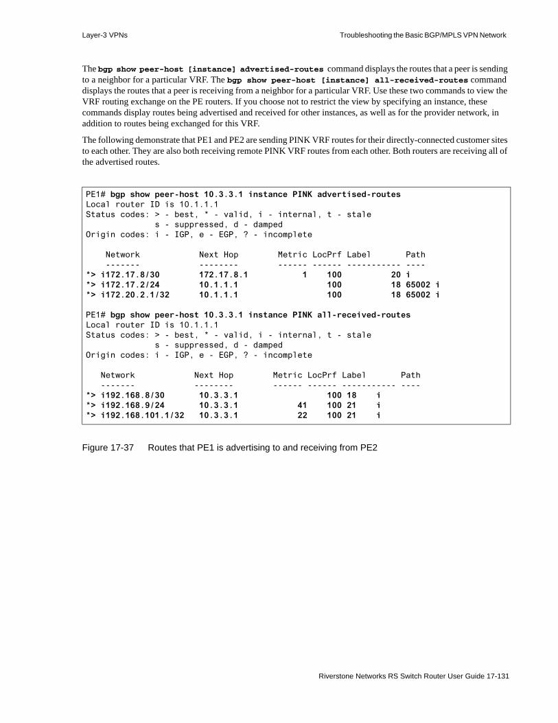
Layer-3 VPNs Troubleshooting the Basic BGP/MPLS VPN Network
The bgp show peer-host [instance] advertised-routes command displays the routes that a peer is sending to a neighbor for a particular VRF. The bgp show peer-host [instance] all-received-routes command displays the routes that a peer is receiving from a neighbor for a particular VRF. Use these two commands to view the VRF routing exchange on the PE routers. If you choose not to restrict the view by specifying an instance, these commands display routes being advertised and received for other instances, as well as for the provider network, in addition to routes being exchanged for this VRF.
The following demonstrate that PE1 and PE2 are sending PINK VRF routes for their directly-connected customer sites to each other. They are also both receiving remote PINK VRF routes from each other. Both routers are receiving all of the advertised routes.
Figure 17-37 Routes that PE1 is advertising to and receiving from PE2
PE1# bgp show peer-host 10.3.3.1 instance PINK advertised-routesLocal router ID is 10.1.1.1Status codes: > - best, * - valid, i - internal, t - stale s - suppressed, d - dampedOrigin codes: i - IGP, e - EGP, ? - incomplete
Network Next Hop Metric LocPrf Label Path ------- -------- ------ ------ ----------- ----*> i172.17.8/30 172.17.8.1 1 100 20 i*> i172.17.2/24 10.1.1.1 100 18 65002 i*> i172.20.2.1/32 10.1.1.1 100 18 65002 i
PE1# bgp show peer-host 10.3.3.1 instance PINK all-received-routesLocal router ID is 10.1.1.1Status codes: > - best, * - valid, i - internal, t - stale s - suppressed, d - dampedOrigin codes: i - IGP, e - EGP, ? - incomplete
Network Next Hop Metric LocPrf Label Path ------- -------- ------ ------ ----------- ----*> i192.168.8/30 10.3.3.1 100 18 i*> i192.168.9/24 10.3.3.1 41 100 21 i*> i192.168.101.1/32 10.3.3.1 22 100 21 i
Riverstone Networks RS Switch Router User Guide 17-131
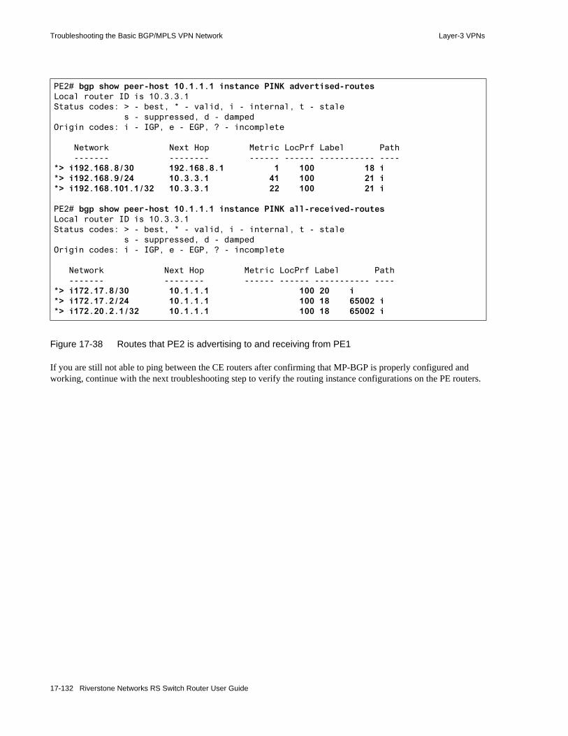
Troubleshooting the Basic BGP/MPLS VPN Network Layer-3 VPNs
Figure 17-38 Routes that PE2 is advertising to and receiving from PE1
If you are still not able to ping between the CE routers after confirming that MP-BGP is properly configured and working, continue with the next troubleshooting step to verify the routing instance configurations on the PE routers.
PE2# bgp show peer-host 10.1.1.1 instance PINK advertised-routesLocal router ID is 10.3.3.1Status codes: > - best, * - valid, i - internal, t - stale s - suppressed, d - dampedOrigin codes: i - IGP, e - EGP, ? - incomplete
Network Next Hop Metric LocPrf Label Path ------- -------- ------ ------ ----------- ----*> i192.168.8/30 192.168.8.1 1 100 18 i*> i192.168.9/24 10.3.3.1 41 100 21 i*> i192.168.101.1/32 10.3.3.1 22 100 21 i
PE2# bgp show peer-host 10.1.1.1 instance PINK all-received-routesLocal router ID is 10.3.3.1Status codes: > - best, * - valid, i - internal, t - stale s - suppressed, d - dampedOrigin codes: i - IGP, e - EGP, ? - incomplete
Network Next Hop Metric LocPrf Label Path ------- -------- ------ ------ ----------- ----*> i172.17.8/30 10.1.1.1 100 20 i*> i172.17.2/24 10.1.1.1 100 18 65002 i*> i172.20.2.1/32 10.1.1.1 100 18 65002 i
17-132 Riverstone Networks RS Switch Router User Guide

Layer-3 VPNs Troubleshooting the Basic BGP/MPLS VPN Network
17.7.5 Troubleshoot Routing Instances on PE Routers
If you are still not able to ping between the CE routers after confirming that MP-BGP is properly configured and working, you should view the routing instances and BGP/MPLS VPN-related RIBs on the PE routers to verify correct routing instance configurations.
On PE routers, the routing-instance show instance command displays the properties configured on a particular instance. These include the Route Distinguisher, interfaces added to the routing instance, and route maps applied as import and export Route Targets. In the display output, verify the following:• That the correct Route Distinguisher is configured. More importantly, check that you did not
configure the same Route Distinguisher for different VRFs on the same PE router. This is especially important for PE routers that are supporting different customers with overlapping address spaces. In this situation, PE routers turn non-unique customer IPv4 addresses into unique VPN-IPv4 prefixes by prepending the Route Distinguisher. If identical Route Distinguishers are accidentally configured for different VRFs, each time the PE router sends routing advertisements, multiple routes (learned from different customers) to the same IPv4 address will repeatedly clobber each other on the receiving PE router, resulting in sporadic access to that address for the receiving PE router’s customers.
• That the appropriate interfaces are added• The logic of the import and export Route Targets applied on this routing instance. (The following
section covers this in greater detail.)
The following demonstrate correctly configured Route Distinguishers on PE1 and PE2 that use their unique loopback addresses and ‘2’ as the unique identifier for the PINK VRF. The necessary interfaces are also added to both routing instances. Both routers are importing routes tagged with a Route Target of ‘target:65001:2’ for the PINK VRF.
Basic BGP/MPLS VPN network troubleshooting steps:• General troubleshooting
- Verify physical connectivity- Eliminate error commands from the active configuration- Verify the correct spelling of all names and references in the active configuration
• Verify basic BGP/MPLS VPN network functionality by pinging between the CE routers- Verify local CE-PE connectivity and routing exchange by pinging between the CE
router and the local PE router- Verify remote connectivity and routing exchange by pinging between the local PE
and remote PE and CE routers- Troubleshoot routing exchange between CE and PE Routers- Verify provider connectivity and VRF routing exchange- Troubleshoot provider network IGP configuration- Troubleshoot provider network MP-BGP configuration - Troubleshoot PE router routing instance configuration - Verify MPLS LSPs and MP-BGP LSP usage- Use traceroute to determine the last hop of connectivity
Riverstone Networks RS Switch Router User Guide 17-133

Troubleshooting the Basic BGP/MPLS VPN Network Layer-3 VPNs
Figure 17-39 PINK routing instance properties on PE1
PE1# routing-instance show instance PINK
PINKType : vrfRoute-Distinguisher : 10.1.1.1:2Router-ID : 10.1.1.1Interfaces : ToCE3 lo0vrf-import : PINK-import, sequence 1 permit, sequence 10 Match clauses community list PINK-import Action Sequence Count Community List ====== ======== ===== ============== permit 10 1 target:65001:2 Set clauses
vrf-export : PINK-export, sequence 1 permit, sequence 10 Match clauses Set clauses set community target:65001:2
Default route : not presentDefault route active : 1
17-134 Riverstone Networks RS Switch Router User Guide

Layer-3 VPNs Troubleshooting the Basic BGP/MPLS VPN Network
Figure 17-40 PINK routing instance properties on PE2
PE2# routing-instance show instance PINK
PINKType : vrfRoute-Distinguisher : 10.3.3.1:2Router-ID : 10.3.3.1Interfaces : ToCE4 lo0vrf-import : PINK-import, sequence 1 permit, sequence 10 Match clauses community list PINK-import Action Sequence Count Community List ====== ======== ===== ============== permit 10 1 target:65001:2 Set clauses
vrf-export : PINK-export, sequence 1 permit, sequence 10 Match clauses Set clauses set community target:65001:2
Default route : not presentDefault route active : 0
Riverstone Networks RS Switch Router User Guide 17-135

Troubleshooting the Basic BGP/MPLS VPN Network Layer-3 VPNs
After checking the routing instance configuration properties, view the BGP/MPLS VPN-related RIBs on the PE routers to verify routing exchange.
Use the ip-router show rib vpn-ipv4 command to view the VPN-IPv4 RIB on PE routers. A PE router filters all routes received from remote PE routers through MP-BGP based on the Route Target(s) that you configure. It discards routes that do not match any import targets on the VRFs that it supports. It installs the remaining routes into the VPN-IPv4 RIB. The VPN-IPv4 RIB contains all routes that satisfy the import policy of at least one of the PE router’s VRFs. Since this is the only table that contains all of the routes from all of the VPNs directly connected to the PE router, it is the only table that relies on Route Distinguishers to keep routes with identical IPv4 prefixes distinct.
The following demonstrate that PE1 and PE2 are receiving all of the necessary VRF routes from each other into their VPN-IPv4 RIBs. The VPN-IPv4 RIB display lists IPv4 routes by Route Distinguisher. Two LSPs between PE1 and PE2 (PE1toPE2 and PE2toPE2) provide the method of transport for these routes.
Figure 17-41 VPN-IPv4 RIB on PE1
PE1# ip-router show rib vpn-ipv4Routing Tables:Generate Default: noDestinations: 20 Routes: 25Holddown: 0 Delete: 4 Hidden: 4Codes: Network - Destination Network Address S - Status + = Best Route, - = Last Active, * = Both Src - Source of the route : Ag - Aggregate, B - BGP derived, C - Connected DVM - DVMRP derived, R - RIP derived, St - Static, O - OSPF derived OE - OSPF ASE derived, D - Default i - IS-IS, L1 - IS-IS level-1, L2 - IS-IS level-2 Next hop - Gateway for the route ; Next hops in use: 4 Netif - Next hop interface Prf1 - Preference of the route, Prf2 - Second Preference of the route Metrc1 - Metric1 of the route, Metrc2 - Metric2 of the route Age - Age of the routeNetwork/Mask S Src Next hop Netif Prf1 Metrc1 Metrc2 Age------------ - --- -------- ----- ---- ------ ------ ---
VPN/IPV4 Unicast
Route Distinguisher 10.3.3.1:2
192.168.8/30 * B Unnumbered PE1toPE2 170 100 165:17:29192.168.9/24 * B Unnumbered PE1toPE2 170 41 100 165:17:29192.168.101.1/32 * B Unnumbered PE1toPE2 170 22 100 165:17:29
17-136 Riverstone Networks RS Switch Router User Guide

Layer-3 VPNs Troubleshooting the Basic BGP/MPLS VPN Network
Figure 17-42 VPN-IPv4 RIB on PE2
After installing a route in the VPN-IPv4 RIB, PE routers determine whether they should import that route into any VRFs by performing route filtering based on the route’s Route Target. A route is only eligible to be installed in the VRF RIB for a routing instance if at least one of its Route Target(s) match the import target(s) configured on that VRF. Routing instances associated with each VRF then select optimal and active routes from the VRF RIB to install in the VRF FIB.
On PE routers, use the ip-router show rib instance command to view VRF RIBs and the ip show route show-vrf command to view VRF FIBs.
Earlier, you verified the presence of local-site routes in the PE router VRF FIBs in the Section 17-105 "Verify Local CE-PE Connectivity and Routing Exchange by Pinging Between the CE Router and the Local PE Router."
The following demonstrate that PE1 and PE2 both import all received remote-site VPN/IPv4 routes into the PINK RIB as IPv4 routes. The BGP routing instance on PE2 and the OSPF routing instance on PE1 then select these routes for import into the PINK FIB.
PE2# ip-router show rib vpn-ipv4Routing Tables:Generate Default: noDestinations: 20 Routes: 25Holddown: 0 Delete: 2 Hidden: 4Codes: Network - Destination Network Address S - Status + = Best Route, - = Last Active, * = Both Src - Source of the route : Ag - Aggregate, B - BGP derived, C - Connected DVM - DVMRP derived, R - RIP derived, St - Static, O - OSPF derived OE - OSPF ASE derived, D - Default i - IS-IS, L1 - IS-IS level-1, L2 - IS-IS level-2 Next hop - Gateway for the route ; Next hops in use: 4 Netif - Next hop interface Prf1 - Preference of the route, Prf2 - Second Preference of the route Metrc1 - Metric1 of the route, Metrc2 - Metric2 of the route Age - Age of the routeNetwork/Mask S Src Next hop Netif Prf1 Metrc1 Metrc2 Age------------ - --- -------- ----- ---- ------ ------ ---
VPN/IPV4 Unicast
Route Distinguisher 10.1.1.1:2
172.17.2/24 * B Unnumbered PE2toPE1 170 100 123:06:37172.17.8/30 * B Unnumbered PE2toPE1 170 100 165:53:27172.20.2.1/32 * B Unnumbered PE2toPE1 170 100 123:06:37
Riverstone Networks RS Switch Router User Guide 17-137

Troubleshooting the Basic BGP/MPLS VPN Network Layer-3 VPNs
Figure 17-43 PINK RIB and FIB on PE1
PE1# ip-router show rib instance PINKRouting Tables:Generate Default: noDestinations: 20 Routes: 25Holddown: 0 Delete: 4 Hidden: 4Codes: Network - Destination Network Address S - Status + = Best Route, - = Last Active, * = Both Src - Source of the route : Ag - Aggregate, B - BGP derived, C - Connected DVM - DVMRP derived, R - RIP derived, St - Static, O - OSPF derived OE - OSPF ASE derived, D - Default i - IS-IS, L1 - IS-IS level-1, L2 - IS-IS level-2 Next hop - Gateway for the route ; Next hops in use: 4 Netif - Next hop interface Netif - Next hop interface Metrc1 - Metric1 of the route, Metrc2 - Metric2 of the route Age - Age of the routeNetwork/Mask S Src Next hop Netif Prf1 Metrc1 Metrc2 Age------------ - --- -------- ----- ---- ------ ------ ---
Routing-instance PINK Unicast
127.0.0.1/32 * C 127.0.0.1 lo0 1 1 0 166:52:59172.17.2/24 * B 172.17.8.2 ToCE3 170 100 124:06:11172.17.8/30 * C 172.17.8.1 ToCE3 1 1 0 166:52:59172.17.8/30 B 172.17.8.2 ToCE3 170 100 124:06:11172.20.2.1/32 * B 172.17.8.2 ToCE3 170 100 124:06:11192.168.8/30 * B Unnumbered PE1toPE2 170 100 166:52:59192.168.9/24 * B Unnumbered PE1toPE2 170 41 100 166:52:59192.168.101.1/32 * B Unnumbered PE1toPE2 170 22 100 166:52:59
PE1# ip show routes show-vrf PINK
Destination Gateway Owner Netif----------- ------- ----- -----127.0.0.1 127.0.0.1 - lo0172.17.2.0/24 172.17.8.2 BGP ToCE3172.17.8.0/30 directly connected - ToCE3172.20.2.1 172.17.8.2 BGP ToCE3192.168.8.0/30 10.0.1.2 BGP PE1toPE2192.168.9.0/24 10.0.1.2 BGP PE1toPE2192.168.101.1 10.0.1.2 BGP PE1toPE2
17-138 Riverstone Networks RS Switch Router User Guide
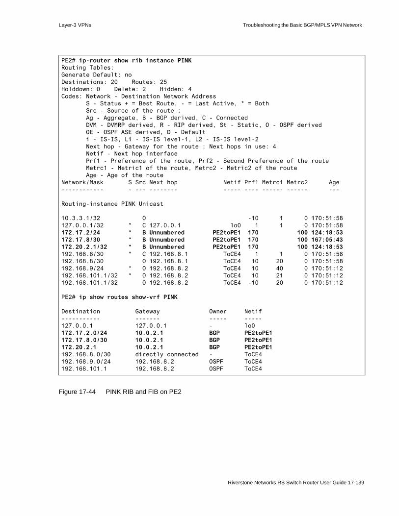
Layer-3 VPNs Troubleshooting the Basic BGP/MPLS VPN Network
Figure 17-44 PINK RIB and FIB on PE2
PE2# ip-router show rib instance PINKRouting Tables:Generate Default: noDestinations: 20 Routes: 25Holddown: 0 Delete: 2 Hidden: 4Codes: Network - Destination Network Address S - Status + = Best Route, - = Last Active, * = Both Src - Source of the route : Ag - Aggregate, B - BGP derived, C - Connected DVM - DVMRP derived, R - RIP derived, St - Static, O - OSPF derived OE - OSPF ASE derived, D - Default i - IS-IS, L1 - IS-IS level-1, L2 - IS-IS level-2 Next hop - Gateway for the route ; Next hops in use: 4 Netif - Next hop interface Prf1 - Preference of the route, Prf2 - Second Preference of the route Metrc1 - Metric1 of the route, Metrc2 - Metric2 of the route Age - Age of the routeNetwork/Mask S Src Next hop Netif Prf1 Metrc1 Metrc2 Age------------ - --- -------- ----- ---- ------ ------ ---
Routing-instance PINK Unicast
10.3.3.1/32 O -10 1 0 170:51:58127.0.0.1/32 * C 127.0.0.1 lo0 1 1 0 170:51:58172.17.2/24 * B Unnumbered PE2toPE1 170 100 124:18:53172.17.8/30 * B Unnumbered PE2toPE1 170 100 167:05:43172.20.2.1/32 * B Unnumbered PE2toPE1 170 100 124:18:53192.168.8/30 * C 192.168.8.1 ToCE4 1 1 0 170:51:58192.168.8/30 O 192.168.8.1 ToCE4 10 20 0 170:51:58192.168.9/24 * O 192.168.8.2 ToCE4 10 40 0 170:51:12192.168.101.1/32 * O 192.168.8.2 ToCE4 10 21 0 170:51:12192.168.101.1/32 O 192.168.8.2 ToCE4 -10 20 0 170:51:12
PE2# ip show routes show-vrf PINK
Destination Gateway Owner Netif----------- ------- ----- -----127.0.0.1 127.0.0.1 - lo0172.17.2.0/24 10.0.2.1 BGP PE2toPE1172.17.8.0/30 10.0.2.1 BGP PE2toPE1172.20.2.1 10.0.2.1 BGP PE2toPE1192.168.8.0/30 directly connected - ToCE4192.168.9.0/24 192.168.8.2 OSPF ToCE4192.168.101.1 192.168.8.2 OSPF ToCE4
Riverstone Networks RS Switch Router User Guide 17-139
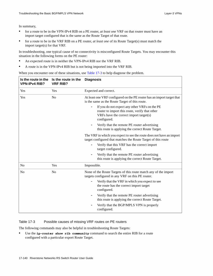
Troubleshooting the Basic BGP/MPLS VPN Network Layer-3 VPNs
In summary, • for a route to be in the VPN-IPv4 RIB on a PE router, at least one VRF on that router must have an
import target configured that is the same as the Route Target of that route.• for a route to be in the VRF RIB on a PE router, at least one of its Route Target(s) must match the
import target(s) for that VRF.
In troubleshooting, one typical cause of no connectivity is misconfigured Route Targets. You may encounter this situation in the following forms on the PE router:• An expected route is in neither the VPN-IPv4 RIB nor the VRF RIB.• A route is in the VPN-IPv4 RIB but is not being imported into the VRF RIB.
When you encounter one of these situations, use Table 17-3 to help diagnose the problem.
Table 17-3 Possible causes of missing VRF routes on PE routers
The following commands may also be helpful in troubleshooting Route Targets:• Use the ip-router show rib community command to search the entire RIB for a route
configured with a particular export Route Target.
Is the route in the VPN-IPv4 RIB?
Is the route in theVRF RIB?
Diagnosis
Yes Yes Expected and correct.
Yes No At least one VRF configured on the PE router has an import target that is the same as the Route Target of this route.
- If you do not expect any other VRFs on the PE router to import this route, verify that other VRFs have the correct import target(s) configured.
- Verify that the remote PE router advertising this route is applying the correct Route Target.
The VRF in which you expect to see the route does not have an import target configured that matches the Route Target of this route
- Verify that this VRF has the correct import target configured.
- Verify that the remote PE router advertising this route is applying the correct Route Target.
No Yes Impossible.
No No None of the Route Targets of this route match any of the import targets configured in any VRF on this PE router.
- Verify that the VRF in which you expect to see the route has the correct import target configured.
- Verify that the remote PE router advertising this route is applying the correct Route Target.
- Verify that the BGP/MPLS VPN is properly configured.
17-140 Riverstone Networks RS Switch Router User Guide

Layer-3 VPNs Troubleshooting the Basic BGP/MPLS VPN Network
• Use the ip-router show rib neighbor command to view all routes received from a particular neighbor.
• Use the ip-router show rib route-distinguisher command to view all routes configured with a particular Route Distinguisher. Note that the Route Distinguisher is not the same as the Route Target.
If you are still not able to ping between the CE routers after confirming that the routing instances are properly configured on the PE routers, continue with the next troubleshooting step to verify MPLS LSPs and MP-BGP LSP usage between the PE routers.
Riverstone Networks RS Switch Router User Guide 17-141
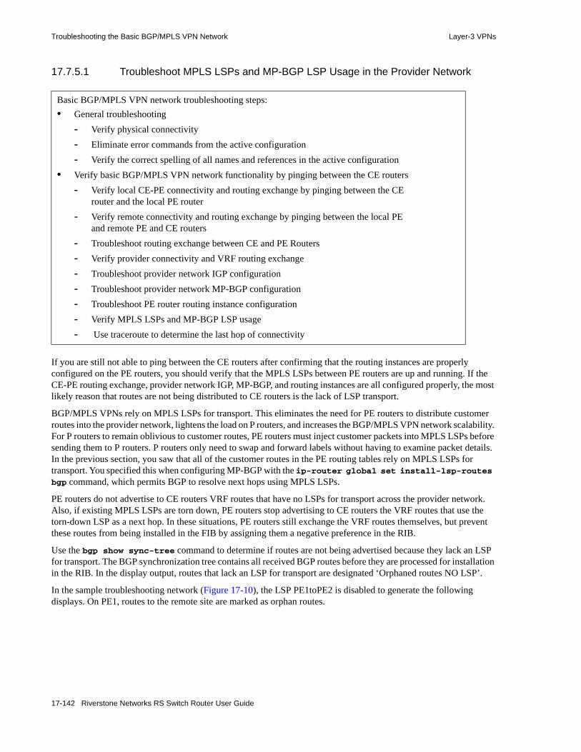
Troubleshooting the Basic BGP/MPLS VPN Network Layer-3 VPNs
17.7.5.1 Troubleshoot MPLS LSPs and MP-BGP LSP Usage in the Provider Network
If you are still not able to ping between the CE routers after confirming that the routing instances are properly configured on the PE routers, you should verify that the MPLS LSPs between PE routers are up and running. If the CE-PE routing exchange, provider network IGP, MP-BGP, and routing instances are all configured properly, the most likely reason that routes are not being distributed to CE routers is the lack of LSP transport.
BGP/MPLS VPNs rely on MPLS LSPs for transport. This eliminates the need for PE routers to distribute customer routes into the provider network, lightens the load on P routers, and increases the BGP/MPLS VPN network scalability. For P routers to remain oblivious to customer routes, PE routers must inject customer packets into MPLS LSPs before sending them to P routers. P routers only need to swap and forward labels without having to examine packet details. In the previous section, you saw that all of the customer routes in the PE routing tables rely on MPLS LSPs for transport. You specified this when configuring MP-BGP with the ip-router global set install-lsp-routes bgp command, which permits BGP to resolve next hops using MPLS LSPs.
PE routers do not advertise to CE routers VRF routes that have no LSPs for transport across the provider network. Also, if existing MPLS LSPs are torn down, PE routers stop advertising to CE routers the VRF routes that use the torn-down LSP as a next hop. In these situations, PE routers still exchange the VRF routes themselves, but prevent these routes from being installed in the FIB by assigning them a negative preference in the RIB.
Use the bgp show sync-tree command to determine if routes are not being advertised because they lack an LSP for transport. The BGP synchronization tree contains all received BGP routes before they are processed for installation in the RIB. In the display output, routes that lack an LSP for transport are designated ‘Orphaned routes NO LSP’.
In the sample troubleshooting network (Figure 17-10), the LSP PE1toPE2 is disabled to generate the following displays. On PE1, routes to the remote site are marked as orphan routes.
Basic BGP/MPLS VPN network troubleshooting steps:• General troubleshooting
- Verify physical connectivity- Eliminate error commands from the active configuration- Verify the correct spelling of all names and references in the active configuration
• Verify basic BGP/MPLS VPN network functionality by pinging between the CE routers- Verify local CE-PE connectivity and routing exchange by pinging between the CE
router and the local PE router- Verify remote connectivity and routing exchange by pinging between the local PE
and remote PE and CE routers- Troubleshoot routing exchange between CE and PE Routers- Verify provider connectivity and VRF routing exchange- Troubleshoot provider network IGP configuration- Troubleshoot provider network MP-BGP configuration - Troubleshoot PE router routing instance configuration - Verify MPLS LSPs and MP-BGP LSP usage- Use traceroute to determine the last hop of connectivity
17-142 Riverstone Networks RS Switch Router User Guide

Layer-3 VPNs Troubleshooting the Basic BGP/MPLS VPN Network
Figure 17-45 BGP synchronization tree on PE1
The following demonstrate that PE1 marks remote-site routes as invalid with a negative preference in the PINK RIB. As a result, these routes are not installed in the PINK FIB and CE3 has no knowledge of them.
PE1# bgp show sync-tree allTask BGP_Sync_4294967295_0: IGP Protocol: ffffffff BGP Group: PROVIDER
Sync Tree (* == active, + == active with alternate, - == inactive with alternate:
Node 10.0.1/30 route 10.0.1/255.255.255.252 metric 1 interface Node 10.0.2/30 route 10.0.2/255.255.255.252 metric 4 next hop/labels:
10.0.1.2/none Node 10.1.1.1/32 route 10.1.1.1/255.255.255.255 metric 1 interface Node 10.2.2.1/32 route 10.2.2.1/255.255.255.255 metric 3 next hop/labels:
10.0.1.2/none Node 10.3.3.1/32 route 10.3.3.1/255.255.255.255 metric 5 next hop/labels:
10.0.1.2/none Forwarding address 10.3.3.1 Routes for group PROVIDER: 192.168.8/255.255.255.252 peer 10.3.3.1 192.168.9/255.255.255 peer 10.3.3.1 192.168.101.1/255.255.255.255 peer 10.3.3.1 Node 127/8 route 127/255 metric 1 interface Node 127.0.0.1/32 route 127.0.0.1/255.255.255.255 metric 1 interface Node 172.17.8/30 route 172.17.8/255.255.255.252 metric 1 interface Next hop hash table (2 hashed): References 7 Hash none Interface References 4 Hash 43 Next hop 10.0.1.2
Task BGP_Sync_lsp_4294967295_0: IGP Protocol: 10000 BGP Group: PROVIDER
Sync Tree (* == active, + == active with alternate, - == inactive with alternate:
Orphaned routes No LSP Forwarding address 10.3.3.1 Routes for group PROVIDER: 192.168.8/255.255.255.252- peer 10.3.3.1 192.168.9/255.255.255- peer 10.3.3.1 192.168.101.1/255.255.255.255- peer 10.3.3.1 Next hop hash table (0 hashed): References 7 Hash none Interface
Riverstone Networks RS Switch Router User Guide 17-143

Troubleshooting the Basic BGP/MPLS VPN Network Layer-3 VPNs
Figure 17-46 PINK RIB and FIB on PE1
PE1# ip-router show rib instance PINKRouting Tables:Generate Default: noDestinations: 19 Routes: 24Holddown: 0 Delete: 6 Hidden: 4Codes: Network - Destination Network Address S - Status + = Best Route, - = Last Active, * = Both Src - Source of the route : Ag - Aggregate, B - BGP derived, C - Connected DVM - DVMRP derived, R - RIP derived, St - Static, O - OSPF derived OE - OSPF ASE derived, D - Default i - IS-IS, L1 - IS-IS level-1, L2 - IS-IS level-2 Next hop - Gateway for the route ; Next hops in use: 4 Netif - Next hop interface Prf1 - Preference of the route, Prf2 - Second Preference of the route Metrc1 - Metric1 of the route, Metrc2 - Metric2 of the route Age - Age of the routeNetwork/Mask S Src Next hop Netif Prf1 Metrc1 Metrc2 Age------------ - --- -------- ----- ---- ------ ------ ---
Routing-instance PINK Unicast
127.0.0.1/32 * C 127.0.0.1 lo0 1 1 0 2:11:27172.17.2/24 * B 172.17.8.2 ToCE3 170 100 2:11:15172.17.8/30 * C 172.17.8.1 ToCE3 1 1 0 2:11:27172.17.8/30 B 172.17.8.2 ToCE3 170 100 2:11:15172.20.2.1/32 * B 172.17.8.2 ToCE3 170 100 2:11:15192.168.8/30 B -170 100 2:09:51192.168.9/24 B -170 41 100 2:09:51192.168.101.1/32 B -170 22 100 2:09:51
PE1# ip show routes show-vrf PINK
Destination Gateway Owner Netif----------- ------- ----- -----127.0.0.1 127.0.0.1 - lo0172.17.2.0/24 172.17.8.2 BGP ToCE3172.17.8.0/30 directly connected - ToCE3172.20.2.1 172.17.8.2 BGP ToCE3
17-144 Riverstone Networks RS Switch Router User Guide
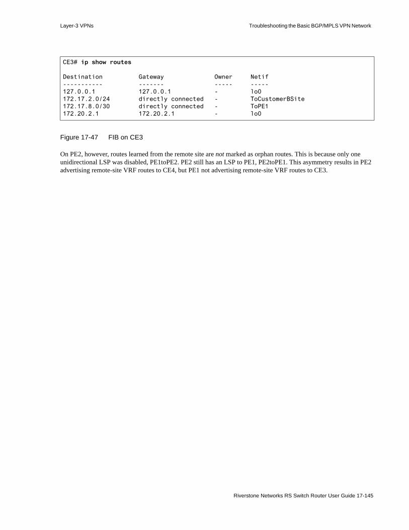
Layer-3 VPNs Troubleshooting the Basic BGP/MPLS VPN Network
Figure 17-47 FIB on CE3
On PE2, however, routes learned from the remote site are not marked as orphan routes. This is because only one unidirectional LSP was disabled, PE1toPE2. PE2 still has an LSP to PE1, PE2toPE1. This asymmetry results in PE2 advertising remote-site VRF routes to CE4, but PE1 not advertising remote-site VRF routes to CE3.
CE3# ip show routes
Destination Gateway Owner Netif----------- ------- ----- -----127.0.0.1 127.0.0.1 - lo0172.17.2.0/24 directly connected - ToCustomerBSite172.17.8.0/30 directly connected - ToPE1172.20.2.1 172.20.2.1 - lo0
Riverstone Networks RS Switch Router User Guide 17-145

Troubleshooting the Basic BGP/MPLS VPN Network Layer-3 VPNs
Figure 17-48 BGP synchronization tree on PE2
The following demonstrate that PE2 does not mark the routes learned from PE1 as invalid and advertises them to CE4. CE4, however, fails when using them.
PE2# bgp show sync-tree allTask BGP_Sync_4294967295_0: IGP Protocol: ffffffff BGP Group: PROVIDER
Sync Tree (* == active, + == active with alternate, - == inactive with alternate:
Node 0.0.0.7/32 route 0.0.0.7/255.255.255.255 metric 1 interface Node 10.0.1/30 route 10.0.1/255.255.255.252 metric 4 next hop/labels:
10.0.2.1/none Node 10.0.2/30 route 10.0.2/255.255.255.252 metric 1 interface Node 10.1.1.1/32 route 10.1.1.1/255.255.255.255 metric 1 next hop/labels:
0.0.0.7/none Forwarding address 10.1.1.1 Routes for group PROVIDER: 172.17.8/255.255.255.252 peer 10.1.1.1 172.17.2/255.255.255 peer 10.1.1.1 172.20.2.1/255.255.255.255 peer 10.1.1.1 Node 10.2.2.1/32 route 10.2.2.1/255.255.255.255 metric 3 next hop/labels:
10.0.2.1/none Node 10.3.3.1/32 route 10.3.3.1/255.255.255.255 metric 1 interface Node 127/8 route 127/255 metric 1 interface Node 127.0.0.1/32 route 127.0.0.1/255.255.255.255 metric 1 interface Node 192.168.1/30 route 192.168.1/255.255.255.252 metric 1 interface Node 192.168.8/30 route 192.168.8/255.255.255.252 metric 1 interface Next hop hash table (3 hashed): References 8 Hash none Interface References 2 Hash 7 Next hop 0.0.0.7 References 2 Hash 13 Next hop 10.0.2.1
Task BGP_Sync_lsp_4294967295_0: IGP Protocol: 10000 BGP Group: PROVIDER
Sync Tree (* == active, + == active with alternate, - == inactive with alternate:
Node 10.1.1.1/32 route 10.1.1.1/255.255.255.255 metric 1 next hop/labels: 0.0.0.7/none
Forwarding address 10.1.1.1 Routes for group PROVIDER: 172.17.8/255.255.255.252 peer 10.1.1.1 172.17.2/255.255.255 peer 10.1.1.1 172.20.2.1/255.255.255.255 peer 10.1.1.1 Next hop hash table (5 hashed): References 8 Hash none Interface References 2 Hash 7 Next hop 0.0.0.7 References 2 Hash 7 Next hop 0.0.0.7 References 1 Hash 7 Next hop 0.0.0.7 References 1 Hash 7 Next hop 0.0.0.7 References 2 Hash 7 Next hop 0.0.0.7
17-146 Riverstone Networks RS Switch Router User Guide

Layer-3 VPNs Troubleshooting the Basic BGP/MPLS VPN Network
Figure 17-49 PINK RIB and FIB on PE2
PE2# ip-router show rib instance PINKRouting Tables:Generate Default: noDestinations: 20 Routes: 25Holddown: 0 Delete: 4 Hidden: 4Codes: Network - Destination Network Address S - Status + = Best Route, - = Last Active, * = Both Src - Source of the route : Ag - Aggregate, B - BGP derived, C - Connected DVM - DVMRP derived, R - RIP derived, St - Static, O - OSPF derived OE - OSPF ASE derived, D - Default i - IS-IS, L1 - IS-IS level-1, L2 - IS-IS level-2 Next hop - Gateway for the route ; Next hops in use: 4 Netif - Next hop interface Prf1 - Preference of the route, Prf2 - Second Preference of the route Metrc1 - Metric1 of the route, Metrc2 - Metric2 of the route Age - Age of the routeNetwork/Mask S Src Next hop Netif Prf1 Metrc1 Metrc2 Age------------ - --- -------- ----- ---- ------ ------ ---
Routing-instance PINK Unicast
10.3.3.1/32 O -10 1 0 2:15:45127.0.0.1/32 * C 127.0.0.1 lo0 1 1 0 2:15:45172.17.2/24 * B Unnumbered PE2toPE1 170 100 2:14:23172.17.8/30 * B Unnumbered PE2toPE1 170 100 2:14:23172.20.2.1/32 * B Unnumbered PE2toPE1 170 100 2:14:23192.168.8/30 * C 192.168.8.1 ToCE4 1 1 0 2:15:45192.168.8/30 O 192.168.8.1 ToCE4 10 20 0 2:15:45192.168.9/24 * O 192.168.8.2 ToCE4 10 40 0 2:15:06192.168.101.1/32 * O 192.168.8.2 ToCE4 10 21 0 2:15:06192.168.101.1/32 O 192.168.8.2 ToCE4 -10 20 0 2:15:06
PE2# ip show routes show-vrf PINK
Destination Gateway Owner Netif----------- ------- ----- -----127.0.0.1 127.0.0.1 - lo0172.17.2.0/24 10.0.2.1 BGP PE2toPE1172.17.8.0/30 10.0.2.1 BGP PE2toPE1172.20.2.1 10.0.2.1 BGP PE2toPE1192.168.8.0/30 directly connected - ToCE4192.168.9.0/24 192.168.8.2 OSPF ToCE4192.168.101.1 192.168.8.2 OSPF ToCE4
Riverstone Networks RS Switch Router User Guide 17-147
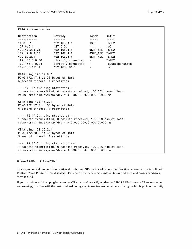
Troubleshooting the Basic BGP/MPLS VPN Network Layer-3 VPNs
Figure 17-50 FIB on CE4
This asymmetrical problem is indicative of having an LSP configured in only one direction between PE routers. If both PE1toPE2 and PE2toPE1 are disabled, PE2 would also mark remote-site routes as orphaned and cease advertising them to CE4.
If you are still not able to ping between the CE routers after verifying that the MPLS LSPs between PE routers are up and running, continue with the next troubleshooting step to use traceroute for determining the last hop of connectivity.
CE4# ip show routes
Destination Gateway Owner Netif----------- ------- ----- -----10.3.3.1 192.168.8.1 OSPF ToPE2127.0.0.1 127.0.0.1 - lo0172.17.2.0/24 192.168.8.1 OSPF_ASE ToPE2172.17.8.0/30 192.168.8.1 OSPF_ASE ToPE2172.20.2.1 192.168.8.1 OSPF_ASE ToPE2192.168.8.0/30 directly connected - ToPE2192.168.9.0/24 directly connected - ToCustomerBSite192.168.101.1 192.168.101.1 - lo0
CE4# ping 172.17.8.2PING 172.17.8.2: 36 bytes of data5 second timeout, 1 repetition
--- 172.17.8.2 ping statistics ---1 packets transmitted, 0 packets received, 100.00% packet lossround-trip min/avg/max/dev = 0.000/0.000/0.000/0.000 ms
CE4# ping 172.17.2.1PING 172.17.2.1: 36 bytes of data5 second timeout, 1 repetition
--- 172.17.2.1 ping statistics ---1 packets transmitted, 0 packets received, 100.00% packet lossround-trip min/avg/max/dev = 0.000/0.000/0.000/0.000 ms
CE4# ping 172.20.2.1PING 172.20.2.1: 36 bytes of data5 second timeout, 1 repetition
--- 172.20.2.1 ping statistics ---1 packets transmitted, 0 packets received, 100.00% packet lossround-trip min/avg/max/dev = 0.000/0.000/0.000/0.000 ms
17-148 Riverstone Networks RS Switch Router User Guide
Layer-3 VPNs Troubleshooting the Basic BGP/MPLS VPN Network
17.7.6 Use Traceroute To Determine the Last Hop of Connectivity
If you are still not able to ping between the CE routers after verifying that MPLS LSPs are up and running, use traceroute to determine the last hop of connectivity.
The following traceroute outputs demonstrate traffic being sent through the local PE router, the P router, the remote PE router, and arriving at the remote CE router. Note that each time customer traffic enters one of the ports on the P router (10.0.1.2 or 10.0.2.1), it is transported using an MPLS LSP.
Basic BGP/MPLS VPN network troubleshooting steps:• General troubleshooting
- Verify physical connectivity- Eliminate error commands from the active configuration- Verify the correct spelling of all names and references in the active configuration
• Verify basic BGP/MPLS VPN network functionality by pinging between the CE routers- Verify local CE-PE connectivity and routing exchange by pinging between the CE
router and the local PE router- Verify remote connectivity and routing exchange by pinging between the local PE
and remote PE and CE routers- Troubleshoot routing exchange between CE and PE Routers- Verify provider connectivity and VRF routing exchange- Troubleshoot provider network IGP configuration- Troubleshoot provider network MP-BGP configuration - Troubleshoot PE router routing instance configuration - Verify MPLS LSPs and MP-BGP LSP usage- Use traceroute to determine the last hop of connectivity
Riverstone Networks RS Switch Router User Guide 17-149

Troubleshooting the Basic BGP/MPLS VPN Network Layer-3 VPNs
Figure 17-51 Traceroute from CE3 to CE4
CE3# traceroute 192.168.8.2traceroute to 192.168.8.2 (192.168.8.2), 30 hops max, 40 byte packets 1 172.17.8.1 (172.17.8.1) [AS 65002] 1 ms 1 ms 0 ms 2 10.0.1.2 (10.0.1.2) [AS 65002] 2 ms 1 ms 1 ms MPLS Label1=4097 EXP1=0 TTL=1 S=0 MPLS Label2=18 EXP2=0 TTL=1 S=1 3 10.3.3.1 (10.3.3.1) [AS 65002] 1 ms 1 ms 1 ms 4 192.168.8.2 (192.168.8.2) [AS 65001] 1 ms 1 ms 1 ms
CE3# traceroute 192.168.9.1traceroute to 192.168.9.1 (192.168.9.1), 30 hops max, 40 byte packets 1 172.17.8.1 (172.17.8.1) [AS 65002] 1 ms 1 ms 0 ms 2 10.0.1.2 (10.0.1.2) [AS 65002] 2 ms 1 ms 1 ms MPLS Label1=4097 EXP1=0 TTL=1 S=0 MPLS Label2=21 EXP2=0 TTL=1 S=1 3 10.3.3.1 (10.3.3.1) [AS 65002] 1 ms 1 ms 1 ms 4 192.168.9.1 (192.168.9.1) [AS 65001] 1 ms 1 ms 1 ms
CE3# traceroute 192.168.101.1traceroute to 192.168.101.1 (192.168.101.1), 30 hops max, 40 byte packets 1 172.17.8.1 (172.17.8.1) [AS 65002] 1 ms 1 ms 0 ms 2 10.0.1.2 (10.0.1.2) [AS 65002] 1 ms 1 ms 1 ms MPLS Label1=4097 EXP1=0 TTL=1 S=0 MPLS Label2=21 EXP2=0 TTL=1 S=1 3 10.3.3.1 (10.3.3.1) [AS 65002] 1 ms 1 ms 1 ms 4 192.168.101.1 (192.168.101.1) [AS 65001] 1 ms 1 ms 1 ms
17-150 Riverstone Networks RS Switch Router User Guide

Layer-3 VPNs Troubleshooting the Basic BGP/MPLS VPN Network
Figure 17-52 Traceroute from CE4 to CE3
CE4# traceroute 172.17.8.2traceroute to 172.17.8.2 (172.17.8.2), 30 hops max, 40 byte packets 1 192.168.8.1 (192.168.8.1) 1 ms 1 ms 0 ms 2 10.0.2.1 (10.0.2.1) 2 ms 1 ms 1 ms MPLS Label1=4097 EXP1=0 TTL=1 S=0 MPLS Label2=19 EXP2=0 TTL=1 S=1 3 10.1.1.1 (10.1.1.1) 2 ms 1 ms 1 ms 4 172.17.8.2 (172.17.8.2) 2 ms 1 ms 2 ms
CE4# traceroute 172.17.2.1traceroute to 172.17.2.1 (172.17.2.1), 30 hops max, 40 byte packets 1 192.168.8.1 (192.168.8.1) 1 ms 1 ms 0 ms 2 10.0.2.1 (10.0.2.1) 2 ms 1 ms 1 ms MPLS Label1=4097 EXP1=0 TTL=1 S=0 MPLS Label2=18 EXP2=0 TTL=1 S=1 3 10.1.1.1 (10.1.1.1) 1 ms 1 ms 1 ms 4 172.17.2.1 (172.17.2.1) 2 ms 2 ms 1 ms
CE4# traceroute 172.20.2.1traceroute to 172.20.2.1 (172.20.2.1), 30 hops max, 40 byte packets 1 192.168.8.1 (192.168.8.1) 1 ms 2 ms 0 ms 2 10.0.2.1 (10.0.2.1) 1 ms 1 ms 1 ms MPLS Label1=4097 EXP1=0 TTL=1 S=0 MPLS Label2=18 EXP2=0 TTL=1 S=1 3 10.1.1.1 (10.1.1.1) 1 ms 1 ms 1 ms 4 172.20.2.1 (172.20.2.1) 2 ms 1 ms 1 ms
Riverstone Networks RS Switch Router User Guide 17-151

Troubleshooting the Basic BGP/MPLS VPN Network Layer-3 VPNs
Alternatively, you can perform the same traceroute from PE routers by specifying that traceroute use VRF routes to resolve the destination address. By default, traceroutes originate with the provider-facing interface on the PE router as the source address. However, the remote-site CE router does not have a route to the provider-facing interface of the PE router. Unless it is configured with a default route, the remote-site CE router only has a route to the same-VRF customer-facing interface on the PE router. Therefore, in order for the traceroute to return to the PE router, it must originate with the address of an interface added to the same VRF as the remote site.
The following demonstrate using the traceroute command with the vrf and source options for specifying the VRF FIB and source address to use. In the sample troubleshooting network (Figure 17-10), the default source address of a traceroute from PE1 to CE4 is 10.0.1.1, the address of PE1’s provider-facing interface. Since this address is not in CE4’s routing tables, CE4 cannot respond. You must specify that traceroute use the address of PE1’s PINK VRF interface, 172.17.8.1, as the source address. The same applies to a traceroute from PE2 to CE3. You must specify that traceroute use 192.168.8.1 instead of 10.0.2.2 as the source address.
Figure 17-53 Traceroute from PE1 to CE4
PE1# traceroute 192.168.8.2 vrf PINK source 172.17.8.1traceroute to 192.168.8.2 (192.168.8.2) from 172.17.8.1, 30 hops max, 40 byte packets 1 10.0.1.2 (10.0.1.2) [AS 65001] 1 ms 1 ms 1 ms MPLS Label1=4097 EXP1=0 TTL=1 S=0 MPLS Label2=18 EXP2=0 TTL=1 S=1 2 10.3.3.1 (10.3.3.1) [AS 65001] 1 ms 1 ms 1 ms 3 192.168.8.2 (192.168.8.2) [AS 65001] 2 ms 1 ms 2 ms
PE1# traceroute 192.168.9.1 vrf PINK source 172.17.8.1traceroute to 192.168.9.1 (192.168.9.1) from 172.17.8.1, 30 hops max, 40 byte packets 1 10.0.1.2 (10.0.1.2) [AS 65001] 1 ms 1 ms 2 ms MPLS Label1=4097 EXP1=0 TTL=1 S=0 MPLS Label2=21 EXP2=0 TTL=1 S=1 2 10.3.3.1 (10.3.3.1) [AS 65001] 1 ms 1 ms 1 ms 3 192.168.9.1 (192.168.9.1) [AS 65001] 1 ms 1 ms 1 ms
PE1# traceroute 192.168.101.1 vrf PINK source 172.17.8.1traceroute to 192.168.101.1 (192.168.101.1) from 172.17.8.1, 30 hops max, 40 byte
packets 1 10.0.1.2 (10.0.1.2) [AS 65001] 1 ms 1 ms 1 ms MPLS Label1=4097 EXP1=0 TTL=1 S=0 MPLS Label2=21 EXP2=0 TTL=1 S=1 2 10.3.3.1 (10.3.3.1) [AS 65001] 2 ms 1 ms 1 ms 3 192.168.101.1 (192.168.101.1) [AS 65001] 1 ms 1 ms 2 ms
17-152 Riverstone Networks RS Switch Router User Guide
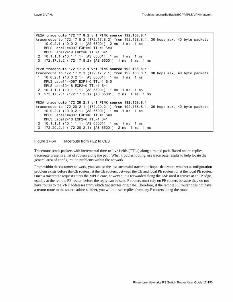
Layer-3 VPNs Troubleshooting the Basic BGP/MPLS VPN Network
Figure 17-54 Traceroute from PE2 to CE3
Traceroute sends packets with incremental time-to-live fields (TTLs) along a routed path. Based on the replies, traceroute presents a list of routers along the path. When troubleshooting, use traceroute results to help locate the general area of configuration problems within the network.
From within the customer network, you can use the last successful traceroute hop to determine whether a configuration problem exists before the CE routers, at the CE routers, between the CE and local PE routers, or at the local PE router. Once a traceroute request enters the MPLS core, however, it is forwarded along the LSP until it arrives at an IP edge, usually at the remote PE router, before the reply can be sent. P routers must rely on PE routers because they do not have routes to the VRF addresses from which traceroutes originate. Therefore, if the remote PE router does not have a return route to the source address either, you will not see replies from any P routers along the route.
PE2# traceroute 172.17.8.2 vrf PINK source 192.168.8.1traceroute to 172.17.8.2 (172.17.8.2) from 192.168.8.1, 30 hops max, 40 byte packets 1 10.0.2.1 (10.0.2.1) [AS 65001] 2 ms 1 ms 1 ms MPLS Label1=4097 EXP1=0 TTL=1 S=0 MPLS Label2=19 EXP2=0 TTL=1 S=1 2 10.1.1.1 (10.1.1.1) [AS 65001] 1 ms 1 ms 1 ms 3 172.17.8.2 (172.17.8.2) [AS 65001] 1 ms 1 ms 1 ms
PE2# traceroute 172.17.2.1 vrf PINK source 192.168.8.1traceroute to 172.17.2.1 (172.17.2.1) from 192.168.8.1, 30 hops max, 40 byte packets 1 10.0.2.1 (10.0.2.1) [AS 65001] 1 ms 1 ms 1 ms MPLS Label1=4097 EXP1=0 TTL=1 S=0 MPLS Label2=18 EXP2=0 TTL=1 S=1 2 10.1.1.1 (10.1.1.1) [AS 65001] 1 ms 1 ms 1 ms 3 172.17.2.1 (172.17.2.1) [AS 65001] 2 ms 1 ms 1 ms
PE2# traceroute 172.20.2.1 vrf PINK source 192.168.8.1traceroute to 172.20.2.1 (172.20.2.1) from 192.168.8.1, 30 hops max, 40 byte packets 1 10.0.2.1 (10.0.2.1) [AS 65001] 1 ms 1 ms 1 ms MPLS Label1=4097 EXP1=0 TTL=1 S=0 MPLS Label2=18 EXP2=0 TTL=1 S=1 2 10.1.1.1 (10.1.1.1) [AS 65001] 1 ms 1 ms 1 ms 3 172.20.2.1 (172.20.2.1) [AS 65001] 2 ms 1 ms 1 ms
Riverstone Networks RS Switch Router User Guide 17-153
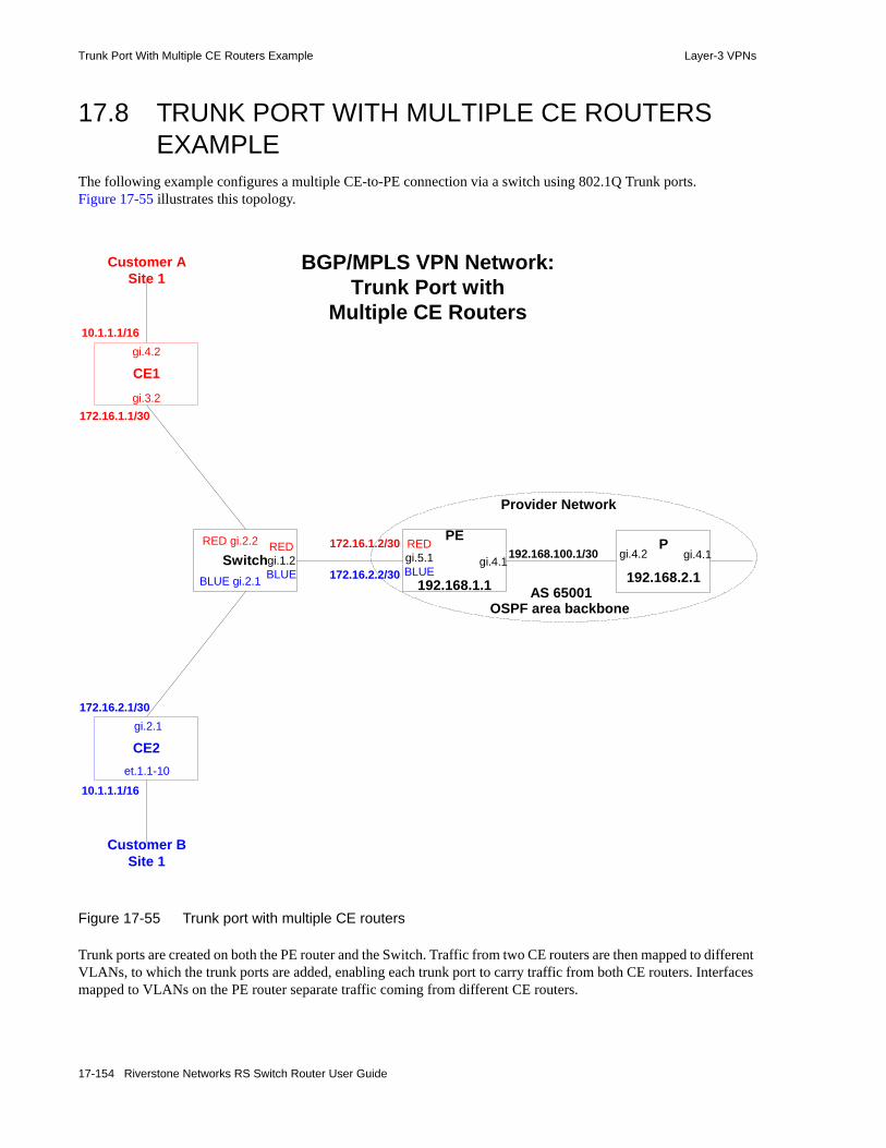
Trunk Port With Multiple CE Routers Example Layer-3 VPNs
17.8 TRUNK PORT WITH MULTIPLE CE ROUTERS EXAMPLE
The following example configures a multiple CE-to-PE connection via a switch using 802.1Q Trunk ports. Figure 17-55 illustrates this topology.
Figure 17-55 Trunk port with multiple CE routers
Trunk ports are created on both the PE router and the Switch. Traffic from two CE routers are then mapped to different VLANs, to which the trunk ports are added, enabling each trunk port to carry traffic from both CE routers. Interfaces mapped to VLANs on the PE router separate traffic coming from different CE routers.
BGP/MPLS VPN Network:Trunk Port with
Multiple CE Routers
PE
192.168.1.1
REDgi.5.1BLUE
gi.4.1Switch
CE2
BLUE gi.2.1
REDgi.1.2BLUE
RED gi.2.2
gi.2.1
et.1.1-10
CE1gi.3.2
gi.4.2
172.16.1.1/30
10.1.1.1/16
172.16.2.1/30
10.1.1.1/16
Customer ASite 1
Customer BSite 1
172.16.1.2/30
172.16.2.2/30AS 65001
P
192.168.2.1
gi.4.2 gi.4.1
Provider Network
OSPF area backbone
192.168.100.1/30
17-154 Riverstone Networks RS Switch Router User Guide

Layer-3 VPNs Trunk Port With Multiple CE Routers Example
When a single MPLS label or ATM virtual channel (VC) is shared with more than one interface over a single trunk port, the MPLS or VC label is no longer sufficient to distinguish traffic. The source VLAN ID must be used. To support this topology, you must use the port enable multi-vrf-support command. This command allows the RS Ethernet Router to overwrite the source or destination socket of datagrams crossing a port with the datagram’s source VLAN ID. When using this command, if either socket is in use for any purpose (for example, in an ACL), overwrite the other one.
Complete configurations for the CE routers, Switch, and PE router follow. Configurations specifically applicable to this example are highlighted.
17.8.0.1 CE1 Complete Configuration
17.8.0.2 CE2 Complete Configuration
vlan create VPN_RED ip id 30vlan add ports gi.3.2 to VPN_RED
interface create ip VPN_RED address-netmask 172.16.1.1/30 vlan VPN_REDinterface create ip ip_RED address-netmask 10.1.1.1/16 port gi.4.2
rip add interface VPN_REDrip add interface ip_REDrip set interface all version 2rip start
vlan create BLUE ip id 40vlan create blue_vpn ip id 20vlan add ports gi.2.1 to BLUEvlan add ports et.1.1-10 to blue_vpn
interface create ip ip_BLUE address-netmask 172.16.2.1/30 vlan BLUEinterface create ip ip_blue_VPN address-netmask 10.1.1.1/16 vlan blue_vpn
rip add interface ip_BLUErip add interface ip_blue_VPNrip set interface all version 2rip start
Riverstone Networks RS Switch Router User Guide 17-155
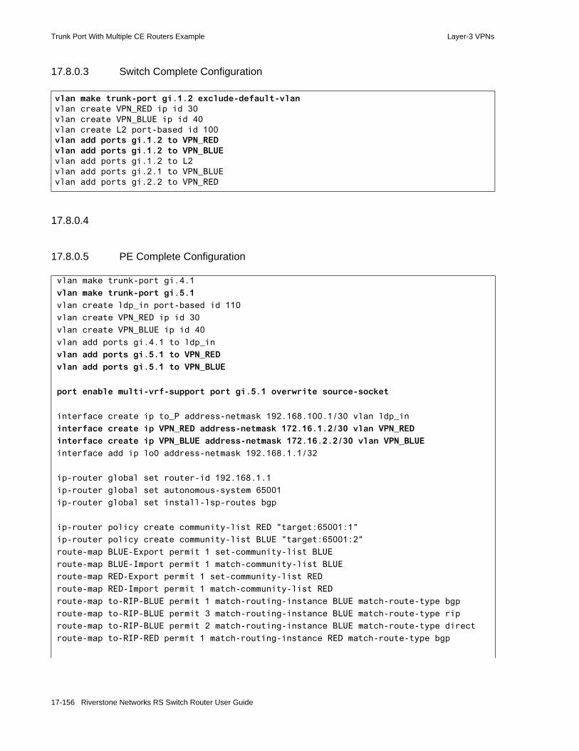
Trunk Port With Multiple CE Routers Example Layer-3 VPNs
17.8.0.3 Switch Complete Configuration
17.8.0.4
17.8.0.5 PE Complete Configuration
vlan make trunk-port gi.1.2 exclude-default-vlanvlan create VPN_RED ip id 30vlan create VPN_BLUE ip id 40vlan create L2 port-based id 100vlan add ports gi.1.2 to VPN_REDvlan add ports gi.1.2 to VPN_BLUEvlan add ports gi.1.2 to L2vlan add ports gi.2.1 to VPN_BLUEvlan add ports gi.2.2 to VPN_RED
vlan make trunk-port gi.4.1
vlan make trunk-port gi.5.1
vlan create ldp_in port-based id 110
vlan create VPN_RED ip id 30
vlan create VPN_BLUE ip id 40
vlan add ports gi.4.1 to ldp_in
vlan add ports gi.5.1 to VPN_RED
vlan add ports gi.5.1 to VPN_BLUE
port enable multi-vrf-support port gi.5.1 overwrite source-socket
interface create ip to_P address-netmask 192.168.100.1/30 vlan ldp_in
interface create ip VPN_RED address-netmask 172.16.1.2/30 vlan VPN_RED
interface create ip VPN_BLUE address-netmask 172.16.2.2/30 vlan VPN_BLUE
interface add ip lo0 address-netmask 192.168.1.1/32
ip-router global set router-id 192.168.1.1
ip-router global set autonomous-system 65001
ip-router global set install-lsp-routes bgp
ip-router policy create community-list RED "target:65001:1"
ip-router policy create community-list BLUE "target:65001:2"
route-map BLUE-Export permit 1 set-community-list BLUE
route-map BLUE-Import permit 1 match-community-list BLUE
route-map RED-Export permit 1 set-community-list RED
route-map RED-Import permit 1 match-community-list RED
route-map to-RIP-BLUE permit 1 match-routing-instance BLUE match-route-type bgp
route-map to-RIP-BLUE permit 3 match-routing-instance BLUE match-route-type rip
route-map to-RIP-BLUE permit 2 match-routing-instance BLUE match-route-type direct
route-map to-RIP-RED permit 1 match-routing-instance RED match-route-type bgp
17-156 Riverstone Networks RS Switch Router User Guide

Layer-3 VPNs Trunk Port With Multiple CE Routers Example
ospf create area backbone
ospf add stub-host 192.168.1.1 to-area backbone cost 5
ospf add interface to_P to-area backbone
ospf start
bgp create peer-group PE-to-P autonomous-system 65001
bgp add peer-host 192.168.2.1 group PE-to-P
bgp set peer-group PE-to-P local-address 192.168.1.1
bgp set peer-group PE-to-P vpnv4-unicast ipv4-unicast
bgp start
mpls add interface to_P
mpls create label-switched-path to_P_lsp from 192.168.1.1 to 192.168.2.1
mpls set label-switched-path to_P_lsp no-cspf
mpls start
rsvp add interface to_P
rsvp start
routing-instance BLUE vrf set route-distinguisher "65001:2" vrf-import BLUE-Import vrf-export BLUE-Export in-sequence 1 out-sequence 1
routing-instance BLUE vrf add interface VPN_BLUE
routing-instance BLUE rip add interface VPN_BLUE
routing-instance BLUE rip set interface VPN_BLUE version 2
routing-instance BLUE rip start
routing-instance BLUE rip set route-map-out to-RIP-BLUE
routing-instance RED vrf set route-distinguisher "65001:1" vrf-import RED-Import vrf-export RED-Export in-sequence 1 out-sequence 1
routing-instance RED vrf add interface VPN_RED
routing-instance RED rip add interface VPN_RED
routing-instance RED rip set interface VPN_RED version 2
routing-instance RED rip start
routing-instance RED rip set route-map-out to-RIP-RED
Riverstone Networks RS Switch Router User Guide 17-157
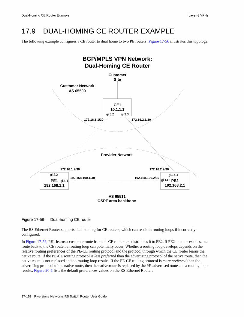
Dual-Homing CE Router Example Layer-3 VPNs
17.9 DUAL-HOMING CE ROUTER EXAMPLEThe following example configures a CE router to dual home to two PE routers. Figure 17-56 illustrates this topology.
Figure 17-56 Dual-homing CE router
The RS Ethernet Router supports dual homing for CE routers, which can result in routing loops if incorrectly configured.
In Figure 17-56, PE1 learns a customer route from the CE router and distributes it to PE2. If PE2 announces the same route back to the CE router, a routing loop can potentially occur. Whether a routing loop develops depends on the relative routing preferences of the PE-CE routing protocol and the protocol through which the CE router learns the native route. If the PE-CE routing protocol is less preferred than the advertising protocol of the native route, then the native route is not replaced and no routing loop results. If the PE-CE routing protocol is more preferred than the advertising protocol of the native route, then the native route is replaced by the PE-advertised route and a routing loop results. Figure 20-1 lists the default preferences values on the RS Ethernet Router.
BGP/MPLS VPN Network:Dual-Homing CE Router
PE1192.168.1.1
gi.2.2
gi.5.1
CE110.1.1.1
gi.3.2 gi.3.3
172.16.1.1/30
CustomerSite
AS 65511
PE2192.168.2.1
gi.14.1
Provider Network
OSPF area backbone
192.168.100.1/30gi.14.4
172.16.2.1/30
AS 65500
172.16.1.2/30
Customer Network
172.16.2.2/30
192.168.100.2/30
17-158 Riverstone Networks RS Switch Router User Guide

Layer-3 VPNs Dual-Homing CE Router Example
OSPF, as a PE-CE routing protocol, has built-in safeguards against routing loops. Before passing remote advertisements to a customer site, PE routers check to see that the advertisements did not originate from the same site using the DN bit in Type-3 LSAs and the VPN Route Tag in Type-5 LSAs. These safeguards are only effective, however, if OSPF is the exclusive PE-CE protocol. If OSPF is not used as the PE-CE protocol for any site within a VPN, the DN bit and the VPN Route Tag do not get set and routing loops can still result. Therefore, using OSPF as a PE-CE protocol does not obviate the need for further loop prevention. For more information on PE-CE OSPF routing loop prevention, see the Section 17-51 "Configuring OSPF Between CE and PE Routers."
Note Regardless of the protocols used and whether routing loops will actually result, whenever dual homing CE routers, it is good practice to ensure routing loop prevention using the BGP Site-of-Origin Extended Community Attribute.
To prevent routing loops, associate each connected site on a PE router with a BGP Site-of-Origin Extended Community Attribute. PE routers use this attribute to check, through VRF import and export policies, that routes learned from a site are not distributed back into that site. Since this verification occurs at the MP-BGP level and not at the routing instance level, it is effective irrespective of what other routing protocols are running between the PE and CE routers. For more information on Extended Community Attribute Route Targets, see the IETF draft BGP Extended Communities Attribute by Ramachandra, Tappan, and Rekhter, or the Section 16-30 "Extended Communities."
When using BGP Extended Community Attributes to define the Site of Origin, select from one of two forms:
origin:<Global autonomous system number>:<Identifier>
origin:<Global IP address>:<Identifier>
After the origin keyword, specify either a global AS number or global IP address, followed by a unique identifier for this particular site.
Note To ensure that the Site of Origin is unique, use only AS numbers or IP addresses that you own. Using private IPv4 addresses or AS numbers can easily result in duplicate Sites of Origin. Even though this example uses a private AS number, you should, in general, only use publicly unique IP addresses or AS numbers.
The following example uses the provider network’s autonomous system number, 65511, to define the Site of Origin. PE1 and PE2 define a common Site of Origin, origin:65511:1, for the customer site. Note that this presupposes agreement between the administration for PE1 and PE2 on the Site of Origin assignment scheme. Since the AS number is used, the site identifier must be unique in this provider network.
In this example, both PE1 and PE2 define the Site of Origin for the customer site in the site’s VRF export policy (trinity-export) and filter for it in the site’s VRF import policy (trinity-import). If a route arrives at a PE router bearing origin:65511:1 as the Site of Origin, it is denied by community-list 11 and never advertised back to the customer site.
Complete configurations for the CE and PE routers follow. Configurations specifically applicable to this example are highlighted.
Riverstone Networks RS Switch Router User Guide 17-159
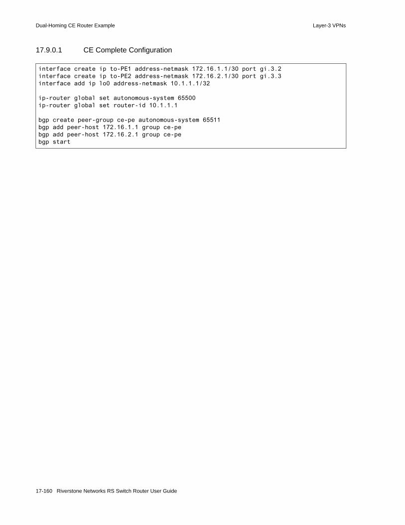
Dual-Homing CE Router Example Layer-3 VPNs
17.9.0.1 CE Complete Configuration
interface create ip to-PE1 address-netmask 172.16.1.1/30 port gi.3.2interface create ip to-PE2 address-netmask 172.16.2.1/30 port gi.3.3interface add ip lo0 address-netmask 10.1.1.1/32
ip-router global set autonomous-system 65500ip-router global set router-id 10.1.1.1
bgp create peer-group ce-pe autonomous-system 65511bgp add peer-host 172.16.1.1 group ce-pebgp add peer-host 172.16.2.1 group ce-pebgp start
17-160 Riverstone Networks RS Switch Router User Guide

Layer-3 VPNs Dual-Homing CE Router Example
17.9.0.2 PE1 Complete Configuration
interface create ip to-PE2 address-netmask 192.168.100.1/30 port gi.5.1interface create ip to-CE address-netmask 172.16.1.2/30 port gi.2.2interface add ip lo0 address-netmask 192.168.1.1/32
ip-router global set router-id 192.168.1.1ip-router global set autonomous-system 65511ip-router global set install-lsp-routes bgp
community-list 11 deny 5 "origin:65511:1"community-list 11 permit 10 "target:65511:2"
ip-router policy create community-list 10 "target:65511:1 origin:65511:1"
route-map ALLROUTES permit 10route-map trinity-export permit 10 set-community-list 10route-map trinity-import permit 10 match-community-list 11
ospf create area backboneospf add interface to-PE2 to-area backboneospf add stub-host 192.168.1.1 to-area backbone cost 20ospf start
bgp create peer-group pe-pe autonomous-system 65511bgp add peer-host 192.168.2.1 group pe-pebgp set peer-group pe-pe local-address 192.168.1.1bgp set peer-group pe-pe vpnv4-unicast ipv4-unicastbgp start
mpls add interface to-PE2mpls create label-switched-path pe1-pe2 from 192.168.1.1 to 192.168.2.1mpls set label-switched-path pe1-pe2 no-cspfmpls start
rsvp add interface to-PE2rsvp start
routing-instance trinity vrf set route-distinguisher 65511:10 vrf-import trinity-import vrf-export trinity-export in-sequence 1 out-sequence 1
routing-instance trinity vrf add interface to-CErouting-instance trinity bgp create peer-group pe-ce autonomous-system 65500routing-instance trinity bgp add peer-host 172.16.1.1 group pe-cerouting-instance trinity bgp set peer-host 172.16.1.1 route-map-out ALLROUTES
out-sequence 1routing-instance trinity bgp start
Riverstone Networks RS Switch Router User Guide 17-161
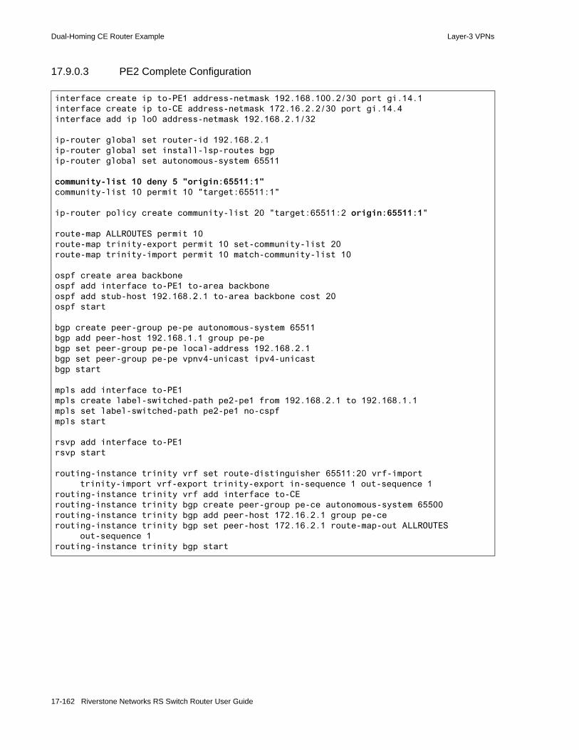
Dual-Homing CE Router Example Layer-3 VPNs
17.9.0.3 PE2 Complete Configuration
interface create ip to-PE1 address-netmask 192.168.100.2/30 port gi.14.1interface create ip to-CE address-netmask 172.16.2.2/30 port gi.14.4interface add ip lo0 address-netmask 192.168.2.1/32
ip-router global set router-id 192.168.2.1ip-router global set install-lsp-routes bgpip-router global set autonomous-system 65511
community-list 10 deny 5 "origin:65511:1"community-list 10 permit 10 "target:65511:1"
ip-router policy create community-list 20 "target:65511:2 origin:65511:1"
route-map ALLROUTES permit 10route-map trinity-export permit 10 set-community-list 20 route-map trinity-import permit 10 match-community-list 10
ospf create area backboneospf add interface to-PE1 to-area backboneospf add stub-host 192.168.2.1 to-area backbone cost 20ospf start
bgp create peer-group pe-pe autonomous-system 65511bgp add peer-host 192.168.1.1 group pe-pebgp set peer-group pe-pe local-address 192.168.2.1bgp set peer-group pe-pe vpnv4-unicast ipv4-unicastbgp start
mpls add interface to-PE1mpls create label-switched-path pe2-pe1 from 192.168.2.1 to 192.168.1.1mpls set label-switched-path pe2-pe1 no-cspfmpls start
rsvp add interface to-PE1rsvp start
routing-instance trinity vrf set route-distinguisher 65511:20 vrf-import trinity-import vrf-export trinity-export in-sequence 1 out-sequence 1
routing-instance trinity vrf add interface to-CErouting-instance trinity bgp create peer-group pe-ce autonomous-system 65500routing-instance trinity bgp add peer-host 172.16.2.1 group pe-cerouting-instance trinity bgp set peer-host 172.16.2.1 route-map-out ALLROUTES
out-sequence 1routing-instance trinity bgp start
17-162 Riverstone Networks RS Switch Router User Guide

Layer-3 VPNs Route Reflector Example
17.10 ROUTE REFLECTOR EXAMPLEMP-BGP is fully compatible with route reflectors. Route reflectors eliminate the need for a fully-meshed MP-IBGP network by requiring that PE routers only peer with the route reflector in their autonomous system. Using route reflectors, however, does not obviate the need for establishing MPLS LSPs between every pair of PE routers that support a common VPN.
Route reflectors are the only routers within the BGP/MPLS VPN network that must maintain routes for sites to which they are not directly connected. A route reflector is not preconfigured with a list of Route Targets. Instead, it accepts all the routes received from its clients. Based on these routes, the route reflector maintains a list of Route Targets actively configured on clients, which it uses to form the inbound route filters it applies to routes received from other route reflectors. When a route reflector no longer has any routes matching a Route Target on its list, it deletes the Route Target after two hours.
To enhance scalability and reduce router overload, deploy multiple route reflectors so that no single route reflector has to maintain all the VPN-IPv4 routes for all of the VPNs the provider network supports.
The following example configures a route reflector in the provider network and illustrates the use of different BGP signalling and forwarding paths. Figure 17-57 illustrates this topology.
Riverstone Networks RS Switch Router User Guide 17-163
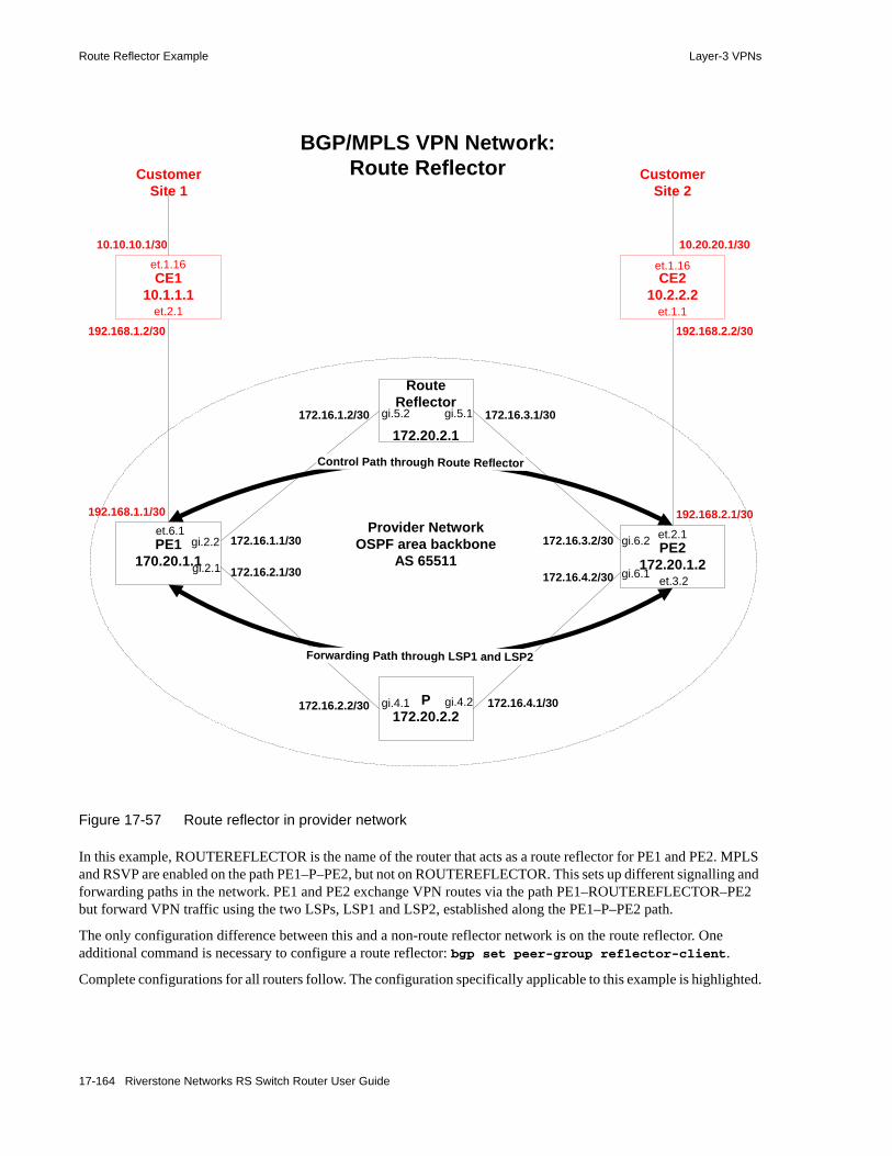
Route Reflector Example Layer-3 VPNs
Figure 17-57 Route reflector in provider network
In this example, ROUTEREFLECTOR is the name of the router that acts as a route reflector for PE1 and PE2. MPLS and RSVP are enabled on the path PE1–P–PE2, but not on ROUTEREFLECTOR. This sets up different signalling and forwarding paths in the network. PE1 and PE2 exchange VPN routes via the path PE1–ROUTEREFLECTOR–PE2 but forward VPN traffic using the two LSPs, LSP1 and LSP2, established along the PE1–P–PE2 path.
The only configuration difference between this and a non-route reflector network is on the route reflector. One additional command is necessary to configure a route reflector: bgp set peer-group reflector-client.
Complete configurations for all routers follow. The configuration specifically applicable to this example is highlighted.
BGP/MPLS VPN Network:Route Reflector
CE210.2.2.2
RouteReflector
172.20.2.1
PE2172.20.1.2
gi.6.2
gi.5.2 gi.5.1
et.2.1
et.3.2
et.1.1
et.1.16
PE1170.20.1.1
gi.2.2et.6.1
CE110.1.1.1
et.2.1
et.1.16
192.168.1.2/30
10.10.10.1/30
172.16.1.1/30
192.168.2.2/30
10.20.20.1/30
CustomerSite 1
CustomerSite 2
P172.20.2.2
gi.4.1 gi.4.2
Provider NetworkOSPF area backbone
AS 65511172.16.2.1/30gi.2.1
192.168.1.1/30
Forwarding Path through LSP1 and LSP2
Control Path through Route Reflector
192.168.2.1/30
gi.6.1
172.16.3.2/30
172.16.4.2/30
172.16.1.2/30 172.16.3.1/30
172.16.2.2/30 172.16.4.1/30
17-164 Riverstone Networks RS Switch Router User Guide

Layer-3 VPNs Route Reflector Example
17.10.0.1 CE1 Complete Configuration
17.10.0.2 CE2 Complete Configuration
interface create ip to-PE1 address-netmask 192.168.1.2/30 port et.2.1interface create ip to-Site1 address-netmask 10.10.10.1/30 port et.1.16interface add ip lo0 address-netmask 10.1.1.1/32
ip-router global set router-id 10.1.1.1
ospf create area backboneospf add interface to-PE1 to-area backboneospf add interface to-Site1 to-area backboneospf add stub-host 10.1.1.1 to-area backbone cost 10ospf start
interface create ip to-PE2 address-netmask 192.168.2.2/30 port et.1.1interface create ip to-Site2 address-netmask 10.20.20.1/30 port et.1.16interface add ip lo0 address-netmask 10.2.2.2/32
ip-router global set router-id 10.2.2.2
rip add interface to-PE2rip add interface to-Site2rip set interface to-PE2 version 2rip set interface to-Site2 version 2rip start
Riverstone Networks RS Switch Router User Guide 17-165

Route Reflector Example Layer-3 VPNs
17.10.0.3 PE1 Complete Configuration
interface create ip to-ROUTEREFLECTOR address-netmask 172.16.1.1/30 port gi.2.2interface create ip to-P address-netmask 172.16.2.1/30 port gi.2.1interface create ip to-CE1 address-netmask 192.168.1.1/30 port et.1.2interface add ip lo0 address-netmask 172.20.1.1/32
ip-router global set router-id 172.20.1.1ip-router global set autonomous-system 65511ip-router global set install-lsp-routes bgp
ip-router policy create community-list vpn1 "target:65511:1"route-map BGPROUTES permit 1 match-route-type bgproute-map vpn1-import permit 1 match-community-list vpn1route-map vpn1-export permit 1 set-community-list vpn1
ospf create area backboneospf add interface to-P to-area backboneospf add interface to-ROUTEREFLECTOR to-area backbone ospf add stub-host 172.20.1.1 to-area backbone cost 10ospf start
bgp create peer-group to-ROUTEREFLECTOR autonomous-system 65511bgp add peer-host 172.20.2.1 group to-ROUTEREFLECTORbgp set peer-group to-ROUTEREFLECTOR local-address 172.20.1.1bgp set peer-group to-ROUTEREFLECTOR vpnv4-unicast ipv4-unicastbgp start
mpls add interface to-Pmpls create label-switched-path lsp2 to 172.20.1.2mpls set label-switched-path lsp2 no-cspfmpls start
rsvp add interface to-Prsvp start
routing-instance vpn1 vrf add interface to-CE1routing-instance vpn1 vrf set vrf-import vpn1-import in-sequence 1routing-instance vpn1 vrf set vrf-export vpn1-export out-sequence 1routing-instance vpn1 vrf set route-distinguisher "65511:1"routing-instance vpn1 ospf add interface to-CE1 to-area backbonerouting-instance vpn1 ospf set route-map-vpn BGPROUTESrouting-instance vpn1 ospf create area backbonerouting-instance vpn1 ospf start
17-166 Riverstone Networks RS Switch Router User Guide

Layer-3 VPNs Route Reflector Example
17.10.0.4 PE2 Complete Configuration
interface create ip to-CE2 address-netmask 192.168.2.1/30 port et.2.1interface create ip to-ROUTEREFLECTOR address-netmask 172.16.3.2/30 port gi.6.2interface create ip to-P address-netmask 172.16.4.2/30 port gi.6.1interface add ip lo0 address-netmask 172.20.1.2/32
ip-router global set router-id 172.20.1.2ip-router global set autonomous-system 65511ip-router global set install-lsp-routes bgp
ip-router policy create community-list vpn1 "target:65511:1"route-map BGPROUTES permit 1 match-route-type bgproute-map vpn1-import permit 1 match-community-list vpn1route-map vpn1-export permit 1 set-community-list vpn1
ospf create area backbone ospf add interface to-ROUTEREFLECTOR to-area backboneospf add interface to-P to-area backboneospf add stub-host 172.20.1.2 to-area backbone cost 10ospf start
bgp create peer-group to-ROUTEREFLECTOR autonomous-system 65511bgp add peer-host 172.20.2.1 group to-ROUTEREFLECTORbgp set peer-group to-ROUTEREFLECTOR local-address 172.20.1.2bgp set peer-group to-ROUTEREFLECTOR vpnv4-unicast ipv4-unicastbgp start
mpls add interface to-Pmpls create label-switched-path lsp1 to 172.20.1.1mpls set label-switched-path lsp1 no-cspf mpls start
rsvp add interface to-Prsvp start
routing-instance vpn1 vrf add interface to-CE2routing-instance vpn1 vrf set route-distinguisher "65511:2" vrf-import vpn1-import
in-sequence 1 vrf-export vpn1-export out-sequence 1routing-instance vpn1 rip add interface to-CE2routing-instance vpn1 rip set interface to-CE2 version 2routing-instance vpn1 rip set route-map-out BGPROUTESrouting-instance vpn1 rip start
Riverstone Networks RS Switch Router User Guide 17-167

Route Reflector Example Layer-3 VPNs
17.10.0.5 ROUTEREFLECTOR Complete Configuration
17.10.0.6
17.10.0.7 P Complete Configuration
interface create ip to-PE1 address-netmask 172.16.1.2/30 port gi.5.2interface create ip to-PE2 address-netmask 172.16.3.1/30 port gi.5.1interface add ip lo0 address-netmask 172.20.2.1/32
ip-router global set router-id 172.20.2.1ip-router global set autonomous-system 65511
ospf create area backboneospf add interface to-PE1 to-area backbone ospf add interface to-PE2 to-area backboneospf add stub-host 172.20.2.1 to-area backbone cost 10ospf start
bgp create peer-group to-PEs autonomous-system 65511bgp add peer-host 172.20.1.1 group to-PEsbgp add peer-host 172.20.1.2 group to-PEsbgp set peer-group to-PEs reflector-clientbgp set peer-group to-PEs local-address 172.20.2.1bgp set peer-group to-PEs vpnv4-unicast ipv4-unicastbgp start
interface create ip to-PE1 address-netmask 172.16.2.2/30 port gi.4.1interface create ip to-PE2 address-netmask 172.16.4.1/30 port gi.4.2interface add ip lo0 address-netmask 172.20.2.2/32
ip-router global set router-id 172.20.2.2ip-router global set install-lsp-routes bgpip-router global set autonomous-system 65511
ospf create area backboneospf add interface to-PE1 to-area backboneospf add interface to-PE2 to-area backboneospf add stub-host 172.20.2.2 to-area backbone cost 10ospf start
mpls add interface to-PE1mpls add interface to-PE2mpls start
rsvp add interface to-PE1rsvp add interface to-PE2rsvp start
17-168 Riverstone Networks RS Switch Router User Guide

Layer-3 VPNs Route Reflector Example
Using the bgp show summary command to verify that both PE routers are peering with the route reflector. The following command outputs show that ROUTEREFLECTOR has route reflecting capabilities enabled and is peering with both PE routers.
PE1# bgp show summary Local router ID is 172.20.1.1, Local AS number 65511BGP Route Entries 6, Unique AS Paths 3Unique Communities 0, Unique Extended Communities 3 Neighbor V AS MsgRcvd MsgSent Up/Down Prefixes Rcvd/Sent-------- - -- ------- ------- ------- ------------------[Group Id: to-ROUTEREFLECTOR VRF: unicast] 172.20.2.1 4 100 61 66 0d0h46m19s 3/3BGP summary, 1 groups, 1 peers
PE2# bgp show summary Local router ID is 172.20.1.2, Local AS number 65511BGP Route Entries 6, Unique AS Paths 5Unique Communities 0, Unique Extended Communities 2 Neighbor V AS MsgRcvd MsgSent Up/Down Prefixes Rcvd/Sent-------- - -- ------- ------- ------- ------------------[Group Id: to-ROUTEREFLECTOR VRF: unicast] 172.20.2.1 4 100 58 57 0d0h50m57s 3/3BGP summary, 1 groups, 1 peers
ROUTEREFLECTOR# bgp show summary Local router ID is 172.20.2.1, Local AS number 65511BGP Route Entries 6, Unique AS Paths 6Unique Communities 0, Unique Extended Communities 2 Neighbor V AS MsgRcvd MsgSent Up/Down Prefixes Rcvd/Sent-------- - -- ------- ------- ------- ------------------[Group Id: to-PEs VRF: unicast] Route Reflector enabled, cluster id is 172.20.2.1172.20.1.2 4 100 56 59 0d0h51m27s 3/3172.20.1.1 4 100 52 50 0d0h46m59s 3/3BGP summary, 1 groups, 2 peers
Riverstone Networks RS Switch Router User Guide 17-169
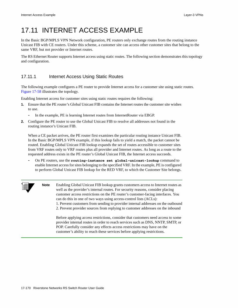
Internet Access Example Layer-3 VPNs
17.11 INTERNET ACCESS EXAMPLEIn the Basic BGP/MPLS VPN Network configuration, PE routers only exchange routes from the routing instance Unicast FIB with CE routers. Under this scheme, a customer site can access other customer sites that belong to the same VRF, but not provider or Internet routes.
The RS Ethernet Router supports Internet access using static routes. The following section demonstrates this topology and configuration.
17.11.1 Internet Access Using Static Routes
The following example configures a PE router to provide Internet access for a customer site using static routes. Figure 17-58 illustrates the topology.
Enabling Internet access for customer sites using static routes requires the following:1. Ensure that the PE router’s Global Unicast FIB contains the Internet routes the customer site wishes
to use.- In the example, PE is learning Internet routes from InternetRouter via EBGP.
2. Configure the PE router to use the Global Unicast FIB to resolve all addresses not found in the routing instance’s Unicast FIB.
When a CE packet arrives, the PE router first examines the particular routing instance Unicast FIB. In the Basic BGP/MPLS VPN example, if this lookup fails to yield a match, the packet cannot be routed. Enabling Global Unicast FIB lookup expands the set of routes accessible to customer sites from VRF routes only to VRF routes plus all provider and Internet routes. As long as a route to the requested address exists in the PE router’s Global Unicast FIB, the Internet access succeeds.- On PE routers, use the routing-instance set global-unicast-lookup command to
enable Internet access for sites belonging to the specified VRF. In the example, PE is configured to perform Global Unicast FIB lookup for the RED VRF, to which the Customer Site belongs.
Note Enabling Global Unicast FIB lookup grants customers access to Internet routes as well as the provider’s internal routes. For security reasons, consider placing customer access restrictions on the PE router’s customer-facing interfaces. You can do this in one of two ways using access-control lists (ACLs): 1. Prevent customers from sending to provider internal addresses on the outbound2. Prevent provider sources from replying to customer addresses on the inbound
Before applying access restrictions, consider that customers need access to some provider internal routes in order to reach services such as DNS, NNTP, SMTP, or POP. Carefully consider any effects access restrictions may have on the customer’s ability to reach these services before applying restrictions.
17-170 Riverstone Networks RS Switch Router User Guide
Layer-3 VPNs Internet Access Example
3. Ensure that Internet-bound traffic from customer sites originate from globally routable IP address(es). In the Basic BGP/MPLS VPN Network, customers may use RFC 1918 private addresses. Separate VRF routing tables on the PE router keep possibly overlapping customer addresses separate. To provide Internet access, PE routers must distribute to the Internet routes that the Internet relies upon for sending to customer sites (step 6). Since they are being distributed to the Internet, these routes must be globally routable. Customers may continue to use private addresses for internal VPN traffic. - In the example, lettered addresses like A.A.A.A/32 and B.B.B.0/24 represent globally routable
IPv4 networks.4. Configure CE routers to use PE router(s) as default gateway(s) for unknown destinations.
- On CE routers, you can do this using the ip add route default gateway command. In the example, PE (C.C.C.1) is configured as the default gateway on CE and CE (B.B.B.1) is configured as the default gateway on CustomerRouter.
5. Configure PE routers to add routes to globally routable IP address(es) from which customer sites originate Internet packets to the Global Unicast FIB. PE routers may already contain these routes in the routing instance FIB for that customer site, but in order for PE routers to distribute these routes to the Internet (step 6), they must exist in the PE router’s Global Unicast FIB. You can add these routes to the PE router’s Global Unicast FIB in one of two ways:- Configuring global static routes to these addresses using the ip add route gateway
command adds them to the global Unicast RIB. If more preferred routes to the same destinations do not already exist in the FIB, these routes become installed. In the example, PE is configured with two static routes, one to CE’s loopback address (A.A.A.A/32) and another to the customer site network (B.B.B.0/24).
- Alternatively, you may use a route map to match a particular network prefix and the set-import-ribs option to add a route to this network in the RIB(s) you specify. For example, the route-map ADDTORIB permit 10 match-prefix network X.X.X.X/32 set-import-ribs “unicast” command adds a route to host X.X.X.X/32 in the global Unicast RIB upon a match. If a more preferred route to the same destination does not already exist in the FIB, this route becomes installed. The set-import-ribs option allows you to concurrently add a route to the matched network to multiple RIBs. Multiple RIBs should be separated by a space and specified within quotes.
6. To provide Internet access, PE routers must distribute globally routable customer addresses to the Internet.- In the example, PE is configured to redistribute all customer-facing static routes (A.A.A.A/32
and B.B.B.0/24) to the EBGP session that it is running to the Internet using the ip-router policy redistribute from-proto static to-proto bgp target-as XYZ command. XYZ represents a global autonomous system number used on the Internet.
Riverstone Networks RS Switch Router User Guide 17-171

Internet Access Example Layer-3 VPNs
Figure 17-58 Internet access using static routes
Complete configurations for all routers follow. The configurations specifically applicable to this example are highlighted.
EBGP
PE10.1.1.1
InternetRouterE.E.E.Eet.6.2
et.6.1
et.3.1 et.3.8
CEA.A.A.A
et.2.1
et.2.8
.1
.1 .1
.1
.2
.2
C.C.C.0/30
F.F.F.0/24
D.D.D.0/30
B.B.B.0/24
CustomerSite
InternetAS XYZ
CustomerRouter
et.1.2.2
CE Routers:Default Gateway
GlobalStatic
Routes toCustomer& Internet
Routes
VRFRoutes toCustomer
Routes to Customer
Customer Routers:Default Gateway
Provider NetworkAS 65001
BGP/MPLS VPN Network:Internet Access with
Static Routes
17-172 Riverstone Networks RS Switch Router User Guide

Layer-3 VPNs Internet Access Example
17.11.1.1 CustomerRouter Complete Configuration
17.11.1.2 CE Complete Configuration
17.11.1.3 PE Complete Configuration
PE is using static routing for PE-CE route distribution, so just like in the Basic BGP/MPLS VPN Network, static routes for the customer site networks (B.B.B.0/24 and A.A.A.A) are added to the RED routing instance.
In addition, these static routes are also added on PE into the Global Unicast FIB. This is necessary for them to be distributed to the Internet.
interface create ip ToCE address-netmask B.B.B.2/24 port et.1.2
ip add route default gateway B.B.B.1
system set name CustomerRouter
vlan create ToPE ip id 200vlan create ToCustomerSite ip id 100vlan add ports et.2.1 to ToPEvlan add ports et.2.8 to ToCustomerSiteinterface create ip ToPE address-netmask C.C.C.2/30 vlan ToPEinterface create ip ToCustomerSite address-netmask B.B.B.1/24 vlan ToCustomerSiteinterface add ip lo0 address-netmask A.A.A.A/32
ip-router global set router-id A.A.A.Aip add route default gateway C.C.C.1
system set name CE
Riverstone Networks RS Switch Router User Guide 17-173

Internet Access Example Layer-3 VPNs
vlan create ToCE ip id 100vlan create ToInternet ip id 300vlan add ports et.6.1 to ToCEvlan add ports et.6.2 to ToInternetinterface create ip ToCE address-netmask C.C.C.1/30 vlan ToCEinterface create ip ToInternet address-netmask D.D.D.1/30 vlan ToInternetinterface add ip lo0 address-netmask 10.1.1.1/32
ip-router global set router-id 10.1.1.1ip-router global set autonomous-system 65001
ip add route B.B.B.0/24 gateway C.C.C.2ip add route A.A.A.A/32 gateway C.C.C.2
community-list RED-import permit 10 target:65001:1ip-router policy create community-list RED-export target:65001:1route-map RED-export permit 10 set-community-list RED-exportroute-map RED-import permit 10 match-community-list RED-import
ip-router policy redistribute from-proto static to-proto bgp target-as XYZ
ospf create area backboneospf add stub-host 10.1.1.1 to-area backbone cost 1ospf add interface ToInternet to-area backboneospf start
bgp create peer-group ToInternet autonomous-system XYZbgp add peer-host D.D.D.2 group ToInternetbgp start
system set name PE
routing-instance RED vrf set route-distinguisher "10.1.1.1:1"routing-instance RED vrf set vrf-import RED-import in-sequence 1routing-instance RED vrf set vrf-export RED-export out-sequence 1routing-instance RED vrf add interface ToCErouting-instance RED ip add route B.B.B.0/24 gateway C.C.C.2routing-instance RED ip add route A.A.A.A/32 gateway C.C.C.2routing-instance RED vrf set global-unicast-lookup
17-174 Riverstone Networks RS Switch Router User Guide
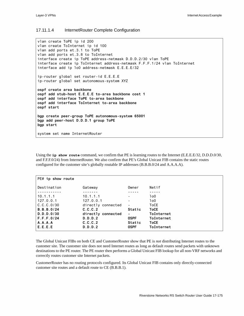
Layer-3 VPNs Internet Access Example
17.11.1.4 InternetRouter Complete Configuration
Using the ip show route command, we confirm that PE is learning routes to the Internet (E.E.E.E/32, D.D.D.0/30, and F.F.F.0/24) from InternetRouter. We also confirm that PE’s Global Unicast FIB contains the static routes configured for the customer site’s globally routable IP addresses (B.B.B.0/24 and A.A.A.A).
The Global Unicast FIBs on both CE and CustomerRouter show that PE is not distributing Internet routes to the customer site. The customer site does not need Internet routes as long as default routes send packets with unknown destinations to the PE router. The PE router then performs a Global Unicast FIB lookup for all non-VRF networks and correctly routes customer site Internet packets.
CustomerRouter has no routing protocols configured. Its Global Unicast FIB contains only directly-connected customer site routes and a default route to CE (B.B.B.1).
vlan create ToPE ip id 200vlan create ToInternet ip id 100vlan add ports et.3.1 to ToPEvlan add ports et.3.8 to ToInternetinterface create ip ToPE address-netmask D.D.D.2/30 vlan ToPEinterface create ip ToInternet address-netmask F.F.F.1/24 vlan ToInternetinterface add ip lo0 address-netmask E.E.E.E/32
ip-router global set router-id E.E.E.Eip-router global set autonomous-system XYZ
ospf create area backboneospf add stub-host E.E.E.E to-area backbone cost 1ospf add interface ToPE to-area backboneospf add interface ToInternet to-area backboneospf start
bgp create peer-group ToPE autonomous-system 65001bgp add peer-host D.D.D.1 group ToPEbgp start
system set name InternetRouter
PE# ip show route
Destination Gateway Owner Netif----------- ------- ----- -----10.1.1.1 10.1.1.1 - lo0127.0.0.1 127.0.0.1 - lo0C.C.C.0/30 directly connected - ToCEB.B.B.0/24 C.C.C.2 Static ToCED.D.D.0/30 directly connected - ToInternetF.F.F.0/24 D.D.D.2 OSPF ToInternetA.A.A.A C.C.C.2 Static ToCEE.E.E.E D.D.D.2 OSPF ToInternet
Riverstone Networks RS Switch Router User Guide 17-175
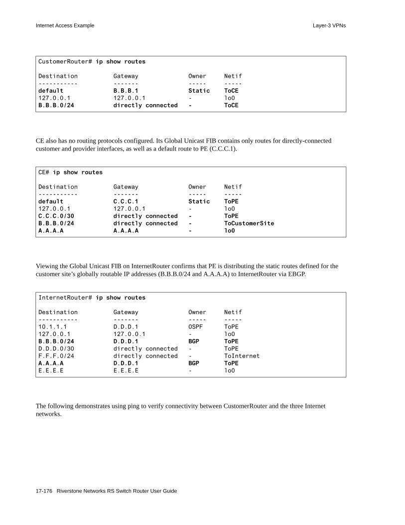
Internet Access Example Layer-3 VPNs
CE also has no routing protocols configured. Its Global Unicast FIB contains only routes for directly-connected customer and provider interfaces, as well as a default route to PE (C.C.C.1).
Viewing the Global Unicast FIB on InternetRouter confirms that PE is distributing the static routes defined for the customer site’s globally routable IP addresses (B.B.B.0/24 and A.A.A.A) to InternetRouter via EBGP.
The following demonstrates using ping to verify connectivity between CustomerRouter and the three Internet networks.
CustomerRouter# ip show routes
Destination Gateway Owner Netif----------- ------- ----- -----default B.B.B.1 Static ToCE127.0.0.1 127.0.0.1 - lo0B.B.B.0/24 directly connected - ToCE
CE# ip show routes
Destination Gateway Owner Netif----------- ------- ----- -----default C.C.C.1 Static ToPE127.0.0.1 127.0.0.1 - lo0C.C.C.0/30 directly connected - ToPEB.B.B.0/24 directly connected - ToCustomerSiteA.A.A.A A.A.A.A - lo0
InternetRouter# ip show routes
Destination Gateway Owner Netif----------- ------- ----- -----10.1.1.1 D.D.D.1 OSPF ToPE127.0.0.1 127.0.0.1 - lo0B.B.B.0/24 D.D.D.1 BGP ToPED.D.D.0/30 directly connected - ToPEF.F.F.0/24 directly connected - ToInternetA.A.A.A D.D.D.1 BGP ToPEE.E.E.E E.E.E.E - lo0
17-176 Riverstone Networks RS Switch Router User Guide

Layer-3 VPNs Internet Access Example
CustomerRouter# ping D.D.D.2PING D.D.D.2: 36 bytes of data5 second timeout, 1 repetition36 bytes from D.D.D.2: icmp_seq=0 ttl=253 time=171.852 ms
--- D.D.D.2 ping statistics ---1 packets transmitted, 1 packets received, 0.00% packet lossround-trip min/avg/max/dev = 171.852/171.852/171.852/0.000 ms
CustomerRouter# ping E.E.E.EPING E.E.E.E: 36 bytes of data5 second timeout, 1 repetition36 bytes from E.E.E.E: icmp_seq=0 ttl=253 time=168.530 ms
--- E.E.E.E ping statistics ---1 packets transmitted, 1 packets received, 0.00% packet lossround-trip min/avg/max/dev = 168.530/168.530/168.530/0.000 ms
CustomerRouter# ping F.F.F.1PING F.F.F.1: 36 bytes of data5 second timeout, 1 repetition36 bytes from F.F.F.1: icmp_seq=0 ttl=253 time=168.648 ms
--- F.F.F.1 ping statistics ---1 packets transmitted, 1 packets received, 0.00% packet lossround-trip min/avg/max/dev = 168.648/168.648/168.648/0.000 ms
Riverstone Networks RS Switch Router User Guide 17-177

Internet Access Example Layer-3 VPNs
17.11.2 Internet Access Using Network Address Translation (NAT)
The following example configures a PE router to provide Internet access for a customer site using network address translation (NAT). Figure 17-59 illustrates the topology.
Enabling Internet access for customer sites using network address translation requires the following:1. Ensure that the PE router’s Global Unicast FIB contains the Internet routes the customer site wishes
to use.- In the example, PE is learning Internet routes from Internet Router via EBGP.
2. Configure the PE router to use the Global Unicast FIB to resolve all addresses not found in the routing instance’s Unicast FIB.
When a CE packet arrives, the PE router first examines the particular routing instance Unicast FIB. In the Basic BGP/MPLS VPN example, if this lookup fails to yield a match, the packet cannot be routed. Enabling Global Unicast FIB lookup expands the set of routes accessible to customer sites from VRF routes only to VRF routes plus all provider and Internet routes. As long as a route to the requested address exists in the PE router’s Global Unicast FIB, the Internet access succeeds.- On PE routers, use the routing-instance set global-unicast-lookup command to
enable Internet access for sites belonging to the specified VRF. In the example, PE is configured to perform Global Unicast FIB lookup for the RED VRF, to which the Customer Site belongs.
Note Enabling Global Unicast FIB lookup grants customers access to Internet routes as well as the provider’s internal routes. For security reasons, consider placing customer access restrictions on the PE router’s customer-facing interfaces. You can do this in one of two ways using access-control lists (ACLs): 1. Prevent customers from sending to provider internal addresses on the outbound2. Prevent provider sources from replying to customer addresses on the inbound
Before applying access restrictions, consider that customers need access to some provider internal routes in order to reach services such as DNS, NNTP, SMTP, or POP. Carefully consider any effects access restrictions may have on the customer’s ability to reach these services before applying restrictions.
17-178 Riverstone Networks RS Switch Router User Guide

Layer-3 VPNs Internet Access Example
3. Use NAT to map Internet-bound traffic from customer sites to globally routable IP address(es). In the Basic BGP/MPLS VPN Network, customers may use RFC 1918 private addresses. Separate VRF routing tables on the PE router keep possibly overlapping customer addresses separate. To provide Internet access, PE routers must distribute to the Internet routes that the Internet relies upon for sending to customer sites (step 6). Since they are being distributed to the Internet, these routes must be globally routable. Customers may continue to use private addresses for internal VPN traffic. - The example maps internal customer addresses to globally routable addresses on the PE router
in the following way:- NAT is enabled on two interfaces. The customer-facing interface (toCustomerRED) is specified
as the interface from which private addresses originate using the inside keyword. The Internet-facing interface (toInternet) is specified as the interface from which public addresses originate using the outside keyword.
- A static mapping is created from private address 100.1.1.1 to public address 172.16.201.3. This mapping converts all IP packets originating from the private address 100.1.1.1 on the toCustomerRED interface (the inside interface) to use the public address 172.16.201.3 before it is sent to the Internet Router. Likewise, any packet originating from the public address 172.16.201.3 on the toInternet interface (the outside interface) should be converted to use the private address 100.1.1.1 before it is sent to the CE router. The global-ip keyword specifies that this is a one-to-one mapping.
- Using the access-control list to1, a dynamic mapping is created from the private network 100.3.1/24 to the public address 172.16.201.4. This mapping converts all IP packets originating from the private network 100.3.1/24 on the toCustomerRED interface (the inside interface) to use the public address 172.16.201.4 before it is sent to the Internet Router. Likewise, any packet originating from the public address 172.16.201.4 on the toInternet interface (the outside interface) should be converted to an address within the private network 100.3.1/24 before it is sent to the CE router.
In this example, the dynamic mapping is not a one-to-one mapping. The global-pool keyword can be used to specify that the public address may be from a pool of addresses. (In this example, it is only a single IP address.) The enable-ip-overload keyword specifies that the number of private addresses is greater than the number of public address(es), and that each public address may be overloaded to carry more than one private address. When private addresses are overloaded, the RS Ethernet Router relies on socket numbers to differentiate between distinct private network addresses being mapped to one public address.
4. Make sure that the PE routers can route to the private address(es)/network(s) from which customers will be originating Internet-bound traffic.- In the example, PE is configured with static routes to the 100.3.1/24 network and the 100.1.1.1
address in the RED VRF. The PE router mapped both of these private customer addresses to globally routable addresses with NAT. (See step 3)
5. Configure CE routers to use PE router(s) as default gateway(s) for unknown destinations.- On CE routers, you can do this using the ip add route default gateway command. In
the example, the PE router (10.3.1.1) is configured as the default gateway on the CE router and the Customer Router (90.3.1.2) is configured as the default gateway for the private customer networks for which the PE router created NAT mappings.
6. To provide Internet access, PE routers must distribute to the Internet those globally routable addresses to which they mapped the private customer addresses.
Riverstone Networks RS Switch Router User Guide 17-179

Internet Access Example Layer-3 VPNs
- In the example, the PE router adds the interface from which it borrowed the globally routable addresses (toInternet) to the EBGP session with Internet Router, ensuring that the 172.16.201/24 network will be distributed to the Internet. Alternatively, the globally routable network may be redistributed into the EBGP session using the ip-router policy redistribute command
Figure 17-59 Internet access using NAT
Complete configurations for the CE and PE routers follow. The configurations specifically applicable to this example are highlighted.
NAT mappings:100.1.1.1 -- 172.16.201.3 (Static)
100.3.1/24 -- 172.16.201.4 (Dynamic)
EBGP
PE33.33.33.33
InternetRouteret.7.4
gi.2.1
et.3.1 et.3.8
CE3.0.0.3
gi.6.1
gi.5.1
.1
.1 .2
.2
10.3.1/24
172.16.201/24172.16.201/24
CustomerSite
InternetAS 64220
OSPFStatic Routes
Default Gateway
VRFRoutes toCustomer
Routes to Customer
OSPF
Provider NetworkAS 61234
BGP/MPLS VPN Network:Internet Access with
Network AddressTranslation (NAT)
InternalProviderRouter
.1
.2
172.17.13/30 IS-IS, MPLS, LDPMP-IBGP
gi.14.3
.3
CustomerRouter
.2
90.3.1/24
.1
100.1.1.1/32100.3.1/24
NAT Inside
NAT Outside
OSPFStatic Routes to100.1.1.1, 100.3.1
17-180 Riverstone Networks RS Switch Router User Guide

Layer-3 VPNs Internet Access Example
17.11.2.1 PE Complete Configuration
interface create ip toProvider address-netmask 172.17.13.2/30 port gi.14.3interface create ip toCustomerRED address-netmask 10.3.1.1/24 port gi.2.1interface create ip toInternet address-netmask 172.16.201.1/24 port et.7.4interface add ip lo0 address-netmask 33.33.33.33/32
acl to1 permit ip 100.3.1/24
ip-router global set router-id 33.33.33.33ip-router global set autonomous-system 61234ip-router global set install-lsp-routes on
ip-router policy create community-list vn1 "target:61234:401" route-map in1 permit 10 match-community-list vn1route-map out1 permit 10 set-community-list vn1route-map test1 permit 10 match-route-type bgp
bgp create peer-group as64220 autonomous-system 64220bgp add peer-host 172.16.201.2 group as64220bgp create peer-group as61234 autonomous-system 61234bgp set peer-group as61234 vpnv4-unicast ipv4-unicastbgp set peer-group as61234 local-address 33.33.33.33bgp set peer-group as61234 next-hop-selfbgp start
isis add area 27.2727.2727isis add interface lo0isis add interface toProviderisis set interface toProvider level 1isis start
mpls add interface toProvidermpls startldp add interface toProviderldp start
routing-instance RED vrf add interface toCustomerREDrouting-instance RED ospf create area backbonerouting-instance RED ospf add interface toCustomerRED to-area backbonerouting-instance RED ospf startrouting-instance RED vrf set route-distinguisher 61234:401 vrf-import in1 in-sequence
1 vrf-export out1 out-sequence 1routing-instance RED ospf set route-map-vpn test1routing-instance RED vrf set global-unicast-lookuprouting-instance RED ip add route 100.3.1/24 gateway 10.3.1.2 routing-instance RED ip add route 100.1.1.1/32 gateway 10.3.1.2 routing-instance RED vrf set router-id 10.3.1.1
nat set interface toCustomerRED insidenat set interface toInternet outsidenat create static local-ip 100.1.1.1 global-ip 172.16.201.3 matches-in-interface
toCustomerRED protocol ipnat create dynamic local-acl-pool to1 global-pool 172.16.201.4 matches-in-interface
toCustomerRED enable-ip-overload
Riverstone Networks RS Switch Router User Guide 17-181
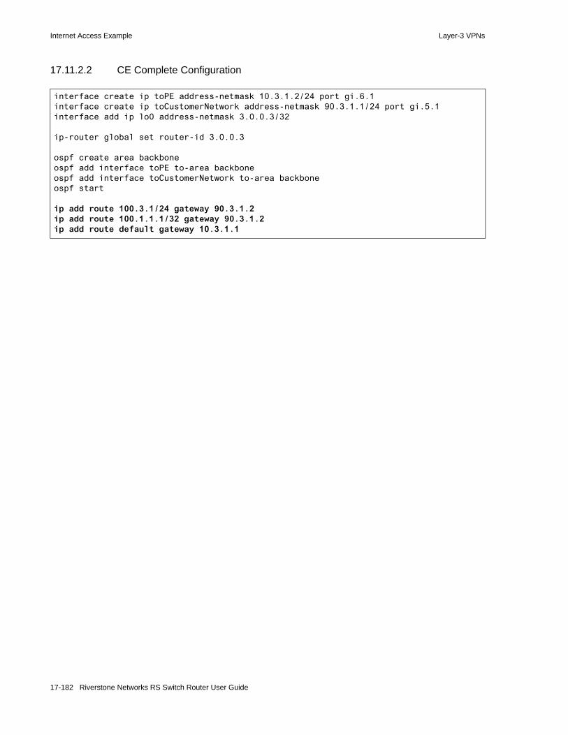
Internet Access Example Layer-3 VPNs
17.11.2.2 CE Complete Configuration
interface create ip toPE address-netmask 10.3.1.2/24 port gi.6.1interface create ip toCustomerNetwork address-netmask 90.3.1.1/24 port gi.5.1interface add ip lo0 address-netmask 3.0.0.3/32
ip-router global set router-id 3.0.0.3
ospf create area backboneospf add interface toPE to-area backboneospf add interface toCustomerNetwork to-area backboneospf start
ip add route 100.3.1/24 gateway 90.3.1.2ip add route 100.1.1.1/32 gateway 90.3.1.2ip add route default gateway 10.3.1.1
17-182 Riverstone Networks RS Switch Router User Guide

Layer-3 VPNs Hub and Spoke Example
17.12 HUB AND SPOKE EXAMPLEThe following example configures a hub and spoke topology separately using BGP and OSPF as the hub CE-PE protocol. Figure 17-60 illustrates this topology and highlights key configurations.
In this hub and spoke network, • PE3 is the hub PE router• CE3 is the hub CE router• PE1 and PE2 are spoke PE routers• CE1 and CE2 are spoke CE routers
PE3 is connected to CE3 through two physical links, which it uses to maintain two different VRFs: VRF spoke-to-hub for learning routes from the spokes and VRF hub-to-spoke for distributing routes to the spokes. (You may use logical links such as VLANs instead of physical links.)
In the spoke-to-hub VRF, PE3 learns routes from PE1 by importing routes with a Route Target of ‘target:65001:1’ and from PE2 by importing routes with a Route Target of ‘target:65001:2’. PE3 distributes these routes to CE3 via the to-CE3 link, which is added to this VRF. The spoke-to-hub export policy of ‘null’ prevents these routes from being advertised back to the spokes.
CE3 installs these routes in the Unicast FIB and advertises them back to PE3 on both links.
At this point, both the spoke-to-hub and hub-to-spoke VRFs contain spoke routes. The spoke-to-hub VRF learns these routes from the spoke PE routers. The hub-to-spoke VRF learns these routes from CE3. The spoke-to-hub VRF export policy of ‘null’ prevents these routes from being advertised back to the spokes.
The hub-to-spoke VRF exports its routes with a Route Target of ‘target:65001:3’, which both spoke PE routers are importing. Note that the hub-to-spoke import policy of ‘NULL’ prevents this VRF from learning spoke routes directly from the spokes. This limits the hub-to-spoke VRF to advertising to spoke routers only the routes learned from the hub CE router. These routes force each spoke to reach other spokes through the hub. So even though there is a link between PE1 and PE2 in the example, they do not exchange VRF routes. Instead, they learn routes for each other’s customer sites through the hub and traverse the hub to reach each other.
The hub and spoke topology relies on the hub CE router distributing routes learned from the hub PE router back to the hub PE router. Most routing protocols have built-in checks to prevent this type of routing loop. When implementing the hub and spoke topology using OSPF and BGP between the hub CE and PE routers, additional configurations are necessary to circumvent protocol anti-looping mechanisms. The following sections outline these configurations, which allow PE routers to distinguish a hub and spoke routing loop from a generic routing loop. Using them, PE routers can still prevent the latter but make allowances for the former.
Riverstone Networks RS Switch Router User Guide 17-183

Hub and Spoke Example Layer-3 VPNs
Figure 17-60 Hub and spoke
Import Targets: "target:65000:1" "target:65000:2"Export Target: NULL
BGP/MPLS VPN Network:Hub and Spoke
PE110.1.1.1
gi.2.2
gi.5.1
PE310.3.3.3
gi.14.1 gi.14.2
172.32.1.2/30
CustomerSite
PE210.2.2.2
gi.14.1
gi.14.4
172.32.2.2/30
172.32.1.1/30 172.32.2.1/30
CE3
AS 65111Customer Network
CustomerSite
CE110.1.1.1
CustomerSite
CE210.1.1.1
AS 65111Customer Network
gi.14.3gi.14.4
192.170.1.0/30192.171.1.0/30
spoketo
hub
hubto
spoke
Import Targets: NULLExport Target: "target:65000:3"
MP-IBGP
Bidirecti
onal MPLS lS
Ps
MP-IBGP
Bidirectional MPLS LSPs
.2
.1
.2
.1
gi.1.2gi.1.1
192.180.1.0/30
.2 .2
.1 .1
192.190.1.0/30
Import Targets: "target:65000:3"Export Target: "target:65000:1"
Import Targets: "target:65000:3"Export Target: "target:65000:2"
Provider NetworkAS 65000 loops 2
OSPF area backbone
Hub learning pathSpoke learning path
Configure differentVPN Route Tag andRouter IDs for thehub PE-CE VRFs
On hub PE, configurea Domain ID different
from those on thespoke PEs
172.22.1.1/30 172.22.1.2/30
17-184 Riverstone Networks RS Switch Router User Guide

Layer-3 VPNs Hub and Spoke Example
17.12.1 OSPF as the Hub CE-PE Protocol
When using OSPF as the hub CE-PE protocol, you must configure the following on the hub PE router. For more information on configuring OSPF between CE and PE routers, see the Section 17-48 "Configuring Static and OSPF Route Distribution Between CE and PE Routers."• Configure a different Router ID for each CE-PE VRF using the routing-instance vrf set
router-id command. This prevents the hub PE router from rejecting the hub CE router’s advertisements (of spoke routes) on the basis that they are self originated. - In the hub and spoke topology (Figure 17-60), PE3 advertises spoke routes to CE3 via the
spoke-to-hub VRF with a router ID. If the hub-to-spoke VRF is configured with the same router ID, when CE3 advertises these routes back to PE3, PE3 would find the router IDs on these advertisements identical to its own and reject the advertisements because they are self originated. The solution is to configure a different router ID for each VRF between the hub CE and PE routers. You can configure multiple loopback addresses and assign them as router IDs to each VRF or use the interface address of the interface added to a VRF as the router ID for that VRF. In the example, PE3 uses the interface address on each VRF as the router ID for that VRF. PE3 originates all LSAs on the spoke-to-hub link with a router ID of 192.171.1.1 and all LSAs on the hub-to-spoke link with a router ID of 192.170.1.1.
• Configure a different VPN Route Tag for each CE-PE VRF using the routing-instance ospf set vpn-route-tag command. Before advertising VRF routes, PE routers use the VPN Route Tag to check that Type-5 LSAs are not redistributed through the OSPF area to another PE router, possibly creating a loop within the same VPN. A PE router ignores received Type-5 LSAs with a VPN Route Tag set to the value you define for its customer site’s VPN. - If the spoke-to-hub and hub-to-spoke VRFs share one VPN Route Tag, PE3 would recognize
routes that CE3 learns from the spoke-to-hub VRF and advertises to the hub-to-spoke VRF as coming from the same customer site. Based on this, PE3 would not install these LSAs. These routes would never be advertised out the hub-to-spoke VRF to the spoke PE routers. The solution is to configure a different VPN Route Tag for each VRF between the hub CE and PE routers. In the example, the OSPF instance in VRF spoke-to-hub is configured with a VPN Route Tag of ‘1005’ and the OSPF instance in VRF hub-to-spoke is configured with a VPN Route Tag of ‘1010’.
• Configure a Domain ID on the hub PE router that is different from those configured on the spoke PE routers using the routing-instance ospf set domain-id command. This forces spoke routes to become Type-5 LSAs on the hub PE. Normally, PE routers treat OSPF routes originating from within the same domain as Type-3 LSAs. Type-3 LSAs rely on one bit, the DN bit, to flag loops. The DN bit is insufficient for PE routers to distinguish hub and spoke loops from generic routing loops. Type-5 LSAs do not impose this limitation. For PE routers to permit hub and spoke loops and still prevent other types of loops, they must distribute remote-site routes as Type-5 LSAs.- In the example, PE3 is configured with a Domain ID of 0.0.0.3 for both VRFs. Both spoke PE
routers distribute routes learned via EBGP from the spoke CE routers to PE3. Since these routes originate from outside the OSPF domain, PE3 already considers them Type-5 LSAs. If the spoke PE routers learn spoke CE routes via OSPF, make sure that the Domain ID you configure on the hub PE router is distinct from the default Domain ID, 0.0.0.0, and the Domain IDs configured on the spoke PE routers. The multiple hub and spoke VRFs on the PE router, however, can share one Domain ID.
Complete OSPF-based configurations for the hub PE and CE routers follow. The configurations specifically applicable to this example are highlighted.
Riverstone Networks RS Switch Router User Guide 17-185
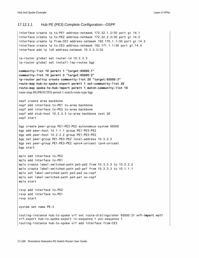
Hub and Spoke Example Layer-3 VPNs
17.12.1.1 Hub PE (PE3) Complete Configuration—OSPF
interface create ip to-PE1 address-netmask 172.32.1.2/30 port gi.14.1
interface create ip to-PE2 address-netmask 172.32.2.2/30 port gi.14.2
interface create ip from-CE3 address-netmask 192.170.1.1/30 port gi.14.3
interface create ip to-CE3 address-netmask 192.171.1.1/30 port gi.14.4
interface add ip lo0 address-netmask 10.3.3.3/32
ip-router global set router-id 10.3.3.3
ip-router global set install-lsp-routes bgp
community-list 10 permit 1 "target:65000:1"
community-list 10 permit 2 "target:65000:2"
ip-router policy create community-list 20 "target:65000:3"
route-map hub-to-spoke-export permit 1 set-community-list 20
route-map spoke-to-hub-import permit 1 match-community-list 10
route-map BGPROUTES permit 1 match-route-type bgp
ospf create area backbone
ospf add interface to-PE1 to-area backbone
ospf add interface to-PE2 to-area backbone
ospf add stub-host 10.3.3.3 to-area backbone cost 20
ospf start
bgp create peer-group PE1-PE3-PE2 autonomous-system 65000
bgp add peer-host 10.1.1.1 group PE1-PE3-PE2
bgp add peer-host 10.2.2.2 group PE1-PE3-PE2
bgp set peer-group PE1-PE3-PE2 local-address 10.3.3.3
bgp set peer-group PE1-PE3-PE2 vpnv4-unicast ipv4-unicast
bgp start
mpls add interface to-PE2
mpls add interface to-PE1
mpls create label-switched-path pe3-pe2 from 10.3.3.3 to 10.2.2.2
mpls create label-switched-path pe3-pe1 from 10.3.3.3 to 10.1.1.1
mpls set label-switched-path pe3-pe2 no-cspf
mpls set label-switched-path pe3-pe1 no-cspf
mpls start
rsvp add interface to-PE2
rsvp add interface to-PE1
rsvp start
system set name PE-3
routing-instance hub-to-spoke vrf set route-distinguisher 65000:31 vrf-import null vrf-export hub-to-spoke-export in-sequence 1 out-sequence 1
routing-instance hub-to-spoke vrf add interface from-CE3
17-186 Riverstone Networks RS Switch Router User Guide

Layer-3 VPNs Hub and Spoke Example
17.12.1.2 Hub CE (CE3) Complete Configuration—OSPF
routing-instance hub-to-spoke vrf set router-id 192.170.1.1
routing-instance hub-to-spoke ospf create area backbone
routing-instance hub-to-spoke ospf add interface from-CE3 to-area backbone
routing-instance hub-to-spoke ospf set vpn-route-tag 1010
routing-instance hub-to-spoke ospf set domain-id 0.0.0.3
routing-instance hub-to-spoke ospf start
routing-instance spoke-to-hub vrf set route-distinguisher 65000:30 vrf-import spoke-to-hub-import vrf-export null in-sequence 1 out-sequence 1
routing-instance spoke-to-hub vrf add interface to-CE3
routing-instance spoke-to-hub vrf set router-id 192.171.1.1
routing-instance spoke-to-hub ospf create area backbone
routing-instance spoke-to-hub ospf add interface to-CE3 to-area backbone
routing-instance hub-to-spoke ospf set vpn-route-tag 1005
routing-instance hub-to-spoke ospf set domain-id 0.0.0.3
routing-instance hub-to-spoke ospf set route-map-vpn BGPROUTES
routing-instance spoke-to-hub ospf start
interface create ip to-PE3 address-netmask 192.170.1.2/30 port gi.1.2interface create ip from-PE3 address-netmask 192.171.1.2/30 port gi.1.1
ospf create area backboneospf add interface to-PE3 to-area backboneospf add interface from-PE3 to-area backboneospf start
system set name CE-3
Riverstone Networks RS Switch Router User Guide 17-187

Hub and Spoke Example Layer-3 VPNs
17.12.2 BGP as the Hub CE-PE Protocol
When using BGP as the hub CE-PE protocol, you must configure the following on the hub PE router. For more information on configuring BGP between CE and PE routers, see the Section 17-94 "Configuring BGP Route Distribution Between CE and PE Routers."• Configure the hub PE router to permit one loop in a received route’s aspath using the ip-router
global set autonomous-system loops command with the parameter 1. This command sets the test condition globally on the hub PE router and applies to all configured VRFs. Normally, BGP discards routes whose aspath lists its own autonomous system because this signals a loop. To allow the necessary hub and spoke loop, this command instructs the BGP process to permit routes that have up to one occurrences of its autonomous system. Allowing up to one occurrence of an AS number permits only one loop and still safeguards against multi-looping routes in whose aspath the current autonomous system number would occur two or more times. - In the hub and spoke topology (Figure 17-60), PE2 is allowed to see up to one occurrences of
its own AS number, 65000, in all BGP routes, including those it receives via PE-CE route distribution from CE3.
• Configure the hub PE router to distribute active Routing Instance routes to the hub CE router using a route map. By default, in the absence of routing policies, BGP announces all routes from the Unicast FIB only. For a hub PE router to announce Routing Instance routes to the hub CE router, you must configure a route map on the hub PE router that enables it to announce the necessary VRF routes and apply this route map to the hub CE peer. For more information on configuring route maps, see Section 16.2.14 "Using Route Maps."- In the example, the route map spoke-to-hub applied to the spoke-to-hub VRF permits PE3 to
advertise all active and optimal VRF routes to CE3. The route map and VRF names need not be identical.
Complete BGP-based configurations for the hub PE and CE routers follow. The configurations specifically applicable to this example are highlighted.
17-188 Riverstone Networks RS Switch Router User Guide

Layer-3 VPNs Hub and Spoke Example
17.12.2.1 Hub PE (PE3) Complete Configuration—BGP
interface create ip to-PE1 address-netmask 172.32.1.2/30 port gi.14.1
interface create ip to-PE2 address-netmask 172.32.2.2/30 port gi.14.2
interface create ip from-CE3 address-netmask 192.170.1.1/30 port gi.14.3
interface create ip to-CE3 address-netmask 192.171.1.1/30 port gi.14.4
interface add ip lo0 address-netmask 10.3.3.3/32
ip-router global set router-id 10.3.3.3
ip-router global set install-lsp-routes bgp
ip-router global set autonomous-system 65000 loops 1
community-list 10 permit 1 "target:65000:1"
community-list 10 permit 2 "target:65000:2"
ip-router policy create community-list 20 "target:65000:3"
route-map hub-to-spoke-export permit 1 set-community-list 20
route-map spoke-to-hub permit 10
route-map spoke-to-hub-import permit 1 match-community-list 10
ospf create area backbone
ospf add interface to-PE1 to-area backbone
ospf add interface to-PE2 to-area backbone
ospf add stub-host 10.3.3.3 to-area backbone cost 20
ospf start
bgp create peer-group PE1-PE3-PE2 autonomous-system 65000
bgp add peer-host 10.1.1.1 group PE1-PE3-PE2
bgp add peer-host 10.2.2.2 group PE1-PE3-PE2
bgp set peer-group PE1-PE3-PE2 local-address 10.3.3.3
bgp set peer-group PE1-PE3-PE2 vpnv4-unicast ipv4-unicast
bgp start
mpls add interface to-PE2
mpls add interface to-PE1
mpls create label-switched-path pe3-pe2 from 10.3.3.3 to 10.2.2.2
mpls create label-switched-path pe3-pe1 from 10.3.3.3 to 10.1.1.1
mpls set label-switched-path pe3-pe2 no-cspf
mpls set label-switched-path pe3-pe1 no-cspf
mpls start
rsvp add interface to-PE2
rsvp add interface to-PE1
rsvp start
system set name PE-3
routing-instance hub-to-spoke vrf set route-distinguisher 65000:31 vrf-import null vrf-export hub-to-spoke-export in-sequence 1 out-sequence 1
Riverstone Networks RS Switch Router User Guide 17-189
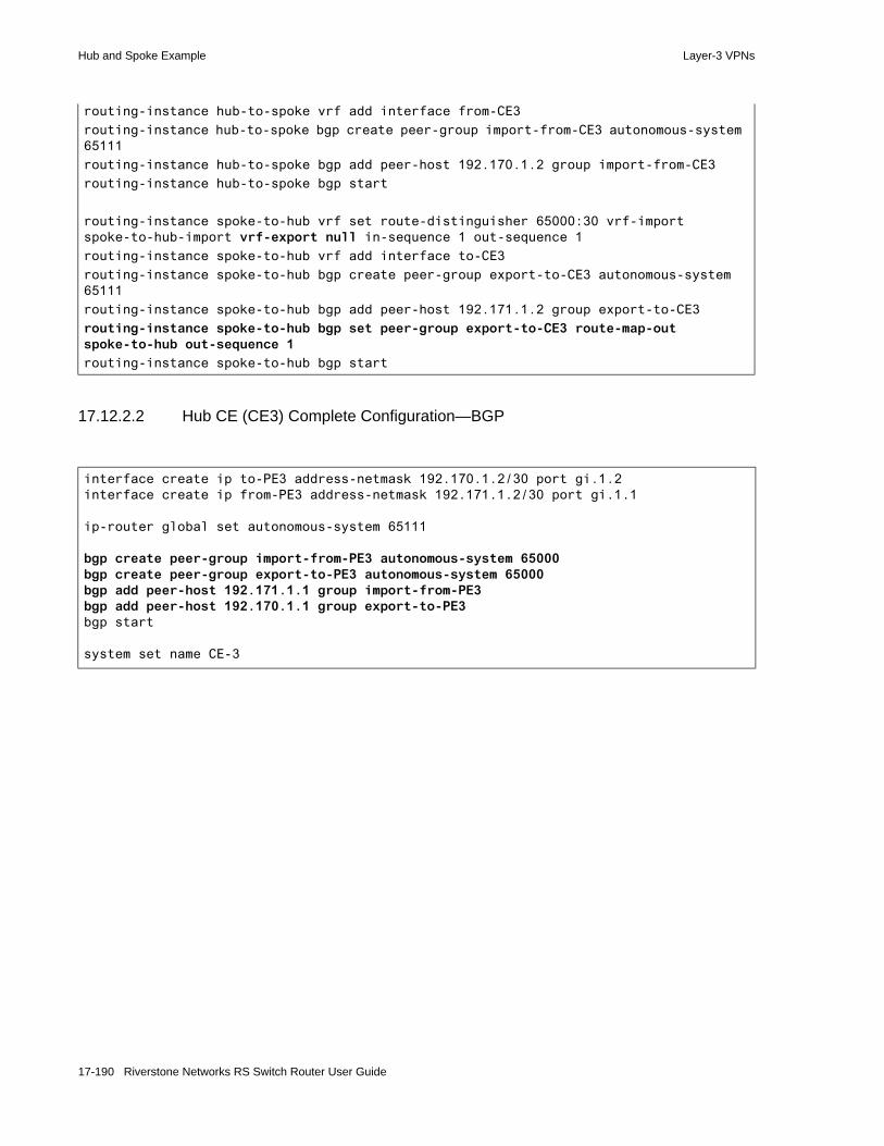
Hub and Spoke Example Layer-3 VPNs
17.12.2.2 Hub CE (CE3) Complete Configuration—BGP
routing-instance hub-to-spoke vrf add interface from-CE3
routing-instance hub-to-spoke bgp create peer-group import-from-CE3 autonomous-system 65111
routing-instance hub-to-spoke bgp add peer-host 192.170.1.2 group import-from-CE3
routing-instance hub-to-spoke bgp start
routing-instance spoke-to-hub vrf set route-distinguisher 65000:30 vrf-import spoke-to-hub-import vrf-export null in-sequence 1 out-sequence 1
routing-instance spoke-to-hub vrf add interface to-CE3
routing-instance spoke-to-hub bgp create peer-group export-to-CE3 autonomous-system 65111
routing-instance spoke-to-hub bgp add peer-host 192.171.1.2 group export-to-CE3
routing-instance spoke-to-hub bgp set peer-group export-to-CE3 route-map-out spoke-to-hub out-sequence 1
routing-instance spoke-to-hub bgp start
interface create ip to-PE3 address-netmask 192.170.1.2/30 port gi.1.2interface create ip from-PE3 address-netmask 192.171.1.2/30 port gi.1.1
ip-router global set autonomous-system 65111
bgp create peer-group import-from-PE3 autonomous-system 65000bgp create peer-group export-to-PE3 autonomous-system 65000bgp add peer-host 192.171.1.1 group import-from-PE3bgp add peer-host 192.170.1.1 group export-to-PE3bgp start
system set name CE-3
17-190 Riverstone Networks RS Switch Router User Guide

Layer-3 VPNs Hub and Spoke Example
17.12.3 Configuring the Spoke PE Router
On the spoke PE router, you must configure the following:• Just like on the hub PE router, configure the spoke PE router to permit one loop in a received route’s
aspath using the ip-router global set autonomous-system loops command with the parameter 1. This command sets the test condition globally on the spoke PE router and applies to all configured VRFs on the spoke PE router. Normally, BGP discards routes whose aspath lists its own autonomous system because this signals a loop. To allow the necessary hub and spoke loop, this command instructs the BGP process to permit routes that have up to one occurrences of its autonomous system. Allowing up to one occurrences of an AS number permits only one loop and still safeguards against multi-looping routes in whose aspaths the current autonomous system number would occur two or more times. - In the hub and spoke topology (Figure 17-60), PE1 is configured to permit up to one occurrence
of its own AS number, 65000, in all BGP routes, including those it receives from PE3 via the hub-to-spoke VRF.
• Do not configure the spoke PE routers to exchange routes with other spoke PE routers. This forces them to learn routes for each other’s customer sites through the hub and traverse the hub to reach each other. Without routing exchange, configuring MPLS LSPs between spoke PE routers is also unnecessary.- In the example, PE1 only has an interface configured to PE2. It is not participating in any
routing protocols with PE2, nor are there any MPLS LSPs configured between PE1 and PE2. The link between PE1 and PE2 can be disabled without affecting their connectivity through the hub.
Configure spoke CE routers as you would any CE router in the Basic BGP/MPLS VPN Network. The following complete configuration for PE1 illustrates how to configure the spoke PE router. The configurations specifically applicable to this example are highlighted.
17.12.3.1 Sample Spoke PE (PE1) Complete Configuration
interface create ip to-PE2 address-netmask 172.22.1.1/30 port gi.5.2
interface create ip to-PE3 address-netmask 172.32.1.1/30 port gi.5.1
interface create ip to-CE1 address-netmask 192.180.1.1/30 port gi.2.2
interface add ip lo0 address-netmask 10.1.1.1/32
ip-router global set router-id 10.1.1.1
ip-router global set install-lsp-routes bgp
ip-router global set autonomous-system 65000 loops 1
ip-router policy create community-list 10 target:65000:1
ip-router policy create community-list 11 target:65000:3
route-map bgp permit 10
route-map trinity-export permit 10 set-community-list 10
route-map trinity-import permit 10 match-community-list 11
ospf create area backbone
ospf add interface to-PE3 to-area backbone
ospf add stub-host 10.1.1.1 to-area backbone cost 20
Riverstone Networks RS Switch Router User Guide 17-191

Hub and Spoke Example Layer-3 VPNs
ospf start
bgp create peer-group PE1-PE3 autonomous-system 65000
bgp add peer-host 10.3.3.3 group PE1-PE3
bgp set peer-group PE1-PE3 local-address 10.1.1.1
bgp set peer-group PE1-PE3 vpnv4-unicast ipv4-unicast
bgp start
mpls add interface to-PE2
mpls add interface to-PE3
mpls create label-switched-path pe1-pe3 from 10.1.1.1 to 10.3.3.3
mpls set label-switched-path pe1-pe3 no-cspf
mpls start
rsvp add interface to-PE2
rsvp add interface to-PE3
rsvp start
system set name PE-1
routing-instance trinity vrf set route-distinguisher 65000:10 vrf-import trinity-import vrf-export trinity-export in-sequence 1 out-sequence 1
routing-instance trinity vrf add interface to-CE1
routing-instance trinity bgp create peer-group PE1-CE1 autonomous-system 65111
routing-instance trinity bgp add peer-host 192.180.1.2 group PE1-CE1
routing-instance trinity bgp set peer-host 192.180.1.2 route-map-out bgp out-sequence 1
routing-instance trinity bgp start
17-192 Riverstone Networks RS Switch Router User Guide
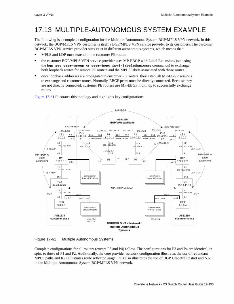
Layer-3 VPNs Multiple-Autonomous System Example
17.13 MULTIPLE-AUTONOMOUS SYSTEM EXAMPLEThe following is a complete configuration for the Multiple-Autonomous System BGP/MPLS VPN network. In this network, the BGP/MPLS VPN customer is itself a BGP/MPLS VPN service provider to its customers. The customer BGP/MPLS VPN service provider sites exist in different autonomous systems, which means that:• MPLS and LDP must extend to the customer PE router.• the customer BGP/MPLS VPN service provider uses MP-EBGP with Label Extensions (set using
the bgp set peer-group or peer-host ipv4-labeledunicast commands) to exchange both loopback routes for remote PE routers and the MPLS labels associated with those routes.
• once loopback addresses are propagated to customer PE routers, they establish MP-EBGP sessions to exchange end customer routes. Normally, EBGP peers must be directly connected. Because they are not directly connected, customer PE routers use MP-EBGP multihop to successfully exchange routes.
Figure 17-61 illustrates this topology and highlights key configurations.
Figure 17-61 Multiple Autonomous Systems
Complete configurations for all routers (except P3 and P4) follow. The configurations for P3 and P4 are identical, in spirt, to those of P1 and P2. Additionally, the core provider network configuration illustrates the use of redundant MPLS paths and R22 illustrates route reflector usage. PE3 also illustrates the use of BGP Graceful Restart and NAT in the Multiple-Autonomous System BGP/MPLS VPN network.
BGP/MPLS VPN Network:Multiple Autonomous
Systems
PE111.11.11.
11
P111.0.0.11
P222.0.0.22
PE222.22.22.
22
PE333.33.33.33
P3 P4
PE444.44.44.44
CE11.0.0.1
CE22.0.0.2
CE33.0.0.3
CE44.0.0.4
6.2
14.1
172.16.1.2/30
10.1
172.16.1.1
10.2 10.2
192.168.1.1 192.168.1.2
10.1 14.1 6.1
2.1
6.2
11.2
14.2
11.111.1
11.1 11.1
172.16.2.1 172.16.2.2
172.16.12.21
192.168.3.1192.168.2.1/30
192.168.2.2
4.2
172.18.22.1/30
172.17.33.1/30
14.3
2.1
6.1
14.2
11.2
14.3
172.17.13.1/30
172.16.11.2
4.2
172.17.11.1/30
10.2 10.2
20.1.1.2/30
14.414.4
R11111.1.1.1
R22122.2.2.2
6.2 6.2`
4.1 4.1
172.18.24.1/30
172.18.44.1/30
carrier/carrierlegacy IGP clients
carrier/carrierlegacy IGP clients
carrier/carrierVPN IGP clients
carrier/carrierVPN IGP clients
et.1.1 et.1.1
gi.5.2 gi.5.2
AS61234customer site 1
AS61236customer site 2
AS61235BGP/VPN backbone
20.2.1.2/30
OSPF
OSPF / LDP
OSPF / LDP
OSPF / RSVPOSPF / RSVPOSPF / RSVP
IS-IS / MB-EBGP OSPF / MB-EBGP
MP-IBGP
MP-IBGP w/Label
Extensions
MP-EBGP Multihop
100.1.1/24100.3.1/24
100.4.1/24
90.3.1.2/24 90.4.1.1/24
IS-IS / LDP
IS-IS / LDP
OSPF OSPF OSPF
MP-IBGP w/Label
Extensions
Riverstone Networks RS Switch Router User Guide 17-193

Multiple-Autonomous System Example Layer-3 VPNs
17.13.0.1 CE1 Complete Configuration
interface create ip v1500 address-netmask 20.1.1.2/30 port gi.6.1interface create ip gi6.2 address-netmask 172.17.11.1/30 port gi.6.2interface add ip lo0 address-netmask 1.0.0.1/32
ip-router global set router-id 1.0.0.1ip-router global set autonomous-system 61234ip-router global set install-lsp-routes on
ip-router policy redistribute from-proto bgp source-as 61235 to-proto bgp target-as 61234
ip-router policy redistribute from-proto bgp source-as 61234 target-as 61235 to-proto bgp
ip-router policy redistribute from-proto isis-level-1 to-proto bgp target-as 61235
bgp create peer-group as61234 autonomous-system 61234bgp create peer-group as61235 autonomous-system 61235bgp add peer-host 111.1.1.1 group as61234bgp add peer-host 33.33.33.33 group as61234bgp set peer-group as61234 local-address 1.0.0.1 next-hop-selfbgp set peer-group as61234 ipv4-labeledunicastbgp set peer-group as61234 graceful-restartbgp add peer-host 20.1.1.1 group as61235bgp set peer-group as61235 ipv4-labeledunicastbgp set peer-group as61235 ipv4-unicastbgp start
isis add area 27.2727.2727isis add interface lo0isis add interface v1500isis add interface gi6.2isis set interface v1500 level 1isis set interface gi6.2 level 1isis set traffic-engineering onisis start
mpls add interface v1500mpls add interface gi6.2mpls start
ldp add interface gi6.2ldp start
system set name CE1
17-194 Riverstone Networks RS Switch Router User Guide
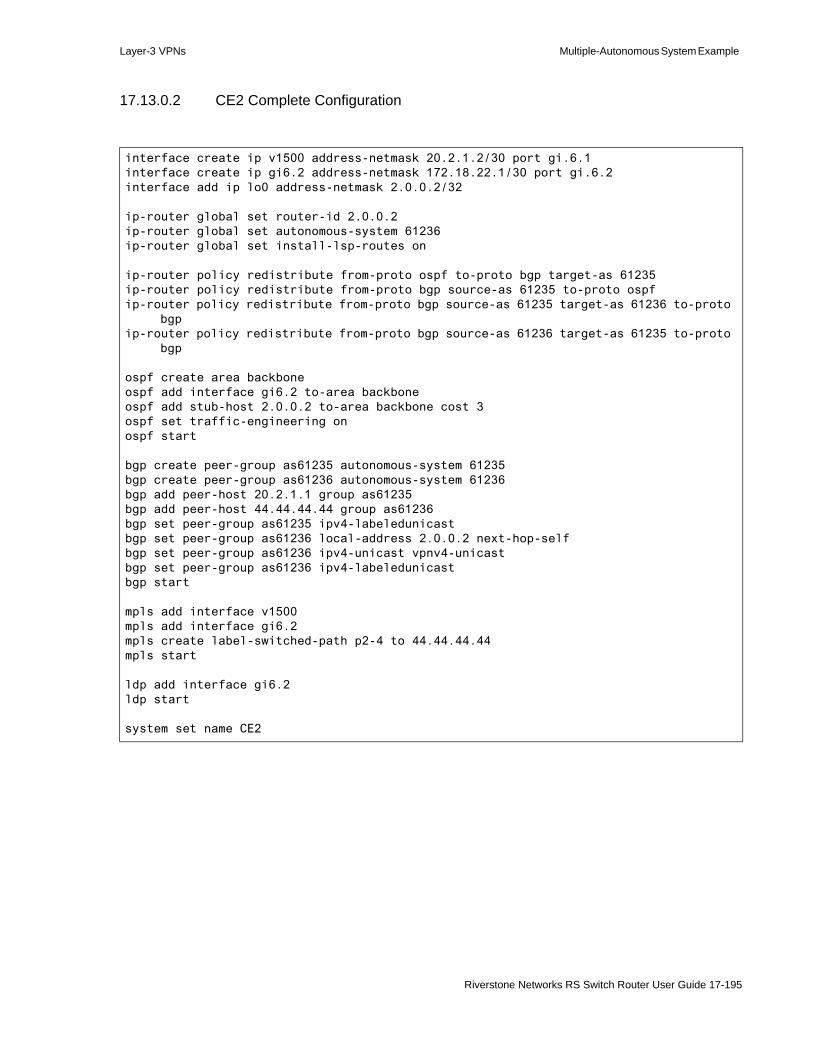
Layer-3 VPNs Multiple-Autonomous System Example
17.13.0.2 CE2 Complete Configuration
interface create ip v1500 address-netmask 20.2.1.2/30 port gi.6.1interface create ip gi6.2 address-netmask 172.18.22.1/30 port gi.6.2interface add ip lo0 address-netmask 2.0.0.2/32
ip-router global set router-id 2.0.0.2ip-router global set autonomous-system 61236ip-router global set install-lsp-routes on
ip-router policy redistribute from-proto ospf to-proto bgp target-as 61235ip-router policy redistribute from-proto bgp source-as 61235 to-proto ospfip-router policy redistribute from-proto bgp source-as 61235 target-as 61236 to-proto
bgpip-router policy redistribute from-proto bgp source-as 61236 target-as 61235 to-proto
bgp
ospf create area backboneospf add interface gi6.2 to-area backboneospf add stub-host 2.0.0.2 to-area backbone cost 3ospf set traffic-engineering onospf start
bgp create peer-group as61235 autonomous-system 61235bgp create peer-group as61236 autonomous-system 61236bgp add peer-host 20.2.1.1 group as61235bgp add peer-host 44.44.44.44 group as61236bgp set peer-group as61235 ipv4-labeledunicastbgp set peer-group as61236 local-address 2.0.0.2 next-hop-selfbgp set peer-group as61236 ipv4-unicast vpnv4-unicastbgp set peer-group as61236 ipv4-labeledunicastbgp start
mpls add interface v1500mpls add interface gi6.2mpls create label-switched-path p2-4 to 44.44.44.44mpls start
ldp add interface gi6.2ldp start
system set name CE2
Riverstone Networks RS Switch Router User Guide 17-195

Multiple-Autonomous System Example Layer-3 VPNs
17.13.0.3 CE3 Complete Configuration
17.13.0.4 CE4 Complete Configuration
interface create ip vpn1 address-netmask 10.3.1.2/24 port gi.6.1interface create ip cn1 address-netmask 90.3.1.1/24 port gi.5.1interface add ip lo0 address-netmask 3.0.0.3/32
ip-router global set router-id 3.0.0.3
ospf create area backboneospf add interface vpn1 to-area backboneospf add interface cn1 to-area backboneospf add stub-host 3.0.0.3 to-area backbone cost 3ospf start
ip add route 100.1.1/24 gateway 90.3.1.2ip add route 100.3.1/24 gateway 90.3.1.2
system set name CE3
interface create ip vpn1 address-netmask 10.4.1.2/24 port gi.6.1interface create ip cn1 address-netmask 90.4.1.1/24 port gi.5.1interface add ip lo0 address-netmask 4.0.0.4/32
ip-router global set router-id 4.0.0.4
ospf create area backboneospf add interface vpn1 to-area backboneospf add interface cn1 to-area backboneospf add stub-host 4.0.0.4 to-area backbone cost 3ospf start
ip add route 100.4.1/24 gateway 90.3.1.2
system set name CE4
17-196 Riverstone Networks RS Switch Router User Guide

Layer-3 VPNs Multiple-Autonomous System Example
17.13.0.5 P1 Complete Configuration
interface create ip gi10.1 address-netmask 172.16.1.1/30 port gi.10.1interface create ip gi10.2 address-netmask 192.168.1.1/30 port gi.10.2interface create ip gi11.1 address-netmask 192.168.2.1/30 port gi.11.1interface add ip lo0 address-netmask 11.0.0.11/32
ip-router global set router-id 11.0.0.11
ospf create area backboneospf add stub-host 11.0.0.11 to-area backbone cost 3ospf add interface gi10.1 to-area backboneospf add interface gi10.2 to-area backboneospf add interface gi11.1 to-area backboneospf set traffic-engineering onospf start
mpls set global point-of-local-repair-enablempls add interface gi10.1mpls add interface gi10.2mpls add interface gi11.1mpls start
rsvp add interface gi10.1rsvp add interface gi10.2rsvp add interface gi11.1rsvp set interface gi10.1 hello-enablersvp set interface gi10.2 hello-enablersvp set interface gi11.1 hello-enablersvp start
system set name P1
Riverstone Networks RS Switch Router User Guide 17-197

Multiple-Autonomous System Example Layer-3 VPNs
17.13.0.6 P2 Complete Configuration
interface create ip gi10.1 address-netmask 172.16.2.1/30 port gi.10.1interface create ip gi10.2 address-netmask 192.168.1.2/30 port gi.10.2interface create ip gi11.1 address-netmask 192.168.3.1/30 port gi.11.1
interface add ip lo0 address-netmask 22.0.0.22/32
ip-router global set router-id 22.0.0.22
ospf create area backboneospf add stub-host 22.0.0.22 to-area backbone cost 3ospf add interface gi10.1 to-area backboneospf add interface gi10.2 to-area backboneospf add interface gi11.1 to-area backboneospf set traffic-engineering onospf start
mpls set global point-of-local-repair-enablempls add interface gi10.1mpls add interface gi10.2mpls add interface gi11.1mpls start
rsvp add interface gi10.1rsvp add interface gi10.2rsvp add interface gi11.1rsvp set interface gi10.1 hello-enablersvp set interface gi10.2 hello-enablersvp set interface gi11.1 hello-enablersvp start
system set name P2
17-198 Riverstone Networks RS Switch Router User Guide

Layer-3 VPNs Multiple-Autonomous System Example
17.13.0.7 R11 Complete Configuration
interface create ip gi41 address-netmask 172.17.11.2/30 port gi.4.1interface create ip gi42 address-netmask 172.17.13.1/30 port gi.4.2interface create ip et11 address-netmask 93.3.1.1/24 port et.1.1interface add ip lo0 address-netmask 111.1.1.1/32
ip set port et.1.1 forwarding-mode destination-basedip set port gi.4.1 forwarding-mode destination-based
ip-router global set install-lsp-routes onip-router global set router-id 111.1.1.1ip-router global set autonomous-system 61234
ip add route 100.3.201/24 gateway 93.3.1.2
ip-router policy redistribute from-proto static to-proto bgp target-as 61234 network 100.3.201/24
ip-router policy redistribute from-proto bgp source-as 61234 to-proto bgp target-as 61234
bgp create peer-group as61234 autonomous-system 61234bgp add peer-host 33.33.33.33 group as61234bgp set peer-group as61234 reflector-clientbgp set peer-group as61234 local-address 111.1.1.1 next-hop-selfbgp set peer-group as61234 vpnv4-unicast ipv4-unicastbgp set cluster-id 1.0.0.255bgp start
isis add area 27.2727.2727isis add interface lo0isis add interface gi42isis add interface gi41isis set interface gi41 level 1isis set interface gi42 level 1isis set traffic-engineering onisis start
mpls add interface gi42mpls add interface gi41mpls start
ldp add interface gi42ldp add interface gi41ldp start
system set name R11
Riverstone Networks RS Switch Router User Guide 17-199

Multiple-Autonomous System Example Layer-3 VPNs
17.13.0.8 R22 Complete Configuration
interface create ip gi41 address-netmask 172.18.22.2/30 port gi.4.1interface create ip gi42 address-netmask 172.18.24.1/30 port gi.4.2interface create ip et11 address-netmask 94.1.1.1/24 port et.1.1interface add ip lo0 address-netmask 122.2.2.2/32
ip set port et.1.1 forwarding-mode destination-basedip set port gi.4.1 forwarding-mode destination-based
ip-router global set router-id 122.2.2.2ip-router global set install-lsp-routes onip-router global set autonomous-system 61236
ip add route 100.4.201/24 gateway 94.1.1.2
ip-router policy redistribute from-proto static to-proto bgp target-as 61234 network 100.4.201/24
ip-router policy redistribute from-proto bgp source-as 61234 to-proto bgp target-as 61234
ospf create area backboneospf add stub-host 122.2.2.2 to-area backbone cost 3ospf add interface gi41 to-area backboneospf add interface gi42 to-area backboneospf set traffic-engineering onospf set igp-shortcuts onospf start
bgp create peer-group as61236 autonomous-system 61236bgp set cluster-id 1.0.0.255bgp set peer-group as61236 local-address 122.2.2.2 next-hop-selfbgp set peer-group as61236 reflector-clientbgp start
mpls add interface gi41mpls add interface gi42mpls start
ldp add interface gi41ldp add interface gi42ldp start
system set name R22
17-200 Riverstone Networks RS Switch Router User Guide

Layer-3 VPNs Multiple-Autonomous System Example
17.13.0.9 PE1 Complete Configuration
interface create ip gi14.1 address-netmask 172.16.1.2/30 port gi.14.1
interface create ip gi14.2 address-netmask 172.16.11.2/30 port gi.14.2
interface create ip v1500 address-netmask 20.1.1.1/30 port gi.14.4
interface add ip lo0 address-netmask 11.11.11.11/32
ip-router global set router-id 11.11.11.11
ip-router global set install-lsp-routes on
ip-router global set autonomous-system 61235
ip-router policy create community-list vn1500 "target:61235:1500"
route-map in1500 permit 10 match-community-list vn1500
route-map out1500 permit 10 set-community-list vn1500
route-map s1500 permit 10 match-route-type bgp
ospf create area backbone
ospf add stub-host 11.11.11.11 to-area backbone cost 3
ospf add interface gi14.1 to-area backbone
ospf add interface gi14.2 to-area backbone
ospf set traffic-engineering on
ospf set igp-shortcuts on
ospf start
bgp create peer-group as61235 autonomous-system 61235
bgp add peer-host 22.22.22.22 group as61235
bgp set peer-group as61235 vpnv4-unicast ipv4-unicast
bgp set peer-group as61235 local-address 11.11.11.11 next-hop-self
bgp start
isis add area 27.2727.2727
isis add interface gi14.1
isis add interface gi14.2
isis set interface gi14.1 level 1
isis set interface gi14.2 level 1
isis set traffic-engineering on
mpls set global local-repair-enable node-protection
mpls add interface gi14.1
mpls add interface gi14.2
mpls add interface v1500
mpls create path p1 num-hops 3
mpls create path p2 num-hops 3
mpls set path p1 hop 1 ip-addr 172.16.1.2 type strict
mpls set path p1 hop 2 ip-addr 172.16.1.1 type strict
mpls set path p1 hop 3 ip-addr 172.16.2.2 type loose
mpls set path p2 hop 1 ip-addr 172.16.11.2 type strict
mpls set path p2 hop 2 ip-addr 172.16.11.1 type strict
Riverstone Networks RS Switch Router User Guide 17-201

Multiple-Autonomous System Example Layer-3 VPNs
mpls set path p2 hop 3 ip-addr 172.16.12.2 type loose
mpls create label-switched-path pp1-2 to 22.22.22.22
mpls set label-switched-path pp1-2 primary p1
mpls set label-switched-path pp1-2 secondary p2 standby
mpls start
rsvp add interface gi14.1
rsvp add interface gi14.2
rsvp set interface gi14.1 hello-enable
rsvp set interface gi14.2 hello-enable
rsvp start
system set name PE1
routing-instance to-ce1-v1500 vrf add interface v1500
routing-instance to-ce1-v1500 bgp create peer-group as61234 autonomous-system 61234
routing-instance to-ce1-v1500 bgp add peer-host 20.1.1.2 group as61234
routing-instance to-ce1-v1500 vrf set route-distinguisher 61235:2999 vrf-import in1500 in-sequence 1 vrf-export out1500 out-sequence 1
routing-instance to-ce1-v1500 bgp set peer-group as61234 route-map-out s1500 out-sequence 1
routing-instance to-ce1-v1500 bgp set peer-group as61234 ipv4-labeledunicast
routing-instance to-ce1-v1500 bgp start
17-202 Riverstone Networks RS Switch Router User Guide

Layer-3 VPNs Multiple-Autonomous System Example
17.13.0.10 PE2 Complete Configuration
interface create ip gi14.1 address-netmask 172.16.2.2/30 port gi.14.1
interface create ip gi14.2 address-netmask 172.16.12.2/30 port gi.14.2
interface create ip v1500 address-netmask 20.2.1.1/30 port gi.14.4
interface add ip lo0 address-netmask 22.22.22.22/32
ip-router global set autonomous-system 61235
ip-router global set router-id 22.22.22.22
ip-router global set install-lsp-routes on
ip-router policy create community-list vn1500 "target:61235:1500"
route-map in1500 permit 10 match-community-list vn1500
route-map out1500 permit 10 set-community-list vn1500
route-map s1500 permit 10 match-route-type bgp
ospf create area backbone
ospf add stub-host 22.22.22.22 to-area backbone cost 3
ospf add interface gi14.1 to-area backbone
ospf add interface gi14.2 to-area backbone
ospf set traffic-engineering on
ospf start
bgp create peer-group as61235 autonomous-system 61235
bgp add peer-host 11.11.11.11 group as61235
bgp set peer-group as61235 local-address 22.22.22.22 next-hop-self
bgp set peer-group as61235 vpnv4-unicast ipv4-unicast
bgp start
isis add area 27.2727.2727
isis add interface gi14.1
isis add interface gi14.2
isis set interface gi14.1 level 1
isis set interface gi14.2 level 1
mpls set global local-repair-enable node-protection
mpls add interface gi14.1
mpls add interface gi14.2
mpls add interface v1500
mpls create label-switched-path pe2-1 from 22.22.22.22 to 11.11.11.11
mpls set label-switched-path pe2-1 fast-reroute
mpls start
rsvp add interface gi14.1
rsvp add interface gi14.2
rsvp set interface gi14.1 hello-enable
rsvp set interface gi14.2 hello-enable
rsvp start
Riverstone Networks RS Switch Router User Guide 17-203

Multiple-Autonomous System Example Layer-3 VPNs
system set name PE2
routing-instance to-ce2-v1500 vrf add interface v1500
routing-instance to-ce2-v1500 vrf set route-distinguisher 61235:3000 vrf-import in1500 in-sequence 1 vrf-export out1500 out-sequence 1
routing-instance to-ce2-v1500 bgp create peer-group as61236 autonomous-system 61236
routing-instance to-ce2-v1500 bgp add peer-host 20.2.1.2 group as61236
routing-instance to-ce2-v1500 bgp set peer-group as61236 route-map-out s1500 out-sequence 1
routing-instance to-ce2-v1500 bgp set peer-group as61236 ipv4-labeledunicast
routing-instance to-ce2-v1500 bgp start
17-204 Riverstone Networks RS Switch Router User Guide

Layer-3 VPNs Multiple-Autonomous System Example
17.13.0.11 PE3 Complete Configuration
port enable multi-vrf-support port gi.2.1 overwrite source-socket
interface create ip gi14.3 address-netmask 172.17.13.2/30 port gi.14.3
interface create ip vpn1 address-netmask 10.3.1.1/24 port gi.2.1
interface create ip et78 address-netmask 172.16.200.2/28 port et.7.8
interface create ip et74 address-netmask 172.16.201.1/24 port et.7.4
interface add ip lo0 address-netmask 33.33.33.33/32
ip-router global set router-id 33.33.33.33
ip-router global set autonomous-system 61234
ip-router global set install-lsp-routes on
ip-router policy create community-list vn1 "target:61234:401"
ip-router policy redistribute from-proto bgp source-as 61235 to-proto bgp target-as 61236 network all restrict
route-map t64220 permit 10 match-route-type direct network 172.16.201/24 match-prefix
route-map a64220 deny 15
route-map in1 permit 10 match-community-list vn1
route-map out1 permit 10 set-community-list vn1
route-map t61234 deny 10 match-aspath-regular-expression "64220 .*"
route-map test1 permit 10 match-route-type bgp
bgp create peer-group as61234 autonomous-system 61234
bgp create peer-group as61236 autonomous-system 61236
bgp create peer-group as64220 autonomous-system 64220
bgp add peer-host 44.44.44.44 group as61236
bgp set peer-group as61236 local-address 33.33.33.33 multihop
bgp set peer-group as61236 vpnv4-unicast
bgp set peer-group as61236 graceful-restart
bgp add peer-host 1.0.0.1 group as61234
bgp set peer-group as61234 local-address 33.33.33.33
bgp set peer-group as61234 next-hop-self
bgp set peer-group as61234 ipv4-labeledunicast
bgp set peer-group as61234 graceful-restart
bgp add peer-host 172.16.200.1 group as64220
bgp set peer-group as64220 route-map-out t64220 out-sequence 10
bgp set peer-host 172.16.200.1 group as64220 route-map-in a64220 in-sequence 10
bgp set resync-time 90
bgp start
isis add area 27.2727.2727
isis add interface lo0
isis add interface gi14.3
isis set interface gi14.3 level 1
isis set traffic-engineering on
isis set restart helper enable restart enable
Riverstone Networks RS Switch Router User Guide 17-205

Multiple-Autonomous System Example Layer-3 VPNs
isis start
mpls add interface gi14.3
mpls start
ldp add interface gi14.3
ldp start
system set name PE3
routing-instance to-ce3-v1 vrf add interface vpn1
routing-instance to-ce3-v1 vrf set route-distinguisher 61234:401 vrf-import in1 in-sequence 1 vrf-export out1 out-sequence 1
routing-instance to-ce3-v1 vrf set global-unicast-lookup
routing-instance to-ce3-v1 vrf set router-id 10.3.1.1
routing-instance to-ce3-v1 ospf create area backbone
routing-instance to-ce3-v1 ospf add interface vpn1 to-area backbone
routing-instance to-ce3-v1 ospf start
routing-instance to-ce3-v1 ip add route 100.3.1/24 gateway 10.3.1.2
nat set interface vpn1 inside
nat set interface et78 outside
nat create static local-ip 100.1.1.1 global-ip 172.16.201.3 matches-in-interface vpn1 protocol ip
17-206 Riverstone Networks RS Switch Router User Guide
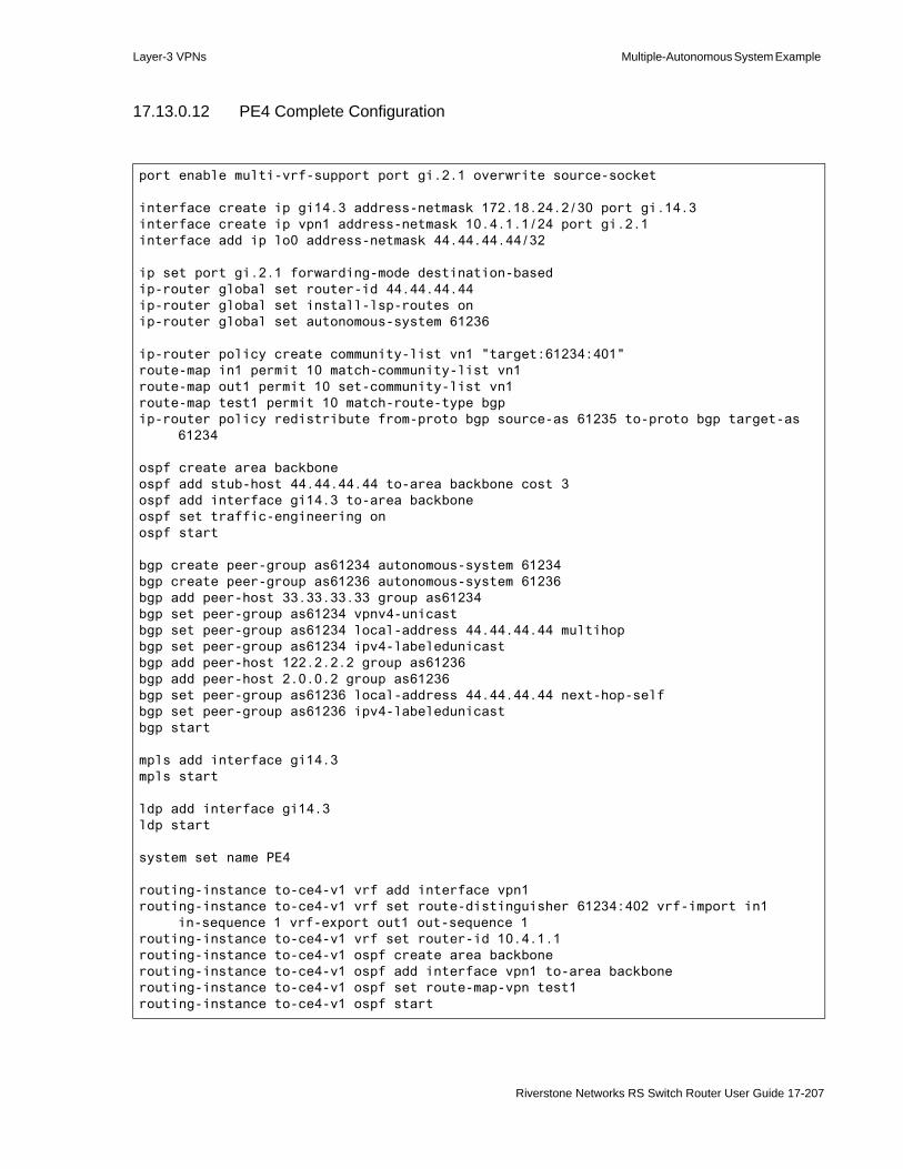
Layer-3 VPNs Multiple-Autonomous System Example
17.13.0.12 PE4 Complete Configuration
port enable multi-vrf-support port gi.2.1 overwrite source-socket
interface create ip gi14.3 address-netmask 172.18.24.2/30 port gi.14.3interface create ip vpn1 address-netmask 10.4.1.1/24 port gi.2.1interface add ip lo0 address-netmask 44.44.44.44/32
ip set port gi.2.1 forwarding-mode destination-basedip-router global set router-id 44.44.44.44ip-router global set install-lsp-routes onip-router global set autonomous-system 61236
ip-router policy create community-list vn1 "target:61234:401"route-map in1 permit 10 match-community-list vn1route-map out1 permit 10 set-community-list vn1route-map test1 permit 10 match-route-type bgpip-router policy redistribute from-proto bgp source-as 61235 to-proto bgp target-as
61234
ospf create area backboneospf add stub-host 44.44.44.44 to-area backbone cost 3ospf add interface gi14.3 to-area backboneospf set traffic-engineering onospf start
bgp create peer-group as61234 autonomous-system 61234bgp create peer-group as61236 autonomous-system 61236bgp add peer-host 33.33.33.33 group as61234bgp set peer-group as61234 vpnv4-unicastbgp set peer-group as61234 local-address 44.44.44.44 multihopbgp set peer-group as61234 ipv4-labeledunicastbgp add peer-host 122.2.2.2 group as61236bgp add peer-host 2.0.0.2 group as61236bgp set peer-group as61236 local-address 44.44.44.44 next-hop-selfbgp set peer-group as61236 ipv4-labeledunicastbgp start
mpls add interface gi14.3mpls start
ldp add interface gi14.3ldp start
system set name PE4
routing-instance to-ce4-v1 vrf add interface vpn1routing-instance to-ce4-v1 vrf set route-distinguisher 61234:402 vrf-import in1
in-sequence 1 vrf-export out1 out-sequence 1routing-instance to-ce4-v1 vrf set router-id 10.4.1.1routing-instance to-ce4-v1 ospf create area backbonerouting-instance to-ce4-v1 ospf add interface vpn1 to-area backbonerouting-instance to-ce4-v1 ospf set route-map-vpn test1routing-instance to-ce4-v1 ospf start
Riverstone Networks RS Switch Router User Guide 17-207

QoS for BGP/MPLS VPNs Layer-3 VPNs
17.14 QOS FOR BGP/MPLS VPNSThe Riverstone implementation of BGP/MPLS VPNs allows Quality of Service (QoS) facilities to be applied to routing instances. Primarily, QoS is accomplished by mapping traffic characteristics, such as internal priority bits or DSCP bits, to the MPLS Experimental bits (Exp bits) on PE routers.
17.14.1 MPLS Experimental Bits
The MPLS QoS capabilities are based on the use of the three Experimental bits (Exp bits) within the MPLS label. When packets traverse the RS Ethernet Router, they are assigned to one of four internal queues based on the value contained within the Exp bits. The priorities of these queues are low, medium, high, and control. In turn, you can configure QoS facilities, such as Weighted-Fair Queueing (WFQ), to affect the behavior of the traffic passing through each of these queues. See the QoS Configuration chapter for details on configuring the QoS facility.
17.14.2 Setting the MPLS Experimental Bits
On PE routers, you can set the MPLS Exp bits for the layer-3 traffic of any routing instance. You can either set the value of the MPLS Exp bits directly or derive it from the following sources:• Riverstone proprietary internal priority bits – 2 bits representing the four priority queues
- 00 = low- 01 = medium- 10 = high- 11 = control
• ToS precedence bits – 3 most significant bits of the ToS byte (see Figure 17-62)• Differentiated Services Code Point (DSCP) bits – 6 most significant bits of the ToS byte (see
Figure 17-62)
Note Use the tos, tos-mask, tos-rewrite, and tos-precedence-rewrite parameters of the qos set ip command to configure the value of the DSCP bits.
17-208 Riverstone Networks RS Switch Router User Guide

Layer-3 VPNs QoS for BGP/MPLS VPNs
Figure 17-62 Comparison of ToS precedence bits to DSCP bits
17.14.2.1 Setting the Exp Bit Directly
Use the routing-instance <name> vrf set exp <value> command to set the value of the MPLS Exp bits directly for a routing instance.
VersionNumber
HeaderLength
PacketLength
Identification...
3 bits
ToS Pre
cedence
Bits
ToS Bits
4 bits
IP Protocol Header
ToS Byte
VersionNumber
HeaderLength
PacketLength
Identification...
IP Protocol Header
0 1 2 3 4 5
6 Diffserv Bits
ToS Byte
0 7
Riverstone Networks RS Switch Router User Guide 17-209
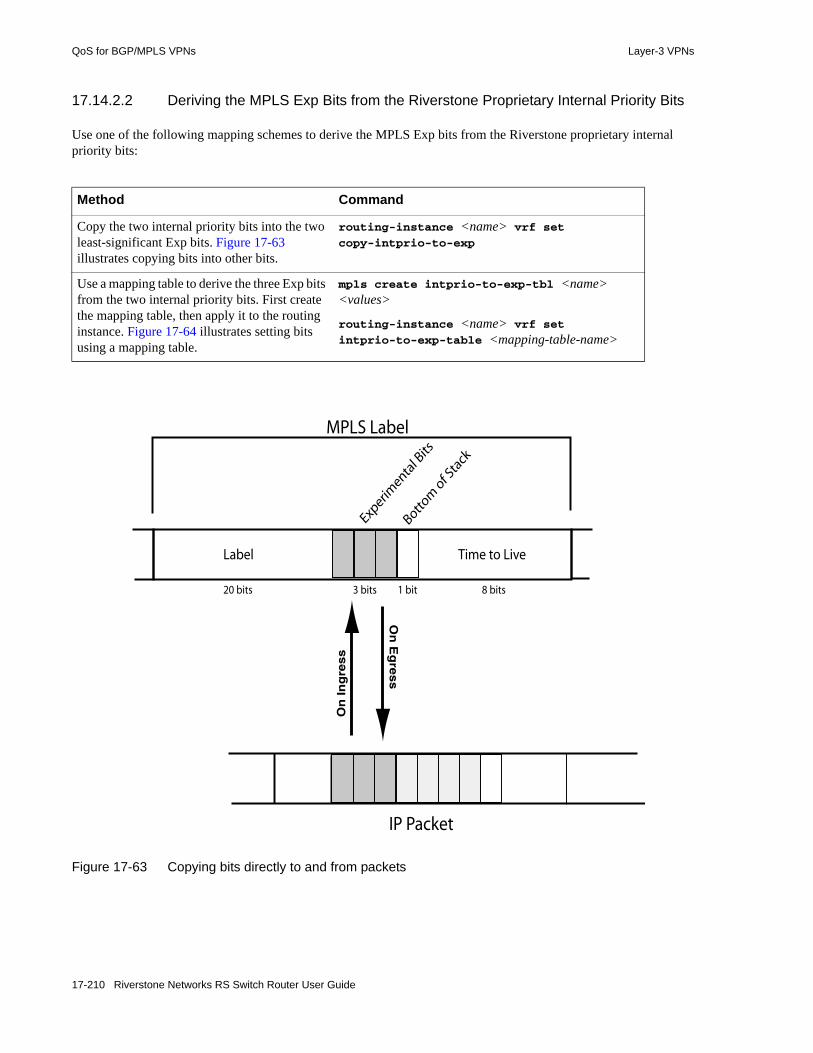
QoS for BGP/MPLS VPNs Layer-3 VPNs
17.14.2.2 Deriving the MPLS Exp Bits from the Riverstone Proprietary Internal Priority Bits
Use one of the following mapping schemes to derive the MPLS Exp bits from the Riverstone proprietary internal priority bits:
Figure 17-63 Copying bits directly to and from packets
Method Command
Copy the two internal priority bits into the two least-significant Exp bits. Figure 17-63 illustrates copying bits into other bits.
routing-instance <name> vrf set copy-intprio-to-exp
Use a mapping table to derive the three Exp bits from the two internal priority bits. First create the mapping table, then apply it to the routing instance. Figure 17-64 illustrates setting bits using a mapping table.
mpls create intprio-to-exp-tbl <name> <values>
routing-instance <name> vrf set intprio-to-exp-table <mapping-table-name>
Label
3 bits
Time to Live
1 bit
Experim
ental B
its
Bottom
of S
tack
8 bits20 bits
MPLS Label
IP Packet
On
In
gre
ss
On
Eg
ress
17-210 Riverstone Networks RS Switch Router User Guide

Layer-3 VPNs QoS for BGP/MPLS VPNs
Figure 17-64 Setting the Exp bits using a mapping table
17.14.2.3 Deriving the MPLS Exp Bits from the ToS Precedence Bits
Use one of the mapping schemes to derive the MPLS Exp bits from the ToS precedence bits:
Label
3 bits
Time to Live
1 bit
Experimenta
l Bits
Bottom
of Sta
ck
8 bits20 bits
MPLS Label
Exp ToS Precedence
exp0exp1exp6exp3exp7exp2exp5
exp6
000001
101
011100
010
110111
VersionNumber
HeaderLength
PacketLength
Identification...
3 bits
ToS Pre
cedence
Bits
ToS Bits
4 bits
IP Protocol Header
IP header ToS Precedence bitsare compared against the table.
The Exp bit value that corresponds to the ToSprecedence is copied intothe MPLS label's Exp bits.
1 1 0
1
2
0 11
Riverstone Networks RS Switch Router User Guide 17-211

QoS for BGP/MPLS VPNs Layer-3 VPNs
17.14.2.4 Deriving the MPLS Exp Bits from the DSCP Bits
The DSCP bits cannot be directly copied into the Exp bits of the The MPLS label. You must define the mapping of DSCP bits to Exp bits using a table. Figure 17-64 illustrates setting bits using a mapping table.
17.14.3 Creating Exp Mapping Tables
Configuring mappings using tables gives flexibility in how packet bits are mapped to Exp bits. For instance, in Figure 17-64, ToS precedence bit value 6 (110 binary) is mapped to Exp bit value 5 (101 binary).
The following lists the possible tables that you can use to map packet bits to the Exp bits. • On ingress:
- DSCP bits to Exp bits (mpls create dscp-to-exp-tbl <name>)- Internal priority bits to Exp bits (mpls create intprio-to-exp-tbl <name>)- ToS precedence bits to Exp bits (mpls create tosprec-to-exp-tbl <name>)
17.14.3.1 Example: Creating a Mapping Table
The following command creates the mapping table illustrated in Figure 17-64:
Method Command
Copy the three ToS precedence bits directly into the three Exp bits. Figure 17-63 illustrates copying bits into other bits.
routing-instance <name> vrf set copy-tosprec-to-exp
Use a mapping table to derive the three Exp bits from the three ToS precedence bits. First create the mapping table, then apply it to the routing instance. Figure 17-64 illustrates setting bits using a mapping table.
mpls create tosprec-to-exp-tbl <name> <values>
routing-instance <name> vrf set tosprec-to-exp-table <mapping-table-name>
Method Command
Use a mapping table to derive the three Exp bits from the six ToS precedence bits. First create the mapping table, then apply it to the routing instance.
mpls create dscp-to-exp-tbl <name> <values>
routing-instance <name> vrf set dscp-to-exp-table <mapping-table-name>
PE(config)# mpls create tosprec-to-exp-tbl <name> tosprec0 0 tosprec1 1 tosprec2 6 tosprec3 3 tosprec4 7 tosprec5 2 tosprec6 5 tosprec7 6
17-212 Riverstone Networks RS Switch Router User Guide

Layer-3 VPNs QoS for BGP/MPLS VPNs
17.14.3.2 Example: Copying Internal Priority Bits to Exp Bits
The following example specifies that when a packet traverses the RED routing instance, its two internal priority bits should be copied into the least significant two bits of its three MPLS Experimental bits.
17.14.3.3 Example: Copying ToS Precedence Bits to Exp Bits
The following example specifies that when a packet traverses the RED routing instance, its three ToS precedence bits should be copied into its three MPLS Experimental bits.
17.14.3.4 Example: Deriving the Exp Bits from DSCP Bits Using a Mapping Table
The following example creates a table named dscp_tbl that maps the DSCP bits to the Exp bits and applies this mapping to any traffic that traverses routing instance RED:
17.14.3.5 Example: Specify a Value for the Exp Bits
The following example specifies that when a packet traverses the RED routing instance, its MPLS Experimental bits should be set to the value ’3’:
17.14.3.6 Example: Deriving the Exp Bits from Internal Priority Bits Using a Mapping Table
The following example creates a table named intprio_tbl that maps the internal priority bits to the Exp bits and applies this mapping to any traffic that traverses routing instance RED:
PE(config)# routing-instance RED vrf set copy-intprio-to-exp
PE(config)# routing-instance RED vrf set copy-tosprec-to-exp
PE(config)# mpls create dscp-to-exp-tbl dscp_tbl dscp0 0 dscp1 1 dscp2 5 dscp7 7
PE(config)# routing-instance RED vrf set dscp-to-exp-table dscp_tbl
PE(config)# routing-instance RED vrf set exp 3
PE(config)# mpls create intprio-to-exp-tbl intprio_tbl intprio0 0 intprio1 1 intprio2 5 intprio7 7
PE(config)# routing-instance RED vrf set intprio-to-exp-table intprio_tbl
Riverstone Networks RS Switch Router User Guide 17-213

QoS for BGP/MPLS VPNs Layer-3 VPNs
17.14.3.7 Example: Deriving the Exp Bits from ToS Precedence Bits Using a Mapping Table
The following example creates a table named tos_tbl that maps the ToS precedence bits to the Exp bits and applies this mapping to any traffic that traverses routing instance RED:
When configuring mapping tables, you do not have to define all values. If a value within any table is not specified, it defaults to zero. In this example, the ToS precedence of 2 (010 binary) maps to an Exp value of 5 (101 binary). ToS precedence value 3 (011 binary), because it is not specified, defaults to an Exp value of 0.
Note If a value within any table is not specified, it defaults to zero.
Use the mpls show diff-serv-tbls command to display the contents of the ingress table.
In the display above, notice that all unspecified values for ToS precedence are wild carded to zero.
PE(config)# mpls create tosprec-to-exp-tbl tos_tbl tosprec0 0 tosprec1 1 tosprec2 5 tosprec7 7
PE(config)# routing-instance RED vrf set tosprec-to-exp-table tos_tbl
PE# mpls show diff-serv-tbls tosprec-to-exp_tbl tos_tbl
TOS precedence to EXP table:---------------------------Table Name TOSPREC --> EXP---------- ---------------tos-tbl 1 1 2 5 7 7 * 0
17-214 Riverstone Networks RS Switch Router User Guide

18 MPLS CONFIGURATION
Multiprotocol Label Switching (MPLS) is a technology that enables routers to forward traffic based on a simple label embedded into the packet header. A router can simply examine the label to determine the next hop for the packet, rather than perform a much more complex route lookup on the destination IP address.While originally designed to speed up layer 3 routing of packets, label-based switching can provide other benefits to IP networks. Riverstone’s MPLS allows you to do the following:• set the path that traffic will take through a network and set performance characteristics for a
class of traffic• add new network routing services without changing the basic forwarding paradigm• create virtual private network (VPN) tunnels throughout the network (without the need for
encryption or end-user applications)
Note The MPLS features described in this chapter are only supported on MPLS-enabled RS Ethernet Router line cards. See your Riverstone representative for specific part numbers and applicable RS Ethernet Router platforms.
This chapter contains the following sections:• For an overview of MPLS concepts and terminology, and the MPLS features supported on the
RS Ethernet Router, see Section 18.1, "MPLS Architecture Overview."• To enable MPLS on the RS Ethernet Router switch router, see Section 18.2, "Enabling and
Starting MPLS on the RS Ethernet Router."• To configure Resource Reservation Protocol (RSVP) signaling for MPLS, see Section 18.3,
"RSVP Configuration."• To configure Label Distribution Protocol (LDP) signaling for MPLS, see Section 18.4, "LDP
Configuration."• To configure layer 3 label switching, see Section 18.5, "Configuring L3 Label Switched Paths."
This section includes information on configuring static and dynamic L3 paths, as well as example configurations.
• To configure layer 2 label switching, see Section 18.6, "Configuring L2 Tunnels." This section includes information on configuring static and dynamic L2 tunnels, as well as example configurations. It also includes information on using the RS Ethernet Router as a dual-homing MTU-s.
• To use MPLS traffic engineering features, see Section 18.7, "Traffic Engineering."• To use QoS facilities with layer-2 and layer-3 traffic traversing an LSP, see Section 18.8, "QoS
For MPLS."
Riverstone Networks RS Switch Router User Guide 18-1

MPLS Architecture Overview MPLS Configuration
Timesaver Titles shown in blue represent hypertext links to the sections. Click on one of the section titles above to go immediately to that section.
18.1 MPLS ARCHITECTURE OVERVIEWA forwarding equivalence class (FEC) is a group of IP packets that are forwarded over the same path with the same forwarding treatment. Examples of FECs include: • unicast packets whose destination address matches a specified IP address prefix• unicast packets whose destination address matches a specified IP address prefix and whose type of
service (ToS) bit matches a specified value• multicast packets with the same source and destination addresses
In “traditional,” non-MPLS networks, each router maps a packet to an FEC based on the destination IP address in the packet’s network layer header. Each FEC is then mapped to a next hop. At each hop, the packet is examined and assigned an FEC and a next hop.
In an MPLS network, packets are forwarded in one direction across a label switched path (LSP), as shown in Figure 18-1. Labels are the mapping of network layer routing to data link layer switched paths. With MPLS, the assignment of a specific packet to an FEC is only done once—at the first router in the path, the ingress label switching router (LSR). Only the ingress LSR1 in the path needs to analyze the layer 3 header information. If the destination address in the incoming packet matches an entry in the routing table, the appropriate label is applied to the packet and the packet is forwarded on to the next hop. At subsequent hops, intermediate or transit LSRs in the path need to only look at the packet label to forward the packet through the MPLS network; no further examination of the packet’s network layer header is required.
Figure 18-1 MPLS label switched path
At the egress LSR at the other edge of the path, the label is stripped off. The packet is then forwarded to its next destination using information in the IP forwarding table. There is one ingress router and one egress router for each LSP. Note that a router cannot be both an ingress and egress LSR for the same LSP.
1. Ingress and egress LSRs are sometimes also referred to as label edge routers (LERs).
Ingress Egress to packetincomingLabel
label assigned label switched label removed
destinationSwitchingRouter
LabelSwitchingRouter
packet
MPLS Network
LabelSwitchingRouter
LabelSwitchingRouter
Transit Transit
18-2 Riverstone Networks RS Switch Router User Guide
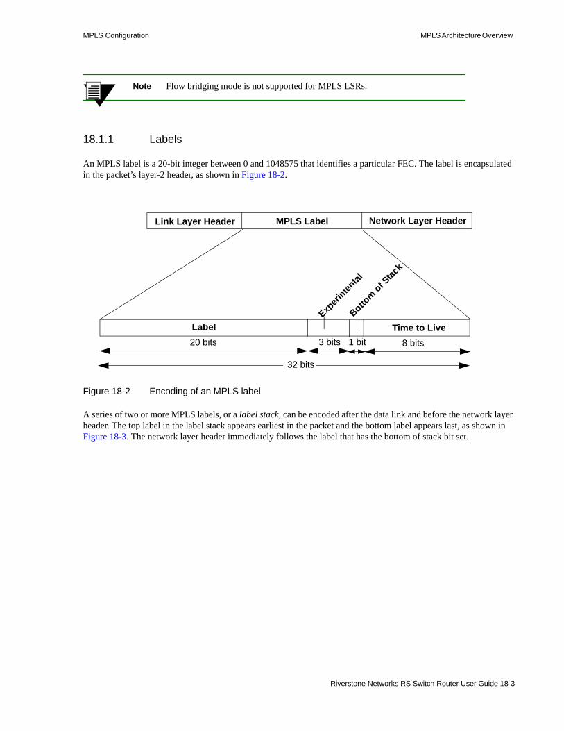
MPLS Configuration MPLS Architecture Overview
Note Flow bridging mode is not supported for MPLS LSRs.
18.1.1 Labels
An MPLS label is a 20-bit integer between 0 and 1048575 that identifies a particular FEC. The label is encapsulated in the packet’s layer-2 header, as shown in Figure 18-2.
Figure 18-2 Encoding of an MPLS label
A series of two or more MPLS labels, or a label stack, can be encoded after the data link and before the network layer header. The top label in the label stack appears earliest in the packet and the bottom label appears last, as shown in Figure 18-3. The network layer header immediately follows the label that has the bottom of stack bit set.
20 bits 3 bits 1 bit 8 bits
Label Time to LiveExp
erimen
tal
Bottom of S
tack
32 bits
Link Layer Header Network Layer HeaderMPLS Label
Riverstone Networks RS Switch Router User Guide 18-3
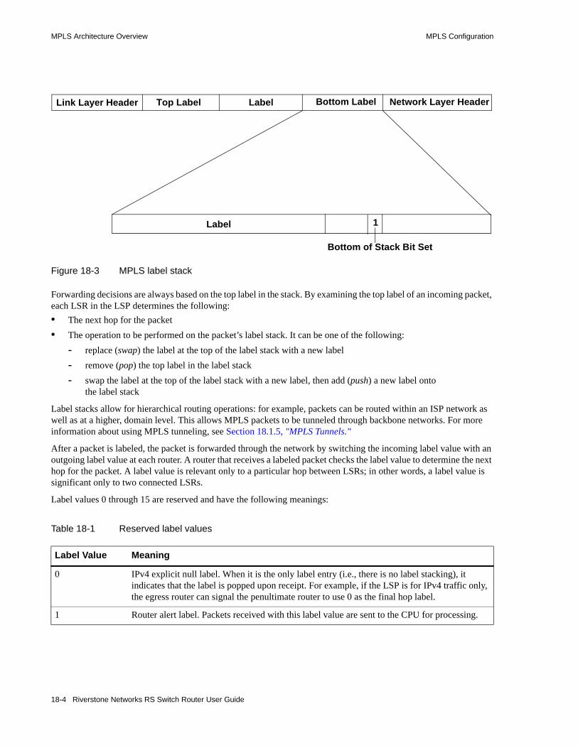
MPLS Architecture Overview MPLS Configuration
Figure 18-3 MPLS label stack
Forwarding decisions are always based on the top label in the stack. By examining the top label of an incoming packet, each LSR in the LSP determines the following:• The next hop for the packet• The operation to be performed on the packet’s label stack. It can be one of the following:
- replace (swap) the label at the top of the label stack with a new label- remove (pop) the top label in the label stack- swap the label at the top of the label stack with a new label, then add (push) a new label onto
the label stack
Label stacks allow for hierarchical routing operations: for example, packets can be routed within an ISP network as well as at a higher, domain level. This allows MPLS packets to be tunneled through backbone networks. For more information about using MPLS tunneling, see Section 18.1.5, "MPLS Tunnels."
After a packet is labeled, the packet is forwarded through the network by switching the incoming label value with an outgoing label value at each router. A router that receives a labeled packet checks the label value to determine the next hop for the packet. A label value is relevant only to a particular hop between LSRs; in other words, a label value is significant only to two connected LSRs.
Label values 0 through 15 are reserved and have the following meanings:
Table 18-1 Reserved label values
Label Value Meaning
0 IPv4 explicit null label. When it is the only label entry (i.e., there is no label stacking), it indicates that the label is popped upon receipt. For example, if the LSP is for IPv4 traffic only, the egress router can signal the penultimate router to use 0 as the final hop label.
1 Router alert label. Packets received with this label value are sent to the CPU for processing.
Label
Link Layer Header Network Layer HeaderBottom LabelTop Label Label
Bottom of Stack Bit Set
1
18-4 Riverstone Networks RS Switch Router User Guide
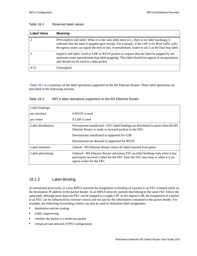
MPLS Configuration MPLS Architecture Overview
Table 18-2 is a summary of the label operations supported on the RS Ethernet Router. These label operations are described in the following sections.
18.1.2 Label Binding
As mentioned previously, in a non-MPLS network the assignment or binding of a packet to an FEC is based solely on the destination IP address in the packet header. In an MPLS network, packets that belong to the same FEC follow the same path, although more than one FEC can be mapped to a single LSP. At the ingress LSR, the assignment of a packet to an FEC can be influenced by external criteria and not just by the information contained in the packet header. For example, the following forwarding criteria can also be used to determine label assignment:• destination unicast routing• traffic engineering• whether the packet is a multicast packet• virtual private network (VPN) configuration
2 IPv6 explicit null label. When it is the only label entry (i.e., there is no label stacking), it indicates that the label is popped upon receipt. For example, if the LSP is for IPv6 traffic only, the egress router can signal the next to last, or penultimate, router to use 2 as the final hop label.
3 Implicit null label. Used in LDP or RSVP packets to request that the label be popped by the upstream router (penultimate hop label popping). This label should not appear in encapsulation and should not be used in a data packet.
4-15 Unassigned.
Table 18-2 MPLS label operations supported on the RS Ethernet Router
Label bindings:
per interface
per router
if RSVP is used
if LDP is used
Label distribution: Downstream unsolicited—FEC-label bindings are distributed to peers when the RS Ethernet Router is ready to forward packets in the FEC.
Downstream unsolicited is supported for LDP.
Downstream-on-demand is supported for RSVP.
Label retention: Liberal—RS Ethernet Router stores all labels learned from peers.
Label advertising: Ordered—RS Ethernet Router advertises FEC-to-label bindings only when it has previously received a label for the FEC from the FEC next-hop or when it is an egress router for the FEC.
Table 18-1 Reserved label values
Label Value Meaning
Riverstone Networks RS Switch Router User Guide 18-5

MPLS Architecture Overview MPLS Configuration
• quality of service (QoS)
The RS Ethernet Router supports the following types of FEC-to-label bindings:• Label bindings can be associated with interfaces. A separate pool of label values is defined for each
interface on which MPLS is enabled.• Label bindings for the router as a whole can be made from a single “global” pool of label values.
Labels that are distributed on different interfaces cannot have the same value.
The label distribution protocol used determines whether the label bindings are assigned on a per-interface or per-router basis. See "Label Distribution Protocols" for more information.
18.1.3 Label Distribution and Management
Before the ingress LSR can label incoming packets for a specific FEC and forward the packets, the LSP must be set up. The binding of the label to the FEC is advertised to neighboring LSRs to establish the LSP. In Figure 18-4, packets sent from R1 to R2 for a particular FEC use the same label binding. In this relationship, R1 is the upstream LSR, while R2 is the downstream LSR. The downstream LSR determines the binding of a label to an FEC and informs the upstream LSR of the binding through a label distribution protocol (discussed later in this section).
Figure 18-4 Label binding distribution
There are two ways an LSR can distribute label bindings:• An LSR can explicitly request a label binding for a particular FEC from its next hop—this is called
downstream on demand label distribution. • An LSR can also distribute label bindings to other LSRs even if it has not been explicitly requested
to do so—this is called downstream unsolicited label distribution. In downstream unsolicited mode, FEC-label bindings are distributed to peers when an LSR is ready to forward packets in the FEC.
18.1.3.1 Label Distribution Protocols
An LSP is defined by the set of labels from the ingress LSR to the egress LSR. When an LSR assigns a label to an FEC, it must let other LSRs in the path know about the label and its meaning. Label distribution protocols help to establish the LSP by providing a set of procedures that LSRs can use to distribute labels. Specifically, label distribution protocols allow an LSR to request a label from a downstream LSR so that it can bind the label to a specific FEC. The downstream LSR responds to the request from the upstream LSR by sending the requested label.
The RS Ethernet Router supports the following protocols for label distribution:
DownstreamLSR
UpstreamLSR
PacketsR1 R2
Label Binding
18-6 Riverstone Networks RS Switch Router User Guide

MPLS Configuration MPLS Architecture Overview
• Label distribution protocol (LDP) is an IETF-defined protocol for LSRs to distribute labels and their meanings to LDP peers. LDP assigns labels from a single pool of labels on a router. To establish an LSP, LDP does not need to rely on routing protocols at every hop along the LSP. LDP allows the establishment of “best effort” LSPs; it does not provide traffic engineering mechanisms. LDP is required for tunneling of layer-2 frames across MPLS networks, as described in Section 18.6, "Configuring L2 Tunnels." For more information about configuring LDP on the RS Ethernet Router, see Section 18.4, "LDP Configuration."
• Resource reservation protocol (RSVP) is a protocol that allows channels or paths to be reserved for high bandwidth transmissions. RSVP assigns labels on a per-interface basis. RSVP is used for traffic engineering, which is often required in core or backbone networks where resources are not always available; see Section 18.7, "Traffic Engineering." For more information about configuring RSVP on the RS Ethernet Router, see Section 18.3, "RSVP Configuration."
The LSP must be set up before packets can be forwarded through the MPLS network. Figure 18-5 shows how labels are created and distributed to create an LSP.
Figure 18-5 LSP creation and packet forwarding
1. Downstream routers distribute label bindings to upstream neighbors.2. Packet P1 is received at router R1.3. Router R1 inserts the appropriate label into the packet and forwards it to the next hop. The packet
label is examined, replaced and forwarded through the MPLS network. (If R1 does not find a match for this FEC, the packet is forwarded using IP forwarding table information.)
4. The label is removed and forwarded using information in the IP forwarding table at R4.
18.1.3.2 Label Advertising Mode
An LSR can advertise label bindings to its peers in one of two modes:• It can make an independent decision to bind a label to an FEC and distribute that binding to its
peers—this is called independent mode.• It can bind a label to a particular FEC if it is the egress LSR for that route or if it has already received
a label binding for that FEC from its next hop for the route—this is called ordered mode.
The RS Ethernet Router supports only ordered label advertising.
to packetincomingdestinationpacket P1 R1 R2 R3 R4
2
1label binding
3 4
Upstream LSR Downstream LSR
label bindingpacket forwarding with labels
Riverstone Networks RS Switch Router User Guide 18-7
MPLS Architecture Overview MPLS Configuration
18.1.3.3 Label Retention Mode
An LSR can store the label bindings in one of two modes:• Only label bindings received from next hop downstream LSR peers are stored—this is called
conservative label retention.• All label bindings received from peer LSRs are stored, even if the peer is not the next hop for a
route—this is called liberal label retention.
The RS Ethernet Router supports only liberal label retention.
18.1.4 Penultimate Hop Popping
The next-to-last LSR in an LSP, or the penultimate LSR, can pop the label stack. This process, called penultimate hop popping (PHP), has the following advantage: If the penultimate LSR does not pop the label stack, the egress LSR must do two table lookups to process the packet: first, it must look at the top label in the stack and pop the stack. Then it must either look at the next label in the stack, or if there is no other label in the stack, look up the packet’s destination address to forward it. By having the penultimate LSR pop the label stack, there is only a single table lookup performed at each of the egress and penultimate LSRs. By default, RS Ethernet Router routers that are PHP LSRs pop the label stack. You can configure the RS Ethernet Router egress router to notify the PHP router to not pop the label stack.
18.1.5 MPLS Tunnels
You can use MPLS label stacks, instead of network layer encapsulation, to tunnel packets across a backbone MPLS network. Tunneling allows shared resources, such as public networks, to be used to carry private communications. For example, companies can use VPN tunnels to send intranet traffic over the Internet. The advantage MPLS offers is that the contents of the tunneled data packets do not need to be examined as they proceed through an LSP, as the forwarding of the packets is based on only the attached labels.
Multiple LSPs traveling between the same LSRs across a network can be sent together on a higher-level tunnel LSP. The packets to be sent through the tunnel LSP are considered to be a single FEC by the LSR at the tunnel entrance. This LSR pushes an additional label onto the packets that enter the tunnel LSP before sending the labeled packets to the next hop in the tunnel. When the packets emerge from the tunnel LSP, the top label is popped.
In Figure 18-6, R1 is the ingress LSR for an LSP to the egress LSR, R4. R2 is the entry point for the tunnel LSP and R3 is the exit point for the tunnel LSP.
18-8 Riverstone Networks RS Switch Router User Guide

MPLS Configuration MPLS Architecture Overview
Figure 18-6 LSP tunneling
R1 assigns the label “5” to packets for the LSP to R4. At R2, the label value is swapped from “5” to “7.” R2 also determines that the packet destined for R3 must pass through the tunnel. It pushes onto the label stack for the packet a new label “22,” a label that is meaningful to the router RA, before forwarding the packet to RA. At the tunnel routers, RA, RB, and RC, label switching is done on the level 2 label. Note that the bottom label in the label stack retains its value as the packet is forwarded through the tunnel LSP; only the top label in the stack is switched.
At RC, the penultimate hop in the tunnel LSP, the label stack is popped before the packet is forwarded out of the tunnel to R3. At R3, the penultimate hop in the LSP, the label stack is popped once again before the unlabeled packet is forwarded to R4.
Note that each LSP is unidirectional. In most cases, it is desirable to have two MPLS LSPs, one going in each direction, to form a logical pipe for the flow of data.
18.1.6 Using SmartTRUNKS with MPLS
SmartTRUNKs can be used as MPLS links (see Figure 18-7). When MPLS commands require port specification, the SmartTRUNK number is supplied instead of the port designation. When using SmartTRUNKS as MPLS links, it is important to remember the following:• When MPLS is set up over a SmartTRUNK, one of the SmartTRUNK’s links is elected to carry all
signaling traffic. This link will continue to carry all signaling traffic for the life of the MPLS link.• Load balancing (the way traffic is shared among the links making up the SmartTRUNK) is
performed on a per-LSP basis. In other words, load balancing across the SmartTRUNK does not consider what is inside the LSP – for example, no load balancing is performed on a set of layer-2 tunnels that exist within an LSP.
• If a fault occurs with one of the links that make up the SmartTRUNK, the LSPs assigned to the faulty link are redistributed to the remaining SmartTRUNK links.
R1 R2 R4R3RC
labelassigned
label swapped,new label ispushed
(PenultimateHop in Tunnel)label stack ispopped
(PenultimateHop in LSP)label stack ispopped
Tunnel LSP
RA RB
labelswapped
labelswapped
Label Stack:
5 7
22
7
26 297 7
Riverstone Networks RS Switch Router User Guide 18-9

MPLS Architecture Overview MPLS Configuration
Figure 18-7 LSPs over SmartTRUNKs
18.1.7 MPLS Table Information
This section describes the various tables that are used to process MPLS packets on the RS Ethernet Router.
18.1.7.1 Output Tag Table (OTT)
The OTT contains information about labels that are to be pushed onto or popped off the MPLS label stack. The OTT entry can also indicate that all labels should be popped off the packet’s label stack (Penultimate Hop Popping). Use the mpls show hw-ott-tbl command to display entries in the hardware OTT by port and index number. OTT information is also maintained in the software; use the mpls show ott-table command to display OTT information by interface name or IP address or for all interfaces. The mpls show ott-table command also displays the index number for the entry in the hardware OTT.
18.1.7.2 Incoming Label Map (ILM)
The ILM contains mappings of labels to output channels and ports. Each entry in the ILM provides an index into the OTT. When an MPLS labeled packet arrives at the RS Ethernet Router, the router uses the top label to perform a lookup in the ILM table. From the ILM table entry, the RS Ethernet Router determines the proper channel and port on which to forward the packet onto the LSP. (If there is no matching ILM table entry for a label value in an incoming packet, the packet is dropped.)
LER TransitLSR
LER
SmartTRUNK
LER LER
SmartTRUNK
All signaling is preformed over the same link
within the SmartTRUNK.
LSP 17
LSP 18
Break in SmartTRUNK link.
LDP/RSVP
Load balancing within the SmartTRUNK is performed on a
per-LSP basis.
LDP/RSVP
LSP 17
LSP 18
LSP 17
LSP 18
LSP 18 LSP 17
A fault in a SmartTRUNK link results in the LSPs being redistributed among the
other available links.
LDP/RSVP LDP/RSVPTransitLSR
18-10 Riverstone Networks RS Switch Router User Guide
MPLS Configuration MPLS Architecture Overview
Use the mpls show hw-ilm-tbl command to display entries in the hardware ILM by port and index number. ILM information is also maintained in the software; use the mpls show ilm-table command to display ILM information by interface name or IP address or for all interfaces.
18.1.7.3 Content Address Memory (CAM)
The CAM is used to map L2 packets to FECs and VC LSPs to the OTT entries. The RS Ethernet Router performs a CAM lookup only if it is the ingress LSR for an LSP. An entry in the CAM table contains the destination and source MAC address, ethertype, VLAN, port of entry (POE), and 802.1q priority. If a CAM entry exists for an L2 packet, the RS Ethernet Router retrieves the appropriate OTT index. The OTT entry identified by the OTT index provides the label to be pushed onto the label stack of the MPLS packet. Use the mpls show hw-cam-tbl command to display entries in the CAM by port and index number.
18.1.7.4 Table Lookups at Ingress LSRs
On ingress LSRs, incoming packets must be classified into FECs in order to put MPLS labels on the packets. The RS Ethernet Router performs OTT lookups to transform packets into MPLS labeled packets. For MPLS labeling of routed packets, the OTT lookup is based on the L3 table entry. For MPLS labeling of bridged packets, a CAM lookup is first performed using the L2 header information. If there is a matching CAM entry, there is an FEC for these bridged packets and the corresponding OTT index is returned. The OTT entry identified by the OTT index provides the label to be pushed onto the label stack of the MPLS packet.
18.1.7.5 Table Lookups at Transit LSRs
On transit LSRs, MPLS packets are switched from the input port to the output port of the LSR using only the information in the top label of the MPLS packet. When a labeled packet arrives at the transit LSR, the router looks up the top label in the ILM table to determine the exit port on the LSR for the packet and the corresponding OTT entry. Before the packet leaves the LSR, the top label must be replaced with another label, since labels only have significance between two LSRs that are connected together. The OTT entry determines the new label for the top of the stack. Before the MPLS packet leaves the LSR, the MPLS time to live (TTL) for the top label is decremented, the top label is discarded, and the new label value from the OTT entry is put in its place.
18.1.7.6 Table Lookups at Egress LSRs
On egress LSRs, the processing of MPLS packets is similar to that done on transit LSRs. The LSR looks up the top label in the ILM table. For any of the following conditions, the MPLS packet is decapsulated and forwarded as a routed or bridged packet:• the ILM entry indicates that this is the end of an L2 tunnel• the END_OF_TUNNEL label is the only label on the label stack• the ILM entry indicates that this node is at the end of the outermost MPLS domain• the explicit null label (label value 0) is the only label on the stack
Riverstone Networks RS Switch Router User Guide 18-11

MPLS Architecture Overview MPLS Configuration
18.1.7.7 LSP-Ping
The LSP-Ping facility allows one to determine connectivity between two Label Edge Routers (LERs) running MPLS. If the Label Switched Path (LSP) was set up using LDP, connectivity is determined by pinging using the IP address and subnet mask of the interface on which the LSP resides. If RSVP was used to set up the LSP, connectivity is determined by pinging the name of the interface on which the LSP resides.
To use the lsp-ping command, first enable the LSP ping task from within Configure mode, using the lsp-ping enable task command. Once this is done, connectivity between two LERs can be tested by performing a ping
For example, the following uses the IP address/mask of the LER interface on which the LSP resides:
The following example uses the interface name (lsp1) of the LSP created by RSVP:
See the LSP-Ping chapter of the Riverstone Networks Command Line Interface Manual for more details regarding the use of the lsp-ping command.
Note LSP-ping works only between LERs. It cannot be used to ping individual Transit Routers.
rs# lsp-ping ldp 111.1.1.1/32
rs# lsp-ping rsvp lsp1
18-12 Riverstone Networks RS Switch Router User Guide
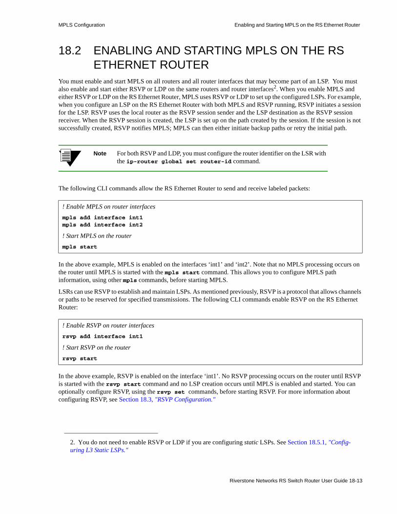
MPLS Configuration Enabling and Starting MPLS on the RS Ethernet Router
18.2 ENABLING AND STARTING MPLS ON THE RS ETHERNET ROUTER
You must enable and start MPLS on all routers and all router interfaces that may become part of an LSP. You must also enable and start either RSVP or LDP on the same routers and router interfaces2. When you enable MPLS and either RSVP or LDP on the RS Ethernet Router, MPLS uses RSVP or LDP to set up the configured LSPs. For example, when you configure an LSP on the RS Ethernet Router with both MPLS and RSVP running, RSVP initiates a session for the LSP. RSVP uses the local router as the RSVP session sender and the LSP destination as the RSVP session receiver. When the RSVP session is created, the LSP is set up on the path created by the session. If the session is not successfully created, RSVP notifies MPLS; MPLS can then either initiate backup paths or retry the initial path.
Note For both RSVP and LDP, you must configure the router identifier on the LSR with the ip-router global set router-id command.
The following CLI commands allow the RS Ethernet Router to send and receive labeled packets:
In the above example, MPLS is enabled on the interfaces ‘int1’ and ‘int2’. Note that no MPLS processing occurs on the router until MPLS is started with the mpls start command. This allows you to configure MPLS path information, using other mpls commands, before starting MPLS.
LSRs can use RSVP to establish and maintain LSPs. As mentioned previously, RSVP is a protocol that allows channels or paths to be reserved for specified transmissions. The following CLI commands enable RSVP on the RS Ethernet Router:
In the above example, RSVP is enabled on the interface ‘int1’. No RSVP processing occurs on the router until RSVP is started with the rsvp start command and no LSP creation occurs until MPLS is enabled and started. You can optionally configure RSVP, using the rsvp set commands, before starting RSVP. For more information about configuring RSVP, see Section 18.3, "RSVP Configuration."
2. You do not need to enable RSVP or LDP if you are configuring static LSPs. See Section 18.5.1, "Config-uring L3 Static LSPs."
! Enable MPLS on router interfacesmpls add interface int1mpls add interface int2
! Start MPLS on the routermpls start
! Enable RSVP on router interfacesrsvp add interface int1
! Start RSVP on the routerrsvp start
Riverstone Networks RS Switch Router User Guide 18-13
Enabling and Starting MPLS on the RS Ethernet Router MPLS Configuration
LSRs can also use LDP to distribute labels and their meanings to LDP peers. LDP enables LSR peers to find each other and establish communications. The following CLI commands enable LDP on the RS Ethernet Router:
In the above example, LDP is enabled on the interfaces ‘int2’. No LDP processing occurs on the router until LDP is started with the ldp start command and no LSP creation occurs until MPLS is enabled and started. You can optionally configure LDP, using other ldp commands, before starting LDP. For more information about configuring LDP, see Section 18.4, "LDP Configuration."
LDP and RSVP each generate signaling traffic to establish and maintain LSPs. In general, you should not enable LDP, RSVP, or MPLS on interfaces where they will not be used. For example, issuing the rsvp add interface all and mpls add interface all commands is an expedient way to enable RSVP and MPLS on all router interfaces. However, if you are using MPLS on a handful of interfaces only, this creates an unnecessary amount of processing overhead and signaling traffic.
! Enable LDP on router interfacesldp add interface int2
! Start LDP on the router
ldp start
18-14 Riverstone Networks RS Switch Router User Guide

MPLS Configuration RSVP Configuration
18.3 RSVP CONFIGURATIONNetwork hosts use the Resource Reservation Protocol (RSVP) to request certain qualities of service from the network for application data flows. Routers also use RSVP to deliver quality of service (QoS) requests to all nodes on the path of a data flow, and to establish and maintain refresh states to provide the requested service. Resources, such as link bandwidth, are reserved on each node along a data path as a result of RSVP requests.
RSVP makes reservations for unidirectional data flows, that is, resource requests are made in only one direction. RSVP senders are distinct from receivers, although an application can be both an RSVP sender and receiver at the same time. RSVP operates on top of IP, however it does not transport application data and is only concerned with the QoS of the packets that are forwarded. RSVP is designed to operate with unicast and multicast routing protocols: the routing protocols determine where packets are forwarded, while the RSVP process consults local routing tables to obtain routes.
Note RSVP on the RS Ethernet Router supports dynamic signaling for MPLS LSPs only. It does not support IP multicast sessions, or resource reservations for real-time audio or video flows.
Note You must configure the router identifier on the LSR with the ip-router global set router-id command.
You must enable both RSVP and MPLS on each router interface on which you want RSVP to run. You also need to enable a unicast routing protocol (for example, OSPF) on the same interface; otherwise, LSPs may not be established between an egress router and all ingress routers. RSVP can be enabled on all router interfaces or on specific router interfaces, as described in Section 18.2, "Enabling and Starting MPLS on the RS Ethernet Router." The following configuration commands enable and start RSVP and MPLS on the router interface to_r1 on the RS Ethernet Router:
Note You should not enable LDP, RSVP, or MPLS on interfaces where they will not be used, as this creates an unnecessary amount of processing overhead and signaling traffic.
18.3.1 Establishing RSVP Sessions
RSVP includes the following types of messages:
rsvp add interface to_r1rsvp startmpls add interface to_r1mpls start
Riverstone Networks RS Switch Router User Guide 18-15

RSVP Configuration MPLS Configuration
• Path messages travel from the potential sender of the data flow to the receiver and include traffic specifications and QoS requirements provided by the sender. Path messages establish the RSVP path between the sender and the path flow destination, storing a path state in each router along the way. The path state includes the unicast IP address of the previous hop.
• Resv messages travel from the intended receiver of the data flow to the sender and identify the session for which the reservation is being made, the level of QoS required by the receiver, and the label binding for the session. Resv messages use the path state information in each router to follow exactly the reverse path (or paths) that the data packets will use, creating and maintaining a reservation state in each router along the path(s).
• Teardown messages delete the reservation. Although RSVP uses session timeouts, teardown messages are a more efficient way to release network resources. Either the sender or receiver of a data flow can initiate a teardown request: PathTear messages are sent by the sender of the data flow, and ResvTear messages are sent by the data flow receiver.
Figure 18-8 illustrates the flow of RSVP Path and Resv messages.
Figure 18-8 RSVP Path and Resv messages
With RSVP, the potential receiver of a data flow is responsible for initiating and maintaining the resource reservation for that flow. The receiver passes a QoS request to the local RSVP process. The RSVP protocol then carries the request to all routers upstream to the data sender(s).
During reservation setup, RSVP determines:• whether the router has sufficient available resources to supply the requested QoS, and• whether the requestor has the administrative permission required to make the reservation
If either of the above checks fail, RSVP returns an error notification to the requestor. Otherwise, if both checks succeed, the reservation is made at the link layer and the request is propagated upstream toward the appropriate sender.
RSVP uses a soft state approach to managing the reservation state in routers, that is, the state is created and periodically refreshed by Path and Resv messages. When a path or reservation state times out, the reservation is deleted or torn down. An explicit teardown message, either PathTear or ResvTear, can also delete the reservation.
Table 18-3 is a summary of the RSVP parameters on the RS Ethernet Router and their default values. The commands that you use to enable an RSVP operation or change a default value are also listed.
Sender Receiver
Path messages
Resv messages
1
2
TransitRouter
TransitRouter
18-16 Riverstone Networks RS Switch Router User Guide

MPLS Configuration RSVP Configuration
The following sections describe the RSVP parameters in more detail.
18.3.2 RSVP Refresh Intervals
As mentioned previously, RSVP soft state management depends upon periodic refreshes of the Path and Resv messages. RSVP Path and Resv refresh messages are sent periodically to refresh the states in neighbor routers and ensure that these states do not time out.
In the following formulas, lifetime is how long an RSVP router keeps a path or reservation state as a valid state:
path-lifetime = path-multiplier * path-refresh-interval
resv-lifetime = resv-multiplier * resv-refresh-interval
Table 18-3 RSVP parameters on the RS Ethernet Router
Parameter Default Value Command to Change Default Value
Path refresh:
path refresh interval
path multiplier
30 seconds
3
rsvp set global path-refresh-interval
rsvp set global path-multiplier
Reservation refresh:
reservation refresh interval
reservation multiplier
30 seconds
3
rsvp set global resv-refresh-interval
rsvp set global resv-multiplier
Hello packets:
hello interval
hello multiplier
(Disabled)
3 seconds
3
rsvp set interface <interface> hello-enablersvp set global hello-interval
rsvp set global hello-multiplier
Authentication:
MD5 signature
(Disabled)
rsvp set interface <interface> auth-method md5
Blockade aging:
interval 60 seconds rsvp set global blockade-aging-interval
Message aggregation:
bundle interval
(Disabled)
5 seconds
rsvp set interface <interface> aggregate-enablersvp set global bundle-interval
Message ID extensions:
summary refresh interval
acknowledgement interval
(Disabled)
3 seconds
1 second
rsvp set interface <interface> msgid-extensions-enable
rsvp set global msgid-list-interval
rsvp set global msgack-interval
LSP preemption: (Disabled) rsvp set global preemption
Riverstone Networks RS Switch Router User Guide 18-17

RSVP Configuration MPLS Configuration
The path-refresh-interval and resv-refresh-interval are the periods of time between the generation of successive refresh messages by an RSVP neighbor. The path-refresh-interval or resv-refresh-interval is set locally at each RSVP router; this value is sent to neighbor routers in Path and Resv messages, respectively. The receiving RSVP node uses the values contained in the messages to calculate the path-lifetime or resv-lifetime for the path or reservation state. On the RS Ethernet Router, the default interval for both Path and Resv refreshes is 30 seconds.
The path-multiplier and resv-multiplier are integers between 1 and 255 that are configured on the local router. On the RS Ethernet Router, the default for both multipliers is 3.
For example, if the path-multiplier is set locally at 3 and the path-refresh-interval received from an RSVP neighbor is 30 seconds, then:
path-lifetime = 3 * 30 = 90 seconds
[path-multiplier minus 1] successive Path refresh messages may be lost without the path state timing out. For example, the path-multiplier default value on the RS Ethernet Router is 3; 2 successive Path refresh messages can be lost without the path state timing out.
On the RS Ethernet Router, you can use the rsvp set global command to set the values for the Path and Resv refresh intervals and multipliers:• The path-refresh-interval parameter specifies the interval at which RSVP sends out Path
messages to the downstream neighbor. The default value is 30 seconds.• The resv-refresh-interval parameter specifies the interval at which RSVP sends out Resv
messages to the upstream neighbor. The default value is 30 seconds.• You can specify a path-multiplier parameter value between 1 and 255. The default value is 3.• You can specify a resv-multiplier parameter value between 1 and 255. The default value is 3.
18.3.3 RSVP Hello Packets
The RS Ethernet Router supports the sending of RSVP hello packets on a per-interface basis. Sending hello packets allows RSVP routers to detect the loss of RSVP state information of a neighbor node, for example, when a link fails or the neighbor router restarts. RSVP hello packets can detect the state change of a neighbor node more quickly than simply relying on RSVP soft state timeouts. For example, if a link fails, RSVP hello packets can detect the state change in about 9 seconds, compared to 90 seconds for an RSVP soft state timeout.
When hello packets are enabled on an interface, RSVP sends unicast hello packets to the RSVP neighbor on that interface. On an RS Ethernet Router interface, hello packets are sent by default at 3-second intervals. RSVP sessions with a neighbor node are considered to be “down” if hello packets are not received within the following time period:
hello-interval * hello-multiplier
On the RS Ethernet Router, the default for the hello-multiplier is 3. Thus, if hello packets are not received from a neighbor within 9 seconds, that neighbor and its RSVP session are considered to be down.
Sending RSVP hello packets is disabled by default on the RS Ethernet Router. You can enable RSVP hello packets on an interface with the hello-enable parameter of the rsvp set interface command. For example, the following command enables RSVP hello packets on the interface ‘int2’:
If an RSVP neighbor on the interface does not support hello packets, soft state timeouts are used to detect loss of state information.
rsvp set interface int2 hello-enable
18-18 Riverstone Networks RS Switch Router User Guide

MPLS Configuration RSVP Configuration
By default, RSVP hello packets are sent at 3-second intervals. You can change this interval with the rsvp set global hello-interval command. For example, the following command sets the sending of RSVP hello packets to 5-second intervals:
By default, the RSVP hello multiplier is 3. You can change this variable with the rsvp set global hello-multiplier command. For example, the following command sets the RSVP hello multiplier to 5:
If RSVP hello packets are supported on all neighbor nodes, you can increase RSVP refresh intervals and thereby reduce the refresh overhead. (See Section 18.3.2, "RSVP Refresh Intervals.") Refresh operations will consume less CPU and bandwidth, allowing scaling for a larger number of sessions. The time needed for node or link failure detection is not adversely impacted.
18.3.4 Authentication
RSVP messages can be authenticated to prevent unauthorized nodes from setting up reservations. On the RS Ethernet Router, RSVP authentication is enabled on a per-interface basis; RSVP authentication is disabled by default. If RSVP authentication is used, all routers connected to the same IP subnet must use authentication. Authentication is performed on all RSVP messages that are sent or received on an interface where RSVP authentication is enabled.
RSVP on the RS Ethernet Router supports the IETF standard MD5 signature authentication. To set RSVP authentication for an interface on the RS Ethernet Router, use the rsvp set interface command. Use the auth-key parameter to specify the password.
For example, the following command sets the MD5 password ‘p55717’ for RSVP sessions on the interface ‘int2’:
In the above example, if you specify interface all, the MD5 password is applied to all RSVP sessions on the router.
18.3.5 Blockade Aging Interval
A “killer reservation” situation occurs when an RSVP reservation request effectively denies service to any other request. For example, an RSVP node attempting (and failing) to make a large reservation can prevent smaller reservation requests from being forwarded and established. On the RS Ethernet Router, when there is a reservation error, the offending request enters a blockade state for a predetermined amount of time. While a reservation request is blockaded, smaller requests can be forwarded and established.
On the RS Ethernet Router, the default time that a request can be blockaded is 60 seconds. You can change this interval with the rsvp set global blockade-aging-interval command. For example, the following command sets the blockade interval to 50 seconds:
rsvp set global hello-interval 5
rsvp set global hello-multiplier 5
rsvp set interface int2 auth-key p55717
rsvp set global blockade-aging-interval 50
Riverstone Networks RS Switch Router User Guide 18-19

RSVP Configuration MPLS Configuration
18.3.6 RSVP Refresh Reduction
As described previously, RSVP uses Path and Resv refresh messages to maintain states between RSVP neighbors. Each RSVP session requires that refresh messages be generated, transmitted, received, and processed for each refresh period. Supporting a large number of RSVP sessions presents a scaling problem as the resources required for processing these messages increase proportionally with the number of RSVP sessions.
The RS Ethernet Router supports the following features that can reduce the overhead required to process refresh messages on a per-interface basis:• Message aggregation• Message ID extensions
The following sections describe how to configure and use these features.
18.3.6.1 RSVP Message Aggregation
The RS Ethernet Router supports the aggregation, or bundling, of multiple RSVP messages on a per-interface basis. Message aggregation helps to scale RSVP by reducing processing overhead and bandwidth consumption. Aggregated RSVP messages can only be sent to RSVP neighbors that support message aggregation. Aggregated RSVP messages must not be used if the RSVP neighbor does not support message aggregation.
RSVP message aggregation is disabled by default on the RS Ethernet Router. You can enable message aggregation on an interface with the aggregate-enable parameter of the rsvp set interface command. For example, the following command enables RSVP message aggregation on the interface ‘int2’:
If message aggregation is enabled on an interface, traffic headed to a specific destination is aggregated at 5-second intervals. You can change this interval with the rsvp set global bundle-interval command. For example, the following command sets RSVP message aggregation to 7-second intervals:
18.3.6.2 Message ID Extensions
The RS Ethernet Router supports message ID extensions, as defined by RFC 2961. These message IDs are generated and processed over a single hop between RSVP neighbors. Enabling message ID extensions provides the following functions:• Summary refresh allows RSVP neighbors to readily identify unchanged messages, thereby reducing
refresh message processing. An unchanged message is a message that represents a previously-advertised state, contains the same information as a previously-transmitted message, and is sent over the same path.
• Use of acknowledgements between RSVP neighbors to detect message loss and to support reliable RSVP message delivery.
rsvp set interface int2 aggregate-enable
rsvp set global bundle-interval 7
18-20 Riverstone Networks RS Switch Router User Guide

MPLS Configuration RSVP Configuration
RSVP message ID extensions are disabled by default on the RS Ethernet Router. You can enable message ID extensions on an interface with the msgid-extensions-enable parameter of the rsvp set interface command. For example, the following command enables RSVP message ID extensions on the interface ‘int2’:
Summary refresh is used to refresh Path and Resv states without transmitting standard Path or Resv messages. Summary refresh is the periodic transmittal of a list of the message IDs associated with states that were previously advertised in Path or Resv messages. The message ID list reduces the amount of information that must be transmitted and processed in order to maintain RSVP state synchronization. By default, the message ID list is sent at 3-second intervals if message ID extensions are enabled for an interface. You can change this interval with the rsvp set global msgid-list-interval command. For example, the following command sets the transmission of the message ID list to 5-second intervals:
Acknowledgements are sent between RSVP neighbors that support message ID extensions. When message ID extensions are enabled, acknowledgements are sent for RSVP messages that advertise state or any other information that was not previously transmitted. Message acknowledgements can be sent in any RSVP message that has an IP destination address that matches the original message generator. Or, the acknowledgement can be sent in a separate acknowledgement message, if no appropriate RSVP message is available. If an acknowledgement is delayed, the corresponding message is retransmitted. To avoid retransmission, the acknowledgement should be sent at minimal intervals. On the RS Ethernet Router, the default interval for sending message acknowledgements is 1 second. You can change this interval with the rsvp set global msgack-interval command. For example, the following command sets the transmission of message acknowledgements to 3-second intervals:
18.3.7 LSP Preemption
When there is not enough bandwidth to establish new LSPs, it may be desirable to preempt an already-established LSP to allow a higher-priority LSP to be established. The priority of an LSP depends upon its setup-priority and hold-priority values, as configured with the mpls create|set label-switched-path commands. (See "Setup and Hold Priority" for information about configuring the setup-priority and hold-priority parameters for an LSP.)
By default, preemption of LSPs is not enabled on the RS Ethernet Router. The following command enables LSP preemption for RSVP-signaled LSPs:
If preemption is enabled, a new LSP can preempt an already-established LSP under the following conditions:• The setup-priority value of the new LSP must be greater than the hold-priority value of the
already-established LSP. For example, an LSP with a setup-priority value of 0 (highest priority) can preempt an LSP with a hold-priority value of 7 (lowest priority).
• There must be enough bandwidth created by preempting the existing LSP to establish the new LSP. If preempting the existing LSP would not create enough bandwidth to support the new LSP, then preemption will not take place.
rsvp set interface int2 msgid-extensions-enable
rsvp set global msgid-list-interval 5
rsvp set global msgack-interval 3
rsvp set global preemption
Riverstone Networks RS Switch Router User Guide 18-21

RSVP Configuration MPLS Configuration
• If multiple LSPs qualify for preemption, the LSP with the most bandwidth would be preempted. • The hold-priority value of the existing LSP must be relatively low so that it can be preempted
by the new LSP. For example, if the hold-priority value of the existing LSP is 0 (highest priority), other LSPs cannot preempt it.
To avoid preemption loops, you must not configure an LSP with both a high setup-priority value and a low hold-priority value. The hold-priority value of the LSP must be equal to or higher than the setup-priority value.
Note If link bandwidth has to be changed for active LSPs on a link interface, first bring down all LSPs that use this link interfaces, change their bandwidths, and then reestablish the LSPs.
18.3.8 Displaying RSVP Information
Table 18-4 is a summary of the RSVP session information that you can display on the RS Ethernet Router and the CLI commands that you use to display the information.
Table 18-4 RSVP session information
To see this information: Use this command:
RSVP global, path state block, reservation state block, traffic control state block, session, and neighbor information.
rsvp show all
RSVP global parameters rsvp show global
RSVP interface parameters rsvp show interface
RSVP neighbors, next-hop, and number of sessions rsvp show neighbors
RSVP path state block information rsvp show psb
RSVP reservation state block information rsvp show rsb
RSVP session information rsvp show session
RSVP traffic control state block information rsvp show tcsb
18-22 Riverstone Networks RS Switch Router User Guide

MPLS Configuration LDP Configuration
18.4 LDP CONFIGURATIONLDP is a set of procedures and messages that allow LSRs to establish an LSP through a network by mapping network-layer routing information to data-link layer switched paths. The LSP can have an endpoint at a directly attached neighbor or it may have an endpoint at an egress LSR with switching enabled via transit LSRs. LDP supports label distribution for MPLS forwarding along normally-routed paths (as determined by destination-based routing protocols); this is also called MPLS hop-by-hop forwarding.
LDP allows the establishment of best-effort LSPs and is generally used where traffic engineering is not required. In contrast, RSVP is generally used for label distribution and LSP setup where traffic engineering is necessary, primarily in backbone networks. LDP is also used for signaling layer 2 FEC-to-label mappings to tunnel L2 frames across an MPLS network, as discussed in Section 18.6.1, "Configuring Dynamic L2 Labels."
You must enable both LDP and MPLS on each router interface on which you want LDP to run. You also need to enable a unicast routing protocol (for example, OSPF) on the same interface; otherwise, LSPs may not be established between an egress router and all ingress routers. LDP can be enabled on all router interfaces or on specific router interfaces, as described in Section 18.2, "Enabling and Starting MPLS on the RS Ethernet Router." The following configuration commands enable and start LDP and MPLS on the router interface to_r1 on the RS Ethernet Router:
Note You must configure the router identifier on the LSR with the ip-router global set router-id command.
Note You should not enable LDP, RSVP, or MPLS on interfaces where they will not be used, as this creates an unnecessary amount of processing overhead and signaling traffic.
18.4.1 Establishing LDP Sessions
LSRs that use LDP to exchange FEC-label binding information are called LDP peers. LDP allows LSRs to discover potential LDP peers automatically. When LDP is started on the RS Ethernet Router, the router attempts to discover other LDP peers by sending LDP hello packets out on its LDP-enabled interfaces. LDP hello packets are sent as multicast UDP packets. If multiple LDP-enabled interfaces exist between two adjacent routers, only one LDP session is established between the routers.
An LDP session using a TCP connection is established between LDP peers to exchange the binding information. When an LDP peer is discovered, the LSR attempts to establish an LDP session through the well-known port 646. After session parameters are successfully negotiated between the peers, the session is used for label distribution.
ldp add interface to_r1ldp startmpls add interface to_r1mpls start
Riverstone Networks RS Switch Router User Guide 18-23

LDP Configuration MPLS Configuration
18.4.2 Monitoring LDP Sessions
In addition to discovering LDP peers, sending hello packets also allows LDP nodes to detect link or peer node failures. When LDP is started, the RS Ethernet Router sends out LDP hello packets every 5 seconds by default. The hello message includes a hold time value that tells the router’s peers how long to wait for a hello message. Since the hold time is set by each LDP router, its neighbors can assume that a router or link is down if they do not receive a hello packet from the router within the specified hold time. The default hello hold time used by LDP on the RS Ethernet Router is 15 seconds. You can use the ldp set interface command to specify a different hello hold time for LDP peers on a specific interface or on all router interfaces. For example, the following command sets the LDP hello hold time to 20 seconds on the interface ‘int1’:
LDP neighbors do not have to set the same hold time value. For example, router R1 can set a hold time of 15 seconds, while its neighbor R2 can set a hold time of 20 seconds.
Once an LDP session is established, LDP keepalive packets are used to monitor the status of the session. On the RS Ethernet Router, keepalive packets are sent at 10 second intervals and if the LDP peer does not respond in 30 seconds, the session is considered down. The default session timeout on the RS Ethernet Router is 30 seconds. You can use the ldp set interface command to specify a different LDP session timeout for LDP peers on a specific interface or on all router interfaces. For example, the following command sets the LDP session timeout to 40 seconds on the interface ‘int1’:
Table 18-5 shows the default times used by the RS Ethernet Router to monitor LDP sessions on both directly-connected LDP peers and remote LDP peers. (For more information about remote LDP peers, see Section 18.4.3, "Remote Peers.")
ldp set interface int1 hold-time 20
ldp set interface int1 keepalive-timeout 40
Table 18-5 Default LDP session monitoring parameters
Session monitoring parameters LDP peer (direct-connect or remote)
Hello Messages:
Send interval (not configurable - 1/3 of hold time) 5 seconds
Hold time 15 seconds
Session Keepalive Messages:
Send interval (not configurable - 1/3 of timeout) 10 seconds
Timeout 30 seconds
18-24 Riverstone Networks RS Switch Router User Guide

MPLS Configuration LDP Configuration
18.4.3 Remote Peers
Note that only directly-connected peers are automatically discovered when LDP is started on the RS Ethernet Router. If you need the router to establish LDP communications with an LSR that is not directly connected, enable LDP on the loopback interface lo0, and use the ldp add remote-peer command to specify the router ID of the remote LSR. For example:
Note The router ID of the remote LDP peer must be the loopback address of the remote router.
You can use the ldp set remote-peer command to specify the hold time for hello messages and the timeout for session keepalive messages for remote LDP peers. You can also use the ldp set interface command to specify the hello hold time for remote LDP peers and LDP neighbors.
For example, the following command sets a hold time of 60 seconds and a keepalive timeout of 45 seconds for the remote peer 100.100.100.102:
You can use the hold-time parameter of the ldp set interface command to specify a different hello hold time for all LDP peers, including remote peers. Setting the hello hold time for a specific remote LDP peer (with the ldp set remote-peer command) takes precedence. The ldp set interface all keepalive-timeout command sets the keepalive timeout for all LDP peers, including remote peers. Setting the keepalive timeout for a specific remote LDP peer (with the ldp set remote-peer command) takes precedence.
18.4.4 Loop Detection
With conventional IP forwarding, packets carry a “Time to Live” (TTL) value in their headers. TTL protects against forwarding loops in the network. When a packet passes through a router, its TTL is decremented by 1. If the TTL reaches 0 before the packet reaches its destination, the packet is discarded. Certain LSP segments may not use TTL. To prevent label request messages from looping in LSPs that traverse non-TTL MPLS networks, you can enable loop detection on the RS Ethernet Router. When enabling loop detection, you also specify the maximum path vector length (the path vector contains a list of LSRs traversed by the label request or label mapping message). When an LSR encounters a path vector length that reaches the specified limit, a loop is assumed.
For example, the following command enables path vector loop detection on the RS Ethernet Router and sets the path vector limit to 100:
ldp add interface lo0ldp add remote-peer 100.100.100.102
ldp set remote-peer 100.100.100.102 hello-hold-time 60 keepalive-timeout 45
ldp set global path-vector-loop-detection-enable path-vector-limit 100
Riverstone Networks RS Switch Router User Guide 18-25
LDP Configuration MPLS Configuration
By default, the TCP session address used by LDP is the primary address of the interface on which LDP is enabled. You can specify that the TCP session address used by LDP is the address of the loopback interface with the following command:
18.4.5 MD5 Password Protection
Since LDP uses TCP as its transport, you can use the IETF standard MD5 signature option to protect LDP session connections. Use the ldp set md5-password command to set an MD5 password on a per-router, per-interface, or per-peer basis.
For example, the following command sets the MD5 password ‘p55717’ for LDP sessions with the peer 100.100.100.102:
In the above example, if you omit the peer keyword and IP address, the MD5 password is applied to all LDP sessions on the router.
18.4.6 Using LDP Filters
With MPLS, there is no way to restrict which FECs are or are not bound to labels. You can, however, create and apply LDP filters that restrict the label bindings that are sent from downstream LSRs to upstream LSRs. You can also create and apply LDP filters that restrict the label requests that an upstream LSR can send to a downstream LSR.
If an upstream LSR does not have label binding information for a specific FEC, it will route packets based on information in the IP routing table. However, if there are several paths of equal cost to the same destination, LDP filters can exclude next-hops from considerations.
On the RS Ethernet Router, you can define an LDP filter for:• outgoing label requests—use the ldp add export-filter request command.• incoming label requests—use the ldp add import-filter request command.• outgoing label bindings—use the ldp add export-filter mapping command.• incoming label bindings—use the ldp add import-filter mapping command.
Note A filtered incoming label binding will still appear in the LDP input label database (displayed with the ldp show database verbose command) on the local router, but will not be considered for LSP establishment. A filtered outgoing label binding is not advertised to the specified neighbor LSR, although it will still be advertised to other LDP neighbors and considered by the local router for LSP establishment.
ldp set global transport-address-loopback
ldp set md5-password p55717 peer 100.100.100.102
18-26 Riverstone Networks RS Switch Router User Guide

MPLS Configuration LDP Configuration
The following shows LDP filter commands configured on the router rs1. The first command specifies that bindings for 6.6.6.6/32 from the neighbor router 6.6.6.6 are not to be used for LSP establishment. The second command allows all other bindings from the same neighbor router to be accepted and used for LSP establishment. Note that the more restrictive filter command has the lower sequence number and will be executed first.
Note that if you run the ldp show database verbose command on rs1 (see the following example), the label binding for 6.6.6.6/32 appears in router rs1’s LDP database, but it is marked as “Filtered” (shown in boldface in the example) and is therefore not considered on rs1 for LSP establishment.
You can also define an LDP prefix filter with the ldp add prefix-filter command. Once defined, the prefix filter can be used in multiple LDP filter commands. For example, if you want to restrict both outgoing and incoming label requests for certain IP addresses, define an LDP prefix filter first.
rs1(config)# ldp add import-filter mapping network 6.6.6.6/32 restrict neighbor 6.6.6.6 sequence 1
rs1(config)# ldp add import-filter mapping network all neighbor 6.6.6.6 sequence 2
rs1# ldp show database verbose
Input label database, 1.1.1.1:0-6.6.6.6:0 Label Prefix 2051 1.1.1.1/32 State:Active 2052 3.3.3.3/32 State:Active 16 6.6.6.6/32 State:Active, Filtered
Output label database, 1.1.1.1:0-6.6.6.6:0 Label Prefix 2049 3.3.3.3/32 State:Active 16 1.1.1.1/32 State:Active Input label database, 1.1.1.1:0-3.3.3.3:0 Label Prefix 2050 1.1.1.1/32 State:Active 16 3.3.3.3/32 State:Active Output label database, 1.1.1.1:0-3.3.3.3:0 Label Prefix 2049 3.3.3.3/32 State:Active 16 1.1.1.1/32 State:Active
Riverstone Networks RS Switch Router User Guide 18-27

LDP Configuration MPLS Configuration
In the following example, the ldp add prefix-filter command defines a prefix filter for the host node 10.10.10.101. The subsequent commands use the prefix filter to prevent requests or bindings for 10.10.10.101 from being sent to other LDP routers.
18.4.7 Displaying LDP Information
Table 18-6 is a summary of the LDP session information that you can display on the RS Ethernet Router and the CLI commands that you use to display the information.
rs(config)# ldp add prefix-filter 101serv network 10.10.10.101/32 host-netrs(config)# ldp add export-filter request restrict prefix-filter 101serv neighbor 1.1.1.1 sequence 1rs(config)# ldp add export-filter mapping restrict prefix-filter 101serv neighbor 1.1.1.1 sequence 1
Table 18-6 LDP peer and session information
To see this information: Use this command:
LDP global, interface, neighbor, and session parameters, and input and output labels for each LDP session
ldp show all
Input and output labels that are exchanged for each LDP session ldp show database
LDP export filter configuration ldp show export-filter
LDP global parameters ldp show global
LDP import filter configuration ldp show import-filter
LDP interface parameters, LDP neighbors on interface, and label space identifier being advertised on interface
ldp show interface
Labels sent and received for L2 FECs and transport LSPs selected for L2 FECs.
ldp show l2-fec
Interface on which LDP neighbor was discovered and label space identifier advertised by neighbor
ldp show neighbor
LDP prefix filter configuration ldp show prefix-filter
LDP remote peer configuration ldp show remote-peer
LDP session state information. Verbose option shows session connection parameters as well as list of next-hop addresses received on the session.
ldp show session
LDP statistics ldp show statistics
18-28 Riverstone Networks RS Switch Router User Guide
MPLS Configuration Configuring L3 Label Switched Paths
18.5 CONFIGURING L3 LABEL SWITCHED PATHSThe RS Ethernet Router supports two basic types of LSPs:• Static LSPs require that you configure all routers and assign all labels in the path. This is similar to
configuring static routes on the router, and there is no reporting of errors or statistics. MPLS must be enabled. No signaling protocol is used, so you do not need to enable RSVP or LDP.
• Dynamic LSPs (also called signaled LSPs) use RSVP to set up the path and dynamically assign labels. On the ingress LSR, you configure the LSP as well as enable MPLS and RSVP. On all other LSRs in the dynamic LSP, you only need to enable MPLS and RSVP.
18.5.1 Configuring L3 Static LSPs
In a static LSP, each router in the path must be configured with static forwarding information. You can specify label values between 16 and 1024. No signaling protocol is used. MPLS must be enabled on all routers, as described in Section 18.2, "Enabling and Starting MPLS on the RS Ethernet Router."
This section describes how to configure the ingress, transit, and PHP LSRs for a static LSP. (For a detailed example of how to configure a static path on an RS Ethernet Router router, see Section 18.5.1.4, "L3 Static Path Configuration Example.")
18.5.1.1 Ingress LSR Configuration
Use the mpls create static-path and mpls set static-path commands to configure a static LSP on the ingress RS Ethernet Router. When configuring the static LSP on the ingress LSR, you specify:• destination IP address for the static path• Non-global label value to be pushed onto the top of the label stack – See note below• next-hop IP address (gateway) for the path
Note These labels must not fall within global label space. By default, non-global label space is the same as RSVP label space (from 3584 to 7167). If necessary, the start of global label space can be moved lower or higher using the mpls set global max-global-label command.
For example, the following command creates the static path SP1 on the ingress LSR. Packets to the destination 50.1.1.1 are assigned the label value 4000 and are sent out on the next-hop 10.1.1.5.
18.5.1.2 Transit LSR Configuration
In a static LSP, transit LSRs can change (swap) the label value at the top of the label stack. Use the mpls set interface command to configure the static LSP on the transit RS Ethernet Router. When configuring the static LSP on the transit LSR, you specify:
mpls create static-path SP1 to 50.1.1.1 push 4000 gateway 10.1.1.5
Riverstone Networks RS Switch Router User Guide 18-29

Configuring L3 Label Switched Paths MPLS Configuration
• the incoming interface or IP address for the path• the next-hop interface or IP address for the path• the incoming label value and one of the following actions to be taken on the label (the label map):
- swap the incoming label with a specified outgoing label value- pop the top value on the label stack- push a new label value on the top of the label stack
For example, the following command on a transit LSR looks at packets arriving on the interface MPLS-R2IN. Packets that have a label value of ‘4000’ have their labels replaced by the value ‘4001’ before they are sent to the next-hop IP address 20.1.1.2.
18.5.1.3 PHP LSR Configuration
In a static LSP, the PHP LSR removes (pops) the label stack and then forwards the packet to the egress LSR. Use the mpls set interface command to configure the static LSP on the PHP RS Ethernet Router. When configuring the static LSP on the PHP LSR, you specify:• the incoming interface or IP address for the path• the next-hop interface or IP address for the path• the incoming label value to be popped from the label stack (normally, this would be the only label in
the stack)
For example, the following command on a PHP LSR looks at packets arriving on the interface MPLS-R3IN. Packets that have a label value of ‘4001’ have their label popped before they are sent to the next-hop IP address 30.1.1.2.
18.5.1.4 L3 Static Path Configuration Example
In the example shown in Figure 18-9, the RS Ethernet Router router R1 is an ingress LSR for a static path. For incoming traffic, the RS Ethernet Router looks up the destination IP address in its routing table. If a path has been configured for the destination address, the appropriate label is pushed on the packet and the packet is forwarded on to the next hop. For traffic destined for the 50.1/16 network, the label ‘4000’ is assigned by R1 before forwarding to the next-hop LSR at 10.1.1.2, in this case, another RS Ethernet Router router, R2, which is also the PHP LSR.
mpls set interface MPLS-R2IN label-map 4000 swap 4001 next-hop 20.1.1.2
mpls set interface MPLS-R3IN label-map 4001 pop next-hop 30.1.1.2
18-30 Riverstone Networks RS Switch Router User Guide
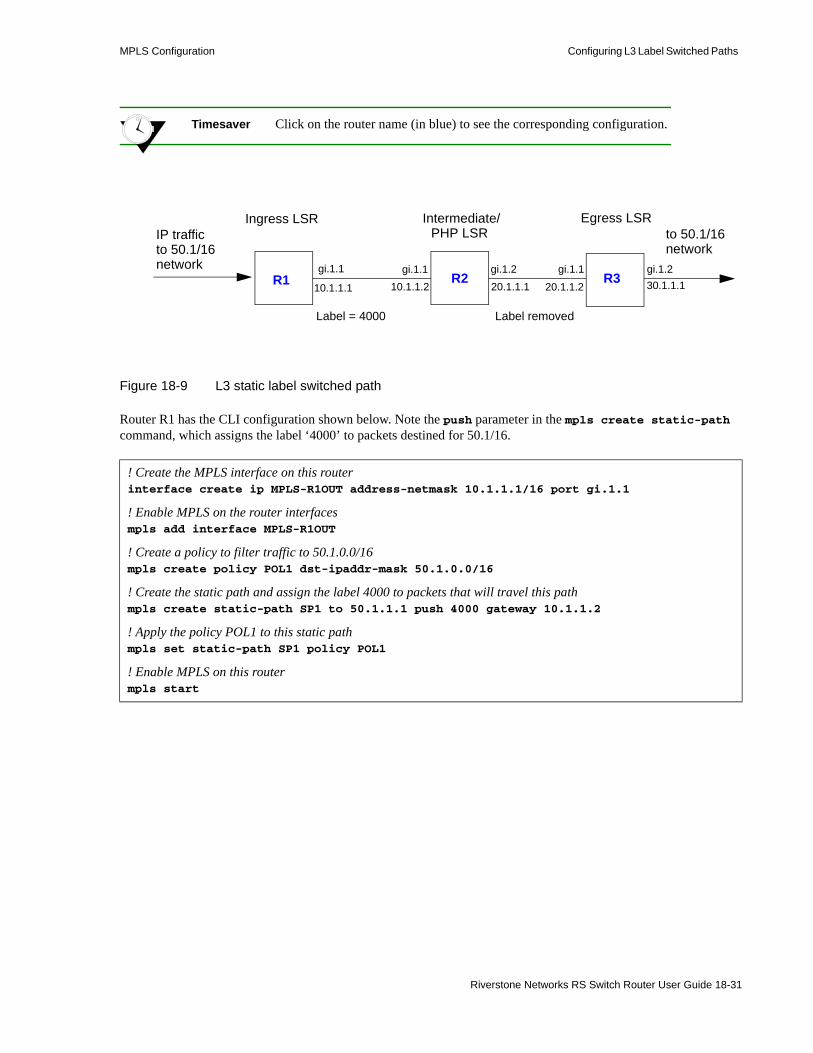
MPLS Configuration Configuring L3 Label Switched Paths
Timesaver Click on the router name (in blue) to see the corresponding configuration.
Figure 18-9 L3 static label switched path
Router R1 has the CLI configuration shown below. Note the push parameter in the mpls create static-path command, which assigns the label ‘4000’ to packets destined for 50.1/16.
! Create the MPLS interface on this routerinterface create ip MPLS-R1OUT address-netmask 10.1.1.1/16 port gi.1.1
! Enable MPLS on the router interfacesmpls add interface MPLS-R1OUT
! Create a policy to filter traffic to 50.1.0.0/16mpls create policy POL1 dst-ipaddr-mask 50.1.0.0/16
! Create the static path and assign the label 4000 to packets that will travel this pathmpls create static-path SP1 to 50.1.1.1 push 4000 gateway 10.1.1.2
! Apply the policy POL1 to this static pathmpls set static-path SP1 policy POL1
! Enable MPLS on this routermpls start
Ingress LSR Egress LSRto 50.1/16network
IP trafficto 50.1/16network
Intermediate/PHP LSR
10.1.1.1 10.1.1.2 20.1.1.1 20.1.1.2 30.1.1.1
Label = 4000 Label removed
gi.1.1 gi.1.1 gi.1.2 gi.1.1 gi.1.2R1 R2 R3
Riverstone Networks RS Switch Router User Guide 18-31

Configuring L3 Label Switched Paths MPLS Configuration
At router R2, packets arriving on interface MPLS-R2IN that are labeled “4000” are stripped of their label and forwarded to the next-hop router (R3) at 20.1.1.2. Note the mpls set interface command in the following configuration for R2:
Router R3 is the egress label edge router in the path. Router R3 has the following configuration:
In the above example, a policy is defined at the ingress router (R1) to filter traffic that is directed onto the static path. There are other ways that you can send traffic on a path, including IGP shortcuts. (See Section 18.7.3, "IGP Shortcuts.")
You can use the mpls show static-paths command to display the MPLS static path information. On router R1, the following is displayed for the configured static path:
You can use the mpls show policy command to display information on MPLS policies. All configured policies are shown; policies that are applied to LSPs are shown to be “INUSE.” The following shows an example of the output from router R1; note that the policy ‘POL1’ is shown to be “INUSE.”
! Create the MPLS interfaces on this routerinterface create ip MPLS-R2IN address-netmask 10.1.1.2/16 port. gi.1.1
interface create ip MPLS-R2OUT address-netmask 20.1.1.1/16 port gi.1.2
! Enable MPLS on the router interfacesmpls add interface MPLS-R2IN
mpls add interface MPLS-R2OUT
! Configure swapping of labels and next-hopmpls set interface MPLS-R2IN label-map 4000 pop next-hop 20.1.1.2
! Enable MPLS on this routermpls start
! Create the MPLS interfaces on this routerinterface create ip MPLS-R3IN address-netmask 20.1.1.2/16 port. gi.1.1
interface create ip MPLS-R3OUT address-netmask 30.1.1.1/16 port gi.1.2
! Enable MPLS on the router interfacesmpls add interface MPLS-R3IN
mpls add interface MPLS-R3OUT
! Enable MPLS on this routermpls start
R1# mpls show static-paths all
Ingress LSP: LSPname To From State LabelIn LabelOut SP1 50.1.1.1 7.7.7.7 Up - 4000
R1# mpls show policy allName Type Destination Port Source Port TOS Prot Use ----------- ---- --------------- ------ ------------- ------ --- ----- -----POL1 L3 50.1.0.0 any 50.1.0.0 any any IP INUSE
18-32 Riverstone Networks RS Switch Router User Guide

MPLS Configuration Configuring L3 Label Switched Paths
You can also use the ip-policy show command to display information on IP policies, including MPLS policies. Only active policies (MPLS policies that are applied to LSPs) are shown.The following is an example of the output on router R1:
Note that in the above output ‘MPLS_PBR_SP1’ refers to the name of the LSP, which in this configuration example is ‘SP1.’ Similarly, the ACL ‘MPLS_ACL_POL1’ refers to the name of the policy, which in this configuration example is ‘POL1.’
18.5.2 Configuring L3 Dynamic LSPs
With dynamic LSPs, you configure the LSP on the ingress router only. The ingress router sends RSVP signaling information to other LSRs in the path in order to establish and maintain the LSP. Labels are dynamically assigned on the LSRs.
Note Configuring LSPs are only required for RSVP-signaled LSPs. LSPs that use LDP do not need to be configured with the mpls commands described in this section.
There are two types of dynamic LSPs:• Explicit: You configure the LSP on the ingress router. The sequence of other routers in the path can
be specified. The path can be strict (the path must go through the specified routers and must not include other routers) or loose (the path can include other routers or interfaces). On the RS Ethernet Router, strict is the default when configuring an explicit path. The ingress router uses signaling to pass forwarding information to each router in the LSP. In non-MPLS networks, explicit routing of packets requires the packet to carry the identity of the explicit route. With MPLS, it is possible to have packets follow an explicit route by having the label represent the route.
With an explicit LSP, each LSR in the path does not independently choose the next hop. Explicit LSPs are useful for policy routing or traffic engineering.
• Constraint-based: You configure the LSP path constraints on the ingress router. The ingress router calculates the entire path or part of the LSP. RSVP is then used to establish the LSP. All routers must be running either the IS-IS or OSPF routing protocol with traffic engineering extensions enabled.
For information on configuring constraint-based LSPs, see Section 18.7, "Traffic Engineering."
R1# ip-policy show all -------------------------------------------------------------------------------- IP Policy name : MPLS_PBR_SP1 Applied Interfaces : all-IP-interfaces local-policy Load Policy : first available Health Check : disabled ACL Source IP/Mask Dest. IP/Mask SrcPort DstPort TOS TOS-MASK Prot ORIG AS --- -------------- ------------- ------- ------- --- -------- ---- ------- MPLS_ACL_POL1anywhere 50.1.0.0/16 any any any None IP Next Hop Information -------------------- Seq Rule ACL Cnt Action Next Hop Cnt Last --- ---- -------- --- ----------- -------- --- ---- 10 permit MPLS_ACL_POL1 0 Policy First 10.1.1.1 0 Dwn
Riverstone Networks RS Switch Router User Guide 18-33

Configuring L3 Label Switched Paths MPLS Configuration
18.5.3 Configuring an Explicit LSP
As mentioned previously, all LSRs in a dynamic LSP use RSVP to establish and maintain the LSP. Therefore, all LSRs must enable RSVP in addition to MPLS. See Section 18.2, "Enabling and Starting MPLS on the RS Ethernet Router."
You configure an explicit LSP only on the ingress router. Configuring an explicit LSP on the ingress router is a two-step process:1. Create one or more explicit paths. You can specify some or all transit LSRs in the path. For each
transit LSR you specified, you designate whether the route from the previous router to this router is direct and cannot include other routers (strict route) or whether the route from the previous router to this router can include other routers (loose route).
2. Create the LSP, specifying the previously created explicit paths as either the primary or secondary path. The secondary path is the alternate path to the destination and is used if the primary path can no longer reach the destination. If the LSP switches from the primary to the secondary path, the LSP will revert back to the primary path when it becomes available.
18.5.3.1 Configuring an Explicit Path
Use the mpls create path and mpls set path commands to configure an explicit path. When configuring an explicit path, you specify the following:• maximum number of hops for the path• hop number and IP address of transit routers in the path• whether the route to the transit router is strict or loose
The following is an example of configuring an explicit path on the RS Ethernet Router:
The mpls create path command shown above creates an explicit path 567 with a total of 3 hops. The mpls set path commands identify each of the three hops in the explicit path. By default, the path is strict—the path must go through the specified hop addresses. (To specify a loose route, include the option type loose.)
18.5.3.2 Configuring the LSP
You can then specify the explicit path as the primary or secondary path for the LSP by specifying the parameter primary or secondary with the mpls set label-switched-path commands. For example, the mpls create label-switched-path command shown below creates an LSP L1 to the destination address 100.1.1.1. The mpls set label-switched-path command specifies the explicit path 567 as the primary path for the LSP:
mpls create path 567 num-hops 3
mpls set path 567 hop-num 1 ip-addr 30.1.1.1mpls set path 567 hop-num 2 ip-addr 30.1.1.2mpls set path 567 hop-num 3 ip-addr 31.1.1.2
mpls create label-switched-path L1 to 100.1.1.1 no-cspfmpls set label-switched-path L1 primary 567 adaptive
18-34 Riverstone Networks RS Switch Router User Guide

MPLS Configuration Configuring L3 Label Switched Paths
Note When configuring an explicit LSP, specify the no-cspf parameter. Otherwise, the LSP waits indefinitely for a valid constrained shortest path first (CSPF) response.
You can configure the same parameters for the LSP or for the explicit path. You configure parameters for an LSP with the mpls create label-switched-path or mpls set label-switched-path commands; the parameters you configure at this level apply to all paths in the LSP. You configure parameters for an explicit path by specifying the primary or secondary path with the mpls set label-switched-path command; the parameters you configure at the explicit path level apply only to that path. If you configure the same parameter at both the LSP and the explicit path level, the explicit path configuration takes precedence.
Table 18-7 shows the parameters that you can configure for an LSP or for each explicit path (primary or secondary). Some of the parameters are described in more detail following the table. Remember that if you configure the same parameter for both an LSP and an explicit path, the explicit path configuration takes precedence. Also note that certain parameters are only configurable for the LSP.
Table 18-7 LSP and explicit path parameters
Parameter Description LSP Path
adaptive LSP waits for a recalculated route to be set up before tearing down the old LSP. Disabled by default. (See "Policies".)
X X
admin-group Specifies whether administrative groups are included or excluded on LSP (see exclude and include parameters). All administrative groups are included by default. (For more detailed explanations of administrative groups and example configurations, see Section 18.7.1, "Administrative Groups.")
X X
bps Bandwidth, in bits, to be reserved with RSVP. (See "Bandwidth".) X X
class-of-service Sets a fixed CoS value for all packets entering the LSP. (See "CoS Value".)
X X
disable Disables the LSP or path. X X
exclude Exclude specified administrative groups. (For more detailed explanations of administrative groups and example configurations, see Section 18.7.1, "Administrative Groups.")
X X
fast-reroute Enables fast rerouting to be used with this LSP. (See "Fast Reroute".) X
from Address of the local router (default is the local router ID). X
hold-priority Priority for this LSP to reserve bandwidth for established session. Default value is 0—other LSPs cannot preempt this LSP. (See "Standby".)
X
hop-limit The maximum number of hops, including the ingress and egress LSR, allowed in this LSP. (See "Hop Limit".)
X X
include Include specified administrative groups. (For more detailed explanations of administrative groups and example configurations, see Section 18.7.1, "Administrative Groups.")
X X
Riverstone Networks RS Switch Router User Guide 18-35

Configuring L3 Label Switched Paths MPLS Configuration
Refer to the mpls create label-switched-path and mpls set label-switched-path commands in the Riverstone RS Switch Router Command Line Interface Reference Manual for more information on the above parameters.
See "Dynamic L3 LSP Configuration Example" for details on how to configure a dynamic LSP on the RS Ethernet Router.
ldp-tunneling Enables this LSP to use LDP over RSVP label stacking. (See "LDP over RSVP LSPs".)
X
metric Assigns a metric to this LSP. (See "LSP Metric".) X
mtu Maximum transmission unit (MTU) for the path. X X
no-cspf LSP does not use constrained shortest path first (CSPF) algorithm. This parameter must be specified for explicit path LSPs. (See "Disabling CSPF".)
X X
no-decrement-ttl TTL field of IP packet is decremented only when exiting LSP. The entire LSP appears as a single hop to IP traffic. (See "Disabling TTL Decrementing".)
X X
no-record-route Disables recording of path route information by LSP. (See "Disabling Path Route Recording".)
X X
policy Specifies the MPLS policy to be applied. (See "Policies".) X X
preference Assigns a preference value to this LSP. (See "Preference".) X X
primary Specifies the name of the primary explicit path. X
retry-interval Number of seconds the ingress LSR waits to try to connect to the egress LSR over the primary path. Default is 15 seconds. (See "Connection Retries".)
X X
retry-limit Number of times the ingress LSR tries to connect to the egress LSR over the primary path. Default is 5000 times. (See "Connection Retries".)
X X
secondary Specifies the name of the secondary explicit path. X
setup-priority Priority for this LSP to reserve bandwidth for session setup. Default value is 7—this LSP cannot preempt other LSPs. (See "Standby".)
X
standby Sets the secondary path in standby state. Disabled by default. (See "Standby".)
X X
to Address of the egress router. X
Table 18-7 LSP and explicit path parameters
Parameter Description LSP Path
18-36 Riverstone Networks RS Switch Router User Guide

MPLS Configuration Configuring L3 Label Switched Paths
18.5.3.3 Adaptive LSP
An LSP can be rerouted if the explicit path is reconfigured or unable to connect. When an LSP is rerouting, the existing path is torn down even if the new optimized route is not yet set up for traffic. Also, transit LSRs can allocate the same amounts of bandwidth to both the old and new paths for the same LSP; this can cause over-allocation of available bandwidth on some links.
To counter these problems, you can configure an LSP or an explicit path to be adaptive. An adaptive LSP or explicit path retains its resources and continues to carry traffic until the new LSP or path is established. An adaptive LSP or explicit path is torn down only when the new route is successfully set up for traffic. Note that if you specify an LSP to be adaptive, all primary and secondary paths of the LSP are adaptive; the primary and secondary paths share bandwidth on common links. If you specify a primary or secondary path to be adaptive, only that path will be adaptive.
18.5.3.4 Bandwidth
You can use the bps parameter to specify the bandwidth, in bits, to be reserved with RSVP for this LSP. (The default bandwidth value is 0.) If you specify a bandwidth, transit routers will reserve outbound link capacity for the LSP. LSP setup may fail if there is a failure in bandwidth reservation.
18.5.3.5 CoS Value
A class of service (CoS) value places traffic into a transmission priority queue. For packets entering an LSP, the ingress LSR can place a specific CoS value into the MPLS header. This CoS value enables all packets that enter the LSP to receive the same class of service, as all LSRs in the LSP will use the CoS set by the ingress LSR. The MPLS header and the CoS value are removed at the egress LSR.
You can assign the CoS value to be set by the ingress LSR by specifying the class-of-service parameter when configuring the LSP. If you do not specify this parameter, the CoS value placed in the MPLS header is the value that corresponds to the internal priority queue used to buffer the packet on the ingress LSR.
18.5.3.6 Hop Limit
The hop limit is the maximum number of hops, including the ingress and egress routers, allowed in the LSP. A hop limit of 2 includes only the ingress and egress routers. The default hop limit is 255, which you can change with the hop-limit parameter.
18.5.3.7 LSP Metric
Assigning a metric to LSPs forces traffic to prefer certain LSPs over other LSPs, to prefer LSPs over IGP paths, or to load share among LSPs or among LSPs and IGP paths. For example, if there are two or more LSPs to the same egress router, the LSP with the lowest metric value is the preferred path. If the metric value is the same for multiple LSPs to the same egress router, the traffic load is shared among the LSPs.
If you are using IGP shortcuts, the LSP metric value can be added to other IGP metrics to determine the total cost of the path. IGP path and LSP metric values can be compared to determine the preferred path. For more information about using LSPs as IGP shortcuts, see Section 18.7.3, "IGP Shortcuts."
If an LSP exists between two BGP peers, the LSP metric represents to downstream BGP neighbors a cost value that does not change even if the LSP is rerouted.
Riverstone Networks RS Switch Router User Guide 18-37

Configuring L3 Label Switched Paths MPLS Configuration
18.5.3.8 Disabling CSPF
The no-cspf parameter disables constrained path LSP computations by the ingress LSR and must be specified when configuring an explicit path LSP. This parameter must not be specified with constrained shortest path first (CSPF) configurations; for an explanation of CSPF and configuration examples, see Section 18.7, "Traffic Engineering."
18.5.3.9 Disabling TTL Decrementing
With normal decrementing, the (time-to-live) TTL field in an IP packet header is decremented by 1 on each LSR in the LSP. With the no-decrement-ttl parameter, the IP packet's TTL field is only decremented by 1 at the egress router when the entire LSP is traversed, thus making the whole LSP appear as one hop. The no-decrement-ttl parameter can be applied to RSVP-signaled LSPs only. Note that the MPLS label has its own TTL that is decremented by 1 for each hop in the LSP. When the label is popped at the PHP router, the label's TTL value is not written to the IP packet's TTL and the IP packet's TTL is decremented by 1 at the egress LSR.
18.5.3.10 Disabling Path Route Recording
By default, RSVP-signaled LSPs on RS Ethernet Routers record path route information. While this information may be useful for troubleshooting, this function must be supported on all transit routers. Specify the no-record-route option to disable the recording.
18.5.3.11 Preference
The default preference value for an LSP is 7, which, with the exception of direct routes, is more preferred than all learned routes. Where there are multiple LSPs between the same source and destination, you can assign a different preference value to an LSP. A smaller value signifies a more desirable path.
18.5.3.12 Connection Retries
The ingress LSR tries to connect to the egress router over the primary path at 15-second intervals for up to 5000 attempts. You can change the intervals at which connections are attempted with the retry-interval parameter or change the maximum number of attempts with the retry-limit parameter. If the number of attempts by the ingress LSR to connect to the egress router exceeds the retry-limit parameter, you will need to restart the primary path.
18.5.3.13 Setup and Hold Priority
The setup-priority and hold-priority parameters in LSP configuration determine whether an LSP can be preempted by another LSP. This is important when there is not enough bandwidth to establish new LSPs. If a new LSP has a higher setup-priority value than the hold-priority value of an existing LSP, the new LSP can preempt the existing LSP. LSPs with higher setup-priority values are usually established before those with lower values. By default, an LSP has a setup-priority of 7, the lowest value, which means that it cannot preempt other LSPs.
If a new LSP has a higher hold-priority value than an existing LSP, the new LSP can preempt the existing LSP. By default, an LSP has a hold-priority of 0, the highest value, which means that it cannot be preempted by other LSPs. You must configure the hold-priority value to be higher (0 is the highest) than or equal to the setup-priority value.
18-38 Riverstone Networks RS Switch Router User Guide

MPLS Configuration Configuring L3 Label Switched Paths
Note In order for an LSP to preempt an already-established LSP of lower priority, you must enable preemption on the RS Ethernet Router with the rsvp set global preemption command. (See Section 18.3.7, "LSP Preemption.")
18.5.3.14 Standby
The secondary path is an alternate path to a destination and is only used if the primary path can no longer reach the destination. If the LSP switches from the primary to the secondary path, it will revert back to the primary when it becomes available. The switch from the primary to the secondary path can take awhile as timeouts and retries need to be exhausted. You can specify that the secondary path be placed into a “hot” standby state to allow faster cutover from the primary to the secondary path in the event of problems with link connectivity. Specify the standby parameter when configuring the secondary path. Note that if paths are placed into hot standby state, all LSRs in the LSP must maintain this state information.
18.5.3.15 Primary/Secondary Fate Sharing
Sometimes it’s desirable for the primary and secondary paths to have nothing in common (this is what is meant by no fate sharing). The ingress LSR can be configured so that if primary and secondary paths are created, the secondary path will contain none of the hops contained within the primary’s path. Using the no-primary-hops option with the mpls set label-switched-path command specifies that if the LSP fails over to the secondary path, no hop in the secondary path will be a hop within the primary path.
18.5.3.16 Path Flapping
If a primary path is in a state of continually coming up and then going down, the LSP will flap, first using the primary path, then the secondary path, then reverting to the primary path, and so on.
If path flapping is an issue with a link on the LSP, use the path-damping-interval option of the mpls set label-switched-path command to create a dampening behavior that checks whether the primary path has settled down and is stable before switching back to the primary path.
The value set for the path-damping-interval is used to exponentially dampen path flapping if a link with a backup link is repeatedly going up and down. The degree to which damping is performed is computed by the following equation:
Next-interval = current interval + current interval / path-flap-interval. The default is zero (disabled).
18.5.3.17 Policies
On the RS Ethernet Router, you can optionally create and apply a policy to specify the type of traffic allowed on the path. On the RS Ethernet Router, a policy is a definition of the type of traffic to which a particular router feature is applied. For example, you can create policies that define traffic from a particular source address to a particular destination address, or traffic of a certain protocol type.
Riverstone Networks RS Switch Router User Guide 18-39

Configuring L3 Label Switched Paths MPLS Configuration
For MPLS, you can create a policy that defines traffic characteristics such as source/destination IP addresses and netmask values, source/destination MAC addresses, VLAN ID, 802.1p priority, and protocol type. You can then apply the policy to an LSP. Only the labeled packets that meet the requirements of the policy are allowed to travel on that LSP. For example, you can define a policy that allows only labeled packets with source IP addresses in the 100.1.1.0/24 network to traverse an LSP.
On the RS Ethernet Router, use the mpls create policy command to create policies that you can apply to LSPs. For example, the following command creates a policy that will allow only labeled traffic with the source IP address 100.1.1.0/24:
You can then use the mpls set static-path or mpls set label-switched-path commands to apply the policy to a previously-created LSP.
Note that an MPLS policy affects the traffic that is forwarded on an LSP. If you want to restrict the establishment of LSPs by restricting the label requests and label bindings that are distributed, use LDP filters. For more information, see Section 18.4.6, "Using LDP Filters."
18.5.3.18 LDP over RSVP LSPs
You can tunnel L3 LDP-signaled LSPs over RSVP-signaled LSPs with the ldp-tunneling parameter. For example, LDP LSPs can be tunneled through a backbone network where LSPs have been established via RSVP for traffic engineering. LDP treats the RSVP-signaled LSP as a single hop.
Note To tunnel LDP LSPs over RSVP LSP, you must enable LDP on the lo0 loopback interface. Also, all routers in the LSP must be in the same OSPF area or in the same IS-IS level.
18.5.3.19 Fast Reroute
The RS Ethernet Router supports fast rerouting of RSVP-signaled LSPs. Fast reroute provides a way to automatically establish backup LSP tunnels, or detour paths, in order to reduce packet loss on the LSP. If there is a link or node failure, an LSP that employs fast reroute is able to redirect user traffic to previously-computed and established detours around the failed link or node.
Note If your network consists of RS Ethernet Routers running both Release 9.4 (or later) and Release 9.3, use the rsvp set global fast-reroute-old-ctype command on the 9.4 RSs to make fast reroute compatible with the 9.3 RSs.
Release 9.3 generates objects of ctype 7, while Release 9.4 generates objects of ctype 1. The command above forces Release 9.4 to generate objects of ctype 7.
mpls create policy allow_subnet_100 src-ipaddr-mask 100.1.1.0/24
mpls set static-path to_SanJose policy allow_subnet_100
18-40 Riverstone Networks RS Switch Router User Guide

MPLS Configuration Configuring L3 Label Switched Paths
A detour is an alternate path established by an upstream LSR on an LSP to a downstream node that is more than one hop away. The detour path does not traverse the immediate downstream node or the outgoing link to the immediate downstream node. No detour path can be established for the egress LSR, since the egress LSR has no downstream link or node. If there is a link or node failure on the LSP, the upstream LSR redirects traffic onto the detour and notifies the ingress LSR of the failure.
Figure 18-10 shows an LSP from the ingress LSR R1 to the egress LSR R4. To protect against a potential failure of the R2 LSR and failure of the links between R1 and R2 and R2 and R3, a detour path is established between R1 and R3. A detour path between R2 and R4 protects against the failure of R3 and link failures between R2 and R3 and R3 and R4. A detour path between R3 and R4 protects only against the failure of the local link between R3 and R4.
Figure 18-10 Detour paths for an LSP
Note Detours represented by dotted lines actually consist of a number of LSRs.
Note that a detour path can be allowed to traverse a number of transit routers, as long as it does not traverse the immediate downstream link and node. Each LSR establishes a maximum of one detour path for each fast reroute LSP.
To achieve timely redirection of traffic onto a detour, it is essential that the detour paths be computed and established in advance of the failure. You enable fast reroute on an LSP at the ingress LSR only; no configuration is necessary on transit and egress LSRs. The ingress LSR uses RSVP to notify downstream routers that fast reroute is configured for the LSP.
Detour paths are established only between routers on the main LSP that support fast reroute. If a router does not support fast reroute, then it will not set up any detours but it will continue to support the LSP. For example, in Figure 18-11, router R2 does not support fast reroute. In this case, detours are only established between routers R1 and R3 and R3 and R4. There is no protection against the failure of R3 and link failures between R2 and R3 and between R3 and R4.
R1 R2 R3 R4EgressIngress
RSVP-signaled LSPDetour
Riverstone Networks RS Switch Router User Guide 18-41
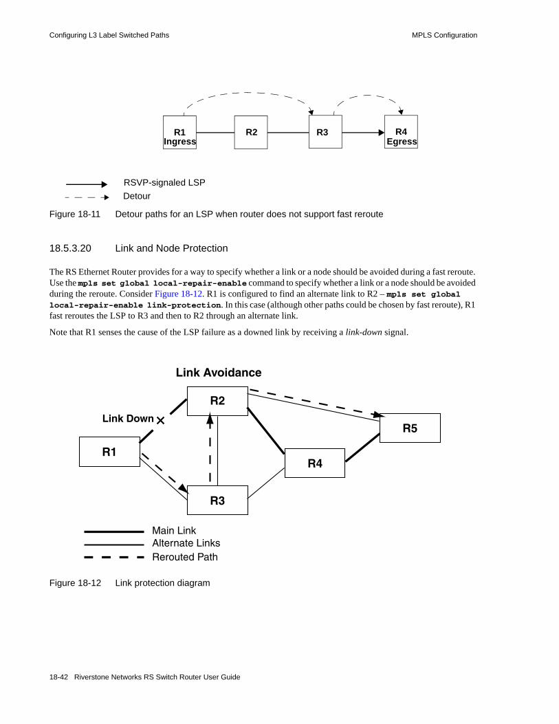
Configuring L3 Label Switched Paths MPLS Configuration
Figure 18-11 Detour paths for an LSP when router does not support fast reroute
18.5.3.20 Link and Node Protection
The RS Ethernet Router provides for a way to specify whether a link or a node should be avoided during a fast reroute. Use the mpls set global local-repair-enable command to specify whether a link or a node should be avoided during the reroute. Consider Figure 18-12. R1 is configured to find an alternate link to R2 – mpls set global local-repair-enable link-protection. In this case (although other paths could be chosen by fast reroute), R1 fast reroutes the LSP to R3 and then to R2 through an alternate link.
Note that R1 senses the cause of the LSP failure as a downed link by receiving a link-down signal.
Figure 18-12 Link protection diagram
R1 R2 R3 R4EgressIngress
RSVP-signaled LSPDetour
Link Down
R2
R1
R3
R4
R5
Link Avoidance
Main LinkAlternate LinksRerouted Path
18-42 Riverstone Networks RS Switch Router User Guide

MPLS Configuration Configuring L3 Label Switched Paths
Fast reroute can be set to protect against the failure of the LSP because of a down node. Use the mpls set global local-repair-enable command, specifying the node-protection option. Doing so, instructs fast reroute to bypass the downed node (see Figure 18-13). Actually, the option node-protection enables both node and link protection at the same time. However, notice the difference in the LSP fast reroute paths shown in Figure 18-12 and Figure 18-13. When node-protection is enabled, the fast reroute path bypasses R2 to complete the LSP.
In Figure 18-13 R1 learns that R2 is down by the elapsing of the hello-packet timer.
Figure 18-13 Node protection diagram
In addition to either link or node protection, a dynamic choice capability can be implemented by specifying the option node-prefer-protection. This option invokes the following behavior: “All detour LSPs starting from this router will use link protection, but if there is a node protection path available, that path is used.”
18.5.3.21 Enabling Fast Reroute
To enable fast reroute on an LSP, specify the fast-reroute parameter with the mpls set label-switched-path command on the ingress LSR. You can optionally configure the following constraints for the detour path(s):• detour-setup-pri and detour-hold-pri set the priority of the detour in taking and holding
resources.• detour-hop-limit is the maximum number of extra hops the detour is allowed to take from the
current node to the downstream merging node. A hop limit of 0 means that only direct links between the current and merging nodes can be considered.
• detour-bps is the allocated bandwidth for the detour. No bandwidth is allocated for the detour. • detour-exclude and detour-include are the administrative groups that are to be excluded or
included for the detour.
R3
R4
R5
Switch Down
Node Avoidance
Main LinkAlternate LinkRerouted Path
R1
Riverstone Networks RS Switch Router User Guide 18-43

Configuring L3 Label Switched Paths MPLS Configuration
Note Detour paths must be within the same OSPF area or the same IS-IS level.
In order for an RS Ethernet Router MPLS LSR to act as a detour-node the command mpls set global point-of-local-repair-enable is required in the detour-node’s configuration. By default, an RS Ethernet Router MPLS LSR along the main path will not attempt to establish a detour path. Only possible detour nodes need to be configured with the mpls set global point-of-local-repair-enable command. The MPLS LSRs on the detour path and the merge node will react automatically to detour messaging. The ingress router, edge of the MPLS cloud, just requires fast reroute to be enabled on the LSP.
18.5.3.22 Dynamic L3 LSP Configuration Example
Figure 18-14 shows a network where RS Ethernet Router router R5 is the ingress router for a dynamic LSP to the egress router R7. The LSP configuration consists of two different path designations: the primary path is an explicit path from R5 to R7, while the secondary path is an explicit path that follows specific hops from R5 to R6 and then to R7. The secondary path also operates in standby mode. Both paths are configured to be adaptive; that is, during route recalculation, the LSP waits until the new optimized route is set up before tearing down the previous LSP. In this example, RSVP is the signaling protocol used (LDP can also be used, as traffic engineering is not being utilized).
Additionally, a dynamic LSP will be configured from RS Ethernet Router router R5 to the router JN1 and another from R6 to R7. These LSPs are also configured to be adaptive.
OSPF is the routing protocol that is used on all RS Ethernet Router routers.
Timesaver Click on the router name (in blue) to see the corresponding configuration.
Figure 18-14 Dynamic L3 LSP paths
JN1 R5
R6
R7
secondary path
primary path
20.1.1.1/16
31.1.1.1/16
LSPs:L1
L2L3
100.1.1.1
30.1.1.1/16
33.1.1.1/16
99.1.1.1/1
18-44 Riverstone Networks RS Switch Router User Guide

MPLS Configuration Configuring L3 Label Switched Paths
The following is the configuration for router R5:
! Create interfacesinterface create ip 30net address-netmask 30.1.1.1/16 port et.1.2
interface create ip 33net address-netmask 33.1.1.1/16 port et.1.5
interface create ip 20net address-netmask 20.1.1.1/16 port et.5.1
interface add ip lo0 address-netmask 98.1.1.1/16
! Configure routerip-router global set autonomous-system 64977ip-router global set router-id 98.1.1.1
! Configure OSPFospf create area backboneospf add interface all to-area backboneospf start
! Enable MPLS on all interfacesmpls add interface all
! Create explicit path 57 (primary path to 100.1.1.1)mpls create path 57
! Create explicit path 567 with 3 hops (secondary path to 100.1.1.1)mpls create path 567 num-hops 3mpls set path 567 hop-num 1 ip-addr 30.1.1.1mpls set path 567 hop-num 2 ip-addr 30.1.1.2mpls set path 567 hop-num 3 ip-addr 31.1.1.2
! Create dynamic LSP L1 to egress router 100.1.1.1 w/ primary, secondary pathsmpls create label-switched-path L1 to 100.1.1.1 no-cspfmpls set label-switched-path L1 primary 57 adaptivempls set label-switched-path L1 secondary 567 adaptive standby
! Create dynamic LSP L2 to egress router 20.1.1.2mpls create label-switched-path L2 to 20.1.1.2 adaptive no-cspf
! Start MPLS on router R5mpls start
! Configure RSVPrsvp add interface allrsvp start
Riverstone Networks RS Switch Router User Guide 18-45

Configuring L3 Label Switched Paths MPLS Configuration
The following is the configuration for router R6:
The following is the configuration for router R7:
! Create interfacesinterface create ip 30net address-netmask 30.1.1.2/16 port et.1.2
interface create ip 31net address-netmask 31.1.1.1/16 port et.1.3
interface create ip 99net address-netmask 99.1.1.1/16 port et.1.1
! Configure routerip-router global set router-id 99.1.1.1
! Configure OSPFospf create area backboneospf add interface all to-area backboneospf start
! Enable MPLS on all interfacesmpls add interface all
! Create dynamic LSP L3 to egress router 100.1.1.1mpls create label-switched-path L3 to 100.1.1.1 adaptive no-cspf
! Start MPLS on router R6mpls start
! Configure RSVPrsvp add interface allrsvp start
! Create interfacesinterface create ip 33net address-netmask 33.1.1.2/16 port et.1.5
interface create ip 31net address-netmask 31.1.1.2/16 port et.1.3
interface create ip 100net address-netmask 100.1.1.1/16 port et.1.1
! Configure router ip-router global set router-id 100.1.1.1
! Configure OSPFospf create area backboneospf add interface all to-area backboneospf start
! Start MPLS on router R7mpls start
! Configure RSVPrsvp add interface allrsvp start
18-46 Riverstone Networks RS Switch Router User Guide

MPLS Configuration Configuring L3 Label Switched Paths
18.5.3.23 Dynamic and Static L3 LSP Configuration Example
In Figure 18-15, R1 is the ingress LSR for both a dynamic LSP and a static LSP. The dynamic LSP has a primary path and one secondary path. Only traffic to the 150.10.0.0/16 network is forwarded on the dynamic LSP, while only traffic to the 160.10.0.0/16 network is forwarded on the static LSP; traffic filtering is performed by defining and applying different policies to the LSPs.
Timesaver Click on the router name (in blue) to see the corresponding configuration.
Figure 18-15 Static and dynamic L3 LSP example
In this example, RSVP is the signaling protocol used (LDP can also be used, as traffic engineering is not being utilized). OSPF is the routing protocol that is used on all RS Ethernet Router routers.
150.10.1.1
160.10.1.1
R1
Dynamic (primary)Static LSP
Dynamic (secondary)
(loose)
R3
R4 R5
R2Traffic R1
Riverstone Networks RS Switch Router User Guide 18-47

Configuring L3 Label Switched Paths MPLS Configuration
R1 has the following configuration:
! Configure interfacesinterface create ip R1R4 address-netmask 200.135.89.73/26 port gi.2.1
interface create ip R1R2 address-netmask 200.135.89.4/28 port gi.2.2
interface add ip lo0 address-netmask 1.1.1.1/16
mpls add interface allrsvp add interface all
! Configure OSPFip-router global set router-id 1.1.1.1
ospf create area backbone
ospf add interface R1R4 to-area backbone
ospf add stub-host 1.1.1.1 to-area backbone cost 10
ospf add interface R1R2 to-area backbone
ospf start
! Create policiesmpls create policy p1 dst-ipaddr-mask 150.10.0.0/16
mpls create policy p2 dst-ipaddr-mask 160.10.0.0/16
! Create dynamic LSP:! Create primary path dp1mpls create path dp1 num-hops 4
mpls set path dp1 hop 1 ip-addr 200.135.89.73 type strict
mpls set path dp1 hop 2 ip-addr 201.135.89.76 type strict
mpls set path dp1 hop 3 ip-addr 201.135.89.130 type strict
mpls set path dp1 hop 4 ip-addr 201.135.89.197 type strict
! Create secondary path dp2l (loose)mpls create path dp2l num-hops 2
mpls set path dp2l hop 1 ip-addr 200.135.89.4 type loose
mpls set path dp2l hop 2 ip-addr 16.128.11.7 type loose
! Configure dynamic LSP d1mpls create label-switched-path d1 to 3.3.3.3 no-cspf
mpls set label-switched-path d1 policy p1
mpls set label-switched-path d1 primary dp1 standby no-cspf
mpls set label-switched-path d1 secondary dp2l no-cspf adaptive standby
! Create static LSP s1mpls create static-path s1 push 70,60,50 gateway 200.135.89.76 to 3.3.3.3
mpls set static-path s1 policy p2
! Start MPLS and RSVPmpls start
rsvp start
18-48 Riverstone Networks RS Switch Router User Guide
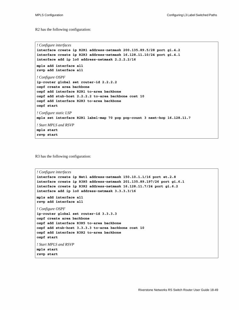
MPLS Configuration Configuring L3 Label Switched Paths
R2 has the following configuration:
R3 has the following configuration:
! Configure interfacesinterface create ip R2R1 address-netmask 200.135.89.5/28 port gi.4.2
interface create ip R2R3 address-netmask 16.128.11.10/24 port gi.4.1
interface add ip lo0 address-netmask 2.2.2.2/16
mpls add interface allrsvp add interface all
! Configure OSPFip-router global set router-id 2.2.2.2
ospf create area backbone
ospf add interface R2R1 to-area backbone
ospf add stub-host 2.2.2.2 to-area backbone cost 10
ospf add interface R2R3 to-area backbone
ospf start
! Configure static LSPmpls set interface R2R1 label-map 70 pop pop-count 3 next-hop 16.128.11.7
! Start MPLS and RSVPmpls start
rsvp start
! Configure interfacesinterface create ip Net1 address-netmask 150.10.1.1/16 port et.2.8
interface create ip R3R5 address-netmask 201.135.89.197/26 port gi.6.1
interface create ip R3R2 address-netmask 16.128.11.7/24 port gi.6.2
interface add ip lo0 address-netmask 3.3.3.3/16
mpls add interface allrsvp add interface all
! Configure OSPFip-router global set router-id 3.3.3.3
ospf create area backbone
ospf add interface R3R5 to-area backbone
ospf add stub-host 3.3.3.3 to-area backbone cost 10
ospf add interface R3R2 to-area backbone
ospf start
! Start MPLS and RSVPmpls start
rsvp start
Riverstone Networks RS Switch Router User Guide 18-49
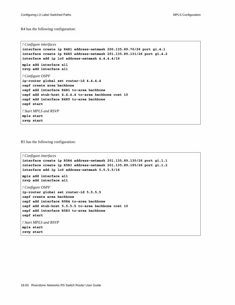
Configuring L3 Label Switched Paths MPLS Configuration
R4 has the following configuration:
R5 has the following configuration:
! Configure interfacesinterface create ip R4R1 address-netmask 200.135.89.76/26 port gi.4.1
interface create ip R4R5 address-netmask 201.135.89.131/26 port gi.4.2
interface add ip lo0 address-netmask 4.4.4.4/16
mpls add interface allrsvp add interface all
! Configure OSPFip-router global set router-id 4.4.4.4
ospf create area backbone
ospf add interface R4R1 to-area backbone
ospf add stub-host 4.4.4.4 to-area backbone cost 10
ospf add interface R4R5 to-area backbone
ospf start
! Start MPLS and RSVPmpls start
rsvp start
! Configure interfacesinterface create ip R5R4 address-netmask 201.135.89.130/26 port gi.1.1
interface create ip R5R3 address-netmask 201.135.89.195/26 port gi.1.2
interface add ip lo0 address-netmask 5.5.5.5/16
mpls add interface allrsvp add interface all
! Configure OSPFip-router global set router-id 5.5.5.5
ospf create area backbone
ospf add interface R5R4 to-area backbone
ospf add stub-host 5.5.5.5 to-area backbone cost 10
ospf add interface R5R3 to-area backbone
ospf start
! Start MPLS and RSVPmpls start
rsvp start
18-50 Riverstone Networks RS Switch Router User Guide
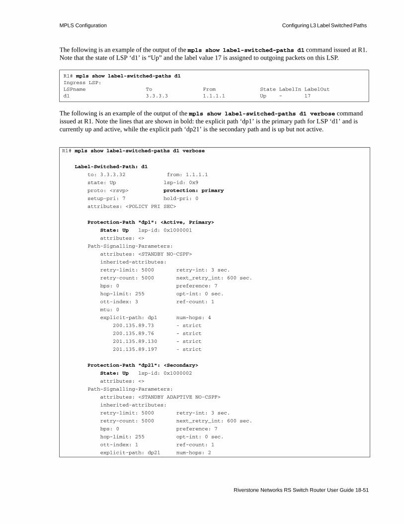
MPLS Configuration Configuring L3 Label Switched Paths
The following is an example of the output of the mpls show label-switched-paths d1 command issued at R1. Note that the state of LSP ‘d1’ is “Up” and the label value 17 is assigned to outgoing packets on this LSP.
The following is an example of the output of the mpls show label-switched-paths d1 verbose command issued at R1. Note the lines that are shown in bold: the explicit path ‘dp1’ is the primary path for LSP ‘d1’ and is currently up and active, while the explicit path ‘dp21’ is the secondary path and is up but not active.
R1# mpls show label-switched-paths d1Ingress LSP:LSPname To From State LabelIn LabelOutd1 3.3.3.3 1.1.1.1 Up - 17
R1# mpls show label-switched-paths d1 verbose
Label-Switched-Path: d1
to: 3.3.3.32 from: 1.1.1.1
state: Up lsp-id: 0x9
proto: <rsvp> protection: primary
setup-pri: 7 hold-pri: 0
attributes: <POLICY PRI SEC>
Protection-Path "dp1": <Active, Primary>
State: Up lsp-id: 0x1000001
attributes: <>
Path-Signalling-Parameters:
attributes: <STANDBY NO-CSPF>
inherited-attributes:
retry-limit: 5000 retry-int: 3 sec.
retry-count: 5000 next_retry_int: 600 sec.
bps: 0 preference: 7
hop-limit: 255 opt-int: 0 sec.
ott-index: 3 ref-count: 1
mtu: 0
explicit-path: dp1 num-hops: 4
200.135.89.73 - strict
200.135.89.76 - strict
201.135.89.130 - strict
201.135.89.197 - strict
Protection-Path "dp2l": <Secondary>
State: Up lsp-id: 0x1000002
attributes: <>
Path-Signalling-Parameters:
attributes: <STANDBY ADAPTIVE NO-CSPF>
inherited-attributes:
retry-limit: 5000 retry-int: 3 sec.
retry-count: 5000 next_retry_int: 600 sec.
bps: 0 preference: 7
hop-limit: 255 opt-int: 0 sec.
ott-index: 1 ref-count: 1
explicit-path: dp2l num-hops: 2
Riverstone Networks RS Switch Router User Guide 18-51

Configuring L3 Label Switched Paths MPLS Configuration
If the link between R1 and R4 becomes unavailable, the configured primary path for the dynamic LSP cannot be used. The configured secondary path is then used for the LSP. A message like the following is displayed:
The secondary path ‘dp2l’ is now used for the LSP, as shown by the mpls show label-switched-paths d1 verbose command at R1. Note that the explicit path ‘dp1,’ the configured primary path, is now down and the configured secondary path ‘dp2l’ is now both up and active.
200.135.89.4 - loose
16.128.11.7 - loose
2001-04-06 16:13:24 %MPLS-I-LSPPATHSWITCH, LSP "d1" switching to Secondary Path "dp2l".
R1# mpls show label-switched-paths d1 verbose
Label-Switched-Path: d1
to: 3.3.3.3 from: 1.1.1.1
state: Up lsp-id: 0x9
proto: <rsvp> protection: secondary
setup-pri: 7 hold-pri: 0
attributes: <POLICY PRI SEC>
Protection-Path "dp1": <Primary>
State: Down lsp-id: 0x1000001
attributes: <>
Path-Signalling-Parameters:
attributes: <STANDBY RETRYING NO-CSPF>
inherited-attributes: <>
retry-limit: 5000 retry-int: 3 sec.
retry-count: 5000 next_retry_int: 600 sec.
bps: 0 preference: 7
hop-limit: 255 opt-int: 0 sec.
ott-index: ref-count: 1
mtu: 0
explicit-path: dp1 num-hops: 4
hop: 200.135.89.73 - strict
hop: 200.135.89.76 - strict
hop: 201.135.89.130 - strict
hop: 201.135.89.197 - strict
Protection-Path "dp2l": <Active, Secondary>
State: Up lsp-id: 0x1000002
attributes: <>
Path-Signalling-Parameters:
attributes: <STANDBY ADAPTIVE NO-CSPF>
inherited-attributes:
retry-limit: 5000 retry-int: 3 sec.
retry-count: 5000 next_retry_int: 600 sec.
bps: 20000000 preference: 7
18-52 Riverstone Networks RS Switch Router User Guide

MPLS Configuration Configuring L3 Label Switched Paths
hop-limit: 255 opt-int: 0 sec.
ott-index: 1 ref-count: 1
explicit-path: dp2l num-hops: 2
200.135.89.4 - loose
16.128.11.7 - loose
Riverstone Networks RS Switch Router User Guide 18-53
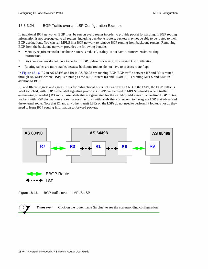
Configuring L3 Label Switched Paths MPLS Configuration
18.5.3.24 BGP Traffic over an LSP Configuration Example
In traditional BGP networks, BGP must be run on every router in order to provide packet forwarding. If BGP routing information is not propagated to all routers, including backbone routers, packets may not be able to be routed to their BGP destinations. You can run MPLS in a BGP network to remove BGP routing from backbone routers. Removing BGP from the backbone network provides the following benefits:• Memory requirements for backbone routers is reduced, as they do not have to store extensive routing
information• Backbone routers do not have to perform BGP update processing, thus saving CPU utilization• Routing tables are more stable, because backbone routers do not have to process route flaps
In Figure 18-16, R7 in AS 63498 and R9 in AS 65498 are running BGP. BGP traffic between R7 and R9 is routed through AS 64498 where OSPF is running as the IGP. Routers R3 and R6 are LSRs running MPLS and LDP, in addition to BGP.
R3 and R6 are ingress and egress LSRs for bidirectional LSPs. R1 is a transit LSR. On the LSPs, the BGP traffic is label switched, with LDP as the label signaling protocol. (RSVP can be used in MPLS networks where traffic engineering is needed.) R3 and R6 use labels that are generated for the next-hop addresses of advertised BGP routes. Packets with BGP destinations are sent across the LSPs with labels that correspond to the egress LSR that advertised the external route. Note that R1 and any other transit LSRs on the LSPs do not need to perform IP lookups nor do they need to learn BGP routing information to forward packets.
Figure 18-16 BGP traffic over an MPLS LSP
Timesaver Click on the router name (in blue) to see the corresponding configuration.
R9R6
AS 64498 AS 65498AS 63498
R7 R3 R1
EBGP Route
LSP
18-54 Riverstone Networks RS Switch Router User Guide

MPLS Configuration Configuring L3 Label Switched Paths
Note By default, routes are automatically advertised between EBGP peers. However, routes are not automatically advertised between IBGP multi-hop peers. Therefore, in the example configuration, you need to configure routes from AS63498 and AS 65498 to be redistributed to the IBGP peers in AS 64498.
The following is the configuration for R7:
R3 is the both the ingress LSR for the LSP to R6 and the egress LSR for the LSP from R6. The following is the configuration for R3:
! Configure interfacesinterface create ip rt7-rt3 address-netmask 137.1.1.7/24 port et.1.1interface create ip rt7-rt3.mp address-netmask 137.2.2.7/24 port et.2.7interface add ip lo0 address-netmask 7.7.7.7/32
! Configure BGPip-router global set router-id 7.7.7.7ip-router global set autonomous-system 63498ip add route default gateway 137.2.2.3ip-router policy redistribute from-proto direct to-proto bgp target-as 64498bgp create peer-group to-rt3 type external autonomous-system 64498bgp add peer-host 137.2.2.3 group to-rt3bgp start
! Configure interfacesinterface create ip rt3-rt7.mp address-netmask 137.2.2.3/24 port et.7.8interface create ip rt3-rt1.mp address-netmask 113.2.2.3/24 port gi.3.1interface add ip lo0 address-netmask 3.3.3.3/32
! Configure BGPip-router global set router-id 3.3.3.3ip-router global set autonomous-system 64498ip-router policy redistribute from-proto bgp source-as 63498 to-proto bgp target-as 64498ip-router policy redistribute from-proto direct to-proto bgp target-as 64498bgp create peer-group to-rt6 type routing autonomous-system 64498bgp create peer-group to-rt7 type external autonomous-system 63498bgp add peer-host 6.6.6.6 group to-rt6bgp add peer-host 137.2.2.7 group to-rt7bgp set peer-group to-rt6 local-address 3.3.3.3 bgp set peer-group to-rt6 next-hop-self Sets R3’s address as next-hop in BGP route advertisementsbgp start
! Configure OSPFospf create area backboneospf add stub-host 3.3.3.3 to-area backbone cost 10ospf add interface rt3-rt1.mp to-area backboneospf start
! Enable and start MPLS and LDP on interface to R1mpls add interface rt3-rt1.mpmpls startldp add interface rt3-rt1.mpldp start
Riverstone Networks RS Switch Router User Guide 18-55

Configuring L3 Label Switched Paths MPLS Configuration
R1 is the transit LSR for the LSPs from R3 to R6 and from R6 to R3. The following is the configuration for R1:
R6 is the both the ingress LSR for the LSP to R3 and the egress LSR for the LSP from R3.The following is the configuration for R6:
! Configure interfacesinterface create ip rt1-rt3.mp address-netmask 113.2.2.1/24 port gi.3.2interface create ip rt1-rt6.mp2 address-netmask 116.3.3.1/24 port gi.3.1interface add ip lo0 address-netmask 1.1.1.1/32
! Configure OSPFip-router global set router-id 1.1.1.1ospf create area backboneospf add stub-host 1.1.1.1 to-area backbone cost 10ospf add interface rt1-rt3.mp to-area backboneospf add interface rt1-rt6.mp2 to-area backboneospf start
! Enable and start MPLS and LDP on interfaces to R3 and R6mpls add interface rt1-rt6.mp2mpls add interface rt1-rt3.mpmpls startldp add interface rt1-rt3.mpldp add interface rt1-rt6.mp2ldp start
! Configure interfacesinterface create ip rt6-rt9 address-netmask 169.1.1.6/24 port et.7.2interface create ip rt6-rt1.mp2 address-netmask 116.3.3.6/24 port gi.4.2
! Configure BGPinterface add ip lo0 address-netmask 6.6.6.6/32ip-router global set router-id 6.6.6.6ip-router global set autonomous-system 64498ip-router policy redistribute from-proto bgp source-as 65498 to-proto bgp target-as 64498ip-router policy redistribute from-proto direct to-proto bgp target-as 64498bgp create peer-group bgp-to-rt9 type external autonomous-system 65498bgp create peer-group to-rt3 type routing autonomous-system 64498bgp add peer-host 169.1.1.9 group bgp-to-rt9bgp add peer-host 3.3.3.3 group to-rt3bgp set peer-group to-rt3 local-address 6.6.6.6 bgp set peer-group to-rt3 next-hop-self Sets R6’s address as next-hop in BGP route advertisementsbgp start
! Configure OSPFospf create area backboneospf add stub-host 6.6.6.6 to-area backbone cost 10ospf add interface rt6-rt1.mp2 to-area backboneospf start
! Enable and start MPLS and LDP on the interface to R1mpls add interface rt6-rt1.mp2mpls startldp add interface rt6-rt1.mp2ldp start
18-56 Riverstone Networks RS Switch Router User Guide

MPLS Configuration Configuring L3 Label Switched Paths
The following is the configuration for R9:
! Configure interfacesinterface create ip rt9-rt6 address-netmask 169.1.1.9/24 port et.1.1interface create ip rt9-32 address-netmask 92.1.1.9/24 port et.3.2interface create ip rt9-33 address-netmask 93.1.1.9/24 port et.3.3interface create ip rt9-34 address-netmask 94.1.1.9/24 port et.3.4interface create ip rt9-35 address-netmask 95.1.1.9/24 port et.3.5interface create ip rt9-36 address-netmask 96.1.1.9/24 port et.3.6interface create ip rt9-37 address-netmask 97.1.1.9/24 port et.3.7interface create ip rt9-38 address-netmask 98.1.1.9/24 port et.3.8interface add ip lo0 address-netmask 9.9.9.9/32
! Configure BGPip-router global set router-id 9.9.9.9ip-router global set autonomous-system 65498ip add route default gateway 169.1.1.6ip-router policy redistribute from-proto direct to-proto bgp target-as 64498bgp create peer-group bgp-to-nil6 type external autonomous-system 64498bgp add peer-host 169.1.1.6 group bgp-to-nil6bgp start
Riverstone Networks RS Switch Router User Guide 18-57

Configuring L2 Tunnels MPLS Configuration
18.6 CONFIGURING L2 TUNNELSRiverstone’s layer-2 (L2) MPLS implementation supports the encapsulation and transport of L2 Protocol Data Units (PDUs) across an MPLS network, by using Transparent LAN Services (TLS) tunnels. These features allow you to use MPLS labels, instead of network layer encapsulation, to tunnel L2 frames across a backbone MPLS network. For metro service providers, this has many important benefits:• Scalability of 802.1q and IP VPN services. With 802.1q VLANs, the total number of VLANs in the
entire network is limited to 4,096. With IP VPNs, layer-2 tunnel protocol (L2TP) tunnels that carry traffic across the MPLS network must be manually configured with a pair of IP addresses assigned to each tunnel. With MPLS, packets to be sent through the L2 tunnel can be considered as a single FEC. Transit LSRs only need to look at the top label to switch the labeled packet across the MPLS network.
• L2 tunnels across backbone networks can be added as virtual interfaces to VLANs, allowing transparent bridging across the backbone. Customer network information, such as MAC addresses and VLAN IDs, is not exposed to the backbone network since only the outer MPLS label is examined by each router in the tunnel.
• Many end-to-end customer-specific or VLAN-specific virtual circuits can be bundled into a small number of L2 tunnels that run through the backbone. Traffic on each virtual circuit is isolated from each other, with the same level of security as a frame relay or ATM virtual circuit.
The RS Ethernet Router supports two methods of transporting L2 VPN frames over MPLS:• Point-to-point LSPs for Virtual Leased Line (VLL) services. (See Section 18.6.2, "Configuring
Point-to-Point L2 LSPs.")• Point-to-multipoint LSPs for Transparent LAN services (TLS). TLS allows transport of Ethernet and
VLAN traffic for multiple sites that belong to the same L2 broadcast domain. (See Section 18.6.3, "Configuring Point-to-Multipoint L2 LSPs (TLS).")
The RS Ethernet Router supports two basic types of virtual circuit labels:• Static labels require that you configure all routers and all labels in the path. MPLS must be enabled.
No signaling protocol is used, so you do not need to enable RSVP or LDP. • Dynamic labels use LDP signaling on the ingress and egress LSRs to specify the FEC-to-label
mapping for the virtual circuit. You can use either RSVP or LDP signaling within the tunnel LSP.
Note The RS Ethernet Router supports the transport of Ethernet frames only with MPLS labels.
18-58 Riverstone Networks RS Switch Router User Guide

MPLS Configuration Configuring L2 Tunnels
18.6.1 Configuring Dynamic L2 Labels
In Figure 18-17, layer-2 frames are received at the ingress LSR R1, then transmitted to the egress LSR R2 across an MPLS network through a tunnel LSP. At the ingress LSR, a virtual circuit (VC) label is added to the L2 frame. The VC label is used to inform the egress LSR how to treat the received packet and the interface on which the frame is to be output. When R1 sends the L2 frame to R2, a tunnel label is pushed onto the MPLS label stack. As the packet traverses through the MPLS network, additional labels can be pushed onto and popped off the label stack. A number of L2 VCs can be carried in this way across a single tunnel LSP.
Note that the process of transporting L2 frames across an MPLS network is unidirectional; you will need to repeat the configuration in the reverse direction to provide bidirectional operation. You must configure the same VC identifiers (for example, VLAN IDs) for each direction of a virtual circuit.
Figure 18-17 Transport of layer 2 frames across an MPLS network
18.6.1.1 Virtual Circuit Signaling
For dynamic label assignments, the VC label is distributed using LDP in downstream unsolicited mode. A remote LDP connection must be established between the ingress and egress LSRs. You configure VLANs to carry the signaling necessary to establish the LDP connection. In this section, these VLANs are referred to as LDP-signaling VLANs.
18.6.1.2 Tunnel LSP Signaling
Either RSVP or LDP can be used to assign and distribute the tunnel labels used within the tunnel LSP. If you use RSVP for signaling in the tunnel LSP, you need to configure LSPs with the mpls create and/or mpls set commands. If you use LDP for signaling in the tunnel LSP, you do not need to configure LSPs with the mpls commands; however, you need to enable and start MPLS on tunnel LSRs.
R1 R2Tunnel LSP (RSVP or LDP)
Virtual Circuit VC label
Tunnel label
(LDP signaling over VLAN)
Layer 2 Frame Layer 2 Frame
Riverstone Networks RS Switch Router User Guide 18-59

Configuring L2 Tunnels MPLS Configuration
Note The maximum transmission unit (MTU) size for MPLS ports must be at least 22 bytes more than the MTU size of incoming non-MPLS traffic; additional bytes are required for multiple labels. The default MTU size for non-MPLS ports on the RS Ethernet Router is 1522 bytes. The default MTU size for ports on MPLS-enabled line cards on the RS Ethernet Router is 1568 bytes, which allows for multiple MPLS labels). The maximum MTU size for MPLS ports is 1600 bytes.
The MPLS network must be configured with an MTU that is large enough to transport the maximum size frame that will be transported in the tunnel LSP (this can be at least 12 bytes more than the largest frame size). If an MPLS packet exceeds the tunnel MTU, it will be dropped. If an egress LSR receives a packet that exceeds the MTU of the destination L2 interface, the packet will be dropped.
18.6.2 Configuring Point-to-Point L2 LSPs
18.6.2.1 FEC-Label Bindings
On the RS Ethernet Router, the following can be used to identify the FEC-to-label binding for a point-to-point virtual circuit LSP:• VLAN ID assigned to a customer by a service provider• incoming port• incoming port and the customer-specific VLAN ID assigned by the customer
This section includes example configurations for each type of FEC-to-label binding.
18.6.2.2 Ingress and Egress LSR Configuration for Point-to-Point L2 LSPs
On the ingress and egress LSRs, configure the following:1. Configure the L2 FEC.
- If you are using the VLAN ID as the FEC, create the VLAN with the vlan create and vlan add ports commands.
- If you are using the incoming port as the FEC, use the mpls set customer-profile command to map the port to a logical customer ID number.
Note The ports that are mapped to a single customer ID number must be either all trunk ports or all access ports.
A port cannot be mapped to more than one customer ID number.
18-60 Riverstone Networks RS Switch Router User Guide
MPLS Configuration Configuring L2 Tunnels
- If you are using a combination of customer VLAN ID and incoming port as the FEC, create the VLAN with the vlan create and vlan add ports commands and use the mpls set customer-profile command to map the port to a logical customer ID number.
2. Advertise the FEC-to-label mapping via LDP to the remote peers. Enable and start LDP.- Specify the remote LDP peer with the ldp add remote-peer command. Specify the router
ID of the remote LDP peer, which must be one of the loopback addresses of the remote router.- If you are using the VLAN ID as the FEC, specify the vlans option with the mpls set
customer-profile command.- If you are using the incoming port as the FEC, specify the customer-id option with the mpls
set customer-profile command.- If you are using a combination of VLAN ID and incoming port as the FEC, specify both the
vlans and customer-id options with the mpls set customer-profile command.3. Configure the LDP-signaling VLAN and interface. The ports at both ends of a link between two
LSRs must belong to the same VLAN, i.e., the VLAN ID must be the same on both routers.4. Configure the tunnel LSP. If you are using RSVP for signaling in the tunnel LSP, use mpls
commands, as described in Section 18.5, "Configuring L3 Label Switched Paths." If you configure more than one tunnel LSP to the same destination, you can specify the preferred LSP to be used with the transport-lsp option of the ldp set l2-tls command. You can also specify if an alternate LSP can be used. Enable and start MPLS and the signaling protocol (either LDP or RSVP) for the tunnel LSP.
Note The transport-lsp option of the ldp set l2-tls command allows you to assign a specific LSP to specific customer traffic. This provides a way to offer different LSP services to different customers.
5. Configure the IGP routing protocol, either OSPF or IS-IS.
18.6.2.3 Transit LSR Configuration for Point-to-Point L2 LSPs
On the transit LSRs, configure the following:1. Configure the LDP- or RSVP-signaling VLAN and interface. 2. Enable and start MPLS and the signaling protocol (either LDP or RSVP) for the tunnel LSP.3. Configure the IGP routing protocol, either OSPF or IS-IS.
Riverstone Networks RS Switch Router User Guide 18-61
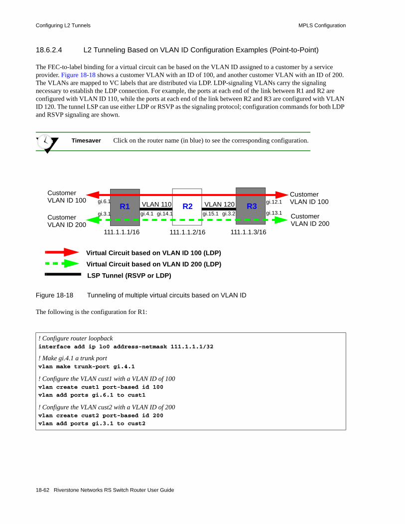
Configuring L2 Tunnels MPLS Configuration
18.6.2.4 L2 Tunneling Based on VLAN ID Configuration Examples (Point-to-Point)
The FEC-to-label binding for a virtual circuit can be based on the VLAN ID assigned to a customer by a service provider. Figure 18-18 shows a customer VLAN with an ID of 100, and another customer VLAN with an ID of 200. The VLANs are mapped to VC labels that are distributed via LDP. LDP-signaling VLANs carry the signaling necessary to establish the LDP connection. For example, the ports at each end of the link between R1 and R2 are configured with VLAN ID 110, while the ports at each end of the link between R2 and R3 are configured with VLAN ID 120. The tunnel LSP can use either LDP or RSVP as the signaling protocol; configuration commands for both LDP and RSVP signaling are shown.
Timesaver Click on the router name (in blue) to see the corresponding configuration.
Figure 18-18 Tunneling of multiple virtual circuits based on VLAN ID
The following is the configuration for R1:
! Configure router loopbackinterface add ip lo0 address-netmask 111.1.1.1/32
! Make gi.4.1 a trunk portvlan make trunk-port gi.4.1
! Configure the VLAN cust1 with a VLAN ID of 100vlan create cust1 port-based id 100
vlan add ports gi.6.1 to cust1
! Configure the VLAN cust2 with a VLAN ID of 200vlan create cust2 port-based id 200
vlan add ports gi.3.1 to cust2
LSP Tunnel (RSVP or LDP)
Customer VLAN ID 100
Customer VLAN ID 100
Virtual Circuit based on VLAN ID 100 (LDP)
R3R1
111.1.1.1/16 111.1.1.3/16
Customer VLAN ID 200
Customer VLAN ID 200
111.1.1.2/16
Virtual Circuit based on VLAN ID 200 (LDP)
R2VLAN 110 VLAN 120gi.6.1
gi.3.1 gi.4.1 gi.14.1 gi.15.1 gi.3.2
gi.12.1
gi.13.1
18-62 Riverstone Networks RS Switch Router User Guide

MPLS Configuration Configuring L2 Tunnels
! Configure the LDP peers and label bindingsldp add interface lo0
ldp add remote-peer 111.1.1.3 adds R3 as LDP peer! Sends label mapping for VLAN ID 100 to R3mpls set customer-profile cust1 vlans 100 type vlan
ldp connect customer-profile cust1 remote-peer 111.1.1.3
! Sends label mapping for VLAN ID 200 to R3mpls set customer-profile cust2 vlans 200 type vlan
ldp connect customer-profile cust2 remote-peer 111.1.1.3
ldp start
! Create the LDP-signaled VLAN and interfacevlan create ldp_in port-based id 110
vlan add ports gi.4.1 to ldp_in
interface create ip to_r2_1 address-netmask 200.1.1.1/16 vlan ldp_in
! If tunnel LSP uses RSVP:mpls add interface to_r2_1
mpls create label-switched-path lsp1 to 111.1.1.3
mpls set label-switched-path lsp1 no-cspf
mpls start
rsvp add interface to_r2_1
rsvp start
! If tunnel LSP uses LDP:mpls add interface to_r2_1
mpls start
ldp add interface to_r2_1
! Configure IGP (in this example, OSPF is the IGP)ip-router global set router-id 111.1.1.1
ospf create area backbone
ospf add stub-host 111.1.1.1 to-area backbone cost 5
ospf add interface to_r2_1 to-area backbone
ospf start
Riverstone Networks RS Switch Router User Guide 18-63
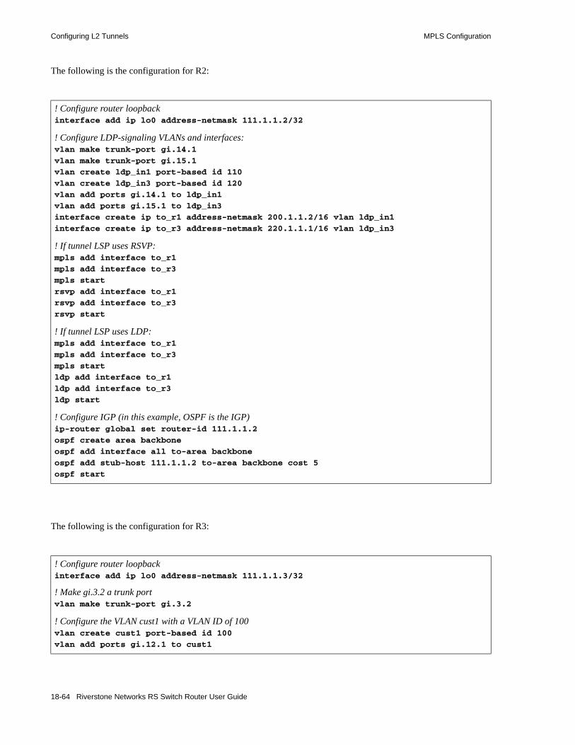
Configuring L2 Tunnels MPLS Configuration
The following is the configuration for R2:
The following is the configuration for R3:
! Configure router loopbackinterface add ip lo0 address-netmask 111.1.1.2/32
! Configure LDP-signaling VLANs and interfaces:vlan make trunk-port gi.14.1
vlan make trunk-port gi.15.1
vlan create ldp_in1 port-based id 110
vlan create ldp_in3 port-based id 120
vlan add ports gi.14.1 to ldp_in1
vlan add ports gi.15.1 to ldp_in3
interface create ip to_r1 address-netmask 200.1.1.2/16 vlan ldp_in1
interface create ip to_r3 address-netmask 220.1.1.1/16 vlan ldp_in3
! If tunnel LSP uses RSVP:mpls add interface to_r1
mpls add interface to_r3
mpls start
rsvp add interface to_r1
rsvp add interface to_r3
rsvp start
! If tunnel LSP uses LDP:mpls add interface to_r1
mpls add interface to_r3
mpls start
ldp add interface to_r1
ldp add interface to_r3
ldp start
! Configure IGP (in this example, OSPF is the IGP)ip-router global set router-id 111.1.1.2
ospf create area backbone
ospf add interface all to-area backbone
ospf add stub-host 111.1.1.2 to-area backbone cost 5
ospf start
! Configure router loopbackinterface add ip lo0 address-netmask 111.1.1.3/32
! Make gi.3.2 a trunk portvlan make trunk-port gi.3.2
! Configure the VLAN cust1 with a VLAN ID of 100vlan create cust1 port-based id 100
vlan add ports gi.12.1 to cust1
18-64 Riverstone Networks RS Switch Router User Guide

MPLS Configuration Configuring L2 Tunnels
! Configure the VLAN cust2 with a VLAN ID of 200vlan create cust2 port-based id 200
vlan add ports gi.13.1 to cust2
! Configure LDP peers and label bindingsldp add interface lo0
ldp add remote-peer 111.1.1.1 adds R1 as LDP peer! Sends label mapping for VLAN ID 100 to R1mpls set customer-profile cust1 vlans 100 type vlan
ldp connect customer-profile cust1 remote-peer 111.1.1.1
! Sends label mapping for VLAN ID 200 to R1mpls set customer-profile cust2 vlans 200 type vlan
ldp connect customer-profile cust2 remote-peer 111.1.1.1
ldp start
! Create the LDP-signaling VLAN and interfacevlan create ldp_in1 port-based id 120
vlan add ports gi.3.2 to ldp_in1
interface create ip to_r2 address-netmask 220.1.1.2/16 vlan ldp_in1
! If tunnel LSP uses RSVP:mpls add interface to_r2
mpls start
rsvp add interface to_r2
rsvp start
! If tunnel LSP uses LDP:mpls add interface to_r2
mpls start
ldp add interface to_r2
ldp start
! Configure IGP (in this example, OSPF is the IGP)ip-router global set router-id 111.1.1.3
ospf create area backbone
ospf add interface to_r2 to-area backbone
ospf add stub-host 111.1.1.3 to-area backbone cost 5
ospf start
Riverstone Networks RS Switch Router User Guide 18-65

Configuring L2 Tunnels MPLS Configuration
Figure 18-19 shows two VLANs, with sites that are connected to routers R1, R3, and R5. The VLANs are mapped to VC labels that are distributed via LDP. The tunnel LSPs can use either LDP or RSVP as the signaling protocol; configuration commands for RSVP tunnel signaling are shown for this example.
Timesaver Click on the router name (in blue) to see the corresponding configuration.
Figure 18-19 Tunneling of virtual circuits based on VLAN ID (RSVP tunnel)
Two LSPs are configured on R1. The LSP from R1 to R5 is configured with a strict explicit path of 3 hops (R1, R6, R5) and is restricted to traffic destined for the 152.1.0.0/16 subnet. The LSP from R1 to R3 is configured with a loose explicit path of 2 hops.
Tunnel LSPs
Virtual Circuit based on VLAN ID
R3R1 R2
R6
R4
Customer VLAN 100
Customer VLAN 200
Customer VLAN 100
Customer VLAN 200
Customer VLAN 100Customer VLAN 200
gi.4.1 gi.14.1 gi.14.2 gi.12.2
gi.12.1
gi.3.1
gi.3.2
gi.13.1
gi.7.2gi.13.2
gi.4.1gi.5.1
gi.4.2
gi.4.2
R5
18-66 Riverstone Networks RS Switch Router User Guide

MPLS Configuration Configuring L2 Tunnels
Note If you configure more than one tunnel LSP to the same destination, you can specify the preferred LSP to be used with the transport-lsp option of the ldp set l2-tls command. You can also specify if an alternate LSP can be used. The transport-lsp option of the ldp set l2-tls command allows you to assign a specific LSP to specific customer traffic. This provides a way to offer different LSP services to different customers.
The following is the configuration for R1:
! Configure VLANs and interfacesvlan create cust1 port-based id 100
vlan create cust2 port-based id 200
vlan create ldp_in port-based id 110
vlan create ldp_in2 port-based id 120
vlan add ports gi.4.2 to ldp_in2
vlan add ports gi.4.1 to ldp_in
vlan add ports gi.6.1,gi.2.2 to cust1
vlan add ports gi.3.1 to cust2
interface create ip to_rs2 address-netmask 200.1.1.1/16 vlan ldp_in LDP-signaling VLAN to R2interface create ip to_rs6 address-netmask 201.1.1.1/16 vlan ldp_in2 LDP-signaling VLAN to R6interface create ip ip_32 address-netmask 124.2.1.1/16 port gi.3.2
interface add ip lo0 address-netmask 111.1.1.1/32
! Configure OSPFip-router global set router-id 111.1.1.1
ospf create area backbone
ospf add stub-host 111.1.1.1 to-area backbone cost 5
ospf add interface to_rs2 to-area backbone
ospf add interface to_rs6 to-area backbone
ospf start
! Configure MPLSmpls add interface to_rs2
mpls add interface to_rs6
! Configure explicit path p1 to R3mpls create path p1 num-hops 2
mpls set path p1 ip-addr 200.1.1.1 type loose hop 1
mpls set path p1 ip-addr 210.1.1.2 type loose hop 2
! Configure explicit path to R5mpls create path to_rs5_primary num-hops 3
mpls set path to_rs5_primary ip-addr 201.1.1.1 type strict hop 1
mpls set path to_rs5_primary ip-addr 201.1.1.2 type strict hop 2
mpls set path to_rs5_primary ip-addr 220.1.1.2 type strict hop 3
! Configure tunnel LSP to R3 with explicit path p1
Riverstone Networks RS Switch Router User Guide 18-67
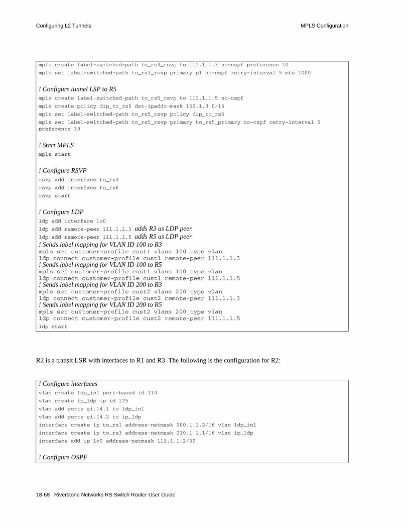
Configuring L2 Tunnels MPLS Configuration
R2 is a transit LSR with interfaces to R1 and R3. The following is the configuration for R2:
mpls create label-switched-path to_rs3_rsvp to 111.1.1.3 no-cspf preference 10
mpls set label-switched-path to_rs3_rsvp primary p1 no-cspf retry-interval 5 mtu 1000
! Configure tunnel LSP to R5mpls create label-switched-path to_rs5_rsvp to 111.1.1.5 no-cspf
mpls create policy dip_to_rs5 dst-ipaddr-mask 152.1.0.0/16
mpls set label-switched-path to_rs5_rsvp policy dip_to_rs5
mpls set label-switched-path to_rs5_rsvp primary to_rs5_primary no-cspf retry-interval 5 preference 30
! Start MPLSmpls start
! Configure RSVPrsvp add interface to_rs2
rsvp add interface to_rs6
rsvp start
! Configure LDPldp add interface lo0
ldp add remote-peer 111.1.1.3 adds R3 as LDP peerldp add remote-peer 111.1.1.5 adds R5 as LDP peer! Sends label mapping for VLAN ID 100 to R3mpls set customer-profile cust1 vlans 100 type vlan ldp connect customer-profile cust1 remote-peer 111.1.1.3! Sends label mapping for VLAN ID 100 to R5mpls set customer-profile cust1 vlans 100 type vlan ldp connect customer-profile cust1 remote-peer 111.1.1.5! Sends label mapping for VLAN ID 200 to R3mpls set customer-profile cust2 vlans 200 type vlan ldp connect customer-profile cust2 remote-peer 111.1.1.3! Sends label mapping for VLAN ID 200 to R5mpls set customer-profile cust2 vlans 200 type vlan ldp connect customer-profile cust2 remote-peer 111.1.1.5
ldp start
! Configure interfacesvlan create ldp_in1 port-based id 110
vlan create ip_ldp ip id 175
vlan add ports gi.14.1 to ldp_in1
vlan add ports gi.14.2 to ip_ldp
interface create ip to_rs1 address-netmask 200.1.1.2/16 vlan ldp_in1
interface create ip to_rs3 address-netmask 210.1.1.1/16 vlan ip_ldp
interface add ip lo0 address-netmask 111.1.1.2/32
! Configure OSPF
18-68 Riverstone Networks RS Switch Router User Guide

MPLS Configuration Configuring L2 Tunnels
Two LSPs are configured on R3: one is from R3 to R5, while the other is from R3 to R1 and restricted to traffic destined for the 124.2.0.0/16 subnet. The following is the configuration for R3:
ip-router global set router-id 111.1.1.2
ospf create area backbone
ospf add interface all to-area backbone
ospf add stub-host 111.1.1.2 to-area backbone cost 5
ospf start
! Configure MPLSmpls add interface to_rs1
mpls add interface to_rs3
mpls start
! Configure RSVPrsvp add interface to_rs1
rsvp add interface to_rs3
rsvp start
! Configure VLANs and interfacesvlan make trunk-port gi.12.2
vlan make trunk-port gi.12.1
vlan create ldp_if1 id 120
vlan create ip_ldp port-based id 175
vlan create cust1 port-based id 100
vlan create cust2 ip id 200
vlan create to_rs1_only ip id 50
vlan add ports gi.12.2 to ip_ldp
vlan add ports gi.14.1,gi.12.2 to cust1
vlan add ports gi.12.1 to ldp_if1
vlan add ports gi.12.1 to cust1
vlan add ports gi.12.2,at.3.1.0.100 to cust2
vlan add ports gi.13.2 to cust2
interface create ip to_rs2 address-netmask 210.1.1.2/16 vlan ip_ldp
interface create ip to_rs4 address-netmask 110.1.1.1/16 vlan ldp_if1
interface add ip lo0 address-netmask 111.1.1.3/32
! Configure OSPFip-router global set router-id 111.1.1.3
ospf create area backbone
ospf add stub-host 111.1.1.3 to-area backbone cost 5
ospf add interface to_rs2 to-area backbone
ospf add interface to_rs4 to-area backbone
ospf start
! Configure MPLS
Riverstone Networks RS Switch Router User Guide 18-69

Configuring L2 Tunnels MPLS Configuration
R4 is a transit LSR with interfaces to R3 and R5. The following is the configuration for R4:
mpls add interface to_rs2
mpls add interface to_rs4
! Create tunnel LSP to R1mpls create label-switched-path to_rs1_rsvp to 111.1.1.1 no-cspf
mpls create policy dip_to_rs1 dst-ipaddr-mask 124.2.0.0/16
mpls set label-switched-path to_rs1_rsvp policy dip_to_rs1
! Create tunnel LSP to R5mpls create label-switched-path to_rs5_rsvp to 111.1.1.5 no-cspf
mpls start
! Configure RSVPrsvp add interface to_rs2
rsvp add interface to_rs4
rsvp start
! Configure LDPldp add interface lo0
! Sends label mapping for VLAN ID 100 to R1mpls set customer-profile cust1 vlans 100 type vlan
ldp connect customer-profile cust1 remote-peer 111.1.1.1
! Sends label mapping for VLAN ID 200 to R1mpls set customer-profile cust2 vlans 200 type vlan ldp connect customer-profile cust2 remote-peer 111.1.1.1
ldp add remote-peer 111.1.1.1 adds R1 as LDP peerldp add remote-peer 111.1.1.5 adds R5 as LDP peer! Sends label mapping for VLAN ID 100 to R5mpls set customer-profile cust1 vlans 100 type vlan ldp connect customer-profile cust1 remote-peer 111.1.1.5
! Sends label mapping for VLAN ID 200 to R5mpls set customer-profile cust2 vlans 200 type vlan ldp connect customer-profile cust2 remote-peer 111.1.1.5
ldp start
! Configure interfacesvlan create rsvp_vlan1 ip id 140
vlan add ports gi.3.2 to rsvp_vlan1
interface create ip to_rs3 address-netmask 110.1.1.2/16 port gi.3.1
interface create ip to_rs5 address-netmask 100.1.1.2/16 vlan rsvp_vlan1
interface add ip lo0 address-netmask 111.1.1.4/32
! Configure OSPFip-router global set router-id 111.1.1.4
ospf create area backbone
18-70 Riverstone Networks RS Switch Router User Guide

MPLS Configuration Configuring L2 Tunnels
Two LSPs are configured on R5. The LSP from R5 to R1 is configured with a loose explicit path of 2 hops and is restricted to traffic destined for the 124.2.0.0/16 subnet. The LSP from R5 to R3 is configured with a primary and secondary path. The primary path is a strict explicit path of 3 hops (R5, R4, R3) and the secondary path is a strict explicit path of 5 hops (R5, R6, R1, R2, R3). The following is the configuration for R5:
ospf add interface all to-area backbone
ospf add stub-host 111.1.1.4 to-area backbone cost 5
ospf start
! Configure MPLSmpls add interface to_rs3
mpls add interface to_rs5
mpls start
! Configure RSVPrsvp add interface to_rs3
rsvp add interface to_rs5
rsvp start
! Configure VLANs and interfaces to R4 and R6vlan make trunk-port gi.13.1
vlan make trunk-port gi.7.2
vlan create cust1 port-based id 100
vlan create ldp_in1 port-based id 130
vlan create to_rs4_vlan port-based id 140
vlan create cust2 ip id 200
vlan add ports gi.12.1,gi.13.2 to cust1
vlan add ports gi.13.2 to ldp_in1
vlan add ports gi.13.1 to to_rs4_vlan
vlan add ports gi.13.1 to cust1
vlan add ports gi.6.1 to cust2
vlan add ports gi.7.2 to cust1
vlan add ports gi.7.2 to ldp_in1
interface create ip to_rs6 address-netmask 220.1.1.2/16 vlan ldp_in1
interface create ip to_rs4 address-netmask 100.1.1.1/16 vlan to_rs4_vlan
interface add ip lo0 address-netmask 111.1.1.5/32
! Configure OSPFip-router global set router-id 111.1.1.5
ospf create area backbone
ospf add interface lo0 to-area backbone
ospf add interface to_rs6 to-area backbone
ospf add stub-host 111.1.1.5 to-area backbone cost 5
ospf add interface to_rs4 to-area backbone
ospf start
Riverstone Networks RS Switch Router User Guide 18-71
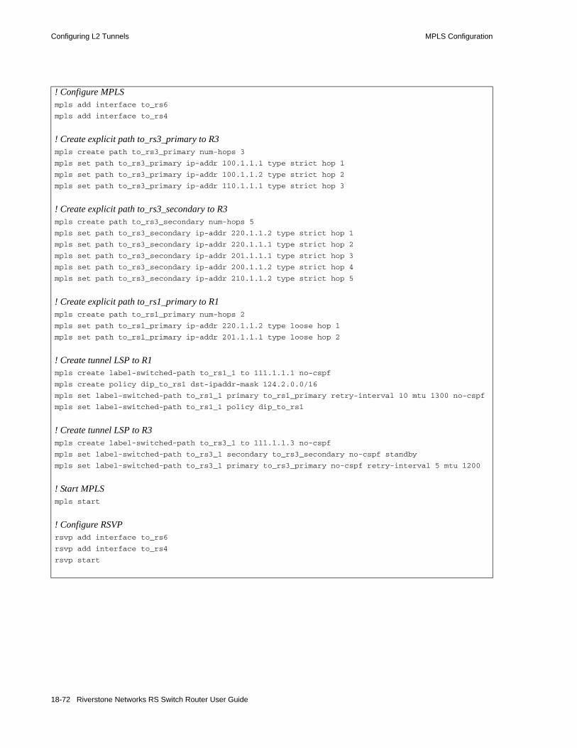
Configuring L2 Tunnels MPLS Configuration
! Configure MPLSmpls add interface to_rs6
mpls add interface to_rs4
! Create explicit path to_rs3_primary to R3mpls create path to_rs3_primary num-hops 3
mpls set path to_rs3_primary ip-addr 100.1.1.1 type strict hop 1
mpls set path to_rs3_primary ip-addr 100.1.1.2 type strict hop 2
mpls set path to_rs3_primary ip-addr 110.1.1.1 type strict hop 3
! Create explicit path to_rs3_secondary to R3mpls create path to_rs3_secondary num-hops 5
mpls set path to_rs3_secondary ip-addr 220.1.1.2 type strict hop 1
mpls set path to_rs3_secondary ip-addr 220.1.1.1 type strict hop 2
mpls set path to_rs3_secondary ip-addr 201.1.1.1 type strict hop 3
mpls set path to_rs3_secondary ip-addr 200.1.1.2 type strict hop 4
mpls set path to_rs3_secondary ip-addr 210.1.1.2 type strict hop 5
! Create explicit path to_rs1_primary to R1mpls create path to_rs1_primary num-hops 2
mpls set path to_rs1_primary ip-addr 220.1.1.2 type loose hop 1
mpls set path to_rs1_primary ip-addr 201.1.1.1 type loose hop 2
! Create tunnel LSP to R1mpls create label-switched-path to_rs1_1 to 111.1.1.1 no-cspf
mpls create policy dip_to_rs1 dst-ipaddr-mask 124.2.0.0/16
mpls set label-switched-path to_rs1_1 primary to_rs1_primary retry-interval 10 mtu 1300 no-cspf
mpls set label-switched-path to_rs1_1 policy dip_to_rs1
! Create tunnel LSP to R3mpls create label-switched-path to_rs3_1 to 111.1.1.3 no-cspf
mpls set label-switched-path to_rs3_1 secondary to_rs3_secondary no-cspf standby
mpls set label-switched-path to_rs3_1 primary to_rs3_primary no-cspf retry-interval 5 mtu 1200
! Start MPLSmpls start
! Configure RSVPrsvp add interface to_rs6
rsvp add interface to_rs4
rsvp start
18-72 Riverstone Networks RS Switch Router User Guide

MPLS Configuration Configuring L2 Tunnels
R6 is a transit LSR with interfaces to R1 and R5. The following is the configuration for R6:
! Configure LDPldp add interface lo0
ldp add remote-peer 111.1.1.1 adds R1 as LDP peerldp add remote-peer 111.1.1.3 adds R3 as LDP peer! Sends label mapping for VLAN ID 100 to R3mpls set customer-profile cust1 vlans 100 type vlan ldp connect customer-profile cust1 remote-peer 111.1.1.3! Sends label mapping for VLAN ID 100 to R1mpls set customer-profile cust1 vlans 100 type vlan ldp connect customer-profile cust1 remote-peer 111.1.1.1! Sends label mapping for VLAN ID 200 to R3mpls set customer-profile cust2 vlans 200 type vlan ldp connect customer-profile cust2 remote-peer 111.1.1.3! Sends label mapping for VLAN ID 200 to R1mpls set customer-profile cust2 vlans 200 type vlan ldp connect customer-profile cust2 remote-peer 111.1.1.1
ldp start
! Configure interfaces to R1 and R5vlan create ip_signal ip id 12
vlan add ports gi.4.1,gi.5.1 to ip_signal
interface create ip to_rs1 address-netmask 201.1.1.2/16 port gi.4.2
interface create ip to_rs5 address-netmask 220.1.1.1/16 vlan ip_signal
interface add ip lo0 address-netmask 111.1.1.6/32
! Configure OSPFip-router global set router-id 111.1.1.6
ospf create area backbone
ospf add interface all to-area backbone
ospf add stub-host 111.1.1.6 to-area backbone cost 5
ospf start
! Configure MPLSmpls add interface to_rs1
mpls add interface to_rs5
mpls start
! Configure RSVPrsvp add interface to_rs1
rsvp add interface to_rs5
rsvp start
Riverstone Networks RS Switch Router User Guide 18-73

Configuring L2 Tunnels MPLS Configuration
18.6.2.5 L2 Tunneling Based on Ports Configuration Examples (Point-to-Point)
The FEC-to-label binding for a virtual circuit can be based on the port on which traffic arrives. One or more incoming ports are mapped to a logical customer ID number, which is then mapped to an FEC.
In Figure 18-20, ports gi.6.1 on R1 and gi.12.1 on R3 are mapped to customer ID 1. Ports gi.3.1 on R1 and gi.13.1 on R3 are mapped to customer ID 2. The customer IDs are mapped to VC labels that are distributed via LDP. You can choose to have either untagged or 802.1q tagged frames transported across the tunnel LSP; the configuration for transporting untagged packets is shown. The tunnel LSP can use either LDP or RSVP as the signaling protocol; configuration commands for both LDP and RSVP tunnel signaling are shown.
Timesaver Click on the router name (in blue) to see the corresponding configuration.
Figure 18-20 Tunneling of multiple virtual circuits based on ports (untagged frames)
L2 Tunnel (RSVP or LDP)
gi.6.1 gi.12.1
Virtual Circuit based on Port for Customer ID 1 (LDP)
R3R1
111.1.1.1/16 111.1.1.3/16
gi.3.1 gi.13.1
111.1.1.2/16
R2
Virtual Circuit based on Port for Customer ID 2 (LDP)
gi.4.1 gi.14.1 gi.15.1 gi.3.2
18-74 Riverstone Networks RS Switch Router User Guide

MPLS Configuration Configuring L2 Tunnels
The following is the configuration for R1:
! Configure router loopbackinterface add ip lo0 address-netmask 111.1.1.1/32
! Make gi.4.1 a trunk port that does not send out 802.1q tagged framesvlan make trunk-port gi.4.1 untagged
! Configure the LDP peers and label bindingsldp add interface lo0
ldp add remote-peer 111.1.1.3 adds R3 as LDP peermpls set customer-profile cust1 in-port-list gi.6.1 customer-id 1 type port maps port gi.6.1 to customer-id 1 and configures the FEC for label mappingmpls set customer-profile cust2 in-port-list gi.3.1 customer-id 2 type port maps port gi.3.1 to customer-id 2 and configures the FEC for label mappingldp connect customer-profile cust1 remote-peer 111.1.1.3 sends label mapping for customer-id 1 to R3ldp connect customer-profile cust2 remote-peer 111.1.1.3 sends label mapping for customer-id 2 to R3ldp start
! Create the LDP-signaling VLAN and interfacevlan create ldp_in port-based id 110
vlan add ports gi.4.1 to ldp_in
interface create ip to_r2_1 address-netmask 200.1.1.1/16 vlan ldp_in
! If tunnel LSP uses RSVP:mpls add interface to_r2_1
mpls start
rsvp add interface to_r2_1
rsvp start
! If tunnel LSP uses LDP:mpls add interface to_r2_1
mpls start
ldp add interface to_r2_1
ldp start
! Configure IGP (in this example, OSPF is the IGP)ip-router global set router-id 111.1.1.1
ospf create area backbone
ospf add stub-host 111.1.1.1 to-area backbone cost 5
ospf add interface to_r2_1 to-area backbone
ospf start
Riverstone Networks RS Switch Router User Guide 18-75

Configuring L2 Tunnels MPLS Configuration
The following is the configuration for R2:
! Configure router loopbackinterface add ip lo0 address-netmask 111.1.1.2/32
! Configure VLANs and interfaces:vlan make trunk-port gi.14.1 untagged configure trunk port that does not send out 802.1q tagged framesvlan make trunk-port gi.15.1 untagged configure trunk port that does not send out 802.1q tagged framesvlan create ldp_in1 port-based id 110
vlan create ldp_in3 port-based id 120
vlan add ports gi.14.1 to ldp_in1
vlan add ports gi.15.1 to ldp_in3
interface create ip to_r1 address-netmask 200.1.1.2/16 vlan ldp_in1
interface create ip to_r3 address-netmask 210.1.1.1/16 vlan ldp_in3
! If tunnel LSP uses RSVP:mpls add interface to_r1
mpls add interface to_r3
mpls start
rsvp add interface to_r1
rsvp add interface to_r3
rsvp start
! If tunnel LSP uses LDP:mpls add interface to_r1
mpls add interface to_r3
mpls start
ldp add interface to_r1
ldp add interface to_r3
ldp start
! Configure IGP (in this example, OSPF is the IGP)ip-router global set router-id 111.1.1.2
ospf create area backbone
ospf add interface all to-area backbone
ospf add stub-host 111.1.1.2 to-area backbone cost 5
ospf start
18-76 Riverstone Networks RS Switch Router User Guide

MPLS Configuration Configuring L2 Tunnels
The following is the configuration for R3:
! Configure router loopbackinterface add ip lo0 address-netmask 111.1.1.3/32
! Make gi.3.2 a trunk port that does not send out 802.1q tagged framesvlan make trunk-port gi.3.2 untagged
! Configure LDP peers and label bindingsldp add interface lo0
ldp add remote-peer 111.1.1.1 adds R1 as LDP peermpls set customer-profile cust1 in-port-list gi.12.1 customer-id 1 type port maps port gi.12.1 to customer-id 1 and configures the FEC for label mappingmpls set customer-profile cust2 in-port-list gi.13.1 customer-id 2 type port maps port gi.13.1 to customer-id 2 and configures the FEC for label mappingldp connect customer-profile cust1 remote-peer 111.1.1.1 sends label mapping for customer-id 1 to R1ldp connect customer-profile cust2 remote-peer 111.1.1.1 sends label mapping for customer-id 2 to R1ldp start
! Create the LDP-signaling VLAN and interfacevlan create ldp_in1 port-based id 120
vlan add ports gi.3.2 to ldp_in1
interface create ip to_r2 address-netmask 220.1.1.2/16 vlan ldp_in1
! If tunnel LSP uses RSVP:mpls add interface to_r2
mpls start
rsvp add interface to_r2
rsvp start
! If tunnel LSP uses LDP:mpls add interface to_r2
mpls start
ldp add interface to_r2
ldp start
! Configure IGP (in this example, OSPF is the IGP)ip-router global set router-id 111.1.1.3
ospf create area backbone
ospf add interface to_r2 to-area backbone
ospf add stub-host 111.1.1.3 to-area backbone cost 5
ospf start
Riverstone Networks RS Switch Router User Guide 18-77

Configuring L2 Tunnels MPLS Configuration
In Figure 18-21, ports gi.6.2, gi.2.1, and gi.5.1 on R1, port gi.15.1 on R3, and port gi.12.2 on R5 are mapped to customer ID 10. The customer IDs are mapped to VC labels that are distributed via LDP. The tunnel LSPs can use either LDP or RSVP as the signaling protocol; configuration commands for RSVP tunnel signaling are shown for this example.
Note The ports that are mapped to a single customer ID number must be either all trunk ports or all access ports. The example shows configurations for transporting 802.1q traffic.
Timesaver Click on the router name (in blue) to see the corresponding configuration.
Figure 18-21 Tunneling of virtual circuits based on ports (RSVP tunnel)
Tunnel LSPs:
Virtual Circuit based on ports
R3R1 R2
R5R6
R4
gi.6.2gi.2.1gi.5.1
Customer ID 10: Customer ID 10:
Customer ID 10:
gi.15.1
gi.12.2
gi.4.1 gi.14.1 gi.14.2 gi.12.2
gi.12.1
gi.3.1
gi.3.2
gi.13.1
gi.13.1gi.4.1gi.5.1
gi.4.2
gi.4.2
18-78 Riverstone Networks RS Switch Router User Guide

MPLS Configuration Configuring L2 Tunnels
Two LSPs are configured on R1. The LSP from R1 to R5 is configured with a strict explicit path of 3 hops (R1, R6, and R5) and is restricted to traffic destined for the 152.1.0.0/16 subnet. The LSP from R1 to R3 is configured with a loose explicit path of 2 hops. The following is the configuration for R1:
! Configure VLANs and interfacesvlan make trunk-port gi.2.1 customer ports must be trunk ports for 802.1q packetsvlan make trunk-port gi.6.2 customer ports must be trunk ports for 802.1q packetsvlan make trunk-port gi.5.1 customer ports must be trunk ports for 802.1q packetsvlan create ldp_in port-based id 110
vlan create ldp_in2 port-based id 120
vlan add ports gi.4.2 to ldp_in2
vlan add ports gi.4.1 to ldp_in
interface create ip to_rs2_1 address-netmask 200.1.1.1/16 vlan ldp_in LDP-signaling VLAN interfaceinterface create ip to_rs2_second address-netmask 201.1.1.1/16 vlan ldp_in2 LDP-signaling VLAN interfaceinterface add ip lo0 address-netmask 111.1.1.1/32
! Configure OSPFip-router global set router-id 111.1.1.1
ospf create area backbone
ospf add stub-host 111.1.1.1 to-area backbone cost 5
ospf add interface to_rs2_1 to-area backbone
ospf add interface to_rs2_second to-area backbone
ospf add interface ip_to_rs3000 to-area backbone
ospf start
! Configure MPLSmpls add interface to_rs2_1
mpls add interface to_rs2_second
! Configure explicit path p1 to R3mpls create path p1 num-hops 2
mpls set path p1 ip-addr 200.1.1.1 type loose hop 1
mpls set path p1 ip-addr 210.1.1.2 type loose hop 2
! Configure explicit path to R5mpls create path to_rs5_primary num-hops 3
mpls set path to_rs5_primary ip-addr 201.1.1.1 type strict hop 1
mpls set path to_rs5_primary ip-addr 201.1.1.2 type strict hop 2
mpls set path to_rs5_primary ip-addr 220.1.1.2 type strict hop 3
! Configure LSP to R3 with explicit path p1mpls create label-switched-path to_rs3_rsvp to 111.1.1.3 no-cspf preference 10
mpls set label-switched-path to_rs3_rsvp primary p1 no-cspf retry-interval 5 mtu 1000
! Configure LSP to R5mpls create label-switched-path to_rs5_rsvp to 111.1.1.5 no-cspf
mpls create policy dip_to_rs5 dst-ipaddr-mask 152.1.0.0/16
mpls set label-switched-path to_rs5_rsvp policy dip_to_rs5
Riverstone Networks RS Switch Router User Guide 18-79

Configuring L2 Tunnels MPLS Configuration
R2 is a transit LSR with interfaces to R1 and R3. The following is the configuration for R2:
mpls set label-switched-path to_rs5_rsvp primary to_rs5_primary no-cspf retry-interval 5 preference 30
! Start MPLSmpls start
! Configure RSVPrsvp add interface to_rs2_1
rsvp add interface to_rs2_second
rsvp start
! Configure LDPldp add interface lo0
mpls set customer-profile cust10 in-port-list gi.6.2 customer-id 10 type port maps port gi.6.2 to customer-id 10 and configures the FEC for label mappingmpls set customer-profile cust10 in-port-list gi.2.1 customer-id 10 type port maps port gi.2.1 to customer-id 10 and configures the FEC for label mappingmpls set customer-profile cust10 in-port-list gi.5.1 customer-id 10 type port maps port gi.5.1 to customer-id 10 and configures the FEC for label mappingldp add remote-peer 111.1.1.3 adds R3 as LDP peerldp connect customer-profile cust10 remote-peer 111.1.1.3 sends label mapping for customer-id 10 to R3ldp connect customer-profile cust10 remote-peer 111.1.1.5 sends label mapping for customer-id 10 to R5ldp add remote-peer 111.1.1.5 adds R5 as LDP peerldp start
! Configure VLANs and interfacesvlan create ldp_in1 port-based id 110
vlan create ip_ldp ip id 175
vlan add ports gi.14.1 to ldp_in1
vlan add ports gi.14.2 to ip_ldp
interface create ip to_RS1 address-netmask 200.1.1.2/16 vlan ldp_in1
interface create ip to_RS3 address-netmask 210.1.1.1/16 vlan ip_ldp
interface add ip lo0 address-netmask 111.1.1.2/32
! Configure OSPFip-router global set router-id 111.1.1.2
ospf create area backbone
ospf add interface all to-area backbone
ospf add stub-host 111.1.1.2 to-area backbone cost 5
ospf start
! Configure MPLSmpls add interface to_RS1
mpls add interface to_RS3
mpls start
18-80 Riverstone Networks RS Switch Router User Guide

MPLS Configuration Configuring L2 Tunnels
Two LSPs are configured on R3: one is from R3 to R5, while the other is from R3 to R1 and is restricted to traffic destined for the 124.2.0.0/16 subnet. The following is the configuration for R3:
! Configure RSVPrsvp add interface to_RS1
rsvp add interface to_RS3
rsvp start
! Configures VLANs and interfacesvlan make trunk-port gi.15.1 customer ports must be trunk ports for 802.1q packetsvlan create ldp_if1 id 120
vlan create ip_ldp port-based id 175
vlan add ports gi.12.2 to ip_ldp
vlan add ports gi.12.1 to ldp_if1
interface create ip to_rs2 address-netmask 210.1.1.2/16 vlan ip_ldp
interface create ip to_rs4 address-netmask 110.1.1.1/16 vlan ldp_if1
interface add ip lo0 address-netmask 111.1.1.3/32
! Configure OSPFip-router global set router-id 111.1.1.3
ospf create area backbone
ospf add stub-host 111.1.1.3 to-area backbone cost 5
ospf add interface to_rs2 to-area backbone
ospf add interface to_rs4 to-area backbone
ospf add interface ip_local_123 to-area backbone
ospf add interface to_rs38000_internet to-area backbone
ospf start
! Configure MPLSmpls add interface to_rs2
mpls add interface to_rs4
mpls create label-switched-path to_rs1_rsvp to 111.1.1.1 no-cspf
mpls create label-switched-path to_rs5_rsvp to 111.1.1.5 no-cspf
mpls create policy dip_to_rs1 dst-ipaddr-mask 124.2.0.0/16
mpls set label-switched-path to_rs1_rsvp policy dip_to_rs1
mpls start
! Configure RSVPrsvp add interface to_rs2
rsvp add interface to_rs4
rsvp start
! Configure LDPldp add interface lo0
mpls set customer-profile cust10 in-port-list gi.15.1 customer-id 10 type port maps port gi.15.1 to customer-id 10 and configures the FEC for label mappingldp add remote-peer 111.1.1.1 adds R1 as LDP peer
Riverstone Networks RS Switch Router User Guide 18-81
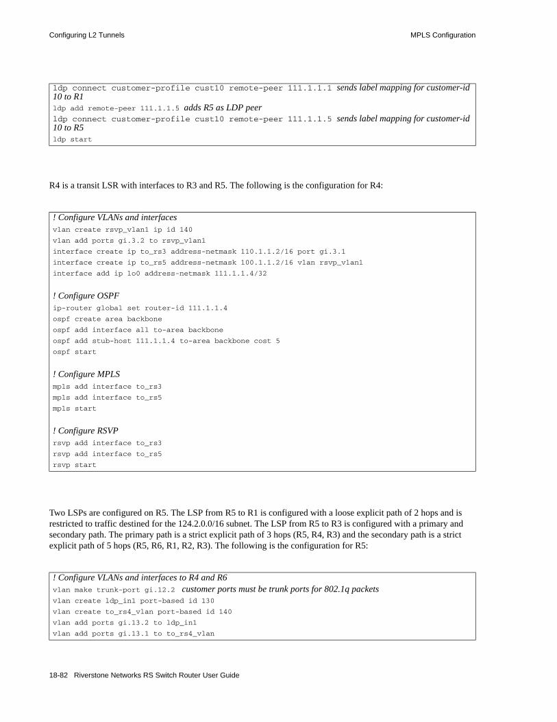
Configuring L2 Tunnels MPLS Configuration
R4 is a transit LSR with interfaces to R3 and R5. The following is the configuration for R4:
Two LSPs are configured on R5. The LSP from R5 to R1 is configured with a loose explicit path of 2 hops and is restricted to traffic destined for the 124.2.0.0/16 subnet. The LSP from R5 to R3 is configured with a primary and secondary path. The primary path is a strict explicit path of 3 hops (R5, R4, R3) and the secondary path is a strict explicit path of 5 hops (R5, R6, R1, R2, R3). The following is the configuration for R5:
ldp connect customer-profile cust10 remote-peer 111.1.1.1 sends label mapping for customer-id 10 to R1ldp add remote-peer 111.1.1.5 adds R5 as LDP peerldp connect customer-profile cust10 remote-peer 111.1.1.5 sends label mapping for customer-id 10 to R5ldp start
! Configure VLANs and interfacesvlan create rsvp_vlan1 ip id 140
vlan add ports gi.3.2 to rsvp_vlan1
interface create ip to_rs3 address-netmask 110.1.1.2/16 port gi.3.1
interface create ip to_rs5 address-netmask 100.1.1.2/16 vlan rsvp_vlan1
interface add ip lo0 address-netmask 111.1.1.4/32
! Configure OSPFip-router global set router-id 111.1.1.4
ospf create area backbone
ospf add interface all to-area backbone
ospf add stub-host 111.1.1.4 to-area backbone cost 5
ospf start
! Configure MPLSmpls add interface to_rs3
mpls add interface to_rs5
mpls start
! Configure RSVPrsvp add interface to_rs3
rsvp add interface to_rs5
rsvp start
! Configure VLANs and interfaces to R4 and R6vlan make trunk-port gi.12.2 customer ports must be trunk ports for 802.1q packetsvlan create ldp_in1 port-based id 130
vlan create to_rs4_vlan port-based id 140
vlan add ports gi.13.2 to ldp_in1
vlan add ports gi.13.1 to to_rs4_vlan
18-82 Riverstone Networks RS Switch Router User Guide

MPLS Configuration Configuring L2 Tunnels
interface create ip to_rs6 address-netmask 220.1.1.2/16 vlan ldp_in1
interface create ip to_rs4 address-netmask 100.1.1.1/16 vlan to_rs4_vlan
interface add ip lo0 address-netmask 111.1.1.5/32
! Configure OSPFip-router global set router-id 111.1.1.5
ospf create area backbone
ospf add interface lo0 to-area backbone
ospf add interface to_rs6 to-area backbone
ospf add stub-host 111.1.1.5 to-area backbone cost 5
ospf add interface to_rs4 to-area backbone
ospf start
! Configure MPLSmpls add interface to_rs6
mpls add interface to_rs4
! Create explicit path to_rs3_primary to R3mpls create path to_rs3_primary num-hops 3
mpls set path to_rs3_primary ip-addr 100.1.1.1 type strict hop 1
mpls set path to_rs3_primary ip-addr 100.1.1.2 type strict hop 2
mpls set path to_rs3_primary ip-addr 110.1.1.1 type strict hop 3
! Create explicit path to_rs3_secondary to R3mpls create path to_rs3_secondary num-hops 5
mpls set path to_rs3_secondary ip-addr 220.1.1.2 type strict hop 1
mpls set path to_rs3_secondary ip-addr 220.1.1.1 type strict hop 2
mpls set path to_rs3_secondary ip-addr 201.1.1.1 type strict hop 3
mpls set path to_rs3_secondary ip-addr 200.1.1.2 type strict hop 4
mpls set path to_rs3_secondary ip-addr 210.1.1.2 type strict hop 5
! Create explicit path to_rs1_primary to R1mpls create path to_rs1_primary num-hops 2
mpls set path to_rs1_primary ip-addr 220.1.1.2 type loose hop 1
mpls set path to_rs1_primary ip-addr 201.1.1.1 type loose hop 2
! Create tunnel LSP to R1mpls create label-switched-path to_rs1_1 to 111.1.1.1 no-cspf
mpls create policy dip_to_rs1 dst-ipaddr-mask 124.2.0.0/16
mpls set label-switched-path to_rs1_1 primary to_rs1_primary retry-interval 10 mtu 1300 no-cspf
mpls set label-switched-path to_rs1_1 policy dip_to_rs1
! Create tunnel LSP to R3mpls create label-switched-path to_rs3_1 to 111.1.1.3 no-cspf
mpls set label-switched-path to_rs3_1 secondary to_rs3_secondary no-cspf standby
mpls set label-switched-path to_rs3_1 primary to_rs3_primary no-cspf retry-interval 5 mtu 1200
! Start MPLSmpls start
Riverstone Networks RS Switch Router User Guide 18-83

Configuring L2 Tunnels MPLS Configuration
R6 is a transit LSR with interfaces to R1 and R5. The following is the configuration for R6:
! Configure RSVPrsvp add interface to_rs6
rsvp add interface to_rs4
rsvp start
! Configure LDPldp add interface lo0
mpls set customer-profile cust10 in-port-list gi.12.1 customer-id 10 type port maps port gi.12.1 to customer-id 10 and configures the FEC for label mappingldp add remote-peer 111.1.1.1 adds R1 as LDP peerldp connect customer-profile cust10 remote-peer 111.1.1.1 sends label mapping for customer-id 10 to R1ldp add remote-peer 111.1.1.3 adds R3 as LDP peerldp connect customer-profile cust10 remote-peer 111.1.1.3 sends label mapping for customer-id 10 to R3ldp start
! Configure interfaces to R1 and R5vlan create ip_signal ip id 12
vlan add ports gi.4.1,gi.5.1 to ip_signal
interface create ip to_rs1 address-netmask 201.1.1.2/16 port gi.4.2
interface create ip to_rs5 address-netmask 220.1.1.1/16 vlan ip_signal
interface add ip lo0 address-netmask 111.1.1.6/32
! Configure OSPFip-router global set router-id 111.1.1.6
ospf create area backbone
ospf add interface all to-area backbone
ospf add stub-host 111.1.1.6 to-area backbone cost 5
ospf start
! Configure MPLSmpls add interface to_rs1
mpls add interface to_rs5
mpls start
! Configure RSVPrsvp add interface to_rs1
rsvp add interface to_rs5
rsvp start
18-84 Riverstone Networks RS Switch Router User Guide

MPLS Configuration Configuring L2 Tunnels
18.6.2.6 L2 Tunneling Based on VLAN ID and Port Configuration Examples (Point-to-Point)
The FEC-to-label binding for a virtual circuit can be based on both a customer-specified VLAN ID and the port on which the traffic arrives. Each combination of VLAN ID and logical customer ID (which represents the incoming port) is mapped to a single FEC.
Figure 18-22 shows two VLANs with sites that are connected to routers R1 and R3. Port gi.6.1 on R1 and gi.12.1 on R3 provide access for the VLANs. Each VLAN ID/port combination is mapped to a VC label that is distributed via LDP. The LSP tunnel can use either LDP or RSVP as the signaling protocol; configuration commands for both LDP and RSVP tunnel signaling are shown.
Timesaver Click on the router name (in blue) to see the corresponding configuration.
Figure 18-22 Tunneling of multiple virtual circuits based on port and VLAN ID
The following is the configuration for R1:
! Configure router loopbackinterface add ip lo0 address-netmask 111.1.1.1/32
! Make gi.4.1 and gi.6.1 trunk portsvlan make trunk-port gi.4.1
vlan make trunk-port gi.6.1
! Configure the VLAN cust1 with a VLAN ID of 100vlan create cust1 port-based id 100
vlan add ports gi.6.1 to cust1
! Configure the VLAN cust2 with a VLAN ID of 200vlan create cust2 port-based id 200
vlan add ports gi.6.1 to cust2
LSP Tunnel (LDP or RSVP)
gi.6.1 gi.12.1
Virtual Circuit based on Port and VLAN ID 100 (LDP)
R3R1
111.1.1.1/16 111.1.1.3/16111.1.1.2/16
R2
Virtual Circuit based on Port and VLAN ID 200 (LDP)
VLAN ID 100
VLAN ID 200
VLAN ID 100
VLAN ID 200gi.4.1 gi.3.2gi.14.1 gi.15.1
Riverstone Networks RS Switch Router User Guide 18-85

Configuring L2 Tunnels MPLS Configuration
! Configure the LDP peers and label bindingsldp add interface lo0
ldp add remote-peer 111.1.1.3 adds R3 as LDP peermpls set customer-profile cust1 in-port-list gi.6.1 customer-id 1 vlans 100 type
port-vlan maps port gi.6.1/VLAN 100 to customer-id 1mpls set customer-profile cust2 in-port-list gi.6.1 customer-id 2 vlans 200 type
port-vlan maps port gi.6.1/VLAN 200 to customer-id 2ldp connect customer-profile cust1 remote-peer 111.1.1.3 sends label mapping for customer-id 1 to R3ldp connect customer-profile cust2 remote-peer 111.1.1.3 sends label mapping for customer-id 2 to R3ldp start
! Create the LDP-signaling VLAN and interfacevlan create ldp_in port-based id 110
vlan add ports gi.4.1 to ldp_in
interface create ip to_r2_1 address-netmask 200.1.1.1/16 vlan ldp_in
! If tunnel LSP uses RSVP:mpls add interface to_r2_1
mpls start
rsvp add interface to_r2_1
rsvp start
! If tunnel LSP uses LDP:mpls add interface to_r2_1
mpls start
ldp add interface to_r2_1
ldp start
! Configure IGP (in this example, OSPF is the IGP)ip-router global set router-id 111.1.1.1
ospf create area backbone
ospf add stub-host 111.1.1.1 to-area backbone cost 5
ospf add interface to_r2_1 to-area backbone
ospf start
18-86 Riverstone Networks RS Switch Router User Guide

MPLS Configuration Configuring L2 Tunnels
The following is the configuration for R2:
! Configure router loopbackinterface add ip lo0 address-netmask 111.1.1.2/32
! Configure VLANs and interfaces:vlan make trunk-port gi.14.1
vlan make trunk-port gi.15.1
vlan create ldp_in1 port-based id 110
vlan create ldp_in3 port-based id 120
vlan add ports gi.14.1 to ldp_in1
vlan add ports gi.15.1 to ldp_in3
interface create ip to_r1 address-netmask 200.1.1.2/16 vlan ldp_in1
interface create ip to_r3 address-netmask 210.1.1.1/16 vlan ldp_in3
! If tunnel LSP uses RSVP:mpls add interface to_r1
mpls add interface to_r3
mpls start
rsvp add interface to_r1
rsvp add interface to_r3
rsvp start
! If tunnel LSP uses LDP:mpls add interface to_r1
mpls add interface to_r3
mpls start
ldp add interface to_r1
ldp add interface to_r3
ldp start
! Configure IGP (in this example, OSPF is the IGP)ip-router global set router-id 111.1.1.2
ospf create area backbone
ospf add interface all to-area backbone
ospf add stub-host 111.1.1.2 to-area backbone cost 5
ospf start
Riverstone Networks RS Switch Router User Guide 18-87
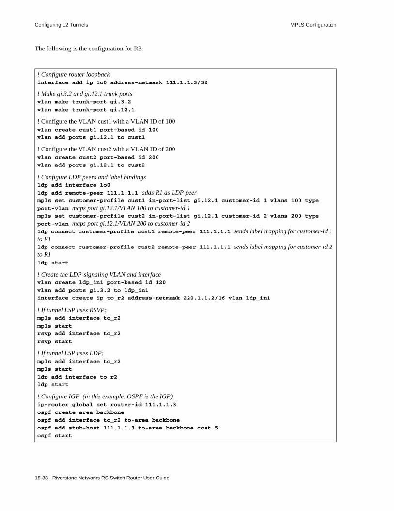
Configuring L2 Tunnels MPLS Configuration
The following is the configuration for R3:
! Configure router loopbackinterface add ip lo0 address-netmask 111.1.1.3/32
! Make gi.3.2 and gi.12.1 trunk portsvlan make trunk-port gi.3.2
vlan make trunk-port gi.12.1
! Configure the VLAN cust1 with a VLAN ID of 100vlan create cust1 port-based id 100
vlan add ports gi.12.1 to cust1
! Configure the VLAN cust2 with a VLAN ID of 200vlan create cust2 port-based id 200
vlan add ports gi.12.1 to cust2
! Configure LDP peers and label bindingsldp add interface lo0
ldp add remote-peer 111.1.1.1 adds R1 as LDP peermpls set customer-profile cust1 in-port-list gi.12.1 customer-id 1 vlans 100 type
port-vlan maps port gi.12.1/VLAN 100 to customer-id 1mpls set customer-profile cust2 in-port-list gi.12.1 customer-id 2 vlans 200 type
port-vlan maps port gi.12.1/VLAN 200 to customer-id 2ldp connect customer-profile cust1 remote-peer 111.1.1.1 sends label mapping for customer-id 1 to R1ldp connect customer-profile cust2 remote-peer 111.1.1.1 sends label mapping for customer-id 2 to R1ldp start
! Create the LDP-signaling VLAN and interfacevlan create ldp_in1 port-based id 120
vlan add ports gi.3.2 to ldp_in1
interface create ip to_r2 address-netmask 220.1.1.2/16 vlan ldp_in1
! If tunnel LSP uses RSVP:mpls add interface to_r2
mpls start
rsvp add interface to_r2
rsvp start
! If tunnel LSP uses LDP:mpls add interface to_r2
mpls start
ldp add interface to_r2
ldp start
! Configure IGP (in this example, OSPF is the IGP)ip-router global set router-id 111.1.1.3
ospf create area backbone
ospf add interface to_r2 to-area backbone
ospf add stub-host 111.1.1.3 to-area backbone cost 5
ospf start
18-88 Riverstone Networks RS Switch Router User Guide

MPLS Configuration Configuring L2 Tunnels
Figure 18-23 shows two VLANs (with IDs 50 and 60) that enter R1 on port gi.2.2. VLAN 50 traffic enters R3 on port gi.15.1, while VLAN 60 traffic enters R5 on port gi.6.2. The VLAN ID/port combinations are mapped to VC labels that are distributed via LDP. The tunnel LSPs can use either LDP or RSVP as the signaling protocol; configuration commands for RSVP tunnel signaling are shown for this example.
Timesaver Click on the router name (in blue) to see the corresponding configuration.
Figure 18-23 Tunneling of virtual circuits based on VLAN ID and port (RSVP tunnel)
Two LSPs are configured on R1. The LSP from R1 to R5 is configured with a strict explicit path of 3 hops (R1, R6, R5) and is restricted to traffic destined for the 152.1.0.0/16 subnet. The LSP from R1 to R3 is configured with a loose explicit path of 2 hops. The following is the configuration for R1:
! Configure VLANs and interfacesvlan create ldp_in port-based id 110
vlan create ldp_in2 port-based 120
vlan create to_rs3_only port-based id 50
vlan create to_rs5_only port-based id 60
vlan add ports gi.4.2 to ldp_in2
Tunnel LSPs
Virtual Circuit based on VLAN ID and port
R3R1 R2
R5R6
R4
Customer VLAN 50Customer VLAN 60
Customer VLAN 60
Customer VLAN 50gi.15.1
gi.6.2
gi.2.2gi.4.1 gi.14.1 gi.14.2 gi.12.2
gi.12.1
gi.3.1
gi.3.2
gi.13.1
gi.13.2gi.4.1gi.5.1
gi.4.2
gi.4.2
Riverstone Networks RS Switch Router User Guide 18-89

Configuring L2 Tunnels MPLS Configuration
vlan add ports gi.4.1 to ldp_in
vlan add ports gi.2.2 to to_rs3_only
vlan add ports gi.2.2 to to_rs5_only
interface create ip to_rs2 address-netmask 200.1.1.1/16 vlan ldp_in LDP-signaling VLAN interfaceinterface create ip to_rs6 address-netmask 201.1.1.1/16 vlan ldp_in2 LDP-signaling VLAN interfaceinterface add ip lo0 address-netmask 111.1.1.1/32
! Configure OSPFip-router global set router-id 111.1.1.1
ospf create area backbone
ospf add stub-host 111.1.1.1 to-area backbone cost 5
ospf add interface to_rs2 to-area backbone
ospf add interface to_rs6 to-area backbone
ospf start
! Configure MPLSmpls add interface to_rs2
mpls add interface to_rs6
! Configure explicit path p1 to R3mpls create path p1 num-hops 2
mpls set path p1 ip-addr 200.1.1.1 type loose hop 1
mpls set path p1 ip-addr 210.1.1.2 type loose hop 2
! Configure explicit path to R5mpls create path to_rs5_primary num-hops 3
mpls set path to_rs5_primary ip-addr 201.1.1.1 type strict hop 1
mpls set path to_rs5_primary ip-addr 201.1.1.2 type strict hop 2
mpls set path to_rs5_primary ip-addr 220.1.1.2 type strict hop 3
! Configure LSP to R3 with explicit path p1mpls create label-switched-path to_rs3_rsvp to 111.1.1.3 no-cspf preference 10
mpls set label-switched-path to_rs3_rsvp primary p1 no-cspf retry-interval 5 mtu 1000
! Configure LSP to R5mpls create label-switched-path to_rs5_rsvp to 111.1.1.5 no-cspf
mpls create policy dip_to_rs5 dst-ipaddr-mask 152.1.0.0/16
mpls set label-switched-path to_rs5_rsvp policy dip_to_rs5
mpls set label-switched-path to_rs5_rsvp primary to_rs5_primary no-cspf retry-interval 5 preference 30
! Start MPLSmpls start
! Configure RSVPrsvp add interface to_rs2
rsvp add interface to_rs6
rsvp start
18-90 Riverstone Networks RS Switch Router User Guide

MPLS Configuration Configuring L2 Tunnels
R2 is a transit LSR with interfaces to R1 and R3. The following is the configuration for R2:
! Configure LDPldp add interface lo0
mpls set customer-profile cust20 in-port-list gi.2.2 customer-id 20 vlans 50 type port-vlan
maps port gi.2.2/VLAN 50 to customer-id 20mpls set customer-profile cust30 in-port-list gi.2.2 customer-id 30 vlans 60 type port-vlanmaps port gi.2.2/VLAN 60 to customer-id 30ldp add remote-peer 111.1.1.3 adds R3 as LDP peerldp add remote-peer 111.1.1.5 adds R5 as LDP peerldp connect customer-profile cust20 remote-peer 111.1.1.3 sends label mapping for customer-id 20 (VLAN 50) to R3ldp connect customer-profile cust30 remote-peer 111.1.1.5 sends label mapping for customer-id 30 (VLAN 60) to R5ldp start
! Configure VLANs and interfacesvlan create ldp_in1 port-based id 110
vlan create ip_ldp ip id 175
vlan add ports gi.14.1 to ldp_in1
vlan add ports gi.14.2 to ip_ldp
interface create ip to_RS1 address-netmask 200.1.1.2/16 vlan ldp_in1
interface create ip to_RS3 address-netmask 210.1.1.1/16 vlan ip_ldp
interface add ip lo0 address-netmask 111.1.1.2/32
! Configure OSPFip-router global set router-id 111.1.1.2
ospf create area backbone
ospf add interface all to-area backbone
ospf add stub-host 111.1.1.2 to-area backbone cost 5
ospf start
! Configure MPLSmpls add interface to_RS1
mpls add interface to_RS3
mpls start
! Configure RSVPrsvp add interface to_RS1
rsvp add interface to_RS3
rsvp start
Riverstone Networks RS Switch Router User Guide 18-91
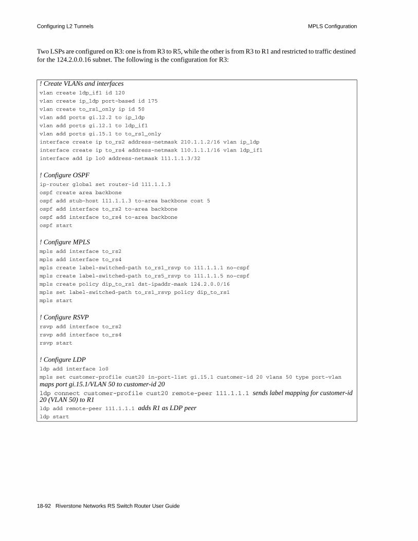
Configuring L2 Tunnels MPLS Configuration
Two LSPs are configured on R3: one is from R3 to R5, while the other is from R3 to R1 and restricted to traffic destined for the 124.2.0.0.16 subnet. The following is the configuration for R3:
! Create VLANs and interfacesvlan create ldp_if1 id 120
vlan create ip_ldp port-based id 175
vlan create to_rs1_only ip id 50
vlan add ports gi.12.2 to ip_ldp
vlan add ports gi.12.1 to ldp_if1
vlan add ports gi.15.1 to to_rs1_only
interface create ip to_rs2 address-netmask 210.1.1.2/16 vlan ip_ldp
interface create ip to_rs4 address-netmask 110.1.1.1/16 vlan ldp_if1
interface add ip lo0 address-netmask 111.1.1.3/32
! Configure OSPFip-router global set router-id 111.1.1.3
ospf create area backbone
ospf add stub-host 111.1.1.3 to-area backbone cost 5
ospf add interface to_rs2 to-area backbone
ospf add interface to_rs4 to-area backbone
ospf start
! Configure MPLSmpls add interface to_rs2
mpls add interface to_rs4
mpls create label-switched-path to_rs1_rsvp to 111.1.1.1 no-cspf
mpls create label-switched-path to_rs5_rsvp to 111.1.1.5 no-cspf
mpls create policy dip_to_rs1 dst-ipaddr-mask 124.2.0.0/16
mpls set label-switched-path to_rs1_rsvp policy dip_to_rs1
mpls start
! Configure RSVPrsvp add interface to_rs2
rsvp add interface to_rs4
rsvp start
! Configure LDPldp add interface lo0
mpls set customer-profile cust20 in-port-list gi.15.1 customer-id 20 vlans 50 type port-vlan
maps port gi.15.1/VLAN 50 to customer-id 20ldp connect customer-profile cust20 remote-peer 111.1.1.1 sends label mapping for customer-id 20 (VLAN 50) to R1ldp add remote-peer 111.1.1.1 adds R1 as LDP peerldp start
18-92 Riverstone Networks RS Switch Router User Guide

MPLS Configuration Configuring L2 Tunnels
R4 is a transit LSR with interfaces to R3 and R5. The following is the configuration for R4:
Two LSPs are configured on R5. The LSP from R5 to R1 is configured with a loose explicit path of 2 hops and is restricted to traffic destined for the 124.2.0.0/16 subnet. The LSP from R5 to R3 is configured with a primary and secondary path. The primary path is a strict explicit path of 3 hops (R5, R4, R3) and the secondary path is a strict explicit path of 5 hops (R5, R6, R1, R2, R3). The following is the configuration for R5:
! Create VLANs and interfacesvlan create rsvp_vlan1 ip id 140
vlan add ports gi.3.2 to rsvp_vlan1
interface create ip to_rs3 address-netmask 110.1.1.2/16 port gi.3.1
interface create ip to_rs5 address-netmask 100.1.1.2/16 vlan rsvp_vlan1
interface add ip lo0 address-netmask 111.1.1.4/32
! Configure OSPFip-router global set router-id 111.1.1.4
ospf create area backbone
ospf add interface all to-area backbone
ospf add stub-host 111.1.1.4 to-area backbone cost 5
ospf start
! Configure MPLSmpls add interface to_rs3
mpls add interface to_rs5
mpls start
! Configure RSVPrsvp add interface to_rs3
rsvp add interface to_rs5
rsvp start
! Configure VLANs and interfacesvlan create ldp_in1 port-based id 130
vlan create to_rs4_vlan port-based id 140
vlan create to_rs1_only port-based id 60
vlan add ports gi.13.2 to ldp_in1
vlan add ports gi.13.1 to to_rs4_vlan
vlan add ports gi.6.2 to to_rs1_only
interface create ip to_rs6 address-netmask 220.1.1.2/16 vlan ldp_in1
interface create ip to_rs4 address-netmask 100.1.1.1/16 vlan to_rs4_vlan
interface add ip lo0 address-netmask 111.1.1.5/32
! Configure OSPFip-router global set router-id 111.1.1.5
ospf create area backbone
ospf add interface lo0 to-area backbone
ospf add interface to_rs6 to-area backbone
Riverstone Networks RS Switch Router User Guide 18-93

Configuring L2 Tunnels MPLS Configuration
ospf add stub-host 111.1.1.5 to-area backbone cost 5
ospf add interface to_rs4 to-area backbone
ospf start
! Configure MPLSmpls add interface to_rs6
mpls add interface to_rs4
! Create explicit path to_rs3_primary to R3mpls create path to_rs3_primary num-hops 3
mpls set path to_rs3_primary ip-addr 100.1.1.1 type strict hop 1
mpls set path to_rs3_primary ip-addr 100.1.1.2 type strict hop 2
mpls set path to_rs3_primary ip-addr 110.1.1.1 type strict hop 3
! Create explicit path to_rs3_secondary to R3mpls create path to_rs3_secondary num-hops 5
mpls set path to_rs3_secondary ip-addr 220.1.1.2 type strict hop 1
mpls set path to_rs3_secondary ip-addr 220.1.1.1 type strict hop 2
mpls set path to_rs3_secondary ip-addr 201.1.1.1 type strict hop 3
mpls set path to_rs3_secondary ip-addr 200.1.1.2 type strict hop 4
mpls set path to_rs3_secondary ip-addr 210.1.1.2 type strict hop 5
! Create explicit path to_rs1_primary to R1mpls create path to_rs1_primary num-hops 2
mpls set path to_rs1_primary ip-addr 220.1.1.2 type loose hop 1
mpls set path to_rs1_primary ip-addr 201.1.1.1 type loose hop 2
! Create tunnel LSP to R1mpls create label-switched-path to_rs1_1 to 111.1.1.1 no-cspf
mpls create policy dip_to_rs1 dst-ipaddr-mask 124.2.0.0/16
mpls set label-switched-path to_rs1_1 primary to_rs1_primary retry-interval 10 mtu 1300 no-cspf
mpls set label-switched-path to_rs1_1 policy dip_to_rs1
! Create tunnel LSP to R3mpls create label-switched-path to_rs3_1 to 111.1.1.3 no-cspf
mpls set label-switched-path to_rs3_1 secondary to_rs3_secondary no-cspf standby
mpls set label-switched-path to_rs3_1 primary to_rs3_primary no-cspf retry-interval 5 mtu 1200
! Start MPLSmpls start
! Configure RSVPrsvp add interface to_rs6
rsvp add interface to_rs4
rsvp start
! Configure LDPldp add interface lo0
18-94 Riverstone Networks RS Switch Router User Guide
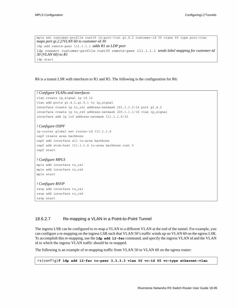
MPLS Configuration Configuring L2 Tunnels
R6 is a transit LSR with interfaces to R1 and R5. The following is the configuration for R6:
18.6.2.7 Re-mapping a VLAN in a Point-to-Point Tunnel
The ingress LSR can be configured to re-map a VLAN to a different VLAN at the end of the tunnel. For example, you can configure a re-mapping on the ingress LSR such that VLAN 50’s traffic winds up on VLAN 60 on the egress LSR. To accomplish this re-mapping, use the ldp add l2-fec command, and specify the ingress VLAN id and the VLAN id to which the ingress VLAN traffic should be re-mapped.
The following is an example of re-mapping traffic from VLAN 50 to VLAN 60 on the egress router:
mpls set customer-profile cust30 in-port-list gi.6.2 customer-id 30 vlans 60 type port-vlanmaps port gi.2.2/VLAN 60 to customer-id 30ldp add remote-peer 111.1.1.1 adds R1 as LDP peerldp connect customer-profile cust30 remote-peer 111.1.1.1 sends label mapping for customer-id 30 (VLAN 60) to R1ldp start
! Configure VLANs and interfacesvlan create ip_signal ip id 12
vlan add ports gi.4.1,gi.5.1 to ip_signal
interface create ip to_rs1 address-netmask 201.1.1.2/16 port gi.4.2
interface create ip to_rs5 address-netmask 220.1.1.1/16 vlan ip_signal
interface add ip lo0 address-netmask 111.1.1.6/32
! Configure OSPFip-router global set router-id 111.1.1.6
ospf create area backbone
ospf add interface all to-area backbone
ospf add stub-host 111.1.1.6 to-area backbone cost 5
ospf start
! Configure MPLSmpls add interface to_rs1
mpls add interface to_rs5
mpls start
! Configure RSVPrsvp add interface to_rs1
rsvp add interface to_rs5
rsvp start
rs(config)# ldp add l2-fec to-peer 3.3.3.3 vlan 50 vc-id 60 vc-type ethernet-vlan
Riverstone Networks RS Switch Router User Guide 18-95
Configuring L2 Tunnels MPLS Configuration
Notice in the example above that VLAN traffic from the VLAN with id of 50 (vlan 50) is re-mapped to VLAN 60 (vc-id 60) on the egress LSR. When using the ldp add l2-fec command you also must set the remote-peer address, and the vc-type must be specified as ethernet-vlan.
18.6.3 Configuring Point-to-Multipoint L2 LSPs (TLS)
This section presents introductory concepts needed for implementing Virtual Private LAN Services (VPLS) over MPLS on Riverstone Networks switch routers. Four VPLS example configurations for the PEs (edge LSRs) are provided. Each example uses a different VPN type. These examples also illustrate the use of LDP and RSVP for the signaling protocol.
This section also shows how to configure the RS Ethernet Router as a dual-homing multi-tenant unit switch (MTU-s) in a Hierarchical VPLS (H-VPLS) network.
18.6.3.1 Introduction – Why VPLS Over MPLS
The Riverstone Networks family of RS Ethernet Routers supports the deployment of VPLS over MPLS layer-2 Transparent LAN Service (TLS). MPLS-based TLS allows Metropolitan Service Providers (MSPs) to create LSP tunnels through an MPLS backbone network for each customer, with each LSP provisioned for customer-specific service. To each customer site, the entire MPLS network appears as a logical L2 switch. Thus, VPLS over MPLS allows business customers to integrate their LAN sites with a metro service provider’s Metropolitan Area Network (MAN). To the business customer, geographically separate networks appear as a single logical VLAN – the MSP’s MAN is transparent to the customer.
18.6.3.2 MPLS Tunnels
With MPLS tunnels, MPLS label stacks are used instead of network layer encapsulation to tunnel packets across a backbone MPLS network. Tunneling allows shared resources such as public networks to be used to carry private communications. For example, companies can use VPN tunnels to send intranet traffic over the Internet. The advantage MPLS offers is that the contents of the tunneled data packets do not need to be examined as they proceed through an LSP, because packet forwarding is based on only the attached labels (See Section 18.1.5, "MPLS Tunnels.").
For example, a customer with three geographically distinct sites can be connected using end-to-end virtual circuit LSPs that are carried over tunnel LSPs. The tunnel label (the label at the top of the MPLS label stack) is used to route traffic over the MPLS backbone, while the VC label (the label at the bottom of the MPLS label stack) is used to determine the egress PE (See Section 18.6.1, "Configuring Dynamic L2 Labels.").
18.6.3.3 Basic PE Configuration for L2 VPLS
The configuration of the PE routers is covered in detail in VPLS Configuration Examples sections. However, the basic process for configuring ingress and egress PEs is explained in the following seven steps:1. Configure the L2 FEC for each customer in a customer profile with the mpls set
customer-profile command. The customer profile must include the following:2. A unique identifier number for each customer
- One or more physical customer-facing ports on the PE, which are assigned to the customer
18-96 Riverstone Networks RS Switch Router User Guide

MPLS Configuration Configuring L2 Tunnels
- The VPN type used with this customer profile – The VPN type specifies the source of traffic to be forwarded through the LSP. Table 18-8 lists the various VPN types and explains their function.
3. Advertise the FEC-to-label mapping via LDP to the remote peers. Enable and start LDP.- Specify the remote LDP peer with the ldp add remote-peer command. Specify the
loopback addresses of the remote router. This is typically the router ID of the remote LDP peer, which is applied to the loopback interface using the interface add ip lo0 <router ID> command.
- Send the label mapping for each customer profile to the appropriate remote peer with the ldp connect customer-profile command.
Table 18-8 VPN types and their descriptions
VPN TYPE Description
Port Specifies a port-to-port VPN. The port is the customer side port – all traffic arriving on this port(s) is identified as belonging to this customer and is forwarded through the LSP.
Port-VLAN Specifies a port-to-VLAN VPN. The port is the customer side port – all traffic arriving on this port(s) that belongs to the specified VLAN is identified as belonging to this customer and is forwarded through the LSP.
VLAN Specifies a VLAN-to-VLAN VPN. All traffic from this VLAN is identified as belonging to this customer and is forwarded through the LSP. Ports are added to the VLAN using the vlan add port command.
Port-VLAN-Range Specifies a port/VLAN range VPN. The port is the customer side port – all traffic arriving on this port(s) that belongs to the specified range of VLANs is identified as belonging to this customer and is forwarded through the LSP.
.
VLAN-Range Specifies a VLAN range to VLAN range VPN. All traffic from any of the specified VLANs is identified as belonging to this customer and is forwarded through the LSP. Ports are added to the VLAN using the vlan add port command.
Riverstone Networks RS Switch Router User Guide 18-97

Configuring L2 Tunnels MPLS Configuration
4. Configure the signaling VLAN (or tunnel LSP) and interface. The ports at both ends of a link between two PEs must belong to the same VLAN, i.e., the VLAN ID must be the same on both routers.
5. Configure the tunnel (or signaling) LSP. Either LDP or RSVP can be used for signaling in the tunnel LSP.
6. Start MPLS and the signaling protocol (either LDP or RSVP) for the tunnel LSP.7. Configure the IGP routing protocol, either OSPF or IS-IS.
18.6.3.4 Transit LSR Configuration for VPLS
The configuration of the transit LSRs depends on many factors. Among these factors are the number of transit LSRs, the signaling protocol, and the type of equipment used. Because of these factors, a complete discussion of transit LSR configurations is beyond the scope of this document. Instead, this document represents the MPLS transit network as an MPLS cloud. This cloud does not specify either the topology or configurations of the transit LSRs within.
In general, LSRs within the MPLS cloud usually require the following components to be configured:• The LDP or RSVP signaling VLAN and interface• Enabling MPLS and the signaling protocol (either LDP or RSVP) for the tunnel LSP• An IGP routing protocol, either OSPF or IS-IS, on the LSRs
For completeness and purposes of education, however, a configuration for a single transit LSR, is presented as an example at the end of this document (see example five). This transit LSR configuration is compatible with all four VPLS example configurations.
18.6.3.5 When to Use 802.1Q Tagging
Table 18-9 describes when to use 802.1Q tagging for a particular VPN type:
Table 18-9 When VPLS uses 802.1Q tagging
VPN Type Customer Port Type .1Q header in VPLS Frame Comment
Port-Only Access Yes If the customer port is an access port, the creation of the customer profile does not define the VLAN(s) being used, so the VPLS VPN is propagated across the link. In the case where the customer port is a trunk port, the VLANs being used are unknown.
Trunk Yes
18-98 Riverstone Networks RS Switch Router User Guide
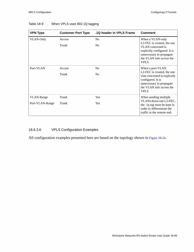
MPLS Configuration Configuring L2 Tunnels
18.6.3.6 VPLS Configuration Examples
All configuration examples presented here are based on the topology shown in Figure 18-24.
VLAN-Only Access No When a VLAN-only L2-FEC is created, the one VLAN concerned is explicitly configured. It is unnecessary to propagate the VLAN info across the VPLS.
Trunk No
Port-VLAN Access No When a port-VLAN L2-FEC is created, the one vlan concerned is explicitly configured. It is unnecessary to propagate the VLAN info across the VPLS
Trunk No
VLAN-Range Trunk Yes When sending multiple VLANs down one L2-FEC, the .1q tag must be kept in order to differentiate the traffic at the remote end.
Port-VLAN-Range Trunk Yes
Table 18-9 When VPLS uses 802.1Q tagging
VPN Type Customer Port Type .1Q header in VPLS Frame Comment
Riverstone Networks RS Switch Router User Guide 18-99

Configuring L2 Tunnels MPLS Configuration
Figure 18-24 VPLS topology for configuration examples
Notice in the figure that each CE is attached to its PE through an Ethernet port (customer facing port). Also, notice the router IDs used by each PE (111.1.1.1 for PE 1, 111.1.1.2 for PE 2, and so on). These router IDs also are used as the loopback interface addresses that identify each PE as a remote peer.
18.6.3.7 Example One – Port-based VPLS Using LDP Over RSVP
The following example creates a Virtual Private LAN Service for customer 1 that resides on CE 1 through CE 3. Notice that with few exceptions the configurations for PE 1 through PE 3 are essentially the same. For this reason, the first configuration (for PE 1) is annotated in detail, while the configurations for PE 2 and PE 3 are annotated only where there are differences.
In this example, the VPN is tunneled using LDP, while TLS signaling is performed using RSVP.
Configuration for PE 1:
Create the Customer 1 VLAN on PE 1, give it the ID of 110, and add the port gi.2.1 to the VLAN:vlan create cust1 port-based id 110
CE 2
CE 1
CE 3
PEPE 2
PE 1 PE 3MPLS Cloud
et.1.1
et.1.1et.1.1
111.1.1.1 111.1.1.3
111.1.1.2
Customer 1
Customer 1
Customer 1
Transit LSR(See Example Five)
18-100 Riverstone Networks RS Switch Router User Guide

MPLS Configuration Configuring L2 Tunnels
vlan add ports gi.2.1 to cust1
Create an interface for the VLAN and assign it an IP address and netmask – This is the interface that faces the core LSRs (note that the IP address for PE 1 is in a different broadcast domain than PE 1 and PE 2):interface create ip to-core1 address-netmask 200.1.1.1/16 vlan cust1
Add an additional (secondary) IP address (other than 127.0.0.1) to the loopback interface (use subnet mask 32) – This IP address is the PE’s remote peer identity:interface add ip lo0 address-netmask 111.1.1.1/32
Set the router ID for OSPF – This can be the same as the new loopback address:ip-router global set router-id 111.1.1.1
Create the OSPF backbone area (used for signaling), add the VLAN interface to the backbone, then start OSPF:ospf create area backboneospf add stub-host 111.1.1.1 to-area backbone cost 5ospf add interface to-core1 to-area backboneospf start
Add the signaling VLAN interface to MPLS:mpls add interface to-core1
Create the label switched paths to the other PEs, identified by their loopback addresses:mpls create label-switched-path to-PE2 to 111.1.1.2mpls create label-switched-path to-PE3 to 111.1.1.3
Turn off CSPF (no-cspf) for each label switched path:mpls set label-switched-path to-PE2 no-cspfmpls set label-switched-path to-PE3 no-cspf
Create the customer profile, assign a customer ID number, specify the customer facing port (et.1.1), the customer profile type (L2-FEC type), then start MPLS:mpls set customer-profile 1-2-3 customer-id 10 in-port-list et.1.1 type portmpls start
Add the VLAN interface to RSVP, and then start RSVP; RSVP performs the signaling for the VPN:rsvp add interface to-core rsvp start
Add the VLAN interface and the remote peer IP addresses (address for PE 2 and PE 3) to LDP:ldp add interface lo0ldp add remote-peer 111.1.1.2ldp add remote-peer 111.1.1.3
Make the VPN connections between this PE (PE 1) and the remote PEs (PE 2 and PE 3) – Here, both the customer profile and the remote peer IP address are specified:ldp connect customer-profile 1-2-3 remote-peer 111.1.1.2
Riverstone Networks RS Switch Router User Guide 18-101

Configuring L2 Tunnels MPLS Configuration
ldp connect customer-profile 1-2-3 remote-peer 111.1.1.3
Start LDP:ldp start
Configuration for PE 2:
Create the Customer 1 VLAN on PE 2, give it the ID of 120, and add the port gi.4.1 to the VLAN:vlan create cust1 port-based id 120vlan add ports gi.4.1 to cust1
The IP address for PE 2 is in a different broadcast domain than PE 1 and PE 3:interface create ip to-core2 address-netmask 201.1.1.1/16 vlan cust1
The IP address for the PE 2 loopback interface ends in a 2:interface add ip lo0 address-netmask 111.1.1.2/32
ip-router global set router-id 111.1.1.2
ospf create area backboneospf add stub-host 111.1.1.2 to-area backbone cost 5ospf add interface to-core2 to-area backboneospf start
mpls add interface to-core
Notice that the label switched paths are going to PE 1 and PE 3:mpls create label-switched-path to-PE1 to 111.1.1.1mpls create label-switched-path to-PE3 to 111.1.1.3mpls set label-switched-path to-PE1 no-cspfmpls set label-switched-path to-PE3 no-cspfmpls set customer-profile 1-2-3 customer-id 10 in-port-list et.1.1 type portmpls start
rsvp add interface to-core2rsvp start
ldp add interface lo0
Notice that for PE 2, the remote peers are PE 1 and PE 3:ldp add remote-peer 111.1.1.1ldp add remote-peer 111.1.1.3ldp connect customer-profile 1-2-3 remote-peer 111.1.1.1ldp connect customer-profile 1-2-3 remote-peer 111.1.1.3ldp start
Configuration for PE 3:
Create the Customer 1 VLAN on PE 3, give it the ID of 130, and add the port gi.4.1 to the VLAN:
18-102 Riverstone Networks RS Switch Router User Guide
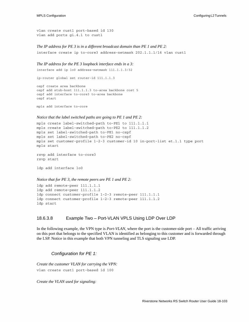
MPLS Configuration Configuring L2 Tunnels
vlan create cust1 port-based id 130vlan add ports gi.4.1 to cust1
The IP address for PE 3 is in a different broadcast domain than PE 1 and PE 2:interface create ip to-core3 address-netmask 202.1.1.1/16 vlan cust1
The IP address for the PE 3 loopback interface ends in a 3:interface add ip lo0 address-netmask 111.1.1.3/32
ip-router global set router-id 111.1.1.3
ospf create area backboneospf add stub-host 111.1.1.3 to-area backbone cost 5ospf add interface to-core3 to-area backboneospf start
mpls add interface to-core
Notice that the label switched paths are going to PE 1 and PE 2:mpls create label-switched-path to-PE1 to 111.1.1.1mpls create label-switched-path to-PE2 to 111.1.1.2mpls set label-switched-path to-PE1 no-cspfmpls set label-switched-path to-PE2 no-cspfmpls set customer-profile 1-2-3 customer-id 10 in-port-list et.1.1 type portmpls start
rsvp add interface to-core3rsvp start
ldp add interface lo0
Notice that for PE 3, the remote peers are PE 1 and PE 2:ldp add remote-peer 111.1.1.1ldp add remote-peer 111.1.1.2ldp connect customer-profile 1-2-3 remote-peer 111.1.1.1ldp connect customer-profile 1-2-3 remote-peer 111.1.1.2ldp start
18.6.3.8 Example Two – Port-VLAN VPLS Using LDP Over LDP
In the following example, the VPN type is Port-VLAN, where the port is the customer-side port – All traffic arriving on this port that belongs to the specified VLAN is identified as belonging to this customer and is forwarded through the LSP. Notice in this example that both VPN tunneling and TLS signaling use LDP.
Configuration for PE 1:
Create the customer VLAN for carrying the VPN:vlan create cust1 port-based id 100
Create the VLAN used for signaling:
Riverstone Networks RS Switch Router User Guide 18-103

Configuring L2 Tunnels MPLS Configuration
vlan create signal1 based id 110
Add the customer-facing port to VLAN cust1:vlan add ports et.1.1 to cust1
Add the MPLS facing port to VLAN signal1:vlan add ports gi.2.1 to signal1
Create an interface for the signaling VLAN and assign it an IP address and netmask – This is the interface that faces the core LSRs:interface create ip to-core1 address-netmask 200.1.1.1/16 vlan signal1
Add an additional IP address (other than 127.0.0.1) to the loopback interface (use subnet mask 32) – This IP address is the PE remote peer identity:interface add ip lo0 address-netmask 111.1.1.1/32
Set the router ID for OSPF – This can be the same as the new loopback address:ip-router global set router-id 111.1.1.1
Create the OSPF backbone area (used for signaling), add the signaling VLAN interface to the backbone, then start OSPF:ospf create area backboneospf add stub-host 111.1.1.1 to-area backbone cost 5ospf add interface to-core1 to-area backboneospf start
Add the signaling VLAN interface to MPLS:mpls add interface to-core
Create the label switched paths to the other PEs, identified by their loopback addresses:mpls create label-switched-path to-PE2 to 111.1.1.2mpls create label-switched-path to-PE3 to 111.1.1.3
Turn off CSPF (no-cspf) for each label switched path:mpls set label-switched-path to-PE2 no-cspfmpls set label-switched-path to-PE3 no-cspf
Create the customer profile, assign a customer ID number, specify the customer facing port (et.1.1), the customer profile type (L2-FEC type), then start MPLS:mpls set customer-profile 1-2-3 customer-id 10 vlans 100 in-port-list et.1.1 type port-vlanmpls start
Add the VLAN interface and the remote peer IP addresses (address for PE 2 and PE 3) to LDP:ldp add interface lo0ldp add interface to-core1ldp add remote-peer 111.1.1.2
18-104 Riverstone Networks RS Switch Router User Guide

MPLS Configuration Configuring L2 Tunnels
ldp add remote-peer 111.1.1.3
Make the VPN connections between this PE (PE 1) and the remote PEs (PE 2 and PE 3) – Here, both the customer profile and the remote peer IP address are specified:ldp connect customer-profile 1-2-3 remote-peer 111.1.1.2ldp connect customer-profile 1-2-3 remote-peer 111.1.1.3
Start LDP:ldp start
Configuration for PE 2:
Create the Customer 1 VLAN on PE 2, give it the ID of 120, and add the port gi.4.1 to the VLAN:vlan create cust1 port-based id 100vlan create signal2 port-based id 120vlan add ports et.1.1 to cust1vlan add ports gi.4.1 to signal2
The IP address for PE 2 is in a different broadcast domain than PE 1 and PE 3:interface create ip to-core2 address-netmask 201.1.1.1/16 vlan signal2
The IP address for the PE 2 loopback interface ends in a 2:interface add ip lo0 address-netmask 111.1.1.2/32
ip-router global set router-id 111.1.1.2
ospf create area backboneospf add stub-host 111.1.1.2 to-area backbone cost 5ospf add interface to-core2 to-area backboneospf start
mpls add interface to-core2
Notice that the label switched paths are going to PE 1 and PE 3:mpls create label-switched-path to-PE1 to 111.1.1.1mpls create label-switched-path to-PE3 to 111.1.1.3mpls set label-switched-path to-PE1 no-cspfmpls set label-switched-path to-PE3 no-cspfmpls set customer-profile 1-2-3 customer-id 10 vlans 100 in-port-list et.1.1 type port-vlanmpls start
ldp add interface lo0ldp add interface to-core2
Notice that for PE 2, the remote peers are PE 1 and PE 3:ldp add remote-peer 111.1.1.1ldp add remote-peer 111.1.1.3ldp connect customer-profile 1-2-3 remote-peer 111.1.1.1ldp connect customer-profile 1-2-3 remote-peer 111.1.1.3
Riverstone Networks RS Switch Router User Guide 18-105
Configuring L2 Tunnels MPLS Configuration
ldp start
Configuration for PE 3:
Create the Customer 1 VLAN on PE 3, give it the ID of 130, and add the port gi.4.1 to the VLAN:vlan create cust1 port-based id 100vlan create signal1 port-based id 130vlan add ports et.1.1 to cust1vlan add ports gi.4.1 to signal3
The IP address for PE 3 is in a different broadcast domain than PE 1 and PE 2:interface create ip to-core3 address-netmask 202.1.1.1/16 vlan signal3
The IP address for the PE 3 loopback interface ends in a 3:interface add ip lo0 address-netmask 111.1.1.3/32
ip-router global set router-id 111.1.1.3
ospf create area backboneospf add stub-host 111.1.1.3 to-area backbone cost 5ospf add interface to-core3 to-area backboneospf start
mpls add interface to-core
Notice that the label switched paths are going to PE 1 and PE 2:mpls create label-switched-path to-PE1 to 111.1.1.1mpls create label-switched-path to-PE2 to 111.1.1.2mpls set label-switched-path to-PE1 no-cspfmpls set label-switched-path to-PE2 no-cspfmpls set customer-profile 1-2-3 customer-id 10 vlans 100 in-port-list et.1.1 type port-vlanmpls start
ldp add interface lo0ldp add interface to-core3
Notice that for PE 3, the remote peers are PE 1 and PE 2:ldp add remote-peer 111.1.1.1ldp add remote-peer 111.1.1.2ldp connect customer-profile 1-2-3 remote-peer 111.1.1.1ldp connect customer-profile 1-2-3 remote-peer 111.1.1.2ldp start
18.6.3.9 Example Three – Port-VLAN VPLS Using LDP Over RSVP
The following example is essentially identical to the one above (Port-VLAN using LDP over LDP), with the exception that RSVP is used as the signaling protocol.
18-106 Riverstone Networks RS Switch Router User Guide

MPLS Configuration Configuring L2 Tunnels
Configuration for PE 1
vlan create cust1 port-based id 100vlan create signal1 port-based id 110vlan add ports et.1.1 to cust1vlan add ports gi.2.1 to signal1
interface create ip to-core1 address-netmask 200.1.1.1/16 vlan signal1interface add ip lo0 address-netmask 111.1.1.1/32
ip-router global set router-id 111.1.1.1
ospf create area backboneospf add stub-host 111.1.1.1 to-area backbone cost 5ospf add interface to-core1 to-area backboneospf start
mpls add interface to-core1mpls create label-switched-path to-PE2 to 111.1.1.2mpls create label-switched-path to-PE3 to 111.1.1.3mpls set label-switched-path to-PE2 no-cspfmpls set label-switched-path to-PE3 no-cspf
Notice that the type is Port-VLAN:mpls set customer-profile 1-2-3 customer-id 10 vlans 100 in-port-list et.1.1 type port-vlanmpls start
In this configuration, RSVP is used for signaling – The interface must be added and RSVP must be started:rsvp add interface to-core1rsvp start
Notice that the interface (to-core) is not added to LDP:ldp add interface lo0
Remote peers for PE 1 are PE 2 and PE 3:ldp add remote-peer 111.1.1.2ldp add remote-peer 111.1.1.3ldp connect customer-profile 1-2-3 remote-peer 111.1.1.2ldp connect customer-profile 1-2-3 remote-peer 111.1.1.3ldp start
Configuration for PE 2
vlan create cust1 port-based id 100vlan create signal2 port-based id 120vlan add ports et.1.1 to cust1vlan add ports gi.4.1 signal2
interface create ip to-core2 address-netmask 201.1.1.1/16 signal2interface add ip lo0 address-netmask 111.1.1.2/32
Riverstone Networks RS Switch Router User Guide 18-107

Configuring L2 Tunnels MPLS Configuration
ip-router global set router-id 111.1.1.2
ospf create area backboneospf add stub-host 111.1.1.2 to-area backbone cost 5ospf add interface to-core2 to-area backboneospf start
mpls add interface to-core2mpls create label-switched-path to-PE1 to 111.1.1.1mpls create label-switched-path to-PE3 to 111.1.1.3mpls set label-switched-path to-PE1 no-cspfmpls set label-switched-path to-PE3 no-cspf
Notice that the type is Port-VLAN:mpls set customer-profile 1-2-3 customer-id 10 vlans 100 in-port-list et.1.1 type port-vlanmpls start
In this configuration, RSVP is used for signaling – The interface must be added and RSVP must be started:rsvp add interface to-core2rsvp start
Notice that the interface (to-core) is not added to LDP:ldp add interface lo0
Remote peers for PE 2 are PE 1 and PE 3:ldp add remote-peer 111.1.1.1ldp add remote-peer 111.1.1.3ldp connect customer-profile 1-2-3 remote-peer 111.1.1.1ldp connect customer-profile 1-2-3 remote-peer 111.1.1.3ldp start
Configuration for PE 3
vlan create cust1 port-based id 100vlan create signal3 port-based id 130vlan add ports et.1.1 to cust1vlan add ports gi.4.1 to signal3
interface create ip to-core3 address-netmask 202.1.1.1/16 vlan signal3interface add ip lo0 address-netmask 111.1.1.3/32
ip-router global set router-id 111.1.1.3
ospf create area backboneospf add stub-host 111.1.1.3 to-area backbone cost 5ospf add interface to-core3 to-area backboneospf start
mpls add interface to-core3mpls create label-switched-path to-PE1 to 111.1.1.1mpls create label-switched-path to-PE2 to 111.1.1.2
18-108 Riverstone Networks RS Switch Router User Guide

MPLS Configuration Configuring L2 Tunnels
mpls set label-switched-path to-PE1 no-cspfmpls set label-switched-path to-PE2 no-cspf
Notice that the type is Port-VLAN:mpls set customer-profile 1-2-3 customer-id 10 vlans 100 in-port-list et.1.1 type port-vlanmpls start
In this configuration, RSVP is used for signaling – The interface must be added and RSVP must be started:rsvp add interface to-core3rsvp start
Notice that the interface (to-core) is not added to LDP:ldp add interface lo0
Remote peers for PE 3 are PE 1 and PE 2:ldp add remote-peer 111.1.1.1ldp add remote-peer 111.1.1.2ldp connect customer-profile 1-2-3 remote-peer 111.1.1.1ldp connect customer-profile 1-2-3 remote-peer 111.1.1.2ldp start
18.6.3.10 Example Four – VLAN-Based VPLS Using LDP over RSVP
This example illustrates the configuration for a VLAN-to-VLAN VPN, which specifies that all traffic from a particular VLAN is identified as belonging to the specified customer and is forwarded through the LSP. Notice that in this example RSVP is used as the signaling protocol.
Notice also that the configuration for the three PE (edge) routers is almost identical to the configurations in example three (Port-VLAN Using LDP over RSVP). The VPN type is the only difference between example three and four.
Configuration for PE 1
vlan create cust1 port-based id 100vlan create signal1 port-based id 110vlan add ports et.1.1 to cust1vlan add ports gi.2.1 signal1
interface create ip to-core1 address-netmask 200.1.1.1/16 signal1interface add ip lo0 address-netmask 111.1.1.1/32
ip-router global set router-id 111.1.1.1
ospf create area backboneospf add stub-host 111.1.1.1 to-area backbone cost 5ospf add interface to-core1 to-area backboneospf start
mpls add interface to-core1
Riverstone Networks RS Switch Router User Guide 18-109
Configuring L2 Tunnels MPLS Configuration
mpls create label-switched-path to-PE2 to 111.1.1.2mpls create label-switched-path to-PE3 to 111.1.1.3mpls set label-switched-path to-PE2 no-cspfmpls set label-switched-path to-PE3 no-cspf
Notice that the VPN type is VLAN:mpls set customer-profile 1-2-3 customer-id 10 vlans 100 type vlanmpls start
rsvp add interface to-core1rsvp start
ldp add interface lo0ldp add remote-peer 111.1.1.2ldp add remote-peer 111.1.1.3ldp connect customer-profile 1-2-3 remote-peer 111.1.1.2ldp connect customer-profile 1-2-3 remote-peer 111.1.1.3ldp start
Configuration for PE 2
vlan create cust1 port-based id 100vlan create signal2 port-based id 120vlan add ports et.1.1 to cust1vlan add ports gi.4.1 signal2
interface create ip to-core2 address-netmask 201.1.1.1/16 signal2interface add ip lo0 address-netmask 111.1.1.2/32
ip-router global set router-id 111.1.1.2
ospf create area backboneospf add stub-host 111.1.1.2 to-area backbone cost 5ospf add interface to-core2 to-area backboneospf start
mpls add interface to-core2mpls create label-switched-path to-PE1 to 111.1.1.1mpls create label-switched-path to-PE3 to 111.1.1.3mpls set label-switched-path to-PE1 no-cspfmpls set label-switched-path to-PE3 no-cspf
Notice that the VPN type is VLAN:mpls set customer-profile 1-2-3 customer-id 10 vlans 100 type vlanmpls start
rsvp add interface to-core2rsvp start
ldp add interface lo0ldp add remote-peer 111.1.1.1ldp add remote-peer 111.1.1.3ldp connect customer-profile 1-2-3 remote-peer 111.1.1.1ldp connect customer-profile 1-2-3 remote-peer 111.1.1.3
18-110 Riverstone Networks RS Switch Router User Guide
MPLS Configuration Configuring L2 Tunnels
ldp start
Configuration for PE 3
vlan create cust1 port-based id 100vlan create signal3 port-based id 130vlan add ports et.1.1 to cust1vlan add ports gi.4.1 to signal3
interface create ip to-core3 address-netmask 202.1.1.1/16 signal3interface add ip lo0 address-netmask 111.1.1.3/32
ip-router global set router-id 111.1.1.3
ospf create area backboneospf add stub-host 111.1.1.3 to-area backbone cost 5ospf add interface to-core3 to-area backboneospf start
mpls add interface to-core3mpls create label-switched-path to-PE1 to 111.1.1.1mpls create label-switched-path to-PE2 to 111.1.1.2mpls set label-switched-path to-PE1 no-cspfmpls set label-switched-path to-PE2 no-cspf
Notice that the VPN type is VLAN:mpls set customer-profile 1-2-3 customer-id 10 vlans 100 type vlanmpls start
rsvp add interface to-core3rsvp start
ldp add interface lo0ldp add remote-peer 111.1.1.1ldp add remote-peer 111.1.1.2ldp connect customer-profile 1-2-3 remote-peer 111.1.1.1ldp connect customer-profile 1-2-3 remote-peer 111.1.1.2ldp start
18.6.3.11 Example Five – Core Configuration for Examples One through Four
The following is a configuration example for an MPLS cloud (transit router cloud). For simplicity, this MPLS cloud consists of a single transit router, whose configuration works with any of the four VPLS examples. Note that this con-figuration is provided for completeness and educational purposes only.
Transit Router Configuration (Core of MPLS Cloud)
vlan create signal1 port-based id 110vlan create signal2 port-based id 120vlan create signal3 port-based id 130vlan add ports gi.3.1 to signal1
Riverstone Networks RS Switch Router User Guide 18-111

Configuring L2 Tunnels MPLS Configuration
vlan add ports gi.3.2 to signal2vlan add ports gi.4.1 to signal3
interface create ip to-core1 address-netmask 200.1.1.2/16 vlan signal1interface create ip to-core2 address-netmask 201.1.1.2/16 vlan signal2interface create ip to-core3 address-netmask 202.1.1.2/16 vlan signal3interface add ip lo0 address-netmask 111.1.1.4/32
ip-router global set router-id 111.1.1.4
ospf create area backboneospf add stub-host 111.1.1.4 to-area backbone cost 5ospf add interface all to-area backboneospf start
mpls add interface to-core1mpls add interface to-core2mpls add interface to-core3mpls start
rsvp add interface to-core1rsvp add interface to-core2rsvp add interface to-core3rsvp start
Note that if the VPN is signaled using LDP the following lines should replace the above four RSVP lines:ldp add interface to-core1ldp add interface to-core2ldp add interface to-core3ldp start
18.6.3.12 Re-mapping a VLAN in a Point-to-Multipoint Tunnel
The ingress LSR can be configured to re-map a VLAN to a different VLAN at the egress LSR. For example, you can configure a mapping on the ingress LSR such that VLAN 50’s traffic winds up on VLAN 60 on the egress LSR. To re-map, two commands are used. First, use the mpls set customer-profile to create a customer profile and to specify the ingress VLAN id. Next, use the ldp connect customer-profile command to specify the ingress VLAN id and the VLAN id to which VLAN traffic should be mapped on the egress LSR:
The following is an example of VLAN re-mapping:
Notice in the example above that VLAN traffic from the VLAN with id of 50 (in mpls set customer-profile) is re-mapped to VLAN 60 (in ldp connect customer-profile) on the egress LSR. When using the ldp connect customer-profile command you also must set the remote-peer address, and the vc-type must be specified as ethernet-vlan.
rs(config)# mpls set customer-profile prof-1 customer-id 111 vlans 50 type vlan
rs(config)# ldp connect customer-profile prof-1 remote-peer 3.3.3.3 vc-id 60 vc-type ethernet-vlan
18-112 Riverstone Networks RS Switch Router User Guide
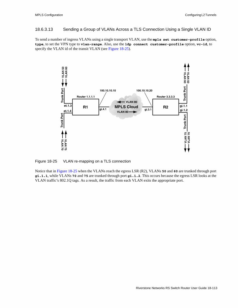
MPLS Configuration Configuring L2 Tunnels
18.6.3.13 Sending a Group of VLANs Across a TLS Connection Using a Single VLAN ID
To send a number of ingress VLANs using a single transport VLAN, use the mpls set customer-profile option, type, to set the VPN type to vlan-range. Also, use the ldp connect customer-profile option, vc-id, to specify the VLAN id of the transit VLAN (see Figure 18-25).
Figure 18-25 VLAN re-mapping on a TLS connection
Notice that in Figure 18-25 when the VLANs reach the egress LSR (R2), VLANs 50 and 60 are trunked through port gi.1.1, while VLANs 70 and 75 are trunked through port gi.1.2. This occurs because the egress LSR looks at the VLAN traffic’s 802.1Q tags. As a result, the traffic from each VLAN exits the appropriate port.
R1 R2MPLS Cloudet.1.3 gi.1.1
Tru
nk
Po
rtV
LA
N 5
0V
LA
N 6
0
Router 1.1.1.1 Router 3.3.3.3
100.10.10.10
gi.4.1et.1.4 gi.1.2
VL
AN
75V
LA
N 70
Tru
nk
Po
rt
VLAN 80
VL
AN
50V
LA
N 60
VL
AN
75
VL
AN
70
Tru
nk
Po
rtTr
un
k P
ort
VLAN 80
100.10.10.20
gi.3.1
Riverstone Networks RS Switch Router User Guide 18-113

Configuring L2 Tunnels MPLS Configuration
The following is an example of configuration for ingress LSR (R1) that sends VLANs 50, 60, 70, and 75 across the MPLS cloud using a single transit VLAN with id 80
This example assumes that the configuration on egress LSR R2 is very similar to R1’s configuration. For instance, the same number of trunk ports and VLANs must exist on both the ingress and egress LSRs. Furthermore, the VLAN ids must be identical on RS1 and RS2.
vlan make trunk-port et.1.3vlan make trunk-port et.1.4
vlan create V1 port-based id 50vlan create V2 port-based id 60vlan create V3 port-based id 70vlan create V4 port-based id 75
vlan add ports et.1.3 to V1vlan add ports et.1.3 to V2vlan add ports et.1.4 to V3vlan add ports et.1.4 to V4
interface create ip mpls1 address-netmask 100.10.10.10/24 port gi.4.1interface add ip lo0 address-netmask 1.1.1.1/32
ip-router global set router-id 1.1.1.1
ospf create area backboneospf add interface mpls1 to-area backboneospf add stub-host 1.1.1.1 to-area backbone cost 10ospf start
mpls set customer-profile prof-1 customer-id 111 in-port-list et.1.3-4 type vlan-range vlans 50,60,70,75mpls add interface mpls1mpls start
ldp add remote-peer 3.3.3.3ldp connect customer-profile prof-1 remote-peer 3.3.3.3 vc-type ethernet-vlan vc-id 80ldp add interface mpls1ldp start
18-114 Riverstone Networks RS Switch Router User Guide
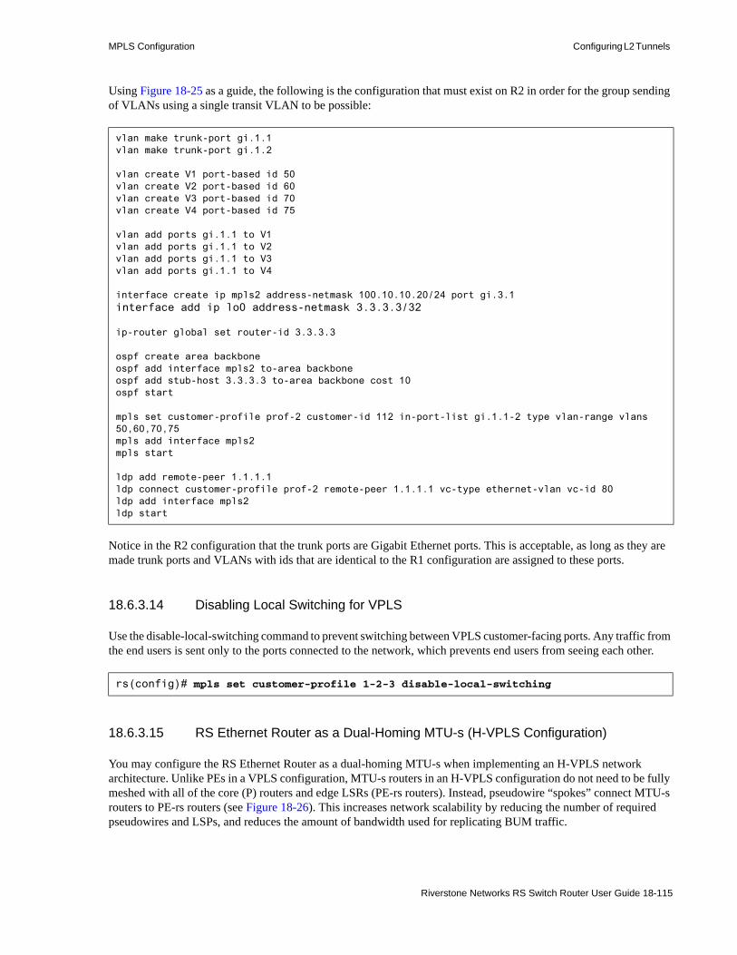
MPLS Configuration Configuring L2 Tunnels
Using Figure 18-25 as a guide, the following is the configuration that must exist on R2 in order for the group sending of VLANs using a single transit VLAN to be possible:
Notice in the R2 configuration that the trunk ports are Gigabit Ethernet ports. This is acceptable, as long as they are made trunk ports and VLANs with ids that are identical to the R1 configuration are assigned to these ports.
18.6.3.14 Disabling Local Switching for VPLS
Use the disable-local-switching command to prevent switching between VPLS customer-facing ports. Any traffic from the end users is sent only to the ports connected to the network, which prevents end users from seeing each other.
18.6.3.15 RS Ethernet Router as a Dual-Homing MTU-s (H-VPLS Configuration)
You may configure the RS Ethernet Router as a dual-homing MTU-s when implementing an H-VPLS network architecture. Unlike PEs in a VPLS configuration, MTU-s routers in an H-VPLS configuration do not need to be fully meshed with all of the core (P) routers and edge LSRs (PE-rs routers). Instead, pseudowire “spokes” connect MTU-s routers to PE-rs routers (see Figure 18-26). This increases network scalability by reducing the number of required pseudowires and LSPs, and reduces the amount of bandwidth used for replicating BUM traffic.
vlan make trunk-port gi.1.1vlan make trunk-port gi.1.2
vlan create V1 port-based id 50vlan create V2 port-based id 60vlan create V3 port-based id 70vlan create V4 port-based id 75
vlan add ports gi.1.1 to V1vlan add ports gi.1.1 to V2vlan add ports gi.1.1 to V3vlan add ports gi.1.1 to V4
interface create ip mpls2 address-netmask 100.10.10.20/24 port gi.3.1interface add ip lo0 address-netmask 3.3.3.3/32
ip-router global set router-id 3.3.3.3
ospf create area backboneospf add interface mpls2 to-area backboneospf add stub-host 3.3.3.3 to-area backbone cost 10ospf start
mpls set customer-profile prof-2 customer-id 112 in-port-list gi.1.1-2 type vlan-range vlans 50,60,70,75mpls add interface mpls2mpls start
ldp add remote-peer 1.1.1.1ldp connect customer-profile prof-2 remote-peer 1.1.1.1 vc-type ethernet-vlan vc-id 80ldp add interface mpls2ldp start
rs(config)# mpls set customer-profile 1-2-3 disable-local-switching
Riverstone Networks RS Switch Router User Guide 18-115

Configuring L2 Tunnels MPLS Configuration
MTU-s routers may be thought of as a second level of PE routers. This architecture enables you to scale VPLS to a larger number of PE routers while reducing signaling and replication overhead because the MTU-s routers use fewer pseudowires.
MTU-s routers are typically positioned at the customer access point, connected to one or two PE-rs routers (peers) by point-to-point pseudowires called spokes. The MTU-s supports Layer 2 switching and maps customer connections to the PE-rs router peers via the spokes. Dual-homing -- connecting an MTU-s to two PE-rs routers -- provides redundancy (fault tolerance). If an MTU-s router is connected to only one peer, if that link goes down, then the MTU-s is completely disconnected from the core network.
In dual-homing configurations, you specify one PE-rs peer as the primary connection and another PE-rs peer as the secondary connection. In Figure 18-26, the spokes from the MTU-s to the primary connection are solid lines and the spokes from the MTU-s to the secondary connection are broken (dotted) lines. If the primary connection goes down, a switchover occurs and the secondary connection immediately becomes active, thus preventing a break in service. (Although the secondary peer is in standby mode, the MTU-s negotiates labels over both connections so if the primary link fails, the secondary link comes up seamlessly.)
Figure 18-26 MTU-s in an H-VPLS Network Architecture
Designating one of the dual-homed peers as a secondary connection avoids loops because only one connection is active at any given time. Therefore, no major “extra” protocol, such as STP, needs to run on the RS Ethernet Router when it is used as an MTU-s to avoid loops.
You may configure the RS Ethernet Router MTU-s to generate MAC withdrawal messages on switchovers, and to limit (dampen) the number of MAC withdrawal messages to prevent flooding these messages if a primary connection flaps (e.g., if a transport LSP goes down and comes back up repeatedly in a short duration), as described later in this chapter. MAC withdrawal messages speed up convergence after a switchover.
If the primary peer connection fails and the dual-homed MTU-s switches over to the secondary peer connection, then the primary connection comes back up, the default behavior is to switch back to the primary connection automatically. You can disable automatic switchback on a global or a per-peer basis in order to manually control if or when to perform the switchback, as described later in this chapter. If you disable automatic switchback, you may switchback manually.
Although you may configure the RS Ethernet Router as an MTU-s router in a dual-homing architecture, you may not use the RS Ethernet Router as a PE-rs router in a dual-homing architecture. The RS Ethernet Router may be used as aggregators and access nodes at the network edge, but it is not intended for use as a core router (PE-rs or P).
M T UM T U -- ss
P EP E -- r sr s
PP -- o n l yo n l y
A c t i v e a n d A c t i v e a n d s t a n d b y s t a n d b y s p o k e ss p o k e s
18-116 Riverstone Networks RS Switch Router User Guide
MPLS Configuration Configuring L2 Tunnels
18.6.3.16 Configuring MTU-s Dual-Homing
To configure an RS Ethernet Router as a dual-homing MTU-s, create a pseudowire connection to a PE-rs router that will be the primary peer and a second pseudowire connection to a PE-rs router that will be designated as the secondary peer. The RS Ethernet Router may not be used as a PE-rs router in dual-homing configurations.
The PE-rs peer configuration depends on the PE-rs router used in the dual-homing architecture. The PE-rs router must support dual-homing.
Previous VPLS examples in this section show how to configure customer VLANs, add loopback interfaces, create the OSPF backbone area, create MPLS interfaces and LSPs to remote peers, create customer profiles (FECs), and add VLAN interface and remote peer connections to the router. These procedures are the same when you use the RS Ethernet Router as a dual-homing MTU-s so they are not repeated here.
The dual-homing MTU-s configuration for H-VPLS differs from VPLS configurations in the way you set the VPN connections between the MTU-s router and the remote peers. When the RS Ethernet Router is used as a dual-homing MTU-s, only two PE-side remote-peer connections per FEC are allowed: a primary peer and a secondary peer. You may set multiple customer-edge side connections.
The following example assumes the MTU-s has been configured except for the VPN connections to the remote PE-rs peers and the MAC withdraw and no switchback features discussed in the next subsections. It assumes the customer profile cust1 has been created using the mpls set customer-profile command and the remote peers (primary PE-rs router with IP address 115.1.1.2 and secondary PE-rs router with IP address 115.1.1.3) have been added using the ldp add remote-peer <ip-addr> command:
Dual-Homing MTU-s Configuration Example
Create the connection to the primary peer PE-rs router:rs(config)# ldp connect customer-profile cust1 remote-peer 115.1.1.2
Create the connection to the secondary peer PE-rs router. The optional keyword “secondary” designates the PE-rs router as the secondary peer:rs(config)# ldp connect customer-profile cust1 remote-peer 115.1.1.3 secondary
If the primary peer connection (115.1.1.2) fails, the MTU-s automatically switches over to the secondary peer connection (115.1.1.3). The next sections describe the MAC withdraw and no switchback features.
18.6.3.17 MAC Withdrawal
In a dual-homing architecture, MAC address withdrawal messages enable faster convergence after a switchover. Without MAC withdrawal, if the primary peer fails and MTU-s switches over to the secondary peer connection, some remote PEs may continue to send traffic to the primary peer until its MAC addresses age out. The MAC address withdrawal feature avoids this problem by sending a MAC withdrawal message to the secondary peer to remove the invalid MAC addresses.
The RS Ethernet Router supports sending a MAC withdrawal message that contains an empty MAC address list, also known as a wildcard address withdrawal. The empty list withdraw message removes all MAC addresses associated with the particular VPLS instance except MAC addresses learned over the pseudowire on which the MAC withdraw message was sent.
Riverstone Networks RS Switch Router User Guide 18-117

Configuring L2 Tunnels MPLS Configuration
The MAC withdrawal feature is disabled by default. You enable MAC withdrawal on a per-peer basis. MAC withdrawal messages are sent only to peers for which you have enabled sending MAC withdraw messages. To enable MAC withdrawal, use the command: rs(config)# ldp set remote-peer <ip-addr> mac-withdraw
For example, to enable sending MAC withdrawal messages to the two peers specified in the dual-homing example in the previous subsection, use the commands:rs(config)# ldp set remote-peer 115.1.1.2 mac-withdrawrs(config)# ldp set remote-peer 115.1.1.3 mac-withdraw
You can verify if MAC address withdrawal is enabled on the router for a particular session with a remote peer using the command:rs# ldp show remote-peer
For detailed information about MAC address withdrawal (enable status, received, sent), use the command:rs# ldp show session verbose
18.6.3.18 MAC Address Withdrawal Dampening (Limiting)
A primary peer connection may go down, forcing a switchover to the secondary peer, then come up and go back down again repeatedly during a short period of time. This is called “flapping”. If MAC withdrawal is enabled and the primary peer connection flaps, it causes a flood of MAC withdrawal messages. Flooding may also occur if a malfunctioning peer sends too many MAC address withdrawal messages.
To prevent MAC withdrawal message flooding, you can limit (dampen) the number of MAC withdrawal messages. The RS Ethernet Router dampens MAC address withdrawal by using a credit-based system (this is essentially a counter-type mechanism). Each credit allows one MAC address message to be received from a remote peer. The credits are assigned on two levels, peer and system. Peer credits are assigned to each remote peer and system credits are assigned to the system as a whole. Remote peers use their credits first to send MAC withdrawal messages to the MTU-s. Every time a peer sends a MAC withdrawal message, its credit total goes down one credit. If a peer runs out of credits, it uses the system credits, if any are available. Each time a peer uses a system credit, the system credit counter is decremented by one. If no credits are available, the MAC withdrawal message is not sent. Each remote peer can only send a MAC withdrawal message if credit is available.
If there are a high number of FECs for which MAC address withdrawal messages must be sent, the configured limit should be high so that MAC withdrawal messages are sent as required. Once the credit limit is reached, no more MAC withdrawal messages are sent until the credit limit is refreshed. Credits are awarded every 10 minutes. After each 10 minute interval, the remaining peer and system credits expire and are refreshed with the configured number of credits.
MAC address withdrawal has the benefit of faster convergence after a switchover, but it also causes higher CPU utilization, so it is best to set a number of peer and system credits that preserve the benefits of fast convergence but do not permit LSP flapping to flood the MTU-s with withdrawal messages.
You set peer and system credits at the global level. You cannot set different credit numbers for different peers. Every peer starts each 10 minute interval with the same number of credits. The default credit value for peers is 65535. The default credit value for the system is 65535. The range of values for both peer and system credits is 1 - 65535. When MAC address withdrawal is enabled, the peers and system use the default values. To configure global peer and system values, use the following commands:rs(config)# ldp set global peer-mac-withdraw-credit <1..65535> rs(config)# ldp set global system-mac-withdraw-credit <1..65535>
18-118 Riverstone Networks RS Switch Router User Guide
MPLS Configuration Configuring L2 Tunnels
Note The MAC address TLV defined in the draft does not include a VLAN field. Therefore, for port-to-port or VLAN range FECs, a MAC withdrawal request with an empty list (wildcard MAC withdrawal, which is the only form of MAC withdrawal the RS Ethernet Router supports) is discarded.
For example, the following two commands set the peer MAC withdraw credit to 50 and the system MAC withdraw credit to 100:rs(config)# ldp set global peer-mac-withdraw-credit 50rs(config)# ldp set global system-mac-withdraw-credit 100
Use the following command to verify or display the global peer and system MAC withdraw credit values:rs# ldp show global
The following command allows you to trace and debug MAC address withdrawal: rs(config)# ldp set trace-options address
The command below enables LDP address withdraw message traces at the LDP layer. When a MAC address withdraw message is received, it prints the FEC TLV contents and MAC address TLV contents.rs(config)# ldp set trace-level 4
18.6.3.19 Disabling Automatic Switchback after a Switchover
If the primary peer connection fails and the dual-homed MTU-s switches over to the secondary peer connection, then the primary connection comes back up, the default behavior is to switch back from the secondary connection to the primary connection automatically.
However, it is strongly recommended that you disable automatic switchback for primary remote peers in dual-homing H-VPLS networks. There are several reasons to disable automatic switchback. One is that if a primary peer flaps (goes down, then comes back up, then goes down and up again repeatedly in a short period of time), disabling automatic switchback avoids constant switchovers. Another reason is that the primary peer may not have enough time to set up its pseudowire to the MTU-s before the MTU-s switches back. Disabling automatic switchback allows you to check and make sure the primary peer is up and fully functional before forcing a switchback as described below.
You may disable automatic switchback on the global level or disable automatic switchback on a per-peer basis.
To disable automatic switchback from secondary peers to primary peers on a global level, use the command:rs(config)# ldp set global no-pwe-switchback
“PWE” stands for pseudowire emulation. This command prevents all secondary peers for all FECs associated with the MTU-s from automatically switching back if their primary peer comes back up after a switchover.
To disable automatic switchback for a specific peer, use the command:rs(config)# ldp set l2-tls customer-id <num> to-peer <ip-addr> no-pwe-switchback
For example, to disable automatic switchback to the primary remote peer connected to the MTU-s in the dual-homing subsection example, use the following command (this example assumes the customer ID is “500”):rs(config)# ldp set l2-tls customer-id 500 to-peer 115.1.1.2 no-pwe-switchback
When automatic switchback is disabled, you must force a switchover back to the primary peer manually after you confirm that it is fully operational (unless you want to continue using the secondary peer). Note that the forced switchover command is available in enabled mode, not in configure mode. To force a switchover, use the following command:
Riverstone Networks RS Switch Router User Guide 18-119
Configuring L2 Tunnels MPLS Configuration
rs# ldp force pwe-switchover customer-id <num> [vc-id <num>]
The optional parameter [vc-id <num>] is to do the pseudowire switchover for a specific customer profile and that customer-profile is of the type vlan-range-to-vlan-range. If you want to do the switchover for the whole customer profile, you do not need to specify this optional parameter.
For example, to force a switchover to the primary peer used for the FEC with the customer ID 500, use the following command:rs# ldp force pwe-switchover customer-id 500
To verify which remote peer is active and whether no-pwe-switchback is enabled, use the command:rs# ldp show l2-fec verbose
The following command shows whether no-pwe-switchback is enabled:rs# ldp show global
18-120 Riverstone Networks RS Switch Router User Guide
MPLS Configuration Traffic Engineering
18.7 TRAFFIC ENGINEERINGOne of the most important applications of MPLS is traffic engineering. Traffic engineering allows you to optimize the utilization of network resources and traffic performance throughout a network. Traffic engineering does not mean that the shortest path is always selected—traditional shortest path routing, as determined by interior gateway protocols (IGPs), can cause both network congestion and the overuse of certain network paths, while longer paths are under-utilized. Traffic engineering allows more efficient use of available bandwidth while avoiding congestion. Packets with the same source and destination addresses can travel completely different paths in the network.
With MPLS, explicit LSPs can provide traffic engineering. For example, you can configure two explicit paths to the same destination, with one the primary and the other the secondary path. However, explicit LSPs require you to configure the paths on the ingress router. More dynamic traffic engineering can be performed with constraint-based LSPs.
Traffic engineering requires extensions to the IGP. The RS Ethernet Router provides extensions to OSPF and IS-IS IGPs to support traffic engineering with MPLS. Traffic engineering is disabled by default for OSPF and IS-IS on RS Ethernet Router routers.
This section discusses some of the features of traffic engineering and provides example configurations.
18.7.1 Administrative Groups
An MPLS administrative group3 designates certain link attributes that can be used to impose additional path constraints. Administrative groups can be used to contain certain traffic trunks within specific topological regions of an MPLS network. You can employ administrative groups for path setup and selection for constrained path LSPs. You can use administrative groups to:• Apply the same policies to a set of resources that are not necessarily in the same topological area.• Specify the relative preference of a set of resources for placement of traffic trunks.• Restrict the placement of traffic trunks to specific sets of resources.• Implement general include/exclude policies.• Enforce policies that contain local traffic within specific regions of the network.• Identify a particular set of resources.
For example, all OC-48 links in a network may be assigned to a particular administrative group. You can also assign subsets of the OC-48 links to other administrative groups.
If you use administrative groups, the names of the groups and their corresponding decimal values must be the same on all routers within the domain. You can configure up to 32 administrative groups in an MPLS domain.
You can specify one or more administrative groups to be included or excluded from an LSP computation. If you include any administrative groups in an LSP computation, each selected link will have at least one included group. If you exclude specific administrative groups in an LSP computation, each selected link cannot have any excluded groups. If you include or exclude administrative groups in an LSP computation, links that do not have an associated group are not considered. You can configure administrative group constraints for an LSP, or for a primary or secondary LSP. You can include or exclude a maximum of 16 administrative groups for an LSP, or for a primary or secondary path.
You can assign one or more administrative groups to a router interface. IGPs use administrative groups to provide information, such as IGP topology, to all routers in the domain.
3. Administrative groups are referred to as resource classes or link colors in some implementations.
Riverstone Networks RS Switch Router User Guide 18-121

Traffic Engineering MPLS Configuration
If you change the administrative group for an LSP, the route is recalculated and the LSP may be rerouted. If you change the administrative group for an interface, the change affects only new LSPs on the interface.
To set up administrative groups, do the following:1. Create the administrative groups with the mpls create admin-group command. Assign each
group a decimal value between 1-32. You must create identical group names and assign the same value to each group on all routers in the MPLS domain. For example:
2. Assign one or more groups to an interface with the mpls set interface command. This identifies the administrative groups to which the interface belongs. For example:
3. Specify administrative groups to be included or excluded from an LSP computation. To include or exclude groups for an LSP, use the mpls create label-switched-path command. For example:
To include or exclude groups for a primary or secondary LSP path, use the mpls set label-switched-path command. For example:
An example of using administrative groups is shown in Section 18.7.2, "Constrained Shortest Path First."
mpls create admin-group sector1 group-value 1
mpls set interface RS1IN admin-group sector1
mpls create label-switched-path LSP1 include sector1
mpls set label-switched-path LSP1 primary PA include sector1
18-122 Riverstone Networks RS Switch Router User Guide

MPLS Configuration Traffic Engineering
Use the mpls show admin-groups command to see the administrative groups configured on an RS Ethernet Router. For example:
The mpls show interface command shows the interfaces configured on an RS Ethernet Router and the administrative group, if any, that is applied to an interface. For example, in the following output the administrative group sector1 is applied to the interfaces R2R3 and R2R1b:
18.7.2 Constrained Shortest Path First
An ingress LSR uses the information in the traffic engineering database (TED) to calculate its LSPs across the network. The constrained shortest path first (CSPF) algorithm is a modification of the OSPF and IS-IS shortest path first calculation. With CSPF, nodes and links for an LSP are accepted or rejected based on resource availability or on whether administrative group or policy constraints are met. The result is an explicit route that provides the shortest path through the network that meets certain constraints. The explicit route, comprised of a sequence of LSR addresses, is passed to the signaling protocol to deliver the path information to each LSR in the LSP.
The CSPF algorithm takes into account link-state and network state information from the TED, as well as the following LSP attributes:• bandwidth• hops• administrative group• setup and hold priority• strict or loose explicit route
When choosing between multiple equal-cost paths to a destination, CSPF applies the following tie-breaking algorithm:1. Select the path whose last hop address is the same as the LSP’s destination address2. Select the path with the fewest number of hops3. Select the path that is least loaded (i.e., with the largest available bandwidth). The least-loaded
selection mechanism aims to equalize the reservations on each link.
rs# mpls show admin-groups Group Bit index ----- --------- sector1 1
rs# mpls show interface allInterface State Administrative groupslo Up <none>lo Up <none>R2R3 Up sector1 R2R1 Up <none>R2R1b Up sector1
Riverstone Networks RS Switch Router User Guide 18-123

Traffic Engineering MPLS Configuration
To enable CSPF on RS Ethernet Router routers:1. If OSPF is the IGP, enable traffic engineering extensions for OSPF with the ospf set
traffic-engineering on command. If IS-IS is the IGP, enable traffic engineering extensions for IS-IS with the isis set traffic-engineering enable command.
Note Traffic engineering with OSPF as the IGP requires support for opaque LSAs (defined by RFC 2370). This support is enabled by default on the RS Ethernet Router, but can be disabled with the ospf set opaque-capability off CLI command. If you are enabling traffic engineering extensions for OSPF, make sure that opaque LSA support has not been disabled.
2. Configure the dynamic LSP, as described in Section 18.5.3, "Configuring an Explicit LSP." Do not specify the no-cspf parameter with the mpls create label-switched-path or mpls set label-switched-path commands.
18.7.2.1 Constrained Path Selection Configuration Example for OSPF Traffic Engineering
The following example illustrates constrained path selection based on an administrative group with OSPF as the IGP. The same administrative group must be configured on all routers in the LSP. In the example shown in Figure 18-27, the administrative group ‘SKY’ with a value of 7 is created on all LSRs and applied to the following interfaces: R1R2b on R1, R2R1b and R2R3 on R2, and R3R2 on R3. An LSP ‘LSP1’ is configured on R1 with R3 as the LSP destination and SKY as the administrative group. That means that even though there are two possible paths from R1 to R3, CSPF selects the path that traverses through the interfaces where the administrative group SKY is applied.
Timesaver Click on the router name (in blue) to see the corresponding configuration.
Figure 18-27 Constrained path selection by administrative group
R1 R2 R3
R1R2
R1R2b*
R2R1
R2R1b*
R2R3* R3R2*
Interface where administrative group is appliedCSPF-selected Path
R1R2b*
18-124 Riverstone Networks RS Switch Router User Guide

MPLS Configuration Traffic Engineering
The following is the configuration for R1:
The following is the configuration for R2:
! Create interfacesinterface create ip R1R2 address-netmask 16.128.11.10/24 port gi.4.1
interface create ip R1R2b address-netmask 94.9.9.10/24 port gi.3.1
interface add ip lo0 address-netmask 1.1.1.1/16
! Configure OSPFip-router global set router-id 1.1.1.1
ospf create area backbone
ospf add stub-host 1.1.1.1 to-area backbone cost 10
ospf add interface R1R2 to-area backbone
ospf add interface R1R2b to-area backbone
ospf set traffic-engineering on Enable traffic engineering extensions for OSPFospf start
! Create and apply admin-groupmpls create admin-group sky group-value 7
mpls add interface R1R2b
mpls set interface R1R2b admin-group sky
! Configure LSP with admin-group constraint (do not specify no-cspf parameter)mpls create label-switched-path LSP1 to 3.3.3.3 include sky
!Enable and start MPLS and RSVPmpls add interface R1R2
mpls start
rsvp add interface R1R2
rsvp add interface R1R2b
rsvp start
! Create interfacesinterface create ip R2R1 address-netmask 16.128.11.7/24 port gi.6.2
interface create ip R2R1b address-netmask 94.9.9.11/24 port gi.5.1
interface create ip R2R3 address-netmask 201.135.89.197/26 port gi.4.1
interface add ip lo0 address-netmask 2.2.2.2/16
! Configure OSPFip-router global set router-id 2.2.2.2
ospf create area backbone
ospf add stub-host 2.2.2.2 to-area backbone cost 10
ospf add interface R2R1 to-area backbone
ospf add interface R2R1b to-area backbone
ospf add interface R2R3 to-area backbone
ospf set traffic-engineering on Enable traffic engineering extensions for OSPFospf start
Riverstone Networks RS Switch Router User Guide 18-125

Traffic Engineering MPLS Configuration
The following is the configuration for R3:
! Create and apply admin-groupmpls create admin-group sky group-value 7
mpls add interface R2R1
mpls add interface R2R1b
mpls add interface R2R3
mpls set interface R2R1b admin-group sky
mpls set interface R2R3 admin-group sky
! Enable and start MPLS and RSVPmpls start
rsvp add interface R2R1
rsvp add interface R2R1b
rsvp add interface R2R3
rsvp start
! Create interfacesinterface create ip R3R2 address-netmask 201.135.89.195/26 port gi.1.2
interface add ip lo0 address-netmask 3.3.3.3/16
! Configure OSPFip-router global set router-id 3.3.3.3
ospf create area backbone
ospf add stub-host 3.3.3.3 to-area backbone cost 10
ospf add interface R3R2 to-area backbone
ospf set traffic-engineering on Enable traffic engineering extensions for OSPFospf start
! Create and apply admin-groupmpls create admin-group sky group-value 7
mpls add interface R3R2
mpls set interface R3R2 admin-group sky
! Enable and start MPLS and RSVPmpls start
rsvp add interface R3R2
rsvp start
18-126 Riverstone Networks RS Switch Router User Guide
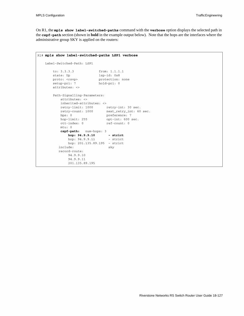
MPLS Configuration Traffic Engineering
On R1, the mpls show label-switched-paths command with the verbose option displays the selected path in the cspf-path section (shown in bold in the example output below). Note that the hops are the interfaces where the administrative group SKY is applied on the routers:
R1# mpls show label-switched-paths LSP1 verbose Label-Switched-Path: LSP1 to: 3.3.3.3 from: 1.1.1.1 state: Up lsp-id: 0x8 proto: <rsvp> protection: none setup-pri: 7 hold-pri: 0 attributes: <> Path-Signalling-Parameters: attributes: <> inherited-attributes: <> retry-limit: 1000 retry-int: 30 sec. retry-count: 1000 next_retry_int: 60 sec. bps: 0 preference: 7 hop-limit: 255 opt-int: 600 sec. ott-index: 0 ref-count: 0 mtu: 0 cspf-path: num-hops: 3 hop: 94.9.9.10 - strict hop: 94.9.9.11 - strict hop: 201.135.89.195 - strict include: sky record-route: 94.9.9.10 94.9.9.11 201.135.89.195
Riverstone Networks RS Switch Router User Guide 18-127
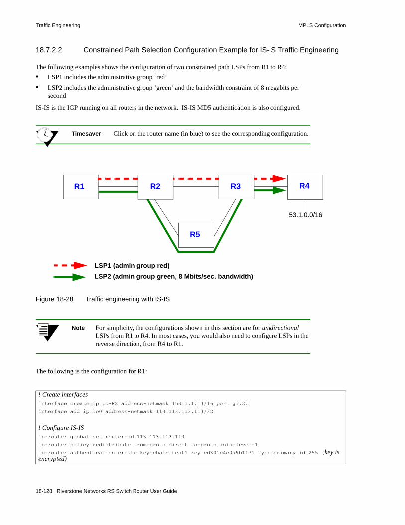
Traffic Engineering MPLS Configuration
18.7.2.2 Constrained Path Selection Configuration Example for IS-IS Traffic Engineering
The following examples shows the configuration of two constrained path LSPs from R1 to R4:• LSP1 includes the administrative group ‘red’• LSP2 includes the administrative group ‘green’ and the bandwidth constraint of 8 megabits per
second
IS-IS is the IGP running on all routers in the network. IS-IS MD5 authentication is also configured.
Timesaver Click on the router name (in blue) to see the corresponding configuration.
Figure 18-28 Traffic engineering with IS-IS
Note For simplicity, the configurations shown in this section are for unidirectional LSPs from R1 to R4. In most cases, you would also need to configure LSPs in the reverse direction, from R4 to R1.
The following is the configuration for R1:
! Create interfacesinterface create ip to-R2 address-netmask 153.1.1.13/16 port gi.2.1
interface add ip lo0 address-netmask 113.113.113.113/32
! Configure IS-ISip-router global set router-id 113.113.113.113
ip-router policy redistribute from-proto direct to-proto isis-level-1
ip-router authentication create key-chain test1 key ed301c4c0a9b1171 type primary id 255 (key is encrypted)
R5
R4R3R2R1
LSP1 (admin group red)LSP2 (admin group green, 8 Mbits/sec. bandwidth)
53.1.0.0/16
18-128 Riverstone Networks RS Switch Router User Guide

MPLS Configuration Traffic Engineering
The following is the configuration for R2:
isis add area 53.da05
isis add interface lo0
isis add interface to-R2
isis set system-id 13.1313.1313.13
isis set interface to-R2 key-chain test1 authentication-method md5
isis set area-key-chain test1 authentication-method md5
isis set traffic-engineering enable
isis set level 1
isis set interface lo0 level 1
isis start
! Configure MPLSmpls add interface to-R2
mpls set interface to-R2 admin-group red,green
mpls create admin-group red group-value 1
mpls create admin-group green group-value 3
mpls create label-switched-path LSP1 from 113.113.113.113 to 124.124.124.124
mpls create label-switched-path LSP2 from 113.113.113.113 to 124.124.124.124
mpls set label-switched-path LSP1 include red
mpls set label-switched-path LSP2 include green bps 8000000
mpls create policy to-53-net dst-ipaddr-mask 53.0.0/16 proto ip
mpls set label-switched-path LSP1 policy to-53-net
mpls start
! Enable and start RSVPrsvp add interface to-R2
rsvp start
! Configure VLANssmarttrunk create st.1 protocol no-protocol
smarttrunk add ports et.3.3 to st.1
smarttrunk add ports et.3.4 to st.1
vlan create to-R3 ip
vlan add ports st.1 to to-R3
vlan create to-R5 ip
vlan add ports et.3.5 to to-R5
! Create interfacesinterface create ip to-R1 address-netmask 153.1.1.12/16 port gi.6.1
interface create ip to-R3 address-netmask 192.1.1.12/24 vlan to-R3
interface create ip to-R5 address-netmask 186.1.1.12/8 vlan to-R5
interface add ip lo0 address-netmask 12.12.12.12/32
! Configure IS-IS
Riverstone Networks RS Switch Router User Guide 18-129

Traffic Engineering MPLS Configuration
The following is the configuration for R3:
ip-router global set router-id 12.12.12.12
ip-router authentication create key-chain test1 key ed301c4c0a9b1171 type primary id 255 (key is encrypted)isis add area 53.da05
isis add interface lo0
isis add interface to-R3
isis add interface to-R5
isis add interface to-R1
isis set system-id 12.1212.1212.12
isis set level 1-and-2
isis set interface to-R3 level 1
isis set interface to-R1 key-chain test1 authentication-method md5
isis set area-key-chain test1 authentication-method md5
isis set interface to-R3 key-chain test1 authentication-method md5
isis set interface to-R5 level 1
isis set interface to-R5 key-chain test1 authentication-method md5
isis set traffic-engineering enable
isis set interface to-R1 level 1
isis start
! Configure MPLSmpls add interface all
mpls add interface lo0
mpls set interface to-R5 bandwidth 20000000
mpls set interface to-R3 admin-group red
mpls set interface to-R1 admin-group red,green
mpls set interface to-R5 admin-group green
mpls create admin-group red group-value 1
mpls create admin-group green group-value 3
mpls start
! Enable and start RSVPrsvp add interface all
rsvp start
! Configure VLANssmarttrunk create st.1 protocol no-protocol
smarttrunk add ports et.13.3 to st.1
smarttrunk add ports et.13.4 to st.1
vlan make trunk-port et.13.8
vlan create to-R2 ip
vlan add ports st.1 to to-R2
vlan create to-R5 ip
vlan add ports et.6.8 to to-R5
vlan create to-R4 ip id 22
18-130 Riverstone Networks RS Switch Router User Guide

MPLS Configuration Traffic Engineering
vlan add ports et.13.8 to to-R4
! Create interfacesinterface add ip lo0 address-netmask 15.15.15.15/32
interface create ip to-R2 address-netmask 192.1.1.15/24 vlan to-R2
interface create ip to-R5 address-netmask 187.1.1.15/16 vlan to-R5
interface create ip to-R4 address-netmask 185.1.1.15/16 vlan to-R4
! Configure IS-ISip-router global set router-id 15.15.15.15
ip-router authentication create key-chain test1 key ed301c4c0a9b1171 id 255 type primary (key is encrypted)isis add area 53.da05
isis add interface to-R5
isis add interface to-R4
isis add interface to-R2
isis add interface lo0
isis set system-id 15.1515.1515.15
isis set interface to-R4 level 1
isis set level 1-and-2
isis set interface to-R5 level 1
isis set interface to-R2 level 1
isis set area-key-chain test1 authentication-method md5
isis set interface to-R2 key-chain test1 authentication-method md5
isis set interface to-R4 key-chain test1 authentication-method md5
isis set interface to-R5 key-chain test1 authentication-method md5
isis set traffic-enghneering enable
isis set interface lo0 level 1
isis start
! Configure MPLSmpls add interface all
mpls set interface to-R5 bandwidth 20000000
mpls set interface to-R5 admin-group green
mpls set interface to-R4 admin-group red,green
mpls set interface to-R2 admin-group red
mpls create admin-group red group-value 1
mpls create admin-group green group-value 3
mpls start
! Enable and start RSVPrsvp add interface all
rsvp start
Riverstone Networks RS Switch Router User Guide 18-131

Traffic Engineering MPLS Configuration
The following is the configuration for R4:
The following is the configuration for R5:
! Configure VLANsvlan create to-R3 ip id 22
vlan add ports et.16.23 to to-R3
vlan create 53net ip
vlan add ports et.13.22 to 53net
vlan make trunk-port et.14.23
! Create interfacesinterface create ip to-R3 address-netmask 185.1.1.24/16 vlan to-R3
interface create ip to-R3 address-netmask 185.1.1.24/16 port et.16.23
interface create ip 53net address-netmask 53.1.1.22/16 vlan 53net
! Configure IS-ISip-router global set router-id 124.124.124.124
ip-router policy redistribute from-proto direct to-proto isis-level-1
ip-router authentication create key-chain test1 key ed301c4c0a9b1171 type primary id 255 (key is encrypted)isis add area 53.da05
isis add interface lo0
isis add interface to-R3
isis set system-id 24.2424.2424.24
isis set level 1
isis set interface to-R3 level 1
isis set interface lo0 level 1
isis set interface to-R3 key-chain test1 authentication-method md5
isis set area-key-chain test1 authentication-method md5
isis set traffic-engineering enable
isis start
! Configure MPLSmpls add interface to-R3
mpls set interface to-R3 admin-group red,green
mpls create admin-group red group-value 1
mpls create admin-group green group-value 3
mpls start
! Configure RSVPrsvp add interface to-R3
rsvp start
! Configure VLANsvlan create to-R2 ip
vlan add ports et.2.15 to to-R2
18-132 Riverstone Networks RS Switch Router User Guide

MPLS Configuration Traffic Engineering
The following is the mpls show label-switched-path LSP1 verbose command on R1 that shows the selected path for LSP1 in the cspf-path section (shown in bold in the example output below). Note that the hops are the interfaces where the administrative group ’red’ is applied on the routers.
vlan create to-R3 ip
vlan add ports et.1.15 to to-R3
! Create interfacesinterface create ip to-R2 address-netmask 186.1.1.26/8 vlan to-R2
interface create ip to-R3 address-netmask 187.1.1.26/16 vlan to-R3
! Configure IS-ISip-router global set router-id 126.126.126.126
ip-router authentication create key-chain test1 key ed301c4c0a9b1171 type primary id 255 (key is encrypted)isis add area 53.da05
isis add interface lo0
isis add interface to-R2
isis add interface to-R3
isis set level 1
isis set system-id 26.2626.2626.26
isis set interface to-R2 level 1
isis set interface to-R3 level 1
isis set area-key-chain test1 authentication-method md5
isis set interface to-R2 key-chain test1 authentication-method md5
isis set interface to-R3 key-chain test1 authentication-method md5
isis set traffic-engineering enable
isis start
! Configure MPLSmpls add interface all
mpls set interface to-R2 admin-group green
mpls set interface to-R3 bandwidth 20000000
mpls set interface to-R2 bandwidth 20000000
mpls set interface to-R3 admin-group green
mpls create admin-group red group-value 1
mpls create admin-group green group-value 3
mpls start
! Enable and start RSVPrsvp add interface all
rsvp start
R1# mpls show label-switched-paths LSP1 verbose
Label-Switched-Path: "LSP1"
to: 124.124.124.124 from: 113.113.113.113
Riverstone Networks RS Switch Router User Guide 18-133

Traffic Engineering MPLS Configuration
The following is the mpls show label-switched-path LSP2 verbose command on R1 that shows the selected path for LSP2 in the cspf-path section (shown in bold in the example output below). Note that the hops are the interfaces where the administrative group ’green’ is applied on the routers. This LSP also has a bandwidth of 8 Mbps reserved on the path.
state: Up lsp-id: 0xf
proto: <rsvp> protection: none
setup-pri: 7 hold-pri: 0
attributes: <FROM_ADDR>
Path-Signalling-Parameters:
attributes: <>
inherited-attributes: <>
retry-limit: 5000 retry-int: 3 sec.
retry-count: 5000 next_retry_int: 0.000000 sec.
bps: 0 preference: 7
hop-limit: 255 opt-int: 600 sec.
ott-index: 3 ref-count: 1
mtu: 0
cspf-path: num-hops: 4
153.1.1.13 - strict
153.1.1.12 - strict
192.1.1.15 - strict
185.1.1.24 - strict
include: red
record-route:
153.1.1.12
192.1.1.15
185.1.1.24
R1# mpls show label-switched-paths LSP2 verbose
Label-Switched-Path: "LSP2"
to: 124.124.124.124 from: 113.113.113.113
state: Up lsp-id: 0x12
proto: <rsvp> protection: none
setup-pri: 7 hold-pri: 0
attributes: <FROM_ADDR BPS>
Path-Signalling-Parameters:
attributes: <>
inherited-attributes: <>
retry-limit: 5000 retry-int: 3 sec.
retry-count: 5000 next_retry_int: 0.000000 sec.
bps: 8000000 preference: 7
hop-limit: 255 opt-int: 600 sec.
ott-index: 6 ref-count: 1
mtu: 0
cspf-path: num-hops: 5
18-134 Riverstone Networks RS Switch Router User Guide

MPLS Configuration Traffic Engineering
The following command shows the IS-IS adjacencies on R1:
The following command shows the IS-IS traffic engineering database on R1:
153.1.1.13 - strict
153.1.1.12 - strict
186.1.1.26 - strict
187.1.1.15 - strict
185.1.1.24 - strict
include: green
record-route:
153.1.1.12
186.1.1.26
187.1.1.15
185.1.1.24
R1# isis show adjacencies
Adjacencies
Interface System State Level Hold(s) SNPA Priority
to-R2 R2 up L1 9 802.2 0:0:0:a3:62:61 100
R1# isis show ted
TED database:
NodeID: R2(12.12.12.12) Age: 1099 secs
Protocol: IS-IS(1)
To: 1212.1212.1212.0e, Local: 186.1.1.12
Color: 0x8
Static BW: 20 Mbps
Reservable BW: 20 Mbps
Available BW [priority]:
[0] 12 Mbps [1] 12 Mbps
[2] 12 Mbps [3] 12 Mbps
[4] 12 Mbps [5] 12 Mbps
[6] 12 Mbps [7] 12 Mbps
To: 1212.1212.1212.0b, Local: 153.1.1.12
Color: 0xe
Static BW: 1 Gbps
Reservable BW: 1 Gbps
Available BW [priority]:
[0] 1 Gbps [1] 1 Gbps
[2] 1 Gbps [3] 1 Gbps
Riverstone Networks RS Switch Router User Guide 18-135

Traffic Engineering MPLS Configuration
[4] 1 Gbps [5] 1 Gbps
[6] 1 Gbps [7] 1 Gbps
To: 1212.1212.1212.0d, Local: 192.1.1.12
Color: 0x2
Static BW: 100 Mbps
Reservable BW: 100 Mbps
Available BW [priority]:
[0] 100 Mbps [1] 100 Mbps
[2] 100 Mbps [3] 100 Mbps
[4] 100 Mbps [5] 100 Mbps
[6] 100 Mbps [7] 100 Mbps
NodeID: 1212.1212.1212.0b00 Age: 1081 secs
Protocol: IS-IS(1)
To: 1313.1313.1313.00
To: 1212.1212.1212.00
NodeID: 1212.1212.1212.0d00 Age: 1076 secs
Protocol: IS-IS(1)
To: 1515.1515.1515.00
To: 1212.1212.1212.00
NodeID: 1212.1212.1212.0e00 Age: 1076 secs
Protocol: IS-IS(1)
To: 2626.2626.2626.00
To: 1212.1212.1212.00
NodeID: R1(113.113.113.113) Age: 1092 secs
Protocol: IS-IS(1)
To: 0000.1717.1717.0a
To: 1212.1212.1212.0b, Local: 153.1.1.13, Remote: 153.1.1.12
Color: 0xa
Static BW: 1 Gbps
Reservable BW: 1 Gbps
Available BW [priority]:
[0] 992 Mbps [1] 992 Mbps
[2] 992 Mbps [3] 992 Mbps
[4] 992 Mbps [5] 992 Mbps
[6] 992 Mbps [7] 992 Mbps
NodeID: R3(15.15.15.15) Age: 1088 secs
Protocol: IS-IS(1)
To: 1515.1515.1515.08, Local: 185.1.1.15
Color: 0xa
Static BW: 100 Mbps
Reservable BW: 100 Mbps
Available BW [priority]:
18-136 Riverstone Networks RS Switch Router User Guide

MPLS Configuration Traffic Engineering
[0] 92 Mbps [1] 92 Mbps
[2] 92 Mbps [3] 92 Mbps
[4] 92 Mbps [5] 92 Mbps
[6] 92 Mbps [7] 92 Mbps
To: 1515.1515.1515.06, Local: 187.1.1.15
Color: 0x8
Static BW: 20 Mbps
Reservable BW: 20 Mbps
Available BW [priority]:
[0] 20 Mbps [1] 20 Mbps
[2] 20 Mbps [3] 20 Mbps
[4] 20 Mbps [5] 20 Mbps
[6] 20 Mbps [7] 20 Mbps
To: 1212.1212.1212.0d, Local: 192.1.1.15, Remote: 192.1.1.12
Color: 0x2
Static BW: 100 Mbps
Reservable BW: 100 Mbps
Available BW [priority]:
[0] 100 Mbps [1] 100 Mbps
[2] 100 Mbps [3] 100 Mbps
[4] 100 Mbps [5] 100 Mbps
[6] 100 Mbps [7] 100 Mbps
NodeID: 1515.1515.1515.0600 Age: 1074 secs
Protocol: IS-IS(1)
To: 2626.2626.2626.00
To: 1515.1515.1515.00
NodeID: 1515.1515.1515.0800 Age: 1070 secs
Protocol: IS-IS(1)
To: 2424.2424.2424.00
To: 1515.1515.1515.00
NodeID: R4(124.124.124.124) Age: 1065 secs
Protocol: IS-IS(1)
To: 1515.1515.1515.08, Local: 185.1.1.24, Remote: 185.1.1.15
Color: 0xa
Static BW: 100 Mbps
Reservable BW: 100 Mbps
Available BW [priority]:
[0] 100 Mbps [1] 100 Mbps
[2] 100 Mbps [3] 100 Mbps
[4] 100 Mbps [5] 100 Mbps
[6] 100 Mbps [7] 100 Mbps
NodeID: R5(126.126.126.126) Age: 1093 secs
Protocol: IS-IS(1)
Riverstone Networks RS Switch Router User Guide 18-137

Traffic Engineering MPLS Configuration
18.7.3 IGP Shortcuts
Link-state IGPs, such as IS-IS and OSPF, use shortest path calculations to produce destination-first hop entries in the routing table. With normal hop-by-hop routing, the first hop is a physical interface on the router. A logical interface, which represents an explicit path LSP, can also be installed in the routing table to be used by the IGP as the first hop to a specified destination. Thus, the LSP is used as a “shortcut” to a specific destination in the network.
Using IGP shortcuts provides the following benefits:• control of traffic to destinations that do not support MPLS LSPs• allows LSPs to be deployed on a regional basis
IGP shortcuts can be enabled on a per-router basis (it is disabled by default). When IGP shortcuts are enabled, each router maintains a list of IGP shortcuts that originate at the local router and the ID of the router at the opposite end of the shortcut. Traffic to nodes that are at the tail end of a shortcut and to nodes that are downstream from the end of a shortcut will flow over the shortcut.
Note To use IGP shortcuts, all routers in the LSP must be in the same OSPF area or in the same IS-IS level.
To enable IGP shortcuts on RS Ethernet Router routers that use OSPF as the IGP:
To: 1515.1515.1515.06, Local: 187.1.1.26, Remote: 187.1.1.15
Color: 0x8
Static BW: 20 Mbps
Reservable BW: 20 Mbps
Available BW [priority]:
[0] 12 Mbps [1] 12 Mbps
[2] 12 Mbps [3] 12 Mbps
[4] 12 Mbps [5] 12 Mbps
[6] 12 Mbps [7] 12 Mbps
To: 1212.1212.1212.0e, Local: 186.1.1.26, Remote: 186.1.1.12
Color: 0x8
Static BW: 20 Mbps
Reservable BW: 20 Mbps
Available BW [priority]:
[0] 20 Mbps [1] 20 Mbps
[2] 20 Mbps [3] 20 Mbps
[4] 20 Mbps [5] 20 Mbps
[6] 20 Mbps [7] 20 Mbps
ip-router global set install-lsp-routes onospf set igp-shortcuts on
18-138 Riverstone Networks RS Switch Router User Guide

MPLS Configuration Traffic Engineering
To enable IGP shortcuts on RS Ethernet Router routers that use IS-IS as the IGP:
18.7.3.1 IS-IS IGP Shortcuts Example
Refer to the example routing network shown in Figure 18-28. On R1, packets for the destination 53.1.0.0/16 (on R4) use the gateway IP address 153.1.1.12 as the immediate next-hop. In the routing table display on R1 shown below, the entry for destination 53.1.0.0/16 is shown in bold:
ip-router global set install-lsp-routes onisis set igp-shortcuts enable
R1# ip show routes
Destination Gateway Owner Netif
----------- ------- ----- -----
10.61.0.0/16 directly connected - en0
12.12.12.12 153.1.1.12 ISIS_L1 to-R2
15.15.15.15 153.1.1.12 ISIS_L1 to-R2
26.26.26.26 153.1.1.12 ISIS_L1 to-R2
27.0.0.0/8 153.1.1.12 ISIS_L1 to-R2
53.1.0.0/16 153.1.1.12 ISIS_L1 to-R2
55.1.0.0/16 153.1.1.12 ISIS_L1 to-R2
92.1.0.0/16 153.1.1.12 ISIS_L1 to-R2
95.1.0.0/16 153.1.1.12 ISIS_L1 to-R2
96.1.0.0/16 153.1.1.12 ISIS_L1 to-R2
97.1.0.0/16 153.1.1.12 ISIS_L1 to-R2
101.1.0.0/16 153.1.1.12 ISIS_L1 to-R2
102.1.0.0/16 153.1.1.12 ISIS_L1 to-R2
103.1.0.0/16 153.1.1.12 ISIS_L1 to-R2
104.1.0.0/16 153.1.1.12 ISIS_L1 to-R2
113.113.113.113 113.113.113.113 - lo0
124.124.124.124 Unnumbered - LSP1
126.126.126.126 153.1.1.12 ISIS_L1 to-R2
127.0.0.1 127.0.0.1 - lo0
134.141.0.0/16 10.61.1.1 Static en0
153.1.0.0/16 directly connected - to-R2
185.1.0.0/16 153.1.1.12 ISIS_L1 to-R2
186.0.0.0/8 153.1.1.12 ISIS_L1 to-R2
187.1.0.0/16 153.1.1.12 ISIS_L1 to-R2
192.1.1.0/24 153.1.1.12 ISIS_L1 to-R2
195.1.0.0/16 153.1.1.12 ISIS_L1 to-R2
Riverstone Networks RS Switch Router User Guide 18-139

Traffic Engineering MPLS Configuration
To enable IGP shortcuts on the router R1, enter the following command:
R1(config)# ip-router global set install-lsp-routes onR1(config)# isis set igp-shortcuts enable
18-140 Riverstone Networks RS Switch Router User Guide
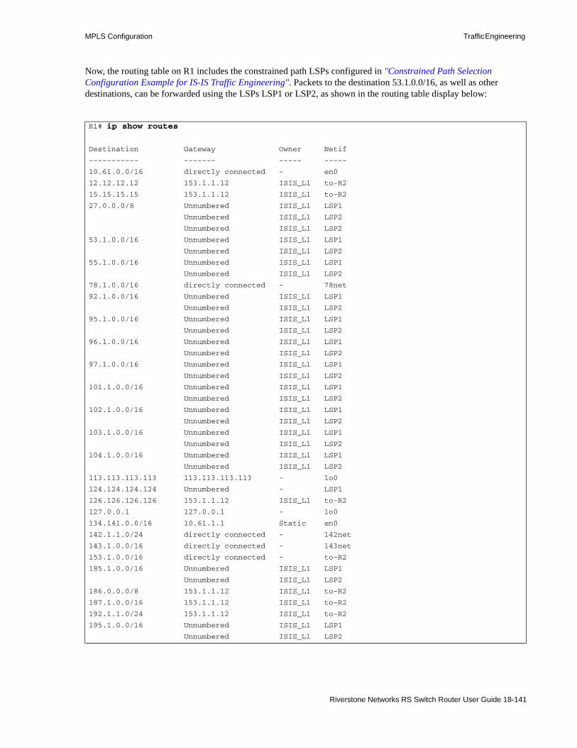
MPLS Configuration Traffic Engineering
Now, the routing table on R1 includes the constrained path LSPs configured in "Constrained Path Selection Configuration Example for IS-IS Traffic Engineering". Packets to the destination 53.1.0.0/16, as well as other destinations, can be forwarded using the LSPs LSP1 or LSP2, as shown in the routing table display below:
R1# ip show routes
Destination Gateway Owner Netif
----------- ------- ----- -----
10.61.0.0/16 directly connected - en0
12.12.12.12 153.1.1.12 ISIS_L1 to-R2
15.15.15.15 153.1.1.12 ISIS_L1 to-R2
27.0.0.0/8 Unnumbered ISIS_L1 LSP1
Unnumbered ISIS_L1 LSP2
Unnumbered ISIS_L1 LSP2
53.1.0.0/16 Unnumbered ISIS_L1 LSP1
Unnumbered ISIS_L1 LSP2
55.1.0.0/16 Unnumbered ISIS_L1 LSP1
Unnumbered ISIS_L1 LSP2
78.1.0.0/16 directly connected - 78net
92.1.0.0/16 Unnumbered ISIS_L1 LSP1
Unnumbered ISIS_L1 LSP2
95.1.0.0/16 Unnumbered ISIS_L1 LSP1
Unnumbered ISIS_L1 LSP2
96.1.0.0/16 Unnumbered ISIS_L1 LSP1
Unnumbered ISIS_L1 LSP2
97.1.0.0/16 Unnumbered ISIS_L1 LSP1
Unnumbered ISIS_L1 LSP2
101.1.0.0/16 Unnumbered ISIS_L1 LSP1
Unnumbered ISIS_L1 LSP2
102.1.0.0/16 Unnumbered ISIS_L1 LSP1
Unnumbered ISIS_L1 LSP2
103.1.0.0/16 Unnumbered ISIS_L1 LSP1
Unnumbered ISIS_L1 LSP2
104.1.0.0/16 Unnumbered ISIS_L1 LSP1
Unnumbered ISIS_L1 LSP2
113.113.113.113 113.113.113.113 - lo0
124.124.124.124 Unnumbered - LSP1
126.126.126.126 153.1.1.12 ISIS_L1 to-R2
127.0.0.1 127.0.0.1 - lo0
134.141.0.0/16 10.61.1.1 Static en0
142.1.1.0/24 directly connected - 142net
143.1.0.0/16 directly connected - 143net
153.1.0.0/16 directly connected - to-R2
185.1.0.0/16 Unnumbered ISIS_L1 LSP1
Unnumbered ISIS_L1 LSP2
186.0.0.0/8 153.1.1.12 ISIS_L1 to-R2
187.1.0.0/16 153.1.1.12 ISIS_L1 to-R2
192.1.1.0/24 153.1.1.12 ISIS_L1 to-R2
195.1.0.0/16 Unnumbered ISIS_L1 LSP1
Unnumbered ISIS_L1 LSP2
Riverstone Networks RS Switch Router User Guide 18-141

Traffic Engineering MPLS Configuration
18.7.3.2 Advertising IGP Shortcuts
IGP shortcuts need to be advertised so that other routers in the autonomous system can calculate paths that use the LSP. You advertise these shortcuts with the isis add label-switched-path command for IS-IS networks and with the ospf add label-switched-path command for OSPF networks.
Note Each LSP is advertised as a unidirectional, point-to-point link. OSPF and IS-IS both verify that there is a bidirectional connection between nodes before using an advertised link. Therefore, you need to configure two LSPs, one in each direction, for paths between two LSRs that will be advertised in IS-IS or OSPF autonomous systems.
The LSP is advertised as a unidirectional, point-to-point link. The advertisement contains: • the source address of the LSP (usually the address of the local router) • the destination address of the LSP (usually the address of the egress router)• a metric value
The metric value is an optional parameter configured for the LSP with the mpls create|set label-switched-path command. If no metric value is configured for the LSP with the isis, ospf, or mpls commands, then a metric value of 1 is used.
18-142 Riverstone Networks RS Switch Router User Guide

MPLS Configuration QoS For MPLS
18.8 QOS FOR MPLSThe Riverstone implementation of MPLS allows Quality of Service (QoS) facilities to be applied to layer-2 tunneled frames and layer-3 packets traversing an LSP. These QoS facilities can be applied to both input and output ports of the LSRs. Primarily, QoS is accomplished by mapping traffic characteristics such as internal priority bits or 802.1P bits to the MPLS Experimental bits (Exp bits).
18.8.1 MPLS Experimental Bits
The MPLS QoS capabilities are based on the use of the three Experimental bits (Exp bits) contained within the MPLS label. The value contained within the Exp bits is used to assign a packets to one of four internal queues when the packets traverse the RS Ethernet Router. The priorities of these queues are low, medium, high, and control. In turn, QoS facilities, such as WFQ, are configured to affect the behavior of the traffic passing through each of these queues.
Note .See the QoS Configuration chapter for details on how to configure the QoS facilities.
For layer-2 frames (TLS), the Exp bit values are derived from the following:• 802.1p priority bits – 3 bits• Riverstone proprietary internal priority bits – 2 bits representing the four priority queues
- 00 = low- 01 = medium- 10 = high- 11 = control
For layer-3 packets, the Exp bit values are derived from the following:• Riverstone proprietary internal priority bits – 2 bits representing the four priority queues
- 00 = low- 01 = medium- 10 = high- 11 = control
• ToS precedence bits – 3 most significant bits of the ToS byte (see Figure 18-29)• Differentiated Services Code Point (DSCP) bits – 6 most significant bits of the ToS byte (see
Figure 18-29)
Note Use the tos, tos-mask, tos-rewrite, and tos-precedence-rewrite parameters of the qos set ip command to configure the value of the DSCP bits.
Riverstone Networks RS Switch Router User Guide 18-143

QoS For MPLS MPLS Configuration
Figure 18-29 Comparison of ToS precedence bits to DSCP bits
18.8.1.1 Setting the Exp Bits
The Exp bits are set by creating an ingress policy on the ingress LSR. This ingress policy sets the Exp bits in relation to values associated with the frames and packets traversing the LSP. For example, if a VLAN trunk port is tunneled through the LSP, the EXP bits can be set by directly copying the values contained within the three 802.1p priority bits of the 802.1Q headers. Once packets/frames have reached the egress LSR, an egress policy can be created on the egress LSR that maps the Exp bits back into the bit values of the packets or frames.
Figure 18-30 shows an example of bits being copied on ingress into the Exp bits, and then copied back to the packet on egress.
Alternately, tables can be configured (using the mpls create command) that map the ingress packet/frame bits to the Exp bits – while other tables can be created that map the Exp bits back to packet/frame bits on the egress. The table method has the advantage of allowing flexibility on how packet/frame bits are mapped to the Exp bits.
VersionNumber
HeaderLength
PacketLength
Identification...
3 bits
ToS Pre
cedence
Bits
ToS Bits
4 bits
IP Protocol Header
ToS Byte
VersionNumber
HeaderLength
PacketLength
Identification...
IP Protocol Header
0 1 2 3 4 5
6 Diffserv Bits
ToS Byte
0 7
18-144 Riverstone Networks RS Switch Router User Guide

MPLS Configuration QoS For MPLS
For example, in Figure 18-31, an ingress table has been created (using the mpls create tosprec-to-exp-tbl command) that maps incoming ToS precedence bits to the Exp bits. In this example, the ToS precedence bits are read from incoming packets then compared against the table to determine how to set the Exp bits. Within the table, any ToS precedence value can be mapped to any Exp bit value – for instance, in Figure 18-31, ToS precedence bit value 6 (110 binary) is mapped to Exp bit value 5 (101 binary).
The following is the command that creates the ingress table mapping in Figure 18-31:
A second table can be created on the egress LSR that maps the Exp bits back to bit fields within packets or frames.
Note The DSCP bits cannot be directly copied into the Exp bits of the The MPLS label. The mapping of DSCP bits to Exp bits must always be done using a table.
Figure 18-30 Copying bits directly to and from packets traversing the LSP
rs(config)# mpls create tosprec-to-exp-tbl <name> tosprec0 0 tosprec1 1 tosprec2 6 tosprec3 3 tosprec4 7 tosprec5 2 tosprec6 5 tosprec7 6
Label
3 bits
Time to Live
1 bit
Experim
ental B
its
Bottom
of S
tack
8 bits20 bits
MPLS Label
IP Packet
On
In
gre
ss
On
Eg
ress
Riverstone Networks RS Switch Router User Guide 18-145
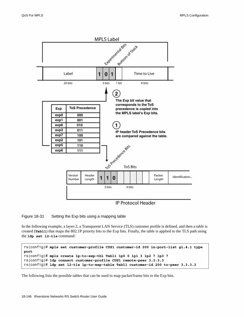
QoS For MPLS MPLS Configuration
Figure 18-31 Setting the Exp bits using a mapping table
In the following example, a layer-2, a Transparent LAN Service (TLS) customer profile is defined, and then a table is created (Tabl1) that maps the 802.1P priority bits to the Exp bits. Finally, the table is applied to the TLS path using the ldp set l2-tls command:
The following lists the possible tables that can be used to map packet/frame bits to the Exp bits.
rs(config)# mpls set customer-profile CUS1 customer-id 200 in-port-list gi.4.1 type portrs(config)# mpls create 1p-to-exp-tbl Tabl1 1p0 0 1p1 3 1p2 7 1p3 7rs(config)# ldp connect customer-profile CUS1 remote-peer 3.3.3.3rs(config)# ldp set l2-tls 1p-to-exp-table Tabl1 customer-id 200 to-peer 3.3.3.3
Label
3 bits
Time to Live
1 bit
Experimenta
l Bits
Bottom
of Sta
ck
8 bits20 bits
MPLS Label
Exp ToS Precedence
exp0exp1exp6exp3exp7exp2exp5
exp6
000001
101
011100
010
110111
VersionNumber
HeaderLength
PacketLength
Identification...
3 bits
ToS Pre
cedence
Bits
ToS Bits
4 bits
IP Protocol Header
IP header ToS Precedence bitsare compared against the table.
The Exp bit value that corresponds to the ToSprecedence is copied intothe MPLS label's Exp bits.
1 1 0
1
2
0 11
18-146 Riverstone Networks RS Switch Router User Guide

MPLS Configuration QoS For MPLS
• On ingress:- 802.1P bits to Exp bits (mpls create 1p-to-exp-tbl <name>)- DSCP bits to Exp bits (mpls create dscp-to-exp-tbl <name>)- Internal priority bits to Exp bits (mpls create intprio-to-exp-tbl <name>)- ToS precedence bits to Exp bits (mpls create tosprec-to-exp-tbl <name>)
• On Egress:- Exp bits to 802.1P bits (mpls create exp-to-1p-tbl <name>)- Exp bits to DSCP bits (mpls create exp-to-dscp-tbl <name>)- Exp bits to ToS precedence bits (mpls create exp-to-tosprec-tbl <name>)
Note There is no facility for mapping Exp bits to internal priority bits on egress. However, Exp bits that were set on ingress using the internal priority bits can be mapped to other packet/frame bits on egress (DSCP, 802.1P, and so on).
Creating and using tables is covered in more detail within the following sections.
18.8.2 Creating Ingress and Egress Policies
This section illustrates the basic steps for creating both an ingress and egress policy for mapping packet and frame bits to and from the Exp bits. Configuration examples for both layer-2 and layer-3 traffic are presented at the end of this section.
18.8.2.1 Layer-2 Ingress and Egress Policies
The following steps outline the process for creating a layer-2 ingress policy on the ingress LSR.1. If using table matching to map frame bits to the Exp bits, use the mpls create command to specify
the type of table, the table’s name, and its contents.2. Use the ldp set l2-tls command to apply the ingress policy to layer-2 TLS tunnel traffic.
The following steps outline the process for creating a layer-2 egress policy on the egress LSR.1. If using table matching to map Exp bits to frame bits, use the mpls create command to specify
the type of table, the table’s name, and its contents.2. Use the mpls set egress-l2-diffserv-policy command to apply the egress policy to layer-2
traffic. Note that the egress policy is applied globally to all layer-2 traffic traversing the LSP.
18.8.2.2 Layer-3 Ingress and Egress Policies
The following steps outline the process for creating a layer-3 ingress policy on the ingress LSR.1. If using table matching to map packet bits to the Exp bits, use the mpls create command to specify
the type of table, the table’s name, and its contents.
Riverstone Networks RS Switch Router User Guide 18-147

QoS For MPLS MPLS Configuration
2. Use the mpls set ingress-diffserv-policy command to apply the ingress policy to layer-3 traffic.
The following steps outline the process for creating a layer-3 egress policy on the egress LSR.1. If using table matching to map Exp bits to packet bits, use the mpls create command to specify
the type of table, the table’s name, and its contents.2. Use the mpls set egress-l3-diffserv-policy command to apply the egress policy to layer-3
traffic. Note that the egress policy is applied globally to all layer-3 traffic traversing the LSP
18.8.2.3 Layer-2 Example
The following example creates an ingress policy that copies the 802.1p bits to the Exp bits, and an egress policy that copies the Exp bits back to the 802.1p bits. It is assumed that all other MPLS parameters have been previously set to create an LSP over which layer-2 traffic is being tunneled.
One the ingress LSR of the LSP with VLAN id 200 and remote peer 100.10.10.11, do the following:
On the egress LSR:
As VLAN traffic traverses the LSP, the Exp bits in the MPLS label carry the values of the 802.1p bits. When leaving the LSP (at egress), the Exp bits in the MPLS label are copied back to the 802.1p bits in the 802.1Q headers.
18.8.2.4 Layer-3 Example
The following example creates an ingress policy that maps ToS precedence bits to Exp bits through the use of a table, and an egress policy that maps the Exp bits back to the ToS precedence bits with another table. It is assumed in this example that the LSP already exists and is fully configured.
On the ingress LSR, create a table named tos_tbl that maps the ToS precedence bits to the Exp bits:
Notice that not all ToS precedence vales are defined, and that a ToS precedence of 2 (010 binary) maps to an Exp value of 5 (101 binary).
Note If a value within any table is not specified, it defaults to zero.
rs(config)# ldp set l2-tls copy-1p-to-exp vlan 200 to-peer 100.10.10.11
rs(config)# mpls set egress-l2-diffserv-policy copy-exp-to-1p
rs(config)# mpls create tosprec-to-exp-tbl tos_tbl tosprec0 0 tosprec1 1 tosprec2 5 tosprec7 7
18-148 Riverstone Networks RS Switch Router User Guide

MPLS Configuration QoS For MPLS
Use the mpls show diff-serv-tbls command to display the contents of the ingress table.
In the display above, notice that all unspecified values for ToS precedence are wild carded to zero.
On the ingress LSR, use the mpls set command to create an ingress policy for LSP path1 that uses the table tos_tbl:
On the egress LSR, create a table named exp_tbl that maps the Exp bits back to the ToS precedence bits:
Notice that not all Exp values are defined, and that the Exp value of 2 (010 binary) is mapped back to a ToS precedence of 2 (tosprec2 was mapped to 5 on the ingress).
Use the mpls show diff-serv-tbls exp-to-tosprec_tbl command to view the contents of table exp_tbl:
On the egress LSR, use the mpls set command to create an egress policy that uses the table exp_tbl:
As layer-3 traffic enters the ingress LSR, the ToS precedence bits in the IP header are compared to the values in tos_tbl, and the Exp bits in the MPLS label are set accordingly. At the egress LSR, exp_tbl is used to map the Exp bits back to the ToS precedence bits.
rs# mpls show diff-serv-tbls tosprec-to-exp_tbl tos_tbl
TOS precedence to EXP table:---------------------------Table Name TOSPREC --> EXP---------- ---------------tos-tbl 1 1 2 5 7 7 * 0
rs(config)# mpls set ingress-diffserv-policy tosprec-to-exp-table tos_tbl label-switched-path path1
rs(config)# mpls create exp-to-tosprec-tbl exp_tbl exp0 0 exp1 1 exp5 2 exp7 7
rs# mpls show diff-serv-tbls exp-to-tosprec_tbl exp_tbl
EXP to TOS precedence table:---------------------------Table Name EXP --> TOSPREC---------- ---------------exp_tbl 1 1 5 2 7 7 * 0
rs(config)# mpls set egress-l3-diffserv-policy exp-to-tosprec-table exp_tbl
Riverstone Networks RS Switch Router User Guide 18-149

Setting the MPLS Table Size MPLS Configuration
18.9 SETTING THE MPLS TABLE SIZEUse the mpls set ott-table-sizes command to redistribute the Output Tag Table (OTT) space among the listed block sizes. These block sizes correspond to the number of replications within a TLS VPN, and are rounded up according to the number of replications. For example, to change the OTT table percentage for seven replications, the percentage of the OTT table block-size of eight would be changed.
Use the mpls show ott-table block-utilization command to view how OTT table space is currently allocated.
Caution This command is intended for experienced MPLS personnel only.
The command has the following format
mpls set ott-table-sizes block-size-n <percentage>
where block-size-n indicates the number of replications within a TLS VPN. These block sizes are fixed numbers based on powers of two – 2, 4, 8, 16, 32, 64, and 128, and <percentage> specifies the percentage of the OTT table that is used by a particular block size. This is illustrated in Table 18-10.
In the following example, the percentage of the OTT table for 32 replications on a TLS VPN is set to 25%, while 64 replications on a TLS VPN is set to 10%:
Table 18-10 Default OTT table percentage per block-size
Block Size Percentage off OTT
1* 50%
2 0%
4 25%
8 12.5%
16 12.5%
32 0%
64 0%
128 0%
* Block 1 cannot be explicitly changed, its size in percent is determined by the percent not used by the other blocks.
rs(config)# mpls set ott-table-sizes block-size-32 25 block-size-64 10
18-150 Riverstone Networks RS Switch Router User Guide

19 MSDP CONFIGURATION GUIDE
The RS Ethernet Router supports the Multicast Source Discovery Protocol (MSDP) as specified in the draft-ietf-msdp-spec-11.txt file.
Use MSDP, in conjunction with the Protocol Independent Multicast - Sparse Mode (PIM-SM) protocol, to implement both intra- and inter-domain multicast routing. Use PIM-SM for multicast routing within a network, then run MSDP for multicast routing between PIM domains.
This chapter contains information about running MSDP on the RS Ethernet Router. It provides:• an overview of MSDP in Section 19.1, "MSDP Overview."• a description of how to configure MSDP on the RS Ethernet Router in Section 19.2,
"Configuring MSDP."
This chapter also describes the following optional tasks:• to configure a default or static peer, refer to Section 19.3, "Defining Peers."• to configure a mesh group, refer to Section 19.4, "Configuring an MSDP Mesh Group."• to modify MSDP default timer values, refer to Section 19.5, "Setting MSDP Timers."• to filter MSDP Source-Active (SA) messages, refer to 19.6, "Filtering SA-Messages."
Note MSDP runs with PIM-SM. To run MSDP on the RS Ethernet Router, you must first configure PIM-SM. For information on running PIM-SM on the RS Ethernet Router, refer to Chapter 23, "PIM-SM Routing Configuration."
Riverstone Networks RS Switch Router User Guide 19-1

MSDP Overview MSDP Configuration Guide
19.1 MSDP OVERVIEWMSDP connects multiple PIM-SM domains. It provides a mechanism for PIM-SM Rendezvous Points (RPs) to discover active sources in other domains. If a domain has receivers for a multicast source in another domain, then PIM-SM is used to build an inter-domain source distribution tree to transmit multicast data from one domain to another. MSDP uses TCP as its transport protocol.
The following sections describe how MSDP operates in conjunction with PIM-SM to provide both intra- and inter-domain multicast routing.
19.1.1 Flooding SA-Messages
A source or a first-hop router (a router directly connected to the source) sends data packets encapsulated in Register messages to its RP. When the RP receives the Register message, the RP decapsulates the Register message and forwards the data packet downstream on the shared distribution tree. The RP that has also been configured as an MSDP peer generates and floods a Source-Active message (SA-message) to its MSDP peers in the different PIM-SM domains. The SA-message alerts the MSDP peers to the new source; it contains information about the source, the multicast group, and the RP that originated the SA message.
19.1.2 Peer RPF Check
Each MSDP peer that receives the SA-message performs a Reverse Path Forwarding (RPF) check based on the RP address in the SA message. If the message passes the RPF check, the MSDP peer caches the SA-message and forwards it to its downstream neighbor away from the source RP. If the message doesn’t pass the RPF check, the MSDP peer drops the message.
19.1.3 Joining the Distribution Tree
When an MSDP peer which is also the RP for its domain receives an SA message, the MSDP peer checks whether there are interested receivers in its domain. If the RP determines that it has receivers for that particular multicast group, the RP triggers an (S,G) join event towards the source. Subsequent packets are then forwarded to the RP and down the shared distribution tree in the domain. Once the distribution tree is built from the RP to the source, then regular PIM-SM processing takes over wherein the designated router or the last hop router of a receiver can join the source tree directly.
Note For information on Reverse Path Forwarding (RPF) and other multicast concepts, refer to Chapter 21, "Multicast Routing Configuration."
19-2 Riverstone Networks RS Switch Router User Guide

MSDP Configuration Guide MSDP Overview
19.1.4 Sending SA-Requests
An RP in a group can send an SA request to an MSDP peer when it wants to know all the active sources for a group. When an MSDP peer receives an SA request, it responds with an SA-Response message which lists all active sources in its SA cache sending to the group specified in the SA request. The peer that sent the request does not flood the SA response to all the other peers.
Riverstone Networks RS Switch Router User Guide 19-3
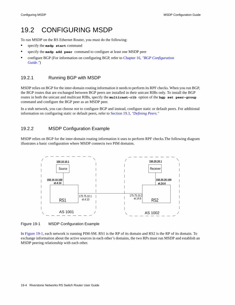
Configuring MSDP MSDP Configuration Guide
19.2 CONFIGURING MSDP To run MSDP on the RS Ethernet Router, you must do the following:• specify the msdp start command • specify the msdp add peer command to configure at least one MSDP peer • configure BGP (For information on configuring BGP, refer to Chapter 16, "BGP Configuration
Guide.")
19.2.1 Running BGP with MSDP
MSDP relies on BGP for the inter-domain routing information it needs to perform its RPF checks. When you run BGP, the BGP routes that are exchanged between BGP peers are installed in their unicast RIBs only. To install the BGP routes in both the unicast and multicast RIBs, specify the multicast-rib option of the bgp set peer-group command and configure the BGP peer as an MSDP peer.
In a stub network, you can choose not to configure BGP and instead, configure static or default peers. For additional information on configuring static or default peers, refer to Section 19.3, "Defining Peers."
19.2.2 MSDP Configuration Example
MSDP relies on BGP for the inter-domain routing information it uses to perform RPF checks.The following diagram illustrates a basic configuration where MSDP connects two PIM domains.
Figure 19-1 MSDP Configuration Example
In Figure 19-1, each network is running PIM-SM. RS1 is the RP of its domain and RS2 is the RP of its domain. To exchange information about the active sources in each other’s domains, the two RPs must run MSDP and establish an MSDP peering relationship with each other.
RS1
150.10.10.1
150.10.10.100
175.75.10.1 175.75.10.2
et.4.14
et.4.10 et.14.6
Source
RS2
150.20.20.1
150.20.20.100et.14.4
Receiver
AS 1001 AS 1002
19-4 Riverstone Networks RS Switch Router User Guide

MSDP Configuration Guide Configuring MSDP
Following are the steps and commands that were used to configure RS1:
! Configure the interfacesinterface create ip to-32k address-netmask 175.75.10.1/24 port et.4.10interface create ip to-pc10 address-netmask 150.10.10.100 port et.4.14interface add ip lo0 address-netmask 1.1.1.1/32
! Set the router ID and autonomous system ip-router global set router-id 1.1.1.1ip-router global set autonomous-system 1001
! Configure OSPFospf create area backboneospf add stub-host 1.1.1.1 to-area backbone cost 10ospf add interface to-pc10 to-area backboneospf set rib multicastospf start
! Configure BGPbgp create peer-group domain-2 autonomous-system 1002 type externalbgp add peer-host 175.75.10.2 group domain-2bgp set peer-group domain-2 multicast-ribbgp start
! Redistribute the directly connected route to BGPip-router policy redistribute from-proto direct to-proto bgp target-as all
! Configure IGMP on the interface connected to the hostigmp add interface to-pc10igmp start
! Configure PIM-SMpim sparse add interface 1.1.1.1pim sparse add interface 175.75.10.1pim sparse add interface to-pc10pim sparse static-rp address 1.1.1.1pim sparse start
! Configure MSDPmsdp add peer local-addr 175.75.10.1 remote-addr 175.75.10.2msdp start
Riverstone Networks RS Switch Router User Guide 19-5

Configuring MSDP MSDP Configuration Guide
Following are the steps and commands that were used to configure RS2:
To verify that the MSDP peering relationship was established between the two routers, you can specify the msdp show peers command as shown in the following examples:
:
! Configure the interfacesinterface create ip to-8k1 address-netmask 175.75.10.2/24 port et.14.6interface create ip to-pc20 address-netmask 150.20.20.100 port et.14.4interface add ip lo0 address-netmask 2.2.2.2/32
! Set the router ID and autonomous system ip-router global set router-id 2.2.2.2ip-router global set autonomous-system 1002
! Configure OSPFospf create area backboneospf add stub-host 2.2.2.2 to-area backbone cost 10ospf add interface to-pc20 to-area backboneospf set rib multicastospf start
! Configure BGPbgp create peer-group domain-1 autonomous-system 1001 type externalbgp add peer-host 175.75.10.1 group domain-1bgp set peer-group domain-1 multicast-ribbgp start
! Redistribute the directly connected route to BGPip-router policy redistribute from-proto direct to-proto bgp target-as all
! Configure IGMP on the interface connected to the hostigmp add interface to-pc20igmp start
! Configure PIM-SMpim sparse add interface to-8k1 boundarypim sparse add interface 2.2.2.2pim sparse add interface to-pc20pim sparse static-rp address 2.2.2.2pim sparse start
! Configure MSDPmsdp add peer local-addr 175.75.10.2 remote-addr 175.75.10.1msdp start
rs1# msdp show peersComp Lcl Rmt State MeshID Flags HoldTimemsdp0 175.75.10.1 175.75.10.2 ESTB 0 (none) 46
rs2# msdp show peersComp Lcl Rmt State MeshID Flags HoldTimemsdp0 175.75.10.2 175.75.10.1 ESTB 0 (none) 19
19-6 Riverstone Networks RS Switch Router User Guide

MSDP Configuration Guide Configuring MSDP
Figure 19-1 shows that RS1 is connected to a source. When this source sends a Register message to RS1, it generates an SA message and sends it to RS2. To view the SA messages that were sent by RS1 to RS2, use the msdp show sa-cache command, as shown in the following example:
As shown in the example, the SA message contains the source (150.10.10.1/32), the multicast group (224.1.2.1/32), and the RP that originated the SA message (1.1.1.1).
rs2# msdp show sa-cacheComp: msdp0 1.1.1.1 (150.10.10.1/32, 224.1.2.1/32)
Riverstone Networks RS Switch Router User Guide 19-7

Defining Peers MSDP Configuration Guide
19.3 DEFINING PEERSYou can optionally define a previously configured peer as either a default peer or a static peer. MSDP does not perform an RPF check when the router receives SA messages from a static or a default peer. Therefore, if you are configuring a static or default peer for a stub network, you don’t need to run BGP between the router and its static or default peer.
19.3.1 Defining a Default Peer
If you want the RS Ethernet Router to accept all SA-messages from a particular peer, define it as the default peer. In the following example, the remote peer, 175.75.10.1, is defined as the default peer. You can define only one default peer.
Use the msdp show default-peers command to verify the default peer as shown in the following example:
19.3.2 Defining a Static Peer
If you want the RS Ethernet Router to accept SA messages from a particular remote peer for a specific RP, you can map the RP address to that remote peer. In the following example, the RS Ethernet Router will accept any SA-message from the remote peer (10.1.1.1) if the IP address of the RP (192.168.2.1) is in the SA-message.
Use the msdp show static-peers command to verify your configuration as shown in the following example:
rs (config)# msdp add peer local-addr 175.75.10.2 remote-addr 175.75.10.1rs (config)# msdp add default-rpf-peer 175.75.10.1
rs# msdp show default-peersComp: msdp0 Default-Peer: 175.75.10.1
rs (config)# msdp add peer local-addr 175.75.10.2 remote-addr 10.1.1.1rs (config)# msdp add static-rpf-peer peer-addr 10.1.1.1 rp-addr 192.168.2.1
rs# msdp show static-peersComp: msdp0 RP: 192.168.2.1 Static-Peer: 10.1.1.1
19-8 Riverstone Networks RS Switch Router User Guide

MSDP Configuration Guide Configuring an MSDP Mesh Group
19.4 CONFIGURING AN MSDP MESH GROUPA mesh group is a group of MSDP peers in one PIM-SM domain. You can configure a mesh group to reduce SA flooding when there are multiple RPs in one domain.
In a mesh group, only the SA-originator forwards the SA message to the members of the mesh group. Mesh group members do not forward SA messages to other members. Instead, the members forward SA messages only to non-mesh group peers and to members of other mesh groups.
For the originator to forward SA messages to all members, each member in the group must have a peer connection with every other member of the mesh group. A peer can be a member of more than one mesh group.
The following diagram illustrates how SA messages are flooded within mesh groups and outside of mesh groups.
Figure 19-2 Flooding SA messages in mesh groups
The source sends a Register message to its RP, RP1. RP1 creates an SA message and floods it to the members of its mesh group, 123.
In addition to mesh group 123, RP3 also belongs to mesh group 124. Therefore, RP3 floods the SA message to the RPs in mesh group 124, but not to mesh group 123.
The RPF neighbor of RP4 is RP7. Therefore, RP4 sends the SA message to RP7, which belongs to another PIM-SM domain.
To specify that an MSDP peer is in a mesh group, use the mesh option as shown in the following example:
rs (config)# msdp add peer local-addr 10.1.1.1 remote-addr 100.10.10.1 mesh 123rs (config)# msdp start
RP1
RP2
RP3
Source
RP4
Mesh Group
124Mesh Group
123
RP7
RP5
RP6
Riverstone Networks RS Switch Router User Guide 19-9

Setting MSDP Timers MSDP Configuration Guide
19.5 SETTING MSDP TIMERSMSDP has a number of timers with default values. The RS Ethernet Router provides commands for changing these default values as described in this section.
• Connect Retry
An MSDP speaker tries to open a TCP connection to its peer at 30 second intervals. You can change this interval as shown in the following example:
• Peer Holdtime
MSDP peers exchange messages at a specified interval. If an MSDP peer does not receive an MSDP message within a specified period, it sends a Notification message and closes the MSDP connection. On the RS Ethernet Router, the default is 90 seconds. You can change this interval as shown in the following example:
• Keep Alive
Once a connection is established, the MSDP peers exchange keepalive messages every 75 seconds.You can change this interval as shown in the following example, which sets the keepalive period to 60 seconds:
• Cache Timeout
The source-active (SA) messages also have timers associated with them. MSDP routers must cache SA messages. By default, the RS Ethernet Router caches SA messages for 60 seconds. You can change this default value, as shown in the following example, which sets the cache time interval to 100 seconds:
• Holddown
In addition, there is a time for the interval between SA-advertisement messages from an (S,G) pair. The default is 30 seconds. You can change this default as shown in the following example, which sets the interval to 45 seconds:
rs (config)# msdp set connect-retry-period 40
rs (config)# msdp set peer-holdtime 100
rs (config)# msdp set keepalive-period 60
rs (config)# msdp set sa-cache timeout 100
rs (config)# msdp set sa-cache holddown 45
19-10 Riverstone Networks RS Switch Router User Guide

MSDP Configuration Guide Filtering SA-Messages
19.6 FILTERING SA-MESSAGESBy default, all SA messages are forwarded to and from the RS Ethernet Router’s MSDP peers and the RS Ethernet Router’s local PIM domain. However, you can configure MSDP filters to control the receiving and forwarding of SA messages. This section describes the three types of filters that are available on the RS Ethernet Router:• PIM filters• incoming SA-message filters• outgoing SA-message filters
Only the RP in the same domain as the source can restrict SA messages. MSDP peers in transit domains should not filter SA messages.
19.6.1 Using PIM Filters
By default, the RP advertises all its registered sources to its peers. You can restrict which sources are advertised by configuring a PIM filter. A PIM filter specifies which (S,G) pairs learned from the local PIM domain should be excluded from the outgoing-SA messages.
To filter local (S,G) pairs from outgoing messages, use the msdp filter pim command as shown in the following example:
19.6.2 Using Incoming SA-Message Filters
When an MSDP peer which is also the RP for its domain receives an SA message, the MSDP peer checks whether there are interested receivers in its domain. You can restrict which (S,G) groups are advertised in the RP’s PIM domain by configuring an incoming SA-message filter. This type of filter specifies which (S,G) group should not be advertised in the PIM domain. (Note though that the RP will continue to propagate the SA-message to its other MSDP peers. It just won’t advertise it in its own domain.)
To filter (S,G) pairs from incoming messages, use the msdp filter incoming-sa-msg command as shown in the following example:
rs (config)# msdp filter pim grp-addr 234.132.145.100 src-addr 132.131.12.1
rs (config)# msdp filter incoming-sa-msg grp-addr 234.132.145.100 src-addr 132.131.12.1
Riverstone Networks RS Switch Router User Guide 19-11
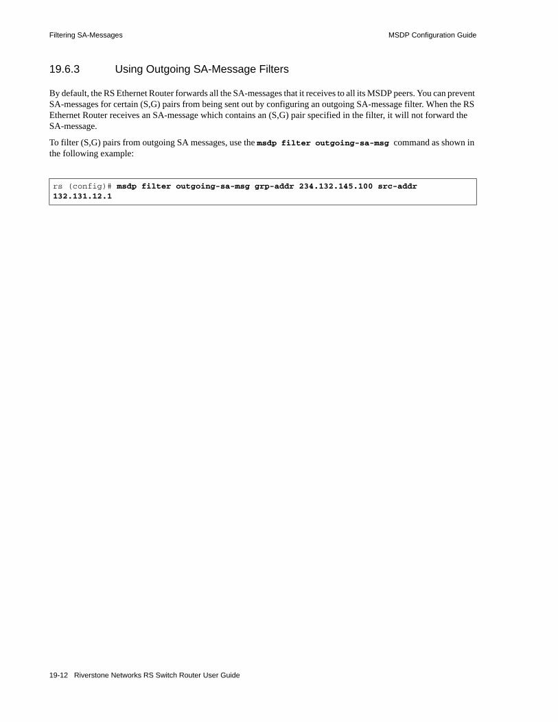
Filtering SA-Messages MSDP Configuration Guide
19.6.3 Using Outgoing SA-Message Filters
By default, the RS Ethernet Router forwards all the SA-messages that it receives to all its MSDP peers. You can prevent SA-messages for certain (S,G) pairs from being sent out by configuring an outgoing SA-message filter. When the RS Ethernet Router receives an SA-message which contains an (S,G) pair specified in the filter, it will not forward the SA-message.
To filter (S,G) pairs from outgoing SA messages, use the msdp filter outgoing-sa-msg command as shown in the following example:
rs (config)# msdp filter outgoing-sa-msg grp-addr 234.132.145.100 src-addr 132.131.12.1
19-12 Riverstone Networks RS Switch Router User Guide

20 ROUTING POLICY CONFIGURATION
The RS Ethernet Router family of routers supports extremely flexible routing policies. The RS Ethernet Router allows the network administrator to control import and export of routing information based on criteria including:• Individual protocol• Source and destination autonomous system• Source and destination interface• Previous hop router• Autonomous system path• Tag associated with routes• Specific destination address
The network administrator can specify a preference level for each combination of routing information being imported by using a flexible masking capability.
The RS Ethernet Router also provides the ability to create advanced and simple routing policies. Simple routing policies provide a quick route redistribution between various routing protocols (RIP, OSPF, IS-IS and BGP). Advanced routing policies provide more control over route redistribution.
20.1 PREFERENCEPreference is the value the RS Ethernet Router routing process uses to order preference of routes from one protocol or peer over another. Preference can be set using several different configuration commands. Preference can be set based on one network interface over another, from one protocol over another, or from one remote gateway over another. Preference may not be used to control the selection of routes within an Interior Gateway Protocol (IGP). This is accomplished automatically by the protocol based on metric.
Preference may be used to select routes from the same Exterior Gateway Protocol (EGP) learned from different peers or autonomous systems. Each route has only one preference value associated with it, even though the preference can be set at many places using configuration commands. The last or most specific preference value set for a route is the value used. A preference value is an arbitrarily assigned value used to determine the order of routes to the same destination in a single routing database. The active route is chosen by the lowest preference value.
A default preference is assigned to each source from which the RS Ethernet Router routing process receives routes. Preference values range from 0 to 255 with the lowest number indicating the most preferred route.
Riverstone Networks RS Switch Router User Guide 20-1
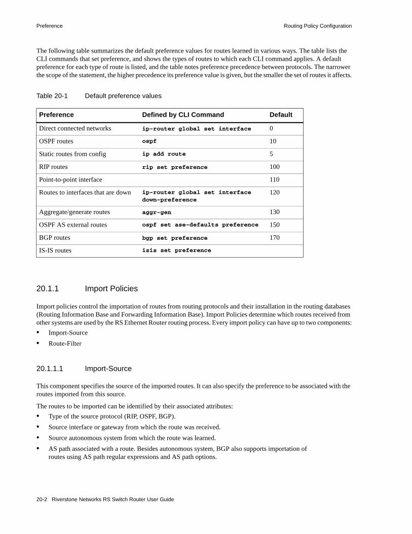
Preference Routing Policy Configuration
The following table summarizes the default preference values for routes learned in various ways. The table lists the CLI commands that set preference, and shows the types of routes to which each CLI command applies. A default preference for each type of route is listed, and the table notes preference precedence between protocols. The narrower the scope of the statement, the higher precedence its preference value is given, but the smaller the set of routes it affects.
20.1.1 Import Policies
Import policies control the importation of routes from routing protocols and their installation in the routing databases (Routing Information Base and Forwarding Information Base). Import Policies determine which routes received from other systems are used by the RS Ethernet Router routing process. Every import policy can have up to two components:• Import-Source• Route-Filter
20.1.1.1 Import-Source
This component specifies the source of the imported routes. It can also specify the preference to be associated with the routes imported from this source.
The routes to be imported can be identified by their associated attributes:• Type of the source protocol (RIP, OSPF, BGP).• Source interface or gateway from which the route was received.• Source autonomous system from which the route was learned.• AS path associated with a route. Besides autonomous system, BGP also supports importation of
routes using AS path regular expressions and AS path options.
Table 20-1 Default preference values
Preference Defined by CLI Command Default
Direct connected networks ip-router global set interface 0
OSPF routes ospf 10
Static routes from config ip add route 5
RIP routes rip set preference 100
Point-to-point interface 110
Routes to interfaces that are down ip-router global set interface down-preference
120
Aggregate/generate routes aggr-gen 130
OSPF AS external routes ospf set ase-defaults preference 150
BGP routes bgp set preference 170
IS-IS routes isis set preference
20-2 Riverstone Networks RS Switch Router User Guide
Routing Policy Configuration Preference
• If multiple communities are specified using the optional-attributes-list, only updates carrying all of the specified communities will be matched. If the specified optional-attributes-list has the value none for the well-known-community option, then only updates lacking the community attribute will be matched.
In some cases, a combination of the associated attributes can be specified to identify the routes to be imported.
Note It is quite possible for several BGP import policies to match a given update. If more than one policy matches, the first matching policy will be used. All later matching policies will be ignored. For this reason, it is generally desirable to order import policies from most to least specific. An import policy with an optional-attributes-list will match any update with any (or no) communities.
The importation of RIP routes may be controlled by source interface and source gateway. RIP does not support the use of preference to choose between RIP routes. That is left to the protocol metrics.
Due to the nature of OSPF, only the importation of ASE routes may be controlled. OSPF intra-and inter-area routes are always imported into the routing table with a preference of 10. If a tag is specified with the import policy, routes with the specified tag will only be imported. It is only possible to restrict the importation of OSPF ASE routes when functioning as an AS border router.
Like the other interior protocols, preference cannot be used to choose between OSPF ASE routes. That is done by the OSPF costs.
20.1.1.2 Route-Filter
This component specifies the individual routes which are to be imported or restricted. The preference to be associated with these routes can also be explicitly specified using this component.
The preference associated with the imported routes are inherited unless explicitly specified. If there is no preference specified with a route-filter, then the preference is inherited from the one specified with the import-source.
Every protocol (RIP, OSPF, and BGP) has a configurable parameter that specifies the default-preference associated with routes imported to that protocol. If a preference is not explicitly specified with the route-filter, as well as the import-source, then it is inherited from the default-preference associated with the protocol for which the routes are being imported.
20.1.2 Export Policies
Export policies control the redistribution of routes to other systems. They determine which routes are advertised by the Unicast Routing Process to other systems. Every export policy can have up to three components:• Export-Destination• Export-Source• Route-Filter
Riverstone Networks RS Switch Router User Guide 20-3

Preference Routing Policy Configuration
20.1.2.1 Export-Destination
This component specifies the destination where the routes are to be exported. It also specifies the attributes associated with the exported routes. The interface, gateway, or the autonomous system to which the routes are to be redistributed are a few examples of export-destinations. The metric, type, tag, and AS-Path are a few examples of attributes associated with the exported routes.
20.1.2.2 Export-Source
This component specifies the source of the exported routes. It can also specify the metric to be associated with the routes exported from this source.
The routes to be exported can be identified by their associated attributes:• Their protocol type (RIP, OSPF, BGP, Static, Direct, Aggregate, IS-IS).• Interface or the gateway from which the route was received.• Autonomous system from which the route was learned.• AS path associated with a route. When BGP is configured, all routes are assigned an AS path when
they are added to the routing table. For interior routes, this AS path specifies IGP as the origin and no ASs in the AS path (the current AS is added when the route is exported). For BGP routes, the AS path is stored as learned from BGP.
• Tag associated with a route. Both OSPF and RIP version 2 currently support tags. All other protocols have a tag of zero.
In some cases, a combination of the associated attributes can be specified to identify the routes to be exported.
20.1.2.3 Route-Filter
This component specifies the individual routes which are to exported or restricted. The metric to be associated with these routes can also be explicitly specified using this component.
The metric associated with the exported routes are inherited unless explicitly specified. If there is no metric specified with a route-filter, then the metric is inherited from the one specified with the export-source.
If a metric was not explicitly specified with both the route-filter and the export-source, then it is inherited from the one specified with the export-destination.
Every protocol (RIP, OSPF, BGP, and IS-IS) has a configurable parameter that specifies the default-metric associated with routes exported to that protocol. If a metric is not explicitly specified with the route-filter, export-source as well as export-destination, then it is inherited from the default-metric associated with the protocol to which the routes are being exported.
20.1.3 Specifying a Route Filter
Routes are filtered by specifying a route-filter that will match a certain set of routes by destination, or by destination and mask. Among other places, route filters are used with martians and in import and export policies.
The action taken when no match is found is dependent on the context. For instance, a route that does match any of the route-filters associated with the specified import or export policies is rejected.
20-4 Riverstone Networks RS Switch Router User Guide

Routing Policy Configuration Preference
A route will match the most specific filter that applies. Specifying more than one filter with the same destination, mask, and modifiers generates an error.
There are three possible formats for a route filter. Not all of these formats are available in all places. In most cases, it is possible to associate additional options with a filter. For example, while creating a martian, it is possible to specify the allow option, while creating an import policy, one can specify a preference, and while creating an export policy one can specify a metric.
The three forms of a route-filter are:
Network[ exact | refines | between number,number]
Network/mask[ exact | refines | between number,number]
Network/masklen[ exact | refines | between number,number]
Matching usually requires both an address and a mask, although the mask is implied in the shorthand forms listed below. These three forms vary in how the mask is specified. In the first form, the mask is implied to be the natural mask of the network. In the second, the mask is explicitly specified. In the third, the mask is specified by the number of contiguous one bits.
If no optional parameters (exact, refines, or between) are specified, any destination that falls in the range given by the network and mask is matched, so the mask of the destination is ignored. If a natural network is specified, the network, any subnets, and any hosts will be matched. Three optional parameters that cause the mask of the destination to also be considered are:
Exact Specifies that the mask of the destination must match the supplied mask exactly. This is used to match a network, but no subnets or hosts of that network.
Refines Specifies that the mask of the destination must be more specified (i.e., longer) than the filter mask. This is used to match subnets and/or hosts of a network, but not the network.
Between number, numberSpecifies that the mask of the destination must be as or more specific (i.e., as long as or longer) than the lower limit (the first number parameter) and no more specific (i.e., as long as or shorter) than the upper limit (the second number). Note that exact and refines are both special cases of between.
20.1.4 Aggregates and Generates
Route aggregation is a method of generating a more general route, given the presence of a specific route. It is used, for example, at an autonomous system border to generate a route to a network to be advertised via BGP given the presence of one or more subnets of that network learned via OSPF. The routing process does not perform any aggregation unless explicitly requested.
Route aggregation is also used by regional and national networks to reduce the amount of routing information passed around. With careful allocation of network addresses to clients, regional networks can just announce one route to regional networks instead of hundreds.
Aggregate routes are not actually used for packet forwarding by the originator of the aggregate route, but only by the receiver (if it wishes). Instead of requiring a route-peer to know about individual subnets which would increase the size of its routing table, the peer is only informed about an aggregate-route which contains all the subnets.
Like export policies, aggregate-routes can have up to three components:• Aggregate-Destination• Aggregate-Source• Route-Filter
Riverstone Networks RS Switch Router User Guide 20-5

Preference Routing Policy Configuration
20.1.4.1 Aggregate-Destination
This component specifies the aggregate/summarized route. It also specifies the attributes associated with the aggregate route. The preference to be associated with an aggregate route can be specified using this component.
20.1.4.2 Aggregate-Source
This component specifies the source of the routes contributing to an aggregate/summarized route. It can also specify the preference to be associated with the contributing routes from this source. This preference can be overridden by explicitly specifying a preference with the route-filter.
The routes contributing to an aggregate can be identified by their associated attributes:• Protocol type (RIP, OSPF, BGP, Static, Direct, Aggregate, IS-IS).• Autonomous system from which the route was learned.• AS path associated with a route. When BGP is configured, all routes are assigned an AS path when
they are added to the routing table. For interior routes, this AS path specifies IGP as the origin and no ASs in the AS path (the current AS is added when the route is exported). For BGP routes, the AS path is stored as learned from BGP.
• Tag associated with a route. Both OSPF and RIP version 2 currently support tags. All other protocols have a tag of zero.
In some cases, a combination of the associated attributes can be specified to identify the routes contributing to an aggregate.
20.1.4.3 Route-Filter
This component specifies the individual routes that are to be aggregated or summarized. The preference to be associated with these routes can also be explicitly specified using this component.
The contributing routes are ordered according to the aggregation preference that applies to them. If there is more than one contributing route with the same aggregating preference, the route's own preferences are used to order the routes. The preference of the aggregate route will be that of contributing route with the lowest aggregate preference.
A route may only contribute to an aggregate route that is more general than itself; it must match the aggregate under its mask. Any given route may only contribute to one aggregate route, which will be the most specific configured, but an aggregate route may contribute to a more general aggregate.
An aggregate-route only comes into existence if at least one of its contributing routes is active.
20.1.5 Authentication
Authentication guarantees that routing information is only imported from trusted routers. Many protocols like RIP V2 and OSPF provide mechanisms for authenticating protocol exchanges. A variety of authentication schemes can be used. Authentication has two components – an Authentication Method and an Authentication Key. Many protocols allow different authentication methods and keys to be used in different parts of the network.
20-6 Riverstone Networks RS Switch Router User Guide

Routing Policy Configuration Configuring Simple Routing Policies
20.1.5.1 Authentication Methods
There are two main authentication methods:
Simple PasswordIn this method, an authentication key of up to 8 characters is included in the packet. If this does not match what is expected, the packet is discarded. This method provides little security, as it is possible to learn the authentication key by watching the protocol packets.
MD5 This method uses the MD5 algorithm to create a crypto-checksum of the protocol packet and an authentication key of up to 16 characters. The transmitted packet does not contain the authentication key itself; instead, it contains a crypto-checksum, called the digest. The receiving router performs a calculation using the correct authentication key and discard the packet if the digest does not match. In addition, a sequence number is maintained to prevent the replay of older packets. This method provides a much stronger assurance that routing data originated from a router with a valid authentication key.
Many protocols allow the specification of two authentication keys per interface. Packets are always sent using the primary keys, but received packets are checked with both the primary and secondary keys before being discarded.
20.1.5.2 Authentication Keys and Key Management
An authentication key permits the generation and verification of the authentication field in protocol packets. In many situations, the same primary and secondary keys are used on several interfaces of a router. To make key management easier, the concept of a key-chain was introduced. Each key-chain has an identifier and can contain up to two keys. One key is the primary key and other is the secondary key. Outgoing packets use the primary authentication key, but incoming packets may match either the primary or secondary authentication key. In Configure mode, instead of specifying the key for each interface (which can be up to 16 characters long), you can specify a key-chain identifier.
The RS Ethernet Router supports MD5 specification of OSPF RFC 2178 which uses the MD5 algorithm and an authentication key of up to 16 characters. Thus there are now three authentication schemes available per interface: none, simple and RFC 2178 OSPF MD5 authentication. It is possible to configure different authentication schemes on different interfaces.
RFC 2178 allows multiple MD5 keys per interface. Each key has two times associated with the key:• A time period that the key will be generated• A time period that the key will be accepted
The RS Ethernet Router only allows one MD5 key per interface. Also, there are no options provided to specify the time period during which the key would be generated and accepted; the specified MD5 key is always generated and accepted. Both these limitations would be removed in a future release.
20.2 CONFIGURING SIMPLE ROUTING POLICIESSimple routing policies provide an efficient way for routing information to be exchanged between routing protocols. The redistribute command can be used to redistribute routes from one routing domain into another routing domain. Redistribution of routes between routing domains is based on route policies. A route policy is a set of conditions based on which routes are redistributed. While the redistribute command may fulfill the export policy requirement for most users, complex export policies may require the use of the commands listed under Export Policies.
Riverstone Networks RS Switch Router User Guide 20-7

Configuring Simple Routing Policies Routing Policy Configuration
The general syntax of the redistribute command is as follows:
The from-proto parameter specifies the protocol of the source routes. The values for the from-proto parameter can be rip, ospf, bgp, direct, static, aggregate, isis-level-1, isis-level-2 and ospf-ase. The to-proto parameter specifies the destination protocol where the routes are to be exported. The values for the to-proto parameter can be rip, ospf, ospf-nssa, isis-level-1, isis-level-2, and bgp. The network parameter provides a means to define a filter for the routes to be distributed. The network parameter defines a filter that is made up of an IP address and a mask. Routes that match the filter are considered as eligible for redistribution.
Every protocol (RIP, OSPF, IS-IS and BGP) has a configurable parameter that specifies the default-metric associated with routes exported to that protocol. If a metric is not explicitly specified with the redistribute command, then it is inherited from the default-metric associated with the protocol to which the routes are being exported.
20.2.1 Redistributing Static Routes
Static routes may be redistributed to another routing protocol such as RIP or OSPF by the following command. The network parameter specifies the set of static routes that will be redistributed by this command. If all static routes are to be redistributed set the network parameter to all. Note that the network parameter is a filter that is used to specify routes that are to be redistributed.
To redistribute static routes, enter one of the following commands in Configure mode:
20.2.2 Redistributing Directly Attached Networks
Routes to directly attached networks are redistributed to another routing protocol such as RIP or OSPF by the following command. The network parameter specifies a set of routes that will be redistributed by this command. If all direct routes are to be redistributed set the network parameter to all. Note that the network parameter is a filter that is used to specify routes that are to be redistributed.
ip-router policy redistribute from-proto <protocol> to-proto <protocol> [network <ipAddr-mask> [exact|refines|between <low-high>]] [metric <number>|restrict] [source-as <number>] [target-as <number>]
To redistribute static routes into RIP. ip-router policy redistribute from-proto static to-proto rip network all
To redistribute static routes into OSPF.
ip-router policy redistribute from-proto static to-proto ospf network all
20-8 Riverstone Networks RS Switch Router User Guide

Routing Policy Configuration Configuring Simple Routing Policies
To redistribute direct routes, enter one of the following commands in Configure mode:
20.2.3 Redistributing RIP into RIP
The RS Ethernet Router routing process requires RIP redistribution into RIP if a protocol is redistributed into RIP.
To redistribute RIP into RIP, enter the following command in Configure mode:
20.2.4 Redistributing RIP into OSPF
RIP routes may be redistributed to OSPF.
To redistribute RIP into OSPF, enter the following command in Configure mode:
20.2.5 Redistributing OSPF to RIP
For the purposes of route redistribution and import-export policies, OSPF intra- and inter-area routes are referred to as ospf routes, and external routes redistributed into OSPF are referred to as ospf-ase routes. Examples of ospf-ase routes include static routes, rip routes, direct routes, bgp routes, or aggregate routes, which are redistributed into an OSPF domain.
OSPF routes may be redistributed into RIP. To redistribute OSPF into RIP, enter the following command in Configure mode:
To redistribute direct routes into RIP. ip-router policy redistribute from-proto direct to-proto rip network all
To redistribute direct routes into OSPF. ip-router policy redistribute from-proto direct to-proto ospf network all
To redistribute RIP into RIP. ip-router policy redistribute from-proto rip to-proto rip
To redistribute RIP into OSPF. ip-router policy redistribute from-proto rip to-proto ospf
To redistribute ospf-ase routes into RIP.
ip-router policy redistribute from-proto ospf-ase to-proto rip
To redistribute ospf routes into RIP.
ip-router policy redistribute from-proto ospf to-proto rip
Riverstone Networks RS Switch Router User Guide 20-9

Configuring Simple Routing Policies Routing Policy Configuration
20.2.6 Redistributing Aggregate Routes
The aggregate parameter causes an aggregate route with the specified IP address and subnet mask to be redistributed.
Note The aggregate route must first be created using the aggr-gen command. This command creates a specified aggregate route for routes that match the aggregate.
To redistribute aggregate routes, enter one of the following commands in Configure mode:
20.2.7 Simple Route Redistribution Example: Redistribution into RIP
For all examples given in this section, refer to the configurations shown in Figure 20-1.
The following configuration commands for router R1:• Determine the IP address for each interface• Specify the static routes configured on the router• Determine its RIP configuration
To redistribute aggregate routes into RIP.
ip-router policy redistribute from-proto
aggregate to-proto rip
To redistribute aggregate routes into OSPF.
ip-router policy redistribute from-proto
aggregate to-proto ospf
!++++++++++++++++++++++++++++++++++++++++++++++++++++++++++++++++++++! Create the various IP interfaces.!++++++++++++++++++++++++++++++++++++++++++++++++++++++++++++++++++++ interface create ip to-r2 address-netmask 120.190.1.1/16 port et.1.2 interface create ip to-r3 address-netmask 130.1.1.1/16 port et.1.3 interface create ip to-r41 address-netmask 140.1.1.1/24 port et.1.4 interface create ip to-r42 address-netmask 140.1.2.1/24 port et.1.5 interface create ip to-r6 address-netmask 160.1.1.1/16 port et.1.6 interface create ip to-r7 address-netmask 170.1.1.1/16 port et.1.7!++++++++++++++++++++++++++++++++++++++++++++++++++++++++++++++++++++! Configure a default route through 170.1.1.7!++++++++++++++++++++++++++++++++++++++++++++++++++++++++++++++++++++ ip add route default gateway 170.1.1.7!+++++++++++++++++++++++++++++++++++++++++++++++++++++++++++++++++++++! Configure static routes to the 135.3.0.0 subnets reachable through! R3. !+++++++++++++++++++++++++++++++++++++++++++++++++++++++++++++++++++++ ip add route 135.3.1.0/24 gateway 130.1.1.3 ip add route 135.3.2.0/24 gateway 130.1.1.3 ip add route 135.3.3.0/24 gateway 130.1.1.3!+++++++++++++++++++++++++++++++++++++++++++++++++++++++++++++++++++++ ! Configure default routes to the other subnets reachable through R2.!+++++++++++++++++++++++++++++++++++++++++++++++++++++++++++++++++++++
20-10 Riverstone Networks RS Switch Router User Guide
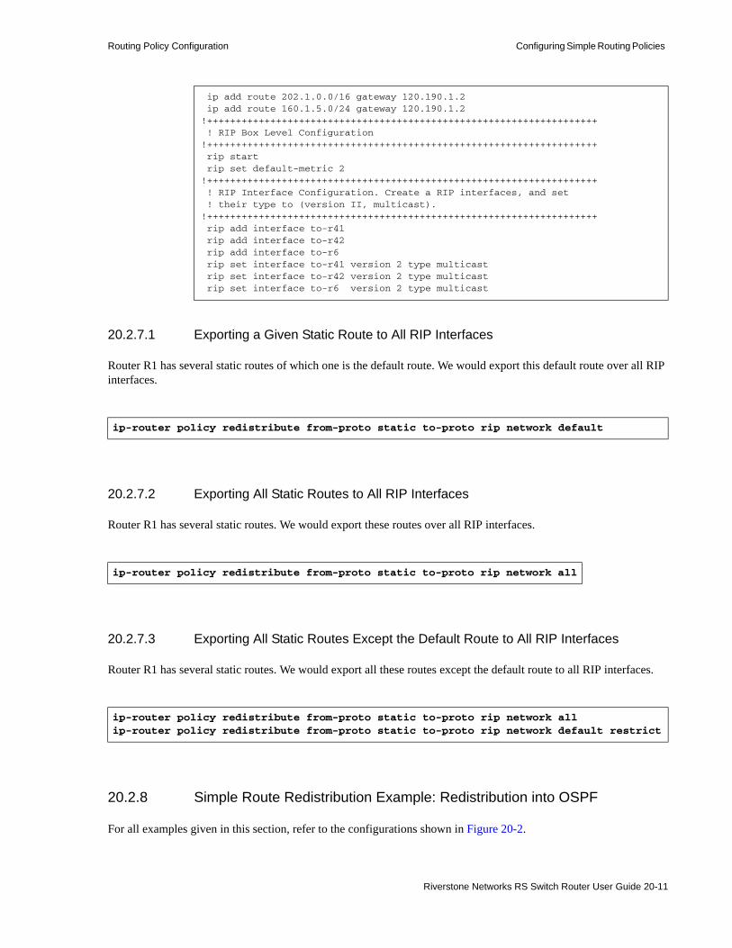
Routing Policy Configuration Configuring Simple Routing Policies
20.2.7.1 Exporting a Given Static Route to All RIP Interfaces
Router R1 has several static routes of which one is the default route. We would export this default route over all RIP interfaces.
20.2.7.2 Exporting All Static Routes to All RIP Interfaces
Router R1 has several static routes. We would export these routes over all RIP interfaces.
20.2.7.3 Exporting All Static Routes Except the Default Route to All RIP Interfaces
Router R1 has several static routes. We would export all these routes except the default route to all RIP interfaces.
20.2.8 Simple Route Redistribution Example: Redistribution into OSPF
For all examples given in this section, refer to the configurations shown in Figure 20-2.
ip add route 202.1.0.0/16 gateway 120.190.1.2 ip add route 160.1.5.0/24 gateway 120.190.1.2!++++++++++++++++++++++++++++++++++++++++++++++++++++++++++++++++++++ ! RIP Box Level Configuration!++++++++++++++++++++++++++++++++++++++++++++++++++++++++++++++++++++ rip start rip set default-metric 2 !++++++++++++++++++++++++++++++++++++++++++++++++++++++++++++++++++++ ! RIP Interface Configuration. Create a RIP interfaces, and set ! their type to (version II, multicast). !++++++++++++++++++++++++++++++++++++++++++++++++++++++++++++++++++++ rip add interface to-r41 rip add interface to-r42 rip add interface to-r6 rip set interface to-r41 version 2 type multicast rip set interface to-r42 version 2 type multicast rip set interface to-r6 version 2 type multicast
ip-router policy redistribute from-proto static to-proto rip network default
ip-router policy redistribute from-proto static to-proto rip network all
ip-router policy redistribute from-proto static to-proto rip network allip-router policy redistribute from-proto static to-proto rip network default restrict
Riverstone Networks RS Switch Router User Guide 20-11

Configuring Simple Routing Policies Routing Policy Configuration
The following configuration commands for router R1:• Determine the IP address for each interface• Specify the static routes configured on the router• Determine its OSPF configuration
20.2.8.1 Exporting All Interface & Static Routes to OSPF
Router R1 has several static routes. We would like to export all these static routes and direct-routes (routes to connected networks) into OSPF.
Note The network parameter specifying the network-filter is optional. The default value for this parameter is all, indicating all networks. Since in the above example, we would like to export all static and direct routes into OSPF, we have not specified this parameter.
!++++++++++++++++++++++++++++++++++++++++++++++++++++++++++++++++++++ ! Create the various IP interfaces.!++++++++++++++++++++++++++++++++++++++++++++++++++++++++++++++++++++ interface create ip to-r2 address-netmask 120.190.1.1/16 port et.1.2 interface create ip to-r3 address-netmask 130.1.1.1/16 port et.1.3 interface create ip to-r41 address-netmask 140.1.1.1/24 port et.1.4 interface create ip to-r42 address-netmask 140.1.2.1/24 port et.1.5 interface create ip to-r6 address-netmask 140.1.3.1/24 port et.1.6!+++++++++++++++++++++++++++++++++++++++++++++++++++++++++++++++++++++ ! Configure default routes to the other subnets reachable through R2.!+++++++++++++++++++++++++++++++++++++++++++++++++++++++++++++++++++++ ip add route 202.1.0.0/16 gateway 120.1.1.2 ip add route 160.1.5.0/24 gateway 120.1.1.2!++++++++++++++++++++++++++++++++++++++++++++++++++++++++++++++++++++ ! OSPF Box Level Configuration!++++++++++++++++++++++++++++++++++++++++++++++++++++++++++++++++++++ ospf start ospf create area 140.1.0.0 ospf create area backbone ospf set ase-defaults cost 4!++++++++++++++++++++++++++++++++++++++++++++++++++++++++++++++++++++ ! OSPF Interface Configuration!++++++++++++++++++++++++++++++++++++++++++++++++++++++++++++++++++++ ospf add interface 140.1.1.1 to-area 140.1.0.0 ospf add interface 140.1.2.1 to-area 140.1.0.0 ospf add interface 140.1.3.1 to-area 140.1.0.0 ospf add interface 130.1.1.1 to-area backbone
ip-router policy redistribute from-proto static to-proto ospfip-router policy redistribute from-proto direct to-proto ospf
20-12 Riverstone Networks RS Switch Router User Guide
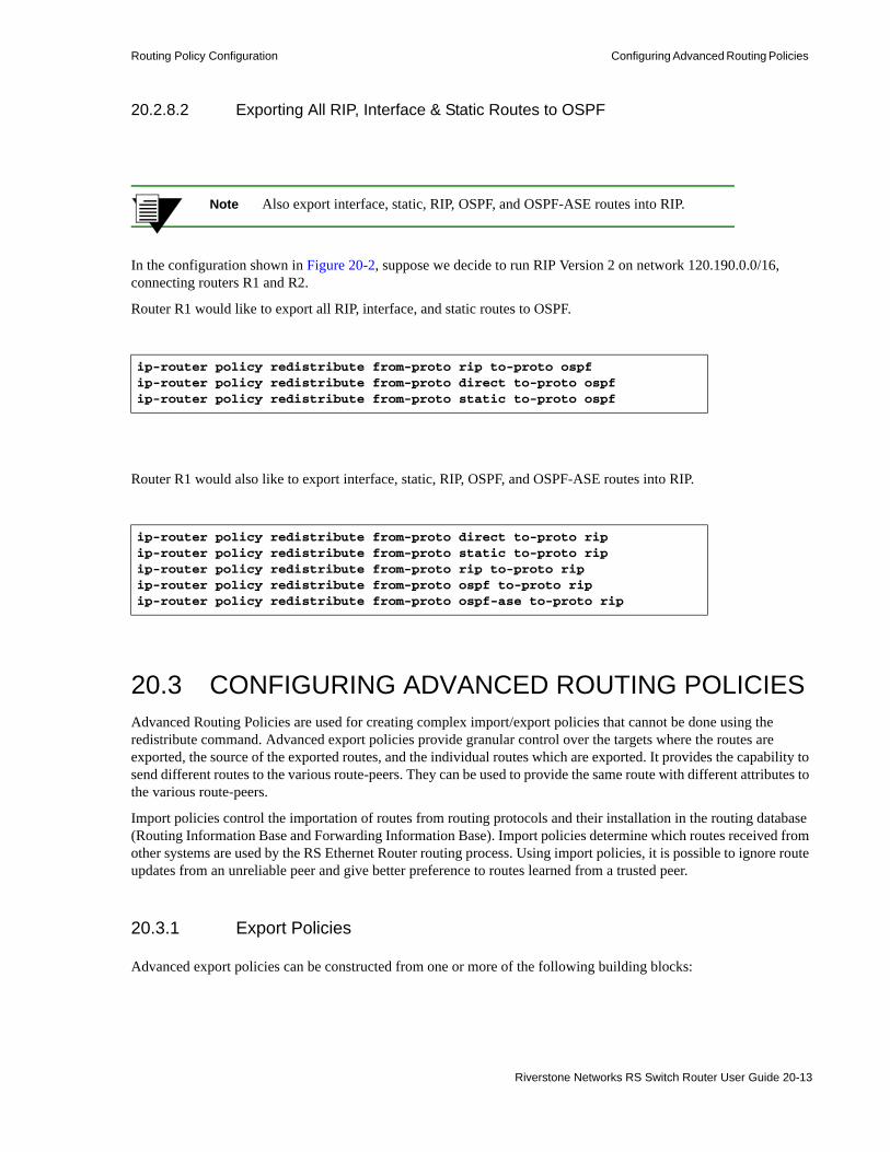
Routing Policy Configuration Configuring Advanced Routing Policies
20.2.8.2 Exporting All RIP, Interface & Static Routes to OSPF
Note Also export interface, static, RIP, OSPF, and OSPF-ASE routes into RIP.
In the configuration shown in Figure 20-2, suppose we decide to run RIP Version 2 on network 120.190.0.0/16, connecting routers R1 and R2.
Router R1 would like to export all RIP, interface, and static routes to OSPF.
Router R1 would also like to export interface, static, RIP, OSPF, and OSPF-ASE routes into RIP.
20.3 CONFIGURING ADVANCED ROUTING POLICIESAdvanced Routing Policies are used for creating complex import/export policies that cannot be done using the redistribute command. Advanced export policies provide granular control over the targets where the routes are exported, the source of the exported routes, and the individual routes which are exported. It provides the capability to send different routes to the various route-peers. They can be used to provide the same route with different attributes to the various route-peers.
Import policies control the importation of routes from routing protocols and their installation in the routing database (Routing Information Base and Forwarding Information Base). Import policies determine which routes received from other systems are used by the RS Ethernet Router routing process. Using import policies, it is possible to ignore route updates from an unreliable peer and give better preference to routes learned from a trusted peer.
20.3.1 Export Policies
Advanced export policies can be constructed from one or more of the following building blocks:
ip-router policy redistribute from-proto rip to-proto ospfip-router policy redistribute from-proto direct to-proto ospfip-router policy redistribute from-proto static to-proto ospf
ip-router policy redistribute from-proto direct to-proto ripip-router policy redistribute from-proto static to-proto ripip-router policy redistribute from-proto rip to-proto ripip-router policy redistribute from-proto ospf to-proto ripip-router policy redistribute from-proto ospf-ase to-proto rip
Riverstone Networks RS Switch Router User Guide 20-13

Configuring Advanced Routing Policies Routing Policy Configuration
• Export Destinations - This component specifies the destination where the routes are to be exported. It also specifies the attributes associated with the exported routes. The interface, gateway or the autonomous system to which the routes are to be redistributed are a few examples of export-destinations. The metric, type, tag, and AS-Path are a few examples of attributes associated with the exported routes.
• Export Sources - This component specifies the source of the exported routes. It can also specify the metric to be associated with the routes exported from this source. The routes to be exported can be identified by their associated attributes, such as protocol type, interface or the gateway from which the route was received, and so on.
• Route Filter - This component provides the means to define a filter for the routes to be distributed. Routes that match a filter are considered as eligible for redistribution. This can be done using one of two methods:- Creating a route-filter and associating an identifier with it. A route-filter has several network
specifications associated with it. Every route is checked against the set of network specifications associated with all route-filters to determine its eligibility for redistribution. The identifier associated with a route-filter is used in the ip-router policy export command.
- Specifying the networks as needed in the ip-router policy export command.
If you want to create a complex route-filter, and you intend to use that route-filter in several export policies, then the first method is recommended. It you do not have complex filter requirements, then use the second method.
After you create one or more building blocks, they are tied together by the iprouter policy export command.
To create route export policies, enter the following command in Configure mode:
<exp-dest-id>The identifier of the export-destination which determines where the routes are to be exported. If no routes to a particular destination are to be exported, then no additional parameters are required.
<exp-src-id>If specified, is the identifier of the export-source which determines the source of the exported routes. If a export-policy for a given export-destination has more than one export-source, then the ip-router policy export destination <exp-dest-id> command should be repeated for each <exp-src-id>.
<filter-id>If specified, is the identifier of the route-filter associated with this export-policy. If there is more than one route-filter for any export-destination and export-source combination, then the ip-router policy export destination <exp-dest-id> source <exp-src-id> command should be repeated for each <filter-id>.
Create an export policy. ip-router policy export destination <exp-dest-id> [source <exp-src-id> [filter <filter-id>|[network <ipAddr-mask> [exact|refines|between <low-high>] [metric <number>|restrict]]]]
20-14 Riverstone Networks RS Switch Router User Guide

Routing Policy Configuration Configuring Advanced Routing Policies
20.3.2 Creating an Export Destination
To create an export destination, enter one the following commands in Configure mode:
20.3.3 Creating an Export Source
To create an export source, enter one of the following commands in Configure mode:
20.3.4 Import Policies
Import policies can be constructed from one or more of the following building blocks:• Import-source - This component specifies the source of the imported routes. It can also specify the
preference to be associated with the routes imported from this source. The routes to be imported can be identified by their associated attributes, including source protocol, source interface, or gateway from which the route was received, and so on.
• Route Filter - This component provides the means to define a filter for the routes to be imported. Routes that match a filter are considered as eligible for importation. This can be done using one of two methods:
- Creating a route-filter and associating an identifier with it. A route-filter has several network specifications associated with it. Every route is checked against the set of network specifications associated with all route-filters to determine its eligibility for importation. The identifier associated with a route-filter is used in the ip-router policy import command.
- Specifying the networks as needed in the ip-router policy import command.
If you want to create a complex route-filter, and you intend to use that route-filter in several import policies, then the first method is recommended. It you do not have complex filter requirements, then use the second method.
After you create one or more building blocks, they are tied together by the ip-router policy import command.
Create a RIP export destination. ip-router policy create rip-export-destination <name>
Create an OSPF export destination. ip-router policy create ospf-export-destination <name>
Create an IS-IS export destination. ip-router policy create isis-export-destination <name>
Create a RIP export source. ip-router policy create rip-export-source <name>
Create an OSPF export source. ip-router policy create ospf-export-source <name>
Create an IS-IS export source. ip-router policy create isis-export-source <name>
Riverstone Networks RS Switch Router User Guide 20-15
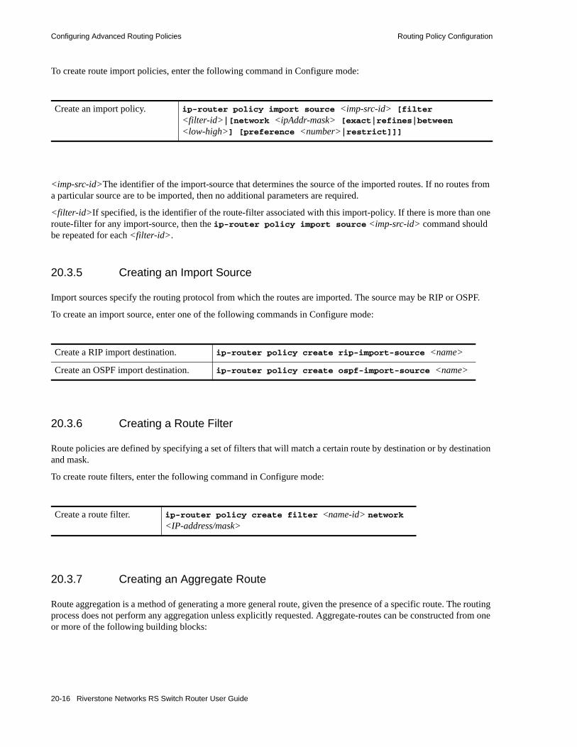
Configuring Advanced Routing Policies Routing Policy Configuration
To create route import policies, enter the following command in Configure mode:
<imp-src-id>The identifier of the import-source that determines the source of the imported routes. If no routes from a particular source are to be imported, then no additional parameters are required.
<filter-id>If specified, is the identifier of the route-filter associated with this import-policy. If there is more than one route-filter for any import-source, then the ip-router policy import source <imp-src-id> command should be repeated for each <filter-id>.
20.3.5 Creating an Import Source
Import sources specify the routing protocol from which the routes are imported. The source may be RIP or OSPF.
To create an import source, enter one of the following commands in Configure mode:
20.3.6 Creating a Route Filter
Route policies are defined by specifying a set of filters that will match a certain route by destination or by destination and mask.
To create route filters, enter the following command in Configure mode:
20.3.7 Creating an Aggregate Route
Route aggregation is a method of generating a more general route, given the presence of a specific route. The routing process does not perform any aggregation unless explicitly requested. Aggregate-routes can be constructed from one or more of the following building blocks:
Create an import policy. ip-router policy import source <imp-src-id> [filter <filter-id>|[network <ipAddr-mask> [exact|refines|between <low-high>] [preference <number>|restrict]]]
Create a RIP import destination. ip-router policy create rip-import-source <name>
Create an OSPF import destination. ip-router policy create ospf-import-source <name>
Create a route filter. ip-router policy create filter <name-id> network <IP-address/mask>
20-16 Riverstone Networks RS Switch Router User Guide
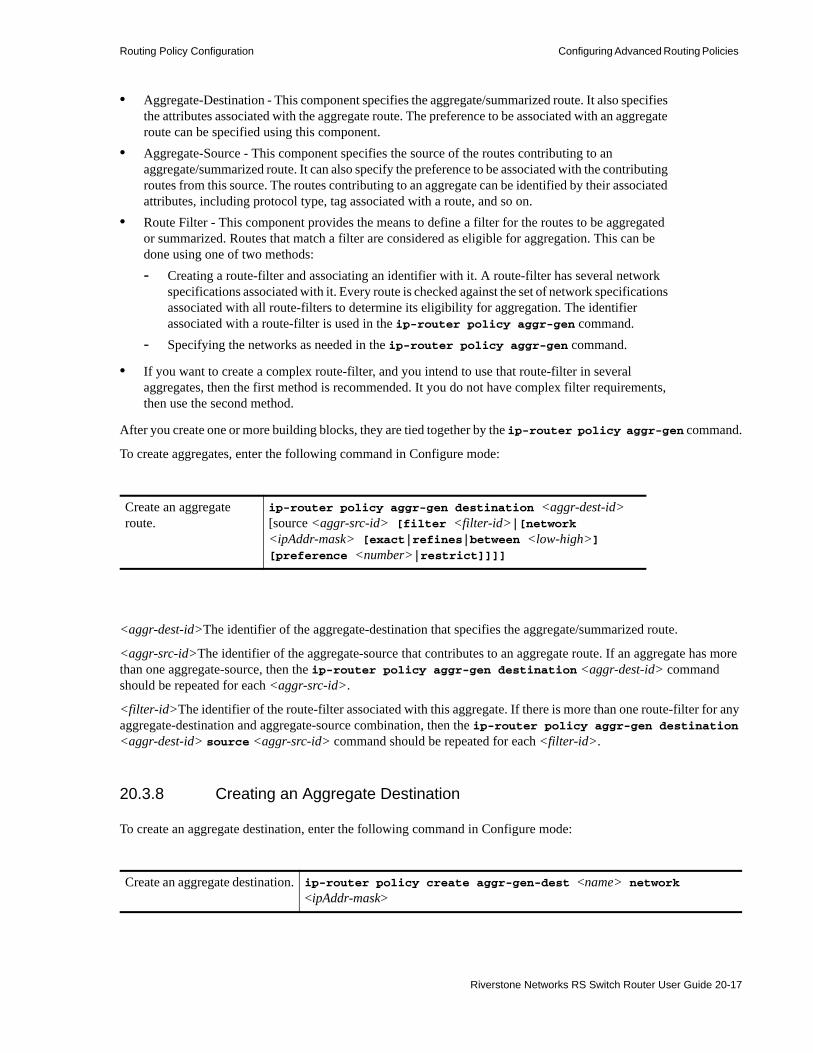
Routing Policy Configuration Configuring Advanced Routing Policies
• Aggregate-Destination - This component specifies the aggregate/summarized route. It also specifies the attributes associated with the aggregate route. The preference to be associated with an aggregate route can be specified using this component.
• Aggregate-Source - This component specifies the source of the routes contributing to an aggregate/summarized route. It can also specify the preference to be associated with the contributing routes from this source. The routes contributing to an aggregate can be identified by their associated attributes, including protocol type, tag associated with a route, and so on.
• Route Filter - This component provides the means to define a filter for the routes to be aggregated or summarized. Routes that match a filter are considered as eligible for aggregation. This can be done using one of two methods:- Creating a route-filter and associating an identifier with it. A route-filter has several network
specifications associated with it. Every route is checked against the set of network specifications associated with all route-filters to determine its eligibility for aggregation. The identifier associated with a route-filter is used in the ip-router policy aggr-gen command.
- Specifying the networks as needed in the ip-router policy aggr-gen command.
• If you want to create a complex route-filter, and you intend to use that route-filter in several aggregates, then the first method is recommended. It you do not have complex filter requirements, then use the second method.
After you create one or more building blocks, they are tied together by the ip-router policy aggr-gen command.
To create aggregates, enter the following command in Configure mode:
<aggr-dest-id>The identifier of the aggregate-destination that specifies the aggregate/summarized route.
<aggr-src-id>The identifier of the aggregate-source that contributes to an aggregate route. If an aggregate has more than one aggregate-source, then the ip-router policy aggr-gen destination <aggr-dest-id> command should be repeated for each <aggr-src-id>.
<filter-id>The identifier of the route-filter associated with this aggregate. If there is more than one route-filter for any aggregate-destination and aggregate-source combination, then the ip-router policy aggr-gen destination <aggr-dest-id> source <aggr-src-id> command should be repeated for each <filter-id>.
20.3.8 Creating an Aggregate Destination
To create an aggregate destination, enter the following command in Configure mode:
Create an aggregate route.
ip-router policy aggr-gen destination <aggr-dest-id> [source <aggr-src-id> [filter <filter-id>|[network <ipAddr-mask> [exact|refines|between <low-high>] [preference <number>|restrict]]]]
Create an aggregate destination. ip-router policy create aggr-gen-dest <name> network <ipAddr-mask>
Riverstone Networks RS Switch Router User Guide 20-17

Configuring Advanced Routing Policies Routing Policy Configuration
20.3.9 Creating an Aggregate Source
To create an aggregate source, enter the following command in Configure mode:
20.3.10 Import Policies Example: Importing from RIP
The importation of RIP routes may be controlled by any of protocol, source interface, or source gateway. If more than one is specified, they are processed from most general (protocol) to most specific (gateway).
RIP does not support the use of preference to choose between routes of the same protocol. That is left to the protocol metrics.
For all examples in this section, refer to the configuration shown in Figure 20-1.
Create an aggregate source. ip-router policy create aggr-gen-source <name> protocol <protocol-name>
20-18 Riverstone Networks RS Switch Router User Guide

Routing Policy Configuration Configuring Advanced Routing Policies
Figure 20-1 Exporting to RIP
The configuration commands shown below for router R1: • Determine the IP address for each interface.• Specify the static routes configured on the router.• Determine its RIP configuration.
Internet
R6
R42
R41
R1
R2
R3
R7
135.3.1.1/24
135.3.2.1/24
135.3.3.1/24
140.1.1.4/24
140.1.1.1/24130.1.1.1/16130.1.1.3/16
120.190.1.1/16
120.190.1.2/16
202.1.0.0/10
160.1.5.0/24
160.1.1.1/16
140.1.2.1/24
170.1.1.1/16
default170.1.1.7/16
RIP V2
RIP v2
(RIP V
1)
10.51.0.0/16
Riverstone Networks RS Switch Router User Guide 20-19

Configuring Advanced Routing Policies Routing Policy Configuration
20.3.10.1 Importing a Selected Subset of Routes from One RIP Trusted Gateway
Router R1 has several RIP peers. Router R41 has an interface on the network 10.51.0.0. By default, router R41 advertises network 10.51.0.0/16 in its RIP updates. Router R1 would like to import all routes except the 10.51.0.0/16 route from its peer R41.1. Add the peer 140.1.1.41 to the list of trusted and source gateways.
!++++++++++++++++++++++++++++++++++++++++++++++++++++++++++++++++++++! Create the various IP interfaces. !++++++++++++++++++++++++++++++++++++++++++++++++++++++++++++++++++++interface create ip to-r2 address-netmask 120.190.1.1/16 port et.1.2 interface create ip to-r3 address-netmask 130.1.1.1/16 port et.1.3interface create ip to-r41 address-netmask 140.1.1.1/24 port et.1.4interface create ip to-r42 address-netmask 140.1.2.1/24 port et.1.5interface create ip to-r6 address-netmask 160.1.1.1/16 port et.1.6interface create ip to-r7 address-netmask 170.1.1.1/16 port et.1.7!++++++++++++++++++++++++++++++++++++++++++++++++++++++++++++++++++++! Configure a default route through 170.1.1.7!++++++++++++++++++++++++++++++++++++++++++++++++++++++++++++++++++++ip add route default gateway 170.1.1.7!+++++++++++++++++++++++++++++++++++++++++++++++++++++++++++++++++++++! Configure default routes to the 135.3.0.0 subnets reachable through ! R3. !+++++++++++++++++++++++++++++++++++++++++++++++++++++++++++++++++++++ ip add route 135.3.1.0/24 gateway 130.1.1.3ip add route 135.3.2.0/24 gateway 130.1.1.3ip add route 135.3.3.0/24 gateway 130.1.1.3!+++++++++++++++++++++++++++++++++++++++++++++++++++++++++++++++++++++! Configure default routes to the other subnets reachable through R2.!+++++++++++++++++++++++++++++++++++++++++++++++++++++++++++++++++++++ip add route 202.1.0.0/16 gateway 120.190.1.2ip add route 160.1.5.0/24 gateway 120.190.1.2!++++++++++++++++++++++++++++++++++++++++++++++++++++++++++++++++++++! RIP Box Level Configuration!++++++++++++++++++++++++++++++++++++++++++++++++++++++++++++++++++++rip startrip set default-metric 2 !++++++++++++++++++++++++++++++++++++++++++++++++++++++++++++++++++++! RIP Interface Configuration. Create a RIP interfaces, and set ! their type to (version II, multicast). !++++++++++++++++++++++++++++++++++++++++++++++++++++++++++++++++++++rip add interface to-r41rip add interface to-r42rip add interface to-r6rip set interface to-r41 version 2 type multicast rip set interface to-r42 version 2 type multicast rip set interface to-r6 version 2 type multicast
rip add source-gateways 140.1.1.41rip add trusted-gateways 140.1.1.41
20-20 Riverstone Networks RS Switch Router User Guide
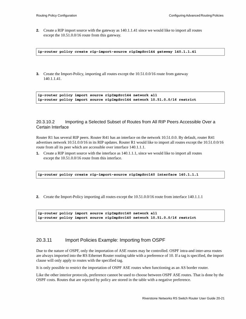
Routing Policy Configuration Configuring Advanced Routing Policies
2. Create a RIP import source with the gateway as 140.1.1.41 since we would like to import all routes except the 10.51.0.0/16 route from this gateway.
3. Create the Import-Policy, importing all routes except the 10.51.0.0/16 route from gateway 140.1.1.41.
20.3.10.2 Importing a Selected Subset of Routes from All RIP Peers Accessible Over a Certain Interface
Router R1 has several RIP peers. Router R41 has an interface on the network 10.51.0.0. By default, router R41 advertises network 10.51.0.0/16 in its RIP updates. Router R1 would like to import all routes except the 10.51.0.0/16 route from all its peer which are accessible over interface 140.1.1.1.1. Create a RIP import source with the interface as 140.1.1.1, since we would like to import all routes
except the 10.51.0.0/16 route from this interface.
2. Create the Import-Policy importing all routes except the 10.51.0.0/16 route from interface 140.1.1.1
20.3.11 Import Policies Example: Importing from OSPF
Due to the nature of OSPF, only the importation of ASE routes may be controlled. OSPF intra-and inter-area routes are always imported into the RS Ethernet Router routing table with a preference of 10. If a tag is specified, the import clause will only apply to routes with the specified tag.
It is only possible to restrict the importation of OSPF ASE routes when functioning as an AS border router.
Like the other interior protocols, preference cannot be used to choose between OSPF ASE routes. That is done by the OSPF costs. Routes that are rejected by policy are stored in the table with a negative preference.
ip-router policy create rip-import-source ripImpSrc144 gateway 140.1.1.41
ip-router policy import source ripImpSrc144 network allip-router policy import source ripImpSrc144 network 10.51.0.0/16 restrict
ip-router policy create rip-import-source ripImpSrc140 interface 140.1.1.1
ip-router policy import source ripImpSrc140 network allip-router policy import source ripImpSrc140 network 10.51.0.0/16 restrict
Riverstone Networks RS Switch Router User Guide 20-21

Configuring Advanced Routing Policies Routing Policy Configuration
For all examples in this section, refer to the configuration shown in Figure 20-2.
Figure 20-2 Exporting to OSPF
The following configuration commands for router R1: • Determine the IP address for each interface• Specify the static routes configured on the router
BG
P
R1
R2
R3
R41
R42
R6
R11
A r e a B
a c k b o n e
A r e a 140.1.0.0(RIP V2)
140.1.1.1/24
140.1.2.1/24
140.1.5/24
140.1.4/24
190.1.1.1/16
120.190.1.1/16
160.1.5.2/24R
10
R5
R7
202.1.2.2/16
140.1.3.1/24130.1.1.1/16
R8
A r e a 150.20.0.0
150.20.3.1/16
150.20.3.2/16
140.1.1.2/24
130.1.1.3/16
120.190.1.2/16
160.1.5.2/24
20-22 Riverstone Networks RS Switch Router User Guide

Routing Policy Configuration Configuring Advanced Routing Policies
• Determine its OSPF configuration
20.3.11.1 Importing a Selected Subset of OSPF-ASE Routes
1. Create a OSPF import source so that only routes that have a tag of 100 are considered for importation.
2. Create the Import-Policy importing all OSPF ASE routes with a tag of 100 except the default ASE route.
!++++++++++++++++++++++++++++++++++++++++++++++++++++++++++++++++++++! Create the various IP interfaces.!++++++++++++++++++++++++++++++++++++++++++++++++++++++++++++++++++++ interface create ip to-r2 address-netmask 120.190.1.1/16 port et.1.2 interface create ip to-r3 address-netmask 130.1.1.1/16 port et.1.3 interface create ip to-r41 address-netmask 140.1.1.1/24 port et.1.4 interface create ip to-r42 address-netmask 140.1.2.1/24 port et.1.5 interface create ip to-r6 address-netmask 140.1.3.1/24 port et.1.6!+++++++++++++++++++++++++++++++++++++++++++++++++++++++++++++++++++++! Configure default routes to the other subnets reachable through R2.!+++++++++++++++++++++++++++++++++++++++++++++++++++++++++++++++++++++ ip add route 202.1.0.0/16 gateway 120.1.1.2 ip add route 160.1.5.0/24 gateway 120.1.1.2!++++++++++++++++++++++++++++++++++++++++++++++++++++++++++++++++++++! OSPF Box Level Configuration!++++++++++++++++++++++++++++++++++++++++++++++++++++++++++++++++++++ ospf start ospf create area 140.1.0.0 ospf create area backbone ospf set ase-defaults cost 4!++++++++++++++++++++++++++++++++++++++++++++++++++++++++++++++++++++! OSPF Interface Configuration!++++++++++++++++++++++++++++++++++++++++++++++++++++++++++++++++++++ ospf add interface 140.1.1.1 to-area 140.1.0.0 ospf add interface 140.1.2.1 to-area 140.1.0.0 ospf add interface 140.1.3.1 to-area 140.1.0.0 ospf add interface 130.1.1.1 to-area backbone
ip-router policy create ospf-import-source ospfImpSrct100 tag 100
ip-router policy import source ospfImpSrct100 network allip-router policy import source ospfImpSrct100 network default restrict
Riverstone Networks RS Switch Router User Guide 20-23

Configuring Advanced Routing Policies Routing Policy Configuration
20.3.12 Export Policies Example: Exporting to RIP
Exporting to RIP is controlled by any of protocol, interface or gateway. If more than one is specified, they are processed from most general (protocol) to most specific (gateway).
It is not possible to set metrics for exporting RIP routes into RIP. Attempts to do this are silently ignored.
If no export policy is specified, RIP and interface routes are exported into RIP. If any policy is specified, the defaults are overridden; it is necessary to explicitly specify everything that should be exported.
RIP version 1 assumes that all subnets of the shared network have the same subnet mask so it is only able to propagate subnets of that network. RIP version 2 removes that restriction and is capable of propagating all routes when not sending version 1 compatible updates.
To announce routes which specify a next hop of the loopback interface (i.e. static and internally generated default routes) via RIP, it is necessary to specify the metric at some level in the export policy. Just setting a default metric for RIP is not sufficient. This is a safeguard to verify that the announcement is intended.
For all examples in this section, refer to the configuration shown in Figure 20-1.
The following configuration commands for router R1: • Determine the IP address for each interface• Specify the static routes configured on the router• Determine its RIP configuration
!++++++++++++++++++++++++++++++++++++++++++++++++++++++++++++++++++++ ! Create the various IP interfaces.!++++++++++++++++++++++++++++++++++++++++++++++++++++++++++++++++++++ interface create ip to-r2 address-netmask 120.190.1.1/16 port et.1.2 interface create ip to-r3 address-netmask 130.1.1.1/16 port et.1.3 interface create ip to-r41 address-netmask 140.1.1.1/24 port et.1.4 interface create ip to-r42 address-netmask 140.1.2.1/24 port et.1.5 interface create ip to-r6 address-netmask 160.1.1.1/16 port et.1.6 interface create ip to-r7 address-netmask 170.1.1.1/16 port et.1.7!++++++++++++++++++++++++++++++++++++++++++++++++++++++++++++++++++++ ! Configure a default route through 170.1.1.7!++++++++++++++++++++++++++++++++++++++++++++++++++++++++++++++++++++ ip add route default gateway 170.1.1.7!+++++++++++++++++++++++++++++++++++++++++++++++++++++++++++++++++++++ ! Configure default routes to the 135.3.0.0 subnets reachable through ! R3. !+++++++++++++++++++++++++++++++++++++++++++++++++++++++++++++++++++++ ip add route 135.3.1.0/24 gateway 130.1.1.3 ip add route 135.3.2.0/24 gateway 130.1.1.3 ip add route 135.3.3.0/24 gateway 130.1.1.3!+++++++++++++++++++++++++++++++++++++++++++++++++++++++++++++++++++++ ! Configure default routes to the other subnets reachable through R2.!+++++++++++++++++++++++++++++++++++++++++++++++++++++++++++++++++++++ ip add route 202.1.0.0/16 gateway 120.190.1.2 ip add route 160.1.5.0/24 gateway 120.190.1.2!++++++++++++++++++++++++++++++++++++++++++++++++++++++++++++++++++++ ! RIP Box Level Configuration!++++++++++++++++++++++++++++++++++++++++++++++++++++++++++++++++++++ rip start rip set default-metric 2 !++++++++++++++++++++++++++++++++++++++++++++++++++++++++++++++++++++ ! RIP Interface Configuration. Create a RIP interfaces, and set ! their type to (version II, multicast). !++++++++++++++++++++++++++++++++++++++++++++++++++++++++++++++++++++
20-24 Riverstone Networks RS Switch Router User Guide
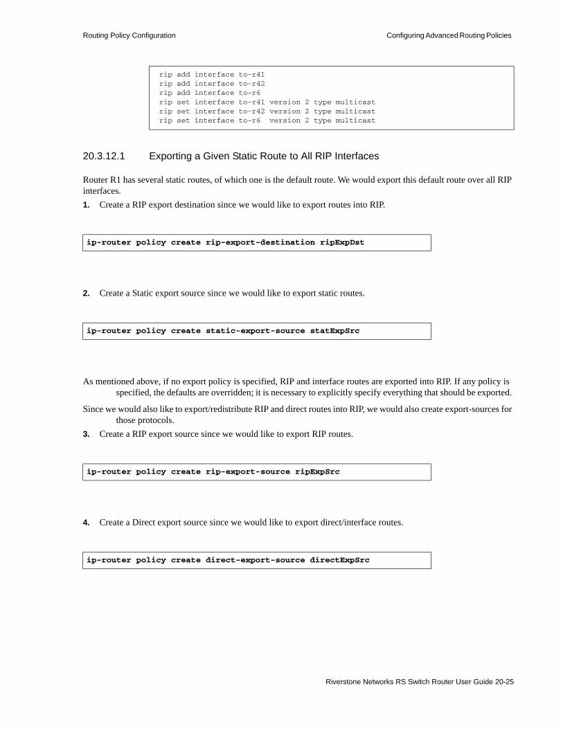
Routing Policy Configuration Configuring Advanced Routing Policies
20.3.12.1 Exporting a Given Static Route to All RIP Interfaces
Router R1 has several static routes, of which one is the default route. We would export this default route over all RIP interfaces.1. Create a RIP export destination since we would like to export routes into RIP.
2. Create a Static export source since we would like to export static routes.
As mentioned above, if no export policy is specified, RIP and interface routes are exported into RIP. If any policy is specified, the defaults are overridden; it is necessary to explicitly specify everything that should be exported.
Since we would also like to export/redistribute RIP and direct routes into RIP, we would also create export-sources for those protocols.
3. Create a RIP export source since we would like to export RIP routes.
4. Create a Direct export source since we would like to export direct/interface routes.
rip add interface to-r41 rip add interface to-r42 rip add interface to-r6 rip set interface to-r41 version 2 type multicast rip set interface to-r42 version 2 type multicast rip set interface to-r6 version 2 type multicast
ip-router policy create rip-export-destination ripExpDst
ip-router policy create static-export-source statExpSrc
ip-router policy create rip-export-source ripExpSrc
ip-router policy create direct-export-source directExpSrc
Riverstone Networks RS Switch Router User Guide 20-25

Configuring Advanced Routing Policies Routing Policy Configuration
5. Create the export-policy redistributing the statically created default route, and all (RIP, Direct) routes into RIP.
20.3.12.2 Exporting a Given Static Route to a Specific RIP Interface
In this case, router R1 would export/redistribute the default route over its interface 140.1.1.1 only.1. Create a RIP export destination for interface with address 140.1.1.1, since we intend to change the
rip export policy only for interface 140.1.1.1.
2. Create a static export source since we would like to export static routes.
3. Create a RIP export source since we would like to export RIP routes.
4. Create a Direct export source since we would like to export direct/interface routes.
ip-router policy export destination ripExpDst source statExpSrc network defaultip-router policy export destination ripExpDst source ripExpSrc network allip-router policy export destination ripExpDst source directExpSrc network all
ip-router policy create rip-export-destination ripExpDst141 interface 140.1.1.1
ip-router policy create static-export-source statExpSrc
ip-router policy create rip-export-source ripExpSrc
ip-router policy create direct-export-source directExpSrc
20-26 Riverstone Networks RS Switch Router User Guide

Routing Policy Configuration Configuring Advanced Routing Policies
5. Create the Export-Policy redistributing the statically created default route, and all (RIP, Direct) routes into RIP.
20.3.12.3 Exporting All Static Routes Reachable Over a Given Interface to a Specific RIP Interface
In this case, router R1 would export/redistribute all static routes accessible through its interface 130.1.1.1 to its RIP-interface 140.1.1.1 only.1. Create a RIP export destination for interface with address 140.1.1.1, since we intend to change the
rip export policy for interface 140.1.1.1
2. Create a Static export source since we would like to export static routes.
3. Create a RIP export source since we would like to export RIP routes.
4. Create a Direct export source.
ip-router policy export destination ripExpDst141 source statExpSrc network defaultip-router policy export destination ripExpDst141 source ripExpSrc network allip-router policy export destination ripExpDst141 source directExpSrc network all
ip-router policy create rip-export-destination ripExpDst141 interface 140.1.1.1
ip-router policy create static-export-source statExpSrc130 interface 130.1.1.1
ip-router policy create rip-export-source ripExpSrc
ip-router policy create direct-export-source directExpSrc
Riverstone Networks RS Switch Router User Guide 20-27
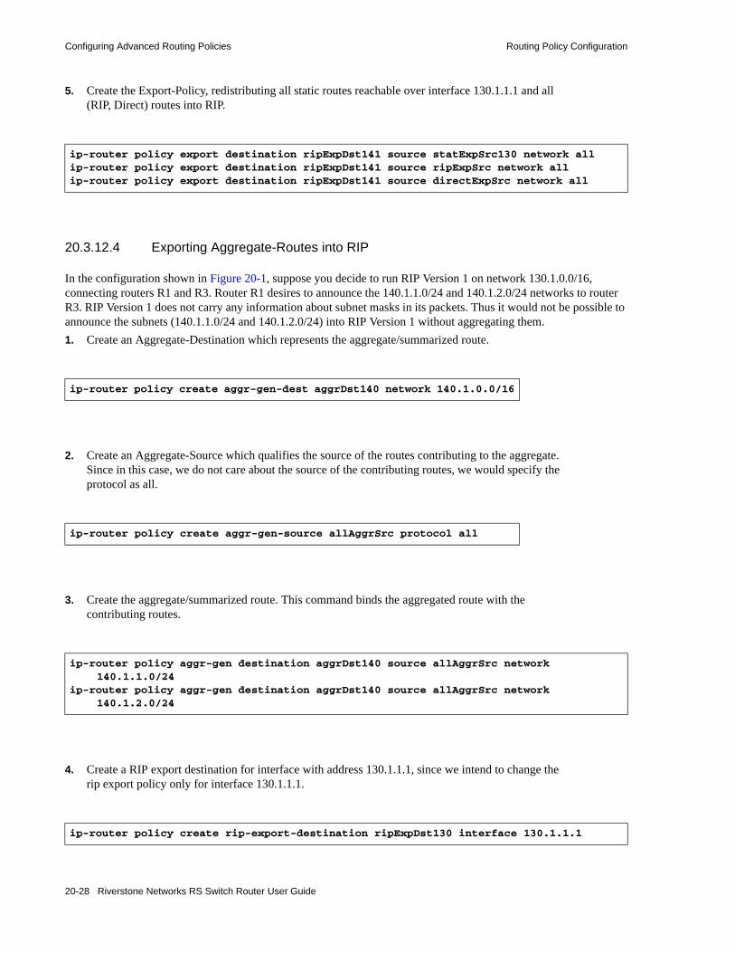
Configuring Advanced Routing Policies Routing Policy Configuration
5. Create the Export-Policy, redistributing all static routes reachable over interface 130.1.1.1 and all (RIP, Direct) routes into RIP.
20.3.12.4 Exporting Aggregate-Routes into RIP
In the configuration shown in Figure 20-1, suppose you decide to run RIP Version 1 on network 130.1.0.0/16, connecting routers R1 and R3. Router R1 desires to announce the 140.1.1.0/24 and 140.1.2.0/24 networks to router R3. RIP Version 1 does not carry any information about subnet masks in its packets. Thus it would not be possible to announce the subnets (140.1.1.0/24 and 140.1.2.0/24) into RIP Version 1 without aggregating them.1. Create an Aggregate-Destination which represents the aggregate/summarized route.
2. Create an Aggregate-Source which qualifies the source of the routes contributing to the aggregate. Since in this case, we do not care about the source of the contributing routes, we would specify the protocol as all.
3. Create the aggregate/summarized route. This command binds the aggregated route with the contributing routes.
4. Create a RIP export destination for interface with address 130.1.1.1, since we intend to change the rip export policy only for interface 130.1.1.1.
ip-router policy export destination ripExpDst141 source statExpSrc130 network allip-router policy export destination ripExpDst141 source ripExpSrc network allip-router policy export destination ripExpDst141 source directExpSrc network all
ip-router policy create aggr-gen-dest aggrDst140 network 140.1.0.0/16
ip-router policy create aggr-gen-source allAggrSrc protocol all
ip-router policy aggr-gen destination aggrDst140 source allAggrSrc network 140.1.1.0/24
ip-router policy aggr-gen destination aggrDst140 source allAggrSrc network 140.1.2.0/24
ip-router policy create rip-export-destination ripExpDst130 interface 130.1.1.1
20-28 Riverstone Networks RS Switch Router User Guide

Routing Policy Configuration Configuring Advanced Routing Policies
5. Create a Aggregate export source since we would to export/redistribute an aggregate/summarized route.
6. Create a RIP export source since we would like to export RIP routes.
7. Create a Direct export source since we would like to export Direct routes.
8. Create the Export-Policy redistributing all (RIP, Direct) routes and the aggregate route 140.1.0.0/16 into RIP.
20.3.13 Export Policies Example: Exporting to OSPF
It is not possible to create OSPF intra- or inter-area routes by exporting routes from the RS Ethernet Router routing table into OSPF. It is only possible to export from the RS Ethernet Router routing table into OSPF ASE routes. It is also not possible to control the propagation of OSPF routes within the OSPF protocol.
There are two types of OSPF ASE routes: type 1 and type 2. The default type is specified by the ospf set ase-defaults type 1/2 command. This may be overridden by a specification in the ip-router policy create ospf-export-destination command.
OSPF ASE routes also have the provision to carry a tag. This is an arbitrary 32-bit number that can be used on OSPF routers to filter routing information. The default tag is specified by the ospf set ase-defaults tag command. This may be overridden by a tag specified with the ip-router policy create ospf-export-destination command.
Interface routes are not automatically exported into OSPF. They have to be explicitly done.
ip-router policy create aggr-export-source aggrExpSrc
ip-router policy create rip-export-source ripExpSrc
ip-router policy create direct-export-source directExpSrc
ip-router policy export destination ripExpDst130 source aggrExpSrc network 140.1.0.0/16
ip-router policy export destination ripExpDst130 source ripExpSrc network allip-router policy export destination ripExpDst130 source directExpSrc network all
Riverstone Networks RS Switch Router User Guide 20-29

Configuring Advanced Routing Policies Routing Policy Configuration
For all examples in this section, refer to the configuration shown in Figure 20-2.
The following configuration commands for router R1: • Determine the IP address for each interface• Specify the static routes configured on the router• Determine its OSPF configuration
20.3.13.1 Exporting All Interface & Static Routes to OSPF
Router R1 has several static routes. We would export these static routes as type-2 OSPF routes. The interface routes would redistributed as type 1 OSPF routes. 1. Create a OSPF export destination for type-1 routes since we would like to redistribute certain routes
into OSPF as type 1 OSPF-ASE routes.
!++++++++++++++++++++++++++++++++++++++++++++++++++++++++++++++++++++ ! Create the various IP interfaces.!++++++++++++++++++++++++++++++++++++++++++++++++++++++++++++++++++++ interface create ip to-r2 address-netmask 120.190.1.1/16 port et.1.2 interface create ip to-r3 address-netmask 130.1.1.1/16 port et.1.3 interface create ip to-r41 address-netmask 140.1.1.1/24 port et.1.4 interface create ip to-r42 address-netmask 140.1.2.1/24 port et.1.5 interface create ip to-r6 address-netmask 140.1.3.1/24 port et.1.6!+++++++++++++++++++++++++++++++++++++++++++++++++++++++++++++++++++++ ! Configure default routes to the other subnets reachable through R2.!+++++++++++++++++++++++++++++++++++++++++++++++++++++++++++++++++++++ ip add route 202.1.0.0/16 gateway 120.1.1.2 ip add route 160.1.5.0/24 gateway 120.1.1.2!++++++++++++++++++++++++++++++++++++++++++++++++++++++++++++++++++++ ! OSPF Box Level Configuration!++++++++++++++++++++++++++++++++++++++++++++++++++++++++++++++++++++ ospf start ospf create area 140.1.0.0 ospf create area backbone ospf set ase-defaults cost 4!++++++++++++++++++++++++++++++++++++++++++++++++++++++++++++++++++++ ! OSPF Interface Configuration!++++++++++++++++++++++++++++++++++++++++++++++++++++++++++++++++++++ ospf add interface 140.1.1.1 to-area 140.1.0.0 ospf add interface 140.1.2.1 to-area 140.1.0.0 ospf add interface 140.1.3.1 to-area 140.1.0.0 ospf add interface 130.1.1.1 to-area backbone
ip-router policy create ospf-export-destination ospfExpDstType1 type 1 metric 1
20-30 Riverstone Networks RS Switch Router User Guide
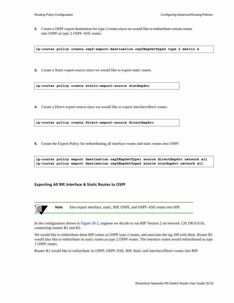
Routing Policy Configuration Configuring Advanced Routing Policies
2. Create a OSPF export destination for type-2 routes since we would like to redistribute certain routes into OSPF as type 2 OSPF-ASE routes.
3. Create a Static export source since we would like to export static routes.
4. Create a Direct export source since we would like to export interface/direct routes.
5. Create the Export-Policy for redistributing all interface routes and static routes into OSPF.
Exporting All RIP, Interface & Static Routes to OSPF
Note Also export interface, static, RIP, OSPF, and OSPF-ASE routes into RIP.
In the configuration shown in Figure 20-2, suppose we decide to run RIP Version 2 on network 120.190.0.0/16, connecting routers R1 and R2.
We would like to redistribute these RIP routes as OSPF type-2 routes, and associate the tag 100 with them. Router R1 would also like to redistribute its static routes as type 2 OSPF routes. The interface routes would redistributed as type 1 OSPF routes.
Router R1 would like to redistribute its OSPF, OSPF-ASE, RIP, Static and Interface/Direct routes into RIP.
ip-router policy create ospf-export-destination ospfExpDstType2 type 2 metric 4
ip-router policy create static-export-source statExpSrc
ip-router policy create direct-export-source directExpSrc
ip-router policy export destination ospfExpDstType1 source directExpSrc network allip-router policy export destination ospfExpDstType2 source statExpSrc network all
Riverstone Networks RS Switch Router User Guide 20-31

Configuring Advanced Routing Policies Routing Policy Configuration
1. Enable RIP on interface 120.190.1.1/16.
2. Create a OSPF export destination for type-1 routes.
3. Create a OSPF export destination for type-2 routes.
4. Create a OSPF export destination for type-2 routes with a tag of 100.
5. Create a RIP export source.
6. Create a Static export source.
rip add interface 120.190.1.1rip set interface 120.190.1.1 version 2 type multicast
ip-router policy create ospf-export-destination ospfExpDstType1 type 1 metric 1
ip-router policy create ospf-export-destination ospfExpDstType2 type 2 metric 4
ip-router policy create ospf-export-destination ospfExpDstType2t100 type 2 tag 100 metric 4
ip-router policy export destination ripExpDst source ripExpSrc network all
ip-router policy create static-export-source statExpSrc
20-32 Riverstone Networks RS Switch Router User Guide

Routing Policy Configuration Configuring Advanced Routing Policies
7. Create a Direct export source.
8. Create the Export-Policy for redistributing all interface, RIP and static routes into OSPF.
9. Create a RIP export destination.
10. Create OSPF export source.
11. Create OSPF-ASE export source.
12. Create the Export-Policy for redistributing all interface, RIP, static, OSPF and OSPF-ASE routes into RIP.
ip-router policy create direct-export-source directExpSrc
ip-router policy export destination ospfExpDstType1 source directExpSrc network allip-router policy export destination ospfExpDstType2 source statExpSrc network allip-router policy export destination ospfExpDstType2t100 source ripExpSrc network all
ip-router policy create rip-export-destination ripExpDst
ip-router policy create ospf-export-source ospfExpSrc type OSPF
ip-router policy create ospf-export-source ospfAseExpSrc type OSPF-ASE
ip-router policy export destination ripExpDst source statExpSrc network allip-router policy export destination ripExpDst source ripExpSrc network allip-router policy export destination ripExpDst source directExpSrc network allip-router policy export destination ripExpDst source ospfExpSrc network allip-router policy export destination ripExpDst source ospfAseExpSrc network all
Riverstone Networks RS Switch Router User Guide 20-33

Configuring Advanced Routing Policies Routing Policy Configuration
20-34 Riverstone Networks RS Switch Router User Guide

21 MULTICAST ROUTING CONFIGURATION
Multicast routing is used to transmit traffic from a single source to multiple receivers. Some applications that use multicasting include teleconferencing or video conferencing.
This chapter describes the RS Ethernet Router’s implementation of multicast routing. It provides an overview of multicast routing, and describes the multicast features supported by the RS Ethernet Router. It contains the following sections:• For an overview of multicast routing, refer to Section 21.1, "Multicast Routing Overview."• To configure Internet Group Management Protocol Version 2.0 (IGMPv2), refer to
Section 21.2, "Configuring IGMP."• To configure IGMP snooping, refer to Section 21.3, "IGMP Snooping."• To configure IGMP proxy, refer to "IGMP Proxy"• To use the multicast replication feature, refer to Section 21.5, "Multicast Replication."• To configure administrative scoping, refer to Section 21.6, "Using TTL Values and
Administratively Scoped Groups."• For information on monitoring multicast routing, refer to Section 21.7, "Monitoring Multicast."
Note The RS Ethernet Router supports the Distance Vector Multicast Routing Protocol (DVMRP) and the Protocol Independent Multicast- Sparse Mode (PIM-SM) protocol. For information on DVMRP, refer to Chapter 22, "DVMRP Routing Configuration." For information on PIM-SM, refer to Chapter 23, "PIM-SM Routing Configuration.".
Riverstone Networks RS Switch Router User Guide 21-1
Multicast Routing Overview Multicast Routing Configuration
21.1 MULTICAST ROUTING OVERVIEWMulticast routing is used to transmit traffic from a source to a group of receivers. Any host can be a source, and the receivers can be anywhere on the Internet as long as they are members of the group to which the multicast packets are addressed. Only the members of a group can receive the multicast data stream.
Multicast group memberships are established and maintained through the Internet Group Management Protocol (IGMP). The RS Ethernet Router supports IGMPv2, as defined in RFC 2236.
Hosts and routers run IGMP to establish group memberships. Routers use IGMP to keep track of members on their directly connected networks.
The RS Ethernet Router uses IGMP to learn about multicast group memberships. To forward multicast traffic on the RS Ethernet Router, you must run a multicast routing protocol, such as DVMRP or PIM. For information on running IGMP on the RS Ethernet Router, refer to Section 21.2, "Configuring IGMP."
21.1.1 IP Multicast Addresses
Multicast IP addresses represent receiver groups and not individual receivers. IP multicast addresses use Class D addresses, which are from 224.0.0.0 to 239.255.255.255. Certain addresses are reserved by the Internet Assigned Numbers Authority (IANA); for a complete list, go to ftp://ftp.isi.edu/in-notes/iana/assignments/multicast-addresses.
21.1.2 Multicast Protocols
There are two types of multicast routing protocols: • dense-mode protocols • sparse-mode protocols
Dense-mode protocols assume that the receivers are densely distributed, meaning most subnets have at least one receiver. Dense-mode protocols use a “flood and prune” technique wherein multicast traffic is flooded throughout the network and paths with no receivers are pruned from the distribution tree. The RS Ethernet Router supports the dense-mode multicast protocol, Distance Vector Multicast Routing Protocol (DVMRP), as specified in the draft-ietf-idmr-dvmrp-v3-09.txt file. For information on DVMRP, refer to Chapter 22, "DVMRP Routing Configuration."
Sparse-mode protocols assume that the receivers are widely dispersed and therefore flooding would be a waste of bandwidth. Sparse mode protocols transmit multicast traffic only to receivers that explicitly request it. The RS Ethernet Router supports the Protocol Independent Multicast- Sparse Mode (PIM-SM) protocol as defined in the draft-ietf-pim-sm-v2-new-04.txt file. For information on PIM-SM, refer to Chapter 23, "PIM-SM Routing Configuration."
Note You cannot configure PIM and DVMRP on the same interface.
On the RS Ethernet Router, multicast protocols are configured on a per-interface basis. The RS Ethernet Router supports up to 4096 multicast interfaces.
21-2 Riverstone Networks RS Switch Router User Guide

Multicast Routing Configuration Multicast Routing Overview
21.1.3 Distribution Trees
Multicast traffic is transmitted to all receivers on the network through multicast distribution trees. There are two types of multicast distribution trees: • source distribution trees • shared distribution trees
A source distribution tree is a spanning tree from the source of the multicast data stream to all receivers on the network. It is also referred to as the shortest path tree (SPT) because packets are forwarded on the path with the smallest metric. Packets are forwarded based on the source address and the multicast group address. The forwarding state is referred to as an (S,G) pair, where S is the IP address of the source, and G is the multicast group address.
A shared distribution tree has its root at one common point from which all multicast traffic is forwarded down to all receivers. Multicast data sources send their multicast traffic to this common point, referred to as the Rendezvous Point (RP), for distribution to all receivers. Multicast packets are forwarded based on the multicast group address only. The forwarding state is referred to as (*, G) where the * represents any source, and G is the multicast group address.
DVMRP uses source distribution tree to propagate multicast traffic. PIM-SM uses both shared and source distribution trees to propagate multicast traffic.
21.1.4 Multicast Forwarding
All multicast routing protocols use reverse path forwarding (RPF) to build shortest path distribution trees to all receivers. On the RS Ethernet Router, RPF uses the routing information in the multicast routing information base (MRIB) to determine the router’s upstream and downstream neighbors; the router forwards a multicast packet only if the packet was received from an upstream interface. When an interface receives a multicast packet, it checks if the packet arrived on the interface the router would use to send out packets to the source. If it did, the router forwards the packet downstream. If it did not, the packet is dropped. This RPF check ensures that traffic is forwarded correctly down the distribution tree.
Riverstone Networks RS Switch Router User Guide 21-3

Configuring IGMP Multicast Routing Configuration
21.2 CONFIGURING IGMP The RS Ethernet Router uses IGMP to learn which multicast groups have members on its directly attached networks. To run a multicast protocol on the RS Ethernet Router, you need to enable IGMP first. The RS Ethernet Router supports IGMPv2 as defined in RFC 2236. This section provides the following information:• for an overview of IGMP, refer to Section 21.2.1, "IGMP Overview."• to enable IGMP on the RS Ethernet Router, refer to Section 21.2.2, "Starting IGMP."• to modify IGMP query defaults, refer to Section Note, "If you are running IGMP on ATM interfaces,
you may have to enable forced bridging on those interfaces. Configuring IGMP Query Intervals."• to modify the robustness variable default, refer to Section 21.2.3, "Configuring the Robustness
Variable."• to set IGM interface parameters, refer to Section 21.2.4, "Configuring IGMP Interface Parameters."• to configure IGMP static groups, refer to Section 21.2.5, "Configuring Static IGMP Groups."
21.2.1 IGMP Overview
Multicast routers and IP hosts use IGMP to dynamically maintain group membership information in a network. A designated router on a network, called the Querier, solicits membership information by periodically sending general queries to its attached network. In response to these queries, hosts periodically multicast membership reports. Hosts also send membership reports when they join a new multicast group.
Each multicast router maintains a list of multicast groups that have at least one member on its attached network. When a router receives a membership report, it adds the group to the list of multicast groups on the network on which it received the report and sets a timer for the membership. If the router doesn’t receive a membership report before the timer expires or if it receives a leave group message from a particular group, then the router removes the group from the list and stops forwarding multicast packets for that group on that network.
The router tracks the number of hosts that are subscribed to any particular group. After each host leaves, the router queries the group’s other subscribers to see if they wish to continue subscribing to the group. In an ATM network, the router does not send this query when the last member of the group leaves.
21.2.2 Starting IGMP
IGMP is disabled on the RS Ethernet Router by default. It does not automatically run when you start a multicast routing protocol, such as DVMRP. You must enable IGMP on all interfaces with directly connected senders and receivers.
IGMP is run on a per-IP interface basis. Since multiple physical ports can be configured with the same IP interface on the RS Ethernet Router (for example, VLANs), IGMP keeps track of multicast host members on a per-port basis. Ports belonging to an IP VLAN without any IGMP membership will not be forwarded any multicast traffic. The following example starts IGMP on the RS Ethernet Router and on the interface pc1:
rs (config)# igmp startrs (config)# igmp add interface pc1
21-4 Riverstone Networks RS Switch Router User Guide

Multicast Routing Configuration Configuring IGMP
Note IGMP is used only to establish group memberships. You must run either DVMRP or PIM-SM to route multicast traffic.
Note If you are running IGMP on ATM interfaces, you may have to enable forced bridging on those interfaces. Configuring IGMP Query Intervals
When you start IGMP on the RS Ethernet Router, it assumes the role of the Querier on each attached network. The Querier sends two types of membership queries, general queries and group-specific queries. General queries are periodically sent out to obtain membership information. In addition, the Querier sends a group-specific query after it receives a leave group message for a group with members on one of its interfaces.
The RS Ethernet Router has default values for the timers associated with these queries. You can change the defaults either globally or on a per-interface basis. This section describes how to set these timers globally. For information on setting these timers for a specific interface, refer to Section 21.2.4, "Configuring IGMP Interface Parameters."
The RS Ethernet Router functions as the Querier unless it hears a query from another multicast router with a lower IP address; then it becomes a non-Querier. Normally, there is only one Querier per physical network.
Note On ATM networks, the RS Ethernet Router does not send a group-specific membership query after the last host belonging to a group leaves.
21.2.2.1 Setting General Query Intervals
The Querier periodically sends a general query to its attached networks to solicit membership information. On the RS Ethernet Router, the default time interval for general queries is 125 seconds. The following example sets the global interval between general queries to 175 seconds:
After a Querier sends out a general query, it waits a certain interval for the membership reports from its attached hosts. On the RS Ethernet Router, the default for this response time is 10 seconds. Changing this value affects the burstiness of IGMP messages. If you increase this value, host responses are spread over a longer interval causing the IGMP traffic to be less bursty. The following example increases the maximum response time to 30 seconds:
rs (config)# igmp set query interval 175
rs (config)# igmp set max-resp-time 30
Riverstone Networks RS Switch Router User Guide 21-5

Configuring IGMP Multicast Routing Configuration
21.2.2.2 Setting the Group-Specific Query Interval
The Querier sends a group-specific query when it receives a leave group message for a group with members on one of its interfaces. If the Querier does not receive a membership report within a specified period, then it assumes that the group has no more local members. The default value is 1 second. The following example sets the global last member query interval to 2 seconds:
21.2.3 Configuring the Robustness Variable
The robustness variable provides for the expected packet loss on a subnet. The default robustness variable is 2. If the subnet is expected to be lossy, then you can increase this variable. You can change this default globally or on a per-interface basis. The following example increases the global robustness variable to 3:
21.2.4 Configuring IGMP Interface Parameters
Use the igmp set interface command for per interface control of the following:• the general query interval • the maximum response time• the group-specific query interval • the robustness variable
The following example enables IGMP on the interface pc1 and sets parameters for this interface:
Use the igmp show interfaces command to view IGMP information about a specified interface, as shown in the following example:
Note If you are running IGMP on ATM interfaces, you may have to enable forced bridging on those interfaces.
rs (config)# igmp set last-mem-query-interval 2
rs (config)# igmp set robustness 3
rs (config)# igmp add interface pc1rs (config)# igmp set interface pc1 max-response-time 8 last-mem-query-interval 2
rs# igmp show interface pc1IGMP Interfaces informationinterface: pc1 150.20.20.100/24, enabled, owner: dvmrp Querier: 150.20.20.100 (this system) Query timer running, next query in: 6 Query Invl: 2:05, Max Resp: 8, Joins: 1 Robust: 2 pc1 224.1.2.1 age 30:37 timeout 2:23
21-6 Riverstone Networks RS Switch Router User Guide

Multicast Routing Configuration Configuring IGMP
21.2.5 Configuring Static IGMP Groups
When IGMP is enabled on an interface, at least one group member needs to be present on the interface for the RS Ethernet Router to retain the group on its list of multicast group memberships for the interface. You can configure a static IGMP group for an interface; a static group can exist without any group members present on the interface.
The following example configures a static IGMP group on the interface pc1:
To view static memberships, use the igmp show static-memberships command as shown in the following example:
21.2.6 Configuring IGMP Implicit Leave
When a host that is already joined to one multicast group tries to join another group, you can configure the RS Ethernet Router to treat the second join as also an implicit leave of the first subscription. Thus, a host can be joined to only one group at a time, and any future joins will cause it to be disconnected from its current group. You can use this feature on bandwidth-constrained links to prevent the traffic of multiple subscribed groups from overwhelming the link and causing jitter.
Configure the implicit leave feature on a per-interface basis using the igmp set interface implicit-leave command:
Use the igmp set leave-exclude-groups command to exclude multicast group(s) from the implicit leave feature:
21.2.7 Configuring IGMP Host-Group Filters
The RS Ethernet Router allows you to specify sets of host-group (H,G) pairs on which to permit or deny subscriptions.
21.2.7.1 Creating Host-Group Filters
Create a filter using the route-map command with the match-host or match-group option. The following example creates a filter that denies subscriptions between host 172.17.8.1 and group 229.1.1.1:
rs(config)# igmp add interface pc1rs(config)# igmp join group 224.1.2.1 interface pc1
rs# igmp show static-memberships allGroup Address Source Address Interface--------------- --------------- ------------------------------224.1.2.1 0.0.0.0 pc1(150.20.20.100)
rs(config)# igmp set interface et0 implicit-leave
rs(config)# igmp set leave-exclude-groups “229.1.1.1”
Riverstone Networks RS Switch Router User Guide 21-7

Configuring IGMP Multicast Routing Configuration
21.2.7.2 Applying Host-Group Filters
Apply the filter in one of two ways:• globally by using the igmp set route-map-in command, or • on a per-interface basis using the igmp set interface route-map-in command.
The following example applies the created route map globally:
The following example applies the created route map on an interface:
21.2.7.3 Viewing Host-Group Filters
Use the route-map show command to view filters:
Use the igmp show command to see which route maps are applied on which interfaces.
rs(config)# route-map A deny 10 match-host 172.17.8.1 match-group 229.1.1.1
rs(config)# igmp set route-map-in A
rs(config)# igmp set interface et0 route-map-in A
rs(config)# route-map show allroute-map A, deny, sequence 10 Match clauses host 172.17.0.0 255.255.0.0 group 229.1.1.1 255.255.255.255 Set clauses
21-8 Riverstone Networks RS Switch Router User Guide

Multicast Routing Configuration IGMP Snooping
21.3 IGMP SNOOPINGUse IGMP snooping to manage multicast traffic in a switched network. When you enable IGMP snooping on a VLAN, the switch monitors traffic between the hosts and the router to determine the following:• IGMP querier ports on the VLAN• multicast groups on the VLAN• ports in a VLAN that belong to the multicast groups
The switch forwards multicast traffic only to those ports associated with multicast groups. This task is independent of L3 multicasting.
21.3.1 Configuring IGMP Snooping
Before you run IGMP snooping, specify the VLAN(s) on which it will be enabled.
The RS Ethernet Router has default parameters that enable the switch to operate with multicast routers. Use the igmp-snooping set vlan command to modify these parameters. Following is an example:
To view multicast information for a VLAN, use the igmp-snooping show vlans command, as shown in the following example:
Note Layer-3 multicasting has built-in snooping capabilities. Therefore, layer-2 snooping cannot be run simultaneously with layer-3 multicasting on the same VLAN.
21.3.2 IGMP Snooping support for VPLS
IGMP snooping is supported for customer-facing Ethernet ports for VPLS. IGMP snooping is supported on a per-VPLS VPN basis, which works even when there are overlapping VLANs across VPNs.
rs(config)# igmp-snooping add vlan bluers(config)# igmp-snooping start
rs(config)# igmp-snooping set vlan blue host-timeout 200 leave-timeout 7
rs# igmp-snooping show vlansVlan: blue VLAN-ID: 100 Ports: et.2.(5-8)
Querier Ports: et.2.5
Group: 224.2.127.254 Ports:et.2.(5-6,8)
Group: 225.1.10.10 Ports:et.2.(5-6,8)
Riverstone Networks RS Switch Router User Guide 21-9

IGMP Proxy Multicast Routing Configuration
21.4 IGMP PROXYIGMP proxy is supported at layer-2. If you enable IGMP proxy on a VLAN, then when IGMP messages are received, they are serviced by that proxy client. The proxy client maintains different group’s membership on the network. When a join message is received: • If the proxy client is already a member of the group, a proxy response is sent back to the requestor. • If the proxy client is not a member of the group, it sends a join request, and the proxy client becomes
a member of the group.
When IGMP proxy is enabled, the router does not forward traffic from the client side.
Use this command to set a specified VLAN to proxy mode.
Use this command to set global proxy mode, that is, all VLANs will act in proxy mode.
rs(config)# igmp-snooping set vlan <vlan-x> proxy-mode
rs(config)# igmp-snooping set global proxy-mode
21-10 Riverstone Networks RS Switch Router User Guide

Multicast Routing Configuration Multicast Replication
21.5 MULTICAST REPLICATIONThe RS Ethernet Router can forward multicast traffic on a trunk port to more than one VLAN in a multicast group. It replicates the multicast packets on the outgoing ports and forwards the packets to the VLANs in the multicast group. (This feature is supported only on 802.1Q trunk ports because only trunk ports can belong to more than one VLAN.)
By default, all ports support replication. The maximum number of replications and (S,G) entries that a port supports depends on the number of ports in a module. For example, by default, a 2-port Gigabit Ethernet module can support up to 32 replications and 2048 (S,G) entries, and a 16-port 10/100 Ethernet module can support up to 8 replications and 1024 (S,G) entries. Table 21-1 shows the number of ports and their corresponding maximum number of replications and (S,G) entries.
If the number of VLANs in a multicast group exceeds the number of replications supported by a trunk port, you can increase the number of replications or the number of (S,G) entries a module can support by using the system set port-replication-in-module command. This command configures the port to increase the number of (S,G) entries or to replicate the multicast packets to more VLANs than the default supported by the hardware.
Use Table 21-1 as a reference when you change the number of replications or (S,G) entries supported by a module. You can set the number of replications or (S,G) entries only to the numbers shown in the table. Therefore, when you use the system set port-replication-in-module command, you can either set the number of replications to 8, 16 or 32, or you can set the number of (S,G) entries to 1024, 2048, or 4096. Note that, as shown in Table 21-1, increasing the number of replications or (S,G) entries decreases the number of ports in a module that support replication.
In the following example, a 16-port 10/100 Ethernet card is on slot 7 of the RS Ethernet Router. As shown in Table 21-1, the default maximum number of replications for a module with 16 ports is only 8. You can increase the number of replications to 16 or 32. The following example increases the number of replications to 16:.
Table 21-1 Replication Table
Number of Ports on Module
Number of Replications
Number of (S,G) Entries
1 32 4096
2 32 2048
4 32 1024
8 16 1024
12 8 1024
16 8 1024
rs(config)# system set port-replication-in-module 7 num-of-replications 16
Riverstone Networks RS Switch Router User Guide 21-11

Multicast Replication Multicast Routing Configuration
After you execute the system set port-replication-in-module command, use the system show port-replication-information command to determine which ports support replication. The following example shows the ports that support replication in the 16-port 10/100 module before the number of replications was increased.
The following example shows the ports that support replication after the number of replications was increased.
rs# system show port-replication-information module 7
Port Replication Configuration Information follow:==================================================
==========================================================| Slot | No. of reps. | No of Indexes | Rep. ports |==========================================================| 7 | 8 | 1024 | et.7.1 || | | | et.7.2 || | | | et.7.3 || | | | et.7.4 || | | | et.7.5 || | | | et.7.6 || | | | et.7.7 || | | | et.7.8 || | | | et.7.9 || | | | et.7.10 || | | | et.7.11 || | | | et.7.12 || | | | et.7.13 || | | | et.7.14 || | | | et.7.15 || | | | et.7.16 |==========================================================
rs# system show port-replication-information module 7
Port Replication Configuration Information follow:==================================================
==========================================================| Slot | No. of reps. | No of Indexes | Rep. ports |==========================================================| 7 | 16 | 1024 | et.7.1 || | | | et.7.2 || | | | et.7.3 || | | | et.7.4 || | | | et.7.5 || | | | et.7.6 || | | | et.7.7 || | | | et.7.8 |==========================================================
21-12 Riverstone Networks RS Switch Router User Guide

Multicast Routing Configuration Multicast Replication
21.5.1 Configuration Example
In the following example, R6 receives multicast packets on port et.5.16. R5 and R6 are connected through 802.1Q trunk ports. The trunk ports on both routers belong to the same VLANs. There are 10 VLANs which have at least one host that belongs to the same multicast group (234.131.145.100). The trunk port on R6 is on a 16-port 10/100 Ethernet module which, by default, supports up to 8 replications only. Therefore, the module is re-configured to support up to 16 replications, allowing R6 to forward multicast traffic to all 10 VLANs in the multicast group.
R5 R6
et.7.3et.4.10
et.5.16
source
et.4.1
et.4.14
et.3.16
Riverstone Networks RS Switch Router User Guide 21-13

Multicast Replication Multicast Routing Configuration
R5 is operating as an L2 switch. Therefore, you just need to configure the trunk port between R5 and R6, and the necessary VLANs. Following is the configuration for R5:
! Configure the trunk portrs(config)# vlan make trunk-port et.4.10
!Create the VLANsrs(config)# vlan create vlan10 ip id 10rs(config)# vlan create vlan11 ip id 11rs(config)# vlan create vlan12 ip id 12rs(config)# vlan create vlan13 ip id 13rs(config)# vlan create vlan14 ip id 14rs(config)# vlan create vlan15 ip id 15rs(config)# vlan create vlan16 ip id 16rs(config)# vlan create vlan17 ip id 17rs(config)# vlan create vlan18 ip id 18rs(config)# vlan create vlan19 ip id 19rs(config)# vlan add ports et.4.10 to vlan10rs(config)# vlan add ports et.4.1 to vlan10rs(config)# vlan add ports et.4.10 to vlan11rs(config)# vlan add ports et.4.1 to vlan11rs(config)# vlan add ports et.4.10 to vlan12rs(config)# vlan add ports et.4.1 to vlan12rs(config)# vlan add ports et.4.10 to vlan13rs(config)# vlan add ports et.4.14 to vlan13rs(config)# vlan add ports et.4.10 to vlan14rs(config)# vlan add ports et.4.14 to vlan14rs(config)# vlan add ports et.4.10 to vlan15rs(config)# vlan add ports et.4.14 to vlan15rs(config)# vlan add ports et.4.10 to vlan16rs(config)# vlan add ports et.4.14 to vlan16rs(config)# vlan add ports et.4.10 to vlan17rs(config)# vlan add ports et.3.16 to vlan17rs(config)# vlan add ports et.4.10 to vlan18rs(config)# vlan add ports et.3.16 to vlan18rs(config)# vlan add ports et.4.10 to vlan19rs(config)# vlan add ports et.3.16 to vlan19
21-14 Riverstone Networks RS Switch Router User Guide

Multicast Routing Configuration Multicast Replication
As previously stated, by default, module 7 on R6 supports 8 replications per port, as shown in the following example:
Therefore, the number of replications supported by slot 7 must be increased to 16.
rs# system show port-replication-information module 7
Port Replication Configuration Information follow:==================================================
==========================================================|Module| No. of reps. | No of Indexes | Rep. ports |==========================================================| 7 | 8 | 1024 | et.7.1 || | | | et.7.2 || | | | et.7.3 || | | | et.7.4 || | | | et.7.5 || | | | et.7.6 || | | | et.7.7 || | | | et.7.8 || | | | et.7.9 || | | | et.7.10 || | | | et.7.11 || | | | et.7.12 || | | | et.7.13 || | | | et.7.14 || | | | et.7.15 || | | | et.7.16 |==========================================================
Riverstone Networks RS Switch Router User Guide 21-15

Multicast Replication Multicast Routing Configuration
Following is the configuration for R6:
! Configure the trunk portrs(config)# vlan make trunk-port et.7.3
!Create the VLANsrs(config)# vlan create vlan10 ip id 10rs(config)# vlan create vlan11 ip id 11rs(config)# vlan create vlan12 ip id 12rs(config)# vlan create vlan13 ip id 13rs(config)# vlan create vlan14 ip id 14rs(config)# vlan create vlan15 ip id 15rs(config)# vlan create vlan16 ip id 16rs(config)# vlan create vlan17 ip id 17rs(config)# vlan create vlan18 ip id 18rs(config)# vlan create vlan19 ip id 19rs(config)# vlan add ports et.7.3 to vlan10rs(config)# vlan add ports et.7.3 to vlan11rs(config)# vlan add ports et.7.3 to vlan12rs(config)# vlan add ports et.7.3 to vlan13rs(config)# vlan add ports et.7.3 to vlan14rs(config)# vlan add ports et.7.3 to vlan15rs(config)# vlan add ports et.7.3 to vlan16rs(config)# vlan add ports et.7.3 to vlan17rs(config)# vlan add ports et.7.3 to vlan18rs(config)# vlan add ports et.7.3 to vlan19
!Configure the interfacesrs(config)# interface create ip ip10 address-netmask 10.1.1.1/16 vlan vlan10rs(config)# interface create ip ip11 address-netmask 11.1.1.1/16 vlan vlan11rs(config)# interface create ip ip12 address-netmask 12.1.1.1/16 vlan vlan12rs(config)# interface create ip ip13 address-netmask 13.1.1.1/16 vlan vlan13rs(config)# interface create ip ip14 address-netmask 14.1.1.1/16 vlan vlan14rs(config)# interface create ip ip15 address-netmask 15.1.1.1/16 vlan vlan15rs(config)# interface create ip ip16 address-netmask 16.1.1.1/16 vlan vlan16rs(config)# interface create ip ip17 address-netmask 17.1.1.1/16 vlan vlan17rs(config)# interface create ip ip18 address-netmask 18.1.1.1/16 vlan vlan18rs(config)# interface create ip ip19 address-netmask 19.1.1.1/16 vlan vlan19
!Enable IGMP on the interfacesrs(config)# igmp add interface ip10rs(config)# igmp add interface ip11rs(config)# igmp add interface ip12rs(config)# igmp add interface ip13rs(config)# igmp add interface ip14rs(config)# igmp add interface ip15rs(config)# igmp add interface ip16rs(config)# igmp add interface ip17rs(config)# igmp add interface ip18rs(config)# igmp add interface ip19
!Start DVMRP and IGMPrs(config)# dvmrp startrs(config)# igmp start
!Set the port replication parametersrs(config)# system set port-replication-in-module 7 num-of-replications 16
21-16 Riverstone Networks RS Switch Router User Guide
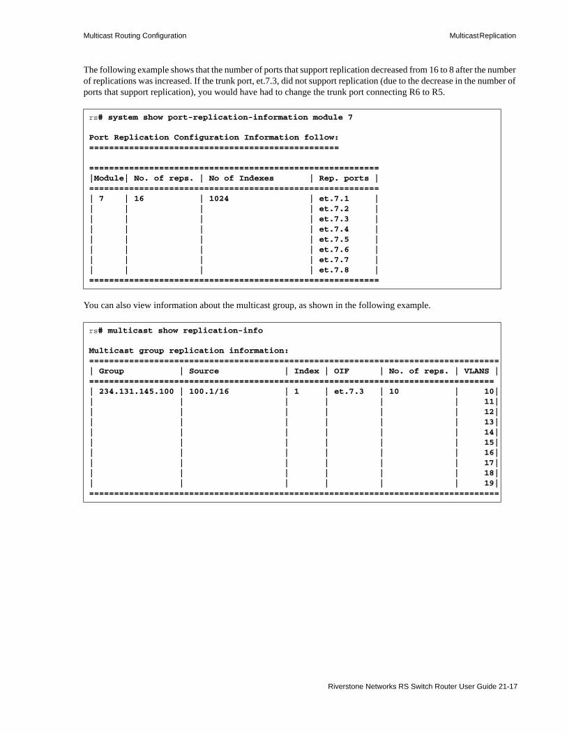
Multicast Routing Configuration Multicast Replication
The following example shows that the number of ports that support replication decreased from 16 to 8 after the number of replications was increased. If the trunk port, et.7.3, did not support replication (due to the decrease in the number of ports that support replication), you would have had to change the trunk port connecting R6 to R5.
You can also view information about the multicast group, as shown in the following example.
rs# system show port-replication-information module 7
Port Replication Configuration Information follow:==================================================
==========================================================|Module| No. of reps. | No of Indexes | Rep. ports |==========================================================| 7 | 16 | 1024 | et.7.1 || | | | et.7.2 || | | | et.7.3 || | | | et.7.4 || | | | et.7.5 || | | | et.7.6 || | | | et.7.7 || | | | et.7.8 |==========================================================
rs# multicast show replication-info
Multicast group replication information:==================================================================================| Group | Source | Index | OIF | No. of reps. | VLANS |=================================================================================| 234.131.145.100 | 100.1/16 | 1 | et.7.3 | 10 | 10|| | | | | | 11|| | | | | | 12|| | | | | | 13|| | | | | | 14|| | | | | | 15|| | | | | | 16|| | | | | | 17|| | | | | | 18|| | | | | | 19|==================================================================================
Riverstone Networks RS Switch Router User Guide 21-17

Using TTL Values and Administratively Scoped Groups Multicast Routing Configuration
21.6 USING TTL VALUES AND ADMINISTRATIVELY SCOPED GROUPS
You can use time-to-live (TTL) threshold values and scopes to control internetwork traffic on each multicast interface. The TTL value controls whether packets are forwarded from an interface. The following are guidelines for assigning TTL values to a multicast application and their corresponding RS Ethernet Router setting for the threshold:
By default, the TTL threshold for all RS Ethernet Router interfaces is 1. You can change this value on a per-interface basis, as shown in the following example:
TTL thresholding is not always considered useful. There is another approach of a range of multicast addresses for “administrative” scoping. In other words, such addresses would be usable within a certain administrative scope, a corporate network, for instance, but would not be forwarded across the internet. The range of addresses from 239.0.0.0 through 239.255.255.255 is reserved for administratively-scoped applications. Any organization can assign this range of addresses and the packets will not be sent out of the organization. In addition, multiple scopes can be defined on a per-interface basis. The following example specifies a multicast address and subnet mask:
Table 21-2 TTL values and their corresponding thresholds on the RS Ethernet Router
TTL Value Threshold Restrictions
1 1 Application restricted to subnet
< 16 16 Application restricted to a site
< 64 64 Application restricted to a region
< 128 128 Application restricted to a continent
255 Application not restricted
rs (config)# multicast set interface int100 threshold 3
rs (config)# multicast set interface int100 boundary 239.0.0.0/8
21-18 Riverstone Networks RS Switch Router User Guide

Multicast Routing Configuration Monitoring Multicast
21.7 MONITORING MULTICASTThe RS Ethernet Router provides various commands for displaying multicast routing information. This section contains examples of these commands.
The multicast show cache command displays the multicast forwarding cache (MFC) tables. The following is an example of the multicast show cache command:
The multicast show counts command displays byte and packets statistics for each (S,G) group. The following is an example:
The multicast show statistics command displays various statistics and error counts. The following is an example:
rs# multicast show cacheSource Address Group Address Incoming I/f Outgoing I/f Exit Ports-------------- ------------- --------------- --------------- ----------150.20.20.1 225.1.1.1 145to152 145to141 et.3.1150.10.10.1 224.1.2.1 145to141 145to152150.20.20.1 224.2.2.2 145to152 145to141 et.3.1rs145#
rs# multicast show countsSource Address Group Address Packet Cnt Byte Count-------------- ------------- ------------ ------------10.10.1.11 224.2.127.254 3 142210.10.1.11 225.1.10.10 18010 1620877210.10.1.11 224.2.190.120 720 229575
rs# multicast show statisticsMulticast forwarding cache statistics information:-------------------------------------------------- MFC entries: 3 MFC lookups: 2144 MFC misses: 2053 Packet upcalls: 2 Upcall overflow count: 2040 Upcall socket full count: 0 Packets that arrived on wrong if.: 0 Packets that arrived with no MFC entry: 2050 MFC entry cleanup due to upcall expiry: 0 Packets with bad tunnel ip address: 0 Count of tunnel errors: 0
Riverstone Networks RS Switch Router User Guide 21-19
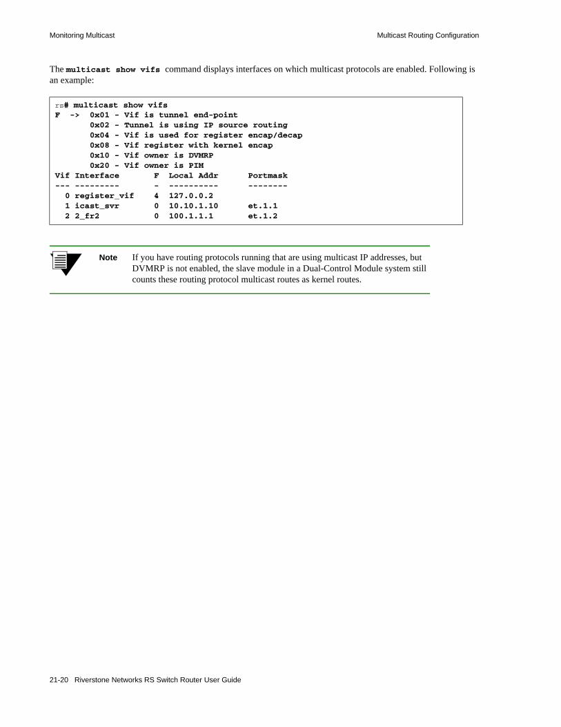
Monitoring Multicast Multicast Routing Configuration
The multicast show vifs command displays interfaces on which multicast protocols are enabled. Following is an example:
Note If you have routing protocols running that are using multicast IP addresses, but DVMRP is not enabled, the slave module in a Dual-Control Module system still counts these routing protocol multicast routes as kernel routes.
rs# multicast show vifsF -> 0x01 - Vif is tunnel end-point 0x02 - Tunnel is using IP source routing 0x04 - Vif is used for register encap/decap 0x08 - Vif register with kernel encap 0x10 - Vif owner is DVMRP 0x20 - Vif owner is PIMVif Interface F Local Addr Portmask--- --------- - ---------- -------- 0 register_vif 4 127.0.0.2 1 icast_svr 0 10.10.1.10 et.1.1 2 2_fr2 0 100.1.1.1 et.1.2
21-20 Riverstone Networks RS Switch Router User Guide

22 DVMRP ROUTING CONFIGURATION
On the RS Ethernet Router, DVMRP routing is implemented as specified in the draft-ietf-idmr-dvmrp-v3-09.txt file, which is an Internet Engineering Task Force (IETF) document.
This chapter provides the following information:• for an overview of DVMRP, refer to Section 22.1, "DVMRP Overview."• to start DVMRP on the RS Ethernet Router, refer to Section 22.2, "Starting DVMRP."• to set the DMRP metric, refer to Section 22.3, "Setting the DVMRP Routing Metric."• to define DVMRP tunnels, refer to Section 22.4, "Configuring a DVMRP Tunnel."
Riverstone Networks RS Switch Router User Guide 22-1

DVMRP Overview DVMRP Routing Configuration
22.1 DVMRP OVERVIEWDVMRP is a dense-mode protocol that uses a “flood and prune” technique to propagate multicast data. For each data source, DVMRP initially floods the multicast data throughout the network. Routers that have no interested receivers send prune messages upstream towards the source. The upstream routers stop sending the multicast traffic to these routers, which are then pruned from the distribution tree. Paths that were previously pruned may be “grafted” back onto the distribution tree when new receivers join the multicast group.
DVMRP builds and maintains a source distribution tree for each data source. A source distribution tree is a shortest path tree that is rooted at the source. DVMRP has a built-in unicast routing protocol which is a distance vector protocol that functions like the Routing Information Protocol (RIP); it uses metrics or hop counts to determine the shortest path back to the source. In DVMRP, the Reverse Path Forwarding (RPF) checks are based on the source address. (For information on distribution trees and RPF checks, refer to Section 21.1, "Multicast Routing Overview.")
To avoid the sending of duplicate packets in a multi-access network, a designated forwarder is selected to forward multicast data on a shared network. The designated forwarder has the lowest metric to the source network. If multiple routers have the same metric, the router with the lowest IP address becomes the designated forwarder.
Not all routers support native multicast routing. Therefore DVMRP supports the tunneling of multicast IP datagrams between routers separated by gateways that do not support multicast routing. The tunnel acts as a virtual network between two routers running DVMRP.
22-2 Riverstone Networks RS Switch Router User Guide

DVMRP Routing Configuration Starting DVMRP
22.2 STARTING DVMRPOn the RS Ethernet Router, DVMRP is disabled by default. You must enable DVMRP on all interfaces that require multicast routing, including those running IGMP. The following example starts DVMRP on the interface pc2:
Note For information on IGMP, refer to Section 21.2, "Configuring IGMP."
To view the status of a DVMRP interface, use the dvmrp show interface command, as shown in the following example.
Note If you are running DVMRP on ATM interfaces, you may have to enable forced bridging on those interfaces.
rs (config)# interface create ip pc2 address-netmask 150.10.10.100/24 port et.2.3rs (config)# dvmrp add interface 150.10.10.100rs (config)# dvmrp start
rs# dvmrp show interface pc2Address Interface Component Vif Nbr #Bad #Bad Count Pkts Routs--------------- --------------- --------- --- ----- ----- -----150.10.10.100 pc2 dvmrp 2 0 0 0
Riverstone Networks RS Switch Router User Guide 22-3
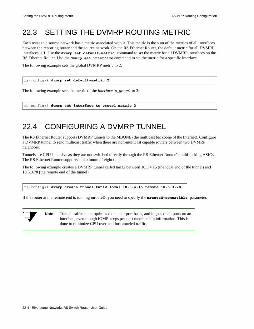
Setting the DVMRP Routing Metric DVMRP Routing Configuration
22.3 SETTING THE DVMRP ROUTING METRICEach route to a source network has a metric associated with it. This metric is the sum of the metrics of all interfaces between the reporting router and the source network. On the RS Ethernet Router, the default metric for all DVMRP interfaces is 1. Use the dvmrp set default-metric command to set the metric for all DVMRP interfaces on the RS Ethernet Router. Use the dvmrp set interface command to set the metric for a specific interface.
The following example sets the global DVMRP metric to 2:
The following example sets the metric of the interface to_group1 to 3:
22.4 CONFIGURING A DVMRP TUNNELThe RS Ethernet Router supports DVMRP tunnels to the MBONE (the multicast backbone of the Internet). Configure a DVMRP tunnel to send multicast traffic when there are non-multicast capable routers between two DVMRP neighbors.
Tunnels are CPU-intensive as they are not switched directly through the RS Ethernet Router’s multi-tasking ASICs. The RS Ethernet Router supports a maximum of eight tunnels.
The following example creates a DVMRP tunnel called tun12 between 10.3.4.15 (the local end of the tunnel) and 10.5.3.78 (the remote end of the tunnel).
If the router at the remote end is running mrouteD, you need to specify the mrouted-compatible parameter.
Note Tunnel traffic is not optimized on a per-port basis, and it goes to all ports on an interface, even though IGMP keeps per-port membership information. This is done to minimize CPU overload for tunneled traffic.
rs(config)# dvmrp set default-metric 2
rs(config)# dvmrp set interface to_group1 metric 3
rs(config)# dvmrp create tunnel tun12 local 10.3.4.15 remote 10.5.3.78
22-4 Riverstone Networks RS Switch Router User Guide

DVMRP Routing Configuration Configuration Example
22.5 CONFIGURATION EXAMPLEFollowing is an example of a basic DVMRP configuration.
In the example, the multicast data source (150.20.20.1) is connected to RS 152. One of the receivers is 150.10.10.1, which is connected to RS 141.
Following is the configuration for RS152, which is connected to the source:
! Create the interfacesinterface create ip pc1 address-netmask 150.20.20.100/24 port et.2.3interface create ip 152to145 address-netmask 192.168.3.1/24 port et.2.1
! Configure IGMPigmp add interface pc1igmp start
! Configure DVMRPdvmrp add interface 152to145dvmrp add interface pc1dvmrp start
RS152 RS145
RS141
Source
Receiver
150.20.20.1
192.168.1.4et.3.1
192.168.3.2et.3.2
192.168.3.1et.2.1
192.168.1.5et.2.1 150.10.10.100
et.3.1
150.20.20.100et.2.3
150.10.10.1
Riverstone Networks RS Switch Router User Guide 22-5
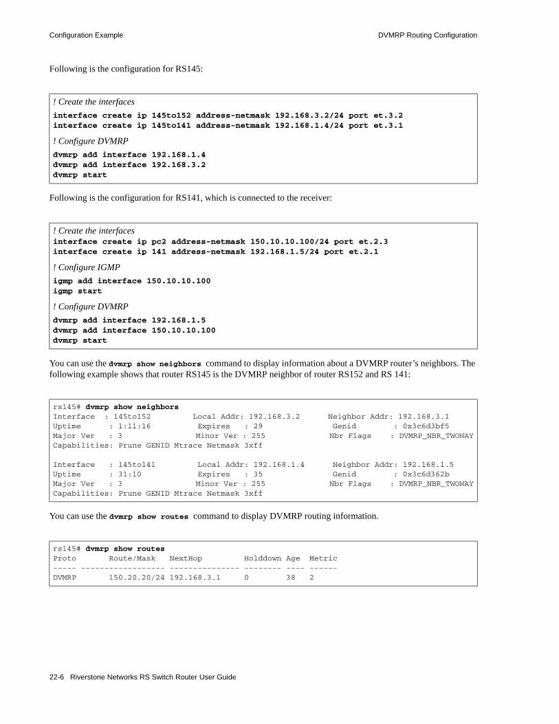
Configuration Example DVMRP Routing Configuration
Following is the configuration for RS145:
Following is the configuration for RS141, which is connected to the receiver:
You can use the dvmrp show neighbors command to display information about a DVMRP router’s neighbors. The following example shows that router RS145 is the DVMRP neighbor of router RS152 and RS 141:
You can use the dvmrp show routes command to display DVMRP routing information.
! Create the interfacesinterface create ip 145to152 address-netmask 192.168.3.2/24 port et.3.2interface create ip 145to141 address-netmask 192.168.1.4/24 port et.3.1
! Configure DVMRPdvmrp add interface 192.168.1.4dvmrp add interface 192.168.3.2dvmrp start
! Create the interfacesinterface create ip pc2 address-netmask 150.10.10.100/24 port et.2.3interface create ip 141 address-netmask 192.168.1.5/24 port et.2.1
! Configure IGMPigmp add interface 150.10.10.100igmp start
! Configure DVMRPdvmrp add interface 192.168.1.5dvmrp add interface 150.10.10.100dvmrp start
rs145# dvmrp show neighborsInterface : 145to152 Local Addr: 192.168.3.2 Neighbor Addr: 192.168.3.1Uptime : 1:11:16 Expires : 29 Genid : 0x3c6d3bf5Major Ver : 3 Minor Ver : 255 Nbr Flags : DVMRP_NBR_TWOWAYCapabilities: Prune GENID Mtrace Netmask 3xff
Interface : 145to141 Local Addr: 192.168.1.4 Neighbor Addr: 192.168.1.5Uptime : 31:10 Expires : 35 Genid : 0x3c6d362bMajor Ver : 3 Minor Ver : 255 Nbr Flags : DVMRP_NBR_TWOWAYCapabilities: Prune GENID Mtrace Netmask 3xff
rs145# dvmrp show routesProto Route/Mask NextHop Holddown Age Metric----- ------------------ --------------- -------- ---- ------DVMRP 150.20.20/24 192.168.3.1 0 38 2
22-6 Riverstone Networks RS Switch Router User Guide

DVMRP Routing Configuration Configuration Example
The multicast facility also has various show commands that you can use to show multicast routing information. One such command is the multicast show cache command, shown below. (For additional information on other multicast show commands, refer to Section 21.7, "Monitoring Multicast.")
rs145# multicast show cacheSource Address Group Address Incoming I/f Outgoing I/f Exit Ports-------------- ------------- --------------- --------------- ----------150.20.20.1 224.2.2.2 145to152 145to141 et.3.1
Riverstone Networks RS Switch Router User Guide 22-7

Configuration Example DVMRP Routing Configuration
22-8 Riverstone Networks RS Switch Router User Guide

23 PIM-SM ROUTING CONFIGURATION
Use the Protocol Independent Multicast (PIM) protocol to forward traffic to multicast groups throughout an internetwork. Unlike the Distance Vector Multicast Protocol (DVMRP), which has its own unicast routing protocol, PIM relies on the unicast routing protocol that is active on the network for forwarding information. It is “independent” in that it can use any unicast routing protocol to provide routing information.
PIM has two operational modes, Dense Mode and Sparse Mode. The RS Ethernet Router supports PIM in Sparse Mode (PIM-SM) as defined in the draft-ietf-pim-sm-v2-new-04.txt file. This chapter provides the following information:• An overview of the PIM-SM protocol (Section 23.1, "PIM-SM Overview.")• How to enable PIM on the RS Ethernet Router (Section 23.2, "Enabling PIM-SM.")• How to configure candidate Bootstrap Router (C-BSR) parameters (Section 23.3, "Configuring
Candidate BSR (C-BSR) Parameters.")• How to configure candidate Rendezvous Point (C-RP) parameters (Section 23.4, "Configuring
Candidate RP (C-RP) Parameters.")• How to modify default PIM parameters globally (Section 23.5, "Setting PIM Global
Parameters.")• How to modify default PIM parameters on a per-interface basis (Section 23.6, "Setting PIM
Interface Parameters.")
Riverstone Networks RS Switch Router User Guide 23-1

PIM-SM Overview PIM-SM Routing Configuration
23.1 PIM-SM OVERVIEWPIM-SM is a sparse-mode multicast routing protocol. ‘Sparse mode’ implies that instead of flooding multicast packets like DVMRP, PIM-SM sends multicast traffic only to receivers that explicitly request it. Routers that run PIM-SM join and leave multicast groups by sending join/prune messages.
PIM-SM distributes multicast traffic through a shared distribution tree with the rendezvous point (RP) at the root. The RP receives all requests to join groups and forwards multicast packets down the common distribution tree. When the traffic reaches a configured threshold, an RP or a router in the shared distribution tree can join the source distribution tree, and prune the source’s packets off the shared distribution tree.
23.1.1 Neighbor Discovery
Neighboring PIM routers discover each other and maintain their relations by periodically exchanging Hello messages. In multi-access networks, these Hello messages contain a router’s priority for becoming the designated router (DR) for the LAN. (For additional information on DRs, refer to Section 23.1.7, "Multi-Access LANs."
23.1.2 Registering Sources
A source or a first-hop router (that is, a router directly connected to the source) sends data packets encapsulated in Register messages to the RP. Upon receiving the Register message, the RP decapsulates the Register message and forwards the data packet downstream on the shared distribution tree. Thus all the downstream members of the multicast group receive the multicast data stream from the RP through the shared distribution tree.
23.1.3 Joining a Multicast Group
To join a multicast group, each locally connected host conveys its membership information through IGMP. The last-hop router (or the DR in a multi-access LAN) sends a join message towards the RP for the group it wants to join. When an intermediate router receives the join message, it checks if it already supports the requested route. If it does, it adds the requesting router to the established distribution tree. If it does not, then it forwards the request to the RP. As subsequent join messages are received for the same group, they are “joined” to the established route.
When no receivers exist for a particular source packet, the RP caches the data for three minutes. This allows the RP to instantly service receiver requests by distributing cached copies of the source packet as soon as it receives a request.
23.1.4 Multicast Forwarding
As previously stated, PIM-SM relies on the unicast routing protocol that is running on the network for forwarding information. On the RS Ethernet Router, static routes or routes learned through OSPF or ISIS can be installed in the multicast routing information base (MRIB).
PIM-SM also uses Reverse Path Forwarding (RPF) to ensure that multicast traffic is forwarded correctly downstream. The RPF check for shared distribution trees is based on the IP address of the RP. The RPF check for source distribution trees is based on the IP address of the source. (For information on RPF and other multicast concepts, refer to Section 21.1, "Multicast Routing Overview.")
23-2 Riverstone Networks RS Switch Router User Guide
PIM-SM Routing Configuration PIM-SM Overview
23.1.5 Obtaining RP Information
The RS Ethernet Router provides two methods for obtaining RP information: dynamically and by configuring static RPs.
To obtain RP information dynamically, routers within a PIM domain collect bootstrap messages. (A domain is a contiguous set of PIM routers configured to operate within a common boundary.) Bootstrap messages indicate which RPs are “up.” Each PIM domain has one bootstrap router that is responsible for sending the bootstrap messages. The bootstrap router is selected through an election where the candidate bootstrap router (C-BSR) with the highest priority is elected as the BSR for the domain. Candidate bootstrap routers are user-configurable.
Typically, the C-BSR is also configured as a candidate RP (C-RP). C-RPs periodically unicast C-RP advertisements to the BSR of the domain. The RP is then selected through a well-known hash function. A router can be an RP for more than one multicast group.
Alternatively, you can configure a static RP for a particular multicast group. If you do so, do not configure C-BSRs and C-RPs. Instead, configure the static RP on all multicast routers in the domain.
23.1.6 Switching from a Shared to a Source Distribution Tree
An RP or a router with directly connected members can switch to a source’s shortest path tree (SPT). When an RP receives a register message for a new source, the RP sends a join message back to the source. This results in an SPT being built from the source to the RP, allowing the multicast traffic to flow directly from the source to the RP, and down the shared distribution tree. Once the RP starts receiving the data packets natively directly from the source, then the RP sends a Register Stop message to the first-hop router to let it know that it should stop sending Register messages. The RP can initiate the switch to the source’s SPT immediately after receiving the first Register message or after a configured threshold is reached. On the RS Ethernet Router, the default behavior is for the RP to switch to the source’s SPT immediately after receiving the first Register message. It is highly recommended that you do not change this default.
A DR or a router with directly connected members can initiate the switch from the shared distribution tree to the source distribution tree immediately after receiving the first data packet or when the data rate reaches a configured threshold. Once a router moves to an SPT, it sends a prune message to its upstream router.
23.1.7 Multi-Access LANs
When there are multiple routers connected to a multi-access network, a DR is elected for the LAN. To maintain group memberships, the DR periodically sends join/prune messages toward the RP of each group for which it has active members. In addition, the DR of a data source sends register messages to the RP, which forwards the packets down the shared tree toward the group members. When the data rate reaches a configured threshold, the DR can switch to the source path tree.
PIM-SM also uses an assert mechanism when there are parallel paths in a multi-access LAN. The routers exchange assert messages which contain their priority for becoming the designated forwarder. The router with the highest priority is selected as the designated forwarder. The designated forwarder is responsible for sending the join/prune messages for the group.
Riverstone Networks RS Switch Router User Guide 23-3

Enabling PIM-SM PIM-SM Routing Configuration
23.2 ENABLING PIM-SMTo run PIM-SM on the RS Ethernet Router you need to do the following:• Install unicast routes (either static, ISIS, or OSPF) in the MRIB.• Start PIM-SM.
The following sections describe each task.
23.2.1 Installing Routes in the MRIB
PIM-SM uses unicast routes to populate the MRIB. By default, when you run a unicast routing protocol, the routes are installed in the unicast RIB. To install the routes on the MRIB, you need to determine which unicast protocol will be used. On the RS Ethernet Router, static, OSPF and ISIS routes can be installed in the MRIB.
To install static routes in the MRIB, define the static routes then use the ip add route command with the multicast-rib option, as shown in the following example:
To install OSPF routes in the MRIB, configure OSPF and use the command shown in the following example:
For information on OSPF, refer to Chapter 13, "OSPF Configuration Guide."
To install ISIS routes in the MRIB, enable ISIS and use the command shown in the following example:
For information on ISIS, refer to Chapter 14, "IS-IS Configuration Guide."
23.2.2 Starting PIM-SM
PIM-SM is disabled on the RS Ethernet Router by default. You must enable PIM-SM on all interfaces that require multicast routing, including those running IGMP. The following example starts PIM-SM:
Note On the RS Ethernet Router, IGMP is also disabled by default. You must enable IGMP on the interfaces with directly connected senders and receivers. For information on IGMP, refer to Section 21.2, "Configuring IGMP."
rs (config)# ip add route multicast-rib
rs (config)# ospf set rib multicast
rs (config)# isis set rib multicast
rs (config)# pim sparse add interface allrs (config)# pim sparse start
23-4 Riverstone Networks RS Switch Router User Guide

PIM-SM Routing Configuration Configuring Candidate BSR (C-BSR) Parameters
23.3 CONFIGURING CANDIDATE BSR (C-BSR) PARAMETERS
Unless there is a static RP, each PIM domain must have a bootstrap router (BSR). The BSR periodically sends bootstrap messages to propagate RP information. PIM routers use the most current bootstrap message to update their knowledge of the RPs.
Bootstrap messages are also used for the BSR election. They contain a C-BSR’s priority for becoming the BSR. The candidate BSR with the highest priority is elected as the BSR.
Use the pim sparse cbsr command to configure the RS Ethernet Router as a C-BSR. When you do so, specify the interface name or IP address that will be used for the C-BSR. Generally, this address is the loopback address.
When you specify the pim sparse cbsr command, you can also set the following bootstrap-related parameters: • The interval at which bootstrap messages are sent. By default, bootstrap messages are sent every 60
seconds.
• The priority used during the BSR election. The default is 0, which means the router cannot become a bootstrap router.
• The period of time within which if no bootstrap messages are sent, the BSR is considered unreachable and a new BSR is elected. By default, this is set to 30 seconds.
• The hash mask for the hash algorithm used in calculating the RP in a group. The default hash mask length is 30.
In addition, you can use the deny-crp parameter to prevent specific C-RPs from being included in bootstrap messages.
The following example configures 10.1.0.1 as the C-BSR address and sets its priority to 100:
To view bootstrap information, use the pim show bsr-info as shown in the following example:
In the example, 10.1.0.1 is the elected BSR.
rs (config)# pim sparse cbsr address 10.1.0.1 priority 100
rs# pim show bsr-infoComp Status CBSR-Pri CBSR-Addr CBSR-mask Deny-CRPs---- ------ -------- --------- --------- ---------sm0 Elected 100 10.1.0.1 30 N/A
Comp Elec-Pri Elec-Addr Elec-mask Interval---- -------- --------- --------- --------sm0 100 10.1.0.1 30 00:01:00
Riverstone Networks RS Switch Router User Guide 23-5

Configuring Candidate RP (C-RP) Parameters PIM-SM Routing Configuration
23.4 CONFIGURING CANDIDATE RP (C-RP) PARAMETERS
The RP is the root of the shared tree. It is responsible for forwarding multicast packets down the shared tree towards group members. There is only one RP in a PIM-SM domain.
Typically, the C-BSR is also configured as a candidate RP (C-RP). Use the pim sparse crp command to configure the RS Ethernet Router as a C-RP. When you do so, specify the interface name or IP address that will be used for the C-RP. Generally, this address is the loopback address.
When you use the pim sparse crp command, you can also set the following parameters:• The interval at which C-RP advertisements are sent to the BSR. By default, C-RP advertisements are
sent every 60 seconds.• The period of time the C-RP advertisements are valid. If no C-RP advertisements are received within
this time, the RP is removed from the candidate list. By default, this value is 150 seconds.• The priority used during the RP election; this is included in the router’s bootstrap messages. By
default, the router’s priority is 0.
The following example configures 10.1.0.1 as the C-RP address and sets its priority to 100:
For interoperability with routers from other vendors, you may need to disable the use of the priority during the RP election. To do so, use the command shown in the following example:
To view information about the C-RP, use the pim show crp command as shown in the following example:
23.4.1 Specifying Multicast Groups
By default, a router is the RP for all multicast groups. You can use the pim sparse crp-group-add command to limit the groups for which the router is an RP. The following is an example:
rs (config)# pim sparse crp address 10.1.0.1 priority 100
rs (config)# pim sparse global cisco-hash
rs# pim show crp grp-address allComponent Name: sm0CRP Address: 10.1.0.1CRP Holdtime: 14:50:38 secondsCRP Priority: 100CRP Adv. Time: 14:48:16 seconds
Group/Mask Group Pri---------- ---------224/4 100
rs (config)# pim sparse crp-group-add 234.132.143.100
23-6 Riverstone Networks RS Switch Router User Guide

PIM-SM Routing Configuration Configuring Candidate RP (C-RP) Parameters
23.4.2 Configuring a Static RP
You can configure a static RP for a particular group. Configuring a static RP decreases the control packets transmitted by the PIM-SM routers, thus minimizing bandwidth usage. When you configure a static RP, do not configure a C-BSR and a C-RP on the routers in that group. Instead, use the pim sparse static-rp command to configure the static RP on all the multicast routers in the domain. You should also use an address that is reachable from all routers. Generally, this address is a loopback address.
Use the pim sparse static-rp command to specify the interface address of the static RP and the multicast group for which it is an RP. Following is an example:
The default hash mask length for the hash algorithm used in calculating the RP in a group is 30. You can use the pim global static-rp-hashmask-len command to change this default for groups with static RPs as shown in the following example:
rs (config)# pim sparse static-rp address 100.10.10.1 group 234.132.143.100
rs (config)# pim sparse global static-rp-hashmask-len 35
Riverstone Networks RS Switch Router User Guide 23-7

Setting PIM Global Parameters PIM-SM Routing Configuration
23.5 SETTING PIM GLOBAL PARAMETERSThe RS Ethernet Router has various default PIM parameters that can be globally configured. This section describes these parameters.
23.5.1 Switching to the Source Tree
Only the DR and the RP can initiate the switch to a source’s SPT. By default, the RP switches to the source SPT when it receives the first Register message from the DR. To change this default behavior, use the pim sparse global command as shown in the following example:
• The no-rp-switch-immediate parameter specifies that the RP should not switch to the source tree immediately after it receives the first Register message from the DR.
• The threshold-rp parameter specifies the data rate (in bytes per second) that triggers the RP to switch to the source tree.
By default, the DR switches to the source SPT when it receives the first data packet from a source. To prevent this, use the pim sparse global command as shown in the following example:
23.5.2 Setting the DR Priority
As stated earlier, when there are multiple routers connected to a multi-access network, a DR is elected for the LAN. The router with the highest priority is elected as the DR for the LAN. In the case of a tie, the router with the lowest IP address becomes the DR.
A router’s priority is contained in the hello messages exchanged between PIM neighbors. By default, the RS Ethernet Router interfaces have a priority of 1. To change the priority for all the RS Ethernet Router interfaces, use the pim global set hello-priority command. To change the priority of a particular interface, use the pim sparse add interface command. Note that the interface priority overrides the global priority value. In the following example, the global priority is set to 5 and the priority for the interface to_group1 is set to 6:
rs (config)# pim sparse global no-rp-switch-immediate threshold-rp 100
rs (config)# pim sparse global no-dr-switch-immediate threshold-dr 100
rs (config)# pim global set hello-priority 5rs (config)# pim sparse add interface to_group1 hello-priority 6
23-8 Riverstone Networks RS Switch Router User Guide
PIM-SM Routing Configuration Setting PIM Global Parameters
23.5.3 Setting PIM Timers
The RS Ethernet Router has default values for various PIM message timers. These timers can be set globally or on a per-interface basis. This section describes how to set these timers globally. To set these timers for a specific interface, refer to Section 23.6, "Setting PIM Interface Parameters."
23.5.3.1 Assert Messages
When there are parallel upstream routers connected to a multi-access LAN, assert messages determine which of the routers will act as the designated forwarder. The designated forwarder is responsible for forwarding packets on the LAN. Downstream routers listen to the assert messages so they know which router is the forwarder, and where to send subsequent join/prune messages. The default interval between assert messages is 180 seconds. The following example decreases this interval to 150 seconds:
23.5.3.2 Hello Messages
Hello messages are periodically exchanged by PIM neighbors to establish and maintain neighbor relationships. They also contain a router’s priority for becoming a DR. By default, hello messages are sent every 30 seconds and time out after 105 seconds. The following example illustrates how to change these defaults:
23.5.3.3 Join/Prune Messages
The DR periodically sends join/prune messages toward the RP for each group for which it has active members. By default, join/prune messages are sent every 60 seconds and time out after 210 seconds. The following example illustrates how to change these defaults:
23.5.3.4 Register Messages
As stated earlier, a data source’s first-hop router sends register messages to the RP when a multicast packet needs to be transmitted on the shared distribution tree. The RP sends Register-Stop messages to the router if the RP has no downstream receivers for the group (or for that particular source), or if the RP has already joined the source tree. When the router receives the Register-Stop message from the RP, it starts the Register-Suppression timer and stops encapsulating data packets in Register messages while the timer is running. If there is data to be registered, the router sends a null Register (a Register message with a zero-length data portion in the inner packet) to the RP for a defined period of time (probe period) before the Register-Suppression timer expires. When the Register- Suppression timer expires, the router resumes sending data packets encapsulated in Register messages to the RP.
rs (config)# pim global set assert-holdtime 150
rs (config)# pim global set hello-holdtime 60 hello-interval 20
rs (config)# pim global set join-prune-holdtime 100 join-prune-interval 30
Riverstone Networks RS Switch Router User Guide 23-9

Setting PIM Global Parameters PIM-SM Routing Configuration
Be default, the Registration Suppression timer is set to 60 seconds and the probe period is set to 5 seconds. To increase the Registration Suppression timeout value to minimize the bursts of traffic to the RP, change these default values using the pim sparse global command, as shown in the following example:
For Register messages, you can also configure PIM-SM to do a check sum calculation on the entire packet, instead of on the PIM-SM header only. This feature is provided for interoperability with routers from other vendors. Use the command shown in the following example:
rs (config)# pim sparse global reg-sup-timeout 100 probe-period 10
rs (config)# pim sparse global whole-packet-checksum
23-10 Riverstone Networks RS Switch Router User Guide

PIM-SM Routing Configuration Setting PIM Interface Parameters
23.6 SETTING PIM INTERFACE PARAMETERSUse the pim sparse add interface command to change the defaults for the following timers for a specific interface:• the assert message timer• the hello message timers• the join/prune message timers
For join/prune messages, you can set two other timers in addition to the holdtime and interval. (Refer to "Join/Prune Messages" for information on these timers.) You can set the join/prune suppression timer and the delay timeout. The join/prune suppression timer is used to reduce redundant join/prune messages. When an interface receives a join/prune message which has a higher holdtime than the interface’s own holdtime, the join/prune suppression timer is started. While this timer is running, no join/prune messages are sent for the group. Its default is 75 seconds.
The join/prune delay timeout is the interval between the time a router’s RPF neighbor changes and the time the router sends a triggered join/prune message to its new RPF neighbor. (A router’s RPF neighbor may change due to changes in the unicast routing table or because of the assert process.)
The following example sets parameters for the interface 152to145:
rs (config)# pim sparse add interface 152to145 hello-priority 3
Riverstone Networks RS Switch Router User Guide 23-11

Configuration Example PIM-SM Routing Configuration
23.7 CONFIGURATION EXAMPLEThe following example illustrates a basic PIM-SM configuration.
.
The source is connected to RS152. It is sending data for the multicast group 225.1.1.1. One of the receivers in that group is connected to RS141. RS145 is configured as the BSR and RP. The routers are also running OSPF.
RS152 RS145
RS141
Source
Receiver
150.20.20.1
192.168.1.4et.3.1
192.168.3.2et.3.2
192.168.3.1et.2.1
192.168.1.5et.2.1 150.10.10.100
et.3.1
150.20.20.100et.2.3
150.10.10.1
23-12 Riverstone Networks RS Switch Router User Guide

PIM-SM Routing Configuration Configuration Example
Following is the configuration for RS152, which is connected to the source:
Following is the configuration for RS141, which is connected to the receiver:
! Create the interfacesinterface create ip 152to145 address-netmask 192.168.3.1 port et.2.1interface create ip pc1 address-netmask 150.20.20.100/24 port et.2.3interface add ip lo0 address-netmask 10.1.0.3/24
! Configure OSPFip-router global set router-id 10.1.0.3ospf create area backboneospf add stub-host 10.1.0.3 to-area backbone cost 3ospf add interface all to-area backboneospf set rib multicastospf start
! Configure IGMPigmp add interface pc1igmp start
! Configure PIM-SMpim sparse add interface allpim sparse add interface 152to145 hello-priority 3pim sparse crp address 10.1.0.3 priority 10pim sparse startpim sparse cbsr address 10.1.0.3 priority 10
!Create the interfacesinterface create ip 141 address-netmask 192.168.1.5 port et.2.1interface create ip pc2 address-netmask 150.10.10.100/24 port et.2.3interface add ip lo0 address-netmask 10.1.0.2/24
!Configure OSPFip-router global set router-id 10.1.0.2ospf create area backboneospf add stub-host 10.1.0.2 to-area backbone cost 3ospf add interface all to-area backboneospf set rib multicastospf start
!Configure IGMPigmp add interface pc2igmp start
!Configure PIM-SMpim sparse add interface allpim sparse crp address 10.1.0.2 priority 20pim sparse startpim sparse cbsr address 10.1.0.2 priority 20
Riverstone Networks RS Switch Router User Guide 23-13

Configuration Example PIM-SM Routing Configuration
Following is the configuration for RS145:
You can use the pim show routes source 150.20.20.1 command to display the PIM routing table. The following example displays route information for the source 150.20.20.1:
You can also use the multicast show cache command to display the multicast forwarding cache as shown in the following example:
!Create the interfacesinterface create ip 145to141 address-netmask 192.168.1.4 port et.3.1interface create ip 145to152 address-netmask 192.168.3.2/24 port et.3.2interface add ip lo0 address-netmask 10.1.0.1/24
!Configure OSPFip-router global set router-id 10.1.0.1ospf create area backboneospf add stub-host 10.1.0.1 to-area backbone cost 5ospf add interface all to-area backboneospf set rib multicastospf start
!Configure PIM-SMpim sparse add interface allpim sparse crp address 10.1.0.1 priority 100pim sparse startpim sparse cbsr address 10.1.0.1 priority 100
rs145# pim show routes source 150.20.20.1
PIM Multicast Routing TableFlags: S - Sparse, C - Directly connected host, L - Local, P - Pruned R - RP-bit set, T - SPT-bit set J - Join SPT, F - Directly connected source, E - External joinTimers: Uptime/ExpiresInterface state: Interface, Timers, Output Ports
(150.20.20.1/32, 225.1.1.1/32), 01:56:18/00:02:47, flags: ST Total packet/byte count: 15640999/1751475608, Rate: 1493160 bytes/sec Incoming interface: 145to152, RPF nbr 192.168.3.1, Outgoing interface list: 145to141 (192.168.1.4), 01:56:18/00:03:13, et.3.1,
rs145# multicast show cacheSource Address Group Address Incoming I/f Outgoing I/f Exit Ports-------------- ------------- --------------- --------------- ----------150.20.20.1 225.1.1.1 145to152 145to141 et.3.1
23-14 Riverstone Networks RS Switch Router User Guide

24 IP POLICY-BASED FORWARDING CONFIGURATION
You can configure the RS Ethernet Router to route IP packets according to policies that you define. IP policy-based routing allows network managers to engineer traffic to make the most efficient use of their network resources.
IP policies forward packets based on layer-3 or layer-4 header information. You can define IP policies to route packets to a set of next-hop IP addresses based on any combination of the following IP header fields:• IP protocol• Source IP address• Destination IP address• Source Socket• Destination Socket• Type of service
For example, you can set up an IP policy to send packets originating from a certain network through a firewall, while letting other packets bypass the firewall. Sites that have multiple Internet service providers can use IP policies to assign user groups to particular ISPs. You can also create IP policies to select service providers based on various traffic types.
24.1 CONFIGURING IP POLICIESTo implement an IP policy, you first create a profile for the packets to be forwarded using an IP policy. For example, you can create a profile defined as “all telnet packets going from network 9.1.0.0/16 to network 15.1.0.0/16”. You then associate the profile with an IP policy. The IP policy specifies what to do with the packets that match the profile. For example, you can create an IP policy that sends packets matching a given profile to next-hop gateway 100.1.1.1.
Configuring an IP policy consists of the following tasks:• Defining a profile • Associating the profile with a policy• Applying the IP policy to an interface
Riverstone Networks RS Switch Router User Guide 24-1

Configuring IP Policies IP Policy-Based Forwarding Configuration
24.1.1 Defining an ACL Profile
An ACL profile specifies the criteria packets must meet to be eligible for IP policy routing. You define profiles with the acl command. For IP policy routing, the RS Ethernet Router uses the packet-related information from the acl command and ignores the other fields.
For example, the following acl command creates a profile called “prof1” for telnet packets going from network 9.1.0.0 to network 15.1.0.0:
See the Riverstone RS Switch Router Command Line Interface Reference Manual for complete syntax information for the acl command.
Note ACLs for non-IP protocols cannot be used for IP policy routing.
24.1.2 Associating the Profile with an IP Policy
Once you have defined a profile with the acl command, you associate the profile with an IP policy by entering one or more ip-policy statements. An ip-policy statement specifies the next-hop gateway (or gateways) where packets matching a profile are forwarded. (See the Riverstone RS Switch Router Command Line Interface Reference Manual for complete syntax information for the ip-policy command.)
For example, the following command creates an IP policy called “p1” and specifies that packets matching profile “prof1” are forwarded to next-hop gateway 10.10.10.10:
You can also set up a policy to prevent packets from being forwarded by an IP policy. For example, the following command creates an IP policy called “p2” that prevents packets matching prof1 from being forwarded using an IP policy:
Packets matching the specified profile are forwarded using dynamic routes instead.
rs(config)# acl prof1 permit ip 9.1.0.0/16 15.1.0.0/16 any any telnet 0
rs(config)# ip-policy p1 permit acl prof1 next-hop-list 10.10.10.10
rs(config)# ip-policy p2 deny acl prof1
24-2 Riverstone Networks RS Switch Router User Guide

IP Policy-Based Forwarding Configuration Configuring IP Policies
24.1.2.1 Creating Multi-Statement IP Policies
An IP policy can contain more than one ip-policy statement. For example, an IP policy can contain one statement that sends all packets matching a profile to one next-hop gateway, and another statement that sends packets matching a different profile to a different next-hop gateway. If an IP policy has multiple ip-policy statements, you can assign each statement a sequence number that controls the order in which they are evaluated. Statements are evaluated from lowest sequence number to highest.
For example, the following commands create an IP policy called “p3”, which consists of two IP policy statements. The ip policy permit statement has a sequence number of 1, which means it is evaluated before the ip policy deny statement, which has a sequence number of 900.
24.1.2.2 Setting the IP Policy Action
You can use the action parameter with the ip-policy permit command to specify when to apply the IP policy route with respect to dynamic or statically configured routes. The options of the action parameter can cause packets to use the IP policy route first, then the dynamic route if the next-hop gateway specified in the IP policy is unavailable; use the dynamic route first, then the IP policy route; or drop the packets if the next-hop gateway specified in the IP policy is unavailable.
For example, the following command causes packets that match the profile to use dynamic routes first and use the IP policy gateway only if a dynamic route is not available:
24.1.2.3 Setting Load Distribution for Next-Hop Gateways
You can specify up to 16 next-hop gateways in an ip-policy statement. If you specify more than one next-hop gateway, you can use the ip-policy set load-policy command to control how the load is distributed among them.
By default, each new flow uses the first available next-hop gateway. You can use the ip-policy set load-policy command to cause flows to use all the next-hop gateways in the ip-policy permit statement sequentially. For example, the following command picks the next gateway in the list for each new flow for policy ‘p1’:
rs(config)# ip-policy p3 permit acl prof1 next-hop-list 10.10.10.10 sequence 1rs(config)# ip-policy p3 deny acl prof2 sequence 900
rs(config)# ip-policy p2 permit acl prof1 action policy-last
rs(config)# ip-policy p1 set load-policy round-robin
Riverstone Networks RS Switch Router User Guide 24-3

Configuring IP Policies IP Policy-Based Forwarding Configuration
24.1.2.4 Verifying Next-Hop Gateways
The ip-policy set pinger on command can be used to check the availability of next-hop gateways by periodically querying them with ICMP_ECHO_REQUESTS. Only gateways that respond to these requests are used for forwarding packets. For example, the following command checks the availability of next-hop gateways specified in the policy ‘p1’:
Note Some hosts may have disabled responding to ICMP_ECHO packets. Make sure each next-hop gateway can respond to ICMP_ECHO packets before using this option.
When the ip-policy set pinger on command is issued, the RS Ethernet Router can verify the state of a next-hop gateway by sending a ping to the gateway at 5-second intervals. If the RS Ethernet Router does not receive a reply from a gateway after four ping requests, the gateway is considered to be “down.”
If you specify that the RS Ethernet Router use TCP connection requests to check the gateway (instead of sending ICMP echo requests), the RS Ethernet Router checks that an application session on the gateway can be established by sending a TCP connection request on the configured port of the gateway at 15-second intervals. If the RS Ethernet Router does not receive a reply from the gateway after four tries, the application is considered to be “down.”
You can change the intervals at which pings or handshakes are attempted and the number of times that the RS Ethernet Router retries the ping or handshake before considering the gateway or application to be “down.”
For example, the following commands cause the RS Ethernet Router to check the availability of next-hop gateways for the IP policy ‘p1’ by pinging every 10 seconds:
You can also have the RS Ethernet Router verify the content of an application on one or more next-hop gateways. For this type of verification, you specify the following:• A string that the RS Ethernet Router sends to a single gateway or to a group of next-hop gateways.
The string can be a simple HTTP command to get a specific HTML page. Or, it can be a command to execute a user-defined CGI script that tests the operation of the application.
• The reply that the application on each gateway sends back that the RS Ethernet Router will use to validate the content. In the case where a specific HTML page is retrieved, the reply can be a string that appears on the page, such as “OK.” If a CGI script is executed on the gateway, it should return a specific response (for example, “OK”) that the RS Ethernet Router can verify.
rs(config)# ip-policy p1 set pinger on
rs(config)# ip-policy p1 set pinger onrs(config)# ip-policy set pinger-options p1 ping-int 10
24-4 Riverstone Networks RS Switch Router User Guide

IP Policy-Based Forwarding Configuration IP Policy Configuration Examples
Application verification, whether a simple TCP handshake or a user-defined action-response check, involves opening and closing a connection to a next-hop gateway. Some applications require specific commands for proper closure of the connection. For example, a connection to an SMTP server application should be closed with the “quit” command. You can configure the RS Ethernet Router to send a specific string to close a connection on a server.
The following is an example of how to configure a simple verification check where the RS Ethernet Router will issue an HTTP command to retrieve an HTML page and check for the string ‘OK’:
24.1.3 Applying an IP Policy to an Interface
After you define the IP policy, it must be applied to an inbound IP interface with the ip-policy apply command. Once the IP policy is applied to the interface, packets start being forwarded according to the IP policy. (See the Riverstone RS Switch Router Command Line Interface Reference Manual for complete syntax information for the ip-policy apply command.)
For example, the following command applies the IP policy ‘p2’ to the interface ‘int2’:
24.1.3.1 Applying an IP Policy to Locally Generated Packets
You can apply an IP policy to locally-generated packets (that is, packets generated by the RS Ethernet Router). For example, the following command applies the IP policy ‘p2’ to locally-generated packets:
24.2 IP POLICY CONFIGURATION EXAMPLESThis section presents some examples of IP policy configurations. The following uses of IP policies are demonstrated:• Routing traffic to different ISPs• Prioritizing service to customers• Authenticating users through a firewall• Firewall load balancing
rs(config)# ip-policy p1 set pinger-options acv-command “GET /test.html” acv-reply “OK” read-till index 25
rs(config)# ip-policy p2 apply interface int2
rs(config)# ip-policy p2 apply local
Riverstone Networks RS Switch Router User Guide 24-5

IP Policy Configuration Examples IP Policy-Based Forwarding Configuration
24.2.1 Routing Traffic to Different ISPs
Sites that have multiple Internet service providers can create IP policies that cause different user groups to use different ISPs. You can also create IP policies to select service providers based on various traffic types.
In the sample configuration in Figure 24-1, the policy router is configured to divide traffic originating within the corporate network between different ISPs (100.1.1.1 and 200.1.1.1).
Figure 24-1 Using an IP policy to route traffic to two different ISPs
HTTP traffic originating from network 10.50.0.0 for destination 207.31.0.0/16 is forwarded to 100.1.1.1. Non-HTTP traffic originating from network 10.50.0.0 for destination 207.31.0.0/16 is forwarded to 200.1.1.1. All other traffic is forwarded to 100.1.1.1.
The following is the IP policy configuration for the Policy Router in Figure 24-1:
interface create ip user-a address-netmask 10.50.1.1/16 port et.1.1interface create ip user-b address-netmask 11.50.1.1/16 port et.1.2
acl user-a-http permit ip 10.50.0.0/16 207.31.0.0/16 any http 0acl user-a permit ip 10.50.0.0/16 207.31.0.0/16 any any 0acl user-b permit ip 11.50.0.0/16 any any any 0
ip-policy net-a permit acl user-a-http next-hop-list 100.1.1.1 action policy-first sequence 20
ip-policy net-a permit acl user-a next-hop-list 200.1.1.1 action policy-only sequence 25
ip-policy net-a apply interface user-a
ip-policy net-b permit acl user-b next-hop-list 200.1.1.1 action policy-first
ip-policy net-b apply interface user-b
Group user-a10.50.*.*
Group user-b11.50.*.*
ISP1100.1.1.1
ISP2200.1.1.1
et.1.1
et.1.2
Policy Router
24-6 Riverstone Networks RS Switch Router User Guide

IP Policy-Based Forwarding Configuration IP Policy Configuration Examples
24.2.2 Prioritizing Service to Customers
An ISP can use policy-based routing on an access router to supply different customers with different levels of service. The sample configuration in Figure 24-2 shows an RS Ethernet Router using an IP policy to classify customers and route traffic to different networks based on customer type.
Figure 24-2 Using an IP policy to prioritize service to customers
Traffic from the premium customer is load balanced across two next-hop gateways in the high-cost, high-availability network. If neither of these gateways is available, then packets are forwarded based on dynamic routes learned via routing protocols.
Traffic from the standard customer always uses one gateway (200.1.1.1). If for some reason that gateway is not available, packets from the standard customer are dropped.
The following is the IP policy configuration for the Policy Router in Figure 24-2:
interface create ip premium-customer address-netmask 10.50.1.1/16 port et.1.1
interface create ip standard-customer address-netmask 11.50.1.1/16 port et.1.2
acl premium-customer permit ip 10.50.0.0/16 any any any 0acl standard-customer permit ip 11.50.0.0/16 any any any 0
ip-policy p1 permit acl premium-customer next-hop-list "100.1.1.1 200.1.1.1" action policy-first sequence 20
ip-policy apply interface premium-customer
ip-policy p2 permit acl standard-customer next-hop-list 200.1.1.1 action policy-only sequence 30
ip-policy apply interface standard-customer
Premium Customer10.50.*.*
Standard Customer11.50.*.*
ISP
et.1.1
et.1.2
Low-Cost Network200.1.1.1
High-Cost, High Availability Network 100.1.1.1
Policy Router
Riverstone Networks RS Switch Router User Guide 24-7

IP Policy Configuration Examples IP Policy-Based Forwarding Configuration
24.2.3 Authenticating Users through a Firewall
You can define an IP policy that authenticates packets from certain users via a firewall before accessing the network. If, for some reason the firewall is not responding, the packets to be authenticated are dropped. Figure 24-3 illustrates this kind of configuration.
Figure 24-3 Using an IP policy to authenticate users through a firewall
Packets from users defined in the “contractors” group are sent through a firewall. If the firewall cannot be reached packets from the contractors group are dropped. Packets from users defined in the “full-timers” group do not have to go through the firewall.
The following is the IP policy configuration for the Policy Router in Figure 24-3:
interface create ip mls0 address-netmask 10.50.1.1/16 port et.1.1
acl contractors permit ip 10.50.1.0/24 any any any 0acl full-timers permit ip 10.50.2.0/24 any any any 0
ip-policy access permit acl contractors next-hop-list 11.1.1.1 action policy-onlyip-policy access permit acl full-timers next-hop-list 12.1.1.1 action policy-firstip-policy access apply interface mls0
full-timers10.50.2.0/24
ServersRout-
Firewall
Policy Router
Router
contractors10.50.1.0/24
11.1.1.1
12.1.1.1
24-8 Riverstone Networks RS Switch Router User Guide

IP Policy-Based Forwarding Configuration IP Policy Configuration Examples
24.2.4 Firewall Load Balancing
Figure 24-4 shows a simplified example of firewall load balancing. This example shows how to provide protection from a complete firewall failure, but it does not show how to protect against asymmetrical paths if a single link failure occurs.
Figure 24-4 Firewall load balancing example
20.1.1.1/24
FireWall1
FireWall2
Server 1
Server 1
192.168.1.1/24
Virtual IP Addresses:12.1.1.1:2112.1.1.2:80
15.1.1.3
15.1.1.4 13.1.1.3
13.1.1.4
PolicyRouter 1
PolicyRouter 2
Riverstone Networks RS Switch Router User Guide 24-9

IP Policy Configuration Examples IP Policy-Based Forwarding Configuration
On Policy Router 1, an ACL profile allows traffic from the clients to the virtual IP addresses of the server (12.1.1.0/24). IP policy configuration will distribute the traffic across the two next hops (the firewalls) based on a hashing of the source IP address (the client’s address, as provided by DHCP). The following is the configuration for Policy Router 1 in Figure 24-4.
! Create client VLANvlan create vClient ip id 10vlan add ports et.1.1 to vClientvlan add ports et.1.2 to vClientvlan add ports et.1.3 to vClientvlan add ports et.1.4 to vClient! Create Firewall VLANvlan create vFirewall ip id 20vlan add ports et.2.1 to vFirewallvlan add ports et.2.2 to vFirewall! Create interfacesinterface create ip iClient address-netmask 20.1.1.1/24 vlan vClientinterface create ip iFirewall address-netmask 15.1.1.1/24 vlan vFirewall! Create ACL to allow client traffic to pass to server VIPsacl AclToLB permit ip any 12.1.1.0/24 any any! Configure IP policyip-policy polToLB permit acl AclToLB next-hop-list “15.1.1.3 15.1.1.4” action policy-onlyip-policy PolToLB apply interface iClientip-policy PolToLB set load-policy ip-hash sipip-policy PolToLB set pinger on! Configure DHCP server to provide clients with IP address pooldhcp dClient define pool 20.1.1.10-20.1.1.100dhcp dClient define parameters gateway 20.1.1.1 address-netmask 20.1.1.0/24
24-10 Riverstone Networks RS Switch Router User Guide

IP Policy-Based Forwarding Configuration Monitoring IP Policies
On Policy Router 2, load balancing groups an ACL profile allows traffic to pass to the clients. IP policy configuration will distribute the traffic across the two next hops (the firewalls) based on a hashing of the destination IP address (the client’s address). The following is the configuration for Policy Router 2 in Figure 24-4.
Note Although the configuration of the firewall devices are not shown here, you need to ensure that services are allowed to pass through the firewall while providing site security.
24.3 MONITORING IP POLICIESThe ip-policy show command reports information about active IP policies, including profile definitions, policy configuration settings, and next-hop gateways. The command also displays statistics about packets that have matched an IP policy statement as well as the number of packets that have been forwarded to each next-hop gateway.
! Create server VLANvlan create vServices ip id 10vlan add ports et.1.1 to vServicesvlan add ports et.1.2 to vServicesvlan add ports et.1.3 to vServicesvlan add ports et.1.4 to vServices! Create Firewall VLANvlan create vFirewall ip id 20vlan add ports et.2.1 to vFirewallvlan add ports et.2.2 to vFirewall! Create interfacesinterface create ip iServices address-netmask 192.168.1.1/24 vlan vServicesinterface create ip iFirewall address-netmask 13.1.1.1/24 vlan vFirewall! Create ACL to allow server traffic to pass to clientsacl AclToClient permit ip any any any any! Configure IP policyip-policy polToClient permit acl AclToClient next-hop-list “13.1.1.3 13.1.1.4” action policy-onlyip-policy PolToClient apply interface iServicesip-policy PolToClient set load-policy ip-hash sipip-policy PolToClient set pinger on! Configure load balancing group for FTP on serversload-balance create group-name MyFtp virtual-ip 12.1.1.1 virtual-port 21 protocol tcpload-balance add host to group 192.168.1.3 port 21 group-name MyFtpload-balance add host to group 192.168.1.4 port 21 group-name MyFtp! Configure load balancing group for HTML on serversload-balance create group-name MyWeb virtual-ip 12.1.1.2 virtual-port 80 protocol tcpload-balance add host to group 192.168.1.3 port 80 group-name MyWebload-balance add host to group 192.168.1.4 port 80 group-name MyWeb
Riverstone Networks RS Switch Router User Guide 24-11

Monitoring IP Policies IP Policy-Based Forwarding Configuration
For example, to display information about an active IP policy called “p1”, enter the following command in Enable mode:
Legend:1. The name of the IP policy.2. The interface where the IP policy was applied.3. The load distribution setting for IP-policy statements that have more than one next-hop gateway;
either first available (the default) or round-robin.4. The names of the profiles (created with an acl statement) associated with this IP policy.5. The source address and filtering mask of this flow.6. The destination address and filtering mask of this flow.7. For TCP or UDP, the number of the source TCP or UDP port.8. For TCP or UDP, the number of the destination TCP or UDP port. 9. The TOS value in the packet.10. The protocol of this profile (IP, ICMP, TCP UDP).11. The sequence in which the statement is evaluated. IP policy statements are listed in the order they
are evaluated (lowest sequence number to highest).12. The rule to apply to the packets matching the profile: either permit or deny13. The name of the profile (ACL) of the packets to be forwarded using an IP policy.
rs# ip-policy show policy-name p1
--------------------------------------------------------------------------------IP Policy name : p1 Applied Interfaces : int1 Load Policy : first available
ACL Source IP/Mask Dest. IP/Mask SrcPort DstPort TOS Prot--- -------------- ------------- --------- --------- --- ----prof1 9.1.1.5/32 15.1.1.2 any any 0 IPprof2 2.2.2.2/32 anywhere any any 0 IPeverything anywhere anywhere any any 0 IP
Next Hop Information -------------------- Seq Rule ACL Cnt Action Next Hop Cnt Last--- ---- -------- --- ----------- -------- --- ----10 permit prof1 0 Policy Only 11.1.1.2 0 Dwn20 permit prof2 0 Policy Last 1.1.1.1 0 Dwn 2.2.2.2 0 Dwn 3.3.3.3 0 Dwn999 permit everything 0 Policy Only drop N/A N/A65536 deny deny 0 N/A normal fwd N/A N/A
1
2
3
4 5 6 7 8 9 10
11 12 13 14 15 16 17 18
19
24-12 Riverstone Networks RS Switch Router User Guide

IP Policy-Based Forwarding Configuration Monitoring IP Policies
14. The number of packets that have matched the profile since the IP policy was applied (or since the ip-policy clear command was last used)
15. The method by which IP policies are applied with respect to dynamic or statically configured routes; possible values are Policy First, Policy Only, or Policy Last.
16. The list of next-hop gateways in effect for the policy statement.17. The number of packets that have been forwarded to this next-hop gateway.18. The state of the link the last time an attempt was made to forward a packet; possible values are up,
down, or N/A.19. Implicit deny rule that is always evaluated last, causing all packets that do not match one of the
profiles to be forwarded normally (with dynamic routes).
See the Riverstone RS Switch Router Command Line Interface Reference Manual for complete syntax information for the ip-policy show command.
Riverstone Networks RS Switch Router User Guide 24-13

Monitoring IP Policies IP Policy-Based Forwarding Configuration
24-14 Riverstone Networks RS Switch Router User Guide
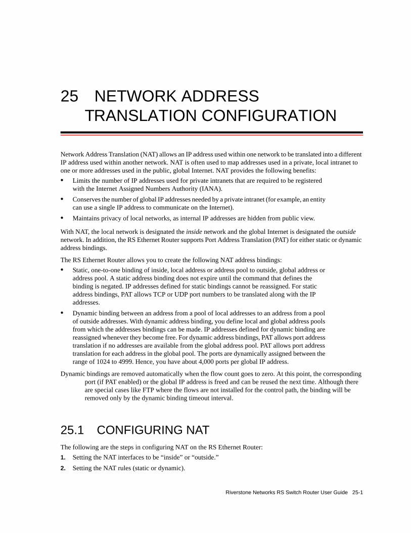
25 NETWORK ADDRESS TRANSLATION CONFIGURATION
Network Address Translation (NAT) allows an IP address used within one network to be translated into a different IP address used within another network. NAT is often used to map addresses used in a private, local intranet to one or more addresses used in the public, global Internet. NAT provides the following benefits:• Limits the number of IP addresses used for private intranets that are required to be registered
with the Internet Assigned Numbers Authority (IANA).• Conserves the number of global IP addresses needed by a private intranet (for example, an entity
can use a single IP address to communicate on the Internet).• Maintains privacy of local networks, as internal IP addresses are hidden from public view.
With NAT, the local network is designated the inside network and the global Internet is designated the outside network. In addition, the RS Ethernet Router supports Port Address Translation (PAT) for either static or dynamic address bindings.
The RS Ethernet Router allows you to create the following NAT address bindings:• Static, one-to-one binding of inside, local address or address pool to outside, global address or
address pool. A static address binding does not expire until the command that defines the binding is negated. IP addresses defined for static bindings cannot be reassigned. For static address bindings, PAT allows TCP or UDP port numbers to be translated along with the IP addresses.
• Dynamic binding between an address from a pool of local addresses to an address from a pool of outside addresses. With dynamic address binding, you define local and global address pools from which the addresses bindings can be made. IP addresses defined for dynamic binding are reassigned whenever they become free. For dynamic address bindings, PAT allows port address translation if no addresses are available from the global address pool. PAT allows port address translation for each address in the global pool. The ports are dynamically assigned between the range of 1024 to 4999. Hence, you have about 4,000 ports per global IP address.
Dynamic bindings are removed automatically when the flow count goes to zero. At this point, the corresponding port (if PAT enabled) or the global IP address is freed and can be reused the next time. Although there are special cases like FTP where the flows are not installed for the control path, the binding will be removed only by the dynamic binding timeout interval.
25.1 CONFIGURING NATThe following are the steps in configuring NAT on the RS Ethernet Router:1. Setting the NAT interfaces to be “inside” or “outside.”2. Setting the NAT rules (static or dynamic).
Riverstone Networks RS Switch Router User Guide 25-1

Forcing Flows through NAT Network Address Translation Configuration
25.1.1 Setting Inside and Outside Interfaces
When NAT is enabled, address translation is only applied to those interfaces which are defined to NAT as “inside” or “outside” interfaces. NAT only translates packets that arrive on a defined inside or outside interface.
To specify an interface as inside (local) or outside (global), enter the following command in Configure mode.
25.1.2 Setting NAT Rules
25.1.2.1 Static
You create NAT static bindings by entering the following command in Configure mode.
25.1.2.2 Dynamic
You create NAT dynamic bindings by entering the following command in Configure mode.
For dynamic address bindings, you define the address pools with previously-created ACLs. You can also specify the enable-port-overload parameter to allow PAT.
25.2 FORCING FLOWS THROUGH NATIf a host on the outside global network knows an inside local address, it can send a message directly to the inside local address. By default, the RS Ethernet Router will route the message to the destination. You can force all flows between the inside local pool and the outside global network to be translated. This prevents a host on the outside global network from being allowed to send messages directly to any address in the local address pool.
Define an interface as inside or outside for NAT. nat set interface <InterfaceName> inside|outside
Enable NAT with static address binding. nat create static protocol ip|tcp|udp local-ip
<local-ip-add/address range> global-ip <global-ip-add/address range> [local-port <tcp/udp local-port>|any] [global-port <tcp/udp global-port>|any]
Enable NAT with dynamic address binding. nat create dynamic local-acl-pool <local-acl> global-pool <ip-addr/ip-addr-range/ip-addr-list/ip-addr-mask> [matches-interface <interface>] [enable-ip-overload]
25-2 Riverstone Networks RS Switch Router User Guide

Network Address Translation Configuration Managing Dynamic Bindings
You force address translation of all flows to and from the inside local pool by entering the following command in Configure mode.
25.3 MANAGING DYNAMIC BINDINGSAs mentioned previously, dynamic address bindings expire only after a period of non-use or when they are manually deleted. The default timeout for dynamic address bindings is 1440 minutes (24 hours). You can manually delete dynamic address bindings for a specific address pool or delete all dynamic address bindings.
To set the timeout for dynamic address bindings, enter the following command in Configure mode.
To flush dynamic address bindings, enter the following command in Enable mode.
25.4 NAT AND DNSNAT can translate an address that appears in a Domain Name System (DNS) response to a name or inverse lookup. For example, if an outside host sends a name lookup to an inside DNS server, the inside DNS server can respond with a local IP address, which NAT translates to a global address.
To enable NAT DNS translation, enter the following command in Configure mode:
Force all flows to and from local address pool to be translated.
nat set secure-plus on|off
Set timeout for dynamic address bindings. nat set dynamic-binding-timeout <minutes> |disable
Flush all dynamic address bindings. nat flush-dynamic-binding all
Flush dynamic address bindings based on local and global ACL pools.
nat flush-dynamic-binding pool-specified
local-acl-pool <local-acl> global-pool <ip-addr/ip-addr-range/ip-addr-list/ip-addr-mask>
Flush dynamic address bindings based on binding type. nat flush-dynamic-binding type-specified dynamic|overloaded-dynamic
Flush dynamic address bindings based on application. nat flush-dynamic-binding owner-specified dns|ftp-control|ftp-data
nat set dns-translation-state enable
Riverstone Networks RS Switch Router User Guide 25-3
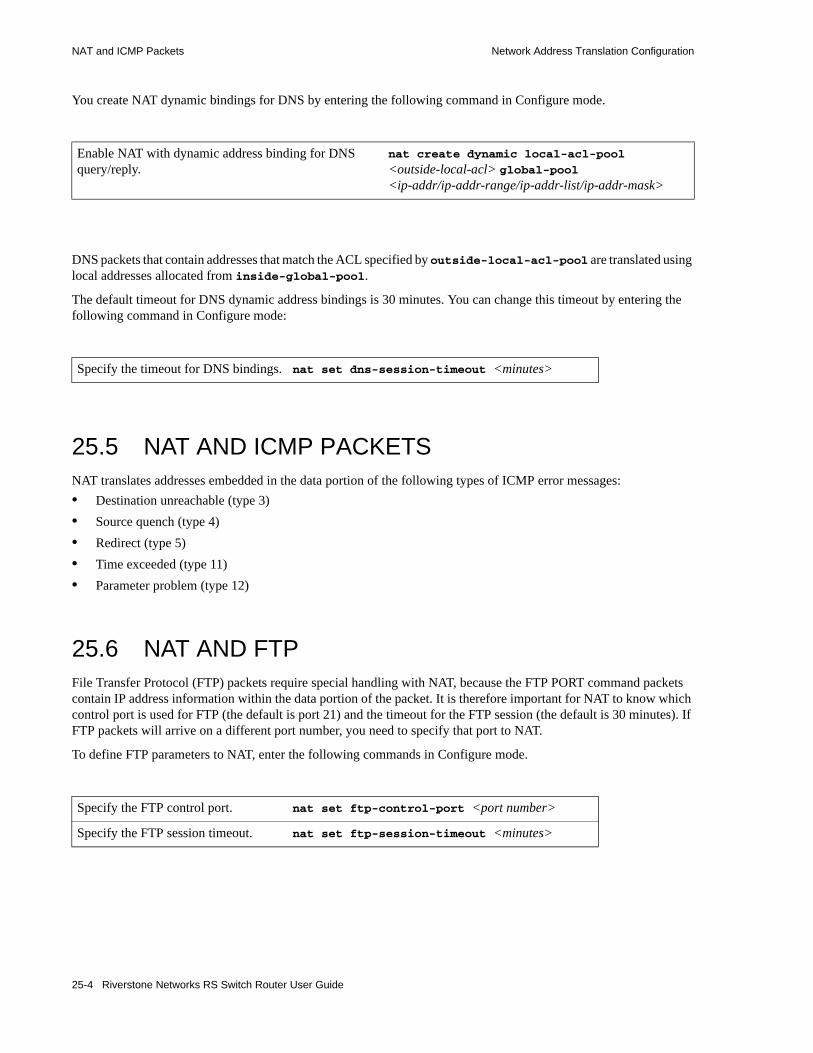
NAT and ICMP Packets Network Address Translation Configuration
You create NAT dynamic bindings for DNS by entering the following command in Configure mode.
DNS packets that contain addresses that match the ACL specified by outside-local-acl-pool are translated using local addresses allocated from inside-global-pool.
The default timeout for DNS dynamic address bindings is 30 minutes. You can change this timeout by entering the following command in Configure mode:
25.5 NAT AND ICMP PACKETSNAT translates addresses embedded in the data portion of the following types of ICMP error messages:• Destination unreachable (type 3)• Source quench (type 4)• Redirect (type 5)• Time exceeded (type 11)• Parameter problem (type 12)
25.6 NAT AND FTPFile Transfer Protocol (FTP) packets require special handling with NAT, because the FTP PORT command packets contain IP address information within the data portion of the packet. It is therefore important for NAT to know which control port is used for FTP (the default is port 21) and the timeout for the FTP session (the default is 30 minutes). If FTP packets will arrive on a different port number, you need to specify that port to NAT.
To define FTP parameters to NAT, enter the following commands in Configure mode.
Enable NAT with dynamic address binding for DNS query/reply.
nat create dynamic local-acl-pool
<outside-local-acl> global-pool <ip-addr/ip-addr-range/ip-addr-list/ip-addr-mask>
Specify the timeout for DNS bindings. nat set dns-session-timeout <minutes>
Specify the FTP control port. nat set ftp-control-port <port number>
Specify the FTP session timeout. nat set ftp-session-timeout <minutes>
25-4 Riverstone Networks RS Switch Router User Guide

Network Address Translation Configuration Monitoring NAT
If PAT is enabled, NAT checks packets for the FTP PORT command. If a packet is to be translated (as determined by the ACL specified for the dynamic address binding), NAT creates a dynamic binding for the PORT command. An outside host will only see a global IP address in an FTP response and not the local IP address.
25.7 MONITORING NATTo display NAT information, enter the following command in Enable mode.
25.8 CONFIGURATION EXAMPLESThis section shows examples of NAT configurations.
25.8.1 Static Configuration
The following example configures a static address binding for inside address 10.1.1.2 to outside address 192.50.20.2:
Figure 25-1 Static address binding configuration
1. The first step is to create the interfaces:
Display NAT information. nat show [translations all|<type>] [timeouts] [statistics]
interface create ip 10-net address-netmask 10.1.1.1/24 port et.2.1interface create ip 192-net address-netmask 192.50.20.1/24 port et.2.2
et.2.2
(192.50.20.1/24)
et.2.1
(10.1.1.1/24)
Global InternetIP network 10.1.1.0/24
Router
interface 10-net interface 192-net10.1.1.2
Outbound: Translate source 10.1.1.2 to 192.50.20.2Inbound: Translate destination 192.50.20.2 to 10.1.1.2
Riverstone Networks RS Switch Router User Guide 25-5
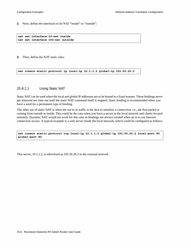
Configuration Examples Network Address Translation Configuration
2. Next, define the interfaces to be NAT “inside” or “outside”:
3. Then, define the NAT static rules:
25.8.1.1 Using Static NAT
Static NAT can be used when the local and global IP addresses are to be bound in a fixed manner. These bindings never get removed nor time out until the static NAT command itself is negated. Static binding is recommended when you have a need for a permanent type of binding.
The other use of static NAT is when the out to in traffic is the first to initialize a connection, i.e., the first packet is coming from outside to inside. This could be the case when you have a server in the local network and clients located remotely. Dynamic NAT would not work for this case as bindings are always created when an in to out Internet connection occurs. A typical example is a web server inside the local network, which could be configured as follows:
This server, 10.1.1.2, is advertised as 192.50.20.2 to the external network.
nat set interface 10-net insidenat set interface 192-net outside
nat create static protocol ip local-ip 10.1.1.2 global-ip 192.50.20.2
nat create static protocol tcp local-ip 10.1.1.2 global-ip 192.50.20.2 local-port 80 global-port 80
25-6 Riverstone Networks RS Switch Router User Guide

Network Address Translation Configuration Configuration Examples
25.8.2 Dynamic Configuration
The following example configures a dynamic address binding for inside addresses 10.1.1.0/24 to outside address 192.50.20.0/24:
Figure 25-2 Dynamic address binding configuration
1. The first step is to create the interfaces:
2. Next, define the interfaces to be NAT “inside” or “outside”:
3. Then, define the NAT dynamic rules by first creating the source ACL pool and then configuring the dynamic bindings:
interface create ip 10-net address-netmask 10.1.1.1/24 port et.2.1interface create ip 192-net address-netmask 192.50.20.1/24 port et.2.2
nat set interface 10-net insidenat set interface 192-net outside
acl lcl permit ip 10.1.1.0/24nat create dynamic local-acl-pool lcl global-pool 192.50.20.0/24
et.2.2
(192.50.20.1/24)
et.2.1
(10.1.1.1/24)
Global InternetIP network 10.1.1.0/24
Router
interface 10-net interface 192-net
10.1.1.4
10.1.1.210.1.1.3
Outbound: Translate source pool 10.1.1.0/24 to global pool 192.50.20.0/24
Riverstone Networks RS Switch Router User Guide 25-7

Configuration Examples Network Address Translation Configuration
25.8.2.1 Using Dynamic NAT
Dynamic NAT can be used when the local network (inside network) is going to initialize the connections. It creates a binding at run time when a packet is sent from a local network, as defined by the NAT dynamic local ACl pool. The network administrator does not have to worry about the way in which the bindings are created; the network administrator just sets the pools and the RS Ethernet Router automatically chooses a free global IP from the global pool for the local IP.
Dynamic bindings are removed when the flow count for that binding goes to zero or the timeout has been reached. The free globals are used again for the next packet.
A typical problem is that if there are more local IP addresses as compared to global IP addresses in the pools, then packets will be dropped if all the globals are used. A solution to this problem is to use PAT with NAT dynamic. This is only possible with TCP or UDP protocols.
25.8.3 Dynamic NAT with IP Overload (PAT) Configuration
The following example configures a dynamic address binding for inside addresses 10.1.1.0/24 to outside address 192.50.20.0/24:
Figure 25-3 Dynamic address binding with PAT
1. The first step is to create the interfaces:
interface create ip 10-net address-netmask 10.1.1.1/24 port et.2.1interface create ip 192-net address-netmask 192.50.20.1/24 port et.2.2
et.2.2
(192.50.20.1/24)
et.2.1
(10.1.1.1/24)
Global InternetIP network 10.1.1.0/24
Router
interface 10-net interface 192-net
10.1.1.4
10.1.1.210.1.1.3
Outbound: Translate source pool 10.1.1.0/24 to global pool 192.50.20.1-192.50.20.3
25-8 Riverstone Networks RS Switch Router User Guide
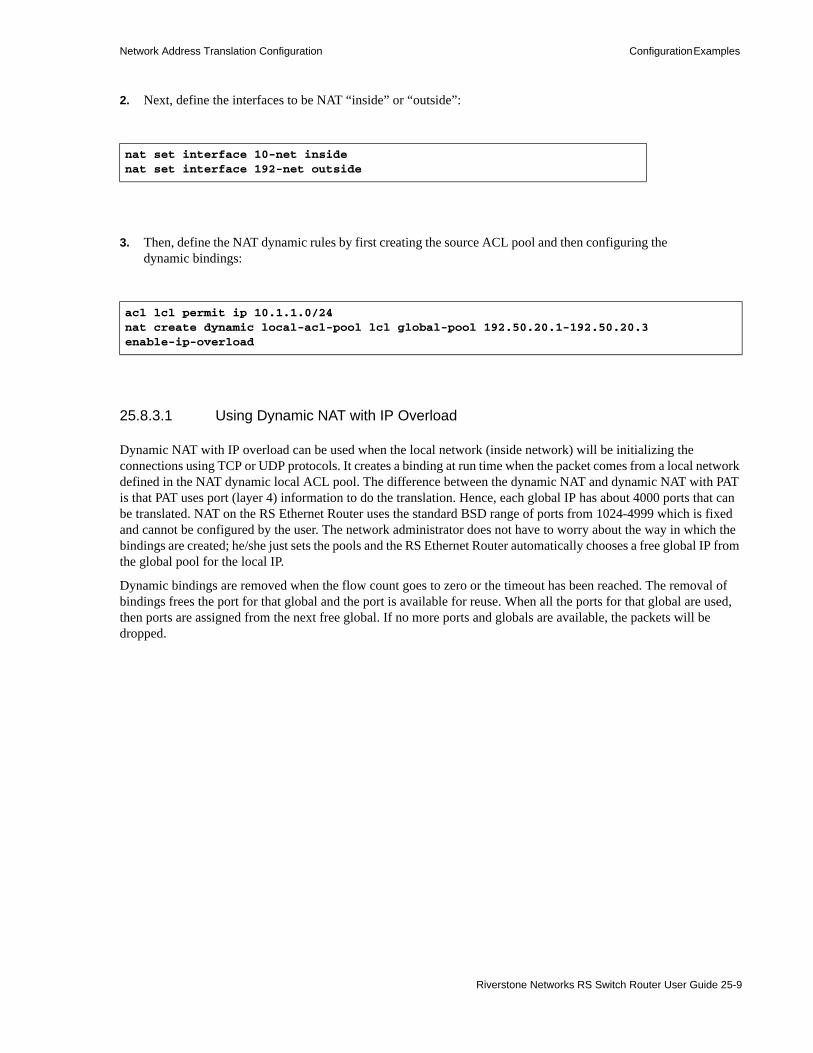
Network Address Translation Configuration Configuration Examples
2. Next, define the interfaces to be NAT “inside” or “outside”:
3. Then, define the NAT dynamic rules by first creating the source ACL pool and then configuring the dynamic bindings:
25.8.3.1 Using Dynamic NAT with IP Overload
Dynamic NAT with IP overload can be used when the local network (inside network) will be initializing the connections using TCP or UDP protocols. It creates a binding at run time when the packet comes from a local network defined in the NAT dynamic local ACL pool. The difference between the dynamic NAT and dynamic NAT with PAT is that PAT uses port (layer 4) information to do the translation. Hence, each global IP has about 4000 ports that can be translated. NAT on the RS Ethernet Router uses the standard BSD range of ports from 1024-4999 which is fixed and cannot be configured by the user. The network administrator does not have to worry about the way in which the bindings are created; he/she just sets the pools and the RS Ethernet Router automatically chooses a free global IP from the global pool for the local IP.
Dynamic bindings are removed when the flow count goes to zero or the timeout has been reached. The removal of bindings frees the port for that global and the port is available for reuse. When all the ports for that global are used, then ports are assigned from the next free global. If no more ports and globals are available, the packets will be dropped.
nat set interface 10-net insidenat set interface 192-net outside
acl lcl permit ip 10.1.1.0/24nat create dynamic local-acl-pool lcl global-pool 192.50.20.1-192.50.20.3 enable-ip-overload
Riverstone Networks RS Switch Router User Guide 25-9

Configuration Examples Network Address Translation Configuration
25.8.4 Dynamic NAT with DNS
The following example configures a DNS dynamic address binding for outside address 192.50.20.2-192.50.20.9 to inside addresses 10.1.1.0/24:
Figure 25-4 Dynamic address binding with DNS
1. The first step is to create the interfaces:
2. Next, define the interfaces to be NAT “inside” or “outside”:
3. Then, define the NAT dynamic rules by first creating the source ACL pool and then configuring the dynamic bindings:
interface create ip 10-net address-netmask 10.1.1.1/24 port et.2.1interface create ip 192-net address-netmask 192.50.20.1/24 port et.2.2
nat set interface 10-net insidenat set interface 192-net outside
acl lcl permit ip 10.1.1.0/24nat create dynamic local-acl-pool lcl global-pool 192.50.20.2-192.50.20.9nat create static local-ip 10.1.1.10 global-ip 192.50.20.10 protocol ip
et.2.2
(192.50.20.1/24)
et.2.1
(10.1.1.1/24)
Global InternetIP network 10.1.1.0/24
Router
interface 10-net interface 192-net
DNS
DNS server static binding of 10.1.1.10 to 192.50.20.10
10.1.1.10
10.1.1.2 10.1.1.3
Server
25-10 Riverstone Networks RS Switch Router User Guide

Network Address Translation Configuration Configuration Examples
25.8.4.1 Using Dynamic NAT with DNS
When a client from outside sends a query to the static global IP address of the DNS server, NAT will translate the global IP address to the local IP address of the DNS server. The DNS server will resolve the query and respond with a reply. The reply can include the local IP address of a host inside the local network (for example, 10.1.1.2); this local IP address will be translated by NAT into a global IP address (for example, 192.50.20.2) in a dynamic binding for the response.
25.8.5 Dynamic NAT with Outside Interface Redundancy
The following example configures a dynamic address binding for inside addresses 10.1.1.0/24 to outside addresses 192.50.20.0/24 on interface 192-net and to outside addresses 201.50.20.0/24 on interface 201-net:
Figure 25-5 Dynamic address binding with outside interface redundancy
1. The first step is to create the interfaces:
2. Next, define the interfaces to be NAT “inside” or “outside”:
interface create ip 10-net address-netmask 10.1.1.1/24 port et.2.1interface create ip 192-net address-netmask 192.50.20.0/24 port et.2.2interface create ip 201-net address-netmask 201.50.20.0/24 port et.2.3
nat set interface 10-net insidenat set interface 192-net outsidenat set interface 201-net outside
et.2.2
(201.50.20.0/24)
et.2.1
(10.1.1.1/24)
IP network 10.1.1.0/24
Router
interface 10-net interface 201-net
10.1.1.4
10.1.1.210.1.1.3
Outbound: Translate source pool 10.1.1.0/24 to global pool 192.50.20.0/24
Global Internet
(192.50.20.0/24)interface 192-net
et.2.3
Translate source pool 10.1.1.0/24 to global pool 201.50.20.0/24
Riverstone Networks RS Switch Router User Guide 25-11

Configuration Examples Network Address Translation Configuration
3. Then, define the NAT dynamic rules by first creating the source ACL pool and then configuring the dynamic bindings:
25.8.5.1 Using Dynamic NAT with Matching Interface Redundancy
If you have redundant connections to the remote network via two different interfaces, you can use NAT for translating the local address to the different global pool specified for the two connections. This case is possible when you have two ISPs connected on two different interfaces to the Internet. Through a routing protocol, some routes will result in traffic going out of one interface and for others going out on the other interface. NAT will check which interface the packet is going out from before selecting a global pool. Hence, you can specify two different global pools with the same local ACL pool on two different interfaces.
acl lcl permit ip 10.1.1.0/24nat create dynamic local-acl-pool lcl global-pool 192.50.20.0/24 matching-interface 192-netnat create dynamic local-acl-pool lcl global-pool 210.50.20.0/24 matching-interface 201-net
25-12 Riverstone Networks RS Switch Router User Guide

26 ACCESS CONTROL LIST CONFIGURATION
This chapter explains how to configure and use Access Control Lists (ACLs) on the RS Ethernet Router. ACLs consist of rules, which in turn are defined by match criteria. When used in conjunction with certain RS Ethernet Router features, ACLs provide control over the forwarding of layer-3 and layer-4 traffic.
26.1 ACL BASICSAn ACL consists of a protocol type and one or more rules which tell the RS Ethernet Router to either permit or deny packets that match the match criteria on which each rule is based. These rules describe particular types of IP packets. ACLs can be simple, consisting of only one rule or they can be complicated, containing a number of rules for assessing packets.
Each ACL is identified by a name, consisting of alphanumeric characters. The ACL name can be a meaningful string such as denyFTP or it can be a simple number such as 100 or 101.
For example, the following ACL (101) consists of a single rule that permits all IP packets from subnet 140.134.170.0/24 to go out through the interface named “to-marketing.”
The following example is a more sophisticated ACL, consisting of three rules, and is applied to inbound packets on interface Int-2:
In the previous example, each rule is added to the ACL using separate entries of the acl command.
Note Notice in the examples above that ACL rules are defined as either permit or deny. All ACL rules must either permit a packet or deny it, no other choices of action are permitted.
rs(config)# acl 101 permit ip 140.134.170.0/24rs(config)# acl 101 apply interface to-marketing output
rs(config)# acl 102 permit ip 134.121.96.0/24 any any anyrs(config)# acl 102 deny ip 141.77.132.0/24 any any anyrs(config)# acl 102 deny tcp any any any anyrs(config)# acl 102 apply interface Int-2 input
Riverstone Networks RS Switch Router User Guide 26-1

ACL Basics Access Control List Configuration
Figure 26-1 Basic components of an ACL
26.1.1 Match Criteria and Creating Rules for ACLs
ACL rules are based on a set of match criteria. Match criteria in an ACL describes characteristics about a packet, which is to be either permitted or denied. These match criteria are used to create rules. In turn, a set of rules define an ACL. In the first example, ACL 101 consisted of a single rule whose match criteria is:1. Check if packet is an IP packet2. Check whether the packet came from subnet 140.134.170.0
If the above match criteria is met, the packet is permitted to exit through the interface to-marketing.
For each protocol type, each match criteria field is position-sensitive. For example, for an IP ACL, the source address is specified first, followed by the destination address, followed by the source port, followed by the destination port, and so on. Specifically, each criterion that define ACL rules are ANDed in order of position from left-to-right. Any match criteria fields that are left blank are wild carded.
Figure 26-2 Relationship between match criteria and rules
acl in-1 permit ip 123.124.10.0/24 any any 80 .......
ACL Name
Source Address
Destination Address
Source Port
Destination Port
Action
The parameter any is usedto skip over irrelevant match
criteria fields
Protocol
Other MatchCriteria
acl in-1 permit ip 123.124.10.0/24 any any 80acl in-1 deny tcp any any any anyacl in-1 deny udp 50.123.75.0/24
Match Criteria
Rule 1Rule 2Rule 3
Missing match criteriaare wild carded
26-2 Riverstone Networks RS Switch Router User Guide

Access Control List Configuration ACL Basics
26.1.1.1 Match Criteria According to Protocol Type
Match criteria differs depending on the protocol type specified in the ACL. The protocol type is not a match criteria and cannot contain the any parameter or be left blank. The protocol type for the ACL must be specified.
For example, an ACL rule of protocol type ip can include the following elements as match criteria:• Source IP address• Destination address• Source port number• Destination port number• TOS• Accounting
Note The accounting keyword specifies that accounting information about the flow is sent to the configured Flow Accounting Server (FAS) or other accounting application using the Light-Weight Flow Accounting Protocol (LFAP). The accounting parameter must be followed by one of three checkpoint time interval parameters: 5-minutes, 15-minutes, or hourly. See Chapter 31 "LFAP Configuration Guide" for more information.
Table 26-1 lists the match criteria for each protocol type and the position in which each must appear within the corresponding ACL.
Table 26-1 ACL protocol types and match criteria
Protocol-type1 Match Criteria2
icmp Source address and mask, destination address and mask, TOS
igmp Source address and mask, destination address and mask, TOS
ip Source address and mask, destination address and mask, source port4, destination port4, TOS, TOS mask, accounting
ip-protocol3 Protocol number, source address and mask, destination address and mask, TOS
route-filter IP address and mask
tcp Source address and mask, destination address and mask, source port, destination port, TOS, TOS mask, accounting, established
udp Source address and mask, destination address and mask, source port, destination port, TOS, TOS mask, accounting
1. All protocol-types match criteria support the log parameter for sending ACL activity to a Syslog server. 2. Most of these match criteria can be skipped by using the keyword any.3. For a list of ip-protocol numbers, see the Riverstone Networks RS Switch Router Command Line Interface Reference.4. For a list of port numbers, see the Riverstone Networks RS Switch Router Command Line Interface Reference.
Riverstone Networks RS Switch Router User Guide 26-3

ACL Basics Access Control List Configuration
26.1.1.2 The Any Parameter and Wild Cards
When defining an ACL it may be desirable to skip a match criteria field. For example, an ACL is defined where the source address is immaterial, but the destination address is required. Since each match criteria field is position-sensitive, the keyword any is used to skip a field – in this case, the source address. In effect, any says “Accept any value for this match criteria.”
For example, the following ACL denies Telnet traffic between any source and destination address and illustrates both the use of the any parameter and the use of wild carding:
Notice in the previous example that both the source address and the destination address are skipped over using the any parameter. Also, notice that the 5th field (the TOS field) is left blank and is treated as a wildcard. The keyword any is needed only to skip a field in order to explicitly specify another field whose position is further along in the ACL On the other hand, if the skipped criteria is at the end of the ACL rule it can be left blank, representing a wildcard.
For example, the following ACL permits all IP-based traffic to pass through the interface Int-1 because all match criteria for protocol type ip are left blank (wild cards):
26.1.2 How Multiple ACL Rules are Evaluated
The sequence of the rules within an ACL consisting of multiple rules is important. When the RS Ethernet Router checks a packet against an ACL, it applies rules in the order in which they reside within the ACL – from first to last. If a packet matches a rule, it is forwarded or dropped based on the permit or deny keyword in the rule. All subsequent rules are ignored. That is, a first-match algorithm is used when applying rules to packets.
Consequently, rules that are more specific (contain more match criteria) should usually be listed ahead of rules that are less specific. For example, the following ACL permits all TCP traffic except any TCP traffic from subnet 100.20.20.0/24:
Notice in the previous example that ACL 101 includes two rules:1. Deny TCP packets from subnet 100.20.20.02. Permit TCP packets
A TCP packet coming from subnet 10.2.0.0/16 matches the first ACL rule, which results in the packet being dropped. However, a TCP packet coming from any other subnet does not match the first ACL rule. Instead, it matches the second ACL rule, which allows the TCP packet through.
Consider the case where the ACL rules in the previous example are reversed:
rs(config)# acl NoTelnet deny ip any any telnet telnet
rs(config)# acl All-IP permit iprs(config)# acl All-IP apply interface Int-1 input output
rs(config)# acl 101 deny tcp 100.20.20.0/24rs(config)# acl 101 permit tcp
rs(config)# acl 101 permit tcprs(config)# acl 101 deny tcp 100.20.20.0/24
26-4 Riverstone Networks RS Switch Router User Guide

Access Control List Configuration ACL Basics
All TCP packets are allowed through, including packets from subnet 100.20.20.0. Because TCP traffic coming from 100.20.20.0 matches the first rule, “all TCP packets are allowed through.” The second rule is not applied because the first rule that matches determines the action taken on the packet.
Note Remember that the first rule that applies to a packet is the only rule that affects the packet. The packet is permitted or denied according to the first rule it satisfies; none of the remaining ACL rules have any effect on the packet.
26.1.2.1 Implicit Deny Rule
At the end of each ACL, the RS Ethernet Router automatically appends the implicit deny rule. For a packet that doesn’t match any of the user-specified rules, the implicit deny rule acts as a catch-all rule that denies all packets – all packets match this rule.
The implicit deny rule exists for security reasons. If an ACL is misconfigured, and a packet that should be allowed to go through is blocked by the implicit deny rule, the worst that happens is an inconvenience. However, a security breach results if a packet that should not be allowed through is sent through. As a result, the implicit deny rule serves as a fail-safe against the accidental misconfiguration of ACLs.
To illustrate how the implicit deny rule works, consider the following ACL:
With the implicit deny rule, this ACL actually has three rules as shown in the following example:
If a packet comes in and doesn't match either of the first two rules, the packet is dropped, because the third rule (the implicit deny rule) matches all packets. Although the implicit deny rule may seem obvious in the previous example, this is not always the case.
For example, consider the following ACL rule:
If a packet comes in from a subnet other than 140.124.200.0, one might expect the packet to go through, because it doesn’t match the first rule, however, this is not the case. With the implicit deny rule attached, the rule looks like this:
A packet coming from a subnet other than 140.124.200.0 would not match the first rule, but would match the implicit deny rule. As a result, no packets would be allowed through. Notice that the first rule is a subset of the second rule.
rs(config)# acl 101 permit ip 100.20.30.40/24rs(config)# acl 101 permit ip 124.123.220.10/24 any nntp
rs(config)# acl 101 permit ip 100.20.30.40/24rs(config)# acl 101 permit ip 124.123.220.10/24 any nntprs(config)# acl 101 deny any any any any any
rs(config)# acl 102 deny ip 140.124.200.0/24
rs(config)# acl 102 deny ip 140.124.200.0/24rs(config)# acl 102 deny any any any any any
Riverstone Networks RS Switch Router User Guide 26-5

Editing ACLs Access Control List Configuration
To allow packets from a subnet other than 140.124.200.0 to pass through, a rule must be explicitly defined to permit other packets to go through. To change the previous example so that it accepts packets from other subnets, a new rule must be added ahead of the implicit deny rule that permits packets to pass.
For example:
Notice that the second rule in this example forwards all IP packets that are not denied by the first rule, and this occurs before the implicit deny rule can be applied.
Because of the implicit deny rule, an ACL works similarly to a firewall that denies all traffic. ACL rules are then created that essentially open “doors” within the firewall that permit specific types of packets to pass.
26.2 EDITING ACLSThe RS Ethernet Router provides three mechanisms for modifying ACLs: • Editing ACLs on a remote workstation and uploading them to the RS Ethernet Router using TFTP
or RCP• Using the RS Ethernet Router’ built-in ACL editor• Using an external SNMP-based application to change ACLs
26.2.1 Editing ACLs on a Remote Workstation
With this method, ACLs are created and edited on a workstation, and then uploaded to the RS Ethernet Router through TFTP or RCP. Use a text editor to edit, delete, replace, or reorder ACL rules and match criteria in a text file. The following example describes how to use this method to affect ACLs on the RS Ethernet Router.
Suppose that ACL 104 is defined and applied to an interface on the RS Ethernet Router, the following steps are performed to change the ACL using a text editor.1. Use the no command to remove the definition and all reference of ACL 104:
Basically, the no acl 104 * command cleans up the system for the new rules for ACL 104 (enter no acl * to remove all ACL definitions and references).
2. On a workstation, the new ACL rules and references are entered into the text file. In this example the text file is named acl.changes, which contains the changes to ACL 104 and its application to interface int12:
rs(config)# acl 101 deny ip 10.1.20.0/24 any any anyrs(config)# acl 101 permit iprs(config)# acl 101 deny any any any any any
rs(config)# no acl 104 *
acl 104 deny tcp 10.11.0.0/16 10.12.0.0/16
acl 104 permit tcp 10.11.0.0 any
acl 104 apply interface int12 input
26-6 Riverstone Networks RS Switch Router User Guide

Access Control List Configuration Editing ACLs
3. Once the file acl.changes is placed on a TFTP server that is reachable by the RS Ethernet Router, and the file is uploaded to the RS Ethernet Router. Once uploaded, the changes are and made active using the following commands:
The first copy command uploads the file acl.changes from the TFTP server to the configuration scratchpad. The next copy command makes the changes take effect by copying them into the active configuration.
Copying the changes into the scratchpad allows the ACL changes to be checked before committing them to the active configuration. If it’s necessary to modify the ACL information residing within the scratchpad, the changes must be made in the file on the TFTP server, and then uploaded to the scratchpad once again.
26.2.2 Using the RS Ethernet Router ACL Editor
The ACL editor in the RS Ethernet Router CLI provides a simple and user-friendly mechanism for editing ACLs. The ACL editor is a facility that is used at the console or through a Telnet session. If you edit an ACL that is currently applied to an object (an interface or port, for example), the changes take effect immediately. There is no need to first remove all references to an ACL before making changes.
The ACL Editor is accessed within Configure mode by specifying the ACL name together with the acl-edit command. For example, to edit ACL 101, issue the command acl-edit 101. Within the ACL editor, you can add new rules, delete existing rules, and re-order rules. To save the changes, use the save command or simply exit the ACL Editor.
26.2.2.1 ACL Editor Example
The following is a simple example of an acl-edit session. In this example it is assumed that:• The RS Ethernet Router active configuration contains an ACL named lfap, which contains the
following rule,acl lfap permit ip any any any any accounting 15-minutes
rs# copy tftp://10.1.1.12/config/acl.changes to scratchpadrs# copy scratchpad to active
Riverstone Networks RS Switch Router User Guide 26-7

Editing ACLs Access Control List Configuration
• A rule is added to lfap so that packets from the subnet 134.128.77.0 are dropped
Notice in the example above that the acl-edit command changes the prompt, lists the current definition for the ACL, and gives it a line number (1*). Next, the new rule, which denies packets from 134.128.77.0 is added (line 2*). If denying packets is going to occur, we need to change the order in which the ACL rules are applied. This is done using the move command. Finally, the exit command is entered, a prompt appears, and the ACL is saved.
After the ACL editor session, the ACL lfap now appears in the active configuration as:
26.2.3 Editing ACLs by SNMP
Certain SNMP-based applications such as the Granite SDK (made available to Riverstone customers) have the ability to access and affect ACLs on an RS Ethernet Router. Because ACLs within the RS Ethernet Router active configuration file and ACLs applied to ports and interfaces are contained within two separate lists, an SNMP-based application can view and edit ACLs independently at both the port/interface level and at the active configuration file level.
To make editing possible through an SNMP-based application, the acl-policy enable command must be set to external.
For example:
When acl-policy is set to external, an SNMP-based application can view and edit any ACL within the active configuration file. Furthermore, the application can see all ACLs currently applied to ports and interfaces, and modify them directly at the port/interface level. Note that while the application can directly modify an ACL on a port or
rs(config)# acl-edit lfap 1*: acl lfap permit ip any any any any accounting 15-minutesrs(acl-edit)>
rs(acl-edit)> acl lfap deny ip 134.128.77.0/24 any any any 1*: acl lfap permit ip any any any any accounting 15-minutes 2*: acl lfap deny ip 134.128.77.0/24 any any anyrs(acl-edit)>
rs(acl-edit)> move 1 after 2 1*: acl lfap deny ip 134.128.77.0/24 any any any 2*: acl lfap permit ip any any any any accounting 15-minutesrs(acl-edit)>
rs(acl-edit)> exitDo you want to commit your ACL changes (yes: commit, no: discard) [yes]? y
rs(config)#
acl lfap deny ip 134.128.77.0/24 any any any anyacl lfap permit ip any any any any accounting 15-minutes
rs(config)# acl-policy enable externalrs(config)# save activers(config)# save startup
26-8 Riverstone Networks RS Switch Router User Guide

Access Control List Configuration Using the ACL Apply Command
interface, it cannot modify that ACL within the active configuration file until the ACL is removed from the port or interface. Once removed, the ACL can be edited within the active configuration file. The changes then take effect when the ACL is reapplied to the port or interface.
26.2.3.1 SNMP Editing ACLs at the Ports/Interfaces Level
The policy option of the acl apply command controls whether an applied ACL can be changed by a remote SNMP-based application.
When an ACL is applied to a port or interface, the policy option can be set to the keywords external or local (by default, ACLs are set to external). If an ACL is applied to a port or interface with the policy option set to local, the ACL cannot be changed by the SNMP-based application at the port/interface level.
For example, consider the following two command lines that apply ACLs to interfaces:
ACL 101 applied to interface In-1 can be modified directly on the interface by an SNMP-based application because its policy is set to external. However, ACL 102 applied to interface In-2 cannot be modified directly on the interface because its policy is set to local.
For an SNMP-based application to be able to modify ACL 102, it must first be removed from the interface by commenting out (or deleting) the line in the active configuration that applies the ACL to the interface. With the ACL removed from the interface, the SNMP-based application can edit ACL 102 within the active configuration file. After changes to ACL 102 are made at the active configuration file level, the altered version of ACL 102 would then be reapplied to the interface.
Note Visit http://www.nmops.org for information about the Granite SDK.
26.3 USING THE ACL APPLY COMMANDIt is important to understand that an ACL is simply a set of one or more rules made up of match criteria and an indicator that specifies whether to permit or deny packets that meet the rules. For an ACL to actually do something on the RS Ethernet Router, an ACL must be applied in one of the following ways:• To an interface, which permits or denies traffic to or from the RS Ethernet Router. ACLs used in this
way are known as interface ACLs.• To a port operating in Layer-4 bridging mode, which permits or denies bridged traffic. ACLs used
in this way are known as layer-4 Bridging ACLs.• To a service, which permits or denies access to services reached through the RS Ethernet Router.
ACLs used in this way are known as service ACLs.• To an RS Ethernet Router facility such as NAT or web-caching, which specifies the criteria that
packets must meet to be relevant to these facilities. ACLs used in this way are known as profile ACLs.
rs(config)# acl 101 apply interface In-1 input policy externalrs(config)# acl 102 apply interface In-2 input policy local
Riverstone Networks RS Switch Router User Guide 26-9

Using the ACL Apply Command Access Control List Configuration
26.3.1 Applying ACLs to Interfaces
An ACL can be applied to an interface to make decisions about either inbound or outbound traffic. Inbound traffic is traffic coming into the RS Ethernet Router. Outbound traffic is traffic going out of the RS Ethernet Router. For each interface, only one ACL can be applied for the same protocol in the same direction. For example, you cannot apply two or more IP ACLs to the same interface in the inbound direction. You can apply two ACLs to the same interface if one is for inbound traffic and one is for outbound traffic. However, this restriction does not prevent you from specifying many rules in an ACL. Just put all of these rules into one ACL and apply it to the interface.
When a packet enters the RS Ethernet Router through an interface where an inbound ACL is applied, the RS Ethernet Router compares the packet to the rules specified by that ACL. If it is permitted, the packet is allowed into the RS Ethernet Router. If not, the packet is dropped. If that packet is to be forwarded to go out another interface (the packet is to be routed), a second ACL check is possible at the output interface. The outbound packet is compared to the rules specified in this outbound ACL. Consequently, it is possible for a packet to go through two separate checks, once at the inbound interface and once more at the outbound interface.
Note To specify whether an ACL is applied to inbound or outbound interface, the keywords input and output are used, respectively.
In general, ACLs should be applied at the inbound interfaces instead of the outbound interfaces. If a packet is denied, the packet should be dropped as early as possible, which is at the inbound interface. Otherwise, the RS Ethernet Router has to process the packet and determine where the packet should go, only to have the packet dropped at the outbound interface. In some cases, however, it may not be simple or possible for the administrator to know ahead of time that a packet should be dropped at the inbound interface. Nonetheless, for performance reasons, ACLs should be applied to the inbound interface.
The following is an example of applying ACL 101 to the interface In-1 in the inbound direction:
26.3.2 Applying ACLs to Layer-4 Bridging Ports
ACLs can be applied to one or more ports operating in layer-4 bridging mode. Traffic that is switched at layer-2 through the RS Ethernet Router can have ACLs applied on the layer-3 and layer-4 information contained in the packet. ACLs that are applied to layer-4 bridging ports affect only bridged traffic. ACLs that are applied to an interface containing these ports affect routed traffic.
Like ACLs that are applied to interfaces, ACLs that are applied to layer-4 bridging ports can be applied to either inbound or outbound traffic. For each port, only one ACL can be applied to the inbound direction and only one to the outbound direction.
In the following example, VLAN group-1 is created and layer-4 bridging is enabled on all five of its Ethernet ports. ACL 101 is then applied to all of the VLAN’s ports:
rs(config)# acl 101 permit ip 124.131.77.0/24rs(config)# acl 101 apply interface In-1 input
rs(config)# vlan create group-1 iprs(config)# vlan add ports et.4.2-6 to group-1rs(config)# vlan enable l4-bridging on group-1rs(config)# acl 101 apply port et.4.2-6 input
26-10 Riverstone Networks RS Switch Router User Guide
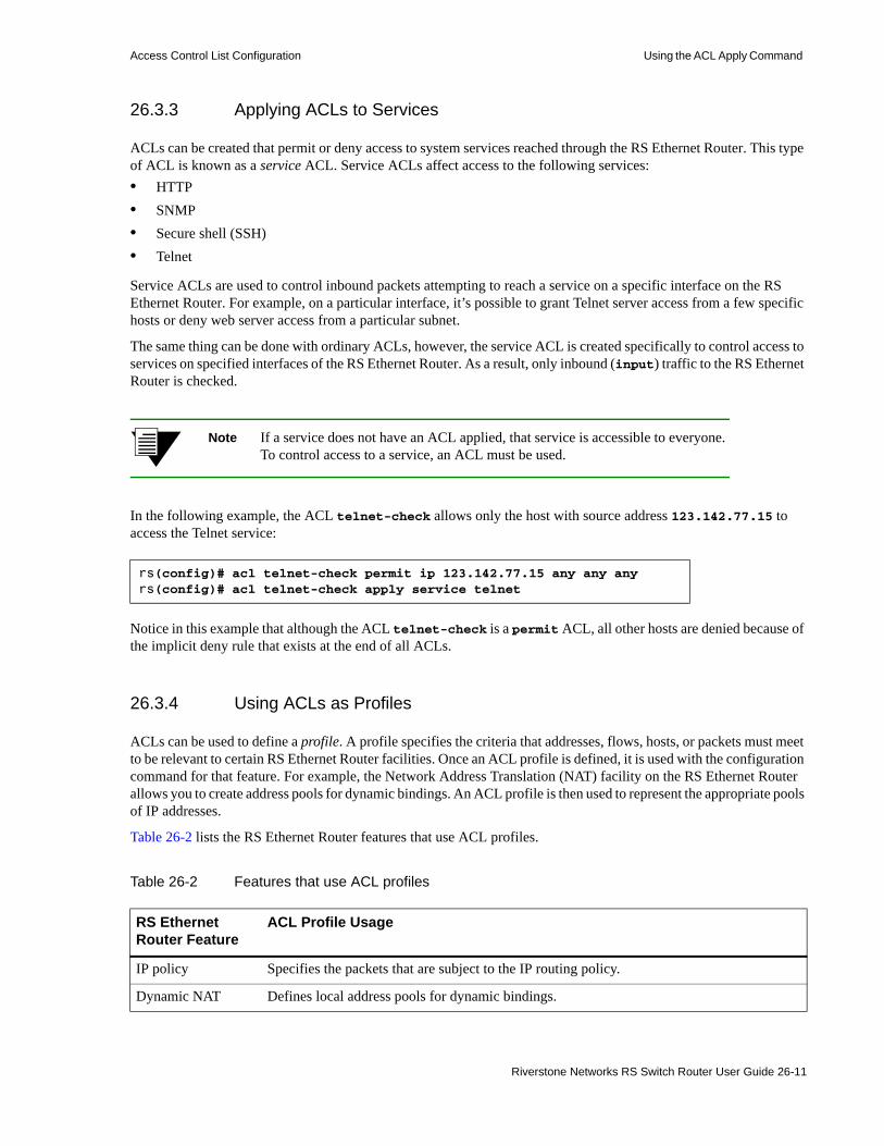
Access Control List Configuration Using the ACL Apply Command
26.3.3 Applying ACLs to Services
ACLs can be created that permit or deny access to system services reached through the RS Ethernet Router. This type of ACL is known as a service ACL. Service ACLs affect access to the following services:• HTTP• SNMP• Secure shell (SSH)• Telnet
Service ACLs are used to control inbound packets attempting to reach a service on a specific interface on the RS Ethernet Router. For example, on a particular interface, it’s possible to grant Telnet server access from a few specific hosts or deny web server access from a particular subnet.
The same thing can be done with ordinary ACLs, however, the service ACL is created specifically to control access to services on specified interfaces of the RS Ethernet Router. As a result, only inbound (input) traffic to the RS Ethernet Router is checked.
Note If a service does not have an ACL applied, that service is accessible to everyone. To control access to a service, an ACL must be used.
In the following example, the ACL telnet-check allows only the host with source address 123.142.77.15 to access the Telnet service:
Notice in this example that although the ACL telnet-check is a permit ACL, all other hosts are denied because of the implicit deny rule that exists at the end of all ACLs.
26.3.4 Using ACLs as Profiles
ACLs can be used to define a profile. A profile specifies the criteria that addresses, flows, hosts, or packets must meet to be relevant to certain RS Ethernet Router facilities. Once an ACL profile is defined, it is used with the configuration command for that feature. For example, the Network Address Translation (NAT) facility on the RS Ethernet Router allows you to create address pools for dynamic bindings. An ACL profile is then used to represent the appropriate pools of IP addresses.
Table 26-2 lists the RS Ethernet Router features that use ACL profiles.
rs(config)# acl telnet-check permit ip 123.142.77.15 any any anyrs(config)# acl telnet-check apply service telnet
Table 26-2 Features that use ACL profiles
RS Ethernet Router Feature
ACL Profile Usage
IP policy Specifies the packets that are subject to the IP routing policy.
Dynamic NAT Defines local address pools for dynamic bindings.
Riverstone Networks RS Switch Router User Guide 26-11

Using the ACL Apply Command Access Control List Configuration
26.3.4.1 Profile ACL Restrictions
Note the following about using profile ACLs:• Only IP ACLs can be used as profile ACLs. ACLs for non-IP protocols cannot be used as profile
ACLs. • The permit/deny keywords, while required in the ACL rule definition, are disregarded in the
commands for the RS Ethernet Router features. In other words, the permit and deny keywords exist within these ACLs only because an ACL definition requires that an action be specified. However, when the ACL is used as a profile ACL, the permit and deny keywords are ignored.
• Only certain ACL match criteria are relevant for each configuration command. For example, the configuration command to create NAT address pools for dynamic bindings (the nat create dynamic command) looks at only the source IP address in the specified ACL rule. The destination IP address, ports, and TOS parameters are ignored.
The following sections contain specific examples of using profile ACLs.
26.3.4.2 Using Profile ACLs with the IP Policy Facility
The IP policy facility uses a profile ACL to define criteria that determines which packets should be forwarded according to an IP policy. Packets that meet the criteria defined in the profile ACL are forwarded according to the ip-policy command that references the profile ACL.
For example, an IP policy can be defined that causes all Telnet packets travelling from source network 9.1.1.0/24 to destination network 15.1.1.0/24 to be forwarded to destination address 10.10.10.10. The profile ACL defines the match criteria (in this case, Telnet packets travelling from source network 9.1.1.0/24 to destination network 15.1.1.0/24). Then, the ip-policy command specifies what happens to packets that match the match criteria (in this example, forward them to address 10.10.10.10). The following commands are an example of profile ACLs used with the ip-policy facility.
This command creates a profile ACL called prof1 that uses as its match criteria all Telnet packets travelling from source network 9.1.1.0/24 to destination network 15.1.1.0/24:
Port mirroring Defines traffic to be mirrored.
Rate limiting Specifies the incoming traffic flow to which rate limiting is applied.
Route maps Specifies which advertised routes will be accepted by the RS Ethernet Router.
Web caching Specifies which HTTP traffic should always (or never) be redirected to the cache servers.Specifies characteristics of web objects that should not be cached.
rs(config)# acl prof1 permit ip 9.1.1.0/24 15.1.1.0/24 any any
Table 26-2 Features that use ACL profiles (Continued)
RS Ethernet Router Feature
ACL Profile Usage
26-12 Riverstone Networks RS Switch Router User Guide

Access Control List Configuration Using the ACL Apply Command
This profile ACL is then used in conjunction with the ip-policy command to cause packets matching prof1’s match criteria (that is, telnet packets travelling from 9.1.1.0/24 to 15.1.1.0/24) to be forwarded to 10.10.10.10:
See Chapter 24 "IP Policy-Based Forwarding Configuration" for more information on using the ip-policy command.
26.3.4.3 Using Profile ACLs with the Traffic Rate Limiting Facility
Traffic rate limiting is a mechanism that allows the control of bandwidth usage by incoming traffic on a per-flow basis. A flow meeting certain criteria can have its packets re-prioritized or dropped if its bandwidth usage exceeds a specified limit.
For example, packets in flows from source address 1.2.2.2 are dropped if their bandwidth usage exceeds 10 Mbps. Use a profile ACL to define the match criteria (in this case, flows from source address 1.2.2.2). Then, use the service <name> create rate-limit and service <name> apply rate-limit commands to specify what happens to packets that match the match criteria (in this example, drop them if their bandwidth usage exceeds 10 Mbps). The following commands are an example of profile ACLs used with rate limiting.
This command creates a profile ACL called prof2 that uses as its match criteria all packets originating from source address 1.2.2.2:
The following command creates a rate limit definition that causes flows matching the profile ACL’s match criteria (that is, traffic from 1.2.2.2) to be restricted to 10 Mbps for each flow. If this rate limit is exceeded, packets are dropped.
When the rate limit definition is applied to an interface (with the service <name> apply rate-limit interface command), packets in flows originating from source address 1.2.2.2 are dropped if their bandwidth usage exceeds 10 Mbps.
26.3.4.4 Using Profile ACLs with Dynamic NAT
Network Address Translation (NAT) allows for the mapping of an IP address used within one network to a different IP address used within another network. NAT is often used to map addresses used in private, local intranets to one or more addresses used in the public, global Internet.
The RS Ethernet Router supports two kinds of NAT: static NAT and dynamic NAT. With dynamic NAT, an IP address within a range of local IP addresses is mapped to an IP address within a range of global IP addresses. For example, IP addresses on network 10.1.1.0/24 can be configured to use an IP address in the range of IP addresses in network 192.50.20.0/24. A profile ACL is used to define the ranges of local IP addresses.
rs(config)# ip-policy p5 permit acl prof1 next-hop-list 10.10.10.10
rs(config)# acl prof2 permit ip 1.2.2.2
rs(config)# service client1 create rate-limit per-flow rate 10000000 exceed-action drop-packetsrs(config)# service client1 apply rate-limit acl prof2 interface int1
Riverstone Networks RS Switch Router User Guide 26-13

Using the ACL Apply Command Access Control List Configuration
The following command creates a profile ACL called local. The local profile specifies as its match criteria the range of IP addresses in network 10.1.1.0/24.
Note When a profile ACL is defined for dynamic NAT, only the source IP address field in the ACL statement is evaluated. All other fields in the ACL statement are ignored.
Once the profile ACL is defined, use the nat create dynamic command to bind the range of IP addresses defined in the local profile to a range in network 192.50.20.0/24.
See Chapter 25 "Network Address Translation Configuration" for more information on using dynamic NAT.
26.3.4.5 Using Profile ACLs with the Port Mirroring Facility
Port mirroring refers to the RS Ethernet Router’ ability to copy traffic on one or more ports to a “mirror” port, where an external analyzer or probe can be attached. In addition to mirroring traffic on one or more ports, the RS Ethernet Router can mirror traffic that matches the match criteria defined within a profile ACL.
For example, all IGMP traffic on the RS Ethernet Router can be mirrored to a particular port. Use a profile ACL to define the match criteria of “all IGMP traffic.” Then, use the port mirroring command to copy packets that match the match criteria to a specified mirror port. The following is an example of using profile ACLs with port mirroring.
This command creates a profile ACL called prof3 that uses as its match criteria all IGMP traffic on the RS Ethernet Router:
The following command causes packets matching the profile ACL’s match criteria (all IGMP traffic) to be copied to mirror port et.1.2.
See Section 29, "Performance Monitoring" for more information on using the port mirroring command.
26.3.4.6 Using Profile ACLs with the Web Caching Facility
Web caching is the RS Ethernet Router’ ability to direct HTTP requests for frequently accessed web objects to local cache servers, rather than to the Internet. Since the HTTP requests are handled locally, response time is faster than if the web objects were retrieved from the Internet.
Profile ACLs are used with web caching in two ways:• Specifying which HTTP traffic should always (or never) be redirected to the cache servers
rs(config)# acl local permit ip 10.1.1.0/24
rs(config)# nat create dynamic local-acl-pool local global-pool 192.50.20.10/24
rs(config)# acl prof3 permit igmp
rs(config)# port mirroring monitor-port et.1.2 target-acl prof3
26-14 Riverstone Networks RS Switch Router User Guide

Access Control List Configuration Using the ACL Apply Command
• Specifying characteristics of web objects that should not be cached
By default, when web caching is enabled all HTTP traffic from all hosts is redirected to the cache servers unless otherwise specified.
For example, packets with a source address of 10.10.10.10 and a destination address of 1.2.3.4 can be specified to always go to the Internet and never to the cache servers. The following commands illustrate this example.
This command creates a profile ACL called prof4 that uses as its match criteria all packets with a source address of 10.10.10.10 and a destination address of 1.2.3.4:
The following command creates a web caching policy that prevents packets matching the profile ACL’s match criteria (packets with a source address of 10.10.10.10 and a destination address of 1.2.3.4) from being redirected to a cache server. Packets that match the profile ACL’s match criteria are sent to the Internet instead.
When the web caching policy is applied to an interface (with the web-cache apply interface command), HTTP traffic with a source address of 10.10.10.10 and a destination address of 1.2.3.4 goes to the Internet instead of to the cache servers.
Profile ACLs also can be used to prevent certain web objects from being cached. For example, information in packets originating from Internet site 1.2.3.4 and destined for local host 10.10.10.10 can be restricted from the cache servers.
The following command creates a profile ACL called prof5 that uses as its match criteria all packets with a source address of 1.2.3.4 and a destination address of 10.10.10.10:
To make packets that match the profile ACL’s match criteria bypass the cache servers, use the following command:
When the web caching policy is applied to an interface, information in packets originating from source address 1.2.3.4 and destined for address 10.10.10.10 are not sent to the cache servers.
See Section 25.2, "Web Caching" for more information on using the web-cache command.
26.3.4.7 Using Profile ACLs with the Route Map Facility
Route maps allow you to create a set of match criteria that defines the conditions for importing routes from a peer and redistributing routes from any routing protocol into a routing peer. Once a route map is defined, it is used as a parameter within other routing configuration commands.
Like ACLs, the route-map command provides match criteria – one of these criteria is match-acl. The match-acl match criteria acts on a policy ACL that uses only the route-filter ACL match criteria, where route-filter specifies a particular route. Route maps (like ACLs) use a first-match policy when evaluating ACLs through the match-acl match criteria.
The following example illustrates how the route-map command uses policy ACLs to affect routes.
rs(config)# acl prof4 permit ip 10.10.10.10 1.2.3.4
rs(config)# web-cache policy1 deny hosts acl prof4
rs(config)# acl prof5 permit ip 1.2.3.4 10.10.10.10
rs(config)# web-cache policy1 create bypass-list acl prof5
Riverstone Networks RS Switch Router User Guide 26-15
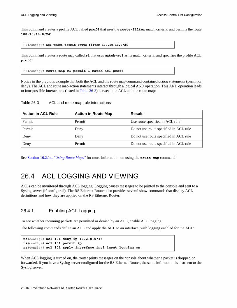
ACL Logging and Viewing Access Control List Configuration
This command creates a profile ACL called prof6 that uses the route-filter match criteria, and permits the route 100.10.10.0/24:
This command creates a route map called r1 that uses match-acl as its match criteria, and specifies the profile ACL prof6:
Notice in the previous example that both the ACL and the route map command contained action statements (permit or deny). The ACL and route map action statements interact through a logical AND operation. This AND operation leads to four possible interactions (listed in Table 26-3) between the ACL and the route map:
See Section 16.2.14, "Using Route Maps" for more information on using the route-map command.
26.4 ACL LOGGING AND VIEWINGACLs can be monitored through ACL logging. Logging causes messages to be printed to the console and sent to a Syslog server (if configured). The RS Ethernet Router also provides several show commands that display ACL definitions and how they are applied on the RS Ethernet Router.
26.4.1 Enabling ACL Logging
To see whether incoming packets are permitted or denied by an ACL, enable ACL logging.
The following commands define an ACL and apply the ACL to an interface, with logging enabled for the ACL:
When ACL logging is turned on, the router prints messages on the console about whether a packet is dropped or forwarded. If you have a Syslog server configured for the RS Ethernet Router, the same information is also sent to the Syslog server.
rs(config)# acl prof6 permit route-filter 100.10.10.0/24
rs(config)# route-map r1 permit 1 match-acl prof6
Table 26-3 ACL and route map rule interactions
Action in ACL Rule Action in Route Map Result
Permit Permit Use route specified in ACL rule
Permit Deny Do not use route specified in ACL rule
Deny Deny Do not use route specified in ACL rule
Deny Permit Do not use route specified in ACL rule
rs(config)# acl 101 deny ip 10.2.0.0/16rs(config)# acl 101 permit iprs(config)# acl 101 apply interface int1 input logging on
26-16 Riverstone Networks RS Switch Router User Guide

Access Control List Configuration ACL Logging and Viewing
26.4.1.1 Per-Rule Logging
To enable per-rule logging, enter the log parameter within each rule within the ACL for which logging is required. Next, specify the logging off option within the acl apply command. This enables logging only on the ACL rule that contain the log parameter. The following commands define an ACL with logging for only one rule. The ACL is then applied to an interface:
For the above commands, the router prints messages on the console only when packets that come from subnet 10.2.0.0/16 on interface int1 are dropped.
26.4.1.2 ACL Logging and Performance
Before enabling ACL logging, you should consider its impact on performance. With ACL logging enabled, the router prints a message at the console before the packet is actually forwarded or dropped. Even if the console is connected to the router at a high baud rate, the delay caused by the console message is still significant. This can get worse if the console is connected at a low baud rate, for example, 1200 baud. Furthermore, if a Syslog server is configured, then a Syslog packet must be sent to the Syslog server, creating additional delay. For these reasons, you should consider the potential performance impact before turning on ACL logging.
26.4.2 Viewing ACLs
The RS Ethernet Router provides a set of show commands that display the ACLs, their rules, and their association to interfaces, ports and services.
rs(config)# acl 101 deny ip 10.2.0.0/16 any any any logrs(config)# acl 101 permit ip any any any anyrs(config)# acl 101 apply interface int1 input logging off
Table 26-4 ACL show commands supported by the RS Ethernet Router
Show Command Action
acl show all Show all ACL definitions
acl show aclname <name> | all Show a specific ACL definition
acl show interface <name> Show an ACL on a specific interface
acl show interface all-ip Show ACLs on all IP interfaces
acl show port Show ACLs applied to a port
acl show service Show ACLs applied to services
Riverstone Networks RS Switch Router User Guide 26-17

ACLs Stored in Hardware Access Control List Configuration
The following is an example of the display from the acl show all command
Notice that each ACL is listed along with its match criteria arranged on lines that represent the ACL’s rules.
26.5 ACLS STORED IN HARDWAREThe primary purpose of the ACL hardware feature is to allow hardware based routing on ports on which any type of ACL rules have been applied.
The ACL CAM feature works by writing the ACL rules into specialized Content Addressable Memory (CAM), which is examined by hardware for each packet. When the hardware matches a rule it increments a per rule 32-bit counter, then performs the configured operation (permit or deny). All other packet processing happens independently, in the usual way.
rs# acl show all
ACL "121":Applied Interface(s): noneApplied Port(s): noneForward Count Source IP/Mask Dest. IP/Mask SrcPort DstPort TOS TOS-MASK Prot Flags------- ----- -------------- ------------- --------- --------- --- --------- ---- -----Permit 0 123.141.77.0 anywhere any any any None IPDeny 0 anywhere anywhere any any any any
Flags: E - Established TCP connections only.
ACL "lfap":Applied Interface(s): noneApplied Port(s): noneForward Count Source IP/Mask Dest. IP/Mask SrcPort DstPort TOS TOS-MASK Prot Flags------- ----- -------------- ------------- --------- --------- --- --------- ---- -----Permit 0 anywhere anywhere any any any None IPDeny 0 anywhere anywhere any any any any
Flags: E - Established TCP connections only.
ACL "test":Applied Interface(s): noneApplied Port(s): et.4.(2-6,10-16)Forward Count Source IP/Mask Dest. IP/Mask SrcPort DstPort TOS TOS-MASK Prot Flags------- ----- -------------- ------------- --------- --------- --- --------- ---- -----Deny 0 anywhere anywhere any any any None IPPermit 0 anywhere anywhere any any any None TCPDeny 0 anywhere anywhere any any any any
Flags: E - Established TCP connections only.
26-18 Riverstone Networks RS Switch Router User Guide

Access Control List Configuration ACLs Stored in Hardware
Note Hardware ACLs work only on inbound traffic; they cannot be applied to outbound traffic.
The ACL CAM feature works on all MPLS gigabit and MPLS POS cards. 10/100 ethernet, T1/T3, ATM, and non-MPLS POS and gigabit cards have no support for this feature.
Before the ACL CAM feature can be used, it must first be enabled on the desired ports. The command used to do this is port enable acl-cam ports <port-list>. If there are ACLs applied directly to the ports being enabled or if there are ACLs applied to interfaces which include the ports, those ACL rules are written into the CAM. Similarly, if there are ACLs applied to all interfaces (i.e. all-ip), those are also written into the CAM on every port which has an interface.
Once these ACL rules are added to the CAM, subsequent packets have these rules applied to them in hardware at wire rate. This means ACL deny rules drop packets without the packets ever going to software. Packets matching ACL permit rules still undergo the normal forwarding processing. This means that if HRT is not enabled on the port, flow lookups are done in hardware for each of the packets – those packets that do not have matching flows are sent to software for a flow entry to be installed to match subsequent packets in the flow. If HRT is enabled on the port then the packet is forwarded directly by the hardware.
It should be noted that the per-rule statistics are incremented independent of the permit/ deny decision. These statistics can be observed with the acl show-cam-stats port <port-list> acl <acl-name> command. The optional “acl” option restricts the output to a particular rule.
The output of the command is as follows:
Note that the counters record only the number of packets that match the rule. The counters are 32-bit, and can eventually wrap around. The counters can be cleared with the acl clear-cam-stats port <port-list> acl <acl-name> command. Also note that the statistics for the implicit deny that terminates every ACL set are also shown.
New ACLs applied to ACL CAM enabled ports or interfaces have their rules written into the CAM hardware on these ports. In addition, when ACL CAM enabled ports are added to VLANs on which interfaces with ACLs are applied, the ACL rules are written into the CAM hardware. Conversely, when ACLs are removed, ports are removed from VLANs or the ACL CAM is disabled on a port, and the ACL rules that are no longer valid are removed from the CAM.
rs# acl show-cam-stats port gi.4.1 acl acl1
Acl acl1 on VLAN 2 --------------------------------Forward Count Source IP/Mask Dest. IP/Mask SrcPort DstPort TOS TOS-MASK Prot Flags------- ----- -------------- ------------- --------- --------- --- --------- ---- -----Permit 0 50.10.10.1/32 anywhere any any 34 30 IPDeny 0 anywhere anywhere any any any any
Riverstone Networks RS Switch Router User Guide 26-19

ACLs Stored in Hardware Access Control List Configuration
26-20 Riverstone Networks RS Switch Router User Guide

27 SECURITY CONFIGURATION
The RS Ethernet Router provides security features that help control access to the RS Ethernet Router and filter traffic going through the RS Ethernet Router. Access to the RS Ethernet Router can be controlled by:• Enabling RADIUS• Enabling TACACS• Enabling TACACS+• Password authentication• Secure shell protocol• Port-based authentication.
Traffic filtering on the RS Ethernet Router enables:• Layer-2 security filters - Perform filtering on source or destination MAC addresses.• Layer-3/4 Access Control Lists - Perform filtering on source or destination IP address, source
or destination TCP/UDP port, TOS or protocol type for IP traffic. Perform access control to services provided on the RS Ethernet Router, for example, Telnet server and HTTP server.
Note Currently, Source Filtering is available on RS Ethernet Router WAN cards; however, application must take place on the entire WAN card.
27.1 CONFIGURING RS ETHERNET ROUTER ACCESS SECURITY
This section describes the following methods of controlling access to the RS Ethernet Router:• RADIUS• TACACS• TACACS+• Passwords• Secure shell• Port-based authentication
Riverstone Networks RS Switch Router User Guide 27-1

Configuring RS Ethernet Router Access Security Security Configuration
27.1.1 Configuring RADIUS
You can secure login or Enable mode access to the RS Ethernet Router by enabling a Remote Authentication Dial-In Service (RADIUS) client. A RADIUS server responds to the RS Ethernet Router RADIUS client to provide authentication.
You can configure as many RADIUS server targets as you have memory for on the RS Ethernet Router, essentially this is unlimited. A timeout is set to tell the RS Ethernet Router how long to wait for a response from RADIUS servers.
Note Verify parameter values before saving radius commands to the active or startup configuration file on the RS Ethernet Router. Any misconfiguration can effectively lock you out of the CLI.
To configure RADIUS security, enter the following commands in Configure mode:
Specify a RADIUS server and configure server-specific parameters.
radius set server <IP-addr> <server-options>
Set time that RADIUS server is ignored after it has failed.
radius set deadtime <minutes>
Set authentication key for RADIUS server. radius set key <string>
Determine the RS Ethernet Router action if there is no server response within a given time. a
a. If this command is not specified, the RS Ethernet Router tries the next configured authentication method (including TACACS+ configuration commands). Otherwise, if the server does not reply within the configured timeout period for the con-figured number of retries, user authentication will fail.
radius set last-resort password|succeed|deny
Set the maximum number of times the RADIUS server is contacted for authentication.
radius set retries <number>
Set the source IP address or interface for use with RADIUS server.
radius set source <ipaddr>|<interface>
Set the maximum time to wait for a RADIUS server reply.
radius set timeout <seconds>
Enable RADIUS. radius enable
Cause RADIUS authentication at user login or when user tries to access Enable mode.
radius authentication login|enable
Logs specified types of command to RADIUS server. radius accounting command level <level>
Logs to RADIUS server when shell is stopped or started on RS Ethernet Router.
radius accounting shell start|stop|all
Logs to RADIUS server SNMP changes to startup or active configuration.
radius accounting snmp active|startup
Logs specified type(s) of messages to RADIUS server. radius accounting system fatal|error|warning|info
27-2 Riverstone Networks RS Switch Router User Guide

Security Configuration Configuring RS Ethernet Router Access Security
27.1.1.1 Monitoring RADIUS
You can monitor RADIUS configuration and statistics within the RS Ethernet Router.
To monitor RADIUS, enter the following commands in Enable mode:
Show RADIUS server statistics. radius show stats
Show all RADIUS parameters. radius show all
Riverstone Networks RS Switch Router User Guide 27-3

Configuring RS Ethernet Router Access Security Security Configuration
27.1.2 Configuring RADIUS Attributes
You can configure the RADIUS server’s user database to return the Riverstone-User-Level attribute along with an Access-Accept response. The Riverstone-User-Level is a Riverstone vendor-specific attribute defined in the dictionary file provided with ROS release. 9.1 and greater. The latest revision of the dictionary file can be found at• http://www.nmops.org
and at• http://www.riverstonenet.com/support/support_docs.shtml
The RS Ethernet Router uses the value of this attribute, which is an integer from 0 to 15, to determine a user’s command mode (in single-user mode) or privilege level (in multi-user mode).
If the RADIUS server does not include a Riverstone-User-Level attribute in the Access-Accept response, the RS Ethernet Router checks the standard RADIUS Service-Type attribute and uses this attribute’s value to determine the user’s command mode or privilege level. Whenever both Riverstone-User-Level and Service-Type attributes are present in an Access-Accept response, the Riverstone-User-Level always takes precedence.
The following sections describe how these attributes are used when the RS Ethernet Router is in single-user mode and when it is in multi-user mode.
27.1.2.1 Single-User Mode
When the RS Ethernet Router is in single-user mode, users that have been authenticated are placed in Login mode, where they have to specify the enable command to move up to Enable mode. You can use the Riverstone-User-Level attribute to automatically place authenticated users in Enable mode (instead of Login mode).
To use this feature, specify the radius set direct-promotion command. This enables the RS Ethernet Router to place a user directly in Enable mode when it receives an Access-Accept packet with a Riverstone-User-Level attribute of 15 (or a Service-Type attribute of 6, administrative). If the Riverstone-User-Level or the Service-Type attribute contains any other value, the user is placed in Login mode.
27.1.2.2 Multi-User Mode
In multi-user mode, the value of the Riverstone-User-Level attribute indicates a user’s privilege level. In the absence of the Riverstone-User-Level attribute, the RS Ethernet Router checks the value of the RADIUS Service-Type attribute. If the value of this attribute is 6 (Administrative), the RS Ethernet Router treats this as if the user has level 15 privileges, providing full access to the system. Any other value will be the same as if the attribute is not there; the RS Ethernet Router places the user at access level 1.
Note For information on configuring the RS Ethernet Router for multi-user mode, refer to Section 3.7.1, "Setting Up Multi-User Access."
Note When negating configuration commands from within multi-user mode, not only do you need sufficient permission to use the negate command, but you must also have sufficient permission to run the commands you are negating
27-4 Riverstone Networks RS Switch Router User Guide
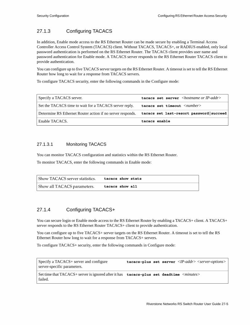
Security Configuration Configuring RS Ethernet Router Access Security
27.1.3 Configuring TACACS
In addition, Enable mode access to the RS Ethernet Router can be made secure by enabling a Terminal Access Controller Access Control System (TACACS) client. Without TACACS, TACACS+, or RADIUS enabled, only local password authentication is performed on the RS Ethernet Router. The TACACS client provides user name and password authentication for Enable mode. A TACACS server responds to the RS Ethernet Router TACACS client to provide authentication.
You can configure up to five TACACS server targets on the RS Ethernet Router. A timeout is set to tell the RS Ethernet Router how long to wait for a response from TACACS servers.
To configure TACACS security, enter the following commands in the Configure mode:
27.1.3.1 Monitoring TACACS
You can monitor TACACS configuration and statistics within the RS Ethernet Router.
To monitor TACACS, enter the following commands in Enable mode:
27.1.4 Configuring TACACS+
You can secure login or Enable mode access to the RS Ethernet Router by enabling a TACACS+ client. A TACACS+ server responds to the RS Ethernet Router TACACS+ client to provide authentication.
You can configure up to five TACACS+ server targets on the RS Ethernet Router. A timeout is set to tell the RS Ethernet Router how long to wait for a response from TACACS+ servers.
To configure TACACS+ security, enter the following commands in Configure mode:
Specify a TACACS server. tacacs set server <hostname or IP-addr>
Set the TACACS time to wait for a TACACS server reply. tacacs set timeout <number>
Determine RS Ethernet Router action if no server responds. tacacs set last-resort password|succeed
Enable TACACS. tacacs enable
Show TACACS server statistics. tacacs show stats
Show all TACACS parameters. tacacs show all
Specify a TACACS+ server and configure server-specific parameters.
tacacs-plus set server <IP-addr> <server-options>
Set time that TACACS+ server is ignored after it has failed.
tacacs-plus set deadtime <minutes>
Riverstone Networks RS Switch Router User Guide 27-5

Configuring RS Ethernet Router Access Security Security Configuration
27.1.4.1 Monitoring TACACS+
You can monitor TACACS+ configuration and statistics within the RS Ethernet Router.
To monitor TACACS+, enter the following commands in Enable mode:
27.1.5 Configuring Passwords
The RS Ethernet Router provides password authentication for accessing the User and Enable modes. If TACACS, TACACS+, or RADIUS is not enabled on the RS Ethernet Router, only local password authentication is performed.
Set authentication key for TACACS+ server. tacacs-plus set key <string>
Determine the RS Ethernet Router action if there is no server response within a given time. a
tacacs-plus set last-resort password|succeed|deny
Set the maximum number of times the TACACS+ server is contacted for authentication.
tacacs-plus set retries <number>
Set the source IP address or interface for use with TACACS+ server.
tacacs-plus set source <ipaddr>|<interface>
Set the maximum time to wait for a TACACS+ server reply.
tacacs-plus set timeout <seconds>
Enable TACACS+. tacacs-plus enable
Cause TACACS+ authentication at user login or when user tries to access Enable mode.
tacacs-plus authentication login|enable
Logs specified types of command to TACACS+ server.
tacacs-plus accounting command level <level>
Logs to TACACS+ server when shell is stopped or started on RS Ethernet Router.
tacacs-plus accounting shell start|stop|all
Logs to TACACS+ server SNMP changes to startup or active configuration.
tacacs-plus accounting snmp active|startup
Logs specified type(s) of messages to TACACS+ server.
tacacs-plus accounting system fatal|error|warning|info
a. If this command is not specified, the RS Ethernet Router tries the next configured authentication method (including RADIUS con-figuration commands). Otherwise, if the server does not reply within the configured timeout period for the configured number of retries, user authentication will fail.
Show TACACS+ server statistics. tacacs-plus show stats
Show all TACACS+ parameters. tacacs-plus show all
27-6 Riverstone Networks RS Switch Router User Guide
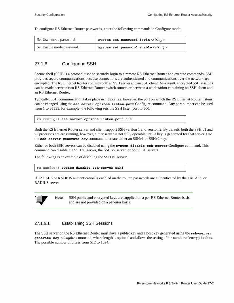
Security Configuration Configuring RS Ethernet Router Access Security
To configure RS Ethernet Router passwords, enter the following commands in Configure mode:
27.1.6 Configuring SSH
Secure shell (SSH) is a protocol used to securely login to a remote RS Ethernet Router and execute commands. SSH provides secure communications because connections are authenticated and communications over the network are encrypted. The RS Ethernet Router contains both an SSH server and an SSH client. As a result, encrypted SSH sessions can be made between two RS Ethernet Router switch routers or between a workstation containing an SSH client and an RS Ethernet Router.
Typically, SSH communication takes place using port 22, however, the port on which the RS Ethernet Router listens can be changed using the ssh server options listen-port Configure command. Any port number can be used from 1 to 65535. for example, the following sets the SSH listen port to 500:
Both the RS Ethernet Router server and client support SSH version 1 and version 2. By default, both the SSH v1 and v2 processes are are running, however, either server is not fully operable until a key is generated for that server. Use the ssh-server generate-key command to create either an SSHv1 or SSHv2 key.
Either or both SSH servers can be disabled using the system disable ssh-server Configure command. This command can disable the SSH v1 server, the SSH v2 server, or both SSH servers.
The following is an example of disabling the SSH v1 server:
If TACACS or RADIUS authentication is enabled on the router, passwords are authenticated by the TACACS or RADIUS server
Note SSH public and encrypted keys are supplied on a per-RS Ethernet Router basis, and are not provided on a per-user basis.
27.1.6.1 Establishing SSH Sessions
The SSH server on the RS Ethernet Router must have a public key and a host key generated using the ssh-server generate-key <length> command, where length is optional and allows the setting of the number of encryption bits. The possible number of bits is from 512 to 1024.
Set User mode password. system set password login <string>
Set Enable mode password. system set password enable <string>
rs(config)# ssh server options listen-port 500
rs(config)# system disable ssh-server ssh1
Riverstone Networks RS Switch Router User Guide 27-7
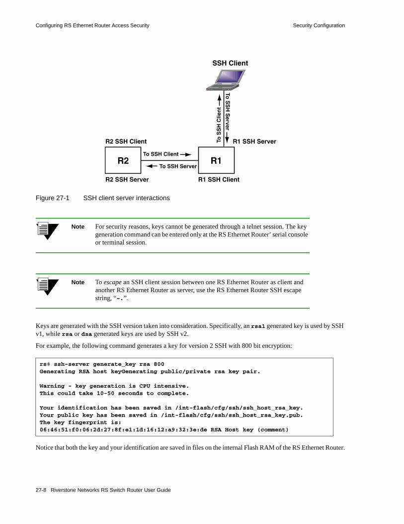
Configuring RS Ethernet Router Access Security Security Configuration
Figure 27-1 SSH client server interactions
Note For security reasons, keys cannot be generated through a telnet session. The key generation command can be entered only at the RS Ethernet Router’ serial console or terminal session.
Note To escape an SSH client session between one RS Ethernet Router as client and another RS Ethernet Router as server, use the RS Ethernet Router SSH escape string, “~.”.
Keys are generated with the SSH version taken into consideration. Specifically, an rsa1 generated key is used by SSH v1, while rsa or dsa generated keys are used by SSH v2.
For example, the following command generates a key for version 2 SSH with 800 bit encryption:
Notice that both the key and your identification are saved in files on the internal Flash RAM of the RS Ethernet Router.
rs# ssh-server generate_key rsa 800Generating RSA host keyGenerating public/private rsa key pair.
Warning - key generation is CPU intensive.This could take 10-50 seconds to complete.
Your identification has been saved in /int-flash/cfg/ssh/ssh_host_rsa_key.Your public key has been saved in /int-flash/cfg/ssh/ssh_host_rsa_key.pub.The key fingerprint is:06:46:51:f0:06:2d:27:8f:e1:1d:16:12:a9:32:3e:de RSA Host key (comment)
R1R2
SSH Client
R1 SSH Server
To SSH Server
To SSH Client
To S
SH
Server
R2 SSH Server
R2 SSH Client
R1 SSH Client
To S
SH
Clie
nt
27-8 Riverstone Networks RS Switch Router User Guide

Security Configuration Configuring RS Ethernet Router Access Security
To access a remote RS Ethernet Router through SSH, use the slogin command from within in Enable mode. The slogin command is much like telnet in that it requires either the hostname or IP address of the remote RS Ethernet Router. Alternately, access to the RS Ethernet Router can be obtained using a username. The default username is root.
For example, using SSH, RS Ethernet Router following command to log into the remote RS Ethernet Router “r1,” from RS Ethernet Router “r2,” using the username “login:”
The SSH server on r1 responds with its public host and server keys. The client on r2 checks the received host key to make sure that the key has not changed since the last SSH session between r1 and r2. If the host key is different from the host key used in previous SSH sessions with r1’s server, the following message appears on r2’s console:
Notice that you are asked if you want to continue to connect to r1’s server. This is a precaution to ensure that the SSH client is connecting to the intended device. To continue the server connection, answer “yes,” r2 then encrypts a random number using both the public host and server keys and sends the encrypted number to r1’s SSH server. Both the SSH server and client use this random number as a key to encrypt communications as the session continues.
You can use CLI commands in the SSH session as you normally would through a console or telnet connection. Furthermore, from this SSH session, you can use the slogin command to access other SSH servers on other remote RS Ethernet Router switch routers.
To end an SSH session, simply type exit.
Note If a new key is generated while there are active SSH sessions on the RS Ethernet Router, those sessions are not severed. This occurs because the keys are used only for initial connection of an SSH session.
r2# slogin login@r1
r2# slogin login@r1
SSH_ERROR: @@@@@@@@@@@@@@@@@@@@@@@@@@@@@@@@@@@@@@@@@@@@@@@@@@@@@@@@@@@SSH_ERROR: @ WARNING: REMOTE HOST IDENTIFICATION HAS CHANGED! @SSH_ERROR: @@@@@@@@@@@@@@@@@@@@@@@@@@@@@@@@@@@@@@@@@@@@@@@@@@@@@@@@@@@SSH_ERROR: IT IS POSSIBLE THAT SOMEONE IS DOING SOMETHING NASTY!SSH_ERROR: Someone could be eavesdropping on you right now (man-in-the-middle attack)!
SSH_ERROR: It is also possible that the RSA host key has just been changed.
Do you want to replace the existing key and continue (yes/no)?
Riverstone Networks RS Switch Router User Guide 27-9
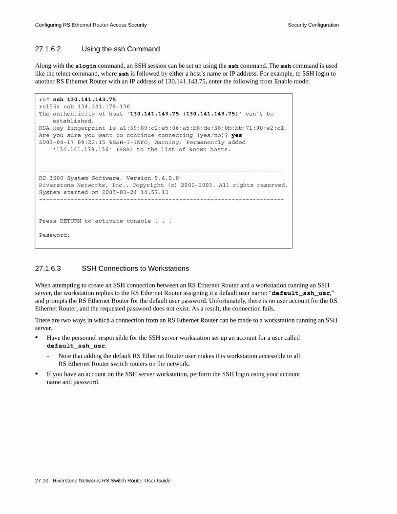
Configuring RS Ethernet Router Access Security Security Configuration
27.1.6.2 Using the ssh Command
Along with the slogin command, an SSH session can be set up using the ssh command. The ssh command is used like the telnet command, where ssh is followed by either a host’s name or IP address. For example, to SSH login to another RS Ethernet Router with an IP address of 130.141.143.75, enter the following from Enable mode:
27.1.6.3 SSH Connections to Workstations
When attempting to create an SSH connection between an RS Ethernet Router and a workstation running an SSH server, the workstation replies to the RS Ethernet Router assigning it a default user name: “default_ssh_usr,” and prompts the RS Ethernet Router for the default user password. Unfortunately, there is no user account for the RS Ethernet Router, and the requested password does not exist. As a result, the connection fails.
There are two ways in which a connection from an RS Ethernet Router can be made to a workstation running an SSH server.• Have the personnel responsible for the SSH server workstation set up an account for a user called
default_ssh_usr. - Note that adding the default RS Ethernet Router user makes this workstation accessible to all
RS Ethernet Router switch routers on the network.• If you have an account on the SSH server workstation, perform the SSH login using your account
name and password.
rs# ssh 130.141.143.75rs156# ssh 134.141.179.136The authenticity of host '130.141.143.75 (130.141.143.75)' can't be
established.RSA key fingerprint is a1:39:89:c2:e5:06:a5:b8:de:38:0b:bb:71:90:e2:c1.Are you sure you want to continue connecting (yes/no)? yes2003-04-17 09:22:15 %SSH-I-INFO, Warning: Permanently added
'134.141.179.136' (RSA) to the list of known hosts.
----------------------------------------------------------------------RS 3000 System Software, Version 9.4.0.0Riverstone Networks, Inc., Copyright (c) 2000-2003. All rights reserved.System started on 2003-03-24 14:57:13----------------------------------------------------------------------
Press RETURN to activate console . . .
Password:
27-10 Riverstone Networks RS Switch Router User Guide

Security Configuration Configuring RS Ethernet Router Access Security
- For example, if user John Smith has an account (jsmith) on the SSH server workstation, he would log in by doing the following:
27.1.6.4 Monitoring SSH Sessions
The RS Ethernet Router allows up to 12 simultaneous Telnet or SSH sessions. There are commands that allow you to monitor SSH use on the RS Ethernet Router and to end a specific SSH session. You can also specify the number of minutes an SSH connection can remain idle before the connection is terminated by the control module. The default is 5 minutes. You can disable this feature, by setting the time-out value to zero.
Note If security is a major matter of concern on your network, it is recommended that you disable telnet and perform all command interactions with the RS Ethernet Router through either the serial console port or through SSH.
To disable telnet enter the following into the RS Ethernet Router’ active and startup configuration files: system disable telnet-server.
rs# ssh [email protected] authenticity of host '130.141.143.75 (130.141.143.75)' can't be established.RSA key fingerprint is 43:fa:26:54:73:a3:bc:30:77:da:b9:d4:4e:73:0f:10.Are you sure you want to continue connecting (yes/no)? yes2003-04-17 10:55:25 %SSH-I-INFO, Warning: Permanently added '130.141.143.75' (RSA) to
the list of known [email protected]'s password:******Last login: Wed Apr 16 10:27:28 2003 from 100.141.17.156Sun Microsystems Inc. SunOS 5.5.1 Generic May 1996Sun Microsystems Inc. SunOS 5.5.1 Generic May 1996ssh-server%
Display the last five SSH connections to the RS Ethernet Router.
system show ssh-access
Specify the time-out value for SSH connections. system set idle-time-out ssh <num>
Show current Telnet and SSH users and session IDs. system show users
End the specified SSH session. system kill ssh-session <session-id>
Riverstone Networks RS Switch Router User Guide 27-11

Port-Based Authentication Security Configuration
27.2 PORT-BASED AUTHENTICATIONLocal area networks (LANs) are often deployed in environments where unauthorized devices or clients may attempt to access the LAN. To prevent unauthorized access to the network, you can configure the RS Ethernet Router to use port-based authentication. The RS Ethernet Router supports the IEEE 802.1x standard for authenticating devices connected to a LAN port. It prevents unauthorized users from accessing a network and its services.
The 802.1x standard can be used only when the client at the other end of the LAN also supports 802.1x. If the client does not support 802.1x, you can configure an authorization filter and apply it to a port. The RS Ethernet Router will then use the filter to authenticate the 802.1x-unaware client on that port. This section describes both types of port-based authentication.
27.2.1 Port-Based Network Access Control on the RS Ethernet Router (802.1x)
The IEEE 802.1x standard defines a protocol for authenticating and authorizing devices attached to a LAN port. This section provides an overview of that protocol and how it is implemented on the RS Ethernet Router.
27.2.1.1 802.1x Overview
The IEEE 802.1x standard defines 3 entities: • the supplicant or client, at one end of a point-to-point LAN segment, is the device being
authenticated before it can access the services offered by the authenticator • the authenticator, at the other end of the LAN segment, authenticates clients attached to its ports
before allowing them to access the available services• the authentication server, which provides the authentication service, determines whether the client
is allowed to access the services provided by the authenticator.
You can configure the RS Ethernet Router to function as the authenticator. The RS Ethernet Router communicates with the client and with the authentication server, facilitating the exchange of information during the authentication process. The protocol between the RS Ethernet Router and the client is the Extensible Authentication Protocol (EAP). The RS Ethernet Router supports RADIUS with EAP extensions as the authentication server. The RADIUS client on the RS Ethernet Router interacts with the RADIUS authentication server.
Authenticating a Client
By default, the RS Ethernet Router ports transmit and receive traffic without authenticating the attached devices. When you enable 802.1x on an RS Ethernet Router port, the port transitions to an unauthorized state, where it allows only EAP frames. Normal traffic is not allowed through a port that is in an unauthorized state. A port remains in this state until authentication is successfully completed.
Both the client and the RS Ethernet Router can initiate authentication. Authentication begins when the RS Ethernet Router port transitions from down to up or when the client sends an authentication request. During authentication, the RS Ethernet Router transmits the EAP frames between the client and the authentication server. The authentication server is transparent to the client. The client may be authenticated based on the user name and password, or the user name, password and MAC address, depending on the RADIUS server setting.
If authentication succeeds, the port transitions to an authorized state and allows normal traffic to be transmitted and received. After the port is authorized, the port can receive packets only from the authenticated client. If a packet’s source address does not match the authenticated address, the port drops the packet.
If authentication fails or if the RS Ethernet Router is unable to contact the authentication server, the port remains in the unauthorized state. Additionally, the port transitions back to the unauthorized state when its link state goes down.
27-12 Riverstone Networks RS Switch Router User Guide

Security Configuration Port-Based Authentication
27.2.1.2 Configuring the RS Ethernet Router for 802.1x Authentication
Following are the tasks required to configure the RS Ethernet Router to use 802.1x authentication:• Configure 802.1x parameters for the RADIUS server.• Enable 802.1x on the RS Ethernet Router ports.
The following sections describe these tasks in detail.
27.2.1.3 Setting 802.1x Parameters for the RADIUS Server
Use the dot1x add server command to specify the RADIUS server(s) that will be used for 802.1x authentication. The dot1x add server command has a usage parameter which specifies whether a RADIUS server will be used for authentication, for accounting, or for both. The authentication server is used to authenticate the client, while the accounting server logs each time a port is authorized or unauthorized.
In addition, the RS Ethernet Router has default parameters it uses when it communicates with the RADIUS authentication server. You can change these defaults with the dot1x set server command. Following are the values that can be configured:• Deadtime, which is the number of minutes the RS Ethernet Router ignores the RADIUS server after
it has failed. The default is 0.• Authentication key the RS Ethernet Router shares with the server.• Number of times the RS Ethernet Router attempts to contact the RADIUS server. The default is 3
times.• Source IP address or interface name used when contacting the RADIUS server. The default is the IP
address of the interface that is used to communicate with the RADIUS server.• Timeout, which is the number of seconds the RS Ethernet Router waits for a response from the
RADIUS server. The default is 3 seconds.• Port numbers used for authentication and/or accounting. The default port for authentication is port
1812, and the default for accounting is port 1813.
Riverstone Networks RS Switch Router User Guide 27-13

Port-Based Authentication Security Configuration
The following example defines one RADIUS server for both authentication and accounting, and sets its authentication key:
Use the dot1x show server command to display the 802.1x-related parameters that affect the RS Ethernet Router’s communication with the authentication server, as shown in the following example.
In addition to displaying the configurable 802.1x parameters, the output also displays the number of client authentication requests that were authorized and that were rejected, the number of challenges, and the number of requests that timed out.
27.2.1.4 Enabling 802.1x on the RS Ethernet Router port(s)
By default, 802.1x authentication is not enabled on the RS Ethernet Router. Specify the following commands to enable 802.1x on the RS Ethernet Router ports:• dot1x enable to enable this feature on the desired port(s) • dot1x set port to set the port’s authorization state to use 802.1x authentication, as described in
the following section
Setting a Port’s Authorization State
You can manually set a port’s authorization state by using the port-control parameter of the dot1x set port command. This parameter has three options:• auto - the port uses 802.1x to authenticate a client before allowing normal traffic. Specify this
option to use 802.1x authentication.• force-unauth - the port is forced to transition to the unauthorized state. The port remains in an
unauthorized state until it is manually reset. When you specify this keyword, authentication is not possible because the port ignores all attempts from the client to be authenticated.
While in this state, packets are blocked in or out of the port depending on what was configured in the admin-control-direction parameter.
rs (config)# dot1x add server 10.10.10.1 usage bothrs (config)# dot1x set server 10.10.10.1 key riverstone
rs# dot1x show server
RADIUS servers listed in order of priority:
Server: 10.10.10.1Usage: authentication accountingAuthentication Port: 1812Accounting Port: 1813key: riverstoneTimeout (seconds): 5Retries: 3 <Default>Deadtime (minutes): -1 <Default>Source IP: <Default>
RADIUS server statistics:
Host Accepts Rejects Challenges Timeouts10.10.10.1 0 0 0 0
27-14 Riverstone Networks RS Switch Router User Guide

Security Configuration Port-Based Authentication
• force-auth - the port allows access without authentication, effectively disabling 802.1x authentication. This is the default.
The following example enables 802.1x authentication on port et.2.1:
27.2.1.5 Client Authentication Through Access-ports and Trunk-ports
The following describes how clients authenticate with the server through access-ports and trunk-ports.1. By default, the first client to authenticate on an access-port is the only client allowed on that port.
However, this situation exists only as long as that client keeps authenticating. If the client stops authenticating, another client can authenticate on that access-port.
2. By using the dot1x set <port> do-not-verify-source command, when the first client authenticates, the access-port is opened for all clients connected to that port.
3. Use the dot1x enable port-list <ports> multiple-instances command on a trunk-port to allow clients within different VLANs to authenticate.
4. The client authentication behavior of clients within VLANs is the same as the client authentication behavior for an access-port, as described in 1 and 2.
- By default, the first client to authenticate on a VLAN is the only client on that VLAN that can authenticate.
- By using the dot1x set <port> do-not-verify-source command on the trunk-port, the first client to authenticate opens the VLAN for all clients on that VLAN.
27.2.1.6 Setting a Port’s 802.1x Timers
Once 802.1x has been enabled on a port, it uses the following operational timers which you can configure with the dot1x set port command:• Maximum number of reauthentication attempts before the port becomes unauthorized. The default
is 2.• Maximum number of authentication requests that can be sent before the authentication session
expires. The default is 2.• Number of seconds between an authentication attempt failed and is tried again. The default is 60
seconds.• Time period between the retransmission of authentication requests to the client. The default is 30
seconds.• Timeout period for the authentication server. The default is 30 seconds.• Timeout period for the client. The default is 30 seconds.
rs (config)# dot1x set port et.2.1 port-control auto rs (config)# dot1x enable port-list et.2.1
Riverstone Networks RS Switch Router User Guide 27-15

Port-Based Authentication Security Configuration
Once you have configured a port’s 802.1x parameters, use the dot1x show parm command to verify the configuration as shown in the following example.
27.2.1.7 Reauthenticating a Port
After a client has been authenticated on a port, you can set the RS Ethernet Router to reauthenticate the client periodically. You can also manually reauthenticate a client at any time. To set periodic reauthentication, specify the reauth-enable parameter of the dot1x set port command and use the reauth-period parameter to specify the reauthentication interval. (The default reauthentication interval is 3600 seconds.) The following example enables periodic reauthentication on port et.2.1 and sets the interval to 4200 seconds:
To manually reauthenticate a port, use the dot1x reauthenticate command as shown in the following example:
If a port was authorized before the dot1x reauthenticate port command was issued, the port remains authorized until reauthentication fails.
27.2.1.8 Reinitializing a Port
If you change previously configured 802.1x parameters, you must reinitialize ports on which 802.1x is enabled so they can use the updated 802.1x parameters. The following example reinitializes port et.2.1:
rs# dot1x show parm all-ports
802.1X parameters ---Parameters for port et.2.1: Port 802.1X Enabled = TRUE Multiple 802.1X instances = FALSE 802.1X protocol aware = TRUE Reauthentication Enabled = FALSE Port Control = Force Authorized Control Direction = Both Transmit period = 30 sec Quiet period = 60 sec Supplicant Timeout = 30 sec Server Timeout = 30 sec Reauthentication period = 3600 sec Max Req sent = 2 Max Reauthenticate sent = 2
rs (config)# dot1x set port et.2.1 reauth-enable reauth-period 4200
rs # dot1x reauthenticate port-list et.2.1
rs # dot1x initialize port-list et.2.1
27-16 Riverstone Networks RS Switch Router User Guide

Security Configuration Port-Based Authentication
Note If you don’t reinitialize the 802.1x ports after revising the 802.1x parameters, the ports will continue to use the old parameters. To enable the ports to use the updated parameters, use the dot1x initialize command.
27.2.1.9 802.1x Configuration Example
In the following example, RS1 is the authenticator. When the end station (an 802.1x-aware device) requests authentication, the RS Ethernet Router communicates with the RADIUS server, which in turn, authenticates the end station.
Figure 27-2 Authenticating an 802.1x-aware client
Following is the configuration for RS1:
Use the dot1x show statistics command to display statistics on Extensible Authentication Protocol over LAN (EAPOL) frames exchanged with the clients.
! Define the RADIUS server to be used for 802.1x authenticationrs (config)# dot1x set server 10.10.10.1 key riverstoners (config)# dot1x add server 10.10.10.1 usage both
!Enable 802.1x authentication on the RS Ethernet Routerrs (config)# dot1x set port et.2.1. port-control autors (config)# dot1x enable port-list et.2.1
rs# dot1x show statistics all-ports802.1X statistics ---Statistics for port et.2.1 vlan -1: Total Frames Received = 0 Total Frames Transmitted = 1 Resp/Id Received = 0 Req/Id Transmitted = 0 Other Resp Received = 0 Other Req Transmitted = 0 Start Received = 0 Logoff Received = 0 Invalid Received = 0 Length Err Received = 0 Latest Version Received = 0 Latest Source Received = 000000:000000rs#
RS1RADIUSserverEnd
Station
Riverstone Networks RS Switch Router User Guide 27-17

Port-Based Authentication Security Configuration
Use the dot1x show status command to display the authentication status of the port.
rs# dot1x show status all-ports802.1X status ---Status for port et.2.1: Port Authorized Port enabled = TRUE Link state = DOWN vlan = -1 Port Status = Authorized authenticator state = Force_auth backend state = Idle
27-18 Riverstone Networks RS Switch Router User Guide

Security Configuration Port-Based Authentication
27.2.1.10 Applying 802.1x Authentication to VLANs
By default, an 802.1x-enabled port authenticates only one client. This works well with access ports that belong to only one VLAN. Trunk ports, though, transmit traffic for multiple VLANs which may represent different clients. Therefore, trunk ports may have to authenticate multiple clients. To configure a port to authenticate multiple clients, specify the multiple-instances parameter of the dot1x enable command.
For example, in Figure 27-2, if port et.2.1 on RS1 was a trunk port, its configuration would be as follows:
27.2.1.11 Reauthenticating a Trunk Port
When you manually reauthenticate a trunk port, you can limit authentication to a specific VLAN or you can specify all VLANs. The following example reauthenticates VLAN BLUE (with VID 21) on port et.2.1:
27.2.2 Authenticating 802.1x-Unaware Devices
When an RS Ethernet Router port is connected to a device that does not support 802.1x, the port can authenticate the client by using an authorization filter. When the RS Ethernet Router receives a packet on a port to which an authorization filter is applied, the port uses the source address (SA) of the packet to query the authentication filter. If the SA matches an address that is on the filter, then the RS Ethernet Router accepts the packet. If the SA does not have a match, then the RS Ethernet Router drops the packet. Additionally, if the client sends out packets with different source addresses, only the first SA is authenticated, even if both addresses are in the filter.
To enable the RS Ethernet Router to authenticate 802.1x-unaware clients:• Configure an authorization filter.• Enable 802.1x on the ports to which the client is connected.
The following sections describe each of these tasks.
!Configure the trunk portrs (config)# vlan make trunk-port et.2.1
!Create the VLANs and add the trunk portrs (config)# vlan create red iprs (config)# vlan create blue iprs (config)# vlan create white iprs (config)# vlan add ports et.2.1 to redrs (config)# vlan add ports et.2.1 to bluers (config)# vlan add ports et.2.1 to white
! Define the RADIUS server to be used for 802.1x authenticationrs (config)# dot1x set server 10.10.10.1 key riverstoners (config)# dot1x add server 10.10.10.1 usage both
!Enable 802.1x authentication on the RS Ethernet Routerrs (config)# dot1x set port et.2.1. port-control autors (config)# dot1x enable port-list et.2.1 multiple-instances
rs # dot1x reauthenticate port-list et.2.1 vlan 21
Riverstone Networks RS Switch Router User Guide 27-19

Port-Based Authentication Security Configuration
27.2.2.1 Configuring an Authorization Filter
An authorization filter contains a list of end-station MAC addresses that are authorized. Only the MAC addresses specified in the filter are authenticated. Frames with source MAC addresses that are not specified in the filter are dropped. When you configure a filter, specify the following:• Name of the authorization filter• MAC address of the end-station to be authenticated• Input ports that the frames with the specified source addresses can use• Optionally, a mask to be applied against the source MAC
Following is an example of an authorization filter:
27.2.2.2 Enabling 802.1x on RS Ethernet Router Ports
The commands for enabling 802.1x on ports connected to 802.1x-unaware clients are much the same as those used for ports connected to 802.1x-aware clients. The only difference is that when you specify the dot1x set port command, use the dot1x-protocol parameter to specify that the client on the other end does not support 802.1x, as shown in the following example:
27.2.2.3 802.1x-Unaware Configuration Example
In the following example, the RS Ethernet Router is connected to an 802.1x-unaware device. In this situation, the RS Ethernet Router does not use the RADIUS server for authentication. Instead, it uses a previously configured authorization filter. If the end station’s MAC address is not in the filter, then that end station’s packets are denied.
Figure 27-3 Authenticating an 802.1x-unaware client
rs (config)# filters add authorization-filter name filter 100 source-mac 000000:0000a0
in-port-list et.3.2
rs (config)# dot1x set port et.2.1. port-control auto dot1x-protocol unawarers (config)# dot1x enable port-list et.2.1
RS1EndStation
27-20 Riverstone Networks RS Switch Router User Guide

Security Configuration Port-Based Authentication
The following example is the configuration for RS1:
Use the filters show authorization-filter command to display the authorization filter, as shown in the following example.
! Configure the authorization filterrs (config)# filters add authorization-filter name filter_100 source-mac 000000:0000a0 in-port-list et.3.2
!Enable 802.1x authentication on the RS Ethernet Routerrs (config)# dot1x set port et.3.2 port-control auto dot1x-protocol unawarers (config)# dot1x enable port-list et.3.2
rs# filters show authorization-filter all-source
Name: filter_100----VLAN: any VLANSource MAC: 000000:0000A0Dest MAC: 000000:000000In-List ports: et.3.2
Riverstone Networks RS Switch Router User Guide 27-21
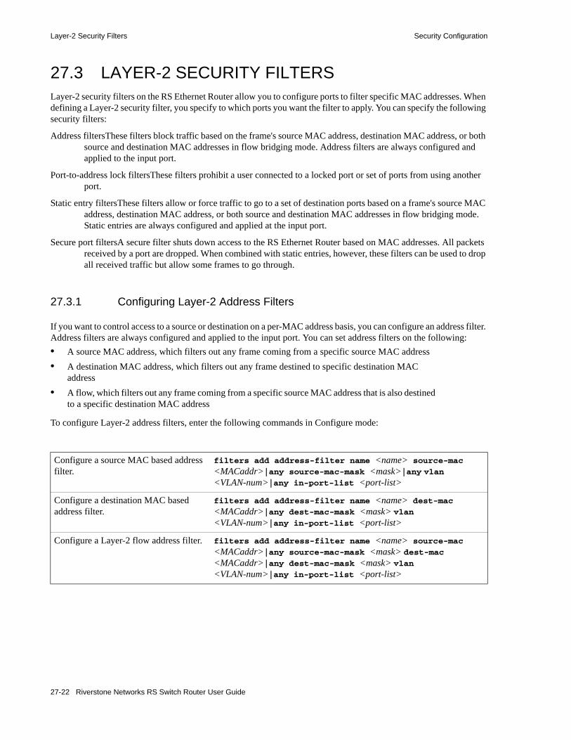
Layer-2 Security Filters Security Configuration
27.3 LAYER-2 SECURITY FILTERSLayer-2 security filters on the RS Ethernet Router allow you to configure ports to filter specific MAC addresses. When defining a Layer-2 security filter, you specify to which ports you want the filter to apply. You can specify the following security filters:
Address filtersThese filters block traffic based on the frame's source MAC address, destination MAC address, or both source and destination MAC addresses in flow bridging mode. Address filters are always configured and applied to the input port.
Port-to-address lock filtersThese filters prohibit a user connected to a locked port or set of ports from using another port.
Static entry filtersThese filters allow or force traffic to go to a set of destination ports based on a frame's source MAC address, destination MAC address, or both source and destination MAC addresses in flow bridging mode. Static entries are always configured and applied at the input port.
Secure port filtersA secure filter shuts down access to the RS Ethernet Router based on MAC addresses. All packets received by a port are dropped. When combined with static entries, however, these filters can be used to drop all received traffic but allow some frames to go through.
27.3.1 Configuring Layer-2 Address Filters
If you want to control access to a source or destination on a per-MAC address basis, you can configure an address filter. Address filters are always configured and applied to the input port. You can set address filters on the following:• A source MAC address, which filters out any frame coming from a specific source MAC address• A destination MAC address, which filters out any frame destined to specific destination MAC
address• A flow, which filters out any frame coming from a specific source MAC address that is also destined
to a specific destination MAC address
To configure Layer-2 address filters, enter the following commands in Configure mode:
Configure a source MAC based address filter.
filters add address-filter name <name> source-mac <MACaddr>|any source-mac-mask <mask>|any vlan <VLAN-num>|any in-port-list <port-list>
Configure a destination MAC based address filter.
filters add address-filter name <name> dest-mac <MACaddr>|any dest-mac-mask <mask> vlan <VLAN-num>|any in-port-list <port-list>
Configure a Layer-2 flow address filter. filters add address-filter name <name> source-mac <MACaddr>|any source-mac-mask <mask> dest-mac <MACaddr>|any dest-mac-mask <mask> vlan <VLAN-num>|any in-port-list <port-list>
27-22 Riverstone Networks RS Switch Router User Guide

Security Configuration Layer-2 Security Filters
27.3.2 Configuring Layer-2 Port-to-Address Lock Filters
Port address lock filters allow you to bind or “lock” specific source MAC addresses to a port or set of ports. Once a port is locked, only the specified source MAC address is allowed to connect to the locked port and the specified source MAC address is not allowed to connect to any other ports.
To configure Layer-2 port address lock filters, enter the following commands in Configure mode:
27.3.3 Configuring Layer-2 Static Entry Filters
Static entry filters allow or force traffic to go to a set of destination ports based on a frame's source MAC address, destination MAC address, or both source and destination MAC addresses in flow bridging mode. Static entries are always configured and applied at the input port. You can set the following static entry filters:• Source static entry, which specifies that any frame coming from source MAC address will be
allowed or disallowed• Destination static entry, which specifies that any frame destined to a specific destination MAC
address will be allowed, disallowed, or forced to go to a set of ports• Flow static entry, which specifies that any frame coming from a specific source MAC address that
is destined to specific destination MAC address will be allowed, disallowed, or forced to go to a set of ports
To configure Layer-2 static entry filters, enter the following commands in Configure mode:
27.3.4 Configuring Layer-2 Secure Port Filters
Secure port filters block access to a specified port. You can use a secure port filter by itself to secure unused ports. Secure port filters can be configured as source or destination port filters. A secure port filter applied to a source port forces all incoming packets to be dropped on a port. A secure port filter applied to a destination port prevents packets from going out a certain port.
You can combine secure port filters with static entries in the following ways:
Configure a port address lock filter. filters add port-address-lock name <name> source-mac <MACaddr> vlan <VLAN-num> in-port-list <port-list>
Configure a source static entry filter.
filters add static-entry name <name> restriction allow|disallow source-mac <MACaddr>|any source-mac-mask <mask> vlan <VLAN-num>|any in-port-list <port-list> out-port-list <port-list>
Configure a destination static entry filter.
filters add static-entry name <name> restriction allow|disallow|force dest-mac <MACaddr> dest-mac-mask <mask>|any vlan <VLAN-num>|any in-port-list <port-list> out-port-list <port-list>
Riverstone Networks RS Switch Router User Guide 27-23

Layer-2 Security Filters Security Configuration
• Combine a source secure port filter with a source static entry to drop all received traffic but allow any frame coming from specific source MAC address to go through.
• Combine a source secure port filter with a flow static entry to drop all received traffic but allow any frame coming from a specific source MAC address that is destined to specific destination MAC address to go through.
• Combine a destination secure port with a destination static entry to drop all received traffic but allow any frame destined to specific destination MAC address go through.
• Combine a destination secure port filter with a flow static entry to drop all received traffic but allow any frame coming from specific source MAC address that is destined to specific destination MAC address to go through.
To configure Layer-2 secure port filters, enter the following commands in Configure mode:
27.3.5 Monitoring Layer-2 Security Filters
The RS Ethernet Router provides display of Layer-2 security filter configurations contained in the routing table.
To display security filter information, enter the following commands in Enable mode.
Configure a source secure port filter. filters add secure-port name <name> direction source vlan <VLAN-num> in-port-list <port-list>
Configure a destination secure port filter.
filters add secure-port name <name> direction destination vlan <VLAN-num> in-port-list <port-list>
Show address filters. filters show address-filter
[all-source|all-destination|all-flow] [source-mac <MACaddr> dest-mac <MACaddr>] [ports <port-list>] [vlan <VLAN-num>]
Show port address lock filters.
filters show port-address-lock ports [ports <port-list>] [vlan <VLAN-num>] [source-mac <MACaddr>]
Show secure port filters. filters show secure-port
Show static entry filters. filters show static-entry
[all-source|all-destination|all-flow] ports <port-list> vlan <VLAN-num> [source-mac <MACaddr> dest-mac <MACaddr>]
27-24 Riverstone Networks RS Switch Router User Guide
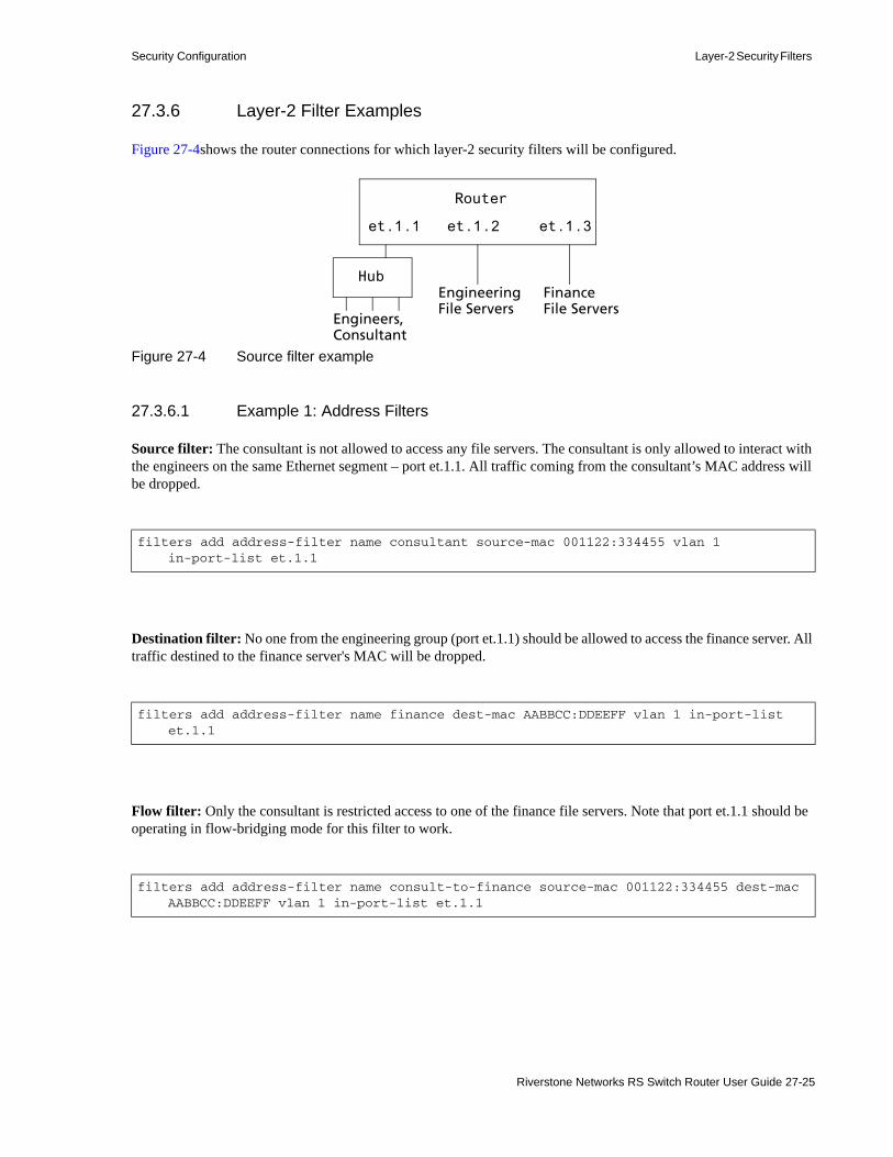
Security Configuration Layer-2 Security Filters
27.3.6 Layer-2 Filter Examples
Figure 27-4shows the router connections for which layer-2 security filters will be configured.
Figure 27-4 Source filter example
27.3.6.1 Example 1: Address Filters
Source filter: The consultant is not allowed to access any file servers. The consultant is only allowed to interact with the engineers on the same Ethernet segment – port et.1.1. All traffic coming from the consultant’s MAC address will be dropped.
Destination filter: No one from the engineering group (port et.1.1) should be allowed to access the finance server. All traffic destined to the finance server's MAC will be dropped.
Flow filter: Only the consultant is restricted access to one of the finance file servers. Note that port et.1.1 should be operating in flow-bridging mode for this filter to work.
filters add address-filter name consultant source-mac 001122:334455 vlan 1 in-port-list et.1.1
filters add address-filter name finance dest-mac AABBCC:DDEEFF vlan 1 in-port-list et.1.1
filters add address-filter name consult-to-finance source-mac 001122:334455 dest-mac AABBCC:DDEEFF vlan 1 in-port-list et.1.1
et.1.1 et.1.2 et.1.3
Hub
Engineers,Consultant
EngineeringFile Servers
FinanceFile Servers
Router
Riverstone Networks RS Switch Router User Guide 27-25

Layer-2 Security Filters Security Configuration
27.3.6.2 Static Entries Example
Source static entry: The consultant is only allowed to access the engineering file servers on port et.1.2.
Destination static entry: Restrict "login multicasts" originating from the engineering segment (port et.1.1) from reaching the finance servers.
or
Flow static entry: Restrict "login multicasts" originating from the consultant from reaching the finance servers.
27.3.6.3 Port-to-Address Lock Examples
You have configured some filters for the consultant on port et.1.1 If the consultant plugs his laptop into a different port, he will bypass the filters. To lock him to port et.1.1, use the following command:
filters add static-entry name consultant source-mac 001122:334455 vlan 1 in-port-list et.1.1 out-port-list et.1.2 restriction allow
filters add static-entry name login-mcasts dest-mac 010000:334455 vlan 1 in-port-list et.1.1 out-port-list et.1.3 restriction disallow
filters add static-entry name login-mcasts dest-mac 010000:334455 vlan 1 in-port-list et.1.1 out-port-list et.1.2 restriction allow
filters add static-entry name consult-to-mcasts source-mac 001122:334455 dest-mac 010000:334455 vlan 1 in-port-list et.1.1 out-port-list et.1.3 restriction disallow
filters add port-address-lock name consultant source-mac 001122:334455 vlan 1 in-port-list et.1.1
27-26 Riverstone Networks RS Switch Router User Guide

Security Configuration Layer-2 Security Filters
Note If the consultant’s MAC is detected on a different port, all of its traffic will be blocked.
27.3.6.4 Example 2: Secure Ports
Source secure port: To block all engineers on port 1 from accessing all other ports, enter the following command:
To allow ONLY the engineering manager access to the engineering servers, you must "punch" a hole through the secure-port wall. A "source static-entry" overrides a "source secure port".
Destination secure port: To block access to all file servers on all ports from port et.1.1 use the following command:
To allow all engineers access to the engineering servers, you must "punch" a hole through the secure-port wall. A "dest static-entry" overrides a "dest secure port".
filters add secure-port name engineers direction source vlan 1 in-port-list et.1.1
filters add static-entry name eng-mgr source-mac 080060:123456 vlan 1 in-port-list et.1.1 out-port-list et.1.2 restriction allow
filters add secure-port name engineers direction dest vlan 1 in-port-list et.1.1
filters add static-entry name eng-server dest-mac 080060:abcdef vlan 1 in-port-list et.1.1 out-port-list et.1.2 restriction allow
Riverstone Networks RS Switch Router User Guide 27-27

Layer-3 Access Control Lists (ACLs) Security Configuration
27.4 LAYER-3 ACCESS CONTROL LISTS (ACLS)Access Control Lists (ACLs) allow you to restrict Layer-3/4 traffic going through the RS Ethernet Router. Each ACL consists of one or more rules describing a particular type of IP traffic. An ACL can be simple, consisting of only one rule, or complicated with many rules. Each rule tells the router to either permit or deny the packet that matches the rule's packet description.
For information about defining and using ACLs on the RS Ethernet Router, see Chapter 26, "Access Control List Configuration."
27.5 LAYER-4 BRIDGING AND FILTERINGLayer-4 bridging is the RS Ethernet Router’s ability to use layer-3/4 information to perform filtering or QoS during bridging. As described in Section 27.3, "Layer-2 Security Filters." above, you can configure ports to filter traffic using MAC addresses. Layer-4 bridging adds the ability to use IP addresses, layer-4 protocol type, and port number to filter traffic in a bridged network. Layer-4 bridging allows you to apply security filters on a “flat” network, where the client and server may reside on the same subnet.
Note Ports that are included in a layer-4 bridging VLAN must reside on updated RS Ethernet Router hardware.
To illustrate this, the following diagram shows an RS Ethernet Router serving as a bridge for a consultant host, file server, and an engineering host, all of which reside on a single subnet.
Figure 27-5 Sample VLAN for layer-4 bridging
You may want to allow the consultant access to the file server for e-mail (SMTP) traffic, but not for Web (HTTP) traffic and allow e-mail, Web, and FTP traffic between the engineer and the file server. You can use Layer-4 bridging to set this up.
Setting up Layer-4 bridging consists of the following steps:• Creating an IP VLAN• Placing the ports on the same VLAN• Enabling Layer-4 Bridging on the VLAN• Creating an ACL that specifies the selection criteria • Applying an ACL to a port
et.1.1 et.1.2
Consultant File Server
Router
1.1.1.1/24 1.1.1.2/24Engineer
et.1.3
1.1.1.3/24
27-28 Riverstone Networks RS Switch Router User Guide

Security Configuration Layer-4 Bridging and Filtering
27.5.1 Creating an IP VLAN for Layer-4 Bridging
To enable Layer-4 bridging on a VLAN, the VLAN must be configured to pass only IP traffic. (Therefore, you cannot enable Layer-4 bridging on port-based VLANS.) To create an IP or IPX VLAN, enter the following command in Configure mode:
For example, to create an IP VLAN called “blue” with an ID of 21, enter the following command in Configure mode:
27.5.2 Placing the Ports on the Same VLAN
Once you have created a VLAN for the ports to be used in layer-4 bridging, you add those ports to the VLAN. To add ports to a VLAN, enter the following command in Configure mode:
To add the ports in the example in Figure 27-5, to the blue VLAN you would enter the following command:
27.5.3 Enabling Layer-4 Bridging on the VLAN
After adding the ports to the VLAN, you enable Layer-4 Bridging on the VLAN. To do this, enter the following command in Configure mode:.
Create an IP or IPX VLAN. vlan create <vlan-name> <type> id <num>
rs(config)# vlan create blue ip id 21
Add ports to a VLAN. vlan add ports <port-list> to <vlan-name>
rs(config)# vlan add ports et.1.1,et.1.2,et.1.3 to blue
Enable Layer 4 bridging. vlan enable l4-bridging on <vlan-name>
Riverstone Networks RS Switch Router User Guide 27-29

Layer-4 Bridging and Filtering Security Configuration
For example, to enable Layer-4 Bridging on the blue VLAN:
27.5.4 Creating ACLs to Specify Selection Criteria for Layer-4 Bridging
Access control lists (ACLs) specify the kind of filtering to be done for Layer-4 Bridging.
In the example in Figure 27-5, to allow the consultants access to the file server for e-mail (SMTP) traffic, but not for Web (HTTP) traffic — and allow e-mail, Web, and FTP traffic between the engineers and the file server, you would create ACLs that allow only SMTP traffic on the port to which the consultants are connected and allow SMTP, HTTP, and FTP traffic on the ports to which the engineers are connected.
The following is an example:
ACL 100 explicitly permits SMTP traffic and denies HTTP traffic. Note that because of the implicit deny rule appended to the end of the ACL, all traffic (not just HTTP traffic) other than SMTP is denied.
ACL 200 explicitly permits SMTP, HTTP, and FTP traffic. The implicit deny rule denies any other traffic. See Section 26.2, "Editing ACLs." for more information on defining ACLs.
27.5.5 Applying a Layer-4 Bridging ACL to a Port
Finally, you apply the ACLs to the ports in the VLAN. To do this, enter the following command in Configure mode:
For the example in Figure 27-5, to apply ACL 100 (which denies all traffic except SMTP) to the consultant port:
rs(config)# vlan enable l4-bridging on blue
acl 100 permit ip any any smtpacl 100 deny ip any any http
acl 200 permit any any smtpacl 200 permit any any httpacl 200 permit any any ftp
Apply a Layer-4 bridging ACL to a port acl <name> apply port <port-list>
rs(config)# acl 100 apply port et.1.1 output
27-30 Riverstone Networks RS Switch Router User Guide

Security Configuration Layer-4 Bridging and Filtering
To apply ACL 200 (which denies all traffic except SMTP, HTTP, and FTP) to the engineer port:
27.5.6 Notes
• Layer-4 Bridging works for IP and IPX traffic only. The RS Ethernet Router will drop non-IP/IPX traffic on a Layer-4 Bridging VLAN. For Appletalk and DECnet packets, a warning is issued before the first packet is dropped.
• If you use a SmartTRUNK in a with Layer-4 Bridging VLAN, the RS Ethernet Router maintains the packet order on a per-flow basis, rather than per-MAC pair. This means that for traffic between a MAC pair consisting of more than one flow, the packets may be disordered if they go through a SmartTRUNK. For traffic that doesn’t go through a SmartTRUNK, the per-MAC pair packet order is kept.
• ACLs applied to a network interface (as opposed to a port) do not have an effect on Layer-4 Bridged traffic, even though the interface may include ports used in Layer-4 Bridging.
rs(config)# acl 200 apply port et.1.3 output
Riverstone Networks RS Switch Router User Guide 27-31

Layer-4 Bridging and Filtering Security Configuration
27-32 Riverstone Networks RS Switch Router User Guide

28 QOS CONFIGURATION
The RS Ethernet Router allows network managers to identify traffic and set Quality of Service (QoS) policies without compromising wire speed performance. The RS Ethernet Router can guarantee bandwidth on an application by application basis, thus accommodating high-priority traffic even during peak periods of usage. QoS policies can be broad enough to encompass all the applications in the network, or relate specifically to a single host-to-host application flow.
The RS Ethernet Router provides four different features to satisfy QoS requirements:
Traffic Prioritization – Allows network administrators to differentiate between mission-critical network traffic and non-critical network traffic and segregate the traffic into different priority queues. Once a packet has been identified, it can be assigned to any one of the four priority queues in order to ensure delivery. Priority can be allocated based on any combination of Layer-2, Layer-3, or Layer-4 traffic.
Weighted Random Early Detection (WRED) – Alleviates traffic congestion by randomly dropping packets before the queues pass their upper thresholds. WRED is intended to work with connection-oriented protocols (especially TCP). However, WRED when applied to a port receiving connection less traffic can reduce latency on that port.
Type of Service (ToS) – ToS Rewrite provides network administrators access to the ToS octet in an IP packet. The ToS octet is designed to provide feedback to the upper layer application. The administrator can mark packets using the ToS rewrite feature so that the application (a routing protocol, for example) can handle the packet based on a predefined mechanism.
Within the RS Ethernet Router, QoS policies are used to classify Layer-2, Layer-3, and Layer-4 traffic into the following priority queues (in order from highest priority to lowest):• Control• High• Medium• Low
Note Control is for router control traffic. The remaining classes are for normal data flows.
Riverstone Networks RS Switch Router User Guide 28-1
Layer-2, Layer-3 and Layer-4 Flow Specification QoS Configuration
Separate buffer space is allocated to each of these four priority queues. By default, buffered traffic in higher priority queues is forwarded ahead of pending traffic in lower priority queues. This is the strict priority queuing policy. During heavy loads, low-priority traffic can be dropped to preserve the throughput of the higher-priority traffic. This ensures that critical traffic will reach its destination even if the exit ports for the traffic are experiencing greater-than-maximum utilization. To prevent low-priority traffic from waiting indefinitely as higher-priority traffic is sent, you can apply the Weighted Fair Queuing (WFQ) queuing policy to set a minimum bandwidth for each class. You can also apply WRED to keep the congestion of TCP traffic under control.
28.1 LAYER-2, LAYER-3 AND LAYER-4 FLOW SPECIFICATION
In the RS Ethernet Router, traffic classification is accomplished by mapping Layer-2, -3, or -4 traffic to one of the four priorities. Each traffic classification is treated as an individual traffic flow in the RS Ethernet Router.
For Layer-2 traffic, you can define a flow based on MAC packet header fields, including source MAC address, destination MAC address, and VLAN IDs. A list of incoming ports can also be specified.
For Layer-3 (IP) traffic, you can define flows, blueprints or templates of IP packet headers:
Ip Fields – The source IP address, destination IP address, UDP/TCP source port, UDP/TCP destination port, TOS (Type of Service), transport protocol (TCP or UDP), and a list of incoming interfaces.
For Layer-4 traffic, you can define a flow based on source/destination TCP/UDP port number in addition to the Layer-3 source/destination IP address.
The flows specify the contents of these fields. If you do not enter a value for a field, a wildcard value (all values acceptable) is assumed for the field.
28.2 PRECEDENCE FOR LAYER-3 FLOWSA precedence from 1 to 7 is associated with each field in a flow. The RS Ethernet Router uses the precedence value associated with the fields to break ties if packets match more than one flow. The highest precedence is 1 and the lowest is 7. Here is the default precedence of the fields:• IP
- Destination port – 1- Destination IP address – 2- Source port – 3- Source IP address – 4- ToS – 5- Interface – 6- Protocol – 7
Use the qos precedence ip command to change the default precedence.
28-2 Riverstone Networks RS Switch Router User Guide

QoS Configuration RS Ethernet Router Queuing Policies
28.3 RS ETHERNET ROUTER QUEUING POLICIESThere are two types of queuing policies you can use on the RS Ethernet Router:
Strict priority – Assures the higher priorities of throughput but at the expense of lower priorities. For example, during heavy loads, low-priority traffic can be dropped to preserve throughput of control-priority traffic. This is the default queuing policy.
Weighted fair queuing – Distributes priority throughput among the four priorities based on percentages. This queuing policy is set on a per-port basis.
28.4 TRAFFIC PRIORITIZATION FOR LAYER-2 FLOWSQoS policies applied to Layer-2 flows allow you to assign priorities based on source and destination MAC addresses. A QoS policy set for a Layer-2 flow allows you to classify the priority of traffic from:• A specific source MAC address to a specific destination MAC address (use only when the port is in
flow bridging mode).• Any source MAC address to a specific destination MAC address.
Before applying a QoS policy to a Layer-2 flow, you must first determine whether a port is in the address-bridging mode or flow-bridging mode. If a port is operating in address-bridging mode (default), you can specify the priority based on the destination MAC address and a VLAN ID. You can also specify a list of ports to apply the policy.
If a port is operating in the flow-bridging mode, you can be more specific and configure priorities for frames that match both a source and a destination MAC address and a VLAN ID. You can also specify a list of ports to apply the policy.
The VLAN ID in the QoS configuration must match the VLAN ID assigned to the list of ports to which the QoS policy is applied. In a Layer-2 only configuration, each port has only one VLAN ID associated with it and the QoS policy should have the same VLAN ID. When different VLANs are assigned to the same port using different protocol VLANs, the Layer-2 QoS policy must match the VLAN ID of the protocol VLAN.
Note In the flow mode, you can also ignore the source MAC address and configure the priority based on the destination MAC address only.
28.4.1 Configuring Layer-2 QoS
When applying QoS to a layer-2 flow, priority can be assigned as follows:• The frame gets assigned a priority within the switch. Select low, medium, high or control.• The frame gets assigned a priority within the switch, and if the exit ports are VLAN trunk ports, the
frame is assigned an 802.1Q priority. Select a number from 0 to 7.
To set a QoS priority on a layer-2 flow, enter the following command in the Configure mode:
Set a layer-2 QoS policy.
qos set l2 name <name> source-mac <MACaddr> dest-mac <MACaddr> vlan <vlanID> in-port-list <port-list> priority control | high | medium | low | <trunk-priority> ignore-ingress-802.1p
Riverstone Networks RS Switch Router User Guide 28-3

Traffic Prioritization for Layer-2 Flows QoS Configuration
Note When applying this command to WAN ports, the ports in <port-list> defining in-port-list are limited to physical ports only. For example, logical channels such as t1.3.1:2 are not supported.
28.4.2 802.1p Class of Service Priority Mapping
The following table shows the default mappings of 802.1p Class of Service (CoS) values to internal priorities for frames:
You can create one or more priority maps that are different from the default priority map and then apply these maps to some or all ports on the RS Ethernet Router. The new priority mapping replaces the default mappings for those ports.
28.4.2.1 Creating and Applying a New Priority Map
To specify a priority map on a per-port basis, enter the following commands in the Configure mode:
For example, the following command creates the priority map all-low which maps all 802.1p priorities to the low internal priority queue:
Table 28-1 802.1p default priority mappings
802.1p CoS values Internal priority queue
0, 1 Low
2, 3 Medium
4, 5 High
6, 7 Control
Create a new priority mapping. qos create priority-map <name> <CoS number> control | high | medium | low
Apply new priority mapping to ports. qos apply priority-map <name> ports <port-list>
qos create priority-map all-low 0 low 1 low 2 low 3 low 4 low 5 low 6 low 7 low
28-4 Riverstone Networks RS Switch Router User Guide

QoS Configuration Traffic Prioritization for Layer-2 Flows
Once a priority map is created, it can then be applied to a set of ports, as shown in the following example:
In the above example, ports et.1.1-4 and ports gi.4.* will use the all-low priority map. All other ports, including ports et.1.5-8, will use the default priority map.
You do not need to specify mappings for all 802.1p values. If you do not specify a particular mapping, the default mapping for that 802.1p priority is used. The following example creates a priority map no-ctrl with the same mappings as the default priority map, except that the 802.1p priority of 7 is mapped to the internal priority high instead of control.
28.4.2.2 Removing or Disabling Per-Port Priority Map
Negating a qos create priority-map command removes the priority map. Before you can remove a priority map, you must negate all commands that use the priority map. Negating a qos apply priority-map command causes the configured ports to use the default priority mapping.
The ability to specify per-port priority maps is enabled on the RS Ethernet Router by default. You can disable use of per-port priority maps on the RS Ethernet Router. All ports on the RS Ethernet Router will then be configured to use the default priority map only. If the commands to create and apply priority maps exist in the active configuration, they will remain in the configuration but be ineffective.
To disable the use of priority maps, enter the following command in the Configure mode:
If the above command is negated, ports on the RS Ethernet Router can use per-port priority maps. If the commands to create and apply priority maps exist in the active configuration, they are reapplied.
28.4.2.3 Displaying Priority Map Information
To display priority maps and the ports on which they are applied, enter the following command in Enable mode:
qos apply priority-map all-low ports et.1.1-4, gi.4.*
qos create priority-map no-ctrl 7 high
Disable use of per-port priority maps on the RS Ethernet Router.
qos priority-map off
Display priority mapping. qos show priority-map <name> | all
Riverstone Networks RS Switch Router User Guide 28-5

Traffic Prioritization for Layer-3 & Layer-4 Flows QoS Configuration
28.5 TRAFFIC PRIORITIZATION FOR LAYER-3 & LAYER-4 FLOWS
QoS policies applied at Layer-3 and -4 allow you to assign priorities based on specific fields in the IP headers. You can set QoS policies for IP flows based on source IP address, destination IP address, source TCP/UDP port, destination TCP/UDP port, type of service (TOS) and transport protocol (TCP or UCP). A QoS policy set on an IP flow allows you to classify the priority of traffic based on:• Layer-3 source-destination flows• Layer-4 source-destination flows• Layer-4 application flows
28.5.1 Configuring IP QoS Policies
To configure an IP QoS policy, perform the following tasks:1. Identify the Layer-3 or -4 flow and set the IP QoS policy.2. Specify the precedence for the fields within an IP flow.
28.5.1.1 Setting an IP QoS Policy
To set a QoS policy on an IP traffic flow, use the following command in the Configure mode:
For example, the following command assigns control priority to any traffic coming from the 10.10.11.0 network:
28.5.1.2 Specifying Precedence for an IP QoS Policy
To specify the precedence for an IP QoS policy, use the following command in the Configure mode:
Set an IP QoS policy. qos set ip <name> <priority> <srcaddr/mask> | any <dstaddr/mask> | any <srcport> | any <dstport> | any <tos> | any <port list> | <interface-list> | any <protocol> | any <tos-mask> | any <tos-precedence-rewrite> | any <tos-rewrite> | any
qos set ip xyz control 10.10.11.0/24
Specify precedence for an IP QoS policy.
qos precedence ip [sip <num>] [dip <num>] [srcport <num>] [destport <num>] [tos <num>] [protocol <num>] [intf <num>]
28-6 Riverstone Networks RS Switch Router User Guide

QoS Configuration Configuring Weighted fair Queueing
28.6 CONFIGURING WEIGHTED FAIR QUEUEING The default queuing policy for all ports on the RS Ethernet Router is strict priority. You can change the queueing policy from strict priority to weighted fair queueing on a port by port basis. The following example sets the queueing policy of port et.4.14 to weighted fair queueing.
Use the qos show weighted-fair command to show a port’s bandwidth allocation, as shown in the following example.
28.6.1 Allocating Bandwidth
When you set a port’s queueing policy to weighted-fair, the bandwidth allocation is set by default to 25% in each queue (control, high, medium, and low). You can change these defaults, as shown in the following example:
Normally, a priority queue is allowed to “borrow” bandwidth from other queues when it has bursty traffic that goes above its limit and the other queues are not using their bandwidth. When you set a queue’s bandwidth, you can also specify from which queue a priority queue can borrow bandwidth, as shown in the following example:
The example specifies the following:• the control queue and the high queue are each allocated 30% of the bandwidth and can borrow
bandwidth from the low and medium queues• the medium queue is allocated 30% of the bandwidth and the low queue is allocated 10%; neither of
them can borrow bandwidth from another queue. This is specified by the keyword none used with the medium-burst and low-burst parameters. Use this keyword when you want to enforce the bandwidth allocation of any of the queues. It prevents a priority queue from using more bandwidth than is specified, even if other queues have unused bandwidth.
rs(config)# qos set queueing-policy weighted-fair port et.4.14
rs# qos show weighted-fair port et.4.14Port Policy Control High Medium Low Idle--------- ------- ------------- ------------- ------------- ------------- -----et.4.14 WFQ 25 25 25 25 0
rs(config)# qos set weighted-fair control 30 high 30 medium 30 low 10
rs(config)# qos set weighted-fair control 30 control-burst low-medium high 30 high-burst low-medium medium 30 medium-burst none low 10 low-burst none port et.4.14
Riverstone Networks RS Switch Router User Guide 28-7
Configuring Weighted fair Queueing QoS Configuration
28.6.2 Running different queueing algorithms
You can also configure priority queues to run different queueing algorithms simultaneously. For example, you can set the control queue to use strict priority, while the other queues use weighted fair, as shown in the following example:
Note If you want to revert the RS Ethernet Router queuing policy from weighted-fair to strict priority (default), use the negate command.
28.6.2.1 WFQ Using Line Cards with Fifth Generation ASICs
The line cards equipped with 5th generation ASICs use somewhat different queuing algorithms. These algorithms provide additional functionality and use the concepts limit, strict, and idle differently. The following explains the use of these terms as applied to line cards with 5th generation ASICs.
limit – the queue cannot exceed the specified percent of the physical bandwidth of the port. For example, setting the low-limit 3 on a 100Mbps port, means that low priority traffic cannot exceed 3Mbps.
strict – strict priority queuing is enforced for this queue. For example, if the control queue is set to strict, while high, medium, and low are set to WFQ, control priority traffic is sent at any time, regardless of the queue that should be sending out traffic based on the WFQ settings.
idle – this is the percent of the time that the port should remain idle. For example, if this is set to 75% on a 100Mbps link, the port can send only at a maximum rate of 25Mbps.
The following is an example of using the idle parameter to control bandwidth on a port – A 100Mbps physical port is assigned to a user with the restriction that the user is to have 20Mbps of throughput, but no other restrictions. To accomplish this, the port is idled by 80%:
This allow all the traffic to be transmitted at up to 20Mbps, while at the same time giving control traffic priority.
rs(config)# qos set weighted-fair strict control high 60 medium 30 low 10
rs(config)# qos set weighted-fair idle 80 control 20 strict control port et.5.1
28-8 Riverstone Networks RS Switch Router User Guide

QoS Configuration Weighted Random Early Detection (WRED)
28.7 WEIGHTED RANDOM EARLY DETECTION (WRED)
WRED is a dynamic process for controlling congestion on RS Ethernet Router ports and the segments of the network associated with the WRED enabled ports. The WRED process consists of setting a minimum queue threshold (min-threshold) and a maximum queue threshold (max-threshold) on any of the four queues (low, medium, high, and control) belonging to a port. Associated with these thresholds is an average queue size, which is dynamically calculated as the instantaneous average buffer depth. If the average queue size is below the min-threshold, no packets are discarded. However, if the average queue size rises above the min-threshold, WRED uses a packet-marking probability algorithm to randomly mark packets for discard. As the average queue size increases toward the max-threshold, the probability of packet drop also increases. Eventually, if the average queue size exceeds the max-threshold, the probability of packet drop becomes 1 (100% of packets are dropped). This increase in the probability of packet drop increases in a linear fashion from 0 to 1 (0% dropped to 100% dropped). Notice that the probability of packet drop roughly depends on bandwidth, i.e.; the more packets sent by a particular connection, the greater the probability that packets will be dropped from that connection.
Note WRED is not supported on 10/100 Mbps line cards that contain fifth generation ASICs.
28.7.1 WRED’s Effect on the Network
WRED’s full capabilities to reduce congestion are best used with TCP (and other connection-oriented protocols). As TCP traffic increases on a WRED port, and the average queue size rises above the min-threshold, some TCP packets begin to drop. Each TCP source interprets dropped packets as an indication of congestion. As a result, each TCP source that has experienced a dropped packet reduces its window, the average queue size decreases, and congestion is alleviated.
Although connection-less protocols do not have the response capability of TCP to sense congestion. Nevertheless, WRED’s technique of dropping packets based on rising probability assures that those connections that are sending the most packets or using the most bandwidth will be more likely to have their packets dropped than lower bandwidth connections. This provides at least some assurance of equality of throughput on a WRED port for connection-less protocols.
28.7.2 Weighting Algorithms in WRED
The following algorithm parameters are all found under the of the qos wred command.
WRED provides for the “fine-tuning” of both the average queue size algorithm and the packet-marking probability algorithm. Control over the average queue size algorithm is provided by the exponential-weighting-constant parameter. Control over the packet-marking probability algorithm is provided by the mark-prob-denominator parameter.
The exponential-weighting-constant parameter specifies how fast the average queue size changes in response to changes in the actual queue depth. In effect, the rate of change of the average queue size can be dampened. The exponential-weighting-constant accepts values from zero (0) to three (3) when WRED is applied to input queues, and from zero (0) to seven (7) when WRED is applied to output queues. Note that 0 provides the least amount of dampening, while larger numbers provide greater amounts of dampening.
Riverstone Networks RS Switch Router User Guide 28-9

Weighted Random Early Detection (WRED) QoS Configuration
This ability to dampen the response time of the average queue size changes WRED’s response to bursty traffic. For example, notice in Figure 28-1 that while the traffic (solid line) bursts at times, the average queue size (dotted curve) is dampened such that it does not rise above the minimum threshold within the duration of the bursts. This keeps the port from discriminating against traffic that might burst slightly at times.
Figure 28-1 Average queue size and bursty traffic
The mark-prob-denominator parameter is used to determine the probability of a packet being dropped when the average queue size is between the minimum and maximum thresholds. The mark-prob-denominator accepts values from zero (0) to three (3) when WRED is applied to input queues and from zero (0) to seven (7) when WRED is applied to output queues. Note that the lower the value specified, the higher the probability that packets will be dropped.
Both the exponential-weighting-constant value and the mark-prob-denominator value are somewhat allegorical in the sense that neither of these values have a direct numerical significance other than acting as control values for WRED. For example, if the value for exponential-weighting-constant is increased from 1 to 2, the dampening of the average queue size response is not twice as slow. Because of this non-specific nature of exponential-weighting-constant and mark-prob-denominator and the fact that each network is different, a discussion of recommend, specific settings for these values is beyond the scope of this User Guide.
When first implementing WRED on your RS Ethernet Router, it is recommended to initially use the default values for min-threshold, max-threshold, the weighting constant, and the probability denominator. If you begin or continue to experience congestion, especially with TCP traffic, try adjusting WRED by making small changes in the various parameters (one-at-a-time), and observing their effect on congestion.
To enable WRED on queues of specific input or output ports, enter the qos wred input | output command in Configure mode. To create a WRED profile to be used an Advance Service Module (ASM) line card, use the qos wred asm command in Configure mode:
Set parameters for the WRED algorithm
qos wred [asm <name> <asm-parameters>] [input | output exponential-weighting-constant <num> | mark-prob-denominator <num> | max-queue-threshold <num> | min-queue-threshold <num> | port <port list> | all-ports | {queue control | high | medium | low} | type assured-forward | expedite-forward | marked-packets] [exp-weight <port> <num>] [one-p-weight <port> <num>] [size-weight <port> <num>] [tos-precedence-weight <port> <num>]
minth
maxthQue
ue
Time
28-10 Riverstone Networks RS Switch Router User Guide

QoS Configuration ToS Rewrite
To set the order in which precedence parameters are evaluated on a port or set of ports, use the qos wred asm-precedence command. This command allows the ordering in which Exp-bits, 802.1p tags, internal queues, and tos-precedence are evaluated.
For example, to set the precedence for port gi.11.1 to tos-precedence first, Exp-bits second, 802.1p tags as third, and internal priority queues as last, enter the following:
For more information on using QoS and WRED, see the QoS chapter of the Riverstone RS Switch Router Command Line Interface Reference Manual.
28.8 TOS REWRITEIP packets that use different paths are subject to delays, as there is little inherent knowledge of how to optimize the paths for different packets from different applications or users. The IP protocol actually provides a facility, which has been part of the IP specification since the protocol’s inception, for an application or upper-layer protocol to specify how a packet should be handled. This facility is called the Type of Service (ToS) octet.
The ToS octet part of the IP specification, however, has not been widely employed in the past. The IETF is looking into using the ToS octet to help resolve IP quality problems. Some newer routing protocols, like OSPF and IS-IS, are designed to be able to examine the ToS octet and calculate routes based on the type of service.
The ToS octet in the IP datagram header consists of three fields:
Figure 28-2 ToS fields
• The three-bit Precedence field is used to indicate the priority of the datagram.• The four-bit ToS field is used to indicate trade-offs between throughput, delay, reliability, and cost.• The one-bit “must be zero” (MBZ) field is not currently used. (In the RS Ethernet Router
configuration, there is no restriction on this bit and it is included as part of the ToS field.)
For example, setting the ToS field to 0010 specifies that a packet will be routed on the most reliable paths. Setting the ToS field to 1000 specifies that a packet will be routed on the paths with the least delay. (Refer to RFC 1349 for the specification of the ToS field value.)
Sets the order of precedence and evaluation
qos wred asm -precedence exp | internal | one-p | port <port-list> | tos-precedence
rs(config)# qos wred asm-precedence tos-precedence exp one-p internal port gi.11.1
MBZToSPrecedence
7 6 5 4 3 2 1 0
Most Significant Bit Least Significant Bit
Riverstone Networks RS Switch Router User Guide 28-11
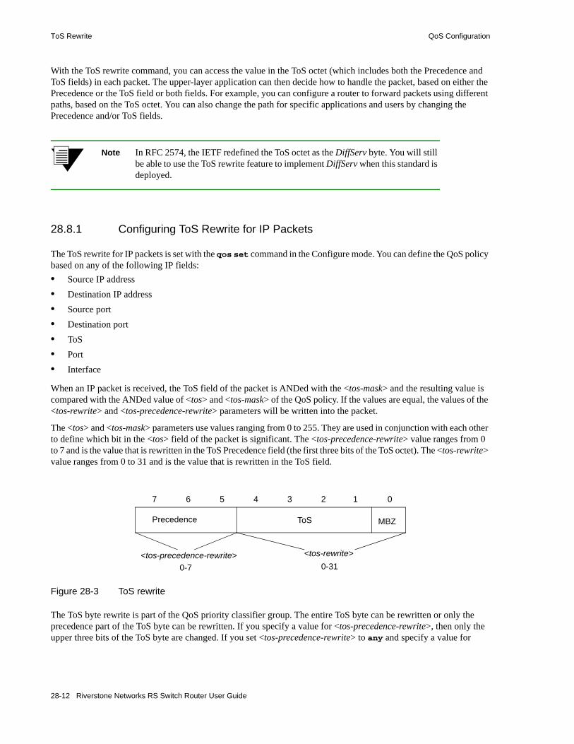
ToS Rewrite QoS Configuration
With the ToS rewrite command, you can access the value in the ToS octet (which includes both the Precedence and ToS fields) in each packet. The upper-layer application can then decide how to handle the packet, based on either the Precedence or the ToS field or both fields. For example, you can configure a router to forward packets using different paths, based on the ToS octet. You can also change the path for specific applications and users by changing the Precedence and/or ToS fields.
Note In RFC 2574, the IETF redefined the ToS octet as the DiffServ byte. You will still be able to use the ToS rewrite feature to implement DiffServ when this standard is deployed.
28.8.1 Configuring ToS Rewrite for IP Packets
The ToS rewrite for IP packets is set with the qos set command in the Configure mode. You can define the QoS policy based on any of the following IP fields:• Source IP address• Destination IP address• Source port• Destination port• ToS• Port• Interface
When an IP packet is received, the ToS field of the packet is ANDed with the <tos-mask> and the resulting value is compared with the ANDed value of <tos> and <tos-mask> of the QoS policy. If the values are equal, the values of the <tos-rewrite> and <tos-precedence-rewrite> parameters will be written into the packet.
The <tos> and <tos-mask> parameters use values ranging from 0 to 255. They are used in conjunction with each other to define which bit in the <tos> field of the packet is significant. The <tos-precedence-rewrite> value ranges from 0 to 7 and is the value that is rewritten in the ToS Precedence field (the first three bits of the ToS octet). The <tos-rewrite> value ranges from 0 to 31 and is the value that is rewritten in the ToS field.
Figure 28-3 ToS rewrite
The ToS byte rewrite is part of the QoS priority classifier group. The entire ToS byte can be rewritten or only the precedence part of the ToS byte can be rewritten. If you specify a value for <tos-precedence-rewrite>, then only the upper three bits of the ToS byte are changed. If you set <tos-precedence-rewrite> to any and specify a value for
MBZToSPrecedence
7 6 5 4 3 2 1 0
<tos-precedence-rewrite> <tos-rewrite>
0-7 0-31
28-12 Riverstone Networks RS Switch Router User Guide

QoS Configuration Monitoring QoS
<tos-rewrite>, then the upper three bits remain unchanged and the lower five bits are rewritten. If you specify values for both <tos-precedence-rewrite> and <tos-rewrite>, then the upper three bits are rewritten to the <tos-precedence-rewrite> value and the lower five bits are rewritten to the <tos-rewrite> value.
For example, the following command will rewrite the ToS Precedence field to 7 if the ToS Precedence field of the incoming packet is 6:
In the above example, the <tos> value of 222 (binary value 1101 1110) and the <tos-mask> value of 224 (binary value 1110 0000) are ANDed together to specify the ToS Precedence field value of 6 (binary value 110). Changing the value in the <tos-mask> parameter determines the bit in the ToS octet field that will be examined.
The following example will rewrite the ToS Precedence and the ToS fields to 5 and 30 if the incoming packet is from the 10.10.10.0/24 network with the ToS Precedence field set to 2 and the ToS field set to 7. In this example, the MBZ bit is included in the ToS field. The figure below shows how the parameter values are derived.
Figure 28-4 ToS rewrite example
The <tos-mask> value determines the ToS bit to be examined, which is all eight bits in this example. The following command configures the ToS rewrite for the example:
28.9 MONITORING QOSThe RS Ethernet Router provides display of QoS statistics and configurations contained in the RS Ethernet Router.
qos set ip tosp6to7 low any any any any 222 any any 224 7
qos set ip tos30to7 low 10.10.10.0/24 any any any 71 any any 255 5 30
100 0 01 1 1
1 1 1 1 1 1 1 1
1 0 1 1 1 1 1 0
Incoming Packet: <tos> = 71
ToS Precedence = 2 ToS = 7
Mask (look at<tos-mask> = 255
ToS Precedence = 5 ToS = 30
<tos-precedence-rewrite> = 5<tos-rewrite> = 30
Rewritten ToS bytefor 10.10.10.0/24packet:
all bits):
Riverstone Networks RS Switch Router User Guide 28-13

Monitoring QoS QoS Configuration
To display QoS information, enter the following commands in Enable mode:
Show all IP QoS flows. qos show ip
Show all Layer-2 QoS flows. qos show l2 all-destination all-flow ports <port-list> vlan <vlanID> source-mac <MACaddr> dest-mac <MACaddr>
Show RED parameters for each port. qos show red [input port <port-list> | all-ports] [output port <port-list> | all-ports] [port <port-list> | all-ports]
Show IP precedence values. qos show precedence ip
Show WFQ bandwidth allocated for each port.
qos show wfq [port <port-list> | all-ports] [input<slot num>] | all-modules]
Show priority mappings. qos show priority-map all
28-14 Riverstone Networks RS Switch Router User Guide

29 PERFORMANCE MONITORING
The RS Ethernet Router is a full wire-speed layer-2, 3 and 4 switching router. As packets enter the RS Ethernet Router, layer-2, 3, and 4 flow tables are populated on each line card. The flow tables contain information on performance statistics and traffic forwarding. Thus the RS Ethernet Router provides the capability to monitor performance at Layer 2, 3, and 4.
Layer-2 performance information is accessible to SNMP through MIB-II and can be displayed by using the l2-tables command in the CLI. Layer-3 and 4 performance statistics are accessible to SNMP through RMON/RMON2 and can be displayed by using the statistics show command in the CLI. In addition to the monitoring commands listed, you can find more monitoring commands listed in each chapter of the Riverstone RS Switch Router Command Line Interface Reference Manual.
To access statistics on the RS Ethernet Router, enter the following commands in Enable mode:
Show DVMRP routes. dvmrp show routes
Show all TCP/UDP connections and services. ip show connections
Show all IP routes. ip show routes
Show all MAC addresses currently in the L2 tables. l2-tables show all-macs
Show info about MACs residing in a port's L2 table. l2-tables show port-macs <port-list>
Show all L2 flows (for ports in flow-bridging mode. l2-tables show all-flows
Show information about the master MAC table. l2-tables show mac-table-stats
Show information about a particular MAC address. l2-tables show mac
Show info about multicasts registered by IGMP. l2-tables show igmp-mcast-registrations
Show whether IGMP is on or off on a VLAN. l2-tables show vlan-igmp-status
Show info about MACs registered by the system. l2-tables show bridge-management
Show SNMP statistics. snmp show statistics
Show ICMP statistics. statistics show icmp
Show IP interface's statistics. statistics show ip
Show unicast routing statistics. statistics show ip-routing
Show multicast statistics. statistics show multicast
Show port error statistics. statistics show port-errors
Show potential physical layer errors. statistics show phy-errors
Riverstone Networks RS Switch Router User Guide 29-1

Configuring the RS Ethernet Router for Port Mirroring Performance Monitoring
29.1 CONFIGURING THE RS ETHERNET ROUTER FOR PORT MIRRORING
The RS Ethernet Router allows you to monitor activity with port mirroring. Port mirroring allows you to monitor the performance and activities of ports on the RS Ethernet Router or for traffic defined by an ACL through just a single, separate port. While in Configure mode, you can configure your RS Ethernet Router for port mirroring with a simple command line like the following:
Note Only one target port may be defined for a given RS Ethernet Router, and only one monitor port may be defined. Also, Riverstone recommends that you monitor Gigabit ports through other Gigabit ports—you would almost certainly experience speed-inconsistency-related problems monitoring a Gigabit port through a 10Base-T or 100Base-TX port.
Note To display 802.1Q tagged packets on the mirroring port, configure the mirroring port as a trunk port using the vlan make trunk-port <port> command.
Show port normal statistics. statistics show port-stats
Show RMON etherStats statistics. statistics show rmon
Show traffic summary statistics. statistics show summary-stats
Show most active tasks. statistics show top
Show TCP statistics. statistics show tcp
Show UDP statistics. statistics show udp
Show TACACS server statistics. tacacs show stats
Show broadcast monitoring information for ports. port show bmon [config][detail][port
<port list>][stats]
Show all VLANs. vlan list
Configure port mirroring. port mirroring monitor-port <port number> target-port <port number> target-acl <acl name>
29-2 Riverstone Networks RS Switch Router User Guide

Performance Monitoring Monitoring Broadcast Traffic
29.2 MONITORING BROADCAST TRAFFICThe RS Ethernet Router allows you to monitor broadcast traffic for one or more ports, and for the control module. You can specify that a port be shut down if its broadcast traffic reaches a certain rate limit for a particular period of time. Additionally, you can configure the RS Ethernet Router to shut down for a specified period, if the packets sent to the control module reach a certain limit during a specified time interval. Packets to be monitored can be limited to broadcast packets only or all packets.
To specify the monitoring of broadcast traffic and the shut down threshold for one or more ports, enter the following command in Configure mode:
Configure monitoring of broadcast traffic.
port bmon <port list> rate <number> duration <number> shutdown <number> packets-limited all|broadcast
Riverstone Networks RS Switch Router User Guide 29-3

Monitoring Broadcast Traffic Performance Monitoring
29-4 Riverstone Networks RS Switch Router User Guide
30 RMON CONFIGURATION
The Remote Network Monitoring (RMON) specifications primarily define Management Information Base (MIB) modules for network monitoring. The RS Ethernet Router supports both the RMON 1 (RFC 2819) and RMON 2 (RFC 2021) specifications. The objects in the RMON 1 and RMON 2 MIB modules define the functions and information exchanged between a network monitoring system (or probe) and network management stations. The RMON 1 MIB modules provide for the monitoring of frames at the MAC layer. The RMON 2 MIB modules focus on monitoring traffic at the network layer through the application-layer (layer-3 through layer-7 of the OSI model) so you can monitor higher-layer protocols running above the network-layer. Management stations can access the RMON 1 and 2 MIB objects via SNMP or the ROS CLI.
To run RMON on the RS Ethernet Router, enable SNMP first, then enable RMON. When you enable RMON on the RS Ethernet Router, the RS Ethernet Router functions as a probe or remote monitor. It allocates a certain amount of its resources to monitoring network traffic and gathering statistics. Thus, a network administrator can use RMON to analyze traffic patterns and troubleshoot the network.
This chapter describes how you can use the ROS CLI to run RMON on the RS Ethernet Router, configure the RMON MIB objects and view RMON statistics.
This chapter provides the following information:• The RMON 1 and RMON 2 MIB objects are divided into functional groups. To learn about the
RMON 1 and RMON 2 functional groups and how they are organized in the RS Ethernet Router, refer to Section 30.1, "RMON Groups."
• To enable RMON on the RS Ethernet Router, refer to Section 30.2, "Enabling RMON."• To configure the RMON groups, refer to Section 30.3, "Configuring RMON Groups."• To allocate memory to RMON, refer to Section 30.4, "Allocating Memory to RMON."• To use CLI filters to limit the display of rmon show commands, see Section 30.5, "Setting
RMON CLI Filters."• To troubleshoot RMON, see Section 30.6, "Troubleshooting RMON."
Riverstone Networks RS Switch Router User Guide 30-1

RMON Groups RMON Configuration
30.1 RMON GROUPSThe RMON 1 and RMON 2 MIB objects are divided into functional groups; each group collects specific information about the network. RMON 1 defines 10 functional groups which provide statistics on network segments at the MAC layer. The RS Ethernet Router supports nine RMON 1 functional groups. It does not support the token ring functional group.
WIth RMON 2, you can monitor or show host-to-host connections and the applications and protocols being used. It defines nine functional groups which provide information at the network-layer through the application-layer of the OSI model. Note that in RMON 2, the layers above the network layer (transport, session, presentation and application) are all referred to as application layer. The RS Ethernet Router supports all nine RMON 2 functional groups.
Each functional group has read-write objects and read-only objects. The read-write objects specify the parameters for the collection of data. These control parameters define what statistics are to be collected. The read-only objects are the collected statistics. In some functional groups, these objects are contained in one table. In most functional groups though, these objects are stored in 2 separate tables; the control parameters are in a control table, and the collected data are in a data table. (For detailed information on the objects and tables in the RMON 1 and RMON 2 groups, refer to RFC 2819 and RFC 2021, respectively.)
Regardless of whether the objects are in one or in two separate tables, the RS Ethernet Router provides CLI support for configuring the control parameters and for viewing the collected data. For information on configuring the read-write objects in each group and for viewing the resulting statistics, refer to Section 30.3, "Configuring RMON Groups."
The RS Ethernet Router provides three levels of support: Lite, Standard and Professional. Each level supports a different set of RMON groups. The Lite and Standard levels support the RMON 1 groups, and the Professional level supports the RMON 2 groups. To run RMON on the RS Ethernet Router, you need to enable at least one level of support. The following tables define the RMON functional groups supported in each level.
Table 30-1 Lite RMON groups
Group Function
EtherStats Records Ethernet statistics (for example, packets dropped, packets sent, etc.) for specified ports.
Event Controls event generation and the resulting action (writing a log entry or sending an SNMP trap to the network management station).
Alarm Generates an event when specified alarm conditions are met.
History Records statistical samples for specified ports.
30-2 Riverstone Networks RS Switch Router User Guide

RMON Configuration RMON Groups
Table 30-2 Standard RMON groups
Group Function
Host Records statistics about the hosts discovered on the network.
Host Top N Gathers the top n hosts, based on a specified rate-based statistic. This group requires the Host group.
Matrix Records statistics for source and destination address pairs.
Filter Specifies the type of packets to be matched and how and where the filtered packets should flow (the channel).
Packet Capture Specifies the capture of filtered packets for a particular channel.
Table 30-3 Professional RMON groups
Group Function
Protocol Directory Contains a list of protocols supported by the RS Ethernet Router and monitored by RMON. See the RMON 2 Protocol Directory appendix in the Riverstone RS Switch Router Command Line Interface Reference Manual.
Protocol Distribution Records the packets and octets for specified ports on a per protocol basis.
Application Layer Host Monitors traffic at the application layer for protocols defined in the Protocol Directory.
Network Layer Host Monitors traffic at the network layer for protocols defined in the Protocol Directory.
Application Layer Matrix (and Top N)
Monitors traffic at the application layer for protocols defined in the Protocol Directory. Top N gathers the top n application layer matrix entries.
Network Layer Matrix (and Top N)
Monitors traffic at the network layer for protocols defined in the Protocol Directory. Top N gathers the top n network layer matrix entries.
Address Map Records MAC address to network address bindings discovered for specified ports.
User History Records historical data on user-defined statistics.
Probe Monitors the probe’s operations. (Use the rmon show probe-config command.))
Riverstone Networks RS Switch Router User Guide 30-3

Enabling RMON RMON Configuration
30.2 ENABLING RMONBy default, RMON is disabled on the RS Ethernet Router. To enable RMON, the following steps are required:1. Enable at least one RMON level of support: Lite, Standard, and/or Professional. 2. Start RMON.
Note SNMP must be enabled on the RS Ethernet Router before you can enable RMON. (For information on SNMP, see Chapter 36, "SNMP Configuration.")
3. If you are using RMON to collect statistics, then you need to enable RMON on the ports for which data will be collected. Refer to Section 30.2.3, "Enabling RMON on Ports." But if you are using RMON to generate events and record alarms only, you do not need to enable RMON on ports.
30.2.1 Enabling RMON Groups
To run RMON on the RS Ethernet Router, you must enable at least one level: Lite, Standard, and/or Professional. (For a list of the RMON groups in each level, refer to Section 30.1, "RMON Groups.") Enabling an RMON level allows you to configure control parameters for the groups in that level. For example, if you enable the Lite level, then you can configure control parameters for the Etherstats, Event, Alarm, and History groups. After configuring the parameters, you can view the resulting data with the various rmon show commands. (For information on configuring control parameters for each group, refer to Section 30.3, "Configuring RMON Groups.")
When you enable an RMON support level, you can also enable default parameters for some RMON groups in that level. When you turn on the defaults, the RS Ethernet Router collects statistics for all groups that have defaults and for all ports on which RMON is enabled. Default control parameters increase the amount of memory used by RMON. To cut back on the resources used by RMON, it is highly recommended, especially for the Professional group, that you enable an RMON level of support without the default parameters. Then, configure only the control parameters you need, as described in Section 30.3, "Configuring RMON Groups."
You can configure each level of support independently of each other, with default control parameters turned on or off. For example, you can enable the Lite group with default parameters for ports et.1.(1-8), and then enable the Standard group with no default parameters for the same ports. You cannot configure Lite on one set of ports and Standard on another set of ports.
30-4 Riverstone Networks RS Switch Router User Guide

RMON Configuration Enabling RMON
Following is a list of the groups that have default control parameters:• Lite Group
- Etherstats- History
• Standard
- Host - Matrix
• Professional- Protocol Distribution- Address Map- Application Layer/Network Layer Host- Application Layer/Network Layer Matrix
In the following example, the Lite level is enabled with default control parameters, and the Standard and Professional groups are enabled without the defaults.
30.2.2 Starting and Stopping RMON
By default, RMON is disabled on the RS Ethernet Router. Use the rmon enable command to start RMON. This command requires that at least one RMON level be enabled. Following is an example:
rs#(config) # rmon set lite default-tables yesrs#(config) # rmon set standard default-tables nors#(config) # rmon set professional default-tables no
rs(config)# rmon set lite default-tables nors(config)# rmon enablers(config)# save active%RMON-I-REGISTER_v1, RMONv1 has automatically registered.2001-09-05 14:15:03 %RMON-I-ENABLED, RMON has been enabled.%RMON-I-ADD_MEM, A total of 4120000 bytes has been allocated for RMON
Riverstone Networks RS Switch Router User Guide 30-5

Enabling RMON RMON Configuration
Once RMON is started, the RS Ethernet Router continues to collect data until you disable RMON using the negate command. Stopping RMON frees up all resources associated with RMON, including any memory allocations. In the following example, the commands enabling RMON are on lines 16 and 17.
Then, lines 16 and 17 are negated, and as a result, RMON is disabled on the RS Ethernet Router. The following example shows the messages displayed after disabling RMON.
rs(config)# show activeRunning system configuration: ! ! Last modified from Telnet (134.141.173.241) on 2001-09-05 14:15:03 ! 1 : port set t3.4.3 wan-encapsulation ppp 2 : port set t1.4.1:1 timeslots 1-12 wan-encapsulation ppp 3 : port set t1.4.1:2 timeslots 13-24 wan-encapsulation ppp ! 4 : vlan create xyz ip 5 : vlan add ports et.2.1 to xyz 6 : vlan add ports et.2.2 to xyz 7 : vlan add ports et.2.3 to xyz 8 : vlan add ports et.2.4 to xyz ! 9 : interface create ip t3port address-netmask 100.50.50.1/24 port t3.4.3 up10 : interface create ip t1port-1 address-netmask 100.30.30.1/24 port t1.4.1:1 up11 : interface create ip t1port-2 address-netmask 100.40.40.1/24 port t1.4.1:2 up12 : interface add ip en0 address-netmask 134.141.179.141/27 !13 : ip add route 134.141.173.0/24 gateway 134.141.179.12914 : ip add route 134.141.176.0/24 gateway 134.141.179.12915 : ip add route 134.141.178.0/24 gateway 134.141.179.129 !16 : rmon set lite default-tables no17 : rmon enable !18 : system set idle-timeout telnet 019 : system set idle-timeout serial 0 !20 : snmp set community public privilege read-write
rs(config)# negate 16-17rs(config)# save active%RMON-I-DEREGISTER_v1, RMONv1 has automatically deregistered.%RMON-I-LITE_OFF, Lite has been disabled.2001-09-05 14:21:41 %RMON-I-DISABLED, RMON has been disabled.%RMON-I-ADD_MEM, A total of 0 bytes has been allocated for RMON
30-6 Riverstone Networks RS Switch Router User Guide
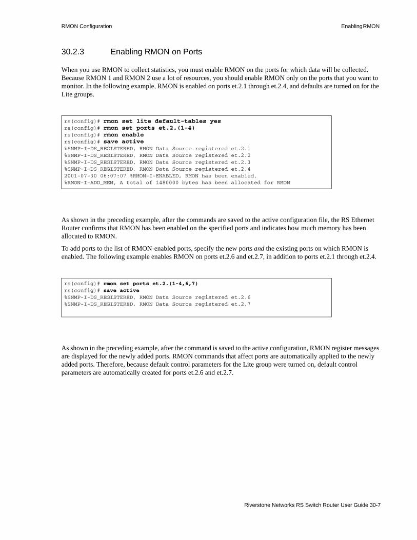
RMON Configuration Enabling RMON
30.2.3 Enabling RMON on Ports
When you use RMON to collect statistics, you must enable RMON on the ports for which data will be collected. Because RMON 1 and RMON 2 use a lot of resources, you should enable RMON only on the ports that you want to monitor. In the following example, RMON is enabled on ports et.2.1 through et.2.4, and defaults are turned on for the Lite groups.
As shown in the preceding example, after the commands are saved to the active configuration file, the RS Ethernet Router confirms that RMON has been enabled on the specified ports and indicates how much memory has been allocated to RMON.
To add ports to the list of RMON-enabled ports, specify the new ports and the existing ports on which RMON is enabled. The following example enables RMON on ports et.2.6 and et.2.7, in addition to ports et.2.1 through et.2.4.
As shown in the preceding example, after the command is saved to the active configuration, RMON register messages are displayed for the newly added ports. RMON commands that affect ports are automatically applied to the newly added ports. Therefore, because default control parameters for the Lite group were turned on, default control parameters are automatically created for ports et.2.6 and et.2.7.
rs(config)# rmon set lite default-tables yesrs(config)# rmon set ports et.2.(1-4)rs(config)# rmon enablers(config)# save active%SNMP-I-DS_REGISTERED, RMON Data Source registered et.2.1%SNMP-I-DS_REGISTERED, RMON Data Source registered et.2.2%SNMP-I-DS_REGISTERED, RMON Data Source registered et.2.3%SNMP-I-DS_REGISTERED, RMON Data Source registered et.2.42001-07-30 06:07:07 %RMON-I-ENABLED, RMON has been enabled.%RMON-I-ADD_MEM, A total of 1480000 bytes has been allocated for RMON
rs(config)# rmon set ports et.2.(1-4,6,7)rs(config)# save active%SNMP-I-DS_REGISTERED, RMON Data Source registered et.2.6%SNMP-I-DS_REGISTERED, RMON Data Source registered et.2.7
Riverstone Networks RS Switch Router User Guide 30-7

Enabling RMON RMON Configuration
Note that RMON is disabled on ports that are not specified in the rmon set ports command. In the following example, only ports et.2.6 and 2.7 are specified. Therefore, RMON is disabled on all the other ports (ports et.2.1 through et.2.4).
Use the rmon show status command to check which levels have been enabled and on what ports, as shown in the following example.
rs(config)# rmon set ports et.2.(6,7)rs(config)# save active%SNMP-I-DS_UNREGISTERED, RMON Data Source un-registered et.2.1%SNMP-I-DS_UNREGISTERED, RMON Data Source un-registered et.2.2%SNMP-I-DS_UNREGISTERED, RMON Data Source un-registered et.2.3%SNMP-I-DS_UNREGISTERED, RMON Data Source un-registered et.2.4%SNMP-I-DS_REGISTERED, RMON Data Source registered et.2.6%SNMP-I-DS_REGISTERED, RMON Data Source registered et.2.7
rs# rmon show statusRMON Status-----------* RMON is ENABLED* RMON updates ENABLED* RMON initialization successful.+--------------------------+| RMON Group Status |+-------+--------+---------+| Group | Status | Default |+-------+--------+---------+| Lite | On | Yes |+-------+--------+---------+| Std | Off | NA |+-------+--------+---------+| Pro | Off | NA |+-------+--------+---------+
Ports RMON enabled on: et.2.(1-4)
RMON Memory Utilization----------------------- Total Bytes Available: 20146176
Total Bytes Allocated to RMON: 4120000 Total Bytes Used: 547184 Total Bytes Free: 3572816
30-8 Riverstone Networks RS Switch Router User Guide
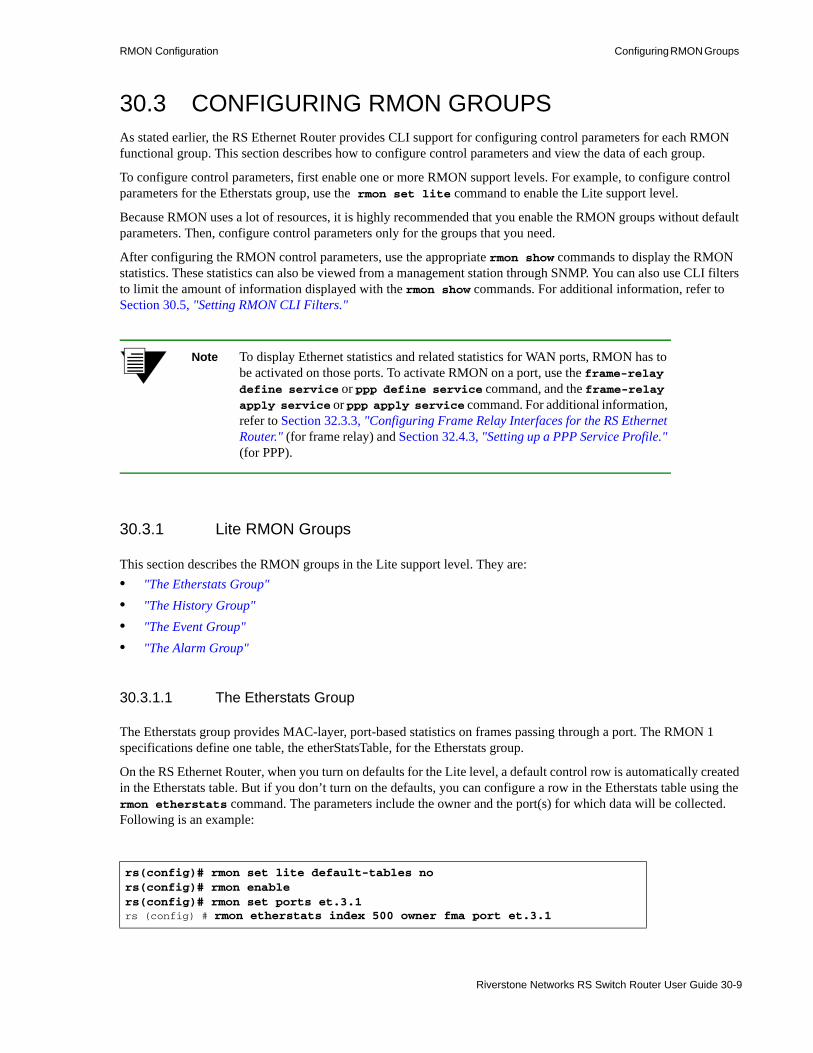
RMON Configuration Configuring RMON Groups
30.3 CONFIGURING RMON GROUPSAs stated earlier, the RS Ethernet Router provides CLI support for configuring control parameters for each RMON functional group. This section describes how to configure control parameters and view the data of each group.
To configure control parameters, first enable one or more RMON support levels. For example, to configure control parameters for the Etherstats group, use the rmon set lite command to enable the Lite support level.
Because RMON uses a lot of resources, it is highly recommended that you enable the RMON groups without default parameters. Then, configure control parameters only for the groups that you need.
After configuring the RMON control parameters, use the appropriate rmon show commands to display the RMON statistics. These statistics can also be viewed from a management station through SNMP. You can also use CLI filters to limit the amount of information displayed with the rmon show commands. For additional information, refer to Section 30.5, "Setting RMON CLI Filters."
Note To display Ethernet statistics and related statistics for WAN ports, RMON has to be activated on those ports. To activate RMON on a port, use the frame-relay define service or ppp define service command, and the frame-relay apply service or ppp apply service command. For additional information, refer to Section 32.3.3, "Configuring Frame Relay Interfaces for the RS Ethernet Router." (for frame relay) and Section 32.4.3, "Setting up a PPP Service Profile." (for PPP).
30.3.1 Lite RMON Groups
This section describes the RMON groups in the Lite support level. They are:• "The Etherstats Group"• "The History Group"• "The Event Group"• "The Alarm Group"
30.3.1.1 The Etherstats Group
The Etherstats group provides MAC-layer, port-based statistics on frames passing through a port. The RMON 1 specifications define one table, the etherStatsTable, for the Etherstats group.
On the RS Ethernet Router, when you turn on defaults for the Lite level, a default control row is automatically created in the Etherstats table. But if you don’t turn on the defaults, you can configure a row in the Etherstats table using the rmon etherstats command. The parameters include the owner and the port(s) for which data will be collected. Following is an example:
rs(config)# rmon set lite default-tables nors(config)# rmon enablers(config)# rmon set ports et.3.1rs (config) # rmon etherstats index 500 owner fma port et.3.1
Riverstone Networks RS Switch Router User Guide 30-9

Configuring RMON Groups RMON Configuration
Use the rmon show etherstats command, as show in the following example, to view the various counts and error conditions on frames received on the specified port. You can use these statistics to evaluate the network load.
30.3.1.2 The History Group
The History group collects statistical samples for a particular port during a specified interval. The History group consists of one control table, historyControlTable, and one data table, etherHistoryTable.
On the RS Ethernet Router, when you turn on defaults for the Lite level, a default control row is automatically created in the History control table. But if you don’t turn on the defaults, you can configure a row in the History control table using the rmon history command. The parameters include the owner, the sampling interval, and the number of samples.
The following example configures a row in the History control table:
rs# rmon show etherstats all-ports RMON I Ethernet Statistics TableIndex: 500, Port: et.3.1, Owner: fma-----RMON EtherStats Total--------------- -----Octets 1568315Frames 22503Broadcast Frames 573Multicast Frames 21639Collisions 064 Byte Frames 1621465-127 Byte Frames 6115128-255 Byte Frames 171256-511 Byte Frames 3512-1023 Byte Frames 01024-1518 Byte Frames 0
rs(config)# rmon set lite default-tables nors(config)# rmon enablers(config)# rmon set ports et.2.1rs(config)# rmon history index 500 port et.2.1 interval 300
30-10 Riverstone Networks RS Switch Router User Guide

RMON Configuration Configuring RMON Groups
Use the rmon show history command to view the collected data as shown in the following example:
30.3.1.3 The Event Group
The Event group consists of one control table, eventTable, and one data table, logTable.The Event group defines the action to be taken when certain conditions occur. Two actions can occur, information is logged in the logTable and an SNMP notification is sent to the management station.
To generate an Event, define the Event then link it to either the Alarm or the Channel group.The Alarm and the Channel groups specify the conditions that trigger the event. Linking the Event group with the Alarm group generates both an alarm and event when the configured alarm threshold is crossed. (Refer to "The Alarm Group" for additional information on linking the Event group with the Channel group.) Linking the Event group with the Channel group generates an event when a packet is matched. (Refer to "The Filter and Channel Group" for additional information on linking the Event group with the Channel group.)
Use the rmon event command to define the Event. The following example specifies that the event is both logged in the Event data table and an SNMP trap generated with the community string “public.”
rs# rmon show history et.2.1RMON I History TableIndex Port Interval(secs) Buckets Owner 500 et.2.1 300 50/50 monitor Index SysUpTime Octets Packets Bcst Mcst Colls %Util Othern 1 02D 00H 55M 22S 0 0 0 0 0 0 0 2 02D 01H 00M 22S 0 0 0 0 0 0 0 3 02D 01H 05M 22S 0 0 0 0 0 0 0 4 02D 01H 10M 22S 0 0 0 0 0 0 0 5 02D 01H 15M 22S 0 0 0 0 0 0 0 6 02D 01H 20M 22S 0 0 0 0 0 0 0 7 02D 01H 25M 22S 0 0 0 0 0 0 0 8 02D 01H 30M 22S 0 0 0 0 0 0 0 9 02D 01H 35M 22S 0 0 0 0 0 0 0 10 02D 01H 40M 23S 0 0 0 0 0 0 0 11 02D 01H 45M 23S 0 0 0 0 0 0 0 12 02D 01H 50M 23S 0 0 0 0 0 0 0 13 02D 01H 55M 23S 0 0 0 0 0 0 0 14 02D 02H 00M 23S 0 0 0 0 0 0 0 15 02D 02H 05M 23S 0 0 0 0 0 0 0 16 02D 02H 10M 23S 0 0 0 0 0 0 0 17 02D 02H 15M 23S 0 0 0 0 0 0 0
rs(config)# rmon set lite default-tables nors(config)# rmon enablers(config)# rmon event index 15 type both community public description "Interface added or module hot swapped in" owner "help desk"
Riverstone Networks RS Switch Router User Guide 30-11

Configuring RMON Groups RMON Configuration
30.3.1.4 The Alarm Group
The Alarm group allows the RS Ethernet Router to poll itself at user-defined intervals. Alarms that constitute an event are logged into the Event data table which can then be polled by the management station. The management station can also be sent notifications.
An alarm can be recorded when the actual value or the difference between actual values rises above or falls below defined rising and falling thresholds. Crossing one threshold does not trigger an alarm. For example, if you configure an alarm for when a falling threshold is crossed, both the rising and the falling thresholds must be crossed before the alarm is actually generated.
You can configure the Alarm group to work with the Event group to generate both an alarm and an event. The Alarm group consists of one table, the alarmTable.When you configure an alarm, you need to specify the following:• SNMP object to be monitored• rising threshold• falling threshold• alarm sample type
The following example configures the RS Ethernet Router to create an event when a module is hot swapped into the chassis or when any new IP interface is configured. The managed object ifTableLastChanged (from RFC 2233) has an object identifier (OID) of 1.3.6.1.2.1.31.1.5.0 and the RS Ethernet Router will poll this OID every 5 minutes (300 seconds).
The rmon event command line configures the following attributes:• Index number 15 to identify this entry in the Event control table.• The event is both logged in the Event data table and an SNMP trap generated with the community
string “public.”• Event owner is “help desk.
The rmon alarm command line configures the following attributes:• Index number 20 to identify this entry in the Alarm table.• The OID 1.3.6.1.2.1.31.1.5.0 identifies the attribute to be monitored.• Samples taken at 300 second (5 minute) intervals.• A “Startup” alarm generation condition instructing the RS Ethernet Router to generate an alarm if
the sample is greater than or equal to the rising threshold or less than or equal to the falling threshold.• Compare value at time of sampling (absolute value) to the specified thresholds.• Rising and falling threshold values are 1.• Rising and falling event index values are 15, which will trigger the Event.
rs(config)# rmon set lite default-tables nors(config)# rmon enablers#(config) rmon event index 15 type both community public description "Interface added or module hot swapped in" owner "help desk"rs#(config) rmon alarm index 20 variable 1.3.6.1.2.1.31.1.5.0 interval 300 startup both type delta-value rising-threshold 1 falling-threshold 1 rising-event-index 15 falling-event-index 15 owner "help desk"
30-12 Riverstone Networks RS Switch Router User Guide

RMON Configuration Configuring RMON Groups
Use the rmon show events command to view the events, as shown in the following example
Use the rmon show alarms command to view the alarms, as shown in the following example
30.3.2 Standard RMON Groups
This section describes the RMON groups that are supported when you enable the Standard support level. They are:• "The Host Group"• "The Host Top-N Group"• "The Matrix Group"• "The Filter and Channel Group"• "The Capture Group"
30.3.2.1 The Host Group
The Host group collects various MAC-layer statistics based on frames transmitted to and from a particular host. The Host group consists of three tables, a control table, hostControlTable, and two data tables: hostTable and HostTimeTable.
On the RS Ethernet Router, when you turn on defaults for the Standard level, a default control row is automatically created in the Host control table. If you don’t turn on the defaults, you can configure a row in the Host control table using the rmon host command. Parameters include the owner and the port(s) for which data will be collected.
rs# rmon show eventsRMON I Event tableIndex Type Community Description Owner 15 both pub interface added helpdeskNo event logs found
rs# rmon show alarmsRMON I Alarm TableIndex: 20, Variable: 1.3.6.1.2.1.31.1.5.0, Owner:-----Rising Event Index : 0Falling Event Index : 0Rising Threshold : 1Falling Threshold : 1Interval : 300Current/Absolute Value: 100/0Sample Type : absoluteStartup Type : both
Riverstone Networks RS Switch Router User Guide 30-13

Configuring RMON Groups RMON Configuration
The following example configures the following parameters: an owner of fma and an index of 500.
Use the rmon show hosts command to view the host-based statistics, as shown in the following example:
The preceding example enables you to monitor traffic on a per-host basis. It displays packets transmitted through port et.3.1 for each host. The hosts are identified by their MAC addresses in the Address column.
30.3.2.2 The Host Top-N Group
The Host Top-N group provides statistics about a set of hosts during a specified interval. For example, you can collect statistics for the top 10 hosts with the highest number of input packets during a 20-second interval.
The Host Top-N statistics are gathered from statistics collected for a particular Host control row. Therefore, to configure the Host Top-N control row, you must first configure the Host control entry with the rmon host command. Then use the rmon host-top-n command to gather the top statistics from the configured host control entry.
The Host Top-N group consists of one control table, hostTopNControlTable, and one data table, hostTopNTable. When you configure a Host Top-N control row, specify the following:• the index of the Host control row on which the statistics will be based • the type of statistics to collect • the ports on which to collect statistics• the number of hosts to include in the table
rs(config)# rmon set standard default-tables nors(config)# rmon enablers(config)# rmon set ports et.3.1rs(config)# rmon host index 500 port et.3.1 owner fma status
rs# rmon show hosts all-ports RMON I Host Table
Index: 500, Port: et.3.1, Owner: fmaAddress InPkts InOctets OutPkts OutOctets Out Bcst Out Mcst------- ------ -------- ------- --------- -------- --------00001D:4F46E9 0 0 21623 1493726 0 000001D:A9AAEF 179 29476 0 0 0 000001D:A9B6B7 0 0 3 192 0 000001D:A9B6B8 0 0 103 6592 0 000001D:A9B938 1 64 36 2304 0 000C048:1E8820 0 0 304 19456 0 000E063:DEFCB1 0 0 15 960 0 0080009:7B965C 1 159 24 1536 0 0080020:B31886 0 0 248 34126 0 0080020:B57CF5 0 0 27 1755 0 0
30-14 Riverstone Networks RS Switch Router User Guide

RMON Configuration Configuring RMON Groups
Whenever you want to do a sampling, enter the rmon host-top-n command to start the sampling. Then, wait the specified sampling interval before using the rmon show host-top-n command to view the results. The Host Top-N report only runs every time you specify the command.
The following example reports on the top 7 hosts with the highest number of outgoing packets. The statistics to be gathered are from the host control row with an index of 500.
The following shows the top 7 hosts based on the specified statistics:
30.3.2.3 The Matrix Group
The Matrix group provides flow-based statistics on frames transmitted from a source address to a destination address. To collect layer-2 matrix information, ports must be configured for flow-bridging mode. (By default, ports on the RS Ethernet Router operate in address-bridging mode.)
The Matrix group consists of one control table, matrixControlTable, and two data tables, matrixSDTable and matrixDSTable.
rs(config)# rmon set standard default-tables nors(config)# rmon enablers(config)# rmon set ports et.3.1rs(config)# rmon host index 500 port et.3.1rs(config)# rmon host-top-n index 600 base out-packets duration 20 host-index 500 size 7
rs# rmon show host-top-n RMON I HostTopN Table---------------------Index: 600, HostIndex: 500RateBase: Out-PacketsTime Remaining: 0Duration: 20Requested Size: 10Granted Size: 10StartTime: 00D 00H 04M 03SOwner:
Address Rate------- ----00001D:4F46E9 19080020:B31886 100001D:A9B938 000C048:1E8820 000E063:2341A1 0080020:B57CF5 000001D:A9AAEF 0
Riverstone Networks RS Switch Router User Guide 30-15

Configuring RMON Groups RMON Configuration
On the RS Ethernet Router, when you turn on defaults for the Standard level, a default control row is automatically created in the Matrix control table. If you don’t turn on the defaults, you can configure a row in the Matrix control table using the rmon matrix command. The following example configures an entry for the Matrix control table for port et.3.1:
The following example displays the flow-based statistics for port et.3.1. It displays statistics for each source and destination pair.
rs(config)# port flow-bridging et.3.1rs(config)# rmon set standard default-tables nors(config)# rmon enablers(config)# rmon set ports et.3.1rs(config)# rmon matrix index 500 owner fma port et.3.1
rs# rmon show matrix et.3.1RMON I Matrix Table
Port: et.3.1, Index: 500, Owner: fmaSrcAddr DstAddr Packets Octets------- ------- ------- ------00001D:4F46E9 01001D:000000 6744 55300800001D:4F46E9 0180C2:000000 17151 109766400001D:A9B6B7 FFFFFF:FFFFFF 3 19200001D:A9B6B8 FFFFFF:FFFFFF 114 729600001D:A9B938 FFFFFF:FFFFFF 36 230400C048:1E8820 FFFFFF:FFFFFF 336 2150400E063:DEFCB1 080020:B57CF5 1 6400E063:DEFCB1 FFFFFF:FFFFFF 15 960080009:7B965C FFFFFF:FFFFFF 27 1728080020:B31886 00001D:A9AAEF 189 31134080020:B31886 00001D:A9B6B8 1 86080020:B31886 00001D:A9B938 4 305080020:B31886 00E063:78FFA1 1 159080020:B31886 080009:7B965C 1 159080020:B31886 FFFFFF:FFFFFF 67 4288080020:B57CF5 00001D:A9AAEF 4 368080020:B57CF5 FFFFFF:FFFFFF 30 1920
30-16 Riverstone Networks RS Switch Router User Guide

RMON Configuration Configuring RMON Groups
30.3.2.4 The Filter and Channel Group
The Filter group provides a mechanism for screening packets. You can configure a data filter or a status filter. A data filter specifies which packets to match based on a packet’s contents. A status filter monitors packets based on their status. The stream of packets that match the filter is called a channel. A channel can be configured to generate an event defined in the Event group. The packets in the channel can also be captured, if defined in the Capture group.
To configure a Filter control table entry, define the Channel entry first, then the Filter. In the following example, the following are configured for the channel:• Index number 601. This index is used to link this channel to the filter. • Packets that match the data and status filters will be accepted.• Data will be collected from port et.3.1.• Data, status and events will flow through this channel.
The following are configured for the filter:• The data to be matched, the data mask and inversion mask to be applied during the match process.• The channel with an index of 601 is linked with this filter.
:
Use the rmon show channels command to view the channels that were configured, as shown in the following example:
rs(config)# rmon channel index 601 accept-type matched port et.3.1 data-control onrs(config)# rmon filter index 600 data "01 80" status enable channel-index 601data-mask "FF FF" data-offset 0 data-not-mask "00 00"
rs# rmon show channels RMON I Channel TableIndex Port AcceptType Flow Status E-Idx OnIdx OffIdx Owner 601 et.3.1 Matched On Ready 0 0 0
Riverstone Networks RS Switch Router User Guide 30-17

Configuring RMON Groups RMON Configuration
Use the rmon show filters command to view the filters that were configured, as shown in the following example:
30.3.2.5 The Capture Group
The Capture group is an extension of the Filter group. It is used for storing and retrieving the captured packets. You can also set up a buffering scheme for capturing packets from one of the channels.
The following example configures the packets to be captured:• Packets from the channel identified by index 601 will be captured• The action of the buffer when it becomes full, which is to wrap around• The maximum number of octets to save is 2048• The maximum number of octets to download during an SNMP retrieval is 25• The maximum number of octets to save in the buffer is 30
:
rs# rmon show filters RMON I Filter TableIndex: 600, ChannelIndex: 601, Offset: 0, Owner: -----Data: 0180DataMask: FFFFDataNotMask: 0000Status: 0StatusMask: 0StatusNotMask: 0
rs(config)# rmon channel index 601 accept-type matched port et.3.1 data-control onrs(config)# rmon filter index 600 data "01 80" status enable channel-index 601data-mask "FF FF" data-offset 0 data-not-mask "00 00"rs(config)# rmon capture index 600 channel-index 601 full-action wrap max-octets 2048download-slice-size 25 slice-size 30
30-18 Riverstone Networks RS Switch Router User Guide

RMON Configuration Configuring RMON Groups
Use the rmon show packet-capture command to view the packets that were captured, as shown in the following example:
rs# rmon show packet-capture RMON I Packet Capture Table & LogsIndex: 600, Channel Index: 601, Owner: -----Bytes Requested: 2048Bytes Granted: 2048Capture Buffer Size (bytes): 30SNMP Download Size (bytes): 25SNMP Download Offset (bytes): 0Space Availability: FullAction of Buffer when full: WrapSysUpTime when capture buffer was turned on: 00D 00H 00M 00S
Index CtrlIndex PktId Length Time Status 2454 600 4135 80 00D 01H 23M 17S 0ADDR HEX ASCII0000: 01 80 C2 00 00 00 00 00 1D 4F 46 E9 00 2E 42 42 | .........OF...BB0010: 03 00 00 00 00 00 01 F4 00 00 1D 72 97 AE | ...........r..
Index CtrlIndex PktId Length Time Status 2455 600 4136 80 00D 01H 23M 19S 0ADDR HEX ASCII0000: 01 80 C2 00 00 00 00 00 1D 4F 46 E9 00 2E 42 42 | .........OF...BB0010: 03 00 00 00 00 00 01 F4 00 00 1D 72 97 AE | ...........r.. ...
Riverstone Networks RS Switch Router User Guide 30-19

Configuring RMON Groups RMON Configuration
30.3.3 Professional RMON Groups
This section describes the RMON 2 groups that are supported when you enable the Professional level. They are:• "The Protocol Directory Group"• "The Protocol Distribution Group"• "Higher-Layer Host Group"• "Higher-Layer Matrix Group"• "Address Map Group"• "User History Group"
On the RS Ethernet Router, the Higher-Layer Host group includes the RMON 2 Application-Layer and Network Layer Host groups; and the Higher-Layer Matrix group includes the RMON 2 Application-Layer and Network-Layer Matrix groups. Note that in RMON 2, all protocols above the network layer are considered application layer.
When you enable the Professional level, you can enable defaults for the following groups: Protocol Distribution, Address Map, Application Layer and Network Layer Hosts groups, and the Application Layer and Network Layer Matrix groups. Turning on the defaults for these groups uses a lot of memory. It is highly recommended that you do not enable the defaults and instead, configure control parameters only for the groups you need.
30.3.3.1 The Protocol Directory Group
The Protocol Directory lists the protocols that the RS Ethernet Router interprets. The RS Ethernet Router’s RMON 2 protocol directory contains over 500 protocols that can be decoded for UDP and TCP ports. For the list of protocols supported by the RS Ethernet Router, refer to Appendix A in the Riverstone RS Switch Router Command Line Interface Reference Manual. (For additional information on the protocols, refer to RFC 2895.)
Use the rmon set protocol-directory command to specify which protocols are interpreted when statistics are collected for each of the following RMON groups: Host, Matrix, and Address Mapping. The command provides the following options:• turn on support for a protocol• turn off support for a protocol• turn off support for a protocol and make the corresponding SNMP object read-only. This prevents
the protocol from being set using SNMP.
The following example turns on support for the ether2 protocol for all three groups:
rs(config)# rmon set protocol-directory ether2 address-map onrs(config)# rmon set protocol-directory ether2 host onrs(config)# rmon set protocol-directory ether2 matrix on
30-20 Riverstone Networks RS Switch Router User Guide

RMON Configuration Configuring RMON Groups
Use the rmon show protocol-directory command to check which protocols are interpreted for each of the RMON groups. As shown in the following example, ether2 is now turned on for all three groups.
30.3.3.2 The Protocol Distribution Group
The Protocol Distribution group is used to determine the protocol encapsulations used in a network. It displays statistics for packets and octets on a per protocol, per port basis. The Protocol Distribution group consists of one control table, protocolDistcontrolTable, and one data table, protocolDistStatsTable.
The following example configures a row in the Protocol Distribution control table for port et.3.1:
Use the rmon show protocol-distribution command to view the collected statistics. It displays the kinds of protocol traffic being received on the specified port.
rs# rmon show protocol-directory all-protocolsRMON II Protocol Directory TableLast Change: 00D 00H 00M 00SIndex AddrMap Host Matrix Status Protocol 1 On On On Active ether2 2 NA Off Off Active idpf 3 NA Off Off Active ip-v4 4 NA Off Off Active chaosnet 5 NA Off Off Active arp 6 NA Off Off Active rarp 7 NA Off Off Active vip 8 NA Off Off Active vloop 9 NA Off Off Active vloop2 10 NA Off Off Active vecho 11 NA Off Off Active vecho213 NA Off Off Active netbios-3com 14 NA Off Off Active atalk 15 NA Off Off Active aarp 16 NA Off Off Active dec
rs(config)# rmon protocol-distribution index 500 owner fma port et.3.1
rs# rmon show protocol-distribution all-ports RMON II Protocol Distribution Table
Index: 500, Port: et.3.1, Owner: fma Pkts Octets Protocol ---- ------ -------- 127 20388 ether2 127 20388 *ether2.ip-v4 127 20388 *ether2.ip-v4.udp 127 20388 *ether2.ip-v4.udp.snmp
Riverstone Networks RS Switch Router User Guide 30-21

Configuring RMON Groups RMON Configuration
30.3.3.3 Higher-Layer Host Group
The Higher-Layer Host group includes the Application-Layer Host group and the Network-Layer Host group. The Network-Layer Host group monitors traffic for each network-layer address. It is similar to the RMON 1 Host group, but it provides more detailed information; for a specific interface, it provides per-protocol statistics for each discovered network address. The Network-Layer Host group consists of one control table, nlHostControlTable, and one data table, nlHostTable.
The Application-Layer Host group monitors traffic, by protocol, for each host. It provides information for all application-layer protocols for each source and destination address. For example, you can determine how much traffic is generated and received by Microsoft Mail for a specific host. The Application-Layer Host group consists of one table, the alHostTable.
Use the rmon hl-host command to configure a control row in the Higher-Layer Host control table. This table, when configured, is used by both application-layer and network-layer host data. Following is an example:
The following example shows application-layer, host-based statistics displayed when you use the rmon show al-host command. The output displays the protocol at the top layer of the protocol stack.
rs(config)# rmon set professional default-tables nors(config)# rmon enablers(config)# rmon set ports et.3.1rs(config)# rmon hl-host index 500 al-max-entries 15 nl-max-entries 15 port et.3.1
rs# rmon show al-host all-ports RMON II Application Layer Host Table
Index: 500, Port: et.3.1, Inserts: 11, Deletes: 0, Owner: Address InPkts InOctets OutPkts OutOctets Protocol------- ------ -------- ------- --------- --------10.50.7.4 0 0 88 8636 ip-v410.50.7.4 0 0 3 364 icmp10.50.7.4 0 0 85 8272 udp10.50.7.4 0 0 85 8272 snmp10.50.7.6 364 52746 0 0 ip-v410.50.7.6 3 364 0 0 icmp10.50.7.6 361 52382 0 0 udp10.50.7.6 361 52382 0 0 snmp10.50.7.45 0 0 276 44110 ip-v410.50.7.45 0 0 276 44110 udp10.50.7.45 0 0 276 44110 snmp
30-22 Riverstone Networks RS Switch Router User Guide
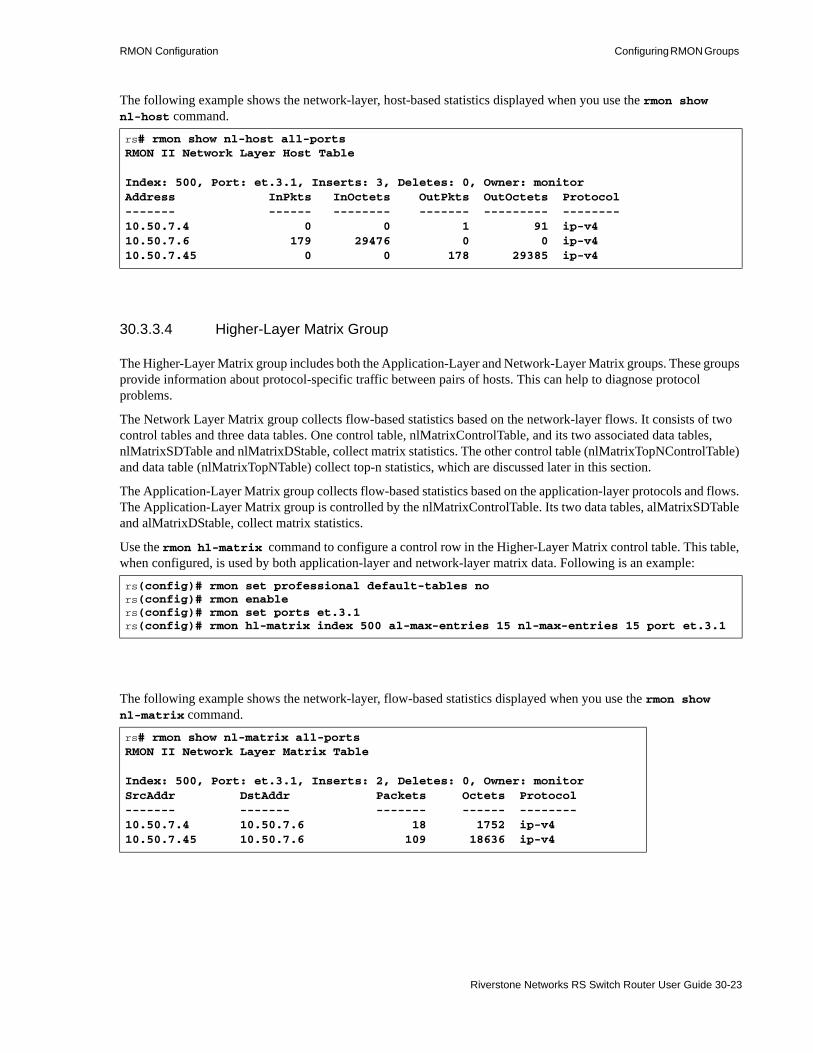
RMON Configuration Configuring RMON Groups
The following example shows the network-layer, host-based statistics displayed when you use the rmon show nl-host command.
30.3.3.4 Higher-Layer Matrix Group
The Higher-Layer Matrix group includes both the Application-Layer and Network-Layer Matrix groups. These groups provide information about protocol-specific traffic between pairs of hosts. This can help to diagnose protocol problems.
The Network Layer Matrix group collects flow-based statistics based on the network-layer flows. It consists of two control tables and three data tables. One control table, nlMatrixControlTable, and its two associated data tables, nlMatrixSDTable and nlMatrixDStable, collect matrix statistics. The other control table (nlMatrixTopNControlTable) and data table (nlMatrixTopNTable) collect top-n statistics, which are discussed later in this section.
The Application-Layer Matrix group collects flow-based statistics based on the application-layer protocols and flows. The Application-Layer Matrix group is controlled by the nlMatrixControlTable. Its two data tables, alMatrixSDTable and alMatrixDStable, collect matrix statistics.
Use the rmon hl-matrix command to configure a control row in the Higher-Layer Matrix control table. This table, when configured, is used by both application-layer and network-layer matrix data. Following is an example:
The following example shows the network-layer, flow-based statistics displayed when you use the rmon show nl-matrix command.
rs# rmon show nl-host all-ports RMON II Network Layer Host Table
Index: 500, Port: et.3.1, Inserts: 3, Deletes: 0, Owner: monitorAddress InPkts InOctets OutPkts OutOctets Protocol------- ------ -------- ------- --------- --------10.50.7.4 0 0 1 91 ip-v410.50.7.6 179 29476 0 0 ip-v410.50.7.45 0 0 178 29385 ip-v4
rs(config)# rmon set professional default-tables nors(config)# rmon enablers(config)# rmon set ports et.3.1rs(config)# rmon hl-matrix index 500 al-max-entries 15 nl-max-entries 15 port et.3.1
rs# rmon show nl-matrix all-ports RMON II Network Layer Matrix Table
Index: 500, Port: et.3.1, Inserts: 2, Deletes: 0, Owner: monitorSrcAddr DstAddr Packets Octets Protocol------- ------- ------- ------ --------10.50.7.4 10.50.7.6 18 1752 ip-v410.50.7.45 10.50.7.6 109 18636 ip-v4
Riverstone Networks RS Switch Router User Guide 30-23

Configuring RMON Groups RMON Configuration
The following example shows the application-layer, flow-based statistics displayed when you use the rmon show al-matrix command. It displays the packet and octet counts, per protocol, for each host and destination pair.
You can also collect and view top-n matrix statistics at the network-level and at the application-level. The top-n statistics rank the traffic between hosts based on a particular parameter.
The Network Layer Matrix group has one control table, nlMatrixTopNControlTable, and data table, nlMatrixTopNTable, for the collection of top-n statistics. The Application Layer Matrix group has one control table, alMatrixTopNControlTable, and data table, alMatrixTopNTable, for the collection of top-n statistics at the application level.
The application-level and network level top-n matrix statistics are gathered from the application-level and network level matrix statistics. Therefore, to configure any of these tables, you must first configure the higher-level matrix with the rmon-hl matrix commands. Then, you can configure the network level and application-level top-n matrix.
The following example configures the network layer top-n matrix control table:.
rs# rmon show al-matrix all-ports RMON II Application Layer Host Table
Index: 500, Port: et.3.1, Inserts: 6, Deletes: 0, Owner: monitorSrcAddr DstAddr Packets Octets Protocol------- ------- ------- ------ --------10.50.7.4 10.50.7.6 18 1752 ip-v410.50.7.4 10.50.7.6 18 1752 udp10.50.7.4 10.50.7.6 18 1752 snmp10.50.7.45 10.50.7.6 109 18636 ip-v410.50.7.45 10.50.7.6 109 18636 udp10.50.7.45 10.50.7.6 109 18636 snmp
rs(config)# rmon set professional default-tables nors(config)# rmon enablers(config)# rmon set ports et.3.1rs(config)# rmon hl-matrix index 500 al-max-entries 15 nl-max-entries 15 port et.3.1rs(config)# rmon nl-matrix-top-n index 100 matrix-index 500 ratebase all-packets duration 60
30-24 Riverstone Networks RS Switch Router User Guide

RMON Configuration Configuring RMON Groups
Following is an example of the rmon show nl-matrix-top-n command:
The following example configures the application layer top-n matrix control table:
Following is an example of the rmon show al-matrix-top-n command:
rs# rmon show nl-matrix-top-nRMON II Nl Matrix Table
Index M-Index RateBase TimeRem Duration Size StartTime Reports Owner 1 500 Octets 20 20 5 00D 00H 51M 37S 1 User
SrcAddr DstAddr PktRate R-PktRate OctetRate R-OctetRate Protocol------- ------- ------- --------- --------- ----------- --------192.100.81.3 10.60.89.88 23 0 19986 0 *ether2.ip-v4192.100.81.1 192.100.81.3 0 0 0 0 *ether2.ip-v4192.100.81.3 192.100.81.1 0 0 0 0 *ether2.ip-v410.60.89.88 192.100.81.3 0 23 0 19986 *ether2.ip-v4
rs(config)# rmon set professional default-tables nors(config)# rmon enablers(config)# rmon set ports et.3.1rs(config)# rmon hl-matrix index 500 al-max-entries 15 nl-max-entries 15 port et.3.1rs(config)# rmon al-matrix-top-n index 100 matrix-index 500 ratebase all-packets duration 60 size 100
rs# rmon show al-matrix-top-nRMON II Al Matrix Table
Index M-Index RateBase TimeRem Duration Size StartTime Reports Owner 1 500 All-Packets 14 20 5 00D 00H 50M 25S 1 SML
SrcAddr DstAddr PktRate R-PktRate OctetRate R-OctetRate Protocol------- ------- ------- --------- --------- ----------- --------192.100.81.3 10.60.89.88 21 0 19836 0 *ether2.ip-v4.tcp.telnet192.100.81.3 10.60.89.88 21 0 19836 0 *ether2.ip-v4.tcp192.100.81.3 10.60.89.88 21 0 19836 0 *ether2.ip-v4192.100.81.1 192.100.81.3 0 0 0 0 *ether2.ip-v4192.100.81.3 192.100.81.1 0 0 0 0 *ether2.ip-v4
Riverstone Networks RS Switch Router User Guide 30-25
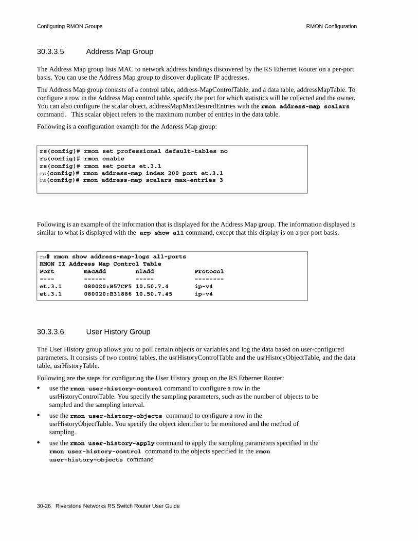
Configuring RMON Groups RMON Configuration
30.3.3.5 Address Map Group
The Address Map group lists MAC to network address bindings discovered by the RS Ethernet Router on a per-port basis. You can use the Address Map group to discover duplicate IP addresses.
The Address Map group consists of a control table, address-MapControlTable, and a data table, addressMapTable. To configure a row in the Address Map control table, specify the port for which statistics will be collected and the owner. You can also configure the scalar object, addressMapMaxDesiredEntries with the rmon address-map scalars command. This scalar object refers to the maximum number of entries in the data table.
Following is a configuration example for the Address Map group:
Following is an example of the information that is displayed for the Address Map group. The information displayed is similar to what is displayed with the arp show all command, except that this display is on a per-port basis.
30.3.3.6 User History Group
The User History group allows you to poll certain objects or variables and log the data based on user-configured parameters. It consists of two control tables, the usrHistoryControlTable and the usrHistoryObjectTable, and the data table, usrHistoryTable.
Following are the steps for configuring the User History group on the RS Ethernet Router:• use the rmon user-history-control command to configure a row in the
usrHistoryControlTable. You specify the sampling parameters, such as the number of objects to be sampled and the sampling interval.
• use the rmon user-history-objects command to configure a row in the usrHistoryObjectTable. You specify the object identifier to be monitored and the method of sampling.
• use the rmon user-history-apply command to apply the sampling parameters specified in the rmon user-history-control command to the objects specified in the rmon user-history-objects command
rs(config)# rmon set professional default-tables nors(config)# rmon enablers(config)# rmon set ports et.3.1rs(config)# rmon address-map index 200 port et.3.1rs(config)# rmon address-map scalars max-entries 3
rs# rmon show address-map-logs all-ports RMON II Address Map Control TablePort macAdd nlAdd Protocol---- ------ ----- --------et.3.1 080020:B57CF5 10.50.7.4 ip-v4et.3.1 080020:B31886 10.50.7.45 ip-v4
30-26 Riverstone Networks RS Switch Router User Guide

RMON Configuration Configuring RMON Groups
The following commands were used to configure the example:• the rmon user-history-control command configures a control row for one MIB object, with
an interval of 10 seconds, and 5 sampling periods • the rmon user-history-objects command specifies the object identifier to be monitored and
specifies that during the specified interval the object’s change in value will be compared to the threshold value
• the rmon user-history-apply command applies the parameters to the object defined by obj1
Use the rmon show user-history command, as shown in the following example to view the data in the usrHistoryTable:
rs(config)# rmon set professional default-tables nors(config)# rmon enablers(config)# rmon set ports et.3.1rs(config)# rmon user-history-control index 600 interval 10 objects 1 samples 5rs(config)# rmon user-history-objects obj1 variable 1.3.6.1.2.1.16.1.1.1.5.500 type delta-valuers(config)# rmon user-history-apply obj1 status enable to 600
rs# rmon show user-history all-indexes RMON II User History TableIndex Objects Interval Buckets Owner Group 600 1 10 5/5 obj1Index Variable Start End Value Status 5 1.3.6.1.2.1.16.1.1.1.5.500 00D 00H 33M 41S 00D 00H 33M 41S Delta 0) NA 6 1.3.6.1.2.1.16.1.1.1.5.500 00D 00H 33M 51S 00D 00H 33M 51S Delta( 0) NA 7 1.3.6.1.2.1.16.1.1.1.5.500 00D 00H 34M 01S 00D 00H 34M 01S Delta( 2067) Pos 8 1.3.6.1.2.1.16.1.1.1.5.500 00D 00H 34M 11S 00D 00H 34M 11S Delta( 7) Pos 9 1.3.6.1.2.1.16.1.1.1.5.500 00D 00H 34M 21S 00D 00H 34M 21S Delta( 8) Pos
Riverstone Networks RS Switch Router User Guide 30-27
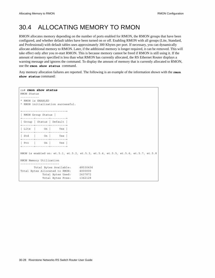
Allocating Memory to RMON RMON Configuration
30.4 ALLOCATING MEMORY TO RMONRMON allocates memory depending on the number of ports enabled for RMON, the RMON groups that have been configured, and whether default tables have been turned on or off. Enabling RMON with all groups (Lite, Standard, and Professional) with default tables uses approximately 300 Kbytes per port. If necessary, you can dynamically allocate additional memory to RMON. Later, if the additional memory is longer required, it can be removed. This will take effect only after you re-start RMON. This is because memory cannot be freed if RMON is still using it. If the amount of memory specified is less than what RMON has currently allocated, the RS Ethernet Router displays a warning message and ignores the command. To display the amount of memory that is currently allocated to RMON, use the rmon show status command.
Any memory allocation failures are reported. The following is an example of the information shown with the rmon show status command:
rs# rmon show statusRMON Status-----------* RMON is ENABLED* RMON initialization successful.
+--------------------------+| RMON Group Status |+-------+--------+---------+| Group | Status | Default |+-------+--------+---------+| Lite | On | Yes |+-------+--------+---------+| Std | On | Yes |+-------+--------+---------+| Pro | On | Yes |+-------+--------+---------+
RMON is enabled on: et.5.1, et.5.2, et.5.3, et.5.4, et.5.5, et.5.6, et.5.7, et.5.8
RMON Memory Utilization----------------------- Total Bytes Available: 48530436Total Bytes Allocated to RMON: 4000000 Total Bytes Used: 2637872 Total Bytes Free: 1362128
30-28 Riverstone Networks RS Switch Router User Guide
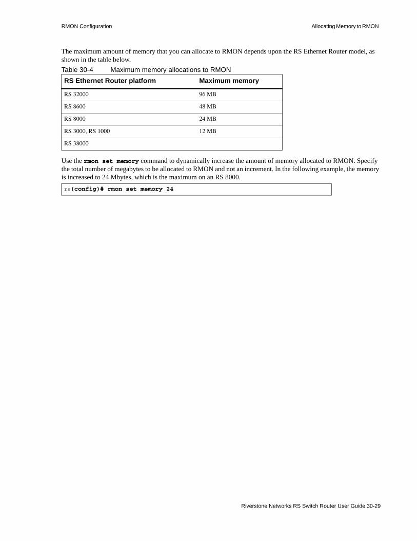
RMON Configuration Allocating Memory to RMON
The maximum amount of memory that you can allocate to RMON depends upon the RS Ethernet Router model, as shown in the table below.Table 30-4 Maximum memory allocations to RMON
Use the rmon set memory command to dynamically increase the amount of memory allocated to RMON. Specify the total number of megabytes to be allocated to RMON and not an increment. In the following example, the memory is increased to 24 Mbytes, which is the maximum on an RS 8000.
RS Ethernet Router platform Maximum memory
RS 32000 96 MB
RS 8600 48 MB
RS 8000 24 MB
RS 3000, RS 1000 12 MB
RS 38000
rs(config)# rmon set memory 24
Riverstone Networks RS Switch Router User Guide 30-29
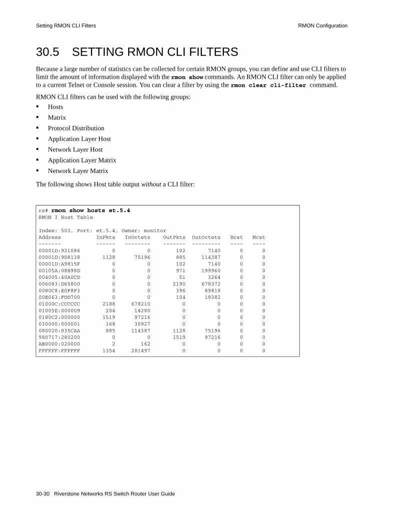
Setting RMON CLI Filters RMON Configuration
30.5 SETTING RMON CLI FILTERSBecause a large number of statistics can be collected for certain RMON groups, you can define and use CLI filters to limit the amount of information displayed with the rmon show commands. An RMON CLI filter can only be applied to a current Telnet or Console session. You can clear a filter by using the rmon clear cli-filter command.
RMON CLI filters can be used with the following groups:• Hosts• Matrix• Protocol Distribution• Application Layer Host• Network Layer Host• Application Layer Matrix• Network Layer Matrix
The following shows Host table output without a CLI filter:
rs# rmon show hosts et.5.4RMON I Host Table Index: 503, Port: et.5.4, Owner: monitorAddress InPkts InOctets OutPkts OutOctets Bcst Mcst------- ------ -------- ------- --------- ---- ----00001D:921086 0 0 102 7140 0 000001D:9D8138 1128 75196 885 114387 0 000001D:A9815F 0 0 102 7140 0 000105A:08B98D 0 0 971 199960 0 0004005:40A0CD 0 0 51 3264 0 0006083:D65800 0 0 2190 678372 0 00080C8:E0F8F3 0 0 396 89818 0 000E063:FDD700 0 0 104 19382 0 001000C:CCCCCC 2188 678210 0 0 0 001005E:000009 204 14280 0 0 0 00180C2:000000 1519 97216 0 0 0 0030000:000001 168 30927 0 0 0 0080020:835CAA 885 114387 1128 75196 0 0980717:280200 0 0 1519 97216 0 0AB0000:020000 2 162 0 0 0 0FFFFFF:FFFFFF 1354 281497 0 0 0 0
30-30 Riverstone Networks RS Switch Router User Guide

RMON Configuration Setting RMON CLI Filters
The following shows the same rmon show hosts command with a filter applied so that only hosts with inpkts greater than 500 are displayed:
You can list the CLI filters as shown below:
rs(config)# rmon set cli-filter 4 inpkts > 500rs# rmon apply cli-filter 4 rs# rmon show hosts et.5.4 RMON I Host TableFilter: inpkts > 500Address Port InPkts InOctets OutPkts OutOctets Bcst Mcst------- ---- ------ -------- ------- --------- ---- ----00001D:9D8138 et.5.4 1204 80110 941 121129 0 001000C:CCCCCC et.5.4 2389 740514 0 0 0 00180C2:000000 et.5.4 1540 98560 0 0 0 0080020:835CAA et.5.4 940 121061 1204 80110 0 0FFFFFF:FFFFFF et.5.4 1372 285105 0 0
rs# rmon show cli-filtersRMON CLI FiltersId Filter-- ------ 4 inpkts > 500You have selected a filter: inpkts > 500
Riverstone Networks RS Switch Router User Guide 30-31

Troubleshooting RMON RMON Configuration
30.6 TROUBLESHOOTING RMONIf you are not seeing the information you expected with an rmon show command, or if the network management station is not collecting the desired statistics, first check that the port is up. Then, use the rmon show status command to check the RMON configuration on the RS Ethernet Router.
Check the following fields on the rmon show status command output:
1. Make sure that RMON has been enabled on the RS Ethernet Router. When the RS Ethernet Router is booted, RMON is off by default. RMON is enabled with the rmon enable command.
2. Make sure that at least one of the RMON support levels—Lite, Standard, or Professional—is turned on with the rmon set lite|standard|professional command.
3. Make sure that RMON is enabled on the port for which you want statistics. Use the rmon set ports command to specify the port on which RMON will be enabled.
4. Make sure that the control table is configured for the report that you want. Depending upon the RMON group, default control tables may be created for all ports on the RS Ethernet Router. Or, if the RMON group is not one for which default control tables can be created, you will need to configure control table entries using the appropriate rmon command.
If you or your application are unable to create a control table row, check the snmp show status output for errors. Make sure that there is a read-write community string. Verify that you can ping the RS Ethernet Router and that no ACLs prevent you from using SNMP to access the RS Ethernet Router.
5. Make sure that RMON has not run out of memory.
rs# rmon show statusRMON Status-----------* RMON is ENABLED * RMON initialization successful.
+--------------------------+| RMON Group Status | +-------+--------+---------+| Group | Status | Default |+-------+--------+---------+| Lite | On | Yes | +-------+--------+---------+| Std | On | Yes |+-------+--------+---------+| Pro | On | Yes |+-------+--------+---------+ RMON is enabled on: et.5.1, et.5.2, et.5.3, et.5.4, et.5.5, et.5.6, et.5.7, et.5.8 RMON Memory Utilization ----------------------- Total Bytes Available: 48530436 Total Bytes Allocated to RMON: 4000000 Total Bytes Used: 2637872 Total Bytes Free: 1362128
1
2
4
3
5
30-32 Riverstone Networks RS Switch Router User Guide
31 LFAP CONFIGURATION GUIDE
31.1 LFAP OVERVIEWThis chapter provides information about version 5.0 of Riverstone’s Lightweight Flow Accounting Protocol (LFAP) accounting architecture. It explain how service providers can use LFAP’s capabilities to improve their network management and to transition to a usage-based billing model.
The RS Ethernet Router platform was engineered with the ability to account for every byte and packet of every flow without affecting routing and switching performance. Riverstone’s LFAP accounting capabilities are integrated into the ASIC architecture of all RS Ethernet Router switch routers. LFAP is particularly valuable for gathering information for layer-2, layer-3, and layer-4 flows.
Across the RS Ethernet Router platform, flow and traffic data is accounted for by the hardware, rather than software, so that enabling accounting features does not impact system performance. Periodically, the router gathers flow data and sends the information through TCP (for connection-oriented delivery guarantee) to an accounting server using the LFAP protocol.
The following information is collected for IP flows:• Source/destination IP address• Source/destination AS• Source/destination port• Ingress/egress port• Type of service (DSCP)• Protocol• Total bytes• Total packets• Total time of flow account• VLAN ID• VLAN priority
The following information is collected for MPLS flows:• Source/destination switch address• Ingress/egress port• Incoming/outgoing MPLS labels• LDP FEC• Source/destination VLAN ID• Next hop address
Riverstone Networks RS Switch Router User Guide 31-1

LFAP Structure LFAP Configuration Guide
• Total bytes• Total packets• Total time of flow account
The following information is collected for ATM flows:• Outgoing flows
- Source/destination IP address associated with the PVC- Protocol – LLC MUX or VC MUX- Egress port- CCE address- Source/destination VLAN- VPI/VCI- Byte count, excluding ATM header- Packets – AAL5 frames, including LLC header- Start/end time
• Incoming flows- Source/destination IP address associated with the PVC- Protocol – LLC MUX or VC MUX- Ingress port- CCE address- VPI/VCI- Byte count, excluding ATM header- start/end time
Note If the ATM PVC is a trunk port or there are multiple peer addresses, no address is reported.
Note See the Riverstone RS Switch Router Command Line interface Reference for an explanation of all LFAP commands and parameters.
31.2 LFAP STRUCTURELFAP is designed to deliver real-time flow data, even in the middle of a flow.As the flow continues, the RS Ethernet Router periodically (configurable down to one minute) reads the ASIC counter and transmits the data to the accounting server.
31-2 Riverstone Networks RS Switch Router User Guide

LFAP Configuration Guide Configuring LFAP
LFAP also allows for the configuration of up to two fail-over servers using the lfap set server command. When an RS Ethernet Router is configured with multiple accounting servers, a connection is established with a primary server; two additional backup servers can also be specified. In the event that the primary server fails, the router automatically recognizes the failure and sends traffic data to the backup server.
RapidOS also provides a MIB that is used to monitor the LFAP accounting process in the RS Ethernet Router. Monitoring these MIB objects keeps you informed about the functioning of the accounting processes. If an accounting process fails, the SNMP agent will send an alert. The MIB also provides access to the number of bytes and packets, if any, that are not accounted for during a sever failure. This is crucial to determining the impact of any accounting server outage.
Figure 31-1 Topology of LFAP to servers and applications
31.3 CONFIGURING LFAPThe process of configuring LFAP on an RS Ethernet Router switch router consists of five main tasks:1. Specifying the IP address of the accounting server(s) on the RS Ethernet Router2. Specifying the list of information to be sent to the accounting server3. Creating and applying ACLs that further define the information sent to the server (ACLs are not
required for MPLS accounting)4. Applying the ACLs to interfaces5. Starting the LFAP agent process on the RS Ethernet Router
Accounting Database Server
Accounting Database Server
3rd Party Accounting /Billing /Planning
Application
LFAPMessages
LFAPMessages
LFAPMessages
Riverstone Networks RS Switch Router User Guide 31-3
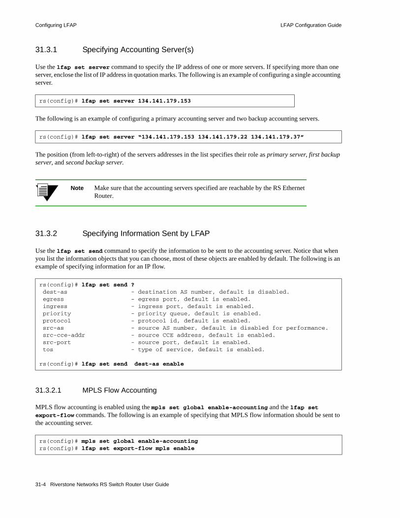
Configuring LFAP LFAP Configuration Guide
31.3.1 Specifying Accounting Server(s)
Use the lfap set server command to specify the IP address of one or more servers. If specifying more than one server, enclose the list of IP address in quotation marks. The following is an example of configuring a single accounting server.
The following is an example of configuring a primary accounting server and two backup accounting servers.
The position (from left-to-right) of the servers addresses in the list specifies their role as primary server, first backup server, and second backup server.
Note Make sure that the accounting servers specified are reachable by the RS Ethernet Router.
31.3.2 Specifying Information Sent by LFAP
Use the lfap set send command to specify the information to be sent to the accounting server. Notice that when you list the information objects that you can choose, most of these objects are enabled by default. The following is an example of specifying information for an IP flow.
31.3.2.1 MPLS Flow Accounting
MPLS flow accounting is enabled using the mpls set global enable-accounting and the lfap set export-flow commands. The following is an example of specifying that MPLS flow information should be sent to the accounting server.
rs(config)# lfap set server 134.141.179.153
rs(config)# lfap set server “134.141.179.153 134.141.179.22 134.141.179.37”
rs(config)# lfap set send ? dest-as - destination AS number, default is disabled. egress - egress port, default is enabled. ingress - ingress port, default is enabled. priority - priority queue, default is enabled. protocol - protocol id, default is enabled. src-as - source AS number, default is disabled for performance. src-cce-addr - source CCE address, default is enabled. src-port - source port, default is enabled. tos - type of service, default is enabled.
rs(config)# lfap set send dest-as enable
rs(config)# mpls set global enable-accountingrs(config)# lfap set export-flow mpls enable
31-4 Riverstone Networks RS Switch Router User Guide

LFAP Configuration Guide Configuring LFAP
In the case of MPLS, the lfap set send command is not used. Currently, the information sent with regard to MPLS flows is predetermined and is not configurable.
Note ACLs are not used with MPLS flow accounting.
31.3.3 Creating Accounting ACLs
Packets that match the ACLs are counted. For example:
In the previous example, all packets are counted because all fields are wildcarded by the any parameter. However, the use of ACLs allows IP accounting data to be narrowed as desired.
If, for example, the source address 10.2.3.0/24 is specified in the ACL definition, then only those packets originating in subnet 10.2.3 would be counted.
The keyword 15-minutes is the checkpoint parameter that tells the LFAP server how to break up long lasting flows. For example, if a video conference lasted 45 minutes, the 15-minute parameter tells the LFAP server to checkpoint the flow as three 15 minute records – this ability is useful for bit rate billing calculations.
Note The checkpoint interval does not affect the RS Ethernet Router in any way. It is merely information passed on to the server.
Next, the ACL is applied to one or more interfaces:
In the previous example, the ACL account-1 is applied to the input and output of all IP interfaces.
Note If accounting is applied to ports within a VLAN, that VLAN must be running layer-4 bridging.
rs(config)# acl account-1 permit ip any any any any accounting 15-minutes
rs(config)# acl account-1 apply interface all-ip input output
Riverstone Networks RS Switch Router User Guide 31-5

Configuring LFAP LFAP Configuration Guide
31.3.4 Starting the LFAP Process
Make sure your accounting server is running and reachable by the RS Ethernet Router. Then, use the lfap start command in Configuration mode to start the LFAP accounting agent. For example:
Notice in the example above that after the lfap start command is saved to the active configuration, a message is displayed that indicates the RS Ethernet Router is connected to the accounting server.
31.3.5 Configuration Examples
This section shows two LFAP configurations: one for a switched system, the other for a routed system. While other configurations are possible, these two simple configurations are shown to provide an idea of what’s necessary to configure flow accounting on an RS Ethernet Router.
31.3.5.1 LFAP on Switched Configuration
The following example shows the part of a configuration file that applies flow accounting to a switched configuration:
In the example above, notice that the VLAN LAB_NMS is created as an IP-based VLAN instead of a port-based VLAN. This is necessary because layer-4 bridging can be applied only against IP VLANs.
rs(config)# lfap startrs(config)# save active
rs(config)# 2001-12-19 13:39:53 %LFAP-I-START, started LFAP Service2001-12-19 13:39:53 %LFAP-I-CONNECT, creating a TCP connection to 134.141.179.153 on dport 3145
! Sample switch configuration with Accounting enabled!vlan create LAB_NMS ipvlan add ports et.2.1-16 to LAB_NMSvlan enable l4-bridging on LAB_NMS ! ! enable IP directly on gig port in slot 3interface create ip to_core address-netmask 192.0.2.130/24 mac-addr 2 port gi.3.1ip add route default gateway 192.0.2.1!ip disable proxy-arp interface all! ! account for all ip flows being l4 bridged!acl lfap permit ip any any any any accounting hourlyacl lfap apply port et.2.1-16 input output!! send to one (up to 3 accounting servers may be specified) !lfap set server "192.0.2.15 192.0.2.25"lfap start
31-6 Riverstone Networks RS Switch Router User Guide
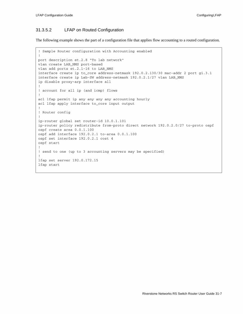
LFAP Configuration Guide Configuring LFAP
31.3.5.2 LFAP on Routed Configuration
The following example shows the part of a configuration file that applies flow accounting to a routed configuration.
! Sample Router configuration with Accounting enabled!port description et.2.8 "To lab network"vlan create LAB_NMS port-basedvlan add ports et.2.1-16 to LAB_NMSinterface create ip to_core address-netmask 192.0.2.130/30 mac-addr 2 port gi.3.1interface create ip Lab-SW address-netmask 192.0.2.1/27 vlan LAB_NMSip disable proxy-arp interface all! ! account for all ip (and icmp) flows!acl lfap permit ip any any any any accounting hourlyacl lfap apply interface to_core input output!! Router config!ip-router global set router-id 10.0.1.101ip-router policy redistribute from-proto direct network 192.0.2.0/27 to-proto ospfospf create area 0.0.1.100ospf add interface 192.0.2.1 to-area 0.0.1.100ospf set interface 192.0.2.1 cost 4ospf start!! send to one (up to 3 accounting servers may be specified) !lfap set server 192.0.172.15lfap start
Riverstone Networks RS Switch Router User Guide 31-7

Network Accounting LFAP Configuration Guide
31.4 NETWORK ACCOUNTINGThe other side of the network accounting equation is the accounting server and the applications that utilize collected data. Riverstone and LFAP essentially provide three tiers of accounting capabilities.
31.4.1 Tier One: Simple Flow Accounting Server
Riverstone makes available an application called the Simple Flow Accounting Server (SFAS). SFAS is a lightweight application designed primarily for troubleshooting and demonstration purposes; and is capable of receiving LFAP messages from a single RS Ethernet Router only. SFAS can be obtained from the web site, http://www.nmops.org. The application can be compiled and run on most platforms. There is also a Windows pre-complied executable available at the same site.
Copy the SFAS file to a workstation that can reach the RS Ethernet Router, compile (if necessary), then start SFAS at the prompt along with the name the file within which LFAP information will be stored. For example:
This starts SFAS and sends the recorded LFAP information to the file data.txt.
31.4.1.1 Example SFAS File
When SFAS is stopped, the data.txt file can be examined for flow accounting results. The following is an example of the contents of the data.txt file:
pterodactyl% ./sfas > data.txt
Riverstone Networks: trivial flow accounting server version 1.2CCE: 134.141.179.156 connected on Thu Dec 6 15:28:36 2001VR receivedCR received FAS Address: 134.141.179.153sent FERU:1.2.28, 9502935, 1(inactive),(absolute) bytes rx 0, tx 108, (absolute) pkts rx 0, tx 1, F:1.2.29, 9508081, 136.141.179.137, 137.141.179.159, 137, 137, 17(udp), 0, 0, 1, 17, None, 0, 134.141.179.156, 5-minute, low, none, 2, 295, U:1.2.29, 9512536, 1(inactive), (absolute) bytes rx 0, tx 108, (absolute) pkts rx 0, tx 1, F:1.2.30, 9517114, 136.141.179.137, 137.141.179.159, 137, 137, 17(udp), 0, 0, 1, 17, None, 0, 134.141.179.156, 5-minute, low, none, 2, 295, U:1.2.30, 9520537, 1(inactive), (absolute) bytes rx 0, tx 108, (absolute) pkts rx 0, tx 1, F:1.2.31, 9527415, 50.141.179.153, 136.141.179.137, 1345, 37, 17(udp), 0, 0, 17, 1, None, 0, 134.141.179.156, 5-minute, low, none, 111, 2, F:1.2.32, 9527415, 136.141.179.137, 50.141.179.153, 37, 1345, 17(udp), 0, 0, 1, 0, None, 0, 134.141.179.156, 5-minute, low, none, 2, 3909, U:1.2.32, 9531740, 1(inactive), (absolute) bytes rx 0, tx 64, (absolute) pkts rx 0, tx 1, U:1.2.31, 9531740, 1(inactive), (absolute) bytes rx 0, tx 46, (absolute) pkts rx 0, tx 1, F:1.2.33, 9535506, 50.141.179.150, 136.141.179.137, 1024, 37, 17(udp), 0, 0, 17, 1, None, 0, 134.141.179.156, 5-minute, low, none, 111, 2, F:1.2.34, 9535506, 136.141.179.137, 50.141.179.150, 37, 1024, 17(udp), 0, 0, 1, 0, None, 0, 134.141.179.156, 5-minute, low, none, 2, 3595,
Caught signal 2 ExitingStats:bad opcode 0 bad handhshake 0 unexpected ara 0 unexpected vra 0bad read 0 bad VR version received 0 lost session 0 number connections 1messages 2329 bytes 295700
31-8 Riverstone Networks RS Switch Router User Guide

LFAP Configuration Guide Network Accounting
In the example above, • the CCE is the Connection Control Entity, specifically, the RS Ethernet Router switch router. In this
case, it is identified by its IP address: 134.141.179.156. • The FAS is the IP address of the SFAS workstation: 134.141.179.153. • Lines within the files are identified by either a U: or an F:. These letters represent the type of
information passing between the RS Ethernet Router and SFAS:
F: – Represents a Flow Accounting Request (FAR) sent by the RS Ethernet Router to the server. These messages are sent when the RS Ethernet Router identifies a new IP flow. The FAR includes all of the flow information that does not change over the life of the flow – For example, the FAR includes the source and destination IP addresses.
U: – Represents a Flow Update Notification (FUN) sent by the RS Ethernet Router to the server. These messages contain data that changes over the life of the flow – For example, the number of bytes and packets being sent over the flow.
Note For details about the LFAP protocol structure, its message packet types, and its packet structures, see the internet drafts: draft-riverstone-lfap-00.txt and draft-riverstone-lfap-data-00.txt. These documents can be obtained at http://www.IETF.org. Also, see RFC 2124.
The following is a list (from left-to-right) of the fields that appear on F (FAR) lines for IP flows:• Flow ID• Switch time at flow start• Source IP address• Destination IP address• Source port• Destination port• Protocol (e.g.: TCP/UDP)• Type of service inbound• Type of service outbound• Ingress port ifIndex• Egress port ifIndex• Source AS• Switch IP address• Checkpoint (flow accounting time – 5-minutes, 15-minutes, or hourly)• Switch priority queue (low, medium, or high)• Next hop address• Source VLAN• Destination VLAN
The following is a list (from left-to-right) of the fields that appear on F (FAR) lines for MPLS flows:• Flow ID
Riverstone Networks RS Switch Router User Guide 31-9
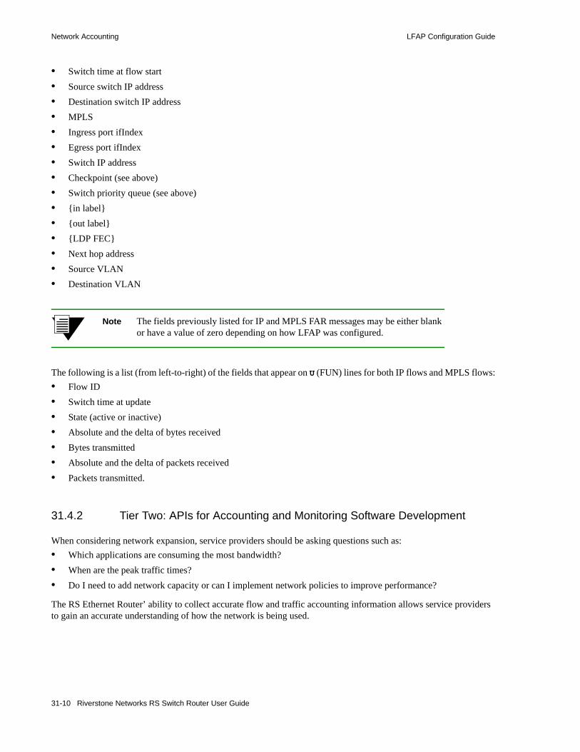
Network Accounting LFAP Configuration Guide
• Switch time at flow start• Source switch IP address• Destination switch IP address• MPLS• Ingress port ifIndex• Egress port ifIndex• Switch IP address• Checkpoint (see above)• Switch priority queue (see above)• {in label}• {out label}• {LDP FEC}• Next hop address• Source VLAN• Destination VLAN
Note The fields previously listed for IP and MPLS FAR messages may be either blank or have a value of zero depending on how LFAP was configured.
The following is a list (from left-to-right) of the fields that appear on U (FUN) lines for both IP flows and MPLS flows:• Flow ID• Switch time at update• State (active or inactive)• Absolute and the delta of bytes received• Bytes transmitted• Absolute and the delta of packets received• Packets transmitted.
31.4.2 Tier Two: APIs for Accounting and Monitoring Software Development
When considering network expansion, service providers should be asking questions such as: • Which applications are consuming the most bandwidth? • When are the peak traffic times? • Do I need to add network capacity or can I implement network policies to improve performance?
The RS Ethernet Router’ ability to collect accurate flow and traffic accounting information allows service providers to gain an accurate understanding of how the network is being used.
31-10 Riverstone Networks RS Switch Router User Guide

LFAP Configuration Guide Network Accounting
With the data gathered with LFAP, service providers can create policies to influence end user behavior. For example, if Napster traffic is known to be prevalent on Friday evenings between certain hours, network policies can be put in place to limit the amount of bandwidth dedicated to Napster traffic (see Figure 31-2). The same can be done for streaming video or music applications. The key, however, is to be able to collect the data.
Figure 31-2 Graphic display of flows by FlowScan
Gathering and analyzing flow accounting data does not require a complex accounting system (though such systems are available for those who need them). Open source applications, used in conjunction with LFAP, can give an accurate graphical view of network traffic. For example, the FlowScan tool, developed by Dave Plonka of the University of Wisconsin–Madison, is a versatile tool that can meet many service providers’ needs. FlowScan and the necessary tools required to gather flow accounting data can be found at Riverstone’s open source network management web site at http://www.nmops.org.
LFAP can also be used to gain a better understanding of the value of existing peering relationships. FlowScan provides tools that allow tabular or graphical views of the AS1 to AS traffic data. Table 31-1 and Table 31-2 were created from LFAP data gathered, using the FlowScan tool. The LFAP data was combined with data from ftp://ftp.arin.net/netinfo/asn.txt. Table 31-1 displays the amount of incoming traffic from the top 10 origin ASNs2. The ASNs are ranked by inbound bits/sec traffic. Table 31-2 shows the top 10 destination ASNs. The data in Table 31-2 is ranked by outbound bits/sec traffic. FlowScan includes a tool that will graphically display historical source and destination AS traffic data within a graphic format (see Figure 31-3).
Table 31-1 Top 10 origin ASNs for five minute sample
Rank Origin-AS Bits/sec in % of total in Bits/sec out % of total out
1 UONET (3582) 2.3 M 62.3% 54.9 K 9.4%
2 NFSNETTEST14-AS (237) 241.3 K 6.5% 16.6 K 2.8%
3 AGIS-NET (4200) 123.9 K 3.4% 75.0 K 12.8%
Riverstone Networks RS Switch Router User Guide 31-11

Network Accounting LFAP Configuration Guide
4 CRITICALPATH (10627) 97.3 K 2.6% 3.2 K 0.5%
5 CNCX-AS1 (2828) 82.1 K 2.2% 2.2 K 0.4%
6 HURRICANE (6939) 66.8 K 1.8% 2.1 K 0.4%
7 NETUSACOM-AS (3967) 65.9 K 1.8% 8.2 K 1.4%
8 QUOTECOM (11803) 41.9 K 1.1% 2.7 K 0.5%
9 MULTICASTTECH (16517) 35.4 K 1.0% 1.9 K 0.3%
10 ALTERNET-AS (701) 28.2 K 0.8% 7.3 K 1.2%
1 – Autonomous System2 – Autonomous System Number
Table 31-2 Top 10 destination ASNs for five minute sample
Rank Origin-AS Bits/sec in % of total in Bits/sec out % of total out
1 PLAYBOY-BLK-1 (14068) 0.0 0.0% 226.3 K 38.6%
2 AGIS-NET (4200) 123.9 K 3.4% 75.0 K 12.8%
3 UONET (3582) 2.3 M 62.3% 54.9 K 9.4%
4 VERIO (2914) 21.7 K 0.6% 20.4 K 3.5%
5 NSFNETTEST14-AS (237) 241.3 K 6.5% 16.6 K 2.8%
6 ALTERNET-AS (703) 422.2 0.0% 14.6 K 2.5%
7 ATT-INTERNET4 (7018) 23.3 K 0.6% 8.7 K 1.5%
8 NETUSACOM-AS (3967) 65.9 K 1.8% 8.2 K 1.4%
9 ALTERNET-AS (701) 28.2 K 0.8% 7.3 K 1.2%
10 CISCOSYSTEMS (109) 10.0 K 0.3% 5.9 K 1.0%
Table 31-1 Top 10 origin ASNs for five minute sample (Continued)
Rank Origin-AS Bits/sec in % of total in Bits/sec out % of total out
31-12 Riverstone Networks RS Switch Router User Guide

LFAP Configuration Guide Network Accounting
Figure 31-3 FlowScan graphic representation of AS to AS flows
31.4.3 Tier Three: Carrier Class Accounting
Some users may require sophisticated and full-featured network accounting applications that can handle every aspect of the accounting process from data collection to automated billing. For these users, Riverstone provides commercial applications through our software partners. Among these application, are Xacct®, an IP mediation application provider; and Portal®, an application for bill presentment and collection.
Riverstone also provides sophisticated LFAP flow collecting applications (Mica and Basalt) that can handle LFAP input from several RS Ethernet Router switch routers. These applications also structure data so that it can be used with both Oracle® and Microsoft® databases.
31.4.3.1 MICA
Mica 3.0 is a full accounting server that has been implemented in a production environment in other service providers’ networks. This package is able to collect data from several RS Ethernet Router network elements and provides data persistency. The current version runs on Solaris 2.6 and above. When running on a Solaris 2.6 machine with 256 MB RAM, the server can handle over 8,000 flows per second. Most service provider networks have traffic with less than 1,000 flows per second. This package is available to Riverstone customers only.
31.4.3.2 Basalt
Basalt is an application that aggregates and processes LFAP flow record files. The first file contains the flow setup information (FAR messages). The second file contains the actual usage information (FUN messages), which is sent from the router to Mica in increments as low as every 5 minutes. Basalt is able to integrate the two files and aggregate the flow usage data. Like Mica, this package is available to Riverstone customers only
Riverstone Networks RS Switch Router User Guide 31-13

Network Accounting LFAP Configuration Guide
31-14 Riverstone Networks RS Switch Router User Guide
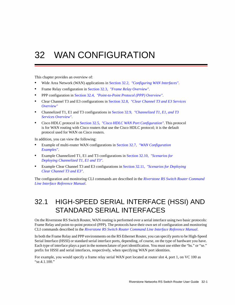
32 WAN CONFIGURATION
This chapter provides an overview of:• Wide Area Network (WAN) applications in Section 32.2, "Configuring WAN Interfaces".• Frame Relay configuration in Section 32.3, "Frame Relay Overview".• PPP configuration in Section 32.4, "Point-to-Point Protocol (PPP) Overview".• Clear Channel T3 and E3 configurations in Section 32.8, "Clear Channel T3 and E3 Services
Overview"• Channelized T1, E1 and T3 configurations in Section 32.9, "Channelized T1, E1, and T3
Services Overview".• Cisco HDLC protocol in Section 32.5, "Cisco HDLC WAN Port Configuration". This protocol
is for WAN routing with Cisco routers that use the Cisco HDLC protocol; it is the default protocol used for WAN on Cisco routers.
In addition, you can view the following: • Example of multi-router WAN configurations in Section 32.7, "WAN Configuration
Examples".• Example Channelized T1, E1 and T3 configurations in Section 32.10, "Scenarios for
Deploying Channelized T1, E1 and T3".• Example Clear Channel T3 and E3 configurations in Section 32.11, "Scenarios for Deploying
Clear Channel T3 and E3".
The configuration and monitoring CLI commands are described in the Riverstone RS Switch Router Command Line Interface Reference Manual.
32.1 HIGH-SPEED SERIAL INTERFACE (HSSI) AND STANDARD SERIAL INTERFACES
On the Riverstone RS Switch Router, WAN routing is performed over a serial interface using two basic protocols: Frame Relay and point-to-point protocol (PPP). The protocols have their own set of configuration and monitoring CLI commands described in the Riverstone RS Switch Router Command Line Interface Reference Manual.
In both the Frame Relay and PPP environments on the RS Ethernet Router, you can specify ports to be High-Speed Serial Interface (HSSI) or standard serial interface ports, depending, of course, on the type of hardware you have. Each type of interface plays a part in the nomenclature of port identification. You must use either the “hs.” or “se.” prefix for HSSI and serial interfaces, respectively, when specifying WAN port identities.
For example, you would specify a frame relay serial WAN port located at router slot 4, port 1, on VC 100 as “se.4.1.100.”
Riverstone Networks RS Switch Router User Guide 32-1

Configuring WAN Interfaces WAN Configuration
Using the same approach, a PPP high-speed serial interface (HSSI) WAN port located at router slot 3, port 2 would be identified as “hs.3.2.”
32.2 CONFIGURING WAN INTERFACESConfiguring IP interfaces for the WAN is generally the same as for the LAN. You can configure IP interfaces on the physical port or you can configure the interface as part of a VLAN for WAN interfaces. However, in the case of IP interfaces, you can configure multiple IP addresses for each interface. Refer to Section 10.2, "Configuring IP Interfaces and Parameters" and Section 26.4, "Configuring IPX Interfaces and Parameters" for more specific information.
There are some special considerations that apply only to WAN interfaces. These are detailed in this section.
32.2.1 Primary and Secondary Addresses
Like LAN interfaces, WAN interfaces can have primary and secondary IP addresses. For Frame Relay, you can configure primary and secondary addresses which are static or dynamic. For PPP, however, the primary addresses may be dynamic or static, but the secondary addresses must be static. This is because the primary addresses of both the local and peer routers are exchanged during IPCP negotiation.
Note There is no mechanism in PPP for obtaining any secondary addresses from the peer.
32.2.2 Static, Mapped, and Dynamic Peer IP Addresses
The following sections describe the difference between static, mapped, and dynamic peer IP addresses and provide simple command line examples for configuration.
32.2.2.1 Static Addresses
If the peer IP address is known before system setup, you can specify the peer address when the interface is created. This disables Inverse ARP (InArp) for Frame Relay on that source/peer address pair. However, InArp will still be enabled for any other addresses on that interface or other interfaces. A static peer address for PPP means that the address the peer supplies during IP Control Protocol (IPCP) negotiations will be ignored.
The following command line displays an example for a port:
rs(config)# interface create ip IPWAN address-netmask 10.50.1.1/16 peer-address 10.50.1.2 port hs.3.1
32-2 Riverstone Networks RS Switch Router User Guide
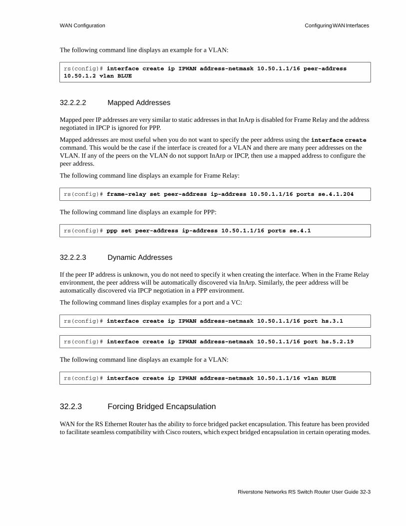
WAN Configuration Configuring WAN Interfaces
The following command line displays an example for a VLAN:
32.2.2.2 Mapped Addresses
Mapped peer IP addresses are very similar to static addresses in that InArp is disabled for Frame Relay and the address negotiated in IPCP is ignored for PPP.
Mapped addresses are most useful when you do not want to specify the peer address using the interface create command. This would be the case if the interface is created for a VLAN and there are many peer addresses on the VLAN. If any of the peers on the VLAN do not support InArp or IPCP, then use a mapped address to configure the peer address.
The following command line displays an example for Frame Relay:
The following command line displays an example for PPP:
32.2.2.3 Dynamic Addresses
If the peer IP address is unknown, you do not need to specify it when creating the interface. When in the Frame Relay environment, the peer address will be automatically discovered via InArp. Similarly, the peer address will be automatically discovered via IPCP negotiation in a PPP environment.
The following command lines display examples for a port and a VC:
The following command line displays an example for a VLAN:
32.2.3 Forcing Bridged Encapsulation
WAN for the RS Ethernet Router has the ability to force bridged packet encapsulation. This feature has been provided to facilitate seamless compatibility with Cisco routers, which expect bridged encapsulation in certain operating modes.
rs(config)# interface create ip IPWAN address-netmask 10.50.1.1/16 peer-address 10.50.1.2 vlan BLUE
rs(config)# frame-relay set peer-address ip-address 10.50.1.1/16 ports se.4.1.204
rs(config)# ppp set peer-address ip-address 10.50.1.1/16 ports se.4.1
rs(config)# interface create ip IPWAN address-netmask 10.50.1.1/16 port hs.3.1
rs(config)# interface create ip IPWAN address-netmask 10.50.1.1/16 port hs.5.2.19
rs(config)# interface create ip IPWAN address-netmask 10.50.1.1/16 vlan BLUE
Riverstone Networks RS Switch Router User Guide 32-3
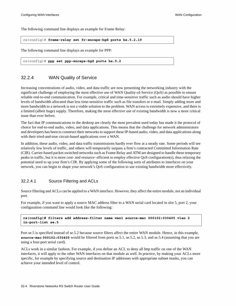
Configuring WAN Interfaces WAN Configuration
The following command line displays an example for Frame Relay:
The following command line displays an example for PPP:
32.2.4 WAN Quality of Service
Increasing concentrations of audio, video, and data traffic are now presenting the networking industry with the significant challenge of employing the most effective use of WAN Quality-of-Service (QoS) as possible to ensure reliable end-to-end communication. For example, critical and time-sensitive traffic such as audio should have higher levels of bandwidth allocated than less time-sensitive traffic such as file transfers or e-mail. Simply adding more and more bandwidth to a network is not a viable solution to the problem. WAN access is extremely expensive, and there is a limited (albeit huge) supply. Therefore, making the most effective use of existing bandwidth is now a more critical issue than ever before.
The fact that IP communications to the desktop are clearly the most prevalent used today has made it the protocol of choice for end-to-end audio, video, and data applications. This means that the challenge for network administrators and developers has been to construct their networks to support these IP-based audio, video, and data applications along with their tried-and-true circuit-based applications over a WAN.
In addition, these audio, video, and data traffic transmissions hardly ever flow at a steady rate. Some periods will see relatively low levels of traffic, and others will temporarily surpass a firm’s contracted Committed Information Rate (CIR). Carrier-based packet-switched networks such as Frame Relay and ATM are designed to handle these temporary peaks in traffic, but it is more cost- and resource- efficient to employ effective QoS configuration(s), thus relaxing the potential need to up your firm’s CIR. By applying some of the following sorts of attributes to interfaces on your network, you can begin to shape your network’s QoS configuration to use existing bandwidth more effectively.
32.2.4.1 Source Filtering and ACLs
Source filtering and ACLs can be applied to a WAN interface. However, they affect the entire module, not an individual port.
For example, if you want to apply a source MAC address filter to a WAN serial card located in slot 5, port 2, your configuration command line would look like the following:
Port se.5 is specified instead of se.5.2 because source filters affect the entire WAN module. Hence, in this example, source-mac 000102:030405 would be filtered from ports se.5.1, se.5.2, se.5.3, and se.5.4 (assuming that you are using a four-port serial card).
ACLs work in a similar fashion. For example, if you define an ACL to deny all http traffic on one of the WAN interfaces, it will apply to the other WAN interfaces on that module as well. In practice, by making your ACLs more specific, for example by specifying source and destination IP addresses with appropriate subnet masks, you can achieve your intended level of control.
rs(config)# frame-relay set fr-encaps-bgd ports hs.5.2.19
rs(config)# ppp set ppp-encaps-bgd ports hs.5.2
rs(config)# filters add address-filter name wan1 source-mac 000102:030405 vlan 2 in-port-list se.5
32-4 Riverstone Networks RS Switch Router User Guide

WAN Configuration Configuring WAN Interfaces
32.2.4.2 Weighted-Fair Queueing
Through the use of Weighted-Fair Queueing QoS policies, WAN packets with the highest priority can be allotted a sizable percentage of the available bandwidth and “whisked through” WAN interface(s). Meanwhile, the remaining bandwidth is distributed for “lower-priority” WAN packets according to the user’s percentage-of-bandwidth specifications. Refer to the Riverstone RS Switch Router Command Line Interface Reference Manual for more detailed configuration information.
Note Weighted-Fair Queueing applies only to best-effort traffic on the WAN card. If you apply any of the WAN specific traffic shaping commands, then weighted fair queuing will no longer be applicable unless you configure the wfq-aware option when defining the service profile. Also, control priority traffic on the WAN card is always treated as strict priority, and ignores the rules applied by weighted-fair queueing. This may alter the weighted-fair queuing statistics if a significant portion of the traffic is control priority traffic.
32.2.4.3 Congestion Management
One of the most important features of configuring the RS Ethernet Router to ensure Quality of Service is the obvious advantage gained when you are able to avoid network congestion. The following topics touch on a few of the most prominent aspects of congestion avoidance when configuring the RS Ethernet Router.
32.2.4.4 Random Early Discard (RED)
Random Early Discard (RED) allows network operators to manage traffic during periods of congestion based on policies. RED works with TCP to provide fair reductions in traffic proportional to the bandwidth being used. Weighted Random Early Discard (WRED) works with IP Precedence or priority, as defined in the qos configuration command line, to provide preferential traffic handling for higher-priority traffic.
The CLI commands related to RED in both the Frame Relay and PPP protocol environments allow you to set maximum and minimum threshold values for each of the low-, medium-, and high-priority categories of WAN traffic.
32.2.4.5 Adaptive Shaping
Adaptive shaping implements the congestion-sensitive rate adjustment function and has the following characteristics:• No blocking of data flow under normal condition if the traffic rate is below Bc+Be.• Reduction to a lower CIR upon detection of network congestion.• Progressive return to the negotiated information transfer rate upon congestion abatement.
The CLI command related to adaptive shaping allows you to set threshold values for triggering the adaptive shaping function.
Riverstone Networks RS Switch Router User Guide 32-5
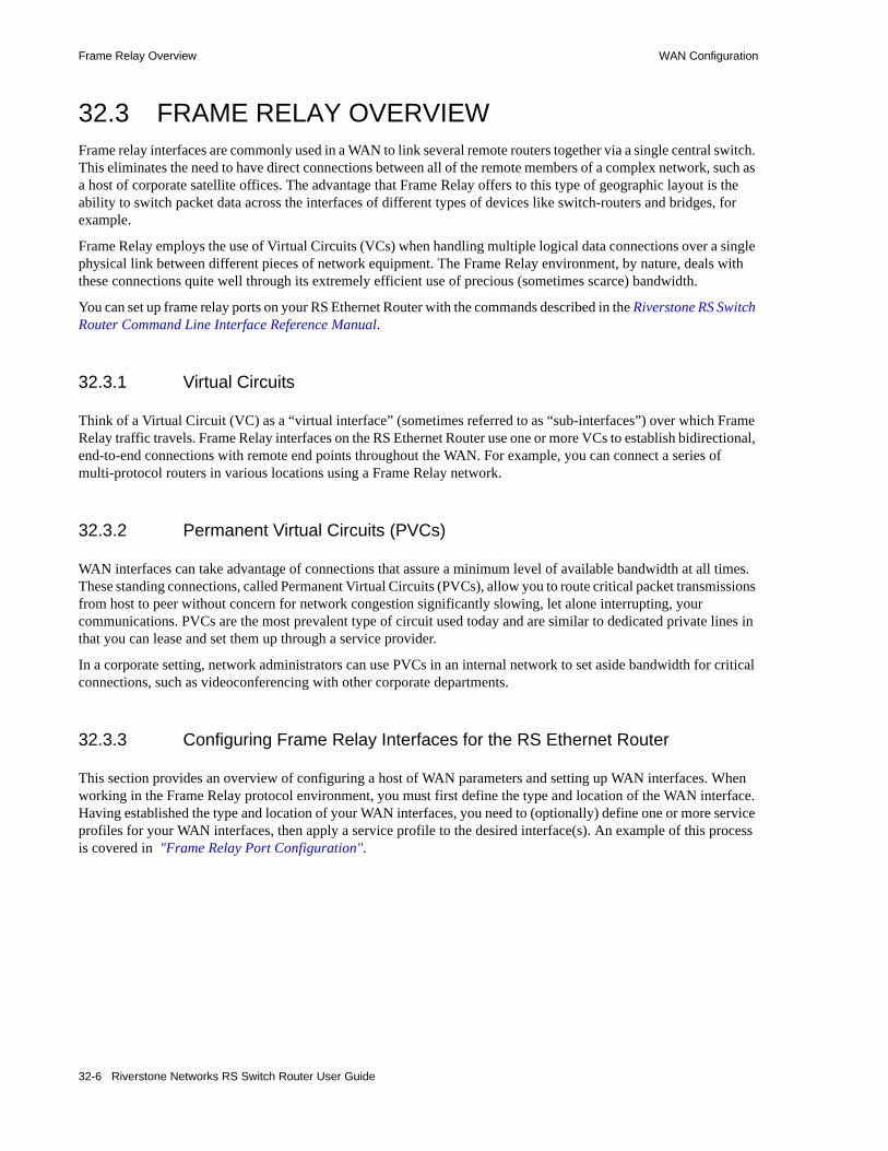
Frame Relay Overview WAN Configuration
32.3 FRAME RELAY OVERVIEWFrame relay interfaces are commonly used in a WAN to link several remote routers together via a single central switch. This eliminates the need to have direct connections between all of the remote members of a complex network, such as a host of corporate satellite offices. The advantage that Frame Relay offers to this type of geographic layout is the ability to switch packet data across the interfaces of different types of devices like switch-routers and bridges, for example.
Frame Relay employs the use of Virtual Circuits (VCs) when handling multiple logical data connections over a single physical link between different pieces of network equipment. The Frame Relay environment, by nature, deals with these connections quite well through its extremely efficient use of precious (sometimes scarce) bandwidth.
You can set up frame relay ports on your RS Ethernet Router with the commands described in the Riverstone RS Switch Router Command Line Interface Reference Manual.
32.3.1 Virtual Circuits
Think of a Virtual Circuit (VC) as a “virtual interface” (sometimes referred to as “sub-interfaces”) over which Frame Relay traffic travels. Frame Relay interfaces on the RS Ethernet Router use one or more VCs to establish bidirectional, end-to-end connections with remote end points throughout the WAN. For example, you can connect a series of multi-protocol routers in various locations using a Frame Relay network.
32.3.2 Permanent Virtual Circuits (PVCs)
WAN interfaces can take advantage of connections that assure a minimum level of available bandwidth at all times. These standing connections, called Permanent Virtual Circuits (PVCs), allow you to route critical packet transmissions from host to peer without concern for network congestion significantly slowing, let alone interrupting, your communications. PVCs are the most prevalent type of circuit used today and are similar to dedicated private lines in that you can lease and set them up through a service provider.
In a corporate setting, network administrators can use PVCs in an internal network to set aside bandwidth for critical connections, such as videoconferencing with other corporate departments.
32.3.3 Configuring Frame Relay Interfaces for the RS Ethernet Router
This section provides an overview of configuring a host of WAN parameters and setting up WAN interfaces. When working in the Frame Relay protocol environment, you must first define the type and location of the WAN interface. Having established the type and location of your WAN interfaces, you need to (optionally) define one or more service profiles for your WAN interfaces, then apply a service profile to the desired interface(s). An example of this process is covered in "Frame Relay Port Configuration".
32-6 Riverstone Networks RS Switch Router User Guide

WAN Configuration Frame Relay Overview
32.3.3.1 Defining the Type and Location of a Frame Relay and VC Interface
To configure a frame relay WAN port, you need to first define the type and location of one or more frame relay WAN ports or virtual circuits (VCs) on your RS Ethernet Router. The following command line displays a simplified example of a frame relay WAN port definition:
Note If the port is a HSSI port that will be connected to a HSSI port on another router, you can also specify clock <clock-source> in your definition.
Then, you must set up a frame relay virtual circuit (VC). The following command line displays a simplified example of a VC definition:
32.3.3.2 Setting up a Frame Relay Service Profile
Once you have defined the type and location of your Frame Relay WAN interface(s), you can configure your RS Ethernet Router to more efficiently utilize available bandwidth for Frame Relay communications.
Note The RS Ethernet Router comes with a set of “default values” for Frame Relay interface configuration settings, which means that setting up a Frame Relay service profile is not absolutely necessary to begin sending and receiving Frame Relay traffic on your RS Ethernet Router.
After you configure one or more service profiles for your Frame Relay interface(s), you can then apply a service profile to active Frame Relay WAN ports, specifying their behavior when handling Frame Relay traffic. The following command line displays all of the possible attributes used to define a Frame Relay service profile:
Define the type and location of a frame relay WAN port.
port set <port> wan-encapsulation frame-relay speed <number>
Define the type and location of a frame relay VC. frame-relay create vc port <port>
Define a frame relay service profile.
frame-relay define service <service name> [Bc <number>] [Be <number>] [becn-adaptive-shaping <number>] [cir <number>] [high-priority-queue-depth <number>] [low-priority-queue-depth <number>] [med-priority-queue-depth <number>] [red on | off] [red-maxTh-high-prio-traffic <number>] [red-maxTh-low-prio-traffic <number>] [red-maxTh-med-prio-traffic <number>] [red-minTh-high-prio-traffic <number>] [red-minTh-low-prio-traffic <number>] [red-minTh-med-prio-traffic <number>] [rmon on | off] [wfq-aware on | off]
Riverstone Networks RS Switch Router User Guide 32-7

Frame Relay Overview WAN Configuration
32.3.3.3 Applying a Service Profile to an Active Frame Relay WAN Port
Once you have created one or more frame relay service profiles, you can specify their use on one or more active frame relay WAN ports on the RS Ethernet Router. The following command line displays a simplified example of this process:
32.3.4 Monitoring Frame Relay WAN Ports
Once you have configured your frame relay WAN interface(s), you can use the CLI to monitor status and statistics for your WAN ports. The following table describes the monitoring commands for WAN interfaces, designed to be used in Enable mode:
32.3.5 Tracing Frame Relay Connections
The RS Ethernet Router can be configured to trace Frame Relay control packets (LMI and DCP) on specified ports. The frame-relay show trace command is useful for debugging frame-relay circuits. By enabling packet tracing, traffic on a specified frame relay link is displayed on the console.
The following, lists the keywords and parameters are used with the frame-relay show trace command.• ctl-packet-trace – Specifies tracing on control packets (supports LMI and DCP only).
- on – Keyword, enables control packet tracing.- off – Keyword, disables control packet tracing.
• max-packets-displayed – Optional field that specifies how many control packets to display. Once the maximum is reached (default value is 60 packets), the packet tracing feature disables itself. If a 0 is entered, the trace runs continuously until the user turns it off.
• packet-trace-level – Optional field that specifies the level of detail displayed on the console.- normal – Compresses important information to a couple of lines.- verbose – Decodes all information and formats it to appear on separate lines.- hex-only – Shows only the raw hexadecimal data of the packets.
Apply a service profile to an active WAN port.
frame-relay apply service <service name> ports <port list>
Display a particular frame relay service profile frame-relay show service <service name>
Display all available frame relay service profiles frame-relay show service all
Display the last reported frame relay error frame-relay show stats ports <port name> last-error
Display active frame relay LMI parameters frame-relay show stats ports <port name> lmi
Display MIBII statistics for frame relay WAN ports
frame-relay show stats ports <port name> mibII
Display a summary of all LMI statistics frame-relay show stats ports <port name> summary
32-8 Riverstone Networks RS Switch Router User Guide

WAN Configuration Frame Relay Overview
• ports – Required field that specifies on which ports to trace.
The following is an example of the output from the frame-relay show trace command:
32.3.6 Frame Relay Port Configuration
To configure frame relay WAN ports, you must first define the type and location of the WAN interface, optionally “set up” a library of configuration settings, then apply those settings to the desired interface(s). The following examples are designed to give you a small model of the steps necessary for a typical frame relay WAN interface specification.
To define the location and identity of a serial frame relay WAN port located at slot 5, port 1 with a speed rating of 45 million bits per second:
To define the location and identity of a High-Speed Serial Interface (HSSI) VC located at slot 4, port 1 with a DLC of 100:
Suppose you wish to set up a service profile called “profile1” that includes the following characteristics:• Committed burst value of 2 million and excessive burst value of 1 million• BECN active shaping at 65 frames• Committed information rate (CIR) of 20 million bits per second• Leave high-, low-, and medium-priority queue depths set to factory defaults
rs# frame-relay show trace ctl-packet-trace on ports t1.4.3:1
Port 3 vc 0 FR Ingress, Unicast, DCLI 0, Status Enquiry, Full, Annex D, Tx Seq 7, Rx Seq 6 Port 3 vc 0 FR Egress, Unicast, DCLI 0, Status, Full, Annex D, Tx Seq 7, Rx Seq 7 DLCI 100: N=1 A=0 DLCI 200: N=1 A=0 Port 3 vc 0 FR Ingress, Unicast, DCLI 0, Status Enquiry, LIV, Annex D, Tx Seq 8, Rx Seq 7Port 3 vc 0 FR Egress, Unicast, DCLI 0, Status, LIV, Annex D, Tx Seq 8, Rx Seq 8Port 3 vc 0 FR Ingress, Unicast, DCLI 0, Status Enquiry, LIV, Annex D, Tx Seq 9, Rx Seq 8Port 3 vc 0 FR Egress, Unicast, DCLI 0, Status, LIV, Annex D, Tx Seq 9, Rx Seq 9Port 3 vc 0 FR Ingress, Unicast, DCLI 0, Status Enquiry, LIV, Annex D, Tx Seq 10, Rx Seq 9Port 3 vc 0 FR Egress, Unicast, DCLI 0, Status, LIV, Annex D, Tx Seq 10, Rx Seq 10Port 3 vc 0 FR Ingress, Unicast, DCLI 0, Status Enquiry, LIV, Annex D, Tx Seq 11, Rx Seq 10Port 3 vc 0 FR Egress, Unicast, DCLI 0, Stat LIV, Annex D, Tx Seq 11, Rx Seq 11
rs(config)# port set se.5.1 wan-encapsulation frame-relay speed 45000000
rs(config)# frame-relay create vc port hs.4.1.100
Riverstone Networks RS Switch Router User Guide 32-9

Point-to-Point Protocol (PPP) Overview WAN Configuration
• Random Early Discard (RED) disabled• RMON enabled
The command line necessary to set up a service profile with the above attributes would be as follows:
To assign the above service profile to the VC interface created earlier (slot 4, port 1):
32.4 POINT-TO-POINT PROTOCOL (PPP) OVERVIEWBecause of its ability to quickly and easily accommodate IP protocol traffic, Point-to-Point Protocol (PPP) routing has become a very important aspect of WAN configuration. Using PPP, you can set up router-to-router, host-to-router, and host-to-host connections.
Establishing a connection in a PPP environment requires that the following events take place:• The router initializing the PPP connection transmits Link Control Protocol (LCP) configuration and
test frames to the remote peer to set up the data link.• Once the connection has been established, the router which initiated the PPP connection transmits a
series of Network Control Protocol (NCP) frames necessary to configure one or more network-layer protocols.
• Finally, when the network-layer protocols have been configured, both the host and remote peer can send packets to one another using any and all of the configured network-layer protocols.
The link will remain active until explicit LCP or NCP frames instruct the host and/or the peer router to close the link, or until some external event (i.e., user interruption or system time-out) takes place.
You can set up PPP ports on your RS Ethernet Router with the commands described in the Riverstone RS Switch Router Command Line Interface Reference Manual.
32.4.1 Use of LCP Magic Numbers
LCP magic numbers enable you to detect situations where PPP LCP packets are looped back from the remote system, resulting in an error message. The use of LCP magic numbers is enabled on the RS Ethernet Router by default. However, should you employ a service profile in which the use of LCP magic numbers has been disabled, undetected “loopback” behavior may become a problem.
Note In the event that a PPP WAN interface remains unrecognized at startup due to loopback interference, you can use the ppp restart command in the CLI to remedy the situation.
rs(config)# frame-relay define service profile1 Bc 2000000 Be 10000000 becn-adaptive-shaping 65 cir 20000000 red off rmon on
rs(config)# frame-relay apply service profile1 ports hs.4.1.100
32-10 Riverstone Networks RS Switch Router User Guide

WAN Configuration Point-to-Point Protocol (PPP) Overview
32.4.2 Configuring PPP Interfaces
This section provides an overview of configuring a host of WAN parameters and setting up WAN interfaces. When working in the PPP environment, you must first define the type and location of your WAN interfaces. Having established the type and location of your WAN interfaces, you need to (optionally) define one or more service profiles for your WAN interfaces, then apply a service profile to the desired interface(s). Examples of this process are displayed in "PPP Port Configuration".
32.4.2.1 Defining the Type and Location of a PPP Interface
To configure a PPP WAN port, you need to first define the type and location of one or more PPP WAN ports on your RS Ethernet Router. The following command line displays a simplified example of a PPP WAN port definition:
If the port is an HSSI port that will be connected to a HSSI port on another router, you can specify clock <clock-source> in the definition.
32.4.3 Setting up a PPP Service Profile
Once you have defined the type and location of your PPP WAN interface(s), you can configure your RS Ethernet Router to more efficiently utilize available bandwidth for PPP communications.
Note The RS Ethernet Router comes with a set of default values for PPP interface configuration settings, which means that setting up a PPP service profile is not absolutely necessary to begin sending and receiving PPP traffic on your RS Ethernet Router.
After you configure one or more service profiles for your PPP interface(s), you can then apply a service profile to active PPP WAN ports, specifying their behavior when handling PPP traffic. The following command line displays all of the possible attributes used to define a PPP service profile:
Define the type and location of a PPP WAN port. port set <port> wan-encapsulation ppp speed <number>
Define a PPP service profile.
ppp define service <service name> [bridging enable | disable ip enable | disable] [high-priority-queue-depth <number>] [lcp-echo on | off] [lcp-magic on | off] [low-priority-queue-depth <number>] [max-configure <number>] [max-failure <number>] [max-terminate <number>] [med-priority-queue-depth <number>] [red on | off] [red-maxTh-high-prio-traffic <number>] [red-maxTh-low-prio-traffic <number>] [red-maxTh-med-prio-traffic <number>] [red-minTh-high-prio-traffic <number>] [red-minTh-low-prio-traffic <number>] [red-minTh-med-prio-traffic <number>] [retry-interval <number>] [rmon on | off]
Riverstone Networks RS Switch Router User Guide 32-11

Point-to-Point Protocol (PPP) Overview WAN Configuration
Note If it is necessary to specify a value for bridging and/or IP, you must specify all three of these values at the same time. You cannot specify just one or two of them in the command line without the other(s).
32.4.3.1 Applying a Service Profile to an Active PPP Port
Once you have created one or more PPP service profiles, you can specify their use on one or more active PPP ports on the RS Ethernet Router. The following command line displays a simplified example of this process:
32.4.4 Configuring Multi-Link PPP Bundles
The multi-link PPP (MLP) standard defines a method for grouping multiple physical PPP links into a logical pipe, called an “MLP bundle.” PPP ports are bundled together on a single WAN module. Large packets are fragmented and transmitted over each physical link in an MLP bundle. At the destination, MLP reassembles the packets and places them in their correct sequence.
Note If you have a four-port Channelized T3 card, this is regarded as two separate WAN modules. Ports 1 and 2 are on one WAN module, and ports 3 and 4 are on the other WAN module. Therefore, you cannot add all four ports to a single MLP bundle.
The following table describes the commands for configuring MLP:
Apply a service profile to an active WAN port. ppp apply service <service name> ports <port list>
Add PPP port(s) to an MLP bundle. ppp add-to-mlp <mlp> port <port list>
Create MLP bundle(s). ppp create-mlp <mlp list> slot <number>
Set MLP encapsulation format. ppp set mlp-encaps-format ports <port list> [format short-format]
Set the size of frames that fragmented for transmission on an MLP bundle.
ppp set mlp-frag-size ports <port list> size <size>
Set the depth of the queue used to hold MLP packets for preserving the packet order.
ppp set mlp-orderq-depth ports <port list> qdepth <number-of-packets>
Set the depth of the queue used to hold packet fragments for reassembly.
ppp set mlp-fragq-depth ports <port list> qdepth <number-of-packets>
32-12 Riverstone Networks RS Switch Router User Guide

WAN Configuration Point-to-Point Protocol (PPP) Overview
32.4.5 Compression on MLP Bundles or Links
Compression can be applied on either a bundle or link basis if MLP is enabled on PPP links. If compression is enabled on a bundle, the packets will be compressed before processing by MLP. If compression is enabled on a link, the packets will be compressed after the MLP processing.
In general, choose bundle compression over link compression whenever possible. Compressing packets before they are “split” by MLP is much more efficient for both the compression algorithm and the WAN card. Link compression is supported to provide the widest range of compatibility with other vendors’ equipment.
32.4.6 Monitoring PPP WAN Ports
Once you have configured your PPP WAN interface(s), you can use the CLI to monitor status and statistics for your WAN ports. The following table describes the monitoring commands for WAN interfaces, designed to be used in the Enable mode:
32.4.7 PPP Port Configuration
To configure PPP WAN ports, you must first define the type and location of the WAN interface, optionally “set up” a library of configuration settings, then apply those settings to the desired interface(s). The following examples are designed to give you a small model of the steps necessary for a typical PPP WAN interface specification.
To define the location and identity of a High-Speed Serial Interface (HSSI) PPP WAN port located at router slot 5, port 1 with a speed rating of 45 million bits per second:
When configuring a PPP connection between two multi-vendor equipment, make sure that the maximum transfer unit (MTU) and the maximum receive unit (MRU) are compatible for each machine. For instance, if Router1 has an MTU=4k/MRU=4k and Router2 has an MTU=9k/MRU=9k, there will be incompatibility issues and the PPP connection may fail. This is because Router1 cannot accommodate the bigger amount of traffic from Router2.
To set the MRU=10k and MTU=10k on the HSSI port hs.5.1:
Display a particular PPP service profile. ppp show service <service name>
Display all available PPP service profiles. ppp show service all
Display bridge NCP statistics for specified PPP WAN port.
ppp show stats port <port name> bridge-ncp
Display IP NCP statistics for specified PPP WAN port. ppp show stats ports <port name> ip-ncp
Display link-status statistics for a specified PPP WAN port.
ppp show stats ports <port name> link-status
Displays information for PPP ports that are added to MLP bundles.
ppp show mlp <mlp list> | all-ports
rs(config)# port set hs.5.1 wan-encapsulation ppp speed 45000000
rs(config)# port set hs.5.1 mtu 10000 mru 10000
Riverstone Networks RS Switch Router User Guide 32-13

Cisco HDLC WAN Port Configuration WAN Configuration
Suppose you wish to set up a service profile called “profile2” that includes the following characteristics:• Bridging enabled• Leave high-, low-, and medium-priority queue depths set to factory defaults• IP enabled• Sending of LCP Echo Requests disabled• Use of LCP magic numbers disabled• The maximum allowable number of unanswered requests set to 8• The maximum allowable number of negative-acknowledgment transmissions set to 5• The maximum allowable number of unanswered/improperly answered connection-termination
requests before declaring the link to a peer lost set to 4• Random Early Discard disabled• The number of seconds between subsequent configuration request transmissions (the “retry
interval”) set to 25• RMON enabled
The command line necessary to set up a service profile with the above attributes would be as follows:
To assign the above service profile to the active PPP WAN port defined earlier (slot 5, port 1):
32.5 CISCO HDLC WAN PORT CONFIGURATIONTo configure Cisco HDLC ports, you must first define the type and location of the WAN interface, optionally “set up” a library of configuration settings, then apply those settings to the desired interface(s). The following examples are designed to give you a small model of the steps necessary for a Cisco HDLC WAN interface specification.
To define the location and identity of a High-Speed Serial Interface (HSSI) Cisco HDLC WAN port located at router slot 5, port 1 with a speed rating of 45 million bits per second:
When you apply cisco-hdlc encapsulation on a WAN port, a default service profile is used. This service profile uses the default values of the profile parameters. If you want to apply a non-default service profile, then you must create a profile and apply it to the port.
32.5.1 Setting up a Cisco HDLC Service Profile
Once you have defined the type and location of your Cisco HDLC WAN interface(s), you can configure your RS Ethernet Router to more efficiently utilize available bandwidth for Cisco HDLC communications.
rs(config)# ppp define service profile2 bridging enable ip enable lcp-echo off lcp-magic off max-configure 8 max-failure 5 max-terminate 4 red off retry-interval 25 rmon on
rs(config)# ppp apply service profile2 ports hs.5.1
rs(config)# port set hs.5.1 wan-encapsulation cisco-hdlc speed 45000000
32-14 Riverstone Networks RS Switch Router User Guide

WAN Configuration Cisco HDLC WAN Port Configuration
Note The RS Ethernet Router comes with a set of “default values” for Cisco HDLC interface configuration settings, which means that setting up a Cisco HDLC service profile is not absolutely necessary to begin sending and receiving Cisco HDLC traffic on your RS Ethernet Router.
Suppose you wish to set up a service profile called “ciscosp” that includes the following characteristics:• Leave high-, low-, and medium-priority queue depths set to factory defaults• Random Early Discard disabled• The number of seconds between “keepalive” messages set to 15• RMON enabled
32.5.2 Applying a Service Profile to an Active Cisco HDLC WAN Port
The command line necessary to set up a service profile with the above attributes would be as follows:
To assign the above service profile to the active Cisco HDLC port defined earlier (slot 5, port 1):
32.5.3 Assigning IP Addresses to a Cisco HDLC WAN Port
The interface address of the local Cisco HDLC WAN port and peer address must conform to the following rules:1. The interface and peer addresses should belong to the same subnet.2. The host part of the addresses should be either 1 or 2. If the host part of the interface address is 1,
then the peer address should be 2, and vice-versa.
For example on routers RS1 and RS2, in subnet 123.45.67.0, the configuration is:
rs(config)# cisco-hdlc define service ciscosp red off keepalive 15 rmon on
rs(config)# cisco-hdlc apply service ciscosp ports hs.5.1
! RS1 Cisco HDLC WAN portrs1(config)# interface create ip cisco_hdlc address-netmask 123.45.6.1/24 peer-address 123.45.67.2 port hs.5.1
! RS2 Cisco HDLC WAN portrs2(config)# interface create ip cisco_hdlc address-netmask 123.45.6.2/24 peer-address 123.45.67.1 port hs.3.2
Riverstone Networks RS Switch Router User Guide 32-15
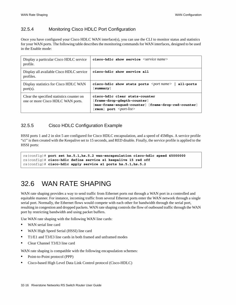
WAN Rate Shaping WAN Configuration
32.5.4 Monitoring Cisco HDLC Port Configuration
Once you have configured your Cisco HDLC WAN interface(s), you can use the CLI to monitor status and statistics for your WAN ports. The following table describes the monitoring commands for WAN interfaces, designed to be used in the Enable mode:
32.5.5 Cisco HDLC Configuration Example
HSSI ports 1 and 2 in slot 5 are configured for Cisco HDLC encapsulation, and a speed of 45Mbps. A service profile “s1” is then created with the Keepalive set to 15 seconds, and RED disable. Finally, the service profile is applied to the HSSI ports:
32.6 WAN RATE SHAPINGWAN rate shaping provides a way to send traffic from Ethernet ports out through a WAN port in a controlled and equitable manner. For instance, incoming traffic from several Ethernet ports enter the WAN network through a single serial port. Normally, the Ethernet flows would compete with each other for bandwidth through the serial port, resulting in congestion and dropped packets. WAN rate shaping controls the flow of outbound traffic through the WAN port by restricting bandwidth and using packet buffers.
Use WAN rate shaping with the following WAN line cards:• WAN serial line card• WAN High Speed Serial (HSSI) line card• T1/E1 and T3/E3 line cards in both framed and unframed modes• Clear Channel T3/E3 line card
WAN rate shaping is compatible with the following encapsulation schemes:• Point-to-Point protocol (PPP)• Cisco-based High Level Data Link Control protocol (Cisco-HDLC)
Display a particular Cisco HDLC service profile.
cisco-hdlc show service <service name>
Display all available Cisco HDLC service profiles.
cisco-hdlc show service all
Display statistics for Cisco HDLC WAN port(s).
cisco-hdlc show stats ports <port name> | all-ports [summary]
Clear the specified statistics counter on one or more Cisco HDLC WAN ports.
cisco-hdlc clear stats-counter [frame-drop-qdepth-counter] [max-frame-enqued-counter] [frame-drop-red-counter] [rmon] port <port-list>
rs(config)# port set hs.5.1,hs.5.2 wan-encapsulation cisco-hdlc speed 45000000rs(config)# cisco-hdlc define service s1 keepalive 15 red offrs(config)# cisco-hdlc apply service s1 ports hs.5.1,hs.5.2
32-16 Riverstone Networks RS Switch Router User Guide
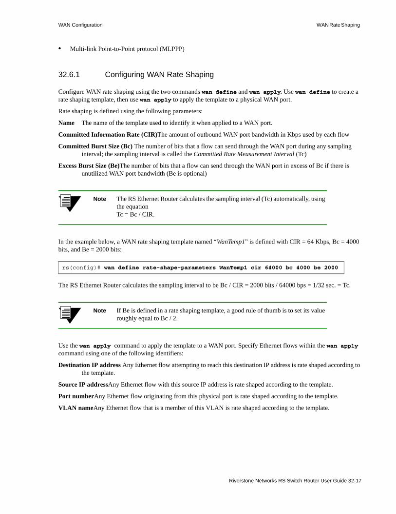
WAN Configuration WAN Rate Shaping
• Multi-link Point-to-Point protocol (MLPPP)
32.6.1 Configuring WAN Rate Shaping
Configure WAN rate shaping using the two commands wan define and wan apply. Use wan define to create a rate shaping template, then use wan apply to apply the template to a physical WAN port.
Rate shaping is defined using the following parameters:
Name The name of the template used to identify it when applied to a WAN port.
Committed Information Rate (CIR)The amount of outbound WAN port bandwidth in Kbps used by each flow
Committed Burst Size (Bc) The number of bits that a flow can send through the WAN port during any sampling interval; the sampling interval is called the Committed Rate Measurement Interval (Tc)
Excess Burst Size (Be)The number of bits that a flow can send through the WAN port in excess of Bc if there is unutilized WAN port bandwidth (Be is optional)
Note The RS Ethernet Router calculates the sampling interval (Tc) automatically, using the equationTc = Bc / CIR.
In the example below, a WAN rate shaping template named “WanTemp1” is defined with CIR = 64 Kbps, Bc = 4000 bits, and Be = 2000 bits:
The RS Ethernet Router calculates the sampling interval to be Bc / CIR = 2000 bits / 64000 bps = 1/32 sec. = Tc.
Note If Be is defined in a rate shaping template, a good rule of thumb is to set its value roughly equal to Bc / 2.
Use the wan apply command to apply the template to a WAN port. Specify Ethernet flows within the wan apply command using one of the following identifiers:
Destination IP address Any Ethernet flow attempting to reach this destination IP address is rate shaped according to the template.
Source IP addressAny Ethernet flow with this source IP address is rate shaped according to the template.
Port numberAny Ethernet flow originating from this physical port is rate shaped according to the template.
VLAN nameAny Ethernet flow that is a member of this VLAN is rate shaped according to the template.
rs(config)# wan define rate-shape-parameters WanTemp1 cir 64000 bc 4000 be 2000
Riverstone Networks RS Switch Router User Guide 32-17

WAN Rate Shaping WAN Configuration
In the example below, the previously defined WAN rate shaping template (WanTemp1) is applied to a Clear Channel T3 WAN port, and the Ethernet flows to be rate shaped are identified by a source IP address:
In the example above, notice that a subnet mask is specified with the source IP address. Adding the subnet mask causes the rate shaping template to be applied to all flows from the subnet 134.141.153.0. To apply rate shaping to a single source IP address, enter the IP address only, but do not specify a subnet mask.
The wan apply command also allows you to set the following parameters that affect rate shaping behavior:
burst-queue-depth:The depth (in packets) of the queue used to buffer packets when Bc or Bc + Be are exceeded.
no-shape-high-priority:Specifies that Ethernet traffic from the high-priority queue does not take part in rate shaping and transmits on the WAN port without bandwidth restrictions.
shape-control-priority:Normally, control-priority traffic (ARP, OSPF, and so on) are not subjected to rate shaping. However, control-priority traffic is included in the rate shaping process if this parameter is specified.
Note Rate shaping control-priority traffic is not recommended.
32.6.2 The WAN Rate Shaping Algorithm
The first step in rate shaping traffic through a WAN port is to allot some percentage of the WAN port’s bandwidth (in Kbps) to each Ethernet flow. This allotted bandwidth is called the Committed Information Rate (CIR). Generally, the total of the CIRs for all rate shaped flows should not exceed the total bandwidth of the WAN port. However, depending on the characteristics of each flow, some oversubscribing of WAN port bandwidth is usually permissible.
Next, the number of bits from each rate-shaped Ethernet flow is measured as they pass through the WAN port. These measurements are taken during equal sampling intervals (Tc), which are some fraction of one second. During a sampling interval, if the number of bits from a flow exceeds a pre-set value, called the Committed Burst Size (Bc), the rate shaping algorithm stops the Ethernet flow from sending packets directly through the WAN port. Instead, packets are sent to a queue, and the queue is emptied at a rate that does not exceed Bc. Because Bc is never exceeded, at the end of one second, the rate shaped Ethernet flow transmits a number of bits less than or equal to CIR.
Note Queue depth is not unlimited. Each queue for each flow can buffer a maximum of 256 packets.
If the traffic through the WAN port is bursty and there are periods when WAN bandwidth is not 100 percent utilized, the rate shaping algorithm can allow each rate shaped Ethernet flow to exceed its Bc by a specified amount called the Excess Burst Size (Be). As with Bc, if during a sampling interval, a particular flow exceeds its allocated Be, packets are buffered until the bit rate for the flow falls to Bc + Be. However, note that Be is not guaranteed because the amount of excess bandwidth typically changes over time. Because of this dynamic nature of excess bandwidth, queuing also can occur if the amount of excess WAN bandwidth falls below Bc + Be.
Figure 32-1 demonstrates how the parameters CIR, Bc, Be, and the sampling rate (Tc) interact to perform rate shaping. Note that in the example, Bc and Be are set to some number of bits and Tc is equal to 1/16 of a second.
rs(config)# wan apply rate-shape-parameters WanTemp1 port t3.3.1 source-ip-address 134.141.153.0/24
32-18 Riverstone Networks RS Switch Router User Guide

WAN Configuration WAN Rate Shaping
Figure 32-1 WAN rate shaping example
The following numbered list corresponds to the numbered points in Figure 32-1:1. The number of bits sent through the WAN port during the sampling period Tc is less than Bc.2. The number of bits sent through the WAN port exceeds Bc. If Be is not defined or if there is no extra
bandwidth available on the WAN interface, packets begin to be queued.3. The number of bits sent through the WAN port exceeds Bc. This occurs only if Be is defined and
there is extra bandwidth available.4. The number of bits sent through the WAN port has exceeds Bc + Be, and packets are queued.5. The number of bits sent through the WAN port drops below Bc + Be; as long as excess bandwidth
is available, the queue begins to empty.6. The number of bits sent through the WAN port drops below Bc, the buffer empties and packets are
once again passed directly through the WAN port.7. One second has elapsed (the sum of the sampling intervals), and the rate shaping algorithm has
controlled the Ethernet flow so that the number of bits sent through the WAN port is approximately equal to CIR.
Notice that if Be is defined and excess bandwidth is available, the amount of WAN port bandwidth utilized by an Ethernet flow can exceed its specified CIR. In the best possible case, where there is sustained excess bandwidth, a flow’s bandwidth can attain a maximum equal to ((Be + Bc) / Bc) * CIR. For example, if CIR = 128 Kbps, Bc = 4000, and Be = 2000, the calculated maximum bandwidth that the Ethernet flow could potentially reach is:
Max Bandwidth = ((2000 + 4000) / 4000) * 128000 = 192000 or 192 Kbps
TIME
BITS
1
2
4 5
6
7
3
Bc + Be
Committed Burst Size (Bc)
Samplinginterval Tc1
Samplinginterval Tc16
(Be)Excess Burst Size
Riverstone Networks RS Switch Router User Guide 32-19

WAN Rate Shaping WAN Configuration
32.6.3 WAN Rate Shaping Example
In this example, computers on three different floors are connected to R1 through Ethernet switches. R1 connects to the WAN through a Clear Channel T3 line. Rate shaping is applied, and limits each switch to 150 Kbps of bandwidth on the Clear Channel T3 line. Flows from each switch are identified by the physical port to which they connect on R1; these ports are et.2.1, et.2.7, and et.3.8. At the other end of the WAN connection, R2 passes Ethernet flows onto the Metro backbone. Conversely, R2 rate shapes Ethernet flows from the Metro backbone that originate on subnet 124.141.77.0/24 and sends them through its own Clear Channel T3 line to R1 (see Figure 32-2).
Figure 32-2 Rate shaping on destination IP address
First, the rate shaping template “dest1” is created on R1, with the rate shape parameters specified as CIR = 150 Kbps, Bc = 5000 bits, Be is unspecified, and R1 sets Tc automatically to Bc / CIR = 1/30 of a second:
Template dest1 is applied to R1’s Clear Channel T3 port for each port connected to an Ethernet switch:
rs(config)# wan define rate-shape-parameters dest1 cir 150000 bc 5000
rs(config)# wan apply rate-shape-parameters dest1 port t3.6.1 traffic-source-port et.2.1rs(config)# wan apply rate-shape-parameters dest1 port t3.6.1 traffic-source-port et.2.7rs(config)# wan apply rate-shape-parameters dest1 port t3.6.1 traffic-source-port et.3.8
WAN
Floor One Floor Two Floor Three
Switch One Switch Two Switch Three
R1
R2
et.2.1 et.3.8et.2.7
t3.6.1
t3.6.1
To MetroBackbone
From Metro Backbone, Subnet 124.141.77.0/24
32-20 Riverstone Networks RS Switch Router User Guide

WAN Configuration WAN Rate Shaping
Next, the rate shaping template “dest2” is created on R2, with the rate shape parameters specified as CIR = 170 Kbps, Bc = 7000 bits, Be is unspecified, and R2 sets Tc automatically to Bc / CIR = 1/24 of a second:
Template dest2 is applied to R2’s Clear Channel T3 port for traffic originating from subnet 124.141.77.0/24:
Once the templates are applied, all Ethernet flows on R1 originating from ports et.2.1, et.2.7, and et.3.8 are rate shaped to a maximum of 150 kbps, while Ethernet flows on R2 originating from subnet 124.141.77.0 are rate shaped to a maximum of 170 Kbps in the opposite direction.
32.6.4 Using WAN Rate Shaping
The following section lists a few situations to keep in mind when using WAN rate shaping.
32.6.4.1 Using Multiple Rate Shaping Templates
The rate shaping algorithm can use only one identifier to determine whether an Ethernet flow should be rate shaped. Furthermore, the identifiers are tested against a flow in the following order:1. Destination IP address2. Source IP address3. VLAN4. Traffic source port
If more than one rate shaping template is applied to a WAN port, the first template with an identifier that matches an Ethernet flow’s internal parameters (as shown in the ordered list above) is applied to the flow. Keep in mind this hierarchy of identifiers when configuring rate shaping to assure that Ethernet flows are rate shaped by the desired template.
For example, two templates are created (temp1 and temp2), each with a different value for CIR and Bc:
Both templates are applied to a single Clear Channel T3 port, one using traffic-source-port as its identifier, the other using vlan as its identifier:
rs(config)# wan define rate-shape-parameters dest2 cir 170000 bc 7000
rs(config)# wan apply rate-shape-parameters dest2 port t3.6.1 source-ip-address 124.141.77.0/24
rs(config)# wan define rate-shape-parameters temp1 cir 150000 bc 5000rs(config)# wan define rate-shape-parameters temp2 cir 200000 bc 9000
rs(config)# wan apply rate-shape-parameters temp1 port t3.2.1 traffic-source-port et.1.2rs(config)# wan apply rate-shape-parameters temp2 port t3.2.1 vlan west-district
Riverstone Networks RS Switch Router User Guide 32-21

WAN Rate Shaping WAN Configuration
Notice that vlan is higher in the identifier hierarchy than traffic-source-port. Because of this, the VLAN name is examined first. As a result, if et.1.2 belongs to VLAN west-district, flows from port et.1.2 will be shaped according to temp2, rather than temp1.
32.6.4.2 Rate Shaping by Best Effort
If CIR and Bc are both set to zero, and Be is set to some value greater than zero, packets from the Ethernet flow controlled by this template will pass through the WAN port only if there is surplus bandwidth equal to or greater than Be. This configuration does not provide any guarantee that the flow’s packets will get through the WAN port; and bandwidth for this flow is attained only on a best-effort basis.
32.6.4.3 Performing Rate Limiting
If the burst-queue-depth is set to zero for a particular template, WAN rate shaping for the affected flows effectively becomes rate limiting. This switch to rate limiting occurs because without a queue, packets are simply dropped whenever the bit rate of a flow reaches Bc and/or Be.
32.6.4.4 Non-Rate Shaped Flows
If Ethernet flows that are not controlled by a WAN rate shaping template are mixed with flows that are controlled. The non-rate shaped flows will disregard the rate shaped flows and take as much bandwidth as they can. For this reason, it’s generally not a good idea to mix rate shaped and non-rate shaped flows on a WAN port.
32.6.4.5 Rate Shaping in Both Directions
WAN rate shaping works best when it is applied in both directions. In other words, if you apply rate shaping to an RS Ethernet Router WAN port going into the WAN, you also should apply rate shaping to the RS Ethernet Router WAN port at the other end of the connection. Applying rate shaping to each RS Ethernet Router allows connection-oriented protocols, such as TCP, to communicate more efficiently and experience fewer instances that could potentially trigger crank-back.
32.6.5 Collective Rate Shaping
WAN rate shaping parameters can be applied collectively to several source IP addresses, destination IP addresses, or VLANs.
For example, the following command lines configure 10.1.1.1 and 10.1.1.2 to both use a CIR of 128 Kbps:
In the example above, line-1 (10.1.1.1) and line-2 (10.1.1.2) are each rate shaping separate lines, each at a CIR of 128 Kbps.
rs(config)# wan define rate-shape-parameters RS1 cir 128000rs(config)# wan apply rate-shape-parameters RS1 port se.2.1 source-ip-address 10.1.1.1rs(config)# wan apply rate-shape-parameters RS1 port se.2.1 source-ip-address 10.1.1.2
32-22 Riverstone Networks RS Switch Router User Guide

WAN Configuration WAN Configuration Examples
The rate shaping parameter, bandwidth-shared, provides a way to make line-1 and line-2 collectively rate shape a CIR of 128 Kbps.
For example:
In the example above, the keyword, bandwidth-shared, causes line-1 (10.1.1.1) and line-2 (10.1.1.2) to share a CIR of 128 Kbps, and collectively rate shape the bandwidth across the two lines
32.7 WAN CONFIGURATION EXAMPLES
32.7.1 Simple Configuration File
The following is an example of a simple configuration file used to test frame relay and PPP WAN ports:
For a broader, more application-oriented WAN configuration example, see "Multi-Router WAN Configuration" next.
32.7.2 Multi-Router WAN Configuration
The following is a diagram of a multi-router WAN configuration encompassing three subnets. From the diagram, you can see that R1 is part of both Subnets 1 and 2, R2 is part of both Subnets 2 and 3, and R3 is part of subnets 1 and 3. You can click on the router label (in blue) to jump to the actual text configuration file for that router:
rs(config)# wan define rate-shape-parameters RS1 cir 128000 bandwidth-sharedrs(config)# wan apply rate-shape-parameters RS1 port se.2.1 source-ip-address 10.1.1.1rs(config)# wan apply rate-shape-parameters RS1 port se.2.1 source-ip-address 10.1.1.2
port set hs.5.1 wan-encapsulation frame-relay speed 45000000port set hs.5.2 wan-encapsulation ppp speed 45000000interface create ip fr1 address-netmask 10.1.1.1/16 port hs.5.1.100interface create ip ppp2 address-netmask 10.2.1.1/16 port hs.5.2interface create ip lan1 address-netmask 10.20.1.1/16 port et.1.1interface create ip lan2 address-netmask 10.30.1.1/16 port et.1.2ip add route 10.10.0.0/16 gateway 10.1.1.2ip add route 10.40.0.0/16 gateway 10.2.1.2
Riverstone Networks RS Switch Router User Guide 32-23
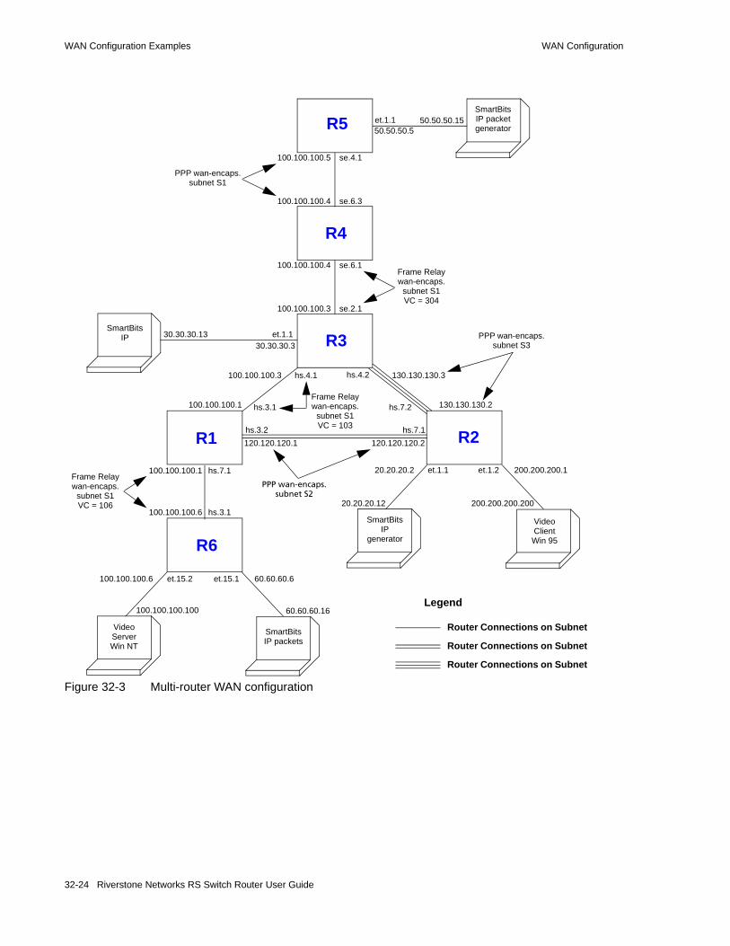
WAN Configuration Examples WAN Configuration
Figure 32-3 Multi-router WAN configuration
R5
R3
R4
R2R1
R6
SmartBitsIP packetgenerator
Video ClientWin 95
SmartBitsIP
generator
SmartBitsIP
Video ServerWin NT
SmartBitsIP packets
50.50.50.550.50.50.15et.1.1
100.100.100.5
100.100.100.4
100.100.100.4
100.100.100.3
se.4.1
se.6.3
se.6.1
se.2.1
hs.4.2hs.4.1
hs.7.2hs.3.1
et.1.1 et.1.2
hs.7.1hs.3.2
et.1.1
hs.7.1
hs.3.1
et.15.2 et.15.1
30.30.30.330.30.30.13
100.100.100.3 130.130.130.3
100.100.100.1 130.130.130.2
200.200.200.20020.20.20.12
20.20.20.2 200.200.200.1
120.120.120.1 120.120.120.2
100.100.100.1
100.100.100.6
100.100.100.100
60.60.60.6
60.60.60.16
100.100.100.6
Frame Relaywan-encaps.
subnet S1VC = 106
PPP wan-encaps.subnet S2
Frame Relaywan-encaps.
subnet S1VC = 103
PPP wan-encaps.subnet S3
PPP wan-encaps.subnet S1
Frame Relaywan-encaps.
subnet S1VC = 304
Legend
Router Connections on Subnet
Router Connections on Subnet
Router Connections on Subnet
32-24 Riverstone Networks RS Switch Router User Guide
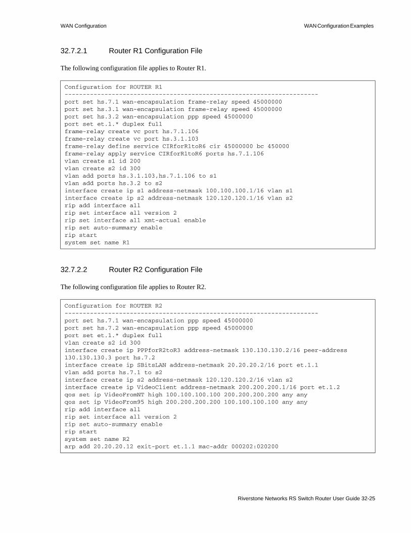
WAN Configuration WAN Configuration Examples
32.7.2.1 Router R1 Configuration File
The following configuration file applies to Router R1.
32.7.2.2 Router R2 Configuration File
The following configuration file applies to Router R2.
Configuration for ROUTER R1----------------------------------------------------------------------port set hs.7.1 wan-encapsulation frame-relay speed 45000000port set hs.3.1 wan-encapsulation frame-relay speed 45000000port set hs.3.2 wan-encapsulation ppp speed 45000000port set et.1.* duplex fullframe-relay create vc port hs.7.1.106frame-relay create vc port hs.3.1.103frame-relay define service CIRforR1toR6 cir 45000000 bc 450000frame-relay apply service CIRforR1toR6 ports hs.7.1.106vlan create s1 id 200vlan create s2 id 300vlan add ports hs.3.1.103,hs.7.1.106 to s1vlan add ports hs.3.2 to s2interface create ip s1 address-netmask 100.100.100.1/16 vlan s1interface create ip s2 address-netmask 120.120.120.1/16 vlan s2rip add interface allrip set interface all version 2rip set interface all xmt-actual enablerip set auto-summary enablerip startsystem set name R1
Configuration for ROUTER R2----------------------------------------------------------------------port set hs.7.1 wan-encapsulation ppp speed 45000000port set hs.7.2 wan-encapsulation ppp speed 45000000port set et.1.* duplex fullvlan create s2 id 300interface create ip PPPforR2toR3 address-netmask 130.130.130.2/16 peer-address 130.130.130.3 port hs.7.2interface create ip SBitsLAN address-netmask 20.20.20.2/16 port et.1.1vlan add ports hs.7.1 to s2interface create ip s2 address-netmask 120.120.120.2/16 vlan s2interface create ip VideoClient address-netmask 200.200.200.1/16 port et.1.2qos set ip VideoFromNT high 100.100.100.100 200.200.200.200 any anyqos set ip VideoFrom95 high 200.200.200.200 100.100.100.100 any anyrip add interface allrip set interface all version 2rip set auto-summary enablerip startsystem set name R2arp add 20.20.20.12 exit-port et.1.1 mac-addr 000202:020200
Riverstone Networks RS Switch Router User Guide 32-25

WAN Configuration Examples WAN Configuration
32.7.2.3 Router R3 Configuration File
The following configuration applies to Router 3.
32.7.2.4 Router R4 Configuration File
The following configuration file applies to Router R4.
Configuration for ROUTER R3----------------------------------------------------------------------port set se.2.1 wan-encapsulation frame-relay speed 1500000port set et.1.* duplex fullport set hs.4.1 wan-encapsulation frame-relay speed 45000000port set hs.4.2 wan-encapsulation ppp speed 45000000frame-relay create vc port se.2.1.304frame-relay create vc port hs.4.1.103vlan create s1 id 200interface create ip SBitsLAN address-netmask 30.30.30.3/16 port et.1.1vlan add ports hs.4.1.103,se.2.1.304 to s1interface create ip PPPforR2toR3 address-netmask 130.130.130.3/16 peer-address 130.130.130.2 port hs.4.2interface create ip s1 address-netmask 100.100.100.3/16 vlan s1rip add interface allrip set interface all version 2rip set interface all xmt-actual enablerip set broadcast-state alwaysrip set auto-summary enablerip startsystem set name R3arp add 30.30.30.13 exit-port et.1.1 mac-addr 000303:030300
Configuration for ROUTER R4----------------------------------------------------------------------port set se.6.1 wan-encapsulation frame-relay speed 1500000port set se.6.3 wan-encapsulation ppp speed 1500000port set et.1.* duplex fullframe-relay create vc port se.6.1.304vlan create s1 id 200vlan add ports se.6.1.304,se.6.3 to s1interface create ip s1 address-netmask 100.100.100.4/16 vlan s1rip add interface allrip set interface all version 2rip set interface all xmt-actual enablerip set broadcast-state alwaysrip set auto-summary enablerip startsystem set name R4
32-26 Riverstone Networks RS Switch Router User Guide

WAN Configuration WAN Configuration Examples
32.7.2.5 Router R5 Configuration File
The following configuration file applies to Router R5.
32.7.2.6 Router R6 Configuration File
The following configuration file applies to Router R6.
!Configuration for ROUTER R5port set se.4.1 wan-encapsulation ppp speed 1500000port set et.1.* duplex fullvlan create s1 id 200interface create ip lan1 address-netmask 50.50.50.5/16 port et.1.1vlan add ports se.4.1 to s1interface create ip s1 address-netmask 100.100.100.5/16 vlan s1rip add interface allrip set auto-summary enablerip set interface all version 2rip startsystem set name R5arp add 50.50.50.15 mac-addr 000505:050500 exit-port et.1.1
!Configuration for ROUTER R6port set et.15.* duplex fullport set hs.3.1 wan-encapsulation frame-relay speed 45000000frame-relay create vc port hs.3.1.106frame-relay define service CIRforR1toR6 cir 45000000 bc 450000frame-relay apply service CIRforR1toR6 ports hs.3.1.106vlan create BridgeforR1toR6 port-based id 106interface create ip FRforR1toR6 address-netmask 100.100.100.6/16 vlan BridgeforR1toR6interface create ip lan1 address-netmask 60.60.60.6/16 port et.15.1vlan add ports hs.3.1.106 to BridgeforR1toR6vlan add ports et.15.2 to BridgeforR1toR6qos set ip VideoFromNT high 100.100.100.100 200.200.200.200 any anyqos set ip VideoFrom95 high 200.200.200.200 100.100.100.100 any anyrip add interface allrip set interface all version 2rip set auto-summary enablerip startsystem set name R6arp add 60.60.60.16 mac-addr 000606:060600 exit-port et.15.1
Riverstone Networks RS Switch Router User Guide 32-27
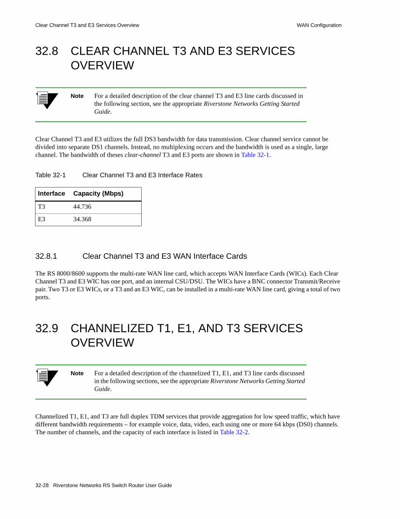
Clear Channel T3 and E3 Services Overview WAN Configuration
32.8 CLEAR CHANNEL T3 AND E3 SERVICES OVERVIEW
Note For a detailed description of the clear channel T3 and E3 line cards discussed in the following section, see the appropriate Riverstone Networks Getting Started Guide.
Clear Channel T3 and E3 utilizes the full DS3 bandwidth for data transmission. Clear channel service cannot be divided into separate DS1 channels. Instead, no multiplexing occurs and the bandwidth is used as a single, large channel. The bandwidth of theses clear-channel T3 and E3 ports are shown in Table 32-1.
32.8.1 Clear Channel T3 and E3 WAN Interface Cards
The RS 8000/8600 supports the multi-rate WAN line card, which accepts WAN Interface Cards (WICs). Each Clear Channel T3 and E3 WIC has one port, and an internal CSU/DSU. The WICs have a BNC connector Transmit/Receive pair. Two T3 or E3 WICs, or a T3 and an E3 WIC, can be installed in a multi-rate WAN line card, giving a total of two ports.
32.9 CHANNELIZED T1, E1, AND T3 SERVICES OVERVIEW
Note For a detailed description of the channelized T1, E1, and T3 line cards discussed in the following sections, see the appropriate Riverstone Networks Getting Started Guide.
Channelized T1, E1, and T3 are full duplex TDM services that provide aggregation for low speed traffic, which have different bandwidth requirements – for example voice, data, video, each using one or more 64 kbps (DS0) channels. The number of channels, and the capacity of each interface is listed in Table 32-2.
Table 32-1 Clear Channel T3 and E3 Interface Rates
Interface Capacity (Mbps)
T3 44.736
E3 34.368
32-28 Riverstone Networks RS Switch Router User Guide

WAN Configuration Channelized T1, E1, and T3 Services Overview
32.9.1 Channelized T1 and E1 WAN Interface Cards
The RS 8000/8600 supports the multi-rate WAN line card, which accepts WAN Interface Cards (WICs). Each T1 and E1 WIC has two ports and an internal CSU/DSU. Two T1 or E1 WICs, or a T1 and E1 WIC, can be installed in a Multi-Rate WAN module, giving a total of four ports. Each T1/E1 WIC has three modes of operation, depending on the service requirements:• Channelized T1 and E1, for services that require multiples of 64 kbps bandwidth. A single channel
is used for each service – for example, T1 can have 24 DS0 channels.• Fractional T1 and E1, for services that require multiples of the 64 kbps channels. For example, T1
services may be high-speed data on a 512 kbps channel, plus 16 low speed data and voice channels at 64 kbps.
• Full (unstructured) T1 and E1, when a service requires the full T1 or E1 bandwidth. For example, point-to-point data transmission.
Warning Hot swapping WICs is not yet supported.
32.9.2 Dedicated Channelized T3 Line Cards
Riverstone offers two channelized T3 line cards, one for the RS 8000/8600, the other, for the RS 38000. The RS 8000/8600 T3 line card provides two channelized T3 ports. The RS 38000 version of the T3 line card four T3 ports. These line cards contain an internal DSU. Each T3 port on the RS 38000 line card has an associated RJ-48c T1 test port. The RS 8000/8600 version has no test ports.
Each channelized T3 port contains a total of 28 DS1 channels available for the serial transmission of data. Each DS1 channel can be configured to use either a portion of the DS1’s bandwidth or the entire bandwidth for data transmission. Bandwidth for each DS1 channel can be configured for n x 56 kbps or n x 64 kbps (where n is 1 to 24).
These channelized T3 line cards provide sophisticated bandwidth aggregation functionality using the standards based multi-link PPP protocol.
Table 32-2 Channelized DS1, E1 and DS3 Interfaces
Interface Number ofChannels
Capacity (Mbps)
Line Speed(Mbps)
DS1 24 DS0 channels 1.536 1.544
E1 32 channels 1.920/1.984
2.048
DS3 28 DS1 lines 43.008 44.736
Riverstone Networks RS Switch Router User Guide 32-29

Channelized T1, E1, and T3 Services Overview WAN Configuration
32.9.2.1 DS1 Test Port Control for the RS 38000 Channelized Line Card
Each Channelized T3 port has an associated T1 test port, which provides access to any of the DS1 channels within a Channelized T3. You can configure the test port in either monitor or break-out mode.• In monitor mode, you may connect an external analyzer to a test port to allow transparent monitoring
of data on a given selected DS1 channel.• In break-out mode, you can remove the selected DS1 channel from service, which allows you to
connect external test equipment to verify the operation of the DS1 channel. The break-out mode is mainly intended for support of external BERT equipment (see Section 32.9.6, "Bit Error Rate Testing").
32.9.3 Configuring Channelized T1, E1 and T3 Interfaces
This section discusses the basics of the Channelized T1, E1 and T3 interfaces. It provides the following examples for configuring these interfaces and basic interface function:• Configuring a Channelized T1 interface• Configuring an Channelized E1 interface• Configuring a Channelized T3 interface• Creating a MLP bundle• Creating a VLAN
32.9.3.1 Configuring a Channelized T1 Interface
The following commands are an example of configuring a basic Channelized T1 interface.
For the Channelized T1 interface example:• port set t1.2.(1-4):1 - Configures the following parameters for ports 1 through 4.• framing esf - Sets the framing type to Extended Super Frame.• fdl ansi - Sets the Facilities Data Link (data channel) to ANSI.• lbo -7.5db - Sets the line loss to -7.5 db.• timeslots 1-24 - Sets the range of time slots to select in a frame from 1 to 24.• wan-encapsulation ppp - Sets the WAN encapsulation type to PPP. This must be specified on
the same line as the timeslots.
32.9.3.2 Configuring a Channelized E1 Interface
The following commands are an example of configuring a basic Channelized E1 interface.
rs(config)# port set t1.2.(1-4) framing esf fdl ansi lbo -7.5dbrs(config)# port set t1.2.(1-4):1 timeslots 1-24 wan-encapsulation ppp
rs(config)# port set e1.2.(1-4) framing crc4 impedance 75ohmrs(config)# port set e1.2.(1-4):1 timeslots 1-31 ts16 wan-encapsulation ppp
32-30 Riverstone Networks RS Switch Router User Guide

WAN Configuration Channelized T1, E1, and T3 Services Overview
For the Channelized E1 interface example:• port set e1.3.(1-4):1 - Configures the following parameters for ports 1 through 4.• framing crc4 - Sets the framing type to Cyclic Redundancy Check 4.• impedance 75ohm - Sets the impedance of the line to 75 ohm.• timeslots 1-31 - Sets the range of time slots to select in a frame from 1 to 31.• ts16 - Sets timeslot 16 to be used for data. If timeslot 16 is used with other timeslots, ts16 must
be specified on the same line as the timeslots.• wan-encapsulation ppp - Sets the WAN encapsulation type to PPP. This must be specified on
the same line as the timeslots and ts16.
32.9.3.3 Configuring a Channelized T3 Interfaces
There are four ways to configure a channelized T3 interface:• Configuring the full DS3 line as a single, large-capacity T3 interface• Configuring partial DS1 bandwidth within the T3 into channels• Configuring indices to divide DS0s into separate channels within the DS3 line • Aggregating full or partial DS1 channels into multi-link PPP bundles
This section describes how to set up a channelized T3 line card for each of these configurations.
Assigning Partial DS1 Bandwidth Within a Channelized T3
Partial bandwidth of any of the T3’s DS1s can be assigned to create a partial DS1 channel. The following example demonstrates this capability.
In the example above, the first 10 timeslots of the fourth DS1 are configured for PPP and assigned to interface T1-4. Notice that when using this type of partial DS1 assignment, the remaining timeslots (11-24) are filled with null data, and become unusable. In other words, timeslots 11-24 cannot be assigned to an interface and the bandwidth is lost.
Assigning Partial DS1 Bandwidth Using Indices
An alternate way of assigning DS1 bandwidth to channels uses a different convention for specifying T3 ports. Specifically, an index is added that allows all of a DS1’s bandwidth to be divided among multiple DS0s. The index format for a T3 port uses the following convention: t3.<slot>.<port>.<index>:<channel>. In this format, the index identifies the DS1, and the channel identifies one or more DS0s within the DS1.
For example – to specify DS1 bandwidth as “index 1” of the “3rd channel” of “port 2” of the “T3 line card” in “slot five,” enter the following: t3.5.2.1:3. Notice here that the index is specified as 1, but could be any number between 1 and 28.
rs(config)# port set t3.6.1:4 timeslots 1-10 wan-encapsulation ppprs(config)# interface create ip T1-4 port t3.6.1:4 address-netmask 201.10.10.10/16
Riverstone Networks RS Switch Router User Guide 32-31

Channelized T1, E1, and T3 Services Overview WAN Configuration
In the following example, indices are used to assign half of a DS1’s bandwidth to one interface and the remaining bandwidth to another interface:
Notice in the example above that unlike the previous example, all the bandwidth of the DS1 is utilized by assigning DS01 through DS010 to interface T1-1 and DS011 through DS024 to interface T1-2.
In the next example, a channel containing a single DS0 is created and then assigned to an interface.
In the example above, interface DS0-1 contains a channel containing a single DS0 line.
Note that while the use of indices could potentially allow each of the 28 DS1s within a T3 port to be divided into 24 independent DS0s (672 DS0s per T3 port), the RS Ethernet Router does not support a sufficient number of interfaces. Each T3 port supports a maximum of 128 interfaces. Furthermore, channelized T3 is not intended to support single DS0 channels. Rather, channelized T3 is designed to transport channels containing many DS0s for related groups of DS1s.
Aggregating DS1 channels into Multi-Link PPP Bundles
The RS Ethernet Router provides the ability to aggregate T3 bandwidth using multi-link PPP (MLP), whether the bandwidth is divided up among complete or partial DS1s on the same port or different ports. The only restriction to using MLP is that it cannot span multiple line cards.
The following example creates several DS0 channels on several DS1s on the T3 line card, assigns them to an MLP bundle, and then assigns the bundle to an interface.
32.9.3.4 Basic Channelized T1, E1 and T3 Interface Functions
The following sections describe how interfaces are assigned to channelized T1, E1, and T3 ports.
rs(config)# port set t3.6.1.1:1 timeslots 1-10 wan-encapsulation ppprs(config)# port set t3.6.1.1:2 timeslots 11-24 wan-encapsulation ppprs(config)# interface create ip T1-1 port t3.6.1.1:1 address-netmask 100.10.10.10/16 rs(config)# interface create ip T1-2 port t3.6.1.1:2 address-netmask 200.10.10.10/16
rs(config)# port set t3.6.1.1:1 timeslots 1 wan-encapsulation ppprs(config)# interface create ip DS0-1 port t3.6.1.1:1 address-netmask 220.10.10.10/16
rs(config)# port set t3.6.1.1:1 timeslots 1-10 wan-encapsulation ppprs(config)# port set t3.6.1.1:2 timeslots 11-24 wan-encapsulation ppprs(config)# port set t3.6.1.3:1 timeslots 1-5 wan-encapsulation ppprs(config)# port set t3.6.1.3:2 timeslots 6-24 wan-encapsulation ppprs(config)# port set t3.6.2.1:1 timeslots 1-24 wan-encapsulation ppp
rs(config)# ppp create-mlp mp.1 slot 6rs(config)# ppp add-to-mlp port t3.6.1.1:1rs(config)# ppp add-to-mlp port t3.6.1.1:2rs(config)# ppp add-to-mlp port t3.6.1.3:1rs(config)# ppp add-to-mlp port t3.6.1.3:2rs(config)# ppp add-to-mlp port t3.6.2.1:1
rs(config)# interface create ip BUNDDLE-1 port mp.1 address-netmask 201.10.10.10/16
32-32 Riverstone Networks RS Switch Router User Guide
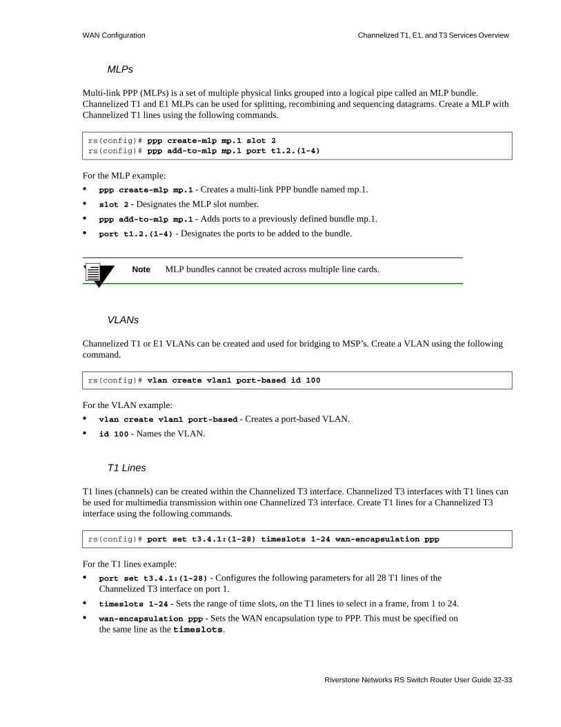
WAN Configuration Channelized T1, E1, and T3 Services Overview
MLPs
Multi-link PPP (MLPs) is a set of multiple physical links grouped into a logical pipe called an MLP bundle. Channelized T1 and E1 MLPs can be used for splitting, recombining and sequencing datagrams. Create a MLP with Channelized T1 lines using the following commands.
For the MLP example:• ppp create-mlp mp.1 - Creates a multi-link PPP bundle named mp.1.• slot 2 - Designates the MLP slot number.• ppp add-to-mlp mp.1 - Adds ports to a previously defined bundle mp.1.• port t1.2.(1-4) - Designates the ports to be added to the bundle.
Note MLP bundles cannot be created across multiple line cards.
VLANs
Channelized T1 or E1 VLANs can be created and used for bridging to MSP’s. Create a VLAN using the following command.
For the VLAN example:• vlan create vlan1 port-based - Creates a port-based VLAN.• id 100 - Names the VLAN.
T1 Lines
T1 lines (channels) can be created within the Channelized T3 interface. Channelized T3 interfaces with T1 lines can be used for multimedia transmission within one Channelized T3 interface. Create T1 lines for a Channelized T3 interface using the following commands.
For the T1 lines example:• port set t3.4.1:(1-28) - Configures the following parameters for all 28 T1 lines of the
Channelized T3 interface on port 1.• timeslots 1-24 - Sets the range of time slots, on the T1 lines to select in a frame, from 1 to 24.• wan-encapsulation ppp - Sets the WAN encapsulation type to PPP. This must be specified on
the same line as the timeslots.
rs(config)# ppp create-mlp mp.1 slot 2rs(config)# ppp add-to-mlp mp.1 port t1.2.(1-4)
rs(config)# vlan create vlan1 port-based id 100
rs(config)# port set t3.4.1:(1-28) timeslots 1-24 wan-encapsulation ppp
Riverstone Networks RS Switch Router User Guide 32-33

Channelized T1, E1, and T3 Services Overview WAN Configuration
32.9.4 Configuring Frame Relay over Channelized T1, E1 and T3 Interfaces
Configure Frame Relay over a Channelized T1, E1 or T3 interface as follows:
32.9.5 Displaying MAC Addresses Stored on WAN Line Cards
The wan show mac-table command displays the contents of the layer-2 MAC addresses table on the WAN line-cards. To use this command, the slot within which the WAN line card resides must be specified.
The following is an example of the wan show mac-table command applied to a T3 module residing in slot 4:
32.9.6 Bit Error Rate Testing
The Bit Error Rate Testing (BERT) functionality allows you to test a DS1, DS0, or E1 interface or a DS1 line or DS0 channel within a DS3, for cable and signal problems while installed in a field environment. BERT consists of sending a data pattern for a configurable amount of time while monitoring the received data pattern. Since BERT expects to receive the same pattern that is being transmitted, you can either configure the line in a loopback configuration or the remote-end can be set up to send the same pattern; setting up a loopback prior to invoking BERT on a given DS1, DS0, or E1 connection is the most common setup. BERT keeps track of the bit receive count versus the number of receive bit errors over time, and the result is the Bit Error Rate.
The patterns available for BERT are selectable from a standard set of both pseudo-random and repetitive patterns (see the parameters for the port bert command).
BERT can only be performed on a single physical or logical port. To perform a BERT test on a single port in a multi-link bundle, the port must first be removed from the bundle.
Table 32-3 displays the loopback types available and the interfaces on which they are supported.
port set t1.4.1:1 timeslots 1-4 wan-encapsulation frame-relayport set e1.5.1:1 timeslots 1-4 wan-encapsulation frame-relayport set t3.6.1:1 timeslots 1-4 wan-encapsulation frame-relayframe-relay create vc port t1.4.1:1.103frame-relay create vc port e1.5.1:1.105frame-relay create vc port t3.6.1:1.104frame-relay define service t1service cir 64000 bc 128000frame-relay apply service t1service ports t1.4.1:1.103frame-relay define service e1service cir 64000 bc 128000frame-relay apply service e1service ports e1.5.1:1.104frame-relay define service t3service cir 1544000 bc 2048000frame-relay apply service t3service ports t3.6.1:1.105interface create ip fr1 address-netmask 10.10.30.1/24 port t1.4.1:1 upinterface create ip fr2 address-netmask 10.10.40.1/24 port e1.5.1:1 upinterface create ip fr3 address-netmask 10.10.50.1/24 port t3.6.1:1 up
rs# wan show mac-table slot 4Id MAC VLAN Source Port VC------ ------------------ ---- ----------------- ------ 1 00:02:02:02:02:02 2 t3.4.1.1 102 2 00:01:01:01:01:01 2 t3.4.1.1 101
32-34 Riverstone Networks RS Switch Router User Guide

WAN Configuration Channelized T1, E1, and T3 Services Overview
Table 32-3 Loopback types supported
Loopback DS0
T1 E1 Ch T3 CC T3
CC E3
Description
local X X X X X Internally loops data back to itself
network-line X X X X X Loops incoming data back out to the line, without re-framing the data
network-payload X X X Loops incoming data back out to the line and re-frames the data
niu-remote-line-fdl-ansi X Sends an FDL ANSI coded request to a Network Interface Unit (NIU), asking the NIU to go into network-line loopback
niu-remote-line-inband X Sends an inband (5 seconds) request to a Network Interface Unit (NIU), asking the NIU to go into network-line loopback
remote-line-fdl-ansi X Sends an FDL ANSI coded request to the remote CSU/DSU, asking CSU/DSU to go into network-line loopback
remote-line-fdl-bellcore X Sends an FDL Bellcore coded request to the remote CSU/DSU, asking CSU/DSU to go into network-line loopback
remote-payload-fdl-ansi X Sends an FDL ANSI coded request to the remote CSU/DSU, asking CSU/DSU to go into network-payload loopback
remote-line-inband X Sends an inband (~5 seconds) coded request to the remote CSU/DSU, asking CSU/DSU to go into network-line loopback
remote-line-feac X Sends a FEAC (Far-End Access Control) coded request to the remote end, asking the remote end to go into network-line loopback
Note: T3 line must be in C-Bit framing when using the FEAC coded request.
Note: T1 lines can be either a T1 port on a WPIM or a T1 line broken out of a T3.
Note: T1 lines must be in ESF framing mode when using any of the FDL coded requests.
Riverstone Networks RS Switch Router User Guide 32-35

Channelized T1, E1, and T3 Services Overview WAN Configuration
Table 32-4 lists the interface types on which BERT is supported:
32.9.6.1 Example One: Using BERT Testing on a DS1 Interface
This example shows the use of BERT to test a structured DS1 interface for a duration of one hour.
Table 32-4 Bit error rate tests (BERT) supported
DS0
T1 E1 Ch T3 CC T3
CC E3
Description
BERT X X X X X Tests line integrity by sending one of various (user selectable) bit patterns and recording whether same pattern is received
Note: To run a BERT successfully (without the aid of external test equipment), the remote side must be in a line loopback mode.
Note: To view results of BERT, use the 'port show serial-link-info <port> all' command.
enableconfig!-----------------------------------------------------------------------------! Configure loopback!-----------------------------------------------------------------------------port set t1.2.1 framing esf lbo -7.5dbport set t1.2.1:1 timeslots 1-24 speed-56 wan-encapsulation pppsave activeexitport loopback t1.2.1 remote-line-fdl-ansi!-----------------------------------------------------------------------------! Set the BERT pattern to use!-----------------------------------------------------------------------------port bert t1.2.1 pattern 2^20-QRSS interval 60!-----------------------------------------------------------------------------!To start the test.!-----------------------------------------------------------------------------port bert t1.2.1 start!-----------------------------------------------------------------------------! During the test, to display progress.!-----------------------------------------------------------------------------port show serial-link-info t1.2.1 all!-----------------------------------------------------------------------------! To stop the test before the one hour interval expires.!-----------------------------------------------------------------------------port bert t1.2.1 stop
32-36 Riverstone Networks RS Switch Router User Guide

WAN Configuration Channelized T1, E1, and T3 Services Overview
32.9.6.2 Example Two: Using BERT Testing on a DS3 Interface
This example shows the use of BERT to do an internal test of the 15th DS1 line of a DS3 interface for a duration of one hour.
32.9.6.3 Example Three: Using BERT Testing on a DS0 Channel within a T1 interface
This example shows the use of BERT to an internal test of the first DS0 channel of a DS1 interface for the duration of one hour:
enableconfig!-----------------------------------------------------------------------------! Configure loopback!-----------------------------------------------------------------------------port set t3.2.1:15 framing esfsave activeexitport loopback t3.2.1:15 remote-line-fdl-ansi!-----------------------------------------------------------------------------! Set the BERT pattern to use!-----------------------------------------------------------------------------port bert t3.2.1:15 pattern 2^20-QRSS interval 60!-----------------------------------------------------------------------------!To start the test.!-----------------------------------------------------------------------------port bert t3.2.1:15 start!-----------------------------------------------------------------------------! During the test, to display progress.!-----------------------------------------------------------------------------port show serial-link-info t3.2.1:15 all
enableconfig!-----------------------------------------------------------------------------! Configure loopback!-----------------------------------------------------------------------------port set t1.4.1:1 timeslots 1 wan-encapsulation pppsave activeexitport loopback t1.4.1 remote-line-fdl-ansi!-----------------------------------------------------------------------------! Set the BERT pattern to use!-----------------------------------------------------------------------------port bert t1.4.1:1 pattern 2^20-QRSS interval 60!-----------------------------------------------------------------------------!To start the test.!-----------------------------------------------------------------------------port bert t1.4.1:1 start!-----------------------------------------------------------------------------! During the test, to display progress.!-----------------------------------------------------------------------------port show serial-link-info t1.4.1:1 all
Riverstone Networks RS Switch Router User Guide 32-37

Channelized T1, E1, and T3 Services Overview WAN Configuration
Example Four: Using BERT Testing on a DS0 channel within a DS3 Interface
This example shows the use of BERT to do an internal test of the second DS0 channel within the third DS1 belonging to a channelized T3 interface for one hour.
Notice in the example above, a T3 index number (3) is used to specify the DS0 number (2).
enableconfig!-----------------------------------------------------------------------------! Configure loopback!-----------------------------------------------------------------------------port set t3.10.1.3:2 timeslots 1 wan-encapsulation pppsave activeexitport loopback t3.10.1.3:2 network-payload!-----------------------------------------------------------------------------! Set the BERT pattern to use!-----------------------------------------------------------------------------port bert t3.10.1.3:2 pattern 2^20-QRSS interval 60!-----------------------------------------------------------------------------!To start the test.!-----------------------------------------------------------------------------port bert t3.10.1.3:2 start!-----------------------------------------------------------------------------! During the test, to display progress.!-----------------------------------------------------------------------------port show serial-link-info t3.10.1.3:2 all
32-38 Riverstone Networks RS Switch Router User Guide

WAN Configuration Channelized T1, E1, and T3 Services Overview
32.9.6.4 Example Five: Using BERT Testing on a Channelized E1 Interface
This example shows the use of BERT to test a structured E1 interface for a duration of one hour.
32.9.7 Configuring a Test using External Test Equipment
If you want to do a test using external test equipment, then enter the port testport <port-list> monitor command before any port set commands.
Using the BERT test on the DS3 interface as an example, the command sequence would be:
enableconfig!-----------------------------------------------------------------------------! Configure loopback!-----------------------------------------------------------------------------port set e1.3.1 framing nocrc4 international-bits 0port set e1.3.1:1 timeslots 1-31 ts16 wan-encapsulation pppsave activeexitport loopback e1.3.1 network-line!-----------------------------------------------------------------------------! Set the BERT pattern to use!-----------------------------------------------------------------------------port bert e1.3.1 pattern 2^20-QRSS interval 60!-----------------------------------------------------------------------------! To start the test.!-----------------------------------------------------------------------------port bert e1.3.1 start!-----------------------------------------------------------------------------! During the test, to display progress.!-----------------------------------------------------------------------------port show serial-link-info e1.3.1 all!-----------------------------------------------------------------------------! To stop the test before the one hour interval expires.!-----------------------------------------------------------------------------port bert e1.3.1 stop
enableconfigport testport t3.2.1:15 monitorport set t3.2.1:15 framing esfsave activeexitport loopback t3.2.1:15 remote-line-fdl-ansiport bert t3.2.1:15 pattern 2^20-QRSS interval 60port bert t3.2.1:15 startport show serial-link-info t3.2.1:15 all
Riverstone Networks RS Switch Router User Guide 32-39

Scenarios for Deploying Channelized T1, E1 and T3 WAN Configuration
32.10 SCENARIOS FOR DEPLOYING CHANNELIZED T1, E1 AND T3
This section describes some scenarios for deploying Channelized T1, E1 and T3. There are nine scenarios, which cover the deployment for:• Bridged MSP MTU/MDU aggregation (see Section 32.10.1)• Routed inter-office connections through an Internet Service Provider (ISP)
- With only Channelized T1 on the RS 8000 and RS 8600 (see Section 32.10.2)- With Channelized T1 and T3 on the RS 8000 and RS 8600 (see Section 32.10.3)
• Routed Metropolitan Backbone- With only Channelized T1 on the RS 8000 and RS 8600 (see Section 32.10.4)- With Channelized T1 and T3 on the RS 8000 and RS 8600 (see Section 32.10.5)
• Routed inter-office connections through an Internet Service Provider (ISP) with Channelized E1 (see Section 32.10.6)
• Routed Metropolitan Backbone with Channelized E1 (see Section 32.11.2)• Transatlantic connection using Channelized T1 and E1 (see Section 32.10.7)• Frame Relay over Channelized T1 (see Section 32.10.8)
32.10.1 Scenario 1: Bridged MSP MTU/MDU Aggregation
In this scenario, a company has several sites that need to be connected. An MSP provides a Channelized T3 connection on their RS 38000. Each site has several LANs interconnected through an RS 3000, which also provides four T1 lines to the MSP. These T1 lines are grouped into a multi-link PPP bundle, so up to seven sites can be interconnected using a single Channelized T3 line. Note that in this scenario, each MTU/MDU has four T1 lines. In practice, an MSP may start with one T1 and grow as their business grows. There is also a cost consideration in that once the MSP uses a certain number of T1 lines it may become more economical to use T3 lines.
Note that if you require redundancy, backup T3 lines could be provided on other RS 38000s.
Figure 32-4 shows the network layout for this scenario. The tables following the figure show the commands used to configure the interfaces for the routers at the MSP, head office (hqsite), and the remote site, rsite2. The interfaces on the routers at the remaining sites are configured in a similar way to the corresponding interfaces for rsite2, using the appropriate IP address for each interface. Only the configurations of the Channelized T1 and T3 interfaces are described.
32-40 Riverstone Networks RS Switch Router User Guide

WAN Configuration Scenarios for Deploying Channelized T1, E1 and T3
32.10.1.1 Hardware Requirements
Figure 32-4 Bridged MSP MTU/MDU Aggregation
Router Hardware Requirements
RS 38000 1 CT3 module with 4 T3 ports.
Each RS 3000 1 Multi-Rate WAN module with 2 T1 WICs.
rsite2
MTU/MDU
Metropolitan Sevice Provider
T1 ( x 4 )
T3 ( 28 T1s)
T1 ( x 4 )
T1 ( x 4 )
T1 ( x 4 ) T1 ( x 4 )
T1 ( x 4 )
T1 ( x 4 )TELCO(PSTN)
RS 32000
rsite3
MTU/MDU
rsite4
MTU/MDU
rsite5
MTU/MDU
rsite6
MTU/MDU
rsite7
MTU/MDU
Internet
hqsite
MTU/MDU
RS 3000
POS
Riverstone Networks RS Switch Router User Guide 32-41

Scenarios for Deploying Channelized T1, E1 and T3 WAN Configuration
32.10.1.2 Metropolitan Service Provider RS 38000 Configuration
The following configuration applies to the RS 38000 router at the Metropolitan Service Provider.
!-----------------------------------------------------------------------------!Configuration for the RS 38000 Channelized T3 interface!-----------------------------------------------------------------------------port set t3.4.1 cablelength 200!-----------------------------------------------------------------------------!Configure the T1 lines on the Channelized T3 interface!-----------------------------------------------------------------------------port set t3.4.1:(1-28) timeslots 1-24 wan-encapsulation ppp!-----------------------------------------------------------------------------!Configure 4 consecutive T1 lines into multilink PPP bundles!-----------------------------------------------------------------------------ppp create-mlp mp.1 slot 4ppp add-to-mlp mp.1 port t3.4.1:(1-4)ppp create-mlp mp.2 slot 4ppp add-to-mlp mp.2 port t3.4.1:(5-8)ppp create-mlp mp.3 slot 4ppp add-to-mlp mp.3 port t3.4.1:(9-12)ppp create-mlp mp.4 slot 4ppp add-to-mlp mp.4 port t3.4.1:(13-16)ppp create-mlp mp.5 slot 4ppp add-to-mlp mp.5 port t3.4.1:(17-20)ppp create-mlp mp.6 slot 4ppp add-to-mlp mp.6 port t3.4.1:(21-24)ppp create-mlp mp.7 slot 4ppp add-to-mlp mp.7 port t3.4.1:(25-28)!-----------------------------------------------------------------------------!Configure VLAN and bridging link to each site:!-----------------------------------------------------------------------------vlan create vlan1 port-based id 100vlan add ports mp.1 to vlan1interface create ip to_vlan1 address-netmask 120.210.1.1/24 vlan vlan1 upvlan create vlan2 port-based id 200vlan add ports mp.2 to vlan2interface create ip to_vlan2 address-netmask 120.210.2.1/24 vlan vlan2 upvlan create vlan3 port-based id 300vlan add ports mp.3 to vlan3interface create ip to_vlan3 address-netmask 120.210.3.1/24 vlan vlan3 upvlan create vlan4 port-based id 400vlan add ports mp.4 to vlan4interface create ip to_vlan4 address-netmask 120.210.4.1/24 vlan vlan4 upvlan create vlan5 port-based id 500vlan add ports mp.5 to vlan5interface create ip to_vlan5 address-netmask 120.210.5.1/24 vlan vlan5 upvlan create vlan6 port-based id 600vlan add ports mp.6 to vlan6interface create ip to_vlan6 address-netmask 120.210.6.1/24 vlan vlan6 upvlan create vlan7 port-based id 700vlan add ports mp.7 to vlan7interface create ip to_vlan7 address-netmask 120.210.7.1/24 vlan vlan7 up
32-42 Riverstone Networks RS Switch Router User Guide
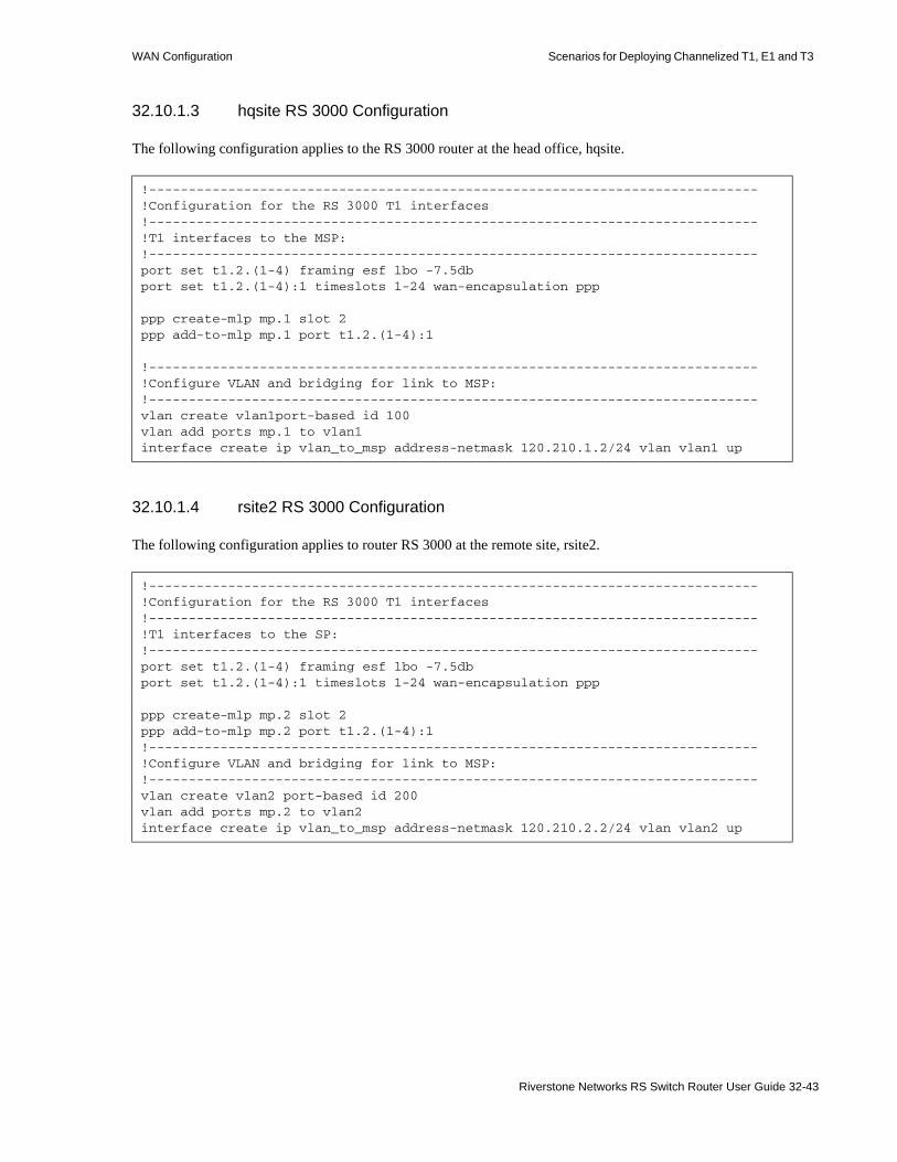
WAN Configuration Scenarios for Deploying Channelized T1, E1 and T3
32.10.1.3 hqsite RS 3000 Configuration
The following configuration applies to the RS 3000 router at the head office, hqsite.
32.10.1.4 rsite2 RS 3000 Configuration
The following configuration applies to router RS 3000 at the remote site, rsite2.
!-----------------------------------------------------------------------------!Configuration for the RS 3000 T1 interfaces!-----------------------------------------------------------------------------!T1 interfaces to the MSP:!-----------------------------------------------------------------------------port set t1.2.(1-4) framing esf lbo -7.5dbport set t1.2.(1-4):1 timeslots 1-24 wan-encapsulation ppp
ppp create-mlp mp.1 slot 2ppp add-to-mlp mp.1 port t1.2.(1-4):1
!-----------------------------------------------------------------------------!Configure VLAN and bridging for link to MSP:!-----------------------------------------------------------------------------vlan create vlan1port-based id 100vlan add ports mp.1 to vlan1interface create ip vlan_to_msp address-netmask 120.210.1.2/24 vlan vlan1 up
!-----------------------------------------------------------------------------!Configuration for the RS 3000 T1 interfaces!-----------------------------------------------------------------------------!T1 interfaces to the SP:!-----------------------------------------------------------------------------port set t1.2.(1-4) framing esf lbo -7.5dbport set t1.2.(1-4):1 timeslots 1-24 wan-encapsulation ppp
ppp create-mlp mp.2 slot 2ppp add-to-mlp mp.2 port t1.2.(1-4):1!-----------------------------------------------------------------------------!Configure VLAN and bridging for link to MSP:!-----------------------------------------------------------------------------vlan create vlan2 port-based id 200vlan add ports mp.2 to vlan2interface create ip vlan_to_msp address-netmask 120.210.2.2/24 vlan vlan2 up
Riverstone Networks RS Switch Router User Guide 32-43
Scenarios for Deploying Channelized T1, E1 and T3 WAN Configuration
32.10.2 Scenario 2: Routed Inter-Office Connections with Only T1 on RS Ethernet Router 8x00
In this scenario, a company’s sites share data that is held at the Internet Service Provider (ISP). The company’s head office contains an RS 8600, and the remote sites each have an RS 3000. To access the shared data or the Internet, all sites have four T1 lines grouped into a multi-link PPP bundle to connect to the ISP, and so are just one hop away.
The company also has significant inter-office communications. All remote sites frequently communicate with head office, so a T1 line is provided to each remote site. Where there is significant traffic between two remote sites, perhaps because they are in the same geographical region, they are also connected by a T1 line. All remote sites are a maximum of two hops away from any other remote site, and RIP is used as the routing protocol.
The ISP provides a Channelized T3 connection on their RS 38000, a LAN that connects to the servers containing the shared data required by the company, and a connection to the Internet.
Figure 32-5 shows the network layout for this scenario. The tables following the figure show the commands used to configure the interfaces for the routers at the ISP, head office (hqsite), and the remote sites, rsite2 and rsite3. The interfaces on the routers at the remaining sites are configured in a similar way to the corresponding interfaces for rsite2, using the appropriate IP address for each interface. Only the configurations of the Channelized T1 and T3 interfaces are described.
32-44 Riverstone Networks RS Switch Router User Guide

WAN Configuration Scenarios for Deploying Channelized T1, E1 and T3
32.10.2.1 Hardware Requirements
Router Hardware Requirements
RS 38000 1 CT3 module (with 4 T3 ports).
RS 8600 (hqsite) 2 Multi-Rate WAN modules with 4 T1 WICs.
RS 3000 (rsite2) 2 Multi-Rate WAN modules with 3 T1 WICs.
RS 3000 (rsite3) 2 Multi-Rate WAN modules with 4 T1 WICs.
RS 3000 (rsite4) 2 Multi-Rate WAN modules with 3 T1 WICs.
RS 3000 (rsite5) 2 Multi-Rate WAN modules with 3 T1 WICs.
RS 3000 (rsite6) 2 Multi-Rate WAN modules with 3 T1 WICs.
RS 3000 (rsite7) 2 Multi-Rate WAN modules with 3 T1 WICs.
Riverstone Networks RS Switch Router User Guide 32-45

Scenarios for Deploying Channelized T1, E1 and T3 WAN Configuration
Figure 32-5 Routed Inter-Office Connections with Only T1 on RS 8x00
T3
Internet
Internet Service Provider
POS
RS 32000
12.20.10.5/24
Shared Data
T1 ( x 4 )T1 ( x 4 )
RS 8600120.210.1.1/24
120.210.2.1/24 120.210.3.1/24
120.210.4.1/24
120.210.5.1/24
120.210.6.1/24120.210.7.1/24
hqsite
rsite2 rsite3
rsite4
rsite5
rsite6rsite7
RS 3000
RS 3000
RS 3000
RS 3000RS 3000
RS 3000
T1
T1
T1
T1
T1
T1
T1
T1
TELCO(PSTN)
T1
32-46 Riverstone Networks RS Switch Router User Guide

WAN Configuration Scenarios for Deploying Channelized T1, E1 and T3
32.10.2.2 ISP RS 38000 Configuration
The following configuration applies to the RS 38000 router at the ISP.
!-----------------------------------------------------------------------------!Configuration for the RS 38000 Channelized T3 interface!-----------------------------------------------------------------------------port set t3.4.1 cablelength 200!-----------------------------------------------------------------------------!Configure the T1 lines on the Channelized T3 interface!-----------------------------------------------------------------------------port set t3.4.1:(1-28) timeslots 1-24 wan-encapsulation ppp!-----------------------------------------------------------------------------!Configure 4 consecutive T1 lines into multilink PPP bundles!-----------------------------------------------------------------------------ppp create-mlp mp.1 slot 4ppp add-to-mlp mp.1 port t3.4.1:(1-4)ppp create-mlp mp.2 slot 4ppp add-to-mlp mp.2 port t3.4.1:(5-8)ppp create-mlp mp.3 slot 4ppp add-to-mlp mp.3 port t3.4.1:(9-12)ppp create-mlp mp.4 slot 4ppp add-to-mlp mp.4 port t3.4.1:(13-16)ppp create-mlp mp.5 slot 4ppp add-to-mlp mp.5 port t3.4.1:(17-20)ppp create-mlp mp.6 slot 4ppp add-to-mlp mp.6 port t3.4.1:(21-24)ppp create-mlp mp.7 slot 4ppp add-to-mlp mp.7 port t3.4.1:(25-28)
interface create ip to_hqsite address-netmask 120.210.1.1/24 port mp.1 upinterface create ip to_rsite2 address-netmask 120.210.2.1/24 port mp.2 upinterface create ip to_rsite3 address-netmask 120.210.3.1/24 port mp.3 upinterface create ip to_rsite4 address-netmask 120.210.4.1/24 port mp.4 upinterface create ip to_rsite5 address-netmask 120.210.5.1/24 port mp.5 upinterface create ip to_rsite6 address-netmask 120.210.6.1/24 port mp.6 upinterface create ip to_rsite7 address-netmask 120.210.7.1/24 port mp.7 up!-----------------------------------------------------------------------------!Configure RIP:!-----------------------------------------------------------------------------rip add interface to_hqsiterip add interface to_rsite2rip add interface to_rsite3rip add interface to_rsite4rip add interface to_rsite5rip add interface to_rsite6rip add interface to_rsite7rip start
Riverstone Networks RS Switch Router User Guide 32-47

Scenarios for Deploying Channelized T1, E1 and T3 WAN Configuration
32.10.2.3 hqsite RS 8600 Configuration
The following configuration applies to the RS 8600 router at the head office, hqsite.
!-----------------------------------------------------------------------------!Configuration for the RS 8600 T1 interfaces!-----------------------------------------------------------------------------!T1 interfaces to the ISP:!-----------------------------------------------------------------------------port set t1.2.1 framing esf lbo -7.5dbport set t1.2.1:1 timeslots 1-24 wan-encapsulation pppport set t1.2.2 framing esf lbo -7.5dbport set t1.2.2:1 timeslots 1-24 wan-encapsulation pppport set t1.2.3 framing esf lbo -7.5dbport set t1.2.3:1 timeslots 1-24 wan-encapsulation pppport set t1.2.4 framing esf lbo -7.5dbport set t1.2.4:1 timeslots 1-24 wan-encapsulation ppp
ppp create-mlp mp.1 slot 2ppp add-to-mlp mp.1 port t1.2.(1-4):1interface create ip to_isp address-netmask 120.210.1.2/24 port mp.1 up!-----------------------------------------------------------------------------!T1 interface to the remote sites:!-----------------------------------------------------------------------------port set t1.3.(1-4) framing esf lbo -7.5dbport set t1.3.(1-4):1 timeslots 1-24 wan-encapsulation pppinterface create ip to_rsite2 address-netmask 120.210.12.2/24 port t1.3.1 upinterface create ip to_rsite3 address-netmask 120.210.13.3/24 port t1.3.2 upinterface create ip to_rsite4 address-netmask 120.210.14.4/24 port t1.3.3 upinterface create ip to_rsite5 address-netmask 120.210.15.5/24 port t1.3.4 upport set t1.4.(1-2) framing esf lbo -7.5dbport set t1.4.(1-2):1 timeslots 1-24 wan-encapsulation pppinterface create ip to_rsite6 address-netmask 120.210.16.6/24 port t1.4.1 upinterface create ip to_rsite7 address-netmask 120.210.17.7/24 port t1.4.2 up!-----------------------------------------------------------------------------!Configure RIP:!-----------------------------------------------------------------------------rip add interface to_isprip add interface to_rsite2rip add interface to_rsite3rip add interface to_rsite4rip add interface to_rsite5rip add interface to_rsite6rip add interface to_rsite7rip start
32-48 Riverstone Networks RS Switch Router User Guide

WAN Configuration Scenarios for Deploying Channelized T1, E1 and T3
32.10.2.4 rsite2 RS 3000 Configuration
The following configuration applies to the RS 3000 router at the remote site, rsite2.
!-----------------------------------------------------------------------------!Configuration for the RS 3000 T1 interfaces!-----------------------------------------------------------------------------!T1 interfaces to the ISP:!-----------------------------------------------------------------------------port set t1.2.1 framing esf lbo -7.5dbport set t1.2.1:1 timeslots 1-24 wan-encapsulation pppport set t1.2.2 framing esf lbo -7.5dbport set t1.2.2:1 timeslots 1-24 wan-encapsulation pppport set t1.2.3 framing esf lbo -7.5dbport set t1.2.3:1 timeslots 1-24 wan-encapsulation pppport set t1.2.4 framing esf lbo -7.5dbport set t1.2.4:1 timeslots 1-24 wan-encapsulation ppp
ppp create-mlp mp.1 slot 2ppp add-to-mlp mp.1 port t1.2.(1-4):1interface create ip to_isp address-netmask 120.210.2.2/24 port mp.1 up!-----------------------------------------------------------------------------!T1 interface to the hqsite:!-----------------------------------------------------------------------------port set t1.3.1 framing esf lbo -7.5dbport set t1.3.1:1 timeslots 1-24 wan-encapsulation pppinterface create ip to_hqsite address-netmask 120.210.12.1/24 port t1.3.1 up!-----------------------------------------------------------------------------!T1 interface to the rsite3:!-----------------------------------------------------------------------------port set t1.3.2 framing esf lbo -7.5dbport set t1.3.2:1 timeslots 1-24 wan-encapsulation pppinterface create ip to_rsite3 address-netmask 120.210.23.3/24 port t1.3.2 up!-----------------------------------------------------------------------------!Configure RIP:!-----------------------------------------------------------------------------rip add interface to_isprip add interface to_hqsiterip add interface to_rsite3rip start
Riverstone Networks RS Switch Router User Guide 32-49

Scenarios for Deploying Channelized T1, E1 and T3 WAN Configuration
32.10.2.5 rsite3 RS 3000 Configuration
The following configuration applies to the RS 3000 router at the remote site, rsite3.
!-----------------------------------------------------------------------------!Configuration for the RS 3000 T1 interfaces!-----------------------------------------------------------------------------!T1 interfaces to the ISP:!-----------------------------------------------------------------------------port set t1.2.1 framing esf lbo -7.5dbport set t1.2.1:1 timeslots 1-24 wan-encapsulation pppport set t1.2.2 framing esf lbo -7.5dbport set t1.2.2:1 timeslots 1-24 wan-encapsulation pppport set t1.2.3 framing esf lbo -7.5dbport set t1.2.3:1 timeslots 1-24 wan-encapsulation pppport set t1.2.4 framing esf lbo -7.5dbport set t1.2.4:1 timeslots 1-24 wan-encapsulation ppp
ppp create-mlp mp.1 slot 2ppp add-to-mlp mp.1 port t1.2.(1-4):1interface create ip to_isp address-netmask 120.210.3.2/24 port mp.1 up!-----------------------------------------------------------------------------!T1 interface to the hqsite:!-----------------------------------------------------------------------------port set t1.3.1 framing esf lbo -7.5dbport set t1.3.1:1 timeslots 1-24 wan-encapsulation pppinterface create ip to_hqsite address-netmask 120.210.13.1/24 port t1.3.1 up!-----------------------------------------------------------------------------!T1 interface to the rsite2:!-----------------------------------------------------------------------------port set t1.3.2 framing esf lbo -7.5dbport set t1.3.2:1 timeslots 1-24 wan-encapsulation pppinterface create ip to_rsite2 address-netmask 120.210.23.2/24 port t1.3.2 up!-----------------------------------------------------------------------------!T1 interface to the rsite3:!-----------------------------------------------------------------------------port set t1.3.3 framing esf lbo -7.5dbport set t1.3.3:1 timeslots 1-24 wan-encapsulation pppinterface create ip to_rsite3 address-netmask 120.210.34.4/24 port t1.3.3 up!-----------------------------------------------------------------------------!Configure RIP:!-----------------------------------------------------------------------------rip add interface to_hqsiterip add interface to_rsite2rip add interface to_rsite3rip start
32-50 Riverstone Networks RS Switch Router User Guide
WAN Configuration Scenarios for Deploying Channelized T1, E1 and T3
32.10.3 Scenario 3: Routed Inter-Office Connections with T1 and T3 on RS 8x00
In this scenario, a company’s sites share data that is held at the Internet Service Provider (ISP). The company’s head office contains an RS 8600, and the remote sites each have an RS 3000. All remote sites have four T1 lines grouped into a multi-link PPP bundle to connect to the RS 8600 at the head office. Where significant traffic between two remote sites exists, they are also connected by a T1 line. All remote sites are a maximum of two hops away from any other remote site, and RIP is used as the routing protocol.
The ISP provides a Channelized T3 connection on their RS 38000, a LAN that connects to the servers containing the shared data required by the company, and a connection to the Internet.
Figure 32-6 shows the network layout for this scenario. The tables following the figure show the commands used to configure the interfaces for the routers at the ISP, head office (hqsite), and the remote sites, rsite2 and rsite3. The interfaces on the routers at the remaining sites are configured in a similar way to the corresponding interfaces for rsite2, using the appropriate IP address for each interface. Only the configurations of the Channelized T1 and T3 interfaces are described.
Riverstone Networks RS Switch Router User Guide 32-51

Scenarios for Deploying Channelized T1, E1 and T3 WAN Configuration
32.10.3.1 Hardware Requirements
Router Hardware Requirements
RS 38000 1 CT3 module (with 4 T3 ports).
RS 8600 (hqsite) 1 CT3 module (with 2 T3 ports).6 Multi-Rate WAN modules with 12 T1 WICs.
RS 3000 (rsite2) 2 Multi-Rate WAN modules with 3 T1 WICs.
RS 3000 (rsite3) 2 Multi-Rate WAN modules with 3 T1 WICs.
RS 3000 (rsite4) 1 Multi-Rate WAN module with 2 T1 WICs.
RS 3000 (rsite5) 2 Multi-Rate WAN modules with 3 T1 WICs.
RS 3000 (rsite6) 2 Multi-Rate WAN modules with 3 T1 WICs.
RS 3000 (rsite7) 2 Multi-Rate WAN modules with 3 T1 WICs.
32-52 Riverstone Networks RS Switch Router User Guide

WAN Configuration Scenarios for Deploying Channelized T1, E1 and T3
Figure 32-6 Routed Inter-Office Connections with T1 and T3 on RS 8x00
Internet
Internet Service Provider
POS
RS 32000
12.20.10.5/24
Shared Data
T1 ( x 4 )
T3
T1
T1
T1
120.210.7.1/24
rsite7
RS 3000
120.210.5.1/24
rsite5
RS 3000
120.210.4.1/24
rsite4
RS 3000
120.210.3.1/24
rsite3
RS 3000120.210.2.1/24
rsite2
RS 3000
120.210.6.1/24
rsite6
RS 3000T1 ( x 4 )
T1 ( x 4 )
T1 ( x 4 )
T1 ( x 4 )
T1 ( x 4 )
RS 8600120.210.1.1/24
hqsite
Riverstone Networks RS Switch Router User Guide 32-53

Scenarios for Deploying Channelized T1, E1 and T3 WAN Configuration
32.10.3.2 ISP RS 38000 Configuration
The following configuration applies to the RS 38000 router at the ISP.
!-----------------------------------------------------------------------------!Configuration for the RS 38000 Channelized T3 interface!-----------------------------------------------------------------------------port set t3.4.1 cablelength 200!-----------------------------------------------------------------------------!Configure the T1 lines on the Channelized T3 interface!-----------------------------------------------------------------------------port set t3.4.1:(1-28) timeslots 1-24 wan-encapsulation ppp!-----------------------------------------------------------------------------!Configure 7 multilink PPP bundles each containing 4 consecutive T1 lines!-----------------------------------------------------------------------------ppp create-mlp mp.1 slot 4ppp add-to-mlp mp.1 port t3.4.1:(1-4)ppp create-mlp mp.2 slot 4ppp add-to-mlp mp.2 port t3.4.1:(5-8)ppp create-mlp mp.3 slot 4ppp add-to-mlp mp.3 port t3.4.1:(9-12)ppp create-mlp mp.4 slot 4ppp add-to-mlp mp.4 port t3.4.1:(13-16)ppp create-mlp mp.5 slot 4ppp add-to-mlp mp.5 port t3.4.1:(17-20)ppp create-mlp mp.6 slot 4ppp add-to-mlp mp.6 port t3.4.1:(21-24)ppp create-mlp mp.7 slot 4ppp add-to-mlp mp.7 port t3.4.1:(25-28)
interface create ip to_hqsite address-netmask 120.210.11.1/24 port mp.1 upinterface create ip to_rsite2 address-netmask 120.210.12.1/24 port mp.2 upinterface create ip to_rsite3 address-netmask 120.210.13.1/24 port mp.3 upinterface create ip to_rsite4 address-netmask 120.210.14.1/24 port mp.4 upinterface create ip to_rsite5 address-netmask 120.210.15.1/24 port mp.5 upinterface create ip to_rsite6 address-netmask 120.210.16.1/24 port mp.6 upinterface create ip to_rsite7 address-netmask 120.210.17.1/24 port mp.7 up!-----------------------------------------------------------------------------!Configure RIP:!-----------------------------------------------------------------------------rip add interface to_hqsiterip add interface to_rsite2rip add interface to_rsite3rip add interface to_rsite4rip add interface to_rsite5rip add interface to_rsite6rip add interface to_rsite7rip start
32-54 Riverstone Networks RS Switch Router User Guide

WAN Configuration Scenarios for Deploying Channelized T1, E1 and T3
32.10.3.3 hqsite RS 8600 Configuration
The following configuration applies to the RS 8600 router at the head office, hqsite.
!-----------------------------------------------------------------------------!Configuration for the RS 8600 Channelized T3 interface!-----------------------------------------------------------------------------port set t3.4.1 cablelength 200!-----------------------------------------------------------------------------!Configure the T1 lines on the Channelized T3 interface!-----------------------------------------------------------------------------port set t3.4.1:(1-28) timeslots 1-24 wan-encapsulation ppp!-----------------------------------------------------------------------------!Configure 7 multilink PPP bundles each containing 4 consecutive T1 lines!-----------------------------------------------------------------------------ppp create-mlp mp.1 slot 4ppp add-to-mlp mp.1 port t3.4.1:(1-4)ppp create-mlp mp.2 slot 4ppp add-to-mlp mp.2 port t3.4.1:(5-8)ppp create-mlp mp.3 slot 4ppp add-to-mlp mp.3 port t3.4.1:(9-12)ppp create-mlp mp.4 slot 4ppp add-to-mlp mp.4 port t3.4.1:(13-16)ppp create-mlp mp.5 slot 4ppp add-to-mlp mp.5 port t3.4.1:(17-20)ppp create-mlp mp.6 slot 4ppp add-to-mlp mp.6 port t3.4.1:(21-24)ppp create-mlp mp.7 slot 4ppp add-to-mlp mp.7 port t3.4.1:(25-28)
interface create ip to_isp1 address-netmask 12.20.11.2/24 port mp.1 upinterface create ip to_isp2 address-netmask 12.20.12.2/24 port mp.2 upinterface create ip to_isp3 address-netmask 12.20.13.2/24 port mp.3 upinterface create ip to_isp4 address-netmask 12.20.14.2/24 port mp.4 upinterface create ip to_isp5 address-netmask 12.20.15.2/24 port mp.5 upinterface create ip to_isp6 address-netmask 12.20.16.2/24 port mp.6 upinterface create ip to_isp7 address-netmask 12.20.17.2/24 port mp.7 up!-----------------------------------------------------------------------------!Configure RIP:!-----------------------------------------------------------------------------rip add interface to_isp1rip add interface to_isp2rip add interface to_isp3rip add interface to_sip4rip add interface to_isp5rip add interface to_isp6rip add interface to_isp7rip start
Riverstone Networks RS Switch Router User Guide 32-55
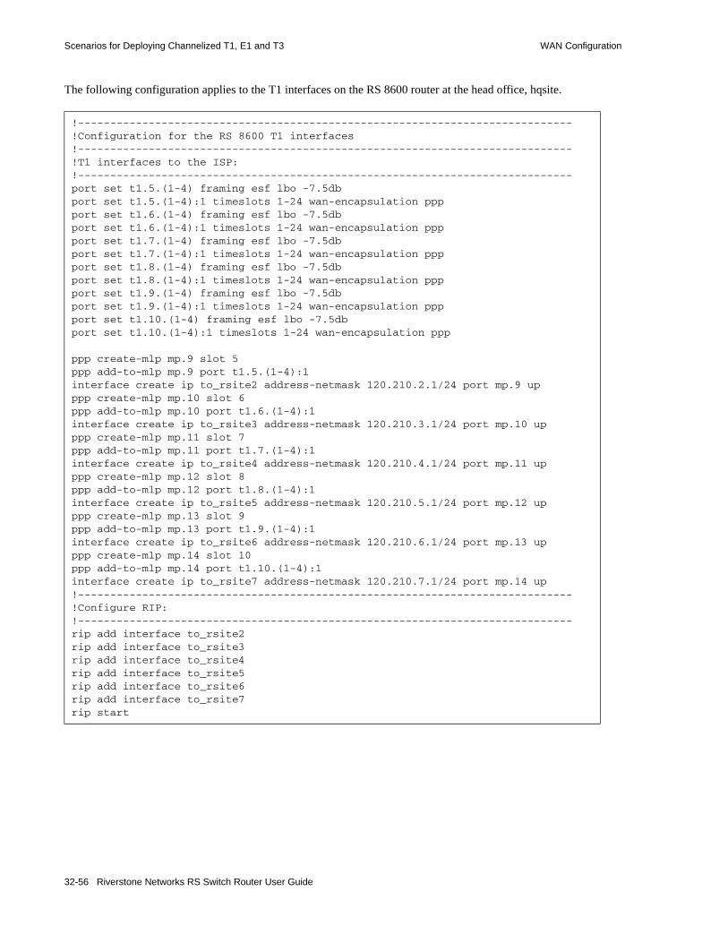
Scenarios for Deploying Channelized T1, E1 and T3 WAN Configuration
The following configuration applies to the T1 interfaces on the RS 8600 router at the head office, hqsite.
!-----------------------------------------------------------------------------!Configuration for the RS 8600 T1 interfaces!-----------------------------------------------------------------------------!T1 interfaces to the ISP:!-----------------------------------------------------------------------------port set t1.5.(1-4) framing esf lbo -7.5dbport set t1.5.(1-4):1 timeslots 1-24 wan-encapsulation pppport set t1.6.(1-4) framing esf lbo -7.5dbport set t1.6.(1-4):1 timeslots 1-24 wan-encapsulation pppport set t1.7.(1-4) framing esf lbo -7.5dbport set t1.7.(1-4):1 timeslots 1-24 wan-encapsulation pppport set t1.8.(1-4) framing esf lbo -7.5dbport set t1.8.(1-4):1 timeslots 1-24 wan-encapsulation pppport set t1.9.(1-4) framing esf lbo -7.5dbport set t1.9.(1-4):1 timeslots 1-24 wan-encapsulation pppport set t1.10.(1-4) framing esf lbo -7.5dbport set t1.10.(1-4):1 timeslots 1-24 wan-encapsulation ppp
ppp create-mlp mp.9 slot 5ppp add-to-mlp mp.9 port t1.5.(1-4):1interface create ip to_rsite2 address-netmask 120.210.2.1/24 port mp.9 upppp create-mlp mp.10 slot 6ppp add-to-mlp mp.10 port t1.6.(1-4):1interface create ip to_rsite3 address-netmask 120.210.3.1/24 port mp.10 upppp create-mlp mp.11 slot 7ppp add-to-mlp mp.11 port t1.7.(1-4):1interface create ip to_rsite4 address-netmask 120.210.4.1/24 port mp.11 upppp create-mlp mp.12 slot 8ppp add-to-mlp mp.12 port t1.8.(1-4):1interface create ip to_rsite5 address-netmask 120.210.5.1/24 port mp.12 upppp create-mlp mp.13 slot 9ppp add-to-mlp mp.13 port t1.9.(1-4):1interface create ip to_rsite6 address-netmask 120.210.6.1/24 port mp.13 upppp create-mlp mp.14 slot 10ppp add-to-mlp mp.14 port t1.10.(1-4):1interface create ip to_rsite7 address-netmask 120.210.7.1/24 port mp.14 up!-----------------------------------------------------------------------------!Configure RIP:!-----------------------------------------------------------------------------rip add interface to_rsite2rip add interface to_rsite3rip add interface to_rsite4rip add interface to_rsite5rip add interface to_rsite6rip add interface to_rsite7rip start
32-56 Riverstone Networks RS Switch Router User Guide

WAN Configuration Scenarios for Deploying Channelized T1, E1 and T3
32.10.3.4 rsite2 RS 3000 Configuration
The following configuration applies to the RS 3000 router at the remote site, rsite2.
!-----------------------------------------------------------------------------!Configuration for the RS 3000 T1 interfaces!-----------------------------------------------------------------------------!Bundled T1 interfaces to hqsite:!-----------------------------------------------------------------------------port set t1.2.1 framing esf lbo -7.5dbport set t1.2.1:1 timeslots 1-24 wan-encapsulation pppport set t1.2.2 framing esf lbo -7.5dbport set t1.2.2:1 timeslots 1-24 wan-encapsulation pppport set t1.2.3 framing esf lbo -7.5dbport set t1.2.3:1 timeslots 1-24 wan-encapsulation pppport set t1.2.4 framing esf lbo -7.5dbport set t1.2.4:1 timeslots 1-24 wan-encapsulation ppp
ppp create-mlp mp.1 slot 2ppp add-to-mlp mp.1 port t1.2.(1-4):1interface create ip to_hqsite address-netmask 120.210.2.2/24 port mp.1 up!-----------------------------------------------------------------------------!T1 interface to the rsite3:!-----------------------------------------------------------------------------port set t1.3.2 framing esf lbo -7.5dbport set t1.3.2:1 timeslots 1-24 wan-encapsulation pppinterface create ip to_rsite3 address-netmask 120.210.23.2/24 port t1.3.2 up!-----------------------------------------------------------------------------!Configure RIP:!-----------------------------------------------------------------------------rip add interface to_hqsiterip add interface to_rsite3rip start
Riverstone Networks RS Switch Router User Guide 32-57

Scenarios for Deploying Channelized T1, E1 and T3 WAN Configuration
32.10.3.5 rsite3 RS 3000 Configuration
The following configuration applies to the RS 3000 router at the remote site, rsite3.
!-----------------------------------------------------------------------------!Configuration for the RS 3000 T1 interfaces!-----------------------------------------------------------------------------!Bundled T1 interfaces to the hqsite:!-----------------------------------------------------------------------------port set t1.2.1 framing esf lbo -7.5dbport set t1.2.1:1 timeslots 1-24 wan-encapsulation pppport set t1.2.2 framing esf lbo -7.5dbport set t1.2.2:1 timeslots 1-24 wan-encapsulation pppport set t1.2.3 framing esf lbo -7.5dbport set t1.2.3:1 timeslots 1-24 wan-encapsulation pppport set t1.2.4 framing esf lbo -7.5dbport set t1.2.4:1 timeslots 1-24 wan-encapsulation ppp
ppp create-mlp mp.1 slot 2ppp add-to-mlp mp.1 port t1.2.(1-4):1interface create ip to_hqsite address-netmask 120.210.3.2/24 port mp.1 up!-----------------------------------------------------------------------------!T1 interface to the rsite2:!-----------------------------------------------------------------------------port set t1.3.2 framing esf lbo -7.5dbport set t1.3.2:1 timeslots 1-24 wan-encapsulation pppinterface create ip to_rsite2 address-netmask 120.210.23.3/24 port t1.3.2 up!-----------------------------------------------------------------------------!T1 interface to the rsite4:!-----------------------------------------------------------------------------port set t1.3.3 framing esf lbo -7.5dbport set t1.3.3:1 timeslots 1-24 wan-encapsulation pppinterface create ip to_rsite3 address-netmask 120.210.34.3/24 port t1.3.3 up!-----------------------------------------------------------------------------!Configure RIP:!-----------------------------------------------------------------------------rip add interface to_hqsiterip add interface to_rsite2rip add interface to_rsite3rip start
32-58 Riverstone Networks RS Switch Router User Guide

WAN Configuration Scenarios for Deploying Channelized T1, E1 and T3
32.10.4 Scenario 4: Routed Metropolitan Backbone with Only T1 on RS 8x00
In this scenario, a number of service providers are connected by a Metropolitan Backbone. The backbone consists of RS 38000 connected by Packet Over SONET (POS) links.
An MSP provides a Channelized T3 service using an RS 38000. A company has two sites that connect to this service:• The head office (hqsite) connects using multi-link PPP bundled T1 lines from an RS 8600.• The remote site, rsite, connects to the MSP using a fractional T1 line, which provides one 768 Kbps
service, one 384 Kbps service, and six 64 Kbps services. Also, a full (unstructured) T1 link is connected directly to the head office.
Internet Service Provider A uses a POS link to the Internet. Internet Service Provider B provides a Channelized T3 service to an Application Service Provider and a Content Provider, both of which connect using multi-link PPP bundled T1 lines from an RS 8000.
Figure 32-7 shows the network layout for this scenario. The tables following the figure show the commands used to configure the interfaces for the routers at the various locations. Only the configurations of the Channelized T1 and T3 interfaces are described.
Riverstone Networks RS Switch Router User Guide 32-59

Scenarios for Deploying Channelized T1, E1 and T3 WAN Configuration
32.10.4.1 Hardware Requirements
Router Hardware Requirements
RS 38000 (MSP) 1 CT3 module (with 4 T3 ports).
RS 8600 (hqsite) 2 Multi-Rate WAN modules with 3 T1 WICs.
RS 3000 (rsite) 2 Multi-Rate WAN modules with 3 T1 WICs.
RS 38000 (ISP B) 1 CT3 module (with 4 T3 ports).
RS 8000 (CP) 2 Multi-Rate WAN modules with 4 T1 WICs.
RS 8000 (ASP) 2 Multi-Rate WAN modules with 4 T1 WICs.
32-60 Riverstone Networks RS Switch Router User Guide

WAN Configuration Scenarios for Deploying Channelized T1, E1 and T3
Figure 32-7 Routed Metropolitan Backbone with Only T1 on RS 8x00
Riverstone Networks RS Switch Router User Guide 32-61

Scenarios for Deploying Channelized T1, E1 and T3 WAN Configuration
32.10.4.2 Metropolitan Service Provider RS 38000 Configuration
The following configuration applies to the RS 38000 router at the Metropolitan Service Provider.
!-----------------------------------------------------------------------------!Configuration for the RS 38000 Channelized T3 interface!-----------------------------------------------------------------------------port set t3.4.1 cablelength 200!-----------------------------------------------------------------------------!Configure the T1 lines on the Channelized T3 interface!-----------------------------------------------------------------------------port set t3.4.1:(1-4) timeslots 1-24 wan-encapsulation pppport set t3.4.1:(9-12) timeslots 1-24 wan-encapsulation pppport set t3.4.1:13 timeslots 1-24 wan-encapsulation ppp!-----------------------------------------------------------------------------!Configure 4 consecutive T1 lines into multilink PPP bundles!-----------------------------------------------------------------------------ppp create-mlp mp.1 slot 4ppp add-to-mlp mp.1 port t3.4.1:(1-4)ppp create-mlp mp.2 slot 4ppp add-to-mlp mp.2 port t3.4.1:(9-12)
interface create ip to_hqsite address-netmask 120.210.23.19/28 port mp.1 upinterface create ip to_rsite_mppp address-netmask 120.210.23.49/28 port mp.2upinterface create ip to_rsite_ft1 address-netmask 120.210.23.65/28 port t3.4.1:13 up!-----------------------------------------------------------------------------!Configure RIP:!-----------------------------------------------------------------------------rip add interface to_hqsiterip add interface to_rsite_mppprip add interface to_rsite_ft1rip start
32-62 Riverstone Networks RS Switch Router User Guide

WAN Configuration Scenarios for Deploying Channelized T1, E1 and T3
32.10.4.3 hqsite RS 8600 Configuration
The following configuration applies to the RS 8600 router at the head office, hqsite.
!-----------------------------------------------------------------------------!Configuration for the RS 8600 T1 interfaces!-----------------------------------------------------------------------------!T1 interfaces to the MSP:!-----------------------------------------------------------------------------port set t1.2.1 framing esf lbo -7.5dbport set t1.2.1:1 timeslots 1-24 wan-encapsulation pppport set t1.2.2 framing esf lbo -7.5dbport set t1.2.2:1 timeslots 1-24 wan-encapsulation pppport set t1.2.3 framing esf lbo -7.5dbport set t1.2.3:1 timeslots 1-24 wan-encapsulation pppport set t1.2.4 framing esf lbo -7.5dbport set t1.2.4:1 timeslots 1-24 wan-encapsulation ppp
ppp create-mlp mp.1 slot 2ppp add-to-mlp mp.1 port t1.2.(1-4):1interface create ip to_msp address-netmask 120.210.23.18/28 port mp.1 up!-----------------------------------------------------------------------------!Full (unstructured) T1 interface to the rsite:!-----------------------------------------------------------------------------port set t1.3.1 framing none wan-encapsulation pppinterface create ip to_rsite address-netmask 120.210.23.35/28 port t1.3.1 up!-----------------------------------------------------------------------------!Configure RIP:!-----------------------------------------------------------------------------rip add interface to_msprip add interface to_rsiterip start
Riverstone Networks RS Switch Router User Guide 32-63
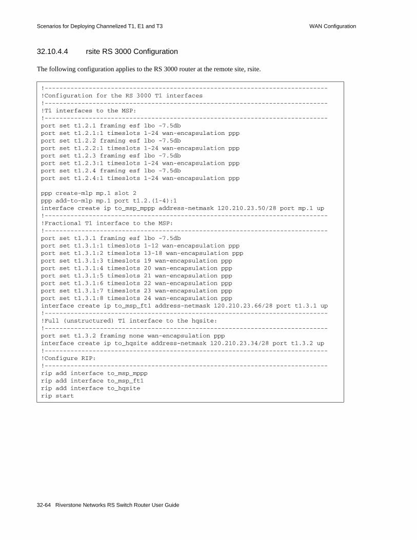
Scenarios for Deploying Channelized T1, E1 and T3 WAN Configuration
32.10.4.4 rsite RS 3000 Configuration
The following configuration applies to the RS 3000 router at the remote site, rsite.
!-----------------------------------------------------------------------------!Configuration for the RS 3000 T1 interfaces!-----------------------------------------------------------------------------!T1 interfaces to the MSP:!-----------------------------------------------------------------------------port set t1.2.1 framing esf lbo -7.5dbport set t1.2.1:1 timeslots 1-24 wan-encapsulation pppport set t1.2.2 framing esf lbo -7.5dbport set t1.2.2:1 timeslots 1-24 wan-encapsulation pppport set t1.2.3 framing esf lbo -7.5dbport set t1.2.3:1 timeslots 1-24 wan-encapsulation pppport set t1.2.4 framing esf lbo -7.5dbport set t1.2.4:1 timeslots 1-24 wan-encapsulation ppp
ppp create-mlp mp.1 slot 2ppp add-to-mlp mp.1 port t1.2.(1-4):1interface create ip to_msp_mppp address-netmask 120.210.23.50/28 port mp.1 up!-----------------------------------------------------------------------------!Fractional T1 interface to the MSP:!-----------------------------------------------------------------------------port set t1.3.1 framing esf lbo -7.5dbport set t1.3.1:1 timeslots 1-12 wan-encapsulation pppport set t1.3.1:2 timeslots 13-18 wan-encapsulation pppport set t1.3.1:3 timeslots 19 wan-encapsulation pppport set t1.3.1:4 timeslots 20 wan-encapsulation pppport set t1.3.1:5 timeslots 21 wan-encapsulation pppport set t1.3.1:6 timeslots 22 wan-encapsulation pppport set t1.3.1:7 timeslots 23 wan-encapsulation pppport set t1.3.1:8 timeslots 24 wan-encapsulation pppinterface create ip to_msp_ft1 address-netmask 120.210.23.66/28 port t1.3.1 up!-----------------------------------------------------------------------------!Full (unstructured) T1 interface to the hqsite:!-----------------------------------------------------------------------------port set t1.3.2 framing none wan-encapsulation pppinterface create ip to_hqsite address-netmask 120.210.23.34/28 port t1.3.2 up!-----------------------------------------------------------------------------!Configure RIP:!-----------------------------------------------------------------------------rip add interface to_msp_mppprip add interface to_msp_ft1rip add interface to_hqsiterip start
32-64 Riverstone Networks RS Switch Router User Guide

WAN Configuration Scenarios for Deploying Channelized T1, E1 and T3
32.10.4.5 Internet Service Provider B RS 38000 Configuration
The following configuration applies to the RS 38000 router at Internet Service Provider B.
32.10.4.6 Content Provider RS 8000 Configuration
The following configuration applies to the RS 8000 router at the Content Provider.
!-----------------------------------------------------------------------------!Configuration for the RS 38000 Channelized T3 interface!-----------------------------------------------------------------------------port set t3.4.1 cablelength 200!-----------------------------------------------------------------------------!Configure the T1 lines on the Channelized T3 interface!-----------------------------------------------------------------------------port set t3.4.1:(1-8) timeslots 1-24 wan-encapsulation pppport set t3.4.1:(13-20) timeslots 1-24 wan-encapsulation ppp!-----------------------------------------------------------------------------!Configure 4 consecutive T1 lines into multilink PPP bundles!-----------------------------------------------------------------------------ppp create-mlp mp.1 slot 4ppp add-to-mlp mp.1 port t3.4.1:(1-8)ppp create-mlp mp.2 slot 4ppp add-to-mlp mp.2 port t3.4.1:(13-20)
interface create ip to_cp address-netmask 110.25.30.6/24 port mp.1 upinterface create ip to_asp address-netmask 130.65.20.9/24 port mp.2 up!-----------------------------------------------------------------------------!Configure RIP:!-----------------------------------------------------------------------------rip add interface to_cprip add interface to_asprip start
!-----------------------------------------------------------------------------!Configuration for the RS 8000 T1 interfaces!-----------------------------------------------------------------------------!T1 interfaces to the ISP:!-----------------------------------------------------------------------------port set t1.2.(1-4) framing esf lbo -7.5dbport set t1.2.(1-4):1 timeslots 1-24 wan-encapsulation pppppp create-mlp mp.1 slot 2ppp add-to-mlp mp.1 port t1.2.(1-4):1interface create ip to_msp address-netmask 110.25.30.5/24 port mp.1 up!-----------------------------------------------------------------------------!Configure RIP:!-----------------------------------------------------------------------------rip add interface to_msprip start
Riverstone Networks RS Switch Router User Guide 32-65

Scenarios for Deploying Channelized T1, E1 and T3 WAN Configuration
32.10.4.7 Application Service Provider RS 8000 Configuration
The following configuration applies to the RS 8000 router at the Application Service Provider.
!-----------------------------------------------------------------------------!Configuration for the RS 8000 T1 interfaces!-----------------------------------------------------------------------------!T1 interfaces to the ISP:!-----------------------------------------------------------------------------port set t1.2.(1-4) framing esf lbo -7.5dbport set t1.2.(1-4):1 timeslots 1-24 wan-encapsulation ppp
ppp create-mlp mp.1 slot 2ppp add-to-mlp mp.1 port t1.2.(1-4):1interface create ip to_msp address-netmask 130.65.20.8/24 port mp.1 up
!-----------------------------------------------------------------------------!Configure RIP:!-----------------------------------------------------------------------------rip add interface to_msprip start
32-66 Riverstone Networks RS Switch Router User Guide
WAN Configuration Scenarios for Deploying Channelized T1, E1 and T3
32.10.5 Scenario 5: Routed Metropolitan Backbone with T1 and T3 on RS 8x00
In this scenario, a number of service providers are connected by a Metropolitan Backbone. The backbone consists of RS 38000 connected by Packet Over SONET (POS) links.
An MSP provides a Channelized T3 service using an RS 38000. A company has two sites that connect to this service:• The head office (hqsite) connects using a T3 line from an RS 8600.• The remote site, rsite, connects to the RS 8600 at head office using four T1 lines bundled with
multi-link PPP, a fractional T1 line, which provides one 768 Kbps service, one 384 Kbps service, and six 64 Kbps services. Also, a full (unstructured) T1 link is connected directly to the RS 8600.
Internet Service Provider A uses a POS link to the Internet. Internet Service Provider B provides a Channelized T3 service to an Application Service Provider and a Content Provider, both of which connect using T3 lines from an RS 8000.
Figure 32-8 shows the network layout for this scenario. The tables following the figure show the commands used to configure the interfaces for the routers at the various locations. Only the configurations of the Channelized T1 and T3 interfaces are described.
Riverstone Networks RS Switch Router User Guide 32-67

Scenarios for Deploying Channelized T1, E1 and T3 WAN Configuration
32.10.5.1 Hardware Requirements
Router Hardware Requirements
RS 38000 (MSP) 1 CT3 module (with 4 T3 ports).
RS 8600 (hqsite) 1 CT3 module (with 2 T3 ports).2 Multi-Rate WAN modules with 3 T1 WICs.
RS 3000 (rsite) 2 Multi-Rate WAN modules with 3 T1 WICs.
RS 38000 (ISP B) 1 CT3 module (with 4 T3 ports).
RS 8000 (CP) 1 CT3 module (with 2 T3 ports).
RS 8000 (ASP) 1 CT3 module (with 2 T3 ports).
32-68 Riverstone Networks RS Switch Router User Guide
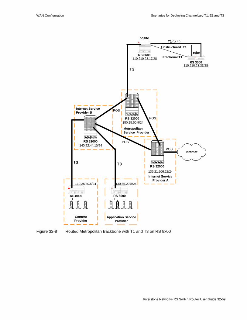
WAN Configuration Scenarios for Deploying Channelized T1, E1 and T3
Figure 32-8 Routed Metropolitan Backbone with T1 and T3 on RS 8x00
MetropolitanService Provider
POS
T3
Fractional T1
Unstructured T1
POS
POS
RS 32000
T3T3
Internet ServiceProvider B
RS 32000
T1 ( x 4 )
ContentProvider
RS 8000
110.25.30.5/24
Application ServiceProvider
RS 8000
130.65.20.8/24
140.22.44.10/24
Internet ServiceProvider A
RS 32000
InternetPOS
136.21.206.22/24
150.25.50.9/24
RS 3000
rsite
110.210.23.33/28
RS 8600
hqsite
110.210.23.17/28
Riverstone Networks RS Switch Router User Guide 32-69

Scenarios for Deploying Channelized T1, E1 and T3 WAN Configuration
32.10.5.2 Metropolitan Service Provider RS 38000 Configuration
The following configuration applies to the RS 38000 router at the Metropolitan Service Provider.
!-----------------------------------------------------------------------------!Configuration for the RS 38000 Channelized T3 interface!-----------------------------------------------------------------------------port set t3.4.1 cablelength 200!-----------------------------------------------------------------------------!Configure the T1 lines on the Channelized T3 interface!-----------------------------------------------------------------------------port set t3.4.1:(1-4) timeslots 1-24 wan-encapsulation pppport set t3.4.1:(9-12) timeslots 1-24 wan-encapsulation pppport set t3.4.1:13 timeslots 1-24 wan-encapsulation ppp!-----------------------------------------------------------------------------!Configure 2 multilink PPP bundles each containing 4 consecutive T1 lines!-----------------------------------------------------------------------------ppp create-mlp mp.1 slot 4ppp add-to-mlp mp.1 port t3.4.1:(1-4)ppp create-mlp mp.2 slot 4ppp add-to-mlp mp.2 port t3.4.1:(9-12)
interface create ip to_hqsite address-netmask 120.210.11.1/24 port mp.1 upinterface create ip to_rsite_mppp address-netmask 120.210.12.1/24 port mp.2 upinterface create ip to_rsite_ft1 address-netmask 120.210.13.1/24 port t3.4.1:13 up!-----------------------------------------------------------------------------!Configure RIP:!-----------------------------------------------------------------------------rip add interface to_hqsiterip add interface to_rsite_mppprip add interface to_rsite_ft1rip start
32-70 Riverstone Networks RS Switch Router User Guide

WAN Configuration Scenarios for Deploying Channelized T1, E1 and T3
32.10.5.3 hqsite RS 8600 Configuration
The following configuration applies to the RS 8600 router at the head office, hqsite.
!-----------------------------------------------------------------------------!Configuration for the RS 8600 Channelized T3 interface!-----------------------------------------------------------------------------port set t3.4.1 cablelength 200!-----------------------------------------------------------------------------!Configure the T1 lines on the Channelized T3 interface!-----------------------------------------------------------------------------port set t3.4.1:(1-4) timeslots 1-24 wan-encapsulation ppp!-----------------------------------------------------------------------------!Configure a multilink PPP bundle containing 4 consecutive T1 lines!-----------------------------------------------------------------------------ppp create-mlp mp.1 slot 4ppp add-to-mlp mp.1 port t3.4.1:(1-4)
interface create ip to_msp address-netmask 120.210.11.2/24 port mp.1 up!-----------------------------------------------------------------------------!Configure RIP:!-----------------------------------------------------------------------------rip add interface to_msprip start
Riverstone Networks RS Switch Router User Guide 32-71

Scenarios for Deploying Channelized T1, E1 and T3 WAN Configuration
The following configuration applies to the T1 interfaces on the RS 8600 router at the head office, hqsite.
!-----------------------------------------------------------------------------!Configuration for the RS 8600 T1 interfaces!-----------------------------------------------------------------------------!Bundled T1 interfaces to the rsite:!-----------------------------------------------------------------------------port set t1.2.1 framing esf lbo -7.5dbport set t1.2.1:1 timeslots 1-24 wan-encapsulation pppport set t1.2.2 framing esf lbo -7.5dbport set t1.2.2:1 timeslots 1-24 wan-encapsulation pppport set t1.2.3 framing esf lbo -7.5dbport set t1.2.3:1 timeslots 1-24 wan-encapsulation pppport set t1.2.4 framing esf lbo -7.5dbport set t1.2.4:1 timeslots 1-24 wan-encapsulation ppp
ppp create-mlp mp.1 slot 2ppp add-to-mlp mp.1 port t1.2.(1-4):1interface create ip to_rsite_mppp address-netmask 120.210.4.1/24 port mp.1 up!-----------------------------------------------------------------------------!Full (unstructured) T1 interface to the rsite:!-----------------------------------------------------------------------------port set t1.3.1 framing none wan-encapsulation pppinterface create ip to_rsite_fullt1 address-netmask 120.210.1.1/24 port t1.3.1 up!-----------------------------------------------------------------------------!Fractional T1 interface to the rsite:!-----------------------------------------------------------------------------port set t1.3.2 framing esf lbo -7.5dbport set t1.3.2:1 timeslots 1-12 wan-encapsulation pppport set t1.3.2:2 timeslots 13-18 wan-encapsulation pppport set t1.3.2:3 timeslots 19 wan-encapsulation pppport set t1.3.2:4 timeslots 20 wan-encapsulation pppport set t1.3.2:5 timeslots 21 wan-encapsulation pppport set t1.3.2:6 timeslots 22 wan-encapsulation pppport set t1.3.2:7 timeslots 23 wan-encapsulation pppport set t1.3.2:8 timeslots 24 wan-encapsulation pppinterface create ip to_rsite_fract1 address-netmask 120.210.24.1/24 port t1.3.2 up!-----------------------------------------------------------------------------!Configure RIP:!-----------------------------------------------------------------------------rip add interface to_rsite_mppprip add interface to_rsite_fullt1rip add interface to_rsite_fract1rip start
32-72 Riverstone Networks RS Switch Router User Guide
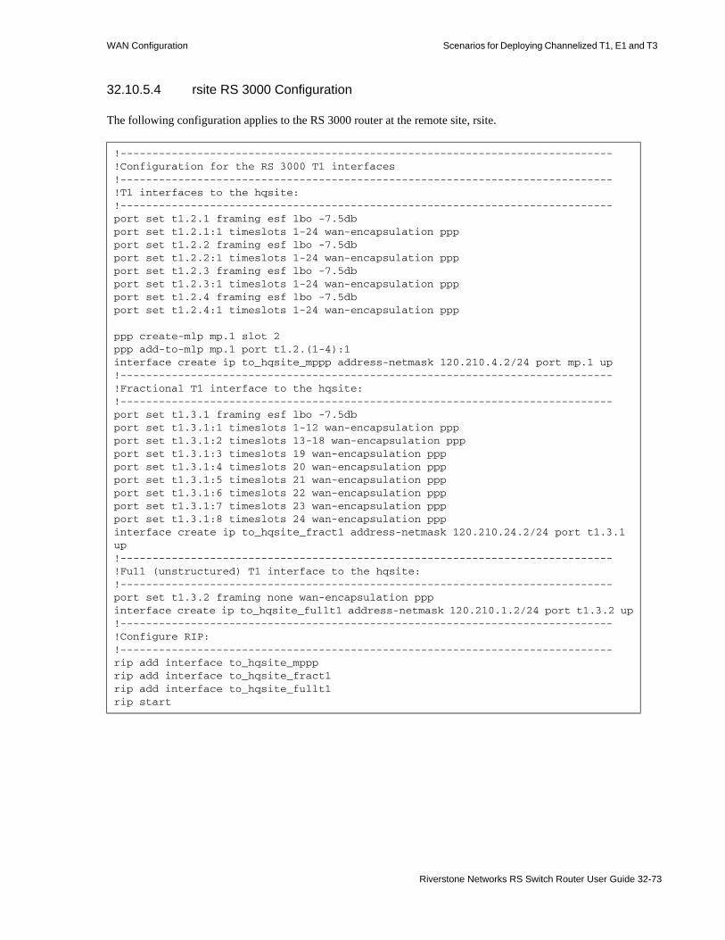
WAN Configuration Scenarios for Deploying Channelized T1, E1 and T3
32.10.5.4 rsite RS 3000 Configuration
The following configuration applies to the RS 3000 router at the remote site, rsite.
!-----------------------------------------------------------------------------!Configuration for the RS 3000 T1 interfaces!-----------------------------------------------------------------------------!T1 interfaces to the hqsite:!-----------------------------------------------------------------------------port set t1.2.1 framing esf lbo -7.5dbport set t1.2.1:1 timeslots 1-24 wan-encapsulation pppport set t1.2.2 framing esf lbo -7.5dbport set t1.2.2:1 timeslots 1-24 wan-encapsulation pppport set t1.2.3 framing esf lbo -7.5dbport set t1.2.3:1 timeslots 1-24 wan-encapsulation pppport set t1.2.4 framing esf lbo -7.5dbport set t1.2.4:1 timeslots 1-24 wan-encapsulation ppp
ppp create-mlp mp.1 slot 2ppp add-to-mlp mp.1 port t1.2.(1-4):1interface create ip to_hqsite_mppp address-netmask 120.210.4.2/24 port mp.1 up!-----------------------------------------------------------------------------!Fractional T1 interface to the hqsite:!-----------------------------------------------------------------------------port set t1.3.1 framing esf lbo -7.5dbport set t1.3.1:1 timeslots 1-12 wan-encapsulation pppport set t1.3.1:2 timeslots 13-18 wan-encapsulation pppport set t1.3.1:3 timeslots 19 wan-encapsulation pppport set t1.3.1:4 timeslots 20 wan-encapsulation pppport set t1.3.1:5 timeslots 21 wan-encapsulation pppport set t1.3.1:6 timeslots 22 wan-encapsulation pppport set t1.3.1:7 timeslots 23 wan-encapsulation pppport set t1.3.1:8 timeslots 24 wan-encapsulation pppinterface create ip to_hqsite_fract1 address-netmask 120.210.24.2/24 port t1.3.1 up!-----------------------------------------------------------------------------!Full (unstructured) T1 interface to the hqsite:!-----------------------------------------------------------------------------port set t1.3.2 framing none wan-encapsulation pppinterface create ip to_hqsite_fullt1 address-netmask 120.210.1.2/24 port t1.3.2 up!-----------------------------------------------------------------------------!Configure RIP:!-----------------------------------------------------------------------------rip add interface to_hqsite_mppprip add interface to_hqsite_fract1rip add interface to_hqsite_fullt1rip start
Riverstone Networks RS Switch Router User Guide 32-73

Scenarios for Deploying Channelized T1, E1 and T3 WAN Configuration
32.10.5.5 Internet Service Provider B RS 38000 Configuration
The following configuration applies to the RS 38000 router at Internet Service Provider B.
!-----------------------------------------------------------------------------!Configuration for the RS 38000 Channelized T3 interface!-----------------------------------------------------------------------------port set t3.4.1 cablelength 250!-----------------------------------------------------------------------------!Configure the T1 lines on the Channelized T3 interface!-----------------------------------------------------------------------------port set t3.4.1:(1-4) timeslots 1-24 wan-encapsulation pppport set t3.4.1:(5-8) timeslots 1-24 wan-encapsulation pppport set t3.4.1:(13-16) timeslots 1-24 wan-encapsulation pppport set t3.4.1:(17-20) timeslots 1-24 wan-encapsulation ppp!-----------------------------------------------------------------------------!Configure 2 multilink PPP bundles each containing 4 consecutive!T1 lines!-----------------------------------------------------------------------------ppp create-mlp mp.1 slot 4ppp add-to-mlp mp.1 port t3.4.1:(1-4)ppp create-mlp mp.2 slot 4ppp add-to-mlp mp.2 port t3.4.1:(5-8)ppp create-mlp mp.3 slot 4ppp add-to-mlp mp.3 port t3.4.1:(13-16)ppp create-mlp mp.4 slot 4ppp add-to-mlp mp.4 port t3.4.1:(17-20)
interface create ip to_cp1 address-netmask 110.25.30.6/24 port mp.1 upinterface create ip to_cp2 address-netmask 110.25.31.7/24 port mp.2 upinterface create ip to_asp1 address-netmask 130.65.20.9/24 port mp.3 upinterface create ip to_asp2 address-netmask 130.65.21.10/24 port mp.4 up!-----------------------------------------------------------------------------!Configure RIP:!-----------------------------------------------------------------------------rip add interface to_cp1rip add interface to_cp2rip add interface to_asp1rip add interface to_asp2rip start
32-74 Riverstone Networks RS Switch Router User Guide

WAN Configuration Scenarios for Deploying Channelized T1, E1 and T3
32.10.5.6 Content Provider RS 8000 Configuration
The following configuration applies to the RS 8000 router at the Content Provider.
32.10.5.7 Application Service Provider RS 8000 Configuration
The following configuration applies to the RS 8000 router at the Application Service Provider.
!-----------------------------------------------------------------------------!Configuration for the RS 8000 T1 interfaces!-----------------------------------------------------------------------------port set t3.4.1 cablelength 250!-----------------------------------------------------------------------------!T3 interface to the ISP B:!-----------------------------------------------------------------------------port set t3.4.1:(1-4) timeslots 1-24 wan-encapsulation pppport set t3.4.1:(5-8) timeslots 1-24 wan-encapsulation ppp
ppp create-mlp mp.1 slot 4ppp add-to-mlp mp.1 port t3.4.1:(1-4)ppp create-mlp mp.2 slot 4ppp add-to-mlp mp.2 port t3.4.1:(5-8)interface create ip to_ispb1 address-netmask 110.25.30.4/24 port mp.1 upinterface create ip to_ispb2 address-netmask 110.25.31.5/24 port mp.2 up!-----------------------------------------------------------------------------!Configure RIP:!-----------------------------------------------------------------------------rip add interface to_ispb1rip add interface to_ispb2rip start
!-----------------------------------------------------------------------------!Configuration for the RS 8000 T1 interfaces!-----------------------------------------------------------------------------port set t3.4.1 cablelength 250!-----------------------------------------------------------------------------!T3 interface to the ISP B:!-----------------------------------------------------------------------------port set t3.4.1:(13-16) timeslots 1-24 wan-encapsulation pppport set t3.4.1:(17-20) timeslots 1-24 wan-encapsulation ppp
ppp create-mlp mp.1 slot 4ppp add-to-mlp mp.1 port t3.4.1:(13-16)ppp create-mlp mp.2 slot 4ppp add-to-mlp mp.2 port t3.4.1:(17-20)interface create ip to_ispb1 address-netmask 130.65.20.7/24 port mp.1 upinterface create ip to_ispb2 address-netmask 130.65.21.8/24 port mp.2 up!-----------------------------------------------------------------------------!Configure RIP:!-----------------------------------------------------------------------------rip add interface to_ispb1rip add interface to_ispb2rip start
Riverstone Networks RS Switch Router User Guide 32-75

Scenarios for Deploying Channelized T1, E1 and T3 WAN Configuration
32.10.6 Scenario 6: Routed Inter-Office Connections with E1 on RS8x00
In this scenario, a company’s sites share data that is held at the Internet Service Provider (ISP). The company’s head office contains an RS 8600, and the remote sites each have an RS 3000. To access the shared data or the Internet, all sites have four E1 lines grouped into a multi-link PPP bundle to connect to the ISP, and so are just one hop away.
The company also has significant inter-office communications. All remote sites frequently communicate with head office, so an E1 line is provided to each remote site. Where there is significant traffic between two remote sites, perhaps because they are in the same geographical region, they are also connected by an E1 line. All remote sites are a maximum of two hops away from any other remote site, and RIP is used as the routing protocol.
The ISP provides a Channelized E3 connection on their proprietary router, a LAN that connects to the servers containing the shared data required by the company, and a connection to the Internet.
Figure 32-9 shows the network layout for this scenario. The tables following the figure show the commands used to configure the interfaces for the routers at the ISP, head office (hqsite), and the remote sites, rsite2 and rsite3. The interfaces on the routers at the remaining sites are configured in a similar way to the corresponding interfaces for rsite2, using the appropriate IP address for each interface. Only the configurations of the Channelized E1 interfaces are described.
Note The configurations in this example specify timeslots 1-31 for the E1 ports. This excludes the use of timeslot 16. If timeslot 16 is to be used, then ts16 must be included in the relevant commands. For example:
port set e1.2.1:1 timeslots 1-31 ts16 wan-encapsulation ppp
32-76 Riverstone Networks RS Switch Router User Guide

WAN Configuration Scenarios for Deploying Channelized T1, E1 and T3
32.10.6.1 Hardware Requirements
Router Hardware Requirements
RS 8600 (hqsite) 2 Multi-Rate WAN modules with 4 E1 WICs.
RS 3000 (rsite2) 2 Multi-Rate WAN modules with 3 E1 WICs.
RS 3000 (rsite3) 2 Multi-Rate WAN modules with 4 E1 WICs.
RS 3000 (rsite4) 2 Multi-Rate WAN modules with 3 E1 WICs.
RS 3000 (rsite5) 2 Multi-Rate WAN modules with 3 E1 WICs.
RS 3000 (rsite6) 2 Multi-Rate WAN modules with 3 E1 WICs.
RS 3000 (rsite7) 2 Multi-Rate WAN modules with 3 E1 WICs.
Riverstone Networks RS Switch Router User Guide 32-77

Scenarios for Deploying Channelized T1, E1 and T3 WAN Configuration
Figure 32-9 Routed Inter-Office Connections with E1 on RS 8x00
E3
Internet
Internet Service Provider
12.20.10.5/24
Shared Data
E1 ( x 4 )E1 ( x 4 )
RS 8600120.210.1.1/24
120.210.2.1/24 120.210.3.1/24
120.210.4.1/24
120.210.5.1/24
120.210.6.1/24120.210.7.1/24
hqsite
rsite2 rsite3
rsite4
rsite5
rsite6rsite7
RS 3000
RS 3000
RS 3000
RS 3000RS 3000
RS 3000
E1
E1
E1
E1
E1
E1
E1
E1
TELCO(PSTN)
E1
Router
32-78 Riverstone Networks RS Switch Router User Guide

WAN Configuration Scenarios for Deploying Channelized T1, E1 and T3
32.10.6.2 hqsite RS 8600 Configuration
The following configuration applies to the RS 8600 router at the head office, hqsite.
!-----------------------------------------------------------------------------!Configuration for the RS 8600 E1 interfaces!-----------------------------------------------------------------------------!E1 interfaces to the ISP:!-----------------------------------------------------------------------------port set e1.2.1 framing crc4port set e1.2.1:1 timeslots 1-31 wan-encapsulation pppport set e1.2.2 framing crc4port set e1.2.2:1 timeslots 1-31 wan-encapsulation pppport set e1.2.3 framing crc4port set e1.2.3:1 timeslots 1-31 wan-encapsulation pppport set e1.2.4 framing crc4port set e1.2.4:1 timeslots 1-31 wan-encapsulation ppp
ppp create-mlp mp.1 slot 2ppp add-to-mlp mp.1 port e1.2.(1-4):1interface create ip to_isp address-netmask 120.210.1.2/24 port mp.1 up!-----------------------------------------------------------------------------!E1 interface to the remote sites:!-----------------------------------------------------------------------------port set e1.3.(1-4) framing crc4port set e1.3.(1-4):1 timeslots 1-31 wan-encapsulation pppinterface create ip to_rsite2 address-netmask 120.210.12.2/24 port e1.3.1 upinterface create ip to_rsite3 address-netmask 120.210.13.3/24 port e1.3.2 upinterface create ip to_rsite4 address-netmask 120.210.14.4/24 port e1.3.3 upinterface create ip to_rsite5 address-netmask 120.210.15.5/24 port e1.3.4 upport set e1.4.(1-2) framing crc4port set e1.4.(1-2):1 timeslots 1-31 wan-encapsulation pppinterface create ip to_rsite6 address-netmask 120.210.16.6/24 port e1.4.1 upinterface create ip to_rsite7 address-netmask 120.210.17.7/24 port e1.4.2 up!-----------------------------------------------------------------------------!Configure RIP:!-----------------------------------------------------------------------------rip add interface to_isprip add interface to_rsite2rip add interface to_rsite3rip add interface to_rsite4rip add interface to_rsite5rip add interface to_rsite6rip add interface to_rsite7rip start
Riverstone Networks RS Switch Router User Guide 32-79

Scenarios for Deploying Channelized T1, E1 and T3 WAN Configuration
32.10.6.3 rsite2 RS 3000 Configuration
The following configuration applies to the RS 3000 router at the remote site, rsite2.
!-----------------------------------------------------------------------------!Configuration for the RS 3000 E1 interfaces!-----------------------------------------------------------------------------!E1 interfaces to the ISP:!-----------------------------------------------------------------------------port set e1.2.1 framing crc4port set e1.2.1:1 timeslots 1-31 wan-encapsulation pppport set e1.2.2 framing crc4port set e1.2.2:1 timeslots 1-31 wan-encapsulation pppport set e1.2.3 framing crc4port set e1.2.3:1 timeslots 1-31 wan-encapsulation pppport set e1.2.4 framing crc4port set e1.2.4:1 timeslots 1-31 wan-encapsulation ppp
ppp create-mlp mp.1 slot 2ppp add-to-mlp mp.1 port e1.2.(1-4):1interface create ip to_isp address-netmask 120.210.2.2/24 port mp.1 up!-----------------------------------------------------------------------------!E1 interface to the hqsite:!-----------------------------------------------------------------------------port set e1.3.1 framing crc4port set e1.3.1:1 timeslots 1-31 wan-encapsulation pppinterface create ip to_hqsite address-netmask 120.210.12.1/24 port e1.3.1 up!-----------------------------------------------------------------------------!E1 interface to the rsite3:!-----------------------------------------------------------------------------port set e1.3.2 framing crc4port set e1.3.2:1 timeslots 1-31 wan-encapsulation pppinterface create ip to_rsite3 address-netmask 120.210.23.3/24 port e1.3.2 up!-----------------------------------------------------------------------------!Configure RIP:!-----------------------------------------------------------------------------rip add interface to_isprip add interface to_hqsiterip add interface to_rsite3rip start
32-80 Riverstone Networks RS Switch Router User Guide

WAN Configuration Scenarios for Deploying Channelized T1, E1 and T3
32.10.6.4 rsite3 RS 3000 Configuration
The following configuration applies to the RS 3000 router at the remote site, rsite3.
32.10.7 Scenario 7: Transatlantic Connection using T1 and E1 on RS 8x00
In this scenario, a T1 link on an RS 8600 is used to connect a company’s site in the USA with its site in Europe. The European site has an RS 8000, with an E1 interface. The T1 interface is configured to use the SF framing at a speed of 56Kbps because the local loop does not support B8ZS. Also, the E1 interface assumes that the T1 is delivered on timeslots 1 to 24, including timeslot 16.
!-----------------------------------------------------------------------------!Configuration for the RS 3000 E1 interfaces!-----------------------------------------------------------------------------!E1 interfaces to the ISP:!-----------------------------------------------------------------------------port set e1.2.1 framing crc4port set e1.2.1:1 timeslots 1-31 wan-encapsulation pppport set e1.2.2 framing crc4port set e1.2.2:1 timeslots 1-31 wan-encapsulation pppport set e1.2.3 framing crc4port set e1.2.3:1 timeslots 1-31 wan-encapsulation pppport set e1.2.4 framing crc4port set e1.2.4:1 timeslots 1-31 wan-encapsulation ppp
ppp create-mlp mp.1 slot 2ppp add-to-mlp mp.1 port e1.2.(1-4):1interface create ip to_isp address-netmask 120.210.3.2/24 port mp.1 up!-----------------------------------------------------------------------------!E1 interface to the hqsite:!-----------------------------------------------------------------------------port set e1.3.1 framing crc4port set e1.3.1:1 timeslots 1-31 wan-encapsulation pppinterface create ip to_hqsite address-netmask 120.210.13.1/24 port e1.3.1 up!-----------------------------------------------------------------------------!E1 interface to the rsite2:!-----------------------------------------------------------------------------port set e1.3.2 framing crc4port set e1.3.2:1 timeslots 1-31 wan-encapsulation pppinterface create ip to_rsite2 address-netmask 120.210.23.2/24 port e1.3.2 up!-----------------------------------------------------------------------------!E1 interface to the rsite3:!-----------------------------------------------------------------------------port set e1.3.3 framing crc4port set e1.3.3:1 timeslots 1-31 wan-encapsulation pppinterface create ip to_rsite3 address-netmask 120.210.34.4/24 port e1.3.3 up!-----------------------------------------------------------------------------!Configure RIP:!-----------------------------------------------------------------------------rip add interface to_hqsiterip add interface to_rsite2rip add interface to_rsite3rip start
Riverstone Networks RS Switch Router User Guide 32-81
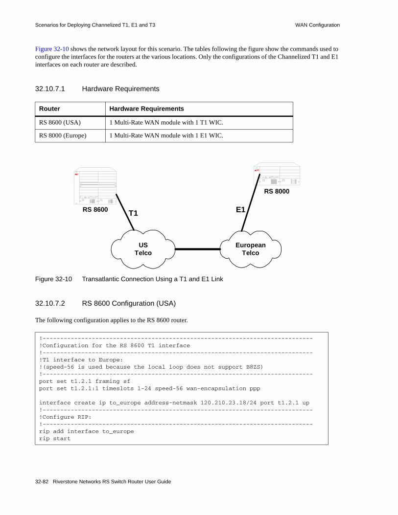
Scenarios for Deploying Channelized T1, E1 and T3 WAN Configuration
Figure 32-10 shows the network layout for this scenario. The tables following the figure show the commands used to configure the interfaces for the routers at the various locations. Only the configurations of the Channelized T1 and E1 interfaces on each router are described.
32.10.7.1 Hardware Requirements
Figure 32-10 Transatlantic Connection Using a T1 and E1 Link
32.10.7.2 RS 8600 Configuration (USA)
The following configuration applies to the RS 8600 router.
Router Hardware Requirements
RS 8600 (USA) 1 Multi-Rate WAN module with 1 T1 WIC.
RS 8000 (Europe) 1 Multi-Rate WAN module with 1 E1 WIC.
!-----------------------------------------------------------------------------!Configuration for the RS 8600 T1 interface!-----------------------------------------------------------------------------!T1 interface to Europe:!(speed-56 is used because the local loop does not support B8ZS)!-----------------------------------------------------------------------------port set t1.2.1 framing sfport set t1.2.1:1 timeslots 1-24 speed-56 wan-encapsulation ppp
interface create ip to_europe address-netmask 120.210.23.18/24 port t1.2.1 up!-----------------------------------------------------------------------------!Configure RIP:!-----------------------------------------------------------------------------rip add interface to_europerip start
USTelco
EuropeanTelco
T1RS 8600
RS 8000
E1
32-82 Riverstone Networks RS Switch Router User Guide

WAN Configuration Scenarios for Deploying Channelized T1, E1 and T3
32.10.7.3 RS 8000 Configuration (Europe)
The following configuration applies to the RS 8000 router.
!-----------------------------------------------------------------------------!Configuration for the RS 8000 E1 interface!-----------------------------------------------------------------------------!E1 interface to the USA:!(assumes T1 is delivered on timeslots 1-24, including timeslot 16)!-----------------------------------------------------------------------------port set e1.2.3 framing crc4port set e1.2.3:1 timeslots 1-24 ts16 speed-56 wan-encapsulation ppp
interface create ip to_europe address-netmask 120.210.24.18/24 port e1.2.3 up!-----------------------------------------------------------------------------!Configure RIP:!-----------------------------------------------------------------------------rip add interface to_usarip start
Riverstone Networks RS Switch Router User Guide 32-83

Scenarios for Deploying Channelized T1, E1 and T3 WAN Configuration
32.10.8 Scenario 8: Configuring Frame Relay over Channelized T1 Interfaces
In this scenario, a Channelized T1 link on an RS 8600 is used to connect a company’s headquarters to six remote sites. The headquarters site has an RS 8600, with a Channelized T1 interface. The Channelized T1 interface is configured to use the ESF framing. Each remote site is assigned a consecutive range of four timeslots as shown in Table 32-5. The Frame Relay CIR and Bc for each remote site is also shown. Remote sites, rsite1 and rsite2, have two VCs on the Channelized T1 interface.
Note The timeslot assignments for each site need not be different; they are different in this example for clarity.
Figure 32-11 shows the network layout for this scenario. The tables following the figure show the commands used to configure the Channelized T1 interfaces for the routers at the various locations.
Table 32-5 Timeslot and CIR Assignments
Router Timeslot assignment
CIR Bc VC Number
Subnet
rsite1 1-4 6400064000
128000128000
106107
110.110.110.0110.110.115.0
rsite2 5-8 6400064000
128000128000
106107
110.110.120.0110.110.115.0
rsite3 9-12 128000 256000 106 110.110.130.0
rsite4 13-16 128000 256000 106 110.110.140.0
rsite5 17-20 128000 256000 106 110.110.150.0
rsite6 21-24 128000 256000 106 110.110.160.0
32-84 Riverstone Networks RS Switch Router User Guide

WAN Configuration Scenarios for Deploying Channelized T1, E1 and T3
Figure 32-11 Frame Relay over Channelized T1
110.110.110.1
T1
T1
T1 T1
T1
T1
T1
rsite1
rsite2
rsite3 rsite4
rsite5
rsite6
hqsite
110.110.110.2/24110.110.115.3/24
110.110.120.2/24110.110.115.4/24
110.110.130.2/24 110.110.140.2/24
110.110.150.2/24
110.110.160.2/24
110.110.110.1/24110.110.115.1/24110.110.120.1/24110.110.115.2/24110.110.130.1/24110.110.140.1/24110.110.150.1/24110.110.160.1/24
Frame RelayNetwork
t1.2.1:1.106t1.2.1:1.107
t1.2.1:1.106t1.2.1:1.107
t1.2.1:1.106 t1.2.1:1.106
t1.2.1:1.106
t1.2.1:1.106
t1.2.1:1.106t1.2.1:1.107t1.2.1:2.106t1.2.1:2.107t1.2.1:3.106t1.2.1:4.106t1.2.1:5.106t1.2.1:6.106
Riverstone Networks RS Switch Router User Guide 32-85
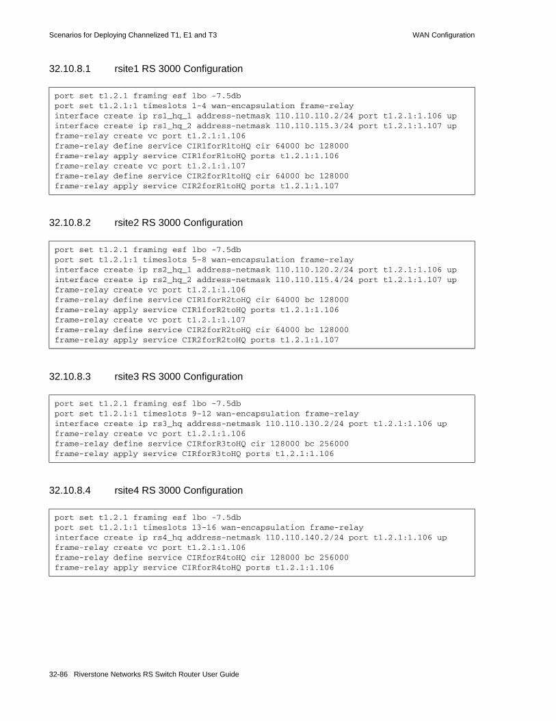
Scenarios for Deploying Channelized T1, E1 and T3 WAN Configuration
32.10.8.1 rsite1 RS 3000 Configuration
32.10.8.2 rsite2 RS 3000 Configuration
32.10.8.3 rsite3 RS 3000 Configuration
32.10.8.4 rsite4 RS 3000 Configuration
port set t1.2.1 framing esf lbo -7.5dbport set t1.2.1:1 timeslots 1-4 wan-encapsulation frame-relayinterface create ip rs1_hq_1 address-netmask 110.110.110.2/24 port t1.2.1:1.106 upinterface create ip rs1_hq_2 address-netmask 110.110.115.3/24 port t1.2.1:1.107 upframe-relay create vc port t1.2.1:1.106frame-relay define service CIR1forR1toHQ cir 64000 bc 128000frame-relay apply service CIR1forR1toHQ ports t1.2.1:1.106frame-relay create vc port t1.2.1:1.107frame-relay define service CIR2forR1toHQ cir 64000 bc 128000frame-relay apply service CIR2forR1toHQ ports t1.2.1:1.107
port set t1.2.1 framing esf lbo -7.5dbport set t1.2.1:1 timeslots 5-8 wan-encapsulation frame-relayinterface create ip rs2_hq_1 address-netmask 110.110.120.2/24 port t1.2.1:1.106 upinterface create ip rs2_hq_2 address-netmask 110.110.115.4/24 port t1.2.1:1.107 upframe-relay create vc port t1.2.1:1.106frame-relay define service CIR1forR2toHQ cir 64000 bc 128000frame-relay apply service CIR1forR2toHQ ports t1.2.1:1.106frame-relay create vc port t1.2.1:1.107frame-relay define service CIR2forR2toHQ cir 64000 bc 128000frame-relay apply service CIR2forR2toHQ ports t1.2.1:1.107
port set t1.2.1 framing esf lbo -7.5dbport set t1.2.1:1 timeslots 9-12 wan-encapsulation frame-relayinterface create ip rs3_hq address-netmask 110.110.130.2/24 port t1.2.1:1.106 upframe-relay create vc port t1.2.1:1.106frame-relay define service CIRforR3toHQ cir 128000 bc 256000frame-relay apply service CIRforR3toHQ ports t1.2.1:1.106
port set t1.2.1 framing esf lbo -7.5dbport set t1.2.1:1 timeslots 13-16 wan-encapsulation frame-relayinterface create ip rs4_hq address-netmask 110.110.140.2/24 port t1.2.1:1.106 upframe-relay create vc port t1.2.1:1.106frame-relay define service CIRforR4toHQ cir 128000 bc 256000frame-relay apply service CIRforR4toHQ ports t1.2.1:1.106
32-86 Riverstone Networks RS Switch Router User Guide
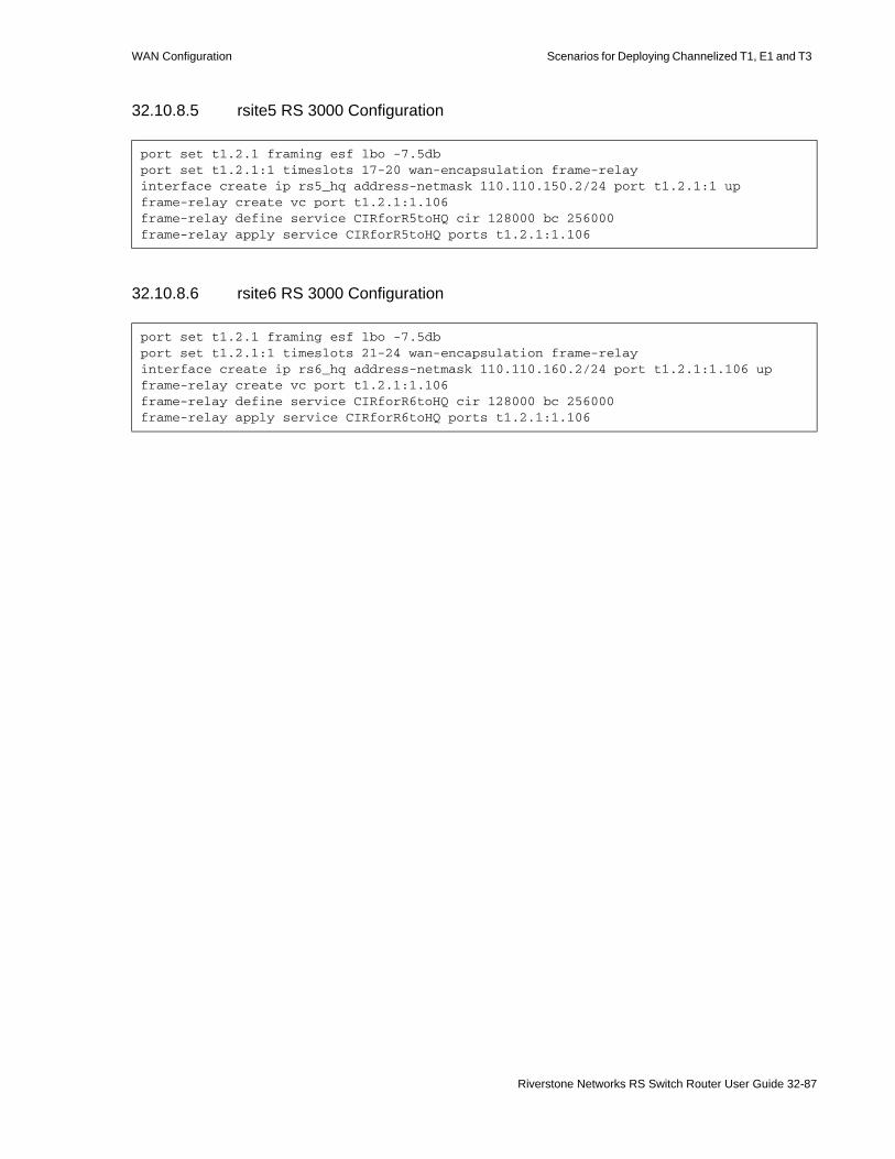
WAN Configuration Scenarios for Deploying Channelized T1, E1 and T3
32.10.8.5 rsite5 RS 3000 Configuration
32.10.8.6 rsite6 RS 3000 Configuration
port set t1.2.1 framing esf lbo -7.5dbport set t1.2.1:1 timeslots 17-20 wan-encapsulation frame-relayinterface create ip rs5_hq address-netmask 110.110.150.2/24 port t1.2.1:1 upframe-relay create vc port t1.2.1:1.106frame-relay define service CIRforR5toHQ cir 128000 bc 256000frame-relay apply service CIRforR5toHQ ports t1.2.1:1.106
port set t1.2.1 framing esf lbo -7.5dbport set t1.2.1:1 timeslots 21-24 wan-encapsulation frame-relayinterface create ip rs6_hq address-netmask 110.110.160.2/24 port t1.2.1:1.106 upframe-relay create vc port t1.2.1:1.106frame-relay define service CIRforR6toHQ cir 128000 bc 256000frame-relay apply service CIRforR6toHQ ports t1.2.1:1.106
Riverstone Networks RS Switch Router User Guide 32-87

Scenarios for Deploying Channelized T1, E1 and T3 WAN Configuration
32.10.8.7 hqsite RS 8600 Configuration
port set t1.2.1 framing esf lbo -7.5dbport set t1.2.1:1 timeslots 1-4 wan-encapsulation frame-relayport set t1.2.1:2 timeslots 5-8 wan-encapsulation frame-relayport set t1.2.1:3 timeslots 9-12 wan-encapsulation frame-relayport set t1.2.1:4 timeslots 13-16 wan-encapsulation frame-relayport set t1.2.1:5 timeslots 17-20 wan-encapsulation frame-relayport set t1.2.1:6 timeslots 21-24 wan-encapsulation frame-relayinterface create ip rsite1_1 address-netmask 110.110.110.1/24 port t1.4.1:1.106 upinterface create ip rsite1_2 address-netmask 110.110.115.1/24 port t1.4.1:1.107 upinterface create ip rsite2_1 address-netmask 110.110.120.1/24 port t1.4.1:2.106 upinterface create ip rsite2_2 address-netmask 110.110.115.2/24 port t1.4.1:1.107 upinterface create ip rsite3 address-netmask 110.110.130.1/24 port t1.4.1:3.106 upinterface create ip rsite4 address-netmask 110.110.140.1/24 port t1.4.1:4.106 upinterface create ip rsite5 address-netmask 110.110.150.1/24 port t1.4.1:5.106 upinterface create ip rsite6 address-netmask 110.110.160.1/24 port t1.4.1:6.106 upframe-relay create vc port t1.2.1:1.106frame-relay define service CIR1forHQtoR1 cir 64000 bc 128000frame-relay apply service CIR1forHQtoR1 ports t1.2.1:1.106frame-relay create vc port t1.2.1:1.107frame-relay define service CIR2forHQtoR1 cir 64000 bc 128000frame-relay apply service CIR2forHQtoR1 ports t1.2.1:1.107frame-relay create vc port t1.2.1:2.106frame-relay define service CIR1forHQtoR2 cir 64000 bc 128000frame-relay apply service CIR1forHQtoR2 ports t1.2.1:2.106frame-relay create vc port t1.2.1:2.107frame-relay define service CIR2forHQtoR2 cir 64000 bc 128000frame-relay apply service CIR2forHQtoR2 ports t1.2.1:2.107frame-relay create vc port t1.2.1:3.106frame-relay define service CIRforHQtoR3 cir 128000 bc 256000frame-relay apply service CIRforHQtoR3 ports t1.2.1:3.106frame-relay create vc port t1.2.1:4.106frame-relay define service CIRforHQtoR4 cir 192000 bc 256000frame-relay apply service CIRforHQtoR4 ports t1.2.1:4.106frame-relay create vc port t1.2.1:5.106frame-relay define service CIRforHQtoR5 cir 192000 bc 256000frame-relay apply service CIRforHQtoR5 ports t1.2.1:5.106frame-relay create vc port t1.2.1:6.106frame-relay define service CIRforHQtoR6 cir 192000 bc 256000frame-relay apply service CIRforHQtoR6 ports t1.2.1:6.106
32-88 Riverstone Networks RS Switch Router User Guide
WAN Configuration Scenarios for Deploying Clear Channel T3 and E3
32.11 SCENARIOS FOR DEPLOYING CLEAR CHANNEL T3 AND E3
This section describes some scenarios for deploying Clear Channel T3.There are two scenarios, which cover the deployment for:• Routed inter-office connections through an Internet Service Provider (ISP) (see Section 32.11.1)• Routed Metropolitan Backbone (see Section 32.11.2)
32.11.1 Scenario 1: Routed Inter-Office Connections through and ISP
In this scenario, a company’s sites share data that is held at the Internet Service Provider (ISP). The company’s head office contains an RS 8000, and the remote sites each have an RS 3000. All remote sites have four Channelized T1 lines grouped into a multi-link PPP bundle to connect to the RS 8000 at head office. Where there is significant traffic between two remote sites, perhaps because they are in the same geographical region, they are also connected by a Channelized T1 line. All remote sites are a maximum of two hops away from any other remote site, and RIP is used as the routing protocol.
The ISP provides a Channelized T3 connection on their RS 8000, a LAN that connects to the servers containing the shared data required by the company, and a Clear Channel T3 connection to the Internet.
Figure 32-12 shows the network layout for this scenario. The tables following the figure show the commands used to configure the interfaces for the routers at the ISP, head office (hqsite), and the remote sites, rsite2 and rsite3. The interfaces on the routers at the remaining sites are configured in a similar way to the corresponding interfaces for rsite2, using the appropriate IP address for each interface.
Riverstone Networks RS Switch Router User Guide 32-89

Scenarios for Deploying Clear Channel T3 and E3 WAN Configuration
32.11.1.1 Hardware Requirements
Router Hardware Requirements
RS 8000 1 Channelized T3 module.1 Multi-Rate WAN module with 1 Clear Channel T3 WIC
RS 8000 (hqsite) 1 Channelized T3 module.6 Multi-Rate WAN modules with 12 Channelized T1 WICs.
RS 3000 (rsite2) 2 Multi-Rate WAN modules with 3 Channelized T1 WICs.
RS 3000 (rsite3) 2 Multi-Rate WAN modules with 3 Channelized T1 WICs.
RS 3000 (rsite4) 1 Multi-Rate WAN module with 2 Channelized T1 WICs.
RS 3000 (rsite5) 2 Multi-Rate WAN modules with 3 Channelized T1 WICs.
RS 3000 (rsite6) 2 Multi-Rate WAN modules with 3 Channelized T1 WICs.
RS 3000 (rsite7) 2 Multi-Rate WAN modules with 3 Channelized T1 WICs.
32-90 Riverstone Networks RS Switch Router User Guide

WAN Configuration Scenarios for Deploying Clear Channel T3 and E3
Figure 32-12 Routed Inter-Office Connections through an ISP
KEY:
T3 refers to Channelized T3
CCT3 refers to Clear Channel T3
Internet
Internet Service Provider
CCT3
12.20.10.5/24
Shared Data
T1 ( x 4 )
T3
T1
T1
T1
120.210.7.1/24
rsite7
RS 3000
120.210.5.1/24
rsite5
RS 3000
120.210.4.1/24
rsite4
RS 3000
120.210.3.1/24
rsite3
RS 3000120.210.2.1/24
rsite2
RS 3000
120.210.6.1/24
rsite6
RS 3000T1 ( x 4 )
T1 ( x 4 )
T1 ( x 4 )
T1 ( x 4 )
T1 ( x 4 )
RS 8600120.210.1.1/24
hqsite
RS 8600
Riverstone Networks RS Switch Router User Guide 32-91

Scenarios for Deploying Clear Channel T3 and E3 WAN Configuration
32.11.1.2 ISP RS 8000 Configuration
The following configuration applies to the RS 8000 router at the ISP.
!-----------------------------------------------------------------------------!Configuration for the RS 8000 Clear Channel T3 interface to the Internet!-----------------------------------------------------------------------------port set t3.2.1 cablelength 200 wan-encapsulation pppinterface create ip to_internet address-netmask 155.32.2.1/24 port t3.2.1 up!-----------------------------------------------------------------------------!Configuration for the RS 8000 Channelized T3 interface!-----------------------------------------------------------------------------port set t3.4.1 cablelength 200!-----------------------------------------------------------------------------!Configure the T1 lines on the Channelized T3 interface!-----------------------------------------------------------------------------port set t3.4.1:(1-28) timeslots 1-24 wan-encapsulation ppp!-----------------------------------------------------------------------------!Configure 7 multilink PPP bundles each containing 4 consecutive T1 lines!-----------------------------------------------------------------------------ppp create-mlp mp.1 slot 4ppp add-to-mlp mp.1 port t3.4.1:(1-4)ppp create-mlp mp.2 slot 4ppp add-to-mlp mp.2 port t3.4.1:(5-8)ppp create-mlp mp.3 slot 4ppp add-to-mlp mp.3 port t3.4.1:(9-12)ppp create-mlp mp.4 slot 4ppp add-to-mlp mp.4 port t3.4.1:(13-16)ppp create-mlp mp.5 slot 4ppp add-to-mlp mp.5 port t3.4.1:(17-20)ppp create-mlp mp.6 slot 4ppp add-to-mlp mp.6 port t3.4.1:(21-24)ppp create-mlp mp.7 slot 4ppp add-to-mlp mp.7 port t3.4.1:(25-28)
interface create ip to_hqsite address-netmask 120.210.11.1/24 port mp.1 upinterface create ip to_rsite2 address-netmask 120.210.12.1/24 port mp.2 upinterface create ip to_rsite3 address-netmask 120.210.13.1/24 port mp.3 upinterface create ip to_rsite4 address-netmask 120.210.14.1/24 port mp.4 upinterface create ip to_rsite5 address-netmask 120.210.15.1/24 port mp.5 upinterface create ip to_rsite6 address-netmask 120.210.16.1/24 port mp.6 upinterface create ip to_rsite7 address-netmask 120.210.17.1/24 port mp.7 up!-----------------------------------------------------------------------------!Configure RIP:!-----------------------------------------------------------------------------rip add interface to_hqsiterip add interface to_rsite2rip add interface to_rsite3rip add interface to_rsite4rip add interface to_rsite5rip add interface to_rsite6rip add interface to_rsite7rip add interface to_internetrip start
32-92 Riverstone Networks RS Switch Router User Guide
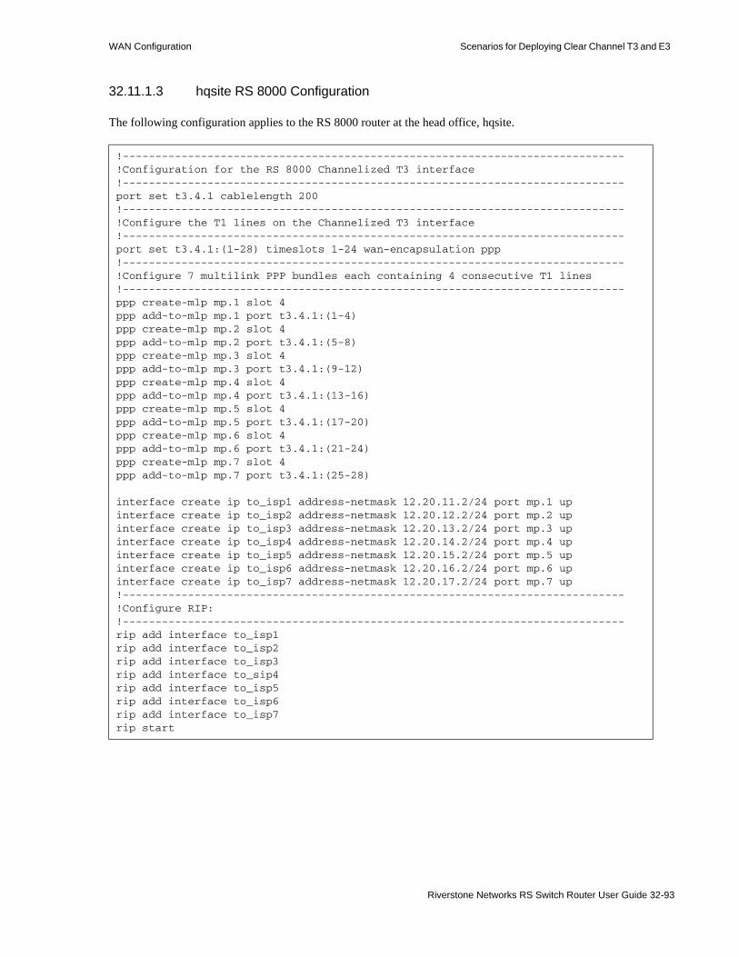
WAN Configuration Scenarios for Deploying Clear Channel T3 and E3
32.11.1.3 hqsite RS 8000 Configuration
The following configuration applies to the RS 8000 router at the head office, hqsite.
!-----------------------------------------------------------------------------!Configuration for the RS 8000 Channelized T3 interface!-----------------------------------------------------------------------------port set t3.4.1 cablelength 200!-----------------------------------------------------------------------------!Configure the T1 lines on the Channelized T3 interface!-----------------------------------------------------------------------------port set t3.4.1:(1-28) timeslots 1-24 wan-encapsulation ppp!-----------------------------------------------------------------------------!Configure 7 multilink PPP bundles each containing 4 consecutive T1 lines!-----------------------------------------------------------------------------ppp create-mlp mp.1 slot 4ppp add-to-mlp mp.1 port t3.4.1:(1-4)ppp create-mlp mp.2 slot 4ppp add-to-mlp mp.2 port t3.4.1:(5-8)ppp create-mlp mp.3 slot 4ppp add-to-mlp mp.3 port t3.4.1:(9-12)ppp create-mlp mp.4 slot 4ppp add-to-mlp mp.4 port t3.4.1:(13-16)ppp create-mlp mp.5 slot 4ppp add-to-mlp mp.5 port t3.4.1:(17-20)ppp create-mlp mp.6 slot 4ppp add-to-mlp mp.6 port t3.4.1:(21-24)ppp create-mlp mp.7 slot 4ppp add-to-mlp mp.7 port t3.4.1:(25-28)
interface create ip to_isp1 address-netmask 12.20.11.2/24 port mp.1 upinterface create ip to_isp2 address-netmask 12.20.12.2/24 port mp.2 upinterface create ip to_isp3 address-netmask 12.20.13.2/24 port mp.3 upinterface create ip to_isp4 address-netmask 12.20.14.2/24 port mp.4 upinterface create ip to_isp5 address-netmask 12.20.15.2/24 port mp.5 upinterface create ip to_isp6 address-netmask 12.20.16.2/24 port mp.6 upinterface create ip to_isp7 address-netmask 12.20.17.2/24 port mp.7 up!-----------------------------------------------------------------------------!Configure RIP:!-----------------------------------------------------------------------------rip add interface to_isp1rip add interface to_isp2rip add interface to_isp3rip add interface to_sip4rip add interface to_isp5rip add interface to_isp6rip add interface to_isp7rip start
Riverstone Networks RS Switch Router User Guide 32-93

Scenarios for Deploying Clear Channel T3 and E3 WAN Configuration
The following configuration applies to the T1 interfaces on the RS 8000 router at the head office, hqsite.
!-----------------------------------------------------------------------------!Configuration for the RS 8000 T1 interfaces!-----------------------------------------------------------------------------!T1 interfaces to the ISP:!-----------------------------------------------------------------------------port set t1.5.(1-4) framing esf lbo -7.5dbport set t1.5.(1-4):1 timeslots 1-24 wan-encapsulation pppport set t1.6.(1-4) framing esf lbo -7.5dbport set t1.6.(1-4):1 timeslots 1-24 wan-encapsulation pppport set t1.7.(1-4) framing esf lbo -7.5dbport set t1.7.(1-4):1 timeslots 1-24 wan-encapsulation pppport set t1.8.(1-4) framing esf lbo -7.5dbport set t1.8.(1-4):1 timeslots 1-24 wan-encapsulation pppport set t1.9.(1-4) framing esf lbo -7.5dbport set t1.9.(1-4):1 timeslots 1-24 wan-encapsulation pppport set t1.10.(1-4) framing esf lbo -7.5dbport set t1.10.(1-4):1 timeslots 1-24 wan-encapsulation ppp
ppp create-mlp mp.9 slot 5ppp add-to-mlp mp.9 port t1.5.(1-4):1interface create ip to_rsite2 address-netmask 120.210.2.1/24 port mp.9 upppp create-mlp mp.10 slot 6ppp add-to-mlp mp.10 port t1.6.(1-4):1interface create ip to_rsite3 address-netmask 120.210.3.1/24 port mp.10 upppp create-mlp mp.11 slot 7ppp add-to-mlp mp.11 port t1.7.(1-4):1interface create ip to_rsite4 address-netmask 120.210.4.1/24 port mp.11 upppp create-mlp mp.12 slot 8ppp add-to-mlp mp.12 port t1.8.(1-4):1interface create ip to_rsite5 address-netmask 120.210.5.1/24 port mp.12 upppp create-mlp mp.13 slot 9ppp add-to-mlp mp.13 port t1.9.(1-4):1interface create ip to_rsite6 address-netmask 120.210.6.1/24 port mp.13 upppp create-mlp mp.14 slot 10ppp add-to-mlp mp.14 port t1.10.(1-4):1interface create ip to_rsite7 address-netmask 120.210.7.1/24 port mp.14 up!-----------------------------------------------------------------------------!Configure RIP:!-----------------------------------------------------------------------------rip add interface to_rsite2rip add interface to_rsite3rip add interface to_rsite4rip add interface to_rsite5rip add interface to_rsite6rip add interface to_rsite7rip start
32-94 Riverstone Networks RS Switch Router User Guide

WAN Configuration Scenarios for Deploying Clear Channel T3 and E3
32.11.1.4 rsite2 RS 3000 Configuration
The following configuration applies to the RS 3000 router at the remote site, rsite2.
!-----------------------------------------------------------------------------!Configuration for the RS 3000 T1 interfaces!-----------------------------------------------------------------------------!Bundled T1 interfaces to hqsite:!-----------------------------------------------------------------------------port set t1.2.1 framing esf lbo -7.5dbport set t1.2.1:1 timeslots 1-24 wan-encapsulation pppport set t1.2.2 framing esf lbo -7.5dbport set t1.2.2:1 timeslots 1-24 wan-encapsulation pppport set t1.2.3 framing esf lbo -7.5dbport set t1.2.3:1 timeslots 1-24 wan-encapsulation pppport set t1.2.4 framing esf lbo -7.5dbport set t1.2.4:1 timeslots 1-24 wan-encapsulation ppp
ppp create-mlp mp.1 slot 2ppp add-to-mlp mp.1 port t1.2.(1-4):1interface create ip to_hqsite address-netmask 120.210.2.2/24 port mp.1 up!-----------------------------------------------------------------------------!T1 interface to the rsite3:!-----------------------------------------------------------------------------port set t1.3.2 framing esf lbo -7.5dbport set t1.3.2:1 timeslots 1-24 wan-encapsulation pppinterface create ip to_rsite3 address-netmask 120.210.23.2/24 port t1.3.2 up!-----------------------------------------------------------------------------!Configure RIP:!-----------------------------------------------------------------------------rip add interface to_hqsiterip add interface to_rsite3rip start
Riverstone Networks RS Switch Router User Guide 32-95

Scenarios for Deploying Clear Channel T3 and E3 WAN Configuration
32.11.1.5 rsite3 RS 3000 Configuration
The following configuration applies to the RS 3000 router at the remote site, rsite3.
!-----------------------------------------------------------------------------!Configuration for the RS 3000 T1 interfaces!-----------------------------------------------------------------------------!Bundled T1 interfaces to the hqsite:!-----------------------------------------------------------------------------port set t1.2.1 framing esf lbo -7.5dbport set t1.2.1:1 timeslots 1-24 wan-encapsulation pppport set t1.2.2 framing esf lbo -7.5dbport set t1.2.2:1 timeslots 1-24 wan-encapsulation pppport set t1.2.3 framing esf lbo -7.5dbport set t1.2.3:1 timeslots 1-24 wan-encapsulation pppport set t1.2.4 framing esf lbo -7.5dbport set t1.2.4:1 timeslots 1-24 wan-encapsulation ppp
ppp create-mlp mp.1 slot 2ppp add-to-mlp mp.1 port t1.2.(1-4):1interface create ip to_hqsite address-netmask 120.210.3.2/24 port mp.1 up!-----------------------------------------------------------------------------!T1 interface to the rsite2:!-----------------------------------------------------------------------------port set t1.3.2 framing esf lbo -7.5dbport set t1.3.2:1 timeslots 1-24 wan-encapsulation pppinterface create ip to_rsite2 address-netmask 120.210.23.3/24 port t1.3.2 up!-----------------------------------------------------------------------------!T1 interface to the rsite4:!-----------------------------------------------------------------------------port set t1.3.3 framing esf lbo -7.5dbport set t1.3.3:1 timeslots 1-24 wan-encapsulation pppinterface create ip to_rsite3 address-netmask 120.210.34.3/24 port t1.3.3 up!-----------------------------------------------------------------------------!Configure RIP:!-----------------------------------------------------------------------------rip add interface to_hqsiterip add interface to_rsite2rip add interface to_rsite3rip start
32-96 Riverstone Networks RS Switch Router User Guide

WAN Configuration Scenarios for Deploying Clear Channel T3 and E3
32.11.2 Scenario 2: Routed Metropolitan Backbone
In this scenario, a number of service providers are connected by a Metropolitan Backbone. The backbone consists of RS 8000s connected by Clear Channel T3 (CCT3) links.
An MSP provides a Channelized T3 (CT3) service using an RS 8000. A company has two sites that connect to this service:• The head office (hqsite) connects using a Channelized T3 line from an RS 8000.• The remote site, rsite, connects to the RS 8000 at head office using four Channelized T1 lines
bundled with multi-link PPP, a fractional T1 line, which provides one 768 Kbps service, one 384 Kbps service, and six 64 Kbps services. Also, a full (unstructured) T1 link is connected directly to the RS 8000.
Internet Service Provider A uses a Clear Channel T3 link to the Internet. Internet Service Provider B provides a Channelized T3 service to an Application Service Provider and a Content Provider, both of which connect using Channelized T3 lines from an RS 8000.
Figure 32-13 shows the network layout for this scenario. The tables following the figure show the commands used to configure the interfaces for the routers at the various locations.
Riverstone Networks RS Switch Router User Guide 32-97

Scenarios for Deploying Clear Channel T3 and E3 WAN Configuration
32.11.2.1 Hardware Requirements
Router Hardware Requirements
RS 8000 (MSP) 1 Channelized T3 module (2 ports).1 Multi-Rate WAN module with 2 Clear Channel T3 WICs
RS 8000 (hqsite) 1 Channelized T3 module (with 2 T3 ports).2 Multi-Rate WAN modules with 3 Channelized T1 WICs.
RS 3000 (rsite) 2 Multi-Rate WAN modules with 3 Channelized T1 WICs.
RS 8000 (ISP A) 2 Multi-Rate WAN modules with 3 Clear Channel T3 WICs
RS 8000 (ISP B) 1 ChannelizedT3 module (2 ports).1 Multi-Rate WAN module with 2 Clear Channel T3 WICs
RS 8000 (CP) 1 ChannelizedT3 module (with 2 T3 ports).
RS 8000 (ASP) 1 ChannelizedT3 module (with 2 T3 ports).
32-98 Riverstone Networks RS Switch Router User Guide

WAN Configuration Scenarios for Deploying Clear Channel T3 and E3
Figure 32-13 Routed Metropolitan Backbone
KEY:
T3 refers to Channelized T3
CCT3 refers to Clear Channel T3
MetropolitanService Provider
CCT3
T3
Fractional T1
Unstructured T1
CCT3
CCT3
RS 8600
T3T3
Internet ServiceProvider B
RS 8600
T1 ( x 4 )
ContentProvider
RS 8000
110.25.30.5/24
Application ServiceProvider
RS 8000
130.65.20.8/24
140.22.44.10/24
150.25.50.9/24
RS 3000
rsite
110.210.23.33/28
RS 8600
hqsite
110.210.23.17/28
135.22.34.0/24
145.33.45.0/24
155.15.5.0/24
Internet ServiceProvider A
RS 8600 Internet
CCT3
136.21.206.22/24
137.2.56.0/24
Riverstone Networks RS Switch Router User Guide 32-99

Scenarios for Deploying Clear Channel T3 and E3 WAN Configuration
32.11.2.2 Metropolitan Service Provider RS 8000 Configuration
The following configuration applies to the RS 8000 router at the Metropolitan Service Provider.
!-----------------------------------------------------------------------------!Configuration for the RS 8000 Clear Channel T3 interfaces!-----------------------------------------------------------------------------port set t3.2.1 cablelength 200 wan-encapsulation pppinterface create ip to_ispa address-netmask 135.22.34.2/24 port t3.2.1 upport set t3.2.2 cablelength 200 wan-encapsulation pppinterface create ip to_ispb address-netmask 155.15.5.2/24 port t3.2.2 up!-----------------------------------------------------------------------------!Configuration for the RS 8000 Channelized T3 interface!-----------------------------------------------------------------------------port set t3.4.1 cablelength 200!-----------------------------------------------------------------------------!Configure the T1 lines on the Channelized T3 interface!-----------------------------------------------------------------------------port set t3.4.1:(1-4) timeslots 1-24 wan-encapsulation pppport set t3.4.1:(9-12) timeslots 1-24 wan-encapsulation pppport set t3.4.1:13 timeslots 1-24 wan-encapsulation ppp!-----------------------------------------------------------------------------!Configure 2 multilink PPP bundles each containing 4 consecutive T1 lines!-----------------------------------------------------------------------------ppp create-mlp mp.1 slot 4ppp add-to-mlp mp.1 port t3.4.1:(1-4)ppp create-mlp mp.2 slot 4ppp add-to-mlp mp.2 port t3.4.1:(9-12)
interface create ip to_hqsite address-netmask 120.210.11.1/24 port mp.1 upinterface create ip to_rsite_mppp address-netmask 120.210.12.1/24 port mp.2 upinterface create ip to_rsite_ft1 address-netmask 120.210.13.1/24 port t3.4.1:13 up!-----------------------------------------------------------------------------!Configure RIP:!-----------------------------------------------------------------------------rip add interface to_hqsiterip add interface to_rsite_mppprip add interface to_rsite_ft1rip add interface to_isparip add interface to_ispbrip start
32-100 Riverstone Networks RS Switch Router User Guide
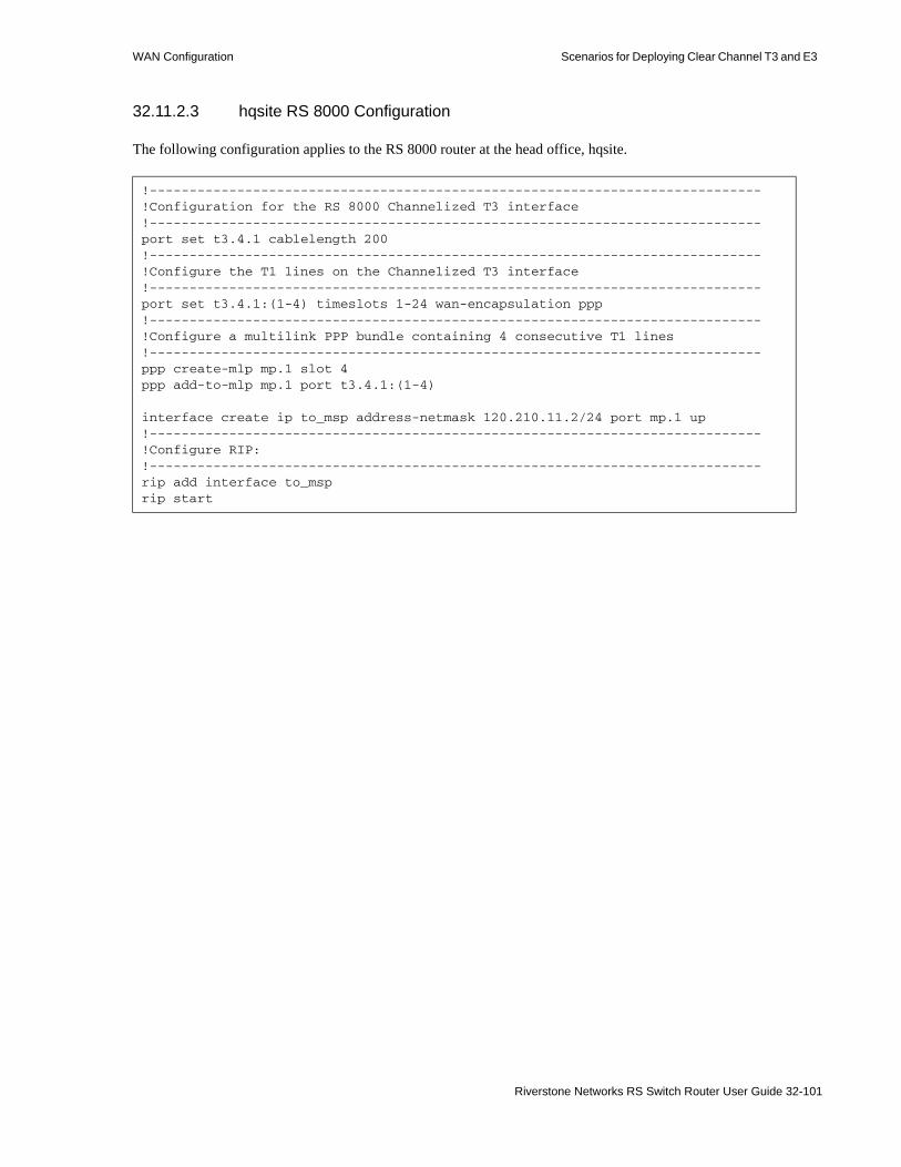
WAN Configuration Scenarios for Deploying Clear Channel T3 and E3
32.11.2.3 hqsite RS 8000 Configuration
The following configuration applies to the RS 8000 router at the head office, hqsite.
!-----------------------------------------------------------------------------!Configuration for the RS 8000 Channelized T3 interface!-----------------------------------------------------------------------------port set t3.4.1 cablelength 200!-----------------------------------------------------------------------------!Configure the T1 lines on the Channelized T3 interface!-----------------------------------------------------------------------------port set t3.4.1:(1-4) timeslots 1-24 wan-encapsulation ppp!-----------------------------------------------------------------------------!Configure a multilink PPP bundle containing 4 consecutive T1 lines!-----------------------------------------------------------------------------ppp create-mlp mp.1 slot 4ppp add-to-mlp mp.1 port t3.4.1:(1-4)
interface create ip to_msp address-netmask 120.210.11.2/24 port mp.1 up!-----------------------------------------------------------------------------!Configure RIP:!-----------------------------------------------------------------------------rip add interface to_msprip start
Riverstone Networks RS Switch Router User Guide 32-101

Scenarios for Deploying Clear Channel T3 and E3 WAN Configuration
The following configuration applies to the T1 interfaces on the RS 8000 router at the head office, hqsite.
!-----------------------------------------------------------------------------!Configuration for the RS 8000 T1 interfaces!-----------------------------------------------------------------------------!Bundled T1 interfaces to the rsite:!-----------------------------------------------------------------------------port set t1.2.1 framing esf lbo -7.5dbport set t1.2.1:1 timeslots 1-24 wan-encapsulation pppport set t1.2.2 framing esf lbo -7.5dbport set t1.2.2:1 timeslots 1-24 wan-encapsulation pppport set t1.2.3 framing esf lbo -7.5dbport set t1.2.3:1 timeslots 1-24 wan-encapsulation pppport set t1.2.4 framing esf lbo -7.5dbport set t1.2.4:1 timeslots 1-24 wan-encapsulation ppp
ppp create-mlp mp.1 slot 2ppp add-to-mlp mp.1 port t1.2.(1-4):1interface create ip to_rsite_mppp address-netmask 120.210.4.1/24 port mp.1 up!-----------------------------------------------------------------------------!Full (unstructured) T1 interface to the rsite:!-----------------------------------------------------------------------------port set t1.3.1 framing none wan-encapsulation pppinterface create ip to_rsite_fullt1 address-netmask 120.210.1.1/24 port t1.3.1 up!-----------------------------------------------------------------------------!Fractional T1 interface to the rsite:!-----------------------------------------------------------------------------port set t1.3.2 framing esf lbo -7.5dbport set t1.3.2:1 timeslots 1-12 wan-encapsulation pppport set t1.3.2:2 timeslots 13-18 wan-encapsulation pppport set t1.3.2:3 timeslots 19 wan-encapsulation pppport set t1.3.2:4 timeslots 20 wan-encapsulation pppport set t1.3.2:5 timeslots 21 wan-encapsulation pppport set t1.3.2:6 timeslots 22 wan-encapsulation pppport set t1.3.2:7 timeslots 23 wan-encapsulation pppport set t1.3.2:8 timeslots 24 wan-encapsulation pppinterface create ip to_rsite_fract1 address-netmask 120.210.24.1/24 port t1.3.2 up!-----------------------------------------------------------------------------!Configure RIP:!-----------------------------------------------------------------------------rip add interface to_rsite_mppprip add interface to_rsite_fullt1rip add interface to_rsite_fract1rip start
32-102 Riverstone Networks RS Switch Router User Guide

WAN Configuration Scenarios for Deploying Clear Channel T3 and E3
32.11.2.4 rsite RS 3000 Configuration
The following configuration applies to the RS 3000 router at the remote site, rsite.
!-----------------------------------------------------------------------------!Configuration for the RS 3000 T1 interfaces!-----------------------------------------------------------------------------!T1 interfaces to the hqsite:!-----------------------------------------------------------------------------port set t1.2.1 framing esf lbo -7.5dbport set t1.2.1:1 timeslots 1-24 wan-encapsulation pppport set t1.2.2 framing esf lbo -7.5dbport set t1.2.2:1 timeslots 1-24 wan-encapsulation pppport set t1.2.3 framing esf lbo -7.5dbport set t1.2.3:1 timeslots 1-24 wan-encapsulation pppport set t1.2.4 framing esf lbo -7.5dbport set t1.2.4:1 timeslots 1-24 wan-encapsulation ppp
ppp create-mlp mp.1 slot 2ppp add-to-mlp mp.1 port t1.2.(1-4):1interface create ip to_hqsite_mppp address-netmask 120.210.4.2/24 port mp.1 up!-----------------------------------------------------------------------------!Fractional T1 interface to the hqsite:!-----------------------------------------------------------------------------port set t1.3.1 framing esf lbo -7.5dbport set t1.3.1:1 timeslots 1-12 wan-encapsulation pppport set t1.3.1:2 timeslots 13-18 wan-encapsulation pppport set t1.3.1:3 timeslots 19 wan-encapsulation pppport set t1.3.1:4 timeslots 20 wan-encapsulation pppport set t1.3.1:5 timeslots 21 wan-encapsulation pppport set t1.3.1:6 timeslots 22 wan-encapsulation pppport set t1.3.1:7 timeslots 23 wan-encapsulation pppport set t1.3.1:8 timeslots 24 wan-encapsulation pppinterface create ip to_hqsite_fract1 address-netmask 120.210.24.2/24 port t1.3.1 up!-----------------------------------------------------------------------------!Full (unstructured) T1 interface to the hqsite:!-----------------------------------------------------------------------------port set t1.3.2 framing none wan-encapsulation pppinterface create ip to_hqsite_fullt1 address-netmask 120.210.1.2/24 port t1.3.2 up!-----------------------------------------------------------------------------!Configure RIP:!-----------------------------------------------------------------------------rip add interface to_hqsite_mppprip add interface to_hqsite_fract1rip add interface to_hqsite_fullt1rip start
Riverstone Networks RS Switch Router User Guide 32-103

Scenarios for Deploying Clear Channel T3 and E3 WAN Configuration
32.11.2.5 Internet Service Provider A RS 8000 Configuration
The following configuration applies to the RS 8000 router at Internet Service Provider A.
!-----------------------------------------------------------------------------!Configuration for the RS 8000 Clear Channel T3 interfaces!-----------------------------------------------------------------------------port set t3.2.1 cablelength 200 wan-encapsulation pppinterface create ip to_internet address-netmask 137.2.56.1/24 port t3.2.1 upport set t3.2.2 cablelength 200 wan-encapsulation pppinterface create ip to_msp address-netmask 135.22.34.1/24 port t3.2.2 upport set t3.3.1 cablelength 200 wan-encapsulation pppinterface create ip to_ispb address-netmask 145.33.45.1/24 port t3.3.1 up!-----------------------------------------------------------------------------!Configuration for the RS 8000 channelized T3 interface!-----------------------------------------------------------------------------port set t3.4.1 cablelength 250!-----------------------------------------------------------------------------!Configure the T1 lines on the T3 interface!-----------------------------------------------------------------------------port set t3.4.1:(1-4) timeslots 1-24 wan-encapsulation pppport set t3.4.1:(5-8) timeslots 1-24 wan-encapsulation pppport set t3.4.1:(13-16) timeslots 1-24 wan-encapsulation pppport set t3.4.1:(17-20) timeslots 1-24 wan-encapsulation ppp!-----------------------------------------------------------------------------!Configure 2 multilink PPP bundles each containing 4 consecutive!T1 lines!-----------------------------------------------------------------------------ppp create-mlp mp.1 slot 4ppp add-to-mlp mp.1 port t3.4.1:(1-4)ppp create-mlp mp.2 slot 4ppp add-to-mlp mp.2 port t3.4.1:(5-8)ppp create-mlp mp.3 slot 4ppp add-to-mlp mp.3 port t3.4.1:(13-16)ppp create-mlp mp.4 slot 4ppp add-to-mlp mp.4 port t3.4.1:(17-20)
interface create ip to_cp1 address-netmask 110.25.30.6/24 port mp.1 upinterface create ip to_cp2 address-netmask 110.25.31.7/24 port mp.2 upinterface create ip to_asp1 address-netmask 130.65.20.9/24 port mp.3 upinterface create ip to_asp2 address-netmask 130.65.21.10/24 port mp.4 up!-----------------------------------------------------------------------------!Configure RIP:!-----------------------------------------------------------------------------rip add interface to_cp1rip add interface to_cp2rip add interface to_asp1rip add interface to_asp2rip add interface to_msprip add interface to_ispbrip add interface to_internetrip start
32-104 Riverstone Networks RS Switch Router User Guide

WAN Configuration Scenarios for Deploying Clear Channel T3 and E3
32.11.2.6 Internet Service Provider B RS 8000 Configuration
The following configuration applies to the RS 8000 router at Internet Service Provider B.
!-----------------------------------------------------------------------------!Configuration for the RS 8000 Clear Channel T3 interfaces!-----------------------------------------------------------------------------port set t3.2.1 cablelength 200 wan-encapsulation pppinterface create ip to_msp address-netmask 155.15.5.1/24 port t3.2.1 upport set t3.2.2 cablelength 200 wan-encapsulation pppinterface create ip to_ispa address-netmask 145.33.45.2/24 port t3.2.2 up!-----------------------------------------------------------------------------!Configuration for the RS 8000 channelized T3 interface!-----------------------------------------------------------------------------port set t3.4.1 cablelength 250!-----------------------------------------------------------------------------!Configure the T1 lines on the T3 interface!-----------------------------------------------------------------------------port set t3.4.1:(1-4) timeslots 1-24 wan-encapsulation pppport set t3.4.1:(5-8) timeslots 1-24 wan-encapsulation pppport set t3.4.1:(13-16) timeslots 1-24 wan-encapsulation pppport set t3.4.1:(17-20) timeslots 1-24 wan-encapsulation ppp!-----------------------------------------------------------------------------!Configure 2 multilink PPP bundles each containing 4 consecutive!T1 lines!-----------------------------------------------------------------------------ppp create-mlp mp.1 slot 4ppp add-to-mlp mp.1 port t3.4.1:(1-4)ppp create-mlp mp.2 slot 4ppp add-to-mlp mp.2 port t3.4.1:(5-8)ppp create-mlp mp.3 slot 4ppp add-to-mlp mp.3 port t3.4.1:(13-16)ppp create-mlp mp.4 slot 4ppp add-to-mlp mp.4 port t3.4.1:(17-20)
interface create ip to_cp1 address-netmask 110.25.30.6/24 port mp.1 upinterface create ip to_cp2 address-netmask 110.25.31.7/24 port mp.2 upinterface create ip to_asp1 address-netmask 130.65.20.9/24 port mp.3 upinterface create ip to_asp2 address-netmask 130.65.21.10/24 port mp.4 up!-----------------------------------------------------------------------------!Configure RIP:!-----------------------------------------------------------------------------rip add interface to_cp1rip add interface to_cp2rip add interface to_asp1rip add interface to_asp2rip add interface to_msprip add interface to_isparip start
Riverstone Networks RS Switch Router User Guide 32-105
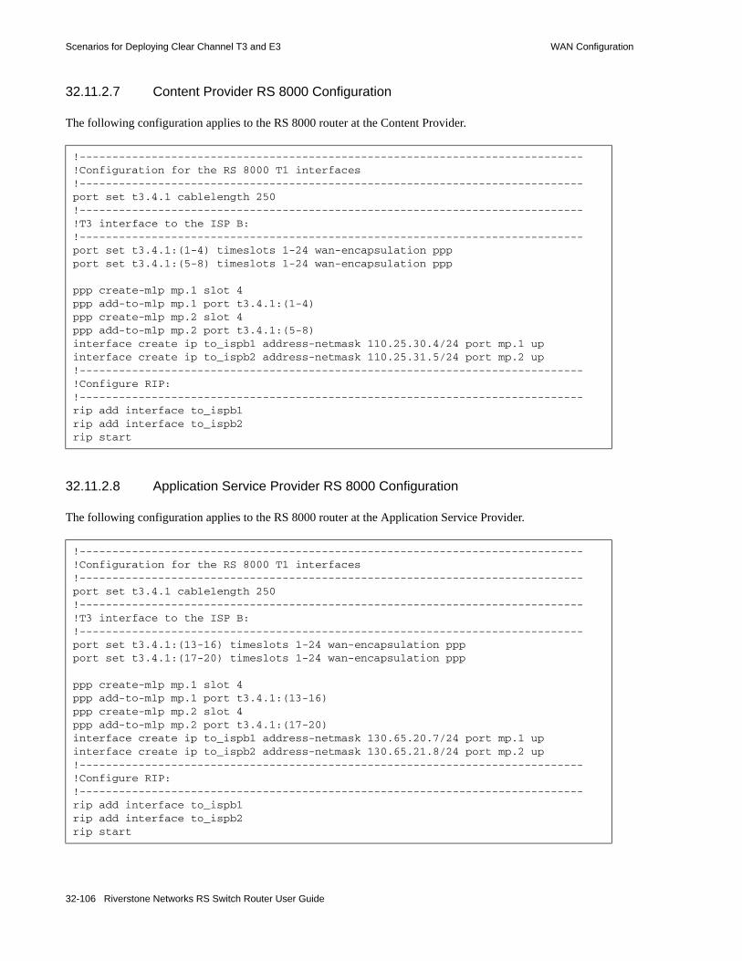
Scenarios for Deploying Clear Channel T3 and E3 WAN Configuration
32.11.2.7 Content Provider RS 8000 Configuration
The following configuration applies to the RS 8000 router at the Content Provider.
32.11.2.8 Application Service Provider RS 8000 Configuration
The following configuration applies to the RS 8000 router at the Application Service Provider.
!-----------------------------------------------------------------------------!Configuration for the RS 8000 T1 interfaces!-----------------------------------------------------------------------------port set t3.4.1 cablelength 250!-----------------------------------------------------------------------------!T3 interface to the ISP B:!-----------------------------------------------------------------------------port set t3.4.1:(1-4) timeslots 1-24 wan-encapsulation pppport set t3.4.1:(5-8) timeslots 1-24 wan-encapsulation ppp
ppp create-mlp mp.1 slot 4ppp add-to-mlp mp.1 port t3.4.1:(1-4)ppp create-mlp mp.2 slot 4ppp add-to-mlp mp.2 port t3.4.1:(5-8)interface create ip to_ispb1 address-netmask 110.25.30.4/24 port mp.1 upinterface create ip to_ispb2 address-netmask 110.25.31.5/24 port mp.2 up!-----------------------------------------------------------------------------!Configure RIP:!-----------------------------------------------------------------------------rip add interface to_ispb1rip add interface to_ispb2rip start
!-----------------------------------------------------------------------------!Configuration for the RS 8000 T1 interfaces!-----------------------------------------------------------------------------port set t3.4.1 cablelength 250!-----------------------------------------------------------------------------!T3 interface to the ISP B:!-----------------------------------------------------------------------------port set t3.4.1:(13-16) timeslots 1-24 wan-encapsulation pppport set t3.4.1:(17-20) timeslots 1-24 wan-encapsulation ppp
ppp create-mlp mp.1 slot 4ppp add-to-mlp mp.1 port t3.4.1:(13-16)ppp create-mlp mp.2 slot 4ppp add-to-mlp mp.2 port t3.4.1:(17-20)interface create ip to_ispb1 address-netmask 130.65.20.7/24 port mp.1 upinterface create ip to_ispb2 address-netmask 130.65.21.8/24 port mp.2 up!-----------------------------------------------------------------------------!Configure RIP:!-----------------------------------------------------------------------------rip add interface to_ispb1rip add interface to_ispb2rip start
32-106 Riverstone Networks RS Switch Router User Guide

WAN Configuration Scenarios for Deploying Clear Channel T3 and E3
Riverstone Networks RS Switch Router User Guide 32-107

Scenarios for Deploying Clear Channel T3 and E3 WAN Configuration
32-108 Riverstone Networks RS Switch Router User Guide

33 SERVICE CONFIGURATION
This chapter describes how to use the service commands to configure rate limiting and shaping. The Service facility provides rate limiting capabilities on ports and interfaces that support layer-2, layer-3, and layer-4 traffic. In addition, the Service facility also provides the ability to rate shape traffic. The procedure for configuring rate limiting and rate shaping services involves first creating the service, then applying it to a port or interface.
Note For additional information about QoS capabilities on the RS Ethernet Router, see Chapter 28, "QoS Configuration."
Note Service commands automatically enter rows in the rsTBMeterTable, rsTBMeterApplyTable, and rsPortRLTable SNMP tables. Conversely, when Service table entries are configured from an SNMP management station, the equivalent Service commands are added to the RS Ethernet Router configuration file.
33.0.1 Rate Limiting and Rate Shaping
Rate limiting differs from rate shaping in that rate limiting allows for the setting of a packet rate limit that when reached causes an exceed action to occur (either packet drop or reduced priority). On the other hand, rate shaping uses buffers and relies on both a packet rate and a burst size. The burst size allows inbound flows on a port or interface to exceed (burst) the predefined rate as long as the flow does not interfere with the committed access rate of other flows.
33.0.2 Rate Limiting and Rate Shaping Capabilities
The Service facility provides the following rate limiting and rate shaping capabilities:• Supports rate limiting at layer-2, layers-3, and layer-4• Supports burst-safe rate limiting• Supports aggregate rate shaping on ingress ports• Supports the application of rate limiting and shaping based on a wide number of criteria:
- ACLs- filters and filter groups
Riverstone Networks RS Switch Router User Guide 33-1

Rate Limiting Services Service Configuration
- Layer-2 Classifiers (L2 Classifiers) for layer-2 traffic- Multi-Field Classifiers (MF Classifiers) for layer-3 traffic
33.1 RATE LIMITING SERVICESWith the exception of Burst-safe (see below), rate limiting is characterized by the setting of a committed traffic rate that when reached, an exceed action is performed. Typically, the exceed action drops packets.
The RS Ethernet Router supports the following rate limit services:• Per-flow Rate Limiting – Limits individual flows to a specified rate. This is the default rate limiting
mode on the RS Ethernet Router.• Aggregate Rate Limiting – Limits an aggregation of flows to a specified rate. This type of rate
limiting is performed completely in hardware and must be enabled on a per-line card basis. If you enable aggregate rate limiting on a line card, you cannot use per-flow or flow-aggregate rate limiting with that card. Aggregate rate limiting is only supported on certain line cards. Make sure the line card supports hardware rate limiting.
• Port-level Rate Limiting – Limits traffic coming into a particular port. This type of policy can be used to limit any type of traffic and is enabled on a per line card basis. If you enable port-level rate limiting on a line card, you cannot use per-flow or flow-aggregate rate limiting with that card.
• Burst-safe Rate Limiting – Limits any aggregate of flows on two levels: the committed access rate (CAR) and the burst-safe rate. Burst-safe rate limiting is supported only on line cards that support aggregate rate limiting.
• Layer-2 Rate Limiting – Limits layer-2 traffic coming into a particular port or VLAN. This type of rate limiting is performed completely in hardware and must be enabled on a per-line card basis. Furthermore, this type of rate limiting is supported only on line cards that contain 5th generation ASICs.
33.2 APPLYING RATE LIMITING SERVICESAfter creating the rate limit service, it is applied to one or more interfaces or ports. When you use the service command to apply a rate limiting services, the traffic to be rate limited is identified through the use of filters, ACLs, and by MF and L2 classifiers. For example, a rate limiting service is created, which specifies a rate and an exceed action. When applying the service to a port, there must be some way of identifying the specific traffic to be rate limited. Through the use of filters, ACLs, and Classifiers, the exact traffic to be rate limited is defined. For instance, traffic can be identified by its IP address, source and destination; MAC address, source and destination, ToS byte, 802.1P priority bits, and so on. The set of identifying parameters that define the exact traffic to be affected is often referred to as the traffic profile.
Note By default, all traffic uses the lowest priority. Because of this, the lower-priority option of the rate limit command does not lower the traffic priority unless the traffic was previously assigned a higher priority using the qos set ip policy command.
33-2 Riverstone Networks RS Switch Router User Guide

Service Configuration Applying Rate Limiting Services
33.2.1 Applying Aggregate and Port-Level Rate Limiting
The following example shows how you can configure an aggregate rate limiting service and a port-level rate limiting service on the RS Ethernet Router. The aggregate rate limiting service restricts traffic from 4 customers (S1, S2, S3, and S4) to 10 Mbps. The port-level rate limiting service restricts traffic from the Internet to 64 Mbps.
Figure 33-1 Applying aggregate and port-level rate limiting
Internet
S1
S4
S2
S3RS64 Mbps 10 Mbps
Riverstone Networks RS Switch Router User Guide 33-3

Applying Rate Limiting Services Service Configuration
The configuration shown in Figure 33-1 is created with the following commands. In this example, ACLs are used to define the traffic profile:
rs(config)# show active
Configure VLANs and interfacesvlan create s1 ipvlan create s2 ipvlan create s3 ipvlan create s4 ipvlan add ports et.2.8 to s1vlan add ports et.2.7 to s2vlan add ports et.2.6 to s3vlan add ports et.2.5 to s4interface create ip from_s1 vlan s1 address-netmask 10.1.1.1interface create ip from_s2 vlan s2 address-netmask 15.1.1.1interface create ip from_s3 vlan s3 address-netmask 20.1.1.1interface create ip from_s4 vlan s4 address-netmask 25.1.1.1
Configure the ACLsacl s1 permit ip 10.1.1.1acl s2 permit ip 15.1.1.1acl s3 permit ip 20.1.1.1acl s4 permit ip 25.1.1.1
Enable aggregate rate limiting
system enable aggregate-rate-limiting slot 2
Configure aggregate rate limitingservice flow1 create rate-limit aggregate rate 10000000 drop-packets
Apply the rate limit service to the traffic on the interfacesservice flow1 apply rate-limit acl s1 interface from_s1service flow1 apply rate-limit acl s2 interface from_s2service flow1 apply rate-limit acl s3 interface from_s3service flow1 apply rate-limit acl s4 interface from_s4
Configure the port-level rate limit serviceservice flow2 create rate-limit input-portlevel rate 64000000 no-action port t1.4.1
33-4 Riverstone Networks RS Switch Router User Guide

Service Configuration Applying Rate Limiting Services
The following example shows how you would use the MF-Classifier to define a traffic profile and apply a rate limit to it:
Use the service show rate-limit command to display information about the rate limit services that are configured:
rs(config)# show active
Configure the VLANs and interfacesvlan create s1 ipvlan create s2 ipvlan create s3 ipvlan create s4 ipvlan add ports et.2.1 to s1vlan add ports et.2.2 to s2vlan add ports et.2.3 to s3vlan add ports et.2.4 to s4interface create ip from_s1 vlan s1 address-netmask 10.1.1.1interface create ip from_s2 vlan s2 address-netmask 15.1.1.1interface create ip from_s3 vlan s3 address-netmask 20.1.1.1interface create ip from_s4 vlan s4 address-netmask 25.1.1.1
Enable aggregate rate limitingsystem enable aggregate-rate-limiting slot 2
Configure aggregate rate limitingservice flow1 create rate-limit aggregate rate 10000000 drop-packets
Apply the rate limit service to the specified traffic on the interfacesservice flow1 apply rate-limit mf-classifier interface from_s1service flow1 apply rate-limit mf-classifier interface from_s2service flow1 apply rate-limit mf-classifier interface from_s3service flow1 apply rate-limit mf-classifier interface from_s4
Configure the port-level rate limit serviceservice flow2 create rate-limit input-portlevel rate 64000000 no-action port t1.4.1
rs# service show rate-limit allRate Limit name: flow1 Type Rate Exceeds Exceed Action ---------- ----------- ----------- ------------------------- Aggregate 1.00 Mbps 0 Drop
Rate Limit name: flow2 Type Rate Exceeds Exceed Action ---------- ----------- ----------- ------------------------- Input 64.00 Kbps 0 None
Riverstone Networks RS Switch Router User Guide 33-5
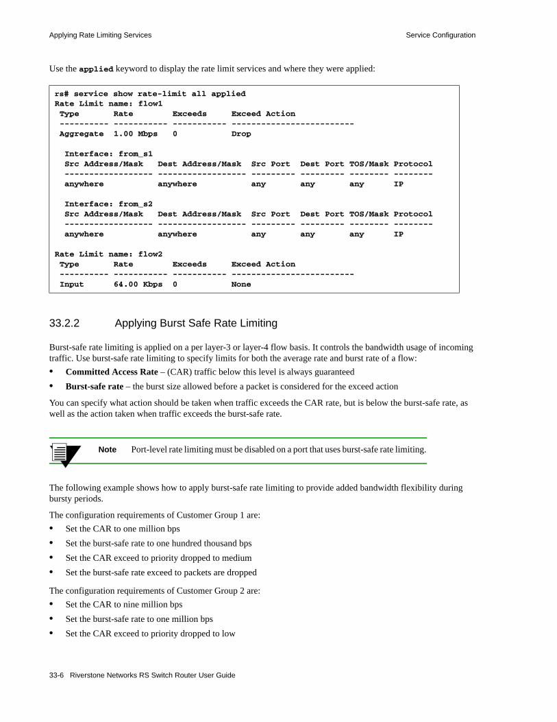
Applying Rate Limiting Services Service Configuration
Use the applied keyword to display the rate limit services and where they were applied:
33.2.2 Applying Burst Safe Rate Limiting
Burst-safe rate limiting is applied on a per layer-3 or layer-4 flow basis. It controls the bandwidth usage of incoming traffic. Use burst-safe rate limiting to specify limits for both the average rate and burst rate of a flow:• Committed Access Rate – (CAR) traffic below this level is always guaranteed• Burst-safe rate – the burst size allowed before a packet is considered for the exceed action
You can specify what action should be taken when traffic exceeds the CAR rate, but is below the burst-safe rate, as well as the action taken when traffic exceeds the burst-safe rate.
Note Port-level rate limiting must be disabled on a port that uses burst-safe rate limiting.
The following example shows how to apply burst-safe rate limiting to provide added bandwidth flexibility during bursty periods.
The configuration requirements of Customer Group 1 are:• Set the CAR to one million bps• Set the burst-safe rate to one hundred thousand bps• Set the CAR exceed to priority dropped to medium• Set the burst-safe rate exceed to packets are dropped
The configuration requirements of Customer Group 2 are:• Set the CAR to nine million bps• Set the burst-safe rate to one million bps• Set the CAR exceed to priority dropped to low
rs# service show rate-limit all appliedRate Limit name: flow1 Type Rate Exceeds Exceed Action ---------- ----------- ----------- ------------------------- Aggregate 1.00 Mbps 0 Drop
Interface: from_s1 Src Address/Mask Dest Address/Mask Src Port Dest Port TOS/Mask Protocol ------------------ ------------------ --------- --------- -------- -------- anywhere anywhere any any any IP
Interface: from_s2 Src Address/Mask Dest Address/Mask Src Port Dest Port TOS/Mask Protocol ------------------ ------------------ --------- --------- -------- -------- anywhere anywhere any any any IP
Rate Limit name: flow2 Type Rate Exceeds Exceed Action ---------- ----------- ----------- ------------------------- Input 64.00 Kbps 0 None
33-6 Riverstone Networks RS Switch Router User Guide

Service Configuration Applying Rate Limiting Services
• Set the burst-safe rate exceed to packets are dropped
Figure 33-2 Burst-Safe configuration example
The configuration shown in Figure 33-2 is created with the following Configure mode commands:
Create the VLANsvlan create customergroup1 ipvlan add ports t1.4.1 to customergroup1vlan create customergroup2 ipvlan add ports t1.4.2 to customergroup2
Create the interfacesinterface create ip customergroup1 vlan customergroup1 address-netmask 100.99.98.97interface create ip customergroup2 vlan customergroup2 address-netmask 101.99.98.97
Enable aggregate rate limitingsystem enable aggregate-rate-limiting slot 4
Create the burst-safe services service customergroup1 create rate-limit burst-safe car-rate 1000000 car-lower-priority burst-rate 100000 burst-drop-packetsservice customergroup2 create rate-limit burst-safe car-rate 9000000 car-lower-priority burst-rate 1000000 burst-drop-packets
Apply burst-safe rate limitingservice customergroup1 apply rate-limit mf-classifier interface customergroup1 source-addr-mask 20.20.10.0/24service customergroup2 apply rate-limit mf-classifier interface customergroup2 source-addr-mask 30.30.10.0/24
RS
CAR = 1 Mbpsburst-safe rate = 100,000 bpsCustomer
Group 1
CustomerGroup 2 CAR = 9 Mbps
burst-safe rate = 1 Mbps
Riverstone Networks RS Switch Router User Guide 33-7

Applying Rate Limiting Services Service Configuration
33.2.3 Applying Layer-2 Rate Limiting
When a layer-2 rate limiting service is applied to a port, the traffic profile is defined by various layer-2 parameters. These parameters can be specified within previously defined filters and/or by selecting layer-2 parameters from a list of classifiers, which are available while applying the service. The following, lists the parameters that can be used to identify layer-2 traffic:• 802.1P priority • Any 802.1P priority that is not in an 1p-grouping• Port number• Group name when multiple ports or filters are used• Destination MAC address• Destination MAC mask address• Source MAC address• Source MAC mask address• VLAN list – specified by VLAN ID #
33.2.3.1 Layer-2 Rate Limiting Prerequisites
Before layer-2 rate limiting services can be applied to a port, both the line card and its physical ports must be set up for layer-2 rate limiting by performing the following five steps:1. use the system enable l2-rate-limiting slot <number> range <range> command to set
a refresh range on the line card to which layer-2 rate limiting will be applied.
To set the proper range for a line card, first decide the rate that will be applied to each port on the line card. Next, use the system show rate-limit-range command to view a list of the ranges and to see whether they are supported on the line cards. Finally, select the range whose minimum and maximum values encompass the required rates.
For example, rate limiting is to be performed on slot 9, on ports gi.9.1 and gi.9.2. Traffic on gi.9.1 will be rate limited to 500 Kbps, while traffic on gi.9.2 will be rate limited to 5 Mbps. Enter the system show rate-limit-range command.
rs# system show rate-limit-rangeRefresh Minimum Maximum------- -------------- --------------Highest 1.47 Mbps 1.00 Gbps High 366.23 Kbps 250.00 Mbps Middle 91.55 Kbps 62.50 Mbps Low 22.89 Kbps 15.62 Mbps Lowest 5.72 Kbps 3.91 Mbps
Module Refresh for Input Port Rate Limiting ------ ------------------------------------ 4 High (9) 8 Not supported 9 All rates are supportedrs#
33-8 Riverstone Networks RS Switch Router User Guide

Service Configuration Applying Rate Limiting Services
Notice in the example above that 500 Kbps and 5 Mbps falls between the minimum and maximum for the high range (266.23 Kbps — 250.00 Mbps). Because of this, the high range is set for slot 9 using the system enable l2-rate-limiting command.
2. Use the port l2-rate-limiting command to set a rate limiting mode (source, destination, or flow). If source or destination mode is selected, a source or destination MAC address, respectively, must be specified within the rate limit service. Furthermore, the bridging-type of the port(s) on which rate limiting occurs must be set to access-bridging (the default). If flow mode is selected, the rate limit service must contain both a source and destination MAC address, and the port(s) on which rate limiting occurs must be set to flow-based bridging. This is done using the port flow-bridging <port-list> command.
3. Use the port l2-rate-limiting command to enable layer-2 rate limiting on the port(s).4. If filters are to be used to identify traffic to be rate limited, use the filters create rate-limit
command to create the filters.
5. If 802.1P priorities are to be used to identify traffic to be rate limited, use the port l2-rate-limiting command to create 802.1P groups (see the 802.1P example).
33.2.3.2 Layer-2 Rate Limiting Using Filters
The following example shows the configuration for an RS Ethernet Router running layer-2 rate limiting with the following conditions:• The line card is a Gigabit Ethernet card in slot 5• The ports on which rate limiting is applied is gi.5.1 and gi.5.2• The rate limit mode is set to source (access-bridging on the ports)• Traffic is to be limited to 10 Mbps• Rate limiting is based on a filter (Filter1) that specifies the source MAC address from which
traffic should be rate limited.• Traffic is to be rate limited to 10 Mbps and the exceed action is “drop-packets”
Notice in the example above that when the service is applied to a group of ports, a group-name must be specified. The group-name is used by SNMP to identify the ports. In this case, the group-name is gig1.
Enable a time-select range for L2 rate limitingsystem enable l2-rate-limiting slot 5 range high
Set the L2 rate limiting mode on the ports and enable L2 rate limitingport l2-rate-limiting gi.5.1-2 mode source
port l2-rate-limiting gi.5.1-2 enable
Create the filter (filter1), which is used when applying the rate limiting servicefilters create rate-limit name Filter1 source-mac 00102d:e34a55
Create the L2 rate limiting service and apply it
service Serv1 create rate-limit l2 rate 10000000 drop-packets
service Serv1 apply rate-limit filter Filter1 port-group gi.5.1-2 group-name gig1
Riverstone Networks RS Switch Router User Guide 33-9

Applying Rate Limiting Services Service Configuration
It’s possible to use a group of several filters for rate limiting, Note that when multiple filters are used, the filters are logically ORed together. In other words, traffic is rate limited if it meets the condition of the first filter “or” the second filter “or” the next filter, and so on. The following is an example of using multiple filters – notice the use of the filter-group command:
Notice in the example above that when the service is applied using a group of filters (F1 and F2), the filter group must have a group-name. This group-name is used by SNMP to identify the filters. In this case, the filter group-name is F-group1.
33.2.3.3 Layer-2 Rate Limiting Using L2 Classifiers
The L2 Classifier parameter of the service apply rate-limit command can provide many of the layer-2 specifiers contained within filters. The following is an example of using an L2 Classifier to assign the same source MAC address that was assigned in the first example that used filters:
33.2.3.4 Layer-2 Rate Limiting Using 802.1P Priorities
Layer-2 rate limiting can be applied to traffic, which is identified by the priority values contained in the frame’s 802.1P priority bits. In turn, these priority bit values (0 to 7) are associated with four priority groups (1 through 4). This association between priority values and priority groups is used to specify the traffic to be rate limited.
Use the port l2-rate-limiting <port-list> 1p-grouping <group-number> 1p-list <priority-number> command to create the association between the 1p-priorities and the 1p-groups.
Create a set of filter to be used when applying the rate limiting servicefilters create rate-limit name F1 source-mac 00102d:e34a55
filters create rate-limit name F2 vlan-list 1-5
Create and apply the service (Serv1) using the two filters above
service Serv1 create rate-limit l2 rate 10000000 drop-packetsservice Serv1 apply rate-limit filter-group F1,F2 group-name F-group1
rs(config)# service Serv1 apply rate-limit l2-classifier ?
1p-grouping - 802.1P priority (1..4) destination-mac - Destination MAC address destination-mac-mask - Destination MAC Mask address (default ffffff:ffffff) group-name - Group Name when multiple ports or filters are used other-1p-grouping - Any 802.1P priority that is not in the 1p-grouping port - Apply the service to a port port-group - Apply the service to a group of ports source-mac - Source MAC address source-mac-mask - Source MAC Mask address (default ffffff:ffffff) vlan-list - list of VLANs (1..4094)
rs(config)# service Serv1 apply rate-limit l2-classifier source-mac 00102d:e34a55 port-group gi.9.1-2 group-name gig1
33-10 Riverstone Networks RS Switch Router User Guide

Service Configuration Applying Rate Limiting Services
The following example associates 1p-priorities with 1p-groups on port gi.9.1:
The associations created in the example above can be visualized in the following table:
Note Notice that there is a fifth 1p-group, which acts as a “catch-all” group. This group contains all 1p-priorities that have not been assigned to an 1p-group.
Once the 1p-priority and 1p-group associations are defined, they can be used to identify traffic to rate limit. In the following example, rate limiting is assigned according to 802.1P priority values and is applied to port gi.5.1:
rs(config)# port l2-rate-limiting gi.9.1 1p-grouping 1 1p-list 0,3rs(config)# port l2-rate-limiting gi.9.1 1p-grouping 2 1p-list 1,2rs(config)# port l2-rate-limiting gi.9.1 1p-grouping 3 1p-list 7
802.1P Group 802.1P priority
Group 1 0,3
Group 2 1,2
Group 3 7
Group 4 –
Group 5 4, 5, 6contains any priority that has not been assigned to groups 1 through 4.
Enable a time-select range for L2 rate limitingsystem enable l2-rate-limiting slot 5 range high
Set the L2 rate limiting mode on the ports and enable L2 rate limitingport l2-rate-limiting gi.5.1 mode sourceport l2-rate-limiting gi.5.1 enable
Associate 802.1p priorities with 802.1P groupsport l2-rate-limiting gi.5.1 1p-grouping 1 1p-list 0,3port l2-rate-limiting gi.5.1 1p-grouping 2 1p-list 1,2
Create the L2 rate limiting serviceservice Serv1 create rate-limit l2 rate 10000000 drop-packetsservice Serv2 create rate-limit l2 rate 50000000 mark-packets
Apply the rate limiting services, using the L2 Classifier “1p-grouping”service Serv1 apply rate-limit l2-classifier 1p-grouping 1 port gi.5.1service Serv2 apply rate-limit l2-classifier 1p-grouping 2 port gi.5.1
Riverstone Networks RS Switch Router User Guide 33-11

Applying Rate Limiting Services Service Configuration
As traffic enters port gi.5.1, if the 802.1P priority bits contain either 0 or 3 (1p-group 1), the rate is limited to 10 Mbps and the exceed action will drop packets. However, if the 802.1P priority bits contain either 1 or 2 (1p-group 2), traffic is rate limited to 50 Mbps and the exceed action will mark packets for identification by Weighted Random Early Discard (WRED).
Rate limiting can also be applied using the fifth 1p-priority group, mentioned earlier. Modifying the example above, the L2 Classifier, other-1p-grouping is used to rate limit on traffic whose 1p-priority bit values have not been assigned to any 1p-groups. For example:
In the example above, a third rate limit services is created (Serv3). Notice that traffic on port gi.5.1 whose priority bits do not contain the values 0, 1, 2, or 3 are rate limited to 100 Mbps and the exceed action is drop packets. This would include any traffic whose 1p-priority bit values are 4, 5, 6, or 7. These vales are the contents of 1p-group five.
33.2.4 Rate Limiting Compatibility
Table 33-1 displays the possible rate limiting schemes that can be used in conjunction with the 5th generation ASIC rate limiting capabilities. Number references coincide with the numbered notes at the end of the table.
Enable a time-select range for L2 rate limitingsystem enable l2-rate-limiting slot 5 range high
Set the L2 rate limiting mode on the ports and enable L2 rate limitingport l2-rate-limiting gi.5.1 mode sourceport l2-rate-limiting gi.5.1 enable
Associate 802.1p priorities with 802.1P groupsport l2-rate-limiting gi.5.1 1p-grouping 1 1p-list 0,3port l2-rate-limiting gi.5.1 1p-grouping 2 1p-list 1,2
Create the L2 rate limiting serviceservice Serv1 create rate-limit l2 rate 10000000 drop-packetsservice Serv2 create rate-limit l2 rate 50000000 mark-packetsservice Serv3 create rate-limit l2 rate 100000000 drop-packets
Apply the rate limiting services, using the L2 Classifier “1p-grouping”service Serv1 apply rate-limit l2-classifier 1p-grouping 1 port gi.5.1service Serv2 apply rate-limit l2-classifier 1p-grouping 2 port gi.5.1service Serv3 apply rate-limit l2-classifier other-1p-grouping port gi.5.1
Table 33-1 Rate limit inter-operability table
Limiting scheme Per Flow RL Aggregate RL Port-level RL Burst-safe RL Layer-2 RL
Per Flow RL *4 Yes Yes Yes Yes
Aggregate RL Yes *4 Yes1 Yes3 Yes
Port-level RL Yes Yes1 *5 No2, 3 Yes
Burst-safe RL Yes Yes3 No2, 3 *4 Yes3
33-12 Riverstone Networks RS Switch Router User Guide
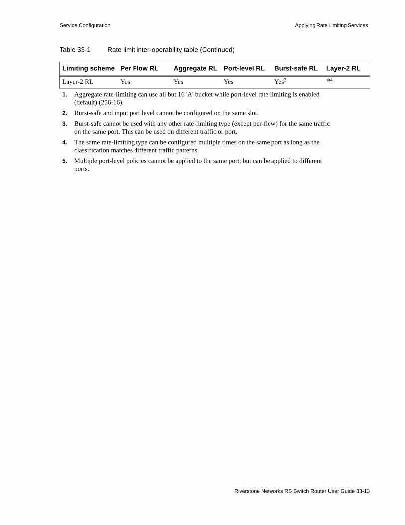
Service Configuration Applying Rate Limiting Services
Layer-2 RL Yes Yes Yes Yes3 *4
1. Aggregate rate-limiting can use all but 16 'A' bucket while port-level rate-limiting is enabled (default) (256-16).
2. Burst-safe and input port level cannot be configured on the same slot.3. Burst-safe cannot be used with any other rate-limiting type (except per-flow) for the same traffic
on the same port. This can be used on different traffic or port.4. The same rate-limiting type can be configured multiple times on the same port as long as the
classification matches different traffic patterns.5. Multiple port-level policies cannot be applied to the same port, but can be applied to different
ports.
Table 33-1 Rate limit inter-operability table (Continued)
Limiting scheme Per Flow RL Aggregate RL Port-level RL Burst-safe RL Layer-2 RL
Riverstone Networks RS Switch Router User Guide 33-13

Rate Shaping Services Service Configuration
33.3 RATE SHAPING SERVICESThe Service facility provides rate shaping on inbound traffic. Rate shaping differs from rate limiting in that rate shaping uses the port priority queues, which enables rate shaping to perform a certain amount of buffering. Like burst-safe rate limiting, rate shaping allows flows to exceed their committed bandwidth up to the burst rate when excess queue space is available. By doing so, rate shaping allows ports to be somewhat over subscribed and still provide adequate throughput. Of course, this is based on the assumption that not all connections will be running at the committed rate and/or bursting at the same time.
Note Rate shaping is supported only on line cards that contain 5th generation ASICs.
A rate shaping service is defined by the following:• Rate – The guaranteed (committed) bit rate for traffic identified by the filter criteria• Burst – The burst rate is a bit rate that exceeds the committed bit rate. If a queue of a particular
priority is empty, traffic using other priority queues can borrow the empty queue’s space. The extra (borrowed) queue space allows the specified traffic to increase its bit rate until it reaches its designated burst rate.
A Rate shaping service is applied to a port or interface by specifying the following:• Port – The input port on which the rate shaping is to take place.• Queue – One of the four internal priority queues. The queues are identified as low, medium, high,
and control.
33.4 APPLYING RATE SHAPING SERVICESA rate shaping service is applied to a port by performing the following steps:1. Use the service <name> create rate-shape input rate <number> burst <number>
command to create the rate shaping service.2. Use the service <name> apply rate-shape port <port-list> queue <queue-name>
command to apply the previously created rate shaping service to an input port queue.
At this point, the rate shaping service has been applied to a port and a queue has been selected. Rate shaping will now occur on traffic arriving on that port and in that queue. However, there is no way to guarantee that the traffic we want to rate shape will arrive in the specified queue. To accurately specify the traffic to be rate shaped, additional identifying parameters are needed. These additional parameters are obtained by associating the rate shaping service with a Quality of Service (QoS) profile using the qos set command.
3. Use the qos set ip command to define a layer-3 or layer-4 QoS profile and associate it with the queue on which the rate shaping service is applied. Use the qos set l2 command to define a layer-2 QoS profile and associate it with the queue that the rate shaping service is applied on.
33.4.1 Associating a Rate Shaping Service with a QoS Profile
Depending on the type of traffic to be rate shaped (layer-2, layer-3, or layer-4), certain prerequisites must be observed. The following is a list of these prerequisites for each type of traffic
33-14 Riverstone Networks RS Switch Router User Guide
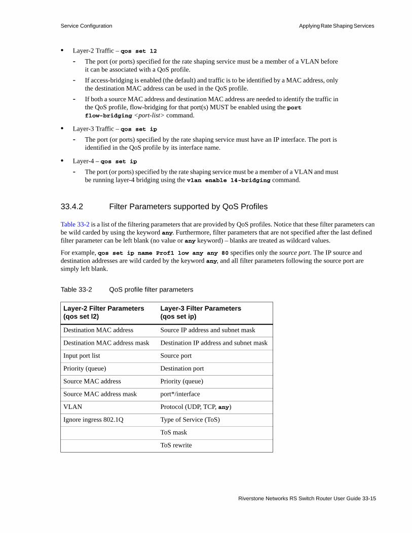
Service Configuration Applying Rate Shaping Services
• Layer-2 Traffic – qos set l2- The port (or ports) specified for the rate shaping service must be a member of a VLAN before
it can be associated with a QoS profile.- If access-bridging is enabled (the default) and traffic is to be identified by a MAC address, only
the destination MAC address can be used in the QoS profile.- If both a source MAC address and destination MAC address are needed to identify the traffic in
the QoS profile, flow-bridging for that port(s) MUST be enabled using the port flow-bridging <port-list> command.
• Layer-3 Traffic – qos set ip- The port (or ports) specified by the rate shaping service must have an IP interface. The port is
identified in the QoS profile by its interface name.
• Layer-4 – qos set ip- The port (or ports) specified by the rate shaping service must be a member of a VLAN and must
be running layer-4 bridging using the vlan enable l4-bridging command.
33.4.2 Filter Parameters supported by QoS Profiles
Table 33-2 is a list of the filtering parameters that are provided by QoS profiles. Notice that these filter parameters can be wild carded by using the keyword any. Furthermore, filter parameters that are not specified after the last defined filter parameter can be left blank (no value or any keyword) – blanks are treated as wildcard values.
For example, qos set ip name Prof1 low any any 80 specifies only the source port. The IP source and destination addresses are wild carded by the keyword any, and all filter parameters following the source port are simply left blank.
Table 33-2 QoS profile filter parameters
Layer-2 Filter Parameters(qos set l2)
Layer-3 Filter Parameters(qos set ip)
Destination MAC address Source IP address and subnet mask
Destination MAC address mask Destination IP address and subnet mask
Input port list Source port
Priority (queue) Destination port
Source MAC address Priority (queue)
Source MAC address mask port*/interface
VLAN Protocol (UDP, TCP, any)
Ignore ingress 802.1Q Type of Service (ToS)
ToS mask
ToS rewrite
Riverstone Networks RS Switch Router User Guide 33-15

Applying Rate Shaping Services Service Configuration
33.4.2.1 Applying Rate Shaping and QoS Profiles to Layer-3 Traffic
The following is an example configuration for rate shaping layer-3 traffic on a Gigabit Ethernet port (gi.9.1), which contains the interface gig1. Rate shaping will be performed on inbound packets from the 100.10.10.0 subnet. The rate is set to 10 Mbps, the burst is 15 Mbps, and the high priority queue is used.
Notice in the example above that both the port (identified by its interface) and the queue specified within the qos set ip command must be the same port and queue that was specified when the rate shaping service was applied.
ToS precedence rewrite
* If port is specified, it must be in a VLAN and layer-4 bridging must be enabled.
For layer-3 rate shaping, create an interface on the portinterface create ip gig1 address-netmask 100.10.10.1/24 port gi.9.1
Define the rate shaping serviceservice rs1 create rate-shape input rate 10000000 burst 15000000
Apply the rate shaping service to a port and specify the priority queueservice rs1 apply rate-shape port gi.9.1 queue high
Associate a layer-3 QoS profile to the rate shaping serviceqos set ip name qos1 high 100.10.10.0/24 any any any any gig1
Table 33-2 QoS profile filter parameters (Continued)
Layer-2 Filter Parameters(qos set l2)
Layer-3 Filter Parameters(qos set ip)
33-16 Riverstone Networks RS Switch Router User Guide
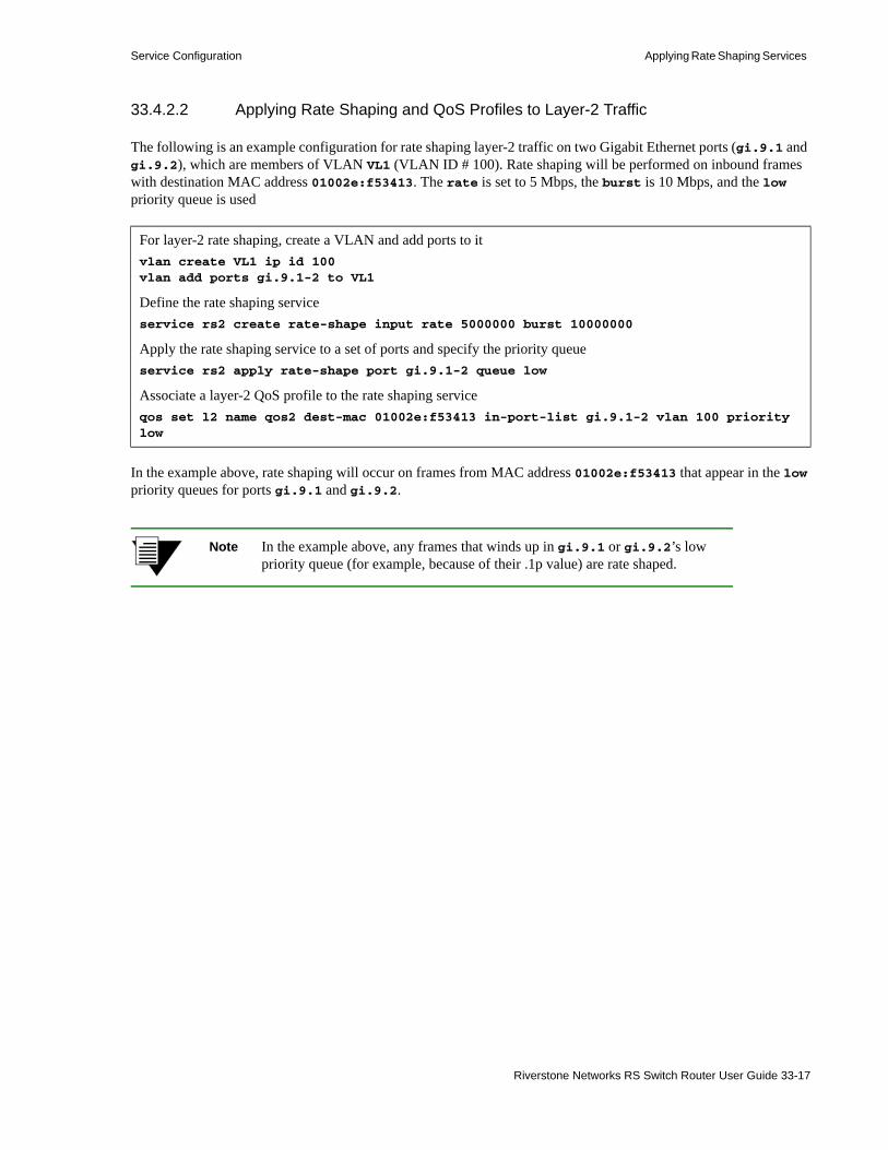
Service Configuration Applying Rate Shaping Services
33.4.2.2 Applying Rate Shaping and QoS Profiles to Layer-2 Traffic
The following is an example configuration for rate shaping layer-2 traffic on two Gigabit Ethernet ports (gi.9.1 and gi.9.2), which are members of VLAN VL1 (VLAN ID # 100). Rate shaping will be performed on inbound frames with destination MAC address 01002e:f53413. The rate is set to 5 Mbps, the burst is 10 Mbps, and the low priority queue is used
In the example above, rate shaping will occur on frames from MAC address 01002e:f53413 that appear in the low priority queues for ports gi.9.1 and gi.9.2.
Note In the example above, any frames that winds up in gi.9.1 or gi.9.2’s low priority queue (for example, because of their .1p value) are rate shaped.
For layer-2 rate shaping, create a VLAN and add ports to itvlan create VL1 ip id 100vlan add ports gi.9.1-2 to VL1
Define the rate shaping serviceservice rs2 create rate-shape input rate 5000000 burst 10000000
Apply the rate shaping service to a set of ports and specify the priority queueservice rs2 apply rate-shape port gi.9.1-2 queue low
Associate a layer-2 QoS profile to the rate shaping serviceqos set l2 name qos2 dest-mac 01002e:f53413 in-port-list gi.9.1-2 vlan 100 priority low
Riverstone Networks RS Switch Router User Guide 33-17

Advanced Rate Shaping Service Configuration
33.5 ADVANCED RATE SHAPINGThe Advanced Services Module (ASM) is a 1-slot, 2-port Gigabit Ethernet line card for the RS 1000, RS 1100, RS 3000, RS 3100, RS 3200, RS 8000 and RS 8600 platforms. The ASM supports all standard GBICs offered on the RS Ethernet Router platform. In addition, the ASM is MPLS-enabled and significantly increases the scalability of the RS Ethernet Router’ MPLS support. The ASM line cards also provide the ability to perform rate-shaping in hardware on both the ingress and egress of the ports. This hardware rate-shaping uses the line card’s Context Addressable Memory (CAM) as well as memory buffers contained in on-card memory.
Note The RS 1000 can only be configured with one ASM.
Note For basic rate-shaping concepts, see 33.3 "Rate Shaping Services." For specific information on WRED see 28.7 "Weighted Random Early Detection (WRED)."
ASM line cards have the following features and benefits:• 256 shapers for ingress & egress• 32 Mbytes per-port per-direction• CAM with 16k entries for rate-shaper classifiers• WRED on each shaper• Separate drop weights configurable for each port – based on 802.1P or ToS-precedence• Groups for shapers or individual shapers• Express-lane per-port in each direction• Default queue per-port in each direction• Configurable buffer size for each shaper• CAR rate and burst rate• Exceed-actions – based on ToS byte, ToS-precedence, DSCP, or EXP bit rewrite• Statistics for each queue and WRED instance• Configurable priorities (4) per queue• Jumbo frame support - Jumbo frames sizes up to 9000 bytes are supported• Additional filtering based on ACL, VLAN, 802.1P, MPLS label, and port-of-entry (POE)
Each shaper can be individually configured into one of three modes:• Single-rate Shaping – Rate-shapers configured with only a Committed Access Rate (CAR)• Dual-rate Shaping – Rate-shapers configured with a CAR and a burst size• Shaper Groups – rate-shapers, each with a CAR, are aggregated into a group. The rate assigned to
the group acts as the collective burst-size for the rate-shapers within the group.
33-18 Riverstone Networks RS Switch Router User Guide

Service Configuration Advanced Rate Shaping
33.5.1 Configuring ASM Rate-shapers
The process of configuring ASM rate-shapers is basically a four-part operation. The following bulleted list describes these basic steps.
Note All of the steps for creating and applying an ASM rate-shaper are performed in configure mode.
• Enable the ACL-CAM facility for each port on which an ASM rate-shaper will reside.• If necessary, create any ACL, WRED profile, or VLAN to be used to classify traffic for the ASM
rate-shaper• Create the rate-shaper by specifying a Committed Access Rate (CAR), and, optionally, by specifying
a burst rate and buffer size.- In this step, ToS-byte, ToS-precedence, DSCP, and EXP rewrites can be assigned to the
rate-shaper• Apply the rate-shaper to a port by specifying a port number, whether to affect input or output traffic,
and an additional traffic classifier (if necessary).- Traffic classifiers provide additional information for identifying traffic to be rate-shaped. This
is explained further in the33.5.1.3"Traffic Classifiers" section.
The following is an example of creating and applying a simple rate-shaper. Later in this section, burst rates, buffer sizes, bit-rewrites, and special classifiers are discussed.
For this example, a rate-shaper is assigned to port gi.11.1, the CAR is set to 1,000,000 bps, and the rate-shaper is assigned to output traffic.
First, the hardware ACL-CAM capabilities are enabled on port gi.11.1:
Next, create the rate-shaper – in this example, called “rate1”:
Finally, the rate-shaper is applied to the output of port gi.11.1. Notice that the port-of-entry (PoE) is used as a classifier to identify the traffic on which the rate-shaper should act:
All traffic coming from the PoE of et.4.3 and going out gi.11.1 is rate-shaped.
Notice in the step above if the port-of-entry classifier was left out, the rate-shaper would simply rate-shape all traffic going out of port gi.11.1.
rs(config)# port enable acl-cam ports gi.11.1
rs(config)# service rate1 create rate-shape asm rate 1000000
rs(config)# service rate1 apply rate-shape asm port-of-entry et.4.3 port gi.11.1 output
Riverstone Networks RS Switch Router User Guide 33-19

Advanced Rate Shaping Service Configuration
Note More than one rate-shaper can be applied to a port, as long as each rate-shaper is differentiated by input, output, and a unique classifier (if necessary).
Note The ASM rate-shape create parameter, “lsp-signal” allows LSPs affected by this rate-shaper to override the configured burst rate or group rate.
33.5.1.1 Rate-Shapers with Different Rates
When applying multiple ASM rate-shapers to a port, each rate-shaper can have a unique CAR. For example, one rate-shaper could have a CAR or 106 bps, while another rate-shaper on the same port could have a CAR of 107 bps. If the rate-shapers’ priorities are equal, each rate-shaper is allowed to send traffic at a rate equivalent of the CAR as a percentage of the total throughput.
For example, two rate-shapers (r1 and r2) are assigned to a 1 gigabit port. The CAR of r1 is 107 bps and the CAR of r2 is 108 bps. Since 107 bps is 1% of the throughput and 108 bps is 10% of the throughput, for every bit sent by r1, 10-bits are sent by r2.
It is important to note that an ASM rate-shaper’s interaction with other ASM rate-shapers on the same port are affected by the rate-shapers’ priority settings and their configured burst-sizes. See 33.5.1.5"Queues and Priorities" and 33.5.1.6"Burst Rates" for more information on these topics.
Exceeding Throughput
Notice that the total of all CARs in either the input or output direction cannot exceed the possible throughput of the line card (109 bps).
For example, the following attempts to apply two rate-shapers to the output of port gi.11.1, where the collective CARs of the rate-shapers exceeds the throughput for port gi.11.1:
rs(config)# service r4 create rate-shape asm rate 1000000000rs(config)# service r5 create rate-shape asm rate 10000000
rs(config)# service r4 apply rate-shape asm port gi.11.1 output
%SVC-I-SERVICE_PORT, Service 'r4' has been successfully attached to ports 'gi.11.1'
rs(config)# service r5 apply rate-shape asm port gi.11.1 output port-of-entry gi.11.2
%CLI-E-FAILED, Execution failed for "service r5 apply rate-shape asm port gi.11.1 output port-of-entry gi.11.2" %SVC-E-ATSRATE, The rates of the shapers applied on the output of port 'gi.11.1' exceeds port throughput
33-20 Riverstone Networks RS Switch Router User Guide

Service Configuration Advanced Rate Shaping
Notice that aside from their CARs, the definitions of r4 and r5 allow both rate-shapers to coincide on port gi.11.1 because r4 specifies output traffic, while r5 specifies output traffic and the additional traffic classifier: “entered the RS Ethernet Router through port gi.11.2.” However, since r4’s CAR (109 bps) plus r5’s CAR (107 bps) exceeds the throughput of gi.11.1, applying both rate-shapers fails, and the error messages above are displayed.
33.5.1.2 Bit Value Rewrites
When creating an ASM rate-shaper, several rewrite capabilities are provided to allow the various precedence indicators of packets to be changed. Table 33-3 lists these rewrite capabilities:
Notice that the only difference between the first five and the last five rewrite capabilities is the word “CAR.” The concept here is that those rewrite capabilities without the word CAR perform their rewrite operations for conforming traffic. While the rewrite capabilities containing the word “CAR” go into effect only after traffic has bursted above the CAR rate.
A rewrite option and it’s “CAR” counterpart can be included within the same rate-shaper. For example, the following ASM rate-shaper (rate3) rewrites the ToS value while the traffic rate is both below and above the CAR rate:
To view the rewrite parameters set for the rate-shaper, use the service show rate-shape asm command from Enable mode:
Table 33-3 Packet rewrite capabilities
Rewrite Capability Meaning
car-exp-rewrite Rewrite the MPLS EXP value for packets exceeding the CAR rate
car-one-p-rewrite Rewrite the 802.1P value for packets exceeding the CAR rate
car-tos-dscp-rewrite Rewrite the ToS DSCP value for packets exceeding the CAR rate
car-tos-prec-rewrite Rewrite the ToS precedence value for packets exceeding the CAR rate
car-tos-rewrite Rewrite the ToS value for packets exceeding the CAR rate
exp-rewrite Rewrite the MPLS EXP value for all packets that match this profile
one-p-rewrite Rewrite the 802.1 value for all packets that match this profile
tos-dscp-rewrite Rewrite the ToS DSCP value for all packets that match this profile
tos-prec-rewrite Rewrite the ToS precedence value for all packets that match this profile
tos-rewrite Rewrite the ToS value for all packets that match this profile
rs(config)# service rate3 create rate-shape asm tos-rewrite 34 car-tos-rewrite 54 rate 1000000 burst 20000
rs# service show rate-shape asm rate3Service Name Rate Burst Buffer Rewrite Action--------------- ---------- ---------- --------------- ------------------------rate3 1000000 1020000 100ms ( 32K) TOS Byte ( 34/ 54)
Riverstone Networks RS Switch Router User Guide 33-21

Advanced Rate Shaping Service Configuration
Notice that the last column shows the type of rewrite and both the pre and post rewrite values.
Note If two rewrite options are being used within the same rate-shaper, they must be the same type. For example, tos-rewrite and car-tos-rewrite can be used within the same rate-shaper, but tos-rewrite and car-exp-rewrite cannot.
DSCP Rewrites
Of the possible rewrite options, the DSCP (Differentiated Services) rewrite option is the least straightforward and uses several coded presets. For this reason, the DSCP rewrite option requires additional explanation.
Differentiated Services (DiffServ) uses the six left-most bits of the ToS byte to define Differentiated Services Code Point (DSCP) values.
The DiffServ bits are arranged as follows within the ToS byte:
The following three bits are used to specify class parameters: delay, throughput, and reliability.
DS5 DS4 DS3 DS2 DS1 DS0 NU* NU*
NU* = not used
Table 33-4 Left-most DiffServ bits and their precedence
Bits Pattern Precedence
111 precedence 7
110 precedence 6
101 precedence 5
100 precedence 4
011 precedence 3
010 precedence 2
001 precedence 1
000 precedence 0
Table 33-5 Right-most DiffServ bits
Bits Position Meaning
bit 3 Delay: 0 = normal, 1 = high
bit 4 Throughput: 0 = normal, 1 = high
bit 5 Reliability: 0 = normal, 1 = high
33-22 Riverstone Networks RS Switch Router User Guide

Service Configuration Advanced Rate Shaping
Note The last two bits of the byte are not used in the DSCP context, and are ignored.
The values specified for both car-tos-dscp-rewrite and tos-dscp-rewrite are predefined Per-Hop Behavior (PHB) code points.
For example, entering the service rate4 create rate-shape asm tos-dscp-rewrite command with a question mark displays the following list:
Table 33-6 displays the names and bit patterns for each PHB, as well as the effect they have on packets.
rs(config)# service rate4 create rate-shape asm tos-dscp-rewrite ?[tos-dscp-rewrite] requires a value of one of these types: number - Value between 0 and 63, inclusive [keyword] - One of the following keywords: AF11 - DSCP AF11 (001010) AF12 - DSCP AF12 (001100) AF13 - DSCP AF13 (001110) AF21 - DSCP AF21 (010010) AF22 - DSCP AF22 (010100) AF23 - DSCP AF23 (010110) AF31 - DSCP AF31 (011010) AF32 - DSCP AF32 (011100) AF33 - DSCP AF33 (011110) AF41 - DSCP AF41 (100010) AF42 - DSCP AF42 (100100) AF43 - DSCP AF43 (100110) CS0 - DSCP CS0 (000000) CS1 - DSCP CS1 (001000) CS2 - DSCP CS2 (010000) CS3 - DSCP CS3 (011000) CS4 - DSCP CS4 (100000) CS5 - DSCP CS5 (101000) CS6 - DSCP CS6 (110000) CS7 - DSCP CS7 (111000) EF-PHB - DSCP EF-PHB (101110)
Table 33-6 PHB code point values
PHB Name Bit Pattern Behavior
AF111 001010 Low Drop Probability
AF12 001100 Medium Drop Probability
AF13 001110 High Drop Probability
AF21 010010 Low Drop Probability
AF22 010100 Medium Drop Probability
AF23 010110 High Drop Probability
AF31 011010 Low Drop Probability
Riverstone Networks RS Switch Router User Guide 33-23

Advanced Rate Shaping Service Configuration
AF32 011100 Medium Drop Probability
AF33 011110 High Drop Probability
AF41 100010 Low Drop Probability
AF42 100100 Medium Drop Probability
AF43 100110 High Drop Probability
CS02 000000 The default BHP.
CS1 001000 Precedence 1
CS2 010000 Precedence 2
CS3 011000 Precedence 3
CS4 100000 Precedence 4
CS5 101000 Precedence 5
CS6 110000 Precedence 6
CS7 111000 Precedence 7
EF-PHB 101110 Expedited Forwarding
Can be used to build a low jitter, low loss, low latency, assured bandwidth service through Diffserv domains. The EF-PHB acts like a point-to- point connection.
1 AF = Assured Forwarding2 CS = Class-Selector
CS values use only the precedence bits. The CS values are included primarily for backward compatibility with other IP precedence schemes.
Table 33-6 PHB code point values (Continued)
PHB Name Bit Pattern Behavior
33-24 Riverstone Networks RS Switch Router User Guide

Service Configuration Advanced Rate Shaping
33.5.1.3 Traffic Classifiers
When ASM rate-shapers are applied, two mandatory parameters must be specified. These parameters are the port number to which the rate-shaper is assigned and whether the rate-shaper affects incoming or outgoing (input/output) traffic. Additional parameters called traffic classifiers can be specified to further identify the traffic on which to act. Furthermore, traffic classifiers make it possible to assign more than one ASM rate-shaper to a port in the same direction (either input or output).
For example, a rate-shaper that uses an ACL as a traffic classifier that identifies traffic from a source address can coexist for the same direction on the same port with another rate shaper that uses an ACL containing a different source address.
Traffic Classifiers and Memory
As traffic enters an ASM rate-shaped port, a check is made through the CAM for traffic classifiers belonging to the port. If a classifier exists, a pointer is used to find the rate-shaper’s definition in context memory. Context memory also contains a pointer to the rate-shaper’s queue in port memory. Conversely, if traffic entering the rate shaped port finds no CAM entry, the traffic is passed directly to the default queue. The default queue handles all such traffic and has a burst size of 109 bps (see Figure 33-3).
Figure 33-3 Traffic classifiers and memory
rs(config)# acl source1 permit ip 100.10.10.1 any any anyrs(config)# acl source2 permit ip 200.10.10.1 any any any
rs(config)# service test1 create rate-shape asm rate 10000rs(config)# service test2 create rate-shape asm rate 1000000
rs(config)# service test1 apply rate-shape asm acl source1 port gi.11.1 inputrs(config)# service test2 apply rate-shape asm acl source2 port gi.11.1 input
CAM
Context Memory
Port Memory
Start of Queue in Memory
Pack
et
(Classifiers)
(Rate-shaper Definition)
CAM Hit
Pack
et
No CAM Hit
To Default Queue
Riverstone Networks RS Switch Router User Guide 33-25

Advanced Rate Shaping Service Configuration
Table 33-7 lists the traffic classifiers that can be specified when the rate-shaper is applied to a port.
Note If an ACL or a VLAN is to be used to classify traffic, it must already exist in the active configuration.
Note There are no precedence or priority differences between traffic classifiers.
In the following example, an ACL (source1) is created, which specifies a source address to be used as a traffic classifier for the ASM rate-shaper rate5:
In the example above, the ASM rate-shaper affects IP traffic with the source address 100.10.10.1 on port gi.11.1.
Table 33-7 ASM rate-shaper traffic classifiers
Classifier Meaning
acl Specify the ACL to classify the traffic
input Apply the rate shaper to the ingress traffic
lsp-name Specify MPLS LSP name to classify the traffic
one-p-priority Specify the IEEE 802.1P value to classify the traffic
output Apply the rate shaper to the egress traffic
port-of-entry Apply the output rate shaper to traffic from the specified input port
vlan Specify VLAN number to classify the traffic
rs(config)# port enable acl-cam ports gi.11.1rs(config)# acl source1 permit ip 100.10.10.1 any any anyrs(config)# service rate5 create rate-shape asm rate 1000000 burst 20000rs(config)# service rate5 apply rate-shape asm acl source1 port gi.11.1 input
33-26 Riverstone Networks RS Switch Router User Guide

Service Configuration Advanced Rate Shaping
Use the service show rate-shape asm command with the applied option to view how the rate-shapers are applied. In the example below, notice that the classifiers are displayed and, in this case, the classifier for the rate-shaper rate5 is the ACL source1.
Note A special classifier exists within the classifier list, named “express-lane.” The express-lane is a special queue that is never rate-shaped, and is used for control information (such as PDUs). Use this classifier to designate this rate-shaper as the express-lane for all traffic on a port for the specified direction (input or output).
33.5.1.4 Setting Buffers
Whenever a rate-shaper is created, a queue for buffering is created automatically. The default buffering size of any queue is 100 milliseconds. The buffer size can be changed by specifying an alternate buffer size while creating the ASM rate-shaper.
For example, the following creates a rate-shaper called rate2 with a rate of 106 bps and a queue size of 200 milliseconds:
To see the sizes of the buffers used by rate-shapers, enter the service show rate-shape asm command from Enable mode:
rs# service show rate-shape asm rate5 applied
Service Name Rate Burst Buffer Rewrite Action--------------- ---------- ---------- --------------- ------------------------rate5 1000000 1020000 100ms ( 12K) None ( 0/ 0)
Ports : gi.11.1 Type : Input ACL Name : source1 Group Name : (2) None Priority : D POE : None VLAN : any 802.1P : any Packet In : 0 Byte In : 0 Packet Out : 0 Byte Out : 0 Packet Drop : 0 Byte Drop : 0 Packet Exceed : 0 Queue Used : 0%
rs(config)# service rate2 create rate-shape asm rate 1000000 buffer 200
rs# service show rate-shape asm allService Name Rate Burst Buffer Rewrite Action--------------- ---------- ---------- --------------- ------------------------rate1 1000000 1000000 100ms ( 12.5K) None ( 0/ 0)Service Name Rate Burst Buffer Rewrite Action--------------- ---------- ---------- --------------- ------------------------rate2 1000000 1000000 200ms ( 25K) None ( 0/ 0)
Riverstone Networks RS Switch Router User Guide 33-27

Advanced Rate Shaping Service Configuration
Notice the difference between the buffer size of the rate-shaper that was created for rate1 (100 ms), and the buffer size created for rate2 (200 ms).
Typically, it is not necessary to alter the buffer size. The default buffer size has been calculated to work with most traffic situations. There are, however, two exceptions in which an altered buffer size can help performance. Each of these exceptions are related to network congestion.
For data traffic, if the CAR is set high and the network has congestion problems, a larger buffer may be required to avoid losing packets. This type of packet loss is known as “tail-drop.”
For voice and video traffic, a smaller buffer may work better during congestion. The concept is that it’s better to drop a word that can be repeated than to experience delay within a conversion. In this case, setting the buffer smaller may increase the chances of tail-drop, but reduces the chances of delay.
Calculating Buffer Size in Memory
While buffer size is specified in milliseconds, the length of time for a buffer is dependent upon how much memory is used by the queue. Because of this relationship between buffer time and memory, rate-shapers with different rates may need more or less memory to provide the same amount of buffering time.
For example if we create a rate-shaper called test that has a rate of 109 bps, more memory will be required to provide the same default 100 milliseconds of buffering:
Notice that the rate-shaper test requires 1.25 megabytes of memory to provide the same 100 milliseconds of buffering.
To calculate the number of bytes of memory used for a particular buffer size, use the following equation:
Where:
t = Buffer size in millisecondsr = Committed Access Rate in bits-per secondb = Bytes required to create the buffer
For example, using a buffer of 200 milliseconds and a CAR of 1000000 bps, the following calculation gives the number of bytes required for the buffer:
rs(config)# service test create rate-shape asm rate 1000000000
rs# service show rate-shape asm allService Name Rate Burst Buffer Rewrite Action--------------- ---------- ---------- --------------- ------------------------rate1 1000000 1000000 100ms ( 12.5K) None ( 0/ 0)Service Name Rate Burst Buffer Rewrite Action--------------- ---------- ---------- --------------- ------------------------rate2 1000000 1000000 200ms ( 25K) None ( 0/ 0)Service Name Rate Burst Buffer Rewrite Action--------------- ---------- ---------- --------------- ------------------------test 1000000000 1000000000 100ms ( 12500K) None ( 0/ 0)
t r×8000------------ b=
200 1000000×8000
------------------------------------ 25000=
33-28 Riverstone Networks RS Switch Router User Guide

Service Configuration Advanced Rate Shaping
In this case, the number of bytes required is 25 Kilobytes.
Note Each set of 256 shapers (in each direction of each port) has 32 MB of packet buffer attached to it. Using the formula described in this section, you should set the buffering as indicated by your traffic patterns.
33.5.1.5 Queues and Priorities
Typically, if multiple rate-shapers with identical CARs and priorities are applied to a port, the rate-shapers deals with traffic in a “round-robin” fashion. This occurs regardless of the rate-shaper classifiers, which do not bestow any special priority.
However, one classifier, priority, determines in what order and rate each rate-shaper handles its traffic during times of congestion. There are four levels of priority, denoted by the letters A through D, where A is the highest priority and D is the lowest. Note here, that if there is no congestion, the rate-shapers use the standard round-robin technique for handling traffic.
For example, three VLANs (v1, v2, and v3) are created and assigned to a trunk port (gi.11.1). Three rate-shapers are created and applied to gi.11.1 such that incoming traffic from v1 has the highest priority, incoming traffic from v2 has the next highest priority, and v3 has the lowest priority. If the RS Ethernet Router becomes congested, traffic from VLAN v1 is favored over traffic from either VLANs v2 or v3, and traffic from VLAN v2 is favored over traffic from v3 (see the following configuration example):
Note The ASM can support the following number of shapers per priority:- Up to 254 shapers can be configured with priority A- Up to 128 shapers can be configured with priority B- Up to 128 shapers can be configured with priority C- Up to 128 shapers can be configured with priority D
rs(config)# vlan create v1 ip id 100rs(config)# vlan create v2 ip id 200rs(config)# vlan create v3 ip id 300
rs(config)# vlan make trunk-port gi.11.1
rs(config)# vlan add ports gi.11.1 to v1rs(config)# vlan add ports gi.11.1 to v2rs(config)# vlan add ports gi.11.1 to v3
rs(config)# service r1 create rate-shape asm rate 1000000rs(config)# service r2 create rate-shape asm rate 1000000rs(config)# service r3 create rate-shape asm rate 1000000
rs(config)# service r1 apply rate-shape asm port gi.11.1 vlan 100 input priority ars(config)# service r2 apply rate-shape asm port gi.11.1 vlan 200 input priority brs(config)# service r3 apply rate-shape asm port gi.11.1 vlan 300 input priority c
Riverstone Networks RS Switch Router User Guide 33-29

Advanced Rate Shaping Service Configuration
Figure 33-4 shows how rate-shapers with different priorities behave as the RS Ethernet Router becomes congested.
Figure 33-4 Priorities and rate-shaper behavior
Number of Queues for Priorities
When assigning priorities to ASM rate-shapers, the following explains queue allocations for each port:• The “express lane” for a port is restricted to one queue (queue 0 in memory).• The default queue for a port is restricted to one queue (queue 1 in memory)• For low or high priorities (D and B), a port is restricted to 125 queues (queues 2-127 in memory)• For medium priorities (C), a port is restricted to 127 queues (queues 128-255 in memory)• For control priorities (A), a port can have 254 queues (queues 2-255 in memory)
Priority = A B Cr1 r2 r3
Priority = Priority =
Priority = A B Cr1 r2 r3
Priority = Priority =
No congestion
3
1
2
First, r1 drains its queueuntil its CAR is met.
Next, r1 and r2 drain theirqueues until theircollective CARs aresatisfied.
Finally, r3 gets to participateuntil all three CARs arereached.
Congestion starts
Queues are dealt with in round-robin fashion.
1
2
2
3
3
3
When queues haveunequal priority, andcongestion occurs:
33-30 Riverstone Networks RS Switch Router User Guide

Service Configuration Advanced Rate Shaping
33.5.1.6 Burst Rates
When creating an ASM rate-shaper, along with the CAR and buffer size a burst-rate can be configured. The burst-rate is the number of bits per second that a rate-shaper can send in excess of its CAR, provided that the CARs of all rate-shapers on the port have been met and there is still additional bandwidth available with respect to the port’s total throughput.
For example, the following creates a rate-shaper that has a CAR of 106 bps and can burst to an additional 80,000 bps provided all CARs on the port to which it becomes assigned are first met and there is still available bandwidth:
To view CARs and burst-rates of ASM rate-shapers, enter the following:
In this case, there are three rate-shapers defined on this RS Ethernet Router (rate1, rate2, and rate3). Notice that each rate-shaper has an additional amount burst bandwidth.
Note that once all CARs for all ASM rate-shapers on a port are satisfied and the rate-shapers are allowed to burst, the algorithm that determines how the remaining throughput is apportioned for bursting is identical to the algorithm used to determine how multiple CARs on the same port use the port’s throughput. The burst algorithm determines burst traffic transmission by rate-shaper priority and percentage of total throughput.
Burst-Rate Example
When using burst-rates, the algorithm allows the first rate-shaper to send its CAR. The algorithm then moves on to the next rate-shaper and allows it to send its CAR and so on, until all 256 (possible) rate-shapers have sent their CAR. If there is time left in the time slot (i.e., the sum of the traffic sent as CAR was < 1 Gigabit), the algorithm returns to deal with each rate shaper that has a burst-rate. The algorithm inspects the queue for packets (the CAR and burst-rate share the same queue). If any packets are present, the algorithm transmits them as long as the total traffic sent by both the CAR and the burst-rate of the shaper does not exceed the port’s throughput.
For example, assume that the time interval for scheduling is 1 second. ASM rate-shaper Shape1 is configured as having a CAR = 600 Mbps, and no burst-rate. ASM rate-shaper Shape2 is configured with a CAR = 400 Mbps and a burst-rate = 800 Mbps.
In the first interval:• Shape1’s queue is filling up at 600 Mbps – It sends out 600 Mbits of CAR and nothing more• Shape2’s queue is filling up at 800 Mbps – It sends out 400 Mbits of CAR; it cannot send out any
more because there is no excess bandwidth available
In the second interval:
rs(config)# service rate1 create rate-shape asm rate 1000000 burst 80000
rs# service show rate-shape asm allService Name Rate Burst Buffer Rewrite Action--------------- ---------- ---------- --------------- ------------------------rate1 1000000 1080000 100ms ( 12K) None ( 0/ 0)Service Name Rate Burst Buffer Rewrite Action--------------- ---------- ---------- --------------- ------------------------rate2 1000000 1050000 100ms ( 12K) None ( 0/ 0)Service Name Rate Burst Buffer Rewrite Action--------------- ---------- ---------- --------------- ------------------------rate3 5000000 5030000 100ms ( 62K) None ( 0/ 0)
Riverstone Networks RS Switch Router User Guide 33-31

Advanced Rate Shaping Service Configuration
• Shape1’s queue is filling up at 100 Mbps – It sends out only 100 Mbits of CAR, and 500 Mbits is unused
• Shape2’s queue is filling up at 1000 Mbps – It sends out 400 Mbits of CAR. Since Shape1 did not use all of its CAR, there is 500 Mbps of excess bandwidth remaining. However, Shape2 cannot use all 500Mbps of the remaining bandwidth; it is allowed to burst only up to 800 Mbps, and so its sends out 400 Mbits to reach its burst-rate and then stops.
In the second time interval, Shape2 sent 400 Mbps of CAR and another 400 Mbits of burst-rate to reach its peak of 800 Mbps
33.5.1.7 Rate-Shape Groups
Rate-shape groups are used to collectively assign a set of rate-shapers to be associated with a unique entity, such as a customer or set of users. For example, a customer needs 106 bps for data traffic and 104 bps for voice traffic. In this case, notice that voice and data require significantly different rate-shape handling, and each will each require its own rate-shaper. Groups, however, allow the creation of an association between these rate-shapers that identifies them for the same customer, and provides a common burst-rate for both rate-shapers.
Note One to 8 rate-shapers can be grouped together in a shaper group and up to 128 shaper groups can be configured in each direction of each port.
Assume that traffic for this customer is on VLAN 100. The following shows how the rate shapers and group are created and applied.1. Create the ASM rate-shaper for data traffic
Because rate-shaper r1 is used for data, it can handle the delay that might come with a slightly larger buffer, which is set to 150 milliseconds.2. Create the ASM rate-shaper for voice traffic:
Because rate-shaper r2 is used for voice, it requires a smaller buffer to avoid delay in the signal; the buffer is set to 50 milliseconds.3. Create the ASM group, “customer1” to which r1 and r2 will be applied:
Use the service show rate-shape asm-group command from Enable mode to view the group and its group rate:
rs(config)# service r1 create rate-shape asm rate 1000000 buffer 150
rs(config)# service r2 create rate-shape asm rate 10000 buffer 50
rs(config)# service customer1 create rate-shape asm-group rate 10000000
rs# service show rate-shape asm-group customer1
Service Name Rate--------------- ----------customer1 10000000
33-32 Riverstone Networks RS Switch Router User Guide

Service Configuration Advanced Rate Shaping
Note Individual rate-shaper burst-rates become inactive when applied to a group. The group rate acts as a collective burst-rate for the rate-shapers. In the example in step 3 (above), the group rate (collective burst-rate) is set to 107 bps.
4. Assign the ASM rate-shapers to the ASM group:
Notice that the traffic that each rate-shaper is responsible for is defined by its 802.1P priority within VLAN 100.
Use the to service show asm rate-shape all applied command from Enable mode to see the rate-shapers contained within each ASM group. For example:
In the example above, notice that rate-shapers r1 and r2 are shown as belonging to ASM group customer1, and that each rate shaper has a different 802.1P priority. Also notice that the burst rate shown for each rate-shaper does not reflect their burst rate within the ASM group. While working as a member of group customer1, the rate-shaper’s burst rate is the ASM group rate (107 bps in this case).
rs(config)# service r1 apply rate-shape asm asm-group customer1 output one-p-priority 1 port gi.11.1 vlan 100rs(config)# service r2 apply rate-shape asm asm-group customer1 output one-p-priority 7 port gi.11.1 vlan 100
rs# service show rate-shape asm all appliedService Name Rate Burst Buffer Rewrite Action--------------- ---------- ---------- --------------- ------------------------r1 1000000 1000000 150ms ( 18K) None ( 0/ 0)
Ports : gi.11.1 Type : Input ACL Name : r1_acl_5 Group Name : (2) customer1 Priority : D POE : None VLAN : 100 802.1P : 1 Packet In : 0 Byte In : 0 Packet Out : 0 Byte Out : 0 Packet Drop : 0 Byte Drop : 0 Packet Exceed : 0 Queue Used : 0%
Service Name Rate Burst Buffer Rewrite Action--------------- ---------- ---------- --------------- ------------------------r2 10000 10000 50ms ( 2K) None ( 0/ 0)
Ports : gi.11.1 Type : Input ACL Name : r2_acl_5 Group Name : (2) customer1 Priority : D POE : None VLAN : 100 802.1P : 7 Packet In : 0 Byte In : 0 Packet Out : 0 Byte Out : 0 Packet Drop : 0 Byte Drop : 0 Packet Exceed : 0 Queue Used : 0%
Riverstone Networks RS Switch Router User Guide 33-33

Advanced Rate Shaping Service Configuration
Group-Rate Example
The following is an example of how rate-shapers within an ASM group interact with the group’s rate.• ASM rate-shapers Shape1 and Shape2 are assigned to the group Group1. Assume that the time
interval for scheduling is 1 second, and Shape1 has a CAR of 100 Mbps, Shape2 has a CAR of 150 Mbps, and Group1 has a Group Access Rate (GAR) of 300 Mbps
In the first interval:• Shape1’s queue is filling up at 100 Mbps – It sends out 100 Mbits of CAR and nothing more• Shape2’s queue is filling up at 200 Mbps – It sends out 150 Mbits of CAR
Therefore, the group GAR used by Group1 is 250 Mbps
In the second interval:• Shape1’s queue is filling up at 50 Mbps – It sends out 50 Mbits of CAR and 50 Mbits is unused• Shape2’s queue is filling up at 200 Mbps – It sends out 150 Mbits of CAR
Since Shape1 did not use all of its CAR, there is 50 Mbps of bandwidth remaining. Shaper2 sends out 50 Mbits to reach the GAR and then stops. So in the second time interval, Shape2 sent 150 Mbps of CAR and another 50 Mbits of excess traffic, leaving 250 Mbps unused.
33-34 Riverstone Networks RS Switch Router User Guide

Service Configuration Using The DiffServ MIB Module to Configure Services
33.6 USING THE DIFFSERV MIB MODULE TO CONFIGURE SERVICES
When you use the service commands to configure rate limiting, these commands create entries in the Rate Limit MIB tables. In addition, you can also configure rate limiting from an SNMP management station. To do so, you configure data paths using the Differentiated Services (DiffServ) MIB module (RFC 2475). Following is a list of the supported data paths:• DataPathStart->Classify->Meter• DataPathStart->Classify->Meter->Action• DataPathStart->Classify1->Meter->Action
- ->Classify2->Meter->Action- ->Classify3->Meter->Action- ->Classify4->Meter->Action
Following is a list of the DiffServ MIB module tables that are used:• diffServDataPathTable• diffServClfrTable• diffServClfrElementTable• diffServMeterTable• diffServActionTable• diffServDscpMarkAcTable
The data paths result in equivalent entries in the following Rate Limit MIB module (RSTONE-RL-MIB.txt) tables:• rsTBMeterTable• rsTBMeterApplyTable• rsPortRLTable
Once the entries in the Rate Limit MIB module tables are made, their corresponding service commands are added to the RS Ethernet Router configuration file. The following table lists the Rate Limit tables and their equivalent CLI service commands.
Table 33-8 Rate limit tables and their corresponding service commands
Rate Limit Table CLI command
rsTBMeterTable service <name> create rate-limit aggregate
service <name> create rate-limit burst-safe
service <name> create rate-limit flow-aggregate
service <name> create rate-limit per-flow
rsTBMeterApplyTable service <name> apply rate-limit acl
rsPortRLTable service <name> create rate-limit input-port-level
service <name> create rate-limit output-port-level
Riverstone Networks RS Switch Router User Guide 33-35
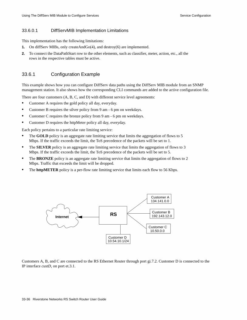
Using The DiffServ MIB Module to Configure Services Service Configuration
33.6.0.1 DiffServMIB Implementation Limitations
This implementation has the following limitations:1. On diffServ MIBs, only createAndGo(4), and destroy(6) are implemented. 2. To connect the DataPathStart row to the other elements, such as classifier, meter, action, etc., all the
rows in the respective tables must be active.
33.6.1 Configuration Example
This example shows how you can configure DiffServ data paths using the DiffServ MIB module from an SNMP management station. It also shows how the corresponding CLI commands are added to the active configuration file.
There are four customers (A, B, C, and D) with different service level agreements:• Customer A requires the gold policy all day, everyday.• Customer B requires the silver policy from 9 am - 6 pm on weekdays.• Customer C requires the bronze policy from 9 am - 6 pm on weekdays.• Customer D requires the httpMeter policy all day, everyday.
Each policy pertains to a particular rate limiting service: • The GOLD policy is an aggregate rate limiting service that limits the aggregation of flows to 5
Mbps. If the traffic exceeds the limit, the ToS precedence of the packets will be set to 1.• The SILVER policy is an aggregate rate limiting service that limits the aggregation of flows to 3
Mbps. If the traffic exceeds the limit, the ToS precedence of the packets will be set to 5.• The BRONZE policy is an aggregate rate limiting service that limits the aggregation of flows to 2
Mbps. Traffic that exceeds the limit will be dropped.• The httpMETER policy is a per-flow rate limiting service that limits each flow to 56 Kbps.
Customers A, B, and C are connected to the RS Ethernet Router through port gi.7.2. Customer D is connected to the IP interface custD, on port et.3.1.
RS
Customer A134.141.0.0
Customer C10.50.0.0
Customer B192.143.12.0
Customer D10.54.10.1/24
Internet
33-36 Riverstone Networks RS Switch Router User Guide

Service Configuration Using The DiffServ MIB Module to Configure Services
The following diagram illustrates the data path configuration for the rate liming services in the example:
ClfrId123
diffServClfrElementTable
MeterId SucceedNxt FailNxt Specific2 0ActionId.1 httpMeter3 0Actionid.2 gold4 0Actionid.3 silver
diffServMeterTable
diffServActionTable
ifIndexDirection PathStart14 inBound ClfrId.131 inBound Clfrid.23 outBound ActionId.3
diffServDataPathTable
diffServClfrTable polAclName ItemProtcol SrcIp DstIphttp-only 1 http any anycustomer-A 1 ip 134.141.0.0 anycustomer-B 1 ip 192.143.12.0anycustomer-C 1 ip 10.50.0.0 any
1 0dropPackets 02 0dscpMark.1 specific3 0dscpMark.5 specific
rsMeterId Type Rate BurstSize FailActionIgold aggregate 5000000 0 tosPrecReSilver aggregate 3000000 0 tosPrecRebronze aggregate 2000000 0 dropPackehttpMeter perFlow 56000 0 dropPacke
polACLTable
rsTBMeterTable
ifIndex ACL MeterId13 customer-A gold14 customer-B silver14 customer-C bronze21 http-only httpMeter
rsTBMeterApplyTable
1 1 MeterId.2 http-only1 2 MeterId.4 cust-B2 3 MeterId.3 cust-A
Data Path Tables Parameter Table
Riverstone Networks RS Switch Router User Guide 33-37

Using The DiffServ MIB Module to Configure Services Service Configuration
Following is the initial configuration of the router:
rs(config)# showRunning system configuration: ! ! Last modified from SNMP on 2001-07-18 13:41:36 !1: snmp set community public privilege read-write 2 : vlan create customer id 50 ip 3 : vlan enable l4-bridging on customer 4 : vlan add ports gi.7.1 to customer 5 : vlan add ports gi.7.2 to customer ! 6 : interface create ip custD address-netmask 10.54.10.1/24 port et.3.1 7 : interface add ip en0 address-netmask 10.50.7.1/24 ! 8 : acl http-only permit ip-protocol 80 any 9 : acl customer-A permit ip 134.141.0.0 any10 : acl customer-B permit ip 192.143.11.0 any11 : acl customer-C permit ip 10.50.0.0/16 any !12 : system enable aggregate-rate-limiting slot 7
rs(config)#
33-38 Riverstone Networks RS Switch Router User Guide

Service Configuration Using The DiffServ MIB Module to Configure Services
Following is the script an SNMP management application would use to create the data paths:
#service gold create rate-limit aggregate rate 5000000 no-actionsetany -v2c -timeout 1000 -retries 0 10.50.7.1 \rsTBMeterType.4.103.111.108.100 -i 3 \rsTBMeterRate.4.103.111.108.100 -g 5000000 \rsTBMeterStatus.4.103.111.108.100 -i 4
#service bronze create rate-limit aggregate rate 2000000 no-actionsetany -v2c -timeout 1000 -retries 0 10.50.7.1 \rsTBMeterType.6.98.114.111.110.122.101 -i 3 \rsTBMeterRate.6.98.114.111.110.122.101 -g 2000000 \rsTBMeterStatus.6.98.114.111.110.122.101 -i 4
#service silver create rate-limit aggregate rate 3000000 no-actionsetany -v2c -timeout 1000 -retries 0 10.50.7.1 \rsTBMeterType.6.115.105.108.118.101.114 -i 3 \rsTBMeterRate.6.115.105.108.118.101.114 -g 3000000 \rsTBMeterStatus.6.115.105.108.118.101.114 -i 4
#service httpMeter create rate-limit per-flow rate 56000setany -v2c -timeout 1000 -retries 0 10.50.7.1 \rsTBMeterType.9.104.116.116.112.77.101.116.101.114 -i 1 \rsTBMeterRate.9.104.116.116.112.77.101.116.101.114 -g 56000 \rsTBMeterStatus.9.104.116.116.112.77.101.116.101.114 -i 4
echo "Creating diffServActionEntry.8 with absoluteDrop(3)"setany -v2c -timeout 10000 -retries 0 10.50.7.1 \diffServActionType.8 -i 3 \diffServActionStatus.8 -i 4
echo "Creating diffServActionEntry.7 with Dscp = 5"#1.3.6.1.2.1.12345.1.4.3.1.1 ==diffServDscpMark.5setany -v2c -timeout 10000 -retries 0 10.50.7.1 \diffServActionSpecific.7 -d "1.3.6.1.2.1.12345.1.4.3.1.1.5" \diffServActionType.7 -i 2 \diffServActionStatus.7 -i 4
echo "Creating diffServActionEntry. with Dscp = 1"setany -v2c -timeout 10000 -retries 0 10.50.7.1 \diffServActionSpecific.9 -d "1.3.6.1.2.1.12345.1.4.3.1.1.1" \ diffServActionType.9 -i 2 \ diffServActionStatus.9 -i 4
echo "Creating diffServMeterEntry.2 specific:bronze Fail next drop packets"setany -v2c 10.50.7.1 \diffServMeterFailNext.2 -d "1.3.6.1.2.1.12345.1.4.2.1.2.8" \diffServMeterSpecific.2 -d "1.3.6.1.4.1.5567.2.25.5.4.1.2.6.98.114.111.110.122.101" \diffServMeterStatus.2 -i 4echo "Creating diffServMeterEntry.4 specific:silver: FailNext Mark with Dscp 5"setany -v2c 10.50.7.1 \diffServMeterFailNext.4 -d "1.3.6.1.2.1.12345.1.4.2.1.2.7" \diffServMeterSpecific.4 -d "1.3.6.1.4.1.5567.2.25.5.4.1.2.6.115.105.108.118.101.114" \diffServMeterStatus.4 -i 4
Riverstone Networks RS Switch Router User Guide 33-39

Using The DiffServ MIB Module to Configure Services Service Configuration
echo "Creating diffServMeterEntry.5 specific:gold: FailNext Mark with Dscp 1"setany -v2c 10.50.7.1 \diffServMeterFailNext.5 -d "1.3.6.1.2.1.12345.1.4.2.1.2.9" \diffServMeterSpecific.5 -d "1.3.6.1.4.1.5567.2.25.5.4.1.2.4.103.111.108.100" \diffServMeterStatus.5 -i 4
echo "Creating diffServMeterEntry.3 specific:httpMeter: Fail next drop packets"setany -v2c 10.50.7.1 \diffServMeterFailNext.3 -d "1.3.6.1.2.1.12345.1.4.2.1.2.8" \diffServMeterSpecific.3 -d "rsTBMeterType.9.104.116.116.112.77.101.116.101.114" \diffServMeterStatus.3 -i 4
echo "Creating diffServClfrEntry.2"setany -v2c 10.50.7.1 \diffServClfrStatus.2 -i 4
echo "Creating diffServClfrEntry.3"setany -v2c 10.50.7.1 \diffServClfrStatus.3 -i 4
#service gold5:10: create rate-limit aggregate rate 5000000 tos-precedence-rewrite 1 time-select 4#echo "Creating diffServClfrElementEntry.2.1 with specific ACL Customer-A Next: meter gold"setany -v2c 10.50.7.1 \diffServClfrElementSpecific.2.1 -d "1.3.6.1.4.1.52.2501.1.12.4.1.3.10.99.117.115.116.111.109.101.114.45.65.1" \diffServClfrElementNext.2.1 -d "1.3.6.1.2.1.12345.1.3.2.1.2.5" \diffServClfrElementStatus.2.1 -i 4
#service bronze2:2: create rate-limit aggregate rate 2000000 drop-packets time-select 5echo "Creating diffServClfrElementEntry.2.2 with specific ACL Customer-C Next: meter bronze"setany -v2c 10.50.7.1 \diffServClfrElementSpecific.2.2 -d "1.3.6.1.4.1.52.2501.1.12.4.1.3.10.99.117.115.116.111.109.101.114.45.67.1" \diffServClfrElementNext.2.2 -d "1.3.6.1.2.1.12345.1.3.2.1.2.2" \diffServClfrElementStatus.2.2 -i 4
#service silver4:10: create rate-limit aggregate rate 3000000 tos-precedence-rewrite 5 time-select 5echo "Creating diffServClfrElementEntry.2.3 with specific ACL Customer-B Next:meter Silver"setany -v2c 10.50.7.1 \diffServClfrElementSpecific.2.3 -d "1.3.6.1.4.1.52.2501.1.12.4.1.3.10.99.117.115.116.111.109.101.114.45.66.1" \diffServClfrElementNext.2.3 -d "1.3.6.1.2.1.12345.1.3.2.1.2.4" \diffServClfrElementStatus.2.3 -i 4
33-40 Riverstone Networks RS Switch Router User Guide
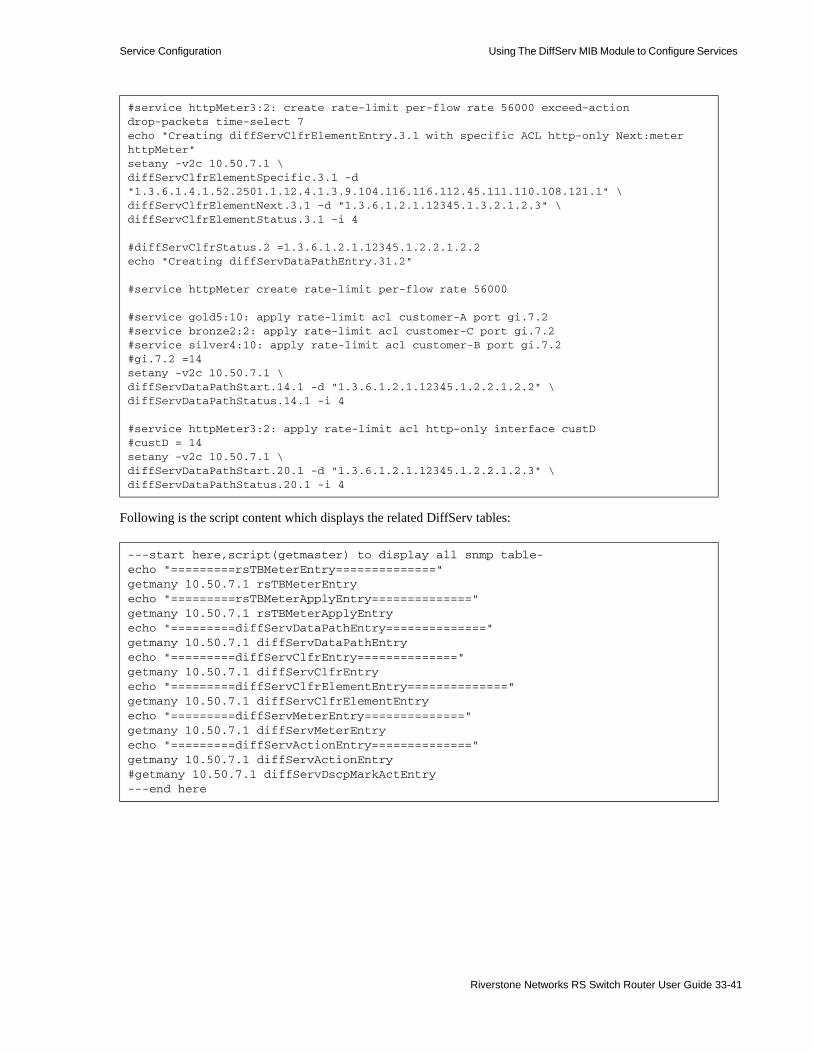
Service Configuration Using The DiffServ MIB Module to Configure Services
Following is the script content which displays the related DiffServ tables:
#service httpMeter3:2: create rate-limit per-flow rate 56000 exceed-action drop-packets time-select 7echo "Creating diffServClfrElementEntry.3.1 with specific ACL http-only Next:meter httpMeter"setany -v2c 10.50.7.1 \diffServClfrElementSpecific.3.1 -d "1.3.6.1.4.1.52.2501.1.12.4.1.3.9.104.116.116.112.45.111.110.108.121.1" \diffServClfrElementNext.3.1 -d "1.3.6.1.2.1.12345.1.3.2.1.2.3" \diffServClfrElementStatus.3.1 -i 4
#diffServClfrStatus.2 =1.3.6.1.2.1.12345.1.2.2.1.2.2echo "Creating diffServDataPathEntry.31.2"
#service httpMeter create rate-limit per-flow rate 56000
#service gold5:10: apply rate-limit acl customer-A port gi.7.2#service bronze2:2: apply rate-limit acl customer-C port gi.7.2#service silver4:10: apply rate-limit acl customer-B port gi.7.2#gi.7.2 =14setany -v2c 10.50.7.1 \diffServDataPathStart.14.1 -d "1.3.6.1.2.1.12345.1.2.2.1.2.2" \diffServDataPathStatus.14.1 -i 4
#service httpMeter3:2: apply rate-limit acl http-only interface custD#custD = 14setany -v2c 10.50.7.1 \diffServDataPathStart.20.1 -d "1.3.6.1.2.1.12345.1.2.2.1.2.3" \diffServDataPathStatus.20.1 -i 4
---start here,script(getmaster) to display all snmp table-echo "=========rsTBMeterEntry=============="getmany 10.50.7.1 rsTBMeterEntryecho "=========rsTBMeterApplyEntry=============="getmany 10.50.7.1 rsTBMeterApplyEntryecho "=========diffServDataPathEntry=============="getmany 10.50.7.1 diffServDataPathEntryecho "=========diffServClfrEntry=============="getmany 10.50.7.1 diffServClfrEntryecho "=========diffServClfrElementEntry=============="getmany 10.50.7.1 diffServClfrElementEntryecho "=========diffServMeterEntry=============="getmany 10.50.7.1 diffServMeterEntryecho "=========diffServActionEntry=============="getmany 10.50.7.1 diffServActionEntry#getmany 10.50.7.1 diffServDscpMarkActEntry---end here
Riverstone Networks RS Switch Router User Guide 33-41

Using The DiffServ MIB Module to Configure Services Service Configuration
Following is the result:
::demo1> getmaster =========rsTBMeterEntry=======================rsTBMeterApplyEntry=======================diffServDataPathEntry=======================diffServClfrEntry=======================diffServClfrElementEntry=======================diffServMeterEntry=======================diffServActionEntry==============::demo1>
33-42 Riverstone Networks RS Switch Router User Guide
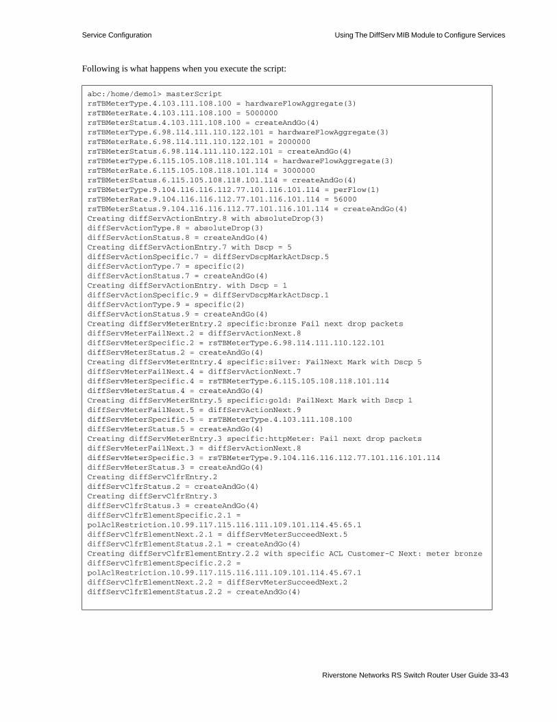
Service Configuration Using The DiffServ MIB Module to Configure Services
Following is what happens when you execute the script:
abc:/home/demo1> masterScriptrsTBMeterType.4.103.111.108.100 = hardwareFlowAggregate(3)rsTBMeterRate.4.103.111.108.100 = 5000000rsTBMeterStatus.4.103.111.108.100 = createAndGo(4)rsTBMeterType.6.98.114.111.110.122.101 = hardwareFlowAggregate(3)rsTBMeterRate.6.98.114.111.110.122.101 = 2000000rsTBMeterStatus.6.98.114.111.110.122.101 = createAndGo(4)rsTBMeterType.6.115.105.108.118.101.114 = hardwareFlowAggregate(3)rsTBMeterRate.6.115.105.108.118.101.114 = 3000000rsTBMeterStatus.6.115.105.108.118.101.114 = createAndGo(4)rsTBMeterType.9.104.116.116.112.77.101.116.101.114 = perFlow(1)rsTBMeterRate.9.104.116.116.112.77.101.116.101.114 = 56000rsTBMeterStatus.9.104.116.116.112.77.101.116.101.114 = createAndGo(4)Creating diffServActionEntry.8 with absoluteDrop(3)diffServActionType.8 = absoluteDrop(3)diffServActionStatus.8 = createAndGo(4)Creating diffServActionEntry.7 with Dscp = 5diffServActionSpecific.7 = diffServDscpMarkActDscp.5diffServActionType.7 = specific(2)diffServActionStatus.7 = createAndGo(4)Creating diffServActionEntry. with Dscp = 1diffServActionSpecific.9 = diffServDscpMarkActDscp.1diffServActionType.9 = specific(2)diffServActionStatus.9 = createAndGo(4)Creating diffServMeterEntry.2 specific:bronze Fail next drop packetsdiffServMeterFailNext.2 = diffServActionNext.8diffServMeterSpecific.2 = rsTBMeterType.6.98.114.111.110.122.101diffServMeterStatus.2 = createAndGo(4)Creating diffServMeterEntry.4 specific:silver: FailNext Mark with Dscp 5diffServMeterFailNext.4 = diffServActionNext.7diffServMeterSpecific.4 = rsTBMeterType.6.115.105.108.118.101.114diffServMeterStatus.4 = createAndGo(4)Creating diffServMeterEntry.5 specific:gold: FailNext Mark with Dscp 1diffServMeterFailNext.5 = diffServActionNext.9diffServMeterSpecific.5 = rsTBMeterType.4.103.111.108.100diffServMeterStatus.5 = createAndGo(4)Creating diffServMeterEntry.3 specific:httpMeter: Fail next drop packetsdiffServMeterFailNext.3 = diffServActionNext.8diffServMeterSpecific.3 = rsTBMeterType.9.104.116.116.112.77.101.116.101.114diffServMeterStatus.3 = createAndGo(4)Creating diffServClfrEntry.2diffServClfrStatus.2 = createAndGo(4)Creating diffServClfrEntry.3diffServClfrStatus.3 = createAndGo(4)diffServClfrElementSpecific.2.1 = polAclRestriction.10.99.117.115.116.111.109.101.114.45.65.1diffServClfrElementNext.2.1 = diffServMeterSucceedNext.5diffServClfrElementStatus.2.1 = createAndGo(4)Creating diffServClfrElementEntry.2.2 with specific ACL Customer-C Next: meter bronzediffServClfrElementSpecific.2.2 = polAclRestriction.10.99.117.115.116.111.109.101.114.45.67.1diffServClfrElementNext.2.2 = diffServMeterSucceedNext.2diffServClfrElementStatus.2.2 = createAndGo(4)
Riverstone Networks RS Switch Router User Guide 33-43

Using The DiffServ MIB Module to Configure Services Service Configuration
Creating diffServClfrElementEntry.2.3 with specific ACL Customer-B Next:meter SilverdiffServClfrElementSpecific.2.3 = polAclRestriction.10.99.117.115.116.111.109.101.114.45.66.1diffServClfrElementNext.2.3 = diffServMeterSucceedNext.4diffServClfrElementStatus.2.3 = createAndGo(4)Creating diffServClfrElementEntry.3.1 with specific ACL http-only Next:meter httpMeterdiffServClfrElementSpecific.3.1 = polAclRestriction.9.104.116.116.112.45.111.110.108.121.1diffServClfrElementNext.3.1 = diffServMeterSucceedNext.3diffServClfrElementStatus.3.1 = createAndGo(4)Creating diffServDataPathEntry.31.2diffServDataPathStart.14.1 = diffServClfrStatus.2diffServDataPathStatus.14.1 = createAndGo(4)diffServDataPathStart.20.1 = diffServClfrStatus.3diffServDataPathStatus.20.1 = createAndGo(4)
33-44 Riverstone Networks RS Switch Router User Guide

Service Configuration Using The DiffServ MIB Module to Configure Services
Following is the CLI configuration file after the master script is executed:
rs(config)# showRunning system configuration: ! ! Last modified from SNMP on 2001-07-18 13:51:09 ! 1 : snmp set community public privilege read-write ! 2 : vlan create customer id 50 ip 3 : vlan enable l4-bridging on customer 4 : vlan add ports gi.7.1 to customer 5 : vlan add ports gi.7.2 to customer ! 6 : interface create ip custD address-netmask 10.54.10.1/24 port et.3.1 7 : interface add ip en0 address-netmask 10.50.7.1/24 ! 8 : acl http-only permit ip-protocol 80 any 9 : acl customer-A permit ip 134.141.0.0 any10 : acl customer-B permit ip 192.143.12.0 any11 : acl customer-C permit ip 10.50.0.0/16 any !12 : system enable aggregate-rate-limiting slot 7! 13V: service httpMeter create rate-limit per-flow rate 5600014 : service httpMeter3:2: create rate-limit per-flow rate 56000 exceed-action drop-packets time-select 715V: service gold create rate-limit aggregate rate 5000000 no-action16V: service bronze create rate-limit aggregate rate 2000000 no-action17V: service silver create rate-limit aggregate rate 3000000 no-action18: service bronze2:2: create rate-limit aggregate rate 2000000 drop-packets time-select 519: service silver4:10: create rate-limit aggregate rate 3000000 tos-precedence-rewrite 5 time-select 520 : service gold5:10: create rate-limit aggregate rate 5000000 tos-precedence-rewrite 1 time-select 421 : service gold5:10: apply rate-limit acl customer-A port gi.7.222 : service bronze2:2: apply rate-limit acl customer-C port gi.7.223 : service silver4:10: apply rate-limit acl customer-B port gi.7.224 : service httpMeter3:2: apply rate-limit acl http-only interface custD !
Riverstone Networks RS Switch Router User Guide 33-45
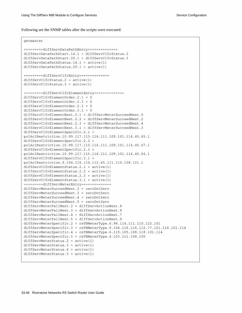
Using The DiffServ MIB Module to Configure Services Service Configuration
Following are the SNMP tables after the scripts were executed:
getmaster
=========diffServDataPathEntry==============diffServDataPathStart.14.1 = diffServClfrStatus.2diffServDataPathStart.20.1 = diffServClfrStatus.3diffServDataPathStatus.14.1 = active(1)diffServDataPathStatus.20.1 = active(1)
=========diffServClfrEntry==============diffServClfrStatus.2 = active(1)diffServClfrStatus.3 = active(1)
=========diffServClfrElementEntry==============diffServClfrElementOrder.2.1 = 0diffServClfrElementOrder.2.2 = 0diffServClfrElementOrder.2.3 = 0diffServClfrElementOrder.3.1 = 0diffServClfrElementNext.2.1 = diffServMeterSucceedNext.5diffServClfrElementNext.2.2 = diffServMeterSucceedNext.2diffServClfrElementNext.2.3 = diffServMeterSucceedNext.4diffServClfrElementNext.3.1 = diffServMeterSucceedNext.3diffServClfrElementSpecific.2.1 = polAclRestriction.10.99.117.115.116.111.109.101.114.45.65.1diffServClfrElementSpecific.2.2 = polAclRestriction.10.99.117.115.116.111.109.101.114.45.67.1diffServClfrElementSpecific.2.3 = polAclRestriction.10.99.117.115.116.111.109.101.114.45.66.1diffServClfrElementSpecific.3.1 = polAclRestriction.9.104.116.116.112.45.111.110.108.121.1diffServClfrElementStatus.2.1 = active(1)diffServClfrElementStatus.2.2 = active(1)diffServClfrElementStatus.2.3 = active(1)diffServClfrElementStatus.3.1 = active(1)=========diffServMeterEntry==============diffServMeterSucceedNext.2 = zeroDotZerodiffServMeterSucceedNext.3 = zeroDotZerodiffServMeterSucceedNext.4 = zeroDotZerodiffServMeterSucceedNext.5 = zeroDotZerodiffServMeterFailNext.2 = diffServActionNext.8diffServMeterFailNext.3 = diffServActionNext.8diffServMeterFailNext.4 = diffServActionNext.7diffServMeterFailNext.5 = diffServActionNext.9diffServMeterSpecific.2 = rsTBMeterType.6.98.114.111.110.122.101diffServMeterSpecific.3 = rsTBMeterType.9.104.116.116.112.77.101.116.101.114diffServMeterSpecific.4 = rsTBMeterType.6.115.105.108.118.101.114diffServMeterSpecific.5 = rsTBMeterType.4.103.111.108.100diffServMeterStatus.2 = active(1)diffServMeterStatus.3 = active(1)diffServMeterStatus.4 = active(1)diffServMeterStatus.5 = active(1)
33-46 Riverstone Networks RS Switch Router User Guide
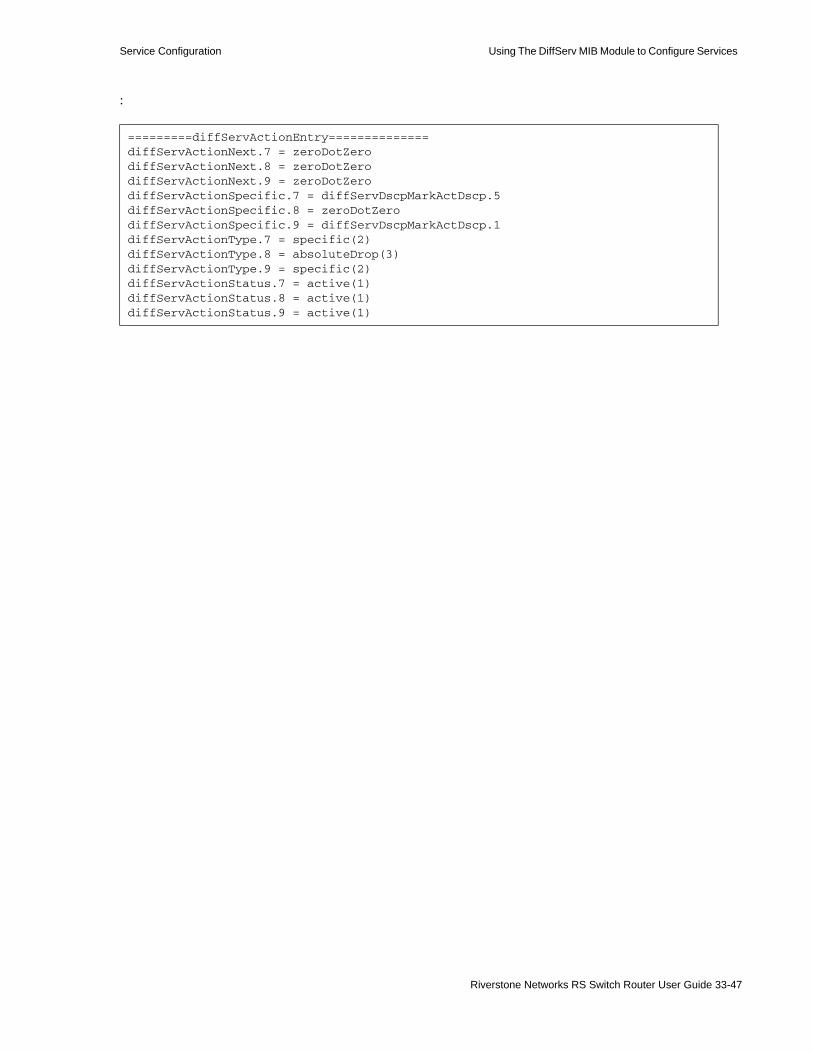
Service Configuration Using The DiffServ MIB Module to Configure Services
:
=========diffServActionEntry==============diffServActionNext.7 = zeroDotZerodiffServActionNext.8 = zeroDotZerodiffServActionNext.9 = zeroDotZerodiffServActionSpecific.7 = diffServDscpMarkActDscp.5diffServActionSpecific.8 = zeroDotZerodiffServActionSpecific.9 = diffServDscpMarkActDscp.1diffServActionType.7 = specific(2)diffServActionType.8 = absoluteDrop(3)diffServActionType.9 = specific(2)diffServActionStatus.7 = active(1)diffServActionStatus.8 = active(1)diffServActionStatus.9 = active(1)
Riverstone Networks RS Switch Router User Guide 33-47

Using The DiffServ MIB Module to Configure Services Service Configuration
You can delete the data paths configured by the master script. Following is an example:
abc:/home/demo1> cat masterExciteDelcat masterExciteDelecho "Deleting diffServDataPathEntry.gi.7.2"setany -v2c -timeout 1000 -retries 0 10.50.7.1 \diffServDataPathStatus.14.1 -i 6
echo "Deleting diffServDataPathEntry.custA"setany -v2c -timeout 1000 -retries 0 10.50.7.1 \diffServDataPathStatus.20.1 -i 6
echo "Deleting diffServMeterEntry.2"setany -v2c 10.50.7.1 \diffServMeterStatus.2 -i 6
echo "Deleting diffServMeterEntry.4"setany -v2c 10.50.7.1 \diffServMeterStatus.4 -i 6
echo "Deleting diffServMeterEntry.5"setany -v2c 10.50.7.1 \diffServMeterStatus.5 -i 6
echo "Deleting diffServMeterEntry.3"setany -v2c 10.50.7.1 \diffServMeterStatus.3 -i 6
echo "Deleting rsTBMeterEntry.bronze"setany 10.50.7.1 rsTBMeterStatus.6.98.114.111.110.122.101 -i 6
echo "Deleting rsTBMeterEntry.gold"setany 10.50.7.1 rsTBMeterStatus.4.103.111.108.100 -i 6
echo "Deleting rsTBMeterEntry.silver"setany 10.50.7.1 rsTBMeterStatus.6.115.105.108.118.101.114 -i 6
echo "Deleting rsTBMeterEntry.httpMeter"setany 10.50.7.1 rsTBMeterStatus.9.104.116.116.112.77.101.116.101.114 -i 6
#General Drop Actionecho "Deleting diffServActionEntry.8"setany -v2c -timeout 10000 -retries 0 10.50.7.1 \diffServActionStatus.8 -i 6
echo "Deleting diffServActionEntry.7"setany -v2c -timeout 10000 -retries 0 10.50.7.1 \diffServActionStatus.7 -i 6
echo "Deleting diffServActionEntry.9"setany -v2c -timeout 10000 -retries 0 10.50.7.1 \diffServActionStatus.9 -i 6
33-48 Riverstone Networks RS Switch Router User Guide

Service Configuration Using The DiffServ MIB Module to Configure Services
:
echo "Deleting diffServClfrElementEntry.2.1"setany -v2c 10.50.7.1 \diffServClfrElementStatus.2.1 -i 6 echo "Deleting diffServClfrElementEntry.2.2"setany -v2c 10.50.7.1 \diffServClfrElementStatus.2.2 -i 6
echo "Deleting diffServClfrElementEntry.2.3"
setany -v2c 10.50.7.1 \diffServClfrElementStatus.2.3 -i 6
echo "Deleting diffServClfrElementEntry.3.1"setany -v2c 10.50.7.1 \diffServClfrElementStatus.3.1 -i 6
echo "Deleting diffServClfrEntry.2"setany -v2c 10.50.7.1 \diffServClfrStatus.2 -i 6
echo "Deleting diffServClfrEntry.3"setany -v2c 10.50.7.1 \diffServClfrStatus.3 -i 6
Riverstone Networks RS Switch Router User Guide 33-49

Using The DiffServ MIB Module to Configure Services Service Configuration
Following is what happens when you delete the data paths:
abc:/home/demo1> masterExciteDelDeleting diffServDataPathEntry.gi.7.2diffServDataPathStatus.14.1 = destroy(6)Deleting diffServDataPathEntry.custAdiffServDataPathStatus.20.1 = destroy(6)Deleting diffServMeterEntry.2diffServMeterStatus.2 = destroy(6)Deleting diffServMeterEntry.4diffServMeterStatus.4 = destroy(6)Deleting diffServMeterEntry.5diffServMeterStatus.5 = destroy(6)Deleting diffServMeterEntry.3diffServMeterStatus.3 = destroy(6)Deleting rsTBMeterEntry.bronzersTBMeterStatus.6.98.114.111.110.122.101 = destroy(6)Deleting rsTBMeterEntry.goldrsTBMeterStatus.4.103.111.108.100 = destroy(6)Deleting rsTBMeterEntry.silverrsTBMeterStatus.6.115.105.108.118.101.114 = destroy(6)Deleting rsTBMeterEntry.httpMeterrsTBMeterStatus.9.104.116.116.112.77.101.116.101.114 = destroy(6)Deleting diffServActionEntry.8diffServActionStatus.8 = destroy(6)Deleting diffServActionEntry.7diffServActionStatus.7 = destroy(6)Deleting diffServActionEntry.9diffServActionStatus.9 = destroy(6)Deleting diffServClfrElementEntry.2.1diffServClfrElementStatus.2.1 = destroy(6)Deleting diffServClfrElementEntry.2.2diffServClfrElementStatus.2.2 = destroy(6)Deleting diffServClfrElementEntry.2.3diffServClfrElementStatus.2.3 = destroy(6)Deleting diffServClfrElementEntry.3.1diffServClfrElementStatus.3.1 = destroy(6)Deleting diffServClfrEntry.2diffServClfrStatus.2 = destroy(6)Deleting diffServClfrEntry.3diffServClfrStatus.3 = destroy(6)
33-50 Riverstone Networks RS Switch Router User Guide

Service Configuration Using The DiffServ MIB Module to Configure Services
The configuration file after you deleted the data paths:
Following are the tables after you deleted the data paths:
rs(config)# showRunning system configuration: ! ! Last modified from SNMP on 2001-07-18 14:01:25 ! 1 : snmp set community public privilege read-write ! 2 : vlan create customer id 50 ip 3 : vlan enable l4-bridging on customer 4 : vlan add ports gi.7.1 to customer 5 : vlan add ports gi.7.2 to customer ! 6 : interface create ip custD address-netmask 10.54.10.1/24 port et.3.1 7 : interface add ip en0 address-netmask 10.50.7.1/24 ! 8 : acl http-only permit ip-protocol 80 any 9 : acl customer-A permit ip 134.141.0.0 any10 : acl customer-B permit ip 192.143.12.0 any11 : acl customer-C permit ip 10.50.0.0/16 any !12 : system enable aggregate-rate-limiting slot 7
rs(config)#
abc:/home/demo1> getmaster =========diffServDataPathEntry=======================diffServClfrEntry=======================diffServClfrElementEntry=======================diffServMeterEntry=======================diffServActionEntry==============abc:/home/demo/demo1>
Riverstone Networks RS Switch Router User Guide 33-51

Using The DiffServ MIB Module to Configure Services Service Configuration
33-52 Riverstone Networks RS Switch Router User Guide
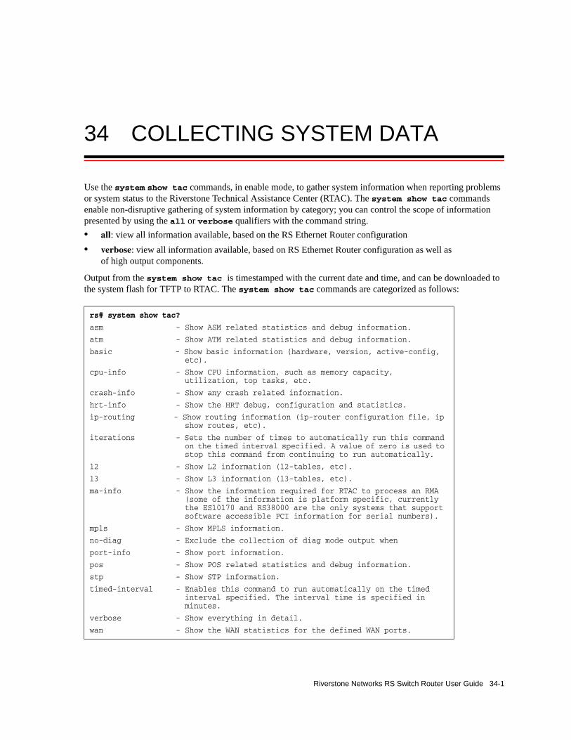
34 COLLECTING SYSTEM DATA
Use the system show tac commands, in enable mode, to gather system information when reporting problems or system status to the Riverstone Technical Assistance Center (RTAC). The system show tac commands enable non-disruptive gathering of system information by category; you can control the scope of information presented by using the all or verbose qualifiers with the command string.• all: view all information available, based on the RS Ethernet Router configuration• verbose: view all information available, based on RS Ethernet Router configuration as well as
of high output components.
Output from the system show tac is timestamped with the current date and time, and can be downloaded to the system flash for TFTP to RTAC. The system show tac commands are categorized as follows:
rs# system show tac?
asm - Show ASM related statistics and debug information.
atm - Show ATM related statistics and debug information.
basic - Show basic information (hardware, version, active-config, etc).
cpu-info - Show CPU information, such as memory capacity, utilization, top tasks, etc.
crash-info - Show any crash related information.
hrt-info - Show the HRT debug, configuration and statistics.
ip-routing - Show routing information (ip-router configuration file, ip show routes, etc).
iterations - Sets the number of times to automatically run this command on the timed interval specified. A value of zero is used to stop this command from continuing to run automatically.
l2 - Show L2 information (l2-tables, etc).
l3 - Show L3 information (l3-tables, etc).
ma-info - Show the information required for RTAC to process an RMA (some of the information is platform specific, currently the ES10170 and RS38000 are the only systems that support software accessible PCI information for serial numbers).
mpls - Show MPLS information.
no-diag - Exclude the collection of diag mode output when
port-info - Show port information.
pos - Show POS related statistics and debug information.
stp - Show STP information.
timed-interval - Enables this command to run automatically on the timed interval specified. The interval time is specified in minutes.
verbose - Show everything in detail.
wan - Show the WAN statistics for the defined WAN ports.
Riverstone Networks RS Switch Router User Guide 34-1

Collecting System Data
Note The output from a system show tac command automatically disables pagination.
34-2 Riverstone Networks RS Switch Router User Guide
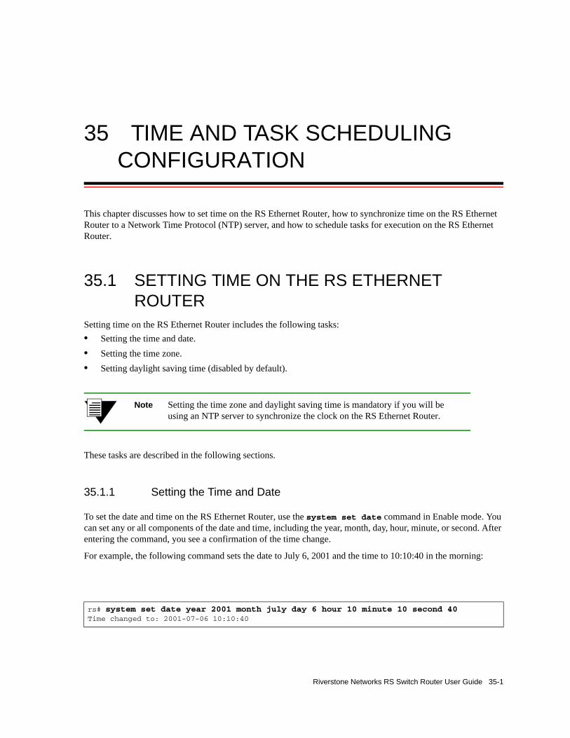
35 TIME AND TASK SCHEDULING CONFIGURATION
This chapter discusses how to set time on the RS Ethernet Router, how to synchronize time on the RS Ethernet Router to a Network Time Protocol (NTP) server, and how to schedule tasks for execution on the RS Ethernet Router.
35.1 SETTING TIME ON THE RS ETHERNET ROUTER
Setting time on the RS Ethernet Router includes the following tasks:• Setting the time and date.• Setting the time zone.• Setting daylight saving time (disabled by default).
Note Setting the time zone and daylight saving time is mandatory if you will be using an NTP server to synchronize the clock on the RS Ethernet Router.
These tasks are described in the following sections.
35.1.1 Setting the Time and Date
To set the date and time on the RS Ethernet Router, use the system set date command in Enable mode. You can set any or all components of the date and time, including the year, month, day, hour, minute, or second. After entering the command, you see a confirmation of the time change.
For example, the following command sets the date to July 6, 2001 and the time to 10:10:40 in the morning:
rs# system set date year 2001 month july day 6 hour 10 minute 10 second 40Time changed to: 2001-07-06 10:10:40
Riverstone Networks RS Switch Router User Guide 35-1

Setting Time on the RS Ethernet Router Time and Task Scheduling Configuration
You can also use the system set date command to set a single component of the date and time. For example, the following command sets the minutes to 30:
Use the system show date command in Enable mode to display the current date and time on the RS Ethernet Router. For example:
35.1.2 Setting the Local Time Zone
This section discusses setting the local time zone on the RS Ethernet Router. If you will be using an NTP server to synchronize the clock on the RS Ethernet Router, you must set the time zone and, if applicable, daylight saving time. For more information about NTP, see Section 35.2, "Synchronizing Time to an NTP Server." For more information about setting daylight saving time, see Section 35.1.3, "Setting Daylight Saving Time."
The local time zone can be defined by its offset (plus or minus hours) from Universal Coordinated Time (UCT), also called “Coordinated Universal Time.” UCT is based on the prime meridian, the meridian that runs through the Greenwich Observatory outside of London, England. As there are roughly 24 time zones that occur at intervals of approximately 15 degrees longitude, the offset of most time zones from UCT would fall in the ranges of +1 to +12 hours or -1 to -12 hours. For example, New York’s time zone can be defined as “UCT minus 5 hours.” Note that there are locations in the world where the offset from UCT also includes a half hour; for example, India’s time zone can be defined as “UCT plus 5 hours and 30 minutes.”
For time zones in the United States, you have the alternative of defining the time zone as Eastern, Central, Mountain, or Pacific Standard Time.
To configure the local time zone on the RS Ethernet Router, use the system set timezone command with one of the time zone keywords. For example, to configure the time zone on a router in California, you can use the following command:
The uct-8 keyword specifies the local time zone by its offset from UCT—”UCT minutes 8 hours.”
rs# system set date minute 30Time changed to: 2001-07-06 10:30:09
rs# system show dateCurrent time: 2001-07-06 10:31:53
rs(config)# system set timezone uct-8
35-2 Riverstone Networks RS Switch Router User Guide

Time and Task Scheduling Configuration Setting Time on the RS Ethernet Router
Alternatively, you can configure the time zone on a router in California with the following command:
The pst keyword specifies the local time zone as “Pacific Standard Time.”
Use the system show timezone command in Enable mode to see the time zone setting on the RS Ethernet Router. For example:
35.1.3 Setting Daylight Saving Time
This section discusses setting daylight saving time (DST) on the RS Ethernet Router. DST is disabled by default on the RS Ethernet Router. If you will be using an NTP server to synchronize the clock on the RS Ethernet Router, you must set the local time zone and DST. For more information about NTP, see Section 35.2, "Synchronizing Time to an NTP Server." For more information about setting the time zone, see Section 35.1.2, "Setting the Local Time Zone."
DST on the RS Ethernet Router can be set in one of three different ways:• According to specific days, for example, from the first Sunday of April to the last Saturday of
October.• According to specific dates, for example, from April 1st to October 31st.• By setting the RS Ethernet Router’s time forward by an hour.
The following example sets DST to start at midnight on the last Sunday of March and end at 2 a.m. on the first Saturday of October:
The following example sets DST to start at 3 a.m. on April 1 and end at midnight on September 15:
rs(config)# system set timezone pst
rs# system show timezoneDaylight saving = OFFUCT Time offset = -8 hours
rs(config)# system set dst-changing s-wk 5 s-dow 1 s-mo 3 e-wk 1 e-dow 7 e-mo 10 e-hr 2
rs(config)# system set dst-fixed s-mo 4 s-day 1 s-hr 3 e-mo 9 e-day 15
Riverstone Networks RS Switch Router User Guide 35-3

Setting Time on the RS Ethernet Router Time and Task Scheduling Configuration
When you specify the system set dst-changing command or the system set dst-fixed command in the active configuration file, the RS Ethernet Router automatically updates the time based on the parameters you entered.
When you set DST by setting the time forward by an hour, saving it to the active configuration file automatically activates the command, causing the time to immediately change forward one hour. Use the negate command to set the time back. Enter the following command in Configure mode to move the time forward by an hour:
rs(config)# system set dst-manual
35-4 Riverstone Networks RS Switch Router User Guide

Time and Task Scheduling Configuration Synchronizing Time to an NTP Server
35.2 SYNCHRONIZING TIME TO AN NTP SERVERNetwork Time Protocol (NTP) is a protocol used to synchronize the clocks on devices in a network, ensuring consistent and accurate times across network operations. The RS Ethernet Router includes an NTP client that can synchronize the clock on the RS Ethernet Router with an NTP server.
Note To ensure that NTP has the correct time, you must configure the local time zone on the RS Ethernet Router and daylight saving time, if applicable. For more information about setting the local time zone, see Section 35.1.2, "Setting the Local Time Zone." For more information about setting daylight saving time, see Section 35.1.3, "Setting Daylight Saving Time."
There are two ways that the NTP client can synchronize the clock on the RS Ethernet Router with an NTP server:• periodically, at regular intervals• immediately, when you enter the appropriate CLI command
35.2.1 Periodic Clock Synchronization
Use the ntp set server command in Configure mode to have the NTP client periodically synchronize its clock with an NTP server. For example, the following command configures the NTP client on the RS Ethernet Router to synchronize its clock with the NTP server at IP address 10.10.10.10:
By default, the NTP client sends a synchronization request to an NTP server every 60 minutes. With the ntp set server command, you can change this interval, as well as change the version of NTP packets sent to the server. For example, the following command changes the interval at which the NTP client on the RS Ethernet Router sends requests to the NTP server to 45 minutes:
rs(config)# ntp set server 10.10.10.10
rs(config)# ntp set server 10.10.10.10 interval 45
Riverstone Networks RS Switch Router User Guide 35-5

Synchronizing Time to an NTP Server Time and Task Scheduling Configuration
35.2.2 Immediate Clock Synchronization
To cause the NTP client to immediately synchronize its clock with an NTP server, use the ntp synchronize server command in Enable mode. Unlike the ntp set server command (which is issued in Configuration mode), the ntp synchronize server command sends a single synchronization request to the NTP server. For example, the following command causes the NTP client to immediately synchronize its clock with the NTP server with IP address 10.10.10.10:
rs# ntp synchronize server 10.10.10.10%NTP-I-TIMESYNC, Time synchronized to Thu Jan 23 23:11:28 1999
35-6 Riverstone Networks RS Switch Router User Guide

Time and Task Scheduling Configuration Scheduling Tasks on the RS Ethernet Router
35.3 SCHEDULING TASKS ON THE RS ETHERNET ROUTER
The scheduler facility on the RS Ethernet Router allows specific tasks, namely CLI commands or SNMP SET operations, to be executed at specified times. You can schedule tasks in one of three ways:• one-time execution at a specific date and time• recurring execution at specific dates and times• recurring execution at specific intervals
The information for a configured task is written as an entry in the scheduling MIB table (specified by RFC 2591), which can be accessed by SNMP management applications. SNMP management applications can therefore modify or delete a task in the MIB table, whether the entry is for a CLI command or for an SNMP SET operation. For a CLI command entry in the scheduling MIB table, the MIB variable (OID) is set to 0.0 (null) and the variable value is set to 0 (zero).
Use the scheduler set cli command to schedule a CLI Enable or Configure mode command to run at specified intervals or at a specific date and time. Use the scheduler set snmp command to schedule an SNMP SET command to run at specified intervals or at a specific date and time. When using the scheduler set snmp command, note the following:• The variable to be set must be of the type INTEGER.• The MIB table must be ReadCreate or ReadWrite.• You must make sure that the index of the OID is valid and references a valid entry.
The following sections provide examples of how to use the scheduler commands.
35.3.1 Scheduling a One-Time Task Execution
To schedule a task to be executed once at a specific time:1. Use the scheduler set calendar command to configure the time at which the one-time task is
to be executed.2. Use the scheduler set cli command or the scheduler set snmp command to define the task
to be run and to attach the calendar to the task.
35.3.1.1 CLI Command Example
The following example shows how to use scheduler commands to start MPLS on the RS Ethernet Router at noon on July 13, 2001.
The following command creates a calendar called ‘d-day’ for noon, July 13, 2001:
rs(config)# scheduler set calendar name d-day months 7 days 13 hours 12
Riverstone Networks RS Switch Router User Guide 35-7

Scheduling Tasks on the RS Ethernet Router Time and Task Scheduling Configuration
The following command applies the calendar ‘d-day’ to the CLI command to start MPLS on the router:
35.3.1.2 SNMP SET Example
The following example shows how to use scheduler commands to bring an interface up at noon on July 13, 2001. The OID for the interface is 1.3.6.1.2.1.2.2.1.7.6 (ifAdminStatus for the ifTable of the IF-MIB); the value to bring the network interface up is 1.
The following command creates a calendar called ‘d-day’ for noon, July 13, 2001:
The following command applies the calendar ‘d-day’ to the SNMP SET command which brings the interface up (note the value is set to 1):
35.3.2 Scheduling Tasks for Recurring Dates and Times
1. Use the scheduler set calendar command to configure the times at which the task is to be executed.
2. Use the scheduler set cli command or the scheduler set snmp command to define the task to be run and to attach the calendar to the task.
35.3.2.1 CLI Command Example
The following example shows how to use scheduler commands to compare the active configuration on the RS Ethernet Router to the startup configuration every Friday evening.
The following command creates a calendar called ‘fridaypm’ for Fridays at 8:30 p.m.:
rs(config)# scheduler set cli name startmpls owner rs cli-cmd “mpls start” one-shot d-day desc “start MPLS at noon on 7/13/01”
rs(config)# scheduler set calendar name d-day months 7 days 13 hours 12
rs(config)# scheduler set snmp name interface-on one-shot d-day owner mgr1 variable 1.3.6.1.2.1.2.2.1.7.6 value 1 context abc
rs(config)# scheduler set calendar name fridaypm months all days all weekdays 6 hours 20 minutes 30
35-8 Riverstone Networks RS Switch Router User Guide

Time and Task Scheduling Configuration Scheduling Tasks on the RS Ethernet Router
The following command applies the calendar ‘fridaypm’ to the CLI command that compares the configuration files on the RS Ethernet Router:
35.3.2.2 SNMP SET Example
The following example shows how to use scheduler commands to configure a network interface to be brought down every Friday at 8:30 p.m. The OID for the interface is 1.3.6.1.2.1.2.2.1.7.6 (ifAdminStatus for the ifTable of the IF-MIB); the value to bring the network interface down is 2.
The following command creates a calendar called ‘fridaypm’ for Fridays at 8:30 p.m.:
The following command applies the calendar ‘fridaypm’ to the SNMP SET command which sets the interface down:
The following example shows how to use scheduler commands to bring the same interface back up every Monday at 5:30 a.m. The OID for the interface is 1.3.6.1.2.1.2.2.1.7.6 (ifAdminStatus for the ifTable of the IF-MIB); the value to bring the network interface up is 1.
The following command creates a calendar called ‘mondayam’ for Mondays at 5:30 a.m.:
The following command applies the calendar ‘mondayam’ to the SNMP SET command which brings the interface up (note the value is set to 1):
35.3.3 Scheduling Tasks for Recurring Intervals
Use the scheduler set cli command or the scheduler set snmp command to define the task to be run and to specify the interval between executions of the task.
35.3.3.1 CLI Command Example
The following example shows how to use scheduler commands to ping a specified host on an hourly basis.
rs(config)# scheduler set cli name compare owner rs cli-cmd “diff startup” calendar fridaypm desc “compare configurations”
rs(config)# scheduler set calendar name fridaypm months all days all weekdays 6 hours 20 minutes 30
rs(config)# scheduler set snmp name interface-off calendar fridaypm owner mgr1 variable 1.3.6.1.2.1.2.2.1.7.6 value 2 context abc
rs(config)# scheduler set calendar name mondayam months all days all weekdays 2 hours 5 minutes 30
rs(config)# scheduler set snmp name interface-on calendar mondayam owner mgr1 variable 1.3.6.1.2.1.2.2.1.7.6 value 1 context abc
Riverstone Networks RS Switch Router User Guide 35-9
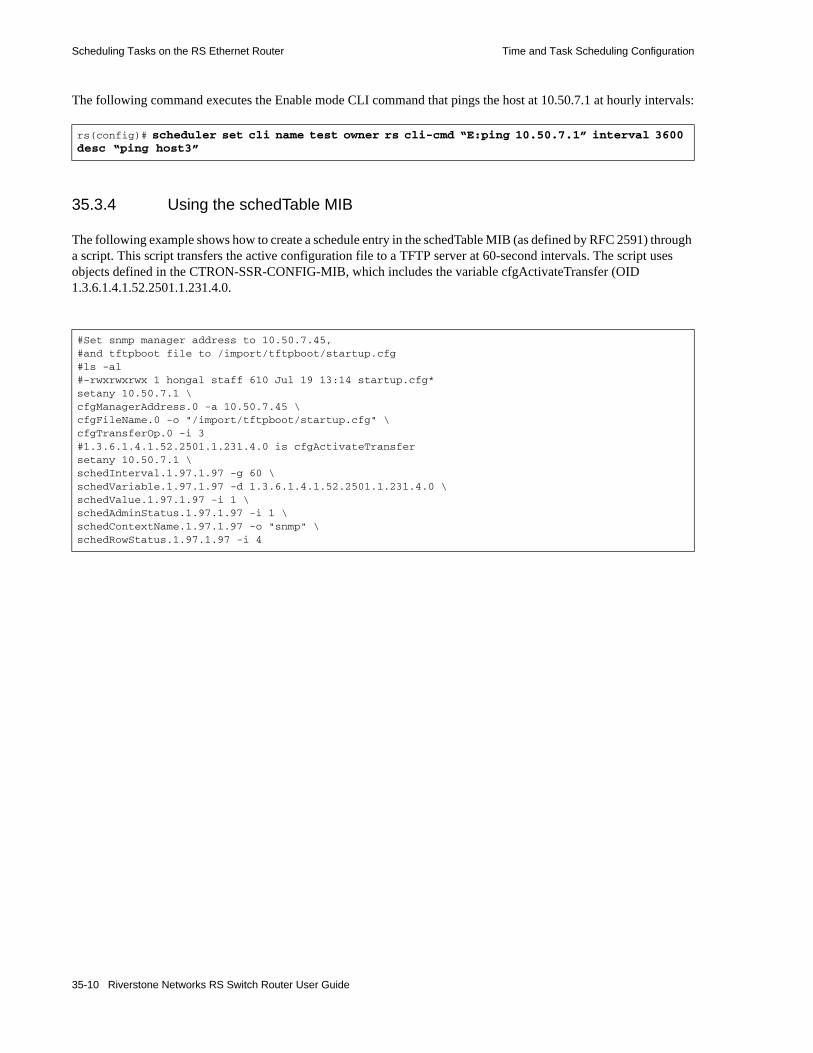
Scheduling Tasks on the RS Ethernet Router Time and Task Scheduling Configuration
The following command executes the Enable mode CLI command that pings the host at 10.50.7.1 at hourly intervals:
35.3.4 Using the schedTable MIB
The following example shows how to create a schedule entry in the schedTable MIB (as defined by RFC 2591) through a script. This script transfers the active configuration file to a TFTP server at 60-second intervals. The script uses objects defined in the CTRON-SSR-CONFIG-MIB, which includes the variable cfgActivateTransfer (OID 1.3.6.1.4.1.52.2501.1.231.4.0.
rs(config)# scheduler set cli name test owner rs cli-cmd “E:ping 10.50.7.1” interval 3600 desc “ping host3”
#Set snmp manager address to 10.50.7.45,#and tftpboot file to /import/tftpboot/startup.cfg#ls -al#-rwxrwxrwx 1 hongal staff 610 Jul 19 13:14 startup.cfg*setany 10.50.7.1 \cfgManagerAddress.0 -a 10.50.7.45 \cfgFileName.0 -o "/import/tftpboot/startup.cfg" \cfgTransferOp.0 -i 3#1.3.6.1.4.1.52.2501.1.231.4.0 is cfgActivateTransfersetany 10.50.7.1 \schedInterval.1.97.1.97 -g 60 \schedVariable.1.97.1.97 -d 1.3.6.1.4.1.52.2501.1.231.4.0 \schedValue.1.97.1.97 -i 1 \schedAdminStatus.1.97.1.97 -i 1 \schedContextName.1.97.1.97 -o "snmp" \schedRowStatus.1.97.1.97 -i 4
35-10 Riverstone Networks RS Switch Router User Guide
36 SNMP CONFIGURATION
The Simple Network Management Protocol (SNMP) is an application layer protocol used to monitor and manage TCP/IP-based networks. It provides for the storage and exchange of management information.
The RS Ethernet Router supports all three SNMP versions: • SNMP Version 1 (SNMPv1) (RFC 1157)• SNMP Version 2c (SNMPv2c) (RFC 1901, RFC 1905, and RFC 1906)• SNMP Version 3 (SNMPv3) (RFC 2570 - 2576)
SNMPv1, SNMPv2c and SNMPv3 can coexist in the same managed network (RFC 2576). You should configure the RS Ethernet Router to run the SNMP version(s) supported by the SNMP management stations. You can run any or all of the SNMP versions on the RS Ethernet Router, depending on the one used by the SNMP management stations. (For additional information on the different SNMP versions, refer to the RFCs for each version.)
You can use the CLI to perform various SNMP tasks. This chapter described how to perform these tasks. It contains the following sections:• To configure access to the Management Information Base (MIB) objects on the RS Ethernet
Router, refer to Section 36.1, "Configuring Access to MIB Objects."• To configure SNMP notifications, refer to Section 36.2, "Configuring SNMP Notifications."• To configure SNMP MIB modules and for a list of MIB modules supported by the RS Ethernet
Router, refer to Section 36.3, "MIB Modules."
Riverstone Networks RS Switch Router User Guide 36-1
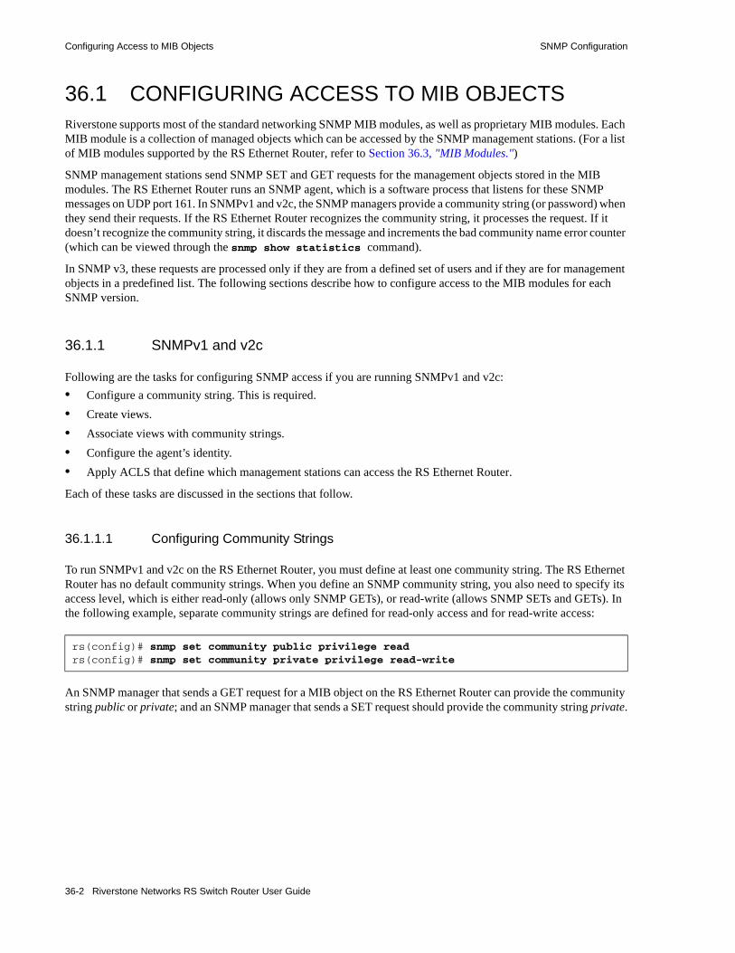
Configuring Access to MIB Objects SNMP Configuration
36.1 CONFIGURING ACCESS TO MIB OBJECTSRiverstone supports most of the standard networking SNMP MIB modules, as well as proprietary MIB modules. Each MIB module is a collection of managed objects which can be accessed by the SNMP management stations. (For a list of MIB modules supported by the RS Ethernet Router, refer to Section 36.3, "MIB Modules.")
SNMP management stations send SNMP SET and GET requests for the management objects stored in the MIB modules. The RS Ethernet Router runs an SNMP agent, which is a software process that listens for these SNMP messages on UDP port 161. In SNMPv1 and v2c, the SNMP managers provide a community string (or password) when they send their requests. If the RS Ethernet Router recognizes the community string, it processes the request. If it doesn’t recognize the community string, it discards the message and increments the bad community name error counter (which can be viewed through the snmp show statistics command).
In SNMP v3, these requests are processed only if they are from a defined set of users and if they are for management objects in a predefined list. The following sections describe how to configure access to the MIB modules for each SNMP version.
36.1.1 SNMPv1 and v2c
Following are the tasks for configuring SNMP access if you are running SNMPv1 and v2c:• Configure a community string. This is required.• Create views.• Associate views with community strings.• Configure the agent’s identity.• Apply ACLS that define which management stations can access the RS Ethernet Router.
Each of these tasks are discussed in the sections that follow.
36.1.1.1 Configuring Community Strings
To run SNMPv1 and v2c on the RS Ethernet Router, you must define at least one community string. The RS Ethernet Router has no default community strings. When you define an SNMP community string, you also need to specify its access level, which is either read-only (allows only SNMP GETs), or read-write (allows SNMP SETs and GETs). In the following example, separate community strings are defined for read-only access and for read-write access:
An SNMP manager that sends a GET request for a MIB object on the RS Ethernet Router can provide the community string public or private; and an SNMP manager that sends a SET request should provide the community string private.
rs(config)# snmp set community public privilege read rs(config)# snmp set community private privilege read-write
36-2 Riverstone Networks RS Switch Router User Guide
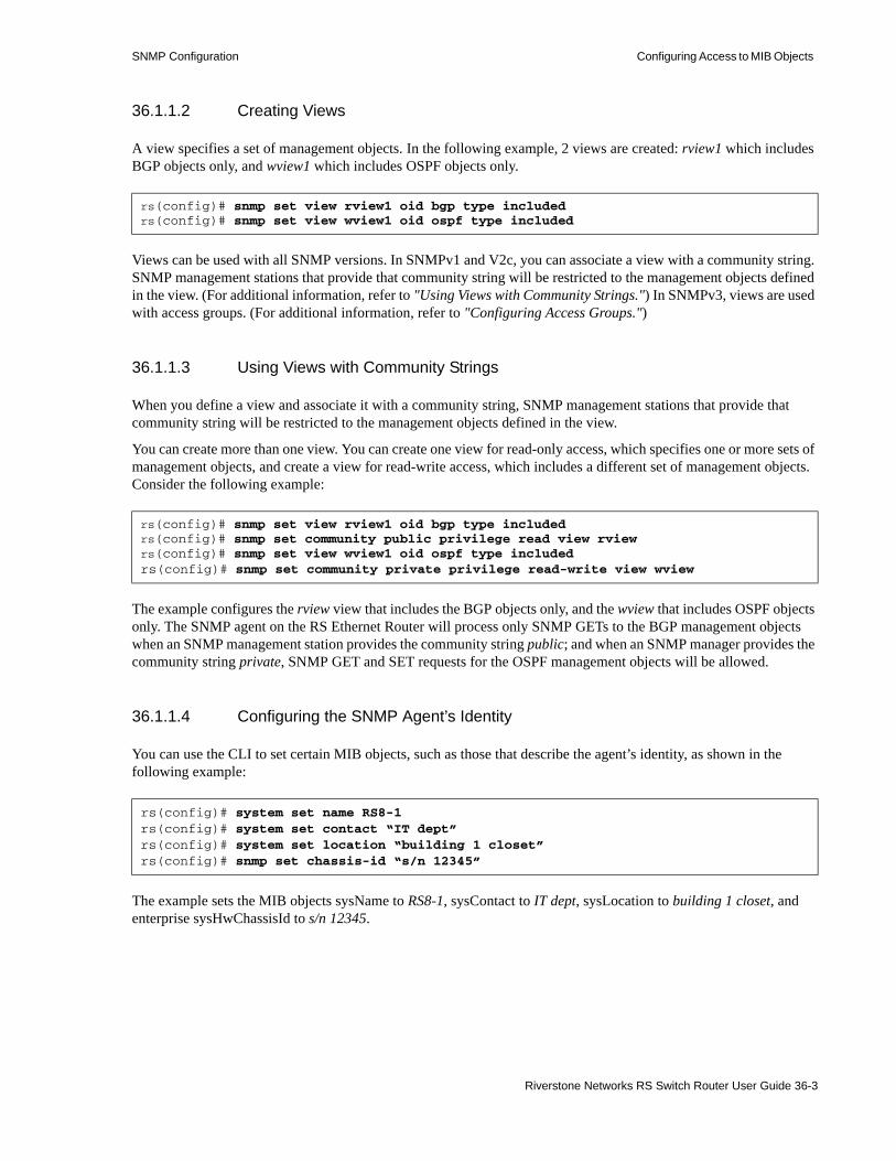
SNMP Configuration Configuring Access to MIB Objects
36.1.1.2 Creating Views
A view specifies a set of management objects. In the following example, 2 views are created: rview1 which includes BGP objects only, and wview1 which includes OSPF objects only.
Views can be used with all SNMP versions. In SNMPv1 and V2c, you can associate a view with a community string. SNMP management stations that provide that community string will be restricted to the management objects defined in the view. (For additional information, refer to "Using Views with Community Strings.") In SNMPv3, views are used with access groups. (For additional information, refer to "Configuring Access Groups.")
36.1.1.3 Using Views with Community Strings
When you define a view and associate it with a community string, SNMP management stations that provide that community string will be restricted to the management objects defined in the view.
You can create more than one view. You can create one view for read-only access, which specifies one or more sets of management objects, and create a view for read-write access, which includes a different set of management objects. Consider the following example:
The example configures the rview view that includes the BGP objects only, and the wview that includes OSPF objects only. The SNMP agent on the RS Ethernet Router will process only SNMP GETs to the BGP management objects when an SNMP management station provides the community string public; and when an SNMP manager provides the community string private, SNMP GET and SET requests for the OSPF management objects will be allowed.
36.1.1.4 Configuring the SNMP Agent’s Identity
You can use the CLI to set certain MIB objects, such as those that describe the agent’s identity, as shown in the following example:
The example sets the MIB objects sysName to RS8-1, sysContact to IT dept, sysLocation to building 1 closet, and enterprise sysHwChassisId to s/n 12345.
rs(config)# snmp set view rview1 oid bgp type includedrs(config)# snmp set view wview1 oid ospf type included
rs(config)# snmp set view rview1 oid bgp type includedrs(config)# snmp set community public privilege read view rviewrs(config)# snmp set view wview1 oid ospf type includedrs(config)# snmp set community private privilege read-write view wview
rs(config)# system set name RS8-1rs(config)# system set contact “IT dept”rs(config)# system set location “building 1 closet”rs(config)# snmp set chassis-id “s/n 12345”
Riverstone Networks RS Switch Router User Guide 36-3
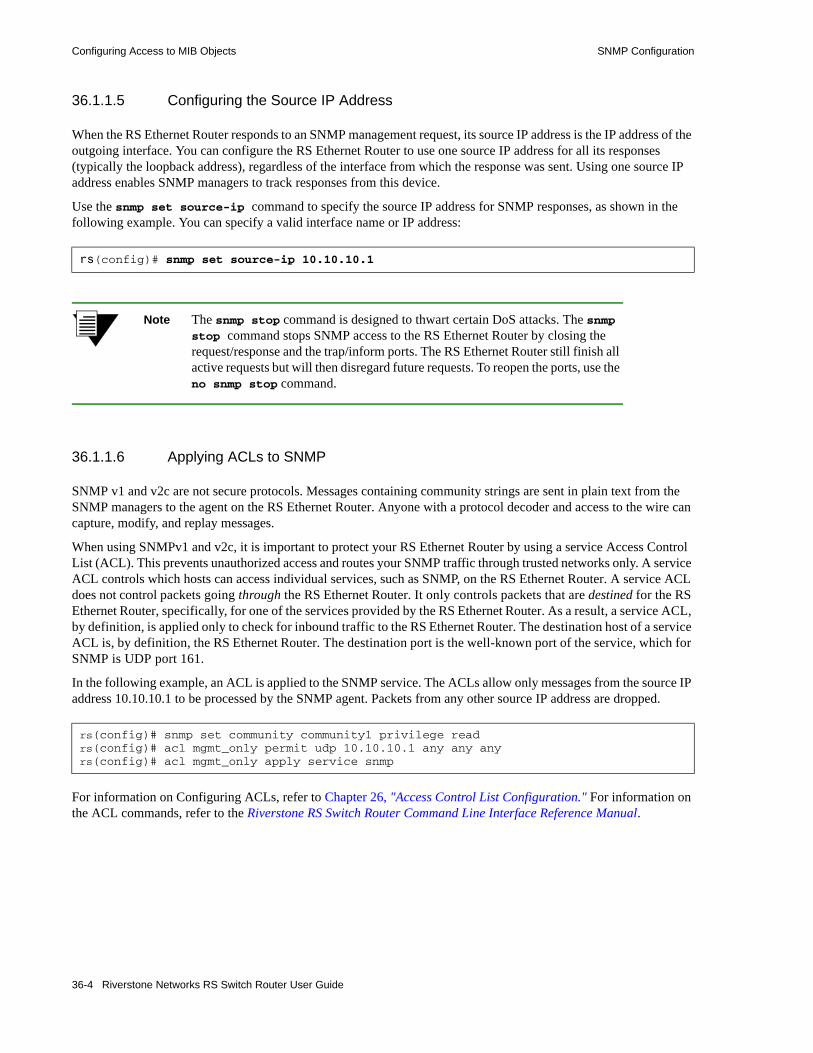
Configuring Access to MIB Objects SNMP Configuration
36.1.1.5 Configuring the Source IP Address
When the RS Ethernet Router responds to an SNMP management request, its source IP address is the IP address of the outgoing interface. You can configure the RS Ethernet Router to use one source IP address for all its responses (typically the loopback address), regardless of the interface from which the response was sent. Using one source IP address enables SNMP managers to track responses from this device.
Use the snmp set source-ip command to specify the source IP address for SNMP responses, as shown in the following example. You can specify a valid interface name or IP address:
Note The snmp stop command is designed to thwart certain DoS attacks. The snmp stop command stops SNMP access to the RS Ethernet Router by closing the request/response and the trap/inform ports. The RS Ethernet Router still finish all active requests but will then disregard future requests. To reopen the ports, use the no snmp stop command.
36.1.1.6 Applying ACLs to SNMP
SNMP v1 and v2c are not secure protocols. Messages containing community strings are sent in plain text from the SNMP managers to the agent on the RS Ethernet Router. Anyone with a protocol decoder and access to the wire can capture, modify, and replay messages.
When using SNMPv1 and v2c, it is important to protect your RS Ethernet Router by using a service Access Control List (ACL). This prevents unauthorized access and routes your SNMP traffic through trusted networks only. A service ACL controls which hosts can access individual services, such as SNMP, on the RS Ethernet Router. A service ACL does not control packets going through the RS Ethernet Router. It only controls packets that are destined for the RS Ethernet Router, specifically, for one of the services provided by the RS Ethernet Router. As a result, a service ACL, by definition, is applied only to check for inbound traffic to the RS Ethernet Router. The destination host of a service ACL is, by definition, the RS Ethernet Router. The destination port is the well-known port of the service, which for SNMP is UDP port 161.
In the following example, an ACL is applied to the SNMP service. The ACLs allow only messages from the source IP address 10.10.10.1 to be processed by the SNMP agent. Packets from any other source IP address are dropped.
For information on Configuring ACLs, refer to Chapter 26, "Access Control List Configuration." For information on the ACL commands, refer to the Riverstone RS Switch Router Command Line Interface Reference Manual.
rs(config)# snmp set source-ip 10.10.10.1
rs(config)# snmp set community community1 privilege readrs(config)# acl mgmt_only permit udp 10.10.10.1 any any anyrs(config)# acl mgmt_only apply service snmp
36-4 Riverstone Networks RS Switch Router User Guide
SNMP Configuration Configuring Access to MIB Objects
36.1.2 SNMP v3
Whereas SNMPv1 and v2c rely on password-like community strings to restrict access to the MIB objects on the RS Ethernet Router, SNMPv3 provides more stringent security. In SNMPv3 only a defined set of users are allowed to access a specific set of management objects.
SNMPv3 also provides message level security. In SNMP v1 and v2c, messages containing community strings are sent in plain text from the SNMP managers to the agent on the RS Ethernet Router. In SNMPv3, these messages can be protected by specifying an authentication protocol and encryption method.
The following tasks are required for configuring SNMP access if you are running SNMPv3:1. Create views as described in "Creating Views."2. Configure access groups.3. Define the users that will have SNMP access to the RS Ethernet Router.
In addition, you can configure the RS Ethernet Router to use one source IP address for the responses it sends to SNMP managers. Refer to Configuring the Source IP Address for additional information.
36.1.2.1 Configuring Access Groups
An access group associates a user group with specific views and with a certain message security level. When you configure an access group, you specify which views the user group can access and at what level. You can specify three types of views: • A read view, which allows read-only access to the MIB objects specified in the view. • A write view, which allows read and write access to the MIB objects specified in the view. • A notify view, which allows notifications to be generated for the MIB objects specified in the view.
Riverstone Networks RS Switch Router User Guide 36-5

Configuring Access to MIB Objects SNMP Configuration
In addition, an access group also defines the message security level of the users in the group. There are three security levels:• noAuthNoPriv - the messages at this security level do not use authentication and encryption. • authNoPriv - the messages at this security level use either MD5 (message digest) or Secure Hash
Algorithm (SHA) authentication, but no encryption.• authPriv - the messages at this security level use either MD5 or SHA authentication, and Data
Encryption Standard (DES) encryption.
Messages to or from the users in the access group will be processed only if they use the authentication protocol and/or encryption method of the security level defined for the group.
In the following example, the first three commands create the following views: the rview which includes BGP objects only; the wview which includes OSPF objects only; and the nview which includes ATM objects only. The last command creates the access group, group100, and associates it with a read view, write view and notify view. The group’s security level is also set to authNoPriv.
You can view each group’s parameters by specifying the snmp show groups command as shown in the following example:
36.1.2.2 Configuring Users
After you create the access groups, define the users for each group. The users will have access only to the views defined for the group. In addition, the RS Ethernet Router will process SNMP messages from these users only. When you add a user to a group, the user’s security level must match the group’s security level. If a user’s security level is authnoPriv, you will need to specify an authentication protocol (MD5 or SHA) and a password. If a user’s security level is authPriv, you will need to specify an authentication protocol, a password, and an encryption key as well.
The following example defines the user usr1.
rs(config)# snmp set view rview oid bgp type includedrs(config)# snmp set view wview oid ospf type includedrs(config)# snmp set view nview oid atmMIB type includedrs(config)# snmp set group group100 v3 level auth notify nview read rview write wview
rs# snmp show groups
Access Groups Table: Security ExactGroup Name Model Level Context Match ReadView WriteView NotifyView Last Changegroup100 USM auth NULL No rview wview nview 2001-07-17, 14:19:38.00v1_default_ro v1 noAuth NULL No All None All 2001-07-16, 14:33:29.00v1_default_ro v2c noAuth NULL No All None All 2001-07-16, 14:33:29.00v1_default_ro USM noAuth NULL No All None All 2001-07-16, 14:33:29.00v1_default_rw v1 noAuth NULL No All All All 2001-07-16, 14:33:29.00v1_default_rw v2c noAuth NULL No All All All 2001-07-16, 14:33:29.00
rs(config)# snmp set group group100 v3 level auth notify nview read rview write wviewrs(config)# snmp set user usr1 group group100 auth-protocol sha password asdfkl
36-6 Riverstone Networks RS Switch Router User Guide

SNMP Configuration Configuring Access to MIB Objects
In the example, usr1 is associated with group100. Therefore usr1’s access to the management objects is restricted to the views defined for group100. In addition, because the security level of group100 is authNoPriv, an authentication protocol and password were also specified.
You can list users and view their parameters by specifying the snmp show users command as shown in the following example:
36.1.2.3 SNMPv3 Sample Configuration
Following is an example of a basic SNMPv3 configuration on the RS Ethernet Router:
The preceding example configured the read, write and notify views for group100. The group also has a security level of authNoPriv which means messages from its users use authentication, but no encryption. Therefore when usr1 was configured with the snmp set user command, an authentication protocol and password were specified. The last line of the example specifies that the RS Ethernet Router will send SNMP v3 inform notifications to IP address 123.45.6.7/24 with authentication. (Notifications are discussed in the next section.)
rs# snmp show users
User Table:EngineID User Name Auth.Prot. Priv.Prot. Group/Security Name Last Change000015bf000000e06336ab4e usr1 SHA Hash None group100 2001-07-17, 14:19:39.00000015bf000000e06336ab4e default None None default 2001-07-16, 14:33:29.00
rs(config)# snmp set view rview oid bgp type includedrs(config)# snmp set view wview oid ospf type includedrs(config)# snmp set view nview oid atmMIB type includedrs(config)# snmp set group group100 v3 level auth notify nview read rview write wviewrs(config)# snmp set user usr1 group group100 auth-protocol sha password asdfklrs(config)# snmp set target 123.45.6.7/24 community usr1 v3 auth type informs
Riverstone Networks RS Switch Router User Guide 36-7

Configuring SNMP Notifications SNMP Configuration
36.2 CONFIGURING SNMP NOTIFICATIONSThe RS Ethernet Router sends notifications to pre-defined targets. The targets are the SNMP management stations that receive the notifications. Notifications inform the SNMP managers about conditions on the network, such as an error condition or an authentication failure.
SNMPv1 defined only one type of notification; these were called traps. SNMP agents sent traps to alert SNMP managers about conditions on the network. Traps did not require acknowledgements from the receivers. Therefore, the SNMP agent never knew whether a trap was received.
SNMP v2c introduced another type of notification, an Inform notification, which is essentially a trap that requires an acknowledgement from the receiver. In SNMPv2c, if the SNMP agent does not receive a response, then it knows the SNMP manager did not receive the notification and it has the option of re-sending it. Note, however, that this increased reliability comes with a price, in the form of network resources. The SNMPv1 traps generate less traffic and use less memory because they are discarded as soon as they are sent. The Inform notifications generate more traffic because of the response required and the retries when an Inform notification is not received. Therefore, when traffic or memory is a concern, it may be best to send SNMPv1 traps. But when acknowledgements are required, send Inform notifications.
The tasks for configuring SNMP notifications are the same for all three SNMP versions. They are:• Specifying the targets. This is required.• Enabling/disabling notifications.• Filtering notifications.• Testing notifications.• Configuring the notification’s source address (SNMPv1 only).
Each task is described in the sections that follow.
36.2.1 Specifying the Targets
To send SNMP notifications, you need to specify the following:• the targets that will receive the notifications. • which notifications the targets will receive, SNMPv1 traps or SNMPv2c Inform notifications. • a community string.
Targets are defined by their IP addresses. Each target that is defined receives a copy of the notifications generated and sent by the RS Ethernet Router agent. A target can be configured to receive either a trap or an Inform.
In addition, you need to specify a community string for the notifications. For SNMPv3, the community string is the user name. For security reasons, the community strings in notifications should be different from the read/write community strings. So when the RS Ethernet Router sends notifications, unauthorized users that capture the notifications will not be able to use the community string to access the MIB modules.
In the following example, Inform notifications will be sent to the target with address 10.10.10.1.
rs(config)# snmp set community community1 privilege readrs(config)# snmp set target 10.10.10.1 community community1 v2c type informs
36-8 Riverstone Networks RS Switch Router User Guide

SNMP Configuration Configuring SNMP Notifications
Note If the IP address of the target is more than one hop away from the RS Ethernet Router, configure the RS Ethernet Router with a static route to the target. If the RS Ethernet Router is rebooted, the static route allows a cold-start notification to be sent to the target. Without a static route, the cold-start notification is lost while the routing protocols are converging.
36.2.2 Enabling/Disabling Notifications
A common security attack on an agent is to send a message containing an invalid community string, then capture the authentication failure notification to learn the correct community string. To avoid this, authentication failure notifications are disabled by default.
All other notifications, though, are enabled once a target is configured. You can globally disable or enable some types of notifications. Following is a list of these notifications:
LinkUp and linkDown notifications per port are also configurable through the ifXTable’s ifLinkUpDownEnabled MIB object (introduced in RFC2233). The command snmp disable trap link-up-down disables linkUp and LinkDown notifications on all ports. The command snmp disable port-trap et.1.3 affects only the specified ports.
In the following example, two targets are defined, but only one is active (10.50.24.55). In addition, the RS Ethernet Router sends all notifications except for SNMPv1 authentication failure (which is disabled by default), OSPF and VRRP notifications. Link Down/Up notifications for port et.1.3 are also disabled.
rs(config)# snmp disable trap ? authentication - Authentication generic trap bgp - bgpEstablished and bgpBackwardTransistion traps cmts - CMTS specific traps environmentals - temperature, fan, power supply traps frame-relay - DLCI up/down trap link-up-down - Link up/down generic trap ospf - sixteen different OSPF traps spanning-tree - newRoot and topologyChange traps vrrp - NewMaster and authFailure traps
rs(config)# snmp set target 10.50.24.55 community public status enablers(config)# snmp set target 10.60.21.23 community community1 status disable owner mrmrs(config)# snmp disable port-trap et.1.3
rs(config)# snmp disable trap ospfrs(config)# snmp disable trap vrrp
Riverstone Networks RS Switch Router User Guide 36-9

Configuring SNMP Notifications SNMP Configuration
You can use the snmp show trap command to display information about the configured targets and to list the status of the notifications.
36.2.3 Filtering Notifications
You can use filters to send different types of notifications to different targets. When the RS Ethernet Router generates a notification, it compares it against the filters of each target that is supposed to receive notifications. It then sends the notification only to the targets that are authorized to receive it. You can configure as many filters as necessary and use them with any SNMP version.
Following are the steps for configuring filters:1. Define the notification.2. Define the notification filter. A notification filter specifies whether certain MIB objects should be
included or excluded in the notifications.3. Define the target parameters. The target parameters provide information about the target, such as the
security level (noAuth, auth or Priv), and the type of messages that can be sent or received by the target.
4. Specify the target address and associate it with the target parameters.5. Define a notification profile. A notification profile associates the notification filter with the target.
Following is an example:
rs# snmp show trap
Trap Target Table:Notification Name Community String Destination Portinform community1 10.10.10.1 162inform usr1 123.65.6.1 162trap public 10.50.24.55 162trap community1 10.60.21.23 162
Traps by Type:Authentication trap : disabledFrame Relay : enabledOSPF : disabledSpanning Tree: enabledBGP : enabledVRRP : disabledEnvironmental: enabledLink Up/Down : enabledCMTS : enabledLink Up/Down Traps disabled by physical port:et.2.1Trap source address: defaultTrap transmit rate: 1 per 2 seconds
rs(config)# snmp set notification note1 type traps tag n1rs(config)# snmp set notification-filter note1 oid bgp type includedrs(config)# snmp set target-params grp100 level auth mp-model v3 security usr1rs(config)# snmp set target-addr grp100 address 110.110.123.5 params grp100 tags n1rs(config)# snmp set notification-profile filter note1 params grp100
36-10 Riverstone Networks RS Switch Router User Guide

SNMP Configuration Configuring SNMP Notifications
In the preceding example, a notification filter is defined for the note1 notification. The notification filter specifies that only notifications for BGP management objects will be sent to 110.110.123.5.
You can use the snmp show notification-filters command to display the notification filters, as shown in the following example:
36.2.4 Testing Notifications
It is also useful to test notifications by using the CLI to verify basic notification configuration. From Enable mode, you can send any number of notifications which can be used to simulate events such as a coldstart/reboot of the system.
Following is a list of the notifications that you can test:
36.2.5 Configuring the Notification Source Address
You can use the snmp set trap-source command to configure the source address of SNMPv1 notifications. You can specify either an IP interface or an IP unicast address. If you specify an interface name, the first non-loopback interface is chosen. For example, the interface to_admin_net has two IP addresses:
rs# snmp show notification-filters
Notification Filters Table:Filter Name Object ID Mask Incl./Excl. Last Changenote1 bgp 0 Included 2001-07-17, 15:33:05.00default iso 0 Included 2001-07-16, 14:33:29.00default ospfTraps 0 Excluded 2001-07-17, 13:07:57.00default vrrpNotifications 0 Excluded 2001-07-17, 13:07:57.00
rs# snmp test trap type ?[type] requires a value of this type: [keyword] - One of the following keywords: PS-failure - send power supply failure trap PS-recover - send power supply recovery trap bgpBackwardTransiti - BGP Backward Transition trap bgpEstablished - BGP Established trap coldStart - send coldStart trap to manager linkDown - send link down for ifIndex 1 to manager linkUp - send link up for ifIndex 1 to manager vrrpNewMaster - Virtual Router Redundancy New Master Trap
rs(config)# interface create ip to_admin_net address-netmask 207.135.88.141/26rs(config)# interface add ip to_admin_net address-netmask 135.78.23.15/29rs(config)# snmp set trap-source to_admin_net
Riverstone Networks RS Switch Router User Guide 36-11

Configuring SNMP Notifications SNMP Configuration
To configure a router for SNMP access so that the management station doesn’t have to keep track of all the different interfaces, use an IP address on the loopback interface as follows:
A management station configured with routing protocols or talking to a router via the default route which runs routing protocols can now reach the RS Ethernet Router over any of the to_*_ net interfaces simply by using the 10.1.1.1 address. Notifications sent from the router will use the source IP address of 10.1.1.1 instead of the default behavior which would be the IP address of the interface chosen to send the notification to the management station (one of the to_*_ net addresses).
Note The snmp set trap-source command is valid for SNMPv1 only.
36.2.6 How the RS Ethernet Router Agent Limits the Rate at which Notifications are Sent
SNMP notifications are managed internally by the RS Ethernet Router. Various subsystems running in the RS Ethernet Router that create SNMP notifications do so by inserting them into a queue managed by the SNMP subsystem (task).
When there is a notification in the queue, a timer is enabled. This timer goes off every two seconds, at which point the agent will extract in first in, first out (FIFO) order one notification off the queue and send it to the specified management station. Thus, one notification is sent every two seconds.
Use the MIB object frTrapMaxRate (milliseconds) described in RFC 2115 to change the notification transmit rate. Note that this value is truncated to seconds and the minimum value is two seconds.
rs(config)# ip-router global set router-id 10.1.1.1rs(config)# interface add ip lo0 address-netmask 10.1.1.1/32rs(config)# interface create ip to_admin_net address-netmask 207.135.88.141/26rs(config)# interface create ip to_mgt_net address-netmask 207.136.88.121/28rs(config)# interface create ip to_engr_net address-netmask 207.137.88.121/28rs(config)# ospf create area backboners(config)# ospf add interface to_admin_net to-area backboners(config)# ospf add interface to_mgt_net to-area backboners(config)# ospf add interface to_engr_net to-area backboners(config)# ospf add stub-host 10.1.1.1 to-area backbone cost 1rs(config)# ospf startrs(config)# snmp set community privilege readrs(config)# snmp set trap-source lo0
36-12 Riverstone Networks RS Switch Router User Guide

SNMP Configuration Configuring SNMP Notifications
Up to 64 notifications can be queued. The typical notification is between 50-150 bytes. This value is presently fixed in software. You can view the current state of the queue by using the snmp show statistics command as shown in the following example:
rs# snmp show statisticsSNMP Engine Info:EngineID Reboots Uptime(Secs) Max. Message Size000015bf000000e06336ab4e 0 342107 4096
SNMP Modules Last changed at : 2001-06-05, 09:29:52.00
SNMP statistics: 20 packets received 4 in get objects processed 4 in get requests 4 in get responses 5 get-next requests 3 in set requests 0 in total objects set 0 bad SNMP versions 0 bad community names 0 ASN.1 parse errors 0 PDUs too big 0 no such names 0 bad values 0 in read onlys 0 in general errors 0 silent Drops 0 unknown security models 0 messages with invalid components 0 unknown PDU types 0 unavailable contexts 0 unknown contexts 0 unknown/unavailable security level 0 outside the engine window 0 unknown user names 0 unknown Engine IDs 0 wrong digests 0 decryption errors 17 packets sent 3 out get requests 3 get-next responses 3 out set requests 0 response PDUs too big 0 no such name errors 0 bad values 0 general errors
6 notifications sent 2 notifications in queue 0 notifications dropped due to queue overflow 0 notifications dropped due to send failures
Riverstone Networks RS Switch Router User Guide 36-13

Configuring SNMP Notifications SNMP Configuration
The status of the notifications are listed at the bottom of the output. Notifications that cannot be sent for reasons such as “no route to host” are retried after exponentially increasing the wait time in seconds from 2 seconds, 4 seconds, etc., up to a maximum of 8 retries.
36-14 Riverstone Networks RS Switch Router User Guide

SNMP Configuration Configuring SNMP Notifications
36.2.7 Logging SNMP Notifications
The SNMP Notification Log MIB (RFC 3014) provides a mechanism for recording notifications. It provides a common infrastructure for other MIBs in the form of a local logging function. In addition, applications can poll the logs to verify if they have missed important notifications. It is intended primarily for senders, but can also be used by receivers.
This section describes how to set global parameters that affect the Notification Log MIB module and how to use the CLI to configure notification logs. It contains the following information:• To set global parameters for the Notification Log MIB module on the RS Ethernet Router, refer to
"Setting Global Notification Log Parameters."• To configure a notification log, refer to "Configuring a Notification Log."
36.2.7.1 Setting Global Notification Log Parameters
Using the CLI, you can limit the number of notifications that are stored and specify how long a notification is stored. By default, none of these limits are set. This can compromise memory usage. Therefore, it is strongly recommended that reasonable values be set for these parameters, based on your system configuration and requirements.
Setting the Log Limit
Use the snmp set notification-log-limit command to specify the maximum number of notifications that can be stored. When the number of notifications logged reaches this maximum number, the oldest notification is deleted. The following example sets the log limit to 100:
Setting the Aging Time
Use the snmp set notification-log-ageout command to set the maximum number of minutes a notification is stored. Setting this value enables older notifications to be deleted, freeing up memory. The following example sets the notification aging time to 60 minutes:
rs(config)# snmp set notification-log-limit 100
rs(config)# snmp set notification-log-ageout 60
Riverstone Networks RS Switch Router User Guide 36-15

Configuring SNMP Notifications SNMP Configuration
Viewing Global Parameters
To view global parameters, use the snmp show notification-log globals command as shown in the following example:
In addition to displaying the notification log limit and aging timeout, the output also displays the number of notifications that have been logged and the number of notifications that were discarded due to a lack of resources or because the log limit was reached.
36.2.7.2 Configuring a Notification Log
When you configure a notification log, you must specify which notifications will be recorded. To do so, configure a notification filter and associate it with a notification log.The filter specifies whether notifications for the objects in the filter will be logged. (For additional information on notification filters, refer to Section 36.2.3, "Filtering Notifications.")
In addition, you can configure a view-based access policy which limits users to pre-defined groups of management information. You can associate an access policy with a notification log, thus limiting which notifications are logged and which notifications are accessed.• For SNMPv1 and v2c, you can associate views with community strings. For additional information,
refer to "Using Views with Community Strings."• For SNMPv3, you can associate views with access groups. For additional information, refer to
"Configuring Access Groups."
The examples in the following sections illustrate how to configure notification logs.
rs# snmp show notification-log globalsnlmConfigGlobalEntryLimit = 100nlmConfigGlobalAgeOut = 60nlmStatsGlobalNotificationsLogged = 0nlmStatsGlobalNotificationsBumped = 0
36-16 Riverstone Networks RS Switch Router User Guide

SNMP Configuration Configuring SNMP Notifications
36.2.7.3 Configuration Examples
The following examples illustrate how to configure the following notification logs:• Notification log with no security attributes• Notification log with filters• Notification log controlled by views and security attributes
Example 1: Using the Default Filter
The following example illustrates how to configure a log that records all notifications that are sent out. The notification filter used is the default, which is a filter with ObjectID iso. Using this filter enables all outgoing notifications to be logged, as long as their security credentials match. In this example though, no security attributes are set, enabling all notifications to be logged and all users to access the log.
The RS Ethernet Router provides various commands for monitoring the notification logs. In the example below, the snmp show notification-log command displays information about the notification log, log1:
Because no security data was given when the log was configured, there are no security credentials displayed. Therefore only the filter is checked when a notification is logged.
!Configure SNMP parametersrs(config)# snmp set community public privilege read-writers(config)# snmp set target 172.16.5.62 community public
!Configure the notification log global parametersrs(config)# snmp set notification-log-limit 100rs(config)# snmp set notification-log-ageout 60
!Configure the notification logrs(config)# snmp set notification-log log1 filtername default store non-volatile
rs# snmp show notification-log config log1nlmLogName : log1nlmConfigLogFilterName : defaultnlmConfigLogEntryLimit : 0nlmConfigLogAdminStatus : enabled(1)nlmConfigLogOperStatus : operational(2)nlmConfigLogStorageType : nonVolatile(3)nlmConfigLogEntryStatus : active(1)nlmStatsLogNotificationsLogged: 1nlmStatsLogNotificationsBumped: 0 --Security Credentials--No security credentials are set
Riverstone Networks RS Switch Router User Guide 36-17

Configuring SNMP Notifications SNMP Configuration
In the following example, the snmp show notification-log config-log command lists the notifications that were logged:
You can use the detail option to view detailed information about each notification, as shown in the following example:
rs# snmp show notification-log config-log allName = nlmLogNameTimeTicks = nlmLogTimeDateAndTime = nlmLogDateAndTimeTargetAddress = nlmLogEngineTAddressNotificationID = nlmLogNotificationIDName TimeTicks DateAndTime TargetAddress NotificationID---- --------- ----------- ------------- --------------log1 80051900 2002-05-01 16:55:10 172.16.5.62 linkDownlog1 80203200 2002-05-01 17:20:24 172.16.5.62 linkDown
rs# snmp show notification-log config-log all detailednlmLogName = log1nlmLogTime = 80051900nlmLogDateAndTime = 2002-05-01 16:55:10nlmLogEngineTAddress = 172.16.5.62linkDownifIndex.10 10ifAdminStatus.10 1ifOperStatus.10 2ifDescr.10 Physical port: gi.3.2
nlmLogName = log1nlmLogTime = 80203200nlmLogDateAndTime = 2002-05-01 17:20:24nlmLogEngineTAddress = 172.16.5.62linkDownifIndex.1 1ifAdminStatus.1 1ifOperStatus.1 1ifDescr.1 Physical port: et.2.1
36-18 Riverstone Networks RS Switch Router User Guide
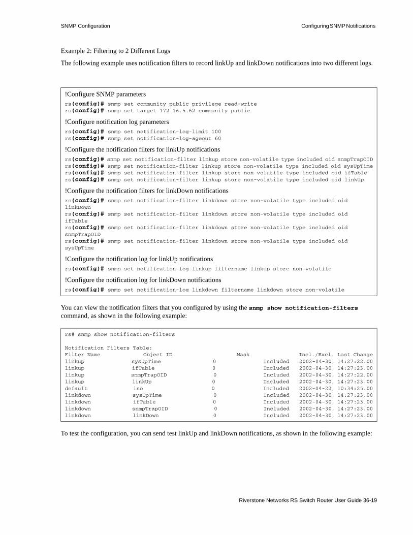
SNMP Configuration Configuring SNMP Notifications
Example 2: Filtering to 2 Different Logs
The following example uses notification filters to record linkUp and linkDown notifications into two different logs.
You can view the notification filters that you configured by using the snmp show notification-filters command, as shown in the following example:
To test the configuration, you can send test linkUp and linkDown notifications, as shown in the following example:
!Configure SNMP parametersrs(config)# snmp set community public privilege read-writers(config)# snmp set target 172.16.5.62 community public
!Configure notification log parametersrs(config)# snmp set notification-log-limit 100rs(config)# snmp set notification-log-ageout 60
!Configure the notification filters for linkUp notificationsrs(config)# snmp set notification-filter linkup store non-volatile type included oid snmpTrapOIDrs(config)# snmp set notification-filter linkup store non-volatile type included oid sysUpTimers(config)# snmp set notification-filter linkup store non-volatile type included oid ifTablers(config)# snmp set notification-filter linkup store non-volatile type included oid linkUp
!Configure the notification filters for linkDown notificationsrs(config)# snmp set notification-filter linkdown store non-volatile type included oidlinkDownrs(config)# snmp set notification-filter linkdown store non-volatile type included oidifTablers(config)# snmp set notification-filter linkdown store non-volatile type included oidsnmpTrapOIDrs(config)# snmp set notification-filter linkdown store non-volatile type included oidsysUpTime
!Configure the notification log for linkUp notificationsrs(config)# snmp set notification-log linkup filtername linkup store non-volatile
!Configure the notification log for linkDown notificationsrs(config)# snmp set notification-log linkdown filtername linkdown store non-volatile
rs# snmp show notification-filters
Notification Filters Table:Filter Name Object ID Mask Incl./Excl. Last Changelinkup sysUpTime 0 Included 2002-04-30, 14:27:22.00linkup ifTable 0 Included 2002-04-30, 14:27:23.00linkup snmpTrapOID 0 Included 2002-04-30, 14:27:22.00linkup linkUp 0 Included 2002-04-30, 14:27:23.00default iso 0 Included 2002-04-22, 10:34:25.00linkdown sysUpTime 0 Included 2002-04-30, 14:27:23.00linkdown ifTable 0 Included 2002-04-30, 14:27:23.00linkdown snmpTrapOID 0 Included 2002-04-30, 14:27:23.00linkdown linkDown 0 Included 2002-04-30, 14:27:23.00
Riverstone Networks RS Switch Router User Guide 36-19

Configuring SNMP Notifications SNMP Configuration
Then, you can view the notifications in each log, as shown in the following example:
rs# snmp test trap type linkup%SNMP-I-SENT_TRAP, Sending notification linkUp to management stationrs# snmp test trap type linkDown%SNMP-I-SENT_TRAP, Sending notification linkDown to management station
rs# snmp show notification-log config-log allName = nlmLogNameTimeTicks = nlmLogTimeDateAndTime = nlmLogDateAndTimeTargetAddress = nlmLogEngineTAddressNotificationID = nlmLogNotificationIDName TimeTicks DateAndTime TargetAddress NotificationID---- --------- ----------- ------------- --------------linkup 70554900 2002-04-30 14:32:20 172.16.5.62 linkUp
linkdown 70554100 2002-04-30 14:32:12 172.16.5.62 linkDown
36-20 Riverstone Networks RS Switch Router User Guide
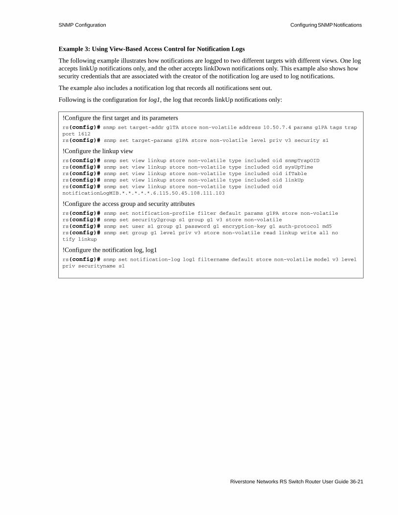
SNMP Configuration Configuring SNMP Notifications
Example 3: Using View-Based Access Control for Notification Logs
The following example illustrates how notifications are logged to two different targets with different views. One log accepts linkUp notifications only, and the other accepts linkDown notifications only. This example also shows how security credentials that are associated with the creator of the notification log are used to log notifications.
The example also includes a notification log that records all notifications sent out.
Following is the configuration for log1, the log that records linkUp notifications only:
!Configure the first target and its parametersrs(config)# snmp set target-addr g1TA store non-volatile address 10.50.7.4 params g1PA tags trap port 1612rs(config)# snmp set target-params g1PA store non-volatile level priv v3 security s1
!Configure the linkup viewrs(config)# snmp set view linkup store non-volatile type included oid snmpTrapOIDrs(config)# snmp set view linkup store non-volatile type included oid sysUpTimers(config)# snmp set view linkup store non-volatile type included oid ifTablers(config)# snmp set view linkup store non-volatile type included oid linkUprs(config)# snmp set view linkup store non-volatile type included oid notificationLogMIB.*.*.*.*.*.6.115.50.45.108.111.103
!Configure the access group and security attributesrs(config)# snmp set notification-profile filter default params g1PA store non-volatilers(config)# snmp set security2group s1 group g1 v3 store non-volatilers(config)# snmp set user s1 group g1 password g1 encryption-key g1 auth-protocol md5rs(config)# snmp set group g1 level priv v3 store non-volatile read linkup write all notify linkup
!Configure the notification log, log1rs(config)# snmp set notification-log log1 filtername default store non-volatile model v3 level priv securityname s1
Riverstone Networks RS Switch Router User Guide 36-21

Configuring SNMP Notifications SNMP Configuration
Following is the configuration for log2, the log that records linkDown notifications only:
Following is the configuration for logall, the log that records all notifications:
The following example sends three types of test notifications:
!Configure the second target and its parametersrs(config)# snmp set target-addr g2TA store non-volatile address 172.16.5.62 params g2PA port 1611rs(config)# snmp set target-params g2PA store non-volatile level priv v3 security s2
!Configure the linkdown viewrs(config)# snmp set view linkdown oid linkDown store non-volatile type includedrs(config)# snmp set view linkdown store non-volatile type included oid ifTablers(config)# snmp set view linkdown store non-volatile type included oid snmpTrapOIDrs(config)# snmp set view linkdown store non-volatile type included oid sysUpTimers(config)# snmp set view linkdown store non-volatile type included oid notificationLogMIB.*.*.*.*.*.6.115.49.108.111.103
!Configure the access group and security attributesrs(config)# snmp set notification-profile filter default params g2PA store non-volatilers(config)# snmp set security2group s2 group g2 v3 store non-volatilers(config)# snmp set user s2 group g2 password g2 encryption-key g2 auth-protocol md5rs(config)# snmp set group g2 level priv v3 store non-volatile read linkdown write allnotify linkdown
!Configure the notification log, log2rs(config)# snmp set notification-log log2 filtername default store non-volatile modelv3 level priv securityname s2
!Configure SNMP parametersrs(config)# snmp set community public privilege read-writers(config)# snmp set target 172.16.5.62 community public
!Configure the notification logrs(config)# snmp set notification-log logall filtername default store non-volatile
rs141# snmp test trap type ps-recover%SNMP-I-SENT_TRAP, Sending notification rsEnvPowerSypplyRecovered to managementstationrs141# snmp test trap type linkdown%SNMP-I-SENT_TRAP, Sending notification linkDown to management stationrs141# snmp test trap type linkUp%SNMP-I-SENT_TRAP, Sending notification linkUp to management station
36-22 Riverstone Networks RS Switch Router User Guide

SNMP Configuration Configuring SNMP Notifications
The following example shows that the LinkUp notification was logged to log1, and the linkDown notification was logged to log2. Additionally all notification were logged to logall which had no filters or security attributes:
rs# snmp show notification-log config-log allName = nlmLogNameTimeTicks = nlmLogTimeDateAndTime = nlmLogDateAndTimeTargetAddress = nlmLogEngineTAddressNotificationID = nlmLogNotificationIDName TimeTicks DateAndTime TargetAddress NotificationID---- --------- ----------- ------------- --------------
log1 418600 2002-05-02 10:24:11 172.16.5.62 linkUp
log2 417400 2002-05-02 10:23:58 172.16.5.62 linkDown
logall 415900 2002-05-02 10:23:44 172.16.5.62 rsEnvirPower SupplyRecoveredlogall 417400 2002-05-02 10:23:58 172.16.5.62 linkDown
logall 418600 2002-05-02 10:24:11 172.16.5.62 linkUp
Riverstone Networks RS Switch Router User Guide 36-23

MIB Modules SNMP Configuration
36.3 MIB MODULESRiverstone supports the following IETF and IEEE standard networking MIB modules and proprietary MIB modules. You can use these MIB modules with any SNMP version. This list can be obtained from the output of the snmp show mibs enable mode command.
Table 36-1 Supported MIBs
MIB II Layer 1 Layer 2 Layer 3 System Related Enterprise
IP-MIBRFC 2011
ETHERLIKE-
MIB | RFC 2665
FRAME-RELAY-DTE-MIB | RFC 2115
BGP4-MIBRFC 1657
RADIUS-AUTH-CLIENT-
MIB | RFC 2618
TCP-MIB RFC 2012
SONET-MIBRFC 1595
BRIDGE-MIBRFC 1493
RIPv2-MIBRFC 1724
RADIUS-ACC-CLIENT MIB
RFC 2620
UDP-MIBRFC 2013
DS0 MIB
RFC 2494
Q-BRIDGE-MIBRFC 2674
OSPF-MIBRFC 1850
DISMAN-SCHEDULE-MIB
RFC 2591
RIVERSTONE-STP-MIB7/16/00
IP-FORWARD-MIBRFC 2096
DS1-MIBRFC 2495
P-BRIDGE-MIBRFC 2674
OSPF-TRAP-
MIB |
RFC 1850
ENTITY-MIB |
RFC2737
RIVERSTONE-RS-AGENT-CAP-MIB
IF-MIBRFC 2233
DS3-MIBRFC 2496
PPP-LCP-MIBRFC 1471
RMON2-MIBRFC 2021
SNMPv3-MIB Modules|
RFC 2570-2576
RIVERSTONE-ATM-MIB |
1/31/01
SNMPv2-MIBRFC 1907
DS0BUNDLE- MIBRFC 2494
PPP-SEC-MIBRFC 1472
VRRP-MIBRFC 2787
DIFF-SERV-MIB |
Draft #5
RIVERSTONE-IMAGE-MIB |
3/16/01
MAU MIBRFC 2668
PPP-IP-NCP-MIBRFC 1473
DVMRP-MIBDraft #4
PING-MIB
RFC 2925
CISCO-BGP-POL- ACCOUNTING-MIB |
12/17/99
PPP-BRIDGE-NCP-MIBRFC 1474
IGMP-MIBRFC 2933
TRACEROUTE-MIB
RFC 2925
RIVERSTONE-LFAP-MIB |
6/15/01
RMON-MIBRFC 1757
ISIS-MIB
Draft #4
NOTIFICATION LOG-MIB RFC 3014
RIVERSTONE-RL-MIB |
10/10/02
36-24 Riverstone Networks RS Switch Router User Guide

SNMP Configuration MIB Modules
ATM-MIBRFC 2515
MPLS-LSR-MIB
Draft #7
DHCP-SERVER-MIB
Draft #7
RIVERSTONE-SNMP-MIB
12/4/00
LAG MIB |
802.3ad
RIVERSTONE-NOTIFICATIONS-MIB
3/12/02
ATM2-MIB
Draft #17
CTRON-LFAP (deprecated)8/28/99
CTRON-SSR-POLICY (deprecated)8/11/99
CTRON-SSR-CONFIG6/27/00
CTRON-SSR-HARDWARE (deprecated)6/27/00
CTRON-SSR-SERVICE-STATUS (deprecated)6/27/00
CTRON-SSR-CAPACITY-MIB
6/27/00
RIVERSTONE-INVENTORY-
MIB
8/22/01
RIVERSTONE-MPLS-MIB
5/24/02
RIVERSTONE-QUEUE-MIB
6/12/02
RIVERSTONE-VLAN-EXTENSION-MIB
8/5/02
Table 36-1 Supported MIBs (Continued)
Riverstone Networks RS Switch Router User Guide 36-25
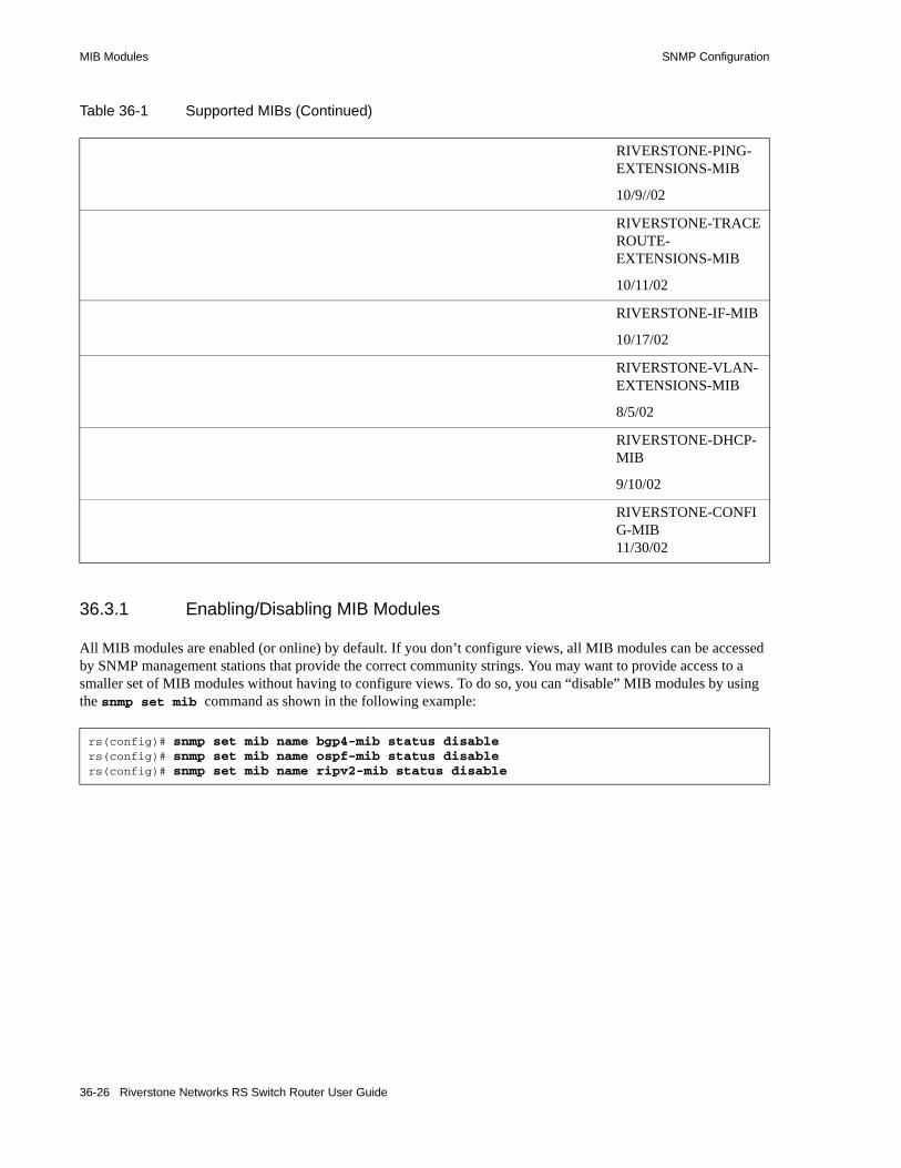
MIB Modules SNMP Configuration
36.3.1 Enabling/Disabling MIB Modules
All MIB modules are enabled (or online) by default. If you don’t configure views, all MIB modules can be accessed by SNMP management stations that provide the correct community strings. You may want to provide access to a smaller set of MIB modules without having to configure views. To do so, you can “disable” MIB modules by using the snmp set mib command as shown in the following example:
RIVERSTONE-PING-EXTENSIONS-MIB
10/9//02
RIVERSTONE-TRACEROUTE-EXTENSIONS-MIB
10/11/02
RIVERSTONE-IF-MIB
10/17/02
RIVERSTONE-VLAN-EXTENSIONS-MIB
8/5/02
RIVERSTONE-DHCP-MIB
9/10/02
RIVERSTONE-CONFIG-MIB11/30/02
rs(config)# snmp set mib name bgp4-mib status disablers(config)# snmp set mib name ospf-mib status disablers(config)# snmp set mib name ripv2-mib status disable
Table 36-1 Supported MIBs (Continued)
36-26 Riverstone Networks RS Switch Router User Guide

SNMP Configuration MIB Modules
You can then view the MIB modules, including their status, as shown in the following example:
36.3.2 SNMPv3 MIB Table Entries
The RS Ethernet Router supports the standard SNMPv3 MIB tables. It provides commands you can use to create rows in these tables. Following is a list of tables and the commands used to add rows to each table.
rs# snmp show mibsSNMP AGENT MIB RegistryLast Modified: 0 days 0 hours 1 min 34 secsIndex Name Version Status----- ---- ------- ------1 SNMPv2-MIB 1907 online2 EtherLike-MIB 2665 online3 MAU-MIB 2668 online4 IF-MIB 2233 online5 IP-MIB 2011 online6 IP-FORWARD-MIB 2096 online7 UDP-MIB 2013 online8 TCP-MIB 2012 online9 BGP4-MIB 1657 offline10 OSPF-MIB 1850 offline11 RIPv2-MIB 1724 offline12 BRIDGE-MIB 1493+2674 online13 FRAME-RELAY-DTE-MIB 2115 online14 PPP-LCP-MIB 1471 online15 PPP-SEC-MIB 1472 online16 PPP-IP-NCP-MIB 1473 online17 PPP-BRIDGE-NCP-MIB 1474 online18 DS0-MIB 2494 online19 DS0BUNDLE-MIB 2494 online...
Table 36-2 SNMPv3 Tables
Use this command... for this table...for additional information,
see...
snmp set snmp-community snmpCommunityTable RFC 2576
snmp set target-addr snmpTargetAddrTable RFC 2573
snmp set target-params snmpTargetParamsTable RFC 2573
snmp set notification snmpNotifyTable RFC 2573
snmp set notification-profile snmpNotifyFilterProfileTable RFC 2573
snmp set notification-filter snmpNotifyFilterTable RFC 2573
snmp set user usmUserTable RFC 2574
snmp set security2group vacmSecurityToGroupTable RFC 2575
Riverstone Networks RS Switch Router User Guide 36-27

MIB Modules SNMP Configuration
Note It is recommended that you use the commands described in Creating Views, Configuring Access Groups, and Configuring Users, instead of the commands in Table 36-2 to configure the MIB tables directly.
snmp set group vacmAccessTable RFC 2575
snmp set view vacmViewTreeFamilyTable RFC 2575
Table 36-2 SNMPv3 Tables
Use this command... for this table...for additional information,
see...
36-28 Riverstone Networks RS Switch Router User Guide

37 WDM CONFIGURATION
The R38-WDMD9-04 line card uses Wave Division Multiplexing (WDM) to provide four channels of 1000Base-TX. While the WDM line card has only a single physical port, each channel acts as a virtual Gigabit Ethernet port, for a total of four Gigabit ports. These WDM virtual ports function as physical ports on the RS 38000; they can be assigned interfaces, added to VLANs, and incorporated into SmartTRUNK aggregations.
Table 37-1 shows the relationship between the channels, their wavelengths, and the ports they represent.
Note Notice in the table above that WDM ports use the same naming convention as other Gigabit Ethernet ports: gi.<slot>.<port number>.
37.1 ENABLING WDM CHANNELSBy default, each WDM Gigabit port is disabled and must be enabled using the port enable wdm command. For example, the following enables the first and second ports (channels) on the WDM line card in slot five of the RS 38000:
Table 37-1 WDM channel, wavelength, and port
Channel Wavelength1 Corresponding Port2
l1 1500 nm Port 1 – gi.x.1
l2 1520 nm Port 2 – gi.x.2
l3 1540 nm Port 3 – gi.x.3
l4 1560 nm Port 4 – gi.x.41 Wavelengths are approximate
2 The X represents the number of the slot in which the WDM line card resides.
rs(config)# port enable wdm ports gi.5.1rs(config)# port enable wdm ports gi.5.2
Riverstone Networks RS Switch Router User Guide 37-1
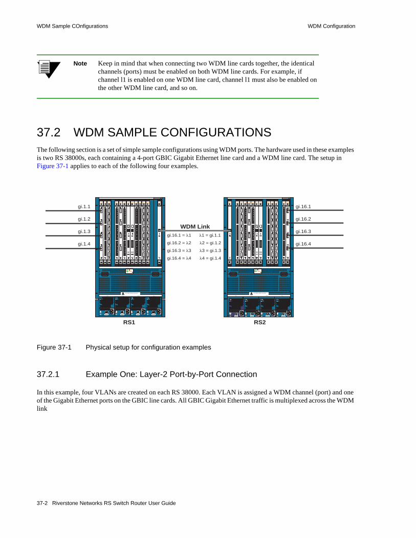
WDM Sample COnfigurations WDM Configuration
Note Keep in mind that when connecting two WDM line cards together, the identical channels (ports) must be enabled on both WDM line cards. For example, if channel l1 is enabled on one WDM line card, channel l1 must also be enabled on the other WDM line card, and so on.
37.2 WDM SAMPLE CONFIGURATIONSThe following section is a set of simple sample configurations using WDM ports. The hardware used in these examples is two RS 38000s, each containing a 4-port GBIC Gigabit Ethernet line card and a WDM line card. The setup in Figure 37-1 applies to each of the following four examples.
Figure 37-1 Physical setup for configuration examples
37.2.1 Example One: Layer-2 Port-by-Port Connection
In this example, four VLANs are created on each RS 38000. Each VLAN is assigned a WDM channel (port) and one of the Gigabit Ethernet ports on the GBIC line cards. All GBIC Gigabit Ethernet traffic is multiplexed across the WDM link
SYSTEM CARDS ACCESS
1 2 3 4 5 6 7 CPU-1 8 9 10 11 12 13 14
PS-1 PS-2 PS-3 PS-4
CPU 0-16
1
2
3
4
1
2
3
4
5
6
7
8
1
2
3
4
1
2
3
4
5
6
7
8
1
2
3
4
5
6
7
8
SYSTEM CARDS ACCESS
1 2 3 4 5 6 7 CPU-1 8 9 10 11 12 13 14
PS-1 PS-2 PS-3 PS-4
CPU 0-16
1
2
3
4
1
2
3
4
5
6
7
8
1
2
3
4
1
2
3
4
5
6
7
8
1
2
3
4
5
6
7
8
FAULT
AC ON
R30-AMC
FAULT
AC ON
R30-AMC
FAULT
AC ON
R30-AMC
FAULT
AC ON
R30-AMC
FAULT
AC ON
R30-AMC
FAULT
AC ON
R30-AMC
FAULT
AC ON
R30-AMC
FAULT
AC ON
R30-AMC
WDM Link
gi.16.1
gi.16.2
gi.16.3
gi.16.4
gi.16.1 = �1
gi.16.2 = �2
gi.16.3 = �3
gi.16.4 = �4
�1 = gi.1.1
�2 = gi.1.2
�3 = gi.1.3
�4 = gi.1.4
gi.1.1
gi.1.2
gi.1.3
gi.1.4
RS1 RS2
37-2 Riverstone Networks RS Switch Router User Guide

WDM Configuration WDM Sample COnfigurations
For RS1, enter the following configuration commands:
For RS2, enter the following configuration lines:
37.2.2 Example Two: Assigning WDM ports to a SmartTRUNK
In this example, all WDM ports are added to a SmartTRUNK. A single VLAN is created on each RS 38000, and both the SmartTRUNKs and the GBIC Gigabit Ethernet ports are added to the VLAN, which connect through the WDM link.
For RS1, enter the following configuration commands:
For RS2, enter the following configuration commands:
rs(config)# port enable wdm ports gi.16.1-4rs(config)# vlan create wdm1 id 2rs(config)# vlan create wdm2 id 3rs(config)# vlan create wdm3 id 4rs(config)# vlan create wdm4 id 5rs(config)# vlan add port gi.16.1,gi.1.1 to wdm1rs(config)# vlan add port gi.16.2,gi.1.2 to wdm2rs(config)# vlan add port gi.16.3,gi.1.3 to wdm3rs(config)# vlan add port gi.16.4,gi.1.4 to wdm4
rs(config)# port enable wdm ports gi.1.1-4rs(config)# vlan create wdm1 id 2rs(config)# vlan create wdm2 id 3rs(config)# vlan create wdm3 id 4rs(config)# vlan create wdm4 id 5rs(config)# vlan add port gi.1.1,gi.16.1 to wdm1rs(config)# vlan add port gi.1.2,gi.16.2 to wdm2rs(config)# vlan add port gi.1.3,gi.16.3 to wdm3rs(config)# vlan add port gi.1.4,gi.16.4 to wdm4
rs(config)# smarttrunk create st.1 protocol no-protocolrs(config)# port enable wdm ports gi.16.1-4rs(config)# smarttrunk add ports gi.16.1-4 to st.1rs(config)# vlan create wdm id 12rs(config)# vlan add ports st.1 to wdmrs(config)# vlan add ports gi.1.1-4 to wdm
rs(config)# smarttrunk create st.1 protocol no-protocolrs(config)# port enable wdm ports gi.1.1-4rs(config)# smarttrunk add ports gi.1.1-4 to st.1rs(config)# vlan create wdm id 12rs(config)# vlan add ports st.1 to wdmrs(config)# vlan add ports gi.16.1-4 to wdm
Riverstone Networks RS Switch Router User Guide 37-3

WDM Sample COnfigurations WDM Configuration
37.2.3 Example Three: Back-to-Back Layer-3 WDM Connection
In this example, each of the WDM ports are assigned interfaces on each RS 38000, where the corresponding WDM ports (channels) on each of the RS 38000s are on the same subnet. This creates four layer-3 connections across the WDM link.
For RS1, enter the following configuration commands:
For RS2, enter the following configuration commands:
37.2.4 Example Four: Layer-3 WDM Connection through Single Interface
In this example, the WDM ports are added to a SmartTRUNK on each RS 38000. The SmartTRUNK is assigned to an interface. As a result, the two RS 38000s are connected such that all WDM ports are within the same subnet.
For RS1, enter the following configuration commands:
For RS2, enter the following configuration commands:
rs(config)# port enable wdm ports gi.16.1-4rs(config)# interface create ip wdm1 address-netmask 192.1.1.1/24 port gi.16.1rs(config)# interface create ip wdm2 address-netmask 193.1.1.1/24 port gi.16.2rs(config)# interface create ip wdm3 address-netmask 194.1.1.1/24 port gi.16.3rs(config)# interface create ip wdm4 address-netmask 195.1.1.1/24 port gi.16.4
rs(config)# port enable wdm ports gi.1.1-4rs(config)# interface create ip wdm1 address-netmask 192.1.1.2/24 port gi.1.1rs(config)# interface create ip wdm2 address-netmask 193.1.1.2/24 port gi.1.2rs(config)# interface create ip wdm3 address-netmask 194.1.1.2/24 port gi.1.3rs(config)# interface create ip wdm4 address-netmask 195.1.1.2/24 port gi.1.4
rs(config)# port enable wdm gi.16.1-4rs(config)# smarttrunk create st.1 protocol no-protocolrs(config)# smarttrunk add ports gi.16.1-4 to st.1rs(config)# interface create ip wdm address-netmask 192.10.31.1/24 port st.1
rs(config)# port enable wdm gi.1.1-4rs(config)# smarttrunk create st.1 protocol no-protocolrs(config)# smarttrunk add ports gi.1.1-4 to st.1rs(config)# interface create ip wdm address-netmask 192.10.31.2/24 port st.1
37-4 Riverstone Networks RS Switch Router User Guide
38 RTR CONFIGURATION
This chapter discusses how to use the Response Time Reporter (RTR) facility on the RS Ethernet Router to determine network availability, the response times between nodes on the network, and route paths between devices. RTR implements the functionality of the SNMP MIBs titled DISMAN-PING-MIB and DISMAN-TRACEROUTE-MIB as defined in RFC 2925. These commands allow you to set-up pre-configured tests to monitor the following:• Connectivity between nodes• Response time between nodes using either the ICMP Echo, a TCP connection operation, a UDP
Echo operation, or and ATM OAM ping.• The number of hops within a route between two nodes and the response time for each hop.• Changes in routes between two nodes.
The data generated from these tests can be used to develop historical trends, send SNMP traps when a configured threshold is exceeded or a route has changed, or for periodic checks of network connectivity. Parameters are available that allow you to determine how much historical data is retained, and under which circumstances SNMP traps are generated.
This chapter contains the following two examples of how RTR can be used to perform response time monitoring:• Section 38.1, "Example of RTR Scheduled PING test," describes how to configure a scheduled
ping test operation• Section 38.2, "Example of RTR Scheduled TRACEROUTE test," describes how to configure a
scheduled traceroute test operation
Each of these examples describe how to configure a test, run it and then view the results of the test.
Note The RTR functionality is now available through SNMP using the RIVERSTONE-PING-EXTENSIONS-MIB and the RIVERSTONE-TRACEROUTE-EXTENSIONS-MIB.
Riverstone Networks RS Switch Router User Guide 38-1

Example of RTR Scheduled PING test RTR Configuration
38.1 EXAMPLE OF RTR SCHEDULED PING TESTThe example in Figure 38-1 shows an RTR scheduled ping test configured from R1 (source) to Host 1 (target). The test is configured on R1.
Figure 38-1 Configuring a RTR scheduled ping test
The following sections describe how to configure a scheduled ping test operation for this example, run it, and view the results:• Section 38.1.1, "Configuring an RTR Scheduled Ping test," describes how to configure a test• Section 38.1.2, "Running an RTR Scheduled Ping Test," describes how to run a test or test operation• Section 38.1.3, "Configuring an RTR Ping Operation to Execute at a Recurring Interval," describes
how to configure a test operation to be performed at a recurring interval• Section 38.1.5, "Viewing the Parameters and Results of an RTR Scheduled Ping Test," describes how
to view the configuration and results of a test or test operation• Section 38.1.6, "Using the RTR ATM OAM Ping facility," describes how to use the RTR ATM OAM
ping capability
38.1.1 Configuring an RTR Scheduled Ping test
This example describes how to configure the test described in Section 38.1, "Example of RTR Scheduled PING test." When configuring a ping operation, there are three mandatory parameters: owner, test-name, and target. The owner/test-name combination comprises the index for the operation being defined and as such must be unique. This index is then used by other commands such as rtr start and rtr show to identify which configured ping operation that you want to start or display. The RTR facility will use the defaults defined in RFC 2925 for all other parameters, unless configured otherwise.
R1
Host 1
IP Address 192.1.1.1
IP Address 193.1.1.1
38-2 Riverstone Networks RS Switch Router User Guide

RTR Configuration Example of RTR Scheduled PING test
In this example, the ping operation is conducted using the Internet Control Message Protocol (ICMP) “ECHO” facility. The owner of the test is “ADMIN,” the test-name is “TEST1,” the probe-fail limit is set at 1 and the probe-failure traps parameter is set to send a trap if the ping operation fails. The SNMP traps will be sent to hosts defined using the SNMP Set Target command for the RS Ethernet Router. Source and target for operation of this test are specified as defined in Figure 38-1. Defaults are accepted for all other parameters:
To finish creating the ping test operation, you must execute a save active command at the configuration prompt, as shown in the following example:
As shown in the example, the test operation is created in the idle state. To run the test operation you must either include the immediate-start parameter or use the rtr start ping command in Enable mode, as described in Section 38.1.2, "Running an RTR Scheduled Ping Test."
38.1.2 Running an RTR Scheduled Ping Test
RTR schedule ping test operations can be run from the Config mode using the immediate-start parameter or from Enable mode using the rtr start ping command. If you include the immediate-start parameter in the rtr schedule ping command during configuration, the command will begin to execute as soon as it is saved to the active configuration, as shown in the following example:
rs(config)# rtr schedule ping owner ADMIN probe-limit-fail 1 probe-failure-traps source 193.1.1.1 target 192.1.1.1 test-name TEST1
rs(config)# save active
%RTR-I-TESTCREATED, Successfully created Ping operation for owner "ADMIN", test
name "TEST1"
%RTR-I-NEWTESTINACTIVE, Newly created test operation is idle. To start the operation, please use the enable mode command "rtr start ping"
rs(config)#
rs<config># rtr schedule ping owner ADMIN probe-limit-fail 1 probe-limit-traps source 193.1.1.1 target 192.1.1.1 test-name TEST1 immediate-start
rs<config># save active
%RTR-I-TESTCREATED, Successfully created Ping operation for owner "ADMIN", test
name "TEST2"
rs(config)#
Riverstone Networks RS Switch Router User Guide 38-3

Example of RTR Scheduled PING test RTR Configuration
If you didn’t use the immediate-start parameter, you must use the rtr start ping command in Enable mode. This example runs the ping test operation configured in Section 38.1.1, "Configuring an RTR Scheduled Ping test." The owner/test-name defined during configuration is used with this command to identify the test operation you want to run.
38.1.3 Configuring an RTR Ping Operation to Execute at a Recurring Interval
Using the frequency parameter of the rtr schedule command, you can configure an RTR Test Operation to be performed at a recurring interval. This example describes how to configure the same test described in Section 38.1, "Example of RTR Scheduled PING test," with the frequency parameter of the rtr schedule command set for a execution at a recurring interval.
In the following example, the rtr schedule ping command is used to configure the test operation to operate at a recurring interval. The frequency parameter is set to run the test operation once per day (every 86400 seconds) and the rest of the parameters are the same as defined in Section 38.1.2, "Running an RTR Scheduled Ping Test."
Once the RTR test operation has been configured it can be set in motion through use of the rtr start command, as described in Section 38.1.2, "Running an RTR Scheduled Ping Test." Alternatively, it could be started at configuration time by inserting the immediate-start parameter in the command. Once started, a command configured with a frequency parameter will run at the recurring interval until it is halted by an rtr suspend command.
38.1.4 Stopping a Running RTR Ping Test Operation
RTR ping test operations can be run from Enable Mode using the rtr start command or from Configure mode by setting the immediate-start parameter in the rtr schedule command. If the command is configured without the frequency parameter specified, it will halt after executing the test operation once. If the command is configured with the frequency parameter to operate at a recurring interval, as described in Section 38.1.3, "Configuring an RTR Ping Operation to Execute at a Recurring Interval," you must halt it using the rtr suspend command from Enable mode. This example describes the command used to suspend the ping test operation configured in Section 38.1.1, "Configuring an RTR Scheduled Ping test." The owner/test-name defined during configuration is used with this command to identify the test operation you want to suspend.
rs# rtr start ping owner ADMIN test-name TEST1
rtr schedule ping owner ADMIN test-name TEST1 probe-limit-fail 1 probe-limit-traps source 192.1.1.1 target 193.1.1.1. frequency 86400
rs(config)# rtr suspend ping owner ADMIN test-name TEST1
38-4 Riverstone Networks RS Switch Router User Guide

RTR Configuration Example of RTR Scheduled PING test
38.1.5 Viewing the Parameters and Results of an RTR Scheduled Ping Test
RTR ping test operations can be run from Enable mode using the rtr start command or from Configure mode by setting the immediate-start parameter in the rtr schedule command. Once a test is run, you need to use the rtr show ping command to view the results of a test. This example shows the parameters and results for the ping test configured in Section 38.1.1, "Configuring an RTR Scheduled Ping test." The owner/test-name defined during
Riverstone Networks RS Switch Router User Guide 38-5

Example of RTR Scheduled PING test RTR Configuration
configuration is used with this command to identify the test operation whose parameters and results you want to view.
38-6 Riverstone Networks RS Switch Router User Guide
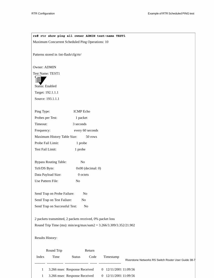
RTR Configuration Example of RTR Scheduled PING test
rs# rtr show ping all owner ADMIN test-name TEST1
Maximum Concurrent Scheduled Ping Operations: 10
Patterns stored in /int-flash/cfg/rtr/
Owner: ADMIN
Test Name: TEST1
Status: Enabled
Target: 192.1.1.1
Source: 193.1.1.1
Ping Type: ICMP Echo
Probes per Test: 1 packet
Timeout: 3 seconds
Frequency: every 60 seconds
Maximum History Table Size: 50 rows
Probe Fail Limit: 1 probe
Test Fail Limit: 1 probe
Bypass Routing Table: No
ToS/DS Byte: 0x00 (decimal: 0)
Data Payload Size: 0 octets
Use Pattern File: No
Send Trap on Probe Failure: No
Send Trap on Test Failure: No
Send Trap on Successful Test: No
2 packets transmitted, 2 packets received, 0% packet loss
Round Trip Time (ms): min/avg/max/sum2 = 3.266/3.309/3.352/21.902
Results History:
Riverstone Networks RS Switch Router User Guide 38-7
Round Trip Return
Index Time Status Code Timestamp
--------- -------------- -------------------- ------ -------------------
1 3.266 msec Response Received 0 12/11/2001 11:09:56
1 3.266 msec Response Received 0 12/11/2001 11:09:56

Example of RTR Scheduled PING test RTR Configuration
38.1.6 Using the RTR ATM OAM Ping facility
Note This section describes just the ATM OAM ping-specific capabilities of the RTR facility. All other RTR scheduling capabilities apply equally to the ATM OAM ping feature.
RTR provides the ability to perform ATM end-to-end or segment pings using Operation Administration and Management (OAM) flows. This is an ATM layer (layer-2) ping capability provided by OAM flows F4 and F5, which exist within the ATM cell header.
The F5 and F4 flows relate to VC and VP monitoring, respectively. Both F4 and F5 flows are designated as either segment or end-to-end inquiries, depending on the encoding within the ATM cell header. An end-to-end flow is from one end-point to another, and is received only by the device terminating the ATM connection. Conversely, segment flows are from one connection point to another – a connection point where a VCI or VPI is assigned, reassigned or terminated.
For F4 flows, the VCI field identifies the OAM as a segment type, if the VCI = 3; or as an end-to-end type, if the VCI = 4. In the case of F4 OAM flows the VPI is equal to that of the user’s data cells.
F5 flows operate in much the same way as F4 flows, however, both the VPI and VCI are set to that of the data flow. In the case of F5 flows, the Path Termination (PT) is used to identify the type of OAM flow (segment or end-to-end). Note that the PT is specified automatically for F5 flows when either the segment or end-to-end option is selected.
Note For a complete list of RTR ATM ping options, see the RTR chapter of the “Riverstone Networks Command Line Interface Reference Manual.”
38.1.6.1 Sending ATM OAM Pings
The following example uses the RTR facility to send an F5 flow to create an end-to-end OAM ping. The example assumes that a VCL of at.5.1.0.100 has been created, and an ATM OAM service of end-to-end has been created and applied to the VCL:
rs(config)# rtr schedule atm-ping atm-flow-type end-to-end atm-port at.5.1.0.100 owner IT test-name test1 immediate-start
38-8 Riverstone Networks RS Switch Router User Guide

RTR Configuration Example of RTR Scheduled PING test
The count of these F5 OAM pings can be viewed using the atm show vc-stats oam command. For example:
The following example uses the RTR facility to send an F4 flow to create an end-to-end OAM ping. The example assumes that a VCL of at.5.1.0.4 (VCI of 4 equals end-to-end for F4 OAM flows) has been created, and an ATM OAM service of end-to-end has been created and applied to the VCL
The count of these F4 OAM pings can be viewed using the atm show vc-stats oam command. For example:
rs# atm show vc-stats port at.5.1.0.100 oamat.5.1.0.100 Transmitted OAM Cells
End Loop Segment Loop AIS RDI +------------+-------------+------------+------------+F5 | 112 | 0 | 0 | 0 | +------------+-------------+------------+------------+F4 | 0 | 0 | 0 | 0 | +------------+-------------+------------+------------+
at.5.1.0.100 Received OAM Cells
End Loop Segment Loop AIS RDI +------------+-------------+------------+------------+F5 | 74 | 0 | 0 | 0 | +------------+-------------+------------+------------+F4 | 0 | 0 | 0 | 0 | +------------+-------------+------------+------------+
Cells Dropped: 0
rs(config)# rtr schedule atm-ping atm-flow-type end-to-end atm-port at.5.1.0.4 owner IT test-name test1 immediate-start
rs# atm show vc-stats port at.5.1.0.4 oamat.5.1.0.100 Transmitted OAM Cells
End Loop Segment Loop AIS RDI +------------+-------------+------------+------------+F5 | 0 | 0 | 0 | 0 | +------------+-------------+------------+------------+F4 | 115 | 0 | 0 | 0 | +------------+-------------+------------+------------+
at.5.1.0.100 Received OAM Cells
End Loop Segment Loop AIS RDI +------------+-------------+------------+------------+F5 | 0 | 0 | 0 | 0 | +------------+-------------+------------+------------+F4 | 101 | 0 | 0 | 0 | +------------+-------------+------------+------------+
Cells Dropped: 0
Riverstone Networks RS Switch Router User Guide 38-9

Example of RTR Scheduled TRACEROUTE test RTR Configuration
38.2 EXAMPLE OF RTR SCHEDULED TRACEROUTE TEST
The example in Figure 38-2 shows an RTR scheduled traceroute test configured from R1 (source) to Host 1 (target). The test is configured on R2.
Figure 38-2 Configuring an RTR Scheduled Traceroute Test
The following sections describe how to configure a Scheduled Traceroute test for this example, run it, and view the results:• To configure a traceroute test operation, see Section 38.2.1, "Configuring an RTR Scheduled
Traceroute Test Operation."• To run a traceroute test operation see Section 38.2.2, "Running an RTR Scheduled Traceroute Test."• To configure a traceroute test operation to be performed at a recurring interval, see Section 38.2.3,
"Configuring an RTR Traceroute Operation to Execute at a Recurring Interval."• To view the configuration and results of a RTR traceroute test operation see Section 38.2.5, "Viewing
the Parameters and Results of an RTR Scheduled Traceroute Test."
38.2.1 Configuring an RTR Scheduled Traceroute Test Operation
This example describes how to configure the test described in Section 38.2, "Example of RTR Scheduled TRACEROUTE test." When configuring a traceroute operation, there are three mandatory parameters: owner, test-name, and target. The owner/test-name combination comprises the index for the operation being defined and as such must be unique. This index is then used by other commands such as rtr start and rtr show to identify the configured traceroute operation that you want to start or view. The RTR facility will use the defaults defined in RFC 2925 for all other parameters, unless configured otherwise.
R1
Host 1
IP Address 192.1.1.1
IP Address 193.1.1.1
38-10 Riverstone Networks RS Switch Router User Guide

RTR Configuration Example of RTR Scheduled TRACEROUTE test
In this example, the owner of the test is “ADMIN,” the test-name is TEST1 and the path-change-traps parameter is set to send a trap if the path between Host 1 and R2 changes. Source and target are specified as defined in Figure 38-2. Defaults are accepted for all other parameters.
Note If you want to save path information during a traceroute test operation, you must add the save-path parameter to the command syntax.
To finish creating the traceroute test operation, you must execute a save active command at the configuration prompt, as shown in the following example:
As shown in the example, the test operation is created in the idle state. To run the test operation you must either include the immediate-start parameter or use the rtr start traceroute command in Enable mode as described in Section 38.2.2, "Running an RTR Scheduled Traceroute Test."
rs(config) rtr schedule traceroute owner ADMIN path-change-traps source 192.1.1.1 target 193.1.1.1 test-name TEST1
rs(config)# save active
%RTR-I-TESTCREATED, Successfully created Traceroute operation for owner "ADMIN", test
name "TEST1"
%RTR-I-NEWTESTINACTIVE, Newly created test operation is idle. To start the operation, please use the enable mode command "rtr start traceroute"
rs(config)#
Riverstone Networks RS Switch Router User Guide 38-11

Example of RTR Scheduled TRACEROUTE test RTR Configuration
38.2.2 Running an RTR Scheduled Traceroute Test
RTR scheduled traceroute test operations can be run from the Config mode using the immediate-start parameter or from Enable Mode using the rtr start traceroute command. If you include the immediate-start parameter in the rtr schedule traceroute command during configuration, the command will begin to execute as soon as it is saved to the active configuration, as shown in the following example:
If you didn’t use the immediate-start parameter, you must use the rtr start traceroute command in enable mode. This example runs the traceroute test operation configured in Section 38.2.1, "Configuring an RTR Scheduled Traceroute Test Operation." The owner/test-name defined during configuration is used with this command to identify the test operation you want to run.
38.2.3 Configuring an RTR Traceroute Operation to Execute at a Recurring Interval
Using the frequency parameter of the rtr schedule traceroute command, you can configure an RTR test operation to be performed at a recurring interval. This example describes how to configure the same test described in Section 38.2, "Example of RTR Scheduled TRACEROUTE test," with the frequency parameter of the rtr schedule traceroute command set for a execution at a recurring interval.
In the following example, the rtr schedule traceroute command is used to configure the test operation to operate at a recurring interval. The frequency parameter is set to run the test operation once per day (every 86400 seconds) and the rest of the parameters are the same as defined in Section 38.1.2, "Running an RTR Scheduled Ping Test."
rs(config)# rtr schedule traceroute owner ADMIN path-change-traps source 193.1.1.1 target 192.1.1.1 test-name TEST1 immediate-start
rs(config)# save active
%RTR-I-TESTCREATED, Successfully created Traceroute operation for owner "ADMIN", test
name "TEST2"
rs(config)#
rs# rtr start traceroute owner ADMIN test-name TEST1
rs(config)# rtr schedule traceroute owner ADMIN test-name TEST1 path-change-traps source 193.1.1.1 target 192.1.1.1 immediate-start frequency 86400
38-12 Riverstone Networks RS Switch Router User Guide
RTR Configuration Example of RTR Scheduled TRACEROUTE test
Once the RTR test operation has been configured it can be set in motion through use of the rtr start traceroute command as described in Section 38.2.2, "Running an RTR Scheduled Traceroute Test." Alternatively, it could be started at configuration time by inserting the immediate-start parameter in the command (as shown in this example). Once started, a command configured with a frequency parameter will run at the recurring interval until it is halted by an rtr suspend traceroute command.
38.2.4 Stopping a Running RTR Traceroute Test Operation
RTR traceroute test operations can be run from Enable mode using the rtr start traceroute command or from Configure mode by setting the immediate-start parameter in the rtr schedule traceroute command. If the command is configured without the frequency parameter specified, it will halt after executing the test operation once. If the command is configured with the frequency parameter to operate at a recurring interval, as described in Section 38.2.3, "Configuring an RTR Traceroute Operation to Execute at a Recurring Interval," you must halt it using the rtr suspend traceroute command from Enable mode. This example describes the command used to suspend the traceroute test operation configured in Section 38.2.1, "Configuring an RTR Scheduled Traceroute Test Operation." The owner/test-name defined during configuration is used with this command to identify the test operation you want to suspend.
38.2.5 Viewing the Parameters and Results of an RTR Scheduled Traceroute Test
RTR show traceroute tests are run from Enable Mode. This example shows the parameters and results for the traceroute test configured in Section 38.2.1, "Configuring an RTR Scheduled Traceroute Test Operation."
38.2.6 Viewing the Parameters and Results of an RTR Scheduled Traceroute Test
RTR traceroute test operations can be run from Enable mode using the rtr start traceroute command or from Configure mode by setting the immediate-start parameter in the rtr schedule traceroute command. Once a test is run, you need to use the rtr show traceroute command to view the results of a test operation. This
rs# rtr suspend traceroute owner ADMIN test-name TEST1
rs(config)# rtr show ping all owner ADMIN test-name TEST1
Riverstone Networks RS Switch Router User Guide 38-13

Example of RTR Scheduled TRACEROUTE test RTR Configuration
example shows the parameters and results for the traceroute test configured in Section 38.2.1, "Configuring an RTR Scheduled Traceroute Test Operation.". The owner/test-name defined during configuration is used with this command
38-14 Riverstone Networks RS Switch Router User Guide

RTR Configuration Example of RTR Scheduled TRACEROUTE test
to identify the test operation whose parameters and results you want to view.
Riverstone Networks RS Switch Router User Guide 38-15
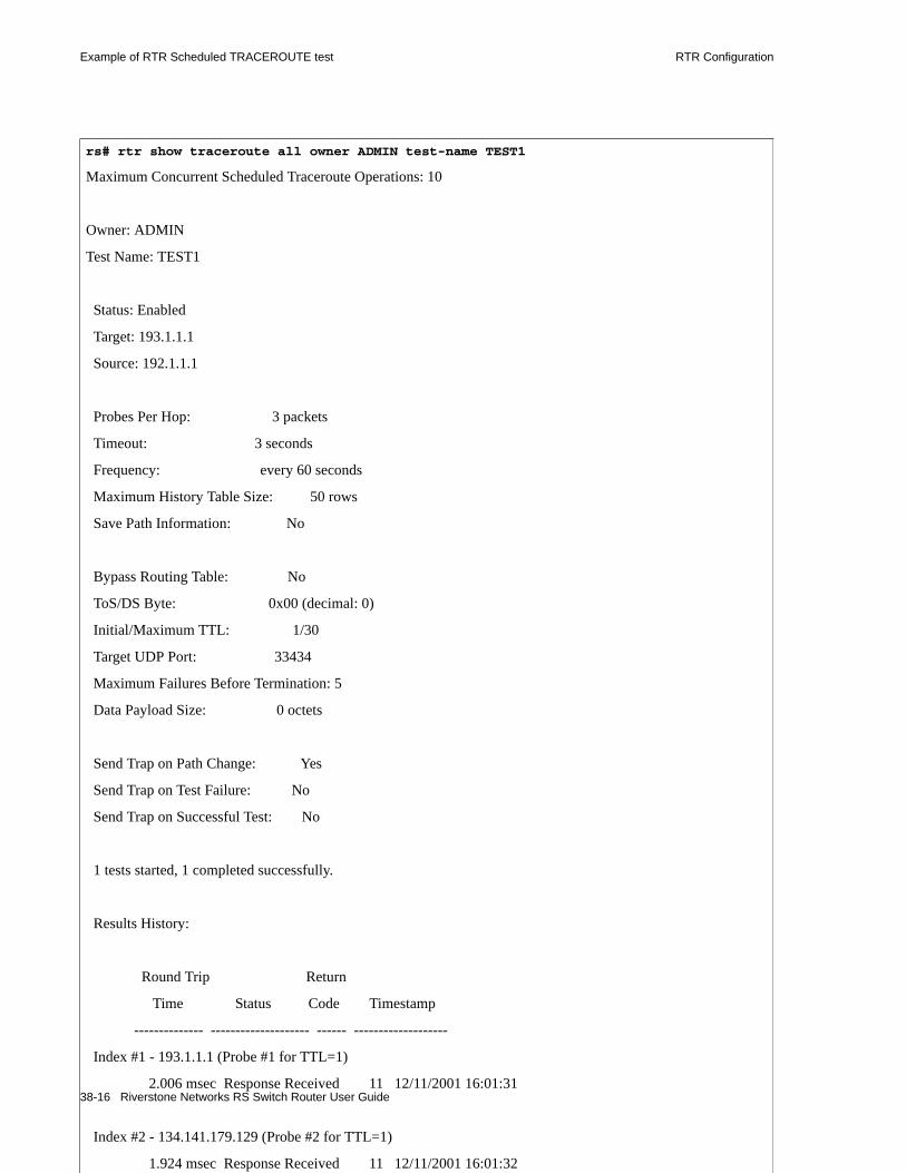
Example of RTR Scheduled TRACEROUTE test RTR Configuration
rs# rtr show traceroute all owner ADMIN test-name TEST1
Maximum Concurrent Scheduled Traceroute Operations: 10
Owner: ADMIN
Test Name: TEST1
Status: Enabled
Target: 193.1.1.1
Source: 192.1.1.1
Probes Per Hop: 3 packets
Timeout: 3 seconds
Frequency: every 60 seconds
Maximum History Table Size: 50 rows
Save Path Information: No
Bypass Routing Table: No
ToS/DS Byte: 0x00 (decimal: 0)
Initial/Maximum TTL: 1/30
Target UDP Port: 33434
Maximum Failures Before Termination: 5
Data Payload Size: 0 octets
Send Trap on Path Change: Yes
Send Trap on Test Failure: No
Send Trap on Successful Test: No
1 tests started, 1 completed successfully.
Results History:
Round Trip Return
Time Status Code Timestamp
-------------- -------------------- ------ -------------------
38-16 Riverstone Networks RS Switch Router User Guide
Index #1 - 193.1.1.1 (Probe #1 for TTL=1)
2.006 msec Response Received 11 12/11/2001 16:01:31
Index #2 - 134.141.179.129 (Probe #2 for TTL=1)
1.924 msec Response Received 11 12/11/2001 16:01:32

RTR Configuration Example of RTR Scheduled TRACEROUTE test
Riverstone Networks RS Switch Router User Guide 38-17

Example of RTR Scheduled TRACEROUTE test RTR Configuration
38-18 Riverstone Networks RS Switch Router User Guide

39 LAYER-2 MAC-PING AND TRACE (ETHERNET OAM)CONFIGURATION GUIDE
This chapter describes operation of the MAC Ping facility. This facility allows you to perform management functions, such as performance monitoring and fault management at the physical (MAC) layer. Using this facility, you can send an EOAM mac ping frame to determine connectivity or include the tracepath option to trace the layer-2 path to a destination RS Ethernet Router.
Configuration and operation of this facility involves the following”• Section 39.0.1, "Setting an Authentication Key."• Section 39.0.2, "Confirming a Layer-2 Connection."• Section 39.0.3, "Sending a MAC Ping Tracepath Packet."• Section 39.0.4, "Managing the name-mac-list Table."• Section 39.0.5, "Displaying mac-ping Statistics."• Section 39.0.6, "Enabling the Tracing Function."
39.0.1 Setting an Authentication Key
In contrast to IP Ping which requires no special authorization, the MAC Ping facility requires use of an authentication key for operation. This key is also used to authorize any Riverstone equipment that is traversed to provide information when the MAC Ping utility is used. If there is non-Riverstone equipment or Riverstone equipment without a correct authentication key along the path between the originator and the target, the MAC Ping operation will succeed however, no trace information will be provided
Use of the authentication key differs somewhat depending on whether you are issuing a simple MAC Ping to determine connectivity and response time or using the traceroute option to identify routers along the path.
.The following sections determine each of these possible uses:• "Setting an Authentication Key for MAC Ping."• "Setting an Authentication Key for MAC Ping with the Traceroute option."
Riverstone Networks RS Switch Router User Guide 39-1
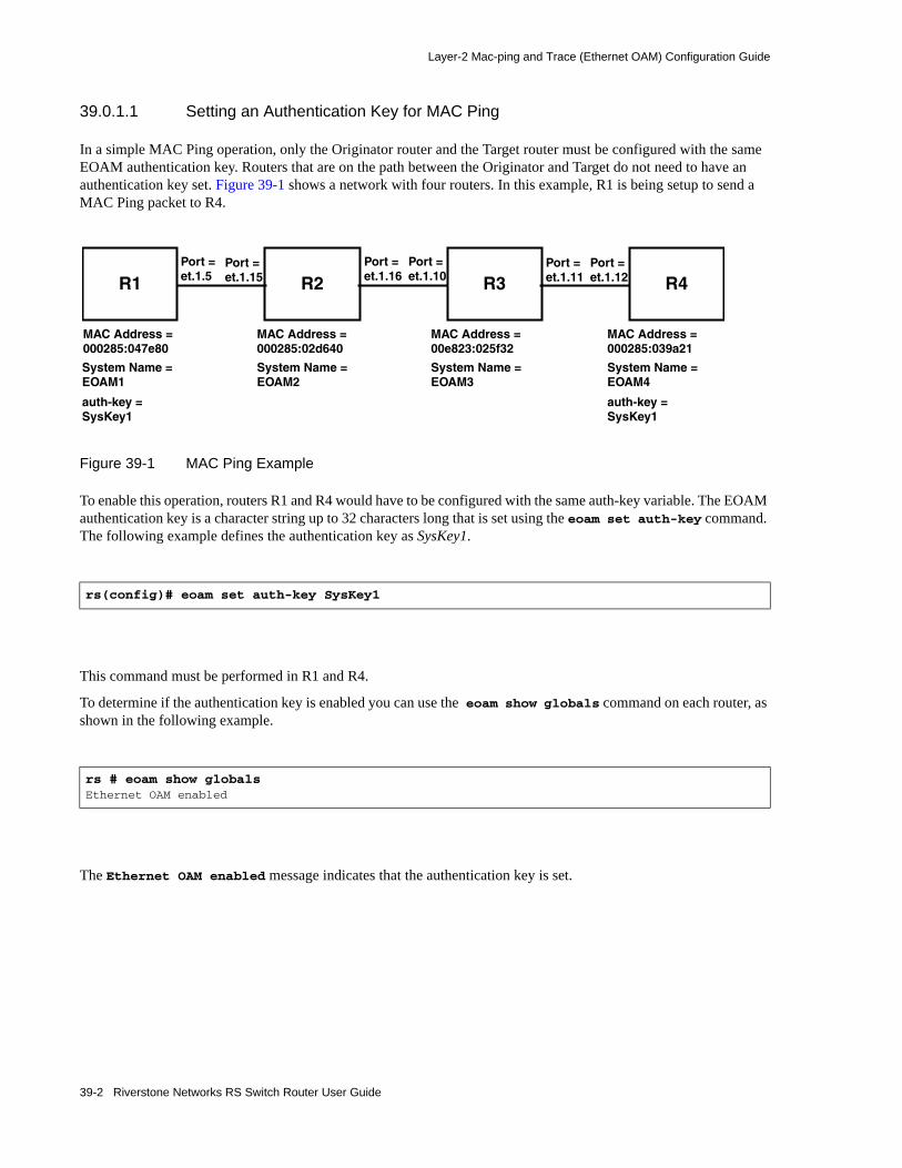
Layer-2 Mac-ping and Trace (Ethernet OAM) Configuration Guide
39.0.1.1 Setting an Authentication Key for MAC Ping
In a simple MAC Ping operation, only the Originator router and the Target router must be configured with the same EOAM authentication key. Routers that are on the path between the Originator and Target do not need to have an authentication key set. Figure 39-1 shows a network with four routers. In this example, R1 is being setup to send a MAC Ping packet to R4.
Figure 39-1 MAC Ping Example
To enable this operation, routers R1 and R4 would have to be configured with the same auth-key variable. The EOAM authentication key is a character string up to 32 characters long that is set using the eoam set auth-key command. The following example defines the authentication key as SysKey1.
This command must be performed in R1 and R4.
To determine if the authentication key is enabled you can use the eoam show globals command on each router, as shown in the following example.
The Ethernet OAM enabled message indicates that the authentication key is set.
rs(config)# eoam set auth-key SysKey1
rs # eoam show globalsEthernet OAM enabled
R1
MAC Address = 000285:047e80
System Name = EOAM1
MAC Address =000285:02d640
MAC Address =00e823:025f32
MAC Address =000285:039a21
System Name = EOAM2
System Name = EOAM3
System Name = EOAM4
Port =et.1.5
auth-key =SysKey1
R2 R3 R4Port =et.1.15
Port =et.1.16
Port =et.1.10
Port =et.1.11
Port =et.1.12
auth-key =SysKey1
39-2 Riverstone Networks RS Switch Router User Guide

Layer-2 Mac-ping and Trace (Ethernet OAM) Configuration Guide
39.0.1.2 Setting an Authentication Key for MAC Ping with the Traceroute option
In a MAC Ping operation using the Traceroute option, the Originator router, the Target router and all intermediate routers between them that you want to obtain Traceroute information about, must be configured with the same EOAM authentication key. Figure 39-2 shows a network with four routers. In this example, R1 is being setup to send a MAC Ping packet with the Traceroute option enabled to R4.
Figure 39-2 MAC Ping example with Traceroute
To enable this operation, routers R1, R2, R3 and R4 have to be configured with the same auth-key variable. The EOAM authentication key is a character string up to 32 characters long that is set using the eoam set auth-key command. The following example defines the authentication key as SysKey1.
This command must be performed in R1, R2, R3 and R4.
To determine if the authentication key is enabled you can use the eoam show globals command on each router, as shown in the following example.
The Ethernet OAM enabled message indicates that the authentication key is set.
rs(config)# eoam set auth-key SysKey1
rs # eoam show globalsEthernet OAM enabled
R1
MAC Address = 000285:047e80
System Name = EOAM1
MAC Address =000285:02d640
MAC Address =00e823:025f32
MAC Address =000285:039a21
System Name = EOAM2
System Name = EOAM3
System Name = EOAM4
Port =et.1.5
auth-key =SysKey1
R2 R3 R4Port =et.1.15
Port =et.1.16
Port =et.1.10
Port =et.1.11
Port =et.1.12
auth-key =SysKey1
auth-key =SysKey1
auth-key =SysKey1
Riverstone Networks RS Switch Router User Guide 39-3

Layer-2 Mac-ping and Trace (Ethernet OAM) Configuration Guide
39.0.2 Confirming a Layer-2 Connection
The EOAM facility allows you to confirm a layer-2 connection between an originator RS Ethernet Router and a target RS Ethernet Router. It also provides the transit time between the two routers. This is performed using the mac-ping command in enable mode. The mac-ping operation can be executed a single time, for a specified number of repetitions, or continuously until interrupted by the user. The output of the operation can be specified to be delivered in as a summary, detailed, or verbose.
To perform this operation, the same authentication key must be set on both the originator RS Ethernet Router and a target RS Ethernet Router, as described in "Setting an Authentication Key for MAC Ping."
To send an Mac Ping operation, you must at minimum specify the target you want to determine a connection to and the port on the originator that you want to send the EOAM frame out on. In the example shown in Figure 39-3, an EOAM frame is being sent to the target (R4) with Mac address of 000285:039a21. The port on the originator (R1) that the EOAM frame is being sent out on is et.1.5.
Figure 39-3 Mac Ping Example
The first example is set to deliver the output in summary format. The following examples will show the verbose and detailed output.
The following example shows the results of setting the mac-ping command to deliver verbose output.
rs(config)# mac-ping 000285:039a21 port et.1.5 summary67 bytes Ping frame sent from "00c863:047e80"
--- Ping Statistics --- 1 frames transmitted, 1 frames received, 0.00% frame lossround-trip min/avg/max/dev = 0.358/0.358/0.358/0.000 ms
R1
MAC Address = 000285:047e80
System Name = EOAM1
MAC Address =000285:02d640
MAC Address =00e823:025f32
MAC Address =000285:039a21
System Name = EOAM2
System Name = EOAM3
System Name = EOAM4
Port =et.1.5
auth-key =SysKey1
R2 R3 R4Port =et.1.15
Port =et.1.16
Port =et.1.10
Port =et.1.11
Port =et.1.12
auth-key =SysKey1
39-4 Riverstone Networks RS Switch Router User Guide

Layer-2 Mac-ping and Trace (Ethernet OAM) Configuration Guide
.
The following example shows the results of setting the mac-ping command to deliver detailed output.
Notice that the output for the detailed option displays the system names (EOAM1 and EOAM2) and the model names (RS 1000 and RS 3000) for each router. Using the mac-ping command with the detailed option populates the mac-name-list on the router that sent the mac-ping packet. This allows you to use the system name in place of the MAC Address for mac-ping operations.
rs(config)# mac-ping 000285:039a21 port et.1.5 verbose67 bytes Ping frame sent from "000285:047e80" 115 bytes from "000285:039a21" seq no 1 time= 0.350 ms,
BM = Bridging Mode, F = Flow-Based, A = Address-Based PT = Port Type, T = Trunk Port, A = Access Port FL = L2 Flow Entry type,N = No Flow S = Static, D = Dynamic FT = Filter policy to Destination ,X = Filter Applied VLAN = vlan, P = Port Based Vlan, N = Not port based vlan , ? = vlan does not exist, /T = vlan switching(translation) policy applied
SNo Input Port VLAN BM PT FT FL MAC-ADDR Output Port VLAN BM PT---- -------------- -------- -- -- -- -- ------------ -------------- -------- -- -- 1 000285:o47e80 et.1.5 A A 2. et.1.12 A A - D 000285:039a21
--- Ping Statistics --- 1 frames transmitted, 1 frames received, 0.00% frame lossround-trip min/avg/max/dev = 0.350/0.350/0.350/0.000 ms
rs# mac-ping 000285:039a21 port et.1.5 detailed67 bytes Ping frame sent from "000285:047e80" 211 bytes from "000285:039a21" seq no 1 time= 0.368 ms,
BM = Bridging Mode, F = Flow-Based, A = Address-Based PT = Port Type, T = Trunk Port, A = Access Port FL = L2 Flow Entry type,N = No Flow S = Static, D = Dynamic FT = Filter policy to Destination ,X = Filter Applied VLAN = vlan, P = Port Based Vlan, N = Not port based vlan , ? = vlan does not exist, /T = vlan switching(translation) policy applied
SNo Input Port VLAN BM PT FT FL MAC-ADDR Output Port VLAN BM PT---- -------------- -------- -- -- -- -- ------------ -------------- -------- -- -- 1 000285:o47e80 et.1.5 A A [ EOAM1, RS 1000, 9.3.0.0-B20 ] 2. et.1.12 A A - D 000285:039a21 [ EOAM4, RS 3000, 9.3.0.0-C11 ]
--- Ping Statistics --- 1 frames transmitted, 1 frames received, 0.00% frame lossround-trip min/avg/max/dev = 0.368/0.368/0.368/0.000 ms
Riverstone Networks RS Switch Router User Guide 39-5

Layer-2 Mac-ping and Trace (Ethernet OAM) Configuration Guide
39.0.3 Sending a MAC Ping Tracepath Packet
The EOAM facility can be used to obtain the layer-2 trace path information between an originator RS Ethernet Router and a target RS Ethernet Router. This is performed using the mac-ping command with the trace-path option set in enable mode. The mac-ping command can be executed a single time, for a specified number of repetitions, or continuously until interrupted by the user. The output of the operation can be specified to be delivered in summary, detailed, or verbose content format.
To perform this operation, the same authentication key must be set on the originator RS Ethernet Router and the target RS Ethernet Router. The authentication key must also be set for any nodes between the originator and target that you want to collect information from, as described in "Setting an Authentication Key for MAC Ping with the Traceroute option."
If there is non-Riverstone equipment or Riverstone equipment without a correct authentication key along the path between the originator and the target, the Mac-ping operation will succeed however, no trace information will be provided.
To execute the mac-ping command, you must at minimum specify the target you want to determine a connection to and the port on the originator that you want to send the EOAM tracepath frame out on. In the example shown in Figure 39-4, an EOAM frame is being sent to the target (R4) with Mac address of 000285:039a21. The port on the originator (R1) that the EOAM tracepath frame is being sent out on is et.1.5. The EOAM frame will traverse R2 and R3 and gather route information from them
Figure 39-4 Mac Ping Tracepath Example
The first example is set to deliver the output in summary format. The following examples will show the verbose and detailed output.
rs# mac-ping 000285:039a21 port et.1.5 summary tracepath67 bytes Trace-path frame sent from "000285:047e80"
--- Trace-Path Statistics --- 1 frames transmitted, 1 frames received, 0.00% frame loss
R1
MAC Address = 000285:047e80
System Name = EOAM1
MAC Address =000285:02d640
MAC Address =00e823:025f32
MAC Address =000285:039a21
System Name = EOAM2
System Name = EOAM3
System Name = EOAM4
Port =et.1.5
auth-key =SysKey1
R2 R3 R4Port =et.1.15
Port =et.1.16
Port =et.1.10
Port =et.1.11
Port =et.1.12
auth-key =SysKey1
auth-key =SysKey1
auth-key =SysKey1
39-6 Riverstone Networks RS Switch Router User Guide

Layer-2 Mac-ping and Trace (Ethernet OAM) Configuration Guide
The following example shows the results of setting the mac-ping command to deliver verbose output...
The following example shows the results of setting the mac-ping command to deliver detailed output.
rs# mac-ping 000285:039a21 port et.1.5 verbose tracepath67 bytes Trace-path frame sent from "000285:047e80" 355 bytes from "00c863:495091" seq no 1 time= 991.400 ms,
BM = Bridging Mode, F = Flow-Based, A = Address-Based PT = Port Type, T = Trunk Port, A = Access Port FL = L2 Flow Entry type,N = No Flow S = Static, D = Dynamic FT = Filter policy to Destination ,X = Filter Applied VLAN = vlan, P = Port Based Vlan, N = Not port based vlan , ? = vlan does not exist, /T = vlan switching(translation) policy applied
SNo Input Port VLAN BM PT FT FL MAC-ADDR Output Port VLAN BM PT---- -------------- -------- -- -- -- -- ------------ -------------- -------- -- -- 1 000285:047e80 et.1.5 A A [ EOAM1, RS 3000, 9.3.0.0-C11 ] 2. et.1.15 A A - D 000285:02d640 et.1.16 A A [ EOAM2, RS 3000, 9.3.0.0-B14 ] 3. et.1.8 A A - D 00c863:495091 [ EOAM1, RS 1000, 9.3.0.0-B20 ]
--- Trace-Path Statistics --- 1 frames transmitted, 1 frames received, 0.00% frame lossround-trip min/avg/max = 991.400/991.400/991.400 ms
rs# mac-ping 00c863:495091 port et.1.16 detailed tracepath67 bytes Ping frame sent from "00c863:495091" 211 bytes from "000285:047e80" seq no 1 time= 0.368 ms,
BM = Bridging Mode, F = Flow-Based, A = Address-Based PT = Port Type, T = Trunk Port, A = Access Port FL = L2 Flow Entry type,N = No Flow S = Static, D = Dynamic FT = Filter policy to Destination ,X = Filter Applied VLAN = vlan, P = Port Based Vlan, N = Not port based vlan , ? = vlan does not exist, /T = vlan switching(translation) policy applied
SNo Input Port VLAN BM PT FT FL MAC-ADDR Output Port VLAN BM PT---- -------------- -------- -- -- -- -- ------------ -------------- -------- -- -- 1 00c863:495091 et.1.8 A A [ EOAM1, RS 1000, 9.3.0.0-B20 ] 2. et.1.16 A A - D 000285:047e80 [ EOAM2, RS 3000, 9.3.0.0-C11 ]
--- Ping Statistics --- 1 frames transmitted, 1 frames received, 0.00% frame lossround-trip min/avg/max/dev = 0.368/0.368/0.368/0.000 ms
Riverstone Networks RS Switch Router User Guide 39-7

Layer-2 Mac-ping and Trace (Ethernet OAM) Configuration Guide
39.0.4 Managing the name-mac-list Table
The name-mac-list table consists of a series of entries that match a MAC Address to its associated system name. When using the mac-ping command, you can use the system name instead of the MAC address if it is in the table. The following sections describe how to populate the table and how to clear it:• Populating the name-mac-list table on page 9• Clearing the name-mac-list Table on page 11
39-8 Riverstone Networks RS Switch Router User Guide
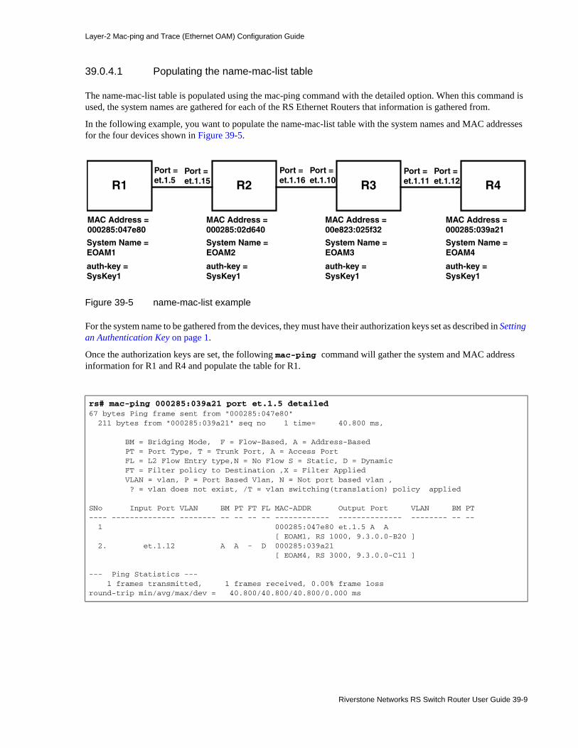
Layer-2 Mac-ping and Trace (Ethernet OAM) Configuration Guide
39.0.4.1 Populating the name-mac-list table
The name-mac-list table is populated using the mac-ping command with the detailed option. When this command is used, the system names are gathered for each of the RS Ethernet Routers that information is gathered from.
In the following example, you want to populate the name-mac-list table with the system names and MAC addresses for the four devices shown in Figure 39-5.
Figure 39-5 name-mac-list example
For the system name to be gathered from the devices, they must have their authorization keys set as described in Setting an Authentication Key on page 1.
Once the authorization keys are set, the following mac-ping command will gather the system and MAC address information for R1 and R4 and populate the table for R1.
rs# mac-ping 000285:039a21 port et.1.5 detailed67 bytes Ping frame sent from "000285:047e80" 211 bytes from "000285:039a21" seq no 1 time= 40.800 ms,
BM = Bridging Mode, F = Flow-Based, A = Address-Based PT = Port Type, T = Trunk Port, A = Access Port FL = L2 Flow Entry type,N = No Flow S = Static, D = Dynamic FT = Filter policy to Destination ,X = Filter Applied VLAN = vlan, P = Port Based Vlan, N = Not port based vlan , ? = vlan does not exist, /T = vlan switching(translation) policy applied
SNo Input Port VLAN BM PT FT FL MAC-ADDR Output Port VLAN BM PT---- -------------- -------- -- -- -- -- ------------ -------------- -------- -- -- 1 000285:047e80 et.1.5 A A [ EOAM1, RS 1000, 9.3.0.0-B20 ] 2. et.1.12 A A - D 000285:039a21 [ EOAM4, RS 3000, 9.3.0.0-C11 ]
--- Ping Statistics --- 1 frames transmitted, 1 frames received, 0.00% frame lossround-trip min/avg/max/dev = 40.800/40.800/40.800/0.000 ms
R1
MAC Address = 000285:047e80
System Name = EOAM1
MAC Address =000285:02d640
MAC Address =00e823:025f32
MAC Address =000285:039a21
System Name = EOAM2
System Name = EOAM3
System Name = EOAM4
Port =et.1.5
auth-key =SysKey1
R2 R3 R4Port =et.1.15
Port =et.1.16
Port =et.1.10
Port =et.1.11
Port =et.1.12
auth-key =SysKey1
auth-key =SysKey1
auth-key =SysKey1
Riverstone Networks RS Switch Router User Guide 39-9

Layer-2 Mac-ping and Trace (Ethernet OAM) Configuration Guide
You can view the generated name-mac-list table using the eoam show name-mac-list command as shown in the following.
To obtain the system names for all of the RS Ethernet Routers along the path between the originator and target routers, you must set the authorization keys as described in Setting an Authentication Key for MAC Ping with the Traceroute option on page 3 and use the traceroute option with the mac-ping command. The following mac-ping command will gather the system and MAC address information for R1, R2, R3 and R4 and populate the table for R1...
rs# eoam show name-mac-listSwitch Name Mac Address DateAndTime
----------- ----------- ----------- EOAM1 000285:047e80 2002-01-31 07:04:20
EOAM4 000285:039a21 2002-01-31 07:04:20
rs# mac-ping 000285:039a21 port et.1.5 detailed67 bytes Ping frame sent from "000285:047e80" 211 bytes from "000285:039a21" seq no 1 time= 40.800 ms,
BM = Bridging Mode, F = Flow-Based, A = Address-Based PT = Port Type, T = Trunk Port, A = Access Port FL = L2 Flow Entry type,N = No Flow S = Static, D = Dynamic FT = Filter policy to Destination ,X = Filter Applied VLAN = vlan, P = Port Based Vlan, N = Not port based vlan , ? = vlan does not exist, /T = vlan switching(translation) policy applied
SNo Input Port VLAN BM PT FT FL MAC-ADDR Output Port VLAN BM PT---- -------------- -------- -- -- -- -- ------------ -------------- -------- -- -- 1 000285:047e80 et.1.5 A A [ EOAM1, RS 1000, 9.3.0.0-B20 ] 2. et.1.15 A A - D 000285:02d640 et.1.16 [ EOAM2, RS 3000, 9.3.0.0-C11 ]
3. et.1.10 A A - D 00e823:025f32 et.1.11 [ EOAM3, RS 3000, 9.3.0.0-C11 ]
4. et.1.12 A A - D 000285:039a21 [ EOAM4, RS 3000, 9.3.0.0-C11 ]
--- Ping Statistics --- 1 frames transmitted, 1 frames received, 0.00% frame lossround-trip min/avg/max/dev = 40.800/40.800/40.800/0.000 ms
39-10 Riverstone Networks RS Switch Router User Guide

Layer-2 Mac-ping and Trace (Ethernet OAM) Configuration Guide
You can view the generated name-mac-list table for this example using the eoam show name-mac-list command as shown in the following.
39.0.4.2 Clearing the name-mac-list Table
To clear the name-mac-list table, use the eoam clear name-mac-list command as shown in the following example.
You can view the generated name-mac-list table for this example using the eoam show name-mac-list command as shown in the following.
rs# eoam show name-mac-listSwitch Name Mac Address DateAndTime
----------- ----------- ----------- EOAM1 000285:047e80 2002-01-31 07:04:20
EOAM2 000285:02d640 2002-01-31 07:04:20EOAM3 00e823:025f32 2002-01-31 07:04:20EOAM4 000285:039a21 2002-01-31 07:04:20
rs# eoam clear name-mac-list
rs# eoam show name-mac-listNo records
Riverstone Networks RS Switch Router User Guide 39-11

Layer-2 Mac-ping and Trace (Ethernet OAM) Configuration Guide
39.0.5 Displaying mac-ping Statistics
The cumulative statistics gathered by the mac-ping command are kept on the originator router. They can be view using the eoam show statistics command as shown in the following example.
You can use the eoam clear statistics command to clear the values in the statistics table, as shown in the following example.
rs# eoam show statisticsIN OUT
---------- ---------- PING frames : 4 30 PING REPLY frames : 22 4
TRACE frames : 11 12 TRACE REPLY frames : 12 11TRACE frame dropped as orignator mac did not match with source mac target : 0 transit : 0 first hop : 0
TTL expired : 0TRACE/PING REPLY frame drop count TTL expired : 0 Target_mac and src_mac mismatch : 0Previous transit and src_mac mismatch : 0 Reverse path not validated : 0 Never traversed this path : 0 No Ping/Trace-path sessions : 0 Session ID not Ping/Trace-path : 0
No return TLS path : 0
EOAM Unknown frames : 0 EOAM Authentication failures : 0 Last cleared time stamp : 2002-01-18 05:43:31
rs# eoam clear statistics
39-12 Riverstone Networks RS Switch Router User Guide

Layer-2 Mac-ping and Trace (Ethernet OAM) Configuration Guide
39.0.6 Enabling the Tracing Function
Using the configure mode command eoam enable tracing, you can display additional information about transmission of the mac-ping packet to the console or the sys log server, as shown in the following example.
With this set, the mac-ping command will display additional information, as shown in the first line (EOAM:TXED Trace frame on port 56) of the following example.
rs(config)# eoam enable tracing
rs# mac-ping 000285:039a21 port et.1.5 detailedEOAM:TXED Trace frame on port 5667 bytes Ping frame sent from "000285:047e80" 211 bytes from "000285:039a21" seq no 1 time= 40.800 ms,
BM = Bridging Mode, F = Flow-Based, A = Address-Based PT = Port Type, T = Trunk Port, A = Access Port FL = L2 Flow Entry type,N = No Flow S = Static, D = Dynamic FT = Filter policy to Destination ,X = Filter Applied VLAN = vlan, P = Port Based Vlan, N = Not port based vlan , ? = vlan does not exist, /T = vlan switching(translation) policy applied
SNo Input Port VLAN BM PT FT FL MAC-ADDR Output Port VLAN BM PT---- -------------- -------- -- -- -- -- ------------ -------------- -------- -- -- 1 000285:047e80 et.1.5 A A [ EOAM1, RS 1000, 9.3.0.0-B20 ] 2. et.1.15 A A - D 000285:02d640 et.1.16 [ EOAM2, RS 3000, 9.3.0.0-C11 ]3. et.1.10 A A - D 00e823:025f32 et.1.11
[ EOAM3, RS 3000, 9.3.0.0-C11 ]4. et.1.12 A A - D 000285:039a21
[ EOAM4, RS 3000, 9.3.0.0-C11 ]
--- Ping Statistics --- 1 frames transmitted, 1 frames received, 0.00% frame lossround-trip min/avg/max/dev = 40.800/40.800/40.800/0.000 ms
Riverstone Networks RS Switch Router User Guide 39-13

Layer-2 Mac-ping and Trace (Ethernet OAM) Configuration Guide
39-14 Riverstone Networks RS Switch Router User Guide