The Adaptive Bubble Router
27
The Adaptive Bubble Router 1 V. Puente, C. Izu , R. Beivide, J.A. Gregorio,F. Vallejo and J.M. Prellezo Universidad de Cantabria, 39005 Santander, Spain University of Adelaide, SA 5005 Australia The design of a new adaptive virtual cut-through router for torus networks is presented in this paper. With much lower VLSI costs than adaptive wormhole routers, the adaptive Bubble router is even faster than deterministic wormhole routers based on virtual channels. This has been achieved by combining a low-cost deadlock avoidance mechanism for virtual cut-through networks, called Bubble flow control, with an adequate design of the router’s arbiter. A thorough methodology has been employed to quantify the impact that this router design has at all levels, from its hardware cost to the system performance when running parallel applications. At the VLSI level, our proposal is the adaptive router with the shortest clock cycle and node delay when compared with other state- of-the-art alternatives. This translates into the lowest latency and highest throughput under standard synthetic loads. At system level, these gains reduce the execution time of the benchmarks considered. Compared with current adaptive wormhole routers, the execution time is reduced by up to 27%. Furthermore, this is the only router that improves system performance when compared with simpler static designs. Key Words: Interconnection subsystem; packet deadlock; crossbar arbitration; hardware routers; VLSI design; performance evaluation; cc-NUMA systems; parallel application benchmarks. 1. INTRODUCTION Parallel and distributed computing performance is generally a fraction of the sum of the computational power provided by the processors that make up the parallel system. This performance degradation can be attributed to two sources: i) the impossibility of adequately balancing the computing load among processors, and ii) the overheads involved in communication between processors and memories. An efficient mapping can be found for a number of applications, resulting in a uniform computational load among processors. However, the cost of communication is unavoidable and we can only do our best to minimize it. Scalable distributed shared-memory multiprocessors with hardware data cache coherence (cc-NUMA) are nowadays the trend in building parallel computers because they provide the most desirable programmability [20]. Other existing distributed shared-memory parallel This work is supported in part by the Spanish CICYT under contract TIC98-1162-C02-01 1
-
Upload
independent -
Category
Documents
-
view
1 -
download
0
Transcript of The Adaptive Bubble Router
The Adaptive Bubble Router 1
V. Puente, C. Izuy, R. Beivide, J.A. Gregorio, F. Vallejo and J.M. PrellezoUniversidad de Cantabria, 39005 Santander, Spain
y University of Adelaide, SA 5005 Australia
The design of a new adaptive virtual cut-through router for torus networks is
presented in this paper. With much lower VLSI costs than adaptive wormhole
routers, the adaptive Bubble router is even faster than deterministic wormhole routers
based on virtual channels. This has been achieved by combining a low-cost deadlock
avoidance mechanism for virtual cut-through networks, called Bubble flow control,
with an adequate design of the router’s arbiter.
A thorough methodology has been employed to quantify the impact that this
router design has at all levels, from its hardware cost to the system performance
when running parallel applications. At the VLSI level, our proposal is the adaptive
router with the shortest clock cycle and node delay when compared with other state-
of-the-art alternatives. This translates into the lowest latency and highest throughput
under standard synthetic loads. At system level, these gains reduce the execution time
of the benchmarks considered. Compared with current adaptive wormhole routers,
the execution time is reduced by up to 27%. Furthermore, this is the only router that
improves system performance when compared with simpler static designs.
Key Words: Interconnection subsystem; packet deadlock; crossbar arbitration; hardware routers;
VLSI design; performance evaluation; cc-NUMA systems; parallel application benchmarks.
1. INTRODUCTION
Parallel and distributed computing performance is generally a fraction of the sum ofthe computational power provided by the processors that make up the parallel system.This performance degradation can be attributed to two sources: i) the impossibility ofadequately balancing the computing load among processors, and ii) the overheads involvedin communication between processors and memories. An efficient mapping can be foundfor a number of applications, resulting in a uniform computational load among processors.However, the cost of communication is unavoidable and we can only do our best to minimizeit.
Scalable distributed shared-memory multiprocessors with hardware data cache coherence(cc-NUMA) are nowadays the trend in building parallel computers because they provide themost desirable programmability [20]. Other existing distributed shared-memory parallel
1This work is supported in part by the Spanish CICYT under contract TIC98-1162-C02-01
1
2 V. PUENTE, C. IZU, R. BEIVIDE, J.A. GREGORIO, F. VALLEJO AND J.M. PRELLEZO
computers rely on the programmer to maintain data coherency throughout the whole system[28]. In both cases, system performance can be seriously limited due to the network delayswhen accessing remote data. The communication subsystem of these machines is composedof a number of interconnected routers arranged in a specific topology. The performance ofthese direct interconnection networks is governed by that of the router and the interconnect.
With respect to network topology, Dally [11] and Agarwal [1] recommended the useof low-degree networks belonging to the class of the k-ary n-cubes. Rings, meshes,tori and hypercubes are representative networks of this class. Some parallel computermanufacturers followed their advice and machines such as the Cray T3D and Cray T3E usethree-dimensional tori. In relation to experimental ASCI ultracomputers, the Option Redemploys two interconnected 2-D meshes and the Blue Mountain uses a three-dimensionaltorus in the top level of the machine[19, 4].
Both T3D and T3E routers [28] use wormhole routing and a set of four and five virtualchannels per direction respectively. The former uses oblivious dimension order routing(DOR) and avoids network deadlock by changing to the next virtual channel when crossinga wrap-around link. The latter employs an additional virtual channel in order to providefully adaptive routing. The router employed by the O-2000 is the SGI Spider [15] whichuses wormhole table-based deterministic routing. Both, T3E and Spider routers, managemessages divided into packets, the maximum size being 700 bits (10 flits) and 800 bits (5micropackets, equivalent to the notion of flits) respectively. Moreover, both routers employmemory queues associated to each virtual channel able to store up to 22 flits in the T3Erouter and up to 5 micropackets in the case of the Spider.
In this research, we are going to propose a new packet router with the same functionalityas the above commercial routers, but using a different design philosophy. Our goal is toproduce the simplest possible hardware design in order to minimize the pin-to-pin routerlatency without compromising the other performance figure of merit: the ability to handlelarge volumes of data, in other words to support high packet throughput. To achievethis goal, we will apply the following architectural strategies: i) Virtual Cut-through flowcontrol (VCT) [18] will be used instead of wormhole; ii) A new and very simple deadlockavoidance mechanism, based on VCT, called Bubble flow control will be employed; and iii)A new arbitration policy supporting multiple output requests will be used which is simplerthan current policies.
As a consequence of strategies i) and ii) the router uses a minimum number of virtualchannels, thus reducing hardware cost and complexity. In addition, strategy iii) allows fora low cost implementation of adaptive routers. The resulting design for a k-ary n-cubenetwork is a particularly simple router which adequately balances base latency and networkthroughput.
The results presented in this paper show that our adaptive Bubble router outperformsstate-of-the-art commercial solutions. In addition, and due to its good trade-off betweensimplicity and performance, the adaptive Bubble router is a serious candidate to implementon-chip network routers. Manufacturers are currently designing a new generation ofmicroprocessor supporting cc-NUMA style multiprocessing and including network routerand interface on-chip, such as the new Compaq/Alpha EV7 [2].
To demonstrate the suitability of the adaptive Bubble router, a quantitative analysiscomparing different router designs has been carried out. We adopted packet latencyand maximum sustained throughput as the basic parameters to validate the goodness ofour proposal. An accurate measurement of these merit figures can only be obtained by
THE ADAPTIVE BUBBLE ROUTER 3
monitoring the low-level characteristics of the corresponding VLSI designs. Therefore,we have designed our router and its corresponding counterparts using high-level VLSIsynthesis tools, which provide us with adequate estimations in terms of required siliconarea and circuit delays. These metrics are fed into a very detailed register-transfer levelsimulator to observe the behavior of the network built from each router design.
Traditionally, synthetic benchmarks have been extensively used in the technical literatureto assess the performance exhibited by the interconnection subsystems. Although thismethodology can be useful in order to stress the communication capabilities, it is also verydesirable to observe the behavior of the network as a part of a whole system executing realloads. In order to provide such a realistic scenario we will use a set of three benchmarksfrom the SPLASH-2 suite [31] running on a state-of-the-art cc-NUMA multiprocessor. Tobuild this experimental testbed an execution-driven simulator based on Rsim [22] has beendeveloped. In this way, in addition to providing metrics under synthetic traffic we are alsoable to show the performance of several designs under the pressure of various real parallelapplications.
The rest of this paper is organized as follows. In Section 2, both theoretical and intuitiveapproaches are employed in order to demonstrate deadlock freedom in our adaptive Bubblerouter; we achieve this goal by using a new flow control function based on restrictedinjection. In Section 3, we present a detailed description of the design of the Bubble router,with special emphasis on a new crossbar arbitration policy. Section 4 is devoted to thedesign of alternative router organizations in order to compare them with the Bubble one. InSection 5, a thorough analysis of the performance exhibited by each solution is presented.The conclusions drawn from this research are discussed in Section 6.
2. BUBBLE FLOW CONTROL INK-ARYN -CUBE NETWORKS
If the routing algorithm and the flow control function are not carefully designed, thenetwork may suffer from packet deadlock. Furthermore, there are topologies composed ofa set of rings, such as a torus network, which are specially deadlock-prone. Consequently, agreat deal of research has been devoted to either preventing or resolving network deadlock.
Deadlock can be prevented by ordering the acquisition of resources in such a way thatstatic dependencies among packets cannot form a cycle. This can be achieved by restrictingthe routing such as in the Turn model [16] or by splitting the traffic into two or more virtualchannels so that cyclic dependencies are eliminated [10]. There are multiple proposals ofadaptive wormhole routers based on these approaches [21, 8]. Common drawbacks of theseproposals are the high hardware complexity of the resulting device and the unbalanced useof the link resources.
A second approach is deadlock recovery. When a deadlock situation is detected, one ormore messages are removed so that the cycle is broken, allowing the rest of packets in thenetwork to finally progress towards their destination [24].
Resource dependencies are not only based on the routing function but on the current statusof the network. Duato’s theory [12] determined the necessary and sufficient conditions fordeadlock freedom. As a consequence of this theory, under certain conditions, we can addfully-adaptive virtual channels to any deadlock-free network knowing that the resultingnetwork is deadlock-free as well. Current adaptive router implementations such as theCrayT3E router [28] use virtual channels both to avoid deadlock and to provide fullyadaptive channels.

4 V. PUENTE, C. IZU, R. BEIVIDE, J.A. GREGORIO, F. VALLEJO AND J.M. PRELLEZO
Focusing on the particular characteristics of VCT networks,we can find simpler deadlock-freedom mechanisms. Under VCT flow control, the basic resource is the queue attachedto the physical (or virtual) channel. This means that message dependencies are localizedbetween adjacent queues. We will see how to take advantage of this to provide a low costdeadlock avoidance mechanism. In order to adequately present this new mechanism, let’sfirst introduce some definitions and after that, we will concentrate on the establishment ofa new deadlock free routing for k-ary n-cube networks.
2.1. Some Formal DefinitionsIn this section, we include some basic definitions mainly derived from [10], [14] and
[6] to make the paper self-contained and to be able to provide a formal definition of ourproposed flow control mechanism.
Definition 2.1. An interconnection network, I , is a strongly connected directed graphI = G(N;Q). The vertices of the graph, N , represent the set of processing nodes. Thearcs of the graph, Q, represent the set of queues associated to the communication linksinterconnecting the nodes. Each queue qi 2 Q has capacity for cap(qi) packets. Thenumber of packets currently stored in that queue is denoted size(qi).
The set of queues Q is divided into three subsets: injection queues QI , delivery queuesQD and network queues QN . Each processor uses a queue from QI to send messagesthat travel through the network employing queues from QN and when they reach theirdestination they enter a queue from QD. Therefore, packets are routed from a queue in thesetQIN = QN[QI to a queue in the setQND = QN[QD. Obviously,Q = QIN[QND.
Definition 2.2. A routing function, R : QIN �N ! P(QND), where P(QND) isthe power set of QND, provides a set of alternative queues to route a packet p located atthe head of the queue qi to its destination node nd. We also denoted head(qi) = nd asthe destination node of the first packet enqueued at qi. A deterministic routing functionprovides a single alternative R(qi; nd) = qj .
Definition 2.3. A routing subfunction,Rs, for a given routing functionR is a routingfunction defined in the same domain as R but its range (set of alternative next queues) isrestricted to a subset QNDs � QND. A simple and convenient way to define the routingsubfunction is as follows
Rs(qi; nd) = R(qi; nd) \QNDs 8qi 2 QIN ;8nd 2 N
Definition 2.4. A flow control function, F : QIN � QND ! ftrue; falseg de-termines the access permission for a packet p located at queue qi to enter the queueqj 2 R(qi; nd). Thus, packet p is allowed to advance from qi to qj if F (qi; qj) = true.The flow control functionF limits the set of alternative next queues provided by the routingfunction and obviously depends on network status.

THE ADAPTIVE BUBBLE ROUTER 5
Similarly to the routing case we can define a flow control subfunctionFs for a given flowcontrol function F as follows
Fs(qi; qj) = F (qi; qj) 8qi 2 QIN ;8qj 2 QNDs
Definition 2.5. A legal configuration is an assignment of a set of packets to eachqueue in a set Qlc � QN such that 8qi 2 Qlc, size(qi) � cap(qi) and the packets storedin each queue have been routed from some qj 2 QIN using the routing function R, andverifying the flow control function F .
In short, a legal configuration represents a network state which is reachable under theselected routing and flow control functions.
Definition 2.6. A deadlocked configuration for a given interconnection network I ,routing functionR, and flow control functionF is a nonempty legal configuration verifyingthe following conditions:
8qi 2 Qlc such that size(qi) > 0; F (qi; qj) = false 8qj 2 R(qi; head(qi))
In a deadlocked configuration, packets cannot advance because the flow control functiondoes not allow the use of any of the alternative queues provided by the routing function.
2.2. Routing and Flow Control Subfunctions for k-ary n-cube Deadlock-freeNetworks
If we are able to find out a pair of routing and flow control subfunctions, Rs and Fs,that provides deadlock freedom, we can apply Duato’s theory [12] for developing a fullyadaptive routing algorithm for k-ary n-cube networks: cube with dimension n and k nodesin each dimension.
To begin with, we can initially assume that the nodes of the k-ary n-cube network arelinked by just two communication queues in opposite directions. Each processing node,n 2 N , can be denoted as n�x, where �x = (x1; ::; xn) is the position in the n-cube andtherefore xi 2 f0; :::; k�1g represents the node coordinate in the dimension i. This meansthat, given two neighbor nodes along the dimension j, n�x and n�y, where xi = yi 8i 6= j,the bidirectional queues connecting both nodes will be denoted as qj�x�y and qj�y�x . Thisnotation unequivocally determines the direction of the channel, the dimension where it islocated and the nodes it connects.
Dimensional Order Routing (DOR) is our candidate for the routing subfunction, Rs.We select this function because it is very simple and it also eliminates any resource cyclicdependencies between packets at different dimensions. Formally, this function can berepresented as,
RDOR(qi�x�y; head(qi�x�y)) = RDOR(qi�x�y; n �d) = qj�y�z
where j, with j � i, is the first dimension in which the coordinates of nodes n�y and n �d
differ, di 6= yi and n�z is the neighbor of n�y in such dimension; in other words, the messageis routed to �z = (y1; ::yj�1; (yj � 1)mod k; yj+1; ::; yn).

6 V. PUENTE, C. IZU, R. BEIVIDE, J.A. GREGORIO, F. VALLEJO AND J.M. PRELLEZO
Thus, the message’s path enters at most once into each traveling dimension. Althoughapplying the subfunction RDOR eliminates any resource cyclic dependencies betweenpackets at different dimensions, deadlock can still occur within packets traveling along thesame dimension. A classical solution [10] is to split each physical link in two (or more)virtual queues and restrict their use in some way.
Our solution does not require any more queues but a flow control subfunction, Fs,restricting the access of packets into a new network dimension. This function is a minormodification of the virtual cut-through flow control and it is formally defined as follows,
FBubble(qi�x�y; qj�y�z) = True if�size(qj�y�z) � cap(qj�y�z)� 1 when i = j
size(qj�y�z) � cap(qj�y�z)� 2 when (i 6= j _ qi�x�y 2 QI)
where qj�y�z = RDOR(qi�x�y; head(qi�x�y)) and for each queue qi�x�y 2 QNDs, the conditioncap(qi�x�y) � 2 must be fulfilled.
Packets moving along a dimensional ring advance as per cut-through flow control.However, the injection of new packets as well as packets changing dimension are onlyallowed if there is room for not just one but two packets.
Using the pair of subfunctions (RDOR; FBubble) in a k-ary n-cube network is a sufficientcondition to prevent deadlock. In fact, if we suppose that under these conditions a deadlockarises in dimension j, necessarily some packet was incorporated to this dimension withoutverifying the function FBubble; note that according to the definition of this function, it isnot possible to reach a legal configuration in which cap(qi) = size(qi) 8qi 2 Qr whereQr � (qj�x0�x1 ; qj�x1�x2 ; :::; qj�xk�1�x0).
In other words, applyingRDOR andFBubble it is impossible to reach a legal configurationin which all queues of a dimension and direction are completely full.
It is important to note that the second free packet space that prevents deadlock in adimension j does not have to be in the queue qj�y�z requested by the packet entering thatdimension but it could be in any of the other queues at that unidirectional ring, Qr. Thisallows us to generalize the subfunction FBubble as follows,
FBubble(qi�x�y; qj�y�z) = True if8<:
size(qj�y�z) � cap(qj�y�z)� 1 when i = j
(size(qj�y�z) � cap(qj�y�z)� 1) ^
(P
8qi2Qrsize(qj) �
P8qi2Qr
cap(qj)� 2) when (i 6= j _ qi�x�y 2 QI)
This subfunction captures all the safe scenarios but the complexity of examining allqueues from a unidirectional ring is considerable. Instead, we could look for the secondfree buffer at the local queue qj �w�y which belongs to the same unidirectional ring as qj�y�z.This strategy is particularly useful for routers with input buffering as it allows the evaluationof FBubble based only on local information.
Intuitively, we can understand how Bubble flow control works by looking at the unidirec-tional ring shown in Figure 1. Packets (shaded queue units) are allowed to move (shadedarrows) from one queue to another inside the ring as per virtual cut-through switching.However, packet injection is only allowed at a given router if there are at least two emptypacket buffers in the dimension (and direction) requested by the packet. By doing so, weguarantee that there is always at least an empty packet buffer in the ring. That free buffer
THE ADAPTIVE BUBBLE ROUTER 7
acts as a bubble, guaranteeing that at least one packet is able to progress. Besides, changingdimension is also treated as an injection into the next dimensional ring.
In short, Bubble flow control avoids deadlock inside rings by preventing packets fromusing the potentially last free buffer of a dimensional ring. Thus, combined with DORrouting it prevents deadlock without requiring any virtual channels.
BubbleControl
BubbleControl
BubbleControl
BubbleControl
BubbleControl
InjectionFrom k-1dimension
Injection Injection From k-1dimension
From k-1dimension
From k-1dimension InjectionInjection From k-1
dimension
FIG. 1. Deadlock avoidance in a unidirectional ring by using Bubble flow control (FBubble).
2.3. Fully-Adaptive Routing Based on RDOR and FBubbleThe previous section has shown how to build a deadlock-free k-ary n-cube network
applying the pair RDOR and FBubble, on the set of queues QNDs. Now, we can add newqueues (virtual channels) between nodes where packets can move using any minimal path(no misrouting). If packets are blocked in these queues, they will use QNDs as escapequeues. We know, according to [14], the resulting network is deadlock-free as well.
Using the previous notation, the flow control function F , which includes FBubble, willbe applied over all queues as follows,
F (qi�x�y; qj�y�z) = True if :�size(qj�y�z) � cap(qj�y�z)� 1 if ((qj�y�z; qi�x�y 2 QNDs ^ i = j) _ qj�y�z =2 QNDs)
size(qj�y�z) � cap(qj�y�z)� 2 if (qj�y�z 2 QNDs ^ (i 6= j _ qi�x�y =2 QNDs))
This means that Bubble is the type of flow control applied when accessing escape queuesand virtual cut-through when accessing adaptive ones. That is, hops from deterministicqueues to adaptive ones will take place freely, while hops from adaptive queues into escapeones are treated as injections into the escape rings.
The routing functionR associated with queues qi 2 QND provides a set of possible nextqueues following a path of minimum distance, including the escape queue from the routingsubfunction RDOR. For 2-D networks R provides up to three queues that are chosen in afixed order according to this selection function:
1. The adaptive queue of the neighbor along the incoming dimension, if the correspond-ing offset is not zero. That is, the number of hops a packet must travel from the currentnode to its destination node, along the incoming dimension, is not zero.
2. The adaptive queue of the neighbor along the other dimension, if the correspondingoffset of that dimension is not zero.
3. The escape queue of the neighbor along the first dimension, if the offset of thisdimension is not zero or the escape queue of the neighbor along the second dimension ifthe offset of the first dimension is zero.
8 V. PUENTE, C. IZU, R. BEIVIDE, J.A. GREGORIO, F. VALLEJO AND J.M. PRELLEZO
Thus, priority is given to the adaptive queues over the escape ones. Obviously, thefunctionF must return true for a packet to progress to the next queue. This selection policyprovides a high routing flexibility, allowing packets to follow any minimal path availablein the network.
The adaptive routing algorithm resulting from applying R and F is deadlock-free. Aswe previously indicated, adding queues to a deadlock-free routing algorithm cannot inducedeadlock, regardless of how packets are routed in the additional queues. The only constraintis that the routing algorithm should not consider the queue currently storing the packet whencomputing the set of routing options. This constraint is met by our routing algorithm becausea packet can be routed on both escape or adaptive queues at any router, regardless of thequeue storing it. Taking into account that DOR with Bubble flow control is deadlock-free,it follows that the whole routing algorithm is also deadlock-free.
2.3.1. Starvation
Controlling the injection flow and the changes of dimension using the Bubble algorithmis an efficient technique for avoiding deadlock. However, under certain conditions, thistechnique may introduce another anomaly: starvation. This problem arises when there isdifferent priority for accessing some of resources. In the escape queues, packets advancingalong a dimension have more priority than those that are trying to enter it.
A B D
p
InjectionConsumption
FIG. 2. Example of starvation in deterministic Bubble flow control (which is resolved by our adaptiveproposal).
For example, in Figure 2, packets going from router A to router D have a higher prioritythan packets trying to be injected at router B. Thus, if traffic between A and D is notstopped, a packet p can be indefinitely waiting to enter B. However, starvation cannotoccur for the adaptive Bubble algorithm because the access to the adaptive queues is notprioritized. This means that packets in transit have the same priority to acquire the adaptivequeue as incoming packets. In the previous example, the packet to be injected at B willsucceed entering the next node’s adaptive queue. Even if that queue is temporarily full, apacket unit will eventually become free because the network is deadlock-free.
3. DESIGN ISSUES FOR THE ADAPTIVE BUBBLE ROUTER: ARBITRATIONSCHEMES
This section discusses the design of the Adaptive Bubble Router, a router for k-aryn-cube networks based on the adaptive routing and flow control functions described in theprevious section.
The complexity of adaptive routers compared with oblivious ones comes mainly fromtwo sources. The first one is the extra resources necessary to prevent/recover from dead-lock. Bubble flow control reduces the minimum number of virtual channels for deadlockprevention to only two. The second one is the arbiter, whose role is to match the inputrequests with the available output ports.

THE ADAPTIVE BUBBLE ROUTER 9
The arbitration among incoming packets is a simple task in a DOR router as each inputrequests only one of the outputs and, therefore, each output port assignment is independentof the rest. Complexity rises with adaptivity because each incoming packet can requestmore than one output port. Independent arbitration for each output port may lead to multipleoutput resources being assigned to the same packet. Furthermore, adaptive routers add oneor more virtual channels in order to avoid deadlock. This, in the best case, duplicates thenumber of possible requests.
There are various arbitration schemes that deal with this complexity. Among others, westarted analyzing the following alternatives:
1. A centralized arbiter that accepts multiple input requests from each incoming message,matching them to all available output ports. Obviously, this approach allows for themaximum number of packets to be routed from input to output in the same cycle.
2. A distributed arbiter, called Output Arbiter Crossbar (OAC). We have limited itscomplexity by forcing each incoming packet to request a single output port per cycle fromits set of possible outputs. Hence, our approach has a complexity similar to a DOR’s arbiter.
3. An arbiter, called Sequential Input Crossbar (SIC), accepting multiple output requestsbut servicing only one input channel per cycle. A similar option was used in the Cray T3Erouter [28].
Although the first alternative provides the best result from the functional point of view,it has a high VLSI cost in terms of delay that has a significant impact on the router clockcycle and delay. In fact, in [26] we explored a design based on Tamir’s Wave Front arbiter[30], which increased the clock cycle by 50% and 37% with respect to the second and thirdschemes. Hence, we discarded that scheme and focused on the remaining two.
As the arbiter is a central building block, its implementation will influence the design ofother router components such as the routing units and/or the output controllers. We willfirst present the detailed implementation of the Bubble router based on the OAC arbiter,and then the other arbitration alternatives.
3.1. Bubble Router with OAC SchemeThe main blocks of the proposed Bubble router for a k-ary 2-cube are shown in Figure 3.
Extensions for a higher dimension network are straightforward. Internal router componentsare clocked synchronously but communications with neighboring routers are asynchronousin order to avoid clock skew problems. There is an escape queue and an adaptive queuefor each physical link. They behave as described in the previous section. Both of themare implemented as FIFO queues with an additional synchronization module to support theasynchronous communication between routers. Thus, we have 9 input queues: four escapeand four adaptive queues respectively and one injection queue.
Input queues and output ports are connected through a crossbar. As Bubble flow controlis an extension of VCT we can multiplex the physical link among its escape and adap-tive virtual channels on a packet-by-packet basis. Therefore, it is not necessary to sendacknowledgment signals for data transmitted each cycle, and so, communication is lesssensitive to wire delays. This also means that the arbiter itself can resolve the contentionbetween the virtual channels to use a common output port. Consequently, we eliminate theneed for virtual channel controllers to connect the crossbar to the output links and we alsoreduce the number of crossbar outputs from 9 to 5. This diminishes the latency of packetscrossing the router.
10 V. PUENTE, C. IZU, R. BEIVIDE, J.A. GREGORIO, F. VALLEJO AND J.M. PRELLEZO
FIG. 3. OAC Router organization.
The approach of the OAC scheme is an extension to the arbitration strategy used in staticrouters in which each input requests a single output. Thus, the arbitration for each outputis an independent module that applies a round robin policy to prevent starvation of any ofthe requesting inputs. In our adaptive router there are up to 3 profitable outputs so we mustissue their requests in a sequential manner, that is, one request per cycle. In other words,we transfer part of the complexity from the arbiter back to the routing unit (RU) attached toits input queue. In each cycle, the RU will request one of the possible outputs, in the ordergiven by the selection function described in Section 2.3, until one of them is granted. It isvery unlikely that a packet could be indefinitely requesting access to its output port due tothe timing between multiple input requests. A simple policy that deals with this problemafter a fixed number of cycles, consists of setting the request to the same output channeluntil it is granted. As this is a rare event, we set its threshold to a large number so that ithas no impact on network performance.
FIG. 4. Partial Router Structure for Output Arbiter Crossbar (OAC).
The set of requests from the 9 RUs is processed by the OAC arbiter, based on theavailable local output ports and the status of the neighbor’s queues. In short, it grants asmany requests as possible, arbitrating among inputs contending for the same output. Thus,arbitration and switching logic is distributed for each output port as shown in Figure 4.
THE ADAPTIVE BUBBLE ROUTER 11
Thus, the (4n + 1)x(2n + 1) crossbar can be subdivided into (2n + 1) multiplexers of(4n+ 1) inputs.
As a packet advances towards its destination, its header phit must be updated by decre-menting the offset in the selected dimension. As the RU is requesting a single output, itcan issue the correct header phit in the same cycle as it makes the request.
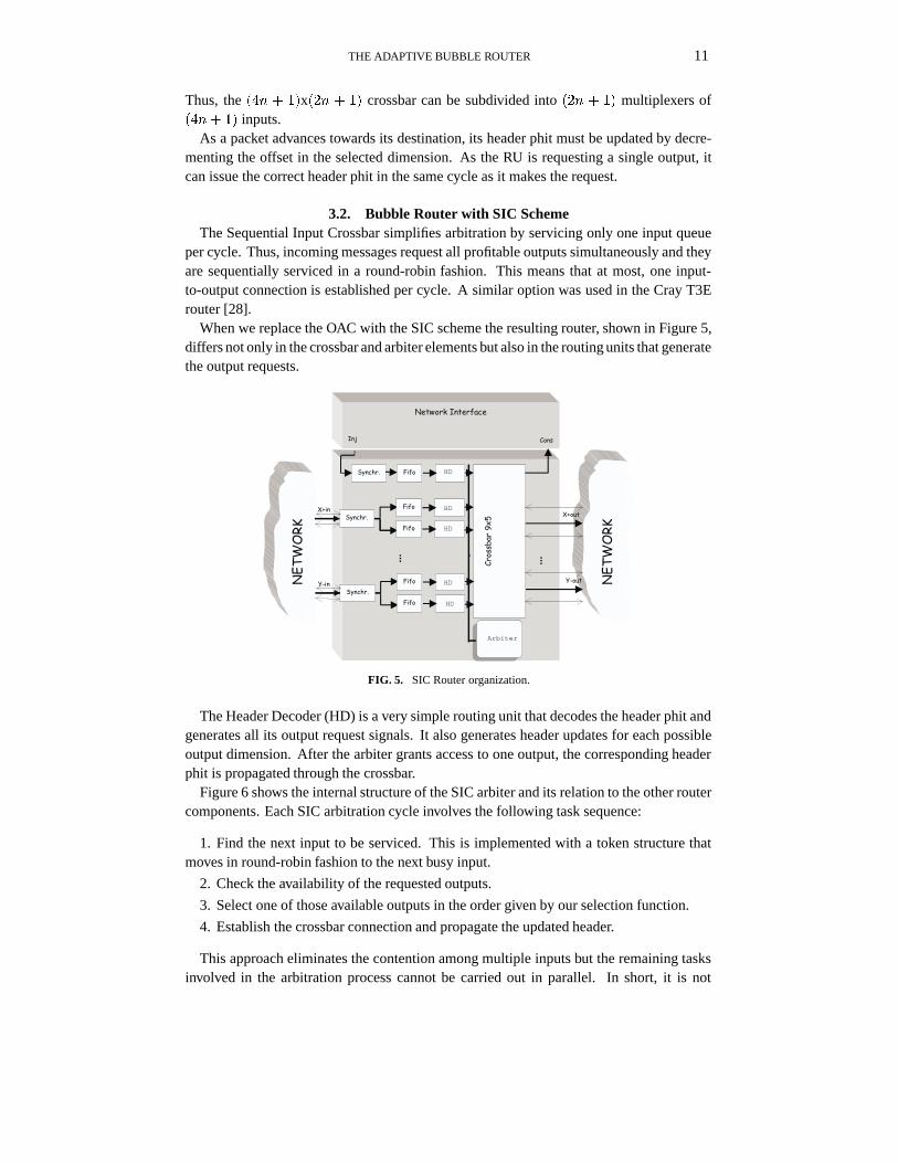
3.2. Bubble Router with SIC SchemeThe Sequential Input Crossbar simplifies arbitration by servicing only one input queue
per cycle. Thus, incoming messages request all profitable outputs simultaneously and theyare sequentially serviced in a round-robin fashion. This means that at most, one input-to-output connection is established per cycle. A similar option was used in the Cray T3Erouter [28].
When we replace the OAC with the SIC scheme the resulting router, shown in Figure 5,differs not only in the crossbar and arbiter elements but also in the routing units that generatethe output requests.
Arbiter
HD
HD
HD
HD
HD
FIG. 5. SIC Router organization.
The Header Decoder (HD) is a very simple routing unit that decodes the header phit andgenerates all its output request signals. It also generates header updates for each possibleoutput dimension. After the arbiter grants access to one output, the corresponding headerphit is propagated through the crossbar.
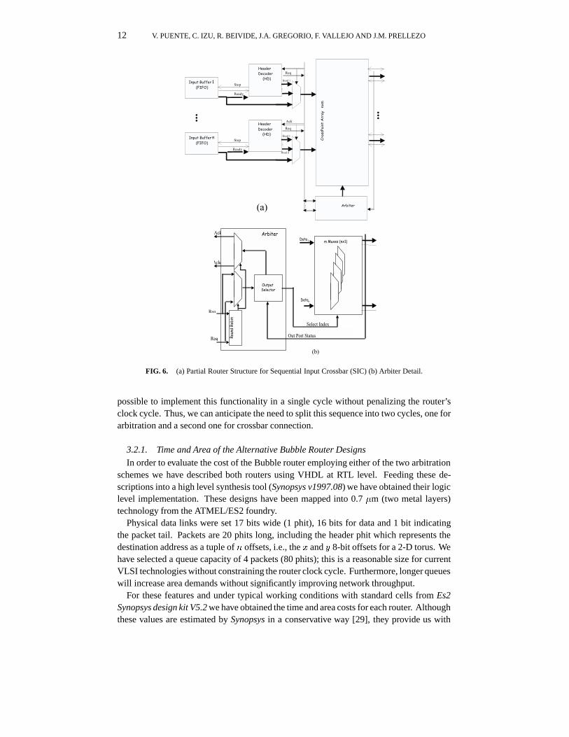
Figure 6 shows the internal structure of the SIC arbiter and its relation to the other routercomponents. Each SIC arbitration cycle involves the following task sequence:
1. Find the next input to be serviced. This is implemented with a token structure thatmoves in round-robin fashion to the next busy input.
2. Check the availability of the requested outputs.
3. Select one of those available outputs in the order given by our selection function.
4. Establish the crossbar connection and propagate the updated header.
This approach eliminates the contention among multiple inputs but the remaining tasksinvolved in the arbitration process cannot be carried out in parallel. In short, it is not
12 V. PUENTE, C. IZU, R. BEIVIDE, J.A. GREGORIO, F. VALLEJO AND J.M. PRELLEZO
(a)
Req
Reqn
Ack1
Ackm
Data 1
Datan
Out Port Status
Select Index
OutputSelector
Arbiter
m Muxes (nx1)
Round
Rob
in
(b)
FIG. 6. (a) Partial Router Structure for Sequential Input Crossbar (SIC) (b) Arbiter Detail.
possible to implement this functionality in a single cycle without penalizing the router’sclock cycle. Thus, we can anticipate the need to split this sequence into two cycles, one forarbitration and a second one for crossbar connection.
3.2.1. Time and Area of the Alternative Bubble Router Designs
In order to evaluate the cost of the Bubble router employing either of the two arbitrationschemes we have described both routers using VHDL at RTL level. Feeding these de-scriptions into a high level synthesis tool (Synopsys v1997.08) we have obtained their logiclevel implementation. These designs have been mapped into 0.7 �m (two metal layers)technology from the ATMEL/ES2 foundry.
Physical data links were set 17 bits wide (1 phit), 16 bits for data and 1 bit indicatingthe packet tail. Packets are 20 phits long, including the header phit which represents thedestination address as a tuple of n offsets, i.e., the x and y 8-bit offsets for a 2-D torus. Wehave selected a queue capacity of 4 packets (80 phits); this is a reasonable size for currentVLSI technologies without constraining the router clock cycle. Furthermore, longer queueswill increase area demands without significantly improving network throughput.
For these features and under typical working conditions with standard cells from Es2Synopsys design kit V5.2 we have obtained the time and area costs for each router. Althoughthese values are estimated by Synopsys in a conservative way [29], they provide us with

THE ADAPTIVE BUBBLE ROUTER 13
values very close to the physical domain. Figures 7.(a) and 7.(b) show the componentdelays and the resulting pipelines for OAC and SIC respectively.
Sync Fifo RUCrossbar
&Arbiter
0.5~1.5 (3.53 ns) 1 (5.23ns) 1 (5.64ns) 1 (5.65ns)
4 Stages
Sync Fifo HD Arbiter
0.5~1.5 (3.53 ns) 1 (5.23ns) 1 (6.02ns) 1 (6.19ns)
5 Stages
Crossbar
1 (6.10ns)
(b)
(a)
FIG. 7. (a) Adaptive Bubble router pipeline with OAC arbitration, (b) Adaptive Bubble router pipeline withSIC arbitration.
Obviously, the component with highest delay determines the maximum clock frequencyof the device. As mentioned before, the SIC implementation has an additional stage, andin both cases the arbitration stage is the one dictating the clock cycle. The FIFO androuting stages consume one cycle each. Finally, because of its asynchronous behavior, thesynchronization module spends a variable amount of time (1 cycle on average).
Once we had identified the critical component, we optimized the other componentsfocusing on area minimization. In this way we reduce the router’s area and balance thetime spent in each pipeline stage. Table 1 summarizes the cost of both routers. There is atrade-off between the two arbiter schemes, OAC being the fast one and SIC using the lessarea. SIC needs less area because it has only one round-robin in comparison with the 5 ofOAC (one per port). On the other hand, in OAC the round-robin completes the arbitrationwhile SIC must complete other tasks as mentioned before. Thus, the different delays.
TABLE 1
Time and Area for each router implementation under typical conditions.
Router Critical Router Router Area Arbiter and CrossbarPath (ns) delay (ns) (mm2) Area (mm2)
BAda-OAC1 5.65 22.60 25.95 8.98BAda-SIC2 6.19 30.90 23.34 4.57
1 Adaptive Bubble router with OAC scheme.2 Adaptive Bubble router with SIC scheme.
14 V. PUENTE, C. IZU, R. BEIVIDE, J.A. GREGORIO, F. VALLEJO AND J.M. PRELLEZO
Sync Fifo RU
0.5~1.5 (3.53 ns) 1 (5.23ns) 1 (6.18ns) 1 (6.28ns)
5 Stages
Sync Fifo HD Arbiter
0.5~1.5 (3.53 ns) 1 (5.23ns) 1 (7.45ns) 1 (7.5 ns)
6 Stages
1 (7.32ns)
VCMux
Crossbar&
Arbiter
1 (6.25ns)
VCMux
1 (6.69ns)
Crossbar
(a)
(b)
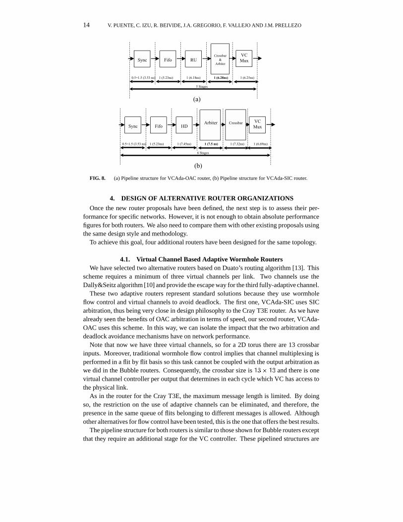
FIG. 8. (a) Pipeline structure for VCAda-OAC router, (b) Pipeline structure for VCAda-SIC router.
4. DESIGN OF ALTERNATIVE ROUTER ORGANIZATIONS
Once the new router proposals have been defined, the next step is to assess their per-formance for specific networks. However, it is not enough to obtain absolute performancefigures for both routers. We also need to compare them with other existing proposals usingthe same design style and methodology.
To achieve this goal, four additional routers have been designed for the same topology.
4.1. Virtual Channel Based Adaptive Wormhole RoutersWe have selected two alternative routers based on Duato’s routing algorithm [13]. This
scheme requires a minimum of three virtual channels per link. Two channels use theDally&Seitz algorithm [10] and provide the escape way for the third fully-adaptive channel.
These two adaptive routers represent standard solutions because they use wormholeflow control and virtual channels to avoid deadlock. The first one, VCAda-SIC uses SICarbitration, thus being very close in design philosophy to the Cray T3E router. As we havealready seen the benefits of OAC arbitration in terms of speed, our second router, VCAda-OAC uses this scheme. In this way, we can isolate the impact that the two arbitration anddeadlock avoidance mechanisms have on network performance.
Note that now we have three virtual channels, so for a 2D torus there are 13 crossbarinputs. Moreover, traditional wormhole flow control implies that channel multiplexing isperformed in a flit by flit basis so this task cannot be coupled with the output arbitration aswe did in the Bubble routers. Consequently, the crossbar size is 13� 13 and there is onevirtual channel controller per output that determines in each cycle which VC has access tothe physical link.
As in the router for the Cray T3E, the maximum message length is limited. By doingso, the restriction on the use of adaptive channels can be eliminated, and therefore, thepresence in the same queue of flits belonging to different messages is allowed. Althoughother alternatives for flow control have been tested, this is the one that offers the best results.
The pipeline structure for both routers is similar to those shown for Bubble routers exceptthat they require an additional stage for the VC controller. These pipelined structures are
THE ADAPTIVE BUBBLE ROUTER 15
shown in Figures 8.(a) and 8.(b). Component delays were calculated under the sameconditions as those in Section 3.2.1.
Although the Cray T3E uses similar arbitration to that of the VCAda-SIC, it uses amultiplexed crossbar. This approach reduces silicon area with respect to our full crossbarimplementation. Notwithstanding, flit-level multiplexing imposed by traditional wormholeflow control would considerably increase the arbiter complexity. Although multiplexing ata larger granularity could increase overall performance, this solution would further increasearbiter complexity.
As the routing unit attached to the input queue multiplexes flits from the differentVCs, those flits will follow different crossbar paths. Thus, multiplexing must be done incoordination with the crossbar module that must rearrange its internal connections to sendthe current flits to their selected outputs. In other words, the 5�5 crossbar must emulatein each multiplexing round the connections of a 13�5 non-multiplexed crossbar. A partialsolution to cope with this complexity is to increase the flit size from the traditional 1 phitto a small multiple. In fact, as the Cray T3E has channel pipelining, its flit size is not 1 but5 phits.
4.2. DOR Routers: the Baseline CaseIn order to measure the cost of adaptivity, two routers using dimensional order routing
(DOR) have been designed.The first router, based on [9], uses wormhole switching and two virtual channels to avoid
deadlock. We have not used more advanced algorithms for handling virtual channels, likethe one proposed in [13], because it increases the router complexity and diminishes themain advantage of deterministic routers: low latency. This router is denoted by VCDOR.
The second one, denoted by BDOR, is a VCT router that applies the Bubble mechanism;thus, it requires a single queue/virtual channel per link. Although this router is a goodbaseline for adaptive Bubble routers, we cannot ignore the risk of starvation as discussedin Section 2.3.1.
Figure 9 shows the pipeline and delays for VCDOR and BDOR obtained when usingthe conditions and methodology as per previous router implementations. Both routers aresimpler than their adaptive counterparts as they have a lower number of VCs and a simplearbiter.
4.3. A Comparison of VLSI Router CostThis section summarizes the VLSI cost of the six routers under study. To fairly compare
among designs, all routers have the same buffer capacity per physical link. As the adaptiveBubble router has two virtual channels, each with a 80-phit queue, we have set the BDORinput queue to be 160-phit long. The VC-based adaptive routers have three virtual channelsso we have employed 40-phit queues for the escape channels and an 80-phit queue for theadaptive one.
The results for silicon area and time delays for each of these six designs, obtained fromthe hardware synthesis tools, are shown in Table 2. Note that the building blocks differin each implementation as was described in each original proposal but we apply the sameVLSI design style.
In all the designs the arbiter sets the cycle time, except for BDOR in which the FIFOqueues are the critical component. As can be seen in this table, the cycle time for BAda-OAC

16 V. PUENTE, C. IZU, R. BEIVIDE, J.A. GREGORIO, F. VALLEJO AND J.M. PRELLEZO
Sync Fifo RUCrossbar
&Arbiter
0.5~1.5 (3.53 ns) 1 (5.25ns) 1 (5.16ns) 1 (5.16ns)
4 Stages
Sync Fifo RUCrossbar
&Arbiter
0.5~1.5 (3.53 ns) 1 (5.23ns) 1 (5.02ns) 1 (5.57ns)
5 Stages
VCMux
1 (5.06ns)
(a)
(b)FIG. 9. (a) Pipeline structure for deterministic Bubble router, (b) Pipeline structure for deterministic Virtual
Channel router.
TABLE 2
Characteristics of router designs.
Router Clock Crossbar Queue Cycle time Area Hop TimeCycles Size Sizes (ns:) (mm
2) (ns:)
BAda-OAC 4 9� 5 80 + 80 5.65 25.95 22.60BAda-SIC 5 9� 5 80 + 80 6.19 23.34 30.90VCAda-OAC. 5 13� 13 80 + 40 + 40 6.28 50.65 31.40VCAda-SIC. 6 13� 13 80 + 40 + 40 7.50 44.59 45.00BDOR 4 5� 5 160 5.25 11.01 21.00VCDOR 5 9� 9 80 + 80 5.57 19.08 27.85
is similar to that of the deterministic wormhole router. This is not surprising as both havea similar arbitration philosophy and use the same number of virtual channels. BAda-OACclock cycle is slightly higher because it also multiplexes incoming packets, however this iscompensated for by the fact that VCDOR requires a fifth stage to multiplex packets at theflit level. Besides, this reduces silicon area for the adaptive Bubble router which uses only56% of the required area for the adaptive wormhole counterpart.
The hop time is a figure of merit because together with the average distance, it providesthe network base latency. Thus, BDOR will exhibit the lowest latency, followed by BAda-OAC. Note that their hop times are smaller than with VCDOR. Thus, we have achieved ourgoal of implementing an adaptive VCT router as fast as current static ones.
Finally, it is clear that methods based on Bubble flow control are, at least, a realisticalternative to the classical wormhole solutions based on virtual channels.
5. NETWORK ANALYSIS
Besides comparing the routers from the VLSI point of view, we must compare theirbehavior in terms of the network performance they provide. Obviously, network perfor-
THE ADAPTIVE BUBBLE ROUTER 17
mance depends greatly on the VLSI implementation as it determines the internal contentionamong incoming packets and the speed at which they are forwarded. Thus, any evaluationof network performance shouldn’t ignore the VLSI costs.
We could analyze the network using a VHDL simulator, like Leapfrog (from Cadence)[3], with the VHDL descriptions already developed at the synthesis phase. On the onehand, this method obtains very precise results and allows for the monitoring of any routerelement. On the other hand, it requires large computational resources, both in simulationtime and memory capacity. For instance, the average time for simulating 20,000 clockcycles of an 8�8 torus on an UltraSparc2 with 128 Mbytes is about 2.5 hours.
With the aim of reducing the design cycle, an object oriented simulator has been devel-oped in C++. This simulator, called SICOSYS (SImulator for COmmunication SYStems)[25], captures the low-level characteristics of each router, including the pipeline stages andthe component delays obtained by using VLSI tools. This approach delivers accurate resultswhich are very close to those obtained through VHDL simulation (showing discrepanciesof less than 4% and with a significant reduction of simulation times). SICOSYS has a mes-sage generator that can produce synthetic loads. Besides, it provides a network interfacefor the simulation of real application loads as will be described later. The following twosections will present the simulation results obtained in both scenarios.
5.1. Network Performance Under Synthetic LoadsThis section presents simulations from an 8-ary 2-cube obtained by SICOSYS for each
router under the component delays presented in the previous sections. In all the experiments,the traffic generation rate is uniform and randomly distributed over time.We considered twodifferent message destination patterns: random and specific permutations.
In the first case, all the nodes have the same probability of becoming the destination fora given message. Two message length distributions were considered for this pattern: fixedlength traffic (40 bytes or 20 phits) and bimodal traffic: a mix of short and long messages(20 phits and 200 phits). Note that in VCT routers the long messages are fragmented into10 small packets.
In the second case, each node exchanges messages with another particular node. Weselected three permutation traffic patterns: matrix transpose, bit reversal, and perfect-shuffle. All three cases are frequently used in numerical applications, such as in ADImethods to solve differential equation systems and in FFT algorithms, among others.
5.1.1. Network Latency at Zero Load
There are many parallel applications that are latency sensitive, so it is important that thenetwork exhibits low latency at low loads. Base latency is a good parameter to estimatethis latency, as network contention at such loads is minimal.
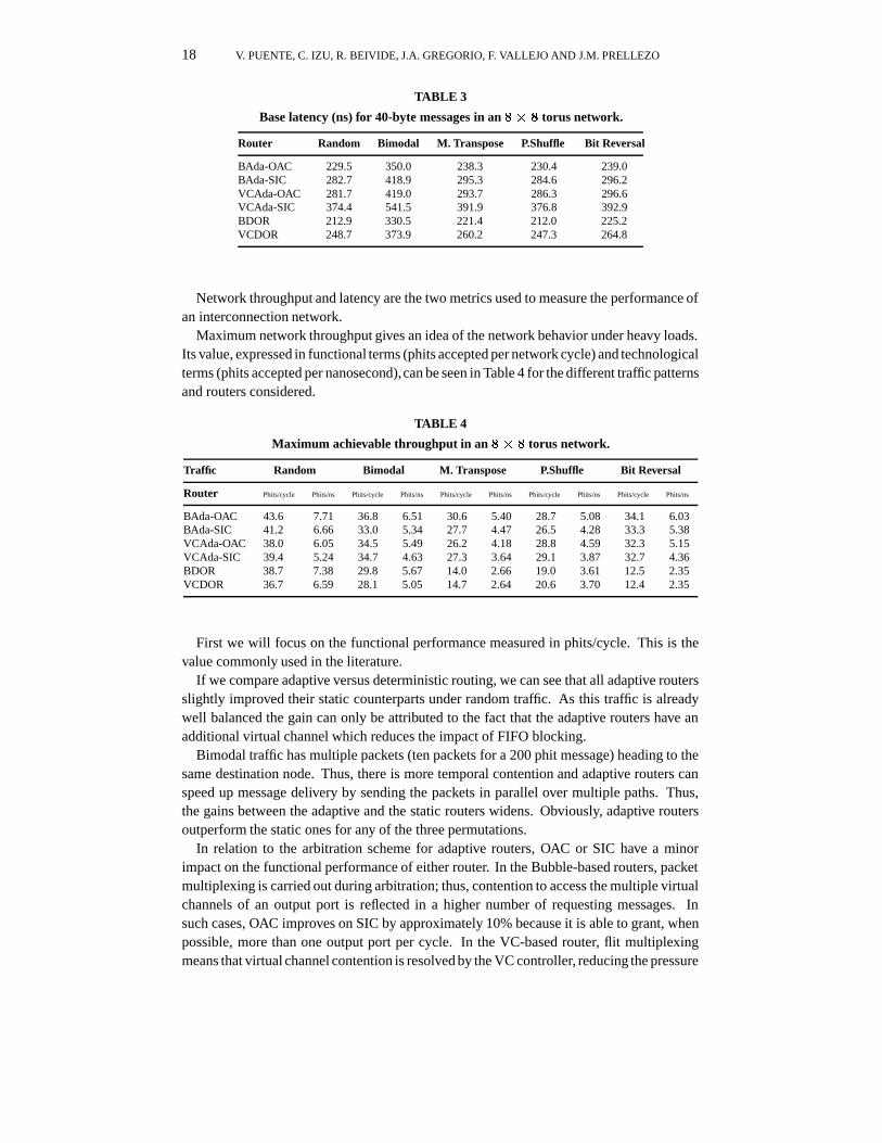
Table 3 shows the base latency for all the router designs and traffic patterns considered.The corresponding values have been obtained when the load applied to the network wasaround 0.05% of the bisection bandwidth.
As base latency depends on the router complexity, it is logical to see that the adaptiverouters exhibit higher values that their static counterparts. However, BAda-OAC presentslower base latency than VCDOR, and it is only 8% slower that BDOR.
5.1.2. Network Latency and Throughput at Variable Load
18 V. PUENTE, C. IZU, R. BEIVIDE, J.A. GREGORIO, F. VALLEJO AND J.M. PRELLEZO
TABLE 3
Base latency (ns) for 40-byte messages in an 8� 8 torus network.
Router Random Bimodal M. Transpose P.Shuffle Bit Reversal
BAda-OAC 229.5 350.0 238.3 230.4 239.0BAda-SIC 282.7 418.9 295.3 284.6 296.2VCAda-OAC 281.7 419.0 293.7 286.3 296.6VCAda-SIC 374.4 541.5 391.9 376.8 392.9BDOR 212.9 330.5 221.4 212.0 225.2VCDOR 248.7 373.9 260.2 247.3 264.8
Network throughput and latency are the two metrics used to measure the performance ofan interconnection network.
Maximum network throughput gives an idea of the network behavior under heavy loads.Its value, expressed in functional terms (phits accepted per network cycle) and technologicalterms (phits accepted per nanosecond),can be seen in Table 4 for the different traffic patternsand routers considered.
TABLE 4
Maximum achievable throughput in an 8� 8 torus network.
Traffic Random Bimodal M. Transpose P.Shuffle Bit Reversal
Router Phits/cycle Phits/ns Phits/cycle Phits/ns Phits/cycle Phits/ns Phits/cycle Phits/ns Phits/cycle Phits/ns
BAda-OAC 43.6 7.71 36.8 6.51 30.6 5.40 28.7 5.08 34.1 6.03BAda-SIC 41.2 6.66 33.0 5.34 27.7 4.47 26.5 4.28 33.3 5.38VCAda-OAC 38.0 6.05 34.5 5.49 26.2 4.18 28.8 4.59 32.3 5.15VCAda-SIC 39.4 5.24 34.7 4.63 27.3 3.64 29.1 3.87 32.7 4.36BDOR 38.7 7.38 29.8 5.67 14.0 2.66 19.0 3.61 12.5 2.35VCDOR 36.7 6.59 28.1 5.05 14.7 2.64 20.6 3.70 12.4 2.35
First we will focus on the functional performance measured in phits/cycle. This is thevalue commonly used in the literature.
If we compare adaptive versus deterministic routing, we can see that all adaptive routersslightly improved their static counterparts under random traffic. As this traffic is alreadywell balanced the gain can only be attributed to the fact that the adaptive routers have anadditional virtual channel which reduces the impact of FIFO blocking.
Bimodal traffic has multiple packets (ten packets for a 200 phit message) heading to thesame destination node. Thus, there is more temporal contention and adaptive routers canspeed up message delivery by sending the packets in parallel over multiple paths. Thus,the gains between the adaptive and the static routers widens. Obviously, adaptive routersoutperform the static ones for any of the three permutations.
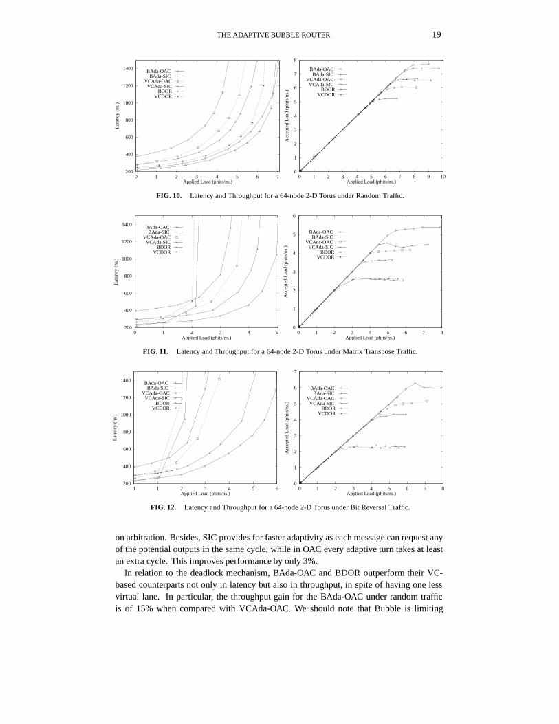
In relation to the arbitration scheme for adaptive routers, OAC or SIC have a minorimpact on the functional performance of either router. In the Bubble-based routers, packetmultiplexing is carried out during arbitration; thus, contention to access the multiple virtualchannels of an output port is reflected in a higher number of requesting messages. Insuch cases, OAC improves on SIC by approximately 10% because it is able to grant, whenpossible, more than one output port per cycle. In the VC-based router, flit multiplexingmeans that virtual channel contention is resolved by the VC controller, reducing the pressure
THE ADAPTIVE BUBBLE ROUTER 19
200
400
600
800
1000
1200
1400
0 1 2 3 4 5 6 7
Lat
ency
(ns
.)
Applied Load (phits/ns.)
BAda-OAC BAda-SIC
VCAda-OACVCAda-SIC
BDORVCDOR
0
1
2
3
4
5
6
7
8
0 1 2 3 4 5 6 7 8 9 10
Acc
epte
d L
oad
(phi
ts/n
s.)
Applied Load (phits/ns.)
BAda-OAC BAda-SIC
VCAda-OAC VCAda-SIC
BDORVCDOR
FIG. 10. Latency and Throughput for a 64-node 2-D Torus under Random Traffic.
200
400
600
800
1000
1200
1400
0 1 2 3 4 5
Lat
ency
(ns
.)
Applied Load (phits/ns.)
BAda-OAC BAda-SIC
VCAda-OACVCAda-SIC
BDORVCDOR
0
1
2
3
4
5
6
0 1 2 3 4 5 6 7 8
Acc
epte
d L
oad
(phi
ts/n
s.)
Applied Load (phits/ns.)
BAda-OAC BAda-SIC
VCAda-OAC VCAda-SIC
BDORVCDOR
FIG. 11. Latency and Throughput for a 64-node 2-D Torus under Matrix Transpose Traffic.
200
400
600
800
1000
1200
1400
0 1 2 3 4 5 6
Lat
ency
(ns
.)
Applied Load (phits/ns.)
BAda-OAC BAda-SIC
VCAda-OACVCAda-SIC
BDORVCDOR
0
1
2
3
4
5
6
7
0 1 2 3 4 5 6 7 8
Acc
epte
d L
oad
(phi
ts/n
s.)
Applied Load (phits/ns.)
BAda-OAC BAda-SIC
VCAda-OAC VCAda-SIC
BDORVCDOR
FIG. 12. Latency and Throughput for a 64-node 2-D Torus under Bit Reversal Traffic.
on arbitration. Besides, SIC provides for faster adaptivity as each message can request anyof the potential outputs in the same cycle, while in OAC every adaptive turn takes at leastan extra cycle. This improves performance by only 3%.
In relation to the deadlock mechanism, BAda-OAC and BDOR outperform their VC-based counterparts not only in latency but also in throughput, in spite of having one lessvirtual lane. In particular, the throughput gain for the BAda-OAC under random trafficis of 15% when compared with VCAda-OAC. We should note that Bubble is limiting
20 V. PUENTE, C. IZU, R. BEIVIDE, J.A. GREGORIO, F. VALLEJO AND J.M. PRELLEZO
the injection of packets at high loads and this is a mechanism which improves networkthroughput for both wormhole [23] and cut-through networks [17]. In this case, limitinginjection proves to be more effective than the additional static virtual channel of VC-based routers. The exception is for SIC-based routers in which the differences in channelmultiplexing distort the result.
However, when we incorporate the VLSI cost, by expressing the network throughput inphits consumed per nanosecond, we observe a different scenario. Figures 10 to 12 showthe network latency versus applied load for three of those patterns. It should be noted thatthese latency values include injection buffer delays. Injection delays must be taken intoaccount in order to produce reliable results because they depend not only on the traffic loadbut also on the traffic pattern.
The first conclusion from these results is that any router proposal cannot be fairlyevaluated without considering its hardware implementation. Many adaptive routers whichmanage to exploit the network resources from a functional point of view cannot competewith implemented static networks as their complexity forfeits any of the gains observed atthe upper level. This trade-off between the potential functional gains and the complexitythey entail is evident in the VC-based adaptive routers: although they appear to improveVCDOR for random and bimodal traffic, their throughput is 15 to 30% worse in phits/ns.Consequently, adaptive router implementation should focus on minimizing both its routerclock cycle and node delay, as the two figures together with the functional properties of therouting strategy will determine network performance.
In relation to the arbiter alternatives, the functional difference between SIC and OACis minimal as discussed before, but their technological difference is considerable. Conse-quently, adaptive routers using OAC outperform their SIC counterparts. Similarly, bothVCAda-SIC and BAda-SIC lose ground with respect to their static counterparts due to theirtechnological cost.
The other source of complexity for adaptive routers is their deadlock avoidance mecha-nism. By looking at Table 4 and Figures 10 to 12 we can see that as Bubble has a nearlynull cost, all Bubble-based routers outperform their VC-based counterparts for any trafficpattern. Therefore, BAda-OAC which combines the two low-cost mechanisms is not onlythe best adaptive router, but it also outperforms both static routers for any traffic pattern.
In short, the BAda-OAC provides the highest throughput with only a minimal incrementof latency compared to its static counterpart (which is not starvation free).
5.2. System Performance Under Real LoadsFinally, we have evaluated the real impact that each router design has on the execution
time of parallel applications.Rsim, a DSM multiprocessor simulator [22], emulates a cc-NUMA architecture with
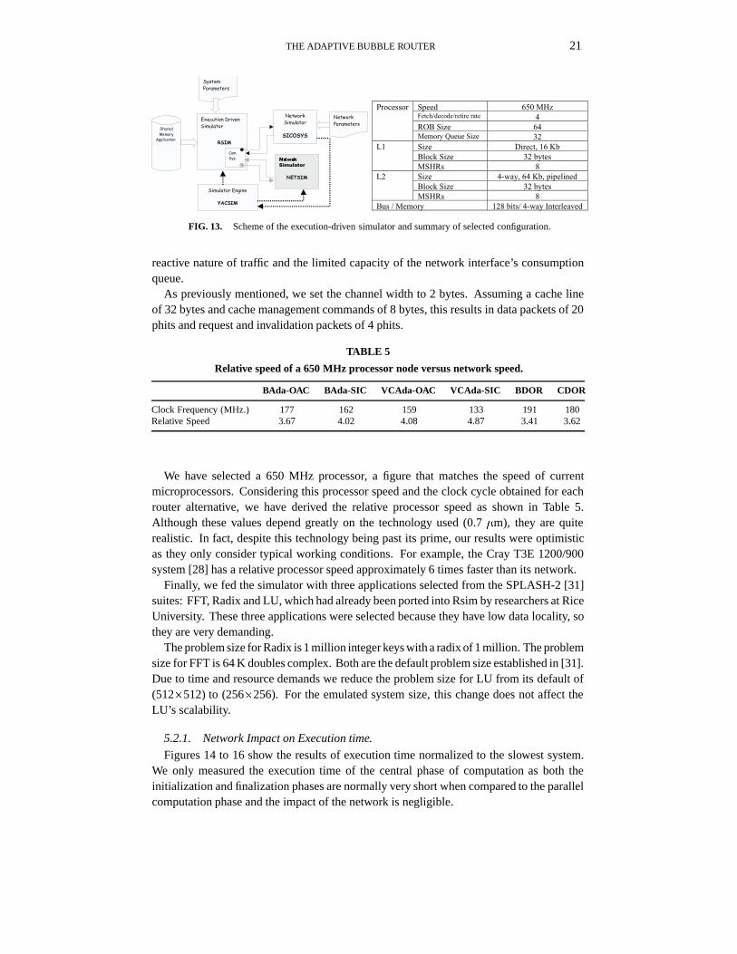
state-of-the-art ILP processors. Although Rsim provides a large range of parameters tospecify the processor and memory hierarchy characteristics, the network configurationchoices are more limited, as it only emulates a wormhole static mesh. Thus, by replacingits network simulator (Netsim) with our RTL network simulator SICOSYS, we can obtain arealistic evaluation of network performance under real loads. Figure 13 shows the role thatSICOSYS plays in this simulation environment, and the main configuration parameters ofthe emulated system.
We use each router alternative to implement a pair of networks: one for request trafficand the other for reply traffic. This approach resolves application deadlock due to the
THE ADAPTIVE BUBBLE ROUTER 21
Shared
Memory
Application
Execution Driven
Simulator
RSIM
Com.
Sys.
Network
Simulator
SICOSYS
Network
Simulator
NETSIM
Simulator Engine
YACSIM
Network
Parameters
System
Parameters
Speed 650 MHzFetch/decode/retire rate 4ROB Size 64
Processor
Memory Queue Size 32Size Direct, 16 KbBlock Size 32 bytes
L1
MSHRs 8Size 4-way, 64 Kb, pipelinedBlock Size 32 bytes
L2
MSHRs 8Bus / Memory 128 bits/ 4-way Interleaved
FIG. 13. Scheme of the execution-driven simulator and summary of selected configuration.
reactive nature of traffic and the limited capacity of the network interface’s consumptionqueue.
As previously mentioned, we set the channel width to 2 bytes. Assuming a cache lineof 32 bytes and cache management commands of 8 bytes, this results in data packets of 20phits and request and invalidation packets of 4 phits.
TABLE 5
Relative speed of a 650 MHz processor node versus network speed.
BAda-OAC BAda-SIC VCAda-OAC VCAda-SIC BDOR CDOR
Clock Frequency (MHz.) 177 162 159 133 191 180Relative Speed 3.67 4.02 4.08 4.87 3.41 3.62
We have selected a 650 MHz processor, a figure that matches the speed of currentmicroprocessors. Considering this processor speed and the clock cycle obtained for eachrouter alternative, we have derived the relative processor speed as shown in Table 5.Although these values depend greatly on the technology used (0.7 �m), they are quiterealistic. In fact, despite this technology being past its prime, our results were optimisticas they only consider typical working conditions. For example, the Cray T3E 1200/900system [28] has a relative processor speed approximately 6 times faster than its network.
Finally, we fed the simulator with three applications selected from the SPLASH-2 [31]suites: FFT, Radix and LU, which had already been ported into Rsim by researchers at RiceUniversity. These three applications were selected because they have low data locality, sothey are very demanding.
The problem size for Radix is 1 million integer keys with a radix of 1 million. The problemsize for FFT is 64 K doubles complex. Both are the default problem size established in [31].Due to time and resource demands we reduce the problem size for LU from its default of(512�512) to (256�256). For the emulated system size, this change does not affect theLU’s scalability.
5.2.1. Network Impact on Execution time.
Figures 14 to 16 show the results of execution time normalized to the slowest system.We only measured the execution time of the central phase of computation as both theinitialization and finalization phases are normally very short when compared to the parallelcomputation phase and the impact of the network is negligible.

22 V. PUENTE, C. IZU, R. BEIVIDE, J.A. GREGORIO, F. VALLEJO AND J.M. PRELLEZO
As expected, the differences in router design have a significant impact on execution time,with up to 25% time reduction in the best cases. Furthermore, these results corroboratethe conclusions we extract from the analysis of synthetic loads, the faster routers being theones with shorter execution times.
If we compare adaptive versus static routers, BAda-OAC is the only adaptive router thatis competitive in relation to both VCDOR and BDOR for any of the three applications. Infact, BAda-OAC is as good or even better than its static counterpart. Thus, although DSMsystems are very sensitive to network latency, BAda-OAC compensates its slightly higherbase latency with its flexibility under non-uniform traffic. If we leave BDOR aside, due to apotential starvation, we could claim that BAda-OAC achieves considerable gains, 5 to 10%in relation to static routers (VCDOR). If we consider an ideal network, in which a remotememory access has the same cost as a local memory access, the reduction in executiontime in relation to that of VCDOR has a ceiling of 30-40% depending on the application.Hence, 10% is a significant achievement.
0
10
20
30
40
50
60
70
80
90
100
BDOR VCDOR BAdaOAC
BAdaSIC
VCAdaOAC
VCAdaSIC
SYNC
MEM
BUSY
80
82
84
86
88
90
92
94
96
98
100
BDOR VCDOR BAdaOAC
BAdaSIC
VCAdaOAC
VCAdaSIC
SYNC
MEM
BUSY
FIG. 14. (a) FFT Normalized execution time for 64 processors in an 8� 8 torus, (b) Zoom.
0
10
20
30
40
50
60
70
80
90
100
BDOR VCDOR BAdaOAC
BAdaSIC
VCAdaOAC
VCAdaSIC
SYNC
MEM
BUSY
70
75
80
85
90
95
100
BDOR VCDOR BAdaOAC
BAdaSIC
VCAdaOAC
VCAdaSIC
SYNC
MEM
BUSY
FIG. 15. (a) Radix Normalized execution time for 64 processors in an 8� 8 torus, (b) Zoom.
In we compare the arbitration schemes, we see again that the technological cost ofSIC has a negative effect in global system performance that in this case is reflected inan increment in execution time of 10 to 15% in relation to their OAC counterparts. If

THE ADAPTIVE BUBBLE ROUTER 23
0
10
20
30
40
50
60
70
80
90
100
BDOR VCDOR BAdaOAC
BAdaSIC
VCAdaOAC
VCAdaSIC
SYNC
MEM
BUSY
75
80
85
90
95
100
BDOR VCDOR BAdaOAC
BAdaSIC
VCAdaOAC
VCAdaSIC
SYNC
MEM
BUSY
FIG. 16. (a) LU Normalized execution time for 64 processors in an 8� 8 torus, (b) Zoom.
we compare the deadlock mechanisms, adaptive Bubble-based routers outperform theirVC-based counterparts with a reduction in execution time of around 10%.
We can see the combined effect of our two proposals: OAC arbitration scheme andBubble flow control in Figure 17. Both mechanisms are critical in reducing the cost ofadaptivity. From the technological point of view, OAC and Bubble reduce the clock cycleby 16% and 8% respectively. These gains are reflected in the applications although thepercentages vary depending on the particular application’s needs.
0
5
10
15
20
25
30
FFT Radix Lu
Bubble-VC
OAC-SIC
Total Impact
%
FIG. 17. Isolating the impact that deadlock avoidance and arbitration schemes have on the performance ofadaptive networks under real loads.
5.2.2. Evolution of Network Performance During the Application’s Execution
To gain a deeper understanding of the impact that the network design has on the systemperformance we have extracted average load and latency values at small time intervals.These results show the load variation of the reply network during execution time. Wefocused only on the reply network because it supports much higher loads than the requestone; besides, this is enough to gain an insight into the network impact on the system’sperformance.
Obviously, networks have different speeds so we express their load both in relation to theirown clock cycle (network cycle) and in relation to the processor cycle which is constantfor all networks. The former value isolates the functional performance (phits/cycle) asmeasured in the previous section. The latter value incorporates the technological cost, and
24 V. PUENTE, C. IZU, R. BEIVIDE, J.A. GREGORIO, F. VALLEJO AND J.M. PRELLEZO
0
5
10
15
20
25
30
35
40
45
50
6.0E+05 1.6E+06 2.6E+06 3.6E+06 4.6E+06 5.6E+06 6.6E+06 7.6E+06 8.6E+06
Execution Time (Processor Cycles)
Loa
d (p
hits
/net
wor
k cy
cle)
BAda-OAC
BAda-SIC
0
2
4
6
8
10
12
14
6.0E+05 1.6E+06 2.6E+06 3.6E+06 4.6E+06 5.6E+06 6.6E+06 7.6E+06 8.6E+06
Execution Time (Processor Cycles)
Loa
d (p
hits
/pro
cess
or c
ycle
)
BAda-OAC
BAda-SIC
0
5
10
15
20
25
30
35
40
45
50
6.0E+05 1.6E+06 2.6E+06 3.6E+06 4.6E+06 5.6E+06 6.6E+06 7.6E+06 8.6E+06
Execution Time (Processor Cycles)
Loa
d (p
hits
/net
wor
k cy
cle)
BDOR
BAda-OAC
VCAda-OAC
0
2
4
6
8
10
12
14
6.0E+05 1.6E+06 2.6E+06 3.6E+06 4.6E+06 5.6E+06 6.6E+06 7.6E+06 8.6E+06
Execution Time (Processor Cycles)
Loa
d (p
hits
/pro
cess
or c
ycle
)
BDOR
BAda-OAC
VCAda-OAC
(a) (b)
(c) (d)
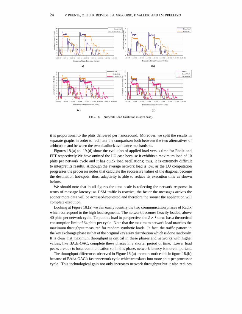
FIG. 18. Network Load Evolution (Radix case).
it is proportional to the phits delivered per nanosecond. Moreover, we split the results inseparate graphs in order to facilitate the comparison both between the two alternatives ofarbitration and between the two deadlock avoidance mechanisms.
Figures 18.(a) to 19.(d) show the evolution of applied load versus time for Radix andFFT respectively.We have omitted the LU case because it exhibits a maximum load of 10phits per network cycle and it has quick load oscillations; thus, it is extremely difficultto interpret its results. Although the average network load is low, as the LU computationprogresses the processor nodes that calculate the successive values of the diagonal becomethe destination hot-spots; thus, adaptivity is able to reduce its execution time as shownbefore.
We should note that in all figures the time scale is reflecting the network response interms of message latency; as DSM traffic is reactive, the faster the messages arrives thesooner more data will be accessed/requested and therefore the sooner the application willcomplete execution.
Looking at Figure 18.(a) we can easily identify the two communication phases of Radixwhich correspond to the high load segments. The network becomes heavily loaded, above40 phits per network cycle. To put this load in perspective, the 8� 8 torus has a theoreticalconsumption limit of 64 phits per cycle. Note that the maximum network load matches themaximum throughput measured for random synthetic loads. In fact, the traffic pattern inthe key exchange phase is that of the original key array distribution which is done randomly.It is clear that maximum throughput is critical in these phases and networks with highervalues, like BAda-OAC, complete these phases in a shorter period of time. Lower loadpeaks are due to local communication so, in this phase, network latency is more important.
The throughput differences observed in Figure 18.(a) are more noticeable in figure 18.(b)because of BAda-OAC’s faster network cycle which translates into more phits per processorcycle. This technological gain not only increases network throughput but it also reduces
THE ADAPTIVE BUBBLE ROUTER 25
0
5
10
15
20
25
30
35
40
45
6.5E+05 7.5E+05 8.5E+05 9.5E+05 1.1E+06 1.2E+06 1.3E+06 1.4E+06
Execution Time (Processor Cycles)
Loa
d (p
hits
/Net
wor
k cy
cle)
Bada-OAC
Bada-SIC
0
2
4
6
8
10
12
6.5E+05 7.5E+05 8.5E+05 9.5E+05 1.1E+06 1.2E+06 1.3E+06 1.4E+06
Execution Time (Processor Cycles)
Loa
d (p
hits
/pro
cess
or c
ycle
)
Bada-OAC
Bada-SIC
0
5
10
15
20
25
30
35
40
45
6.5E+05 7.5E+05 8.5E+05 9.5E+05 1.1E+06 1.2E+06 1.3E+06
Execution Time (Processor Cycles)
Loa
d (p
hits
/Net
wor
k cy
cle)
VCDOR
BAda-OAC
VCAda-OAC
0
2
4
6
8
10
12
6.5E+05 7.5E+05 8.5E+05 9.5E+05 1.1E+06 1.2E+06 1.3E+06 1.4E+06
Execution Time (Processor Cycles)
Loa
d (p
hits
/pro
cess
or c
ycle
)
VCDOR
BAda-OAC
VCAda-OAC
(a) (b)
(c) (d)
FIG. 19. Network Load Evolution (FFT case).
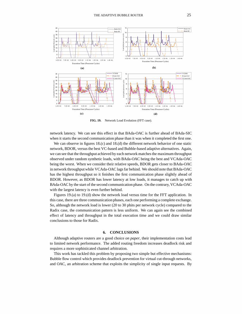
network latency. We can see this effect in that BAda-OAC is further ahead of BAda-SICwhen it starts the second communication phase than it was when it completed the first one.
We can observe in figures 18.(c) and 18.(d) the different network behavior of one staticnetwork, BDOR, versus the best VC-based and Bubble-based adaptive alternatives. Again,we can see that the throughput achieved by each network matches the maximum throughputobserved under random synthetic loads, with BAda-OAC being the best and VCAda-OACbeing the worst. When we consider their relative speeds, BDOR gets closer to BAda-OACin network throughput while VCAda-OAC lags far behind. We should note that BAda-OAChas the highest throughput so it finishes the first communication phase slightly ahead ofBDOR. However, as BDOR has lower latency at low loads, it manages to catch up withBAda-OAC by the start of the second communication phase. On the contrary, VCAda-OACwith the largest latency is even further behind.
Figures 19.(a) to 19.(d) show the network load versus time for the FFT application. Inthis case, there are three communication phases, each one performing a complete exchange.So, although the network load is lower (20 to 30 phits per network cycle) compared to theRadix case, the communication pattern is less uniform. We can again see the combinedeffect of latency and throughput in the total execution time and we could draw similarconclusions to those for Radix.
6. CONCLUSIONS
Although adaptive routers are a good choice on paper, their implementation costs leadto limited network performance. The added routing freedom increases deadlock risk andrequires a more sophisticated channel arbitration.
This work has tackled this problem by proposing two simple but effective mechanisms:Bubble flow control which provides deadlock prevention for virtual cut-through networks,and OAC, an arbitration scheme that exploits the simplicity of single input requests. By
26 V. PUENTE, C. IZU, R. BEIVIDE, J.A. GREGORIO, F. VALLEJO AND J.M. PRELLEZO
combining these two mechanisms, we have designed a new fully-adaptive router for k-aryn-cube networks with the minimum possible number of virtual channels, two per physicallink. This router has been compared with adaptive routers that use previous solutions eitherfor the deadlock prevention mechanism or the arbitration scheme and with static routers inorder to estimate the viability of the proposal.
Traditionally, routers have been evaluated by applying synthetic loads to RTL networksimulators. Although this methodology highlights the functional gains of a router architec-ture, it does not take into account the VLSI costs or the behavior of the networks as part ofa whole system. Thus, our comparison started by evaluating the VLSI cost of each routeralternative and incorporating these costs into the network simulator. In this way, simula-tions provided us with network performance both from the functional and technologicalpoints of view. Finally, all these factors were taken into account to estimate the impact ofeach router on cc-NUMA system performance.
The evaluation at these three levels shows the goodness of our proposal. The routerexhibits a low clock cycle and the shortest node delay. This, together with adaptivitytranslates into the best network performance under any synthetic traffic pattern. Similarly,low network latency and high network throughput reduce the execution time of parallelapplications while all other adaptive routers exhibited higher execution times than those ofstatic routers.
The key to success is achieving a router implementation that minimizes both router clockcycle and node delay, as these two figures together with the functional properties of therouting strategy will determine network performance. Our adaptive Bubble router achievesthis goal and therefore it can be considered as one of the best candidates for multiprocessornetwork designs.
REFERENCES
1. A. Agarwal, “Limits on interconnection network performance,” IEEE Trans. on Parallel and DistributedSystems, vol. 2, no. 4, pp. 398–412, October 1991.
2. R. Kessler,“Alpha 21364 to Ease Memory Bottleneck”, Microprocessors Report, Vol 12, Issue 14, October26, 1998.
3. Cadence design framework II online help. Version 4.4.1 1997, February 97.
4. Blue Mountain Home Page, available at http://www.lanl.gov/asci/bluemtn/.
5. J. Carbonaro and F. Verhoorn, “Cavallino: The teraflops router and NIC,” Proceedings of Hot InterconnectsSymposium IV, August 1996.
6. C. Carrion, R. Beivide, J.A. Gregorio and F. Vallejo, “A flow control mechanism to avoid message deadlockin k-ary n-cube networks,” Fourth International Conference on High Performance Computing, pp. 322-329,India, December,1997.
7. A.A. Chien, “A cost and speed model for k-ary n-cube wormhole routers," Proceedings of Hot Intercon-nects’93, Palo Alto, California, August 1993.
8. A. A. Chien and J. H. Kim, “ Planar-Adaptive Routing: Low-cost Adaptive Networks for Multiprocessors”,Proceedings of the 19th Annual International Symposium on Computer Architecture, May 1992.
9. W. J. Dally and C. L. Seitz, “The torus routing chip,” Journal of Distributed Computing, vol. 1, no. 3, pp.187–196, October 1986.
10. W.J. Dally and C.L. Seitz, “Deadlock-free message routing in multiprocessor interconnection networks” IEEETrans. on Computers, vol. C-36, no. 5, pp. 547-553, 1987.
11. W. J. Dally, “Performance analysis of k-ary n-cube interconnection networks,” IEEE Trans. on Computers,vol. C–39, no. 6, pp. 775–785, June 1990.
12. J. Duato,"A new theory of deadlock-free adaptive routing in wormhole networks." IEEE Trans. on Paralleland Distributed Systems, vol.4, no.12, pp.1320-1331, December 1993.
THE ADAPTIVE BUBBLE ROUTER 27
13. J. Duato and P. Lopez,"Performance of adaptive routing algorithms k-ary n-cubes" Proceedings of theWorkshop on Parallel Computing Routing and Communications, May 1994.
14. J. Duato,“A necessary and sufficient condition for deadlock-free routing in cut-through and store-and-forwardnetworks”. IEEE Trans. on Parallel and Distributed Systems, vol.7, no.8, pp.841-854, August 1996.
15. M. Galles, “Scalable pipelined interconnect for distributed endpoint routing: The SPIDER chip,” Proceedingsof Hot Interconnects Symposium IV, August 1996.
16. C. J. Glass and L. M. Ni, “The Turn Model for Adaptive Routing, ” Proceedings of the 19th AnnualInternational Symposium on Computer Architecture, May 1992.
17. C. Izu, C. Carrion, J.A. Gregorio and R. Beivide, ”Restricted Injection Flow Control for k-ary n-cubeNetworks,”Proceedings of Parallel and Distributed Computer Systems PDCS’97, Oct. 1997.
18. P. Kermani and L. Kleinrock, “Virtual cut-through: a new computer communication switching tech-nique,”Computer Networks, vol. 3, pp. 267-286, 1979.
19. A. R. Larzelere II, “Creating simulation capabilities,” IEEE Computational Science & Engineering, pp.27-35,January-March 1998.
20. J. Laudon and D. Lenoski, “The SGI Origin: A cc-NUMA highly scalable server,” International Symposiumon Computer Architecture, June 1997.
21. D. H. Linder and J. C. Harden, ” An Adaptive and Fault Tolerant Wormhole Routing Strategy for k-aryn-cubes” IEEE Trans. on Computers , 40(1), pp. 2-12, January 1991.
22. V. S. Pai, P. Ranganathan, S. Adve ”Rsim: An execution-Driven Simulator for ILP-Based Shared-MemoryMultiprocessors and Uniprocessors”, IEEE TCCA Newsletter, Oct. 1997.
23. F. Petrini, M. Vanneschi, ”Minimal Adaptive Routing with Limited Injection on Toroidal k-ary n-cubes”,Proceedings Supercomputing’96, Nov. 1996.
24. T. M. Pinkston and S. Warnakulasuriya, ”On Deadlocks in Interconnection Networks”. Proceedings of the24th Annual International Symposium on Computer Architecture , June 1997.
25. J.M. Prellezo, V. Puente, J.A. Gregorio and R. Beivide, “SICOSYS: an interconnection network simu-lator for parallel computers”, Universidad de Cantabria Technical Report TR-ATC2-UC98, available athttp://www.atc.unican.es/ REPORTS/TR-ATC2-UC98.pdf June 1998.
26. V. Puente, J.A. Gregorio, C. Izu, R. Beivide and F. Vallejo “Low-level Router Design and its Impact onSupercomputer System Performance”, International Conference on Supercomputing, June 1999.
27. V. Puente, J.A. Gregorio,J. M. Prellezo, R. Beivide,J. Duato, C. Izu “Adaptive Bubble Router: a Design toBalance Latency and Throughput in Networks for Parallel Computers”, International Conference ParallelProcessing ICPP’99, Sept. 1999.
28. S.L.Scott and G. Thorson, "The Cray T3E network: Adaptive routing in a high performance 3-D torus", HotInterconnects Symposium IV, August 1996.
29. Synopsys On Line Documentation Version 1997.08, 1997.
30. Y. Tamir and C. Chi, “Symmetric Crossbar Arbiters for VLSI Communication Switches”, IEEE Trans. onParallel and Distributed Systems, vol. 4, no. 1, pp. 13-27, January 1993.
31. S. C. Woo, M. Ohara, E. Torrie, J.P. Singh, A. Gupta "The SPLASH-2 Programs: Characterization andMethodological Considerations". Proceedings of the 22nd International Symposium on Computer Architecture,June 1995.