A Critical Analysis of Molten Salt Reactor (Msr) Safety Systems.
10
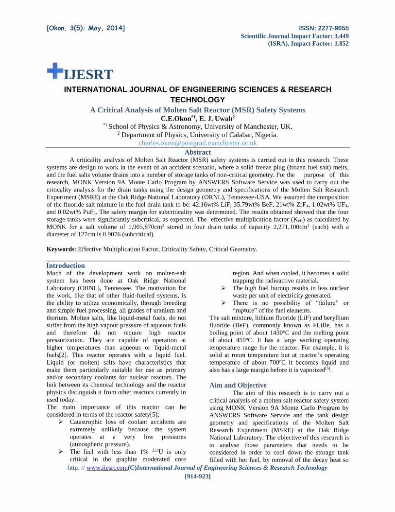
[Okon, 3(5): May, 2014] ISSN: 2277-9655 Scientific Journal Impact Factor: 3.449 (ISRA), Impact Factor: 1.852 http: // www.ijesrt.com(C)International Journal of Engineering Sciences & Research Technology [914-923] IJESRT INTERNATIONAL JOURNAL OF ENGINEERING SCIENCES & RESEARCH TECHNOLOGY A Critical Analysis of Molten Salt Reactor (MSR) Safety Systems C.E.Okon *1 , E. J. Uwah 2 *1 School of Physics & Astronomy, University of Manchester, UK. 2 Department of Physics, University of Calabar, Nigeria. [email protected] Abstract A criticality analysis of Molten Salt Reactor (MSR) safety systems is carried out in this research. These systems are design to work in the event of an accident scenario, where a solid freeze plug (frozen fuel salt) melts, and the fuel salts volume drains into a number of storage tanks of non-critical geometry. For the purpose of this research, MONK Version 9A Monte Carlo Program by ANSWERS Software Service was used to carry out the criticality analysis for the drain tanks using the design geometry and specifications of the Molten Salt Research Experiment (MSRE) at the Oak Ridge National Laboratory (ORNL), Tennessee-USA. We assumed the composition of the fluoride salt mixture in the fuel drain tank to be: 42.16wt% LiF, 35.79wt% BeF, 21wt% ZrF 4, 1.02wt% UF4, and 0.02wt% PuF3. The safety margin for subcriticality was determined. The results obtained showed that the four storage tanks were significantly subcritical, as expected. The effective multiplication factor (Keff) as calculated by MONK for a salt volume of 1,905,870cm 3 stored in four drain tanks of capacity 2,271,100cm 3 (each) with a diameter of 127cm is 0.9076 (subcritical). Keywords: Effective Multiplication Factor, Criticality Safety, Critical Geometry. Introduction Much of the development work on molten-salt system has been done at Oak Ridge National Laboratory (ORNL), Tennessee. The motivation for the work, like that of other fluid-fuelled systems, is the ability to utilize economically, through breeding and simple fuel processing, all grades of uranium and thorium. Molten salts, like liquid-metal fuels, do not suffer from the high vapour pressure of aqueous fuels and therefore do not require high reactor pressurization. They are capable of operation at higher temperatures than aqueous or liquid-metal fuels[2]. This reactor operates with a liquid fuel. Liquid (or molten) salts have characteristics that make them particularly suitable for use as primary and/or secondary coolants for nuclear reactors. The link between its chemical technology and the reactor physics distinguish it from other reactors currently in used today. The main importance of this reactor can be considered in terms of the reactor safety[5]; Catastrophic loss of coolant accidents are extremely unlikely because the system operates at a very low pressures (atmospheric pressure). The fuel with less than 1% 233 U is only critical in the graphite moderated core region. And when cooled, it becomes a solid trapping the radioactive material. The high fuel burnup results in less nuclear waste per unit of electricity generated. There is no possibility of “failure” or “rupture” of the fuel elements. The salt mixture, lithium fluoride (LiF) and beryllium fluoride (BeF), commonly known as FLiBe, has a boiling point of about 1430 o C and the melting point of about 459 o C. It has a large working operating temperature range for the reactor. For example, it is solid at room temperature but at reactor’s operating temperature of about 700 o C it becomes liquid and also has a large margin before it is vaporized [5] . Aim and Objective The aim of this research is to carry out a critical analysis of a molten salt reactor safety system using MONK Version 9A Monte Carlo Program by ANSWERS Software Service and the tank design geometry and specifications of the Molten Salt Research Experiment (MSRE) at the Oak Ridge National Laboratory. The objective of this research is to analyse those parameters that needs to be considered in order to cool down the storage tank filled with hot fuel, by removal of the decay heat so
Transcript of A Critical Analysis of Molten Salt Reactor (Msr) Safety Systems.
[Okon, 3(5): May, 2014] ISSN: 2277-9655
Scientific Journal Impact Factor: 3.449
(ISRA), Impact Factor: 1.852
http: // www.ijesrt.com(C)International Journal of Engineering Sciences & Research Technology
[914-923]
IJESRT INTERNATIONAL JOURNAL OF ENGINEERING SCIENCES & RESEARCH
TECHNOLOGY
A Critical Analysis of Molten Salt Reactor (MSR) Safety Systems C.E.Okon*1, E. J. Uwah2
*1 School of Physics & Astronomy, University of Manchester, UK. 2 Department of Physics, University of Calabar, Nigeria.
Abstract A criticality analysis of Molten Salt Reactor (MSR) safety systems is carried out in this research. These
systems are design to work in the event of an accident scenario, where a solid freeze plug (frozen fuel salt) melts,
and the fuel salts volume drains into a number of storage tanks of non-critical geometry. For the purpose of this
research, MONK Version 9A Monte Carlo Program by ANSWERS Software Service was used to carry out the
criticality analysis for the drain tanks using the design geometry and specifications of the Molten Salt Research
Experiment (MSRE) at the Oak Ridge National Laboratory (ORNL), Tennessee-USA. We assumed the composition
of the fluoride salt mixture in the fuel drain tank to be: 42.16wt% LiF, 35.79wt% BeF, 21wt% ZrF4, 1.02wt% UF4,
and 0.02wt% PuF3. The safety margin for subcriticality was determined. The results obtained showed that the four
storage tanks were significantly subcritical, as expected. The effective multiplication factor (Keff) as calculated by
MONK for a salt volume of 1,905,870cm3 stored in four drain tanks of capacity 2,271,100cm3 (each) with a
diameter of 127cm is 0.9076 (subcritical).
Keywords: Effective Multiplication Factor, Criticality Safety, Critical Geometry.
Introduction Much of the development work on molten-salt
system has been done at Oak Ridge National
Laboratory (ORNL), Tennessee. The motivation for
the work, like that of other fluid-fuelled systems, is
the ability to utilize economically, through breeding
and simple fuel processing, all grades of uranium and
thorium. Molten salts, like liquid-metal fuels, do not
suffer from the high vapour pressure of aqueous fuels
and therefore do not require high reactor
pressurization. They are capable of operation at
higher temperatures than aqueous or liquid-metal
fuels[2]. This reactor operates with a liquid fuel.
Liquid (or molten) salts have characteristics that
make them particularly suitable for use as primary
and/or secondary coolants for nuclear reactors. The
link between its chemical technology and the reactor
physics distinguish it from other reactors currently in
used today.
The main importance of this reactor can be
considered in terms of the reactor safety[5];
Catastrophic loss of coolant accidents are
extremely unlikely because the system
operates at a very low pressures
(atmospheric pressure).
The fuel with less than 1% 233U is only
critical in the graphite moderated core
region. And when cooled, it becomes a solid
trapping the radioactive material.
The high fuel burnup results in less nuclear
waste per unit of electricity generated.
There is no possibility of “failure” or
“rupture” of the fuel elements.
The salt mixture, lithium fluoride (LiF) and beryllium
fluoride (BeF), commonly known as FLiBe, has a
boiling point of about 1430oC and the melting point
of about 459oC. It has a large working operating
temperature range for the reactor. For example, it is
solid at room temperature but at reactor’s operating
temperature of about 700oC it becomes liquid and
also has a large margin before it is vaporized[5].
Aim and Objective The aim of this research is to carry out a
critical analysis of a molten salt reactor safety system
using MONK Version 9A Monte Carlo Program by
ANSWERS Software Service and the tank design
geometry and specifications of the Molten Salt
Research Experiment (MSRE) at the Oak Ridge
National Laboratory. The objective of this research is
to analyse those parameters that needs to be
considered in order to cool down the storage tank
filled with hot fuel, by removal of the decay heat so
[Okon, 3(5): May, 2014] ISSN: 2277-9655
Scientific Journal Impact Factor: 3.449
(ISRA), Impact Factor: 1.852
http: // www.ijesrt.com(C)International Journal of Engineering Sciences & Research Technology
[914-923]
as to maintain the integrity of the tank and keep the
fuel in a subcritical state.
Limitations of Study In an actual plant we have to analyze the
transient (i.e. how long it will take the fuel to
completely drain to the drain tank) but for this project
the sub-criticality analysis assumes that the fuel has
been completely drained into the tank. The cooling
system and the heater assembly surrounding each
tank or any other structural material or machinery in
the cell is not considered in the analysis. Material
geometry/specifications used for the component
dimensions were gotten from the reports from related
articles on Molten Salt Breeder Reactor (MSBR) &
Molten Salt Reactor Experiment (MSRE).
Basic Reactor Emergency Safety Systems Freeze Plug
The freeze plug is kept actively frozen by an
external cooling fan blowing air into the area. In an
event of total loss of power, the Freeze Plug (valve)
melts, and the bulk of core salt drains by gravity into
the drain tank with passively cooled configuration
where nuclear fission and melt down is not
possible[6].
Critically Safe Fuel Drain Tanks:
The fuel drain tank is necessary in the case
of pump power failure because even if the reactor is
immediately scrammed, decay-heat generation may
raise the core temperatures to intolerable levels as the
fuel salt, being its own coolant, is no longer in
motion[3]. The capacity of one fuel drain tank is
enough to hold all the fuel cell in the entire reactor
but for safety reasons the fuel can be distributed
equally into two or more fuel tanks linked together.
The tank is design with a pump bowl to
accommodate any excess of coolant salt volume.
Each bowl is provided with an overflow line directed
to the first coolant-salt drain tank. The jet pump is
used to pump back the salt from the tank to the
circulation system. Once in the tank, the fuel salt is
cooled by the fluoroborate (as in the case of MSBR)
secondary coolant salt through U-tubes which extend
into the tank from headers located at the top of the
tanks. For MSBR, the maximum cooling
requirements are 60 Mw(t) but the system is design
for 300Mw(t). The fluoroborate coolant is circulated
by natural convection (since power failure may have
caused the initial emergency). The heat is then
dumped into the atmosphere via air coolers and
chimneys[3].
Methodology MONK 9A Simulation
MONK is a Monte Carlo neutronics
computer program used in the study of nuclear
criticality safety and reactor physics analysis[1]. The
version of MONK used for this dissertation is
MONK Version 9A, the ANSWERS Software
Package.
Since the goal of criticality safety is to
assure that all operations are subcritical, the ability to
adjust the balance routinely is, of course, very
necessary. Thus, any methods that favour some
combination of low production and high absorption
and leakage may be employed. The production rate
for neutrons depends on the amount and type of each
fissionable material present in a system[4].
Drain Tanks Design Specification
The material used for the drain tank design
is Hastelloy. Hastelloy material was designed as a
“super alloy” or high temperature alloy. It suffers
much less loss of ductility under neutron irradiation
compared to stainless steel. This material is
developed for corrosion resistance of oxidising and
reducing agent. The material integrity cannot be
perturbed when exposed to very high temperature. It
is designed to survive under high-temperature and
high-stress service. The primary ingredient of this
material is nickel, but it also contains chromium,
molybdenum, carbon, manganese, silicon titanium,
copper, sulphur, iron and boron. The material has a
density of 8.08 g/cm3, melting point of 1323-1371oC,
thermal conductivity of 10.1-12.5 W/m-K and a heat
capacity of 0.427J/goC, The chemical composition by
proportion of Hastelloy alloy used for this design is
as shown below[7] (the format is taken from the
MONK input file, and the values are fractional
compositions by mass):
Ni PROP 0.66
Cr PROP 0.10
Mo PROP 0.15
C PROP 0.0004
Mn PROP 0.01
Si PROP 0.01
Ti PROP 0.00865
Cu PROP 0.0035
S PROP 0.0002
Fe PROP 0.05
B PROP 0.0001
Stated below are the drain tanks design parameters[3];
Drain Tank Capacity = 2,271 litres
(2.271 m3)
Drain Tank Inner diameter = 1.27m
Drain Tank Outer diameter = 1.312m
[Okon, 3(5): May, 2014] ISSN: 2277-9655
Scientific Journal Impact Factor: 3.449
(ISRA), Impact Factor: 1.852
http: // www.ijesrt.com(C)International Journal of Engineering Sciences & Research Technology
[914-923]
Drain Tank inner height = 2.1844m
Fuel Salt Density = 2.02 g/cm3
Total Fuel Salt Volume = 1,905.9 litres
(1.906 m3)
Water bath height = 4.00m
The MONK input files have been prepared using the
above material geometry and specifications, and are
provided in Appendix 2A of this report. The results
are displayed in tabular form in Appendix 1A, and a
graphical interpretation of the results is provided
below in this report.
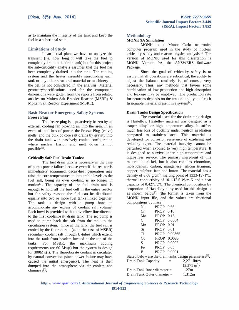
Design Assumption: the drain tanks are welded to the
bottom of the cell such that the minimum separation
of each tank from the cell wall and its two neighbours
are equal.
Diagonal (d) as calculated below = 243.34cm
Inner tank diameter is 127cm and the radius (r) =
63.5cm
Maximum length of the diagonal (D) is 460.48cm
Separation (x) as calculated below = 45.07cm
The Area of a square is given by the formular
A = S2 where S is the length of one side.
But if the length of the diogonal is known, the area is
half of the digonals.
Since both digonals are congruent, this simplified to:
The above calculated figures were also used for the
MONK modelling.
One of the assumptions made in this design is that,
the total fuel salt is equally distributed into four drain
tanks of equal dimensions. Therefore, the input files
are written for different values of fuel volumes to
ascertain the critical volume and critical diameter.
Fig.1: MONK modelling for the MSR Drain Tanks (see
code in Appendix B)
[Okon, 3(5): May, 2014] ISSN: 2277-9655
Scientific Journal Impact Factor: 3.449
(ISRA), Impact Factor: 1.852
http: // www.ijesrt.com(C)International Journal of Engineering Sciences & Research Technology
[914-923]
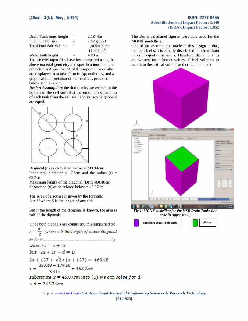
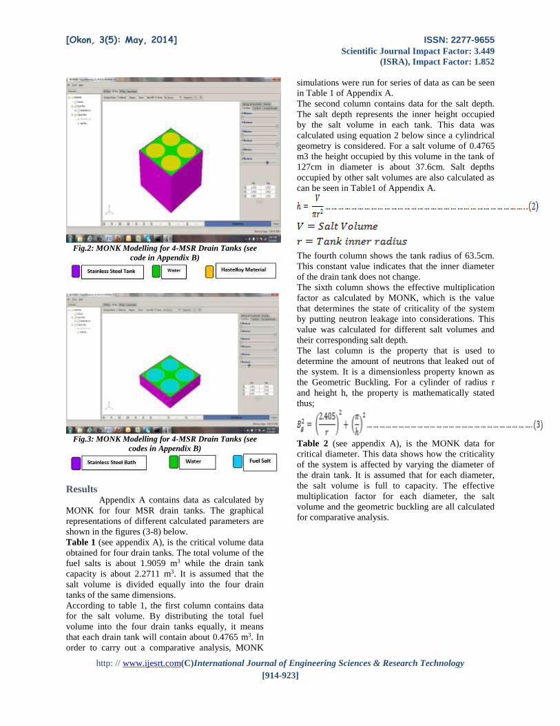
Fig.2: MONK Modelling for 4-MSR Drain Tanks (see
code in Appendix B)
Fig.3: MONK Modelling for 4-MSR Drain Tanks (see
codes in Appendix B)
Results Appendix A contains data as calculated by
MONK for four MSR drain tanks. The graphical
representations of different calculated parameters are
shown in the figures (3-8) below.
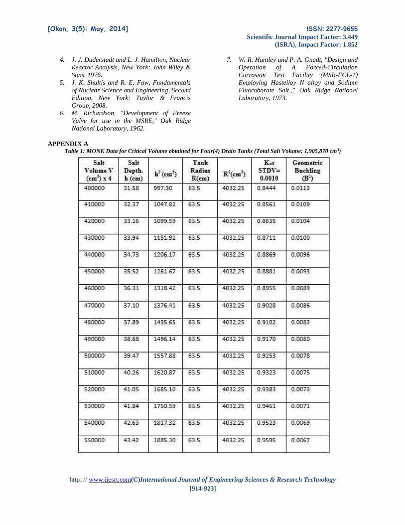
Table 1 (see appendix A), is the critical volume data
obtained for four drain tanks. The total volume of the
fuel salts is about 1.9059 m3 while the drain tank
capacity is about 2.2711 m3. It is assumed that the
salt volume is divided equally into the four drain
tanks of the same dimensions.
According to table 1, the first column contains data
for the salt volume. By distributing the total fuel
volume into the four drain tanks equally, it means
that each drain tank will contain about 0.4765 m3. In
order to carry out a comparative analysis, MONK
simulations were run for series of data as can be seen
in Table 1 of Appendix A.
The second column contains data for the salt depth.
The salt depth represents the inner height occupied
by the salt volume in each tank. This data was
calculated using equation 2 below since a cylindrical
geometry is considered. For a salt volume of 0.4765
m3 the height occupied by this volume in the tank of
127cm in diameter is about 37.6cm. Salt depths
occupied by other salt volumes are also calculated as
can be seen in Table1 of Appendix A.
The fourth column shows the tank radius of 63.5cm.
This constant value indicates that the inner diameter
of the drain tank does not change.
The sixth column shows the effective multiplication
factor as calculated by MONK, which is the value
that determines the state of criticality of the system
by putting neutron leakage into considerations. This
value was calculated for different salt volumes and
their corresponding salt depth.
The last column is the property that is used to
determine the amount of neutrons that leaked out of
the system. It is a dimensionless property known as
the Geometric Buckling. For a cylinder of radius r
and height h, the property is mathematically stated
thus;
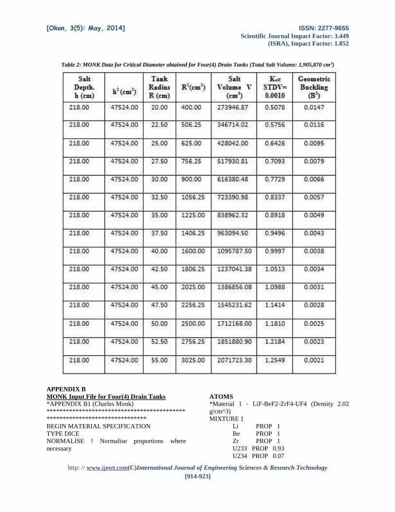
Table 2 (see appendix A), is the MONK data for
critical diameter. This data shows how the criticality
of the system is affected by varying the diameter of
the drain tank. It is assumed that for each diameter,
the salt volume is full to capacity. The effective
multiplication factor for each diameter, the salt
volume and the geometric buckling are all calculated
for comparative analysis.
[Okon, 3(5): May, 2014] ISSN: 2277-9655
Scientific Journal Impact Factor: 3.449
(ISRA), Impact Factor: 1.852
http: // www.ijesrt.com(C)International Journal of Engineering Sciences & Research Technology
[914-923]
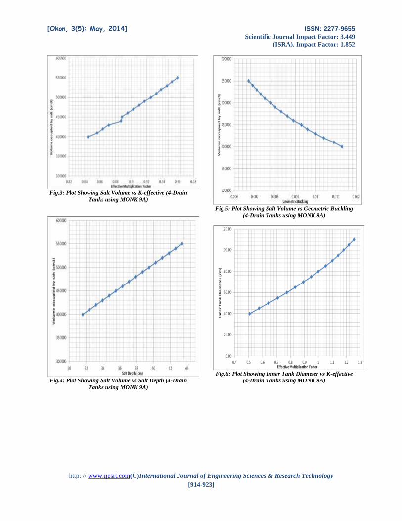
Fig.3: Plot Showing Salt Volume vs K-effective (4-Drain
Tanks using MONK 9A)
Fig.4: Plot Showing Salt Volume vs Salt Depth (4-Drain
Tanks using MONK 9A)
Fig.5: Plot Showing Salt Volume vs Geometric Buckling
(4-Drain Tanks using MONK 9A)
Fig.6: Plot Showing Inner Tank Diameter vs K-effective
(4-Drain Tanks using MONK 9A)
[Okon, 3(5): May, 2014] ISSN: 2277-9655
Scientific Journal Impact Factor: 3.449
(ISRA), Impact Factor: 1.852
http: // www.ijesrt.com(C)International Journal of Engineering Sciences & Research Technology
[914-923]
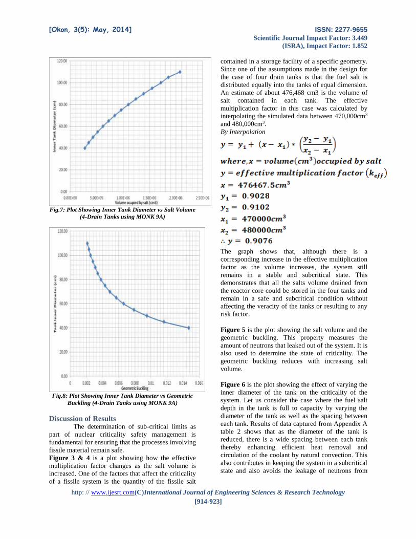
Fig.7: Plot Showing Inner Tank Diameter vs Salt Volume
(4-Drain Tanks using MONK 9A)
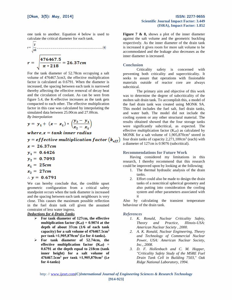
Fig.8: Plot Showing Inner Tank Diameter vs Geometric
Buckling (4-Drain Tanks using MONK 9A)
Discussion of Results The determination of sub-critical limits as
part of nuclear criticality safety management is
fundamental for ensuring that the processes involving
fissile material remain safe.
Figure 3 & 4 is a plot showing how the effective
multiplication factor changes as the salt volume is
increased. One of the factors that affect the criticality
of a fissile system is the quantity of the fissile salt
contained in a storage facility of a specific geometry.
Since one of the assumptions made in the design for
the case of four drain tanks is that the fuel salt is
distributed equally into the tanks of equal dimension.
An estimate of about 476,468 cm3 is the volume of
salt contained in each tank. The effective
multiplication factor in this case was calculated by
interpolating the simulated data between 470,000cm3
and 480,000cm3.
By Interpolation
The graph shows that, although there is a
corresponding increase in the effective multiplication
factor as the volume increases, the system still
remains in a stable and subcritical state. This
demonstrates that all the salts volume drained from
the reactor core could be stored in the four tanks and
remain in a safe and subcritical condition without
affecting the veracity of the tanks or resulting to any
risk factor.
Figure 5 is the plot showing the salt volume and the
geometric buckling. This property measures the
amount of neutrons that leaked out of the system. It is
also used to determine the state of criticality. The
geometric buckling reduces with increasing salt
volume.
Figure 6 is the plot showing the effect of varying the
inner diameter of the tank on the criticality of the
system. Let us consider the case where the fuel salt
depth in the tank is full to capacity by varying the
diameter of the tank as well as the spacing between
each tank. Results of data captured from Appendix A
table 2 shows that as the diameter of the tank is
reduced, there is a wide spacing between each tank
thereby enhancing efficient heat removal and
circulation of the coolant by natural convection. This
also contributes in keeping the system in a subcritical
state and also avoids the leakage of neutrons from
[Okon, 3(5): May, 2014] ISSN: 2277-9655
Scientific Journal Impact Factor: 3.449
(ISRA), Impact Factor: 1.852
http: // www.ijesrt.com(C)International Journal of Engineering Sciences & Research Technology
[914-923]
one tank to another. Equation 4 below is used to
calculate the critical diameter for each tank.
For the tank diameter of 52.78cm occupying a salt
volume of 476467.5cm3, the effective multiplication
factor is calculated as 0.6791. When the diameter is
increased, the spacing between each tank is narrowed
thereby affecting the effective removal of decay heat
and the circulation of coolant. As can be seen from
figure 5.4, the K-effective increases as the tank gets
compacted to each other. The effective multiplication
factor in this case was calculated by interpolating the
simulated data between 25.00cm and 27.00cm.
By Interpolation
We can hereby conclude that, the credible upset
geometric configuration from a critical safety
standpoint occurs when the tank diameter is increased
and the spacing between each tank neighbours is very
close. This causes the maximum possible reflection
in the fuel drain tank cell given the assumed
constraint of less water ingress.
Deductions for 4-Drain Tanks
For tank diameter of 127cm, the effective
multiplication factor (Keff) = 0.9074 at the
depth of about 37cm (1/6 of each tank
capacity) for a salt volume of 476467.5cm3
per tank ≈1,905,870cm3 (i.e for 4-tanks).
For tank diameter of 52.74cm, the
effective multiplication factor (Keff) =
0.6791 at the depth equal to 218cm (tank
inner height) for a salt volume of
476467.5cm3 per tank ≈1,905,870cm3 (i.e
for 4-tanks)
Figure 7 & 8, shows a plot of the inner diameter
against the salt volume and the geometric buckling
respectively. As the inner diameter of the drain tank
is increased it gives room for more salt volume to be
accommodated and the leakage also decreases as the
inner diameter is increased.
Conclusion Criticality safety is concerned with
preventing both criticality and supercriticality. It
seeks to assure that operations with fissionable
materials outside of reactor core are always
subcritical.
The primary aim and objective of this work
was to determine the degree of subcriticality of the
molten salt drain tank. To accomplish this, a model of
the fuel drain tank was created using MONK 9A.
This model includes the fuel salt, fuel drain tanks,
and water bath. The model did not include the
cooling system or any other structural material. The
results obtained showed that the four storage tanks
were significantly subcritical, as expected. The
effective multiplication factor (Keff) as calculated by
MONK for a salt volume of 1,905,870cm3 stored in
four drain tanks of capacity 2,271,100cm3 (each) with
a diameter of 127cm is 0.9076 (subcritical).
Recommendations for Future Work Having considered my limitations in this
research, I thereby recommend that this research
could be improved upon by looking at the following;
1. The thermal hydraulic analysis of the drain
tanks.
2. Effort could also be made to design the drain
tanks of a noncritical spherical geometry and
also putting into consideration the cooling
system and other parameters associated with
it
Also by calculating the transient temperature
behaviour of the drain tank.
References 1. K. Ronald, Nuclear Criticality Safety,
Theory and Practice, Illinois-USA:
American Nuclear Society , 2000.
2. A. K. Ronald, Nuclear Engineering, Theory
and Technology of Commercial Nuclear
Power, USA: American Nuclear Society,
Inc., 2008.
3. D. F. Hollenbach and C. M. Hopper,
"Criticality Safety Study of the MSRE Fuel
Drain Tank Cell in Building 7503," Oak
Ridge National Laboratory, 1994.
[Okon, 3(5): May, 2014] ISSN: 2277-9655
Scientific Journal Impact Factor: 3.449
(ISRA), Impact Factor: 1.852
http: // www.ijesrt.com(C)International Journal of Engineering Sciences & Research Technology
[914-923]
4. J. J. Duderstadt and L. J. Hamilton, Nuclear
Reactor Analysis, New York: John Wiley &
Sons, 1976.
5. J. K. Shultis and R. E. Faw, Fundamentals
of Nuclear Science and Engineering, Second
Edition, New York: Taylor & Francis
Group, 2008.
6. M. Richardson, "Development of Freeze
Valve for use in the MSRE," Oak Ridge
National Laboratory, 1962.
7. W. R. Huntley and P. A. Gnadt, "Design and
Operation of A Forced-Circulation
Corrosion Test Facility (MSR-FCL-1)
Employing Hastelloy N alloy and Sodium
Fluoroborate Salt.," Oak Ridge National
Laboratory, 1973.
APPENDIX A Table 1: MONK Data for Critical Volume obtained for Four(4) Drain Tanks (Total Salt Volume: 1,905,870 cm3)
[Okon, 3(5): May, 2014] ISSN: 2277-9655
Scientific Journal Impact Factor: 3.449
(ISRA), Impact Factor: 1.852
http: // www.ijesrt.com(C)International Journal of Engineering Sciences & Research Technology
[914-923]
Table 2: MONK Data for Critical Diameter obtained for Four(4) Drain Tanks (Total Salt Volume: 1,905,870 cm3)
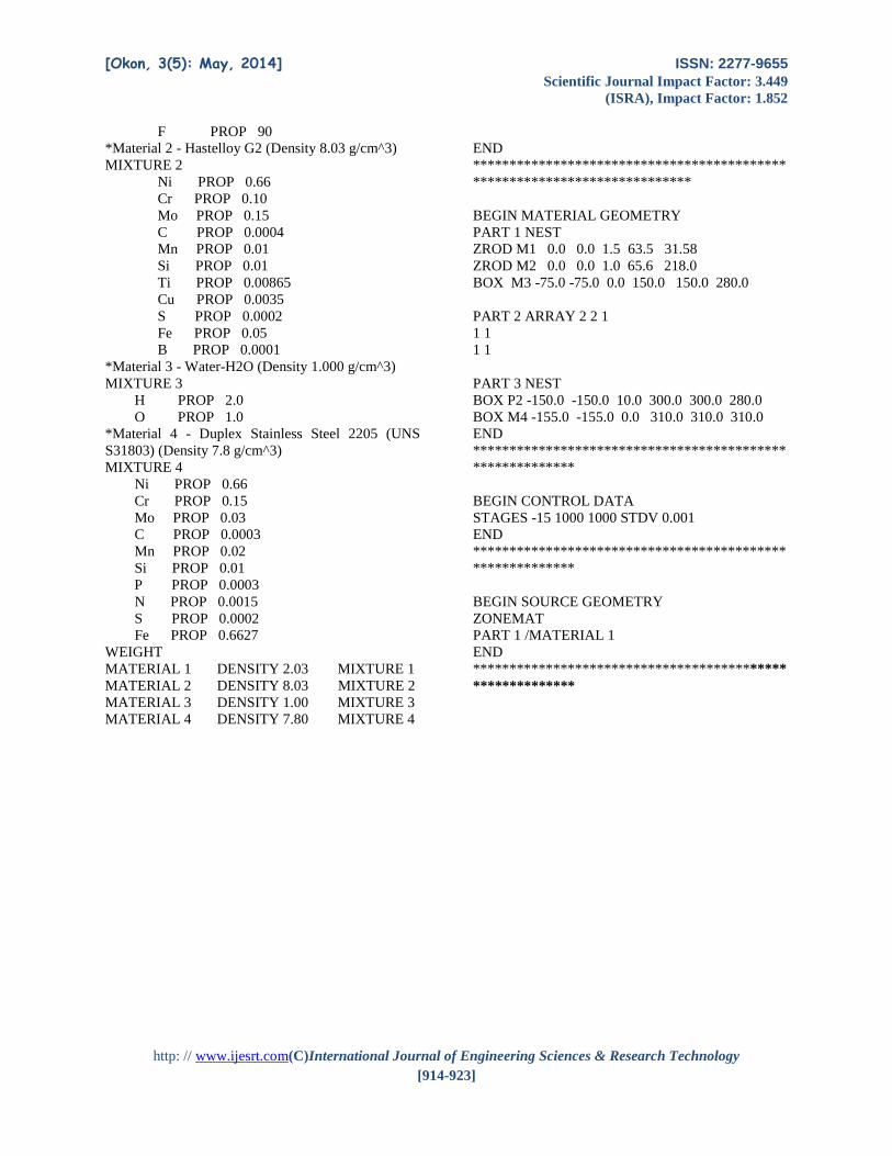
APPENDIX B
MONK Input File for Four(4) Drain Tanks
*APPENDIX B1 (Charles Monk)
*******************************************
*******************************
BEGIN MATERIAL SPECIFICATION
TYPE DICE
NORMALISE ! Normalise proportions where
necessary
ATOMS
*Material 1 - LiF-BeF2-ZrF4-UF4 (Density 2.02
g/cm^3)
MIXTURE 1
Li PROP 1
Be PROP 1
Zr PROP 1
U233 PROP 0.93
U234 PROP 0.07
[Okon, 3(5): May, 2014] ISSN: 2277-9655
Scientific Journal Impact Factor: 3.449
(ISRA), Impact Factor: 1.852
http: // www.ijesrt.com(C)International Journal of Engineering Sciences & Research Technology
[914-923]
F PROP 90
*Material 2 - Hastelloy G2 (Density 8.03 g/cm^3)
MIXTURE 2
Ni PROP 0.66
Cr PROP 0.10
Mo PROP 0.15
C PROP 0.0004
Mn PROP 0.01
Si PROP 0.01
Ti PROP 0.00865
Cu PROP 0.0035
S PROP 0.0002
Fe PROP 0.05
B PROP 0.0001
*Material 3 - Water-H2O (Density 1.000 g/cm^3)
MIXTURE 3
H PROP 2.0
O PROP 1.0
*Material 4 - Duplex Stainless Steel 2205 (UNS
S31803) (Density 7.8 g/cm^3)
MIXTURE 4
Ni PROP 0.66
Cr PROP 0.15
Mo PROP 0.03
C PROP 0.0003
Mn PROP 0.02
Si PROP 0.01
P PROP 0.0003
N PROP 0.0015
S PROP 0.0002
Fe PROP 0.6627
WEIGHT
MATERIAL 1 DENSITY 2.03 MIXTURE 1
MATERIAL 2 DENSITY 8.03 MIXTURE 2
MATERIAL 3 DENSITY 1.00 MIXTURE 3
MATERIAL 4 DENSITY 7.80 MIXTURE 4
END
*******************************************
******************************
BEGIN MATERIAL GEOMETRY
PART 1 NEST
ZROD M1 0.0 0.0 1.5 63.5 31.58
ZROD M2 0.0 0.0 1.0 65.6 218.0
BOX M3 -75.0 -75.0 0.0 150.0 150.0 280.0
PART 2 ARRAY 2 2 1
1 1
1 1
PART 3 NEST
BOX P2 -150.0 -150.0 10.0 300.0 300.0 280.0
BOX M4 -155.0 -155.0 0.0 310.0 310.0 310.0
END
*******************************************
**************
BEGIN CONTROL DATA
STAGES -15 1000 1000 STDV 0.001
END
*******************************************
**************
BEGIN SOURCE GEOMETRY
ZONEMAT
PART 1 /MATERIAL 1
END
*******************************************
**************