
Concrete-based Molten Salt Thermal Energy Storage (TES ...
18
energy.gov/solar-office energy.gov/solar-office energy.gov/solar-office energy.gov/solar-office energy.gov/solar-office Concrete-based Molten Salt Thermal Energy Storage (TES) Tank Design Youyang Zhao, PhD National Renewable Energy Laboratory DOE SETO Gen3 CSP Summit 2021 August 25-26, 2021 Project Teams: NREL, MIT, Morgan Advanced Materials, JT Thorpe & Son, Worley
-
Upload
khangminh22 -
Category
Documents
-
view
10 -
download
0
Transcript of Concrete-based Molten Salt Thermal Energy Storage (TES ...

energy.gov/solar-officeenergy.gov/solar-officeenergy.gov/solar-office
energy.gov/solar-officeenergy.gov/solar-office
Concrete-based Molten Salt Thermal Energy Storage (TES) Tank DesignYouyang Zhao, PhDNational Renewable Energy LaboratoryDOE SETO Gen3 CSP Summit 2021August 25-26, 2021
Project Teams: NREL, MIT, Morgan Advanced Materials, JT Thorpe & Son, Worley
energy.gov/solar-officeenergy.gov/solar-officeenergy.gov/solar-officeenergy.gov/solar-officeenergy.gov/solar-officeenergy.gov/solar-office
What’s New I? A Concrete-based TES Tank Structure
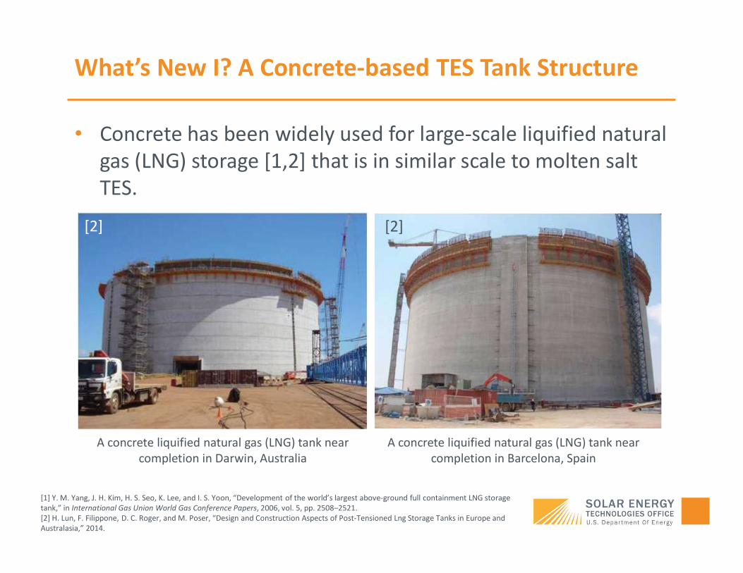
• Concrete has been widely used for large-scale liquified natural gas (LNG) storage [1,2] that is in similar scale to molten salt TES.
[1] Y. M. Yang, J. H. Kim, H. S. Seo, K. Lee, and I. S. Yoon, “Development of the world’s largest above-ground full containment LNG storage tank,” in International Gas Union World Gas Conference Papers, 2006, vol. 5, pp. 2508–2521.[2] H. Lun, F. Filippone, D. C. Roger, and M. Poser, “Design and Construction Aspects of Post-Tensioned Lng Storage Tanks in Europe and Australasia,” 2014.
A concrete liquified natural gas (LNG) tank near completion in Darwin, Australia
A concrete liquified natural gas (LNG) tank near completion in Barcelona, Spain
[2] [2]

energy.gov/solar-officeenergy.gov/solar-officeenergy.gov/solar-officeenergy.gov/solar-officeenergy.gov/solar-officeenergy.gov/solar-office
What’s New I? A Concrete-based TES Tank Structure
• Concrete has been widely used for large-scale liquified natural gas (LNG) storage [1,2] that is in similar scale to molten salt TES.
• Potential benefits• Avoid potential thermomechanical failure associated with a
metal-based tank structure • One of the suspected failure modes for current Gen2 metal-based
TES tanks
• A concrete tank structure may mitigate certain differential thermal expansion at the metal tank/concrete foundation interface for a metal-based tank design• One of the known issues for current Gen2 metal-based TES tanks
[1] Y. M. Yang, J. H. Kim, H. S. Seo, K. Lee, and I. S. Yoon, “Development of the world’s largest above-ground full containment LNG storage tank,” in International Gas Union World Gas Conference Papers, 2006, vol. 5, pp. 2508–2521.[2] H. Lun, F. Filippone, D. C. Roger, and M. Poser, “Design and Construction Aspects of Post-Tensioned Lng Storage Tanks in Europe and Australasia,” 2014.

energy.gov/solar-officeenergy.gov/solar-officeenergy.gov/solar-officeenergy.gov/solar-officeenergy.gov/solar-officeenergy.gov/solar-office
Conceptual Concrete TES Design – Advisian/Worley
• Key challenge is to manage the thermal and mechanical stresses of the concrete walls, foundation, joints and the metal roof
Concrete foundation
Concrete walls
Metal roof
Suspended deck roof insulation
energy.gov/solar-officeenergy.gov/solar-officeenergy.gov/solar-officeenergy.gov/solar-officeenergy.gov/solar-officeenergy.gov/solar-office
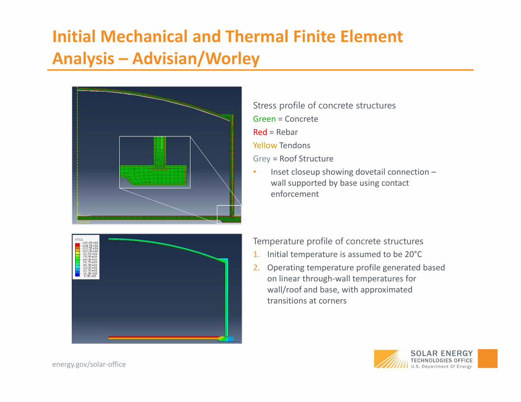
Initial Mechanical and Thermal Finite Element Analysis – Advisian/Worley
Stress profile of concrete structuresGreen = ConcreteRed = RebarYellow TendonsGrey = Roof Structure• Inset closeup showing dovetail connection –
wall supported by base using contact enforcement
Temperature profile of concrete structures1. Initial temperature is assumed to be 20°C2. Operating temperature profile generated based
on linear through-wall temperatures for wall/roof and base, with approximated transitions at corners

energy.gov/solar-officeenergy.gov/solar-officeenergy.gov/solar-officeenergy.gov/solar-officeenergy.gov/solar-officeenergy.gov/solar-office
What’s New II? A New Concept for Internal Thermal Insulation
• Using internal thermal insulation to manage the temperature and temperature gradient of the concrete is key.• The objective is NOT to develop a high-temperature concrete material.
• High-temperature concrete can be costly• Chemical resistance to molten salt is unknown if in direct contact• Thermal insulation of high-temperature concrete can be poor
meaning tank size/cost can be prohibitive• Instead, the objective is to use current Portland-cement material for
structure support only.• Various construction Codes require to keep concrete temperature
as low as possible.
Main question is how to design internal thermal insulation to reduce temperature of concrete structure
(also applicable to metal-based tank structure)

energy.gov/solar-officeenergy.gov/solar-officeenergy.gov/solar-officeenergy.gov/solar-officeenergy.gov/solar-officeenergy.gov/solar-office
Current State-of-the-art Internal Insulation Design
Gen3 CSP Topic 1 Liquid Pathway TES Design by NREL [1]
Green = Dense hot-face (low porosity to prevent salt permeation)Yellow = Back-up insulation (high porosity to provide thermal insulation)Red = Insulation fiber board/blanket (highly porous and lightweight to provide thermal insulation)
Key risks:1. Failure of hot-face (1) at mortar joints, (2) at expansion joints, (3) due to cracking, etc. can
cause salt leakage into back-up insulation leading to reduced thermal insulation2. Clogging of open porosities in the porous roof insulation due to salt condensation can lead
to reduced thermal insulation. Weight gain of roof insulation is another potential issue.
The open and interconnected porosity in these internal insulation materials is a major risk
Total area exposed to molten salt ≈ 1,500 m2
or 17,700 ft2
[1] C. Turchi, S. Gage, J. Martinek et al. 2021. CSP Gen3: Liquid-Phase Pathway to SunShot. Golden, CO: National Renewable Energy Laboratory. NREL/TP-5700-79323. https://www.nrel.gov/docs/fy21osti/79323.pdf.
energy.gov/solar-officeenergy.gov/solar-officeenergy.gov/solar-officeenergy.gov/solar-officeenergy.gov/solar-officeenergy.gov/solar-office
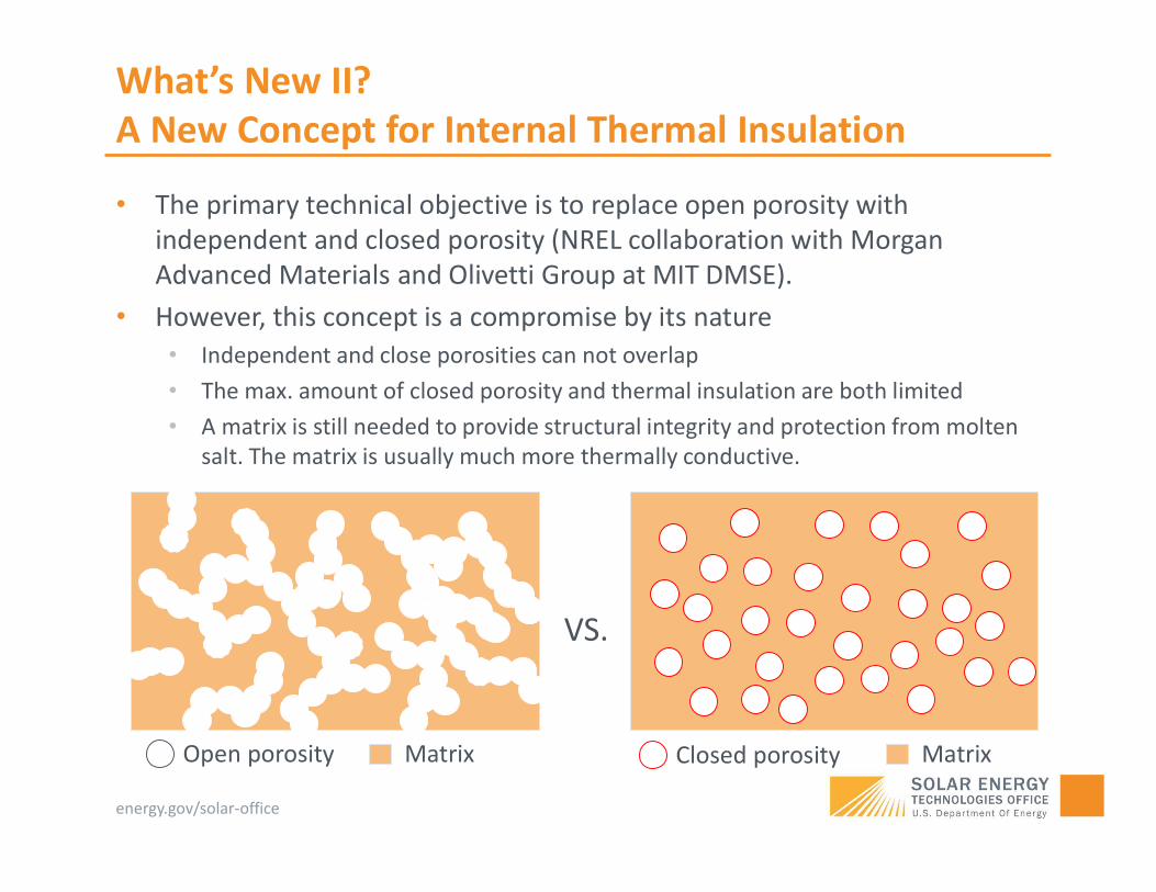
What’s New II? A New Concept for Internal Thermal Insulation
• The primary technical objective is to replace open porosity with independent and closed porosity (NREL collaboration with Morgan Advanced Materials and Olivetti Group at MIT DMSE).
• However, this concept is a compromise by its nature• Independent and close porosities can not overlap• The max. amount of closed porosity and thermal insulation are both limited • A matrix is still needed to provide structural integrity and protection from molten
salt. The matrix is usually much more thermally conductive.
Closed porosity Matrix
VS.
Open porosity Matrix

energy.gov/solar-officeenergy.gov/solar-officeenergy.gov/solar-officeenergy.gov/solar-officeenergy.gov/solar-officeenergy.gov/solar-office
What’s New II? A New Concept for Internal Thermal Insulation
• Main challenge is to find the method of introducing closed porosity while balancing the thermal insulation, mechanical strength and chemical resistance to molten salt
• Our material system of choice:
Closed porosity: aluminosilicate cenospheres
Matrix: amorphous Na-aluminosilicate geopolymer
1. Open porosity around 10-20 vol.%• Due to dehydration and curing of Na-
aluminosilicate geopolymer2. Closed porosity around 20-30 vol.%
• 20-30 vol.% is close to the upper limit before significant reduction of mechanical strength

energy.gov/solar-officeenergy.gov/solar-officeenergy.gov/solar-officeenergy.gov/solar-officeenergy.gov/solar-officeenergy.gov/solar-office
Geopolymer Relevance to Molten Salt TES Application
[1] Concrete Institute of Australia, “Recommended Practice: Geopolymer Concrete,” Concrete Solutions 2011. Concrete Institute of Australia, North Sydney, Australia, 2011
Relevance to molten salt applications:1. Water escape pathway during drying/curing and degree of geo-polymerization vs. open porosities2. Maximum amount of hollow cenosphere addition vs. effective thermal conductivity3. Stability of the interface between geopolymer matrix and additives4. Na from the activator solution vs. chemical stability (cation diffusion, ion exchange, etc.)5. Overall mechanical properties of geopolymers
[1] Green = NaPurple = AlYellow = SiRed = O
Sodiu
m alum
ino-si
licate
hydr
ate
Sodiu
m alum
io-sil
icate
Anatas
e
Quartz
Calcium
carb
onate
Amorph
ous
0
20
40
60
80
100
Frac
tion
of P
hase
s /
wt.%
Identified Phase
60°C 720°C 900°C
Heat treatment effectNa-aluminosilicate geopolymer structure

energy.gov/solar-officeenergy.gov/solar-officeenergy.gov/solar-officeenergy.gov/solar-officeenergy.gov/solar-officeenergy.gov/solar-office
Geopolymer Properties – Key Properties
Curing StepsDensity (g/cm3)
Open Porosity (vol.%)
Permanent Linear Change (%)
GP-10 GP-20 GP-10 GP-20 GP-10 GP-20
1. Room Temperature for 24 hours 1.05 1.09 Not measured Not measured
2. 60°C for 7 days (after step 1) 0.86 1.01 22.0 11.1 -0.27 -0.273. 400°C for 5 hours (after step 1 and 2) 0.82 0.93 20.8 10.9 -0.90 -0.724. 720°C for 5 hours (after step 1 and 2) 0.83 0.90 20.7 10.7 -1.36 -0.405. 900°C for 5 hours (after step 1 and 2) 0.87 0.88 9.0 8.1 -3.37 -0.70
0 200 400 600 800 1000 12000.1
0.2
0.3
0.4
0.5
0.6
The
rmal
Con
duct
ivity
/ W
m-1
K-1
Temperature / °C
K-23 Kaolite Super HS Cast Kaolite Super HS Gun GP-10 GP-20
CTE from dilatometry: 2.38×10⁻⁶ °C-1

energy.gov/solar-officeenergy.gov/solar-officeenergy.gov/solar-officeenergy.gov/solar-officeenergy.gov/solar-officeenergy.gov/solar-office
Comparison to Commercial Insulation
Insulation Materials with Open Porosity
Conductivity (W/m K)% Increase
Dry Wet
GP w/ 25% 0.25 0.381 52.4%
GP w/15% 0.30 0.378 26.0%
K-23 w/ 73% 0.10 0.803 703%
Kaolite 2200 w/ 56.8% 0.2 0.583 191.5%
Kao-tuff CV w/ 21.5% 1.3 1.473 13.3%
SR-90 w/ 18% 3.0 3.156 5.2%
Best balance
Too much increase
Bad insulation
Biggest design question: Can we design to operate GP in the wetted state
(no more salt permeation*)?
Group I
Group II
*The main assumption is that cenospheres remain intact when the insulation is immersed in molten salt. NREL is currently investigating this assumption.

energy.gov/solar-officeenergy.gov/solar-officeenergy.gov/solar-officeenergy.gov/solar-officeenergy.gov/solar-officeenergy.gov/solar-office
Wet Operation of GP Insulation?
Closed porosity: aluminosilicate cenospheres
Matrix: amorphous Na-aluminosilicate geopolymer
Open porosity wetted by molten salt
GP before salt immersion
EDS after 24-hr salt immersion

energy.gov/solar-officeenergy.gov/solar-officeenergy.gov/solar-officeenergy.gov/solar-officeenergy.gov/solar-officeenergy.gov/solar-office
EDS after 24-hr salt immersion
Wet Operation of GP Insulation?
Closed porosity: aluminosilicate cenospheres
Matrix: amorphous Na-aluminosilicate geopolymer
Open porosity wetted by molten salt
GP before salt immersionNREL is currently investigating the long-term chemical, mechanical, and thermal
stability of the selected geopolymer insulation in molten salt.
energy.gov/solar-officeenergy.gov/solar-officeenergy.gov/solar-officeenergy.gov/solar-officeenergy.gov/solar-officeenergy.gov/solar-office
Thank you
Contact InformationYouyang Zhao, [email protected] Thermal Energy Science & Technologies Grouphttps://www.nrel.gov/csp/
energy.gov/solar-officeenergy.gov/solar-officeenergy.gov/solar-officeenergy.gov/solar-officeenergy.gov/solar-officeenergy.gov/solar-office
Backup Slides

energy.gov/solar-officeenergy.gov/solar-officeenergy.gov/solar-officeenergy.gov/solar-officeenergy.gov/solar-officeenergy.gov/solar-office
Preliminary Costing and Insulation Effectiveness
MaterialThermal
cond.Gravimetric
CostDensity
Volumetric cost
M
W/m K $/kg kg/m3 $/m3 (W/m K)-1∙(kg/m3)-1∙($/kg)-1
Dry GP-10 and GP-20 0.35 5.61 900 5049.0 0.000566Wetted GP-10 and GP-20 0.45 5.61 900 5049.0 0.000440Dry Ref. Porous Insulation 0.08 1.8 513 923.4 0.013537
Wetted Ref. Porous Insulation 1 1.8 513 923.4 0.001083Dry Ref. Dense Insulation 1.3 0.65 2270 1475.5 0.000521
Wetted Ref. Dense Insulation 1.3 0.65 2270 1475.5 0.000521
Clarifications for :• It does not include higher tank structure cost due to increase of tank diameter• It does not include increased salt inventory cost due to salt permeation into
insulation• It does not assume any protective layer such as a hot face layer – this is not a
comparison to Gen3 Liquid Pathway design• It does not include any other costs due to potential maintenance, repair, etc.
where is thermal conductivity, is the bulk density and is gravimetric cost of the insulation material.

energy.gov/solar-officeenergy.gov/solar-officeenergy.gov/solar-officeenergy.gov/solar-officeenergy.gov/solar-officeenergy.gov/solar-office
Preliminary Costing and Insulation Effectiveness
MaterialThermal
cond.Gravimetric
CostDensity
Volumetric cost
M
W/m K $/kg kg/m3 $/m3 (W/m K)-1∙(kg/m3)-1∙($/kg)-1
Dry GP-10 and GP-20 0.35 5.61 900 5049.0 0.000566Wetted GP-10 and GP-20 0.45 5.61 900 5049.0 0.000440Dry Ref. Porous Insulation 0.08 1.8 513 923.4 0.013537
Wetted Ref. Porous Insulation 1 1.8 513 923.4 0.001083Dry Ref. Dense Insulation 1.3 0.65 2270 1475.5 0.000521
Wetted Ref. Dense Insulation 1.3 0.65 2270 1475.5 0.000521
Implications:• If geopolymer’s cost can be reduced by ~2x, it can be (1) one of the most cost-
effective molten salt insulation with little salt permeation concerns, and (2) comparable to wetted porous insulation but more advantageous in terms of tank structure cost
• Conservative estimation is that salt inventory increase due to wet operation is 0.6–0.9% of total TES cost.
• NREL is currently analyze the technical feasibility of wet operation (a fail-“safer” design) – mainly for long-term chemical compatibility of embedded cenospheres.