snap reactor overview - CiteSeerX
103
AFWL-TN-84-1 4 AFWL-TN- 84-14 - SNAP REACTOR OVERVIEW . (0 Susan S. Voss August 1984 H t1Z Final Report Approved for public release; distribution unlimited.. DTIC F IECTE OCT 2 6 684 V AIR FORCE WEAPONS LABORATORY Air Force Systems Command -. Kirtland Air Force Base, NM 87117 84 10 22 146
-
Upload
khangminh22 -
Category
Documents
-
view
1 -
download
0
Transcript of snap reactor overview - CiteSeerX

AFWL-TN-84-1 4 AFWL-TN-84-14
- SNAP REACTOR OVERVIEW .
(0 Susan S. Voss
August 1984
H t1ZFinal Report
Approved for public release; distribution unlimited..
DTICF IECTEOCT 2 6 684
V AIR FORCE WEAPONS LABORATORYAir Force Systems Command -.Kirtland Air Force Base, NM 87117
84 10 22 146
AFWL-TN-84- 14
This final report was prepared by the Air Force Weapons Laboratory,Kirtland Air Force Base, New Mexico, under Job Order 57972311. Susan S. Voss(NTYN) was the Laboratory Project Officer-in-Charge.
When Government drawings, specifications, or other data are usea for anypurpose other than in connection with a definitely Government-relatea procure-ment, the United States Government incurs no responsiollity or any obligation -whatsoever. The fact that the Government may have fornulated or in any waysupplied the said drawings, specifications, or other data, is not to beregarded by implication, or otherwise in any manner construed, as licensingthe holder, or any other person or corporation; or as conveying any rights orpermission to manufacture, use, or sell any patented invention that may in anyway be related thereto.
This report has been authored by an employee of the United States -
Government. Accordingly, the United States Government retains a nonexclusive,royalty-free license to publish or reproduce the material contained herein, orallow others to do so, for the United States Government purposes.
This report has been reviewed by the Public Affairs Office and isreleasable to the National Technical Information Service (NTIS). At NTIS, itwill be available to the general public, including foreign nations.
If your address has changed, it you wish to be removed from our mailinyglist, or if your organization no longer employs the addressee, please notifyAFUL/NTYN, Kirtlan AFB, NM 87117 to help us maintain a current mailing list.
This technical report has been reviewed and is approvea for publication.....
SUSAN S. VOSSProject Officer
FOR THE COIIMANDER
Ah:ES H. LEE, JR ALt Colonel, USAF Colo el , USAF "--Chief, Nuc Power , Wpn Studies Br Chi f, Advanced Technology Fivision
DO NOT RETURN COPIES OF THIS REPORT UN ESS CON'TKACTUAL OBLIU0 IOINi.S OR NOTICE.ON A SPECIFIC DOCUHErIT REQUIRES THAT IT BE RETURN(E). '""
._
.. ' . .. * ~ *5 ** ~ .~ -.. -.- - . .. */* ***** 5 5 . S * . 5 . . *~5~ . . . . .. .-

Contents
Page
| 1. Objectives.1" !
UDCC1V.-°.-
S. Introduction. 1
3. Deck Wetness Experiments at the United States Naval
Academy. 5
4. Model. 6
5. Model Instrumentation. 8
6. Experiment Facility. 9
7. Experiments. 9
8. Results. 14
9. Theoretical Predictions. 20
10. The Optimum Bow. 25
11. Conclusions. 26
12. Acknowledgements. 27
References. 29
Table 1. Literature Survey on Effects of Above Watera Bow Form on Deck Wetness. 32
" Table 2. FFG7 Hull Particulars. 33
* Table 3. Bow Form Particulars. 34
Table 4. Wave Conditions for Model Tests. 35
- Table 5. Achieved Significant Wave Heights. 36
Table 6. Impact Pressure Results. 37
" Appendix 1. Bow Design Method. 38
Appendix 2. Data Analysis. 43Appendix 3. Critical Velocity. 62
ii ".

*UNCLASSIFIED* SECURITY CLASSIFICATION OF THIS PAGE
REPORT DOCUMENTATION PAGEtis. REPORT SECURITY CLASSIFICATION 1b. RESTRICTIVE MARKINGS
Unclassified______________________- 2a. SECURITY CLASSIFICATION AUTHORITY 3. OISTRIBUTION/AVAI LABILITY OF REPORT
Approved for public release; distribution2W. DECLASSIFICATIONIOOWNGRAOING SCHEDULE unlimited.
4. PERFORMING ORGANIZATION REPORT NUMBER(S) L. MONITORING ORGANIZATION REPORT NUMBER(S)
Go. NAME OF PERFORMING ORGANIZATION b. OFFICE SYMBOL 74. NAME OF MONITORING ORGANIZATION
* Air Force Weapons Laboratory NY ____________________
6cB. ADDRESS (City. State and ZIP Code) 7b. ADDRESS (City, State and ZIP Code)
Kirtland Air Force Base, NM 87117
Ba& NAME OF FUNOING/SPONSORING Bb. OFFICE SYMBOL 9. PROCUREMENT INSTRUMENT IDENTIFICATION NUMBERORGANIZATION (if applicable)
8e. ADDRESS (City. State and ZIP Code) 10. SOURCE OF FUNDING NOS.
PROGRAM PROJECT TASK WORK UNITELEMENT NO. NO. NO. NO.
3 7t. TITLE flnciude security Coaujcation, 62601F 5797 23 01SNAP REACTOR OVERVIEW_______________________
12. PERSONAL AUTHORISI
Vdoss, Susan S.13.. TYPE OF REPORT 13b. TIME COVERED 14. DATE OF REPORT (Yr..,M. Day) 15. PAGE COUNT
16I. SUPPLEMENTARY NOTATION
heSA eco rgasaeoutlining somesrpot Asmmr of the program wekesesr gvn
20. DISTRIBUTION/AVAILABILITY OF ABSTRACT 21. ABSTRACT SECURITY CLASSIFICATION
UNCLASSI FIE D/UNLIMITE 01 SAME AS RIPT. Z: OTIC USERS [2 Un cIas s if ie d* 22&. NAME OF RESPONSIBLE INDIVIDUAL 22b. TELEPHONE NUMBER 22c. OF F ICE SYMBO L
Susan S. Voss niueAaCo,*(505) 844-0146 NTYNDD FORM 1473,83 APR EDITION OF I JAN 73IS OBSOLETE. UNCLASSIFIED
I SECURITY CLASSIFICATION OF THIS PAGE
....................................

UNCLASSIFIEDSECURITY CLASSIFICATION OP THIS PAGE
F18. SUBJECT TERMS (Continued)
Experimental Reactor, SNAP 8 Developmental Reactor, SNAP 50/SPUR, SPUR.
UNCLASIFIE
SECUITY LASSPICTIONOP TIS PGE
%I

AFWL-TN-84- i4
CONTENTS
Section Page
I INTRODUCTION 1
II SPACE REACTOR PROGRAM REVIEW 2
III SNAP 2 POWER CONVERSION PLANT 15
IV SNAP EXPERIMENTAL REACTOR 19
V SANP 2 DEVELOPMENTAL REACTOR 26
VI SNAP 8 SYSTEM OVERVIEW 32
VII SNAP 8 EXPERIMENTAL REACTOR 34
VIII SNAP 8 DEVELOPMENTAL REACTOR 41
IX CONCEPTUAL SNAP 8 REACTOR DESIGNS 52
X SNAP 1OA 57
XI SNAP 50 82
XII LESSONS LEARNED 88
REFERENCES 92
Accenslon For
'lwD .° ,a

AFWL-TN-84-14
FIGURES
Figure Page
1 Original SNAP 10 concept 6
2 Structural illustration of SNAP 2 unit 16
3 SNAP 2 Mercury Rankine system schematic 17
4 SER building elevation view 20
5 SER radial reflector cross section 21
6 SER fuel-moderator element assembly 21
7 SNAP experimental reactor NaK coolant flow diagram 23
8 S2DR fuel rod assembly and core cross section 27
9 S2DR fuel element 28
10 SNAP 8 system 33
11 S8ER fuel element 37
12 S8ER test facility 39
13 SNAP 8 reactor and reflector assembly 44
14 Frontispiece: SNAP 8 nuclear system 46
15 Reflector and control drums for SNAP 8developmental reactor 47
16 Zr-H reactor system 53
17 5-kWe system schematic 55
18 Control and reflector assembly 61
19 SNAP 1OA thermoelectric pump configuration schematic 64
20 Construction of SNAP 1OA thermoelectric converter 64
21 SNAP 1OA ground demonstration test 68
22 SNAPSHOT launch and transfer orbit 71
23 SNAP 1OA/Agena/Atlas vehicle configuration 72
iv
1 -
S. . . .. . . . . . . . . . . . . . . . . . . . . . . . .

AFWL-TN-84-14
FIGURES (Continued)
*Figure Page
24 Spacecraft configuration 74
25 SNAP 50 schematic - 83
26 SNAP 50/SPUR power conversion system 85
TABLES
Table Page
1 SNAP reactor test experience 4
2 SNAP reactor system development programs 5
3 Summary of SER operation 24
4 SER scram summary 25
5 Significant milestone dates for S2DR operation 30
6 S2DR reactor scrams 31
7 S8ER design data summary 35
8 S8DR characteristics 42
9 Weight breakdown of the SNAP 50 84
V/Vi
....-.. ___
. ... ..... ..... ... I

AFWL-TN-84-14
I. INTRODUCTION
The Space Nuclear Auxiliary Power (SNAP) program was begun in 1955 and
terminated in 1973. nuring that period approximately $850 million then-year
dollars were spent to develop nuclear power sources capable of producing from
500 W up to 1000 kWe. The technology base was broad and encompassed a wide
range of materials and power conversion systems.
This report gives a concise description of the overall space reactor
program with emphasis on the main SNAP reactors and a detailed account of
their design and testing. This report is not meant to be a detailed review of
the technical accomplishments, but rather a starting place to present an
overall picture of the program.
1o.-
- *.% 7. . . . . . .. . . . . . . . . . .-.-. . 7

AFWL-TN-84-14
II. SPACE REACTOR PROGRAM REVIEW
ZIRCONIUM-HYDRIDE (Zr-H) SPACE REACTOR HISTORICAL OVERVIEW
In 1948, the Air Force (AF) commissioned the Rand Corporation to recommend
development work in reconnaissance satellite programs known as Project
Feedback (Ref. 1). The growing need for a reliable power source for space
applications was addressed. Specialized studies on nuclear-electric sources
for space applications were done under the Pied Piper Program conducted in 1954
(Ref. 2). These studies were later integrated into the Weapons Systems 117-L
(WS 117-L) program, which conducted studies on a wide spectrum of energy and
satellite systems for space. From 1952 to 1955 the Atomic Energy Commission .
(AEC)* did an analysis of nuclear power sources and evaluated them on their
feasibility to be used with future spacecraft. In 1955, a joint AF-AEC con-
mittee established specifications for nuclear power in space. This included
the power, life and interrelation of the nuclear device and spacecraft. The
role of the AEC was to promote the development and utilization of atomic
energy. The Pied Piper Program was later renamed the SNAP program.
The objective of the AEC's SNAP Program was development of compact, light-
weighot, reliable atomic electric devices for space, sea and land uses. The
AEC was a procurement agency for Department of Defense (DOD) and NationalAeronautics and Space Administration (NASA) requirements. It was responsible --"for developing technology that would allow the requirement to be generated as
well as for meeting that requirement and for carrying out the initial phases
of the test operation. The AF was in charge of establishing a mission and
providing support in the launch phase (Ref. 1).
In 1955, a formal request for proposal studies was issued jointly by the
Department of Reactor Development (DRD) of the AEC and the Air Force Wright
Air Development Center (AFWADC). AiResearch and Atomics International (AI)
proposed a Zr-H reactor coupled to a Mercury-Rankine power conversion system.
The early work was done independently by Lockheed Missiles and Space Division
(LMSD) with Thompson Ramo Wooldridge (TRW) and AI with AiResearch of the
Garrett Corporation. Funding was jointly sponsored by the AEC for the reactor
development and the AF for work on the power conversion system (Ref. 3).
*Now known as Department of Energy (DOE).
2

AFWL-TN-84-14
The request was specifically for possible power sources (1 to 10 kWe) with
minimum weight and the ability to operate for up to 1 year of unattended
operation. The acronym SNAP initially stood for Secondary Nuclear Auxiliary
Power was later changed to Systems for Nuclear Auxiliary Power. The even num-
bered SNAP were for the reactor systems and the odd numbered for the radioiso-
tope generator (RTG) systems.
In June 1957, AEC assumed complete control of the project and AI became
the prime contractor. TRW was contracted to complete work on the power con-
version system and the research being completed by AiResearch was phased out
completely by March 1958 (Ref. 3). Atomics International chose an epithermal
reactor design for space applications over a fast reactor because the critical
mass of a useful fast reactor would result in an uranium cost of the order of
one million dollars (1961). For a reactor which was to be pruduced in quan-
tity the resulting cost would have been greater than that of delivery into
space when the launch costs fell below $1000 per pound (Ref. 4). Also, for
temperatures between 315 to 10930C the Zr-H reactor was lighter than an
equivalent fast reactor.
The early space reactor system was considered to be essential in meeting
near-term and future power needs in space. The Joint Committee on Atomic
Energy (JCAE) urged that an aggressive program be pursued and that it should
be given high priority by both NASA and AEC (Ref. 1).
The first SNAP critical assembly was tested in October 1957, three weeks
after Sputnik I was launched. The SNAP Experimental Reactor (SER) was
operated in 1959 and the SNAP 2 Developmental Reactor (S2DR) in 1961. The
SNAP 2 reactor had Zr-H fuel to be coupled with a Mercury-Rankine power conver-
sion system. Table 1 is a compilation of SNAP reactor test experience and
Table 2 outlines the development program.
In December 1963, the SNAP 2 program was cancelled due to government
budget cuts. The Mercury-Rankine program managed by TRW was also phased out
beginning October 1, 1966. Funding for the SNAP 2 reactor including CRU
through Fiscal 1964 totalled $60 million (Ref. 5).
In 1958, the AF requested Al to study a reactor designed with thermo-
electric conversion units. In March 1959, the AF established a firm require-
ment for a 500 W unit when the SNAP 1OA program was started for use with a
3
. . . . . . . . . . . . . . . . . . . . . . ."~ *.~**~.* * * * * . . * - .. . . . . . . . .%.. . . . . .

AFWL-TN-84-14
co ro -
I- I. I M
-C-
IIn
U.
ien .
LU.% nI
U-U
L
4.11
w -w I" u-w ix C A
C4
ta %
I~l 0%.J4

AFWL-TN-84- 14
V) t oa
CD U- mC CD
V) L nct"UO n .e = -0 c uV( .-.
M-3 + 4 Ui.. oI ;,D -
0C.. 4-J ~ " ~ a
0. CC < .. AC0= ..4- V)AC"L. 0'c =~1 CC eaI L
to4 - I 0-
03 0
Km c CA L. Q C
r- 14 4C CLI CD CD CD C- . 0 4
CAC C I (a c 0 430 %J ~ C Ci cr Li 4-) C 0 4J3C
LO 0n Mo -N;o k 4-3-- c
0.a) u CL C0
(3) C4 UC C. 0- ILJ.0J 4-) '~I u 0 -
a) C to W CA =0 rn. 00% n n' i i4-
I- 0
U- = L- =0 r(a L 4.3 (D =C
-. m @. rLU *4) - -III 4.3O 4-
4- m 4.. r-s-- =I G m(L-CL 4- CLJ I'0 uA CLA o- LC . c..*
06 4
>A - ,( , r A r
0 - Li c 41.i 4 c - 40 L L -o - .0 -
C-0 -' L- % m( Ac=00 - L 4JLiit CC =) Li.-D -J- -M 4 0 C1(
L @0 aJ) 43 M4
ev . 4L M L9-C4J 0 = C 4A M (
@3L 0 ma a) 41
5- ~ ~ ~ ~ ~ U C 4.'U@C)4 V)CO C 4. .
.30 05-0.~5-L 33.

AFWL-TN-84-14
reconnaissance satellite. In March 1960, Westinghouse Electric Corporationwas awarded a contract to develop a thermoelectric converter to be used with aspace reactor. The initial SNAP 10 design was a purely conduction cooledsystem (Fig. 1) which was later changed to include a forced convection heat
transfer system.
SEPARATION MECHANISM
-Be CONDUCTOR PLATESBe END REFLECTOR
go SIDE REFLECTOR
............
THERMOELECTRIC.......COLUMNS CONTAINING VESSEL
FINNED RADIATOR-"--"
Figure 1. Original SNAP 10 concept (after Ref. 7).
In May 1960, the AEC and AF jointly initiated the Space System AbbreviatedDevelopment Plan for Nuclear Auxiliary Power Orbital Test (SNAPSHOT) program.A total of four flights were scheduled; two SNAP 10 launches and two SNAP 2launches. The LMSD was designated as the AF prime contractor responsible forthe launch vehicle, system integration and launch operation and Al as AECprime contractor for reactor power unit development (Ref. 8).
6

AFWL-TN-84-14
In 1963, changes in the AF program resulted in the cancellation of a spe-
cific requirement for the 0.5 to 3 kWe power range. The most advanced program
for use with the nuclear power supply was Project 461 which had experienced
setbacks due to technology and budget cuts and, therefore, was no longer con-
sidered a valid candidate (Ref. 1). The AF experienced a major cut in their
FY 64 budget which called for a reorganization of priorities. This reorgani-
zation also called for a change in the AEC program.
The rate of development for particular reactor systems designed for specif-
ic flight missions were slowed in keeping with the requirements of the user
agencies. These changes included the cancellation of the SNAP 2 reactor, but
with continued development of its power conversion system, cancellation of
the SNAP 4 reactor and cancellation of the SNAP 1OA flight test. The flight
test was cancelled because there was no immediate requirement existing for the
flight unit and according to AF policy there was to be no flight test unless
there was a requirement for operational needs (Ref. 9).
These changes were of major concern to the JCAE. They coordinated
meetings between AEC, AF, AI and LMSD to better understand the chain of events
(Ref. 9). It was agreed by all agencies that the flight test was needed to
provide the user with a sense of confidence in the power source. The AF had
requested that the flight be funded but DO) disagreed because they felt it was
the primary responsibility of the AEC since potential applications for the
project had been delayed. The AEC had appropriated the money in the FY 65
budget but it was denied by the Bureau of the Budget (Ref. 9).
The AEC requested $15 million to flight test the SNAP 1OA, but the Bureau
of the Budget* turned down their request and reduced the sum to $8.6 million.
Funding for the SNAP 1OA totalled $53 million dollars through FY 64. The
objective of the reoriented development was to push the output from the
hundreds of watts into the kilowatt and megawatt range (Ref. 5).
Members of the JCAE conducted an aggressive approach in finding monies forthe launch. The AF consented to continue financing the launch through their
prime contractor LSD and to use AF personnel to assist in management,
contract administration and launch operations (Ref. 9).
*Now known as Office of Management and Budget (OMB).
7
J."
". . . . . . . .. . . . .

AFWL-TN-84-14
In February 1964, the Joint Congressional Committee on Atomic Energy pro-
posed that the AEC fund the SNAP 1OA flight test. A total of $14.6 million
dollars was approved for the controversial flight test (Ref. 9). The SNAP
1OA was reinstated on March 1964 with the actual flight test on April 3, 1965.
The system functioned properly for 43 days until the voltage regulator sent
spurious commands, causing premature shutdown of the reactor. The SNAP IOA
program was formally concluded on June 30, 1966.
In 1959, NASA requested a power source in the 30 kWe and up power range
for electric propulsion and interplanetary communication. This was the
beginning of the joint NASA and AEC development of the SNAP 8 reactor. It was
to be a minimum of a 5-year joint effort between both agencies. NASA was in
charge of developing the power conversion equipment and overall system
integration while AEC was to develop the reactor (Ref. 1). Aerojet-General
Corporation was NASA's prime contractor while AEC continued with Al.
It was designed to produce 30 to 60 kWe for up to 1 year using a
Mercury-Rankine cycle power conversion system. Two systems were tested under
the SNAP 8 program: the SNAP 8 Experimental Reactor (S8ER) and the SNAP 8
Developmental Reactor (S8DR). Cracked fuel cladding was found upon posttest
examination in both systems.
After the SNAP 8 program was concluded, studies were continued using the
basic SNAP reactor with minor adjustments. These include the 5 kWe Reactor
Thermoelectric System and the Advanced Zirconium-Hydride Reactor. There were
alternate programs being pursued at the same time as the SNAP reactor program,
many of these began when the Airplane Nuclear Propulsion (ANP) program ended
in 1961. It was continued with a technology development program at General
Electric (GE), Pratt and Whitney, Oak Ridge National Lab (ORNL) and Los AlamosScientific Lab (LASL)*. The GE effort was continued in the design of the 710 -
reactor system. Pratt and Whitney continued with their design of the SNAP 50
and ORNL with their work on the Medium Power Reactor Experiment (MPRE) (Ref.
10). These were later designated the advanced power reactors which were being
developed to meet power needs from the upper kilowatt-electric range to the
megawatt range.
*Now known as Los Alamos National Laboratory (LANL).
8

AFWL-TN- 84-14
The SNAP program was ended in the early 1970s due to cutbacks in govern-
ment funding. It was during this time that many concurrent space programs
also experienced cutbacks or were ended as government spending was shifted
away from space exploration and development work. In 1971, major changes were
being made within the engineering industry. Both manned and unmanned programs
were severely curtailed as the Nixon Administration refused to commit itself
to a firm post-Apollo plan because of social and economic problems. NASA was
forced to reorganize its priorities, which included reducing or omitting
programs so that emphasis could be placed on the development of the space
shuttle and the national space station.
During 1969 NASA came up with a requirement which would need the Zr-H
reactor system which was the semipermanent orbiting space station. This
helped the Zr-H system weather through the major FY 71 budget cuts. It was
considered important for future space base programs for NASA and essential to
an evolving space base program. The Zr-H was changed to include a life
expectancy of 20,000 h and possible 4-it shielding designs for use with manned
missions (Ref. 11). The advance liquid metal program was cancelled and
General Atomics (GA) was chosen as the prime contractor for thermionic devel-
opment. A thermionic reactor was continued to be supported because of its
potential to meet a variety of power needs (Ref. 12).
The FY 71 budget cuts did result in a 75 percent decrease in funding for
the Zr-H system, 30 percent decrease in the thermionic studies, 50 percent
decrease in reactor safety, termination of the Brayton cycle power conversion
by NASA and the reduction of the NERVA rocket program to fuel development.
These reductions were to permit allocation of funding to higher priority
programs (Ref. 12).
The Zr-H reactor program once again was reoriented in 1972 by focusing on a
5 kWe system using a thermoelectric conversion system with a lifetime of 5
years. The program was to be accelerated if a mission was identified. Also,
during this time NASA's emphasis changed as work on the space shuttle begin
(Ref. 13).
9 i
* .. .
. ... . . . . . . . . . . . *

AFWL-TN-84-14
In 1973, NASA and AEC closed out on the entire program for the development
and application of nuclear reactor power in space. The emphasis was shifted to
RTGs which could meet the power needs for DOD's and NASA's near term missions.
David Gabriel, the Director of Space Nuclear Systems Division of the AEC
concluded in his statement to the JCAE that "... the missions which were
likely to require large amounts of energy, now appear to be postponed until
around 1990 or later. These projected delays along with budget priorities,
led to the decision that the distant payoffs did not warrant continued funding
of high powered nuclear propulsion and reactor power systems" (Ref. 14).
The space reactor program was on a sharp decline since 1964 when the
AEC was forced to recognize that a mission requirement was needed to continue
development. At this point the emphasis was shifted away from flight
missions to a long-term development program. A definite and urgent mission
would have been needed to shift the program's momentum back to a viable
system.
A low level of funding was continued on the space reactor program. This
included work on thermionic conversion and thermoelectric conversion systems.
During FY 73, NASA spent $6.7 million on space power and reduced spending
to one million during F 74 (Ref. 5). Fiscal 1974 budget for research and
development of NASA totalled $2.2 billion.
SNAP 50 PROGRAM REVIEW
The SNAP 50/SPUR program was established under a triagency agreement
between AEC, NASA and the AF in 1962. The SPUR was an acronym for Space
Nuclear Unit Reactor. It was separate from the space power work being con-
ducted at AI. The SNAP 50 was a fast reactor with a predicted output of
300 kWe which could be upgraded to 1000 kWe. It was to have an operating
lifetime of 10,000 h with a minimum specific weight of 20 lb/kWe, not
including shielding.
The AEC was responsible for the overall coordination of a prototype
demonstration power plant through flight test. The AF was responsible for
establishing a requirement, project integration and flight testing while NASA
maintained cognizance of the program and contributed appropriate technical
data from its other related work.* Pratt and Whitney was assigned to develop
*Speech by Dr. R. I. Strough, CANEL, Pratt-Whitney, 1964. "
10

AFWL-TN-84-14
the reactor, shield, auxiliary pump and control system. They were also in
charge of the overall integration of the power plant design and development.
AiResearch was selected to design and develop the boiler, condenser, and tur-
boalternator. The reflector drive-motor was to be developed by Westinghouse
-" Electric Corporation.
Pratt and Whitney was chosen as the main contractor due to the work they
had just completed on reactor power systems. From 1956 to 1961, they con-
ducted studies for the ANP program. This included the technological develop-ment to construct and operate a compact, high temperature, lithium-cooled
reactor. Studies were also conducted by Pratt and Whitney on a sodium cooled,
solid-fuel element reactor. Emphasis was later shifted to work on the Lithium
Cooled Reactor Experiment (LCRE) which operated at 1903"C with a power output
of 10 MWe.
In November 1962, a triagency agreement was signed authorizing Pratt and
Whitney to begin work on a space reactor system. Work on the SNAP 50/SPUR was
completed at the Connecticut Advanced Nuclear Engineering Laboratory (CANEL),
Middleton, Connecticut. The Army Corps of Engineers constructed CANEL in
1957. A total of 1600 Pratt and Whitney employees worked on the project and
, . 14 full-time employees from the AEC.* The SNAP 50 had a budget of approxima-
* tely $20 million per year for work on system development and material testing.
By 1965, the component designs, materials, fuels and subcomponent development
* phase had been completed. Pratt and Whitney submitted a proposal for con-
tinued work which would enable them to prepare a qualified system to be
flight-tested in the early part of 1975 after completion of reactor and
electric conversion system ground testing.
The estimated cost to carry the program through ground testing of a proto-
type SNAP 50 was estimated to be $500 million and double that for a flight
qualified unit. A power plant for manned space flight would cost several
billion dollars, since extensive flight testing would be needed to meet the
stringent reliability requirements (Ref. 15). Funding was denied due to a
lack of a specific application for a high power system in space, also the AEC
did not envision the construction of a reactor experiment or of a prototype
*CANEL Press Kit, Pratt-Whitney, 1962.
11

AFWL-TN-84-14
system for sometime. Instead they closed the program at the point of tech-
nology and materials development. The program was rapidly shutdown with the
initiation of government budget cuts. In 1965, the Congressional AEC strongly
recommended to AEC that it shift the SNAP 50 program out of CANEL due to major
changes in the programs objectives (Ref. 16). Although the program did not
proceed past the developmental stage, Pratt and Whitney were commended by the
Chairman of the AEC, Dr. Glenn Seaborg, for a well managed program which had
met its objectives (Ref. 17).
In 1967 work on advanced space power systems was transferred to the
Lawrence Radiation Laboratory (LRL), Livermore, California. The SNAP 50 tech-
nology was used as a basis for initating the LRL program (Ref. 18). Several
reference designs were generated by LRL to help in determining problem areas
and performance capabilities.
The designs represented several classifications of space reactors, from
near-term to advanced technology. The designs included detailed paper and
computer studies on materials and system analysis (the systems were never
tested).
In 1968 the LRL-710 program was closed out to put emphasis on the SNAP 50
and thermionic reactor which were considered to have a wider range of applica-
tion. Also, the funding for the SNAP 50 was reduced at this time with its
* pace dependent upon future needs and progress. The AEC work on the
Mercury-Rankine was ended, but NASA continued with their development of the
project.
Through the early 1970s, NASA Lewis Research Center incorporated the SNAP
50/SPUR design research in developing the Advanced Power Reactor (APR). The
APR was an uranium nitride fueled, fast spectrum reactor. It was designed to
operate at 2.17 MWt with a nominal power output of 300 kWe. The design
- operating lifetime of the reactor and power plant was set at 50,000 h (Refs.
19 and 20).
The reactor design had 253 fuel pins. The fuel was fully enriched uranium
nitride clad in tungsten and T-111 (Ta 8% W, 2% Hf) and then placed in a T-111
honeycomb structure. The core heat was removed by lithium which flowed
through an annular passage between the honeycomb structure and fuel pin.
12
• . .-* .

AFWL-TN-84-14
The core was reflected by a layer of TZM (Mo - 0.5% Ti, 0.080 Zr) which
surrounded the core vessel. Within the outer reflector were six control
drums. The control drums contained fuel pins on one side of the drum and
T-111, which acted as a poison, on the other side. Reactivity was gained by
rotating the fuel into the core.
The APR was to use a Brayton power conversion system. The design included
a single, lithium cooled primary loop, one or more complete inert gas power
conversion loops, and a main radiation loop for waste heat rejection (Refs. 1
and 20).
Although the system was never tested, research was completed on materials,
power conversion, and shielding. The APR reports bring together much of the
technology from the SNAP program in a coordinated fashion. This informationcould prove valuable to the present space power program.
SPACE REACTOR SAFETY
The apparent need for a safety program led to the inception of the
Aerospace Nuclear Safety Program. The program was established to evaluate the
nuclear hazards associated with the construction, launch, operation and dis-
posal of SNAP systems and to develop methods and designs to assure their
radiological safety (Ref. 21).
The safety structure was predetermined by interactions between AEC, AI,
Sandia Mational Laboratory, AF, NASA and other participating agencies. In
this manner a safety plan was defined in the early 1960s. Atomics
International had primary responsibility for safety and was funded by the AEC.
Other associate contracts were also funded by the AEC. Laboratories such as
Sandia and Phillips Petroleum were chosen for specific tests because of theirfacilities.*
The philosophy behind the safety tests was to view the tests as a means of
confirmation of an analytical model. Many of the tests provided comparison of
the physical phenomena to the analytic tools as a means of modeling the
system. The excursion tests that were done at Idaho National Laboratory by
Phillips Petroleum were important in supporting the analytical predictions and
as a means of verifying how safe the system actually was.
*Personal conversation with Bob Detterman of Rockwell Int., September 15,
1961.
.4. 13

AFWL-TN-84-14
The tests were designed by .the contractor with feedback from governing
agencies. Many times special instrumentation was needed in which the contrac-tor could go outside of his/her own organization to seek support, if it had
the approval of the AEC. Atomics International would then provide the reactor
hardware for the test. Sandia National Laboratories was AEC's main contractor
for the Aerospace Safety Independent Review. They conducted many of the majortests and evaluated the results. Before a launch was permitted AI had to pro-
vide proof that under all circumstances the launch of the reactor would not
pose a serious threat. First they had to go before an AEC licensing board
which was the advisory committee on safeguards used for civilian nuclear
plants. The safety committee had planned to adopt the same stringent safety
review used for civilian purposes with the exception of the public review.
All review was done in a closed meeting. Upon receiving approval of the safe-
guards board they had to receive final approval by a joint committee of AF and
AEC.
Experimental and analytical work was done on reactor disintegration, fuel
rod reentry burnup, critical configurations, reactor transient behavior,
mechanical and thermochemical incidents, end-of-life shutdown and disposal
mode shutdown. The test results provided a firm basis for the evaluation of
the probability of potential radiological exposure for particular SNAP
missions.
The results of the Aerospace Safety Program are most applicable to the SNAP
8 and SNAP 1OA reactor, but many of the results can be applied to current
programs. These include the analytical models developed in the areas of
reentry trajectory and stability, heat transfer and fluid flow, and flow
dependent chemical reactions. Also, much data on the thermophysical, ther-
mochemical and mechanical properties of fuel, structure and shield materials
are applicable to the current program (Ref. 21). Also, the logic and struc-
ture behind the SNAP safety tests can be evaluated and applied to the current
safety program.
14
• '.

AFWL-TN-84-14
III. SNAP 2 POWER CONVERSION PLANT
The SNAP 2 system was designed as a self-contained auxiliary power unit
capable of producing 3 to 5 kWe. In the system, sodium-potassium (NaK) is :.
circulated through the reactor core and then flows into the boiler-superheater
where the heat is transferred to the mercury working fluid of the Rankine
power conversion cycle (Fig. 2). The mercury becomes superheated vapor which
is expanded through the turbine. The turbine's mechanical output is converted
into electrical power by an alternator. The mercury vapor is then condensed
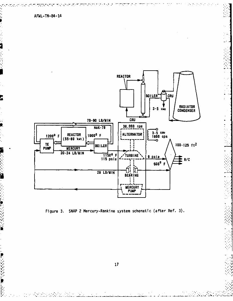
in the radiator-condensor to complete the cycle (Fig. 3). The Power
Conversion System (PCS) has all of its rotating components mounted into a
single shaft unit called the ComDined Rotating Unit (CRU). The design philos-
ophy behind the S2DR flight system was one of depenoaoility at minimum weight
which could survive launch stresses and temperatures.
The CRU was developed by TRW, Inc. The design criteria for the CRU turbo-
alternator are as follows:
* Net power output of 3.5 kWe
e Isothermal, hermetically sealed housing
9 Mercury lubricated bearings
e Permanent-magnet (PM) alternator
9 Single shaft assembly
. Vapor cooling of alternator
Mercury vapor entering at a temperature of 6210 C, and a pressure of2
8 kg/cm , expands through the two stage axial-flow turbine which drives the
three-phase, six-pole PM alternator. The shaft of the unit rotates at 36,000
rpm. The mercury vapor exhausts to a pressure of 0.6 kg/cm and cools the
alternator as it flows through the unit and over the finned stator housing.
The shaft is supported by two mercury-lubricated journal bearings for which
lubricant is supplied by the on-shaft centrifugal mercury pump. The enclosure
housing is hermetically sealed, as is the alternator stator (Ref. 3).
The final design was the CRU-V. An accumulated time of 21,196 h of
testing was completed on the flight-type CRU-Vs. The conclusions drawn were:
15
- - . . . . -.
_ •.. . . . ... . .. . . . .,,.... . . . . . . • , .m,... .I lm__J a -. mT.. -- J

AFWL-TN-84-14
C%
cc
44.
164
AFWL-TN-84- 14
REACTOR
L i BOILER CRU
70-90 LB/UIN R
INaK-78 36,000 rpm
1200F REACTOR ~ ALTERNATOR. 3 W be
11500 F /TURB INE\ l115 psla Il R/C
BURINU
L 17

AFWL-TN-84-14
(a) The CRU-V was capable of providing 3.5 kWe or more during long-term
endurance and design point operation with high intrinsic reliability. Three
CRU-Vs were operated 2500 h or more; one operated 4759 h and was found to be
in excellent condition upon disassembly. There was every indication that the
developed hardware was capable of at least 10,000 h operation.
(b) The CRU-V was capable of successfully performing repeated injection-
type start-ups with high reliability. One CRU-V successfully completed 37
start-ups with no reduction in performance. In tests of four CRU-Vs, the
ability of the machinery to reliably complete start-up at preheat levels as
low as 2040C was established.
(c) The CRU-V was capable of undergoing shock vibration levels charac-
teristic of potential launch vehicles without adverse effect. Performance
tests before and after shock vibration together with disassembly inspection
indicated that the launch environment caused no performance loss or hardware
damage.
(d) Substantial safe operating margins existed about the CRU-V nominal
operating band. The CRU-V performance tests covering wide ranges for all key
parameters gave no indication that limits were being approached or that
unfavorable trends were developing.
(e) The CRU-V power outputs up to 5.6 kWe were demonstrated, and it was
estimated that even higher outputs were possible with the present PM machine.
If a Lundell type alternator was substituted for the PM type (within the rotor-
stator envelope) power outputs of 9 kWe and higher would be possible with the
same basic CRU design (Ref. 3).
Research was done on every facet of design for a complete power conversion
system. Material testing was stressed to ensure a system capable of
withstanding a high temperature, high radiation environment. Much of the
research done was used in design of the SNAP 1OA flight system which was
actually flight-tested in 1965.
1
18",'
. . .. ,

AFWL-TN-84-14
IV. SNAP EXPERIMENTAL REACTOR
The SNAP Experimental Reactor (SER) was the first one to be built by the
specifications set down for space satellite applications. It was designed and
tested by Al. Testing was conducted in an underground facility which housed
the reactor system in a containment vessel with the heat exchange system
located in the outer section (Fig. 4). Criticality was achieved in September
1959 and final shutdown of the system was in December 1961. A total of 5300 h
of testing was completed at temperatures greater than 482 0C.
SER CORE DESIGN
The SER core was cylindrical, having an outside diameter of 24.13 cm and a
wall thickness of 0.24 cm (Fig. 5). The total core volume was 0.01 m3 . Both
the top and bottom were penetrated by 3.18 cm coolant lines. The coolant was
NaK which entered the core through lower inlet lines. The core vessel housed
upper and lower grid plates which distributed the coolant in the core and held
the fuel elements in place (Ref. 23).
FUEL/MODERATOR
The core consisted of 61 fuel elements arranged within a hexagonal array.
The resulting interstices between the core vessel and fuel array were filled
with Be sections, which acted as inner reflectors and physical barriers. Each
fuel pellet was 2.54 x 2.49 cm dia. The fuel elements also acted as moderator
to thermalize the neutrons, they were hydrided to a Nh = 6.022 x 10 at/cm
The fuel was composed of a Zr-H alloy with 10 without U23 enriched to 93.123percent. The alloy has a density of 5.58 kg/cm and is 2.1 volume percent U
and 97.9 volume percent ZrH (Fig. 6). The total fuel loading consisted of
3.0 kg of U2 35 .
The fuel cladding was fabricated of Hastelloy B, with an outside diameter
of 2.54 cm and a wall thickness of 0.25 mm. The inside surface of the
cladding was coated with a 0.05 to 0.08 mm layer of a B free ceramic coating
which was Solarmic Coating No. 514-35A. Each fuel element was sealed at the
ends by welding a 1.27 cm thick stainless steel endcap.
19

AFWL-TN-84- 14
UCA
zI
0 11
IL-
41
0 0 CL
ull
UO-
20j

AFWL-TN-84-14
CORE VESSEL CONTROL ELEMENT
FILLER -SAFETY ELEMENT
Figure 5. SER radial reflector cross section (after Ref. 3).
7w/o-93% ENRICHED URANIUM93.w/o-ZrH WITH
H2 DENSITY OF 6.0 X 10²² at/CM
3
1"O.D. X 0.010 WALL 0.975"DIA X I0" LONG;WELD STAINLESS STEEL B TUBE
STAINLESS STEEL END CAP AND INDEX PIN
14"
Figure 6. SER fuel-moderator element assembly (after Ref. 3).
21
. .. . . . . . . . . . .

AFL-TN-84-14
REFLECTORS
Beryllium was used for the external reflectors. The system hao three
separate sections:
e 0.64 cm thick plates stacked along the three flat surfaces, also used
for control,
* three partial circular drums which could be rotated away from the core,
thereby, decreasing the amount of reflector surface. These were used for
active control,
e and specially shaped pieces which filled the void left between the
plates, the control drums, and the outer core vessel.
Beryllium was also placed within the core which fillea the physical void
between the circular vessel and hexagonal fuel array and acted as a reflector.
CONTROL
The control drums were rotated by a direct motor drive geared so that the
maximum reactivity insertion was 0.015%/s (2.5F/s). At the beginning of the
operation, each control drum had a total worth of $3.82 when rotated from 0 to
180 degrees. Three independent safety elements were used both as reflectors
and as a means of scramming the reactor system; they were each worth 5 percent
in reactivity. Each safety element was pivoted about a hinge below the core.
A scram was achieved by cutting power to the magnet which held them allowing
them to fall from the core. A complete scram took 240 ms.
COOLANT SYSTEM
Eutectic NaK (78 weight percent K) was used as the coolant for the SER.
It was pumped through a system consisting of an electomagnetic (EM) pump, a
permanent magnet-type flowmeter, a plugging indicator for determining oxygen
and/or precipitated hydrides in NaK and an intermediate heat exchanger (Fig.
7). The SER was tested independent of its energy conversion system.
The polyphase, linear induction EM pump was specially developed by AI for .-3 3the SNAP reactor. It could circulate 1.45 x 10" m /s of 538 0C eutectic NaK at
2a head of 0.84 kg/m
22
. . . . . . . .. .. . . . . . . .
. . . . --..

AFWL-TN-84-14
-an
I.-.
3m 0.
- - - - 4
= IN-
rwZ U me.I
m~~ 4J M64C
-m
-------
-c =
so4- -. ~B= 3 64maSfl SMm SM09
- = m S23

AFWL-TN-84-14
OPERATING HISTORY
Full criticality of the SER was initiated on October 20, 1959 with final shut-
down on November 19, 1960. It operated at up to 50 kW thermal, with a tem-
perature output of 648.9 0C for 1800 h and 4820C for 3500 h (Table 3). There
was a total of 72 scrams throughout its operating lifetime (Table 4). Most
* were caused by minor difficulties which did not entail any major modifications
to the system.
TABLE 3. SUMMARY OF SER OPERATION (after Ref. 3)
Initial fuel loading September 17, 1959
Final shutdown November 19, 1960
Elapsed time during testing 10,306 h, 440 days
Reactor operating time 6035 h, 58.5% of total time
Operation at 50 kW and 1200OF 1877 h, 31.1:% of total
core outlet temperatures operating time
Operation at 50 kW and less than 2290 h, 38.0% of total
1200OF core outlet temperature operating time
Operation less than 50 kW and less 1868 h, 30.9, of total
than 1200OF core outlet temperature operating time
Reactor down time 4271 h, 41.5% of total time
Holidays and weekends 1288 h, 30.1% of total down time
Routine maintenance and experi- 1245 h, 29.2% of total down time
mental preparation
Heater bundle failure 680 h, 15.9% of total down time
Other component failure 1058 h, 24.8% of total down time
Total energy generated 224.6 MW/h
Equivalent time at 50 kW 4493 h, 187 days
24

AFIJL-TN-84-14
TABLE 4. SER SCRAM SUMMARY (after Ref. 3)
Number of Probable CauseOccurrences
17 Abnormal signal in log power channels 3 and 4 andpower level channels 6 through 8
15 Individual safety dropped out
13 Low "J" tub NaK level alarm
12 Circuit noise and accidental
6 False signal, source unknown
3 Disturbing of instrument cable in trench
3 Abnormal signal in startup channel (Channel 3)period instrumentation
1 Instrument trouble
1 Heater bundle failure
I Electrical power failure -
0 Initiated internal to core
72 Total through August 31, 1960
CONCLUSION
The two main objectives of the S2ER were to investigate: (a) The ability
of the reactor to override reactivity losses associated with obtaining
operating conditions and extended operation at these levels; and (b) to deter-
mine stability and safety of the reactor. Testing confirmed that the reactor
was stable and capable of running for an extended period of time without an
excess loss of reactivity.
The S2ER was considered a success. It gave continued confidence in the
development of the SNAP program; it also led to in-depth research in component
development.
25

AFWL-TN-84-14
V. SNAP 2 DEVELOPMENTAL REACTOR
The S2DR was the second reactor to be built and tested in the developing
program of space reactors. The objective was to design and test the operabil-
ity of a complete power plant system. It was the first model to use a flight
control assembly. Studies were done on the reactor, individual components and
the support system. The S2DR was tested and monitored so that it could be
flight verified under the SNAPSHOT program. It was to be flight tested in
September 1963 and January 1964, but the flights were cancelled due to a shift
in the budget, which also resulted in the termination of the entire SNAP 2
reactor program with continued research being compteted on the power conver-
sion system.
The system was designed so that the nuclear reactor could be integrated
with a Compact Power Unit (CPU). The CPU used a ercury-Rankine cycle with a
predicted power output of 3.5 kWe. Criticality was initiated in April 1961,
with the final shutdown in December 1962.
CORE DESCRIPTION
The reactor vessel had a diameter of 22.86 cm, a length of 40.6 cm and a
wall thickness of 0.16 cm. The reactor vessel housed the fuel pins, inner
reflectors and grid plates (Fig. 8). The reactor and lower grid plates were
fabricated from Hastelloy C and the upper grid plate of Carpenter LE-42
(Invar). The upper and lower grid plate held the fuel pins in place and
distributed the coolant evenly through the core. The fuel was arranged in a
triangular array, with a total of 37 fuel pins. The resulting reactor core
was a right hexagonal cylinder about 20 cn across the flats, 23 cm across the
corners and 24.5 cm long. Six radial pieces of Be were used to fill the voids
between the fuel and the core vessel. These were used as inner reflectors as
well as physical barriers.
The top and bottom vessel heads were conical with apex angles of 120
degrees. The core assembly was held in place by 12 Inconel-X springs
compressed between the grid plate and the top head assembly. The six inner Be
reflectors held the upper grid plate. The plate was not attached to the reac-
tor vessel and, therefore, was free to expand axially with thermal changes.
The bottom grid plate rested on a ledge machined into the bottom head assembly
of the core vessel (Ref. 24).
26
f'''.,.' '---. - ""::':'...: . .'. .".-. ..- .". . .""- .: . ..... . ..,.:". . . . .... .... ...."..2 - -.: ,''.--_'-.2"'-, -' 2 ,' .,' ,... .-. ,'-',,?

AFWL-TN-84-14
SAFETY NO.2
/ SAFETY ELEMENTS
NTERNAL BERYLLIUMREFLECTORS
" DRUM
DRUM FUEL ELEMENTS r .NO. 2 N '.1
"CONTRO DRUMS
BERYLLIUM REFLECTOR COOLANTRETURN PIPE .SHIMS
SAFETY N0.2 - N
Figure 8. S2DR fuel rod assembly and core cross section (after Ref. 3).
The SNAP 2 working fluid was NaK (78% K). It was distributed through the
bottom of the reactor vessel and through the lower grid plate. The flow then
passed through the core into the plenum chamber between the top grid plate and
the top vessel head. The flow then exited from the reactor head and was
transferred to the primary and secondary head transfer loops.
The fuel elements were composed of 10 weight percent enriched U23 , goweight percent Zr-H and 0.1 weight percent C. The S2DR fuel rods were
1.22 3hydriaed to an average of 6.44 x 10 at/cm ; therefore, acting as both the
moderator as well as the fuel. The nominal, cold radial gap between the rod
and the H barrier was 0.01 cm. The cladding was fabricated from Hastelloy N,
chosen for its mechanical properties and its coefficient of expansion which
is close to that of the fuel alloy. The mean coefficient of thermal expansion
between 210C to 648.90C is 1.32 x 10" cm/cm 0C for the Hastelloy N and 1.17 x
10-6 cm/cm°C for the fuel alloy (Ref. 25).
27
.-=, " .

AFWL-TN-84-14
The cladding was coated with a ceramic barrier, Solaranic S 1435-SM2 which
helped to minimize the loss of H. The loss of H was one of the major factors
in the decrease of reactivity as a function of temperature and time. As the
core temperature rose, the H dissociation pressure increased as did the per-
meation rate through the ceramic diffusion barrier. To accommodate the
loss of reactivity, a thin layer of Sm was applied on the inside of the
cladding which acted as a burnable poison.
The fuel elements were solid cylinders 25.4 cm long by 3.08 cm outside
diameter (Fig. 9). The fuel cladding had an outside diameter of 3.18 cm and a
wall thickness of 0.003 cm.
At each end of the fuel tube was a BeO piece which functioned as a reflec-
tor. The end pieces were 3.81 cm long by 3.08 cm in diameter and placed at
each end of the fuel rod. The elements were sealed by welding the stainless
steel fuel caps to the ends. The overall length of the fuel pins was 33.6 cm.L
REFLECTORS
The core was reflected in four ways (a) Be pieces which fit into the end
of the fuel elements, (b) inner reflectors which filled the interstices be-
tween the hexagonal fuel array and circular core vessel ; (c) the rotating
control drums, and (c) an external Be reflector 5.8 cm thick which surrounded
the core vessel. The external reflector was split longitudinally into two
halves, hinged at the bottom and retained at the top with a thin stainless
steel band. During an actual flight, the separation of the band due to
melting upon reentry or actuation of the band release devices would cause the
reflector to fall away from the core and the reactor to shut down.
0.28I ,13.225±0003 INDESIGN A-1 END CAP DESIGN H END CAPTYP BeO REFLECTOR BD REFLECTOR
// rFUEL ROD \ \
9~00 _____HASTELLOY N CLADDINGDIA IN
70 001 ". .- "DIA IN '
Figure 9. S2DR fuel element (after Ref. 25).
28
-..
-. -' - . . ' . . ' . . " .- . % • . . . . '% . . ." . ." -. . - " . .. . " . - - - . • • . . . . .. - ." • . -. '."__._.._"_-___-_- . % . . .

.~~~~ ~ ~ .. .. . . . .
AFWL-TN-84-14
REACTOR CONTROL
The S2DR flight system was to be brought to critical by first locking two
of the control drums into the outer reflector and then slowly rotating the
other two into the external voids until criticality was reached. Power was to
be maintained by adjusting the position of the two rotating control drums.
During ground testing the locked control drums were replaced by special
safety elements which were designed to fall away from the core in the case of
a scram. These were maintained at a full-up position unless scrammed. During
testing the two Be control drums were mounted on the top and bottom flange
assemblies which were maintained concentric with the reactor by four centeringe&
lugs. The control drums were rotated by constant-speed reversible motors at a
rate of 0.56 deg/s, which corresponded to a maximum insertion of 2.1F/s. Each
of the control drums were connected directly to its drive motor through an
antibacklash worm gear (Ref. 24).
SAFETY ELEMENTS
Safety drive mechanisms were located beneath the reactor which operated the
Be safety elements. The two safety elements were mounted on the top and bot-
tom flange assemblies which were maintained concentric with the reactor by
four centering lugs. Limit switches were provided on each of the safety ele-
ments and control drums so that their action could be interlocked to ensure
singular movement. Limit switches were used with the safety elements to
determine full-up or full-down position. The safety elements were held up by.-
electromagnets attached to the drive mechanism. The safety elements were
dropped from the reactor during a scram by release of the electromagnet (Ref.
24). Figure 8 gives a clear picture of the safety elements and control drums
for the S2DR.
S2DR REACTOR CORE TEST HISTORY
Significant operation milestones are presented in Table 5. Studies were
done on (a) the rate of reactivity change caused by H loss and redistribu-
tion; (b) the transient response of the reactor to periodic variations of
reactivity and flow; (c) the measurement of power coefficients of reactivity;
and (d) the ability to hold up for long-term operations. The reactor was
29
,p .

- - o - , . - w-- , . -, . . • 7 - ,- -
. - - - .- . .
AFWL-TN-84-14
TABLE 5. SIGNIFICANT MILESTONE DATES FOR S2DR OPERATION (after Ref. 3)
Milestone Date ..
Facility (SETF) acceptance 12-05-60
S2DS installation completed 03-15-61
Initial criticality 04-03-61
Initial SNAP 10 design power and temperature 08-08-61
Initial SNAP 2 design power and temperature 06-26-62
Surpassed SER total energy release 10-30-62
Terminated power operation 12-11-62
Terminated nuclear testing 12-21-62
tested with changes in coolant inlet temperature ana coolant outlet tem-
perature. Also, the change in the reactivity loss rate over time was deter-
mined. There was a total of 39 scrams during the reactor's testing. See
Table 6 for the complete scram outline. None of the scrams were initiated by
system failure during the lifetime of the S2DR and only three due to instru-
ment failures (Ref. 3).
CONCLUSIONIS
There were no major problems in the testing of the S2DR. Testing allowed
a closer look into the compatibility of the reactor's materials, ability to
operate in a radiation environment and to withstand thermal cycling. The
experimental program allowed evaluation of operating characteristics such as
long-term reactivity loss rate, Xe poisoning effects and H redistribution
effects. These characteristics were used to evaluate the performance of other
SNAP reactors (Ref. 24).
30

AFWL-TN-84-14
TABLE 6. S2DR REACTOR SCRAMS (after Ref. 3)
Reason Number of Scrams
Spurious noise (Channel 4, startup level) 7
Spurious noise (Channel 6, intermediate level) 2
Spurious noise (Channel 7, intermediate level) 11
Power fluctuation 14
Contractor (severed feed line) 1
Primary NaK flow loss during plugging run 3
Primary NaK flow loss during flow oscillation I
Instrument malfunction
NaK level recorder 1Core temperature recorder 1Fuel temperature recorder 1
Operator (checking equipment during operation ) 5
31
. . . . . . . . .. . . . . . . . . .•.

AFWL-TN-84-14
VI. SNAP 8 SYSTEM OVERVIEW
The SNAP 8 nuclear reactor was designed to produce approximately 35 kWe
output for use in space. The major performance objectives being 600 kW of
thermal power, 704.40C NaK outlet temperature, 10,000 h endurance, orbital
start up and automatic control, high reliability and low weight (Ref. 26).
The following statement was given by President Kennedy in a "Report to the
Congress from the President of the United States" and included in the report
"United States Aeronautics and Space Activities 1962," January 18, 1963 (Ref.
27).
"The SNAP-8 Electric Power Generation System will providepower for advanced space missions, such as lunar stationsor orbiting space platforms, and for interplanetary com-munications. In addition, SNAP 8 may provide an earlyelectrical propulsion capability. It is also designed toprovide some advanced technology which will be requiredfor higher powered nuclear electric systems in the mega-watt range."
In the 1960s the value of a space reactor was recognized at many levels in the
political echelon.
The SNAP 8 was a joint project between AEC and NASA. The AEC was respon-
sible for the nuclear system and ground testing of the complete electrical
generating system. The NASA was responsible for the power conversion system,
the spacecraft, for nonnuclear testing of the electrical generating system,
and for flight testing (Ref. 27). A Mercury-Rankine cycle power conversion
system was developed by Aerojet General Corporation (Ref. 27).
Testing was completed on two prototypes of the SNAP 8 reactor design: the
S8ER and S8DR. The main conclusions drawn from these two tests was the need to
improve fuel rod design and the thermohydraulics of the system.
A Mercury-Rankine cycle power conversion system was to be used with the
SNAP 8 reactor (Fig. 10). NASA was helping to develop four dynamic power con-
version systems for space applications: an organic Rankine, the SNAP 8
Mercury-Rankine, a potassium-Rankine and the Brayton cycle. As of April 1970,
the Mercury-Rankine development was further along than the other systems.
32
" " - , " - - - - " ,."" ".'. . . . . ." . ."7

AFWL-TN-84-14
REACTOR MERCURYPRIMARY INTERMEDIATE RANKINELOOP LOOP LOOP
TURB INE
t t I tALREACTOR IHX BOILER HEAT REJECTION LOOP 7
COND ".
EM PUMP NaK PMA HG PMA NaK PMA
Figure 10. SNAP 8 system (after Ref. 28).
A Mercury-Rankine system was tested for 7320 h without replacement of any
components. Every major component was tested at design conditions for at
least 10,000 h. The power conversion system was also started and stopped 135
times to study its flexibility and durability. Posttest examination showed
that, with a single exception, the components were in good shape. The single
exception was the mercury pump in which some cavitation damage was found on
the rear face of the impeller of the centrifugal pump (Ref. 28).
It was concluded in Ref. 18 that the SNAP 8, using a Mercury-Rankine con-
version system, appears to be capable of producing 50 kWe at a reactor outlet
temperature of 660 0C and if the reactor-life predictions were realized, for
about 40,000 h. The estimated weight for a 30 kWe SNAP 8 system, including
shielding was 2873 kg (Ref. 29).
33

AFWL-TN-84-14
VII. SNAP 8 EXPERIMENTAL REACTOR
The S8ER was used as a proof-of-concept test reactor. The design perfor-
mance objectives of the SNAP 8 were 600 kWt power output, 7040C NaK outlet
temperature and 12,00 h power operation with high reliability. Testing was
performed in a dry He atmosphere at AI Nuclear Development Field Laboratory.
The S8ER was tested from May 1963 to April 1965. A complete outline of the
S8ER is presented in Table 7.
Operation of the S8ER demonstrated:
(a) Sustained power operation capability. The S8ER released greater than
5.1 x 10⁶ kWh of energy during 500 days of nuclear operation, including 100
days of 600 kt and 704 0C outlet temperature and 365 days at more than 400 kWt
and 704°C outlet temperature.
(b) Static and dynamic stability.
(c) Acceptable integrity of the interim H barrier coating on the cladding
tubes.
(d) Capability of tolerating rapid changes in the power level. During
the power coefficient measurements, the core was subjected to about 155 rapid
changes in power (100 kWt in 1 min.).
(e) Verification of SNAP 8 reference design (Ref. 30).
REACTOR DESCRIPTION
The reactor contained 211 fuel-moderator elements. Each element consisted
of an individual fuel rod, a H diffusion barrier containing burnable poison,
exterior cladding, endcaps and grid plate indexing pins (Fig. 11).
The fuel was 93.15 percent enriched U235 in a solid Zr-U alloy (10% U)22 2hydrided to a density of 6.0 x 10²² at/cm . The outside diameter of the fuel
rod was 1.35 cm with an active length of 35.56 cm. The diametrical gas gap
was 3.2 mils (cold). A ceramic coating (A1-87630), 7.6 x 10- cm thick, was
applied on the inside of the fuel cladding to prevent the loss of H. A burn-
able poison, Sui203, was added to the ceramic coating, approximately 1.35 mg
SM2O3 per linear centimeter of fuel element. The burnable poison compensated
for the excess reactivity at the beginning-of-lite and helped to maintain a
relatively constant power level.
34
.... . . . . . . . .. .. . *. .. . .

AFWL-TN-84-14
TABLE 7. S8ER DESIGN ATA SUMMARY (after Ref. 34)
Design Parameters
Design power level 600 kWtLife 10,000 hPrimary coolant NaK 78 eutecticSecondary coolant Nak 78 eutectlcNumber of fuel elements 211Fuel loading 6.56 kg of U enriched g3.151Reflector 7.62 ca nominal thickness BeControl 6 rotating control and safety
drums
Fuel Elements
Composition Hydrldgj Zr-U alloyHydrogen concentration 6 x 10- at/ccAlloy 90 wt % Zr - 10 wt % UCladding (Hastelloy N) 0.0254 cm walls and 0.635 cm
end capsFuel rod diameter 1.35/cmFuel rod length 35.56 cmH2 diffusion 0.00762 an thick ceramic coating
on inside of cladding surfaceBurnable poison 48 mg of S142N per elementMaximum cladding temperature at
design power level 7820CMaximum core temperature at design
power level 839gC
Reactor Core
Core vessel size 23.72 cm OD by 53.34 cm nominalheight
Core vessel material 316 SSCore vessel wall thickness 0.16 cmUpper grid plate material 316 SSUpper grid plate diameter 23.34 cmUpper grid plate thickness 0.873 cmUpper grid plate coolant passages 420 0.397 cm dia holesLower grid plate material Hastelloy CLower grid plate diameter 23.34 cmLower grid plate thickness 0.794 cmLower grid plate coolant passages 420 0.318 cm dia holesInternal reflector 18 BeO filler piecesInternal reflector cladding Hastelloy N
Control and Safety Elements
flumber of elements 6Material BeLength 36.83 cmDrum radius of curvature 11.91 cmNominal thickness 7.62 cmWeight of each control element
(including support and shim) 12.02 kgRadial bushing clearance
(self aligning) 0.004 to 0.006 diaFriction torque 1.13 N/m
35

AFWL-TN-84-14
TABLE 7. (Concluded)
Control Element Drives
Drive means 1 reversible a-c motor per controlelement (only one element canbe inserted at one time)
Element rotation rate 0.055 rpm (2%/s)Element rotation range 105 degTime to rotate full range 319 sCoast rotation 0.0.33 deg (0.2F)Rotation stops Limit switches and mechanical stopOverload protection Slip clutchOrive system backlash None - taken out by scram spring
Scram System
Scram Power Torsional springScram torque 3.387 N/m total
2.258 N/m for acceleration
Scram activation Deenergizing of electromagneticclutch
Primary Coolant
Flow rate 0.0083 m3 /SReactor inlet temperature 5930CReactor inlet pressure 0.0113 kg/mReactor outlet temperature 7040CReactor outlet pressure 0.0108 kg/mNaK inventory 142.8 kg
Secondary Coolant
Flow rate 0.0083 m13 /
Heat exchanger inlet temperature 5660 CEM pump inlet pressure 0.0089 kg/m
2
Heat exchanger outlet temperature 677 0CEM pump outlet pressure 0.0159 kg/m
NaK inventory 282.1 kg
Nuclear Characteristics
Lattice spacing 1.45 cmMean prompt neutron lifetime 6.7 usEffective delayed neutron fraction 0.0077Median fission energy 0.21 en 2Thermal flux 2 x 10 n/cm2/s
.36

AFWL-TN-84-14 - -.
GRID PLATE INDEXING
PIN
HASTELLOY END CAP
CERAMIC COATING ON INSIDE-OF CLADDING CONUINING
FUEL ROD, Zr- 1 W% u
atom/cc OF H.
1~m IiHASTELLOY END CAP
Figure 11. S8ER fuel element (after Ref. 7).
37
41 . .

.... - ....- .- -;. r- .1 - ; .-. * , - -,, . . - .- .. -s - . .. 7--• 7 7 _ 7 : 7 ': 7 ' , - - , .- - - ' .
AFWL-TN-84-14
The cladding was 2.54 x 10 cm thick, it was fabricated from Hastelloy N.Endcaps made from Hastelloy N were seal welded to the tubings. The fuel ele-
ments were arrangea in a hexagonal array. They were held in place by end pens
which fit into the upper and lower grid plates. Figure 12 is a schematic of
the SBER fuel pin (Ref. 7).
The circular core vessel was fabricated from Hastelloy N. It was 53.34 cm
long with an Outside diameter of 23.72 cm. The core vessel was 0.27 cm thick.
The upper grid plate was fabricated from 316 stainless steel and the lower of
Hastelloy C. There were 18 internal BeO reflectors with Type 316 stainless
steel casings. These were used to fill the interstices between the fuel and
core vessel.
REFLECTOR SYSTEM
A solid layer of Be, 7.62 cm thick, surrounded the active length of the
core vessel. It was composed of two halves pinned together. The reactor was
suocritical with this single layer of Be. Criticality was brought about by
the rotation of the six control drums located outside of the Be ring. The
control drums were half segments of right circular cylinders fabricated from
Be. Each reflector drum was driven by its own mechanism. The control drums
were used to vary the amount of neutron leakage from the core and, therefore,
control the power level.
Three of the control drums were used for start-up and were driven in by
springs. The other three reflector drums were used for fine control and were
driven stepwise by long-term directional control drum actuators. The control
drums were also used as safety elements to scram the reactor. A release
mechanism would allow the control drums to fall away from the core vessel,
thereby causing the reactor to shutdown.
During testing, removable shims were used on the back of the control drums
to permit adjustments of its worth prior to reactor start-up. Position
readout and limit switch information were also included during testing (Ref.
7).
38
.. ... ...: .

AFWL-TN-84-14
In-
Li'
LL U13 CC3 V ca ass-V
p- L
us -W = 4
LU-
..................................................................T ......1.........La do

AFWL-TN-84-14
HEAT TRANSFER SYSTEM
Heat from the core was removed by the primary coolant system. The working
fluid was eutectic NaK (78% K). Heat from the primary coolant system was
rejected to the NaK secondary coolant system through an intermediate heat
exchanger. The secondary system rejected heat to the atmosphere by means of
an air-to-NaK heat exchanger. The coolant was circulated by an electromagnetic
pump.
REACTOR FACILITIES
The SSER was tested below ground in a shielded containment vessel (Fig.
12). The reactor core assembly was suspended by the shutdown shield, which
was a high density borated concrete, lead insulated air-cooled barrier. Above
this were the control drive mechanisms and primary coolant piping. Helium was
used inside the pressure vessel to help slow corrosion of the Be reflectors.
Water cooling coils encircled the 1.91 cm thick carbon-steel containment
vessel (Ref. 32).
CONCLUSION
In posttest examinations of the SER, fuel rod-bowing was not observed,hut in one case ovality was found, and this was a massively dehydrided rod.
From the metallographic examination it was concluded that a large portion of
the core had undergone phase change (Ref. 33). The maximum density changes
observed in the S8ER fuel elements appeared to correlate best with the calcu-
lated two-phase region B-S. This was also the region of maximum calculated
temperature which was believed to contribute to a low H region (Ref. 34).
40

AFUIL-TN-84-14
VIII. SNAP 8 DEVELOPMENTAL REACTOR
The S8DR was a prototype flight system tested to provide long-term
operating experience at rated conditions and to verify the reliability of the
reactor support system.
The design objectives of the SDR were to maintain a power output of 600
kWt, a coolant outlet temperature of 7040C and an operating lifetime of
12,000 h. Testing of the reactor core began in January 1969 and ended prema-
turely in December 1969 after approximately 7000 h of operation. Testing was
ended due to indications of ruptured fuel cladding (Ref. 35). An outline of
the S8DR is presented in Table 8.
REACTOR DESCRIPTION
The S8DR was a modified version of the S8ER core design, the major changes
were:
* longer fuel rods and reactor vessel,
* an improved hydrogen retention barrier,
* larger radial and axial gas gaps between the fuel and cladding,
* an improved coolant flow profile within the core (Ref. 36).
The S8DR was a Zr-U alloy with 10.5 weight percent U. The U was 93.15
percent enriched U?5 s The fuel was hyarided to an Nh = 6.0 x 10² 2 at/cm3
The fuel rod had a diameter of 1.34 cm and an active length of 41.91 cm. The
axial gas gap was 240 mils, with a diametral gas gap of 7.0 mils. The fuel
cladding was fabricated from Hastelloy-N. It was 43.51 cm long, 0.025 cm
thick and had an inside diameter of 1.37 cm. A ceramic barrier was applied on
the inside of the fuel cladding to retard H diffusion through the cladding.
The S8DR used SCB-1 as its ceramic barrier. The SCB-1 has greater resistance
to thermal shock than Al-87630 which was used on the S8ER. A burnable poison
was also applied to the inside of the cladding to compensate for long-term z....
reactivity losses. The poison, Sm203 , was blended in the ceramic barrier
material for this purpose.
The reactor core vessel was fabricated from 316 SS. It was 66.65 cm long
with an internal diameter of 23.40 cm and was 0.2667 cm thick (Fig. 13). The
core had a total of 211 fuel elements arranged in a triangular array on a
41
p ,I

AFWL-TN-84-14
TABLE 8. S8DR CHARACTERISTICS
General
Design Power Level 600 kWtReactor outlet temperature 704.CReactor inlet temperature 593*CAverage power density 37 kW/L of core
Maximum Power Level I MtReactor outlet temperature 5931CReactor inlet temperature 443-C
Design Life 12,000 hPrimary Coolant NaKSecondary Coolant NaKNumber of Fuel Elements 211Fuel Loading 8.2 k9 U enriche to 93.15!. U2 3s
Reflector 13.018 cm, normal thicknessControl 6 rotating Be reflector drums
Reactor Core
Core Vessel Size- 23.480 am ID by 81.788 anheight to outlet line
Material 316 stainless steelWall thickness 0.231 am
Grid PlatesCoolant passages 420(0.396 an dia)Spacing of Fuel element positioning holes 1.45S am (triangular lattice)Spacing of coolant holes n.841 cm (hexagonal lattice)IUpper grid plate
Material 316 stainless steelDiameter 23.411 cmThickness 2.169 cm
Lower grid plateMaterial Hastelloy CDiameter 23.411 cmThickness 1.651 cm
Internal ReflectorsMaterial 30 stainless-steel Clad BeO and
12 solid stainless-steel piecesCladding thickness 0.076 anCladding material 316 stainless steel
Fuel Elements
Fuel RodsComposition Nydrided ZrU alloyFuel 10.5 wt UEnrichment 93.15 wt wHydrogen concentration 6.05 x 10z at/ccDiameter 1.344 cmLength 42.736 amAxial hydrogen gap 0.610 cmRadial hydrogen gap 0.089 mmH2 diffusion barrier n.051 min ceramic coating on
inside of cladding surface
TA imensions are at room temperature conditions unless otherwise specified.
42
. . .. ,.
.S A A .%A A.~ ' V.........

AFWL-TN-84-14
TABLE 8. (Concluded)
Burnable PoiSon 58 mg Sm03/element (in ceramic)Cladding (Hastelloy N) 1.372 cm ID. 11.3 mils thickFuel Elements
Diameter 1.430 anLength 44.006 cm (excluding positioning
pins)
Peak fuel temperature at design power
l evel 8070CPeak Cladding temperature at design power
level 742CAverage fuel burnup (12,000 h at 600 kW) 0.22 metal atom %
Control Drums
Number of Drums 6Material BeLength 39.052 cm (total reflector
length 46.99 cm)Drum Radius of Curvature 11.43 amNominal Thickness 13.018Drive Means Electromagnetic stepping motorRotation Range 0 to 1Og9Full-In Stop 1.0 1.0Full-Out Stop 135 ± 2.0Drive-System Backlash t0.05*Scram Power Torsional spring
Nuclear Characteristics
Mean Prompt Neutron Lifetime 8.4 usEffective Delayed Neutron Fraction 0.0080Median Fission Energy 0.15 e 2Thermal Flux @600 kW (<1 eV) 3 x 10 n/cm sRadial Peak to Average Power 1.29Axial Peak to Average Power 1.36Clean, Met, Excess Reactivity $1A.4NaK Reactivity Worth $0.25Total Isothermal Temperature Coeff. of -0.18f/*F at 21°C
Reactivity -0.20f/*F at 649*CPower Coefficient of Reactivity -n.035%/kWRise to 600( kW Power and 1200*F Core
Average Temperature -2.15
Reactivity Inventory (12,000 h) -Hot, end of life excess (600 kW) $5.45Samarium burnout $2.90Fission product poisoning
Xe -S1.05Sm -31.02Other -1.17
Axial hydrogen redistribution -30.65Hjqgogen loss -$5.15U burnup -S0.66
Control Drum WorthTotal - 6 drums $21.06Single drum $ 3.90Maximum differential worth S /deg
Thermal and Hydraulic Characteristics ":"
Average Heat Flux (at 600 kW) 148.144 W/m2
Fuel to Coolant Heat Transfer Area 4.05 mCollant Flow Area in Core
Cold 57.04 am2
Hot 60.664 cm2
Hydraulic Diameter (individual coolant channel) 2.057 m-Mass Flow Through Core (600 kW and 200-F AT) 6.144 kg/s
Average velocity through core, not 1.402 m/sMass Flow Through Core (1000 kid) 7.554 kg/s
Average velocity through core, hot 1.707 m/s
% 43
S-. . ..

AFWL-TN-84-14
-j
I- U
Ti (?0!C30
Lujz CCCLu u
40 '4-:
x =M. =- c,
U) Z a a"I US
=~ caCD K' 0.
aa2/
LU.= = to
CM CS -1 4)-9 LL
C2.'o 'U
ca a-
C2 0,
-C c-
I.94ca
ca
* 44
Ir 2-U
---.- x- ----- ------ ,-- - - - - -- •
AFWL-TN-84-14
1.45 cm centerline spacing. The fuel was held in place by end pins which fitinto the upper and lower grid plates. Internal reflectors were placed in the
voids between the circular core vessel and the triangular fuel array. Thirty
BeO inner reflectors clad in 316 SS were used along with 12 smaller filler
rods of 316 SS. A 0.1 Ci Po-Be source was locatea at the top head of the
vessel (Fig. 14).
A flow distribution and a flow baffle plate, both fabricated from
Hastelloy C, were located below the lower grid plate. The flow distributor
was a basket shaped piece with a wedge facing the nozzle. It had 64 holes
around the side to distribute the flow evenly to the baffle plate. The baffle
plate was a disk with 73 holes sized and shaped to provide the desired flow
distribution in the core.
The coolant used was eutectic NaK (78% K). The coolant entered the lower
plenum through the flow distributor, through the baffle plate and into the 420
tricusp coolant channels between the fuel elements. The coolant then con-
tinued upward through the coolant channels and exited through the upper grid
plate into the upper plenum. The upper grid plate was fabricated from 316 SS.
The coolant then mixed in the upper plenum and exited through the reactor
outlet pipe. In-core thermocouples were used to monitor 27 of the upper grid
plate flow channels. The thermocouples were held in place by a bridge which
positioned the junctions at the centers of the coolant passages just over the
top surface of the grid plate (Ref. 37).
REFLECTOR AND CONTROL SYSTEM
The SNAP 8 system was designed to operate from 10 to 100 percent of its
rated power. The power level was adjusted by an automatic controller which
sensed the reactor coolant outlet temperatures and adjusted the position of
the control drums to maintain the proper outlet temperature (Ref. 38).
The complete reflector system was designed in two halves. Each half was
supported by a hinged-pivot fixture on the bottom of the core vessel (Fig. 15).
The reflector halves were designed to bear against support brackets at the top
of the core vessel. They were held in place by a thin steel tension band
wrapped around the outside. It was also designed so that when used on an
actual flight system, the reflectors could be removed from the reactor.
45
.... .......... ..

CONTROL ACTUATOR
RE-ENTRY BAND.- REACTOR VESSEL
REFLECTOR
CONTROL DRUM -FUEL ELEMENTS ~
FLOW BAFFLE
A - NaK OUTLET PIPENaI( INLET PIPE.
SHIELDSCRAM SPRING
LIH
RING
Figure 14. Frontispiece: SNAP 8 nuclear system.
46
. . . .

AFWL-TN-84- 14
FLIGHT TYPE DRUMPOSITION INDICATOR
CONTROLDRUM
SCRA MECANIM 81SERER E
BRACUAET
REFLECTO FIXED RFLECTORDRUM THIUNSS .
DDRUM
REACTO FULL
GRINSPRATD
BAFFLEEPTAT
(after Ref.CTO 39).
47.
LII FUE ELEM ENTS.. .. ..

AFWL-TN-84-14
Immediate shutdown of the reactor could be achieved by breaking the retaining
band, thereby ejecting the reflector assembly. This form of shutdown would
occur as a result of:
* command destruct,
9 a temperature drop in the coolant outlet line,
e or reentry heating.
If the reflector was ejected from the reactor, the reactor could not be
made critical unless the core was immersed in water or other moderating
material (Ref. 38). A shaped destruct charge (which could disperse the core
components) was another safety feature being considered. This would guarantee
that the reactor would not become critical during launch and preorbital opera-
tions. The charge would only be allowed to detonate with a signal from ground
command. After the spacecraft was successfully in orbit, the destruct system
was to be ejected. The ejection was to be accomplished by firing pyrotechnic
pressure cartridges which would pull a pin on the destruct charge assembly.
The assembly was to be jettisoned away from the core by a preloaded spring
(Ref. 38). These safety precautions were not used for the S8DR ground test,
rather emergency shutdown was achieved by snapping the control drums to a
full-out position using scram springs.
The reflector assembly consisted of an annulus of Be which surrounded the
length of the core vessel and six movable reflector drums. The annulus of Be
was 8.89 cm thick and approximately 45 Cm long. External Be cusps were
attached to the core vessel and spaced so that they provided a half circle in
which the control drums could rotate. Control of the reactor was achieved by
rotation of six right circular cylinders of Be. The control drums had a
radius of 11.4 cm and a nominal thickness of 7.94 cm. The cylinders were
rotated into half circular voids, thereby, controlling the neutron population
within the core.
Three of the six control drums were used as start-up drums. They were
driven in by springs and locked into a full-in position. The other three
control drums were used to bring the reactor up to critical and maintain a
constant power level. The control drums' reactivity worth could be adjusted * .
48

- AFWL-TN-84-14
by adding Be shims, approximately 2.54 cm thick, to the back of the control
drums. All of these surfaces were anodized to provide them with a high
emissivity level. The reflector assembly was designed to limit the Be tem-
perature to less than 7320C.
The control drums used for fine control were driven by stepper motors.
The actuators were eight pole reluctance motors which produced torque by the
interaction of magnetic forces between stationary teeth on the fixed poles and
the notched teeth cut into the cylindrical rotor (Ref. 34). The stator-pole
tooth alignment was such that, as each pole was energized, the rotor teeth
were in a position to provide maximum torque. While not energized, the rotor
was held in place by a brake mechanism (Ref. 3).
The control drums were held in place by a pair of self-aligning, journal
bearings. The bearing was held in a spherical cartridge. Contact surfaces
between the ball and socket were coa!ted with AL203 and then coated with a Mo
disulfate base which acted as a dry film lubricant. The bearings were
designed for operation at 621.1 0C with an environmental pressure of 1.33 x
10- 3 Pa or less (Ref. 37).
HEAT TRANSFER SYSTEM
The S8DR was tested without an energy conversion system. Heat was removed
from the core using NaK as the working fluid. Eutectic NaK was the primary
and secondary heat transfer medium. Final heat rejection was by means of an
airblast heat exchanger. An electromagnetic pump was used to circulate the
coolant (Ref. 35).
OPERATING HISTORY
The S8DR was operated via an automatic control system similar to the one
to be used with the SNAP 8 flight system. The S8DR included complete flight-
type control drive hardware. Testing was done in a vacuum chamber maintained
at 10O torr. The test facility contained equipment to control test vault
temperature, pressure and oxygen concentration within allowable limits. The
reactor was installed with a vacuum chamber in a shielded pit below the vault
floor. A vacuum of 10" torr or better was maintained within the chamber by
two mechanical fore pumps ana two oil diffusion pumps located in an equipment
room adjacent to the test vault. All radioactive coolant NaK piping and
equipment was located within the sealed vault. Backup power sources were pro-
vided to ensure there would not be a total loss of power at any time during
testing (Ref. 39).
49
. - . - - *..*
.. * . . . . . . . . .

AFWL-TN-84-14
Testing began in June 1968 with an initial power output of 600 kWt and an
outlet temperature of 704 0C. After a thousand hours of testing, the reactor
was boosted to 1 MW(t) for a total of 431 h. It was then returned to its ini-
tial operating level (Ref. 37).
Soon after testing began, anomalous oscillations were observed in the
reactor power level and the outlet coolant temperature. The oscillations con-
tinued for the first 1500 h (Ref. 40). After the one megawatt run there was a
noticeable increase in coolant activity and a greater reactivity loss rate,
indicating ruptures in the fuel cladding.
Testing was shutdown in December 1969 after completing 7000 h. All of the
flight sytstem components operated successfully without failure or degradation
in performance. These include control drum bearings, actuators, position
switches and the cable harness.
Upon postexamination of the S8DR core, it was found that 72 of the 211
fuel elements had cracked cladding tubes. The cladding cracks were typical of
a stress-rupture phenomenon.
An investigation of the S8DR operating data indicated that the oscillatory5a behavior was due to the clustering of the fuel elements under a thermal gra-
dient, followed by an abrupt declustering caused by the rehydriding of the
fuel rod. The rehydriding process applied a force in the opposite direcion.
The diffusion of H from hotter to colder regions of the fuel rod caused it to
act as if it had a delayed, negative coefficient of thermal expansion. This
was initially believed to be a stabilizing factor and prevent thermalclustering of the fuel, but the S8DR test and other out-of-core testing have
shown that the particular set of time constants and material properties can
result in an unstable, oscillatory condition (Ref. 40).
The following conclusions were drawn from the examination of the fuel
elements:
a. The fuel element cladding ruptures were the result of excessive
cladding strain caused by fuel swelling due to temperatures in excess of the
design value.
b. The fuel growth exceeded design limits due to over-temperature fuel
conditions in the core. This resulted from hydraulic maldistributions attri-
buted to fuel element bowing/clustering patterns, greater than anticipated
50

AFWL-TN-84-14
coolant bypass flow near the core periphery and the detrimental effects of
surge tank gas (which was entrained in the NaK coolant) on the fuel element-to-
coolant heat transfer characteristics.
c. The Hastelloy N cladding material strain-to-rupture characteristics
observed in SDR were in good agreement with design values.
d. Excluding elements which sustained major damage (e.g., cracked"-
elements), it appears that some measure of H barrier damage was incurred rela-
tively early in life, particularly in the tube section of the fuel elements.
The damage seems to have occurred primarily as the results of stresses caused
by element-to-element loadings resulting from bowing/clustering of the
elements.
e. The growth behavior of the Zr-H fuel material may be more temperature
sensitive than previous data would indicate. The effect on S8DR of such
increased sensitivity would have reduced full growth margins but cannot, per
se, be ascribed as a prime contributing failure mechanism.
f. A statistical correlation was found that indicates that Cu impurity
contents greater than 150 ppm in the fuel have the effect of reducing the fuel
growth with respect to fuel containing lesser amounts of Cu when such fuelsare subjected to essentially identical operating environments (Ref. 35).
CONCLUSION
The S8DR was the last reactor to be tested under the SNAP program. It was
one of two reactors tested under the SNAP 8 program being developed as a power
source for either a manned or unmanned application. It was concluded that
design changes would have to be made to avoid cyclic clustering and
declustering of the fuel elements. The advances made during the SNAP 8
program were used in conceptual design studies of space reactors.
51
"i .. . . .. .

AFWL-TN-84-14
IX. CONCEPTUAL SNAP 8 REACTOR DESIGNS
After the testing of the S8DR, the emphasis of the SNAP 8 programs went
into the design of four conceptual reactors from between 1969 to 1971. The
four reactor studies were the Zr-H reference reactor, the 5 kWe system, the
Reactor Core Test and the Space Power Faculty Reactor.
Zr-H ADVANCED REACTOR
The Zr-H advanced reactor was designed specifically to be used in a manned
mission with a 4 ir shielding design (Fig. 16). The design objectives were 600
kWt power, an outlet temperature of 704 0C and the ability to operate for over
20,000 h unattended. It was to use a SNAP 8 core design with slight changes,
such as:
* using fins on the fuel elements,
* increasing the number of fuel elements to 295,
* use ot Incolnel 800 or Hastelloy X for the cladding material.
The Zr-H reference reactor control drums were designed to minimize the 4 W
shielding envelope of the system. The drums were smaller in diameter and
designed to be cooled by the inlet NaK. The- were to be fabricated from 77.7
BeO which acted as a reflector and Ta-lO W which acted as poison. The reac-
tivity was controlled by rotating the control drums which added poison or
fuel.
The Zr-H reactor was designed to be compatible with more than one energy
conversion system, depending upon the mission (Ref. 40). It was designed to
meet system requirements for a 25 kWe thermoelectric power conversion system
(Ref. 3).
5 kWe THERMOELECTRIC REACTOR SYSTEM
The 5 kWe reactor was being designed to produce from I to 10 kWe using the
U-Zr SNAP reactor and a compact tubular lead telluride thermoelectric con-
verter. The thermoelectric unit was being developed by Westinghouse
Astronuclear Laboratory (Ref. 1). The 5 kWe reactor was designed to operate
for 5 years for use in an unmanned mission.
The design objectives were:
e 5-year life;
52
.............. '... . . .. . .. . .. ."
-o° o -, -° q°.'. .- 'q °O'. o" .- , .- ..- . . .•-....-° . ".'. . .. .. . . °.,...o,. o ., °°.. .. D .°--o

AFWL-TN-84-14
Byi C
gg
a~4J
CM - 44U I
U.)
Inn
dja
L>L, z
w li
0 4z,
53

AFWL-Th-84-14
* 5 kWe met unconditional power at the power system-spacecraft mating
plane in a space environment at end-of-life;
e compatible with unmanned-type spacecraft and launch vehicles such
as TITAN Class boost vehicles;
e radiation dose at the payload mating plant of 10 gamma and 1012
NVT, neutrons, average;
* use of Zr-H reactor and PbTe compact thermoelectric tubular tech-
nology, and
e automatic start-up and control capability (Ref. 28).
The 5 kWe reactor core was to be 26.67 cm in diameter by 40.64 an long. A
total of 85, 2.54 cm dia fuel pins, were to be used. Each fuel rod consisted
of a segmented (5-piece) fuel rod of hydrided 10 percent U-Zr alloy, sealed
within a Hastelloy X cladding tube. A Durnable poison was included as a
vapor-deposited coating of GdO, applied to the radial surfaces of the fuel
slugs (Ref. 7).
Of the 85 fuel elements in the core assembly; 27 were finned in a left-
hand direction, 27 in a right-hand direction and 31 were unfinned. The spe-
cial fin design was incorporated to improve the reactors thermohydraulic
performance.
The main difference of the 5 kWe system from the other Zr-H reactors was
its reflector assembly. The reflector assembly was tapered and, instead of
having rotating control drums, the reflector had vertical sliding control
segments (Fig. 17). The reflector was 3.048 cm thick at the top of the reac-
tor and 9.14 cm thick at the bottom. Two segments of the reflector assembly
were designed to slide vertically to provide reactivity control. By lowering
the segments, a 10.16 cm high window core midplane was opened which would
decrease the reactivity (Ref. 42). Control actuators were used to monitor the Ireflectors position. The frustum shape of the reflector was chosen to mini-
mize overall system weight (Ref. 43).
In choosing the optimum design, the basic requirement was that at
operating conditions, portions of the movable control element must not
protrude outside the cone. Protruding portions would cause radiation scatter ;.
on to the dose plane so the shield diameter would have to be increased. Three
54
..... ° "
. . . . . . . . . . . . . . . . .. . . . . . . . . . . . . . . . . . . . . .
* .. ,

AFWL-TN-84-14
REACTOR
RE FLECTOR
GAMMA -RAYSHELNEUTRON SHIELD
PRIMARY VOLUMEACCUMULATORS
PUM
POWER MODULES
SECONDARYVOLUME
ACCUMULATOR RADIATOR
___MAIN BUS BAR
Figure 17. 5-kWe system schematic (after Ref. 7).
55
.* .- .*.* . - 7. -7 -2 * . *

AFWL-TN-84-14
configurations were analyzed using the cone-shape reflector system. It was
found that the sliding reflector resulted in a weight savings of around 45.6 kg
or more over a rotating drum system (Ref. 43).
The 5 kWe reactor was never tested, but extensive preliminary work was
completed. This work includes computer analysis, material testing and design.
The reactor core test was designed as a test reactor for the resolution of
fuel element design problems that were outstanding after the S8DR operation.
The Space Power Facility was designed for operation in conjunction with a NASA
program for operation at the Plumbrook Space Power Facility. This reactor
represented the last design effort in the SNAP 8 family of reactors (Ref. 7).
:V-
56
r- 7.... . . . . ......

AFWL-TN-84-14
X. SNAP 1OA
The SNAP 1OA was a Zr-H reactor designed to produce a minimum of 500 We
for up to 1 year or longer. It incorporated static/dynamic control and ther-
moelectric conversion systems.
The SNAP IOA was the only nuclear reactor the United States has actuallyflight tested. It was successfully launched on 3 April 1965 from Vandenberg
AFB, California, and placed in a circular polar orbit. After 43 days of suc-
cessful operation, the reactor was shutdown as the result of a high voltage
failure sequence in the electrical system of the Agena spacecraft. The flightwas considered successful, because the reactor was automatically brought up to
operating level via ground command and operated as predicted from ground
testing. Also, the SNAP IOA program confirmed that a space reactor could be
safely transported and launched into orbit.
This reactor was also ground tested with a pseudoflight system which was
operated in a simulated space environment. It was operated for 10,000 h
without interruption before being shutdown for posttest examination. The SNAP
IOA demonstrated the feasibility of the operation of a reactor in space.Although the power output is too low to meet the current needs, much of the
technology and program knowledge gained from the SNAP IOA testing is relevant
today.
FUEL ELEMENT DESIGN
The reactor core consisted of 37 fuel elements each 32.64 cm long and
3.17 cm in dia. The cladding was fabricated from Hastelloy N, with a wall
thickness of 0.038 cm. The ends of the fuel element were sealed with end caps
made of Hastelloy N and welded to the cladding tubes. The fuel was 31.11 cmIIlong and 3.07 cm in dia. There was an axial gas gap of 0.0076 cm which wasfilled with H to promote heat transfer (Ref. 44). The cladding tubes were
coated with a ceramic layer, Solaramic ($14-35A), which helped to prevent Hleakage from the fuel element. The protective layer was from 2 to 4 mils
thick. A burnable poison, SM2 03, was added to the ceramic barrier to decrease
the initial amount of reactivity. The reactor ran at a virtually steady-state
power level without dynamic control.
57

AFWL-TN-84-14
The ceramic glass barrier was composed of a proprietary coating made from
technical grade oxides, nitrates, and carbonates. It has a theoretical dell-3 3
sity of 3.1 g/cm and an actual density of 2.8 g/cm . The ceramic coating was
applied in three firings. In the last two firings a small quantity of SmO was
incorporated in the coating. The nominal SmO loading was 3.1 + 0.3 mg/cm.
One end cap of the fuel element was welded to a cladding tube prior to
application of the ceramic barrier. After the ceramic barrier was fired, a
fuel rod was inserted into the cladding tube. The tube was then sealed
against H loss by insertion of a ceramic coated blend cap. The H barrier was
made complete by locally heating the cladding tube and blend cap to the
ceramic surfaces together. Following the blending operation, an end cap was
welded to the cladding tube, covering the blend cap (Ref. 45).
Each fuel pin was composed of approximately 128 g of U2 3 s , 11.8 g of U13 8 ,
24.6 g of H and 1215 g of Zr. A small amount of C was also used as a grain
refiner. The total weight was approximately 1.38 kg of fuel material per fuel
element. The U was fully enriched. The fuel was hydrided to an Nh of 6.35 x22 3
10 at/cm . All of the edges of the fuel were rounded to prevent damage to
the ceramic barrier during .3sembly and handling of the fuel element.
Less than 10 of the 37 fuel elements had a nominal H content of 6.0 x 10223
at/cm and/or a SM203 loading of 6.3 mg/cm. The special fuel rods were used to
adjust the excess reactivity and passive control characteristics of the core
(Ref. 46).
REACTOR CORE
A total of 37 fuel elements, arranged in a triangular array were used in
the SNAP 10A. The fuel elements were set in a 3.2 cm center-to-center
triangular spacing. Internal side reflectors of Be were used to round the
hexagonal core configuration and to fill the voids between the fuel and the
reactor vessel. The reactor vessel was fabricated from type 316 SS with an
inside diameter of 22.54 cm, a length of 39.62 cm and a minimum wall thickness
of 0.081 cm. A support ring, two NaK inlet pipes and support bracketry, all
of which are fabricated from 316 SS, were welded to the reactor vessel.
The fuel elements were held in place by upper and lower grid plates. Top
and bottom end pins 0.615 cm and 0.455 cm in diameter, were engaged in holes
in the upper and lower grid plate (Ref. 47). Each plate was 22.22 cm in
58
..- , . ' . . j ' ... - '. . -. '-. . - - ,- , ' - ' - ,. - . . - ." . , " ." . . , " - i ..- - .. . '. ' . " .- - .- . " - .- . . . .,., -.- .

AFWL-TN-84-14
diameter and fabricated from Hastelloy C. The upper plate was a solid piece
of Hastelloy C which was 0.317 cm thick. The lower plate was a brazed
assembly consisting of a 0.152 cm thick baffle plate and a 0.152 cm thick ori-
fice plate with spacers between them. The overall thickness being 1.27 cm
(Ref. 46). Each plate was perforated with 72 holes on a 1.85 cm triangular
pitch for the coolant flow. The diameter of the flow holes in the orifice
plate varied from 0.635 cm surrounding the central fuel elements and 0.477 cm
at the perimeter holes. The lower grid plate was supported by a ring at the
bottom of the reactor vessel and the top grid plate was spring-loaded against
the vessel top head to allow for thermal expansion of the core in the axial
direction (Ref. 42). A total of 12 springs were used, they were made of Rene
41 wire and each exerted a force 166.7 N. The free and compressed lengths
were 1.53 and 1.27 cm, respectively (Ref. 46).
REACTOR REFLECTOR AND CONTROL SYSTEM
The SNAP 1OA reactor was reflected by a layer of Be, approximately 5.08 cm
thick, which surrounded the outside of the core. This layer was made up of
plane sections approximating a cylinder. Four semicylindrical cavities, spaced
90 degrees apart were set in the Be reflector.
Four semicylindrical control drums were used for control of the reactor.
They had a radius of 8.89 cm and a length of 25.72 cm. The control drums were
used to regulate the amount of neutron leakage from the core, thereby con-
trolling the reactor power level. The total weight of the reflector system
was 46.8 kg.
The flight system was designed so that after the start-up command was
received, squibs would be fired into actuators adjacent to each control drum,
thereby, pulling the pin and releasing the drum. Two control drums were imme-
diately inserted and the fine control drums would then be stepped in. The
sudden insertion of the two coarse control drums would add $4.30 of reac-
tivity. Fifty seconds after the start-up command, the two control drums would
take their first step. The fine control drums then were stepped in a half a
degree every 150 s. Criticality was then reached approximately 7 h after
start-up. The rate of temperature and power increase during start-up was
limited to ensure reactor stability. Recommendations were made to increase the
59
....-.

AFWL-TN-84-14
reactivity worth of the course control rods, so that the reactor could be made
critical within 30 min rather than the 6 h required on SNAPSHOT (Ref. 48).
Start-up would then be limited by the thermal stress criteria, rather than
reactor stability. Control was to be linked to the NaK outlet temperature.
When the NaK outlet temperature dropped below an estaolished point, the fine
control drums would take another step inward. This would continue for 72 h
after the start-up command, at which time all dynamic movement was ended (Ref.
49). The reactor then ran at steady-state power without dynamic control. The
SNAP 1OA possessed a strong negative temperature coefficient which was used
for inherent control and stability over the operating lifetime (Ref. 50).
The control drum actuator's motor was designed so that it rotated in
finite Steps. These drums were linked to the actuator by two gears. The
pinion gear attached to the motor shaft was made of Haynes Stellite 6B, and
the gear segment attached to the drums was made of a Ti alloy. A coat of an
Alpha Molybote X-15 was used to prevent self-welding of the gears (Ref. 36).
The reflector/control assembly was fabricated in two halves (Fig. 18).
Each control drum rotated on a pair of self-aligning bearings--the upper was a
radial bearing and the lower was a radial-thrust bearing (Ref. 51). A
retaining hand was used to hold the two reflector halves together. This band
was held off from the reflector by flexible graphite blocks to prevent self-
welding. A gap between the reflector system and the core vessel was main-
tained to ensure that they would not self-weld.
The reactor system could be shutdown by the ejection of the reflector
assembly. The reflector ejection would take place if one of three signals
were given: (a) a ground command through an umbilical prior to lift-off,
(b) telemetry or (c) a failure sensing device.
The failure-sensing device was sensitive to low converter output voltage.
If the failure sensing device was actuated, a 1 min timer was started. If the
signal was a minor fluctuation and the system returned to normal, the timer
would reset. If not, a 1 h delay time would be started which would trigger an
electrically actuated band release device if the command was not cancelled
(Ref. 47).
60
. . . . . . . . .o .o. .,- .o .. ' .- .° ,.. .o . . .. . . .". .

AFWL-TN-84-14
"a2a"
am* REVE
OS sum
pFA
7OKA"
cum09
Icrr
oft"
L- S
Fiue1. Coto=n rfetraseby(ftrRf )
W61
.M A f.. . . . . . . . . . . . . . . ... . .. . . . . . . . . . . . . . . . . . . . . . . .
MW. ..

AFWL-TN-84-14
The band release device was a hollow cylinder fabricated from Rene 41which contained an electrical heater, the total length being 5.8 cm which
included band end fittings. The band release device was an integral part of
the reflector retaining band which caused it to break by applying heat. The
heater consisted of 32 Ga W wires coiled around a ceramic bobbin and placed
within the cylinder.
When the retaining band breaks, it causes the reflector halves to fall
away from the reactor and cause immediate shutdown of the reactor. Ejection
is accomplished by compression springs located at the bottom of the reflector
halves. When the retaining band is released, the reflector halves are pivoted
outward by the spring force (Ref. 47).
A second band release device is also provided to separate the reflector
retaining band. It is actuated by a drop in the NaK outlet temperature. Asteel rod is mated with a Mo tube, they are rigidly jointed at one end by anotched stud, which also serves as a shear pin between two overlapping, end-
fittings of the reflector retaining band and bolt. If the temperaure of the
coolant goes below a specified value, the difference in thermal expansion of
the stainless steel and Mo will cause the stud to break, thereby, releasing
the retaining band (Ref. 47).
The retaining band is also designed to release upon reentry heating. This
ensures that the reflector assembly will be rejected before impact and allow
dispersion of the fuel elements from the core.
HEAT TRANSFER AND POWER CONVERSION SYSTEM
A NaK alloy was used as coolant for the SNAP 1OA. The coolant outlet tem-
perature was 543.3 0C. The NaK was circulated through the core and thermo-
electric converters by means of a liquid metal d.c. conduction-type pump.
The pump was powered by its own lead-tin-telluride (PbSnTe) theremoelectric
converters. The PbTe N and PbSnTe P were chosen on the basis of high figure
merit at the operating temperature relative to other materials. The pump was3designed to produce a minimum of 831 cm /s of NaK flow at 565.50C against a
head of 0.091 kg/cm3 .
The PbTe thermoelectric elements were initially to be used on the SNAP 1OA
power conversion system, they were considered advantages because they had a
high performance level and had been used extensively in other applications.
62

AFWL-TN-84-14
Three distinct disadvantages were known: (1) high sublimation rates at
operating temperatures, (2) low strength and brittle mechanical behavior and
(3) lack of a contacting material and contacting process that would meet the
SNAP 1OA requirements (Ref. 52).
In 1961, P and N-type thermoelectric SiGe alloys were developed by the RCA
Princeton Research Laboratories. Although they have lower performance than
PbTe, they are advantageous in that they have (1) lower vapor pressure at high
temperature (2) good mechanical integrity and (3) stability at temperatures
greater than those required by the SNAP 1OA (Ref. 3). The SiGe thermoelectric
were also chosen for the SNAP 1OA because of their predicted growth potential.
The power conversion system consisted of N and P doped SiGe thermoelectric
materials, thermally coupled but electrically isolated from the NaK heat
transfer medium (Fig. 19) (Ref. 34). A total of 2880 pellets were electri-
cally connected in two parallel paths by Cu straps at the hot end of the
pellet and Al radiator platelets at the cold end (Ref. 54). They were bonded
onto the radiator surface. The radiator consisted of 40 SS tubes arranged in
a conical configuration. The heat was transferred from the NaK tube through a
thin alumina disc, which was used as insulation, then to the SiGe pellets to
an individual Al radiator. The total effective radiator area was 5.8 m2 (Ref.
50). The TE system was designed to operate at a hot junction temperature of
573 0C with a maximum of 5930C. They were limited as a result of the increase
in electrical contact resistance between the SiGe pellet and the W shoe (Ref.
44).
Ground testing of the thermoelectric system was done in a simulated space
environment. Degradation of the power output was observed and this was attri-
buted to the disposition of carbonaceous material on the module insulators.
This carbon resulted from the outgassing of the electrical insulation, par-
ticularly that which was hot, in the case of the system tests and from vacuum
pump oil contamination, in the case of module tests (Ref. 53).
The NaK tubes were fabricated from 405 SS, the electrical insulator of
alumina, the hot strap material of Cu, the compensator and element shoe of W
and the fin material of Al (Fig. 20). All materials were brazed or otherwise
metallurgically bonded together. During the FSM-1, nonnuclear testing, it was
established that the estimated degradation rate was 4 percent for 1 year of
operation (Ref. 30). The total power output was to be 500 W or more.
63• :. .I

AFWtL-TN-84-14
PAATH
Fiue1.NP1A throeetrc0uoFgrtosceai (ate Ref. 52)
OPEATS PATHSN
GOLD aAC~iG PATHN
A)TRIAL RDCINMDUECNTUTO 8)T FINALPROUTO OUECNTUTO
ALUMINA2 "~yo C.S______PLAUING
S P IS TR PLIYIN
ALUMINUMS TUASTEI ASSEMBL CUPPER CONAC - - - - -
UOPPER CHOETC ~NL CSCG f.SINGL
S-64 ANLO @OR j SNOR
PELLES*RT WOA
405 STAAR.ESS STEE
Figure~~~~~~I 20Mosrcino NPiAtemeeticonverterTE (ate Re.h2)
LOWER "OE64
. . .
AFWL-TN-84-14
To ensure the NaK would not freeze and cause plugging in the system, it
was kept above 32.4 0C during prelaunch, launch and prestart-up of the nuclear
reactor in orbit. The NaK was loaded into the system at 380C before launch.
Three techniques were used to ensure the NaK would not freeze: (a) an ejec-
table heat shield with emissivity coatings designed to effect a net heat input
into the system and (b) the inherent heat capacity of the system and (c) an
induced low flow of the NaK to provide a more uniform temperature distribution
(Ref. 44). Two Cu electrodes were placed on the pump throat to accept an
auxiliary current supply of about 40 A to maintain the required 3 percent flow
prior to start-up of the system. During the actual flight, the flow was 7
percent of full flow which was nearly double the design requirement. The
thermoelectric pump contributed half the flow and the auxiliary power source
the other half.
Bellow type expansion compensators attached to the return legs were used
to ensure a relatively constant pressure of 2.41 kPa. This was to ensure that
the NaK would remain void free and to prevent cavitation in the pump (Ref. 44
and 46). The bellows were restrained from moving during launch to prevent
overstressing by a locking device. In the event of a lock-release failure of
one unit, the second bellows assembly was capable of absorbing the full net
expansion of the NaK without exceeding the maximum allowable pressure.
The SNAP 1OA structure was fabricated from Ti, 20 mil thick, formed into a
corrugated cone. The structure transferred the reactor shield loads to the
spacecraft and directly supported the thermoelectric conversion system (Ref.
48 and 53). The reactor was supported on the converter structure by four -.
support legs formed from 0.081 cm 6AL-4V Ti alloy. The support legs were
designed to support the entire structure during launch loads, and were
attached to the reactor and converter structure with blind bolts (Ref. 47).
SHIELDING
The SNAP IOA system had a shadow shield designed to keep the dose rate
under specified values at the reference dose plane. The shield assembly was
located directly beneath the reactor and weighed 98.6 kg. The shield was
fabricated from a cold pressed LiH shielding material reinforced with
stainless steel and contained in a stainless steel casing. The honeycomb.
65
. . . . . . .. . . . .

AFWL-TN-84-14
design was used to minimize crack propagation and to hold the LiH block
together when subjected to thermal gradients (Ref. 47). A specific gamma
shield for the SNAP IOA was unnecessary. During SNAPSHOT the measured gamma
dose rate at the reference dose was 7 x 10 r/yr compared to the design objec-
tive of 1 x 10 r/yr (Ref. 53). A set of eight spring assemblies attached to
the shield casing and to a parabolic plate below the shield were used as sup-
port. To position the LiH against the forward end of the launch phase, a
spring-support mechanism preloads the hydride to the anticipated vertical
acceleration load during launch. The casing length was approximately 81.28 cm
and the LiH length was 69.77 cm. The maximum and minimum shield diameters
were 53.65 cm and 20.10 cm, respectively (Ref. 47).
The shield was designed to limit the total reactor integrated nuclear7 12 2radiation to less than 4 x 10 R of gamma radiation and 5 x 10 n/cm neutron
energies of 1.0 MeV at any point on the dose plane (Ref. 55). The reference
dose plane was 152 cm in diameter located 533.4 cm below the reactor core.
SNAP IOA TEST HISTORY
During the SNAP 10 program a total of eight prototype and qualification
systems were built and tested. Three were used for structural tests, three
were prototype thermal vacuum performance tests, two were final complete
system qualification models and the final flight system. The two qualifica-
tion systems consisted of a nuclear system and a nonnuclear unit which used an
electrical heater to simulate the reactor core, both of which used flight
hardware (Ref. 48).
NONNUCLEAR THERMAL TESTS (PSM-3)
The PSM-3 was the first prototype system to be tested under the SNAP IOA
program. Testing was done to explore thermal, hydraulic and heat transfer
characteristics (Ref. 43). An electric heater was used to simulate the
nuclear heat source, also the system utilized a partial PbTe converter instead
of the SiGe thermoelectrics which were used on the flight system".
Testing was done in a vacuum of 10"3 mm Hg and a cold wall heat-rejection
sink temperature between 40C and 65.50 C. Detailed thermal behavior of the
system in orbit prior to reactor start-up was experimentally verified by local ***.
liquid nitrogen cold plates and a gross simulation by infrared lamps of the "
solar heating and shade effects (Ref. 53).
66
:: I':

AFWL-TN-84-14
Over l000 h of testing was accomplished with this system at operating
temperatures between 930C and 4820C during the time period April 10 and
October 12, 1962. Valuable information was obtained from the initial thermal
testing and changes were made on the following test of a full-scale, non-
nuclear system (FSM-1).
SNAP 1OA FLIGHT SYSTEM PROTOTYPE (FSM-1)
The SNAP 1OA flight system prototype was full-scale, nonnuclear mock-up
with a special heating unit to simulate the reactor heat source. Testing was
conducted from September 8, 1963 to January 16, 1964. The FSM-1 was tested to
simulate conditions from ground launch to nuclear start-up in earth orbit
(Ref. 56). All testing was done in a vacuum environment.
Testing was begun with a simulated prestart-up orbital test, including athermal and nuclear checkout. Operation then began on a 90 day full-power
test with an average outlet temperature of 4930C and average power output of ---
400 We.
The thermoelectric power converter, coolant volume expansion compensator,
thermoelectric d.c. conduction pump, and instrument assemblies were of devel-
opmental flight design. Whereas the Ti support structure was of qualified
flight design.
SNAP 1OA FSM-4
The flight system mockup number four (FSM-4) was a nonnuclear test system
duplicated in every detail to that of the flight system except for the nuclear
heat source (Fig. 21). A special heating unit was used to simulate the reac-
tor as a heat source. It was the only test system to be loaded with NaK and
thermal performance tested at both acceptance and qualification levels (Ref.
57). The FSM-4 was a prenuclear test to demonstrate successful start-up in
surviving the initial temperature transient.
The FSM-4 was tested in the same facilities used by FSM-1. The system wastested in a vacuum environment. The test facility was insulated with panels
in which cryogenic fluid was circulated to simulate the thermal environment of
space.
67
• ° . ., . . , . . . S• . S- . S 5 5 .. . .. . .. • . - . * . - - • "• °

AFWL-TN-84-14
I IO6-I
am I09 I
- '4-
LU U1
I 41
dOOl allid
-c
1.c
XHI0
V)
r% e a e r% fffnm e%0% 0
tU,
68

AFWL-T-84-14
The main four objectives in testing of the FSM-4 include:
* shock and vibration testing of a NaK loaded system,
9 simulated orbital operation before start-up,
e simulated orbital start-up sequence with emphasis on the thermal
transient, and
* thermal reference endurance testing (Ref. 57).
Testing demonstrated that the flight system would produce rated power after
being subjected to the launch and orbital environment. The endurance indi-
cated problem areas in degradation of the electrical output via shorting of
the converter insulators which resulted in an expenditure of effort to deter-
mine the cause of this degradation and to redesign the system (Ref. 53).
SNAP IOA/AGENA COMPATIBILITY TESTING
To ensure mechanical and electrical compatibility with the Agena D vehicle
an electrical mockup, the FSEM-2, was mated to the Agena D functional metal
mockup. The FSEM-2 system had electrical and instrumentation mounted on a
complete structure; however the reactor, coolant system, power conversion
unit, and radiation shield were simulated by mass mockups to duplicate the
* weight and handling characteristics of the flight unit (Ref. 53).
The FSEM-2 was the first system to test the compatibility of the electri-
cal system with the Agena vehicle, several problems were identified which led
to changes in the flight design. The system was later rewired and flight
qualified equipment added, the new design was named the FSEM-2A. The system
was subjected to shock, vibration, acceleration, temperature, vacuum con-
ditions simulating flight environmental conditions and initial investigation
of electromagnetic interference.
The final compatibility testing was done on the FSEM-3. Testing was con-
ducted at LMSC's Sunnyvale facility between May 1964 and February 1965.
Compatibility tests consisted of programming the two mockups through a simu- .-
lated flight sequence of events with the main unregulated power bus maintained
at either 23.5 or 28 Vdc.
A significant amount of information was obtained from the SNAP IOA
electrical mockup testing. Several changes were made in the system before
being flight qualified.
69
. . . . . . . . . . . . . . . *-."- ..*% . . .
... .~~......... .oI .o.......-.-.---...o.,_..o-, ...... .- o......... o.,o

AFWL-TN-84-14
SNAP 1OA GROUND QUALIFICATION SYSTEM
The SNAP IA nuclear ground test, designated the S1OF-3, was identical to
the flight tested SNAP 1OA including its structure, shield, PCS, and expansion
compensators with minor modifications to accommodate for ground safety.
The reactor system was brought up to full power on 22 January 1965 witn
final shutdown on 15 March 1966. The system had over 10,000 h of unin-
terrupted operation. It was operated at 35 kW thermal for 390 days and then
raised to 44 kWt after receiving permission from the AEC. Active control was
employed for first 3 days after the raise in power followed by 25 days of
static control (Ref. 53).
At the end of 1 year, the outlet temperature had decreased greater than
predicted. This was mainly attributed to the continuing H redistribution, but
other system uncertainties affected the reactivity performance also. It was
determined that the H redistribution effect was essentially completed during
the active control period for high temperature reactors, and that all other
uncertainties were reduced due to the strong dependency of the H to redistri-
bute at high temperatures.
Another important conclusion was that the FS-4 reactor temperature drift
was almost the same as the flight tested SNAP 10A. This verified that the
behavior of statically controlled SNAP reactors could be predicted based on
prototype ground testing.
SNAP 1OA FLIGHT TEST
The SNAP 1OA flight system, FS-3, was launched 3 April 1965 from
Vandenberg AFB into a circular polar orbit (Fig. 22). The system operated
successfully for 43 days when it shut down due to failure of the voltage
regulator on board the Agena spacecraft. Although secondary payloads were
included on the SNAPSHOT launch, the main purpose for the flight was to
observe the behavior of the SNAP IOA in space.
The complete SNAP IOA system had an overall height of 347.9 cm and a
mounting base diameter of 127 cm. The total weight of the system was 436.4 kg,
100 kg for the radiation shield and 22.7 kg of diagnostic instrumentation
(Fig. 23) (Ref. 54).
70.°p-

AFWL-T-84-14
C3
ca
ZUJC3 ca
LA..=
UU,
Lu LAJr.crLU U. C 4-
'41
4--
E l 4J
4T)
CDC
ccc
Ccr0
LI-
C,,
Im
C.33
LL. CD
-j c
LULLW-z U
71

AFWL-TN-84-14
St:E
U L
uj=I I- I I
C-,
VI 4m
m~U I I- 10
.4.fri C2
LL CDI- .X~a- - L
CL o'. Ia -
Lai,
L LL.
cc aNC . Im>
72o

AFWL-TN-84-14
The flight system used the SNAP 1OA reactor desig outlined earlier. The
* FS-4 included an instrumentation compartment which housed the start-up and
control system, diagnostic instrumentation and electrical connections which
were used to mate the reactor system with the Agena (Ref. 48).
Preflight testing included the following:
" Fabrication completed 17 September 1964.
" Acceptance-level shock and vibration tests successfully passed
24 September 1964.
" Fuel loading and dry critical testing completed 26 October 1964.
" NaK loading and thermal reference testing completed 15 January 1965.
(Using electric heaters to simulate the heat source.)
" System shipped to VAFB 18 February 1965.
9 System checked out and mated to Atlas-Agena on 2 April 1965.
During launch the reactor was protected by a nose fairing which was
ejected at the end of the Atlas boost phase. An ejectable heat shield whichcovered the thermoelectric converters was used to ensure that the liquid metal
coolant would not freeze and was ejected when the coolant temperature reached
48.90C. The shield was released by pyrotechnics and ejected from the radiator
by preloaded springs.
The SNAP 1OA was mated to the forward end of the Agena by a payload
adapter. The Agena vehicle provided the essential power distribution system,
tracking and command system, control system and voltage regulation (Fig. 24).
The SNAP IOA and Agena were designed to operate as a single integrated
spacecraft (Ref. 54).
An Atlas-Agena vehicle was used to boost the reactor up to orbit. The
Atlas booster and sustainer separated and the Agena was used to place the
system into orbit.
One of the secondary payloads was a Cs-fueled ion engine which was
designed to produce approximately 0.0089 to 0.0131 N of thrust along the
vehicles neutral axis, where it would produce no force to alter vehicle atti-
tude. The system was intended to demonstrate the cyclic operation of the
engine in space for an extended period, to compare with laboratory testing and
demonstrate compatibility with the reactor system and the Agena (Ref. 53).
73
:::::::

,.FWL-TN-84-14
ac;L 0
)p. 0.U
I- ace
4c4.)
0 0
0 a Z'4-:
z 0
-C4
X 41
luUcm,
ne 4J
1-
lU-
zz
C CL
44
zz
74

AFWL-TN-84-14
The ion engine was to operate from its own secondary batteries, where excess
nuclear power output was used to recharge these batteries after each ion.
thruster operation.
A total of eight research experiments were on the vehicle at launch.
These were provided by AF Cambridge Research Laboratories (AFCRL), AF Space
Systems Division (AFSSD) and Army (Ref. 58). These eight payloads were as
follows:
a. AFCRL
* Micrometeorite detector (grid)
9 Micrometeorite detector (membrane)
e Electrical structures
o Density gauge
o Erosion detector
o Impedance probe
b. AFSSD
o Stability of surfaces
c. Army
o SECOR
Prior to launch, the 5-MC side of the impedance prone was inoperative, but
all other experiments were functioning normally. The secondary payloads were
energized on revolution 21 for total recording on the Link 3 tape recorder. The
SECOR was ejected during revolution 0 and the other experiments were kept
energized almost continuously following revolution 23 to absorb the power that
would normally have been used to charge the ion engine battery (Ref. 58). Two
of the experiments failed. The micrometerorite (membrane) detector failed
before data were even taken, and one complete unit (of two provided) of the sta-
bility of surfaces experiment failed between revolutions 192 and 243 during
which time Link 3 tape recorder was not enabled (Ref. 58). Information on the
experimental results can be found in Reference 60.
75
%"

AFWL-TN-84-14
The reactor began operation after receiving a special coded command from
ground command. The start-up command was given 3.7 h after launch. Once ini-
tiated the four drum locking pins were released and power was applied to the
start-up command. The two course control drums were immediately inserted to
their full-in position and the fine control drums were step-wise inserted, criti-
cality was reached within 6 h after receiving the start-up command.
The active control phase lasted for 154 h after the initial start-up.
During the active control period the reactor system did not reach steady state
because of the change in reactivity following each drum step insertion. During
this phase the operation of the ion engine caused electromagnetic interference,
upsetting the attitude control and, therefore, the vehicle stability causing the
vehicle to slew severely. The source of the electromagnetic interference has
been attributed to cycling off and on of the high voltage supply due to overload
condition caused by contamination and arcing at the high voltage terminals of
the Cs ion thruster (Ref. 48). Much of the telemetry data was unintelligible.
The ion engine was shut-off until the effects of the proolem could be better
understood. The decision not to operate the ion engine meant that its batteries
did not require recharging, thus reducing vehicle power demand by a maximum of
100 W (Ref. 48). The malfunction and failure sensing systems which had to be
initiated by ground control were not activated because of the possibility the
ion engine could cause the other systems to malfunction. The Link 2 tape
recorder, which was used to detect drum steps between acquisitions was shut-off
after orbit #39, because of the rate of deterioration of the tape.
After 600 to 700 h at full power, a faster than expected decrease in con-
verter isolation resistance became apparent. The gross electrical power output
was close to that expected, but the net power was decreased by 10 W lost to
ground.
It was concluded that the degradation of FS-4 isolation resistance was due
to deposition on the individual alumina insulators of hydrocarbons from insu-
lating materials used in the instrument compartment and the Agena. Also, the
high temperature wire inside the supporting structure tended to outgas at
operating temperatures in the hard space vacuum (Ref. 53).
* 76
*-; -.. . . % -. ..- * . - . . .. ... * *... •. - .- ... . - -..-* *. .. . -.-. . . . ...- :.... • . .- ... . -. -. . . ... .

AFWL-TN-84-14
On May 16, during its 555 orbit, contact with the spacecraft was lost.Communication was regained 40 h later in orbit 574. "The telemetry data
revealed a vehicle status inconsistent with any logical mode of operation of the
malfunction and failure detection system, failure of a number of independent
electrical components and a number of operations which could only be explained
by ground commands that hadn't been sent." (Ref. 48).
The reflectors had been ejected away from the reactor (yet still connected
to the system by the actuator cables) resulting in zero power output. The
spacecraft was operating from the failure battery supply. The command system
was inoperative, the redundant 115 Vac-power system was dead which resulted in
the loss of control movement gyros attitude control system and about half the
telemetry data. On May 21 during orbit 616 the failure batteries were depleted
and telemetry transmission ceased.
The reason for the unexpectpd shutdown was analyzed by AI and LMSC, the
R, conclusions reached after examining information received from SNAPSHOT and
ground testing of the electrical system are as follows:
(a) The failure was unexpected, i.e., impending trouble was not indicated
by prefailure telemetry data.
(b) The most plausible cause of shutdown is spurious commanding which
resulted from a high voltage failure of the command decoder.
(c) The probable cause of the command decoder failure is high system bus
voltage due to:
* A piece-part failure in the voltage regulator; or
* overstressing of the voltage regulator caused by reduced vehicle
loads, or controller operation resulting in increased reactor power output.
(d) The initial malfunction cannot be determined.
(e) Principal equipment damage noted was most probably due to high voltage.
(f) All data anomalies can be credibly explained by a high voltage con-
dition.
(g) The failure batteries were probably connected to the bus by a spurious
command and not as the result of a low-voltage malfunction sequence.
77
*. . . . . .. . . . . . . . . . . . .

AFWL-TN-84-14
(h) The thermal and radiation environment was not a significant factor in
the shutdown.
(i) The possibility of collision, explosion, or other catastrophe is not
supported by the data.
(j) The flight anomalied noted (ion engine interference with telemetry and
vehicle attitude, and the decline of thermoelectric converter resistance to
ground) were not factors in the shutdown (Ref. 58).
The SP'AP IOA is currently in its initial 4000 year orbit. The SNAPSHOT
flight test was valuable in that it demonstrated the feasibility of the opera-
tion of a reactor in space. Valuable information on the characteristics of
space operation were also recorded, these include the fluctuation in power as it
went from the sun's view to the earth's shadow, the effectiveness of the
radiation shield, the performance of the electromagnetic pump and expansion com-
pensators, the neutron source strength obtainable in earth's orbit from proton
and alpha-n reactions and the interaction of the EM pump and the converter
current with the earth's magnetic field.
Final recommendations intended to simplify and improve operation and to
increase the amount of information available from the spacecraft is as follows
(Ref. 40):
(a) Future tests of reactor powered satellites should incorporate more
accelerometer instrumentation. Because these payloads (with their heavy lumped
reactor and shield masses) are configured differently from other satellites,
there is no body of directly comparable flight test data from which structural
design criteria may be derived.
(b) Launch pad preheating of the SNAP IOA unit was a significant
contributor to the stable NaK temperature and high flow during prestart-up.
This procedure should be continued on future flights. The requirement for bat-
teries to supply current to the pump during prestart-up can be eliminated withpreheating.
78
• °
. . -. . . . .. . . . . . . . .

AFWL-TN-84-14
(c) The inherent stability of SNAP reactors has been thoroughly
demonstrateo; the rate of temperature and power increase during start-up should
be limited by thermal stress criteria rather than reactor stability criteria.
There is no requirement for the long time delay between the beginning of start-
up and criticality or between the initial power transient and full power.
(d) The control system temperature sensor should be redesigned so that
it can be mounted in better thermal contact with the NaK, or it should be
replaced by a current sensor. Either change would simplify calibration proce-
dures, decrease control system response time, and simplify or eliminate NaK tube
penetrations. The time required for reactor start-up should be reauced; inser-
tion of the coarse control elements should decrease subcriticality enough that
the reactor can he made critical within 30 min rather than the 6 h required on
SNAPSHOT. The use of ground commands in controlling the system can be given
more serious consideration where simplification is desired.
(e) Payload radiation doses in the Agena aft rack can be reduced to
1 x 10¹¹ NVt/yr which will allow the use of unhardened, off-the-shelf electronic
equipment. This could be accomplished by local shielding. On more advanced
systems an improved shield (similar to that used on SNAP 2 and SNAP 8) together
with a tapered reflector, could be used to reduce neutron scattering.
(f) Advanced system designs could resolve the diffculty of removing
all gas during NaK loading by minimizing entrapment areas and establishing
toleration amounts. One of the factors which should be cons'idered in designing
facilities is elimination of gas from the SNAP system.
(g) Instrumentation for any future system should taken into account
the differing requirements of realtime and off-line analysis, and normal and
anomolous operation.
(h) The malfunction and failure circuits should be redesigned to pro- .-
vide 1/ increased operational flexibility by separation of diagnostic and auto-
matic reactor shutdown functions; 2/ ability to enable and disable the
automatic shutdown functions; and 3/ high voltage detection. Redundancy of
telemetry tape recorders, failure power supplies, and critical parameter instru-
mentation should be increased. Backup protection against high voltage,
resulting from voltage regulator failure, and increased design against over-
voltage in vital control and instrumentation equipment should be provided
throughout the entire spacecraft.
79
................... . "....... *, °-
- .. "°
. .."..." ."- ." ,* ""-

AFWL-TN-84-14
(i) Tests and/or analyses of the voltage regulator should be performed
prior to a second flight test to better define the conditions which overstress
individual regulator components. An attempt should be made to eliminate the
bias errors on individual telemetry channels by precise end-to-end calibrations.
An investigation of the causes of the lower noise levels and higher accuracies
of the 5 and 20 mV. submultiplexers compared to the 50 mV sub and main multi-
plexers could lead to improvements in the accuracy of future telemetry systems.
The tape recorder provided valuable information for engineering analysis and
explained several apparent performance anomalies during SNAPSHOT; providing its
reliability can be improved, the recorder should be used routinely on future
flights as well as for malfunction-failure situations.
(j) The type and causes of telemetry errors observed on SNAPSHOT " -
should be taken into account when selecting instrumentation for future flights.
(k) An experiment to measure the change in thermal emittance and solar
absorption of SNAP 1OA thermal control surfaces in space (similar to that which
failed on SNAPSHOT) should be included on a future flight test. Alternatively,
more accurate system radiator temperature measurements taken over complete
orbits could serve the same purpose on surfaces at operating temperatures,
though probably not as accurately.
(1) Sun/shade effects at full power were small, but not negligible.
The effect of sun/shade on both power output and instrumentation performance
should be considered in the design of future systems to assure that they will
continue to be small.
(m) The effect of magnetic torques on spacecraft attitude control
should be considered early in the design of future systems so that the pumps can
be located and oriented to provide countertorquing, if required.
(n) SNAPSHOT provided information which not only indicated a number of
ways in which future reactor or thermoelectric space power systems could be
improved, but also demonstrated the adequacy of the SNAP IOA design and test
program. Thus SNAP 1OA and SNAPSHOT provided a firm, proven basis for the
design, fabrication and test of more advanced systems (Ref. 48).
The SNAP 1OA reactor system performed as expected and did not greatly
deviate from the ground test results as extrapolated for space. The failure of
the flight test was not related to the reactor system, but to the voltage regu-
lator on board the Agena. The safety program developed for the SNAPSHOT program
80, o.e
° .

AFWL-TN-84-14
has valuable information which can be applied to the current space reactor
program. This includes information on system testing preflight evaluation,
reactor transportation, launch pad procedures and flight precautions. Every
.. step must be carefully safeguarded to ensure that no radioactive material is . -
released, or that the system does not go critical before it is in a safe orbit. "'
*1
81
• o
. . . . . .. -- a. * . . .

AFWL-TN-84-14
XI. SNAP 50
The SNAP 50 was a fast reactor with a power output of 300 kWe which could be
upgraded to 1000 kWe. Lithium was used as the reactor coolant. The Cb alloys
were to be used for all areas in contact with Li and all high temperature
regions, such as the pressure vessel, core support structure and fuel element
cladding. The support structure which would be subjected to temperatures under
574 0 C, was to be made from Ti alloys. The UC and UN fuel alloys were both being
considered as fuel choices, with the emphasis on the UN due to the good results
obtained from in-pile fuel irradiation test (Ref. 60).
The Li coolant entered and exited the pressure vessel at the lower head.
Thereby, cooling the core boundary and pressure vessel before entering the core
from the upper plenum.
Six pivoted reflector segments were to be used for reactor control which
completely surrounded the core. Each reflector consisted of a Cb alloy con-
tainer filled with blocks of BeO. Each reflector was to be connected to the
reactor and support structure by flexure bearings at each end, and driven by a
colinear drive, d.c. stepping motor with a harmonic gear reducing unit. The
reflector drive motor was located behind the shield, being connected to the
reflectors by shafts which penetrated the shield. The reflector drive motor was
operational at 672 K with drive torque of about 0.388 Rn. Steady-state control I]was to be dependent upon the reactor coolant outlet temperature.
POWER CONVERSION SYSTEM
A Rankine cycle energy conversion system with K working fluid was to be usedas the power conversion system for the SNAP 50 (Fig. 25). A direct and indirect
cycle were both being considered. The direct system had the advantage of a
weight savings of 1.82 kg/kWe, whereas the indirect system was more reliable
(Table 9). Schematics of the direct and indirect power conversion systems are
shown in Figure 26.
82
,.-, -* --

AFWL-TN -84-14
ui ca
CLLco,
L Cfl
cm.
C3 UJc
ItC CD
83C
cc~ i CD I.

AFWL-TN-84-14
TABLE 9. WEIGHT BREAKDOWN OF THE SNAP 50 (after Ref. 61)
300 kWe kg
Reactor 816.5
Primary System 199.6
Power Conversion System 775.6
Heat Rejection System 1106.2
Controls and Structures 419.6 -.
Total Power Plant Wt 3397.4
Power Plant Specific Wt 11.34 kg/kVie
84
.. . . . .. . . ..
. . . . . . . . . . . . . . . . . . . . . . .. . . .

AFWL-TN-84-14
RAIAORACC MOTOR.PUMPS
DIRECT SYSTEM INDIRECT SYSTEM
Figure 26. SNAP 50/SPUR power conversion system (after Ref. 60).
85

AFWL-TN-84-14
The following is an overview of the power conversion system planned for the
SNAP 50. Heat is removed from the reactor and transported to the K boiler by
molten Li. The Li is circulated through the reactor and over the boiler tubes
by a high temperature pump. The Li from the reactor was delivered to the boilerat a temperature of 1093.3 0C. Molten K from the boiler flows to the feed pump
and then enters the boiler tubes where it is evaporated by the heat from the
circulating Li. Potassium vapor from the boiler drives a turbine to which the
alternator is coupled and the vapor exhausted from the turbine discharges into
the tubes of an extended surface radiator at a temperature in excess of 537 0C.
The vapor was condensed in the radiator tubes from which the heat of conden-
sation was radiated to space. The liquid K condensate from the radiator was
then returned to the boiler feed pump by means of a jet pump.
Some of the electric power from the alternator was diverted and conditioned
to operate the pumps, controls and other auxiliaries. The remainder of the
alternator electrical output was delivered to the useful load via whatever power
conditioning equipment may be required.
The entire system, with the exception of the electrical components, the
radiator fins and armor, and a few special parts, was to be constructed of Co-1
Zr alloy. The Cb-. Zr is highly resistant to corrosion by Li. Extensive -
testing was completed on the Cb-1 Zr alloy, such as structural tests, corrosion
tests and fuel irradiation tests.
RADIATOR
The space radiator used stainless steel meteoroid armor and stainless steel
clad copper fins to increase the radiator surface area. Beryllium was also
under consideration for the armor and fins (Ref. 61).
CONCLUSION
The SNAP 50 was a developmental reactor program separate from the main *-
program at AI. The other SNAP reactors incorporated a thermal reactor with
either thermoelectric or Rankine cycle energy conversion systems, whereas the
SNAP 50 concentrated on a fast reactor with a K, Rankine cycle power conversion
system. The SNAP 50 was advantageous in that it would operate a high conversion
efficiencies and high power levels. But, because of the Rankine cycle conver-
sion, it had a higher probability of single point failure and increased weight.
Also, it operated at high temperature levels and material problems had to be
taken into account.
86

AFWL-TN-84-14
Although the SNAP 50 program never went beyond the developmental stage due
to a complete cut in funding, it was considered a feasible system for power
levels of 300 to 1000 kWe. A complete, in-depth look into the SNAP 50 design
and development can be found in Reference 22.
87
. . . . . .

AFWL-T-84-14
XII. LESSONS LEARNED
CONCLUS IONS
The SNAP reactor program was the beginning of the development of compact
nuclear reactor systems for space applications in the United States. During the
period from 1951 to 1973 a total of six prototype reactors were tested. The
SNAP program opened the frontier for the development of compact nuclear reactors
capable of producing high power levels at a small specific weight.
In the early fifties, when a projected need for space power was recognized,
a pre-established mission was not identified. There were many envisioned
missions which would require power levels a reactor system could provide, but
many of these missions changed, were dropped or their power needs were met by
other means. With the advancement of solar technology, the thrust for reactor
technology development lessened. Also, many of the missions had different lead
times which was not conducive in mating the power source with the mission.
There were many different missions identified for the SNAP 8 reactor, such
as a manned space station, radar systems, reconnaissance systems, meterorologi-
cal satellite, terrestrial power plant, lunar base power source, communication
satellite and the Manned Orbiting Laboratory (MOL). Many of these systems were
eventually developed but an alternate power source was used. During the late
1960s the SNAP 8 was considered essential for meeting the low power requirements
for space. The time testing was completed on the S8DR and cracking of the fuel
cladding was discovered coinciding with government cuts of the space power
program. The loss in confidence in the SNAP 8 system extended into the whole
program.
In identifying potential missions two questions should be asked: (a) Can
an alternative source of energy meet these needs more efficiently, effectively
and safely? and, (b) Is it honestly a realistic need, or will the program be
scrapped within a few years time? The power need must be real! It is important
to have a well defined goal and mission. If an advance reactor system is being
developed without a clear cut purpose, the program will eventually be reduced or
eliminated. At the start of the program it cannot be assumed that an indisput-
able need will appear down the road, rather it should be established clearly
beforehand.
88
1 . . ) 1 1 1 . . . . . . .. . . .. .. . . . . .. . .. .
AFWL-TN-84-14"
The SNAP program was coordinated by the AEC. The AF and NASA both played a
part in funding and development out the overall coordinator was the AEC. This
was advantageous in that the AEC was able to keep the program funded even
during the times general support was lagging. Also, the reactor program had
strong support by the JCAE. This program was considered to be a priority.
In 1963 the USAF pulled out all funding for the development and manufac-
turing of the Agena vehicle which was to be used to launch the SNAP 2 and SNAP
1OA. Also, all AF funding on the SNAP 1OA flight test was also withdrawn for
lack of a minimum requirement for space nuclear power systems. Without the
backing of the AF, the Bureau of the Budget took the position that specific
mission requirements should govern the pace of the AEC's space reactor program
(Ref. 52). The SNAP 2 reactor program, SNAP 50 program and SNAP 1OA flight test
were all cancelled due to a reorganization of priorities. But the AEC was able
to appropriate the funding from within the department to proceed with the actual
flight testing of the SNAP 1OA.
The establishment of a strong central agency is an important consideration.
It needs to be politically strong, capable of bearing through changes in the
political network. Also, this agency can help to establish reasonable goals and
follow them, to determine which missions are applicable and probable, to choose
a feasible reactor design capable of meeting the goals and to coordinate the
funding from several agencies to ensure a well coordinated and productive
program.
The importance of a strong, central agency can be seen. Without the con- -
tinued support of the AEC, the SNAP 10A would not have been flight tested. The
AEC continued to support the reactor program even through a political lull.
Once a mission is identified it is important to establish early into the
program the power needs, weight and size limits, and Mode of operation. Will
the system be pulsed or run at steady state? What is the maximum weight that
can be put into orbit? Is the power need the absolute minimum or the ceiling?
These questions need to be addressed early into the game.
The SNAP 50 was designed to operate at power levels from 300 to 1000 kWe.
Four years of design, materials testing, and small scale system testing was
completed with a budget of greater than $20 million per year. It was not until
;- 89
. . . .

AFL-TN-84-14
the Initial developmental program was completed and large scale testing was tobegin that it was decided that the SNAP 50 power levels were too high for pre-
dicted mission needs. When programs were cut due to reoriertatlon of priorities
the advanced system was one of the first to be cut. The lead time for Doth the
application and the reactor system should be addressed. The power needs should
be established before the program begins to help ensure a strong and continuing
program.
Safety will play a big role in determining the fate of the reactor program.
If the reactor can never be launched due to the safety hazards, the program will
be considered a waste. Therefore, a safety criteria should be established early
on which will identify requirements which must be met. From here a safety plan -ai
can be established which would outline needed research and testing. An indepen-
dent safety analysis program should be maintained to increase the level of con-
fidence in the safety results and analysis. One thing tn t should he kept in
mind is that a reactor will need to be launched as a proof-of-concept test.
Before a user will risk their project, they will demand proof that the reactor
is safe and reliable.
Areas of'interest encountered in the SNAP 1OA orbital test also should be
taken into account. They include modeling of the launch stress load, the use of
a heat shield during prestart-up of the reactor to ensure that the sodium-
potassium would not freeze causing blockage in the system, the torque
experienced by the spacecraft from the interaction of the thermoelectric pump
magnet and converter current with the earth's magnetic field, the effect of
solar heating on the system's power capabilities which cause a decrease in the
temperature difference between the radiator and space, the effective neutron
source level in space, to determine the effectiveness of the LiH radiation
shield in space without the added scattering from test cell structures, and the
change in performance of the thermoelectrics in space.
As stated earlier, there are several issues that must be addressed to ensure
a strong reactor program. First, have an indisputable need which will help to
ensure political support and funding. Second, initiate a strong control agency
with enough clout to help ensure continuous support. Third, establish goals and
design requirements early into the program so that the final designs can meet
90 ,-*
'2 , -0

AFWL-TN-84-14
the program needs. And finally, investigate the early research efforts whichmay open new avenues of thought and identify potential road blocks. Political,financial, developmental, and design problems have all been faced once in thepursuit of developing a space nuclear reactor. In understanding these problems,efforts can be made to prevent them from recurring in current and future spaceprograms.
o-
I>
91 :"
oV

AFWL- TN-84-14
REFERENCES
1. JCAE Hearings, 85th Congress, 2nd Session, 1960.
2. Final SNAPSHOT Safeguards Report, (NAA-SR-10022) Atomtcs International,Canoga Park, Call f, Jul 1, 1964.
3. JArrett, A. A., SNAP 2 Summary Report, (AI-AEC-13068) AtomicsInternational, Canoga Park, Calif, Jul 1973.
4. Snyder, N. W., ed., Space Power Power Systems, Progress in Astronautics and
Rocketry - Volume 4, Academic Press, 1961.
5. Carwile, C., Cost Summaries - Reactor Power Systems, Internal DOE doc,Feb 1973.
6. Asquith, T. G., "Material Considerations for the Design of Space Reactor andIsotope Nuclear Electric Power Systems," Presented at American Society forMetals, Los Angeles, Calif, Mar 11-14, 1968.
7. -taub, W. D., Ed., SNAP Programs Summary Report, (AI-AEC-13067) Atomics
International, Canoga Park, Calif, Jul 1973.
R. JCAE Hearings, 8Rth Congress, 1963.
9. JCAE Hearings, 89th Congress, 1964.
10. JCAE Hearings, 93rd Congress, 1968.
11. JCAE Hearings, 94th Congress, 1969.
12. JCAE Hearings, 95th Congress, 1970.
13. JCAE Hearings, 97th Congress, 1972.
14. JCAE Hearings, 98th Congress, 1973.
15. "SNAP 50/SPUR Technology," Av Wk and Sp Tech., Nov 1965.
16. "Shift is Urged from CANEL on Nuclear Project," HTFG Courant, May 1965.
17. Seaborg Says CANEL Halt No Reflection on Its Work, Middletown Press,7-6-65, (Pg. 5).
18. JCAE Hearings, 92nd Congress, 1967.
19. Turney, G. E., Kieffer, A. W., and Patrick, E. J., OperatingCharacteristics of the Primary Flow Loop of a Conceptual Nuclear BraytonSpace Powerplant, (NASA-TM-X-2161), NASA Lewis Rsch Cen, Cleveland, Onio,Mar 1971.
20. Peoples, T. A., Malfunction Analysis of a Conceputal Space Power FastSpectrum Reactor, (NASA-TM-X-2057), NASA Lewis RscM Cen, Cleveland,Ohio, Dec 1"97'0
AFWL-TN-84-14
21. Otter, T. M., Butrey, K. E. and Johnson, R. P., Aerospace Safety ProgramSummary Report, (AI-AEC-13100) Atomics International, Canoga Park,Calif, Jul 1973.
22. SNAP 2 Structural and Dynamic Analysis, (NAA-SR-9054) AtomicsInternational, Canoga Park, Calif, 1964.
23. Physics Measurements on the SNAP Experimental Reactor (SER), (NAA-SR-5619)Atomics International, Canoga Park, Calif, 1961.
24. Felton, L. D., Final Report on the SNAP 2 Development Reactor S2DR) TestProgram, (NAA-SR-8295) Atomics International, Canoga Park, Calif,
25. Dennision, W. F., Assembly of S-2DR Fuel Elements, (NAA-SR-7048) AtomicsInternational, Canoga Park, Calif, Dec 1962,
26. Mason, D. G., SNAP 8 Design Description, (NA,.SR-M1r!iO-874O) AtomicsInternational, Canoga Park, Calit, Aug 1963.
27. Johnson, C. E., SNAP Technical Briefs, Part 4, SNAP 8, (NAA-SR-MEMO-8215(Part 4)) Atomics International, Canoga Park, Calif, Mar 1963.
28. English, R. E., Technology for Nuclear Dynamic Space Power Systems,(NASA-TM-X-52771) NASA Lewis Rsch Center, Cleveland, Ohio, Apr 1970.
29. SNAP Systems Capabilities, (NAA-SR-11685 Vol I) Atomics International,Canoga Park, Calif, Dec 1965.
30. Fead, T. M., Felton, L. D., and Rooney, N. L., SNAP 8 Experiment ReactorOperations and Test Results, (NAA-SR-10903) Atomics International, CanogaPark, Calif, Jun 1965.
31. SNAP 8 Experimental Reactor Operations and Test Results, (NAA-SR-10903)Atomics International, Canoga Park, Calif, 1965.
32. Johnson, C. E., SNAP Program Report, (NAA-SR-11092) Atomics International,Canoga Park, Calif, Jun 1965.
33. Dyer, R. E., DissemblZ and Post-Operation, Examination of the SNAP 8ER,(NAA-SR-11520) Atomics International, Canoga Park, Calif, Jun 1967.
34. SNAP 8 Summary S8ER and S8DR, (NAA-SR-MEMO-12099) Atomics International,Canoga Park, Calif, Aug 1966.
35. Lillie, A. H. and Rooney, V. L., Findings of the SNAP 8 DevelopmentalReactor Post-Test Examination, (Al-AEC-13003) Atomics International,Canoga Park, Calif, Jun 1971.
36. Swensen, L. D., S8DR Nuclear Analysis, (AI-AEC-12864) AtomicsInternational, Canoga Park, Calif, Oct 1969.
37. Asquith, J. G., SNAP Reactor Programs Progress Report, May-Jul 1969,(AI-AEC-12870) Atomics International, Canoga Park, Calif, Sep 1979.
93

AF14L-TN-84 14 -
3R. Mason, 0. G., .SNAP R Design Description, (NAA-SR-MEI-8740) AtomicsInternational , Canoga Par ,Tfi 19 6 3
39. Felton, L. D. and May, H. D., Summary of SNAP 8 Developmental Reactor,(8ROperations, (Al-AEC-130071 Atomics International, Canoga Park,aiJun 1973.
401. Detterman, R. L., Maki, L. M., and Wilson, R. F., Technology Status - LHSpace Power k<eactor, Atomics International, Canoga Park, Calif, 1973.
41. Keshlshian, V., Radiation Shielding For Zr-H Reactor Systems,(AI-AEC-13081), Atomics International, Canoga Park, Calif, Jun 1973.
42. Rood, H., Ed., Reactor Assembly 5 kWe Reactor Thermoelectric System,(AI-AEC-13D75) Atomics International, Canoga Park, Calif, Jun 1973.
43. Horton, P. H. and Kurzeka, J. W., Zirconium-Hydride Reactor ControlReflector Systems Summary Report, (AI-AEC-13078) Atomics international,Canoga Park, Calif, Jun 1978.
44. SNAP Systems Capabilities, (Vol II) (NAA-SR-8617), Atomics International,Caopa Park, Calif, Oct 1964.
45. Burdi, G. F., Ed., SNAP Technology Handbook, Vol 11, Hydride Fuels andCladding, (NAA-SR-8617, Vol 1I), Atomics International, Canoga Park, Calif,Niov 1964
46. Susnir, T. and Harncon, .,Ed., SNAP 10A Reactor Design Summary,(NAA-sR-IAEMO-8679) Atomics International, Canoga Park, Calif, 1964.
47. Davis, W. W. and Susnir, T. , SNAP 10A Reactor Design Summary, Rev. 1,(NAA-SR-MEMU-8679) Atomics International, Canoga Park, Calif, Oct 1964.
48. Berg, G. E., Final SNAPSHOT Performance Report Summary, (NAA-SR-11934)A tomics International, Canoga Park, Calif, Aug 1966.
49. Compact Thermoelectric Converter Systems Technology Final Report,(NASA-CR-121210) Atomics International, Canoga Park, Calft, Jun 1973.
50. 2 kW SNAP 10A Developmental Proz am, (NAA-SR-MEMO-8818) AtomnicsInternational, Canoga Park, Calit, Aug 1963.
51. Horton, P. H. and Kurzeka, J. W., Zirconium Hydride Reactor ControlReflector Systems Summary Report, (AI-AEC;-13078) Atomics International,Canoga Park, Calif, Jun 1972.
52. Space Nuclear System TE NaK Pump Development Summary Report,(AI-AEC-13091) Atomics International, Canoga Park, Calif, 1973.
53. Staub, D. W., SNAP10A Summrary Report, (NAA-SR-12073) AtomicsInternational, Cao ak alf Malr 1967.
54. Galatine, R. M., Preliminary SNAPSHOT-i Performance Summary,(NAA-SR-11430) Atomics International, Canoga Park, Calit, Aug 1965.
94
AFWL-TN-84-14
55. Hawley, T. P., SNAP 4OA FS-3) Reactor Performance, Atomics International,
Canoga Park, CaT-iT, Aug 1966.
56. Bixson, L. L., Ed., SNAP IOA Flight System Prototype (FS1M-1) Performance,(NAA-SR-10735) Atomics International, Canoga Dirk, Calif, May 1965.
57. Soske, P. L., SNAP IOA FSM-4 System Test, (NAA-SR-11814) AtomicsInternational, Canoga Park, Calit, Mar 1966.
58. Pohlman, T. F., Ed., SNAPSHOT Failure Analysis Report,
(LMSC-A764749/NAA-SR-MENO-11635) , Atomics International, Canoga Park,
Calif, Sep 1965.
59. McKeown, D., et al, Satellite Measurements of the Interaction of Surfaces
with the Upper Atmosphere, Air Force Weapons Laboratory, Kirtland AFb,
Mex, Dec 1967.
60. SNAP 50/SPUR Program Summary, (CIILM-5889) Pratt and Whitney, Middletown,
Conn, Sep 1964.
61. Douthett, E. M., Col. (USAF) and Stough, R. I., "SNAP 50/SPUR Program,Symposium on Advance Propulsion Concepts," Middletown, Conn, Apr 26-28,
1965.
95/g