Shape memory polymer snap-fits for active disassembly
9
Shape memory polymer snap-fits for active disassembly John Carrell a , Derrick Tate b , Shiren Wang a, * , Hong-Chao Zhang a, ** a Department of Industrial Engineering, Texas Tech University, Lubbock, TX 79409-3061, USA b Department of Mechanical Engineering, Texas Tech University, Lubbock, TX, USA article info Article history: Received 16 August 2010 Received in revised form 19 June 2011 Accepted 28 June 2011 Available online 12 July 2011 Keywords: Active disassembly Shape memory alloy Taguchi methods Shape memory polymer abstract This paper explores a means to simplify disassembly by engineering a snap-fit that automatically releases upon exposure to a heat field thus limiting manual labor or machine operation for disassembly. Shape memory polymer (SMP) snap-fits were designed and manufactured to actively release upon a thermal trigger. Snap-fits were designed with an added feature known here as a release angle that would allow for an uninterrupted movement for disassembly in the presence of an elevated temperature. SMP snap- fits were then manufactured and tested. Testing was performed for demonstration of the active release of the SMP snap-fits and for analysis of active disassembly (AD) process parameters. Taguchi methods were used to analyze the AD process parameters, including heating method and disassembly temperature. The results from this research show the successful demonstration of the SMP snap-fits within a manufac- tured product housing. AD process parameter analysis shows that both the heating method and temperature affect the AD process. The analysis determines that by increasing the heat exchange rate the snap-fit disassembly time is shortened. From the performed experiments, it was seen that an Oil bath at 150 C produced the best results in regards to disassembly time and signal-noise ratio. The results from experimentation demonstrate the possibility of acceptable heat-releasable fasteners for more efficient disassembly and exhibit benefits over current AD elements comprised of shape memory alloys. Ó 2011 Elsevier Ltd. All rights reserved. 1. Introduction With the current focus on the environment, disassembly is becoming a heavily promoted, if not mandatory, end-of-life (EoL) activity for many products because of the environmental benefits that can be gained by disassembly (Council Directive 2002/96/EC of 27 January 2003 on Waste Electrical and Electronic Equipment (WEEE), 2003). Disassembly can allow for the disposal of hazardous materials, increase component reuse, and provide purer recycling streams (Linton, 2000). Unfortunately, for a number of products, particularly small electronic products, disassembly has not been a popular EoL activity due mainly to the high cost of disassembly operations. Current disassembly operations are not economically viable and need to be improved in regards to labor, product integrity, and flexibility (Carrell et al., 2009). Disassembly operations in industry are done by either manual or automated methods. For manual disassembly, operators use tools to forcefully disassemble a large variety of products resulting in a large labor cost along with destruction of the product and its components. Automated disassembly is a more efficient method in regards to labor, but the product variety for automated disassembly is greatly limited and hardly justifies the investment in machinery (Duflou et al., 2008). Because of these deficiencies in current disassembly methods, research has continually focused on ways to improve the flexibility and efficiency of disassembly operations. Much of the focus has been on design methodologies that incorporate simple and efficient disassembly mechanisms. The most basic of these methodologies is Design for Disassembly (DfD) that relies on easily released fasteners within product assemblies, proper handling operations, and standardized designs for flexible and efficient disassembly operations (Zhang et al., 1997). The focus of DfD is on one-to-one disassembly, defined as one action releases one fastener. The one-to-one disassembly focus of DfD can make disassembly more efficient and flexible, but the benefits from DfD are limited according to the number of fastening elements within the design (Duflou et al., 2008). Because of this limitation, a concept of a one-to-many disassembly process, defined as one action releases a number of fasteners has been proposed. The one-to-many disassembly process has introduced two methodologies: Disas- sembly Embedded Design (DED) and Active Disassembly (AD). DED relies on specialized disassembly mechanisms within the product’s * Corresponding author. ** Corresponding author. E-mail addresses: [email protected] (S. Wang), [email protected] (H.-C. Zhang). Contents lists available at ScienceDirect Journal of Cleaner Production journal homepage: www.elsevier.com/locate/jclepro 0959-6526/$ e see front matter Ó 2011 Elsevier Ltd. All rights reserved. doi:10.1016/j.jclepro.2011.06.027 Journal of Cleaner Production 19 (2011) 2066e2074
Transcript of Shape memory polymer snap-fits for active disassembly

lable at ScienceDirect
Journal of Cleaner Production 19 (2011) 2066e2074
Contents lists avai
Journal of Cleaner Production
journal homepage: www.elsevier .com/locate/ jc lepro
Shape memory polymer snap-fits for active disassembly
John Carrell a, Derrick Tate b, Shiren Wang a,*, Hong-Chao Zhang a,**
aDepartment of Industrial Engineering, Texas Tech University, Lubbock, TX 79409-3061, USAbDepartment of Mechanical Engineering, Texas Tech University, Lubbock, TX, USA
a r t i c l e i n f o
Article history:Received 16 August 2010Received in revised form19 June 2011Accepted 28 June 2011Available online 12 July 2011
Keywords:Active disassemblyShape memory alloyTaguchi methodsShape memory polymer
* Corresponding author.** Corresponding author.
E-mail addresses: [email protected] (S. Wan(H.-C. Zhang).
0959-6526/$ e see front matter � 2011 Elsevier Ltd.doi:10.1016/j.jclepro.2011.06.027
a b s t r a c t
This paper explores a means to simplify disassembly by engineering a snap-fit that automatically releasesupon exposure to a heat field thus limiting manual labor or machine operation for disassembly. Shapememory polymer (SMP) snap-fits were designed and manufactured to actively release upon a thermaltrigger. Snap-fits were designed with an added feature known here as a release angle that would allowfor an uninterrupted movement for disassembly in the presence of an elevated temperature. SMP snap-fits were then manufactured and tested. Testing was performed for demonstration of the active release ofthe SMP snap-fits and for analysis of active disassembly (AD) process parameters. Taguchi methods wereused to analyze the AD process parameters, including heating method and disassembly temperature. Theresults from this research show the successful demonstration of the SMP snap-fits within a manufac-tured product housing. AD process parameter analysis shows that both the heating method andtemperature affect the AD process. The analysis determines that by increasing the heat exchange rate thesnap-fit disassembly time is shortened. From the performed experiments, it was seen that an Oil bath at150 �C produced the best results in regards to disassembly time and signal-noise ratio. The results fromexperimentation demonstrate the possibility of acceptable heat-releasable fasteners for more efficientdisassembly and exhibit benefits over current AD elements comprised of shape memory alloys.
� 2011 Elsevier Ltd. All rights reserved.
1. Introduction
With the current focus on the environment, disassembly isbecoming a heavily promoted, if not mandatory, end-of-life (EoL)activity for many products because of the environmental benefitsthat can be gained by disassembly (Council Directive 2002/96/EC of27 January 2003 on Waste Electrical and Electronic Equipment(WEEE), 2003). Disassembly can allow for the disposal ofhazardous materials, increase component reuse, and provide purerrecycling streams (Linton, 2000). Unfortunately, for a number ofproducts, particularly small electronic products, disassembly hasnot been a popular EoL activity due mainly to the high cost ofdisassembly operations. Current disassembly operations are noteconomically viable and need to be improved in regards to labor,product integrity, and flexibility (Carrell et al., 2009). Disassemblyoperations in industry are done by either manual or automatedmethods. For manual disassembly, operators use tools to forcefullydisassemble a large variety of products resulting in a large labor
All rights reserved.
cost along with destruction of the product and its components.Automated disassembly is a more efficient method in regards tolabor, but the product variety for automated disassembly is greatlylimited and hardly justifies the investment in machinery (Duflouet al., 2008). Because of these deficiencies in current disassemblymethods, research has continually focused on ways to improve theflexibility and efficiency of disassembly operations. Much of thefocus has been on design methodologies that incorporate simpleand efficient disassembly mechanisms. The most basic of thesemethodologies is Design for Disassembly (DfD) that relies on easilyreleased fasteners within product assemblies, proper handlingoperations, and standardized designs for flexible and efficientdisassembly operations (Zhang et al., 1997). The focus of DfD is onone-to-one disassembly, defined as one action releases one fastener.The one-to-one disassembly focus of DfD can make disassemblymore efficient and flexible, but the benefits from DfD are limitedaccording to the number of fastening elements within the design(Duflou et al., 2008). Because of this limitation, a concept ofa one-to-many disassembly process, defined as one action releasesa number of fasteners has been proposed. The one-to-manydisassembly process has introduced two methodologies: Disas-sembly Embedded Design (DED) and Active Disassembly (AD). DEDrelies on specialized disassembly mechanisms within the product’s

J. Carrell et al. / Journal of Cleaner Production 19 (2011) 2066e2074 2067
design. These specialized disassembly mechanisms will react to anenvironmental field (e.g. mechanical, thermal, chemical, etc.) andcause the product to disassemble. Conceptual designs for DED haveshown efficiency improvements with disassembly processes, butdue to their specialization per product, intense work in the designstage is needed, which limits DED’s flexibility and use (Willemset al., 2005). In an effort to reduce this design work and increaseflexibility, AD has resulted. Unlike DED, AD relies on genericfastening elements, which can be easily incorporated into existingdesigns with little to no added design effort. This general applica-tion of such elements has created the flexible and efficient disas-sembly processes needed to make disassembly a moreeconomically viable EoL activity (Duflou et al.,2006).
A number of AD elements have been conceptually designed andanalyzed. A good review of basic AD concepts can be seen in Duflou,Willems et al. (Duflou et al.,2006), where the mechanisms forfreezing elements, pneumo-elements, soluble elements, and shapememory material (SMM) elements are all analyzed and critiqued.Beyond conceptual review, more in-depth discussion andmodelingof elements has been seen with hydrogen-storage alloys andpressure-triggered elements. Kasa and Suga (Kasa and Suga, 1999),Suga (Suga, 1999), and Suga and Hosada (Suga and Hosoda, 2000)provide an in-depth analysis of hydrogen-storage alloys, which arespecial alloys that can bond surfaces together. When exposed toa high-hydrogen environment, these alloys break down releasingthe bond. The focus for hydrogen-storage alloys has been in thedisassembly of bonded integrated circuits in printed circuit boards.Willems, Dewulf et al.(Willems et al., 2007a,b) used topologymodeling to design and analyze a pressure-triggered element.Design of the element was based on a plastic assembly snap thatwould release and separate product components at increasedpressures (Willems et al., 2007a,b).
While these studies provide conceptual examples of howAD canbe incorporated within product designs, only a few studies haveactually designed, manufactured, and tested AD elements. Of thesestudies, the Cleaner Research group at Brunel University in Englandhas performed the most research. The Cleaner Research group hasprimarily focused on SMM elements. Their first studies startedwithshape memory alloys (SMAs), which recover large stress deforma-tions when heated above their martensitic transformationtemperature. Because the deformation is stress induced, SMAsexhibit large forces during their recovery or shape memory effect(SME) (Otsuka and Wayman, 1998). With this in mind, the CleanerResearch group retrofitted a variety of electronic devices with SMAactuators that force open a product assembly upon exposure toa thermal field. The results from these studies showed the flexi-bility and effectiveness through the successful implementation ofthe SMA actuators for disassembly of electronic products (Chiodoet al., 1997, Chiodo et al., 1998a,b, 2002).
Another set of AD studies performed by the Cleaner Researchgroup involved shapememory polymers (SMPs). SMPs are similar toSMAs as their SME is heat-activated, but themechanism for the SMEis mainly strained basedmeaning they do not exhibit large recoveryforces. This has made them more suitable for releasable fasteners(Chiodo et al.,1998a,b). Thefirst study using SMP elementswas seenin Chiodo et al., inpress, (Chiodo et al., 1998a,b), where a SMPcompression sleeve was designed and implemented to release anassembly bolt. The group continued its study with SMPs with thedesign of SMP screws. At ambient temperatures, the SMP screwsfunction like regular screws, and at elevated temperatures, thescrews lose their threading to release from the product. Retrofittingof these screws has been done in a number of AD studies for elec-tronic products (Chiodoet al.,1999a,b; Chiodo et al.,inpress). Beyondretrofitting with SMP compression sleeves screws, the CleanerResearch group has also looked at original element designs for
specificproduct applications, suchasanLCDbracket thatwill releaseupon a thermal trigger (Chiodo et al., 2000).
The purpose of this researchwas to expand onprevious works inAD by designing, manufacturing, and testing a SMP heat-releasablesnap-fit. In doing so, two main objectives were determined thatcould differentiate this research from previous works. Theseobjectives included:
� Create a generic design and application of heat-releasable SMPsnap-fits. The snap-fit is a very common fastener and by usingit as the foundation for a heat-releasable SMP snap-fit themakes the incorporation of the SMP snap-fit within existingproducts simple. This simple application would not requireefforts for retrofitting as with previous works particularly withSMA elements and some SMP elements
� Determine AD control parameter analysis. A detailed analysisof the heating method and temperature for the snap-fits weredetermined by testing. This provided key data into how the ADprocess should be controlled and goes beyond the pass/faildisassembly criteria in previous works
This paper will further discuss the methods for meeting theseobjectives by first discussing the special shape memory propertiesand mechanism of SMPs that affected the design of the SMP alongwith accepted models for the shape recovery of the SMP to explainthe heat recovery of the SMP snap-fit. Establishment of experimentprocedures will then be made along with the results of suchexperiments. Finally, a discussion will be made to compare thedesired objectives with actual results seen in experimentation.
2. Methods
2.1. SMP mechanism
SMPs have the ability to hold and recover temporary deforma-tions upon application of a heat field. This special ability is based onthe SME of the SMP, which is explained by the material behavior ofthe SMP at various thermal and mechanical constraints (Gall et al.,2002; Sittner et al., 2002). The basis of the SME is on the polymerarchitecture, which consists of special “switching” and “hard”segment cross-links. The hard segment cross-links set the perma-nent shape of the polymer and are the strong cross-links formed bychemical bonding. Conversely, the switching segment cross-linksare reversible cross-links that upon heating to the glass transitiontemperature (Tg) allow the SMP to be deformed in an open stateand set into a secondary shape in a closed state. The thermo-mechanical mechanism for the SME is illustrated in Fig. 1. FromFig. 1, State A shows the SMP heated above the Tg. Above the Tg, theswitching segments are in a state of hyperelasticity, and the hardsegment cross-links hold the polymer in its permanent shape.Because the switching segments are hyperelastic, the SMP is ina rubbery state allowing for easy deformation, seen from State B. InState B, the deformations set the SMP into the desired secondaryshape and based on the drastically reduced mechanical properties(i.e. tensile strength, elastic modulus, etc.) the needed deformationstress is minimal. Cooling the polymer under constraint, as seen inState C, will allow those switching segments to “turn on” or returnto a rigid state. These switching segments would then hold thedeformation and place the SMP is in its glassy state, as seen in StateD. Reheating the SMP would then return the switching segments toa hyperelastic state and allow the hard segment cross-links toreturn to their position thus returning the SMP back to its perma-nent shape, seen in State A (Otsuka and Wayman, 1998; Liu et al.,2007; Behl and Lendlein, 2007).

Fig. 1. Illustration of SME in SMP network-adapted from Behl and Lendlein (Behl andLendlein, 2007).
J. Carrell et al. / Journal of Cleaner Production 19 (2011) 2066e20742068
Understanding the shape memory properties of the SMP wasimportant in explaining the heat actuation and relating results fromthe performed experiments. Of particular interest in this researchwas the actuation time for shape recovery of the SMP snap-fits. Inconsidering this performance characteristic previous models forshape memory behavior were used to explain the key variables andfindings in this research. For the intent of this research, a previouslydeveloped storage deformation model (See Liu et al (Liu et al.,2006)) was used. Storage deformation models separate the transi-tion phases of the SMP into two phases: an active phase and frozenphase. The active phase is the rubbery state of the SMP, whereconformational change of the macromolecular chain is allowed anddeformation is entropic. The frozen phase is the rigid state of theSMP, where conformational change is stored and the deformationentropic energy is internal energy. These models assume a changein volume fraction of the SMP from rigid material to rubberymaterial or vice-versa at given temperatures. Commonly, theHelmholtz energy explains this relationship,
Htotal ¼ frðTÞHr þ fgðTÞHg (1)
where Htotal is the total Helmholtz energy at temperature T, Hris theHelmholtz energy of the rubbery material at T > Tg, Hg, is theHelmholtz energy of the glassy material at T « Tg, fr, and fg are thusfunctions of temperature and their sum must be equal to 1. Like-wise, equations for stress and strain can be developed,
e ¼ ff ef þ�1� ff
�ea
s ¼ ff sf þ�1� ff
�sa
(2)
where:s and e are the total stress and strain, s f and ef are the stressand strain of the frozen phase, sa and ea are the stress and strain ofthe rubbery phase, and ff the volume fraction of the frozen phase,which is derived by
ff ¼ 1� 11þ cf ðTh � TÞn (3)
where: Th is the reference temperature, cf and n are thermal fitting.
The storage deformation energy and thus strain is presentduring the frozen and active phase. These strains are key for themodeling the SME. The frozen strain, which is the strain followingcooling and trained deformation, is modeled by
ef ¼Zff
eef ðxÞdf þ eif þ eTf (4)
where: eef is the entropic frozen strain, eif is the internal energeticstrain and eTf is the frozen thermal strain. eef can be anisotropic andshould thus be integrated with respect to position vector, x, todetermine the overall contribution.
The stored strained in the frozen state explains the end state forthe polymer (i.e. trained, set deformation), but the thermal process(i.e. the cooling to store and heating to recover) effectively storesstrain, as well and must also be accounted for to explain the SME.This strain explains the active strain,
ea ¼ eea þ eTa (5)
where: eea is the entropic active strain and eTa is the active thermalstrain. In combination of the two strains, the total strain during anyperiod in the thermomechanical cycle becomes
e ¼Zff
eef ðxÞdf þhff e
if þ
�1� ff
�eea
iþhff e
Tf þ
�1� ff
�eTa
i(6)
This strain model would build upon the shape recovery rate ofthe SMP by considering the heat transfer to the SMP. Respectfully,full recovery is seenwhen the active phase volume is 100%, and it isthen safe to assume that this active phase can only be reachedwhen the entire SMP part is above. Particularly, Eq. (4) points outthe thermal fitting parameters for the SMP that correspond to thevolume fraction of the SMP and are thus dependent on the thermalproperties of the SMPs. The recovery rate can bemodeled accordingto the heat transfer by using Fourier’s law. A simple model for theheat transfer between the heating body and the part can becalculated by determining
t ¼ �T lnTN � TgTN � Ti
(7)
where T is a time constant for the part, Tiis the initial temperature ofthe part, TN is the temperature of the heating body, t time to heatthe part to its is the glass transition temperature (Tg). The timeconstant T will thus be dependent on the heat transfer coefficientbetween the part and the heating body via
T ¼ rcV
hA(8)
where r is the density of the part, c is the specific heat capacity ofthe part, V is volume of the part, h is the heat transfer coefficientbetween the part and the heating body, and is the heating area ofthe part (Lienhard, 2008).
Based on the strain model and time response model, the shaperecovery was determined to be dependent on the density of theSMP, heat capacity of the SMP, volume of the SMP part, heat transferbetween the SMP part and heating body, and the residual storagedeformation strain. These variables were therefore the main factorsthat affect the actuation for shape recovery of the SMP elements inthe AD process. Furthermore, these variables also showed theimportance in the design of the SMP element in shape recovery andactuation.

Fig. 3. Designed Snap-Fit. Set parameters are listed and variable parameters seen inTable 2.
J. Carrell et al. / Journal of Cleaner Production 19 (2011) 2066e2074 2069
2.2. Snap fit design
Considering the SMP’s SME, the design of the SMP snap-fit fol-lowed criteria based on 1) the need for both a permanent andtemporary shape and 2) the limited mechanical properties forrecovery. The SMP requires two shapes. One shape will be thepermanent shape of the SMP and will be the return shape uponheating the unconstrained SMP. Since a heat-activated disassemblyaction was desired for the snap-fit the permanent shape wasdetermined to be the release shape of the SMP. The other shapewasthe temporary shape of the SMP for which the SMP returns fromupon heating. It was then desired that the temporary shape be thenormal shape of a snap-fit.
This release shape is dependent on the mechanical properties ofthe SMP for shape recovery. The limited mechanical properties forrecovery are explained by the internal forces of the hard segmentsto return to their primary position and are the main drivers in theshape recovery the key component to the recovery stress of theSMP. Typically, the recovery stress is very small, and even uponsmall force constraints, shape recovery can be greatly hindered. Thedesign of the SMP element thus becomes important for propershape recovery. The design of the snap-fit in this case must be sothat unnecessary constraints are avoided in shape recovery. For thesnap-fit, this is done by the release angle of the snap-fit and fixedsection at the end of the snap-fit. The release angle and fixedsection will create a rotating motion about the fixed section. Thisrotation is essential to avoid constraints upon the snap-fit (SeeFig. 2). The surface contact between snap-fit and the housing catchwill create friction once the snap-fit begins its release. By rotatingabout the fix section of the snap-fit this contact is reduced at thebeginning of the movement of the snap-fit and allows for uncon-strained recovery of the snap-fit. The rotation is mitigated by theadded pressure due to thermal expansion of the snap-fit andhousing catch.
3. Experiment
3.1. Active disassembly experiments
SMP snap-fits were designed and manufactured for experi-mentation. The design of the snap-fits called for consideration ofa primary shape and secondary shape. The primary shape of thesnap-fit was the return shape of the snap-fit upon heat activation.The primary shape thus required an added release angle that woulddetermine the deflection of the snap-fit upon heat actuation (See
Fig. 2. Heat activated release of SMP snap-fit and housing removal.
Fig. 3). The snap-fits were machined according this primary shapedesign from a sheet 6.35 mm commercially available SMP thermo-setting known as Veriflex. Veriflex is a two-part epoxy that isproduced by Cornerstone Research Group Inc. To perform thenecessary deflection upon heat actuation, the snap-fits were pro-grammed or trained into a secondary shape. The secondary shapefor the snap-fit straightened the snap-fit for assembly. Thissecondary shape is the common shape of regular polymer snap-fits.The training process was accomplished by a combination ofthermal and mechanical fields. Above its Tg, the Veriflex is verypliable and can thus be easily formed or trained into a secondaryshape. Holding the secondary shape and cooling the snap-fitsbelow the Tg sets the secondary shape, and upon unconstrainedreheating will allow the return of the snap-fit to its primary shape(See Fig. 4).
The intent of this research was to demonstrate SMP snap-fits forheat-activated disassembly. In doing this an object needed to bedisassembled, so simple housings to which the snap-fits wouldhold together and upon heat activation disassemble weremachined. PC was chosen as the housing material because of itsthermal properties (Vicat Softening Point w150 �C) that could
Fig. 4. Thermomechanical Cycle for SMP Snap-Fit.

Table 1Control and Noise Factors and Levels.
Factor Levels
1 2 3 4
A. Method Air Oil e e
B. Temperature 130 �C 140 �C 150 �C e
C. Design 1 2 3 4
Table 2Snap-Fit design parameters.
Design Length(mm)
Overhang(mm)
Thickness(mm)
Releaseangle (�)
1 15.9 2.3 2.3 1592 15.9 1.5 1.8 1673 12.7 2.3 1.8 1534 12.7 1.5 2.3 163
Note: Per the design constraints, the assembly angle, disassembly angle, and widthwere constant at 45� , 90� , and 6.35 mm, respectively.
J. Carrell et al. / Journal of Cleaner Production 19 (2011) 2066e20742070
withstand the thermal cycling of the snap-fits for heat actuation. PCis also naturally transparent, which permitted the release of thesnap-fit to be seen through the housing. The pieces for the PChousings were machined according to the dimensions of the SMPsnap-fits. Top and bottom housings were assembled using screws.Screws were also used to affix the assembly tab of the snap-fitswithin the top housings. Once the snap-fits were attached, thehousings were assembled by latching the snap-fit of the tophousings to the recess in the bottom housing.
Designed experiments were performed to determine the keycontrol factors for the AD process. Taguchi methods were incor-porated in this set of experiments (Phadke, 1989). Control factorsfor the AD process included the method of heating (Oil bath or Airbath) and the temperature for disassembly. Based on trial experi-ments, the temperatures levels were chosen to be 130 �C, 140 �C,and 150 �C. Noise factors of interest were the variable dimensionsof the snap-fits (See Table 1). In an industrialized AD process, it isexpected that a variety of products will be processed.With a varietyof products process, it would be difficult to control the design ofsnap-fits within each product thus making the design of the snap-fit an uncontrollable noise factor. For the experiment, the noise dueto design was simulated by testing the four designs of the snap-fit(See Table 2). For Air bath testing, assembled housings were placedin a Fisher.
Isotemp Gravity Convection Oven and were allowed to dwell attemperature until release of all the snap-fits was seen. For Oil bathtesting, assembled housings were placed in a Buchi Heating Bath.Since temperature control was done manually, a �5 �C allowancefrom the set temperaturewasmade for both Air andOil bath testing.
Because the disassembly time effectively measures the effi-ciency and effectiveness of the AD process, it was chosen as the
Fig. 5. Tensile Test Results, a) results for Veriflex at room
quality characteristic or measured response for this research. Toaccount for the noise and variability within the process, a signal-to-noise ratio was created for the disassembly time. The signal-to-noise ratio measured the control the temperature and heatingmethod have over the disassembly time with the inherent noise orvariability of the AD process. A maximum value in the signal-to-noise ratio indicated the disassembly process that minimizes thetime for disassembly while also minimizing the noise or variabilityin the process. The signal-noise ratio was thus based on a smaller-the-better type,
h ¼ �10 log10
1n
Xni¼1
y2i
!(9)
where: h is the Signal-to-noise ratio, n is the number of responses,and yi is the response for the ith response.
3.2. Shape memory testing experiments
In concurrence with the anticipated results for active release ofthe SMP snap-fits under application of a heat field, basic shapememory testing was also performed. This basic testing was per-formed in a Shimadzu AGS J Tensile Test machine fitted witha thermal chamber. Column shaped Veriflex samples(45 mm L � 2.5 W � 8.5 mm) were machined and tested using thefollowing procedure:
1. Verifelx samples heated above Tg (105 �C according to ref(Veriflex E2 Epoxy, 2009)) and stretched to 44% strain.Resulting stress-strain was recorded
2. Veriflex samples while constrained inmachinewere allowed tocool to room temperature.
3. Bottom constraint of Veriflex sample was removed and Veriflexsample. Resulting strain was measured. Shape fixity of theVeriflex was determined according to this step by:
Rf ¼ em � epe
m4. While unconstrained Veriflex sample was heated above Tg forshape recovery and allowed to cool. Resulting strain wasmeasured. Shape recovery was determined according to thisstep by:
Rr ¼ e0 � epe0
Along with thermomechanical shape memory testing, a basictensile test was also performed on the Veriflex at room
temperature and b) results for Veriflex at 105 �C.
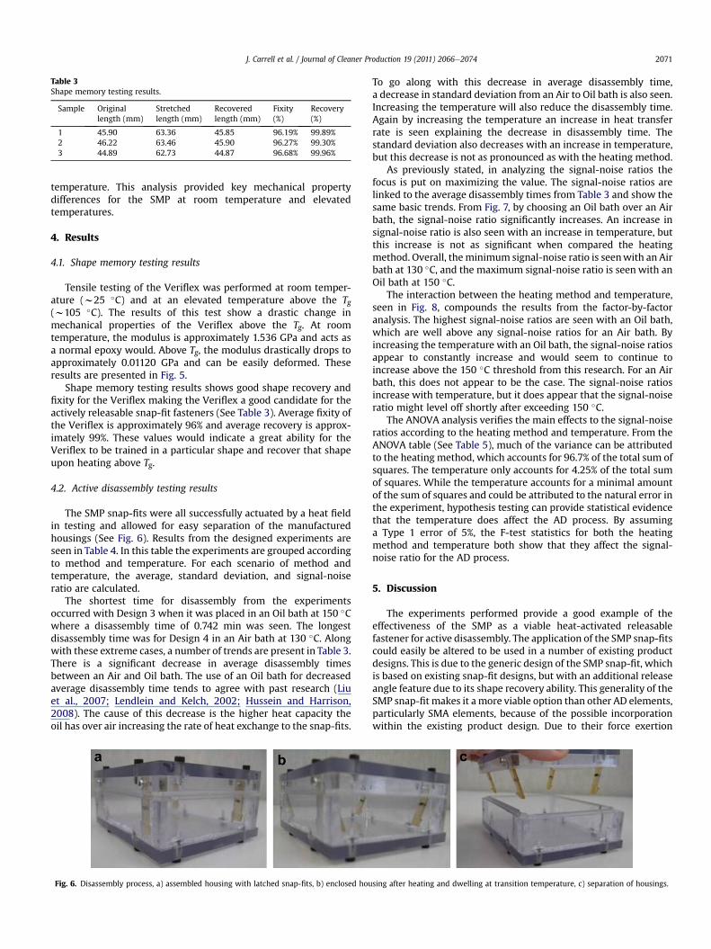
Table 3Shape memory testing results.
Sample Originallength (mm)
Stretchedlength (mm)
Recoveredlength (mm)
Fixity(%)
Recovery(%)
1 45.90 63.36 45.85 96.19% 99.89%2 46.22 63.46 45.90 96.27% 99.30%3 44.89 62.73 44.87 96.68% 99.96%
J. Carrell et al. / Journal of Cleaner Production 19 (2011) 2066e2074 2071
temperature. This analysis provided key mechanical propertydifferences for the SMP at room temperature and elevatedtemperatures.
4. Results
4.1. Shape memory testing results
Tensile testing of the Veriflex was performed at room temper-ature (w25 �C) and at an elevated temperature above the Tg(w105 �C). The results of this test show a drastic change inmechanical properties of the Veriflex above the Tg. At roomtemperature, the modulus is approximately 1.536 GPa and acts asa normal epoxy would. Above Tg, the modulus drastically drops toapproximately 0.01120 GPa and can be easily deformed. Theseresults are presented in Fig. 5.
Shape memory testing results shows good shape recovery andfixity for the Veriflex making the Veriflex a good candidate for theactively releasable snap-fit fasteners (See Table 3). Average fixity ofthe Veriflex is approximately 96% and average recovery is approx-imately 99%. These values would indicate a great ability for theVeriflex to be trained in a particular shape and recover that shapeupon heating above Tg.
4.2. Active disassembly testing results
The SMP snap-fits were all successfully actuated by a heat fieldin testing and allowed for easy separation of the manufacturedhousings (See Fig. 6). Results from the designed experiments areseen in Table 4. In this table the experiments are grouped accordingto method and temperature. For each scenario of method andtemperature, the average, standard deviation, and signal-noiseratio are calculated.
The shortest time for disassembly from the experimentsoccurred with Design 3 when it was placed in an Oil bath at 150 �Cwhere a disassembly time of 0.742 min was seen. The longestdisassembly time was for Design 4 in an Air bath at 130 �C. Alongwith these extreme cases, a number of trends are present in Table 3.There is a significant decrease in average disassembly timesbetween an Air and Oil bath. The use of an Oil bath for decreasedaverage disassembly time tends to agree with past research (Liuet al., 2007; Lendlein and Kelch, 2002; Hussein and Harrison,2008). The cause of this decrease is the higher heat capacity theoil has over air increasing the rate of heat exchange to the snap-fits.
Fig. 6. Disassembly process, a) assembled housing with latched snap-fits, b) enclosed hou
To go along with this decrease in average disassembly time,a decrease in standard deviation from an Air to Oil bath is also seen.Increasing the temperature will also reduce the disassembly time.Again by increasing the temperature an increase in heat transferrate is seen explaining the decrease in disassembly time. Thestandard deviation also decreases with an increase in temperature,but this decrease is not as pronounced as with the heating method.
As previously stated, in analyzing the signal-noise ratios thefocus is put on maximizing the value. The signal-noise ratios arelinked to the average disassembly times from Table 3 and show thesame basic trends. From Fig. 7, by choosing an Oil bath over an Airbath, the signal-noise ratio significantly increases. An increase insignal-noise ratio is also seen with an increase in temperature, butthis increase is not as significant when compared the heatingmethod. Overall, theminimum signal-noise ratio is seenwith an Airbath at 130 �C, and the maximum signal-noise ratio is seen with anOil bath at 150 �C.
The interaction between the heating method and temperature,seen in Fig. 8, compounds the results from the factor-by-factoranalysis. The highest signal-noise ratios are seen with an Oil bath,which are well above any signal-noise ratios for an Air bath. Byincreasing the temperature with an Oil bath, the signal-noise ratiosappear to constantly increase and would seem to continue toincrease above the 150 �C threshold from this research. For an Airbath, this does not appear to be the case. The signal-noise ratiosincrease with temperature, but it does appear that the signal-noiseratio might level off shortly after exceeding 150 �C.
The ANOVA analysis verifies the main effects to the signal-noiseratios according to the heating method and temperature. From theANOVA table (See Table 5), much of the variance can be attributedto the heating method, which accounts for 96.7% of the total sum ofsquares. The temperature only accounts for 4.25% of the total sumof squares. While the temperature accounts for a minimal amountof the sum of squares and could be attributed to the natural error inthe experiment, hypothesis testing can provide statistical evidencethat the temperature does affect the AD process. By assuminga Type 1 error of 5%, the F-test statistics for both the heatingmethod and temperature both show that they affect the signal-noise ratio for the AD process.
5. Discussion
The experiments performed provide a good example of theeffectiveness of the SMP as a viable heat-activated releasablefastener for active disassembly. The application of the SMP snap-fitscould easily be altered to be used in a number of existing productdesigns. This is due to the generic design of the SMP snap-fit, whichis based on existing snap-fit designs, but with an additional releaseangle feature due to its shape recovery ability. This generality of theSMP snap-fit makes it a more viable option than other AD elements,particularly SMA elements, because of the possible incorporationwithin the existing product design. Due to their force exertion
sing after heating and dwelling at transition temperature, c) separation of housings.

Table 4Summary of experiment results.
Method Temp Design Average Std. Dev. S/N
1 2 3 4
Air 130 �C 13.477 11.811 14.523 15.372 13.796 1.533 �22.835Air 140 �C 9.045 7.545 9.639 9.645 8.969 0.990 �19.094Air 150 �C 7.823 7.476 7.601 9.457 8.089 0.923 �18.200Oil 130 �C 1.845 1.159 1.123 1.435 1.391 0.334 �3.047Oil 140 �C 1.015 0.835 0.929 1.122 0.975 0.122 0.167Oil 150 �C 0.777 0.745 0.742 0.796 0.765 0.026 2.323
J. Carrell et al. / Journal of Cleaner Production 19 (2011) 2066e20742072
during shape recovery SMA elements are used to force componentsin AD products, but the problem that arises in such an application isthe focus on placement of the SMA element. If the SMA element isnot place properly heat-activated disassembly can fail and can evendamage the product (Chiodo et al., 2002). Because the SMP snap-fitcan be easily incorporatedwithin the product with the replacementof existing snap-fits, placement is not an issue and does not hinderthe design process. While placement of the SMP snap-fit is not anissue, the design of the SMP snap-fit and catch within the productcould possibly present issueswhere heat-activated disassembly canfail. Failure could be possible with cases of great thermal expansionof the housing catch and SMP snap-fit, which would impede theshape recovery force of the SMP. This was not a problem in exper-imentation due to the design of the snap-fit and catch along withthe selectedmaterials for the experiment, which have relatively lowthermal expansion stress in comparison to the recovery stress of theVeriflex. A detailed analysis of recovery stress for the Veriflex isseen in Tandon et al (Tandon et al., 2009). In this work, the Veriflexexhibits sustained recovery stress of approximately 0.56 MPa andmomentary maximum recovery stress of approximately 0.76 MPa.Given these recovery stress values, there should be sufficientrecovery force to allow for a number of heat-releasable snap-fitdesigns to disassemble easily upon heat activation. If, however,heat-activated release is inhibited by the special design of otherproducts, the flexibility in design of the SMP snap-fit, particularly inthe permanent shape, could alleviate this problem. For example,Fig. 9 illustrates such a primary shape for the snap-fit, which issimilar to theMPL SMP screws seen in Chiodo et al., inpress (Chiodoet al., 1999a,b). This snap-fit overhang would be formed in training.Upon heat recovery the overhang of the snap-fit will pull away fromthe surface of the housing catch and the snap-fit would elongate.This would avoid any surface friction force constraints and simplepart separation could follow. This flexibility in design of thepermanent shape of the SMP snap-fit provides another benefit over
Fig. 7. Main Effects Plot for Signal-Noise ratios.
other SMA elements and again puts a focus on design of the product(i.e. snap-fit and catch) rather than placement.
Thermomechanical properties of the SMP also exhibit a partic-ular benefit over SMAs in the training process. The most strikingbeing the drastic change in modulus for the SMP above Tg. Thismechanical change provides a clear benefit of SMPs over SMAs inshape training because little force is needed to form the SMP into itssecondary shape which is done above. SMAs do not exhibit thedrastic drop in modulus with heating and require a large force toshape into its secondary shape (Meng and Hu, 2009). Furthermore,the shape recovery exhibited by SMPs is much greater than SMAs.As exhibited in this research, approximately 44% strain wasrecovered by the SMP in the testing performed in this research andgreater strains (up to 800%) could be recovered barring limitationsof the tensile machine fitted with the thermal chamber. SMAs havebeen limited by their secondary shape to deformations of approx-imately 8% strain (Liu et al., 2007).
Flexibility with the AD process is also seen with temperaturecontrols and applied heating methods per the experimental results.The results from experimentationmatch the emphasis on increasedheat transfer to reduce recovery time from the accepted models. Aspreviously established, the shape recovery of the snap-fits isdependent on the density of the SMP, heat capacity of the SMP,volume of the SMP part, and heat transfer between the SMP partand heating body, and the residual storage deformation strain. Forthe experiment, the SMP density and heat capacity are constant forthe snap-fits, so the design of the snap-fit and heat transfer coef-ficient become the main controlling factors for the heating processand shape recovery. In the performed experiments, the designs ofthe snap-fits were varied and the resulting varied volumes, surfaceareas, and residual storage deformation strains explain the slightdifferences in recovery rates at tested temperatures. The resultsshow this but due to the small changes in design drastic changes inthe shape recovery rate was not seen. This could not be said for the
Fig. 8. Interaction Plot for Signal-Noise ratio.
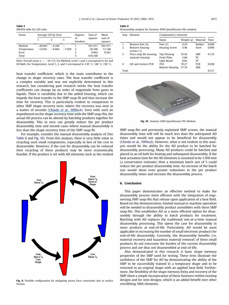
Table 5ANOVA table for S/N ratio.
Factor Average S/N by level Degreesoffreedom
Sum ofsquares
Meansum ofsquares
1 2 3
Method �20.043 �0.186 e 1 591.471 591.471Temperature �12.941 �9.464 �7.939 2 26.296 13.148Error 2 0.402 0.201Total 5 618.168
Note: Overall mean h ¼ �10:115. For Method, Level 1 and 2 correspond to Air andOil Bath. For Temperature, Level 1, 2, and 3 correspond to 130 �C, 140 �C, 150 �C.
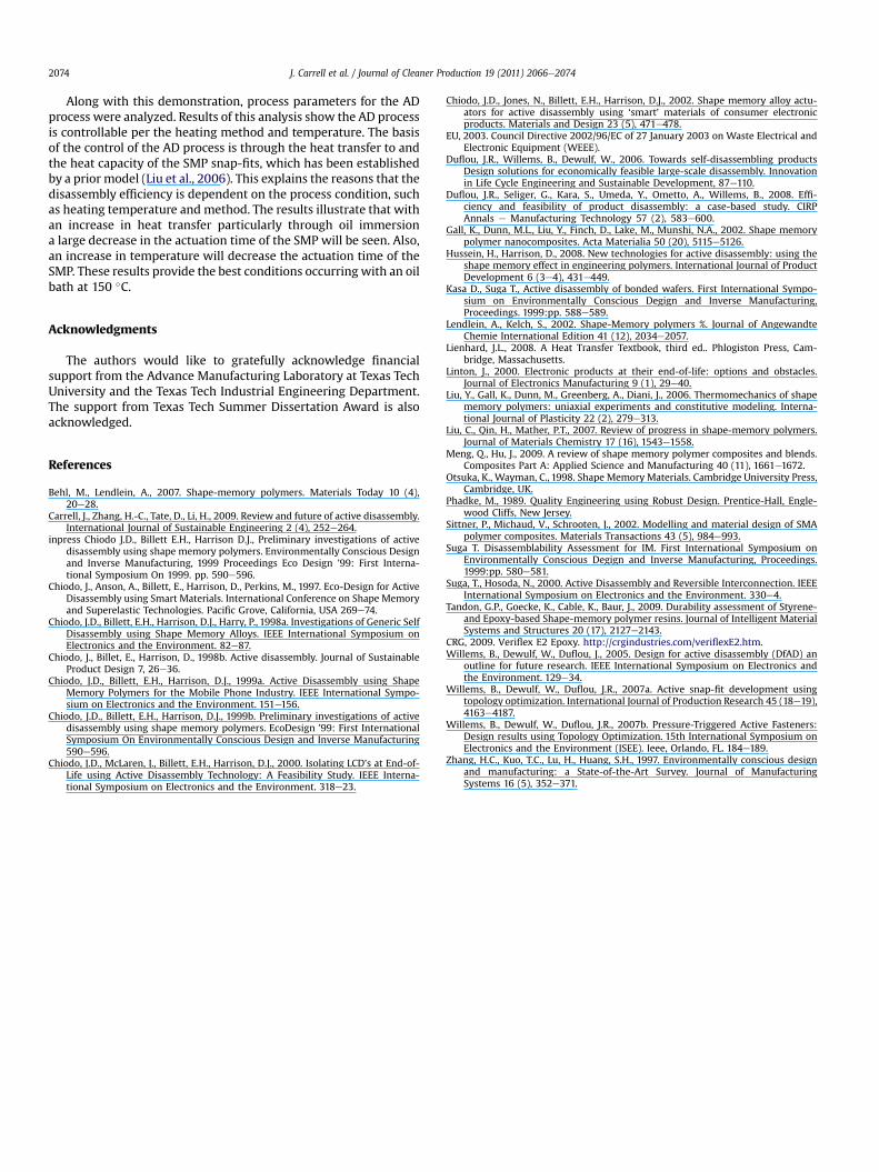
Table 6Disassembly analysis for Siemens 4100 SpeedStream DSL modem.
Step Element Component(s) removed
Name Weight (g) Material Time
1 Remove feet (4) Feet (2) 0.29 Rubber 0.0492 Remove housing
screws (1)Housing Screw 0.46 Steel 0.094
3 Press snap fits housing.separate housing
Top Housing 35.42 ABS 0.135Front Plate 2.84 PCLight Board 0.85 PC
4 Lift and remove PCB PCB 70.27 PCB 0.038Bottom Housing 37.76 ABS
Total 0.317
Fig. 10. Siemens 4100 SpeedStream DSL Modem.
J. Carrell et al. / Journal of Cleaner Production 19 (2011) 2066e2074 2073
heat transfer coefficient, which is the main contributor to thechange in shape recovery rates. The heat transfer coefficient isa complex variable and was not explicitly determined in thisresearch, but considering past research works the heat transfercoefficients can change by an order of magnitude from gases toliquids. There is variability due to the added housing, which canimpede the heat transfer to the SMP snap-fit and thus increase thetime for recovery. This is particularly evident in comparison toother SMP shape recovery tests, where the recovery was seen ina matter of seconds (Chiodo et al., 1999a,b). Even with such animpediment on the shape recovery timewith the SMP snap-fits, theactual AD process can be altered by batching products together fordisassembly. This in turn can greatly reduce the per productdisassembly time and exceed cases where manual disassembly isless than the shape recovery time of the SMP snap-fit.
For example, consider the manual disassembly analysis of (SeeTable 6 and Fig. 10). From this analysis, there is very little value inrecycling such small components, especially in lieu of the cost todisassemble. However, if the cost for disassembly can be reducedthen recycling of these products may be more economicallyfeasible. If the product is set with AD elements such as the studied
Fig. 9. Possible configuration for mitigating excess force constraints due to surfacefriction.
SMP snap-fits and previously explained SMP screws, the manualdisassembly time will still be much less than the anticipated ADtimes and would not appear to be beneficial for disassembly(Chiodo et al., 1999a,b). However, what is not evident in this anal-ysis would be the ability for the AD product to be batched fordisassembly processing. Many AD products could be batched andplaced in an oil bath for heating and subsequent disassembly. If theheat actuation time for the AD elements is assumed to be 1.500min(a conservative estimate) then a minimum batch size of 5 couldreduce the per product disassembly time. An increase of the batchsize would show even greater reductions in the per productdisassembly times and increase the disassembly process.
6. Conclusion
This paper demonstrates an effective method to make thedisassembly process more efficient with the integration of engi-neering SMP snap-fits that release upon application of a heat field.Based on this demonstration, limited manual or machine operationwill be needed to disassembly product assemblies with these SMPsnap-fits. This establishes AD as a more efficient option for disas-sembly through the ability to batch products for treatment.Batching with AD replaces the traditional one-at-a-time manualdisassembly processing. This opens the case for disassembly inmore products at end-of-life. Particularly, AD would be mostapplicable in increasing the number of small electronic products forend-of-life disassembly. Currently, the disassembly benefits (i.e.material recovery and hazardous material removal) of these smallproducts do not overcome the burden of the current disassemblyprocess and are thus not disassembled at end-of-life.
Also demonstrated in this research is basic shape memoryproperties of the SMP used for testing. These tests illustrate theusefulness of the SMP for AD by demonstrating the ability of theSMP to be successfully trained in a temporary shape and to bereturned to an original shape with an applied heat field. Further-more, the flexibility of the shape memory fixity and recovery of theSMP show a simple incorporation of these fasteners within existingdesigns and for new designs, which is an added benefit over otherretrofitting SMA elements.
J. Carrell et al. / Journal of Cleaner Production 19 (2011) 2066e20742074
Along with this demonstration, process parameters for the ADprocess were analyzed. Results of this analysis show the AD processis controllable per the heating method and temperature. The basisof the control of the AD process is through the heat transfer to andthe heat capacity of the SMP snap-fits, which has been establishedby a prior model (Liu et al., 2006). This explains the reasons that thedisassembly efficiency is dependent on the process condition, suchas heating temperature and method. The results illustrate that withan increase in heat transfer particularly through oil immersiona large decrease in the actuation time of the SMP will be seen. Also,an increase in temperature will decrease the actuation time of theSMP. These results provide the best conditions occurring with an oilbath at 150 �C.
Acknowledgments
The authors would like to gratefully acknowledge financialsupport from the Advance Manufacturing Laboratory at Texas TechUniversity and the Texas Tech Industrial Engineering Department.The support from Texas Tech Summer Dissertation Award is alsoacknowledged.
References
Behl, M., Lendlein, A., 2007. Shape-memory polymers. Materials Today 10 (4),20e28.
Carrell, J., Zhang, H.-C., Tate, D., Li, H., 2009. Review and future of active disassembly.International Journal of Sustainable Engineering 2 (4), 252e264.
inpress Chiodo J.D., Billett E.H., Harrison D.J., Preliminary investigations of activedisassembly using shape memory polymers. Environmentally Conscious Designand Inverse Manufacturing, 1999 Proceedings Eco Design ’99: First Interna-tional Symposium On 1999. pp. 590e596.
Chiodo, J., Anson, A., Billett, E., Harrison, D., Perkins, M., 1997. Eco-Design for ActiveDisassembly using Smart Materials. International Conference on Shape Memoryand Superelastic Technologies. Pacific Grove, California, USA 269e74.
Chiodo, J.D., Billett, E.H., Harrison, D.J., Harry, P., 1998a. Investigations of Generic SelfDisassembly using Shape Memory Alloys. IEEE International Symposium onElectronics and the Environment. 82e87.
Chiodo, J., Billet, E., Harrison, D., 1998b. Active disassembly. Journal of SustainableProduct Design 7, 26e36.
Chiodo, J.D., Billett, E.H., Harrison, D.J., 1999a. Active Disassembly using ShapeMemory Polymers for the Mobile Phone Industry. IEEE International Sympo-sium on Electronics and the Environment. 151e156.
Chiodo, J.D., Billett, E.H., Harrison, D.J., 1999b. Preliminary investigations of activedisassembly using shape memory polymers. EcoDesign ’99: First InternationalSymposium On Environmentally Conscious Design and Inverse Manufacturing590e596.
Chiodo, J.D., McLaren, J., Billett, E.H., Harrison, D.J., 2000. Isolating LCD’s at End-of-Life using Active Disassembly Technology: A Feasibility Study. IEEE Interna-tional Symposium on Electronics and the Environment. 318e23.
Chiodo, J.D., Jones, N., Billett, E.H., Harrison, D.J., 2002. Shape memory alloy actu-ators for active disassembly using ‘smart’ materials of consumer electronicproducts. Materials and Design 23 (5), 471e478.
EU, 2003. Council Directive 2002/96/EC of 27 January 2003 on Waste Electrical andElectronic Equipment (WEEE).
Duflou, J.R., Willems, B., Dewulf, W., 2006. Towards self-disassembling productsDesign solutions for economically feasible large-scale disassembly. Innovationin Life Cycle Engineering and Sustainable Development, 87e110.
Duflou, J.R., Seliger, G., Kara, S., Umeda, Y., Ometto, A., Willems, B., 2008. Effi-ciency and feasibility of product disassembly: a case-based study. CIRPAnnals e Manufacturing Technology 57 (2), 583e600.
Gall, K., Dunn, M.L., Liu, Y., Finch, D., Lake, M., Munshi, N.A., 2002. Shape memorypolymer nanocomposites. Acta Materialia 50 (20), 5115e5126.
Hussein, H., Harrison, D., 2008. New technologies for active disassembly: using theshape memory effect in engineering polymers. International Journal of ProductDevelopment 6 (3e4), 431e449.
Kasa D., Suga T., Active disassembly of bonded wafers. First International Sympo-sium on Environmentally Conscious Degign and Inverse Manufacturing,Proceedings. 1999:pp. 588e589.
Lendlein, A., Kelch, S., 2002. Shape-Memory polymers %. Journal of AngewandteChemie International Edition 41 (12), 2034e2057.
Lienhard, J.L., 2008. A Heat Transfer Textbook, third ed.. Phlogiston Press, Cam-bridge, Massachusetts.
Linton, J., 2000. Electronic products at their end-of-life: options and obstacles.Journal of Electronics Manufacturing 9 (1), 29e40.
Liu, Y., Gall, K., Dunn, M., Greenberg, A., Diani, J., 2006. Thermomechanics of shapememory polymers: uniaxial experiments and constitutive modeling. Interna-tional Journal of Plasticity 22 (2), 279e313.
Liu, C., Qin, H., Mather, P.T., 2007. Review of progress in shape-memory polymers.Journal of Materials Chemistry 17 (16), 1543e1558.
Meng, Q., Hu, J., 2009. A review of shape memory polymer composites and blends.Composites Part A: Applied Science and Manufacturing 40 (11), 1661e1672.
Otsuka, K., Wayman, C., 1998. Shape Memory Materials. Cambridge University Press,Cambridge, UK.
Phadke, M., 1989. Quality Engineering using Robust Design. Prentice-Hall, Engle-wood Cliffs, New Jersey.
Sittner, P., Michaud, V., Schrooten, J., 2002. Modelling and material design of SMApolymer composites. Materials Transactions 43 (5), 984e993.
Suga T. Disassemblability Assessment for IM. First International Symposium onEnvironmentally Conscious Degign and Inverse Manufacturing, Proceedings.1999:pp. 580e581.
Suga, T., Hosoda, N., 2000. Active Disassembly and Reversible Interconnection. IEEEInternational Symposium on Electronics and the Environment. 330e4.
Tandon, G.P., Goecke, K., Cable, K., Baur, J., 2009. Durability assessment of Styrene-and Epoxy-based Shape-memory polymer resins. Journal of Intelligent MaterialSystems and Structures 20 (17), 2127e2143.
CRG, 2009. Veriflex E2 Epoxy. http://crgindustries.com/veriflexE2.htm.Willems, B., Dewulf, W., Duflou, J., 2005. Design for active disassembly (DfAD) an
outline for future research. IEEE International Symposium on Electronics andthe Environment. 129e34.
Willems, B., Dewulf, W., Duflou, J.R., 2007a. Active snap-fit development usingtopology optimization. International Journal of Production Research 45 (18e19),4163e4187.
Willems, B., Dewulf, W., Duflou, J.R., 2007b. Pressure-Triggered Active Fasteners:Design results using Topology Optimization. 15th International Symposium onElectronics and the Environment (ISEE). Ieee, Orlando, FL. 184e189.
Zhang, H.C., Kuo, T.C., Lu, H., Huang, S.H., 1997. Environmentally conscious designand manufacturing: a State-of-the-Art Survey. Journal of ManufacturingSystems 16 (5), 352e371.