Automatic PC disassembly for component recovery
8
ORIGINAL ARTICLE F. Torres Æ P. Gil Æ S. T. Puente J. Pomares Æ R. Aracil Automatic PC disassembly for component recovery Abstract In this article, a personal computer disassem- bly cell is presented. With this cell, a certain degree of automatism is afforded for the non-destructive disas- sembly process and for the recycling of these kinds of mass-produced electronic products. Each component of the product can be separated. The disassembly cell is composed of several sub-systems, each of which is ded- icated to the planning and execution of one type of task. A computer vision system is employed for the recogni- tion and localisation of the product and of each of its components. The disassembly system proposed here also has a modelling system for the products and each of its components, the information necessary for the planning of tasks, generating the disassembly sequence and planning of the disassembly movements. These systems co-operate with each other to achieve a semi-automatic disassembly of the product. Keywords Non-destructive disassembly Æ Automatic disassembly Æ Recognition and location of components Æ Component recovery 1 Introduction In the past, technological innovations arose from the need to survive. Nowadays, technological changes also come about from the desire to improve the quality of life. However, natural resources of raw materials for industrial use are limited. During the industrial revolu- tion, no consideration was given to our natural surroundings when designing new products. Today, ecology is increasingly being considered at the design stage of new products because of the great amount of industrial residues that are generated [1]. Many gov- ernments impose laws concerning the recycling of products, to take better advantage of components and/ or raw materials for recycling. In 1998, the European Commission introduced a draft law (Waste Electrical and Electronic Equipment) concerning the management of electrical and electronic residues and which was most recently amended in April 2002. The key to efficient recycling is in the disassembly of the product, allowing the removal of material, compo- nents and/or toxic substances. The phases of the service life of a product [2] can be divided into: 1. The design of the product: Where the product is made according to what the desired model is and the information available about the different components that it will be composed of, considering its environ- mental impact and its ease of recycling and re- usability. 2. The manufacture of the product: Where the product is made according to its original design. 3. The use of the product: This phase may vary according to the individual user. 4. The recovery of the product: The last phase, where the different parts are recycled for their re-use in the building of other new products. The recycling is aimed at recovering the materials made available by disassembling and separating them through chemical processes. Disassembly is the key process in the recovery of the re-usable parts of a product, as well as in the separation of its materials. This is an important process, not only in the recycling of products, but also in their systematic maintenance where a damaged or defective component is replaced by another. Two different types of disassembly may be consid- ered, either destructive or non-destructive, depending on F. Torres (&) Æ P. Gil Æ S. T. Puente Æ J. Pomares Dept. of Physics, Systems Engineering and Signal Theory, University of Alicante, Crta. San Vicente s/n., PO Box 99, Alicante, Spain E-mail: [email protected] Tel.: +34-965-903682 Fax: +34-965-909750 R. Aracil DISAM, Polytechnic University of Madrid, Madrid, Spain
-
Upload
independent -
Category
Documents
-
view
0 -
download
0
Transcript of Automatic PC disassembly for component recovery
ORIGINAL ARTICLE
F. Torres Æ P. Gil Æ S. T. PuenteJ. Pomares Æ R. Aracil
Automatic PC disassembly for component recovery
Abstract In this article, a personal computer disassem-bly cell is presented. With this cell, a certain degree ofautomatism is afforded for the non-destructive disas-sembly process and for the recycling of these kinds ofmass-produced electronic products. Each component ofthe product can be separated. The disassembly cell iscomposed of several sub-systems, each of which is ded-icated to the planning and execution of one type of task.A computer vision system is employed for the recogni-tion and localisation of the product and of each of itscomponents. The disassembly system proposed here alsohas a modelling system for the products and each of itscomponents, the information necessary for the planningof tasks, generating the disassembly sequence andplanning of the disassembly movements. These systemsco-operate with each other to achieve a semi-automaticdisassembly of the product.
Keywords Non-destructive disassembly Æ Automaticdisassembly Æ Recognition and location of components ÆComponent recovery
1 Introduction
In the past, technological innovations arose from theneed to survive. Nowadays, technological changes alsocome about from the desire to improve the quality oflife. However, natural resources of raw materials forindustrial use are limited. During the industrial revolu-tion, no consideration was given to our natural
surroundings when designing new products. Today,ecology is increasingly being considered at the designstage of new products because of the great amount ofindustrial residues that are generated [1]. Many gov-ernments impose laws concerning the recycling ofproducts, to take better advantage of components and/or raw materials for recycling. In 1998, the EuropeanCommission introduced a draft law (Waste Electricaland Electronic Equipment) concerning the managementof electrical and electronic residues and which was mostrecently amended in April 2002.
The key to efficient recycling is in the disassembly ofthe product, allowing the removal of material, compo-nents and/or toxic substances.
The phases of the service life of a product [2] can bedivided into:
1. The design of the product: Where the product is madeaccording to what the desired model is and theinformation available about the different componentsthat it will be composed of, considering its environ-mental impact and its ease of recycling and re-usability.
2. The manufacture of the product: Where the productis made according to its original design.
3. The use of the product: This phase may varyaccording to the individual user.
4. The recovery of the product: The last phase, wherethe different parts are recycled for their re-use in thebuilding of other new products.
The recycling is aimed at recovering the materialsmade available by disassembling and separating themthrough chemical processes.
Disassembly is the key process in the recovery of there-usable parts of a product, as well as in the separationof its materials. This is an important process, not only inthe recycling of products, but also in their systematicmaintenance where a damaged or defective componentis replaced by another.
Two different types of disassembly may be consid-ered, either destructive or non-destructive, depending on
F. Torres (&) Æ P. Gil Æ S. T. Puente Æ J. PomaresDept. of Physics, Systems Engineering and Signal Theory,University of Alicante, Crta. San Vicente s/n.,PO Box 99, Alicante, SpainE-mail: [email protected].: +34-965-903682Fax: +34-965-909750
R. AracilDISAM, Polytechnic University of Madrid,Madrid, Spain
the kind of operation that has to be made: automaticdisassembly techniques are used in maintenance work toavoid high-risk manual tasks, and the degree of suchdisassembly depends on the type of components in-volved and/or the type of work to be done. The processdoes not conclude with a disassembly, it continues laterwith an assembly that allows the recovery of the oper-ability of the product (i.e. car assembly plant, changingbrake shoes, oil changes, wheels, battery, etc.). In suchcases the disassembly tasks serve as a guide for a sub-sequent assembly, and this has to be done by means of anon-destructive process.
When a disassembly is done to recycle a product byseparating its components and/or raw materials, the use,or not, of destructive techniques in a given operationalso depends on the sorting relationship between thematerials and components, defined by the manufactur-ing process used for the product.
The disassembly process of a product can be total orpartial. For example, in a maintenance application, onlythe components to be replaced and those that preventtheir dismounting have to be disassembled, whereas in arecycling application, the disassembly of the entireproduct is generally necessary.
2 System architecture
An automatic disassembly process is justified when aflexible manufacturing cell is able to carry out a con-tinuous disassembly operation. This contrasts with whathappens in an assembly process where the manufactureof a given type of product for a certain period of time iswell-known and based on the demand for the product.The disassembly process is different because the sametype of product is seldom introduced into the processone after another, so the disassembly process is influ-enced by a great variety of models, and even differenttypes of products, which therefore creates great uncer-tainty regarding not only their order but their structuralconfiguration [3].
A flexible manufacturing cell is therefore recom-mended for disassembly processes in which a greatcapacity of recognition and adaptability are required,due to the constant appearance of different types ofproducts. In addition, this should be as automatic aspossible and achieved within the shortest possible time.Thus, a certain rhythm can be guaranteed in the process,and its automation will be justified.
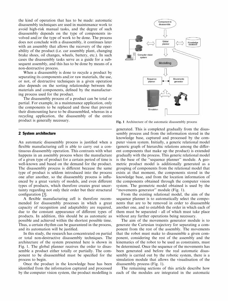
In this study, the research has concentrated on partialor total non-destructive disassembly techniques. Thearchitecture of the system presented here is shown inFig. 1. The global planner receives the order to disas-semble a product either totally or partially. The com-ponent to be disassembled must be specified for theprocess to begin.
Once the product in the knowledge base has beenidentified from the information captured and processedby the computer vision system, the product modelling is
generated. This is completed gradually from the disas-sembly process and from the information stored in theknowledge base, captured and processed by the com-puter vision system. Initially, a generic relational model(generic graph of hierarchic relations among the differ-ent components that make up the product) is extendedgradually with the process. This generic relational modelis the base of the ‘‘sequence planner’’ module. A geo-metric product model is additionally generated as agrouping of components from the relational model thatexists at that moment, the components stored in theknowledge base, and from the location information ofthe components obtained through the computer visionsystem. The geometric model obtained is used by the‘‘movements generator’’ module (Fig. 1).
From the existing relational model, the aim of thesequence planner is to automatically select the compo-nents that are to be removed in order to disassembleanother one, and to establish the order in which each ofthem must be separated - all of which must take placewithout any further operations being necessary.
The aim of the movements generator module is togenerate the Cartesian trajectory for separating a com-ponent from the rest of the assembly. The movementsthat the robot must make to disassemble a given com-ponent, considering the rest of the assembly and thekinematics of the robot to be used as constraints, mustbe determined. Once the sequence of the movements hasbeen generated and before the real automatic disas-sembly is carried out by the robotic system, there is asimulation module that allows the visualisation of thedisassembly process (Fig. 1).
The remaining sections of this article describe howeach of the modules are integrated in the automatic
Fig. 1 Architecture of the automatic disassembly process
disassembly process (Fig. 1). Finally, a real example of aPC non-destructive partial disassembly is presented.
2.1 Computer vision system
The sensory part of the disassembly process is formed bythe computer vision system. The two aims of this exer-cise are the recognition and location of the componentsand fasteners as well as the product itself.
2.1.1 Architecture employed
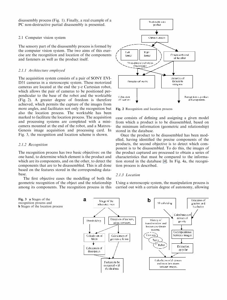
The acquisition system consists of a pair of SONY EVI-D31 cameras in a stereoscopic system. These motorizedcameras are located at the end the y-z Cartesian robot,which allows the pair of cameras to be positioned per-pendicular to the base of the robot and the worktable(Fig. 2). A greater degree of freedom is thereforeachieved, which permits the capture of the images frommore angles, and facilitates not only the recognition butalso the location process. The worktable has beenmarked to facilitate the location process. The acquisitionand processing systems are completed with a mini-camera mounted at the end of the robot, and a Matrox-Genesis image acquisition and processing card. InFig. 3, the recognition and location scheme is shown.
2.1.2 Recognition
The recognition process has two basic objectives: on theone hand, to determine which element is the product andwhich are its components, and on the other, to detect thecomponents that are to be disassembled. This is all donebased on the features stored in the corresponding data-base.
The first objective eases the modelling of both thegeometric recognition of the object and the relationshipamong its components. The recognition process in this
case consists of defining and assigning a given modelfrom which a product is to be disassembled, based onthe minimum information (geometric and relationship)stored in the database.
Once the product to be disassembled has been mod-elled, having identified the precise components of theproducts, the second objective is to detect which com-ponent is to be disassembled. To do this, the images ofthe product captured are processed to obtain a series ofcharacteristics that must be compared to the informa-tion stored in the database [4]. In Fig. 4a, the recogni-tion process is described.
2.1.3 Location
Using a stereoscopic system, the manipulation process iscarried out with a certain degree of autonomy, allowing
Fig. 2 Recognition and location process
Fig. 3 a Stages of therecognition process andb Stages of the location process
the system to work in a semi-automatic way, trying toavoid the need for any human operator as far as possi-ble. At the same time, it contributes to greater flexibilityso that it does not matter whether the manipulationprocess is dynamic.
Two problems arise in developing a location systembased on computer vision. Firstly, the optical architec-ture of the camera (intrinsic parameters) is subject to theinternal parameters (focal, distortions, centre points,etc.). Secondly, it is necessary to know the different co-ordinate systems of the elements that make up the dis-assembly cell, as well as the changes and variations thatsome of them experience with respect to others whensome type of movement has taken place.
The intrinsic parameters that model the optics (lensand motorisation) can be obtained from the technicalinformation provided by the manufacturer as well asfrom calibration techniques that allow the determinationof the exact values of those parameters whenever theoptics are modified.
Two cameras with motorised zoom lenses and asystem of automatic focusing form the location system.The main problem with using video cameras whose lensparameters are not fixed is the necessity to recalibratethe system whenever changes in the optics take place.This occurs when it is necessary to acquire generalimages of the object in the first place and images of thedetails (use of the zoom lens) later on. In order to avoidthe recalibration of the camera whenever there is achange in the position of the motor on which a lens ismounted (for example due to an automatic focus), amethodology based on providing a model of the lensesof the cameras has been used [5, 6].
To construct the model, it is necessary to know themaximum and minimum positions of the movement ofthe motors and to repeat the calibration process for eachposition of the steps of the motor.
The camera is calibrated for each position of the stepsof the motor, and from the internal parameters obtainedfor each one of these positions, the function that inter-polates and approximates the model of the behaviour of
the camera, is computed. From this model, a focal value,a zoom lens, a distortion and a centre point areapproximated and computed according to the positionor motor step used.
From these estimations it is possible to obtain three-dimensional models that relate the positions of the focusand zoom motor, which are introduced into the camerato move the lenses, with the value of an internalparameter that is obtained for each combination of fo-cus and zoom lens. In this way, three main functions areachieved with which each of the different values ob-tained from the internal parameters of the camera (focal,distortion and centre point) are adjusted, by means of aninterpolation process.
Once the internal parameters of the camera have beenmodelled according to the focus and zoom motor posi-tions, the modelled intrinsic parameters of the camera(focus, centre point and distortions of lens) can becomputed depending on the motor positions that havebeen used for the lenses. Given a determined position ofthe lens in each camera of the stereoscopic system, thevalue for each given parameter is computed.
The second problem is to obtain the extrinsicparameters of the cameras in the stereoscopic systemThis is the set of transformations (rotations and trans-fers) of the stereoscopic system that the cameras undergowhen they make movements to adapt to a suitabledirection and position to obtain a point of view allowingthe acquisition of images.
The knowledge of this set of transformations allowsthe position and direction of each of the cameras in thestereoscopic system with respect to the object that is tobe disassembled. Knowing the transformations that aretaking place in the stereoscopic system is not reallysufficient with regard to a component of that object to beestablished. Therefore, whenever movement is made toobtain a suitable point of view, it is also necessary tomodel the elements included in the disassembly cell.
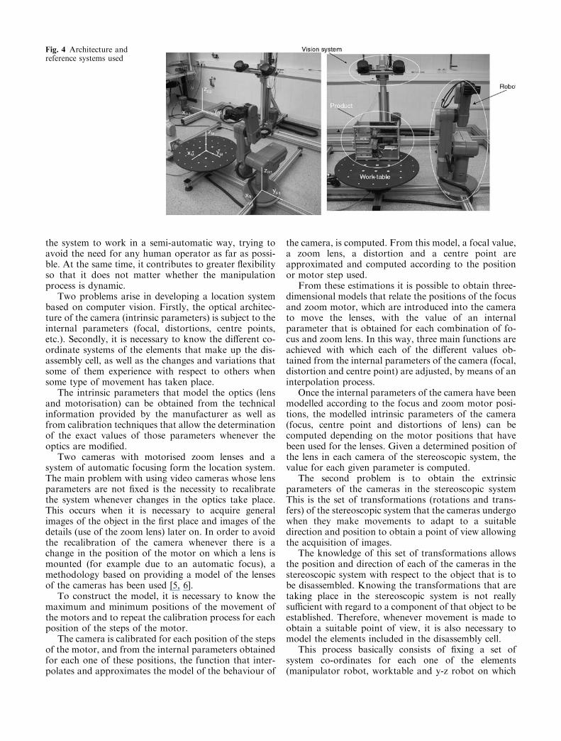
This process basically consists of fixing a set ofsystem co-ordinates for each one of the elements(manipulator robot, worktable and y-z robot on which
Fig. 4 Architecture andreference systems used
the stereoscopic system is located). The system ofco-ordinates of the manipulator robot is taken as anabsolute system of reference. In this way, the positionsand directions are computed with respect to this system(Fig. 4). Once the reference systems, and where they arelocated are known, it is only necessary to know thevariations that are taking place in them when each of theelements that make up the disassembly cell are moved.
The variations of the manipulator robot are itskinematics, i.e. the turns in the worktable are known andthe change of location of the stereoscopic system is theposition that the y-z robot assumes.
Whenever a variation in some of the reference systemstakes place it is stored temporarily, so that it is possible toknow the transformation that has been produced.
From the images that are captured by the cameras inthe stereoscopic system, a reconstruction process ismade, which obtains the spatial co-ordinates of an ob-ject in the space. To compute these, a set of character-istics is extracted. Fundamentally, these are corners andsegments of the edges of the objects that appear in theimages, from which a process of correspondence be-tween the characteristics obtained in both images ismade, and subsequently, the epi-polar geometry thatrelates both views is computed [7, 8].
The space co-ordinates (3D) of the product andcomponents can be calculated once the intrinsicparameters of the cameras and the estimate of the epi-polar geometry between the views obtained from thecaptured images are known, as well as the transforma-tions that take place between table and cameras, whichhave been stored. The generic process used for thelocation is outlined in Fig. 3b.
2.2 Modelling
Before the disassembly process, it is necessary to have amodel that provides sufficient information to the systemfor it to be able to do the disassembly.
The assemblies, as well as the products, are groups ofcomponents and/or sub-assemblies linked in them.There are different schemes representing them accordingto what they need to reflect. There are schemes that tryto show a product from the designer�s point of view,others from the user�s point of view, and others based onthe relationships among the different components or thecharacteristics of such components, etc. Therefore, whenselecting the representation of a product to be disas-sembled, it is necessary to carry out a study of thecharacteristics that need to be reflected in the scheme,the type of disassembly to be done, and to whom suchrepresentation is directed.
The characteristics of the product that are to be re-flected influence the representation through the granu-larity of the model of each of the components of which itis composed. For example, to disassemble a PC, thecomponents to consider in this case are the cards, powersupply, hard drive, etc., in the representation, it is not
necessary to save information about the chips or othercomponents of a card or any other element. With thisrepresentation it will not be possible to disassemble thechips or all those elements that are not represented, butif that disassembly level is not required, the scheme iscorrect and simpler.
In the literature, there are several ways of representinga product [9], using the complete knowledge of theircomponents [10, 11], using the geometric characteristicsof the products and components [12], by means of agraph constructed using geometric, topological andfunctional data of the product [13], using a components-connections graph to represent the product and thesubsequent transformation into a tree [14, 15, 16], bymeans of the relationship among groups of components,using clusters [17] with directed graphs, considering thenodes as components and the edges as the relationshipsamong them [18] (using ‘‘and/or graphs’’ [19, 20, 21, 22]).
In this study two models are used:
1. A relational model and its function to represent therelationships among the components through theexisting contacts among them, which define newcomponents (assemblies), so that a product can beexpressed as the union of a set of assemblies withhierarchic relations through a graph [23]. Thismethod has advantages over others, such as an easierand intuitive representation to allow the increase ofthe degree of granularity, from an existing represen-tation, as well as to obtain the disassembly sequence,applying a set of pre-defined rules, and reducing it, inthis case, to a search to determine what assemblies acomponent belongs to.
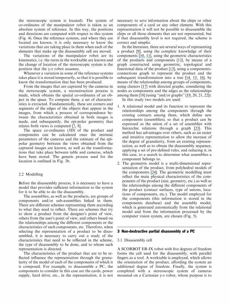
2. The geometric model is a multi-dimensional repre-sentation of the product, from polyhedral models ofthe components [24]. The geometric modelling mustreflect the main physical characteristics of the com-ponents of the product (size, geometry, etc.) as well asthe relationships among the different components ofthe product (contact surfaces, type of unions, loca-tions of components, etc.). The model employed forthe components (this information is stored in thecomponents database) and the assembly model,which is generated automatically from the relationalmodel and from the information processed by thecomputer vision system, are chosen (Fig. 5).
3 Non-destructive partial disassembly of a PC
3.1 Disassembly cell
A SCORBOT ER-IX robot with five degrees of freedomforms the cell used for the disassembly, with parallelfingers as a tool. A worktable is employed, which allowsthe orientation of the product, affording the system anadditional degree of freedom. Finally, the system iscompleted with a stereoscopic system of camerasmounted on a Cartesian y-z robot, whose purpose is to
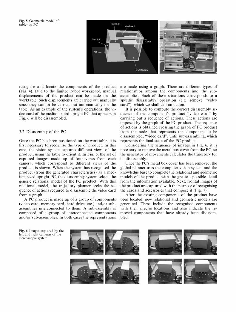
recognise and locate the components of the product(Fig. 4). Due to the limited robot workspace, manualdisplacements of the product can be made on theworktable. Such displacements are carried out manuallysince they cannot be carried out automatically on thetable. As an example of the system�s operations, the vi-deo card of the medium-sized upright PC that appears inFig. 6 will be disassembled.
3.2 Disassembly of the PC
Once the PC has been positioned on the worktable, it isfirst necessary to recognise the type of product. In thiscase, the vision system captures different views of theproduct, using the table to orient it. In Fig. 6, the set ofcaptured images made up of four views from eachcamera, which correspond to different views of theproduct, is shown. When the system has recognised theproduct (from the generated characteristics) as a med-ium-sized upright PC, the disassembly system selects thegeneric relational model of the PC product. With thisrelational model, the trajectory planner seeks the se-quence of actions required to disassemble the video cardfrom a graph.
A PC product is made up of a group of components(video card, memory card, hard drive, etc.) and/or sub-assemblies interconnected to them. A sub-assembly iscomposed of a group of interconnected componentsand/or sub-assemblies. In both cases the representations
are made using a graph. There are different types ofrelationships among the components and the sub-assemblies. Each of these situations corresponds to aspecific disassembly operation (e.g. remove ‘‘videocard’’), which we shall call an action.
It is possible to compute the correct disassembly se-quence of the component�s product ‘‘video card’’ bycarrying out a sequence of actions. These actions areimposed by the graph of the PC product. The sequenceof actions is obtained crossing the graph of PC productfrom the node that represents the component to bedisassembled, ‘‘video card’’, until sub-assembling, whichrepresents the final state of the PC product.
Considering the sequence of images in Fig. 6, it isnecessary to remove the metal box cover from the PC, sothe generator of movements calculates the trajectory forits disassembly.
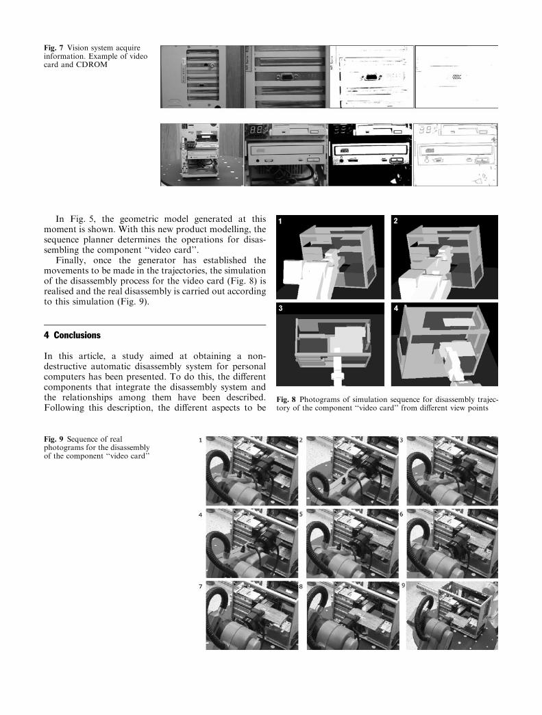
Once the PC�s metal box cover has been removed, theglobal planner uses the computer vision system and theknowledge base to complete the relational and geometricmodels of the product with the greatest possible detailfrom the information available. Next, frontal images ofthe product are captured with the purpose of recognisingthe cards and accessories that compose it (Fig. 7).
After the existing components of the product havebeen located, new relational and geometric models aregenerated. These include the recognised componentswith their precise locations and also indicate the re-moved components that have already been disassem-bled.
Fig. 6 Images captured by theleft and right cameras of thestereoscopic system
Fig. 5 Geometric model oftable-top PC
In Fig. 5, the geometric model generated at thismoment is shown. With this new product modelling, thesequence planner determines the operations for disas-sembling the component ‘‘video card’’.
Finally, once the generator has established themovements to be made in the trajectories, the simulationof the disassembly process for the video card (Fig. 8) isrealised and the real disassembly is carried out accordingto this simulation (Fig. 9).
4 Conclusions
In this article, a study aimed at obtaining a non-destructive automatic disassembly system for personalcomputers has been presented. To do this, the differentcomponents that integrate the disassembly system andthe relationships among them have been described.Following this description, the different aspects to be
Fig. 7 Vision system acquireinformation. Example of videocard and CDROM
Fig. 8 Photograms of simulation sequence for disassembly trajec-tory of the component ‘‘video card’’ from different view points
Fig. 9 Sequence of realphotograms for the disassemblyof the component ‘‘video card’’

considered for the disassembly of each element in thesystem and the details of the processes have been shown.
The main sensory component of the disassemblysystem is composed of a computer vision system madeup of stereo cameras mounted on a y-z robot. Thisoptical system captured the information required tocarry out the two phases described in this article: i.e.recognition and location.
As shown in recent research in the field of automaticdisassembly, it is necessary to have a representation ofthe product that permits the disassembly of the targetcomponents. A representation of the product, based ontwo models, has also been proposed: i.e. relational andgeometric. The first one provides a hierarchic vision ofthe unions between the different components of theproduct, whereas the second one offers multi-dimen-sional information of the product. Both models includedin the disassembly system provide, a priori, the infor-mation required for the entire process.
The results obtained from the disassembly of a pre-viously modelled PC are shown. The tests demonstratethe good operation of the proposed process, thanks tothe flexibility of the computer vision system, which al-lows the disassembly system to function correctly inspite of the deficiencies inherent in the model and/or thecorrespondence between the model and the real productto be disassembled.
We are currently working on providing greaterrobustness to the sensing system by integrating forcecontrol as well as including alternative distance sensors,such as lasers. We are also testing the use of a secondrobot for the supervision of the disassembly process.
Acknowledgements This work was funded by the following SpanishCICYT project ‘‘Sistema Robotizado de Desensamblado Auto-matico basado en Modelos y Vision Artificial’’ (TAP1999–0436).
References
1. Hesselbach J, Kuhn M (1998) Survey of processes at disas-sembly companies. Proceedings, IFAC Workshop of IntelligentAssembly and Disassembly (IAD�98), Bled, Slovenia, pp 99–103
2. Gungor A, Gupta SM (1999) Issues in environmentally con-scious manufacturing and product recovery: a survey. ComputIndust Eng 36:811–853
3. Gil P, Puente ST, Torres F, Pomares J, Candelas FA (2001)Data fusion from multiple cameras for automatic disassembly.Proceedings, IFAC Workshop of Intelligent Assembly andDisassembly (IAD�01), Canela, Brazil
4. Najjari H, Steiner SJ (1996) 3D CAD-based object recognitionfor a flexible assembly cell. In: Intelligent Robots and
Computer Vision XV: Algorithms, Techniques, Active Vision,and Materials Handling 2904:167–177
5. Willson RG (1994) Modeling and calibration automated zoomlenses. Phd. Thesis Department of Electrical and ComputerEngineering, Carnegie Mellon University
6. Ahmed Moumem, Farag AA (2000) A neural optimizationframework for zoom-lens camera calibration. Proceedings ofIEEE, International Conference on Computer Vision(CVPR�2000), Hilton Head Island, SC, 1:403–409
7. Faugeras O (1993) Three dimensional computer vision. Ageometric viewpoint, Cambridge
8. Hartley and Zisserman (2001) Multiple view geometry incomputer vision. Cambridge
9. O�Shea B, Grewal SS, Kaebernick H (1998) State of the artliterature survey on disassembly planning. J Concurr Engin ResAppl 6(4):345–357
10. Subramani AK, Dewhurst P (1991) Automatic generation ofproduct disassembly sequences. Annals of the CIRP 40(1)
11. Yokota K, Brough DR (1992) Assembly/disassembly sequenceplanning. Assembly Autom 2(3):31–38
12. Qian WH, Pagello E (1994) On the scenario and heuristic�s ofdisassemblies. Proceedings, IEEE International Conference onRobotics and Automation, pp 264–271
13. Zussman E, Lenz E, Shpitalni M (1990) An approach to theautomatic assembly planning problem.Annals of theCIRP 39(1)
14. Kuo TC (2000) Disassembly sequence and cost analysis for elec-tromechanical products. Rob Comput IntegrManuf 16:43–54
15. Zhang HC, Kuo TC (1996) A graph-based approach to disas-sembly model for end-of-life product recycling. Proceedings,IEEE/CPMT Electronics Manufacturing Technology Sympo-sium, pp 247–254
16. Zhang HC, Kuo TC (1997) A graph-based disassembly se-quence planning for EOL product recycling. ProceedingsIEEE/CPMT Electronics Manufacturing Technology Sympo-sium, pp 140–151
17. O�Seha B, Kaebernick H, Grewal SS (2000) Using a clustergraph representation of products for application in the disas-sembly planning process. Concurr Eng Res Appl 8(3):158–170
18. Puente ST, Torres F, Gil P (2001) An approach to disassemblysequence generation. Proceedings IFAC Workshop of Intelli-gent Assembly and Disassembly (IAD�01), Canela, Brazil
19. De Mello HLS, Sanderson AC (1995) AND/OR graph repre-sentation of assembly plans. IEEE Transaction On RoboticsAnd Automation 6(2):188–199
20. Lee S, Yi C (1993) Forced-based reasoning in assembly plan-ning. Vision Sensors and Control for Automated Manufac-turing Systems, SPIE 2063:97–108
21. Perlewitz H, Muller K, Seliger G (1998) Usage mode and effectsanalysis to support disassembly process planning. Proceedings,IFAC Workshop of Intelligent Assembly and Disassembly(IAD�98), Bled, Slovenia, pp 11–16
22. Zorc S (1998) Learning in assembly planning. Proceedings,IFAC Workshop of Intelligent Assembly and Disassembly(IAD�98), Bled, Slovenia, pp 17–22
23. Puente ST, Torres F, Pomares J (2001) Product disassemblyscheduling using graph models. Proceedings of SPIE, Interna-tional Symposium on Intelligent Systems and AdvancedManufacturing, Newton, USA, 4569:63–70
24. Pomares J, Torres F, Puente ST (2001) Disassembly movementsfor geometrical objects through heuristic methods. Proceedingsof SPIE, International Symposium on Intelligent Systems andAdvanced Manufacturing, Newton, USA, 4569:71–80