PC CONNECTION Programmable Terminal
69
PC CONNECTION Programmable Terminal Operation Manual Produced March 1999
-
Upload
khangminh22 -
Category
Documents
-
view
0 -
download
0
Transcript of PC CONNECTION Programmable Terminal

���
PC CONNECTIONProgrammable TerminalOperation ManualProduced March 1999

�
OMRON Product ReferencesAll OMRON products are capitalized in this manual. The word “Unit” is also capitalized when it refers to anOMRON product, regardless of whether or not it appears in the proper name of the product.
The abbreviation “Ch,” which appears in some displays and on some OMRON products, often means“word” and is abbreviated “Wd” in documentation in this sense.
The abbreviation “PC” means Programmable Controller and is not used as an abbreviation for anythingelse.
Visual AidsThe following headings appear in the left column of the manual to help you locate different types of infor-mation.
Note Indicates information of particular interest for efficient and convenient operationof the product.
1, 2, 3... 1. Indicates lists of one sort or another, such as procedures, checklists, etc.
� Names of Devices and ToolsPT Refers to an OMRON NT series programmable terminal.
PC Refers to a Mitsubishi A series or FX series programmable controller.
System installer Refers to an OMRON NT series system installer.
PT Type Model Applicable PC Personal Computer
NT31/NT31C Attached to the sup-port tool (*1)
Mitsubishi A seriesMitsubishi FX series
For IBM PC/AT com-patibles
NT631/NT631C Attached to the sup-port tool (*1)
Mitsubishi A seriesMitsubishi FX series
For IBM PC/AT com-patibles
(*1) System program for NT31/NT31C and NT631/NT631C is attached to“NT Series Support Tool for Windows 95/98 (Ver. 3.0)”.
� OMRON, 1999��� ������ ����� � ���� �� ���� ����������� ��� � ��������� ����� �� � ������ ������ �� ����������� �� ���
����� �� �� ��� ����� ���������� ��������� ������������� ��������� �� �������� ������� �� ����� ������ ������
���� �� ���� �
� ����� ��������� �� ������ ���� ����� �� �� �� �� �� ����������� �������� ����� ������ ����� ����
�� ���������� ������� �� ����� ��� ������������ ��������� �� ����������� �������� �� ���� ������ �� ������ �� �����
������� ������ �� ��������� ��� �� ��!� �� �� ���������� �� ���� ������� ������� ���� ������ ��
������������� ��� ����� �� ���������� ���� �� ��� ��������� ������ ��� ������ �������� ���� �� �� �� �� ������
������ �������� �� ���� ������������

���
����� �� �����
��������� � � �������� ������ �� � � � � � � � � � � � � � � � � � � � � � � � � � � � � � � � � � � � � � � � � � � � � � � � � � � � � �
������� ��������� �� � � � � � � � � � � � � � � � � � � � � � � � � � � � � � � � � � � � � � � � � � � � � � � � � � � � �
� ������ ��������� �� � � � � � � � � � � � � � � � � � � � � � � � � � � � � � � � � � � � � � � � � � � � � � � � � � � � � �
����� ������������ �������� ������������ � ��� ������� ���������� � � � � � � � � � � � � � � � � � � � � � � � � � � � � � � � � � � � � � � � � � � � � � � � � � � �
�� ��������� ��� ������ ������� �� � � � � � � � � � � � � � � � � � � � � � � � � � � � � � � � � � � � � � � � � � � � �
��� ������ �� ��� !���� "� � � � � � � � � � � � � � � � � � � � � � � � � � � � � � � � � � � � � � � � � � � � � � � � � � � �
����� ���� ���� ���!����� � ������ ���"!���#��$ �%����� & �� ������ �!� ��� ��� #� � � � � � � � � � � � � � � � � � � � � � � � � � � � � � � � � � � � � � � � � � � � � � � � � � � � �
� �������� $� � � � � � � � � � � � � � � � � � � � � � � � � � � � � � � � � � � � � � � � � � � � � � � � � � � � � � � � � � � �
�� ������ �%� � � � � � � � � � � � � � � � � � � � � � � � � � � � � � � � � � � � � � � � � � � � � � � � � � � � � � � � � � � � � � �
�" �������� ����� %� � � � � � � � � � � � � � � � � � � � � � � � � � � � � � � � � � � � � � � � � � � � � � � � � � � � � � �
�& � �� '����� ��� !��� (������ ��� � � � � � � � � � � � � � � � � � � � � � � � � � � � � � � � � � � � � � � �
����� '��� ���� ���!����� (� '& ��� � ����� �!� ��� ��� �#� � � � � � � � � � � � � � � � � � � � � � � � � � � � � � � � � � � � � � � � � � � � � � � � � �
�� �������� �)� � � � � � � � � � � � � � � � � � � � � � � � � � � � � � � � � � � � � � � � � � � � � � � � � � � � � � � � � � � �
��� ������ "�� � � � � � � � � � � � � � � � � � � � � � � � � � � � � � � � � � � � � � � � � � � � � � � � � � � � � � � � � � � � � � �
��" �������� ����� "%� � � � � � � � � � � � � � � � � � � � � � � � � � � � � � � � � � � � � � � � � � � � � � � � � � � � � � �
����)�� � &'
�)��

���� �����
����
Related Manuals and Their Contents:The related manuals are indicated below.The * symbol at the end of the manual number is the revision history symbol.
[Connections between the programmable terminal (PT) and programmable controllers (PC), etc.]
� PC Connection, Operation Manual V042-E1-�. . . . . . . . . . . . . . . . . . . . . .
This Operation manual describes how to connect the programmable terminal(PT) to programmable controllers (PC) and other equipment, and how to makethe settings required for these connections.
[For information on NT series PT functions, operations, and restrictions]
� NT31/31C Programmable Terminal Operation Manual V043-E1-�. . . . .
� NT631/631C Programmable Terminal Operation Manual V044-E1-�. . .
These manuals contain full descriptions of NT series PT functions, operations,and restrictions.
� NT Series Support Tool for Windows 95/98 (Ver. 3.0) OperationManual V053-E1-�. . . . . . . . . . . . . . . . . . . . . . . . . . . . . . . . . . . . . . . . . . . . . .
The screens displayed in the PT are created and transferred with the supporttool. This manual describes how to create and transfer the screen data. It de-scribes also how to use the system installer for installing the system program tothe PT.

��
How to Use the ManualThis Operation Manual comprises the following Sections.
SECTION 1 Connectable Hardware Combinations
This section describes the combinations of PT and programmable controller thatcan be connected.This section also describes the types of system program and system installer re-quired for connection with a PC produced by the other manufacturers to opera-tion of such a PC, and the types of usable support tools.
SECTION 2 Use with Mitsubishi A Series Computer Link Systems
This section describes how to make the connections and settings when a PT isconnected to a Mitsubishi A series programmable controller in a computer linksystem.This section also describes the combinations of PTs and programmable control-lers that can be connected, the connection method of cables, the settings re-quired for operation, and the specific errors that may occur when using the PT ina computer link system that uses a Mitsubishi A series programmable controller.
SECTION 3 Use with Mitsubishi FX
This section describes how to make the connections and settings when a PT isconnected to a Mitsubishi FX series programmable controller.This section also describes primarily the combinations of PTs and programmablecontrollers that can be connected, the connection method of cables, and the set-tings required for operation.
Appendix
This section describes the differences of the PT functions depending on the con-nected host and the specifications of the connectors of OMRON products usedfor communications.

�
����� ���
!�� ����� ��*��� ������� �������� ��� ���� ��� ������������ !�������
��� ��������� ������� �� ���� ������� �� ������� ��� ��� ��� � ������� ��������� �� ��� ������
��� ������� ������ �� ���� ������� � �� ����� ��� ��������� ������� ������ �������� ��
��� �� �� ������ �������� �������
� �������� ������ �� � � � � � � � � � � � � � � � � � � � � � � � � � � � � � � � � � � � � � � � � � � � � � � � � � � � � � � � � � � � � �
������� ��������� �� � � � � � � � � � � � � � � � � � � � � � � � � � � � � � � � � � � � � � � � � � � � � � � � � � � � � � � � � � � � �
� ������ ��������� �� � � � � � � � � � � � � � � � � � � � � � � � � � � � � � � � � � � � � � � � � � � � � � � � � � � � � � � � � � � � � �

WARNING
WARNING
Caution
��
1 Intended AudienceThis manual is intended for the following personnel, who must also have knowl-edge of electrical systems (an electrical engineer or the equivalent).
� Personnel in charge of installing FA systems.
� Personnel in charge of designing FA systems.
� Personnel in charge of managing FA systems and facilities.
2 General PrecautionsThe user must operate the product according to the performance specificationsdescribed in the operation manuals.Before using the product under conditions which are not described in the manualor applying the product to nuclear control systems, railroad systems, aviationsystems, vehicles, combustion systems, medical equipment, amusement ma-chines, safety equipment, and other systems, machines, and equipment thatmay have a serious influence on lives and property if used improperly, consultyour OMRON representative.Make sure that the ratings and preformance characteristics of the product aresufficient for the systems, machines, and equipment, and be sure to provide thesystems, machines, and equipment with double safety mechanisms.This manual provides information for using the Programmable Terminal. Be sureto read this manual before attempting to use the software and keep this manualclose at hand for reference during operation.
It is extremely important that Programmable Terminals related devices be usedfor the specified purpose and under the specified conditions, especially in ap-plications that can directly or indirectly affect human life. You must consult withyour OMRON representative before applying Programmable Terminals to theabovementioned applications.
Do not use input functions such as PT touch swiches for applications where dan-ger to human life or serious damage is possible, or for emergency switch applica-tions.
3 Safety PrecautionsIn order to use this product safely and correctly, you must read and fully under-stand the “Safety Precautions” in the NT series Operation Manual before using it.
After connecting a communication cable, always secure it with the screws.Otherwise the cable may disconnect, causing operation to fail.

���

�
Terminology
� BCD (binary coded decimal)The value is stored as a decimal number instead of as a hexadecimal number by using only 0 to 9 of thehexadecimal numbers (0 to F). By using the decimal representation, the conversion of decimal numbersbecomes easy.For example, when decimal “1234” is to be stored to the channel, it is usually required to be converted tothe hexadecimal “04D2”, because the channel is hexadecimal. When using BCD, decimal “1234” is storedas “1234” to the channel.
� Counter (C)
Area used by a Mitsubishi PC.Word device to be used for storing the present value of the counter used for program.
� Output relay (Y)
Area used by a Mitsubishi PC.Bit device connected to an actual output contact. As the case may be, output bits of the specific functionmodule is allocated.
� State (S)
Area used by a Mitsubishi PC.Bit device primarily used for status of processing when using step ladder command or as an annunciator.
� Contact
Term for the PLC made by OMRON indicating the minimum unit of I/O. It is set to ON or OFF.
� Timer (T)
Area used by a Mitsubishi PC.Word device to be used for storing the present value of the timer used for program.
� Direct access
Connection method in which word bits on a PC and a memory table, lamp, or touch switch correspondone-to-one, and memory contents are automatically updated to reflect any change in one side directly toanother.For example, if bits on a PC corresponding to a PT lamp are turned on, the PT lamp will light up. If a value iswritten to words on the PC corresponding to a PT value memory table, the same value data is written tothe corresponding value memory table.It is possible to control a PT from a PC without transmitting the command from the PC to the PT allowingrapid communication between the PC and PT by decreasing tasks at the PC side.
� Channel (CH)
Term for the PLC made by OMRON. I/O unit for 16 “contacts”. It may expressed as “CH”.
� Communication speed (bps)Data amount possible to be sent and received during period of time. “Bps” is a abbreviation for “bits persecond” and refers to the number of bits sent or received in 1 sec.
� Data register (D)Area used by a Mitsubishi PC.Word device to be used for storing values or words.In D8000 and higher, it has a specific function for the operation of a PC.
� Input relay (X)Area used by a Mitsubishi PC.Bit device connected to an actual input contact. As the case may be, input bits of the specific functionmodule are allocated.
� Bit
Term for information processing, such as computer, and refers to the minimum unit of data. It can be set totwo values, “0” or “1”. In PCs made by Mitsubishi, “contact” is expressed by “bit”. “0” and “1” correspond to“OFF” and “ON”, respectively.

��
� Bit device
Area in Mitsubishi PC for reading and writing primarily by bits.There are four types of bit devices usable in the PT.
� M (auxiliary relay)
� S (state)
� X (input relay)
� Y (output relay)
� Auxiliary relay (M)
Area used by a Mitsubishi PC.Bit device which cannot be connected to an I/O contact, but can be used as I/O in programs.In M8000 and higher, there are specific functions for the operation of a PC.
� Memory switchPerforms setting related to the PT operation. This is not an actual switch like a DIP switch, but a switchelectrically memorized inside the PT.It can be set via a “memory switch” of the “maintenance mode” in the PT.
� Memory tableMemory inside the PT the user can use for displaying data in the PT. There are two memory tables: thevalue memory table for storing values and the word memory table for storing words.
� WordTerm for information processing, such as computer, and refers to a unit corresponding to “channel”. 16bits corresponds to 1 word.In a Mitsubishi PC, “channel” is expressed as “word”.
� Word deviceArea in a Mitsubishi PC primarily read by words.There are three types of word devices usable in the PT:
� D (data register)
� T (timer)
� C (counter)

�
����� �
����������� �������� ������������
!�� ����� ������� ��� ��������� ����+��� ��������� ��� ��� �� � �� �! ��� ��� ������� ������� �� ���� ���
����� ��� �� �� +�� ��,��� ���������� �� � ������ �������
��� ������� ���������� � � � � � � � � � � � � � � � � � � � � � � � � � � � � � � � � � � � � � � � � � � � � � � � � � � �
�� ��������� ��� ������ ������� �� � � � � � � � � � � � � � � � � � � � � � � � � � � � � � � � � � � � � � � � � � � � �
��� ������ �� ��� !���� "� � � � � � � � � � � � � � � � � � � � � � � � � � � � � � � � � � � � � � � � � � � � � � � � � � � �

�
�������� ��������� Section1--1
1-1 Possible CombinationsThe table below shows the combinations that can be connected.
PT Type Model Connector Connection to MitsubishiA (Computer Link)
Connection toMitsubishi FX
RS-232C RS-422A
Mitsubishi FX
NT31/NT31C NT31-ST121�-EV1 RS-232C � " �NT31/NT31C(*1)
NT31-ST121�-EV1NT31C-ST141�-EV1 RS-422A " � �
NT631/NT631CNT631-ST211�-EV1
�RS-232C � " �NT631/NT631C
(*1) NT631C-ST141�-EV1NT631C-ST151�-EV1 RS-422A " � �
�: Direct connection- : Via RS-232C/RS-422A convertor unit
(*1) In order to use NT31/NT31C, NT631S/NT631C in multi-vendor systems, adedicated system program must be installed in the PT using the “NT seriessystem installer”.

�
������� ��� ����� ������ Section1--2
1-2 Installing the System ProgramIn order to use an NT31/NT31C or NT631/NT631C in a multi-vendor system, adedicated system program must be installed in the PT using the “NT series systeminstaller” shown in the table below.
PT Type Model Applicable PC Personal Computer
NT31/NT31C Attached to the sup-port tool (*1)
Mitsubishi A seriesMitsubishi FX series
For IBM PC/AT com-patibles
NT631/NT631C Attached to the sup-port tool (*1)
Mitsubishi A seriesMitsubishi FX series
For IBM PC/AT com-patibles
(*1) System program for NT31/NT31C and NT631/NT631C is attached to“NT Series Support Tool for Windows 95/98 (Ver. 3.0)” (NT-ZJ3MX1/NT-ZJ3MX1-EV3).
For details on how to operate the system installer, refer to its instruction manual, orthe PT Operation manual.

�
������ ������� ����� Section1--3
1-3 Usable Support ToolsWhen using the PT in a multi-vendor system, one of the following support toolsmust be used.
Model Hardware Requirement
NT-ZJ3MX1-EV3NT-ZJCMX1-EV3
For IBM PC/AT compatibles
The programmable controllers (PC) that can be connected to the PT are deter-mined by the “PLC Vendor” data set in the screen data memory board. According-ly, screen data complying with the programmable controller to be connected mustbe transferred to the PT in advance.The “PLC Vendor” is set with the support tool. The applicable programmable con-trollers (PCs) depending on the “PLC Vendor” setting are as follows.
PLC Vendor Applicable Programmable Controller (PLC)
OMRON For connection to an OMRON CS1 series, C series, orCVM1/CV series PLC
Mitsubishi A For connection to a Mitsubishi Electric MELSEC A seriesPC
Mitsubishi FX For connection to a Mitsubishi Electric MELSEC FX seriesPC
Memory link (MEMLINK) For a memory link connection with NT31/NT31C orNT631/NT631C

�
����� �
�� ��� !���"��� � � ����� ���#"��� ���$ %�����
!�� ����� ������� ��+ �� ��.� ��� �������� ��� ������� +��� � �! � ������� �� � /������ � ����� �������
����� ��������� � � �� ���� ��. �������
�� ������ �!� ��� ��� #� � � � � � � � � � � � � � � � � � � � � � � � � � � � � � � � � � � � � � � � � � � � � � � � � � � � �
� �������� $� � � � � � � � � � � � � � � � � � � � � � � � � � � � � � � � � � � � � � � � � � � � � � � � � � � � � � � � � � � �
�� ������ �%� � � � � � � � � � � � � � � � � � � � � � � � � � � � � � � � � � � � � � � � � � � � � � � � � � � � � � � � � � � � � � �
�" �������� ����� %� � � � � � � � � � � � � � � � � � � � � � � � � � � � � � � � � � � � � � � � � � � � � � � � � � � � � � �
�& � �� '����� ��� !��� (������ ��� � � � � � � � � � � � � � � � � � � � � � � � � � � � � � � � � � � � � � � �

������ ��� �� ��� Section 2--1
2-1 Usable PTs and PCsThe PT, PC, and computer link module models that can be used in a computer linksystem that uses Mitsubishi A series PCs are indicated here.
Usable PT ModelsThe PT models that can be used with a computer link system that uses MitsubishiA series PCs are tabled below.When using NT31/NT31C, NT631/NT631C, install the system program for Mitsu-bishi A computer links in advance with the “NT series system installer”.
PT Type Model
NT31 NT31-ST121�-EV1
NT31C NT31C-ST141�-EV1
NT631 NT631-ST211�-EV1
NT631C NT631C-ST141�-EV1NT631C-ST151�-EV1
Reference: For details on the direct connection function, refer to the Operation manual for thePT model used.

������ ��� �� ��� Section 2--1
Modules Mounted at the Connected PCConnections to a Mitsubishi A series PC are made at a computer link module. Thetable below lists the computer link modules to which the connection can be madewith each type of connector.
Computer Link Module UsedSeries CPU Module
RS-232C RS-422
A0J2H A0J2HCPU A0J2-C214S1
A1SHA1SJHA2SHA2USA2US-S1A2USH-S1
A1SHCPUA1SJHCPUA2SHCPUA2USCPUA2USCPU-S1A2USHCPU-S1
A1SJ71UC24-R2 A1SJ71UC24-R4
A1NA2NA2N-S1A3NA2AA2A-S1A3AA2UA2U-S1A3U
A1NCPUA2NCPUA2NCPU-S1A3NCPUA2ACPUA2ACPU-S1A3ACPUA2UCPUA2UCPU-S1A3UCPU
AJ71UC24

�
������� Section 2--2
2-2 ConnectionThis section describes the methods for connection between the PT and the com-puter link module.Make cables that are suitable for the conditions of use, following the wiring detailsgiven in this section.The communication connector (terminal block) of each device is as follows:
- NT31/NT31CSerial port A (RS-232C dedicated connector)Serial port B (switching RS-232C/RS-422A/485 connectors)
- NT631/NT631CSerial port A (RS-232C dedicated connector)Serial port B (switching RS-232C connector and RS-422A/485 terminalblocks)
- Computer link moduleRS-232C connector or RS-422A terminal block

�
������� Section 2--2
Parts Required for ConnectionThe connectors, connector covers, crimp terminals, and recommended cables foruse with OMRON products are described here.For details on the connectors, connector covers, and crimp terminals used at thecomputer link module side, refer to the manual for the computer link module.
� Parts for RS-232C (Common to PT and NT-AL001)
Part Model Remarks
Connector XM2A-0901 9-pin type, made by OMRON
XM2A-2501 25-pin type, made by OMRON
DE-9P 9-pin type, made by JAE
Connector cover XM2S-0911 9-pin type, made by OMRON
XM2S-2511 25-pin type, made by OMRON
DE-CI-J6 9-pin type, made by JAE
Cable AWG28�5PIFVV-SB
Multi-core shielded cable, madeby Fujikura, Ltd
CO-MA-VV-SB5P�28AWG
Multi-core shielded cable, madeby Hitachi Cable, Ltd
� Recommended Parts for RS-422A Terminal Block (For NT631/NT631C)
<Appropriate crimp terminals>
Fork type Round type
6.2 mm or less 6.2 mm or less
Part Model Remarks
Crimp terminal(M3.5)
2-YS3A Fork type, made by Japan Sold-erless Terminal MFG(M3.5)
2-YAS3.5 Fork type, made by Fuji Terminal
2Y-3.5 Fork type, made by Nichifu Ter-minal
2-3.5 Round type, made by JapanSolderless Terminal MFG
V2-S3.5 Round type, made by Fuji Termi-nal
2-3.5 Round type, made by NichifuTerminal
Cable H-9293A(CO-HC-ESV-3P�7/0.2)
Made by Hirakawa Hewtechcorp.
�
������� Section 2--2
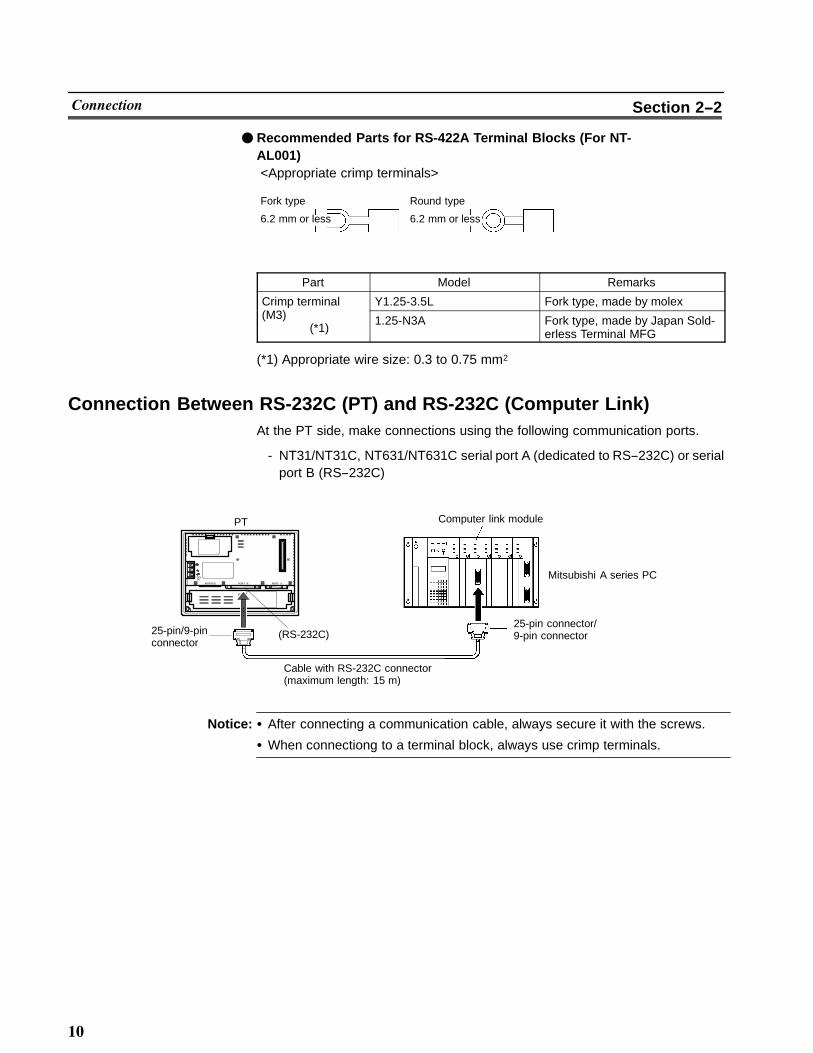
� Recommended Parts for RS-422A Terminal Blocks (For NT-AL001)<Appropriate crimp terminals>
Fork type Round type
6.2 mm or less 6.2 mm or less
Part Model Remarks
Crimp terminal Y1.25-3.5L Fork type, made by molex(M3)
(*1)1.25-N3A Fork type, made by Japan Sold-
erless Terminal MFG
(*1) Appropriate wire size: 0.3 to 0.75 mm2
Connection Between RS-232C (PT) and RS-232C (Computer Link)At the PT side, make connections using the following communication ports.
- NT31/NT31C, NT631/NT631C serial port A (dedicated to RS--232C) or serialport B (RS--232C)
PT
25-pin connector/9-pin connector
Mitsubishi A series PC
Computer link module
Cable with RS-232C connector(maximum length: 15 m)
(RS-232C)25-pin/9-pinconnector
�����
����� ��� ��� �
Notice: � After connecting a communication cable, always secure it with the screws.
� When connectiong to a terminal block, always use crimp terminals.

��
������� Section 2--2
� Wiring When Computer Link Module has a 25-pin Connector
There is a shielding wire at the computer link module side only: connect it to theconnector cover and to the No.1 pin (FG).
123456789
FG
RDRSCS+5V
SG
Shielding wire
PT
1234567820
FGSDRDRSCSDRSGCDER
(25-pin)
SD
(9-pin)
Mitsubishi computer link module
RS-232Cinterface
Pin No.Abbrev. Pin No. Abbrev.
RS-232Cinterface
Connectorcover
�When using NT31/31C serial port B�
12345678
Pin No.Abbrev.
FG
RDRSCS
SG
RS-232C/422A485interface
Shielding wire
NT31/NT31C side
RS-232Cinterface
234567820
(25-pin)
Pin No. Abbrev.
SD
(25-pin)
Connectorcover
25
FGSDRDRSCSDRSGCDER
1
Mitsubishi computer link module
� Wiring When Computer Link Module has a 9-pin Connector
Shielding wire
PT
RS-232Cinterface
123456789
CDRDSDERSGDRRSCS
(9-pin)
Pin No. Abbrev.
123456789
Pin No.Abbrev.
FG
RDRSCS+5V
SG
RS-232Cinterface
SD
(9-pin)
Connectorcover
Connectorcover
Mitsubishi computer link module

��
������� Section 2--2
�When using NT31/31C serial port B�
12345678
Pin No.Abbrev.
FG
RDRSCS
SG
RS-232C/422A485interface
Shielding wire
NT31/NT31C side Mitsubishi computer link module
SD
(25-pin)
Connectorcover
25
Pin No. Abbrev.
RS-232Cinterface
(9-pin)
123456789
CDRDSDERSGDRRSCS
Connectorcover
Connection Between RS-232C (PT) and RS-422A (Computer Link Module)On the PT side, make connections using the following communication ports.
- NT31/NT31C, NT631/NT631C serial port A (RS--232C) or serial port B(RS--232C)
25-pin/9-pinconnector
RS-422A cable(maximum length: 500 m)
Mitsubishi A series PC
9-pin connector
RS-232C/RS-422Aconvertorunit (NT-AL001)
Cable with RS-232C connector(maximum length: 15 m)
(RS-232C)
Computer link modulePT
RS-422A terminal block
�����
����� ��� ��� �
Notice: � After connecting a communication cable, always secure it with the screws.
� When connectiong to a terminal block, always use crimp terminals.

��
������� Section 2--2
� Wiring Between PT and NT-AL001
123456789
Pin No.Abbrev.
FG
RDRSCS+5V
SG
RS-232Cinterface
Shielding wire
PT
RS-232Cinterface
23456789
SDRDRSCS+5VDRERSG
(9-pin)
Pin No. Abbrev.
SD
(9-pin)
Connectorcover
Connectorcover
NT--AL001 RS--232C connector
12345678
Pin No.Abbrev.
FG
RDRSCS
SG
RS-232C/422A485interface
Shieldingwire
NT31/NT31C side NT--AL001 RS--232C connector
RS-232Cinterface
23456789
SDRDRSCS+5VDRERSG
(9-pin)
Pin No. Abbrev.
SD
(25-pin)
Connectorcover
25
Connectorcover
0V+5V
Reference: +5 is not output from serial port B of NT31/NT31C and NT631/NT631C.The power for NT-AL001 should be supplied externally.

��
������� Section 2--2
� Wiring Between NT-AL001 and Computer Link Module
Make the connections between SDB and SDA, and RDB and RDA, with twistedpair wires
87654321
Pin No.Abbrev.
CSA (--)CSB (+)RDA (--)RDB (+)SDA (--)SDB (+)
SGGND
RS-422Ainterface
Shielding wire
NT-AL001 RS-422A terminal block Computer link module
RS-422Ainterface
SDA (--)SDB (+)RDA (--)RDB (+)
SGFG
Abbrev.
Connection Between RS-422A (PT) and RS-422A (Computer Link Module)At the PT side, make a connection using the following communication ports.
- NT631/NT631CRS--422A terminal block
- NT31/NT31CSerial port B (RS--422A)
RS-422A terminalblockRS-422A terminal block
or connector
Mitsubishi A series PC
Computer link module
RS-422A cable (maximum length: 500 m)
PT
�����
����� ��� ��� �
Notice: � After connecting a communication cable, always secure it with the screws.
� When connectiong to a terminal block, always use crimp terminals.

��
������� Section 2--2
� Wiring
Make the connections between SDB and SDA, and RDB and RDA, with twistedpair wires.
Abbrev.
SDASDBRDARDB
RS-422Ainterface
Shielding wire
PT RS-422A Computer link module
RS-422Ainterface
SDASDBRDARDBSGFG
Abbrev.
Connection Between RS-422A (PT) and RS-232C (Computer Link)At the PT side, make connections using the following communication ports.
- NT631/NT631CRS--422A terminal block
- NT31/NT31CSerial port B (RS--422A)
RS-422A terminalblock or Connector
Computer link module
Mitsubishi A series PC
25-pin connector/9-pin connector
Cable with RS-232C connector(maximum length: 15 m)
9-pin cable
RS-422A cable(maximum length: 500 m)
RS-232C/RS-422Aconvertor unit(NT-AL001)
PT
�����
����� ��� ��� �
Notice: � After connecting a communication cable, always secure it with the screws.
� When connectiong to a terminal block, always use crimp terminals.

�
������� Section 2--2
� Wiring Between PT and NT-AL001
Make the connections between SDB and SDA, and RDB and RDA, with twistedpair wires.
Abbrev.
SDASDBRDARDB
RS-422Ainterface
Shielding wire
PT RS-422A
87654321
Pin No. Abbrev.
CSACSBRDARDBSDASDBSG
GND
RS-422Ainterface
NT-AL001 RS-422A terminal block
� Wiring to NT-AL001 when Computer Link Module has 25-pin Connector
Connect the power supply to the NT-AL001 (5 VDC) at pin No.6 (+5V) and pin No.9(SG) of the RS-232C connector.
23456789
Pin No.Abbrev.
SDRDRSCS+5VDRERSG
RS-232Cinterface
Shielding wire
NT-AL001 RS-232C connector Mitsubishi computer link module
RS-232Cinterface
1234567820
FGSDRDRSCSDRSGCDER
(25-pin)(9-pin)
Pin No. Abbrev.
0V+5V
Connector cover
� Wiring to NT-AL001 when Computer Link Module has 9-pin Connector
Connect the power supply to the NT-AL001 (5 VDC) at pin No.6 (+5V) and pin No.9(SG) of the RS-232C connector.
23456789
Pin No.Abbrev.
SDRDRSCS+5VDRERSG
RS-232Cinterface
Shielding wire
NT-AL001 RS-232C connectorMitsubishi computer link module
RS-232Cinterface
123456789
CDRDSDERSGDRRSCS
(9-pin)(9-pin)
Pin No. Abbrev.
0V+5V
Connectorcover
Connectorcover

�
������� Section 2--2
Setting of Terminator When Using NT31/NT31C or NT631/NT631CWhen using NT31/NT31C or NT/631/NT631C, terminator present/absent whenusing RS--422A is set by a “terminal for terminator (TRM)”. When connecting a PTto a Mitsubishi A series PC with an RS-422A communication, set the terminator atthe PT side as follows.
� When Using NT31/NT31C
When using NT31/NT31C, there is a “terminator setting terminal” on serial port Bconnector. Short the No.9 and 10 terminals of serial port B inside the connector,and set the terminator to “ON (present)”.
9101112
Pin No.Abbrev.
TRMRDB (+)SDB (+)
Connectorcover
25
Terminator
Between No.9and 10 terminals
Function
ShortcircuitTerminator ONShorts only when connecting to the end terminal ofRS-422A/485 cable.
Open circuitTerminator OFFOpens only when connecting to a terminal other thanthe end terminal of the RS-422A/485 cable.

��
������� Section 2--2
� When Using NT631/NT631C
When using NT631/NT631C, there is a “terminal for terminator” on serial port Bterminal block. Short the TRM and RDA terminals of serial port B using the shortbracket, and set the terminator to “ON (present)”.
RDA
TRM
RDB
SDA
Shortbracket
Between TRM and RDAterminals
Function
ShortcircuitTerminator ONShorts only when connecting to the end terminal ofRS-422A/485 cable.
Open circuitTerminator OFFOpens only when connecting to a terminal other thanthe end terminal of the RS-422A/485 cable.

��
������ Section 2--3
2-3 SettingThis section describes the settings required at each device in order to use a com-puter link system that uses Mitsubishi A series PCs.
Settings at the PTMake the following settings in the PT’s maintenance mode by using the memoryswitches. When using NT31/NT31C or NT631/NT631C, install the system pro-gram for Mitsubishi A computer links in advance using the “NT series system in-staller”.
Reference: Set the other memory switches in accordance with the conditions of use.
Item Setting
Port select (*1) RS-232C or RS-422A
Comm. Type (*2) Computer link
Baud Rate 9600 bps or 19200 bps
PC type AnN, AnA, or AnU
Communication automatic reset ON/OFF
Time-out supervising time (*3) 1 to 10 sec.
Communication retrying (*3) 0 to 255 times
(*1) NT31/NT31C and NT631/NT631C only
(*2) The screen representation of the items to be set differs a little according to thePT model.
(*3) NT31/NT31C and NT631/NT631C only
For the “PC type” item, set the type of CPU module as follows.
Setting CPU Module
AnN A0J2HCPUA1SHCPU A1SJHCPUA2SHCPU A2NCPU A2NCPU-S1A3NCPU
AnA A2ACPU A2ACPU-S1A3ACPU
AnU A2UCPU A2UCPU-S1A2USCPU A2USCPU-S1A3UCPU A2USHCPU-S1
�
������ Section 2--3
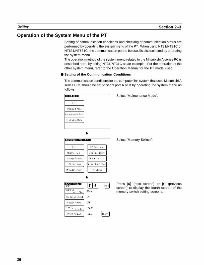
Operation of the System Menu of the PTSetting of communication conditions and checking of communication status areperformed by operating the system menu of the PT. When using NT31/NT31C orNT631/NT631C, the communication port to be used is also selected by operatingthe system menu.The operation method of the system menu related to the Mitsubishi A series PC isdescribed here, by taking NT31/NT31C as an example. For the operation of theother system menu, refer to the Operation Manual for the PT model used.
� Setting of the Communication Conditions
The communication conditions for the computer link system that uses Mitsubishi Aseries PCs should be set to serial port A or B by operating the system menu asfollows:
Select “Maintenance Mode”.
Select “Memory Switch”.
Press [ ] (next screen) or [ ] (previousscreen) to display the fourth screen of thememory switch setting screens.

��
������ Section 2--3
Press the touch switch of the port (“Comm. AMethod” or “Comm. B Method”), to which thecomputer link system that uses Mitsubishi Aseries PCs is to be set, to display “A-Calc-Link”.The display on the right of each touch switchwill be changed by pressing the switch.
Press the “Set” on the right of the touch switchof the selected port.The screen on the left shows the case whenserial port A is to be used.
Press the “Connect Model” and “Comm.Speed” to select the type of the host to beconnected and the communication speed.The display on the right of each touch switchwill be changed by pressing the switch.
Press “Quit”.The selected connected host type and thecommunication speed are displayed.
��
������ Section 2--3
If “Abort” is pressed on the setting screen for the connected host type and commu-nication speed, the memory switch setting screen (fourth screen) returns withoutexecuting setting of the connected host type and communication speed.
When the setting of the connected host type and communication speed is com-pleted, the memory switch setting screen (fourth screen) returns.To set the other memory switches, switch the screen by pressing [ ] (next screen)or [ ] (previous screen) to select the screen to set the desired setting item.
- If “Quit” is pressed on the memory switch setting screen, the memory switch isset as displayed on the screen, then returns to “MAINTENANCE MODEMENU”.
- If “Quit” is pressed on the memory switch setting screen, setting of the memoryswitch is canceled, then returns to “MAINTENANCE MODE MENU”.
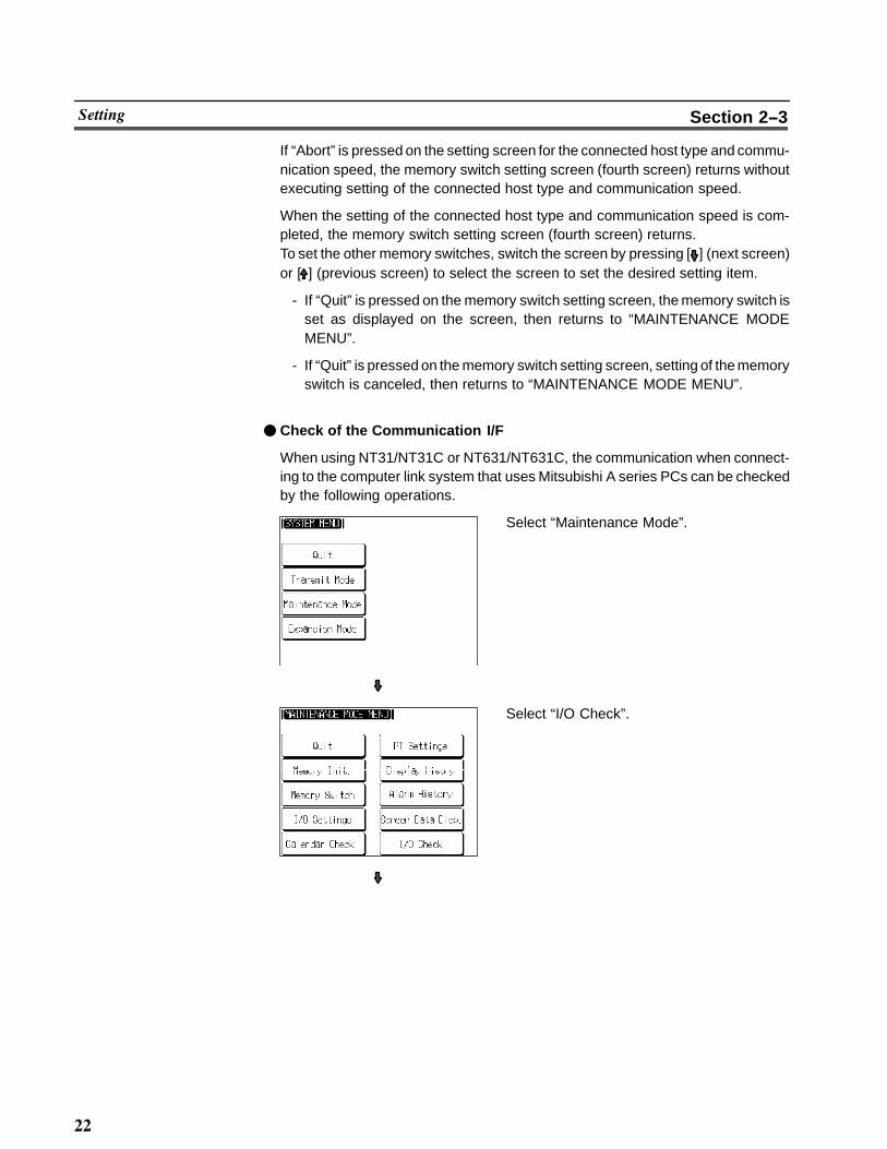
� Check of the Communication I/F
When using NT31/NT31C or NT631/NT631C, the communication when connect-ing to the computer link system that uses Mitsubishi A series PCs can be checkedby the following operations.
Select “Maintenance Mode”.
Select “I/O Check”.

��
������ Section 2--3
Select “I/F Check”.
Press “Comm. Port A” or “Comm. Port B”.The check screen appears.
To execute checking, press “Execute”.The data is transmitted to the host for check-ing the communication and displayed on“Sending Data” in hexadecimal.The screen on the left shows the case whenserial port A is to be checked.
- If communication with the host is performed normally, the response from thehost is displayed on “Received Data” in hexadecimal.
- If communication with the host is not performed normally, the communicationerror display (serial port A communication error) appears.
If the communication error display appears on the communication I/F checkscreen, there is a problem with communication. Check the setting of the commu-nication table, memory switch, or host.

��
������ Section 2--3
Settings for NT-AL001When using the RS-232C/RS-422 convertor unit (NT-AL001), set the RS-422Acommunication conditions with the DIP switches as shown in the figure below.
[SW1-1] Not used (always ON)
(Factory setting)
Transmission at any time
[SW1-5, 6] Selection of RS-422A transmission mode
4-wire type
[SW1-3, 4] Selection of 2-wire type/4-wire type
[SW1-2] Setting for built-in terminal resistorON Terminal resistor used
OFFON
OFFON
SW1-3 SW1-4
SW1-5 SW1-6

��
������ Section 2--3
Computer Link Module SettingsAfter connecting the PT and PC, set the conditions in the table below at the com-puter link module at the PC side.Set these conditions using the switches provided on each type of module by fol-lowing the instructions given below.For a detailed explanation of the setting method, refer to the Operation Manual foreach module.
Item Setting
When using an RS-232Cconnector
When using an RS-422Aterminal block
I/O port RS-232C RS-422A
Baud rate Set the same baud rate as set at the PT.
Transmissionformat
ASCII 7 bits, 2 stop bits
Parity Even
Control protocol Type 1
Unit No.(Station number)
00
<A0J2-C214S1>
Unit No. (Station number) setting (SW3/SW4)Set both SW3 and SW4 to “0”.
Transmission control protocol setting (SW5)When using an RS-232C connector, set to “1”.When using an RS-422A terminal block, set to “5”.
Computer link/multidrop link selection (SW10)Set to “ON” (computer link).
Main channel setting (SW11)When using an RS-232C connector, set to “OFF” (RS-232C).When using an RS-422A terminal block, set to “ON” (RS-422A).
“Write during run” enable/disable setting (SW12)Set to “ON” (enabled).
Transmission speed setting (SW13 to SW15)
Data length setting (SW16)Set to “OFF” (7 bits).
Parity check yes/no setting (SW17)Set to “ON” (yes).
Parity (odd/even) setting (SW18)Set to “ON” (even).
Stop bit setting (SW19)Set to “ON” (2 bits).
Sum check yes/no setting (SW20)Set to “ON” (yes).
Transmission side terminal resistor present/absent setting (SW22Set to “ON” (present) (setting invalid when RS-232C is used).
Receiving side terminal resistor present/absent setting (SW23)Set to “ON” (present) (setting invalid when RS-232C is used).
SW13 SW14 SW15ONOFF
OFFON
ONON19,200bps
9,600bps

�
������ Section 2--3
<AJ71UC24>
SW13 SW14 SW15ONOFF
OFFON
ONON19,200bps
9,600bps
Transmission control protocol settingWhen using an RS-232C connector, set to “1”.When using an RS-422A terminal block, set to “5”.
Unit No. (Station number) settingSet both switches to “0”.
Main channel setting (SW11)When using an RS-232C connector, set to “OFF” (RS-232C).When using an RS-422A terminal block, set to “ON” (RS-422A).
Data length setting (SW12)Set to “OFF” (7 bits).
Transmission speed setting (SW13 to SW15)
Parity check yes/no setting (SW16)Set to “ON” (yes).
Parity (odd/even) setting (SW17)Set to “ON” (even).
Stop bit setting (SW18)Set to “ON” (2 bits).
Sum check yes/no setting (SW21)Set to “ON” (yes).
“Write during run” enable/disable setting (SW22)Set to “ON” (enabled).
Computer link/multidrop link selection (SW23)Set to “ON” (computer link).

�
������ Section 2--3
<A1SJ71UC24-R2> (RS-232C dedicated)
Transmission control protocol settingSet to “1”.
“Write during run” enable/disable setting (SW04)Set to “ON” (enabled).
Transmission speed setting (SW05 to SW07)
Data length setting (SW08)Set to “OFF” (7 bits).
Parity check yes/no setting (SW09)Set to “ON” (yes).
Parity (odd/even) setting (SW10)Set to “ON” (even).
Stop bit setting (SW11)Set to “ON” (2 bits).
Sum check yes/no setting (SW12)Set to “ON” (yes).
SW05 SW06 SW07ONOFF
OFFON
ONON19,200bps
9,600bps

��
������ Section 2--3
<A1SJ71UC24-R4> (RS-422A dedicated)
Unit No. (Station number) settingSet both switches to “0”.
Transmission control protocol settingSet to “5”.
Computer link/multidrop link selection (SW02)Set to “ON” (computer link).
“Write during run” enable/disable setting (SW04)Set to “ON” (enabled).
Transmission speed setting (SW05 to SW07)
Data length setting (SW08)Set to “OFF” (7 bits).
Parity check yes/no setting (SW09)Set to “ON” (yes).
Parity (odd/even) setting (SW10)Set to “ON” (even).
Stop bit setting (SW11)Set to “ON” (2 bits).
Sum check yes/no setting (SW12)Set to “ON” (yes).
SW05 SW06 SW07ONOFF
OFFON
ONON19,200bps
9,600bps

��
��������� ����� Section 2--4
2-4 Allocation AreasThis section describes the types of area to which bits and words can be allocated,and the ranges of these areas for each PC.
Bits and Words Allocated to the PCBits and words can be allocated to Mitsubishi A series PCs as follows.
WordSymbol Area Name Bit Numeric
ValueCharacterString(*)
D Data registers � � �
M Internal relays � � �
T Timers � " �
C Counters � " �
L Latching relays � � �
B Link relays(hexadecimal input)
� � �
W Link registers(hexadecimal input)
� � �
X Input relays(hexadecimal input)
� � �
Y Output relays(hexadecimal input)
� � �
R File registers � � �
(*4) Includes the PT status control area and PT status notify area� : Possible - : Possible (1 word only) �: Not possible
� Restrictions on Use
The restrictions and cautions that apply specifically when using a PT with a com-puter link system that uses Mitsubishi A series PCs are presented here. For de-tails on other, general restrictions, refer to the Operation Manual for the PT modelused.
Values usable by the PT
- When using NT31/NT31C or NT631/NT631CThe value representation used in the PT can be specified to “BCD” (binarycoded decimal) or “binary” (hexadecimal).The value representation (BCD/binary) can be specified for all memory tablesat once by using the support tool “PT configuration” - “system” - “Numeral stor-age type”.The representation of the values can be specified for each memory table.

�
��������� ����� Section 2--4
Bit notification
Notification can be conducted in bit units to bit devices. In this case, the bitsother than those used for notification will not be changed.To word devices, notification is conducted in word units, and the other bits in thesame word of the bit used for notification may be changed (on the notificationcontact between the momentary touch switch and the external I/O input, theother bit in the same word will be cleared to “0”).
Points to be noted when allocating words to bit devices
When notifying in word units to the bit devices, the PT is accessed in 16-bitunits. Therefore, when allocating words (channels) to bit devices, be sure toset a device No. which is multiple of 16.
Points to be noted when using word devices
T (timer) and C (counter) can be notified in word units only.To the word devices other than T (timer) and C (counter), both bits and wordscan be allocated.
Numeral storage type at the PT side
When using NT31/NT31C or NT631/NT631C, the values can be stored in thehost in BCD or binary (hexadecimal) by specifying “value representation ”.The representation normally used in the Mitsubishi A series PC is binary.Therefore, by specifying the value representation at the PT side to “binary”, thevalues changed at the PT side can be notified as they are to the host.
(Example) When the value representation at the PT side is specified to “BCD”,the value is entered at the PT side:(Allocated channel: 1 channel)
PT Mitsubishi A series PCNotification
<Value>
Memory Entered value
D0100 1234
D0102 0600
D0104 9999
<Value>
Memory Stored value
D0100 04D2
D0102 0258
D0104 270F
(Example) When the value representation at the PT side is specified to “binary”,the value is entered at the PT side:(Allocated channel: 1 channel)
PT Mitsubishi A series PCNotification
<Value>
Memory Entered value
D0100 1234
D0102 0600
D0104 9999
<Value>
Memory Stored value
D0100 1234
D0102 0600
D0104 9999

��
��������� ����� Section 2--4
Reference: When using a PT in which “Numeral storage type” can be specified, the value rep-resentation can be specified to “BCD” or “binary” for all the value memory tables, orby each value memory table.For the details on how to use the value representation, refer to Operation Manualfor NT31/NT31C or NT631/NTC (V044-E1-�, V043-E1-�). For the details onhow to specify the value representation, refer to Operation Manual for NT seriesSupport Tool for Windows 95/98 (Ver. 3.0) (V053-E1-�).
Mitsubishi A Series PC Allocation Areas
��� Bit Devices (Bit Units)
�� Input Relays(X)
OutputRelays (Y)
Link Relays (B) Internal Relays(M)
Latch Relays(L)
Special InternalRelays (M)
A0J2HCPU 0000 to 01DF 0000 to 01DF
A1SHCPU 0000 to 00FF 0000 to 00FF
A1SJCPU 0000 to 00FF 0000 to 00FF
A2SHCPU 0000 to 01FF 0000 to 01FF B0000 to B03FF M0000 to M2047 L0000 to L2047
A2NCPU 0000 to 01FF 0000 to 01FF
A2NCPU-S1 0000 to 03FF 0000 to 03FF
A3NCPU 0000 to 07FF 0000 to 07FF
A2ACPU 0000 to 01FF 0000 to 01FF
A2ACPU-S1 0000 to 03FF 0000 to 03FF B0000 to B0FFFM9008 to M9247
A3ACPU 0000 to 07FF 0000 to 07FF
A2UCPU 0000 to 01FF 0000 to 01FF M0000 to M8191 L0000 to L8191
A2UCPU-S1 0000 to 03FF 0000 to 03FF
A2USCPU 0000 to 01FF 0000 to 01FFB0000 to B1FFF
A2USCPU-S1 0000 to 03FF 0000 to 03FF
A2USHCPU-S1 0000 to 1FFF 0000 to 1FFF B0000 to B1FFF M0000 to M8191 L0000 to L2047
A3UCPU 0000 to 07FF 0000 to 07FF B0000 to B1FFF M0000 to M8191 L0000 to L8191
Reference: � The values indicated in the table above are the ranges that can actually be set with thesupport tool and used by the PT.
� The ranges actually usable differ according to the system configuration.

��
��������� ����� Section 2--4
��� Word Devices���
��Data Registers
(D)Timers (T) Counters (C) Link Registers
(W)File Registers
(R)Special DataRegisters (D)
A0J2HCPU
A1SHCPU
A1SJCPU
A2SHCPU D0000 to D1023 T0000 to T0255 C0000 to C0255 W0000 to W03FF R0000 to R4095A2NCPU
D0000 to D1023 T0000 to T0255 C0000 to C0255 W0000 to W03FF R0000 to R4095
A2NCPU-S1
A3NCPU
A2ACPU
A2ACPU-S1 D0000 to D6143 T0000 to T2047 C0000 to C1023 W0000 to W0FFF D9000 to D9255
A3ACPU
D0000 to D6143 T0000 to T2047 C0000 to C1023 W0000 to W0FFF
A2UCPU
A2UCPU-S1
A2USCPUR0000 to R8191
A2USCPU-S1 D0000 to D8191 T0000 to T2047 C0000 to C1023 W0000 to W1FFF
A2USHCPU-S1
A3UCPU
Reference: � The values indicated in the table above are the ranges that can actually be set with thesupport tool and used by the PT.
� The ranges actually usable differ according to the system configuration.
� The values accessed with timers and counters are the timer and counter present values.

��
�������� ����� �� ����� ������� Section 2--5
2-5 Specific Errors and Their RemediesThis section describes the specific errors that may occur when using the PT in acomputer link system that uses Mitsubishi A series PCs, and the remedies toemploy when they occur. For errors which occur when using the PT in the ordinalcondition and the remedies to employ when they occur, refer to the OperationManual for the PT model used.
Setting ErrorsIf an area that does not exist in the PC is specified when creating a PT screen withthe support tool, the screen shown below is displayed during PT operation.
<When using NT31/NT31C or NT631/NT631C>
XXXXX: Screen numberYYYYY : Device No.
If this happens, first check that the area at the PC being used has been secured,then set the correct device.
Reception ErrorsIf a reception error occurs during PT operation, the screen shown below is dis-played.
<When using NT31/NT31C or NT631/NT631C>
<Error contents>Parity errorOver run errorFlaming errorBuffer over flowTime--outPC No. error
Error response received
Undefined command error

��
�������� ����� �� ����� ������� Section 2--5
The errors that occur specifically with computer link systems that use Mitsubishi Aseries PCs are described below. For details on errors other than those indicatedbelow, refer to the Operation manual for the PT.
Message Cause Corrective Action
PC Numbererror
� Due to noise, the data hasbeen changed on the transmis-sion line.
� If the system is used at a sitesubject to a lot of noise, usecables with protection againstnoise on the transmissionroute.
Exchange No.error
� The station No. at the PC sidehas been changed.
� The PC has sent erroneousdata.
� Due to noise, the data hasbeen changed on the transmis-sion route.
� Set the station No. at the PCside to “0”.
� Check the operation at the PCside.
� If the system is used at a sitesubject to a lot of noise, usecables with protection againstnoise on the transmissionroute.
Sum checkerror
� The PC has sent erroneousdata.
� Due to noise, the data hasbeen changed on the transmis-sion line.
� Check the operation at the PCside.
� If the system is used at a sitesubject to a lot of noise, usecables with protection againstnoise on the transmissionroute.

��
����� &
�� '�� !���"��� � �(
!�� ����� ������� ��+ �� ��.� ��� �������� ��� ������� +��� � �! � ������� �� � /������ 01 ����� �������
����� ����������
��� � ����� �!� ��� ��� �#� � � � � � � � � � � � � � � � � � � � � � � � � � � � � � � � � � � � � � � � � � � � � � � � � �
�� �������� �)� � � � � � � � � � � � � � � � � � � � � � � � � � � � � � � � � � � � � � � � � � � � � � � � � � � � � � � � � � � �
��� ������ "�� � � � � � � � � � � � � � � � � � � � � � � � � � � � � � � � � � � � � � � � � � � � � � � � � � � � � � � � � � � � � � �
��" �������� ����� "%� � � � � � � � � � � � � � � � � � � � � � � � � � � � � � � � � � � � � � � � � � � � � � � � � � � � � � �
�
���������� ��� �� ��� Section 3--1
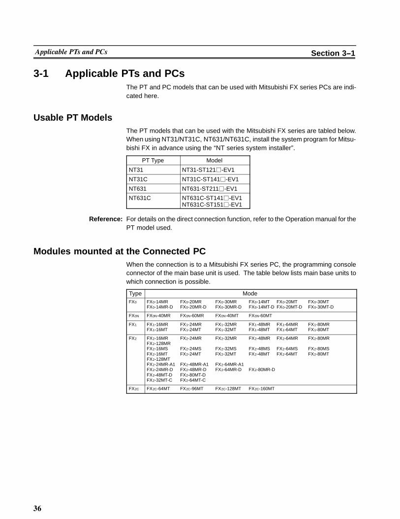
3-1 Applicable PTs and PCsThe PT and PC models that can be used with Mitsubishi FX series PCs are indi-cated here.
Usable PT ModelsThe PT models that can be used with the Mitsubishi FX series are tabled below.When using NT31/NT31C, NT631/NT631C, install the system program for Mitsu-bishi FX in advance using the “NT series system installer”.
PT Type Model
NT31 NT31-ST121�-EV1
NT31C NT31C-ST141�-EV1
NT631 NT631-ST211�-EV1
NT631C NT631C-ST141�-EV1NT631C-ST151�-EV1
Reference: For details on the direct connection function, refer to the Operation manual for thePT model used.
Modules mounted at the Connected PCWhen the connection is to a Mitsubishi FX series PC, the programming consoleconnector of the main base unit is used. The table below lists main base units towhich connection is possible.
Type ModeFX0 FX0-14MR FX0-20MR FX0-30MR FX0-14MT FX0-20MT FX0-30MT
FX0-14MR-D FX0-20MR-D FX0-30MR-D FX0-14MT-D FX0-20MT-D FX0-30MT-D
FX0N FX0N-40MR FX0N-60MR FX0N-40MT FX0N-60MT
FX1 FX1-16MR FX1-24MR FX1-32MR FX1-48MR FX1-64MR FX1-80MRFX1-16MT FX1-24MT FX1-32MT FX1-48MT FX1-64MT FX1-80MT
FX2 FX2-16MR FX2-24MR FX2-32MR FX2-48MR FX2-64MR FX2-80MRFX2-128MRFX2-16MS FX2-24MS FX2-32MS FX2-48MS FX2-64MS FX2-80MSFX2-16MT FX2-24MT FX2-32MT FX2-48MT FX2-64MT FX2-80MTFX2-128MTFX2-24MR-A1 FX2-48MR-A1 FX2-64MR-A1FX2-24MR-D FX2-48MR-D FX2-64MR-D FX2-80MR-DFX2-48MT-D FX2-80MT-DFX2-32MT-C FX2-64MT-C
FX2C FX2C-64MT FX2C-96MT FX2C-128MT FX2C-160MT

�
������� Section 3--2
3-2 ConnectionThe connection is made between the RS-232C connector of the PT to the Mitsu-bishi FX series PC via an RS-232C/RS-422A convertor unit (type NT-AL001).When using NT31/NT31C or NT631/NT631C, connection can be made from aRS-422A connector/terminal block at the PT side.Make the cables in accordance with the wiring schemes shown in this section, andin accordance with the conditions of use.
The communication cnnector (terminal block) of each device is as follows:
� NT31/31C
Serial port A (RS-232C dedicated connector)Serial port B (switching RS-232C/RS-422A/485 connectors)
� NT631/631C
Serial port A (RS-232C dedicated connector)Serial port B (switching RS-232C connector and RS-422A/485 terminal blocks)
� FX Series PC
RS-422A connector
Parts Required for ConnectionThe connectors, connector covers, crimp terminals, and recommended cables foruse with OMRON products are described here.For details on the connectors, connector covers, and crimp terminals used withMitsubishi products, refer to the manual for the Mitsubishi product.
���� Parts for RS-232C connector (Common to PT and NT-AL001)
Part Model Remarks
Connector XM2A-0901 9-pin type, made by OMRON
XM2A-2501 25-pin type, made by OMRON
DE-9P 9-pin type, made by JAE
Connector cover XM2S-0911 9-pin type, made by OMRON
XM2A-2511 25-pin type, made by OMRON
DE-CI-J6 9-pin type, made by JAE
Cable AWG28X5PIFVV-SB
Multi-core shielded cable, made by Fujiku-ra, Ltd
CO-MA-VV-SB5PX28AWG
Multi-core shielded cable, made by HitachiCable, Ltd

��
������� Section 3--2
���� Recommended Parts for RS-422A Terminal Blocks (For NT-AL001)
Round type
6.2 mm or less
Fork type
6.2 mm or less
<Appropriate crimp terminals>
Part Model Remarks
Crimp terminal (M3) Y1.25-3.5L Fork type, made by Molex(*1) 1.25-N3A Fork type, made by Japan Solderless Ter-
minal MFG
(*1) Appropriate wire size: 0.3 to 0.75 mm2

��
������� Section 3--2
When connecting RS-232C (PT) and RS-422A (FX)At the PT side, make a connection using the following communication ports.
� NT31/NT31C or NT631/NT631CSerial port A (RS-232C dedicated connector)orSerial port B (RS-232C connector)
25-pin connector/9-pin connector
PT
RS-232C cable(maximum length: 15 m)
RS-232C/RS-422Aconvertor unit
(NT-AL001)
9-pin connector
RS-422A cable(maximum length: 500 m)
25-pin connector
Mitsubishi FX series PC
Basic module
RS-232C�����
����� ��� ��� �
Notice: � After connecting a communication cable, always secure it with the screws.
� When connectiong to a terminal block, always use crimp terminals.
���� Wiring between PT and NT-AL001
123456789
Pin No.Abbrev.
FG
SDRDRSCS+5V
SG
RS-232Cinterface
Shieldingwire
PT NT-AL001 RS-232C connector
RS-232Cinterface
Pin No. Abbrev.
23456789
SDRDRSCS+5VDRERSG
(9-pin)
Connector cover
(9-pin)
Connector cover

�
������� Section 3--2
<When using NT31/NT31C serial port B>
12345678
Pin No.Abbrev.
FG
RDRSCS
SG
RS-232C/422A/485interface
Shieldingwire
NT31/NT31C side NT--AL001 RS--232C connector
RS-232Cinterface
23456789
SDRDRSCS+5VDRERSG
(9-pin)
Pin No. Abbrev.
SD
(25-pin)
Connectorcover
25
Connectorcover
0V+5V
���� Wiring between NT-AL001 and PC
When using FX1, FX2, or FX2c, connect a cable with the wiring scheme shownbelow directly to the programming console connector of the PC.The programming console connectors of FX0 and FX0N have a different shape;with these types connect a cable with the wiring scheme below to anFX-20P-CADP cable made by Mitsubishi, then connect the FX-20P-CADP to theprogramming console connector of the PC.
12345678
Pin No.Abbrev.
FGSG
SDBSDARDBRDACSBCSA
RS-422Ainterface
Shieldingwire
NT-AL001 RS-422A terminal block FX series PC
RS-422Ainterfac�
Pin No.
234
151617
25-pin8-pin terminal block
1
Make the connections between SDA and SDB, RDA and RDB, and CSA and CSB,with twisted pair wires.

��
������� Section 3--2
When connecting RS-422A (PT) and RS-422A (FX)At the PT side, make a connection using the following communication port:
� NT31/NT31CSerial port B (RS-422A connector)
� NT631/NT631CSerial port B (RS-422A terminal block)
25--pin connector/crimp terminal
RS--422A terminal blockor connector
RS--422A cable(maximum length: 500m)
25-pin connector
Mitsubishi FX series PC
Basic module
�����
����� ��� ��� �
PT
Notice: � After connecting a communication cable, always secure it with the screws.
� When connectiong to a terminal block, always use crimp terminals.
���� Wiring Between PT and PC
When using FX1, FX2, or FX2c, connect a cable with the wiring scheme shownbelow directly to the programming console connector of the PC.The programming console connectors of FX0 and FX0N have a different shape;with these types connect a cable with the wiring scheme below to anFX-20P-CADP cable made by Mitsubishi, then connect the FX-20P-CADP to theprogramming console connector of the PC.Make the connections between SDA and SDB, RDA and RDB, and RSA and RSBwith twisted pair wires.
Abbrev.
SDASDBRDARDB
RS-422Ainterface
Shielding wire
PT RS-422A
17
1615
43
21
Pin No.
RS-422Ainterface
FX series PC
RSARSB
25-pin

��
������� Section 3--2
Setting of Terminator When Using NT31/NT31C or NT631/NT631CWhen using NT31/NT31C or NT/631/NT631C, terminator present/absent whenusing RS-422A is set by a “terminal for terminator (TRM)”. When connecting a PTto a Mitsubishi FX series PC with an RS-422A communication, set the terminatorat the PT side as follows.
���� When using NT31/NT31C
When using NT31/NT31C, there is a “terminal for terminator” on serial port B con-nector. Short the No.9 and 10 terminals of serial port B inside the connector, andset the terminator to “ON (present)”.
9101112
Pin No.Abbrev.
TRMRDB (+)SDB (+)
Connectorcover
25
Terminator
Between No.9and 10 terminals
Function
Short circuitTerminator ONShorts only when connecting to the end terminal of theRS-422A/485 cable.
Open circuitTerminator OFFOpens only when connecting to a terminal other thanthe end terminal of the RS-422A/485 cable.
���� When using NT631/NT631C
When using NT631/NT631C, there is a “terminal for terminator” on serial port Bterminal block. Short the TRM and RDA terminals of serial port B using the shortbracket, and set the terminator to “ON (present)”.
RDA
TRM
RDB
SDA
Short bracket
Between TRM andRDA terminals
Function
Short circuitTerminator ONShorts only when connecting to the end terminal of theRS-422A/485 cable.
Open circuitTerminator is absent.Opens only when connecting to a terminal other thanthe end terminal of the RS-422A/485 cable.

��
������ Section 3--3
3-3 SettingThis section describes the settings required at each device in order to use the pro-gramming console connector of a Mitsubishi FX series PC.
Settings at the PTMake the following settings in the PT’s maintenance mode by using the memoryswitches. When using NT30/NT30C, install the system program for Mitsubishi FXin advance using the “NT series system installer”.
Reference: Set the other memory switches in accordance with the conditions of use.
���� When using NT31/NT31C or NT631/NT631C
Item Setting
Serial port Aprotocol
Mitsubishi FX, not used, or bar code reader(when Mitsubishi FX is selected for serial port B)
Serial port Bprotocol
Mitsubishi FX or not used (when Mitsubishi FXis selected for serial port A)
Comm. type With FX0 :FX0With FX0N :FX0NWith FX1 :FX1With FX2, FX2C :FX2/FX2C

��
������ Section 3--3
Operation of the System Menu of the PTSetting of communication conditions and checking of communication status areperformed by operating the system menu of the PT. When using NT31/NT31C orNT631/NT631C, the communication port to be used is also selected by operatingthe system menu.The operation method of the system menu related to the Mitsubishi FX series PCis described here, by taking NT31/NT31C as an example. For the operation of theother system menu, refer to the Operation Manual for the PT model used.
���� Setting of the Communication Conditions
The communication conditions for the computer link system that uses MitsubishiFX series PCs should be set to serial port A or B by operating the system menuas follows:
Select “Maintenance Mode”.
Select “Memory Switch”.
Display the fourth memory switch screen bypressing the [ ] (next screen) or [ ] (previousscreen) touch switch.
Press the touch switch of the port (“Comm. AMethod” or “Comm. B Method”), to which thecomputer link system that uses Mitsubishi Aseries PCs is to be set, to display “MIT-SUBISHI FX”.The display on the right of each touch switchwill be changed by pressing the switch.

��
������ Section 3--3
Press the “Set” on the right of the touch switchof the selected port.The screen on the left shows the case whenserial port A is to be used.
Press the “Connect Model” to select the typeof the host to be connected.The display on the right of each touch switchwill be changed by pressing the switch.
Press “Quit”.The selected connected host type and thecommunication speed are displayed.
� If “Abort” is pressed on the setting screen for connected host type and commu-nication speed, the memory switch setting screen (fourth screen) returns with-out executing the setting of the connected host type and communication speed.
When the setting of connected host type and communication speed is completed,the memory switch setting screen (fourth screen) returns.To set the other memory switches, switch the screen by pressing [ ] (next screen)or [ ] (previous screen) to select the screen to set the desired setting item.
� If “Quit” is pressed on the memory switch setting screen, the memory switch isset as displayed on the screen, then returns to “MAINTENANCE MODEMENU”.
� If “Abort” is pressed on the memory switch setting screen, setting of the memoryswitch is canceled, then returns to “MAINTENANCE MODE MENU”.

�
������ Section 3--3
���� Check of the Communication I/F
When using NT31/NT31C or NT631/NT631C, the communication when con-necting to the computer link system that uses Mitsubishi FX series PCs can bechecked by operating as follows.
Select “Maintenance Mode”.
Select “I/O Check”.
Select “I/F Check”.
Select “Comm. Port A” or “Comm. Port B”.The check screen appears.

�
������ Section 3--3
To execute checking, press “Execute”.The data is transmitted to the host for check-ing the communication and displayed on“Sending Data” in hexadecimal.The screen on the left shows the case whenserial port A is to be checked.
� If the communication with the host is performed normally, the response from thehost is displayed on “Received Data” in hexadecimal.
� If the communication with the host is not performed normally, the communica-tion error display (serial port A communication error) appears.
If the communication error display appears on the communication I/F checkscreen, there is a problem in communication. Check the setting of the communica-tion table, memory switch, or host.

��
������ Section 3--3
Settings at the NT-AL001When using the RS-232C/RS-422 convertor unit (NT-AL001), set the RS-422Acommunication conditions with the DIP switches as shown in the figure below.
[SW1-1] Not used (always ON)
(Factory setting)
Transmission at any time
[SW1-5, 6] Selection of RS-422A transmission mode
4-wire type
[SW1-3, 4] Selection of 2-wire type/4-wire type
[SW1-2] Setting for built-in terminal resistorON Terminal resistor used
OFFON
OFFON
SW1-3 SW1-4
SW1-5 SW1-6
PC SettingsNo particular settings have to be made at the PC in order to use the PT with a pro-gramming console connector.

��
��������� ����� Section 3--4
3-4 Allocation AreasThis section describes the types of area to which bits and words can be allocated,and the ranges of these areas for each PC.
Bits and Words Allocated to the PCBits and words can be allocated to Mitsubishi FX series PCs as follows.
WordSymbol Area Name Bit Numeric
ValueCharacter
String(*)
D Data registers � � �
M Internal relays � � �
T Timers � " 1 �
C Counters � " 2 �
S State relays � � �
X Input relays � � �
Y Output relays � � �
(*) Includes the PT status control area and PT status notify area� : Possible" 1: Possible (1 word only)" 2: For C0 to C199, 1 word possible; for C200 and higher,
2 words possible� : Not possible
Reference: Allocations cannot be made to the special use areas for data registers (D) and aux-iliary registers (M).
���� Restrictions on Use
The restrictions and cautions that apply specifically when using a PT with a com-puter link system that uses Mitsubishi FX series PCs are presented here. For de-tails on other, general restrictions, refer to the Operation Manual for the PT modelused.
Values usable by the PT
� When using NT31/NT31C or NT631/NT631CThe value representation used in the PT can be specified to “BCD” (binary codeddecimal) or “binary” (hexadecimal).The value representation (BCD/binary) can be specified for all memory tables atonce by using the support tool “PT configuration” -- “system” -- “Numeral storagetype”.The representation of the values can be specified for each memory table.

�
��������� ����� Section 3--4
Bit notificationNotification can be conducted in bit units to bit devices. In this case, the bits otherthan those used for notification will not be changed.To word devices, notification is conducted in word units, and the other bits in thesame word of the bit used for notification may be changed (on the notification con-tact between the momentary touch switch and the external I/O input, the other bitin the same word will be cleared to “0”).
Points to be noted when allocating words to bit devices other than X and YWhen notifying in word units to the bit devices, the PT is accessed in 16--bit units.Therefore, when allocating words (channels) to bit devices, be sure to set a deviceNo. which is a multiple of 16.
Points to be noted when allocating to X (input relays) and Y (output relays)In X and Y, the device No. is expressed in octal. Therefore, when allocating words(channels) to X or Y, ensure that the last two digits of the device Nos. are “00”, “20”,“40”, or “60”.
First + 1 bitNumber ofallocated words
First + 14 bitsFirst word First + 0 bits1 word First + 2 bitsFirst + 15 bits
Bit
First + 17 bitsFirst + 30 bitsFirst + 1 word First + 16 bitsFirst + 18 bitsFirst + 31 bits
215 14 1 0
Points to be noted when using word devicesThe word device D (data register) can be used for both bit and word allocation.In all areas of T (timer) and C0 -- 199 of C (counter), each device is 16 bits andoccupies 1 word (channel). In the case of counter C200 and higher, one word de-vice is 32 bits and occupies 2 words (channel).
� Normal device
Number ofallocated words
First word
First + 1 word
Bit
First word device (lower 16 bits)
First word device (upper 16 bits)
15 14 13 12 11 10 9 8 234567 1 0
� 32-bit devices from C200 onward
Number ofallocated words
First word
First + 1 word
First word device
First + 1 word device
Bit15 14 13 12 11 10 9 8 234567 1 0

��
��������� ����� Section 3--4
Numeral storage type at the PT sideWhen using NT31/NT31C or NT631/NT631C, the values can be stored in the hostin BCD or binary (hexadecimal) by specifying “value representation ”.The representation normally used in the Mitsubishi FX series PC is binary. There-fore, by specifying the value representation at the PT side to “binary”, the valueschanged at the PT side can be notified as they are to the host.
(Example) When the value representation at the PT side is specified to “BCD”, thevalue is entered at the PT side:(Allocated channel: 1 channel)
PTNotification
<Value>
MemoryD0100D0102D0104
Entered value123406009999
Mitsubishi FX series PC
<Value>
D0100D0102D0104
Stored value04D20258270F
Memory
(Example) When the value representation at the PT side is specified to “binary”,the value is entered at the PT side:(Allocated channel: 1 channel)
PTNotification
<Value>
MemoryD0100D0102D0104
Entered value123406009999
Mitsubishi FX series PC
<Value>
D0100D0102D0104
Stored valueMemory123406009999
Reference: � When using a PT in which “Numeral storage type” can be specified, the valuerepresentation can be specified to “BCD” or “binary” for all the value memorytables, or by each value memory table.
� For the details on how to use the value representation, refer to Operation Manualfor NT31/NT31C or NT631/NTC (V043-E1-�, V044-E1-�). For the details onhow to specify the value representation, refer to Operation Manual for NT seriesSupport Tool for Windows 95/98 (Ver. 3.0) (V053-E1-�).

��
��������� ����� Section 3--4
Mitsubishi FX Series PC Allocation Areas
Type UnitData
Registers(D)
AuxiliaryRelays
(M)
Timers(T)
Counters(C)
State Relays(S)
Input Relays(X)
OutputRelays
(Y)
FX0 Bit ------ M0 to M511 ------ ------ S0 to S63 X0 to X177 X0 to X177
FX0N Word D0 to D31 M0 to M496 T0 to T55 C0 to C254 S0 to S48 X0 to X17 Y0 to Y17
FX1 Bit ------ M0 to M1023 ------ ------ S0 to S999 X0 to X177 X0 to X177
Word D0 to D127 M0 to M1008 T0 to T245 C0 to C254 S0 to S984 X0 to X17 Y0 to Y17
FX2 Bit ------ M0 to M1023 ------ ------ S0 to S999 X0 to X177 X0 to X177FX2
FX2C Word D0 to D511 M0 to M1008 T0 to T255 C0 to C255 S0 to S984 X0 to X17 Y0 to Y17
Reference: � The values indicated in the table above are the ranges that can actually be setwith the support tool and used by the PT.
� The ranges actually usable differ according to the system configuration.

��
����)�(
!�� ����� ������� ��� � ������� �� ��� �������� �� 2/(23 ������ ���� ��� �����������
���'34�1 � 2/(23 ������ �������� � ������� &"� � � � � � � � � � � � � � � � � � � � � � � � � � � � � �

RDA
TRM
RDB
SDA
SDB
RSA
RSB
24V�DC
��
����� ������� ������� ������������� Appendix A
APPENDIX AOMRON Product Connector Specifications
PT Connectors���� RS-232C connector specifications
� Connector type : RS-232C connector (9-pin)
� Electrical characteristics : Conform to EIA RS-232C
� Connection signals
ConnectorPin No.
Signal Name Abbreviation Signal DirectionPT ↔ External Device
1 Not used -- --
2 Send data SD (TXD) "
3 Receive data RD (RXD) "
4 Request to send RS (RTS) "
5 Clear to send CS (CTS) "
6 +5V for convertor (max. 150 mA) +5V "
9 Signal ground SG --
(*) For NT631/NT631C serial port B, there is no +5V output.
RS-422A terminal block of NT631/NT631C
� Connection terminal block : RS-422A terminal block (M3.5 screw)
� Electrical characteristics : Conform to EIA RS-422A
� Connection signals
Signal Name Abbreviation Signal DirectionPT ↔ External Device
Receive data (--) RDA "
Send resistor TRM --
Receive data (+) RDB "
Send data (--) SDA "
Send data (+) SDB "
Request to send (--) RSA "
Request to send (+) RSB "
Functional earth --

1 14
13 25
��
����� ������� ������� ������������� Appendix A
���� RS-232C/RS-422A Share Connector Specifications (Only NT31/NT31C)
� Connected terminal block : 25-pin connector
� Electrical characteristics : Conform to EIA RS--232C and 422A
� Connection signals
ConnectorPin No.
Signal Name Abbreviation Signal DirectionPT ↔ External Device
2 Send data (RS-232C) SD (TXD) "
3 Receive data (RS-232C) RD (RXD) "
4 Request to send (RS-232C) RS (RTS) "
5 Data send ready (RS-232C) CS (CTS) "
7 Signal ground SG --
9 Terminator (RS-422A) TRM --
10 Receive data (+) (RS-422A) RDB (+) "
11 Send data (+) (RS-422A) SDB (+) "
15 Send data (--) (RS-422A) SDA (--) "
16 Receive data (--) (RS-422A) RDA (--) "
23 Request to send (+) (RS-422A) RSB (+) "
24 Request to send (--) (RS-422A) RSA (--) "

�
����� ������� ������� ������������� Appendix A
RS-232C/RS-422 Convertor Unit (NT-AL001)���� RS-232C connector specifications
� Connector type : RS-232C connector (9-pin)
� Electrical characteristics : Conform to EIA RS-232C
� Connection signals
ConnectorPin No.
Signal Name Abbreviation Signal DirectionPT ↔ External Device
Connectorcover
Grounding or earth for safetypurposes
FG --
1 Not used -- --
2 Send data SD (TXD) "
3 Receive data RD (RXD) "
4 Receive dataRequest to send(shorted to CS internally)
RS (RTS) "
5 Clear to send (shorted to RS in-ternally)
CS (CTS) "
6 +5V for convertor (150 mA) +5V "
7 Data set ready (shorted to ERinternally) *
DR (DSR) -- *
8 Data terminal ready (shorted toDR internally) *
ER (DTR) -- *
9 Signal ground SG (GND) --
- The connector cover is connected to the functional ground terminal (pin No.1) ofthe RS-422A terminal block.
* Pins No.7 and No.8 are connected internally to each other and do not have thefunction as the control lines.
���� RS-422A terminal block specifications
� Connected terminal block : RS-422A terminal block (M3 screw)
� Electrical characteristics : Conform to EIA RS-422A
� Connection signals
ConnectorPin No.
Signal Name Abbreviation Signal DirectionPT ↔ External Device
1 Functional ground FG --
2 Signal ground SG (GND) --
3 Send data (+) SDB "
4 Send data (--) SDA "
5 Receive data (+) RDB "
6 Receive data (--) RDA "
7 Request to send (+) CSB "
8 Request to send (--) CSA "
Note: The CSB and CSA signals are for special applications.

INDEX
B
Bit notificationfor Mitsubishi A computer links 2-26. . . . . .for Mitsubishi FX 3-15. . . . . . . . . . . . . . . . .
Bits 2-25. . . . . . . . . . . . . . . . . . . . . . . . . . . . . . . . . . . .
Bits and Words Allocated to the PCfor Mitsubishi A computer links 2-25. . . . .for Mitsubishi FX 3-14. . . . . . . . . . . . . . . . .
C
Check of the Communication I/Ffor Mitsubishi A computer links 2-18. . . . .for Mitsubishi FX 3-11. . . . . . . . . . . . . . . . .
Computer link 2-2. . . . . . . . . . . . . . . . . . . . . . . . . . . .
Computer Link Module Settings<A0J2-C214S1> 2-21. . . . . . . . . . . . . . . .<A1SJ71UC24-R2>(RS--232C dedicated) 2-23. . . . . . . . . . . .<A1SJ71UC24-R4>
(RS--422A dedicated) 2-24. . . . . . . . . . . . .<AJ71UC24> 2-22. . . . . . . . . . . . . . . . . . .
D
Direct connection version 1-2. . . . . . . . . . . . . . . . . .
M
Methods for connection(for Mitsubishi A computer links)
RS--232C (PT) and RS--232C(Computer Link) 2-6. . . . . . . . . . . . . . . . . . .RS--232C (PT) and RS--422A(Computer Link) 2-8. . . . . . . . . . . . . . . . . . .RS--422A (PT) and RS--232C(Computer Link) 2-11. . . . . . . . . . . . . . . . . .RS--422A (PT) and RS--422A(Computer Link) 2-10. . . . . . . . . . . . . . . . . .
Methods for connection(for Mitsubishi FX)
RS--232C (PT) and RS--422A (FX) 3-4. . . .RS--422A (PT) and RS--422A (FX) 3-6. . . .
Mitsubishi A Series PC Allocation Areas 2-27. . . .
Mitsubishi FX Series PC Allocation Areas 3-17. . .
Modules Mounted at the Connected PCfor Mitsubishi A computer links 2-3. . . . . .for Mitsubishi FX 3-2. . . . . . . . . . . . . . . . . .
O
Operation of the System Menu of the PTfor Mitsubishi A computer links 2-16. . . . .for Mitsubishi FX 3-9. . . . . . . . . . . . . . . . . .
P
Parts for RS--232C (Common to PT and NT--AL001)for Mitsubishi A computer links 2-5. . . . . .for Mitsubishi FX 3-3. . . . . . . . . . . . . . . . . .
Parts Required for Connectionfor Mitsubishi A computer links 2-5. . . . . .for Mitsubishi FX 3-3. . . . . . . . . . . . . . . . . .
PC Settingsfor Mitsubishi FX 3-13. . . . . . . . . . . . . . . . .
Points to be noted when allocating wordsto bit devices
for Mitsubishi A computer links 2-26. . . . .
Points to be noted when using word devicesfor Mitsubishi A computer links 2-26. . . . .
Possible Combinations 1-2. . . . . . . . . . . . . . . . . . . .
R
Reception Errorsfor Mitsubishi A computer links 2-29. . . . .
Recommended Parts for RS--422A Terminal Block(for NT631/NT631C)
for Mitsubishi A computer links 2-5. . . . . .
Recommended Parts for RS--422A Terminal Blocks(for NT--AL001)
for Mitsubishi A computer links 2-6. . . . . .for Mitsubishi FX 3-3. . . . . . . . . . . . . . . . . .
RS--232C connector specificationsOMRON PT APP-2. . . . . . . . . . . . . . . . . . .NT--AL001 APP-4. . . . . . . . . . . . . . . . . . . . .
RS--232C/RS--422 Convertor Unit(NT--AL001) APP-4. . . . . . . . . . . . . . . . . . . . . . . . . .
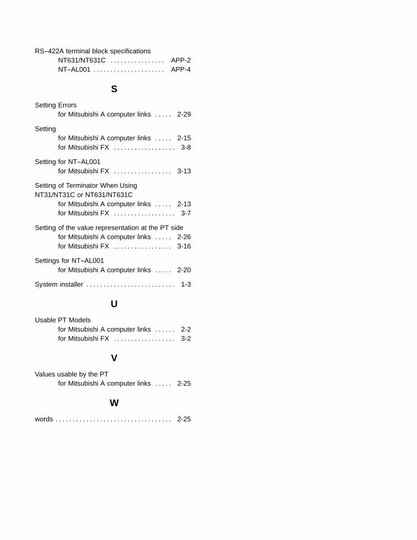
RS--422A terminal block specificationsNT631/NT631C APP-2. . . . . . . . . . . . . . . .NT--AL001 APP-4. . . . . . . . . . . . . . . . . . . . .
S
Setting Errorsfor Mitsubishi A computer links 2-29. . . . .
Settingfor Mitsubishi A computer links 2-15. . . . .for Mitsubishi FX 3-8. . . . . . . . . . . . . . . . . .
Setting for NT--AL001for Mitsubishi FX 3-13. . . . . . . . . . . . . . . . .
Setting of Terminator When UsingNT31/NT31C or NT631/NT631C
for Mitsubishi A computer links 2-13. . . . .for Mitsubishi FX 3-7. . . . . . . . . . . . . . . . . .
Setting of the value representation at the PT sidefor Mitsubishi A computer links 2-26. . . . .for Mitsubishi FX 3-16. . . . . . . . . . . . . . . . .
Settings for NT--AL001for Mitsubishi A computer links 2-20. . . . .
System installer 1-3. . . . . . . . . . . . . . . . . . . . . . . . . .
U
Usable PT Modelsfor Mitsubishi A computer links 2-2. . . . . .for Mitsubishi FX 3-2. . . . . . . . . . . . . . . . . .
V
Values usable by the PTfor Mitsubishi A computer links 2-25. . . . .
W
words 2-25. . . . . . . . . . . . . . . . . . . . . . . . . . . . . . . . . .

Revision History
A manual revision code appears as a suffix to the catalog number on the front cover of the manual.
Cat. No. V042-E1-1
Revision code
The following table outlines the changes made to the manual during each revision. Page numbers refer to theprevious version.
Revision code Date Revised content
1 March 1999 Original production