Programmable Delay Detonator
77
PROGRAMMABLE ELECTRONIC DELAY DETONATOR.DOC ABSTRACT
Transcript of Programmable Delay Detonator

PROGRAMMABLE ELECTRONIC DELAY DETONATOR.DOC
ABSTRACT

PROGRAMMABLE ELECTRONIC DELAY DETONATOR.DOC
2
ABSTRACT
The detonator includes means for charging the capacitor from the supply in response
to occurrence of a first signal and for transferring stored electrical energy to the explosive
thereby to fire the explosive in response to occurrence of a second signal; and means for
storing an electrical representation of the firing delay time supplied from the firing
console, for responding to a first command from the firing console by transmitting the
firing delay time representation stored in the apparatus to the firing console, for supplying
the first signal in response to a second command from the firing console, and for
supplying the second signal as soon as a time interval, commencing on a third command
from the firing console, has elapsed, which time interval is substantially equal to the
firing delay time stored in the module.

PROGRAMMABLE ELECTRONIC DELAY DETONATOR.DOC
3
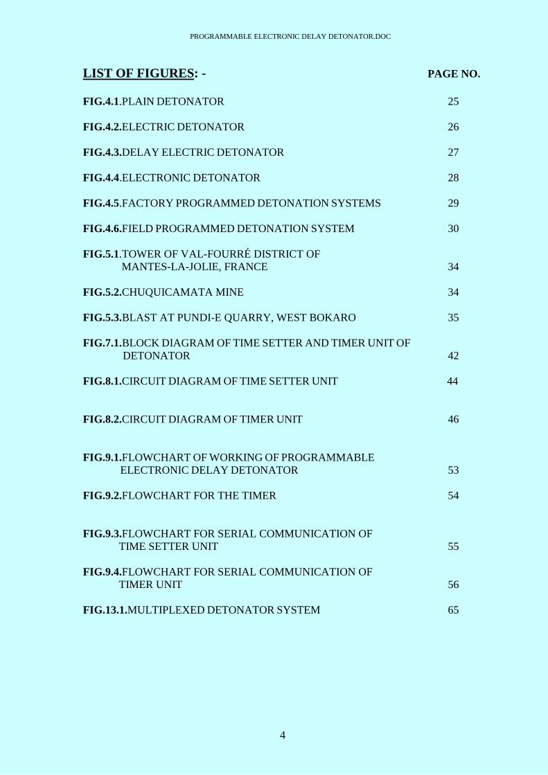
LIST OF FIGURES
PROGRAMMABLE ELECTRONIC DELAY DETONATOR.DOC
4
LIST OF FIGURES: - PAGE NO.
FIG.4.1.PLAIN DETONATOR 25
FIG.4.2.ELECTRIC DETONATOR 26
FIG.4.3.DELAY ELECTRIC DETONATOR 27
FIG.4.4.ELECTRONIC DETONATOR 28
FIG.4.5.FACTORY PROGRAMMED DETONATION SYSTEMS 29
FIG.4.6.FIELD PROGRAMMED DETONATION SYSTEM 30
FIG.5.1.TOWER OF VAL-FOURRÉ DISTRICT OF
MANTES-LA-JOLIE, FRANCE 34
FIG.5.2.CHUQUICAMATA MINE 34
FIG.5.3.BLAST AT PUNDI-E QUARRY, WEST BOKARO 35
FIG.7.1.BLOCK DIAGRAM OF TIME SETTER AND TIMER UNIT OF
DETONATOR 42
FIG.8.1.CIRCUIT DIAGRAM OF TIME SETTER UNIT 44
FIG.8.2.CIRCUIT DIAGRAM OF TIMER UNIT 46
FIG.9.1.FLOWCHART OF WORKING OF PROGRAMMABLE
ELECTRONIC DELAY DETONATOR 53
FIG.9.2.FLOWCHART FOR THE TIMER 54
FIG.9.3.FLOWCHART FOR SERIAL COMMUNICATION OF
TIME SETTER UNIT 55
FIG.9.4.FLOWCHART FOR SERIAL COMMUNICATION OF
TIMER UNIT 56
FIG.13.1.MULTIPLEXED DETONATOR SYSTEM 65

PROGRAMMABLE ELECTRONIC DELAY DETONATOR.DOC
5
FIG.A.1. TIME SETTER UNIT 72
FIG.A.2. TIMER UNIT 73
FIG.B.1.PIN CONFIGURATION OF AT89C51RD2 74
FIG.B.2.44 KEYPAD 75
FIG.B.3.162 LCD DISPLAY 75
FIG.B.4.REGULATOR IC 7805 76
FIG.B.5.MAX 232 IC 76
FIG.B.6. PIN CONFIGURATION OF ATTINY 12 77

PROGRAMMABLE ELECTRONIC DELAY DETONATOR.DOC
6
CHAPTER 1
INTRODUCTION

PROGRAMMABLE ELECTRONIC DELAY DETONATOR.DOC
7
1. INTRODUCTION: -
The mining and explosives industry is rapidly adopting technology in all forms in
order to improve performance. One such technology that is being developed to improve
blasting efficiency and mining economics is the electronic detonator. Currently, there are
several types of electronics systems being tested and used in the industry, all of which
utilize some type of stored energy device to provide energy for their timing and firing
circuits. We will review the basic electronic detonator design concepts currently being
developed and used in the industry. If travel to almost any mine site today and you will
encounter the same type of technology that is changing the fundamental way other
industries will compete in the next millennium. It would be very common for the visitor
to encounter the latest forms of communication technology, computer systems, global
positioning systems (GPS), and laser measurement technologies, to name a few. Global
competition and increasing customer demands are forcing operators to seek out and adopt
these technologies in order for them to produce their product more economically and
more efficiently. The mine’s blasting operation is no exception. Today, many operators
employ the newest explosives, equipment, designs, and measurement tools in an effort to
ensure every pound of explosives is being utilized to its fullest potential.
One specific technology that has been under development for several years, by several
manufacturers, and is beginning to be tested and used increasingly in the industry is the
electronic detonator. Electronic detonators, of which there are several different types and
designs, all utilize stored electrical energy inside the detonator as a means of providing
the timing delay and initiation energy. All other detonator technologies, including shock
tube, electric or safety fuse initiated, utilize pyrotechnic energy as a means of delay and
initiation. Figure 1 shows the basic components and design of a typical shock tube
detonator, electric detonator and an electronic detonator.
Presently known delay detonators have a built-in chemical delay located between the
fuse head and primary charge. The length of delay is affected by the use of differing
chemical mixes and lengths of the delay unit. It is believed that existing delay detonators
are frequently inaccurate, their inaccuracy stemming from the chemical delay element,
especially in long series delay detonators. The inaccuracies are such that detonators in a
delay series can explode out of sequence. Also, known electric delay detonators have a

PROGRAMMABLE ELECTRONIC DELAY DETONATOR.DOC
8
significant risk of accidental detonation by static electricity, stray currents, induction from
overhead power cables, and radio waves. Known delay detonators are believed to be less
than fully secure from use by unauthorized personnel.
Among the several objects of the project are to replace chemical delay by a compact
electronic package exhibiting substantially greater flexibility of operation for an electrical
delay detonator; to significantly increase delay detonator accuracy; to increase delay
detonator flexibility so that one integrated electronic unit is programmable for any delay
time; to increase delay detonator safety over presently available delay detonators; to
provide an electronic delay detonator capable of two-way communication with a
detonation controller in order to provide status information about the integrated
component within the blasting delay detonator unit; to provide an electronic blasting
delay detonator unit having a fail-safe mode of operation incorporated into the device to
prevent premature ignition of the detonator; to provide an electronic blasting delay
detonator unit which recognizes a unique detonation code to start its delay timer
sequence; to provide an electronic blasting delay detonator unit having a power storage
capability within the device to allow independent operation once the detonation code has
been recognized; to provide an electronic blasting delay detonator unit having power up
and power down modes of operation which are usable in the event it is necessary to abort
the firing of a detonator network; to provide a precision electronic blasting delay
detonator unit utilizing attached or self-contained integrating timing circuits which can be
controlled through a single pair of wires and so that two or more such detonator units are
connectable in a parallel wired electrical network; to provide an electronic blasting delay
detonator unit which is able to be charged or fired by electrical means; to provide an
electronic blasting delay detonator unit which is able to electronically respond to an
integrated initiation device immediately prior to blasting giving status, program delay
time, and designated number; to provide an electronic blasting delay detonator unit
having a factory programmed security code unique to the operator which excludes
unauthorized use; to provide an electronic blasting delay detonator unit which can be
rendered harmless by issuing an abort command from a firing console; to provide an
electronic blasting delay detonator unit having a security code which is unique to the user
and which can be kept secret with the manufacturer so that the user need not know the
code and fire control command which initiates timing circuits and subsequently
capacitive discharge and firing of the individual detonators; to provide an electronic

PROGRAMMABLE ELECTRONIC DELAY DETONATOR.DOC
9
blasting console system compatible with the foregoing electronic blasting delay detonator
units having a fire control program requiring a single user security code for usage; to
provide an electronic blasting delay detonator unit having three leg wires, two long ones
for power and firing purposes and the third solely for factory programming which can be
clipped and sealed.

PROGRAMMABLE ELECTRONIC DELAY DETONATOR.DOC
10
CHAPTER 2
ORGANIZATION PROFILE

PROGRAMMABLE ELECTRONIC DELAY DETONATOR.DOC
11
2. ORGANIZATION PROFILE: -
ARMAMENT AND RESEARCH DEVELOPMENT ESTABLISHMENT
Dr. Homi Bhabha road Pashan, Pune-411021
2.1. BACKGROUND
Established in 1958, Armament Research & Development Establishment is on the
threshold of the fifth decade of its existence, under defense research & development
organization.
The task of Armament R&D was entrusted to ARDE to achieve the cherished goal of
self-sufficiency in the vital field of Armaments. ARDE embarked on its mission in a
rudimentary facility within the campus of Ammunition Factory, Kirkee and personnel
were drawn from erstwhile Technical Development Establishment (Weapons) located in
Jabalpur and Technical Development Establishment (Ammunition) at Kirkee. In 1966,
ARDE moved to its presort location at Pashan on the out-skirts of pune City, where its
distinguished neighbor is the National Chemical Laboratory, a major CSIR Laboratory.
We are indeed fortunate to be located in a city with a very strong Science and Technology
culture and to have the resources of several sister R&D Labs/Establishments, Higher
Academic Institution, R&D Centers in the Non-Defense Sector, the industries in and
around the environs of Pune and Mumbai Metropolis.
The progress of ARDE over the past 40 years can be viewed as a journey from the
"know-what" and "know-how" phase to the "know-why" phase of armament design and
development. The capability of ARDE embraces the whole gamut of research,
development, prototyping, test and evaluation, and transfer of technology activities,
including limited scale pilot-plant production of crucial items in the complex, multi-
disciplinary field of conventional armament technology.
PROGRAMMABLE ELECTRONIC DELAY DETONATOR.DOC
12
2.2. ROLE
The Armament Research & Development is primarily concerned with research,
design & development in the field of conventional armaments for all the three Defense
Services. One of the largest R&D Establishments in the DRDO, it is the lead
Establishment in the conventional armament group of labs/establishments.
The Charter of Duties of ARDE as envisaged at its formation has undergone
considerable changes though the role per se remains more or less unaltered. The current
Charter of Duties broadly covers the following:
Design and development of indigenous armament stores to meet Services'
requirement & to establish their production.
Assistance in the technical evaluation and subsequent production of foreign stores.
AHSP (Authority Holding Sealed Particulars) Duties till Establishment of free-
flow production of newly developed stores.
Design and development of stores for other agencies (e.g. Home Ministry).
Basic/applied research.
Modelling and software for armaments.
It is seen that the Charter of Duties encompasses the entire gamut of activities which
goes by the generic name of R&D viz., research, design, development, testing, evaluation,
production, quality assurance and documentation.
The work at ARDE embraces a wide range of disciplines including applied
mechanical, electrical and aeronautical engineering, electronics, applied chemistry,
physics, mathematics and ballistics, operational research, metallurgy and material
sciences. The advice and assistance of higher academic institutions like ISRO, CMTI and
the industry in both Public and Private Sector, is actively and frequently enlisted for
completing the multifarious tasks related to the projects undertaken by ARDE.

PROGRAMMABLE ELECTRONIC DELAY DETONATOR.DOC
13
CHAPTER 3
OBJECTIVE OF THE PROJECT
PROGRAMMABLE ELECTRONIC DELAY DETONATOR.DOC
14
4. OBJECTIVE: -
Detonators are very essential devices in many fields of application. They should be
very accurate in their functioning for reliable operation. For that the time delay generated
by the detonators should be very accurate. The programmed delay and the testing delay
should not vary much i.e. there should be very less error between the two.
The detonators, which have been invented till date, are having a fixed delay for their
operation and that to a very large delay ranging from 200ms to 10s. Hence, the attempt in
this project will be to reduce the delay and also to generate a variable delay for the
detonators as per the requirement of the situation.
The other various objectives of this project are: -
To provide greater flexibility of operation for an electronic delay detonator.
To significantly increase delay detonator accuracy.
To increase delay detonator flexibility so that one integrated electronic unit is
programmable for any delay time.
To increase delay detonator safety over presently available delay detonators.
To provide an electronic delay detonator capable of two-way communication with
a detonation controller in order to provide status information about the integrated
component within the blasting delay detonator unit.
To provide an electronic blasting delay detonator unit which recognizes a unique
detonation code to start its delay timer sequence (optional).
To provide a precision electronic blasting delay detonator unit utilizing attached
or self-contained integrating timing circuits which can be controlled through a
single pair of wires and so that two or more such detonator units are connectable
in a parallel wired electrical network
To provide an electronic blasting delay detonator unit which is able to be charged
or fired by electrical means.
To provide an electronic blasting delay detonator unit which can be rendered
harmless by issuing an abort command from a firing console.
To provide an electronic blasting delay detonator unit having a security code
which is unique to the user and which can be kept secret (optional).
PROGRAMMABLE ELECTRONIC DELAY DETONATOR.DOC
15
UNIQUE FEATURES: -
In addition to highly accurate timing circuits, the micro-chip design described herein
incorporates:
1. Safety elements, including a unique fire control command which eliminates the
majority of types of accidental electrical initiation.
2. On-line programmability such that a single detonator may be programmed for any
delay period.
3. A factory programmed security code unique to the operator which will provide a high
degree of security and exclude unauthorized use.
An important concept to consider in the design of electronic detonator of the
project is that it need only have two wires and therefore arrays of such devices would be
designed simply to be wired together in parallel. In addition, a very large number of
different delays could be initiated using the present standard two blasting lead wire
system.
Read-only-memory (ROM) holds the firing console program and security code
information which is secret even from the normal authorized user. Random access
memory (RAM) holds information input from the keyboard and provides memory
locations for calculations and formation of communications

PROGRAMMABLE ELECTRONIC DELAY DETONATOR.DOC
16
CHAPTER 4
LITERATURE SURVEY

PROGRAMMABLE ELECTRONIC DELAY DETONATOR.DOC
17
4. LITERATURE SURVEY: -
4.1. TYPES OF EXPLOSIVES
In considering the use of high explosives, the first requirement is to use the most
effective explosive available for the situation. This will require the selection of a burster
with maximum effect and acceptable safety level. This will usually mean using the
smallest possible amount of suitable primary explosives. In practice, it is usually found
that maximum efficiency can often be achieved by using a very small primary charge to
explode a secondary charge which builds up the initiating shock to where full detonation
of the burster charge is obtained. Such an intermediate charge is known as a booster. The
combined system of the primary charge and booster charge form an explosive train,
which together with the main charge (bursting charge) form the explosive system of the
weapon.
Main classifications of explosives:-
By velocity
By sensitivity
By job function
By science
By chemistry
By velocity
-Low
e.g. black powder or gun powder
-Medium
e.g. Mercury Fulminate (VOD=4480 m/s)
-High
e.g. HMX (VOD=9110 m/s), also TNT, PETN

PROGRAMMABLE ELECTRONIC DELAY DETONATOR.DOC
18
By sensitivity
- Primary
A very sensitive explosive such as Mercury Fulminate or Lead Azide
Typically used as initiators in detonators
Sensitive to heat, shock, friction and static electricity
- Secondary
Typically high velocity shockwave propagators such as PETN or boosters
Insensitive to normal handling
- Tertiary
Typically blasting agents such as ANFO
Very insensitive and often require a booster for optimal energy release
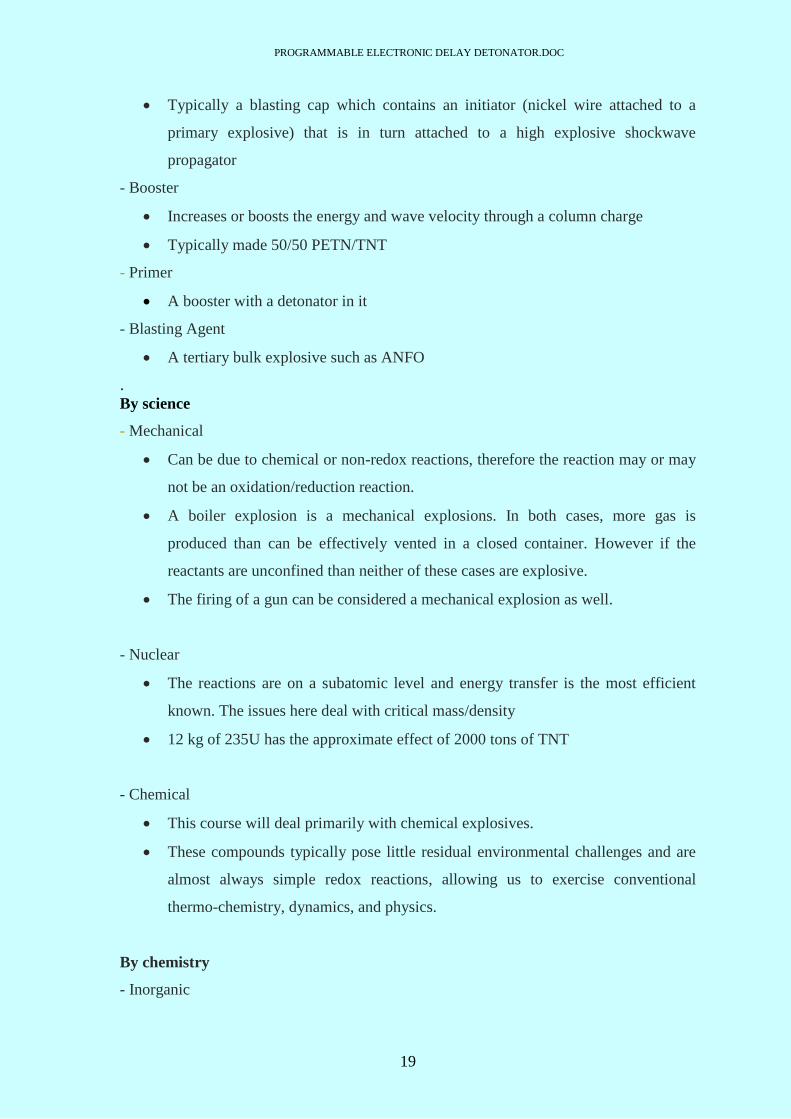
By job function
- Initiator
Any devise that “starts” the explosive process
- Detonator
PROGRAMMABLE ELECTRONIC DELAY DETONATOR.DOC
19
Typically a blasting cap which contains an initiator (nickel wire attached to a
primary explosive) that is in turn attached to a high explosive shockwave
propagator
- Booster
Increases or boosts the energy and wave velocity through a column charge
Typically made 50/50 PETN/TNT
- Primer
A booster with a detonator in it
- Blasting Agent
A tertiary bulk explosive such as ANFO
.By science
- Mechanical
Can be due to chemical or non-redox reactions, therefore the reaction may or may
not be an oxidation/reduction reaction.
A boiler explosion is a mechanical explosions. In both cases, more gas is
produced than can be effectively vented in a closed container. However if the
reactants are unconfined than neither of these cases are explosive.
The firing of a gun can be considered a mechanical explosion as well.
- Nuclear
The reactions are on a subatomic level and energy transfer is the most efficient
known. The issues here deal with critical mass/density
12 kg of 235U has the approximate effect of 2000 tons of TNT
- Chemical
This course will deal primarily with chemical explosives.
These compounds typically pose little residual environmental challenges and are
almost always simple redox reactions, allowing us to exercise conventional
thermo-chemistry, dynamics, and physics.
By chemistry
- Inorganic

PROGRAMMABLE ELECTRONIC DELAY DETONATOR.DOC
20
Inorganic compounds are often composed of metal-salts.
Inorganic compounds are considered all compounds except hydro carbons, their
derivatives, and some compounds of carbon
- Organic
Organic compounds are primarily composed of carbon, hydrogen, nitrogen, and
oxygen (i.e. Hydrocarbons)
Organic compounds are considered to be all compounds of carbon, except for
some binary and tertiary compounds
The basic high explosive train consists of the detonator, booster, and bursting
charge. The high explosive charges are loaded into their containers by one of three
methods:
cast-loaded
pre-loaded
extrusion
4.1.1. Propellants
Propellants are classified as single-base, double-base, and composite. Single base
propellants include compositions that are principally gelatinized nitrocellulose and
contain no high-explosive ingredient such as nitroglycerin. Double-base propellants are
mainly compositions that are predominately nitrocellulose and nitroglycerin. Composite
propellants are compositions that contain mixtures of fuel and inorganic oxidants but do
not contain a significant amount of nitrocellulose or nitroglycerin.
There are many different types of propellants currently in use. Some of the more
frequently used types are black powder and smokeless powder.
4.1.2. Initiating Explosives
Under normal conditions, initiating explosives will not burn, but they will detonate if
ignited. Their strength and brisance are inferior, but they are sufficient to detonate high
explosives. Because of their sensitivity, they are used in munitions for initiating and
intensifying high-order explosions.

PROGRAMMABLE ELECTRONIC DELAY DETONATOR.DOC
21
Mercury fulminate is white when pure but ordinarily, it has a faint brownish
yellow or gray tint. It is a heavy, practically non-hygroscopic, crystalline solid.
Lead azide is a crystalline, cream-colored compound which is practically
insoluble in water. When lead azide is stored in water, however, care must be
taken to assure that the water is free of bacteria-forming impurities which may
react with the dextrinated lead azide to form a gas.
Lead Styphnate has two forms: six-sided monohydrate crystals and small
rectangular crystals. Lead styphnate varies in color from yellow to brown. Lead
styphnate is particularly sensitive to fire and the discharge of static
electricity.
Tetracene is a colorless or pale yellow material. It is soluble in strong
hydrochloric acid but practically insoluble in alcohol, water, benzene, ether, and
carbon tetrachloride..
(DDNP) is a yellowish brown powder. It is soluble in acetic acid, acetone, strong
hydrochloric acid, and most of the solvents but is insoluble in water. A solution
of cold sodium hydroxide may be used to destroy it. DDNP may be desensitized
by immersing it in water, as it does not react in water at normal temperature.
4.1.3. Auxiliary Explosives
The explosives used as auxiliary explosives are less sensitive than the primary high
explosives that are employed in initiators, primers, and detonators. However, they are
generally more sensitive than those high explosives used as filler charges or bursting
explosives.
PROGRAMMABLE ELECTRONIC DELAY DETONATOR.DOC
22
Tetrytol is a cast mixture of tetryl and TNT and is designed to obtain a tetryl
mixture that may be used in burster tubes for chemical bombs, in demolition
blocks, and in cast shaped charges.
PETN (Pentaerythritoltetranitrate) is one of the strongest known high explosives.
It is more sensitive to shock or friction than TNT or tetryl, and it is never used
alone as a booster. It is primarily used in booster and bursting charges of small
caliber ammunition.
Tetryl (Trinitrophenylmethylnitramine) can be initiated from flame, friction,
shock, or sparks; it burns readily and is quite likely to detonate if burned in large
quantities.
TNT (Trinitrotoluene) is a constituent of many explosives, such as amatol,
pentolite, tetrytol, torpex, tritonal, picratol, ednatol, and composition B. It has
been used under such names as Triton, Trotyl, Trilite, Trinol, and Tritolo. In a
refined form, TNT is one of the most stable of high explosives and can be stored
over long periods of time. It is relatively insensitive to blows or friction.
4.2. DEFLAGRATION VS. DETONATION
Deflagration is a process of subsonic combustion that usually propagates through
thermal conductivity (hot burning material heats the next layer of cold material and
ignites it).
Detonation is a process of supersonic combustion in which a shock wave is
propagated forward due to energy release in a reaction zone behind it. It is the more
powerful of the two general classes of combustion, the other one being deflagration. In a
detonation, the shock compresses the material thus increasing the temperature to the point

PROGRAMMABLE ELECTRONIC DELAY DETONATOR.DOC
23
of ignition. The ignited material burns behind the shock and releases energy that supports
the shock propagation. This self-sustained detonation wave is different from a
deflagration that propagates at a subsonic speed (i.e., slower than the sound speed of the
explosive material itself), and without a shock or any significant pressure change.
Because detonations generate high pressures, they are usually much more destructive than
deflagrations.
Deflagrations are thermal processes that proceed radially outward in all directions
through the available fuel away from the ignition source. As the volume of the reaction
zone expands with every passing moment, the larger surface area contacts more fuel, like
the surface of an inflating balloon. The reaction starts small and gathers energy with time.
This process occurs at speeds depending largely on the chemistry of the fuel--from 1 to
10 meters per second in gasoline vapors mixed with air to hundreds of meters per second
in black powder or nitrocellulose propellants. These speeds are less than the speed of
sound in the fuel (The speed of sound through a material is not constant, but dependent on
the density of the material; the higher its density, the higher the speed of sound will be
through it). Deflagrations, then, are thermally initiated reactions propagating at subsonic
speeds through materials like: mixtures of natural gas and air, LP gases and air, or
gasoline vapors and air; black powder or nitrocellulose (single-base) propellants or rocket
fuels. The pressures developed by deflagrating explosions are dependent on the fuels
involved, their geometry, and the strength (failure pressure) of a confining vessel or
structure (if any). Pressures can range from 0.1psi to approximately 100psi for gasoline:
air mixtures to several thousand psi for propellants. Times of development are on the
order of thousandths of a second to a half-second or more. Maximum temperatures are on
the order of 1000-2000 degrees Celsius (2000-4000 degrees Fahrenheit).
Detonations are very different. While a detonation is still chemically an oxidation
reaction, it does not involve a combination with oxygen. It involves only special
chemically unstable molecules that, when energized, instantaneously splits into many
small pieces that then recombine into different chemical products releasing very large
amounts of heat as they do so. High explosives are defined as materials intended to
function by detonation, such as TNT, nitroglycerine, C4, picric acid, and dynamite. The
reaction speeds are higher than the speed of sound in the material (i.e., supersonic). Since
PROGRAMMABLE ELECTRONIC DELAY DETONATOR.DOC
24
most explosives are roughly the same density, a reaction speed of 1000 m/s (3100 feet per
second) is set as the minimum speed that distinguishes detonations from deflagrations.
Due to the supersonic reaction speed, a shock wave develops in the explosive (like the
sonic boom from supersonic aircraft) that triggers the propagating reaction. Detonation
speeds are on the order of 1000-10000 m/s so times of development are on the order of
millionths of a second. Temperatures produced can be 3000-5000 degrees Celsius and
pressures can be from 10000 psi to 100000 psi. It should be noted that a few materials can
transition from deflagration to detonation depending on their geometry (long, straight
galleries or pipes), starting temperature, and manner of initiation. Double-base smokeless
powders (containing nitroglycerine), perchlorate-based flashpowders, hydrogen/air
mixtures and acetylene (pure or with air) can detonate under some conditions.
The effects of detonations are very different from those of deflagrations.
Deflagrations tend to push, shove, and heave, often with very limited shattering and little
production of secondary missiles (fragmentation). Building components may have time to
move in response to the pressure as it builds up and vent it. The maximum pressures
developed by deflagrations are often limited by the failure pressure of the surrounding
structure. Detonations, on the other hand, tend to shatter, pulverize and splinter nearby
materials with fragments propelled away at a very high speed. There is no time to move
and relieve pressure so damage tends to be much more localized (seated) in the vicinity of
the explosive charge (and its initiator) than a deflagration whose damage is more
generalized. Damage from a deflagration tends to be more severe away from the ignition
point, as the reaction energy grows with the expanding reaction (flame) front.
4.3. TYPES OF DETONATOR
The various detonators that have been developed till date are described as follows:
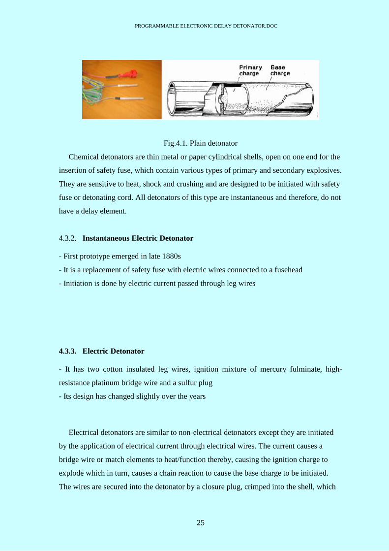
4.3.1. Chemical (plain) detonator
- Have a primary (initiating) charge and a base charge of high explosive
- Primary charge of ASA
- Base charge of PETN or RDX
PROGRAMMABLE ELECTRONIC DELAY DETONATOR.DOC
25
Fig.4.1. Plain detonator
Chemical detonators are thin metal or paper cylindrical shells, open on one end for the
insertion of safety fuse, which contain various types of primary and secondary explosives.
They are sensitive to heat, shock and crushing and are designed to be initiated with safety
fuse or detonating cord. All detonators of this type are instantaneous and therefore, do not
have a delay element.
4.3.2. Instantaneous Electric Detonator
- First prototype emerged in late 1880s
- It is a replacement of safety fuse with electric wires connected to a fusehead
- Initiation is done by electric current passed through leg wires
4.3.3. Electric Detonator
- It has two cotton insulated leg wires, ignition mixture of mercury fulminate, high-
resistance platinum bridge wire and a sulfur plug
- Its design has changed slightly over the years
Electrical detonators are similar to non-electrical detonators except they are initiated
by the application of electrical current through electrical wires. The current causes a
bridge wire or match elements to heat/function thereby, causing the ignition charge to
explode which in turn, causes a chain reaction to cause the base charge to be initiated.
The wires are secured into the detonator by a closure plug, crimped into the shell, which
PROGRAMMABLE ELECTRONIC DELAY DETONATOR.DOC
26
seals the explosive from moisture. In addition to sensitivity from heat, shock and
crushing, these products are subject to extraneous electricity due to the presence of
electrical wire.
Fig.4.2. Electric Detonator
4.3.4. Delay Electric Detonator
- It is same as instantaneous electric detonator, except for inclusion of delay powder train
- Delay time based on length and composition of delay powder
- Half-second delay during early 1900s; millisecond delay during 1943

PROGRAMMABLE ELECTRONIC DELAY DETONATOR.DOC
27
Fig.4.3. Delay electric detonator
4.3.5. Electronic detonator
- Idea of electronic detonator was first discussed in the beginning of 1990s
- Recognized potential to increase detonator accuracy and improve customer results
- Costly technology has been used in this case
- Minesite drive to increase accuracy resulted in various manufacturers beginning to
develop and market versions of electronic detonator
- Several different designs have been developed under this although fundamental
structure is basically the same
- Computer chip is used to control the delay timing which uses electrical energy stored in
one or more capacitors to provide power for timing clock and initiation energy
- Therefore delay is achieved electronically not pyrotechnically (powder)
Fig.4.4. Electronic Detonator
PROGRAMMABLE ELECTRONIC DELAY DETONATOR.DOC
28
4.4. TYPES OF DETONATION SYSTEMS
There are probably a dozen different electronic detonator systems either in
development, or being utilized, in the world today. Their differences include detonator
construction, timing precision, communication protocol, blasting machines, tie-in,
connectors, etc. Although they are each uniquely different from one another, there are a
few basic design features that are common. A brief overview of the generic system
architectures found in the industry today is provided herein.
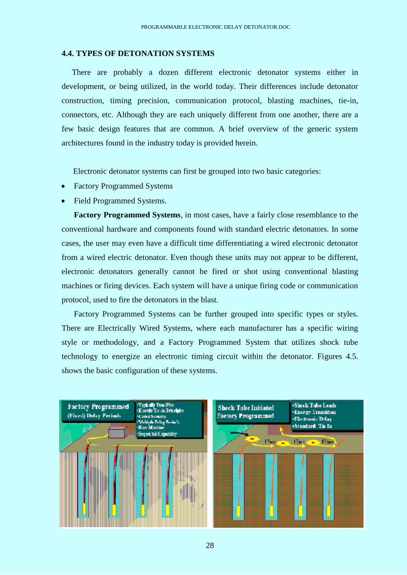
Electronic detonator systems can first be grouped into two basic categories:
Factory Programmed Systems
Field Programmed Systems.
Factory Programmed Systems, in most cases, have a fairly close resemblance to the
conventional hardware and components found with standard electric detonators. In some
cases, the user may even have a difficult time differentiating a wired electronic detonator
from a wired electric detonator. Even though these units may not appear to be different,
electronic detonators generally cannot be fired or shot using conventional blasting
machines or firing devices. Each system will have a unique firing code or communication
protocol, used to fire the detonators in the blast.
Factory Programmed Systems can be further grouped into specific types or styles.
There are Electrically Wired Systems, where each manufacturer has a specific wiring
style or methodology, and a Factory Programmed System that utilizes shock tube
technology to energize an electronic timing circuit within the detonator. Figures 4.5.
shows the basic configuration of these systems.
PROGRAMMABLE ELECTRONIC DELAY DETONATOR.DOC
29
Fig.4.5. Factory Programmed detonation Systems
Field Programmed Systems utilize electronic technology to program delay times "on
the bench". Each system is manufactured for, or with, unique system architectures, styles,
hardware and communication protocol. There are no fixed delay times associated with
these detonators. These systems rely on direct communication with the detonator (either
prior to loading, after loading, or just prior to firing) for the proper delay time and
subsequent blast design. In general, these systems will utilize some type of electronic
memory, which allows them to be reprogrammed at any time up until the fire command is
given.
Designs, as well as amount and type of additional equipment necessary for use, vary
considerably in Field Programmable Systems. Example of system concept in use today is
shown in Figure 4.6. Figure 4.6. depicts a system concept that would utilize computer
technology to program detonators either directly from the blast machine or via blast
design software. Programming may also be done in some cases with handheld
test/programmers prior to final connection of the blast. Other system concepts may utilize
a handheld test and programming unit to check the detonator’s circuitry prior to final
connection to the blast machine. Following connection, the entire circuit can be checked
via the blasting machine for system level continuity.

PROGRAMMABLE ELECTRONIC DELAY DETONATOR.DOC
30
Fig.4.6. Field programmed detonation system

PROGRAMMABLE ELECTRONIC DELAY DETONATOR.DOC
31
CHAPTER 5
REAL TIME APPLICATIONS

PROGRAMMABLE ELECTRONIC DELAY DETONATOR.DOC
32
5. REAL TIME APPLICATIONS: -
5.1. CASE 1: - Towers of the Val-Fourré district of Mantes-la-Jolie, France
Three apartment towers in the Val-Fourré district of Mantes-la-Jolie, France were demolished
with the help of Orica’s electronic detonator System on Sunday July 2, 2006. The demolitions
were part of a ten-year-old Urban Renewal Program that is being undertaken by the city located
30 miles (50 kms) northwest of Paris, and involves remaking what was once one of the least
attractive suburbs in France.
Built in the 1960’s-70’s, the three towers on Edgar Degas Street were called K1, K2 and K3
and stood 160 feet tall, but took less than 10 seconds to fall. The blast took three months to plan
and used 580 kgs of explosives and 3138 electronic detonators. This historic blast was also the
largest electronic demolition blast ever undertaken in Europe and was very close to being the
largest electronic blast of any kind ever fired in the world.
Several of France’s most experienced demolition companies were involved in this complex
project. Site management was handled by CEBTP and a different company was assigned to each
building. Melchiorre was responsible for K1, SMD for K2 and Cardem for K3. As well, local
company ATD supplied 3300 feet (1000 m) of water hose for dust suppression.
NEF Paris was responsible for the overall blast design with support from Orica Germany
personnel: Dirk Grothe, Jan Lindenau and Peter Reinders who provided valuable
recommendations and tips. The blast itself was fired by Guy Thomasson and Jean-Louis
Schreiber of NEF Paris, using 2 i-kon™ Blaster 2400S units in synchro mode.
The blast went off perfectly as planned and none of the surrounding buildings, some as close
as 120 feet, sustained any damage. As soon as the site is cleaned up, construction will begin on a
huge aquatic theme park.
PROGRAMMABLE ELECTRONIC DELAY DETONATOR.DOC
33
5.2. CASE 2: - Chuquicamata mine
Chuquicamata mine is the largest and deepest open pit copper mine in the world. It is owned
and operated by state-owned codelco mining, Chile. It is located in Chile’s second region,
1600kms north of Santiago. The production is approximately 600000 tonnes/yr of fine copper.
The requirement was of very specific fragmentation size to maximize the output. Great depth
of mine means steeper slopes, which affect haul truck efficiency. A key geological challenge was
the lack of stability in the west wall, which is next to a fault line that runs through the pit.
Avoidance of wall collapses was critical. Location of mine required the equipment to be
subjected to extreme aridity, severe temperatures, high solar radiation levels and frequent strong
static electricity.
The mine consists of 7 different geological sectors and blast plans must be customized to each
unique area. Typical blast was 100 holes x 12 1/2” diameter on a 7m x 9m pattern, producing
about 250,000 tonnes of rock per shot, using a powder factor of 0.33 kgs per tonne. To increase
the safety and maintain highwall stability, blast size was restricted and bench height was reduced
from 26m to 18m. The electronic detonators were used to for this operation. The mine was
carefully explored with pattern expansion, increased blast size and potentially, steeper walls.
The blast resulted in Consistent fragmentation size with i-kon™ detonator, significantly
improved crusher and SAG mill efficiency, and reduced wear and tear on loaders and haul
trucks. Smaller rock size has reduced the amount and cost of mechanical and electrical energy
required in downstream copper extraction processes. Increased vibration control has reduced
blast impact on pit walls and contributed to overall pit stability. Reduced powder factor saves on
overall explosives consumption.

PROGRAMMABLE ELECTRONIC DELAY DETONATOR.DOC
34
Fig.5.1. Tower of Val-Fourré district of Mantes-la-Jolie, France (courtesy: www.i-
konsystem.com)
Fig.5.2. Chuquicamata mine (courtesy: www.i-konsystem.com)
PROGRAMMABLE ELECTRONIC DELAY DETONATOR.DOC
35
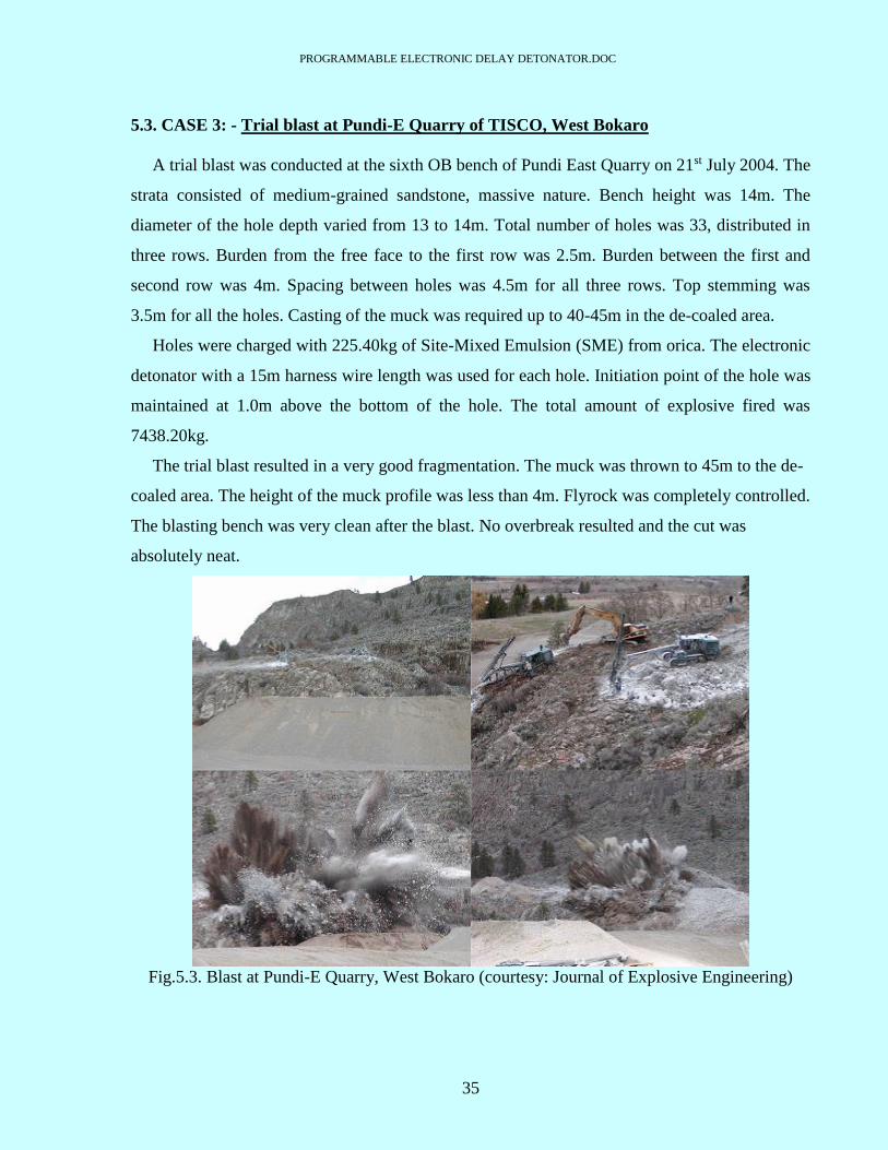
5.3. CASE 3: - Trial blast at Pundi-E Quarry of TISCO, West Bokaro
A trial blast was conducted at the sixth OB bench of Pundi East Quarry on 21st July 2004. The
strata consisted of medium-grained sandstone, massive nature. Bench height was 14m. The
diameter of the hole depth varied from 13 to 14m. Total number of holes was 33, distributed in
three rows. Burden from the free face to the first row was 2.5m. Burden between the first and
second row was 4m. Spacing between holes was 4.5m for all three rows. Top stemming was
3.5m for all the holes. Casting of the muck was required up to 40-45m in the de-coaled area.
Holes were charged with 225.40kg of Site-Mixed Emulsion (SME) from orica. The electronic
detonator with a 15m harness wire length was used for each hole. Initiation point of the hole was
maintained at 1.0m above the bottom of the hole. The total amount of explosive fired was
7438.20kg.
The trial blast resulted in a very good fragmentation. The muck was thrown to 45m to the de-
coaled area. The height of the muck profile was less than 4m. Flyrock was completely controlled.
The blasting bench was very clean after the blast. No overbreak resulted and the cut was
absolutely neat.
Fig.5.3. Blast at Pundi-E Quarry, West Bokaro (courtesy: Journal of Explosive Engineering)

PROGRAMMABLE ELECTRONIC DELAY DETONATOR.DOC
36
CHAPTER 6
SIGNIFICANCE OF DELAY

PROGRAMMABLE ELECTRONIC DELAY DETONATOR.DOC
37
6. SIGNIFICANCE OF DELAY: -
A delay is a device that causes time to pass from when a device is set up to the time that it
explodes.
6.1. TYPES OF DELAY: -
There are many types of delay. They are discussed as follows: -
6.1.1. Fuse delay
It is extremely simple to delay explosive devices that employ fuses for ignition. Perhaps the
simplest way to do so is with a cigarette. An average cigarette burns for between 8-11 minutes.
The higher the "tar" and nicotine rating, the slower the cigarette burns. Low "tar" and nicotine
cigarettes burn quicker than the higher "tar" and nicotine cigarettes, but they are also less likely
to go out if left unattended, i.e. not smoked. Depending on the wind or draft in a given place, a
high "tar" cigarette is better for delaying the ignition of a fuse, but there must be enough wind or
draft to give the cigarette enough oxygen to burn. People who use cigarettes for the purpose of
delaying fuses will often test the cigarettes that they plan to use in advance to make sure they
stay lit and to see how long it will burn. Once a cigarettes burn rate is determined, it is a simple
matter of carefully putting a hole all the way through a cigarette with a toothpick at the point
desired, and pushing the fuse for a device in the hole formed.
6.1.2. Chemical delay
Chemical delays are uncommon, but they can be extremely effective in some cases. The delay
would ensure that a bomb would detonate hours or even days after the initial bombing raid. If a
glass container is filled with concentrated sulfuric acid, and capped with several thicknesses of
aluminum foil, or a cap that it will eat through, then it can be used as a delay. Sulfuric acid will
react with aluminum foil to produce aluminum sulfate and hydrogen gas, and so the container
must be open to the air on one end so that the pressure of the hydrogen gas that is forming does
not break the container.
6.1.3. Timer delay
There are several ways to build a timer delay. By simply using a screw as one contact at the
time that detonation is desired, and using the hour hand of a clock as the other contact, a simple
timer can be made. The main advantage with this type of timer is that it can be set for a

PROGRAMMABLE ELECTRONIC DELAY DETONATOR.DOC
38
minimum time of ms. By attaching the wires of a squib or igniter to a the supply, a timer with a
delay of up to 25ms can be made. Such a timer could be extremely small.
6.2. NEED OF APPLYING DELAY
For proper fragmentation
To reduce ground vibration and air blast
To minimize the destruction and increase the output
To enable sequential blasting
6.2.1. Ground Vibration
When an explosive detonates within a borehole it causes the rock in the immediate vicinity to
crack or distort. Outside this immediate vicinity of the blast site permanent deformation does not
occur, instead the rapidly decaying stress waves from the explosion cause the ground to exhibit
elastic properties whereby the rock particles are returned to their original position as the stress
waves pass. This causes ground vibration to radiate away from the blast site, the effect reducing
as distance increases.
It is always in the operator's interest to reduce both ground and airborne vibration from blast
events to the minimum possible for any specific blast design because it is this that substantially
increases the efficiency, and therefore, economy of blasting operations.
6.2.2. Air-Blast
All of the energy liberated by the explosive is initially in the form of a highly compressed gas.
Some of that gas escapes to the surface and travels through the air as airblast. The largest part of
the compressed gas energy goes into breaking and moving rock. The sudden movement of the
rock at its face or at the ground surface also causes a disturbance, which propagates through the
air. Parts of these disturbances are in the audible range of frequencies (>20 Hz) and are
collectively called noise. Some of these disturbances are in the sub-audible range. Both parts
together are called airblast. If sufficiently intense, they can cause buildings to vibrate and crack
windows to vibrate or break and discomfort or pain to individuals.

PROGRAMMABLE ELECTRONIC DELAY DETONATOR.DOC
39
Air blast is usually caused by one of three mechanisms. The first cause is energy released
from unconfined explosives such as uncovered detonating cord trunklines or mudcapping used in
secondary blasting. The second cause is the release of explosive energy from inadequately
confined borehole charges resulting from inadequate stemming, inadequate burden or mud
seams. The third cause is movement of the burden and the ground surface. Blasts are designed
to displace the burden.

PROGRAMMABLE ELECTRONIC DELAY DETONATOR.DOC
40
CHAPTER 7
WORKING PRINCIPLE AND
MODEL CONCEPT

PROGRAMMABLE ELECTRONIC DELAY DETONATOR.DOC
41
7.1. WORKING PRINCIPLE: -
The detonator unit works on the principle that whenever the counting in the counter is
completed, a port pin goes high. This high pin is used for further processing.
The user feeds the desired delay in ms within the range from the keyboard, which is converted
into equivalent count value required to give the delay by the program.
The formula for generating the desired count value for a particular delay time is as follows: -
N= (Time delay Crystal frequency) / 12
Count value = 65536 - n
The counter will start working only after entering the correct password. In case of wrong
password the system will not work.

PROGRAMMABLE ELECTRONIC DELAY DETONATOR.DOC
42
7.2. BLOCK DIAGRAM: -
Fig.7.1. Block diagram of time setter and timer unit of detonator
The control unit block diagram basically consists of a keypad, a LCD display, a power supply
unit viz. battery and a microcontroller unit. All the inputs are entered through the keypad. The
inputs entered are directly displayed on the LCD screen. The microcontroller unit performs the
necessary calculation and interfacing operations so that the control unit and the timer unit
communicate with each other. The output driver section is the interface between the control and
timer unit.
The timer block diagram basically consists of a d.c. power supply which a 5-10V battery, a
regulator, an oscillator, a counter, a power-on-reset ckt. and an igniter device viz. squib. The
squib is basically a SCR. To the gate of the SCR the output of the counter circuit is given; to the
anode of the squib the stored energy of the capacitor is given. The output from this squib will
then ignite the explosive.
In the actual implementation the assembly of power-on-reset, oscillator and counter is
replaced by a microcontroller. The regulator will provide a constant voltage of 5V to the
microcontroller (POR, oscillator, counter).

PROGRAMMABLE ELECTRONIC DELAY DETONATOR.DOC
43
CHAPTER 8
HARDWARE DESIGN

PROGRAMMABLE ELECTRONIC DELAY DETONATOR.DOC
44
8. HARDWARE DESIGN: -
8.1. TIME SETTER UNIT: -
Fig.8.1. Circuit diagram for time setter unit

PROGRAMMABLE ELECTRONIC DELAY DETONATOR.DOC
45
Time setter description:-
The time setter unit contains a power supply unit, a LCD display unit, a keypad matrix and a
communication section.
The power supply unit is a constant 5V supply. It consists of a regulator IC which can take a
maximum of 20V input voltage and in turn produces a 5V constant output voltage.
The keypad is used to enter the inputs into the system. The various inputs for the system are
detonator ID, delay time and password (optional). The keypad is connected to the port 2 pins of
the AT89C51RD2 microcontroller. Any key pressed will be sensed by the port 2 pins and the
corresponding key pressed will be displayed on the LCD display.
The LCD display connected to the port 0 of the microcontroller is a 16×2 display. It will
display the detonator ID, delay time entered by the user.
A MAX 232 IC is also connected to the TXD, RXD pins of the controller to facilitate the
serial communication between the time setter and the timer unit by converting the TTL standard
into the RS232 standards.
Whenever the user enters a particular detonator ID through the keypad, the value will get
displayed on the LCD screen. This ID will then be sent to the timer unit via serial
communication and then will get store into the EEPROM memory of the timer microcontroller.
Similarly the entered delay time will also get serially transferred to the timer part after
calculating the necessary count value for that particular delay time.
The crystal connected to the microcontroller provides the necessary frequency for the
operation of the microcontroller.

PROGRAMMABLE ELECTRONIC DELAY DETONATOR.DOC
46
8.2. TIMER UNIT: -
Fig.8.2. Circuit diagram for timer unit

PROGRAMMABLE ELECTRONIC DELAY DETONATOR.DOC
47
Timer description:-
The timer unit basically consists of an 8-pin microcontroller, a charging-discharging section
and ignitor section.
The purpose of using the 8-pin microcontroller is to achieve a detonator which is small in
size. The microcontroller used here is an AVR microcontroller. The timer microcontroller is used
to store the delay subroutine to generate the desired delay entered by the user.
The charging-discharging section consists of an NPN transistor which is used as a switch for
charging and discharging the storage capacitor. Two zener diodes have been employed in order
to provide the necessary voltages to the microcontroller and the charging capacitor for their
operation. The switching of the transistor is controlled from the time setter side. The base of the
transistor is connected to a port pin of the setter side microcontroller. At first the transistor is
kept ON so that the storage capacitor gets charged to the desired value. Then the transistor is
switched OFF so that the stored energy is discharged to the anode terminal of a SCR. Now when
the delay subroutine is called then the timer microcontroller will execute that routine and will
output a delay pulse which will act as gate pulse for the SCR and hence the SCR will get ON and
in turn will glow the LED. The SCR and the LED constitutes the ignitor section for the timer.
In the actual scenario this LED will get replaced by some explosives train in order to carry out
the blasting operation. All the data from the time setter side is received via the MAX 232 IC.
PROGRAMMABLE ELECTRONIC DELAY DETONATOR.DOC
48
8.3. WORKING: -
First, d.c. current from battery is supplied to the electronic detonator in order to activate their
microcircuitry in the integrated delay circuit. Once this is performed, a command may be given
to power up their capacitive storage devices such as capacitor. When power storage is complete,
the electronic timing delays within each electronic detonator will be initiated at precisely the
same time by a complex firing code issued by the firing console after a firing button is depressed
by the operator. If, however, something is shown to be wrong by the firing console, the operator
may power down the detonator power storage units such as capacitor by issuing an abort
command, thus rendering the detonator harmless before disconnecting the firing console from
the firing circuit.
For safety, the detonator is made such that direct current passing through the circuit does not
initiate the device, initiation only being possible by the use of the correct signal. This eliminates
accidental initiation caused by stray currents, electromagnetic fields, radio waves, static
electricity, etc. However, in order to protect the microchip from accidental burn-out due to
current or voltage overloading in such a situation, a voltage regulating device and an associated
transient suppressor such as a varistor is provided.
8.4. SECURITY: -
For the purpose of security, a binary security code is used in the preferred embodiment of the
invention. The code is unique to the user or manufacturer. To eliminate unauthorized use this
code is kept secret with only the manufacturer knowing the combination. The user need not
know this code as it is integrated in the software control program supplied by the manufacturer
with the firing console. The security code controls the powering-up of the appropriate discharge
circuits until this command has been given, the detonator cannot be energized and fired. Thus the
blasting cap will not fire when linked up to any d.c. or a.c. power source. To fire the detonator or
a series of these detonators, one would therefore have to have in their possession not only a firing
console made or marketed by the manufacturer of the detonator, but one that is compatible with
the detonators one is going to use.
The construction includes three leg wires, two long ones for power and firing purposes, and
the third solely for factory programming which is clipped and sealed after this process. If,

PROGRAMMABLE ELECTRONIC DELAY DETONATOR.DOC
49
however, programming in the field is required, the third wire may be left intact for later
programming.
Software is provided in the form of ROM packs (Read Only Memory-microchips) for
updating ease. Such software training packages can eliminate the need for blasting personnel
being sent to retraining courses, eliminating extra cost and lost man-time. Such programs can
even test the personnel as well as teach them and thus finally pass them out and permit them to
use the firing console in the true firing mode after several successful simulations.

PROGRAMMABLE ELECTRONIC DELAY DETONATOR.DOC
50
CHAPTER 9
SOFTWARE DESIGN
PROGRAMMABLE ELECTRONIC DELAY DETONATOR.DOC
51
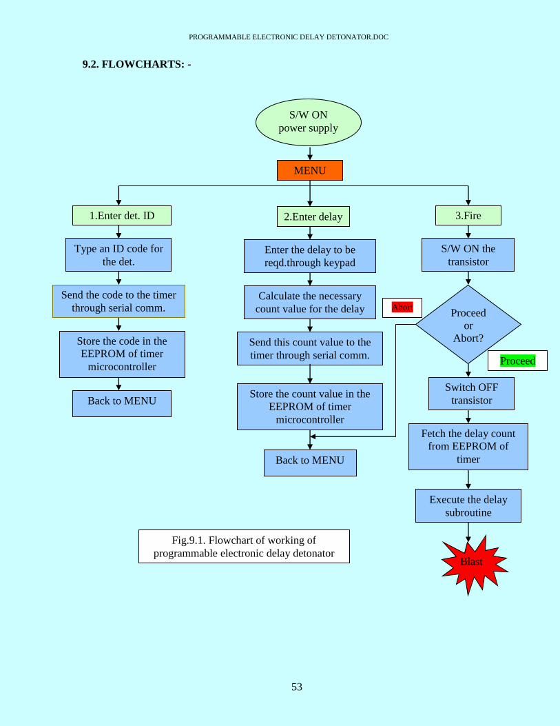
9. SOFTWARE DESIGN: -
9.1. ALGORITHM
The basic algorithm for the working of the electronic delay detonator is shown in the attached
figure.
The software should work in the following manner: -
Initially both the microcontrollers of time setter unit and the timer module will be in the
reset condition.
Once the battery supply in switched ON, it will wake up both the microcontrollers.
Then one MENU screen should appear in the LCD display as,
1. Enter detonator ID 2.Enter delay 3. Fire
1. Enter detonator ID
When the user enters ‘1’ through the keyboard, then the LCD should display “enter the
detonator ID”.
Then the user will type the detonator ID as some 2-digit decimal number.
Then this ID value will be sent to the timer module via serial communication.
There it will be stored in the EEPROM memory of the timer microcontroller.
Then the control will return to the MENU screen.
2. Enter delay
When the user enters ‘2’ through the keyboard then the LCD should display “enter the
delay”.
Then the user will enter the delay value say ‘25’ (for 25ms delay) through keyboard.
Then the microcontroller of the time setter unit will calculate the necessary count value
for the entered delay value.
This calculated count value will then be sent to the timer module via serial
communication.
There it will get stored in the EEPROM memory of the timer microcontroller.
Then the control will return to the MENU screen.
PROGRAMMABLE ELECTRONIC DELAY DETONATOR.DOC
52
3. Fire
When the user enters ‘3’ through the keyboard, then the LCD should display “charge the
capacitor”.
Then the user will enter ‘C’ through keyboard which will generate a high pulse at pin
P2.4 (pin no.25). This will short the transistor at the timer side and the storage capacitor
will get charged.
Now the LCD should display “abort or proceed”.
If the user enters ‘X’ then the control should return to the MENU.
If the user enters ‘A’ then setter microcontroller should generate a low pulse at pin P2.4
(pin no.25). This will switch OFF the transistor and hence the storage capacitor voltage
will get applied to the anode of the SCR in timer side.
When the user enters ‘F’, then the timer microcontroller must fetch (read) the stored
count value from the EEPROM memory and should execute the timing subroutine and
generate a pulse at pin PB2 (pin no. 7) for the gate of the SCR.
Apart from the above mentioned points, we can also keep the provision for the password
for nullifying the unauthorized access of the setter unit (this is optional). In this, setter will
have a unique security code. Only after entering that particular code, the setter will operate
otherwise not.
The software part also contains the LCD and keyboard interfacing programming.
PROGRAMMABLE ELECTRONIC DELAY DETONATOR.DOC
53
9.2. FLOWCHARTS: -
S/W ON
power supply
MENU
2.Enter delay
Enter the delay to be
reqd.through keypad
Calculate the necessary
count value for the delay
Send this count value to the
timer through serial comm.
Store the count value in the
EEPROM of timer
microcontroller
Back to MENU
1.Enter det. ID
Type an ID code for
the det.
Send the code to the timer
through serial comm.
Store the code in the
EEPROM of timer
microcontroller
Back to MENU
3.Fire
S/W ON the
transistor
Proceed
or
Abort?
Switch OFF
transistor
Fetch the delay count
from EEPROM of
timer
Execute the delay
subroutine
Blast
Abort
Proceed
Fig.9.1. Flowchart of working of
programmable electronic delay detonator

PROGRAMMABLE ELECTRONIC DELAY DETONATOR.DOC
54
9.2.1. Delay subroutine flowchart: -
Stop the timer
Fig.9.2. Flowchart for the timer
NO
YES
Start
Select one of
the timers
Select the
timer mode
Calculate/fetch
the count value
Enter count value in
timer register
Start the timer
Monitor the
timer flag
Is timer
flag bit
set?

PROGRAMMABLE ELECTRONIC DELAY DETONATOR.DOC
55
9.2.2. Serial communication subroutine for time setter unit: -
Start
Set the timer mode
for communication
Set the baud rate
Set the serial mode
for communication
Start the timer
Set the timer in
transmitting mode
Load the SBUF
register with the data
to be sent
Monitor the transmit
interrupt flag
Is the data
sent?
Transmit next data
NO
YES
Fig.9.3.Flowchart for serial communication of time setter unit

PROGRAMMABLE ELECTRONIC DELAY DETONATOR.DOC
56
9.2.3. Serial communication subroutine for timer unit: -
Start
Set the timer mode
for communication
Set the baud rate
Set the serial mode
for communication
Start the timer
Set the timer in
receiving mode
Is the data
received?
Monitor the receive
interrupt flag
Save the received data
in SBUF register
Receive next data
NO
YES
Fig.9.4. Flowchart for serial communication of timer unit

PROGRAMMABLE ELECTRONIC DELAY DETONATOR.DOC
57
CHAPTER 10
ADVANTAGES OF THE PRESENT STATE OF ART

PROGRAMMABLE ELECTRONIC DELAY DETONATOR.DOC
58
10. ADVANTAGES OF THE PRESENT STATE OF ART
The delay detonator of the project is a microcontroller based detonator model. So far the
various detonators that are developed till date have been employing different methods of delay
generation.
At first the chemical detonator came into the picture which employed a train of chemicals
for generating the delay before blasting. But the delay generated by chemicals (pyrotechnically)
is very unreliable, as they can never provide an accurate delay and hence causes uncontrolled
blasting and more destruction.
After that the next state of art that can into existent is the shock tube delay detonator. In this
model the delay is generated using a piezoceramic assembly which is used to convert the
mechanical vibration into electrical signal which is further used for the delay generation. But this
assembly is very complex in itself and very costly too. Hence this model is not used frequently.
The next type of delay detonator is the electrical detonator. In this case the delay is
generated using electric signal. The current causes a bridge wire or match elements to
heat/function thereby, causing the ignition charge to explode which in turn, causes a chain
reaction to cause the base charge to be initiated. This system is highly susceptible to extraneous
electricity, AC/DC voltages, stray currents, electrostatic discharge etc. and hence is not highly
reliable.
Now a days the electronic detonators are being employed which eliminates almost every
drawback of the earlier inventions. Under the electronic detonator, various concepts have been
employed for better performance. This includes counter based delay generation, timer chip based
delay generation.
The counter based delay detonator consists on separate oscillator section, counter section and
reset circuitary. All these separate sections used to increase the size of the detonator unit. Hence
the detonators formed are considerably bigger in size.
The delays generated by timer chip based detonator are of limited range. For example in case
of the timer IC 555 the delay time depends on the resistor and capacitor used which are not
PROGRAMMABLE ELECTRONIC DELAY DETONATOR.DOC
59
reliable. Hence the requirement is for one such model which can eliminate all the above
drawbacks.
For this a microcontroller based detonator model is highly efficient. In this project a
microcontroller based delay detonator has been designed which can provide the following
enhanced features: -
1. The microcontroller includes the oscillator, counter and reset circuit within itself hence the
size of the timer unit reduces considerably.
2. The microcontroller can generate large range of delay time based on the crystal frequency.
3. The microcontroller provides an electronic delay detonator capable of two-way
communication.
4. On-line programmability such that a single detonator may be programmed for any delay
period.
5. The detonator is blasted by specific blasting machine (setter). Hence outside access is
prohibited.

PROGRAMMABLE ELECTRONIC DELAY DETONATOR.DOC
60
CHAPTER 11
SPECIFICATIONS

PROGRAMMABLE ELECTRONIC DELAY DETONATOR.DOC
61
11. SPECIFICATIONS: -
Physical size of PCB : 40mm by 60mm
Delay timing : Settable at factory
Multiples of 25ms or 500ms
Accuracy of 1ms(if possible 100µs)
Over/under voltage : no operation
Reliability : 100%
Charging voltage : approx. 25V
Testing voltage : 5V d.c. ; 3-5mA
Firing current : 1A for 4ms
Polarity : f ree
Connection : 2 wire system for charging & firing in parallel or
bus system.
Blasting machine : The detonator should fire with our blasting
machine only.
Password for unauthorized operation control.
Sympathetic detonation : 1. When one detonator fires at 50m in water
then no other detonator should fire at that
time.
2. Delay timings should not be affected by
shock.
Construction : 1. It should have 2 pins at one end for
crimping/soldering.
2. It should have 2 cups on the other end for
connection to the lead wire.
3. It should be potted with suitable potting
material so as to meet environmental
conditions as per miligrade std.331B.
Environmental conditions : 1. It should be designed to work in all environ-
mental conditions (snow, desert, sea).
2. It should be properly packed to survive shock,
vibration, acceleration/deaccelaration during
handling, transportation & storage.
3. The electronic timer & time setter should be
subjected to qualification tests as per
miligrade std.331B.
Shelf life : 10 years.
PROGRAMMABLE ELECTRONIC DELAY DETONATOR.DOC
62
CHAPTER 12
EXPERIMENTATION AND TESTING

PROGRAMMABLE ELECTRONIC DELAY DETONATOR.DOC
63
12. EXPERIMENTATION AND TESTING: -
S.NO. DELAY ENTERED
(in ms) DELAY
OBTAINED (in ms) ACCURACY
1
2
3
4
5
6
7
8
9
10
PROGRAMMABLE ELECTRONIC DELAY DETONATOR.DOC
64
CHAPTER 14
RESULT AND CONCLUSION

PROGRAMMABLE ELECTRONIC DELAY DETONATOR.DOC
65
14. RESULT AND CONCLUSION: -

PROGRAMMABLE ELECTRONIC DELAY DETONATOR.DOC
66
CHAPTER 13
FUTURE PROSPECTS
PROGRAMMABLE ELECTRONIC DELAY DETONATOR.DOC
67
13. FUTURE PROSPECTS: -
Technologies are being updated every minute. Today is the age of miniaturization and
simplicity. A more compact and reliable material will find its way up in the new-age markets.
This project basically works on this main aim. The programmable electronic delay detonator
of this project uses an efficient 8051 microcontroller. Hence it fulfills the requirement of
compactness, reliability and speed.
However the timer circuit designed is required to be of very small size. Hence using the SMD
components and using 2-layer or 4-layer PCBs, which will reduce the size of the circuit
considerably, can do the further improvement.
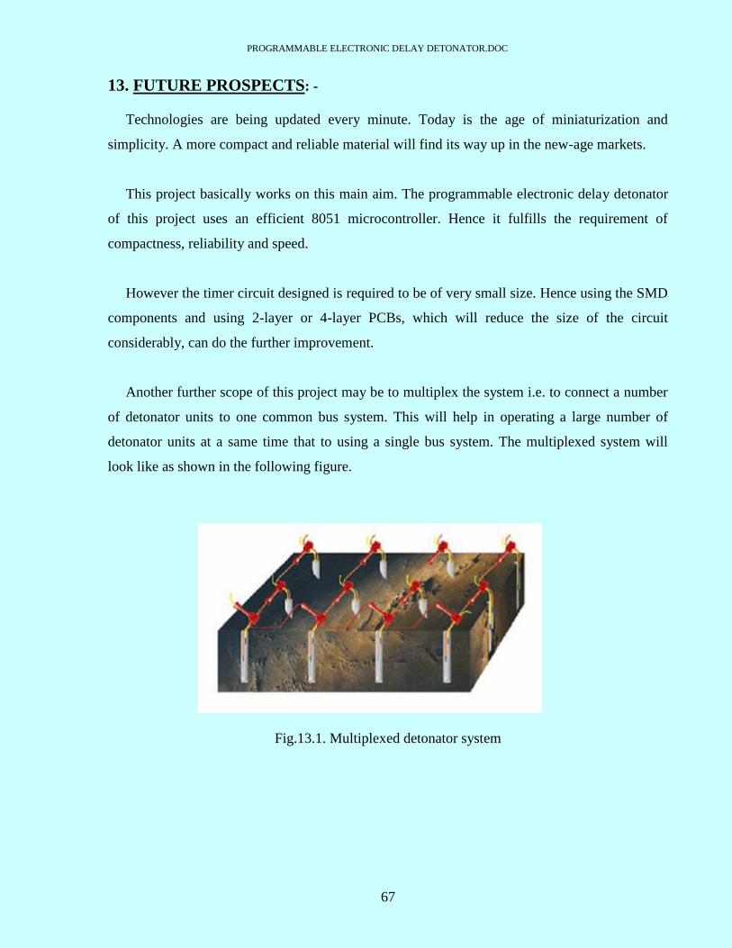
Another further scope of this project may be to multiplex the system i.e. to connect a number
of detonator units to one common bus system. This will help in operating a large number of
detonator units at a same time that to using a single bus system. The multiplexed system will
look like as shown in the following figure.
Fig.13.1. Multiplexed detonator system

PROGRAMMABLE ELECTRONIC DELAY DETONATOR.DOC
68
REFERENCES

PROGRAMMABLE ELECTRONIC DELAY DETONATOR.DOC
69
15. REFERENCES: -
1. Ochi; Koji (Iwamizawa, JP), Harada; Masahide (Sapporo, JP), Kobayashi; Kunio
(Takasaki, JP) ; US Patent no. 4,984,519; “Delay circuit for use in electric blasting system” ;
January 15,1991.
2. Pallanck; Robert G. (Windsor, CT), Rode; Kenneth A. (Collinsville, CT); US Patent no.
5,173,569; “Digital delay detonator” ; December 22,1992.
3. Prinz; Francois (San Jose, CA), Steeves; Kent (Newark, DE), Atkeson; Peter L. C.
(Newark, DE), Walsh; Brendan (Elkton, MD), Wilson; J. Michael (Gilroy, CA); US Patent
no. 5,460,093; “programmable electronic time delay initiator”; October 24,1995.
4. Gwynn,III,James C.(Litiz,PA); US Patent no. 5,621,184; “programmable
electronic timer circuit” ; April 15,1997.
5. Eddy, Christopher L.; (McCandless, PA) ; Singhal, Rajeev N.; (Pittsburgh,
PA); US Patent no. 20030029344; “System for the initiation of rounds of individually delayed
detonators”; February 13, 2003.
6. Peter.J.Duniam (Flemington,AU):Peter.J.McCallum (The Gap,AU);William.H.Birney
(Nidrea,AU);US Patent no.6,644,202 B1;”Blasting arrangement”; November 11,2003.
7. Claude Pathe (Hery); Rapheal Trousselle (Auxerre);US Patent no.6,173,651 B1;” Method
of Detonator control with electronic ignition module, coded blast controlling unit and ignition
module for its implementation”; January 16,2001.
8. Tatsumi Arakawa (yokohama); Masaaki Nishi; Kazuhiro Kurogi (Nobeoka,Japan);US .
Patent no.5,602,713: “Electronic delay detonator”; February 11,1997
9. Gerald.L.Oswald (New Ringgold);US Patent no.4,445,435;”Electronic delay blasting
circuit”; May 1,1984.
PROGRAMMABLE ELECTRONIC DELAY DETONATOR.DOC
70
10. Kenneth N. Jarrott (Royston park);Eric J. Parker (Vista);US Patent no. 4,632,031;
“Programmable electronic delay fuse”; December 30,1986.
11. Kosuke Miki (Sagamihara); Shiro Hiruta (Tokyo);US Patent no. 4,586,437; “Electronic
delay detonator”; May 6,1986.
12. Lawson J. Tyler ; Paul N. Worsey (Rolla);US Patent no. 4,674,047; “ Integrated detonator
delay circuits and firing console”; June 16, 1987.
13. Andre Guimard (Toulouse);Denis Harle (Rouen);US Patent no. 5,520,114; “ Method of
controlling detonators fitted with integrated delay electronic ignition modules, encoded
firing control and encoded ignition module assembly for implementation purposes”; May 28,
1996.
14. Dirk Hummel (Hennef);Olaf Cramer (Essen);US Patent no. 6,851,369 B2; “Access control
for electronic blasting machines”; February 8, 2005.
15. Developments with Electronic Detonators by John T. Watson.
Websites:
www.uspto.gov
www.drdo.org
www.dtic.mil
www.epanorama.com
www.atmel.com
www.alldatasheet.com
www.i-konsytem.com
www.freepatentonline.com
Reference books: -
The 8051 microcontroller and embedded systems – Mazidi & Mazidi
The 8051 microcontroller-Architecture, programming and interfacing - Kenneth.J.Ayala

PROGRAMMABLE ELECTRONIC DELAY DETONATOR.DOC
71
APPENDIX
PROGRAMMABLE ELECTRONIC DELAY DETONATOR.DOC
72
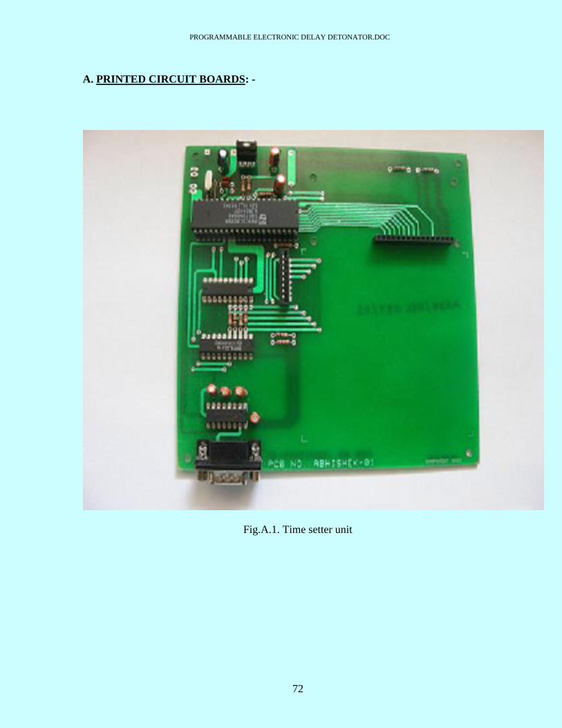
A. PRINTED CIRCUIT BOARDS: -
Fig.A.1. Time setter unit

PROGRAMMABLE ELECTRONIC DELAY DETONATOR.DOC
73
Fig.A.2. Timer unit, Keypad, LCD display
PROGRAMMABLE ELECTRONIC DELAY DETONATOR.DOC
74
B. CIRCUIT COMPONENTS: -
1. TIME SETTER UNIT: -
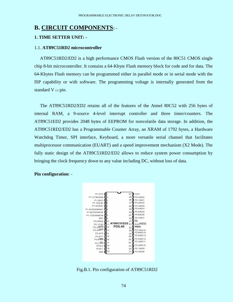
1.1. AT89C51RD2 microcontroller
AT89C51RD2/ED2 is a high performance CMOS Flash version of the 80C51 CMOS single
chip 8-bit microcontroller. It contains a 64-Kbyte Flash memory block for code and for data. The
64-Kbytes Flash memory can be programmed either in parallel mode or in serial mode with the
ISP capability or with software. The programming voltage is internally generated from the
standard V CC pin.
The AT89C51RD2/ED2 retains all of the features of the Atmel 80C52 with 256 bytes of
internal RAM, a 9-source 4-level interrupt controller and three timer/counters. The
AT89C51ED2 provides 2048 bytes of EEPROM for nonvolatile data storage. In addition, the
AT89C51RD2/ED2 has a Programmable Counter Array, an XRAM of 1792 bytes, a Hardware
Watchdog Timer, SPI interface, Keyboard, a more versatile serial channel that facilitates
multiprocessor communication (EUART) and a speed improvement mechanism (X2 Mode). The
fully static design of the AT89C51RD2/ED2 allows to reduce system power consumption by
bringing the clock frequency down to any value including DC, without loss of data.
Pin configuration: -
Fig.B.1. Pin configuration of AT89C51RD2
PROGRAMMABLE ELECTRONIC DELAY DETONATOR.DOC
75
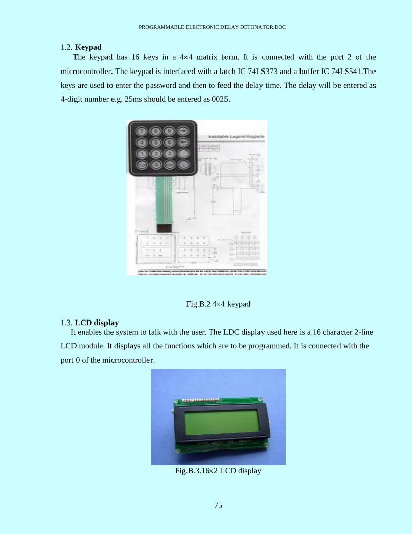
1.2. Keypad
The keypad has 16 keys in a 44 matrix form. It is connected with the port 2 of the
microcontroller. The keypad is interfaced with a latch IC 74LS373 and a buffer IC 74LS541.The
keys are used to enter the password and then to feed the delay time. The delay will be entered as
4-digit number e.g. 25ms should be entered as 0025.
Fig.B.2 44 keypad
1.3. LCD display
It enables the system to talk with the user. The LDC display used here is a 16 character 2-line
LCD module. It displays all the functions which are to be programmed. It is connected with the
port 0 of the microcontroller.
Fig.B.3.162 LCD display
PROGRAMMABLE ELECTRONIC DELAY DETONATOR.DOC
76
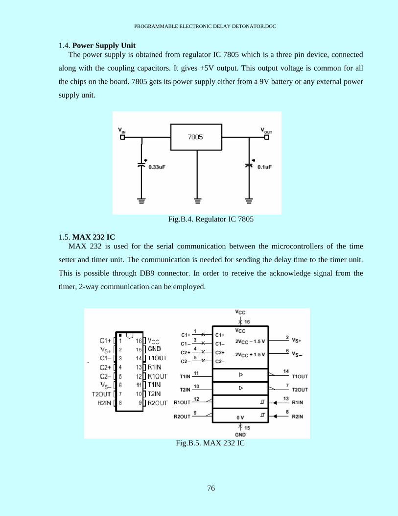
1.4. Power Supply Unit
The power supply is obtained from regulator IC 7805 which is a three pin device, connected
along with the coupling capacitors. It gives +5V output. This output voltage is common for all
the chips on the board. 7805 gets its power supply either from a 9V battery or any external power
supply unit.
Fig.B.4. Regulator IC 7805
1.5. MAX 232 IC
MAX 232 is used for the serial communication between the microcontrollers of the time
setter and timer unit. The communication is needed for sending the delay time to the timer unit.
This is possible through DB9 connector. In order to receive the acknowledge signal from the
timer, 2-way communication can be employed.
Fig.B.5. MAX 232 IC
PROGRAMMABLE ELECTRONIC DELAY DETONATOR.DOC
77
2. TIMER UNIT: -
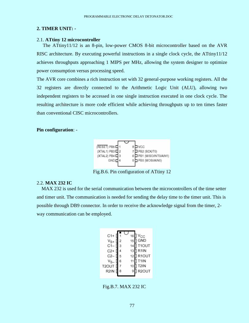
2.1. ATtiny 12 microcontroller
The ATtiny11/12 is an 8-pin, low-power CMOS 8-bit microcontroller based on the AVR
RISC architecture. By executing powerful instructions in a single clock cycle, the ATtiny11/12
achieves throughputs approaching 1 MIPS per MHz, allowing the system designer to optimize
power consumption versus processing speed.
The AVR core combines a rich instruction set with 32 general-purpose working registers. All the
32 registers are directly connected to the Arithmetic Logic Unit (ALU), allowing two
independent registers to be accessed in one single instruction executed in one clock cycle. The
resulting architecture is more code efficient while achieving throughputs up to ten times faster
than conventional CISC microcontrollers.
Pin configuration: -
Fig.B.6. Pin configuration of ATtiny 12
2.2. MAX 232 IC
MAX 232 is used for the serial communication between the microcontrollers of the time setter
and timer unit. The communication is needed for sending the delay time to the timer unit. This is
possible through DB9 connector. In order to receive the acknowledge signal from the timer, 2-
way communication can be employed.
Fig.B.7. MAX 232 IC