Programmable Logic Controller (PLC)
119
1
-
Upload
khangminh22 -
Category
Documents
-
view
0 -
download
0
Transcript of Programmable Logic Controller (PLC)

1

2

3

4

5

6

7

8

9

10

11

12

13

14

15

16

17

18
19

20

21

22

23

24

25

26

27

28

29

30

31

1

2

3

4

5
6

7

8

9

10

11

12

13
14

15

16

17

18

19

20

21

22

23

24

25

26

27

28

29

30

31

32

1

2

3

4

5

6

7

8

9

10

11

12

13

14

15

16

17

18

19

20

21
22

23

24

25

26

27

28

29

30

MODULE-5
PLC AND ITS APPLICATIONS
Introduction of Programmable Logic Controller (PLC)
Programmable logic controllers are now the most widely used industrial process
control technology. A programmable logic controller (PLC) is an industrial grade
computer that is capable of being programmed to perform control functions. The
programmable controller has eliminated much of the hardwiring associated with
conventional relay control circuits. Other benefits include easy programming and
installation, high control speed, network compatibility, troubleshooting and
testing convenience, and high reliability. The programmable logic controller is
designed for multiple input and output arrangements, extended temperature
ranges, immunity to electrical noise, and resistance to vibration and impact.
Programs for the control and operation of manufacturing process equipment and
machinery are typically stored in battery-backed or non-volatile memory. A PLC
is an example of a real-time system since the output of the system controlled by
the PLC depends on the input conditions. The programmable logic controller is,
then, basically a digital computer designed for use in machine control. Unlike a
personal computer, it has been designed to operate in the industrial environment
and is equipped with special input/output interfaces and a control programming
language. The common abbreviation used in industry for these devices, PC, can
be confusing because it is also the abbreviation for “personal computer.”
Therefore, most manufacturers refer to their programmable controller as a PLC,
which stands for “programmable logic controller.”
Advantages of PLC
Programmable controllers offer several advantages over a conventional relay type
of control. Relays have to be hardwired to perform a specific function. When the
system requirements change, the relay wiring has to be changed or modified. In
extreme cases, such as in the auto industry, complete control panels had to be
replaced since it was not economically feasible to rewire the old panels with each
model changeover. The programmable controller has eliminated much of the
hardwiring associated with conventional relay control circuits. It is small and
inexpensive compared to equivalent relay-based process control systems. Modern
control systems still include relays, but these are rarely used for logic. In addition
to cost savings, PLCs provide many other benefits including:
• Increased Reliability. Once a program has been written and tested, it can be
easily downloaded to other PLCs. Since all the logic is contained in the PLC’s
memory, there is no chance of making a logic wiring error. The program takes
the place of much of the external wiring that would normally be required for

control of a process. Hardwiring, though still required to connect field devices,
is less intensive. PLCs also offer the reliability associated with solid-state
components.
• More Flexibility. It is easier to create and change a program in a PLC than to
wire and rewire a circuit. With a PLC the relationships between the inputs and
outputs are determined by the user program instead of the manner in which they
are interconnected. Original equipment manufacturers can provide system
updates by simply sending out a new program. End users can modify the program
in the fi eld, or if desired, security can be provided by hardware features such as
key locks and by software passwords.
• Lower Cost. PLCs were originally designed to replace relay control logic, and
the cost savings have been so significant that relay control is becoming obsolete
except for power applications. Generally, if an application has more than about
a half-dozen control relays, it will probably be less expensive to install a PLC.
• Communications Capability. A PLC can communicate with other controllers or
computer equipment to perform such functions as supervisory control, data
gathering, monitoring devices and process parameters, and download and upload
of programs.
• Faster Response Time. PLCs are designed for highspeed and real-time
applications. The programmable controller operates in real time, which means
that an event taking place in the
fi eld will result in the execution of an operation or output. Machines that process
thousands of items per second and objects that spend only a fraction of a second
in front of a sensor require the PLC’s quick-response capability.
• Easier to Troubleshoot. PLCs have resident diagnostics and override functions
that allow users to easily trace and correct software and hardware problems. To
find and fix problems, users can display the control program on a monitor and
watch it in real time as it executes.

Different parts of PLC by drawing the block diagram and purpose of
each part of PLC
A typical PLC can be divided into parts, as illustrated in Figure 1-8. These are the
central processing unit (CPU), the input/output (I/O) section, the power supply,
and the programming device.
The term architecture can refer to PLC hardware, to PLC software, or to a
combination of
both. An open architecture design allows the system to be connected easily to
devices and programs made by other manufacturers.
There are two ways in which I/Os (Inputs/Outputs) are incorporated into the PLC:
fixed and modular. Fixed I/O is typical of small PLCs that come in one package
with no separate, removable units. The processor and I/O are packaged together,
and the I/O terminals will have a fixed number of connections built in for inputs
and outputs. The main advantage of this type of packaging is lower cost. The
number of available I/O points varies and usually can be expanded by buying
additional units of fixed I/O. One disadvantage of fixed I/O is its lack of
flexibility; you are limited in what you can get in the quantities and types dictated
by the packaging. Also, for some models, if any part in the unit fails, the whole
unit has to be replaced.

Modular I/O is divided by compartments into which separate modules can be
plugged. This feature greatly increases your options and the unit’s flexibility. You
can choose from the modules available from the manufacturer and mix them any
way you desire. The basic modular controller consists of a rack, power supply,
processor module (CPU), input/output (I/O modules), and an operator interface
for programming and monitoring. The modules plug into a rack. When a module
is slid into the
rack, it makes an electrical connection with a series of contacts called the
backplane, located at the rear of the rack. The PLC processor is also connected to
the backplane and can communicate with all the modules in the rack.
The power supply supplies DC power to other modules that plug into the rack.
For large PLC systems, this power supply does not normally supply power to the
field devices. With larger systems, power to fi eld devices is provided by external
alternating current (AC) or direct current (DC) supplies. For some small micro-
PLC systems, the power supply may be used to power field devices.
The processor (CPU) is the “brain” of the PLC. A typical processor usually
consists of a microprocessor for implementing the logic and controlling the
communications among the modules. The processor requires memory for storing
the results of the logical operations performed by the microprocessor. Memory is
also required for the program EPROM or EEPROM plus RAM. The CPU controls
all PLC activity and is designed so that the user can enter the desired program in
relay ladder logic. The PLC program is executed as part of a repetitive process
referred to as a scan. A typical PLC scan starts with the CPU reading the status of
inputs. Then, the application program is executed. Once the program execution is
completed, the CPU performs internal diagnostic and communication tasks. Next,
the status of all outputs is updated. This process is repeated continuously as long
as the PLC is in the run mode.
The I/O system forms the interface by which field devices are connected to the
controller. The purpose of this interface is to condition the various signals
received from or sent to external field devices. Input devices such as pushbuttons,
limit switches, and sensors are hardwired to the input terminals. Output devices
such as small motors, motor starters, solenoid valves, and indicator lights are
hardwired to the output terminals. To electrically isolate the internal components
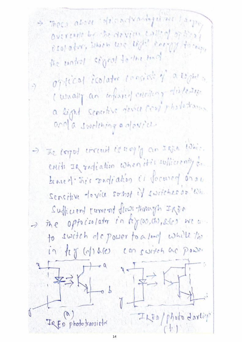
from the input and output terminals, PLCs commonly employ an optical isolator,
which uses light to couple the circuits together.
A programming device is used to enter the desired program into the memory of
the processor. The program can be entered using relay ladder logic, which is one
of the most popular programming languages. Instead of words, ladder logic
programming language uses graphic symbols that show their intended outcome.

A program in ladder logic is similar to a schematic for a relay control circuit.
It is a special language written to make it easy for people familiar with relay logic
control to program the PLC.
A personal computer (PC) is the most commonly used programming device. Most
brands of PLCs have software available so that a PC can be used as the
programming device. This software allows users to create, edit, document, store,
and troubleshoot ladder logic programs. The computer monitor is able to display
more logic on the screen than can hand-held types, thus simplifying the
interpretation of the program. The personal computer communicates with the
PLC processor via a serial or parallel data communications link, or Ethernet. If
the programming unit is not in use, it may be unplugged and removed. Removing
the programming unit will not affect the operation of the user program.
A program is a user-developed series of instructions that directs the PLC to
execute actions. A programming language provides rules for combining the
instructions so that they produce the desired actions.
Relay ladder logic (RLL) is the standard programming language used with PLCs.
Its origin is based on electromechanical relay control. The relay ladder logic
program graphically represents rungs of contacts, coils, and special instruction
blocks. RLL was originally designed for easy use and understanding for its users
and has been modified to keep up with the increasing demands of industry’s
control needs.
Application of PLC
There are three major types of PLC application: single ended, multitask, and
control management.
A single ended or stand-alone PLC application involves one PLC controlling one
process. This would be a stand-alone unit and would not be used for
communicating with other computers or PLCs. The size and sophistication of the
process being controlled are obvious factors in determining which PLC to select.
The applications could dictate a large processor, but usually this category requires
a small PLC.
A multitask PLC application involves one PLC controlling several processes.
Adequate I/O capacity is a significant factor in this type of installation. In
addition, if the PLC would be a subsystem of a larger process and would have to
communicate with a central PLC or computer, provisions for a data
communications network are also required.
A control management PLC application involves one PLC controlling several
others. This kind of application requires a large PLC processor designed to

communicate with other PLCs and possibly with a computer. The control
management PLC supervises several PLCs by downloading programs that tell the
other PLCs what has to be done. It must be capable of connection to all the PLCs
so that by proper addressing it can communicate with anyone it wishes to
Because of the versatility of PLC, it is used in various places for automation. In
industries various processes needs to be controlled at every instant of time such
as valve control, pressure control, robotic action, etc. It becomes tedious and
infeasible for humans to control all such activities on their own. Thus, relays were
used to perform those activities. However, a relay can be used only for a specific
and limited operation which makes their use bulky and uneconomic. On the
contrary PLC having the ability to perform number of tasks by simply modifying
the program has become a prominent device for automation of such activities.
There are various
places where a PLC can be used. Some of those are listed as below:
Robotic arm in car manufacturing
Air compressors
Airport runway lighting control
Traffic signal control
Smoke alarm control
Process valve control
Textile equipment
Vacuum pump system
Apart from these applications, PLC is widely used in automation of electrical
power system. At electrical substations automatic reclosing, circuit breaker
tripping, capacitor switching, etc. can be controlled with PLCs.

Ladder diagram
• Lets use a PLC in place of the relay.
• The first thing that's necessary is to create what's called a Ladder Diagram.
• We have to create one of these because, unfortunately, a PLC doesn't
understand a schematic diagram it only recognizes code.
• Most PLCs have software which convert ladder diagrams into code.
• First Step : Translate all of the items we're using into symbols the PLC
understands.
• Second step : We must tell the PLC where everything is located. In other
words we have to give all the devices an address.
• Final step : We have to convert the schematic into a logical sequence of
events.
First step:
• The PLC doesn't understand terms like switch, relay, bell, etc.
• It prefers input, output, coil, contact, etc.
• It doesn't care what the actual input or output device actually is. It only cares
that its an input or an output.
• First we replace the battery with a symbol. This symbol is common to all
ladder diagrams. We draw what are called bus bars.
• These simply look like two vertical bars. One on each side of the diagram.
Think of the left one as being + voltage and the right one as being ground.
Further think of the current (logic) flow as being from left to right.
• Next we give the inputs a symbol. In this basic example we have one real
world input. (i.e. the switch).
• We give the input that the switch will be connected to the symbol shown
below. This symbol can also be used as the contact of a relay.
• Next we give the outputs a symbol. In this example we use one output (i.e. the
bell).
• We give the output that the bell will be physically connected to the symbol
shown below. This symbol is used as the coil of a relay.

• The AC supply is an external supply so we don't put it in our ladder. The PLC
only cares about which output it turns on and not what's physically connected to
it.
Second step:
• We must tell the PLC where everything is located. In other words we have to
give all the devices an address.
• Where is the switch going to be physically connected to the PLC? How about
the bell? We start with a blank road map in the PLCs town and give each item
an address.
• Could you find your friends if you didn't know their address? You know they
live in the same town but which house? The plc town has a lot of houses (inputs
and outputs) but we have to figure out who lives where (what device is
connected where).
• We'll get further into the addressing scheme later. The PLC manufacturers
each do it a different way! For now let's say that our input will be called "0000".
The output will be called "500".
Final step:
• Convert the schematic into a logical sequence of events.
• The program we're going to write tells the PLC what to do when certain events
take place.
• In our example we have to tell the plc what to do when the operator turns on
the switch.
• Final converted diagram.
• We eliminated the real world relay from needing a symbol.
Description of contacts and coils in the following states
i) Normally open
Load :
• The load(LD) instruction is a normally open contact. It is sometimes also
called examine if on (XIO).(as in examine the input to see if its physically on).
The symbol for a load instruction is shown below.

• This is used when an input signal is needed to be present for the symbol to
turn on.
• When the physical input is on we can say that the instruction is True.
• We examine the input for an on signal. If the input is physically on then the
symbol is on.
• An on condition is also referred to as a logic 1 state.
ii) Normally closed
Load Bar :
• The Load bar instruction is a normally closed contact. It is sometimes also
called LoaDNot or examine if closed(XIC)(as in examine the input to see if its
physically closed) The symbol for a loadbar instruction is shown below.
• This is used when an input signal does not need to be present for the symbol to
turn on.
• When the physical input is off we can say that the instruction is True.
• We examine the input for an off signal. If the input is physically off then the
symbol is on.
• With most PLCs this instruction (Load or Loadbar) MUST be the first
symbol on the left of the ladder.
iii) Energized output
out:
• The Out instruction is sometimes also called an Output Energize instruction.
The output instruction is like a relay coil. Its symbol looks as shown below.
• When there is a path of True instructions preceding this on the ladder rung, it
will also be True.
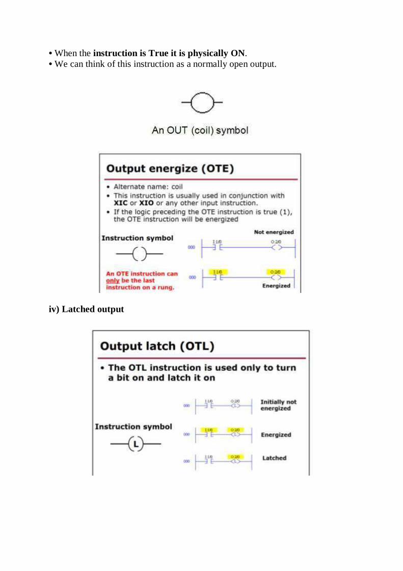
• When the instruction is True it is physically ON.
• We can think of this instruction as a normally open output.
iv) Latched output

Out bar:
• The Outbar instruction is sometimes also called an OutNot instruction.
• The Outbar instruction is like a normally closed relay coil. Its symbol looks
like that shown below.
Ladder diagrams
i)AND gate
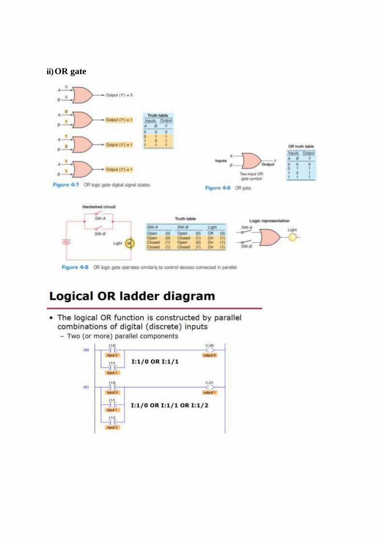
ii) OR gate

iii) NOT gate

Ladder diagrams for combination circuits using NAND, NOR, OR and
NOT


Timers i)T
ON
• TIMER : It is an instruction that waits a set amount of time before doing
something.
• Type of Timers : On-Delay Timer and Off-Delay Timer.
On-Delay Timer :
• Simply "delays turning on".
• After sensor (input) turns ON, wait x-seconds before activating a solenoid
valve(output).
• This is the most common timer. It is often called TON(timer on-delay),
TIM(timer) or TMR(timer).

ii) T OFF
Off-Delay Timer :
• Simply "delays turning off".
• After sensor (input) sees a target it turn on a solenoid (output).
• When the sensor no longer sees the target it hold the solenoid on for x-seconds
before turning it off.
• It is called a TOF (timer off-delay).

iii) Retentive timer
Counters CTU

CTD
Ladder diagram using Timers and Counters


Ladder diagram for DOL starter

SPECIAL CONTROL SYSTEMS
DCS:
A distributed control system (DCS) is part of a manufacturing system.
Distributed control systems (DCS) are used in industrial and civil engineering
applications to monitor and control distributed equipment with remote human
intervention.
It is generally, since the 1970s, digital, and normally consists of field
instruments, connected via wiring to computer buses or electrical buses to
multiplexer/demultiplexers and A/D's or analog to digital and finally the
Human-Machine Interface (HMI) or control consoles. A DCS is a process
control system that uses a network to interconnect sensors, controllers, operator
terminals and actuators. A DCS typically contains one or more computers for
control and mostly use both proprietary interconnections and protocols for
communications. See PAS.
DCS is a very broad term that describes solutions across a large variety of
industries, including:
* Electrical power grids and electrical generation plants
* Environmental control systems
* Traffic signals
* Water management systems
* Refining and chemical plants
* Pharmaceutical manufacturing
SCADA:
SCADA is the acronym for Supervisory Control And Data Acquisition.
SCADA may be called Human-Machine Interface (HMI) in Europe. The term
refers to a large-scale, distributed measurement (and control) system. SCADA
systems are used to monitor or to control chemical, physical or transport
processes.
The three components of a SCADA system are:
1. Multiple Remote Terminal Units (also known as RTUs or Outstations).
2. Master Station and HMI Computer(s).
3. Communication infrastructure
Contents
* 1 Systems concepts
* 2 Human Machine Interface
* 3 Hardware solutions
* 4 System components
* 5 Remote Terminal Unit (RTU)
* 6 Master Station
* 7 Operational philosophy
* 8 Communication infrastructure and methods
* 9 Future trends in SCADA
* 10 Practical uses
* 11 External links
The term SCADA usually refers to a central system that monitors and controls a
complete site. The bulk of the site control is actually performed automatically
by a Remote Terminal Unit (RTU) or by a Programmable Logic Controller
(PLC). Host control functions are almost always restricted to basic site over-ride
or supervisory level capability.
SCADA systems typically implement a distributed database which contains data
elements called points. A point represents a single input or output value
monitored or controlled by the system. Points can be either "hard" or "soft". A
hard point is representative of an actual input or output connected to the system,
while a soft point represents the result of logic and math operations applied to
other hard and soft points. The point values are normally stored as value-
timestamp combinations; the value and the timestamp when the value was
recorded or calculated. A series of value-timestamp combinations is the history
of that point.

DCS vs. SCADA
DCS and SCADA are monitoring and control mechanisms that are used in
industrial installations to keep track and control of the processes and equipment;
to ensure that everything goes smoothly, and none of the equipment work outside
the specified limits. The most significant difference between the two is their
general design. DCS, or Data Control System, is process oriented, as it focuses
more on the processes in each step of the operation. SCADA, or Supervisory
Control and Data Acquisition, focuses more on the acquisition and collation
of data for reference of the personnel who are charged with keeping track of the
operation.
DCS is process state driven, while SCADA is even driven. DCS does all its tasks
in a sequential manner, and events are not recorded until it is scanned by the
station. In contrast, SCADA is event driven. It does not call scans on a regular
basis, but waits for an event or for a change in value in one component to trigger
certain actions. SCADA is a bit more advantageous in this aspect, as it lightens

the load of the host. Changes are also recorded much earlier, as an event is logged
as soon as a value changes state.
In terms of applications, DCS is the system of choice for installations that are
limited to a small locale, like a single factory or plant, while SCADA is preferred
when the entire system is spread across a much larger geographic location,
examples of which would be oil wells spread out in a large field. Part of the reason
for this is the fact that DCS needs to be always connected to the I/O of the system,
while SCADA is expected to perform even when field communications fail for
some time. SCADA does this by keeping a record of all current values, so that
even if the base station is unable to extract new information from a remote
location, it would still be able to present the last recorded values.
Summary:
1. DCS is process oriented, while SCADA is data acquisition oriented.
2. DCS is process state driven, while SCADA is event driven.
3. DCS is commonly used to handle operations on a single locale, while SCADA
is preferred for applications that are spread over a wide geographic location.