Fan Controller
27
PSoC® Creator™ Component Datasheet Document Number: 001-79359 Rev. ** Revised May 17, 2012 Features Support for up to 16 PWM controlled, 4-wire brushless DC fans Individual or banked PWM outputs with tachometer inputs Supports 25 kHz, 50 kHz or user-specified PWM frequencies Supports fan speeds up to 25,000 RPM Supports 4-pole and 6-pole motors Supports fan stall / rotor lock detection on all fans Supports firmware controlled or hardware controlled fan speed regulation Customizable alert pin for fan fault reporting General Description The Fan Controller component enables designers to quickly and easily develop fan controller solutions using PSoC. The component is a system-level solution that encapsulates all necessary hardware blocks including PWMs, tachometer input capture timer, control registers, status registers and a DMA controller reducing development time and effort. The component is customizable through a graphical user interface enabling designers to enter fan electromechanical parameters such as duty cycle-to-RPM mapping and physical fan bank organization. Performance parameters including PWM frequency and resolution as well as open or closed loop control methodology can be configured through the same user interface. Once the system parameters are entered, the component delivers the most optimal implementation saving resources within PSoC to enable integration of other thermal management and system management functionality. Easy-to-use APIs are provided to enable firmware developers to get up and running quickly. NOTE: Designs using the Fan Controller component should not use PSoC’s low power sleep or hibernate modes. Entering those modes prevents the Fan Controller component from controlling and monitoring the fans. Fan Controller 2.10
-
Upload
khangminh22 -
Category
Documents
-
view
0 -
download
0
Transcript of Fan Controller

PSoC® Creator™ Component Datasheet
Document Number: 001-79359 Rev. ** Revised May 17, 2012
Features
Support for up to 16 PWM controlled, 4-wire brushless DC fans
Individual or banked PWM outputs with tachometer inputs
Supports 25 kHz, 50 kHz or user-specified PWM frequencies
Supports fan speeds up to 25,000 RPM
Supports 4-pole and 6-pole motors
Supports fan stall / rotor lock detection on all fans
Supports firmware controlled or hardware controlled fan speed regulation
Customizable alert pin for fan fault reporting
General Description
The Fan Controller component enables designers to quickly and easily develop fan controller solutions using PSoC. The component is a system-level solution that encapsulates all necessary hardware blocks including PWMs, tachometer input capture timer, control registers, status registers and a DMA controller reducing development time and effort.
The component is customizable through a graphical user interface enabling designers to enter fan electromechanical parameters such as duty cycle-to-RPM mapping and physical fan bank organization. Performance parameters including PWM frequency and resolution as well as open or closed loop control methodology can be configured through the same user interface. Once the system parameters are entered, the component delivers the most optimal implementation saving resources within PSoC to enable integration of other thermal management and system management functionality. Easy-to-use APIs are provided to enable firmware developers to get up and running quickly.
NOTE: Designs using the Fan Controller component should not use PSoC’s low power sleep or hibernate modes. Entering those modes prevents the Fan Controller component from controlling and monitoring the fans.
Fan Controller 2.10

Fan Controller PSoC® Creator™ Component Datasheet
Page 2 of 27 Document Number: 001-79359 Rev. **
When to Use a Fan Controller
The Fan Controller component should be used in any thermal management application that needs to drive and monitor 4-wire, PWM based DC cooling fans. If the application requires more than 16 fans, the Fan Controller component can be instantiated multiple times. Similarly, if the fans in the application are organized into banks, designers have the option of instantiating one Fan Controller component per bank or instantiating one component that handles all the banks.
Input/Output Connections
This section describes the various input and output connections for the Fan Controller. An asterisk (*) in the list of I/Os states that the I/O may be hidden on the symbol under the conditions listed in the description of that I/O.
clock – Input *
An input for a user-defined clock source for the fan control PWMs. It is present only when the External Clock option is selected in the component customizer.
tach1..16 – Input *
Tachometer signal from each fan that enables the Fan Controller to measure fan rotational speeds. The component is designed to work with 4-pole DC fans that produce 2 high-low pulse trains per rotation on their tachometer output or 6-pole DC fans that produce 3 high-low pulse trains. tach2..16 inputs are optional.
fan1..16 – Output *
PWM output with variable duty cycle to control the speed of the fans. These output terminals are replaced by the bank1..8 outputs if fan banking is enabled. fan2..16 are optional.
Note that for Hardware UDB mode, the maximum number of fan outputs (and associated tach inputs) is limited to 12 to minimize digital resource utilization.
bank1..8 – Output *
PWM output with variable duty cycle to control the speed of the fan banks. These outputs appear only when banking is enabled.
alert – Output *
Active high output terminal asserted when fan faults are detected (if enabled).

PSoC® Creator™ Component Datasheet Fan Controller
Document Number: 001-79359 Rev. ** Page 3 of 27
eoc – Output *
End-of-Cycle output is pulsed high each time the tachometer block has measured the speed of all fans in the system. This can be used to synchronize firmware algorithms to the Fan Controller hardware by connecting the terminal to a Status Register component or to an Interrupt component.
Component Parameters
Drag a Fan Controller onto your design and double click it to open the Configure dialog. This tab is used to configure the fundamental operating parameters of the component.
Figure 1 shows the Configure dialog.
Basic Tab Options
This tab is used to configure the fundamental operating parameters of the component.
Figure 1. Basic Configuration Dialog

Fan Controller PSoC® Creator™ Component Datasheet
Page 4 of 27 Document Number: 001-79359 Rev. **
Fan Control Method – Firmware/Hardware
This parameter determines how the fan speeds are controlled. Firmware (CPU) setting is used when user firmware controls fan speed regulation. Firmware can set PWM duty cycles and read back fan speeds to determine the appropriate action.
Hardware (UDB) setting dictates that hardware blocks inside PSoC control fan speed regulation automatically without any CPU intervention. Firmware sets the desired speed for each fan and the hardware automatically adjusts the PWM duty cycle to achieve and maintain the desired speed within specified tolerance limits. Default setting is Firmware (CPU).
Firmware (CPU) setting should be selected in cases where:
1. The designer has a complex or custom fan control algorithm to be implemented in firmware within PSoC.
2. Anexternal host controller is responsible formanaging the fan speed algorithm and the Fan Controller component is simply being used as the hardware interface to the fans.
3. Multiple fans areorganized into banks sharing a common PWM drive signal.
Hardware (UDB) setting should be selected in cases where the designer wants to control multiple fans independently and wants to do so with minimal firmware development.
Hardware Control Mode – Damping Factor
In hardware controlled fan mode, this parameter controls the dynamic response time of the hardware control loop. This parameter controls how frequently the hardware adjusts the PWM duty cycles for each fan.
In situations where there are only a few fans, a higher damping factor ensures that the control loop can regulate to the desired speed without oscillating around the desired speed target. In situations where many fans are being controlled, a lower damping factor ensures adequate response time to changes in fan speed. This parameter enables fine tuning of the hardware control logic to match the selected fan’s electromechanical characteristics. The valid range for this parameter is 0..1.27 (specified in seconds). Default setting is 0.64.
Hardware Control Mode – Tolerance
In hardware controlled fan mode, this parameter sets the acceptable tolerance when specifying desired fan speed targets. The tolerance is specified as a percentage relative to the desired speed setting. This parameter enables fine tuning of the hardware control logic to match the selected fans electromechanical characteristics.
The valid range for this parameter is 1..10%. Default setting is 1%. If 8-bit PWM resolution is selected in the Fan Controller Fans tab as shown in Figure 2, a Tolerance parameter setting of 5% is recommended.

PSoC® Creator™ Component Datasheet Fan Controller
Document Number: 001-79359 Rev. ** Page 5 of 27
Hardware Control Mode – Acoustic Noise Reduction
In hardware controlled fan mode, this parameter limits audible noise from fans by limiting the positive rate of change of speed. If enabled, and firmware requests an increase in desired fan speed, the PWM duty cycle applied to the fan increases gradually to the new setting rather than applying a sudden step change. This eliminates noisy fan whir from sudden speed increases. Default setting is checked.
Alerts – FanStall / RotorLock
The Fan Controller can be configured to generate an active-high alert signal when a fan stalls or stops rotating due to a mechanical obstruction. Default setting is checked.
Alerts – UDB SpeedRegulationFailure
The Fan Controller can be configured to generate an active-high alert signal in hardware controlled fan mode when the hardware control loop is not able to achieve the desired speed. Default setting is un-checked.
Connections – Display as Bus
If checked, the tach inputs and fan/bank outputs will be displayed as buses. Otherwise, they are displayed as individual terminals.
Connections – External Clock
If checked, it allows the user to connect an external clock source to the component clock input. If unchecked, then an internal clock source will be used.

Fan Controller PSoC® Creator™ Component Datasheet
Page 6 of 27 Document Number: 001-79359 Rev. **
Fans Tab Options
This tab is used to configure fan-specific parameters.
Figure 2. Fans Configuration Dialog
Motor Support
This parameter specifies the number of high – low pulses that appear on the fan’s tachometer output per revolution. The 4-pole option means there are 2 high and 2 low pulses per fan revolution, while the 6-pole option means that there are 3 high and 3 low pulses per fan revolution.
PWM Output Configuration – Number of Fans
This parameter specifies how many fans are in the system. The valid range for this parameter is 1..16. Default setting is 4.

PSoC® Creator™ Component Datasheet Fan Controller
Document Number: 001-79359 Rev. ** Page 7 of 27
PWM Output Configuration – Number of Banks
This parameter is only visible in firmware control mode and specifies how many fan banks are in the system. It is assumed that when fans are organized into banks, each bank has the same number of fans. Therefore, the number of fans must be divisible by the number of banks. The value 0 indicates that the fans are not banked. For banked operation, the valid range for this parameter is from 1to (Number of Fans/2). Default setting is 0.
PWM Output Configuration – PWM Resolution
This parameter specifies the resolution of the duty cycle for the modulated PWM signal that drives the fans to control rotational speed. Valid options for this parameter are 8-bit or 10-bit. Default setting is 8-bit.
PWM Output Configuration – PWM Frequency
This parameter specifies the frequency of the modulated PWM signal that drives the fans. Valid options for this parameter are 25 kHz or 50 kHz when internal clock is used. Default setting is 25 kHz. When an external clock is used, this parameter is grayed out since the PWM frequency depends on the input clock source. See the Functional Description section for more details.
Fan Specifications – Duty A (%), RPM A
These parameters together specify one data point on the duty cycle-to-RPM transfer function for the selected fan or bank of fans. The RPM A parameter specifies the speed the fan nominally runs at when driven by a PWM with a duty cycle of Duty A (%). This information is available from the fan manufacturer’s datasheet. It should be noted that the Fan Controller component may drive PWM duty cycles down to 0% even if Duty A (%) is set to a non-zero value.
The valid range for the Duty A (%) parameter is 0-99. Default setting is 25.
The valid range for the RPM A parameter is 500..24,999. Default setting is 1,000.
Fan Specifications – Duty B (%), RPM B
These parameters together specify a 2nd data point on the duty cycle-to-RPM transfer function for the selected fan or bank of fans. The RPM B parameter specifies the speed the fan nominally runs at when driven by a PWM with a duty cycle of Duty B (%). This information is available from the fan manufacturer’s datasheet. It should be noted that the Fan Controller component may drive PWM duty cycles up to 100% even if Duty B (%) is set below 100%.
The valid range for the Duty B (%) parameter is 1-100. Default setting is 100.
The valid range for the RPM B parameter is 501..25,000. Default setting is 10,000.
Fan Controller PSoC® Creator™ Component Datasheet
Page 8 of 27 Document Number: 001-79359 Rev. **
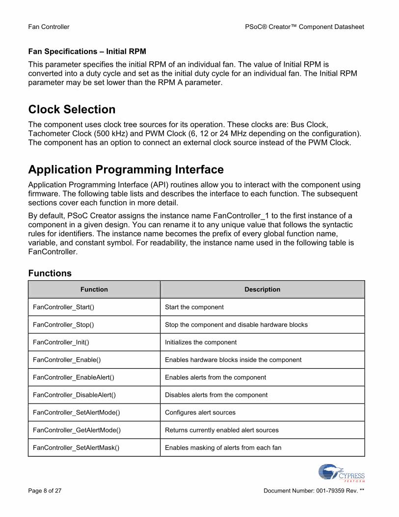
Fan Specifications – Initial RPM
This parameter specifies the initial RPM of an individual fan. The value of Initial RPM is converted into a duty cycle and set as the initial duty cycle for an individual fan. The Initial RPM parameter may be set lower than the RPM A parameter.
Clock Selection
The component uses clock tree sources for its operation. These clocks are: Bus Clock, Tachometer Clock (500 kHz) and PWM Clock (6, 12 or 24 MHz depending on the configuration). The component has an option to connect an external clock source instead of the PWM Clock.
Application Programming Interface
Application Programming Interface (API) routines allow you to interact with the component using firmware. The following table lists and describes the interface to each function. The subsequent sections cover each function in more detail.
By default, PSoC Creator assigns the instance name FanController_1 to the first instance of a component in a given design. You can rename it to any unique value that follows the syntactic rules for identifiers. The instance name becomes the prefix of every global function name, variable, and constant symbol. For readability, the instance name used in the following table is FanController.
Functions
Function Description
FanController_Start() Start the component
FanController_Stop() Stop the component and disable hardware blocks
FanController_Init() Initializes the component
FanController_Enable() Enables hardware blocks inside the component
FanController_EnableAlert() Enables alerts from the component
FanController_DisableAlert() Disables alerts from the component
FanController_SetAlertMode() Configures alert sources
FanController_GetAlertMode() Returns currently enabled alert sources
FanController_SetAlertMask() Enables masking of alerts from each fan

PSoC® Creator™ Component Datasheet Fan Controller
Document Number: 001-79359 Rev. ** Page 9 of 27
Function Description
FanController_GetAlertMask() Returns alert masking status of each fan
FanController_GetAlertSource() Returns pending alert source(s)
FanController_GetFanStallStatus() Returns a bit mask representing the stall status of each fan
FanController_GetFanSpeedStatus() Returns a bit mask representing the speed regulation status of each fan in hardware control mode
FanController_SetDutyCycle() Sets the PWM duty cycle for the specified fan or fan bank
FanController_GetDutyCycle() Returns the PWM duty cycle for the specified fan or fan bank
FanController_SetDesiredSpeed() Sets the desired fans speed for the specified fan in hardware control mode
FanController_GetDesiredSpeed() Returns the desired fans speed for the specified fan in hardware control mode
FanController_GetActualSpeed() Returns the actual speed for the specified fan
FanController_OverrideHardwareControl() Enables firmware to override hardware (UDB) fan control
Global Variables
Variable Description
FanController_initVar(static) The initVar variable is used to indicate initial configuration of this component. This variable is pre-pended with the component name. The variable is initialized to zero and set to 1 the first time FanController_Start() is called. This allows for component initialization without re-initialization in all subsequent calls to the FanController_Start() routine.
If re-initialization of the component is required the FanController_Stop() routine should be called followed by the FanController_Init() and FanController_Enable().

Fan Controller PSoC® Creator™ Component Datasheet
Page 10 of 27 Document Number: 001-79359 Rev. **
voidFanController_Start(void)
Description: Enables the component. Calls the Init() API if the component has not been initialized before. Calls the Enable() API.
Parameters: None
Return Value: None
Side Effects: None
voidFanController_Stop(void)
Description: Disables the component. All PWM outputs will be driven to 100% duty cycle to ensure cooling continues while the component is not operational.
Parameters: None
Return Value: None
Side Effects: Alert pin is deasserted.
voidFanController_Init(void)
Description: Initializes the component.
Parameters: None
Return Value: None
Side Effects: None
voidFanController_Enable(void)
Description: Enables hardware blocks within the component.
Parameters: None
Return Value: None
Side Effects: None
PSoC® Creator™ Component Datasheet Fan Controller
Document Number: 001-79359 Rev. ** Page 11 of 27
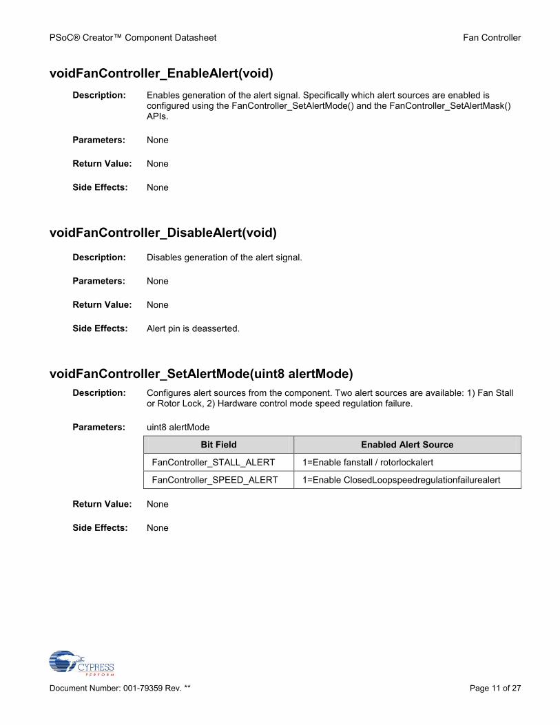
voidFanController_EnableAlert(void)
Description: Enables generation of the alert signal. Specifically which alert sources are enabled is configured using the FanController_SetAlertMode() and the FanController_SetAlertMask() APIs.
Parameters: None
Return Value: None
Side Effects: None
voidFanController_DisableAlert(void)
Description: Disables generation of the alert signal.
Parameters: None
Return Value: None
Side Effects: Alert pin is deasserted.
voidFanController_SetAlertMode(uint8 alertMode)
Description: Configures alert sources from the component. Two alert sources are available: 1) Fan Stall or Rotor Lock, 2) Hardware control mode speed regulation failure.
Parameters: uint8 alertMode
Bit Field Enabled Alert Source
FanController_STALL_ALERT 1=Enable fanstall / rotorlockalert
FanController_SPEED_ALERT 1=Enable ClosedLoopspeedregulationfailurealert
Return Value: None
Side Effects: None

Fan Controller PSoC® Creator™ Component Datasheet
Page 12 of 27 Document Number: 001-79359 Rev. **
uint8FanController_GetAlertMode(void)
Description: Returns the alert sources that are enabled.
Parameters: None
Return Value: uint8 alertMode
Bit Field Enabled Alert Source
FanController_STALL_ALERT 1=Enable fanstall / rotorlockalert
FanController_SPEED_ALERT 1=Enable ClosedLoopspeedregulationfailurealert
Side Effects: None
voidFanController_SetAlertMask(uint16 alertMask)
Description: Enables or disables alerts from each fan through a mask. Masking applies to both fan stall alerts and speed regulation failure alerts.
Parameters: uint16 alertMask
Bit Field Enabled Alert Source
bit0 1=Enable alerts for Fan1
bit1 1=Enable alerts for Fan2
… …
bit15 1=Enable alerts for Fan16
Return Value: None
Side Effects: None

PSoC® Creator™ Component Datasheet Fan Controller
Document Number: 001-79359 Rev. ** Page 13 of 27
uint16FanController_GetAlertMask(void)
Description: Returns alert mask status from each fan. Masking applies to both fan stall alerts and speed regulation failure alerts.
Parameters: None
Return Value: uint16 alertMask
Bit Field Enabled Alert Source
bit0 1=Enable alerts for Fan1
bit1 1=Enable alerts for Fan2
… …
bit15 1=Enable alerts for Fan16
Side Effects: None
uint8FanController_GetAlertSource(void)
Description: Returns pending alert sources from the component. This API can be used to poll the alert status of the component. Alternatively, if the alert pin is used to generate interrupts to PSoC’s CPU core, the interrupt service routine can use this API to determine the source of the alert. In either case, when this API returns a non-zero value, the FanController_GetFanStallStatus() and FanController_GetFanSpeedStatus() APIs can provide further information on which fan(s) has(have) a fault.
Parameters: uint8 alertMode
Bit Field Pending Alert
FanController_STALL_ALERT 1=Fanstall / rotorlockalert pending
FanController_SPEED_ALERT 1=Closed Loopspeedregulationfailurealert pending
Return Value: None
Side Effects: None

Fan Controller PSoC® Creator™ Component Datasheet
Page 14 of 27 Document Number: 001-79359 Rev. **
uint16FanController_GetFanStallStatus(void)
Description: Returns the stall / rotor lock status of all fans.
Parameters: None
Return Value: uint16 stallStatus
Bit Field Status
bit0 Fan1 stall status (1=stall, 0=OK)
bit1 Fan2 stall status
… …
bit15 Fan16 stall status
Side Effects:
Calling this API clears all pending fan stall alerts and de-asserts the alert pin. If stall alerts are pending, the alert pin is re-asserted synchronous to the next end-of-cycle (eoc) pulse.
uint16FanController_GetFanSpeedStatus(void)
Description: Returns the hardware fan control mode speed regulation status of all fans. Speed regulation failures occur in two cases: 1) if the desired fan speed exceeds the current actual fan speed but the fan’s duty cycle is already at 100%, 2) if the desired fan speed is below the current actual fan speed, but the fan’s duty cycle is already at 0%.
Parameters: None
Return Value: uint16 speedStatus
Bit Field Status
bit0 Fan1 speed regulation status (1=failure, 0=OK)
bit1 Fan2 speed regulation status
… …
bit15 Fan16 speed regulation status
Side Effects: Calling this API clears all pending speed regulation alerts and de-asserts the alert pin. If speed regulation alerts are pending, the alert pin is re-asserted synchronous to the next end-of-cycle (eoc) pulse.

PSoC® Creator™ Component Datasheet Fan Controller
Document Number: 001-79359 Rev. ** Page 15 of 27
voidFanController_SetDutyCycle(uint8 fanOrBankNumber, uint16 dutyCycle)
Description: Sets the PWM duty cycle of the selected fan or fan bank in hundredths of a percent. In hardware fan control mode, if manual duty cycle control is desirable, call the FanController_OverrideHardwareControl() API prior to calling this API.
Parameters: uint8 fanOrBankNumber
Valid range is 1..16 but should not exceed the number of fans or banks in the system.
uint16 dutyCycle
Duty cycle in hundredths of a percent. For example, 50% duty cycle = 5000. Valid range is 0..10000.
Return Value: None
Side Effects: None
uint16FanController_GetDutyCycle(uint8 fanOrBankNumber)
Description: Returns the current PWM duty cycle of the selected fan or fan bank in hundredths of a percent.
Parameters: uint8 fanOrBankNumber
Valid range is 1..16 but should not exceed the number of fans or banks in the system.
Return Value: Duty cycle in hundredths of a percent. For example, 50% duty cycle = 5000.
Side Effects: None

Fan Controller PSoC® Creator™ Component Datasheet
Page 16 of 27 Document Number: 001-79359 Rev. **
voidFanController_SetDesiredSpeed(uint8 fanNumber, uint16 rpm)
Description: Sets the desired speed of the specified fan in revolutions per minute (RPM). In hardware fan control mode, the RPM parameter is passed to the control loop hardware as the new target fan speed for regulation. In firmware fan control mode, the RPM parameter is converted to a duty cycle based on the fan parameters entered into the Fans tab of the customizer and written to the appropriate PWM. This provides firmware with a method for initiating coarse level speed control. Fine level firmware speed control can then be achieved using the FanController_SetDutyCycle() API.
Parameters: uint8 fanNumber
Valid range is 1..16 but should not exceed the number of fans in the system.
uint16 rpm
Valid range is 500..25,000 but should not exceed the maximum RPM that the fan is capable of running at. Doing so will cause a speed regulation failure.
Return Value: None
Side Effects: None
uint16FanController_GetDesiredSpeed(uint8 fanNumber)
Description: Returns the currently desired speed for the selected fan.
Parameters: uint8 fanNumber
Valid range is 1..16 but should not exceed the number of fans in the system.
Return Value: Currently desired speed for the selected fan in RPM
Side Effects: None

PSoC® Creator™ Component Datasheet Fan Controller
Document Number: 001-79359 Rev. ** Page 17 of 27
uint16 FanController_GetActualSpeed(uint8 fanNumber)
Description: Returns the current actual speed for the selected fan.
Parameters: uint8 fanNumber
Valid range is 1..16 but should not exceed the number of fans in the system.
Return Value: Current actual speed for the selected fan in RPM
Side Effects: None
Note On PSoC3 devices, when operating in Hardware mode, FanController_GetActualSpeed() should be called within a specific time window. Refer to Functional description section for more details.
voidFanController_OverrideHardwareControl(uint8 override)
Description: Allows firmware to take over fan control in hardware fan control mode. Note that this API cannot be called in firmware fan control mode.
Parameters: uint8 override
0 = hardware assumes control of fans
1 = firmware assumes control of fans
Valid range is 0..1. Default is 0
Return Value: None
Side Effects: None
Sample Firmware Source Code
PSoC Creator provides numerous example projects that include schematics and example code in the Find Example Project dialog. For component-specific examples, open the dialog from the Component Catalog or an instance of the component in a schematic. For general examples, open the dialog from the Start Page or File menu. As needed, use the Filter Options in the dialog to narrow the list of projects available to select.
Refer to the "Find Example Project" topic in the PSoC Creator Help for more information.

Fan Controller PSoC® Creator™ Component Datasheet
Page 18 of 27 Document Number: 001-79359 Rev. **
Interrupt Service Routine
The Fan Controller component does not provide any interrupt service routine APIs automatically. To use interrupts for this component add an interrupt component from the Cypress standard catalog in PSoC Creator.
Functional Description
Custom Clock
The component has a feature that allows the connection of an external clock. The frequency of the clock source determines the PWM output frequency, and the relation between the input clock frequency(fCLK) and output PWM frequency(fPWM) is shown in the following equations:
fPWM = fCLK / 240, for 8 bit resolution;
fPWM = fCLK / 960, for 10 bit resolution.
(where the 240 and 960 constants are Maximum periods for the 8-bit and 10-bit resolution modes, respectively).
Actual Speed
When this component is used in a PSoC 3 design, there is a requirement that this API be called within a specific time frame (tACT) after the "eoc" pulse is generated to ensure reliable capture of the 16-bit speed value. This restriction is due to the 8051 CPU core reading the 16-bit value 8-bits at a time. Outside of this region the possibility exists that the actual speed MSB and actual speed LSB read could contain data from two different fan speed measurements (previous and current).
To guarantee that this does not happen, the GetActualSpeed() API must be called within this time period after the "eoc" pulse has been generated:
tACT = 2 * 60/RPMnMAX
Note RPMnMAX is the maximum rotation speed of fanN – the last fan that is used in the configuration.

PSoC® Creator™ Component Datasheet Fan Controller
Document Number: 001-79359 Rev. ** Page 19 of 27
Block Diagram and Configuration
The schematic shown in Figure 3 shows high level block diagrams of the two fundamental operating modes of the component: 1) open loop control mode (firmware regulates fan speeds) and 2) closed loop control mode (hardware regulates fan speeds).
Figure 3. Fan Controller Block Diagram
Registers
The Fan Controller has several control and status registers that are used by the firmware APIs to control operation and monitor status. None of these registers are directly accessible by user firmware.

Fan Controller PSoC® Creator™ Component Datasheet
Page 20 of 27 Document Number: 001-79359 Rev. **
Resources
The Fan Controller component is placed throughout the UDB array. The component utilizes the following resources:
Configuration[1]
Resource Type
Datapath Cells
Macrocells Status Cells
Control Cells
DMA Channels
Interrupts
Firmware mode, 8-bit, 4 Fans 4 28 3 4 1 –
Firmware mode, 8-bit, 8 Fans 6 36 3 4 1 –
Firmware mode, 8-bit, 12 Fans 8 46 4 5 1 –
Firmware mode, 8-bit, 16 Fans 10 56 4 5 1 –
Firmware mode, 10-bit, 4 Fans 6 28 3 4 1 –
Firmware mode, 10-bit, 8 Fans 10 36 3 4 1 –
Firmware mode, 10-bit, 12 Fans 14 46 4 5 1 –
Firmware mode, 10-bit, 16 Fans 18 56 4 5 1 –
Hardware mode, 8-bit, 4 Fans 6 57 4 8 2 –
Hardware mode, 8-bit, 8 Fans 10 93 4 12 2 –
Hardware mode, 8-bit, 12 Fans 14 132 6 17 2 –
Hardware mode, 10-bit, 4 Fans 10 57 4 8 2 –
Hardware mode, 10-bit, 8 Fans 18 93 4 12 2 –
API Memory Usage
The component memory usage varies significantly, depending on the compiler, device, number of APIs used and component configuration. The following table provides the memory usage for all APIs available in the given component configuration.
The measurements have been done with the associated compiler configured in Release mode with optimization set for Size. For a specific design, the map file generated by the compiler can be analyzed to determine the memory usage.
1. For the Hardware mode, resources used by the Damping Factor feature are not included.

PSoC® Creator™ Component Datasheet Fan Controller
Document Number: 001-79359 Rev. ** Page 21 of 27
Configuration[2]
PSoC 3 (Keil_PK51) PSoC 5 (GCC) PSoC 5LP (GCC)
Flash
Bytes
SRAM
Bytes
Flash
Bytes
SRAM
Bytes
Flash
Bytes
SRAM
Bytes
Firmware mode, 8-bit, 4 Fans 1396 87 856 106 856 106
Firmware mode, 8-bit, 8 Fans 1396 171 840 206 840 206
Firmware mode, 8-bit, 12 Fans 1413 255 872 306 872 306
Firmware mode, 8-bit, 16 Fans 1413 339 876 406 880 406
Firmware mode, 10-bit, 4 Fans 1425 87 872 106 868 106
Firmware mode, 10-bit, 8 Fans 1425 171 852 206 852 206
Firmware mode, 10-bit, 12 Fans 1442 255 884 306 888 306
Firmware mode, 10-bit, 16 Fans 1442 339 888 406 892 406
Hardware mode, 8-bit, 4 Fans 2222 129 1380 163 1380 163
Hardware mode, 8-bit, 8 Fans 2222 253 1380 319 1380 319
Hardware mode, 8-bit, 12 Fans 2243 377 1428 475 1424 475
Hardware mode, 10-bit, 4 Fans 2239 129 1388 163 1388 163
Hardware mode, 10-bit, 8 Fans 2239 253 1388 319 1388 319
2. For the Hardware mode, resources used by the Damping Factor feature are not included.

Fan Controller PSoC® Creator™ Component Datasheet
Page 22 of 27 Document Number: 001-79359 Rev. **
DC and AC Electrical Characteristics
Specifications are valid for –40 °C ≤ TA ≤ 85 °C and TJ ≤ 100 °C, except where noted. Specifications are valid for 1.71 V to 5.5 V, except where noted.
DC Characteristics (PWM clock – 6 MHz)
Parameter Description Min Typ[3]
Max Unit
Idd Component current consumption(Firmware mode, 4 Fans)
8-bit resolution – 108 – μA
10-bit resolution – 139 – μA
Component current consumption(Firmware mode, 8 Fans)
8-bit resolution – 194 – μA
10-bit resolution – 260 – μA
Component current consumption(Firmware mode, 12 Fans)
8-bit resolution – 307 – μA
10-bit resolution – 395 – μA
Component current consumption(Firmware mode, 16 Fans)
8-bit resolution – 392 – μA
10-bit resolution – 505 – μA
Component current consumption(Hardware mode, 4 Fans)
8-bit resolution – 225 – μA
10-bit resolution – 269 – μA
Component current consumption(Hardware mode, 8 Fans)
8-bit resolution – 417 – μA
10-bit resolution – 518 – μA
Component current consumption(Hardware mode, 12 Fans)
8-bit resolution – 636 – μA
3. Device I/O and clock distribution current not included. Other factors such as routing conditions, frequency of tach inputs and temperature also have an impact on the current consumption. The values are at 25 °C.

PSoC® Creator™ Component Datasheet Fan Controller
Document Number: 001-79359 Rev. ** Page 23 of 27
DC Characteristics (PWM clock – 12 MHz)
Parameter Description Min Typ Max Unit
Idd Component current consumption(Firmware mode, 4 Fans)
8-bit resolution – 169 – μA
10-bit resolution – 233 – μA
Component current consumption(Firmware mode, 8 Fans)
8-bit resolution – 310 – μA
10-bit resolution – 439 – μA
Component current consumption(Firmware mode, 12 Fans)
8-bit resolution – 498 – μA
10-bit resolution – 677 – μA
Component current consumption(Firmware mode, 16 Fans)
8-bit resolution – 641 – μA
10-bit resolution – 871 – μA
Component current consumption(Hardware mode, 4 Fans)
8-bit resolution – 403 – μA
10-bit resolution – 492 – μA
Component current consumption(Hardware mode, 8 Fans)
8-bit resolution – 756 – μA
10-bit resolution – 951 – μA
Component current consumption(Hardware mode, 12 Fans)
8-bit resolution – 1162 – μA

Fan Controller PSoC® Creator™ Component Datasheet
Page 24 of 27 Document Number: 001-79359 Rev. **
DC Characteristics (PWM clock – 24 MHz)
Parameter Description Min Typ Max Unit
Idd Component current consumption(Firmware mode, 4 Fans)
8-bit resolution – 290 – μA
10-bit resolution – 417 – μA
Component current consumption(Firmware mode, 8 Fans)
8-bit resolution – 545 – μA
10-bit resolution – 798 – μA
Component current consumption(Firmware mode, 12 Fans)
8-bit resolution – 887 – μA
10-bit resolution – 1243 – μA
Component current consumption(Firmware mode, 16 Fans)
8-bit resolution – 1150 – μA
10-bit resolution – 1607 – μA
Component current consumption(Hardware mode, 4 Fans)
8-bit resolution – 753 – μA
10-bit resolution – 938 – μA
Component current consumption(Hardware mode, 8 Fans)
8-bit resolution – 1446 – μA
10-bit resolution – 1826 – μA
Component current consumption(Hardware mode, 12 Fans)
8-bit resolution – 2220 – μA

PSoC® Creator™ Component Datasheet Fan Controller
Document Number: 001-79359 Rev. ** Page 25 of 27
AC Specifications
Parameter Description Min Typ Max Unit
fpwm_clk Input clock frequency[4]
Firmware mode, 8-bit, 4 Fans – – 54 MHz
Firmware mode, 8-bit, 8 Fans – – 46 MHz
Firmware mode, 8-bit, 12 Fans – – 39 MHz
Firmware mode, 8-bit, 16 Fans – – 28 MHz
Firmware mode, 10-bit, 4 Fans – – 42 MHz
Firmware mode, 10-bit, 8 Fans – – 42 MHz
Firmware mode, 10-bit, 12 Fans – – 41 MHz
Firmware mode, 10-bit, 16 Fans – – 37 MHz
Hardware mode, 8-bit, 4 Fans – – 57 MHz
Hardware mode, 8-bit, 8 Fans – – 57 MHz
Hardware mode, 8-bit, 12 Fans – – 40 MHz
Hardware mode, 10-bit, 4 Fans – – 50 MHz
Hardware mode, 10-bit, 8 Fans – – 47 MHz
ftach_clk Tachometer clock frequency – 500 – kHz
Tach Resolution
Tachometer counter resolution – 16 – Bits
ftach Tachometer Speed 500[5]
– 25000
RPM
4. The values provide a maximum safe operating PWM frequency for the Fans. The component may run at higher clock frequencies, at which point you will need to validate the timing requirements with Static Timing Analysis results.
5.Speed less than the minimum will be interpreted as halted.

Fan Controller PSoC® Creator™ Component Datasheet
Page 26 of 27 Document Number: 001-79359 Rev. **
Component Changes
This section lists the major changes in the component from the previous version.
Version Description of Changes Reason for Changes / Impact
2.10 Updated component characterization data.
Added PSoC 5LP support
2.0 Added component characterization data.
Changed Damping Factor behavior. In previous versions Damping Factor specified a delay between speed measurements of each fan and the value of delay wasn’t specified in any units. In this version, Damping Factor specifies a delay
between start-to-start of speed measurements of all fans. In addition, this delay is now specified in seconds.
Added new parameter Initial RPM to every fan in the configuration.
This parameter specifies approximate speed of rotation of the specific fan at component start. In previous versions all fans were initialized with maximum speed.
Added new feature of selecting the type of motors that are supported by the component.
This parameter specifies the number of high – low pulses per fan revolution. 2 high-low pulses for4 pole motors, 3 high-low pulses - 6 pole motors.
Component symbol was extended with a functionality of adding external clock source to drive internal PWMs. This option is accessible in customizer's GUI.
New component feature. Allows connection to an external clock. Based on the value of the source clock and the resolution of PWMs in the configuration it is possible to regulate the PWM Output Frequency.
Added new feature, that is selectable in the customizer's GUI and used to display components inputs and output as a bus.
Now the sets of tach1-tachN, fan1-fanN and bank1-bankN connections can be shown as buses. This allows space to be saved on the schematic as this option reduces the size of component symbol.
Added Keil function reentrancy support to the APIs.
Add the capability for customers to specify any individual generated functions as reentrant.
Removed obsolete function name - FanController_OverrideClosedLoop(), which was a simple #define of FanController_OverrideHardwareControl().
As this was marked obsolete in previous versions, it is removed in this version.

PSoC® Creator™ Component Datasheet Fan Controller
Document Number: 001-79359 Rev. ** Page 27 of 27
Version Description of Changes Reason for Changes / Impact
1.20 1. Updated for compatibility with PSoC Creator v2.0
2. Re-classified as “Concept” component
3. SetDesiredSpeed() API modified for improved accuracy
1.10 1. SetDesiredSpeed() API corrected
2. Glitch filter added to tachometer inputs
3. Fan control terminology changed from Open/Closed loop to Firmware/Hardware control method
4. Symbol colors and size updated
5. Resource utilization updated (reduced)
6. References to power management APIs removed (not supported)
1.0 First release
© Cypress Semiconductor Corporation, 2012. The information contained herein is subject to change without notice. Cypress Semiconductor Corporation assumes no responsibility for the use of any circuitry other than circuitry embodied in a Cypress product. Nor does it convey or imply any license under patent or other rights. Cypress products are not warranted nor intended to be used for medical, life support, life saving, critical control, or safety applications, unless pursuant to an express written agreement with Cypress. Furthermore, Cypress does not authorize its products for use as critical components in life-support systems where a malfunction or failure may reasonably be expected to result in significant injury to the user. The inclusion of Cypress products in life-support systems application implies that the manufacturer assumes all risk of such use and in doing so indemnifies Cypress against all charges.
PSoC® is a registered trademark, and PSoC Creator™ and Programmable System-on-Chip™ are trademarks of Cypress Semiconductor Corp. All other trademarks or registered trademarks referenced herein are property of the respective corporations.
Any Source Code (software and/or firmware) is owned by Cypress Semiconductor Corporation (Cypress) and is protected by and subject to worldwide patent protection (United States and foreign), United States copyright laws and international treaty provisions. Cypress hereby grants to licensee a personal, non-exclusive, non-transferable license to copy, use, modify, create derivative works of, and compile the Cypress Source Code and derivative works for the sole purpose of creating custom software and or firmware in support of licensee product to be used only in conjunction with a Cypress integrated circuit as specified in the applicable agreement. Any reproduction, modification, translation, compilation, or representation of this Source Code except as specified above is prohibited without the express written permission of Cypress.
Disclaimer: CYPRESS MAKES NO WARRANTY OF ANY KIND, EXPRESS OR IMPLIED, WITH REGARD TO THIS MATERIAL, INCLUDING, BUT NOT LIMITED TO, THE IMPLIED WARRANTIES OF MERCHANTABILITY AND FITNESS FOR A PARTICULAR PURPOSE. Cypress reserves the right to make changes without further notice to the materials described herein. Cypress does not assume any liability arising out of the application or use of any product or circuit described herein. Cypress does not authorize its products for use as critical components in life-support systems where a malfunction or failure may reasonably be expected to result in significant injury to the user. The inclusion of Cypress’ product in a life-support systems application implies that the manufacturer assumes all risk of such use and in doing so indemnifies Cypress against all charges.
Use may be limited by and subject to the applicable Cypress software license agreement.