FCS rem - “CASSETTE” FAN COIL - FERROLI
52
FCS rem “CASSETTE” FAN COIL Mod. 04÷20 - 04-4T÷20-4T TECHNICAL MANUAL FERROLI adheres to the EUROVENT certification programme. The products concerned appear in the products guide to www.eurovent-certification.com
-
Upload
khangminh22 -
Category
Documents
-
view
4 -
download
0
Transcript of FCS rem - “CASSETTE” FAN COIL - FERROLI

FCS rem“CASSETTE” FAN COILMod. 04÷20 - 04-4T÷20-4T
TECHNICAL MANUAL
FERROLI adheres to the
EUROVENT certification
programme.
The products concerned
appear in the products guide to
www.eurovent-certification.com

2
La ditta costruttrice declina ogni responsabilità per le inesattezze contenute nel presente, se dovute ad errori di stampa o di trascrizioni.
Si riserva il diritto di apportare modifiche e migliorie ai prodotti a catalogo in qualsiasi momento e senza preavviso.
TABLE OF CONTENTS
THIS MANUAL IS DIVIDED INTO SECTIONS. THEIR NAMES APPEAR IN THE HEADING OF EACH PAGE
GENERAL SPECIFICATIONS . . . . . . . . . . . . . . . . . . . . . . . . . . . . . . . . . . . . . . . . . . . . . . . . . . . . . . . . . . . . . . . . . . . . . . . . . . . . . . . . . . .4PURPOSE OF THE MACHINE . . . . . . . . . . . . . . . . . . . . . . . . . . . . . . . . . . . . . . . . . . . . . . . . . . . . . . . . . . . . . . . . . . . . . . . . . . . . . . .4AVAILABLE VERSION . . . . . . . . . . . . . . . . . . . . . . . . . . . . . . . . . . . . . . . . . . . . . . . . . . . . . . . . . . . . . . . . . . . . . . . . . . . . . . . . . . . . . .4DESCRIPTION OF THE MAIN COMPONENTS . . . . . . . . . . . . . . . . . . . . . . . . . . . . . . . . . . . . . . . . . . . . . . . . . . . . . . . . . . . . . . . . . .4CONFIGURATIONS . . . . . . . . . . . . . . . . . . . . . . . . . . . . . . . . . . . . . . . . . . . . . . . . . . . . . . . . . . . . . . . . . . . . . . . . . . . . . . . . . . . . . . . .4TECHNICAL DATA . . . . . . . . . . . . . . . . . . . . . . . . . . . . . . . . . . . . . . . . . . . . . . . . . . . . . . . . . . . . . . . . . . . . . . . . . . . . . . . . . . . . . . . . .5
OPERATION RANGE . . . . . . . . . . . . . . . . . . . . . . . . . . . . . . . . . . . . . . . . . . . . . . . . . . . . . . . . . . . . . . . . . . . . . . . . . . . . . . . . . . . . . . . . .6LIMITS TO OPERATION . . . . . . . . . . . . . . . . . . . . . . . . . . . . . . . . . . . . . . . . . . . . . . . . . . . . . . . . . . . . . . . . . . . . . . . . . . . . . . . . . . . .6
HOW TO SELECT THE UNIT . . . . . . . . . . . . . . . . . . . . . . . . . . . . . . . . . . . . . . . . . . . . . . . . . . . . . . . . . . . . . . . . . . . . . . . . . . . . . . . . . .7SELECTION CRITERIA . . . . . . . . . . . . . . . . . . . . . . . . . . . . . . . . . . . . . . . . . . . . . . . . . . . . . . . . . . . . . . . . . . . . . . . . . . . . . . . . . . . . .7
GENERAL SPECIFICATIONS - IR UNIT FOR COOLING MODE ONLY . . . . . . . . . . . . . . . . . . . . . . . . . . . . . . . . . . . . . . . . . . . . . . . . . .102 PIPES VERSION . . . . . . . . . . . . . . . . . . . . . . . . . . . . . . . . . . . . . . . . . . . . . . . . . . . . . . . . . . . . . . . . . . . . . . . . . . . . . . . . . . . . . . . .10MOD. 04 COOLING CAPACITY . . . . . . . . . . . . . . . . . . . . . . . . . . . . . . . . . . . . . . . . . . . . . . . . . . . . . . . . . . . . . . . . . . . . . . . . . . . . . .10MOD. 08 COOLING CAPACITY . . . . . . . . . . . . . . . . . . . . . . . . . . . . . . . . . . . . . . . . . . . . . . . . . . . . . . . . . . . . . . . . . . . . . . . . . . . . . .11MOD. 10 COOLING CAPACITY . . . . . . . . . . . . . . . . . . . . . . . . . . . . . . . . . . . . . . . . . . . . . . . . . . . . . . . . . . . . . . . . . . . . . . . . . . . . . .12MOD. 12 COOLING CAPACITY . . . . . . . . . . . . . . . . . . . . . . . . . . . . . . . . . . . . . . . . . . . . . . . . . . . . . . . . . . . . . . . . . . . . . . . . . . . . . .13MOD. 16 COOLING CAPACITY . . . . . . . . . . . . . . . . . . . . . . . . . . . . . . . . . . . . . . . . . . . . . . . . . . . . . . . . . . . . . . . . . . . . . . . . . . . . . .14MOD. 20 COOLING CAPACITY . . . . . . . . . . . . . . . . . . . . . . . . . . . . . . . . . . . . . . . . . . . . . . . . . . . . . . . . . . . . . . . . . . . . . . . . . . . . . .154 PIPES VERSION . . . . . . . . . . . . . . . . . . . . . . . . . . . . . . . . . . . . . . . . . . . . . . . . . . . . . . . . . . . . . . . . . . . . . . . . . . . . . . . . . . . . . . . .16MOD. 04-4T COOLING CAPACITY . . . . . . . . . . . . . . . . . . . . . . . . . . . . . . . . . . . . . . . . . . . . . . . . . . . . . . . . . . . . . . . . . . . . . . . . . . . .16MOD. 10-4T COOLING CAPACITY . . . . . . . . . . . . . . . . . . . . . . . . . . . . . . . . . . . . . . . . . . . . . . . . . . . . . . . . . . . . . . . . . . . . . . . . . . . .17MOD. 20-4T COOLING CAPACITY . . . . . . . . . . . . . . . . . . . . . . . . . . . . . . . . . . . . . . . . . . . . . . . . . . . . . . . . . . . . . . . . . . . . . . . . . . . .18
GENERAL SPECIFICATIONS - IP HEAT PUMP UNIT . . . . . . . . . . . . . . . . . . . . . . . . . . . . . . . . . . . . . . . . . . . . . . . . . . . . . . . . . . . . . . .192 PIPES VERSION . . . . . . . . . . . . . . . . . . . . . . . . . . . . . . . . . . . . . . . . . . . . . . . . . . . . . . . . . . . . . . . . . . . . . . . . . . . . . . . . . . . . . . . .19MOD. 04 HEATING CAPACITY . . . . . . . . . . . . . . . . . . . . . . . . . . . . . . . . . . . . . . . . . . . . . . . . . . . . . . . . . . . . . . . . . . . . . . . . . . . . . . .19MOD. 08 HEATING CAPACITY . . . . . . . . . . . . . . . . . . . . . . . . . . . . . . . . . . . . . . . . . . . . . . . . . . . . . . . . . . . . . . . . . . . . . . . . . . . . . . .20MOD. 10 HEATING CAPACITY . . . . . . . . . . . . . . . . . . . . . . . . . . . . . . . . . . . . . . . . . . . . . . . . . . . . . . . . . . . . . . . . . . . . . . . . . . . . . . .23MOD. 12 HEATING CAPACITY . . . . . . . . . . . . . . . . . . . . . . . . . . . . . . . . . . . . . . . . . . . . . . . . . . . . . . . . . . . . . . . . . . . . . . . . . . . . . . .22MOD. 16 HEATING CAPACITY . . . . . . . . . . . . . . . . . . . . . . . . . . . . . . . . . . . . . . . . . . . . . . . . . . . . . . . . . . . . . . . . . . . . . . . . . . . . . . .23MOD. 20 HEATING CAPACITY . . . . . . . . . . . . . . . . . . . . . . . . . . . . . . . . . . . . . . . . . . . . . . . . . . . . . . . . . . . . . . . . . . . . . . . . . . . . . . .244 PIPES VERSION . . . . . . . . . . . . . . . . . . . . . . . . . . . . . . . . . . . . . . . . . . . . . . . . . . . . . . . . . . . . . . . . . . . . . . . . . . . . . . . . . . . . . . . .25MOD. 04-4T HEATING CAPACITY . . . . . . . . . . . . . . . . . . . . . . . . . . . . . . . . . . . . . . . . . . . . . . . . . . . . . . . . . . . . . . . . . . . . . . . . . . . .25MOD. 10-4T HEATING CAPACITY . . . . . . . . . . . . . . . . . . . . . . . . . . . . . . . . . . . . . . . . . . . . . . . . . . . . . . . . . . . . . . . . . . . . . . . . . . . .26MOD. 20-4T HEATING CAPACITY . . . . . . . . . . . . . . . . . . . . . . . . . . . . . . . . . . . . . . . . . . . . . . . . . . . . . . . . . . . . . . . . . . . . . . . . . . . .27
DATA CORRECTION FACTORS . . . . . . . . . . . . . . . . . . . . . . . . . . . . . . . . . . . . . . . . . . . . . . . . . . . . . . . . . . . . . . . . . . . . . . . . . . . . . . . . .28DATA CORRECTION FACTORS . . . . . . . . . . . . . . . . . . . . . . . . . . . . . . . . . . . . . . . . . . . . . . . . . . . . . . . . . . . . . . . . . . . . . . . . . . . . . .28
WATER PRESSURE DROPS . . . . . . . . . . . . . . . . . . . . . . . . . . . . . . . . . . . . . . . . . . . . . . . . . . . . . . . . . . . . . . . . . . . . . . . . . . . . . . . . . . .30WATER PRESSURE DROP . . . . . . . . . . . . . . . . . . . . . . . . . . . . . . . . . . . . . . . . . . . . . . . . . . . . . . . . . . . . . . . . . . . . . . . . . . . . . . . . .30
NOISE LEVELS . . . . . . . . . . . . . . . . . . . . . . . . . . . . . . . . . . . . . . . . . . . . . . . . . . . . . . . . . . . . . . . . . . . . . . . . . . . . . . . . . . . . . . . . . . . . . .31NOISE LEVELS . . . . . . . . . . . . . . . . . . . . . . . . . . . . . . . . . . . . . . . . . . . . . . . . . . . . . . . . . . . . . . . . . . . . . . . . . . . . . . . . . . . . . . . . . . .31
OVERALL DIMENSION . . . . . . . . . . . . . . . . . . . . . . . . . . . . . . . . . . . . . . . . . . . . . . . . . . . . . . . . . . . . . . . . . . . . . . . . . . . . . . . . . . . . . . . .32DIMENSIONS FOR INSTALLING MODELS 04 - 08 - 10 AND 04-4T AND 10-4T . . . . . . . . . . . . . . . . . . . . . . . . . . . . . . . . . . . . . . . .32WET CONNECTIONS . . . . . . . . . . . . . . . . . . . . . . . . . . . . . . . . . . . . . . . . . . . . . . . . . . . . . . . . . . . . . . . . . . . . . . . . . . . . . . . . . . . . . .32DIMENSIONS FOR INSTALLING MODELS 12-16-20 AND 20-4T . . . . . . . . . . . . . . . . . . . . . . . . . . . . . . . . . . . . . . . . . . . . . . . . . . . .33WET CONNECTIONS . . . . . . . . . . . . . . . . . . . . . . . . . . . . . . . . . . . . . . . . . . . . . . . . . . . . . . . . . . . . . . . . . . . . . . . . . . . . . . . . . . . . . .33
INSTALLATION OPTIONS . . . . . . . . . . . . . . . . . . . . . . . . . . . . . . . . . . . . . . . . . . . . . . . . . . . . . . . . . . . . . . . . . . . . . . . . . . . . . . . . . . . . .34INSTALLATION OPTIONS . . . . . . . . . . . . . . . . . . . . . . . . . . . . . . . . . . . . . . . . . . . . . . . . . . . . . . . . . . . . . . . . . . . . . . . . . . . . . . . . . . .34PRELIMINARY INSPECTIONS PRIOR TO STARTING . . . . . . . . . . . . . . . . . . . . . . . . . . . . . . . . . . . . . . . . . . . . . . . . . . . . . . . . . . . .35
ACCESSORY . . . . . . . . . . . . . . . . . . . . . . . . . . . . . . . . . . . . . . . . . . . . . . . . . . . . . . . . . . . . . . . . . . . . . . . . . . . . . . . . . . . . . . . . . . . . . . . .36ACCESSORY COMBINATIONS . . . . . . . . . . . . . . . . . . . . . . . . . . . . . . . . . . . . . . . . . . . . . . . . . . . . . . . . . . . . . . . . . . . . . . . . . . . . . .36CONTROL PANEL . . . . . . . . . . . . . . . . . . . . . . . . . . . . . . . . . . . . . . . . . . . . . . . . . . . . . . . . . . . . . . . . . . . . . . . . . . . . . . . . . . . . . . . . .36FUNCTIONS . . . . . . . . . . . . . . . . . . . . . . . . . . . . . . . . . . . . . . . . . . . . . . . . . . . . . . . . . . . . . . . . . . . . . . . . . . . . . . . . . . . . . . . . . . . . .36DESCRIPTION OF COMMUTATOR (CMR-F) . . . . . . . . . . . . . . . . . . . . . . . . . . . . . . . . . . . . . . . . . . . . . . . . . . . . . . . . . . . . . . . . . . . .37DESCRIPTION OF BASIC THERMOSTAT (TAR-F) . . . . . . . . . . . . . . . . . . . . . . . . . . . . . . . . . . . . . . . . . . . . . . . . . . . . . . . . . . . . . . .37DESCRIPTION OF THE EVOLVED THERMOSTAT (TER-F) . . . . . . . . . . . . . . . . . . . . . . . . . . . . . . . . . . . . . . . . . . . . . . . . . . . . . . . .37OVERALL DIMENSIONS OF THE CONTROL PANEL . . . . . . . . . . . . . . . . . . . . . . . . . . . . . . . . . . . . . . . . . . . . . . . . . . . . . . . . . . . . .38TECHNICAL SPECIFICATIONS . . . . . . . . . . . . . . . . . . . . . . . . . . . . . . . . . . . . . . . . . . . . . . . . . . . . . . . . . . . . . . . . . . . . . . . . . . . . . .38INSTALLATION OPTIONS . . . . . . . . . . . . . . . . . . . . . . . . . . . . . . . . . . . . . . . . . . . . . . . . . . . . . . . . . . . . . . . . . . . . . . . . . . . . . . . . . . .39INFRARED REMOTE FOR REM CONFIGURATION . . . . . . . . . . . . . . . . . . . . . . . . . . . . . . . . . . . . . . . . . . . . . . . . . . . . . . . . . . . . . .40INFRARED REMOTE DIMENSIONS . . . . . . . . . . . . . . . . . . . . . . . . . . . . . . . . . . . . . . . . . . . . . . . . . . . . . . . . . . . . . . . . . . . . . . . . . .41VALVE INSTALLATION . . . . . . . . . . . . . . . . . . . . . . . . . . . . . . . . . . . . . . . . . . . . . . . . . . . . . . . . . . . . . . . . . . . . . . . . . . . . . . . . . . . . .42VALVE TECHNICAL DATA . . . . . . . . . . . . . . . . . . . . . . . . . . . . . . . . . . . . . . . . . . . . . . . . . . . . . . . . . . . . . . . . . . . . . . . . . . . . . . . . . .43VALVES WORKING PRESSURE DROP . . . . . . . . . . . . . . . . . . . . . . . . . . . . . . . . . . . . . . . . . . . . . . . . . . . . . . . . . . . . . . . . . . . . . . .43ENABLING THERMOSTAT (TC-F) . . . . . . . . . . . . . . . . . . . . . . . . . . . . . . . . . . . . . . . . . . . . . . . . . . . . . . . . . . . . . . . . . . . . . . . . . . . .44TRAY (BCN) . . . . . . . . . . . . . . . . . . . . . . . . . . . . . . . . . . . . . . . . . . . . . . . . . . . . . . . . . . . . . . . . . . . . . . . . . . . . . . . . . . . . . . . . . . . . . .44
ELECTRICAL CONNECTIONS . . . . . . . . . . . . . . . . . . . . . . . . . . . . . . . . . . . . . . . . . . . . . . . . . . . . . . . . . . . . . . . . . . . . . . . . . . . . . . . . . .45FOR BASIC CONFIGURATION . . . . . . . . . . . . . . . . . . . . . . . . . . . . . . . . . . . . . . . . . . . . . . . . . . . . . . . . . . . . . . . . . . . . . . . . . . . . . .45INSTALLATION NOTES . . . . . . . . . . . . . . . . . . . . . . . . . . . . . . . . . . . . . . . . . . . . . . . . . . . . . . . . . . . . . . . . . . . . . . . . . . . . . . . . . . . .451 - ELECTRICAL CONNECTIONS OF THE COMMUTATOR CONTROL . . . . . . . . . . . . . . . . . . . . . . . . . . . . . . . . . . . . . . . . . . . . . .462 - ELECTRICAL CONNECTIONS OF THE BASIC THERMOSTAT CONTROL . . . . . . . . . . . . . . . . . . . . . . . . . . . . . . . . . . . . . . . . .473 - ELECTRICAL CONNECTIONS OF THE EVOLVED THERMOSTAT CONTROL . . . . . . . . . . . . . . . . . . . . . . . . . . . . . . . . . . . . . .48FOR REM CONFIGURATION . . . . . . . . . . . . . . . . . . . . . . . . . . . . . . . . . . . . . . . . . . . . . . . . . . . . . . . . . . . . . . . . . . . . . . . . . . . . . . . .49
Purpose of the machine
The cassette convector fan is a terminal appliance that treats the air in a room both in the summer and winter. The appliance
must be installed on the ceiling. It is equipped with a very pleasantly designed grille.
Available version
This new series of cassette type convector fans is available in the version with 2 pipes in 6 sizes and 2.4 to 10 kW nominal
cooling capacity ratings and in the version with 4 pipes (-4T) in 3 sizes with 1.9 to 9.8 kW nominal cooling capacity ratings.
Configurations
The series of fan cassette is available in two different configurations.
Basic: no control electronics, combined with the series of control panels for remote installation wall
Rem: with its own regulations and infrared remote control to set the parameters.
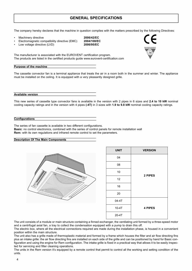
Description Of The Main Components
The unit consists of a module or main structure containing a finned exchanger, the ventilating unit formed by a three-speed motor
and a centrifugal axial fan, a tray to collect the condensation equipped with a pump to drain this off.
The electric box, where all the electrical connections required are made during the installation phase, is housed in a convenient
position within the main structure.
The unit also has a grille made of thermoplastic material and formed by a frame which houses the filter and air flow directing fins
plus an intake grille: the air flow directing fins are installed on each side of the grille and can be positioned by hand for Basic con-
figuration and using the engine for Rem configuration. The intake grille is fixed in a practical way that allows it to be easily inspec-
ted for servicing and filter cleaning operations.
The units in the Rem version it’s equipped by a remote control that permit to control all the working and setting condition of the
units.
UNIT VERSION
04
2 PIPES
08
10
12
16
20
04-4T
4 PIPES10-4T
20-4T
GENERAL SPECIFICATIONS
4
The company hereby declares that the machine in question complies with the matters prescribed by the following Directives:
• Machinery directive 2006/42/EC• Electromagnetic compatibility directive (EMC) 2004/108/EC• Low voltage directive (LVD) 2006/95/EC
The manufacturer is associated with the EUROVENT certification program.
The products are listed in the certified products guide www.eurovent-certification.com
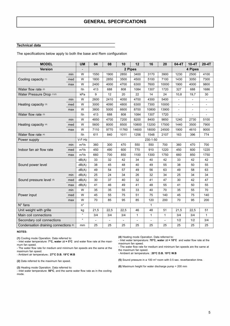
Technical data
The specifications below apply to both the base and Rem configuration
(4) Heating mode Operation. Data referred to:
- Inlet water temperature: 70°C, water Δt = 10°C and water flow rate at the
maximum fan speed.
- The water flow rate for medium and minimum fan speeds are the same at
the maximum fan speed.
- Ambient air temperature.: 20°C D.B. 19°C W.B
(5) Sound pressure in a 100 m3 room with 0.5 sec. reverberation time.
(6) Maximum height for water discharge pump = 200 mm
NOTES:
(1) Cooling mode Operation. Data referred to:
- Inlet water temperature: 7°C, water Δt = 5°C and water flow rate at the maxi-
mum fan speed.
- The water flow rate for medium and minimum fan speeds are the same at the
maximum fan speed.
- Ambient air temperature.: 27°C D.B. 19°C W.B
(2) Data referred to the maximum fan speed.
(3) Heating mode Operation. Data referred to:
- Inlet water temperature: 50°C, and the same water flow rate as in the cooling
mode.
MODEL UM 04 08 10 12 16 20 04-4T 10-4T 20-4T
Version - 2 Pipes 4 Pipes
Cooling capacity (1)
min W 1550 1900 2850 3400 3170 3900 1230 2500 4100
med W 1800 2850 3500 4500 5100 7100 1430 3050 7300
max W 2400 4000 4700 6300 7600 10000 1900 4000 9800
Water flow rate (2) l\h 413 688 808 1084 1307 1720 327 688 1686
Water Pressure Drop (1)(2) kPa 9 12 20 22 14 24 10,8 19,7 30
Heating capacity (3)
min W 2600 2410 4050 4700 4300 5400 - - -
med W 3000 4090 4800 6300 7300 10000 - - -
max W 3800 5000 6600 8700 10800 13900 - - -
Water flow rate (3) l\h 413 688 808 1084 1307 1720 - - -
Heating capacity (4)
min W 4850 4700 7200 8200 8400 9850 1240 2730 5100
med W 5600 8000 8500 10800 13200 17500 1440 3500 7900
max W 7110 9770 11760 14600 18000 24500 1900 4610 9000
Water flow rate (4) l\h 611 840 1011 1256 1548 2107 163 396 774
Power supply V-F-Hz 230-1-50
Indoor fan air flow rate
min m3\h 360 300 470 550 550 700 360 470 700
med m3\h 450 490 600 770 910 1220 450 600 1220
max m3\h 660 700 850 1100 1300 1750 660 850 1750
Sound power level
dB(A) 33 32 42 34 40 42 33 42 42
dB(A) 38 45 48 40 49 55 38 50 55
dB(A) 49 54 57 49 56 63 49 58 63
Sound pressure level (5)
min dB(A) 25 24 34 26 32 34 25 34 34
med dB(A) 30 37 40 32 41 47 30 42 47
max dB(A) 41 46 49 41 48 55 41 50 55
Power input
min W 35 35 55 33 40 70 35 55 70
med W 45 55 75 51 75 140 45 75 140
max W 70 85 95 85 120 200 70 95 200
N° fans n° 1
Unit weight with grille kg 21,5 22,5 22,5 46 48 51 21,5 22,5 51
Main coil connections “ 3/4 3/4 3/4 1 1 1 3/4 3/4 1
Secondary coil connections “ - - - - - - 1/2 1/2 3/4
Condensation draining connections (6) mm 25 25 25 25 25 25 25 25 25
GENERAL SPECIFICATIONS
5
6
OPERATION RANGE
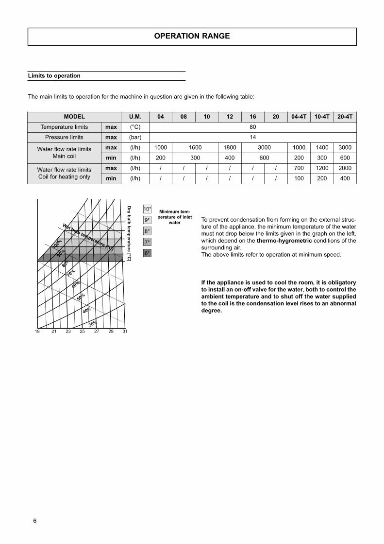
Limits to operation
The main limits to operation for the machine in question are given in the following table:
MODEL U.M. 04 08 10 12 16 20 04-4T 10-4T 20-4T
Temperature limits max (°C) 80
Pressure limits max (bar) 14
Water flow rate limits
Main coil
max (l/h) 1000 1600 1800 3000 1000 1400 3000
min (l/h) 200 300 400 600 200 300 600
Water flow rate limits
Coil for heating only
max (l/h) / / / / / / 700 1200 2000
min (l/h) / / / / / / 100 200 400
Dry
bu
lb te
mp
era
ture
[°C]
Wet bulb temperature [°C]
Minimum tem-perature of inlet
waterTo prevent condensation from forming on the external struc-
ture of the appliance, the minimum temperature of the water
must not drop below the limits given in the graph on the left,
which depend on the thermo-hygrometric conditions of the
surrounding air.
The above limits refer to operation at minimum speed.
If the appliance is used to cool the room, it is obligatoryto install an on-off valve for the water, both to control theambient temperature and to shut off the water suppliedto the coil is the condensation level rises to an abnormaldegree.
7
HOW TO SELECT THE UNIT
Selection criteria
Example of how the unit is selected:An example of how the unit is selected has been given for explanatory purposes and to illustrate how the graphs or tables in the
documentation are used. The selection will be made supposing that the unit is to be operated at the same conditions, but instal-
led in two different types of system:
A) system with two pipes for heating and cooling
B) system with four pipes
A unit able to guarantee the following performances must be selected:
Total cooling capacity 3600 [Watt]Sensitive cooling capacity 2900 [Watt]Operating ambient temperature 27 [°C] D.B and 19 [°C ] W.BThe value must be obtained at the medium speed.Heating capacity 4500 [Watt]Operating ambient temperature 20 [°C] d.b.Water flow rate as in operation in the cooling mode for the unit with two pipes.
The value must be obtained at the medium speed.
- Selection A (unit for system with two pipes)
The efficiency values of the “COOLING AND HEATING EFFICIENCIES” tables refer to the maximum speed of the fan. The cor-
rection coefficients in the “DATA CORRECTION FACTORS” tables can be used to determine the efficiencies at the medium and
minimum speeds. To use the tables, the parameters of the required values must be calculated again, considering operation at
the maximum speed.
Checking the "Technical Data" table for all the models, the suitable unit model according the required performances and ope-
rating conditions is the model 10, which provides as standard cooling capacity the following ones::
Total cooling capacity required at the maximum speed = 4700 [Watt] Total cooling capacity required at the medium speed = 3500 [Watt]
Cooling operating conditions Operating conditions deqfinition for the required performances.
By the " DATA CORRECTION FACTORS" table and using the right correction values for the selected model, the required performances are:
Total cooling capacity required at the maximum speed Pft max = 3600/0.74 = 4865 [Watt]Sensible cooling effect required at the maximum speed Pft max = 2900/0.72 = 4028 [Watt]Considering that the total efficiency value in the cooling mode mainly depends on the wet bulb temperature of the air, while the
sensible cooling effect depends on the dry bulb temperature, the ratio between the two remains more or less fixed and charac-
teristic of each model since these operating temperatures are set beforehand. The choice will therefore tend to consider the total
cooling efficiency as priority. The "Cooling capacity" table for the selected model 10 can be used to calculate the required cooling
capacity and to obtain the following:
inlet water temperature 5[°C] and a Δt of 6.6[°C]
inlet water temperature 6[°C] and a Δt of 5.6[°C]
inlet water temperature 7[°C] and a Δt of 4.6[°C]
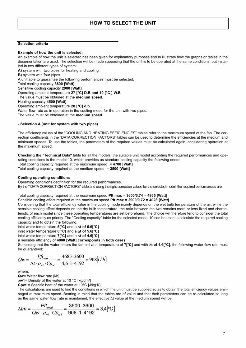
a sensible efficiency of 4000 [Watt] corresponds in both casesSupposing that the water enters the fan coil at a temperature of 7[°C] and with Δt of 4.6[°C], the following water flow rate must
be guaranteed:
where:
Qw= Water flow rate [l/h]
ρw1= Density of the water at 10 °C [kg/dm³]
Cpw1= Specific heat of the water at 10°C [J/kg·K]
The calculations are used to find the conditions in which the unit must be supplied so as to obtain the total efficiency values envi-
saged at maximum speed. Bearing in mind that the tables are of value and that their parameters can be re-calculated so long
as the same water flow rate is maintained, the effective Δt value at the medium speed will be:
8
HOW TO SELECT THE UNIT
Selection of the model and the operating conditions in the cooling mode will therefore be as follows
Model 10Total cooling capacity 3600 [Watt]Sensible cooling effect 4000·0.72=2880 [Watt]Inlet water temperature 7[°C]Δt of the water 3.4[°C]
Water flow rate 908[l/h]
The loss of head can be calculated from the “WATER PRESSURE DROPS” graph and is 25[KPa].If the loss of head is incompatible with the characteristics of the pump in the circuit, it would be possible to opt for the solution with
different inlet temperature and Δt values so as to modify the water flow rate delivered to the unit.
If valve kit VTV-1 is used, the additional loss of head with the unit supplied can be calculated from the “WATER PRESSURE
DROP VALVES” graph and is 12 [KPa]
Heating operating conditionsCalculation of the optimal conditions in which the unit must be supplied so as to obtain the required Heating capacity.
Let us suppose that a system with two pipes is used and that it must operate with the same water flow rate calculated for ope-
ration in the cooling mode. Here again, the parameters of the required power must be re-calculated, considering that the fan will
operate at maximum speed. The correction coefficients in the “DATA CORRECTION FACTORS” table can be used to calculate
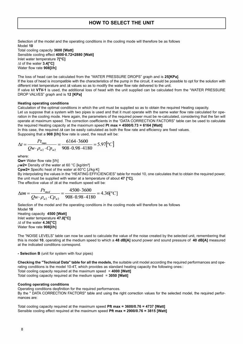
the required Heating capacity at the maximum speed Pt max = 4500/0.73 = 6164 [Watt]In this case, the required Δt can be easily calculated as both the flow rate and efficiency are fixed values.
Supposing that a 908 [l/h] flow rate is used, the result will be:
where:
Qw= Water flow rate [l/h]
ρw2= Density of the water at 60 °C [kg/dm³]
Cpw2= Specific heat of the water at 60°C [J/kg·K]
By interpolating the values in the “HEATING EFFICIENCIES” table for model 10, one calculates that to obtain the required power,
the unit must be supplied with water at a temperature of about 47 [°C].The effective value of Δt at the medium speed will be:
Selection of the model and the operating conditions in the cooling mode will therefore be as follows
Model 10Heating capacity 4500 [Watt]
Inlet water temperature 47.0[°C]Δt of the water 4.36[°C]
Water flow rate 908[l/h]
The “NOISE LEVELS” table can now be used to calculate the value of the noise created by the selected unit, remembering that
this is model 10, operating at the medium speed to which a 48 dB[A] sound power and sound pressure of 40 dB[A] measured
at the indicated conditions correspond.
- Selection B (unit for system with four pipes)
Checking the "Technical Data" table for all the models, the suitable unit model according the required performances and ope-
rating conditions is the model 10-4T, which provides as standard heating capacity the following ones::
Total cooling capacity required at the maximum speed = 4000 [Watt]
Total cooling capacity required at the medium speed = 3050 [Watt]
Cooling operating conditions
Operating conditions deqfinition for the required performances.
By the " DATA CORRECTION FACTORS" table and using the right correction values for the selected model, the required perfor-
mances are:
Total cooling capacity required at the maximum speed Pft max = 3600/0.76 = 4737 [Watt]
Sensible cooling effect required at the maximum speed Pft max = 2900/0.76 = 3815 [Watt]
9
HOW TO SELECT THE UNIT
The "Cooling capacity" table for the selected model 10-4T can be used to calculate the required cooling capacity and to obtain
the following:
Total efficiency = 4737 [Watt] with water in the following conditions.
inlet water temperature 5[°C] and a Δt of 5.4 [°C]
inlet water temperature 6[°C] and a Δt of 4.35[°C]
inlet water temperature 7[°C] and a Δt of 3.3 [°C]
a sensible efficiency of 3700 [Watt] corresponds in both cases
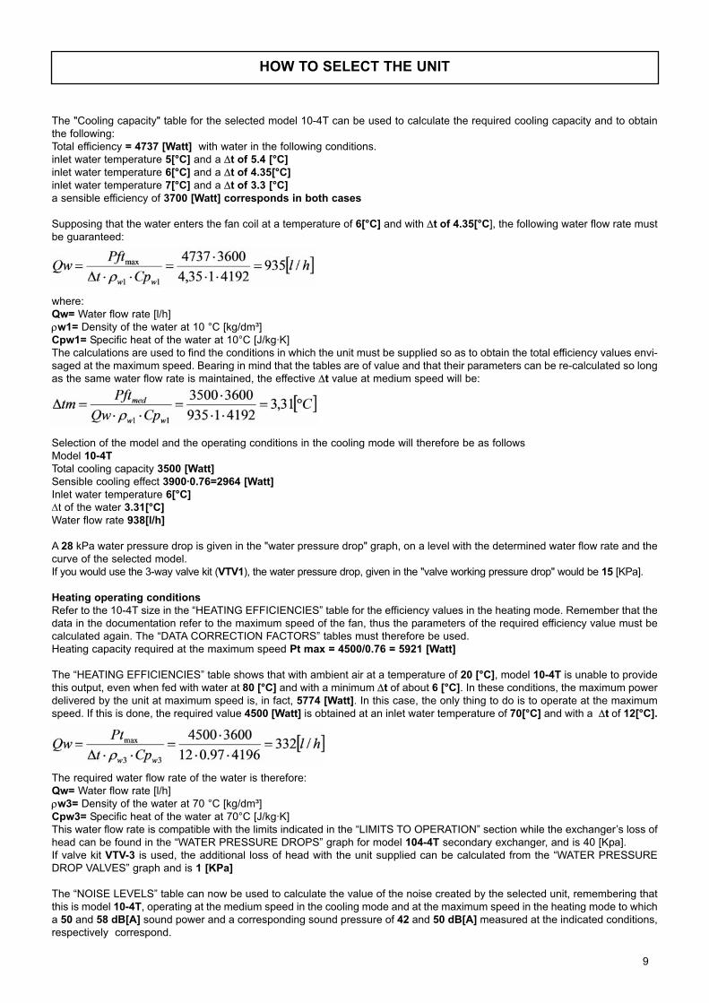
Supposing that the water enters the fan coil at a temperature of 6[°C] and with Δt of 4.35[°C], the following water flow rate must
be guaranteed:
where:
Qw= Water flow rate [l/h]
ρw1= Density of the water at 10 °C [kg/dm³]
Cpw1= Specific heat of the water at 10°C [J/kg·K]
The calculations are used to find the conditions in which the unit must be supplied so as to obtain the total efficiency values envi-
saged at the maximum speed. Bearing in mind that the tables are of value and that their parameters can be re-calculated so long
as the same water flow rate is maintained, the effective Δt value at medium speed will be:
Selection of the model and the operating conditions in the cooling mode will therefore be as follows
Model 10-4TTotal cooling capacity 3500 [Watt]Sensible cooling effect 3900·0.76=2964 [Watt]Inlet water temperature 6[°C]Δt of the water 3.31[°C]
Water flow rate 938[l/h]
A 28 kPa water pressure drop is given in the "water pressure drop" graph, on a level with the determined water flow rate and the
curve of the selected model.
If you would use the 3-way valve kit (VTV1), the water pressure drop, given in the "valve working pressure drop" would be 15 [KPa].
Heating operating conditions Refer to the 10-4T size in the “HEATING EFFICIENCIES” table for the efficiency values in the heating mode. Remember that the
data in the documentation refer to the maximum speed of the fan, thus the parameters of the required efficiency value must be
calculated again. The “DATA CORRECTION FACTORS” tables must therefore be used.
Heating capacity required at the maximum speed Pt max = 4500/0.76 = 5921 [Watt]
The “HEATING EFFICIENCIES” table shows that with ambient air at a temperature of 20 [°C], model 10-4T is unable to provide
this output, even when fed with water at 80 [°C] and with a minimum Δt of about 6 [°C]. In these conditions, the maximum power
delivered by the unit at maximum speed is, in fact, 5774 [Watt]. In this case, the only thing to do is to operate at the maximum
speed. If this is done, the required value 4500 [Watt] is obtained at an inlet water temperature of 70[°C] and with a Δt of 12[°C].
The required water flow rate of the water is therefore:
Qw= Water flow rate [l/h]
ρw3= Density of the water at 70 °C [kg/dm³]
Cpw3= Specific heat of the water at 70°C [J/kg·K]
This water flow rate is compatible with the limits indicated in the “LIMITS TO OPERATION” section while the exchanger’s loss of
head can be found in the “WATER PRESSURE DROPS” graph for model 104-4T secondary exchanger, and is 40 [Kpa].
If valve kit VTV-3 is used, the additional loss of head with the unit supplied can be calculated from the “WATER PRESSURE
DROP VALVES” graph and is 1 [KPa]
The “NOISE LEVELS” table can now be used to calculate the value of the noise created by the selected unit, remembering that
this is model 10-4T, operating at the medium speed in the cooling mode and at the maximum speed in the heating mode to which
a 50 and 58 dB[A] sound power and a corresponding sound pressure of 42 and 50 dB[A] measured at the indicated conditions,
respectively correspond.
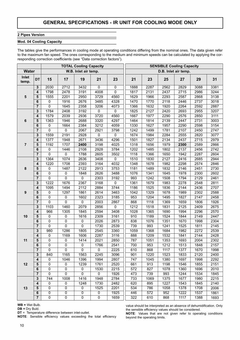
GENERAL SPECIFICATIONS - IR UNIT FOR COOLING MODE ONLY
Mod. 04 Cooling Capacity
The tables give the performances in cooling mode at operating conditions differing from the nominal ones. The data given refer
to the maximum fan speed. The ones corresponding to the medium and minimum speeds can be calculated by applying the cor-
responding correction coefficients (see “Data correction factors”).
WB = Wet Bulb.
DB = Dry Buld.
DT = Temperature difference between inlet-outlet.
NOTE: Sensible efficiency values exceeding the total efficiency
TOTAL Cooling Capacity
Water W.B. Inlet air temp.
Inlettemp.
DT 15 17 19 21 23
5
3 2030 2712 3432 0 0
4 1798 2478 3191 4008 0
5 1555 2201 2950 3729 4560
6 0 1916 2676 3485 4328
7 0 1645 2358 3206 4073
6
3 1784 2408 3192 0 0
4 1579 2039 2936 3720 4560
5 1363 1946 2688 3320 4297
6 0 1664 2384 3212 4059
7 0 0 2067 2921 3798
7
3 1559 2191 2928 0 0
4 1377 1948 2671 3436 4296
5 1192 1707 2400 3198 4025
6 0 1446 2108 2928 3784
7 0 0 1788 2605 3502
8
3 1364 1074 2636 3408 0
4 1220 1708 2393 3164 4032
5 0 1487 2122 2913 3753
6 0 0 1848 2626 3488
7 0 0 0 2303 3192
9
3 1222 1676 2367 3168 0
4 1095 1494 2112 2884 3744
5 0 1297 1861 2614 3463
6 0 0 1602 2323 3185
7 0 0 0 2003 2867
10
3 1103 1460 2079 2856 0
4 966 1305 1845 2594 3408
5 0 0 1616 2309 3161
6 0 0 0 2026 2873
7 0 0 0 1730 2539
11
3 980 1286 1805 2545 3360
4 0 1169 1606 2287 3116
5 0 0 1414 2021 2850
6 0 0 0 1766 2541
7 0 0 0 0 2225
12
3 840 1165 1563 2245 3096
4 0 1046 1396 1994 2807
5 0 0 1239 1761 2520
6 0 0 0 1530 2215
7 0 0 0 0 1926
13
3 744 1008 1416 1948 2784
4 0 0 1248 1730 2482
5 0 0 0 1525 2201
6 0 0 0 0 1925
7 0 0 0 0 1659
SENSIBLE Cooling Capacity
D.B. Inlet air temp.
21 23 25 27 29 31
1888 2287 2562 2829 3088 3381
1817 2131 2437 2715 2986 3244
1629 1966 2293 2587 2868 3138
1470 1770 2118 2446 2737 3018
1366 1632 1920 2264 2592 2887
1825 2127 2420 2693 2955 3207
1667 1977 2290 2576 2850 3111
1464 1814 2139 2447 2731 3003
1330 1627 1957 2290 2598 3154
1242 1499 1781 2107 2450 2747
1674 1984 2284 2555 2820 3077
1501 1827 2134 2437 2715 2979
1318 1656 1979 2300 2589 2866
1202 1485 1802 2137 2456 2742
1118 1366 1650 1942 2287 2604
1510 1830 2127 2416 2685 2944
1348 1678 1982 2298 2574 2846
1181 1489 1832 2146 2451 2730
1076 1341 1645 1978 2300 2602
993 1242 1508 1794 2129 2461
1361 1679 1983 2278 2548 2811
1186 1525 1836 2144 2436 2707
1042 1329 1678 1989 2302 2588
953 1204 1495 1827 2147 2458
868 1118 1369 1659 1806 1926
1212 1518 1831 2125 2409 2675
1028 1365 1690 1994 2296 2570
910 1189 1524 1844 2149 2447
838 1076 1351 1670 1998 2304
739 993 1241 1525 1811 2145
1059 1368 1684 1982 2272 2539
888 1209 1532 1841 2144 2428
787 1051 1353 1693 2004 2302
700 953 1212 1513 1848 2157
610 868 1117 1377 1670 1998
901 1220 1523 1833 2120 2400
747 1045 1380 1697 1998 2292
661 913 1198 1546 1855 2151
572 827 1078 1360 1696 2010
473 739 993 1244 1534 1845
733 1069 1375 1677 1980 2215
620 895 1227 1543 1845 2140
534 786 1058 1378 1708 2006
446 572 952 1222 1537 1861
322 610 868 1117 1388 1693
2 Pipes Version
value should be interpreted as an absence of dehumidification. Only
the sensible efficiency values should be considered.
NOTE: Values that are not given refer to operating conditions
beyond the operating limits.
10

GENERAL SPECIFICATIONS - IR UNIT FOR COOLING MODE ONLY
Mod. 08 Cooling Capacity
TOTAL Cooling Capacity
Water W.B. Inlet air temp.
Inlettemp.
DT 15 17 19 21 23
5
3 3383 4520 0 0 0
4 2997 4129 5318 0 0
5 2592 3669 4917 6215 7600
6 2241 3194 4460 5808 7213
7 0 2742 3929 5343 6789
6
3 2973 4014 0 0 0
4 2632 3398 4893 6200 0
5 2272 3243 4480 5534 7162
6 0 2773 3974 5354 6766
7 0 0 3444 4868 6330
7
3 2598 3651 4880 0 0
4 2294 3246 4452 5727 0
5 1987 2845 4000 5331 6708
6 0 2409 3514 4880 6306
7 0 0 2980 4341 5837
8
3 2274 1790 4394 0 0
4 2033 2846 3988 5273 0
5 1838 2479 3536 4855 6255
6 0 2128 3080 4376 5813
7 0 0 2629 3838 5321
9
3 2036 2793 3945 0 0
4 1824 2490 3520 4807 6240
5 0 2162 3102 4356 5772
6 0 0 2670 3872 5308
7 0 0 0 3339 4778
10
3 1838 2434 3464 4760 0
4 1610 2175 3075 4324 5680
5 0 1912 2693 3848 5268
6 0 0 2311 3377 4789
7 0 0 0 2883 4232
11
3 1634 2143 3008 4242 0
4 1400 1949 2676 3812 5194
5 0 0 2357 3368 4750
6 0 0 0 2944 4235
7 0 0 0 2492 3709
12
3 1400 1942 2606 3742 0
4 0 1743 2327 3324 4679
5 0 0 2064 2935 4199
6 0 0 0 2549 3692
7 0 0 0 0 3210
13
3 1240 1680 2360 3246 4640
4 0 1520 2080 2883 4136
5 0 0 1843 2542 3668
6 0 0 0 2215 3208
7 0 0 0 0 2764
SENSIBLE Cooling Capacity
D.B. Inlet air temp.
21 23 25 27 29 31
2709 3281 3676 4060 4431 4851
2607 3057 3497 3895 4284 4655
2337 2820 3290 3712 4116 4502
2109 2540 3039 3509 3927 4331
1960 2342 2755 3249 3719 4142
2619 3052 3473 3863 4239 4602
2391 2837 3286 3696 4089 4463
2100 2603 3069 3510 3918 4309
1909 2334 2807 3286 3728 4525
1782 2151 2556 3022 3515 3941
2401 2846 3277 3666 4046 4415
2154 2621 3062 3497 3895 4275
1891 2376 2840 3300 3714 4113
1725 2131 2585 3066 3523 3934
1605 1960 2367 2786 3282 3737
2166 2625 3052 3467 3852 4224
1934 2408 2843 3297 3693 4083
1694 2136 2628 3079 3517 3916
1544 1924 2360 2839 3300 3734
1425 1782 2164 2574 3055 3531
1953 2409 2846 3268 3656 4033
1702 2187 2634 3076 3495 3884
1494 1908 2407 2854 3303 3713
1367 1728 2145 2622 3081 3527
1245 1605 1964 2380 2592 2764
1738 2178 2627 3049 3457 3838
1475 1958 2425 2861 3294 3688
1306 1706 2186 2646 3083 3511
1202 1544 1938 2396 2867 3306
1061 1425 1780 2188 2598 3078
1519 1963 2416 2844 3259 3643
1274 1735 2197 2641 3076 3484
1129 1507 1941 2428 2875 3303
1005 1367 1739 2171 2652 3094
875 1245 1603 1975 2396 2867
1292 1750 2185 2630 3042 3444
1072 1500 1980 2435 2866 3288
948 1309 1719 2218 2661 3086
821 1187 1546 1951 2434 2884
678 1061 1425 1784 2202 2647
1052 1533 1973 2406 2841 3178
889 1283 1760 2214 2648 3071
766 1128 1519 1977 2451 2878
640 820 1365 1754 2205 2670
463 875 1245 1603 1992 2429
WB = Wet Bulb.
DB = Dry Buld.
DT = Temperature difference between inlet-outlet.
NOTE: Sensible efficiency values exceeding the total efficiency
value should be interpreted as an absence of dehumidification. Only
the sensible efficiency values should be considered.
NOTE: Values that are not given refer to operating conditions
beyond the operating limits.
11
GENERAL SPECIFICATIONS - IR UNIT FOR COOLING MODE ONLY
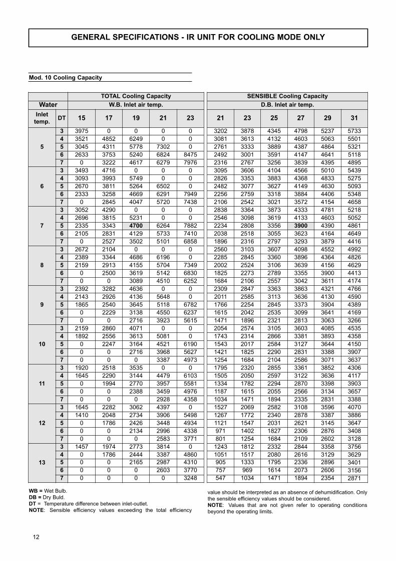
Mod. 10 Cooling Capacity
TOTAL Cooling Capacity
Water W.B. Inlet air temp.
Inlettemp.
DT 15 17 19 21 23
5
3 3975 0 0 0 0
4 3521 4852 6249 0 0
5 3045 4311 5778 7302 0
6 2633 3753 5240 6824 8475
7 0 3222 4617 6279 7976
6
3 3493 4716 0 0 0
4 3093 3993 5749 0 0
5 2670 3811 5264 6502 0
6 2333 3258 4669 6291 7949
7 0 2845 4047 5720 7438
7
3 3052 4290 0 0 0
4 2696 3815 5231 0 0
5 2335 3343 4700 6264 7882
6 2105 2831 4129 5733 7410
7 0 2527 3502 5101 6858
8
3 2672 2104 0 0 0
4 2389 3344 4686 6196 0
5 2159 2913 4155 5704 7349
6 0 2500 3619 5142 6830
7 0 0 3089 4510 6252
9
3 2392 3282 4636 0 0
4 2143 2926 4136 5648 0
5 1865 2540 3645 5118 6782
6 0 2229 3138 4550 6237
7 0 0 2716 3923 5615
10
3 2159 2860 4071 0 0
4 1892 2556 3613 5081 0
5 0 2247 3164 4521 6190
6 0 0 2716 3968 5627
7 0 0 0 3387 4973
11
3 1920 2518 3535 0 0
4 1645 2290 3144 4479 6103
5 0 1994 2770 3957 5581
6 0 0 2388 3459 4976
7 0 0 0 2928 4358
12
3 1645 2282 3062 4397 0
4 1410 2048 2734 3906 5498
5 0 1786 2426 3448 4934
6 0 0 2134 2996 4338
7 0 0 0 2583 3771
13
3 1457 1974 2773 3814 0
4 0 1786 2444 3387 4860
5 0 0 2165 2987 4310
6 0 0 0 2603 3770
7 0 0 0 0 3248
SENSIBLE Cooling Capacity
D.B. Inlet air temp.
21 23 25 27 29 31
3202 3878 4345 4798 5237 5733
3081 3613 4132 4603 5063 5501
2761 3333 3889 4387 4864 5321
2492 3001 3591 4147 4641 5118
2316 2767 3256 3839 4395 4895
3095 3606 4104 4566 5010 5439
2826 3353 3883 4368 4833 5275
2482 3077 3627 4149 4630 5093
2256 2759 3318 3884 4406 5348
2106 2542 3021 3572 4154 4658
2838 3364 3873 4333 4781 5218
2546 3098 3619 4133 4603 5052
2234 2808 3356 3900 4390 4861
2038 2518 3055 3623 4164 4649
1896 2316 2797 3293 3879 4416
2560 3103 3607 4098 4552 4992
2285 2845 3360 3896 4364 4826
2002 2524 3106 3639 4156 4629
1825 2273 2789 3355 3900 4413
1684 2106 2557 3042 3611 4174
2309 2847 3363 3863 4321 4766
2011 2585 3113 3636 4130 4590
1766 2254 2845 3373 3904 4389
1615 2042 2535 3099 3641 4169
1471 1896 2321 2813 3063 3266
2054 2574 3105 3603 4085 4535
1743 2314 2866 3381 3893 4358
1543 2017 2584 3127 3644 4150
1421 1825 2290 2831 3388 3907
1254 1684 2104 2586 3071 3637
1795 2320 2855 3361 3852 4306
1505 2050 2597 3122 3636 4117
1334 1782 2294 2870 3398 3903
1187 1615 2055 2566 3134 3657
1034 1471 1894 2335 2831 3388
1527 2069 2582 3108 3596 4070
1267 1772 2340 2878 3387 3886
1121 1547 2031 2621 3145 3647
971 1402 1827 2306 2876 3408
801 1254 1684 2109 2602 3128
1243 1812 2332 2844 3358 3756
1051 1517 2080 2616 3129 3629
905 1333 1795 2336 2896 3401
757 969 1614 2073 2606 3156
547 1034 1471 1894 2354 2871
WB = Wet Bulb.
DB = Dry Buld.
DT = Temperature difference between inlet-outlet.
NOTE: Sensible efficiency values exceeding the total efficiency
value should be interpreted as an absence of dehumidification. Only
the sensible efficiency values should be considered.
NOTE: Values that are not given refer to operating conditions
beyond the operating limits.
12
GENERAL SPECIFICATIONS - IR UNIT FOR COOLING MODE ONLY
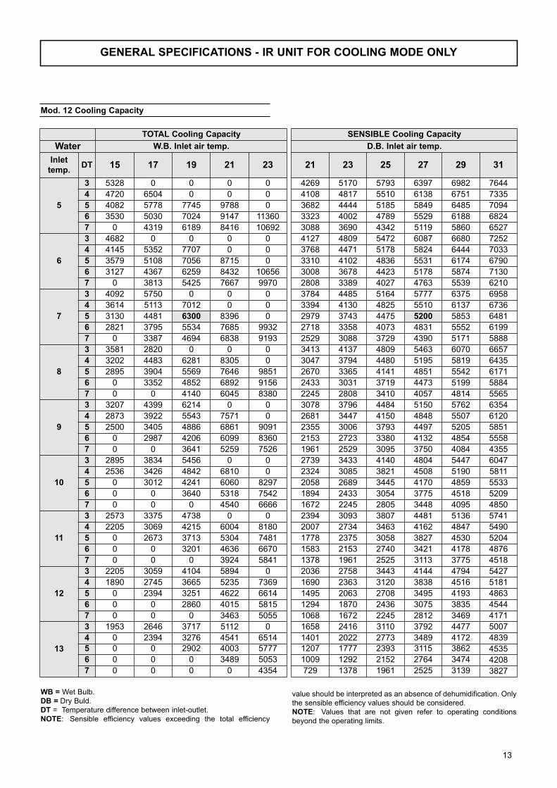
Mod. 12 Cooling Capacity
TOTAL Cooling Capacity
Water W.B. Inlet air temp.
Inlettemp.
DT 15 17 19 21 23
5
3 5328 0 0 0 0
4 4720 6504 0 0 0
5 4082 5778 7745 9788 0
6 3530 5030 7024 9147 11360
7 0 4319 6189 8416 10692
6
3 4682 0 0 0 0
4 4145 5352 7707 0 0
5 3579 5108 7056 8715 0
6 3127 4367 6259 8432 10656
7 0 3813 5425 7667 9970
7
3 4092 5750 0 0 0
4 3614 5113 7012 0 0
5 3130 4481 6300 8396 0
6 2821 3795 5534 7685 9932
7 0 3387 4694 6838 9193
8
3 3581 2820 0 0 0
4 3202 4483 6281 8305 0
5 2895 3904 5569 7646 9851
6 0 3352 4852 6892 9156
7 0 0 4140 6045 8380
9
3 3207 4399 6214 0 0
4 2873 3922 5543 7571 0
5 2500 3405 4886 6861 9091
6 0 2987 4206 6099 8360
7 0 0 3641 5259 7526
10
3 2895 3834 5456 0 0
4 2536 3426 4842 6810 0
5 0 3012 4241 6060 8297
6 0 0 3640 5318 7542
7 0 0 0 4540 6666
11
3 2573 3375 4738 0 0
4 2205 3069 4215 6004 8180
5 0 2673 3713 5304 7481
6 0 0 3201 4636 6670
7 0 0 0 3924 5841
12
3 2205 3059 4104 5894 0
4 1890 2745 3665 5235 7369
5 0 2394 3251 4622 6614
6 0 0 2860 4015 5815
7 0 0 0 3463 5055
13
3 1953 2646 3717 5112 0
4 0 2394 3276 4541 6514
5 0 0 2902 4003 5777
6 0 0 0 3489 5053
7 0 0 0 0 4354
SENSIBLE Cooling Capacity
D.B. Inlet air temp.
21 23 25 27 29 31
4269 5170 5793 6397 6982 7644
4108 4817 5510 6138 6751 7335
3682 4444 5185 5849 6485 7094
3323 4002 4789 5529 6188 6824
3088 3690 4342 5119 5860 6527
4127 4809 5472 6087 6680 7252
3768 4471 5178 5824 6444 7033
3310 4102 4836 5531 6174 6790
3008 3678 4423 5178 5874 7130
2808 3389 4027 4763 5539 6210
3784 4485 5164 5777 6375 6958
3394 4130 4825 5510 6137 6736
2979 3743 4475 5200 5853 6481
2718 3358 4073 4831 5552 6199
2529 3088 3729 4390 5171 5888
3413 4137 4809 5463 6070 6657
3047 3794 4480 5195 5819 6435
2670 3365 4141 4851 5542 6171
2433 3031 3719 4473 5199 5884
2245 2808 3410 4057 4814 5565
3078 3796 4484 5150 5762 6354
2681 3447 4150 4848 5507 6120
2355 3006 3793 4497 5205 5851
2153 2723 3380 4132 4854 5558
1961 2529 3095 3750 4084 4355
2739 3433 4140 4804 5447 6047
2324 3085 3821 4508 5190 5811
2058 2689 3445 4170 4859 5533
1894 2433 3054 3775 4518 5209
1672 2245 2805 3448 4095 4850
2394 3093 3807 4481 5136 5741
2007 2734 3463 4162 4847 5490
1778 2375 3058 3827 4530 5204
1583 2153 2740 3421 4178 4876
1378 1961 2525 3113 3775 4518
2036 2758 3443 4144 4794 5427
1690 2363 3120 3838 4516 5181
1495 2063 2708 3495 4193 4863
1294 1870 2436 3075 3835 4544
1068 1672 2245 2812 3469 4171
1658 2416 3110 3792 4477 5007
1401 2022 2773 3489 4172 4839
1207 1777 2393 3115 3862 4535
1009 1292 2152 2764 3474 4208
729 1378 1961 2525 3139 3827
WB = Wet Bulb.
DB = Dry Buld.
DT = Temperature difference between inlet-outlet.
NOTE: Sensible efficiency values exceeding the total efficiency
value should be interpreted as an absence of dehumidification. Only
the sensible efficiency values should be considered.
NOTE: Values that are not given refer to operating conditions
beyond the operating limits.
13
GENERAL SPECIFICATIONS - IR UNIT FOR COOLING MODE ONLY
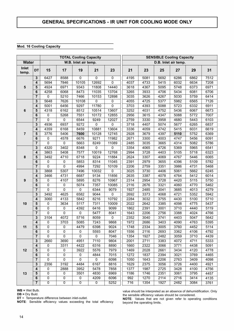
Mod. 16 Cooling Capacity
TOTAL Cooling Capacity
Water W.B. Inlet air temp.
Inlettemp.
DT 15 17 19 21 23
5
3 6427 8588 0 0 0
4 5694 7846 10105 12692 0
5 4924 6971 9343 11808 14440
6 4258 6068 8473 11035 13704
7 0 5210 7466 10153 12898
6
3 5648 7626 10108 0 0
4 5001 6456 9297 11780 0
5 4318 6162 8512 10514 13607
6 0 5268 7551 10172 12855
7 0 0 6544 9249 12027
7
3 4936 6937 9272 0 0
4 4359 6168 8459 10881 13604
5 3776 5406 7600 10128 12745
6 0 4578 6676 9271 11982
7 0 0 5663 8249 11089
8
3 4320 3402 8348 0 0
4 3863 5408 7577 10019 12768
5 3492 4710 6718 9224 11884
6 0 0 5853 8314 11045
7 0 0 4994 7292 10109
9
3 3868 5307 7496 10032 0
4 3466 4731 6687 9134 11856
5 0 4107 5895 8276 10967
6 0 0 5074 7357 10085
7 0 0 0 6344 9079
10
3 3492 4625 6582 9044 0
4 3060 4133 5842 8216 10792
5 0 3634 5117 7311 10009
6 0 0 4392 6416 9099
7 0 0 0 5477 8041
11
3 3104 4072 5716 8059 0
4 0 3703 5085 7243 9868
5 0 0 4479 6398 9024
6 0 0 0 5593 8047
7 0 0 0 0 7046
12
3 2660 3690 4951 7110 9804
4 0 3311 4422 6316 8890
5 0 0 3922 5576 7979
6 0 0 0 4844 7015
7 0 0 0 0 6098
13
3 2356 3192 4484 6167 8816
4 0 2888 3952 5478 7858
5 0 0 3501 4830 6969
6 0 0 0 4209 6096
7 0 0 0 0 5252
SENSIBLE Cooling Capacity
D.B. Inlet air temp.
21 23 25 27 29 31
4195 5081 5692 6286 6862 7512
4037 4733 5415 6032 6634 7208
3618 4367 5095 5748 6373 6971
3265 3933 4706 5434 6081 6706
3035 3626 4267 5030 5759 6414
4055 4725 5377 5982 6565 7126
3703 4393 5088 5723 6332 6911
3252 4031 4752 5436 6067 6673
2956 3615 4347 5088 5772 7007
2759 3330 3958 4680 5443 6103
3718 4407 5074 5677 6265 6837
3336 4059 4742 5415 6031 6619
2928 3679 4397 5110 5752 6369
2671 3300 4003 4747 5456 6091
2485 3035 3665 4314 5082 5786
3354 4065 4726 5369 5965 6541
2994 3728 4403 5105 5718 6323
2624 3307 4069 4767 5446 6065
2391 2979 3655 4396 5109 5782
2206 2759 3351 3986 4731 5468
3025 3730 4406 5061 5662 6245
2635 3387 4078 4764 5412 6014
2314 2954 3728 4420 5115 5750
2116 2676 3321 4060 4770 5462
1927 2485 3041 3685 4013 4279
2692 3373 4068 4721 5352 5942
2284 3032 3755 4430 5100 5710
2022 2642 3385 4098 4775 5437
1862 2391 3001 3710 4440 5119
1643 2206 2756 3388 4024 4766
2352 3040 3741 4403 5047 5642
1972 2686 3403 4090 4763 5395
1748 2334 3005 3760 4452 5114
1556 2116 2693 3362 4106 4792
1354 1927 2482 3059 3710 4439
2001 2711 3383 4072 4711 5333
1660 2322 3066 3771 4438 5091
1469 2028 2661 3434 4120 4778
1272 1837 2394 3021 3769 4465
1050 1643 2206 2763 3409 4098
1629 2375 3056 3726 4400 4921
1377 1987 2725 3428 4100 4756
1186 1746 2351 3061 3795 4457
992 1270 2114 2716 3414 4135
716 1354 1927 2482 3084 3761
WB = Wet Bulb.
DB = Dry Buld.
DT = Temperature difference between inlet-outlet.
NOTE: Sensible efficiency values exceeding the total efficiency
value should be interpreted as an absence of dehumidification. Only
the sensible efficiency values should be considered.
NOTE: Values that are not given refer to operating conditions
beyond the operating limits.
14
GENERAL SPECIFICATIONS - IR UNIT FOR COOLING MODE ONLY
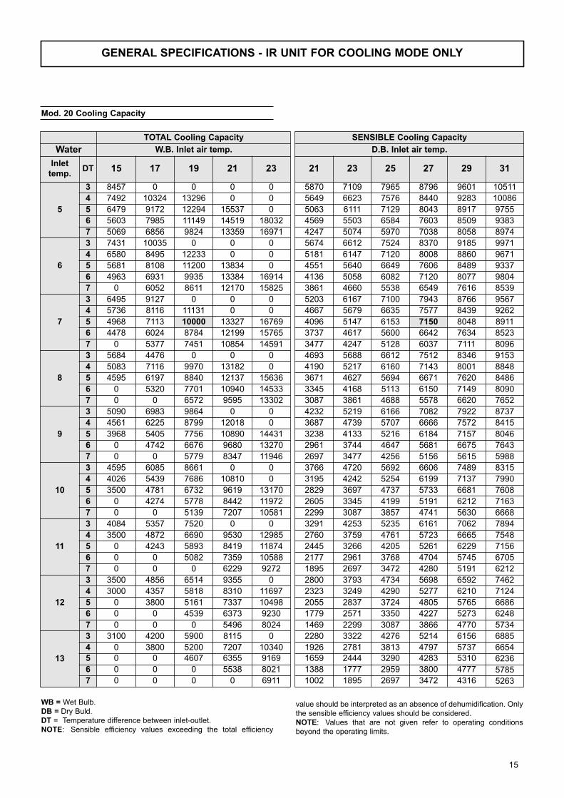
Mod. 20 Cooling Capacity
TOTAL Cooling Capacity
Water W.B. Inlet air temp.
Inlettemp.
DT 15 17 19 21 23
5
3 8457 0 0 0 0
4 7492 10324 13296 0 0
5 6479 9172 12294 15537 0
6 5603 7985 11149 14519 18032
7 5069 6856 9824 13359 16971
6
3 7431 10035 0 0 0
4 6580 8495 12233 0 0
5 5681 8108 11200 13834 0
6 4963 6931 9935 13384 16914
7 0 6052 8611 12170 15825
7
3 6495 9127 0 0 0
4 5736 8116 11131 0 0
5 4968 7113 10000 13327 16769
6 4478 6024 8784 12199 15765
7 0 5377 7451 10854 14591
8
3 5684 4476 0 0 0
4 5083 7116 9970 13182 0
5 4595 6197 8840 12137 15636
6 0 5320 7701 10940 14533
7 0 0 6572 9595 13302
9
3 5090 6983 9864 0 0
4 4561 6225 8799 12018 0
5 3968 5405 7756 10890 14431
6 0 4742 6676 9680 13270
7 0 0 5779 8347 11946
10
3 4595 6085 8661 0 0
4 4026 5439 7686 10810 0
5 3500 4781 6732 9619 13170
6 0 4274 5778 8442 11972
7 0 0 5139 7207 10581
11
3 4084 5357 7520 0 0
4 3500 4872 6690 9530 12985
5 0 4243 5893 8419 11874
6 0 0 5082 7359 10588
7 0 0 0 6229 9272
12
3 3500 4856 6514 9355 0
4 3000 4357 5818 8310 11697
5 0 3800 5161 7337 10498
6 0 0 4539 6373 9230
7 0 0 0 5496 8024
13
3 3100 4200 5900 8115 0
4 0 3800 5200 7207 10340
5 0 0 4607 6355 9169
6 0 0 0 5538 8021
7 0 0 0 0 6911
SENSIBLE Cooling Capacity
D.B. Inlet air temp.
21 23 25 27 29 31
5870 7109 7965 8796 9601 10511
5649 6623 7576 8440 9283 10086
5063 6111 7129 8043 8917 9755
4569 5503 6584 7603 8509 9383
4247 5074 5970 7038 8058 8974
5674 6612 7524 8370 9185 9971
5181 6147 7120 8008 8860 9671
4551 5640 6649 7606 8489 9337
4136 5058 6082 7120 8077 9804
3861 4660 5538 6549 7616 8539
5203 6167 7100 7943 8766 9567
4667 5679 6635 7577 8439 9262
4096 5147 6153 7150 8048 8911
3737 4617 5600 6642 7634 8523
3477 4247 5128 6037 7111 8096
4693 5688 6612 7512 8346 9153
4190 5217 6160 7143 8001 8848
3671 4627 5694 6671 7620 8486
3345 4168 5113 6150 7149 8090
3087 3861 4688 5578 6620 7652
4232 5219 6166 7082 7922 8737
3687 4739 5707 6666 7572 8415
3238 4133 5216 6184 7157 8046
2961 3744 4647 5681 6675 7643
2697 3477 4256 5156 5615 5988
3766 4720 5692 6606 7489 8315
3195 4242 5254 6199 7137 7990
2829 3697 4737 5733 6681 7608
2605 3345 4199 5191 6212 7163
2299 3087 3857 4741 5630 6668
3291 4253 5235 6161 7062 7894
2760 3759 4761 5723 6665 7548
2445 3266 4205 5261 6229 7156
2177 2961 3768 4704 5745 6705
1895 2697 3472 4280 5191 6212
2800 3793 4734 5698 6592 7462
2323 3249 4290 5277 6210 7124
2055 2837 3724 4805 5765 6686
1779 2571 3350 4227 5273 6248
1469 2299 3087 3866 4770 5734
2280 3322 4276 5214 6156 6885
1926 2781 3813 4797 5737 6654
1659 2444 3290 4283 5310 6236
1388 1777 2959 3800 4777 5785
1002 1895 2697 3472 4316 5263
WB = Wet Bulb.
DB = Dry Buld.
DT = Temperature difference between inlet-outlet.
NOTE: Sensible efficiency values exceeding the total efficiency
value should be interpreted as an absence of dehumidification. Only
the sensible efficiency values should be considered.
NOTE: Values that are not given refer to operating conditions
beyond the operating limits.
15
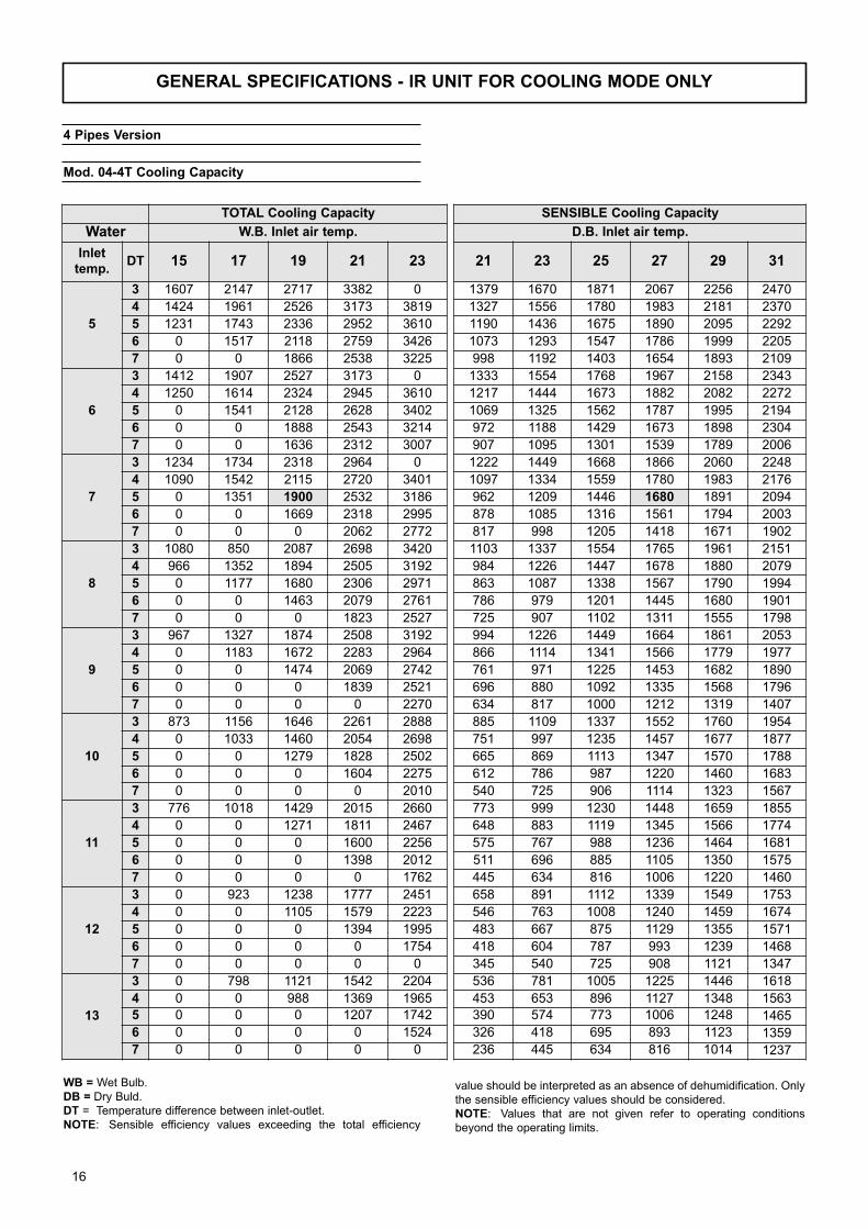
GENERAL SPECIFICATIONS - IR UNIT FOR COOLING MODE ONLY
Mod. 04-4T Cooling Capacity
TOTAL Cooling Capacity
Water W.B. Inlet air temp.
Inlettemp.
DT 15 17 19 21 23
5
3 1607 2147 2717 3382 0
4 1424 1961 2526 3173 3819
5 1231 1743 2336 2952 3610
6 0 1517 2118 2759 3426
7 0 0 1866 2538 3225
6
3 1412 1907 2527 3173 0
4 1250 1614 2324 2945 3610
5 0 1541 2128 2628 3402
6 0 0 1888 2543 3214
7 0 0 1636 2312 3007
7
3 1234 1734 2318 2964 0
4 1090 1542 2115 2720 3401
5 0 1351 1900 2532 3186
6 0 0 1669 2318 2995
7 0 0 0 2062 2772
8
3 1080 850 2087 2698 3420
4 966 1352 1894 2505 3192
5 0 1177 1680 2306 2971
6 0 0 1463 2079 2761
7 0 0 0 1823 2527
9
3 967 1327 1874 2508 3192
4 0 1183 1672 2283 2964
5 0 0 1474 2069 2742
6 0 0 0 1839 2521
7 0 0 0 0 2270
10
3 873 1156 1646 2261 2888
4 0 1033 1460 2054 2698
5 0 0 1279 1828 2502
6 0 0 0 1604 2275
7 0 0 0 0 2010
11
3 776 1018 1429 2015 2660
4 0 0 1271 1811 2467
5 0 0 0 1600 2256
6 0 0 0 1398 2012
7 0 0 0 0 1762
12
3 0 923 1238 1777 2451
4 0 0 1105 1579 2223
5 0 0 0 1394 1995
6 0 0 0 0 1754
7 0 0 0 0 0
13
3 0 798 1121 1542 2204
4 0 0 988 1369 1965
5 0 0 0 1207 1742
6 0 0 0 0 1524
7 0 0 0 0 0
SENSIBLE Cooling Capacity
D.B. Inlet air temp.
21 23 25 27 29 31
1379 1670 1871 2067 2256 2470
1327 1556 1780 1983 2181 2370
1190 1436 1675 1890 2095 2292
1073 1293 1547 1786 1999 2205
998 1192 1403 1654 1893 2109
1333 1554 1768 1967 2158 2343
1217 1444 1673 1882 2082 2272
1069 1325 1562 1787 1995 2194
972 1188 1429 1673 1898 2304
907 1095 1301 1539 1789 2006
1222 1449 1668 1866 2060 2248
1097 1334 1559 1780 1983 2176
962 1209 1446 1680 1891 2094
878 1085 1316 1561 1794 2003
817 998 1205 1418 1671 1902
1103 1337 1554 1765 1961 2151
984 1226 1447 1678 1880 2079
863 1087 1338 1567 1790 1994
786 979 1201 1445 1680 1901
725 907 1102 1311 1555 1798
994 1226 1449 1664 1861 2053
866 1114 1341 1566 1779 1977
761 971 1225 1453 1682 1890
696 880 1092 1335 1568 1796
634 817 1000 1212 1319 1407
885 1109 1337 1552 1760 1954
751 997 1235 1457 1677 1877
665 869 1113 1347 1570 1788
612 786 987 1220 1460 1683
540 725 906 1114 1323 1567
773 999 1230 1448 1659 1855
648 883 1119 1345 1566 1774
575 767 988 1236 1464 1681
511 696 885 1105 1350 1575
445 634 816 1006 1220 1460
658 891 1112 1339 1549 1753
546 763 1008 1240 1459 1674
483 667 875 1129 1355 1571
418 604 787 993 1239 1468
345 540 725 908 1121 1347
536 781 1005 1225 1446 1618
453 653 896 1127 1348 1563
390 574 773 1006 1248 1465
326 418 695 893 1123 1359
236 445 634 816 1014 1237
4 Pipes Version
WB = Wet Bulb.
DB = Dry Buld.
DT = Temperature difference between inlet-outlet.
NOTE: Sensible efficiency values exceeding the total efficiency
value should be interpreted as an absence of dehumidification. Only
the sensible efficiency values should be considered.
NOTE: Values that are not given refer to operating conditions
beyond the operating limits.
16
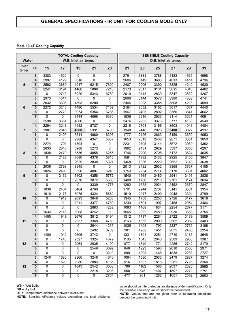
GENERAL SPECIFICATIONS - IR UNIT FOR COOLING MODE ONLY
Mod. 10-4T Cooling Capacity
TOTAL Cooling Capacity
Water W.B. Inlet air temp.
Inlettemp.
DT 15 17 19 21 23
5
3 3383 4520 0 0 0
4 2997 4129 5318 0 0
5 2592 3669 4917 6215 7600
6 2241 3194 4460 5808 7213
7 0 2742 3929 5343 6789
6
3 2973 4014 0 0 0
4 2632 3398 4893 6200 0
5 2272 3243 4480 5534 7162
6 0 2773 3974 5354 6766
7 0 0 3444 4868 6330
7
3 2598 3651 4880 0 0
4 2294 3246 4452 5727 0
5 1987 2845 4000 5331 6708
6 0 2409 3514 4880 6306
7 0 0 2980 4341 5837
8
3 2274 1790 4394 0 0
4 2033 2846 3988 5273 0
5 1838 2479 3536 4855 6255
6 0 2128 3080 4376 5813
7 0 0 2629 3838 5321
9
3 2036 2793 3945 0 0
4 1824 2490 3520 4807 6240
5 0 2162 3102 4356 5772
6 0 0 2670 3872 5308
7 0 0 0 3339 4778
10
3 1838 2434 3464 4760 0
4 1610 2175 3075 4324 5680
5 0 1912 2693 3848 5268
6 0 0 2311 3377 4789
7 0 0 0 2883 4232
11
3 1634 2143 3008 4242 0
4 1400 1949 2676 3812 5194
5 0 0 2357 3368 4750
6 0 0 0 2944 4235
7 0 0 0 2492 3709
12
3 1400 1942 2606 3742 0
4 0 1743 2327 3324 4679
5 0 0 2064 2935 4199
6 0 0 0 2549 3692
7 0 0 0 0 3210
13
3 1240 1680 2360 3246 4640
4 0 1520 2080 2883 4136
5 0 0 1843 2542 3668
6 0 0 0 2215 3208
7 0 0 0 0 2764
SENSIBLE Cooling Capacity
D.B. Inlet air temp.
21 23 25 27 29 31
2791 3381 3788 4183 4565 4998
2686 3149 3603 4013 4414 4796
2407 2906 3390 3825 4240 4639
2173 2617 3131 3615 4046 4462
2019 2413 2839 3347 3832 4267
2698 3144 3578 3980 4368 4741
2464 2923 3385 3808 4213 4599
2164 2682 3162 3617 4037 4440
1967 2405 2892 3386 3841 4662
1836 2216 2633 3114 3621 4061
2474 2932 3376 3777 4168 4549
2219 2701 3155 3603 4013 4404
1948 2448 2926 3400 3827 4237
1777 2196 2663 3159 3630 4053
1653 2019 2438 2871 3381 3850
2231 2705 3144 3572 3969 4352
1992 2481 2929 3397 3805 4207
1746 2200 2708 3172 3624 4035
1591 1982 2432 2925 3400 3847
1468 1836 2229 2652 3148 3638
2013 2482 2932 3368 3767 4155
1753 2254 2714 3170 3601 4002
1540 1965 2480 2941 3403 3826
1408 1780 2210 2701 3174 3634
1282 1653 2024 2452 2670 2847
1791 2244 2707 3141 3561 3954
1519 2017 2499 2948 3394 3799
1345 1758 2253 2726 3177 3618
1239 1591 1997 2468 2954 3406
1093 1468 1834 2254 2677 3171
1565 2022 2489 2930 3358 3754
1312 1787 2264 2722 3169 3589
1163 1553 2000 2502 2962 3403
1035 1408 1792 2237 2732 3188
901 1282 1651 2035 2468 2954
1331 1804 2251 2710 3135 3548
1105 1545 2040 2509 2953 3387
977 1349 1771 2285 2742 3179
846 1223 1593 2010 2508 2971
699 1093 1468 1838 2268 2727
1084 1580 2033 2479 2927 3274
916 1322 1813 2281 2728 3164
789 1162 1565 2037 2525 2965
660 845 1407 1807 2272 2751
477 901 1282 1651 2052 2503
WB = Wet Bulb.
DB = Dry Buld.
DT = Temperature difference between inlet-outlet.
NOTE: Sensible efficiency values exceeding the total efficiency
value should be interpreted as an absence of dehumidification. Only
the sensible efficiency values should be considered.
NOTE: Values that are not given refer to operating conditions
beyond the operating limits.
17
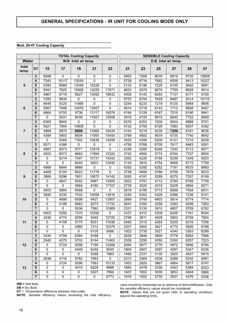
GENERAL SPECIFICATIONS - IR UNIT FOR COOLING MODE ONLY
Mod. 20-4T Cooling Capacity
TOTAL Cooling Capacity
Water W.B. Inlet air temp.
Inlettemp.
DT 15 17 19 21 23
5
3 8288 0 0 0 0
4 7343 10117 13030 0 0
5 6350 8989 12048 15226 0
6 5491 7825 10926 14229 17671
7 4967 6719 9627 13092 16632
6
3 7283 9834 0 0 0
4 6448 8325 11988 0 0
5 5567 7946 10976 13557 0
6 4864 6793 9736 13117 16576
7 0 5931 8439 11927 15508
7
3 6365 8945 0 0 0
4 5621 7954 10908 0 0
5 4869 6970 9800 13060 16434
6 4389 5903 8608 11955 15450
7 0 5269 7302 10636 14299
8
3 5571 4386 0 0 0
4 4981 6973 9771 12919 0
5 4503 6073 8663 11894 15324
6 0 5214 7547 10721 14242
7 0 0 6440 9403 13035
9
3 4988 6844 9666 0 0
4 4469 6100 8623 11778 0
5 3889 5296 7601 10672 14142
6 0 4647 6542 9487 13005
7 0 0 5664 8180 11707
10
3 4503 5964 8488 0 0
4 3945 5330 7533 10594 13916
5 0 4686 6598 9427 12907
6 0 4188 5663 8273 11732
7 0 0 5036 7062 10369
11
3 4003 5250 7370 10392 0
4 3430 4774 6556 9340 12725
5 0 4158 5775 8251 11636
6 0 0 4980 7212 10376
7 0 0 0 6105 9086
12
3 3430 4759 6384 9168 0
4 2940 4270 5702 8144 11463
5 0 3724 5058 7190 10288
6 0 0 4449 6246 9045
7 0 0 0 5386 7863
13
3 3038 4116 5782 7953 0
4 0 3724 5096 7063 10133
5 0 0 4515 6228 8986
6 0 0 0 5427 7860
7 0 0 0 0 6773
SENSIBLE Cooling Capacity
D.B. Inlet air temp.
21 23 25 27 29 31
5952 7209 8076 8919 9735 10658
5728 6716 7682 8558 9413 10227
5133 6196 7229 8155 9042 9891
4633 5579 6676 7709 8628 9514
4306 5145 6053 7137 8171 9100
5753 6704 7629 8487 9314 10110
5254 6233 7219 8120 8984 9806
4614 5719 6742 7712 8608 9467
4194 5129 6167 7219 8190 9941
3915 4725 5615 6640 7722 8659
5276 6253 7200 8054 8888 9701
4732 5759 6728 7683 8557 9392
4154 5219 6239 7250 8161 9036
3789 4682 5679 6735 7740 8642
3525 4306 5200 6121 7210 8209
4758 5768 6705 7617 8463 9281
4248 5290 6246 7243 8113 8971
3722 4692 5774 6764 7727 8604
3392 4226 5185 6236 7249 8203
3130 3915 4754 5656 6712 7759
4292 5292 6252 7181 8033 8860
3738 4806 5786 6759 7678 8533
3283 4191 5289 6270 7257 8158
3002 3797 4712 5760 6768 7749
2735 3525 4315 5228 5694 6071
3819 4786 5772 6699 7594 8431
3240 4302 5328 6286 7236 8101
2869 3749 4803 5814 6774 7714
2641 3392 4258 5263 6299 7263
2331 3130 3910 4807 5709 6762
3337 4312 5308 6248 7161 8004
2798 3811 4828 5803 6758 7654
2480 3312 4264 5335 6316 7256
2207 3002 3821 4770 5826 6798
1922 2735 3521 4340 5263 6299
2839 3846 4800 5778 6684 7566
2356 3295 4350 5350 6297 7223
2084 2877 3776 4872 5846 6780
1804 2607 3397 4287 5347 6336
1490 2331 3130 3920 4837 5815
2312 3369 4336 5286 6242 6981
1953 2820 3867 4864 5817 6747
1683 2478 3336 4343 5384 6323
1407 1802 3000 3853 4844 5866
1016 1922 2735 3521 4376 5336
WB = Wet Bulb.
DB = Dry Buld.
DT = Temperature difference between inlet-outlet.
NOTE: Sensible efficiency values exceeding the total efficiency
value should be interpreted as an absence of dehumidification. Only
the sensible efficiency values should be considered.
NOTE: Values that are not given refer to operating conditions
beyond the operating limits.
18
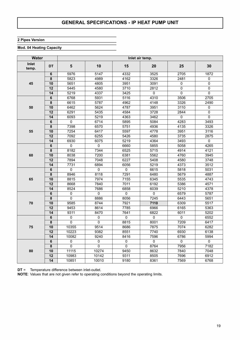
GENERAL SPECIFICATIONS - IP HEAT PUMP UNIT
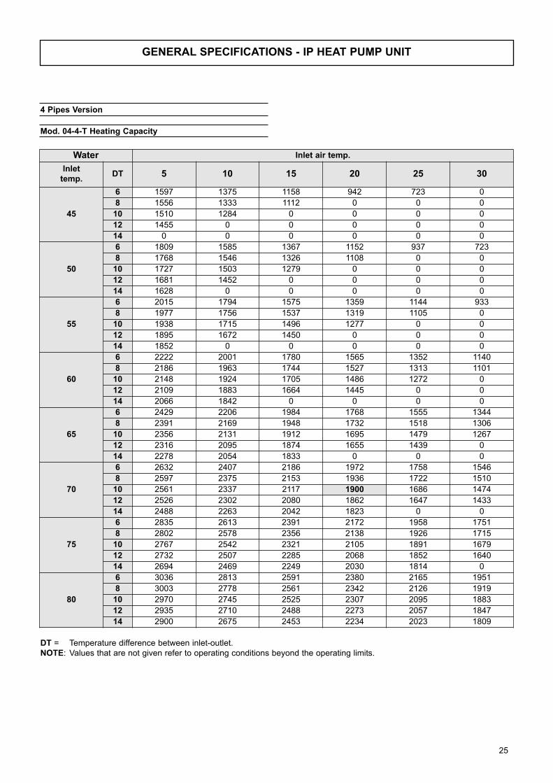
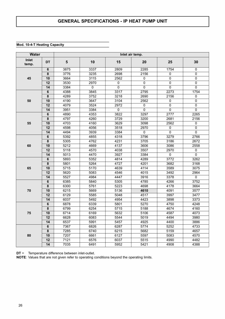
DT = Temperature difference between inlet-outlet.
NOTE: Values that are not given refer to operating conditions beyond the operating limits.
Water Inlet air temp.
Inlettemp.
DT 5 10 15 20 25 30
45
6 5976 5147 4332 3525 2705 1872
8 5823 4989 4162 3326 2481 0
10 5651 4805 3951 3091 0 0
12 5445 4580 3710 2812 0 0
14 5219 4337 3425 0 0 0
50
6 6768 5931 5116 4310 3506 2705
8 6615 5787 4962 4148 3326 2490
10 6462 5624 4787 3951 3110 0
12 6291 5435 4584 3728 2844 0
14 6093 5219 4363 3462 0 0
55
6 0 6714 5895 5084 4283 3493
8 7398 6570 5751 4936 4135 3326
10 7254 6417 5597 4778 3951 3116
12 7092 6255 5426 4580 3735 2875
14 6930 6075 5219 4364 3493 0
60
6 0 0 6660 5855 5058 4265
8 8182 7344 6525 5715 4914 4121
10 8038 7200 6381 5562 4760 3945
12 7894 7048 6227 5408 4580 3748
14 7731 6894 6056 5219 4373 3512
65
6 0 0 0 6615 5818 5031
8 8946 8118 7291 6480 5679 4887
10 8815 7974 7155 6345 5535 4743
12 8668 7840 7011 6192 5386 4571
14 8524 7686 6858 6039 5210 4378
70
6 0 0 0 0 6579 5787
8 0 8886 8056 7245 6443 5651
10 9585 8744 7921 7110 6309 5517
12 9453 8614 7785 6966 6165 5363
14 9311 8470 7641 6822 6011 5202
75
6 0 0 0 0 0 6552
8 0 0 8815 8001 7209 6417
10 10355 9514 8686 7875 7074 6282
12 10223 9382 8551 7740 6930 6138
14 10082 9240 8416 7596 6786 5994
80
6 0 0 0 0 0 0
8 0 0 0 8764 7956 7182
10 11115 10274 9450 8632 7840 7048
12 10983 10142 9311 8505 7696 6912
14 10851 10010 9180 8361 7569 6768
Mod. 04 Heating Capacity
2 Pipes Version
19
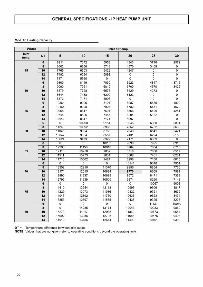
GENERAL SPECIFICATIONS - IP HEAT PUMP UNIT
DT = Temperature difference between inlet-outlet.
NOTE: Values that are not given refer to operating conditions beyond the operating limits.
Water Inlet air temp.
Inlettemp.
DT 5 10 15 20 25 30
45
6 8211 7072 5953 4843 3716 2572
8 8002 6856 5718 4570 3409 0
10 7765 6603 5429 4247 0 0
12 7482 6294 5098 0 0 0
14 7171 5960 0 0 0 0
50
6 9300 8149 7030 5923 4817 3716
8 9090 7951 6819 5700 4570 3422
10 8879 7728 6578 5429 4273 0
12 8644 7468 6299 5123 0 0
14 8372 7171 5996 0 0 0
55
6 10364 9226 8101 6987 5885 4800
8 10166 9028 7903 6782 5681 4570
10 9968 8817 7691 6566 5429 4281
12 9745 8595 7457 6294 5132 0
14 9523 8347 7171 5997 0 0
60
6 0 10290 9151 8045 6950 5861
8 11243 10092 8966 7852 6752 5663
10 11045 9894 8768 7643 6541 5421
12 10847 9684 8557 7431 6294 5150
14 10624 9473 8322 7171 6009 0
65
6 0 0 10203 9090 7995 6913
8 12293 11156 10018 8904 7804 6715
10 12113 10958 9832 8718 7606 6517
12 11911 10773 9634 8508 7401 6281
14 11713 10562 9424 8298 7160 6015
70
6 0 0 0 10141 9040 7951
8 13352 12210 11070 9956 8854 7765
10 13171 12015 10884 9770 8669 7581
12 12990 11837 10698 9572 8471 7369
14 12795 11639 10500 9374 8260 7148
75
6 0 0 0 0 10067 9003
8 14410 13254 12113 10995 9906 8817
10 14229 13073 11936 10822 9721 8632
12 14047 12892 11750 10636 9523 8434
14 13853 12697 11565 10438 9325 8236
80
6 0 0 0 0 11131 10030
8 0 14285 13171 12043 10933 9869
10 15273 14117 12985 11862 10773 9684
12 15092 13936 12795 11688 10575 9498
14 14910 13756 12614 11490 10401 9300
Mod. 08 Heating Capacity
20
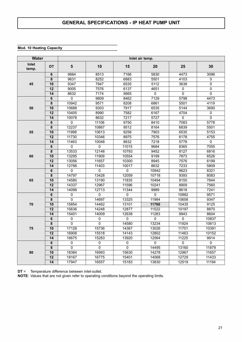
GENERAL SPECIFICATIONS - IP HEAT PUMP UNIT
DT = Temperature difference between inlet-outlet.
NOTE: Values that are not given refer to operating conditions beyond the operating limits.
Water Inlet air temp.
Inlettemp.
DT 5 10 15 20 25 30
45
6 9884 8513 7166 5830 4473 3096
8 9631 8252 6883 5501 4103 0
10 9347 7947 6535 5112 3638 0
12 9005 7576 6137 4651 0 0
14 8632 7174 5665 0 0 0
50
6 0 9809 8462 7129 5798 4473
8 10942 9571 8208 6861 5501 4119
10 10688 9303 7917 6535 5144 3690
12 10405 8990 7582 6167 4704 0
14 10078 8632 7217 5727 0 0
55
6 0 11106 9750 8410 7083 5778
8 12237 10867 9512 8164 6839 5501
10 11998 10613 9258 7903 6535 5153
12 11730 10346 8975 7576 6178 4755
14 11463 10048 8632 7218 5778 0
60
6 0 0 11015 9684 8365 7055
8 13533 12148 10793 9452 8127 6816
10 13295 11909 10554 9199 7873 6526
12 13056 11657 10300 8945 7576 6199
14 12788 11403 10017 8632 7233 5809
65
6 0 0 0 10942 9623 8321
8 14797 13428 12059 10718 9393 8083
10 14580 13190 11835 10494 9155 7844
12 14337 12967 11596 10241 8909 7560
14 14098 12713 11344 9989 8618 7241
70
6 0 0 0 0 10882 9571
8 0 14697 13325 11984 10658 9347
10 15854 14462 13101 11760 10435 9125
12 15636 14248 12877 11522 10197 8870
14 15401 14009 12638 11283 9943 8604
75
6 0 0 0 0 0 10837
8 0 0 14580 13234 11924 10613
10 17128 15736 14367 13026 11701 10391
12 16908 15518 14143 12802 11463 10152
14 16675 15283 13920 12564 11225 9914
80
6 0 0 0 0 0 0
8 0 0 0 14495 13160 11879
10 18384 16993 15630 14278 12967 11657
12 18167 16775 15401 14068 12729 11433
14 17947 16557 15183 13830 12519 11194
Mod. 10 Heating Capacity
21
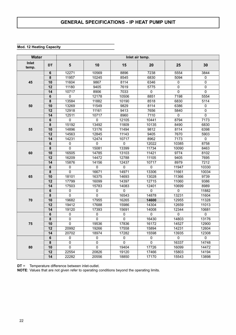
GENERAL SPECIFICATIONS - IP HEAT PUMP UNIT
DT = Temperature difference between inlet-outlet.
NOTE: Values that are not given refer to operating conditions beyond the operating limits.
Water Inlet air temp.
Inlettemp.
DT 5 10 15 20 25 30
45
6 12271 10569 8896 7238 5554 3844
8 11957 10245 8545 6830 5094 0
10 11604 9867 8114 6346 0 0
12 11180 9405 7619 5775 0 0
14 10717 8906 7033 0 0 0
50
6 0 12178 10506 8851 7198 5554
8 13584 11882 10190 8518 6830 5114
10 13269 11549 9829 8114 6386 0
12 12918 11161 9413 7656 5840 0
14 12511 10717 8960 7110 0 0
55
6 0 0 12105 10441 8794 7173
8 15192 13492 11809 10135 8490 6830
10 14896 13176 11494 9812 8114 6398
12 14563 12845 11143 9405 7670 5903
14 14231 12474 10717 8962 7173 0
60
6 0 0 0 12022 10385 8758
8 0 15081 13399 11734 10090 8463
10 16505 14785 13103 11421 9774 8102
12 16209 14472 12788 11105 9405 7695
14 15876 14156 12437 10717 8979 7212
65
6 0 0 0 0 11947 10330
8 0 16671 14971 13306 11661 10034
10 18101 16375 14693 13028 11366 9739
12 17799 16099 14397 12715 11060 9386
14 17503 15783 14083 12401 10699 8989
70
6 0 0 0 0 0 11882
8 0 0 16543 14878 13231 11604
10 19682 17955 16265 14600 12955 11328
12 19412 17688 15986 14304 12659 11013
14 19120 17393 15691 14008 12344 10681
75
6 0 0 0 0 0 0
8 0 0 0 16430 14803 13176
10 0 19536 17836 16172 14527 12900
12 20992 19266 17558 15894 14231 12604
14 20702 18974 17282 15598 13935 12308
80
6 0 0 0 0 0 0
8 0 0 0 0 16337 14748
10 0 0 19404 17726 16099 14472
12 22554 20826 19120 17466 15803 14194
14 22282 20556 18850 17170 15543 13898
Mod. 12 Heating Capacity
22

GENERAL SPECIFICATIONS - IP HEAT PUMP UNIT
DT = Temperature difference between inlet-outlet.
NOTE: Values that are not given refer to operating conditions beyond the operating limits.
Water Inlet air temp.
Inlettemp.
DT 5 10 15 20 25 30
45
6 15128 13030 10968 8923 6847 4739
8 14742 12631 10535 8420 6280 0
10 14307 12165 10003 7824 0 0
12 13784 11596 9393 0 0 0
14 13212 10980 0 0 0 0
50
6 17134 15014 12952 10912 8875 6847
8 16748 14649 12563 10501 8420 6305
10 16359 14239 12118 10003 7873 0
12 15926 13760 11605 9439 0 0
14 15425 13212 11046 0 0 0
55
6 19094 16998 14924 12872 10842 8843
8 18729 16634 14560 12495 10467 8420
10 18365 16244 14170 12096 10003 7888
12 17954 15836 13738 11596 9456 0
14 17545 15379 13212 11048 0 0
60
6 0 18958 16860 14822 12804 10798
8 20713 18593 16519 14467 12439 10433
10 20349 18229 16155 14081 12050 9988
12 19984 17842 15766 13691 11596 9488
14 19573 17453 15333 13212 11070 0
65
6 0 20896 18798 16748 14730 12736
8 22649 20553 18457 16405 14377 12371
10 22316 20188 18114 16062 14012 12006
12 21944 19848 17750 15676 13636 11571
14 21579 19459 17363 15289 13191 11083
70
6 0 0 20713 18683 16655 14649
8 24599 22496 20395 18343 16313 14307
10 24266 22136 20052 18000 15972 13966
12 23933 21808 19709 17635 15607 13577
14 23573 21443 19345 17271 15218 13169
75
6 0 0 0 20577 18547 16587
8 26549 24419 22316 20256 18250 16244
10 26216 24086 21990 19938 17910 15904
12 25880 23753 21647 19595 17545 15539
14 25523 23393 21307 19230 17181 15175
80
6 0 0 0 0 20507 18479
8 0 26318 24266 22187 20142 18182
10 28139 26009 23923 21854 19848 17842
12 27806 25676 23573 21533 19483 17499
14 27470 25343 23240 21168 19162 17134
Mod. 16 Heating Capacity
23
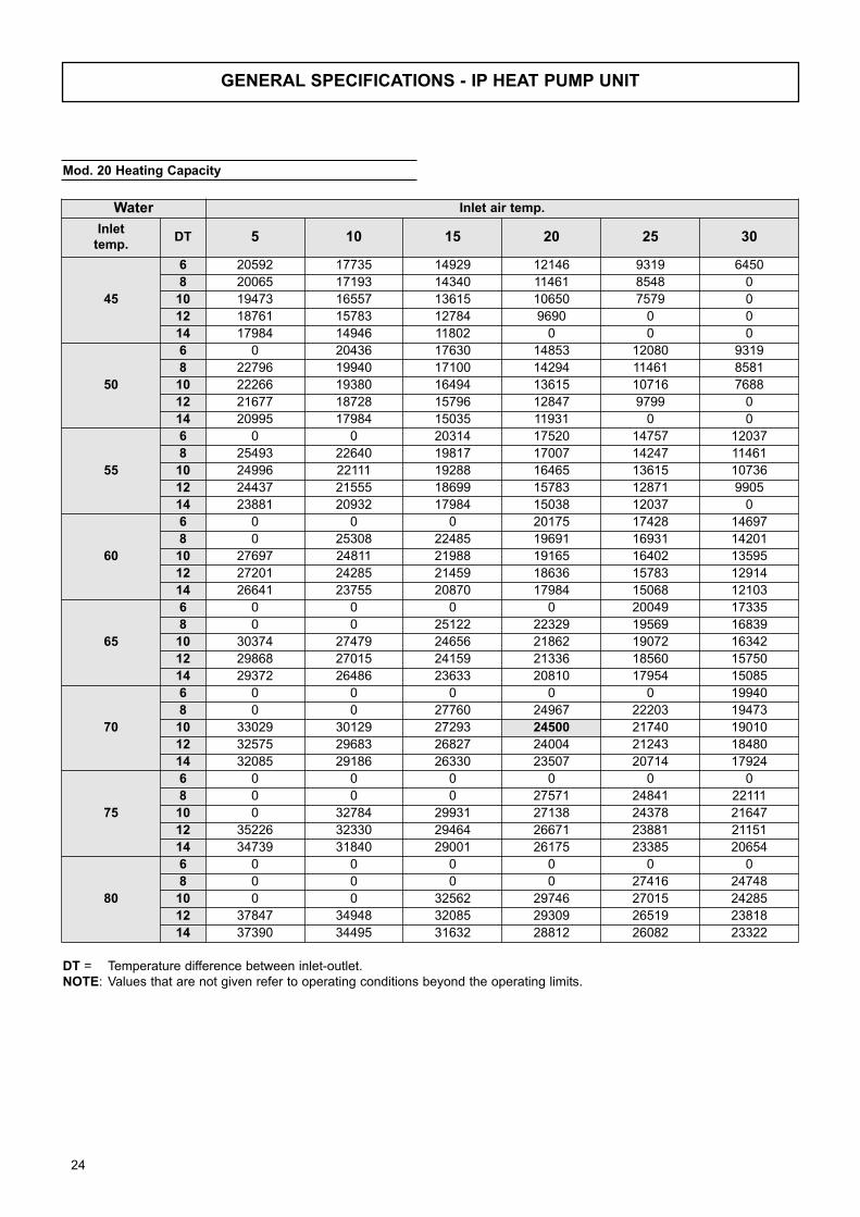
GENERAL SPECIFICATIONS - IP HEAT PUMP UNIT
DT = Temperature difference between inlet-outlet.
NOTE: Values that are not given refer to operating conditions beyond the operating limits.
Water Inlet air temp.
Inlettemp.
DT 5 10 15 20 25 30
45
6 20592 17735 14929 12146 9319 6450
8 20065 17193 14340 11461 8548 0
10 19473 16557 13615 10650 7579 0
12 18761 15783 12784 9690 0 0
14 17984 14946 11802 0 0 0
50
6 0 20436 17630 14853 12080 9319
8 22796 19940 17100 14294 11461 8581
10 22266 19380 16494 13615 10716 7688
12 21677 18728 15796 12847 9799 0
14 20995 17984 15035 11931 0 0
55
6 0 0 20314 17520 14757 12037
8 25493 22640 19817 17007 14247 11461
10 24996 22111 19288 16465 13615 10736
12 24437 21555 18699 15783 12871 9905
14 23881 20932 17984 15038 12037 0
60
6 0 0 0 20175 17428 14697
8 0 25308 22485 19691 16931 14201
10 27697 24811 21988 19165 16402 13595
12 27201 24285 21459 18636 15783 12914
14 26641 23755 20870 17984 15068 12103
65
6 0 0 0 0 20049 17335
8 0 0 25122 22329 19569 16839
10 30374 27479 24656 21862 19072 16342
12 29868 27015 24159 21336 18560 15750
14 29372 26486 23633 20810 17954 15085
70
6 0 0 0 0 0 19940
8 0 0 27760 24967 22203 19473
10 33029 30129 27293 24500 21740 19010
12 32575 29683 26827 24004 21243 18480
14 32085 29186 26330 23507 20714 17924
75
6 0 0 0 0 0 0
8 0 0 0 27571 24841 22111
10 0 32784 29931 27138 24378 21647
12 35226 32330 29464 26671 23881 21151
14 34739 31840 29001 26175 23385 20654
80
6 0 0 0 0 0 0
8 0 0 0 0 27416 24748
10 0 0 32562 29746 27015 24285
12 37847 34948 32085 29309 26519 23818
14 37390 34495 31632 28812 26082 23322
Mod. 20 Heating Capacity
24
GENERAL SPECIFICATIONS - IP HEAT PUMP UNIT
DT = Temperature difference between inlet-outlet.
NOTE: Values that are not given refer to operating conditions beyond the operating limits.
Water Inlet air temp.
Inlettemp.
DT 5 10 15 20 25 30
45
6 1597 1375 1158 942 723 0
8 1556 1333 1112 0 0 0
10 1510 1284 0 0 0 0
12 1455 0 0 0 0 0
14 0 0 0 0 0 0
50
6 1809 1585 1367 1152 937 723
8 1768 1546 1326 1108 0 0
10 1727 1503 1279 0 0 0
12 1681 1452 0 0 0 0
14 1628 0 0 0 0 0
55
6 2015 1794 1575 1359 1144 933
8 1977 1756 1537 1319 1105 0
10 1938 1715 1496 1277 0 0
12 1895 1672 1450 0 0 0
14 1852 0 0 0 0 0
60
6 2222 2001 1780 1565 1352 1140
8 2186 1963 1744 1527 1313 1101
10 2148 1924 1705 1486 1272 0
12 2109 1883 1664 1445 0 0
14 2066 1842 0 0 0 0
65
6 2429 2206 1984 1768 1555 1344
8 2391 2169 1948 1732 1518 1306
10 2356 2131 1912 1695 1479 1267
12 2316 2095 1874 1655 1439 0
14 2278 2054 1833 0 0 0
70
6 2632 2407 2186 1972 1758 1546
8 2597 2375 2153 1936 1722 1510
10 2561 2337 2117 1900 1686 1474
12 2526 2302 2080 1862 1647 1433
14 2488 2263 2042 1823 0 0
75
6 2835 2613 2391 2172 1958 1751
8 2802 2578 2356 2138 1926 1715
10 2767 2542 2321 2105 1891 1679
12 2732 2507 2285 2068 1852 1640
14 2694 2469 2249 2030 1814 0
80
6 3036 2813 2591 2380 2165 1951
8 3003 2778 2561 2342 2126 1919
10 2970 2745 2525 2307 2095 1883
12 2935 2710 2488 2273 2057 1847
14 2900 2675 2453 2234 2023 1809
Mod. 04-4-T Heating Capacity
4 Pipes Version
25
GENERAL SPECIFICATIONS - IP HEAT PUMP UNIT
DT = Temperature difference between inlet-outlet.
NOTE: Values that are not given refer to operating conditions beyond the operating limits.
Water Inlet air temp.
Inlettemp.
DT 5 10 15 20 25 30
45
6 3875 3337 2809 2285 1754 0
8 3776 3235 2698 2156 0 0
10 3664 3115 2562 0 0 0
12 3530 2970 0 0 0 0
14 3384 0 0 0 0 0
50
6 4388 3845 3317 2795 2273 1754
8 4289 3752 3218 2690 2156 0
10 4190 3647 3104 2562 0 0
12 4079 3524 2972 0 0 0
14 3951 3384 0 0 0 0
55
6 4890 4353 3822 3297 2777 2265
8 4797 4260 3729 3200 2681 2156
10 4703 4160 3629 3098 2562 0
12 4598 4056 3518 2970 0 0
14 4494 3939 3384 0 0 0
60
6 5392 4855 4318 3796 3279 2766
8 5305 4762 4231 3705 3186 2672
10 5212 4669 4137 3606 3086 2558
12 5118 4570 4038 3507 2970 0
14 5013 4470 3927 3384 0 0
65
6 5893 5352 4814 4289 3772 3262
8 5801 5264 4727 4201 3682 3168
10 5715 5170 4639 4114 3589 3075
12 5620 5083 4546 4015 3492 2964
14 5527 4984 4447 3916 3378 0
70
6 6385 5840 5305 4785 4266 3752
8 6300 5761 5223 4698 4178 3664
10 6215 5669 5136 4610 4091 3577
12 6129 5585 5048 4517 3997 3477
14 6037 5492 4954 4423 3898 3373
75
6 6878 6339 5801 5270 4750 4248
8 6799 6254 5715 5188 4674 4160
10 6714 6169 5632 5106 4587 4073
12 6628 6083 5544 5019 4494 3980
14 6537 5991 5457 4925 4400 3886
80
6 7367 6826 6287 5774 5252 4733
8 7285 6740 6215 5682 5159 4657
10 7207 6661 6127 5597 5083 4570
12 7121 6576 6037 5515 4990 4482
14 7035 6491 5952 5421 4908 4388
Mod. 10-4-T Heating Capacity
26
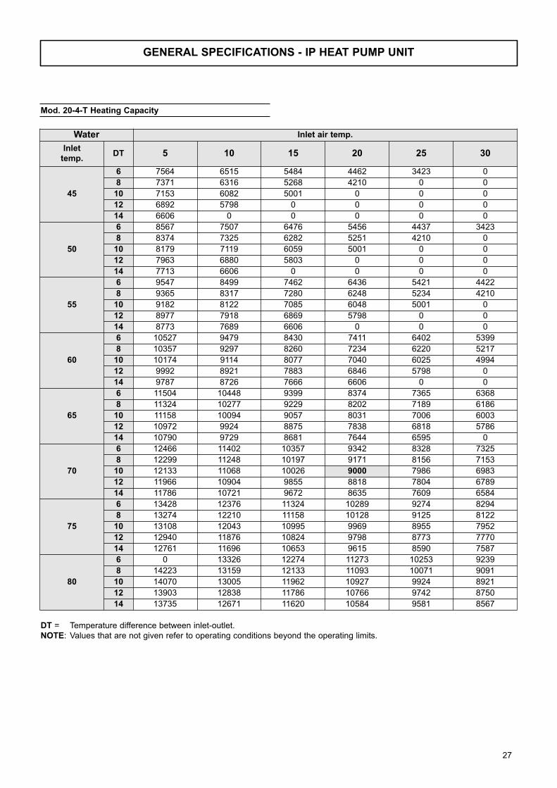
GENERAL SPECIFICATIONS - IP HEAT PUMP UNIT
DT = Temperature difference between inlet-outlet.
NOTE: Values that are not given refer to operating conditions beyond the operating limits.
Water Inlet air temp.
Inlettemp.
DT 5 10 15 20 25 30
45
6 7564 6515 5484 4462 3423 0
8 7371 6316 5268 4210 0 0
10 7153 6082 5001 0 0 0
12 6892 5798 0 0 0 0
14 6606 0 0 0 0 0
50
6 8567 7507 6476 5456 4437 3423
8 8374 7325 6282 5251 4210 0
10 8179 7119 6059 5001 0 0
12 7963 6880 5803 0 0 0
14 7713 6606 0 0 0 0
55
6 9547 8499 7462 6436 5421 4422
8 9365 8317 7280 6248 5234 4210
10 9182 8122 7085 6048 5001 0
12 8977 7918 6869 5798 0 0
14 8773 7689 6606 0 0 0
60
6 10527 9479 8430 7411 6402 5399
8 10357 9297 8260 7234 6220 5217
10 10174 9114 8077 7040 6025 4994
12 9992 8921 7883 6846 5798 0
14 9787 8726 7666 6606 0 0
65
6 11504 10448 9399 8374 7365 6368
8 11324 10277 9229 8202 7189 6186
10 11158 10094 9057 8031 7006 6003
12 10972 9924 8875 7838 6818 5786
14 10790 9729 8681 7644 6595 0
70
6 12466 11402 10357 9342 8328 7325
8 12299 11248 10197 9171 8156 7153
10 12133 11068 10026 9000 7986 6983
12 11966 10904 9855 8818 7804 6789
14 11786 10721 9672 8635 7609 6584
75
6 13428 12376 11324 10289 9274 8294
8 13274 12210 11158 10128 9125 8122
10 13108 12043 10995 9969 8955 7952
12 12940 11876 10824 9798 8773 7770
14 12761 11696 10653 9615 8590 7587
80
6 0 13326 12274 11273 10253 9239
8 14223 13159 12133 11093 10071 9091
10 14070 13005 11962 10927 9924 8921
12 13903 12838 11786 10766 9742 8750
14 13735 12671 11620 10584 9581 8567
Mod. 20-4-T Heating Capacity
27
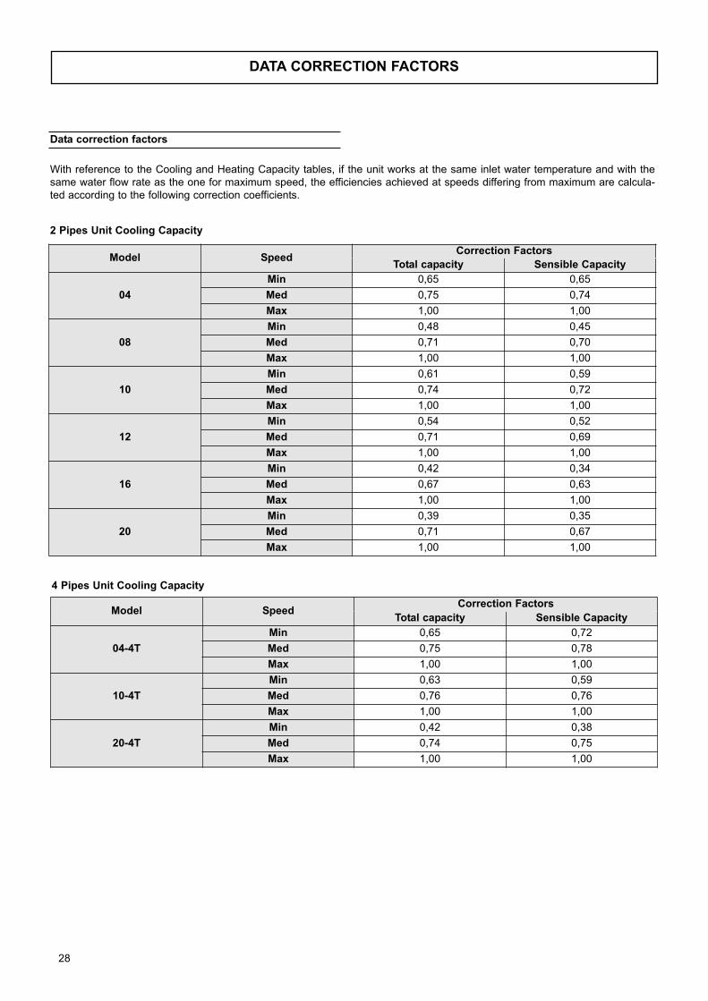
Data correction factors
With reference to the Cooling and Heating Capacity tables, if the unit works at the same inlet water temperature and with the
same water flow rate as the one for maximum speed, the efficiencies achieved at speeds differing from maximum are calcula-
ted according to the following correction coefficients.
Model SpeedCorrection Factors
Total capacity Sensible Capacity
04
Min 0,65 0,65
Med 0,75 0,74
Max 1,00 1,00
08
Min 0,48 0,45
Med 0,71 0,70
Max 1,00 1,00
10
Min 0,61 0,59
Med 0,74 0,72
Max 1,00 1,00
12
Min 0,54 0,52
Med 0,71 0,69
Max 1,00 1,00
16
Min 0,42 0,34
Med 0,67 0,63
Max 1,00 1,00
20
Min 0,39 0,35
Med 0,71 0,67
Max 1,00 1,00
2 Pipes Unit Cooling Capacity
Model SpeedCorrection Factors
Total capacity Sensible Capacity
04-4T
Min 0,65 0,72
Med 0,75 0,78
Max 1,00 1,00
10-4T
Min 0,63 0,59
Med 0,76 0,76
Max 1,00 1,00
20-4T
Min 0,42 0,38
Med 0,74 0,75
Max 1,00 1,00
4 Pipes Unit Cooling Capacity
DATA CORRECTION FACTORS
28
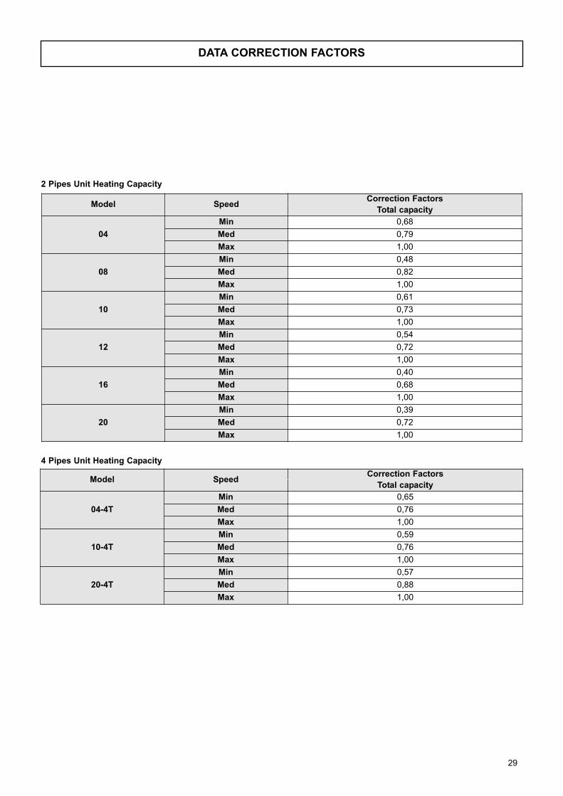
Model SpeedCorrection Factors
Total capacity
04
Min 0,68
Med 0,79
Max 1,00
08
Min 0,48
Med 0,82
Max 1,00
10
Min 0,61
Med 0,73
Max 1,00
12
Min 0,54
Med 0,72
Max 1,00
16
Min 0,40
Med 0,68
Max 1,00
20
Min 0,39
Med 0,72
Max 1,00
Model SpeedCorrection Factors
Total capacity
04-4T
Min 0,65
Med 0,76
Max 1,00
10-4T
Min 0,59
Med 0,76
Max 1,00
20-4T
Min 0,57
Med 0,88
Max 1,00
2 Pipes Unit Heating Capacity
4 Pipes Unit Heating Capacity
DATA CORRECTION FACTORS
29
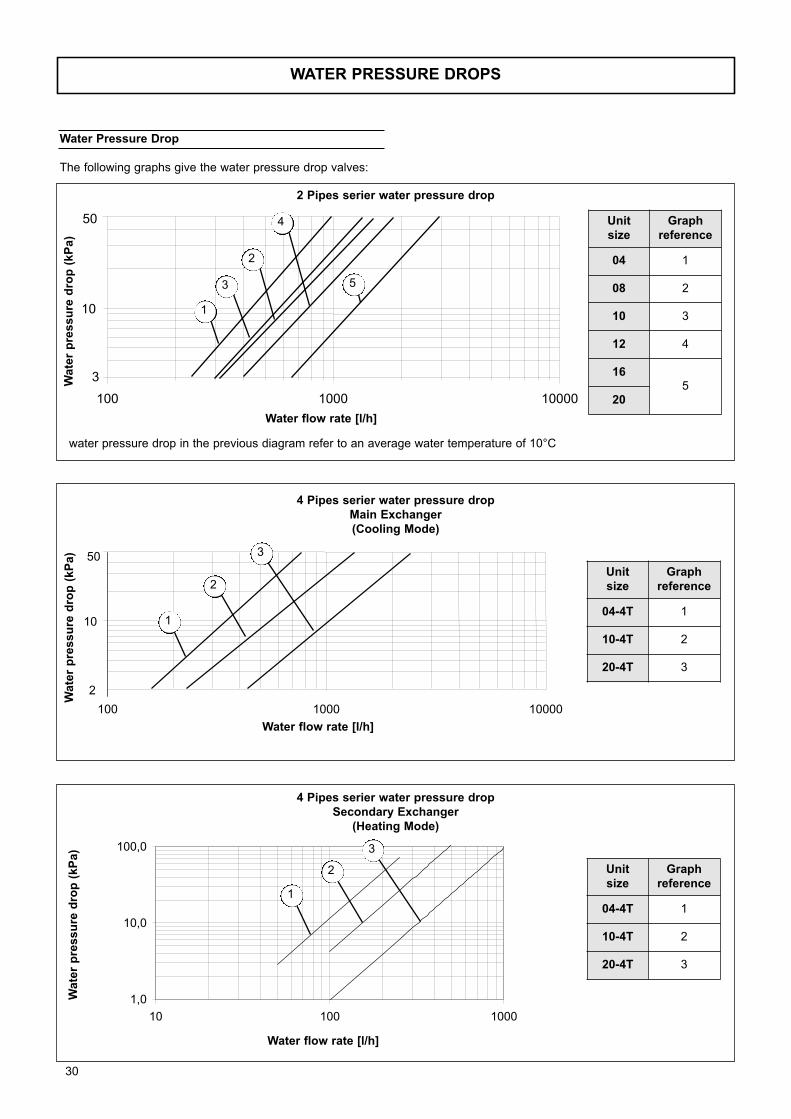
2
10
50
100 1000 10000
10000
3
10
100 1000
50
30
Wate
r p
ressu
re d
rop
(kP
a)
Water flow rate [l/h]
4 Pipes serier water pressure dropMain Exchanger(Cooling Mode)
WATER PRESSURE DROPS
Water Pressure Drop
The following graphs give the water pressure drop valves:
Wa
ter
pre
ss
ure
dro
p (
kP
a)
Water flow rate [l/h]
water pressure drop in the previous diagram refer to an average water temperature of 10°C
2 Pipes serier water pressure drop
1
5
2
4
3
1
2
3
Unit size
Graph reference
04 1
08 2
10 3
12 4
165
20
Unit size
Graph reference
04-4T 1
10-4T 2
20-4T 3
1,0
10,0
100,0
10 100 1000
Wate
r p
ressu
re d
rop
(kP
a)
Water flow rate [l/h]
4 Pipes serier water pressure dropSecondary Exchanger
(Heating Mode)
1
2
3
Unit size
Graph reference
04-4T 1
10-4T 2
20-4T 3
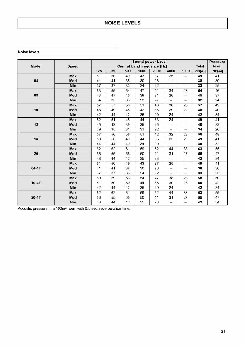
31
NOISE LEVELS
Noise levels
Model Speed
Sound power Level PressurelevelCentral band frequency [Hz] Total
125 250 500 1000 2000 4000 8000 [dB(A)] [dB(A)]
04
Max 51 50 49 43 37 25 -- 49 41
Med 41 41 38 30 26 -- -- 38 30
Min 37 37 33 24 22 -- -- 33 25
08
Max 53 55 54 47 41 34 23 54 46
Med 43 47 45 39 31 26 -- 45 37
Min 34 35 33 23 -- -- -- 32 24
10
Max 57 57 56 51 46 38 28 57 49
Med 48 49 48 42 36 29 22 48 40
Min 42 44 42 35 29 24 -- 42 34
12
Max 52 51 48 44 33 24 -- 49 41
Med 45 43 39 35 25 -- -- 40 32
Min 39 35 31 31 22 -- -- 34 26
16
Max 57 56 56 51 42 32 28 56 48
Med 50 50 49 44 35 25 20 49 41
Min 44 44 40 34 20 -- -- 40 32
20
Max 62 62 61 59 52 44 33 63 55
Med 56 55 55 50 41 31 27 55 47
Min 48 44 42 35 23 -- -- 42 34
04-4T
Max 51 50 49 43 37 25 -- 49 41
Med 41 41 38 30 26 -- -- 38 30
Min 37 37 33 24 22 -- -- 33 25
10-4T
Max 59 59 56 54 47 38 28 58 50
Med 51 50 50 44 38 30 23 50 42
Min 42 44 42 35 29 24 -- 42 34
20-4T
Max 62 62 61 59 52 44 33 63 55
Med 56 55 55 50 41 31 27 55 47
Min 48 44 42 35 23 -- -- 42 34
Acoustic pressure in a 100m3 room with 0.5 sec. reverberation time.
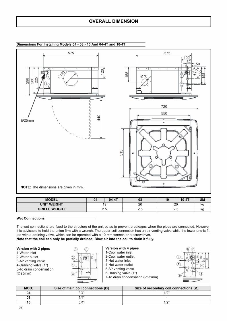
OVERALL DIMENSION
Ø25mm
Ø150 Ø70
298
280
225
120
440
575 575
720
550
10052
5250
158
158155
11090
515
Version with 2 pipes1-Water inlet
2-Water outlet
3-Air venting valve
4-Draining valve (1")
5-To drain condensation
(∅25mm)
Version with 4 pipes1-Cool water inlet
2-Cool water outlet
3-Hot water inlet
4-Hot water outlet
5-Air venting valve
6-Draining valve (1")
7-To drain condensation (∅25mm)
Dimensions For Installing Models 04 - 08 - 10 And 04-4T and 10-4T
NOTE: The dimensions are given in mm.
MODEL 04 04-4T 08 10 10-4T UM
UNIT WEIGHT 19 20 20 kg
GRILLE WEIGHT 2.5 2.5 2.5 kg
2
3
1
4
5
2
5
1
6
4
3
7
158
Wet Connections
The wet connections are fixed to the structure of the unit so as to prevent breakages when the pipes are connected. However,
it is advisable to hold the union firm with a wrench. The upper coil connection has an air venting valve while the lower one is fit-
ted with a draining valve, which can be operated with a 10 mm wrench or a screwdriver.
Note that the coil can only be partially drained. Blow air into the coil to drain it fully.
MOD. Size of main coil connections [Ø] Size of secondary coil connections [Ø]
04 3/4” 1/2”
08 3/4” -
10 3/4” 1/2”
32
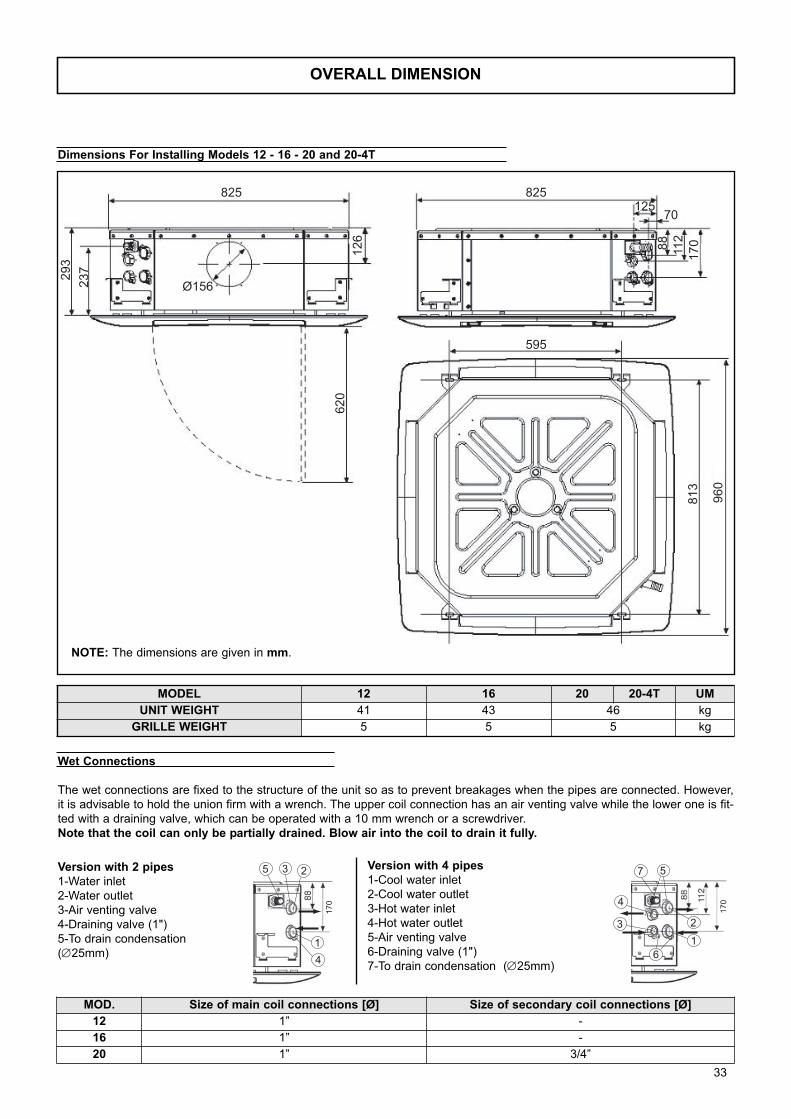
OVERALL DIMENSION
MODEL 12 16 20 20-4T UM
UNIT WEIGHT 41 43 46 kg
GRILLE WEIGHT 5 5 5 kg
825
Ø156
825
595
70125
620
960
813
293
126
17011288
237
Version with 2 pipes1-Water inlet
2-Water outlet
3-Air venting valve
4-Draining valve (1")
5-To drain condensation
(∅25mm)
Version with 4 pipes1-Cool water inlet
2-Cool water outlet
3-Hot water inlet
4-Hot water outlet
5-Air venting valve
6-Draining valve (1")
7-To drain condensation (∅25mm)
Dimensions For Installing Models 12 - 16 - 20 and 20-4T
NOTE: The dimensions are given in mm.
1
3 2
4
5
170
2
5
1
4
3
6
7
170
Wet Connections
The wet connections are fixed to the structure of the unit so as to prevent breakages when the pipes are connected. However,
it is advisable to hold the union firm with a wrench. The upper coil connection has an air venting valve while the lower one is fit-
ted with a draining valve, which can be operated with a 10 mm wrench or a screwdriver.
Note that the coil can only be partially drained. Blow air into the coil to drain it fully.
MOD. Size of main coil connections [Ø] Size of secondary coil connections [Ø]
12 1” -
16 1” -
20 1” 3/4”
33
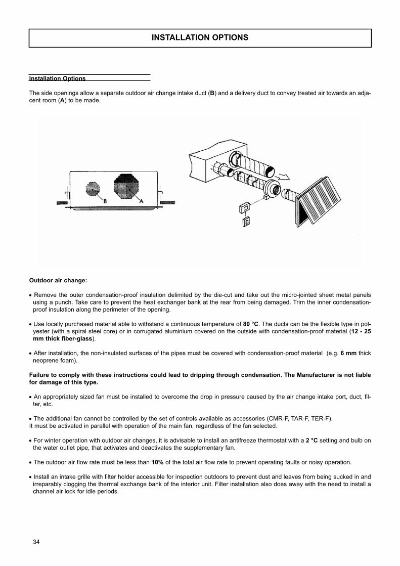
INSTALLATION OPTIONS
Installation Options
The side openings allow a separate outdoor air change intake duct (B) and a delivery duct to convey treated air towards an adja-
cent room (A) to be made.
Outdoor air change:
• Remove the outer condensation-proof insulation delimited by the die-cut and take out the micro-jointed sheet metal panels
using a punch. Take care to prevent the heat exchanger bank at the rear from being damaged. Trim the inner condensation-
proof insulation along the perimeter of the opening.
• Use locally purchased material able to withstand a continuous temperature of 80 °C. The ducts can be the flexible type in pol-
yester (with a spiral steel core) or in corrugated aluminium covered on the outside with condensation-proof material (12 - 25mm thick fiber-glass).
• After installation, the non-insulated surfaces of the pipes must be covered with condensation-proof material (e.g. 6 mm thick
neoprene foam).
Failure to comply with these instructions could lead to dripping through condensation. The Manufacturer is not liablefor damage of this type.
• An appropriately sized fan must be installed to overcome the drop in pressure caused by the air change intake port, duct, fil-
ter, etc.
• The additional fan cannot be controlled by the set of controls available as accessories (CMR-F, TAR-F, TER-F).
It must be activated in parallel with operation of the main fan, regardless of the fan selected.
• For winter operation with outdoor air changes, it is advisable to install an antifreeze thermostat with a 2 °C setting and bulb on
the water outlet pipe, that activates and deactivates the supplementary fan.
• The outdoor air flow rate must be less than 10% of the total air flow rate to prevent operating faults or noisy operation.
• Install an intake grille with filter holder accessible for inspection outdoors to prevent dust and leaves from being sucked in and
irreparably clogging the thermal exchange bank of the interior unit. Filter installation also does away with the need to install a
channel air lock for idle periods.
34
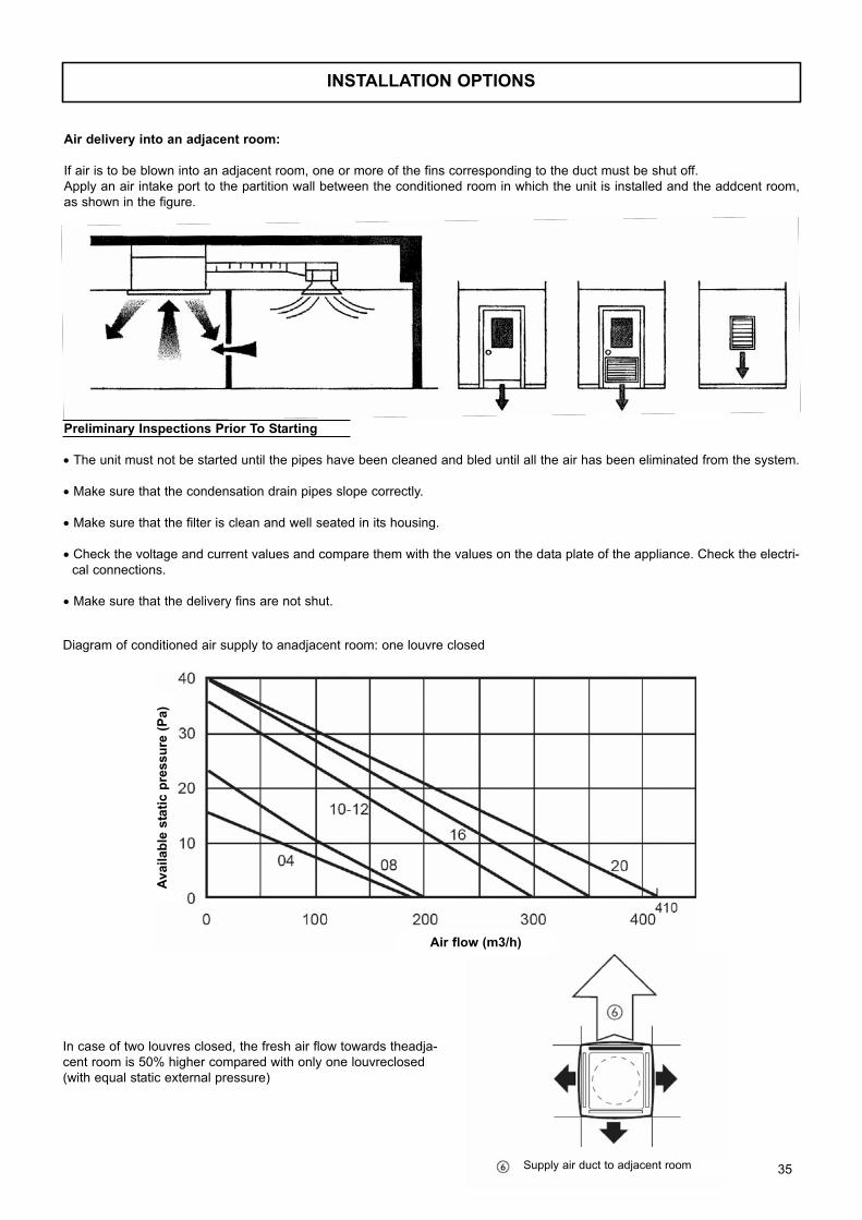
INSTALLATION OPTIONS
Air delivery into an adjacent room:
If air is to be blown into an adjacent room, one or more of the fins corresponding to the duct must be shut off.
Apply an air intake port to the partition wall between the conditioned room in which the unit is installed and the addcent room,
as shown in the figure.
Diagram of conditioned air supply to anadjacent room: one louvre closed
In case of two louvres closed, the fresh air flow towards theadja-
cent room is 50% higher compared with only one louvreclosed
(with equal static external pressure)
Preliminary Inspections Prior To Starting
• The unit must not be started until the pipes have been cleaned and bled until all the air has been eliminated from the system.
• Make sure that the condensation drain pipes slope correctly.
• Make sure that the filter is clean and well seated in its housing.
• Check the voltage and current values and compare them with the values on the data plate of the appliance. Check the electri-
cal connections.
• Make sure that the delivery fins are not shut.
Availab
le s
tati
c p
ressu
re (
Pa)
Air flow (m3/h)
Supply air duct to adjacent room 35
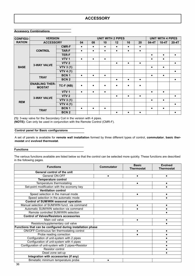
Accessory Combinations
ACCESSORY
(1): 3-way valve for the Secondary Coil in the version with 4 pipes.
(NOTE): Can only be used in conjunction with the Remote Control (CMR-F).
Control panel for Basic configuraions
A set of panels is available for remote wall installation formed by three different types of control, commutator, basic ther-mostat and evolved thermostat.
Functions
The various functions available are listed below so that the control can be selected more quickly. These functions are described
in the following pages.
Functions CommutatorBasic
ThermostatEvolved
Thermostat
General control of the unit
General ON-OFF • • •Temperature control
Temperature thermostating • •Set-point modification with the economy key •
Ventilation control
Speed selection in the manual mode • •Speed selection in the automatic mode •
Control of SUM/WIN seasonal operation
Manual selection of SUM/WIN funct. via command • •Automatic SUM/WIN selection via command • •
Remote controlled SUM/WIN selection •Control of Valves/Resistors accessories
Main coil valve • •Resistors/supplementary coil valve •
Functions that can be configured during installation phase
ON/OFF-Continuous fan thermostating control • •Probe reading correction • •
Configuration of unit-system with 2 pipes •Configuration of unit-system with 4 pipes •
Configuration of unit-system with 2 pipes+Resistor •Resistor control •
Dead zone set-up •Integration with accessories (if any)
Bimetallic minimum temperature probe •
CONFIGU-RATION
VERSION UNIT WITH 2 PIPES UNIT WITH 4 PIPES
ACCESSORY 04 08 10 12 16 20 04-4T 10-4T 20-4T
BASE
CONTROL
CMR-F • • • • • •TAR-F • • • • • •TER-F • • •
3-WAY VALVE
VTV 1 • • • • •VTV 2 • • • •
VTV 3 (1) • •VTV 4 (1) •
TRAYBCN 1 • • • • •BCN 2 • • • •
ENABLING THER-MOSTAT
TC-F (NB) • • • • • •
REM
3-WAY VALVE
VTV 1 • • • • •VTV 2 • • • •
VTV 3 (1) • •VTV 4 (1) •
TRAYBCN 1 • • • • •BCN 2 • • • •
36
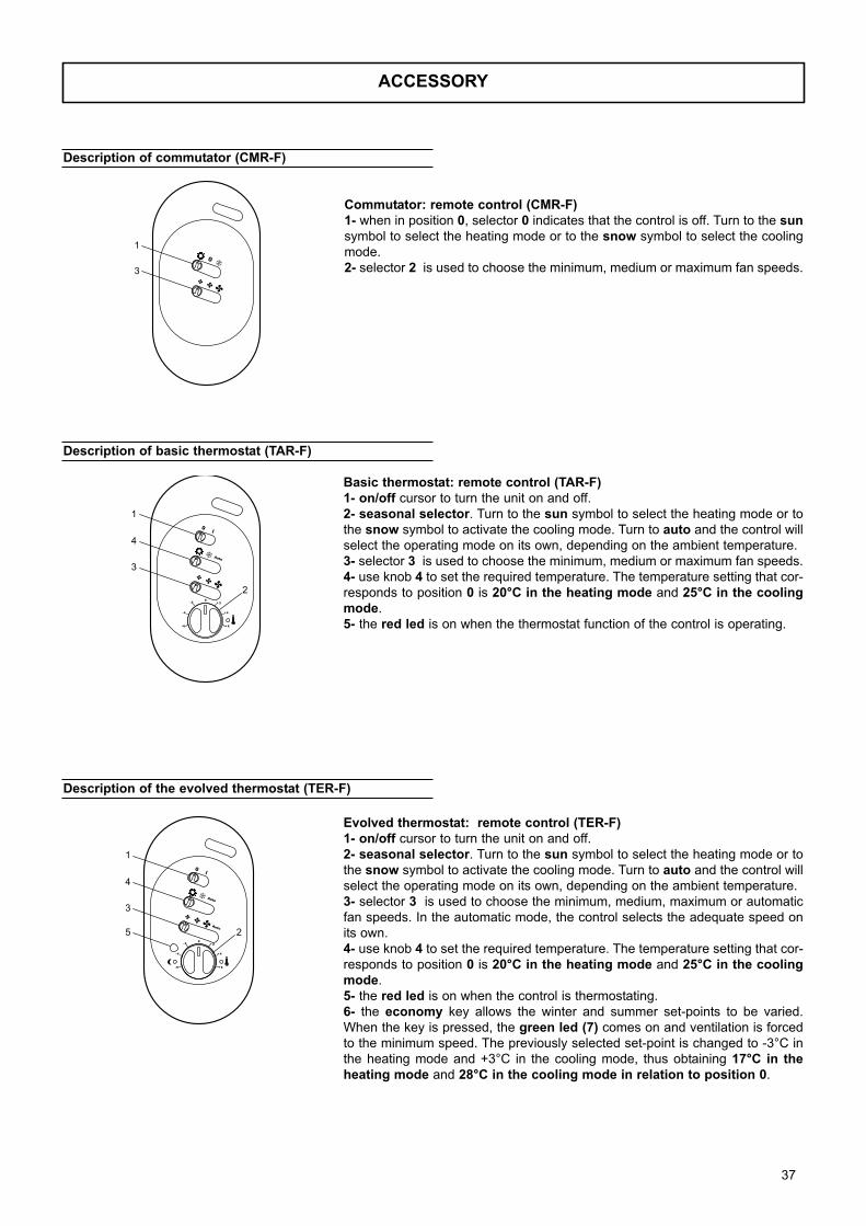
ACCESSORY
Description of commutator (CMR-F)
Description of basic thermostat (TAR-F)
Description of the evolved thermostat (TER-F)
Commutator: remote control (CMR-F)1- when in position 0, selector 0 indicates that the control is off. Turn to the sunsymbol to select the heating mode or to the snow symbol to select the cooling
mode.
2- selector 2 is used to choose the minimum, medium or maximum fan speeds.
Basic thermostat: remote control (TAR-F)1- on/off cursor to turn the unit on and off.
2- seasonal selector. Turn to the sun symbol to select the heating mode or to
the snow symbol to activate the cooling mode. Turn to auto and the control will
select the operating mode on its own, depending on the ambient temperature.
3- selector 3 is used to choose the minimum, medium or maximum fan speeds.
4- use knob 4 to set the required temperature. The temperature setting that cor-
responds to position 0 is 20°C in the heating mode and 25°C in the coolingmode.
5- the red led is on when the thermostat function of the control is operating.
Evolved thermostat: remote control (TER-F)1- on/off cursor to turn the unit on and off.
2- seasonal selector. Turn to the sun symbol to select the heating mode or to
the snow symbol to activate the cooling mode. Turn to auto and the control will
select the operating mode on its own, depending on the ambient temperature.
3- selector 3 is used to choose the minimum, medium, maximum or automatic
fan speeds. In the automatic mode, the control selects the adequate speed on
its own.
4- use knob 4 to set the required temperature. The temperature setting that cor-
responds to position 0 is 20°C in the heating mode and 25°C in the coolingmode.
5- the red led is on when the control is thermostating.
6- the economy key allows the winter and summer set-points to be varied.
When the key is pressed, the green led (7) comes on and ventilation is forced
to the minimum speed. The previously selected set-point is changed to -3°C in
the heating mode and +3°C in the cooling mode, thus obtaining 17°C in theheating mode and 28°C in the cooling mode in relation to position 0.
37
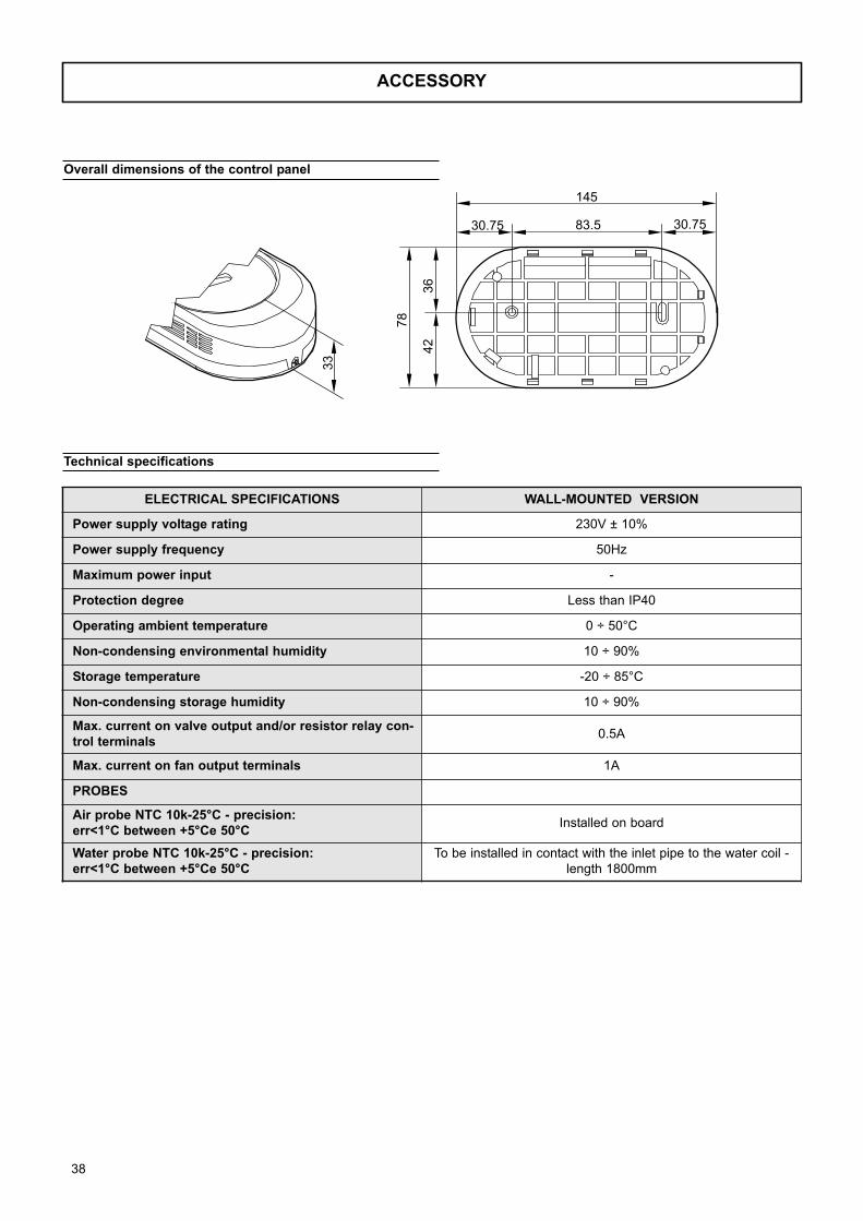
ACCESSORY
Overall dimensions of the control panel
Technical specifications
78
42
33
36
30.75 30.7583.5
145
ELECTRICAL SPECIFICATIONS WALL-MOUNTED VERSION
Power supply voltage rating 230V ± 10%
Power supply frequency 50Hz
Maximum power input -
Protection degree Less than IP40
Operating ambient temperature 0 ÷ 50°C
Non-condensing environmental humidity 10 ÷ 90%
Storage temperature -20 ÷ 85°C
Non-condensing storage humidity 10 ÷ 90%
Max. current on valve output and/or resistor relay con-trol terminals
0.5A
Max. current on fan output terminals 1A
PROBES
Air probe NTC 10k-25°C - precision: err<1°C between +5°Ce 50°C
Installed on board
Water probe NTC 10k-25°C - precision: err<1°C between +5°Ce 50°C
To be installed in contact with the inlet pipe to the water coil -
length 1800mm
38
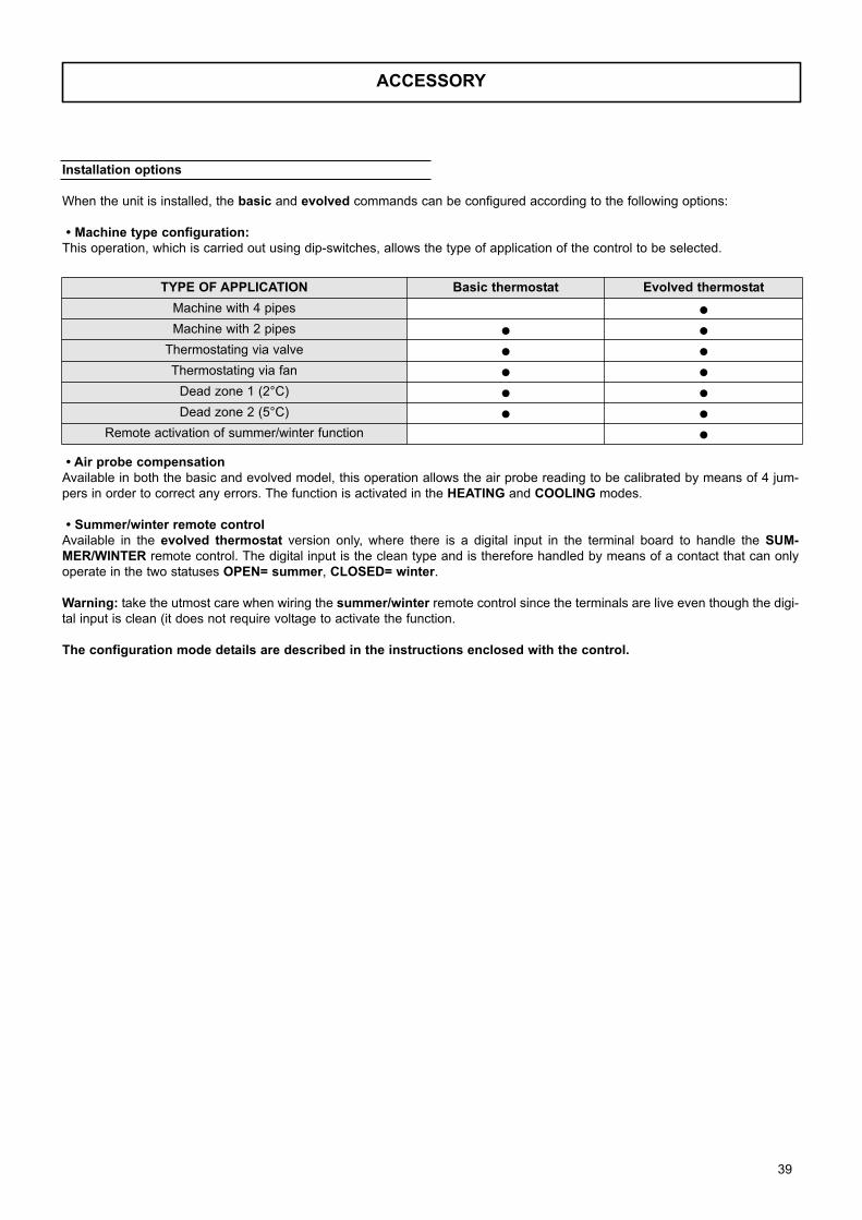
ACCESSORY
Installation options
When the unit is installed, the basic and evolved commands can be configured according to the following options:
• Machine type configuration:This operation, which is carried out using dip-switches, allows the type of application of the control to be selected.
• Air probe compensationAvailable in both the basic and evolved model, this operation allows the air probe reading to be calibrated by means of 4 jum-
pers in order to correct any errors. The function is activated in the HEATING and COOLING modes.
• Summer/winter remote controlAvailable in the evolved thermostat version only, where there is a digital input in the terminal board to handle the SUM-MER/WINTER remote control. The digital input is the clean type and is therefore handled by means of a contact that can only
operate in the two statuses OPEN= summer, CLOSED= winter.
Warning: take the utmost care when wiring the summer/winter remote control since the terminals are live even though the digi-
tal input is clean (it does not require voltage to activate the function.
The configuration mode details are described in the instructions enclosed with the control.
TYPE OF APPLICATION Basic thermostat Evolved thermostat
Machine with 4 pipes •Machine with 2 pipes • •
Thermostating via valve • •Thermostating via fan • •
Dead zone 1 (2°C) • •Dead zone 2 (5°C) • •
Remote activation of summer/winter function •
39
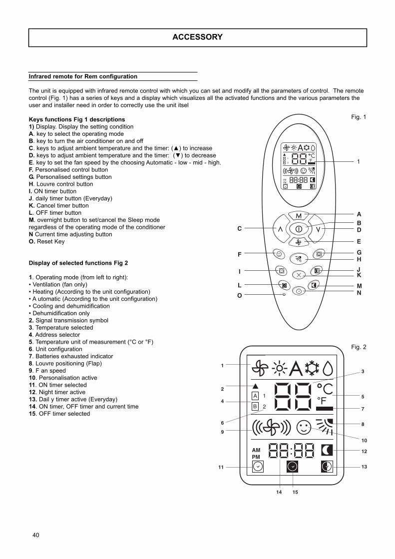
ACCESSORY
Infrared remote for Rem configuration
The unit is equipped with infrared remote control with which you can set and modify all the parameters of control. The remote
control (Fig. 1) has a series of keys and a display which visualizes all the activated functions and the various parameters the
user and installer need in order to correctly use the unit itsel
Keys functions Fig 1 descriptions1) Display. Display the setting condition
A. key to select the operating mode
B. key to turn the air conditioner on and off
C. keys to adjust ambient temperature and the timer: (▲) to increase
D. keys to adjust ambient temperature and the timer: (▼) to decrease
E. key to set the fan speed by the choosing Automatic - low - mid - high.
F. Personalised control button
G. Personalised settings button
H. Louvre control button
I. ON timer button
J. daily timer button (Everyday)
K. Cancel timer button
L. OFF timer button
M. overnight button to set/cancel the Sleep mode
regardless of the operating mode of the conditioner
N Current time adjusting button
O. Reset Key
Display of selected functions Fig 2
1. Operating mode (from left to right):
• Ventilation (fan only)
• Heating (According to the unit configuration)
• A utomatic (According to the unit configuration)
• Cooling and dehumidification
• Dehumidification only
2. Signal transmission symbol
3. Temperature selected
4. Address selector
5. Temperature unit of measurement (°C or °F)
6. Unit configuration
7. Batteries exhausted indicator
8. Louvre positioning (Flap)
9. F an speed
10. Personalisation active
11. ON timer selected
12. Night timer active
13. Dail y timer active (Everyday)
14. ON timer, OFF timer and current time
15. OFF timer selected
A
AMPM
A
B
1
2F 1
ABD
E
GH
JK
MN
C
F
I
L
O
AMPM
A
B
1
2F
3
5
7
8
10
12
13
1
2
4
6
9
11
14 15
Fig. 1
Fig. 2
40

ACCESSORY
A
AMPM
A
B
1
2F
2861
181
635,28,23
2,77
7,58
78
A
Infrared remote dimensions
41
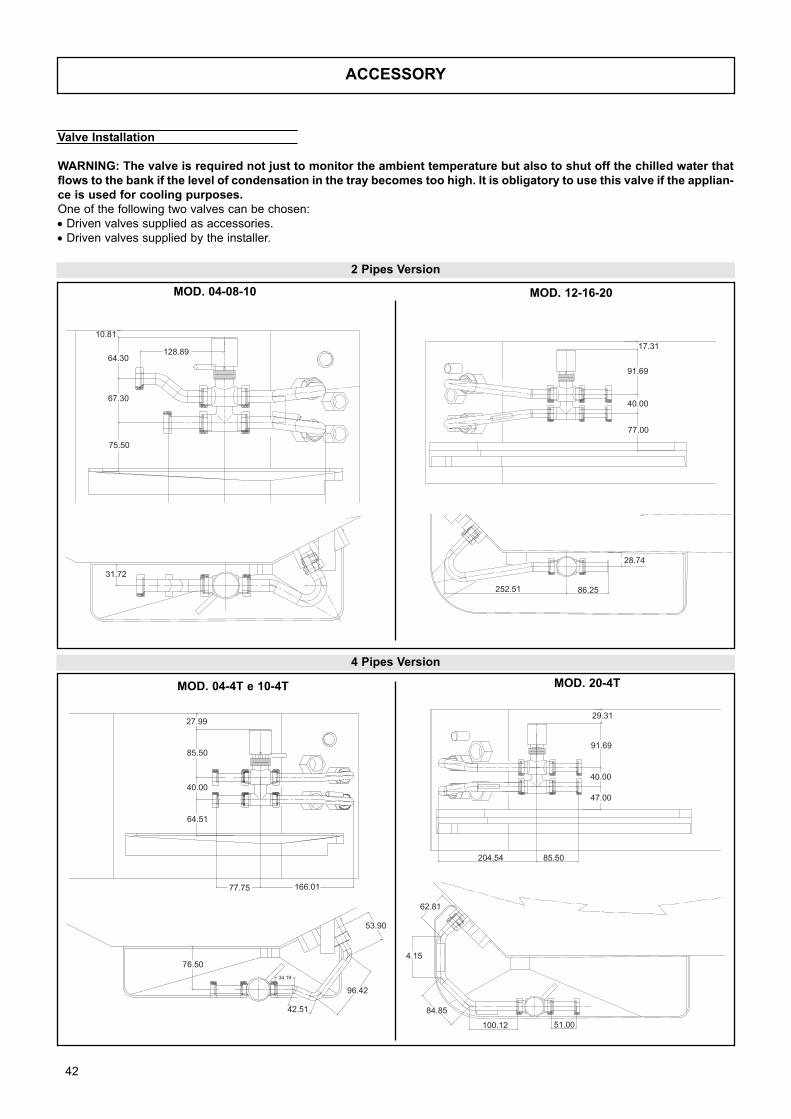
42
ACCESSORY
Valve Installation
WARNING: The valve is required not just to monitor the ambient temperature but also to shut off the chilled water thatflows to the bank if the level of condensation in the tray becomes too high. It is obligatory to use this valve if the applian-ce is used for cooling purposes.One of the following two valves can be chosen:
• Driven valves supplied as accessories.
• Driven valves supplied by the installer.
MOD. 04-08-10 MOD. 12-16-20
MOD. 04-4T e 10-4T MOD. 20-4T
2 Pipes Version
4 Pipes Version
75.50
67.30
64.30
10.81
128.89
31.72
77.00
40.00
91.69
17.31
252.51 86.25
28.74
204.54 85.50
47.00
40.00
91.69
29.31
62.81
4.15
84.85
100.12 51.00
27.99
85.50
40.00
64.51
77.75 166.01
76.50
42.51
96.42
53.90
34.19
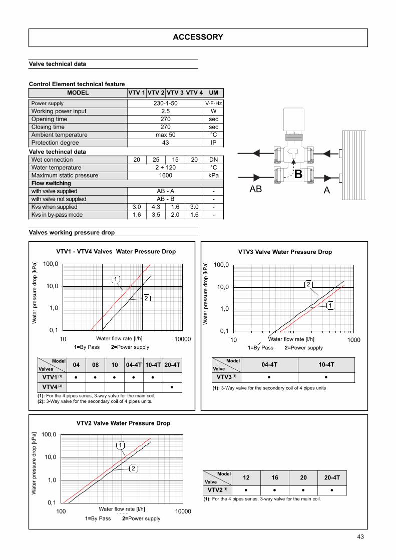
0,1
1,0
10,0
100,0
10 100 1000 100000,1
1,0
10,0
100,0
10 100 1000
0,1
1,0
10,0
100,0
100 1000 10000
1
2
2
1
1
2
43
ACCESSORY
Valve technical data
Valves working pressure drop
Control Element technical feature
04 08 10 04-4T 10-4T 20-4T
VTV1 (1) • • • • •VTV4 (2) •
Valves
Model
(1): For the 4 pipes series, 3-way valve for the main coil.
(2): 3-Way valve for the secondary coil of 4 pipes units.
04-4T 10-4T
VTV3 (1) • •Valve
Model
(1): 3-Way valve for the secondary coil of 4 pipes units
1=By Pass 2=Power supply 1=By Pass 2=Power supply
12 16 20 20-4T
VTV2 (1) • • • •
Model
(1): For the 4 pipes series, 3-way valve for the main coil.
1=By Pass 2=Power supply
VTV1 - VTV4 Valves Water Pressure Drop VTV3 Valve Water Pressure Drop
VTV2 Valve Water Pressure Drop
Valve
Wate
r pre
ssure
dro
p [
kP
a]
Wate
r pre
ssure
dro
p [
kP
a]
Water flow rate [l/h] Water flow rate [l/h]
Wate
r pre
ssure
dro
p [
kP
a]
Water flow rate [l/h]
Power supply 230-1-50 V-F-Hz
Working power input 2.5 W
Opening time 270 sec
Closing time 270 sec
Ambient temperature max 50 °C
Protection degree 43 IP
Wet connection 20 25 15 20 DN
Water temperature 2 ÷ 120 °C
Maximum static pressure 1600 kPa
Flow switching
with valve supplied AB - A -
with valve not supplied AB - B -
Kvs when supplied 3.0 4.3 1.6 3.0 -
Kvs in by-pass mode 1.6 3.5 2.0 1.6 -
MODEL VTV 1 VTV 2 VTV 3 VTV 4 UM
BAAB
Valve techincal data
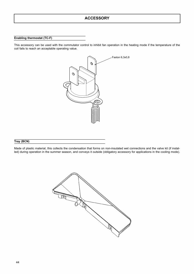
ACCESSORY
Enabling thermostat (TC-F)
This accessory can be used with the commutator control to inhibit fan operation in the heating mode if the temperature of the
coil fails to reach an acceptable operating value.
Tray (BCN)
Made of plastic material, this collects the condensation that forms on non-insulated wet connections and the valve kit (if instal-
led) during operation in the summer season, and conveys it outside (obligatory accessory for applications in the cooling mode).
44
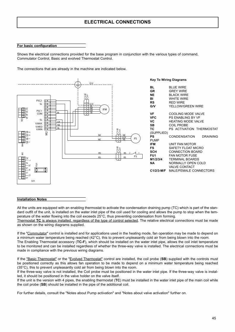
ELECTRICAL CONNECTIONS
Key To Wiring Diagrams
BL BLUE WIRE
GR GREY WIRE
NE BLACK WIRE
BI WHITE WIRE
RS RED WIRE
G/V YELLOW/GREEN WIRE
VF COOLING MODE VALVE
VFC PS ENABLING BY VF
VC HEATING MODE VALVE
SB COIL PROBE
TC PS ACTIVATION THERMOSTAT
(SUPPLIED)
PS CONDENSATION DRAINING
PUMP
IFM UNIT FAN MOTOR
FS SAFETY FLOAT MICRO
SCH CONNECTION BOARD
FU1 FAN MOTOR FUSE
M1/2/3/4 TERMINAL BOARDS
NA NORMALLY OPEN COLD
VALVE CONTACT
C1/2/3-M/F MALE/FEMALE CONNECTORS
The connections that are already in the machine are indicated below.
Installation Notes
All the units are equipped with an enabling thermostat to activate the condensation draining pump (TC) which is part of the stan-
dard outfit of the unit, is installed on the water inlet pipe of the coil used for cooling and allows the pump to stop when the tem-
perature of the water flowing into the coil exceeds 25°C, thus preventing condensation from forming.
Thermostat TC is always installed, regardless of the type of control selected. The relative electrical connections must be made
as shown on the wiring diagrams supplied.
If the "Commutator" control is installed and for applications used in the heating mode, fan operation may be made to depend on
a minimum water temperature being reached (42°C), this to prevent unpleasantly cold air from being blown into the room.
The Enabling Thermostat accessory (TC-F), which should be installed on the water inlet pipe, allows the coil inlet temperature
to be monitored and can be installed regardless of whether the three-way valve is installed. The electrical connections must be
made in compliance with the previous wiring diagrams.
If the "Basic Thermostat" or the "Evolved Thermostat" control are installed, the coil probe (SB) supplied with the controls must
be positioned correctly as this allows fan operation to be made to depend on a minimum water temperature being reached
(35°C), this to prevent unpleasantly cold air from being blown into the room.
If the three-way valve is not installed, the Coil probe must be positioned in the water inlet pipe. If the three-way valve is instal-
led, it should be positioned in the valve holder on the valve itself.
If the unit is the version with 4 pipes, the enabling thermostat (TC) must be installed in the water inlet pipe of the main coil while
the coil probe (SB) should be installed in the pipe of the additional coil.
For further details, consult the "Notes about Pump activation" and "Notes about valve activation" further on.
LVF
22
11
M1
SBSB
SBSB
C2-
MC
2-F
C1-
FC
1-M
C3-
FC
3-M
SCH
BI BI
GR
GR
NE
NE
NE
NE
NEG/V
G/V
NE
RS
RS
RS
RS
BL
BLG/V
FS
22
111 1
2 2
3 3
PS
IFM
66
55
44
33
221 1
N12
1314
TCTC
VC
M4
M3
VCVC
VFVF
SL
PSC1COM
V.MINV.MEDV.MAX
FU1
M2
SLPSC2
12
For basic configuration
Shows the electrical connections provided for the base program in conjunction with the various types of command,
Commutator Control, Basic and evolved Thermostat Control.
45
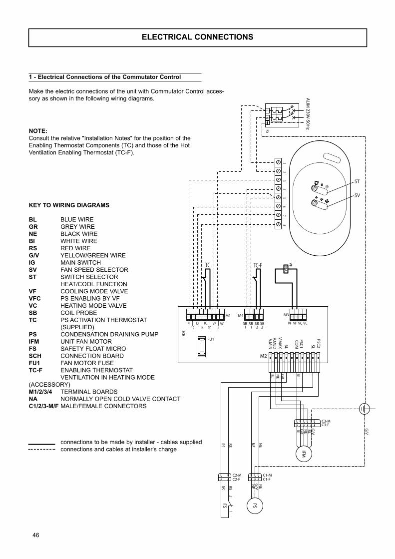
ELECTRICAL CONNECTIONS
NATC-F
8
TC
12
34
65
7
VF
LN
IG
ALIM
230V-50Hz
LVF
2 211
M1
SB SB SBSB
C2-MC2-F C1-F
C1-M
C3-FC3-M
SCH
BIBI
GR
GR
NE
NE
NE
NE
NE
G/V
G/V
NE
RS
RS
RS
RS
BL
BLG
/V
FS
2
2
1
1 1
1
2
2
3
3
PS
IFM
6
6
5
5
4
4
3
3
2
21
1
N12
1314
TCTC
VC
M4 M3
VCVCVFVF
SL
PSC1
COM
V.MIN
V.MED
V.MA
X
FU1
M2
SLPSC
2
12
ST
SV
NOTE:Consult the relative "Installation Notes" for the position of the
Enabling Thermostat Components (TC) and those of the Hot
Ventilation Enabling Thermostat (TC-F).
1 - Electrical Connections of the Commutator Control
Make the electric connections of the unit with Commutator Control acces-
sory as shown in the following wiring diagrams.
KEY TO WIRING DIAGRAMS
BL BLUE WIRE
GR GREY WIRE
NE BLACK WIRE
BI WHITE WIRE
RS RED WIRE
G/V YELLOW/GREEN WIRE
IG MAIN SWITCH
SV FAN SPEED SELECTOR
ST SWITCH SELECTOR
HEAT/COOL FUNCTION
VF COOLING MODE VALVE
VFC PS ENABLING BY VF
VC HEATING MODE VALVE
SB COIL PROBE
TC PS ACTIVATION THERMOSTAT
(SUPPLIED)
PS CONDENSATION DRAINING PUMP
IFM UNIT FAN MOTOR
FS SAFETY FLOAT MICRO
SCH CONNECTION BOARD
FU1 FAN MOTOR FUSE
TC-F ENABLING THERMOSTAT
VENTILATION IN HEATING MODE
(ACCESSORY)
M1/2/3/4 TERMINAL BOARDS
NA NORMALLY OPEN COLD VALVE CONTACT
C1/2/3-M/F MALE/FEMALE CONNECTORS
connections to be made by installer - cables supplied
connections and cables at installer's charge
46
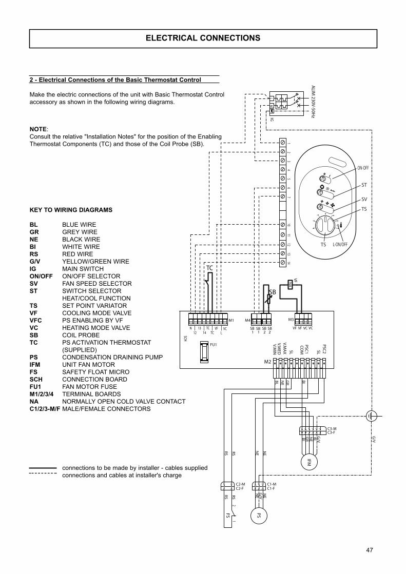
ELECTRICAL CONNECTIONS
NA
1412
1311
107
56
43
21
VF
LN
IG
ALIM
230V-50Hz
LVF
2 211
M1
SB SB SBSB
C2-MC2-F C1-F
C1-M
C3-FC3-M
SCH
BIBI
GR
GR
NE
NE
NE
NE
NE
G/V
G/V
NE
RS
RS
RS
RS
BL
BLG
/V
FS
2
2
1
1 1
1
2
2
3
3
PS
IFM
6
6
5
5
4
4
3
3
2
21
1
N12
1314
TCTC
VC
M4 M3
VCVCVFVF
SL
PSC1
COM
V.MIN
V.MED
V.MA
X
FU1
M2
SLPSC
2
12
TC
SB
ON-OFF
ST
SV
TS
TS L-ON/OFF
NOTE:
Consult the relative "Installation Notes" for the position of the Enabling
Thermostat Components (TC) and those of the Coil Probe (SB).
2 - Electrical Connections of the Basic Thermostat Control
Make the electric connections of the unit with Basic Thermostat Control
accessory as shown in the following wiring diagrams.
KEY TO WIRING DIAGRAMS
BL BLUE WIRE
GR GREY WIRE
NE BLACK WIRE
BI WHITE WIRE
RS RED WIRE
G/V YELLOW/GREEN WIRE
IG MAIN SWITCH
ON/OFF ON/OFF SELECTOR
SV FAN SPEED SELECTOR
ST SWITCH SELECTOR
HEAT/COOL FUNCTION
TS SET POINT VARIATOR
VF COOLING MODE VALVE
VFC PS ENABLING BY VF
VC HEATING MODE VALVE
SB COIL PROBE
TC PS ACTIVATION THERMOSTAT
(SUPPLIED)
PS CONDENSATION DRAINING PUMP
IFM UNIT FAN MOTOR
FS SAFETY FLOAT MICRO
SCH CONNECTION BOARD
FU1 FAN MOTOR FUSE
M1/2/3/4 TERMINAL BOARDS
NA NORMALLY OPEN COLD VALVE CONTACT
C1/2/3-M/F MALE/FEMALE CONNECTORS
connections to be made by installer - cables supplied
connections and cables at installer's charge
47
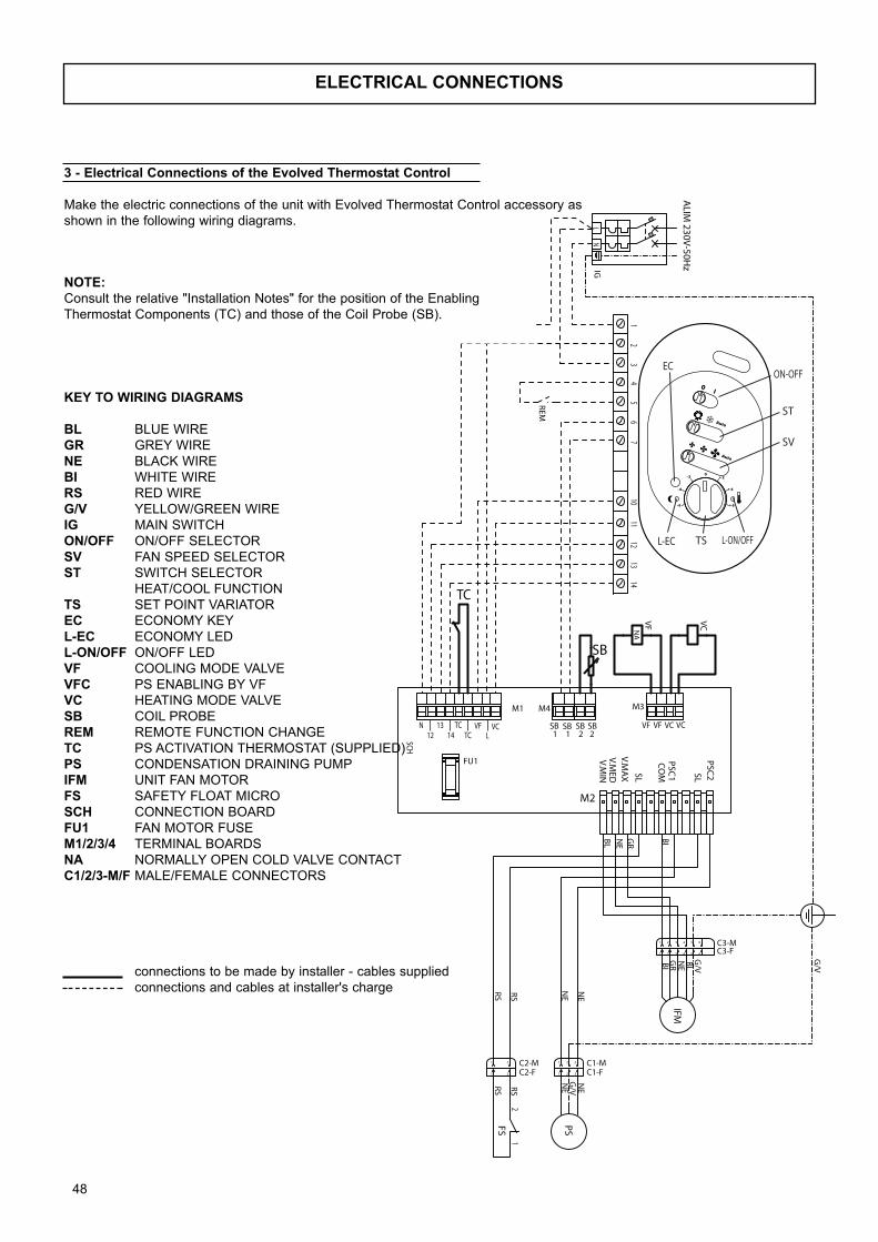
ELECTRICAL CONNECTIONS
NA
LVF
2 211
M1
SB SB SBSB
C2-MC2-F C1-F
C1-M
C3-FC3-M
SCH
BIBI
GR
GR
NE
NE
NE
NE
NE
G/V
G/V
NE
RS
RS
RS
RS
BL
BLG
/V
FS
2
2
1
1 1
1
2
2
3
3
PS
IFM
6
6
5
5
4
4
3
3
2
21
1
TC
N12
1314
TCTC
VC
M4 M3
VCVCVFVF
SL
PSC1
COM
V.MIN
V.MED
V.MA
X
FU1
M2
SLPSC
2
LN
IG
ALIM
230V-50Hz
12
34
65
710
1113
1214
SB
VCVF
12
REM
ON-OFF
ST
SV
TSL-EC
EC
L-ON/OFF
NOTE:Consult the relative "Installation Notes" for the position of the Enabling
Thermostat Components (TC) and those of the Coil Probe (SB).
3 - Electrical Connections of the Evolved Thermostat Control
Make the electric connections of the unit with Evolved Thermostat Control accessory as
shown in the following wiring diagrams.
KEY TO WIRING DIAGRAMS
BL BLUE WIRE
GR GREY WIRE
NE BLACK WIRE
BI WHITE WIRE
RS RED WIRE
G/V YELLOW/GREEN WIRE
IG MAIN SWITCH
ON/OFF ON/OFF SELECTOR
SV FAN SPEED SELECTOR
ST SWITCH SELECTOR
HEAT/COOL FUNCTION
TS SET POINT VARIATOR
EC ECONOMY KEY
L-EC ECONOMY LED
L-ON/OFF ON/OFF LED
VF COOLING MODE VALVE
VFC PS ENABLING BY VF
VC HEATING MODE VALVE
SB COIL PROBE
REM REMOTE FUNCTION CHANGE
TC PS ACTIVATION THERMOSTAT (SUPPLIED)
PS CONDENSATION DRAINING PUMP
IFM UNIT FAN MOTOR
FS SAFETY FLOAT MICRO
SCH CONNECTION BOARD
FU1 FAN MOTOR FUSE
M1/2/3/4 TERMINAL BOARDS
NA NORMALLY OPEN COLD VALVE CONTACT
C1/2/3-M/F MALE/FEMALE CONNECTORS
connections to be made by installer - cables supplied
connections and cables at installer's charge
48
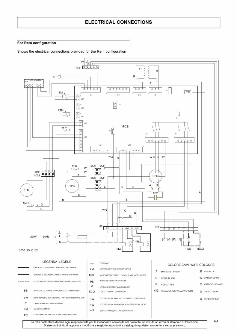
ELECTRICAL CONNECTIONS
49
G
G
WW
B
A
RR
A
A B
A
O
C
B
WG
C R
Y/G
Y/G
A
B
B
B
O
BR
W Y D R
1LM
2PCB
1 2 3 4
1MSL1 2
5 6 7 8
1CF 1 2 3 4
1CM 1 2 3 4
DISPLAY�BOARD
1TM
1M1 2
1PS
1TP1
1FS1 2
2CM1
2
3CM1
2
3
2CF1
2
3CF1
2
3
1T
1IFM
1FC
1HW
1PCB
J6A.1
J6A.2
J6B.1
J6B.2
J6B.1
J6B.2
J18.1
J18.2
J11.7
J11.6
J11.5
J11.4
J11.3
J11.2
J11.1
1
1
1
1
J6A
J6B
J6C
J5.1
1J18
J11
1
J5.2 J5.3
J5
1
J5.4
J8.1
J5.5
J8.2 J8.3
J8
J8.4 J8.5
1
J10.1 J10.2
J15.1
J15
J17.1
J17.2
J10.3
J10
1
J10.4
J20.7
J17
J10.5
J20.6
J10.6
J20.5 J20.4
J20
J20.3
1
J13.1
J20.2
J13.2
J20.1
J13
J13.3
1
1
J7
J7.1
1
J2.1
J7.2
J2.2
J7.3
J2
J2.3
J7.4 J7.5 J7.6
J1.1
J1
1
J4
J4.1 J4.2 J4.3 J4.4 J4.5
J3
2TM
1WS
1
2
1ECO
1
2C G P I
L
N
B035125H0102
1CW
230V��1~��50Hz
2TBC G P I 1 2 3
1TBPE L N N HW N CW
5CF 1 2 3 4 5
FS
IFM
TM
FC
T
LEGENDA��LEGEND
CABLAGGIO�DEL�COSTRUTTORE / FACTORY�WIRING
COLLEGAMENTI DELL'INSTALLATORE / WIRING�BY�OTHERS
CABLAGGIO�DELL'INSTALLATORE / WIRING�BY�OTHERS
MICRO�GALLEGGIANTE�SICUREZZA / SAFETY�MICRO�FLOAT
MOTORE�VENTIL.UNITA'�INTERNA / FAN�MOTOR�INTERNAL�UNIT
TRASFORMATORE / TRANSFORMER
SENSORE / SENSOR
CONDENSATORE�MOTORE�VENTIL. / FAN�CAPACITOR
TP
M
MSL
PS
LM
TEST�POINT
MOTORE�ALETTONE / LOUVER�MOTOR
MICROINTERRUTTORE� / LOUVERLOUVER�MICRO�SWITCH
POMPA�SCARICO / DRAIN�PUMPE
MANUAL�OVERRIDE / MANUAL�RESET
WS
CONTATTO�ECO� / �ECO�SWITCHECO
CW
HW
CONTATTO�FINESTRA / WINDOW�SWITCH
ELETTROVALVOLA�FREDDO / COOLING�ELECTRIC�VALVE
ELETTROVALVOLA�CALDO / HEATING�ELECTRICAL�VALVE
Y/G
A
C
R
GIALLO/VERDE / YELLOW/GREEN
MARRONE / BROWN
NERO / BLACK
ROSSO / RED
B
W
O
G
COLORE�CAVI��WIRE�COLOURS
BLU / BLUE
BIANCO / WHITE
ARANCIO / ORANGE
GRIGIO / GRAY
D VERDE / GREEN
For Rem configuration
Shows the electrical connections provided for the Rem configuration
La ditta costruttrice declina ogni responsabilità per le inesattezze contenute nel presente, se dovute ad errori di stampa o di trascrizioni.
Si riserva il diritto di apportare modifiche e migliorie ai prodotti a catalogo in qualsiasi momento e senza preavviso.

����

����

Co
d.
3Q
E2
01
24