Universal Fuzzy Logic Controller
12
Universal Fuzzy Logic Controller Sourabh Kaushal, Raghav Sharma Department of electronics & Communication Institute of science & Technology Klawad, Haryana,India Email: [email protected], [email protected] ABSTRACT – This research paper emphasis on the universal controller implemented by us. Fuzzy logic is a powerful problem-solving methodology with wide range of application in industrial control, consumer electronics, management, medicine, expert system and information technology. It provides a simple way to draw definite conclusion from vague information and is very close to the way the human being think and make decision even under highly uncertain environment. Fuzzy logic has rapidly become one of the most successful of today's technologies for developing control systems. The reason for which is very simple. Fuzzy logic addresses such applications perfectly as it resembles human decision making with an ability to generate precise solutions from certain or approximate information. It fills an important gap in engineering design methods left vacant by purely mathematical approaches (e.g. linear control design), and purely logic- based approaches (e.g. expert systems) in system design. In our research we implemented the mamdani type fuzzy logic controller using MATLAB software. In addition, we also implemented the algorithm for universal implementation of Mamdani type fuzzy logic controller. Keywords: Fuzzy, Controller, Mamdani Model, MATLAB I. INTRODUCTION The research work deals with a Fuzzy Logic Controller using MATLAB. An example system i.e. battery charger is being implemented using MATLAB for testing purpose. The response of the system will be simulated by using Fuzzy Logic Toolbox in MATLAB. The aim of this project is to design a fuzzy logic based rapid battery charger that has two inputs, temperature and temperature gradient, and charging current as output. The battery temperature can vary between 0 and 50 degree centigrade. The battery is likely to get damaged beyond this temperature. Let us assume that the temperature sensor gives 0-5 volts as output, corresponding to the variation in temperature in range 0 to 50 degree centigrade which is divided into 50 equal parts, each part representing one-degree temperature. The temperature gradient obtained from sensor is in mv/10 seconds. II. METHODOLOGY A. Using MATLAB along with FIS editor For implementation of Mamdani type fuzzy logic system we are using MATLAB so here we are giving a brief introduction to MATLAB along with FIS editor which has been used for verifying the implemented system. MATLAB is a product of The Math works, Inc. and is an advanced interactive software package specially designed for scientific and engineering computation. The Matlab environment integrates graphic illustrations with precise numerical calculations, and is a powerful, easy-to-use, and comprehensive tool for performing all kinds of computations and scientific data visualization. Matlab has proven to be a very flexible and usable tool for solving problems in many areas. Matlab is a high-performance language for technical computing. It integrates computation, visualization, and programming in an easy-to-use environment where problems and solutions are expressed in familiar mathematical notation [7]. B. FIS Editor window in MATLAB The FIS Editor displays general information about a fuzzy inference system. There is a simple diagram at the top that shows the names of each input variable on the left, and those of each output variable on the right[7].
-
Upload
independent -
Category
Documents
-
view
1 -
download
0
Transcript of Universal Fuzzy Logic Controller
Universal Fuzzy Logic Controller Sourabh Kaushal, Raghav Sharma
Department of electronics & Communication
Institute of science & Technology Klawad, Haryana,India
Email: [email protected], [email protected]
ABSTRACT – This research paper emphasis on the
universal controller implemented by us. Fuzzy logic is a
powerful problem-solving methodology with wide range
of application in industrial control, consumer
electronics, management, medicine, expert system and
information technology. It provides a simple way to
draw definite conclusion from vague information and is
very close to the way the human being think and make
decision even under highly uncertain environment.
Fuzzy logic has rapidly become one of the most
successful of today's technologies for developing control
systems. The reason for which is very simple. Fuzzy
logic addresses such applications perfectly as it
resembles human decision making with an ability to
generate precise solutions from certain or approximate
information. It fills an important gap in engineering
design methods left vacant by purely mathematical
approaches (e.g. linear control design), and purely logic-
based approaches (e.g. expert systems) in system design.
In our research we implemented the mamdani type
fuzzy logic controller using MATLAB software. In
addition, we also implemented the algorithm for
universal implementation of Mamdani type fuzzy logic
controller.
Keywords: Fuzzy, Controller, Mamdani Model, MATLAB
I. INTRODUCTION
The research work deals with a Fuzzy Logic
Controller using MATLAB. An example system i.e.
battery charger is being implemented using
MATLAB for testing purpose. The response of the
system will be simulated by using Fuzzy Logic
Toolbox in MATLAB. The aim of this project is to
design a fuzzy logic based rapid battery charger that
has two inputs, temperature and temperature gradient,
and charging current as output. The battery
temperature can vary between 0 and 50 degree
centigrade. The battery is likely to get damaged
beyond this temperature. Let us assume that the
temperature sensor gives 0-5 volts as output,
corresponding to the variation in temperature in range
0 to 50 degree centigrade which is divided into 50
equal parts, each part representing one-degree
temperature. The temperature gradient obtained from
sensor is in mv/10 seconds.
II. METHODOLOGY
A. Using MATLAB along with FIS editor
For implementation of Mamdani type fuzzy logic
system we are using MATLAB so here we are giving
a brief introduction to MATLAB along with FIS
editor which has been used for verifying the
implemented system.
MATLAB is a product of The Math works, Inc.
and is an advanced interactive software package
specially designed for scientific and engineering
computation. The Matlab environment integrates
graphic illustrations with precise numerical
calculations, and is a powerful, easy-to-use, and
comprehensive tool for performing all kinds of
computations and scientific data visualization.
Matlab has proven to be a very flexible and usable
tool for solving problems in many areas. Matlab is a
high-performance language for technical computing.
It integrates computation, visualization, and
programming in an easy-to-use environment where
problems and solutions are expressed in familiar
mathematical notation [7].
B. FIS Editor window in MATLAB
The FIS Editor displays general information about
a fuzzy inference system. There is a simple diagram
at the top that shows the names of each input variable
on the left, and those of each output variable on the
right[7].
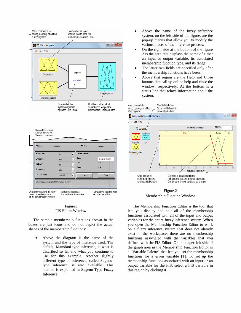
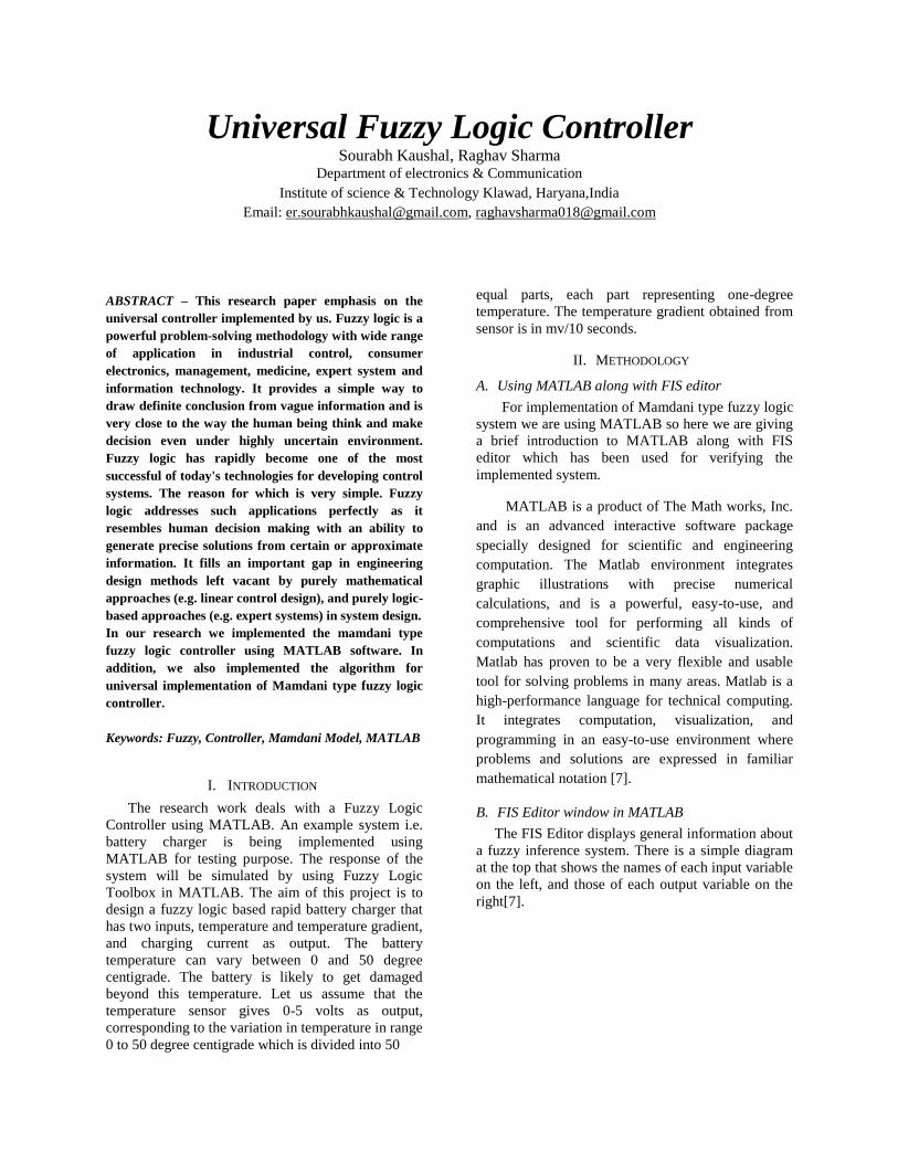
Figure1
FIS Editor Window
The sample membership functions shown in the
boxes are just icons and do not depict the actual
shapes of the membership functions:
Above the diagram is the name of the
system and the type of inference used. The
default, Mamdani-type inference, is what is
described so far and what you continue to
use for this example. Another slightly
different type of inference, called Sugeno-
type inference, is also available. This
method is explained in Sugeno-Type Fuzzy
Inference.
Above the name of the fuzzy inference
system, on the left side of the figure, are the
pop-up menus that allow you to modify the
various pieces of the inference process.
On the right side at the bottom of the figure
2 is the area that displays the name of either
an input or output variable, its associated
membership function type, and its range.
The latter two fields are specified only after
the membership functions have been.
Above that region are the Help and Close
buttons that call up online help and close the
window, respectively. At the bottom is a
status line that relays information about the
system.
Figure 2
Membership Function Window
The Membership Function Editor is the tool that
lets you display and edit all of the membership
functions associated with all of the input and output
variables for the entire fuzzy inference system. When
you open the Membership Function Editor to work
on a fuzzy inference system that does not already
exist in the workspace, there are no membership
functions associated with the variables that you
defined with the FIS Editor. On the upper-left side of
the graph area in the Membership Function Editor is
a "Variable Palette" that lets you set the membership
functions for a given variable [1]. To set up the
membership functions associated with an input or an
output variable for the FIS, select a FIS variable in
this region by clicking it.
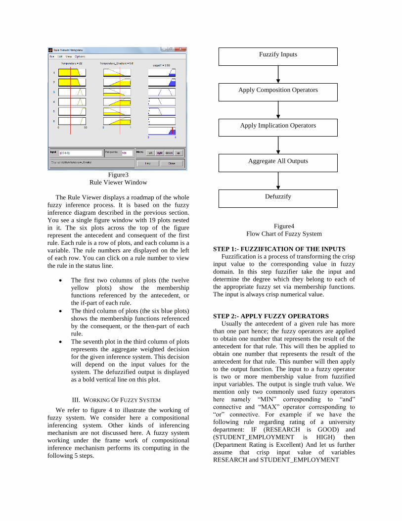
Figure3
Rule Viewer Window
The Rule Viewer displays a roadmap of the whole
fuzzy inference process. It is based on the fuzzy
inference diagram described in the previous section.
You see a single figure window with 19 plots nested
in it. The six plots across the top of the figure
represent the antecedent and consequent of the first
rule. Each rule is a row of plots, and each column is a
variable. The rule numbers are displayed on the left
of each row. You can click on a rule number to view
the rule in the status line.
The first two columns of plots (the twelve
yellow plots) show the membership
functions referenced by the antecedent, or
the if-part of each rule.
The third column of plots (the six blue plots)
shows the membership functions referenced
by the consequent, or the then-part of each
rule.
The seventh plot in the third column of plots
represents the aggregate weighted decision
for the given inference system. This decision
will depend on the input values for the
system. The defuzzified output is displayed
as a bold vertical line on this plot.
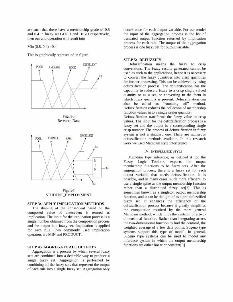
III. WORKING OF FUZZY SYSTEM
We refer to figure 4 to illustrate the working of
fuzzy system. We consider here a compositional
inferencing system. Other kinds of inferencing
mechanism are not discussed here. A fuzzy system
working under the frame work of compositional
inference mechanism performs its computing in the
following 5 steps.
Figure4
Flow Chart of Fuzzy System
STEP 1:- FUZZIFICATION OF THE INPUTS
Fuzzification is a process of transforming the crisp
input value to the corresponding value in fuzzy
domain. In this step fuzzifier take the input and
determine the degree which they belong to each of
the appropriate fuzzy set via membership functions.
The input is always crisp numerical value.
STEP 2:- APPLY FUZZY OPERATORS
Usually the antecedent of a given rule has more
than one part hence; the fuzzy operators are applied
to obtain one number that represents the result of the
antecedent for that rule. This will then be applied to
obtain one number that represents the result of the
antecedent for that rule. This number will then apply
to the output function. The input to a fuzzy operator
is two or more membership value from fuzzified
input variables. The output is single truth value. We
mention only two commonly used fuzzy operators
here namely “MIN” corresponding to “and”
connective and “MAX” operator corresponding to
“or” connective. For example if we have the
following rule regarding rating of a university
department: IF (RESEARCH is GOOD) and
(STUDENT_EMPLOYMENT is HIGH) then
(Department Rating is Excellent) And let us further
assume that crisp input value of variables
RESEARCH and STUDENT_EMPLOYMENT
Fuzzify Inputs
Apply Composition Operators
Apply Implication Operators
Aggregate All Outputs
Defuzzify
are such that these have a membership grade of 0.8
and 0.4 in fuzzy set GOOD and HIGH respectively,
then our and operation will result into
Min (0.8, 0.4) =0.4
This is graphically represented in figure
Figure5
Research Data
Figure6
STUDENT_EMPLOYMENT
STEP 3:- APPLY IMPLICATION METHODS The shaping of the consequent based on the
composed value of antecedent is termed as
implication. The input for the implication process is a
single number obtained from the composition process
and the output is a fuzzy set. Implication is applied
for each rule. Two commonly used implication
operators are MIN and PRODUCT.
STEP 4:- AGGREGATE ALL OUTPUTS
Aggregation is a process by which several fuzzy
sets are combined into a desirable way to produce a
single fuzzy set. Aggregation is performed by
combining all the fuzzy sets that represent the output
of each rule into a single fuzzy set. Aggregation only
occurs once for each output variable. For our model
the input of the aggregation process is the list of
truncated output function returned by implication
process for each rule. The output of the aggregation
process is one fuzzy set for output variable.
STEP 5:- DEFUZZIFY
Defuzzification means the fuzzy to crisp
conversions. The fuzzy results generated cannot be
used as such to the applications, hence it is necessary
to convert the fuzzy quantities into crisp quantities
for further processing. This can be achieved by using
defuzzification process. The defuzzification has the
capability to reduce a fuzzy to a crisp single-valued
quantity or as a set, or converting to the form in
which fuzzy quantity is present. Defuzzification can
also be called as “rounding off” method.
Defuzzification reduces the collection of membership
function values in to a single sealer quantity.
Defuzzification transforms the fuzzy value to crisp
values. The input for the defuzzification process is a
fuzzy set and the output is a corresponding single
crisp number. The process of defuzzification in fuzzy
system is not a standard one. There are numerous
defuzzification methods available. In this research
work we used Mamdani style interference.
IV. INTEFERENCE STYLE
Mamdani type inference, as defined it for the
Fuzzy Logic Toolbox, expects the output
membership functions to be fuzzy sets. After the
aggregation process, there is a fuzzy set for each
output variable that needs defuzzification. It is
possible, and in many cases much more efficient, to
use a single spike as the output membership function
rather than a distributed fuzzy set[2]. This is
sometimes known as a singleton output membership
function, and it can be thought of as a pre-defuzzified
fuzzy set. It enhances the efficiency of the
defuzzification process because it greatly simplifies
the computation required by the more general
Mamdani method, which finds the centroid of a two-
dimensional function. Rather than integrating across
the two-dimensional function to find the centroid, the
weighted average of a few data points. Sugeno type
systems support this type of model. In general,
Sugeno type systems can be used to model any
inference system in which the output membership
functions are either linear or constant[3].
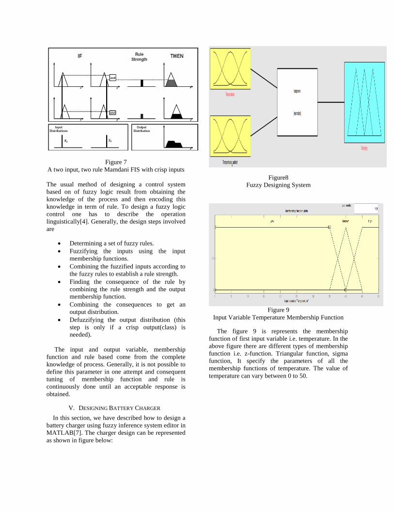
Figure 7
A two input, two rule Mamdani FIS with crisp inputs
The usual method of designing a control system
based on of fuzzy logic result from obtaining the
knowledge of the process and then encoding this
knowledge in term of rule. To design a fuzzy logic
control one has to describe the operation
linguistically[4]. Generally, the design steps involved
are
Determining a set of fuzzy rules.
Fuzzifying the inputs using the input
membership functions.
Combining the fuzzified inputs according to
the fuzzy rules to establish a rule strength.
Finding the consequence of the rule by
combining the rule strength and the output
membership function.
Combining the consequences to get an
output distribution.
Defuzzifying the output distribution (this
step is only if a crisp output(class) is
needed).
The input and output variable, membership
function and rule based come from the complete
knowledge of process. Generally, it is not possible to
define this parameter in one attempt and consequent
tuning of membership function and rule is
continuously done until an acceptable response is
obtained.
V. DESIGNING BATTERY CHARGER
In this section, we have described how to design a
battery charger using fuzzy inference system editor in
MATLAB[7]. The charger design can be represented
as shown in figure below:
Figure8
Fuzzy Designing System
Figure 9
Input Variable Temperature Membership Function
The figure 9 is represents the membership
function of first input variable i.e. temperature. In the
above figure there are different types of membership
function i.e. z-function. Triangular function, sigma
function, It specify the parameters of all the
membership functions of temperature. The value of
temperature can vary between 0 to 50.
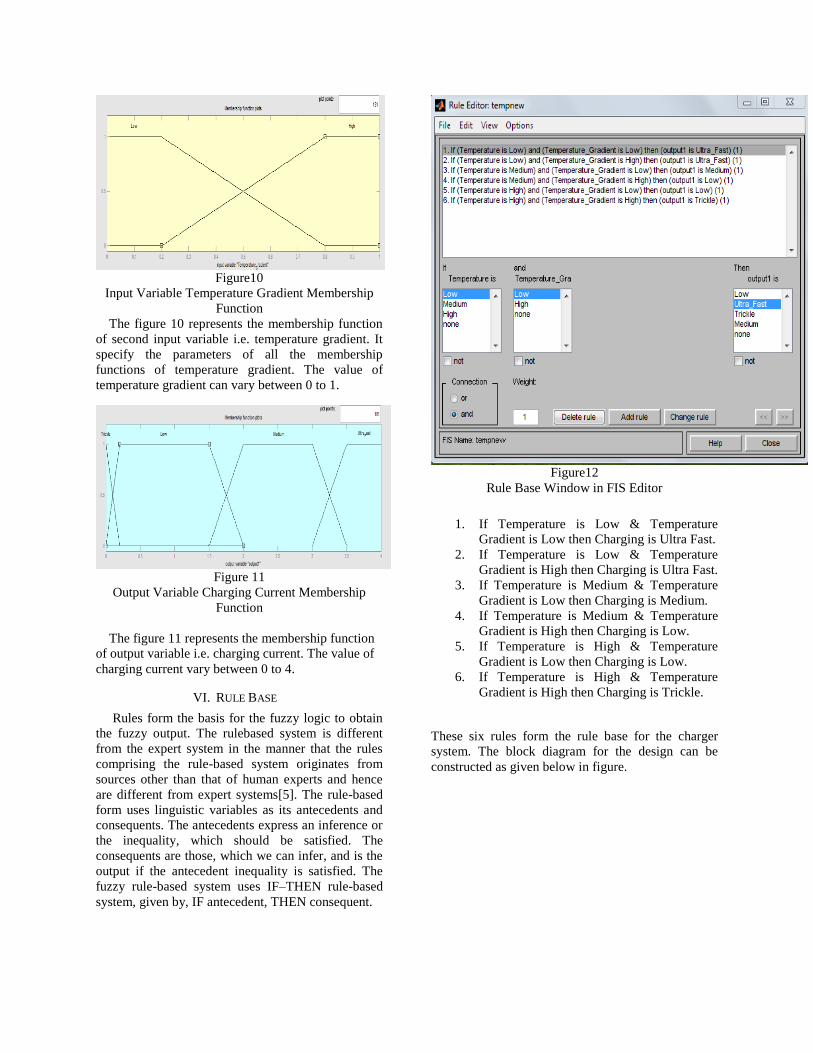
Figure10
Input Variable Temperature Gradient Membership
Function
The figure 10 represents the membership function
of second input variable i.e. temperature gradient. It
specify the parameters of all the membership
functions of temperature gradient. The value of
temperature gradient can vary between 0 to 1.
Figure 11
Output Variable Charging Current Membership
Function
The figure 11 represents the membership function
of output variable i.e. charging current. The value of
charging current vary between 0 to 4.
VI. RULE BASE
Rules form the basis for the fuzzy logic to obtain
the fuzzy output. The rulebased system is different
from the expert system in the manner that the rules
comprising the rule-based system originates from
sources other than that of human experts and hence
are different from expert systems[5]. The rule-based
form uses linguistic variables as its antecedents and
consequents. The antecedents express an inference or
the inequality, which should be satisfied. The
consequents are those, which we can infer, and is the
output if the antecedent inequality is satisfied. The
fuzzy rule-based system uses IF–THEN rule-based
system, given by, IF antecedent, THEN consequent.
Figure12
Rule Base Window in FIS Editor
1. If Temperature is Low & Temperature
Gradient is Low then Charging is Ultra Fast.
2. If Temperature is Low & Temperature
Gradient is High then Charging is Ultra Fast.
3. If Temperature is Medium & Temperature
Gradient is Low then Charging is Medium.
4. If Temperature is Medium & Temperature
Gradient is High then Charging is Low.
5. If Temperature is High & Temperature
Gradient is Low then Charging is Low.
6. If Temperature is High & Temperature
Gradient is High then Charging is Trickle.
These six rules form the rule base for the charger
system. The block diagram for the design can be
constructed as given below in figure.
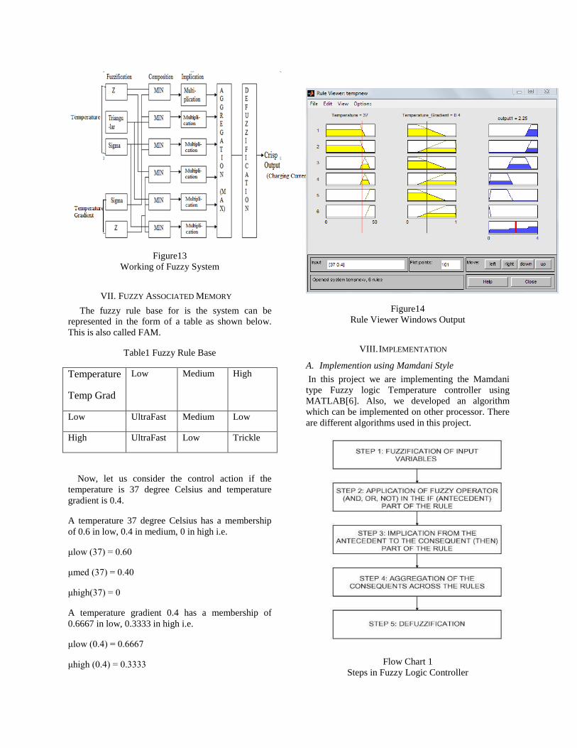
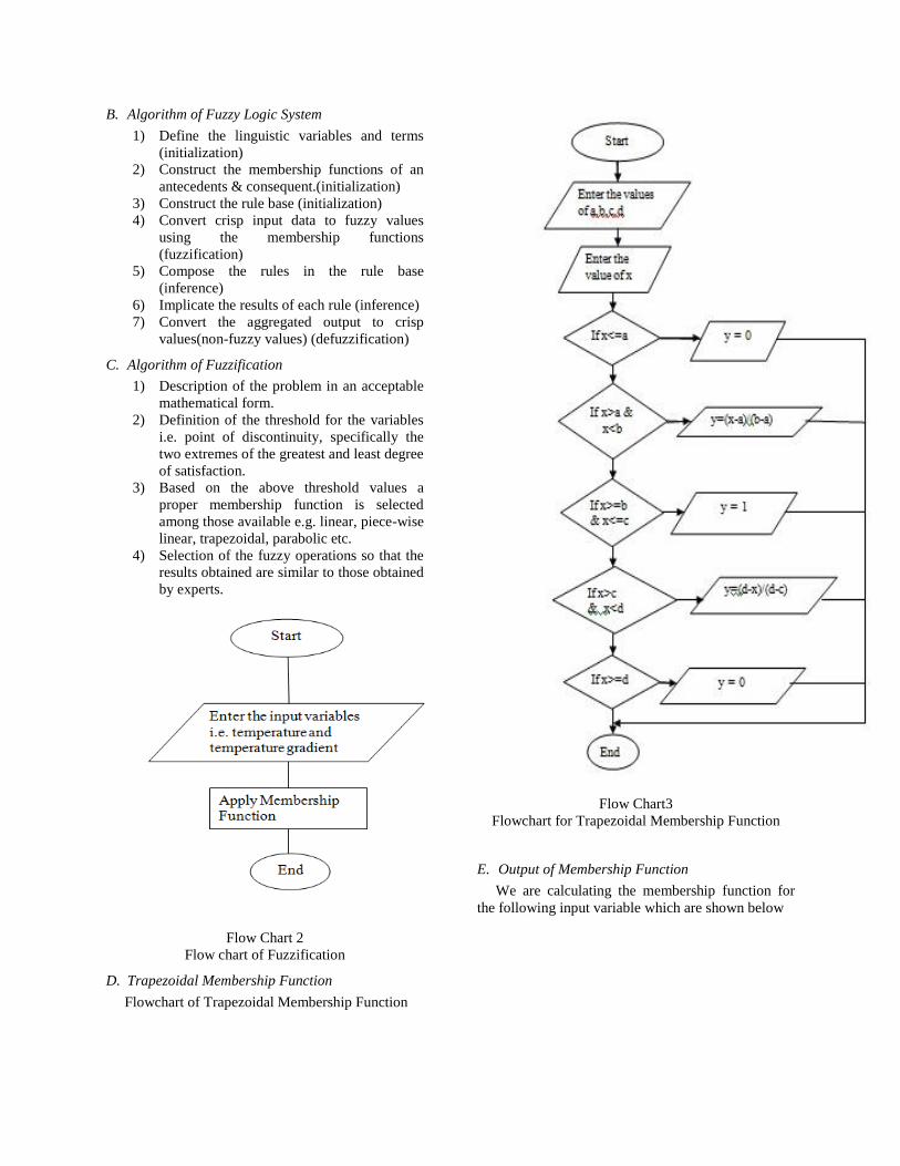
Figure13
Working of Fuzzy System
VII. FUZZY ASSOCIATED MEMORY
The fuzzy rule base for is the system can be
represented in the form of a table as shown below.
This is also called FAM.
Table1 Fuzzy Rule Base
Temperature
Temp Grad
Low Medium High
Low UltraFast Medium Low
High UltraFast Low Trickle
Now, let us consider the control action if the
temperature is 37 degree Celsius and temperature
gradient is 0.4.
A temperature 37 degree Celsius has a membership
of 0.6 in low, 0.4 in medium, 0 in high i.e.
μlow (37) = 0.60
μmed (37) = 0.40
μhigh(37) = 0
A temperature gradient 0.4 has a membership of
0.6667 in low, 0.3333 in high i.e.
μlow (0.4) = 0.6667
μhigh (0.4) = 0.3333
Figure14
Rule Viewer Windows Output
VIII. IMPLEMENTATION
A. Implemention using Mamdani Style
In this project we are implementing the Mamdani
type Fuzzy logic Temperature controller using
MATLAB[6]. Also, we developed an algorithm
which can be implemented on other processor. There
are different algorithms used in this project.
Flow Chart 1
Steps in Fuzzy Logic Controller
B. Algorithm of Fuzzy Logic System
1) Define the linguistic variables and terms
(initialization)
2) Construct the membership functions of an
antecedents & consequent.(initialization)
3) Construct the rule base (initialization)
4) Convert crisp input data to fuzzy values
using the membership functions
(fuzzification)
5) Compose the rules in the rule base
(inference)
6) Implicate the results of each rule (inference)
7) Convert the aggregated output to crisp
values(non-fuzzy values) (defuzzification)
C. Algorithm of Fuzzification
1) Description of the problem in an acceptable
mathematical form.
2) Definition of the threshold for the variables
i.e. point of discontinuity, specifically the
two extremes of the greatest and least degree
of satisfaction.
3) Based on the above threshold values a
proper membership function is selected
among those available e.g. linear, piece-wise
linear, trapezoidal, parabolic etc.
4) Selection of the fuzzy operations so that the
results obtained are similar to those obtained
by experts.
Flow Chart 2
Flow chart of Fuzzification
D. Trapezoidal Membership Function
Flowchart of Trapezoidal Membership Function
Flow Chart3
Flowchart for Trapezoidal Membership Function
E. Output of Membership Function
We are calculating the membership function for
the following input variable which are shown below
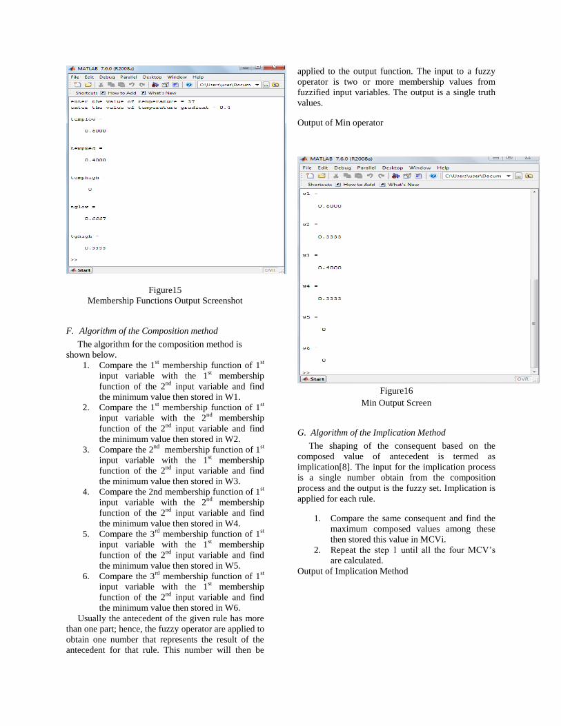
Figure15
Membership Functions Output Screenshot
F. Algorithm of the Composition method
The algorithm for the composition method is
shown below.
1. Compare the 1st membership function of 1
st
input variable with the 1st membership
function of the 2nd
input variable and find
the minimum value then stored in W1.
2. Compare the 1st membership function of 1
st
input variable with the 2nd
membership
function of the 2nd
input variable and find
the minimum value then stored in W2.
3. Compare the 2nd
membership function of 1st
input variable with the 1st membership
function of the 2nd
input variable and find
the minimum value then stored in W3.
4. Compare the 2nd membership function of 1st
input variable with the 2nd
membership
function of the 2nd
input variable and find
the minimum value then stored in W4.
5. Compare the 3rd
membership function of 1st
input variable with the 1st membership
function of the 2nd
input variable and find
the minimum value then stored in W5.
6. Compare the 3rd
membership function of 1st
input variable with the 1st membership
function of the 2nd
input variable and find
the minimum value then stored in W6.
Usually the antecedent of the given rule has more
than one part; hence, the fuzzy operator are applied to
obtain one number that represents the result of the
antecedent for that rule. This number will then be
applied to the output function. The input to a fuzzy
operator is two or more membership values from
fuzzified input variables. The output is a single truth
values.
Output of Min operator
Figure16
Min Output Screen
G. Algorithm of the Implication Method
The shaping of the consequent based on the
composed value of antecedent is termed as
implication[8]. The input for the implication process
is a single number obtain from the composition
process and the output is the fuzzy set. Implication is
applied for each rule.
1. Compare the same consequent and find the
maximum composed values among these
then stored this value in MCVi.
2. Repeat the step 1 until all the four MCV’s
are calculated.
Output of Implication Method
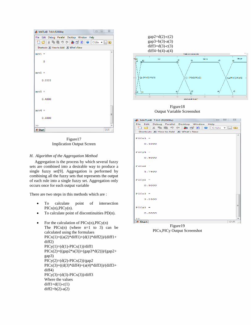
Figure17
Implication Output Screen
H. Algorithm of the Aggregation Method
Aggregation is the process by which several fuzzy
sets are combined into a desirable way to produce a
single fuzzy set[9]. Aggregation is performed by
combining all the fuzzy sets that represents the output
of each rule into a single fuzzy set. Aggregation only
occurs once for each output variable
There are two steps in this methods which are :
To calculate point of intersection
PICx(n),PICy(n).
To calculate point of discontinuities PD(n).
For the calculation of PICx(n),PICy(n)
The PICx(n) (where n=1 to 3) can be
calculated using the formulaes
PICx(1)=((a(2)*diff1)+(d(1)*diff2))/(diff1+
diff2)
PICy(1)=(d(1)-PICx(1))/diff1
PICx(2)=((gap2*a(3))+(gap3*d(2)))/(gap2+
gap3)
PICy(2)=(d(2)-PICx(2))/gap2
PICx(3)=((d(3)*diff4)+(a(4)*diff3))/(diff3+
diff4)
PICy(3)=(d(3)-PICx(3))/diff3
Where the values
diff1=d(1)-c(1)
diff2=b(2)-a(2)
gap2=d(2)-c(2)
gap3=b(3)-a(3)
diff3=d(3)-c(3)
diff4=b(4)-a(4)
Figure18
Output Variable Screenshot
Figure19
PICx,PICy Output Screenshot
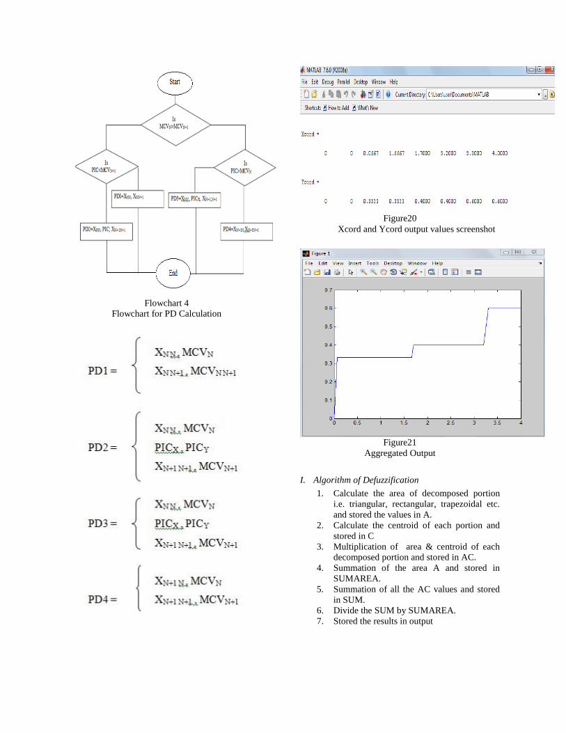
Flowchart 4
Flowchart for PD Calculation
Figure20
Xcord and Ycord output values screenshot
Figure21
Aggregated Output
I. Algorithm of Defuzzification
1. Calculate the area of decomposed portion
i.e. triangular, rectangular, trapezoidal etc.
and stored the values in A.
2. Calculate the centroid of each portion and
stored in C
3. Multiplication of area & centroid of each
decomposed portion and stored in AC.
4. Summation of the area A and stored in
SUMAREA.
5. Summation of all the AC values and stored
in SUM.
6. Divide the SUM by SUMAREA.
7. Stored the results in output
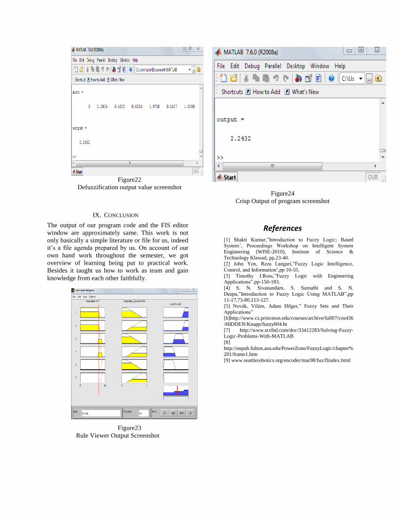
Figure22
Defuzzification output value screenshot
IX. CONCLUSION
The output of our program code and the FIS editor
window are approximately same. This work is not
only basically a simple literature or file for us, indeed
it’s a file agenda prepared by us. On account of our
own hand work throughout the semester, we got
overview of learning being put to practical work.
Besides it taught us how to work as team and gain
knowledge from each other faithfully.
Figure23
Rule Viewer Output Screenshot
Figure24
Crisp Output of program screenshot
References [1] Shakti Kumar,”Introduction to Fuzzy Logic; Based System’, Proceedings Workshop on Intelligent System
Engineering (WISE-2010), Institute of Science &
Technology Klawad, pp.23-40. [2] John Yen, Reza Langari,”Fuzzy Logic Intelligence,
Control, and Information’,pp 10-55.
[3] Timothy J.Ross,”Fuzzy Logic with Engineering Applications”.pp-150-183.
[4] S. N. Sivanandam, S. Sumathi and S. N.
Deepa,”Introduction to Fuzzy Logic Using MATLAB”,pp 11-17,73-80,113-127.
[5] Novák, Vilém, Adam Hilger,” Fuzzy Sets and Their
Applications” [6]http://www.cs.princeton.edu/courses/archive/fall07/cos436
/HIDDEN/Knapp/fuzzy004.ht
[7] http://www.scribd.com/doc/33412283/Solving-Fuzzy-Logic-Problems-With-MATLAB
[8]
http://enpub.fulton.asu.edu/PowerZone/FuzzyLogic/chapter%201/frame1.htm
[9] www.seattlerobotics.org/encoder/mar98/fuz/flindex.html