UNIVERSAL HYBRID CONTROLLER - Smar
34
UNIVERSAL HYBRID CONTROLLER smar
-
Upload
khangminh22 -
Category
Documents
-
view
3 -
download
0
Transcript of UNIVERSAL HYBRID CONTROLLER - Smar

UNIVERSAL HYBRIDCONTROLLER
smar
�smar
True Industrial Universal Hybrid Controller.
Slim hardware and code for reliability and dependability.
Fault tolerant for high availability with many levels of redundancy.
Compact, modular and scaleable.
Remote I/O for distributed and long distance data transfer.
Ready for Foundation Fieldbus, Profibus, DeviceNet and Modbus.
Modbus/TCP and Modbus RTU for control network.
Ethernet and/or Serial OPC server for HMI clients.
The LC700 modularity makes it flexible enough to reach small and large applications as well as making future expansions a breeze. The LC700 modular architecture is supported on a standard DIN-rail mounted backplane (Rack) into which all Modules are installed.
Smar has a wide range of modules for the LC700 such as; Power Supply, Controller (CPU), Discrete I/O’s, Analog I/O’s, Special Signals and Network Interface Modules.
A large Function Block library comes already built-in on the flash memory. Function Blocks can be used as many times
as necessary with no licensing scheme as you may find in other vendors. The limit will be the available memory and not a restringing contract to limit your imagination.
The LC700 can operate stand-alone in a single rack configuration, or networked as a large control system. Expanding a LC700 based system is very easy and comes at a minimal cost. Enlarging the system is as easy as adding more I/O modules or connecting additional LC700 controllers. Because it is so compact, additional cabinet space may not be required.
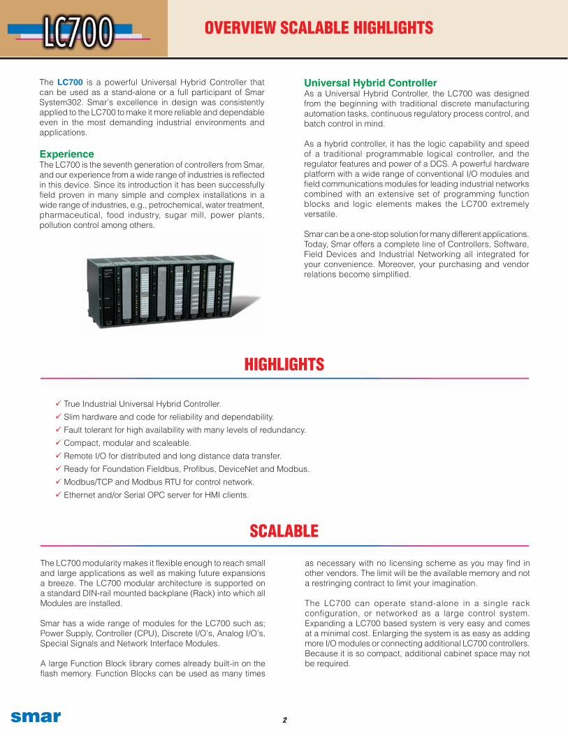
The LC700 is a powerful Universal Hybrid Controller that can be used as a stand-alone or a full participant of Smar System302. Smar’s excellence in design was consistently applied to the LC700 to make it more reliable and dependable even in the most demanding industrial environments and applications.
ExperienceThe LC700 is the seventh generation of controllers from Smar, and our experience from a wide range of industries is reflected in this device. Since its introduction it has been successfully field proven in many simple and complex installations in a wide range of industries, e.g., petrochemical, water treatment, pharmaceutical, food industry, sugar mill, power plants, pollution control among others.
OVERVIEW SCALABLE HIGHLIGHTS
SCALABLE
HIGHLIGHTS
Universal Hybrid ControllerAs a Universal Hybrid Controller, the LC700 was designed from the beginning with traditional discrete manufacturing automation tasks, continuous regulatory process control, and batch control in mind.
As a hybrid controller, it has the logic capability and speed of a traditional programmable logical controller, and the regulator features and power of a DCS. A powerful hardware platform with a wide range of conventional I/O modules and field communications modules for leading industrial networks combined with an extensive set of programming function blocks and logic elements makes the LC700 extremely versatile.
Smar can be a one-stop solution for many different applications. Today, Smar offers a complete line of Controllers, Software, Field Devices and Industrial Networking all integrated for your convenience. Moreover, your purchasing and vendor relations become simplified.

� smar
Processor module 3 serial communication ports Relay for failure indication Real time clock
Power Supply module optional redundant Power Supply
Rack 0 (4 slots) Rack n (4 slots)
I/O modules
Local I/O Expansion
BASIC COMPONENTS
Up to 15 Expansion Racks can be connected to accommodate a large variety of Modules.
The LC700 is composed of Racks carrying slots where Modules are mounted. Additional Racks can be added to support the installation of more Modules. Racks are connected between them through the use of Flat-Cables. This type of expansion is called “local expansion”.
Another way to expand the LC700 system is to add remote units in different areas of interest and have them connected with a twisted pair cable to the main Processor. This technique-provides great signal distribution, besides reduction of wireand installation costs.
The Illustration shows a simple LC700 system with local andremote I/O expansion.

�smar
Remote I/O makes it possible to distribute racks with I/O modules at various locations in the field and connects them to the CPU via a high-speed EIA-485 network. Distributing the Racks will save in wiring and installation costs and the signals can still be part of the same configuration.
Remote I/O functionality is also the key to the LC700 processor (CPU) redundancy as it allows both the main and standby CPU to be connected to the I/O remote system, always enabling the active CPU (the one in control) to access data on the remote I/O system(s). The remote I/O master capability is already built into the CPU, hence no additional remote I/O module is required. The remote I/O subsystems are each fitted with a remote I/O interface module with highspeed redundant communications ports.
Significant cable savingsRemote I/O drastically reduces wiring, simplifies installation and maintenance work. Remote I/O network communication speed can be configured up to 230.4 kbit/s while long connecting twistedpair cable size will depend on the configured speed and line conditions.
Up to six remote-I/O subsystems can be connected per processor module (CPU) achieving significant cable savings. This reduces discrete wiring by locating I/O subsystems close to the process by eliminating terminal blocks and long wire runs. Remote I/O also increases module capacity. Any conventional I/O or field communications module can be located in the remote I/O racks.
Remote I/O network redundancyWhen the application calls for very high availability, the remote I/O networking can also be made redundant providing protection against cable breaks and shorts. In the unlikely event that communication on one of the EIA-485 networks breaks down, communication between the CPUs and the remote I/O subsystems will be done over the second network allowing control to continue. Therefore, added security and protection is achieved, no single point of failure can disable the control system.
REMOTE I/O
Remote I/O capability to improve distribution and installation savings
...
� smar
Unexpected control interruptions can be both costly and dangerous. Therefore, the LC700 has been designed to ensure multiple layers of redundancy and enable you to build a system fault tolerant from the ground up providing uninterrupted control.
Two identical LC700 racks with power supply and controller modules may be connected in parallel to provide redundant power and control. A key to the fault tolerance is that the main and standby sets are physically separated to eliminate common causes. Because they are on different racks, they will not necessarily be subjected to the same operation hazards, such as conducted noise, propagated interference or even situations of common damaged signal lines. Internal diagnostics ensures that in case of failure on the main processor the standby will gracefully resume the control and alert operation.
Top level features for the redundant system• Control switchover is synchronized and fast.• A faulty unit can be replaced without stopping the process.• Replacement of a faulty processor (main or standby) does
not demand pre-configuration.• A modification sent to the main processor is automatically
passed to the standby processor.
REDUNDANCY
Redundancy on all levels for high system integrityThe LC700 makes possible redundancy at every level:
LC700 System:• Redundant power supplies with dedicated relay for failure indication.• Redundant processors (CPU) with dedicated relay for failure indication.• Redundant racks.• Redundant remote I/O communication ports.
Control network level:• Redundant Ethernet wiring.• Redundant Serial Port access.• Single node per segment.• Redundant network hub/switch.• Redundant hub/switch power supply.
Workstation Level:• Multiple operator workstations.• Dual workstation network cards.• Multiple hard disks.• UPS power.• Redundant OPC Server.
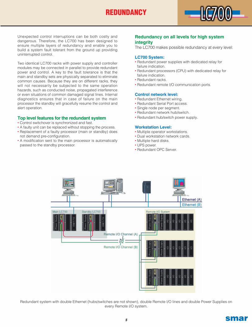
Redundant system with double Ethernet (hubs/switches are not shown), double Remote I/O lines and double Power Supplies on every Remote I/O system.
�smar
As shown above, the LC700 has a wide variety of redundancies available making it possible to tailor the most cost effective solution for each particular need. You can relax, secure in the knowledge that the LC700 is very fault tolerant, providing a good degree of safety and also a high availability ensuring minimum losses due to process downtime. Virtually impervious, you can enjoy safe reliable control at all times. Because of the extensive self-diagnostics in every part of the system, the operators are notified in case of any device or communication failure.
Industrial StrengthMission critical control applications require a high level of safety and availability that cannot be met by soft logic in a PC for or in a black box. PC processors and desktop-derived operating systems are designed for desktop application tasks far less critical with an emphasis on graphics and with less stringent response requirements than control.
These may need to be manually “rebooted” after a power loss or “lockup”. Such architecture is not suitable for the control level of a plant.
The LC700 is instead based on a powerful embedded processor and a stable embedded industrial grade real-time multitasking operating system designed for critical applications and uninterrupted operation.
True real-time performance ensures timely control. This platform also requires less memory, therefore making it even more reliable.
The LC700 has no moving parts such as fans or hard disks. The program runs in NVRAM memory, so, in the event of a power failure, that data can be stored for many years. This also enables retentive memory coils, where the last output value before power failure is remembered, and the controller automatically reverts to this last value when power is re-applied.
Likewise, integrated values such as flow or energy totals arealso retained during power losses.
Easy Maintenance and OperationThe LC700 has built in self-diagnostics and also includes a diagnostic status block. Device status is communicated and displayed at the operator workstation. A CPU failure is also indicated locally by a local LED and a relay output suitable for separate interlocks. Because the LC700 has no external battery, there are no parts that need replacing, reducing maintenance work. Commissioning becomes simpler with the ID circuit and remote checking. LEDs clearly indicate if inputs or outputs are forced or locked and active communication on the Remote I/O network.
REDUNDANCY
� smar
CONTROL NETWORK
The LC700 uses the widely accepted and well-understood industry standard Modbus protocol as a control network. Several options are supported. You can use Modbus/RTU with EIA-485 wiring communicating at a speed up to 115.2 kbit/s for long distances in industrial environments or Modbus/ TCP using Ethernet wiring at a speed up to 10/100 Mbit/s. A direct EIA-232 for short local connection is also possible, ideal for a portable computer or a local operator panel, e.g., for maintenance. The Modbus network is used as a control level network passing process variables and modes to the operator workstations as well as configurations and diagnostics to the engineering stations. The Modbus protocol has a fair amount of interoperability and enables the LC700 to replace other Modbus controllers and integrate to existing control systems.
The simplicity of Modbus makes it easy to use and most engineers are already familiar with it. Other Modbus device types can be connected on the same network as the LC700 in multi-drop architecture, simplifying the networks.
Modbus/RTUSeveral LC700s may be multi-dropped on the same EIA-485network with a simple twisted pair wiring. This makes very large and distributed systems possible. The LC700 may also co-exist with other Modbus devices on the same network.
The maximum network size depends on the selected speed and the prevailing line conditions and environment. The Modbus/RTU protocol limits a network to a single master, but the LC700 CPU module has three independent communication ports making it possible to connect three masters at the same time, e.g., to get redundant workstations and communication networks.
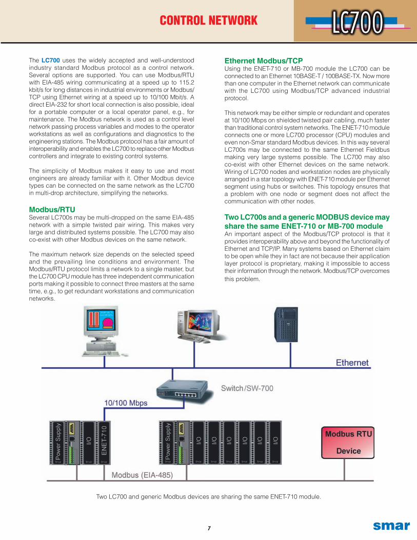
Two LC700 and generic Modbus devices are sharing the same ENET-710 module.
Ethernet Modbus/TCPUsing the ENET-710 or MB-700 module the LC700 can be connected to an Ethernet 10BASE-T / 100BASE-TX. Now more than one computer in the Ethernet network can communicate with the LC700 using Modbus/TCP advanced industrial protocol.
This network may be either simple or redundant and operates at 10/100 Mbps on shielded twisted pair cabling, much faster than traditional control system networks. The ENET-710 module connects one or more LC700 processor (CPU) modules and even non-Smar standard Modbus devices. In this way several LC700s may be connected to the same Ethernet Fieldbus making very large systems possible. The LC700 may also co-exist with other Ethernet devices on the same network. Wiring of LC700 nodes and workstation nodes are physically arranged in a star topology with ENET-710 module per Ethernet segment using hubs or switches. This topology ensures that a problem with one node or segment does not affect the communication with other nodes.
Two LC700s and a generic MODBUS device may share the same ENET-710 or MB-700 moduleAn important aspect of the Modbus/TCP protocol is that it provides interoperability above and beyond the functionality of Ethernet and TCP/IP. Many systems based on Ethernet claim to be open while they in fact are not because their application layer protocol is proprietary, making it impossible to access their information through the network. Modbus/TCP overcomes this problem.
�smar
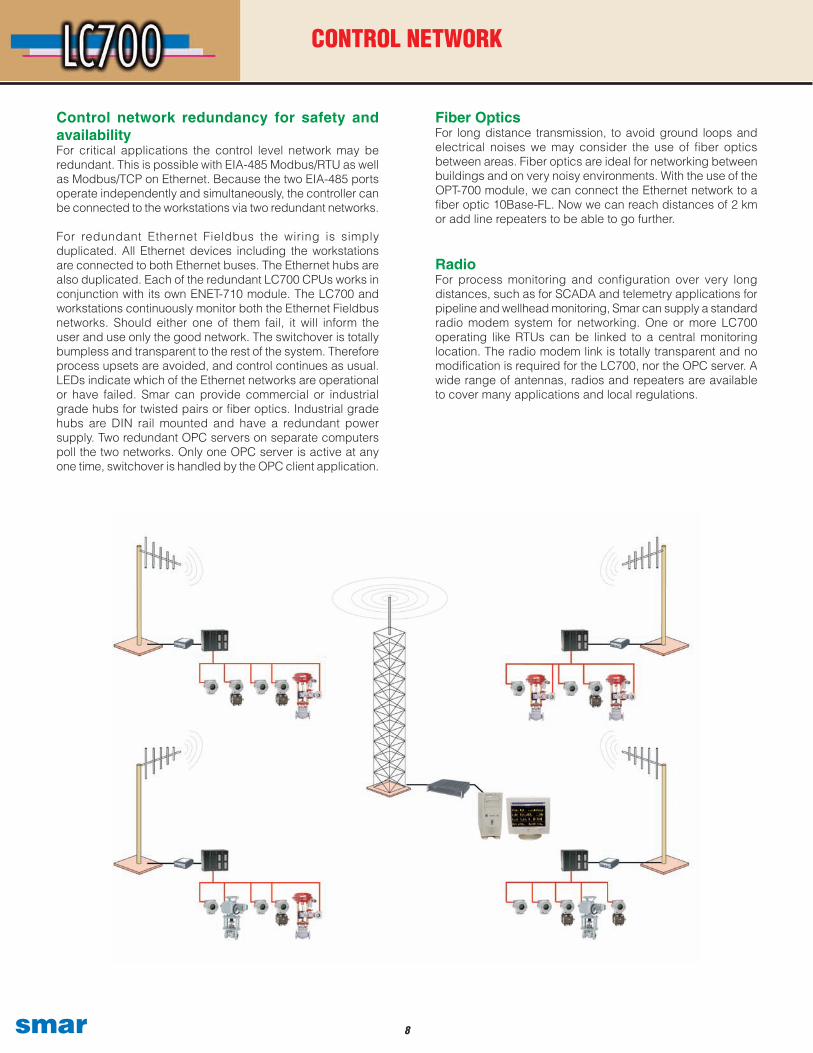
Control network redundancy for safety and availabilityFor critical applications the control level network may be redundant. This is possible with EIA-485 Modbus/RTU as well as Modbus/TCP on Ethernet. Because the two EIA-485 ports operate independently and simultaneously, the controller can be connected to the workstations via two redundant networks.
For redundant Ethernet Fieldbus the wiring is simply duplicated. All Ethernet devices including the workstations are connected to both Ethernet buses. The Ethernet hubs are also duplicated. Each of the redundant LC700 CPUs works in conjunction with its own ENET-710 module. The LC700 and workstations continuously monitor both the Ethernet Fieldbus networks. Should either one of them fail, it will inform the user and use only the good network. The switchover is totally bumpless and transparent to the rest of the system. Therefore process upsets are avoided, and control continues as usual. LEDs indicate which of the Ethernet networks are operational or have failed. Smar can provide commercial or industrial grade hubs for twisted pairs or fiber optics. Industrial grade hubs are DIN rail mounted and have a redundant power supply. Two redundant OPC servers on separate computers poll the two networks. Only one OPC server is active at any one time, switchover is handled by the OPC client application.
Fiber OpticsFor long distance transmission, to avoid ground loops and electrical noises we may consider the use of fiber optics between areas. Fiber optics are ideal for networking between buildings and on very noisy environments. With the use of the OPT-700 module, we can connect the Ethernet network to a fiber optic 10Base-FL. Now we can reach distances of 2 km or add line repeaters to be able to go further.
RadioFor process monitoring and configuration over very long distances, such as for SCADA and telemetry applications for pipeline and wellhead monitoring, Smar can supply a standard radio modem system for networking. One or more LC700 operating like RTUs can be linked to a central monitoring location. The radio modem link is totally transparent and no modification is required for the LC700, nor the OPC server. A wide range of antennas, radios and repeaters are available to cover many applications and local regulations.
CONTROL NETWORK
� smar
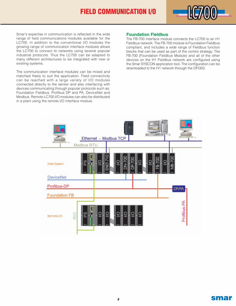
Foundation FieldbusThe FB-700 interface module connects the LC700 to an H1 Fieldbus network. The FB-700 module is Foundation Fieldbus compliant, and includes a wide range of Fieldbus function blocks that can be used as part of the control strategy. The FB-700 (Foundation Fieldbus Module) and all of the other devices on the H1 Fieldbus network are configured using the Smar SYSCON application tool. The configuration can be downloaded to the H1 network through the DFI302.
Smar’s expertise in communication is reflected in the wide range of field communications modules available for the LC700. In addition to the conventional I/O modules the growing range of communication interface modules allows the LC700 to connect to networks using several popular industrial protocols. Thus the LC700 can be adapted to many different architectures to be integrated with new or existing systems.
The communication interface modules can be mixed and matched freely to suit the application. Field connectivity can be reached with a large variety of I/O modules connected directly to the sensor and also interfacing with devices communicating through popular protocols such as: Foundation Fieldbus, Profibus DP and PA, DeviceNet and Modbus. Remote LC700 I/O modules can also be distributed in a plant using the remote I/O interface module.
FIELD COMMUNICATION I/O
10smar
FIELD COMMUNICATION I/O
ProfibusThe DP-700* Profibus High Performance Master Scanner uses the Profibus-DP protocol that lets the LC700 communicate with Profibus-DP and Profibus-PA.
In the case of Profibus-PA, third party couplers or linking devices need to be installed in the line.
Profibus-DP is widely used among devices common in discrete factory automation and includes variable speed drives. Smar also
carries a broad range of advanced Profibus- PA field devices.
ModbusThe MB-700 Modbus Master Scanner allows the communication between several LC700 systems or with any modbus slave.
A wide range of legacy equipment common in existing plants using the ubiquitous Modbus protocol can be accessed by the LC700. The data retrieved can be displayed to the operators and used as part of the control strategy.
Foundation Fieldbus and Modbus gatewayFieldbus instruments may be connected to the LC700 just like any other form of I/O. It also allows the LC700 to act as a gateway between Fieldbus and Modbus allowing legacy system access Fieldbus devices. A LC700 may be connected on the Fieldbus like any other device to handle discrete controls and interlocks. PS302 power supply modules and PSI302 Fieldbus power supply impedance modules can also be fitted to the LC700 to provide the power for the Fieldbus devices.
DeviceNetDN-700* DeviceNet High Performance Master Scanner adds the capability of integrating DeviceNet slave devices as I/O to the LC700. DeviceNet is widely used among devices common to discrete factory automation.
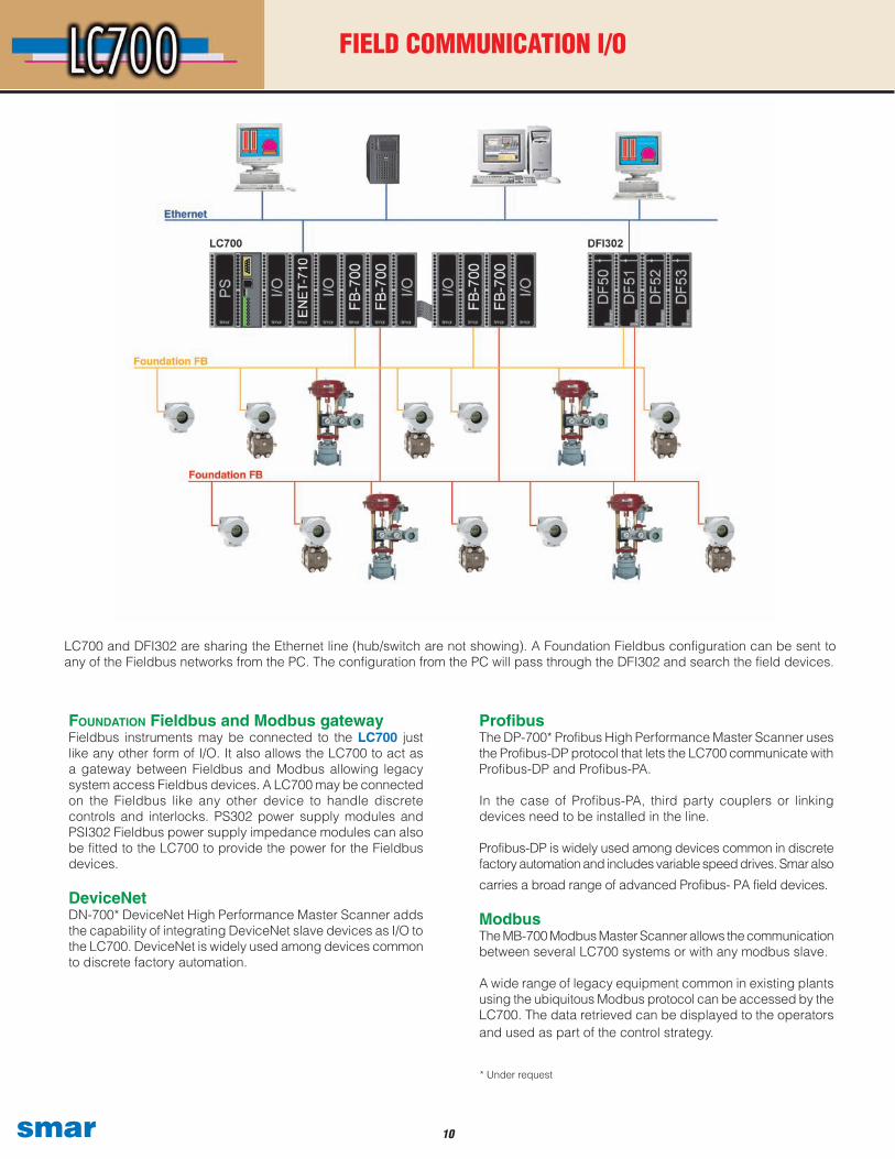
LC700 and DFI302 are sharing the Ethernet line (hub/switch are not showing). A Foundation Fieldbus configuration can be sent to any of the Fieldbus networks from the PC. The configuration from the PC will pass through the DFI302 and search the field devices.
* Under request
11 smar
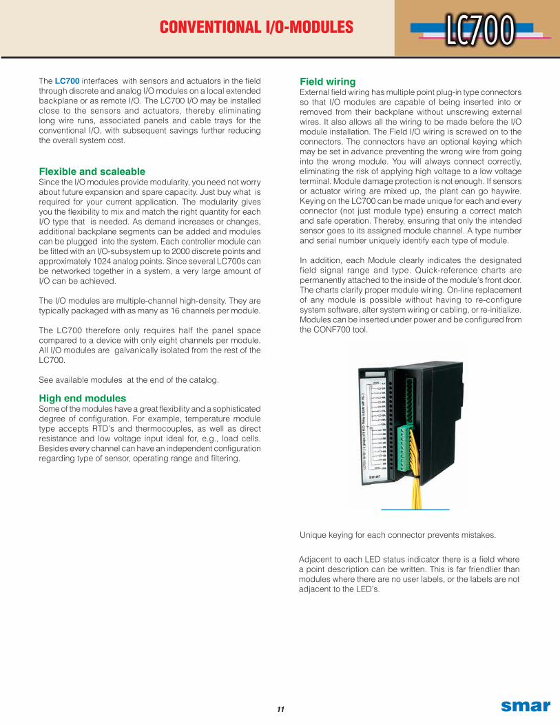
Unique keying for each connector prevents mistakes.
The LC700 interfaces with sensors and actuators in the field through discrete and analog I/O modules on a local extended backplane or as remote I/O. The LC700 I/O may be installed close to the sensors and actuators, thereby eliminating long wire runs, associated panels and cable trays for the conventional I/O, with subsequent savings further reducing the overall system cost.
Flexible and scaleableSince the I/O modules provide modularity, you need not worry about future expansion and spare capacity. Just buy what is required for your current application. The modularity gives you the flexibility to mix and match the right quantity for each I/O type that is needed. As demand increases or changes, additional backplane segments can be added and modules can be plugged into the system. Each controller module can be fitted with an I/O-subsystem up to 2000 discrete points and approximately 1024 analog points. Since several LC700s can be networked together in a system, a very large amount of I/O can be achieved.
The I/O modules are multiple-channel high-density. They are typically packaged with as many as 16 channels per module.
The LC700 therefore only requires half the panel space compared to a device with only eight channels per module. All I/O modules are galvanically isolated from the rest of the LC700.
See available modules at the end of the catalog.
Field wiringExternal field wiring has multiple point plug-in type connectors so that I/O modules are capable of being inserted into or removed from their backplane without unscrewing external wires. It also allows all the wiring to be made before the I/O module installation. The Field I/O wiring is screwed on to the connectors. The connectors have an optional keying which may be set in advance preventing the wrong wire from going into the wrong module. You will always connect correctly, eliminating the risk of applying high voltage to a low voltage terminal. Module damage protection is not enough. If sensors or actuator wiring are mixed up, the plant can go haywire. Keying on the LC700 can be made unique for each and every connector (not just module type) ensuring a correct match and safe operation. Thereby, ensuring that only the intended sensor goes to its assigned module channel. A type number and serial number uniquely identify each type of module.
In addition, each Module clearly indicates the designated field signal range and type. Quick-reference charts are permanently attached to the inside of the module’s front door. The charts clarify proper module wiring. On-line replacement of any module is possible without having to re-configure system software, alter system wiring or cabling, or re-initialize. Modules can be inserted under power and be configured from the CONF700 tool.
CONVENTIONAL I/O-MODULES
High end modulesSome of the modules have a great flexibility and a sophisticated degree of configuration. For example, temperature module type accepts RTD’s and thermocouples, as well as direct resistance and low voltage input ideal for, e.g., load cells. Besides every channel can have an independent configuration regarding type of sensor, operating range and filtering.
Adjacent to each LED status indicator there is a field where a point description can be written. This is far friendlier than modules where there are no user labels, or the labels are not adjacent to the LED’s.
1�smar
Since the beginning the LC700 was designed with traditional discrete manufacturing automation tasks, continuous regulatory process control, and batch control tasks in mind. The high performance CPU has an extensive set of ladder elements and function blocks enabling it to be used in a wide range of applications, e.g., boiler control and burner management. This allows the user to build the control strategies required for optimal control. Built-in real time clocks lets you build control strategies that take date and time of day into consideration.
The configuration is stored in a non-volatile memory thatrequires no external battery or maintenance.
User FriendlyThe selected controller mode (run or hold) is clearly indicated on the front of the controller by individual LEDs and can be set from the engineering tool on-line. The controller module continuously monitors its own status and indicates power and failure via color-coded LED status indicators on each controller faceplate. A relay contact on the module will also change the status at failure. This may be used as an additional alert to the user, and as part of the safety interlocks. Status indication include FAIL (the controller has failed), HOLD (application program execution has been paused), RUN (normal operation) and FORCE (any I/O which is forced or frozen).
Controller RedundancyThe LC700 controller redundancy is much more than just CPU module redundancy. In fact, backplane and power supplies are also made redundant.Totally separate backplanes, CPU’s and power supplies to completely eliminate common causes. Many CPU redundancy solutions in the market have many weak points; the two CPUs may be sharing the same backplane, which if damaged will render both CPUs useless. In the case of the LC700, the main and standby controllers have no parts in common, and can even be mounted in separate panels to avoid common environmental stress. Failure of a backplane only affects one CPU. Fierce EMI/RFI in one location only affects one CPU, the same goes for surges, leaks and other non-predictable occurrences in harsh environments.
This design gives the LC700 an exceptionally high availability ideal for processes that must run continuously for long periods of time without interruption The process is not affected by a CPU failure. Hours and days of potentially lost production can be avoided, with corresponding savings. A minimum of additional hardware required for redundancy will pay for itself in no time.
The LC700 redundancy is a hot standby scheme where one CPU is active while the other is passive. The passive controller is continuously monitoring the health of the
active CPU via a secure inter-CPU connection assuring a very fast switchover. In the event of a main controller failure, the passive CPU becomes active and takes over all functions with no significant bump to the plant. The two CPUs change information over the high-speed inter- CPU connection at every cycle, enabling the backup to smoothly take over using up-to-date information and therefore a minimum impact on the process. The inter- CPU communication keeps all time-related functions in lock step: PID controller integration, timers, counters, real time clock and totalizers. The inter-CPU communication is transparent to the user, no special configuration is required.
The redundancy capability is built into the CPU modules; no additional modules for the remote I/O or inter-CPU communication are required. Nor is any central redundancy manager device required. Therefore saving precious panel space, and reducing hardware costs
Network switch overThe redundancy automatically manages the Modbus network address of the CPUs, upon control transfer the backup CPU takes over the address of the failed CPU as it switches from passive to active. This is totally transparent to the user and all communication nodes and software; hence no special configuration of any kind is required in the host computers the redundancy is extremely simple to set up.
Indication and announcementLEDs indicate which controller is active and which is passive, or perhaps failed. Workstations monitor the status of both CPUs via the communication and immediately notify the user of any faults to the active or passive CPU. Additionally, the CPU has a failure relay output ideal for connection to independent shutdown logic. When a new configuration is downloaded to the active CPU, it is automatically copied to the passive controller via the inter-CPU link ensuring that it is ready to take over the control task in case of failure. The configuration integrity is always checked at power-up and while running the active and passive CPUs are compared. In case of mismatch the active CPU configuration is copied to the passive CPU. This ensures that a newly replaced CPU module is updated with the existing configuration. It does not need to be pre-configured before installation. Because this task is automatic, there is no risk of switchover failures due to incompatible configurations.
Power Supply RedundancyThe power supply redundancy in the LC700 is already two tiers, and can be made quadruple if required. The
CONTROLLER
1� smar
most common solution is two redundant CPUs in individual backplanes have just one power supply module each, dual redundant power. Another option is to have a single CPU powered by two redundant power supply modules, typically connected to different sources. For maximum system integrity, two redundant CPUs in individual backplanes with two redundant power supplies each, quadruple power redundancy. This way the system is able to handle CPU failures and multiple power supply failures.
IEC 61131-3 Ladder Diagram with Function BlocksThe LC700 control strategy and user application program is built using the standard IEC 61131-3 ladder diagram language (relay ladder logic). This is the most widely used
language for logic since it is completely graphical, idealfor machinery control. Proprietary programming languages are a thing of the past. Many function blocks are tailored for process control tasks and are already built-in in the flash memory of the processor module. Following are tables commenting on the logic and function blocks that are ready for the Ladder Logic configuration.
CONTROLLER
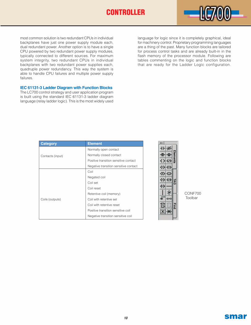
Category Element
Normally open contact
Normally closed contact
Positive transition sensitive contact
Negative transition sensitive contact
Coil
Negated coil
Coil set
Coil reset
Retentive coil (memory)
Coil with retentive set
Coil with retentive reset
Positive transition sensitive coil
Negative transition sensitive coil
Contacts (input)
Coils (outputs)
CONF700 Toolbar
1�smar
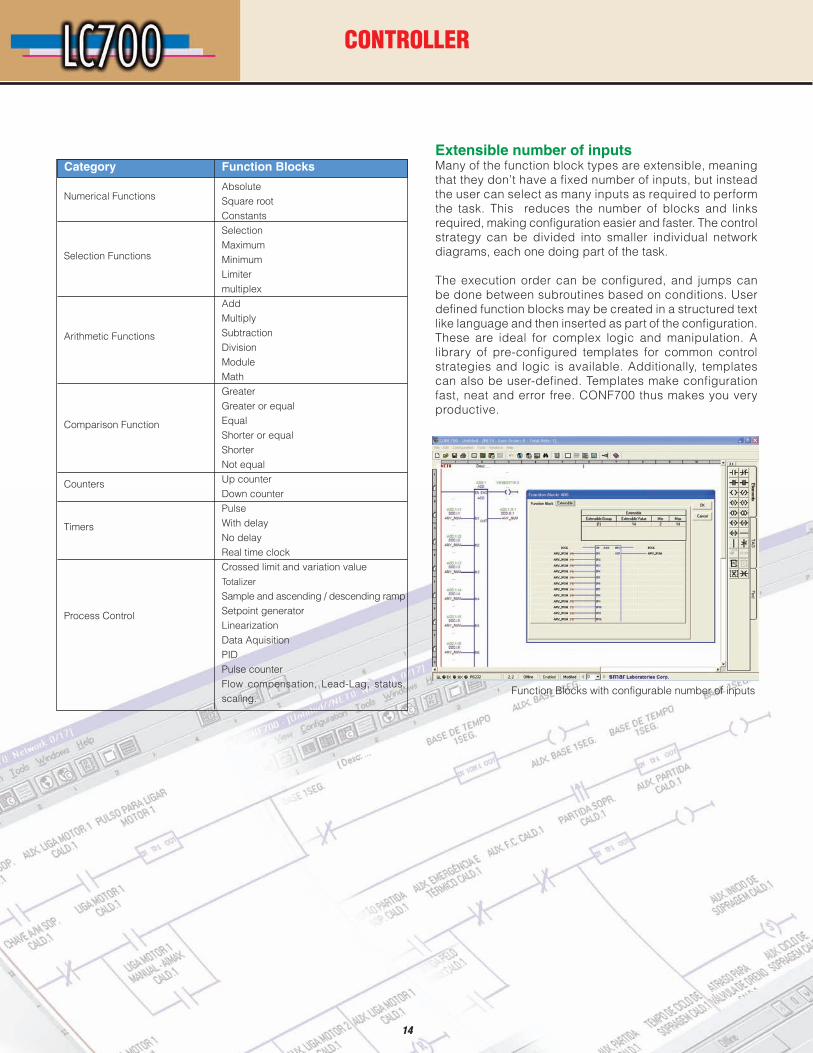
Extensible number of inputsMany of the function block types are extensible, meaning that they don’t have a fixed number of inputs, but instead the user can select as many inputs as required to perform the task. This reduces the number of blocks and links required, making configuration easier and faster. The control strategy can be divided into smaller individual network diagrams, each one doing part of the task.
The execution order can be configured, and jumps can be done between subroutines based on conditions. User defined function blocks may be created in a structured text like language and then inserted as part of the configuration. These are ideal for complex logic and manipulation. A library of pre-configured templates for common control strategies and logic is available. Additionally, templates can also be user-defined. Templates make configuration fast, neat and error free. CONF700 thus makes you very productive.
AbsoluteSquare rootConstants SelectionMaximumMinimumLimitermultiplex AddMultiplySubtractionDivisionModuleMath GreaterGreater or equalEqualShorter or equalShorter Not equalUp counter Down counterPulseWith delayNo delay Real time clockCrossed limit and variation valueTotalizer
Sample and ascending / descending rampSetpoint generatorLinearizationData AquisitionPIDPulse counterFlow compensation, Lead-Lag, status, scaling.
Category Function Blocks
Numerical Functions
CONTROLLER
Selection Functions
Arithmetic Functions
Comparison Function
Counters
Timers
Process Control
1�
Function Blocks with configurable number of inputs
1� smar
Single integrated system databaseAn OPC Server feature called “address space browsing” gives the system a single integrated database even if software from several third party suppliers is used. Once a tag has been created in CONF700, it becomes available for access by all other client applications. From the client application you can browse or navigate by pointing and clicking through a Windows Explorer like hierarchy until you reach the parameter. You don’t have to retype any tags, eliminating problems due to typographical errors. Since OPC is completely tag based, you don’t have to deal with mapping of device addresses, memory registers and bits and bytes etc. as was common with the old PLC and HMI combinations. OPC instead gives an unprecedented level of integration and ease of use, yet complete openness and security.
OPC CLIENT / SERVER ARCHITECTURE
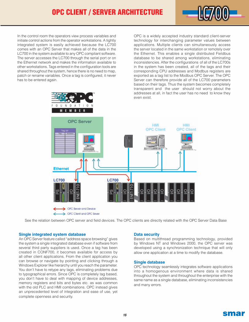
In the control room the operators view process variables and initiate control actions from the operator workstations. A tightly integrated system is easily achieved because the LC700 comes with an OPC Server that makes all of the data in the LC700 in the system available to any OPC compliant software. The server accesses the LC700 through the serial port or on the Ethernet network and makes the information available to other workstations. Tags entered in the configuration tools are shared throughout the system, hence there is no need to map, patch or rename variables. Once a tag is configured, it never has to be entered again.
Data securityBased on multithread programming technology, provided by Windows NT and Windows 2000, the OPC server was developed using a synchronization technique that will only allow one application at a time to modify the database.
Single databaseOPC technology seamlessly integrates software applications into a homogenous environment where data is shared throughout the system and throughout the enterprise with the same name as a single database, eliminating inconsistencies and many errors.
See the relation between OPC server and field devices. The OPC clients are directly related with the OPC Server Data Base
OPC is a widely accepted industry standard client-server technology for interchanging parameter values between applications. Multiple clients can simultaneously access the server located in the same workstation or remotely over the Ethernet. This enables a single distributed Fieldbus database to be shared among workstations, eliminating inconsistencies. After the configurations of all of the LC700s in the system has been created, all of the tags and their corresponding CPU addresses and Modbus registers are exported as a tag list to the Modbus OPC Server. The OPC Server can therefore provide all of the LC700 parameters based on their tags. Thus the system becomes completely transparent and the user should not worry about the addresses at all, in fact the user has no need to know they even exist.
1�smar
CONFIGURATION AND DIAGNOSTICS TOOL
Hardware configuration
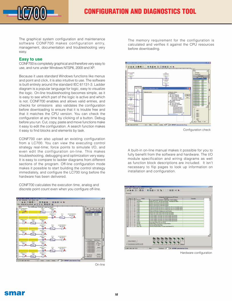
The graphical system configuration and maintenance software CONF700 makes configurat ion entry, management, documentation and troubleshooting very easy.
Easy to useCONF700 is completely graphical and therefore very easy to use, and runs under Windows NTSP6, 2000 and XP.
Because it uses standard Windows functions like menusand point and click, it is also intuitive to use. The software is built entirely around the standard IEC 61131-3. Ladder diagram is a popular language for logic, easy to visualize the logic. On-line troubleshooting becomes simple, as it is easy to see which part of the logic is active and which is not. CONF700 enables and allows valid entries, and checks for omissions also validates the configuration before downloading to ensure that it is trouble free and that it matches the CPU version. You can check the configuration at any time by clicking of a button. Debug before you run. Cut, copy, paste and move functions make it easy to edit the configuration. A search function makes it easy to find blocks and elements by task.
CONF700 can also upload an existing configuration from a LC700. You can view the executing control strategy real-time; force points to simulate I/O, and even edit the configuration on-line. This makes troubleshooting, debugging and optimization very easy. It is easy to compare to ladder diagrams from different sections of the program. Off-line configuration mode makes it possible to start building the control strategy immediately, and configure the LC700 long before the hardware has been delivered.
CONF700 calculates the execution time, analog anddiscrete point count even when you configure off-line.
On-line.
Configuration check
On-line
The memory requirement for the configuration is calculated and verifies it against the CPU resources before downloading.
A built-in on-line manual makes it possible for you to fully benefit from the software and hardware. The I/O module specification and wiring diagrams as well as function block descriptions are included. It isn’t necessary to flip pages to look up information on installation and configuration.

1� smar
CONFIGURATION AND DIAGNOSTICS TOOL
Integrates with Windows and MS-OfficeBecause the CONF700 is designed to work on the standard Windows operating system, it benefits from the latest information technology integrating with the common MS-Office suite.
CONF700 has an automatic Modbus register cross reference listing which can be exported to a MS-Access file at the click of a button. This is useful if you have to configure any software application that does not support OPC to communicate with the LC700. This flexibility and openness makes the data available to other applications. In Excel you can easily sort and filter the information to get just the part in which you are interested.
Documentation The documentation process is traditionally a very time consuming task in project engineering. To manually document the work, or do it in a third party software, is too time consuming and costly, and is prone to error. Therefore the CONF700 software has full built-in documentation capability, allowing you to document as you are configuring. All the documentation features are user friendly and extremely easy to use - just fill in the blanks. A large part of the documentation is generated automatically. These powerful features make it easier to manage your configurations, and is the most productive way of documenting your work. Documentation includes
Modbus addresses lists converted to MS-Excel
Optimization
Ladder diagram
general project information, hardware configuration, wiring, I/O, control strategy, parameters etc. The user can also enter descriptions and annotations. The configuration can be printed or transferred as a MS Access database. New programmers can understand configurations made by others.
1�smar
CONFIGURATION AND DIAGNOSTICS TOOL
FB-700 I/O Function Blocks
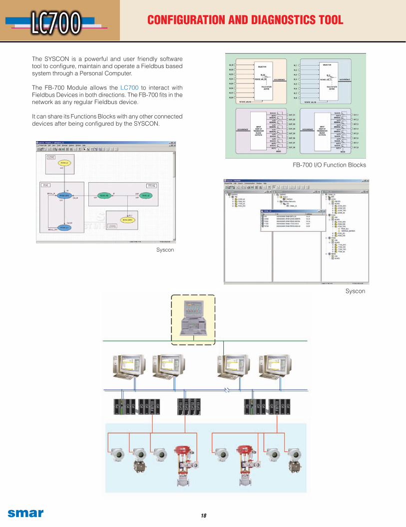
Syscon
Syscon
The SYSCON is a powerful and user friendly software tool to configure, maintain and operate a Fieldbus based system through a Personal Computer.
The FB-700 Module allows the LC700 to interact with Fieldbus Devices in both directions. The FB-700 fits in the network as any regular Fieldbus device.
It can share its Functions Blocks with any other connected devices after being configured by the SYSCON.
1� smar
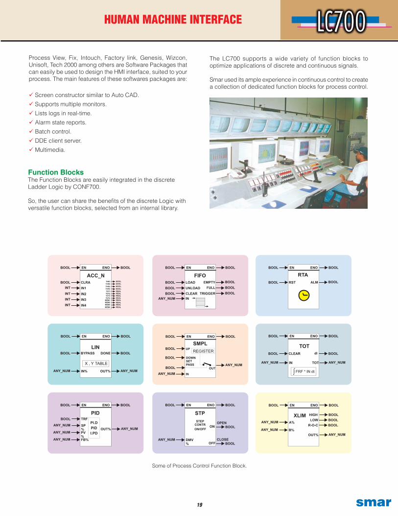
Function BlocksThe Function Blocks are easily integrated in the discreteLadder Logic by CONF700.
So, the user can share the benefits of the discrete Logic with versatile function blocks, selected from an internal library.
Process View, Fix, Intouch, Factory link, Genesis, Wizcon, Unisoft, Tech 2000 among others are Software Packages that can easily be used to design the HMI interface, suited to your process. The main features of these softwares packages are:
Screen constructor similar to Auto CAD.
Supports multiple monitors.
Lists logs in real-time.
Alarm state reports.
Batch control.
DDE client server.
Multimedia.
Some of Process Control Function Block.
HUMAN MACHINE INTERFACE
The LC700 supports a wide variety of function blocks to optimize applications of discrete and continuous signals.
Smar used its ample experience in continuous control to create a collection of dedicated function blocks for process control.
�0smar
TECHNICAL SPECIFICATIONS
Functional Specifications
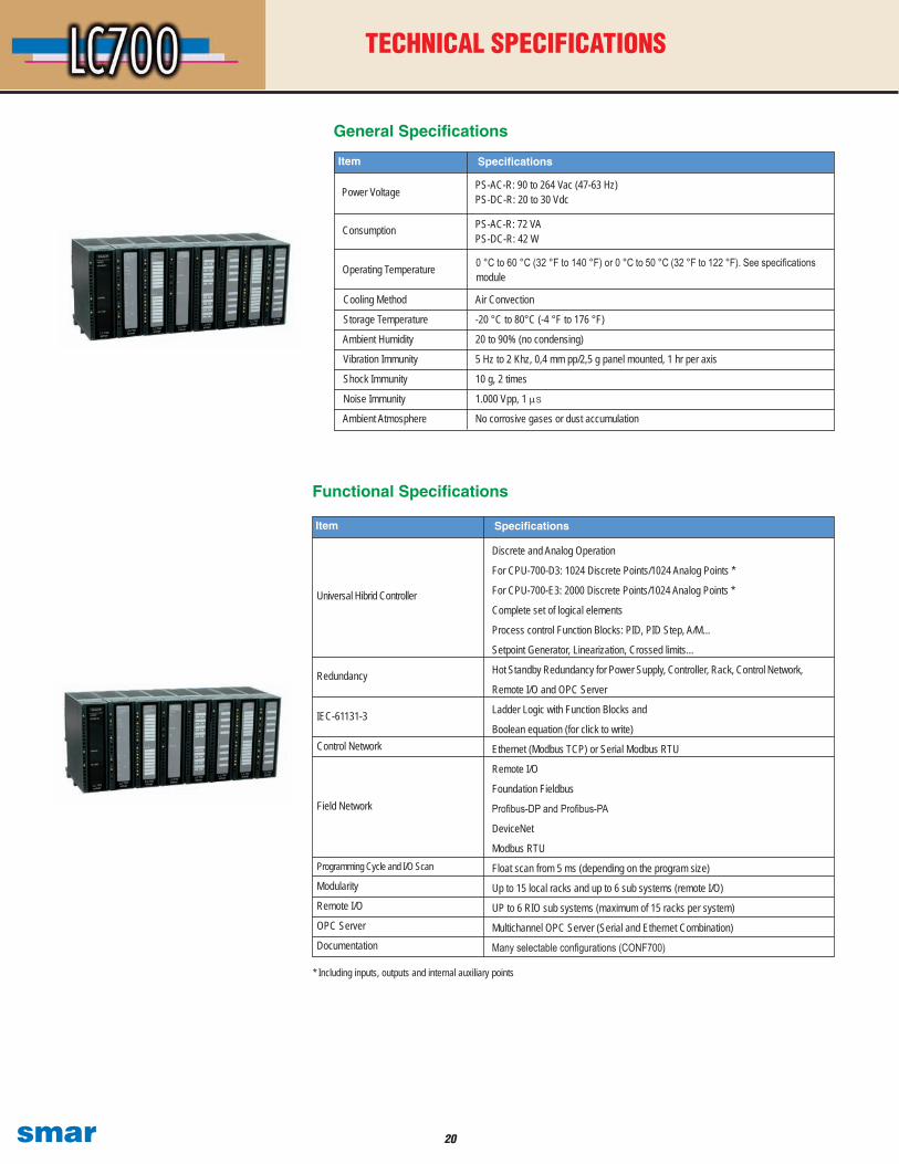
General Specifications
Air Convection
-20 °C to 80°C (-4 °F to 176 °F)
20 to 90% (no condensing)
5 Hz to 2 Khz, 0,4 mm pp/2,5 g panel mounted, 1 hr per axis
10 g, 2 times
1.000 Vpp, 1 µs
No corrosive gases or dust accumulation
Cooling Method
Storage Temperature
Ambient Humidity
Vibration Immunity
Shock Immunity
Noise Immunity
Ambient Atmosphere
Operating Temperature 0 °C to 60 °C (32 °F to 140 °F) or 0 °C to 50 °C (32 °F to 122 °F). See specifications module
Item Specifications
Discrete and Analog Operation
For CPU-700-D3: 1024 Discrete Points/1024 Analog Points *
For CPU-700-E3: 2000 Discrete Points/1024 Analog Points *
Complete set of logical elements
Process control Function Blocks: PID, PID Step, A/M...
Setpoint Generator, Linearization, Crossed limits...
Hot Standby Redundancy for Power Supply, Controller, Rack, Control Network,
Remote I/O and OPC Server
Ladder Logic with Function Blocks and
Boolean equation (for click to write)
Ethernet (Modbus TCP) or Serial Modbus RTU
Remote I/O
Foundation Fieldbus
Profibus-DP and Profibus-PA
DeviceNet
Modbus RTU
Float scan from 5 ms (depending on the program size)
Up to 15 local racks and up to 6 sub systems (remote I/O)
UP to 6 RIO sub systems (maximum of 15 racks per system)
Multichannel OPC Server (Serial and Ethernet Combination)
Many selectable configurations (CONF700)
Universal Hibrid Controller
Item Specifications
Redundancy
IEC-61131-3
Control Network
Field Network
Programming Cycle and I/O Scan
Modularity
Remote I/O
OPC Server
Documentation
* Including inputs, outputs and internal auxiliary points
Power Voltage PS-AC-R: 90 to 264 Vac (47-63 Hz)PS-DC-R: 20 to 30 Vdc
Consumption PS-AC-R: 72 VAPS-DC-R: 42 W

�1 smar
TECHNICAL SPECIFICATIONS
Master
P1 - 9600 bps to 57.6 KbpsP2 - 9600 bps to 115.2 KbpsP3 (As Modbus RTU) - 9600 bps to 115.2 KbpsP3 (As Remote I/O) - 57.6 Kbps to 230.4 Kbps
1600 Vrms @ 1 minute
CPU-700-D3
3 Independent PortsP1 - DB9 Female (EIA-232C)P2 - Modbus RTU (EIA-485)P3 - Modbus RTU or Remote I/O (EIA-485)
P1 - Female DB9P2 and P3 - Terminal blocks
NVRAM
Model
Number of Ports
Connectors
Remote I/O Type
Baud Rates
RS-485 Isolation
Configuration Memory
RIO-700-D3 I/O Remote Port (P3) works with
+ 5 VdcRunHoldForceRxTxFail
Operation and Diagnostic LEDs
320 mA Current Consumption of the 5Vdc Internal Power Supply
CPU Processor Module

��smar
TECHNICAL SPECIFICATIONS
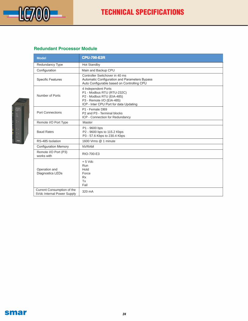
Redundant Processor Module
Model
Redundancy TypeConfiguration
Specific Features
Number of Ports
Port Connections
Configuration Memory
CPU-700-D3R
Hot StandbyMain and Backup CPUController Switchover in 40 ms Automatic Configuration and Parameters BypassAuto Configurable based on Controlling CPU4 Independent PortsP1 - Modbus RTU (RS-232C)P2 - Modbus RTU (EIA-485)P3 - Remote I/O (EIA-485)ICP - Inter CPU Port for data Updating
P1 - 9600 bpsP2 - 9600 bps to 115.2 KbpsP3 - 57.6 Kbps to 230.4 Kbps
NVRAM
P1 - Female DB9P2 and P3 - Terminal BlocksICP - Connection for Redundancy
Remote I/O Port Type Master
Baud Rates
RS-485 Isolation 1600 Vrms @ 1 minute
Remote I/O Port works with RIO-700-D3
Operation and Diagnostic LEDs
+ 5 VdcRunHoldForceRx TxFail
Current Consumption of the 5 Vdc Internal Power Supply
320 mA

�� smar
CPU Processor Module
Number of Ports
CPU-700-E3
3 Independent PortsP1 - DB9 Female (EIA-232C)P2 - Modbus RTU (EIA-485)P3 - Modbus RTU or Remote I/O (EIA-485)
P1 - 9600 bpsP2 - 9600 bps to 115.2 KbpsP3 (As Modbus RTU) - 9600 bps to 115.2 KbpsP3 (As Remote I/O) - 57.6 Kbps to 230.4 Kbps
Remote I/O Type Master
Baud Rates
RS-485 Isolation
NVRAMConfiguration Memory
1600 Vrms @ 1 minute
I/O Remote Port (P3) works with RIO - 700-E3
+ 5 VdcRunHoldForceRx TxFail
Connectors
Current Consumption of the 5Vdc Internal Power Supply
Operation and Diagnostic LEDs
P1 - Female DB9P2 and P3 - Terminal blocks
CPU-700-E3CPU-700-E3CPU-700-E3Model
320 mA
TECHNICAL SPECIFICATIONS
��smar
Redundancy Type
CPU-700-E3R
Hot Standby
4 Independent PortsP1 - Modbus RTU (RTU-232C)P2 - Modbus RTU (EIA-485)P3 - Remote I/O (EIA-485)ICP - Inter CPU Port for data Updating
Specific FeaturesController Switchover in 40 msAutomatic Configuration and Parameters BypassAuto Configurable based on Controlling CPU
Number of Ports
RS-485 Isolation
NVRAMConfiguration Memory
1600 Vrms @ 1 minute
RIO-700-E3
+ 5 VdcRunHoldForceRxTxFail
Configuration Main and Backup CPU
Port ConnectionsP1 - Female DB9P2 and P3 - Terminal blocksICP - Connection for Redundancy
CPU-700-E3RCPU-700-E3RModel
Redundant Processor Module
CPU-700-E3R
Baud RatesP1 - 9600 bpsP2 - 9600 bps to 115.2 KbpsP3 - 57.6 Kbps to 230.4 Kbps
Remote I/O Port (P3) works with
Remote I/O Port Type
Operation and Diagnostics LEDs
Master
Current Consumption of the 5Vdc Internal Power Supply
320 mA
TECHNICAL SPECIFICATIONS
�� smar
TECHNICAL SPECIFICATIONS
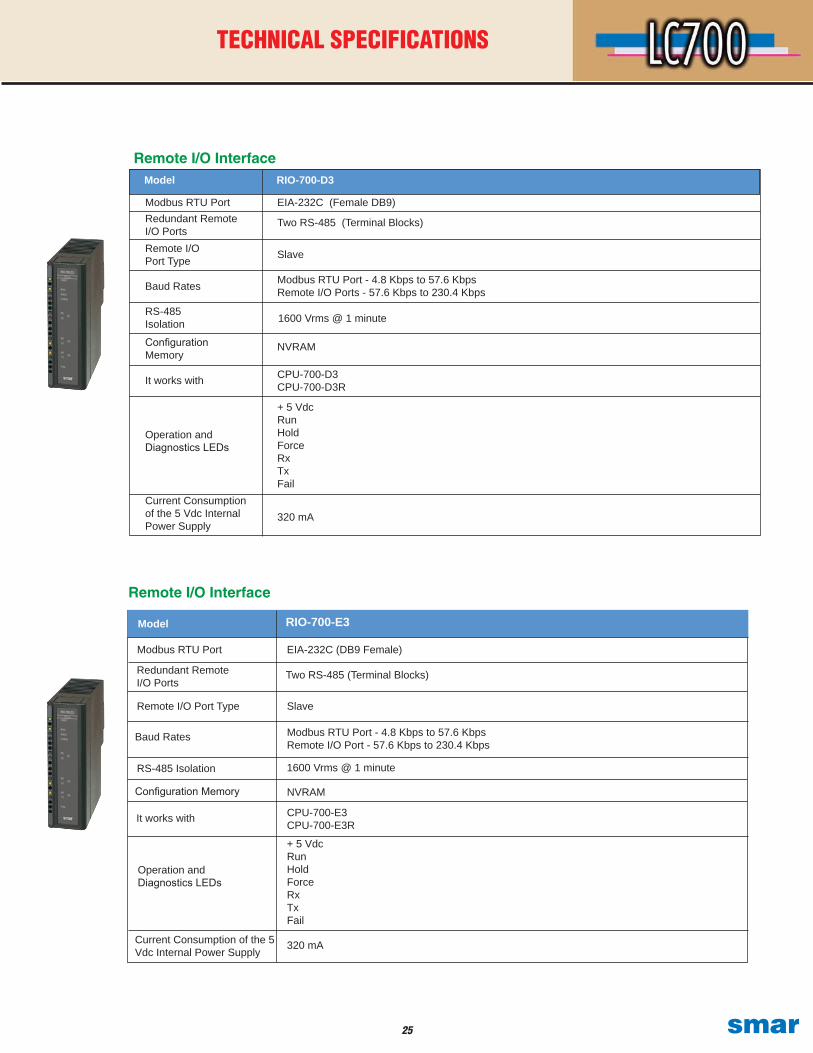
Remote I/O Interface
CPU-700-D3 CPU-700-D3R
+ 5 VdcRunHoldForceRxTxFail
Model
Modbus RTU PortRedundant Remote I/O PortsRemote I/O Port Type
Baud Rates
RS-485 Isolation
Configuration Memory
It works with
Operation and Diagnostics LEDs
Current Consumption of the 5 Vdc Internal Power Supply
RIO-700-D3
EIA-232C (Female DB9)
Two RS-485 (Terminal Blocks)
Slave
Modbus RTU Port - 4.8 Kbps to 57.6 KbpsRemote I/O Ports - 57.6 Kbps to 230.4 Kbps
1600 Vrms @ 1 minute
320 mA
NVRAM
Remote I/O Interface
Modbus RTU Port
RIO-700-E3
EIA-232C (DB9 Female)
Model
Modbus RTU Port - 4.8 Kbps to 57.6 KbpsRemote I/O Port - 57.6 Kbps to 230.4 Kbps
Baud Rates
It works with
NVRAMConfiguration Memory
CPU-700-E3CPU-700-E3R
+ 5 VdcRunHoldForceRxTxFail
Redundant Remote I/O Ports
Current Consumption of the 5 Vdc Internal Power Supply
Operation and Diagnostics LEDs
320 mA
Two RS-485 (Terminal Blocks)
RS-485 Isolation 1600 Vrms @ 1 minute
Remote I/O Port Type Slave
��smar
TECHNICAL SPECIFICATIONS
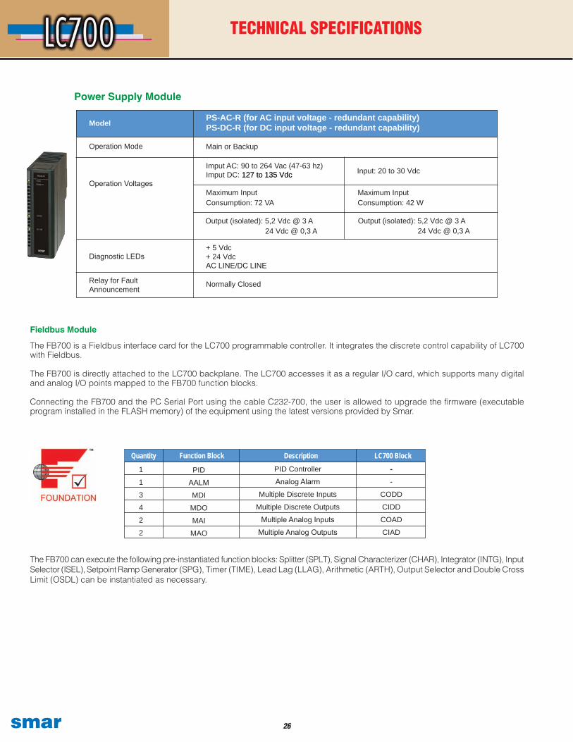
Fieldbus Module
The FB700 is a Fieldbus interface card for the LC700 programmable controller. It integrates the discrete control capability of LC700 with Fieldbus.
The FB700 is directly attached to the LC700 backplane. The LC700 accesses it as a regular I/O card, which supports many digital and analog I/O points mapped to the FB700 function blocks.
Connecting the FB700 and the PC Serial Port using the cable C232-700, the user is allowed to upgrade the firmware (executable program installed in the FLASH memory) of the equipment using the latest versions provided by Smar.
The FB700 can execute the following pre-instantiated function blocks: Splitter (SPLT), Signal Characterizer (CHAR), Integrator (INTG), Input Selector (ISEL), Setpoint Ramp Generator (SPG), Timer (TIME), Lead Lag (LLAG), Arithmetic (ARTH), Output Selector and Double Cross Limit (OSDL) can be instantiated as necessary.
1
1
3
4
2
2
PID Controller
Analog Alarm
Multiple Discrete Inputs
Multiple Discrete Outputs
Multiple Analog Inputs
Multiple Analog Outputs
--
CODD
CIDD
COAD
CIAD
Function BlockQuantity Description LC700 Block
PID
AALM
MDI
MDO
MAI
MAO
Power Supply Module
Model
Operation Mode
Operation Voltages
Diagnostic LEDs
Relay for Fault Announcement
PS-AC-R (for AC input voltage - redundant capability)PS-DC-R (for DC input voltage - redundant capability)
Main or Backup
Imput AC: 90 to 264 Vac (47-63 hz)Imput DC: 127 to 135 Vdc127 to 135 Vdc
Maximum Input Consumption: 72 VA
+ 5 Vdc + 24 VdcAC LINE/DC LINE
Normally Closed
Input: 20 to 30 Vdc
Maximum Input Consumption: 42 W
Output (isolated): 5,2 Vdc @ 3 A 24 Vdc @ 0,3 A
Output (isolated): 5,2 Vdc @ 3 A 24 Vdc @ 0,3 A
�� smar
TECHNICAL SPECIFICATIONS
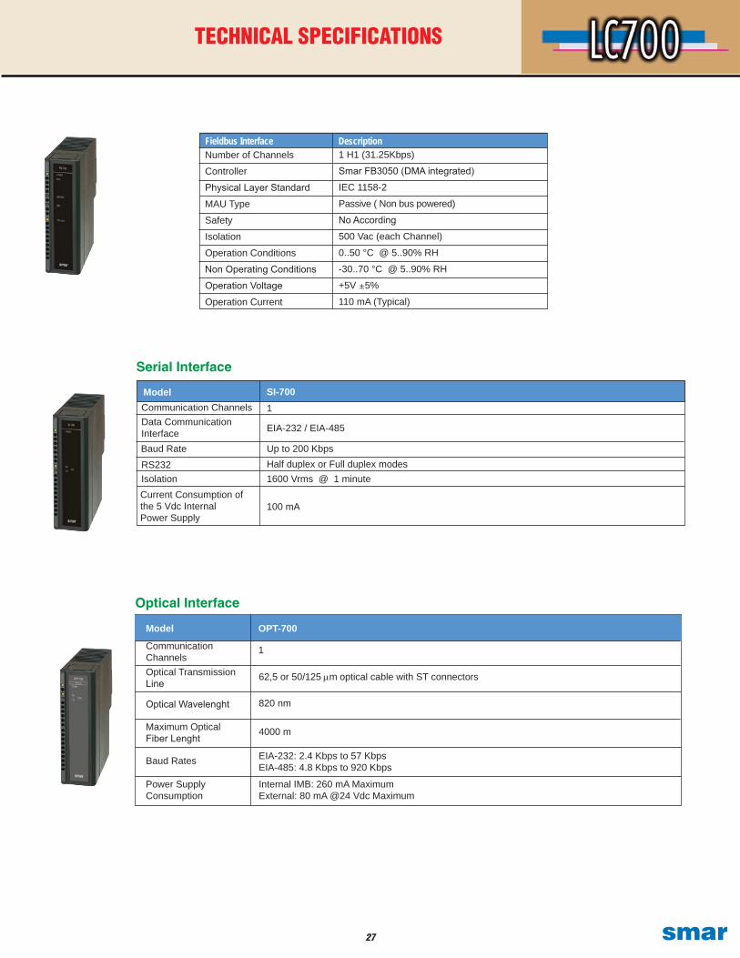
Serial Interface
SI-700
EIA-232 / EIA-485
Up to 200 KbpsHalf duplex or Full duplex modes1600 Vrms @ 1 minute
100 mA
1ModelCommunication ChannelsData Communication InterfaceBaud Rate RS232IsolationCurrent Consumption of the 5 Vdc Internal Power Supply
Number of Channels
Controller
Physical Layer Standard
MAU Type
Safety
Isolation
Operation Conditions
Non Operating Conditions
Operation Voltage
Operation Current
1 H1 (31.25Kbps)
Smar FB3050 (DMA integrated)
IEC 1158-2
Passive ( Non bus powered)
No According
500 Vac (each Channel)
0..50 °C @ 5..90% RH
-30..70 °C @ 5..90% RH
+5V ±5%
110 mA (Typical)
DescriptionFieldbus Interface
Optical Interface
1
62,5 or 50/125 µm optical cable with ST connectors
820 nm
4000 m
EIA-232: 2.4 Kbps to 57 KbpsEIA-485: 4.8 Kbps to 920 Kbps
Internal IMB: 260 mA MaximumExternal: 80 mA @24 Vdc Maximum
Model
Communication ChannelsOptical Transmission Line
Optical Wavelenght
Maximum Optical Fiber Lenght
Baud Rates
OPT-700
Power Supply Consumption
��smar
TECHNICAL SPECIFICATIONS
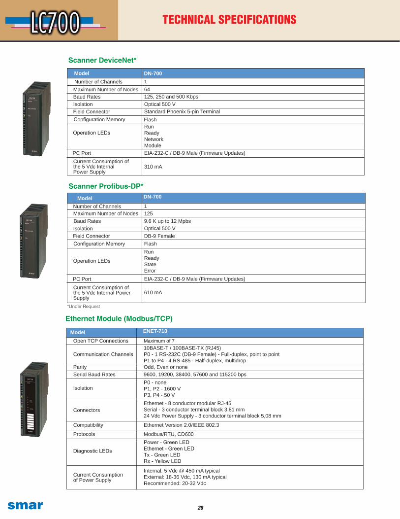
Ethernet Module (Modbus/TCP)
Open TCP Connections
Serial Baud Rates
Isolation
Connectors
Protocols
Model
Diagnostic LEDs
Communication Channels
ENET-710
Maximum of 7
9600, 19200, 38400, 57600 and 115200 bpsP0 - noneP1, P2 - 1600 VP3, P4 - 50 V
Modbus/RTU, CD600
Ethernet - 8 conductor modular RJ-45Serial - 3 conductor terminal block 3,81 mm24 Vdc Power Supply - 3 conductor terminal block 5,08 mm
Internal: 5 Vdc @ 450 mA typical External: 18-36 Vdc, 130 mA typicalRecommended: 20-32 Vdc
10BASE-T / 100BASE-TX (RJ45)P0 - 1 RS-232C (DB-9 Female) - Full-duplex, point to pointP1 to P4 - 4 RS-485 - Half-duplex, multidrop
Power - Green LEDEthernet - Green LEDTx - Green LEDRx - Yellow LED
Current Consumption of Power Supply
Scanner Profibus-DP*DN-700
1
9.6 K up to 12 MpbsOptical 500 V
FlashDB-9 Female
610 mA
125
EIA-232-C / DB-9 Male (Firmware Updates)
Number of Channels
Baud RatesIsolationField ConnectorConfiguration Memory
PC Port
Model
Operation LEDs
Maximum Number of Nodes
Current Consumption of the 5 Vdc Internal Power Supply
RunReadyStateError
Scanner DeviceNet*
DN-7001
125, 250 and 500 KbpsOptical 500 V
FlashStandard Phoenix 5-pin Terminal
310 mA
64
EIA-232-C / DB-9 Male (Firmware Updates)
Run ReadyNetworkModule
Number of Channels
Baud RatesIsolationField ConnectorConfiguration Memory
PC Port
Model
Current Consumption of the 5 Vdc Internal Power Supply
Operation LEDs
Maximum Number of Nodes
*Under Request
Parity Odd, Even or none
Compatibility Ethernet Version 2.0/IEEE 802.3
�� smar
TECHNICAL SPECIFICATIONS
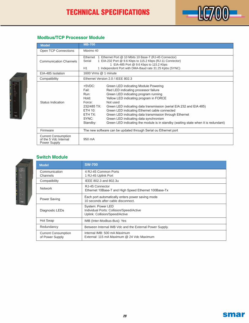
Modbus/TCP Processor Module
Open TCP Connections
Compatibility
Status Indication
Model
Communication Channels
MB-700
Máximo 40
Ethernet Version 2.0 / IEEE 802.3EIA-485 Isolation 1600 Vrms @ 1 minute
950 mA
The new software can be updated through Serial ou Ethernet portFirmware
Current Consumption of the 5 Vdc Internal Power Supply
Ethernet 1 Ethernet Port @ 10 Mbits 10 Base-T (RJ-45 Connector)Serial 1 EIA-232 Port @ 9.6 Kbps to 115.2 Kbps (RJ-11 Connector) 1 EIA-485 Port @ 9.6 Kbps to 115.2 KbpsH1 1 Independent Port with DMA-Baud rate 31.25 Kpbs (SYNC)
+5VDC: Green LED indicating Module PoweringFail: Red LED indicating processor failureRun: Green LED indicating program running Hold: Yellow LED indicating program in FORCE Force: Not used232/485 TX: Green LED indicating data transmission (serial EIA 232 and EIA 485)ETH 10: Green LED indicating Ethernet cable connectedETH TX: Green LED indicating data transmission through EthernetSYNC: Green LED indicating data synchronismStandby: Green LED indicating the module is in standby (waiting state when it is redundant)
Switch Module
Communication Channels
SW-700
4 RJ-45 Common Ports1 RJ-45 Uplink Port
Model
Compatibility IEEE 802.3 and 802.3u
Network RJ-45 ConnectorEthernet 10Base-T and High Speed Ethernet 100Base-Tx
Power Saving Each port automatically enters power saving mode 10 seconds after cable disconnect.
Diagnostic LEDsSystem: Power LED Individual Ports: Collision/Speed/Active Uplink: Collision/Speed/Active
Hot Swap IMB (Inter-Modbus-Bus): Yes
Redundancy Between Internal IMB Vdc and the External Power Supply.
Current Consumption of Power Supply
Internal IMB: 500 mA MaximumExternal: 115 mA Maximum @ 24 Vdc Maximum
�0smar
TECHNICAL SPECIFICATIONS
Nominal Input
Voltage
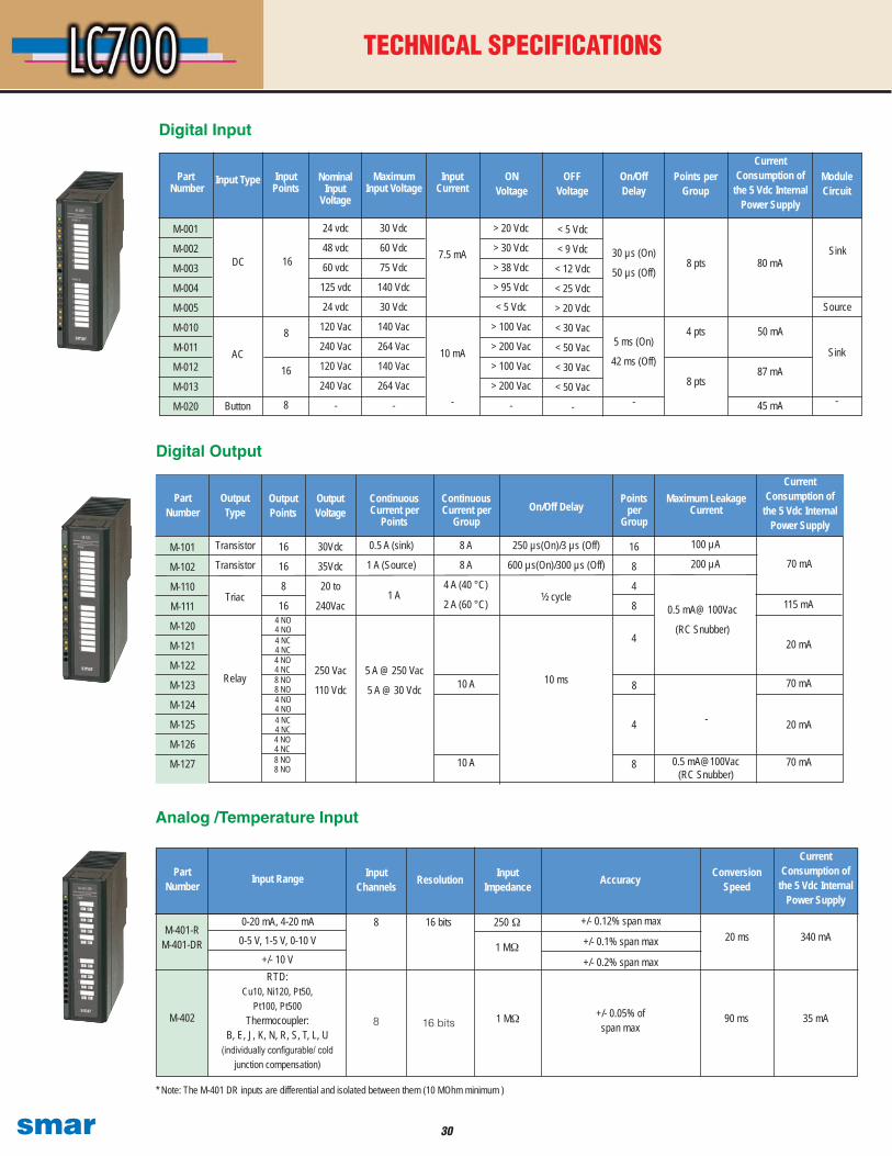
Digital Input
Analog /Temperature Input
0-20 mA, 4-20 mA0-5 V, 1-5 V, 0-10 V
+/- 10 V
8 250
+/- 0.1% span max
90 ms
* Note: The M-401 DR inputs are differential and isolated between them (10 MOhm minimum )
AccuracyPart
Number Resolution
Digital Output
16
8
4
8
M-001
M-002
M-003
M-004
M-005
M-010
M-011
M-012
M-013
M-020
Input Points
30 Vdc
60 Vdc
75 Vdc
140 Vdc
30 Vdc
140 Vac
264 Vac
140 Vac
264 Vac
-
OFF Voltage
30 µs (On)
50 µs (Off)
Points per Group
Current Consumption of
the 5 Vdc Internal Power Supply
ON Voltage
Module Circuit
Input Type
24 vdc
48 vdc
60 vdc
125 vdc
24 vdc
120 Vac
240 Vac
120 Vac
240 Vac
-
8 pts
4 pts
80 mA
45 mA
50 mA
87 mA
M-101
M-102
M-110
M-111
M-120
M-121
M-122
M-123
M-124
M-125
M-126
M-127
Transistor
Transistor16
16
8
16
Continuous Current per
Points
Points per
Group
Continuous Current per
GroupOn/Off Delay
Current Consumption of
the 5 Vdc Internal Power Supply
Maximum Leakage Current
30Vdc
35Vdc
20 to
240Vac
DC
Button
AC
16
8
16
8
Part Number
Maximum Input Voltage
Part Number
Input Current
> 20 Vdc
> 30 Vdc
> 38 Vdc
> 95 Vdc
< 5 Vdc
> 100 Vac
> 200 Vac
> 100 Vac
> 200 Vac
-
< 5 Vdc
< 9 Vdc
< 12 Vdc
< 25 Vdc
> 20 Vdc
< 30 Vac
< 50 Vac
< 30 Vac
< 50 Vac
-
On/Off Delay
Source
7.5 mA
5 ms (On)
42 ms (Off)
-
10 mA
-
Output Type
Output Points
Output Voltage
8 A
8 A
4 A (40 °C)
2 A (60 °C)
250 µs(On)/3 µs (Off)
600 µs(On)/300 µs (Off)
0.5 A (sink)
1 A (Source)
250 Vac
110 Vdc
5 A @ 250 Vac
5 A @ 30 VdcRelay
Triac
10 A 10 ms
4
8
4
8
70 mA
0.5 mA@ 100Vac
(RC Snubber)
-
20 mA
70 mA
20 mA
Input Range
RTD:Cu10, Ni120, Pt50,
Pt100, Pt500Thermocoupler:
B, E, J, K, N, R, S, T, L, U(individually configurable/ cold
junction compensation)
Input Channels
8
16 bits
16 bits
Input Impedance
1 M
+/- 0.05% of span max
+/- 0.12% span max
Conversion Speed
20 ms
Current Consumption of
the 5 Vdc Internal Power Supply
35 mA
340 mA
M-402
M-401-RM-401-DR
100 µA
200 µA
8 pts
Sink
Sink
½ cycle
4 NO4 NO4 NC4 NC4 NO4 NC8 NO8 NO4 NO4 NO4 NC4 NC4 NO4 NC
115 mA
1 M
+/- 0.2% span max
1 A
-
8 NO8 NO
70 mA0.5 mA@100Vac (RC Snubber)
10 A
�1 smar
TECHNICAL SPECIFICATIONS
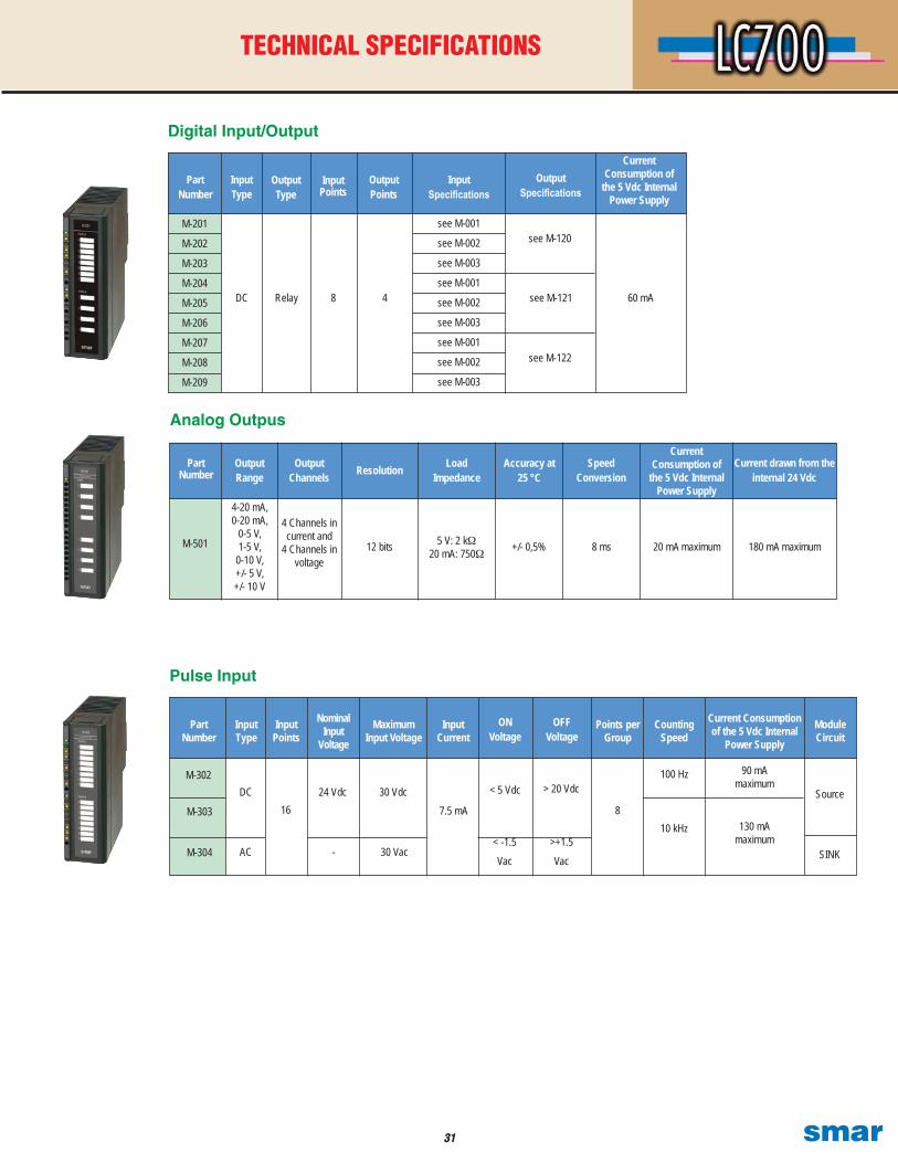
Pulse Input
Module Circuit
Source
Analog Outpus
Digital Input/Output
M-201
M-202
M-203
M-204
M-205
M-206
M-207
M-208
M-209
Input Type
Output Type
Input Points
Output Points
Input Specifications
Output Specifications
Current Consumption of
the 5 Vdc Internal Power Supply
Part Number
DC Relay 8 4
see M-001
see M-002
see M-003
see M-001
see M-002
see M-003
see M-001
see M-002
see M-003
see M-120
60 mAsee M-121
see M-122
M-303
Input Type
Input Points
Maximum Input Voltage
Input Current
ON Voltage
OFF Voltage
Points per Group
Counting Speed
Current Consumption of the 5 Vdc Internal
Power Supply
Nominal Input
Voltage
Part Number
M-302
1624 VdcDC 30 Vdc
7.5 mA
< 5 Vdc > 20 Vdc
8
100 Hz
130 mAmaximum
90 mAmaximum
10 kHz
M-501
Output Range
Output Channels Resolution Load
ImpedanceAccuracy at
25 °CSpeed
Conversion
Current Consumption of
the 5 Vdc Internal Power Supply
Part Number
4-20 mA, 0-20 mA,
0-5 V, 1-5 V,
0-10 V, +/- 5 V, +/- 10 V
12 bits 5 V: 2 k 20 mA: 750 8 ms+/- 0,5% 180 mA maximum
4 Channels in current and
4 Channels in voltage
Current drawn from the internal 24 Vdc
20 mA maximum
M-304 AC - 30 Vac< -1.5Vac
>+1.5Vac SINK
��smar
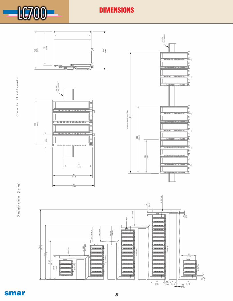
Con
nect
ion
of L
ocal
Exp
ansi
onD
imen
sion
s in
mm
(in
ches
)
DIMENSIONS
�� smar
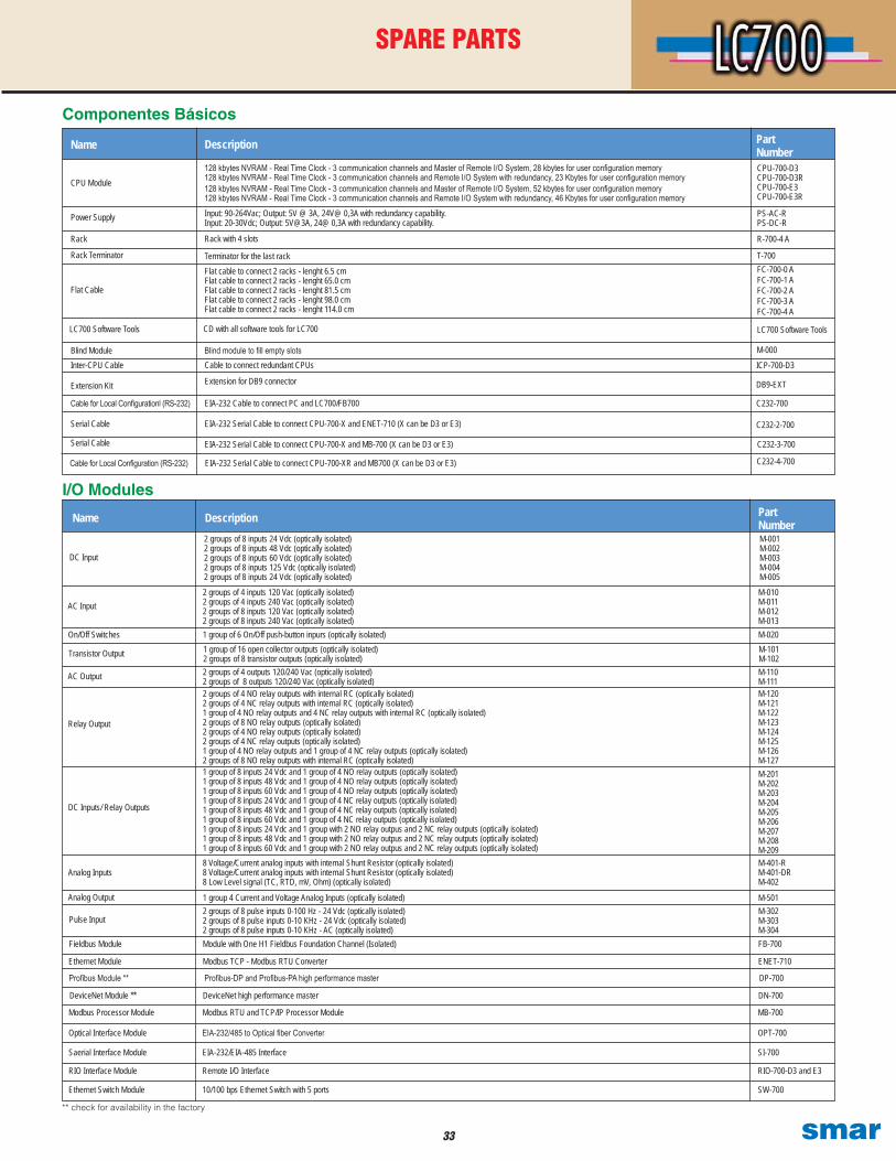
Componentes Básicos
Name Description Part NumberCPU-700-D3CPU-700-D3R CPU-700-E3 CPU-700-E3R
LC700 Software Tools
Blind module to fill empty slotsCable to connect redundant CPUs
Extension for DB9 connector
EIA-232 Cable to connect PC and LC700/FB700
EIA-232 Serial Cable to connect CPU-700-X and ENET-710 (X can be D3 or E3)
EIA-232 Serial Cable to connect CPU-700-X and MB-700 (X can be D3 or E3)
128 kbytes NVRAM - Real Time Clock - 3 communication channels and Master of Remote I/O System, 28 kbytes for user configuration memory128 kbytes NVRAM - Real Time Clock - 3 communication channels and Remote I/O System with redundancy, 23 Kbytes for user configuration memory
Input: 90-264Vac; Output: 5V @ 3A, 24V@ 0,3A with redundancy capability.Input: 20-30Vdc; Output: 5V@3A, 24@ 0,3A with redundancy capability.
Rack with 4 slots
Terminator for the last rack Flat cable to connect 2 racks - lenght 6.5 cmFlat cable to connect 2 racks - lenght 65.0 cmFlat cable to connect 2 racks - lenght 81.5 cmFlat cable to connect 2 racks - lenght 98.0 cmFlat cable to connect 2 racks - lenght 114.0 cm
C232-3-700
PS-AC-RPS-DC-R
R-700-4 A
FC-700-0 AFC-700-1 AFC-700-2 AFC-700-3 AFC-700-4 A
1 group of 8 inputs 24 Vdc and 1 group of 4 NO relay outputs (optically isolated)1 group of 8 inputs 48 Vdc and 1 group of 4 NO relay outputs (optically isolated)1 group of 8 inputs 60 Vdc and 1 group of 4 NO relay outputs (optically isolated)1 group of 8 inputs 24 Vdc and 1 group of 4 NC relay outputs (optically isolated)1 group of 8 inputs 48 Vdc and 1 group of 4 NC relay outputs (optically isolated)1 group of 8 inputs 60 Vdc and 1 group of 4 NC relay outputs (optically isolated)1 group of 8 inputs 24 Vdc and 1 group with 2 NO relay outpus and 2 NC relay outputs (optically isolated)1 group of 8 inputs 48 Vdc and 1 group with 2 NO relay outpus and 2 NC relay outputs (optically isolated)1 group of 8 inputs 60 Vdc and 1 group with 2 NO relay outpus and 2 NC relay outputs (optically isolated)
AC Input
Name Description Part Number
On/Off Switches
Transistor Output
AC Output
Relay Output
DC Input
M-001M-002M-003M-004M-005
DC Inputs/ Relay Outputs
2 groups of 8 inputs 24 Vdc (optically isolated)2 groups of 8 inputs 48 Vdc (optically isolated)2 groups of 8 inputs 60 Vdc (optically isolated)2 groups of 8 inputs 125 Vdc (optically isolated)2 groups of 8 inputs 24 Vdc (optically isolated)
1 group of 16 open collector outputs (optically isolated)2 groups of 8 transistor outputs (optically isolated)
2 groups of 4 NO relay outputs with internal RC (optically isolated)2 groups of 4 NC relay outputs with internal RC (optically isolated)1 group of 4 NO relay outputs and 4 NC relay outputs with internal RC (optically isolated)2 groups of 8 NO relay outputs (optically isolated)2 groups of 4 NO relay outputs (optically isolated)2 groups of 4 NC relay outputs (optically isolated)1 group of 4 NO relay outputs and 1 group of 4 NC relay outputs (optically isolated)2 groups of 8 NO relay outputs with internal RC (optically isolated)
2 groups of 4 inputs 120 Vac (optically isolated)2 groups of 4 inputs 240 Vac (optically isolated)2 groups of 8 inputs 120 Vac (optically isolated)2 groups of 8 inputs 240 Vac (optically isolated)1 group of 6 On/Off push-button inpurs (optically isolated)
2 groups of 4 outputs 120/240 Vac (optically isolated)2 groups of 8 outputs 120/240 Vac (optically isolated)
M-010M-011M-012M-013M-020M-101M-102M-110M-111
M-201M-202M-203M-204M-205M-206M-207M-208M-209
T-700
Analog Inputs8 Voltage/Current analog inputs with internal Shunt Resistor (optically isolated)8 Voltage/Current analog inputs with internal Shunt Resistor (optically isolated)8 Low Level signal (TC, RTD, mV, Ohm) (optically isolated)
M-401-RM-401-DRM-402
I/O Modules
Pulse Input
1 group 4 Current and Voltage Analog Inputs (optically isolated)
Fieldbus Module
Ethernet Module
Profibus Module **
DeviceNet Module **
Modbus Processor Module
Analog Output2 groups of 8 pulse inputs 0-100 Hz - 24 Vdc (optically isolated)2 groups of 8 pulse inputs 0-10 KHz - 24 Vdc (optically isolated)2 groups of 8 pulse inputs 0-10 KHz - AC (optically isolated)Module with One H1 Fieldbus Foundation Channel (Isolated)
Modbus TCP - Modbus RTU Converter
Profibus-DP and Profibus-PA high performance master
DeviceNet high performance master
Modbus RTU and TCP/IP Processor Module
M-302M-303M-304
M-501
FB-700
ENET-710
DP-700
DN-700
MB-700
M-120M-121M-122M-123M-124M-125M-126M-127
Optical Interface Module EIA-232/485 to Optical fiber Converter OPT-700
Saerial Interface Module EIA-232/EIA-485 Interface SI-700
RIO Interface Module Remote I/O Interface RIO-700-D3 and E3
Ethernet Switch Module 10/100 bps Ethernet Switch with 5 ports SW-700
** check for availability in the factory
EIA-232 Serial Cable to connect CPU-700-XR and MB700 (X can be D3 or E3)
128 kbytes NVRAM - Real Time Clock - 3 communication channels and Master of Remote I/O System, 52 kbytes for user configuration memory128 kbytes NVRAM - Real Time Clock - 3 communication channels and Remote I/O System with redundancy, 46 Kbytes for user configuration memory
C232-2-700
CD with all software tools for LC700
M-000
ICP-700-D3
DB9-EXT
C232-700
C232-4-700
SPARE PARTS
Power Supply
Rack
Rack Terminator
Flat Cable
Blind ModuleInter-CPU Cable
Extension Kit
Serial Cable
Serial Cable
CPU Module
Cable for Local Configuration (RS-232)
LC700 Software Tools
Cable for Local Configurationl (RS-232)

© Copyright 2005 - Smar International - all rights reserved. - December/2008
smarSpecifications and information are subject to change without notice.
Up-to-date address information is available on our website.
web: www.smar.com/contactus.asp
www.smar.com
L C 7 0 0 C E