
Graphic LCD Controller (GraphicLCDCtrl)
25
www.infineon.com Please note that Cypress is an Infineon Technologies Company. The document following this cover page is marked as “Cypress” document as this is the company that originally developed the product. Please note that Infineon will continue to offer the product to new and existing customers as part of the Infineon product portfolio. Continuity of document content The fact that Infineon offers the following product as part of the Infineon product portfolio does not lead to any changes to this document. Future revisions will occur when appropriate, and any changes will be set out on the document history page. Continuity of ordering part numbers Infineon continues to support existing part numbers. Please continue to use the ordering part numbers listed in the datasheet for ordering.
-
Upload
khangminh22 -
Category
Documents
-
view
1 -
download
0
Transcript of Graphic LCD Controller (GraphicLCDCtrl)

www.infineon.com
Please note that Cypress is an Infineon Technologies Company.The document following this cover page is marked as “Cypress” document as this is the company that originally developed the product. Please note that Infineon will continue to offer the product to new and existing customers as part of the Infineon product portfolio.
Continuity of document contentThe fact that Infineon offers the following product as part of the Infineon product portfolio does not lead to any changes to this document. Future revisions will occur when appropriate, and any changes will be set out on the document history page.
Continuity of ordering part numbersInfineon continues to support existing part numbers. Please continue to use the ordering part numbers listed in the datasheet for ordering.

PSoC® Creator™ Component Datasheet
Cypress Semiconductor Corporation • 198 Champion Court • San Jose, CA 95134-1709 • 408-943-2600 Document Number: 002-24089 Rev. *A Revised June 29, 2018
Features
▪ Fully programmable screen size support up to HVGA resolution including:
□ QVGA (320x240) @ 60 Hz 16 bpp
□ WQVGA (480x272) @ 60 Hz 16 bpp
□ HVGA (480x320) @ 60 Hz 16 bpp
▪ Supports virtual screen operation
▪ Can be used with SEGGER emWin graphics library
▪ Performs read and write transactions during the blanking intervals
▪ Generates continuous timing signals to the panel without CPU intervention
▪ Supports up to a 23-bit address and a 16-bit data async SRAM device used as externally provided frame buffer
▪ Generates a selectable interrupt pulse at the entry and exit of the horizontal and vertical blanking intervals
General Description The Graphic LCD Controller (GraphicLCDCtrl) Component provides the interface to an LCD panel that has an LCD driver, but not an LCD controller. This type of panel does not include a frame buffer. The frame buffer must be provided externally.
This Component also interfaces to an externally provided frame buffer implemented using a 16-bit-wide async SRAM device.
This Component is designed to work with the SEGGER emWin graphics library. This library provides a full-featured set of graphics functions for drawing and rendering text and images. emWin graphics library available for PSoC 3, PSoC 4 and PSoC 5LP devices: www.cypress.com/go/comp_emWin
Graphic LCD Controller (GraphicLCDCtrl) 1.80

Graphic LCD Controller (GraphicLCDCtrl) PSoC® Creator™ Component Datasheet
Page 2 of 24 Document Number: 002-24089 Rev. *A
When to Use a GraphicLCDCtrl
The GraphicLCDCtrl Component supports many LCD panels. It directly drives the control signals and manages the frame buffer in an external SRAM. The Component generates the dotclk, hsync, vsync, and de outputs to access data from the SRAM and display it on the LCD.
The frame buffer SRAM can only be accessed for reads and writes when it is not refreshing the LCD panel. If a read or write is requested during the refresh period, the API functions provided will wait until the refresh gets to a blanking period. During the blanking period, the read or write is completed.
An interrupt can be used to indicate the entry and exit from blanking periods. This is particularly useful when coupled with an RTOS, which can swap in or swap out tasks that require access to the frame buffer when a blanking period is entered and exited.
Input/Output Connections
This section describes the input and output connections for the GraphicLCDCtrl Component. Some I/Os may be hidden on the symbol under the conditions listed in the description of that I/O.
Input May Be Hidden Description
di_lsb[7:0] N The lower eight bits of the input data bus. They are used for data during a read transaction. Connect these signals to an input pin on the device and disable the “Input Synchronized” selection for these pins. The signals themselves are synchronized already because they are driven based on synchronous output signals.
di_msb[7:0] N The upper eight bits of the input data bus. They are used for data during a read transaction. Connect these signals to an input pin on the device and disable the “Input Synchronized” selection for these pins. The signals themselves are synchronized already because they are driven based on synchronous output signals.
clock N The clock that operates this Component. It is twice the frequency of the dotclk.
Output May Be Hidden Description
do_lsb[7:0] N The lower eight bits of the output data bus. They are used for data during a write transaction.
do_msb[7:0] N The upper eight bits of the output data bus. They are used for data during a write transaction.
doe N The output enable for the data bus Component within PSoC. It is normally connected to the output enable of the Input/Output pin Component for the data buses.
addr0[7:0] N The lowest eight bits of the address bus connected to the frame buffer.
addr1[7:0] N The middle eight bits of the address bus connected to the frame buffer.
addr2[6:0] N The upper seven bits of the address bus connected to the frame buffer. The number of data bits needed by the frame buffer depends on the SRAM device you use.
nwe N Active-low write enable for the frame buffer SRAM.
noe N Active-low output enable for the frame buffer.

PSoC® Creator™ Component Datasheet Graphic LCD Controller (GraphicLCDCtrl)
Document Number: 002-24089 Rev. *A Page 3 of 24
Output May Be Hidden Description
de N Data enable for the panel.
hsync N Horizontal sync timing signal for the panel.
vsync N Vertical sync timing signal for the panel.
dotclk N Clock driven to the panel. This clock is one-half the rate of the incoming clock.
interrupt Y Edge-triggered interrupt signal. This output is hidden if no interrupt generation is selected.
Schematic Macro Information The macro is configured with the default settings to interface with the Optrex T-55343GD035JU-LW-AEN panel. The clock included in the macro is set to 13 MHz, which results in a 6.5-MHz dotclk provided to the Optrex QVGA panel.
Typically, only some of the bits of the upper address bits (addr2) are used to connect to the frame buffer. How many depends on the size of the SRAM you use. Based on the number of address bits you need, you can use the following steps to adjust the size of that bus.
▪ Configure the addr2 output pin Component and set the “Number of Pins.”
▪ Right-click on the signal driving the output pin and select “Edit Name And Width.” Then adjust the “Left Index” to reflect the width of the output pin.
The "Input Synchronized" option is unchecked on all of the data pins and the generation of API functions for all of the pins is turned off.

Graphic LCD Controller (GraphicLCDCtrl) PSoC® Creator™ Component Datasheet
Page 4 of 24 Document Number: 002-24089 Rev. *A
Component Parameters Drag a GraphicLCDCtrl Component onto your design and double-click it to open the Configure dialog. The default GraphicLCDCtrl settings are configured for operation with the Optrex panel.
The Configure GraphicLCDCtrl dialog contains the following parameters. All of these settings are compile-time selections; you do not need to change these settings at run time. They are all characteristics of the panel and frame buffer SRAM being used.
Sync Pulse Polarity
Based on this setting, the hsync and vsync signals are either Active High (pulse generated is a high pulse) or Active Low. This selection controls both hsync and vsync polarity. The default setting is Active Low.
Transition Dotclk Edge
Dotclk is the clock that is sent to the panel, off of which the panel operates. When the transition is set to Rising edge, all of the associated signals such as hsync, vsync, and de, transition on the rising edge of dotclk. When set to Falling edge, they transition on the falling edge of dotclk.
Typically, if the panel specifies a setup and hold time to one edge of dotclk, you should configure this setting to the other edge of the clock. This provides approximately one-half clock cycle of both setup and hold. The default setting is Falling edge.

PSoC® Creator™ Component Datasheet Graphic LCD Controller (GraphicLCDCtrl)
Document Number: 002-24089 Rev. *A Page 5 of 24
Horizontal Timing (dotclk)
▪ Sync Width – Defines the horizontal sync width in dotclks. This value can be set between 1 and 256 clock cycles. The default setting is 2.
▪ Back Porch – Defines the horizontal back porch width in dotclks. This value can be set between 6 and 256 clock cycles. A minimum of 6 gives an early enough indication to the state machine to prevent a read or write access that could not complete before the active screen area begins. Some panel specifications measure the back porch as the region between the end of the sync signal and the start of the active region. Other panel specifications consider the back porch to be the region from the start of the sync pulse to the start of the active region. This Component measures the back porch as the period from the end of the sync pulse to the start of the active region. The default setting is 66.
▪ Active Region – Defines the horizontal active region width in dotclks. The active region is implemented using a setting that is a multiple of 4. This allows for regions as large as 1024 x 1024 while using only 8-bit counters. All popular screen sizes are multiples of 4 in both directions. This value can be set between 4 and 1024 (must be a multiple of 4) clock cycles. The default setting is 320.
▪ Front Porch – Defines the horizontal front porch width in dotclks. This value can be set between 1 and 256 clock cycles. The default setting is 20.
Vertical Timing (lines)
▪ Sync Width – Defines the vertical sync width in lines. This value can be set between 1 and 256 clock cycles. The default setting is 2.
▪ Back Porch – Defines the vertical back porch width in lines. This value can be set between 1 and 256 lines. Some panel specifications measure the back porch as the region between the end of the sync signal and the start of the active region. Other panel specifications consider the back porch to be the region from the start of the sync pulse to the start of the active region. This Component measures the back porch as the period from the end of the sync pulse to the start of the active region. The default setting is 16.
▪ Active Region – Defines the vertical active region width in lines. The active region is implemented using a setting that is a multiple of 4. This allows for regions as large as 1024 x 1024 while using only 8-bit counters. All popular screen sizes are multiples of 4 in both directions. This value can be set between 4 and 1024 (must be a multiple of 4) lines. The default setting is 240.
▪ Front Porch – Defines the vertical front porch width in lines. This value can be set between 1 and 256 lines. The default setting is 4.
Graphic LCD Controller (GraphicLCDCtrl) PSoC® Creator™ Component Datasheet
Page 6 of 24 Document Number: 002-24089 Rev. *A
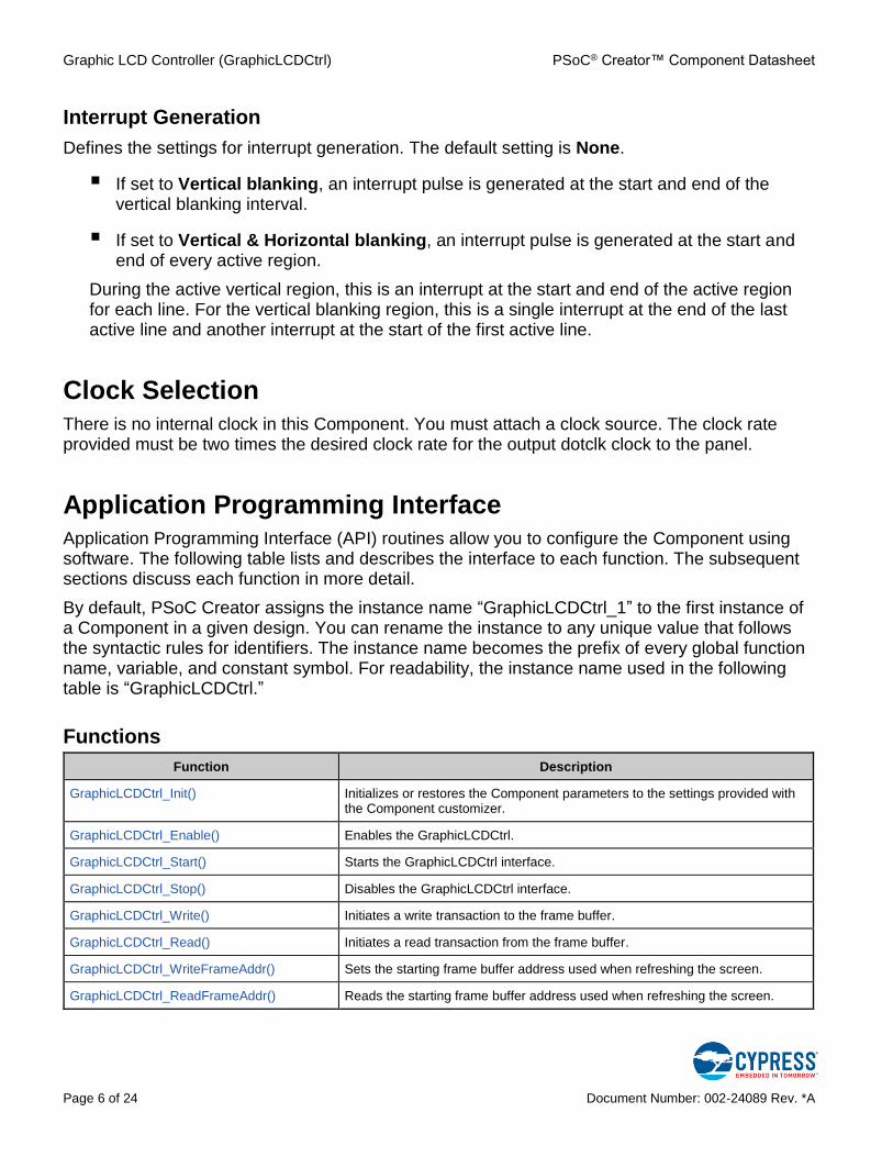
Interrupt Generation
Defines the settings for interrupt generation. The default setting is None.
▪ If set to Vertical blanking, an interrupt pulse is generated at the start and end of the vertical blanking interval.
▪ If set to Vertical & Horizontal blanking, an interrupt pulse is generated at the start and end of every active region.
During the active vertical region, this is an interrupt at the start and end of the active region for each line. For the vertical blanking region, this is a single interrupt at the end of the last active line and another interrupt at the start of the first active line.
Clock Selection
There is no internal clock in this Component. You must attach a clock source. The clock rate provided must be two times the desired clock rate for the output dotclk clock to the panel.
Application Programming Interface Application Programming Interface (API) routines allow you to configure the Component using software. The following table lists and describes the interface to each function. The subsequent sections discuss each function in more detail.
By default, PSoC Creator assigns the instance name “GraphicLCDCtrl_1” to the first instance of a Component in a given design. You can rename the instance to any unique value that follows the syntactic rules for identifiers. The instance name becomes the prefix of every global function name, variable, and constant symbol. For readability, the instance name used in the following table is “GraphicLCDCtrl.”
Functions
Function Description
GraphicLCDCtrl_Init() Initializes or restores the Component parameters to the settings provided with the Component customizer.
GraphicLCDCtrl_Enable() Enables the GraphicLCDCtrl.
GraphicLCDCtrl_Start() Starts the GraphicLCDCtrl interface.
GraphicLCDCtrl_Stop() Disables the GraphicLCDCtrl interface.
GraphicLCDCtrl_Write() Initiates a write transaction to the frame buffer.
GraphicLCDCtrl_Read() Initiates a read transaction from the frame buffer.
GraphicLCDCtrl_WriteFrameAddr() Sets the starting frame buffer address used when refreshing the screen.
GraphicLCDCtrl_ReadFrameAddr() Reads the starting frame buffer address used when refreshing the screen.

PSoC® Creator™ Component Datasheet Graphic LCD Controller (GraphicLCDCtrl)
Document Number: 002-24089 Rev. *A Page 7 of 24
Function Description
GraphicLCDCtrl_WriteLineIncr() Sets the address spacing between adjacent lines.
GraphicLCDCtrl_ReadLineIncr() Reads the address increment between lines.
GraphicLCDCtrl_Sleep() Saves the configuration and disables the GraphicLCDCtrl.
GraphicLCDCtrl_Wakeup() Restores the configuration and enables the GraphicLCDCtrl.
GraphicLCDCtrl_SaveConfig() Saves the configuration of the GraphicLCDCtrl.
GraphicLCDCtrl_RestoreConfig() Restores the configuration of the GraphicLCDCtrl.
Global Variables
Variable Description
GraphicLCDCtrl_initVar GraphicLCDCtrl_initVar indicates whether the Graphic LCD Controller has been initialized. The variable is initialized to 0 and set to 1 the first time GraphicLCDCtrl_Start() is called. This allows the Component to restart without reinitialization after the first call to the GraphicLCDCtrl_Start() routine.
If reinitialization of the Component is required, then the GraphicLCDCtrl_Init() function can be called before the GraphicLCDCtrl_Start() or GraphicLCDCtrl_Enable() function.
void GraphicLCDCtrl_Init(void)
Description: This function initializes or restores the Component parameters to the settings provided with the Component customizer. The compile time configuration that defines timing generation is restored to the settings provided with the customizer. The run-time configuration for the frame buffer address is set to 0; for the line increment it is set to the display line size.
Side Effects: The Component must be disabled by GraphicLCDCtrl_Stop() before this function call, otherwise the Component’s behavior can be unexpected. This reinitializes the Component with the following exceptions: it does not clear data from the FIFOs and does not reset Component hardware state machines.
void GraphicLCDCtrl_Enable(void)
Description: This function activates the hardware and begins Component operation. It is not necessary to call GraphicLCDCtrl_Enable() because the GraphicLCDCtrl_Start() routine calls this function, which is the preferred method to begin Component operation.
void GraphicLCDCtrl_Start(void)
Description: Configures the Component for operation, begins generation of the clock, timing signals, interrupt, and starts refreshing the screen from the frame buffer. Sets the frame buffer address to 0 and the number of entries between lines to the line width.
Side Effects: GraphicLCDCtrl_initVar used to check the initial configuration, modified on the first function call.

Graphic LCD Controller (GraphicLCDCtrl) PSoC® Creator™ Component Datasheet
Page 8 of 24 Document Number: 002-24089 Rev. *A
void GraphicLCDCtrl_Stop(void)
Description: Disables the GraphicLCDCtrl Component.
void GraphicLCDCtrl_Write(uint32 addr, uint16 wrData)
Description: Initiates a write transaction to the frame buffer using the address and data provided. The write is a posted write, so this function returns before the write has actually completed on the interface. If the command queue is full, this function does not return until space is available to queue this write request.
Parameters: addr: The address to be sent on the address lines of the Component (addr2[6:0], addr1[7:0], addr0[7:0]).
wrData: The data sent to the do_msb[7:0] (most significant byte) and do_lsb[7:0] (least significant byte) pins.
uint16 GraphicLCDCtrl_Read(uint32 addr)
Description: Initiates a read transaction from the frame buffer. The read executes after all currently posted writes have completed. The function waits until the read completes and then returns the read value.
Parameters: addr: Address to be sent on the address lines of the Component (addr2[6:0], addr1[7:0], addr0[7:0])
Return Value: Read value from the di_msb[7:0] (most significant byte) and di_lsb[7:0] (least significant byte) pins
void GraphicLCDCtrl_WriteFrameAddr(uint32 addr)
Description: Sets the starting frame buffer address used when refreshing the screen. This register is read during each vertical blanking interval. To implement an atomic update of this register it should be written during the active refresh region.
Parameters: addr: The address to be sent to the address lines of the Component (addr2[6:0], addr1[7:0], addr0[7:0]).
uint32 GraphicLCDCtrl_ReadFrameAddr(void)
Description: Reads the starting frame buffer address used when refreshing the screen.
Return Value: The address of the start of the frame buffer.
void GraphicLCDCtrl_WriteLineIncr(uint32 incr)
Description: Sets the address spacing between adjacent lines. By default, this is the display size of a line. This setting can be used to align lines to a different word boundary or to implement a virtual line length that is larger than the display region.
Parameters: incr: The address increment between lines. Must be at least the display size of a line.

PSoC® Creator™ Component Datasheet Graphic LCD Controller (GraphicLCDCtrl)
Document Number: 002-24089 Rev. *A Page 9 of 24
uint32 GraphicLCDCtrl_ReadLineIncr(void)
Description: Reads the address increment between lines.
Return Value: The address increment between lines.
void GraphicLCDCtrl_Sleep(void)
Description: Disables block's operation and saves its configuration. Should be called prior to entering Sleep.
void GraphicLCDCtrl_Wakeup(void)
Description: Enables block's operation and restores its configuration. Should be called after awaking from Sleep.
Side Effects: Calling the GraphicLCDCtrl_Wakeup() function without first calling the GraphicLCDCtrl_Sleep() function can produce unexpected behavior.
void GraphicLCDCtrl_SaveConfig(void)
Description: This function saves the Component configuration and nonretention registers. It also saves the current Component parameter values, as defined in the Configure dialog or as modified by appropriate APIs. This function is called by the GraphicLCDCtrl_Sleep() function.
void GraphicLCDCtrl_RestoreConfig(void)
Description: This function restores the Component configuration and nonretention registers. It also restores the Component parameter values to what they were before calling the GraphicLCDCtrl_Sleep() function.
Side Effects: If this API is called before GraphicLCDCtrl_SaveConfig(), the Component configurations will be restored to their default settings. The run-time configuration for the frame buffer address is set to 0; for the line increment it is set to the display line size.

Graphic LCD Controller (GraphicLCDCtrl) PSoC® Creator™ Component Datasheet
Page 10 of 24 Document Number: 002-24089 Rev. *A
API Memory Usage
The Component memory usage varies significantly, depending on the compiler, device, number of APIs used and Component configuration. The following table provides the memory usage for all APIs available in the given Component configuration.
The measurements have been done with associated compiler configured in Release mode with optimization set for Size. For a specific design the map file generated by the compiler can be analyzed to determine the memory usage.
Configuration PSoC 3
(Keil_PK51)
PSoC 4
(GCC)
PSoC 5LP
(GCC)
PSoC 6 MCU
(GCC)
Flash
Bytes
SRAM
Bytes
Flash
Bytes
SRAM
Bytes
Flash
Bytes
SRAM
Bytes
Flash
Bytes
SRAM
Bytes
Default 417 6 540 6 480 6 576 6
Sample Firmware Source Code
PSoC Creator provides many code examples that include schematics and example code in the Find Code Example dialog. For Component-specific examples, open the dialog from the Component Catalog or an instance of the Component in a schematic. For general examples, open the dialog from the Start Page or File menu. As needed, use the Filter Options in the dialog to narrow the list of projects available to select.
Refer to the “Find Code Example” topic in the PSoC Creator Help for more information.

PSoC® Creator™ Component Datasheet Graphic LCD Controller (GraphicLCDCtrl)
Document Number: 002-24089 Rev. *A Page 11 of 24
Functional Description This Component generates continuous timing signals to the panel without CPU intervention. During the refresh period, the Component also generates read requests to the frame buffer, scanning through a frame of 16-bit pixel data. During the blanking intervals (horizontal and vertical) the Component can generate read or write transactions on the frame buffer interface.
Block Diagram and Configuration
The GraphicLCDCtrl Component is implemented as a set of configured UDBs. Figure 1 shows this implementation.
Figure 1. Block Diagram
cy_psoc3_dp8
Sync
counter
BP
counter
FP
counter
Active
counter
Horizontal
cy_psoc3_dp8
Sync
counter
BP
counter
FP
counter
Active
counter
Vertical
cy_psoc3_dp
Addr1 counter
cy_psoc3_dp
Addr0 counter
cy_psoc3_dp
Addr2 counter
Random memory
access Addr2
Random memory
access Addr1
Random memory
access Addr0
cy_psoc3_dp
LSB Input
data bus
cy_psoc3_dp
MSB Input
data bus
MSB Output
data bus
LSB Output
data bus
Timing generation
Control logic
Ou
tpu
t lo
gic
SRAM Access
hsync
vsync
de
dotclk
doe
nwe
noe
interrupt
addr[22:0]
data[15:0]

Graphic LCD Controller (GraphicLCDCtrl) PSoC® Creator™ Component Datasheet
Page 12 of 24 Document Number: 002-24089 Rev. *A
Screen Refresh and Timing
Throughout a frame time, the Component generates the configured vertical timing pattern on vsync, and throughout each line of the frame the Component generates the configured horizontal pattern on hsync. In addition to hsync and vsync, some panels require a de (data enable) signal that is active high during the active portion of the screen refresh. All panels operate in the same way, although the timing of each of the segments of the refresh period differs. Figure 2 shows the timing diagram for a typical panel.
Figure 2. Typical Panel Timing
SYNC BP FPACT
1 2 3 319 3203184
1LINE 2LINE 3LINE 239LINE 240LINE
SYNC BP FPACT
1 2 7 2482472462452442436543 249 1
dotclk
x
de
hsync
dotclk
hsync
y
vsync
Horizontal timing:
Vertical timing:
The sequence for each frame for the vertical signal and the sequence for each line for the horizontal signal follow this pattern:
▪ Sync pulse: Period where the sync pulse is active
▪ Back Porch: Period from the end of the sync pulse until the active display area
▪ Active: Display area on the screen
▪ Front Porch: Period from the end of the active display until the sync pulse starts
PSoC® Creator™ Component Datasheet Graphic LCD Controller (GraphicLCDCtrl)
Document Number: 002-24089 Rev. *A Page 13 of 24
Address Generation
As the screen is refreshed, the Component must scan through the frame buffer generating the addresses for the pixels on the screen. Each pixel requires one 16-bit read from the frame buffer. For the beginning of each frame, the index into the frame buffer is reset to the designated starting point for the frame buffer. The value is set to 0 initially and can then be changed using API functions. The frame buffer address does not affect the read and write API functions, it only affects the refresh operation.
Frame Buffer Transactions
The controller Component can perform either read or write transactions. These transactions have the following parameters:
▪ Read or write
▪ Address: Up to a 23-bit address
▪ Data: 16-bit value. Sent on “do” (data out) for writes and read on “di” (data in) for reads.
The implementation used for this Component combines the 23 bits of address with a 1-bit read/write indicator. This allows the address and transaction type to be transferred to the Component in three bytes. It also allows the transaction type and address to stay together in the datapath FIFO.
Read and write transactions are performed during the horizontal and vertical blanking intervals.
Idle Condition
When neither a read nor a write is occurring on the frame buffer interface, the interface is in the idle state. The idle state control signals are the same as the values for reading. The values for the output pins in the idle condition are as follows:
▪ do: Don’t care (may be left at its last state)
▪ doe: 0
▪ addr: Don’t care (may be left at its last state)
▪ nwe: 1
▪ noe: 0
Any signal not listed in the description of the read and write transactions is in the idle state.

Graphic LCD Controller (GraphicLCDCtrl) PSoC® Creator™ Component Datasheet
Page 14 of 24 Document Number: 002-24089 Rev. *A
Write Transaction
The Component implements the timing diagram shown in Figure 3 for a write transaction. This diagram shows that the write transaction requires four dotclk cycles (all diagrams are in dotclk cycles). This transaction can be immediately preceded or followed by another read or write transaction or may be in the idle state before or after a write transaction.
The interface to the CPU allows the CPU to make posted write requests (request a write providing the address and data and then proceed before the transaction is actually completed to the frame buffer). The implementation allows the CPU to have four write requests outstanding without stalling.
Note the pattern of the noe and doe signals, which prevents the data bus from being driven by both the Component and the frame buffer regardless of the skew of the signals.
Figure 3. Write Transaction Timing Diagram
addr
nwe
noe
do
doe
Read Transaction
This Component implements the timing diagram shown in Figure 4 for a read transaction. This transaction can be immediately preceded or followed by another read or write transaction or may be in the idle state before or after a write transaction.
Figure 4. Read Transaction Timing Diagram
addr
di
Sample di

PSoC® Creator™ Component Datasheet Graphic LCD Controller (GraphicLCDCtrl)
Document Number: 002-24089 Rev. *A Page 15 of 24
Industry Standards
MISRA Compliance
This section describes the MISRA-C:2004 compliance and deviations for the Component. There are two types of deviations defined:
▪ project deviations – deviations that are applicable for all PSoC Creator Components
▪ specific deviations – deviations that are applicable only for this Component
This section provides information on Component-specific deviations. For non-PSoC 6 devices, project deviations are described in the MISRA Compliance section of the System Reference Guide along with information on the MISRA compliance verification environment. For PSoC 6 devices, refer to the Generated Files (PSoC 6) topic in the PSoC Creator Help for information on MISRA compliance and deviations for files generated by PSoC Creator.
The GraphicLCDIntf Component has the following specific deviations:
Rule Rule Class Rule Description Description of Deviation(s)
19.7 A A function should be used in preference to a function-like macro.
Function-like macro needed to provide instance non-specific API names.
Registers
GraphicLCDCtrl_STATUS_REG
Bits 7 6 5 4 3 2 1 0
Value reserved v_blanking h_blanking avail full
▪ full: Set if the command/data FIFO is full
▪ avail: Set if the read data is valid for the CPU
▪ h_blanking: Set during the horizontal blanking interval
▪ v_blanking: Set during the vertical blanking interval

Graphic LCD Controller (GraphicLCDCtrl) PSoC® Creator™ Component Datasheet
Page 16 of 24 Document Number: 002-24089 Rev. *A
Resources The Graphic LCD Controller Component is placed throughout the UDB array. The Component utilizes the following resources.
Configuration
Resource Type
Datapath Cells
Macrocells Status Cells Control
Cells DMA
Channels Interrupts
Default 7 35 1 1 – –
AC Characteristics
Specifications are valid for –40 °C ≤ TA ≤ 85 °C and TJ ≤ 100 °C, except where noted. Specifications are valid for 1.71 V to 5.5 V, except where noted.
Parameter Description Min Typ Max Unit
fDOTCLK Dotclk frequency − − 20 MHz
fCLOCK Component clock frequency − 2*fDOTCLK − MHz
tDOTCLK Dotclk period − 1/fDOTCLK − ns
tCKL Dotclk low time − 0.5 − 1/fDOTCLK
tCKH Dotclk high time − 0.5 − 1/fDOTCLK
Screen Refresh and Data Transaction Timing
tHSYNC Horizontal sync pulse period 1 − 256 tDOTCLK
tHBP Horizontal back porch period 6 − 256 tDOTCLK
tHACTIVE Horizontal active region period 4 − 1024 tDOTCLK
tHFP Horizontal front porch period 1 − 256 tDOTCLK
tHBLANK Horizontal blanking period − tHSYNC + tHBP + tHFP
− tDOTCLK
HCYCLE Horizontal cycle − tHBLANK + tHACTIVE
− tDOTCLK
tVSYNC Vertical sync pulse period 1 − 256 HCYCLE
tVBP Vertical back porch period 1 − 256 HCYCLE
tVACTIVE Vertical active region period 4 − 1024 HCYCLE
tVFP Vertical front porch period 1 − 256 HCYCLE

PSoC® Creator™ Component Datasheet Graphic LCD Controller (GraphicLCDCtrl)
Document Number: 002-24089 Rev. *A Page 17 of 24
Parameter Description Min Typ Max Unit
tVBLANK Horizontal cycle − tVSYNC + tVBP + tVFP
− HCYCLE
VCYCLE Vertical cycle − tVBLANK + tVACTIVE
− HCYCLE
Pixel Timing
tHV Phase difference of sync signal falling edge − tHFP − tDOTCLK
tVSYS Vertical sync setup time − 0.5 − tDOTCLK
tVSYH Vertical sync hold time − 0.5 − tDOTCLK
tHSYS Horizontal sync setup time − 0.5 − tDOTCLK
tHSYH Horizontal sync hold time − 0.5 − tDOTCLK
tDS Data setup time to LCD panel − 0.5 − tDOTCLK
tDH Data hold time to LCD panel − 0.5 − tDOTCLK
Frame Buffer Transaction Timing
tAS Address setup time 1 − − tDOTCLK
tAH Address hold time − 2 − tDOTCLK
tPWE NWE pulse width − 1 − tDOTCLK
tDSW Data setup time to frame buffer − 1 − tDOTCLK
tDHW Data hold time to frame buffer − 1 − tDOTCLK
tCYCLE Clock cycle time
Write cycle 4 − − tDOTCLK
Read cycle 2 − − tDOTCLK
tACC Data access time − 1 − tDOTCLK
tOH Output hold time − 0 − tDOTCLK

Graphic LCD Controller (GraphicLCDCtrl) PSoC® Creator™ Component Datasheet
Page 18 of 24 Document Number: 002-24089 Rev. *A
Figure 5. Screen Refresh and Data Transaction Timing Diagram
Vertical timing
de
lines
dotclk
hsync(active low)
de
Horizontal timing
pixel data
dotclk(falling edge)
LINE
0
LINE
1
LINE
N-2
LINE
N-1Dummy Dummy
pixel
0
pixel
1
pixel
N-2
pixel
N-1
pixel
2
tVSYNC tVFPtVACTIVE
tVBP
VCYCLE
tHSYNCtHACTIVE
tHBP
tHFP
HCYCLE
dotclk(rising edge)
hsync(active high)
hsync(active high)
vsync(active high)
hsync(active low)
vsync(active low)

PSoC® Creator™ Component Datasheet Graphic LCD Controller (GraphicLCDCtrl)
Document Number: 002-24089 Rev. *A Page 19 of 24
Figure 6. Pixel Timing Diagram
vsync(active low)
Valid Data
dotclk(rising edge)
pixel data
tDS tDH
tDOTCLK
tCKLtCKH
tHSYS tHSYH
tVSYHtVSYS
tHV
dotclk(falling edge)
hsync(active low)
vsync(active high)
hsync(active high)

Graphic LCD Controller (GraphicLCDCtrl) PSoC® Creator™ Component Datasheet
Page 20 of 24 Document Number: 002-24089 Rev. *A
Figure 7. Frame Buffer Data Transaction Timing Diagram
nwe
addr
noe
doe
dotclk
Write Cycle
tAS
tPWE
Valid Datado
tAH
tDSW tDHW
tCYCLE
Read Cycle
tACC tOH
Valid Datadi
addr
dotclk
tCYCLE
How to Use STA Results for Characteristics Data
You can calculate the maximums for your designs with the Static Timing Analysis (STA) results using the following methods:
fclock Maximum Component clock frequency appears in Timing results in the clock summary as the named external clock. The following graphic shows an example of the clock limitations.
PSoC® Creator™ Component Datasheet Graphic LCD Controller (GraphicLCDCtrl)
Document Number: 002-24089 Rev. *A Page 21 of 24
The remaining parameters are implementation-specific and are measured in clock cycles. They can be divided into two categories.
▪ The parameters that are used to configure the Component:
Screen Refresh and Data Transaction Timing Parameters
fDOTCLK Clock driven to the panel. This clock is one-half the rate of the incoming clock. The Component allows you to change the dotclk edge for the signal transition to the panel. The parameter can be set to ‘rising edge’ or ‘falling edge’. If you set it to the rising edge, all output signals change on the rising edge of dotclk. If you set it to the falling edge, the output transitions occur at the same time as the falling edge of dotclk. That allows those signals to then be sampled by the panel on the opposite edge of dotclk and satisfy setup and hold times.
tHSYNC The period that the horizontal hsync pulse is active in dotclks. The signal can either be active high (pulse generated is a high pulse) or active low (pulse generated is a low pulse). The polarity of the signal is set in the Component customizer.
tHBP The period from the end of the hsync pulse to the start of the active region in dotclks.
tHACTIVE The horizontal active region period (display area) in dotclks.
tHFP The period from the end of the active display until the hsync pulse starts in dotclks.
tVSYNC The period that the vertical sync pulse is active in HCYCLE. The signal can either be active high (pulse generated is a high pulse) or active low (pulse generated is a low pulse). The polarity of the signal is set in the Component customizer.
tVBP The period from the end of the vsync pulse to the start of the active region in HCYCLE.
tVACTIVE The vertical active region period (display area) in HCYCLE.
tVFP The period from the end of the active display until the vsync pulse starts in HCYCLE.
VCYCLE The period during which one whole frame is updated. This is defined as the sum of tVSYNC, tVBP, tVACTIVE and tVFP periods.
tVBLANK The number of blanking lines for the frame period. During this period the frame buffer can be updated (the Component initiates a write/read transaction to the frame buffer). There is no data flow to an LCD panel during the blanking period. The period is the sum of the tVSYNC, tVBP, and tVFP intervals.
HCYCLE The period during which one horizontal line is updated. Defined as the sum of the tHSYNC, tHBP, tHACTIVE, and tHFP periods.
tHBLANK The number of blanking pixels for one horizontal line. During this period the frame buffer can be updated (the Component initiates a write/read transaction to the frame buffer). There is no data flow to an LCD panel during the blanking period. The period is the sum of the tHSYNC, tHBP, and tHFP intervals.

Graphic LCD Controller (GraphicLCDCtrl) PSoC® Creator™ Component Datasheet
Page 22 of 24 Document Number: 002-24089 Rev. *A
▪ The parameters that are fixed based on the Component implementation:
Pixel Timing Parameters
tDOTCLK Period of dotclk signal.
tCKL The Component generates a 50-percent duty cycle dotclk.
tCKH The Component generates a 50-percent duty cycle dotclk.
tVSYS The minimum amount of time the vsync signal is valid before the active edge of the dotclk signal.
tVSYH The minimum amount of time the vsync signal is valid after the active edge of the dotclk signal.
tHSYS The minimum amount of time the hsync signal is valid before the active edge of the dotclk signal.
tHSYH The minimum amount of time the hsync signal is valid after the active edge of the dotclk signal.
Note that tVSYS, tVSYH, tHSYS, tHSYH parameters are defined by the relation between dotclk and vsync for vertical timing and dotclk and hsync for horizontal timing. You can change the dotclk edge for the signal transition to the panel. That allows those signals to then be sampled by the panel on the opposite edge of dotclk and satisfy setup and hold times. That allows you to have almost a full half dotclk cycle of setup and hold time that tVSYS, tVSYH, tHSYS, tHSYH signals.
tHV The phase difference of the sync signal active edge. In the Component implementation, vertical counting is done at the first cycle of the horizontal front porch, so the phase difference of vsync before hsync is equal to the horizontal front porch period (tHFP).
tDS The minimum amount of time the data is valid on the input to the panel before the active edge of the dotclk signal.
tDH The minimum amount of time the data is valid on the input to the panel after the active edge of the dotclk signal.
To determine these parameters, the timing for the SRAM that is used as frame buffer must be considered together with GraphicLCDCtrl Component implementation. As the screen refreshes, the Component scans through the frame buffer, generating the addresses for the pixels on the screen. The addresses to the frame buffer change on active dotclk edge. The delay between dotclk and address signals is near zero, because both of these signals are generated on the internal Component clock and then propagated to the output pins. This allows almost a full half dotclk cycle of hold time. Setup time is calculated as a full half period of dotclk minus tAA for the SRAM frame buffer. tAA can be found in the respective SRAM datasheet.

PSoC® Creator™ Component Datasheet Graphic LCD Controller (GraphicLCDCtrl)
Document Number: 002-24089 Rev. *A Page 23 of 24
Frame Buffer Data Transaction Parameters
tAS The minimum amount of time the address signal is valid before the falling edge of the nwe signal.
tAH The minimum amount of time the address signal is valid after the rising edge of the nwe signal.
tPWE The minimum pulse width low time for the write signal.
tCYCLE The period of time during which a single transaction (write/read) is performed on the interface to the frame buffer.
tDSW The minimum amount of time the data is valid before the falling edge of the write signal.
tDHW The minimum amount of time the data is valid after the rising edge of the write signal.
tACC The minimum amount of time the data is sampled after the address is valid for the read transaction.
tOH The minimum amount of time the data should be valid after active edge of the dotclk signal the data is sampled.
Component Changes This section lists the major changes in the Component from the previous version.
Version Description of Changes Reason for Changes / Impact
1.80.a Updated the datasheet. Changed link location to the library.
1.80 Added PSoC 4 and PSoC 6 MCU support.
Added MISRA Compliance section.
1.70.c Minor datasheet edits.
1.70.b Minor datasheet edits.
1.70.a Removed references to PSoC 5. PSoC 5 replaced with PSoC 5LP.
1.70 Added PSoC 5LP support.
Added DC characteristics section to datasheet
1.61 Added all Component APIs with the CYREENTRANT keyword when they are included in the .cyre file.
Not all APIs are truly reentrant. Comments in the Component API source files indicate which functions are candidates.
This change is required to eliminate compiler warnings for functions that are not reentrant used in a safe way: protected from concurrent calls by flags or Critical Sections.
Added timing constraints to mark false timing paths in the Component.
Removes paths that are not used from timing analysis. This avoids false timing violation messages.

Graphic LCD Controller (GraphicLCDCtrl) PSoC® Creator™ Component Datasheet
Page 24 of 24 Document Number: 002-24089 Rev. *A
Version Description of Changes Reason for Changes / Impact
1.60.a Removed references to associated kits from datasheet.
1.60 Resampled FIFO block status signals to DP clock.
Allows the Component to function with the same timing results for all PSoC 3 and PSoC 5 silicons.
Minor datasheet edits and updates
© Cypress Semiconductor Corporation, 2018. This document is the property of Cypress Semiconductor Corporation and its subsidiaries, including Spansion LLC (“Cypress”) . This document, including any software or firmware included or referenced in this document (“Software”), is owned by Cypress under the intellectual property laws and treaties of the United States and other countries worldwide. Cypress reserves all rights under such laws and treaties and does not, except as specifically stated in this paragraph, grant any license under its patents, copyrights, trademarks, or other intellectual property rights. If the Software is not accompanied by a license agreement and you do not otherwise have a written agreement with Cypress governing the use of the Software, then Cypress hereby grants you a personal, non-exclusive, nontransferable license (without the right to sublicense) (1) under its copyright rights in the Software (a) for Software provided in source code form, to modify and reproduce the Software solely for use with Cypress hardware products, only internally within your organization, and (b) to distribute the Software in binary code form externally to end users (either directly or indirectly through resellers and distributors), solely for use on Cypress hardware product units, and (2) under those claims of Cypress’s patents that are infringed by the Software (as provided by Cypress, unmodified) to make, use, distribute, and import the Software solely for use with Cypress hardware products. Any other use, reproduction, modification, translation, or compilation of the Software is prohibited.
TO THE EXTENT PERMITTED BY APPLICABLE LAW, CYPRESS MAKES NO WARRANTY OF ANY KIND, EXPRESS OR IMPLIED, WITH REGARD TO THIS DOCUMENT OR ANY SOFTWARE OR ACCOMPANYING HARDWARE, INCLUDING, BUT NOT LIMITED TO, THE IMPLIED WARRANTIES OF MERCHANTABILITY AND FITNESS FOR A PARTICULAR PURPOSE. To the extent permitted by applicable law, Cypress reserves the right to make changes to this document without further notice. Cypress does not assume any liability arising out of the application or use of any product or circuit described in this document. Any information provided in this document, including any sample design information or programming code, is provided only for reference purposes. It is the responsibility of the user of this document to properly design, program, and test the functionality and safety of any application made of this information and any resulting product. Cypress products are not designed, intended, or authorized for use as critical Components in systems designed or intended for the operation of weapons, weapons systems, nuclear installations, life-support devices or systems, other medical devices or systems (including resuscitation equipment and surgical implants), pollution control or hazardous substances management, or other uses where the failure of the device or system could cause personal injury, death, or property damage (“Unintended Uses”). A critical Component is any Component of a device or system whose failure to perform can be reasonably expected to cause the failure of the device or system, or to affect its safety or effectiveness. Cypress is not liable, in whole or in part, and you shall and hereby do release Cypress from any claim, damage, or other liability arising from or related to all Unintended Uses of Cypress products. You shall indemnify and hold Cypress harmless from and against all claims, costs, damages, and other liabilities, including claims for personal injury or death, arising from or related to any Unintended Uses of Cypress products.
Cypress, the Cypress logo, Spansion, the Spansion logo, and combinations thereof, WICED, PSoC, CapSense, EZ-USB, F-RAM, and Traveo are trademarks or registered trademarks of Cypress in the United States and other countries. For a more complete list of Cypress trademarks, visit cypress.com. Other names and brands may be claimed as property of their respective owners.