SPECIFICATIONS FOR LCD MODULE
23
LCD Module Specification Version: A1 SC12864028-V01 SINO CRYSTAL (SHENZHEN) TECHNOLOGY CO., LTD. www.sinocrystal.net P1 of 23 SPECIFICATIONS FOR LCD MODULE CUSTOMER MODEL SC12864028-V01 CUSTOMER APPROVED APPROVED BY CHECKED BY ORGANIZED BY Lr.Yin Wf.Luo ADD:6F. B block of 10 Building Huafeng Technology Park. Fengtang Road Fuyong town Baoan district Shenzhen Guangdong TEL:0755-81452160 FAX:0755-81452166
-
Upload
khangminh22 -
Category
Documents
-
view
2 -
download
0
Transcript of SPECIFICATIONS FOR LCD MODULE
LCD Module Specification Version: A1 SC12864028-V01
SINO CRYSTAL (SHENZHEN) TECHNOLOGY CO., LTD. www.sinocrystal.net P1 of 23
SPECIFICATIONS FOR LCD
MODULE
CUSTOMER
MODEL SC12864028-V01
CUSTOMER
APPROVED
APPROVED BY CHECKED BY ORGANIZED BY
Lr.Yin Wf.Luo
ADD:6F. B block of 10 Building Huafeng Technology Park. Fengtang Road
Fuyong town Baoan district Shenzhen Guangdong
TEL:0755-81452160
FAX:0755-81452166

LCD Module Specification Version: A1 SC12864028-V01
SINO CRYSTAL (SHENZHEN) TECHNOLOGY CO., LTD. www.sinocrystal.net P2 of 23
Specification Revision History
Version Content Date
A0 First Issue 31-Aug-2012
A1 Change Backlight Outline 20-Dec-2012

LCD Module Specification Version: A1 SC12864028-V01
SINO CRYSTAL (SHENZHEN) TECHNOLOGY CO., LTD. www.sinocrystal.net P3 of 23
CONTENTS
MODULE CLASSIFICATION INFORMATION
PHYSICAL DATA
MECHANICAL DIMENSIONS
BLOCK DIAGRAM
INTERFACE PIN CONNECTIONS
ABSOLUTE MAXIMUM RATINGS
ELECTRICAL CHARACTERISTICS
BACKLIGHT
OPTICAL CHARACTERISTICS
OPERATING PRINCIPLES METHODS
DISPLAY DATA RAM ADDRESS MAP
POWER SUPPLY FOR LCM MODULE
EXAMPLE
RELIABILITY
INSPECTION CRITERIA
PRECAUTIONS FOR USING LCD MODULES
USING LCD MODULES

LCD Module Specification Version: A1 SC12864028-V01
SHENZHEN SINO CRYSTAL TECHNOLOGY CO., LTD. www.sinocrystal.net Page 1 of 20
MODULE CLASSIFICATION INFORMATION
PHYSICAL DATA
ITEM STANDARD VALUE UNIT
NUMBER OF GRAPHIC 128×64 Mm
MODULE DIMENSION 71.8×52.6×6.8(MAX) Mm
EFFECTIVE DISPLAY AREA 60.77×32.93 Mm
DOT SIZE 0.45×0.49 Mm
DOT PITCH 0.476×0.515 Mm
LCD TYPE FSTN/POSITIVE/TRANSMISSIVE
DUTY 1/64
VIEWING DIRECTION 6 o’clock
BACK LIGHT TYPE SIDE LIT LED
BACK LIGHT COLOR WHITE
APPROX. WEIGHT 85 G
MECHANICAL DIMENSIONS
新 图
SinoCrystal (ShenZhen) Tech CO., LTD.
修改背光结构(重新开模)
双面胶T=0.3
LCD Module Specification Version: A1 SC12864028-V01
SHENZHEN SINO CRYSTAL TECHNOLOGY CO., LTD. www.sinocrystal.net Page 2 of 20
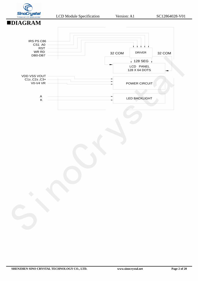
DIAGRAM
LED BACKLIGHT
POWER CIRCUIT
LCD PANEL
128 X 64 DOTS
DRIVER
128 SEG
32 COM 32 COMWR RD
RST
DB0-DB7
VDD VSS VOUTC1±,C2±,C3+
V0-V4 VR
A
K
CS1 A0
IRS PS C86

LCD Module Specification Version: A1 SC12864028-V01
SHENZHEN SINO CRYSTAL TECHNOLOGY CO., LTD. www.sinocrystal.net Page 3 of 20
INTERFACE PIN CONNECTIONS
NO SYMBOL LEVEL FUNCTION
1 CS1 H/L Chip select signal
2 RST H/L Chip reset signal
3 A0 H/L
Register selection input
H : Indicate that D0 to D7 are display data.
L:Indicate that D0 to D7 are control data
4 WR(R/W) H/L 8080 series: Write signal
6800 series: Read or Write signal
5 RD(E) H/L 8080 series: Read signal
6800 series: Enable signal
6-13
D0-D5
D6(SCL)
D7(SI)
H/L
This is an 8-bit bi-directional data bus that connects
to an 8-bit or 16-bit standard MPU data bus.
When the serial interface (SPI-4) is selected (P/S =
“L”) :
D7 : serial data input (SI) ;
D6 : the serial clock input (SCL).
D0 to D5 should be connected to VDD or floating.
14 VDD -- Supply voltage for logic
15 VSS -- Ground
16 VOUT -- Power for LCD
17 C3+ -- DC/DC voltage converter. Connect a capacitor
between this terminal and the CAP1N terminal.
18 C1- -- DC/DC voltage converter. Connect a capacitor
between this terminal and the CAP1P terminal.
19 C1+ --
DC/DC voltage converter. Connect a capacitor
between this terminal and the CAP1N terminal. Reset
signal.
20 C2+ -- DC/DC voltage converter. Connect a capacitor
between this terminal and the CAP2N terminal.
21 C2- --
DC/DC voltage converter. Connect a capacitor
between this terminal and the CAP2P terminal. Chip
select.
22-26 V4-V0 -- This is a multi-level power supply for the liquid
crystal drive.
27 VR -- Contrast adjustment input.
28 C86 H/L C86 = “H”: 6800 Series MPU interface.
C86 = “L”: 8080 Series MPU interface.
29 PS H/L P/S = “H”: Parallel interface
P/S = “L”: Serial interface
30 IRS H/L RS = “H”: Use the internal resistors
IRS = “L”: Do not use the internal resistors.
LCD Module Specification Version: A1 SC12864028-V01
SHENZHEN SINO CRYSTAL TECHNOLOGY CO., LTD. www.sinocrystal.net Page 4 of 20
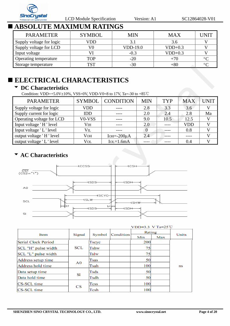
ABSOLUTE MAXIMUM RATINGS
PARAMETER SYMBOL MIN MAX UNIT
Supply voltage for logic VDD 3.1 3.6 V
Supply voltage for LCD V0 VDD-19.0 VDD+0.3 V
Input voltage VI -0.3 VDD+0.3 V
Operating temperature TOP -20 +70 C
Storage temperature TST -30 +80 C
ELECTRICAL CHARACTERISTICS
DC Characteristics Condition: VDD=+5.0V±10%, VSS=0V, VDD-V0=8 to 17V, Ta=-30 to +85℃
PARAMETER SYMBOL CONDITION MIN TYP MAX UNIT
Supply voltage for logic VDD ---- 2.8 3.3 3.6 V
Supply current for logic IDD ---- 2.0 2.4 2.8 Ma
Operating voltage for LCD V0-VSS ---- 9.0 10.5 12.5 V
Input voltage ' H ' level VIH ---- 2.0 ---- VDD V
Input voltage ' L ' level VIL ---- 0 ---- 0.8 V
output voltage ' H ' level VOH IOH=-200A 2.4 ---- ---- V
output voltage ' L ' level VOL IOL=1.6mA ---- ---- 0.4 V
AC Characteristics

LCD Module Specification Version: A1 SC12864028-V01
SHENZHEN SINO CRYSTAL TECHNOLOGY CO., LTD. www.sinocrystal.net Page 5 of 20
BACKLIGHT
Backlight Type
Backlight Type: LED
Power Supply For Backlight
Absolute Maximum Rating
PARAMETER SYMBOL CONDITION MAX UNIT Absolute maximum forward current Ifm 60 Ma
Peak forward current Ifp 1 MSEC plus 10% Duty Cycle 30 mA
Reverse voltage VR 5.0 V
Life Hour If(forward current) =45mA 20000 H
Note: For operation above 25℃,Then Ifm Ifp must be decreased, the Current decreased is -1.08mA/℃ for DC
drive and -2.58mA/℃ Pulse drive, the power dissipation is -4.5mW/℃.The product working current must
not more than the 70% of the Ifm or Ifp according to the working temperature.
Electrical-Optical Characteristics
PARAMETER SYMBOL CONDITION MIN TYP MAX UNIT
Forward voltage Vf (LED(+)-LED(-))
2.8 3.3 3.5 V
Forward current If ---- 15 ---- mA
Reverse current Ir VR=5.0V ---- ---- 160 A
Wavelength
(Chromaticity) λp If(forward current) = 15mA
x=0.275
y=0.285
x=0.295
y=0.300
x=0.305
y=0.315
Luminance Lv If(forward current) = 15mA 200 260 cd/㎡
Note:The Master Screen’s luminance is
the average value of 5 points,and The
Lvmin./Lvmax. is not less than 70%.
The measurement instrument is BM-7
luminance Colorimeter. The aperture is
Φ5 mm.

LCD Module Specification Version: A1 SC12864028-V01
SHENZHEN SINO CRYSTAL TECHNOLOGY CO., LTD. www.sinocrystal.net Page 6 of 20
OPTICAL CHARACTERISTICS
Test instrument is LCD-5000,made in Japan
Item Symbol Condition Min Typ Max Unit Remarks Note
Operating voltage Vop 25℃ 9.6 9.8 10.0 V --- ---
Response time Tr ---- ---- 128 400 Ms --- 1
Td ---- ---- 143 400 Ms --- 1
Contrast ratio Cr ---- ---- 24 ---- --- --- 2
Viewing angle
range Cr≥6
---- 60 ---- Deg Ø=0° 3
---- 28 ---- Deg Ø=180° 3
Definition Of Viewing Angle
Note1: Definition of response time
Note2: Definition of contrast ratio ‘Cr’ Note3: Definition of viewing angle range ‘’

LCD Module Specification Version: A1 SC12864028-V01
SHENZHEN SINO CRYSTAL TECHNOLOGY CO., LTD. www.sinocrystal.net Page 7 of 20
Note4:Measuring Instruments For Electro-optical Characteristics
*1.Light source position for measuring the reflective type of LCD panel
*2.Light source position for measuring the transflective / transmissive types of LCD panel
θ θ0
NORMAL
θ0 –θ=30
LIGHT SOURCE
(*1)
(*2)

LCD Module Specification Version: A1 SC12864028-V01
SHENZHEN SINO CRYSTAL TECHNOLOGY CO., LTD. www.sinocrystal.net Page 8 of 20
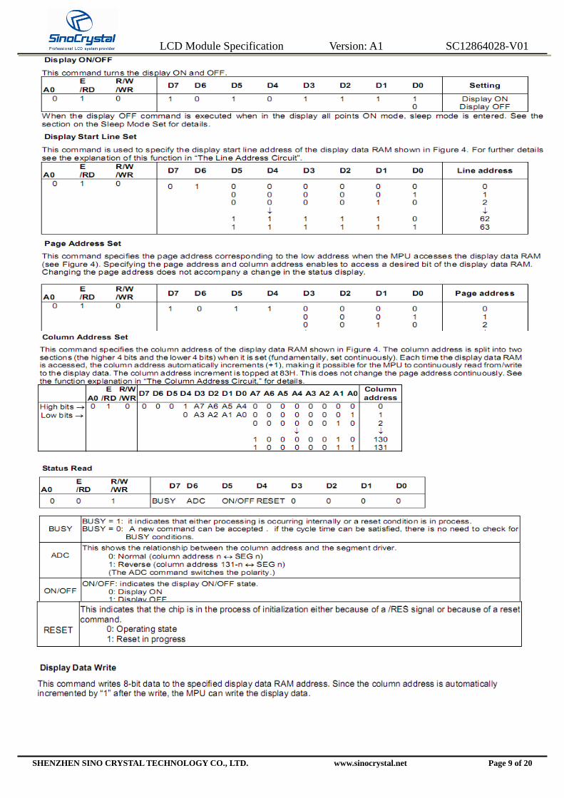
OPERATING PRINCIPLES METHODS
Control And Display Command
LCD Module Specification Version: A1 SC12864028-V01
SHENZHEN SINO CRYSTAL TECHNOLOGY CO., LTD. www.sinocrystal.net Page 9 of 20

LCD Module Specification Version: A1 SC12864028-V01
SHENZHEN SINO CRYSTAL TECHNOLOGY CO., LTD. www.sinocrystal.net Page 10 of 20

LCD Module Specification Version: A1 SC12864028-V01
SHENZHEN SINO CRYSTAL TECHNOLOGY CO., LTD. www.sinocrystal.net Page 11 of 20

LCD Module Specification Version: A1 SC12864028-V01
SHENZHEN SINO CRYSTAL TECHNOLOGY CO., LTD. www.sinocrystal.net Page 12 of 20
LCD Module Specification Version: A1 SC12864028-V01
SHENZHEN SINO CRYSTAL TECHNOLOGY CO., LTD. www.sinocrystal.net Page 13 of 20
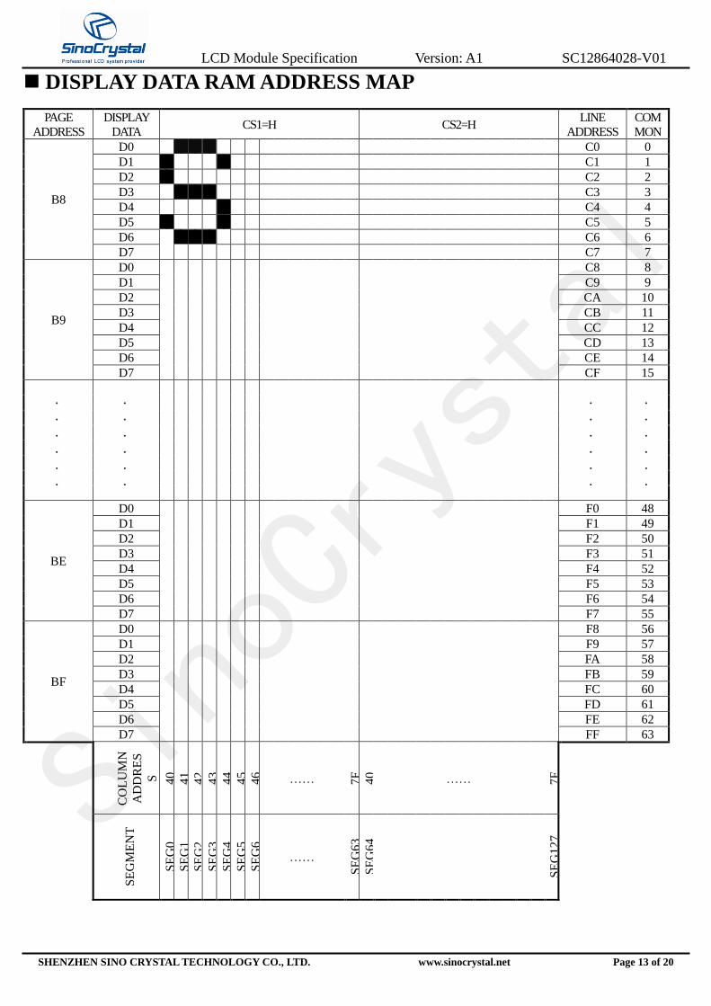
DISPLAY DATA RAM ADDRESS MAP
PAGE
ADDRESS
DISPLAY
DATA CS1=H CS2=H
LINE
ADDRESS
COM
MON
B8
D0 C0 0
D1 C1 1
D2 C2 2
D3 C3 3
D4 C4 4
D5 C5 5
D6 C6 6
D7 C7 7
B9
D0 C8 8
D1 C9 9
D2 CA 10
D3 CB 11
D4 CC 12
D5 CD 13
D6 CE 14
D7 CF 15
.
.
.
.
.
.
.
.
.
.
.
.
.
.
.
.
.
.
.
.
.
.
.
.
BE
D0 F0 48
D1 F1 49
D2 F2 50
D3 F3 51
D4 F4 52
D5 F5 53
D6 F6 54
D7 F7 55
BF
D0 F8 56
D1 F9 57
D2 FA 58
D3 FB 59
D4 FC 60
D5 FD 61
D6 FE 62
D7 FF 63
CO
LU
MN
AD
DR
ES
S
40
41
42
43
44
45
46
…… 7F
40
…… 7F
SE
GM
EN
T
SE
G0
S
EG
1
SE
G2
SE
G3
S
EG
4
SE
G5
SE
G6
……
SE
G63
SE
G64
SE
G12
7

LCD Module Specification Version: A1 SC12864028-V01
SHENZHEN SINO CRYSTAL TECHNOLOGY CO., LTD. www.sinocrystal.net Page 14 of 20
POWER SUPPLY FOR LCM MODULE
GND
VDDVSS
GND +5.0V
A(+)
K(-)
+5.0V
SC
S12
8640
15-V
02
LCD Module Specification Version: A1 SC12864028-V01
SHENZHEN SINO CRYSTAL TECHNOLOGY CO., LTD. www.sinocrystal.net Page 15 of 20
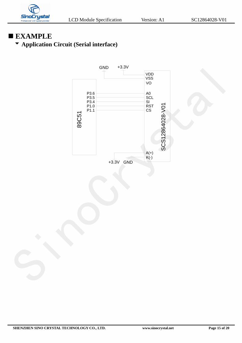
EXAMPLE
Application Circuit (Serial interface)
+3.3V
89C
51
GND
VSS
GND
A(+)
K(-)
P1.0P1.1
P3.4P3.5P3.6
VO
VDD
+3.3V
A0SCLSIRSTCS
SC
S12864028-V
01
LCD Module Specification Version: A1 SC12864028-V01
SHENZHEN SINO CRYSTAL TECHNOLOGY CO., LTD. www.sinocrystal.net Page 16 of 20
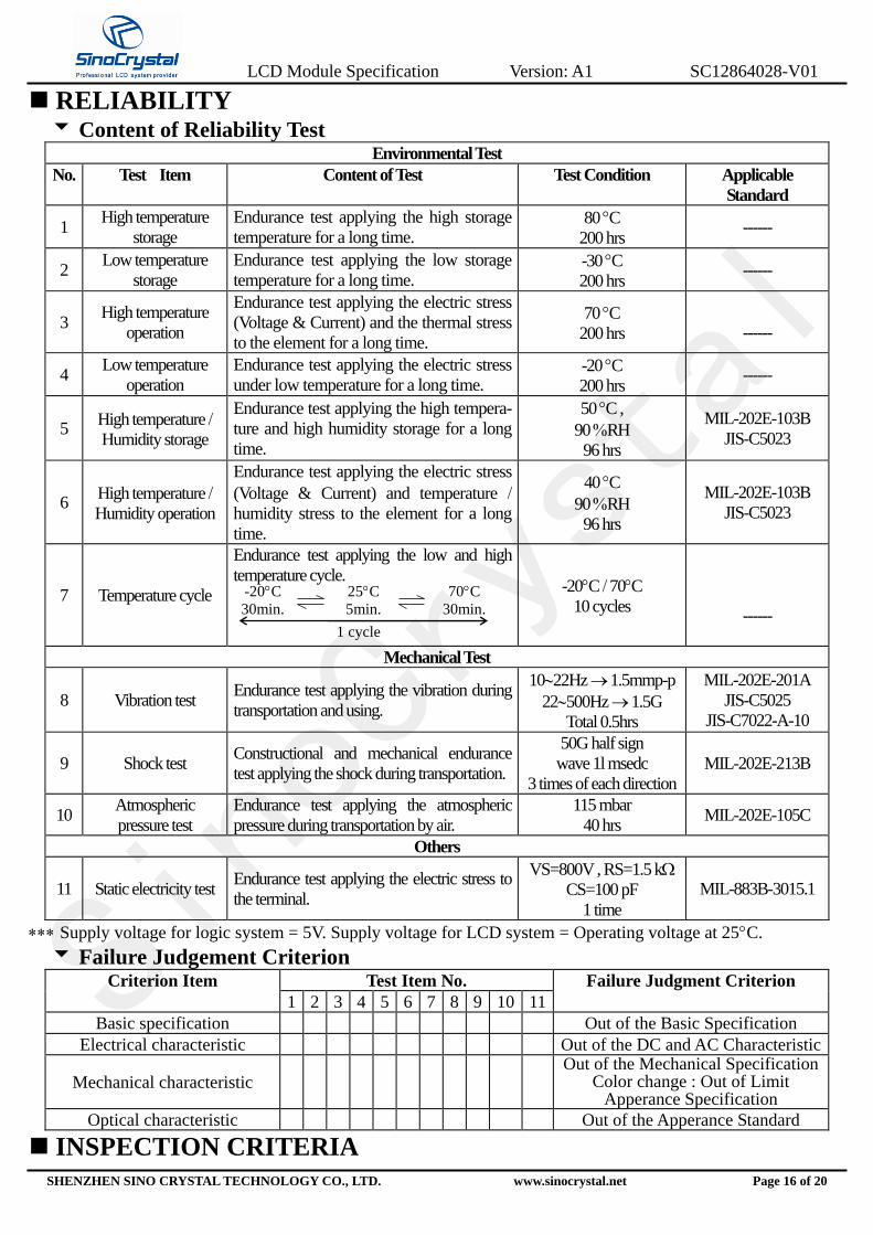
RELIABILITY Content of Reliability Test
Environmental Test
No. Test Item Content of Test Test Condition Applicable
Standard
1 High temperature
storage
Endurance test applying the high storage
temperature for a long time. 80 C
200 hrs ------
2 Low temperature
storage
Endurance test applying the low storage
temperature for a long time. -30 C
200 hrs ------
3 High temperature
operation
Endurance test applying the electric stress
(Voltage & Current) and the thermal stress
to the element for a long time.
70 C
200 hrs
------
4 Low temperature
operation
Endurance test applying the electric stress
under low temperature for a long time. -20 C
200 hrs ------
5 High temperature
Humidity storage
Endurance test applying the high tempera-
ture and high humidity storage for a long
time.
50 C ,
90 RH
96 hrs
MIL-202E-103B
JIS-C5023
6 High temperature
Humidity operation
Endurance test applying the electric stress
(Voltage & Current) and temperature
humidity stress to the element for a long
time.
40 C
90 RH
96 hrs
MIL-202E-103B
JIS-C5023
7 Temperature cycle
Endurance test applying the low and high
temperature cycle.
-20C 70C
10 cycles
------
Mechanical Test
8 Vibration test Endurance test applying the vibration during
transportation and using.
1022Hz 1.5mmp-p
22500Hz 1.5G
Total 0.5hrs
MIL-202E-201A
JIS-C5025
JIS-C7022-A-10
9 Shock test Constructional and mechanical endurance
test applying the shock during transportation.
50G half sign
wave 1l msedc
3 times of each direction
MIL-202E-213B
10 Atmospheric
pressure test
Endurance test applying the atmospheric
pressure during transportation by air.
115 mbar
40 hrs MIL-202E-105C
Others
11 Static electricity test Endurance test applying the electric stress to
the terminal.
VS=800V , RS=1.5 k
CS=100 pF
1 time
MIL-883B-3015.1
Supply voltage for logic system = 5V. Supply voltage for LCD system = Operating voltage at 25C.
Failure Judgement Criterion Criterion Item Test Item No. Failure Judgment Criterion
1 2 3 4 5 6 7 8 9 10 11
Basic specification Out of the Basic Specification
Electrical characteristic Out of the DC and AC Characteristic
Mechanical characteristic Out of the Mechanical Specification
Color change : Out of Limit Apperance Specification
Optical characteristic Out of the Apperance Standard
INSPECTION CRITERIA
25C
5min.
1 cycle
70C
30min.
-20C
30min.

LCD Module Specification Version: A1 SC12864028-V01
SHENZHEN SINO CRYSTAL TECHNOLOGY CO., LTD. www.sinocrystal.net Page 17 of 20
see :Q/SC0002-05
PRECAUTIONS FOR USING LCD MODULES Handing Precautions
(1) The display panel is made of glass. Do not subject it to a mechanical shock by dropping it or
impact.
(2) If the display panel is damaged and the liquid crystal substance leaks out, be sure not to get
any in your mouth. If the substance contacts your skin or clothes, wash it off using soap and
water.
(3) Do not apply excessive force to the display surface or the adjoining areas since this may
cause the color tone to vary.
(4) The polarizer covering the display surface of the LCD module is soft and easily scratched.
Handle this polarizer carefully.
(5) If the display surface becomes contaminated, breathe on the surface and gently wipe it with a
soft dry cloth. If it is heavily contaminated, moisten cloth with one of the following solvents :
- Isopropyl alcohol
- Ethyl alcohol
(6) Solvents other than those above-mentioned may damage the polarizer. Especially, do not use
the following.
- Water
- Ketone
- Aromatic solvents
(7) Exercise care to minimize corrosion of the electrode. Corrosion of the electrodes is
accelerated by water droplets, moisture condensation or a current flow in a high-humidity
environment.
LCD Module Specification Version: A1 SC12864028-V01
SHENZHEN SINO CRYSTAL TECHNOLOGY CO., LTD. www.sinocrystal.net Page 18 of 20
USING LCD MODULES Liquid Crystal Display Modules
LCD is composed of glass and polarizer. Pay attention to the following items when handling.
(1) Please keep the temperature within specified range for use and storage. Polarization degradation,
bubble generation or polarizer peel-off may occur with high temperature and high humidity.
(2) Do not touch, push or rub the exposed polarizers with anything harder than an HB pencil lead
(glass, tweezers, etc.).
(3) N-hexane is recommended for cleaning the adhesives used to attach front/rear polarizers and
reflectors made of organic substances which will be damaged by chemicals such as acetone,
toluene, ethanol and isopropylalcohol.
(4) When the display surface becomes dusty, wipe gently with absorbent cotton or other soft
material like chamois soaked in petroleum benzin. Do not scrub hard to avoid damaging the
display surface.
(5) Wipe off saliva or water drops immediately, contact with water over a long period of time may
cause deformation or color fading.
(6) Avoid contacting oil and fats.
(7) Condensation on the surface and contact with terminals due to cold will damage, stain or dirty
the polarizers. After products are tested at low temperature they must be warmed up in a
container before coming is contacting with room temperature air.
(8) Do not put or attach anything on the display area to avoid leaving marks on.
(9) Do not touch the display with bare hands. This will stain the display area and degradate
insulation between terminals (some cosmetics are determinated to the polarizers).
(10) As glass is fragile. It tends to become or chipped during handling especially on the edges.
Please avoid dropping or jarring.
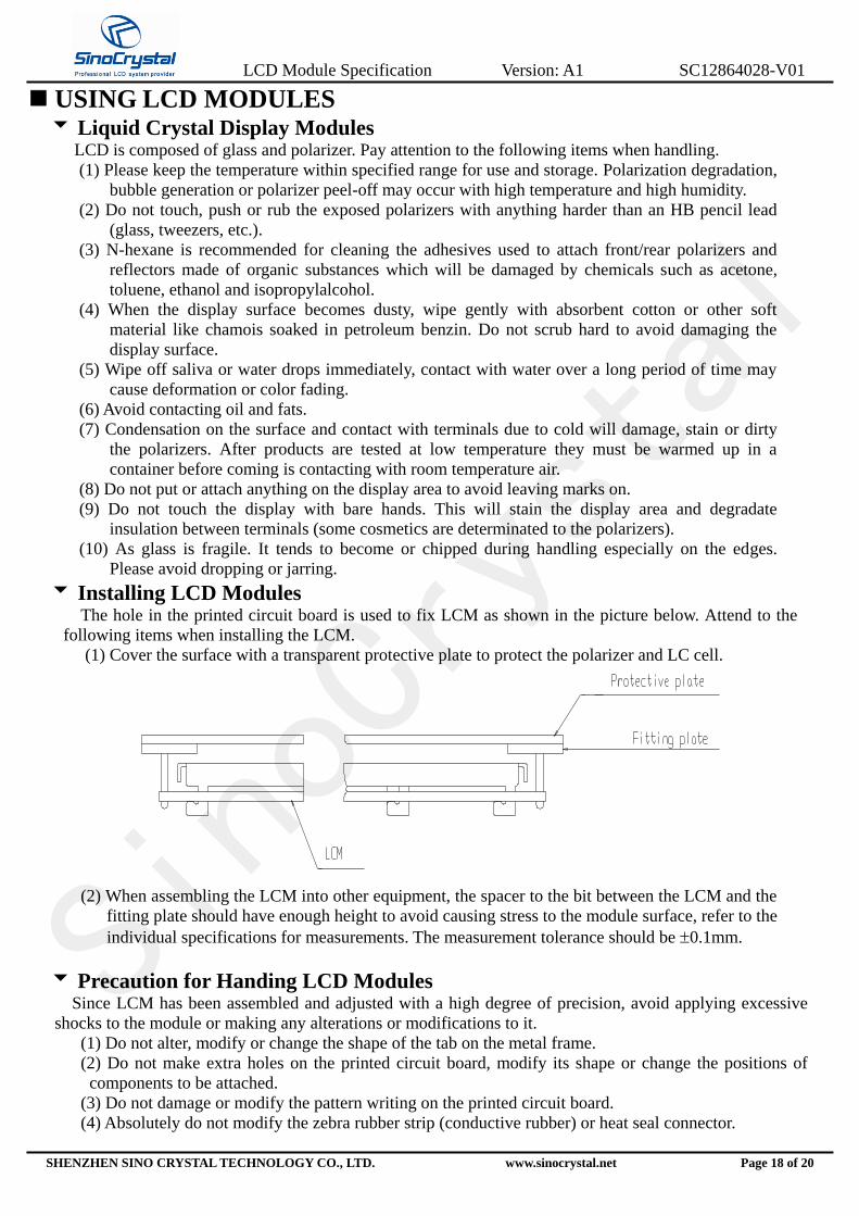
Installing LCD Modules The hole in the printed circuit board is used to fix LCM as shown in the picture below. Attend to the
following items when installing the LCM.
(1) Cover the surface with a transparent protective plate to protect the polarizer and LC cell.
(2) When assembling the LCM into other equipment, the spacer to the bit between the LCM and the
fitting plate should have enough height to avoid causing stress to the module surface, refer to the
individual specifications for measurements. The measurement tolerance should be 0.1mm.
Precaution for Handing LCD Modules Since LCM has been assembled and adjusted with a high degree of precision, avoid applying excessive
shocks to the module or making any alterations or modifications to it.
(1) Do not alter, modify or change the shape of the tab on the metal frame.
(2) Do not make extra holes on the printed circuit board, modify its shape or change the positions of
components to be attached.
(3) Do not damage or modify the pattern writing on the printed circuit board.
(4) Absolutely do not modify the zebra rubber strip (conductive rubber) or heat seal connector.

LCD Module Specification Version: A1 SC12864028-V01
SHENZHEN SINO CRYSTAL TECHNOLOGY CO., LTD. www.sinocrystal.net Page 19 of 20
(5) Except for soldering the interface, do not make any alterations or modifications with a soldering
iron.
(6) Do not drop, bend or twist LCM.
Electro-Static Discharge Control Since this module uses a CMOS LSI, the same careful attention should be paid to electrostatic discharge as
for an ordinary CMOS IC.
(1) Make certain that you are grounded when handing LCM.
(2) Before remove LCM from its packing case or incorporating it into a set, be sure the module and
your body have the same electric potential.
(3) When soldering the terminal of LCM, make certain the AC power source for the soldering iron
does not leak.
(4) When using an electric screwdriver to attach LCM, the screwdriver should be of ground
potentiality to minimize as much as possible any transmission of electromagnetic waves produced
sparks coming from the commutator of the motor.
(5) As far as possible make the electric potential of your work clothes and that of the work bench the
ground potential.
(6) To reduce the generation of static electricity be careful that the air in the work is not too dried. A
relative humidity of 50%-60% is recommended.
Precaution for soldering to the LCM (1) Observe the following when soldering lead wire, connector cable and etc. to the LCM.
- Soldering iron temperature : 280C 10C.
- Soldering time : 3-4 sec.
- Solder : eutectic solder.
If soldering flux is used, be sure to remove any remaining flux after finishing to soldering
operation. (This does not apply in the case of a non-halogen type of flux.) It is recommended that
you protect the LCD surface with a cover during soldering to prevent any damage dur to flux
spatters.
(2) When soldering the electroluminescent panel and PC board, the panel and board should not be
detached more than three times. This maximum number is determined by the temperature and
time conditions mentioned above, though there may be some variance depending on the
temperature of the soldering iron.
(3) When remove the electroluminescent panel from the PC board, be sure the solder has completely
melted, the soldered pad on the PC board could be damaged.
Precautions for Operation (1) Viewing angle varies with the change of liquid crystal driving voltage (VO). Adjust VO to show
the best contrast.
(2) Driving the LCD in the voltage above the limit shortens its life.
(3) Response time is greatly delayed at temperature below the operating temperature range. However,
this does not mean the LCD will be out of the order. It will recover when it returns to the specified
temperature range.
(4) If the display area is pushed hard during operation, the display will become abnormal. However, it
will return to normal if it is turned off and then back on.
(5) Condensation on terminals can cause an electrochemical reaction disrupting the terminal circuit.
Therefore, it must be used under the relative condition of 40C , 50% RH.
(6) When turning the power on, input each signal after the positive/negative voltage becomes stable.

LCD Module Specification Version: A1 SC12864028-V01
SHENZHEN SINO CRYSTAL TECHNOLOGY CO., LTD. www.sinocrystal.net Page 20 of 20
Storage When storing LCD’s as spares for some years, the following precaution are necessary.
(1) Store them in a sealed polyethylene bag. If properly sealed, there is no need for dessicant.
(2) Store them in a dark place. Do not expose to sunlight or fluorescent light, keep the temperature
between 0C and 35C.
(3) The polarizer surface should not come in contact with any other objects. (We advise you to store
them in the container in which they were shipped.)
(4) Environmental conditions :
- Do not leave them for more than 168hrs. at 80C.
- Should not be left for more than 48hrs. at -30C.
Safety (1) It is recommended to crush damaged or unnecessary LCD’s into pieces and wash them off with
solvents such as acetone and ethanol, which should later be burned.
(2) If any liquid out of a damaged glass cell and comes in contact with the hands, wash off thoroughly
with soap and water.
Limited Warranty Unless agreed between SINO and customer, SINO will replace or repair any of its LCD modules
which are found to be functionally defective when inspected in accordance with SINO LCD acceptance
standards (copies available upon request) for a period of one year from date of shipments.
Cosmetic/visual defects must be returned to SINO within 90 days of shipment. Confirmation of such date
shall be based on freight documents. The warranty liability of SINO limited to repair and/or replacement on the terms
set forth above. SINO will not be responsible for any subsequent or consequential events.
Return LCM under warranty
No warranty can be granted if the precautions stated above have been disregarded. The typical
examples of violations are :
- Broken LCD glass.
- PCB eyelet’s damaged or modified.
- PCB conductors damaged.
- Circuit modified in any way, including addition of components.
- PCB tampered with by grinding, engraving or painting varnish.
- soldering to or modifying the bezel in any manner.
Module repairs will be invoiced to the customer upon mutual agreement. Modules must be returned
with sufficient description of the failures or defects. Any connectors or cable installed by the customer
must be removed completely without damaging the PCB eyelet’s, conductors and terminals.