SUPPLEMENTAL SPECIFICATIONS
394
SUPPLEMENTAL SPECIFICATIONS Supplement to the 2000 Edition of the Standard Specifications For Highway and Bridge Construction March 2004 New Mexico Department of Transportation
-
Upload
khangminh22 -
Category
Documents
-
view
2 -
download
0
Transcript of SUPPLEMENTAL SPECIFICATIONS

SUPPLEMENTAL SPECIFICATIONS
Supplement to the 2000 Edition of the Standard Specifications
For Highway and Bridge Construction
March 2004
New Mexico Department of Transportation

NEW MEXICO DEPARTMENT OF TRANSPORTATION SUPPLEMENTAL SPECIFICATIONS
TABLE OF CONTENTS
1/2
DIVISION 200 - EARTHWORK
Sections Page
203 EXCAVATION, BORROW, AND EMBANKMENT 203-1 to 203-21 206 EXCAVATION AND BACKFILL FOR CULVERTS AND MINOR
STRUCTURES 206-1 to 206-3
210 STRUCTURE EXCAVATION AND BACKFILL FOR BRIDGES 210-1 to 210-3
DIVISION 300 - BASES Sections Page
303 BASE COURSE (QC/QA) 303-1 to 303-6 304 BASE COURSE (NON QC/QA) 304-1 to 304-7 306 CEMENT AND LIME TREATED SUBGRADE 306A-1 to 306B-10
DIVISION 400 - SURFACE TREATMENTS AND PAVEMENTS
Sections Page
401 PAVEMENT SMOOTHNESS MEASUREMENT 401-1 to 401-10 402 BITUMINOUS MATERIALS, HYDRATED LIME, & LIQUID ANTI-STRIPPING
AGENTS 402-1 to 402-7
403 OPEN-GRADED FRICTION COURSE (QC/QA) 403-1 to 403-4 404 OPEN GRADED FRICTION COURSE (NON QC/QA) 404-1 to 404-5 405 DETOUR PAVEMENTS 405-1 to 405-4 407 TACK COAT 407-1 to 407-2 408 PRIME COAT 408-1 to 408-3 412 HOT-IN-PLACE RECYCLING OF ASPHALT PAVEMENT (REMIXING
METHOD) 412-1 to 412-6
413 SINGLE-MACHINE HOT IN-PLACE SURFACE REPAVING 413-1 to 413-7 415 PAVEMENT SURFACE RESTORATION 415-1 to 415-8 420 PLANT-MIX BITUMINOUS PAVEMENT (DENSE-GRADED A,B,C,D, NON
QC/QA) 420-1 to 420-20
421 PLANT-MIX BITUMINOUS PAVEMENT (DENSE-GRADED A,B,C,D, QC/QA) 421-1 to 421-17 422 PLANT-MIX BITUMINOUS PAVEMENT (SUPERPAVE, NON QC/QA) 422-1 to 422-22 423 PLANT MIX BITUMINOUS PAVEMENT (SUPERPAVE QC/QA) 423-1 to 423-19 450 PORTLAND CEMENT CONCRETE PAVEMENT (QC/QA) 450-1 to 450-15
DIVISION 500 - STRUCTURES
Sections Page
501 DRIVEN BEARING PILES 501-1 to 501-18 502 DRILLED SHAFT CONCRETE BEARING PILES 502-1 to 502-19 506 MECHANICALLY STABILIZED EARTH RETAINING STRUCTURES 506-1 to 506-10 510 PORTLAND CEMENT CONCRETE 510-1 to 510-41 535 CRACK SEALING USING LOW-VISCOSITY GRAVITY-FED SEALERS 535-1 to 535-5

NEW MEXICO DEPARTMENT OF TRANSPORTATION SUPPLEMENTAL SPECIFICATIONS
TABLE OF CONTENTS
2/2
536 POLYMER CONCRETE BRIDGE DECK OVERLAY 536-1 to 536-9 540 STEEL REINFORCEMENT 540-1 to 540-13
DIVISION 600 - MISCELLANEOUS CONSTRUCTION
Sections Page
602 SLOPE AND EROSION PROTECTION STRUCTURES 602-1 to 602-12 604 SOIL AND DRAINAGE GEOTEXTILES 604-1 to 604-7 606 METAL AND CONCRETE WALL BARRIER 606-1 to 606-13
DIVISION 700 - TRAFFIC CONTROL DEVICES
Sections Page
701 TRAFFIC SIGNS AND SIGN STRUCTURES 701-1 to 701-22
DIVISION 900 - QUALITY CRITERIA Sections Page
901 QUALITY CONTROL/QUALITY ASSURANCE (QC/QA) 901-1 to 901-19 920 EVALUATION OF PROPERTIES FOR PLANT-MIXED BITUMINOUS
PAVEMENT 920-1 to 920-4
NEW MEXICO DEPARTMENT OF TRANSPORTATION SUPPLEMENTAL SPECIFICATIONS FOR
EXCAVATION, BORROW AND EMBANKMENT
SECTION 203 All provisions of the New Mexico Department Of Transportation's Standard Specifications for Highway and Bridge Construction shall apply in addition to the following: Delete SECTION 203 - EXCAVATION, BORROW AND EMBANKMENT in its entirety and substitute the following: 203.1 DESCRIPTION. 203.11 This work shall consist of excavation, providing borrow, constructing embankment, hauling, disposing, placing, and compacting all materials in compliance with the specifications, and the lines, grades, thicknesses, and typical cross-sections shown in the contract. 203.2 MATERIALS. Geotechnical investigation results are shown in the Contract Documents or are available from the Project Office. The geotechnical investigation is provided for information only. Information contained in the geotechnical investigation is not a representation or warranty of the continuity of the conditions identified beyond the test holes or test pits subsurface investigation. It is expressly understood that the Contractor is solely responsible for interpretations and conclusions drawn from this geotechnical information. 203.21 Classification of Materials. Material will be classified for payment as follows: A. Rock Excavation. Rock excavation is defined as sound and solid masses, layers, or
ledges of mineral matter in place and of such hardness and texture that it meets one of the following field test criteria: 1. Ripping Test. Materials which cannot be effectively loosened or broken down by
ripping in a single pass with a late model, well-maintained tractor-mounted hydraulic ripper equipped with one digging point of standard manufacturer’s design adequately sized for use with, and propelled by, a crawler-type tractor with a minimum net flywheel power rating of 190 kW (255hp), operating in low gear will be classified as rock excavation; or
2. Seismic Test. The Contractor may elect to use seismic velocities performed by a
person qualified to classify material. In this case, all materials with seismic velocities over 1800 m/s (6000 ft/s) will be classified as rock excavation. At least 14 days prior to performing the excavation work, the Contractor shall submit for
203-1

approval to the Project Manager the qualifications of the person performing and interpreting the seismic testing. However, in all cases, an Item 1 (crawler-type tractor ripper) will be used to resolve differences with regard to type of material, if velocities fall below 1800 m/s (6000 ft/s).
3. Handling Test. All boulders or detached pieces of solid rock more than 1 m3 (1.3
yd3) in volume which cannot be readily broken down with excavation equipment will be classified as rock excavation.
B. Unclassified Excavation. Unclassified excavation includes all material other than
rock excavation. All boulders or detached pieces of solid rock less than 1 m3 (1.3 yd3) in volume will be classified as unclassified excavation.
C. Borrow. Borrow shall consist of approved material required for the construction of
embankments, or for other portions of the work, and, unless otherwise defined in the contract, shall be obtained from contractor provided sources that have been approved by the Project Manager. Borrow shall be provided in accordance with the requirements of Section 203.34, below. R-values shall conform with the values shown in the contract.
D. Embankment. Embankment shall consist of constructing embankments and
miscellaneous fill with suitable materials from unclassified excavation, borrow, and other sources.
E. Subexcavation. Subexcavation shall consist of excavating unsuitable and unstable
material below established profile grade or typical cross-section to the dimensions shown on the plans, or as designated by the Project Manager. The removed materials shall be hauled and disposed of at the site(s) designated in the contract or as determined by the Project Manager. Voids created by subexcavation in roadbed areas shall be backfilled with approved material meeting the R-value requirements shown in the contract.
203.3 CONSTRUCTION REQUIREMENTS. 203.31 General. Excavation and embankment for the roadway, intersections, and entrances shall be finished to reasonably smooth and uniform surfaces. No materials shall be wasted without prior approval by the Project Manager. Material with an R-value less than the design R-value shall not be placed, or be allowed to remain, within the top 600 mm (2 feet) of the finished subgrade. Excavation operations shall be conducted to preserve the materials below and beyond the lines and grades of all excavations in the soundest possible condition. Prior to beginning excavation, grading, and embankment operations in any area, all necessary clearing and grubbing shall be performed in accordance with Section 201, Clearing and Grubbing. The Contractor shall notify the Project Manager sufficiently in advance of opening excavation or borrow areas so that cross-section elevations and measurements of the ground surface may be taken.
203-2

In the event the Contractor encounters a previously unreported environmental or cultural resource which is not included in the Contract, the Contractor shall terminate all further operations in the immediate area until the Department has had the opportunity to review and complete appropriate mitigation actions as required in subsection 107.12, Environmental and Cultural Resource Discoveries. All excess or unsuitable excavated material, including rock and boulders that cannot be used in embankments, may be placed in the toe of any fill or may be used to flatten slopes of nearby fills. The work will be completed in a manner satisfactory tothe Project Manager. This will require that a minimum of 600 mm (2 ft) of cover soil placed over the rocks and boulders All excess material that cannot be used in embankments will be disposed in a manner suitable to the Project Manager and in conformance with environmental requirements. 203.32 Excavation. All roadbed earth cut sections shall be removed to subgrade elevation for the full width of the roadbed. Roadbed cut sections resulting from excavation shall be finished to a reasonably smooth and uniform surface. The Contractor shall remove unsuitable or unstable material below finished subgrade. The Contractor shall conduct removal operations of unsuitable material in such a way that the necessary cross-sectional measurements can be taken before the backfill is placed. All removed material shall be disposed of as shown in the contract. Material will be considered unsuitable if it has an R-value that is less than the R-value designated in the contract, or if deleterious material is present, and will be considered unstable if saturated and pumping. 203.321 Limits of Excavation. All excavation shall be to the lines and grades shown in the drawings. Surveying during excavation, for excavation control purposes, shall be the responsibility of the Contractor. All quantities shall be measured and classified in place, to the lines shown on the drawings. The limits of material meeting the classification of rock excavation, as covered in subsection 203.21A paragraphs 1 Ripping Test or 2 Seismic Test, shall be determined by conducting either the ripping test or the seismic test at the boundaries of excavated material that will be classified as rock excavation and material that will be classified as unclassified excavation. The Department shall verify these tests. The limits of material to be classified as rock excavation must be agreed upon by both the contractor and the Project Manager prior to the material being excavated. As an alternative, the limits of rock excavation may be determined based on the estimated percentages shown in the contract as covered in subsection 203.41A. If material has been classified as rock excavation, as covered in subsection 203.21 A, Rock Excavation, paragraph 2 Seismic Test and such material is overlain by soil or overburden, the quantities for rock excavation shall be measured from the blaster’s drill hole log cards. Such log cards shall become a part of the surveying records supporting the computation of rock excavation quantities. 203.33 Rock Cuts. The Contractor shall be responsible for using proper drilling and blasting procedures in accordance with the criteria hereinafter described. Controlled blasting rock excavation will be in accordance with accepted practices and shall produce a clean face on the excavated cut which will be unaffected by subsequent
203-3

blasting and excavation operations. Unless otherwise provided, roadbed cuts in rock shall be excavated to subgrade elevation. A tolerance of 150 mm (6 in.) below the subgrade elevation will be permitted. Undrained pockets shall not be left on the roadbed surface. Base course shall be placed on the rock cut foundation and compacted to the required density. After compaction, the surfacing material shall be in compliance with the grade, elevation, and typical section shown in the contract. 203.331 Blasting Requirements. This provision concerns excavation of rock using controlled blasting to establish a specified backslope with minimal blast damage, and production blasting to facilitate excavation. A. Definitions.
1. Controlled Blasting refers to the controlled use of explosives and blasting accessories in carefully spaced and aligned blast holes to provide a free surface or shear plane in the rock along the specified backslope; and to limit fly rock, permanent ground displacement, air concussion, and overbreak. Controlled blasting methods covered by this Specification include pre-splitting and cushion blasting.
2. Pre-Splitting is the simultaneous detonation of a single line of blast holes drilled
along a specified excavation backslope before production blast holes are fired. The spacing for pre-split blast holes is typically less than for production blast holes.
3. Cushion Blasting (also known as Trim Blasting) is the simultaneous detonation of
a single line of blast holes along a specified excavation backslope after the main excavation has been completed. This method is performed to trim the excavation to the final backslope. The spacing for cushion blast holes is typically less than for production blast holes.
4. Production Blasting is fragmentation blasting in the main excavation area,
usually using more widely spaced blast holes than are used for controlled blasting.
5. Final Line, or Controlled Blast Line refers to the row of controlled blast holes
drilled in the plane of the specified excavation backslope. The controlled blast holes drilled in this plane constitute the basis for payment under the Controlled Blasting pay item. All blast holes drilled in front of the final line blast holes are considered to be production blast holes, which are incidental to the Rock Excavation pay item.
6. Buffer Row is the first row of production blast holes immediately adjacent to, and
drilled in a plane parallel to, the controlled blast line. The explosive load in the buffer row should generally be reduced from standard production loads to minimize blast-induced damage to the final excavation backslope.
203-4
7. Blasting Operations are all activities related to blasting, including but not restricted to collaring and drilling of blast holes; preparing, fixing, loading, and firing of explosive charges; assessment of the blast after detonation; and handling of misfires.
B. Submittals.
1. Blaster in Charge. At least 30 calendar days before the delivery or use of explosive material, the Contractor shall submit for approval the name and qualifications of the person authorized to act on behalf of the Contractor and who must be licensed by the applicable state and/or local regulatory agencies to possess, transport, and use explosives. The qualifications of the Blaster in Charge shall include a list of three or more blasting projects of similar complexity that were successfully completed within the preceding five years. References relating to these projects shall be provided. The Blaster in Charge shall be approved by the Project Manager prior to the beginning of any drilling or blasting work. The Blaster in Charge shall be on-site during all blasting operations.
2. Blasting Plans. The Contractor shall provide a General Blasting Plan for each cut that requires blasting. The General Blasting Plan shall include a description of the proposed blasting operation; preliminary design criteria for production and controlled blasting including blast hole depths and patterns; and details regarding explosives and blasting accessories that will be used. The general blasting plan shall be submitted to the Project Manager no less than two weeks prior to commencing drilling and blasting operations on the specified cut. At least 48 hours prior to an individual blast, the Contractor shall submit a Detailed Blasting Plan for the blast, which contains the full details of the drilling and blasting patterns and controls the Contractor proposes to use for controlled blasting and production blasting. The intent of the Detailed Blasting Plan is to document the details for individual blasts with respect to schedule, design parameters, and actual blast hole patterns. The Detailed Blasting Plan for an individual blast shall contain the following minimum information:
a. Station limits of the proposed shot, including bench elevation if
appropriate. b. Date and time that blasting will take place. c. Removal of overburden, if applicable. d. Plan and cross section diagrams of proposed drill pattern for controlled
and production blast holes, including buffer rows, free face, burden, blast hole spacing, blast hole diameters, blast hole angles, lift height, and subdrill depth. Plans and cross sections shall be accurately drawn to scale.
203-5

e. Loading diagram showing the type and amount of explosives, primers, and initiators; and the location, depth, and type of stemming.
f. Initiation sequence of controlled and production blast holes, including
delay times and delay system. g. Manufacturer’s data sheets for all explosives, primers, and initiators to be
employed.
All blasting plans must be submitted to the Project Manager for review and approval by the Department. Any Department concerns will be discussed with the Contractor as quickly as possible. Any revisions to the blasting plans that are required based on the review by the Project Manager shall be submitted in writing to the Project Manager for final review and approval. Drilling and blasting operations related to a General Blasting Plan shall not proceed without prior written approval of the plan by the Project Manager. Loading of blast holes associated with a specific Detailed Blasting Plan shall not proceed without prior written approval of the plan by the Project Manager. Although Blasting Plan submittals and approvals will allow for quality control and record keeping purposes, it remains the responsibility of the Contractor to execute the Contractor’s blasting operations according to the approved plans.
The Contractor shall cease blasting operations and submit revised blasting plans if it is determined that through the methods being employed, property beyond the right-of-way is being adversely impacted by the blasting operations.
3. Blasting Records. Each shot shall have a Blasting Record prepared and
submitted by the Contractor on the day of the blast containing the following information:
a. Actual dimensions of the shot, including blast hole diameters and depths,
burden, spacing, subdrilling depths, stemming, powder loads, powder factors, and timing.
b. A drawing or sketch showing direction of the face and physical shot layout. c. Location of the blast in relation to project stationing and elevation. d. Date and time of loading and detonation. e. Name and signature of the person in responsible charge of loading and
firing. f. Comments by Blaster in Charge regarding misfires, fly rock occurrences,
unusual results or effects; and damage to existing facilities, adjacent property, or completed work.
203-6
g. Vibration and blast monitoring results. h. Any complaints received due to the blasting.
C. Explosives. Whenever explosives are used, they shall be of the character and amounts as permitted by State and local laws and ordinances, and all the requirements established by respective agencies having jurisdiction over them. The transportation, storage, handling, and use of explosives shall be in accordance with applicable federal, state, and local laws and regulations. All explosives and accessory devices shall be from a recognized supplier, and shall be products of a company regularly engaged in the manufacture of explosives and related products. The handling and use of explosives and accessory devices shall be in accordance with the instructions of the manufacturers. Products with an expired shelf life shall not be used.
The federal agencies administering regulations that involve explosive material are the Bureau of Alcohol, Tobacco, and Firearms (ATF), U.S. Department of Transportation (DOT), and the Occupational Safety and Health Administration (OSHA). State and local agencies include the Fire Marshal, Sheriff, and others. Specific basic authority (Code of Regulations) and responsibility definitions include: 1. ATF – Storage and accountability (record keeping and security) as prescribed in
27 CFR Part55. 2. OSHA – Transportation, worker safety and health as prescribed in 29 CFR;
storage and unsafe blasting practices in handling and use as prescribed in Part 1926, Subpart U (1926.900); Use and Loading of Explosives into Blast holes.
3. DOT – Transportation and public safety.
D. Safety. General safe practices that shall be followed by the Contractor include:
1. Federal, state, and local regulations pertaining to the transportation, storage, and use of explosives must be strictly followed.
2. When required, a blasting permit must be obtained from the local regulatory
agency by the Blaster in Charge to conduct the intended blasting. 3. Only persons authorized and qualified based on training and experience shall be
allowed to handle and use explosives. 4. No person shall smoke, carry matches or other flame producing devices, nor
shall firearms or loaded cartridges be carried while in or near a motor vehicle transporting explosives.
203-7

5. All explosives must be accounted for at all times. Explosives not being used must be stored in a locked, approved magazine facility required under the applicable provisions of DOT, ATF, and OSHA.
6. The Contractor shall post all required areas and vehicles with appropriate signs,
as required by federal regulations. 7. Necessary guards or flag persons must be safely stationed on highways during
blasting to control highway traffic. 8. The Contractor shall observe the entire blast area for a minimum of five (5)
minutes following each blast before commencing work in the cut. Potentially dangerous boulders or other material located beyond the excavation limits shall be removed by the Contractor. The Contractor shall cease blasting operations if it is determined that the required slopes are not being obtained in a stable condition, or if the safety and convenience of the traveling public are being jeopardized.
E. Pre-Blast Survey. For each cut that requires blasting, the Contractor shall perform a
pre-blast survey of nearby buildings, structures, utilities, water supplies, or other environmentally sensitive areas which may potentially be at risk from blasting damage. The pre-blast condition survey shall be performed in accordance with SECTION 617-VIBRATION MONITORING. The Contractor shall certify to the Project Manager in writing prior to drilling blast holes that the pre-blast survey for a specified cut has been completed.
The Contractor, prior to the commencement of blasting, shall notify adjacent property owners and occupants of local buildings. The Contractor shall be responsible for damages resulting from blasting.
F. Blasting Test Sections. The adequacy of each proposed Blasting Plan shall be
demonstrated by means of Blasting Test Section(s) when material of different geologic characteristic is encountered. For projects involving multiple cuts in similar geologic materials, the requirement for a Blasting Test Section in each cut may be reduced upon concurrence by the Project Manager. Blasting Test Sections shall include drilling, blasting, and excavating cut sections approximately 30 m (100 ft) long, to determine the optimum combination of method, blast hole spacing, and charge. When field conditions warrant, the Contractor may be directed to use test section lengths less than 30 m (100 ft) long. Requirements of the Blasting Test Sections shall include the following:
1. The Blasting Test Section shall be accomplished in accordance with all
requirements of Section 203.331, Blasting Requirements. A Detailed Blasting Plan for the test section shall be prepared by the Contractor, and submitted to the Project Manager at least 48 hours prior to the planned time of the blast. This Plan must be approved by the Project Manager prior to blasting the test section.
203-8

The Contractor shall begin the tests with the controlled blast holes spaced at 0.75-meters (30 inches) unless the Contractor’s Blasting Plan indicates otherwise.
. Following blasting, a sufficient amount of material shall be removed from the test section so that it can be determined if the blast hole diameter, blast hole spacing, and amount of explosives are adequate to provide the required backslope. The Contractor shall not drill ahead of the test section area until the test section has been excavated and the adequacy of results evaluated. If at any time during the progress of the main blasting operation the methods of drilling and blasting do not produce the desired results, the Contractor shall revise and retest the blasting techniques until a technique is developed that will produce the required results. The results will be considered unsatisfactory if:
a. There is an excessive amount of breakage beyond the indicated lines and grade.
b. There is excessive flyrock. c. The final backslope within the tolerances specified is non-uniform. d. Ground vibration and air blast levels exceed limits as covered in
subsection 203.331G(2), Mitigation and Monitoring. e. There are violations of other requirements of the specifications. f. Slopes are unstable. g. Safety of the public is jeopardized. h. Property or natural features are endangered.
G. Blasting Execution.
1. Notification and Schedule.
a. The Contractor shall coordinate blasting operations with the Project Manager, and notify the Project Manager a minimum of 1.5 hours prior to the blast. The time of the blast shall be estimated within a one-hour timeframe. For example, the contactor shall notify the Project Manager by 0900 hours of a blast scheduled between 1030 and 1130 hours.
b. Subject to permit provisions, the Contractor shall notify required federal,
state, and local agencies prior to each blast, or provide these agencies a blasting schedule.
203-9

c. Occupants of buildings and owners of structures and utilities that have been identified in the pre-blast survey shall be notified a minimum of 48 hours before drilling or blasting begins. Notification shall include the location and intended time of blasting.
d. Once the blast is tied in, it shall be detonated at the planned time, unless
approved otherwise by the Project Manager.
2. Mitigation and Monitoring.
a. Vibration Control and Monitoring. The Contractor shall perform vibration control and monitoring of areas identified by the pre-blast survey as described in SECTION 617 VIBRATION MONITORING.
b. Air Blast and Noise Control. The Contractor shall maintain air blast and
noise control in areas identified by the pre-blast survey as described in SECTION 617 VIBRATION MONITORING.
c. Flyrock Control. Before the firing of blasts in areas where flying rock may
result in personal injury or unacceptable damage to property or the work, the rock to be blasted shall be covered with blasting mats, soil, or other equally serviceable material, to limit flyrock from the blast area.
3. Controlled Blasting Requirements. Controlled blasting shall be carried out in
accordance with the Detailed Blasting Plans that produced acceptable results in Blasting Test Sections. The following requirements shall apply to both pre-splitting and cushion blasting:
a. If the overburden is of such nature and material that it will not support drill
holes, the Contractor shall completely remove all overburden soil and loose rock along the top of the cut to expose the rock surface prior to drilling the controlled blast holes.
b. Controlled blast holes shall be verified with functioning mechanical
devices to determine the angle at which the drill steel enters the rock. Controlled blast hole drilling will not be permitted if these devices are inoperative.
c. The Contractor shall drill 50-mm to 75-mm (2-in. to 3-in.) nominal diameter
blast holes at such spacing center to center, as determined by Blasting Test Sections or satisfactory results achieved in similar geologic materials, to achieve acceptable results, but in no case shall the spacing exceed 1 m (3 ft.).
d. The Contractor shall control drilling operations by the use of the proper
equipment and technique to ensure that no blast holes deviate from the plane of the planned construction backslope by more than 200 mm (8 in.)
203-10

either parallel or normal to the slope. Blast holes exceeding these limits shall not be paid for unless, in the opinion of the Project Manager, satisfactory slopes are being obtained.
e. The controlled blast holes shall be drilled on the controlled blast line at the
required slope inclination, to the full depth of the cut, or to a pre-determined stage elevation. The height of any individual lift shall not exceed 10 m (33 ft), and shall be less than 10 m (33 ft) if the Project Manager considers that the tolerance in directional control is inadequate. If greater than 5 percent of the controlled blast holes are misaligned in any one lift, the Contractor shall reduce the height of the lifts until the 200 mm (8-inch) tolerance is met. Upon satisfactory demonstration of directional control and blast results, the length of controlled blast holes may be incrementally increased only with written approval of the Project Manager.
f. Unloaded and un-stemmed guide holes, when used between loaded
controlled blast holes, shall be of the same diameter, drilled in the same plane, and drilled to the same tolerance as controlled blast holes.
g. When the cut height will require more than one lift, a maximum offset of
600 mm (24 in.) at the bottom of each lift shall be permitted to allow for drill equipment clearances. The Contractor shall begin the control blast hole drilling at a point which will allow for necessary offsets, and shall adjust at the start of lower lifts as necessary to compensate for any drift which may have occurred in the upper lifts.
h. The use of horizontal blast holes for controlled blasting is prohibited. i. Explosive charges, detonating cord, and other items necessary for the
blasting operation shall be in accordance with the explosive manufacturer’s recommendations and instructions, and shall be the full responsibility of the Contractor.
j. Before placing charges, the Contractor shall determine that the hole is free
of obstructions for its entire depth. All necessary precautions, including the use of PVC casing if required, shall be exercised so that the placing of the charges will not cause caving of material from the walls of the holes.
k. Only standard explosives manufactured especially for the appropriate type
of controlled blasting (cushion or pre-splitting) shall be used in controlled blast holes, unless otherwise approved by the Project Manager. Ammonium nitrate and fuel oil (ANFO) shall not be loaded in the controlled blast holes. Blast hole conditions may vary from dry to filled with water, and the Contractor shall be required to use explosives and blasting accessories that are necessary to achieve satisfactory results.
203-11

l. Continuous column cartridge-type explosives used with detonating cord shall be assembled and affixed to the detonating cord in accordance with the explosive manufacturers instructions, a copy of which shall be provided to the Project Manager.
m. The bottom charge of a controlled blast hole may be larger than the
charges above, but shall not be large enough to cause overbreak. The top charge in a controlled blast hole shall be placed far enough below the collar, and reduced sufficiently, to avoid overbreaking or heaving.
n. The upper portion of all controlled blast holes, from the top charge to the
hole collar, shall be stemmed. Stemming materials shall be a dry, angular, and granular material, all of which passes a 9.5 mm (3/8-inch) sieve.
4. Pre-Split Blasting. If pre-split blasting is approved, the following shall apply in
addition to the provisions of Section 203.331, Subsection G3, Controlled Blasting:
a. As long as equally satisfactory slopes are obtained, the Contractor may
either detonate the pre-split blast holes before drilling for production blasting, or detonate the pre-split blast holes and production holes in the same blast, provided that the pre-split blast holes are fired first.
b. When fired with the main production blast, the pre-split blast holes shall be
detonated at least 75 milliseconds before production blast holes. c. Pre-split blast holes shall generally be detonated simultaneously.
However, if required to reduce ground vibrations, noise, or air blast, pre-split blast holes may be delayed in sections to reduce the charge weight per delay.
d. The line of pre-split blast holes shall extend beyond the limits of the
production blast holes to be detonated. The minimum length of this extension shall be 10 m (33 ft), or to the end of the cut; but shall not be greater than ½ of the distance of the expected blast advance.
e. In no case will pre-split blasting be allowed where the controlled blast line
to free face distance is less than 6 m (20 ft) or less than 3 times the blast hole depth, whichever is greater.
5. Cushion Blasting. If cushion blasting is approved, the following shall apply, in
addition to the provisions of Section 203.331, Subsection G3, Controlled Blasting:
a. Cushion blast holes shall be detonated as part of a final shot, after all
other blasting on a lift or other excavation has taken place.
203-12

b. If production blast holes are included in the final shot, cushion blast holes
shall be detonated last. The difference in delay time between the cushion blast line and the buffer row shall not be greater than 75 milliseconds nor less than 25 milliseconds.
c. The cushion blast holes shall be detonated simultaneously, or in sections
subject to charge weight per delay limitations for vibration, noise, or air blast control.
6. Production Blasting. Production blasting shall be carried out in accordance with
the Blasting Plan that produced acceptable results in Blasting Test Sections. The following requirements shall apply to production blasting:
a. The Contractor shall take all necessary precautions in production blasting
so as to minimize blast damage to the final excavation backslope. b. The buffer row of production blast holes shall be drilled on a plane
approximately parallel to the controlled blast line. c. The buffer row of production blast holes shall be no closer than 2 m (6 ft)
to the controlled blast line, unless the Contractor can demonstrate that the final excavation backslope will not be damaged by the production blast, and approved by the Project Manager.
d. Where necessary to minimize damage to the excavation backslope, blast
holes in the buffer row shall be loaded lighter than other production holes. e. Except in the lower-most lift, the bottom of production blast holes shall not
be lower than the bottom of controlled blast holes. f. Production blast holes shall not exceed 150 mm (6 in.) in diameter, unless
otherwise approved by the Project Manager. g. Before placing charges, the Contractor shall determine that the blast holes
are free of obstructions for the entire depth. All necessary precautions, including PVC casing if required, shall be exercised so that placing of charges will not cause caving of material from blast hole sidewalls.
h. Stemming material used in production blast holes shall be a dry, angular,
and granular material, all of which passes a 9.5 mm (3/8-inch) sieve. i. Production blast holes shall be detonated in a controlled delay sequence
toward a free face. j. The use of horizontal blast holes for production blasting is prohibited,
except for equipment access.
203-13

k. Blast hole conditions may vary from dry to wet, and the Contractor shall be
required to use explosives and blasting accessories that are necessary to achieve satisfactory results.
7. Scaling and Stabilization of Slopes Established by Controlled Blasting.
a. The Contractor shall observe the entire blast area following a blast before commencing work in the cut. Any rocks considered by the Project Manager to be loose, hanging, or potentially dangerous within a blast area, or other material located beyond the excavation limits shall be removed by the Contractor. Drilling of the next round will not be allowed until this work has been completed, unless approved by the Project Manager.
b. Slopes established by controlled blasting shall be scaled throughout the
span of the contract and at such frequency as required to remove all hazardous loose rock or overhangs. The slopes shall be hand scaled using a suitable standard steel mine scaling rod. Subject to the Project Manager’s approval, other methods such as machine scaling, hydraulic splitters, or light blasting may be used in lieu of or to supplement hand scaling. Payment for scaling of excavation backslopes established by controlled blasting shall be incidental to the contract unit price for Rock Excavation.
c. If in-place stabilization is required, as determined by the Project Manager,
rock bolting or other approved stabilization techniques will be used. Stabilization necessitated by the geologic conditions, will be paid for at the appropriate unit price. Stabilization necessitated by the Contractor’s blasting operations, shall be performed at the Contractor’s expense.
d. The Contractor shall cease blasting operations if it is determined by the
Project Manager that the required slopes are not being obtained in a stable condition, or if the safety and convenience of the traveling public are being jeopardized. Results will be considered unsatisfactory if:
1. There is an excessive amount of breakage beyond the indicated lines
and grade. 2. There is excessive flyrock. 3. The final backslope within the tolerances specified are non-uniform. 4. Ground vibration and air blast levels exceed limits as covered in
subsection 203.331G(2), Mitigation and Monitoring. 5. There are violations of other requirements of the specifications.
203-14

6. Slopes are unstable. 7. The safety of the public is jeopardized. 8. Property or natural features are endangered.
203.34 Borrow. Unless otherwise specified in the Contract, the Contractor will obtain its own borrow source. Unless otherwise approved by the Project Manager, borrow material in any area will not be placed until after the unclassified excavation has been utilized for embankment in that area. If the Contractor places more borrow than is required and thereby causes a waste of excavation, the amount of the waste will be deducted from the borrow volume as measured in the borrow area. All borrow areas which are to be measured for payment by cross-sectioning shall be bladed and left in such shape as to permit accurate measurements after excavation has been completed. The Contractor shall not remove borrow beyond the dimensions and elevations established, and no material shall be removed prior to the surveying the site. The finished borrow areas shall be approximately true to the established line and grade. When it is necessary to remove fencing in connection with borrow operations, the fencing shall be replaced in as good or better condition than it was originally. The Contractor shall be responsible for the confinement of livestock when a portion of fence is removed. All unsuitable material shall be disposed of as shown in the contract or as directed by the Project Manager. 203.35 Embankments. Embankment material shall not be placed on frozen earth, nor shall frozen soils be placed in any embankments. Embankment construction shall be suspended when embankment materials become frozen, and construction operations shall not be resumed until the materials are thoroughly thawed and sufficiently dried for satisfactory compaction. Prior to beginning embankment construction, scalping shall be accomplished in accordance with Section 201, Clearing and Grubbing. When embankment is to be placed and compacted on hillsides, when new embankment is to be compacted against existing embankments, or when embankment is built one-half width at a time, the slopes that are steeper than one vertical to four horizontal, when measured at right angles to the roadway, shall be continuously benched as the work is brought up in layers. The exceptions are solid rock or as otherwise noted in the contract. Benching shall be of sufficient width to permit operation of placing and compacting equipment, and the additional excavation required will not be measured or paid for. Material thus cut out shall be recompacted along with the new embankment material at the Contractor’s expense. Rock, broken concrete, or other solid materials shall not be placed in embankment areas where driven piling or drilled caissons are to be constructed, or where a utility line or other structure is to be placed. A. Roadbed Embankments. Where a roadbed embankment to be constructed is 1.20 m
(4 ft) or less in height, the original ground surface shall be completely broken up by plowing, scarifying, or stepping up to a minimum depth of 150 mm (6 in.). This area shall then be compacted to 95% of maximum density. The existing ground under pipe culvert bedding shall be broken up and compacted as herein provided,
203-15

regardless of embankment height. Roadbed embankment of earth material shall be placed in horizontal layers not exceeding 200 mm (8 in.), loose measurement, and shall be compacted in accordance with subsection 203.37, Moisture and Density Control. Where embankment is to be constructed across swampy ground that will not support the weight of trucks or other hauling equipment, the lower part of the fill may be constructed by placing an approved geotextile separating/reinforcing fabric directly on the natural ground. Trucks or other hauling equipment may be supported while placing subsequent layers by end dumping successive loads of approved granular material in a uniformly distributed layer not to exceed 600 mm (24 in.) in thickness. Construction of embankment across swampy ground shall be initiated only after written approval from the Geotechnical Section. The approval will be contingent on an investigation of the swampy ground and approval of the material to be used in the construction of the embankment. Spreading equipment shall be used on each layer to obtain reasonably uniform thickness prior to compacting. As the compaction of each layer progresses, necessary manipulation shall be accomplished to assure uniformity of density. Construction equipment shall be routed uniformly over the entire surface of each layer. Each layer of embankment shall be properly compacted before the next layer is started.
When the embankment material consists predominantly of rock fragments of such size that the material cannot be placed in layers of the thickness prescribed without crushing, pulverizing or further breaking down the pieces resulting from excavation, such material containing more than 25% of rock larger than 150 mm (6 in.) in diameter shall be placed in layers of sufficient depth to contain the maximum size rock in the material. In no case shall the thickness of the layers exceed 1 m (3 ft) before compacting, except that individual rocks or boulders of a size not exceeding 1 m (3 ft) in the greatest dimension will be permitted, provided they are distributed and the interstices filled to form a dense, compact mass. If the interstices between the rock fragments are not completely filled, the Contractor shall construct a bridge over the top of the rock fragments to prevent the overlying embankment material from filling the interstices. Rock fragments which may degrade with time or be water sensitive such as shale or gypsum, shall not be utilized as rock fill within any portion of roadway embankments. Such material shall be considered waste material. Suitable material shall be used to replace rock waste material. The Contractor shall submit a bridging plan to the Project Manager for review and approval a minimum of two weeks prior to the proposed construction of the bridging material. The plan shall include, as a minimum, a suitable geotextile separator/reinforcing fabric placed directly on top of the rock fragment layer, followed by 300 mm to 1.0 m (1 ft to 3 ft) of a fine grained compacted layer of suitable borrow material. Another acceptable separator/reinforcing fabric shall be placed directly on top of the compacted borrow, followed by placing a non-rock fragment embankment material. The bridging material shall cover the entire rock fragment area. Placement of large boulders in the toe of the slope is acceptable based on the following limitations:
203-16

1. Size of boulders is limited to 1/2 the embankment height with a maximum size of 3 m (10 ft).
2. Large boulders may be placed when the minimum height of fill is 2.5 m (8 ft)
measured at the edge of the roadway shoulder. 3. Boulders shall be placed inside a line 150 mm (6 in.) from the slope stake and
spaced a minimum of 1 m (3 ft) edge to edge. All boulders within this line shall be covered with specification embankment material.
4. Boulders greater than 1 m (3 ft) in any dimension shall not be placed in the
roadway prism between the outermost edges of the outside shoulders.
Rock embankments shall be constructed to subgrade elevation and a tolerance of 150 mm (6 in.) below subgrade elevation will be permitted. When the embankment is a rock foundation, the subbase or base course material shall be compacted to the required density. After compaction the surfacing material shall be in substantial compliance with the grade, depth and typical section shown on the plans for the type of material placed. Rock fills shall be consolidated by the use of appropriate equipment and watered where necessary to obtain proper consolidation. If embankment can be placed only on one side of abutments, center walls, piers, or culvert headwalls care shall be taken that the area immediately adjacent to the structure is not compacted to the extent that it will cause overturning of, or excessive pressure against, the structure. When noted in the contract, the fill adjacent to the bent of a bridge shall not be placed higher than the bottom of the back wall of the bent until the superstructure is in place. When embankment is to be placed on both sides of a concrete wall or box-type structure, operations shall be so conducted that the embankment is always at approximately the same elevation on both sides of the structure.
B. Non-Roadbed Embankments. Non-roadbed embankments of earth material
(including but not necessary limited to dikes, etc.), shall be placed in horizontal layers and compacted uniformly over the entire surface of each layer in accordance with subsection 203.37, Moisture and Density Control, unless otherwise provided in the contract. When the embankment material consists of rock it shall be placed in layers of sufficient depth to contain the maximum size rock in the material, provided it is carefully distributed and the interstices filled to form a dense mass. Non-roadbed rock embankments may be constructed by end dumping, or casting, providing rock is covered and uniformly dressed. When non-roadbed embankment is to be placed on hillsides, when such embankment is to be constructed against existing embankments, or when such embankment is built one-half width at a time, the slopes that are steeper than one vertical to four horizontal, when measured at right angles to the centerline of the embankment, shall, except in solid rock, be continuously benched over those areas where it is required as the work is brought up in layers. Benching shall be of sufficient width to permit operation of equipment, and the excavation required will not be measured or paid for.
203-17

203.36 Subexcavation. When called for in the contract or required by the Project Manager, the Contractor shall remove unsuitable and unstable materials from the subgrade. B ackfill with approved materials to the finished graded sections shall be done in such a way that the Project Manager can take the necessary cross-sectional measurements before the backfill is placed. All removed materials shall be disposed of as shown in the contract or as directed by the Project Manager. The Contractor shall backfill the subexcavated section back to the finished graded section with the appropriate material. 203.37 Moisture and Density Control. Unless otherwise provided in the contract, or as noted below (rock embankments), roadbed, roadbed embankment, non-roadbed embankment, and roadway median excavation or embankment, shall be constructed with moisture and density control. Each layer of embankment shall be compacted to not less than 95% of maximum density, except the top 150 mm (6 in.) of the roadbed shall be constructed in accordance with Section 207, Subgrade Preparation. Unless otherwise provided in the contract, the moisture content of the soil at the time of compaction shall not exceed the optimum or be less than the optimum minus five percentage points as determined by AASHTO T 224 and AASHTO T 99, Method C, except that soils subject to high volume changes may require moisture contents in excess of the optimum, if approved by the Project Manager. For all soils with a plasticity index of 15 or greater, the moisture content of the soil at the time of compaction shall be in the range of optimum minus 1% to optimum plus 4%. If the moisture content at the time of compaction is not within the specified range, the material shall be either moistened or dried and thoroughly mixed by reprocessing, to the full depth of the lift, before recompaction. Construction of roadbed embankments predominantly of rock or coarse grained material (65% or greater retained on the 4.75-mm (No. 4) sieve) will not require moisture and density control, except that the top 150 mm (6 in.) of the embankment shall be constructed in accordance with the requirements of subsection 207.3, Construction Requirements. Construction of non-roadbed embankments of rock material will not require moisture and density control unless otherwise specified. Maximum densities will be determined by AASHTO T 224 and AASHTO T 99, Method C, and field densities will be determined by AASHTO T 205, use of nuclear methods in conformity with AASHTO T 238 and T 239, or other approved methods. Densities shall be taken at each lift just prior to each succeeding lift. 203.4 METHOD OF MEASUREMENT. 203.41 Measurement will be made as follows: Rock excavation will be measured by the cubic meter (cubic yard). Unclassified excavation will be measured by the cubic meter (cubic yard). Borrow will be measured by the cubic meter (cubic yard) or metric ton (ton). Subexcavation will be measured by the cubic meter (cubic yard) or metric ton (ton).
203-18

Controlled blasting will be measured by the lineal meter (lineal foot). Pre-blast condition survey will be measured by the lump sum unit. A. Rock Excavation. Percentages of excavated material that is anticipated to be
classified as Rock Excavation will be shown in the contract. Unless otherwise requested by the contractor, measurement of Rock Excavation will be based on the estimated percentages shown in the contract. If requested by the contractor, Rock Excavation will be measured in its original position for all material that has been determined to be classified as rock excavation, as defined in subsection 203.21 A. When subsection 203.21A is used to classify and determine measurement of Rock Excavation, only those volumes which meet the definition of Rock Excavation will be measured, which may be more or less than that estimated in the contract. Volumes will be calculated in accordance with paragraph 203.41 B. The measurements will include overbreakage in rock excavation from the backslopes to an amount not to exceed 250 mm (10 in.) beyond the contract slope limit.
B. Unclassified Excavation, Borrow, and Subexcavation. Unclassified excavation and
borrow will be measured in its original position. The measurements will include slides, not attributable to carelessness of the Contractor, and authorized excavation of suitable borrow material. Subexcavation will be measured in its original position. It will include authorized excavation of rock, shale, muck, or other unsuitable material, and its placement in the required embankment or disposal as directed by the Project Manager. Suitable backfill will be measured separately as borrow. The Contractor shall submit to the Project Manager the original ground surface and final surface data for each phase of construction utilizing electronic XML compatible format as approved by the Project Manager. Volume summary reports shall be submitted to the Project Manager based on this electronic data for each phase of construction including a detailed report summarizing basis of final volumes. A licensed New Mexico Professional Engineer or Professional Surveyor who accepts responsibility for the accuracy of the work shall certify these volumes.
C. Controlled Blasting. Measurement for controlled blasting will be by the lineal meter
(lineal foot) of blast holes drilled along the final line, whether loaded or not. Blast hole lengths will be measured from the top of the rock surface to the elevation of the roadway ditch, or to a bench elevation set by the Project Manager. Note that quantities for Controlled Blasting shown in the Plans are based on assumed blast hole spacing. Actual quantities will depend on field conditions and results from test sections.
203.5 BASIS OF PAYMENT. 203.51 Payment will be made as follows: Rock excavation will be paid for at the contract unit price per cubic meter (cubic yard).
203-19

Unclassified excavation will be paid for at the contract unit price per cubic meter (cubic yard). Borrow will be paid for at the contract unit price per cubic meter (cubic yard) or metric ton (ton). Subexcavation will be paid for at the contract unit price per cubic meter (cubic yard) or metric ton (ton). Controlled blasting will be paid for at the contract unit price per lineal meter (lineal foot). Pre-blast condition survey will be paid for at the lump sum contract price. Payment will be made under: Pay Item Pay Unit Rock Excavation Cubic Meter (Cubic Yard) Unclassified Excavation Cubic Meter (Cubic Yard) Borrow Cubic Meter (Cubic Yard), Metric Ton (Ton) Subexcavation Cubic Meter (Cubic Yard), Metric Ton (Ton) Controlled Blasting Linear Meter (Linear Foot) Pre-Blast Condition Survey Lump Sum 203.52 Extra Work. Excavated materials which require more than one handling prior to final placement, including loamy topsoil required to be stockpiled and reserved for later use in the work, will be paid for (1) at the contract unit price for unclassified excavation for each handling directed by the Project Manager, or (2) may be paid for as another item of work for the second handling when so specified in the contract. Acceptable borrow material which requires more than one handling prior to final placement will be paid for (1) at the contract unit price for borrow for each handling approved by the Project Manager, or (2) may be paid for as another item for the second handling when so specified. If excavated and borrow materials are handled more than once, at the Contractor’s request or for the convenience of the Contractor, there will be no payment for the additional handling. Stabilization necessitated by geological conditions. Base course as required to backfill rock subgrade conditions. 203.53 Work Included in Payment. The following work will be considered as included in the payment for the main item(s) and will not be measured or paid for separately: Controlled blasting drill holes through overburden for the contractor’s convenience. Production Blasting. Scaling within the limits of a final backslope established by controlled blasting.
203-20

Mobilization of any equipment and testing of rock as covered in subsection 203.21 A, Rock Excavation. Time delays to perform testing of rock as covered in subsection 203.21 A, Rock Excavation. Material required to fill the voids and irregularities in the subgrade below the tolerance limit from contract established elevation, except where the Project Manager requires removal of unsuitable materials designated as subexcavation. Surveying, for the purpose of payment, is considered incidental to the excavation work and shall be the responsibility of the Contractor. All hauling related to Rock Excavation, Unclassified Excavation, Borrow and Subexcavation. Fence removal and replacement.
203-21

NEW MEXICO DEPARTMENT OF TRANSPORTATION SUPPLEMENTAL SPECIFICATIONS FOR
EXCAVATION AND BACKFILL FOR CULVERTS AND MINOR STRUCTURES
SECTION 206 All provisions of the New Mexico Department Of Transportation's Standard Specifications for Highway and Bridge Construction shall apply in addition to the following: Delete SECTION 206 - EXCAVATION AND BACKFILL FOR CULVERTS AND MINOR STRUCTURES in its entirety and substitute the following: 206.1 DESCRIPTION. 206.11 This work shall consist of the excavation, placement, and compaction of select backfill, and disposal of all materials required for the construction of box culverts, storm drains, cattle guards, and other drainage structures in accordance with the specifications, lines and grades, typical cross-sections, and revised structure lists shown in or added to the contract. Ditches at inlets and outlets of culverts, and other ditches indicated in the plans, shall be constructed under the item for unclassified excavation. 206.2 MATERIALS. 206.21 Select Backfill. Select backfill material shall be composed of stone, crushed stone, crushed or screened gravel, caliche, sand, or a combination of such materials. The material shall be free from organic matter, silt, clay balls, and other deleterious materials. The material shall not contain lumps or stones larger than 50 mm (2 in.) in diameter. The materials shall conform to AASHTO A-1, A-2-4, or A-3 as determined by AASHTO M 145, unless otherwise shown in the contract. 206.22 Flowable Fill. As an alternative to the select backfill, the contractor may substitute flowable fill meeting the requirements of Section 516, “Flowable Fill” at no additional cost to the Department. 206.23 Bedding. Bedding material shall be loose sand or sandy soil all of which 100% shall pass a 9.5-mm (3/8-in.) sieve and not more than 20% of which passes a 75-µm (No. 200) sieve. 206.3 CONSTRUCTION REQUIREMENTS. 206.31 General. Unsuitable foundation material shall be removed from below the bottom of a structure, as directed by the Project Manager. Material removed below the bottom of the structure shall be replaced with approved material. Culverts shall be backfilled with backfill material per Subsection 206.21 or 206.22 unless otherwise shown in the plans. The upper 150-mm (6.0 in.) of existing ground foundations shall be
206-1
compacted to not less than 95.0% of maximum density within the proper range of moisture content as determined by AASHTO T 99 Method C Modified. The density and the approved surface elevation and shape of the foundation shall be maintained immediately prior to the placement of structures and forms. Backfilling shall consist of suitable materials that conform to Subsection 206.21 and shall be uniformly distributed in layers not to exceed 200-mm (8.0-in.), loose measurement, in depth and shall be uniformly compacted to 100% of maximum density at the proper moisture content as determined by AASHTO T 99 Method C Modified using AASHTO T 224 to correct for coarse particle content. Field densities and moistures shall be determined by use of nuclear methods in accordance with ASTM D 2922. No backfill shall be placed against newly constructed masonry or concrete structures for a period of 14 days or until the concrete has developed a compressive strength of 17.25 Mpa (2500 lb/in2). Backfill compaction shall be accomplished in a manner that shall not damage or move the structure. Backfill material shall not be placed on frozen earth nor shall frozen material be placed within the backfill. Operations shall be suspended when backfill materials become frozen, and shall not be resumed until the materials are thoroughly thawed and sufficiently dried so that the in-place moisture content shall not exceed the optimum moisture content or be less than the optimum moisture content minus 5.0 percentage points as was previously determined by AASHTO T 99 Method C Modified using AASHTO T 224 to correct for coarse particle content, for satisfactory compaction. The Contractor following the completion of the work shall remove all sheeting and bracing used in performing structure excavation. 206.32 Pipe Culverts, Storm Drains, and Structural Plate Pipe. When rock or other unyielding foundation material is encountered, it shall be removed below the bottom of the structure for a depth not less than 300-mm (12-in.). This extra depth excavation shall be backfilled using an approved free-draining material obtained from roadway excavation if available. Otherwise, it shall be base course or other granular material. Trenches shall be excavated to a width sufficient to allow for proper jointing of the pipe and thorough compaction of the bedding and backfill material under and around the pipe to meet the compaction requirements of Subsection 206.31. Shoring or slope lay backs of trenches shall be in conformance with all applicable OSHA regulations. The completed trench bottom shall be uniformly compacted for its full length and width. When required, in the case of cross drains, the trench shall have a longitudinal camber of the magnitude specified. 206.33 Box Culverts and Other Drainage Structures. The elevations at the bottoms of footings, as shown on the plans, are approximate and all materials shall be removed to the field established elevations. Excavation in rock or other hard foundation material shall be cut to a firm surface, either level, stepped, or serrated to the neat lines of the footings. All seams and cavities shall be cleaned and filled with concrete or grout. Where footings are to be placed on excavated surface other than rock, special care shall be taken to prevent the removal of material below the established grade, except where unsuitable material is encountered. The final 150-mm (6-in.) above the established grade for the bottom of the footings, shall be removed by hand labor prior to the placing of the footing material. Where the Contractor excavates below the
206-2

established final elevation for bottom of footings or beyond the neat lines of the footings in rock or other hard foundation material, the areas shall be backfilled with concrete of the same class as the footings. After each footing excavation is completed, the Contractor shall notify the Project Manager or his designee. Footings shall not be placed until the Project Manager or his designee has approved the depth of the excavation and the character of the foundation material. The density, the approved surface elevation, and shape of the foundation shall be maintained immediately prior to the placement of the reinforcing steel. 206.4 METHOD OF MEASUREMENT. 206.41 Unsuitable material excavation shall be measured by the cubic meter (cubic yard). Unsuitable material excavation shall be measured in place between the flowline of the structure and the limits of unsuitable material excavation as determined by the Project Manager. 206.5 BASIS OF PAYMENT 206.51 Unsuitable material excavation shall be paid for at the contract unit price per cubic meter (cubic yard). Payment will be made under:
Pay Item Pay Unit Unsuitable Material Excavation Cubic Meter (Cubic Yard) 206.53 Work Included in Payment: Excavation, disposal of unsuitable material, backfill and select backfill material, placement and compaction of select backfill for culverts, storm drains, other drainage structures, box culverts, and minor structures shall be included in the contract unit price per linear meter (foot) of culvert. Excavation shall include all dewatering, pumping, bailing, draining, sheeting, bracing, and incidentals required for proper execution of the work. Select backfill shall include the use of Section 516, “Flowable Fill”. Backfilling with concrete of the same class as the footings where the Contractor excavates below the established final elevation for bottom of footings or beyond the neat lines of the footings in rock or other hard foundation material shall be included in the contract unit price per linear meter (foot) of culvert. Unrippable rock or unyielding material will be defined and paid for as covered in Section 203, “Excavation, Borrow, and Embankment”.
206-3

NEW MEXICO DEPARTMENT OF TRANSPORTATION SUPPLEMENTAL SPECIFICATIONS FOR
STRUCTURE EXCAVATION AND BACKFILL FOR BRIDGES
SECTION 210
All provisions of the New Mexico Department Of Transportation's Standard Specifications for Highway and Bridge Construction shall apply in addition to the following: Delete SECTION 210 - STRUCTURE EXCAVATION AND BACKFILL FOR BRIDGES in its entirety and substitute the following: 210.1 DESCRIPTION. This work shall consist of the excavation, backfill, and disposal of all materials required for the construction of bridge structures in compliance with the specifications and the lines, grades, and typical cross-sections shown in the contract. All structure excavation for bridges below the designed slope or subgrade lines, as shown on the plans, shall be included under this item. Structure excavation for bridges shall include all pumping, bailing, draining, sheeting, bracing, and incidentals required for proper execution of the work. 210.2 MATERIALS. 210.21 Approach Slab. Under the approach slab and extending 3 meters (10 ft) beyond the end of the approach for the full width of the abutment and to a depth designated in the plans AASHTO A-1-a material as per subsection 210.32 (A). 210.3 CONSTRUCTION REQUIREMENTS. 210.31 General. The elevations of the bottom of footings shown in the contract are approximate only, and all material shall be removed to the elevation established by the Project Manager to provide satisfactory foundations. Excavation in rock or other hard foundation material shall be cut to a firm surface, either level, stepped, or serrated as directed, and to the neat lines of the footings. All seams and cavities shall be cleaned and filled with concrete or grout. Suitable surplus excavated material may be used in the construction of embankments, and all unsuitable material shall be wasted. Where footings are to placed on excavated surfaces other than rock, special care shall be taken to prevent removal of material below the established grade. The final 150 mm (6 in.) above the established grade for the bottoms of footings for bridge abutments and piers shall be removed by hand labor immediately prior to the placing of the footing material. Where the Contractor excavates below the established final elevation for bottoms of footings or beyond the neat lines of the footings, in rock or other hard foundation material, such areas shall be backfilled, at the Contractor’s expense, with concrete of the same class as the footings. After each footing excavation is completed, the Contractor shall notify the Project Manager. Footings shall not be placed until the
210-1

Project Manager has approved the depth of the excavation and the character of the foundation material. Wet pits shall be dewatered for inspection and for construction of footings. Where the site of the work or character of the material to be excavated requires the installation of cofferdams, such temporary structures shall be well braced and as watertight as practicable. No timber or bracing shall be placed inside cofferdams that cannot subsequently be removed without damage to the concrete. The interior dimensions of temporary structures shall be sufficient to provide ample clearance for pile driving, for form construction, for inspection, and to permit placing of sump pumps outside the forms. Cofferdams that become tilted or moved in an amount detrimental to the structure shall be corrected at the Contractor’s expense. When required, the Contractor shall submit working drawings showing proposed methods of constructing cofferdams, cribs, shoring, or other analogous temporary structures. The working drawings shall be submitted to the Project Manager for review. The submittal of working drawings shall in no way relieve the Contractor of any responsibility. All excavated areas not occupied by piers, abutments, or other permanent structures shall be backfilled to the adjoining finished surface. No rock shall be used in the backfill closer than 600 mm (2 ft) from the backfilled surface of the structure. Backfill material shall be placed in approximately level layers for the full length and width of the area to be backfilled. When necessary to prevent wedge action, the slopes bounding the area being backfilled shall be benched as per subsection 203.35, Embankments. All acceptable surplus structure excavation shall be used in embankment construction or disposed of as directed. All unsuitable excavation shall be disposed outside the limits of construction or as directed by the Project Manager. No backfill material shall be placed against structure walls until test specimens indicate the concrete has developed a compressive strength of 17.25 Mpa (2500 lb/in.2). Backfill material shall be placed in such a manner that unbalanced loading will be prevented. 210.32 Compaction. Each layer of backfill material shall not exceed 200 mm (8 in.) in uncompacted depth and shall be compacted to 100% of the standard proctor for AASHTO A-1-a material and roadway embankment as determined by AASHTO T 99 Method C (TTCP Modified), before the succeeding layer is placed. Field densities shall be determined by the use of nuclear methods in accordance with AASHTO T 310. Behind the bridge abutment and extending 15 m (50 ft), the excavated volume shall be backfilled and compacted as follows:
A. Under the approach slab and extending 3 meters (10 ft) beyond the end of the approach for the full width of the abutment and to a depth designated in the plans AASHTO A-1-a material shall be compacted to 100% of the standard proctor. AASHTO A-1-a material shall have a maximum course fraction size of 37.5 mm (1-1/2 in.). Volume of A-1-a material will be paid under Structure Excavation and Backfill for Bridges.
B. The remaining volume behind the abutment and extending 15 m (50 feet) shall
be compacted to 100% of the standard proctor for roadway embankment.
210-2

The Contractor may use any type of equipment necessary to obtain the required density for all backfill provided the use of such equipment will not damage the structure. Damage to the structure resulting from the Contractor’s operations shall be corrected at the Contractor’s expense. Backfill, when completed and compacted to the required density, shall conform to the elevations and to the typical section shown in the contract. 210.4 METHOD OF MEASUREMENT. 210.41 Structure excavation and backfill for bridges will be measured by the meter3 (yd3). Structure excavation and backfill for bridges will be measured in its original position from the ground surface after excavation of any overburden material to final plan grade, to the bottom of the structure or structure footings. For the purpose of this measurement, the ground surface shall be defined as the bottoms of channel excavations, the template sections of the roadway cuts, or the natural ground surface. This requirement shall apply whether or not the Contractor elects to excavate for the roadway or channel prior to making the excavation for the structure. Structure excavation and backfill for bridges for all grade separation structures will be measured in its original position between the template section of the lower roadway and the bottom of the footings. 210.5 BASIS OF PAYMENT. 210.51 Structure excavation and backfill for bridges will be paid for at the contract unit price per m3 (yd3). Payment will be made under: Pay Item Pay Unit Structure Excavation and Backfill for Bridges Cubic Meter (Cubic Yard) Payment will not be made for material excavated outside the area bounded by vertical planes 500 mm (18 in.) from the footings and parallel thereto, the neat lines for footings in rock, or for material excavated below the established final elevation. 210.52 Work Included in Payment. Compaction to 100% of Standard Proctor for 15-m (50-ft) approach to bridge abutments. Any temporary shoring of excavations required for construction phasing. Dewatering of excavations for structure backfill.
210-3

NEW MEXICO DEPARTMENT OF TRANSPORTATION SUPPLEMENTAL SPECIFICATIONS FOR
BASE COURSE (QC/QA)
SECTION 303 All provisions of the New Mexico Department Of Transportation's Standard Specifications for Highway and Bridge Construction shall apply in addition to the following: Delete SECTION 303 - BASE COURSE (QC/QA) in its entirety and substitute the following: 303.1 DESCRIPTION. 303.11 General. This work shall consist of furnishing, hauling, and placing base course as designated in the contract. 303.12 Stockpiling. This work shall consist of furnishing aggregate material, hauling and stockpiling the material to the locations designated in the contract. 303.13 Removing, Processing and Placing Base Course. This work shall consist of removing existing base course, stockpiling the removed material, processing the removed material, hauling, and placing the processed base course in accordance with the plans. The Contractor shall take all appropriate steps to prevent contamination of this material. 303.2 MATERIALS. 303.21 Base course shall be composed of crushed stone, crushed or screened gravel, caliche, sand, reclaimed asphalt pavement (RAP), processed glass aggregate, or a combination of such materials. Base course shall be free from all organic matter and all other deleterious materials, including silt and clay balls. Note 1: A maximum of ten (10) percent by weight processed glass aggregate shall be permitted in a composite base course. The processed glass aggregate shall be incorporated such that the resulting composite blend is uniform and homogeneous throughout. Processed glass aggregate shall meet all physical properties and deleterious substance requirements of AASHTO M 318, “Glass Cullet Use for Soil-Aggregate Base Course.” Base course will be accepted based on periodic samples taken from the roadway as designated in Section 901. The aggregate materials, including processed glass aggregate, shall be combined in such proportions that the resulting composite blend meets the following gradation requirements shown in Table 303-A, unless otherwise shown in the contract.
303-1

Table 303-A Base Course Gradation
Sieve Size Target Value
25.0 mm (1.0 in.) 100 19.0 mm (3/4 in.) 90 4.75 mm (No. 4) 45 2.0 mm (No. 10) 32 75 µm (No. 200) 6.0
Additionally, at least 50% of the materials retained on the 4.75 mm (No. 4) sieve shall have at least two fractured faces when evaluated by NMDOT Method FF-1, “Fractured Face Determination for Coarse Aggregate.” Base course shall have an Aggregate Index of 35 or less when calculated in accordance with Section 910. The liquid limit shall be 25 or less and the plastic index shall be 6 or less. When RAP and/or processed glass aggregate are used in combination with untreated aggregate, the Aggregate Index shall be determined on the untreated natural aggregate only. 303.22 Quality Acceptance of Aggregate. Samples will be tested to determine the quality of the natural aggregate in terms of its Aggregate Index, in accordance with Section 910 except when RAP is used. When RAP is used, the requirements of Section 303.21 shall apply. 303.23 Source Acceptance. Samples of the crushed natural aggregate shall be submitted to a Department approved laboratory for testing to ensure that the crushed natural product meets the Department’s quality requirements. The Contractor is required to mine and process the material source in such a manner that the finished product meets the specifications for the project. If the material fails to meet requirements, it will not be accepted. For material obtained from commercial sources, the supplier may maintain an ongoing approval by submitting samples for testing on a semiannual basis in accordance with procedures established by the Department. 303.3 CONSTRUCTION REQUIREMENTS. 303.31 Preparation of Foundation. The surface upon which the base course is to be placed shall be cleaned of all loose and deleterious materials and shall be free from frozen material. The top 150 mm (6 in.) shall meet the density requirements of Section 207, Subgrade Preparation, or subsection 303.32, Mixing and Placing, immediately before placing the subbase or base course. At the request of the Project Manager, the subgrade shall be proof-rolled with a 27-metric-ton (30-ton) roller and all identified soft areas shall be corrected at no additional cost to the Department. 303.32 Mixing and Placing. The Contractor shall provide a homogeneous mixture of un-segregated and uniformly dispersed materials as placed in position for compacting. The Contractor shall spread and compact base course in layers that will permit the required density to be obtained. Layers are not to exceed 150 mm (6 in.) compacted
303-2

thickness unless otherwise shown on the plans. Density requirements will be determined by AASHTO T 180, Method D (TTCP Modified). Field density tests will be taken at locations in accordance with the Contractor’s Quality Control Plan and densities will be determined by the use of nuclear methods in conformity with AASHTO T 310. When RAP is used, nuclear moisture contents must be corrected for residual hydrocarbons before computing in-place dry densities by the nuclear method. 303.33 Surface Tolerance. The final surface of the base course shall not deviate in excess of 12.5 mm (1/2 in.) from the testing edge with a 3-meter (10-foot) straightedge resting on any two points or from a string line stretched from blue top to blue top stake. All deviations from this tolerance shall be corrected at no additional cost to the Department. 303.34 Plan Base Course and Subbase Depths. Base course depth will be monitored and recorded throughout the placement operations with methods and at intervals in compliance with the Department’s current Minimum Testing and Acceptance Requirements and as approved by the Project Manager. Should a deficiency of more than 12.5 mm (0.5 inches) in placed thickness become evident, the Project Manager will have the alternative of:
A. Accepting the in-place mixed material and reducing payment for it by the deficient quantity at contract unit prices; or
B. Accepting the in-place mixed material with subsequent replacement of the
deficient thickness planned depth up to planned thickness with specification base course material.
303.35 Stockpiled Base Course. The Contractor shall stockpile base course or subbase material at the locations shown on the plans and shall prevent segregation and unnecessary aggregate material loss at each stockpile location. The Contractor shall construct a pad of the stockpile aggregate material at the stockpile location(s) and shall use equipment capable of properly stacking each stockpile in a neat and regular shape. Stockpiling shall be performed in accordance with subsection 421.224 or 423.224, Stockpiling. The pad shall be 150 mm (6 in.) deep unless otherwise shown on the plans. Contaminated or unsatisfactorily stockpiled aggregate material shall be replaced at no additional cost to the Department. 303.36 Removing and Processing Base Course. The Contractor shall use extreme care in removing base course material from the roadway and shall keep contamination of the base course material to a minimum. 303.37 Contractor Process Control. The Contractor shall develop and administer a quality control plan sufficient to assure that the completed product meets all requirements of these specifications. The plan shall satisfy the requirements of subsection 901.2, Contractor Process Quality Control. The quality control plan shall
303-3

address all elements, which affect the quality of the base course, including, but not limited to, the following:
A. Contractor management and process control personnel B. Testing equipment and lab facilities C. Aggregate production D. Quality of components E. Stockpile management F. Proportioning G. Mixing and processing H. Transporting I. Placing and spreading J. Compaction K. Line and grade control
The quality control plan shall identify by name, personnel who are responsible for sampling and testing the base course. All sampling and testing shall be performed by qualified sampling and testing personnel as set forth in Section 901. The Contractor’s process control technicians will be expected to use test results, inspections, and other quality control practices to assure the quality of each material source, and to control processes for crushing, mixing, proportioning, processing, transporting, placing, spreading, and compacting of base course to assure conformance with the contract documents. The quality control plan shall set forth how these depict the method in which these duties and responsibilities will be accomplished and documented. The plan shall also provide criteria for correction or rejection of unsatisfactory materials. 303.4 ACCEPTANCE AND PAY FACTOR DETERMINATION. 303.41 The base course will be sampled and tested on a statistically random basis. See Table 901-D-1 or Table 901-D-2 for acceptance guidelines, including sublot and lot sizes. Evaluation of the materials for acceptance will be determined in accordance with subsection 901.5, Quality Level Analysis. Base course shall be compacted to at least 96% of maximum density as determined by AASHTO T 180 Method D (TTCP Modified). Material that does not meet density requirements shall be reprocessed until the required density is achieved. Density and thickness will not be considered in the Quality Level Analysis for pay factor determination. If the required density cannot be achieved, the material shall be removed and replaced with suitable material. Pay factors for base course will be determined for each lot using the equation in subsection 901.5 (I) and Table 901-B. The “f” factor in the equation in subsection 901.5 (I) and limits for the evaluation of materials is shown in Table 303-B.
303-4

Table 303-B Limits
Specification Limit Characteristic "f" Factor
Lower Upper 19.0 mm (3/4 in.) 6 T.V. - 10% T.V. + 10% 4.75 mm (No. 4) 10 T.V. - 15% T.V. + 15% 2.0 mm (No. 10) 6 T.V. - 12% T.V. + 12% 75 µm (No. 200) 20 T.V. - 4.0% T.V. + 4.0%
If the Composite Pay Factor is less than 80%, the Contractor shall reprocess the base course material until an acceptable quality level is obtained. If the Composite Pay Factor is 80% or greater but less than 100%, Contractor will be given the option to accept payment at the reduced price, or reprocess the base course material to improve the quality level and retest for acceptance. If the Contractor elects to reprocess, only one attempt of reprocessing and retesting will be allowed, with the final pay factor being determined by results of the retesting. If the Contractor elects to reprocess to improve the Composite Pay Factor, and the Pay Factor after reprocessing is below 80%, the Contractor shall reprocess the base course material until an acceptable quality level is obtained. However, in this case no additional reprocessing to improve the Composite Pay Factor will be permitted once a composite pay factor of 80% or more is achieved. If the Contractor cannot achieve a minimum pay factor of 80%, the base course shall be removed and replaced at no additional cost to the Department. When the contract requires stockpiling of base course for later use by the Department, acceptance testing will be performed on samples taken as the base course material is being placed in the stockpile. Base course material obtaining a Composite Pay Factor of 80% or greater will be accepted at the computed pay factor, and no further attempts to improve the pay factor will be allowed. Material obtaining a Composite Pay Factor less than 80% will be rejected, and the base course shall be removed and replaced at no additional cost to the Department. 303.5 METHOD OF MEASUREMENT. 303.51 Base course will be measured by the square meter, metric ton, or cubic meter (square yard, ton or cubic yard). Stockpiled base course will be measured by the metric ton (ton) or by the cubic meter (cubic yard). Remove, process, and place base course material will be measured by the metric ton (ton) or by the square meter (square yard). 303.52 When base course is to be measured by the square meter (square yard), the average width of the base course will be used in computing quantities. The length used in computing the area shall be station to station along the centerline of roadway. All dimensions shall be as shown on the typical section of the plans. When the contract
303-5

calls for base course to be stockpiled or placed on the roadway and to be measured by the metric ton (ton), the weight of moisture in excess of optimum moisture content plus 2.0 percentage points will be deducted from the quantities weighed. 303.53 Stockpiling. When base course material is to be measured by the cubic meter (cubic yard), stockpiled material quantities will be computed from measurements taken by Department personnel at the stockpile site(s). When base course material is to be measured by the metric ton (ton), the material for the stockpile pad will be incidental to the work and no measurement will be made therefor. When base course is to be measured by the cubic meter (cubic yard), the material for the stockpile pad will be included in the measurement. 303.54 Remove, Process, and Place Base Course. When stockpiling of the removed base course material is required in conjunction with removing, processing, and placing base course, the stockpiling operations shall be considered incidental to the work, and no separate measurement will be made therefor. 303.6 BASIS OF PAYMENT. 303.61 The accepted quantities of Base Course; Stockpiled Base Course; or Remove, Process, and Place Base Course will be paid for at the contract unit price per square meter, metric ton, or cubic meter (square yard, ton, or cubic yard), modified by the appropriate pay factor as determined in subsection 301.4, Acceptance and Pay Factor Determination. Payment for material in a lot will be made at the price determined by multiplying the contract unit bid price by the Composite Pay Factor computed for that lot. Payment will be made under: Pay Item Pay Unit Base Course Metric Ton (Ton) Base Course Cubic Meter (Cubic Yard) Base Course _____mm (in.) Depth Square Meter (Square Yard) Remove, Process and Place Base Course Metric Ton (Ton) Remove, Process and Place Base Course Square Meter (Square Yard) Stockpiled Base Course Metric Ton (Ton) Stockpiled Base Course Cubic Meter (Cubic Yard)
303-6

NEW MEXICO DEPARTMENT OF TRANSPORTATION SUPPLEMENTAL SPECIFICATIONS FOR
BASE COURSE (NON QC/QA)
SECTION 304
All provisions of the New Mexico Department Of Transportation's Standard Specifications for Highway and Bridge Construction shall apply in addition to the following: Delete SECTION 304 - BASE COURSE in its entirety and substitute the following: 304.1 DESCRIPTION. 304.11 General. This work shall consist of furnishing, hauling, and placing base course as designated in the contract. 304.12 Stockpiling. This work shall consist of furnishing aggregate material, hauling and stockpiling the material to the locations designated in the contract. 304.13 Removing, Processing and Placing Base Course. This work shall consist of removing existing base course, stockpiling the removed material, processing the removed material, hauling, and placing the processed base course in accordance with the plans. The Contractor shall take all appropriate steps to prevent contamination of the material. 304.2 MATERIALS. 304.21 Base course shall be composed of crushed stone, crushed or screened gravel, caliche, sand, reclaimed asphalt pavement (RAP), processed glass aggregate, or a combination of such materials. Base course shall be free from organic matter and other deleterious materials, including silt and clay balls. Note 1: A maximum of ten (10) percent by weight processed glass aggregate shall be permitted in a composite base course. The processed glass aggregate shall be incorporated such that the resulting composite blend is uniform and homogeneous throughout. Processed glass aggregate shall meet all physical properties and deleterious substance requirements of AASHTO M 318, “Glass Cullet Use for Soil-Aggregate Base Course.” The aggregate materials, including processed glass aggregate, shall be combined in such proportions that the resulting composite blend meets the following gradation requirements shown in Table 304-A, unless otherwise shown in the contract.
304-1

Table 304-A
Base Course Gradation
Percent Passing Sieve Size Type I Type II
25.0 mm (1.0 in.) 100 100 19.0 mm (3/4 in.) 80 - 100 85 - 100 4.75 mm (No. 4) 30 - 60 40 - 70 2.0 mm (No. 10) 20 - 45 30 - 55 75 µm (No. 200) 3.0 - 10.0 4.0 - 12.0
Note 2: Unless otherwise specified, the Contractor shall use the Type I gradation. At least 50% of the materials retained on the 4.75 mm (No. 4) sieve shall have at least two fractured faces when evaluated by NMDOT Method FF-1, “Fractured Face Determination for Coarse Aggregate.” Base course shall have an Aggregate Index of 35 or less when calculated in accordance with Section 910. The liquid limit shall be 25 or less and the plastic index shall be 6 or less. When RAP and/or processed glass aggregate are used in combination with untreated aggregate, the Aggregate Index shall be determined on the untreated natural aggregate only. 304.22 Quality Acceptance of Aggregate. Samples will be tested to determine the quality of the natural aggregate in terms of its Aggregate Index, in accordance with Section 910 except when RAP is used. When RAP is used, the requirements of Section 304.21 shall apply. 304.23 Source Acceptance. Samples of the crushed natural aggregate shall be submitted to a Department approved laboratory for testing to ensure that the crushed natural product meets the Department’s quality requirements. The Contractor is required to mine and process the material source in such a manner that the finished product meets the specifications for the project. If the material fails to meet requirements, it will not be accepted. For material obtained from commercial sources, the supplier may maintain an ongoing approval by submitting samples for testing on a semiannual basis in accordance with procedures established by the Department. 304.3 CONSTRUCTION REQUIREMENTS. 304.31 Preparation of Foundation. The surface upon which the base course is to be placed shall be cleaned of all loose and deleterious materials and shall be free from frozen material. The top 150 mm (6 in.) shall meet the density requirements of Section 207, Subgrade Preparation, or subsection 304.32, Mixing and Placing, immediately before placing the subbase or base course. At the request of the Project Manager, the subgrade shall be proof-rolled with a 27-metric-ton (30-ton) roller and all identified soft areas shall be corrected at no additional cost to the Department.
304-2

304.32 Mixing and Placing. The Contractor shall provide a homogeneous mixture of un-segregated and uniformly dispersed materials as placed in position for compacting. The Contractor shall spread and compact base course in layers that will permit the required density to be obtained. Layers are not to exceed 150 mm (6 in.) compacted thickness unless otherwise shown on the plans. Density requirements shall be determined in accordance with AASHTO T 180, Method D (TTCP Modified). Base course shall be compacted to not less than 96% of maximum density. Field density tests will be taken at locations designated by the Project Manager and densities will be determined by the use of nuclear methods in conformity with AASHTO T 310. When RAP is used, nuclear moisture contents must be corrected for residual hydrocarbons before computing in-place dry densities by the nuclear method. 304.33 Surface Tolerance. The final surface of the base course shall not deviate in excess of 12.5 mm (1/2 in.) from the testing edge with a 3-meter (10-foot) straightedge resting on any two points or from a string line stretched from blue top to blue top stake. All deviations from this tolerance shall be corrected at no additional cost to the Department. 304.34 Plan Base Course and Subbase Depths. Base course depth will be monitored and recorded throughout the placement operations with methods and at intervals in compliance with the Department’s current Minimum Testing and Acceptance Requirements and as approved by the Project Manager. Should a deficiency of more than 12.5 mm (0.5 inches) in placed thickness become evident, the Project Manager will have the alternative of:
A. Accepting the in-place mixed material and reducing payment for it, by the deficient quantity at contract unit prices; or
B. Accepting the in-place mixed material with subsequent replacement of the
deficient thickness planned depth up to planned thickness with specification base course material..
304.35 Stockpiled Base Course. The Contractor shall stockpile base course or subbase material at the locations shown on the plans and shall prevent segregation and unnecessary aggregate material loss at each stockpile location. The Contractor shall construct a pad of the stockpile aggregate material at the stockpile location(s) and shall use equipment capable of properly stacking each stockpile in a neat and regular shape. Stockpiling shall be performed in accordance with subsection 420.224 or 422.224, Stockpiling. The pad shall be 150 mm (6 in.) deep unless otherwise shown on the plans. Contaminated or unsatisfactorily stockpiled aggregate material shall be replaced at no additional cost to the Department. 304.36 Removing and Processing Base Course. The Contractor shall use extreme care in removing base course material from the roadway and shall keep contamination of the base course to a minimum. This material shall not be required to meet the requirements of Section 304.2.
304-3

304.37 Contractor Process Quality Control. The Contractor shall develop and administer a quality control plan sufficient to assure that the completed product meets all the following minimum requirements:
A. The Contractor shall sample the stockpiled base course at a point approved by the Project Manager and shall conduct gradation testing, fractured faces (FF), liquid limit (LL), and plasticity index (PI) testing in accordance with applicable AASHTO test procedures.
B. The sampling and testing shall be accomplished by qualified testing personnel
meeting the requirements of Section 422, Plant-Mix Bituminous Pavement (Superpave – Non QC/QA), using equipment furnished by the Contractor.
C. The Contractor shall establish their own laboratory in which to do the testing.
D. The Contractor shall comply with the appropriate requirements of subsection
422.4, Contractor Process Quality Control Testing.
E. Gradation and fractured faces testing shall be accomplished at the rate of one test per 450 metric tons (500 tons) of material produced, and LL and PI testing shall be conducted at the rate of one test per 900 metric tons (1000 tons) of material produced. If the total project quantity of base course is less than 450 metric ton (500 tons), a minimum of one gradation test, one fractured face determination, one liquid limit test, and one plasticity index determination will be conducted.
F. The Contractor shall establish a plan for line and grade control. G. The Contractor shall perform compacted thickness tests at a minimum rate of at
least one test per 900 metric tons (1000 tons) of placed material per Note 2 of either Table 901-(C)1 or Table 901-(C)2.
304.4 ACCEPTANCE. 304.41 Acceptance of base course will be based on samples taken after the material that has been placed on the roadbed and before compacting. The Contractor shall control the operations such that the following tolerances are met:
304-4

Table 304-B Acceptance Testing Tolerances
Specification Limit Characteristic
Lower Upper Gradation (Refer to
Table 304-A) Refer to Table 304-A for
LSL per sieve class. Refer to Table 304-A
for USL per sieve class.Density 96% ---
Transverse Surface Tolerance
T.V. - 12.5 mm (0.5 in.) T.V. + 12.5 mm (0.5 in.)
Note 3: T.V. = Target Value Acceptance of stockpiled base course for gradation requirements will be based on samples taken as the aggregate material is stockpiled. This testing will be considered acceptance testing and such testing will be conducted by the Department or a designated representative, in accordance with the Department’s current Minimum Acceptance and Testing Requirements. Acceptance test results will be furnished to the Contractor’s quality control representative or designee within two (2) working days after the samples are taken. If the base course material that is placed by the Contractor does not meet the specifications, it will be subject to removal or corrective action by the Contractor at no expense to the Department. 304.5 METHOD OF MEASUREMENT. 304.51 Base course will be measured by the square meter, metric ton, or cubic meter (square yard, ton, or cubic yard). Note 4: Measurement of base course by the square meter (square yard) shall include all necessary materials, labor, tools, equipment, and “TESTING BY THE CONTRACTOR”, to complete the work as directed by the Project Manager. Materials shall be considered to include all aggregate and water. Stockpiled base course material will be measured by the metric ton (ton) or cubic meter (cubic yard). Remove, process, and place base course material will be measured by the metric ton or square meter (ton or square yard). Base course testing by the Contractor will be measured by the lump sum, unless measurement for the base course is made by the square meter (square yard), as noted above. Placement of state-furnished base course will be measured by the metric ton (ton) or cubic meter (cubic yard).
304-5

304.52 When base course is to be measured by the square meter (square yard), the average width of the base course will be used in computing quantities. The length used in computing the area shall be station to station along the centerline of roadway. All dimensions shall be as shown on the typical section of the plans. When the contract calls for base course material to be stockpiled or placed on the roadway and to be measured by the metric ton (ton), the weight of moisture in excess of optimum moisture content plus 2.0 percentage points will be deducted from the quantities weighed. 304.53 Stockpiling. When base course material is to be measured by the cubic meter (cubic yard), stockpiled material quantities will be computed from measurements taken by Department personnel at the stockpile site(s). When base course material is to be measured by the metric ton (ton), the material from the stockpile pad will be incidental to the work and no measurement will be made therefor. When base course material is to be measured by the cubic meter (cubic yard), the material for the stockpile pad will be included in the measurement. 304.54 Remove, Process, and Place Base Course. When stockpiling of the removed base course material is required in conjunction with removing, processing, and placing base course, the stockpiling operations shall be considered incidental to the work, and no separate measurement will be made therefor. 304.6 BASIS OF PAYMENT. 304.61 Base course will be paid for at the contract unit price per square meter, metric ton, or cubic meter (square yard, ton, or cubic yard). Note 5: When base course is paid for by the square meter (square yard), payment shall be considered full compensation for all necessary materials, labor, tools, equipment, and “TESTING BY THE CONTRACTOR” to complete the work as directed by the Project Manager. Materials shall be considered to include all aggregate and water. Stockpiled base course material will be paid for at the contract unit price per metric ton or cubic meter (ton or cubic yard). Remove, process, and place base course material will be paid for at the contract unit price per metric ton or square meter (ton or square yard). Base course testing by the Contractor will be paid for at the lump sum contract price, unless base course is paid for at the contract unit price per square meter (square yard), as noted above. Placement of state-furnished base course material will be paid for at the contract unit price per metric ton or cubic meter (ton or cubic yard).
304-6

Payment will be made under: Pay Item Pay Unit Base Course Metric Ton (Ton) Base Course Cubic Meter (Cubic Yard) Base Course _____mm (in.) Depth Square Meter (Square Yard) Placement of State Furnished Base Course Cubic Meter (Cubic Yard) Placement of State Furnished Base Course Metric Ton (Ton) Remove, Process, and Place Base Course Square Meter (Square Yard) Remove, Process, and Place Base Course Metric Ton (Ton) Stockpiled Base Course Cubic Meter (Cubic Yard) Stockpiled Base Course Metric Ton (Ton) Base Course Testing by the Contractor Lump Sum 304.62 When stockpiling or placement of State-furnished base course is called for in the contract, all necessary hauling will be included in the unit prices. 304.63 Base Course Testing by the Contractor. Partial payments will be made according to the percentage of sampling and testing completed as determined by the Project Manager. Before sampling and testing begins on the project, the Project Manager will determine and notify the Contractor of the percentages of sampling and testing to be paid for as certain phases of the sampling and testing are completed.
304-7

NEW MEXICO DEPARTMENT OF TRANSPORTATION SUPPLEMENTAL SPECIFICATIONS FOR
PORTLAND CEMENT OR LIME TREATED SUBGRADE
SECTION 306 All pertinent provisions of the New Mexico Department Of Transportation's Standard Specifications For Highway And Bridge Construction shall apply in addition to the following: Delete SECTION 306 – CEMENT – AND - LIME SLURRY - TREATED SUBGRADE in its entirety and substitute the following: Part A: Portland Cement Treated Subgrade
306A.1 DESCRIPTION. 306A.11 This work shall consist of preparing the roadbed for Portland cement-stabilization, furnishing and applying Portland cement, mixing and processing the Portland cement with the new or existing subgrade materials or combination thereof, and compacting the mixture to the lines, grades, and dimensions shown on the plans and in accordance with the requirements of these specifications. 306A.2 MATERIALS. 306A.21 Portland Cement. Portland cement shall be in accordance with the requirements of ASTM C 150 Type I or Type II Portland Cement. 306A.3 CONSTRUCTION REQUIREMENTS. 306A.31 General. Where designated, the depth of subgrade shown on the plans shall be treated with amounts of Portland cement established by the Department’s State Materials Bureau’s mix design. No work shall be done during wet or inclement weather. The mixing and placing of cement-treated subgrade shall be permitted when the ambient atmospheric temperature is 4oC (40oF) and rising in the shade. The mixing and placing of cement-treated subgrade shall not be permitted on frozen subgrade. Additionally, the mixing and placing of cement-treated subgrade shall not be permitted when conditions indicate that the ambient atmospheric temperature may be expected to fall below 0°C (32°F) within an upcoming 48-hour period unless suitable enclosures and/or heating devices are provided. When suitable enclosures and/or heating devices are provided, they shall have adequate strength and be securely anchored to avert blow-away or collapse during adverse weather. The subgrade shall be shaped to the plan grades prior to addition Portland cement so as to permit the construction of a uniform compacted course cement-treated soil to the
306A-1

thickness shown on the plans. The Contractor shall regulate his sequence of work so that the total planned depth of treated subgrade material shall be completely free of all stones that can be retained on a 75.0-mm (3.0-inch) sieve and all deleterious substances such as sticks, debris, and vegetable matter. After the addition of Portland cement, areas lacking sufficient stability in the sole opinion of the Project Manager shall be test rolled with a vehicle having a minimum weight of 27 metric tons (30 tons). Failing areas shall be corrected as approved by the Project Manager. Corrective actions may include sub-excavating to a depth not to exceed 1.0-meter (3.0-feet) and replacing with suitable material, or engineered designs utilizing, but not limited to, aggregates, underdrains, geotextiles, and/or reinforcement materials, or combinations thereof, to stabilize the subgrade to carry the intended design loads. Where unstable subgrade is encountered in cuts or existing grades, due to no fault or neglect of the Contractor, sub-excavation and borrow will be paid for and measured as per Section 203. Engineered designs will be measured and paid for on an item-by-item basis or as specified in the contract. The Contractor shall conduct operations in such a way that the Project Manager can take the necessary cross-sectional measurements before the backfill is placed. Where unstable subgrade is due to the failure of the Contractor to maintain adequate surface drainage, or is due to any other fault or neglect of the Contractor, the unstable condition shall be corrected as outlined above at no expense to the Department. Prior to the addition of the Portland cement, the treated subgrade to the depth specified in the contract, shall be pulverized such that a minimum of 80%, by weight, of these materials shall pass through a 4.75 mm (No. 4) sieve. 306A.32 Portland Cement Method. Portland cement shall be uniformly applied at the specified rate of application to achieve an evenly disbursed specified percentage of Portland cement throughout the specified treatment depth that is shown on the contract and where complete initial mixing, placing, and compaction operations can be completed during the same working day. The Contractor shall handle the processing of the cement in such a manner that the cement dust will present no hazard to the public or workers due to accidental spills, discharges, loadings, etc. Mixing, placing, compaction, and finishing shall be performed the same day the cement is placed. 306A.33 Mixing. Mixing shall take place immediately after the application of the Portland cement. The Portland cement, soil, and water shall be thoroughly mixed and blended by means of a self-propelled rotary-type mixing machine, as approved by the Project Manager, until a uniform mixture throughout the required depth and width is obtained. There shall be a 150-mm (6-in.) minimum overlap between passes. The mixing machine shall make as many passes as required to uniformly mix the Portland cement, soil, and water to the full depth of the pulverized layer. Streaks and pockets of Portland cement shall be considered as evidence of inadequate mixing.
306A-2

The moisture content of the material immediately following the blending of Portland cement, soil, and water shall not be less than optimum nor more than optimum plus 5%. 306A.34 Finishing Operations. Compaction shall begin immediately after mixing has been completed and shall be completely finished within 4 hours after the compaction process was begun. For acceptance, the treated roadbed depth shall be compacted to 100% of maximum density, as determined by AASHTO T 99, Method C Modified, and measured as soon as the compactive effort has been completed. The top surface of the finished treated subgrade shall not vary more than 30 mm (0.1 ft) above or below established grade and 15 mm (0.05 ft) above or below the typical cross-section measured on the finished surface at right angles to the centerline. The Contractor shall correct all deviations from these tolerances. Rolling with a pneumatic or other suitable roller sufficiently light to prevent hairline cracking shall finish the completed section. Upon completion of the compaction, the cement-treated subgrade shall be cured for a period of (7) seven days and shall be maintained in a moist, not saturated, condition throughout the entire conditioning period. to prevent drying. If permitted by local jurisdiction, an alternate curing procedure utilizing a CSS-1 or SS-1 emulsified asphalt may be spray-applied, at the Contractor’s expense, to the surface at a rate that fully covers and seals the surface. Protection of Treated Subgrade: No vehicles or equipment, other than sprinkling or spraying equipment, shall be permitted on the treated subgrade during the curing period, unless otherwise directed by the Project Manager. The roadway shall not be opened to the traveling public until a base, subbase, or a wearing surface has been placed unless otherwise allowed by the Project Manager. The Contractor at no cost to the Department shall repair damage to treated subgrade due to the Contractor’s operations. 306A.4 METHOD OF MEASUREMENT. Cement-treated subgrade will be measured by the square meter (square yard). Portland cement will be measured by the ton (Ton). Measurements will be taken on the top width of the completed treated subgrade. Water will not be measured separately. Test rolling will not be measured separately. Enclosures and heating devices for cold weather protection will not be measured separately.
306A-3

Grade control will not be measured separately. 306A.5 BASIS OF PAYMENT. 306A.51 The cement-treated subgrade will be paid for at the contract unit price per square meter (square yard). Payment will be made under: Pay Item Pay Unit Cement-Treated Subgrade Square Meter (Square Yard) Portland Cement Metric Ton (Ton)
Water, test rolling, cold weather protection and grade control will be considered incidental and no separate payment will be provided to the Contractor.
306A-4

Part B: Lime Treated Subgrade 306B.1 DESCRIPTION. 306B.11 This work shall consist of preparing the roadbed for lime-stabilization, furnishing and applying hydrated lime, quicklime, or lime-slurry, mixing and processing the hydrated lime, quicklime, or lime-slurry with the new or existing subgrade materials or combination thereof, and compacting the mixture to the lines, grades, and dimensions shown on the project plans and in accordance with the requirements of these specifications. 306B.2 MATERIALS. 306B.21 Hydrated Lime. Hydrated lime shall conform to the requirements of AASHTO M 216. Hydrated lime when dry sieved in a mechanical shaker for ten (10) minutes, + 30 seconds, a 250 gram test sample shall conform to the gradation requirement in Table 306B-A.
Table 306B-A
Hydrated Lime Gradation Requirements
Percent Passing Sieve Size Minimum Maximum
600 µm (No. 30) Sieve 97.0 100.0 75 µm (No. 200) Sieve 75.0 97.0
306B.22 Quicklime. Quicklime shall conform to the requirements of AASHTO M 216. Quicklime when dry sieved in a mechanical shaker for ten (10) minutes, + 30 seconds, a 250 gram test sample shall conform to the gradations requirement in Table 306B-B.
Table 306B-B Quicklime Gradation Requirements
Percent Passing Sieve Size
Minimum Maximum 19.0 mm (3/4 inch) Sieve 95.0 100.0 150 µm (No. 100) Sieve 0.0 25.0
306B.23 Commercial Lime-Slurry. Commercial lime-slurry shall be a pumpable suspension of solids in water. The water or liquid portion of the slurry shall not contain dissolved material in sufficient quantity that would be objectionable for the purpose intended. The solids portion of the mixture, when considered on the basis of “solids content,” shall consist principally of hydrated lime of a quality and fineness sufficient to meet the following requirements as to chemical composition and residue:
306B-5

A. Chemical Composition. The “solids content” of the lime-slurry shall consist of a minimum of 90%, by weight, of calcium and magnesium oxides.
B. Residue. The percent by weight of retained “solids content” residue of the lime-
slurry mixture shall conform to the requirement in Table 306B-C.
Table 306B-C Lime-Slurry "Solids Content" Gradation Requirements
Percent Passing Sieve Size
Minimum Maximum 4.75 µm (No. 4) Sieve 99.8 100.0 600µm (No. 30) Sieve 96.0 99.8
C. Grade. Commercial lime-slurry shall conform to the minimum ”dry solids
content”, which is generally 25% to 40%, as approved by the Project Manager. 306B.3 CONSTRUCTION REQUIREMENTS. 306B.31 General. Where designated, the compacted depth of lime treated subgrade shown on the plans shall be treated with amounts of hydrated lime, quicklime, or lime-slurry established by the Department’s State Materials Bureau’s mix design based on testing with hydrated lime. If quicklime is used, it shall be at the same percentage as hydrated lime as determined by the mix design. The compacted depth of lime treated subgrade shall be verified by the Project Manager using a phenolphthalein indicator chemical that is supplied by the Contractor. No work shall be done during wet or inclement weather. The mixing and placing of hydrated lime, quicklime, or lime-slurry treated subgrade shall be permitted when the ambient atmospheric temperature is 4°C (40°F) and rising in the shade. The mixing and placing of hydrated lime, quicklime, or lime-slurry shall not be permitted on frozen subgrade or when the projected temperatures may fall below 4oC (40oF) in the shade within the upcoming 24-hour period. The subgrade shall be shaped to the plan grades prior to addition of hydrated lime, quicklime, or lime-slurry so as to permit the construction of a uniform compacted course of hydrated lime, quicklime, or lime-slurry treated soil to the thickness shown on the plans. The Contractor shall regulate his sequence of work so that the total planned depth of treated subgrade material shall be completely free of all stones that can be retained on a 75.0-mm (3.0-inch) sieve and all deleterious substances such as sticks, debris, and vegetable matter. After the addition of hydrated lime, quicklime, or lime-slurry, areas lacking sufficient stability in the sole opinion of the Project Manager shall be test rolled with a vehicle having a minimum weight of 27 metric tons (30 tons). Failing areas shall be corrected as approved by the Project Manager. Corrective actions may include sub-excavating to
306B-6

a depth not to exceed 1.0-meter (3.0-feet) and replacing with suitable material, or engineered designs utilizing, but not limited to, aggregates, underdrains, geotextiles, and/or reinforcement materials, or combinations thereof, to stabilize the subgrade to carry the intended design loads. Where unstable subgrade is encountered in cuts or existing grades, due to no fault or neglect of the Contractor, sub-excavation and borrow will be paid for and measured as per Section 203. Engineered designs will be measured and paid for on an item-by-item basis or as specified in the contract. The Contractor shall conduct operations in such a way that the Project Manager can take the necessary cross-sectional measurements before the backfill is placed. Where unstable subgrade is due to the failure of the Contractor to maintain adequate surface drainage, or is due to any other fault or neglect of the Contractor, the unstable condition shall be corrected as outlined above at no expense to the Department. After site preparation and testing and before the application of hydrated lime, quicklime, or lime-slurry, the subgrade shall be scarified to the planned depth of treatment. 306B.32 Hydrated Lime and Quicklime Method. Either dry hydrated lime or quicklime, that meets the requirement of Section 306B.2, shall be uniformly applied at the specified percentage that is approved by the Project Manager onto the prepared scarified subgrade area where the first mixing, placing, and compaction operations can be accomplished during the same working day. The Contractor shall handle the processing of the hydrated lime or quicklime in such a manner that the hydrated lime or quicklime will present no hazard to the public or workers due to accidental spills, discharges, loadings, etc. 306B.33 Lime-Slurry Method. Lime-slurry, that meets the requirements of Section 306B.2, shall be uniformly applied at the specified percentage of dry solids content that is approved by the Project Manager onto the prepared scarified subgrade area where the first mixing, placing, and compaction operations can be accomplished during the same working day. The application distributor shall be equipped with a pump and a spray bar, and shall provide continuous circulation of the slurry while in transit and during application. The lime-slurry shall be applied within 24 hours of its production. Otherwise, if the lime-slurry is not applied within 24 hours of its production, it shall not be used on the project and shall be removed from the project and at no cost to the Department. Additionally the Contractor shall replace lime-slurry that has been exposed on the ground to the open air for a period of ten (10) hours or more, or has been subjected to excessive moisture loss at no additional cost to the Department. The Contractor shall handle the processing of the lime-slurry in such a manner that the lime-slurry will present no hazard to the public or workers due to accidental spills, discharges, loadings, etc. 306B.34 Initial Mixing. Initial mixing shall take place immediately after the application of the hydrated lime, quicklime, or lime-slurry. The hydrated lime, quicklime, or lime-
306B-7
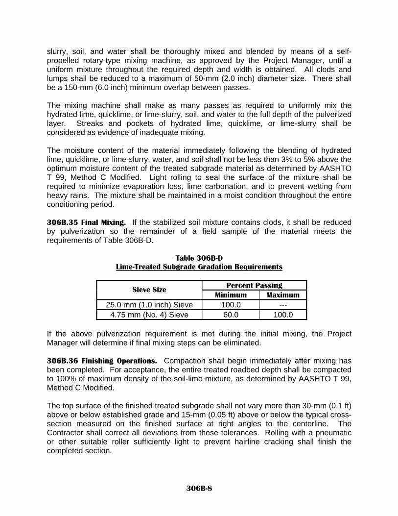
slurry, soil, and water shall be thoroughly mixed and blended by means of a self-propelled rotary-type mixing machine, as approved by the Project Manager, until a uniform mixture throughout the required depth and width is obtained. All clods and lumps shall be reduced to a maximum of 50-mm (2.0 inch) diameter size. There shall be a 150-mm (6.0 inch) minimum overlap between passes. The mixing machine shall make as many passes as required to uniformly mix the hydrated lime, quicklime, or lime-slurry, soil, and water to the full depth of the pulverized layer. Streaks and pockets of hydrated lime, quicklime, or lime-slurry shall be considered as evidence of inadequate mixing. The moisture content of the material immediately following the blending of hydrated lime, quicklime, or lime-slurry, water, and soil shall not be less than 3% to 5% above the optimum moisture content of the treated subgrade material as determined by AASHTO T 99, Method C Modified. Light rolling to seal the surface of the mixture shall be required to minimize evaporation loss, lime carbonation, and to prevent wetting from heavy rains. The mixture shall be maintained in a moist condition throughout the entire conditioning period. 306B.35 Final Mixing. If the stabilized soil mixture contains clods, it shall be reduced by pulverization so the remainder of a field sample of the material meets the requirements of Table 306B-D.
Table 306B-D Lime-Treated Subgrade Gradation Requirements
Percent Passing Sieve Size
Minimum Maximum 25.0 mm (1.0 inch) Sieve 100.0 --- 4.75 mm (No. 4) Sieve 60.0 100.0
If the above pulverization requirement is met during the initial mixing, the Project Manager will determine if final mixing steps can be eliminated. 306B.36 Finishing Operations. Compaction shall begin immediately after mixing has been completed. For acceptance, the entire treated roadbed depth shall be compacted to 100% of maximum density of the soil-lime mixture, as determined by AASHTO T 99, Method C Modified. The top surface of the finished treated subgrade shall not vary more than 30-mm (0.1 ft) above or below established grade and 15-mm (0.05 ft) above or below the typical cross-section measured on the finished surface at right angles to the centerline. The Contractor shall correct all deviations from these tolerances. Rolling with a pneumatic or other suitable roller sufficiently light to prevent hairline cracking shall finish the completed section.
306B-8

306B.37 Curing. 306B.371 General Upon completion of the compaction, the treated subgrade shall be cured for a minimum period of 24 hours to be certain that the slaking and/or curing process has been completed. During the curing period, when the atmospheric temperature is above 4oC (40oF), either an asphalt emulsion curing seal consisting of either a SS or CSS emulsion at an application rate between 0.10 and 0.20 gallons per square yard of surface as determined by the Project Manager or a water curing seal shall be applied to maintain the moisture content at 3% to 5% above the optimum moisture content of the treated subgrade material as determined by AASHTO T 99, Method C Modified, during the curing process. 306B.38 Protection of Treated Subgrade. No vehicles or equipment shall be permitted on the hydrated lime, quicklime, or lime-slurry treated subgrade during the curing period, unless otherwise directed by the Project Manager. The roadway shall not be opened to the traveling public until a base, subbase, or a wearing surface has been placed unless otherwise allowed by the Project Manager. The Contractor at no cost to the Department shall repair damage to treated subgrade due to the Contractor’s operations. 306B.4 METHOD OF MEASUREMENT. Hydrated lime, quicklime, or lime-slurry treated subgrade will be measured by the square meter (square yard). Measurements will be taken on the top width of the completed treated subgrade. Hydrated lime, quicklime, or lime-slurry will be measured as hydrated lime by the ton (Ton) according to SECTION 402 – BITUMINOUS MATERIAL, HYDRATED LIME, AND LIQUID ANTI-STRIPPING AGENTS. Quicklime will be measured by the ton (Ton), but shall be paid as hydrated lime by the ton (Ton) using the conversion that 1.0 ton (Ton) of quicklime is equal to 1.3 ton (Ton) of hydrated lime. Water will not be measured separately. Test rolling will not be measured separately. Grade control will not be measured separately.
306B-9

306B.5 BASIS OF PAYMENT. 306B.51 The hydrated lime, quicklime, or lime-slurry treated subgrade will be paid for at the contract unit price per square meter (square yard). The hydrated lime will be paid for at the contract unit price per ton (Ton) in accordance with SECTION 402 – BITUMINOUS MATERIAL, HYDRATED LIME, AND LIQUID ANTI-STRIPPING AGENTS, Payment will be made under: Pay Item Pay Unit Lime Treated Subgrade Square Meter (Square Yard) Hydrated Lime* Metric Ton (Ton)
* Bid item to be paid under the 402 prefix as indicated in the bid schedule. Water, test rolling, cold weather protection, grade control, and phenolphthalein indicator chemical will be considered incidental and no separate payment will be provided to the Contractor.
306B-10

NEW MEXICO DEPARTMENT OF TRANSPORTATION SUPPLEMENTAL SPECIFICATIONS FOR
PAVEMENT SMOOTHNESS MEASUREMENT
SECTION 401 All pertinent provisions of the New Mexico Department Of Transportation's Standard Specifications For Highway And Bridge Construction shall apply in addition to the follow-ing: Delete SECTION 401 - PAVEMENT SMOOTHNESS MEASUREMENT in its entirety and substitute the following: 401.1 DESCRIPTION. 401.11 This work shall consist of furnishing and utilizing profile testing equipment to perform pavement smoothness measurements, in accordance with requirements de-scribed herein using an International Roughness Index (IRI) profilometer that utilizes a Department State Materials Bureau approved computer program. Note 1: This specification should be used on all new and reconstruction projects. How-ever, for overlay, rehabilitation, and pavement preservation projects, it should only be used when two or more opportunities to achieve smoothness are provided to the Con-tractor. Examples of these types of opportunities are pavement surface milling followed by a PMBP overlay and projects where two or more lifts of PMBP will be constructed. 401.2 CONSTRUCTION REQUIREMENTS. 401.21 Straightedge Measurements. The final surface of all Plant-Mix Bituminous Pavement (PMBP), Stone Matrix Asphalt (SMA), Open-Graded Friction Course (OGFC), and Portland Cement Concrete Pavement (PCCP) not subject to profile meas-urement shall be tested using an approved 3.0-m (10-ft) straightedge at both right an-gles and parallel to the centerline. All surface deviations in excess of 3 mm in 3.0 m (1/8 in. in 10 ft) shall be corrected as directed by the Project Manager. The following are specifically excluded from profile measurement and shall be evaluated using a straightedge:
A. Shoulders, turnouts, median lanes and other areas less than 0.8-km (0.5 mile), as designated by the Project Manager during a pre-paving conference.
B. Concrete pavement slab removal and replacement, and intersections not
paved integrally with the main line.
401.22 Profile Testing Equipment. The Contractor shall provide, operate, and maintain on the project a profile measurement device that will meet the requirements of AASHTO PP 50. The profile measurement device will utilize computer programs that are refer-
401-1

enced in AASHTO PP 37 or an equal that has been given prior approval by the Depart-ment’s State Materials Bureau. 401.23 Profile Measurements. The longitudinal smoothness of the final surface of OGFC, PMBP, SMA, or PCCP shall be tested using a profile measuring device and shall be performed per the requirements of AASHTO PP-52 using a cutoff wavelength of 91.4 meters (300 feet). On PMBP projects, all profile and corrective measurements shall be performed on the final surface of PMBP before the OGFC, if any, is allowed to be placed by the Project Manager. On PCCP projects, all profile and corrective meas-urements shall be performed on the finished surface of PCCP before longitudinal dia-mond grooving operations are allowed by the Project Manager. All profile measure-ments will be submitted to the Project Manager, in a format approved by the State Materials Bureau, within two (2) working days of actual data collection. If the actual data is not submitted by the Contractor to the Project Manager within two (2) working days of their actual collection, the Department shall not pay incentives greater than 100.0% for the section that this particular data represents per the criteria presented in Table 401-A, Table 401-B, Table 401-C, or Table 401-D. 401.24 Technician Certification. The Department’s Technician Training and Certifica-tion Program (TTCP) shall certify all individuals performing profile measurement testing for acceptance and pay adjustment. The certification will be based on demonstration of ability and a written test. The term and expiration date of certification and requirements for renewal of certification shall be as established by the TTCP. If a concern arises as to the competence of a certified individual, this concern must be documented in writing to the Department’s State Materials Bureau Chief and the Assistant District Engineer. The Department’s State Materials Bureau Chief, through the TTCP, will investigate the concern. If this investigation substantiates the concern, corrective action or de-certification will be implemented in accordance with procedures established by the TTCP Board of Directors. 401.25 Profile Measuring Device Calibration and Certification. The profile measuring device shall be certified in accordance with the Department’s Standard Practice #002-03 “Certification of Inertial Profilers”. The profile measuring device shall have a current TTCP calibration sticker or shall have a manufacturer’s calibration and certification cer-tificate which shall only be valid until the date of the next TTCP sponsored annual profile measuring device certification test. The Contractor shall calibrate the profile measuring device. Both horizontal and vertical calibration shall be performed before each use. Additional calibrations or verifications may be required as directed by the Project Manager. Calibrations shall be performed in accordance with the manufacturer’s approved procedures and the Contractor shall maintain copies of the calibration documentation and manufacturer’s procedures with the machine. If the profile measuring device does not meet manufacturer’s calibration requirements, the contractor shall remove the machine from the project until adjustments can be made to bring the profile measurement device back into calibration requirements. The TTCP
401-2

profile measuring device Certification Number shall be reported to the TTCP Administra-tor by the Project Manager in order to provide notification that the non-calibrated ma-chine is not to be used on other projects until re-certification is obtained. Once the profile measurement device is re-certified by the manufacturer, a copy of the certificate shall be provided to the Department’s TTCP Administrator. 401.26 Profile Measurement. The Contractor shall thoroughly sweep the roadway sur-face and then shall obtain the Project Manager’s approval before beginning any profile operation. The profile measuring device shall be operated per AASHTO PP-52 and in conformance with manufacturer’s recommendations using a cutoff wavelength of 91.4 meters (300 feet). The profile measuring device shall be capable of maintaining the correct speed in accordance with the manufacturer's recommendations without interfering with traffic or the operation of the profile measuring device and shall be operated on the driving sur-face of the roadway. The Contractor shall determine the International Roughness Index (IRI) for each lane, reported to the nearest mm per km (0.1-in./ mi), in accordance with the following:
A. The IRI shall be determined for each 0.1-km (0.1-mi) section or fraction thereof. B. Profile traces shall be made for each wheel path, for each lane. The traces
shall be located 1.0 m (3.0 ft) from and parallel to the approximate location of pavement lane lines unless otherwise directed by the Project Manager. Addi-tionally, for dual-sensor profilers, the centerline distance between sensors shall be 1700 mm (67.0-inches) + 12.5 mm (0.5 inch).
C. At transverse joints, the profile traces shall commence 5.0 m (15 ft) into the
previous placement. D. The IRI used for evaluating each 0.1-km (0.1-mi) section shall be the average
of the profile traces for each wheel path. This information shall be submitted in a summarized format consistent with AASHTO PP 52 recommendations to the Project Manager. The profile traces shall be maintained by the Contractor.
Additional profiles shall be taken to retest paved surfaces that have received corrective work, and as directed by the Project Manager, to check previously submitted data or to identify the limits of surface irregularities.
Each profile trace shall also include the following information: A. Project number; B. Date; C. Lane profiled; D. Beginning and ending stations;
401-3

E. Intermittent reference stations at least every 10 m (50 ft); F. Horizontal equation stations; G. Location of bridge abutments; H. Net total linear meters (feet) of each lane; and I. Operator’s signature.
Profile testing is considered part of the paving operation. The proposed frequency for profile testing shall be included in the paving plan submitted by the Contractor at the pre-paving conference. Before any subsequent paving operation, the Project Manager shall approve the final pavement smoothness summary. 401.27 Evaluation for Corrective Work. For determining corrective work needed and pay adjustments, the pavement shall be evaluated in 0.1-km (0.1-mi) sections. When the measured smoothness value falls within the Table 401-A, Table 401-B, Table 401-C, or Table 401-D “Corrective Work Required” values, the pavement shall be evaluated by the Contractor in order to develop an appropriate corrective action plan. The correc-tive action plan, which may include diamond grinding, overlaying, or removing and re-placing, shall be submitted to the Project Manager for review and approval. After the corrective action has been completed by the Contractor, the corrective area shall be re-profiled to verify compliance with specification requirements. All corrective action, in-cluding all necessary traffic control, shall be completed at no additional cost to the De-partment. If the pay factor for any 0.1-km (0.1-mi) section meets or is greater than the Table 401-A, Table 401-B, Table 401-C, or Table 401-D 100.0% pay factor, additional corrective work for the purpose of reducing that reported measured smoothness value shall not be allowed by the Project Manager. If the pay factor for any 0.1-km (0.1-mi) section is less than the Table 401-A, Table 401-B, Table 401-C, or Table 401-D 100.0% pay factor smoothness value and is equal to or greater than 90.0%, the Contractor may accept the designated pay factor. If the Con-tractor does not accept the designated pay factor and elects to develop a corrective ac-tion plan to further reduce the measured smoothness value to increase the designated pay factor, the Project Manager shall review the plan and if approved, shall allow such work. All elected corrective action, including all necessary traffic control, shall be com-pleted at no additional cost to the Department. Areas of localized roughness shall be identified through a 7.6 meter (25-feet) moving average filter. The difference between the 7.6 meter (25 foot) moving average and the reported relative elevation for every profile point will be determined by the Contractor in accordance with the method proposed in Transportation Research Board Report #02-4050 entitled “Application of Profile Data to Detect Localized Roughness”, Transporta-tion Research Record No. 1813 entitled “Construction 2002”, pages 55 - 81. Reported deviations greater than 3.8 mm (0.15-in) shall be evaluated by the Contractor in order to develop an appropriate corrective action plan. Positive deviations shall be considered “bumps” and negative deviations shall be considered “dips”.
401-4

The Project Manager shall determine which of these localized roughness areas, if any, need corrective action by the Contractor at no additional cost to the Department. If cor-rective action is required by the Project Manager, re-profile of the affected 0.1-km (0.1-mi) section will be required per Section 401.28. 401.28 Corrective Work. Corrective work shall be limited to diamond grinding, overlay-ing or removing and replacing. The Contractor shall submit a written corrective work proposal to the Project Manager that includes the methods and procedures that will be used. The Contractor shall not commence corrective work until the methods and pro-cedures have been approved in writing by the Project Manager. Approval by the Project Manager shall not relieve the Contractor of the responsibility of producing work in con-formity with the specifications. All corrective work including all necessary traffic control shall be completed at no additional cost to the Department. Corrective work shall conform to the following:
A. Diamond Grinding. Diamond grinding shall be performed by a roadway planing device to the extent necessary to bring the reported average measured smooth-ness value to an acceptable level per Table 401-A, Table 401-B, Table 401-C, or Table 401-D. The diamond grinding shall not reduce planned pavement thickness by more than 7.5 mm (0.3 in.) and shall be “daylighted” to produce a smooth finish. For PMBP, when an OGFC is not required as part of the contract, a fog seal shall be applied to the ground areas as approved by the Project Manager. For PCCP, additional diamond grinding shall be performed as necessary in the transverse di-rection such that the lateral limits are at a constant offset from and parallel to the nearest lane line or pavement edge and in the longitudinal direction such that the grinding begins and ends at lines normal to the pavement centerline. All diamond ground locations shall be neat rectangular areas of uniform appearance. The sur-face texture shall be such that the skid resistance is comparable to adjacent sec-tions that do not require grinding. All damage to the curing membrane resulting from diamond grinding shall be repaired immediately. All diamond grinding work including necessary traffic control and curing membrane repair shall be completed at no additional cost to the Department. B. Overlaying. When an additional lift of PMBP or SMA is used to correct a rough pavement, it shall meet all the requirements of the appropriate specification as specified in the contract. The overlay lift shall extend the full width of the underly-ing pavement surface and have a finished compacted thickness sufficient to cor-rect the roughness and produce a final surface meeting all specification require-ments. If the overlay does not meet the longitudinal smoothness requirement, a second overlay will not be allowed. Repairs to an overlay not meeting smoothness requirement shall be corrected by diamond grinding or removing and replacing as approved by the Project Manager.
401-5

C. Removing and Replacing. When repair of rough pavement is made by remov-ing and replacing, the pavement shall be removed the full width of the lane and the full thickness of the course in areas requiring corrective work. The removal area shall begin and end with a transverse saw cut perpendicular to centerline. Re-placement material shall be PMBP, SMA, or PCCP meeting all requirements of the contract. D. OGFC Placement. If the measured average IRI of the OGFC is greater than the measured average IRI of the PMBP on the same 0.1-km (0.1-mi) section, the pay factor for the PMBP section shall be based on the OGFC’s measured average IRI and not the PMBP’s measured average IRI.
All 0.1-km (0.1-mi.) section of travel lane on which corrective work was performed shall be re-profiled and the re-profile reported measured smoothness data shall be used to represent that particular individual section. The previous section reported measured smoothness data shall be deleted for price adjustment purposes. 401.3 BASIS OF PAYMENT. 401.31 All surface smoothness testing and corrective work to bring the final surface within specification smoothness shall be included in the unit contract price for Plant-Mix Bituminous Pavement (PMBP), Stone Matrix Asphalt (SMA), or Portland Cement Con-crete Pavement (PCCP). No separate payment will be paid for surface smoothness testing and corrective work. 401.32 Price Adjustment. A price adjustment will be calculated for each 0.1-km (0.1-mi) section of travel lane. The price adjustment shall apply to the total accepted quan-tity of the total thickness or area of PMBP or SMA as referenced by the contract, or to the total thickness or area of PCCP constructed under this contract for the actual lane width and roadway length represented by the price adjustment. Shoulder and turnout areas shall not be included for payment purposes. The price adjustment shall be de-termined by applying the appropriate percentage to the unit bid price for the pay item Plant Mix Bituminous Pavement (PMBP), Stone Matrix Asphalt (SMA), or Portland Ce-ment Concrete Pavement (PCCP). 401.321 Price Adjustment for New or Reconstruction PMBP or SMA Projects. Price adjustments will be based on the final average IRI after any corrective work has been performed and measured per Table 401-A.
401-6

Table 401-A IRI Based Profile Pay Adjustment Schedule For New or Reconstruction PMBP and/or
SMA Pavements (Based on an Initial Serviceability Index = 4.3)
Type of Roadway
Interstate Routes National Highway Routes US (Non-NH) and NM Routes IRI IRI IRI
mm per 0.1-km
inch per 0.1-mi
mm per 0.1-km
inch per 0.1-mi
mm per 0.1-km
inch per 0.1-mi
Pay Factor (Percent)
<911 <57.7 <879 <55.7 <740 <46.9 110.0% 911 to 917 57.7 to 58.1 879 to 889 55.7 to 56.3 740 to 766 46.9 to 48.5 109.0% 918 to 925 58.2 to 58.6 890 to 900 56.4 to 57.0 767 to 789 48.6 to 50.0 108.0% 926 to931 58.7 to 59.0 901 to 909 57.1 to 57.6 790 to 813 50.1 to 51.5 107.0% 932 to 939 59.1 to 59.5 910 to 920 57.7 to 58.3 814 to 838 51.6 to 53.1 106.0% 940 to 947 59.6 to 60.0 921 to 930 58.4 to 58.9 839 to 862 53.2 to 54.6 105.0% 948 to 953 60.1 to 60.4 931 to 941 59.0 to 59.6 863 to 887 54.7 to 56.2 104.0% 954 to 961 60.5 to 60.9 942 to 950 59.7 to 60.2 888 to 912 56.3 to 57.8 103.0% 962 to 969 61.0 to 61.4 951 to 961 60.3 to 60.9 913 to 936 57.9 to 59.3 102.0% 970 to 976 61.5 to 61.8 962 to 972 61.0 to 61.6 937 to 961 59.4 to 60.9 101.0% 977 to 985 61.9 to 62.4 973 to 982 61.7 to 62.2 962 to 987 61.0 to 62.5 100.0% 986 to 991 62.5 to 62.8 983 to 993 62.3 to 62.9 988 to 1,012 62.6 to 64.1 99.0% 992 to 999 62.9 to 63.3 994 to 1,004 63.0 to 63.6 1,013 to 1,037 64.2 to 65.7 98.0%
1,000 to 1,007 63.4 to 63.8 1,005 to 1,015 63.4 to 64.3 1,038 to 1,062 65.8 to 67.3 97.0% 1,008 to 1,015 63.9 to 64.3 1,016 to 1,026 64.4 to 65.0 1,063 to 1,088 67.4 to 68.9 96.0% 1,016 to 1,023 64.4 to 64.8 1,027 to 1,037 65.1 to 65.7 1,089 to 1,115 69.0 to 70.6 95.0% 1,024 to 1,031 64.9 to 65.3 1,038 to 1,048 65.8 to 66.4 1,116 to 1,140 70.7 to 72.2 94.0% 1,032 to 1,039 65.4 to 65.8 1,049 to 1,059 66.5 to 67.1 1,141 to 1,165 72.3 to 73.8 93.0% 1,040 to 1,047 65.9 to 66.3 1,060 to 1,070 67.2 to 67.8 1,166 to 1,192 73.9 to 75.5 92.0% 1,048 to 1,055 66.4 to 66.8 1,071 to 1,081 67.9 to 68.5 1,193 to 1,217 75.6 to 77.1 91.0% 1,056 to 1,062 66.9 to 67.3 1,082 to 1,092 68.6 to 69.2 1,218 to 1,244 77.2 to 78.8 90.0%
> 1,062 > 67.3 > 1,092 > 69.2 > 1,244 > 78.8 Corrective
Work Required
401.322 Price Adjustment for Rehabilitation and Overlay PMBP or SMA Projects. Price adjustments will be based on the final average IRI after any corrective work has been performed and measured per Table 401-B.
401-7

Table 401-B IRI Based Profile Pay Adjustment Schedule For Rehabilitation or Overlay PMBP and/or
SMA Pavements (Based on an Initial Serviceability Index = 4.2)
Type of Roadway
Interstate Routes National Highway Routes US (Non-NH) and NM Routes IRI IRI IRI
mm per 0.1-km
inch per 0.1-mi
mm per 0.1-km
inch per 0.1-mi
mm per 0.1-km
inch per 0.1-mi
Pay Fac-tor (Per-
cent)
<999 <63.6 <972 <61.6 <837 <53.0 110.0% 999 to 1,010 63.6 to 64.0 972 to 983 61.6 to 62.3 837 to 859 53.0 to 54.4 109.0%
1,011 to 1,018 64.1 to 64.5 984 to 993 62.4 to 62.9 860 to 882 54.5 to 55.9 108.0% 1,019 to 1,025 64.6 to 64.9 994 to 1,002 63.0 to 63.5 883 to 908 56.0 to 57.5 107.0% 1,026 to 1,031 65.0 to 65.3 1,003 to 1,012 63.6 to 64.1 909 to 931 57.6 to 59.0 106.0% 1,032 to 1,039 65.4 to 65.8 1,013 to 1,023 64.2 to 64.8 932 to 955 59.1 to 60.5 105.0% 1,040 to 1,045 65.9 to 66.2 1,024 to 1,032 64.9 to 65.4 956 to 979 60.6 to 62.0 104.0% 1,046 to 1,053 66.3 to 66.7 1,033 to 1,042 65.5 to 66.0 980 to 1,004 62.1 to 63.6 103.0% 1,054 to 1,059 66.8 to 67.1 1,043 to 1,053 66.1 to 66.7 1,005 to 1,028 63.7 to 65.1 102.0% 1,060 to 1,067 67.2 to 67.6 1,054 to 1,062 66.8 to 67.3 1,029 to 1,051 65.2 to 66.6 101.0% 1,068 to 1,073 67.7 to 68.0 1,063 to 1,073 67.4 to 68.0 1,052 to 1,077 66.7 to 68.2 100.0% 1,074 to 1,081 68.1 to 68.5 1,074 to 1,083 68.1 to 68.6 1,078 to 1,102 68.3 to 69.8 99.0% 1,082 to 1,089 68.6 to 69.0 1,084 to 1,094 68.9 to 69.3 1,103 to 1,126 69.9 to 71.3 98.0% 1,090 to 1,097 69.1 to 69.5 1,095 to 1,103 69.4 to 69.9 1,127 to 1,151 71.4 to 72.9 97.0% 1,098 to 1,103 69.6 to 69.9 1,104 to 1,115 70.0 to 70.6 1,152 to 1,176 73.0 to 74.5 96.0% 1,104 to 1,111 70.0 to 70.4 1,116 to 1,126 70.7 to 71.3 1,177 to 1,201 74.6 to 76.1 95.0% 1,112 to 1,119 70.5 to 70.9 1,127 to 1,135 71.4 to 71.9 1,202 to 1,227 76.2 to 77.7 94.0% 1,120 to 1,127 71.0 to 71.4 1,136 to 1,146 72.0 to 72.6 1,228 to 1,252 77.8 to 79.3 93.0% 1,128 to 1,133 71.5 to 71.8 1,147 to 1,157 72.7 to 73.3 1,253 to 1,277 79.4 to 80.9 92.0% 1,134 to 1,141 71.9 to 72.3 1,158 to 1,168 73.4 to 74.0 1,278 to 1,304 81.0 to 82.6 91.0% 1,142 to 1,149 72.4 to 72.8 1,169 to 1,178 74.1 to 74.6 1,305 to 1,329 82.7 to 84.2 90.0%
> 1,149 > 72.8 > 1,178 > 74.6 > 1,329 > 84.2 Correc-
tive Work Required
401.323 Price Adjustment for PCCP Pavement, PCCP Ramps, PCCP Tapers, and PCCP Holding Lanes. Price adjustments will be based on the final average IRI after any cor-rective work has been performed and measured per Table 401-C.
401-8

Table 401-C IRI Based Profile Pay Adjustment Schedule for PCC Pavements, Ramps, Tapers, and
Holding Lanes (Based on an Initial Serviceability Index = 4.3)
Interstate and National Highway
Routes US (Non-NH) and NM Routes
IRI IRI mm per 0.1-km inch per 0.1-mi mm per 0.1 km inch per 0.1-mi
Pay Factor (Percent)
<824 <52.2 <783 <49.6 110.0% 824 to 840 52.2 to 53.2 783 to 804 49.6 to 50.9 109.0% 841 to 856 53.3 to 54.2 805 to 822 51.0 to 52.1 108.0% 857 to 871 54.3 to 55.2 823 to 843 52.2 to 53.4 107.0% 872 to 887 55.3 to 56.2 844 to 864 53.5 to 54.7 106.0% 888 to 903 56.3 to 57.2 865 to 882 54.8 to 55.9 105.0% 904 to 919 57.3 to 58.2 883 to 903 56.0 to 57.2 104.0% 920 to 935 58.3 to 59.2 904 to 923 57.3 to 58.5 103.0% 936 to 950 59.3 to 60.2 924 to 944 58.6 to 59.8 102.0% 951 to 968 60.3 to 61.3 945 to 965 59.9 to 61.1 101.0% 969 to 983 61.4 to 62.3 966 to 985 61.2 to 62.4 100.0% 984 to 999 62.4 to 63.3 986 to 1,007 62.5 to 63.8 99.0%
1,000 to 1,017 63.4 to 64.4 1,008 to 1,028 63.9 to 65.1 98.0% 1,018 to 1,032 64.5 to 65.4 1,029 to 1,048 65.2 to 66.4 97.0% 1,033 to 1,048 65.5 to 66.4 1,049 to 1,070 66.5 to 67.8 96.0% 1,049 to 1,066 66.5 to 67.5 1,071 to 1,091 67.9 to 69.1 95.0% 1,067 to 1,081 67.6 to 68.5 1,092 to 1,113 69.2 to 70.5 94.0% 1,082 to 1,099 68.6 to 69.6 1,114 to 1,133 70.6 to 71.8 93.0% 1,100 to 1,116 69.7 to 70.7 1,134 to 1,156 71.9 to 73.2 92.0% 1,117 to 1,132 70.8 to 71.7 1,157 to 1,178 73.3 to 74.6 91.0% 1,133 to 1,149 71.8 to 72.8 1,179 to 1,200 74.7 to 76.0 90.0%
> 1,149 > 72.8 > 1,200 > 76.0 Corrective Work Required
401.324 Price Adjustment for Miscellaneous PMBP or SMA. Unit price adjustments will be made in accordance with Table 401-D for miscellaneous PMBP or SMA pavement to include ramps, tapers, and holding lanes that are greater than 0.8-km (0.5-mi) in length. All ramps, tapers, and holding lanes that are less than 0.8-km (0.5-mi) in length will be measured in accordance with 401.21.
401-9
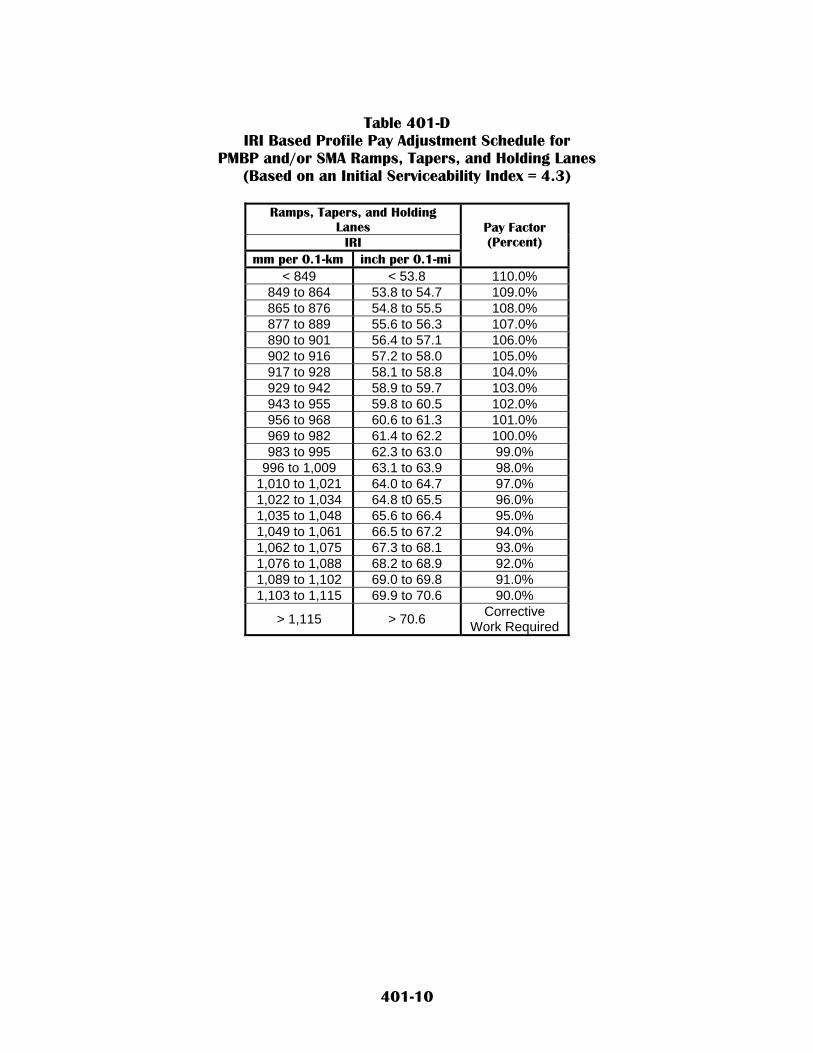
Table 401-D
IRI Based Profile Pay Adjustment Schedule for PMBP and/or SMA Ramps, Tapers, and Holding Lanes
(Based on an Initial Serviceability Index = 4.3)
Ramps, Tapers, and Holding Lanes
IRI mm per 0.1-km inch per 0.1-mi
Pay Factor (Percent)
< 849 < 53.8 110.0% 849 to 864 53.8 to 54.7 109.0% 865 to 876 54.8 to 55.5 108.0% 877 to 889 55.6 to 56.3 107.0% 890 to 901 56.4 to 57.1 106.0% 902 to 916 57.2 to 58.0 105.0% 917 to 928 58.1 to 58.8 104.0% 929 to 942 58.9 to 59.7 103.0% 943 to 955 59.8 to 60.5 102.0% 956 to 968 60.6 to 61.3 101.0% 969 to 982 61.4 to 62.2 100.0% 983 to 995 62.3 to 63.0 99.0%
996 to 1,009 63.1 to 63.9 98.0% 1,010 to 1,021 64.0 to 64.7 97.0% 1,022 to 1,034 64.8 t0 65.5 96.0% 1,035 to 1,048 65.6 to 66.4 95.0% 1,049 to 1,061 66.5 to 67.2 94.0% 1,062 to 1,075 67.3 to 68.1 93.0% 1,076 to 1,088 68.2 to 68.9 92.0% 1,089 to 1,102 69.0 to 69.8 91.0% 1,103 to 1,115 69.9 to 70.6 90.0%
> 1,115 > 70.6 Corrective Work Required
401-10

NEW MEXICO DEPARTMENT OF TRANSPORTATION SUPPLEMENTAL SPECIFICATIONS FOR
BITUMINOUS MATERIALS, HYDRATED LIME, AND LIQUID ANTI-STRIPPING AGENTS
SECTION 402 All pertinent provisions of the New Mexico Department Of Transportation's Standard Specifications For Highway And Bridge Construction shall apply in addition to the following: Delete SECTION 402 - BITUMINOUS MATERIALS, HYDRATED LIME, AND LIQUID ANTI-STRIPING AGENTS in its entirety and substitute the following: 402.1 DESCRIPTION. 402.11 This work shall consist of the furnishing, mixing or applying of bituminous materials, hydrated lime or liquid anti-stripping agents. During the progress of the work, no change affecting the uniformity of the bituminous materials shall be made in the source of the crude stock, method of manufacture, or the supplier without written approval from the Project Manager. 402.2 MATERIALS. 402.21 Sampling and Testing. Unless otherwise provided, materials will be sampled and tested by the Department. Sampling, testing, and inspection of materials shall conform to applicable requirements of Section 105, Control of Work; and Section 106, Control of Materials. Performance-graded asphalt binders shall be sampled and tested in accordance with the requirements outlined in the Standard Practice for Certifying Suppliers of Performance-Graded Asphalt Binders. Materials incorporated in the bituminous mix that have not been approved by the Project Manager will be considered defective and unauthorized, and payment will not be made therefore. The Department may waive the testing of materials and may require the Contractor to furnish certified test reports for such materials. The certified test reports shall indicate compliance with the requirements herein provided for the designated type and grade of material. No obligation is assumed in the acceptance of such test certificates, and the Department may test such certified materials. The Department may test bituminous materials at the place of manufacture or shipping. 402.211 Acceptance. Acceptance of asphalt cement shall be done in accordance with the requirements outlined in the Standard Practice for Certifying Suppliers of Performance-Graded Binders. 402.22 Shipping. Bituminous materials shall be loaded and shipped in sealed, insulated tank cars or tank trucks with satisfactory means provided for sampling of the bituminous material. The shipping tanks of the insulated tank cars and tank trucks shall be completely free of all foreign matter. Bituminous materials contaminated by foreign matter will be rejected. Each load of bituminous material delivered may be conditionally
402-1

accepted for use by the Project Manager upon receipt of the Loading Certificate of Test, subject to the provisions of subsection 402.21, Sampling and Testing. Performance-Graded Binder shall be shipped in accordance with the requirements outlined in the Standard Practice for Certifying Suppliers of Performance-Graded Asphalt Binders. 402.23 Asphalt Cement. Asphalt cement binders shall be uncracked petroleum asphalts and shall be prepared by the refining of crude petroleum by suitable methods, at a temperature not to exceed 371°C (700°F). Asphalt cements shall be free from thermal decomposition products and shall not be blended with materials that have been subjected to cracking. The asphalt cement shall not contain residue from non-asphaltic sources. Asphalt cement shall be homogeneous, free from water and shall not foam when heated to 177°C (350°F) and shall conform to all the requirements of Performance-Graded Asphalt Binder. 402.231 Performance-Graded Asphalt Binder. Performance-graded asphalt binder shall meet the requirements of AASHTO M 320, Standard Specification for Performance-Graded Asphalt Binder. A performance-graded asphalt binder with a high-end or low-end temperature grade in excess of that called for in the plans and specifications may be substituted for the specified performance-graded asphalt binder at no additional cost to the Department. 402.24 Polymer-Modified Asphalt Cement. To meet the requirements of the project, a liquid anti-strip may be required. The need for a liquid anti-strip will be determined by the Department in consultation with the asphalt supplier. When liquid anti-strip is required, it will be added to the asphalt at its point of manufacture. Polymer-Modified Asphalt Cement shall meet the requirements of Table 402-A.
Table 402-A Polymer-Modified Asphalt Cement (PAC-20)
Test Requirement
Viscosity, 60°C (140°F), Poise (Note 1) 1,600+ Viscosity, 135°C (275°F), Cs 2,000- Penetration, 25°C (77°F), 100 g (3.5 oz), 5 seconds, 0.1 mm 75 - 100 Penetration, 4°C (39.2°F), 200 g (7.0 oz), 60 seconds, 0.1 mm 30+ Flash Point, COC, °C (°F) 218+ (425+) Solubility in Trichloroethylene, % 99.0+ Softening Point, R&B, °C (°F) 52+ (125+) Separation, R&B Difference, °C (°F) (Note 2) 4 (7.2) Residue from RTFOT Penetration, 4°C (39.2°F), 200 g (7.0 oz), 60 seconds, 0.1 mm 15+ Elastic Recovery, 25°C (77°F), % (Note 3) 60+
Note 1: Based on use of a straight wall capillary viscometer at a one (1) reciprocal second shear rate Note 2: Method of testing described in ASTM D 5892 Note 3: Method of testing described in ASTM D 6084
402-2

402.25 Emulsified Asphalt. Emulsified asphalt shall consist of uncracked petroleum asphalt uniformly emulsified with water and an emulsifying or stabilizing agent. Emulsified asphalt shall be homogenous and show no separation of asphalt after thorough mixing. Anionic emulsified asphalt shall meet the requirements of AASHTO M 140 and cationic emulsions shall meet the requirements of AASHTO M 208. 402.251 High-Float Emulsions. High-float emulsions of the designation HFE-60, HFE-90, HFE-150 and HFE-300 shall meet the requirements of Table 402-B.
Table 402-B High-Float Emulsions Requirements
Test HFE-60 HFE-90 HFE-150 HFE-300
Viscosity, Saybolt Furol at 50°C (122°F), seconds 50+ 50+ 50+ 50+ Sieve Test, Retained on 850 µ (No. 20) Sieve, % 0.10- 0.10- 0.10- 0.10- Settlement, 5 Days, % 5- 5- 5- 5- Storage Stability Test, 1 Day, % 1- 1- 1- 1- Demulsibility, 35 ml (1.2 fl oz) 0.10 N, CaCl, % 30+ 30+ --- --- Residue from Distillation Test to 260°C (500°F) 65+ 65+ 65+ 65+ Oil Distillate by Volume of Emulsion, % 1- 3- 7- 7- Coating Test, 3 minutes All Grades, Stones Coated Thoroughly Tests on Residue from Distillation Test Penetration at 25°C (77°F), 100 g (3.5 oz), 5 sec, 0.1 mm 60 - 90 90 - 150 150 - 300 300+ Float Test at 60°C (140°F), seconds 1200+ 1200+ 1200+ 1200+
402.252 Polymer-Modified High-Float Emulsions. Bituminous material shall be a high-float emulsion containing polymer-modified asphalt, water, with a minimum of 1% liquid anti-stripping agent and emulsion in HFE-150P and HFE-300P only and shall comply with the requirements of Table 402-C.
Table 402-C Polymer-Modified High-Float Emulsions Requirements
Test HFE-60P HFE-100P HFE-150P HFE-300P
Viscosity, Saybolt Furol at 50°C (122°F), seconds 50+ 50+ 50+ 50+ Sieve Test, Retained on 850µ (No. 20) Sieve, % 0.10- 0.10- 0.10- 0.10- Storage Stability Test, 1 Day, % 1- 1- 1- 1- Demulsibility, 35 ml (1.2 fl oz) 0.10 N, CaCl, % 30+ 30+ --- --- Residue from Distillation Test to 260°C (400°F) 65+ 65+ 65+ 65+ Oil Distillate by Volume of Emulsion, % 1- 3- 7- 7- Tests on Residue from Distillation Test Penetration at 25°C (77°F), 100 g (3.5 oz), 5 sec, 0.1 mm
60 - 90 90 - 150 150 - 300 300+
Ductility 25°C (77°F), 5 cm/min (2 in/min) 100+ (40+) 100+ (40+) 100+ (40+) --- Elastic Recovery, % 55+ (Note1) 58+ (Note 1) 25+ (Note 2) 25+ (Note 2) Float Test @ 60°C (140°F), seconds 1200+ 1200+ 1200+ 1200+ Note 1: Test in accordance with AASHTO T 301 at a test temperature of 10°C (50°F) Note 2: Test in accordance with AASHTO T 301 at a test temperature of 4°C (39.2°F)
402-3
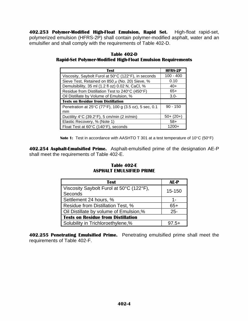
402.253 Polymer-Modified High-Float Emulsion, Rapid Set. High-float rapid-set, polymerized emulsion (HFRS-2P) shall contain polymer-modified asphalt, water and an emulsifier and shall comply with the requirements of Table 402-D.
Table 402-D Rapid-Set Polymer-Modified High-Float Emulsion Requirements
Test HFRS-2P
Viscosity, Saybolt Furol at 50°C (122°F), in seconds 100 - 400 Sieve Test, Retained on 850 µ (No. 20) Sieve, % 0.10 Demulsibility, 35 ml (1.2 fl oz) 0.02 N, CaCl, % 40+ Residue from Distillation Test to 240°C (450°F) 65+ Oil Distillate by Volume of Emulsion, % 3.0- Tests on Residue from Distillation Penetration at 25°C (77°F), 100 g (3.5 oz), 5 sec, 0.1 mm
90 - 150
Ductility 4°C (39.2°F), 5 cm/min (2 in/min) 50+ (20+) Elastic Recovery, % (Note 1) 58+ Float Test at 60°C (140°F), seconds 1200+
Note 1: Test in accordance with AASHTO T 301 at a test temperature of 10°C (50°F)
402.254 Asphalt-Emulsified Prime. Asphalt-emulsified prime of the designation AE-P shall meet the requirements of Table 402-E.
Table 402-E ASPHALT EMULSIFIED PRIME
Test AE-P
Viscosity Saybolt Furol at 50°C (122°F), Seconds 15-150
Settlement 24 hours, % 1- Residue from Distillation Test, % 65+ Oil Distillate by volume of Emulsion,% 25- Tests on Residue from Distillation Solubility in Trichloroethylene,% 97.5+
402.255 Penetrating Emulsified Prime. Penetrating emulsified prime shall meet the requirements of Table 402-F.
402-4

Table 402-F PENETRATING EMULSIFIED PRIME
Test PE-P
Viscosity, Saybolt Furol at 50°C (122°F), Seconds 75-
Sieve Test, Retained on 850 µm (0.35 in.) Sieve, % 0.1-
Residue from Distillation Test, % 38+ Oil Distillate by volume of Emulsion, % 0-4
402.26 Cutback Asphalts (Medium-Curing Type). Cutback asphalt shall conform to the requirements AASHTO M 82. However, MC-30 shall not be allowed for use on any Department project. 402.27 Hydrated Lime. Hydrated lime shall conform to the requirements of ASTM C 1097 with the following exception: Delete subsection 4.1 of ASTM C 1097 and substitute the following: “Hydrated lime, either dry or slurry form, shall have 3.0% or less retained on the 600 µm sieve and 25% or less retained on a 75 µm sieve.” The fineness of hydrated lime shall be determined in accordance with AASHTO T 219, except that a sample of approximately 100 g (3.5 oz) shall be used for the testing described in subsections 6.1 and 6.1.1. 402.28 Liquid Anti-Stripping Agents. When required, a liquid anti-stripping agent shall be added to the designated bituminous materials. Unless otherwise provided, the required amount of anti-stripping agent shall be thoroughly mixed with the asphalt cement to provide a uniform and homogeneous product. The liquid anti-stripping agent shall be added either by the use of in-line blending systems installed at the hot mix plant or at the refinery or terminal. The Department may require pre-approval of anti-stripping agents. Once designated for use on a specific project, the brand, grade or percentage of anti-stripping agent shall not be changed without approval of the Mix Designer. 402.3 CONSTRUCTION REQUIREMENTS. 402.31 General. Materials shall be mixed, applied, or incorporated in the work in accordance with the requirements of applicable sections of the specifications. The Contractor shall submit the name and address of the material supplier to the Project Manager. Representative samples of each grade or classification of bituminous materials to be furnished shall be submitted for testing, when required by the Project Manager. Bituminous materials shall be mixed or applied within the temperature range approved by the Project Manager.
402-5
402.4 METHOD OF MEASUREMENT AND BASIS OF PAYMENT. Bituminous material will be measured by the metric ton (Ton). Hydrated lime will be measured by the metric ton (Ton). Liquid anti-stripping agent will be measured by the metric ton (Ton). If no unit price for the liquid anti-striping agent is established in the contract for Plant Mix Bituminous Pavement, liquid anti-striping agent will be paid for at the certified invoice cost plus 15%, subject to the restrictions stated in Subsections 420.28 “Mix Design”. (Or applicable subsection for the mix design specified in contract.) High float emulsion will be measured by the metric ton (Ton). Polymer Modified High Float emulsion will be measured by the metric ton (Ton). Cutback Asphalt (Medium Curing Type) will be measured by the metric ton (Ton). Polymer Asphalt Cement will be measured by the metric ton (Ton). Performance Graded Bituminous Material will be measured by the metric ton (Ton). When bituminous materials are not stored in tanks for the exclusive use on the project, the quantity may be determined on an individual lot basis as follows:
Tons of bituminous material = T x X
Where: T – Number of tons placed and accepted bituminous material X – Average asphalt content of the mixture in percent.
402.5 BASIS OF PAYMENT. Bituminous material will be measured by the metric ton (Ton). Hydrated lime will be measured by the metric ton (Ton). High float emulsion will be measured by the metric ton (Ton). Polymer Modified High Float emulsion will be measured by the metric ton (Ton). Cutback Asphalt (Medium Curing Type) will be measured by the metric ton (Ton). Polymer Asphalt Cement will be measured by the metric ton (Ton). Performance Graded Bituminous Material will be measured by the metric ton (Ton).
402-6

Payment will be made under: Pay Item Pay Unit _____ Bituminous material Metric Ton (Ton) Hydrated Lime Metric Ton (Ton) Liquid anti-stripping agent Metric Ton (Ton) High float emulsion - ______ Metric Ton (Ton) Polymer Modified High Float emulsion Metric Ton (Ton) Polymer Asphalt Cement Metric Ton (Ton) ______ Performance Graded Bituminous Material Metric Ton (Ton) Cutback Asphalt (Medium Curing Type) Metric Ton (Ton)
402-7

NEW MEXICO DEPARTMENT OF TRANSPORTATION SUPPLEMENTAL SPECIFICATIONS FOR
OPEN-GRADED FRICTION COURSE (QC/QA)
SECTION 403
All pertinent provisions of the New Mexico Department Of Transportation's Standard Specifications For Highway And Bridge Construction shall apply in addition to the following: Delete SECTION 403 - OPEN-GRADED FRICTION COURSE (QC/QA) in its entirety and substitute the following: 403.1 DESCRIPTION. 403.11 This work shall consist of constructing an open-graded friction course (OGFC) on a prepared surface. OGFC shall be composed of aggregate, bituminous material, and hydrated lime. 403.2 MATERIALS. 403.21 Aggregate. The aggregate shall be crushed stone or crushed gravel, composed of hard durable pebbles or fragments to provide a material that will meet the grading requirements of Table 403-A, when tested by means of AASHTO T 11 and T 27. The OGFC type shall be as indicated in the contract. Acceptance of the aggregate for gradation purposes will be determined by testing of samples obtained from combined aggregates and lime if used, before addition of asphaltic materials.
Table 403-A
OPEN-GRADED FRICTION COURSE GRADATION REQUIREMENTS
Sieve Size Percent Passing I II III 19.0 mm (3/4 in.) 100 100 100 12.0 mm (1/2 in.) 100 100 70–90 9.5 mm (3/8 in.) 90–100 95–100 40–65 4.75 mm (No. 4) 25–55 30–55 15–25 2.0 mm (No. 10) 0–12 0–20 6–12 425 µm (No. 40) 0–8 0–12 0–8 75 µm (No. 200) 0–4 0–6 0–5
A. At least 75 percent of the material retained on the 4.75 mm (No. 4) sieve shall be
particles having at least two fractured faces. Fractured faces shall be determined using NMDOT Agency Method FF-1, “Fractured Face Determination for Coarse Aggregate.”
B. The aggregate shall be free from organic matter, lumps or balls of clay, or other
material that will prevent thorough coating with bituminous material.
403-1

C. The aggregate shall have an Aggregate Index of 20 or less when calculated in
accordance with Section 910. D. The combining of materials from two or more sources to produce aggregate will be
permitted only when each source meets all applicable quality requirements.
403.22 Bituminous Material. The type and grade of bituminous material will be specified in the contract. The bituminous material shall meet the requirements of Section 402, Bituminous Materials, Hydrated Lime and Liquid Anti-Stripping Agents. 403.23 Hydrated Lime. Hydrated lime shall meet the requirements of Section 402 Bituminous Materials, Hydrated Lime and Liquid Anti-Stripping Agents. 403.24 Mix Design. The District Laboratory shall develop the OGFC mix design. The resultant job mix formula gradation shall be within the master range for the specified type of OGFC. The design shall establish whether hydrated lime is required in the OGFC and the quantity to be used. When lime is to be added, it shall be included in the gradation for establishing the laboratory mix design. The laboratory mix design shall establish a single percentage of aggregate passing each required sieve size and a single percentage of bituminous material to be added to the aggregate. 403.3 CONSTRUCTION REQUIREMENTS. 403.31 General. The percentage of bituminous material shall be maintained within plus or minus 0.3% as determined by the strap method. Calibration and plant control shall be the Contractor’s responsibility. 403.32 Preparation of Roadbed. Before placing OGFC, all foreign matter shall be cleaned from the existing surface. 403.33 Weather Limitations. The OGFC shall not be placed on wet surfaces or when OGFC may be placed only when the ambient temperature and the chill factor are both 20°C (70°F) or above. When the ambient temperature is 35°C (90°F) or above the chill factor will not be considered. The chill factor is defined as the ambient temperature in °C minus the wind velocity in km/h x 0.342 (°F minus wind velocity in mph). The wind velocity shall be the velocity determined by the average of the maximum and minimum wind velocity observed during a three-minute period immediately before or concurrent with ongoing OGFC placement operations taken at 1.5 m (5 ft) above the surface of the road. 403.34 Mixing Requirements. Hot-mix plants shall conform to the requirements of Section 423, Plant-Mix Bituminous Pavement, and shall be sufficient for the work to be performed. The mineral aggregate shall be free of oily or carbonaceous coatings before entering the mixer, and the moisture content of the mixed material shall not exceed 1% by weight of the dry aggregate. The aggregate shall be mixed with bituminous material until all aggregate particles are thoroughly and uniformly coated. The temperature of the mixture for placement will be established by the Project Manager, and it shall not
403-2

vary more than plus or minus 10°C (20°F). The temperature of the OGFC mixture for placement shall not exceed 127°C (260°F), nor be less than 82°C (180°F), except that when polymer-modified asphalt cements are used, the temperature of the mixture for placement shall not exceed 150°C (300°F), nor be less than 100°C (220°F). When hydrated lime is required, it shall be added to the aggregate in accordance with the requirements of Section 423, Plant-Mix Bituminous Pavement. 403.35 Placement and Finishing. The OGFC shall be placed by means of a paving machine meeting the requirements of subsection 423.333, Pavers, except that the Project Manager may require use of a 12-m (40-ft) minimum external reference to improve the rideability in any case deemed necessary. Immediately following placement of the OGFC, the surface shall be given at least one complete rolling with a steel-wheeled, self-propelled roller of such weight as to accomplish good consolidation without excessive breakage of the aggregate. Additional rolling shall be required at locations where the desired consolidation was not initially obtained and shall continue for the duration necessary to achieve proper consolidation. The finished surface shall be smooth and true to the dimensions shown on the plans. When tested by means of a 3-m (10-ft) straightedge, it shall be free of all irregularities in excess of 3 mm (1/8 in.). All low and defective areas shall be immediately removed and replaced with fresh hot OGFC, compacted to conform to the surrounding area, at the Contractor’s expense. 403.351 Plan Surfacing Depths. Plan depths will be monitored and recorded throughout the surfacing operations at intervals designated by the Project Manager. The Department will not be liable for payment for any excess in depth of course(s). Unsatisfactory work shall be repaired, replaced, or otherwise corrected by the Contractor at no cost to the Department as directed by the Project Manager. Type I and Type II open-graded friction course less than 12mm (1/2 in.) in depth and Type III open-graded friction course less than 19mm (3/4 in.) in depth will be rejected and subsequently removed and replaced with the required thickness at no additional cost to the Department. 403.36 Contractor Process Control. The Contractor shall comply with the process control requirements of Section 423, Plant-Mix Bituminous Pavement (QC/QA). 403.361 Independent Assurance Testing. Independent assurance sampling and testing will be performed in accordance with subsection 901.3, Independent Assurance Testing. 403.37 Adherence to Specifications and Rejection of Nonspecification Material. The Contractor shall produce material in substantial compliance with all specification requirements, regardless of whether the requirements are used for acceptance and pay factor determination. The Contractor shall take corrective action to remedy any property of the mix that is out of specification. Contractors who elect to produce material that is not within the specification limits do so at their own risk. Said material will be subject to rejection at the discretion of the Project Manager. All material that is rejected shall be removed and replaced with specification material at no additional cost to the Department.
403-3
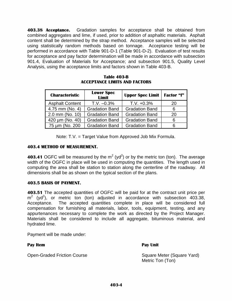
403.38 Acceptance. Gradation samples for acceptance shall be obtained from combined aggregates and lime, if used, prior to addition of asphaltic materials. Asphalt content shall be determined by the strap method. Acceptance samples will be selected using statistically random methods based on tonnage. Acceptance testing will be performed in accordance with Table 901-D-1 (Table 901-D-2). Evaluation of test results for acceptance and pay factor determination will be made in accordance with subsection 901.4, Evaluation of Materials for Acceptance; and subsection 901.5, Quality Level Analysis, using the acceptance limits and factors shown in Table 403-B.
Table 403-B
ACCEPTANCE LIMITS AND FACTORS
Characteristic Lower Spec Limit Upper Spec Limit Factor “f”
Asphalt Content T.V. –0.3% T.V. +0.3% 20 4.75 mm (No. 4) Gradation Band Gradation Band 6 2.0 mm (No. 10) Gradation Band Gradation Band 20 420 µm (No. 40) Gradation Band Gradation Band 6 75 µm (No. 200 Gradation Band Gradation Band 6
Note: T.V. = Target Value from Approved Job Mix Formula.
403.4 METHOD OF MEASUREMENT. 403.41 OGFC will be measured by the m2 (yd2) or by the metric ton (ton). The average width of the OGFC in place will be used in computing the quantities. The length used in computing the area shall be station to station along the centerline of the roadway. All dimensions shall be as shown on the typical section of the plans. 403.5 BASIS OF PAYMENT. 403.51 The accepted quantities of OGFC will be paid for at the contract unit price per m2 (yd2), or metric ton (ton) adjusted in accordance with subsection 403.38, Acceptance. The accepted quantities complete in place will be considered full compensation for furnishing all materials, labor, tools, equipment, testing, and any appurtenances necessary to complete the work as directed by the Project Manager. Materials shall be considered to include all aggregate, bituminous material, and hydrated lime. Payment will be made under: Pay Item Pay Unit Open-Graded Friction Course Square Meter (Square Yard) Metric Ton (Ton)
403-4

NEW MEXICO DEPARTMENT OF TRANSPORTATION SUPPLEMENTAL SPECIFICATIONS FOR
OPEN-GRADED FRICTION COURSE (NON QC/QA)
SECTION 404
All pertinent provisions of the New Mexico Department Of Transportation's Standard Specifications For Highway And Bridge Construction shall apply in addition to the following: Delete SECTION 404 - OPEN-GRADED FRICTION COURSE in its entirety and substitute the following: 404.1 DESCRIPTION. 404.11 This work shall consist of constructing an open-graded friction course (OGFC) on a prepared surface. OGFC shall be composed of aggregate, bituminous material, and hydrated lime. 404.2 MATERIALS. 404.21 Aggregate. The aggregate shall be crushed stone or crushed gravel, composed of hard durable pebbles or fragments to provide a material that will meet the grading requirements of Table 404-A, when tested by means of AASHTO T 11 and T 27. The OGFC type shall be as indicated in the contract. Acceptance of the aggregate for gradation purposes will be determined by testing of samples obtained from combined aggregates and lime, if used, before addition of asphaltic materials.
Table 404-A
OPEN-GRADED FRICTION COURSE GRADATION REQUIREMENTS
Percent Passing Sieve Size I II III
19.0 mm (3/4 in.) 100 100 100 12.0 mm (1/2 in.) 100 100 70–90 9.5 mm (3/8 in.) 90–100 95–100 40–65 4.75 mm (No. 4) 25–55 30–55 15–25 2.0 mm (No. 10) 0–12 0–20 6–12 425 µm (No. 40) 0–8 0–12 0–8 75 µm (No. 200) 0–4 0–6 0–5
A. At least 75 percent of the material retained on the 4.75 mm (No. 4) sieve shall be
particles having at least two fractured faces. Fractured faces shall be determined using NMDOT Method FF-1, “Fractured Face Determination for Coarse Aggregate.”
B. The aggregate shall be free from vegetable matter, lumps or balls of clay, or other
material that will prevent thorough coating with bituminous material.
404-1

C. The aggregate shall have an Aggregate Index of 20 or less when calculated in
accordance with Section 910. D. The combining of materials from two or more sources to produce aggregate will be
permitted only when each source meets all applicable quality requirements.
404.22 Bituminous Material. The type and grade of bituminous material will be specified in the contract. The bituminous material shall meet the requirements of Section 402, Bituminous Materials, Hydrated Lime and Liquid Anti-Stripping Agents. 404.23 Hydrated Lime. Hydrated lime shall meet the requirements of Section 402 Bituminous Materials, Hydrated Lime and Liquid Anti-Stripping Agents. 404.24 Mix Design The District Laboratory shall develop the OGFC mix design. The resultant job mix formula gradation shall be within the master range for the specified type of OGFC. The design shall establish whether hydrated lime is required in the OGFC and the quantity to be used. When lime is to be added, it shall be included in the gradation for establishing the laboratory mix design. The laboratory mix design shall establish a single percentage of aggregate passing each required sieve size and a single percentage of bituminous material to be added to the aggregate. 404.3 CONSTRUCTION REQUIREMENTS. 404.31 General. The percentage of bituminous material shall be maintained within plus or minus 0.3% as determined by the strap method. Calibration and plant control shall be the Contractor’s responsibility. 404.32 Preparation of Roadbed. Before placing OGFC, all foreign matter shall be cleaned from the existing surface. 404.33 Weather Limitations. The OGFC shall not be placed on wet surfaces or when weather conditions otherwise prevent the proper handling and finishing of the OGFC. OGFC may be placed only when the ambient temperature and the chill factor are both 20°C (70°F) or above. When the ambient temperature is 35°C (90°F) or above the chill factor will not be considered. The chill factor is defined as the ambient temperature in °C minus the wind velocity in km/h x 0.342 (°F minus wind velocity in mph). The wind velocity shall be the velocity determined by the average of the maximum and minimum wind velocity observed during a three-minute period immediately before or concurrent with ongoing OGFC placement operations taken at 1.5 m (5 ft) above the surface of the road. 404.34 Mixing Requirements. Hot mix plants shall conform to the requirements of Section 422, Plant Mix Bituminous Pavement, and shall be of a size and capacity commensurate with the magnitude of the work to be performed. The mineral aggregate shall be free of oily or carbonaceous coatings before entering the mixer, and the moisture content of the mixed material shall not exceed 1% by weight of the dry
404-2

aggregate. The aggregate shall be mixed with bituminous material until all aggregate particles are thoroughly and uniformly coated. The temperature of the mixture for placement will be established by the Project Manager, and it shall not vary more than plus or minus 10 °C (20 °F). The temperature of the OGFC mixture for placement shall not exceed 127 °C (260 °F), nor be less than 82 °C (180 °F), except that when polymer-modified asphalt cements are used, the temperature of the mixture for placement shall not exceed 150 °C (300 °F), nor be less than 100 °C (220 °F). When hydrated lime is required, it shall be added to the aggregate in accordance with the requirements of Section 422, Plant Mix Bituminous Pavement. 404.35 Placement and Finishing. The OGFC shall be placed by means of a paving machine meeting the requirements of subsection 422.333, Pavers, except that the Project Manager may require use of a 12-m (40-ft) minimum external reference to improve the rideability in any case deemed necessary. Immediately following placement of the OGFC, the surface shall be given at least one complete rolling with a steel-wheeled, self-propelled roller of such weight as to accomplish good consolidation without excessive breakage of the aggregate. Additional rolling shall be required at locations where the desired consolidation was not initially obtained and shall continue for the duration necessary to achieve proper consolidation. The finished surface shall be smooth and true to the dimensions shown on the plans. When tested by means of a 3-m (10-ft) straightedge, it shall be free of all irregularities in excess of 3 mm (1/8 in.). All low and defective areas shall be immediately removed and replaced with fresh hot OGFC compacted to conform to the surrounding area, at the Contractor’s expense. 404.351 Plan Surfacing Depths. Plan depths will be monitored and recorded throughout the surfacing operations at intervals designated by the Project Manager. The Department will not be liable for payment for any excess in depth of course(s). Unsatisfactory work shall be repaired, replaced, or otherwise corrected by the Contractor at no cost to the Department as directed by the Project Manager. Type I and Type II open-graded friction course less than 12mm (1/2 in.) in depth and Type III open-graded friction course less than 19mm (3/4 in.) in depth will be rejected and subsequently removed and replaced with the required thickness at no additional cost to the Department. 404.36 Contractor Process Quality Control Testing. The Contractor shall sample the stockpiled aggregate at a point agreed to by the Project Manager and shall conduct testing on those samples in accordance with applicable test procedures. This sampling and testing shall be accomplished by qualified testing personnel using equipment furnished by the Contractor that meets all applicable ASTM and AASHTO requirements. The applicable test procedures, performed as described in the NMDOT Technician Training and Certification Manual, are as follows: AASHTO T 2 Sampling Aggregates AASHTO T 11 Materials Finer than 75 µm (No. 200) Sieve in Mineral Aggregates by
Washing AASHTO T 27 Sieve Analysis of Fine and Coarse Aggregates
404-3

AASHTO T 248 Reducing Field Samples of Aggregate to Testing Size NMDOT FF-1 Fractured Face Determination for Coarse Aggregate The material shall be sampled and tested at the rate of at least one test per 225 metric tons (250 tons) of material produced for the first 1800 metric tons (2000 tons) of production, and at least one test per each 450 metric tons (500 tons) of material produced thereafter. 404.37 Suspension of Operations. If one or more properties listed in subsection 404.38, Department Quality Assurance Testing, fail to meet the specification requirements for a period of one day or a maximum production of 900 metric tons (1000 tons); the production will be halted by the Project Manager. The gradation information obtained by the Contractor shall be used by the Contractor to determine causes or factors that may be a contribution to the problem and to determine the solution to the problem. The Contractor shall propose a plan to solve the problem. Approval of the plan must be obtained from the Project Manager before resumption of paving operations. Upon approval of the proposed plan, the Contractor may resume operations to determine if the actions taken have corrected the problem. The Contractor shall limit production to 900 metric tons (1000 tons) that will be tested in 450-metric-ton (500-ton) increments. If that testing indicates that the problem has been corrected, the Contractor may resume full operations. If the problem has not been corrected, further trial runs and testing as described herein will be required. The Contractor shall take corrective action to remedy any property of the mix that is out of specification. Contractors who elect to produce material that is not within the specification limits do so at their own risk. Price reductions due to out of specification material being placed will be deducted from the unit price of the item in accordance with the Department’s current Acceptance and Price Reduction Procedures. All material that is rejected shall be removed and replaced with specification material at the Contractor’s expense. Material that is improperly graded or segregated or fails to meet the requirements herein provided, shall be corrected or removed and disposed of immediately as directed by the Project Manager at the Contractor’s expense. 404.38 Department Quality Assurance Testing. After the mix design has been issued and approved, the Contractor shall control the mixture production on the project such that the tolerances of Table 404-B are met. The Department shall conduct quality assurance sampling, testing, and monitoring to ensure that the Contractor provides a mix that meets the tolerances. Acceptance for gradation will be based on testing of samples obtained from combined aggregates and lime, if used, before addition of asphaltic materials. Acceptance for asphalt content will be based on strap method. Acceptance for lime content will be based on daily strap totals. The testing will be conducted in accordance with the Department’s minimum Acceptance Testing Requirements. Acceptance test results will be provided to the Contractor’s Quality Control Representative or designee by the end of the workday after the samples are taken.
404-4

Table 404-B
ACCEPTANCE TESTING TOLERANCES
Characteristic Lower Spec. Limit
Upper Spec. Limit
Asphaltic Content T.V. –0.3% T.V. +0.3% Lime Content T.V. –0.3% T.V. +0.3% 4.75 mm (No. 4) Gradation Band Gradation Band 2.0 mm (No. 10 Gradation Band Gradation Band 425 µm (No. 40) Gradation Band Gradation Band 75 µm (No 200 Gradation Band Gradation Band
Note: T.V. = Target Value from Approved Job Mix Formula.
404.4 METHOD OF MEASUREMENT 404.41 OGFC will be measured by the square meter (square yard) or metric ton (ton). The average width of the OGFC in place will be used in computing the quantities. The length used in computing the area shall be station to station along the centerline of the roadway. All dimensions shall be as shown on the typical section of the plans. 404.5 BASIS OF PAYMENT. 404.51 The accepted quantities of OGFC will be paid for at the contract unit price per square meter (square yard), or metric ton (ton). The accepted quantities complete in place will be considered full compensation for furnishing all materials, labor, tools, equipment, testing, and any appurtenances necessary to complete the work as directed by the Project Manager. Materials shall be considered to include all aggregate, bituminous material, and hydrated lime. The checking of the depth of the course(s)for process control and cutting of the test cores that include the refilling and compacting with acceptable materials shall be done by and at the expense of the Contractor under the direct supervision of the Project Manager. Payment will be made under: Pay Item Pay Unit Open-Graded Friction Course Square Meter (Square Yard) Metric Ton (Ton) 404.52 Price Adjustments. A price reduction in accordance with the Department’s Price Reduction Guidelines will be applied if the OGFC, bituminous material, or hydrated lime are not produced, mixed, or placed in accordance with the contract requirements.
404-5

NEW MEXICO DEPARTMENT OF TRANSPORTATION SUPPLEMENTAL SPECIFICATIONS FOR
DETOUR PAVEMENTS
SECTION 405 All provisions of the New Mexico Department Of Transportation's Standard Specifications for Highway and Bridge Construction shall apply except as modified herein. Delete SECTION 405 – DETOUR PAVEMENTS in its entirety and substitute the following: 405.1 DESCRIPTION. 405.11. This work shall consist of furnishing and placing surfacing materials, including subgrade preparation, base course, prime coat, bituminous material, tack coat, and open graded friction course (OGFC) as specified. This work shall also consist of maintenance and removal and disposal of detour pavements in an environmentally acceptable manner, and shall include all hauling. Detour Pavements may also be salvaged as directed by the Project Manager, and shall include all hauling and stockpiling of salvageable materials. NOTE: Unless otherwise noted in the contract, detour embankment, drainage, and major structures will not be included, in the item for Detour Pavement Construction. Embankment, drainage and major structures shall conform to their applicable sections; and will be as listed separately in the contract. 405.2 MATERIALS. 405.21 Surfacing materials may be obtained by the Contractor from any source determined by the Contractor to be suitable for the construction of the detour in accordance with SECTION 106 - CONTROL OF MATERIALS. 405.22 Approval of Pavement Section. The Detour pavement section shown in the contract is based on ‘R’ value of in-place materials on the project. If, however, the R- value of the in-place materials at the detour site is suspected to be different than the R-Value shown in the contract, the Contractor shall utilize a material of a suitable R-Value. The Contractor’s proposed material’s R-Value shall be used to determine the appropriate new structural number using the Structural Coefficients shown in Table 405-A and adjust the thickness of the detour section accordingly. Material within 600 mm (2 ft) of the finished subgrade for the detour section shall have an R-value meeting the requirements specified in the contract or exceeding the R-value range used for design of the detour pavement.
405-1

Note: The structural number of a pavement layer is the thickness multiplied by the structural coefficient. Two weeks prior to construction of the detour, the Contractor shall submit his proposal to the Project Manager and District Construction Engineer for approval. The proposal shall include the thickness of surfacing and the type of materials that the Contractor proposes to use. This approval shall not relieve the Contractor of the responsibility for the work and for the cost of maintenance and repair of the detour. 405.23 Alternate Pavement Section. The approved alternate detour pavement section shall have an equivalent or greater structural number as that of the detour pavement section shown in the contract. Structural coefficients for determination of structural numbers shall be as defined in Table 405-A.
Table 405-A ACCEPTANCE TESTING TOLERANCES
Description Structural Coefficient per mm (in.)
Thickness Base Course 0.004 (0.10) Asphalt-Treated Base 0.012 (0.30) PMBP 0.016 (0.40) *Cold-Mixed Asphalt Pavement 0.006 (0.15)
* Cold-mixed asphalt pavement may be used in areas with low traffic volumes. The Contractor must receive written approval to use cold mixed asphalt pavement from the District Construction Engineer. 3.0 CONSTRUCTION. 405.31 General. The Contractor shall construct the detour pavement in accordance with the following applicable specifications:
Excavation, Borrow, and Embankment SECTION 203 – EXCAVATION, BORROW, & EMBANKMENT
Subgrade Preparation SECTION 207 - SUBGRADE PREPARATION Base Course SECTION 304 - BASE COURSE Concrete Structures SECTION 511 - CONCRETE STRUCTURES Pipe Culverts SECTION 570 – PIPE CULVERTS Prime Coat SECTION 408 - PRIME COAT Plant Mix Bituminous Pavement SECTION 401 - PLANT MIX BITUMINOUS PAVEMENT Tack Coat SECTION 407 - TACK COAT Open Graded Friction Course SECTION 404 - OPEN GRADED FRICTION COURSE
405-2

When designated in the contract, detours shall include a final surface of open-graded friction course. The Contractor shall maintain safe traffic flow as detailed in the contract at all times during construction. 405.32 Testing/Design Requirements. The Contractor shall provide R-values for the upper 600 mm (2 ft) of the detour subgrade. The R-values shall be determined from sieve analysis and Atterburg limits using the Department’s current procedures. PMBP for detour surfacing shall be tested by the Contractor in accordance with the Department’s “Minimum Acceptance Requirements for Federal-Aid Projects”. Cold-mixed asphalt shall be tested by the Contractor in accordance with the Department’s Procedures for Cold-In-Situ Recycled Materials. All required testing shall be performed in accordance with the Department’s “Technician Training and Certification Program” Manual and by or under the supervision of certified technician. PMBP shall be designed by the Contractor in accordance with the requirements of applicable specifications for PLANT MIX BITUMINOUS PAVEMENT as specified in the contract, and as directed by the Project Manager. Cold mixed asphalt shall be provided by the Contractor in accordance with the Department’s procedures for designing Cold-In-Situ Recycled Materials. Note: All above referenced documents and manuals may be obtained from the State Materials Bureau (505) 827-3246. 405.33 Maintenance of Detour Section. The Contractor is responsible for all maintenance and repair of the detour(s) as not to impact the public. If it is determined by the Project Manager that the detour surfacing is in need of repair, the Contractor shall take immediate actions to correct the problem upon notification. If the corrective actions fail to perform satisfactorily, as determined by the Project Manager, the Contractor shall overlay the detour with additional (PMBP) at no additional cost to the Department. If the Contractor fails to immediately maintain the detour surfacing when directed to do so by the Project Manager, the Contractor will be assessed the liquidated damages established in SECTION 108 - PROSECUTION AND PROGRESS, for each day that the detour remains unacceptable to the Project Manager. 405.34 Removal of Detours. When use of the detour is permanently discontinued, the surfacing materials shall be removed and disposed of in an environmentally acceptable manner or salvaged as directed by the Project Manager.
405-3

If detour pavement material is salvaged as directed by the Project Manager, it shall include hauling and stockpiling of salvageable materials. 405.4 METHOD OF MEASUREMENT 405.41 Detour pavements will be measured by the square meter (square yard). Measurement will be made on the top width and length, measured along the centerline, of the surfacing actually placed and maintained. 405.5 BASIS OF PAYMENT. 405.51 Detour pavements will be paid for at the contract unit price per square meter (square yard), unless otherwise noted in the contract. Unless otherwise noted in the contract, detour embankment will not be included in the item for Detour Pavement Construction. The embankment will be listed separately in the contract and as directed by the Project Manager. Payment will be made under: Pay Item Pay Unit Detour Pavement Construction Square Meter (Square Yard)
405.52 Work Included in Payment. The following work or items will be considered as included in the payment for Detour Pavement Construction and will not be measured or paid for separately: Submittals; Maintenance of detours; Furnishing and placement of OGFC on detours, if designated in the contract; Base course; Removal of detour materials including surfacing, earthwork, and drainage structures; Furnishing and placement of prime and tack coat; Subgrade preparation; Testing; Hauling and stockpiling of salvageable materials.
405-4

NEW MEXICO DEPARTMENT OF TRANSPORTATION SUPPLEMENTAL SPECIFICATIONS FOR
TACK COAT
SECTION 407 All pertinent provisions of the New Mexico Department Of Transportation’s Standard Specifications For Highway And Bridge Construction shall apply except as modified herein: Delete SECTION 407 – TACK COAT and substitute the following: 407.1 DESCRIPTION. 407.11 This work shall consist of providing a bituminous material and applying it to an existing Plant Mixed Bituminous or Portland cement concrete pavement surface. 407.2 MATERIALS. 407.21 Unless otherwise approved by the Project Manager from the Department’s list of approved materials, bituminous material for tack coat shall be one of the following types: CSS-1, CSS-1H, or SS-1, or SS-1H emulsified asphalt or Performance-Graded Asphalt Binder Bituminous materials shall meet the requirements of Section 402, Bituminous Materials, Hydrated Lime and Liquid Anti-Stripping Agents. 407.3 CONSTRUCTION REQUIREMENTS. 407.31 General. The Project Manager will determine the rate of application of tack coat. 407.32 Weather Limitations. Tack coat shall not be applied on a wet surface or for emulsions only, when the atmospheric temperature is below the manufacturer’s recommended application temperature. 407.33 Equipment. The equipment shall include a bituminous distributor and equipment for heating bituminous material. Equipment for heating and applying bituminous material shall meet the requirements of Section 408, Prime Coat. 407.34 Preparation of Surface. The surfaces and edges to be tacked shall be dry, patched, cleaned, and free of dirt, surface moisture, vegetation and other deleterious materials or irregularities.
407-1

407.35 Application of Bituminous Material. Bituminous material shall be uniformly applied with a pressure distributor at the rate determined by the Project Manager that will provide”residual” asphalt cement content of approximately 0.18 to 0.4 l/m2 (0.04 to 0.08 gal/yd2). All nozzles on the pressure distributor shall be fully opened and functional and shall be turned at the same angle to the spray bar, approximately 30o. In addition, the spray bar shall be at an adjusted height above the pavement surface to provide for a double or triple lap of the applied bituminous material. Traffic shall be kept off of the tack coat at all times unless otherwise approved by the Project Manager. If the roadway being paved is closed to traffic, the tack coat may be placed as much as 24 hours ahead of the laydown operation. If the roadway being paved is open to traffic, the tack coat shall be placed only over the area that can be successfully paved during that particular day’s laydown operation. If emulsified asphalts are used for the tack coat, paving operations may begin after the emulsified asphalt has fully cured. 407.4 METHOD OF PAYMENT. 407.41 Bituminous material for tack coat will be measured by the metric ton (ton). 407.5 BASIS OF PAYMENT. 407.51 Bituminous material for tack coat will be paid for at the contract unit price per metric ton (Ton). Payment will be made under: Pay Item Pay Unit Bituminous Material for Tack Coat Metric Ton (Ton) Separate payment shall not be made for water added at the refinery or on site to further dilute emulsified asphalts. Payment will only be made for the certified quantities of emulsified asphalt or Department approved equal. Separate payment for reapplication of tack coat that has been damaged by traffic or construction equipment will not be made.
407-2

NEW MEXICO DEPARTMENT OF TRANSPORTATION SUPPLEMENTAL SPECIFICATIONS FOR
PRIME COAT SECTION 408
All pertinent provisions of the New Mexico Department Of Transportation's Standard Specifications For Highway And Bridge Construction shall apply except as modified herein: Delete SECTION 408 – PRIME COAT and substitute the following: 408.1 DESCRIPTION. 408.11 This work shall consist of providing bituminous material and blotter material if required, and applying it to an existing surface. 408.2 MATERIALS. 408.21 Unless otherwise approved by the Project Manager bituminous material for prime coat shall be one of the following types:
Asphalt Emulsified Prime (AE-P); Penetrating Emulsified Prime (PE-P); or MC-70.
Prime coat shall be composed of bituminous material meeting the requirements of Section 402, Bituminous Materials, Hydrated Lime and Liquid Anti-Stripping Agents. 408.211 Certification. The Contractor shall provide a manufacturer’s written certification that the prime materials to be used are chemically the same materials as those on the Department’s “Approved Products Listing” and have not been changed or altered in any way. 408.22 Blotter Material. The blotter material shall be a fine aggregate (sand) conforming to the gradation requirements of Table 408-A, unless otherwise approved by the Project Manager.
408-1

Table 408-A BLOTTER MATERIAL
Sieve Size Percent Passing 9.5 mm (3/8 in.) 100 4.75 mm (No. 4) 80–100 1.18 mm (No. 16) 45–80 300 µm (No. 50) 10–30 150 µm (No. 100) 2–10
408.3 CONSTRUCTION REQUIREMENTS. 408.31 Weather and Temperature Limitations. Prime material shall not be applied on a wet surface, when the atmospheric temperature is below 10°C (50°F), or when weather conditions prevent the proper placement of the prime coat. Due to wet weather conditions or to protect the existing work in progress during a Department approved project suspension of work, the Project Manager may waive these weather and temperature limitations. 408.32 Equipment. The equipment shall include a distributor, and equipment for heating bituminous material. The distributor shall be capable of maintaining prime material at an even temperature, distributing the material uniformly on variable widths with uniform pressure, and at readily determined, controlled rates ranging from 0.25 to 4.5 L/m² (0.05 to 1.0 gal/yd2). The distributor shall circulate the prime material within the tank, the spray bar and all other accessories used therewith, when spraying is not being performed. The distributor shall be equipped with a hand spray gun having a means for precise control with single or double nozzle and a positive shut-off valve. Distributor equipment shall include a tachometer, pressure gauges, accurate volume-measuring devices or a calibrated tank, and, a thermometer for measuring temperatures of tank contents. Distributors shall be equipped with a power unit for the pump and full-circulation spray bars, which can be adjusted laterally and vertically. 408.33 Preparation of Surface. The surface to be primed shall be shaped to the specified grade and section, and shall be free from all ruts, corrugations, segregated materials, or other irregularities, and shall be uniformly compacted to meet all requirements of Section 304. The surface shall be slightly moist but not saturated when prime is applied. 408.34 Application of Prime Material. Prime coat shall not be applied until the Project Manager has approved the quantities, application rates, material temperature, and areas to be treated.
408-2

Prime material shall be applied to a width of the section to be primed by means of a pressure distributor, in a uniform and continuous spread. All nozzles on the pressure distributor shall be fully opened and functional and shall be turned at the same angle to the spray bar, approximately 30o. In addition, the spray bar shall be at an adjusted height above the pavement surface to provide for a double or triple lap of the prime material. If an area requires the use of a hand held wands, the application shall be uniform. Should clogging, skipping, streaking or other irregularities in distribution occur, operations shall cease until corrective action is taken. When traffic is permitted on the surface, one-way traffic shall be maintained on the untreated portion of the roadbed until the prime material has been absorbed by the surface and will not pick up. Traffic shall then be transferred to the treated portion and the remaining width of the section can then be primed. Application of prime material, loading and cleaning of distributor, dilution rates of prime material concentrate where applicable, curing of material and storage shall be accomplished in accordance with the manufacturer’s recommendations. 408.35 Application of Blotter Material. If the prime material fails to penetrate the surface within 24 hours after its application, blotter material may be spread in the amounts necessary to absorb excess material. If an area must be open to traffic before the required 24-hour waiting period, the Project Manager may approve the use of blotter sand only in those areas that must be opened up to traffic. 408.4 METHOD OF MEASUREMENT. 408.41 Prime coat material will be measured by the metric ton (ton). 408.5 BASIS OF PAYMENT. 408.51 Prime coat material will be paid for at the contract unit price per metric ton (ton). Payment will be made under: Pay Item Pay Unit Prime Coat Material Metric Ton (Ton) Separate payment will not be made for blotter material.
408-3

NEW MEXICO DEPARTMENT OF TRANSPORTATION SUPPLEMENTAL SPECIFICATIONS FOR
HOT IN-PLACE RECYCLING OF ASPHALT PAVEMENT
(REMIXING METHOD) SECTION 412
All pertinent provisions of the New Mexico Department Of Transportation's Standard Specifications For Highway And Bridge Construction shall apply in addition to the following: Delete SECTION 412 - HOT IN-PLACE RECYCLING OF ASPHALT PAVEMENT (REMIXING METHOD) in its entirety and substitute the following: 412.1 DESCRIPTION. 412.11 This work shall consist of in-place recycling of the existing asphalt surface in a multi-step process of cleaning, heating, milling, rejuvenating if required, spreading and leveling the recycled material, and placement and compaction of new plant-mix bituminous material (PMBP) over the recycled surface in accordance with the contract. If required, blending of the recycled material with an asphalt-rejuvenating agent shall be as specified in the contract. Note 1: If a rejuvenating agent is being considered for use and before the actual letting of this work for Contractor bidding, the Department’s State Materials Bureau shall have a minimum of sixty (60) days to conduct the field and laboratory analysis of the existing pavement material to determine if, what type, and the initial application rate of rejuvenating agent that shall be used in the contract. This information shall then be specified in the contract for Contractor bidding purposes. Note 2: Unless otherwise specified in the contract, no rejuvenating agent will be required. 412.2 MATERIALS. 412.21 Rejuvenating Agent. If required in the contract, the recycling agent that is added to the recycled material shall conform to the requirements of AASHTO R-14, “Classifying Hot-Mix Recycling Agents”. 412.22 Plant-Mix Bituminous Pavement (PMBP). The PMBP material shall conform to either one of the following material specifications:
A. Section 420, “Plant-Mix Bituminous Pavement (Dense-Graded A, B, C, D)”; or B. Section 422, “Plant-Mix Bituminous Pavement (Superpave – Non QC/QA)”.
The Contractor shall provide a PMBP mixture design that shall be in full compliance with either Subsection 420.28 or 422.28. The PMBP mixture design shall be submitted and
412-1
approved by the Department’s State Materials Bureau before the beginning of the project. Such approval, however, shall not relieve the Contractor of their full responsibility for producing an acceptable PMBP mixture at all times. 412.3 CONSTRUCTION REQUIREMENTS. 412.31 Equipment. 412.311 General. The Contractor shall notify the Project Manager at the pre-construction conference of the type of equipment intended for use. The equipment shall be on the project in general operating condition in sufficient time for evaluation by the Project Manager. The Contractor shall be required to demonstrate required rate, depth, and satisfactory recycling operations on the roadway before being allowed to commence full operations. If equipment and/or recycling operations fail to meet requirements or provide satisfactory results, the Contractor shall correct or replace operation/equipment. The equipment shall operate such that the recycling process meets all local, State, and Federal air quality standards. 412.312 Heating Unit(s). The heating units(s) shall be capable of heating the existing asphalt pavement to a temperature high enough to allow milling of the material to the specified minimum depth without breaking aggregate particles, without charring the existing asphalt, and without producing undesirable pollutants. The heating mechanism shall be so equipped that heat application shall be under an enclosed or shielded hood. Units that employ direct flame heating of the pavement surface shall not be used. 412.313 Milling Unit(s). Milling unit(s), capable of milling to the specified depth, shall be used. The units shall be equipped with automatic height controls in order to clear utility manholes and other obstructions in the pavement surface. The units shall have sufficient power to mill through the high spots and create a leveled surface conforming to the plan finished profile of the pavement. 412.314 Rejuvenating Agent Storage Unit. The storage unit shall be thermostatically controlled to maintain the rejuvenating agent at a constant temperature specified by the supplier. 412.315 Metering Unit. The unit shall be capable of applying the rejuvenating agent in a uniform manner to the entire quantity of the milled material and shall incorporate a meter for continuous verification of quantities. The volume applied shall vary in direct proportion to the operating speed of the recycling system and shall be synchronized with the volume of material milled. The allowable application tolerance for rejuvenating agent shall be ± 0.5% of the specified application rate. The rejuvenating agent shall be added to the milled material before the addition of PMBP. 412.316 Blending Unit. The unit shall be a twin shaft pugmill capable of thoroughly mixing the milled material, rejuvenating agent, and virgin PMBP so as to produce a uniform, consistent final product.
412-2

412.317 Spreading and Leveling Unit. The unit shall be equipped with automatic grade controls. It shall be capable of spreading and leveling the blended, mixed, recycled material uniformly and without segregation over the width being processed and to the finished grade and cross slope as specified on the plans. 412.318 Compaction Equipment. Equipment proposed for use shall conform to the requirements of Section 420.344 or 422.334. 412.32 Construction Details. 412.321 Cleaning of Existing Pavement Surface. The existing pavement surface to be recycled shall be cleaned of all dirt, fabric, thermoplastic markings, rubberized materials, oils and other objectionable materials by blading, brooming, or other methods approved by the Project Manager before beginning hot in-place recycling. 412.323 Heating, Milling, and Processing. The in-place asphalt surface shall be evenly heated, milled, and processed to the widths and depths shown in the contract. Heating shall be controlled to assure uniform heat penetration without causing differential softening of the pavement, without breaking of the aggregate particles, without charring of the asphalt, and without producing undesirable pollutants. Rejuvenating agent, if required, shall be uniformly applied to the milled material before the addition of any new PMBP. The contractor shall determine the actual amount of rejuvenating agent to be added in order to address field conditions and to optimize the properties of the in-place pavement. The milled material, rejuvenating agent (if required), and PMBP (if required) shall be uniformly mixed to produce a consistent, homogeneous final product. 412.324 Placing and Compacting. The recycled mixture shall be uniformly spread and leveled, without segregation, to the width, finished grade, and cross slope as specified on the plans. Immediately after the recycled mixture has been spread, leveled, and surface irregularities have been adjusted, it shall be thoroughly and uniformly compacted in accordance with the requirements of Section 420.35 or 422.35. 412.325 Temperature Requirements. The asphalt materials shall have a temperature in a range between 107 °C (225 °F) and 149 °C (300 °F) as measured immediately behind the laydown machine. 412.326 Joints. The heating unit shall supply heat a minimum of 100 mm (4 in.) beyond the width of recycling. Joints shall conform to the requirements in either Subsection 420.37 or 422.37. 412.327 Debris and Waste Material Disposal. The Contractor shall dispose of all debris and waste material in an environmentally safe manner and at locations approved by the Project Manager.
412-3

412.328 Weather Limitations. Hot in-place recycling of asphalt pavement shall not take place when the roadway surface is wet or when weather conditions otherwise prevent the proper handling, finishing, and compacting of the bituminous mixture. 412.329 Surface Tolerance. The compacted surface of the recycled pavement material or if new PMBP is required by the contract the compacted surface of the PMBP, shall conform to the requirements of either Subsection 420.38 or 422.38. 412.3210 Plan Surfacing Depths. The compacted surface depth for the recycled pavement material, or if new PMBP material is required by the contract, the compacted recycled/PMBP material depth will be monitored and recorded throughout the placement operations with methods and at intervals in compliance with the Department’s Minimum Testing and Acceptance Requirements and as approved by the Project Manager. Should a deficiency of more than 12.5 mm (0.5 inches) in placed compacted thickness become evident, the Project Manager will have the alternative of either:
A. Accepting the in-place compacted thickness and reducing payment for it by the deficient quantity at contract unit process: or
B. Rejecting the in-place mixed material and requiring subsequent replacement
with new material at no additional cost to the Department. 412.4 CONTRACTOR PROCESS QUALITY CONTROL TESTING. 412.41 Contractor Quality Control for Materials. For new PMBP materials, the requirements of either Subsection 420.41 or 422.41 shall be met by the Contractor except that tests shall be made from random samples taken from the PMBP windrow before the material goes through the paver instead of after the PMBP has been placed on the roadbed and before compacting. 412.42 Contractor Quality Control for Compaction. The requirements of either Subsection 420.42 or 422.42 shall be met by the Contractor. 412.43 Suspension of Operations. The provisions of either Subsection 420.43 or 422.43 shall apply. 412.44 Project Verification Testing. For new PMBP materials, the requirements of either Subsection 420.44 or 422.44 shall be met by the Contractor. 412.5 DEPARTMENT QUALITY ASSURANCE TESTING. 412.51 Department Quality Assurance Testing for PMBP Mix. For new PMBP materials, the requirements of either Subsection 420.51 or 422.51 shall apply except that acceptance will be based on tests made from random samples taken from the PMBP windrow before the material goes through the paver instead of after the PMBP has been placed on the roadbed and before compacting.
412-4

412.52 Department Quality Assurance Testing for PMBP Compaction. The requirements of either Subsection 420.52 or 422.52 shall apply. However, the Department shall grant an exception to the mean density requirement of at least 93.00% of the theoretical maximum density if the Contractor can successfully demonstrate to the Project Manager that a minimum of 93.00% cannot be reasonably obtained due to the conditions of the existing pavement structure and/or subgrade materials. If this exemption is granted by the Project Manager, the Contractor shall construct a roadway test strip and develop a proposed PMBP compaction process that will obtain the highest possible density based on the gain of density per pass of an approved roller, as defined in Subsection 413.318. The Project Manager, except for the roadway test strip, shall review and approve the Contractor’s plan before full paving operations shall begin. In no case, shall the percentage of the theoretical maximum density exceed 98.00% nor shall it be more than 3.00% lower than the target density. If a lot exceeds either of these density requirements, the Project Manager, depending on the situation, shall have the sole option of either:
A. Requiring the Contractor to remove and replace the lot of PMBP material at no additional cost to the Department; or
B. If it is in the best interest of the Department, not requiring the Contractor to
remove and replace the PMBP material but instead pay for the lot at 50% of the contract price.
If at anytime during construction the Project Manager determines that the mean measured densities are consistently higher, but not to exceed 93.00%, or lower than the current lot’s target density, the Project Manager may establish a new acceptance lot on the project. 412.53 Department Quality Assurance Testing for PMBP Smoothness. If two or more lifts of new PMBP material are required in the contract, the requirements of Section 401 shall be met by the Contractor. 412.6 METHOD OF MEASUREMENT. 412.61 Hot in-place recycling of asphalt pavement will be measured by the square meter (square yard). 412.62 When specified in the contract, PMBP will be measured in accordance with Section 420.6 or Section 422.6. 412.63 Rejuvenating agent shall be measured by the liter (gallon). 412.7 BASIS OF PAYMENT. 412.71 Hot in-place recycling of asphalt pavement will be paid for at the contract unit price per square meter (square yard) complete in place and will be considered full
412-5

compensation for all materials, testing, labor, tools, equipment, and any appurtenances necessary to complete the work including cleaning of existing pavement, hauling and disposal of debris, heating, milling, mixing and relaying of recycled material, applying rejuvenating agents, and rolling and compacting of the recycled asphalt mixture 412.72 When specified in the contract, Plant-Mix Bituminous Pavement (PMBP) material will be paid for in accordance with Section 420.7 or 422.7. Rejuvenating agent will be paid for at the contract unit price per liter (gallon). Smoothness shall be considered incidental to the PMBP per subsection 401.31. Payment will be made under: Pay Item Pay Unit Hot In-place Recycling of Asphalt Pavement Square Meter (Square Yard) PMBP Sampling and Testing by the Contractor Lump Sum Rejuvenating Agent Liter (Gallon)
412-6

NEW MEXICO DEPARTMENT OF TRANSPORTATION SUPPLEMENTAL SPECIFICATIONS FOR
SINGLE-MACHINE HOT IN-PLACE SURFACE REPAVING
SECTION 413 All pertinent provisions of the New Mexico Department Of Transportation's Standard Specifications For Highway And Bridge Construction shall apply in addition to the following: Delete SECTION 413 - SINGLE HOT IN-PLACE SURFACE REPAVING in its entirety and substitute the following: 413.1 DESCRIPTION 413.11 This work shall consist of in-place recycling of the existing asphalt surface in a simultaneous multi-step process of cleaning, heating, milling/scarifying, rejuvenating if required, spreading and leveling the recycled material, and placement and compaction of new plant-mix bituminous material over the recycled surface in accordance with the contract. If required, blending of the recycled material with an asphalt-rejuvenating agent shall be as specified in the contract. Note 1: If an rejuvenating agent is being considered for use and before the actual letting of this work for Contractor bidding, the Department’s State Materials Bureau shall have a minimum of sixty (60) days to conduct the field and laboratory analysis of the existing pavement material to determine if, what type, and the initial application rate of rejuvenating agent that shall be used in the contract. This information shall then be specified in the contract for Contractor bidding purposes. Note 2: Unless otherwise specified in the contract, no rejuvenating agent will be required. 413.2 MATERIALS. 413.21 Rejuvenating Agent. If required in the contract, the recycling agent that is added to the recycled material shall conform to the requirements of AASHTO R-14, “Classifying Hot-Mix Recycling Agents”. 413.22 Plant-Mix Bituminous Pavement (PMBP). The PMBP material shall conform to either one of the following material specifications:
A. Section 420, “Plant-Mix Bituminous Pavement (Dense-Graded A, B, C, D)”; or B. Section 422, “Plant-Mix Bituminous Pavement (Superpave – Non QC/QA)”.
The Contractor shall provide a PMBP mixture deign that shall be in full compliance with either Subsection 420.28 0r 422.28. The PMBP mixture design shall be submitted and
413-1

approved by the Department’s State Materials Bureau before the beginning of the project. Such approval, however, shall not relieve the Contractor of their full responsibility for producing an acceptable PMBP mixture at all times. 413.3 CONSTRUCTION REQUIREMENTS. 413.31 Equipment. 413.311 General. The Contractor shall notify the Project Manager at the preconstruction conference of the type of equipment intended for use. The equipment shall be on the project in general operating condition in sufficient time for evaluation by the Project Manager. The machine shall be a single, self-propelled mobile unit capable of heating, scarifying, rejuvenating, mixing, leveling the existing surface material, and immediately laying new hot-mix material over the recycled surface. The Contractor shall be required to demonstrate required rate, depth, and satisfactory recycling operations on the roadway before being allowed to commence full operations. If equipment and/or recycling operations fail to meet requirements or provide satisfactory results, the Contractor shall correct or replace operation/equipment. The equipment shall operate such that the recycling process meets all local, State, and Federal air quality standards. 413.312 Heating Unit. The heating unit shall be of a type specifically designed to heat the upper layer of asphalt pavement. The unit shall impart heat to the asphalt pavement in a manner that:
A. Will not cause burning, charring, coking, or scrubbing of the recycled mix. B. Will fully meet all state and local air quality requirements. C. Will not pose unacceptable health risks to people or damage to property. D. Will not break aggregate particles. E. Will produce sufficient heat to soften the pavement to the a minimum depth of
25 mm (1.0 in.).
The heating unit shall be so equipped that heat application will be under an enclosed or shielded hood. All flames shall be shielded so that blasting or scrubbing of the existing pavement is eliminated. The equipment shall be capable of applying heat uniformly to the pavement surface under controlled atmospheric conditions, which will eliminate the presence of free oxygen under the heating chamber. The unit shall be capable of height adjustments. 413.33 Milling/Scarifying Unit. The unit shall be capable of removing the pavement to a minimum depth of 25 mm (1.0 in.). It shall be capable of loosening the in-place asphalt pavement to a minimum depth of 25 mm (1.0 in.) without excessive breaking of the aggregate. It shall be equipped with automatic height controls, in order to clear
413-2

utility manholes and other obstructions in the pavement surface, and automatic grade and cross slope controls. The unit shall have sufficient power to push the scarifiers through the high spots and create a leveled surface conforming to the plan finished profile of the pavement. 413.314 Rejuvenating Agent Storage Unit. The storage unit shall be thermostatically controlled to maintain the rejuvenating agent at a constant temperature specified by the supplier. 413.315 Metering Unit. The unit shall be capable of applying the rejuvenating agent in a uniform manner to the entire quantity of the milled/scarified material and shall incorporate a meter for continuous verification of quantities. The volume applied shall vary in direct proportion to the operating speed of the recycling system and shall be synchronized with the volume of material mixed or scarified. The allowable application tolerance for the rejuvenating agent shall be ± 0.5% of the specified application rate. 413.316 Blending Unit. The unit shall be capable of thoroughly mixing the scarified material with rejuvenating agent, producing a uniform, consistent final product. 413.317 Spreading and Leveling Unit. The unit shall be equipped with automatic grade controls. It shall be capable of spreading and leveling the blended, mixed, recycled material uniformly over the width being processed and to the finished grade and cross slope as specified on the plans. The unit shall be equipped with a leveling blade and auger capable of moving recycled material in a transverse direction to the center of the windrow. The unit shall also be equipped with a recycling screed, which shall partially compact the recycled mix before placement of the top layer of new PMBP. The speed of the repaver shall be coordinated with the production of the PMBP plant to achieve a continuous operation. 413.318 Compaction Equipment. Equipment proposed for use shall conform to the requirements of Section 420.344 or 422.334. 413.32 Construction Details. 413.321 Cleaning of Existing Pavement Surface. The existing pavement surface to be recycled shall be cleaned of all dirt, fabric, thermoplastic markings, rubberized materials, oils, and other objectionable materials by blading, brooming, or other method approved by the Project Manager before beginning the hot in-place surface repaving. 413.322 Heating, Milling/Scarifying, and Processing. The in-place asphalt surface shall be evenly heated, milled/scarified, and reworked to a minimum depth of 25 mm (1.0 in.), and to the widths shown in the contract. The surface of the existing pavement shall be heated with continuously moving heaters to allow the pavement to be scarified to a minimum of 25 mm (1 in.) average depth in a single pass, hold the surface temperature of the old pavement below 246 °C (475 °F), and produce reclaimed mix at a temperature of not less than 107 °C (225 °F). The heating operation shall extend at
413-3

least 100 mm (4.0 in.) beyond the width of scarification on both sides. The heated pavement shall be immediately scarified by scarifying shanks spaced so that they provide complete coverage of the surface without leaving ridges and mounted so that they can be controlled from the operator’s platform. The depth of scarification shall be a minimum of 25 mm (1.0 in.). Scarification shall cut through the pavement at a level that comes within 6 mm (1/4 in.) of being in alignment with the grade and cross slope of the finished pavement. Immediately following the milling/scarifying process, the rejuvenating agent, if required, shall be uniformly applied to the milled/scarified material. The contractor shall determine the actual amount of rejuvenating agent to be added in order to address field conditions and to optimize the properties of the in-place pavement. 413.325 Placing and Compacting. The recycled mixture shall be uniformly spread and leveled without segregation, to the width, finished grade, and cross slope as specified on the plans. After partial compaction of the recycled mixture by means of a recycling screed, a new layer of PMBP is to be placed on top of the recycled paving material by means of a four-section vibratory screed, in one continuous operation while the temperature of the recycled mix placed by the recycling screed is maintained at a minimum of 107°C (225 °F). The mat shall be thoroughly and uniformly compacted in accordance with Section 420.35 or 422.35. 413.326 Temperature Requirements. The asphalt materials shall have a temperature in a range between 107°C (225°F) and 149°C (300°F), as measured immediately behind the laydown machine. 413.327 Joints. The heating unit shall supply heat a minimum of 100 mm (4 in.) beyond the width of recycling. Joints shall conform to the requirements in either Subsection 420.37 or 422.37. 413.328 Debris and Waste Material Disposal. The contractor shall dispose of all debris and waste material in an environmentally safe manner and at locations approved by the Project Manager. 413.329 Weather Limitations. Single-machine hot in-place surface repaving shall not take place when the roadway surface is wet or when weather conditions otherwise prevent the proper handling, finishing, and compacting of the bituminous mixture. 413.3210 Surface Tolerance. The compacted surface of the recycled pavement material or if new PMBP is required by the contract the compacted surface of the PMBP, shall conform to the requirements of either Subsection 420.38 or 422.38. 413.3211 Plan Surfacing Depths. The compacted surface depth for the recycled pavement material, or if new PMBP material is required by the contract, the compacted recycled/PMBP material depth will be monitored and recorded throughout the placement operations with methods and at intervals in compliance with the Department’s Minimum Testing and Acceptance Requirements and as approved by the Project Manager. Should a deficiency of more than 12.5 mm (0.5 inches) in placed
413-4

compacted thickness become evident, the Project Manager will have the alternative of either:
A. Accepting the in-place compacted thickness and reducing payment for it by the deficient quantity at contract unit process: or
B. Rejecting the in-place mixed material and requiring subsequent replacement
with new material at no additional cost to the Department. 413.4 CONTRACTOR PROCESS QUALITY CONTROL TESTING. 413.41 Contractor Quality Control for Materials. For new PMBP materials, the requirements of either Subsection 420.41 or 422.41 shall be met by the Contractor except that tests shall be made from random samples taken from the PMBP windrow before the material goes through the paver instead of after the PMBP has been placed on the roadbed and before compacting. 413.42 Contractor Quality Control for Compaction. The requirements of either Subsection 420.42 or 422.42 shall be met by the Contractor. 413.43 Suspension of Operations. The provisions of either Subsection 420.43 or 422.43 shall apply. 413.44 Project Verification Testing. For new PMBP materials, the requirements of either Subsection 420.44 or 422.44 shall be met by the Contractor. 413.5 DEPARTMENT QUALITY ASSURANCE TESTING. 413.51 Department Quality Assurance Testing for PMBP Mix. For new PMBP materials, the requirements of either Subsection 420.51 or 422.51 shall apply except that acceptance will be based on tests made from random samples taken from the PMBP windrow before the material goes through the paver instead of after the PMBP has been placed on the roadbed and before compacting. 413.52 Department Quality Assurance Testing for PMBP Compaction. The requirements of either Subsection 420.52 or 422.52 shall apply. However, the Department shall grant an exception to the mean density requirement of at least 93.00% of the theoretical maximum density if the Contractor can successfully demonstrate to the Project Manager that a minimum of 93.00% cannot be reasonably obtained due to the conditions of the existing pavement structure and/or subgrade materials. If this exemption is granted by the Project Manager, the Contractor shall construct a roadway test strip and develop a proposed PMBP compaction process that will obtain the highest possible density based on the gain of density per pass of an approved roller, as defined in Subsection 413.318. The Project Manager, except for the roadway test strip, shall review and approve the Contractor’s plan before full paving operations shall begin. In no case, shall the percentage of the theoretical maximum density exceed 98.00% nor shall it be more than 3.00% lower than the target density. If a lot exceeds either of
413-5

these density requirements, the Project Manager, depending on the situation, shall have the sole option of either:
A. Requiring the Contractor to remove and replace the lot of PMBP material at no additional cost to the Department; or
B. If it is in the best interest of the Department, not requiring the Contractor to
remove and replace the PMBP material but instead pay for the lot at 50% of the contract price.
If at anytime during construction the Project Manager determines that the mean measured densities are consistently higher, but not to exceed 93.00%, or lower than the current lot’s target density, the Project Manager may establish a new acceptance lot on the project. 413.53 Department Quality Assurance Testing for PMBP Smoothness. If two or more lifts of new PMBP material are required in the contract, the requirements of Section 401 shall be met by the Contractor. 413.4 METHOD OF MEASUREMENT. 413.41 Single Machine Hot In-Place Surface Repaving will be measured by the square meter (square yard). 413.42 Plant-Mix Bituminous Pavement will be measured in accordance with Section 420.6 or Section 422.6. 413.42 Rejuvenating agent shall be measured by the liter (gallon). 413.5 BASIS OF PAYMENT 413.51 Single-Machine Hot In-Place Surface Repaving will be paid for at the unit price per square meter (square yard), complete, in place and operational, and will be considered full compensation for all material, testing, labor, tools, equipment, and appurtenances necessary to complete the work, including cleaning of existing pavement, hauling and disposal of debris, heating scarifying, mixing, and re-laying recycled material, furnishing and applying recycling agents, and rolling and compacting of the recycled asphalt mixture. 413.52 Plant-Mix Bituminous Pavement (PMBP) material will be paid for in accordance with Section 420.7 or 422.7. Rejuvenating agent will be paid for at the contract price per liter (gallon). Smoothness shall be considered incidental to the PMBP per subsection 401.31.
413-6

Payment will be made under: Pay Item Pay Unit Single-Machine Hot In-Place Surface Repaving Square Meter (Square Yard) PMBP Sampling and Testing by the Contractor Lump Sum Rejuvenating Agent Liter (Gallon)
413-7

NEW MEXICO DEPARTMENT OF TRANSPORTATION SUPPLEMENTAL SPECIFICATIONS FOR
PAVEMENT SURFACE RESTORATION
SECTION 415 All pertinent provisions of the New Mexico Department Of Transportation's Standard Specifications For Highway And Bridge Construction shall apply in addition to the following: Delete SECTION 415 - PAVEMENT SURFACE RESTORATION in its entirety and substitute the following: 415.1 DESCRIPTION. 415.11 General. This specification covers the requirements for Option A, In-Situ Cold Recycling of Existing Surfacing; and Option B, Cold Milling and Placing an Inlay of Hot-Recycled Bituminous Pavement and/or Plant-Mix Bituminous Pavement (PMBP). The Contractor may choose either of the options contained in this specification unless otherwise indicated on the plans, and at the contractor’s option, change to the other option one time during that project at no additional cost to the Department. 415.12 Option A: In-Situ Cold Recycling of Existing Surfacing. This work shall consist of pulverizing the existing surfacing; mixing an emulsified binder agent, hot hydrated lime slurry with quick lime if specified, and water if required, with the pulverized surfacing; spreading and compacting the mixture to the specified width and thickness; and sealing of the compacted surface. All Option A work shall be for a minimum depth of 100 mm (4 in.), unless otherwise designated in the plans, and to the widths specified in the plans and as provided herein unless otherwise directed by the Project Manager. 415.13 Option B: Cold Mill/Inlay of Hot Recycled Bituminous Pavement and/or Plant-Mix Bituminous Pavement. This work shall consist of cold milling, applying a tack coat, and placing an inlay of Hot Recycled Bituminous Pavement and/or Plant-Mix Bituminous Pavement (PMBP). The PMBP shall be composed of a mixture of performance-grade bituminous material, aggregate, reclaimed asphalt pavement (RAP), if applicable, softening agents if applicable, blending sand, mineral filler, hydrated lime. The PMBP shall meet a Department-recognized PMBP mixture type with a nominal size of 19 mm (3/4 in.) or greater and shall meet or exceed requirements of either Section 420 or 422, Plant-Mix Bituminous Pavement. Tack coat shall meet the requirements of subsection 407, Tack Coat. All Option B work shall be for a minimum depth of 75mm (3 in.) unless otherwise designated in the plans, and to the widths specified in the plans and as provided herein unless otherwise directed by the Project Manager. 415.2 MATERIALS. 415.21 Option A: In-Situ Cold Recycling of Existing Surfacing. The emulsified binder agent shall be Polymerized High-Float Emulsion HFE-150P unless otherwise specified
415-1

in the plans with the option to change one grade up or down at a change in unit price based on a difference in invoice prices for the different grades of emulsion. Changes in grade of binder agent shall be made only with the concurrence of the Project Manager and District Lab Supervisor. The polymerized high-float emulsion shall meet the requirements of Section 402, Bituminous Materials, Hydrated Lime, and Liquid Anti-Stripping Agents. The cold recycled material shall meet the following gradation requirements:
Table 415-A COLD RECYCLED PAVEMENT GRADATION REQUIREMENTS
Sieve Size Percent Passing
* 31.5 mm (1-1/4 in.) 100 25.0 mm (1 in.) 90–100
* Allow 37.5 mm (1-1/2 in.) when pavement with fabric is recycled. The sealing emulsion shall be diluted High-Float Emulsion, CSS-1 or other approved equal. If the use of hot hydrated lime slurry is specified, the lime used for the production of hot hydrated slurry shall be high-calcium pebble quicklime meeting the requirements of ASTM C 977. The water used for the production of hot hydrated lime slurry shall be clear and free of deleterious amounts of acid, oil, alkali, organic matter, salt, sugar, or other detrimental material. Water meeting the requirements of subsection 510.24, Water, is acceptable. The hot hydrated lime slurry shall have a minimum dry solids content of 35% by weight and shall consist of a uniform, pumpable suspension of solids in water. 415.211 Option A Mix Design. The Contractor shall provide a laboratory mix design developed and tested in accordance with procedures established by the Department. The mix design shall establish the initial target addition rate for the emulsified binder agent and for the hot hydrated lime slurry if specified. Copies of the laboratory mix design, along with all supporting documentation, shall be provided to the Project Manager, the District Laboratory Supervisor, and the State Materials Bureau and it shall be approved by the Department’s State Materials Bureau prior to use. The laboratory mix design shall be considered as a starting point only and the target addition rates for emulsified binder agent and hot hydrated lime slurry may be adjusted as necessary with the approval of the Project Manager. 415.22 Option B: Cold Mill/Inlay of Hot Recycled Bituminous Pavement and/or Plant-Mix Bituminous Pavement. Cold millings removed during the surface restoration process shall become the property of the Department, unless otherwise specified. Cold milling material from this contract may be used as RAP (Reclaimed Asphalt Pavement) in the PMBP inlay if approved by the Department. The PMBP shall meet the requirements of either Section 420 or 422, Plant-Mix Bituminous Pavement and Section 407, Tack Coat. The PMBP mixture shall utilize performance-graded bituminous
415-2

material meeting the requirements of Section 402, Bituminous Materials, Hydrated Lime, and Liquid Anti-Stripping Agents. 415.221 Option B Mix Design. The Contractor shall provide a mix design developed and approved in accordance with the requirements of either Section 420 or 422. 415.3 EQUIPMENT. 415.31 Option A: In-Situ Cold Recycling of Existing Surfacing. 415.311 Cold In-Situ Machinery. The Contractor shall furnish a self-propelled machine capable of pulverizing in-situ bituminous materials to the depth specified in one pass. The machine shall have a minimum rotor cutting width of 3.7 m (12 ft) and standard automatic depth controls, and shall maintain a constant cutting depth. The machine shall also incorporate screening and crushing capabilities to reduce or remove oversize particles before mixing with emulsion. Oversize particles shall be reduced to size by crushing, but the Contractor may, with concurrence of the Project Manager, waste up to a maximum of two percent oversize material prior to adding emulsion. The emulsified agent shall be applied through a mixing machine capable of mixing the pulverized material and the emulsified binder agent to a homogeneous mixture and placing the mixture in a windrow. The method of depositing the mixed material in a windrow shall be such that segregation does not occur. A positive displacement pump, capable of accurately metering the required quantity of emulsified binder agent into the pulverized material, shall be used. The pump shall be equipped with a positive interlock system that will permit addition of the emulsified binder agent only when the pulverized material is present in the mixing chamber and will automatically shut off when the material is not in the mixing chamber. Each mixing machine shall be equipped with a meter capable of registering the rate of flow and total delivery of the emulsified binder agent introduced into the mixture. The Contractor shall calibrate the meter, in the presence of the Project Manager, before beginning recycling operations. Subsequent checks or calibrations of the meter shall be as directed by the Project Manager. 415.312 Lime Slurry Equipment. The lime slurry shall be produced at the job site using a batch type process. The equipment shall accurately proportion the quicklime and water; adequately mix the two to obtain proper slaking; and maintain a uniform homogeneous slurry. Transports used to convey the slurry to the roadway shall employ horizontal mixing shafts to prevent settlement and maintain a uniform, homogenous mixture. The lime slurry shall be added to the pulverized surfacing by a spray bar located at the cutting head on the milling machine. A metering device shall be used, and it shall accurately measure the amount of slurry delivered to within plus or minus 10% by weight. 415.313 Pavers. Placing of the recycled bituminous base course shall be accomplished with a self-propelled bituminous paver meeting the requirements of subsection 420.323, Pavers, except that heating of the screed will not be permitted. This equipment shall be capable of spreading the recycled bituminous base in one continuous pass, without segregation, to the typical section shown on the plans. When
415-3

a pick-up machine is used to feed the windrow into the paver hopper, the pick-up machine shall be capable of picking up the entire windrow down to the underlying materials. 415.314 Rollers. Rollers shall meet the requirements of subsection 420.324, Compaction Equipment. The number, weight, and type of rollers shall be sufficient to obtain the required compaction while the mixture is in a workable condition except that one pneumatic roller shall be 27-metric-ton (30-ton) minimum weight. All rollers shall be equipped with pads and a water system that prevents sticking of the recycled mixture to the roller wheels. 415.315 Brooms. The Contractor shall have on hand at all times a rotary power broom maintained in good working order and of a design suitable for removing aggregate that becomes dislodged from the surface of the recycled surface. 415.32 Option B: Cold Mill /Inlay of Hot Recycled Bituminous Pavement and/or Plant Mix Bituminous Pavement. The requirements of either Section 420 or 422, Plant-Mix Bituminous Pavement; Section 407, Tack Coat; and Section 414, Cold Milling, shall apply. 415.4 CONSTRUCTION REQUIREMENTS. 415.41 Prior to beginning the pavement surface restoration operations (Option A or Option B), the Contractor shall submit a paving schedule to the Project Manager to be reviewed at the pre-paving conference. The Contractor may begin paving operations only after the Project Manager has given the Contractor written approval. Plan depths will be monitored and recorded throughout the pavement surface restoration operations and at intervals designated by the Project Manager. The Department will not be liable for payment for any excess in depth. Unsatisfactory work and/or deficient thickness shall be replaced or otherwise corrected by the Contractor at no cost to the Department. 415.42 Option A: In-Situ Cold Recycling of Existing Surfacing. The existing surfacing shall be cold recycled in a manner that does not disturb the underlying material in the existing roadway. Prior to initiating recycling operations or other inherent work, the Contractor shall clear, grub, and remove all vegetation and debris within the width of pavement to be recycled. Disposal of said debris shall be as directed by the Project Manager. The Contractor may add water to the pulverized material for the purpose of cooling the cutting teeth on the mill or pulverizing equipment or to facilitate uniform mixing with the emulsified binder agent. Water may be added before or concurrently with the emulsified binder agent. A means shall be provided for accurately metering and registering the rate of flow of water into the pulverized material. When the typical section that is to be recycled is situated on a super elevated or sloped section, the initial pass of the milling equipment shall begin at the lowest portion of the section and proceed in succession towards the higher end of the slope. Fillets of fine, pulverized material which form adjacent to a vertical face shall be removed before spreading the recycled mix, except that such fillets adjacent to existing pavement that will be removed by overlapping during a subsequent milling operation need not be removed. If
415-4

segregation occurs either in the windrow or behind the paver, the Project Manager may require the Contractor to make changes in the equipment or operations. These changes may include, but shall not be limited to, the following:
1. Reducing the forward speed of the milling operation; 2. Increasing the amount of material going through the crusher; 3. Adjusting the crusher to produce more fines; 4. Adjusting the height of free fall of material from the mixing unit; 5. Adjusting the amount of water in the mixture; and/or 6. Adjusting the paver as appropriate.
The Contractor may be required to make other changes in equipment or operations, as necessary to obtain a specification end product. When a section of pavement to be recycled contains a paving fabric, as identified in the plans, the Contractor shall be required to waste excessively oversized material as directed by the Project Manager. This may require changes in equipment and procedures. Changes may include but are not limited to adjusting the milling rate, adding or changing screens, or removing a section of screen deck, in order to obtain an acceptable end product. These changes will be made at no additional cost to the Department. When a section of pavement to be recycled contains a paving fabric not identified in the plans, or, if the vertical location of the fabric varies by more than 1” from that shown in the plans, the Contractor shall submit a written proposal to the Project Manager describing in detail his recommendation for addressing the fabric. The proposal shall address the size of shredded fabric pieces, the removal of oversize fabric pieces, the removal of oversize RAP, and any anticipated changes to emulsion addition rate. Recommendations may include, but will not be limited to, the following:
1. Removing the fabric if it is within 1” of the top of the surface to be recycled. 2. Decreasing the depth of cold recycling if the fabric is within 1” of the bottom of
the surface to be recycled. 3. Making changes to equipment and procedures that will provide for incorporating
the fabric into the recycled layer such that an acceptable end product is obtained. Any proposal that incorporates a reduction of the existing pavement thickness or a decrease in the depth of cold recycling shall include an analysis addressing the structural adequacy of the proposed new pavement section and shall be reviewed by
415-5

the Department’s State Materials Bureau before actual approval. The Contractor shall not commence work until the proposal has been approved in writing by the Project Manager. The recycled bituminous base shall be spread in one continuous pass, without segregation, to the typical section shown on the plans. 415.421 Surface Tolerance. The final surface of recycled bituminous base shall not deviate in excess of 6.0 mm (¼ inch) from the testing edge with a 3-m (10-ft) straightedge resting on any two points. All deviations from this tolerance shall be corrected at no additional cost to the Department. 415.422 Temperature and Weather Limitations. Recycling operations shall not be performed when the weather is foggy or rainy, or when weather conditions are such that—proper mixing, spreading and compaction requirements of the recycled material cannot be accomplished. 415.423 Binder Application. The emulsified binder agent shall be applied to the pulverized material at the target addition rate as determined in accordance with Subsection 415.211. An allowable tolerance of plus or minus 0.2% of the target binder content shall be maintained at all times. 415.424 Lime Slurry Addition. The quicklime shall be slaked with the required amount of water and uniformly incorporated into the pulverized surfacing at a rate that will result in 1.5% hydrated lime by dry weight of pulverized surfacing. The amount of lime slurry being added shall be controlled by the continuous weighing of the pulverized surfacing. 415.425 Density and Rolling Requirements. The Contractor shall establish a rolling pattern such that a minimum of ninety six percent (96%) of a laboratory briquette, prepared in accordance with Department molding and testing procedures, is obtained. The Project Manager may require a re-demonstration of rolling capabilities when a change in the recycled materials is observed, whenever a change in rolling equipment is made, or if densities are not being obtained with the rolling pattern being used. Initial rolling shall normally be performed with a 27-metric-ton (30-ton) pneumatic roller and continued until no displacement is necessary, in order to initially seat the mixture. One or two passes with a small pneumatic roller may be made before application of the 27-metric-ton (30-ton) roller. Final rolling to eliminate pneumatic tire marks and achieve density shall be done by steel wheel roller(s), either in static or vibratory mode, as required, to achieve required density. Rolling shall be performed in accordance with subsection 420.35, Compaction. Rolling that results in cracking, movement, or other types of pavement distress shall be discontinued until the problem can be resolved. Discontinuation and commencement of rolling operations shall be at the sole discretion of the Project Manager. 415.426 Finishing Operations. After the recycled material has been spread and compacted, vehicles, including Contractor’s equipment, shall not be permitted on the completed recycled bituminous base for at least two hours. The area may then be
415-6

opened to all traffic and shall be allowed to cure such that the free moisture in the recycled material is reduced to 1% or less above the natural moisture of the pavement by total weight of mix, before placing the surfacing. The natural moisture content of the existing pavement shall be determined from samples taken at a maximum of 1.6-km (1-mi) intervals or as approved by the Project Manager. The free moisture content shall be determined from samples taken from the same areas and same intervals sampled for the natural moisture content. The samples shall be taken and the free moisture determined immediately before any sealing or overlaying operations. The surface of the recycled pavement shall be maintained in a condition suitable for the safe accommodation of traffic. All loose aggregate that develops on the surface of the recycled pavement shall be removed by power brooming. After the free moisture content of the recycled material is 1% or less above the natural moisture of the material, the surface shall be sealed with emulsion, at an approximate rate of 230 to 450 ml/m2 (0.05 to 0.10 gal/yd2), in order to control surface raveling. All unacceptable recycled bituminous base shall be repaired by the Contractor, as directed by the Project Manager, before placing a subsequent surfacing course. Said repair(s) shall be made at no additional cost to the Department. 415.43 Option B: Cold Mill/Inlay of Hot Recycled Bituminous Pavement and/or Plant-Mix Bituminous Pavement. Pavement surface shall be milled, if so required by the contract, to the grades, depths and widths indicated in the plans. The face of the surface restoration shall be cleaned of all dirt and other objectionable material by blading, brooming, or other methods approved by the Project Manager. The requirements of either Section 420 or 422, Plant-Mix Bituminous Pavement; Section 407, Tack Coat; and Section 414, Cold Milling, shall apply. 415.5 METHOD OF MEASUREMENT. 415.51 Option A: In-Situ Cold Recycling of Existing Surfacing. Surface restoration utilizing in-situ cold recycling of existing surfacing shall be measured by the square meter (square yard). 415.52 Option B: Cold Mill/Inlay of Hot Recycled Bituminous Pavement and/or Plant-Mix Bituminous Pavement. Surface restoration utilizing cold mill/inlay of hot recycled bituminous pavement and/or plant-mix bituminous pavement shall be measured by the square meter (square yard). 415.6 BASIS OF PAYMENT. When surface restoration by the square meter (square yard) is called for in the contract, all Contractor testing for any of the options indicated in this specification will be included in surface restoration by the square meter (square yard). 415.61 Option A: In-Situ Cold Recycling of Existing Surfacing. The accepted quantities for in-situ cold recycling of existing surfacing will be paid for at the unit price bid per square meter (square yard). The cost shall include all labor, materials (Polymerized High-Float Emulsion, hot hydrated lime slurry/quick lime, sealing emulsion, and water, if
415-7

required), tools, equipment, and all incidentals necessary to complete the work, including but not limited to cleaning existing pavement, mixing, repaving, compaction, and sealing of the compacted surface, if required, as directed by the Project Manager. When the actual quantity of Polymerized High-Float Emulsion varies outside the range of 1.0% to 2.0%, the actual amount of variation will be paid for or credited at the invoice price per metric ton (ton) of emulsion. 415.62 Option B: Cold Mill/Inlay of Hot Recycled Bituminous Pavement and/or Plant Mix Bituminous Pavement. The accepted quantities for cold mill/inlay of hot recycled bituminous pavement and/or plant-mix bituminous pavement will be paid for at the unit price bid per square meter (square yard). The cost shall include furnishing all labor, materials (performance-graded bituminous material for PMBP, aggregate, blending sand, mineral filler, hydrated lime, softening agent, and bituminous material for tack coat); tools, equipment, and all incidentals necessary to complete the work, including but not limited to cleaning existing pavement, cold milling, applying a tack coat, mixing and placing in inlay of plant-mix bituminous pavement (PMBP), and compaction, as directed by the Project Manager. Payment will be made under: Pay Item Pay Unit Pavement Surface Restoration Square Meter (Square Yard)
415-8

NEW MEXICO DEPARTMENT OF TRANSPORTATION SUPPLEMENTAL SPECIFICATIONS FOR
PLANT-MIX BITUMINOUS PAVEMENT (DENSE-GRADED A, B, C, D - NON QC/QA)
SECTION 420
All pertinent provisions of the New Mexico Department Of Transportation's Standard Specifications For Highway And Bridge Construction shall apply in addition to the following: Delete SECTION 420 - PLANT-MIX BITUMINOUS PAVEMENT (DENSE-GRADED A, B, C, D) in its entirety and substitute the following: 420.1 DESCRIPTION. 420.11 This work shall consist of constructing one or more courses of plant-mix bituminous pavement (PMBP) on a prepared base. PMBP shall be composed of a mixture of bituminous material, aggregate, blending sand, mineral filler, and hydrated lime if required. Reclaimed Asphalt Pavement (RAP) will be permitted in all PMBP mixtures, unless otherwise prohibited in the contract, provided that the resulting mixture conforms to all specification requirements. The aggregate fractions shall be sized and uniformly graded and combined in such proportions as directed by the Department. 420.2 MATERIALS. 420.21 All materials shall be tested in accordance with applicable AASHTO methods, as modified by the Department when applicable, or other test procedures designated by the Department. The State Materials Bureau shall decide all questions pertaining to the interpretation of test procedures. Material that is improperly graded or segregated, or fails to meet the requirements herein provided, shall be corrected or removed and disposed of immediately as directed by the Project Manager, at no additional cost to the Department. 420.22 Aggregate Gradation. The aggregate gradation of the plant produced PMBP mixture shall meet the requirements of Table 420-A. At no additional cost to the Department, wet preparation, per AASHTO T 146 (Method A), shall be required by the Project Manager if the Project Manager believes that deleterious materials are present in the aggregate stockpiles prior to aggregate gradation testing. The PMBP type shall be as indicated in the contract. The combining of materials from two or more sources to produce aggregate shall be permitted only when each source meets all applicable quality requirements.
420-1

420.221 Gradation and Quality Requirements.
Table 420-A PLANT MIX BITUMINOUS PAVEMENT
AGGREGATE CLASSIFICATION Sieve Size Percent Passing
A B C D 31.5 mm (1-1/4 in.) -- -- -- 100
25.0 mm (1 in.) 100 -- -- 86 – 98 19.0 mm (3/4 in.) 80 – 98 100 -- 70 – 90 12.5 mm (1/2 in.) 65 – 85 80 – 98 100 60 – 80 9.5 mm (3/8 in.) 55 – 75 70 – 90 70 – 98 50 – 70 4.75 mm (No. 4) 40 – 55 50 – 65 45 – 70 34 – 54
2.00 mm (No. 10) 30 – 40 32 – 45 30 – 50 22 – 42 425 µm (No. 40) 10 – 20 10 – 22 15 – 25 8 – 22 75 µm (No. 200) 3.0 – 7.0 3.0 – 8.0 4.0 – 8.0 3.0 – 7.0
A. Aggregate Quality. For each individual material source, the PMBP coarse aggregate
shall have an Aggregate Index of 25.0 or less when calculated in accordance with Section 910.
For aggregate stockpiles, all material passing the 425 µm (No. 40) sieve shall be non-plastic. The amount of crushing shall be regulated so that at least 75%, by dry weight, of the plus 4.75 mm (No. 4) sieve material shall have at least two fractured faces when evaluated by NMDOT Method FF-1 “Fractured Face Determination for Coarse Aggregate.” The combined aggregate, excluding RAP, shall have a minimum Sand Equivalent of 45 as determined in accordance with AASHTO T 176 (Alternate Method No. 1).
B. Fractured Faces. A face will be considered fractured when at least one-half of the
projected particle area exhibits a rough, angular, or broken texture with well defined edges.
420.222 Quality Acceptance of Aggregate. Samples will be tested in accordance with Section 910, “Aggregate Index.” 420.223 Production. When producing aggregates for PMBP, natural fines shall be removed by screening and stockpiled separately. The Contractor shall use as a minimum, the 4.75 mm (No. 4) screen for this operation. The Contractor may use a larger screen if needed to properly control the crushing and screening operation. The aggregate retained on the scalping screen shall then be crushed, separated and stockpiled as specified herein. Crushing operations shall be regulated in a manner that produces material within the specified gradation band. When producing aggregates for PMBP the crushed material shall be separated into at least two stockpiles of fine and coarse aggregates.
420-2

420.224 Stockpiling. Stockpiles shall be constructed upon prepared sites and when completed shall be neat and regular in shape and so constructed to prevent segregation of the aggregate. Sufficient storage space shall be provided for each size of aggregate. Stockpiles of different types or sizes of aggregate shall be spaced far enough apart, or separated by suitable walls or partitions, to prevent the mixing of the aggregates. The different aggregate sizes shall be kept separated until they have been delivered to the cold feed system feeding the drier. Aggregate shall be deposited in an appropriate place away from vehicular and equipment traffic and shall be stored in a manner to prevent contamination. The storage yard shall be maintained neat and orderly and the separate stockpiles shall be readily accessible for sampling. 420.225 Combining. When the crushed materials from the stockpiles are combined, including RAP if used in the mixture, the product of such combination shall meet the gradation requirements. In order to meet the specified mix design criteria, blending sand may be added up to a maximum of 20.0%. Controlled feeders from each stockpile shall be used to blend the materials. 420.226 Acceptance of Aggregate. The liquid limit, plasticity index, sand equivalent and fractured face count of PMBP aggregate, excluding RAP, shall be determined from representative samples taken after the aggregate materials have been blended and prior to the addition of hydrated lime and mixing with bituminous material. The test results from these samples will be the basis for acceptance of such aggregate. The Project Manager may sample and test the aggregate at any time during production or stockpiling and/or may request to split samples with the Contractor. For Reclaimed Asphalt Pavement (RAP), aggregate acceptance shall be based on the requirements of subsection 420.27. 420.23 Bituminous Material. The type and grade of bituminous material will be specified in the contract. The bituminous materials shall meet the requirements of Section 402, “Bituminous Material, Hydrated Lime and Liquid Anti-Stripping Agents”. The asphalt source and grade to be used shall not be changed, after State Material Bureau’s issuance or concurrence of the mix design, without written approval of the Department’s State Materials Bureau. 420.24 Hydrated Lime. Hydrated lime shall conform to the requirements of Section 402.26, “Bituminous Material, Hydrated Lime and Liquid Anti-Stripping Agents”. 420.25 Blending Sand. Blending sand shall consist of the natural fines from the scalping process, concrete sand, sandy material or a combination of any or all of these that is graded in such a manner that it satisfies the mix design requirements. The need for and actual percentage of blending sand will be determined based on design mix criteria tests developed from samples taken from the Contractor’s stockpiles during crushing operations and submitted to an approved testing laboratory. Blending sand may be added up to a maximum of 20.0%.
420-3

420.26 Mineral Filler. Mineral filler shall conform to the requirements of AASHTO M 17, and shall be approved by the State Materials Bureau. Fly ash shall not be acceptable as mineral filler for PMBP. 420.27 Reclaimed Asphalt Pavement. Unless otherwise prohibited in the contract, the Contractor shall have the option of utilizing Reclaimed Asphalt Pavement (RAP) removed under the contract or RAP from an existing stockpile that shall consist of salvaged, milled, pulverized, broken, or crushed bituminous pavement. After sufficient quantities of Reclaimed Asphalt Pavement (RAP) aggregate samples have been obtained from performing AASHTO T 308, aggregate acceptance shall be based upon each fraction of course aggregate having a percent wear of forty (40.0) or less at 500 revolutions when tested in accordance with AASHTO T 96. Additionally, the minimum fractured faces content of the plus 4.75 mm (No. 4) RAP material shall meet the requirements of subsection 420.221 (A). A maximum of 15.0%, by total weight of PMBP mixture, RAP may be used in the production of PMBP mixtures without changing the bituminous material. For RAP percentages greater than 15.0% to a maximum of 25.0%, both the bituminous material’s high and low temperature grades shall be lowered one grade (i.e. a PG 76-22 would be lowered to a PG 70-28) and RAP may then be used in the production of PMBP mixtures. The RAP percentages greater than 25.0% shall not be used in the production of PMBP mixtures. RAP shall be processed such that 100% shall pass a 37.5-mm (1-1/2-inch) sieve before introduction into the mixing plant. Dirt, debris, or other objectionable materials shall not contaminate the RAP. The extracted RAP aggregate shall meet all quality requirements of Section 420.221. The contractor shall have the option of utilizing RAP removed under the contract or RAP from an existing stockpile. No additional payment by the Department shall be made to the Contractor if RAP materials are used in the manufacturing process of asphalt mixtures. 420.28 Mix Design. The Contractor shall provide a mix design developed by a Department approved testing laboratory. A list of approved testing laboratories is available from the State Materials Bureau. Under special circumstances where the Contractor is unable to obtain a mix design from an approved testing laboratory, the State Materials Bureau may at its discretion perform the mix design. All costs associated with the development of the mix design by an approved testing laboratory, other than the State Materials Bureau, shall be borne by the Contractor. The mix design may be developed at any time after the aggregate production has been stabilized after at least 13,500 metric tons (15,000 tons) or half the estimated quantity, whichever is less, have been produced. At least five independent aggregate gradations test results shall be submitted to the Project Manager from each stockpile. If this data shows considerable variation in the material the contractor shall produce additional material to develop consistency in the test results prior to the development of the mix design. If RAP is to be included in the mix design, all quality control test results specified in subsection 420.27 must be submitted. AASHTO T 164, Method B or Method E shall determine asphalt content of the RAP. The Contractor shall provide a copy of the request to develop a mix design, along with all supporting documents the State Materials Bureau. This submittal shall include the Contractor’s suggested aggregate combination and the percentage of RAP, if used. Along with this submittal, the Contractor shall submit copies of all stockpile test results.
420-4

If the State Materials Bureau develops a mix design, it may take in excess of 30 working days for the design to be issued. If an approved testing laboratory other that the State Materials Bureau develops the mix design, the design results shall be summarized in a format approved by the State Materials Bureau and submitted to the State Materials Bureau for review and concurrence. The submittal shall include the results of all testing determinations for the individual mix components as well as for the mixture itself. The issuance of a mix design developed by the State Materials Bureau or concurrence by the Department of a mix design developed by another approved testing laboratory shall not relieve the Contractor of full responsibility for producing an acceptable mixture through the plant. The mix design shall be considered as a starting point only and may be adjusted as described in subsection 420.29. All mix designs shall be developed and tested in accordance with procedures established by the State Materials Bureau. The resultant job mix formula gradation shall be within the master range for the specified type of PMBP as described in Table 420-A. A minimum of 1.0% hydrated lime will be required in all mix designs. Lime shall be included in the gradation for establishing the mix design. The mix design for each mixture shall establish a single percentage of aggregate passing each required sieve size and a single percentage of bituminous material to be added to the aggregate. The mix design shall be developed using Marshall apparatus in accordance with AASHTO T 245 as modified by the Department. Specimens shall be compacted by applying 75 blows to each face. The design must provide 3.5% to 4.5% air voids in the resultant design mix for Class B and Class C mixes and 4.0% to 5.0% air voids for Class A and Class D mixes. The minimum acceptable design Marshall Stability shall be 7300 N (1640 lb) for Class B and Class C mixes and 8000 N (1800 lb) for Class A and Class D mixes with a flow of 8 to 16 for all mixes. For Class A and Class D mixes the stability to flow ratio shall be a minimum of 900:1 (200:1). The mix design shall ensure that the gradation is at least 1.0% below the maximum density line of the 0.45 power curve on the 425µm (No. 40) screen. The minimum acceptable retained strength during design, when the PMBP is tested in accordance with AASHTO T 165 and compared to the unconfined compressive strength of a PMBP mixture that does not contain hydrated lime, shall be equal to or exceed 85.0% at 7.0% ± 1.0% air voids. The Contractor shall provide a mixture that meets all applicable criteria. If tests indicate the need for additives or modifiers not indicated in the Contract, more than 1.0% hydrated lime, or a change in grade or source of binder to satisfy mix design requirements, any additional cost for these items shall be borne by the Contractor. The State Materials Bureau will normally approve a mix design for a period of one year from the date of issue or concurrence. The design may be used or re-issued during that time provided acceptable evidence is submitted to the State Materials Bureau verifying that the component materials have not changed significantly. If a change in sources of materials or crushing operations be made, the Project Manager may require a new laboratory mix design before the new materials may be used. When unsatisfactory results or other conditions make it necessary, the Project Manager may require that a new mix design be developed. 420.29 Mix Design Adjustment. All material incorporated into the work shall be evaluated for acceptance in accordance with the Department’s current Acceptance and Price Reduction Procedures and subsection 420.73. Material shall be evaluated for
420-5

acceptance using the mix design in effect at the time the material was produced. The mix design and/or subsequent field designs may be adjusted as described herein. 420.291 Job Mix Formula. The job mix formula (JMF) is defined as the combined aggregate gradation and the percentage of each material component to be used in the mix. The JMF shall comply with all aggregate gradation requirements and shall result in a mix that meets all specified mix design requirements. When hydrated lime is used in the job mix formula, the mix design recommended percentage shall be increase by 0.2% to account for the effective loss of hydrated lime during actual PMBP production. The result of the laboratory mix design developed in accordance with subsection 420.28 is designated as JMF1. 420.292 Job Mix Formula Adjustment. The contractor may propose adjustments to the job mix formula in accordance with subsection 920.22, “Job Mix Formula Adjustments”. 420.3 CONSTRUCTION REQUIREMENTS. 420.31 General. Sufficient storage space shall be provided for each size of aggregate and RAP. The different aggregate and RAP sizes shall be kept separated until they have been delivered to the cold feed system feeding the drier. In placing the coarse aggregate and fine aggregate and RAP in storage or moving it from storage to the cold feed bins, methods which cause segregation, degradation or the combining of materials of different grading shall not be permitted. Segregated or degraded material shall be re-screened or wasted. Should mineral filler material be required, a separate storage and bin feeder shall be provided for the filler material. Aggregates and RAP shall not require prior preparation other than gradation control, except that those containing gravitational water shall be stockpiled and allowed to drain before mixing. After the required amounts of aggregate, RAP (if used), and bituminous material have been introduced into the mixer; the materials shall be mixed until all aggregate particles are completely and uniformly coated with the bituminous material. If it is determined by the Project Manager that excessive uncoated aggregate exists, the Contractor shall take corrective action to remedy the problem. The moisture content of the bituminous mixture at discharge from the mixer shall not exceed 0.5%. 420.311 Mix Temperature Requirements. The target temperature of the bituminous mixture at discharge from the mixer shall be as specified on the mix design. The temperature shall not exceed the target temperature by more than 11°C (20°F). 420.32 Addition of Hydrated Lime. The hydrated lime shall be added to the entire portion of aggregate in an enclosed pugmill immediately after leaving the cold feed and just before introduction into the dryer drum or aggregate dryer. The hydrated lime shall be added to the aggregate such that loss of hydrated lime is minimal or nonexistent. Placement of the lime on an open conveyer belt will not be permitted. Placement of the lime on an enclosed belt that does not permit blowing or loss of lime is acceptable. A vane feeder shall be located in the outfeed of the lime silo. A flow sensor shall be installed on the discharge from the vane feeder. The sensor shall activate an audible and visual signal at the control panel when lime flow is interrupted. The lime silo shall
420-6
be provided with an approved means of metering the lime being added to the mix, at typical discharge rates, to an accuracy of 3.0% or better by weight of the hydrated lime. Approved means for metering lime shall include load cell weighing devices placed beneath each leg of the silo, or a weigh belt feeder between the silo discharge and the pugmill. Other means of metering the addition of lime shall be approved by the Project Manager prior to use. External strain gauges affixed to the legs of the silo will not be permitted. The hydrated lime content shall be controlled within the specification limits per Table 420-C. If load cell weighing devices are used for lime metering, a cast-in-place concrete foundation pad shall support the silo. Grout shall be placed between the foundation and the load cells to ensure intimate contact between the load cell and the foundation. Based on the approved mix design summary, the moisture content of the combined aggregates shall be at the recommended saturated surface dry (SSD) moisture content plus an additional 1.5% + 0.5% by weight, at the time the aggregate and lime are mixed. The Project Manager may adjust the moisture content of the coarse and fine aggregates to obtain proper coating of the aggregates with hydrated lime and to eliminate dust pollution. The Contractor will provide a method to positively determine the amount of moisture added to lime-aggregate mix. 420.33 Equipment. 420.331 Mixing Plants. A. Plant Scales. Scales shall be accurate to 0.5% of the maximum load allowed as per
the latest Department of Transportation publication. A licensed scale serviceman shall certify the scales with a copy of the certification submitted to the Project Manager.
B. Equipment for Preparation of Bituminous Materials. Tanks for storage of
bituminous material shall be equipped to heat and hold the material at the required temperatures. The tank shall be provided with a capability to measure the temperature of the asphalt in the tank. The heating shall be accomplished by approved means and such that no flame shall be in contact with the tank. The circulating system for the bituminous material shall be designed to assure proper and continuous circulation during the operating period. A suitable outlet for sampling bituminous material shall be installed in the line leading from the storage tank to the plant, and provisions shall be made for measuring and sampling the storage tanks.
C. Feeder for Drier. The plant shall be provided with accurate mechanical means for
uniformly feeding the aggregate into the drier so that uniform production and uniform temperature will be obtained.
D. Drier. The plant shall include a system to continuously agitate the aggregate during
the heating and drying process. The drier shall be capable of drying and heating aggregate in such a manner as to preclude the mineral aggregate from becoming coated with fuel oil or carbon. If it is determined that the aggregate is coated, the Contractor shall take corrective action, which may include changing type of burner fuel at no additional cost to the Department.
420-7
E. Bins. The plant shall include storage bins of sufficient capacity to supply the mixer
when it is operating at full capacity. Bins shall be arranged to assure separate and adequate storage of appropriate fractions of the mineral aggregates. When necessary, the contractor shall assure positive separation of the bins by the use of separating boards. Separate dry storage shall be provided for hydrated lime. The gates on the bins shall not leak. Bins shall be equipped with low bin warning devices that indicate at the control panel when the bins are low.
F. Bituminous Material Control Unit. The Contractor shall provide satisfactory means
to obtain the proper amount of bituminous material in the mix within the tolerance specified, either by weighing or metering. The Contractor shall provide means for checking the quantity or rate of flow of bituminous material into the mixer.
G. Thermometric Equipment. An approved thermometer with a range in temperature
reading from 38 to 204 °C (100 to 400 °F) shall be fixed in the bituminous feed line at a suitable location near the charging valve at the mixer unit. The plant shall also be equipped with another approved thermometric instrument so placed at the discharge chute of the drier as to register automatically the temperature of the heated aggregates or mix as applicable. The record of discharge temperatures will be provided to the Project Manager upon the completion of each week’s production and when requested by the Project Manager during the course of production.
H. Truck Scales. The bituminous mixture shall be weighed on approved scales
furnished by the Contractor or on public scales, in accordance with subsection 109.1, “Measurement of Quantity”.
I. The contractor shall fully comply with Section 107, “Legal Relations, Environmental
Requirements, and Responsibilities to the Public”. J. Requirements for Batching Plants.
1. Weigh Box or Hopper. The equipment shall include a means of accurately
weighing each size of aggregate in a weigh box or hopper suspended on scales and of ample size to hold a full batch. The gate shall close tightly so that no material is allowed to leak into the mixer while a batch is being weighed. The scales shall be tested in accordance with subsection 109.1, Measurement of Quantity. When RAP is used at a batch plant, it shall be added only at the weigh hopper. The plant shall be modified to permit the RAP material to feed directly into the weigh hopper.
2. Bituminous Material Control. The equipment used to measure the bituminous
material shall be accurate to plus or minus 0.3 percent. The bituminous material bucket shall be a non-tilting type with a loose sheet metal cover. The section of the bituminous line between the charging valve and the spray bar shall be provided with a valve and outlet for checking the meter when the metering device is substituted for a bituminous material bucket.
420-8

3. Mixer. The batch mixer shall have a batch capacity of not less than 900 kg (2000
lb). 4. Control of Mixing Time. The plant shall be capable of adequately controlling
mixing time. The mixer shall be equipped with an accurate timing device that will signal the completion of mixing time.
K. Requirements for Drum Mix Plants. The drum mixer and necessary auxiliary
equipment shall be specifically designed to provide a final product conforming to specifications. Auxiliary equipment to the drum mix plant shall provide the following: 1. Separate cold feed controls for each material. 2. Automatic interlocking device for cold feed, asphalt, and additive. 3. Means for determining moisture content of aggregate and RAP so the dry weight
of cold feed can be determined for proper setting of asphalt, and additive flow. The Contractor shall determine the moisture content of the aggregate and RAP at least twice daily and shall adjust the moisture correction equipment accordingly.
4. Means for sampling individual cold feeds and provisions for sequential sampling
of aggregate, RAP, asphalt cement, and additives while under full production. 5. Equipment for temperature sensing of mix at discharge and automatic burner
controls. 6. A surge storage system having a minimum capacity of 36 metric tons (40 tons)
designed and equipped to prevent segregation. The surge storage system bins shall be equipped with adequate mechanical or electrical devices to indicate when bins are less than 1/4 full. The device shall automatically provide an audible or visual warning. The plant shall not be operated unless this automatic system is in good working order.
7. The bin(s) containing fine aggregate and filler, if required, shall be equipped with
a device which will prevent any hang-up of material while the plant is operating. 8. A minimum of one cold feed bin will be required for each aggregate fraction used
in the mix. 9. The cold feed shall be equipped with adequate mechanical or electrical devices
to indicate when the bins are empty or when the cold feed belt is not carrying the proper amount of material. The device shall automatically lock the cold feed belt and provide an audible or visual warning. The plant shall not be operated unless this automatic system is in good working order.
420-9

10. A separate cold feed shall be provided for RAP material. RAP shall be introduced into the drum at a location such that it does not come into direct contact with the burner flame.
11. The feeding mechanism shall include an individual belt feeder with a variable
speed feeder drive controlled by electronically operated actuators. The bituminous feed control shall be coupled with the total aggregate weight measurement device in such manner as to automatically vary the bitumen feed rate as necessary to maintain the required proportion.
420.332 Haul Equipment. Trucks used for hauling bituminous mixtures shall have tight, clean, smooth metal beds that have been thinly coated with a minimum amount of Department-approved release agent to prevent the mixture from adhering to the bed. Diesel fuel shall not be used. 420.333 Pavers. Pavers shall be self-contained, self-propelled units, provided with an activated screed or a strike-off assembly, heated if necessary, and capable of spreading and finishing courses of PMBP material to the crowns, widths and thickness as specified in the contract. Pavers shall be operated at a speed no greater than 5 km/h (3 mph). Materials introduced in front of the screed shall maintain a consistent depth to avoid variation in pressure on the screed. The auger box shall be maintained at 1/3 to 2/3 full. Pavers shall be equipped with a receiving hopper with sufficient capacity to affect a uniform spreading operation. The hopper shall be equipped with a distribution system capable of maintaining a uniform amount of mixture in front of the screed. The paver shall be capable of being operated at forward speeds consistent with satisfactory laying of the mixture. The screed shall be adjustable for both height and crown and shall be equipped with a controlled heating device. The screed or strike-off assembly shall produce a finished surface of an even and uniform texture for the full width being paved without tearing, shoving or gouging the mixture. Screeds shall include any strike-off device operated by tamping or vibrating action. The paver shall be equipped with an automatic leveling device controlled from an external guide. The initial pass for each course shall be made using a paver equipped with a 12.0-m (40.0-ft) minimum external reference, except that this requirement will not apply when PMBP is placed adjacent to Portland cement concrete pavement or when short lengths of PMBP placement is required. Subsequent passes and passes adjacent to PCCP shall utilize a matching device of 300-mm (1.0-ft) minimum length riding on the adjacent lay. 420.334 Compaction Equipment. The number, weight, and type of rollers furnished shall be sufficient to obtain the required compaction while the mixture is in a workable condition. The selection of roller types shall provide the specified pavement density. 420.34 Placement Operations. The PMBP mixture shall be placed on the approved surface, spread and struck off to the grade and elevation established. It shall be spread and compacted in layers as shown on the plans or as directed by the Project Manager. The asphalt paver shall be used to distribute the mixture either over the entire width or over such partial width as may be practicable. The subgrade, base course or bituminous treated base (BTB) upon which the PMBP is to be placed shall be cleaned
420-10
of all loose material or other deleterious materials prior to placement of the PMBP. These surfaces shall be free of frozen material and the moisture and density requirements of the applicable section shall be met before placement of the new PMBP. The PMBP may be dumped from the hauling vehicles directly into the paving machine or it may be dumped upon the surface being paved and subsequently loaded into the paving machine; however, no PMBP shall be dumped from the hauling vehicles at a distance greater than 75 m (250 ft) in front of the paving machine. When PMBP is dumped upon the surface being paved, the loading equipment shall be self-supporting and shall not exert any vertical load on the paving machine. Substantially all of the PMBP dumped shall be picked up and loaded into the paving machine. The control system on the paving machine shall control the elevation of the screed at each end either by controlling the elevation of one end directly and the other indirectly through controlling the transverse slope or by controlling the elevation of each end independently, including any screed attachments used for widening, etc., unless otherwise directed by the Project Manager. Failure of the control system to achieve the desired typical section shall be cause for the suspension of the paving operations. When dumping directly into the paving machine from trucks, care shall be taken to avoid jarring the machine or moving it out of alignment. All courses of PMBP shall be placed and finished by means of self-propelled paving machines except under certain conditions or at certain locations where the Project Manager deems the use of self-propelled paving machines impracticable. Self-propelled paving machines shall spread the PMBP without segregation or tearing within the specified tolerances, true to the line, grade, and crown indicated on the plans. On areas where irregularities or unavoidable obstacles make the use of mechanical spreading and finishing equipment impracticable, the mixture shall be dumped, spread and leveled to give the required compacted thickness. When required by the Project Manager, existing surfaces shall be cleaned and a tack coat shall be applied in accordance with Section 407, “Tack Coat”. 420.341 Temperature and Weather Limitations. PMBP shall not be placed on wet or frozen surfaces or when weather conditions otherwise prevent the proper handling, finishing, and compacting of the PMBP. 420.35 Compaction. Immediately after the bituminous mixture has been spread, struck-off and surface irregularities adjusted, it shall be thoroughly and uniformly compacted. The sequence of rolling operations shall provide the specified pavement density. Rolling operations shall not disturb the typical section required by the plans. Rollers shall be operated at speeds less than 5 km/h (3 mph) and slow enough to minimize displacement of the bituminous mixture. The use of equipment that results in excessive crushing of aggregates will not be permitted. Any roller marks resulting from use of a pneumatic roller shall be removed. Any displacement occurring as a result of the reversing of the direction of a roller, or from other causes, shall be corrected immediately. Care shall be exercised in rolling not to displace the line and grade of the edges of the bituminous mixture. To prevent adhesion of the mixture to the rollers, the wheels shall be kept properly moistened with water or water mixed with very small quantities of detergent or other approved material. Excess liquid will not be permitted. Diesel fuel or other petroleum diluents shall not be used for any reason. Along forms,
420-11

curbs, headers, walls and other places not accessible to the rollers, the mixture shall be thoroughly compacted with hot hand tampers, smoothing irons or with mechanical tampers. On depressed areas, a trench roller or cleated compression strips under the roller may be used to transmit compression to the depressed area. Mixtures that become loose, broken, mixed with dirt, segregated or are defective shall be removed and replaced with fresh hot bituminous mixture, and compacted to conform with the surrounding area, at the Contractor’s expense. Areas showing excess or deficiency of bituminous material shall be corrected immediately as directed by the Project Manager. 420.36 Miscellaneous Paving. Construction of miscellaneous paving including guardrail pads, slope paving, ditch paving, minor turnouts, bituminous curb, and raised median paving shall be governed by Section 417, “Miscellaneous Paving”. Miscellaneous paving as defined in this paragraph shall be excluded from quality assurance testing as described in subsection 420.5. 420.37 Joints. Placing of the PMBP shall be as continuous as possible. Rollers shall not pass over the unprotected end of a freshly laid mixture. When PMBP is placed over bituminous-treated base or when open-graded friction course is placed over PMBP, longitudinal joints shall be staggered at least 150 mm (6 in.) relative to longitudinal joints of the underlying course. Unless otherwise shown on the plans, all transverse and longitudinal joints shall be tapered in accordance with this specification. Transverse joints shall have at least a 1.0-m (3.0-ft) minimum taper, but in no case shall the taper slope be steeper than 24:1. Longitudinal joints shall have at least a 300-mm (1.0-ft) minimum taper, but in no case shall the taper slope be steeper than 6:1. All transverse tapers shall be cut and squared off prior to commencing new work. Tapered longitudinal joints from previous operations shall be cleaned and tack coated unless otherwise directed by the Project Manager. All joints shall be completely bonded. The surface of each course at all joints shall be smooth and shall not show deviations in excess of 5mm (3/16 in.) when tested with a 3.0-m (10.0-ft) straightedge in any direction. When paving under traffic, the Contractor shall plan the daily surfacing operations on a schedule so that the longitudinal joints are not left exposed longer than seven (7) consecutive calendar days. 420.38 Surface Tolerances. The surface of each completed course shall be smooth and shall not show deviations in excess of 3mm (1/8 in.) when tested with a 3.0-m (10.0-ft) straightedge in any direction. All humps or depressions exceeding this tolerance shall be corrected immediately as directed by the Project Manager. 420.39 Plan Surfacing Depths. Plan depths, for new and reconstruction projects, shall be monitored and recorded throughout the surfacing operations with methods and at intervals designated by the Project Manager. Should a deficient plan depth of more than 12.5 mm (0.5 inches) become evident and corrections no longer can be applied, the Contractor shall submit a corrective action plan to the Project Manager for review and approval. The Department will pay for the material in-place or up to the planned pavement thickness.
420-12

420.4 CONTRACTOR PROCESS QUALITY CONTROL TESTING. 420.41 Contractor Quality Control for Materials. The Contractor is responsible for the quality of materials and construction. The Department reserves the right to obtain samples of any portion of any material at any point of the operation for the Department’s use. The Contractor shall implement a quality control and implementation plan that will effectively monitor the operations and provide the Department with timely notice of conditions adverse to the continuous and uniform production of an acceptable product. At the pre-construction conference, the Contractor shall submit the name of the Quality Control Representative to the Project Manager. The Contractor shall also, at that time, submit a quality control and operation plan, including the procedures to be followed in developing, applying and updating the quality control charts, to the Project Manager for approval. This plan shall follow the requirements outlined by the Department. The Contractor shall sample the stockpiled aggregate at a point agreed to by the Project Manager and the mixed material behind the laydown machine and shall conduct testing on those samples in accordance with applicable test procedures. Qualified testing personnel using equipment furnished by the Contractor that meets all applicable ASTM and AASHTO requirements shall accomplish this sampling and testing. The Contractor shall establish a laboratory on the project separate and distinct from the Department’s Laboratory and quality assurance facilities. The Contractor shall submit verification that all of the Contractor’s equipment meets the applicable standards. Equipment that does not meet the applicable standards shall be removed from the project. Testing for quality control shall be performed under the direct supervision of an individual certified by the State Materials Bureau’s Technician Training and Certification Program (TTCP). The certification will be based on demonstration of abilities for test methods and procedures, and a written test. The TTCP Board of Directors in conjunction with the State Materials Bureau and the State Construction Bureau will establish the term and expiration date of certification and requirements for renewal of certification. If a concern arises as to the competence of a certified individual, this concern must be documented in accordance with the TTCP Manual. The TTCP Manual requires a written complaint be addressed to the TTCP Lab Supervisor or State Materials Bureau Chief. The State Materials Bureau through the TTCP will investigate the concern. If this investigation substantiates the concern, disciplinary action such as probation, revocation, or suspension of certification will be implemented in accordance with procedures established by TTCP Board of Directors. The applicable test procedures, performed as described in the State Material Bureau’s Technician Training and Certification Program Manual, are as follows: AASHTO T 2 Sampling Aggregates AASHTO T 11 Materials Finer Than 75 µm (No. 200) Sieve in Mineral Aggregates by
Washing AASHTO T 27 Sieve Analysis of Fine and Coarse Aggregates AASHTO T 30 Mechanical Analysis of Extracted Aggregate AASHTO T 40 Sampling Bituminous Materials AASHTO T 85 Specific Gravity and Adsorption of Course Aggregate AASHTO T 87 Dry Preparation of Disturbed Soil and Soil Aggregate AASHTO T 89 Determining the Liquid Limit of Soils
420-13

AASHTO T 90 Determining the Plastic Limit and Plasticity Index of Soils AASHTO T 146 Wet Preparation of Disturbed Soil Samples for Test AASHTO T 164 Quantitative Extraction of Bitumen from Bituminous Paving Mixtures AASHTO T 166 Bulk Specific Gravity of Compacted Bituminous Paving Mixtures Using
Saturated Surface-Dry Specimens AASHTO T 168 Sampling Bituminous Paving Mixtures AASHTO T 176 Plastic Fines in Graded Aggregates and Soils by use of the Sand
Equivalent Test AASHTO T 182 Coating and Stripping of Bituminous-Aggregate Mixtures AASHTO T 209 Theoretical Maximum Specific Gravity and Density of Bituminous
Paving Mixtures AASHTO T 218 Sampling Hydrated Lime AASHTO T 245 Resistance to Plastic Flow of Bituminous Mixtures Using Marshall
Apparatus AASHTO T 248 Reducing Field Samples of Aggregate to Testing Size AASHTO T 255 Total Moisture Content of Aggregates by Drying AASHTO T 269 Percent Air Voids in Compacted Dense and Open Bituminous
Mixtures AASHTO T 308 Determining the Asphalt Binder Content of Hot Mix Asphalt (HMA) by
the Ignition Method ASTM D 2950 Density of Bituminous Concrete in Place by Nuclear Methods NMDOT FF-1 Fractured Face Determination for Coarse Aggregate Using these test procedures, the Contractor’s Quality Control Testing shall consist of the following as a minimum: A. Stockpile Testing. The Contractor shall perform gradation tests, sand equivalent
tests, liquid limit determinations, plastic limit determinations, and fractured faces determinations on each fraction of aggregate stockpiled at the hot mix plant. The Project Manager shall approve the location for the sampling of stockpiled aggregate. Each fraction of material shall be sampled and tested at the rate of at least one test per 230 metric tons (250 tons) of material produced for the first 1815 metric tons (2000 tons) of production and at least one test per 450 metric tons (500 tons) of material produced after that time.
B. Asphalt Binder Content and Aggregate Gradations. The Contractor shall sample the
PMBP mixture from behind the paver and shall determine the asphalt content and the aggregate gradation of the sample that is prepared for testing per AASHTO T 308. Additionally, each oven used to perform AASHTO T 308 shall be individually calibrated before its actual use per the latest Department’s “Ignition Oven Calibration Factors” procedure. If any Quality Control or Quality Analysis oven has not been properly calibrated per this procedure before actual production of any job mix formula, the Project Manager shall cease all paving operations until such a calibration of all ovens has been completed at no additional cost to the Department for any incurred Contractor delays. This procedure is available through the Department’s State Materials Bureau. The material shall be sampled and tested at the rate of at least one test per 900 metric tons (1000 tons) of material produced with
420-14

at least two tests per day’s production when production exceeds 450 metric tons (500 tons) and a minimum of one test per day when production is less than 450 metric tons (500 tons).
C. Quality Control Test Submittals. By noon of the workday after the material has been
produced or placed, the Contractor shall deliver to the Project Manager a copy of all test results that were run that day. The Contractor’s Quality Control Representative shall also certify that the test results obtained are a true and accurate representation of the material sampled.
The Contractor on the project shall control the aggregate gradations during the production of PMBP such that the maximum variation from the approved job mix formula, using a moving average of three tests, shall comply with the established tolerances of Table 420-B.
Table 420-B Aggregate Gradation Variation Allowance
Sieve Size Percent Tolerance
Nominal Maximum Sieve and 9.5 mm (3/8 in.) Note (1) ± 5 4.75 mm, 2.00 mm, and 425 µm (No. 4, 10, and 40) ± 4
75 µm (No. 200) ± 1.4 Note 1: The “Nominal Maximum Sieve” for a Type A PMBP gradation shall be the 19.0mm (3/4 in) sieve, for a Type B PMBP gradation shall be the 12.5mm (1/2 in) sieve, for a Type C PMBP gradation shall be the 9.5mm (3/8 in) sieve, and for a Type D PMBP gradation shall be the 25.0mm (1 in) sieve. If the Contractor’s production testing indicates that this requirement is not being met, the Contractor shall take corrective action to ensure that the requirement is complied with. 420.42 Contractor Quality Control for Compaction. The Contractor shall monitor the compaction process by determining the density of the PMBP with a portable nuclear density test device in conformity with ASTM D 2950. The Contractor from cut pavement samples shall establish the calibration of the portable nuclear device. The density readings of the cut pavement samples shall be determined by the Contractor in accordance with AASHTO T 166 (weight, volume method) and the density readings of the pavement shall be determined by the portable nuclear density test device in conformity with ASTM D 2950 and shall be correlated by the Contractor. The Contractor shall conduct testing at the minimum rate of one per 270 metric tons (300 tons) and shall furnish all test results to the Project Manager. It is intended that quality control density testing be done while the bituminous mixture is hot enough to permit further compaction if necessary. Rolling for any compactive effort will not be allowed beyond the point at which it becomes ineffective or damage begins to occur. Additionally, use of vibratory mode will not be permitted when the temperature of the mix is below 93°C (200°F).
420-15

420.43 Suspension of Operations. If the test results for the properties listed in subsection 420.5, Department Quality Assurance Testing, indicate that the material fails to meet the specification requirements for a period of one (1) day or 1360 metric tons (1500 tons), the Contractor shall initiate corrective action. If the PMBP material further fails to meet the specifications for a total of two (2) consecutive days or a maximum total production of 2720 metric tons (3000 tons) of PMBP, the Project Manager shall halt the production of PMBP. The gradation information obtained by the Contractor shall be used by the Contractor to determine the causes or factors that may be a contribution to the problem and to determine a solution to the problem. The Contractor shall propose a plan to solve the problem. Approval of the plan must be obtained from the Project Manager before resumption of paving operations. Upon approval of the proposed plan, the Contractor may resume operations to determine if the actions taken have corrected the problem. The Contractor shall limit production to 900 metric tons (1000 tons) that will be tested in 450-metric-ton (500-ton) increments. If that testing indicates that the problem has been corrected, the Contractor may resume full operations. If the problem has not been corrected, further trial runs and testing as described herein will be required. The Contractor shall produce material in substantial compliance with all specification requirements, regardless of whether the requirements are used for acceptance and/or price reduction determination. Evaluation of test results for specification compliance and treatment of material that does not meet specifications will be done in accordance with Section 920. All material that is rejected shall be removed and replaced with specification material at the Contractor’s expense. All material that is rejected shall be removed and replaced with specification material at the Contractor’s expense and the Department shall not grant additional contract time. 420.44 Project Verification Testing. Project verification sampling and testing shall be performed by the Department to assure that the Contractor’s field personnel are using correct and accurate procedures and proper equipment. The Department’s personnel on split samples furnished to the Department by the Contractor shall perform project verification testing. Samples taken for verification testing will be obtained and split by the Contractor’s technicians and witnessed by Department personnel. 420.5 DEPARTMENT QUALITY ASSURANCE TESTING. 420.51 Department Quality Assurance Testing for PMBP Mix. Acceptance will be based on tests made from stratified random samples taken after the PMBP has been placed on the roadbed and before compacting. After the mix design has been issued, the Contractor shall control the mixture production on the project such that the tolerances of Table 420-C are met. The Department will conduct quality assurance sampling, testing, and monitoring to insure that the Contractor provides a mix that meets the tolerances. The Department, in accordance with it’s Minimum Acceptance Testing Requirements, will conduct this testing. Acceptance test results will be provided to the Contractor’s Quality Control Representative or designee by the end of the following workday after the samples are taken.
Table 420-C
420-16

Acceptance Testing Tolerances
Specification Limit Characteristic Lower Upper
Marshall Stability (Class A and D) 8,000 N (1,800 Lbs) --- Marshall Stability (Class B and C) 7,300 N (1,640 Lbs) ---
Marshall Flow 8 16 Stability/Flow Ratio (Class A and D Only) 900:1 (200:1) ---
Air Voids T.V. - 1.60% T.V. + 1.60% Asphalt Content (Ignition Oven) T.V. - 0.5% T.V. + 0.5% Hydrated Lime Content (Strap) T.V. - 0.2% T.V. + 0.2%
Nominal Maximum and 9.5 mm (3/8 in.) Sieves T.V. - 5% T.V. + 5%
4.75 mm (No. 4), 2.00 mm (No. 10), and 425 µm (No. 40) Sieves T.V. - 4% T.V. + 4%
75 µm (No. 200) Sieve T.V. - 1.4% T.V. + 1.4%
Target Value (T.V.) shall be obtained from the approved Job Mix Formula. The Department shall sample the PMBP mixture from behind the paver and shall determine the asphalt Content and the aggregate gradation of the sample that shall be prepared for analysis per AASHTO T 308. Additionally, each oven used to perform AASHTO T 308 shall be individually calibrated before its actual use per the latest Department’s “Ignition Oven Calibration Factors” procedure. If any Quality Control or Quality Analysis oven has not been properly calibrated per this procedure within two (2) days of actual production of any job mix formula, the Project Manager shall cease all paving operations until such a calibration of all ovens has been completed at no additional cost to the Department for any incurred Contractor delays that are directly related to this issue. Also, all PMBP material that is produced during this time period is produced at the Contractor’s risk of price reduction or removal per the outcome of actual testing results. This procedure is available through the Department’s State Materials Bureau. 420.52 Department Quality Assurance Testing for Compaction. The PMBP shall be divided into acceptance sections or lots of 1360 metric tons (1500 tons) or one day’s production, whichever is less, for the purpose of defining areas represented by each series of acceptance tests. The Department may use a stratified random sampling plan to enhance the quality of acceptance sampling and testing. The density of each acceptance section or lot will be evaluated by a minimum of three cut pavement samples taken in conformity with AASHTO T 166 at randomly selected sites within the test section. The cut pavement samples shall be taken and prepared by the Contractor for testing. Department personnel shall do the testing. The Contractor shall core each lift of the PMBP full-depth in accordance with applicable AASHTO and Department procedures. All questions arising from the sampling operation, including the diameter of core samples will be decided by the Project Manager. The Contractor shall identify each core sample with a location marking and deliver all core samples to the test site
420-17

within the time specified by the Project Manager. The mean density obtained for all tests in each acceptance section or lot shall be at least 93.00% of the theoretical maximum density as determined from AASHTO T 209. In addition, each individual test value obtained within an acceptance section or lot shall be at least 90.00% of the theoretical maximum density and shall not exceed 98.00% of the theoretical maximum density. In the event an individual test result falls below 90.00% or exceeds 98.00% of the theoretical maximum density, the Assistant District Engineer shall determine the disposition of the material represented by the test. 420.6 METHOD OF MEASUREMENT. 420.61 PMBP Complete will be measured by the metric ton (Ton). 420.62 Plant mix bituminous pavement will be measured by the metric ton (Ton). Bituminous material and hydrated lime will be measured according to Section 402 “Bituminous Material, Hydrated Lime, and Liquid Anti-Stripping Agents”. 420.63 Plant mix bituminous pavement will be measured by the square meter (square yard). When plant mix bituminous pavement is to be measured by the square meter (square yard), the average width of the PMBP in place will be used in computing the quantities. The length used in computing the area shall be station to station along the centerline of the roadway. All dimensions shall be as shown on the typical section of the plans. 420.64 PMBP sampling and testing by the Contractor will be measured by the lump sum, unless otherwise stated. 420.7 BASIS OF PAYMENT. 420.71 PMBP Complete will be paid for at the contract unit price per metric ton (ton). PMBP Complete will constitute full compensation for all materials, labor, tools, equipment, and appurtenances necessary to complete the work as directed by the Project Manager. Materials shall be considered to include all aggregate, bituminous material, filler, or hydrated lime, and other additives or modifiers as required. 420.72 Plant mix bituminous pavement will be paid for at the contract unit price per metric ton (ton). Bituminous material and hydrated lime will be paid for by the metric ton (ton) according to SECTION 402 - BITUMINOUS MATERIAL, HYDRATED LIME, AND LIQUID ANTI-STRIPPING AGENTS. 420.73 PMBP sampling and testing by the Contractor will be paid for at the lump sum contract price, unless otherwise stated. PMBP Sampling and Testing by the Contractor shall include providing all cut pavement samples and density testing.
420-18

420.74 Plant mix bituminous pavement will be paid for at the contract unit price per square meter (square yard). When plant mix bituminous pavement by the square meter (square yard) is called for in the contract, the accepted quantities complete in place will be considered full compensation for all materials, labor, tools, equipment, PMBP Sampling and Testing by the Contractor, and any appurtenances necessary to complete the work as directed by the Project Manager. Materials shall be considered to include all aggregate, bituminous material, hydrated lime, filler and other additives or modifiers as required. Payment will be made under: Pay Item Pay Unit PMBP Complete Metric Ton (Ton) Plant-Mix Bituminous Pavement (PMBP) Metric Ton (Ton) _____Bituminous Material * Metric Ton (Ton) Hydrated Lime * Metric Ton (Ton) PMBP Sampling and Testing by the Contractor Lump Sum Plant-Mix Bituminous Pavement (PMBP) Square Meter (Square Yard)
* Bid items to be paid under the 402 prefix as indicated in the bid schedule 420.75 Price Adjustments. If the State Materials Bureau and the contractor agree that a change in the source of asphalt during construction is beneficial to the quality of the bituminous mix, a change in unit price based on the difference in invoice prices for the different grades of asphalt will be effected. No change in unit prices will be made when the source of asphalt is changed at the request of the Contractor. Price reductions due to out of specification material being placed will be deducted from the unit price for the item in accordance with the Department’s current Acceptance and Price Reduction Procedures. 420.751 Price Adjustment for Roadbed Density. The payment of the unit price will be adjusted for roadway density as outlined in Table 420-D. The adjustment will be applied on a lot-by-lot basis for each lift. The adjustment will be based on the average of all density tests for the lot. The price adjustment will be applied only to the pay item for PMBP.
420-19

Table 420-D PRICE ADJUSTMENTS FOR ROADWAY DENSITY
Average Density Percent of
Contract Price to be Paid
Above 98.00 * 97.00 – 98.00 90% 96.00 – 96.99 95% 95.00 – 95.99 100% 94.00 – 94.99 102% 93.00 – 93.99 100% 92.00 – 92.99 95% 91.00 – 91.99 90% 90.00 – 90.99 80%
Less than 90.00 * * This lot shall be removed and replaced. In lieu thereof, the Contractor and the Assistant District Engineer may agree in writing that it is in the best interest of the Department that the lot not be removed but instead be paid for at 50% of the contract price. 420.76 Partial Payments for Testing and Sampling by the Contractor. Partial payments will be made according to the percentage of sampling and testing completed as determined by the Project Manager. Before commencement of sampling and testing on the project, the Project Manager will determine and notify the Contractor of the percentages of sampling and testing to be paid for as certain phases of the sampling and testing are completed.
420-20

NEW MEXICO DEPARTMENT OF TRANSPORTATION SUPPLEMENTAL SPECIFICATIONS FOR
PLANT-MIX BITUMINOUS PAVEMENT (DENSE-GRADED A, B, C, D: QC/QA)
SECTION 421
All pertinent provisions of the New Mexico Department Of Transportation's Standard Specifications For Highway And Bridge Construction shall apply in addition to the following: Delete SECTION 421 - PLANT-MIX BITUMINOUS PAVEMENT (DENSE-GRADED A. B. C. D: QC/QA) in its entirety and substitute the following: 421.1 DESCRIPTION. 421.11 This work shall consist of constructing one or more courses of plant-mix bituminous pavement (PMBP) on a prepared base. PMBP shall be composed of a mixture of bituminous material, aggregate, blending sand, mineral filler, and hydrated lime if required. Reclaimed Asphalt Pavement (RAP) will be permitted in all PMBP mixtures, unless otherwise prohibited in the contract, provided that the resulting mixture conforms to all specification requirements. The aggregate fractions shall be sized and uniformly graded and combined in such proportions as directed by the Department. 421.2 MATERIALS. 421.21 All materials shall be tested in accordance with applicable AASHTO methods, as modified by the Department when applicable, or other test procedures designated by the Department. The State Materials Bureau shall decide all questions pertaining to the interpretation of test results. Material that is improperly graded or segregated, or fails to meet the requirements herein provided, shall be corrected or removed and disposed of immediately as directed by the Project Manager, at no additional cost to the Department. 421.22 Aggregate Gradation. The aggregate gradation of the plant produced PMBP mixture shall meet the requirements of Table 421-A. At no additional cost to the Department, wet preparation, per AASHTO T 146 (Method A), shall be required by the Project Manager if the Project Manager believes that deleterious materials are present in the aggregate stockpiles prior to aggregate gradation testing. The PMBP type shall be as indicated in the contract. The combining of materials from two or more sources to produce aggregate shall be permitted only when each source meets all applicable quality requirements. 421.221 Gradation and Quality Requirements.
421-1

Table 421-A PLANT-MIX BITUMINOUS PAVEMENT
AGGREGATE CLASSIFICATION Sieve Size Percent Passing
A B C D 31.5 mm (1-1/4 in,) -- -- -- 100
25.0 mm (1 in.) 100 -- -- 86 – 98 19.0 mm (3/4 in.) 80 – 98 100 -- 71 – 90 12.5 mm (1/2 in.) 65 – 85 80 – 98 100 60 – 80 9.5 mm (3/8 in.) 55 – 75 70 – 90 70 – 98 50 –70 4.75 mm (No. 4) 40 – 55 50 – 65 45 – 70 34 – 54 2.00 mm (No. 10) 30 – 40 32 – 45 30 – 50 22 – 42 425 µm (No. 40) 10 – 20 10 – 22 15 – 25 8 – 22 75 µm (No. 200) 3.0 – 7.0 3.0 – 8.0 4.0 – 8.0 3.0 – 7.0
A. Aggregate Quality. For each individual material source, the PMBP coarse aggregate
shall have an Aggregate Index of 25.0 or less when calculated in accordance with Section 910.
For aggregate stockpiles, all material passing the 425 µm (No. 40) sieve shall be non-plastic. The amount of crushing shall be regulated so that at least 75%, by dry weight, of the plus 4.75 mm (No. 4) sieve material shall have at least two fractured faces when evaluated by NMDOT Method FF-1 “Fractured Face Determination for Coarse Aggregate.” The combined aggregate, excluding RAP, shall have a minimum Sand Equivalent of 45 as determined in accordance with AASHTO T 176 (Alternate Method No. 1).
B. Fractured Faces. A face will be considered fractured when at least one-half of the
projected particle area exhibits a rough, angular, or broken texture with well defined edges.
421.222 Quality Acceptance of Aggregate. Samples will be tested in accordance with Section 910, “Aggregate Index”. 421.223 Production. When producing aggregates for PMBP, natural fines shall be removed by screening and stockpiled separately. The Contractor shall use as a minimum, the 4.75 mm (No. 4) screen for this screening operation. The Contractor may use a larger screen if needed to properly control the crushing and screening operation. The aggregate retained on the scalping screen shall then be crushed, separated and stockpiled as specified herein. Crushing operations shall be regulated in a manner that produces material within the specified gradation band. When producing aggregates for PMBP, the crushed material shall be separated into at least two stockpiles of fine and coarse aggregates. 421.224 Stockpiling. Stockpiles shall be constructed upon prepared sites and when completed shall be neat and regular in shape and so constructed to prevent segregation
421-2

of the aggregate. Sufficient storage space shall be provided for each size of aggregate. Stockpiles of different types or sizes of aggregate shall be spaced far enough apart, or separated by suitable walls or partitions, to prevent the mixing of the aggregates. The different aggregate sizes shall be kept separated until they have been delivered to the cold feed system feeding the drier. Aggregate shall not be deposited where traffic, vehicles, or Contractor’s equipment will either run over or through the piles, or in any way cause foreign matter to become mixed with the aggregates. The storage yard shall be maintained neat and orderly and the separate stockpiles shall be readily accessible for sampling. 421.225 Combining. When the crushed materials from the stockpiles are combined, including RAP if used in the mixture, the product of such combination shall meet the gradation requirements. In order to meet the specified mix design criteria, blending sand may be added up to a maximum of 20.0%. Controlled feeders from each stockpile shall be used to blend the materials. 421.226 Acceptance of Aggregate. The liquid limit, plasticity index, sand equivalent, and fractured face count of PMBP aggregate, excluding RAP, shall be determined from representative samples taken after the aggregate materials have been blended and prior to the addition of hydrated lime and mixing with bituminous material. The test results from these samples will be the basis for acceptance of such aggregate. The Project Manager may sample and test the aggregate at any time during production or stockpiling and/or may request to split samples with the Contractor. For Reclaimed Asphalt Pavement (RAP), aggregate acceptance shall be based on the requirements of subsection 421.27. 421.23 Bituminous Material. The type and grade of bituminous material will be specified in the contract. The bituminous materials shall meet the requirements of Section 402, “Bituminous Material, Hydrated Lime and Liquid Anti-Stripping Agents”. The asphalt source to be used shall not be changed, after State Material Bureau’s issuance or concurrence of the mix design, without written approval of the Department’s State Materials Bureau. 421.24 Hydrated Lime. Hydrated lime shall conform to the requirements of Section 402.26, “Bituminous Material, Hydrated Lime and Liquid Anti-Stripping Agents”. 421.25 Blending Sand. Blending sand shall consist of the natural fines from the scalping process, concrete sand, sandy material or a combination of any or all of these that is graded in such a manner that it satisfies the mix design requirements. The need for and actual percentage of blending sand will be determined based on design mix criteria tests developed from samples taken from the Contractor’s stockpiles during crushing operations and submitted to an approved testing laboratory. Blending sand may be added up to a maximum of 20.0%. 421.26 Mineral Filler. Mineral filler shall conform to the requirements of AASHTO M 17, and shall be approved by the State Materials Bureau. Fly ash shall not be acceptable as mineral filler for PMBP.
421-3

421.27 Reclaimed Asphalt Pavement. Unless otherwise designated in the plans, the Contractor shall have the option of utilizing Reclaimed Asphalt Pavement (RAP) removed from the project or RAP from an existing stockpile that shall consist of salvaged, milled, pulverized, broken, or crushed bituminous pavement. After sufficient quantities of Reclaimed Asphalt Pavement (RAP) aggregate samples have been obtained from performing AASHTO T 308, aggregate acceptance shall be based upon each fraction of course aggregate having a percent wear of forty (40.0) or less at 500 revolutions when tested in accordance with AASHTO T 96. Additionally, the minimum fractured faces content of the plus 4.75 mm (No. 4) RAP material shall meet the requirements of subsection 420.221 (A). A maximum of 15.0%, by total weight of PMBP mixture, RAP may be used in the production of PMBP mixtures without changing the bituminous material. For RAP percentages greater than 15.0% to a maximum of 25.0%, both the bituminous material’s high and low temperature grades shall be lowered one grade (i.e. a PG 76-22 would be lowered to a PG 70-28) and RAP may then be used in the production of PMBP mixtures. The RAP percentages greater than 25.0% shall not be used in the production of PMBP mixtures. RAP shall be processed such that 100% shall pass a 37.5-mm (1-1/2-inch) sieve prior to introduction into the mixing plant. Dirt, debris, or other objectionable materials shall not contaminate the RAP. The extracted RAP aggregate shall meet all quality requirements of Section 421.221. The contractor shall have the option of utilizing RAP removed under the contract or RAP from an existing stockpile. No additional payment by the Department shall be made to the Contractor if RAP materials are used in the manufacturing process of asphalt mixtures. 421.28 Mix Design. The Contractor shall provide a mix design developed by a Department approved testing laboratory. A list of approved testing laboratories is available from the State Materials Bureau. Under special circumstances where the Contractor is unable to obtain a mix design from an approved private testing laboratory, the State Materials Bureau may at its discretion perform the mix design. All costs associated with the development of the mix design by an approved testing laboratory, other than the State Materials Bureau, shall be borne by the Contractor. The mix design may be developed at any time after the aggregate production has been stabilized after at least 13,500 metric tons (15,000 tons) or half the estimated quantity, whichever is less, have been produced. At least five independent aggregate gradation test results shall be submitted to the Project Manager from each stockpile. If this data shows considerable variation in the material the Contractor shall produce additional material to develop consistency in the test results prior to the development of the mix design. If RAP is to be included in the mix design, all quality control test results specified in subsection 421.27 must be submitted. AASHTO T 164, Method B or Method E shall determine asphalt content of the RAP. The Contractor shall provide a copy of the request to develop a mix design, along with all supporting documents, to the State Materials Bureau. This submittal shall include the Contractor’s suggested aggregate combination, including the percentage of RAP, if used. Along with this submittal the Contractor shall submit copies of all stockpile test results. If the State Materials Bureau develops a mix design, it may take in excess of 30 working days for the design to be issued. If an approved testing laboratory other than the State Materials
421-4

Bureau develops the mix design, the design results shall be summarized in a format approved by the State Materials Bureau and submitted to the State materials Bureau for review and concurrence. The submittal shall include the results of all testing determinations for the individual mix components as well as for the mixture itself. The issuance of a mix design developed by the State Materials Bureau or concurrence by the Department of a mix design developed by another approved testing laboratory shall not relieve the Contractor of full responsibility for producing an acceptable mixture through the plant. The mix design shall be considered as a starting point only and may be adjusted as described in subsection 421.29. All mix designs shall be developed and tested in accordance with procedures established by the State Materials Bureau. The resultant job mix formula gradation shall be within the master range for the specified type of PMBP as described in Table 421-A. A minimum of 1.0% hydrated lime will be required in all mix designs. Lime shall be included in the gradation for establishing the mix design. The mix design for each mixture shall establish a single percentage of aggregate passing each required sieve size and a single percentage of bituminous material to be added to the aggregate. The mix design shall be developed using Marshall apparatus in accordance with AASHTO T 245 as modified by the Department. Specimens shall be compacted by applying 75 blows to each face. The design must provide 3.5% to 4.5% air voids in the resultant design mix for Class B and Class C mixes and 4.0% to 5.0% air voids for Class A and Class D mixes. The minimum acceptable design Marshall Stability shall be 7300 N (1640 lb) for Class B and Class C mixes and 8000 N (1800 lb) for Class A and Class D mixes with a flow of 8 to 16 for all mixes. For Class A and Class D mixes, the stability to flow ratio shall be a minimum of 900:1 (200:1). The mix design shall ensure that the gradation is at least 1.0% below the maximum density line of the 0.45 power curve on the 425 µm (No. 40) screen. The minimum acceptable retained strength during design when the PMBP is tested in accordance with AASHTO T 165 and compared to the unconfined compressive strength of a PMBP mixture that does not contain hydrated lime shall be equal to or exceed 85.0% at 7.0% ± 1.0% air voids. The Contractor shall provide a mixture that meets all applicable criteria. If tests indicate the need for additives or modifiers not indicated in the Contract, more than 1.0% hydrated lime, or a change in grade or source of binder to satisfy mix design requirements, any additional cost for these items shall be borne by the Contractor. The State Materials Bureau will normally approve a mix design for a period of one year from the date of issue or concurrence. The design may be used or re-issued during that time provided acceptable evidence is submitted to the State Materials Bureau verifying that the component materials have not changed significantly. If a change in sources of materials or crushing operations is made, the Project Manager may require a new laboratory mix design before the new materials may be used. When unsatisfactory results or other conditions make it necessary, the Project Manager may require that a new mix design be developed. 421.29 Mix Design Adjustment. All material incorporated into the work shall be evaluated for acceptance in accordance with subsection 421.5, Acceptance, and Section 901. Material shall be evaluated for acceptance using the mix design in effect at the time the material was produced. The laboratory mix design and/or subsequent field designs may be adjusted as described herein.
421-5

421.291 Job Mix Formula. The job mix formula (JMF) is defined as the combined aggregate gradation and the percentage of each material component to be used in the mix. The JMF shall comply with all aggregate gradation requirements and shall result in a mix that meets all specified mix design requirements. When hydrated lime is used in the job mix formula, the mix design recommended percentage shall be increased by 0.2% to account for the effective loss of hydrated lime during actual PMBP production. The result of the laboratory mix design developed in accordance with subsection 421.28 is designated as JMF1. 421.292 Job Mix Formula Adjustment. The contractor may propose adjustments to the job mix formula in accordance with subsection 920.22, “Job Mix Formula Adjustments”. 421.3 CONSTRUCTION REQUIREMENTS. 421.31 General. Sufficient storage space shall be provided for each size of aggregate and RAP. The different aggregate and RAP sizes shall be kept separated until they have been delivered to the cold feed system feeding the drier. In placing the coarse aggregate, fine aggregate and RAP in storage or moving it from storage to the cold feed bins, methods that cause segregation, degradation or the combining of materials of different grading shall not be permitted. Segregated or degraded material shall be rescreened or wasted. Should mineral filler material be required, a separate storage and bin feeder shall be provided for the filler material. Aggregates and RAP shall not require prior preparation other than gradation control, except that those containing gravitational water shall be stockpiled and allowed to drain prior to mixing. After the required amounts of aggregate, RAP (if used), and bituminous material have been introduced into the mixer, the materials shall be mixed until all aggregate particles are completely and uniformly coated with the bituminous material. If it is determined by the Project Manager that excessive uncoated aggregate exists, the Contractor shall take corrective action to remedy the problem. The moisture content of the bituminous mixture at discharge from the mixer shall not exceed 0.5%. 421.311 Mix Temperature Requirements. The target temperature of the bituminous mixture at discharge from the mixer shall be as specified on the mix design. The temperature shall not exceed the target temperature by more than 11°C (20°F). 421.32 Addition of Hydrated Lime. The hydrated lime shall be added to the entire portion of aggregate in an enclosed pugmill immediately after leaving the cold feed and just prior to introduction into the dryer drum or aggregate dryer. The hydrated lime shall be added to the aggregate such that loss of hydrated lime is minimal or nonexistent. Placement of the lime on an open conveyer belt will not be permitted. Placement of the lime on an enclosed belt that does not permit blowing or loss of lime is acceptable. A vane feeder shall be located in the outfeed of the lime silo. A flow sensor shall be installed on the discharge from the vane feeder. The sensor shall activate an audible and visual signal at the plant control panel when lime flow is interrupted. The lime silo shall be provided with an approved means of metering the lime being added to the mix, at typical discharge rates, to an accuracy of 3.0% percent or better, by weight of the
421-6
hydrated lime. Approved means for metering lime shall include load cell weighing devices placed beneath each leg of the silo, or a weighbelt feeder between the silo discharge and the pugmill. Other means of metering the addition of lime shall be approved by the Project Manager prior to use. External strain gauges affixed to the legs of the silo will not be permitted. Hydrated lime content shall be controlled to within the specification limits per Table 421-A. If load cell weighing devices are used for lime metering, the silo shall be supported by a cast-in-place concrete foundation pad. Grout shall be placed between the foundation and the load cells to ensure intimate contact between the load cell and the foundation. Based on the approved mix design summary, the moisture content of the combined aggregates shall be at the recommended saturated surface dry (SSD) moisture content plus an additional 1.5% + 0.5% by weight, at the time the aggregate and the lime are mixed. The Project Manager may increase the moisture content of the coarse and fine aggregates to obtain proper coating of the aggregates with hydrated lime and to eliminate dust pollution. The Contractor will provide a method to positively determine the amount of moisture added to lime-aggregate mix. 421.33 Equipment. 421.321 Mixing Plants. A. Plant Scales. Scales shall be accurate to 0.5% of the maximum load allowed as per
the latest Department of Transportation publication. A licensed scale serviceman shall certify the scales with a copy of the certification submitted to the Project Manager.
B. Equipment for Preparation of Bituminous Materials. Tanks for storage of
bituminous material shall be equipped to heat and hold the material at the required temperatures. The tank shall be provided with a capability to measure the temperature of the asphalt in the tank. The heating shall be accomplished by approved means and such that no flame shall be in contact with the tank. The circulating system for the bituminous material shall be designed to assure proper and continuous circulation during the operating period. A suitable outlet for sampling bituminous material shall be installed in the line leading from the storage tank to the plant and provisions shall be made for measuring and sampling the storage tanks.
C. Feeder for Drier. The plant shall be provided with accurate mechanical means for
uniformly feeding the aggregate into the drier so that uniform production and uniform temperature will be obtained.
D. Drier. The plant shall include a system to continuously agitate the aggregate during
the heating and drying process. The drier shall be capable of drying and heating aggregate in such a manner as to preclude the mineral aggregate from becoming coated with fuel oil or carbon. If it is determined that the aggregate is coated, the Contractor shall take corrective action, which may include changing type of burner fuel at no additional cost to the Department.
421-7

E. Bins. The plant shall include storage bins of sufficient capacity to supply the mixer when it is operating at full capacity. Bins shall be arranged to assure separate and adequate storage of appropriate fractions of the mineral aggregates. When necessary, the Contractor shall assure positive separation of the bins by the use of separating boards. Separate dry storage shall be provided for hydrated lime. The gates on the bins shall not leak. Bins shall be equipped with low bin warning devices that indicate at the control panel when the bins are low.
F. Bituminous Material Control Unit. The Contractor shall provide satisfactory means
to obtain the proper amount of bituminous material in the mix within the tolerance specified, either by weighing or metering. The Contractor shall provide means for checking the quantity or rate of flow of bituminous material into the mixer.
G. Thermometric Equipment. An approved thermometer with a range in temperature
reading from 38 to 204 °C (100 to 400 °F) shall be fixed in the bituminous feed line at a suitable location near the charging valve at the mixer unit. The plant shall also be equipped with another approved thermometric instrument so placed at the discharge chute of the drier as to register automatically the temperature of the heated aggregates or mix as applicable. The record of discharge temperatures will be provided to the Project Manager upon the completion of each week’s production and when requested by the Project Manager during the course of production.
H. Truck Scales. The bituminous mixture shall be weighed on approved scales
furnished by the Contractor or on public scales, in accordance with subsection 109.1, “Measurement of Quantity”.
I. The Contractor shall fully comply with Section 107, “Legal Relations, Environmental
Requirements, and Responsibilities to the Public”. J. Requirements for Batching Plants.
1. Weigh Box or Hopper. The equipment shall include a means of accurately
weighing each size of aggregate in a weigh box or hopper suspended on scales and of ample size to hold a full batch. The gate shall close tightly so that no material is allowed to leak into the mixer while a batch is being weighed. The scales shall be tested in accordance with subsection 109.1, Measurement of Quantity.
2. Bituminous Material Control. The equipment used to measure the bituminous
material shall be accurate to plus or minus 0.3%. The bituminous material bucket shall be a non-tilting type with a loose sheet metal cover. The section of the bituminous line between the charging valve and the spray bar shall be provided with a valve and outlet for checking the meter when the metering device is substituted for a bituminous material bucket.
421-8

3. Mixer. The batch mixer shall be capable of producing a uniform mixture within the specified tolerances. The mixer shall have a batch capacity of not less than 2000 pounds (900 kg).
4. Control of Mixing Time. The plant shall be capable of adequately controlling
mixing time. The mixer shall be equipped with an accurate timing device that will signal the completion of mixing time.
K. Requirements for Drum Mix Plants. The drum mixer and necessary auxiliary
equipment shall be specifically designed to provide a final product conforming to specifications. Auxiliary equipment to the drum mix plant shall provide the following: 1. Separate cold feed controls for each material. 2. Automatic interlocking device for cold feed, asphalt, and additive. 3. Means for determining moisture content of aggregate so the dry weight of cold
feed can be determined for proper setting of asphalt, and additive flow. The Contractor shall determine the moisture content of the aggregate at least twice daily and shall adjust the moisture-correction equipment accordingly.
4. Means for sampling individual cold feeds and provisions for sequential sampling
of aggregate, RAP, asphalt cement, and additives while under full production. 5. Equipment for temperature-sensing of mix at discharge, and automatic burner
controls. 6. A surge storage system having a minimum capacity of 36 metric tons (40 tons)
designed and equipped to prevent segregation. The surge storage system bins shall be equipped with adequate mechanical or electrical devices to indicate when bins are less than 1/4 full. The device shall automatically provide an audible or visual warning. The plant shall not be operated unless this automatic system is in good working order.
7. The bin(s) containing fine aggregate and filler if required, shall be equipped with
a device which will prevent any hang-up of material while the plant is operating. 8. A minimum of one cold feed bin will be required for each aggregate fraction used
in the mix. 9. The cold feed shall be equipped with adequate mechanical or electrical devices
to indicate when the bins are empty or when the cold feed belt is not carrying the proper amount of material. The device shall automatically lock the cold feed belt and provide an audible or visual warning. The plant shall not be operated unless this automatic system is in good working order.
421-9

10. A separate cold feed shall be provided for RAP material. RAP shall be introduced into the drum at a location such that it does not come into direct contact with the burner flame.
11. The feeding mechanism shall include an individual belt feeder with a variable
speed feeder drive controlled by electronically operated actuators. The bituminous feed control shall be coupled with the total aggregate weight measurement device in such manner as to automatically vary the bitumen feed rate as necessary to maintain the required proportion.
421.322 Haul Equipment. Trucks used for hauling bituminous mixtures shall have tight, clean, smooth metal beds that have been thinly coated with a minimum amount of Department-approved release agent to prevent the mixture from adhering to the bed. Diesel fuel shall not be used. 421.323 Pavers. Pavers shall be self-contained, self-propelled units, provided with an activated screed or a strike-off assembly, heated if necessary, and capable of spreading and finishing courses of PMBP material to the crowns, widths and thickness as specified in the contract. Pavers shall be operated at a speed no greater than 5 km/h (3 mph). Materials introduced in front of the screed shall maintain a consistent depth to avoid variation in pressure on the screed. The auger box shall be maintained at 1/3 to 2/3 full. Pavers shall be equipped with a receiving hopper with sufficient capacity to effect a uniform spreading operation. The hopper shall be equipped with a distribution system capable of maintaining a uniform amount of mixture in front of the screed. The pavers shall be capable of being operated at forward speeds consistent with satisfactory laying of the mixture. The screed shall be adjustable for both height and crown and shall be equipped with a controlled heating device. The screed or strike-off assembly shall produce a finished surface of an even and uniform texture for the full width being paved without tearing, shoving or gouging the mixture. Screeds shall include any strike-off device operated by tamping or vibrating action. The paver shall be equipped with an automatic leveling device controlled from an external guide. The initial pass for each course shall be made using a paver equipped with a 12.0-m (40.0-ft) minimum external reference, except that this requirement will not apply when PMBP is placed adjacent to Portland cement concrete pavement or when short lengths of PMBP placement is required. Subsequent passes and passes adjacent to PCCP shall utilize a matching device of 300 mm (1.0 ft) minimum length riding on the adjacent lay. 421.324 Compaction Equipment. The number, weight, and type of rollers furnished shall be sufficient to obtain the required compaction while the mixture is in a workable condition. The selection of roller types shall provide the specified pavement density. 421.34 Placement Operations. The PMBP mixture shall be placed on the approved surface, spread and struck off to the grade and elevation established. It shall be spread and compacted in layers as shown on the plans or as directed by the Project Manager. The asphalt paver shall be used to distribute the mixture either over the entire width or over such partial width as may be practicable. The subgrade, base course or bituminous-treated base (BTB) upon which the PMBP is to be placed shall be cleaned
421-10

of all loose material or other deleterious materials prior to placement of the PMBP. These surfaces shall be free of frozen material, and the moisture and density requirements of the applicable section shall be met prior to placement of the new PMBP. The PMBP may be dumped from the hauling vehicles directly into the paving machine or it may be dumped upon the surface being paved and subsequently loaded into the paving machine; however, no PMBP shall be dumped from the hauling vehicles at a distance greater than 75 m (250 ft) in front of the paving machine. When PMBP is dumped upon the surface being paved, the loading equipment shall be self-supporting and shall not exert any vertical load on the paving machine. Substantially all of the PMBP dumped shall be picked up and loaded into the paving machine. The speed of the paving machine shall be coordinated with the production of the plant to achieve a continuous operation. Sufficient hauling equipment shall be available to insure continuous operation. The control system on the paving machine shall control the elevation of the screed at each end either by controlling the elevation of one end directly and the other indirectly through controlling the transverse slope or by controlling the elevation of each end independently, including any screed attachments used for widening, etc., unless otherwise directed by the Project Manager. Failure of the control system to achieve the desired typical section shall be cause for the suspension of the paving operations. When dumping directly into the paving machine from trucks, care shall be taken to avoid jarring the machine or moving it out of alignment. All courses of PMBP shall be placed and finished by means of self-propelled paving machines except under certain conditions or at certain locations where the Project Manager deems the use of self-propelled paving machines impracticable. Self-propelled paving machines shall spread the PMBP without segregation or tearing within the specified tolerances, true to the line, grade, and crown indicated on the plans. On areas where irregularities or unavoidable obstacles make the use of mechanical spreading and finishing equipment impracticable, the mixture shall be dumped, spread and leveled to give the required compacted thickness. When required by the Project Manager, existing surfaces shall be cleaned and a tack coat shall be applied in accordance with Section 407, “Tack Coat”. 421.341 Temperature and Weather Limitations. PMBP shall not be placed on wet or frozen surfaces or when weather conditions otherwise prevent the proper handling, finishing, and compacting of the PMBP. 421.35 Compaction. Immediately after the bituminous mixture has been spread, struck-off and surface irregularities adjusted, it shall be thoroughly and uniformly compacted. The sequence of rolling operations shall provide the specified pavement density. Rolling operations shall not disturb the typical section required by the plans. Rollers shall be operated at speeds less than 5 km/h (3 mph) and slowly enough to minimize displacement of the bituminous mixture. The use of equipment that results in excessive crushing of aggregates will not be permitted. Any roller marks resulting from use of a pneumatic roller shall be removed. Any displacement occurring as a result of the reversing of the direction of a roller, or from other causes, shall be corrected immediately. Care shall be exercised in rolling not to displace the line and grade of the edges of the bituminous mixture. To prevent adhesion of the mixture to the rollers, the wheels shall be kept properly moistened with water or water mixed with very small
421-11

quantities of detergent or other approved material. Excess liquid will not be permitted. Diesel fuel or other petroleum diluents shall not be used for any reason. Along forms, curbs, headers, walls and other places not accessible to the rollers, the mixture shall be thoroughly compacted with hot hand tampers, smoothing irons or with mechanical tampers. On depressed areas, a trench roller or cleated compression strips under the roller may be used to transmit compression to the depressed area. Mixtures that become loose, broken, mixed with dirt, segregated or are defective shall be removed and replaced with fresh hot bituminous mixture, and compacted to conform with the surrounding area, at the Contractor’s expense. Areas showing excess or deficiency of bituminous material shall be corrected immediately as directed by the Project Manager. 421.36 Miscellaneous Paving. Construction of miscellaneous paving including guardrail pads, slope paving, ditch paving, minor turnouts, bituminous curb, and raised median paving shall be governed by Section 417, “Miscellaneous Paving”. Miscellaneous paving as defined in this paragraph shall be excluded from Quality Level Analysis for pay factor determination. 421.37 Joints. Placing of the PMBP shall be as continuous as possible. Rollers shall not pass over the unprotected end of a freshly laid mixture. When PMBP is placed over bituminous treated base or when open-graded friction course is placed over PMBP, longitudinal joints shall be staggered at least 150 mm (6 in.) relative to longitudinal joints of the underlying course. Unless otherwise shown on the plans, all transverse and longitudinal joints shall be tapered in accordance with this specification. Transverse joints shall have at least a 1.0-m (3.0-ft) minimum taper, but in no case shall the taper slope be steeper than 24:1. Longitudinal joints shall have at least a 300-mm (1.0-ft) minimum taper, but in no case shall the taper slope be steeper than 6:1. All transverse tapers shall be cut and squared off prior to commencing new work. Tapered longitudinal joints from previous operations shall be cleaned and tack coated unless otherwise directed by the Project Manager. All joints shall be completely bonded. The surface of each course at all joints shall be smooth and shall not show deviations in excess of 5 mm (3/16 in.) when tested with a 3.0-m (10.0-ft) straightedge in any direction. When paving under traffic the Contractor shall plan the daily surfacing operations on a schedule so that the longitudinal joints are not left exposed longer than seven (7) consecutive calendar days. 421.38 Surface Tolerances. The surface of each completed course shall be smooth and shall not show deviations in excess of 3 mm (1/8 in.) when tested with a 3.0-m (10-ft) straightedge in any direction. All humps or depressions exceeding this tolerance shall be corrected immediately as directed by the Project Manager. The final PMBP surfacing course shall meet the requirements of Section 401. 421.39 Plan Surfacing Depths. Plan depths, for new and reconstruction projects, will be monitored and recorded throughout the surfacing operations with methods and at intervals designated by the Project Manager. Should a deficient plan depth of more than 12.5 mm (0.5 inches) become evident and corrections no longer can be applied, the Contractor shall submit a corrective action plan to the Project Manager for review
421-12

and approval. The Department will pay for the material in-place or up to the planned pavement thickness. 421.4 CONTRACTOR PROCESS QUALITY CONTROL TESTING. 421.41 Contractor Process Quality Control. The Contractor shall administer a Quality Control Plan, referred to hereafter as “the Plan,” sufficient to assure a product meeting the contract requirements. The Plan shall meet the requirements of subsection 901.2, Contractor Process Quality Control. A. The Plan shall address all elements which effect the quality of the asphalt concrete
including, but not limited to the following: 1. Mix design(s); 2. Aggregate production; 3. Quality of components; 4. Stockpile management; 5. Proportioning; 6. Mixing, including addition of RAP, , hydrated lime, and/or asphalt additive, if
required; 7. Transporting; 8. Placing and finishing; 9. Joints; 10. Compaction; 11. Smoothness; 12. Thickness, when required; and 13. Shakedown period B. The Plan shall identify personnel responsible for sampling and testing of PMBP. All
sampling and testing for PMBP will be performed by TTCP qualified sampling and testing personnel as set forth in Section 901. The Contractor shall provide at least two TTCP qualified technicians, as follows: 1. The Process Control Technician(s) (PCT) is responsible for inspection, sampling,
and testing performed at the hot mix plant and at the Contractor’s field laboratory. The PCT will be expected to utilize laboratory test results and other quality control practices to assure the quality of aggregate sources and other mix components, and adjust and control mix proportioning to meet the mix design(s). The PCT shall be responsible for periodically inspecting all equipment utilized in proportioning and mixing to assure its proper operating condition and to assure that proportioning and mixing is in conformance with the mix design and other requirements.
2. The Quality Control Technician(s) (QCT) is responsible for inspection, sampling,
and testing performed at the paving site. The QCT will be expected to assure that the delivered materials meet the requirements of the contract. The QCT shall be responsible for periodically inspecting all equipment utilized in
421-13

transporting, placing, finishing and compacting to assure its proper operating condition, and to assure placing, finishing, joint construction, compaction, and thickness when required, is in conformance with the specifications.
C. The Plan shall set forth the coordination of the activities of the PCT and QCT and
how they will be documented. This shall include the frequency of each type of test, the criteria used by the PCT and QCT to reject or correct unsatisfactory materials, and a description of when and how corrective actions are to be taken.
D. The Plan shall describe in detail proposed Process Control and Acceptance
sampling and testing programs, including method of determination of random sampling locations. Sample locations for Acceptance tests shall be developed in such a manner that the center of the sample is no closer than 300 mm (12.0 in.) to a joint or edge of the pavement mat.
421.42 Contractor Quality Control for Compaction. The Contractor shall monitor the compaction process by determining the density of the PMBP with a portable nuclear density test device in conformity with ASTM D 2950. The Contractor, from cut pavement samples, shall establish calibration of the portable nuclear device. The density readings of the cut pavement samples shall be determined by the Contractor in accordance with AASHTO T 166 (weight, volume method) and the density readings of the pavement shall be determined by the portable nuclear density test device in conformity with ASTM D 2950 and shall be correlated by the Contractor. The Contractor shall conduct testing per the requirements of Section 901, Table 901-C-(3)(4). The target density for acceptance of PMBP will be 94.5% of the theoretical maximum density as determined from AASHTO T 209. In addition, each individual test value obtained within an acceptance section or sublot shall be at least 90.00% of the theoretical maximum density and shall not exceed 98.00% of the theoretical maximum density. In the event an individual test result falls below 90.00% or exceeds 98.00% of the theoretical density, the Contractor may perform, with the Project Manager’s approval, additional density testing to verify the individual density test result. Then, the Assistant District Engineer shall determine the disposition of that acceptance section or sublot by:
a. Accepting the acceptance section or sublot; b. Determining that portion of the material in that acceptance section or sublot be
removed or replaced at no additional cost to the Department, or c. Determining that portion of the material in that acceptance section or sublot shall
be paid for at a 50% pay factor. For purposes of acceptance and pay factor determination, density shall be determined from cut pavement sections (cores) 150 mm (6.0 in.) in diameter extending through the full thickness of the PMBP. Determination of theoretical maximum density shall be calculated using an average of all maximum specific gravity values by both the Contractor and the Department obtained the day the material represented by the core was placed. The Contractor shall obtain and test a minimum of two samples and the
421-14

Department a minimum of one sample for maximum specific gravity for each day during which PMBP is placed. It is intended that quality control density testing be done while the bituminous mixture is hot enough to permit further compaction if necessary. Rolling for any compactive effort will not be allowed beyond the point at which it becomes ineffective or damage begins to occur. Additionally, use of vibratory mode will not be permitted when the temperature of the mix is below 93°C (200°F). 421.43 Adherence to Specifications and Rejection of Nonspecification Material. The Contractor shall produce material in substantial compliance with all specification requirements, regardless of whether the requirements are used for acceptance and pay factor determination. Evaluation of test results for specification compliance and treatment of material that does not meet specifications will be done in accordance with Section 920. All material that is rejected shall be removed and replaced with specification material at the Contractor’s expense. 421.5 ACCEPTANCE. 421.51 The mixture and/or pavement will be sampled and tested on a statistically random basis in accordance with Section 901, Table 901-D(1)(2). Evaluation of the materials for acceptance will be determined in accordance with subsection 901.5, Quality Level Analysis, using Table 421-A:
Table 421-A Acceptance Limits
Specification Limit Characteristic
Lower Upper Asphalt Content (Ignition Oven) T.V. - 0.5% T.V. + 0.5%
Mat Density T.V. - 2.5% T.V. + 2.5% Hydrated Lime Content (Strap) T.V. - 0.2% T.V. + 0.2%
Air Voids T.V. - 1.60% T.V. + 1.60% Nominal Maximum and 9.5 mm (3.8 in.) Sieves T.V. - 5% T.V. + 5% 2.00 mm (No. 10) and 425 µm (No. 40) Sieves T.V. - 4% T.V. + 4%
75 µm (No. 200) Sieve T.V. - 1.4% T.V. + 1.4%
Target Value (T.V.) shall be obtained from the approved Job Mix Formula. Note 1: The “Nominal Maximum Sieve” for a Type A PMBP gradation shall be the 19.0mm (3/4 in) sieve, for a Type B PMBP gradation shall be the 12.5mm (1/2 in) sieve, for a Type C PMBP gradation shall be the 9.5 mm (3/8 in) sieve, and for a Type D PMBP gradation shall be the 25.0mm (1 in) sieve. The Department shall sample the PMBP mixture from behind the paver and shall determine the asphalt Content and the aggregate gradation of the sample that shall be prepared for analysis per AASHTO T 308. Additionally, each oven used to perform AASHTO T 308 shall be individually calibrated before its actual use per the latest Department’s “Ignition Oven Calibration Factors” procedure. If any Quality Control or
421-15

Quality Analysis oven has not been properly calibrated per this procedure within two (2) days of actual production of any job mix formula, the Project Manager shall cease all paving operations until such a calibration of all ovens has been completed at no additional cost to the Department for any incurred Contractor delays that are directly related to this issue. Also, all PMBP material that is produced during this time period is produced at the Contractor’s risk of price reduction or removal per the outcome of actual testing results. This procedure is available through the Department’s State Materials Bureau. 421.6 METHOD OF MEASUREMENT. 421.61 PMBP Complete will be measured by the metric ton (ton). 421.62 Plant mix bituminous pavement will be measured by the metric ton (ton). Bituminous material and hydrated lime will be measured according to SECTION 402 – BITUMINOUS MATERIAL, HYDRATED LIME, AND LIQUID ANTI-STRIPPING AGENTS. 421.63 Plant mix bituminous pavement will be measured by the square meter (square yard). When plant-mix bituminous pavement is to be measured by the square meter (square yard), the average width of the PMBP in place will be used in computing quantities. The length used in computing the area shall be station-to-station along the centerline of the roadway. All dimensions shall be as shown on the typical sections of the plans. 421.7 BASIS OF PAYMENT. 421.71 The accepted quantities of PMBP will be paid for at the pay unit stated in the contract, and will be adjusted in accordance with subsection 901.5, Quality Level Analysis. Payment for (material) PMBP in a lot will be made at a price determined by multiplying the contract unit bid price by the composite pay factor. The following table will be used to calculate the Composite Pay Factor:
Measured Characteristic Factor 'f" Asphalt Content 50
Mat Density 50 Air Voids 50 Gradation ---
Nominal Maximum Sieve 10 9.5 mm (3/8 in.) Sieve 10 2.0 mm (No. 10) Sieve 15 425 µm (No. 40) Sieve 15 75 µm (No 200) Sieve 15
421-16

421.711 When plant mix bituminous pavement complete is called for in the contract, the accepted quantities will be paid for at contract unit price, adjusted as described in subsection 421.71. Said payment will constitute full compensation for all materials, labor, tools, equipment, and appurtenances necessary to complete the work as directed by the Project Manager. Materials shall be considered to include all aggregate, bituminous material, hydrated lime, filler, and other additives or modifiers as required. 421.712 The accepted quantities of bituminous material will be paid for at the contract unit price per metric ton (ton), adjusted as described in subsection 421.71. 421.713 The accepted quantities of hydrated lime will be paid for at the contract unit price per metric ton (ton), adjusted as described in subsection 421.71. Said payment shall be full compensation for furnishing, mixing, and processing lime material. 421.714 When plant mix bituminous pavement by the square meter (square yard) is called for in the contract, the accepted quantities will be paid for at contract unit price, adjusted as described in subsection 421.71. Payment will constitute full compensation for all materials, labor, tools, equipment, and appurtenances necessary to complete the work as directed by the Project Manager. Materials shall be considered to include all aggregate, bituminous material, hydrated lime, filler, and other additives or modifiers as required. Payment will be made under: Pay Item Pay Unit PMBP Complete Metric Ton (Ton) Plant-Mix Bituminous Pavement (PMBP) Metric Ton (Ton) Bituminous Material * Metric Ton (Ton) Hydrated Lime * Metric Ton (Ton) Plant-Mix Bituminous Pavement (PMBP) Square Meter (Square Yard)
*: Bid items to be paid under the 402 prefix as indicated in the bid schedule.
421-17

NEW MEXICO DEPARTMENT OF TRANSPORTATION SUPPLEMENTAL SPECIFICATIONS FOR
PLANT-MIX BITUMINOUS PAVEMENT (SUPERPAVE - NON QC/QA))
SECTION 422
All pertinent provisions of the New Mexico Department Of Transportation's Standard Specifications For Highway And Bridge Construction shall apply in addition to the following: Delete SECTION 422 - PLANT-MIX BITUMINOUS PAVEMENT (SUPERPAVE - NON QC/QA) in its entirety and substitute the following: 422.1 DESCRIPTION. 422.11 This work shall consist of constructing one or more courses of plant-mix bituminous pavement (PMBP) on a prepared base. PMBP shall be composed of a mixture of bituminous material, aggregate, blending sand, mineral filler, and hydrated lime if required. Reclaimed Asphalt Pavement (RAP) will be permitted in all PMBP mixtures, unless otherwise prohibited in the contract, provided that the resulting mixture conforms to all specification requirements. The aggregate fractions shall be sized and uniformly graded and combined in such proportions as directed by the Department. 422.2 MATERIALS. 422.21 All materials shall be tested in accordance with applicable AASHTO methods, as modified by the Department when applicable, or other test procedures designated by the Department. The State Materials Bureau shall decide all questions pertaining to the interpretation of test procedures. Material that is improperly graded or segregated, or fails to meet the requirements herein provided, shall be corrected or removed and disposed of immediately as directed by the Project Manager, at no additional cost to the Department. 422.22 Aggregate Gradation. The aggregate gradation of the PMBP mixture shall meet the requirements of Table 422-A. At no additional cost to the Department, wet preparation, per AASHTO T 146 (Method A), shall be required by the Project Manager if the Project Manager believes that deleterious materials are present in the aggregate stockpiles prior to aggregate gradation testing. The PMBP type shall be as indicated in the contract. The combining of materials from two or more sources to produce aggregate shall be permitted only when each source meets all applicable quality requirements. 422.221 Gradation and Quality Requirements.
422-1

Table 422-A PLANT-MIX BITUMINOUS PAVEMENT
AGGREGATE GRADATION CONTROL POINTS
Percent Passing SP-I SP-II SP-III SP-IV Sieve Size
Min Max Min Max Min Max Min Max 50.0 mm (2 in.) 100 -- -- -- -- -- -- --
37.5 mm (1-1/2 in.) 90 100 100 -- -- -- -- -- 25.0 mm (1 in.) -- 90 90 100 100 -- -- --
19.0 mm (3/4 in.) -- -- -- 90 90 100 100 -- 12.5 mm (1/2 in.) -- -- -- -- -- 90 90 100 9.5 mm (3/8 in.) -- -- -- -- -- -- -- 90 4.75 mm (No. 4) -- -- -- -- -- -- -- -- 2.36 mm (No. 8) 15 41 19 45 23 49 28 58 75 µm (No. 200) 0.0 6.0 1.0 7.0 2.0 8.0 2.0 10.0
A. Aggregate Quality. For each individual material source, the PMBP coarse aggregate
shall have an Aggregate Index of 25.0 or less when calculated in accordance with Section 910.
For aggregate stockpiles, the amount of crushing shall be regulated so that the minimum fractured faces content of the plus 4.75mm (No. 4) material complies with the requirements of Table 422-B and when evaluated by NMDOT Method FF-1, “Fractured Face Determination for Coarse Aggregate.” The plus 9.5mm (3/8-in.) material shall contain a maximum of 20.0% flat, elongated particles with a dimensional ratio of 3:1 or greater as determined by ASTM D 4791. All combined material, excluding RAP, passing the 425µm (No. 40) sieve shall be non-plastic. The minimum sand equivalent value and the minimum fine aggregate angularity value of the combined aggregate, excluding RAP, before the addition of hydrated lime, shall comply with the requirements of Table 422-B. The sand equivalent value shall be determined in accordance with AASHTO T 176 (Alternate Method No. 1) and the fine aggregate angularity value shall be determined in accordance with AASHTO T 304 (Method A).
B. Fractured Faces. A face will be considered fractured when at least one-half of the
projected particle area exhibits a rough, angular, or broken texture with well defined edges.
422-2

Table 423-B Fractured Faces, Sand Equivalent, and Fine Aggregate Angularity
Estimated Traffic,
ESALs x 106 (Note 1) Fractured Faces
(Note 2) Sand
Equivalent Fine Aggregate
Angularity < 3.0 75.0 / --- 45.0 40.0
> 3.0 to < 10.0 85.0 / 80.0 45.0 45.0 > 10.0 to < 30.0 95.0 / 90.0 45.0 45.0
> 30.0 100.0 / 100.0 50.0 45.0
Note 1: ESALs are based on a 20-year design life for all scenarios. Note 2: Under "Fractured Faces", 85.0 / 80.0 denotes that 85.0% of the course aggregate shall have at least one (1) fractured face and 80.0% shall have at least two (2) fractured faces.
422.222 Quality Acceptance of Aggregate. Samples shall be tested in accordance with Section 910, “Aggregate Index.” 422.223 Production. When producing aggregates for PMBP, natural fines shall be removed by screening and stockpiled separately. The Contractor shall use as a minimum, the 4.75 mm (No. 4) screen for this operation. The Contractor may use a larger screen if needed to properly control the crushing and screening operation. The aggregate retained on the scalping screen shall then be crushed, separated and stockpiled as specified herein. Crushing operations shall be regulated in a manner that produces material within the specified gradation band. When producing aggregates for PMBP the crushed material shall be separated into at least two stockpiles of fine and coarse aggregates. 422.224 Stockpiling. Stockpiles shall be constructed upon prepared sites and when completed shall be neat and regular in shape and so constructed to prevent segregation of the aggregate. Sufficient storage space shall be provided for each size of aggregate. Stockpiles of different types or sizes of aggregate shall be spaced far enough apart, or separated by suitable walls or partitions, to prevent the mixing of the aggregates. The different aggregate sizes shall be kept separated until they have been delivered to the cold feed system feeding the drier. Aggregate shall not be deposited where traffic, vehicles, or Contractor’s equipment will either run over or through the piles, or in any way cause foreign matter to become mixed with the aggregates. The storage yard shall be maintained neat and orderly and the separate stockpiles shall be readily accessible for sampling. 422.225 Combining. When the crushed materials from the stockpiles are combined, including RAP if used in the mixture, the product of such combination shall meet the gradation requirements. In order to meet the specified mix design criteria, blending
422-3

sand may be added up to a maximum of 20.0%. Controlled feeders from each of the stockpile shall be used to blend the materials. 422.226 Acceptance of Aggregate. The plasticity index, sand equivalent, fine aggregate angularity, flat and elongated particles count, and fractured face count of PMBP aggregate, excluding RAP, shall be determined from representative samples taken after the aggregate materials have been blended and prior to the addition of hydrated lime and mixing with bituminous material. The test results from these samples shall be the basis for acceptance of such aggregate. The Project Manager may sample and test the aggregate at any time during production or stockpiling and/or may request to split samples with the Contractor. For Reclaimed Asphalt Pavement (RAP), aggregate acceptance will be based on the requirements of subsection 422.27. 422.23 Bituminous Material. The type and grade of bituminous material shall be specified in the contract. The bituminous materials shall meet the requirements of Section 402, “Bituminous Material, Hydrated Lime and Liquid Anti-Stripping Agents”. The asphalt source to be used shall not be changed after State Material Bureau’s issuance or concurrence of the mix design without written approval of the Department’s State Materials Bureau. 422.24 Hydrated Lime. Hydrated lime shall conform to the requirements of subsection 402.26 “Bituminous Material, Hydrated Lime and Liquid Anti-Stripping Agents”. 422.25 Blending Sand. Blending sand shall consist of the natural fines from the scalping process, concrete sand, sandy material or a combination of any or all of these that is graded in such a manner that it satisfies the mix design requirements. The need for and actual percentage of blending sand shall be determined based on design mix criteria tests developed from samples taken from the Contractor’s stockpiles during crushing operations and submitted to an approved testing laboratory. Blending sand may be added up to a maximum of 20.0%. 422.26 Mineral Filler. Mineral filler shall conform to the requirements of AASHTO M 17, and shall be approved by the State Materials Bureau. Fly ash shall not be acceptable as mineral filler for PMBP. 422.27 Reclaimed Asphalt Pavement. Unless otherwise designated in the plans, the Contractor shall have the option of utilizing Reclaimed Asphalt Pavement (RAP) removed under the contract or RAP from an existing stockpile that shall consist of salvaged, milled, pulverized, broken, or crushed bituminous pavement. After sufficient quantities of Reclaimed Asphalt Pavement (RAP) aggregate samples have been obtained from performing AASHTO T 308, aggregate acceptance shall be based upon each fraction of course aggregate having a percent wear of forty (40.0) or less at 500 revolutions when tested in accordance with AASHTO T 96. Additionally, the minimum fractured faces content of the plus 4.75mm (No. 4) RAP material shall comply with the requirements of Table 422-B and when evaluated by NMDOT Method FF-1, “Fractured Face Determination for Coarse Aggregate” and the plus 9.5mm (3/8-in.) RAP material shall contain a maximum of 20.0% flat, elongated particles with a dimensional ratio of
422-4

3:1 or greater as determined by ASTM D 4791. A maximum of 15.0%, by total weight of PMBP mixture, RAP may be used in the production of Superpave asphalt mixtures without changing the bituminous material. For RAP percentages greater than 15.0% to a maximum of 25.0%, both the bituminous material’s high and low temperature grades shall be lowered one grade (i.e. a PG 76-22 would be lowered to a PG 70-28) and RAP may then be used in the production of Superpave asphalt mixtures. The RAP percentages greater than 25.0% shall not be used in the production of Superpave asphalt mixtures. RAP shall be processed such that 100% shall pass a 37.5-mm (1-1.2 inch) sieve before introduction into the mixing plant. Dirt, debris, or other objectionable materials shall not contaminate the RAP. Unless otherwise prohibited in the contract, the contractor shall have the option of utilizing RAP removed under the contract or RAP from an existing stockpile. No additional payment by the Department shall be made to the Contractor if RAP materials are used in the manufacturing process of Superpave asphalt mixtures. 422.28 Mix Design. The Contractor shall provide a mix design developed by a Department approved testing laboratory. A list of approved private testing laboratories is available from the State Materials Bureau. Under special circumstances where the Contractor is unable to obtain a mix design from an approved private testing laboratory, the State Materials Bureau may at its discretion perform the mix design. All costs associated with the development of the mix design by an approved private testing laboratory, other than the State Materials Bureau, shall be borne by the Contractor. The mix design may be developed at any time after the aggregate production has been stabilized after at least 13,500 metric tons (15,000 tons) or half the estimated quantity, whichever is less, have been produced. At least five independent aggregate gradation test results shall be submitted to the Project Manager from each stockpile. If this data shows considerable variation in the material the contractor shall produce additional material to develop consistency in the test results before the development of the mix design. The Contractor shall provide a copy of the request to develop a mix design, along with all supporting documents that shall conform to the design procedures in AASHTO Provisional Standard PP-28and the State Materials Bureau. This submittal shall include the Contractor’s suggested aggregate combination. Along with this submittal, the Contractor shall submit copies of all stockpile test results. If the State Materials Bureau develops a mix design, it may take in excess of 30 working days for the design to be issued. If an approved laboratory other than the State Materials Bureau develops the mix design, the design results shall be summarized in a format approved by the State Materials Bureau and then submitted to the State Materials Bureau for review and concurrence. The submittal shall include the results and design worksheets of all testing determinations, per AASHTO Provisional Standard PP-28, for the individual mix components as well as for the mixture itself. The issuance of a mix design developed by the State Materials Bureau or concurrence by the Department of a mix design developed by another approved testing laboratory shall not relieve the Contractor of full responsibility for producing an acceptable mixture through the plant. The mix design shall be considered as a starting point only and may be adjusted as described in subsection 422.29. All mix designs shall be developed and tested in accordance with procedures established by the State Materials Bureau. The resultant
422-5

job mix formula gradation shall be within the master range for the specified type of PMBP as described in Table 422-A. A minimum of 1.0% hydrated lime shall be required in all mix designs. Lime shall be included in the gradation for establishing the laboratory mix design. The mix design for each mixture shall establish a single percentage of aggregate passing each required sieve size and a single percentage of bituminous material to be added to the aggregate. The mix design shall be developed using the SHRP gyratory compactor in accordance with AASHTO PP28 except as specifically modified in this Section and shall conform to the requirements of Table 422-C. The minimum acceptable retained strength during design, when the PMBP is tested in accordance with AASHTO T 165 and compared to the unconfined compressive strength of a PMBP mixture that does not contain an anti-strip additive, shall be a minimum of 85.0% at 7.0% ± 1.0% air voids. The Contractor shall provide a mixture that meets all applicable criteria. If tests indicate the need for additives or modifiers not indicated in the Contract, more than 1.0% hydrated lime, or a change in source of binder to satisfy mix design requirements, any additional cost for these items shall be borne by the Contractor.
Table 422-C Superpave PMBP Design Requirements for Aggregates with Less Than 3.0% Absorption
Voids in the Mineral Aggregate (VMA), Percent
Nominal Maximum Aggregate Size, mm 25.0 (SP-II) 19.0 (SP-III) 12.5 (SP-IV)
Voids Filled with Asphalt (VFA)
Range, Percent (Note 2)
Dust to Binder Ratio
Range
20-Year Design ESALs
(Millions)
NinitialNdesign
(Note 1) Nmaximum
Min Max Min Max Min Max Min Max Min Max < 0.3 < 91.5 72.0 80.0
0.3 to < 3.0 < 90.5 68.0 78.0 > 3.0 < 89.0
96.0 < 98.0 12.5 14.0 13.5 15.0 14.5 16.0 68.0 75.0
0.6 1.4
Superpave PMBP Design Requirements for Aggregates with 3.0% or Greater Absorption
Voids in the Mineral Aggregate (VMA), Percent
Nominal Maximum Aggregate Size, mm 25.0 (SP-II) 19.0 (SP-III) 12.5 (SP-IV)
Voids Filled with Asphalt (VFA)
Range, Percent (Note 2)
Dust to Binder Ratio
Range
20-Year Design ESALs
(Millions)
NinitialNdesign
(Note 3) Nmaximum
Min Max Min Max Min Max Min Max Min Max < 0.3 < 91.5 70.0 80.0
0.3 to < 3.0 < 90.5 65.0 78.0 > 3.0 < 89.0
96.5 < 98.0 12.0 14.0 13.0 15.0 14.0 16.0 65.0 75.0
0.6 1.4
Note 1: Design Air Void Content of 4.0% Note 2: For 25.0 mm nominal maximum size mixtures, the specified lower limit of the
VFA shall be 70 percent for the design traffic level < 0.3 million ESALs. Note 3: Design Air Void Content of 3.5% The State Materials Bureau will normally approve a mix design for use for a period of one year from the date of issue or concurrence. The design may be used or re-issued during that time provided acceptable evidence is submitted to the State Materials Bureau verifying that the component materials have not changed significantly. If a
422-6
change in sources of materials or crushing operations is made, the Project Manager may then require a new mix design before the new materials may be used. When unsatisfactory results or other conditions make it necessary, the Project Manager may also require that a new mix design be developed. 422.29 Mix Design Adjustment. All material incorporated into the work shall be evaluated for acceptance in accordance with the Department’s current Acceptance and Price Reduction Procedures and subsection 422.73. Material shall be evaluated for acceptance using the mix design in effect at the time the material was produced. The mix design and/or subsequent field designs may be adjusted as described herein. 422.291 Job Mix Formula. The job mix formula (JMF) is defined as the combined aggregate gradation and the percentage of each material component to be used in the mix. The JMF shall comply with all aggregate gradation requirements and shall result in a mix that meets all specified mix design requirements. When hydrated lime is used in the job mix formula, the mix design recommended percentage shall be increase by 0.2% to account for the effective loss of hydrated lime during actual PMBP production. The result of the laboratory mix design developed in accordance with subsection 422.28 is designated as JMF1. 422.292 Job Mix Formula Adjustment. The contractor may propose adjustments to the job mix formula in accordance with subsection 920.22, “Job Mix Formula Adjustments”. 422.3 CONSTRUCTION REQUIREMENTS. 422.31 General. Sufficient storage space shall be provided for each size of aggregate and RAP. The different aggregate and RAP sizes shall be kept separated until they have been delivered to the cold feed system feeding the drier. In placing the coarse aggregate and fine aggregate in storage or moving it from storage to the cold feed bins, methods that cause segregation, degradation or the combining of materials of different gradings shall not be permitted. Segregated or degraded material shall be re-screened or wasted. Should mineral filler material be required, a separate storage and bin feeder shall be provided for the filler material. Aggregates and RAP shall not require prior preparation other than gradation control, except that those containing gravitational water shall be stockpiled and allowed to drain before mixing. After the required amounts of aggregate, RAP (if used), and bituminous material have been introduced into the mixer, the materials shall be mixed until all aggregate particles are completely and uniformly coated with the bituminous material. If it is determined by the Project Manager that excessive uncoated aggregate exists, the Contractor shall take corrective action to remedy the problem. The moisture content of the bituminous mixture at discharge from the mixer shall not exceed 0.5%. 422.311 Mix Temperature Requirements. The target temperature of the bituminous mixture at discharge from the mixer shall be as specified on the mix design. The temperature shall not exceed the target temperature by more than 11°C (20°F).
422-7

422.32 Addition of Hydrated Lime. The hydrated lime shall be added to the entire portion of aggregate in an enclosed pug mill immediately after leaving the cold feed and just prior to introduction into the dryer drum or aggregate dryer. The hydrated lime shall be added to the aggregate such that loss of hydrated lime is minimal or nonexistent. Placement of the lime on an open conveyer belt shall not be permitted. Placement of the lime on an enclosed belt that does not permit blowing or loss of lime is acceptable. A vane feeder shall be located in the out feed of the lime silo. A flow sensor shall be installed on the discharge from the vane feeder. The sensor shall activate an audible and visual signal at the control panel when lime flow is interrupted. The lime silo shall be provided with an approved means of metering the lime being added to the mix, at typical discharge rates, to an accuracy of 3.0% or better by weight of the hydrated lime. Approved means for metering lime shall include load cell weighing devices placed beneath each leg of the silo, or a weigh belt feeder between the silo discharge and the pug mill. Other means of metering the addition of lime shall be approved by the Project Manager prior to use. External strain gauges affixed to the legs of the silo shall not be permitted. The hydrated lime content shall be controlled within the specification limits per Table 422-E. If load cell weighing devices are used for lime metering, a cast-in-place concrete foundation pad shall be used to support the silo. Grout shall be placed between the foundation and the load cells to ensure intimate contact between the load cell and the foundation. Based on the approved mix design summary, the moisture content of the combined aggregates shall be at the recommended saturated surface dry (SSD) moisture content plus an additional 1.5% ± 0.5% by weight, at the time the aggregate and lime are mixed. The Project Manager may increase the moisture content of the coarse and fine aggregates to obtain proper coating of the aggregates with hydrated lime and to eliminate dust pollution. The Contractor shall provide a method to positively determine the amount of moisture added to lime-aggregate mix. 422.33 EQUIPMENT. 422.331 Mixing Plants. A. Plant Scales. Scales shall be accurate to 0.5% of the maximum load allowed as per
the latest Department of Transportation publication. A licensed scale serviceman must certify the scales with a copy of the certification submitted to the Project Manager.
B. Equipment for Preparation of Bituminous Materials. Tanks for storage of
bituminous material shall be equipped to heat and hold the material at the required temperatures. The tank shall be provided with a capability to measure the temperature of the asphalt in the tank. The heating shall be accomplished by approved means and such that no flame shall be in contact with the tank. The circulating system for the bituminous material shall be designed to assure proper and continuous circulation during the operating period. A suitable outlet for sampling bituminous material shall be installed in the line leading from the storage tank to the plant, and provisions shall be made for measuring and sampling the storage tanks.
422-8

C. Feeder for Drier. The plant shall be provided with accurate mechanical means for uniformly feeding the aggregate into the drier so that uniform production and uniform temperature shall be obtained.
D. Drier. The plant shall include a system to continuously agitate the aggregate during
the heating and drying process. The drier shall be capable of drying and heating aggregate in such a manner as to preclude the mineral aggregate from becoming coated with fuel oil or carbon. If it is determined that the aggregate is coated, the Contractor shall take corrective action, which may include changing type of burner fuel at no additional cost to the Department.
E. Bins. The plant shall include storage bins of sufficient capacity to supply the mixer
when it is operating at full capacity. Bins shall be arranged to assure separate and adequate storage of appropriate fractions of the mineral aggregates. When necessary, the contractor shall assure positive separation of the bins by the use of separating boards. Separate dry storage shall be provided for hydrated lime. The gates on the bins shall not leak. Bins shall be equipped with low-bin warning devices that indicate at the control panel when the bins are low.
F. Bituminous Material Control Unit. The Contractor shall provide satisfactory means
to obtain the proper amount of bituminous material in the mix within the tolerance specified, either by weighing or metering. The Contractor shall provide means for checking the quantity or rate of flow of bituminous material into the mixer.
G. Thermometric Equipment. An approved thermometer with a range in temperature
reading from 38oC to 204°C (100oF to 400°F) shall be fixed in the bituminous feed line at a suitable location near the charging valve at the mixer unit. The plant shall also be equipped with another approved thermometric instrument so placed at the discharge chute of the drier as to register automatically the temperature of the heated aggregates or mix as applicable. The record of discharge temperatures shall be provided to the Project Manager upon the completion of each week’s production and when requested by the Project Manager during the course of production.
H. Truck Scales. The bituminous mixture shall be weighed on approved scales
furnished by the Contractor or on public scales, in accordance with subsection 109.1, “Measurement of Quantity”.
I. The contractor shall fully comply with Section 107, Legal Relations, Environmental Requirements, and Responsibilities to the Public.
J. Requirements for Batching Plants.
1. Weigh Box or Hopper. The equipment shall include a means of accurately weighing each size of aggregate in a weigh box or hopper suspended on scales and of ample size to hold a full batch. The gate shall close tightly so that no material is allowed to leak into the mixer while a batch is being weighed. The
422-9

scales shall be tested in accordance with subsection 109.1, Measurement of Quantity.
2. Bituminous Material Control. The equipment used to measure the bituminous
material shall be accurate to plus or minus 0.3%. The bituminous material bucket shall be a non-tilting type with a loose sheet metal cover. The section of the bituminous line between the charging valve and the spray bar shall be provided with a valve and outlet for checking the meter when the metering device is substituted for a bituminous material bucket.
3. Mixer. The batch mixer shall be capable of producing a uniform mixture within
the specified tolerances. The mixer shall have a batch capacity of not less than 900 kg (2000 pounds).
4. Control of Mixing Time. The plant shall be capable of adequately controlling
mixing time. The mixer shall be equipped with an accurate timing device that shall signal the completion of mixing time.
K. Requirements for Drum Mix Plants. The drum mixer and necessary auxiliary
equipment shall be specifically designed to provide a final product conforming to specifications. Auxiliary equipment to the drum mix plant shall provide the following:
1. Separate cold feed controls for each material. 2. Automatic interlocking device for cold feed, asphalt, and additive. 3. Means for determining moisture content of aggregate so the dry weight of cold
feed can be determined for proper setting of asphalt and additive flow. The Contractor shall determine the moisture content of the aggregate at least twice daily and shall adjust the moisture correction equipment accordingly.
4. Means for sampling individual cold feeds and provisions for sequential sampling
of aggregate, RAP, asphalt cement, and additives while under full production. 5. Equipment for temperature sensing of mix at discharge and automatic burner
controls. 6. A surge storage system having a minimum capacity of 36 metric tons (40 tons)
designed and equipped to prevent segregation. The surge storage system bins shall be equipped with adequate mechanical or electrical devices to indicate when bins are less than 1/4 full. The device shall automatically provide an audible or visual warning. The plant shall not be operated unless this automatic system is in good working order.
7. The bin(s) containing fine aggregate and filler, if required, shall be equipped with
a device that shall prevent any hang-up of material while the plant is operating.
422-10

8. A minimum of one cold feed bin shall be required for each aggregate fraction
used in the mix. 9. The cold feed shall be equipped with adequate mechanical or electrical devices
to indicate when the bins are empty or when the cold feed belt is not carrying the proper amount of material. The device shall automatically lock the cold feed belt and provide an audible or visual warning. The plant shall not be operated unless this automatic system is in good working order.
10.A separate cold feed shall be provided for RAP material. RAP shall be
introduced into the drum at a location such that it does not come into direct contact with the burner flame.
11.The feeding mechanism shall include an individual belt feeder with a variable
speed feeder drive controlled by electronically operated actuators. The bituminous feed control shall be coupled with the total aggregate weight measurement device in such manner as to automatically vary the bitumen feed rate as necessary to maintain the required proportion.
422.332 Haul Equipment. Trucks used for hauling bituminous mixtures shall have tight, clean, smooth metal beds that have been thinly coated with a minimum amount of a Department-approved release agent to prevent the mixture from adhering to the bed. Diesel fuel shall not be used. 422.333 Pavers. Pavers shall be self-contained, self-propelled units, provided with an activated screed or a strike-off assembly, heated if necessary, and capable of spreading and finishing courses of PMBP material to the crowns, widths, and thickness as specified in the contract. Pavers shall be operated at a speed no greater than 5 km/h (3 mph). Materials introduced in front of the screed shall maintain a consistent depth to avoid variation in pressure on the screed. The auger box shall be maintained at 1/3 to 2/3 full. Pavers shall be equipped with a receiving hopper having sufficient capacity to affect a uniform spreading operation. The hopper shall be equipped with a distribution system capable of maintaining a uniform amount of mixture in front of the screed. The paver shall be capable of being operated at forward speeds consistent with satisfactory laying of the mixture. The screed shall be adjustable for both height and crown, and shall be equipped with a controlled heating device. The screed or strike-off assembly shall produce a finished surface of an even and uniform texture for the full width being paved without tearing, shoving or gouging the mixture. Screeds shall include any strike-off device operated by tamping or vibrating action. The paver shall be equipped with an automatic leveling device controlled from an external guide. The initial pass for each course shall be made using a paver equipped with a 12.0-m (40.0-ft) minimum external reference, except that this requirement shall not apply when PMBP is placed adjacent to Portland cement concrete pavement or when short lengths of PMBP placement are required. Subsequent passes and passes adjacent to PCCP shall utilize a matching device of 300-mm (1.0-ft) minimum length riding on the adjacent lay.
422-11

422.334 Compaction Equipment. The number, weight, and type of rollers furnished shall be sufficient to obtain the required compaction while the mixture is in a workable condition. The selection of roller types shall provide the specified pavement density. 422.34 Placement Operations. The PMBP mixture shall be placed on the approved surface, spread and struck off to the grade and elevation established. It shall be spread and compacted in layers as shown on the plans or as directed by the Project Manager. The asphalt paver shall be used to distribute the mixture either over the entire width or over such partial width as may be practicable. The subgrade, base course or bituminous treated base (BTB) upon which the PMBP is to be placed shall be cleaned of all loose material or other deleterious materials prior to placement of the PMBP. These surfaces shall be free of frozen material, and the moisture and density requirements of the applicable section shall be met prior to placement of the new PMBP. The PMBP may be dumped from the hauling vehicles directly into the paving machine or it may be dumped upon the surface being paved and subsequently loaded into the paving machine; however, no PMBP shall be dumped from the hauling vehicles at a distance greater than 75 m (250 ft) in front of the paving machine. When PMBP is dumped upon the surface being paved, the loading equipment shall be self-supporting and shall not exert any vertical load on the paving machine. Substantially all of the PMBP dumped shall be picked up and loaded into the paving machine. The speed of the paving machine shall be coordinated with the production of the plant to achieve a continuous operation. Sufficient hauling equipment shall be available to insure continuous operation. The control system on the paving machine shall control the elevation of the screed at each end, either by controlling the elevation of one end directly and the other indirectly through controlling the transverse slope or by controlling the elevation of each end independently, including any screed attachments used for widening, etc., unless otherwise directed by the Project Manager. Failure of the control system to achieve the desired typical section shall be cause for the suspension of the paving operations. When dumping directly into the paving machine from trucks, care shall be taken to avoid jarring the machine or moving it out of alignment. All courses of PMBP shall be placed and finished by means of self-propelled paving machines except under certain conditions or at certain locations where the Project Manager deems the use of self-propelled paving machines impracticable. Self-propelled paving machines shall spread the PMBP without segregation or tearing within the specified tolerances, true to the line, grade, and crown indicated on the plans. On areas where irregularities or unavoidable obstacles make the use of mechanical spreading and finishing equipment impracticable, the mixture shall be dumped, spread and leveled to give the required compacted thickness. When required by the Project Manager, existing surfaces shall be cleaned and a tack coat shall be applied in accordance with Section 407, “Tack Coat”. 422.341 Temperature and Weather Limitations. PMBP shall not be placed on wet or frozen surfaces or when weather conditions otherwise prevent the proper handling, finishing, and compacting of the PMBP. 422.35 Compaction. Immediately after the bituminous mixture has been spread, struck-off and surface irregularities adjusted, it shall be thoroughly and uniformly
422-12

compacted. The sequence of rolling operations shall provide the specified pavement density. Rolling operations shall not disturb the typical section required by the plans. Rollers shall be operated at speeds less than 5 km/h (3 mph) and slow enough to minimize displacement of the bituminous mixture. The use of equipment that results in excessive crushing of aggregates shall not be permitted. Any roller marks resulting from use of a pneumatic roller shall be removed. Any displacement occurring as a result of the reversing of the direction of a roller, or from other causes, shall be corrected immediately. Care shall be exercised in rolling not to displace the line and grade of the edges of the bituminous mixture. To prevent adhesion of the mixture to the rollers, the wheels shall be kept properly moistened with water or water mixed with very small quantities of detergent or other approved material. Excess liquid shall not be permitted. Diesel fuel or other petroleum diluents shall not be used for any reason. Along forms, curbs, headers, walls and other places not accessible to the rollers, the mixture shall be thoroughly compacted with hot hand tampers, smoothing irons or with mechanical tampers. On depressed areas, a trench roller or cleated compression strips under the roller may be used to transmit compression to the depressed area. Mixtures that become loose, broken, mixed with dirt, segregated, or are defective, shall be removed and replaced with fresh hot bituminous mixture, and compacted to conform with the surrounding area, at the Contractor’s expense. Areas showing excess or deficiency of bituminous material shall be corrected immediately as directed by the Project Manager. 422.36 Miscellaneous Paving. Construction of miscellaneous paving including guardrail pads, slope paving, ditch paving, minor turnouts, bituminous curb, and raised median paving shall be governed by Section 417, “Miscellaneous Paving”. Miscellaneous paving as defined in this paragraph shall be excluded from quality assurance testing as described in subsection 422.5. 422.37 Joints. Placing of the PMBP shall be as continuous as possible. Rollers shall not pass over the unprotected end of a freshly laid mixture. When PMBP is placed over bituminous treated base or when open-graded friction course is placed over PMBP, longitudinal joints shall be staggered at least 150 mm (6.0 in.) relative to longitudinal joints of the underlying course. Unless otherwise shown on the plans, all transverse and longitudinal joints shall be tapered in accordance with this specification. Tapered transverse joints shall have at least a 1.0-m (3.0-ft) minimum taper, but in no case shall the taper slope be steeper than (24:1). Tapered longitudinal joints shall have at least a 300-mm (1.0-ft) minimum taper, but in no case shall the taper slope be steeper than 6:1. All transverse tapers shall be cut and squared off prior to commencing new work. Tapered longitudinal joints from previous operations shall be cleaned and tack coated unless otherwise directed by the Project Manager. All joints shall be completely bonded. The surface of each course at all joints shall be smooth and shall not show deviations in excess of 5 mm (3/16 in.) when tested with a 3.0-m (10.0-ft) straightedge in any direction. When paving under traffic, the Contractor shall plan the daily surfacing operations on a schedule so that the tapered longitudinal joints are not left exposed longer than seven (7) consecutive calendar days.
422-13

422.38 Surface Tolerances. The surface of each completed course shall be smooth and shall not show deviations in excess of 3 mm (1/8 in.) when tested with a 3.0-m (10.0-ft) straightedge in any direction. All humps or depressions exceeding this tolerance shall be corrected immediately as directed by the Project Manager. 422.39 Plan Surfacing Depths. Plan depths, for new or reconstruction projects, shall be monitored and recorded throughout the surfacing operations with methods and at intervals designated by the Project Manager. Should a deficient plan depth of more than 12.5 mm (0.5 inches) become evident and corrections no longer can be applied, the Contractor shall submit a corrective action plan to the Project Manager for review and approval. The Department will pay for the material in-place or up to the planned pavement thickness. 422.4 CONTRACTOR PROCESS QUALITY CONTROL TESTING. 422.41 Contractor Quality Control for Materials. The Contractor is responsible for the quality of materials and construction. The Department reserves the right to obtain samples of any portion of any material at any point of the operation for the Department’s use. The Contractor shall implement a quality control and operations plan that shall effectively monitor the operations and provide the Department with timely notice of conditions adverse to the continuous and uniform production of an acceptable product. At the preconstruction conference, the Contractor shall submit the name of the Quality Control Representative to the Project Manager. The Contractor shall, at that time, submit a quality control and operation plan, including the procedures to be followed in developing, applying and updating the quality control charts, to the Project Manager for approval. This plan shall follow the requirements outlined by the Department. The Contractor shall sample the stockpiled aggregate at a point agreed to by the Project Manager and the mixed material behind the laydown machine and shall conduct testing on those samples in accordance with applicable test procedures. Qualified testing personnel using equipment furnished by the Contractor that meets all applicable ASTM and AASHTO requirements shall accomplish this sampling and testing. The Contractor shall establish a laboratory on the project separate and distinct from the Department’s Laboratory and quality assurance facilities. The Contractor shall submit verification that all of the Contractor’s equipment meets the applicable standards. Equipment that does not meet the applicable standards shall be removed from the project. Testing for quality control shall be performed under the direct supervision of an individual certified by the State Materials Bureau’s Technician Training and Certification Program (TTCP). The certification will be based on demonstration of abilities for test methods and procedures, and a written test. The TTCP Board of Directors in conjunction with the State Materials Bureau and the State Construction Bureau will establish term and expiration date of certification and requirements for renewal of certification. If a concern arises as to the competence of a certified individual, this concern must be documented in accordance with the TTCP Manual. The TTCP Manual requires a written complaint be addressed to the TTCP Lab Supervisor or the State Materials Bureau Chief. The State Materials Bureau through the TTCP will investigate the concern. If this investigation substantiates the concern, disciplinary action such as probation, revocation, or suspension of certification will be implemented in accordance with procedures established by TTCP Board of
422-14

Directors. The applicable test procedures, performed as described in the State Materials Bureau’s Technician Training and Certification Program Manual, are as follows:
• AASHTO T 2 Sampling Aggregates • AASHTO T 11 Materials Finer than 75 µm (No. 200) Sieve in Mineral
Aggregates by Washing • AASHTO T 27 Sieve Analysis of Fine and Coarse Aggregates • AASHTO T 30 Mechanical Analysis of Extracted Aggregate • AASHTO T 40 Sampling Bituminous Materials • AASHTO T 85 Specific Gravity and Absorption of Coarse Aggregate • AASHTO T 87 Dry Preparation of Disturbed Soil and Soil Aggregate • AASHTO T 89 Determining the Liquid Limit of Soils; • AASHTO T 90 Determining the Plastic Limit and Plasticity Index of Soils • AASHTO T 146 Wet Preparation of Disturbed Soil Samples for Test • AASHTO T 164 Quantitative Extraction of Bitumen from Bituminous Paving
Mixtures • AASHTO T 166 Bulk Specific Gravity of Compacted Bituminous Mixtures Using
Saturated Surface-Dry Specimens • AASHTO T 168 Sampling Bituminous Paving Mixtures • AASHTO T 176 Plastic Fines in Graded Aggregates and Soils by Use of the
Sand Equivalent Test • AASHTO T 182 Coating and Stripping of Bituminous-Aggregate Mixtures • AASHTO T 209 Theoretical Maximum Specific Gravity and Density of
Bituminous Paving Mixtures • AASHTO T 218 Sampling Hydrated Lime • AASHTO T 248 Reducing Field Samples of Aggregate to Testing Size • AASHTO T 255 Total Moisture Content of Aggregate by Drying • AASHTO T 269 Percent Air Voids in Compacted Dense and Open Bituminous
Mixtures • AASHTO T 304 Uncompacted Void Content of Fine Aggregate • AASHTO T 308 Determining the Asphalt Binder Content of Hot Mix Asphalt
(HMA) by the Ignition Method • AASHTO TP 4 Standard Method for Preparing and Determining the Density of
Hot Mix Asphalt (HMA) Specimens by Means of the SHRP Gyratory Compactor
• ASTM D 2950 Density of Bituminous Concrete in Place by Nuclear Methods • ASTM D 4791 Flat Particles, Elongated Particles, or Flat and Elongated
Particles in Coarse Aggregate • NMDOT FF-1 Fractured Face Determination for Coarse Aggregate.
Using these test procedures, the Contractor’s Quality Control Testing shall consist of the following as a minimum:
422-15

A. Stockpile Testing. The Contractor shall perform gradation tests, sand equivalent tests, fine aggregate angularity tests, liquid limit determinations, plastic limit determinations, flat-elongated particle determinations, and fractured faces determinations on each fraction of aggregate stockpiled at the hot mix plant. The Project Manager shall approve the location for the sampling of stockpiled aggregate. Each fraction of material shall be samples and tested at the rate of at least one test per 230 metric tons (250 tons) of material produced for the first 1815 metric tons (2000 tons) of production and at least one test per 450 metric tons (500 tons) of material produced after that time.
B. Asphalt Binder Content and Aggregate Gradation. The Contractor shall sample the
PMBP mixture from behind the paver and shall determine the asphalt content, for information purposes only, and the aggregate gradation of the sample that is prepared for testing per AASHTO T 308. Additionally, each oven used to perform AASHTO T 308 shall be individually calibrated before its actual use per the latest Department’s “Ignition Oven Calibration Factors” procedure. If any Quality Control or Quality Analysis oven has not been properly calibrated per this procedure before actual production of any job mix formula, the Project Manager shall cease all paving operations until such a calibration of all ovens has been completed at no additional cost to the Department for any incurred Contractor delays. This procedure is available through the Department’s State Materials Bureau. The material shall be sampled and tested at the rate of at least one test per 900 metric tons (1000 tons) of material produced with at least two tests per day’s production when production exceeds 450 metric tons (500 tons) and a minimum of one test per day when production is between 90 metric tons (100 tons) and 450 metric tons (500 tons).
C. Quality Control Test Submittals. By noon of the workday after the material has been
produced or placed, the Contractor shall deliver to the Project Manager a copy of all test results that were run that day. The Contractor’s Quality Control Representative shall also certify that the test results obtained are a true and accurate representation of the material sampled.
The Contractor on the project shall control the aggregate gradations during production of PMBP such that the maximum variation from the approved job mix formula, using a moving average of three tests, shall comply with the established tolerances of Table 422-D.
422-16

Table 422-D Aggregate Gradation Variation Allowance
Sieve Size Percent Tolerance
Nominal Maximum Sieve, 9.5 mm (3/8 in.), and 4.75 mm (# 4) Note (5)
± 5
75 µm (No. 200) ± 1.4 Note 5: The “Nominal Maximum Sieve” for a SP-1 PMBP gradation shall be the 37.5mm (1-1/2 in) sieve, for a SP-II PMBP gradation shall be the 25.0mm (1 in) sieve, for a SP-III PMBP gradation shall be the 19.0mm (3/4 in) sieve, and for a SP-IV PMBP gradation shall be the 12.5mm (1/2 in) sieve. If the Contractor’s production testing indicates that this requirement is not being met, the Contractor shall take corrective action to ensure that the requirement is complied with. 422.42 Contractor Quality Control for Compaction. The Contractor shall monitor the compaction process by determining the density of the PMBP with a portable nuclear density test device in conformity with ASTM D 2950. The Contractor from cut pavement samples shall establish the calibration of the portable nuclear device. The density readings of the cut pavement samples shall be determined by the Contractor in accordance with AASHTO T 166 (weight, volume method) and the density readings of the pavement shall be determined by the portable nuclear density test device in conformity with ASTM D 2950 and shall be correlated by the Contractor. The Contractor shall conduct testing at the minimum rate of one per 270 metric tons (300 tons) and shall furnish all test results to the Project Manager. It is intended that quality control density testing be done while the bituminous mixture is hot enough to permit further compaction if necessary. Rolling for any compactive effort shall not be allowed beyond the point at which it becomes ineffective or damage begins to occur. Additionally, use of vibratory mode shall not be permitted when the temperature of the mix is below 93°C (200°F). 422.43 Suspension of Operations. If the test results for the properties listed in subsection 422.5, Department Quality Assurance Testing, indicate that the material fails to meet the specification requirements for a period of one (1) day or 1360 metric tons (1500 tons), the Contractor shall initiate corrective action. If the PMBP material further fails to meet the specifications requirements for a total of two (2) consecutive days or a maximum total production of 2720 metric tons (3000 tons), the Project Manager shall halt the production of PMBP. The gradation information obtained by the Contractor shall be used by the Contractor to determine the causes or factors that may be a contribution to the problem and to determine a solution to the problem. The Contractor shall propose a plan to solve the problem. Approval of the plan shall be obtained from the Project Manager before resumption of paving operations. Upon approval of the proposed plan, the Contractor may resume operations to determine if the actions taken have corrected the problem. The Contractor shall limit production to 900 metric tons
422-17
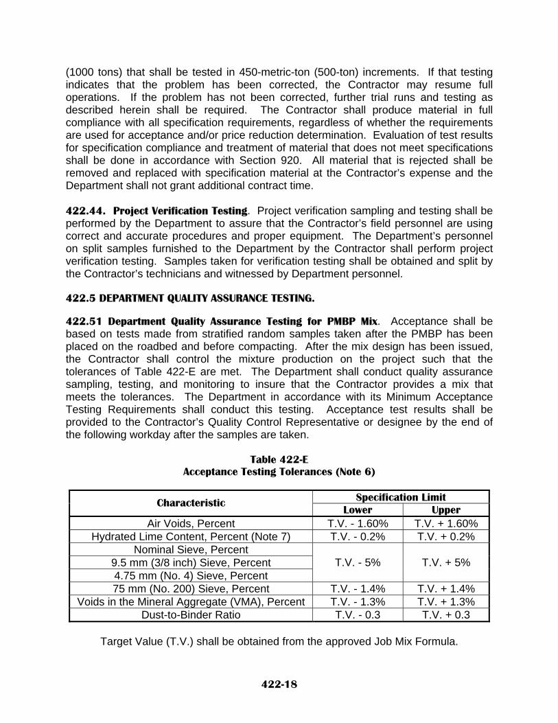
(1000 tons) that shall be tested in 450-metric-ton (500-ton) increments. If that testing indicates that the problem has been corrected, the Contractor may resume full operations. If the problem has not been corrected, further trial runs and testing as described herein shall be required. The Contractor shall produce material in full compliance with all specification requirements, regardless of whether the requirements are used for acceptance and/or price reduction determination. Evaluation of test results for specification compliance and treatment of material that does not meet specifications shall be done in accordance with Section 920. All material that is rejected shall be removed and replaced with specification material at the Contractor’s expense and the Department shall not grant additional contract time. 422.44. Project Verification Testing. Project verification sampling and testing shall be performed by the Department to assure that the Contractor’s field personnel are using correct and accurate procedures and proper equipment. The Department’s personnel on split samples furnished to the Department by the Contractor shall perform project verification testing. Samples taken for verification testing shall be obtained and split by the Contractor’s technicians and witnessed by Department personnel. 422.5 DEPARTMENT QUALITY ASSURANCE TESTING. 422.51 Department Quality Assurance Testing for PMBP Mix. Acceptance shall be based on tests made from stratified random samples taken after the PMBP has been placed on the roadbed and before compacting. After the mix design has been issued, the Contractor shall control the mixture production on the project such that the tolerances of Table 422-E are met. The Department shall conduct quality assurance sampling, testing, and monitoring to insure that the Contractor provides a mix that meets the tolerances. The Department in accordance with its Minimum Acceptance Testing Requirements shall conduct this testing. Acceptance test results shall be provided to the Contractor’s Quality Control Representative or designee by the end of the following workday after the samples are taken.
Table 422-E Acceptance Testing Tolerances (Note 6)
Specification Limit Characteristic
Lower Upper Air Voids, Percent T.V. - 1.60% T.V. + 1.60%
Hydrated Lime Content, Percent (Note 7) T.V. - 0.2% T.V. + 0.2% Nominal Sieve, Percent
9.5 mm (3/8 inch) Sieve, Percent 4.75 mm (No. 4) Sieve, Percent
T.V. - 5% T.V. + 5%
75 mm (No. 200) Sieve, Percent T.V. - 1.4% T.V. + 1.4% Voids in the Mineral Aggregate (VMA), Percent T.V. - 1.3% T.V. + 1.3%
Dust-to-Binder Ratio T.V. - 0.3 T.V. + 0.3
Target Value (T.V.) shall be obtained from the approved Job Mix Formula.
422-18

Note 6: All gradation, VMA, and Dust-to-Binder Ratio values shall be determined using the AASHTO T 308 testing results Note 7: Shall be determined based on daily tank straps The Department shall sample the PMBP mixture from behind the paver and shall determine the asphalt content, for information purposes only, and the aggregate gradation of the sample that shall be prepared for analysis per AASHTO T 308. Additionally, each oven used to perform AASHTO T 308 shall be individually calibrated before its actual use per the latest Department’s “Ignition Oven Calibration Factors” procedure. If any Quality Control or Quality Analysis oven has not been properly calibrated per this procedure within two (2) days of actual production of any job mix formula, the Project Manager shall cease all paving operations until such a calibration of all ovens has been completed at no additional cost to the Department for any incurred Contractor delays that are directly related to this issue. Also, all PMBP material that is produced during this time period is produced at the Contractor’s risk of price reduction or removal per the outcome of actual testing results. This procedure is available through the Department’s State Materials Bureau. 422.52 Department Quality Acceptance Testing for Compaction. The PMBP shall be divided into acceptance sections or lots of 1360 metric tons (1500 tons) or one day’s production, whichever is less, for the purpose of defining areas represented by each series of acceptance tests. The Department shall use a stratified random sampling plan to enhance the quality of acceptance sampling and testing. The density of each acceptance section or lot shall be evaluated by a minimum of three cut pavement samples taken in conformity with AASHTO T 166 at randomly selected sites within the test section. The cut pavement samples shall be taken and prepared by the Contractor for testing. Department personnel shall do the testing. The Contractor shall core each lift of the PMBP full depth in accordance with applicable AASHTO and Department procedures. All questions arising from the sampling operation, including diameter of core samples shall be decided by the Project Manager. The Contractor shall identify each core sample with a location marking and deliver all core samples to the test site within the time specified by the Project Manager. The mean density obtained for all tests in each acceptance section or lot shall be at least 93% of the theoretical maximum density as determined from AASHTO T 209. In addition, each individual test value obtained within an acceptance section or lot shall be at least 90.00% of the theoretical maximum density and shall not exceed 98.00% of the theoretical maximum density. In the event an individual test result falls below 90.00% or exceeds 98.00% of the theoretical maximum density, the Assistant District Engineer shall determine the disposition of the material represented by the test. 422.6 METHOD OF MEASUREMENT. 422.61 PMBP Complete will be measured by the metric ton (ton).
422-19

422.62 Plant mix bituminous pavement will be measured by the metric ton (ton). Bituminous material and hydrated lime will be measured, using daily tank staps, according to SECTION 402 - BITUMINOUS MATERIAL, HYDRATED LIME, AND LIQUID ANTI-STRIPPING AGENTS. 422.63 Plant mix bituminous pavement will be measured by the square meter (square yard). When plant mix bituminous pavement is to be measured by the square meter (square yard), the average width of the PMBP in place will be used in computing the quantities. The length used in computing the area shall be station to station along the centerline of roadway. All dimensions shall be as shown on the typical section of the plans. 422.64 PMBP sampling and testing by the Contractor will be measured by the lump sum, unless otherwise stated. 422.7 BASIS OF PAYMENT. 422.71 PMBP Complete will be paid for at the contract unit price per metric ton (ton). PMBP Complete will constitute full compensation for all materials, labor, tools, equipment, and appurtenances necessary to complete the work as directed by the Project Manager. Materials shall be considered to include all aggregate, bituminous material, filler, hydrated lime and other additives or modifiers as required. 422.72 Plant mix bituminous pavement will be paid for at the contract unit price per metric ton (ton). Bituminous material and hydrated lime will be paid for by the metric ton (ton) according to SECTION 402 - BITUMINOUS MATERIAL, HYDRATED LIME, AND LIQUID ANTI-STRIPPING AGENTS. 422.73 PMBP sampling and testing by the Contractor will be paid for at the lump sum contract price, unless otherwise stated. PMBP Sampling and Testing by the Contractor shall include providing all cut pavement samples and density testing. 422.74 Plant mix bituminous pavement will be paid for at the contract unit price per square meter (square yard). When plant mix bituminous pavement by the square meter (square yard) is called for in the contract, the accepted quantities complete in place will be considered full compensation for all materials, labor, tools, equipment, PMBP Sampling and Testing by the Contractor, and any appurtenances necessary to complete the work as directed by the Project Manager. Materials shall be considered to include all aggregate, bituminous material, hydrated lime, filler and other additives or modifiers as required.
422-20
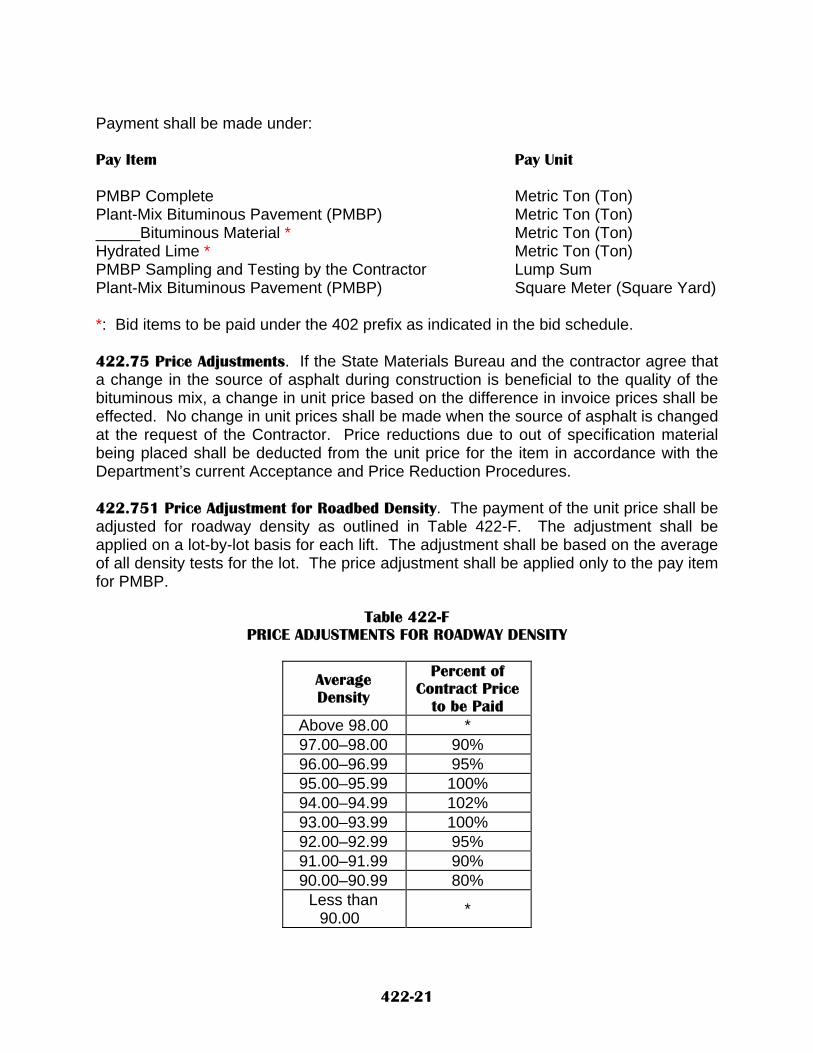
Payment shall be made under: Pay Item Pay Unit PMBP Complete Metric Ton (Ton) Plant-Mix Bituminous Pavement (PMBP) Metric Ton (Ton) _____Bituminous Material * Metric Ton (Ton) Hydrated Lime * Metric Ton (Ton) PMBP Sampling and Testing by the Contractor Lump Sum Plant-Mix Bituminous Pavement (PMBP) Square Meter (Square Yard) *: Bid items to be paid under the 402 prefix as indicated in the bid schedule.
422.75 Price Adjustments. If the State Materials Bureau and the contractor agree that a change in the source of asphalt during construction is beneficial to the quality of the bituminous mix, a change in unit price based on the difference in invoice prices shall be effected. No change in unit prices shall be made when the source of asphalt is changed at the request of the Contractor. Price reductions due to out of specification material being placed shall be deducted from the unit price for the item in accordance with the Department’s current Acceptance and Price Reduction Procedures. 422.751 Price Adjustment for Roadbed Density. The payment of the unit price shall be adjusted for roadway density as outlined in Table 422-F. The adjustment shall be applied on a lot-by-lot basis for each lift. The adjustment shall be based on the average of all density tests for the lot. The price adjustment shall be applied only to the pay item for PMBP.
Table 422-F PRICE ADJUSTMENTS FOR ROADWAY DENSITY
Average Density
Percent of Contract Price
to be Paid Above 98.00 * 97.00–98.00 90% 96.00–96.99 95% 95.00–95.99 100% 94.00–94.99 102% 93.00–93.99 100% 92.00–92.99 95% 91.00–91.99 90% 90.00–90.99 80%
Less than 90.00 *
422-21

* This lot shall be removed and replaced. In lieu thereof, the Contractor and the Assistant District Engineer may agree in writing that it is in the best interest of the Department that the lot not be removed but instead be paid for at 50% of the contract price. 422.76 Partial Payments for Testing and Sampling by the Contractor. Partial payments shall be made according to the percentage of sampling and testing completed as determined by the Project Manager. Prior to commencement of sampling and testing on the project, the Project Manager shall determine and notify the Contractor of the percentages of sampling and testing to be paid for as certain phases of the sampling and testing are completed.
422-22

NEW MEXICO DEPARTMENT OF TRANSPORTATION SUPPLEMENTAL SPECIFICATIONS FOR
PLANT-MIX BITUMINOUS PAVEMENT (SUPERPAVE QC/QA)
SECTION 423
All pertinent provisions of the New Mexico Department Of Transportation's Standard Specifications For Highway And Bridge Construction shall apply in addition to the following: Delete SECTION 423 - PLANT-MIX BITUMINOUS PAVEMENT (SUPERPAVE QC/QA) in its entirety and substitute the following: 423.1 DESCRIPTION. 423.11 This work shall consist of constructing one or more courses of plant-mix bituminous pavement (PMBP) on a prepared base. PMBP shall be composed of a mixture of bituminous material, aggregate, blending sand, mineral filler, and hydrated lime if required. Reclaimed Asphalt Pavement (RAP) will be permitted in all PMBP mixtures, unless otherwise prohibited in the contract, provided that the resulting mixture conforms to all specification requirements. The aggregate fractions shall be sized and uniformly graded and combined in such proportions as directed by the Department. 423.2 MATERIALS. 423.21 All materials shall be tested in accordance with applicable AASHTO methods, as modified by the Department when applicable, or other test procedures designated by the Department. The State Materials Bureau shall decide all questions pertaining to the interpretation of test procedures. Material that is improperly graded or segregated, or fails to meet the requirements herein provided, shall be corrected or removed and disposed of immediately as directed by the Project Manager, at no additional cost to the Department. The aggregate gradation of the PMBP mixture shall meet the requirements of Table 423-A. At no additional cost to the Department, wet preparation, per AASHTO T 146 (Method A), shall be required by the Project Manager if the Project Manager believes that deleterious Materials are present in the aggregate stockpiles prior to aggregate gradation testing. The PMBP type shall be as indicated in the contract. The combining of materials from two or more sources to produce aggregate shall be permitted only when each source meets all applicable quality requirements. 423.221 Gradation and Quality Requirements
423-1

Table 423-A PLANT-MIX BITUMINOUS PAVEMENT
AGGREGATE GRADATION CONTROL POINTS
Percent Passing Sieve Size SP-I SP-II SP-III SP-IV
Min Max Min Max Min Max Min Max 50.0 mm (2 in.) 100 -- -- -- -- -- -- --
37.5 mm (1-1/2 in.) 90 100 100 -- -- -- -- -- 25.0 mm (1 in.) -- 90 90 100 100 -- -- --
19.0 mm (3/4 in.) -- -- -- 90 90 100 100 -- 12.5 mm (1/2 in.) -- -- -- -- -- 90 90 100 9.5 mm (3/8 in.) -- -- -- -- -- -- -- 90 4.75 mm (No. 4) -- -- -- -- -- -- -- 2.36 mm (No. 8) 15 41 19 45 23 49 28 58 75 µm (No. 200) 0.0 6.0 1.0 7.0 2.0 8.0 2.0 10.0
A. Aggregate Quality. For each individual material source, the PMBP coarse aggregate
shall have an Aggregate Index of 25.0 or less when calculated in accordance with Section 910.
For aggregate stockpiles, the amount of crushing shall be regulated so that the minimum fractured faces content of the plus 4.75mm (No. 4) material complies with the requirements of Table 422-B and when evaluated by NMDOT Method FF-1, “Fractured Face Determination for Coarse Aggregate.” The plus 9.5mm (3/8-in.) material shall contain a maximum of 20.0% flat, elongated particles with a dimensional ratio of 3:1 or greater as determined by ASTM D 4791. All combined material, excluding RAP, passing the 425 µm (No. 40) sieve shall be non-plastic. The minimum sand equivalent value and the minimum fine aggregate angularity value of the combined aggregate, excluding RAP, before the addition of hydrated lime, shall comply with the requirements of Table 422-B. The sand equivalent value shall be determined in accordance with AASHTO T 176 (Alternate Method No. 1) and the fine aggregate angularity value shall be determined in accordance with AASHTO T 304 (Method A).
B. Fractured Faces. A face will be considered fractured when at least one-half of the
projected particle area exhibits a rough, angular, or broken texture with well defined edges.
423-2

Table 423-B
Fractured Faces, Sand Equivalent, and Fine Aggregate Angularity
Estimated Traffic, ESALs x 106 (Note 1)
Fractured Faces (Note 2)
Sand Equivalent Fine Aggregate Angularity
< 3.0 75.0 / --- 45.0 40.0 > 3.0 to < 10.0 85.0 / 80.0 45.0 45.0 > 10.0 to < 30.0 95.0 / 90.0 45.0 45.0
> 30.0 100.0 / 100.0 50.0 45.0
Note 1: ESALs are based on a 20-year design life for all scenarios. Note 2: Under "Fractured Faces", 85.0 / 80.0 denotes that 85.0% of the course aggregate shall have at least one (1) fractured face and 80.0% shall have at least two (2) fractured faces.
423.222 Quality Acceptance of Aggregate. Samples will be tested in accordance with Section 910, “Aggregate Index”. 423.223 Production. When producing aggregates for PMBP, natural fines shall be removed by screening and stockpiled separately. The Contractor shall use as a minimum, the 4.75mm (No. 4) screen for this operation. The Contractor may use a larger screen if needed to properly control the crushing and screening operation. The aggregate retained on the scalping screen shall then be crushed, separated and stockpiled as specified herein. Crushing operations shall be regulated in a manner that produces material within the specified gradation band. When producing aggregates for PMBP the crushed material shall be separated into at least two stockpiles of fine and coarse aggregates. 423.224 Stockpiling. Stockpiles shall be constructed upon prepared sites and when completed shall be neat and regular in shape and so constructed to prevent segregation of the aggregate. Sufficient storage space shall be provided for each size of aggregate. Stockpiles of different types or sizes of aggregate shall be spaced far enough apart, or separated by suitable walls or partitions, to prevent the mixing of the aggregates. The different aggregate sizes shall be kept separated until they have been delivered to the cold feed system feeding the drier. Aggregate shall not be deposited where traffic, vehicles, or Contractor’s equipment will either run over or through the piles, or in any way cause foreign matter to become mixed with the aggregates. The storage yard shall be maintained neat and orderly and the separate stockpiles shall be readily accessible for sampling. 423.225 Combining. When the crushed materials from the stockpiles are combined, including RAP if used in the mixture, the product of such combination shall meet the gradation requirements. In order to meet the specified mix design criteria, blending
423-3

sand may be added up to a maximum of 20.0%. Controlled feeders from each stockpile shall be used to blend the materials. 423.226 Acceptance of Aggregate. The plasticity index, sand equivalent, fine aggregate angularity, flat and elongated particles count, and fractured face count of PMBP aggregate, excluding RAP, shall be determined from representative samples taken after the aggregate materials have been blended and prior to the addition of hydrated lime and mixing with bituminous material. The test results from these samples will be the basis for acceptance of such aggregate. The Project Manager may sample and test the aggregate at any time during production or stockpiling and/or may request to split samples with the Contractor. For Reclaimed Asphalt Pavement (RAP), aggregate acceptance will be based on the requirements of subsection 423.27. 423.23 Bituminous Material. The type and grade of bituminous material will be specified in the contract. The bituminous materials shall meet the requirements of Section 402, “Bituminous Material, Hydrated Lime and Liquid Anti-Stripping Agents”. The asphalt source to be used shall not be changed after State Material Bureau’s issuance or concurrence of the mix design without written approval of the Department’s State Materials Bureau. 423.24 Hydrated Lime. Hydrated lime shall conform to the requirements of subsection 402.26, “Bituminous Material, Hydrated Lime and Liquid Anti-Stripping Agents”. 423.25 Blending Sand. Blending sand shall consist of the natural fines from the scalping process, concrete sand, sandy material or a combination of any or all of these that is graded in such a manner that it satisfies the mix design requirements. The need for and actual percentage of blending sand shall be determined based on design mix criteria tests developed from samples taken from the Contractor’s stockpiles during crushing operations and submitted to an approved testing laboratory. Blending sand may be added up to a maximum of 20.0%. 423.26 Mineral Filler. Mineral filler shall conform to the requirements of AASHTO M 17, and shall be approved by the State Materials Bureau. Fly ash shall not be acceptable as a mineral filler for PMBP. 423.27 Reclaimed Asphalt Pavement. Unless otherwise prohibited in the contract, the Contractor shall have the option of utilizing Reclaimed Asphalt Pavement (RAP) removed under the contract or RAP from an existing stockpile that shall consist of salvaged, milled, pulverized, broken, or crushed bituminous pavement. After sufficient quantities of Reclaimed Asphalt Pavement (RAP) aggregate samples have been obtained from performing AASHTO T 308, aggregate acceptance shall be based upon each fraction of course aggregate having a percent wear of forty (40.0) or less at 500 revolutions when tested in accordance with AASHTO T 96. Additionally, the minimum fractured faces content of the plus 4.75mm (No. 4) RAP material shall comply with the requirements of Table 422-B and when evaluated by NMDOT Method FF-1, “Fractured Face Determination for Coarse Aggregate” and the plus 9.5mm (3/8-in.) RAP material
423-4

shall contain a maximum of 20.0% flat, elongated particles with a dimensional ratio of 3:1 or greater as determined by ASTM D 4791. A maximum of 15.0%, by total weight of PMBP mixture, RAP may be used in the production of Superpave asphalt mixtures without changing the bituminous material. For RAP percentages greater than 15.0% to a maximum of 25.0%, both the bituminous material’s high and low temperature grades shall be lowered one grade (i.e. a PG 76-22 would be lowered to a PG 70-28) and RAP may then be used in the production of Superpave asphalt mixtures. The RAP percentages greater than 25.0% shall not be used in the production of Superpave asphalt mixtures. RAP shall be processed such that 100% shall pass a 37.5-mm (1-1.2 inch) sieve before introduction into the mixing plant. Dirt, debris, or other objectionable materials shall not contaminate the RAP. Unless otherwise prohibited in the contract, the contractor shall have the option of utilizing RAP removed under the contract or RAP from an existing stockpile. No additional payment by the Department shall be made to the Contractor if RAP materials are used in the manufacturing process of Superpave asphalt mixtures. 423.28 Mix Design. The Contractor shall provide a mix design developed by a Department approved testing laboratory. A list of approved private testing laboratories is available from the State Materials Bureau. Under special circumstances where the Contractor is unable to obtain a mix design from an approved private testing laboratory, the State Materials Bureau may at its discretion perform the mix design. All costs associated with the development of the mix design by an approved private testing laboratory, other than the State Materials Bureau, shall be borne by the Contractor. The mix design may be developed at any time after the aggregate production has been stabilized after at least 13,500 metric tons (15,000 tons) or half the estimated quantity, whichever is less, have been produced. At least five independent aggregate gradation test results shall be submitted to the Project Manager from each stockpile. If this data shows considerable variation in the material the contractor shall produce additional material to develop consistency in the test results before the development of the mix design. The Contractor shall provide a copy of the request to develop a mix design, along with all supporting documents that shall conform to the design procedures in AASHTO Provisional Standard PP-28, to the Project Manager and the State Materials Bureau. This submittal shall include the Contractor’s suggested aggregate combination. Along with this submittal, the Contractor shall submit copies of all stockpile test results. If the State Materials Bureau develops a mix design, it may take in excess of 30 working days for the design to be issued. If an approved laboratory other than the State Materials Bureau develops the mix design, the design results shall be summarized in a format approved by the State Materials Bureau and then submitted to the State Materials Bureau for review and concurrence. The submittal shall include the results and design worksheets of all testing determinations, per AASHTO Provisional Standard PP-28, for the individual mix components as well as for the mixture itself. The issuance of a mix design developed by the State Materials Bureau or concurrence by the Department of a mix design developed by another approved testing laboratory shall not relieve the Contractor of full responsibility for producing an acceptable mixture through the plant. The mix design shall be considered as a starting point only and may be adjusted as described in subsection 423.29. All mix designs shall be developed and
423-5

tested in accordance with procedures established by the State Materials Bureau. The resultant job mix formula gradation shall be within the master range for the specified type of PMBP as described in Table 423-A. A minimum of 1.0% hydrated lime shall be required in all mix designs. When lime is to be added, it is included in the gradation for establishing the laboratory mix design. The mix design for each mixture shall establish a single percentage of aggregate passing each required sieve size and a single percentage of bituminous material to be added to the aggregate. The mix design shall be developed using the SHRP gyratory compactor in accordance with AASHTO PP28 except as specifically modified in this Section and shall conform to the requirements of Table 423-C. The minimum acceptable retained strength during design, when the PMBP is tested in accordance with AASHTO T 165 and compared to the unconfined compressive strength of a PMBP mixture that does not contain an anti-strip additive, shall be a minimum of 85.0% at 7.0% ± 1.0% air voids. The Contractor shall provide a mixture that meets all applicable criteria. If tests indicate the need for additives or modifiers not indicated in the Contract, more than 1.0% hydrated lime, or a change in source of binder to satisfy mix design requirements, any additional cost for these items shall be borne by the Contractor.
Table 423-C Superpave PMBP Design Requirements for Aggregates with Less Than 3.0% Absorption
Voids in the Mineral Aggregate (VMA), Percent
Nominal Maximum Aggregate Size, mm 25.0 (SP-II) 19.0 (SP-III) 12.5 (SP-IV)
Voids Filled with Asphalt (VFA) Range,
Percent (Note 2)
Dust to Binder Ratio
Range
20-Year Design ESALs
(Millions)
NinitialNdesign
(Note 1) Nmaximum
Min Max Min Max Min Max Min Max Min Max < 0.3 < 91.5 72.0 80.0
0.3 to < 3.0 < 90.5 68.0 78.0 > 3.0 < 89.0
96.0 < 98.0 12.5 14.0 13.5 15.0 14.5 16.0 68.0 75.0
0.6 1.4
Superpave PMBP Design Requirements for Aggregates with 3.0% or Greater Absorption
Voids in the Mineral Aggregate (VMA), Percent
Nominal Maximum Aggregate Size, mm 25.0 (SP-II) 19.0 (SP-III) 12.5 (SP-IV)
Voids Filled with Asphalt (VFA) Range,
Percent (Note 2)
Dust to Binder Ratio
Range
20-Year Design ESALs
(Millions)
NinitialNdesign
(Note 3) Nmaximum
Min Max Min Max Min Max Min Max Min Max < 0.3 < 91.5 70.0 80.0
0.3 to < 3.0 < 90.5 65.0 78.0 > 3.0 < 89.0
96.5 < 98.0 12.0 14.0 13.0 15.0 14.0 16.0 65.0 75.0
0.6 1.4
Note 1: Design Air Void Content of 4.0% Note 2: For 25.0 mm nominal maximum size mixtures, the specified lower limit of the
VFA shall be 70 percent for the design traffic level < 0.3 million ESALs. Note 3: Design Air Void Content of 3.5% The State Materials Bureau will normally approve a mix design for use for a period of one year from the date of issue or concurrence. The design may be used or re-issued during that time provided acceptable evidence is submitted to the State Materials
423-6

Bureau verifying that the component materials have not changed significantly. If a change in sources of materials or crushing operations is made, the Project Manager may then require a new mix design before the new materials may be used. When unsatisfactory results or other conditions make it necessary, the Project Manager may also require that a new mix design be developed. 423.29 Mix Design Adjustment. All material incorporated into the work shall be evaluated for acceptance in accordance with subsection 423.5, Acceptance, and Section 901. Material shall be evaluated for acceptance using the mix design in effect at the time the material was produced. The mix design and/or subsequent field designs may be adjusted as described herein. 423.291 Job Mix Formula. The job mix formula (JMF) is defined as the combined aggregate gradation and the percentage of each material component to be used in the mix. The JMF shall comply with all aggregate gradation requirements and shall result in a mix that meets all specified mix design requirements. When hydrated lime is used in the job mix formula, the mix design recommended percentage shall be increase by 0.2% to account for the effective loss of hydrated lime during actual PMBP production. The result of the laboratory mix design developed in accordance with subsection 423.28 is designated as JMF1. 423.292 Job Mix Formula Adjustment. The contractor may propose adjustments to the job mix formula in accordance with subsection 920.22, “Job Mix Formula Adjustments”. 423.3 CONSTRUCTION REQUIREMENTS. 423.31 General. Sufficient storage space shall be provided for each size of aggregate and RAP. The different aggregate and RAP sizes shall be kept separated until they have been delivered to the cold feed system feeding the drier. In placing the coarse aggregate and fine aggregate in storage or moving it from storage to the cold feed bins, methods that cause segregation, degradation or the combining of materials of different gradings shall not be permitted. Segregated or degraded material shall be re-screened or wasted. Should mineral filler material be required, a separate storage and bin feeder shall be provided for the filler material. Aggregates and RAP shall not require prior preparation other than gradation control, except that those containing gravitational water shall be stockpiled and allowed to drain before mixing. After the required amounts of aggregate, RAP (if used), and bituminous material have been introduced into the mixer, the materials shall be mixed until all aggregate particles are completely and uniformly coated with the bituminous material. If it is determined by the Project Manager that excessive uncoated aggregate exists, the Contractor shall take corrective action to remedy the problem. The moisture content of the bituminous mixture at discharge from the mixer shall not exceed 0.5%. 423.311 Mix Temperature Requirements. The target temperature of the bituminous mixture at discharge from the mixer shall be as specified on the mix design. The temperature shall not exceed the target temperature by more than 11°C (20°F).
423-7

423.32 Addition of Hydrated Lime. The hydrated lime shall be added to the entire portion of aggregate in an enclosed pug mill immediately after leaving the cold feed and just before introduction into the dryer drum or aggregate dryer. The hydrated lime shall be added to the aggregate such that loss of hydrated lime is minimal or nonexistent. Placement of the lime on an open conveyer belt shall not be permitted. Placement of the lime on an enclosed belt that does not permit blowing or loss of lime is acceptable. A vane feeder shall be located in the out feed of the lime silo. A flow sensor shall be installed on the discharge from the vane feeder. The sensor shall activate an audible and visual signal at the control panel when lime flow is interrupted. The lime silo shall be provided with an approved means of metering the lime being added to the mix, at typical discharge rates, to an accuracy of 3.0% or better by weight of the hydrated lime. Approved means for metering lime shall include load cell weighing devices placed beneath each leg of the silo, or a weigh belt feeder between the silo discharge and the pug mill. Other means of metering the addition of lime shall be approved by the Project Manager prior to use. External strain gauges affixed to the legs of the silo shall not be permitted. The hydrated lime content shall be controlled within the specification limits per Table 423-D. If load cell weighing devices are used for lime metering, a cast-in-place concrete foundation pad shall be used to support the silo. Grout shall be placed between the foundation and the load cells to ensure intimate contact between the load cell and the foundation. Based on the approved mix design summary, the moisture content of the combined aggregates shall be at the recommended saturated surface dry (SSD) moisture content plus an additional 1.5% ± 0.5% by weight, at the time the aggregate and lime are mixed. The Project Manager may increase the moisture content of the coarse and fine aggregates to obtain proper coating of the aggregates with hydrated lime and to eliminate dust pollution. The Contractor shall provide a method to positively determine the amount of moisture added to lime-aggregate mix. 423.33 Equipment. 423.331 Mixing Plants. A. Plant Scales. Scales shall be accurate to 0.5% of the maximum load allowed as per
the latest Department of Transportation publication. A licensed scale serviceman must certify the scales with a copy of the certification submitted to the Project Manager.
B. Equipment for Preparation of Bituminous Materials. Tanks for storage of
bituminous material shall be equipped to heat and hold the material at the required temperatures. The tank shall be provided with a capability to measure the temperature of the asphalt in the tank. The heating shall be accomplished by approved means and such that no flame shall be in contact with the tank. The circulating system for the bituminous material shall be designed to assure proper and continuous circulation during the operating period. A suitable outlet for sampling bituminous material shall be installed in the line leading from the storage tank to the plant, and provisions shall be made for measuring and sampling the storage tanks.
423-8

C. Feeder for Drier. The plant shall be provided with accurate mechanical means for uniformly feeding the aggregate into the drier so that uniform production and uniform temperature shall be obtained.
D. Drier. The plant shall include a system to continuously agitate the aggregate during
the heating and drying process. The drier shall be capable of drying and heating aggregate in such a manner as to preclude the mineral aggregate from becoming coated with fuel oil or carbon. If it is determined that the aggregate is coated, the Contractor shall take corrective action, which may include changing type of burner fuel at no additional cost to the Department.
E. Bins. The plant shall include storage bins of sufficient capacity to supply the mixer
when it is operating at full capacity. Bins shall be arranged to assure separate and adequate storage of appropriate fractions of the mineral aggregates. When necessary, the contractor shall assure positive separation of the bins by the use of separating boards. Separate dry storage shall be provided for hydrated lime. The gates on the bins shall not leak. Bins shall be equipped with low-bin warning devices that indicate at the control panel when the bins are low.
F. Bituminous Material Control Unit. The Contractor shall provide satisfactory means
to obtain the proper amount of bituminous material in the mix within the tolerance specified, either by weighing or metering. The Contractor shall provide means for checking the quantity or rate of flow of bituminous material into the mixer.
G. Thermometric Equipment. An approved thermometer with a range in temperature
reading from 38oC to 204°C (100oF to 400°F) shall be fixed in the bituminous feed line at a suitable location near the charging valve at the mixer unit. The plant shall also be equipped with another approved thermometric instrument so placed at the discharge chute of the drier as to register automatically the temperature of the heated aggregates or mix as applicable. The record of discharge temperatures shall be provided to the Project Manager upon the completion of each week’s production and when requested by the Project Manager during the course of production.
H. Truck Scales. The bituminous mixture shall be weighed on approved scales
furnished by the Contractor or on public scales, in accordance with subsection 109.1, “Measurement of Quantity”.
I. The contractor shall fully comply with Section 107, Legal Relations, Environmental
Requirements, and Responsibilities to the Public J. Requirements for Batching Plants.
1. Weigh Box or Hopper. The equipment shall include a means of accurately weighing each size of aggregate in a weigh box or hopper suspended on scales and of ample size to hold a full batch. The gate shall close tightly so that no material is allowed to leak into the mixer while a batch is being weighed. The
423-9

scales shall be tested in accordance with subsection 109.1, Measurement of Quantity.
2. Bituminous Material Control. The equipment used to measure the bituminous
material shall be accurate to plus or minus 0.3%. The bituminous material bucket shall be a non-tilting type with a loose sheet metal cover. The section of the bituminous line between the charging valve and the spray bar shall be provided with a valve and outlet for checking the meter when the metering device is substituted for a bituminous material bucket.
3. Mixer. The batch mixer shall be capable of producing a uniform mixture within
the specified tolerances. The mixer shall have a batch capacity of not less than 900 kg (2000 pounds).
4. Control of Mixing Time. The plant shall be capable of adequately controlling
mixing time. The mixer shall be equipped with an accurate timing device that shall signal the completion of mixing time.
K. Requirements for Drum Mix Plants. The drum mixer and necessary auxiliary
equipment shall be specifically designed to provide a final product conforming to specifications. Auxiliary equipment to the drum mix plant shall provide the following:
1. Separate cold feed controls for each material. 2. Automatic interlocking device for cold feed, asphalt, and additive. 3. Means for determining moisture content of aggregate so the dry weight of cold
feed can be determined for proper setting of asphalt and additive flow. The Contractor shall determine the moisture content of the aggregate at least twice daily and shall adjust the moisture correction equipment accordingly.
4. Means for sampling individual cold feeds and provisions for sequential sampling
of aggregate, RAP, asphalt cement, and additives while under full production. 5. Equipment for temperature sensing of mix at discharge and automatic burner
controls. 6. A surge storage system having a minimum capacity of 36 metric tons (40 tons)
designed and equipped to prevent segregation. The surge storage system bins shall be equipped with adequate mechanical or electrical devices to indicate when bins are less than 1/4 full. The device shall automatically provide an audible or visual warning. The plant shall not be operated unless this automatic system is in good working order.
7. The bin(s) containing fine aggregate and filler, if required, shall be equipped with
a device that shall prevent any hang-up of material while the plant is operating.
423-10

8. A minimum of one cold feed bin shall be required for each aggregate fraction
used in the mix. 9. The cold feed shall be equipped with adequate mechanical or electrical devices
to indicate when the bins are empty or when the cold feed belt is not carrying the proper amount of material. The device shall automatically lock the cold feed belt and provide an audible or visual warning. The plant shall not be operated unless this automatic system is in good working order.
10. A separate cold feed shall be provided for RAP material. RAP shall be
introduced into the drum at a location such that it does not come into direct contact with the burner flame.
11. The feeding mechanism shall include an individual belt feeder with a variable
speed feeder drive controlled by electronically operated actuators. The bituminous feed control shall be coupled with the total aggregate weight measurement device in such manner as to automatically vary the bitumen feed rate as necessary to maintain the required proportion.
423.332 Haul Equipment. Trucks used for hauling bituminous mixtures shall have tight, clean, smooth metal beds that have been thinly coated with a minimum amount of a Department-approved release agent to prevent the mixture from adhering to the bed. Diesel fuel shall not be used. 423.333 Pavers. Pavers shall be self-contained, self-propelled units, provided with an activated screed or a strike-off assembly, heated if necessary, and capable of spreading and finishing courses of PMBP material to the crowns, widths, and thickness as specified in the contract. Pavers shall be operated at a speed no greater than 5 km/h (3 mph). Materials introduced in front of the screed shall maintain a consistent depth to avoid variation in pressure on the screed. The auger box shall be maintained at 1/3 to 2/3 full. Pavers shall be equipped with a receiving hopper having sufficient capacity to affect a uniform spreading operation. The hopper shall be equipped with a distribution system capable of maintaining a uniform amount of mixture in front of the screed. The paver shall be capable of being operated at forward speeds consistent with satisfactory laying of the mixture. The screed shall be adjustable for both height and crown, and shall be equipped with a controlled heating device. The screed or strike-off assembly shall produce a finished surface of an even and uniform texture for the full width being paved without tearing, shoving or gouging the mixture. Screeds shall include any strike-off device operated by tamping or vibrating action. The paver shall be equipped with an automatic leveling device controlled from an external guide. The initial pass for each course shall be made using a paver equipped with a 12.0-m (40.0-ft) minimum external reference, except that this requirement shall not apply when PMBP is placed adjacent to Portland cement concrete pavement or when short lengths of PMBP placement are required. Subsequent passes and passes adjacent to PCCP shall utilize a matching device of 300-mm (1.0-ft) minimum length riding on the adjacent lay.
423-11

423.334 Compaction Equipment. The number, weight, and type of rollers furnished shall be sufficient to obtain the required compaction while the mixture is in a workable condition. The selection of roller types shall provide the specified pavement density. 423.34 Placement Operations. The PMBP mixture shall be placed on the approved surface, spread and struck off to the grade and elevation established. It shall be spread and compacted in layers as shown on the plans or as directed by the Project Manager. The asphalt paver shall be used to distribute the mixture either over the entire width or over such partial width as may be practicable. The subgrade, base course or bituminous treated base (BTB) upon which the PMBP is to be placed shall be cleaned of all loose material or other deleterious materials prior to placement of the PMBP. These surfaces shall be free of frozen material, and the moisture and density requirements of the applicable section shall be met before placement of the new PMBP. The PMBP may be dumped from the hauling vehicles directly into the paving machine or it may be dumped upon the surface being paved and subsequently loaded into the paving machine; however, no PMBP shall be dumped from the hauling vehicles at a distance greater than 75 m (250 ft) in front of the paving machine. When PMBP is dumped upon the surface being paved, the loading equipment shall be self-supporting and shall not exert any vertical load on the paving machine. Substantially all of the PMBP dumped shall be picked up and loaded into the paving machine. The speed of the paving machine shall be coordinated with the production of the plant to achieve a continuous operation. Sufficient hauling equipment shall be available to insure continuous operation. The control system on the paving machine shall control the elevation of the screed at each end, either by controlling the elevation of one end directly and the other indirectly through controlling the transverse slope or by controlling the elevation of each end independently, including any screed attachments used for widening, etc., unless otherwise directed by the Project Manager. Failure of the control system to achieve the desired typical section shall be cause for the suspension of the paving operations. When dumping directly into the paving machine from trucks, care shall be taken to avoid jarring the machine or moving it out of alignment. All courses of PMBP shall be placed and finished by means of self-propelled paving machines except under certain conditions or at certain locations where the Project Manager deems the use of self-propelled paving machines impracticable. Self-propelled paving machines shall spread the PMBP without segregation or tearing within the specified tolerances, true to the line, grade, and crown indicated on the plans. On areas where irregularities or unavoidable obstacles make the use of mechanical spreading and finishing equipment impracticable, the mixture shall be dumped, spread and leveled to give the required compacted thickness. When required by the Project Manager, existing surfaces shall be cleaned and a tack coat shall be applied in accordance with Section 407, “Tack Coat”. 423.341 Temperature and Weather Limitations. PMBP shall not be placed on wet or frozen surfaces or when weather conditions otherwise prevent the proper handling, finishing, and compacting of the PMBP.
423-12

423.35 Compaction. Immediately after the bituminous mixture has been spread, struck-off and surface irregularities adjusted, it shall be thoroughly and uniformly compacted. The sequence of rolling operations shall provide the specified pavement density. Rolling operations shall not disturb the typical section required by the plans. Rollers shall be operated at speeds less than 5 km/h (3 mph) and slow enough to minimize displacement of the bituminous mixture. The use of equipment that results in excessive crushing of aggregates shall not be permitted. Any roller marks resulting from use of a pneumatic roller shall be removed. Any displacement occurring because of the reversing of the direction of a roller, or from other causes, shall be corrected immediately. Care shall be exercised in rolling not to displace the line and grade of the edges of the bituminous mixture. To prevent adhesion of the mixture to the rollers, the wheels shall be kept properly moistened with water or water mixed with very small quantities of detergent or other approved material. Excess liquid shall not be permitted. Diesel fuel or other petroleum diluents shall not be used for any reason. Along forms, curbs, headers, walls and other places not accessible to the rollers, the mixture shall be thoroughly compacted with hot hand tampers, smoothing irons or with mechanical tampers. On depressed areas, a trench roller or cleated compression strips under the roller may be used to transmit compression to the depressed area. Mixtures that become loose, broken, mixed with dirt, segregated, or are defective, shall be removed and replaced with fresh hot bituminous mixture, and compacted to conform with the surrounding area, at the Contractor’s expense. Areas showing excess or deficiency of bituminous material shall be corrected immediately as directed by the Project Manager. 423.36 Miscellaneous Paving. Construction of miscellaneous paving including guardrail pads, slope paving, ditch paving, minor turnouts, bituminous curb, and raised median paving shall be governed by Section 417, “Miscellaneous Paving”. Miscellaneous paving as defined in this paragraph shall be excluded from Quality Level Analysis for pay factor determination. 423.37 Joints. Placing of the PMBP shall be as continuous as possible. Rollers shall not pass over the unprotected end of a freshly laid mixture. When PMBP is placed over bituminous treated base or when open-graded friction course is placed over PMBP, longitudinal joints shall be staggered at least 150 mm (6.0 in.) relative to longitudinal joints of the underlying course. Unless otherwise shown on the plans, all transverse and longitudinal joints shall be tapered in accordance with this specification. Tapered transverse joints shall have at least a 1.0-m (3.0-ft) minimum taper, but in no case shall the taper slope be steeper than (24:1). Tapered longitudinal joints shall have at least a 300-mm (1.0-ft) minimum taper, but in no case shall the taper slope be steeper than 6:1. All transverse tapers shall be cut and squared off before commencing new work. Tapered longitudinal joints from previous operations shall be cleaned and tack coated unless otherwise directed by the Project Manager. All joints shall be completely bonded. The surface of each course at all joints shall be smooth and shall not show deviations in excess of 5 mm (3/16 in.) when tested with a 3.0-m (10.0-ft) straightedge in any direction. When paving under traffic, the Contractor shall plan the daily surfacing operations on a schedule so that the tapered longitudinal joints are not left exposed longer than seven (7) consecutive calendar days.
423-13

423.38 Surface Tolerances. The surface of each completed course shall be smooth and shall not show deviations in excess of 3 mm (1/8 in.) when tested with a 3.0 m (10.0 ft) straightedge in any direction. All humps or depressions exceeding this tolerance shall be corrected immediately as directed by the Project Manager. The final PMBP surfacing course shall meet the requirements of Section 401. 423.39 Plan Surfacing Depths. Plan depths, for new or reconstruction projects, shall be monitored and recorded throughout the surfacing operations with methods and at intervals designated by the Project Manager. Should a deficient plan depth of more than 12.5 mm (0.5 inches) become evident and corrections no longer can be applied, the Contractor shall submit a corrective action plan to the Project Manager for review and approval. The Department will pay for the material in-place or up to the planned pavement thickness. 423.4 CONTRACTOR PROCESS QUALITY CONTROL TESTING. 423.41 Contractor Process Quality Control. The Contractor shall administer a Quality Control Plan, referred to hereafter as “the Plan,” sufficient to assure a product meeting the contract requirements. The Plan shall meet the requirements of subsection 901.2, Contractor Process Quality Control. A. The Plan shall address all elements that affect the quality of the asphalt concrete
including, but not limited to the following: 1. Mix design(s); 2. Aggregate production; 3. Quality of components; 4. Stockpile management 5. Proportioning; 6. Mixing, including addition of hydrated lime, and/or asphalt additive, if required; 7. Transporting; 8. Placing and finishing; 9. Joints; 10. Compaction; 11. Smoothness; 12. Thickness, when required; and
13. Shakedown period
B. The Plan shall identify personnel responsible for sampling and testing of PMBP. All sampling and testing for PMBP will be performed by TTCP certified sampling and testing personnel as set forth in Section 901. The Contractor shall provide at least two TTCP certified technicians, as follows:
1. The Process Control Technician(s) (PCT) is responsible for inspection, sampling,
and testing performed at the hot mix plant and at the Contractor’s field laboratory. The PCT will be expected to utilize laboratory test results and other quality
423-14

control practices to assure the quality of aggregate sources and other mix components, and adjust and control mix proportioning to meet the mix design(s). The PCT shall be responsible for periodically inspecting all equipment utilized in proportioning and mixing to assure its proper operating condition and to assure that proportioning and mixing is in conformance with the mix design and other requirements.
2. The Quality Control Technician(s) (QCT) is responsible for inspection, sampling,
and testing performed at the paving site. The QCT will be expected to assure that the delivered materials meet the requirements of the contract. The QCT shall be responsible for periodically inspecting all equipment utilized in transporting, placing, finishing and compacting to assure its proper operating condition, and to assure placing, finishing, joint construction, compaction, and thickness when required, are in conformance with the specifications.
C. The Plan shall set forth the coordination of the activities of the PCT and QCT and
how they will be documented. This shall include the frequency of each type of test, the criteria used by the PCT and QCT to reject or correct unsatisfactory materials, and a description of when and how corrective actions are to be taken.
D. The Plan shall describe in detail proposed Process Control and Acceptance
sampling and testing programs, including method of determination of random sampling locations. Sample locations for Acceptance tests shall be developed in such a manner that the center of the sample is no closer than 300 mm (12.0 in.) to a joint or edge of the pavement mat.
423.42 Contractor Quality Control for Compaction. The Contractor shall monitor the compaction process by determining the density of the PMBP with a portable nuclear density test device in conformity with ASTM D 2950. The Contractor from cut pavement samples shall establish calibration of the portable nuclear device. The density readings of the cut pavement samples shall be determined by the Contractor in accordance with AASHTO T 166 (weight, volume method) and the density readings of the pavement shall be determined by the portable nuclear density test device in conformity with ASTM D 2950 and shall be correlated by the Contractor. The Contractor shall conduct testing per the requirements of Section 901,Table 901-C(3)(4) and shall furnish all test results to the Project Manager. The target density for acceptance of PMBP will be 94.50% of the theoretical maximum density as determined from AASHTO T 209. In addition, each individual test value obtained within an acceptance section or sublot shall be at least 90.00% of the theoretical maximum density and shall not exceed 98.00% of the theoretical maximum density. In the event an individual test result falls below 90.00% or exceeds 98.00% of the theoretical density, the Contractor may perform, with the Project Manager’s approval, additional testing to verify the individual test result. Then, the Assistant District Engineer shall determine the disposition of that acceptance section or sublot by: a. Accepting the acceptance section or sublot;
423-15

b. Determining that portion of the material in that acceptance section or sublot be removed or replaced at no additional cost to the Department, or
c. Determining that portion of the material in that acceptance section or sublot shall be paid for at a 50% pay factor.
For purposes of acceptance and pay factor determination, density shall be determined from cut pavement sections (cores) 150mm (6.0-in.) in diameter extending through the full thickness of the PMBP. Determination of theoretical maximum density shall be calculated using an average of all maximum specific gravity values by both the Contractor and the Department obtained the day the material represented by the core was placed. The Contractor shall obtain and test a minimum of two samples and the Department shall obtain and test a minimum of one sample for maximum specific gravity for each day during which PMBP is placed. It is intended that quality control density testing be done while the bituminous mixture is hot enough to permit further compaction if necessary. Rolling for any compactive effort shall not be allowed beyond the point at which it becomes ineffective or damage begins to occur to the PMBP. Additionally, use of vibratory mode shall not be permitted when the temperature of the mix is below 93°C (200°F). 423.43 Adherence to Specifications and Rejection of Nonspecification Material. The Contractor shall produce material in substantial compliance with all specification requirements, regardless of whether the requirements are used for acceptance and/or pay factor determination. Evaluation of test results for specification compliance and treatment of material that does not meet specifications will be done in accordance with Section 920. All material that is rejected shall be removed and replaced with specification material at the Contractor’s expense. 423.5 ACCEPTANCE. 423.51 Acceptance. The mixture and/or pavement will be sampled and tested on a statistically random basis in accordance with Section 901, Table 901-D(1)(2). Evaluation of the materials for acceptance will be determined in accordance with subsection 901.5, Quality Level Analysis, using the acceptance limits per Table 423-D:
423-16

Table 423-D Acceptance Testing Tolerances (Note 7)
Specification Limit Characteristic
Lower Upper Air Voids, Percent T.V. - 1.60% T.V. + 1.60%
Mat Density T.V. - 2.5% T.V. + 2.5% Hydrated Lime Content, Percent (Note 8) T.V. - 0.2% T.V. + 0.2%
Nominal Sieve, Percent (Note 9) 9.5 mm (3/8 inch) Sieve, Percent
4.75 mm (#4) Sieve, Percent T.V. - 5% T.V. + 5%
75 µm (#200) Sieve, Percent T.V. - 1.4% T.V. + 1.4% Voids in the Mineral Aggregate (VMA), Percent T.V. - 1.3% T.V. + 1.3%
Dust-to-Binder Ratio T.V. - 0.3 T.V. + 0.3 NOTE 7: All gradation, VMA, VFA, and Dust-to-Binder Ratio values shall be determined using the AASHTO T 308 testing results. NOTE 8: Shall be determined based on daily tank straps. Target Value (T.V.) shall be obtained from the approved Job Mix Formula. NOTE 9: The “Nominal Maximum Sieve” for a SP-I PMBP gradation shall be the 37.5mm (1-1/2 in) sieve, for a SP-II PMBP gradation shall be the 25.0mm (1 in) sieve, for a SP-III PMBP gradation shall be the 19.0mm (3/4 in) sieve, and for a SP-IV PMBP gradation shall be the 12.5mm (1/2 in) sieve. The Contractor shall sample the PMBP mixture from behind the paver and shall determine the asphalt content, for informational purposes only, and the aggregate gradation of the sample that shall be prepared for analysis per AASHTO T 308. Additionally, each oven used to perform AASHTO T 308 shall be individually calibrated before its actual use per the latest Department’s “Ignition Oven Calibration Factors” procedure. If any Quality Control or Quality Analysis oven has not been properly calibrated per this procedure within two (2) days of actual production of any job mix formula, the Project Manager shall cease all paving operations until such a calibration of all ovens has been completed at no additional cost to the Department for any incurred Contractor delays that are directly related to this issue. Also, all PMBP material that is produced during this time period is produced at the Contractor’s risk of price reduction or removal per the outcome of actual testing results. This procedure is available through the Department’s State Materials Bureau. 423.6 METHOD OF MEASUREMENT. 421.61 PMBP Complete will be measured by the metric ton (ton). 421.62 Plant mix bituminous pavement will be measured by the metric ton (ton).
423-17

Bituminous material and hydrated lime will be measured, by daily tank strap, by the metric ton (ton) according to SECTION 402 – BITUMINOUS MATERIAL, HYDRATED LIME, AND LIQUID ANTI-STRIPPING AGENTS. 420.63 Plant mix bituminous pavement will be measured by the square meter (square yard). When plant-mix bituminous pavement is to be measured by the square meter (square yard), the average width of the PMBP in place will be used in computing quantities. The length used in computing the area shall be station-to-station along the centerline of the roadway. All dimensions shall be as shown on the typical sections of the plans. 423.7 BASIS OF PAYMENT. 423.71 The accepted quantities of PMBP will be paid for at the pay unit stated in the contract, and will be adjusted in accordance with subsection 901.5, Quality Level Analysis. Payment for (material) PMBP in a lot will be made at a price determined by multiplying the contract unit bid price by the composite pay factor. The following table will be used to calculate the Composite Pay Factor:
Table 423-E Composite Pay Factors
Characteristic "f" Factor Mat Density 50
Air Voids 50 Nominal Sieve 10
9.5 mm (3/8 inch) Sieve 10 4.75 mm (#4) Sieve 15 75 µm (#200) Sieve 15
Voids in the Mineral Aggregate (VMA) 40 Dust-to-Binder Ratio 10
423.711 When plant mix bituminous pavement complete is called for in the contract, the accepted quantities will be paid for at contract unit price, adjusted as described in subsection 423.71. Said payment will constitute full compensation for all materials, labor, tools, equipment, and appurtenances necessary to complete the work as directed by the Project Manager. Materials shall be considered to include all aggregate, bituminous material, hydrated lime, filler and other additives or modifiers as required. 423.712 The accepted quantities of bituminous material will be paid for at the contract unit price per metric ton (ton), adjusted as described in subsection 423.71.
423-18

423.713 The accepted quantities of hydrated lime will be paid for at the contract unit price per metric ton (ton), adjusted as described in subsection 423.71. Said payment shall be full compensation for furnishing, mixing, and processing lime material. 423.714 When plant mix bituminous pavement by the square meter (square yard) is called for in the contract, the accepted quantities will be paid for at contract unit price, adjusted as described in subsection 423.71. Payment will constitute full compensation for all materials, labor, tools, equipment, and appurtenances necessary to complete the work as directed by the Project Manager. Materials shall be considered to include all aggregate, bituminous material, hydrated lime, filler and other additives or modifiers as required. Payment will be made under: Pay Item Pay Unit PMBP Complete Metric Ton (Ton) Plant-Mix Bituminous Pavement (PMBP) Metric Ton (Ton) Bituminous Material * Metric Ton (Ton) Hydrated Lime * Metric Ton (Ton) Plant-Mix Bituminous Pavement (PMBP) Square Meter (Square Yard) *: Bid items to be paid under the 402 prefix as indicated in the bid schedule.
423-19

NEW MEXICO DEPARTMENT OF TRANSPORTATION SUPPLEMENTAL SPECIFICATIONS FOR
PORTLAND CEMENT CONCRETE PAVEMENT (QC/QA)
SECTION 450 All provisions of the New Mexico Department Of Transportation’s Standard Specifications for Highway And Bridge Construction shall apply in addition to the following: 450.1 DESCRIPTION. 450.11 This work shall consist of constructing Portland cement concrete pavement (PCCP) in one course, on a prepared subgrade or base course. 450.2 MATERIALS. 450.21 Portland cement, air-entraining admixtures, chemical admixtures, fly ash, water and aggregate shall meet the requirements of Section 510, Portland Cement Concrete. 450.22 Dowels & Tie Bars. Dowels and tie bars shall meet the applicable requirements of Section 540, Steel Reinforcement. 450.23 Joint Sealing Material. Joint sealing material shall meet the requirements of Section 452, Sealing & Resealing Concrete Pavement Joints. 450.24 Curing Compound. Resin base curing compound shall meet the requirements of AASHTO M 148 for Type 2, Class B white pigmented curing compounds. 450.25 Sheet Materials for Curing & Protecting Concrete. Sheet materials for protecting concrete shall meet the requirements of AASHTO M 171, except that only the white reflective type shall be used. 450.3 CONSTRUCTION REQUIREMENTS. 450.31 Proportioning. The concrete shall meet the requirements for concrete Class F of subsection 510.12, Classifications. Structural concrete Class AA may be substituted for concrete Class F if the concrete is not slip-formed. If the use of Structural concrete Class AA is approved, the mixing time, as defined in Section 510, Portland Cement Concrete, shall not exceed 1½ hours or 300 total mixing and agitating revolutions of the drum or blades, whichever comes first. The concrete shall be proportioned to meet all of the fresh and hardened properties required in subsection 510.41. The concrete mix design submittal shall include all of the documentation required in subsection 510.42.
450-1

A copy of the approved mix design issued by the State Materials Laboratory must be available on the job whenever the concrete mix is being used. 450.32 Equipment. 450.321 Batching Plant. Batching plants and equipment shall meet the requirements in subsection 510.44. 450.322 Mixers. Mixers shall meet the requirements of subsection 510.447, Mixing. 450.323 Transporting. Truck mixers, truck agitators or non-agitating trucks shall comply with subsection 510.46. 450.324 Slip-Form Paver. The concrete shall be placed with an approved slip-form paver designed to spread, consolidate screed and float finish the freshly placed concrete in one complete pass of the machine such that a dense and homogeneous pavement is achieved with a minimum of hand finishing. The vibrators of the slip-form paver shall be behind the auger. Pavers with vibrators in front of the auger shall not be used on NMDOT projects. The sliding forms of slip-form pavers shall be rigidly held together laterally to prevent them from spreading. Slip form pavers shall be equipped with internal vibrators, which shall meet or exceed the following specifications at manufacturers design frequency of 10,000 vibrations per minute (vpm): A. Amplitude (peak to peak) = 1.78 mm (0.070 in.) B. Centrifugal force = 544.31 kg (1200 lb) Slip-form pavers shall also be equipped with an electronic monitoring device displaying the operating frequency of each individual internal vibrator for any paving projects, which involve more than 182.88 m (600 linear feet) of concrete pavement. The monitoring device shall have a readout display near the operator’s controls, visible to the paver operator and to the Department Inspector. It shall record, at a minimum, the time of day, station location, paver track speed and operating frequency of each individual vibrator. It shall operate continuously while paving, and shall display the frequencies for each vibrator with manual or automatic sequencing among all individual vibrators. The depth that internal vibrators penetrate into the concrete pavement slab shall be set to mid-slab depth or as deep as possible, while passing above any reinforcing steel. An operating position-locking device shall be provided so that no part of the vibrating unit can be lowered such that it will come in contact with reinforcing steel or tie bars while paving.
450-2

Horizontal spacing of vibrators shall not exceed the manufacturer’s recommendations, and in no case exceed 460 mm (18 in.), center-to-center. The space from the outer edge of the pavement to the outside vibrator shall not exceed 230 mm (9 in.). The longitudinal axis of the vibrator body shall be parallel to the direction of paving, such that the end of each vibrator shall also be oriented exactly parallel to the direction of paving, as well as parallel to the pavement surface. 450.325 Concrete Saw. Sawing equipment shall be adequate in number of units and power to complete the required sawing within the maximum time allotted. The saw equipment may utilize a water-cooled diamond edge saw blade, an abrasive wheel, or shall be of the “early entry dry cut” type with a skid plate, as defined by ACI 302. The contractor shall provide at least one standby saw in good working order. An ample supply of saw blades (and skid plates, if the early entry dry cut saws are used) shall be maintained at the work site at all times during sawing operations. 450.326 Curing Compound Application Equipment. Curing compounds shall be applied with equipment that uses a pressure tank or pump, equipped with a feed tank agitator that provides continuous agitation of the compound during spraying operations. The nozzle shall be of the two-line type and shall contain sufficient air to properly atomize the compound. 450.33 General. For slip-form paving, the subgrade shall be constructed a sufficient distance beyond each edge of the area to be paved to accommodate the slip-form equipment. The Contractor shall ensure appropriate lateral support is provided so the section is constructed according to contract requirements. The Contractor shall maintain base course to the correct elevation and cross section and in a smooth and compacted condition until the concrete placement is completed. Base course shall be uniformly moist when the concrete is placed. The Contractor shall set a reference line, approved by the Project Manager, parallel to the established finish grade. This reference line shall be used for grade control for subsequent finish grading operations. Concrete shall not be mixed, placed, finished, or repaired when the natural light is inadequate, as determined by the Project Manager, unless an adequate and approved artificial lighting system is operated. Each vibrator on the paving machine must be individually calibrated each day with a vibratory tachometer to provide 8000 vpm to 10,000 vpm before any concrete can be
450-3
placed. If a vibrator is found not to comply with this requirement, it shall be fixed or replaced immediately. 450.331 Handling, Measuring, Batching & Mixing Materials. Handling, measuring, batching and mixing materials shall meet the requirements of Section 510, Portland Cement Concrete. 450.332 Placing, Spreading & Compacting Concrete. Concrete shall be placed in uniform thickness for the full width of the lane or area to be paved, without segregation, and with a minimum of redistribution. Concrete shall not be placed more than 15 m (50 ft) ahead of the strike-off device on the finishing machine. Placing concrete shall be continuous between transverse joints without the use of intermediate bulkheads. Where dowel baskets are used, the concrete shall not be placed by end dumping from dump trucks directly onto the grade. End-dumps may be used to transfer the concrete to the equipment designed to place it completely across the grade. Windrowing the concrete will not be permitted. Where concrete is to be placed adjacent to a recently constructed PCCP lane, mechanical equipment shall not be operated on that lane until the concrete has attained a compressive strength of 20.7 MPa (3000 psi). Equipment that is supported on existing pavement shall be equipped with protective pads on crawler tracks or rubber-tire wheels. The crawler tracks or rubber-tire wheels on the bearing surface shall be offset far enough from the edge of the pavement to avoid breaking it. A. Slip-Form Paving. The slip-form paver shall distribute the concrete into its final
position, uniformly and without delay. The alignment and elevation of the paver shall be regulated from outside reference lines established for this purpose. The paver shall vibrate the concrete for the full width and depth of the strip of pavement being placed such that the maximum consolidation is achieved without segregating the concrete. The vibration shall be adequate to produce a consistency of concrete that will stand normal to the surface with sharp well-defined edges. The sliding forms shall be rigidly held together laterally to prevent them from spreading apart.
If “vibrator trails” caused by segregation are visible immediately behind the paver, the paving operation will be adjusted to eliminate them. If these efforts are unsuccessful, the paving operation will be suspended until the cause of the segregation has been eliminated. The plastic concrete shall be effectively consolidated by internal vibration. Internal vibration shall be defined as vibration by devices located within the specified thickness of pavement section and ahead of the screen a distance that is at least equal to the pavement thickness.
450-4

The frequency of vibration shall be continuously monitored by obtaining readings for the time of day, operating frequency for each vibrator, station location, and paver track speed. The Contractor will make a record of these readings after each 7.5 m (25 ft) of paving, or after each five minutes of time, whichever occurs first. A record of the data will be provided to the Department Inspector at the close of paving operations for the day, or at the specific request of the Project Manager. The rate of vibration of each vibrating unit shall be maintained between 6500 and 10,000 vibrations per minute. The frequency of the vibration shall be varied proportionately with the rate of travel to result in a non-segregated cross-section with uniform density and air content. The concrete shall be maintained at a uniform consistency and the paver shall be operated in a continuous forward movement. All concrete mixing, delivering, and spreading operations shall be coordinated to provide uniform progress, minimizing the stopping and starting of the paver. If it is necessary to stop the forward movement of the paver, the vibratory and tamping elements shall also be stopped immediately. No tractive force shall be applied to the machine, except that which is controlled from the machine.
B. Other Paving. For ramps, intersections, irregular areas, locations inaccessible to slip-form paving equipment or other similar type paving that involves small quantities of PCCP, concrete pavement may be placed between stationary side forms. The concrete shall be compacted by internal vibration, finished to the required surface smoothness by the hand-float method or other suitable means, and cured by approved methods.
Side forms shall have a height equal to or greater than the specified depth of pavement, be of ample strength to resist deformation, and be free from warps, bends or kinks. Forms shall be securely set in place to withstand the weight, impact, and vibrating of the finishing machines, without visible springing or settlement. Forms shall be drilled in advance of being placed to accommodate tie bars where specified. Forms built of wood shall remain in place at least 12 hours after the concrete has been placed unless the ambient temperature is less than 4.4 °C (40 °F). No wooden forms shall be removed when the ambient temperature is less than 4.4 °C (40 °F) unless the concrete has been in place for at least 24 hours. Forms made of metal shall remain in place at least 12 hours after the concrete has been placed. All forms shall be cleaned and oiled each time they are used. Curing compound shall be applied to all concrete surfaces exposed by removal of the forms immediately after the forms are removed. The Contractor shall check the alignment and grade elevations of the forms and make all necessary corrections immediately before placing the concrete. When a
450-5

form has been disturbed or when the base course under a form has become unstable, the form shall be reset and rechecked, as directed by the Project Manager.
450.333 Weather & Temperature Limitations. Weather and temperature limitations shall meet the requirements of Subsection 511.33, Weather & Temperature Limitations, except that if the use of Structural concrete Class AA is approved, the concrete shall have a temperature of at least 10 °C (50 °F) and not more than 32 °C (90 °F) at the time of placement. 450.334 Rate of Evaporation Limitations. Portland cement concrete pavement shall not be placed unless the combination of air temperature, temperature of fresh concrete, relative humidity and wind velocity at the surface of the concrete are such that the rate of evaporation is less than 0.98 kg/m2/h (0.2 lb/ft2/h), as determined from Section 512, Superstructure Concrete, Figure 512-A Surface Evaporation from Concrete. To estimate the rate of evaporation: 1. Enter the chart at measured air temperature, and move vertically to relative humidity. 2. Move right to the line corresponding to the concrete temperature. 3. Move downward to the line representing the wind velocity. 4. Read the evaporation rate on the scale to the left of this point. The wind velocity used shall be the average of the maximum and minimum wind velocities observed in a three-minute period immediately before or concurrent with the concrete placement operations, measured 1.5 m (5 ft) above the surface of the pavement at the point of concrete placement most exposed to the wind. Concrete shall not be placed during periods of high air temperatures, low humidity, or high winds unless one or more of the following measures have been taken and maintained to the satisfaction of the Project Manager to reduce the rate of evaporation to within the specified rate: A. Erect windbreaks to reduce the wind velocity over the concrete surface. B. Place concrete during nighttime or early morning hours. C. Lower the fresh concrete temperature during hot weather by using cool aggregate
and chilled water, by adding ice as part of the mixing water, or by adding liquid nitrogen to the concrete mix after it has been discharged into the ready mix truck.
D. Increase the relative humidity at the site with a fog spray maintained over the entire
concrete surface until the final finish has been achieved and the curing compound has been applied.
450-6
450.335 Change in Atmospheric Conditions. Contractors may choose to proceed with the Portland cement concrete pavement placement during marginal weather, but they do so at their own risk. Concrete damaged due to changing weather conditions shall be repaired, or removed and replaced, as determined by the District Construction Engineer, and at the Contractor’s expense. 450.34 Joints. Joints shall be constructed at the locations, intervals and dimensions specified in the contract, and shall be sealed in accordance with Section, 452 Sealing & Resealing Concrete Pavement Joints. However, the maximum spacing between joints shall be not greater than 4.57 m (15 ft), and the maximum length to width ratio for the joints shall be 1.5:1. There shall be no re-entrant corners. Every effort shall be made to avoid tapered corners. If a tapered corner is formed, then a control joint shall be placed at: A. one-half the distance between the end of the taper and the opposite side, if the base
leg is less than or equal to 3 m (10 ft), but greater than 1.5 m (5 ft) long; or B. third points along the base leg, if the base leg is greater than 3 m (10 ft) long. The faces of all joints shall be constructed perpendicular to the surface of the PCCP. Any joints added to control cracking shall be doweled in exactly the same manner as the standard joints, in accordance with the plans and specifications. Transverse and longitudinal contraction joints shall be constructed by means of sawing the freshly hardened concrete as soon as possible after it is placed. Sawing of the transverse contraction and longitudinal joints shall be a two-phase operation. The initial saw cut should be 6 mm to 10 mm (1/4 to 3/8 in.) wide. The second sealant reservoir shaping saw cut shall be made in accordance with the details shown in the contract. The minimum initial saw cut depth should be at least one-third the pavement depth, unless the early entry dry cut method is used, in which case the depth of the saw cut shall be at least 31.75 mm (1-1/4 in.) deep. In no case shall the saw cut be deep enough to cause damage to the steel reinforcement. Sawing of the joints shall begin as soon as possible after the concrete has hardened enough to permit a person to stand on the surface without leaving visible tracks or indentations, and before uncontrolled shrinkage cracking takes place. All saw cutting shall be completed no later than four hours after the concrete has hardened enough that a person can stand on the surface without leaving visible tracks or indentations. The saw blades (and the skid plates, if the early entry dry cut method is used) shall be changed as often as required to control and minimize spalling. A sufficient supply of replacement saw blades and skid plates shall be available at the project site to be sure that the sawing operations will proceed without interruption until completed.
450-7

In general, all joints should be sawed in sequence. However, control transverse joints may be sawed at intervals shown in the contract or at an interval that will most effectively minimize the possibility of uncontrolled cracking. If necessary, the sawing operations shall be carried on day and night, regardless of weather conditions. The sawing of any joint shall be omitted if a crack occurs at or near the joint location prior to the time of sawing. Sawing shall be discontinued at a joint when a crack develops ahead of the saw. All damage to the concrete resulting from the sawing operations shall be repaired immediately after the sawing is completed, at the Contractor’s expense. 450.341 Longitudinal Joints. Longitudinal joints shall be cut with approved concrete saws to the depth, width, and lines shown in the contract, and suitable guides or devices shall be used to assure true cutting of the longitudinal joint. The sawed area shall be thoroughly cleaned and, when directed by the Project Manager, the joint shall be sealed immediately. Deformed steel tie bars shall be as specified in the contract and shall be placed perpendicular to the longitudinal joints. Tie bars shall be placed by approved equipment, or rigidly secured by chairs or other approved supports, to prevent displacement. Tie bars shall not be painted or coated with asphalt or other material, or enclosed in tubes or sleeves, except when the Project Manager determines that it is necessary for the Contractor to reapply a corrosion-resistant coating to the tie bars after they have been bent and straightened. Tie bars should not be placed within 380 mm (15 in.) of transverse joints. When using tie bars longer than 815 mm (32 in.) with skewed joints, tie bars shall not be placed within 460 mm (18 in.) of transverse joints. The Contractor has the option of using a two-part threaded tie bar and splice coupler system or of bending the tie bars, unless otherwise directed by the Project Manager. If the Contractor bends the tie bars, they shall be Grade 420 steel, and they shall be bent at right angles against the form of the first lane constructed and then straightened into final position before the concrete of the adjacent lane is placed. When construction of PCCP abuts an existing lane of pavement constructed under another contract, the holes shall be drilled at mid-depth of the thinner slab. Joints shall be constructed with tie bars as shown in the contract. The face of the existing PCCP shall be drilled to accept half of the tie bar length. The drill holes shall be a diameter that will provide a close fit for the tie bars, which shall be epoxied into the drill holes. 450.342 Transverse Contraction Joints. Transverse contraction joints shall be constructed with load transfer devices (dowels) as shown in the contract. Dowels shall be held in position parallel to the surface and centerline of the slab by chairs or other approved supports. The Contractor shall submit shop drawings of welded dowel
450-8

assemblies for approval. Concrete shall not be placed until approval of welded dowel assemblies is received. When dowel baskets are used, they shall be checked before placing the concrete to ensure that they are properly aligned and securely anchored in the pavement base. Dowel baskets shall be secured to the base with steel stakes having a minimum diameter of 8 mm (0.3 in.). These stakes shall be embedded into the base a minimum depth of 150 mm (6 in.) for treated permeable bases, and 250 mm (10 in.) for untreated permeable bases or aggregate bases. A minimum of eight stakes per basket shall be provided. All temporary spacer wires extending across the joint shall be removed from the basket. Each dowel shall be lightly and uniformly coated along its full length with an approved form release agent. In no case shall grease be used to lubricate the dowels. Transverse contraction joints shall be created by sawing grooves in the surface of the pavement with an approved gang saw incorporating at least four separate blades. The grooves shall be sawed to the dimensions and at the spacing and lines shown in the contract. 450.343 Construction Joints. Construction joints shall be placed when there is an interruption in the paving operation of more than 90 minutes from the time the concrete was batched. Construction joints shall be constructed with epoxy-coated or stainless steel dowels. The minimum dowel size shall be a Number 30 (10) dowel, or a size having a diameter equal to one-eighth of the slab thickness (rounded to the nearest 5 mm [1/4 in.]), whichever is greater. The dowels shall be placed at 300-mm (12-in.) spacing center-to-center at mid-depth of the slab. For construction of PCCP abutting pavement constructed under another contract, holes shall be drilled at the mid-depth of the thinner slab. The transverse face of the existing PCCP shall be drilled to accept half of the dowel length. No transverse construction joint shall be constructed within 3 m (10 ft) of a contraction joint or plane of weakness. If sufficient concrete has not been mixed at the time of interruption to form a slab at least 3 m (10 ft) long, the excess concrete back to the last preceding joint shall be removed and disposed of as directed by the Project Manager. 450.35 Finishing. After the concrete has been given a preliminary finish by means of finishing devices incorporated in the slip-form paving equipment, the surface of the fresh concrete shall be checked by the Contractor with a straightedge device at least 3 m (10 ft) long. High areas indicated by the straightedge device shall be removed by the hand-float method. Each successive check with the straightedge device shall lap the previous check path by at least half the length of the straightedge. These requirements may be waived if the Contractor successfully demonstrates that other means will consistently produce a surface with a satisfactory profile index that meets the
450-9

profilograph requirement specified in SECTION 401 - PAVEMENT SMOOTHNESS MEASUREMENT. All edge slumping of the pavement, exclusive of specified edging, in excess of 6 mm (1/4 in.) shall be corrected before the concrete has hardened. If edge slump exceeds 13 mm in 3 m (1/2 in. in 10 ft) or less of hardened concrete, the entire panel between the transverse and longitudinal joints shall be removed and replaced with concrete true to the specified line, grade, and cross-section, at the Contractor’s expense. Before the concrete has taken its initial set, the edges of the pavement on each side of transverse expansion joints, formed joints, transverse construction joints, and emergency construction joints shall be worked with an approved tool to produce a well-defined and continuous radius with a smooth and dense mortar finish. The surface of the slab shall not be unduly disturbed by tilting the tool during use. The pavement shall be given a final finish surface by grooving or diamond grinding. Grooving shall be performed in accordance with subsection 512.383, Grooving of Hardened Concrete. Diamond grinding shall be performed in accordance with Section 455, Diamond Grinding of PCCP. At the beginning and end of paving each day, the Contractor shall, with an approved stamp, indent the concrete surface near the right hand edge of the panel to indicate the date, month, and year of placement. At 150-m (500-ft) intervals, the Contractor shall, with an approved stamp, indent the concrete surface near the right-hand edge of the pavement with the stationing of the roadway. 450.351 Protection of fresh Concrete. The Contractor shall have a sufficient quantity of polyethylene sheeting readily available to cover the entire pavement anticipated to be placed in three hours of maximum operation. This sheeting shall be reserved exclusively for the protection of the pavement in case of rain or other adverse conditions. 450.352 Surfacing Smoothness Requirements. The longitudinal smoothness of the finished surface of the PCCP in each through traffic lane and passing lane shall be tested with an approved profilograph, in accordance with SECTION 401 - PAVEMENT SMOOTHNESS MEASUREMENT. The following are specifically excluded from profilograph measurement and shall be evaluated using a straightedge in accordance with SECTION 401 - PAVEMENT SMOOTHNESS MEASUREMENT. A. Horizontal curves with a centerline radius of curvature less than 300 m (1000 ft) and
the super elevation transition to such curves.
450-10

B. Shoulders, ramps, tapers, holding lanes, turn-outs, medians, concrete pavement slab removal and replacement, intersections not paved integrally with the mainline, and other non-mainline pavement.
450.353 Straightedge Measurements. The surface of all PCCP not subject to profilograph measurements shall be tested using an approved 3-m (10-ft) straightedge at both right angles and parallel to the centerline. All surface deviations in excess of 6 mm (1/4 inch) in 3 m (10 ft) shall be corrected as directed by the Project Manager. 450.36 Curing. Immediately after finishing operations have been completed and as soon as marring of the concrete will not occur, the entire surface of the newly placed concrete shall be cured by applying a curing compound or by covering with sheeting material, at the Contractor’s option, unless otherwise directed by the Project Manager. If curing compound is used, it shall be immediately reapplied over any control joints that were cut through previously applied coatings of curing compound. 450.361 Application of Curing Compound. Before placing the curing compound in the spray tank, it shall be thoroughly agitated by means of compressed air or other approved means, until the pigments in the original container are uniformly suspended. The compound shall not be diluted by the addition of solvents or altered in any manner. All curing compound placed in the spray tanks shall be withdrawn directly from manufacturer’s original containers bearing the manufacturer’s name, brand, and lot number. If the compound has become chilled to the extent that it is too viscous for proper stiffening or application or if portions of the vehicle have been precipitated from solution, it shall be heated to restore proper fluidity but it shall not be heated above 38 °C (100 °F). Curing compound shall be applied to the entire area of the exposed surface of the concrete with an approved mechanical spray machine. The fog spray shall be protected from the wind with an adequate shield and shall be applied uniformly at a minimum rate of at least 0.3 L/m2 (1 gal/150 ft2). The curing compound shall be applied immediately after the concrete has been finished and after surplus water that has collected on the surface has disappeared, or at a time designated by the Project Manager. The curing compound shall not be applied during or immediately after rainfall. If it becomes necessary to leave the pavement uncoated overnight, it shall be covered with plastic sheeting material, which shall remain in place until weather conditions are favorable for application of the curing compound. If rain falls on the newly coated pavement before the film has dried enough to resist damage, or if the film is damaged from any cause, the Contractor shall apply an additional coat(s) of curing compound to the affected area at a rate determined by the Project Manager.
450-11

If hairline cracks develop in the pavement before finishing is completed, the Project Manager may order the application of the curing compound at an earlier stage. The Contractor shall apply curing compounds in a manner that will enable the Project Manager to readily determine the rate of application. The Contractor shall protect applied curing compound areas from all traffic, including pedestrian traffic, for at least 10 days unless the Project Manager authorizes opening to traffic earlier. 450.362 Use of Sheeting Materials. Sheeting materials shall be placed over the pavement immediately after finishing operations are completed, or when ordered and in the manner specified by the Project Manager. The sheeting shall be placed so that individual sheets overlap at least 610 mm (24 inches), and the lapped areas shall be held in close contact with the pavement by weighing them down with earth or boards to prevent movement by the wind. The sheeting shall extend downward to cover the edges of the pavement and shall be secured to the subgrade with a continuous bank of earth or surfacing material. The sheeting shall be protected from damage and shall remain in place for at least 10 days unless the Project Manager authorizes opening to traffic earlier. Holes occurring in the sheeting shall be patched immediately to the satisfaction of the Project Manager. 450.37 Diamond Grinding of PCCP. After the concrete has been allowed to cure sufficiently, but in no case less than 48 hours, the surface of the concrete shall be grooved in accordance with Section 455. Unless otherwise approved by the Project Manager, all grooves will be in a transverse direction. 450.38 Protections from, and Opening to, Traffic. The Contractor shall protect new pavement against both public traffic and traffic caused by the Contractor’s operations and employees. This shall include providing sentries to direct traffic, and the erecting and maintaining warning signs, lights, pavement bridges, or crossovers in accordance with the contract traffic control requirements. The pavement will not be opened to traffic until the concrete has reached a compressive strength of 20.7 MPa (3000 psi) based on the requirements of subsection 510.5, Concrete Sampling and Testing, unless otherwise directed by the Project Manager. The Contractor shall clean the pavement of all loose materials and debris before opening to traffic. 450.39 Replacement of Defective Pavement Slabs. Before final acceptance, damaged pavement such as broken slabs, and slabs with random cracks, non-working contraction joints, and spalls shall be replaced as directed by the Project Manager.
450-12

450.4 CONTRACTOR PROCESS QUALITY CONTROL. 450.41 Process Control Plan. The Contractor shall administer a Process Control Plan, referred to hereafter as “the Plan” sufficient to assure a product meeting the contract requirements. The Plan shall meet the requirements of subsection 901.2, Contractor Process Quality Control. A. The Plan shall address all elements, which affect the quality of the Portland cement
concrete paving including, but not limited to the following:
1. Mix Design(s) 2. Aggregate production 3. Quality of Components 4. Stockpile Management 5. Proportioning 6. Mixing 7. Transporting 8. Placing 9. Vibration and Consolidation 10. Finishing 11. Joints 12. Smoothness 13. Thickness
B. The Plan shall identify personnel responsible for sampling and testing of PCCP. All sampling and testing for PCCP will be performed by qualified sampling and testing personnel as set forth in Section 901. The Contractor shall provide at least two qualified technicians, as follows:
1. The Process Control Technician(s) (PCT) is responsible for inspection, sampling,
and testing performed at the concrete batching facility and at the Contractor’s field laboratory. The PCT will be expected to utilize laboratory test results and other quality control practices to assure the quality of aggregate sources and other mix components, and adjust and control mix proportioning to meet the mix
450-13

design(s). The PCT shall be responsible for periodically inspecting all equipment used in proportioning and mixing to assure its proper operating condition and to assure that proportioning and mixing is in conformance with the mix design and other requirements.
2. The Quality Control Technician(s) (QCT) is responsible for inspection, sampling,
and testing performed at the paving site. The QCT will be expected to assure that the delivered materials meet the requirements of the contract. The QCT shall be responsible for periodically inspecting all equipment utilized in transporting, placing, and finishing to assure its proper operating condition, and to assure that the final constructed product is in conformance with the specifications.
C. The Plan shall set forth the coordination of the activities of the PCT and QCT and
how they will be documented. This shall include the frequency of each type of test, the criteria used by the PCT and QCT to reject or correct unsatisfactory materials, and a description of when and how corrective actions are to be taken.
D. The Plan shall describe in detail proposed Process Control and Acceptance
sampling and testing programs, including method of determination of random sampling locations. Sampling and testing shall conform to Table 901-C-1 (901-C-2) and 901-C-5 (901-C-6).
450.42 Adherence to Specifications and Rejection of Non-specification Material. The Contractor shall produce material in substantial compliance with all specification requirements, regardless of whether the requirements are used for acceptance and pay factor determination. The Contractor shall be required to take corrective action to remedy any property of the mix that is out of specification. Contractors who elect to continue to produce material that is not within the specification limits do so at their own risk. Said material will be subject to rejection at the discretion of the Project Manager. All material that is rejected shall be removed and replaced with specification material at the Contractor’s expense. 450.5 ACCEPTANCE. 450.51 The concrete will be sampled and tested on a statistically random basis in accordance with Section 901. See Table 901-D-1 (901-D-2) for acceptance guidelines. Evaluation of the materials for acceptance will be determined in accordance with subsection 901.5, Quality Level Analysis, using the following acceptance limits.
450-14

Table 450-A ACCEPTANCE LIMITS Characteristic Lower Spec Limit Upper Spec Limit Entrained Air T.V . –1.5% T.V +1.5% Compressive Strength
T.V . –6900 kPa (–1000 psi) T.V . +6900 kPa(+1000 psi)
Thickness T.V –25 mm (–1 in.) T.V +25 mm (+1 in.) Unless otherwise provided in the contract, target values for acceptance shall be as follows: Entrained air 6% Compressive strength Target Strength from Mix Design Thickness Nominal Plan Thickness +19 mm (+3/4 in.)
450.6 METHOD OF MEASUREMENT. 450.61 Unless otherwise provided in the Contract documents, Portland cement concrete pavement will be measured by the square meter (square yard). 450.7 BASIS OF PAYMENT. 450.71 The accepted quantities of PCCP will be paid for at the contract unit price per square meter (square yard), which prices and payment shall be full compensation for the work described in this Section, and the PCCP contract unit price will be adjusted in accordance with subsection 901.5, Quality Level Analysis. Payment for PCCP in a lot will be made at a price determined by multiplying the contract unit bid price by the composite pay factor. The following table will be used to calculate the Composite Pay Factor.
Table 450-B COMPOSITE PAY FACTOR
Measured Characteristic Factor “f” Entrained Air 50 Compressive Strength 50 Thickness 50
Payment will be made under: Pay Item Pay Unit Concrete Pavement ______ mm (in.) Square Meter (Square Yard)
450-15

NEW MEXICO DEPARTMENT OF TRANSPORTATION SUPPLEMENTAL SPECIFICATIONS FOR
DRIVEN BEARING PILES
SECTION 501 All pertinent provisions of the New Mexico Department Of Transportation’s Standard Specifications For Highway And Bridge Construction shall apply except as modified herein: Delete SECTION 501 – DRIVEN BEARING PILES in its entirety and substitute the following: 501.1 DESCRIPTION. 501.11. This work shall consist of furnishing and driving bearing piles of the type and dimensions designated, including cutting off or splicing additional pile length when required, as designated in the contract and in accordance with these specifications. Piling shall conform to and be installed in accordance with the specifications, at the location, and to the elevation, penetration or bearing shown in the contract, or as directed by the Project Manager. 501.12 Approvals. All submittals as required below shall be made to the Project Manager for approval by the State Geotechnical Engineer. All other construction and/or field design changes will be submitted to the Project Manager for review and approval by a Department Foundation Engineer who will be assigned by the State Geotechnical Engineer. 501.2 MATERIALS. 501.21 General. Materials shall conform to the requirements of the specified AASHTO, ASTM material specifications, or referenced Sections of the Department’s Standard Specifications as follows:
501-1

Table 501-A
APPLICABLE BEARING PILE STANDARDS1
Material Description Standard Structural Steel Piles and Columns (HP) AASHTO M 183M/M 183 Splice Plates for Structural Steel Piles AASHTO M 183M/M 183 Castings for Pile Shoes AASHTO M 103M/M 103 Steel Pipe Piles2 and Columns ASTM A 252, Gr. 2 Backing Rings for Steel Pipe Pile Splices ASTM A 252, Gr. 2 End Plate for Closed End Pipe Piles AASHTO M 183M/M 183 Portland Cement Concrete, Class G Section 510 Precast Prestressed Concrete Piles Section 518 Paint Section 544
1Timber piles shall not be used, unless otherwise provided for in the contract. 2Continuous spiral weld pipe shall not be used, unless otherwise provided for in the contract.
501.22 Furnishing Piles. 501.221 Steel Piles. Steel piles shall be furnished in lengths shown in the contract. Specified lengths of piles greater than 10 m (32.8 ft) but less than 25 m (82 ft) may be furnished utilizing one field splice to obtain the required length. Specified lengths of piles greater than 25 m (82 ft) may be furnished utilizing two field splices to obtain the required length. The minimum splice length shall be 2 m (6.6 ft). In no case shall any steel pile be furnished with more than two splices. Camber and sweep in excess of the mill tolerance will not be accepted. 501.222 Precast Prestressed Concrete Piles. The manufacture of precast prestressed concrete piles shall conform to Section 518, Prestressed Concrete Members, and the details shown in the contract. All piles shall be furnished in lengths shown in the contract without field splices. 501.223 Splices. Splices shall be as detailed in the contract. Materials shall conform to that designated in Table 501-A, Applicable Bearing Pile Standards. Prefabricated splices shall not be utilized unless otherwise provided for in the contract. If additional length is required due to inadequate bearing, splices shall be constructed according to the requirements in subsection 501.354, Splices. 501.23 Submittals. The following submittals shall be furnished to the Project Manager:
A. Six certified copies of mill test reports of structural steel piles, pile columns, steel pipe piles and pipe pile columns, as well as splice plates, backing rings, end plates, and pile shoes, conforming with all the requirements herein provided.
501-2

Heat numbers shall be indicated on the test reports and clearly marked on each pile furnished.
B. Certification of each welder as required under Section 541, Steel Structures.
Welders’ certification shall be sufficient for those positions required to field weld splices and end plates.
C. Certification and testing required for concrete for pipe piles as required in Section
510, Portland Cement Concrete, for Class G Concrete.
D. Certification and testing for precast prestressed concrete piles as required in Section 518, Prestressed Concrete Members.
E. Certification of paint as provided in Section 544, Protective Coating of New
Structural Steel.
501.231 Pile Driving Equipment Submittals. Not less than 30 days prior to commencement of driving pile, pile driving equipment information necessary to perform a Wave Equation Analysis of the driving system shall be submitted to the Project Manager. The required information shall be provided on the Pile and Driving Equipment Data Form furnished by the State Geotechnical Engineer. All applicable information requested on the form shall be provided. Such information includes, but is not limited to:
A. Pile hammer make, model number, and serial number; B. Driving head assembly, type, model number, and weight; C. Hammer cushion, material, size, and thickness; and D. Pile cushion, material, size, and thickness.
1. The Contractor will be notified of the acceptance or rejection of the driving system within 10 calendar days of the Project Manager’s receipt of the Pile and Driving Equipment Data Form. The criteria used for acceptance or rejection is as covered in subsection 501.314, Approval of Driving System.
If the driving equipment is rejected, the Contractor shall modify or replace the pile driving equipment, at the Contractor’s expense, until the required acceptance criteria is met. The Project Manager will notify the Contractor of the acceptance or rejection of the revised driving equipment within seven calendar days of receipt of a revised Pile and Equipment Data Form.
2. When open-end (single-acting) diesel hammers are proposed for the driving
operation, the Contractor shall submit, with the Pile and Equipment Data Form, a chart from the manufacturer equating stroke and blows per minute for the particular hammer to be used.
501-3

3. When closed-end (double-acting) diesel hammers are proposed for the driving operation, the Contractor shall submit, with the Pile and Driving Equipment Data Form, a chart equating bounce chamber pressure and hose length to either equivalent energy or stroke for the proposed hammer. The actual hose length utilized with the closed-end hammer shall be specified. The chart shall be calibrated to the atmospheric pressure based on the elevation of the project site to the nearest 500 m (1640 ft) elevation.
When double acting or differential acting air/steam hammers are proposed for the driving operation, the Contractor shall submit a chart equating the plant operating pressure to the equivalent delivered energy of the hammer, including losses in the hose. The chart shall be calibrated to the atmospheric pressure criteria stated above. A Certificate of Calibration of the pressure gauge required for double acting hammers shall be submitted to the Project Manager. The calibration shall be certified by a licensed laboratory and shall have been performed within a period of not more than six months prior to the commencement of driving.
501.3 CONSTRUCTION REQUIREMENTS. 501.31 Equipment. 501.311 Pile Hammers. Steam, air, diesel, or hydraulic hammers may be utilized for driving piles. Gravity hammers shall not be used except where specified for use in dynamic testing of drilled shafts or augercast piles. A. Steam and Air Hammers. The plant and equipment furnished for steam and air
hammers shall have sufficient capacity to maintain at the hammer, the volume and pressure specified by the manufacturer under working conditions. The plant and equipment shall be equipped with accurate pressure gages, which are easily accessible to the inspector. The weight of the striking parts of air and steam hammers shall not be less than 1/3 the weight of drive head and pile being driven, and in all cases the striking parts shall weigh at least 1250 kg (2756 lb).
B. Diesel Hammers. Open-end diesel hammers shall be equipped with a means to permit the inspector to visually determine hammer stroke at all times during pile driving operations, such as rings on the ram or a scale extending above the ram cylinder, unless Saximeter stroke measurement equipment is available.
Closed-end diesel hammers shall be equipped with a bounce chamber pressure gauge, mounted with a hose of sufficient length to be easily read by the inspector.
C. Hydraulic Hammers. Hydraulic hammers shall be equipped with a digital display of delivered hammer energy for each stroke. Certification of hammer energy measurement read-out shall be provided to the Project Manager.
501-4
D. Vibratory Hammers. Non-impact hammers, such as vibratory hammers shall not be
used unless either specifically permitted in writing by the State Geotechnical Engineer or stated in the contract.
When permitted, such hammers shall be used for installing production piles only after the pile tip elevation is established for safe support of the pile load, by load testing by static load test, or by dynamic testing with an impact hammer. As a condition of approval of the non-impact hammers, the Contractor shall perform such load tests and extra work required to drive test piles, at the Contractor’s expense, and as directed by the State Geotechnical Engineer. Installation of production piles with vibratory hammers shall be controlled according to power consumption, rate of penetration, specified tip elevation, or other means acceptable to the State Geotechnical Engineer which assure pile load capacity equals or exceeds the test pile capacity. In addition, one of every 10 piles driven with a vibratory hammer shall be re-struck with an impact hammer of suitable energy to verify pile capacity as covered in subsection 501.32, Driven Pile Capacity.
501.312 Driving Apparatus. A. Hammer Cushion. All impact pile driving equipment, except gravity and hydraulic
hammers, shall be equipped with a suitable thickness of hammer cushion material to prevent damage to the hammer or pile and to ensure uniform driving behavior. Hammer cushions shall be made of durable, manufactured materials, provided in accordance with the hammer manufacturer’s guidelines except that all wood, wire rope, and asbestos hammer cushions are disallowed and shall not be used. A striker plate as recommended by the hammer manufacturer shall be placed on the hammer cushion to ensure uniform compression of the cushion material.
B. Drive Head. Piles driven with impact hammers shall be equipped with a suitable
steel drive head to distribute the hammer blow to the pile head. The drive head shall be axially aligned with the hammer and the pile, shall be guided by the leads, and shall not be free-swinging.
The drive head shall fit around the pile head in such a manner as to prevent transfer of torsional forces during driving while maintaining proper alignment of hammer and pile. The pile heads shall be cut squarely and a drive head insert, as recommended by the hammer manufacturer, shall be provided to fit the particular pile type and dimensions.
For precast concrete and prestressed concrete piles, the pile head shall be plane and perpendicular to the longitudinal axis of the pile to prevent eccentric impacts from the drive head.
C. Pile Cushion. A pile cushion made of plywood shall protect the heads of concrete
piles. The minimum plywood thickness placed on the pile head prior to driving shall
501-5

not be less than 100 mm (4 in.). Greater thicknesses may be required if, as a result of the Wave Equation Analysis or Dynamic Testing, the pile compressive or tensile stresses are determined to be unacceptable.
D. Leads. Piles shall be supported in line and position with leads while being driven.
Pile driver leads shall be constructed in a manner that facilitates freedom of movement of the hammer while maintaining alignment of the hammer and the pile to ensure concentric impact for each blow.
The pile section being driven shall not extend above the leads. The leads shall be adequately embedded in the ground or restrained by a rigid brace in order to maintain alignment. The leads shall be of sufficient length to make the use of a follower unnecessary and shall be so designed as to permit proper alignment of batter piles. Leads may be either fixed or swinging type. Swinging leads, when used, shall be fitted with a pile gate at the bottom of the leads and, in the case of batter piles, a horizontal brace shall be required between the crane and the leads.
E. Pile Extensions. Followers shall not be used. Where required and approved by the
Foundation Engineer, the Contractor shall use an extra length pile with splice(s), and ensure that the leads are of adequate length so that followers will not be required. After cut-off, undamaged extra length pile may be re-used as a production pile. subsection 501.22, Furnishing Piles, shall apply with regard to the allowable splices per pile.
F. Templates. Unless otherwise approved in writing by the Project Manager, heavy
metal templates, securely anchored in position, shall be used to maintain pile positions when driving a pile bent.
G. Preboring Equipment. Equipment for preboring shall have the capability of
accomplishing the construction requirements required in subsection 501.332, Preboring.
H. Inspection Equipment. The Contractor shall have available at all times a suitable
device, approved by the Project Manager, for thoroughly illuminating the entire interior length of pipe piles after being driven.
501.313 Minimum Manufacturer’s Rated Hammer Energy. Unless minimum hammer energy is specified in the contract, the Contractor’s proposed hammer shall be rated by the manufacturer at or above the appropriate minimum energy level as specified in Table 501-B, corresponding to the required ultimate pile capacity shown in the contract.
501-6

Table 501-B
REQUIRED HAMMER ENERGY
Ultimate Pile Capacity (kN) Minimum Manufacturer’s Rated Hammer Energy (N-m)
1000 and under 30,000 1001 to 1500 42,500 1501 to 1750 50,000 1751 to 2000 57,500 2001 and over Wave Equation Analysis Required
501.314 Approval of Driving System. The driving system proposed by the Contractor shall be subject to approval by the Foundation Engineer. The driving system includes the hammer and driving apparatus proposed on the Pile and Driving Equipment Data Form. Transportation of the driving system to the project site prior to receiving approval of the driving system will be done at the Contractor’s own risk. The following criteria shall be used to evaluate the driving system for approval or rejection: A. The driving system meets the general requirements established in subsections
501.311, Pile Hammers, and 501.312, Driving Apparatus. B. The manufacturer’s rated hammer energy meets or exceeds the minimum hammer
energy requirements established in subsection 501.313, Minimum Manufacturer’s Rated Hammer Energy, or as shown in the contract.
C. The Wave Equation Analysis indicates that the expected driving resistance (required
ultimate capacity) can be achieved at less than 10 blows per 25 mm (1 in.). D. The Wave Equation Analysis indicates that the pile stresses will not exceed the
allowable stresses at the expected driving resistance (required ultimate capacity) as indicated in Table 501-C.
E. When dynamic tests are specified as covered in Section 504, Load Testing of
Bearing Piles, and acceptance of the hammer system is conditional to the measured energy transfer efficiency, as covered in subsection 501.34 Variations of Approved Driving Systems.
501-7

Table 501-C WAVE EQUATION ANALYSIS ALLOWABLE DRIVING STRESS
Description Maximum Stress1,2
Steel Piles Compressive Stress 90% of yield strength (0.90 Fy)
Concrete piles
Compressive Stress 85% of the compressive strength3
minus the effective prestress (0.85 F’c – effective prestress)
Tensile Stress (3√F’c + effective prestress)
1 If the pile stresses determined by Wave Equation Analysis exceed the allowable stresses, the hammer system may be approved if a heavier pile section is substituted and approved by the State Geotechnical Engineer. Additional costs arising from using heavier pile sections shall be at the Contractor’s expense.
2 Alternatively, if the pile stresses determined by Wave Equation Analysis exceed the
allowable stresses, the hammer system may be approved, if additional testing, that is Static or Dynamic, is performed beyond that shown in the contract and such testing verifies that pile driving resistances will produce stresses in the pile within acceptable ranges. Such additional testing beyond that shown in the contract shall be performed at the Contractor’s expense.
3 Compressive strength at 28 days.
501.32 Driven Pile Capacity. The ultimate pile capacity shown in the contract will generally be the design load of the pile multiplied by an appropriate factor of safety. The factor of safety utilized depends on the type and extent of pile testing specified as well as the specified method of monitoring the pile capacity. In general, the factors of safety employed will be as shown in Table 501-D.
Table 501-D FACTORS OF SAFETY FOR DRIVEN PILES
Capacity Monitoring
Test Method Method Factor of
Safety Static Load Test Wave Equation Analysis 1.9 Dynamic Load Test Wave Equation Analysis 2.25 None performed Wave Equation Analysis 2.75 None performed Dynamic Formula 3.50
The required ultimate pile capacity shown in the contract, in some cases, may be higher than the service pile design load multiplied by the specified factor of safety. In these cases, the required ultimate pile capacity includes the resistance to be encountered in
501-8

penetrating unsuitable layers in addition to the actual design load multiplied by the specified factor of safety. 501.321 Determination of Pile Capacity with Impact Hammer. The ultimate pile capacity will be determined and monitored by one of the methods described herein, as designated in the contract. A. Wave Equation Analysis. The Foundation Engineer based on a Wave Equation
Analysis will determine the ultimate pile capacity. Piles shall be driven with the approved driving equipment to the required resistance based on the operating energy of the hammer. The resistance criteria will be indicated on the Wave Equation Analysis Acceptance Graph. Adequate pile penetration will be considered to have been obtained when the specified Wave Equation resistance criteria is achieved and as covered in subsections 501.352, Minimum Penetration Elevation, and 501.353, Estimated Penetration Elevation. If the predicted pile penetration varies dramatically (± 25% of plan length) from the actual pile penetration, a revised Wave Equation Analysis will be performed as covered in subsection 501.342, Revised Wave Equation Analysis.
B. Dynamic Formula. The dynamic formula will be used to determine the ultimate pile capacity only if the contract specifies that the dynamic formula shall be used or the State Geotechnical Engineer approves the use of the dynamic formula. In this case, the piles shall be driven to a depth necessary to obtain the ultimate pile capacity according to the following formula and as covered in subsection 501.352, Minimum Penetration Elevation:
Ru = 6.7√E log10 (1ON) – 445 (Metric units only) Where: Ru = The ultimate pile capacity in kilonewtons (kN); E = The manufacturer’s hammer energy in newton-meters (N•m), at the ram
stroke observed in the field; N = The number of hammer blows per 25 mm (1 in.) at final penetration.
501.322 Determination of Pile Capacity with Vibratory Hammer. When a vibratory hammer is utilized for installation of the piles, the ultimate capacity of the piles will be determined by impacting the first pile and every tenth pile of each foundation element with an approved impact hammer, after the vibratory equipment has been removed. The ultimate pile capacity will then be determined by one of the methods described in subsection 501.321, Determination of Pile Capacity with Impact Hammer.
501-9

If an impacted pile in a group fails to attain the required ultimate capacity at the specified penetration elevation, that pile shall be spliced as required and driven until the required ultimate capacity is achieved. The next nine piles in the group shall then be installed with the vibratory hammer to the same depth as the final penetration elevation of the previously impacted pile with similar vibratory hammer power consumption and rate of penetration. 501.33 Preparation for Driving. 501.331 Abutment Piles. Unless otherwise shown in the contract, abutment bearing piles shall not be driven until the approach embankment material, underneath and adjacent to the abutment, has been placed and compacted to the required density. The surface of the approach embankment, after compaction, shall not be lower than the elevation of the bottom of the abutment. 501.332 Preboring. The Contractor shall prebore holes at pile locations, to the depths, and of the size shown in the contract. When prebored holes are not called for in the contract and the use of prebored holes is approved by the State Geotechnical Engineer, the holes shall be drilled to the depth established by the Foundation Engineer to permit the piles to be driven to the minimum penetration elevation and required bearing capacity without overstress or damage to the piles. The preboring of holes shall be performed in the presence of the inspector, by approved methods, and in such a manner that the piles will be positioned as shown in the contract within the allowable tolerances. All voids remaining around the pile after completion of driving shall be filled with sand or other approved material. A. Obstructions. If subsurface obstructions, such as boulders or rock layers are
encountered, the borehole diameter may be increased to the least dimension, which is adequate for pile installation. Penetration through obstructions shall be in accordance with subsection 502.343B, Obstructions.
B. Rock Sockets. When the contract requires a pile to be driven in a rock socket, that is
bore hole larger than the diameter of the pile, the portion of the hole in solid material shall be filled with Class G substructure concrete.
Placement of the concrete shall be accomplished in accordance with the applicable requirements of subsection 502.3, Construction Requirements. The portion of the hole above solid material may be filled with sand or other suitable material unless otherwise shown in the contract.
C. Application of Prebored Holes. Prebored holes for piles shall not be used unless
called for in the contract, or unless it has been demonstrated to the satisfaction of the Foundation Engineer that a pile cannot be driven to a required minimum penetration elevation as described in subsection 501.352, Minimum Penetration Elevation.
501-10

The determination of need for prebored holes for piles not specified in the contract will be based on the following driving resistances: 1. For steel piles, prebored holes may be approved when the set is less than 19
mm (3/4 in.) in 10 blows, with the hammer delivering the minimum energy as required in the contract;
2. For precast concrete piles, prebored holes may be approved when the set is less
than 25 mm (1 in.) in 10 blows, with the hammer delivering the minimum energy as required in the contract;
3. For all piles, prebored holes may be approved if the resistance is sufficient to
overstress the pile as indicated by the Wave Equation Analysis Field Acceptance Chart for the approved hammer system.
D. Diameter of Prebored Holes. The Foundation Engineer will establish the diameter of the prebored holes. In general, the diameter established will be as shown in Tables 501-E or 501-F.
E. Temporary Casing. Temporary casing may be specified or required due to soil
conditions where sloughing or caving occurs into the hole, or where a hole is required to be kept dry from groundwater, such as socketed holes into shale. Where temporary casing is required, the diameter of the drilled hole shall be increased as necessary to place the casing. The casing shall be pulled after driving the pile and after the hole is backfilled with the appropriate material.
Table 501-E DIAMETER OF PREBORED HOLES IN SOIL
Pile Type Diameter
Cylindrical Concrete Piles 50 mm (2 in.) smaller than the outside pile diameter
Square Concrete Piles Minimum pile width
H-Piles 50 mm (2 in.) smaller than the diagonal measurement of pile
501-11
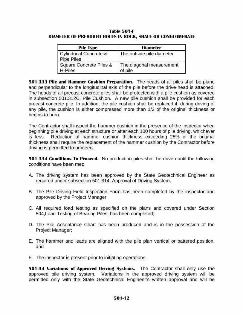
Table 501-F DIAMETER OF PREBORED HOLES IN ROCK, SHALE OR CONGLOMERATE
Pile Type Diameter
Cylindrical Concrete & Pipe Piles
The outside pile diameter
Square Concrete Piles & H-Piles
The diagonal measurement of pile
501.333 Pile and Hammer Cushion Preparation. The heads of all piles shall be plane and perpendicular to the longitudinal axis of the pile before the drive head is attached. The heads of all precast concrete piles shall be protected with a pile cushion as covered in subsection 501.312C, Pile Cushion. A new pile cushion shall be provided for each precast concrete pile. In addition, the pile cushion shall be replaced if, during driving of any pile, the cushion is either compressed more than 1/2 of the original thickness or begins to burn. The Contractor shall inspect the hammer cushion in the presence of the inspector when beginning pile driving at each structure or after each 100 hours of pile driving, whichever is less. Reduction of hammer cushion thickness exceeding 25% of the original thickness shall require the replacement of the hammer cushion by the Contractor before driving is permitted to proceed. 501.334 Conditions To Proceed. No production piles shall be driven until the following conditions have been met: A. The driving system has been approved by the State Geotechnical Engineer as
required under subsection 501.314, Approval of Driving System. B. The Pile Driving Field Inspection Form has been completed by the inspector and
approved by the Project Manager; C. All required load testing as specified on the plans and covered under Section
504,Load Testing of Bearing Piles, has been completed; D. The Pile Acceptance Chart has been produced and is in the possession of the
Project Manager; E. The hammer and leads are aligned with the pile plan vertical or battered position,
and F. The inspector is present prior to initiating operations. 501.34 Variations of Approved Driving Systems. The Contractor shall only use the approved pile driving system. Variations in the approved driving system will be permitted only with the State Geotechnical Engineer’s written approval and will be
501-12

considered only after the Contractor has submitted a new Pile and Driving Equipment Data Form. When a change in the driving system is requested, the Contractor will be notified of the acceptance or rejection of the revised driving system within 72 hours of the Project Manager’s receipt of the data form. The time required for submission, review, and approval of a revised driving system shall not constitute a basis for a contract time extension to the Contractor. 501.341 Variations Due to Dynamic Testing. The Contractor’s hammer will be rejected by the State Geotechnical Engineer when it is determined that the hammer is unable to transfer sufficient energy to perform the dynamic testing as per section 504 Load Testing of Bearing Piles. The hammer will be rejected due to, but not limited to the following reasons: Pre-ignition from overheating or malfunctioning of the injection system; poor hammer or capblock maintenance. Upon rejection, the hammer will be removed from service until repaired or replaced to the satisfaction of the State Geotechnical Engineer. 501.342 Revised Wave Equation Analysis. When variations in the driving system occur, when preboring is used to facilitate pile penetration not originally specified in the contract, or when the pile penetrations are considerably more or less than that estimated in the contract, a revised Wave Equation Analysis will be performed to establish a revised driving resistance criteria. No piles shall be driven until the Project Manager receives the revised Pile Acceptance Graph. 501.35 Pile Driving Operation. Approval of a pile hammer relative to allowable driving stresses shall not relieve the Contractor of responsibility for piles damaged because of misalignment of the leads, failure of capblock or cushion material, failure of splices, malfunctioning of the pile hammer or other improper construction methods. Piles damaged for such reasons will be rejected and shall be replaced at the Contractor’s expense, when the Foundation Engineer determines that the damage impairs the strength of the pile, or the measured resistance is in question. During pile driving, the hammer cushion and pile cushion shall be replaced as described in subsection 501.333, Pile and Hammer Cushion Preparation, before excessive compression or damage takes place. 501.351 Pile Measurement and Recording. The Contractor shall make the first pile driven at each substructure element accessible to the inspector for measurement and for marking of the pile in 300 mm (12 in.) increments. The first pile driven will then have the blows per 300 mm (12 in.) recorded along the entire pile installation until the pile tip is within 2 m (6 ft) of the scheduled penetration elevation or until the pile begins to set up, whichever comes first. At that point, the set in millimeters (inches) per 10 or 20 blows, as required, will be measured and recorded until the required set is achieved for the given operating energy of the hammer.
501-13

501.352 Minimum Penetration Elevation. Where the penetration elevation is specified in the contract as “Minimum Penetration Elevation,” the piles will be required to be driven to at least that elevation. If the piles do not develop the required ultimate bearing capacity at that elevation, the Contractor shall continue to drive the piles until the required resistance is attained. If the piles develop a set less than the limits established in subsection 501.332C, Application of Prebored Holes, and the pile tip is above the specified minimum penetration elevation, drilling shall be performed so that the piles are driven to the minimum penetration elevation without damage. 501.353 Estimated Penetration Elevation. When the penetration elevation is specified in the contract as “Estimated Penetration Elevation,” the piles shall be driven to the required ultimate capacity. If the piles attain the required resistance above the estimated penetration elevation, the Contractor shall terminate driving and the piles will be accepted at the shallower penetration. 501.354 Pile Groups. When driving piles in pile groups for pile cap foundations (more than one row of piles in the pile group), all piles will be driven to the estimated or minimum penetration elevation as defined in the contract, prior to determining pile capacity for acceptance. After all piles in the pile group are driven to the required tip elevation, the piles will be restruck to determine the pile ultimate capacity. If the piles do not develop the required ultimate bearing capacity at that elevation, the Contractor shall continue to drive the piles until the required resistance is attained. 501.355 Splices. Except as permitted in subsection 501.22, Furnishing Piles, piles shall be furnished full length. Splices in steel piles shall conform to the details shown in the contract and shall be welded in conformance with the requirements provided in Section 541, Steel Structures. Splices for closed-end pipe piles shall be watertight. Splices for precast concrete piles shall be made by the cement dowel method unless the State Geotechnical Engineer approves an alternate splice detail. Mechanical splices for concrete or steel piles, if utilized, are to be selected from the Qualified Products List, provided by the State Geotechnical Engineer. 501.356 Cut-Off Lengths. The tops of all permanent piles shall be cut off at the elevation shown in the contract or as directed by the Project Manager. All cut-off lengths shall become the property of the Contractor and shall be removed by the Contractor from the project site. 501.357 Filling Closed-End Pipe Piles. After closed-end steel pipe piles have been driven, they shall be inspected for water or other foreign substance inside the piles. All water and foreign substances inside the piles shall be removed. Upon approval of the driven piles by the Project Manager, the piles shall be filled with Class A concrete with a 100 mm to 150 mm (4 to 6 in.) slump. Placement of the concrete shall be as covered in subsection 502.347, Concrete Placement.
501-14

The schedule for driving piles shall be such as to avoid vibrations and pressure reaching piles or other structural component in which concrete has been placed and taken initial set, but has not attained sufficient strength to resist damage. 501.358 Filling Open-End Pipe Piles. After open-end steel pipe piles have been driven, they shall be inspected for water inside the piles. If water is present, pea gravel shall be placed in the pile to an elevation of three feet above the water level in the pile. Upon approval of the driven piles by the Project Manager, the piles shall be filled with Class A concrete with a 100 mm to 150 mm (4 to 6 in.) slump to fill the remaining void above the pea gravel or above the soil plug. At a minimum, the concrete shall be placed in the upper 1.5 m 5 ft) of the piles. Placement of the concrete shall be as covered in subsection 502.347, Concrete Placement. The schedule for driving piles shall be such as to avoid vibrations and pressure reaching piles or other structural component in which concrete has been placed and taken initial set, but has not attained sufficient strength to resist damage. 501.36 Pile Acceptance. Piles driven will be accepted when all of the requirements of this subsection have been met. 501.361 Pile Load Capacity and Penetration. Piles shall be driven to the required ultimate capacity as determined by the specified capacity monitoring method in accordance with subsection 501.32, Driven Pile Capacity. In addition, when called for in the contract, piles shall be installed to the penetration elevation in accordance with subsection 501.352, Minimum Penetration Elevation. 501.362 Location and Alignment Tolerances. Pulling laterally on piles to correct misalignment or splicing a properly aligned section on a misaligned section to meet tolerances, will not be permitted. The following location and alignment tolerances shall apply: A. Trestle and Abutment Beam Piling. Trestle piling and abutment beam piling shall be
driven with a maximum variation not to exceed 19 mm/m (1/4 in./ft) from the vertical or batter shown, with the pile varying not more than 75 mm (3 in.) from the plan position at any point along its length.
B. Foundation Piling. Foundation piling capped below grade, shall be driven with a
maximum variation not to exceed 20 mm/m (1/4 in./ft) from the vertical or batter shown, with the tops of the piles at cut off elevation varying not more than 150 mm (3 in.) from the plan position.
501-15

C. Edge Distance. No pile shall be within 225 mm (9 in.) of an edge of a cap or beam. Increases in size of a cap or beam to meet this edge distance requirement shall be at the Contractor’s expense.
D. Pile Orientation. H Piles shall not have rotated more than 30 degrees out of the plan
orientation of the strong axis and weak axis of the pile shown on the plans. E. Pile Tops. The tops of all piles shall be cut off normal to the pile or to a specified
bevel, and within the elevation tolerance, shown in the contract. 501.363 Damaged Pile Limitations. Piles damaged, described as follows, will be rejected:
A. Piles that are broken cracked or split by reason of internal defects or due to improper driving.
B. Precast concrete piles, which have been subjected to excessive or undue
abuse or improper handling, resulting in crushing and spalling of concrete, injurious splitting, or visible cracks, which, as determined by the Project Manager, affects the strength or service life of the pile.
C. Steel piles which have been bent or deformed during installation and
exceed mill tolerances for sweep and camber.
D. Closed-end pipe piles, which show evidence of groundwater infiltration into the pile or that, show breaks or deformation that would impair the strength of the completed piles.
501.364 Correcting Rejected Piles. The Contractor without added compensation shall correct piles damaged during driving by reason of internal defects, or by improper driving, by methods approved by the Project Manager. If the location or alignment tolerances specified are exceeded, the extent of overloading shall be investigated and, if the Foundation Engineer determines that corrective measures are necessary, suitable measures shall be designed and constructed by the Contractor. The design shall be subject to approval by the State Geotechnical Engineer. The Contractor shall bear all costs, including delays, associated with the corrective action. Corrective methods may include, but shall not be limited to the following: A. The pile may be withdrawn and replaced by a new, and when necessary, longer pile, B. Additional piles may be driven adjacent to defective piles or misaligned piles,
provided that there is no detriment to the structure; or
501-16

C. A sufficient portion of the footing may be extended to properly embed the pile. 501.4 METHOD OF MEASUREMENT. 501.41 Driven piles will be measured by the meter (foot). Prebored holes for bearing piles will be measured by the meter (foot). Pile Splices will be measured by the unit per each. Pile shoes will be measured by the unit per each. Pile Cut-Offs will be measured by the meter (foot). 501.42 Pile Extensions. When extensions of piles are necessary, the extension length approved by the Project Manager will be included in the measurement of piles. 501.43 Driven Piles. Driven piles will be measured below the cut-off elevation to the nearest meter (foot). 501.44 Pile Cut-Offs. Pile Cut-offs will be measured to the nearest meter (foot) of the total of the plan lengths of pile less the total lengths of the in-place piles after cut-off. 501.45 Prebored Holes for Bearing Piles. Prebored holes for bearing piles will be measured below the grade elevation from which the drill hole remains in the final construction after excavation of any overburden material. No measurement will be made for drilling through soil or rock layers that are subsequently excavated to achieve final plan grades or work platforms unless changes specifically authorizing such payment are issued. 501.46 Pile Splices. Pile Splices will be measured for splices required when piles are driven deeper than the estimated penetration elevation shown in the contract to achieve the required ultimate capacity. Only two splices per pile will be measured. 501.5 BASIS OF PAYMENT. 501.51 Driven piles will be paid for at the contract unit price per meter (foot) for the length of pile driven in place. Prebored holes for bearing piles will be paid for at the contract unit price per meter (foot). Pile Splices will be paid for at the contract unit price per each. Pile shoes will be paid for at the contract unit price per each. Pile Cut-Offs will be paid for at the contract unit price per meter (foot).
501-17

Payment for pile splices shall be limited to two splices per pile and only those splices made to drive the piles in excess of the length of pile specified in the contract will be paid for. Payment will be made under: Pay Item Pay Unit Driven Piles (type) Meter (Foot) Prebored Holes for Bearing Piles, ____mm (in.) diameter Meter (Foot) Pile Splices Each Pile Shoes Each Pile Cut-Offs Meter (Foot) 501.52 Work Included In Payment. The following work will be considered as included in the payment for the main item(s) and will not be measured or paid for separately: A. Extra length pile used as a follower. B. Material and backfill placement for prebored holes for bearing piles, including Class
G concrete in rock sockets. C. Temporary casing and oversizing of prebored holes to accommodate temporary
casing. D. Steel reinforcement required in steel pipe piles filled with concrete. E. Furnishing and driving pile to replace piles which were previously accepted by the
Project Manager and are subsequently damaged through improper handling, driving, or construction operations prior to completion of the contract.
F. Increases to the contract quantity of prebored holes for bearing piles which are not
called for in the contract, but are approved by the State Geotechnical Engineer, will be paid for at a negotiated unit price per meter (foot) as established by the Project Manager.
G. Piles that have been driven or partially driven and are subsequently rejected by the
Project Manager and are pulled or left in place. H. Class A concrete and placement in closed-end pipe piles. I. Mobilization and time lost due to re-mobilization of new hammer due to poor
hammer performance or as determined by dynamic testing. J. Restrike of piles in pile groups to determine pile capacity.
501-18

NEW MEXICO DEPARTMENT OF TRANSPORTATION SUPPLEMENTAL SPECIFICATIONS FOR
DRILLED SHAFT CONCRETE BEARING PILES
SECTION 502 All pertinent provisions of the New Mexico Department Of Transportation's Standard Specifications For Highway And Bridge Construction shall apply in addition to the following: Delete SECTION 502 - DRILLED SHAFT CONCRETE BEARING PILES in its entirety and substitute the following: 502.1 DESCRIPTION. 502.11. This work shall consist of furnishing all necessary labor, material and equipment and performing all operations needed to construct “drilled shaft” concrete bearing piles (hereafter referred to as drilled shafts). Construction of drilled shafts, with or without underreamed bottoms (“bell bottoms”), shall include the placing of reinforcing steel and concrete. Drilled shafts shall conform to and be constructed in accordance with the specifications and at the location, elevation and details shown in the contract. 502.12 Work Experience. Within the last two years prior to the bid date for the particular project, the Contractor or subcontractor performing the work must have been involved in the successful construction of at least two projects involving the type and the method of construction that is required of those shown in the contract. The superintendent who will be in charge of the work shall have been the superintendent on at least one of the projects listed. The Contractor or subcontractor, if the work is subcontracted, shall be able to demonstrate to the satisfaction of the State Geotechnical Engineer the ability to satisfactorily complete the work. 502.13 Approvals. All submittals as required below shall be made to the Project Manager for approval by the State Geotechnical Engineer. All other construction and/or field design changes will be submitted to the Project Manager for review and approval by a Department Foundation Engineer who will be assigned by the State Geotechnical Engineer. 502.2 MATERIALS. 502.21 General. Materials for drilled shafts shall conform to the requirements of the specified AASHTO, ASTM material specifications, or referenced Sections of the Standard Specifications as listed in Table 502-A.
502-1

Table 502-A APPLICABLE BEARING PILE STANDARDS
Material Description Standard
Portland Cement Concrete, Class G Section 510 Reinforcing Steel Cage Section 540 Reinforcing Steel HP Pile AASHTO M 183 Permanent Steel Pipe Casing AASHTO M 183
502.22 Additional Requirements. The following material requirements for drilled shafts shall be in addition to the referenced specifications. 502.221 Concrete. See Section 510 for Class G concrete mix requirements for admixtures, and slump. 502.222 Temporary Casings. Temporary casings shall be steel and shall be smooth, clean, watertight and of ample strength to withstand both handling and driving stresses and the pressures of concrete and the surrounding soils. The outside diameter of the casing shall be at least the size of shaft specified in the contract. 502.223 Permanent Casings. The wall thickness of permanent casings shown in the contract is the minimum thickness required for the constructed condition of the shaft. The Contractor shall provide a greater wall thickness as necessary, to withstand handling and installation stresses. The dimensions of casings are subject to American Pipe Institute tolerances applicable to regular steel pipe. When approved, the Contractor may elect to provide a casing larger in diameter than shown in the contract at no increase in contract unit price. 502.3 CONSTRUCTION REQUIREMENTS. 502.31 Equipment. The Contractor’s equipment shall be suitable for the design requirements of the foundation and for the materials encountered in excavating the shaft and underreams. The equipment shall meet the general requirements as follows: 502.311 Excavation and Drilling Equipment. The excavation and drilling equipment shall have kelley bar length, adequate power, torque and down thrust to excavate a hole of the specified diameter to a depth of 20% beyond the depths shown in the contract. The excavation and underreaming tools shall be of adequate design, size and strength to perform the work shown in the contract. Excavation equipment shall be capable of producing a completed shaft excavation having a planar bottom. The cutting edges of the excavation equipment shall be normal to the vertical axis of the equipment within a tolerance of ± 30 mm/m (± 0.36 in./ft) of diameter. As a minimum, underreaming tools shall be capable of excavating to at least the bearing area and height shown in the contract. Actual base diameter produced by the Contractor’s tool shall not exceed three times the specified shaft diameter. All other plan dimensions shown for the underreaming may be varied, when approved by the Foundation Engineer, to
502-2
accommodate the Contractor’s equipment. When overreaming of the shaft sidewall is required by the Foundation Engineer, an overreaming bucket, grooving tool, or other approved equipment shall be utilized. The overreaming tool shall effect an oversized shaft diameter to a minimum of 15 mm (0.6 in.) and a maximum of 75 mm (3 in.). When the material encountered cannot be drilled, using conventional earth augers with soil or rock teeth, drill buckets, or underreaming tools, the Contractor shall provide special drilling equipment including, but not limited to rock core barrels, rock tools, blasting materials, and other equipment as necessary to construct the shaft excavation required. Approval by the Project Manager is required before blasting is permitted. 502.312 Slurry Equipment. Desanding equipment shall be provided by the Contractor as necessary to control slurry sand content to less than 8% by volume for mineral slurry and 1% by volume for polymer slurry at any point in the shaft excavation after recycling or equilibrating the slurry in the shaft. Slurry tanks of adequate capacity shall be required for slurry circulation, storage, and treatment. No excavated slurry pits will be allowed in lieu of slurry tanks without the written permission of the Project Manager. A slurry sampling tool shall be utilized by the Contractor for making the required slurry control tests as covered in subsection 502.342(c), 2, Slurry Control Tests. The slurry sampler shall consist of a cable with a weighted cone shaped stopper, a cylindrical sampler center stayed for alignment, and a top stopper with a hole drilled through the center for slipping onto the cable. 502.313 Concrete Placement Equipment. Depending on the type of shaft construction, placement of concrete in the excavated shaft shall be accomplished with a rigid tremie pipe, a concrete pump line, or a drop chute.
A. Tremies. Rigid tremie pipe used to place concrete shall consist of a tube of sufficient length, weight, and diameter to discharge concrete at the shaft base elevation. The tremie shall not contain aluminum parts which will have contact with the concrete. The tremie inside diameter shall not be less than 250 mm (10 in.). The inside and outside surfaces of the tremie shall be clean and smooth to permit both flow of concrete and unimpeded withdrawal during concreting. The wall thickness of the tremie shall be adequate to prevent crimping or sharp bends which restrict concrete placement. The tremie used for slurry displacement concrete placement shall be watertight. In slurry displacement shafts, a plug, valve, or bottom plate shall be used to separate the concrete from the displacement fluid until the concrete is flowing through the orifice. Plugs, if left in the shaft concrete, shall be of a material approved by the Project Manager, which will not cause a defect in the shaft. The discharge end of the tremie shall be constructed to permit the free radial flow of concrete during placement operations.
B. Concrete Pumps and Lines. All pump lines shall be a minimum of 125 mm (5 in.)
in diameter (Schedule-40 steel pipe or heavier) constructed with watertight joints. A plug shall be as described for tremies.
502-3

C. Drop Chutes. Drop chutes shall consist of a rigid pipe of either one piece construction or sections, which can be added and removed from a metal hopper. Flexible trunk line hose will not be permitted.
502.32 Submittals. For the particular type of drilled shaft construction identified herein, the Contractor shall furnish the required submittals to the State Geotechnical Engineer for review and approval. Where the Contractor has provided Work Experience and Proposed Construction Procedure submittals to the State Geotechnical Engineer from previous Department projects of similar size, difficulty and geology, and has had successful completion of those projects, the Contractor may reference the previously completed project(s) in lieu of the detailed submittal requirements listed below. 502.321 Work Experience. Documentation shall be submitted verifying that the Contractor or subcontractor has performed the required work experience as described in subsection 502.12, Work Experience. Such documentation shall include the names and phone numbers of owners’ representatives who can verify the Contractor’s successful completion of the projects listed. 502.322 Proposed Construction Procedure. At least 30 days before work is to begin, the Contractor shall submit a complete written description of the Contractor’s proposed construction procedure. The information required in this submittal shall be as follows:
A. Name and experience record of the superintendent in charge of drilled shaft operations;
B. List of proposed equipment to be used including cranes, drills, augers, bailing
buckets, final cleaning equipment, desanding equipment, slurry pumps, core sampling equipment, tremies or concrete pumps, casing, etc.;
C. Description of overall construction operation sequence; D. Description of shaft excavation methods; E. Details of the methods to mix, circulate, and desand slurry, when slurry is
required; F. Manufacturer and type of apparatus to be used to test slurry as required; G. Description of methods to clean the shaft excavation; H. Details of reinforcement placement including support and centralization methods;
and I. Details of concrete placement including proposed operational procedures for free
fall, tremie or pumping methods.
502-4

502.323 Review and Approval. The State Geotechnical Engineer will evaluate the proposed construction procedure for conformance with the contract. Within 14 days after receipt of the plan, the Contractor will be notified of any additional information required and changes necessary to meet the contract requirements. All procedural approvals given shall be subject to trial in the field, and shall not relieve the Contractor of the responsibility to satisfactorily complete the work as detailed. 502.33 Construction Preparations. 502.331 Site and Subsurface Conditions. The Contractor shall examine the areas and conditions under which the foundations are to be installed and evaluate any constraints that may affect the operations, such as overhead clearances, site accessibility, proximity of existing structures, etc. The Contractor shall also be familiar with and have examined the subsurface exploration data shown in the contract, lab test results, rock core samples, etc. The test results and rock core samples are available to the Contractor for examination upon request. 502.332 Protection of Existing Structures. The Contractor shall take preventative measures to prevent damage to existing structures and utilities. Preventive measures shall include, but are not limited to, selecting construction methods and procedures that will prevent caving of the shaft excavation, monitoring and controlling the vibrations from construction activities such as the driving of casing or sheeting, drilling of the shaft, or from blasting, if permitted. The Contractor shall be responsible for selecting and using equipment and procedures that keep adjacent ground surface deformations within acceptable levels. If required in the contract, the Contractor shall submit a preventative measures plan to the Project Manager, a minimum of ten (10) working days before the construction of the shaft, for review by the State Geotechnical Engineer, of any existing structures requiring protection. Review of the plan by the State Geotechnical Engineer does not relieve the Contractor of responsibility of control of the work. 502.333 Site Preparation. When footings are present, the excavation to bottom of footing elevation shall be completed before shaft construction begins unless otherwise noted in the contract or approved by the Project Manager. When drilled shafts are to be installed in conjunction with embankment placement, the Contractor shall construct the shafts after the placement of fill unless otherwise shown in the contract or approved by the Project Manager. 502.334 Proof Drilled Shafts. A proof drilled shaft shall be constructed, when called for, at the location shown in the contract. When a proof shaft is specified, no production shaft shall be constructed until the Foundation Engineer approves the adequacy of the equipment and methodology used in the construction. A proof shaft may also be load tested as required in the contract and Section 504, Load Testing of Bearing Piles. The shaft shall be drilled to the maximum depth of any production shaft unless otherwise shown in the contract. When shown in the contract, underreaming of a specified proof shaft will be required to establish the feasibility of underreaming in a specific soil strata or rock. Unless otherwise specified in the contract, the proof shaft shall be filled with concrete in the same manner that the production shafts are to be constructed. Failure
502-5
by the Contractor to demonstrate to the Foundation Engineer the adequacy of methods and equipment, shall be reason to require that the Contractor propose alterations in equipment and method to eliminate unsatisfactory results. Additional proof shafts required to demonstrate the adequacy of altered methods or construction equipment shall be at the Contractor’s expense. Once the Foundation Engineer has approved the proof shaft, the production shafts shall be constructed by the same method and with the same equipment as that used on the approved proof shaft. No changes in the method or equipment used on the production shafts will be allowed without written approval by the Foundation Engineer. The concreted proof shaft(s) shall be cut off 1.5 m (5 ft) below finished grade and left in place. The disturbed areas at the sites of the proof shafts shall be restored as nearly as practical to their original condition. 502.34 Construction of Drilled Shafts. 502.341 Selection of Equipment and Method. The Contractor shall be responsible for selecting the proper equipment and method of construction, to perform the excavations required for the shafts, including maintaining hole stability, underreaming the shafts if specified, through whatever materials are encountered, to the dimensions and elevation shown in the contract. The permanent casing method shall be used only when required in the contract or authorized by the Foundation Engineer. 502.342 Safety. All work shall proceed in a manner where safety of the Contractor’s workforce and Department employees are maintained. The Contractor shall ensure that no individual is at risk to his or her individual safety. The Contractor shall adhere to all governing Federal (OSHA), State, and local laws at all times. All personnel shall have safety belts with tie-off when working in the vicinity of an open shaft hole. 502.343 Acceptable Construction Methods. 502.341 Dry Construction Method. The dry construction method shall be used only at sites where the groundwater level and soil conditions are suitable to permit construction of the shaft in a relatively dry excavation, and where the sides and bottom of the shaft may be visually inspected prior to placing the concrete. The dry method consists of drilling the shaft excavation, removing accumulated water and loose material from the excavation, placing the reinforcing cage, and concreting the shaft in a relatively dry excavation. The Foundation Engineer will approve the dry construction method only when the shaft excavation demonstrates the following:
A. Less than 300 mm (12 in.) of water accumulates above the base over a one hour period without pumping;
B. The sides and bottom of the hole remain stable without detrimental caving,
sloughing or swelling over a four hour period immediately following completion of excavation; and,
C. All loose material and water can be satisfactorily removed prior to inspection and
prior to concrete placement.
502-6

The Contractor shall use the slurry displacement construction method or the casing construction method for shafts that do not meet these requirements for the dry construction method. 502.342 Casing Construction Method. The casing construction method may be used either when shown in the contract or at sites where the dry construction method is inadequate to prevent hole caving, excessive deformation of the hole, or excessive water infiltration. Where required, the casing method may be used in combination with the slurry displacement method or the dry construction method. The casing shall be advanced through the ground by twisting, driving, or vibrating before being cleaned out, unless the contract allows for the casing to be placed in a predrilled hole. No extra compensation will be allowed for concrete required to fill an oversized casing or an oversized excavation required to place the casing.
A. Temporary Casing. All subsurface casing shall be considered temporary unless
shown as permanent casing in the contract. The Contractor shall remove temporary casing during concreting of the drilled shaft while the concrete is in a fluid state. If the Contractor elects to remove a casing and substitute a longer or larger diameter casing through caving soils, the excavation shall be stabilized with slurry before the new casing is installed, or other methods, as approved by the Foundation Engineer, may be used to control the stability of the excavation and protect the integrity of the foundation soils. Before the casing is withdrawn, the level of fresh concrete in the casing shall be at least 3 m (10 ft) above either the hydrostatic water level or the level of drilling fluid, whichever is higher. As the casing is withdrawn, care shall be exercised to maintain an adequate level of concrete within the casing so that fluid trapped behind the casing is displaced upward and discharged at the ground surface without contaminating or displacing the shaft concrete. Temporary casings which become bound or fouled during shaft construction and cannot be practically removed, shall constitute a defect in the drilled shaft. The Contractor shall be responsible for improving such defective shafts to the satisfaction of the Foundation Engineer. Such improvement may consist of, but is not limited to, removing the shaft concrete and extending the shaft deeper to compensate for loss of frictional capacity in the cased zone, providing straddle shafts to compensate for capacity loss, or providing a replacement shaft. All corrective measures, including redesign of footings caused by defective shafts, shall be done to the satisfaction of the State Geotechnical Engineer by the Contractor, without either compensation or an extension of Contract Time. No additional compensation will be made for casing remaining in place.
B. Permanent Casing. Permanent casing shall be used when shown in the contract.
The casing shall be continuous between top and bottom elevation shown in the contract. After installation is complete, the permanent casing shall be cut off at the prescribed elevation and the shaft completed by installing the necessary reinforcing steel and concrete in the casing. When temporary casings are shown in the contract in conjunction with permanent casings or authorized in writing by
502-7

the State Geotechnical Engineer, the Contractor shall maintain both alignment of the temporary outer casing with the permanent inner casing and maintain a positive, water tight seal between the two casings during excavation and concreting operations. Where an oversized hole or temporary casing is approved by the Project Manager, to aid in the placement of the permanent casing, the exterior annular space outside of the permanent casing shall be postgrouted, such that the direct contact between casing and the surrounding soil/rock is created.
502.343 Slurry Displacement Construction Method. The slurry displacement method may be used at sites where a dry excavation cannot be maintained for placement of the shaft concrete, with or without a casing. This method consists of using mineral or polymer slurry, or water, if approved by the Foundation Engineer, to maintain stability of the hole perimeter while advancing the excavation to final depth, placing the reinforcing cage, and concreting the shaft. The slurry displacement method shall require demanding the slurry during final cleaning of the excavation by means of a bailing bucket, air lift, or submersible pump. Concrete shall be placed with a tremie or concrete pump beginning at the shaft bottom. During construction, the level of slurry in the shaft excavation shall be maintained at a height sufficient to prevent caving of the hole, but in no case shall the level be less than 2 m (6.7 ft) above the highest expected piezometric pressure head along the depth of the shaft. When permanent casings are not shown in the contract, temporary surface casings shall be provided to aid shaft alignment and position and to prevent sloughing of the top of the shaft excavation unless the Contractor demonstrates to the satisfaction of the Foundation Engineer that such casing is not required. If at any time the slurry construction method fails to produce the necessary results, the Contractor shall discontinue operations and make suitable modifications to the procedures and equipment used, to bring the operations into conformance with the contract requirements. 502.3431 Polymer Slurry Requirements. Polymer slurry shall have sufficient viscosity and gel characteristics to stabilize the hole and inhibit the influx of ground water into the excavated hole with a positive pressure head in the hole. The percentage and specific gravity of the material used to make the suspension shall be sufficient to maintain the stability of the excavation and to allow proper concrete placement. Acceptable ranges of values for these physical properties shall be in conformance with Table 502-C(1).
502-8

Table 502-C(1) POLYMER SLURRY REQUIREMENTS
EMULSIFIED OR DRY PHPA POLYMER
Property (Units)
Requirements (At Time of Introduction or Prior to Concreting)
Test Method
Density (Mg/m³) 1.0–1.02 Density Balance
Viscosity (seconds/quart) 50–120 Marsh
Funnel Yield Point (Pa) 1.4–5.7 Reometer
pH 8–11.7 pH Paper Sand Content (% by volume) 0–1 API Method
Note: Tests shall be performed when the slurry temperature is above 4°C (40 °F). Also, Reometer Viscosity may be used in lieu of the Marsh Funnel Viscosity and ranges shall be within manufacturers, recommendations.
The polymer slurry shall be premixed thoroughly with clean fresh water and adequate time (as prescribed by the polymer manufacturer) allotted for hydration prior to introduction into the shaft excavation. The Contractor shall take all steps necessary to prevent the slurry from losing the required viscosity and gel characteristics in the shaft. Polymer slurry shall be neutralized with bleach and disposed of offsite in suitable areas approved by the Project Manager. 502.3432 Mineral Slurry Requirements. Attapulgite, in lieu of Bentonite, may be used where saline or chemically contaminated groundwater occurs. Mineral slurry shall have both a mineral grain size that will remain in suspension and have sufficient viscosity and gel characteristics to transport excavated material to a suitable screening system. The percentage and specific gravity of the material used to make the suspension shall be sufficient to maintain the stability of the excavation and to allow proper concrete placement. Acceptable ranges of values for these physical properties shall be in conformance with Table 502-C(2).
502-9

Table 502-C(2) MINERAL SLURRY REQUIREMENTS
SODIUM BENTONITE OR ATTAPULGITE IN FRESH WATER
Property (Units)
At Time of Slurry
Introduction
In Hole at Time of Concreting
Test Method
Density (Mg/m3) N/A 1.03–1.20 Density Balance
Viscosity (seconds/quart) 28–45 N/A Marsh Cone
Yield Point (Pa) 0.5–3.5 N/A Reometer PH 8–10 8–10 pH paper
Sand Content N/A 0–4 API Method
Note: Tests shall be performed when the slurry temperature is above 4°C (39 °F). Also, Reometer Viscosity may be used in lieu of the Marsh Funnel Viscosity and ranges shall be within manufacturers, recommendations.
The mineral slurry shall be premixed thoroughly with clean fresh water and adequate time (as prescribed by the mineral manufacturer) allotted for hydration prior to introduction into the shaft excavation. The Contractor shall take all steps necessary to prevent the slurry from “setting up“ in the shaft. Such methods may include, but are not limited to agitation, circulation, or adjusting the properties of the slurry. Disposal of all slurry shall be done offsite in suitable areas approved by the Project Manager. 502.3433 Slurry Control Tests. Control tests using suitable apparatus shall be carried out on the mineral slurry by the Contractor to determine density, viscosity, pH, and sand content. When slurry samples are found to be unacceptable, the Contractor shall take whatever action is necessary to bring the mineral slurry within the contract requirements. Concrete shall not be placed unless the inspector has approved the bottom hole test results required below and until resampling and testing results produce acceptable values. Reports of all tests required, signed by the Contractor, shall be furnished to the Project Manager upon completion of each drilled shaft.
A. Pre-entry Tests. Tests to determine viscosity and pH value shall be done prior to the slurry being pumped into the excavation to establish a consistent working pattern. A minimum of two sets of tests shall be made during the first eight hours of slurry processing. When the results show consistent behavior, the testing frequency may be decreased to one set every eight hours of slurry use.
B. Bottom Hole Tests. Prior to placing concrete in any shaft excavation, tests shall
be made of slurry samples taken from the base of the shaft until samples produce acceptable values for density, pH, and sand content.
502-10

502.344 Excavation of Shaft. Shaft excavations shall be made at the locations, to the bottom of shaft elevations, shaft geometry, and dimensions shown in the contract. The Contractor shall extend drilled shaft tip elevations when the Foundation Engineer determines that the material encountered during excavation is unsuitable or differs from that anticipated in the design of the drilled shaft. The Contractor shall remove all materials encountered in forming the drilled shaft excavation to the dimensions shown in the contract. Materials that are removed from shaft excavations shall be disposed of by the Contractor as directed by the Project Manager. When the construction methods employed utilize vibrating temporary or permanent casing, adjacent casings shall not be placed or shafts excavated until 48 hours has elapsed from the completion of the pour of the previous shaft or concrete breaks from the adjacent shaft achieve at least 14 MPa (2 ksi), whichever comes first. Production may continue on alternate shafts at the same substructure element or at an alternate element, until the 48 hour or achieving a 14 MPa (2 ksi) concrete break limitation has expired. This requirement shall apply to excavating any shaft, regardless of construction method employed, where the spacing of the adjacent shafts is less than four (4) shaft diameters.
A. Underream and Overream. Underreamed shafts shall be excavated to form the height and bearing area of the size and shape shown in the contract. Sidewall overreaming shall be required when the sidewall of the hole is determined, by the Foundation Engineer, to have either softened due to excavation methods, swelled due to delays in concreting, or degraded because of slurry cake build-up. The thickness and elevation of sidewall overreaming shall be as directed by the Foundation Engineer.
B. Obstructions. Unanticipated surface and subsurface obstructions, at drilled shaft
locations, shall be removed by the Contractor. Such obstructions may include manmade materials, such as old concrete foundations and natural materials such as boulders or nested cobble zones. The Foundation or Geotechnical Report, provided by the Department includes the soil boring and rock core information, as well as groundwater conditions present at the time of the field investigation. Such information shall constitute conditions which are to be anticipated by the Contractor. Rock strata indicated by the soil borings, rock cores logged in the contract, and rock sockets specified as the bearing strata, shall not constitute obstructions. When obstructions are encountered, the Contractor is required to notify the Department inspector of the changed conditions as covered in subsection 502.44 Obstruction Removal., C. Workers in Shaft. The Contractor shall not permit workers to enter the shaft excavation for any reason unless:
1. Suitable casing has been installed; 2. The water level has been lowered and stabilized below the level to be
occupied; and
502-11

3. Adequate safety equipment and procedures have been provided to workmen entering the excavation.
502.345 Soil Samples and Rock Cores. The Contractor shall take soil samples or rock cores at the locations shown in the contract or as directed by the Foundation Engineer to determine the character of the material directly below the bottom shaft elevation. Soil borings shall be performed prior to excavating the shafts. Rock cores may be performed prior to excavating the shaft from the bottom of an exploration hole at no additional cost to the Department. The soil and rock core samples shall be extracted and shipped in accordance with the Department’s Manual of Highway Structure Foundation Investigation and Subsurface Exploration. Unless otherwise shown in the contract, bore holes or rock cores shall be taken beginning at the top of the rock socket elevation to a minimum depth of 3 m (10 ft) below the bottom of the drilled shaft excavation. Rock Quality Designation (RQD), percent recovery, joint orientation and infilling, and joint water shall be recorded from the rock cores extracted. After exploration is completed, core holes in rock shall be filled with grout, slurry, or mortar having a minimum compressive strength of 21 MPa (3 ksi) at 28 days. The Contractor shall ensure that the geologist’s field log cards are delivered to the State Geotechnical Engineer immediately upon completion of the logs. Soil samples or rock cores will not be required to have laboratory testing performed by the Contractor’s geotechnical consultant unless specifically called for in the contract. The State Geotechnical Engineer will notify the Contractor of the final required depth of the shaft after receipt of the geologist’s field log sheets and performance of lab testing is required. The Contractor shall expect that notification of the final depth of the shaft excavation may take as long as 48 hours from the time the field log sheets or the soil and rock samples test results are received by the State Geotechnical Engineer. 502.346 Shaft Excavation Inspection. The Contractor shall determine the dimensions and alignment. Final shaft depths shall be measured with a suitable weighted tape or other approved methods after final cleaning. Unless otherwise stated in the contract, a minimum of 50% of the base of each shaft shall have less than 15 mm (0.6 in.) of sediment at the time of placement of the concrete. The maximum depth of sediment or debris at any place on the base of the shaft shall not exceed 40 mm (1.6 in.). For dry shafts, the maximum depth of water shall not exceed 75 mm (3 in.) prior to concrete pour and cleanliness will be determined by visual inspection. For slurry displacement shafts, inspection will be determined by methods deemed appropriate by the Foundation Engineer.
A. Inspection Procedures. The Contractor will be notified by the Project Manager as to what procedure(s) will be used for the shaft inspections. The Contractor shall supply the required equipment and labor necessary for the Project Manager to complete the shaft inspection procedure utilized. Inspection procedures may include, but are not limited to, the following:
1. Inserting a casing in the shaft excavation temporarily for alignment,
cleanliness, and dimension checks;
502-12
2. Inserting a rigid rod assembly with several 90° offsets equal to the shaft diameter;
3. 3. Use of Department supplied video equipment; and 4. Use of a weighted tape and evaluation of results of desanding and density
tests for slurry displacement excavations.
B. Remedial Work for Substandard Excavation. When a shaft excavation is determined to be substandard by the Foundation Engineer, due to the excavation not meeting requirements such as alignment tolerances, sidewall degradation, softening, or swelling, the Contractor shall develop, propose, and, after approval by the State Geotechnical Engineer, implement corrective measures. All of the remedial work performed by the Contractor to bring the shaft excavation into compliance, shall be performed at the Contractor’s expense and without extension of the Contract Time. The corrective measures may include, but are not limited to, the following:
1. Overdrill the shaft excavation to a larger diameter to permit accurate
placement of the reinforcing steel unit with the required minimum cover; 2. Overream sidewalls of the shaft; 3. Increase the number and/or size of the steel reinforcement bars; and 4. Enlarge the bearing area of the underream within tolerance allowed.
502.347 Reinforcing Steel Unit Placement. The reinforcing steel unit shall be as shown in the contract and may consist of longitudinal bars and circular ties or a structural steel shape. The structural shape or the reinforcing steel cage, consisting of longitudinal bars, ties, cage stiffener bars, spacers, centralizers, and other necessary appurtenances, shall be placed as a unit immediately after the shaft excavation is inspected and accepted, and prior to concrete placement. The reinforcing steel unit in the shaft shall be tied and supported so that the reinforcing unit will remain within allowable tolerances given in subsection 502.35, Location and Alignment Tolerances. Concrete spacers or other approved noncorrosive spacing devices shall be used at sufficient intervals, near the bottom and at intervals not exceeding 3 m (10 ft) up the shaft, to ensure concentric spacing for the entire reinforcement unit length. Spacers shall be constructed of approved material, equal in quality and durability to the concrete specified for the shaft. The spacers shall be of adequate dimension to insure a minimum clear distance between the outside of the reinforcing unit and the side of the excavated hole as shown in the contract. The bottom of the shaft into which the reinforcing steel cage is to placed will be inspected immediately before placement of the cage to insure that no sloughing has occurred.
502-13

The elevation of the top of the reinforcement unit shall be checked before and after the concrete is placed. If the reinforcement unit is not maintained within the specified tolerances, corrections shall be made by the Contractor to the satisfaction of the Project Manager. No additional shafts shall be constructed, until the Contractor has modified the reinforcement unit support in a manner satisfactory to the Project Manager. In general, the reinforcement unit shall be maintained at its proper elevation and orientation by means of an approved support mechanism at the ground surface. Alternatively, the reinforcement unit may be supported at the proper elevation by extending a required number of vertical bars from the detailed cage reinforcement, in order to support the cage off the bottom of the hole in a stable manner. This alternative may be used provided that the reinforcement unit does not buckle. Approved cylindrical concrete feet (bottom supports) shall be provided to ensure that the bottom of the reinforcement unit is maintained at the proper distance above the base, when the alternative support method is used. When the vertical reinforcement is extended for support, stiffener bars and spacers shall be used as required similar to the primary cage reinforcement. No tie reinforcement will be required, for the vertical extension bars, unless otherwise required by the Project Manager. Concrete shall be placed in each shaft immediately upon installation of the cage. If more than twenty four hours elapses between the placement of the cage and the start of concrete placement, the cage shall be removed and the shaft inspected for sloughing or other damage. 502.348 Concrete Placement. Concrete placement shall be performed in accordance with the applicable portions of Section 511, Concrete Structures, and with the requirements herein. Concrete shall be placed as soon as possible after reinforcing steel placement and shall be continuous from the bottom to the top elevation of the shaft. Concrete placement shall continue after the shaft excavation is full and until good quality concrete is evident at the top of the shaft. The elapsed time from batching the concrete at the plant in a given truck to placement of the concrete in the shaft shall not exceed two hours. A longer placement time may be approved if the Contractor demonstrates that the concrete mixture remains workable and plastic over the longer placement time. All admixtures, when approved for use, shall be adjusted for the conditions encountered on the job so the concrete remains in a workable plastic state through the approved placement limit. Concrete shall be placed either by free fall, through a rigid tremie pipe or concrete pump. 502.3481 Concrete Placement by Free Fall. Free fall placement shall only be permitted in relatively dry holes where the maximum depth of water does not exceed 75 mm (3 in.). Concrete placed by free fall shall fall directly to the base without contacting either the rebar cage or hole sidewall by means of a hopper at the top of the shaft or through a rigid pipe extension from the hopper. The maximum height of free fall placement shall not exceed 12 m (40 ft) below the bottom of the hopper or the rigid pipe extension. Free fall will not be permitted in slurry displacement shafts. If concrete placement causes the shaft excavation to cave or slough, or if the concrete strikes the reinforcement unit or sidewall, the Contractor shall reduce the height of free fall or reduce the rate of concrete flow into the excavation. If placement cannot be satisfactorily accomplished by free fall
502-14

in the opinion of the Project Manager, the Contractor shall use either a tremie or pumping to accomplish the pour. 502.3482 Concrete Placement with Tremie or by Pumping. Rigid tremie pipe or concrete pumps may be used for concrete placement in either dry or slurry displacement shafts. Underwater placement shall not begin until the tremie or pump line is placed to within one tremie or pump line diameter of the shaft base elevation. Plugs shall be removed from the excavation if not specifically approved to remain in the shaft. The discharge end shall be immersed at least 2 m (6.7 ft) in concrete at all times after starting the flow of concrete. The flow of concrete shall be continuous. The concrete in tremies or pump lines shall be maintained at a positive pressure differential at all times to prevent water or slurry intrusion into the shaft concrete. When lifting pump lines during concreting, the Contractor shall temporarily reduce the line pressure until the orifice has been repositioned at a higher level in the excavation. If at any time during the concrete pour, the orifice is removed from the fluid concrete column and discharges concrete above the rising concrete level, the shaft will be considered defective. At the Contractor’s own risk and cost, the reinforcing cage and concrete may be removed and the necessary sidewall removal shall be completed as directed by the Foundation Engineer. However, final acceptance of the shaft shall be as covered in subsection 502.37. 502.35 Location and Alignment Tolerances. The following construction tolerances shall be adhered to unless otherwise stated in the contract or directed by the Project Manager:
A. The drilled shaft and its concentric reinforcement steel unit shall be within 75 mm (3 in.) of plan position at the top of the shaft;
B. The vertical alignment of a vertical drilled shaft shall not vary from the plan
alignment by more than 20 mm/m (1/4 in./ft) of depth. The alignment of a battered drilled shaft shall not vary by more than 40 mm/m (0.44 in./ft) of depth from the specified batter;
C. The top of the reinforcing steel unit shall be no more than 150 mm (6 in.) above
and no more than 75 mm (3 in.) below plan elevation; and D. The top elevation shall have a tolerance of plus 25 mm (1 in.) or minus 75 mm (3
in.) from the plan top of shaft elevation. 502.36 Load Testing. When the contract includes load testing, all testing shall be completed prior to construction of production shafts, unless otherwise approved by the State Geotechnical Engineer. The Contractor shall allow three working days after the last load test is completed before receiving tip elevations of the production shafts from the State Geotechnical Engineer and proceeding with the construction of production shafts. After testing is completed, the test shafts and reaction shafts shall be cut off at an elevation of 1.5 m (5 ft) below the finished ground elevation.
502-15

502.37 Acceptance, Rejection and Correction of Drilled Shafts. 502.371 Acceptance. Drilled shafts will be accepted for full payment when all the requirements of these specifications have been adhered to in addition to the following:
A. Concrete Strength. Drilled shafts will be accepted contingent upon the final breaks of the test cylinders verifying the required minimum 28 day compressive strength.
B. Location and Alignment Tolerances. Drilled shafts will be accepted contingent upon the construction tolerances of the completed shaft being satisfied according to the requirements of subsection 502.35, Location and Alignment Tolerances.
C. Shaft Integrity. When applicable, shafts will be accepted when the pile integrity testing report(s) provides verification of the structural integrity of the piles.
502.372 Rejection. The following criteria shall apply in the rejection of drilled shafts:
A. Rejection Based on Concrete Strength. If the 28-day compressive strength is less than that specified, the shafts may either be rejected completely or accepted in place in accordance with subsection 510.6, Price Adjustments.
B. Rejection Based on Location and Alignment Tolerances. If the location or
alignment tolerances specified are exceeded, the shafts will be rejected. If the State Geotechnical Engineer determines that the extent of overloading is not detrimental to the performance of the shaft, the shaft will be accepted.
C. Rejection Based on Shaft Integrity. Rejection of a shaft based on results of
integrity testing will require conclusive evidence that a defect exists in the shaft which may result in inadequate or unsafe performance under service loads. If the record is complex or inconclusive, the State Geotechnical Engineer may require a corehole be drilled in the shaft(s) of questionable quality. If a defect is confirmed, the Contractor shall bear all costs involved with the coring including pressure grouting. If no defects are found, the Department will pay for all coring costs, including pressure grouting of the coreholes.
502.373 Correction of Defective Drilled Shafts. The Contractor shall be responsible for correcting all unacceptable drilled shafts to the satisfaction of the State Geotechnical Engineer. Materials and work necessary to complete corrections for defective shafts shall be furnished by the Contractor, at the Contractor’s expense, and without an extension of the contract time. Once corrective measures have been completed, payment will be made for the rejected shaft(s). When a shaft is determined to be unacceptable, the Contractor shall submit a plan for remedial action to the State Geotechnical Engineer for approval. Modifications to the foundation piles and load transfer mechanisms caused by the remedial action shall require that calculations and working drawings, stamped by a registered professional engineer for all foundation elements affected, be provided.
502-16

502.4 METHOD OF MEASUREMENT. 502.41 Drilled shaft foundations will be measured by the meter (foot). Permanent casing will be measured by the meter (foot). Steel shape reinforcement for concrete bearing piles will be measured by the kilogram (pound). Soil borings and rock cores shall be measured by the meter (foot). Shaft obstruction removal will be measured by the meter (foot). Reinforcing steel will be measured in accordance with Section 540, Steel Reinforcement. 502.42 Drilled Shafts. Measurement of drilled shafts will be by the meter (foot). No measurement will be made for additional depth of shaft or additional shafts due to defective procedures. Measurement of proof shafts, will be made only on the first proof shaft constructed in place. 502.43 Soil Borings and Rock Cores. Soil borings will be measured from the bottom of the exploration hole to existing grade. Rock cores will be measured from the point at which rock cores are recovered to the bottom of the rock coring. 502.44 Obstruction Removal. Measurement will be made vertically and will begin at the elevation at which an obstruction is encountered and end at the elevation at which the obstruction is penetrated and when conventional drilling equipment is otherwise adequate to advance the hole. To qualify for Obstruction Removal measurement the Contractor shall immediately notify the Department inspector of the occurrence of an obstruction when encountered, and the Department inspector has agreed upon, recorded, and measured the obstruction removal while drilling is progressing. Measurement for Obstruction Removal shall occur when the contractor:
A. Employs special procedures and tools after the hole cannot be advanced using conventional augers fitted with soil or rock teeth, drilling buckets or underreaming tools. Such special procedures and tools may include, but are not limited to chisels, boulder breakers, percussion hammers, core barrels, air tools, hand excavation, temporary casing, and increasing the hole diameter, or;
502-17

B. The rate of auger advancement has decreased through the material such that the rate of drilling through the obstruction is less than 25% of the rate of drilling above the obstruction.
No measurement for Obstruction Removal will be made if the Department inspector has not been notified of the occurrence of an obstruction when it is encountered and no agreement has been made by the inspector to begin measurement while drilling is progressing. Cost for obstruction removal shall include the cost for delays and no additional contract time will be allowed unless the Contractor submits and the Project Manager approves a detailed schedule analysis establishing the critical path nature of the additional time required to complete the Obstruction Removal. No measurement for Obstruction Removal will be made for oversized holes, excavations, or removal of obstructed material from outside the specified shaft diameter. 502.5 BASIS OF PAYMENT. 502.51 Drilled shaft foundations will be paid for at the contract unit price per meter (foot). Permanent casing will be paid for at the contract unit price per meter (foot). Steel shape reinforcement for concrete bearing piles will be paid for at the contract unit price per kilogram (pound). Soil borings and rock cores will be paid for at the contract unit price per meter (foot). Shaft obstruction removal will be paid for at the contract unit price per meter. Payment will be made under: Pay Item Pay Unit Drilled Shaft Foundation____Diameter Meter (Foot) Permanent Casing____Diameter Meter (Foot) Steel Shape Reinforcement Kilogram (Pound) Soil Borings Meter (Foot) Rock Cores Meter (Foot) Obstruction Removal Meter (Foot)
Structural steel shapes used as shaft reinforcement will be paid for as steel shape reinforcement for concrete bearing piles. 502.52 Work Included in Payment. The following work and items will be considered as included in the payment for the main item(s) and will not be measured or paid for separately:
502-18

A. Methods employed by the Contractor to maintain stability of the shaft, including the use of temporary casings, slurry assisted shaft excavation, or use of grout collars.
B. All work associated with sidewall overreaming. C. Drilled shaft concrete required to fill shafts including oversized excavations,
underreams, and overreams. D. Excavation of anticipated materials shown in the contract of different densities
and character including employment of special tools and procedures necessary to accomplish the excavation through bedrock.
E. Additional wall thickness required for handling and installation of permanent
casing. F. The equipment and labor required for the shaft inspection procedure. G. Additional reinforcing steel used only for the Contractor’s convenience such as
cage stabilizers, centralizers, and for cage support.
502-19

NEW MEXICO DEPARTMENT OF TRANSPORTATION SUPPLEMENTAL SPECIFICATIONS FOR
MECHANICALLY STABILIZED EARTH RETAINING STRUCTURES
SECTION 506
All pertinent provisions of the New Mexico Department Of Transportation's Standard Specifications For Highway And Bridge Construction shall apply in addition to the following: Delete SECTION 506 - MECHANICALLY STABILIZED EARTH RETAINING STRUCTURES in its entirety and substitute the following: 506.1 DESCRIPTION. 506.11. This work shall consist of designing, furnishing and constructing mechanically stabilized earth (MSE) retaining structures in accordance with these specifications and in compliance with the lines, grades, dimensions and details shown in the contract. 506.12 Preapproved Systems. The MSE earth retaining system furnished shall be one of the products listed in the contract. The general features of the system furnished, including design and configuration of precast elements, fasteners, connections, soil reinforcements, joint fillers, filter cloth and other necessary components, shall be those that have been approved by the Bridge Engineer. 506.2 MATERIALS. 506.21 Precast Concrete Elements. Precast concrete elements shall conform to the requirements of Section 510, Portland Cement Concrete and Section 511, Concrete Structures. The concrete shall be Class D. The mix design shall be prepared by the precaster and approved by the Department’s State Materials Bureau. All embedded components shall be set in place to the dimensions and tolerances designated in the contract, prior to casting. 506.211 Concrete Testing and Inspection. Precast concrete elements will be tested and inspected for acceptance in accordance with Section 510, Portland Cement Concrete and Section 511, Concrete Structures. At least one set of cylinders shall be made for each day’s production. 506.212 Casting. Precast concrete face panels shall be cast on a horizontal surface with the front face of the panel at the bottom of the form. Connection hardware shall be set in the rear face. The concrete in each precast concrete panel shall be placed without interruption and shall be consolidated by deploying an approved vibrator, supplemented by such hand tamping as may be necessary, to force the concrete into the corner of the forms to eliminate the formation of stone pockets or cleavage planes. Clear form oil shall be used throughout the casting operation. The Contractor shall
506-1

advise the Bridge Engineer of the starting date for concrete panel casting at least 15 days prior to beginning the operation. 506.213 Finish. A. Nonexposed Surfaces. Rear faces of precast concrete panels shall have an
unformed surface texture roughly screeded to eliminate open pockets of aggregates and surface distortions in excess of 5 mm (3/16 in.). All other nonexposed surfaces shall receive a Class I finish.
B. Exposed Surfaces. The type of finish required on exposed surfaces shall be as
shown in the contract.
If an exposed aggregate finish is specified it shall be produced as follows: 1. Prior to placing concrete, a set retardant shall be applied to the casting forms in
accordance with the manufacturer’s instructions. 2. After removal from the forms and after the concrete has set sufficiently to prevent
its dislodging, the aggregate shall be exposed by a combination of brushing and washing with clear water. The depth of exposure shall be between 10 mm and 15 mm (3/8 to 1/2 in.).
3. An acrylic resin scaler consisting of 80% thinner and 20% acrylic solids by
weight, shall be applied to exposed aggregate surface at a rate of 1 L per 6 m² (1 gal./250 ft2).
506.214 Tolerances. All precast concrete elements shall be manufactured with the following tolerances: A. All dimensions shall be within precast concrete panel shall not exceed 5 mm (0.2
in.); B. Surface defects on smooth formed surface measured on a length of 1.5 m (5 ft) shall
not exceed 3 mm (3/16 in.). Surface defects on the textured-finish surfaces measured over a length of 1.5 m (5 ft) shall not exceed 8 mm (5/16 in.); and
C. Panel squareness as determined by the difference between the two diagonals shall
not exceed 13 mm (1/2 in.). 506.215 Identification and Markings. The date of manufacture, the production lot number, and the piece mark shall be inscribed on a non-exposed surface of each element. 506.216 Handling, Storage and Shipping. All units shall be handled, stored, and shipped in such a manner to eliminate the dangers of chipping, discoloration, cracks, fractures, and excessive bending stresses. Panels in storage shall be supported in firm
506-2

blocking to protect the panel connection devices and the exposed exterior finish. Storing and shipping shall be in accordance with the manufacturer’s recommendations. 506.217 Compressive Strength. Elements shall not be shipped or placed in the wall until the design strength has been attained. The facing elements shall be cast on a flat area and shall be fully supported until the concrete reaches a minimum compressive strength of 7 MPa (1000 psi). Unless otherwise specified by the wall manufacturer, the elements may be handled when a compressive strength of 7 MPa (1000 psi) has been attained. Curing must, however, continue for the specified period. Acceptance of concrete panels with respect to compressive strength will be determined on the basis of production lots. A production lot is defined as a group of panels that will be represented by a single compressive strength sample and will consist of either 40 panels or a single day’s production, whichever is less. 506.218 Rejection. Units shall be rejected because of failure to meet any of the requirements specified in this specification. In addition, any or all of the following defects shall be sufficient cause for rejection: A. Connection defects and/or connection imbeds/inserts out of tolerance; B. Defects that indicated imperfect molding; C. Defects indicating honeycombing or open texture concrete; D. Cracked or severely chipped panels. Patching of cracked or chipped panels shall
not be allowed; E. Color variation on front face of panel due to excess form oil or other reason; and F. Presence of oil on panels for any reason. 506.22 Reinforcing Steel. Reinforcing steel shall conform to the requirements of Section 540, Steel Reinforcement. 506.23 Soil Reinforcement. Geosynthetics shall not be used for soil reinforcement. Steel connection hardware shall be galvanized in accordance with AASHTO M 111. The soil reinforcement shall be adequately supported while lifting and placing such that the galvanization remains intact and is not cracked. 506.231 Reinforcing Strips. Reinforcing strips shall be hot rolled, from bars, to the required shape and dimensions. Their physical and mechanical properties shall conform to the requirements of AASHTO M 223M, Grade 65 or equivalent. Tie strips shall be shop fabricated of hot rolled steel conforming to the minimum requirements of ASTM A 570M, Grade 50 or equivalent. The minimum bending radius
506-3
of the tie strips shall be 25 mm (1 in.). Galvanization shall be applied after the strips are fabricated. 506.232 Reinforcing Bar Mats. Reinforcing bar mats shall be shop fabricated of cold-drawn steel wire conforming to the minimum requirements of AASHTO M 32 and shall be welded into the finished mesh fabric in accordance with AASHTO M 55. Mesh button heads shall be formed such that the variation between the longest and shortest wire in any mesh is less than 25 mm (1 in.). Galvanization shall be applied after the mesh is fabricated. Twenty-five-mm (1-in.) coil embed shall be fabricated of cold drawn steel wire conforming to AISI C 1035. 506.233 Connector Pins. Connector pins and mat bars shall be fabricated from A-36 steel and welded to the soil reinforcement mats as shown in the plans. Connector bars shall be fabricated of cold drawn steel wire conforming to the requirements of AASHTO M 32. 506.24 Fasteners. Connection hardware shall conform to the requirements shown in the contract or the approved working drawings. Connection hardware shall be cast in the precast concrete panels such that all connectors are in alignment and will result in all connectors transferring full and even load to the grid or strap reinforcement. A tolerance of 5 mm (3/16 in.) between the connector and the reinforcement grid or straps will be allowed for field installation Fasteners shall be galvanized and conform to the requirements of AASHTO M 164 or equivalent. 506.25 Precast Concrete Panel Joints. Where the wall wraps around a corner, a corner block panel shall be provided with flange extensions that will allow for differential movement without exposing the panel joints. The back face of vertical and horizontal joints shall be covered with filter fabric. Joint filler, bearing pads, and filter fabric shall be as recommended by the wall manufacturer and shall meet the requirements shown on the approved working drawings. A. If required, provide flexible foam strips for filler for vertical joints between panels, and
in horizontal joints where pads are used, where indicated on the plans. B. Provide in horizontal joints between panels preformed EPDM rubber pads
conforming to ASTM D 2000 for 4AA, 812 rubbers, neoprene elastomeric pads having a Durometer Hardness of 55 ± 5, or high density polyethylene pads with a minimum density of 0.946 g/cm3 (60 lb/ft3) in accordance with ASTM 1505.
C. Cover all joints between panels on the back side of the wall with a geotextile meeting
the minimum requirements for filtration applications as specified by AASHTO M 288. The minimum lap width shall be 300 mm (1 ft).
506.26 Backfill Material. Backfill material shall be substantially free of shale, organic matter, and other soft particles of poor durability. The material shall have a soundness
506-4

loss of 30 or less when tested in conformity with AASHTO T 104 using a magnesium sulfate solution with a test duration of four cycles. Gradations will be determined by AASHTO T 27 and shall be in accordance with Table 506-A, unless otherwise specified.
Table 506-A BACKFILL GRADATION REQUIREMENTS
Sieve Size Percent Passing
100 mm (4 in.) 100 425µm (No. 40) 0−60 75 µm (No. 200) 0−15
Plasticity Index (PI), as determined by AASHTO T 90, shall not exceed six.
506.261 Internal Friction Angle Requirement. The material shall exhibit an angle of internal friction of not less than 34°, unless otherwise shown in the contract, as derived from the standard Direct Shear Test, AASHTO T 236. The test shall be run on the portion finer than the 2.0 mm (No. 10). The sample will be compacted as specified in subsection 506.351, Compaction, at optimum moisture content, to 95% of maximum density. No direct shear testing will be required for backfills when the gradation is less than 20% passing a 19 mm (3/4 in.) sieve. 506.262 Electrochemical Requirements. The backfill material shall meet the electrochemical requirements of Table 506-B when steel soil reinforcement is used.
Table 506-B ELECTROCHEMICAL REQUIREMENTS
Characteristic Requirement Test Method
PH 5 to 10 AASHTO T 288 Resistivity, min. >2500 ohm-cm* AASHTO T 288 Chlorides, max. <100 ppm * AASHTO T 291 Sulfates, max. <200 ppm* AASHTO T 290 Organic Content < 1% AASHTO T 267
*Unless otherwise shown in the contract No electrochemical testing will be required for backfills when the gradation is less than 20% passing a 19.0 mm (3/4 in.) sieve and less than 5.0% passes the 75 µm (No. 200) sieve. 506.263 Rock Backfill. Material meeting the requirements of article 506.26 but that is composed primarily of rock fragments [material having less than 25 percent passing a 19-mm (3/4-in.) sieve shall be considered to be “rock backfill.” When such material is used, a separator geotextile meeting the minimum requirements for filtration applications as specified by AASHTO M 288, shall be placed over the top of and vertically up the backside of the backfill material prior to placing the top 610 mm (2.0 ft)
506-5

of backfill. Additionally, the upper 610 mm (2.0 ft) of backfill shall contain no stones greater than 75 mm (3 in.) in their greatest dimension and shall be composed of material not considered to be rock backfill. The separator geotextile shall conform to the requirements of Section 604, Soil and Drainage Geotextiles. 506.27 Cast-in-Place Concrete. Cast-in-place concrete shall conform to the requirements of Section 510, Portland Cement Concrete and Section 511, Concrete Structures. Unless otherwise approved, all cast-in-place concrete shall be Class A, except that concrete for leveling pads shall be Class B. 506.28 Submittals. Working drawings and design calculations shall be sealed and signed by a New Mexico registered engineer responsible for their preparation. 506.281 Working Drawings. Working drawings shall be submitted to the Bridge Engineer for review and approval at least 40 calendar days before work is to begin. Three complete sets of half-size prints shall be submitted for preliminary review. One set of prints will be returned to the Contractor with notations. The Contractor shall make necessary corrections and submit eight sets of prints for final review, approval and distribution. Fabrication or erection shall not begin until the Contractor has received written notification that the drawings have been approved. Working drawings shall include the following: A. Layout of the wall including plan and elevation views; B. Existing ground elevations that have been field verified by the Contractor for each
location that will involve wall construction wholly or in part on natural ground; C. Complete details of all elements and component parts required for the proper
construction of the system; D. A complete listing of materials specifications; E. Earthwork requirements, including specifications for material and compaction; and F. Other information required by the contract or requested by the Bridge Engineer. Approval of the final working drawings submitted by the Contractor covers the requirements for strength and detail, and the Department assumes no responsibility for errors or omissions in the working drawings. Approval shall not relieve the Contractor of any responsibility under the contract for the successful completion of the work. Three sets of the manufacturer’s written erection instructions shall accompany the final working drawings submittal. 506.282 Design Calculations. Along with the working drawing submittals, the Contractor shall submit complete design calculations, including those required to establish service life, to the State Geotechnical Engineer for approval. The calculations shall sustain that the proposed design satisfies the design parameters shown in the
506-6

contract and listed in these specifications, and meets design requirements of the latest edition of the AASHTO Standard Specifications for Highway Bridges or FHWA Standards (FHWA-NHI-00-043), whichever is more restrictive. Unless otherwise specified in the contract, all structures shall be designed to conform to the requirements shown in Table 506-C. 506.283 Certificates of Compliance. The Contractor shall furnish the Project Manager a Certificate of Compliance for all material, exclusive of backfill and concrete, certifying that the material complies with the requirements contained in the contract or on the approved working drawings. 506.284 Exposed Surface Finish Panel Sample. When an exposed aggregate or other architectural finish is specified, a 1 m by 1 m (39 in. by 39 in.) panel, finished as specified, shall be delivered to the project site for approval by the Landscape Architect.
Table 506-C DESIGN PARAMETERS
Description Value
Factor of Safety Against Overturning 2.0 Factor of Safety Against Sliding 1.5 Service Life 75 years Service Life (Supporting Structure Loads)
100 years
Soil Unit Weight (Retained ) 18.8 kN/m3
(120 lbs./ft3)
Soil Unit Weight (Reinforced) 19.6 kN/m3
(125 lbs./ft3) Friction Angle (Retained Soil) 30° Friction Angle (Reinforced Soil) 34°1
Coefficient of Sliding Friction 1
Allowable Bearing Pressure 1
1Or as shown in the contract. 506.3 CONSTRUCTION REQUIREMENTS. 506.31 Earthwork Earthwork for wall construction shall be conducted in accordance with the requirements for earthwork specified in Section 203, Excavation, Borrow and Embankment unless specifically changed by this section or the contract. Excavated material shall be disposed of in an approved manner. 506.32 Foundation Preparation. The foundation for the structural volume shall be graded level for the entire area of the base of the structure plus 300 mm (12 in.) on all sides, or to the limits shown in the contract. Prior to wall construction, the foundation shall be proof-rolled with a minimum of three passes of a 70 kN (8 ton) smooth sheet
506-7

vibratory roller or equal, as approved by the Project Manager. Foundation materials found to be unsuitable or incapable of sustaining the required compaction shall be removed to the limits authorized by the Project Manager, replaced with suitable material and compacted in accordance with the requirements specified herein, unless an alternate procedure is approved by the State Geotechnical Engineer. 506.33 Concrete Leveling Pad. Leveling pad shall be provided as shown in the working drawings. The pads shall be cured a minimum of 12 hours before placement of wall panels. 506.34 Wall Erection. Walls shall be erected in accordance with the manufacturer’s written instructions. A field representative from the manufacturer shall be available during the erection of the first 10% of the wall (and as called upon by the Project Manager thereafter) to assist the fabricator, contractor and Project Manager. Panels shall be placed so that their final position is vertical or battered as shown in the contract. Panels shall be placed in successive horizontal lifts in the sequence shown on the working drawings as backfill placement proceeds. 506.341 Placement Tolerances for Walls with Rigid Facing. As backfill material is placed, the panels shall be maintained in the correct vertical alignment by means of temporary wedges or bracing as is recommended by the manufacturer. Vertical and horizontal alignment tolerances shall not exceed 19 mm (3/4 in.) when measured along a 3-m (10-ft) straightedge. The overall vertical tolerance (plumbness) of the wall shall not exceed 4 mm/m (1/2 in./10 ft) of wall height. The maximum permissible offset at any panel joint shall not exceed 10 mm (0.4 in.). 506.342 Placement Tolerances for Walls with Flexible Facing. Vertical and horizontal alignment tolerances shall not exceed 50 mm (2 in.) when measured along a 3-m (10-ft) straightedge. The overall vertical tolerance (plumbness) of the wall shall not exceed 25 mm per 3 m (1 in./10 ft) of wall height. 506.343 Placement of Reinforcement Elements. The reinforcement elements shall be placed normal to the face of the wall, unless otherwise shown on the plans. The reinforcement shall bear uniformly on the compacted reinforced soil from the connection to the wall to the end of the reinforcing elements. In no case shall reinforcement elements be cut to accommodate obstructions within the reinforced soil zone. No welding of soil reinforcements will be allowed (shop or field welds) to extend lengths of longitudinal reinforcements. Approved shop welds at the connections and approved spot welds at the transverse and longitudinal intersections of bar mats will be allowed. 506.35 Backfill Placement. Backfill placement shall closely follow erection of each course of facing panels. Backfill shall be placed in such a manner as to avoid damage or disturbance of the wall materials, misalignment of facing panels, or damage to soil reinforcement. Wall materials which are damaged during backfill placement shall be removed and replaced by the Contractor at no additional cost to the Department. Misalignment or distortion of wall facing panels, due to placement of backfill outside the
506-8

limits of this specification, shall be corrected by the Contractor at no additional cost to the Department. 506.351 Compaction. Backfill shall be compacted, as determined by AASHTO T 99, Method C or D, with oversize correction as outlined in Note 7, to 95% of the maximum density, except as required below. A. Compaction of Bridge Approaches. Within 15 m (50 ft) of the centerline of a bridge
abutment, the backfill density requirement shall be100% of maximum density. This density shall be controlled adjacent and around all pile or casing penetrations through the reinforced soil mass at the abutment.
B. Compaction Against Face of Walls. Within 1 m (3.3 ft) of the of the wall facing, the
backfill density requirement shall be 90% density. Compaction shall be achieved by a minimum number of passes of a lightweight mechanical tamper, roller, or vibratory system. The minimum number of passes shall be determined by a test section prior to compaction against face of walls and approved by the Project Manager. Only approved compaction equipment used in the test section shall be used for production work. Change in approved equipment shall require the contractor to conduct a new test section and re-approval of the minimum number of passes by the Project Manager.
506.352 Moisture Control. The moisture content of the backfill material prior to and during compaction shall be uniformly distributed throughout each layer. Backfill materials shall have a placement moisture content 3% less than or equal to optimum. Backfill material, with a placement moisture content in excess of optimum, shall be removed and reworked until the moisture content is uniform and acceptable throughout the entire lift. 506.353 Lift Thickness. The maximum lift thickness after compaction shall not exceed 200 mm (8 in.). The Contractor shall decrease this lift thickness, if necessary, to obtain the specified density. 506.354 Protection of the Work. At the end of each day’s operation, the Contractor shall slope the last level of backfill away from the wall facing to direct runoff away from the structure. In addition, the Contractor shall not allow surface runoff from adjacent areas to enter the wall construction site. 506.4 METHOD OF MEASUREMENT. 506.41. MSE walls will be measured by the square meter (square foot). Excavation of unsuitable foundation material will be measured by the cubic meter (cubic yard). 506.42. Measurement of MSE walls will be made on the facial area of the wall calculated on the basis of the dimensions shown in the contract or approved
506-9

modifications thereto. Authorized excavation of unsuitable material will be measured from the foundation surface to the depth of excavation in its original position. No measurement will be made for material excavated outside the area bounded by vertical planes 600 mm (2 ft) beyond the limits of the material designated for removal. 506.5 BASIS OF PAYMENT. 506.51. MSE walls will be paid for at the contract unit price per square meter (square foot). Excavation of unsuitable foundation material will be paid for by the cubic meter (cubic yard). Payment will be made under: Pay Item Pay Unit
MSE Wall Square Meter (Square Foot) Excavation of Unsuitable Foundation Material Cubic Meter (Cubic Yard) 506.52 Work Included In Payment. The following work will be considered as included in the payment for the main item(s) and will not be measured or paid for separately: A. Excavation for earth retaining walls other than authorized excavation of unsuitable
foundation material, and including any required temporary shoring; B. Placement and compaction of suitable material for excavation of unsuitable
foundation material; C. Excavation for MSE Walls other than authorized excavation of unsuitable foundation
material; D. Dewatering for excavation of MSE Walls or authorized unsuitable foundation
materials; E. Leveling pads, facing elements, reinforcing bars, soil reinforcements, attachment
devices, backfill, coping, foundation preparation, and geotextile fabric; and F. Provision of manufacturer’s field representative.
506-10

NEW MEXICO DEPARTMENT OF TRANSPORTATION SUPPLEMENTAL SPECIFICATIONS FOR
PORTLAND CEMENT CONCRETE
SECTION 510 All pertinent provisions of the New Mexico Department Of Transportation's Standard Specifications For Highway And Bridge Construction shall apply in addition to the follow-ing: Delete SECTION 510 - PORTLAND CEMENT CONCRETE in its entirety and substitute the following: 510.1 DESCRIPTION. 510.11 General. This work shall consist of furnishing and placing Portland cement concrete in compliance with the specifications and the lines, grades, and dimensions shown in the contract or established by the Project Manager. The class of Portland Cement Concrete shall be as specified in the plans, contract and standard drawings. Unless otherwise waived by the Department’s State Materials Bureau, the Contractor shall use a concrete mixture utilizing fly ash as a portion of the total cementitious mate-rial. 510.12 Classifications The designated classes of Portland cement concrete are shown in Table 510-A and shall be provided as specified in the contract:
Table 510-A Concrete Classes for design of Concrete Mixtures (Note1)
Class Use Minimum Compres-sive Strength at 28 Days (Note 2) (Pro-
duction)
Maximum Allowable De-sign Slump
(Note 3)
Percent Air Content (Note 4)
A Cast in Place 20.7 MPa (3000 psi) 140 mm (5.5 in.) See Project Risk Zone
AA Structural 27.6 MPa (4,000 psi) 140 mm (5.5 in.) Requirements (Note 7)
D Non-structural 17.3 MPa (2,500 psi) 140 mm (5.5 in.) ---
E (Note 5) Slip Form 17.3 MPa (2,500 psi) 65 mm (2.5 in.) See Project Risk Zone
F (Note 5) Structural 20.7 MPa (3,000 psi) 65 mm( 2.5 in.) Requirements (Note 7)
G (Note 6) Drilled Shafts 20.7 MPa (3,000 psi) See Note 6 No entrained air agent
permitted
HPC Bridge Decks 27.6 MPa (4,000 psi) 140 mm (5.5 in.) See Project Risk Zone
Requirements (Note 7)Special (Note 8)
510-1

Note 1: All mix proportions, cement and fly ash contents, as well as the maximum wa-ter/cementitious ratio and slump allowed in the field are the values noted in Sec-tion510.5 “Construction Requirements”, for slump and air content, and shown on the approved mix design issued by the State Materials Bureau, for actual mix proportions and ratios. Table 510-A is to be used only for designing concrete mixes. It is not to be used to evaluate concrete delivered to any Department projects. Any water added to the concrete mixture in the field shall not exceed the maximum water content shown on the Department’s State Materials Bureau’s approved mix design. Note 2: A minimum compressive strength overdesign for new mixes shall be at least 8.3 MPa (1200 psi) greater than the specified compressive strength. For existing mixes with at least 15 compressive strength tests, the minimum allowable average compres-sive strength will be determined as follows:
f'cr = f'c + (1.34 x k x s) Equation (1)
f'cr = f'c + (2.33 x k x s) – 500 Equation (2)
Where:
f'cr = minimum allowable average compressive strength; f'c = specified minimum compressive strength; k = factor from Table 510-B for increase in standard deviation if the total
number of tests is less than 30, but equal to or greater than 15; and s = standard deviation for the compressive strength tests submitted within
(6.9 MPa) 1,000 psi of specified strength.
The larger value from either Equation (1) or Equation (2) shall be used for the determi-nation of f'cr.
Table 510-B
k-Factor for Increasing Standard Deviation
Total Number
of Tests k-Factor
15 1.16 20 1.08 25 1.03
30 or more 1.00
Linear interpolation for an intermediate number of tests shall be allowed.
A mix may only be considered an existing mix if it has 15 or more test results from the preceding 12-month period. If the mix does not have 15 or more test results from the preceding 12-month period, the mix shall be considered a new mix.
510-2

Note 3: As determined by AASHTO T 119. Note 4: The minimum air content allowed for mix design submittal purposes shall be 6.5% for low risk zones; 7.0% for medium risk zones; and 7.5% for high risk zones. These contents shall be confirmed by either the pressure method, volumetric method, or hardened air method as discussed in Subsection 510.42 “Mix Design Submittal”. Note 5: The minimum strength for Class E and Class F concrete shall be achieved at 14 days. The minimum over-design required for Class F shall be 5.5 MPa (800 psi) at 14 days unless a lower value is calculated using the greater value from either Equation (1) or Equation (2). The minimum over-design for Class E shall be 4.1 MPa (600 psi) at 14 days, unless a lower number is calculated using the greater value from either Equa-tion (1) or Equation (2). Note 6: For class G, the minimum cementitious content shall be at least 277 kg (611 lb), the maximum water/cementitious ratio shall not exceed 0.44, the maximum sized aggregate used shall not exceed 19 mm (0.75 in.) and the sand/aggregate ratio shall be between 40% to 42% by volume of total aggregate. The maximum air content shall not exceed 3.0% and no air entrainment agent shall be used. For all conditions except for placement under a drilling fluid, the slump range shall be 175 mm + 25 mm (7.0 in + 1.0 in). For placement under a drilling fluid, the slump range shall be 200 mm + 25 mm (8.0 in + 1.0 in). All admixtures, when approved for use, shall be adjusted for the conditions encountered at the job site so the concrete remains in a workable plastic state through a two hour placement limit. Note 7: The Project Risk Zone shall be defined as either low, medium or high freeze/thaw risk per Table 510-M. Specific requirements for each zone are shown in Section 510.41. Note 8: Properties and characteristics of special mixtures are unique to a job, and will be specifically detailed in the project specifications. 510.13 Class Substitution. Any structural class of concrete approved for a specified compressive strength requirement in excess of that called for in the project plans and specifications may be substituted for a lower strength mixture, as long as the design slump characteristics remain the same (i.e. Class AA for Class A, Class F for Class E). Class A or Class AA shall not be substituted for Class E or Class F concrete mix. This substitution, when approved by the Project Manager, shall be made at no additional cost to the Department. 510.2 MATERIALS. All materials shall be tested in accordance with applicable AASHTO and ASTM methods or other test procedures designated by the Department’s State Ma-terials Bureau. The Department’s State Materials Bureau shall decide all questions arising as to the interpretation of test procedures. Material that is improperly graded or segregated, or fails to meet the requirements herein provided, shall be corrected or re-moved and disposed of immediately as directed by the Project Manager, at no addi-tional cost to the Department.
510-3

510.201. The contractor shall use pre-approved materials, as shown on the current Department approved materials lists. No change in the source or character of the mate-rials shall be made without due notice to and written approval from the Department’s State Materials Bureau. A list of pre-approved materials may be obtained from the De-partment’s State Materials Bureau. 510.21 Portland Cement. Portland cement shall be “low-alkali” and shall meet the re-quirements of ASTM C 150 for the type required. Unless otherwise approved by the Department’s State Materials Bureau, Type II, Low-Alkali cement shall be furnished. If the ASR mitigation tests required in subsection 510.32 is less than 0.08% and the sul-fate concentration is less than 1,000 ppm, then the requirement for low-alkali shall be waived. 510.211 Source Approval and Acceptance. Acceptance of Portland cement will be based on certification of approved sources and satisfactory test results on project verifi-cation samples. Cement from a particular source or supplier must be pre-approved by the Department’s State Materials Bureau before being used in Portland cement con-crete. The request for source approval shall include the following information:
A. The name of the supplier or company; B. Location of the cement plant; C. Type and capacity of storage facilities; D. Average and maximum production capabilities; E. Production procedures; F. Details regarding the in-house quality control program, including the follow-
ing;
1. Routine sampling and testing frequency; 2. Documentation that the laboratory responsible for the certified ASTM C
150, ASTM C 595, and ASTM C 1157 test results is currently participat-ing in the Cement & Concrete Reference Laboratory (CCRL) proficiency sample and the pozzolanic inspection programs. Additionally, the labo-ratory shall submit a copy of their letter authorizing CCRL to send a copy of their inspection programs and proficiency result reports directly to the Department’s State Materials Bureau.
3. Measures taken to ensure that cement not meeting specification re-
quirements is kept separated from other cement meeting these specifications.
G. Copies of test reports showing results obtained in the quality control program
for the previous six months, including at least one (1) comprehensive ASTM C 150 analysis for each month.
510-4

Sources approved by the Department’s State Materials Bureau will be placed on the Department’s approved source list. 510.212 Sources on Approved List. Sources on the approved list shall furnish the fol-lowing information to the Department’s State Materials Bureau on a monthly basis:
A. Copies of test results obtained in their routine quality control program; and B. A certified ASTM C 150 or ASTM C 595 analysis.
510.213 Withdrawal of Source Approval. The Department’s State Materials Bureau for any of the following reasons may revoke source approval:
A. If there is a change in equipment or production procedures from those shown in the original request for approval;
B. If a project sample fails to comply with specification requirements; C. If the chemistry and or physical properties vary more than allowed above; D. If a source becomes inactive for a period of three (3) months or more, or E. If a source does not furnish cement to the Department for a period of one (1) year.
All cement for any given structure shall be manufactured at the same production facility unless otherwise approved by the Department’s State Materials Bureau. Source changes in cement will only be allowed upon written request by the Contractor to the Project Manager which will then be immediately forwarded to the Department’s State Materials Bureau for their written approval. The Department’s State Materials Bureau will issue a written decision within five (5) working days of receipt of all required informa-tion to the Department’s State Materials Bureau from the Project Manager. Compliance with ASTM C 150 is not sufficient documentation to verify equivalence of the proposed cement. Proof that the proposed cement produces concrete in which all of the hardened properties are equal to or better than the original cement must be pro-vided before approval can be issued. 510.214 Blended Portland-Fly Ash Cement. Blended Portland-fly ash cement shall meet the requirements of ASTM C 595 and ASTM C 1157 and shall consist of Portland cement uniformly blended with fly ash, either by intergrinding the Portland cement and fly ash or by blending the Portland cement and the fly ash. The Portland cement and the fly ash shall meet the requirements of their individual respective specifications. The cement producer shall provide proof that the blended Portland-fly ash cement contains a minimum of 20% of fly ash (by weight of the cement only). 510.2141 Approval of Blended Portland-Fly Ash Cement Source. The prospective blended Portland-fly ash cement supplier shall furnish acceptable test data showing that
510-5
the blended Portland fly ash cement does impart satisfactory strength and durability to the concrete per the requirements of Table 510-A and Section 510.42 “Mix Design”. 510.215 Packaging. When Portland cement and blended Portland-fly ash cement is delivered in packages, the packages shall plainly state the name brand, the source manufacturing facility, and the cement type. When cement is delivered in bulk, the same information shall be contained in the shipping documents accompanying the shipment. 510.216 Storage. All cement shall be well protected from rain, condensation and all other sources of moisture. Cement of different brands or types, or which comes from different production facilities shall be stored separately. Separate, readily identifiable storage shall be furnished at the project or plant site for blended Portland-fly ash ce-ment. Portland cement and Portland-fly ash cement shall not be mixed or intermingled. 510.217 Rejection. All cement which has come in contact with moisture, fly ash or other cements or which has partially set, contains lumps, or fails to meet the specified requirements shall be rejected by the Project Manager and immediately removed from the project site at no additional cost to the Department. 510.22 Admixtures. The total chloride content (both soluble and insoluble) of any ad-mixture or combinations of admixtures shall not exceed 1000 ppm. All admixtures used must be on the current list of approved Department products. 510.221 Air entraining Admixtures. Air-entraining admixtures for concrete shall con-form to the requirements of AASHTO M 154. 510.222 Chemical Admixtures. Water-reducing and set-controlling admixtures (includ-ing all normal, middle, and high-range water reducers), set-retarding admixtures, and non-chloride set-accelerating admixtures, or combinations thereof shall conform to the requirements of Subsection 510.22 “Admixtures” and AASHTO M 194. 510.23 Curing Materials. 510.231 Liquid Membrane Forming Compounds. Unless otherwise specified, liquid membrane-forming compounds for curing concrete shall conform to the requirements of Type 1-D or Type 2 when tested in accordance with AASHTO M 148. 510.232 Linseed Oil Emulsion. Linseed oil emulsion-curing agent shall not be used on any Department projects. 510.233 Sheet Materials for Curing Concrete. Sheet materials for curing concrete shall meet the requirements of AASHTO M 171 except that only white reflective type shall be permitted. 510.24 Water. Testing of potable water from municipal or other sources approved by the New Mexico Environmental Department (NMED) shall not be required. Water from
510-6

other sources must have prior approval from the Department’s State Materials Bureau before incorporating into any work. Water shall be sampled and tested in accordance with AASHTO T 26. Water used in mixing and curing concrete or for washing concrete aggregates shall be clear and free from injurious amounts of acid, oil, alkali, organic matter, or other deleterious material. Water shall have a pH value of not less than 6.0 or more than 8.5, as determined by AASHTO T 26, prior to its use. The sulfate content and the chloride content each shall not exceed 1000 ppm. Where a source of water is relatively shallow, the intake shall be enclosed and the level of water shall be main-tained at such a depth to exclude silt, clay, vegetable matter and other foreign material. Residual water, wash water, or recycled water generated from any equipment, mixer trucks or central mixers shall not be used as all or any part of the water added to any concrete mixture used on Department projects. 510.25 Aggregate. The combining of materials from two (2) or more approved material sources to produce aggregate will be permitted as follows:
A. Each individual source complies with all material requirements except the gradation; and
B. The blended material meets all requirements, including the gradation re-
quirements.
All aggregates shall be evaluated for reactivity by AASHTO T 303 or by ASTM C 1293. The initial “Proof-of-Reactivity-Potential” test will be performed utilizing a standard Rio Grande Type I-II low alkali cement from the Rio Grande Cement plant located at Tijeras, New Mexico. This cement shall have an alkali content between 0.5% to 0.6%. Aggre-gates that exhibit mean mortar bar expansions at 14 days greater than 0.10% shall be considered potentially reactive. Aggregates will be considered innocuous if their maxi-mum expansion is less than 0.10% at 14 days unless ASTM C 1293 is used, then the aggregate shall be considered to be innocuous if the average expansion measured at the end of one (1) year is less than 0.04%. If a particular aggregate source is deemed non-reactive (innocuous) by the Department’s State Materials Bureau, that particular aggregate source will not have to be re-evaluated for a period of three (3) years unless the Department has concerns due to perceived changes in that particular aggregate source. A current list of reactive, potentially reactive and non-reactive (innocuous) ag-gregate sources tested to date may be obtained from the Department’s State Materials Bureau. 510.251 Combined Gradation. At the option of the supplier, except for HPC mixes, which must be designed using the Combined Gradation Concepts, the aggregates used in any concrete mixture may be evaluated in accordance with the combined gradation resulting from the addition of specified weights of individual coarse and fine aggregates. The gradation of the combination of all the proposed aggregates shall be evaluated in accordance with the following parameters:
A. Coarseness Factor (CF) = Q / (Q + I) Equation (3)
510-7

Where: Q = the percentage of the combined gradation, by weight of total ag-
gregate retained on or above the 9.5 mm (3/8 in.) sieve; and I = the percentage of the combined gradation, by weight of total ag-
gregate, passing the 9.5 mm (3/8 in.) sieve, but retained on the 2.36 mm (No. 8) sieve.
B. Workability Factor (W) is defined as the percentage of the combined gradation, by weight of the total aggregate, passing the 2.36 mm (No. 8) sieve C. Mortar Factor that is defined as the percentage of the total volume of the entire concrete mixture occupied by cement, fly ash, water, air, all other pozzolans and the volume of the minus No.8 sieve combined aggregate material D. Paste Factor that is defined as the percentage of the total volume of the entire concrete mixture occupied by cement, fly ash, water, air and all other pozzolans (W is not included in this factor).
All aggregates shall be graded and/or combined to produce a uniform gradation, from the coarsest to the finest particle sizes. If the combined gradation protocol is chosen, all aggregates used shall be in compliance with the individual physical and chemical prop-erties required below. Only the individual gradation requirements will not apply. Con-crete mixtures designed on the combined gradation basis should use targets for the coarseness factor and the workability factor as shown in table 510 C. The gradations for the individual aggregate stockpiles used to achieve these factors should be realisti-cally maintainable in the field so that the supplier can maintain these designated factors during production.
Table 510-C Recommended Workability Factor and Coarseness Factor Targets
Nominal Maximum
Aggregate Size Workability
Factor Coarseness
Factor 37.5 mm (1.5 in.) 31-33 60-70 25.0 mm (1.0 in.) 33-35 55-65 19.0 mm (3/4 in.) 38-40 45-55 12.5 mm (1/2 in.) 40-42 10-20
510.252 Coarse Aggregate. Coarse aggregate shall be crushed stone, crushed gravel, or natural washed gravel, conforming to the requirements herein provided. Unless oth-erwise specified below, or by other special provisions, at least 50% by weight of the plus 9.5 mm (3/8 in) sieve size particles shall have a minimum of one (1) fractured face, ex-cept for Class G mixes. Class G mixes shall have at least 50% of the particles with no fractured faces. The specification requiring a minimum of 50% of the particles to have at least one (1) fractured face may be waived by the Project Manager for all concrete
510-8

mixtures, except Class G, if the amount of material finer than the 75 µm (No. 200) sieve for the combined gradation of the fine and coarse aggregate is less than 1.0%. A face will be considered fractured when at least one-half of the projected particle area exhibits a rough, angular, or broken texture with well defined edges. 510.253 Deleterious Substances. The amount of deleterious substances shall not ex-ceed the limits shown in Table 510-D when tested in accordance with the procedures shown in Table 510-J.
Table 510-D Coarse Aggregate Deleterious
Substance Tolerances
Substance Percent by Weight (Maximum)
Soft Fragments 2.0% Coal and Lignite 0.25%
Clay Lumps 2.5% Materials Passing 75 µm
(No. 200) Sieve 2.0%
Flat and Elongated Pieces (Note 10) Note 10: The plus 9.5 mm (3/8in.) material shall contain a maximum of 15.0% flat, elongated particles with a dimensional ratio of 3:1 or greater as determined by ASTM D 4791. Concrete aggregate shall be free from all sticks, roots and other organic matter. Aggre-gate contaminated with sticks, roots, and other organic matter shall be rejected from project use by the Project Manager. 510.254 Coarse Aggregate Quality Requirements. Coarse aggregate shall have an Ag-gregate Index (A.I.) of 25 or less, when calculated in accordance with Section 910, “Ag-gregate Index”. Aggregates with an A.I. greater than 25 shall be rejected from project use by the Project Manager. 510.255 Coarse Aggregate Gradation Requirements. Coarse aggregate shall conform to the gradations shown in Table 510-E unless the mix has been submitted and ap-proved using the combined gradation protocols.
510-9

Table 510-E
Course Aggregate Gradation Requirements
Aggregate Size 37.5 mm (1.5 in.)
25.0 mm (1.0 in.)
19.0 mm (0.75 in.)
12.5 mm (0.5 in.) Class G
Sieve Size Percent Passing 50.0 mm (2.0 in.) 100 --- --- --- --- 37.5 mm (1.5 in.) 95 - 100 100 --- --- --- 25.0 mm (1.0 in.) --- 95 - 100 100 --- 100 19.0 mm (3/4 in.) 35 - 70 --- 90 - 100 100 90 - 100 12.5 mm (0.5 in.) --- 25 - 60 --- 90 - 100 --- 9.5 mm (3/8 in.) 10 - 30 --- 20 - 55 40 - 70 20 - 55 4.75 mm (No. 4) 0 - 5 0 - 10 0 - 10 0 - 15 0 - 10 2.36 mm (No. 8) --- 0 - 5 0 - 5 0 - 5 0 - 5 75 µm (No. 200) 0.0 - 2.0 0.0 - 2.0 0.0 - 2.0 0.0 - 2.0 0.0 - 2.0
When coarse aggregate is crushed material with one hundred percent (100%) fractured faces and comprised of material with a minimum of two (2) fractured faces, material passing the 75 µm (No. 200) sieve shall not exceed two (2.0) percent by weight. Coarse aggregate with more than the maximum percentage passing the 75 µm (No. 200) sieve may be accepted provided the combined gradation of the coarse and fine aggregate percentage passing the 75 µm (No. 200) sieve does not exceed two (2.0) percent. 510.256 PCCP Gradations. The coarse aggregate for PCCP shall meet the gradation requirements shown in Table 510-E unless the mix has been submitted and approved using the Combined Gradation protocols. One hundred (100) percent by weight, of the particles retained on or above the 3/8 inch sieve shall have a minimum of one fractured face, unless the combined gradation of the coarse and fine aggregate has less than 1.0% passing the 75 µm (No. 200) sieve. The contractor shall have the option of eliminating the fractured face requirement by washing the aggregate to produce a minus 75 µm (No. 200) percentage for the com-bined gradation of the coarse and fine aggregate less than 1.0%. The contractor shall provide proof that the mix design can meet the minimum specified hardened properties required in these specifications. The contractor shall submit proof of performance in accordance with the procedures outlined herein. 510.26 Fine Aggregate. Fine aggregate shall consist of natural sand, manufactured sand and/or a combination of both conforming to the requirements herein. 510.261 Deleterious Substances. The amount of deleterious substances shall not ex-ceed the limits shown in Table 510-F:
510-10

Table 510-F
Fine Aggregate Deleterious Substance Tolerances
Substance Percent by
Weight (Maximum)
Soft Fragments 2.0% Coal and Lignite 1.0%
Clay Lumps 3.0% Materials Passing 75 µm
(No. 200) Sieve 3.0%
510.262 Fine Aggregate Quality Requirements. Fine aggregate shall have a soundness loss of 12 or less when tested in accordance with AASHTO T 104 using magnesium sul-fate solution with a test duration of five (5) cycles. The sand equivalent, when tested in accordance with AASHTO T 176, shall be at least 75. 510.263 Fine Aggregate Gradation Requirements. Fine aggregate shall be well graded from coarse to fine and shall conform with the grading requirements shown in Table 510-G unless the mix has been submitted and approved by the Department’s State Ma-terials Bureau using the combined gradation protocols. The gradation requirements shown represent the extreme limits that will be used to determine acceptability for use from all sources of supply. The fine aggregate shall have not more than 45% passing any sieve and retained on the next consecutive sieve shown in Table 510-G. The de-gree of uniformity will be determined by a fineness modulus test, conforming to the re-quirements of AASHTO M6, of representative samples obtained by the Project Manager from sources to be used by the Contractor. Fine aggregate from the designated source(s) shall not have a variation in fineness modulus greater than 0.20 above or be-low the fineness modulus of the original representative sample used for the approved concrete mix design(s). Variations in excess of these tolerances may be cause for re-jection of the fine aggregate until the Department’s State Materials Bureau receives verification that the source is maintaining the designated production tolerances.
510-11

Table 510-G Fine Aggregate Gradation
Requirements
Sieve Size Percent Passing 9.5 mm (3/8 in.) 100 4.75 mm (No. 4) 90 - 100 2.36 mm (No. 8) 70 - 95 1.18 mm (No. 16) 45 - 80 600 µm (No. 30) 25 - 60 300 µm (No. 50) 5 - 30
150 µm (No. 100) 0 - 8 75 µm (No. 200) 0.0 - 3.0
Fine aggregate with more than the maximum percentage passing the 75 µm (No. 200) sieve may be accepted, provided the combined gradation with the coarse aggregate does not exceed two (2.0) percent. 510.27 Fly Ash. Fly ash shall conform to the physical and chemical requirements of ASTM C 618, including the optional requirements for available alkalis and reactivity with cement alkalis, as modified by the Department with the exceptions shown in Table 510-H. The Contractor shall use Class F Fly Ash if either the coarse or the fine aggregate is reactive. If both the coarse and the fine aggregate are non-reactive, then the Contractor may choose to use a C/F blend Fly Ash or a Class C Fly Ash.
Table 510-H Fly Ash Requirements
Characteristic Class C Class F
Sum of Al203, SiO2, and Fe2O3 --- > 85% Moisture Content, Maximum % 1.0 1.0 Loss on Ignition, Maximum % 3.0 3.0
Magnesium Oxide (MgO), Maximum % (Note 11) 5.0 5.0 Available Alkalis, Maximum % 1.5 1.5
Calcium Oxide (CaO), Maximum % (Note 12) 50.0 8.0 Note 11: When the autoclave expansion or contraction limit is not exceeded when combined with the cement that will be used on the project, a MgO content above 5.0% will be acceptable. Note 12: Fly ash meeting the requirements of ASTM C618 and containing more than 8.0% by weight of bulk CaO may not be used in concrete exposed to sulfate environ-ments or with potentially reactive or known reactive aggregate.
510-12

If fly ash is supplied in bags, the bags must be waterproof and the name brand, the manufacturer, type, and source shall be clearly identified thereon. Each fly ash ship-ment to the project site shall be accompanied by a copy of a properly executed certifi-cate of compliance. Source changes in fly ash may be allowed only after a written re-quest by the Contractor is made to the Project Manager who will then forwarded the request to the Department’s State Materials Bureau for their review and written approval once the equivalency of the proposed material has been verified. Compliance with ASTM C 618 is not sufficient documentation to permit a change of sources. Information must be provided verifying the equivalence in performance of the proposed source to the original source. Blending of Class C and Class F fly ash is permitted. However, the blended fly ash must be approved before its actual use on a project by the Department’s State Materials Bureau. Blended fly ash shall meet all requirements of ASTM C 618, and may only be used in concrete mixes in which both the coarse and the fine aggre-gate is non-reactive (innocuous).
510.271 Source Approval and Acceptance. Acceptance of fly ash will be based on cer-tification of approved sources and satisfactory test results on project verification sam-ples. Fly ash from a particular source or supplier must be pre-approved by the Depart-ment’s State Materials Bureau before being used in Portland cement concrete. The request for source approval shall include the following information:
A. The name of supplier or company; B. Location of the source power plant; C. Coal type and origin; D. Combustion process; E. Storage facilities and capacity; F. Production procedures; G. Details regarding the supplier’s quality control program including the follow-
ing;
1. Routine sampling and testing frequency; 2. Evidence that the Laboratory responsible for the certified ASTM C618
test results is currently participating in the Cement & Concrete Refer-ence Laboratory (CCRL) proficiency sample and pozzolanic inspection programs. Additionally, the laboratory shall submit a copy of their letter authorizing CCRL to send a copy of their inspection and proficiency re-ports directly to the Department’s State Materials Bureau;
510-13

3. Measures taken to ensure that fly ash not meeting specification re-quirements is kept separated from material meeting the requirements; and
H. Copies of test reports showing results obtained in the quality control program
for the previous six months including at least one complete ASTM C618 analysis for each month.
Sources approved by the Department’s State Materials Bureau will be placed on the Department’s approved source list. The placing of a source on the approved materials list does not mean that this material can be automatically substituted for a different source also on the approved materials list. See Subsection 510.27, “Fly Ash”, for pro-cedures addressing a change of source in an approved mix design. 510.272 Sources on Approved List. Sources on the approved list shall furnish the fol-lowing information to the Department’s State Materials Bureau on a monthly basis:
A. Copies of test results obtained in their routine quality control program; and B. A certified ASTM C618 analysis.
510.273 Withdrawal of Source Approval Source approval may be revoked by the De-partment’s State Materials Bureau for any of the following reasons:
A. If there is a change in equipment or production procedures from those shown in the original request for approval;
B. If a project sample fails to comply with specification requirements; C. If a source becomes inactive for three (3) consecutive months or more; or D. If a source does not furnish fly ash to the Department for a period of one (1) year.
510.28 Fibrous Concrete Reinforcement. Fibers used in the concrete mix shall be used at a minimum dosage rate of 0.89 kg/m3 (1.5 lb/yd3) of concrete. All fibers shall be 100% virgin polypropylene fibrillated fibers, containing no reprocessed olefin materials, and specifically manufactured for use in Portland cement concrete. 510.29 Lithium. The Contractor may use lithium nitrate (LiNO3 ) as an admixture to control expansions caused by reactive aggregate. Lithium shall be used in the form of a solution consisting of 30%, by weight, lithium nitrate (LiNO3). If used, it shall be used at a dosage rate of 4.6 L of solution for each kg (0.55 gal. /lb) of sodium equivalent, as determined from the cement mill certificate. For each liter (gallon) of lithium nitrate solu-tion used, 0.85 L (0.2 gal.) of water shall be subtracted from the total design water in the concrete mixture design. The lithium solution used shall be certified to comply with the following characteristics as shown in Table 510-I:
510-14

Table 510-I Lithium Solution Requirements
Characteristics Requirements
Lithium Nitrate, Weight % 29.5 minimum NaOH, Weight % 0.1 maximum
Cl, Weight % 0.2 maximum SO4, Weight % 0.1 maximum
Heavy Metals, ppm 250 maximum Elemental Mercury, ppm 0.8 maximum
510.3 Aggregate Testing. Coarse and fine aggregate will be tested in accordance with AASHTO methods as shown in Table 510-J and such other methods as may be re-quired by the Department’s State Materials Bureau. Approval of a concrete mixture de-sign using the designated aggregate source will remain in effect for the duration of the designated approval period as long as the results of tests for specific gravity, absorp-tion, gradation and sand equivalent (for fine aggregate only) performed on representa-tive samples on a semi-annual basis and all other tests, except ASR, on an annual ba-sis comply with all requirements contained herein.
Table 510-J Aggregate Test Methods
Aggregate Test Method
Sampling AASHTO T-2 Clay Lumps AASHTO T-112
Amount of Material Passing 75 µm (No. 200) Sieve
AASHTO T-11
Sieve Analysis AASHTO T-27 Soundness with Magnesium Sulfate AASHTO T-104
Sand Equivalent AASHTO T-176 Soft Fragments AASHTO T-112
Flat and Elongated Pieces ASTM D-4791 510.31 Control of Alkali-Silica Reactivity (ASR). If the Contractor elects to use an ag-gregate source which has been designated as potentially reactive or known reactive, a combination of one or more of the following ASR inhibiting admixtures, Table 510-K shall be used to provide a concrete mixture that meets the maximum expansion re-quirements below:
510-15

Table 510-K ASR Inhibiting Admixtures
Fly Ash (Class F) Subsection 510.27 Blended Cement Subsection 510.214
Ground Granulated Blast Furnace Slag (GGBFS),
Grade 100 and 200 AASHTO M-302
Silica Fume AASHTO M-307 Lithium Nitrate (LiNO3) Subsection 510.29
Unless it is determined in Sections 510.32 “ASR Mitigation” and 510.33 “ASR Mitigation Evaluation Criteria” that a larger dosage is required to properly mitigate ASR, the admix-ture(s) shall be incorporated into the concrete per Table 510-L:
Table 510-L ASR Mitigation Dosage Rate Requirements
Fly Ash (Class F) 20% (minimum) by weight of cement only for binary
blends; 12% (minimum) by weight for ternary blends as long as the total pozzolan dosage is at least 20%.
Blended Cement 20% (minimum) by weight of cement only GGBFS 25% to 50% by weight of cement only
Silica Fume 5% to 12% by weight of cement only
Lithium Nitrate 4.6 Liter/meter3 (0.55 gallons/yard3) of solution for each kg (pound) of cement sodium equivalent
510.32 ASR Mitigation Requirements. The effectiveness of the admixture(s) in control-ling deleterious expansion shall be determined by mortar bars made and tested in ac-cordance with AASHTO T 303-96 using the cement, fly ash, other mitigating admixtures and the proposed aggregate intended for use in the proposed concrete mixture. 510.33 ASR Mitigation Evaluation Criteria. An admixture shall be considered effective in controlling deleterious expansion due to ASR when the mean mortar bar expansion at 14 days is less than or equal to 0.10%, when tested in accordance with Section 510.42 “Mix Design”. Aggregates that are classified as reactive shall be retested each time the comprehensive mix evaluation is performed to verify the effectiveness of the mitigation measures being exercised. If the supplier feels that the coarse and the fine aggregates are innocuous although the test results generated from AASHTO T 303 or ASTM C 1293 indicate either potentially reactive or reactive material, the following documenta-tion can be submitted for proof that the coarse and the fine aggregates are innocuous:
A. A letter prepared and signed by a registered Professional Engineer in New Mex-ico who is familiar with ASR stating that he/she has direct knowledge of ASR and its manifestations in concrete and that the subject aggregates have never been observed to be associated with any ASR deterioration of concrete, and;
510-16

B. At least two core samples shall be obtained from completely different structures, each of which are at least 15 years old, and which used the subject aggregates in a cement-only mixture (no fly ash). These cores will be submitted to a petro-grapher for evaluation of the presence of ASR gel.
C. Upon receipt of the stamped letter from the Registered Professional Engineer, if
there is no evidence of ASR gel found in either of the cores, then the aggregate sources will be considered as innocuous.
510.4 Construction Requirements. 510.41 Project Zones. The concrete will be adjusted to meet the level of risk associ-ated with potential damage from freezing and thawing cycles. For these specifications, one freeze/thaw cycle is defined as a day in which the lowest recorded temperature for that day is equal to or less than –4.0o C (25.0o F) as recorded on the database main-tained by the Western Regional Climate Center whose web site can be located at www.wrcc.dri.edu. Each zone is defined as follows:
Low-Risk – The average annual number of freeze/thaw cycles is equal to or less than 30 cycles per year; Medium-Risk – The average annual number of freeze/thaw cycles is greater than 30 but less than or equal to 130 cycles per year; High-Risk – The average annual number of freeze/thaw cycles is greater than 130 cycles per year.
The number of freeze/thaw cycles shall be determined from a count of the total number of days with minimum temperatures equal to or below –4.0o C (25.0o F) obtained from the closest weather station to the actual project location with the most similar environ-mental conditions. Table 510-M shall be used to determine the required risk zone with the exceptions as noted.
510-17

Table 510-M
Statewide Concrete Risk Zone
Dis-trict Num-ber
County Name
Station Name Concrete Risk Zone
Dis-trict Num-ber
County Name
Station Name Concrete Risk Zone
1 Doña Ana (County Wide) Low 4 Mora (County Wide) High 1 Grant (County Wide) Low 4 Quay (County Wide) Medium 1 Hidalgo (County Wide) Low 4 San Mi-
guel (County Wide) Medium
1 Luna (County Wide) Low 4 Union (County Wide) Medium 1 Sierra (County Wide) Low 5 Los Ala-
mos (County Wide) Medium
1 Socorro (County Wide) Medium 5 Rio Arriba (County Wide*) Medium 2 Chaves (County Wide) Low 5 Rio Arriba Chama High 2 Curry (County Wide) Medium 5 Rio Arriba Dulce High 2 De Baca (County Wide) Medium 5 Rio Arriba El Vado Dam High 2 Eddy (County Wide) Low 5 Rio Arriba Gavilan High 2 Lea (County Wide) Low 5 Rio Arriba Lindrith High 2 Lincoln (County
Wide*) Medium 5 Rio Arriba Tres Piedras High
2 Lincoln Ruidoso High 5 San Juan (County Wide) Medium 2 Otero (County Wide) Medium 5 Santa Fe (County Wide) Medium 2 Roosevelt (County Wide) Medium 5 Taos (County Wide) High 3 Bernalillo (County
Wide*) Medium 5 Torrance (County Wide) Medium
3 Bernalillo Sandia Crest High 6 Catron (County Wide) High 3 Sandoval (County Wide) Medium 6 Cibola (County Wide) High 3 Valencia (County Wide) Medium 6 McKinley (County Wide*) Medium 4 Colfax (County Wide) High 6 McKinley Gallup High 4 Guadalupe (County Wide) Medium 6 Sandoval (County Wide) High 4 Harding (County Wide) Medium
(*) With these noted exceptions 510.42 Mix Design. The contractor shall submit representative samples of the pro-posed materials to a private testing laboratory (PTL). The PTL shall be pre-approved and certified by the Department’s State Materials Bureau and shall be supervised, on site, by a Professional Civil Engineer licensed by the State of New Mexico. The Profes-sional Engineer shall have a minimum of three (3) years direct experience in proportion-ing and testing Portland cement concrete mixes. Class F fly ash shall be added to all concrete mixtures used on Department projects. If fly ash is the only pozzolan used, it shall be added at a minimum of 20% by weight of cement only. When non-reactive (in-nocuous) aggregate is used, a Class C or C/F blended fly ash may be used in place of the Class F fly ash at a minimum dosage rate of 25% by weight of cement. If other poz-zolans, such as silica fume, metakaolin or ground-granulated-blast-furnace-slag (GGBFS) is used, then the minimum amount of fly ash used may be reduced to 12% for mixtures using Class F fly ash, and 15% for mixtures using Class C ash. When multiple pozzolans are used, the total pozzolan content shall be at least 20% when Class F fly
510-18

ash is used and 25% when Class C or C/F blend fly ash is used. Documentation must be submitted to the Department’s State Materials Bureau verifying the following:
A. A proof mix prepared using the weights shown in the requested mixture design shall be prepared and tested. A complete companion set of compressive strength test cylinders shall be prepared and submitted to the respective De-partment District Laboratory for comparison testing. The companion cylinders shall be cured with all cylinders cast from this batch of concrete until at least 48 hours after they have been cast. The companion cylinders shall then be trans-ported in a protected, cushioned container in an upright position to the respec-tive Department District Laboratory, where they will be conditioned in accor-dance with AASHTO T23.
B. All structural mixes, except those exclusively used for prestressed concrete
members, shall demonstrate that the 28-day laboratory cast and cured com-pressive strength is at least 130% of the 7-day laboratory cast and cured com-pressive strength. The 56-day laboratory cast and cured compressive strength shall be at least 108% of the 28-day laboratory cured compressive strength. This includes all mixes used in slip-formed applications.
C. All structural concrete mixtures shall have a minimum durability factor of:
1. Greater than or equal to 85 for Low-Risk Zones; 2. Greater than or equal to 90 for Medium-Risk Zones; and; 3. Greater than or equal to 95 for High-Risk Zones.
The durability index shall be determined from at least one prism tested at 28 days to 300 cycles, in accordance with ASTM C666, Method A. All prisms tested for durability index shall have been cured as follows:
1. The first seven (7) days in a lime saturated water bath at a temperature of
23.0o + 1.6o C (73.3o + 3.0o F); 2. The following 21 days in a lime saturated water bath at a temperature of
37.8o + 1.6o C (100.0o + 3.0o F).
If the specimen cannot be tested immediately upon completion of curing, then upon completion of curing it shall be immediately placed into a freezer maintained at a maximum temperature of –12.2o C (10.0o F) until it can be tested. D. For all structural classes of concrete, the concrete shall have a hardened air void
system with the following characteristics, when examined in accordance with the linear traverse method of ASTM C457:
1. The minimum air content shall be 5.0%;
510-19

2. The specific surface (a) shall be greater than 23.6 mm-1 (600 in.-1); and 3. The spacing factor (L) shall be less than 0.20 mm (0.008 in).
E. The concrete shall comply with the ASR mitigation requirements detailed in Sub-sections 510.32, “ASR Mitigation Requirements”, and 510.33, “ASR Mitigation Evaluation Criteria”, as determined by the Department’s State Materials Bureau.
F. All structural concrete shall have a Chloride Ion Penetrability that is
1. Less than or equal to 3000 coulombs at 28 days for Low-Risk Zones; or 2. Less than 2500 coulombs at 28 days for Medium-Risk Zones; or 3. Less than 2000 coulombs at 28 days for High-Risk Zones when tested in ac-
cordance with ASTM C1202.
Concrete to be tested for Rapid Chloride Penetrability shall be cured in the following manner:
1. Initial cure from the time of placement for the first seven (7) days shall be in accordance with AASHTO T 23 and Section 510.5 “Construction Require-ments” herein; and
2. Beginning on the eighth day, the specimens shall be submerged in lime satu-
rated water maintained at a temperature of 37.8o + 1.6o C (100.0 + 3.0° F) for an additional 21 days.
G. HPC concrete mixtures shall have maximum shrinkage values not to exceed
0.05% at 56 days when tested with 75 x 75 x 100 mm (3 x 4 x 16 inch) prisms or 75 x 75 x 280 mm (3 x 3 x 11 inch) prisms and cured in a standard cure for the first 7 days. Thereafter, they shall be maintained at a relative humidity of 50% thereafter, and tested in accordance with AASHTO T 160.
H. The test results of both a trial mix and a slump loss test shall demonstrate that
the concrete mixture slump meet the requirements of Class G.
All fresh properties of the concrete shall be determined by technicians certified as Con-crete Field Technician, in accordance with American Concrete Institute (ACI) or the De-partment’s Technician Training and Certification Program (TTCP). All hardened proper-ties shall be determined by laboratories approved by the Department’s State Materials Bureau. Technicians performing tests on hardened concrete shall, at a minimum, be certified as an ACI Level I Laboratory Technician or by TTCP for Compressive Strength Testing of Concrete.
510-20

510.421 Concrete mixtures developed using the combined gradation process shall be designed to produce a coarseness factor, a workability factor, a mortar factor and a paste ratio that demonstrate a uniform combined gradation, an optimized cementitious content, and a reduced shrinkage potential. The aggregates should be combined to produce a coarseness factor and an adjusted workability factor as shown in Table 510-C. The Department’s State Materials Bureau may deny approval if these factors do not appear to be properly adjusted. 510.422 All concrete mixtures shall be developed to provide compressive strengths as close as possible to the over-design strengths calculated per Note 2 in Section 510.12. Mixes that demonstrate compressive strengths significantly in excess of these calcu-lated strengths may not be approved or may be temporarily approved by the Depart-ment’s State Materials Bureau to provide sufficient time for a more cost-effective mix design to be developed. 510.43 Mix Design Submittal. A request for concrete mixture design(s) approval shall be submitted to the Department’s State Materials Bureau. If approval is requested for a specific project, the request shall be submitted through the Project Manager. Copies of the submittal shall be sent to the respective Department District Laboratory Supervisor and the Project Manager (when appropriate). Each request shall be made in writing on a cover letter exhibiting the Company name of the requestor, company address and telephone number, requestor’s name and signature, and the Stamp of the Professional Engineer who is currently registered by the State of New Mexico who is principally re-sponsible for the concrete mixture design work. All concrete mix designs must be sub-mitted for review and re-approval on an annual basis, unless an extension is granted in accordance with the provisions contained herein. The mix design submittal shall ac-company the requester’s written request for review and approval, and shall include, at a minimum, the following:
A. Comprehensive list of all materials used in the mixtures, and the properties of each of the components, including:
1. Aggregates
a. Coarse and fine aggregate source name(s); b. Specific location of coarse and fine aggregate source(s); c. For new sources which are not currently on the Department previously used
list, a complete ASTM C295 “Petrographic Examination of Aggregates for Concrete” and an ASTM C294 “Constituents of Natural Mineral Aggregates” for both the coarse and fine aggregate material must be submitted after all processing and manufacturing procedures have been completed and the ag-gregate is ready for use in a concrete mixture design. The report must include the geologic origin of the material. The analysis is to be performed and certi-fied by a petrographer who has been previously approved by the Department’s State Materials Bureau to perform such work;
510-21

d. Soundness loss (coarse and fine aggregates) with calculations; e. Percent of fractured faces for the coarse aggregate; f. Gradations for the coarse and fine aggregate, including AASHTO T11; g Bulk saturated surface dry (SSD) specific gravities (coarse and fine aggre-
gates); h. Los Angeles wear abrasion; i. Fineness modulus (fine aggregate); j. Aggregate absorption (coarse and fine aggregate); k. Aggregate correction factor; l. Sand equivalent of fine aggregate; m. Dry-rodded unit weight of the coarse aggregate; n. Clay lumps content of the fine aggregate; and o. Organic impurities content, including soft fragments, coal and lignite, flat or
elongated pieces and other deleterious substances.
2. Cement
a. ASTM C150 Analysis; b. Chemistry and physical properties of the cement, including the amount of C3S,
C2S, C3A, the amount finer than 45 µm (No. 325) sieve and the Blaine Fine-ness; and
c. Cube strengths.
3. Fly Ash
a. ASTM C618 Analysis; b. Specific gravity; c. Material retained on the 45 µm (No. 325) sieve; d. Moisture content;
510-22

e. Loss on ignition; f. Magnesium oxide content; and g. Calcium oxide content.
4. Blended Cement
a. ASTM C595/C1157 Analysis; b. Chemistry and physical properties of the cement, including the percentage of
C3S, C2S, C3A, the amount finer than 45 µm (No. 325) Sieve and the Blaine Fineness;
c. Total alkalis; d. ASTM C618 Analysis; and e. Documentation of percent of fly ash added to cement.
5. Admixtures
a. Documentation of compliance with appropriate ASTM requirements; and b. Verification of supply availability.
6. Water
B. Concrete mixture proportions for each class of concrete for which approval is be-ing requested. If the supplier is submitting under the combined gradation provi-sions, this must be clearly stated on the submittal;
C. Water/cementitious ratio for each concrete mixture design; D. Type and amount of admixtures used in each mixture design (admixtures must
be on the approved materials list); E. Water source and location (including pH, available akalies, and a full chemical
analysis, if the water source is not a certified NMED public potable water sup-ply);
F. Material test results documenting the required properties of the fresh and hard-
ened concrete, including:
1. Plastic concrete.
510-23

a. Ambient air temperature; b. Concrete temperature; c. Slump (in the case where super-plasticizer is used, the slump before and
after addition of the super-plasticizer); d. Unit weight; and e. Air content measured in accordance with AASHTO T-152 “Air Content of
Freshly Mixed Concrete by the Pressure Method” or AASHTO T-196 “Air Content of Freshly Mixed Concrete by the Volumetric Method” (if super-plasticizer is used, show the measured air content before and after the su-per-plasticizer has been added).
2. Hardened Concrete (for new mixes)
a. Compressive strength tests (the average of three cylinders tested at the ages of 7, 28 and 56 days, except for Class E and Class F which will have two cyl-inders tested at 7, 14, 28 and 56 days);
b. Type of fracture of each cylinder; c. Durability factor (for structural mixes only); d. Hardened air void analysis (for structural mixes only); e. Rapid chloride penetrability (for structural mixes only); and f. Expansion data from AASHTO T 303.
3. Hardened concrete (for existing mixes)
a. Consecutive compressive strength data with individual specimen test results from 7, 28 and 56 days (at least 15 tests required). This data will be pre-sented in chronological order;
b. Durability factor (for structural mixes only); c. Hardened air void analysis (for structural mixes only); d. Rapid chloride penetrability (for structural mixes only); and e. Expansion data from AASHTO T 303.
510-24

4. Incidental concrete mixes defined as concrete mixes intended for projects for which less than 230 m3 (300 yd3) of each class of concrete is anticipated, but not more than 575 m3 (750 yd3) for all concrete used on the project:
a. Compressive strength data (field performance data if the mix has been used
within the previous 12 months, or laboratory mix performance data if it has not been used in the field); and
b. Air content, as measured by the pressure method or the volumetric method. If
superplasticizer is used, show the air before and after the superplasticizer has been added.
After all of the documentation has been received by the Department’s State Materials Bureau from the Project Manager, a minimum of ten (10) working days shall be allowed for the review of the mixture design submittal packages. If the documentation verifies compliance with the Department’s requirements, the designs will be approved for a pe-riod of one (1) year from the date of issuance. A minimum of thirty (30) days before the anniversary of an approved mixture design issuance, the supplier may request that the mixture design(s) be reissued. The supplier must provide test reports showing that the mixture design(s) met all specification requirements during the issue period. The ready-mix concrete supplier may request that existing mixture designs be re-issued for an ad-ditional two years, so that the total approval period for any individual mix design does not exceed three (3) years. This approval period will be granted if documentation is provided to prove that:
A. All constituent materials and the material’s properties remain the same; B. The compressive strength performance criteria described in Subsection 510.12,
Classifications, are satisfied; C. All other fresh and hardened properties are complied with on all Department pro-
jects that the mixture has previously been used on; and D. The coefficient of variation (CV), determined in accordance with ACI 214, for all
concrete produced from any production facility used to supply concrete for De-partment projects is less than 12%; or
E. If field performance data shows that the Coefficient of Variation exceeds 12%,
the supplier must submit a Comprehensive Operations QC/QA Manual in writing that will reduce the variability of his production process, and improve the de-pendability.
F. If the constituent materials change, it will be the supplier’s responsibility to provide the necessary documentation to the Department’s State Materials Bureau describing their resolution to the problem. Either the supplier will return the affected material to the ap-proved condition, or a new concrete mixture design package must be submitted for ap-
510-25
proval. If the compressive strengths do not comply with Department requirements, the supplier will adjust the quality control system, the concrete mixture proportions, the mix-ture ingredients, or a combination of the above. A written summary of the supplier’s resolution will be submitted to the Department’s State Materials Bureau for approval. The subject concrete mixture may not be used on Department projects until the supplier receives written approval from the Department’s State Materials Bureau. Simply adding additional cement will not be considered a sufficient explanation or reso-lution without additional documentation explaining why other measures are not required. 510.5 Construction Requirements. All Department and Contractor personnel perform-ing field testing of concrete on Department projects shall be certified by ACI or TTCP as a Concrete Field Testing Technician.
A. The contractor shall be responsible for providing a concrete mixture that has been reviewed and approved by the Department’s State Materials Bureau. The allowable slump range for non-superplasticized Class AA and Class A concrete will be 90 mm ± 25 mm (3.5 in. ± 1.0 in.). The allowable slump range for Class E and Class F Slip-Formed Concrete will be 38 mm ± 25 mm (1.5 in. ± 1.0 in.). The air content for all structural concrete will be measured by the pressure meter in accordance with AASHTO T 152 in accordance with the fol-lowing criteria:
1. Low Risk - between 4.5% and 9%; or 2. Medium Risk – between 5.5% and 9%; or 3. High Risk – between 6.0% and 10%.
B. If it is found that the approved mixture design will not work, the Private Testing Laboratory who designed the mixture and the Department’s State Materials Bu-reau will be contacted immediately. The Private Testing Laboratory will work directly with the project representatives to determine why the approved mixture design will not work, and will make the necessary changes to resolve any prob-lems found. The Project Manager may request that the Department’s State Materials Bureau’s Concrete Engineer be involved in assisting in identifying and correcting these problems but at no time will this relieve the Contractor of their responsibilities to provide an adequate concrete mixture design that meets all project requirements.
510.51 Batching. Measuring and batching of material shall be done at a batching facil-ity or by continuous volumetric batching in a continuous mixer. Any facilities or equip-ment used to batch concrete shall comply with the requirements in Chapters 9-11 of AASHTO M 157. All facilities and equipment shall be comprehensively reviewed and approved by the Project Manager before batching concrete operations begin on any Department project. If the Coefficient of Variation for the batch facility shown on the mix design submittal exceeds 12%, then a comprehensive Plant Operations and Quality Control Manual shall be submitted and approved by the Project Manager before any fa-cilities and/or equipment can be approved. Methods and equipment for adding air-
510-26
entraining agent or other admixtures to the batch must be included in the Plant Opera-tions and Quality Control Manual. 510.511 Batching Plant. Batching plants shall include clearly separated aggregate bins or clearly separated stockpiles, silos for cement and fly ash, weighing hoppers, and scales. They shall also be equipped to proportion aggregates, bulk cement and fly ash by means of properly calibrated weighing devices unless otherwise required in the con-tract. Aggregate scales and hoppers may provide for weighing each aggregate on a separate scale or for accumulative weighing on a single scale for all aggregates. If ce-ment is used in bulk, a bin, hopper, and separate scale for cement shall be included. Fly ash may be weighed in the same hopper with the Portland cement. However, the cement shall be weighed first, with the fly ash weighed only after all the cement has been placed onto the scale. The weighing hoppers shall be properly sealed and vented to preclude dusting during operations. The batch plant site, layout, equipment and pro-visions for transporting material shall be such as to ensure a continuous supply of mate-rial to the work site. The Batch plant operator shall have a direct view of each of the in-dividual scales and admixture sight tubes from the normal operating position while preparing each individual batch of concrete. It is not sufficient to be able to see only the computer measurements-the individual scales and sight tubes must be easily visible. The batch plant shall:
A. Accurately weigh and batch materials for Portland cement or Portland cement/fly ash concrete within the tolerances specified;
B. Provide a means of removing an overload of any one material prior to contamina-
tion by any other material when more than one material is weighed in one hop-per;
C. Provide scale dials or instrumentation devices for admixture bottles, beam scales
and load cells, which are readily visible to both the operator and the inspector, regardless of whether a computer is utilized to prepare the batch;
D. Incorporate weighing hopper or hoppers of sufficient size to contain the material
without loss or spillage; and E. Properly combine and re-combine the various mixture components to obtain the
required uniformity and consistency.
The weighing hopper or hoppers shall be so designed to efficiently discharge all weighed materials for each batch. The material charging equipment shall deliver the batch to the mixer without loss or spillage of any of the components. Scales for weigh-ing aggregates, cement, water and fly ash shall conform to the requirements of Subsec-tion 109.01, “Measurement of Quantity”.
510-27

The Project Manager shall approve all concrete batch facilities before batching any con-crete for Department projects. At the request of the Project Manager, the State Materi-als Bureau’s State Concrete Engineer may provide the inspection and approval. 510.512 Portland Cement and Fly Ash. Either sacked or bulk cement and fly ash may be used. No fraction of a sack shall be used in a batch of concrete unless the cement or fly ash is weighed. Cement and fly ash shall be measured by weight. Fly ash may be weighed cumulatively with the Portland cement. However, the cement shall be weighed before the fly ash. All bulk cement and fly ash shall be weighed on an ap-proved weighing device, except when continuous proportioning and mixing equipment is used. The accuracy of batching shall be such that the weight of cement, and the com-bined weight of cement plus fly ash is within + 1% of the required weights. All other cementitious materials, such as silica fume, GGBFS, metakaolinite, etc., shall also be weighed within + 1% for target scale weight for the total cementitious greater than 1,000 pounds. If the target scale weight for the total cementitious is less than 1,000 pounds, then the total cementitious materials weight shall be within + 30 pounds of the target weight. If a load of concrete arrives on the project with a cement or total cementitious weight which exceeds the target weight by more than + 1.0%, the supplier will be noti-fied immediately of the discrepancy by the Project Manager so that corrective actions can be taken by the Supplier. However, at the discretion of the Project Manager, if this target weight is not exceeded by no more than +2.0% or not less than –1.5%, no more than five (5) individual loads of such out of specification concrete may be accepted for each 100 consecutive cubic yards of concrete delivered, regardless of whether the ex-cesses are for the same material or for other target batch weights. Any subsequent loads, past the five (5) individual loads if they were allowed by the Project Manager, of concrete that exceed the specified target weights for any of the batch constituents shall not be used on the project, and shall be immediately rejected from the project by the Project Manager and disposed of without any additional cost to the Department. If silica fume is used in a slurry form, it shall be properly agitated to insure the mixture has not settled. The dosage of silica fume shall be based on the weight of solids only. The wa-ter in the slurry shall be included in the total water amount used to determine wa-ter/cementitious ratio. The water in the slurry shall be subtracted from the total water content shown on the approved mix design (along with the water contained in the ag-gregates) to determine the total amount of free water to be added to the mix. Scales and hoppers shall be used for weighing the cement and fly ash with a device to indicate complete discharge of the batch of cement and fly ash into the mixer. Cement and fly ash supplied in bulk shall be contained in weather tight bins and weighing hoppers. Discharge chutes shall not be suspended from the weighing hoppers and shall be ar-ranged so that cement and fly ash will not lodge in, or leak from them. 510.513 Water. Mixing water shall consist of water added to the batch, ice added to the batch, and water occurring as surface moisture on the aggregates. The added wa-ter shall be measured by weight or volume such that the maximum amount of total wa-ter shown on the approved mix design is not exceeded. Added ice shall be measured by weight. In the case of truck mixers, the wash water shall be completely discharged before loading the next batch of concrete.
510-28

510.514 Aggregates. Aggregates for all concrete shall be handled from stockpiles, or other sources, to the batching plant in such a manner as to secure a uniform grading of the material. Aggregates that have become segregated or mixed with earth or other foreign materials shall not be used. Methods of handling aggregates that result in seg-regation, degradation, contamination or excessive breakage of particles will not be per-mitted. No aggregate in the form of frozen lumps shall be used in the manufacture of concrete. The gradation of the stockpiles shall be maintained so that they comply with the standard gradation requirements for each sieve size shown in Table 510-E and Ta-ble 510-G, unless the mixes have been approved under the combined gradation proto-col. If the mix is approved under the combined gradation protocol, then the on-site gra-dation of the stockpiles shall be arithmetically combined in the proportions shown on the approved mix design. The coarseness factor must be within + 4% of the approved coarseness factor shown on the approved mix design, and the workability factor must be within + 3% of the value shown on the approved mix design. If the concrete mixture being used has been approved under the combined gradation protocols, then at the dis-cretion of the concrete supplier, the actual gradation of the aggregate stockpiles can be determined immediately before the concrete placement. The Project Manager, or his designated agent, will then enter the actual gradation into the Department’s Concrete Field Report Form used for inspection of the concrete in the field. This program auto-matically re-calculates the approved aggregate batch weights to provide a final com-bined gradation that has a coarseness factor within + 2% of the approved coarseness factor, and a workability factor within + 1.5% of the approved workability factor. If the existing gradations cannot be adjusted to re-create the original gradation, those stock-piles shall not be used on the project until the gradations have been corrected suffi-ciently to provide a combined gradation within the designated tolerances. Fine aggre-gate and individual sizes of coarse aggregate shall be separately stored and accurately weighed in an adequate hopper or hoppers in the respective amounts required by the approved mixture design. Batching shall be so conducted as to provide the weights of material required, within a tolerance of + 2%, unless the actual target weight is less than 450 kg (1,000 pounds). For a target weight that is less than 450 kg (1,000 pounds), the batch tolerance for that individual aggregate shall be + 23 kg (50 pounds). If a load of concrete arrives on the project with a fine aggregate or coarse aggregate weight which exceeds the target weight by more than + 2%, but not more than + 3%, the supplier will be notified of the discrepancy immediately by the Project Manager, but the subject load of concrete may be used, at the Project Manager’s discretion. However, no more than five (5) individual loads which exceed the maximum allowable batch tolerances for any of the batch constituents, as described herein will be permitted for each consecutive 100 cubic yards of concrete delivered, regardless of whether the excess are for the same material or for other target batch weights. Any subsequent loads of concrete that exceed the specified target weights for any of the batch constituents shall not be used on the project and shall be immediately rejected from the project by the Project Man-ager and disposed of without any additional cost to the Department. Any loads that ex-ceed the target aggregate weights by more than + 3% shall be immediately rejected from the project by the Project Manager and disposed of at no additional cost to the De-partment. Aggregates that do not comply with the specified gradations shall be recom-bined to bring them within the specified limits or the Project Manager shall reject them.
510-29

No payment by the Department will be made for recombining aggregates or for the cost of washing. 510.515 Stockpiles. Fine and coarse aggregates from different sources of supply shall not be mixed or stored in the same stockpile or used alternately in the same work with-out approval of the Project Manager. All aggregates shall be stockpiled in such a man-ner that segregation of coarse and fine particles of each size is avoided. Aggregates from different sources and of different gradings shall not be stockpiled together. The quantity of material in the stockpile shall be adequate to provide all of the concrete re-quired for the section or sections to be constructed during a scheduled operation. The contractor shall take necessary measures to prevent intermingling of the different sizes of stockpiled aggregates. Such preventative measures may include, but are not limited to, physical separation of stockpiles or construction of bulkheads of adequate length and height. The contractor shall take necessary measures to prevent contamination of aggregates by contact with the ground and stockpiled aggregates shall be protected from dust and other foreign matter. 510.516 Moisture Control. The moisture content of the fine aggregate shall be con-tinuously monitored by the supplier, in the case of an operation which uses moisture sensing equipment, or it shall be checked at least once daily by the supplier, in the case of a manually operated facility. The moisture content of the coarse aggregate shall be checked by the supplier at least once per day. Operations which utilize moisture sens-ing equipment will also have the moisture content of the aggregates measured manually by the supplier at least once per day. This moisture determination shall be performed immediately preceding the preparation of the first load of concrete and compared to the moisture determination made by the moisture sensing equipment. If the moisture con-tent determined by the moisture sensing equipment differs from the manually deter-mined moisture content by more than 0.5%, the computer will be adjusted immediately, and rechecked. A certificate will be prepared by the Batch Operator and submitted to the project with the first load of concrete showing the following:
1. Pan weight (it is not acceptable to tare out the pan weight on scales equipped to do so);
2. Wet weight of the pan and the sample;
3. First dry weight of the pan and the sample;
4. Second dry weight of the pan and the sample;
5. Third dry weight of the pan and the sample (if necessary);
6. The absolute moisture content of the sample;
7. The actual reading of the moisture probe from the same sample as that which
was actually tested; and
510-30

8. The calculated difference between the actual moisture content test and the mois-ture content shown by the moisture sensing equipment.
9. Moisture content determinations for the purposes of calibrating and/or checking the moisture content of aggregates used in the batching operation shall be performed in ac-cordance with one of the following procedures and shown to the nearest 0.5%:
1. AASHTO T 217 “Determination of Moisture in Soils by means of a Calcium Car-bide Gas Pressure moisture Tester;”
The shelf life of the calcium carbide is relatively short. The age of the calcium carbide shall be closely monitored, and replaced in strict accordance with the manufacturer’s recommendations.
2. AASHTO T 255 “Total Moisture Content of Aggregate by Drying”. The hot-plate
method may be used for this purpose, as long as no material is lost and the pan is continuously agitated during the drying process.
All aggregates produced or handled by hydraulic methods and washed aggregates shall be stockpiled or binned for draining at least 12 hours before being batched. Rail ship-ments requiring more than 12 hours will be accepted as adequate binning only if the car bodies permit free drainage. If the aggregates contain high or non-uniform moisture contents, storage or stockpile periods in excess of 12 hours may be required by the Pro-ject Manager. 510.517 Air-Entraining and Chemical Admixtures. Admixtures shall be stored in sepa-rate containers and in a manner that will avoid contamination, evaporation, and dam-age. Liquid admixtures shall be protected from freezing and from temperature changes that adversely affects their characteristics. Methods and equipment for adding air-entraining agent or other admixtures to the batch shall be approved by the Project Man-ager prior their actual use. For admixtures used in the form of suspensions of non-stable solutions, agitating equipment shall be provided to ensure thorough distribution of the ingredients. Volumetric measures for each batch shall be marked in ounces, and shall be constructed so that the quantity of admixture required can be readily deter-mined before being injected into the batch. All liquid admixtures shall be measured into the mixer within + 3% of the required amount. 510.518 Mixing. Concrete may be mixed at the site of the work, in a central mix plant, or in agitating truck mixers. The uniformity of the concrete mixture shall be in accor-dance with the criteria presented in AASHTO M 157 Section 10.2. The mixer shall be of a type and capacity approved by the Project Manager except that the central plant mixer shall have a rated capacity of at least 2.3 cubic meters (3 cubic yards). Continuous mixed concrete shall be mixed at the placement site, and shall have a mixing screw, which is at least 2.4 m (8 ft) in length. Mixers shall be completely cleaned before the start of the project and at suitable intervals thereafter or as required by the Project Man-ager. The pick up and throw-over blades in the mixing drum shall be repaired or re-placed when they are worn down 19 mm (0.75 in.) or more. The Contractor shall:
510-31

A. Have available at the job site a copy of the manufacturer’s design drawings
showing dimensions and arrangements of blades in reference to original height and depth; or
B. Provide permanent marks on blades to show points of 19 mm (0.75 in.) wear
from the original new conditions. Drilled holes of 6 mm (0.25 in.) diameter near the end and at the midpoint of each blade are recommended.
510.519 Production Requirements. The production of ready-mixed concrete and the production of site-mixed concrete shall meet the applicable requirements of AASHTO M 157, as well as the following requirements:
A. All production facilities shall be certified to comply with National Ready Mix Con-crete Association (NRMCA) criteria for concrete production facilities.
B. Addition of Materials. There shall be no water in the drum before initiating batch-
ing of concrete. When initiating batching operations, the batch shall be charged into the drum so that a portion of the mixing water shall enter in advance of the cement and aggregates. Introduction of the unmixed materials (cement, coarse aggregate, fine aggregate, admixtures, and the remainder of the water) shall then be performed by a uniform and simultaneous flow into the mixer, with all water in-troduced into the drum by the first fifteen (15) seconds of the mixing period. The throat of the drum shall be kept free of such accumulations as may restrict the free flow of materials into the drum. When the concrete is delivered in transit mixers or agitators, additional water may be added to the batch materials and additional mixing performed to increase the slump to meet the specified require-ments. Any water added to the concrete in the field shall be noted by the field in-spector. The maximum amount of water shown on the approved mix design sheet shall not be exceeded under any circumstances.
C. Slump Requirements. Concrete that is not within the specified slump limits at the
time of placement shall not be used. D. Mixing Speed. The mixer shall be operated at a drum speed not to exceed the
maximum speed shown on the manufacturer’s nameplate. E. Mixer Capacity. The volume of concrete mixed per batch shall not exceed the
mixer’s nominal capacity in cubic meters (cubic ft), as shown on the manufac-turer’s standard rating plate on the mixer. An overload of up to 10% above the mixer’s nominal capacity may be permitted provided concrete test data for strength, segregation, and uniform consistency are satisfactory, and provided no spillage of concrete takes place. The volume of concrete mixed or transported shall not be less than 0.75 cubic meters (1.0 cubic yard).
510-32

F. Mixing Time. For purposes of these specifications, the term "mixing time" shall be defined as the time elapsed from the time the cement comes in contact with the aggregates until the concrete is deposited in place at the site of the work. Concrete mixed less than the minimum specified time shall not be used on De-partment projects. When the concrete is hauled in truck mixers or truck agitators, the mixing time shall not exceed 1.5 hours. Under conditions contributing to quick stiffening of the concrete, or when the temperature of the concrete is 27 oC (80 oF) or above for all superstructure concrete, or 29 oC (85 °F) for all other con-crete, the mixing time shall not exceed 60 minutes. When the concrete is hauled in non-agitating trucks, the time elapsed from initial mixing to completion of the final finish of the concrete at the project shall not exceed 45 minutes. Un-der conditions contributing to quick stiffening of the concrete, or when the temperature of the concrete is 27 oC (80 oF) or above, the allowable placement time shall not exceed 30 minutes.
G. Extended Mixing Time. In rural and remote areas of the State where the mixing
time cannot be met, the contractor may request, in writing, additional time over the 1.5 hours (or 60 minutes) maximum mixing time limit. The request shall be sent to the respective Department Assistant District Engineer, and shall include the following information:
1. The reason(s) for the additional mixing time requested; 2. The additional time required over the specified mixing time; 3. The procedures, methods and type of materials or admixtures being pro-
posed to ensure that the concrete delivered to the project will meet all re-quired hardened properties; and
4. Documentation to prove that the additional time is not detrimental to the
quality of the concrete.
The Assistant District Engineer will submit the documentation to the Depart-ment’s State Materials Bureau for review. The Department’s State Materials Bu-reau will issue a recommendation in writing to the Assistant District Engineer within five (5) working days from receipt of the request. If the Assistant District Engineer allows a "provisional" mixing time extension, a trial batch of concrete shall be batched at the designated production facility, and hauled to the project site. This concrete will be batched in the same quantities anticipated during the course of the project. It will be placed into a non-critical application to assess the actual ability of the concrete to be placed, finished and to achieve the required compressive strength and plastic air contents. If these properties comply with project requirements, the Assistant District Engineer may approve it for use on the project. The Department will pay for one trial batch placement. If additional placements are required to achieve the specified fresh and hardened properties, they will be performed at the Contractor’s expense.
510-33

510.52 Transporting. Mixed concrete from a central mix plant may be transported in non-agitating trucks only when the slump is less than 50 mm (2 in). Concrete with a slump in excess of 50 mm (2 in) shall only be transported in properly certified revolving-drum mixer trucks. Concrete produced in a dry-batched concrete plant shall only be transported in revolving-drum mixer trucks. 510.521 Non-Agitator Trucks. Bodies of non-agitating hauling equipment for concrete shall be smooth, mortar-tight metal containers and shall be capable of discharging the concrete at a satisfactory controlled rate without segregation. Covers shall be provided when needed for protection. 510.522 Truck Mixers and Agitators. The Contractor shall furnish the manufacturer’s rated capacity of each mixer and agitator, and the recommended speed of rotation for the various uses of each mixer, to the Project Manager. All agitator trucks shall be equipped with a plate directly attached to the truck in a readily visible location, designat-ing specific properties regarding that truck, including, but not limited to the designated mixing speed of the drum. The truck mixers or agitators shall have been inspected by the Contractor and found to comply with the National Ready Mix Concrete Association Guidelines within the last 12 months. A copy of the inspection for each unit shall be on file and available for review by Department personnel upon request. When the truck arrives at the project site, the site tube on the water tank will be immediately checked. If there is any water missing from the tank, the truck will be immediately rejected by the Project Manager unless the missing water can be properly accounted for. 510.523 On-Site Mixing. Upon arrival at the project site, Agitator Trucks shall re-mix the concrete in accordance with the following criteria:
1. If the concrete was mixed in a central mix plant, the concrete shall be mixed at the designated mixing speed for a minimum of two minutes, before discharging any concrete;
2. If the concrete was mixed inside the Agitator Truck, then the concrete shall be
mixed at the designated mixing speed for a minimum of five minutes, before discharging any concrete;
3. If any water, water reducing admixtures, entrained air or other ingredient is
added to the concrete, the additional material shall be mixed at the designated mixing speed for at least five minutes before discharging any concrete.
510.53 Weather and Temperature Limitations. The requirements of Subsections 451.333, Weather and Temperature Limitations, and Subsection 511.33, Weather and Temperature Limitations, shall apply. 510.6 Concrete Sampling and Testing. Slump, unit weight, air content tests and com-pressive strength test cylinders shall be prepared with concrete obtained from the point at which the concrete is placed into the item being cast. All results for the tests per-
510-34

formed in accordance with this unit will be provided to the Contractor and the concrete supplier by the Project Manager immediately upon completion of the final compressive strength test. If a super-plasticizer is used, the slump shall be measured before and immediately after the addition of the super-plasticizer. The slump specifications defined on the approved mix design shall not be exceeded before introduction of the super-plasticizer. The slump shall not exceed 200 mm (8 in) after the super-plasticizer has been added. Super-plasticized concrete shall be checked for segregation before being placed and during the course of the placement. Segregated concrete shall not be placed. Concrete cylinders for compressive strength tests are to be molded and cured in accordance with AASHTO T23 "Making and Curing Concrete Test Specimens in the Field" using 100 mm by 200 mm (4 in. by 8 in.) single use plastic cylinder molds with plastic lids (150 mm by 300 mm (6 in. by 12 in.) cylinder molds will be used only when the nominal maximum size of the aggregate is equal to or greater than 38 mm (1.5 in.). Consolidation of the concrete for all compressive strength test cylinders, unit weighs tests and air content tests cast from slip-form concrete shall be accomplished with a vi-brator. The contractor is responsible for providing all vibratory equipment and all equipment required to operate the vibratory equipment. Rodding of slip-form concrete will not be permitted. Initial curing for concrete cylinders shall begin immediately after molding by submerging the specimens in a water bath maintained at a temperature of 21 ± 5 °C (70 ± 10 °F). In no case shall the time between sampling of the concrete and starting of initial curing of the compressive strength test specimens exceed 25 minutes. Water complying with Subsection 510.24, Water, shall be used for the initial curing of all compressive strength test specimens. The Contractor shall make provisions for ensur-ing the cylinders are not disturbed during the initial curing period. For each placement, the contractor shall furnish a concrete curing container of sufficient capacity to hold the entire compressive strength test specimens anticipated for that placement (more than one container may be used). A convenient container for 100 mm by 200 mm (4 in. by 8 in.) specimens is a 19-L (5-gal.) plastic bucket. This size bucket will contain four 100 mm by 200 mm (4 in. by 8 in.) specimens. If 150 mm by 300 mm (6 in. by 12 in.) specimens are required, it will be necessary to use a slightly larger container (for exam-ple: a “rubbermaid” container) if all specimens are to be placed in the same container. The container(s) shall be located within 15 m (50 ft) of the site chosen, in advance, by Department inspection personnel for testing of the concrete and molding of the concrete cylinders, unless otherwise approved by the Project Manager. The Contractor shall fill the container(s) with water and maintain a water temperature between 16 and 26 °C (60 and 80 °F). The Contractor shall maintain this container(s) in the same undisturbed lo-cation for a minimum of 21 hours, but not to exceed 48 hours, from the time of place-ment. After the cylinders have been removed and transported to the final testing loca-tion, the contractor may empty the container(s) and re-use it (them) for other placements. The cost of furnishing and maintaining the curing containers as noted above will be incidental to the Item being placed. After initial curing, the concrete cylin-ders shall be transported to the respective Department District Laboratory (or the project field laboratory) for standard curing. The cylinders shall be transported to the laboratory not sooner than 48 hours from the time of molding. During transportation, the compres-sive strength test specimens will be protected from exposure to sun, wind, rain, vibra-tions, moisture loss and any other violent or unnecessary effects to the test specimens. The test specimens will be transported in a cushioned, protected container that supports
510-35

them in an upright position. Transporting of the concrete cylinders from the field to the respective Department District Laboratory or the project field office after the initial curing has begun, but before a minimum of 21 hours has elapsed since molding, or before the concrete has become sufficiently strong to be transported without damage is prohibited. Responsibility for transporting the test specimens from the initial curing environment to the final curing environment shall belong to the party who originally prepared the test specimens. 510.61 Concrete Testing. Department personnel shall be responsible for obtaining at least one (1) sample from each of the first three (3) concrete loads delivered to the pro-ject site. Each of these loads shall be tested for slump, air content, and unit weight. Additionally, a set of compressive strength test cylinders will be cast from one of these three loads, determined on a random basis. Beginning with the 4th load of concrete de-livered to the project, one randomly selected load from each sub-lot of 6 trucks (3 loads for bridge deck placements) shall be tested in accordance with the test procedures de-scribed above. All tests and cylinders shall be tested and handled in accordance with the procedures described above. 510.62 Concrete Strength. Concrete compressive strength shall be determined from the average of two or more concrete cylinders made from the same sample of concrete and tested at the specified age. The cylinders will be made, handled, and stored in ac-cordance with AASHTO T23 "Making and Curing Concrete Test Specimens in the Field" and tested in accordance with AASHTO T22 "Compressive Strength of Cylindrical Con-crete Specimens". 510.621 Individual Strength Test. Unless otherwise specified, an "individual strength test" will be determined by testing two or more cylinders at 28 days (or at 14 days for slip-formed concrete). At least four (4) cylinders shall be made for each set. The first cylinder shall be tested at seven days for use as an indicator of the early concrete com-pressive strength. The second and third cylinders shall be tested to determine the "In-dividual Strength Test" result. The fourth cylinder shall remain available for testing if the Within-Test-Coefficient-of-Variation (WTCV) exceeds 5%, as determined by ACI 214.3.4.1. If the fourth cylinder is tested, the "Individual Strength Test" result will be the average of all of the cylinders tested at that age, unless one or more of the following conditions exist:
A. There is a visible defect in the cylinder or the capping, and/or orientation of the cylinder with respect to its perpendicularity or the parallelism of the ends;
B. A significant irregularity occurred while loading the test specimen to failure, such
as a sudden load burst, cyclic or pulsating loads, or a loading rate not in accor-dance with AASHTO T22.
510.622 In-Place Concrete Strength Measurements. The Contractor may request to measure the in-place strength of the concrete for construction-related purposes. The equipment to perform the requested test shall be furnished by the Contractor. The cost of performing the in-place strength tests shall be borne by the Contractor at no addi-
510-36

tional cost to the Department. The Department will test field-cured cylinders. The method of measuring the in-place strength of the concrete shall be one of the following procedures:
A. Core Testing. This method shall be performed in accordance with AASHTO T24, and as further defined in Subsection 510.514, Investigation of Low Strength Cyl-inder Test Results;
B. The Maturity Method. This method integrates the heat of hydration and the time
since the concrete was batched. It shall be correlated for the specific concrete mix before being used in the field;
C. The Windsor Probe. This method measures the depth of penetration of a spe-
cially fabricated probe into the concrete. This method must be calibrated for the specific concrete mix before being used in the field;
D. The Pull-Out Test. This method measures the pull-out resistance of a specially
fabricated plug cast into the concrete in question. This method must be cali-brated to the specific concrete mix before being used in the field;
E. The Match-Cure Method. This method places additional cylinders into a specially
controlled chamber which maintains the temperature to that of the concrete being represented;
F. The Cast-in-Place Cylinder Method. This method tests a cylinder, which is actu-
ally cast into the concrete being evaluated. The hole remaining after the cast-in-place-cylinder is removed must be filled with a non-shrink grout or a Type K ce-ment; or
G. Field Cured Cylinders. All field cured cylinders shall be cast in accordance with
AASHTO T 23, and cured in strict accordance with AASHTO T 23, Section 9.4.1.
The method of measuring in-place strength chosen, with the exception of Method G (Field Cured Cylinders), must be submitted to the Department’s State Materials Bureau for approval, with complete supporting documentation before it can be used in the field. Field cured cylinders will not be considered appropriate measurements of in-place strength for any superstructure considerations. In-place strength measurements for construction related purposes or for acceptance of concrete including, but not limited to removal of forms, post-tensioning, shoring, or vertical supports shall be performed by one of the methods outlined in A through F, above. Core testing, pull-out test or cast-in place cylinder methods will not be allowed on bridge decks. Unless less stringent requirements are specified elsewhere in the contract, forms may be stripped or traffic permitted on the structure or pavement when the correlated in-
510-37

place compressive strength is at least equal to the strength required for the intended application. 510.623 Acceptance of Concrete Based on Cylinders. The concrete will be accepted with respect to compressive strength indicated by cylinder tests, when both of the fol-lowing requirements are met:
A. The running average of three (3) consecutive individual strength tests meets or exceeds the specified strength; and,
B. No individual strength test falls below the specified strength by more than 3.4
MPa (500 psi); and,
When the cylinder based acceptance requirements are not met, the Department will re-view the strength tests and notify the Contractor in writing whether the concrete will be accepted at full price, will be accepted at a reduced price, or shall be removed and re-placed by the Contractor at no additional cost to the Department. Only that area of con-crete represented by the individual strength test failing to meet any one of the cylinder based acceptance requirements, shall be subject to investigation, a price reduction, or removal. When the cylinder-based acceptance requirements are not met, steps shall be taken by the Contractor to resolve the problem. The proposed resolution will be submit-ted in writing, to the Project Manager, who will forward the information to the Depart-ment’s State Materials Bureau. The mere addition of extra cement will normally not be considered a sufficient resolu-tion. 510.624 Investigation of Low Strength Cylinder Test Results. The Contractor may use one of the in-place strength test methods outlined in Subsection 510.622, In-Place Con-crete Strength Measurements if the normal acceptance tests do not comply with Sub-section 510.623, Acceptance of Concrete Based on Cylinders, above. Core tests may not be used for any investigation involving bridge decks.
A. If cores are used to determine the in-place compressive strength, all cores shall be obtained by the Contractor in accordance with AASHTO T24 "Obtaining and Testing Drilled Cores and Sawed Beams of Concrete". The cores will be tested in accordance with AASHTO T22 "Compressive Strength of Cylindrical Concrete Specimens";
1. If the concrete in the structure will be dry under normal service conditions, the
cores will be air dried at a temperature range of 16 to 26 °C (60 to 80 °F), and at a relative humidity of less than 60% for seven days before testing. The cores will be tested dry.
2. If the concrete in the structure will be more than superficially wet under service
conditions, the cores will be cured in lime-saturated water for at least 40 hours before testing. The cores will then be tested wet.
510-38

B. Procedure for Coring of Non-Bridge Structures. If the Contractor elects to core,
the Contractor must core within 42 calendar days of the initial concrete place-ment. A core-set consisting of at least three cores shall be taken for each indi-vidual strength test falling below the specified strength, and a minimum of one core-set will be obtained for each lot of 1900 m2 (2500 yd2) for PCCP or for each lot of 380 m3 (500 yd3) for any other structures. The Assistant District Engineer will determine the locations to be cored.
C. Procedure for Coring of Bridge Structures. If the Contractor elects to core, the
Bridge Design Section will develop a coring plan within 38 calendar days of the initial concrete placement. A core set consisting of at least three cores shall be taken for each individual strength test falling below the specified strength. The Contractor shall be notified when the coring plan has been approved and the cor-ing shall be accomplished within seven calendar days of receipt of the notifica-tion, but in no case later than 56 days after the initial concrete placement.
D. As an alternative to Paragraphs 2 and 3 above, or to investigate any bridge
decks, the Contractor may request in writing to the Project Manager that he be allowed to use one of the in-place strength test methods described in Subsection 510.622, In-Place Concrete Strength Measurements, to determine the actual in-place strength of the concrete. This request will be forwarded to the Depart-ment’s State Materials Bureau for their approval. Approval in writing from the Department’s State Materials Bureau must be received before the requested test method can be used in the field. Acceptance will be determined in accordance with Table 510-N, using the payment factor associated with the average of three or more tests.
E. Acceptance of Concrete Based on Measurement of In-Place Strength. The con-crete will be accepted with respect to the compressive strength indicated by core tests, when the average of all core sets is at least 85% of the specified strength, and if the average of any core set is no less than 75% percent of the specified strength. If alternate in-place strength test methods are used, the concrete will be accepted with respect to the compressive strength determined when the av-erage of all tests is equal to or greater than the specified strength, and no indi-vidual strength is less than 3.4 MPa (500 psi) less than the specified strength.
If the in-place strengths are not adequate for acceptance at full price, the concrete shall be evaluated by the Department State Materials Bureau’s State Concrete Engineer. Af-ter reviewing the recommendations from the State Concrete Engineer, the Assistant District Engineer or the Bridge Engineer for bridge structures, shall require that the sub-ject concrete shall be:
A. Removed and replaced by the Contractor at no additional cost to the Depart-ment; or,
510-39

B. Paid for at the adjusted concrete contract unit price, in accordance with the ap-propriate price adjustment table in Subsection 510.7, Price Adjustments.
Additional in-place strength tests may be required from locations represented by erratic initial test results, only as approved and/or required by the Department. 510.7 Price Adjustments. Price adjustments for non-compliance with strength specifi-cations of the concrete, accepted by the Department, will be based on 28-day strength (14- day strength for PCCP) or in-place strength tests. 510.71 Cylinder Based Price Adjustments. If low strength concrete is accepted based on cylinders, the payment allowed for all of the concrete placed during the same place-ment as the low strength concrete will be in accordance with Table 510-N. In the case where two different Pay Adjustments are determined, the lowest Percentage Pay ad-justment shall apply.
Table 510-N Price Adjustment Percentages for Low Strength Concrete Based on Cylinders
Average of 3 Consecutive Tests Compared to Specified Strength
OR Amount Individual Strength is Less Than Specified Strength
Pay Adjustment Factor
100% or greater 3.4 MPa (500 psi) 100% 97% to 99% 3.8 MPa (550 psi) 96% 94% to 96% 4.1 MPa (600 psi) 91% 90% to 93% 4.3 MPa (625 psi) 84% 85% to 93% 4.5 MPa (650 psi) 75% 80% to 84% 4.7 MPa (675 psi) 64% 75% to 79% 4.8 MPa (700 psi) 50%
Less than 75% More than 4.8 MPa (700 psi) Note 17 Note 17: This concrete shall be removed and replaced, at the Contractor’s expense, with concrete which meets the specification requirements, or if permitted in writing by the Assistant District Engineer, non-structural concrete may be allowed to remain in place, and the concrete will be paid for at 25% of the contract price. 510.72 Price Adjustments based on In-Place Strength Tests. If low strength concrete is accepted based on core tests, the payment allowed for all of the concrete placed during the same placement as the low strength concrete shall be in accordance with Table 510-O. If the concrete strength measurement method used is based on one of the other in-place test methods shown in Subsection 510.622, In-Place Concrete Strength Meas-urements, Field cured cylinders will not be allowed for determining price adjustments and the payment allowed for all of the concrete placed during the same placement as the low strength concrete shall be in accordance with Table 510-O using the payment factor associated with the average compressive strength of three or more tests.
510-40

Table 510-O Price Adjustment Percentage for Low Strength Concrete Based on Core Tests
Percent of Specified
Strength from In-Place Strength Tests
Pay Adjustment Factor
85% or greater 100% 80% to 84% (Note 18) 90%
75% to 79% 80% 70% to 74% 70%
Less than 70% Remove Concrete Note 18: If the Hardened Air Void System of the questionable concrete, as determined by the linear traverse method of ASTM C 457, is in compliance with the hardened air system defined in Subsection 510.42, Paragraph D, the Contractor shall be paid 100% of the contract unit price. The cost incurred in performing the in-place strength tests and the hardened air void determination(s) will be at the Contractor’s expense.
510-41

NEW MEXICO DEPARTMENT OF TRANSPORTATION SUPPLEMENTAL SPECIFICATIONS FOR
CRACK SEALING USING LOW-VISCOSITY, GRAVITY-FED SEALERS
SECTION 535
All pertinent provisions of the New Mexico Department Of Transportation's Standard Specifications For Highway And Bridge Construction shall apply in addition to the following: Delete SECTION 535 - CRACK SEALING USING HIGH MOLECULAR WEIGHT METHACRYLATE in its entirety and substitute the following: 535.1 DESCRIPTION. 535.11. This work shall consist of preparing concrete cracks and concrete surfaces for sealing, furnishing and applying High Molecular Weight Methacrylate (HMWM) or other polymer with low viscosity, low surface tension, which exhibits an affinity to concrete and steel, to seal individual cracks or surfaces and applying sand to treated surfaces in accordance with the specifications and with the contract requirements. 535.2 MATERIALS. 535.21 High Molecular Weight Methacrylate (HMWM). The material used for sealing cracks and concrete surfaces shall be a low viscosity, non-fuming, HMWM resin selected from the Department’s Approved Products List for High Molecular Weight Methacrylate and shall conform to the requirements of Table 535-A.
Table 535-A
HMWM PROPERTY REQUIREMENTS
Property Test RequirementsResin Specifications:
Viscosity, Centipoises* 8 to 25 Specific Gravity 1.00 to 1.07
Flash Point, °C (°F), Minimum Pinsky- Martens CC 82 (180) Tensile Elongation, %, Minimum ASTM D 638 5
Performance Properties of Resin: Cure Speed: Surface Cure, Hours, Maximum
@ 23 °C (73 °F) @ Application Temperature
8 24
Gel Time, Minutes, @ Application Temperature, 50 ml Sample 20 to 90
*Brookfield Model LVT Viscometer, Spindle I at 60 rpm
535-1
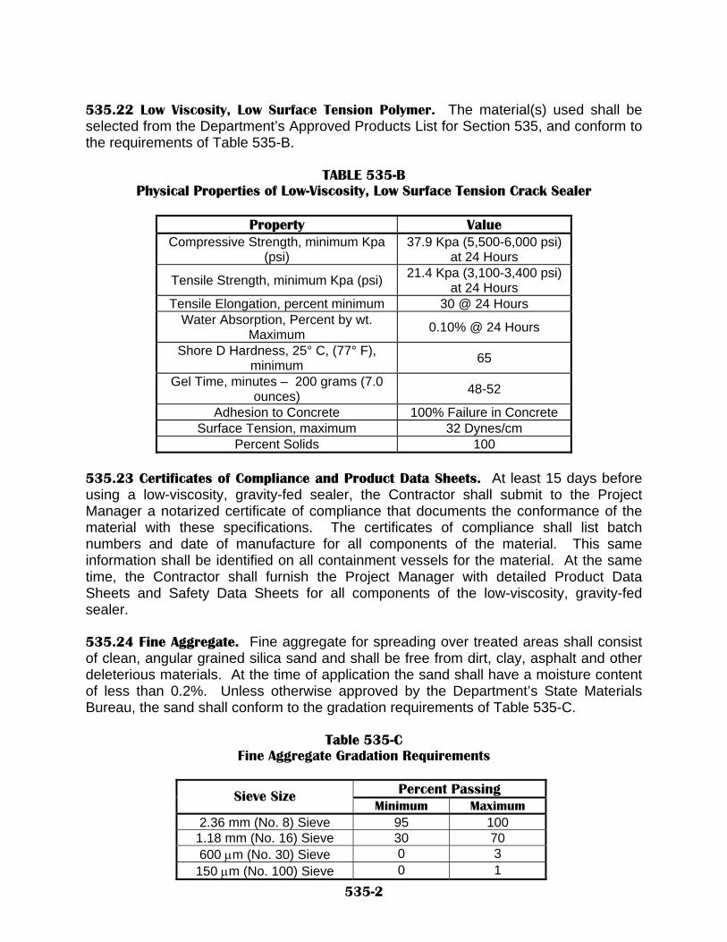
535.22 Low Viscosity, Low Surface Tension Polymer. The material(s) used shall be selected from the Department’s Approved Products List for Section 535, and conform to the requirements of Table 535-B.
TABLE 535-B
Physical Properties of Low-Viscosity, Low Surface Tension Crack Sealer
Property Value Compressive Strength, minimum Kpa
(psi) 37.9 Kpa (5,500-6,000 psi)
at 24 Hours
Tensile Strength, minimum Kpa (psi) 21.4 Kpa (3,100-3,400 psi) at 24 Hours
Tensile Elongation, percent minimum 30 @ 24 Hours Water Absorption, Percent by wt.
Maximum 0.10% @ 24 Hours
Shore D Hardness, 25° C, (77° F), minimum 65
Gel Time, minutes – 200 grams (7.0 ounces) 48-52
Adhesion to Concrete 100% Failure in Concrete Surface Tension, maximum 32 Dynes/cm
Percent Solids 100
535.23 Certificates of Compliance and Product Data Sheets. At least 15 days before using a low-viscosity, gravity-fed sealer, the Contractor shall submit to the Project Manager a notarized certificate of compliance that documents the conformance of the material with these specifications. The certificates of compliance shall list batch numbers and date of manufacture for all components of the material. This same information shall be identified on all containment vessels for the material. At the same time, the Contractor shall furnish the Project Manager with detailed Product Data Sheets and Safety Data Sheets for all components of the low-viscosity, gravity-fed sealer. 535.24 Fine Aggregate. Fine aggregate for spreading over treated areas shall consist of clean, angular grained silica sand and shall be free from dirt, clay, asphalt and other deleterious materials. At the time of application the sand shall have a moisture content of less than 0.2%. Unless otherwise approved by the Department’s State Materials Bureau, the sand shall conform to the gradation requirements of Table 535-C.
Table 535-C Fine Aggregate Gradation Requirements
Percent Passing Sieve Size
Minimum Maximum 2.36 mm (No. 8) Sieve 95 100
1.18 mm (No. 16) Sieve 30 70 600 µm (No. 30) Sieve 0 3
150 µm (No. 100) Sieve 0 1 535-2

535.3 CONSTRUCTION REQUIREMENTS. 535.31. Sealing shall be done by sealing individual cracks or where closely space map cracking has occurred on concrete bridge decks, the method of sealing shall be by flooding the entire surface. The Project Manager will determine the method of sealing to be used. 535.311 Planning and Demonstration. At least 15 days before the application of the low-viscosity, gravity-fed sealer, the Contractor shall present a written plan for crack sealing to the Project Manager for approval. The plan shall indicate the materials to be used, the proposed methods of deck preparation and application, safety considerations for personnel engaged in blasting and sealing operations, and the protection of other persons, vehicles and other property from injury or damage. Before the start of the crack sealing operations, the Contractor shall demonstrate to the Project Manager, on the bridge decks or slabs to be sealed, that the combination of materials, methods of application and the experience of personnel will provide acceptable results. 535.312 Sequence of Operations. Crack sealing on new concrete bridge decks or approach slabs shall not take place until after 28 days of curing. For latex-modified concrete overlays, crack sealing shall not take place until after 7 days of curing. Where the bridge decks or slabs are to also receive a penetrating water repellent treatment, the penetrating water repellent shall be applied first, unless otherwise approved by the Project Manager. 535.32 Surface Preparation. Concrete surfaces adjacent to and within 75 mm to 125 mm (3 in. to 5 in.) of individual cracks, and concrete surfaces to be sealed by flooding shall be prepared by sandblasting or shot blasting to remove all asphaltic material, oil, dirt, rubber, curing compounds, paint and other deleterious substances which may interfere with the bonding and the curing of the low-viscosity, gravity-fed sealer. All loose material shall then be removed from visible cracks by air blasting with oil free compressed air or by vacuuming. The concrete surfaces and cracks to be treated shall be substantially dry at the time of application of the low-viscosity, gravity-fed sealer. 535.33 Storage of Low-Viscosity, Gravity-Fed Sealer. The individual components of low-viscosity, gravity-fed sealer, if supplied separately, shall not contact each other directly. Containers of individual components shall not be stored together in a manner that will allow leakage or spillage from one to contact the containers or material of the other. The low-viscosity, gravity-fed sealer shall be stored within the temperature ranges specified by the manufacturer. 535.34 Application of Low-Viscosity, Gravity-Fed Sealer. The concrete surface temperatures shall be per manufacturer recommendations at the time of the low-viscosity, gravity-fed sealer ’s application. The Contractor shall carefully follow the manufacturer’s written recommendations for mixing the low-viscosity, gravity-fed sealer. The low-viscosity, gravity-fed sealer shall be applied per manufacturer’s recommendations after the mixing of the components. The anticipated rate of application is approximately 1 Liter/16 linear meters (1 gal/200 linear foot) for crack
535-3

sealing and approximately 1 Liter/2.5 m² (1 gal/100 ft2) for surface sealing. Wider cracks 1 mm (0.030 in.) or greater may require two or more applications of the low-viscosity, gravity-fed sealer for sealing. Temporary surface sealing of wider full depth deck cracks on the deck underside may also be necessary. Equipment to apply the low-viscosity, gravity-fed sealer may consist of a container with a nozzle, a low-pressure sprayer, and a roller 75 mm (3 in.) or less in width or other devices approved by the Project Manager. A broom, roller or squeegee may be used to work the low-viscosity, gravity-fed sealer into the cracks. The curing period will be determined from manufacturer’s recommendations and will be verified during the demonstration. 535.341 Excess Low-Viscosity, Gravity-Fed Sealer. Excess low-viscosity, gravity-fed sealer shall be swept from the treated areas per the manufacturer’s recommendations after the crack sealer material’s application. Excess low-viscosity, gravity-fed sealer for the purpose of this specification is that which does not fill the cracks and is not absorbed by the concrete surface but fills or partially fills the grooves in a tined or grooved surface. 535.35 Application of Sand. Dry silica sand shall be applied at an approximate rate of 4.3 kg/m² (8 lb/yd2) to treated surfaces and areas covered with excess low-viscosity, gravity-fed sealer. Sand shall be placed before any gelling of the low-viscosity, gravity-fed sealer occurs. Excess sand shall be removed after the curing period. 535.36 Limitation of Operations. The Contractor shall conduct the operations in such a manner as to protect persons, vehicles and property from injury or damage. The low-viscosity, gravity-fed sealer shall be prevented from leaking through cracks onto traffic below. If deck preparation procedures or the low-viscosity, gravity-fed sealer deface the appearance of bridge components other than the crack scaled areas, the Contractor shall repair those components to the satisfaction of the Project Manager, at no additional cost to the Department. 535.4 METHOD OF MEASUREMENT. 535.41. Crack sealing will be measured by the meter (linear foot). Concrete surface treatment will be measured by the square meter (square yard). 535.5 BASIS OF PAYMENT. 535.51. Crack sealing will be paid for at the contract unit price per linear meter (linear foot). Concrete surface treatment will be paid for at the contract unit price per square meter (square yard).
535-4

Payment will be made under: Pay Item Pay Unit Crack Sealing Meter (Linear Foot)
or Concrete Surface Treatment Square Meter (Square Yard)
535-5

NEW MEXICO DEPARTMENT OF TRANSPORTATION SUPPLEMENTAL SPECIFICATIONS FOR
POLYMER CONCRETE BRIDGE DECK OVERLAY
SECTION 536
All pertinent provisions of the New Mexico State Highway and Transportation Department Standard Specifications for Highway and Bridge Construction shall apply in addition to the following: 1.0 DESCRIPTION. 1.1 This work shall consist of furnishing and applying a polymer concrete bridge deck overlay in accordance with this specification, and in conformity with the lines, grades and details shown on the plans. 2.0 USAGE LIMITATIONS. 2.1 Polymer concrete bridge deck overlays are not recommended for use on bridges that have been constructed using stay-in-place forms. The reason for this recommendation is because the in-place concrete will have no means for the evaporation of internal and/or encapsulated water that in turn may cause future damage to both the concrete substrate and the polymer concrete bridge deck overlay. If it is decided to use this material on these types of bridges, then additional preconstruction efforts must be planned for on a project specific basis with assistance from the Department’s Bridge Design Section, State Materials Bureau, and the epoxy or epoxy urethane manufacturer. 2.2 Polymer concrete bridge deck overlays should not be placed on hydraulic cement concrete that is less than 56 days of age. 3.0 WARRANTY. 3.1 In addition to the requirements of Section 106.11, a minimum 5-year warranty shall be furnished by the Contractor for the performance of the polymer concrete bridge deck overlay. The warranty shall be secured by a surety bond on a form that is acceptable to the Department in an amount equal to the extended total of the bid for the polymer concrete bridge deck overlay material. The surety shall be authorized to transact business in New Mexico and shall be approved in Federal Circular 570 published by the United States Treasury Department. 3.2 The performance of the polymer concrete bridge deck overlay shall be evaluated annually by a joint team consisting of a Contractor and a Department Highway District representative (to coincide with the anniversary date of the previous year’s evaluation ±30 days) for the entire warranty period. During this period, no spalling, scaling, cracking or delamination of the polymer concrete bridge deck overlay shall occur. Spalling shall be defined as existing when broken or missing pieces of concrete overlay
536-1

occur, scaling as when the bridge deck overlay surface has a visible, exposed, rough surface texture resulting from a loss of either aggregate or mortar and delamination as when there is visible debonding of the concrete bridge deck overlay from the existing bridge deck surface. Cracking shall be defined as any crack visible to the naked eye. At the end of each yearly evaluation period, the Department Highway District representative shall provide the Contractor and the Department’s Bridge Engineer with a report of findings that clearly describes if any cracking or delamination has occurred within the installed polymer concrete bridge deck overlay. 3.3 The Department will perform annual skid testing of the polymer concrete bridge deck overlay, in conformance with AASHTO T 242. For the entire warranty period, the average skid number shall be 45 or higher. 3.4 If the performance of the polymer concrete bridge deck overlay, based on Section 3.2 and/or 3.3 is not acceptable, the Department’s Bridge Engineer shall notify the Contractor, in writing, that corrective work needs to be completed, at no additional cost to the Department, within 180 days of receipt of the written notification. 4.1 SUBMITTALS. 4.1 The Contractor shall submit a complete and comprehensive summary of the Manufacturer’s recommended procedures and requirements for the material being proposed for use to the Project Manager fourteen (14) days before the application of the polymer concrete bridge deck overlay. The Contractor shall submit to the Project Manager the manufacturer’s certification verifying conformance to the material specifications. 5.0 MATERIALS. 5.1 The epoxy or epoxy urethane resin base and hardener shall be composed of a two-part, 100% solids, thermosetting, moisture-insensitive, flexible, high-elongation compound meeting the material properties shown in either Table 536-A or Table 536-B as specified by the Department:
536-2

TABLE 536-A Epoxy Physical Requirements
Property Test Method Minimum Maximum Remarks
Viscosity ASTM D 2393 Brookfield RVT, Spindle #3 @ 20 rpm 7 poises 25 poises
Gel Time ASTM C 881, Paragraph 11.2 modified 15 minutes 45 minutes
Compressive Strength @ 3 Hours
ASTM C 579 modified (with plastic inserts) 1,000 psi --- Mixed with aggregate
Compressive Strength @ 24 Hours
ASTM C 579 modified (with plastic inserts) 5,000 psi --- Mixed with aggregate
Tensile strength (neat) @ 7 days ASTM D 638 2,200 psi 5,000 psi
Elongation (neat) @ 7 days ASTM D 638 30% 80%
Adhesive strength @ 24 hours
ACI 503R, Appendix A, VTM 92 250 psi --- Mixed with aggregate with
100% failure in concrete Permeability to chloride
ion @ 28 days AASHTO T 277 --- 100 coulombs
Absorption (neat) @ 24 Hours ASTM D 570 --- 1%
Thermal compatibility ASTM C 884 No delamination of overlay Mixed with aggregate
Infrared spectrum AASHTO T 237, Paragraphs 4 and 5
To be established for each component
TABLE 536-B
Epoxy Urethane Physical Requirements
Property Test Method Minimum Maximum Remarks
Viscosity ASTM D 2393 Brookfield RVT, Spindle #3 @ 20 rpm 35 poises 70 poises
Gel Time ASTM C 881, Paragraph 11.2 modified 15 minutes 45 minutes
Compressive Strength @ 3 Hours
ASTM C 579 modified (with plastic inserts) 1,000 psi --- Mixed with aggregate
Compressive Strength @ 24 Hours
ASTM C 579 modified (with plastic inserts) 5,000 psi --- Mixed with aggregate
Tensile strength (neat) @ 7 days ASTM D 638 2,200 psi 5,000 psi
Elongation (neat) @ 7 days ASTM D 638 30% 100%
Adhesive strength @ 24 hours
ACI 503R, Appendix A, VTM 92 250 psi --- Mixed with aggregate with
100% failure in concrete Permeability to chloride
ion @ 28 days AASHTO T 277 --- 100 coulombs
Shore D hardness ASTM D 2240 60 70 Flexural creep, total movement in 7 days California Test Method 419 0.0065 in ---
Flexural yield strength ASTM D 790 5,000 psi --- Absorption (neat) @ 24
Hours ASTM D 570 --- 1%
Thermal compatibility ASTM C 884 No delamination of overlay Mixed with aggregate
Infrared spectrum AASHTO T 237, Paragraphs 4 and 5
To be established for each component
536-3

5.2 The Contractor shall provide a certified laboratory report from a Department State Materials Bureau approved laboratory, verifying that the provided polymer concrete materials meet the requirements of this specification. This certification shall include a Fourier Transform Infrared Spectrophotometry (FTIR) spectrum in transmittance mode and a bulk sample of each component tested. All data shall be maintained as confidential by the Department and used only for information purposes only. 5.3 For each project, for information purposes only, the Department will obtain additional infrared spectrums on the epoxy or epoxy urethane materials submitted for comparative purposes. The Project Manager will obtain a single ½ pint sample of each component in the field and send those samples to the Department’s State Materials Bureau. The Department’s State Materials Bureau will then obtain an infrared spectrum on the submitted field samples and report their comparative findings back to the Project Manager within fourteen (14) days after their receipt at the Department’s State Materials Bureau. 5.4 The Project Manager will accept the epoxy or epoxy urethane based on the certified laboratory report and the comparative Infrared Spectrum analysis of the field samples that was performed by the Department’s State Materials Bureau. 5.5 The aggregate shall be angular grained, stone aggregate that is free of dirt, clay and foreign or organic material. Additionally, the aggregate shall meet the material properties shown in Table 536-C and Table 536-D:
TABLE 536-C Required Aggregate Properties
Property Test Method Minimum Maximum Remarks
Soundness Loss, 5 cycles in Magnesium
Sulfate AASHTO T 104 --- 8%
Micro-Deval AASHTO TP 58 --- 10% Aggregate must meet the gradation shown in Table
536-D Moh's Hardness --- 7 --- Moisture Content AASHTO T 255 --- 0.2%
TABLE 536-D
Required Aggregate Gradation
Percent Passing Sieve Size Minimum Maximum
No. 4 100% --- No. 8 30% 75%
No. 16 0% 5% No. 30 0% 1%
No. 200 0% 0.2%
536-4

5.51 Acceptance of Aggregate. Table 536-C “Required Aggregate Properties” shall be determined from a representative sample of the aggregate before it is actually used on a project by the Department’s State Materials Bureau. The Department’s State Materials Bureau will report their acceptance recommendation to the Project Manager within (14) days after the receipt of the representative aggregate sample at the Department’s State Materials Bureau. 6.0 EQUIPMENT. All equipment is subject to approval by the Project Manager, and shall comply with the following requirements: 6.1 Surface Preparation Equipment. 6.1.1 The shot-blasting equipment shall be capable of producing a surface relief equal to the International Concrete Repair Institute (ICRI) Surface Preparation Level 5-7, or ASTM E 965 Pavement Macro-texture Depth of 1.0 mm to 2.0 mm. 6.2 Mechanical Application Equipment. 6.2.1 The epoxy or epoxy urethane distribution system shall be capable of accurate and complete mixing of the epoxy or epoxy urethane resin and hardening agent and providing a uniform and accurate distribution of the epoxy or epoxy urethane materials at the specified rate on 100% of the work area. 6.2.2 The self-propelled aggregate spreader shall be capable of providing a uniform and accurate application of the dry aggregate, at the manufacture’s recommended specified application rate, over 100% of the work area. 6.2.3 The air compressor shall be capable of producing a sufficient amount of oil free and moisture free compressed air to remove all dust and loose material from the application surface before the application of the epoxy or epoxy urethane. 6.3 Hand Application Equipment (When Used). 6.3.1 The Contractor shall provide calibrated containers for the accurate measurement of the epoxy or epoxy urethane components. 6.3.2 Paddle type or other mixing device shall be capable of accurate and complete mixing of the epoxy or epoxy urethane resin and hardening agent. 6.3.3 Notched squeegees and brooms shall be capable of spreading the epoxy or epoxy urethane material in accordance with this specification and the manufacturer’s requirements. When notched squeegees are used, they shall be inspected periodically during application for wear of notch depth exceeding the requirement to properly distribute the epoxy or epoxy urethane resin uniformly over deck work area.
536-5
6.3.4 The aggregate spreader shall be capable of uniform and accurate application of the dry aggregate at the manufacture’s recommended specified application rate. 6.3.5 Adequate additional hand tools to facilitate the placement of the polymer concrete bridge deck overlay shall be in accordance with this specification and the manufacturer’s requirements. 6.4 Vacuum Truck(s). Vacuum trucks shall be clean and free of dripping engine fluids. Drip pans may be installed to prevent dripping of fluids on to the clean deck and/or polymer concrete bridge deck overlay. 6.5 Power Broom(s). Power brooms shall be clean and free of dripping engine fluids. Drip pans may be installed to prevent dripping of fluids on to the clean deck and/or polymer concrete bridge deck overlay. 6.6 General. Provide an overall combination of labor and equipment that shall have the capability of proportioning and mixing the epoxy or epoxy urethane components and placing the epoxy or epoxy urethane and aggregate in accordance with this specification and the manufacturer’s requirements. 7.0 PRECONSTRUCTION. 7.1 Concrete Deck Patching and Repair 7.1.1 Exclusive of this specification and when called for in the contract per Section 533 “Repair of Concrete Structures”, the Contractor shall remove all deteriorated concrete and repair the area with suitable patching materials that are on the Department’s “Approved Product List”. 7.1.2 Exclusive of this specification and when called for in the contract per Section 534 “Epoxy Injection”, the Contractor shall rehabilitate the existing concrete by structurally re-bonding cracks or delaminations using an epoxy injection system. 8.0 DECK PREPARATION. 8.1 Any deck repair for patching, deck delamination and/or crack filling shall be completed before the application of the polymer concrete bridge deck overlay per Paragraph 7.0 “Preconstruction”. 8.2 Visible moisture shall be identified by taping a 18” x 18” plastic sheet to the deck for a minimum of 2 hours per ASTM D 4263. If moisture appears on the bottom of the plastic sheet, the polymer concrete bridge deck overlay process cannot proceed. 8.3 Before placement of the polymer concrete bridge deck overlay, the entire deck surface shall be cleaned by shot-blasting and/or other means using the approved cleaning method to remove all asphaltic materials, oils, dirt, rubber, curing compounds, paint carbonation, laitance, weak surface mortar and other potentially detrimental materials, which may interfere with the bonding or curing of the polymer concrete bridge
536-6

deck overlay. Acceptable cleaning is usually achieved by significantly changing the color of the concrete and mortar and beginning to expose coarse aggregate particles. Any mortar that is sound and soundly bonded to the coarse aggregate must have open pores resulting from thecleaning to be considered adequate for bond. Pavement markings shall be considered clean when the concrete has exposed aggregate showing through the pavement markings. A vacuum cleaner or air compressor shall be used to remove all dust and other loose material. Brooms shall not be used and will not be permitted. 8.4 If the Project Manager determines that an approved cleaning method has changed prior to the completion of the job, the Contractor must return to the approved cleaning methods and re-clean the suspect areas or verify through tests at no additional cost to the Department that the method is acceptable. 8.5 There shall be no visible moisture present on the surface of the concrete at the time of application of the polymer concrete bridge deck overlay. Compressed air may be used to dry the deck surface, as long as there is no oil or other deleterious debris contained within the air stream. 9.0 CONSTRUCTION METHODS. 9.1 Safety Provisions. The Contractor’s personnel shall be thoroughly trained in the safe handling of materials in accordance with the Manufacturer’s requirements and shall provide written certification of this training to the Project Manager before the application of the polymer concrete bridge deck overlay. 9.2 Storage of Materials. The materials shall be stored in accordance with the Manufacturer’s requirements. 9.3 Surface Preparation. Before placing the first course, the Contractor shall determine the bridge deck has been properly prepared and has obtained approval by the Project Manager: 9.3.1 All deck drains and areas of curb or railing above the proposed surface shall be closed and protected to ensure that epoxy or epoxy urethane and aggregate will not pass through the drains. 9.3.2 All of the approved surface preparations described above have been properly completed. 9.4 Temperature limitations. 9.4.1 Polymer concrete bridge deck overlays shall not be placed when the deck temperature exceeds the manufacturer’s requirements or that otherwise required by the contract specifications for the placement of concrete decks. 9.4.2 The temperature of the bridge deck surface and all epoxy or epoxy urethane and aggregate components shall be per manufacturer’s requirements at the time of
536-7

application. Any artificial means to elevate the temperature of the bridge deck will not be permitted. 9.4.3 Epoxy or epoxy urethane shall not be applied if the air temperature is expected to drop below the manufacturer’s requirements within 8 hours after application or if the epoxy or epoxy urethane‘s gel time is less than 10 minutes. 9.5 Application. Polymer concrete bridge deck overlay materials shall not be placed when weather or surface conditions are such that the material cannot be properly handled, placed and cured within the time allowed for road or lane closures. 9.6 The polymer concrete bridge deck overlay shall be applied in two (2) separate courses in accordance with the following rate of application, and the total of the two applications shall not be less than 7.5 gallons per 100 square feet. 9.6.1 The first course shall have coverage of no less than 2.5 gal/100 square feet, and shall have a minimum aggregate coverage of at least 10 pounds per square yard, but of sufficient quantity to completely cover the epoxy or epoxy urethane. 9.6.2 The second course shall have coverage of no less than 5.0 gallons per 100 square feet, and a minimum aggregate coverage of at least 14 pounds per square yard, but of sufficient quantity to completely cover the epoxy or epoxy urethane. 9.6.3 After the epoxy or epoxy urethane mixture has been prepared for the polymer concrete bridge deck overlay, it shall be immediately and uniformly applied to the surface of the bridge deck with a notched squeegee, as recommended by the epoxy manufacturer, or with a mechanized batch mixing/application system. 9.6.4 The dry aggregate shall be applied in such a manner as to cover the epoxy or epoxy urethane mixture completely per manufacturer’s requirements. 9.6.5 First course applications, which do not receive enough aggregate prior to gel shall be removed and replaced at no additional cost to the Department. 9.6.6 A second course insufficiently covered with aggregate may be left in place, but additional applications shall be completed before opening to traffic at no additionally cost to the Department. 9.7 Each course of polymer concrete bridge deck overlay shall be cured until vacuuming or brooming can be performed without tearing or damaging the surface. 9.8 Traffic or equipment shall not be permitted on the polymer concrete bridge deck overlay surface during the curing period per manufacturer’s requirements. 9.9 After the first course has been cured, all loose aggregate shall be removed by vacuuming or brooming and the next polymer concrete bridge deck overlay course shall be applied to completion.
536-8

9.10 The Contractor shall plan and prosecute the work to provide at least the minimum curing periods specified herein, or other longer minimum curing periods, as prescribed by the manufacturer prior to opening to public or construction traffic, unless otherwise permitted by the Project Manager. 9.11 Traffic will not be allowed on the roadway until both applications have been placed and cured. 9.12 The Contractor shall correct all surface variations exceeding ¼ inch in 3 ft. unless otherwise directed by the Project Manager. 9.13 Unless otherwise specified, the polymer concrete bridge deck overlay shall be applied over the expansion joints of the bridge deck. The expansion joints shall be provided with bond breakers. Within 12 hours of application and before opening to traffic, the polymer concrete bridge deck overlay shall be removed over each joint by removal of the bond breakers, or by scoring the polymer concrete bridge deck overlay before gelling or by saw cutting after cure. In the event, the Contractor’s operations damages the bridge expansion joint, the Contractor shall be responsible for its repairs at no additional cost to the Department. 9.14 In the event the Contractor’s operation damages or mars the polymer concrete bridge deck overlay, the Contractor shall remove the damaged areas by saw-cutting in rectangular sections to the top of the concrete deck surface, and replacing the various courses, in accordance with this specification at no additional cost to the Department. 10.0 METHOD OF MEASUREMENT. 10.1 Polymer concrete bridge deck overlay will be measured by square yard. 11.0 BASIS OF PAYMENT. 11.1 Polymer concrete bridge deck overlay will be paid for at the contract unit price per square yard. Said payment shall be full compensation for all labor, equipment, materials, and appurtenances necessary to complete the work. Any required work under Section 535 “Crack Sealing using Low-Viscosity, Gravity-Fed Sealers”, shall be considered incidental to the cost of the polymer concrete bridge deck overlay.
Payment will be made either under: Pay Item Pay Unit Epoxy Polymer Concrete Bridge Deck Overlay Square Yard
or Epoxy Urethane Polymer Concrete Bridge Deck Overlay Square Yard
536-9

NEW MEXICO DEPARTMENT OF TRANSPORTATION SUPPLEMENTAL SPECIFICATIONS FOR
STEEL REINFORCEMENT
SECTION 540 All provisions of the New Mexico Department Of Transportation’s Standard Specifications for Highway and Bridge Construction shall apply except as modified herein. Delete SECTION 540 - STEEL REINFORCEMENT in its entirety and substitute the following: NOTE: For metric bar conversion: See appendix. 540.1 DESCRIPTION. 540.11 This work shall consist of furnishing and placing steel reinforcement in compliance with the specifications and the dimensions, spacing, and type shown in the contract and in accordance with the specifications. The drawings shall specify which coating systems will be furnished with the reinforcing. In general, three coating systems are available. They are (1) uncoated steel, (2) epoxy-coated reinforcement, and (3) hot-dipped galvanized reinforcement. Systems (2) and (3) may be specified for the protective coating of reinforcing bars for bridge decks and other concrete components exposed to weather and road salts. 540.2 MATERIALS. 540.21 Bar Reinforcement. Unless otherwise noted, bar reinforcement shall be deformed bars conforming to the requirements of AASHTO M 31 M/M 31-95, Grade 60. The nominal dimensions (English system) of the reinforcing bars are as shown in Table 540-A below.
540-1

TABLE 540-A NOMINAL DIMENSIONS OF REINFORCEMENT
Bar Designation No. Nominal Weight (lb/ft) Diameter (in.)
*3 0.376 0.375 *4 0.668 0.500 *5 1.043 0.625 *6 1.502 0.750 *7 2.044 0.875 *8 2.670 1.000 *9 3.400 1.128 *10 4.303 1.270 *11 5.313 1.410 *14 7.650 1.693 *18 13.600 2.257
* NOTE: For metric bar conversion: See appendix. Grade 60 reinforcing bars may be substituted for Grade 40 reinforcing bars at no additional cost to the Department except that vertical bars in abutment back walls and stirrup bars which project from prestressed concrete beams or other precast units shall always be Grade 40. 540.22 Welded Wire Fabric. Welded wire fabric shall conform with the requirements of AASHTO M 55 M/ M 55-00. 540.23 Spiral Reinforcement. Spiral reinforcement shall be fabricated from steel bars conforming to the requirements of AASHTO M 31M/M31-95, or from cold drawn steel wire conforming to the requirements of AASHTO M 32 M/ M32-00, as specified in the contract. 540.24 Reinforcing Wire. Wire for reinforcement shall conform with the requirements of AASHTO M32 M/M 32-00. EPOXY-COATED REINFORCING BARS. 540.25E Epoxy-Coated Reinforcing Bars. Subsections ending with an “E” are paragraphs describing and specifying the fabrication and placement of epoxy-coated reinforcing bars (System 2). Epoxy-coated reinforcing bars shall conform to the requirements of AASHTO M 284 / M 284 M-01 except as modified herein. Plants supplying epoxy-coated reinforcing bars must be currently certified in both the coating process and fabrication by the Concrete Reinforcing Steel Institute (CRSI). 540.26E Coating Material. The coating material shall be a light colored powdered epoxy resin which will highlight rusting of untreated bar areas. The coating material shall be selected from the Department’s Qualified Products list for Powdered Epoxy Resin Products for Coating Reinforcing Steel.
540-2

The Contractor shall provide for the submittal to the Department at least one representative four-ounce sample of the resin powder used to coat each given lot of bars. 540.27E Accessories. Tie wire for tying epoxy-coated reinforcing bars shall be plastic coated. Chairs, supports, and clips shall be one of the following: A. Steel, fully coated with plastic or fusion-bonded epoxy. B. Galvanized steel, with the cradle and the upper 2 in. of the chair, support, or clip,
coated with fusion-bonded epoxy or plastic. C. Metal chairs or other metal supports for reinforcement which contact the exposed
surfaces of the concrete shall be galvanized. D. Metal chairs or other metal supports for regular reinforcement shall be galvanized,
painted or epoxy coated. E. Metal chairs or other metal supports for epoxy-coated reinforcement shall be epoxy
coated. F. Sand chairs or other metal supports placed directly on dirt shall be galvanized, or G. Concrete blocks may be used in lieu of sand chairs or other metal supports placed
directly on the dirt. When preformed metal forms are used, continuous chairs or supports shall be used. 540.28E Certificates of Compliance. The Contractor shall furnish Certificates of Compliance from the fabricator to the Project Manager indicating compliance with the applicable requirements of this specification. The copies shall accompany each shipment of reinforcing steel to the project. The certificate of compliance shall indicate the project number, the shipping invoice number, the name of the manufacturer, pounds shipped, heat numbers, laboratory test reports, and grade of steel. Note: this part of the Certificates of Compliance are the same for each of the three coating systems. 540.29E Epoxy-Coated Reinforcing Bar Certificates of Compliance. The applicator shall furnish the Department’s Inspector three copies of a notarized Certificate of Compliance for each shipment of coated bars. The Certificate of Compliance shall contain all the information required in subsection 540.27E, Certificates of Compliance, and shall also state that the representative samples of the coated bars have been tested, and that the test results comply with the requirements of AASHTO M 284/ M 284 M-01, this specification, and batch numbers of the epoxy resin.
540-3

Results of tests by the fabricator during coating shall be retained and made available to Department’s inspectors for inclusion in final inspection reports. 540.3E CONSTRUCTION REQUIREMENTS. 540.31E GENERAL. Unless otherwise provided, dimensions on plans are to the centerlines of bars. 540.311E Bundling and Tagging. Bar reinforcement shall be shipped in standard bundles, tagged and marked in accordance with the Code of Standard Practice of the Concrete Reinforcement Steel Institute. 540.32E Bar Bending. Bent bar reinforcement shall be cold bent around a pin to the shapes shown in the contract. Unless otherwise specified, bending shall be done in an adequately equipped shop. Field bending of Grade 60 bars and epoxy-coated bars is not permitted. Unless otherwise provided, the diameter of bend shall be in accordance with Table 540-B. This table specifies minimum pin diameters for all coating systems.
TABLE 540-B MINIMUM DIAMETER OF BENDS
Type of Reinforcement Size Minimum Pin Diameter
UNCOATED BARS Stirrups and Ties *#3 through #5 5 bar diameters Main Reinforcement *#3 through #5 6 bar diameters All types *#6 through #8 6 bar diameters All types *#9 through #11 8 bar diameters All types *#14 through #18 10 bar diameters
COATED BARS Stirrups and Ties *#3 through #5 7.5 bar diameters Main Reinforcement *#3 through #5 9 bar diameters All types *#6 through #8 9 bar diameters All types *#9 through #11 12 bar diameters All types *#14 through #18 15 bar diameters * NOTE: For metric bar conversion: See appendix. 540.33E Requirements for Epoxy-Coated Reinforcing Bars. Where epoxy-coated bars are detailed over 40 feet long, the Contractor may furnish such bars in two sections with lap splices.
540-4
The Contractor shall submit to the Bridge Engineer, in writing, a request for such a substitution showing details of splice locations and lengths of lap splices. The Contractor shall submit the request prior to fabrication of the bars, and shall allow at least two weeks for review and approval. Longer total bar lengths resulting from the proposal shall be provided at no additional cost to the Department. The applicator shall make a trial run of the coating process to ensure that the process meets the specified requirements. All required tests shall be performed on the trial specimens before production is started on the reinforcing bars for the project. The Contractor shall notify the Department’s Bridge Design Section at least 30 days before the date of the trial run. 540.331E Coating Thickness. The thickness of the coating after curing shall be between 6 mils and 10 mils. For acceptance, at least 80 percent of all recorded film thickness measurements shall be in this range. 540.332E Cure of Coating. The epoxy coating film shall be fully cured. The applicator shall ensure that the entire coated production lot is supplied in a fully-cured condition. 540.333E Continuity of Coating. The coating shall be free from holes, voids, contamination, cracks and damaged areas as determined by a visual examination of a representative number of bars. A 67.5-volt holiday detector shall be used in the production line to continuously check the coated bar for holidays. There shall be no more than three holidays or pinholes per linear foot of coated bar. 540.334E Coating Inspection and Tagging. Before coating reinforcing bars with epoxy, the Department’s inspectors will inspect and tag approved bar bundles. It will be the applicator’s responsibility to maintain these tags through the coating process. The tagged bar in a bundle shall be the last to be fed through the cleaning unit. The tag shall be removed prior to cleaning and placed back on the last bar following coating and before re-bundling. After coating is complete, a second tag will be attached to the bundle by the inspector, indicating that the bundle has been inspected and accepted for epoxy coating. The Project Manager will not accept bundles arriving on the project without inspection tags indicating that the coating meets specification requirements. 540.335E Storage and Handling of Epoxy- Coated Reinforcing Bars. Epoxy-coated reinforcing steel shall be handled and stored by methods that will not damage the epoxy coating. Epoxy-coated reinforcing steel shall be transported and stored on wooden or padded supports.
540-5

Devices used for handling epoxy-coated reinforcement bars shall have adequately padded contact areas. Bundling bands shall be padded, and all bundles shall be lifted with a strong back, with multiple support points, or with a platform bridge so as to prevent bar-to-bar abrasion from snags in the bar bundle. Bars or bundles shall not be dropped or dragged. Epoxy-coated reinforcing bars shall not be stored on the ground, and shall not be stored outdoors in sunlight for more than 30 days. 540.336E Repair of Damaged Coating. All visible damage and cracks in the coating shall be repaired prior to shipping. The total surface area covered by patching by the coating applicator shall not exceed one percent in any one-foot section. Sheared ends and other cuts and exposed areas shall be patched promptly before detrimental oxidation occurs. Areas to be repaired shall be clean and free from surface contaminants. All visible damage and cracks in the coating due to shipping and field handling shall be repaired by patching before the concrete is placed. The total bar surface area covered by patching material shall not exceed two percent in any one-foot section. HOT DIP GALVANIZED REINFORCING BARS 540.24G Hot Dip-Galvanized Reinforcing Bars. Subsections ending with a “G” are paragraphs describing and specifying the fabrication and placement of hot-dip galvanized reinforcing bars (System 3). Hot-Dip Galvanized reinforcing bars shall conform to the current requirements of AASHTO M 111 M / M111-99 (ASTM A 123). The galvanizing plant must be approved by the Bridge Design Section of the New Mexico Department Of Transportation. Galvanizing shall be accomplished after fabrication; that is, after cutting bars to length, and after bending bars to the required shapes. 540.25G Galvanizing Material. Zinc for galvanizing shall conform to ASTM B 6. 540.26G Accessories. Tie wire for tying galvanized reinforcing bars shall be galvanized. Chairs, supports, and clips shall also be galvanized, or covered with plastic as specified in Subsection 540.26E. 540.27G Certificates of Compliance. The Contractor shall furnish Certificates of Compliance from the fabricator to the Project Manager for the uncoated (black) steel, as described in Subsection 540.27E above. 540.28G Galvanized Steel Certificates of Compliance. The galvanizer shall furnish the Department’s Inspector three copies of a notarized Certificate of Compliance for each shipment of galvanized bars. The Certificate of Compliance shall contain all of the information required in Subsection 540.27G, plus results of inspections of bars for thickness of galvanizing, adherence, and smoothness or appearance.
540-6
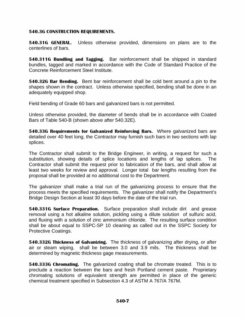
540.3G CONSTRUCTION REQUIREMENTS. 540.31G GENERAL. Unless otherwise provided, dimensions on plans are to the centerlines of bars. 540.311G Bundling and Tagging. Bar reinforcement shall be shipped in standard bundles, tagged and marked in accordance with the Code of Standard Practice of the Concrete Reinforcement Steel Institute. 540.32G Bar Bending. Bent bar reinforcement shall be cold bent around a pin to the shapes shown in the contract. Unless otherwise specified, bending shall be done in an adequately equipped shop. Field bending of Grade 60 bars and galvanized bars is not permitted. Unless otherwise provided, the diameter of bends shall be in accordance with Coated Bars of Table 540-B (shown above after 540.32E). 540.33G Requirements for Galvanized Reinforcing Bars. Where galvanized bars are detailed over 40 feet long, the Contractor may furnish such bars in two sections with lap splices. The Contractor shall submit to the Bridge Engineer, in writing, a request for such a substitution, showing details of splice locations and lengths of lap splices. The Contractor shall submit the request prior to fabrication of the bars, and shall allow at least two weeks for review and approval. Longer total bar lengths resulting from the proposal shall be provided at no additional cost to the Department. The galvanizer shall make a trial run of the galvanizing process to ensure that the process meets the specified requirements. The galvanizer shall notify the Department’s Bridge Design Section at least 30 days before the date of the trial run. 540.331G Surface Preparation. Surface preparation shall include dirt and grease removal using a hot alkaline solution, pickling using a dilute solution of sulfuric acid, and fluxing with a solution of zinc ammonium chloride. The resulting surface condition shall be about equal to SSPC-SP 10 cleaning as called out in the SSPC Society for Protective Coatings. 540.332G Thickness of Galvanizing. The thickness of galvanizing after drying, or after air or steam wiping, shall be between 3.0 and 3.9 mils. The thickness shall be determined by magnetic thickness gage measurements. 540.333G Chromating. The galvanized coating shall be chromate treated. This is to preclude a reaction between the bars and fresh Portland cement paste. Proprietary chromating solutions of equivalent strength are permitted in place of the generic chemical treatment specified in Subsection 4.3 of ASTM A 767/A 767M.
540-7

540.334G Finish and Adherence of Coating. The zinc coating shall have no bare spots. The coating shall be free of blisters, flux spots or inclusions, dross, and acid or black spots. Bars that stick together after galvanizing shall be rejected. In addition, the presence of tears or sharp spikes which make the bar hazardous to handle shall be cause for rejection. A matte gray finish appearance shall not be, by itself, a cause for rejection. The coating shall be adherent so it cannot be removed by any reasonable process of handling or erection. 540.335G Coating Inspection and Tagging. Before galvanizing reinforcing bars, the Department’s inspectors will inspect approved bar bundles. After galvanizing, the inspectors will inspect and tag approved bar bundles. The Project Manager will not accept bundles arriving on the project without inspection tags indicating that the coating meets specification requirements. 540.336G Storage, Handling, and Repair of Galvanized Reinforcing Bars. When storing, handling, and repairing galvanized reinforcing bars, Contractors shall follow the “Guidelines for Job-Site Practices” described in Appendix XI of ASTM A 767/A 767M. 540.34 GENERAL CONSTRUCTION REQUIREMENTS FOR ALL SYSTEMS. 540.341 Splicing. Splicing of bars other than at the locations specified in the contract will not be permitted unless otherwise approved by the Bridge Engineer. Bars in lapped splices shall be placed and securely tied in a manner that will maintain at least the minimum reinforcing cover required. Spiral reinforcement my be placed by lapping or butt welding. If lap splicing is used, laps shall be at least 48 bar or wire diameters, but not less than one foot. The welding of splices shall conform with the requirements herein provided. Mechanical couplers will be permitted provided that the splice strength verified by tests is greater or equal to 125% of the yield stress of the spliced reinforcing bars. Welded wire fabric and bar-mat reinforcement shall be lapped as shown in the contract. If not shown in the contract, the length of overlap measured between the outer-most cross wires of each sheet shall be at least one spacing of cross wires plus two inches. 540.342 Field Cutting. If it becomes necessary to cut bars to length in the field, bars shall be sheared or sawed. Flame cutting will not be permitted on coated bars. Flame cutting will be permitted on uncoated bars provided that the flame cut will be made at least six inches beyond where the bar is no longer required. The ends of coated bars cut in the field shall be patched with suitable patching material. 540.343 Reinforcing Bar Placement. Reinforcing bars shall be placed as shown in the contract, and shall be securely tied in position with wire not smaller than 16 gauge.
540-8

Reinforcing shall be placed, supported, and tied carefully, and concrete shall be placed and vibrated with care, to avoid damage to the coatings. All intersections shall be tied except where the reinforcing bar spacing is less than one foot in either direction. Where the spacing is less than one foot in either direction, alternate intersections shall be tied. Metal spacers, chairs, hangers, and other approved devices of adequate strength to prevent crushing under full load shall be used to hold the reinforcing bars in position. The use of concrete blocks to support reinforcing bars will not be permitted, except that dense, rectangular concrete blocks may be used to support the bottom mat of reinforcement in slabs that are cast on earth. Such concrete blocks shall: (a) have compressive strength and density equal to or greater than the concrete to be placed, (b) shall occupy a small area, and (c) shall contain embedded tie wires to provide for the attachment of reinforcement to the block. Wooden spacers or supports shall not be used to hold reinforcing in position. Reinforcing bar mats in bridge deck and concrete box culvert slabs shall be securely tied down to beams and forms to prevent upward movement of the bar mats during concrete placement. Maximum spacing between ties shall be 10 feet. 540.344 Reinforcing Bar Placement Tolerances. Variations in spacing between adjacent bars shall not exceed ½ inch, or 1 /24 of the spacing dimension shown in the contract, whichever is greater. With the exception of slabs cast on earth, the clear cover of reinforcement shall not vary more than ¼ inch, or 1/8 of the dimension shown in the contract, whichever is greater. The clear cover of the reinforcement in slabs cast on earth shall not vary more than minus ½ inch from the position shown in the contract. 540.35 Cleaning of Reinforcing Bars. Before concrete is placed, the reinforcing bars shall be cleaned of dirt, mortar, oil, loose rust, loose mill scale and other materials that would reduce or destroy the bond. 540.36 Welding of Reinforcing Steel. Reinforcing steel shall be welded only when shown in the contract or authorized in writing by the Bridge Engineer. Welding shall conform with the requirements of AWS Specification D1.4, Reinforcing Steel Welding Code. 540.37 Concrete Cover Requirements. The concrete cover shall be as shown in the contract. Concrete cover shall be defined as the distance from the surface of concrete to the edge of the bar nearest to that surface. If cover dimensions are not shown on the contract, the concrete cover dimensions of Table 540-C shall apply.
540-9

TABLE 540-C CONCRETE COVER REQUIREMENTS
Location Minimum cover Concrete Cast Against and Permanently 3.0 in. Exposed to Earth
Concrete Exposed to Earth or Weather Principal Reinforcement 2.0 in. Stirrups, Ties and Spirals 1 ½ in.
Concrete Bridge Slabs
Top Reinforcement 2.0 in. Bottom Reinforcement 1.0 in.
Concrete not Exposed to Weather or in Contact with Ground Principal Reinforcement 1 ½ in. Stirrups, Ties, and Spirals 1.0 in. Bar Bundles * 2.0 in. *Or equal to the diameter of a single bar of equivalent area, whichever is greater. 540.38 Final Inspection. No concrete shall be placed until the Project Manager has inspected the reinforcing steel in place and has authorized the Contractor to place the concrete. Acceptance of the reinforcing steel shall not relieve the Contractor of responsibility for the cover and position control of the steel. 540.4 METHOD OF MEASUREMENT. 540.41 Reinforcing bars will be measured by the pound. Epoxy- coated reinforcing bars will be measured by the pound. Galvanized reinforcing bars will be measured by the pound. 540.42 Measurement of reinforcing steel will be based on the computed weight of the bars.
540-10

The computed weight of reinforcing bars will be based on the nominal unit weight of the bar sizes shown in Table 540-A. The computed weights of epoxy-coated or galvanized reinforcing bars will be based on the nominal weights of the bars before application of the epoxy-coating or galvanizing of the bars. When splices are made for the convenience of the Contractor, and are approved by the Bridge Engineer at locations not shown in the contract, the extra steel required for laps will not be included in computing the weight of the bars. 540.5 BASIS OF PAYMENT. 540.51 Reinforcing bars will be paid for at the contract unit price per pound. Epoxy-coated reinforcing bars and galvanized reinforcing bars will be paid for at the contract unit price per pound. Payment will be made under: Pay Item Pay Unit Reinforcing Bars, Grade____ pound Epoxy-Coated Bars, Grade____ pound Galvanized Bars, Grade____ pound 540.52 Work Included in Payment. The following work and items will be considered as included in the payment for the main items and will not be measured or paid for separately: A. Clips, supports, wire, and other material used for fastening reinforcement, and B. Samples and submittals. C. Welded wire fabric shall be considered as included in the cost for concrete.
Appendix (Metric Conversions)
Bar Reinforcement A. Bar reinforcement shall be soft-converted deformed bars conforming to the
requirements of AASHTO M 31M. The nominal dimensions of soft-converted reinforcing bars are shown in the following table.
540-11
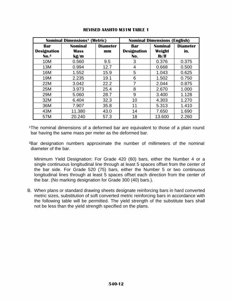
REVISED AASHTO M31M TABLE 1
Nominal Dimensions¹ (Metric) Nominal Dimensions (English) Bar
Designation No.²
Nominal Mass kg/m
Diameter mm
Bar Designation
No.
Nominal Weight lb/lf
Diameter in.
10M 0.560 9.5 3 0.376 0.375 13M 0.994 12.7 4 0.668 0.500 16M 1.552 15.9 5 1.043 0.625 19M 2.235 19.1 6 1.502 0.750 22M 3.042 22.2 7 2.044 0.875 25M 3.973 25.4 8 2.670 1.000 29M 5.060 28.7 9 3.400 1.128 32M 6.404 32.3 10 4.303 1.270 36M 7.907 35.8 11 5.313 1.410 43M 11.380 43.0 14 7.650 1.690 57M 20.240 57.3 18 13.600 2.260
¹The nominal dimensions of a deformed bar are equivalent to those of a plain round bar having the same mass per meter as the deformed bar.
²Bar designation numbers approximate the number of millimeters of the nominal diameter of the bar.
Minimum Yield Designation: For Grade 420 (60) bars, either the Number 4 or a single continuous longitudinal line through at least 5 spaces offset from the center of the bar side. For Grade 520 (75) bars, either the Number 5 or two continuous longitudinal lines through at least 5 spaces offset each direction from the center of the bar. (No marking designation for Grade 300 (40) bars.).
B. When plans or standard drawing sheets designate reinforcing bars in hard converted
metric sizes, substitution of soft converted metric reinforcing bars in accordance with the following table will be permitted. The yield strength of the substitute bars shall not be less than the yield strength specified on the plans.
540-12

SUBSTITUTION OF SOFT-CONVERTED METRIC REINFORCING BARS
Hard-Converted Metric Bar
Substitute Soft-Converted Metric Bar
Bar Size No.
Bar Diameter, mm
Bar Size No.
Bar Diameter, mm
10M 11.3 13M 12.7 15M 16.0 16M 15.9 20M 19.5 19M 19.1 25M 25.2 25M 25.4 30M 29.9 32M 32.3 35M 35.7 36M 35.8 45M 43.7 43M 43.0 55M 56.4 57M 57.3
The substitutions shall be bar for bar at the spacings shown on plans or standard drawing. Adjustments in pay weight will be made for the substitutions as listed in the above table.
C. Grade 420 (60) reinforcing bars may be substituted for Grade 300 (40) reinforcing bars at no additional cost to the Department, except that no substitutions shall be allowed for vertical bars in abutment back walls.
COMMON CONVERSION FACTORS
Convert From Into Multiply By Kilograms (kg) Pounds (lb.) 2.2046
Meters (m) Feet (ft.) 3.2808 Millimeters (mm) Inches (in.) 0.0394
BAR GRADES
Metric Grade Imperial Grade Grade 300 Grade 40 Grade 420 Grade 60 Grade 520 Grade 75
540-13
NEW MEXICO DEPARTMENT OF TRANSPORTATION SUPPLEMENTAL SPECIFICATIONS FOR
SLOPE AND EROSION PROTECTION STRUCTURES
SECTION 602 All provisions of the New Mexico Department Of Transportation's Standard Specifications for Highway and Bridge Construction shall apply except as modified herein. Delete SECTION 602 - SLOPE AND EROSION PROTECTION STRUCTURES in its entirety, and replace with the following: 602.1 DESCRIPTION. 602.11 General Description. This work shall consist of furnishing and placing riprap, gabions, mattresses, sacked concrete revetment, concrete block revetment, wrapped rockfacing, and other systems specified in the contract; on the slopes of embankments and the sides and bottoms of channels, drain outlets, ditches, and other locations shown in the contract. The work shall be performed at the locations shown in the contract, and in compliance with its lines, grades, and dimensions. The types of slope protection structures to be furnished and placed shall be as specified in the contract. In general, the types shall be “W” or hexagonal double-twisted wire mesh riprap, double-twisted wire mesh gabions and/or double-twisted wire mesh mattresses; and/or welded wire mesh gabions and welded wire mesh mattresses and wrapped rockfaces. All types shall be furnished galvanized to conform to ASTM A 641M (ASTM A 641). When specified in the contract, gabions, mattresses, and riprap shall be coated with polyvinyl chloride (PVC) over the galvanizing, in conformance with Subsection 602.222 I below. Specifications for riprap and the double-twisted gabions and mattresses shall conform to the specifications included herein and to ASTM A 975-97, Standard Specification for Double-Twisted Hexagonal Mesh Gabions and Revet Mattresses. Welded wire mesh gabions, mattresses, and wrapped rockfaces shall conform to the specifications included herein and to ASTM A 974-97, Standard Specification for Welded Wire Fabric Gabions and Gabion Mattresses. 602.2 MATERIALS. 602.21 Classifications. Riprap and gabions will be classified as shown in Table 602-A. At least 80 % of the stones used shall meet the specified size requirements. Stones less than the minimum dimensions shown may be used only to fill the voids between stones. For riprap Class A, wrapped rockfaces, and gabions, stones smaller than the least dimension of the mesh openings shall not be used.
602-1

TABLE 602-A
RIPRAP CLASSIFICATIONS & GABION REQUIREMENTS
Class Description Stone Volume Cubic Meters(Cubic Ft.)
*Minimum Dimension, mm (In.)
Min. Max. A Wire Enclosed Riprap 0.005 (1/6) 0.02 (2/3) 100 (4) B Non-Enclosed Riprap 0.03 (1) 0.06 (2) 150 (6) C Non-Enclosed Riprap 0.06 (2) 0.12 (4) 225 (9) D Derrick Stone 0.40 (14) 0.75 (27) 300 E Grouted Riprap 0.01 (1/3) 0.03 (1) 75 F Grouted Riprap 0.03 (1) 0.06 (2) 150 G Rock Plating --- --- **100 to 200 N/A Wrapped Rockfacing --- --- 25 (1) N/A Gabions --- --- **100 to 200 * Minimum size in the least dimension. **Seventy to eighty percent (70%-80%) of the stone shall be at least 100 mm (4
in.) but not more than 200 mm (8 in.) in least dimension. The remainder of the stone shall be no larger than 100 mm (4in.) in any dimension. Class B and C stone shall have at least two fractured faces.
602.22 Riprap, Gabions, and Mattresses. 602.221 Stone for Riprap, Gabions, Mattresses, and Rockfaces. Except for riprap Class G, stone shall be rocks or rough quarry stone with a percent of wear of not more than 60, as determined by AASHTO T 96. The stone shall have a soundness loss of not more than 21, as determined by AASHTO T 104 using a magnesium sulfate solution with a test duration of five cycles. Stone for riprap, gabions mattresses, and rockfaces shall also meet the requirements of Subsection 602.21, Classifications. 602.222 Wire Mesh. The double-twisted wire mesh for riprap, gabions, and mattresses shall form hexagons (or “W’s”, for one type of riprap), and be non-raveling. The double-twisted wire mesh shall meet the strength requirements of Subsection 602.223, Pull-Apart Test, of these Special Provisions. The welded wire mesh for gabions, wrapped rockfaces, and mattresses shall form squares or rectangles, be non-raveling, and shall meet the strength requirements of Subsection 7, Material Properties, of ASTM A974-97, except that the strength requirements for joints of mattresses shall be 1,340 kg/m (900 lb/ft) instead of 890 kg/m (600 lb/ft). A. Wire. The wire used to construct the mesh for riprap, gabions, and mattresses shall
conform to the requirements of ASTM A 641M (ASTM A 641), shall be soft temper, and shall have a Class 3 zinc coating. The wire composing the mesh shall be 3.0 mm (0.120 in.) in diameter for gabions and riprap, and 2.2 mm (0.087 in.) in diameter for revetment mattresses and wrapped rockfaces.
602-2

B. Mesh Openings. The mesh openings shall be uniform in size, with hexagonal
dimensions for riprap and double-twisted gabions measuring approximately 83 mm x 120mm (3 ¼ in. x 4 ¾ in.) and approximately 64 mm x 83 mm (2 ½ in. x 3 ¼ in.) for double-twisted revetment mattresses. The mesh openings for welded wire mesh gabions shall be approximately 76 mm x 76 mm (3 in. x 3 in.), and the openings for welded wire mesh for revetment mattresses and wrapped rockfaces shall be about 38 mm x 76 mm (1 ½ in. x 3 in.). If “W” wire fabric is used for riprap, the mesh openings shall be about 50 mm x 100 mm (2 in. x 4 in.).
C. Selvedges. All edges of standard double-twisted gabions, mattresses and wrapped
rockfaces, including end panels and the diaphragms, if any, shall be mechanically selvedged in such a way to prevent unraveling of the mesh, and to develop the full strength of the mesh. The wire used for the selvedge shall have a diameter of at least 3.8 mm (0.150 in.).
D. Lacing and Tie Wire. Lacing wire for double-twisted gabions, mattresses and
wrapped rockfaces shall be 2.2 mm (0.087 in.) in diameter or larger. Tie wire for double-twisted gabions, mattresses shall be 2.2 mm (0.087 in.) in diameter or larger. Tie wire for riprap shall be 3.0 mm (0.120 in.) in diameter or larger. Lacing and tie wire shall have the same tensile unit strength and type of coating as the wire used to construct the mesh.
E. Spiral Binders. Spiral binders are a standard fastener for welded mesh gabions,
mattresses and wrapped rockfaces, and shall be formed from wire meeting the same quality requirements as specified for the gabions, mattresses and wrapped rockfaces. Wire for spiral binders shall be 2.7 mm (0.106 in.) in diameter or larger. Unless otherwise approved, the maximum inside diameter of the spiral binders shall not exceed 64 mm (2 ½ inches) with a maximum pitch of 76 mm (3 inches).
F. Alternate Fasteners. Alternate fasteners for use with double-twisted wire mesh or
welded mesh riprap, gabions, mattresses or wrapped rockfaces, such as ring fasteners, may be used if approved by the Project Manager. Wire for these fasteners must meet the same quality requirements as specified for the gabions, mattresses, riprap or wrapped rockfaces.
G. Minimum Strength of Fasteners. Standard fasteners, alternate fasteners, and spiral
binders must provide a minimum strength of 2,080 kg/m (1,400 lbs per lineal foot) for gabion baskets, and 1,340 kg/m (900 lbs per foot) for mattresses and wrapped rockfaces.
H. Approval of Alternative Fasteners. Alternative fasteners, including interlocking
fasteners, ring fasteners, and spiral binders, may be used instead of lacing wire, provided that these fasteners will develop joint strengths no less than those specified in “G” above. The fasteners must be tested in accordance with Subsection 602.223, Pull-Apart Test. At least 60 days before using the alternative fasteners, the Contractor shall submit certified test reports to the Project Manager, verifying that
602-3

the alternative fastening system will meet the pull-apart test requirements. The pull-apart testing shall have been completed by a laboratory of verifiable reputation.
The Contractor shall provide a complete description of the fastener system, including drawings and photographs, showing the number of fasteners required, details of the fasteners, and load capacities of the system. Fasteners shall meet the following requirements:
a. Each interlocking fastener shall be locked and closed. For gabions, interlocking
fasteners shall be used in every other opening. For mattresses and wrapped rockfaces, the interlocking fasteners shall be used in every opening.
b. Each overlapping ring fastener shall be closed and the free ends shall overlap a
minimum of 25 mm (1 in.). One ring shall be provided for each opening. This type of fastener may be used in forming the individual baskets, but shall not be allowed in interconnecting the baskets.
I. Polyvinyl Chloride Coating. Polyvinyl coating, when called for on the plans, shall
meet the following requirements:
Thickness of coating: The nominal thickness of the PVC coating shall be 0.55 mm (0.0216 in.) per side. The minimum thickness of the PVC coating shall be 0.38 mm (0.0150 in.) per side. PVC coating shall be applied over the galvanizing. PVC Material Requirements. When PVC coated wire is specified, the galvanized wire shall be coated by extruded or fusion bonded PVC material. The coating color shall be gray or green, unless other colors are specified. The initial properties of the PVC coating shall meet the following requirements:
a. Specific Gravity: In the range of 1.2 to 1.40, ASTM D 792. b. Abrasion Resistance: The percentage of weight loss shall be less than 12 %,
when tested according to ASTM D 1242, Method B at 200 cycles, CSI-A Abrader Tape, 80 grit.
c. Brittleness Temperature: Not higher than 15 F, ASTM D 746. d. Tensile Strength: Extruded Coating - Not less than 2,980 psi, ASTM D 412.
Fusion Bonded Coating - Not less than 2,275 psi, ASTM D 638. e. Modulus of Elasticity: Extruded Coating - Not less than 2,700 psi, at 100 %
strain, ASTM D 412. Fusion Bonded Coating - Not less than 1,980 psi at 100 percent strain, ASTM D 638.
f. Ultraviolet Light Exposure: A test period of not less than 3,000 hours, using
apparatus Type E at 63 C, ASTM G 23. g. Salt Spray Test: A test period of not less than 3,000 hours, ASTM B 117.
602-4

After the exposure to ultraviolet light and the salt spray test as specified above, the PVC coating shall not show cracks, blisters, splits, nor noticeable change of color (surface chalk). In addition, the specific gravity, resistance to abrasion, tensile strength, and modulus of elasticity shall not change more than 6 percent, 10 percent, 25 percent, and 25 percent respectively, from their initial values.
602.223 Pull-Apart Test. A. Sample Preparation. A set of two identical rectangular panels, each with a width of
about 10-1/2 mesh openings along a selvage wire, shall be joined along the two selvage wires by the proposed alternate fastening system. If the fasteners are also to be used to join two individual gabion baskets, two additional selvage wires that are each mechanically wrapped with mesh wires shall be included so that each fastener confines two selvage and two mesh wires.
B. Test Procedures. A new set of jointed panels shall be mounted in a loading machine
with grips or clamps such that the panels are uniformly secured along the full width. The grips or clamps shall be designed to transmit only tension forces. The load shall then be applied at a uniform rate of 23 kg/s (50.7 lbs/s) until failure occurs. The failure is defined as when the maximum load is reached and a drop in strength is observed with subsequent loading, or when the opening between any two of the jointed selvage wires becomes greater than 50 mm (2 in.) at any place along the panel width. The minimum strength of jointed gabion panels at failure shall be 2,080 kg/m (1,400 lb/ft), and the minimum strength of jointed mattress and wrapped rockfaces panels at failure shall be 1,340 kg/m (900 lb/ft).
602.224 Certification. The Contractor shall submit a certificate stating that all wire mesh, gabion baskets, lacing wire, tie wire, and alternate approved fastener systems used in the contract meets the requirements of this specification. The certificate shall be submitted to the Project Manager before the material is incorporated into the work. 602.225 Stakes. Stakes for riprap shall be steel railroad rails, standard weight galvanized steel pipe, or steel angles. Steel railroad rails shall have a unit weight of at least 14.9 kg/m (30 lbs/yd). Standard weight galvanized steel pipe shall be at least 100 mm (4 inches) outside diameter. Steel angles shall be at least 100 by 100 by 9.5 mm (4 x 4 x 3/8 inches) in dimensions. 602.226 Grout. Portland cement, aggregate, and water for grout shall conform to the requirements of Section 510, Portland Cement Concrete. 602.23 Sacked Concrete Revetment. The sacked concrete revetment manufacturer must be listed as an approved vendor on the Department’s “Approved Products Listing.” Bags of sacked concrete shall weigh between 27 and 36 kg (60 and 80 lb) each, dry weight, and shall contain between 0.014 and 0.019 cubic meters (0.018 and 0.025 cubic yards) of concrete material. Each bag shall contain a concrete mix of one part of cement to three parts of sand, or a mix design shown in the contract, or a mix design
602-5

having first been approved by the Central Materials Laboratory. The concrete mix shall be capable of attaining a minimum compressive strength of 24.1 MPa (3500 psi) after 28 days, unless otherwise specified in the contract. The sacked concrete shall be kept in dry storage at all times until application. A. Packaging. Sacks used for concrete riprap shall be made of jute, cotton, or scrim-
reinforced paper, and shall be completely biodegradable and capable of holding the sand-cement mix without significant leakage.
The sack material shall be permeable and shall permit passage of sufficient water to ensure complete hydration of the concrete mix. Paper sacks shall be made of non-asphaltic three-layer laminated paper reinforced with polyester fiber scrim. Paper sack perforations shall be uniform and offset in the three-layer bag to prevent the dry cement from escaping. Only one type and size of sack shall be used throughout the project unless otherwise shown in the contract.
B. Portland Cement. Portland cement shall conform to the requirements of Section 510, Portland Cement Concrete.
C. Aggregate. Aggregate shall conform to the requirements of Section 510, Portland
Cement Concrete, for fine aggregate. C. Steel Anchorage. Steel staples shall conform to the requirements of Section 540,
Steel Reinforcement, and shall be epoxy coated in accordance with AASHTO M 284/M 284 M, or galvanized in accordance with ASTM A 153/A 153 M, Specification for Zinc Coating (Hot-Dip) on iron and steel hardware.
602.24 Concrete Block Revetment. Concrete block revetment products must be listed as approved in the Department’s “Approved Products Listing,” before incorporation into the work. Concrete block revetments shall be of the type and size shown in the contract. Concrete block units shall have a minimum compressive strength of 20.7 MPa (3000 psi), unless otherwise shown in the contract, and shall be compatible with the geotextile(s) (filter fabrics) used in conjunction with this work. 602.3 CONSTRUCTION REQUIREMENTS. 602.31 General Placement Requirements. Slope and erosion protection structures shall be constructed in accordance with the details shown in the contract or established by the Project Manager. Riprap stones shall be placed to form a continuous blanket of the minimum thickness shown in the contract. Unless otherwise specified, Rock Plating (Riprap Class G) shall have a minimum thickness of 300 mm (12 in.) Stones shall be placed with their long
602-6

axis parallel to the toe of the slope, and such that they have stable bearing upon the underlying soil or stones. The larger stones shall be as close to each other as practical, and shall be chinked with smaller stones except when Class E or F (grouted) riprap is called for. The finished surface of the riprap shall not vary more than 75 mm (3 in.) from the designated slope, except that derrick stone riprap shall not vary more than 200 mm (8 in.) from the designated plane. Unless otherwise specified, the foundation course shall be placed in a trench excavated to a depth of 600 mm (24 in.) below the toe of the slope of the embankment or side of channel. A layer of Class 1 geotextile (filter fabric) shall be placed at the interface between all slope and erosion protection structures and the supporting soil or backfill material, or placed as shown in the contract. Slope and erosion protection structures shall be placed in a manner that will not tear or otherwise damage the geotextile. 602.311 Grouted Riprap Placement. Voids in grouted riprap shall be completely filled with grout for the full thickness of the riprap. After the grout is placed, the surface of the riprap shall be swept with a stiff broom. Grout shall be protected from freezing for at least four days after placement. Grouted riprap placed in hot, dry weather shall be cured in accordance with the requirements of Subsection 511.39, Curing. 602.312 Proportioning and Mixing Grout. Grout used in riprap shall consist of one part Portland cement and three parts fine aggregate by volume. The cement and fine aggregate shall be mixed with water to a thick, workable consistency. 602.313 Class A Riprap Placement. The stones in Class A (wire enclosed) riprap shall be enclosed on all sides with wire mesh. The wire mesh shall be drawn tightly against the stone on all sides. Edges of wire mesh may be connected using approved fasteners or lacing wire, but shall be double-loop-woven to adjacent edges at least once with lacing wire to ensure that strength and flexibility at the points of connection are equal to or greater than those of the mesh. Lacing shall be continuous as far as is practicable and shall pass through each mesh opening. Where splicing is necessary, an overlap of lacing of at least 300 mm (12 in.) shall be provided. Galvanized wire ties to connect the top and bottom layers of mesh shall be spaced approximately 600 mm (24 in.) on centers and shall be anchored to the bottom layer of wire fabric, extended through the rock layer, and tied securely to the top layer of wire
602-7
fabric. Wire enclosed riprap shall be anchored to the slopes by steel stakes driven through the riprap into the embankment. Stakes shall be spaced as shown in the contract. 602.314 Placement of Geotextile. Unless otherwise specified, Class 1 non-woven geotextile fabric conforming to the requirements of Section 604, Soil and Drainage Geotextiles (AASHTO M 288) shall be placed between the riprap or mattresses and wrapped rockfaces, and the supporting soil. 602.32 Sacked Concrete Revetment Placement. Placement of sacked concrete revetment shall conform to the details and requirements shown in the contract or as directed by the Project Manager. Sacked concrete revetment shall be placed within a tolerance of 60 mm (2.4 in.) of the established grade and slope. Unless otherwise specified, the foundation course shall be placed in a trench excavated to a depth of 600 mm (24 in.) below the toe of the slope of the embankment or side of channel. The remaining courses shall be placed as shown in the contract, and shall be placed so that sack ends and steel staple anchors in succeeding courses are staggered. Each row of sacks shall be tamped sufficiently to round out the bags, eliminate wrinkles, minimize voids, and prepare an even surface for the next row. The Contractor shall place and compact the backfill behind each row of sacked concrete revetments before placing the next row. The method of compaction shall be as approved by the Project Manager. Backfill adjacent to the bags shall be free of large stones and jagged objects. Sacked concrete revetments shall be anchored using steel staples. Anchoring shall be done in a manner that does not damage the bags excessively. All bags damaged to the point that the integrity of the bag is compromised will be rejected, and shall be replaced at no additional cost to the Department. After placing sacked concrete revetments, the Contractor shall wet it thoroughly and keep it moist for at least three days unless otherwise directed by the Project Manager. 602.33 Concrete Block Revetment Placement. Concrete block revetment systems shall be constructed in strict accordance with the manufacturer’s recommendations and the details shown in the contract. Slopes shall be prepared by removing all obstructions, and by filling voids with approved material or by contouring slopes so that sudden or sharp variations in contour are eliminated.
602-8

602.34 Gabions. Gabions shall be supplied in the dimensions shown in the contract. Gabion dimensions are subject to a tolerance limit of plus or minus five percent of the manufacturer’s stated sizes. 602.341 Assembly of Gabion Baskets. Gabions shall be fabricated so that the sides, ends, lids and diaphragms can be assembled at the construction site into rectangular baskets of the specified sizes. Gabions shall be of single unit construction. Where the length of the gabion exceeds one and one half (1 ½) times the horizontal width, the gabion shall be equally divided by diaphragms composed of the same mesh as the body of the gabions, into cells whose length does not exceed the horizontal width. The gabion shall be furnished with the necessary diaphragms secured in proper position on the base section so that no additional tying at this juncture will be necessary. Perimeter edges shall be securely selvaged or bound so that the joints formed by tying the selvages have strengths equal to or greater than that of the body of the mesh. Perimeter edges of the gabion baskets and diaphragms shall be assembled using approved fasteners or lacing wire. Fasteners, other than lacing wire, shall be placed in each mesh opening. Lacing shall be done by double looping tightly through every other mesh opening. In all cases, gabions shall be assembled by either: 1. Double looped lacing twice, or 2. Connected with approved fasteners and then double looped lacing once. 602.342 Foundation Preparation. The top 150 mm (6 in.) of the gabion foundation shall be leveled and compacted to at least 95% of maximum density. Density requirements will be determined by AASHTO T 99 and field densities will be determined by AASHTO T 205. 602.343 Placement of Gabion Baskets. Assembled, empty gabion baskets shall be set into position as shown in the contract or directed by the Project Manager. So that proper alignment is ensured, gabion stretching shall be effected in a manner approved by the Project Engineer. Each unit shall be securely wired to adjacent units along the top and vertical edges prior to the placing of the stone. 602.344 Placement of Gabion Stone. All baskets are to be completely filled with stone. The stone shall be placed to eliminate as many pockets as possible, and in equal lifts of 0.23 m to 0.30 m (9 in. to 12 in.), depending on the desired finished gabion height. In order to minimize local deformations, gabions shall be filled in stages, and shall not be filled to a height exceeding 0.30m (12 in.) more than an adjoining gabion. Stone at exposed surfaces shall be hand-placed to provide an aesthetic appearance.
602-9

Cross-connecting wires shall be provided on gabions whose cells are 450 mm (18 in.) in height or greater. These cross-connecting wires shall be inserted directly above each lift of stone in a manner shown in the contract or as directed by the Project Manager. Two connecting wires in each direction for each lift shall be equally spaced horizontally and tightly tied through two mesh openings at opposite faces of each gabion cell. Gabions shall be filled in a manner that will result in minimal voids or bulges, will provide the proper alignment, and will give the gabions a neat, square appearance. After filling a gabion, the lid shall be bent over and tightly bound to the perimeters and diaphragms in accordance with Subsection 602.341, Assembly of Gabion Baskets. Gabions having poor alignment or construction will be rejected and shall be reconstructed at no additional cost to the Department. 602.345 Gabion Marking. Each gabion shall be clearly marked by color code or some other readily identifiable means to indicate size. 602.346 Placement of Geotextile. Unless otherwise specified, Class 1 non-woven geotextile filter fabric conforming to the requirements of SECTION 604, SOIL AND DRAINAGE GEOTEXTILES (AASHTO M 288), shall be installed between gabion baskets and the supporting soil, and between gabion baskets and the backfill material. 602.35 Wrapped Rockfacing Placement. Placement of wrapped rockfaces shall conform to the details and requirements shown in the contract or as directed by the Project Manager. Wrapped rockfaces shall be placed within a tolerance of 60 mm (2.4 in.) of the established grade and slope. Unless otherwise specified, the foundation course shall be placed to a depth of 450 mm (18 in.) below the toe of the slope of the embankment or side of channel. The remaining courses shall be placed as shown in the contract. Each level of welded wire forms shall be place with biaxial geogrid as required in the contract. Biaxial geogrid shall be embedded as required in the contract in the embankment face and tensioned with anchor pins to remove slack. Biaxial geogrid shall also be lapped on edge of adjacent panels a minimum of 300 mm (12 in.). Welded wire form face shall be tamped sufficiently to eliminate wrinkles, minimize voids, and prepare an even surface for the next row. The Contractor shall place and compact the backfill behind each welded wire form level before placing the next row. The method of compaction shall be as approved by the Project Manager.
602-10

602.4 METHOD OF MEASUREMENT. 602.41 Riprap, except Class G, will be measured by the cubic meter (cubic yard). Riprap Class G will be measured by the square meter (square yard). Sacked concrete revetment will be measured by the cubic meter (cubic yard). Concrete block revetment will be measured by the square meter (square yard). Gabions will be measured by the cubic meter (cubic yard). Revetment mattresses will be measured by the cubic meter (cubic yard). Wrapped rockfacing will be measured by the square meter (square yard). 602.42 Measurement of riprap will be based on the thickness shown in the contract and the area measured on the surface of the riprap. Measurement of concrete block revetment will be based on the area measured on the surface of the revetment. Measurement of gabions will be based on basket dimensions shown in the contract. Measurement of mattresses will be based on basket dimensions shown in the contract. Measurement of wrapped rockfacing will be based on the area measured on the surface of the wrapped rockface. 602.5 BASIS OF PAYMENT. 602.51 Riprap, except Class G, will be paid for at the contract unit price per cubic meter (cubic yard). Riprap Class G will be paid for at the contract unit price per square meter (square yard). Sacked concrete revetment will be paid for at the contract unit price per cubic meter (cubic yard). Concrete block revetment will be paid for at the contract unit price per square meter (square yard). Gabions will be paid for at the contract unit price per cubic meter (cubic yard). Revetment mattresses will be paid for at the contract unit price per cubic meter (cubic yard).
602-11

Wrapped rockfacing will be paid for at the contract unit price per square meter (square yard). Payment will be made under: Pay Item Pay Unit Riprap Class___ Cubic Meter (Cubic Yard) Riprap Class G Square Meter (Square Yard) Sacked Concrete Revetment Cubic Meter (Cubic Yard) Concrete Block Revetment Square Meter (Square Yard) Gabions Cubic Meter (Cubic Yard) Revetment Mattresses Cubic Meter (Cubic Yard) Wrapped Rockfacing Square Meter (Square Yard) 602.52 Work Included in Payment. The following work and items will be considered as included in the payment for the main item(s) and will not be measured or paid for separately: A. Excavation, backfilling, and disposal of material required for the placement of slope
and erosion protection structures. B. Dewatering. C. Stakes and steel staples required; drainage geotextile(s). D. Biaxial geogrid, crushed stone, welded wire form
602-12

NEW MEXICO DEPARTMENT OF TRANSPORTATION SUPPLEMENTAL SPECIFICATIONS FOR
SOIL & DRAINAGE GEOTEXTILES
SECTION 604 All provisions of the New Mexico Department Of Transportation’s Standard Specifications for Highway and Bridge Construction shall apply except as modified herein. Delete SECTION 604 - SOIL & DRAINAGE GEOTEXTILES, in it's entirety and substitute the following: 604.1 DESCRIPTION. 604.11 General. The Contractor shall furnish geotextiles in conformance with the latest edition of AASHTO M 288, which shall be placed as shown in the contract. 604.2 MATERIALS. 604.21 Classifications. Table 604-A lists the classes to be used for each geotextile application.
TABLE 604-A CROSS REFERENCE OF OLD CLASSES TO NEW CLASSES OF GEOTEXTILES
Geotextile Previous Class Current Class Subsurface Drainage A or B 2 or 3 Sediment Control B 2 Erosion Control C or D 1 or 2 Separation C or D 2 or 3 Stabilization None 1
Note: Class 1 is specified for more severe or harsh installation conditions where there is a great potential for geotextile damage, and Class 2 and 3 are specified for less severe conditions 604.22 Geotextiles for Subsurface Drainage. 604.221 Subsurface Drainage Geotextiles. This work shall consist of furnishing and placing a geotextile fabric (woven slit film geotextiles or geotextiles made from yarns of a flat tape-like character will not be allowed.) against a soil, in an underground drainage system, or in an edgedrain. The purpose is to allow for long-term passage of water into a subsurface drain system retaining the in situ soil. The primary function of the geotextile in subsurface drainage applications is filtration.
604-1

In this application, one soil sample shall be taken by the Contractor and will be tested by the Department to confirm the applicable apparent opening size (AOS) based on the percent in situ soil passing the 0.075 mm (-200) sieve, and cohesiveness (P.I.). The aggregate shall be compacted with vibratory equipment to a minimum compaction of ninety five percent (95%) of AASHTO T 99. If a higher compactive effort is required, a geotextile suited for more severe installation conditions shall be substituted. Subsurface Drainage Geotextiles shall be Class 2 or Class 3. Class 2 Subsurface Drainage Applications. Class 2 Geotextiles are for drain system installations which require use of very coarse sharp angular aggregate of 25 mm (1") diameter or greater, or require a depth of trench greater than two (2) meters (six (6) feet). Class 3 Subsurface Drainage Applications. Class 3 Geotextiles shall allow long-term passage of water into a subsurface drain system, thus retaining the in-situ soil. Class 3 Geotextiles are for general underdrain installations which require smooth graded surfaces having no sharp angular projections, and fine aggregate is used. 604.23 Sediment Control Geotextiles. This work shall consist of furnishing, placing and maintaining geotextiles for temporary sediment control measures. The purpose is to prevent the eroded soil from being transported off the construction site to rivers, streams, and impoundments, and prevent damage to private property from storm water runoff. Sediment Control Geotextiles shall be Class 2. 604.24 Erosion Control Geotextiles. This work shall consist of furnishing, placing, constructing, and maintaining a geotextile between erosion control structures (rip-rap and gabions), and the in situ soil. The purpose is to prevent soil loss resulting in excessive scour, and to prevent hydraulic uplift pressures that may cause instability of the erosion control structure. Woven slit film geotextiles or geotextiles made from yarns of a flat tape-like character shall not be allowed. When a Woven Monofilament geotextile is used then the geotextile class shall be Class 2. All other geotextiles shall be Class 1. Geotextiles for Erosion Control Structures shall be Class 1 or Class 2. 604.25 Geotextiles for Separation Applications. 604.251 Separation Geotextiles. This work shall consist of furnishing and placing a geotextile fabric to serve as a semi-permeable separator. The purpose is to prevent mixing of a subgrade soil and sub-base or base material. The separator geotextile is appropriate for pavement structures constructed over soils with an R-value greater than 20. Separator geotextiles may be made of woven, or non-woven material. Separation Geotextiles shall be Class 2 or Class 3.
604-2
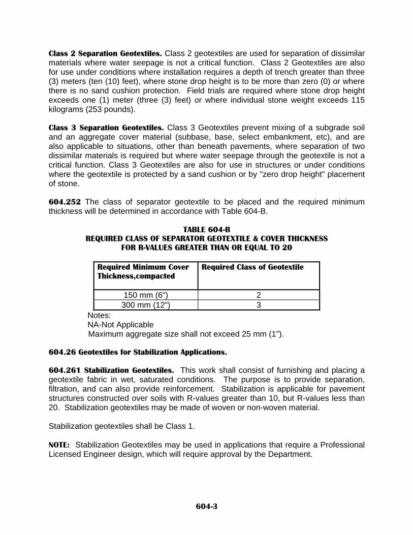
Class 2 Separation Geotextiles. Class 2 geotextiles are used for separation of dissimilar materials where water seepage is not a critical function. Class 2 Geotextiles are also for use under conditions where installation requires a depth of trench greater than three (3) meters (ten (10) feet), where stone drop height is to be more than zero (0) or where there is no sand cushion protection. Field trials are required where stone drop height exceeds one (1) meter (three (3) feet) or where individual stone weight exceeds 115 kilograms (253 pounds). Class 3 Separation Geotextiles. Class 3 Geotextiles prevent mixing of a subgrade soil and an aggregate cover material (subbase, base, select embankment, etc), and are also applicable to situations, other than beneath pavements, where separation of two dissimilar materials is required but where water seepage through the geotextile is not a critical function. Class 3 Geotextiles are also for use in structures or under conditions where the geotextile is protected by a sand cushion or by "zero drop height" placement of stone. 604.252 The class of separator geotextile to be placed and the required minimum thickness will be determined in accordance with Table 604-B.
TABLE 604-B REQUIRED CLASS OF SEPARATOR GEOTEXTILE & COVER THICKNESS
FOR R-VALUES GREATER THAN OR EQUAL TO 20
Required Minimum Cover Thickness,compacted
Required Class of Geotextile
150 mm (6") 2 300 mm (12") 3
Notes: NA-Not Applicable Maximum aggregate size shall not exceed 25 mm (1").
604.26 Geotextiles for Stabilization Applications. 604.261 Stabilization Geotextiles. This work shall consist of furnishing and placing a geotextile fabric in wet, saturated conditions. The purpose is to provide separation, filtration, and can also provide reinforcement. Stabilization is applicable for pavement structures constructed over soils with R-values greater than 10, but R-values less than 20. Stabilization geotextiles may be made of woven or non-woven material. Stabilization geotextiles shall be Class 1. NOTE: Stabilization Geotextiles may be used in applications that require a Professional Licensed Engineer design, which will require approval by the Department.
604-3

604.27 Certification. For each class of geotextile fabric, the Contractor shall furnish, from the manufacturer, a certificate stating that the geotextile furnished meets the physical and chemical requirements of the latest edition of AASHTO M 288, and that geotextile fabric meets soil strength (R-value) requirements for the respective application. The certification shall also include the product name, chemical composition of the filaments or yarns, or other pertinent information to fully describe the geotextile. The certification shall be furnished to the Project Manager prior to geotextile placement. 604.28 R-Values corresponding to California Bearing Ratios used in AASHTO M 288 are presented in Table 604-C.
TABLE 604-C CBR VALUES USED IN AASHTO M 288 AND CORRESPONDING R-VALUES
Soil Strength (CBR) Corresponding R-Value
1 10 2 15 3 20
604.3 CONSTRUCTION REQUIREMENTS. 604.31 General. The following shall apply to each geotextile application: 604.311 Geotextile Packaging, Storage and Handling. Each geotextile roll shall be wrapped with a material that will protect the geotextile, including the ends of the roll, from damage due to shipment, water, sunlight, and contaminants. During storage, geotextile rolls shall be elevated off the ground and adequately covered to protect them from the following: Site construction damage (tearing, excessive mud, wet cement, or epoxy), precipitation, extended ultraviolet radiation including direct sunlight, chemicals that are strong acids or strong bases, flames including welding sparks, and temperatures above 71° C (1600 F) and below-30° C (-220 F). 604.312 Geotextile Exposure Following Placement. Exposure of geotextiles to the elements following laydown shall not exceed fourteen (14) days, unless otherwise directed by the Project Manager. 604.313 Site Preparation. The installation site of each geotextile shall be prepared by clearing and grading the area and preparing a firm, smooth surface on which to lay geotextiles, as required in the contract. The Contractor shall remove all sharp objects, large stones, and shall cut trees and shrubs flush with its specific application.
604-4

The Contractor shall ensure correct orientation (roll direction). Geotextiles shall be placed as smoothly as possible on the prepared surface, pulled tight, aligned, and anchored such that the geotextile is wrinkle free and does not show evidence of holes, tears, or rips before placing cover material upon the geotextile. Prior to placement of cover material, geotextiles may be held in place by pins, staples, or piles of fill or rock as required by fill placement procedures. On curves, geotextiles may be folded or cut to conform to the curve. Vehicles shall not be allowed directly on any geotextile unless 150 mm (6") of material has been placed on the geotextile. Vehicles shall also not be allowed to turn on this first lift above the geotextile. 604.314 Backfill. Backfill operations shall not commence until approval by the Project Manager is obtained. Backfill should not be end dumped directly onto exposed geotextile. The backfill material shall be placed by end dumping onto previously spread backfill and then pushing the dumped backfill over the exposed geotextile using a motor grader or bulldozer. On subgrades having an R-value less than 10, the material placed on the geotextile shall be dumped and spread simultaneously to minimize the potential of a localized subgrade failure. Each lift of backfill shall not exceed 200 mm (8 inches) uncompacted depth unless otherwise specified in the contract. After placement, each lift shall then be compacted to ninety five percent (95%) of maximum density as determined by AASHTO T 99, Method C. The use of vibratory compaction equipment will be allowed on initial lifts of material, if approved by the Project Manager. A minimum lift thickness of 150 mm (6 inches) shall be maintained. Ruts occurring during construction shall be filled with additional material and compacted to the specified density to maintain an even backfill surface and the minimum lift thickness over the geotextile. The Project Manager prior to covering shall approve all geotextile placements. 604.32 Subsurface Drainage Geotextiles. Geotextiles shall be placed and as shown in the contract, and in accordance with SECTION 605 - DRAINS, where applicable. In repairing subsurface drainage geotextiles, the Contractor shall clear all damaged areas and repair in accordance with the manufacturer's recommendations. The Project Manager shall approve all repairs. 604.33 Sediment Control Geotextiles. Geotextiles shall be placed shown in the contract, and in accordance with SECTION 603 - TEMPORARY EROSION & SEDIMENT CONTROL, where applicable.
604-5

In repairing sediment control geotextiles, the Contractor shall clear the damaged area and repair in accordance with the manufacturer's recommendations. The Project Manager shall approve all repairs. 604.34 Erosion Control Geotextiles. Geotextiles shall be placed as shown in the contract, and in accordance with SECTION 602 - SLOPE & EROSION PROTECTION STRUCTURES, where applicable. In repairing erosion control geotextiles, the Contractor shall clear the damaged area and repair in accordance with the manufacturer's recommendations. The Project Manager shall approve all repairs. 604.35 Separation/Stabilization Geotextiles. When using geotextiles for separation and stabilization, they shall be placed as shown in the contract or as per manufacturer's recommendations, whichever is more stringent. Adjacent geotextile rolls shall be folded, overlapped, sewn, or joined as shown in TABLE 604-D unless manufacturer's recommendations or specific applications detailed in the contract are more stringent.
TABLE 604-D MINIMUM GEOTEXTILE OVERLAP REQUIREMENTS FOR SEPARATION/STABILIZATION GEOTEXTILES
Soil Strength R Value Un-Sewn Seams Overlap
Millimeters (inches) Sewn Seams Overlap Millimeters (inches)
Less than 10 -- 230 (9) 10 to 15 1000 (40) 200 (8) 15 to 20 750 (30) 75 (3)
Greater than 20 600 (24) --- NOTE: Both factory and field sewn or sealed seams shall meet or exceed the strength requirements as required by the manufacturer. 604.351 Repair of Damaged Seperation/Stabilization Geotextiles. Damaged geotextiles shall be repaired immediately. The Contractor shall clear the damaged area plus an additional one (1) meter (three (3) feet) around the damaged area and repaired in accordance with Table 604-D, unless manufacturer's recommendations or specific applications detailed in the contract are more stringent. The Contractor shall replace any removed cover material and compact to the specified density.
604-6

604.4 METHOD OF MEASUREMENT. 604.41 Geotextiles of the Class specified, or as required by the Project Manager, will be measured by the square meter (square yard). Measurement will be based on dimensions shown in the contract. Overlaps will not be measured for payment. 604.5 BASIS OF PAYMENT. 604.51 Geotextiles will be paid for at the contract unit price per square meter (square yard). Payment will be made under: Pay Item Pay Unit Geotextile Class____ Square Meter (Square Yard) 604.52 Work Included in Payment. The following work and items will be considered as included in the payment for the main item(s) and will not be measured or paid for separately: Repair of damaged geotextile fabric as a result of the Contractor's negligence, improper shipping, handling, packaging, or storing. Geotextile packaging, storage and handling. Overlaps, anchoring, splicing and seam assemblies.
604-7

NEW MEXICO DEPARTMENT OF TRANSPORTATION SUPPLEMENTAL SPECIFICATIONS FOR
METAL AND CONCRETE WALL BARRIER
SECTION 606 All provisions of the New Mexico Department Of Transportation’s Standard Specifications for Highway And Bridge Construction shall apply except as modified herein: Delete SECTION 606 – METAL AND CONCRETE WALL BARRIER in its entirety and substitute the following: 606.1 DESCRIPTION. 606.11 This work shall consist of the construction of metal barrier and end treatments, and concrete wall barrier (CWB) in compliance with these specifications, manufacturer’s recommendations, manufacturer’s approved shop drawings and the lines, grades, and dimensions shown in the contract. Unless otherwise specified, the Contractor shall furnish all materials, labor, tools, equipment, and any other appurtenances necessary to complete the work. The construction shall include the assembly and erection of all component parts and materials. 606.12 Metal Barrier and End Treatments. The types of metal barrier are designated as follows: A. W-Beam Metal Barrier B. Thrie Beam Metal Barrier C. W-Beam Weathering Metal Barrier D. Thrie Beam Weathering Metal Barrier The types of end treatments are: A. Metal Barrier End Treatment-Type B (See note Below) B. Metal Barrier End Treatment-Departure End: Type 1, Type 2 (See Table 606-A),
Type A (Turndown), or Type D (Buried in backslope). C. Metal Barrier End Treatment-Approach End: Type 1, Type 2, or Type D as per
subsection 606.24 Metal Barrier End Treatments. Note: The use of metal barrier end treatment Type B shall be limited to curved guardrail installations on low-volume, low-speed roadways as detailed in the contract.
606-1

606.13 Concrete Wall Barrier. The types of CWB are designated as: A. Slip-formed CWB B. Cast-in-place CWB C. Precast CWB The construction of the various types of CWB shall include foundation preparation, component parts, and materials complete at the locations shown in the contract. 606.131 Concrete Wall Barrier Access Panel. This work shall consist of furnishing and installing concrete wall barrier access panels in compliance with the lines, grades, dimensions, and details shown in the contract or as directed by the Project Manager. The steel access panel shall be contoured to the shape of and shall be flush with the concrete wall barrier. The steel access panel shall not compromise the structural integrity and performance of the concrete wall barrier assembly. The steel shall be AASHTO M 270, Grade 36. The steel access panel shall be coated in conformance with SECTION 545 – PROTECTIVE COATING OF MISCELLANEOUS STRUCTURAL STEEL. 606.2 MATERIALS. 606.21 Metal Barrier Elements. Materials used for metal barrier installations shall comply with those detailed in A Guide to Standardized Highway Barrier Hardware, 1995, AASHTO-AGC-ARTBA Report. 606.211 Rail Elements. A. Galvanized Metal Barrier. W-beam and thrie beam rail elements shall consist of a
corrugated beam conforming to the requirements of AASHTO M 180, Type II, Class A.
Steel rail elements may be galvanized before or after fabrication, in accordance with
the requirements of AASHTO M 180. The wire rope or wire cable, and required fittings, shall conform to the requirements
of AASHTO M 30 for the specified diameter and strength class. B. Weathering Metal Barrier. W-beam and thrie beam materials for corrosion-resistant
“weathering” metal barrier shall comply with the requirements of AASHTO M 180, Type IV, Class A, and ASTM A 606-90 Type IV, having a corrosion resistance at least four times that of plain carbon steel.
606.212 Fasteners. Fasteners include bolts, nuts, and washers. Unless otherwise specified, all fasteners shall be galvanized in accordance with the current requirements
606-2

of AASHTO M 111 or ASTM A 153, whichever may apply. All galvanizing shall be done after fabrication. Bolts shall conform to the requirements of ASTM A 307 and nuts to the requirements of ASTM A 563, Grade A or better. Fasteners for weathering metal barrier shall conform to the requirements of AASHTO M 180 for Type IV beams. 606.213 Posts. Posts include post, blocks, support angles, and support plates. A. Wood Posts and Wood Blocks. Wood posts and wood blocks shall be southern
yellow pine, western larch, ponderosa pine, douglas fir, or lodgepole pine and shall be either rough sawn (unplaned) or S4S with nominal dimensions indicated and with a stress grade of at least 8275 kPa (1200 psi).
The size tolerance of rough-sawn blocks in the direction of the boltholes shall be
within ± 6 mm (1/4 in.) of specified dimensions. Only one combination of post and block shall be used for any one continuous length of barrier.
Posts shall be straight and free from all defects, and shall not vary more than 25 mm
(1 in.) from a straight line connecting both ends. The cutting, framing, routing, and boring shall be done before the timber receives a
preservative treatment. Wood posts and blocks shall be pressure treated with petroleum-pentachlorophenol consisting of not more than 95 parts by weight of petroleum oil and not less than five parts by weight of pentachlorophenol, with ammoniacal copper arsenite, or with chromated copper arsenate. The empty-cell process shall be used for petroleum-pentachlorophenol treatment. The amount of pentachlorophenol retained shall be at least 4.8 kg of dry salt per m3 (0.3 lb of dry salt per ft3) of wood. Treatment with ammoniacal copper arsenite or chromated copper arsenate shall be done in accordance with the requirements of American Wood Preservers Association (AWPA) C14.
Wood preservatives shall conform to the requirements of AASHTO M 133. B. Structural Shape Posts and Blocks. Structural shape posts shall conform to ASTM A
36 and shall be galvanized in accordance with ASTM A 123. No punching, drilling, or cutting will be permitted after galvanizing. Blocks used with metal barrier shall comply with the requirements of NCHRP Report 350.
The wood blocks shall conform to subsection A. Wood Posts &Wood Blocks, above. The plastic blocks shall be selected from the Department’s listing of “Approved Products for Plastic Blockouts”, contact the State Maintenance Bureau at (505) 827-5525.
606-3

Suppliers of plastic blocks proposed for inclusion on the Department’s “Approved Products Listing” shall submit certification for approval by the Traffic Services Engineer.
606.22 Concrete Wall Barrier. Concrete shall be Class A and conform to the provisions of SECTION 510, PORTLAND CEMENT CONCRETE. Reinforcing steel shall conform to the requirements of SECTION 540, STEEL REINFORCEMENT. Preformed bituminous joint filler shall comply with the requirements of AASHTO M 213. Penetrating water repellent shall comply with the requirements of SECTION 532, PENETRATING WATER REPELLENT TREATMENT. 606.23 Materials Certification. The Contractor shall furnish mill test reports and other test reports to the Project Manager, certifying that all materials and fabrication comply with these specifications. Fabrication shall be done by an identifiable source. These reports shall show the results of physical and chemical tests of the metal and its coating. 606.24 Metal Barrier End Treatments. All materials shall be new, of quality workmanship, and of the size indicated by the manufacturer. Metal barrier end treatments shall be selected from subsection 606.12 Metal Barrier and End Treatments. Pre-qualification Requirements. Suppliers of metal barrier end treatments proposed for inclusion on the Department’s Approved Products Listing shall submit certification for approval by the Traffic Services Engineer. The certification shall be a signed and notarized statement prepared by the manufacturer stating that the materials proposed for use have met the testing requirements as indicated in NCHRP Report 350. The Contractor shall furnish to the Project Manager for approval, the manufacturer’s certificates, literature, and shop drawings prior to fabrication and installation of the terminal and its transition.
606-4

Approved Systems. The types of approved metal barrier end treatments for Types 1 and 2 are listed below in Table 606-A
Table 606-A Metal Barrier End Treatments
Type End Treatment
System System Length
# of Posts
Begin Length of Need
Acceptable Offset or Flare
Manufacturer
1 SKT 350 50’-0” 8 Third Post 25:1 Road Systems
1 ET Plus 50’ 50’-0” 8 Third Post 25:1 Trinity Industries
2 ET Plus 37’-6” 37’-6” 7 Third Post 25:1 Trinity Industries
2 FLEAT 350 37’-6” 7 Third Post Varies 2’-6” to 4’-0”
Road Systems
Usage for Types 1 and 2 End Treatment Systems. The 50’ length systems (Type 1) shall be used on all roadways with a speed of 65 mph or greater or as specified in the contract or by the District Traffic Engineer. The 37’- 6” length systems (Type 2) shall be used on all other roadways or as specified in the contract or by the District Traffic Engineer. The entire face of the impact head shall be covered with one continuous piece of Type VII reflective yellow sheeting with 3” strips of black tape, spaced 2 ¾” apart, and sloping downward at a 45° angle toward the side of the guardrail on which traffic is to pass, unless otherwise specified by the District Traffic Engineer. 606.25 Member Identification and Marking. The manufacturer shall permanently stamp the specific type of metal barrier end treatment being used at each location, so that each is readily identifiable in the field. The permanent stamp shall correspond with those shown on the shop drawings provided to the Project Manager. 606.26 Reflective Barrier Delineators. Reflective barrier delineators shall be of the types shown in the contract, shall be amber in color when placed on median barrier, or white when placed on shoulder-side barrier. When placed on median barrier, reflective barrier delineators shall be placed back to back. Reference is made to SECTION 703 - TRAFFIC MARKERS. 606.3 CONSTRUCTION REQUIREMENTS. 606.31 During construction the Contractor shall take all necessary precautions to prevent all exposed metal or concrete barrier ends from becoming a hazard to the traveling public as approved by the Project Manager.
606-5

606.32 Metal Barrier Installation. Steel parts stored in transit, in open cars or trucks, or outside in yards or at job sites shall be positioned to allow free drainage and air circulation. All fabricated steel parts shall be handled with care to avoid gouges, scratches, and dents. The steel shall be kept clean of all foreign material such as paint, grease, oil, chalk marks, crayon marks, concrete spatter, or other deleterious substances. When weathering metal barrier is called for, natural oxidation of the steel will not be considered foreign material. Coating, galvanizing, blast cleaning, or pickling of weathering metal barrier to remove mill scale will not be required. All bolts except adjustment bolts shall be drawn tight. Bolts shall be of sufficient length to extend beyond the nuts. 606.321 Posts. Posts shall be set plumb, in hand-dug or mechanically made holes, or by driving. If upward vertical adjustment of posts is necessary, the post shall be removed and reinstalled. The method of driving shall be such as to avoid battering or distorting the posts. Driving of steel posts will be permitted through the bituminous surfacing. Driving of wooden posts will not be permitted through bituminous surfacing unless guide holes are precut or drilled through the bituminous material. In all cases, post drilling and driving shall be performed in a manner that does not cause bulging, distressing, or other disturbance of the bituminous surface. Post holes shall be backfilled with acceptable material such as base course or cold mix, that shall be placed in layers. Each layer shall be compacted with hand operated tamping equipment to not less than 95% of maximum density. Any damaged bituminous surfacing material shall be replaced with approved bituminous surfacing material or cold mix and shall be thoroughly compacted. Concrete may be used in lieu of bituminous surfacing material if the hot mix plant has been removed or is no longer operational at no additional cost to the Department and when approved by the Project Manager. Should bulging or other distress of the bituminous surfacing occur when driving steel posts, these posts shall be removed and reinstalled utilizing guide holes drilled through the bituminous surfacing. The guide holes shall have a maximum diameter in accordance with Table 606-B.
606-6

Table 606-B REQUIRED GUIDE HOLE DIAMETER
Type Maximum Diameter Round Wood Diameter of Post Square Wood Dimension of Side Steel Shape Dimension of Least Side
After the guide holes have been precut or drilled, if bulging or other distress of the bituminous surfacing occurs during post driving, or if posts are prevented from being driven to the designated depths, the driving shall cease. The post(s) shall then be removed, and the guide holes shall be extended as necessary. 606.322 Metal Rail Installation. Rail elements shall be erected in a manner resulting in a smooth, continuous installation. Rails shall be overlapped in the same direction as the traffic flow of the nearest lane. Only such drilling or cutting as may be necessary for special connections and for sampling will be permitted in the field. Rails to be erected on a radius of 45 m (150 ft) or less shall be shop curved to the appropriate curvature of the installation. 606.324 Repair of Damaged Coating. Where the galvanizing of metal barrier or appurtenances has been damaged, the coating shall be repaired by galvanizing or by coating with two coats of zinc dust-zinc oxide paint conforming to Federal Specifications TT-P-641 or ML-P-21035. 606.33 Concrete Wall Barrier. Permanent CWB may be cast in place, precast, or slip formed. All precast CWB shall be of the same length and design, and intermixing will not be allowed. The Contractor shall be responsible for damage to precast CWB occurring in any phase of the work. The Project Manager will be the sole judge as to the severity of the damage and may either reject or accept the damaged precast CWB. In the event that a precast CWB is rejected because of damage, the Contractor shall replace or repair it at no additional cost to the Department. 606.331 Concrete Wall Barrier Fabrication. All fabrication of CWB shall be accomplished in accordance with the applicable provisions of SECTION 510, PORTLAND CEMENT CONCRETE, and SECTION 511, CONCRETE STRUCTURES. Temporary precast CWB shall be constructed in 3-m (10-ft) units true to the lines and grades shown in the contract. Permanent CWB shall be constructed true to line and grade, and the top of the completed barrier shall not deviate more than ± 5 mm (0.19 in.). The CWB shall have a Class 2, Rubbed Surface Finish, or Special Surface Finish, complying with the
606-7

requirements of subsection 511.38, Finishing; and shall be smooth, dense, and free of air bubble pockets, pits, depressions, honeycombs, and other irregularities. Sandblasting, if required by the manufacturer, shall be accomplished such that mortar used in the surface finish is not displaced from the bubble pockets, pits, depressions, and honeycombs. CWB shall be cured in conformance with the requirements of subsection 511.39, Curing. The entire exposed surfaces of CWB shall be treated with penetrating water-repellent treatment in accordance with SECTION 532, PENETRATING WATER REPELLENT TREATMENT. When called for in the contract, penetrating water repellent shall be applied first, and then the Special Surface Finish. Fly ash will not be required in the Portland cement concrete used to fabricate temporary traffic control CWB. 606.332 CWB Joint Treatment. When transverse weakened-plane joints are sawed, the sawing shall be done at such time that no raveling will occur and when the concrete has hardened sufficiently so that no crumbling or shape deformation will occur when the forms are removed. Control joints shall be sawed at intervals of 3 m (10 ft). After completion of sawing operations, the sawed area shall be thoroughly cleaned of all debris. A construction joint shall be made at the end of each day of permanent placement operations and at any point where concrete placement is interrupted for 30 minutes or more. 606.333 Concrete Wall Barrier Installation. The Contractor shall construct all footings and foundations, and prepare the subgrade as necessary, before the placement of CWB as shown in the contract. Vertically offset (atypical) CWB shall be constructed to the lines, grades, and dimensions shown in the contract. A. Temporary Concrete Wall Barrier Requirements. Temporary CWB shall be precast
and be of the same length and design as shown in the contract. Intermixing of CWB shapes shall not be allowed. The Contractor shall set temporary CWB at the locations shown in the contract in accordance with the requirements for traffic control. The Contractor shall provide all loading, hauling, and unloading necessary for use at designated sites as shown in the contract.
When resetting of CWB is called for, the Contractor shall reset the required CWB
during construction at the locations shown in the contract.
606-8

After completion of the project the Contractor shall remove, load, haul, unload, and
stockpile the State-retained or State-furnished CWB at the locations designated in the contract or as determined by the Project Manager.
CWB Retained by the State, State Furnished CWB, and Temporary CWB Retained by the Contractor shall meet all applicable requirements of subsection 606.33 Concrete Wall Barrier.
B. Temporary CWB (Concrete Wall Barrier Retained by the State). When the contract
calls for CWB Retained by the State, the Contractor shall furnish new CWB at the locations shown in the contract.
New CWB complete with shop drawings and all connecting hardware, as approved by the Project Manager, shall become the property of the Department upon completion of the project.
C. State-Furnished Concrete Wall Barrier. When the contract calls for State-Furnished
CWB, the Contractor shall load, haul, and unload State-Furnished CWB from origin(s) to destination(s) as shown in the contract.
State-Furnished CWB shall remain the property of the Department upon completion
of the project. When State-Furnished CWB is provided, the Contractor shall provide all missing
connecting hardware for the CWB assembly, as shown in the contract, if none is included.
D. Temporary Concrete Wall Barrier Retained by the Contractor. When the Contract
calls for Temporary CWB Retained by the Contractor, the Contractor shall furnish new or used CWB, at the locations shown in the contract.
Temporary CWB Retained by the Contractor will remain the property of the
Contractor upon completion of the project. The Contractor shall also provide connecting hardware for the CWB assembly as
shown in the contract. 606.34 Metal Barrier End Treatment. Metal barrier end treatment systems shall be fabricated and installed in accordance with the manufacturer’s recommendations and approved shop drawings, and as specified in the contract. Posts shall be installed according to Subsection 606.321 Posts with the following exceptions: Metal barrier end treatment breakaway posts shall be set plumb, in hand-dug or mechanically made holes, and shall not be driven. Postholes shall be backfilled with existing materials or materials such as base course or cold mix. The postholes shall be
606-9
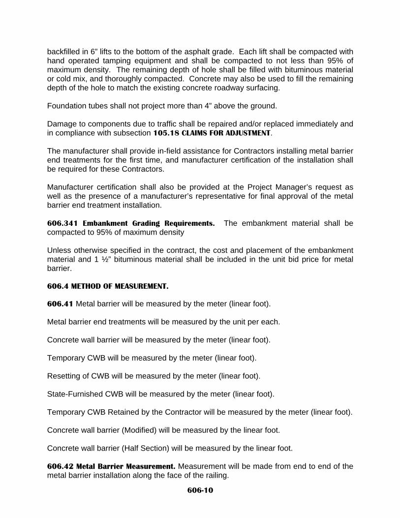
backfilled in 6” lifts to the bottom of the asphalt grade. Each lift shall be compacted with hand operated tamping equipment and shall be compacted to not less than 95% of maximum density. The remaining depth of hole shall be filled with bituminous material or cold mix, and thoroughly compacted. Concrete may also be used to fill the remaining depth of the hole to match the existing concrete roadway surfacing. Foundation tubes shall not project more than 4” above the ground. Damage to components due to traffic shall be repaired and/or replaced immediately and in compliance with subsection 105.18 CLAIMS FOR ADJUSTMENT. The manufacturer shall provide in-field assistance for Contractors installing metal barrier end treatments for the first time, and manufacturer certification of the installation shall be required for these Contractors. Manufacturer certification shall also be provided at the Project Manager’s request as well as the presence of a manufacturer’s representative for final approval of the metal barrier end treatment installation. 606.341 Embankment Grading Requirements. The embankment material shall be compacted to 95% of maximum density Unless otherwise specified in the contract, the cost and placement of the embankment material and 1 ½” bituminous material shall be included in the unit bid price for metal barrier. 606.4 METHOD OF MEASUREMENT. 606.41 Metal barrier will be measured by the meter (linear foot). Metal barrier end treatments will be measured by the unit per each. Concrete wall barrier will be measured by the meter (linear foot). Temporary CWB will be measured by the meter (linear foot). Resetting of CWB will be measured by the meter (linear foot). State-Furnished CWB will be measured by the meter (linear foot). Temporary CWB Retained by the Contractor will be measured by the meter (linear foot). Concrete wall barrier (Modified) will be measured by the linear foot. Concrete wall barrier (Half Section) will be measured by the linear foot. 606.42 Metal Barrier Measurement. Measurement will be made from end to end of the metal barrier installation along the face of the railing.
606-10

Measurement of metal barrier shall include the W-beam portion of the end treatment for types B, and D end treatment systems. Measurement of metal barrier (25’ section) is included in the type A end treatment systems. Measurement of metal barrier (50’ section and 37’-6” section) is included in the types 1 and 2 end treatment systems. Measurement for metal barrier thrie beam shall include all W-beam to thrie-beam transitions sections. Double sections of twelve foot - six inch (12’-6”) thrie beam used for thrie beam to CWB transitions will not be measured, but shall be included in the cost of metal barrier thrie beam and will not be paid for separately. 606.43 Concrete Wall Barrier Measurement. Concrete wall barrier will be measured along the centerline of the barrier. 606.5 BASIS OF PAYMENT. 606.51 Metal barrier will be paid for at the contract unit price per meter. (linear foot). Metal barrier end treatment will be paid for at the contract unit price per each. Concrete wall barrier will be paid for at the contract unit price per meter (linear foot). Temporary CWB will be paid for at the contract unit price per meter (linear foot). Resetting of CWB will be paid for at the contract unit price per meter (linear foot). State-Furnished CWB will be paid for at the contract unit price per meter (linear foot). Temporary CWB Retained by the Contractor will be paid for at the contract unit price per meter (linear foot). Concrete wall barrier (Modified) will be paid for at the contract unit price per meter (linear foot). Concrete wall barrier (Half Section) will be paid for at the contract unit price per meter (linear foot).
606-11

Payment will be made under: Pay Item Pay Unit Metal Barrier W-Beam Meter (Linear Foot) Metal Barrier Thrie Beam Meter (Linear Foot) Metal Barrier End Treatment Each Weathering Metal Barrier W-Beam Meter (Linear Foot) Weathering Metal Barrier Thrie Beam Meter (Linear Foot) Concrete Wall Barrier ______mm Meter (Linear Foot) Temporary Concrete Wall Barrier Meter (Linear Foot) Resetting of CWB Meter (Linear Foot) State-Furnished CWB Meter (Linear Foot) Temporary CWB Retained by the Contractor Meter (Linear Foot) Concrete Wall Barrier (Modified) Meter (Linear Foot) Concrete Wall Barrier (Half Section) Meter (Linear Foot) 606.52 Work Included in Payment. The following work and items will be considered as included in the payment for the main item(s) and will not be measured or paid for separately: A. All loading, hauling, unloading, stockpiling, or disposal. B. Footings, foundations, and subgrade preparation. C. Reflective sheeting and reflectors installed on metal barrier and impact head of end
treatment. D. All connecting hardware. E. Reflective barrier delineators installed on permanent and temporary CWB. F. Curing of CWB and application of penetrating water-repellent treatment. G. Backfilling and compacting of holes created by removal and installation of posts. H. Patching material at posts. I. Connection pins for temporary CWB. J. Concrete wall barrier access panel. K. Reinforcing Steel.
606-12

L. W-Beam to Thrie-Beam transition sections (Included in the measurement and
payment for thrie-beam). M. Double sections of twelve foot - six inch (12’-6”) thrie-beam used for thrie beam to
CWB transitions (Not included in the measurement, but shall be included in the payment for thrie beam).
N. Metal barrier end treatment posts, sleeves, rail and impact head. O. Embankment material and 1 ½” layer of bituminous material for the 1:10 (10:1)
slope.
606-13

NEW MEXICO DEPARTMENT OF TRANSPORTATION SUPPLEMENTAL SPECIFICATIONS FOR
TRAFFIC SIGNS & SIGN STRUCTURES
SECTION 701 All provisions of the New Mexico Department Of Transportation’s Standard Specifications for Highway and Bridge Construction shall apply except as modified herein. Delete SECTION 701 - TRAFFIC SIGNS & SIGN STRUCTURES in its entirety and substitute the following: 701.1 DESCRIPTION. 701.11 General. This work shall consist of furnishing and installing traffic signs and sign structures in compliance with the Manual On Uniform Traffic Control Devices (MUTCD), and as shown in the plans. 701.2 MATERIALS. 701.21 General. Materials shall be manufactured in accordance with the requirements of ASTM standards, FHWA Specification FP-96, and Federal Register Volume 48, No. 200, (10/14/83). 701.211 Sign Manufacturer's Quality Control. All permanent signs shall be manufactured following procedures set forth in a certified quality control (QC) program. The Department’s Traffic Services Engineer prior to fabrication must certify the written QC program. Signs not manufactured under a certified QC program or signs, which have been manufactured by a supplier, which has been decertified, as described in subsection 701.212, De-certification of Quality Control Program, will be subject to rejection. The Q C program shall include, but not necessarily be limited to, the following items. A. Basis of acceptance of incoming raw materials including:
1. Sign manufacturers shall supply certification of compliance from the respective manufacturers of each sign material component; or
2. Sign manufacturer shall have an Independent Testing Laboratory (ITL) check
random lots and certify sign component materials to ensure they meet specifications, and;
3. Methods of manufacture shall be submitted by the manufacturer and approved
by the Traffic Services Engineer.
701-1

B. The types, methods and frequencies of control test. C. Provisions for recording QC program data for each sign component as follows:
1. The sign manufacturer shall maintain a logbook, or any approved form of documentation, to cross-reference sign certifications. The record shall include certifications of each lot of sign component materials used to make the respective sign. These records shall be maintained for at least three years.
2. The sign manufacturer shall also file and be able to cross-reference any special
instructions on how to apply sign materials ( for example, preparation of substrate prior to applying sign sheeting, special inks to be used, etc.).
D. Provisions for conducting a final inspection are as follows:
1. Provide a manufacturing checklist for all signs. The checklist must identify the lot number of the sign component material being used and cross-reference it with the certification of compliance provided by the manufacturer or the ITL, for the respective sign material component.
2. Send a completed checklist to the Project Manager with each shipment of signs.
E. Name and position of the person responsible for quality control. 701.212 De-certification of Quality Control Program. Should a sign manufacturer not follow their certified written QC program and fabricate signs that do not conform to Department specifications, approval of the QC program may be withdrawn. The de-certification period will be based on the severity and nature of infractions and will be determined by the Traffic Services Engineer. Sign manufacturers may not be allowed to supply signs for Department projects during the time period they do not have a certified QC program. However, the Traffic Services Engineer may allow the sign manufacturer to supply signs, under the following conditions, when their QC program certification has been withdrawn: A. Upon approval by the Department for the sign manufacturer to hire an Independent
Testing Laboratory (ITL) to inspect the manufacture of all signs to be used on Department projects.
B. The ITL must have a certified quality control program. The ITL shall provide a
checklist in accordance with their certified QC program to the Project Manager indicating the signs have been inspected and conform to the specifications.
Meeting all requirements as determined by the Traffic Services Engineer or designee may recertify sign manufacturers.
701-2

701.213 Verification of Manufacturer's Certification. The Contractor shall submit, in writing, the name of the proposed sign manufacturer and project number. The Traffic Services Section will be requested to verify that the Contractor's proposed sign manufacturer has a certified QC program, or an ITL's QC program has been certified and all checklists have been signed by the respective ITL. 701.214 Sign Identification. The following identification labels shall be affixed to all signs and shall include the information as listed. A. Manufacturing Identification Labels. These labels shall include:
1. The wording “Manufactured By” followed by the Initials of Sign Fabricator. 2. Month and Year fabricated. 3. Reflective Sheeting Manufacturer’s Identification Initials. 4. The statement “Property of the State of New Mexico, Defacing or Theft is a
Crime.”
B. Contractor's Identification Label. This label shall include:
1. The Contractor’s Name; and 2. Date Installed, Month and Year.
These labels may be either die stamped in 10-mm (3/8-in.) letters and numerals, or may be made with high-tack adhesive sign sheeting, reflective or non-reflective, prepared with screened ink in 12-mm (1/2-in.) letters and numerals. The labels shall be placed on the lower backside of the sign, and located so as not to fall behind any post or frame member. Die stamping shall be performed in a manner that will not damage the finished sign. The label shall have similar weather resistance characteristics as the sheeting and shall last for at least the expected service life of the sign. 701.215 Special Coded Signs. The Contractor shall provide special coded signs in accordance with plan drawings. Significant deviations of plan drawing sign sizes for special coded signs shall be submitted to the Project Manager for approval. These submittals shall be drawings showing the complete legend, arrangement of letters and numerals, letter and numeral height, letter series, symbols, borders, and dimensions. The drawings shall be submitted and approved prior to the installation of I-beam posts and prior to submitting overhead sign structures shop drawings for review. 701.22 Sign Components.
701-3

701.221 Retroreflective Sheeting. Retroreflective sheeting used in the fabrication of traffic control signs and devices shall be of the type specified in the contract and shall be a material listed on the Department's Approved Products Listing for retroreflective sheeting. The Contractor shall provide certification that retroreflective sheeting complies with the requirements of ASTM D 4956-01. Retroreflective sheeting shall consist of a smooth, flat exterior film with retroreflective elements having a uniform homogeneous appearance. The sheeting shall be weather resistant and shall have a protected, pre-coated adhesive backing. A. Colors. The diffuse day color of the retroreflective sheeting shall conform to the
requirements of Table 13 of ASTM D 4956-01 and shall be determined in accordance with ASTM E 97.
B. Coefficient of Retroreflection. The coefficient of retroreflection of the sign sheeting
expressed as specific intensity per unit area (SIA) or average candela per lux per square meter (average candlepower per foot-candle per square foot). The intensities shall have at least the minimum values at 0.2° and 0.5° observation (divergence) angles, and, when specified in the contract, at least the minimum values at 0.1° and/or 1.0° observation angles. The intensity values are shown in tables 701-A, - 701-H. Testing methods shall be conducted in accordance with ASTM E 810.
701-4

Table 701-A TYPE III SHEETING—ENCAPSULATED LENS
HIGH INTENSITY
Minimum Reflectivity (Average candela per lux per square meter or average candlepower per foot-candle per square foot) OA* EA* White Orange Yellow Red Green Blue Brown 0.2° -4° 250.0 100.0 170.0 45.0 45.0 20.0 12.0 0.2° +30
° 150.0 60.0 100.0 25.0 25.0 11.0 8.5
0.5° -4° 95.0 30.0 62.0 15.0 15.0 7.5 5.0 0.5° +30
° 65.0 25.0 45.0 10.0 10.0 5.0 3.5
*: OA = Observation Angle *: EA = Entrance Angle
Table 701-B TYPE IV SHEETING—UNMETALLIZED MICROPRISMATIC ELEMENT
Minimum Reflectivity (Average candela per lux per square meter or average candlepower per foot-candle per square foot) OA* EA* White Orange Yellow Red Green Blue Brown 0.2° -4° 250.0 100.0 170.0 35.0 35.0 20.0 7.0 0.2° +30° 80.0 34.0 54.0 9.0 9.0 5.0 2.0 0.5° -4° 135.0 64.0 100.0 17.0 17.0 10.0 4.0 0.5° +30° 55.0 22.0 37.0 6.5 6.5 3.5 1.4
*: OA = Observation Angle *: EA = Entrance Angle
Table 701-C TYPE V SHEETING—METALLIZED MICROPRISMATIC ELEMENT
Minimum Reflectivity (Average candela per lux per square meter or average candlepower per foot candle per square foot) OA* EA* White Orange Yellow Red Green Blue 0.2° -4° 700.0 280.0 470.0 120.0 120.0 56.0 0.2° +30° 400.0 160.0 270.0 72.0 72.0 32.0 0.5° -4° 160.0 64.0 110.0 28.0 28.0 13.0 0.5° +30° 75.0 30.0 51.0 13.0 13.0 6.0
*: OA = Observation Angle *: EA = Entrance Angle
701-5

Table 701-D TYPE VII SHEETING - MICROPRISMATIC LENS
Minimum Reflectivity (Average candela per lux per square meter or average candle power per foot candle per square foot) OA*
EA*
White
Orange
Yellow
Green
Red
Blue
Type VII F Fluorescent Orange
0.1° -4° 1000 375 750 100 200 45 -- 0.1° +30° 570 215 430 57 115 26 -- 0.2° -4° 750 280 560 75 150 34 200 0.2° +30° 430 160 320 43 86 20 120 0.5° -4° 240 90 180 24 48 11 80 0.5° +30° 135 50 100 14 27 6.0 50
*: OA = Observation Angle *: EA = Entrance Angle
701-6

TABLE 701-E
TYPE VIII SHEETING - MICROPRISMATIC LENS
Minimum Reflectivity (Average candela per lux per square meter or average candle power per foot candle per square foot) OA* EA* White Orange Yellow Green Red Blue Brown 0.1° -4° 1000 375 750 100 150 60 30 0.1° +30° 460 175 345 46 69 28 14 0.2° -4° 700 265 525 70 105 42 21 0.2° +30° 325 120 245 33 49 20 10 0.5° -4° 250 94 190 25 38 15 7.5 0.5° +30° 115 43 86 12 17 7 3.5
*: OA = Observation Angle *: EA = Entrance Angle
TABLE 701-F
TYPE VIII F SHEETING – FLUORESCENT MICROPRISMATIC LENS
Minimum Reflectivity for Fluorescent Sheeting (Average candela per lux per square meter or average candle power per foot candle per square foot) OA* EA* Orange Yellow Yellow-Green 0.1° -4° 350 700 880 0.1° +30° 120 280 360 0.2° -4° 200 405 520 0.2° +30° 85 185 240 0.5° -4° 90 165 215 0.5° +30° 36 90 115
*: OA = Observation Angle *: EA = Entrance Angle
701-7

TABLE 701-G TYPE IX SHEETING - MICROPRISMATIC LENS
Minimum Reflectivity (Average candela per lux per square meter or average candlepower per foot candle per square foot) OA* EA* White Orange Yellow Red Green Blue 0.1° -4° 660 250 500 130 66 30 0.1° +30° 370 140 280 74 37 17 0.1° +45° 120 -- 90 24 12.5 6.0 0.2° -4° 380 145 285 76 38 17 0.2° +30° 215 82 162 43 22 10 0.2° +45° 90 -- 70 26 9.8 4.5 0.5° -4° 240 90 180 48 24 11 0.5° +30° 135 50 100 27 14 6.0 0.5° +45° 35 -- 27 10 3.5 1.5 1.0° -4° 80 30 60 16 8.0 3.6 1.0° +30° 45 17 34 9.0 4.5 2.0 1.0° +45° 10 -- 8.8 3 1.6 0.8
*: OA = Observation Angle *: EA = Entrance Angle
701-8

TABLE 701-H
TYPE IX-F SHEETING - FLUORESCENT MICRO PRISMATIC ELEMENT
Minimum Reflectivity (Average candela per lux per square meter or average candle power per foot candle per square foot) OA* Rotation
Angle EA* Yellow Yellow/Green
0.1° 0° –4° 420 560 0.1° 0° +30° 300 465 0.1° 0° +45° 22 30 0.1° 90° –4° 380 525 0.1° 90° +30° 200 300 0.1° 90° +45° 115 160 0.2° 0° –4° 280 375 0.2° 0° +30° 170 225 0.2° 0° +45° 18 25 0.2° 90° –4° 200 275 0.2° 90° +30° 130 180 0.2° 90° +45° 90 125 0.5° 0° –4° 160 225 0.5° 0° +30° 100 145 0.5° 0° +45° 5 7 0.5° 90° –4° 170 250 0.5° 90° +30° 45 70 0.5° 90° +45° 25 40 1.0° 0° –4° 55 75 1.0° 0° +30° 32 45 1.0° 0° +45° 3 4 1.0° 90° –4° 35 50 1.0° 90° +30° 16 25 1.0° 90° +45° 9 12
*: EA = Entrance Angle *: OA = Observation Angle C. Retroreflective Sheeting Backing. The backing required for sheeting Types III
through IX shall be in accordance with Class 1 through 5 as specified in ASTM D 4956-01 Sections 4.3.1, 4.3.2, 4.3.3, 4.3.4, and 4.3.5.
D. Retroreflective Sheeting Durability and Workmanship. The retroreflective sheeting
shall conform to the requirements specified in ASTM D 4956-01 Sections 6.4 through 6.11. Retroreflective sheeting shall have sufficient strength and flexibility to
701-9

be handled, processed, and applied according to the recommendations of the sheeting manufacturer without appreciable stretching.
When processed and applied in accordance with recommended procedures,
retroreflective material shall be weather resistant and following cleaning shall show no appreciable discoloration, cracking, blistering, or dimensional change.
Retroreflective material, when exposed to normal traffic and weather, shall not
support fungus growth or accumulate dirt to the extent that the retroreflective brightness before cleaning is less than 75% of the retroreflective brightness after cleaning, when measured at 0.2° divergence and –4° incidence.
The sheeting surface shall be readily refurbished by cleaning and clear overcoating
in accordance with manufacturer's recommendations. Retroreflective sheeting shall be applied to properly treated substrate as
recommended by the sheeting manufacturer. Paints and sealers shall be dry before succeeding coats are applied and before packaging. Finished signs shall show careful workmanship and have a smooth and uniform surface. All letters and numbers shall be clean-cut and sharp.
The sheeting surface shall be solvent resistant such that it can be cleaned with a
soft, clean cloth dampened with VM&P naphtha or mineral spirits. E. Retroreflective Sheeting Delivery and Handling. Retroreflective sheeting shall be
delivered in good condition, shall have a good appearance, and shall be free from ragged edges, cracks, and extraneous materials.
When retroreflective sheeting is furnished in continuous rolls, splices shall be
smooth with no discernible lines of demarcation, and the sheeting shall be suitable for continuous application. Retroreflective sheeting shall be packaged so that no damage or defacement can occur during shipment or storage.
Sheeting shall be used within the time frame recommended by the manufacturer. F. Multiple Pieces of Sign Sheeting. Sign faces comprising two or more pieces of
retroreflective sheeting shall match in color and provide uniform appearance and brilliance by day and night.
The entire face of each sign panel shall be covered with one unspliced sheet of
retroreflective sheeting, except that splicing is permissible where the substrate panel exceeds 1200 mm (48 in.) in vertical dimension. No vertical splicing of sheeting shall be used. Materials shall be color matched and the top piece shall overlap the bottom by a minimum of 13 mm (0.5 in.) in order to eliminate water penetration.
701-10

G. Screening Inks and Process Paste. Screening inks, process pastes or film overlays can be used, in lieu of manufactured colors at the option of the sign manufacturer, to produce both the legend and background. Only the film overlays or screened colors of green, blue, red, brown and black may be used.
Only those screening inks, process pastes or film overlays recommended by the
retroreflective-sheeting manufacturer shall be used. The retroreflective sheeting manufacturer's recommendations shall be submitted in writing and a copy filed in accordance with the requirements of paragraph 701.211 (C)(2).
All inks shall be UV resistant with no additional clear coating or UV protection
required. All inks shall be one part non-isocynate material. All inks shall easily be removed from sign screens with citrus-based environmentally friendly screen cleaning solvents.
1. Outdoor Weather ability. The outdoor weather ability of the applied screening
inks, process paste or film overlay shall be comparable to the outdoor durability of the retroreflective sheeting.
2. Adherence. No screening inks, process pastes or film overlay shall be removed
when tested by applying cellophane tape over a properly cured color processed area and removing the tape with one quick motion. The tape shall be 19-mm (3/4-in.) wide 3M Company Scotch Brand Cellophane Tape No. 600, or approved equal.
3. Solvent Resistance. After proper curing, screened sign faces shall be resistant to
cleaning solvents recommended by the manufacturer of the retroreflective sheeting and the screening inks, process pastes, and film overlay.
4. Vandal Resistance. Screened sign faces shall be resistant to aromatic type
solvents recommended by the manufacturer of the retroreflective sheeting, screening inks, process pastes, and film overlay for the removal of paints or other oil based matter sprayed or painted on signs.
5. Color. The color of the screened sign face surface shall meet all applicable
requirements and shall conform to the Standard Highway Signs Color Specification, which may be provided by the Traffic Services Engineer.
6. Retroreflective Intensity (Transparent Colors). Transparent colored inks or
transparent colored film overlays shall be processed and applied in accordance with the recommendations of the sheeting manufacturer.
The minimum retroreflective intensity value of the transparent color area
processed on white sheeting shall be not less than 70 % of those values specified in Tables 701-A through 701-H (as applicable) for each color at 0.2° observation and –4° entrance angles (or 0.1° and/or1.0° observation angles if
701-11

specified in the contract), expressed in candelas per lux per square meter (candelas per foot-candle per square foot) of processed area.
7. Process Colors on Sheeting. Retroreflective intensity values shall be 70% of the
retroreflective values shown in Tables 701-A through 701-H (as applicable). Corresponding values (at 0.2º observation angle and -4º entrance angle) are included in Tables 701-I, 701-J, 701-K, 701-L, 701-M and 701-N.
8. Process Inks. Process inks shall equal 70% of the coefficient of retroreflection of
new sheeting and 70% after the warranty period.
Table 701-I TYPE III RETROREFLECTIVE INTENSITY
Process Color on Type III Encapsulated Lens Sheeting High Intensity
White Reflective Sheeting per Retroreflective Intensity Value (average candelas per lux per square meter or
average candelas per foot candle per square foot)
Red Blue Green 31.5 14.0 31.5
Table 701-J TYPE IV RETROREFLECTIVE INTENSITY
Process Color on Type IV Unmetallized Microprismatic Element Retroreflective Sheeting White Reflective Sheeting per
Retroreflective Intensity Value (average candelas per lux per square meter or
average candelas per foot candle per square foot)
Red Blue Green 24.5 14.0 24.5
701-12

Table 701-K TYPE V RETROREFLECTIVE INTENSITY
Process Color on Type V Metallized Microprismatic Element Retroreflective Sheeting White Reflective Sheeting per
Retroreflective Intensity Value (average candelas per lux per square meter or
average candelas per foot candle per square foot)
Red Blue Green 84 39.2 84
Table 701-L
TYPE VII RETROREFLECTIVE INTENSITY Process Color on Type VII Microprismatic Element
Retroreflective Sheeting White Reflective Sheeting per Retroreflective Intensity Value
(average candelas per lux per square meter or average candelas per foot candle per square foot)
Red Blue Green 105 23.8 52.5
Table 701-M
TYPE VIII RETROREFLECTIVE INTENSITY Process Color on Type VIII Microprismatic Element
Retroreflective Sheeting White Reflective Sheeting per Retroreflective Intensity Value
(average candelas per lux per square meter or average candelas per foot candle per square foot)
Red Blue Green 73.5 29.4 49
Table 701-N
TYPE IX RETROREFLECTIVE INTENSITY Process Color on Type IX Microprismatic Element
Retroreflective Sheeting White Reflective Sheeting per Retroreflective Intensity Value
(average candelas per lux per square meter or average candelas per foot candle per square foot)
Red Blue Green 53.2 11.9 26.6
701-13

701.222 Sign Legends and Sheeting. The word “legend” used herein and in the contract indicates all letters, numerals, symbols, arrows, borders or other accessories that contain and convey the sign message. Retroreflective sheeting for legends including letters, numerals, symbols, borders and route markers shall be white, unless otherwise specified in the contract, meeting the requirements specified in subsection 701.221, Retroreflective Sheeting. The retroreflective sheeting for legends shall be a minimum of Type III Sheeting-Encapsulated Lens (High Intensity). Legends shall conform to the details shown in the contract and the provisions of MUTCD. Color, reflectorization, and configuration of legends shall be as shown in the contract and as herein provided. The legend may be: A. A sign sheeting with integral, semi-rigid, 0.13-mm (0.005-in.) minimum thickness
aluminum backing. B. Approved self-adhering, machine cut sheeting. C. Reverse screened using weatherproof screen process enamel that is compatible
with the background and that will provide the designated colors and retroreflectorization of the sign, or reverse film overlaid with an approved film overlay.
D. Reverse screening shall only be permitted on sign faces larger than 2.75 m2 (9 ft2)
when Type III sheeting is used as the base sheeting material. The legends shall be applied edge sealed, reverse screened, clear coated, and finished, as applicable, as recommended by the manufacturer of the reflective sheeting.
Borders on extruded panel signs shall be:
1. 29 mm (1-1/8 in.) wide with 150 mm (6 in.) corner radii for signs under 1.5 m (5 ft) in height;
2. 50 mm (2 in.) wide with 225 mm (9 in.) corner radii for signs 1.8 m (6 ft) to 2.3
m (7.5 ft) in height; and 3. 75 mm (3 in.) wide with 300 mm (12 in.) corner radii for signs 2.4 m (8 ft) or
more in height.
701.223 Sign Backgrounds. Color and configuration of sign backgrounds shall be as shown in the contract. The sign face shall provide a plane surface free from warps, dents, burrs, mars, or other defects resulting from fabrication, shipment, storage, or
701-14

installation. The entire sign face may be rejected because of any of these defects or because of dirty, marred, or defective background or legend. Completed sign faces mounted in place will be inspected at night to ensure compliance. Signs shall be surfaced with a minimum of Type III Sheeting-Encapsulated Lens (High Intensity). 701.224 Aluminum Panel Signs. Aluminum panel signs under 600 mm (24 in.) in width shall be 2-mm (0.08-in.) minimum thickness 6061-T6 or 5052-H38 aluminum alloy. Aluminum panel signs 600 mm (24 in.) and over in width shall be 3-mm (1/8-in.) minimum thickness 6061-T6 or 5052-H38 aluminum alloy. All aluminum alloys shall conform to the requirements of ASTM B 209 and shall be supplied as flat stock material. All aluminum panel signs shall have smooth edges and corners. A. Corners. The corners shall be cut to the appropriate radius as specified in the
Manual of Standard Highway Signs, which may be obtained from the Traffic Services Engineer.
B. Aluminum Sign Substrate. The aluminum sign substrate shall be prepared for
retroreflective sheeting as specified by the facing material manufacturer. Retroreflective sheeting, legend, and clear coat shall be applied in accordance with manufacturer's recommendations. A copy of the manufacturers recommendations shall be kept on file as specified in subsection 701.211 (C) (2), for review by the Department during the periodic inspections of the manufacturer’s sign shop.
The aluminum sign panel shall have a punched hole to receive a carriage bolt or a
lock washer for use with a carriage bolt and tamper proof nut. 701.225 Extruded Panel Signs. Sign Installations to be mounted on steel I-Beam posts or on overhead sign structures may be one of the following types of construction: A. Aluminum Extrusions. Aluminum extrusions shall be aluminum alloy 6063-T6
conforming to the requirements of ASTM B 221, furnished in 300-mm (12-in.) or 150-mm (6-in.) sections as shown in the contract. Extrusions shall be flat and straight within the tolerance established by ASTM B 221.
B. Fabrication of Metal Panels. All extrusion-type signs shall be covered with a metal
facing panel. The metal facing panel shall be of the same metal as the extrusions. Flatness of panel when installed shall be equal to or less than 2.5 mm per meter of
length (1/32 in. per ft) and 4 mm per meter (0.004 in. per in.) of width.
701-15

Metal facing panels shall be made up of a minimum number of panel units 600 mm (2 ft) to 1200 mm (4 ft) wide, installed vertically to cover the extrusions. No horizontal splices will be allowed in the metal facing panels for signs up to 2.4 m (8 ft) in height.
Horizontal splices in the metal facing shall be offset by 12 mm (1/2 in.) to 25 mm (1
in.) from the corresponding extrusion joint. Aluminum metal facing panels shall be 1.5 mm (0.060 in.) minimum thickness
aluminum sheet of alloy 6061-T6 or 5052-H38 conforming to the requirements of ASTM B 209 and shall be supplied as flat stock material.
C. Extrusion Hardware. Hardware for aluminum extrusions shall be aluminum alloy
2025-T4 with alumilite or alodine finish, conforming to the requirements of ASTM B 221.
701.226 Inspection. All material and finished signs shall be subject to inspection and release for installation by the Project Manager or inspector at the project site prior to installation, and shall be subject to final inspection at the project after installation. The entire sign may be rejected if there are mars, damage, stains, discolorations, or defacements resulting from fabrication, storage, shipment or installation. The Department shall at all times, during work hours, have free entry hours to the parts of the sign manufacturing plant that are involved in the manufacture and production of signs. Adequate facilities required for inspection shall be furnished without charge to the Department for inspection of signs and to verify the manufacturer's QC program. Test panels, 300 mm (12 in.) by 300 mm (12 in.) representative of each state of production, shall be furnished, on request to the Inspector. These panels shall be processed along with the regular production run and witnessed by the inspector. Should there be any question as to validity of a test panel, a complete sign shall be furnished upon request. Signs not conforming in all respects to the requirements of these specifications may be rejected and the manufacturer's QC program may be withdrawn. 701.227 Packaging and Shipping. All signs and hardware shall be suitably packaged and protected for proper shipment, storage and shall be delivered in perfect condition to the project site. 701.23 Field Overlay Panels for Existing Extruded Signs. The retroreflective sheeting overlay panels shall consist of a retroreflectorized face sheet fastened over an existing extruded sign. The face sheet shall be either 1.5 mm (0.060 in.) minimum thickness aluminum sheet of alloy 6061-T6 or 5052-H38, conforming to the requirements of ASTM B 209 with Type III sheeting backgrounds applied; unless specified otherwise in the contract; or Type III, sheeting with integral, semi-rigid, 0.13 mm (0.005 in.) minimum thickness or greater aluminum alloy backing. All legends shall be Type III.
701-16

The installation of retroreflective sheeting field overlay shall be in accordance with the requirements of subsection 701.222, Sign Legends and Sheeting. Removal of existing legend and repair of all imperfections shall be as directed by the Project Manager. Further preparation of panels shall conform to the manufacturer’s recommendation. 701.24 Sign Structures and Hardware. Steel posts and base posts for aluminum panel signs shall be of the type shown on the Department’s Approved Products Listing, and shall be of the dimensions and cross sections as detailed in the contract. All installations shall meet NCHRP Report 350 criteria for single and multiple-post installations. The Contractor shall supply certification of compliance to the Project Manager. All installations shall comply to post manufacturer’s wind load chart, or as specified in the contract. Steel posts and base posts shall be finished by one of the following methods: A. Hot dipped galvanized in accordance with the requirements of ASTM A 525 or
ASTM A 123; B. Hot dip galvanized zinc coating in accordance with the requirements of AASHTO M
120, followed by a chromate conversion coating and a cross-linked polyurethane acrylic exterior coating.
C. U-channel posts shall be painted with a black paint (Color No. 17038) or green paint
(Color No. 14109). The paint shall meet the requirements of Federal Standard 595-A, and the paint coating shall be a minimum of one (1) mil in thickness.
701.241 Hardware for Post Assembly. Hardware for post assembly shall be hot dipped galvanized or cadmium plated in accordance with ASTM A 165, stainless steel, or mechanically galvanized in accordance with ASTM B 545-83 (Class Fe/Sn 20). Post assembly hardware shall be of the dimensions shown in the contract. 701.242 Fasteners. Size M8 for sign attachment shall be a tamper proof carriage bolt, hot dipped galvanized, or cadmium plated in accordance with ASTM A 165, stainless steel, or mechanically galvanized in accordance with ASTM B 545-83 (Class Fe/Sn 20). Attachment of signs utilizing rivets is allowed. Follow manufacturer’s recommendations for installation procedures. Tamper resistant nuts, size M8 shall be used and fabricated from C 1008 hot rolled steel, case hardened to R55-60, and plated with zinc yellow dichromate, 0.05 mm (0.002 in.) to 0.13 mm (0.005 in.) thickness. 701.243 I-Beam Posts. I-beam posts for extruded panel signs shall be fabricated from standard structural steel shapes in conformance with the requirements of ASTM A 36 and as shown in the contract. I-beam posts shall be finished by one of the following methods:
701-17

A. Hot dipped galvanized in accordance with the requirements of ASTM A 123; B. Cold galvanized in accordance with the fabrication method approved by the Traffic
Services Engineer, or C. Coated in accordance with the provisions of SECTION 545 - PROTECTIVE
COATING OF MISCELLANEOUS STRUCTURAL STEEL. I-beam posts shall include fuse plate mechanisms as shown in the contract. 701.244 Overhead Sign Structures. Overhead sign structures shall be fabricated as shown in the contract. 701.245 Breakaway Base Systems. Type I breakaway base systems shall include slip-type connection, hardware, and stub post as shown in the contract. 701.3 FABRICATION 701.31 Shop Drawing Submittals & Review. The Contractor shall submit to the Project Manager for approval prior to fabrication, detailed shop drawings for overhead sign structures. The Department’s Bridge Section will review overhead sign structure shop drawings. The Contractor shall not erect the signs until the shop drawings have been approved. The Contractor shall be responsible for proper selection and installation of I-beam posts and breakaway base systems for final actual sign dimensions. These installations shall be in accordance with the details provided in the contract for I-beam post Installations. 701.32 General Fabrication Requirements. Standard signs shall be constructed in accordance with the Department's detailed drawings. Each sign face shown in the contract shall meet the specifications in the Standard Highway Signs Manual for proper arrangement, spacing of letters, letter height, letter series, symbols, and borders for the specified size and message shown in the contract. Material 12 mm (1/2 in.) thick or less may be sheared, blanked, sawed, or milled. Material over 12 mm (1/2in.) thick shall be sawed or milled. Cut edges shall be true, smooth, and free from excessive burr or ragged breaks. Reentrant cuts shall be filleted by drilling prior to cutting. Flame cutting will not be permitted. Boltholes shall be drilled to finish sizes.
701-18

Metal extrusions, facing panels, and legend items shall be shop assembled. Facing panels shall be tightly butted together. Additional fastenings, not to exceed 8 per facing panel, shall be used as necessary to attain satisfactory flatness. Field assembly of these items will not be permitted. Assembled signs which are more than 2.4 m (8 ft) high may be delivered to the job site in two parts. 701.33 Fabrication Requirements for Contact Surfaces. Steel surfaces to be in contact with aluminum shall be galvanized or stainless steel. Aluminum surfaces to be in contact with concrete or earth shall be given a thick coat of an alkali resistant bituminous paint. 701.4 CONSTRUCTION REQUIREMENTS. 701.41 General. The Contractor shall erect traffic sign structures at locations shown in the contract and in conformity with the lines and grades staked in the field. Existing traffic control signs and sign structures removed by the Contractor shall be delivered to locations designated in the contract, or by the Project Manager, and shall be documented in the Traffic Control Diary in accordance with SECTION 618 – TRAFFIC CONTROL MANAGEMENT. 701.411 Installation of Breakaway Sign Posts. The Contractor shall install extruded breakaway signs so slope material or other materials that would interfere with the breakaway systems do not cover the breakaway systems. 701.412 Verification of Manufacturer Certification. The signs shall be supplied with an identification on the back of the sign, as specified in subsection 701.214, Sign Identification, which matches the approved sign manufacturer identified by the documentation letter. The Contractor shall not install permanent signs until the Project Manager (1) has verified that the shipment of signs delivered has a manufacturer's checklist, and (2) has given the Contractor authorization to begin sign installations. The Contractor must use the manufacturer for which certification was requested. 701.42 Site Storage Requirements. Materials shall be stored so as not to be on the ground or in contact with surface runoff water. The Contractor shall not store signs, posts, or hardware on the pavement or shoulder. 701.43 Installation Requirements. Sign structure footing foundations and backfill shall be compacted to 95% of maximum density as determined by AASHTO T 99.
701-19

Posts shall be set plumb. The faces of all posts on which a sign is to be mounted shall lie in the same plane. 701.44 Construction of Electrical Components. The Contractor shall furnish and install all electrical components, including light fixtures, lamps, ballasts, wires, conduit, and junction boxes, and all appurtenances necessary for proper mounting and for proper operation of the electrical system shown on the plans as specified in subsection 716.25. 701.45 Removing and Resetting Traffic Signs. When called for, the Contractor shall remove existing traffic signs, posts, and associated appurtenances from designated locations and reset signs on new signposts and base posts, using new hardware that is redesigned for existing conditions, at new locations as specified in the contract and SECTION 618 – TRAFFIC CONTROL MANAGEMENT. A written schedule for the removal and resetting of existing traffic signs shall be submitted to the Project Manager for approval prior to commencement of sign removal. 701.451 Removing and Resetting Extruded Panel Signs. The Contractor shall remove designated existing extruded panel signs, I-beam posts, and footing; suitably remove and dispose of the materials in an environmentally acceptable manner; and/or stockpile I-beam posts at locations designated in the contract. Removed extruded panel signs shall be reset on new I-beam posts and breakaway base systems and using new hardware in compliance with subsections 701.243, I-Beam Posts; and 701.245, Breakaway Base Systems. New I-beam posts, new breakaway base systems, and new hardware shall be redesigned for existing conditions as per manufacturer’s recommendations, and as detailed in the contract. Holes left by the removal of I-beam post footing shall be backfilled and compacted in compliance with SECTION 203 - EXCAVATION, BORROW, AND EMBANKMENT. 701.46 Installation of Mileposts. The Contractor shall notify the Project Manager two (2) weeks in advance of placement of mileposts. Milepost locations will be marked by the District Traffic Engineer. 701.5 METHOD OF MEASUREMENT. 701.51 Extruded panel signs will be measured by the square meter (square foot). Panel signs will be measured by the square meter (square foot) of sign face area. Overhead sign structures will be measured by the unit per each. Steel I-beam posts for extruded panel signs will be measured by the meter (foot). Breakaway base systems for I-beam posts will be measured by the unit per each.
701-20

Steel posts and base posts for aluminum panel signs will be measured by the meter (foot). Retroreflective sheeting field overlay panels will be measured by the square meter (square foot). Removing and resetting of traffic signs will be measured by the unit per each. Removing and resetting of panel and extruded panel signs will be measured by the unit per each. 701.52 No measurement will be made for any portion of steel I-beam post extending below ground level. Measurement of steel I-beam post length will not include stub posts. 701.6 BASIS OF PAYMENT. 701.61 Extruded panel signs will be paid for at the contract unit price per square meter (square foot). Panel signs will be paid for at the contract unit price per square meter (square foot) of sign face area. Overhead sign structures will be paid for at the contract unit price per each. Steel I-beam posts for extruded panel signs will be paid for at the contract unit price per meter (foot). Breakaway base systems for I beam posts will be paid for at the contract unit price per each. Steel posts and base posts for aluminum panel signs will be paid for at the contract unit price per meter (foot). Retroreflective sheeting field overlay panels will be paid for at the contract unit price per square meter (square foot). Removing and resetting of traffic signs will be paid for at the contract unit price per each. Removing and resetting of panel and extruded panel signs will be paid for at the contract unit price per each.
701-21

Payment will be made under: Pay Item Pay Unit Extruded Panel Signs Square Meter (Square Foot) Panel Signs Square Meter (Square Foot) Overhead Sign Structure, ____Type, ____,Size Each Steel I-Beam Posts Meter (Foot) Breakaway Base System for Steel I Beam Post Each Steel Posts & Base Posts for Aluminum Panel Signs Meter (Foot) Retroreflective Sheeting Field Overlay Panels Meter (Foot) Remove and Reset Traffic Sign Each Remove and Reset Panel Sign Each Remove and Reset Extruded Panel Sign Each 701.62 Work Included in Payment. The following work and items will be considered as included in the payment for the main items and will not be measured or paid for separately: A. Hardware, B. Excavation, backfill, and compaction for sign installation and/or removal, C. Reinforcing steel, D. Concrete, E. Hauling of removals; and F. Protective coatings.
701-22

NEW MEXICO DEPARTMENT OF TRANSPORTATION SUPPLEMENTAL SPECIFICATIONS FOR
QUALITY CONTROL/QUALITY ASSURANCE (QC/QA)
SECTION 901 All provisions of the New Mexico Department Of Transportation’s Standard Specifications for Highway and Bridge Construction in addition to the following: Delete SECTION 901 - QUALITY CONTROL/QUALITY ASSURANCE (QC/QA) in its entirety and substitute the following: DEFINITIONS: Quality Control Testing (Process Control Testing): Sampling and testing performed by the Contractor for process control to provide a product fulfilling the requirements of the contract. Quality Assurance Testing (Acceptance Testing): Sampling and testing performed by the Department, or its designated agent, to determine acceptability for payment and pay factor. Independent Assurance Testing: Independent sampling and testing or other procedures performed by personnel of the Department, or its designated agent, who do not have direct responsibility for quality control or quality assurance sampling and testing. The purpose of this testing is to provide an independent evaluation of testing procedures used in the acceptance program by both the Department and the Contractor. Independent assurance tests will not be used as a basis for material acceptance. Validation: A procedure whereby Contractor test results are compared to Department test results using statistical methods, specifically the F-test to compare variances and t-test to compare means. Technician Training and Certification Program (TTCP): A Statewide program for training and certification of inspection, sampling and testing personnel developed and administered by the Department’s State Materials Bureau in partnership with Associated Contractors of New Mexico. TTCP Trainee: A technician who has taken the respective TTCP training course and possesses a TTCP issued certificate of training completion that covers all testing procedures being performed by that technician. Additionally, the TTCP Trainee must be currently receiving the required “on-the-job” training under the direct supervision of a TTCP certified technician and as such, is eligible to take a particular TTCP certification examination. Qualified Sampling and Testing Personnel: Individuals who have been certified by the Department’s State Materials Bureau through the TTCP to perform inspection,
901-1

sampling, and testing for process control or acceptance. For purposes of this specification, “qualified” and “certified” have the same meaning and may be used interchangeably. Direct Supervision: The required supervision of TTCP Trainee by a certified TTCP technician who is on a project with the TTCP Trainee and who is both signing off and is personally and directly responsible for all of that TTCP Trainee’s sampling and testing procedures, results, and reports. 901.1 INSPECTIONS AND TESTING OF MATERIALS. A. General. All materials are subject to inspection, sampling, and testing at any time before acceptance of the work. References to a New Mexico test method in the contract or to a federal specification or to a specification or test designation of the American Association of State Highway and Transportation Officials (AASHTO), the American Society for Testing and Materials (ASTM), or any other recognized national organization, shall mean the latest revision of that test method or specification for the work in effect on the day the advertisement for bids for the work is dated, unless otherwise noted. All test methods may be subject to modification at the discretion of the Department’s State Materials Bureau Laboratory. Modifications to AASHTO or ASTM test methods can be found in the current TTCP Manual. Materials will be sampled by the Department at the direction of the Project Manager and will be tested for acceptance by a representative of the Department unless otherwise specified in the Contract. Copies of all Department acceptance test results will be furnished to the Contractor’s representative within two (2) working days after they have been sampled. Other Department test results will be furnished to the Contractor upon their request. Tests may or may not be performed at the work site, and the Contractor shall not rely on results of Department testing being available for process quality control. The Contractor may observe any testing performed by the Department. If the Contractor observes a deviation from the specified sampling or testing procedures by either the Contractor or Department, the Contractor shall immediately verbally describe the observed deviation to the Project Manager’s designated representative. Written and full documentation of the observed deviation shall be presented to the Project Manager within 24 hours. B. Technician Certification. All individuals performing inspection, sampling, or testing for acceptance (including process control tests used for acceptance as set forth in Section.901.1 (c) of these Specifications) shall be TTCP certified for tests required under this Contract or shall be a TTCP Trainee under the direct supervision of a TTCP certified technician. Additionally, testing for process control shall be performed under the supervision of a TTCP certified individual. The certification will be based on demonstration of abilities for test methods and procedures, and a written test. The TTCP Board of Directors will establish term and expiration date of certification and requirements for renewal of certification.
901-2

If a concern arises as to the competence of a certified individual or TTCP Trainee, this concern must be documented in writing in accordance with procedures detailed in the current TTCP Manual. The concern will be investigated and acted upon in accordance with procedures detailed in the current TTCP Manual. C. Acceptance Sampling and Testing. Items designated for acceptance will be randomly sampled and tested in accordance with Tables 901–D (1) and 901–D (2) for the particular item. Samples may also be taken any time the material appears defective or when the Project Manager determines that a change in the process or product has occurred. The Department will conduct acceptance testing independently from the Contractor’s process control sampling and testing program. In instances where acceptance testing is identical in method and property to process control testing performed by the Contractor, the process control tests will be incorporated with acceptance testing for purposes of acceptance and pay factor determination. Incorporation of the Contractor’s test results will be dependent on the following conditions:
1. The Contractor’s process control procedures have been approved as described in subsection 901.2.
2. The Contractor’s test results have been validated against the Department’s test
results using approved statistical methods. These methods will consist of the F-test and t-test, conducted at a level of significance of 0.01.
3. All Contractor test results for the test method and property being evaluated,
comprising the Contractor's entire random sampling plan, will be used. If the statistical comparison validates the test data, pay factor determination will be based on all test data, both the Department’s and the Contractor’s, for that particular material and property. If the statistical comparison does not validate the test data, then the Project Manager and process control technician shall investigate to determine the reason for the discrepancy. If the investigation identifies the reason for the discrepancy, the data set containing the faulty data will be corrected or eliminated from consideration, as appropriate. If the reason for the discrepancy cannot be resolved, then pay factor determination will be based on the Department’s test values only 901.2 CONTRACTOR PROCESS QUALITY CONTROL. A. General. The Contractor shall provide process control measures adequate to produce a constructed product of acceptable quality. The Contractor shall perform process control sampling, testing, and inspection during all phases of the work at a rate sufficient to assure that the work conforms to contract requirements (Tables 901–C (1) through 901–C(6). The Department will not take samples or test for process quality control and will in no manner assist in controlling the Contractor's production operations. The Contractor
901-3

shall provide personnel and equipment capable of providing a product that conforms to specified requirements. Continual production of non-conforming work at reduced price, in lieu of adjustments to bring work into conformance, will not be allowed. 1. Quality Control Plan. Unless otherwise specified, the Contractor shall provide and maintain a quality control plan, along with all the personnel, equipment, supplies and facilities necessary to obtain samples, perform tests and otherwise control the quality of the product to meet contract requirements. At the pre-construction conference the Contractor shall be prepared to present and discuss the Quality Control responsibilities for specified items as included in the contract. The Contractor shall submit a proposed Quality Control Plan for the appropriate items to the Project Manager for approval at least two weeks before the start of work. The plan shall detail the inspections, testing procedures, sampling and testing frequencies, corrective action strategies that will be used by the Contractor to control the quality of the work and to assure contract compliance. The Contractor shall utilize the department's furnished “Contractor Process Quality Control Plan Guidelines” available from the Project Manager or Department's Construction Bureau in developing the Quality Control Plan. The Contractor shall not start work on the subject items including crushing and material preparation without an approved Quality Control Plan. No payment including stockpile payment will be made for materials produced that are subject to specific Quality Control requirements without an approved and implemented Quality Control Plan. The Contractor shall certify in writing to the Project Manager that all of the testing equipment to be used is properly calibrated and will meet the specifications applicable to the specified test procedures. 2. Quality Control Laboratory. All Contractor process quality control testing under the plan shall be performed by qualified personnel utilizing either a private testing laboratory or Contractor furnished laboratory. The Contractor’s quality control laboratory may be portable or permanent, but in either case must provide equivalent power, water supply, climate control, and operating space to the Type II Laboratory as per subsection 622.322. The quality control laboratory shall be provided with appropriate equipment to perform all required tests indicated on Tables 901–C (1) through 901–C (6) as modified by the State Materials Bureau. A list of essential equipment and approved gyratory compactors is available from the State Materials Bureau. All equipment used for quality control testing shall be either calibrated or verified as required by AASHTO R 18. As a minimum, equipment shall be calibrated or verified each time it is placed in service on a new project or at a new location. In no case shall the time interval between calibrations or verifications exceed that specified in AASHTO R 18. Complete documentation of all calibrations and verifications shall be maintained at the laboratory and shall be made available to the Project Manager upon request. The Project Manager shall determine the acceptability of the Contractor’s quality control laboratory. The laboratory facilities shall be kept clean and all equipment shall be maintained in proper working condition. The Project Manager or representative shall be permitted unrestricted access to inspect and review the Contractor’s laboratory facility and testing operations. The Project Manager will advise the Contractor in writing of any noted deficiencies concerning the laboratory facility, equipment, supplies, or testing personnel and procedures. Deficiencies that affect test results shall be grounds for the Project Manager to order an
901-4

immediate stop to incorporating the affected materials into the work, until deficiencies are corrected satisfactorily. 3. Plan Administration and Technician Qualification. A qualified individual shall administer the plan. This individual must be an employee of the Contractor or a consultant engaged by the Contractor. The individual shall have full authority to institute any and all actions necessary for the successful operation of the plan. Process control technicians (PCT) and quality control technicians (QCT) performing the actual sampling, testing, or inspection shall be TTCP certified as described in subsection 901.1(B) of these Specifications. In the event that certified personnel become unavailable, for any reason, production shall be ceased until such time that qualified testing personnel are on the project and testing can be competently resumed. 4. Sampling. The plan shall contain a system for sampling that assures all materials being produced will have an equal chance of being selected for testing. This shall be done using a systematic application of a random sampling selection technique. The Project Manager shall be provided the opportunity to witness all sampling. All sampling shall be in accordance with specified Department, AASHTO or ASTM procedures, with modifications as determined by the State Materials Bureau. When directed by the Project Manager, the Contractor shall sample and test any material that appears inconsistent with similar material being sampled, unless such material is voluntarily removed and replaced or corrected by the Contractor. Diagnostic testing or other testing which is not part of the random sampling plan will not be included in the quality level analysis for pay factor determination. 5. Testing. All testing shall be performed in accordance with the acceptance test procedures applicable to the specified contract items or other methods set forth in the quality control plan. The Contractor shall provide copies of all quality control test results to the Project Manager within two (2) working days after the respective sample has been taken. These results shall be furnished to the Project Manager on forms meeting the approval of the Project Manager. 6. Records. The Contractor shall maintain complete records of all quality control tests and inspections. The records shall be available to the Project Manager for review with copies being furnished upon request. 7. Control Charts. The Contractor shall maintain control charts acceptable to the Project Manager for all tests indicated on Tables 901–C (1) through 901–C (6). Control charts shall be kept at a location satisfactory to the Project Manager and shall be current. As a minimum, the control charts shall identify the project number, the contract item number, the test number, each test parameter, the upper and lower specification limit applicable to each test parameter, and the Contractor's test results. The Contractor shall use the control charts as part of a process control system for identifying product and equipment problems and for identifying potential pay factor reductions before they occur.
901-5

8. Payment. When a contract pay item for Contractor process quality control is provided, the Contractor will be paid the contract lump sum amount bid according to the following partial payment schedule:
a. Twenty-five percent of the contract lump sum bid amount or one-half percent of the original contract amount, whichever is less, when the quality control plan is approved; or b. The remaining portion of the contract lump sum bid amount will be paid on a prorated basis according to total job progress.
Payment will be full compensation for providing and maintaining the approved quality control plan and performing all sampling, testing, and inspections in conformance with requirements of the contract, including all cut pavement samples required for both Contractor process control and Department acceptance testing. Failure of the Contractor to provide properly documented test results as outlined in the contract and specifications will be justification for withholding payment for Contract Process Quality Control Item. 901.3 INDEPENDENT ASSURANCE TESTING. Independent assurance testing will be performed for both Contractor and Department sampling and testing programs to assure that the Contractor and Department field personnel are using correct and accurate procedures and proper equipment. Personnel who do not have direct responsibility for process control or acceptance testing on the project will perform the independent assurance sampling and testing. The independent assurance testing will be performed on split samples from process control and acceptance programs. 901.4 EVALUATION OF MATERIALS FOR ACCEPTANCE. Material specified to be sampled and tested for acceptance will be evaluated for acceptance in accordance with this subsection. All acceptance test results for a lot will be analyzed collectively and statistically by the Quality Level Analysis method using the procedures listed to determine the total estimated percent of the lot that is within specification limits. Quality Level Analysis is a statistical procedure for estimating the percent compliance to a specification, and is affected by shifts in the arithmetic mean, (x), and by the sample standard deviation(s). As an incentive to produce quality material, a pay factor greater than 1.00 may be obtained. The maximum pay factor obtainable is 1.05. A lot containing non-specification material (less than 1.00 pay factor) may be accepted at a reduced price provided the composite pay factor is at least 0.75, with no individual criteria being rejectable, and there are no isolated defects identified by the Project Manager. The Project Manager may terminate a lot and the material in the shortened lot paid for at a reduced pay factor, or removed as directed by the Project Manager.
901-6

A lot containing non-specification material that fails to achieve a composite pay factor of at least 0.75 or an individual criteria that is rejectable shall be rejected unless the Contractor submits a written request for acceptance of the material at a reduced price not to exceed 50%. Such request shall include an engineering analysis showing expected effects on performance. The Project Manager will determine whether the material may remain in place and the price reduction accepted. If it is determined that the material shall be removed from the project, the Contractor will remove and dispose of the non-specification materials in an environmentally acceptable manner at no cost to the Department. If less than three samples have been obtained at the time a lot is terminated, the material in the shortened lot will be included as a part of the preceding lot and the pay factor computed for that revised lot. The Project Manager may reject material that appears to be defective based on visual inspection. Such rejected material shall not be used in the work. No payment will be made for the materials rejected by the Project Manager, except as otherwise provided in these specifications. 901.5 QUALITY LEVEL ANALYSIS. Standard Deviation Method Procedures are as follows: A. The results of tests on material not incorporated in the work will not be included in
the Quality Level Analysis. B. Determine the arithmetic mean (x) of the test results:
n
xx ∑=
Where: Σ = summation of x = individual test value n = total number of test values C. Compute the sample standard deviation(s):
( )( )1
2
−
−= ∑
n
xxs
D. Compute the upper quality index (QU):
sxUSLQU
−=
901-7

Where: USL equals upper specification limit or target value (TV) plus allowable deviation.
E. Compute the lower quality index (QL)
sLSLxQL
−=
Where: LSL equals lower specification limit or target value (TV) minus allowable deviation.
F. Determine PU (the percent within the upper specification limit which corresponds to a
given QU) from Table 901-A. Note: If a USL is not specified, Pu will be 100. G. Determine PL (the percent within the lower specification limit which corresponds to a
given QL) from Table 901-A. Note: If an LSL is not specified, PL will be 100. H. Determine the Quality Level (the total percent within specification limits).
Quality Level = (PU + PL) – 100 I. Using the Quality Level from Step (G), determine the lot pay factor (PF) from Table
901-B. J. Composite Pay Factor (CPF) Determination for each lot
CPF = [f1(PF1) + f2(PF2) . . . fj(PFj)] / Σf
Where: fj = Price Adjustment Factor listed in the Specifications for the applicable material j = No. of character list being evaluated
PFj = Individual Pay Factor Determined for each individual component Σf = Sum of the “f” (price adjustment) factors, 1 to j. Numbers used in the above calculations shall be carried to significant figures and rounded according to AASHTO Standard Recommended Practice R-11. 901.6 METHOD OF MEASUREMENT.
901-8

Contractor Process Quality Control will be measured by the unit lump sum. 901.7 BASIS OF PAYMENT. Contractor Process Quality Control will be paid for at the contract lump sum amount in accordance with the partial payment schedule set forth in subsection 901.2.A.8. Payment will be made under:
Pay Item Pay Unit Contractor Process Quality Control Lump Sum
901-9
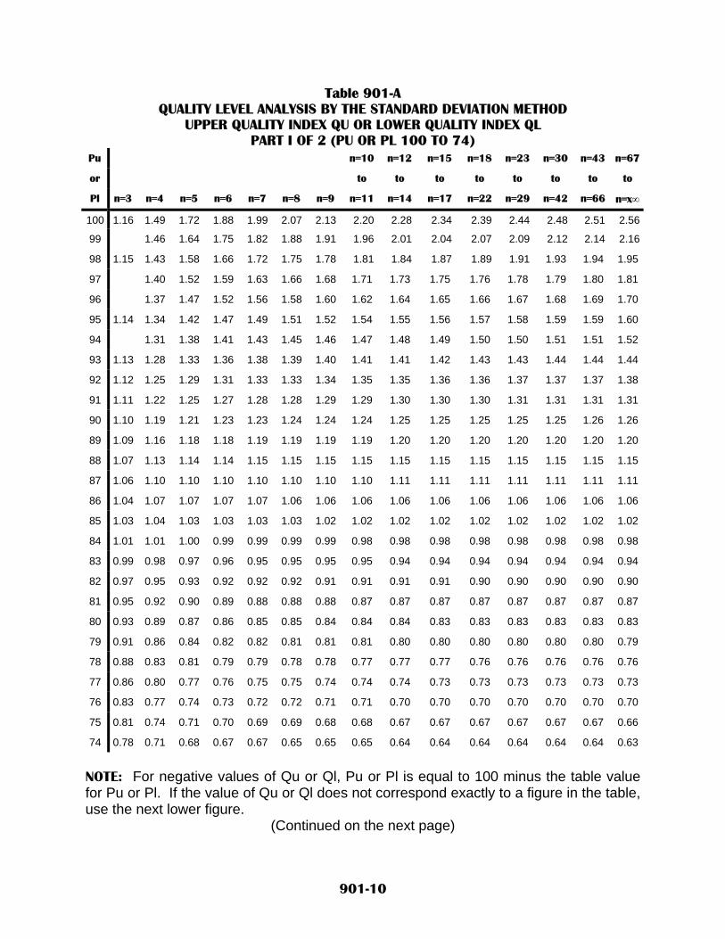
Table 901-A QUALITY LEVEL ANALYSIS BY THE STANDARD DEVIATION METHOD
UPPER QUALITY INDEX QU OR LOWER QUALITY INDEX QL PART I OF 2 (PU OR PL 100 TO 74)
Pu n=10 n=12 n=15 n=18 n=23 n=30 n=43 n=67
or to to to to to to to to
Pl n=3 n=4 n=5 n=6 n=7 n=8 n=9 n=11 n=14 n=17 n=22 n=29 n=42 n=66 n=x∞
100 1.16 1.49 1.72 1.88 1.99 2.07 2.13 2.20 2.28 2.34 2.39 2.44 2.48 2.51 2.56
99 1.46 1.64 1.75 1.82 1.88 1.91 1.96 2.01 2.04 2.07 2.09 2.12 2.14 2.16
98 1.15 1.43 1.58 1.66 1.72 1.75 1.78 1.81 1.84 1.87 1.89 1.91 1.93 1.94 1.95
97 1.40 1.52 1.59 1.63 1.66 1.68 1.71 1.73 1.75 1.76 1.78 1.79 1.80 1.81
96 1.37 1.47 1.52 1.56 1.58 1.60 1.62 1.64 1.65 1.66 1.67 1.68 1.69 1.70
95 1.14 1.34 1.42 1.47 1.49 1.51 1.52 1.54 1.55 1.56 1.57 1.58 1.59 1.59 1.60
94 1.31 1.38 1.41 1.43 1.45 1.46 1.47 1.48 1.49 1.50 1.50 1.51 1.51 1.52
93 1.13 1.28 1.33 1.36 1.38 1.39 1.40 1.41 1.41 1.42 1.43 1.43 1.44 1.44 1.44
92 1.12 1.25 1.29 1.31 1.33 1.33 1.34 1.35 1.35 1.36 1.36 1.37 1.37 1.37 1.38
91 1.11 1.22 1.25 1.27 1.28 1.28 1.29 1.29 1.30 1.30 1.30 1.31 1.31 1.31 1.31
90 1.10 1.19 1.21 1.23 1.23 1.24 1.24 1.24 1.25 1.25 1.25 1.25 1.25 1.26 1.26
89 1.09 1.16 1.18 1.18 1.19 1.19 1.19 1.19 1.20 1.20 1.20 1.20 1.20 1.20 1.20
88 1.07 1.13 1.14 1.14 1.15 1.15 1.15 1.15 1.15 1.15 1.15 1.15 1.15 1.15 1.15
87 1.06 1.10 1.10 1.10 1.10 1.10 1.10 1.10 1.11 1.11 1.11 1.11 1.11 1.11 1.11
86 1.04 1.07 1.07 1.07 1.07 1.06 1.06 1.06 1.06 1.06 1.06 1.06 1.06 1.06 1.06
85 1.03 1.04 1.03 1.03 1.03 1.03 1.02 1.02 1.02 1.02 1.02 1.02 1.02 1.02 1.02
84 1.01 1.01 1.00 0.99 0.99 0.99 0.99 0.98 0.98 0.98 0.98 0.98 0.98 0.98 0.98
83 0.99 0.98 0.97 0.96 0.95 0.95 0.95 0.95 0.94 0.94 0.94 0.94 0.94 0.94 0.94
82 0.97 0.95 0.93 0.92 0.92 0.92 0.91 0.91 0.91 0.91 0.90 0.90 0.90 0.90 0.90
81 0.95 0.92 0.90 0.89 0.88 0.88 0.88 0.87 0.87 0.87 0.87 0.87 0.87 0.87 0.87
80 0.93 0.89 0.87 0.86 0.85 0.85 0.84 0.84 0.84 0.83 0.83 0.83 0.83 0.83 0.83
79 0.91 0.86 0.84 0.82 0.82 0.81 0.81 0.81 0.80 0.80 0.80 0.80 0.80 0.80 0.79
78 0.88 0.83 0.81 0.79 0.79 0.78 0.78 0.77 0.77 0.77 0.76 0.76 0.76 0.76 0.76
77 0.86 0.80 0.77 0.76 0.75 0.75 0.74 0.74 0.74 0.73 0.73 0.73 0.73 0.73 0.73
76 0.83 0.77 0.74 0.73 0.72 0.72 0.71 0.71 0.70 0.70 0.70 0.70 0.70 0.70 0.70
75 0.81 0.74 0.71 0.70 0.69 0.69 0.68 0.68 0.67 0.67 0.67 0.67 0.67 0.67 0.66
74 0.78 0.71 0.68 0.67 0.67 0.65 0.65 0.65 0.64 0.64 0.64 0.64 0.64 0.64 0.63
NOTE: For negative values of Qu or Ql, Pu or Pl is equal to 100 minus the table value for Pu or Pl. If the value of Qu or Ql does not correspond exactly to a figure in the table, use the next lower figure.
(Continued on the next page)
901-10

Table 901-A QUALITY LEVEL ANALYSIS BY THE STANDARD DEVIATION METHOD
UPPER QUALITY INDEX QU OR LOWER QUALITY INDEX QL PART 2 OF 2 (PU OR PL 73 TO 50)
Pu n=10 n=12 n=15 n=18 n=23 n=30 n=43 n=6
7
or to to to to to to to To
Pl n=3 n=4 n=5 n=6 n=7 n=8 n=9 n=11 n=14 n=17 n=22 n=29 n=42 n=66 n=x∞
73 0.75 0.68 0.65 0.64 0.63 0.62 0.62 0.62 0.61 0.61 0.61 0.61 0.61 0.61 0.60
72 0.73 0.65 0.62 0.61 0.60 0.59 0.59 0.59 0.58 0.58 0.58 0.58 0.58 0.58 0.57
71 0.70 0.62 0.59 0.58 0.57 0.57 0.56 0.56 0.55 0.55 0.55 0.55 0.55 0.55 0.54
70 0.67 0.59 0.56 0.55 0.54 0.54 0.53 0.53 0.52 0.52 0.52 0.52 0.52 0.52 0.52
69 0.64 0.56 0.53 0.52 0.51 0.51 0.50 0.50 0.50 0.49 0.49 0.49 0.49 0.49 0.49
68 0.61 0.53 0.50 0.49 0.48 0.48 0.48 0.47 0.47 0.47 0.46 0.46 0.46 0.46 0.46
67 0.58 0.50 0.47 0.46 0.45 0.45 0.45 0.44 0.44 0.44 0.44 0.43 0.43 0.43 0.43
66 0.55 0.47 0.45 0.43 0.43 0.42 0.42 0.42 0.41 0.41 0.41 0.41 0.41 0.41 0.40
65 0.51 0.44 0.42 0.40 0.40 0.39 0.39 0.39 0.38 0.38 0.38 0.38 0.38 0.38 0.38
64 0.48 0.41 0.39 0.38 0.37 0.37 0.36 0.36 0.36 0.36 0.35 0.35 0.35 0.35 0.35
63 0.45 0.38 0.36 0.35 0.34 0.34 0.34 0.33 0.33 0.33 0.33 0.33 0.33 0.33 0.32
62 0.41 0.35 0.33 0.32 0.32 0.31 0.31 0.31 0.30 0.30 0.30 0.30 0.30 0.30 0.30
61 0.38 0.30 0.30 0.30 0.29 0.28 0.28 0.28 0.28 0.28 0.28 0.28 0.28 0.28 0.28
60 0.34 0.28 0.28 0.25 0.25 0.25 0.25 0.25 0.25 0.25 0.25 0.25 0.25 0.25 0.25
59 0.31 0.27 0.25 0.23 0.23 0.23 0.23 0.23 0.23 0.23 0.23 0.23 0.23 0.23 0.23
58 0.30 0.25 0.23 0.20 0.20 0.20 0.20 0.20 0.20 0.20 0.20 0.20 0.20 0.20 0.20
57 0.25 0.20 0.18 0.18 0.18 0.18 0.18 0.18 0.18 0.18 0.18 0.18 0.18 0.18 0.18
56 0.20 0.18 0.16 0.15 0.15 0.15 0.15 0.15 0.15 0.15 0.15 0.15 0.15 0.15 0.15
55 0.18 0.15 0.13 0.13 0.13 0.13 0.13 0.13 0.13 0.13 0.13 0.13 0.13 0.13 0.13
54 0.15 0.13 0.10 0.10 0.10 0.10 0.10 0.10 0.10 0.10 0.10 0.10 0.10 0.10 0.10
53 0.10 0.10 0.08 0.08 0.08 0.08 0.08 0.08 0.08 0.08 0.08 0.08 0.08 0.08 0.08
52 0.08 0.05 0.05 0.05 0.05 0.05 0.05 0.05 0.05 0.05 0.05 0.05 0.05 0.05 0.05
51 0.05 0.03 0.03 0.03 0.03 0.03 0.03 0.03 0.03 0.03 0.03 0.03 0.03 0.03 0.03
50 0.00 0.00 0.00 0.00 0.00 0.00 0.00 0.00 0.00 0.00 0.00 0.00 0.00 0.00 0.00
NOTE: For negative values of Qu or Ql, Pu or Pl is equal to 100 minus the table value for Pu or Pl. If the value of Qu or Ql does not correspond exactly to a figure in the table, use the next lower figure.
901-11

Table 901-B PAY FACTORS
PAY FACTOR Minimum Required Percent of Work Within Specifications Limits for a Given Pay Factor (Pu+PL) - 100
n=3 n=4 n=5 n=6 n=7 n=8 n=9 n=10
to n=11
n=12 to
n=14
n=15 to
n=17
n=18 to
n=22
n=23 to
n=29
n=30 to
n=42
n=43 to
n=66
n=67 to
n=∞ 1.05 100 100 100 100 100 100 100 100 100 100 1.04 100 99 97 95 96 96 96 97 97 97 97 1.03 100 98 96 94 92 93 93 94 95 95 96 96 1.02 99 97 94 91 89 90 91 92 93 93 94 94 1.01 100 100 100 98 95 92 89 87 88 89 90 91 92 92 93 1.00 69 75 78 80 82 83 84 85 86 87 88 89 90 91 92 0.99 66 72 76 78 80 81 82 83 84 85 86 87 89 90 91 0.98 64 70 74 76 78 79 80 81 82 84 85 86 87 88 90 0.97 63 68 72 74 76 77 78 79 81 82 83 84 86 87 88 0.96 61 67 70 72 74 75 76 78 79 81 82 83 84 86 87 0.95 59 65 68 71 72 74 75 76 78 79 80 82 83 84 86 0.94 58 63 67 69 71 72 73 75 76 78 79 80 82 83 85 0.93 57 62 65 67 69 71 72 73 75 76 78 79 80 82 84 0.92 55 60 63 66 68 69 70 72 73 75 76 78 79 81 82 0.91 54 59 62 64 66 68 69 70 72 74 75 76 78 79 81 0.90 53 57 61 63 65 66 67 69 71 72 74 75 77 78 80 0.89 51 56 59 62 63 65 66 68 69 71 72 74 75 77 79 0.88 50 55 58 60 62 64 65 66 68 70 71 73 74 76 78 0.87 49 53 57 59 61 62 63 65 67 68 70 71 73 75 77 0.86 48 52 55 58 59 61 62 64 66 67 69 70 72 74 76 0.85 46 51 54 56 58 60 61 62 64 66 67 69 71 72 75 0.84 45 49 53 55 57 58 60 61 63 65 66 68 70 71 73 0.83 44 48 51 54 56 57 58 60 62 64 65 67 69 70 72 0.82 43 47 50 53 54 56 57 59 61 62 64 66 67 69 71 0.81 41 46 49 51 53 55 56 58 59 61 63 64 66 68 70 0.80 40 44 48 50 52 54 55 56 58 60 62 63 65 67 69 0.79 39 43 46 49 51 52 54 55 57 59 61 62 64 66 68 0.78 38 42 45 48 50 51 52 54 56 58 59 61 63 65 67 0.77 36 41 44 46 48 50 51 53 55 57 58 60 62 64 66 0.75 33 38 42 44 46 48 49 51 53 54 56 58 60 62 64 0.76 35 39 43 45 47 49 50 52 54 56 57 59 61 63 65
Reject VALUES LESS THAN THOSE SHOWN ABOVE
NOTE: If the value of (Pu+PL) – 100 does not correspond to a (Pu+PL) – 100 value in this table, use the next lower (Pu+PL) – 100 value
901-12

Table 901-C(1) Minimum Process Control Guidelines Aggregates and Base Course - Metric
Item Property Testing Frequency Test Method
Sampling As specified AASHTO T 2, 248 Gradation AASHTO T 11, 27, 146 (Note 1)
Fractured Faces NMDOT Method FF 1 Sand Equivalent AASHTO T 176 Atterberg Limits
1 per 900 t
AASHTO T 89, 90
Aggregate Index As needed to control operations with a minimum of 1 per month
during aggregate production Per Section 910
Aggregate for Base Course, Plant Mix
Bituminous Pavement, and Open Graded
Friction Course
Moisture Content As needed to control operations AASHTO T 255 Los Angeles Wear AASHTO T 96 Soundness Loss AASHTO T 104
Plant Mix Bituminous Pavement Adsorption
As needed to confirm quality based on AASHTO TP 58
testing results. AASHTO T 85 Sampling As specified AASHTO T 2, 248 Gradation AASHTO T 11, 27
Sand Equivalent 1 per 900 t AASHTO T 176 Aggregate for PCCP
Moisture Content As needed to control operations AASHTO T 255 Sampling As specified AASHTO T 2, 248
Moisture Content AASHTO T 265 Density 1 per 900 t AASHTO T 180
Gradation AASHTO T 11, 27, 30 Base Course
Thickness 1 per 1,500 t Per Note 2
Note 1: For gradations to control crushing operations, the Contractor may, at their own risk, modify AASHTO T 146 to improve the timelines of test results. However, any modified method tests shall not be considered in acceptance determinations by the Project Manager Note 2: Measurement shall be taken at a randomly selected location. At that location, the thickness shall be determined by removing all of the in-place compacted material, placing a straight edge tool (i.e. a survey lath) across the hole, measuring the thickness to the nearest 5.0 mm (1/4 inch) using a measuring tape, and then replacing and recompacting the removed material.
901-13

Table 901-C(2)
Minimum Process Control Guidelines Aggregates and Base Course - English
Item Property Testing Frequency Test Method
Sampling As specified AASHTO T 2, 248 Gradation AASHTO T 11, 27, 146 (Note 1)
Fractured Faces NMDOT Method FF 1 Sand Equivalent AASHTO T 176 Atterberg Limits
1 per 1,000 tonst
AASHTO T 89, 90
Aggregate Index As needed to control operations with a minimum of 1 per month
during aggregate production Per Section 910
Aggregate for Base Course, Plant Mix
Bituminous Pavement, and Open Graded
Friction Course
Moisture Content As needed to control operations AASHTO T 255 Los Angeles Wear AASHTO T 96 Soundness Loss AASHTO T 104
Plant Mix Bituminous Pavement Adsorption
As needed to confirm quality based on AASHTO TP 58
testing results. AASHTO T 85 Sampling As specified AASHTO T 2, 248 Gradation AASHTO T 11, 27
Sand Equivalent 1 per1,000 tons AASHTO T 176 Aggregate for PCCP
Moisture Content As needed to control operations AASHTO T 255 Sampling As specified AASHTO T 2, 248
Moisture Content AASHTO T 265 Density 1 per 1,000 tons AASHTO T 180
Gradation AASHTO T 11, 27, 30 Base Course
Thickness 1 per 2,000 tons Per Note 2
Note 1: For gradations to control crushing operations, the Contractor may, at their own risk, modify AASHTO T 146 to improve the timelines of test results. However, any modified method tests shall not be considered in acceptance determinations by the Project Manager Note 2: Measurement shall be taken at a randomly selected location. At that location, the thickness shall be determined by removing all of the in-place compacted material, placing a straight edge tool (i.e. a survey lath) across the hole, measuring the thickness to the nearest 5.0 mm (1/4 inch) using a measuring tape, and then replacing and recompacting the removed material.
901-14
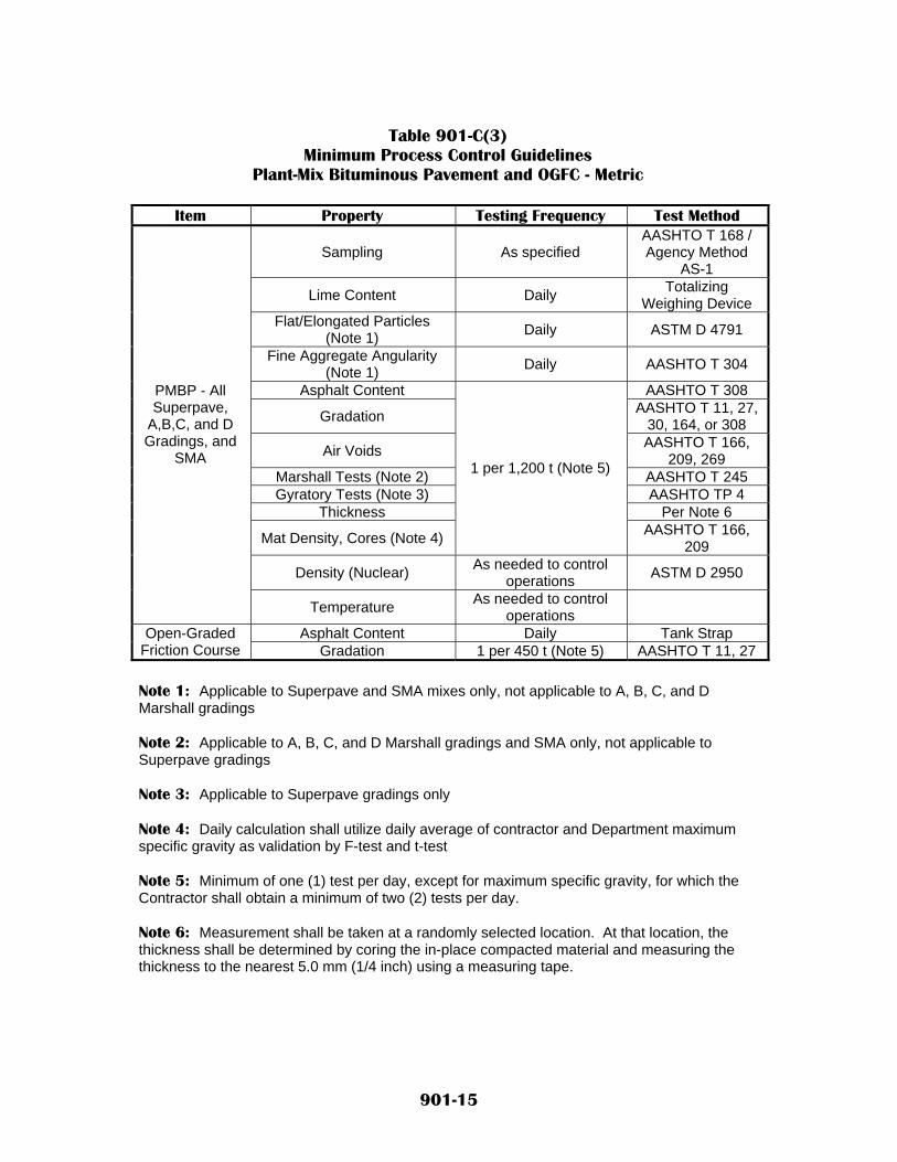
Table 901-C(3)
Minimum Process Control Guidelines Plant-Mix Bituminous Pavement and OGFC - Metric
Item Property Testing Frequency Test Method
Sampling As specified AASHTO T 168 / Agency Method
AS-1
Lime Content Daily Totalizing Weighing Device
Flat/Elongated Particles (Note 1) Daily ASTM D 4791
Fine Aggregate Angularity (Note 1) Daily AASHTO T 304
Asphalt Content AASHTO T 308
Gradation AASHTO T 11, 27, 30, 164, or 308
Air Voids AASHTO T 166, 209, 269
Marshall Tests (Note 2) AASHTO T 245 Gyratory Tests (Note 3) AASHTO TP 4
Thickness Per Note 6
Mat Density, Cores (Note 4)
1 per 1,200 t (Note 5)
AASHTO T 166, 209
Density (Nuclear) As needed to control operations ASTM D 2950
PMBP - All Superpave,
A,B,C, and D Gradings, and
SMA
Temperature As needed to control operations
Asphalt Content Daily Tank Strap Open-Graded Friction Course Gradation 1 per 450 t (Note 5) AASHTO T 11, 27
Note 1: Applicable to Superpave and SMA mixes only, not applicable to A, B, C, and D Marshall gradings Note 2: Applicable to A, B, C, and D Marshall gradings and SMA only, not applicable to Superpave gradings Note 3: Applicable to Superpave gradings only Note 4: Daily calculation shall utilize daily average of contractor and Department maximum specific gravity as validation by F-test and t-test Note 5: Minimum of one (1) test per day, except for maximum specific gravity, for which the Contractor shall obtain a minimum of two (2) tests per day. Note 6: Measurement shall be taken at a randomly selected location. At that location, the thickness shall be determined by coring the in-place compacted material and measuring the thickness to the nearest 5.0 mm (1/4 inch) using a measuring tape.
901-15

Table 901-C(4) Minimum Process Control Guidelines
Plant-Mix Bituminous Pavement and OGFC - English
Item Property Testing Frequency Test Method
Sampling As specified AASHTO T 168 / Agency Method
AS-1
Lime Content Daily Totalizing Weighing Device
Flat/Elongated Particles (Note 1) Daily ASTM D 4791
Fine Aggregate Angularity (Note 1) Daily AASHTO T 304
Asphalt Content AASHTO T 308
Gradation AASHTO T 11, 27, 30, 164, or 308
Air Voids AASHTO T 166, 209, 269
Marshall Tests (Note 2) AASHTO T 245 Gyratory Tests (Note 3) AASHTO TP 4
Thickness Per Note 6 Mat Density, Cores
(Note 4)
1 per 1,500 Tons (Note 5)
AASHTO T 166, 209
Density (Nuclear) As needed to control operations ASTM D 2950
PMBP - All Superpave,
A,B,C, and D Gradings, and
SMA
Temperature As needed to control operations
Asphalt Content Daily Tank Strap Open-Graded Friction Course Gradation 1 per 500 Tons (Note 5) AASHTO T 11, 27
Note 1: Applicable to Superpave and SMA mixes only, not applicable to A, B, C, and D Marshall gradings Note 2: Applicable to A, B, C, and D Marshall gradings and SMA only, not applicable to Superpave gradings Note 3: Applicable to Superpave gradings only Note 4: Daily calculation shall utilize daily average of contractor and Department maximum specific gravity as validation by F-test and t-test Note 5: Minimum of one (1) test per day, except for maximum specific gravity, for which the Contractor shall obtain a minimum of two (2) tests per day. Note 6: Measurement shall be taken at a randomly selected location. At that location, the thickness shall be determined by coring the in-place compacted material and measuring the thickness to the nearest 5.0 mm (1/4 inch) using a measuring tape.
901-16

Table 901-C(5) Minimum Process Control Guidelines
Portland Cement Concrete Pavement - Metric
Item Property Testing Frequency Test Method Unit Weight 1 per 100 m3 AASHTO T 121
Air Entrainment 1 per 100 m3 AASHTO T 152 Slump 1 per 100 m3 AASHTO T 119
Fresh Concrete for PCCP
Compressive Strength 1 per 100 m3 AASHTO T 22/23/231
PCCP in Place Thickness (Note 1) 2 per 2,000 m2 (Note 2) ---
Note 1: All corrective work specified in subsection 450.352 or 451 352 shall be completed before determining pavement thickness Note 2: Thickness determinations shall be by actual survey conducted before construction of the PCCP and which are located at fixed, randomly selected locations.
Table 901-C(6)
Minimum Process Control Guidelines Portland Cement Concrete Pavement - English
Item Property Testing Frequency Test Method
Unit Weight 1 per 125 yd3 AASHTO T 121 Air Entrainment 1 per 125 yd3 AASHTO T 152
Slump 1 per 125 yd3 AASHTO T 119 Fresh Concrete
for PCCP Compressive Strength 1 per 125 yd3 AASHTO T 22/23/231
PCCP in Place Thickness (Note 1) 2 per 2,400 yd2 (Note 2) ---
Note 1: All corrective work specified in subsection 450.352 or 451.352 shall be completed before determining pavement thickness Note 2: Thickness determinations shall be by actual survey conducted before and after the construction of the PCCP and which are located at fixed, randomly selected locations.
901-17

Table 901-D (1) Minimum Acceptance Guidelines - Metric
Item Property Point of
Acceptance Sublot Size Lot Size Test Method
Sampling As Specified AASHTO T 2, 248
Gradation Roadway before compaction
AASHTO T 11, 27
Thickness Per Note 7 Base Course
Density Roadway after
compaction
1 per 1,500 t Per project (Note 5) AASHTO T 180, 238,
239
Sampling As Specified --- --- AASHTO T 168
Asphalt Content Roadway AASHTO T 308
Mat Density Cores (Note 1) --- AASHTO T
166, 209
Gradation AASHTO T 11, 27, 30, 164, or 308
Air Voids
Before compaction
Per Project approved mix design
AASHTO T 166, 209,
269
Thickness After compaction --- Per Note 8
Marshall Tests (Note 2) --- --- AASHTO T
245
Asphalt Mixtures
Gyratory Tests (Note 3) ---
1 per 3,600 t (Note 4)
--- AASHTO TP 4
Asphalt Content Windrow Tank Strap Open-Graded Friction Course Gradation Cold Feed
1 per 1,350 t (Note 4)
Per project approved mix design AASHTO T
11, 27
Air Entrainment AASHTO T 152 Fresh
Concrete for PCCP Compressive
Strength
Deliver to grade 1 per 400 cubic meters 4000 cubic meters AASHTO T
22, 23, 231 In-Place PCCP
Thickness (Note 6) --- 2 per 8, 000 m2 Per project (Note 4) Per Note 9
Note 1: Density calculation will utilize daily average of Contractor and Department maximum specific gravity as validated by F-test and t-test. The Department will obtain a minimum of one (1) maximum specific gravity sample per day. Note 2: Applicable to A, B, C, and D Marshall gradings and SMA only. Not applicable to Superpave gradings. Note 3. Applicable to Superpave gradings only. Note 4: Minimum of three (3) sublots required. Note 5: Minimum of ten (10) samples per lot. Note 6: All corrective work specified in subsection 450.352 or 451.352 shall be completed before determining pavement thickness Note 7: Measurement shall be taken at a randomly selected location. At that location, the thickness shall be determined by removing all of the in-place compacted material, placing a straight edge tool (i.e. a survey lath) across the hole and measuring the thickness to the nearest 5.0 mm (1/4 inch) using a measuring tape. Note 8 Measurement shall be taken at a randomly selected location. At that location, the thickness shall be determined by coring the in-place compacted material and measuring the thickness to the nearest 5.0 mm (1/4 inch) using a measuring tape. Note 9: Thickness determinations shall be by actual survey conducted before and after the construction of the PCCP and which are located at fixed, randomly selected locations.
901-18

Table 901-D (2) Minimum Acceptance Guidelines - English
Item Property Point of Acceptance Sublot Size Lot Size Test Method
Sampling As Specified --- --- AASHTO T 2, 248
Gradation Roadway
before compaction
AASHTO T 11, 27
Thickness Per Note 7
Base Course
Density Roadway after
compaction
1 per 2,000 Tons Per project (Note 5)
AASHTO T 180, 238, 239
Sampling As Specified --- --- AASHTO T 168 Asphalt Content Roadway AASHTO T 308
Mat Density Cores (Note 1) --- AASHTO T 166,
209
Gradation AASHTO T 11, 27, 30, 164, or
308
Air Voids
Before compaction
Per Project approved mix
design
AASHTO T 166, 209, 269
Thickness After compaction --- Per Note 8
Marshall Tests (Note 2) --- --- AASHTO T 245
Asphalt Mixtures
Gyratory Tests (Note 3) ---
1 per 4,500 Tons (Note 4)
--- AASHTO TP 4
Asphalt Content Windrow Tank Strap Open-Graded Friction Course Gradation Cold Feed
1 per 1,500 Tons (Note 4)
Per project approved mix
design AASHTO T 11,
27 Air Entrainment AASHTO T 152 Fresh Concrete
for PCCP Compressive Strength
Deliver to grade 1 per 500 cubic yards 5,000 cubic yards AASHTO T 22,
23, 231
In-Place PCCP Thickness (Note 6) --- 2 per 9,500 yd2 Per project (Note 4) Per Note 9
Note 1: Density calculation will utilize daily average of Contractor and Department maximum specific gravity as validated by F-test and t-test. The Department will obtain a minimum of one (1) maximum specific gravity sample per day. Note 2: Applicable to A, B, C, and D Marshall gradings and SMA only. Not applicable to Superpave gradings. Note 3. Applicable to Superpave gradings only. Note 4: Minimum of three (3) sublots required. Note 5: Minimum of ten (10) samples per lot. Note 6: All corrective work specified in subsection 450.352 or 451.352 shall be completed before determining pavement thickness Note 7: Measurement shall be taken at a randomly selected location. At that location, the thickness shall be determined by removing all of the in-place compacted material, placing a straight edge tool (i.e. a survey lath) across the hole and measuring the thickness to the nearest 5.0 mm (1/4 inch) using a measuring tape. Note 8 Measurement shall be taken at a randomly selected location. At that location, the thickness shall be determined by coring the in-place compacted material and measuring the thickness to the nearest 5.0 mm (1/4 inch) using a measuring tape. Note 9: Thickness determinations shall be by actual survey conducted before and after the construction of the PCCP and which are located at fixed, randomly selected locations.
901-19

NEW MEXICO DEPARTMENT OF TRANSPORTATION SUPPLEMENTAL SPECIFICATIONS FOR
EVALUATION OF PROPERTIES FOR PLANT-MIXED BITUMINOUS PAVEMENT
SECTION 920 All provisions of the New Mexico Department Of Transportation’s Standard Specifications for Highway and Bridge Construction shall apply in addition to the following: Delete SECTION 920 - EVALUATION OF PROPERTIES FOR HOT-MIX ASPHALT PAVEMENT in its entirety and substitute the following:
920.1 SOURCE PROPERTIES. Soundness loss, Los Angeles Wear, and absorption will be evaluated in accordance with Section 910, Aggregate Index. 920.2 MIX DESIGN PROPERTIES. Plant-Mixed Bituminous Pavement (PMBP) mix design properties are listed in Table 920-A. All tests and calculations to determine PMBP mix design properties shall be performed in accordance with the latest mix design procedures issued by the State Materials Bureau and applicable AASHTO procedures. All methods presented in the New Mexico Technician Training and Certification Program (TTCP) shall be followed where applicable. 920.21 Laboratory Mix Designs. All PMBP mix design properties shall be in compliance with specification requirements for the type and grading shown in the contract when combined in the proportions shown in the project approved PMBP laboratory mix design. Test results and calculations verifying specification compliance shall be included in the PMBP mix design submittal. Failure of the PMBP mix design to comply with specification requirements for mix design properties will be grounds for rejection of the mix design. 920.22 Job Mix Formula Adjustments. For a given lot, all adjustments to the job mix formula made subsequent to the laboratory mix design shall be in compliance with specification requirements for the type and grading shown in the contract when combined in the proportions shown in the adjusted job mix formula. Test results and calculations verifying specification compliance shall be included in the request for approval of the job mix formula adjustment. Failures of the revised job mix formula to comply with specification requirements for mix design properties will be grounds for rejection of the revised job mix formula. Adjustments to the job mix formula shall be concurred with by the approved testing laboratory responsible for the laboratory mix design and must be accepted by the Department’s State Materials Bureau prior to use.
920-1

920.23 Mix Properties During Mix Production. During actual production of mix for a given lot, the Contractor will be allowed production tolerances from acceptance targets in accordance with the specifications. Mix design properties will not be evaluated during actual mix production, except when a property is also shown as a process control or acceptance property on Table 920-A. 920.3 PROCESS CONTROL PROPERTIES. Process control properties are listed in Table 920-A. For each lot, the Contractor will monitor process control properties by testing at or above specified minimum rates during production of aggregates and hot mix asphalt. The Department may, at its option, perform testing to monitor process control or verify process control properties, at frequencies it deems appropriate. Tests and calculations to determine process control properties shall be performed in accordance with the AASHTO procedures. Methods presented in the New Mexico Technician Training and Certification Program (TTCP) shall be followed where applicable. 920.31 Evaluation of Process Control Properties. Process control properties for a given lot will be evaluated continually throughout aggregate and mixture production. The Contractor shall provide test results and values in a timely manner. The objective is to minimize production of out-of-specification material while waiting for test results. Failure to provide process control information as required by the specifications will be grounds for suspending the Contractor’s operations. Process control properties will be evaluated as follows: A. Mean Value. For a given lot, the mean of all test results or values for a given
property shall be in compliance with specification requirements for that property. The mean and standard deviation of all test results for a given property shall be recalculated on a continuous basis each time new data becomes available. If the mean falls outside of specification limits, the Contractor shall cease production, investigate to determine causes, and propose corrective action. Production shall not resume until corrective measures are implemented to the satisfaction of the Project Manager. If, at the conclusion of production, the mean of one or more process control properties is out of specification, the material will be rejected, and the Contractor shall remove the material and replace it with complying material at no cost to the Department.
B. Individual Test Results. For a given lot, if an individual test result falls outside of
specification limits and is two or more standard deviations from the mean of all previously produced material, the Contractor shall cease production, investigate to determine causes, and propose corrective action. Production shall not resume until corrective measures are implemented to the satisfaction of the Project Manager. If an individual test is outside of specification limits but is less than two standard deviations from the mean of previously produced material, the Contractor shall investigate and propose corrective action if appropriate, but will not be required to cease production.
920-2

C. Consecutive Test Results. For a given lot, if two consecutive test results fall outside of specification limits, regardless of deviation from the mean, the Contractor shall cease production, investigate to determine causes, and propose corrective action. Production shall not resume until corrective measures are implemented to the satisfaction of the Project Manager.
920.32 Stockpile Evaluation. For a given lot, properties such as fractured faces, sand equivalent, fine aggregate angularity, plasticity index, etc., that are typically evaluated on combined aggregates may be evaluated for each individual stockpile at the Contractor’s option. If the mean of each property is within specification limits for each individual stockpile, no evaluation of properties for the combined aggregates will be required. However, if the mean for each property of each stockpile is not within specification limits, or if properties for each stockpile are not evaluated, the Contractor shall provide a means acceptable to the Project Manager for sampling the combined materials, prior to addition of hydrated lime, and evaluation will be based on samples obtained at that location. 920.4 ACCEPTANCE PROPERTIES. Acceptance properties are listed on Table 920-A. Tests and calculations to determine Acceptance properties shall be performed in accordance with the AASHTO procedures. Methods presented in the New Mexico Technician Training and Certification Program (TTCP) shall be followed where applicable. 920.41 Evaluation of Acceptance Properties. Acceptance properties shall be evaluated and pay factor, incentive, or price reduction, if any, shall be determined in accordance with the requirements of the paving specification applicable to this contract.
920-3

Table 920-A Acceptance Properties
Property Source 920.1 Mix Design &
Adjustment 920.2 Process Control
920.3 Acceptance 920.4
% Asphalt --- 420, 421, 424, and 425 421 and 425 420, 421, 424, and
425 % Gmm @ Ninitial --- 422 and 423 --- ---
% Gmm @ Nmaximum --- 422 and 423 --- ---
% Hydrated Lime --- 420, 421, 422, 423, 424, and 425 --- 420, 421, 422,
423, 424, and 425 425 µm (No. 40) Sieve --- --- 420 --- 75 µm (No. 200) Sieve --- --- 420 ---
Aggregate Index (Section 910) 420, 421, 422, 423, 424, and
425 --- 420, 421, 422,
423, 424, and 425 ---
Air Voids --- 420, 421, 422, 423, 424, and 425 421, 423, and 425 420, 421, 422,
423, 424, and 425
Compacted Thickness --- --- 420, 421, 422, 423, 424, and 425 ---
Draindown --- 424 and 425 --- --- Dust/Binder Ratio --- 422 and 423 422 and 423 422 and 423
Fine Aggregate Angularity --- --- 422, 423, 424, and 425 ---
Flat/Elongated Particles --- --- 422, 423, 424, and 425 ---
Flow --- 420 and 421 421 420
Fractured Faces --- --- 420, 421, 422, 423, 424, and 425 ---
Gradation --- 420, 421, 422, 423, 424, and 425
420, 421, 422, 423, 424, and 425
420, 421, 422, 423, 424, and 425
Pavement Density (Cores) --- --- 421, 423, and 425 420, 421, 422, 423, 424, and 425
Pavement Density (Nuclear) --- --- 420, 421, 422, 423, 424, and 425 ---
Plasticity Index --- --- 420, 421, 422, 423, 424, and 425 ---
Retained Strength --- 420 and 421 --- ---
Sand Equivalency --- --- 420, 421, 422, 423, 424, and 425 ---
Stability --- 420 and 421 421 and 425 420 and 424 Stability/Flow Ratio --- 420 and 421 421 420 VCADCR > VCAMIX --- 424 and 425 --- ---
Voids filled with Asphalt (VFA) --- 422 and 423 --- --- Voids in Mineral Aggregate
(VMA) --- 422 and 423 422 and 423 422 and 423
Note 1: The numbers shown in Table 920-A refer to sections in this edition of the NMDOT Standard Specifications.
920-4