Communications Specifications
131
-
Upload
khangminh22 -
Category
Documents
-
view
1 -
download
0
Transcript of Communications Specifications

Communications Specifications 1
Communications Specifications
*1 FINS message communications are supported by CJ-series Controllers only.*2 A baud rate of 4 Mbps is not supported for branch lines and thus cannot be used for Slave Units with Cables (i.e., Bit Slave Units).*3 Round cable I, round cable II and Flat Cable I are all different types of cable. To use more than one type of cable at a time, Repeater Units must be used to separate
them on trunk lines and sub-trunk lines.
Item Specification
Communications protocol CompoNet Network protocol
Types of communicationsRemote I/O communications (programless, constant sharing of data with Slave Units) and message communications (explicit message communications as required with Slave Units and FINS message communications as required with controllers) *1
Baud rate 4 Mbps *2, 3 Mbps, 1.5 Mbps, 93.75 kbps
Modulation Base-band
Coding Manchester code
Error control Manchester code rules, CRC
Communications media *3
The following media can be used. • Round cable I 2-wire 0.75 mm2
• Round cable II 4-wire 0.75 mm2
• Flat Cable I
Communications distance and wiring Refer to Cable Types, Baud Rates, and Maximum Distances in the Master Unit Operation Manual.
Connectable Master Units CompoNet Master Units
Connectable Slave Units CompoNet Slave Units
Maximum I/O capacityWord Slave Units: 1,024 inputs and 1,024 outputs (2,048 I/O points total)Bit Slave Units: 256 inputs and 256 outputs (512 I/O points total)
Maximum number of nodesWord Slave Units: 64 input nodes and 64 output nodesBit Slave Units: 128 input nodes and 128 output nodesRepeater Units: 64 nodes
Bits allocated per node addressWord Slave Units: 16 bitsBit Slave Units: 2 bits
Maximum number of nodes per trunk line or sub-trunk line
32 nodes (including Repeater Units)
Applicable node addressesWord Slave Units: IN0 to IN63 and OUT0 to OUT63Bit Slave Units: IN0 to IN127 and OUT0 to OUT127Repeater Units: 0 to 63
Repeater Unit application conditions
Up to 64 Repeater Units can be connected per network (i.e., per Master Unit). Up to 32 Repeater Units can be connected per trunk line or per sub-trunk line. When Repeater Units are connected in series from the Master Unit, up to two extra segment layers can be created (i.e., up to 2 Repeater Units are allowed between a Slave Unit and the Master Unit).
Signal lines Two lines: BDH (communications data high) and BDL (communications data low)
Power linesTwo lines: BS+ and BS− (power for communications and internal Slave Unit circuits)
• Power is supplied from the Master Unit or Repeater Units.
Communications power supply voltage 24 VDC ±10%
Connection formsRound cable II (4-wire) or Flat cable I at baud rate of 93.75 kbits/s: No restrictions Other cables or baud rates: Trunk line and branch lines
Connections for Slave Units and Repeater Units: T-branch or multidrop connections
MEMO
2

3 CJ1W/CS1W-CRM21 3
CompoNet Master UnitsCJ-series CompoNet Master Units ........................................................................................5
■CJ1W-CRM21CS-series CompoNet Master Units........................................................................................6
■CS1W-CRM21CompoNet Master Board for PCI Bus/CompactPCI Bus ................................................................7
■3G8F7-CRM21/3G8F8-CRM21
4 CJ/CS-series CompoNet Master Units CJ1W/CS1W-CRM21
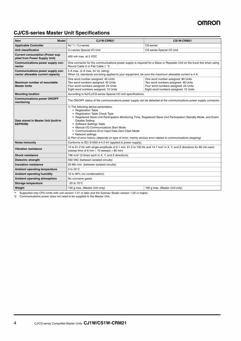
CJ/CS-series Master Unit Specifications
*1 Supported only CPU Units with unit version 1.01 or later and the Sysmac Studio version 1.02 or higher.*2 Communications power does not need to be supplied to the Master Unit.
Item Model CJ1W-CRM21 CS1W-CRM21
Applicable Controller NJ *1 / CJ-series CS-series
Unit classification CJ-series Special I/O Unit CS-series Special I/O Unit
Current consumption (Power sup-plied from Power Supply Unit)
400 mA max. at 5 VDC
Communications power supply con-nector
One connector for the communications power supply is required for a Slave or Repeater Unit on the trunk line when using Round Cable II or Flat Cable I. *2
Communications power supply con-nector allowable current capacity
5 A max. (4 A max. for UL rating)When UL standards are being applied to your equipment, be sure the maximum allowable current is 4 A.
Maximum number of mountableMaster Units
One word number assigned: 40 UnitsTwo word numbers assigned: 40 UnitsFour word numbers assigned: 24 UnitsEight word numbers assigned: 12 Units
One word number assigned: 80 UnitsTwo word numbers assigned: 48 UnitsFour word numbers assigned: 24 UnitsEight word numbers assigned: 12 Units
Mounting location According to NJ/CJ/CS-series Special I/O Unit specifications.
Communications power ON/OFFmonitoring
The ON/OFF status of the communications power supply can be detected at the communications power supply connector.
Data stored in Master Unit (built-inEEPROM)
1) The following device parameters:• Registration Table• Registration Table Check Type• Registered Slave Unit Participation Monitoring Time, Registered Slave Unit Participation Standby Mode, and Event
Disable Setting• Software Settings Table• Manual I/O Communications Start Mode• Communications Error Input Data Zero Clear Mode• Network settings
2) Part of error history (depends on type of error; mainly serious error related to communications stopping)
Noise immunity Conforms to IEC 61000-4-4 2 kV (applied to power supply).
Vibration resistance10 to 61.2 Hz with single-amplitude of 0.1 mm, 61.2 to 150 Hz and 14.7 m/s2 in X, Y, and Z directions for 80 min each (sweep time of 8 min × 10 sweeps = 80 min)
Shock resistance 196 m/s2 (3 times each in X, Y, and Z directions)
Dielectric strength 500 VAC (between isolated circuits)
Insulation resistance 20 MΩ min. (between isolated circuits)
Ambient operating temperature 0 to 55°C
Ambient operating humidity 10 to 90% (no condensation)
Ambient operating atmosphere No corrosive gases
Storage temperature −20 to 75°C
Weight 130 g max. (Master Unit only) 190 g max. (Master Unit only)

5 CJ-series CompoNet Master Units CJ1W-CRM21
CJ-series CompoNet Master Units
CJ1W-CRM21NJ/CJ-series CompoNet Master Units Increase the Range of Applicability of Sensors and Actuators. The NJ/CJ-series CompoNet Master Unit manages the CompoNet network, controls communications between the Controller and Slave Units, and handles I/O data and message data.• Setup is simple. Make the master's mode settings and set the baud rate, and
you're ready to go.
• Control up to 2,560 I/O points and 384 nodes with one Master Unit.
• Intuitive memory mapping with separate areas for Word Slave Units and Bit
Slave Units.
• Seven-segment display helps with startup and enables prompt detection of problems.
• Collect information from Slave Units using message communications, or use
message communications to set parameters.
• Inherits the ease of use of the CompoBus/S.
• Flexible I/O allocations with software setting function.
Ordering Information
* These Units are also available with a DCN-TB4 Terminal Conversion Adapter included in the package. Add "(-B)" to the end of the model number to receive theAdapter as well.
Dimensions (Unit: mm)
CJ1W-CRM21
Name
SpecificationsNumber of unit
numbers allocated
Power consumption (A)
ModelTypes of communications
Maximum number of I/O points per Master Unit
5-V system 24-V system 26-V system
CJ1 Special I/O Unit *
• Remote I/O communi-cations
• Message communica-tions
Word Slave Units: 1,024 inputs and 1,024 outputs (2,048 I/O points total)Bit Slave Units: 256 inputs and 256 outputs (512 I/O points total)
1, 2, 4, or 8 0.4 --- CJ1W-CRM21
31
3.6
80.7
652.7
90
5.3
CRM21
+100
MSNSSDRDMACHNo.
MODE
X101
ON
X100
BS+
BS-
DC24VINPUT
NETWORKPS
BS+
BD H
DB L
BS-
SW 1 2 3 4
1 2 3 4
01
23456789
01
23456789
01
23456789

6 CS-series CompoNet Master Units CS1W-CRM21
CS-series CompoNet Master Units
CS1W-CRM21CS-series CompoNet Master Units Increase the Range of Applicability of Sensors and Actuators. The CS-series CompoNet Master Unit manages the CompoNet net-work, controls communications between the PLC and Slave Units, and handles I/O data and message data.• Setup is simple. Make the master's mode settings and set the baud rate, and
you're ready to go.
• Control up to 2,560 I/O points and 384 nodes with one Master Unit.
• Intuitive memory mapping with separate areas for Word Slave Units and Bit
Slave Units.
• Seven-segment display helps with startup and enables prompt detection of problems.
• Collect information from Slave Units using message communications, or use
message communications to set parameters.
• Inherits the ease of use of the CompoBus/S.
• Flexible I/O allocations with software setting function.
Ordering Information
* These Units are also available with a DCN-TB4 Terminal Conversion Adapter included in the package. Add "(-B)" to the end of the model number to receive theAdapter as well.
Dimensions (Unit: mm)
CS1W-CRM21
Name
SpecificationsNumber of unit
numbers allocated
Power consumption (A)
ModelTypes of communications
Maximum number of I/O points per Master Unit
5-V system 24-V system 26-V system
CS1 Special I/O Unit *
• Remote I/O communi-cations
• Message communica-tions
Word Slave Units: 1,024 inputs and 1,024 outputs (2,048 I/O points total)Bit Slave Units: 256 inputs and 256 outputs (512 I/O points total)
1, 2, 4, or 8 0.4 --- CS1W-CRM21
130
34.5 3.6
15.7 100.5
CRM21MSNS
SDRD
+100
MACHNo.
X101
MODE
ON
X100
12
34
1 DR02 DR13 ESTP4 REGS
NETWORKPOWERSUPPLY
DC24VINPUT
BS+
BS +
BD H
BD L
BS -
BS-
98765432109876543210
9876543210

CompoNet Master Board for PCI Bus/CompactPCI Bus 3G8F7-CRM21/3G8F8-CRM21 7
CompoNet Master Board for PCI Bus/CompactPCI Bus
3G8F7-CRM21/3G8F8-CRM21CompoNet Master Board for PC which provides ultra-high speed control
• Two type product variation of PCI Bus type and Compact PCI Bus type
• Windows-base environment. Compatible with other OS, too when shared memory area is used.
• Combine PC with High-speed communication network "CompoNet" to achieve further fast communications.
• Familiar C/C++/VB based programming.
Ordering Information
General Specifications Development Environment
• Microsoft Visual C++ (Ver 6.0 to Ver 2008)• Microsoft Visual Basic (Ver 6.0)• CodeGear C++Builder (Ver 5 to Ver 2009)
Precautions for Correct UseWhen you use the Board in an OS other than Windows by directly accessing the shared memory interface, provide the development environment applicable for the OS.
Name Specification Model
CompoNet Master Board for PCI Bus PCI bus Rev2.2 5V 3G8F7-CRM21
CompoNet Master Board for CompactPCI Bus PICMG 2.0 R3.0 5V 32-Bit 3U 3G8F8-CRM21
ItemSpecifications
3G8F7-CRM21 (PCI) 3G8F8-CRM21(CompactPCI)
Bus specification
PCI bus Rev2.25 V
PICMG 2.0 R3.05 V32-Bit 3U
Number of mountable boards
4 pieces 7 pieces
Compatible OS Microsoft Windows 2000 / XP (32 Bit version) / Vista (32 Bit version) Other OS can be used, when the shared memory interface is directly accessed.
Weight 90 g max. 150 g max.
Operation voltage
Internal power supply: 5 VDC±5%3.3 VDC is not used.
Consumption current
Internal power supply: 5 VDC and 1.5 A maxCommunications power supply: 24 VDC and 80 mA max
Vibration resistance
10 to 57 Hz, Amplitude 0.075 mm, 57 to 150 HzAcceleration 9.8 m/s2, 80 min in each direction of X, Y and Z (8 min of each sweep time × 10 sweeps = total 80 min)
Shock resistance 147 m/s2, 3 times in each direction of X, Y and Z.
Ambient operating temperature
0 to 55°C
Ambient operating humidity
0% to 80% RH (with no condensation)
0% to 90% RH (with no condensation)
Ambient operating atmosphere
No corrosive gas
Storage temperature -20 to +60°C
8 CompoNet Master Board for PCI Bus/CompactPCI Bus 3G8F7-CRM21/3G8F8-CRM21
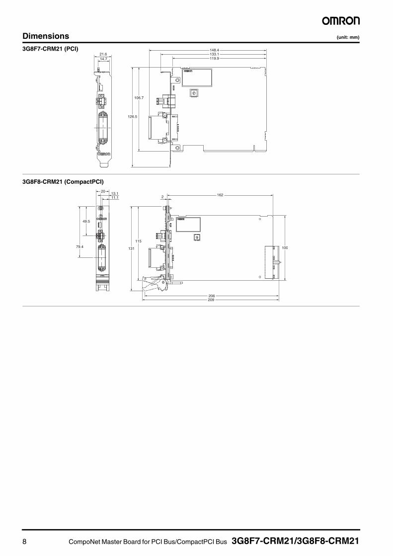
Dimensions (unit: mm)
126.5
106.7
21.614.7
148.4133.1119.9
3G8F7-CRM21 (PCI)
131
115
2013.1 16211.1
79.4
49.5
2
100
209206
3G8F8-CRM21 (CompactPCI)

9 Overview of Gateway Unit 9
CompoNetGatewayUnit
Overview of Gateway Unit ............................................................................................................................10CompoNet Setting ........................................................................................................................................11CompoNet Gateway Unit for CC-Link...........................................................................................................12
■GQ-CRM21
10 Overview of Gateway Unit
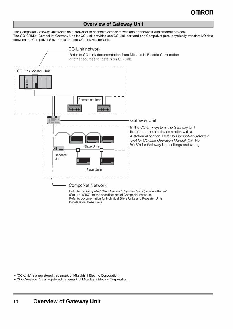
The CompoNet Gateway Unit works as a converter to connect CompoNet with another network with different protocol.The GQ-CRM21 CompoNet Gateway Unit for CC-Link provides one CC-Link port and one CompoNet port. It cyclically transfers I/O databetween the CompoNet Slave Units and the CC-Link Master Unit.
• “CC-Link” is a registered trademark of Mitsubishi Electric Corporation.• “GX-Developer” is a registered trademark of Mitsubishi Electric Corporation.
Overview of Gateway Unit
Slave Units
CC-Link Master Unit
Remote stations
CC-Link network
CompoNet Network
Slave Units
Gateway Unit
In the CC-Link system, the Gateway Unitis set as a remote device station with a4-station allocation. Refer to CompoNet Gateway Unit for CC-Link Operation Manual (Cat. No. W489) for Gateway Unit settings and wiring.
Refer to CC-Link documentation from Mitsubishi Electric Corporationor other sources for details on CC-Link.
Repeater Unit
Refer to the CompoNet Slave Unit and Repeater Unit Operation Manual (Cat. No. W457) for the specifications of CompoNet networks.Refer to documentation for individual Slave Units and Repeater Units fordetails on those Units.
Overview of Gateway Unit 11
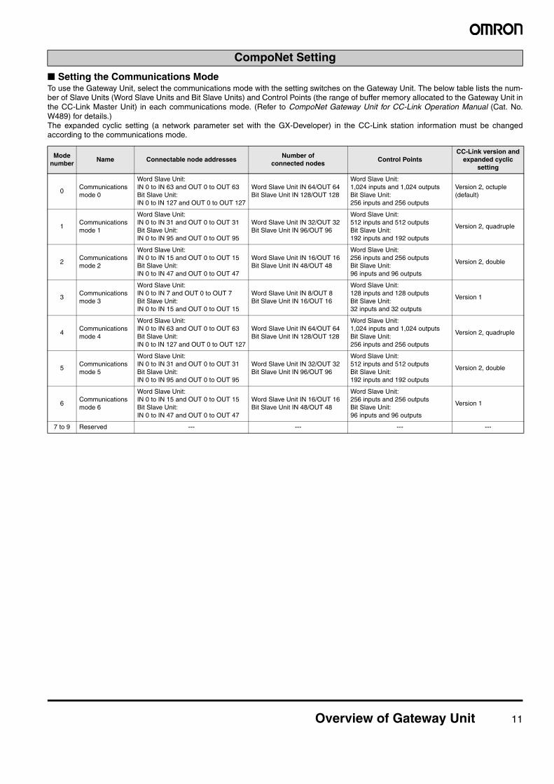
■ Setting the Communications ModeTo use the Gateway Unit, select the communications mode with the setting switches on the Gateway Unit. The below table lists the num-ber of Slave Units (Word Slave Units and Bit Slave Units) and Control Points (the range of buffer memory allocated to the Gateway Unit inthe CC-Link Master Unit) in each communications mode. (Refer to CompoNet Gateway Unit for CC-Link Operation Manual (Cat. No.W489) for details.) The expanded cyclic setting (a network parameter set with the GX-Developer) in the CC-Link station information must be changedaccording to the communications mode.
CompoNet Setting
Mode number
Name Connectable node addressesNumber of
connected nodesControl Points
CC-Link version andexpanded cyclic
setting
0Communicationsmode 0
Word Slave Unit:IN 0 to IN 63 and OUT 0 to OUT 63Bit Slave Unit:IN 0 to IN 127 and OUT 0 to OUT 127
Word Slave Unit IN 64/OUT 64Bit Slave Unit IN 128/OUT 128
Word Slave Unit:1,024 inputs and 1,024 outputsBit Slave Unit:256 inputs and 256 outputs
Version 2, octuple(default)
1Communicationsmode 1
Word Slave Unit:IN 0 to IN 31 and OUT 0 to OUT 31Bit Slave Unit:IN 0 to IN 95 and OUT 0 to OUT 95
Word Slave Unit IN 32/OUT 32Bit Slave Unit IN 96/OUT 96
Word Slave Unit:512 inputs and 512 outputsBit Slave Unit:192 inputs and 192 outputs
Version 2, quadruple
2Communicationsmode 2
Word Slave Unit:IN 0 to IN 15 and OUT 0 to OUT 15Bit Slave Unit:IN 0 to IN 47 and OUT 0 to OUT 47
Word Slave Unit IN 16/OUT 16Bit Slave Unit IN 48/OUT 48
Word Slave Unit:256 inputs and 256 outputsBit Slave Unit:96 inputs and 96 outputs
Version 2, double
3Communicationsmode 3
Word Slave Unit:IN 0 to IN 7 and OUT 0 to OUT 7Bit Slave Unit:IN 0 to IN 15 and OUT 0 to OUT 15
Word Slave Unit IN 8/OUT 8Bit Slave Unit IN 16/OUT 16
Word Slave Unit:128 inputs and 128 outputsBit Slave Unit:32 inputs and 32 outputs
Version 1
4Communicationsmode 4
Word Slave Unit:IN 0 to IN 63 and OUT 0 to OUT 63Bit Slave Unit:IN 0 to IN 127 and OUT 0 to OUT 127
Word Slave Unit IN 64/OUT 64Bit Slave Unit IN 128/OUT 128
Word Slave Unit:1,024 inputs and 1,024 outputsBit Slave Unit:256 inputs and 256 outputs
Version 2, quadruple
5Communicationsmode 5
Word Slave Unit:IN 0 to IN 31 and OUT 0 to OUT 31Bit Slave Unit:IN 0 to IN 95 and OUT 0 to OUT 95
Word Slave Unit IN 32/OUT 32Bit Slave Unit IN 96/OUT 96
Word Slave Unit:512 inputs and 512 outputsBit Slave Unit:192 inputs and 192 outputs
Version 2, double
6Communicationsmode 6
Word Slave Unit:IN 0 to IN 15 and OUT 0 to OUT 15Bit Slave Unit:IN 0 to IN 47 and OUT 0 to OUT 47
Word Slave Unit IN 16/OUT 16Bit Slave Unit IN 48/OUT 48
Word Slave Unit:256 inputs and 256 outputsBit Slave Unit:96 inputs and 96 outputs
Version 1
7 to 9 Reserved --- --- --- ---
12 CompoNet Gateway Unit for CC-Link GQ-CRM21
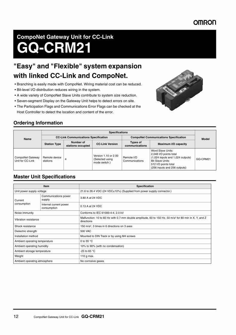
CompoNet Gateway Unit for CC-Link
GQ-CRM21"Easy" and "Flexible" system expansionwith linked CC-Link and CompoNet. • Branching is easily made with CompoNet. Wiring material cost can be reduced.
• Bit-level I/O distribution reduces wiring in the system.
• A wide variety of CompoNet Slave Units contribute to system size reduction.
• Seven-segment Display on the Gateway Unit helps to detect errors on site.
• The Participation Flags and Communications Error Flags can be checked at the
Host Controller to detect the location and content of the error.
Ordering Information
Master Unit Specifications
Name
Specifications
ModelCC-Link Communications Specification CompoNet Communications Specification
Station TypeNumber of
stations occupiedCC-Link Version
Types ofcommunications
Maximum I/O capacity
CompoNet GatewayUnit for CC-Link
Remote devicestations
4Version 1.10 or 2.00(Selected usingmode switch.)
Remote I/OCommunications
Word Slave Units:2,048 I/O points total(1,024 inputs and 1,024 outputs)Bit Slave Units:512 I/O points total(256 inputs and 256 outputs)
GQ-CRM21
Item Specification
Unit power supply voltage 21.6 to 26.4 VDC (24 VDC±10%) (Supplied from power supply connector.)
Current consumption
Communications power supply
3.80 A at 24 VDC
Internal current power consumption
0.13 A at 24 VDC
Noise immunity Conforms to IEC 61000-4-4, 2.0 kV
Vibration resistanceMalfunction: 10 to 60 Hz with 0.7-mm double amplitude, 60 to 150 Hz, 50 m/s2 for 80 min in X, Y, and Z directions
Shock resistance 150 m/s2, 3 times in 6 directions on 3 axes
Dielectric strength 500 VAC
Installation method Mounted to DIN Track or by using M4 screws
Ambient operating temperature 0 to 55 °C
Ambient operating humidity 10% to 90% (with no condensation)
Ambient storage temperature -25 to 65 °C
Weight 110 g max.
Ambient operating atmosphere No corrosive gases
CompoNet Gateway Unit for CC-Link GQ-CRM21 13
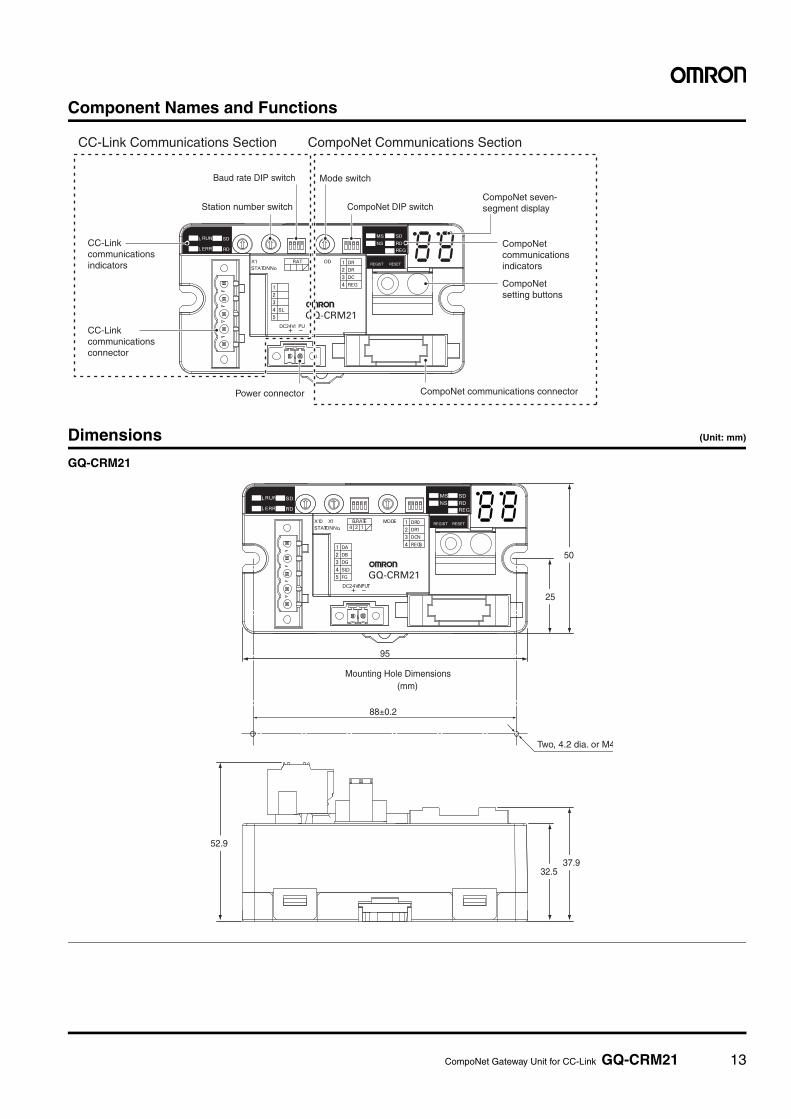
Component Names and Functions
Dimensions (Unit: mm)
GQ-CRM21
CC-Linkcommunicationsconnector
CompoNet communications connectorPower connector
Baud rate DIP switch
CC-Link Communications Section CompoNet Communications Section
Mode switch
Station number switch CompoNet DIP switchCompoNet seven- segment display
CompoNetcommunicationsindicators
CC-Linkcommunicationsindicators
CompoNetsetting buttons
L
L
RUN
ERR RD
SDRD
REGIST RESET
REG
SD
NS
MS
STATION No.
X10 MODEX1 B.RATE DR0
DR1
DCN
REGSDA
DB
DG
SLD
FG
DC24V INPUT
124
25
50
52.9
95
37.9
Mounting Hole Dimensions(mm)
88±0.2
Two, 4.2 dia. or M4
32.5
14 CompoNet Gateway Unit for CC-Link GQ-CRM21
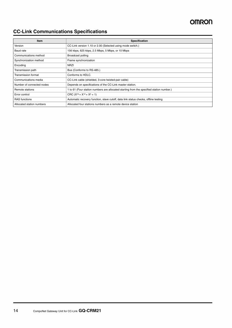
CC-Link Communications Specifications
Item Specification
Version CC-Link version 1.10 or 2.00 (Selected using mode switch.)
Baud rate 156 kbps, 625 kbps, 2.5 Mbps, 5 Mbps, or 10 Mbps
Communications method Broadcast polling
Synchronization method Frame synchronization
Encoding NRZI
Transmission path Bus (Conforms to RS-485.)
Transmission format Conforms to HDLC.
Communications media CC-Link cable (shielded, 3-core twisted-pair cable)
Number of connected nodes Depends on specifications of the CC-Link master station.
Remote stations 1 to 61 (Four station numbers are allocated starting from the specified station number.)
Error control CRC (X16 + X12 + X5 + 1)
RAS functions Automatic recovery function, slave cutoff, data link status checks, offline testing
Allocated station numbers Allocated four stations numbers as a remote device station
15 CRT1-series Smart Slave Units 15
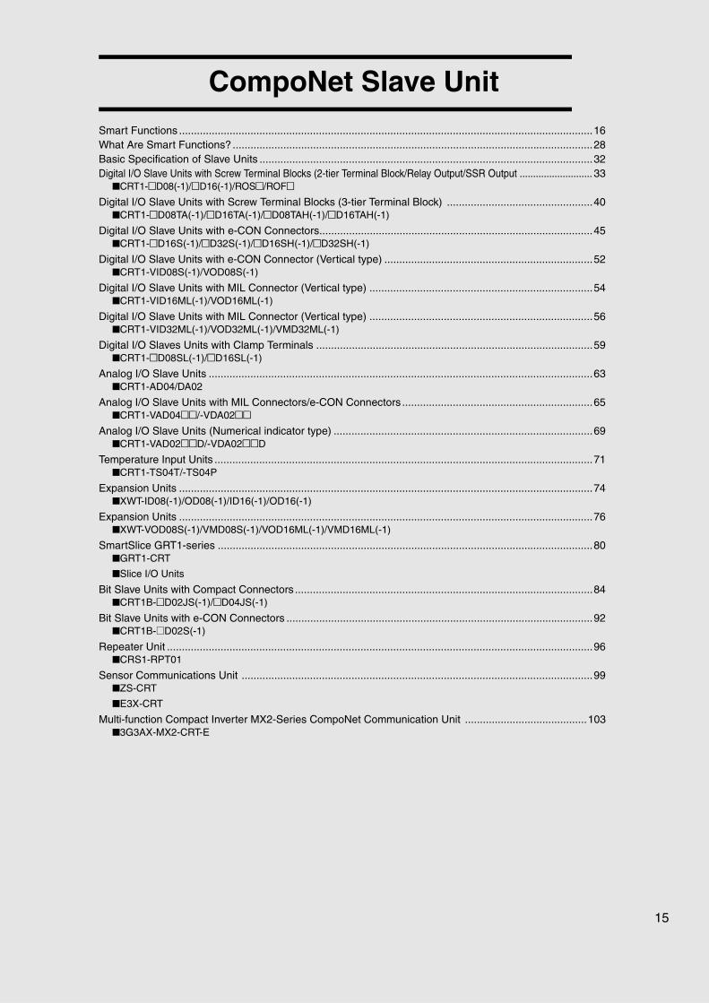
CompoNet Slave Unit
Smart Functions ...........................................................................................................................................16What Are Smart Functions? .........................................................................................................................28Basic Specification of Slave Units ................................................................................................................32Digital I/O Slave Units with Screw Terminal Blocks (2-tier Terminal Block/Relay Output/SSR Output ........................... 33
■CRT1-@D08(-1)/@D16(-1)/ROS@/ROF@Digital I/O Slave Units with Screw Terminal Blocks (3-tier Terminal Block) .................................................40
■CRT1-@D08TA(-1)/@D16TA(-1)/@D08TAH(-1)/@D16TAH(-1)
Digital I/O Slave Units with e-CON Connectors............................................................................................45■CRT1-@D16S(-1)/@D32S(-1)/@D16SH(-1)/@D32SH(-1)
Digital I/O Slave Units with e-CON Connector (Vertical type) ......................................................................52■CRT1-VID08S(-1)/VOD08S(-1)
Digital I/O Slave Units with MIL Connector (Vertical type) ...........................................................................54■CRT1-VID16ML(-1)/VOD16ML(-1)
Digital I/O Slave Units with MIL Connector (Vertical type) ...........................................................................56■CRT1-VID32ML(-1)/VOD32ML(-1)/VMD32ML(-1)
Digital I/O Slaves Units with Clamp Terminals .............................................................................................59■CRT1-@D08SL(-1)/@D16SL(-1)
Analog I/O Slave Units .................................................................................................................................63■CRT1-AD04/DA02
Analog I/O Slave Units with MIL Connectors/e-CON Connectors ................................................................65■CRT1-VAD04@@/-VDA02@@
Analog I/O Slave Units (Numerical indicator type) .......................................................................................69■CRT1-VAD02@@D/-VDA02@@D
Temperature Input Units ...............................................................................................................................71■CRT1-TS04T/-TS04P
Expansion Units ...........................................................................................................................................74■XWT-ID08(-1)/OD08(-1)/ID16(-1)/OD16(-1)
Expansion Units ...........................................................................................................................................76■XWT-VOD08S(-1)/VMD08S(-1)/VOD16ML(-1)/VMD16ML(-1)
SmartSlice GRT1-series ..............................................................................................................................80■GRT1-CRT
■Slice I/O Units
Bit Slave Units with Compact Connectors ....................................................................................................84■CRT1B-@D02JS(-1)/@D04JS(-1)
Bit Slave Units with e-CON Connectors .......................................................................................................92■CRT1B-@D02S(-1)
Repeater Unit ...............................................................................................................................................96■CRS1-RPT01
Sensor Communications Unit ......................................................................................................................99■ZS-CRT
■E3X-CRT
Multi-function Compact Inverter MX2-Series CompoNet Communication Unit .........................................103■3G3AX-MX2-CRT-E
16 CRT1-series Smart Slave Units
Smart Functions
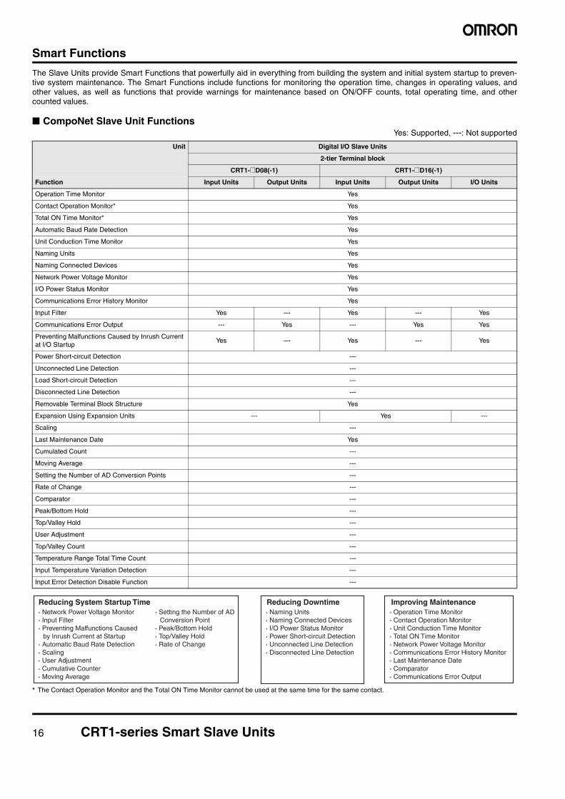
The Slave Units provide Smart Functions that powerfully aid in everything from building the system and initial system startup to preven-tive system maintenance. The Smart Functions include functions for monitoring the operation time, changes in operating values, andother values, as well as functions that provide warnings for maintenance based on ON/OFF counts, total operating time, and othercounted values.
■ CompoNet Slave Unit FunctionsYes: Supported, ---: Not supported
* The Contact Operation Monitor and the Total ON Time Monitor cannot be used at the same time for the same contact.
Unit Digital I/O Slave Units
2-tier Terminal block
CRT1-@D08(-1) CRT1-@D16(-1)
Function Input Units Output Units Input Units Output Units I/O Units
Operation Time Monitor Yes
Contact Operation Monitor* Yes
Total ON Time Monitor* Yes
Automatic Baud Rate Detection Yes
Unit Conduction Time Monitor Yes
Naming Units Yes
Naming Connected Devices Yes
Network Power Voltage Monitor Yes
I/O Power Status Monitor Yes
Communications Error History Monitor Yes
Input Filter Yes --- Yes --- Yes
Communications Error Output --- Yes --- Yes Yes
Preventing Malfunctions Caused by Inrush Current at I/O Startup
Yes --- Yes --- Yes
Power Short-circuit Detection ---
Unconnected Line Detection ---
Load Short-circuit Detection ---
Disconnected Line Detection ---
Removable Terminal Block Structure Yes
Expansion Using Expansion Units --- Yes ---
Scaling ---
Last Maintenance Date Yes
Cumulated Count ---
Moving Average ---
Setting the Number of AD Conversion Points ---
Rate of Change ---
Comparator ---
Peak/Bottom Hold ---
Top/Valley Hold ---
User Adjustment ---
Top/Valley Count ---
Temperature Range Total Time Count ---
Input Temperature Variation Detection ---
Input Error Detection Disable Function ---
Reducing System Startup Time· Network Power Voltage Monitor· Input Filter· Preventing Malfunctions Caused
by Inrush Current at Startup· Automatic Baud Rate Detection· Scaling· User Adjustment· Cumulative Counter· Moving Average
· Setting the Number of AD Conversion Point
· Peak/Bottom Hold· Top/Valley Hold· Rate of Change
· Operation Time Monitor· Contact Operation Monitor· Unit Conduction Time Monitor· Total ON Time Monitor· Network Power Voltage Monitor· Communications Error History Monitor· Last Maintenance Date· Comparator· Communications Error Output
Improving Maintenance · Naming Units · Naming Connected Devices · I/O Power Status Monitor · Power Short-circuit Detection · Unconnected Line Detection · Disconnected Line Detection
Reducing Downtime
CRT1-series Smart Slave Units 17
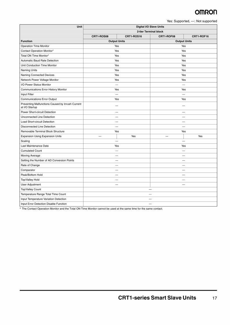
Yes: Supported, ---: Not supported
* The Contact Operation Monitor and the Total ON Time Monitor cannot be used at the same time for the same contact.
Unit Digital I/O Slave Units
2-tier Terminal block
CRT1-ROS08 CRT1-ROS16 CRT1-ROF08 CRT1-ROF16
Function Output Units Output Units
Operation Time Monitor Yes Yes
Contact Operation Monitor* Yes Yes
Total ON Time Monitor* Yes Yes
Automatic Baud Rate Detection Yes Yes
Unit Conduction Time Monitor Yes Yes
Naming Units Yes Yes
Naming Connected Devices Yes Yes
Network Power Voltage Monitor Yes Yes
I/O Power Status Monitor --- ---
Communications Error History Monitor Yes Yes
Input Filter --- ---
Communications Error Output Yes Yes
Preventing Malfunctions Caused by Inrush Current at I/O Startup
--- ---
Power Short-circuit Detection --- ---
Unconnected Line Detection --- ---
Load Short-circuit Detection --- ---
Disconnected Line Detection --- ---
Removable Terminal Block Structure Yes Yes
Expansion Using Expansion Units --- Yes --- Yes
Scaling --- ---
Last Maintenance Date Yes Yes
Cumulated Count --- ---
Moving Average --- ---
Setting the Number of AD Conversion Points --- ---
Rate of Change --- ---
Comparator --- ---
Peak/Bottom Hold --- ---
Top/Valley Hold --- ---
User Adjustment --- ---
Top/Valley Count ---
Temperature Range Total Time Count ---
Input Temperature Variation Detection ---
Input Error Detection Disable Function ---
18 CRT1-series Smart Slave Units
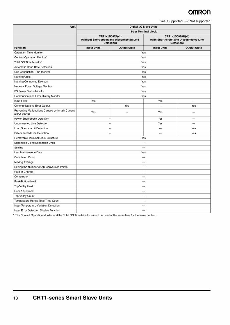
Yes: Supported, ---: Not supported
* The Contact Operation Monitor and the Total ON Time Monitor cannot be used at the same time for the same contact.
Unit Digital I/O Slave Units
3-tier Terminal block
CRT1-@D08TA(-1)(without Short-circuit and Disconnected Line
Detection)
CRT1-@D08TAH(-1)(with Short-circuit and Disconnected Line
Detection)
Function Input Units Output Units Input Units Output Units
Operation Time Monitor Yes
Contact Operation Monitor* Yes
Total ON Time Monitor* Yes
Automatic Baud Rate Detection Yes
Unit Conduction Time Monitor Yes
Naming Units Yes
Naming Connected Devices Yes
Network Power Voltage Monitor Yes
I/O Power Status Monitor Yes
Communications Error History Monitor Yes
Input Filter Yes --- Yes ---
Communications Error Output --- Yes --- Yes
Preventing Malfunctions Caused by Inrush Current at I/O Startup
Yes --- Yes ---
Power Short-circuit Detection --- Yes ---
Unconnected Line Detection --- Yes ---
Load Short-circuit Detection --- --- Yes
Disconnected Line Detection --- --- Yes
Removable Terminal Block Structure Yes
Expansion Using Expansion Units ---
Scaling ---
Last Maintenance Date Yes
Cumulated Count ---
Moving Average ---
Setting the Number of AD Conversion Points ---
Rate of Change ---
Comparator ---
Peak/Bottom Hold ---
Top/Valley Hold ---
User Adjustment ---
Top/Valley Count ---
Temperature Range Total Time Count ---
Input Temperature Variation Detection ---
Input Error Detection Disable Function ---
CRT1-series Smart Slave Units 19
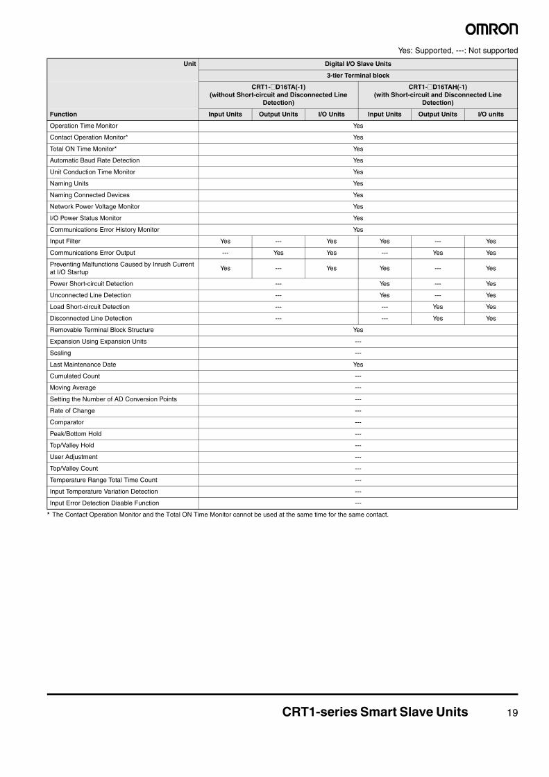
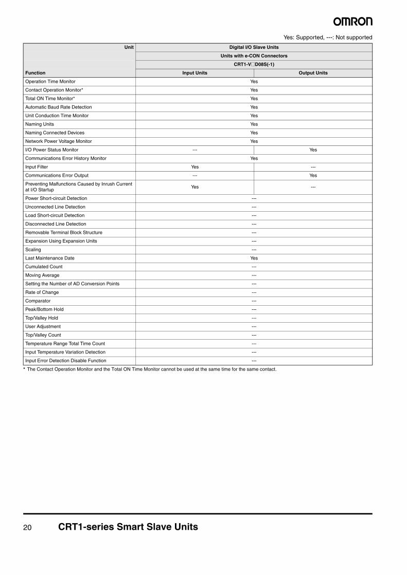
Yes: Supported, ---: Not supported
* The Contact Operation Monitor and the Total ON Time Monitor cannot be used at the same time for the same contact.
Unit Digital I/O Slave Units
3-tier Terminal block
CRT1-@D16TA(-1)(without Short-circuit and Disconnected Line
Detection)
CRT1-@D16TAH(-1)(with Short-circuit and Disconnected Line
Detection)
Function Input Units Output Units I/O Units Input Units Output Units I/O units
Operation Time Monitor Yes
Contact Operation Monitor* Yes
Total ON Time Monitor* Yes
Automatic Baud Rate Detection Yes
Unit Conduction Time Monitor Yes
Naming Units Yes
Naming Connected Devices Yes
Network Power Voltage Monitor Yes
I/O Power Status Monitor Yes
Communications Error History Monitor Yes
Input Filter Yes --- Yes Yes --- Yes
Communications Error Output --- Yes Yes --- Yes Yes
Preventing Malfunctions Caused by Inrush Current at I/O Startup
Yes --- Yes Yes --- Yes
Power Short-circuit Detection --- Yes --- Yes
Unconnected Line Detection --- Yes --- Yes
Load Short-circuit Detection --- --- Yes Yes
Disconnected Line Detection --- --- Yes Yes
Removable Terminal Block Structure Yes
Expansion Using Expansion Units ---
Scaling ---
Last Maintenance Date Yes
Cumulated Count ---
Moving Average ---
Setting the Number of AD Conversion Points ---
Rate of Change ---
Comparator ---
Peak/Bottom Hold ---
Top/Valley Hold ---
User Adjustment ---
Top/Valley Count ---
Temperature Range Total Time Count ---
Input Temperature Variation Detection ---
Input Error Detection Disable Function ---
20 CRT1-series Smart Slave Units
Yes: Supported, ---: Not supported
* The Contact Operation Monitor and the Total ON Time Monitor cannot be used at the same time for the same contact.
Unit Digital I/O Slave Units
Units with e-CON Connectors
CRT1-V@D08S(-1)
Function Input Units Output Units
Operation Time Monitor Yes
Contact Operation Monitor* Yes
Total ON Time Monitor* Yes
Automatic Baud Rate Detection Yes
Unit Conduction Time Monitor Yes
Naming Units Yes
Naming Connected Devices Yes
Network Power Voltage Monitor Yes
I/O Power Status Monitor --- Yes
Communications Error History Monitor Yes
Input Filter Yes ---
Communications Error Output --- Yes
Preventing Malfunctions Caused by Inrush Current at I/O Startup
Yes ---
Power Short-circuit Detection ---
Unconnected Line Detection ---
Load Short-circuit Detection ---
Disconnected Line Detection ---
Removable Terminal Block Structure ---
Expansion Using Expansion Units ---
Scaling ---
Last Maintenance Date Yes
Cumulated Count ---
Moving Average ---
Setting the Number of AD Conversion Points ---
Rate of Change ---
Comparator ---
Peak/Bottom Hold ---
Top/Valley Hold ---
User Adjustment ---
Top/Valley Count ---
Temperature Range Total Time Count ---
Input Temperature Variation Detection ---
Input Error Detection Disable Function ---

CRT1-series Smart Slave Units 21
Yes: Supported, ---: Not supported
* The Contact Operation Monitor and the Total ON Time Monitor cannot be used at the same time for the same contact.
Unit Digital I/O Slave Units
Units with e-CON Connectors
CRT1-@D16S(-1)(without Short-circuit and Disconnected Line
Detection)
CRT1-@D16SH(-1)(with Short-circuit and Disconnected Line Detection)
Function Input Units Output Units I/O Units Input Units Output Units I/O units
Operation Time Monitor Yes
Contact Operation Monitor* Yes
Total ON Time Monitor* Yes
Automatic Baud Rate Detection Yes
Unit Conduction Time Monitor Yes
Naming Units Yes
Naming Connected Devices Yes
Network Power Voltage Monitor Yes
I/O Power Status Monitor --- Yes Yes --- Yes Yes
Communications Error History Monitor Yes
Input Filter Yes --- Yes Yes --- Yes
Communications Error Output --- Yes Yes --- Yes Yes
Preventing Malfunctions Caused by Inrush Current at I/O Startup
Yes --- Yes Yes --- Yes
Power Short-circuit Detection --- Yes --- Yes
Unconnected Line Detection --- Yes --- Yes
Load Short-circuit Detection --- --- Yes Yes
Disconnected Line Detection --- --- Yes Yes
Removable Terminal Block Structure ---
Expansion Using Expansion Units ---
Scaling ---
Last Maintenance Date Yes
Cumulated Count ---
Moving Average ---
Setting the Number of AD Conversion Points ---
Rate of Change ---
Comparator ---
Peak/Bottom Hold ---
Top/Valley Hold ---
User Adjustment ---
Top/Valley Count ---
Temperature Range Total Time Count ---
Input Temperature Variation Detection ---
Input Error Detection Disable Function ---
22 CRT1-series Smart Slave Units
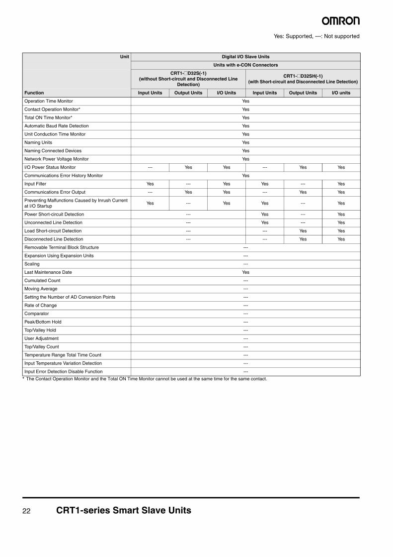
Yes: Supported, ---: Not supported
* The Contact Operation Monitor and the Total ON Time Monitor cannot be used at the same time for the same contact.
Unit Digital I/O Slave Units
Units with e-CON Connectors
CRT1-@D32S(-1)(without Short-circuit and Disconnected Line
Detection)
CRT1-@D32SH(-1)(with Short-circuit and Disconnected Line Detection)
Function Input Units Output Units I/O Units Input Units Output Units I/O units
Operation Time Monitor Yes
Contact Operation Monitor* Yes
Total ON Time Monitor* Yes
Automatic Baud Rate Detection Yes
Unit Conduction Time Monitor Yes
Naming Units Yes
Naming Connected Devices Yes
Network Power Voltage Monitor Yes
I/O Power Status Monitor --- Yes Yes --- Yes Yes
Communications Error History Monitor Yes
Input Filter Yes --- Yes Yes --- Yes
Communications Error Output --- Yes Yes --- Yes Yes
Preventing Malfunctions Caused by Inrush Current at I/O Startup
Yes --- Yes Yes --- Yes
Power Short-circuit Detection --- Yes --- Yes
Unconnected Line Detection --- Yes --- Yes
Load Short-circuit Detection --- --- Yes Yes
Disconnected Line Detection --- --- Yes Yes
Removable Terminal Block Structure ---
Expansion Using Expansion Units ---
Scaling ---
Last Maintenance Date Yes
Cumulated Count ---
Moving Average ---
Setting the Number of AD Conversion Points ---
Rate of Change ---
Comparator ---
Peak/Bottom Hold ---
Top/Valley Hold ---
User Adjustment ---
Top/Valley Count ---
Temperature Range Total Time Count ---
Input Temperature Variation Detection ---
Input Error Detection Disable Function ---
CRT1-series Smart Slave Units 23
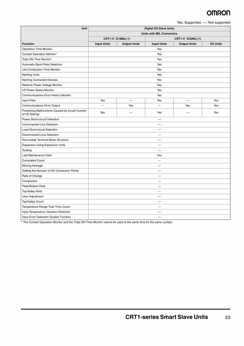
Yes: Supported, ---: Not supported
* The Contact Operation Monitor and the Total ON Time Monitor cannot be used at the same time for the same contact.
Unit Digital I/O Slave Units
Units with MIL Connectors
CRT1-V@D16ML(-1) CRT1-V@D32ML(-1)
Function Input Units Output Units Input Units Output Units I/O Units
Operation Time Monitor Yes
Contact Operation Monitor* Yes
Total ON Time Monitor* Yes
Automatic Baud Rate Detection Yes
Unit Conduction Time Monitor Yes
Naming Units Yes
Naming Connected Devices Yes
Network Power Voltage Monitor Yes
I/O Power Status Monitor Yes
Communications Error History Monitor Yes
Input Filter Yes --- Yes --- Yes
Communications Error Output --- Yes --- Yes Yes
Preventing Malfunctions Caused by Inrush Current at I/O Startup
Yes --- Yes --- Yes
Power Short-circuit Detection ---
Unconnected Line Detection ---
Load Short-circuit Detection ---
Disconnected Line Detection ---
Removable Terminal Block Structure ---
Expansion Using Expansion Units ---
Scaling ---
Last Maintenance Date Yes
Cumulated Count ---
Moving Average ---
Setting the Number of AD Conversion Points ---
Rate of Change ---
Comparator ---
Peak/Bottom Hold ---
Top/Valley Hold ---
User Adjustment ---
Top/Valley Count ---
Temperature Range Total Time Count ---
Input Temperature Variation Detection ---
Input Error Detection Disable Function ---
24 CRT1-series Smart Slave Units
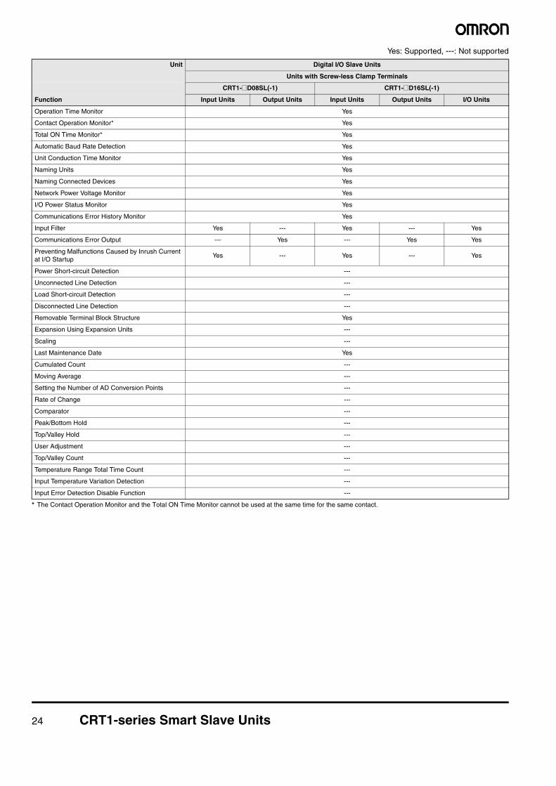
Yes: Supported, ---: Not supported
* The Contact Operation Monitor and the Total ON Time Monitor cannot be used at the same time for the same contact.
Unit Digital I/O Slave Units
Units with Screw-less Clamp Terminals
CRT1-@D08SL(-1) CRT1-@D16SL(-1)
Function Input Units Output Units Input Units Output Units I/O Units
Operation Time Monitor Yes
Contact Operation Monitor* Yes
Total ON Time Monitor* Yes
Automatic Baud Rate Detection Yes
Unit Conduction Time Monitor Yes
Naming Units Yes
Naming Connected Devices Yes
Network Power Voltage Monitor Yes
I/O Power Status Monitor Yes
Communications Error History Monitor Yes
Input Filter Yes --- Yes --- Yes
Communications Error Output --- Yes --- Yes Yes
Preventing Malfunctions Caused by Inrush Current at I/O Startup
Yes --- Yes --- Yes
Power Short-circuit Detection ---
Unconnected Line Detection ---
Load Short-circuit Detection ---
Disconnected Line Detection ---
Removable Terminal Block Structure Yes
Expansion Using Expansion Units ---
Scaling ---
Last Maintenance Date Yes
Cumulated Count ---
Moving Average ---
Setting the Number of AD Conversion Points ---
Rate of Change ---
Comparator ---
Peak/Bottom Hold ---
Top/Valley Hold ---
User Adjustment ---
Top/Valley Count ---
Temperature Range Total Time Count ---
Input Temperature Variation Detection ---
Input Error Detection Disable Function ---
CRT1-series Smart Slave Units 25
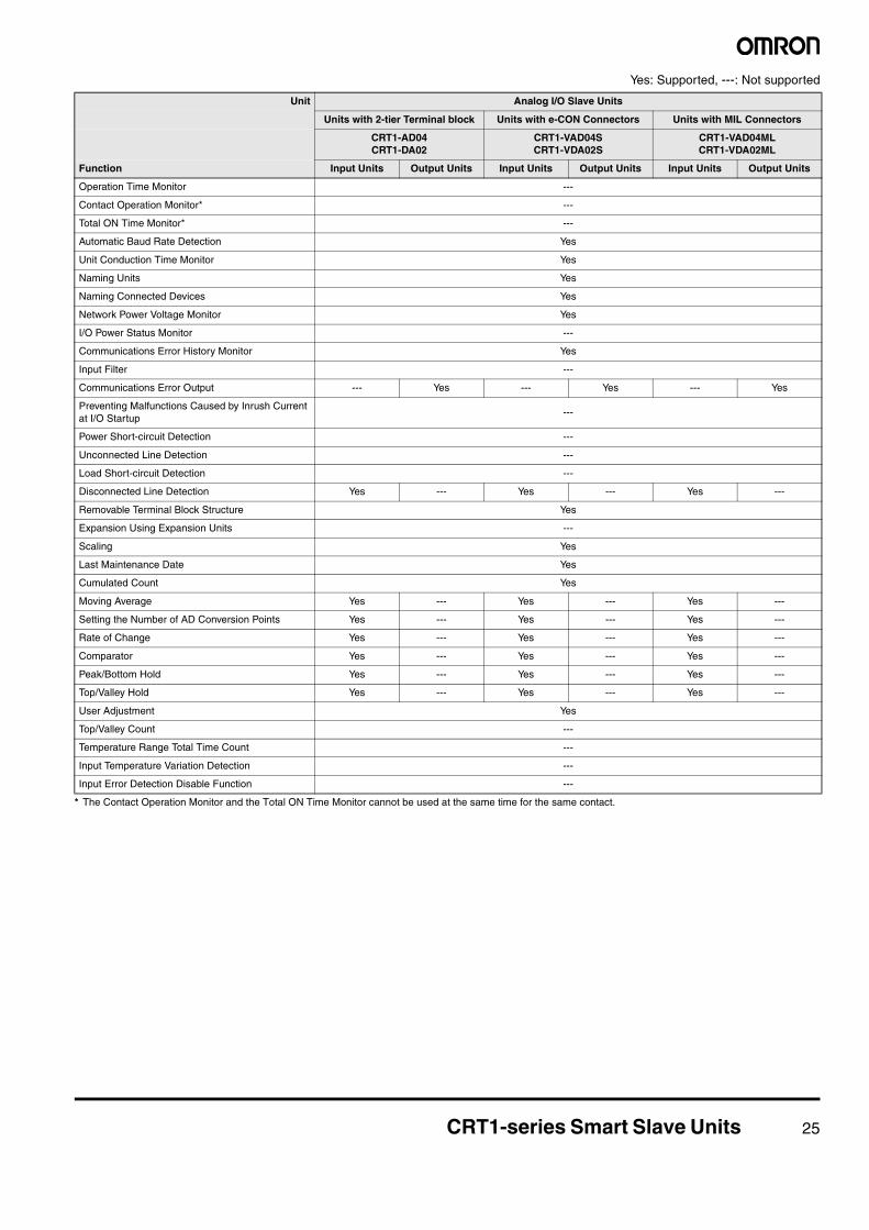
Yes: Supported, ---: Not supported
* The Contact Operation Monitor and the Total ON Time Monitor cannot be used at the same time for the same contact.
Unit Analog I/O Slave Units
Units with 2-tier Terminal block Units with e-CON Connectors Units with MIL Connectors
CRT1-AD04CRT1-DA02
CRT1-VAD04SCRT1-VDA02S
CRT1-VAD04MLCRT1-VDA02ML
Function Input Units Output Units Input Units Output Units Input Units Output Units
Operation Time Monitor ---
Contact Operation Monitor* ---
Total ON Time Monitor* ---
Automatic Baud Rate Detection Yes
Unit Conduction Time Monitor Yes
Naming Units Yes
Naming Connected Devices Yes
Network Power Voltage Monitor Yes
I/O Power Status Monitor ---
Communications Error History Monitor Yes
Input Filter ---
Communications Error Output --- Yes --- Yes --- Yes
Preventing Malfunctions Caused by Inrush Current at I/O Startup
---
Power Short-circuit Detection ---
Unconnected Line Detection ---
Load Short-circuit Detection ---
Disconnected Line Detection Yes --- Yes --- Yes ---
Removable Terminal Block Structure Yes
Expansion Using Expansion Units ---
Scaling Yes
Last Maintenance Date Yes
Cumulated Count Yes
Moving Average Yes --- Yes --- Yes ---
Setting the Number of AD Conversion Points Yes --- Yes --- Yes ---
Rate of Change Yes --- Yes --- Yes ---
Comparator Yes --- Yes --- Yes ---
Peak/Bottom Hold Yes --- Yes --- Yes ---
Top/Valley Hold Yes --- Yes --- Yes ---
User Adjustment Yes
Top/Valley Count ---
Temperature Range Total Time Count ---
Input Temperature Variation Detection ---
Input Error Detection Disable Function ---
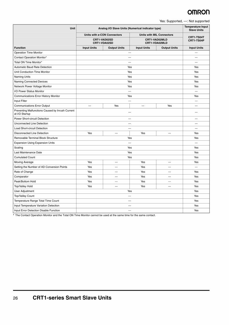
26 CRT1-series Smart Slave Units
Yes: Supported, ---: Not supported
* The Contact Operation Monitor and the Total ON Time Monitor cannot be used at the same time for the same contact.
Unit Analog I/O Slave Units (Numerical indicator type)Temperature Input
Slave Units
Units with e-CON Connectors Units with MIL ConnectorsCRT1-TS04TCRT1-TS04PCRT1-VAD02SD
CRT1-VDA02SDCRT1-VAD02MLDCRT1-VDA02MLD
Function Input Units Output Units Input Units Output Units Input Units
Operation Time Monitor --- ---
Contact Operation Monitor* --- ---
Total ON Time Monitor* --- ---
Automatic Baud Rate Detection Yes Yes
Unit Conduction Time Monitor Yes Yes
Naming Units Yes Yes
Naming Connected Devices Yes Yes
Network Power Voltage Monitor Yes Yes
I/O Power Status Monitor --- ---
Communications Error History Monitor Yes Yes
Input Filter --- ---
Communications Error Output --- Yes --- Yes ---
Preventing Malfunctions Caused by Inrush Current at I/O Startup
--- ---
Power Short-circuit Detection --- ---
Unconnected Line Detection --- ---
Load Short-circuit Detection --- ---
Disconnected Line Detection Yes --- Yes --- Yes
Removable Terminal Block Structure Yes Yes
Expansion Using Expansion Units --- ---
Scaling Yes Yes
Last Maintenance Date Yes Yes
Cumulated Count Yes Yes
Moving Average Yes --- Yes --- Yes
Setting the Number of AD Conversion Points Yes --- Yes --- ---
Rate of Change Yes --- Yes --- Yes
Comparator Yes --- Yes --- Yes
Peak/Bottom Hold Yes --- Yes --- Yes
Top/Valley Hold Yes --- Yes --- Yes
User Adjustment Yes Yes
Top/Valley Count --- Yes
Temperature Range Total Time Count --- Yes
Input Temperature Variation Detection --- Yes
Input Error Detection Disable Function --- Yes
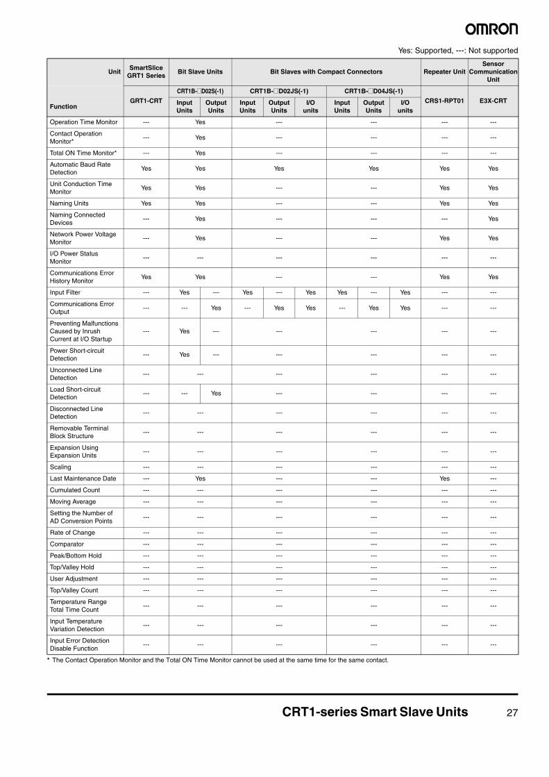
CRT1-series Smart Slave Units 27
Yes: Supported, ---: Not supported
* The Contact Operation Monitor and the Total ON Time Monitor cannot be used at the same time for the same contact.
UnitSmartSlice
GRT1 SeriesBit Slave Units Bit Slaves with Compact Connectors Repeater Unit
Sensor Communication
Unit
GRT1-CRT
CRT1B-@D02S(-1) CRT1B-@D02JS(-1) CRT1B-@D04JS(-1)
CRS1-RPT01 E3X-CRTFunction
Input Units
Output Units
Input Units
Output Units
I/O units
Input Units
Output Units
I/O units
Operation Time Monitor --- Yes --- --- --- ---
Contact Operation Monitor*
--- Yes --- --- --- ---
Total ON Time Monitor* --- Yes --- --- --- ---
Automatic Baud Rate Detection
Yes Yes Yes Yes Yes Yes
Unit Conduction Time Monitor
Yes Yes --- --- Yes Yes
Naming Units Yes Yes --- --- Yes Yes
Naming Connected Devices
--- Yes --- --- --- Yes
Network Power Voltage Monitor
--- Yes --- --- Yes Yes
I/O Power Status Monitor
--- --- --- --- --- ---
Communications Error History Monitor
Yes Yes --- --- Yes Yes
Input Filter --- Yes --- Yes --- Yes Yes --- Yes --- ---
Communications Error Output
--- --- Yes --- Yes Yes --- Yes Yes --- ---
Preventing Malfunctions Caused by Inrush Current at I/O Startup
--- Yes --- --- --- --- ---
Power Short-circuit Detection
--- Yes --- --- --- --- ---
Unconnected Line Detection
--- --- --- --- --- ---
Load Short-circuit Detection
--- --- Yes --- --- --- ---
Disconnected Line Detection
--- --- --- --- --- ---
Removable Terminal Block Structure
--- --- --- --- --- ---
Expansion Using Expansion Units
--- --- --- --- --- ---
Scaling --- --- --- --- --- ---
Last Maintenance Date --- Yes --- --- Yes ---
Cumulated Count --- --- --- --- --- ---
Moving Average --- --- --- --- --- ---
Setting the Number of AD Conversion Points
--- --- --- --- --- ---
Rate of Change --- --- --- --- --- ---
Comparator --- --- --- --- --- ---
Peak/Bottom Hold --- --- --- --- --- ---
Top/Valley Hold --- --- --- --- --- ---
User Adjustment --- --- --- --- --- ---
Top/Valley Count --- --- --- --- --- ---
Temperature Range Total Time Count
--- --- --- --- --- ---
Input Temperature Variation Detection
--- --- --- --- --- ---
Input Error Detection Disable Function
--- --- --- --- --- ---
28 CRT1-series Smart Slave Units
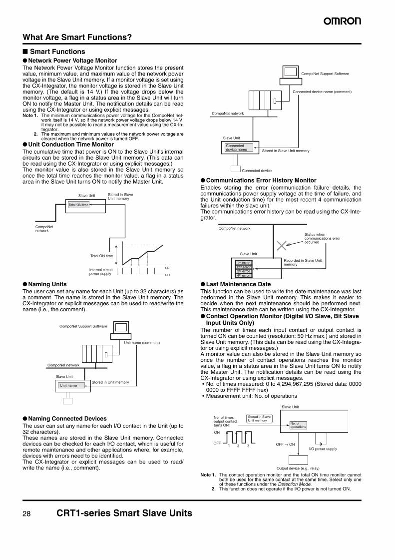
What Are Smart Functions?
■ Smart Functions● Network Power Voltage MonitorThe Network Power Voltage Monitor function stores the presentvalue, minimum value, and maximum value of the network powervoltage in the Slave Unit memory. If a monitor voltage is set usingthe CX-Integrator, the monitor voltage is stored in the Slave Unitmemory. (The default is 14 V.) If the voltage drops below themonitor voltage, a flag in a status area in the Slave Unit will turnON to notify the Master Unit. The notification details can be readusing the CX-Integrator or using explicit messages.Note 1. The minimum communications power voltage for the CompoNet net-
work itself is 14 V, so if the network power voltage drops below 14 V,it may not be possible to read a measurement value using the CX-In-tegrator.
2. The maximum and minimum values of the network power voltage arecleared when the network power is turned OFF.
● Unit Conduction Time MonitorThe cumulative time that power is ON to the Slave Unit's internalcircuits can be stored in the Slave Unit memory. (This data canbe read using the CX-Integrator or using explicit messages.)The monitor value is also stored in the Slave Unit memory soonce the total time reaches the monitor value, a flag in a statusarea in the Slave Unit turns ON to notify the Master Unit.
● Naming UnitsThe user can set any name for each Unit (up to 32 characters) asa comment. The name is stored in the Slave Unit memory. TheCX-Integrator or explicit messages can be used to read/write thename (i.e., the comment).
● Naming Connected DevicesThe user can set any name for each I/O contact in the Unit (up to32 characters).These names are stored in the Slave Unit memory. Connecteddevices can be checked for each I/O contact, which is useful forremote maintenance and other applications where, for example,devices with errors need to be identified. The CX-Integrator or explicit messages can be used to read/write the name (i.e., comment).
● Communications Error History MonitorEnables storing the error (communication failure details, thecommunications power supply voltage at the time of failure, andthe Unit conduction time) for the most recent 4 communicationfailures within the slave unit.The communications error history can be read using the CX-Inte-grator.
● Last Maintenance DateThis function can be used to write the date maintenance was lastperformed in the Slave Unit memory. This makes it easier todecide when the next maintenance should be performed next.This maintenance date can be written using the CX-Integrator.● Contact Operation Monitor (Digital I/O Slave, Bit Slave
Input Units Only)The number of times each input contact or output contact isturned ON can be counted (resolution: 50 Hz max.) and stored inSlave Unit memory. (This data can be read using the CX-Integra-tor or using explicit messages.)A monitor value can also be stored in the Slave Unit memory soonce the number of contact operations reaches the monitorvalue, a flag in a status area in the Slave Unit turns ON to notifythe Master Unit. The notification details can be read using theCX-Integrator or using explicit messages.• No. of times measured: 0 to 4,294,967,295 (Stored data: 0000
0000 to FFFF FFFF hex)• Measurement unit: No. of operations
Note 1. The contact operation monitor and the total ON time monitor cannotboth be used for the same contact at the same time. Select only oneof these functions under the Detection Mode.
2. This function does not operate if the I/O power is not turned ON.
CompoNet network
Slave Unit
Total ON time
Total ON time
ON
OFF
Stored in Slave Unit memory
Internal circuit power supply
CompoNet Support Software
Unit name (comment)
CompoNet network
Slave Unit
Unit nameStored in Unit memory
CompoNet Support Software
Connected device name (comment)
Stored in Slave Unit memory
Connected device
Slave Unit
CompoNet network
Connected device name
CompoNet network
Slave Unit
4th error3rd error2nd error1st error
Recorded in Slave Unit memory
Status when communications error occurred
1 2 3
Slave Unit
OFF → ON
Output device (e.g., relay)
I/O power supply
Stored in Slave Unit memory
No. of operations
No. of times output contact turns ON:
ON
OFF
CRT1-series Smart Slave Units 29
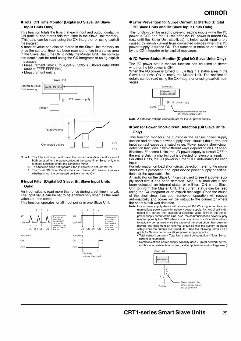
● Total ON Time Monitor (Digital I/O Slave, Bit Slave Input Units Only)
This function totals the time that each input and output contact isON (unit: s) and stores this total time in the Slave Unit memory.(This data can be read using the CX-Integrator or using explicitmessages.)A monitor value can also be stored in the Slave Unit memory soonce the set total time has been reached, a flag in a status areain the Slave Unit turns ON to notify the Master Unit. The notifica-tion details can be read using the CX-Integrator or using explicitmessages.• Measurement time: 0 to 4,294,967,295 s (Stored data: 0000
0000 to FFFF FFFF Hex)• Measurement unit: s
Note 1. The total ON time monitor and the contact operation monitor cannotboth be used for the same contact at the same time. Select only oneof these functions under the Detection Mode.
2. This function does not operate if the I/O power is not turned ON.3. The Total ON Time Monitor Function checks at 1 second intervals
whether or not the connected device is turned ON.
● Input Filter (Digital I/O Slave, Bit Slave Input Units Only)
An input value is read more than once during a set time interval.The input value can be set to be enabled only when all the readvalues are the same.This function operates for all input points in one Slave Unit.
● Error Prevention for Surge Current at Startup (Digital I/O Slave Units and Bit Slave Input Units Only)
This function can be used to prevent reading inputs while the I/Opower is OFF and for 100 ms after the I/O power is turned ON(i.e., until the Slave Unit stabilizes). It helps avoid input errorscaused by inrush current from connected devices when the I/Opower supply is turned ON. This function is enabled or disabledby the CX-Integrator or by explicit messages.
● I/O Power Status Monitor (Digital I/O Slave Units Only)The I/O power status monitor function can be used to detectwhether the I/O power is ON.When the I/O power is turned OFF, a flag in a status area in theSlave Unit turns ON to notify the Master Unit. The notificationdetails can be read using the CX-Integrator or using explicit mes-sages.
Note: A detection voltage cannot be set for the I/O power supply.
● Sensor Power Short-circuit Detection (Bit Slave Units Only)
This function monitors the current in the sensor power supplysection and detects a power supply short-circuit if the current perinput contact exceeds a rated value. Power supply short-circuitdetection functions in two different ways depending on Unit spec-ifications. For some Units, the I/O power supply is turned OFF tothe entire Unit if a short-circuit is detected for even one input.For other Units, the I/O power is turned OFF individually for eachinput.For information on load short-circuit detection, refer to the powershort-circuit protection and input device power supply specifica-tions for the applicable Unit.An indicator on the Slave Unit can be used to see if a power sup-ply short-circuit has been detected. Also, if a short-circuit hasbeen detected, an internal status bit will turn ON in the SlaveUnit to inform the Master Unit. The current status can be readusing the CX-Integrator or an explicit message. Once the causeof the short-circuit has been removed, operation will recoverautomatically and power will be output to the connector wherethe short-circuit was detected.Note: Use a power supply device with a rating of 100 W or higher as the com-
munications power supply for network power supply. A short-circuit is de-tected if a current that exceeds a specified value flows in the sensorpower supply output of the Unit. Also, the communications power supplymay temporarily turn OFF when a short circuit occurs. Operation will au-tomatically be restored once the cause of the short circuit has been re-moved, but implement an external circuit so that the system operatessafely while the outputs are turned OFF. Use the following formula as aguide for Sensor communications power supply capacity.• Total network current = Total Unit current consumption + Total Sensor
current consumption• Communications power supply capacity used ≥ (Total network current
+ (Short-circuit detection current)) • (CompoNet network voltage used)
ON
OFF
Stored in Slave Unit memory
Slave Unit
I/O power supply
Total ON time
Connected device
Sensor
Total ON time
OFF
ON
OFF
ON
OFF
ON
ON OFF OFF ON ON ON ON ON
4 3 21 4 3 21
Input data
OFF
ON
Input data
The internal input data remains OFF because the read input data was not ON all 4 times.
ON delay (= input filter time)
The internal input data turns ON because the read input data was ON all 4 times.
Slave Unit
I/O power supply
Sensor
I/O power supply voltage
Monitors whether or not the I/O power supply is ON.
Short-circuit
Sensor
Short-circuits in the sensor power supply can be detected.
Slave Unit
30 CRT1-series Smart Slave Units
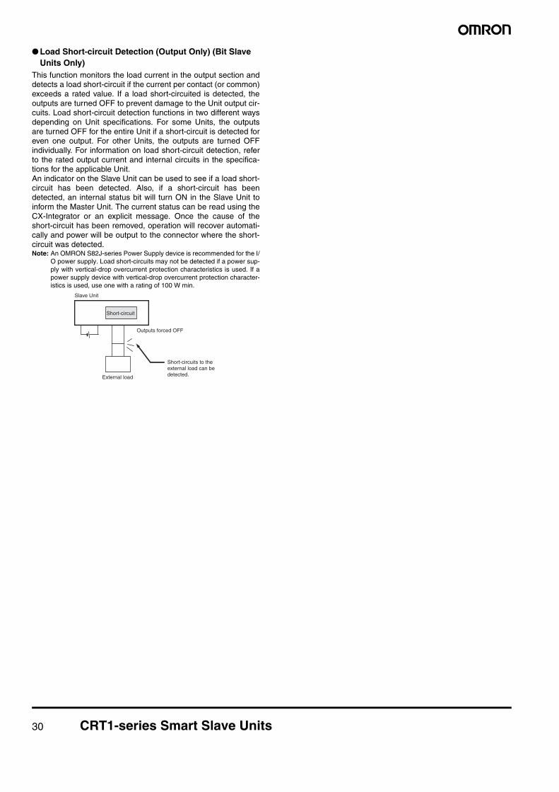
● Load Short-circuit Detection (Output Only) (Bit Slave Units Only)
This function monitors the load current in the output section anddetects a load short-circuit if the current per contact (or common)exceeds a rated value. If a load short-circuited is detected, theoutputs are turned OFF to prevent damage to the Unit output cir-cuits. Load short-circuit detection functions in two different waysdepending on Unit specifications. For some Units, the outputsare turned OFF for the entire Unit if a short-circuit is detected foreven one output. For other Units, the outputs are turned OFFindividually. For information on load short-circuit detection, referto the rated output current and internal circuits in the specifica-tions for the applicable Unit.An indicator on the Slave Unit can be used to see if a load short-circuit has been detected. Also, if a short-circuit has beendetected, an internal status bit will turn ON in the Slave Unit toinform the Master Unit. The current status can be read using theCX-Integrator or an explicit message. Once the cause of theshort-circuit has been removed, operation will recover automati-cally and power will be output to the connector where the short-circuit was detected.Note: An OMRON S82J-series Power Supply device is recommended for the I/
O power supply. Load short-circuits may not be detected if a power sup-ply with vertical-drop overcurrent protection characteristics is used. If apower supply device with vertical-drop overcurrent protection character-istics is used, use one with a rating of 100 W min.
Short-circuit
Outputs forced OFF
External load
Short-circuits to the external load can be detected.
Slave Unit
31
MEMO
32 Basic Specification of Slave Units
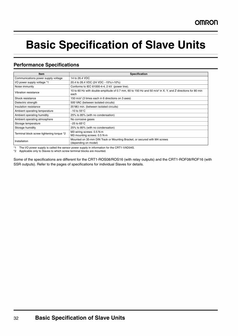
Basic Specification of Slave Units
Performance Specifications
*1 The I/O power supply is called the sensor power supply in information for the CRT1-VAD04S.*2 Applicable only to Slaves to which screw terminal blocks are mounted.
Some of the specifications are different for the CRT1-ROS08/ROS16 (with relay outputs) and the CRT1-ROF08/ROF16 (with SSR outputs). Refer to the pages of specifications for individual Slaves for details.
Item Specification
Communications power supply voltage 14 to 26.4 VDC
I/O power supply voltage *1 20.4 to 26.4 VDC (24 VDC −15%/+10%)
Noise immunity Conforms to IEC 61000-4-4, 2 kV (power line).
Vibration resistance10 to 60 Hz with double-amplitude of 0.7 mm, 60 to 150 Hz and 50 m/s2 in X, Y, and Z directions for 80 min each
Shock resistance 150 m/s2 (3 times each in 6 directions on 3 axes)
Dielectric strength 500 VAC (between isolated circuits)
Insulation resistance 20 MΩ min. (between isolated circuits)
Ambient operating temperature −10 to 55°CAmbient operating humidity 25% to 85% (with no condensation)
Ambient operating atmosphere No corrosive gases
Storage temperature −25 to 65°CStorage humidity 25% to 85% (with no condensation)
Terminal block screw tightening torque *2M3 wiring screws: 0.5 N·mM3 mounting screws: 0.5 N·m
InstallationMounted on 35-mm DIN Track or Mounting Bracket, or secured with M4 screws(depending on model)
Digital I/O Slave Units with Screw Terminal Blocks (2-tier Terminal Block/Relay Output/SSR Output) CRT1-@D08(-1)/@D16(-1)/ROS@/ROF@ 33
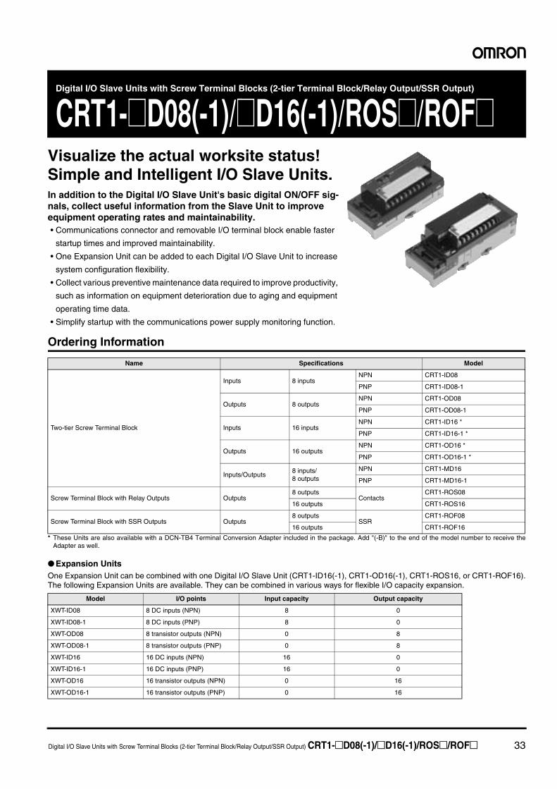
Digital I/O Slave Units with Screw Terminal Blocks (2-tier Terminal Block/Relay Output/SSR Output)
CRT1-@D08(-1)/@D16(-1)/ROS@/ROF@Visualize the actual worksite status!Simple and Intelligent I/O Slave Units.In addition to the Digital I/O Slave Unit's basic digital ON/OFF sig-nals, collect useful information from the Slave Unit to improve equipment operating rates and maintainability. • Communications connector and removable I/O terminal block enable faster
startup times and improved maintainability.
• One Expansion Unit can be added to each Digital I/O Slave Unit to increase
system configuration flexibility.
• Collect various preventive maintenance data required to improve productivity,
such as information on equipment deterioration due to aging and equipment
operating time data.
• Simplify startup with the communications power supply monitoring function.
Ordering Information
* These Units are also available with a DCN-TB4 Terminal Conversion Adapter included in the package. Add "(-B)" to the end of the model number to receive theAdapter as well.
● Expansion UnitsOne Expansion Unit can be combined with one Digital I/O Slave Unit (CRT1-ID16(-1), CRT1-OD16(-1), CRT1-ROS16, or CRT1-ROF16).The following Expansion Units are available. They can be combined in various ways for flexible I/O capacity expansion.
Name Specifications Model
Two-tier Screw Terminal Block
Inputs 8 inputsNPN CRT1-ID08
PNP CRT1-ID08-1
Outputs 8 outputsNPN CRT1-OD08
PNP CRT1-OD08-1
Inputs 16 inputsNPN CRT1-ID16 *
PNP CRT1-ID16-1 *
Outputs 16 outputsNPN CRT1-OD16 *
PNP CRT1-OD16-1 *
Inputs/Outputs8 inputs/8 outputs
NPN CRT1-MD16
PNP CRT1-MD16-1
Screw Terminal Block with Relay Outputs Outputs8 outputs
ContactsCRT1-ROS08
16 outputs CRT1-ROS16
Screw Terminal Block with SSR Outputs Outputs8 outputs
SSRCRT1-ROF08
16 outputs CRT1-ROF16
Model I/O points Input capacity Output capacity
XWT-ID08 8 DC inputs (NPN) 8 0
XWT-ID08-1 8 DC inputs (PNP) 8 0
XWT-OD08 8 transistor outputs (NPN) 0 8
XWT-OD08-1 8 transistor outputs (PNP) 0 8
XWT-ID16 16 DC inputs (NPN) 16 0
XWT-ID16-1 16 DC inputs (PNP) 16 0
XWT-OD16 16 transistor outputs (NPN) 0 16
XWT-OD16-1 16 transistor outputs (PNP) 0 16
34 Digital I/O Slave Units with Screw Terminal Blocks (2-tier Terminal Block/Relay Output/SSR Output) CRT1-@D08(-1)/@D16(-1)/ROS@/ROF@
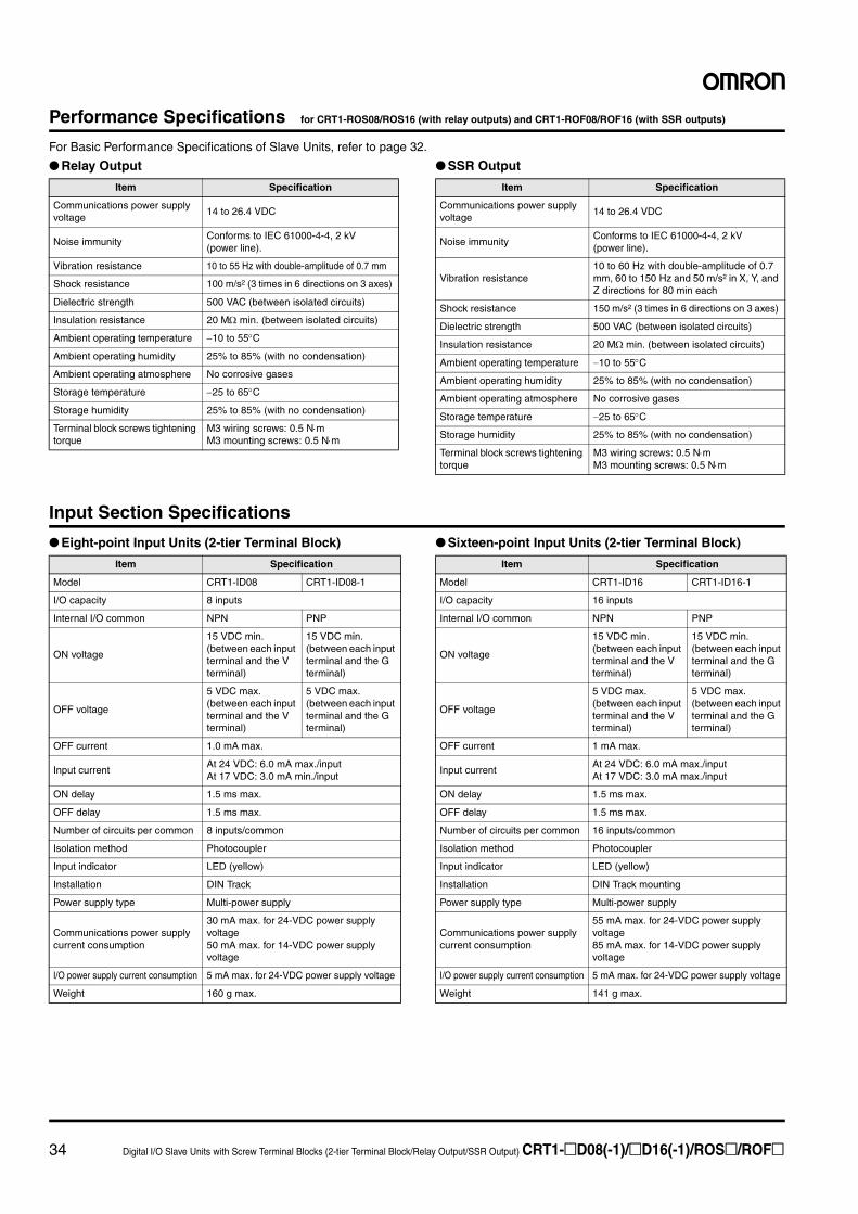
Performance Specifications for CRT1-ROS08/ROS16 (with relay outputs) and CRT1-ROF08/ROF16 (with SSR outputs)
For Basic Performance Specifications of Slave Units, refer to page 32.
● Relay Output ● SSR Output
Input Section Specifications
● Eight-point Input Units (2-tier Terminal Block) ● Sixteen-point Input Units (2-tier Terminal Block)
Item Specification
Communications power supply voltage
14 to 26.4 VDC
Noise immunityConforms to IEC 61000-4-4, 2 kV (power line).
Vibration resistance 10 to 55 Hz with double-amplitude of 0.7 mm
Shock resistance 100 m/s2 (3 times in 6 directions on 3 axes)
Dielectric strength 500 VAC (between isolated circuits)
Insulation resistance 20 MΩ min. (between isolated circuits)
Ambient operating temperature −10 to 55°C
Ambient operating humidity 25% to 85% (with no condensation)
Ambient operating atmosphere No corrosive gases
Storage temperature −25 to 65°C
Storage humidity 25% to 85% (with no condensation)
Terminal block screws tightening torque
M3 wiring screws: 0.5 N⋅mM3 mounting screws: 0.5 N⋅m
Item Specification
Communications power supply voltage
14 to 26.4 VDC
Noise immunityConforms to IEC 61000-4-4, 2 kV (power line).
Vibration resistance10 to 60 Hz with double-amplitude of 0.7 mm, 60 to 150 Hz and 50 m/s2 in X, Y, and Z directions for 80 min each
Shock resistance 150 m/s2 (3 times in 6 directions on 3 axes)
Dielectric strength 500 VAC (between isolated circuits)
Insulation resistance 20 MΩ min. (between isolated circuits)
Ambient operating temperature −10 to 55°C
Ambient operating humidity 25% to 85% (with no condensation)
Ambient operating atmosphere No corrosive gases
Storage temperature −25 to 65°C
Storage humidity 25% to 85% (with no condensation)
Terminal block screws tightening torque
M3 wiring screws: 0.5 N⋅mM3 mounting screws: 0.5 N⋅m
Item Specification
Model CRT1-ID08 CRT1-ID08-1
I/O capacity 8 inputs
Internal I/O common NPN PNP
ON voltage
15 VDC min. (between each input terminal and the V terminal)
15 VDC min. (between each input terminal and the G terminal)
OFF voltage
5 VDC max. (between each input terminal and the V terminal)
5 VDC max. (between each input terminal and the G terminal)
OFF current 1.0 mA max.
Input currentAt 24 VDC: 6.0 mA max./inputAt 17 VDC: 3.0 mA min./input
ON delay 1.5 ms max.
OFF delay 1.5 ms max.
Number of circuits per common 8 inputs/common
Isolation method Photocoupler
Input indicator LED (yellow)
Installation DIN Track
Power supply type Multi-power supply
Communications power supply current consumption
30 mA max. for 24-VDC power supply voltage50 mA max. for 14-VDC power supply voltage
I/O power supply current consumption 5 mA max. for 24-VDC power supply voltage
Weight 160 g max.
Item Specification
Model CRT1-ID16 CRT1-ID16-1
I/O capacity 16 inputs
Internal I/O common NPN PNP
ON voltage
15 VDC min. (between each input terminal and the V terminal)
15 VDC min. (between each input terminal and the G terminal)
OFF voltage
5 VDC max. (between each input terminal and the V terminal)
5 VDC max. (between each input terminal and the G terminal)
OFF current 1 mA max.
Input currentAt 24 VDC: 6.0 mA max./inputAt 17 VDC: 3.0 mA max./input
ON delay 1.5 ms max.
OFF delay 1.5 ms max.
Number of circuits per common 16 inputs/common
Isolation method Photocoupler
Input indicator LED (yellow)
Installation DIN Track mounting
Power supply type Multi-power supply
Communications power supply current consumption
55 mA max. for 24-VDC power supply voltage85 mA max. for 14-VDC power supply voltage
I/O power supply current consumption 5 mA max. for 24-VDC power supply voltage
Weight 141 g max.

Digital I/O Slave Units with Screw Terminal Blocks (2-tier Terminal Block/Relay Output/SSR Output) CRT1-@D08(-1)/@D16(-1)/ROS@/ROF@ 35
Output Section Specifications
● Eight-point Output Units (2-tier Terminal Block) ● Sixteen-point Output Units (2-tier Terminal Block)
● Eight-point Output Units (Relay Outputs) ● Sixteen-point Output Units (Relay Outputs) (per Output)
Item Specification
Model CRT1-OD08 CRT1-OD08-1
I/O capacity 8 outputs
Internal I/O common NPN PNP
Rated output current 0.5 A/output, 2 A/common
Residual voltage
1.2 V max. (0.5 A DC, between each output terminal and the G terminal)
1.2 V max. (0.5 A DC, between each output terminal and the V terminal)
Leakage current 0.1 mA max.
ON delay 0.5 ms max.
OFF delay 1.5 ms max.
Number of circuits per common 8 outputs/common
Isolation method Photocoupler
Output indicators LED (yellow)
Installation DIN Track
Power supply type Multi-power supply
Communications power supply current consumption
35 mA max. for 24-VDC power supply voltage55 mA max. for 14-VDC power supply voltage
I/O power supply current consumption 15 mA max. for 24-VDC power supply voltage
Output handling for communications errors
Select either hold or clear from CX-Integrator.
Weight 160 g max.
Item Specification
Model CRT1-OD16 CRT1-OD16-1
I/O capacity 16 outputs
Internal I/O common NPN PNP
Rated output current 0.5 A/output, 4 A/common
Residual voltage
1.2 V max. (0.5 A DC, between each output terminal and the G terminal)
1.2 V max. (0.5 A DC, between each output terminal and the V terminal)
Leakage current 0.1 mA max.
ON delay 0.5 ms max.
OFF delay 1.5 ms max.
Number of circuits per common 16 outputs/common
Isolation method Photocoupler
Output indicators LED (yellow)
Installation DIN Track mounting
Power supply type Multi-power supply
Communications power supply current consumption
55 mA max. for 24-VDC power supply voltage85 mA max. for 14-VDC power supply voltage
I/O power supply current consumption 15 mA max. for 24-VDC power supply voltage
Output handling for communications errors
Hold or clear can be selected. (CX-Integrator)
Weight 141 g max.
Item Specification
Model CRT1-ROS08
I/O capacity 8 outputs
Mounted Relays DRTA-NY5W-K (5 VDC)
Rated loadResistive load250 VAC, 2 A, common: 8 A30 VDC, 2 A, common: 8 A
Rated ON current 3 A
Maximum contact voltage 250 VAC, 125 VDC
Maximum contact current 3 A
Maximum switching capacity 750 VA AC, 90 W DC
Minimum applicable load (reference value)
5 VDC, 1 mA
Mechanical service life 20,000,000 operations min.
Electrical service life 100,000 operations min.
Installation method DIN Track
Communications power supply current consumption
95 mA max. for 24-VDC power supply voltage150 mA max. for 14-VDC power supply voltage
Output hold for communications errors
Select either hold or clear from CX-Integrator.
Weight 170 g max.
Item Specification
Model CRT1-ROS16
I/O capacity 16 outputs
Mounted Relays DRTA-NY5W-K (5 VDC)
Rated loadResistive load250 VAC, 2 A, common: 8 A30 VDC, 2 A, common: 8 A
Rated ON current 3 A
Maximum contact voltage 250 VAC, 125 VDC
Maximum contact current 3 A
Maximum switching capacity 750 VA AC, 90 W DC
Minimum applicable load (reference value)
5 VDC, 1 mA
Mechanical service life 20,000,000 operations min.
Electrical service life 100,000 operations min.
Installation DIN Track mounting
Communications power supply current consumption
155 mA max. for 24-VDC power supply voltage255 mA max. for 14-VDC power supply voltage
Output hold for communications errors
Hold or clear can be selected. (CX-Integrator)
Weight 260 g max.
36 Digital I/O Slave Units with Screw Terminal Blocks (2-tier Terminal Block/Relay Output/SSR Output) CRT1-@D08(-1)/@D16(-1)/ROS@/ROF@
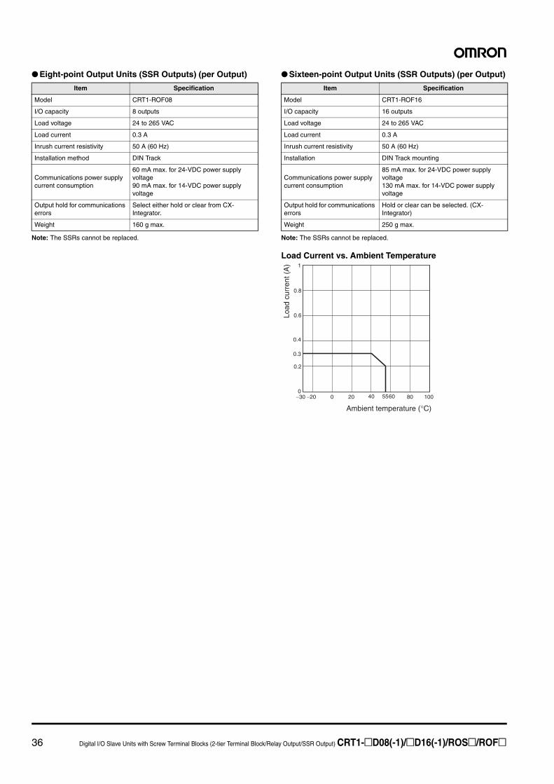
● Eight-point Output Units (SSR Outputs) (per Output)
Note: The SSRs cannot be replaced.
● Sixteen-point Output Units (SSR Outputs) (per Output)
Note: The SSRs cannot be replaced.
Load Current vs. Ambient Temperature
Item Specification
Model CRT1-ROF08
I/O capacity 8 outputs
Load voltage 24 to 265 VAC
Load current 0.3 A
Inrush current resistivity 50 A (60 Hz)
Installation method DIN Track
Communications power supply current consumption
60 mA max. for 24-VDC power supply voltage90 mA max. for 14-VDC power supply voltage
Output hold for communications errors
Select either hold or clear from CX-Integrator.
Weight 160 g max.
Item Specification
Model CRT1-ROF16
I/O capacity 16 outputs
Load voltage 24 to 265 VAC
Load current 0.3 A
Inrush current resistivity 50 A (60 Hz)
Installation DIN Track mounting
Communications power supply current consumption
85 mA max. for 24-VDC power supply voltage130 mA max. for 14-VDC power supply voltage
Output hold for communications errors
Hold or clear can be selected. (CX-Integrator)
Weight 250 g max.
−30 −20 0 20 40 5560 80 100
1
0.8
0.6
0.4
0.3
0.2
0
Ambient temperature (°C)
Load
cur
rent
(A
)
Digital I/O Slave Units with Screw Terminal Blocks (2-tier Terminal Block/Relay Output/SSR Output) CRT1-@D08(-1)/@D16(-1)/ROS@/ROF@ 37
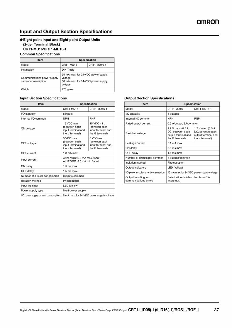
Input and Output Section Specifications
● Eight-point Input and Eight-point Output Units (2-tier Terminal Block)CRT1-MD16/CRT1-MD16-1
Common Specifications
Input Section Specifications Output Section Specifications
Item Specification
Model CRT1-MD16 CRT1-MD16-1
Installation DIN Track
Communications power supply current consumption
35 mA max. for 24-VDC power supply voltage60 mA max. for 14-VDC power supply voltage
Weight 170 g max.
Item Specification
Model CRT1-MD16 CRT1-MD16-1
I/O capacity 8 inputs
Internal I/O common NPN PNP
ON voltage
15 VDC min. (between each input terminal and the V terminal)
15 VDC min. (between each input terminal and the G terminal)
OFF voltage
5 VDC max. (between each input terminal and the V terminal)
5 VDC max. (between each input terminal and the G terminal)
OFF current 1.0 mA max.
Input currentAt 24 VDC: 6.0 mA max./inputAt 17 VDC: 3.0 mA min./input
ON delay 1.5 ms max.
OFF delay 1.5 ms max.
Number of circuits per common 8 inputs/common
Isolation method Photocoupler
Input indicator LED (yellow)
Power supply type Multi-power supply
I/O power supply current consumption 5 mA max. for 24-VDC power supply voltage
Item Specification
Model CRT1-MD16 CRT1-MD16-1
I/O capacity 8 outputs
Internal I/O common NPN PNP
Rated output current 0.5 A/output, 2A/common
Residual voltage
1.2 V max. (0.5 A DC, between each output terminal and the G terminal)
1.2 V max. (0.5 A DC, between each output terminal and the V terminal)
Leakage current 0.1 mA max.
ON delay 0.5 ms max.
OFF delay 1.5 ms max.
Number of circuits per common 8 outputs/common
Isolation method Photocoupler
Output indicators LED (yellow)
I/O power supply current consumption 15 mA max. for 24-VDC power supply voltage
Output handling for communications errors
Select either hold or clear from CX-Integrator.
38 Digital I/O Slave Units with Screw Terminal Blocks (2-tier Terminal Block/Relay Output/SSR Output) CRT1-@D08(-1)/@D16(-1)/ROS@/ROF@
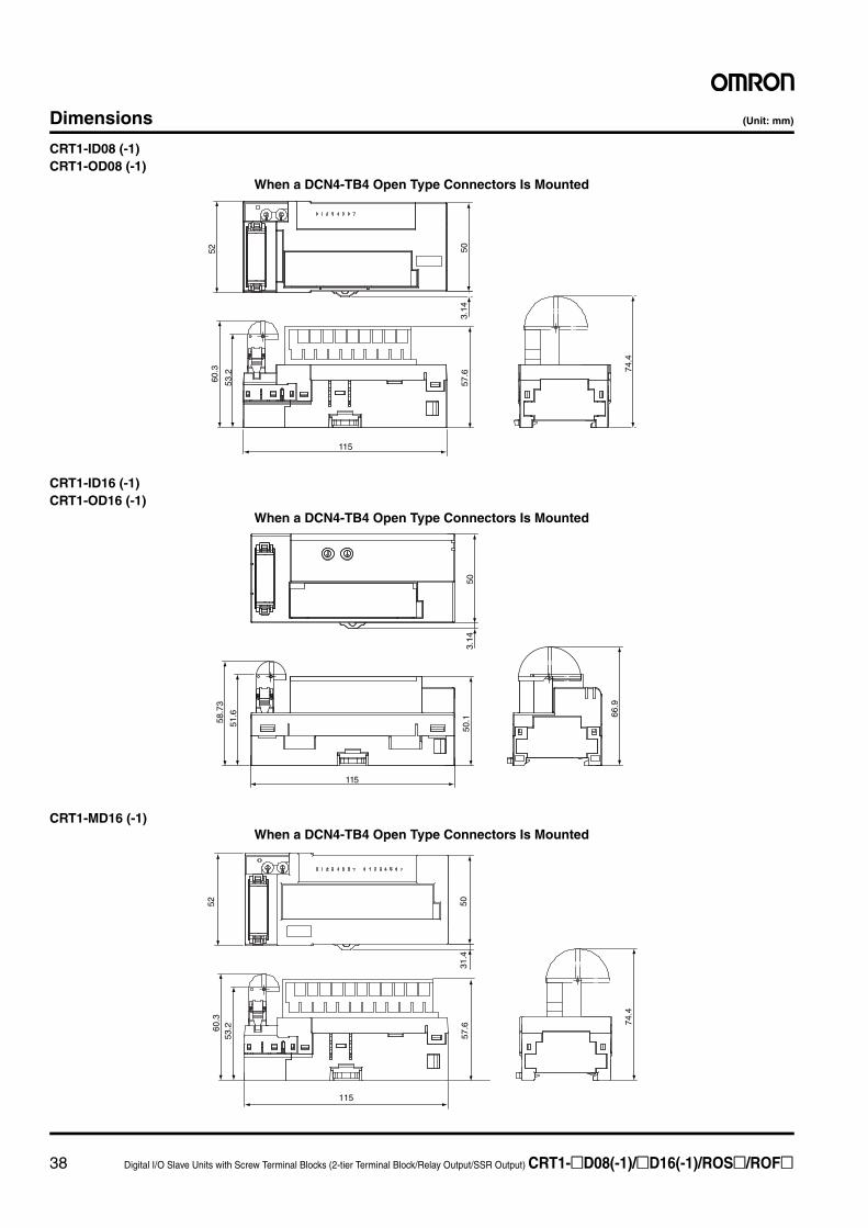
Dimensions (Unit: mm)
CRT1-ID08 (-1)CRT1-OD08 (-1)
CRT1-ID16 (-1)CRT1-OD16 (-1)
CRT1-MD16 (-1)
3.14
50
60.3
53.2
115
57.6 74
.4
52
When a DCN4-TB4 Open Type Connectors Is Mounted
503.
14
58.7
3
51.6
115
50.1 66
.9
When a DCN4-TB4 Open Type Connectors Is Mounted
115
74.4
5031
.457
.6
5260
.353
.2
When a DCN4-TB4 Open Type Connectors Is Mounted
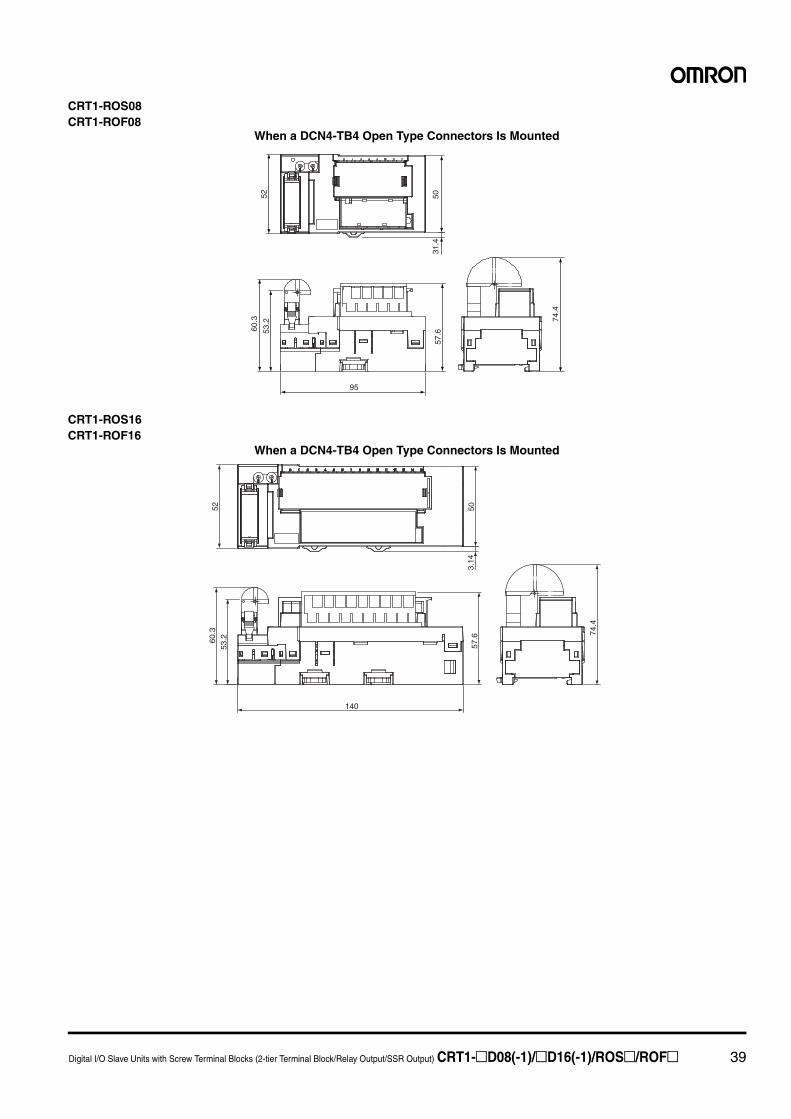
Digital I/O Slave Units with Screw Terminal Blocks (2-tier Terminal Block/Relay Output/SSR Output) CRT1-@D08(-1)/@D16(-1)/ROS@/ROF@ 39
CRT1-ROS08CRT1-ROF08
CRT1-ROS16CRT1-ROF16
95
60.3
53.2
5052
31.4
57.6
74.4
When a DCN4-TB4 Open Type Connectors Is Mounted
5260
.353
.2
140
57.6
503.
14
74.4
When a DCN4-TB4 Open Type Connectors Is Mounted
40 Digital I/O Slave Units with Screw Terminal Blocks (3-tier Terminal Block) CRT1-@D08TA(-1)/@D16TA(-1)/@D08TAH(-1)/@D16TAH(-1)
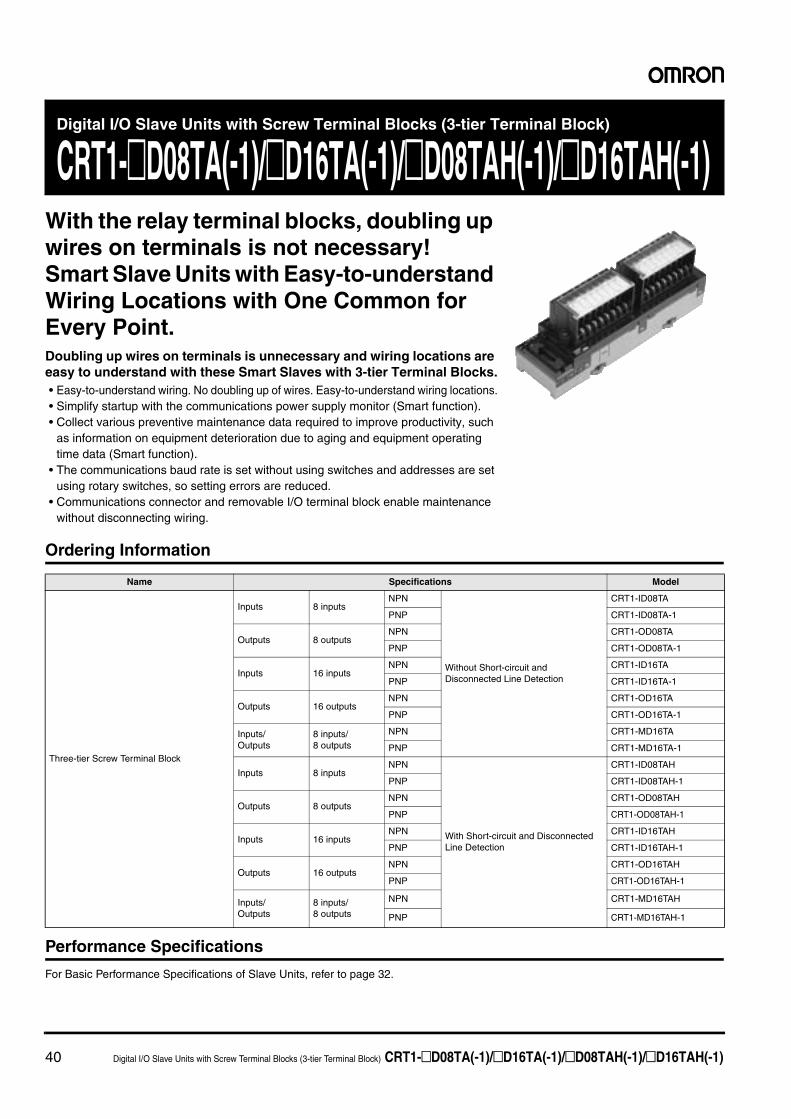
Digital I/O Slave Units with Screw Terminal Blocks (3-tier Terminal Block)
CRT1-@D08TA(-1)/@D16TA(-1)/@D08TAH(-1)/@D16TAH(-1)With the relay terminal blocks, doubling up wires on terminals is not necessary!Smart Slave Units with Easy-to-understand Wiring Locations with One Common for Every Point.Doubling up wires on terminals is unnecessary and wiring locations are easy to understand with these Smart Slaves with 3-tier Terminal Blocks.• Easy-to-understand wiring. No doubling up of wires. Easy-to-understand wiring locations.• Simplify startup with the communications power supply monitor (Smart function).• Collect various preventive maintenance data required to improve productivity, such
as information on equipment deterioration due to aging and equipment operating time data (Smart function).
• The communications baud rate is set without using switches and addresses are set using rotary switches, so setting errors are reduced.
• Communications connector and removable I/O terminal block enable maintenance without disconnecting wiring.
Ordering Information
Performance Specifications
For Basic Performance Specifications of Slave Units, refer to page 32.
Name Specifications Model
Three-tier Screw Terminal Block
Inputs 8 inputsNPN
Without Short-circuit and Disconnected Line Detection
CRT1-ID08TA
PNP CRT1-ID08TA-1
Outputs 8 outputsNPN CRT1-OD08TA
PNP CRT1-OD08TA-1
Inputs 16 inputsNPN CRT1-ID16TA
PNP CRT1-ID16TA-1
Outputs 16 outputsNPN CRT1-OD16TA
PNP CRT1-OD16TA-1
Inputs/Outputs
8 inputs/8 outputs
NPN CRT1-MD16TA
PNP CRT1-MD16TA-1
Inputs 8 inputsNPN
With Short-circuit and Disconnected Line Detection
CRT1-ID08TAH
PNP CRT1-ID08TAH-1
Outputs 8 outputsNPN CRT1-OD08TAH
PNP CRT1-OD08TAH-1
Inputs 16 inputsNPN CRT1-ID16TAH
PNP CRT1-ID16TAH-1
Outputs 16 outputsNPN CRT1-OD16TAH
PNP CRT1-OD16TAH-1
Inputs/Outputs
8 inputs/8 outputs
NPN CRT1-MD16TAH
PNP CRT1-MD16TAH-1
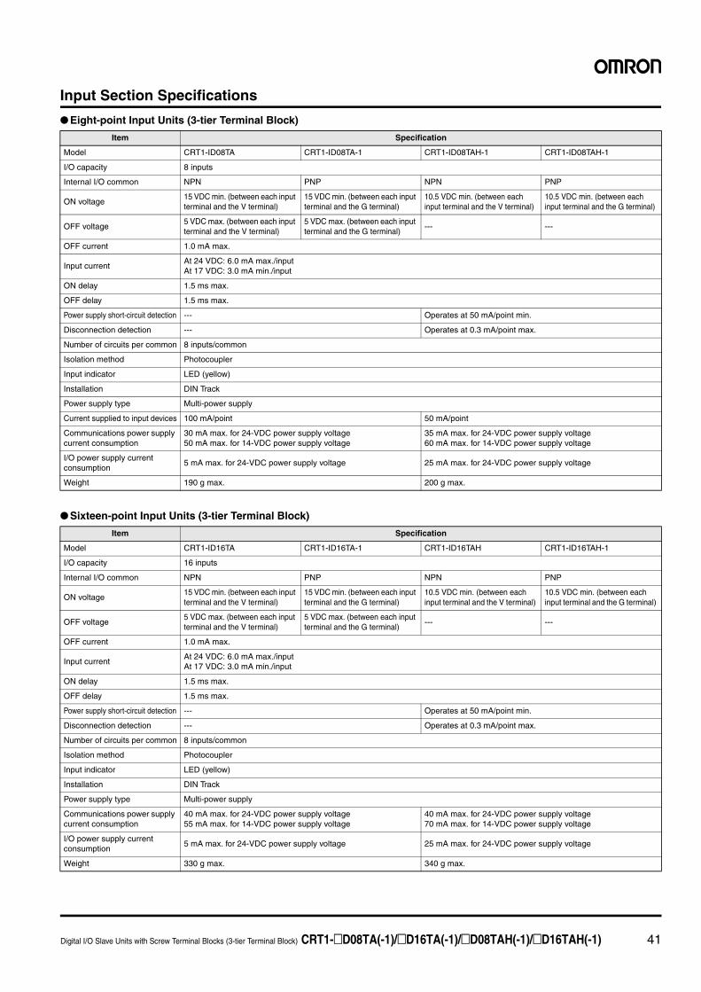
Digital I/O Slave Units with Screw Terminal Blocks (3-tier Terminal Block) CRT1-@D08TA(-1)/@D16TA(-1)/@D08TAH(-1)/@D16TAH(-1) 41
Input Section Specifications
● Eight-point Input Units (3-tier Terminal Block)
● Sixteen-point Input Units (3-tier Terminal Block)
Item Specification
Model CRT1-ID08TA CRT1-ID08TA-1 CRT1-ID08TAH-1 CRT1-ID08TAH-1
I/O capacity 8 inputs
Internal I/O common NPN PNP NPN PNP
ON voltage15 VDC min. (between each input terminal and the V terminal)
15 VDC min. (between each input terminal and the G terminal)
10.5 VDC min. (between each input terminal and the V terminal)
10.5 VDC min. (between each input terminal and the G terminal)
OFF voltage5 VDC max. (between each input terminal and the V terminal)
5 VDC max. (between each input terminal and the G terminal)
--- ---
OFF current 1.0 mA max.
Input currentAt 24 VDC: 6.0 mA max./inputAt 17 VDC: 3.0 mA min./input
ON delay 1.5 ms max.
OFF delay 1.5 ms max.
Power supply short-circuit detection --- Operates at 50 mA/point min.
Disconnection detection --- Operates at 0.3 mA/point max.
Number of circuits per common 8 inputs/common
Isolation method Photocoupler
Input indicator LED (yellow)
Installation DIN Track
Power supply type Multi-power supply
Current supplied to input devices 100 mA/point 50 mA/point
Communications power supply current consumption
30 mA max. for 24-VDC power supply voltage50 mA max. for 14-VDC power supply voltage
35 mA max. for 24-VDC power supply voltage60 mA max. for 14-VDC power supply voltage
I/O power supply current consumption
5 mA max. for 24-VDC power supply voltage 25 mA max. for 24-VDC power supply voltage
Weight 190 g max. 200 g max.
Item Specification
Model CRT1-ID16TA CRT1-ID16TA-1 CRT1-ID16TAH CRT1-ID16TAH-1
I/O capacity 16 inputs
Internal I/O common NPN PNP NPN PNP
ON voltage15 VDC min. (between each input terminal and the V terminal)
15 VDC min. (between each input terminal and the G terminal)
10.5 VDC min. (between each input terminal and the V terminal)
10.5 VDC min. (between each input terminal and the G terminal)
OFF voltage5 VDC max. (between each input terminal and the V terminal)
5 VDC max. (between each input terminal and the G terminal)
--- ---
OFF current 1.0 mA max.
Input currentAt 24 VDC: 6.0 mA max./inputAt 17 VDC: 3.0 mA min./input
ON delay 1.5 ms max.
OFF delay 1.5 ms max.
Power supply short-circuit detection --- Operates at 50 mA/point min.
Disconnection detection --- Operates at 0.3 mA/point max.
Number of circuits per common 8 inputs/common
Isolation method Photocoupler
Input indicator LED (yellow)
Installation DIN Track
Power supply type Multi-power supply
Communications power supply current consumption
40 mA max. for 24-VDC power supply voltage55 mA max. for 14-VDC power supply voltage
40 mA max. for 24-VDC power supply voltage70 mA max. for 14-VDC power supply voltage
I/O power supply current consumption
5 mA max. for 24-VDC power supply voltage 25 mA max. for 24-VDC power supply voltage
Weight 330 g max. 340 g max.
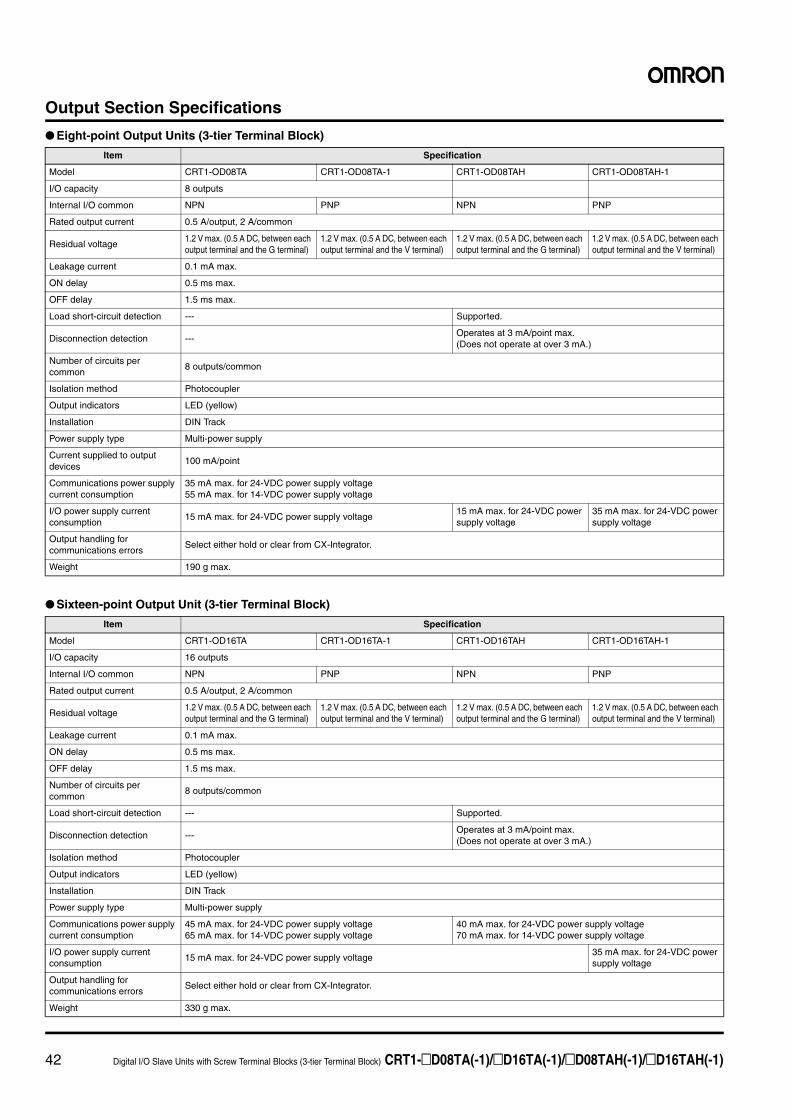
42 Digital I/O Slave Units with Screw Terminal Blocks (3-tier Terminal Block) CRT1-@D08TA(-1)/@D16TA(-1)/@D08TAH(-1)/@D16TAH(-1)
Output Section Specifications
● Eight-point Output Units (3-tier Terminal Block)
● Sixteen-point Output Unit (3-tier Terminal Block)
Item Specification
Model CRT1-OD08TA CRT1-OD08TA-1 CRT1-OD08TAH CRT1-OD08TAH-1
I/O capacity 8 outputs
Internal I/O common NPN PNP NPN PNP
Rated output current 0.5 A/output, 2 A/common
Residual voltage1.2 V max. (0.5 A DC, between each output terminal and the G terminal)
1.2 V max. (0.5 A DC, between each output terminal and the V terminal)
1.2 V max. (0.5 A DC, between each output terminal and the G terminal)
1.2 V max. (0.5 A DC, between each output terminal and the V terminal)
Leakage current 0.1 mA max.
ON delay 0.5 ms max.
OFF delay 1.5 ms max.
Load short-circuit detection --- Supported.
Disconnection detection ---Operates at 3 mA/point max. (Does not operate at over 3 mA.)
Number of circuits per common
8 outputs/common
Isolation method Photocoupler
Output indicators LED (yellow)
Installation DIN Track
Power supply type Multi-power supply
Current supplied to output devices
100 mA/point
Communications power supply current consumption
35 mA max. for 24-VDC power supply voltage55 mA max. for 14-VDC power supply voltage
I/O power supply current consumption
15 mA max. for 24-VDC power supply voltage15 mA max. for 24-VDC power supply voltage
35 mA max. for 24-VDC power supply voltage
Output handling for communications errors
Select either hold or clear from CX-Integrator.
Weight 190 g max.
Item Specification
Model CRT1-OD16TA CRT1-OD16TA-1 CRT1-OD16TAH CRT1-OD16TAH-1
I/O capacity 16 outputs
Internal I/O common NPN PNP NPN PNP
Rated output current 0.5 A/output, 2 A/common
Residual voltage1.2 V max. (0.5 A DC, between each output terminal and the G terminal)
1.2 V max. (0.5 A DC, between each output terminal and the V terminal)
1.2 V max. (0.5 A DC, between each output terminal and the G terminal)
1.2 V max. (0.5 A DC, between each output terminal and the V terminal)
Leakage current 0.1 mA max.
ON delay 0.5 ms max.
OFF delay 1.5 ms max.
Number of circuits per common
8 outputs/common
Load short-circuit detection --- Supported.
Disconnection detection ---Operates at 3 mA/point max.(Does not operate at over 3 mA.)
Isolation method Photocoupler
Output indicators LED (yellow)
Installation DIN Track
Power supply type Multi-power supply
Communications power supply current consumption
45 mA max. for 24-VDC power supply voltage65 mA max. for 14-VDC power supply voltage
40 mA max. for 24-VDC power supply voltage70 mA max. for 14-VDC power supply voltage
I/O power supply current consumption
15 mA max. for 24-VDC power supply voltage35 mA max. for 24-VDC power supply voltage
Output handling for communications errors
Select either hold or clear from CX-Integrator.
Weight 330 g max.
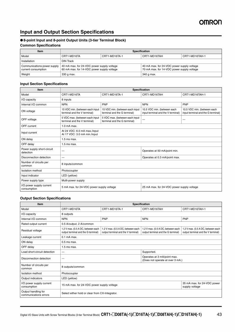
Digital I/O Slave Units with Screw Terminal Blocks (3-tier Terminal Block) CRT1-@D08TA(-1)/@D16TA(-1)/@D08TAH(-1)/@D16TAH(-1) 43
Input and Output Section Specifications
● 8-point Input and 8-point Output Units (3-tier Terminal Block)Common Specifications
Input Section Specifications
Output Section Specifications
Item Specification
Model CRT1-MD16TA CRT1-MD16TA-1 CRT1-MD16TAH CRT1-MD16TAH-1
Installation DIN Track
Communications power supply current consumption
40 mA max. for 24-VDC power supply voltage60 mA max. for 14-VDC power supply voltage
40 mA max. for 24-VDC power supply voltage70 mA max. for 14-VDC power supply voltage
Weight 330 g max. 340 g max.
Item Specification
Model CRT1-MD16TA CRT1-MD16TA-1 CRT1-MD16TAH CRT1-MD16TAH-1
I/O capacity 8 inputs
Internal I/O common NPN PNP NPN PNP
ON voltage15 VDC min. (between each input terminal and the V terminal)
15 VDC min. (between each input terminal and the G terminal)
10.5 VDC min. (between each input terminal and the V terminal)
10.5 VDC min. (between each input terminal and the G terminal)
OFF voltage5 VDC max. (between each input terminal and the V terminal)
5 VDC max. (between each input terminal and the G terminal)
--- ---
OFF current 1.0 mA max.
Input currentAt 24 VDC: 6.0 mA max./inputAt 17 VDC: 3.0 mA min./input
ON delay 1.5 ms max.
OFF delay 1.5 ms max.
Power supply short-circuit detection
--- Operates at 50 mA/point min.
Disconnection detection --- Operates at 0.3 mA/point max.
Number of circuits per common
8 inputs/common
Isolation method Photocoupler
Input indicator LED (yellow)
Power supply type Multi-power supply
I/O power supply current consumption
5 mA max. for 24-VDC power supply voltage 25 mA max. for 24-VDC power supply voltage
Item Specification
Model CRT1-MD16TA CRT1-MD16TA-1 CRT1-MD16TAH CRT1-MD16TAH-1
I/O capacity 8 outputs
Internal I/O common NPN PNP NPN PNP
Rated output current 0.5 A/output, 2 A/common
Residual voltage1.2 V max. (0.5 A DC, between each output terminal and the G terminal)
1.2 V max. (0.5 A DC, between each output terminal and the V terminal)
1.2 V max. (0.5 A DC, between each output terminal and the G terminal)
1.2 V max. (0.5 A DC, between each output terminal and the V terminal)
Leakage current 0.1 mA max.
ON delay 0.5 ms max.
OFF delay 1.5 ms max.
Load short-circuit detection --- Supported.
Disconnection detection ---Operates at 3 mA/point max. (Does not operate at over 3 mA.)
Number of circuits per common
8 outputs/common
Isolation method Photocoupler
Output indicators LED (yellow)
I/O power supply current consumption
15 mA max. for 24-VDC power supply voltage35 mA max. for 24-VDC power supply voltage
Output handling for communications errors
Select either hold or clear from CX-Integrator.
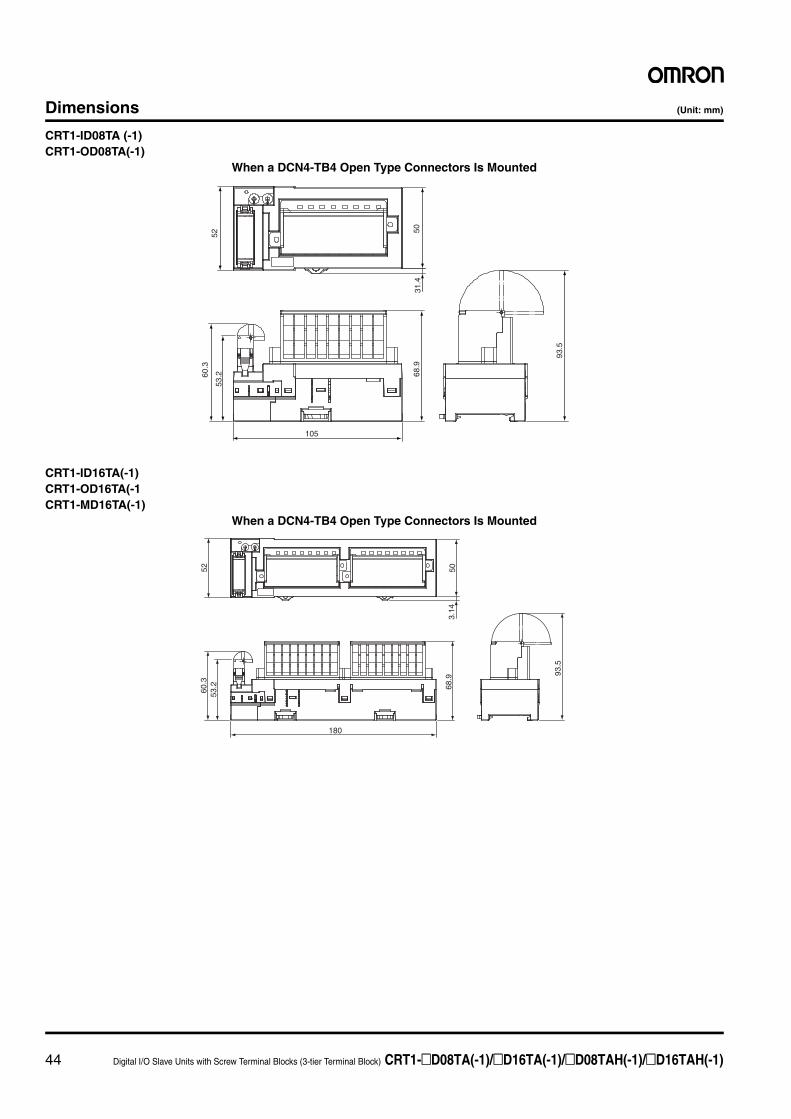
44 Digital I/O Slave Units with Screw Terminal Blocks (3-tier Terminal Block) CRT1-@D08TA(-1)/@D16TA(-1)/@D08TAH(-1)/@D16TAH(-1)
Dimensions (Unit: mm)
CRT1-ID08TA (-1)CRT1-OD08TA(-1)
CRT1-ID16TA(-1)CRT1-OD16TA(-1CRT1-MD16TA(-1)
105
5031
.4
52
93.5
68.9
60.3
53.2
When a DCN4-TB4 Open Type Connectors Is Mounted
180
52 503.
14
60.3
53.2 68
.9
93.5
When a DCN4-TB4 Open Type Connectors Is Mounted
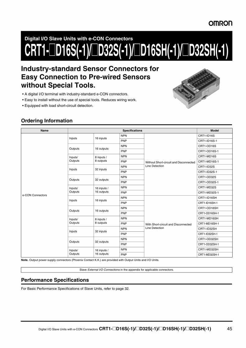
Digital I/O Slave Units with e-CON Connectors CRT1-@D16S(-1)/@D32S(-1)/@D16SH(-1)/@D32SH(-1) 45
Digital I/O Slave Units with e-CON Connectors
CRT1-@D16S(-1)/@D32S(-1)/@D16SH(-1)/@D32SH(-1)Industry-standard Sensor Connectors for Easy Connection to Pre-wired Sensors without Special Tools.• A digital I/O terminal with industry-standard e-CON connectors.
• Easy to install without the use of special tools. Reduces wiring work.
• Equipped with load short-circuit detection.
Ordering Information
Note. Output power supply connectors (Phoenix Contact K.K.) are provided with Output Units and I/O Units.
Performance Specifications
For Basic Performance Specifications of Slave Units, refer to page 32.
Name Specifications Model
e-CON Connectors
Inputs 16 inputsNPN
Without Short-circuit and Disconnected Line Detection
CRT1-ID16S
PNP CRT1-ID16S-1
Outputs 16 outputsNPN CRT1-OD16S
PNP CRT1-OD16S-1
Inputs/Outputs
8 inputs /8 outputs
NPN CRT1-MD16S
PNP CRT1-MD16S-1
Inputs 32 inputsNPN CRT1-ID32S
PNP CRT1-ID32S-1
Outputs 32 outputsNPN CRT1-OD32S
PNP CRT1-OD32S-1
Inputs/Outputs
16 inputs /16 outputs
NPN CRT1-MD32S
PNP CRT1-MD32S-1
Inputs 16 inputsNPN
With Short-circuit and Disconnected Line Detection
CRT1-ID16SH
PNP CRT1-ID16SH-1
Outputs 16 outputsNPN CRT1-OD16SH
PNP CRT1-OD16SH-1
Inputs/Outputs
8 inputs /8 outputs
NPN CRT1-MD16SH
PNP CRT1-MD16SH-1
Inputs 32 inputsNPN CRT1-ID32SH
PNP CRT1-ID32SH-1
Outputs 32 outputsNPN CRT1-OD32SH
PNP CRT1-OD32SH-1
Inputs/Outputs
16 inputs /16 outputs
NPN CRT1-MD32SH
PNP CRT1-MD32SH-1
Slave External I/O Connections in the appendix for applicable connectors.
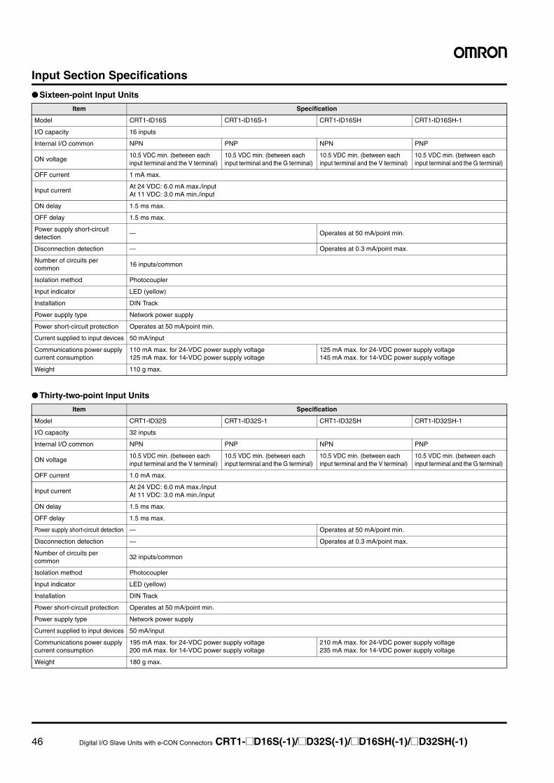
46 Digital I/O Slave Units with e-CON Connectors CRT1-@D16S(-1)/@D32S(-1)/@D16SH(-1)/@D32SH(-1)
Input Section Specifications
● Sixteen-point Input Units
● Thirty-two-point Input Units
Item Specification
Model CRT1-ID16S CRT1-ID16S-1 CRT1-ID16SH CRT1-ID16SH-1
I/O capacity 16 inputs
Internal I/O common NPN PNP NPN PNP
ON voltage10.5 VDC min. (between each input terminal and the V terminal)
10.5 VDC min. (between each input terminal and the G terminal)
10.5 VDC min. (between each input terminal and the V terminal)
10.5 VDC min. (between each input terminal and the G terminal)
OFF current 1 mA max.
Input currentAt 24 VDC: 6.0 mA max./inputAt 11 VDC: 3.0 mA min./input
ON delay 1.5 ms max.
OFF delay 1.5 ms max.
Power supply short-circuit detection
--- Operates at 50 mA/point min.
Disconnection detection --- Operates at 0.3 mA/point max.
Number of circuits per common
16 inputs/common
Isolation method Photocoupler
Input indicator LED (yellow)
Installation DIN Track
Power supply type Network power supply
Power short-circuit protection Operates at 50 mA/point min.
Current supplied to input devices 50 mA/input
Communications power supply current consumption
110 mA max. for 24-VDC power supply voltage125 mA max. for 14-VDC power supply voltage
125 mA max. for 24-VDC power supply voltage145 mA max. for 14-VDC power supply voltage
Weight 110 g max.
Item Specification
Model CRT1-ID32S CRT1-ID32S-1 CRT1-ID32SH CRT1-ID32SH-1
I/O capacity 32 inputs
Internal I/O common NPN PNP NPN PNP
ON voltage10.5 VDC min. (between each input terminal and the V terminal)
10.5 VDC min. (between each input terminal and the G terminal)
10.5 VDC min. (between each input terminal and the V terminal)
10.5 VDC min. (between each input terminal and the G terminal)
OFF current 1.0 mA max.
Input currentAt 24 VDC: 6.0 mA max./inputAt 11 VDC: 3.0 mA min./input
ON delay 1.5 ms max.
OFF delay 1.5 ms max.
Power supply short-circuit detection --- Operates at 50 mA/point min.
Disconnection detection --- Operates at 0.3 mA/point max.
Number of circuits per common
32 inputs/common
Isolation method Photocoupler
Input indicator LED (yellow)
Installation DIN Track
Power short-circuit protection Operates at 50 mA/point min.
Power supply type Network power supply
Current supplied to input devices 50 mA/input
Communications power supply current consumption
195 mA max. for 24-VDC power supply voltage200 mA max. for 14-VDC power supply voltage
210 mA max. for 24-VDC power supply voltage235 mA max. for 14-VDC power supply voltage
Weight 180 g max.
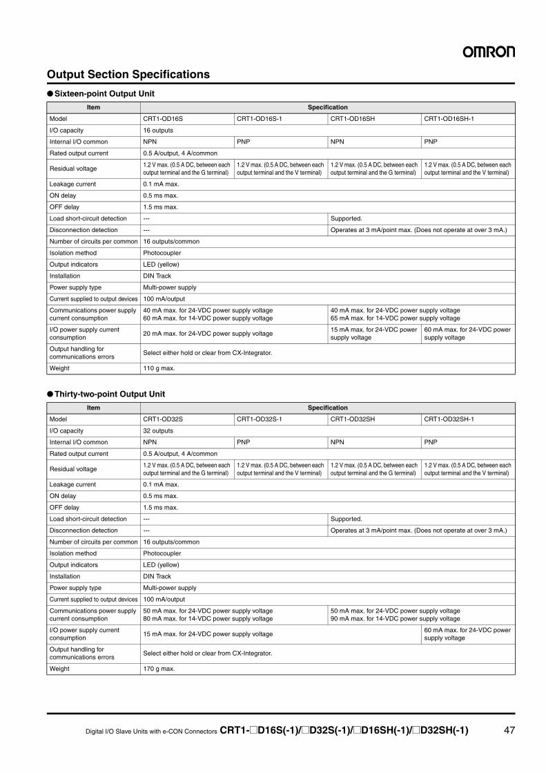
Digital I/O Slave Units with e-CON Connectors CRT1-@D16S(-1)/@D32S(-1)/@D16SH(-1)/@D32SH(-1) 47
Output Section Specifications
● Sixteen-point Output Unit
● Thirty-two-point Output Unit
Item Specification
Model CRT1-OD16S CRT1-OD16S-1 CRT1-OD16SH CRT1-OD16SH-1
I/O capacity 16 outputs
Internal I/O common NPN PNP NPN PNP
Rated output current 0.5 A/output, 4 A/common
Residual voltage1.2 V max. (0.5 A DC, between each output terminal and the G terminal)
1.2 V max. (0.5 A DC, between each output terminal and the V terminal)
1.2 V max. (0.5 A DC, between each output terminal and the G terminal)
1.2 V max. (0.5 A DC, between each output terminal and the V terminal)
Leakage current 0.1 mA max.
ON delay 0.5 ms max.
OFF delay 1.5 ms max.
Load short-circuit detection --- Supported.
Disconnection detection --- Operates at 3 mA/point max. (Does not operate at over 3 mA.)
Number of circuits per common 16 outputs/common
Isolation method Photocoupler
Output indicators LED (yellow)
Installation DIN Track
Power supply type Multi-power supply
Current supplied to output devices 100 mA/output
Communications power supply current consumption
40 mA max. for 24-VDC power supply voltage60 mA max. for 14-VDC power supply voltage
40 mA max. for 24-VDC power supply voltage65 mA max. for 14-VDC power supply voltage
I/O power supply current consumption
20 mA max. for 24-VDC power supply voltage15 mA max. for 24-VDC power supply voltage
60 mA max. for 24-VDC power supply voltage
Output handling for communications errors
Select either hold or clear from CX-Integrator.
Weight 110 g max.
Item Specification
Model CRT1-OD32S CRT1-OD32S-1 CRT1-OD32SH CRT1-OD32SH-1
I/O capacity 32 outputs
Internal I/O common NPN PNP NPN PNP
Rated output current 0.5 A/output, 4 A/common
Residual voltage1.2 V max. (0.5 A DC, between each output terminal and the G terminal)
1.2 V max. (0.5 A DC, between each output terminal and the V terminal)
1.2 V max. (0.5 A DC, between each output terminal and the G terminal)
1.2 V max. (0.5 A DC, between each output terminal and the V terminal)
Leakage current 0.1 mA max.
ON delay 0.5 ms max.
OFF delay 1.5 ms max.
Load short-circuit detection --- Supported.
Disconnection detection --- Operates at 3 mA/point max. (Does not operate at over 3 mA.)
Number of circuits per common 16 outputs/common
Isolation method Photocoupler
Output indicators LED (yellow)
Installation DIN Track
Power supply type Multi-power supply
Current supplied to output devices 100 mA/output
Communications power supply current consumption
50 mA max. for 24-VDC power supply voltage80 mA max. for 14-VDC power supply voltage
50 mA max. for 24-VDC power supply voltage90 mA max. for 14-VDC power supply voltage
I/O power supply current consumption
15 mA max. for 24-VDC power supply voltage60 mA max. for 24-VDC power supply voltage
Output handling for communications errors
Select either hold or clear from CX-Integrator.
Weight 170 g max.
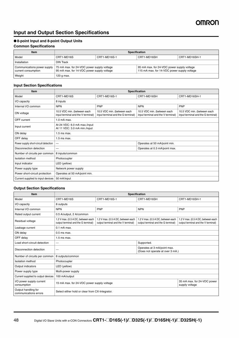
48 Digital I/O Slave Units with e-CON Connectors CRT1-@D16S(-1)/@D32S(-1)/@D16SH(-1)/@D32SH(-1)
Input and Output Section Specifications
● 8-point Input and 8-point Output UnitsCommon Specifications
Input Section Specifications
Output Section Specifications
Item Specification
Model CRT1-MD16S CRT1-MD16S-1 CRT1-MD16SH CRT1-MD16SH-1
Installation DIN Track
Communications power supply current consumption
75 mA max. for 24-VDC power supply voltage95 mA max. for 14-VDC power supply voltage
95 mA max. for 24-VDC power supply voltage115 mA max. for 14-VDC power supply voltage
Weight 120 g max.
Item Specification
Model CRT1-MD16S CRT1-MD16S-1 CRT1-MD16SH CRT1-MD16SH-1
I/O capacity 8 inputs
Internal I/O common NPN PNP NPN PNP
ON voltage10.5 VDC min. (between each input terminal and the V terminal)
10.5 VDC min. (between each input terminal and the G terminal)
10.5 VDC min. (between each input terminal and the V terminal)
10.5 VDC min. (between each input terminal and the G terminal)
OFF current 1.0 mA max.
Input currentAt 24 VDC: 6.0 mA max./inputAt 11 VDC: 3.0 mA min./input
ON delay 1.5 ms max.
OFF delay 1.5 ms max.
Power supply short-circuit detection --- Operates at 50 mA/point min.
Disconnection detection --- Operates at 0.3 mA/point max.
Number of circuits per common 8 inputs/common
Isolation method Photocoupler
Input indicator LED (yellow)
Power supply type Network power supply
Power short-circuit protection Operates at 50 mA/point min.
Current supplied to input devices 50 mA/input
Item Specification
Model CRT1-MD16S CRT1-MD16S-1 CRT1-MD16SH CRT1-MD16SH-1
I/O capacity 8 outputs
Internal I/O common NPN PNP NPN PNP
Rated output current 0.5 A/output, 2 A/common
Residual voltage1.2 V max. (0.5 A DC, between each output terminal and the G terminal)
1.2 V max. (0.5 A DC, between each output terminal and the V terminal)
1.2 V max. (0.5 A DC, between each output terminal and the G terminal)
1.2 V max. (0.5 A DC, between each output terminal and the V terminal)
Leakage current 0.1 mA max.
ON delay 0.5 ms max.
OFF delay 1.5 ms max.
Load short-circuit detection --- Supported.
Disconnection detection ---Operates at 3 mA/point max. (Does not operate at over 3 mA.)
Number of circuits per common 8 outputs/common
Isolation method Photocoupler
Output indicators LED (yellow)
Power supply type Multi-power supply
Current supplied to output devices 100 mA/output
I/O power supply current consumption
15 mA max. for 24-VDC power supply voltage35 mA max. for 24-VDC power supply voltage
Output handling for communications errors
Select either hold or clear from CX-Integrator.
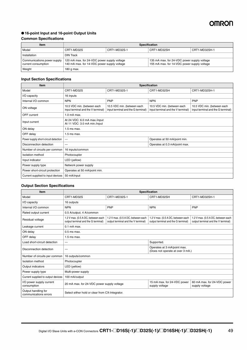
Digital I/O Slave Units with e-CON Connectors CRT1-@D16S(-1)/@D32S(-1)/@D16SH(-1)/@D32SH(-1) 49
● 16-point Input and 16-point Output UnitsCommon Specifications
Input Section Specifications
Output Section Specifications
Item Specification
Model CRT1-MD32S CRT1-MD32S-1 CRT1-MD32SH CRT1-MD32SH-1
Installation DIN Track
Communications power supply current consumption
120 mA max. for 24-VDC power supply voltage140 mA max. for 14-VDC power supply voltage
135 mA max. for 24-VDC power supply voltage155 mA max. for 14-VDC power supply voltage
Weight 180 g max.
Item Specification
Model CRT1-MD32S CRT1-MD32S-1 CRT1-MD32SH CRT1-MD32SH-1
I/O capacity 16 inputs
Internal I/O common NPN PNP NPN PNP
ON voltage10.5 VDC min. (between each input terminal and the V terminal)
10.5 VDC min. (between each input terminal and the G terminal)
10.5 VDC min. (between each input terminal and the V terminal)
10.5 VDC min. (between each input terminal and the G terminal)
OFF current 1.0 mA max.
Input currentAt 24 VDC: 6.0 mA max./inputAt 11 VDC: 3.0 mA min./input
ON delay 1.5 ms max.
OFF delay 1.5 ms max.
Power supply short-circuit detection --- Operates at 50 mA/point min.
Disconnection detection --- Operates at 0.3 mA/point max.
Number of circuits per common 16 inputs/common
Isolation method Photocoupler
Input indicator LED (yellow)
Power supply type Network power supply
Power short-circuit protection Operates at 50 mA/point min.
Current supplied to input devices 50 mA/input
Item Specification
Model CRT1-MD32S CRT1-MD32S-1 CRT1-MD32SH CRT1-MD32SH-1
I/O capacity 16 outputs
Internal I/O common NPN PNP NPN PNP
Rated output current 0.5 A/output, 4 A/common
Residual voltage1.2 V max. (0.5 A DC, between each output terminal and the G terminal)
1.2 V max. (0.5 A DC, between each output terminal and the V terminal)
1.2 V max. (0.5 A DC, between each output terminal and the G terminal)
1.2 V max. (0.5 A DC, between each output terminal and the V terminal)
Leakage current 0.1 mA max.
ON delay 0.5 ms max.
OFF delay 1.5 ms max.
Load short-circuit detection --- Supported.
Disconnection detection ---Operates at 3 mA/point max. (Does not operate at over 3 mA.)
Number of circuits per common 16 outputs/common
Isolation method Photocoupler
Output indicators LED (yellow)
Power supply type Multi-power supply
Current supplied to output devices 100 mA/output
I/O power supply current consumption
20 mA max. for 24-VDC power supply voltage15 mA max. for 24-VDC power supply voltage
60 mA max. for 24-VDC power supply voltage
Output handling for communications errors
Select either hold or clear from CX-Integrator.
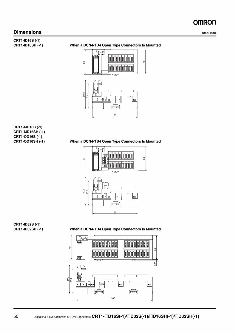
50 Digital I/O Slave Units with e-CON Connectors CRT1-@D16S(-1)/@D32S(-1)/@D16SH(-1)/@D32SH(-1)
Dimensions (Unit: mm)
CRT1-ID16S (-1)CRT1-ID16SH (-1) When a DCN4-TB4 Open Type Connectors Is Mounted
CRT1-MD16S (-1)CRT1-MD16SH (-1)CRT1-OD16S (-1)CRT1-OD16SH (-1) When a DCN4-TB4 Open Type Connectors Is Mounted
CRT1-ID32S (-1)CRT1-ID32SH (-1) When a DCN4-TB4 Open Type Connectors Is Mounted
50
60.3
53.2
95
52
50
60.3
53.2
95
52
160
5260
.3
53.2
3.14
50
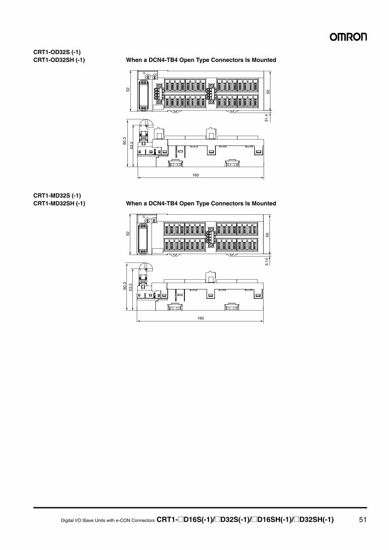
Digital I/O Slave Units with e-CON Connectors CRT1-@D16S(-1)/@D32S(-1)/@D16SH(-1)/@D32SH(-1) 51
CRT1-OD32S (-1)CRT1-OD32SH (-1) When a DCN4-TB4 Open Type Connectors Is Mounted
CRT1-MD32S (-1)CRT1-MD32SH (-1) When a DCN4-TB4 Open Type Connectors Is Mounted
160
31.4
505253
.260.3
160
503.
14
5260
.3
53.2
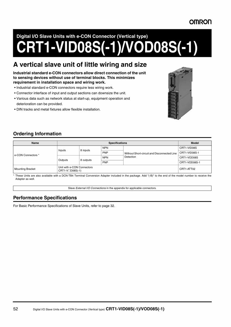
52 Digital I/O Slave Units with e-CON Connector (Vertical type) CRT1-VID08S(-1)/VOD08S(-1)
Digital I/O Slave Units with e-CON Connector (Vertical type)
CRT1-VID08S(-1)/VOD08S(-1)A vertical slave unit of little wiring and sizeIndustrial standard e-CON connectors allow direct connection of the unit to sensing devices without use of terminal blocks. This minimizes requirement in installation space and wiring work.• Industrial standard e-CON connectors require less wiring work.
• Connector interface of input and output sections can downsize the unit.
• Various data such as network status at start-up, equipment operation and
deterioration can be provided.
• DIN tracks and metal fixtures allow flexible installation.
Ordering Information
* These Units are also available with a DCN-TB4 Terminal Conversion Adapter included in the package. Add "(-B)" to the end of the model number to receive theAdapter as well.
Performance Specifications
For Basic Performance Specifications of Slave Units, refer to page 32.
Name Specifications Model
e-CON Connectors *
Inputs 8 inputsNPN
Without Short-circuit and Disconnected Line Detection
CRT1-VID08S
PNP CRT1-VID08S-1
Outputs 8 outputsNPN CRT1-VOD08S
PNP CRT1-VOD08S-1
Mounting BracketUnit with e-CON ConnectorsCRT1-V@D08S(-1)
CRT1-ATT02
Slave External I/O Connections in the appendix for applicable connectors.
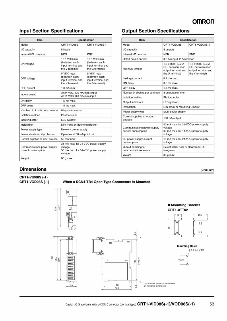
Digital I/O Slave Units with e-CON Connector (Vertical type) CRT1-VID08S(-1)/VOD08S(-1) 53
Input Section Specifications Output Section Specifications
Dimensions (Unit: mm)
Item Specification
Model CRT1-VID08S CRT1-VID08S-1
I/O capacity 8 inputs
Internal I/O common NPN PNP
ON voltage
10.5 VDC min. (between each input terminal and the V terminal)
10.5 VDC min. (between each input terminal and the G terminal)
OFF voltage
5 VDC max. (between each input terminal and the V terminal)
5 VDC max. (between each input terminal and the G terminal)
OFF current 1.0 mA max.
Input currentAt 24 VDC: 6.0 mA max./inputAt 11 VDC: 3.0 mA min./input
ON delay 1.5 ms max.
OFF delay 1.5 ms max.
Number of circuits per common 8 inputs/common
Isolation method Photocoupler
Input indicator LED (yellow)
Installation DIN Track or Mounting Bracket
Power supply type Network power supply
Power short-circuit protection Operates at 50 mA/point min.
Current supplied to input devices 50 mA/input
Communications power supply current consumption
35 mA max. for 24-VDC power supply voltage50 mA max. for 14-VDC power supply voltage
Weight 80 g max.
Item Specification
Model CRT1-VOD08S CRT1-VOD08S-1
I/O capacity 8 outputs
Internal I/O common NPN PNP
Rated output current 0.3 A/output, 2 A/common
Residual voltage
1.2 V max. (0.3 A DC, between each output terminal and the G terminal)
1.2 V max. (0.3 A DC, between each output terminal and the V terminal)
Leakage current 0.1 mA max.
ON delay 0.5 ms max.
OFF delay 1.5 ms max.
Number of circuits per common 8 outputs/common
Isolation method Photocoupler
Output indicators LED (yellow)
Installation DIN Track or Mounting Bracket
Power supply type Multi-power supply
Current supplied to output devices
100 mA/output
Communications power supply current consumption
40 mA max. for 24-VDC power supply voltage60 mA max. for 14-VDC power supply voltage
I/O power supply current consumption
15 mA max. for 24-VDC power supply voltage
Output handling for communications errors
Select either hold or clear from CX-Integrator.
Weight 80 g max.
The numbers inside the parentheses are reference dimensions.
66.260
(101
.7)
905.
323
(102
)
(90)
96.7
6.4
85.7
92.8
CRT1-VID08S (-1)CRT1-VOD08S (-1) When a DCN4-TB4 Open Type Connectors Is Mounted
Mounting Holes
13 26.7
16±0.2
2-3.2 dia. or M3
35
● Mounting BracketCRT1-ATT02
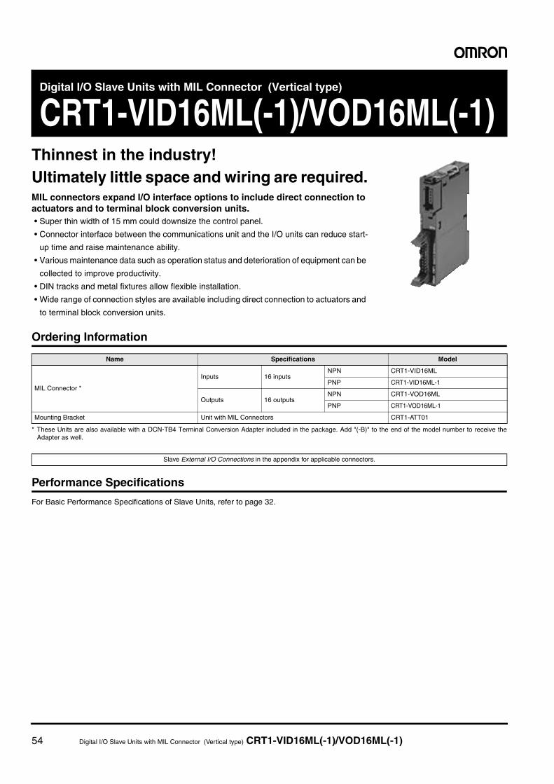
54 Digital I/O Slave Units with MIL Connector (Vertical type) CRT1-VID16ML(-1)/VOD16ML(-1)
Digital I/O Slave Units with MIL Connector (Vertical type)
CRT1-VID16ML(-1)/VOD16ML(-1)Thinnest in the industry!Ultimately little space and wiring are required.MIL connectors expand I/O interface options to include direct connection to actuators and to terminal block conversion units.• Super thin width of 15 mm could downsize the control panel.
• Connector interface between the communications unit and the I/O units can reduce start-
up time and raise maintenance ability.
• Various maintenance data such as operation status and deterioration of equipment can be
collected to improve productivity.
• DIN tracks and metal fixtures allow flexible installation.
• Wide range of connection styles are available including direct connection to actuators and
to terminal block conversion units.
Ordering Information
* These Units are also available with a DCN-TB4 Terminal Conversion Adapter included in the package. Add "(-B)" to the end of the model number to receive theAdapter as well.
Performance Specifications
For Basic Performance Specifications of Slave Units, refer to page 32.
Name Specifications Model
MIL Connector *
Inputs 16 inputsNPN CRT1-VID16ML
PNP CRT1-VID16ML-1
Outputs 16 outputsNPN CRT1-VOD16ML
PNP CRT1-VOD16ML-1
Mounting Bracket Unit with MIL Connectors CRT1-ATT01
Slave External I/O Connections in the appendix for applicable connectors.
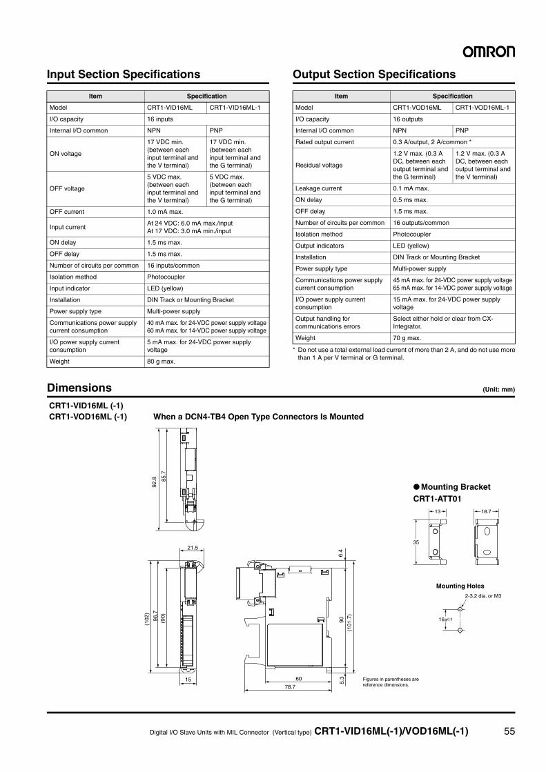
Digital I/O Slave Units with MIL Connector (Vertical type) CRT1-VID16ML(-1)/VOD16ML(-1) 55
Input Section Specifications Output Section Specifications
* Do not use a total external load current of more than 2 A, and do not use morethan 1 A per V terminal or G terminal.
Dimensions (Unit: mm)
Item Specification
Model CRT1-VID16ML CRT1-VID16ML-1
I/O capacity 16 inputs
Internal I/O common NPN PNP
ON voltage
17 VDC min. (between each input terminal and the V terminal)
17 VDC min. (between each input terminal and the G terminal)
OFF voltage
5 VDC max. (between each input terminal and the V terminal)
5 VDC max. (between each input terminal and the G terminal)
OFF current 1.0 mA max.
Input currentAt 24 VDC: 6.0 mA max./inputAt 17 VDC: 3.0 mA min./input
ON delay 1.5 ms max.
OFF delay 1.5 ms max.
Number of circuits per common 16 inputs/common
Isolation method Photocoupler
Input indicator LED (yellow)
Installation DIN Track or Mounting Bracket
Power supply type Multi-power supply
Communications power supply current consumption
40 mA max. for 24-VDC power supply voltage60 mA max. for 14-VDC power supply voltage
I/O power supply current consumption
5 mA max. for 24-VDC power supply voltage
Weight 80 g max.
Item Specification
Model CRT1-VOD16ML CRT1-VOD16ML-1
I/O capacity 16 outputs
Internal I/O common NPN PNP
Rated output current 0.3 A/output, 2 A/common *
Residual voltage
1.2 V max. (0.3 A DC, between each output terminal and the G terminal)
1.2 V max. (0.3 A DC, between each output terminal and the V terminal)
Leakage current 0.1 mA max.
ON delay 0.5 ms max.
OFF delay 1.5 ms max.
Number of circuits per common 16 outputs/common
Isolation method Photocoupler
Output indicators LED (yellow)
Installation DIN Track or Mounting Bracket
Power supply type Multi-power supply
Communications power supply current consumption
45 mA max. for 24-VDC power supply voltage65 mA max. for 14-VDC power supply voltage
I/O power supply current consumption
15 mA max. for 24-VDC power supply voltage
Output handling for communications errors
Select either hold or clear from CX-Integrator.
Weight 70 g max.5.
3
78.7
6015
21.5
92.8 85
.7
(102
)
96.7
(90)
90(1
01.7
)
6.4
Figures in parentheses arereference dimensions.
CRT1-VID16ML (-1)CRT1-VOD16ML (-1) When a DCN4-TB4 Open Type Connectors Is Mounted
● Mounting BracketCRT1-ATT01
Mounting Holes
16±0.2
2-3.2 dia. or M3
13 18.7
35

56 Digital I/O Slave Units with MIL Connector (Vertical type) CRT1-VID32ML(-1)/VOD32ML(-1)/VMD32ML(-1)
Digital I/O Slave Units with MIL Connector (Vertical type)
CRT1-VID32ML(-1)/VOD32ML(-1)/VMD32ML(-1)Aggregation of multi-I/O points!A compact and little wiring slave with 32 points and MIL connectorMIL connectors expand I/O interface options to include collective connection of multiple I/O points to boards as well as direct connection to actuators via branching cables.• Super compact slave with 32 points and MIL connector (35 mm wide x 60 mm deep x 80 mm high)
• Aggregation of multi I/O points enables connection to actuators and boards.
• Connector interface between the communications unit and the I/O units greatly reduces
wiring man-hour.
• DIN tracks and metal fixtures allow flexible installation.
• Various maintenance data such as operation status and deterioration of equipment can be
collected to improve productivity.
Ordering Information
* These Units are also available with a DCN-TB4 Terminal Conversion Adapter included in the package. Add "(-B)" to the end of the model number to receive theAdapter as well.
Performance Specifications
For Basic Performance Specifications of Slave Units, refer to page 32.
Name Specifications Model
MIL Connector *
Inputs 32 inputsNPN CRT1-VID32ML
PNP CRT1-VID32ML-1
Outputs 32 outputsNPN CRT1-VOD32ML
PNP CRT1-VOD32ML-1
Inputs/Outputs
16 inputs/16 outputs
NPN CRT1-VMD32ML
PNP CRT1-VMD32ML-1
Mounting BracketUnit with MIL ConnectorsCRT1-V@D32ML(-1)
SRT1-ATT02
Slave External I/O Connections in the appendix for applicable connectors.
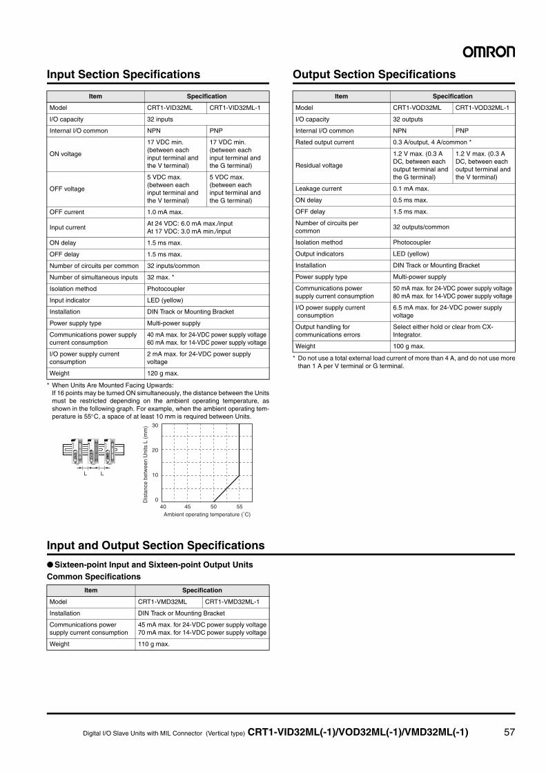
Digital I/O Slave Units with MIL Connector (Vertical type) CRT1-VID32ML(-1)/VOD32ML(-1)/VMD32ML(-1) 57
Input Section Specifications
* When Units Are Mounted Facing Upwards:If 16 points may be turned ON simultaneously, the distance between the Unitsmust be restricted depending on the ambient operating temperature, asshown in the following graph. For example, when the ambient operating tem-perature is 55°C, a space of at least 10 mm is required between Units.
Output Section Specifications
* Do not use a total external load current of more than 4 A, and do not use morethan 1 A per V terminal or G terminal.
Input and Output Section Specifications
● Sixteen-point Input and Sixteen-point Output UnitsCommon Specifications
Item Specification
Model CRT1-VID32ML CRT1-VID32ML-1
I/O capacity 32 inputs
Internal I/O common NPN PNP
ON voltage
17 VDC min. (between each input terminal and the V terminal)
17 VDC min. (between each input terminal and the G terminal)
OFF voltage
5 VDC max. (between each input terminal and the V terminal)
5 VDC max. (between each input terminal and the G terminal)
OFF current 1.0 mA max.
Input currentAt 24 VDC: 6.0 mA max./inputAt 17 VDC: 3.0 mA min./input
ON delay 1.5 ms max.
OFF delay 1.5 ms max.
Number of circuits per common 32 inputs/common
Number of simultaneous inputs 32 max. *
Isolation method Photocoupler
Input indicator LED (yellow)
Installation DIN Track or Mounting Bracket
Power supply type Multi-power supply
Communications power supply current consumption
40 mA max. for 24-VDC power supply voltage60 mA max. for 14-VDC power supply voltage
I/O power supply current consumption
2 mA max. for 24-VDC power supply voltage
Weight 120 g max.
Ambient operating temperature (˚C)40 45 50 55
30
20
10
0Dis
tanc
e be
twee
n U
nits
L (
mm
)
L L
Item Specification
Model CRT1-VOD32ML CRT1-VOD32ML-1
I/O capacity 32 outputs
Internal I/O common NPN PNP
Rated output current 0.3 A/output, 4 A/common *
Residual voltage
1.2 V max. (0.3 A DC, between each output terminal and the G terminal)
1.2 V max. (0.3 A DC, between each output terminal and the V terminal)
Leakage current 0.1 mA max.
ON delay 0.5 ms max.
OFF delay 1.5 ms max.
Number of circuits per common
32 outputs/common
Isolation method Photocoupler
Output indicators LED (yellow)
Installation DIN Track or Mounting Bracket
Power supply type Multi-power supply
Communications power supply current consumption
50 mA max. for 24-VDC power supply voltage80 mA max. for 14-VDC power supply voltage
I/O power supply current consumption
6.5 mA max. for 24-VDC power supply voltage
Output handling for communications errors
Select either hold or clear from CX-Integrator.
Weight 100 g max.
Item Specification
Model CRT1-VMD32ML CRT1-VMD32ML-1
Installation DIN Track or Mounting Bracket
Communications power supply current consumption
45 mA max. for 24-VDC power supply voltage70 mA max. for 14-VDC power supply voltage
Weight 110 g max.
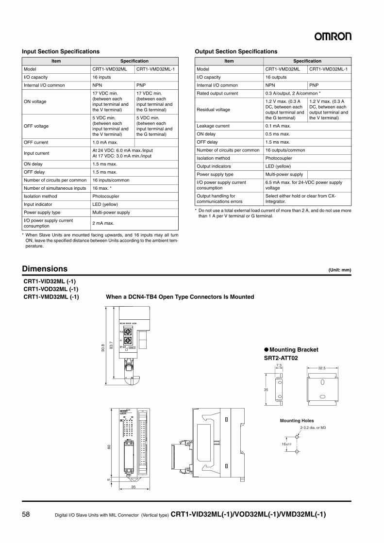
58 Digital I/O Slave Units with MIL Connector (Vertical type) CRT1-VID32ML(-1)/VOD32ML(-1)/VMD32ML(-1)
Input Section Specifications
* When Slave Units are mounted facing upwards, and 16 inputs may all turnON, leave the specified distance between Units according to the ambient tem-perature.
Output Section Specifications
* Do not use a total external load current of more than 2 A, and do not use morethan 1 A per V terminal or G terminal.
Dimensions (Unit: mm)
Item Specification
Model CRT1-VMD32ML CRT1-VMD32ML-1
I/O capacity 16 inputs
Internal I/O common NPN PNP
ON voltage
17 VDC min. (between each input terminal and the V terminal)
17 VDC min. (between each input terminal and the G terminal)
OFF voltage
5 VDC min. (between each input terminal and the V terminal)
5 VDC min. (between each input terminal and the G terminal)
OFF current 1.0 mA max.
Input currentAt 24 VDC: 6.0 mA max./inputAt 17 VDC: 3.0 mA min./input
ON delay 1.5 ms max.
OFF delay 1.5 ms max.
Number of circuits per common 16 inputs/common
Number of simultaneous inputs 16 max. *
Isolation method Photocoupler
Input indicator LED (yellow)
Power supply type Multi-power supply
I/O power supply current consumption
2 mA max.
Item Specification
Model CRT1-VMD32ML CRT1-VMD32ML-1
I/O capacity 16 outputs
Internal I/O common NPN PNP
Rated output current 0.3 A/output, 2 A/common *
Residual voltage
1.2 V max. (0.3 A DC, between each output terminal and the G terminal)
1.2 V max. (0.3 A DC, between each output terminal and the V terminal)
Leakage current 0.1 mA max.
ON delay 0.5 ms max.
OFF delay 1.5 ms max.
Number of circuits per common 16 outputs/common
Isolation method Photocoupler
Output indicators LED (yellow)
Power supply type Multi-power supply
I/O power supply current consumption
6.5 mA max. for 24-VDC power supply voltage
Output handling for communications errors
Select either hold or clear from CX-Integrator.
CRT1-VID32ML (-1)CRT1-VOD32ML (-1)CRT1-VMD32ML (-1) When a DCN4-TB4 Open Type Connectors Is Mounted
● Mounting BracketSRT2-ATT02
35
805
83.7
90.8
7.332.5
16±0.2
2-3.2 dia. or M3
35
Mounting Holes
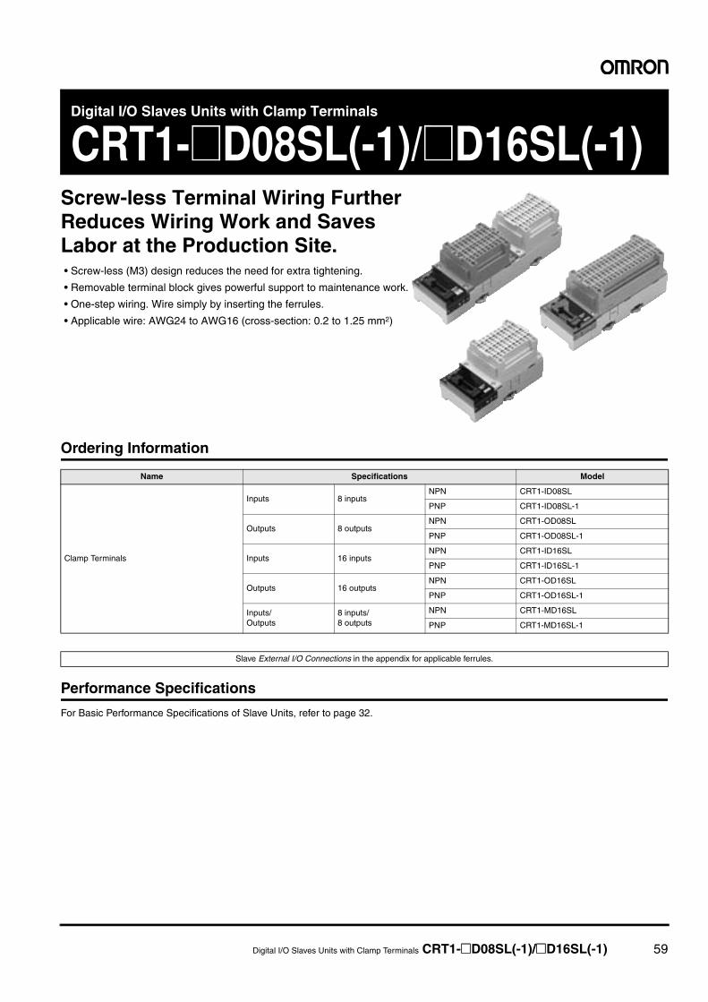
Digital I/O Slaves Units with Clamp Terminals CRT1-@D08SL(-1)/@D16SL(-1) 59
Digital I/O Slaves Units with Clamp Terminals
CRT1-@D08SL(-1)/@D16SL(-1)Screw-less Terminal Wiring Further Reduces Wiring Work and Saves Labor at the Production Site.• Screw-less (M3) design reduces the need for extra tightening.
• Removable terminal block gives powerful support to maintenance work.
• One-step wiring. Wire simply by inserting the ferrules.
• Applicable wire: AWG24 to AWG16 (cross-section: 0.2 to 1.25 mm2)
Ordering Information
Performance Specifications
For Basic Performance Specifications of Slave Units, refer to page 32.
Name Specifications Model
Clamp Terminals
Inputs 8 inputsNPN CRT1-ID08SL
PNP CRT1-ID08SL-1
Outputs 8 outputsNPN CRT1-OD08SL
PNP CRT1-OD08SL-1
Inputs 16 inputsNPN CRT1-ID16SL
PNP CRT1-ID16SL-1
Outputs 16 outputsNPN CRT1-OD16SL
PNP CRT1-OD16SL-1
Inputs/Outputs
8 inputs/8 outputs
NPN CRT1-MD16SL
PNP CRT1-MD16SL-1
Slave External I/O Connections in the appendix for applicable ferrules.
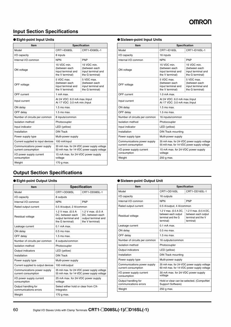
60 Digital I/O Slaves Units with Clamp Terminals CRT1-@D08SL(-1)/@D16SL(-1)
Input Section Specifications
● Eight-point Input Units ● Sixteen-point Input Units
Output Section Specifications
● Eight-point Output Units ● Sixteen-point Output Unit
Item Specification
Model CRT1-ID08SL CRT1-ID08SL-1
I/O capacity 8 inputs
Internal I/O common NPN PNP
ON voltage
15 VDC min. (between each input terminal and the V terminal)
15 VDC min. (between each input terminal and the G terminal)
OFF voltage
5 VDC max. (between each input terminal and the V terminal)
5 VDC max. (between each input terminal and the G terminal)
OFF current 1 mA max.
Input currentAt 24 VDC: 6.0 mA max./inputAt 17 VDC: 3.0 mA min./input
ON delay 1.5 ms max.
OFF delay 1.5 ms max.
Number of circuits per common 8 inputs/common
Isolation method Photocoupler
Input indicator LED (yellow)
Installation DIN Track
Power supply type Multi-power supply
Current supplied to input devices 100 mA/input
Communications power supply current consumption
30 mA max. for 24-VDC power supply voltage50 mA max. for 14-VDC power supply voltage
I/O power supply current consumption
15 mA max. for 24-VDC power supply voltage
Weight 170 g max.
Item Specification
Model CRT1-ID16SL CRT1-ID16SL-1
I/O capacity 16 inputs
Internal I/O common NPN PNP
ON voltage
15 VDC min. (between each input terminal and the V terminal)
15 VDC min. (between each input terminal and the G terminal)
OFF voltage
5 VDC max. (between each input terminal and the V terminal)
5 VDC max. (between each input terminal and the G terminal)
OFF current 1.0 mA max.
Input currentAt 24 VDC: 6.0 mA max./inputAt 17 VDC: 3.0 mA max./input
ON delay 1.5 ms max.
OFF delay 1.5 ms max.
Number of circuits per common 16 inputs/common
Isolation method Photocoupler
Input indicator LED (yellow)
Installation DIN Track mounting
Power supply type Multi-power supply
Communications power supply current consumption
35 mA max. for 24-VDC power supply voltage55 mA max. for 14-VDC power supply voltage
I/O power supply current consumption
15 mA max. for 24-VDC power supply voltage
Weight 250 g max.
Item SpecificationModel CRT1-OD08SL CRT1-OD08SL-1
I/O capacity 8 outputs
Internal I/O common NPN PNP
Rated output current 0.5 A/output, 2 A/common
Residual voltage
1.2 V max. (0.5 A DC, between each output terminal and the G terminal)
1.2 V max. (0.5 A DC, between each output terminal and the V terminal)
Leakage current 0.1 mA max.
ON delay 0.5 ms max.
OFF delay 1.5 ms max.
Number of circuits per common 8 outputs/common
Isolation method Photocoupler
Output indicators LED (yellow)
Installation DIN Track
Power supply type Multi-power supply
Current supplied to output devices 100 mA/output
Communications power supply current consumption
35 mA max. for 24-VDC power supply voltage55 mA max. for 14-VDC power supply voltage
I/O power supply current consumption
25 mA max. for 24-VDC power supply voltage
Output handling for communications errors
Select either hold or clear from CX-Integrator.
Weight 170 g max.
Item Specification
Model CRT1-OD16SL CRT1-OD16SL-1
I/O capacity 16 outputs
Internal I/O common NPN PNP
Rated output current 0.5 A/output, 4 A/common
Residual voltage
1.2 V max. (0.5 A DC, between each output terminal and the G terminal)
1.2 V max. (0.5 A DC, between each output terminal and the V terminal)
Leakage current 0.1 mA max.
ON delay 0.5 ms max.
OFF delay 1.5 ms max.
Number of circuits per common 16 outputs/common
Isolation method Photocoupler
Output indicators LED (yellow)
Installation DIN Track mounting
Power supply type Multi-power supply
Communications power supply current consumption
35 mA max. for 24-VDC power supply voltage60 mA max. for 14-VDC power supply voltage
I/O power supply current consumption
30 mA max. for 24-VDC power supply voltage
Output handling for communications errors
Hold or clear can be selected. (CompoNet Support Software)
Weight 250 g max.
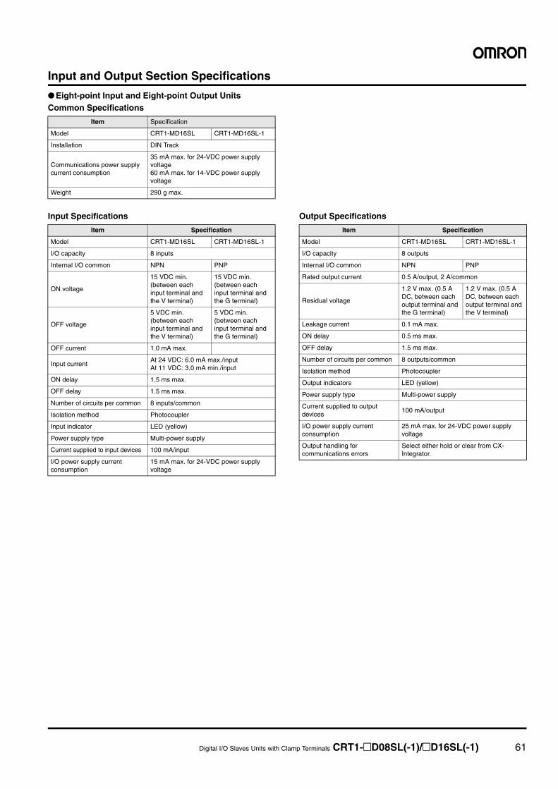
Digital I/O Slaves Units with Clamp Terminals CRT1-@D08SL(-1)/@D16SL(-1) 61
Input and Output Section Specifications
● Eight-point Input and Eight-point Output UnitsCommon Specifications
Input Specifications Output Specifications
Item Specification
Model CRT1-MD16SL CRT1-MD16SL-1
Installation DIN Track
Communications power supply current consumption
35 mA max. for 24-VDC power supply voltage60 mA max. for 14-VDC power supply voltage
Weight 290 g max.
Item Specification
Model CRT1-MD16SL CRT1-MD16SL-1
I/O capacity 8 inputs
Internal I/O common NPN PNP
ON voltage
15 VDC min. (between each input terminal and the V terminal)
15 VDC min. (between each input terminal and the G terminal)
OFF voltage
5 VDC min. (between each input terminal and the V terminal)
5 VDC min. (between each input terminal and the G terminal)
OFF current 1.0 mA max.
Input currentAt 24 VDC: 6.0 mA max./inputAt 11 VDC: 3.0 mA min./input
ON delay 1.5 ms max.
OFF delay 1.5 ms max.
Number of circuits per common 8 inputs/common
Isolation method Photocoupler
Input indicator LED (yellow)
Power supply type Multi-power supply
Current supplied to input devices 100 mA/input
I/O power supply current consumption
15 mA max. for 24-VDC power supply voltage
Item Specification
Model CRT1-MD16SL CRT1-MD16SL-1
I/O capacity 8 outputs
Internal I/O common NPN PNP
Rated output current 0.5 A/output, 2 A/common
Residual voltage
1.2 V max. (0.5 A DC, between each output terminal and the G terminal)
1.2 V max. (0.5 A DC, between each output terminal and the V terminal)
Leakage current 0.1 mA max.
ON delay 0.5 ms max.
OFF delay 1.5 ms max.
Number of circuits per common 8 outputs/common
Isolation method Photocoupler
Output indicators LED (yellow)
Power supply type Multi-power supply
Current supplied to output devices
100 mA/output
I/O power supply current consumption
25 mA max. for 24-VDC power supply voltage
Output handling for communications errors
Select either hold or clear from CX-Integrator.
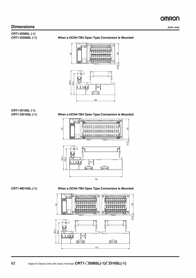
62 Digital I/O Slaves Units with Clamp Terminals CRT1-@D08SL(-1)/@D16SL(-1)
Dimensions (Unit: mm)
CRT1-ID08SL (-1)CRT1-OD08SL (-1) When a DCN4-TB4 Open Type Connectors Is Mounted
CRT1-ID16SL (-1)CRT1-OD16SL (-1) When a DCN4-TB4 Open Type Connectors Is Mounted
CRT1-MD16SL (-1) When a DCN4-TB4 Open Type Connectors Is Mounted
503.
14
60.3
53.2
96
52
52
3.14
60.3
53.2
132
50
503.
14
170
5260
.3
53.2
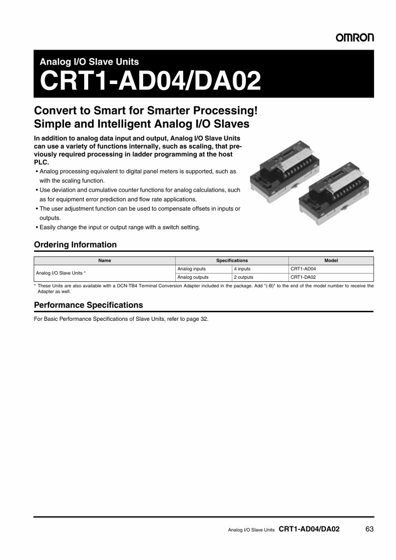
Analog I/O Slave Units CRT1-AD04/DA02 63
Analog I/O Slave Units
CRT1-AD04/DA02Convert to Smart for Smarter Processing!Simple and Intelligent Analog I/O SlavesIn addition to analog data input and output, Analog I/O Slave Units can use a variety of functions internally, such as scaling, that pre-viously required processing in ladder programming at the host PLC.• Analog processing equivalent to digital panel meters is supported, such as
with the scaling function.
• Use deviation and cumulative counter functions for analog calculations, such
as for equipment error prediction and flow rate applications.
• The user adjustment function can be used to compensate offsets in inputs or
outputs.
• Easily change the input or output range with a switch setting.
Ordering Information
* These Units are also available with a DCN-TB4 Terminal Conversion Adapter included in the package. Add "(-B)" to the end of the model number to receive theAdapter as well.
Performance Specifications
For Basic Performance Specifications of Slave Units, refer to page 32.
Name Specifications Model
Analog I/O Slave Units *Analog inputs 4 inputs CRT1-AD04
Analog outputs 2 outputs CRT1-DA02
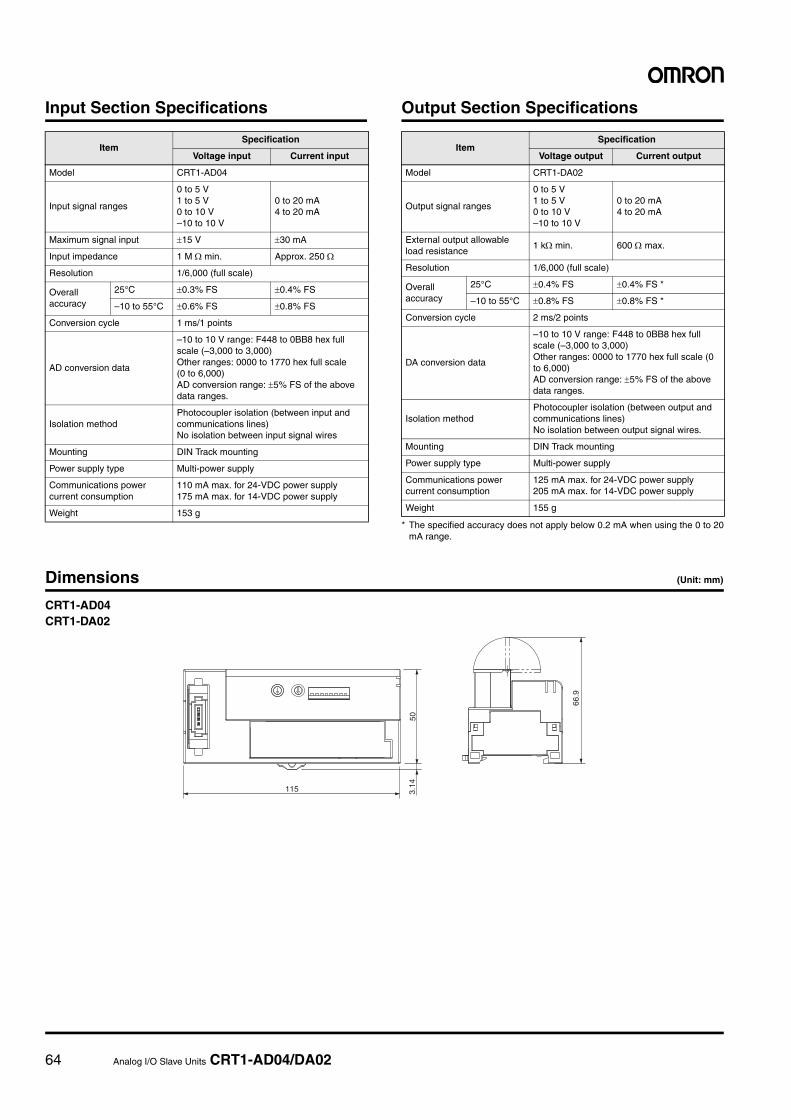
64 Analog I/O Slave Units CRT1-AD04/DA02
Input Section Specifications Output Section Specifications
* The specified accuracy does not apply below 0.2 mA when using the 0 to 20mA range.
Dimensions (Unit: mm)
CRT1-AD04CRT1-DA02
ItemSpecification
Voltage input Current input
Model CRT1-AD04
Input signal ranges
0 to 5 V1 to 5 V0 to 10 V–10 to 10 V
0 to 20 mA4 to 20 mA
Maximum signal input ±15 V ±30 mA
Input impedance 1 M Ω min. Approx. 250 Ω
Resolution 1/6,000 (full scale)
Overall accuracy
25°C ±0.3% FS ±0.4% FS
–10 to 55°C ±0.6% FS ±0.8% FS
Conversion cycle 1 ms/1 points
AD conversion data
–10 to 10 V range: F448 to 0BB8 hex full scale (–3,000 to 3,000)Other ranges: 0000 to 1770 hex full scale (0 to 6,000) AD conversion range: ±5% FS of the above data ranges.
Isolation methodPhotocoupler isolation (between input and communications lines)No isolation between input signal wires
Mounting DIN Track mounting
Power supply type Multi-power supply
Communications power current consumption
110 mA max. for 24-VDC power supply175 mA max. for 14-VDC power supply
Weight 153 g
ItemSpecification
Voltage output Current output
Model CRT1-DA02
Output signal ranges
0 to 5 V1 to 5 V0 to 10 V–10 to 10 V
0 to 20 mA4 to 20 mA
External output allowable load resistance
1 kΩ min. 600 Ω max.
Resolution 1/6,000 (full scale)
Overall accuracy
25°C ±0.4% FS ±0.4% FS *
–10 to 55°C ±0.8% FS ±0.8% FS *
Conversion cycle 2 ms/2 points
DA conversion data
–10 to 10 V range: F448 to 0BB8 hex full scale (–3,000 to 3,000)Other ranges: 0000 to 1770 hex full scale (0 to 6,000) AD conversion range: ±5% FS of the above data ranges.
Isolation methodPhotocoupler isolation (between output and communications lines)No isolation between output signal wires.
Mounting DIN Track mounting
Power supply type Multi-power supply
Communications power current consumption
125 mA max. for 24-VDC power supply205 mA max. for 14-VDC power supply
Weight 155 g
115 3.14
50
66.9
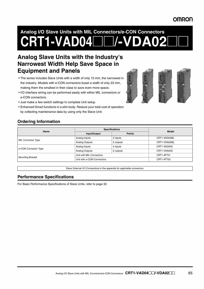
Analog I/O Slave Units with MIL Connectors/e-CON Connectors CRT1-VAD04@@/-VDA02@@ 65
Analog I/O Slave Units with MIL Connectors/e-CON Connectors
CRT1-VAD04@@/-VDA02@@Analog Slave Units with the Industry's Narrowest Width Help Save Space in Equipment and Panels• The series includes Slave Units with a width of only 15 mm, the narrowest in
the industry. Models with e-CON connectors boast a width of only 23 mm,
making them the smallest in their class to save even more space.
• I/O interface wiring can be performed easily with either MIL connectors or
e-CON connectors.
• Just make a few switch settings to complete Unit setup.
• Enhanced Smart functions in a slim body. Reduce your total cost of operation
by collecting maintenance data by using only the Slave Unit.
Ordering Information
Performance Specifications
For Basic Performance Specifications of Slave Units, refer to page 32.
NameSpecifications
ModelInput/Output Points
MIL Connector TypeAnalog Inputs 4 inputs CRT1-VAD04ML
Analog Outputs 2 outputs CRT1-VDA02ML
e-CON Connector TypeAnalog Inputs 4 inputs CRT1-VAD04S
Analog Outputs 2 outputs CRT1-VDA02S
Mounting BracketUnit with MIL Connectors CRT1-ATT01
Unit with e-CON Connectors CRT1-ATT02
Slave External I/O Connections in the appendix for applicable connectors.
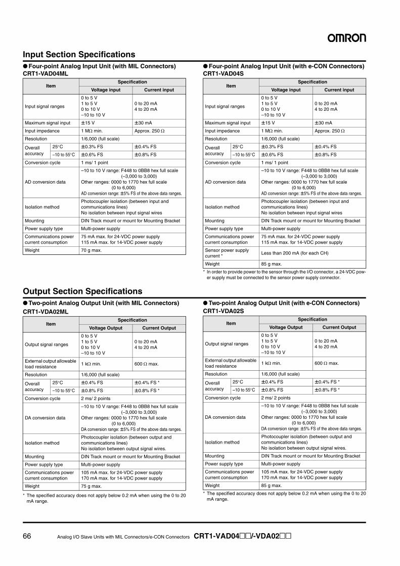
66 Analog I/O Slave Units with MIL Connectors/e-CON Connectors CRT1-VAD04@@/-VDA02@@
Input Section Specifications● Four-point Analog Input Unit (with MIL Connectors)CRT1-VAD04ML
● Four-point Analog Input Unit (with e-CON Connectors)CRT1-VAD04S
* In order to provide power to the sensor through the I/O connector, a 24-VDC pow-er supply must be connected to the sensor power supply connector.
Output Section Specifications● Two-point Analog Output Unit (with MIL Connectors)CRT1-VDA02ML
* The specified accuracy does not apply below 0.2 mA when using the 0 to 20mA range.
● Two-point Analog Output Unit (with e-CON Connectors)CRT1-VDA02S
* The specified accuracy does not apply below 0.2 mA when using the 0 to 20mA range.
ItemSpecification
Voltage input Current input
Input signal ranges
0 to 5 V1 to 5 V0 to 10 V–10 to 10 V
0 to 20 mA4 to 20 mA
Maximum signal input ±15 V ±30 mA
Input impedance 1 MΩ min. Approx. 250 Ω
Resolution 1/6,000 (full scale)
Overallaccuracy
25°C ±0.3% FS ±0.4% FS
–10 to 55°C ±0.6% FS ±0.8% FS
Conversion cycle 1 ms/ 1 point
AD conversion data
–10 to 10 V range: F448 to 0BB8 hex full scale (–3,000 to 3,000)
Other ranges: 0000 to 1770 hex full scale (0 to 6,000)
AD conversion range: ±5% FS of the above data ranges.
Isolation methodPhotocoupler isolation (between input and communications lines)No isolation between input signal wires
Mounting DIN Track mount or mount for Mounting Bracket
Power supply type Multi-power supply
Communications power current consumption
75 mA max. for 24-VDC power supply115 mA max. for 14-VDC power supply
Weight 70 g max.
ItemSpecification
Voltage input Current input
Input signal ranges
0 to 5 V1 to 5 V0 to 10 V–10 to 10 V
0 to 20 mA4 to 20 mA
Maximum signal input ±15 V ±30 mA
Input impedance 1 MΩ min. Approx. 250 Ω
Resolution 1/6,000 (full scale)
Overallaccuracy
25°C ±0.3% FS ±0.4% FS
–10 to 55°C ±0.6% FS ±0.8% FS
Conversion cycle 1 ms/ 1 point
AD conversion data
–10 to 10 V range: F448 to 0BB8 hex full scale (–3,000 to 3,000)
Other ranges: 0000 to 1770 hex full scale (0 to 6,000)
AD conversion range: ±5% FS of the above data ranges.
Isolation methodPhotocoupler isolation (between input and communications lines)No isolation between input signal wires
Mounting DIN Track mount or mount for Mounting Bracket
Power supply type Multi-power supply
Communications power current consumption
75 mA max. for 24-VDC power supply115 mA max. for 14-VDC power supply
Sensor power supply current *
Less than 200 mA (for each CH)
Weight 85 g max.
ItemSpecification
Voltage Output Current Output
Output signal ranges
0 to 5 V1 to 5 V0 to 10 V–10 to 10 V
0 to 20 mA4 to 20 mA
External output allowable load resistance
1 kΩ min. 600 Ω max.
Resolution 1/6,000 (full scale)
Overall accuracy
25°C ±0.4% FS ±0.4% FS *
–10 to 55°C ±0.8% FS ±0.8% FS *
Conversion cycle 2 ms/ 2 points
DA conversion data
–10 to 10 V range: F448 to 0BB8 hex full scale (–3,000 to 3,000)
Other ranges: 0000 to 1770 hex full scale (0 to 6,000)
DA conversion range: ±5% FS of the above data ranges.
Isolation methodPhotocoupler isolation (between output and communications lines)No isolation between output signal wires.
Mounting DIN Track mount or mount for Mounting Bracket
Power supply type Multi-power supply
Communications power current consumption
105 mA max. for 24-VDC power supply170 mA max. for 14-VDC power supply
Weight 75 g max.
ItemSpecification
Voltage Output Current Output
Output signal ranges
0 to 5 V1 to 5 V0 to 10 V–10 to 10 V
0 to 20 mA4 to 20 mA
External output allowable load resistance
1 kΩ min. 600 Ω max.
Resolution 1/6,000 (full scale)
Overall accuracy
25°C ±0.4% FS ±0.4% FS *
–10 to 55°C ±0.8% FS ±0.8% FS *
Conversion cycle 2 ms/ 2 points
DA conversion data
–10 to 10 V range: F448 to 0BB8 hex full scale (–3,000 to 3,000)
Other ranges: 0000 to 1770 hex full scale (0 to 6,000)
DA conversion range: ±5% FS of the above data ranges.
Isolation methodPhotocoupler isolation (between output and communications lines)No isolation between output signal wires.
Mounting DIN Track mount or mount for Mounting Bracket
Power supply type Multi-power supply
Communications power current consumption
105 mA max. for 24-VDC power supply170 mA max. for 14-VDC power supply
Weight 85 g max.

Analog I/O Slave Units with MIL Connectors/e-CON Connectors CRT1-VAD04@@/-VDA02@@ 67
Dimensions (Unit: mm)
● Four-point Analog Input Unit (with MIL Connectors)CRT1-VAD04ML
● Two-point Analog Output Unit (with MIL Connectors)CRT1-VDA02ML
92.8 85
.7
(102
)
96.7
(90)
90(1
01.7
)5.
36.
415 60
78.73
Mounting Holes
16±0.2
2-3.2 dia. or M3
13 18.7
35
When a DCN4-TB4 Open Type Connectors Is Mounted
● Mounting BracketCRT1-ATT01
Note: The numbers inside the parentheses are reference dimensions.
5.3
92.8 85
.7
(102
)96
.7(9
0)
90(1
01.7
)6.
4
15 6078.73
When a DCN4-TB4 Open Type Connectors Is Mounted
Mounting Holes
16±0.2
2-3.2 dia. or M3
13 18.7
35
● Mounting BracketCRT1-ATT01
Note: The numbers inside the parentheses are reference dimensions.

68 Analog I/O Slave Units with MIL Connectors/e-CON Connectors CRT1-VAD04@@/-VDA02@@
● Four-point Analog Input Unit (with e-CON Connectors)CRT1-VAD04S
● Two-point Analog Output Unit (with e-CON Connectors)CRT1-VDA02S
92.8 85
.7
(102
)
96.7
(90)
90(1
01.7
)5.
36.
423 60
66.2
26.7
16±0.2
2-3.2 dia. or M3
35
13
Mounting Holes
When a DCN4-TB4 Open Type Connectors Is Mounted
● Mounting BracketCRT1-ATT02
Note: The numbers inside the parentheses are reference dimensions.
92.8 85
.7
(102
)96
.7(9
0)
90(1
01.7
)5.
36.
4
23 6066.2
When a DCN4-TB4 Open Type Connectors Is Mounted
26.7
16±0.2
2-3.2 dia. or M3
35
13
Mounting Holes
● Mounting BracketCRT1-ATT02
Note: The numbers inside the parentheses are reference dimensions.
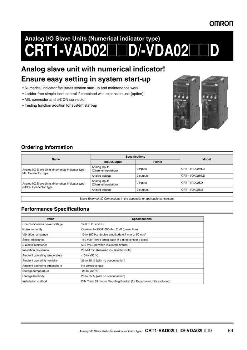
Analog I/O Slave Units (Numerical indicator type) CRT1-VAD02@@D/-VDA02@@D 69
Analog I/O Slave Units (Numerical indicator type)
CRT1-VAD02@@D/-VDA02@@DAnalog slave unit with numerical indicator!Ensure easy setting in system start-up• Numerical indicator facilitates system start-up and maintenance work
• Ladder-free simple local control if combined with expansion unit (option)
• MIL connector and e-CON connector
• Testing function addition for system start-up
Ordering Information
Performance Specifications
NameSpecifications
ModelInput/Output Points
Analog I/O Slave Units (Numerical indicator type) MIL Connector Type
Analog inputs(Channel Insulation)
2 inputs CRT1-VAD02MLD
Analog outputs 2 outputs CRT1-VDA02MLD
Analog I/O Slave Units (Numerical indicator type) e-CON Connector Type
Analog inputs(Channel Insulation)
2 inputs CRT1-VAD02SD
Analog outputs 2 outputs CRT1-VDA02SD
Slave External I/O Connections in the appendix for applicable connectors.
Items Specifications
Communications power voltage 14.0 to 26.4 VDC
Noise immunity Conform to IEC61000-4-4, 2 kV (power line)
Vibration resistance 10 to 150 Hz, double amplitude 0.7 mm or 50 m/s2
Shock resistance 150 m/s2 (three times each in 6 directions of 3 axes)
Dialectic resistance 500 VAC (between insulated circuits)
Insulation resistance 20 MΩ min (between insulated circuits)
Ambient operating temperature -10 to +55 °C
Ambient operating humidity 25 to 85 % (with no condensation)
Ambient operating atmosphere No corrosive gas
Storage temperature -25 to +65 °C
Storage humidity 25 to 85 % (with no condensation)
Installation method DIN Track 35 mm or Mounting Bracket (for Expansion Units excluded)
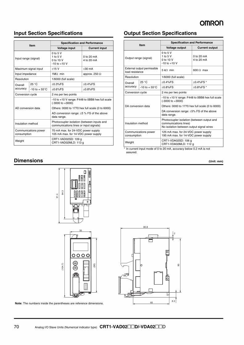
70 Analog I/O Slave Units (Numerical indicator type) CRT1-VAD02@@D/-VDA02@@D
Input Section Specifications Output Section Specifications
* In current input mode of 0 to 20 mA, accuracy below 0.2 mA is not assured.
Dimensions (Unit: mm)
ItemSpecification and Performance
Voltage input Current input
Input range (signal)
0 to 5 V1 to 5 V0 to 10 V-10 to +10 V
0 to 20 mA4 to 20 mA
Maximum signal input ±15 V ±30 mA
Input impedance 1MΩ min approx. 250 Ω
Resolution 1/6000 (full scale)
Overall accuracy
25 °C ±0.3%FS ±0.4%FS
-10 to + 55°C ±0.6%FS ±0.8%FS
Conversion cycle 2 ms per two points
AD conversion data
-10 to +10 V range: F448 to 0BB8 hex full scale (-3000 to +3000)
Others: 0000 to 1770 hex full scale (0 to 6000)
AD conversion range: ±5 % FS of the above data range.
Insulation methodPhotocoupler isolation (between inputs and communications lines or input signals)
Communications power consumption
70 mA max. for 24-VDC power supply105 mA max. for 14-VDC power supply
WeightCRT1-VAD02SD: 109 gCRT1-VAD02MLD: 113 g
ItemSpecification and Performance
Voltage output Current output
Output range (signal)
0 to 5 V1 to 5 V0 to 10 V-10 to +10 V
0 to 20 mA4 to 20 mA
External output permissible load resistance
5 kΩ min 600 Ω max
Resolution 1/6000 (full scale)
Overall accuracy
25 °C ±0.4%FS ±0.4%FS *
-10 to + 55°C ±0.8%FS ±0.8%FS *
Conversion cycle 2 ms per two points
DA conversion data
-10 to +10 V range: F448 to 0BB8 hex full scale (-3000 to +3000)
Others: 0000 to 1770 hex full scale (0 to 6000)
DA conversion range: ±5% FS of the above data range.
Insulation methodPhotocoupler isolation (between output and communications lines)No isolation between output signal wires
Communications power consumption
125 mA max. for 24-VDC power supply195 mA max. for 14-VDC power supply
WeightCRT1-VDA02SD: 106 gCRT1-VDA02MLD: 112 g
35
91.4 84
.3
60
80.8
(104
.7)
(90)
2
90
8.3Note: The numbers inside the parentheses are reference dimensions.
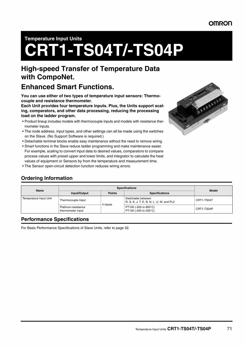
Temperature Input Units CRT1-TS04T/-TS04P 71
Temperature Input Units
CRT1-TS04T/-TS04PHigh-speed Transfer of Temperature Data with CompoNet. Enhanced Smart Functions.You can use either of two types of temperature input sensors: Thermo-couple and resistance thermometer. Each Unit provides four temperature inputs. Plus, the Units support scal-ing, comparators, and other data processing, reducing the processing load on the ladder program.• Product lineup includes models with thermocouple inputs and models with resistance ther-
mometer inputs.• The node address, input types, and other settings can all be made using the switches
on the Slave. (No Support Software is required.) • Detachable terminal blocks enable easy maintenance without the need to remove wiring. • Smart functions in the Slave reduce ladder programming and make maintenance easier.
For example, scaling to convert input data to desired values, comparators to compare process values with preset upper and lower limits, and integrator to calculate the heat values of equipment or Sensors by from the temperature and measurement time.
• The Sensor open-circuit detection function reduces wiring errors.
Ordering Information
Performance Specifications
For Basic Performance Specifications of Slave Units, refer to page 32.
NameSpecifications
ModelInput/Output Points Specifications
Temperature Input UnitThermocouple Input
4 inputs
Switchable betweenR, S, K, J, T, E, B, N, L, U, W, and PL2
CRT1-TS04T
Platinum-resistance thermometer input
PT100 (-200 to 850°C)PT100 (-200 to 200°C)
CRT1-TS04P
72 Temperature Input Units CRT1-TS04T/-TS04P
Specifications
Effects of Mounting Direction on Accuracy A cold junction compensator is included in the Terminal Block of the CRT1-TS04T. The input accuracy depends on the mounting direction
if only the Unit is replaced.
Item model CRT1-TS04T CRT1-TS04P
Input type
Switchable between R, S, K, J, T, E, B, N, L, U, W, and PL2When set with CX-Integrator: Input types can be set individually for each input.Wen set with DIP switch: The same input type setting applies to all 4 inputs.
Switchable between PT100 (−200 to 850°C) and PT100 (−200 to 200°C)When set with CX-Integrator: Input types can be set individually for each input.When set with DIP switch: The same input type setting applies to all 4 inputs.
Indicator accuracy
(±0.3% of indication value or ±1°C, whichever is larger) ±1 digit max.
−200 to 850°C input range:(±0.3% of indication value or ±0.8°C, whichever is larger) ±1 digit max.−200 to 200°C input range:(±0.3% of indication value or ±0.5°C, whichever is larger) ±1 digit max.
Conversion cycle 250 ms/4 points
Temperature conversion data
Binary data (4-digit hexadecimal when Normal Display Mode is selected or 8-digit hexadecimal when 1/100 Display Mode is selected.)
Isolation methodBetween input and communication lines: Photocoupler isolationBetween temperature input signals: Photocoupler isolation
Mounting method 35-mm DIN track mounting
Communications power supply current
75 mA max. at 24 VDC110 mA max. at 14 VDC
75 mA max. at 24 VDC110 mA max. at 14 VDC
Weight 148 g max. 147 g max.
Indicator Accuracy in Exceptional Cases
Input type and temperature range
Input accuracy
K, T, and N below −100°C ±2°C ±1 digit max.
U and L ±2°C ±1 digit max.
R and S below 200°C ±3°C ±1 digit max.
B below 400°C Not specified.
W±0.3% of indication value or ±3°C (whichever is larger) ±1 digit max.
PL2±0.3% of indication value or ±2°C (whichever is larger) ±1 digit max.
Mounting direction Input accuracy
Mounted normally As specified in the Performance Specifications.
Mounted in any direction other than the above
±0.3% of indication value or ±2°C (whichever is larger) ±1 digit max.
Indicator Accuracy in Exceptional Cases
Input type and temperature range
Input accuracy
K, T, and N below −100°C ±3°C ±1 digit max.
U and L ±3°C ±1 digit max.
R and S below 200°C ±4°C ±1 digit max.
B below 400°C Not specified.
W±0.3% of indication value or ±4°C (whichever is larger) ±1 digit max.
PL2±0.3% of indication value or ±3°C (whichever is larger)
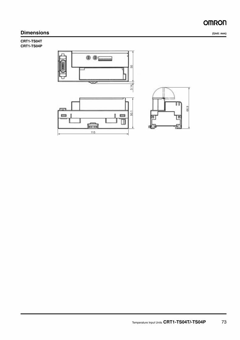
Temperature Input Units CRT1-TS04T/-TS04P 73
Dimensions (Unit: mm)
CRT1-TS04TCRT1-TS04P
3.14
50115
66.9
50.1
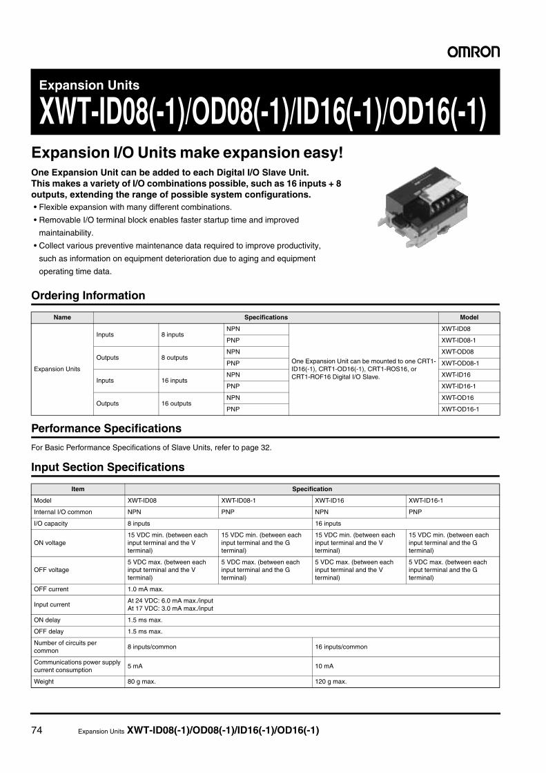
74 Expansion Units XWT-ID08(-1)/OD08(-1)/ID16(-1)/OD16(-1)
Expansion Units
XWT-ID08(-1)/OD08(-1)/ID16(-1)/OD16(-1)Expansion I/O Units make expansion easy!One Expansion Unit can be added to each Digital I/O Slave Unit. This makes a variety of I/O combinations possible, such as 16 inputs + 8 outputs, extending the range of possible system configurations.• Flexible expansion with many different combinations.
• Removable I/O terminal block enables faster startup time and improved
maintainability.
• Collect various preventive maintenance data required to improve productivity,
such as information on equipment deterioration due to aging and equipment
operating time data.
Ordering Information
Performance Specifications
For Basic Performance Specifications of Slave Units, refer to page 32.
Input Section Specifications
Name Specifications Model
Expansion Units
Inputs 8 inputsNPN
One Expansion Unit can be mounted to one CRT1-ID16(-1), CRT1-OD16(-1), CRT1-ROS16, or CRT1-ROF16 Digital I/O Slave.
XWT-ID08
PNP XWT-ID08-1
Outputs 8 outputsNPN XWT-OD08
PNP XWT-OD08-1
Inputs 16 inputsNPN XWT-ID16
PNP XWT-ID16-1
Outputs 16 outputsNPN XWT-OD16
PNP XWT-OD16-1
Item Specification
Model XWT-ID08 XWT-ID08-1 XWT-ID16 XWT-ID16-1
Internal I/O common NPN PNP NPN PNP
I/O capacity 8 inputs 16 inputs
ON voltage15 VDC min. (between each input terminal and the V terminal)
15 VDC min. (between each input terminal and the G terminal)
15 VDC min. (between each input terminal and the V terminal)
15 VDC min. (between each input terminal and the G terminal)
OFF voltage5 VDC max. (between each input terminal and the V terminal)
5 VDC max. (between each input terminal and the G terminal)
5 VDC max. (between each input terminal and the V terminal)
5 VDC max. (between each input terminal and the G terminal)
OFF current 1.0 mA max.
Input currentAt 24 VDC: 6.0 mA max./inputAt 17 VDC: 3.0 mA max./input
ON delay 1.5 ms max.
OFF delay 1.5 ms max.
Number of circuits per common
8 inputs/common 16 inputs/common
Communications power supply current consumption
5 mA 10 mA
Weight 80 g max. 120 g max.
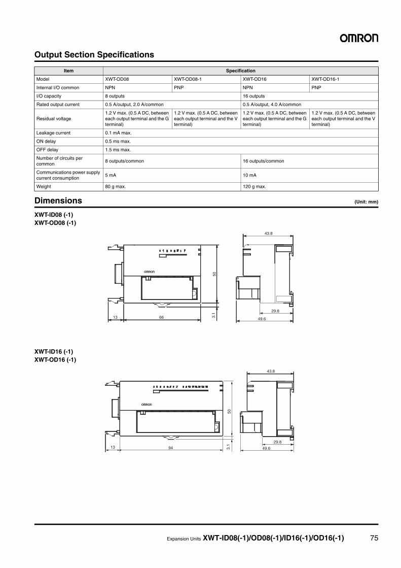
Expansion Units XWT-ID08(-1)/OD08(-1)/ID16(-1)/OD16(-1) 75
Output Section Specifications
Dimensions (Unit: mm)
XWT-ID08 (-1)XWT-OD08 (-1)
XWT-ID16 (-1)XWT-OD16 (-1)
Item Specification
Model XWT-OD08 XWT-OD08-1 XWT-OD16 XWT-OD16-1
Internal I/O common NPN PNP NPN PNP
I/O capacity 8 outputs 16 outputs
Rated output current 0.5 A/output, 2.0 A/common 0.5 A/output, 4.0 A/common
Residual voltage1.2 V max. (0.5 A DC, between each output terminal and the G terminal)
1.2 V max. (0.5 A DC, between each output terminal and the V terminal)
1.2 V max. (0.5 A DC, between each output terminal and the G terminal)
1.2 V max. (0.5 A DC, between each output terminal and the V terminal)
Leakage current 0.1 mA max.
ON delay 0.5 ms max.
OFF delay 1.5 ms max.
Number of circuits per common
8 outputs/common 16 outputs/common
Communications power supply current consumption
5 mA 10 mA
Weight 80 g max. 120 g max.
43.8
29.8
49.6
503.
1
6613
43.8
503.
1
49.6
29.89413
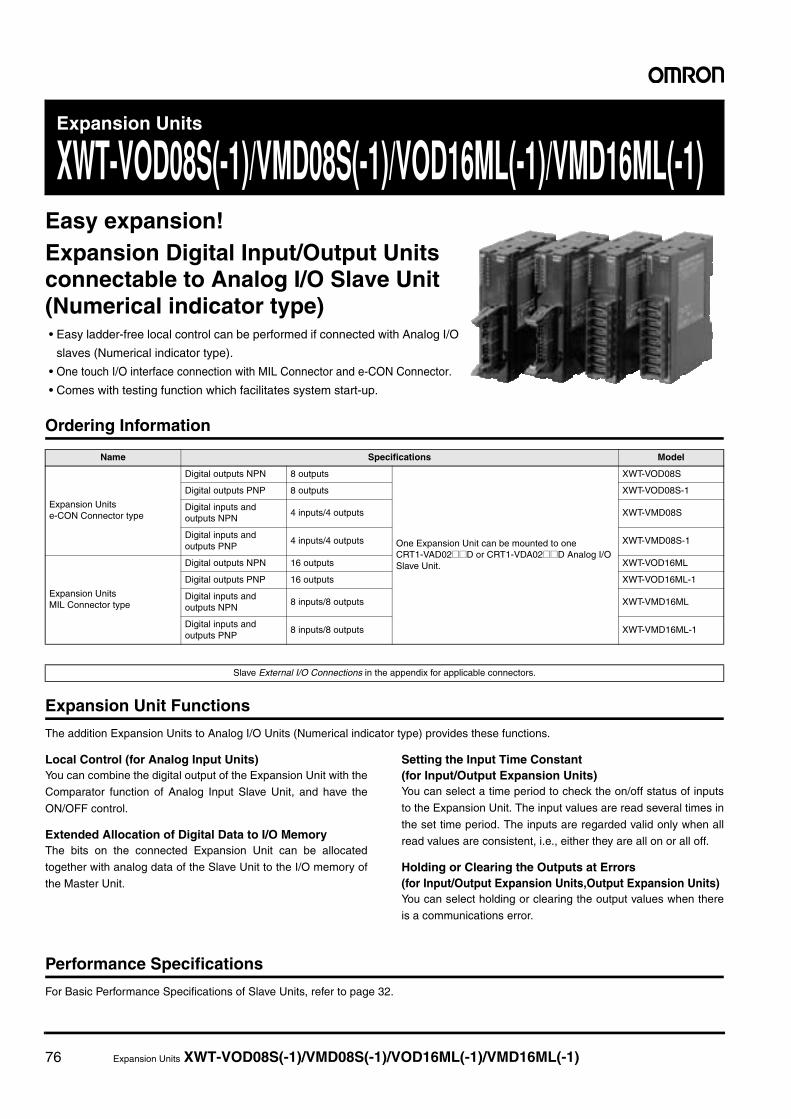
76 Expansion Units XWT-VOD08S(-1)/VMD08S(-1)/VOD16ML(-1)/VMD16ML(-1)
Expansion Units
XWT-VOD08S(-1)/VMD08S(-1)/VOD16ML(-1)/VMD16ML(-1)Easy expansion!Expansion Digital Input/Output Units connectable to Analog I/O Slave Unit(Numerical indicator type)• Easy ladder-free local control can be performed if connected with Analog I/O
slaves (Numerical indicator type).
• One touch I/O interface connection with MIL Connector and e-CON Connector.
• Comes with testing function which facilitates system start-up.
Ordering Information
Expansion Unit Functions
The addition Expansion Units to Analog I/O Units (Numerical indicator type) provides these functions.
Local Control (for Analog Input Units)You can combine the digital output of the Expansion Unit with the
Comparator function of Analog Input Slave Unit, and have the
ON/OFF control.
Extended Allocation of Digital Data to I/O MemoryThe bits on the connected Expansion Unit can be allocated
together with analog data of the Slave Unit to the I/O memory of
the Master Unit.
Setting the Input Time Constant(for Input/Output Expansion Units) You can select a time period to check the on/off status of inputs
to the Expansion Unit. The input values are read several times in
the set time period. The inputs are regarded valid only when all
read values are consistent, i.e., either they are all on or all off.
Holding or Clearing the Outputs at Errors(for Input/Output Expansion Units,Output Expansion Units)You can select holding or clearing the output values when there
is a communications error.
Performance Specifications
For Basic Performance Specifications of Slave Units, refer to page 32.
Name Specifications Model
Expansion Units e-CON Connector type
Digital outputs NPN 8 outputs
One Expansion Unit can be mounted to one CRT1-VAD02@@D or CRT1-VDA02@@D Analog I/O Slave Unit.
XWT-VOD08S
Digital outputs PNP 8 outputs XWT-VOD08S-1
Digital inputs and outputs NPN
4 inputs/4 outputs XWT-VMD08S
Digital inputs and outputs PNP
4 inputs/4 outputs XWT-VMD08S-1
Expansion Units MIL Connector type
Digital outputs NPN 16 outputs XWT-VOD16ML
Digital outputs PNP 16 outputs XWT-VOD16ML-1
Digital inputs and outputs NPN
8 inputs/8 outputs XWT-VMD16ML
Digital inputs and outputs PNP
8 inputs/8 outputs XWT-VMD16ML-1
Slave External I/O Connections in the appendix for applicable connectors.
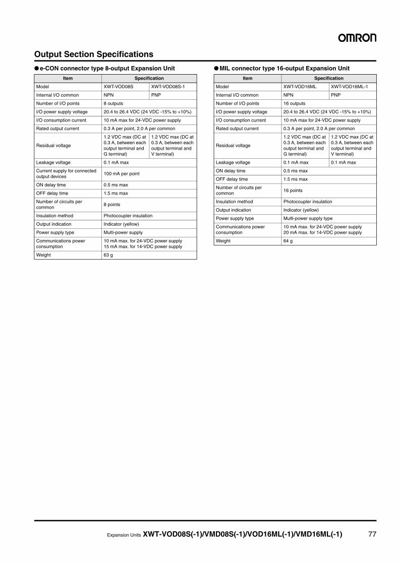
Expansion Units XWT-VOD08S(-1)/VMD08S(-1)/VOD16ML(-1)/VMD16ML(-1) 77
Output Section Specifications
● e-CON connector type 8-output Expansion Unit ● MIL connector type 16-output Expansion Unit
Item Specification
Model XWT-VOD08S XWT-VOD08S-1
Internal I/O common NPN PNP
Number of I/O points 8 outputs
I/O power supply voltage 20.4 to 26.4 VDC (24 VDC -15% to +10%)
I/O consumption current 10 mA max for 24-VDC power supply
Rated output current 0.3 A per point, 2.0 A per common
Residual voltage
1.2 VDC max (DC at 0.3 A, between each output terminal and G terminal)
1.2 VDC max (DC at 0.3 A, between each output terminal and V terminal)
Leakage voltage 0.1 mA max
Current supply for connected output devices
100 mA per point
ON delay time 0.5 ms max
OFF delay time 1.5 ms max
Number of circuits per common
8 points
Insulation method Photocoupler insulation
Output indication Indicator (yellow)
Power supply type Multi-power supply
Communications power consumption
10 mA max. for 24-VDC power supply15 mA max. for 14-VDC power supply
Weight 63 g
Item Specification
Model XWT-VOD16ML XWT-VOD16ML-1
Internal I/O common NPN PNP
Number of I/O points 16 outputs
I/O power supply voltage 20.4 to 26.4 VDC (24 VDC -15% to +10%)
I/O consumption current 10 mA max for 24-VDC power supply
Rated output current 0.3 A per point, 2.0 A per common
Residual voltage
1.2 VDC max (DC at 0.3 A, between each output terminal and G terminal)
1.2 VDC max (DC at 0.3 A, between each output terminal and V terminal)
Leakage voltage 0.1 mA max 0.1 mA max
ON delay time 0.5 ms max
OFF delay time 1.5 ms max
Number of circuits per common
16 points
Insulation method Photocoupler insulation
Output indication Indicator (yellow)
Power supply type Multi-power supply type
Communications power consumption
10 mA max. for 24-VDC power supply20 mA max. for 14-VDC power supply
Weight 64 g
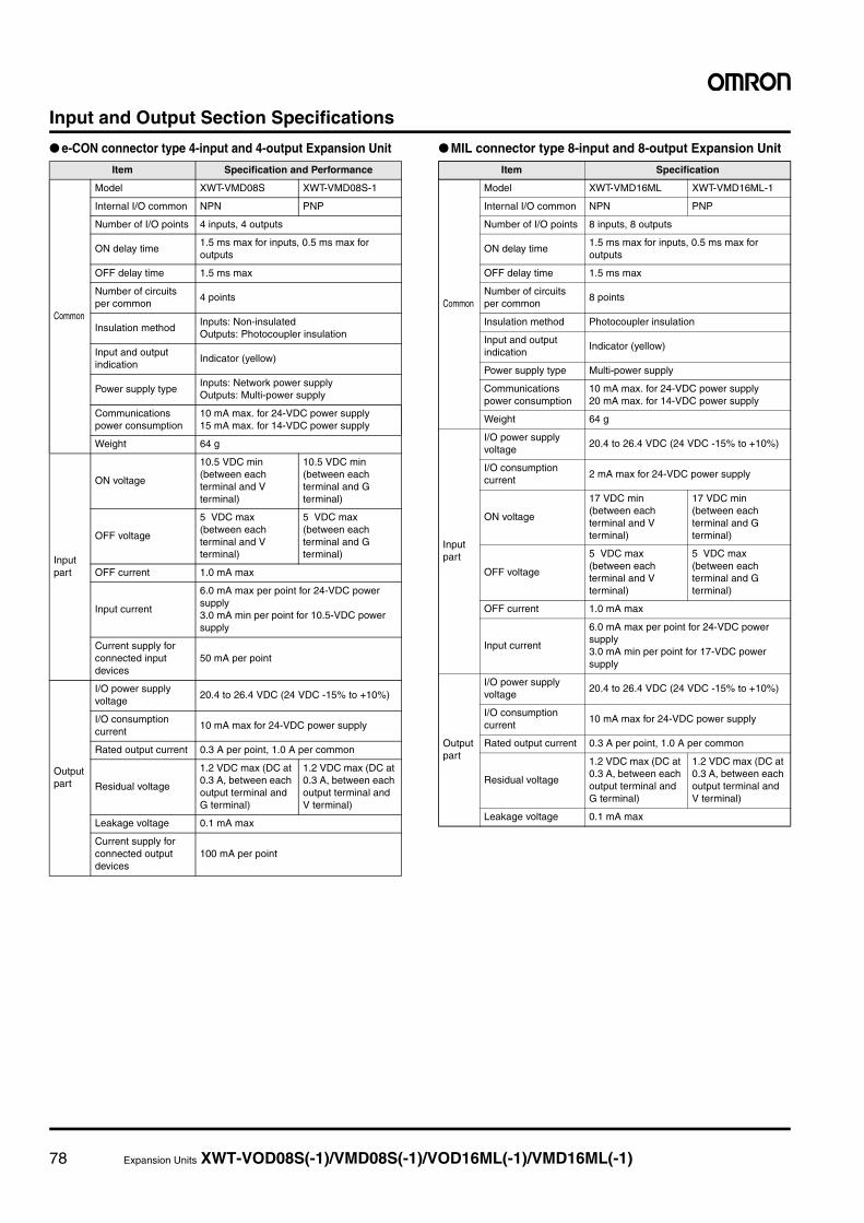
78 Expansion Units XWT-VOD08S(-1)/VMD08S(-1)/VOD16ML(-1)/VMD16ML(-1)
Input and Output Section Specifications
● e-CON connector type 4-input and 4-output Expansion Unit ● MIL connector type 8-input and 8-output Expansion Unit
Item Specification and Performance
Common
Model XWT-VMD08S XWT-VMD08S-1
Internal I/O common NPN PNP
Number of I/O points 4 inputs, 4 outputs
ON delay time1.5 ms max for inputs, 0.5 ms max for outputs
OFF delay time 1.5 ms max
Number of circuits per common
4 points
Insulation methodInputs: Non-insulatedOutputs: Photocoupler insulation
Input and output indication
Indicator (yellow)
Power supply typeInputs: Network power supplyOutputs: Multi-power supply
Communications power consumption
10 mA max. for 24-VDC power supply15 mA max. for 14-VDC power supply
Weight 64 g
Input part
ON voltage
10.5 VDC min (between each terminal and V terminal)
10.5 VDC min (between each terminal and G terminal)
OFF voltage
5 VDC max (between each terminal and V terminal)
5 VDC max (between each terminal and G terminal)
OFF current 1.0 mA max
Input current
6.0 mA max per point for 24-VDC power supply3.0 mA min per point for 10.5-VDC power supply
Current supply for connected input devices
50 mA per point
Output part
I/O power supply voltage
20.4 to 26.4 VDC (24 VDC -15% to +10%)
I/O consumption current
10 mA max for 24-VDC power supply
Rated output current 0.3 A per point, 1.0 A per common
Residual voltage
1.2 VDC max (DC at 0.3 A, between each output terminal and G terminal)
1.2 VDC max (DC at 0.3 A, between each output terminal and V terminal)
Leakage voltage 0.1 mA max
Current supply for connected output devices
100 mA per point
Item Specification
Common
Model XWT-VMD16ML XWT-VMD16ML-1
Internal I/O common NPN PNP
Number of I/O points 8 inputs, 8 outputs
ON delay time1.5 ms max for inputs, 0.5 ms max for outputs
OFF delay time 1.5 ms max
Number of circuits per common
8 points
Insulation method Photocoupler insulation
Input and output indication
Indicator (yellow)
Power supply type Multi-power supply
Communications power consumption
10 mA max. for 24-VDC power supply20 mA max. for 14-VDC power supply
Weight 64 g
Input part
I/O power supply voltage
20.4 to 26.4 VDC (24 VDC -15% to +10%)
I/O consumption current
2 mA max for 24-VDC power supply
ON voltage
17 VDC min (between each terminal and V terminal)
17 VDC min (between each terminal and G terminal)
OFF voltage
5 VDC max (between each terminal and V terminal)
5 VDC max (between each terminal and G terminal)
OFF current 1.0 mA max
Input current
6.0 mA max per point for 24-VDC power supply3.0 mA min per point for 17-VDC power supply
Output part
I/O power supply voltage
20.4 to 26.4 VDC (24 VDC -15% to +10%)
I/O consumption current
10 mA max for 24-VDC power supply
Rated output current 0.3 A per point, 1.0 A per common
Residual voltage
1.2 VDC max (DC at 0.3 A, between each output terminal and G terminal)
1.2 VDC max (DC at 0.3 A, between each output terminal and V terminal)
Leakage voltage 0.1 mA max
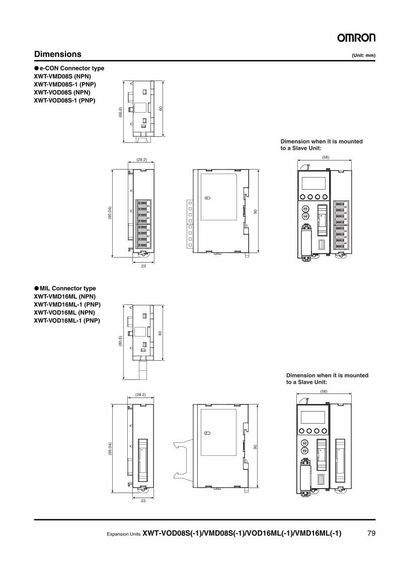
Expansion Units XWT-VOD08S(-1)/VMD08S(-1)/VOD16ML(-1)/VMD16ML(-1) 79
Dimensions (Unit: mm)
● e-CON Connector type
● MIL Connector type
(66.
6)
(95.
04)
(28.2)
90
60
23
(58)
Dimension when it is mounted to a Slave Unit:
XWT-VMD08S (NPN)XWT-VMD08S-1 (PNP)XWT-VOD08S (NPN)XWT-VOD08S-1 (PNP)
(80.
6)
(95.
04)
(28.2)
23
90
60
(58)
Dimension when it is mounted to a Slave Unit:
XWT-VMD16ML (NPN)XWT-VMD16ML-1 (PNP)XWT-VOD16ML (NPN)XWT-VOD16ML-1 (PNP)
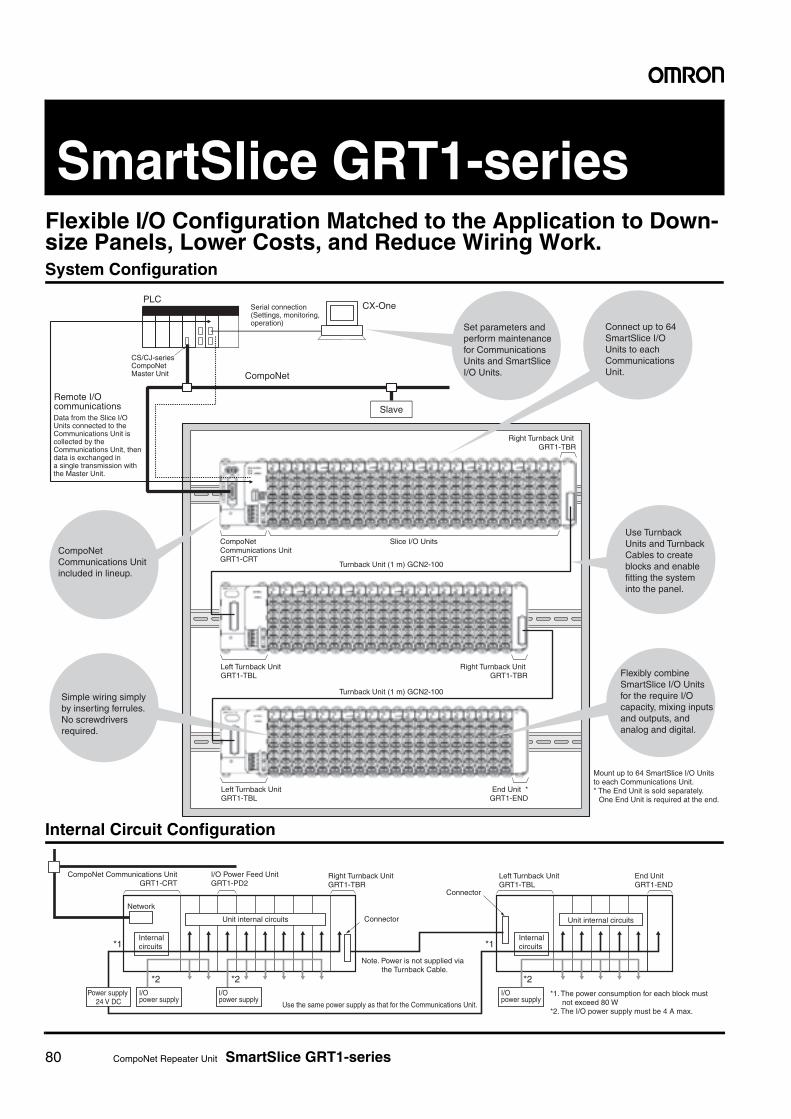
80 CompoNet Repeater Unit SmartSlice GRT1-series
SmartSlice GRT1-seriesFlexible I/O Configuration Matched to the Application to Down-size Panels, Lower Costs, and Reduce Wiring Work.System Configuration
Internal Circuit Configuration
Set parameters and perform maintenance for Communications Units and SmartSlice I/O Units.
Connect up to 64 SmartSlice I/O Units to each Communications Unit.
CompoNet Communications Unit included in lineup.
Use Turnback Units and Turnback Cables to create blocks and enable fitting the system into the panel.
Simple wiring simply by inserting ferrules. No screwdrivers required.
Flexibly combine SmartSlice I/O Units for the require I/O capacity, mixing inputs and outputs, and analog and digital.
Mount up to 64 SmartSlice I/O Units to each Communications Unit.* The End Unit is sold separately.
One End Unit is required at the end.
CompoNet Communications Unit GRT1-CRT
Left Turnback Unit GRT1-TBL
Left Turnback Unit GRT1-TBL
Right Turnback Unit GRT1-TBR
Right Turnback Unit GRT1-TBR
End Unit * GRT1-END
Remote I/O communicationsData from the Slice I/O Units connected to theCommunications Unit is collected by the Communications Unit, then data is exchanged ina single transmission with the Master Unit.
CS/CJ-series CompoNetMaster Unit
Serial connection(Settings, monitoring,operation)
PLCCX-One
CompoNet
Slave
Slice I/O Units
Turnback Unit (1 m) GCN2-100
Turnback Unit (1 m) GCN2-100
CompoNet Communications Unit GRT1-CRT
I/O Power Feed Unit GRT1-PD2
Left Turnback Unit GRT1-TBL
Right Turnback Unit GRT1-TBR
Network
Unit internal circuits Unit internal circuits
Internalcircuits
Internalcircuits
Connector
Connector
Power supply 24 V DC
I/O power supply
I/O power supply
I/O power supply
End Unit GRT1-END
Use the same power supply as that for the Communications Unit.
Note. Power is not supplied via the Turnback Cable.
*1
*2
*1
*2*2
*1. The power consumption for each block must not exceed 80 W
*2. The I/O power supply must be 4 A max.

SmartSlice CompoNet Communications Unit GRT1-CRT 81
SmartSlice CompoNet Communications Unit
GRT1-CRTThe CompoNet-compliant unit can inter-face up to 256 inputs and 256 outputs at one node. • Connects to up to 64 SmartSlice I/O Units.
• Concentrate I/O at one Slave: Up to 256 inputs and 256 outputs.
• Mix different I/O types at one Slave to help save space.
• Just set the node address for easy startup.
• Replace SmartSlice I/O Units online while continuing communications, minimiz-
ing system downtime.
• Smart function provided to monitor operating status, facilitating preventive main-
tenance and increasing operating rates.
• Register dummy SmartSlice I/O to reduce design work for future expansions.
Ordering Information
Specifications
* For power supply input to the Slice I/O Units.
Name Specifications Model
CompoNet Communications UnitConnects to up 64 SmartSlice I/O Units(Inputs: 32 bytes maximum, Outputs: 32 bytes maximum)
GRT1-CRT
Item Model GRT1-DRT
Network power supply voltage 14 to 26.4 V DC
Unit power supply voltage 20.4 to 26.4 V DC (24 V +10%/−15%)
I/O power supply voltage20.4 to 26.4 V DC *(24 V +10%/−15%)
Noise immunity Conforms to IEC 61000-4-4, 2 kV (power line)
Vibration resistance+10 to 60 Hz, 0.7-mm double amplitude60 to 150 Hz: 50 m/s2
Shock resistance 150 m/s2
Dielectric strength 500 V AC between isolated circuits
Insulation resistance 20 MΩ min. between isolated circuits
Ambient operating temperature −10 to 55°C (with no icing or condensation)
Ambient operating humidity 25% to 85%
Ambient operating environment No corrosive gases
Ambient storage temperature −25 to 65°C (with no icing or condensation)
Mounting method 35-mm DIN track mounting
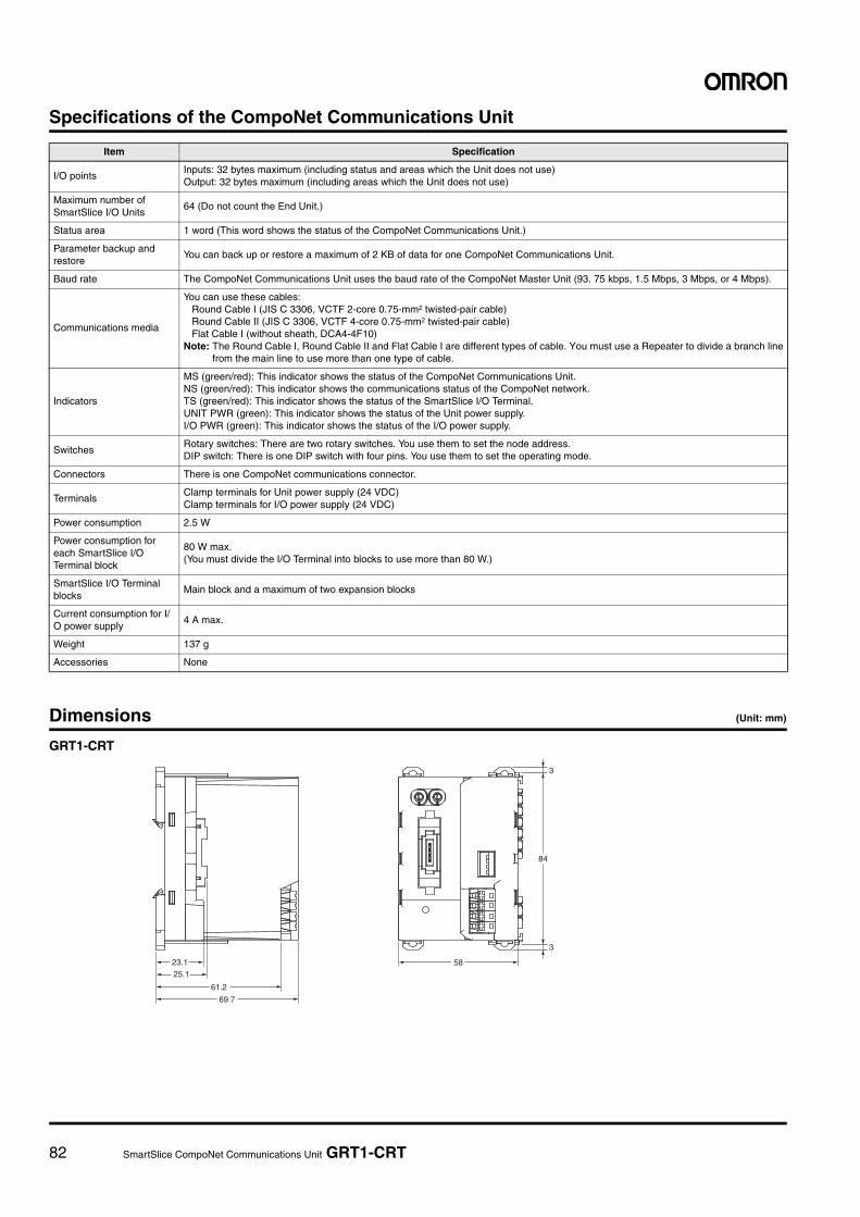
82 SmartSlice CompoNet Communications Unit GRT1-CRT
Specifications of the CompoNet Communications Unit
Dimensions (Unit: mm)
GRT1-CRT
Item Specification
I/O points Inputs: 32 bytes maximum (including status and areas which the Unit does not use)Output: 32 bytes maximum (including areas which the Unit does not use)
Maximum number of SmartSlice I/O Units
64 (Do not count the End Unit.)
Status area 1 word (This word shows the status of the CompoNet Communications Unit.)
Parameter backup and restore
You can back up or restore a maximum of 2 KB of data for one CompoNet Communications Unit.
Baud rate The CompoNet Communications Unit uses the baud rate of the CompoNet Master Unit (93. 75 kbps, 1.5 Mbps, 3 Mbps, or 4 Mbps).
Communications media
You can use these cables:Round Cable I (JIS C 3306, VCTF 2-core 0.75-mm2 twisted-pair cable) Round Cable II (JIS C 3306, VCTF 4-core 0.75-mm2 twisted-pair cable)Flat Cable I (without sheath, DCA4-4F10)
Note: The Round Cable I, Round Cable II and Flat Cable I are different types of cable. You must use a Repeater to divide a branch linefrom the main line to use more than one type of cable.
Indicators
MS (green/red): This indicator shows the status of the CompoNet Communications Unit. NS (green/red): This indicator shows the communications status of the CompoNet network. TS (green/red): This indicator shows the status of the SmartSlice I/O Terminal. UNIT PWR (green): This indicator shows the status of the Unit power supply. I/O PWR (green): This indicator shows the status of the I/O power supply.
Switches Rotary switches: There are two rotary switches. You use them to set the node address. DIP switch: There is one DIP switch with four pins. You use them to set the operating mode.
Connectors There is one CompoNet communications connector.
Terminals Clamp terminals for Unit power supply (24 VDC) Clamp terminals for I/O power supply (24 VDC)
Power consumption 2.5 W
Power consumption for each SmartSlice I/O Terminal block
80 W max. (You must divide the I/O Terminal into blocks to use more than 80 W.)
SmartSlice I/O Terminal blocks
Main block and a maximum of two expansion blocks
Current consumption for I/O power supply
4 A max.
Weight 137 g
Accessories None
3
3
5823.1
25.1
61.2
69.7
84
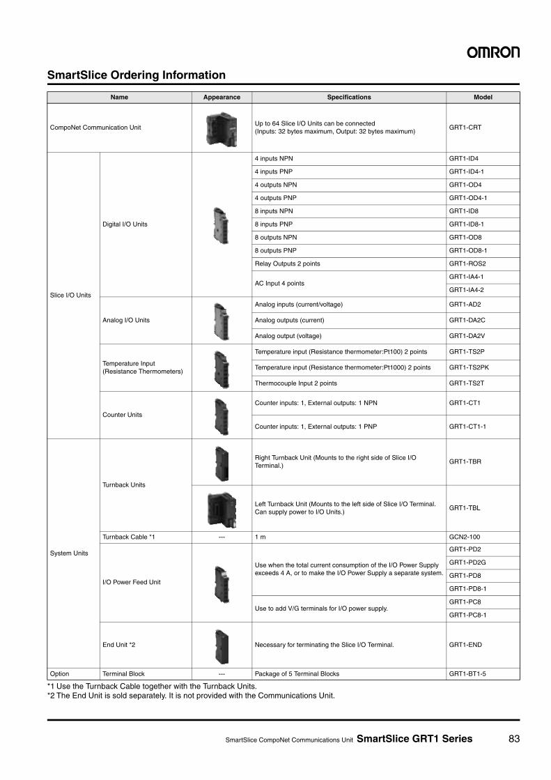
SmartSlice CompoNet Communications Unit SmartSlice GRT1 Series 83
SmartSlice Ordering Information
*1 Use the Turnback Cable together with the Turnback Units.*2 The End Unit is sold separately. It is not provided with the Communications Unit.
Name Appearance Specifications Model
CompoNet Communication UnitUp to 64 Slice I/O Units can be connected(Inputs: 32 bytes maximum, Output: 32 bytes maximum)
GRT1-CRT
Slice I/O Units
Digital I/O Units
4 inputs NPN GRT1-ID4
4 inputs PNP GRT1-ID4-1
4 outputs NPN GRT1-OD4
4 outputs PNP GRT1-OD4-1
8 inputs NPN GRT1-ID8
8 inputs PNP GRT1-ID8-1
8 outputs NPN GRT1-OD8
8 outputs PNP GRT1-OD8-1
Relay Outputs 2 points GRT1-ROS2
AC Input 4 pointsGRT1-IA4-1
GRT1-IA4-2
Analog I/O Units
Analog inputs (current/voltage) GRT1-AD2
Analog outputs (current) GRT1-DA2C
Analog output (voltage) GRT1-DA2V
Temperature Input(Resistance Thermometers)
Temperature input (Resistance thermometer:Pt100) 2 points GRT1-TS2P
Temperature input (Resistance thermometer:Pt1000) 2 points GRT1-TS2PK
Thermocouple Input 2 points GRT1-TS2T
Counter Units
Counter inputs: 1, External outputs: 1 NPN GRT1-CT1
Counter inputs: 1, External outputs: 1 PNP GRT1-CT1-1
System Units
Turnback Units
Right Turnback Unit (Mounts to the right side of Slice I/O Terminal.)
GRT1-TBR
Left Turnback Unit (Mounts to the left side of Slice I/O Terminal. Can supply power to I/O Units.)
GRT1-TBL
Turnback Cable *1 --- 1 m GCN2-100
I/O Power Feed Unit
Use when the total current consumption of the I/O Power Supply exceeds 4 A, or to make the I/O Power Supply a separate system.
GRT1-PD2
GRT1-PD2G
GRT1-PD8
GRT1-PD8-1
Use to add V/G terminals for I/O power supply.GRT1-PC8
GRT1-PC8-1
End Unit *2 Necessary for terminating the Slice I/O Terminal. GRT1-END
Option Terminal Block --- Package of 5 Terminal Blocks GRT1-BT1-5
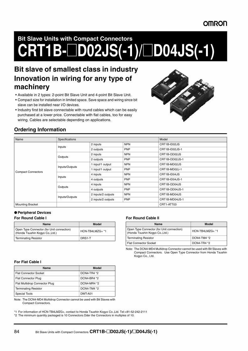
84 Bit Slave Units with Compact Connectors CRT1B-@D02JS(-1)/@D04JS(-1)
Bit Slave Units with Compact Connectors
CRT1B-@D02JS(-1)/@D04JS(-1)Bit slave of smallest class in industryInnovation in wiring for any type of machinery• Available in 2 types: 2-point Bit Slave Unit and 4-point Bit Slave Unit.• Compact size for installation in limited space. Save space and wiring since bit
slave can be installed near I/O devices.• Industry first bit slave connectable with round cables which can be easily
purchased at a lower price. Connectable with flat cables, too for easy wiring. Cables are selectable depending on applications.
Ordering Information
● Peripheral DevicesFor Round Cable l For Round Cable ll
Note: The DCN4-MD4 Multidrop Connector cannot be used with Bit Slaves withCompact Connectors. Use Open Type Connector from Honda TsushinKogyo Co., Ltd.
For Flat Cable l
Note: The DCN4-MD4 Multidrop Connector cannot be used with Bit Slaves withCompact Connectors.
*1 For information of HCN-TB4LMZG+, contact to Honda Tsushin Kogyo Co.,Ltd. Tel:+81-52-242-2111*2 The minimum quantity packaged is 10 Connectors.Oder the Connectors in multiples of 10.
Name Specifications Model
Compact Connectors
Inputs2 inputs NPN CRT1B-ID02JS
2 outputs PNP CRT1B-ID02JS-1
Outputs2 inputs NPN CRT1B-OD02JS
2 outputs PNP CRT1B-OD02JS-1
Inputs/Outputs1 input/1 output NPN CRT1B-MD02JS
1 input/1 output PNP CRT1B-MD02J-1
Inputs4 inputs NPN CRT1B-ID04JS
4 outputs PNP CRT1B-ID04JS-1
Outputs4 inputs NPN CRT1B-OD04JS
4 outputs PNP CRT1B-OD04JS-1
Inputs/Outputs2 inputs/2 outputs NPN CRT1B-MD04JS
2 inputs/2 outputs PNP CRT1B-MD04JS-1
Mounting Bracket CRT1-ATT03
Name Model
Open Type Connector (for Unit connection) (Honda Tsushin Kogyo Co.,Ltd.)
HCN-TB4LMZG+ *1
Terminating Resistor DRS1-T
Name Model
Open Type Connector (for Unit connection) (Honda Tsushin Kogyo Co.,Ltd.)
HCN-TB4LMZG+ *1
Terminating Resistor DCN4-TM4 *2
Flat Connector Socket DCN4-TR4 *2
Name Model
Flat Connector Socket DCN4-TR4 *2
Flat Connector Plug DCN4-BR4 *2
Flat Multidrop Connector Plug DCN4-MR4 *2
Terminating Resistor DCN4-TM4 *2
Special Tools DWT-A01
Bit Slave Units with Compact Connectors CRT1B-@D02JS(-1)/@D04JS(-1) 85
● Compact ConnectorsThe compact connectors use XA-series Connectors from JST Mfg. Co., Ltd. Special cable connectors must be attached for cables con-
necting to external devices if a Slave Unit with Compact Connectors is used.
Note 1. Automated Crimp Tools are also available. For details, contact the manufacturer.2. For information on the processing procedure, refer to the instruction manual included with the tool or contact the manufacturer (JST Mfg. Co., Ltd.).
Performance Specifications
For Basic Performance Specifications of Slave Units, refer to page 32.
Input Section Specifications
* The current consumption is for Bit Slave Unit communications current when all inputs are OFF, i.e., it does not include input device current consumption. The com-munications power supply is also used for the I/O power supply for sensors. Be sure to consider the sensor current consumption and the number of sensors connectedin addition to the communications power. The power supply current consumption is expressed by the following formula.
Communications power supply current consumption = Bit Slave Unit communications current consumption + (Bit Slave Unit input current × number of inputsused) + (sensor current consumption × number of sensors used)
Name
Applicable cable range
Model Crimping Toolmm2 AWG#
Wire sheath external diameter
Contacts
Loose terminal0.08 to 0.33 28 to 22 1.2 to 1.9
BXA-001T-P0.6 YC-692R
Chain terminal SXA-001T-P0.6 YRS-692
Loose terminal0.22 to 0.5 24 to 20 1.5 to 1.9
BXA-01T-P0.6 YC-701R
Chain terminal SXA-01T-P0.6 YRS-701
Housing --- --- XAP-03V-1 ---
Item Specification
Model CRT1B-ID02JS CRT1B-ID02JS-1 CRT1B-ID04JS CRT1B-ID04JS-1
I/O capacity 2 inputs 4 inputs
Internal I/O common NPN PNP NPN PNP
ON voltage10.5 VDC min. (between each input terminal and the V terminal)
10.5 VDC min. (between each input terminal and the G terminal)
10.5 VDC min. (between each input terminal and the V terminal)
10.5 VDC min. (between each input terminal and the G terminal)
OFF voltage --- --- --- ---
OFF current 1.0 mA max. 1.0 mA max.
Input current 3.0 mA min./input (at 10.5 VDC) 3.0 mA min./input (at 10.5 VDC)
Sensor power supply voltageCommunications power supply voltage 0 V (max.)Communications power supply voltage −1 V (min.)
Communications power supply voltage 0 V (max.)Communications power supply voltage −1 V (min.)
ON delay 1.5 ms max. 1.5 ms max.
OFF delay 1.5 ms max. 1.5 ms max.
Number of circuits per common 2 inputs/common 4 inputs/common
Power short-circuit detection Not supported. Not supported.
Isolation method No isolation No isolation
Input indicators LEDs (yellow) LEDs (yellow)
Degree of protection IEC standard IP20 IEC standard IP20
Installation M4 screw mounting using CRT1B-ATT03 Mounting Bracket M4 screw mounting using CRT1B-ATT03 Mounting Bracket
Power supply type Network power supply Network power supply
Communications power supply current consumption *
25 mA max. for 24-VDC power supply voltage30 mA max. for 14-VDC power supply voltage
35 mA max. for 24-VDC power supply voltage40 mA max. for 14-VDC power supply voltage
Input device supply current 50 mA/point (G terminal) 50 mA/point (V terminal) 50 mA/point (G terminal) 50 mA/point (V terminal)
Weight 16 g max. 21 g max.
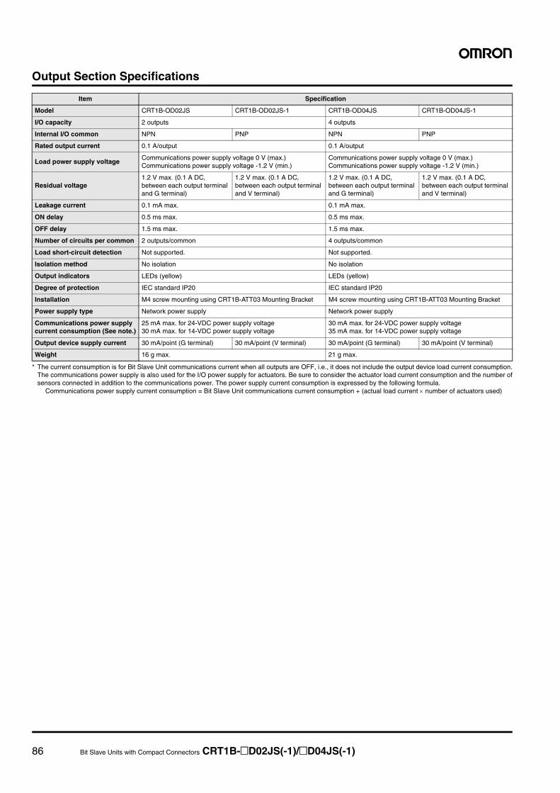
86 Bit Slave Units with Compact Connectors CRT1B-@D02JS(-1)/@D04JS(-1)
Output Section Specifications
* The current consumption is for Bit Slave Unit communications current when all outputs are OFF, i.e., it does not include the output device load current consumption.The communications power supply is also used for the I/O power supply for actuators. Be sure to consider the actuator load current consumption and the number ofsensors connected in addition to the communications power. The power supply current consumption is expressed by the following formula.
Communications power supply current consumption = Bit Slave Unit communications current consumption + (actual load current × number of actuators used)
Item Specification
Model CRT1B-OD02JS CRT1B-OD02JS-1 CRT1B-OD04JS CRT1B-OD04JS-1
I/O capacity 2 outputs 4 outputs
Internal I/O common NPN PNP NPN PNP
Rated output current 0.1 A/output 0.1 A/output
Load power supply voltageCommunications power supply voltage 0 V (max.)Communications power supply voltage -1.2 V (min.)
Communications power supply voltage 0 V (max.)Communications power supply voltage -1.2 V (min.)
Residual voltage1.2 V max. (0.1 A DC, between each output terminal and G terminal)
1.2 V max. (0.1 A DC, between each output terminal and V terminal)
1.2 V max. (0.1 A DC, between each output terminal and G terminal)
1.2 V max. (0.1 A DC, between each output terminal and V terminal)
Leakage current 0.1 mA max. 0.1 mA max.
ON delay 0.5 ms max. 0.5 ms max.
OFF delay 1.5 ms max. 1.5 ms max.
Number of circuits per common 2 outputs/common 4 outputs/common
Load short-circuit detection Not supported. Not supported.
Isolation method No isolation No isolation
Output indicators LEDs (yellow) LEDs (yellow)
Degree of protection IEC standard IP20 IEC standard IP20
Installation M4 screw mounting using CRT1B-ATT03 Mounting Bracket M4 screw mounting using CRT1B-ATT03 Mounting Bracket
Power supply type Network power supply Network power supply
Communications power supply current consumption (See note.)
25 mA max. for 24-VDC power supply voltage30 mA max. for 14-VDC power supply voltage
30 mA max. for 24-VDC power supply voltage35 mA max. for 14-VDC power supply voltage
Output device supply current 30 mA/point (G terminal) 30 mA/point (V terminal) 30 mA/point (G terminal) 30 mA/point (V terminal)
Weight 16 g max. 21 g max.
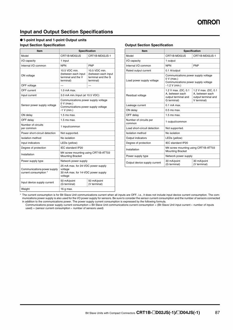
Bit Slave Units with Compact Connectors CRT1B-@D02JS(-1)/@D04JS(-1) 87
Input and Output Section Specifications
● 1-point Input and 1-point Output unitsInput Section Specification Output Section Specification
* The current consumption is for Bit Slave Unit communications current when all inputs are OFF, i.e., it does not include input device current consumption. The com-munications power supply is also used for the I/O power supply for sensors. Be sure to consider the sensor current consumption and the number of sensors connectedin addition to the communications power. The power supply current consumption is expressed by the following formula.
Communications power supply current consumption = Bit Slave Unit communications current consumption + (Bit Slave Unit input current × number of inputsused) + (sensor current consumption × number of sensors used)
Item Specification
Model CRT1B-MD02JS CRT1B-MD02JS-1
I/O capacity 1 input
Internal I/O common NPN PNP
ON voltage
10.5 VDC min. (between each input terminal and the V terminal)
10.5 VDC min. (between each input terminal and the G terminal)
OFF voltage --- ---
OFF current 1.0 mA max.
Input current 3.0 mA min./input (at 10.5 VDC)
Sensor power supply voltage
Communications power supply voltage 0 V (max.)Communications power supply voltage -1 V (min.)
ON delay 1.5 ms max.
OFF delay 1.5 ms max.
Number of circuits per common
1 input/common
Power short-circuit detection Not supported.
Isolation method No isolation
Input indicators LEDs (yellow)
Degree of protection IEC standard IP20
InstallationM4 screw mounting using CRT1B-ATT03 Mounting Bracket
Power supply type Network power supply
Communications power supply current consumption *
25 mA max. for 24-VDC power supply voltage30 mA max. for 14-VDC power supply voltage
Input device supply current50 mA/point (G terminal)
50 mA/point (V terminal)
Weight 16 g max.
Item Specification
Model CRT1B-MD02JS CRT1B-MD02JS-1
I/O capacity 1 output
Internal I/O common NPN PNP
Rated output current 0.1 A/output
Load power supply voltage
Communications power supply voltage 0 V (max.)Communications power supply voltage −1.2 V (min.)
Residual voltage
1.2 V max. (DC, 0.1 A, between each output terminal and G terminal)
1.2 V max. (DC, 0.1 A, between each output terminal and V terminal)
Leakage current 0.1 mA max.
ON delay 0.5 ms max.
OFF delay 1.5 ms max.
Number of circuits per common
1 output/common
Load short-circuit detection Not supported.
Isolation method No isolation
Output indicators LEDs (yellow)
Degree of protection IEC standard IP20
InstallationM4 screw mounting using CRT1B-ATT03 Mounting Bracket
Power supply type Network power supply
Output device supply current30 mA/point (G terminal)
30 mA/point (V terminal)
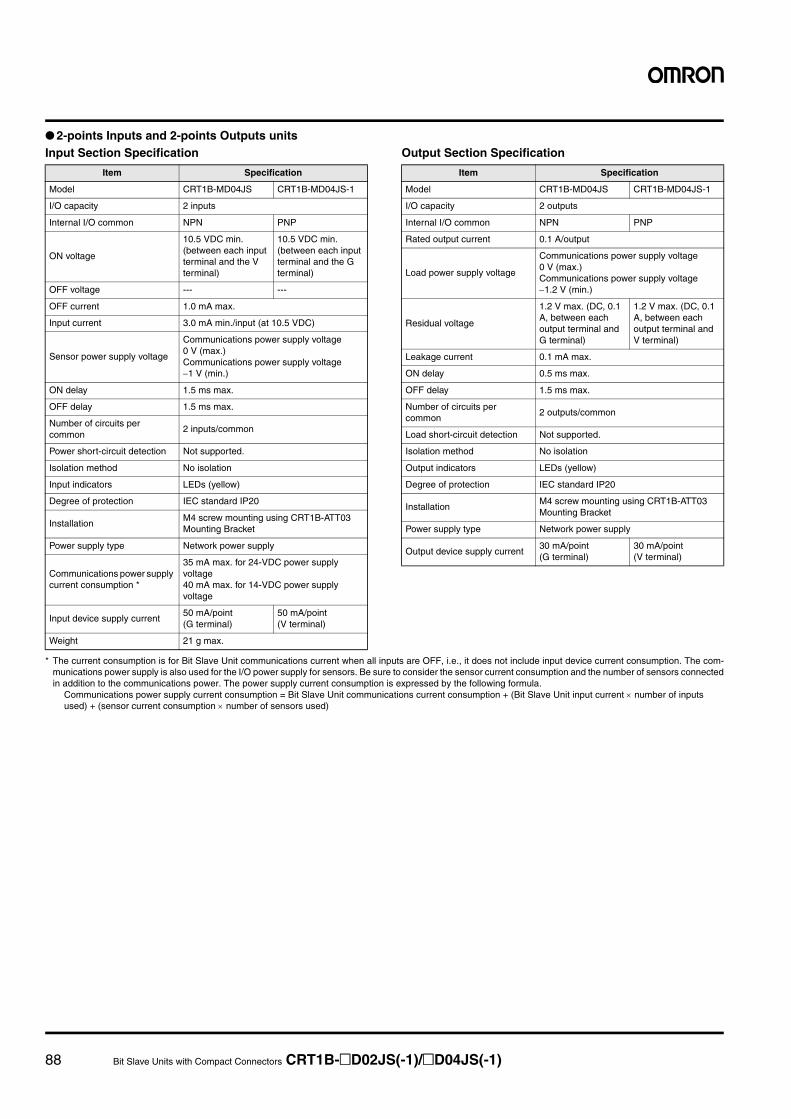
88 Bit Slave Units with Compact Connectors CRT1B-@D02JS(-1)/@D04JS(-1)
● 2-points Inputs and 2-points Outputs unitsInput Section Specification Output Section Specification
* The current consumption is for Bit Slave Unit communications current when all inputs are OFF, i.e., it does not include input device current consumption. The com-munications power supply is also used for the I/O power supply for sensors. Be sure to consider the sensor current consumption and the number of sensors connectedin addition to the communications power. The power supply current consumption is expressed by the following formula.
Communications power supply current consumption = Bit Slave Unit communications current consumption + (Bit Slave Unit input current × number of inputsused) + (sensor current consumption × number of sensors used)
Item Specification
Model CRT1B-MD04JS CRT1B-MD04JS-1
I/O capacity 2 inputs
Internal I/O common NPN PNP
ON voltage
10.5 VDC min. (between each input terminal and the V terminal)
10.5 VDC min. (between each input terminal and the G terminal)
OFF voltage --- ---
OFF current 1.0 mA max.
Input current 3.0 mA min./input (at 10.5 VDC)
Sensor power supply voltage
Communications power supply voltage 0 V (max.)Communications power supply voltage −1 V (min.)
ON delay 1.5 ms max.
OFF delay 1.5 ms max.
Number of circuits per common
2 inputs/common
Power short-circuit detection Not supported.
Isolation method No isolation
Input indicators LEDs (yellow)
Degree of protection IEC standard IP20
InstallationM4 screw mounting using CRT1B-ATT03 Mounting Bracket
Power supply type Network power supply
Communications power supply current consumption *
35 mA max. for 24-VDC power supply voltage40 mA max. for 14-VDC power supply voltage
Input device supply current50 mA/point (G terminal)
50 mA/point (V terminal)
Weight 21 g max.
Item Specification
Model CRT1B-MD04JS CRT1B-MD04JS-1
I/O capacity 2 outputs
Internal I/O common NPN PNP
Rated output current 0.1 A/output
Load power supply voltage
Communications power supply voltage 0 V (max.)Communications power supply voltage −1.2 V (min.)
Residual voltage
1.2 V max. (DC, 0.1 A, between each output terminal and G terminal)
1.2 V max. (DC, 0.1 A, between each output terminal and V terminal)
Leakage current 0.1 mA max.
ON delay 0.5 ms max.
OFF delay 1.5 ms max.
Number of circuits per common
2 outputs/common
Load short-circuit detection Not supported.
Isolation method No isolation
Output indicators LEDs (yellow)
Degree of protection IEC standard IP20
InstallationM4 screw mounting using CRT1B-ATT03 Mounting Bracket
Power supply type Network power supply
Output device supply current30 mA/point (G terminal)
30 mA/point (V terminal)
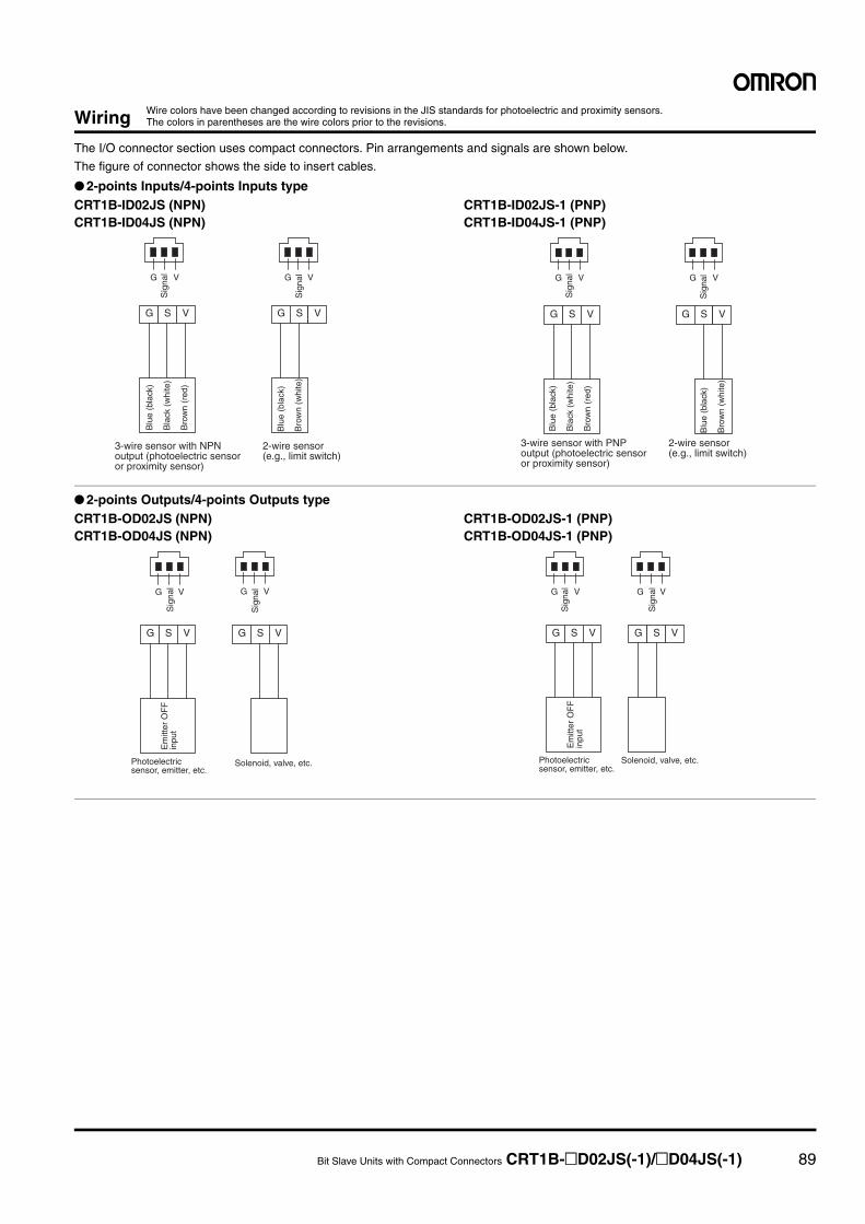
Bit Slave Units with Compact Connectors CRT1B-@D02JS(-1)/@D04JS(-1) 89
Wiring
The I/O connector section uses compact connectors. Pin arrangements and signals are shown below.
The figure of connector shows the side to insert cables.
● 2-points Inputs/4-points Inputs typeCRT1B-ID02JS (NPN)CRT1B-ID04JS (NPN)
CRT1B-ID02JS-1 (PNP)CRT1B-ID04JS-1 (PNP)
● 2-points Outputs/4-points Outputs typeCRT1B-OD02JS (NPN)CRT1B-OD04JS (NPN)
CRT1B-OD02JS-1 (PNP)CRT1B-OD04JS-1 (PNP)
Wire colors have been changed according to revisions in the JIS standards for photoelectric and proximity sensors. The colors in parentheses are the wire colors prior to the revisions.
G S V G S V
V G V G
Sig
nal
Sig
nal
Blu
e (b
lack
)
Bla
ck (
whi
te)
Bro
wn
(red
)
Blu
e (b
lack
)
Bro
wn
(whi
te)
3-wire sensor with NPN output (photoelectric sensor or proximity sensor)
2-wire sensor (e.g., limit switch)
G S V G S V
V G V G
Sig
nal
Sig
nal
Blu
e (b
lack
)
Bla
ck (
whi
te)
Bro
wn
(red
)
Blu
e (b
lack
)
Bro
wn
(whi
te)
3-wire sensor with PNP output (photoelectric sensor or proximity sensor)
2-wire sensor (e.g., limit switch)
G S V
Solenoid, valve, etc.
G S V
Sig
nal
Sig
nal
Em
itter
OF
F
inpu
t
Photoelectric sensor, emitter, etc.
V G V G
G S VG S V
Solenoid, valve, etc.
Sig
nal
Sig
nal
Em
itter
OF
F
inpu
t
Photoelectric sensor, emitter, etc.
V G V G
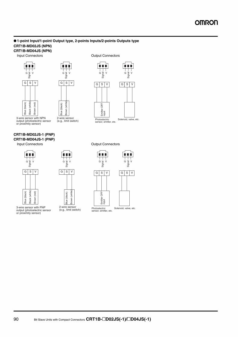
90 Bit Slave Units with Compact Connectors CRT1B-@D02JS(-1)/@D04JS(-1)
● 1-point Input/1-point Output type, 2-points Inputs/2-points Outputs typeCRT1B-MD02JS (NPN)CRT1B-MD04JS (NPN)
CRT1B-MD02JS-1 (PNP)CRT1B-MD04JS-1 (PNP)
G S V G S V
V G V G
Sig
nal
Sig
nal
Blu
e (b
lack
)
Bla
ck (
whi
te)
Bro
wn
(red
)
Blu
e (b
lack
)
Bro
wn
(whi
te)
3-wire sensor with NPN output (photoelectric sensor or proximity sensor)
2-wire sensor (e.g., limit switch)
G S V G S V
V G V G
Solenoid, valve, etc.
Sig
nal
Sig
nal
Em
itter
OF
F
inpu
t
Photoelectric sensor, emitter, etc.
Output ConnectorsInput Connectors
G S V G S V
V G V G
Sig
nal
Sig
nal
Blu
e (b
lack
)
Bla
ck (
whi
te)
Bro
wn
(red
)
Blu
e (b
lack
)
Bro
wn
(whi
te)
3-wire sensor with PNP output (photoelectric sensor or proximity sensor)
2-wire sensor (e.g., limit switch)
G S V G S V
V G V G
Solenoid, valve, etc.
Sig
nal
Sig
nal
Em
itter
OF
F
inpu
t
Photoelectric sensor, emitter, etc.
Output ConnectorsInput Connectors
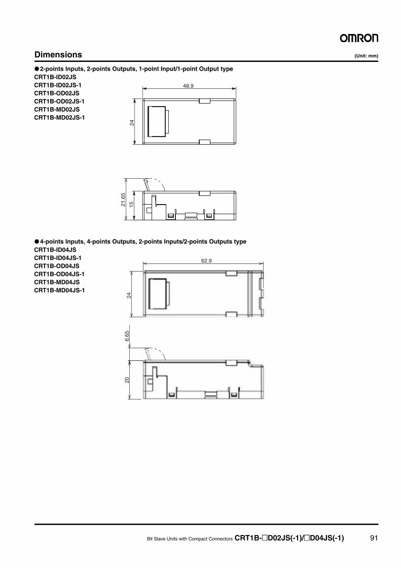
Bit Slave Units with Compact Connectors CRT1B-@D02JS(-1)/@D04JS(-1) 91
Dimensions (Unit: mm)
● 2-points Inputs, 2-points Outputs, 1-point Input/1-point Output type
● 4-points Inputs, 4-points Outputs, 2-points Inputs/2-points Outputs type
1521.6
5
24
48.9
CRT1B-ID02JSCRT1B-ID02JS-1CRT1B-OD02JSCRT1B-OD02JS-1CRT1B-MD02JSCRT1B-MD02JS-1
206.
6524
62.9
CRT1B-ID04JSCRT1B-ID04JS-1CRT1B-OD04JSCRT1B-OD04JS-1CRT1B-MD04JSCRT1B-MD04JS-1
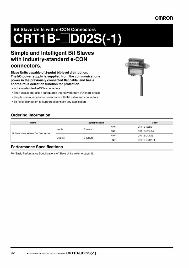
92 Bit Slave Units with e-CON Connectors CRT1B-@D02S(-1)
Bit Slave Units with e-CON Connectors
CRT1B-@D02S(-1)Simple and Intelligent Bit Slaves with Industry-standard e-CON connectors. Slave Units capable of 2-point bit-level distribution.The I/O power supply is supplied from the communications power in the previously connected flat cable, and has a short-circuit detection function for protection.• Industry-standard e-CON connectors
• Short-circuit protection safeguards the network from I/O short circuits.
• Simple communications connections with flat cable and connectors.
• Bit-level distribution to support essentially any application.
Ordering Information
Performance Specifications
For Basic Performance Specifications of Slave Units, refer to page 32.
Name Specifications Model
Bit Slave Units with e-CON Connectors
Inputs 2 inputsNPN CRT1B-ID02S
PNP CRT1B-ID02S-1
Outputs 2 outputsNPN CRT1B-OD02S
PNP CRT1B-OD02S-1
Bit Slave Units with e-CON Connectors CRT1B-@D02S(-1) 93
Input Section Specifications
* The current consumption is for Bit Slave Unit communications current when all inputs are OFF, i.e., it does not include input device current consumption. The com-munications power supply is also used for the I/O power supply for sensors. Be sure to consider the sensor current consumption and the number of sensors connectedin addition to the communications power.The power supply current consumption is expressed by the following formula.Communications power supply current consumption = Bit Slave Unit communications current consumption + (Bit Slave Unit input current x number of inputs used) +(sensor current consumption x number of sensors used)
Item Specification
Model CRT1B-ID02S CRT1B-ID02S-1
I/O capacity 2 inputs
Internal I/O common NPN PNP
ON voltage 10.5 VDC min. (between each input terminal and the V terminal) 10.5 VDC min. (between each input terminal and the G terminal)
OFF voltage 5 VDC max. (between each input terminal and the V terminal) 5 VDC max. (between each input terminal and the G terminal)
OFF current 1.0 mA max.
Input current 3.0 mA max./input (at 10.5 VDC)
Sensor power supply voltageCommunications power supply voltage + 0 V (max.)Communications power supply voltage − 1 V (min.)
ON delay 1.5 ms max.
OFF delay 1.5 ms max.
Number of circuits per common 2 inputs/common
Power short-circuit detection Supported
Isolation method No isolation
Input indicators LEDs (yellow)
Degree of protection IEC standard IP20
Installation Screw installation (M4)
Power supply type Network power supply
Communications power supply current consumption *
65 mA max. for 24-VDC power supply voltage80 mA max. for 14-VDC power supply voltage
45 mA max. for 24-VDC power supply voltage65 mA max. for 14-VDC power supply voltage
Weight 70 g max.
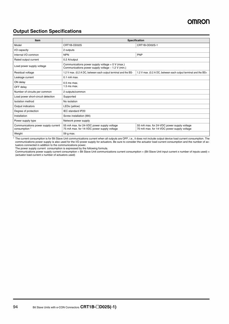
94 Bit Slave Units with e-CON Connectors CRT1B-@D02S(-1)
Output Section Specifications
* The current consumption is for Bit Slave Unit communications current when all outputs are OFF, i.e., it does not include output device load current consumption. Thecommunications power supply is also used for the I/O power supply for actuators. Be sure to consider the actuator load current consumption and the number of ac-tuators connected in addition to the communications power.The power supply current consumption is expressed by the following formula.Communications power supply current consumption = Bit Slave Unit communications current consumption + (Bit Slave Unit input current x number of inputs used) +(actuator load current x number of actuators used)
Item Specification
Model CRT1B-OD02S CRT1B-OD02S-1
I/O capacity 2 outputs
Internal I/O common NPN PNP
Rated output current 0.2 A/output
Load power supply voltageCommunications power supply voltage + 0 V (max.)Communications power supply voltage − 1.2 V (min.)
Residual voltage 1.2 V max. (0.2 A DC, between each output terminal and the BS- 1.2 V max. (0.2 A DC, between each output terminal and the BS+
Leakage current 0.1 mA max.
ON delay 0.5 ms max. 1.5 ms max. OFF delay
Number of circuits per common 2 outputs/common
Load power short-circuit detection Supported
Isolation method No isolation
Output indicators LEDs (yellow)
Degree of protection IEC standard IP20
Installation Screw installation (M4)
Power supply type Network power supply
Communications power supply current consumption *
55 mA max. for 24-VDC power supply voltage75 mA max. for 14-VDC power supply voltage
55 mA max. for 24-VDC power supply voltage70 mA max. for 14-VDC power supply voltage
Weight 59 g max.
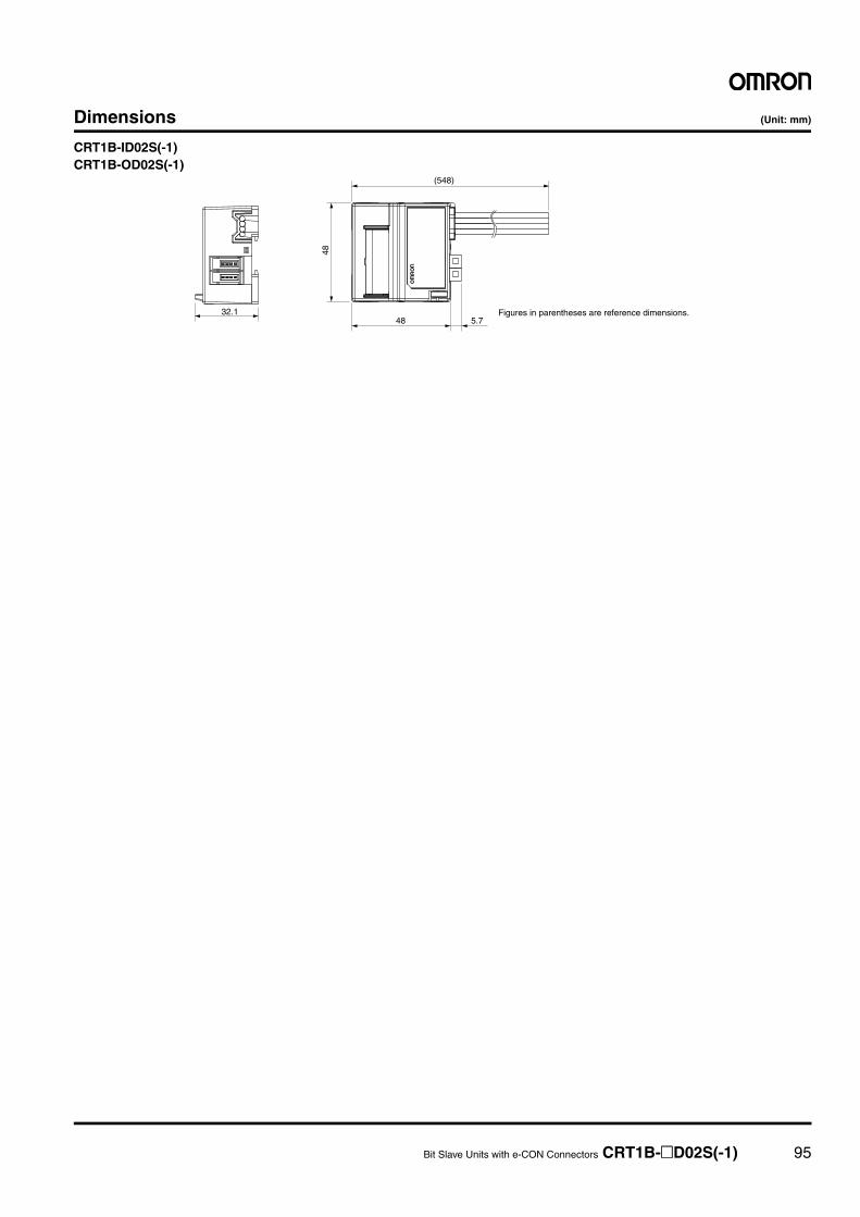
Bit Slave Units with e-CON Connectors CRT1B-@D02S(-1) 95
Dimensions (Unit: mm)
CRT1B-ID02S(-1)CRT1B-OD02S(-1)
32.148
485.7
(548)
Figures in parentheses are reference dimensions.
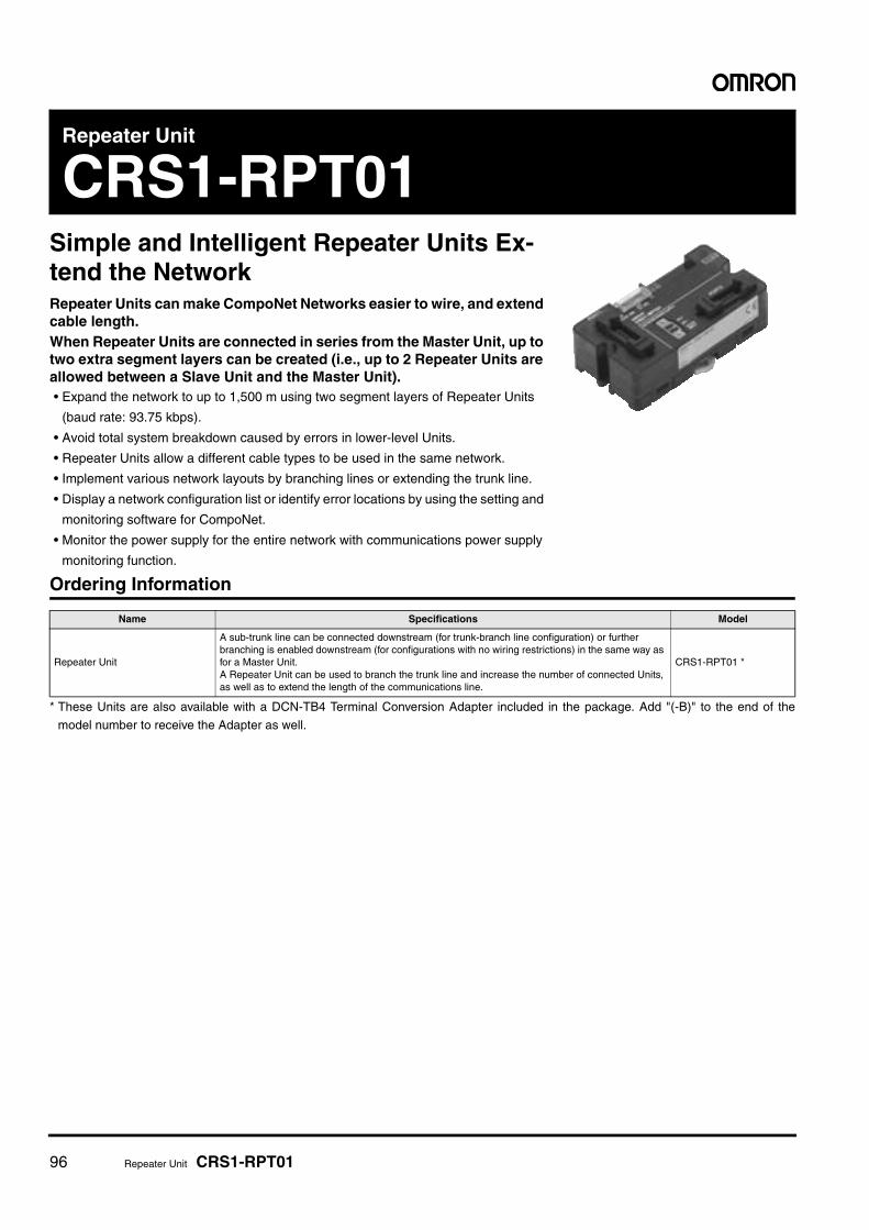
96 Repeater Unit CRS1-RPT01
Repeater Unit
CRS1-RPT01Simple and Intelligent Repeater Units Ex-tend the NetworkRepeater Units can make CompoNet Networks easier to wire, and extend cable length.When Repeater Units are connected in series from the Master Unit, up to two extra segment layers can be created (i.e., up to 2 Repeater Units are allowed between a Slave Unit and the Master Unit).• Expand the network to up to 1,500 m using two segment layers of Repeater Units
(baud rate: 93.75 kbps).
• Avoid total system breakdown caused by errors in lower-level Units.
• Repeater Units allow a different cable types to be used in the same network.
• Implement various network layouts by branching lines or extending the trunk line.
• Display a network configuration list or identify error locations by using the setting and
monitoring software for CompoNet.
• Monitor the power supply for the entire network with communications power supply
monitoring function.
Ordering Information
* These Units are also available with a DCN-TB4 Terminal Conversion Adapter included in the package. Add "(-B)" to the end of the
model number to receive the Adapter as well.
Name Specifications Model
Repeater Unit
A sub-trunk line can be connected downstream (for trunk-branch line configuration) or further branching is enabled downstream (for configurations with no wiring restrictions) in the same way as for a Master Unit.A Repeater Unit can be used to branch the trunk line and increase the number of connected Units, as well as to extend the length of the communications line.
CRS1-RPT01 *
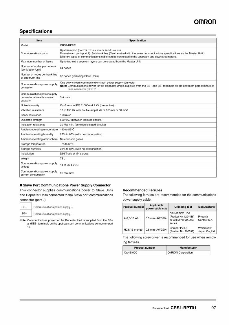
Repeater Unit CRS1-RPT01 97
Specifications
● Slave Port Communications Power Supply ConnectorThis connector supplies communications power to Slave Units
and Repeater Units connected to the Slave port communications
connector (port 2).
Note: Communications power for the Repeater Unit is supplied from the BS+and BS− terminals on the upstream port communications connector (port1).
Recommended FerrulesThe following ferrules are recommended for the communications
power supply cable.
The following screwdriver is recommended for use when remov-
ing ferrules.
Item Specification
Model CRS1-RPT01
Communications portsUpstream port (port 1): Ttrunk line or sub-trunk lineDownstream port (port 2): Sub-trunk line (Can be wired with the same communications specifications as the Master Unit.) Different types of communications cable can be connected to the upstream and downstream ports.
Maximum number of layers Up to two extra segment layers can be created from the Master Unit.
Number of nodes per network (per Master Unit)
64 nodes
Number of nodes per trunk line or sub-trunk line
32 nodes (Including Slave Units)
Communications power supply connector
One downstream communications port power supply connectorNote: Communications power for the Repeater Unit is supplied from the BS+ and BS- terminals on the upstream port communica-
tions connector (PORT1).
Communications power supply connector allowable current capacity
5 A max.
Noise immunity Conforms to IEC 61000-4-4 2 kV (power line).
Vibration resistance 10 to 150 Hz with double-amplitude of 0.7 mm or 50 m/s2
Shock resistance 150 m/s2
Dielectric strength 500 VAC (between isolated circuits)
Insulation resistance 20 MΩ min. (between isolated circuits)
Ambient operating temperature −10 to 55°C
Ambient operating humidity 25% to 85% (with no condensation)
Ambient operating atmosphere No corrosive gases
Storage temperature −25 to 65°C
Storage humidity 25% to 85% (with no condensation)
Installation DIN Track or M4 screws
Weight 73 g
Communications power supply voltage
14 to 26.4 VDC
Communications power supply current consumption
95 mA max.
BS+
BS−
Communications power supply +
Communications power supply −
Product numberApplicable
power cable size Crimping tool Manufacturer
AI0,5-10 WH 0.5 mm (AWG20)
CRIMPFOX UD6(Product No. 1204436) or CRIMPTFOX ZA3 series
Phoenix Contact K.K.
H0.5/16 orange 0.5 mm (AWG20)Crimper PZ1.5(Product No. 900599)
Weidmuellr Japan Co.,Ltd.
Product number Manufacturer
XW4Z-00C OMRON Corporation
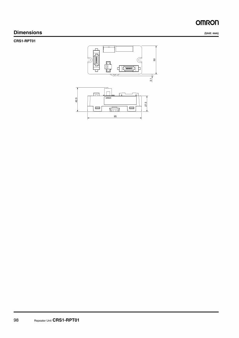
98 Repeater Unit CRS1-RPT01
Dimensions (Unit: mm)
CRS1-RPT01
42.3
50
3.1
27.5
95
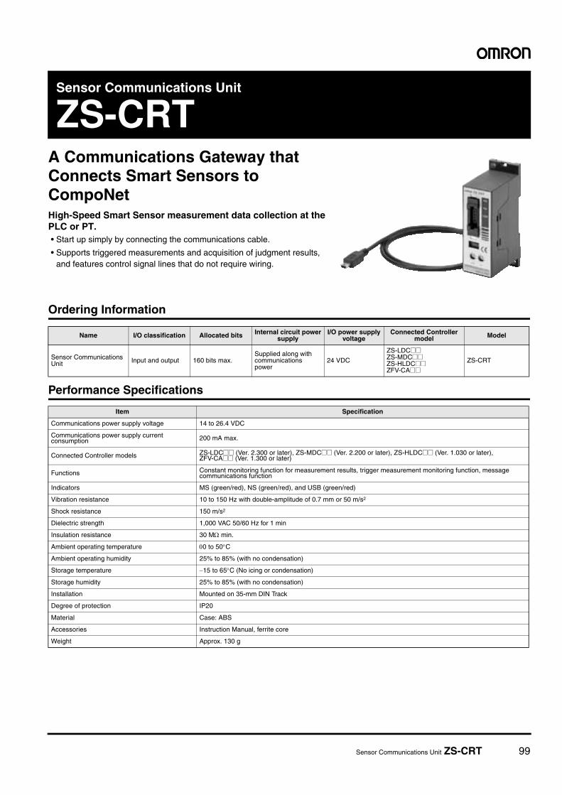
Sensor Communications Unit ZS-CRT 99
Sensor Communications Unit
ZS-CRTA Communications Gateway that Connects Smart Sensors to CompoNetHigh-Speed Smart Sensor measurement data collection at the PLC or PT.• Start up simply by connecting the communications cable.
• Supports triggered measurements and acquisition of judgment results, and features control signal lines that do not require wiring.
Ordering Information
Performance Specifications
Name I/O classification Allocated bits Internal circuit power supply
I/O power supply voltage
Connected Controller model Model
Sensor Communications Unit Input and output 160 bits max.
Supplied along with communications power
24 VDC
ZS-LDC@@ZS-MDC@@ZS-HLDC@@ZFV-CA@@
ZS-CRT
Item Specification
Communications power supply voltage 14 to 26.4 VDC
Communications power supply current consumption 200 mA max.
Connected Controller models ZS-LDC@@ (Ver. 2.300 or later), ZS-MDC@@ (Ver. 2.200 or later), ZS-HLDC@@ (Ver. 1.030 or later), ZFV-CA@@ (Ver. 1.300 or later)
Functions Constant monitoring function for measurement results, trigger measurement monitoring function, message communications function
Indicators MS (green/red), NS (green/red), and USB (green/red)
Vibration resistance 10 to 150 Hz with double-amplitude of 0.7 mm or 50 m/s2
Shock resistance 150 m/s2
Dielectric strength 1,000 VAC 50/60 Hz for 1 min
Insulation resistance 30 MΩ min.
Ambient operating temperature 00 to 50°C
Ambient operating humidity 25% to 85% (with no condensation)
Storage temperature −15 to 65°C (No icing or condensation)
Storage humidity 25% to 85% (with no condensation)
Installation Mounted on 35-mm DIN Track
Degree of protection IP20
Material Case: ABS
Accessories Instruction Manual, ferrite core
Weight Approx. 130 g
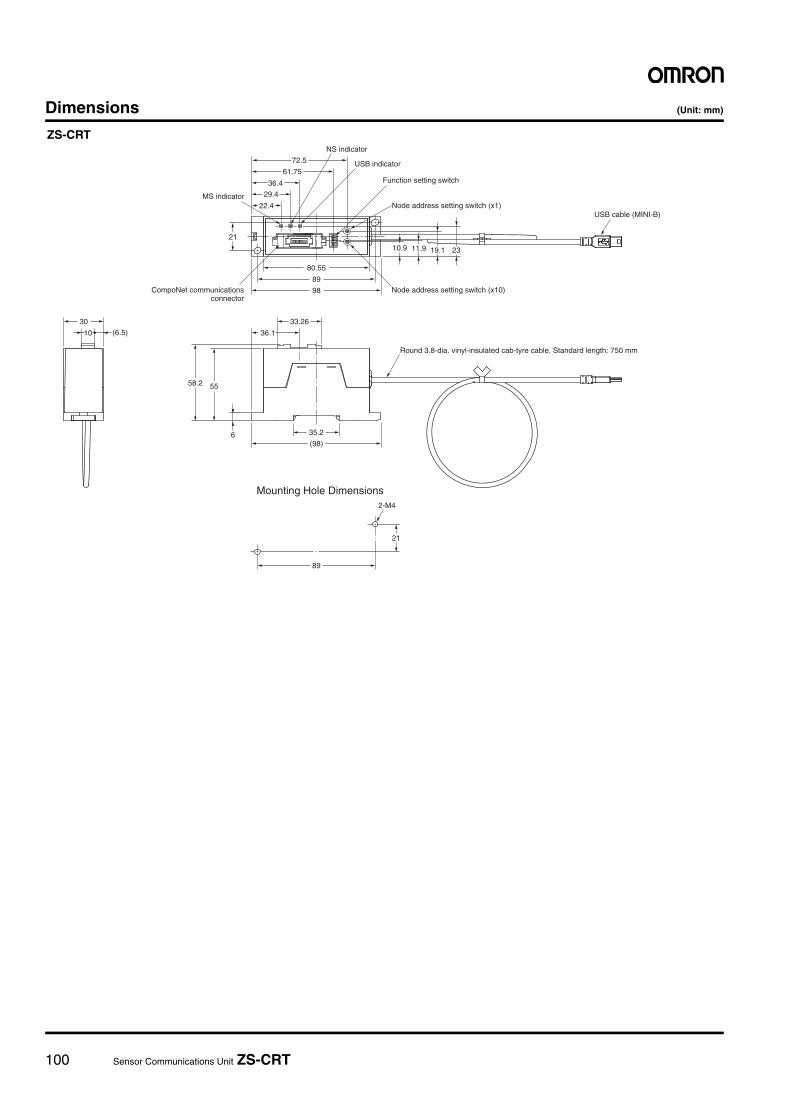
100 Sensor Communications Unit ZS-CRT
Dimensions (Unit: mm)
(98)
98
10.9 2319.111.9
72.5
61.75
29.4
36.4
22.4
21
89
80.55
35.2
5558.2
6
36.1
33.2630
10 (6.5)
Round 3.8-dia. vinyl-insulated cab-tyre cable, Standard length: 750 mm
Mounting Hole Dimensions
CompoNet communicationsconnector
Node address setting switch (x10)
Node address setting switch (x1)
Function setting switch
USB indicator
NS indicator
MS indicator
USB cable (MINI-B)
2-M4
21
89
ZS-CRT
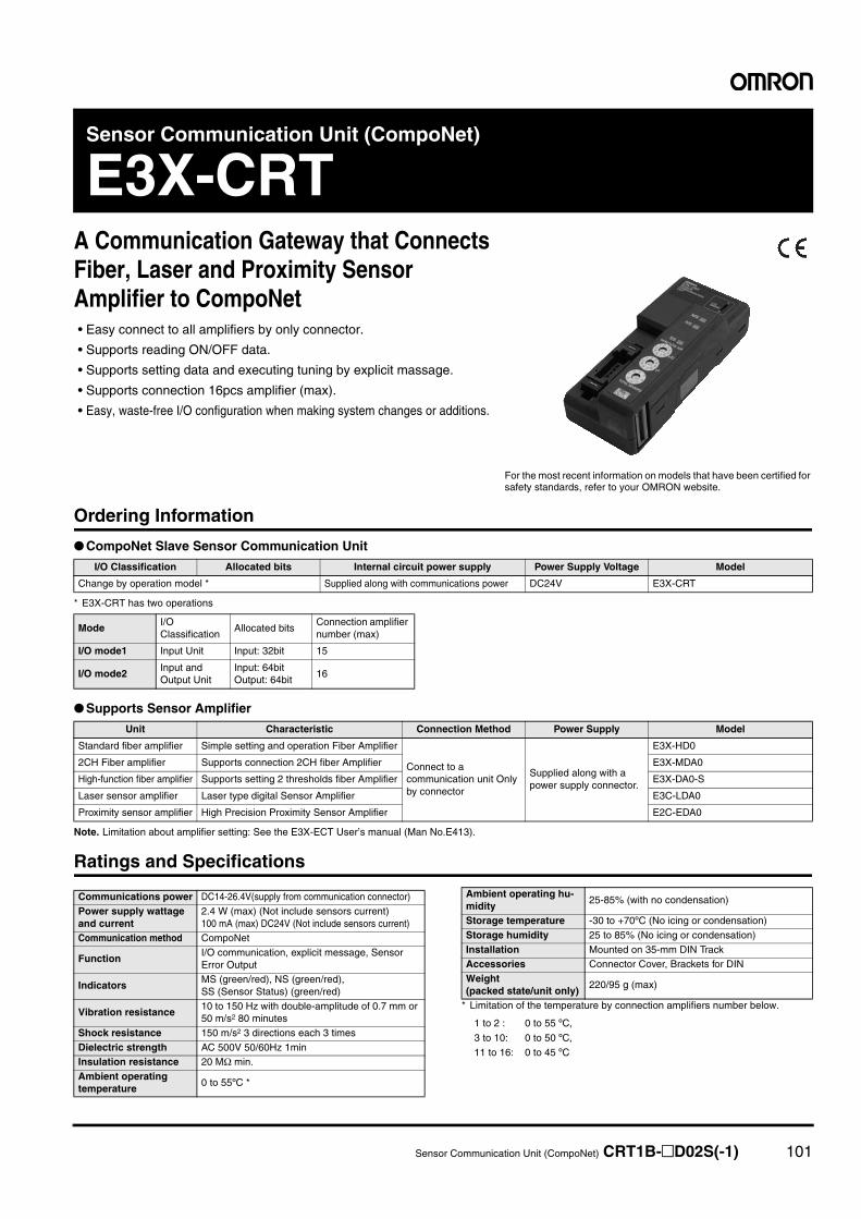
Sensor Communication Unit (CompoNet) CRT1B-@D02S(-1) 101
Sensor Communication Unit (CompoNet)
E3X-CRTA Communication Gateway that Connects Fiber, Laser and Proximity Sensor Amplifier to CompoNet• Easy connect to all amplifiers by only connector.
• Supports reading ON/OFF data.
• Supports setting data and executing tuning by explicit massage.
• Supports connection 16pcs amplifier (max).
• Easy, waste-free I/O configuration when making system changes or additions.
Ordering Information
● CompoNet Slave Sensor Communication Unit
* E3X-CRT has two operations
● Supports Sensor Amplifier
Note. Limitation about amplifier setting: See the E3X-ECT User’s manual (Man No.E413).
Ratings and Specifications
* Limitation of the temperature by connection amplifiers number below.
For the most recent information on models that have been certified for safety standards, refer to your OMRON website.
I/O Classification Allocated bits Internal circuit power supply Power Supply Voltage Model
Change by operation model * Supplied along with communications power DC24V E3X-CRT
ModeI/O Classification
Allocated bitsConnection amplifier number (max)
I/O mode1 Input Unit Input: 32bit 15
I/O mode2Input and Output Unit
Input: 64bitOutput: 64bit
16
Unit Characteristic Connection Method Power Supply Model
Standard fiber amplifier Simple setting and operation Fiber Amplifier
Connect to a communication unit Only by connector
Supplied along with a power supply connector.
E3X-HD0
2CH Fiber amplifier Supports connection 2CH fiber Amplifier E3X-MDA0
High-function fiber amplifier Supports setting 2 thresholds fiber Amplifier E3X-DA0-S
Laser sensor amplifier Laser type digital Sensor Amplifier E3C-LDA0
Proximity sensor amplifier High Precision Proximity Sensor Amplifier E2C-EDA0
Communications power DC14-26.4V(supply from communication connector)Power supply wattage and current
2.4 W (max) (Not include sensors current)100 mA (max) DC24V (Not include sensors current)
Communication method CompoNet
FunctionI/O communication, explicit message, Sensor Error Output
IndicatorsMS (green/red), NS (green/red),SS (Sensor Status) (green/red)
Vibration resistance10 to 150 Hz with double-amplitude of 0.7 mm or 50 m/s2 80 minutes
Shock resistance 150 m/s2 3 directions each 3 timesDielectric strength AC 500V 50/60Hz 1minInsulation resistance 20 MΩ min.Ambient operating temperature
0 to 55ºC *
Ambient operating hu-midity
25-85% (with no condensation)
Storage temperature -30 to +70ºC (No icing or condensation)Storage humidity 25 to 85% (No icing or condensation)Installation Mounted on 35-mm DIN TrackAccessories Connector Cover, Brackets for DINWeight(packed state/unit only)
220/95 g (max)
1 to 2 : 0 to 55 ºC,
3 to 10: 0 to 50 ºC,
11 to 16: 0 to 45 ºC
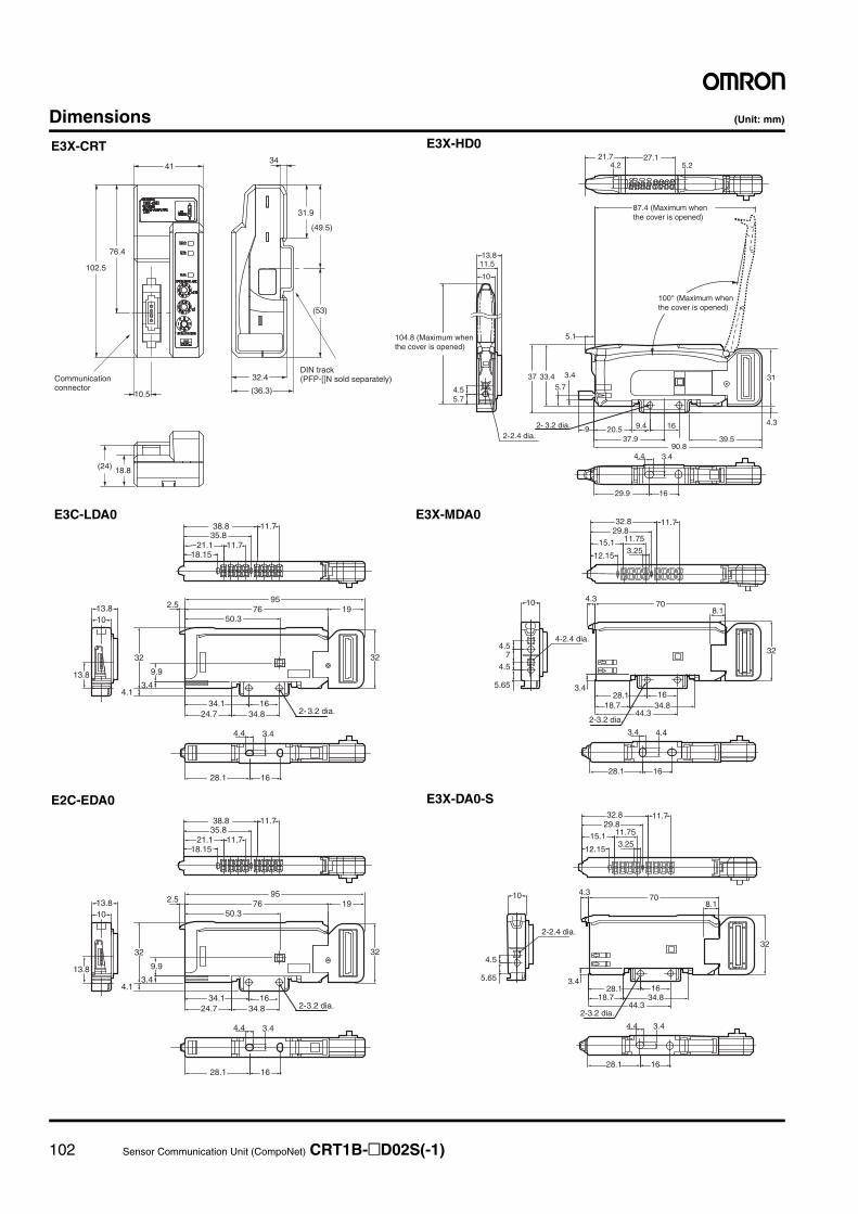
102 Sensor Communication Unit (CompoNet) CRT1B-@D02S(-1)
Dimensions (Unit: mm)
(53)
(49.5)
31.9
34
(36.3)
DIN track (PFP-[]N sold separately)32.4Communication
connector
41
102.5
76.4
10.5
(24) 18.8
E3X-CRT E3X-HD0
E3C-LDA0 E3X-MDA0
E2C-EDA0 E3X-DA0-S
3.44.4
15.1
32.8
4.3
28.1 1634.8
44.3
70
32
3.4
4.5
5.65
10
28.1 16
11.7
11.75
3.2512.15
8.1
29.8
2-3.2 dia.
2-2.4 dia.
18.7
15.1
32.8
4.3
28.1 1634.8
44.3
70
32
3.4
4.5
4.5
5.65
10
28.1 16
4.43.4
11.7
11.75
3.2512.15
8.1
7
29.8
2-3.2 dia.
4-2.4 dia.
18.7
5.1
87.4 (Maximum when the cover is opened)
100° (Maximum when the cover is opened)
104.8 (Maximum when the cover is opened)
31
4.3
37 33.45.7
3.4
4.55.7
10
11.513.8
29.9 16
3.4
4.2 5.2
4.4
21.7 27.1
2- 3.2 dia.2-2.4 dia.
20.5 16
39.590.8
9.4
37.99
21.1
38.8
2.5
34.1 1634.8
7695
1950.3
32
9.9
4.1
32
3.413.8
1013.8
28.1 16
3.44.4
11.7
11.718.15
35.8
2-3.2 dia.24.7
21.1
38.8
2.5
34.1 1634.8
7695
1950.3
32
9.9
4.1
32
3.413.8
1013.8
28.1 16
3.44.4
11.7
11.718.15
35.8
2- 3.2 dia.24.7
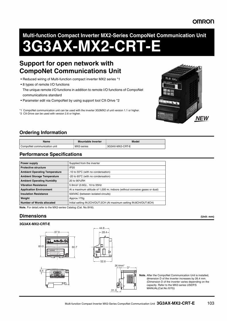
Multi-function Compact Inverter MX2-Series CompoNet Communication Unit 3G3AX-MX2-CRT-E 103
Multi-function Compact Inverter MX2-Series CompoNet Communication Unit
3G3AX-MX2-CRT-ESupport for open network with CompoNet Communications Unit• Reduced wiring of Multi-function compact inverter MX2 series *1
• 8 types of remote I/O functions
The unique remote I/O functions in addition to remote I/O functions of CompoNet
communications standard
• Parameter edit via CompoNet by using support tool CX-Drive *2
*1 CompoNet communication unit can be used with the inverter 3G3MX2 of unit version 1.1 or higher.*2 CX-Drive can be used with version 2.6 or higher.
Ordering Information
Performance Specifications
Note. For detail,refer to the MX2-series Catalog (Cat. No.I916).
Dimensions (Unit: mm)
3G3AX-MX2-CRT-E
Name Mountable Inverter Model
CompoNet communication unit MX2-series 3G3AX-MX2-CRT-E
Power supply Supplied from the inverter
Protective structure IP20
Ambient Operating Temperature -10 to 55ºC (with no condensation)
Ambient Storage Temperature -20 to 65ºC (with no condensation)
Ambient Operating Humidity 20 to 90%RH
Vibration Resistance 5.9m/s2 (0.6G) , 10 to 55Hz
Application Environment At a maximum altitude of 1,000 m; indoors (without corrosive gases or dust)
Insulation Resistance 500VAC (between isolated circuits)
Weight Approx.170g
Number of Words allocated Initial setting IN:2CH/OUT:2CH (At maximum setting IN:8CH/OUT:8CH)
9.4
67.6
52.6
28.4
D*26.4mm*
60.760.0
44.8
31.3
Note. After the CompoNet Communication Unit is installed, dimension D of the inverter increases by 26.4 mm.(Dimension D of the inverter varies depending on the capacity. Refer to the MX2-series USER'S MANUAL(Cat.No.I570))
MEMO
104
105 Appendix 105
AppendixCompoNet Network Configuration Elements ...................................................... 106
Types of Node Addresses for CompoNet Networks............................................ 107
CompoNet Network Specification ....................................................................... 108
Communications and I/O Power Supply Wiring .................................................. 109
Connecting External I/O for Slave Units.............................................................. 111
■ Connecting to e-CON Connector Terminals
■ Connecting to MIL Connector Terminals
■ Connecting to Screw-less Clamp Terminal Blocks
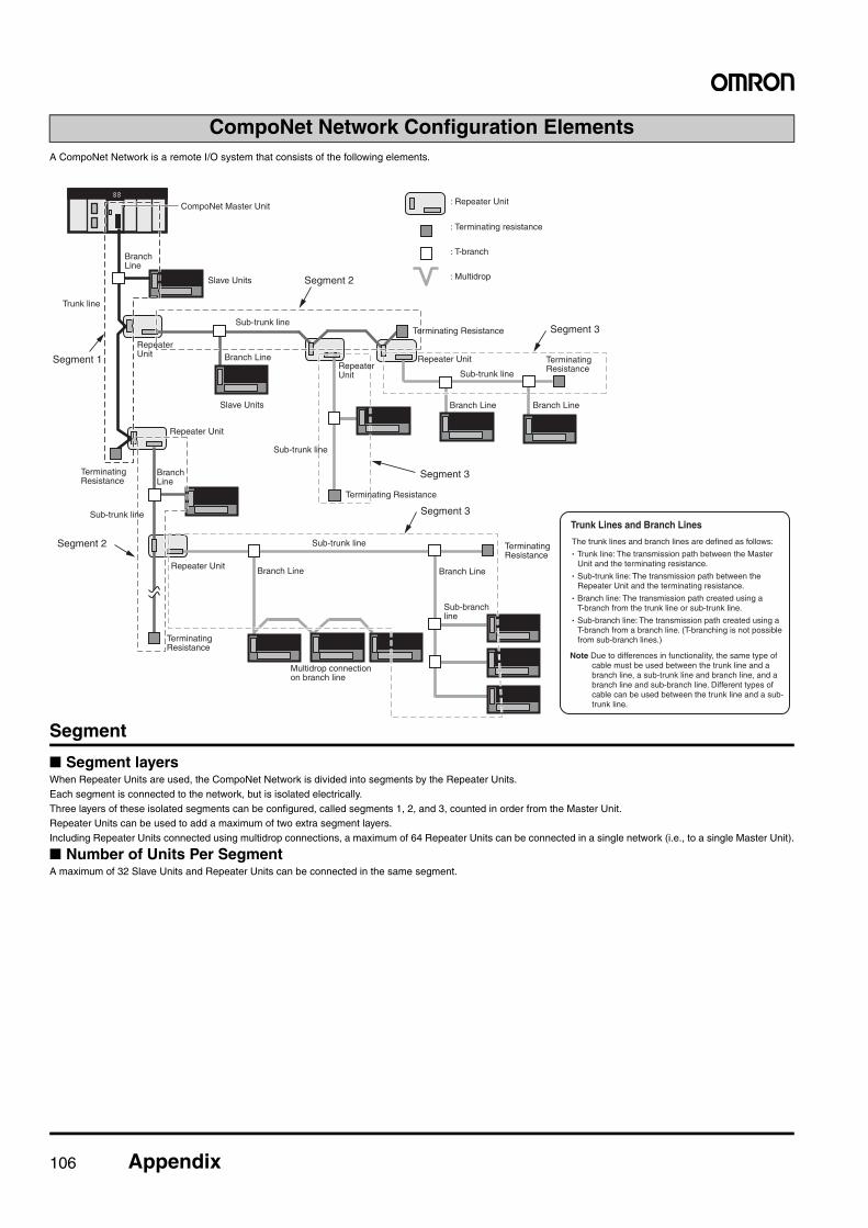
106 Appendix
A CompoNet Network is a remote I/O system that consists of the following elements.
Segment
■ Segment layersWhen Repeater Units are used, the CompoNet Network is divided into segments by the Repeater Units.Each segment is connected to the network, but is isolated electrically.Three layers of these isolated segments can be configured, called segments 1, 2, and 3, counted in order from the Master Unit.Repeater Units can be used to add a maximum of two extra segment layers.Including Repeater Units connected using multidrop connections, a maximum of 64 Repeater Units can be connected in a single network (i.e., to a single Master Unit).
■ Number of Units Per SegmentA maximum of 32 Slave Units and Repeater Units can be connected in the same segment.
CompoNet Network Configuration Elements
: Repeater Unit
Repeater Unit
Repeater Unit
Repeater Unit
Slave Units
Slave Units
Branch Line
Branch Line
Branch LineBranch Line
Branch Line
Sub-trunk line
Sub-trunk line
Sub-trunk line
Sub-branch line
Sub-trunk line
Sub-trunk line
Trunk line
: Terminating resistance
Terminating Resistance
Terminating Resistance
Terminating Resistance
Terminating Resistance
Terminating Resistance
: T-branch
: Multidrop
Segment 3
Multidrop connection on branch line
CompoNet Master Unit
Segment 3
Segment 3
Segment 2
Segment 2
Segment 1
Branch Line
Terminating Resistance
Branch Line
Repeater Unit
Repeater Unit
Trunk Lines and Branch Lines
The trunk lines and branch lines are defined as follows:
· Trunk line: The transmission path between the Master Unit and the terminating resistance.
· Sub-trunk line: The transmission path between the Repeater Unit and the terminating resistance.
· Branch line: The transmission path created using a T-branch from the trunk line or sub-trunk line.
· Sub-branch line: The transmission path created using a T-branch from a branch line. (T-branching is not possible from sub-branch lines.)
Note Due to differences in functionality, the same type of cable must be used between the trunk line and a branch line, a sub-trunk line and branch line, and a branch line and sub-branch line. Different types of cable can be used between the trunk line and a sub-trunk line.
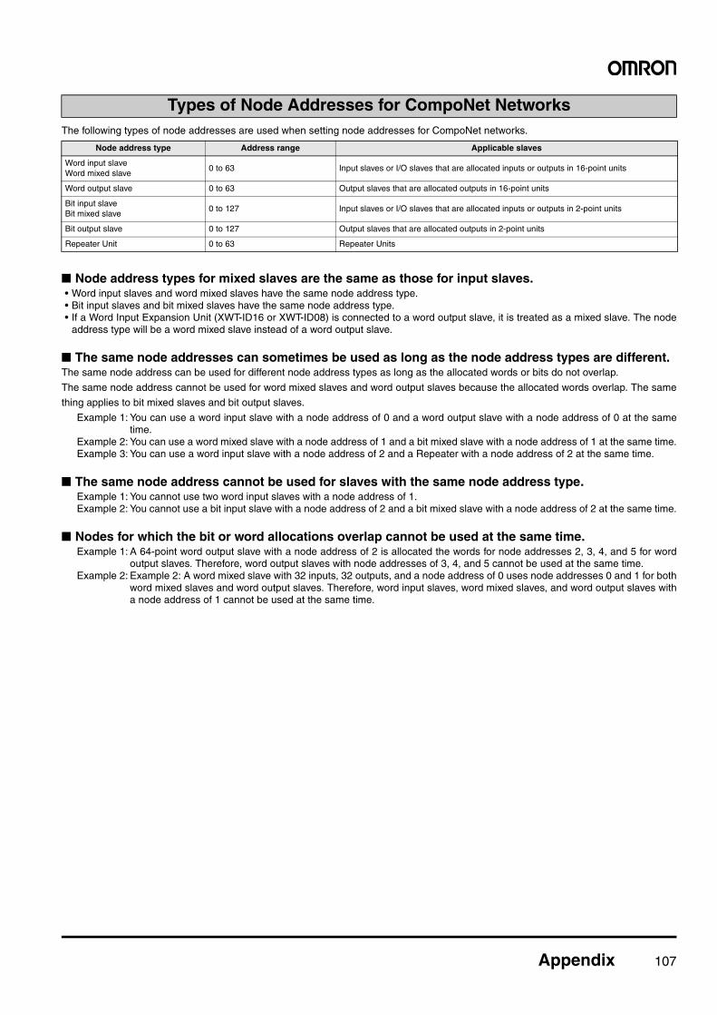
Appendix 107
The following types of node addresses are used when setting node addresses for CompoNet networks.
■ Node address types for mixed slaves are the same as those for input slaves.• Word input slaves and word mixed slaves have the same node address type.• Bit input slaves and bit mixed slaves have the same node address type.• If a Word Input Expansion Unit (XWT-ID16 or XWT-ID08) is connected to a word output slave, it is treated as a mixed slave. The node
address type will be a word mixed slave instead of a word output slave.
■ The same node addresses can sometimes be used as long as the node address types are different.The same node address can be used for different node address types as long as the allocated words or bits do not overlap.
The same node address cannot be used for word mixed slaves and word output slaves because the allocated words overlap. The same
thing applies to bit mixed slaves and bit output slaves.
Example 1: You can use a word input slave with a node address of 0 and a word output slave with a node address of 0 at the sametime.
Example 2: You can use a word mixed slave with a node address of 1 and a bit mixed slave with a node address of 1 at the same time.Example 3: You can use a word input slave with a node address of 2 and a Repeater with a node address of 2 at the same time.
■ The same node address cannot be used for slaves with the same node address type.Example 1: You cannot use two word input slaves with a node address of 1.Example 2: You cannot use a bit input slave with a node address of 2 and a bit mixed slave with a node address of 2 at the same time.
■ Nodes for which the bit or word allocations overlap cannot be used at the same time.Example 1: A 64-point word output slave with a node address of 2 is allocated the words for node addresses 2, 3, 4, and 5 for word
output slaves. Therefore, word output slaves with node addresses of 3, 4, and 5 cannot be used at the same time.Example 2: Example 2: A word mixed slave with 32 inputs, 32 outputs, and a node address of 0 uses node addresses 0 and 1 for both
word mixed slaves and word output slaves. Therefore, word input slaves, word mixed slaves, and word output slaves witha node address of 1 cannot be used at the same time.
Types of Node Addresses for CompoNet Networks
Node address type Address range Applicable slaves
Word input slaveWord mixed slave
0 to 63 Input slaves or I/O slaves that are allocated inputs or outputs in 16-point units
Word output slave 0 to 63 Output slaves that are allocated outputs in 16-point units
Bit input slaveBit mixed slave
0 to 127 Input slaves or I/O slaves that are allocated inputs or outputs in 2-point units
Bit output slave 0 to 127 Output slaves that are allocated outputs in 2-point units
Repeater Unit 0 to 63 Repeater Units
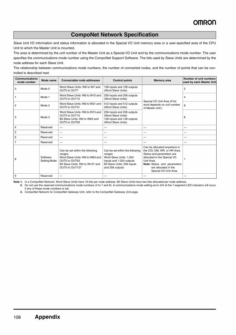
108 Appendix
Slave Unit I/O information and status information is allocated in the Special I/O Unit memory area or a user-specified area of the CPU
Unit to which the Master Unit is mounted.
The area is determined by the unit number of the Master Unit as a Special I/O Unit and by the communications mode number. The user
specifies the communications mode number using the CompoNet Support Software. The bits used by Slave Units are determined by the
node address for each Slave Unit.
The relationship between communications mode numbers, the number of connected nodes, and the number of points that can be con-
trolled is described next.
Note 1. In a CompoNet Network, Word Slave Units have 16 bits per node address. Bit Slave Units have two bits allocated per node address.2. Do not use the reserved communications mode numbers (4 to 7 and 9). A communications mode setting error (H4 at the 7-segment LED indicator) will occur
if any of these mode numbers is set.3. CompoNet Network for CompoNet Gateway Unit, refer to the CompoNet Gateway Unit page.
CompoNet Network Specification
Communications mode number
Mode name Connectable node addresses Control points Memory areaNumber of unit numbers used by each Master Unit
0 Mode 0Word Slave Units: IN0 to IN7 and OUT0 to OUT7
128 inputs and 128 outputs (Word Slave Units)
Special I/O Unit Area (First word depends on unit number of Master Unit.)
2
1 Mode 1Word Slave Units: IN0 to IN15 and OUT0 to OUT15
256 inputs and 256 outputs (Word Slave Units)
4
2 Mode 2Word Slave Units: IN0 to IN31 and OUT0 to OUT31
512 inputs and 512 outputs (Word Slave Units)
8
3 Mode 3
Word Slave Units: IN0 to IN15 and OUT0 to OUT15Bit Slave Units: IN0 to IN63 and OUT0 to OUT63
256 inputs and 256 outputs (Word Slave Units)128 inputs and 128 outputs (Word Slave Units)
8
4 Reserved --- --- --- ---
5 Reserved --- --- --- ---
6 Reserved --- --- --- ---
7 Reserved --- --- --- ---
8Software Setting Mode
Can be set within the following ranges: Word Slave Units: IN0 to IN63 and OUT0 to OUT63Bit Slave Units: IN0 to IN127 and OUT0 to OUT127
Can be set within the following ranges: Word Slave Units: 1,024 inputs and 1,024 outputs Bit Slave Units: 256 inputs and 256 outputs
Can be allocated anywhere in the CIO, DM, WR, or HR Area. Status and parameters are allocated in the Special I/O Unit Area.Note: Status and parameters
are allocated in the Special I/O Unit Area.
1
9 Reserved --- --- --- ---
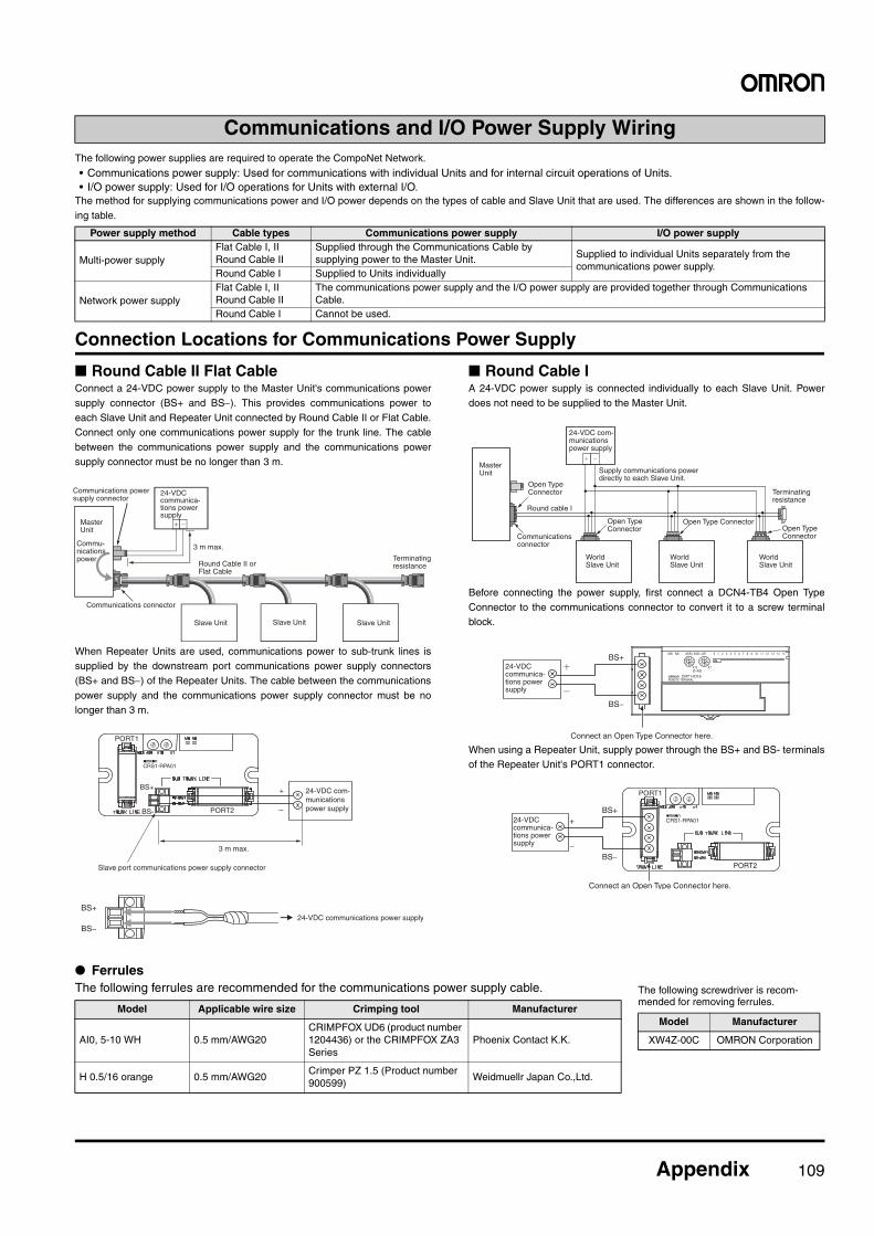
Appendix 109
The following power supplies are required to operate the CompoNet Network.
• Communications power supply: Used for communications with individual Units and for internal circuit operations of Units.• I/O power supply: Used for I/O operations for Units with external I/O.
The method for supplying communications power and I/O power depends on the types of cable and Slave Unit that are used. The differences are shown in the follow-ing table.
Connection Locations for Communications Power Supply
■ Round Cable II Flat CableConnect a 24-VDC power supply to the Master Unit's communications powersupply connector (BS+ and BS−). This provides communications power toeach Slave Unit and Repeater Unit connected by Round Cable II or Flat Cable.Connect only one communications power supply for the trunk line. The cablebetween the communications power supply and the communications powersupply connector must be no longer than 3 m.
When Repeater Units are used, communications power to sub-trunk lines issupplied by the downstream port communications power supply connectors(BS+ and BS−) of the Repeater Units. The cable between the communicationspower supply and the communications power supply connector must be nolonger than 3 m.
■ Round Cable IA 24-VDC power supply is connected individually to each Slave Unit. Powerdoes not need to be supplied to the Master Unit.
Before connecting the power supply, first connect a DCN4-TB4 Open TypeConnector to the communications connector to convert it to a screw terminalblock.
When using a Repeater Unit, supply power through the BS+ and BS- terminalsof the Repeater Unit's PORT1 connector.
● FerrulesThe following ferrules are recommended for the communications power supply cable.
Communications and I/O Power Supply Wiring
Power supply method Cable types Communications power supply I/O power supply
Multi-power supplyFlat Cable I, IIRound Cable II
Supplied through the Communications Cable by supplying power to the Master Unit. Supplied to individual Units separately from the
communications power supply.Round Cable I Supplied to Units individually
Network power supplyFlat Cable I, IIRound Cable II
The communications power supply and the I/O power supply are provided together through Communications Cable.
Round Cable I Cannot be used.
Slave Unit Slave Unit Slave Unit
Terminating resistanceRound Cable II or
Flat Cable
3 m max.
Master Unit
Commu-nications power
Communications power supply connector
Communications connector
24-VDC communica-tions power supply
+
−
PORT1
CRS1-RPA01
BS+
BS- PORT2
BS+
BS−
Slave port communications power supply connector
24-VDC communications power supply
3 m max.
24-VDC com-munications power supply
Open TypeConnector
Open Type Connector
Open Type ConnectorOpen Type Connector
Terminating resistance
Round cable I
MasterUnit
Communications connector
24-VDC com-munications power supply
Supply communications power directly to each Slave Unit.
World Slave Unit
World Slave Unit
World Slave Unit
MS NS
REMOTE TERMINAL
WORD NODE ADR 0 1 2 3 4 5 6 7 8 9 151413121110
X10[0-63]
X1
IN
01234
5678
9 01234
5678
9
CRT1-ID16
Connect an Open Type Connector here.
24-VDC communica-tions power supply
BS+
BS−
Connect an Open Type Connector here.
24-VDC communica-tions power supply
CRS1-RPA01+
−
PORT1
PORT2
BS+
BS−
Model Applicable wire size Crimping tool Manufacturer
AI0, 5-10 WH 0.5 mm/AWG20CRIMPFOX UD6 (product number 1204436) or the CRIMPFOX ZA3 Series
Phoenix Contact K.K.
H 0.5/16 orange 0.5 mm/AWG20Crimper PZ 1.5 (Product number 900599)
Weidmuellr Japan Co.,Ltd.
The following screwdriver is recom-mended for removing ferrules.
Model Manufacturer
XW4Z-00C OMRON Corporation
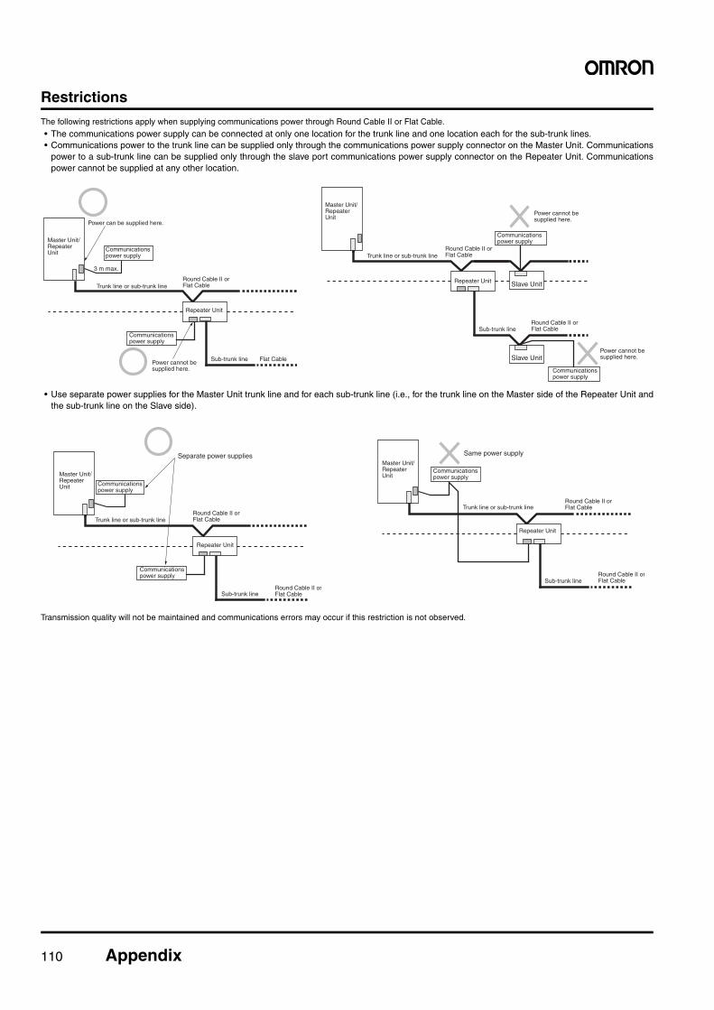
110 Appendix
RestrictionsThe following restrictions apply when supplying communications power through Round Cable II or Flat Cable.
• The communications power supply can be connected at only one location for the trunk line and one location each for the sub-trunk lines.• Communications power to the trunk line can be supplied only through the communications power supply connector on the Master Unit. Communications
power to a sub-trunk line can be supplied only through the slave port communications power supply connector on the Repeater Unit. Communicationspower cannot be supplied at any other location.
• Use separate power supplies for the Master Unit trunk line and for each sub-trunk line (i.e., for the trunk line on the Master side of the Repeater Unit andthe sub-trunk line on the Slave side).
Transmission quality will not be maintained and communications errors may occur if this restriction is not observed.
3 m max.
Trunk line or sub-trunk lineRound Cable II or Flat Cable
Sub-trunk line Flat Cable
Repeater Unit
Master Unit/ Repeater Unit
Power can be supplied here.
Communications power supply
Power cannot be supplied here.
Communications power supply
Slave Unit
Slave Unit
Trunk line or sub-trunk lineRound Cable II or Flat Cable
Sub-trunk lineRound Cable II or Flat Cable
Repeater Unit
Master Unit/ Repeater Unit
Communications power supply
Power cannot be supplied here.
Communications power supply
Power cannot be supplied here.
Separate power supplies
Trunk line or sub-trunk lineRound Cable II or Flat Cable
Sub-trunk lineRound Cable II orFlat Cable
Repeater Unit
Master Unit/ Repeater Unit Communications
power supply
Communications power supply
Same power supplyMaster Unit/ Repeater Unit
Trunk line or sub-trunk lineRound Cable II or Flat Cable
Sub-trunk lineRound Cable II orFlat Cable
Repeater Unit
Communications power supply
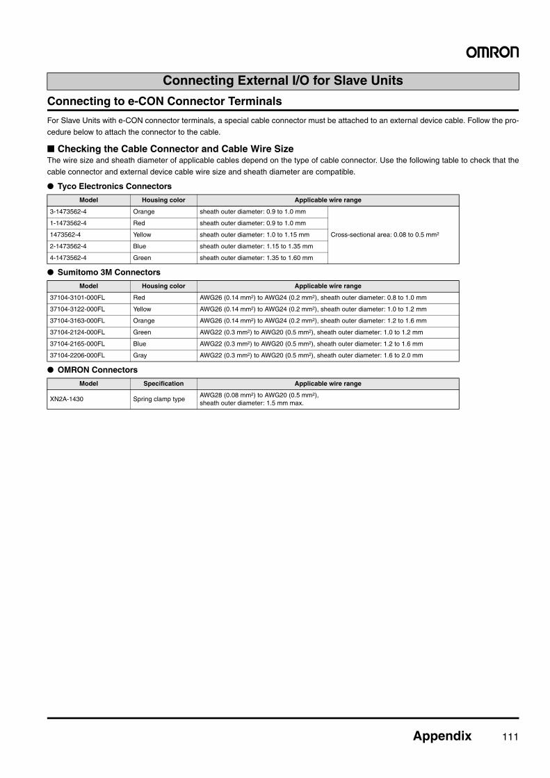
Appendix 111
Connecting to e-CON Connector Terminals
For Slave Units with e-CON connector terminals, a special cable connector must be attached to an external device cable. Follow the pro-
cedure below to attach the connector to the cable.
■ Checking the Cable Connector and Cable Wire SizeThe wire size and sheath diameter of applicable cables depend on the type of cable connector. Use the following table to check that the
cable connector and external device cable wire size and sheath diameter are compatible.
● Tyco Electronics Connectors
● Sumitomo 3M Connectors
● OMRON Connectors
Connecting External I/O for Slave Units
Model Housing color Applicable wire range
3-1473562-4 Orange sheath outer diameter: 0.9 to 1.0 mm
Cross-sectional area: 0.08 to 0.5 mm2
1-1473562-4 Red sheath outer diameter: 0.9 to 1.0 mm
1473562-4 Yellow sheath outer diameter: 1.0 to 1.15 mm
2-1473562-4 Blue sheath outer diameter: 1.15 to 1.35 mm
4-1473562-4 Green sheath outer diameter: 1.35 to 1.60 mm
Model Housing color Applicable wire range
37104-3101-000FL Red AWG26 (0.14 mm2) to AWG24 (0.2 mm2), sheath outer diameter: 0.8 to 1.0 mm
37104-3122-000FL Yellow AWG26 (0.14 mm2) to AWG24 (0.2 mm2), sheath outer diameter: 1.0 to 1.2 mm
37104-3163-000FL Orange AWG26 (0.14 mm2) to AWG24 (0.2 mm2), sheath outer diameter: 1.2 to 1.6 mm
37104-2124-000FL Green AWG22 (0.3 mm2) to AWG20 (0.5 mm2), sheath outer diameter: 1.0 to 1.2 mm
37104-2165-000FL Blue AWG22 (0.3 mm2) to AWG20 (0.5 mm2), sheath outer diameter: 1.2 to 1.6 mm
37104-2206-000FL Gray AWG22 (0.3 mm2) to AWG20 (0.5 mm2), sheath outer diameter: 1.6 to 2.0 mm
Model Specification Applicable wire range
XN2A-1430 Spring clamp typeAWG28 (0.08 mm2) to AWG20 (0.5 mm2),sheath outer diameter: 1.5 mm max.
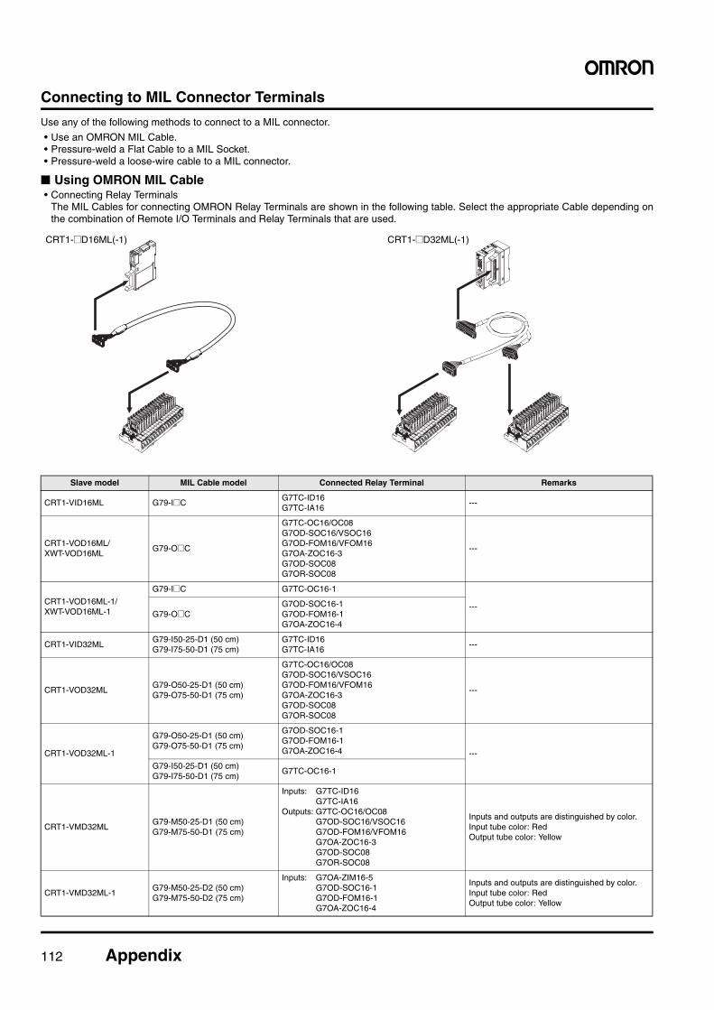
112 Appendix
Connecting to MIL Connector Terminals
Use any of the following methods to connect to a MIL connector.
• Use an OMRON MIL Cable.• Pressure-weld a Flat Cable to a MIL Socket.• Pressure-weld a loose-wire cable to a MIL connector.
■ Using OMRON MIL Cable• Connecting Relay Terminals
The MIL Cables for connecting OMRON Relay Terminals are shown in the following table. Select the appropriate Cable depending onthe combination of Remote I/O Terminals and Relay Terminals that are used.
CRT1-@D16ML(-1) CRT1-@D32ML(-1)
Slave model MIL Cable model Connected Relay Terminal Remarks
CRT1-VID16ML G79-I@CG7TC-ID16G7TC-IA16
---
CRT1-VOD16ML/XWT-VOD16ML
G79-O@C
G7TC-OC16/OC08G7OD-SOC16/VSOC16G7OD-FOM16/VFOM16G7OA-ZOC16-3G7OD-SOC08G7OR-SOC08
---
CRT1-VOD16ML-1/XWT-VOD16ML-1
G79-I@C G7TC-OC16-1
---G79-O@C
G7OD-SOC16-1G7OD-FOM16-1G7OA-ZOC16-4
CRT1-VID32MLG79-I50-25-D1 (50 cm)G79-I75-50-D1 (75 cm)
G7TC-ID16G7TC-IA16
---
CRT1-VOD32MLG79-O50-25-D1 (50 cm)G79-O75-50-D1 (75 cm)
G7TC-OC16/OC08G7OD-SOC16/VSOC16G7OD-FOM16/VFOM16G7OA-ZOC16-3G7OD-SOC08G7OR-SOC08
---
CRT1-VOD32ML-1
G79-O50-25-D1 (50 cm)G79-O75-50-D1 (75 cm)
G7OD-SOC16-1G7OD-FOM16-1G7OA-ZOC16-4 ---
G79-I50-25-D1 (50 cm)G79-I75-50-D1 (75 cm)
G7TC-OC16-1
CRT1-VMD32MLG79-M50-25-D1 (50 cm)G79-M75-50-D1 (75 cm)
Inputs: G7TC-ID16G7TC-IA16
Outputs: G7TC-OC16/OC08G7OD-SOC16/VSOC16G7OD-FOM16/VFOM16G7OA-ZOC16-3G7OD-SOC08G7OR-SOC08
Inputs and outputs are distinguished by color.Input tube color: RedOutput tube color: Yellow
CRT1-VMD32ML-1G79-M50-25-D2 (50 cm)G79-M75-50-D2 (75 cm)
Inputs: G7OA-ZIM16-5G7OD-SOC16-1G7OD-FOM16-1G7OA-ZOC16-4
Inputs and outputs are distinguished by color.Input tube color: RedOutput tube color: Yellow
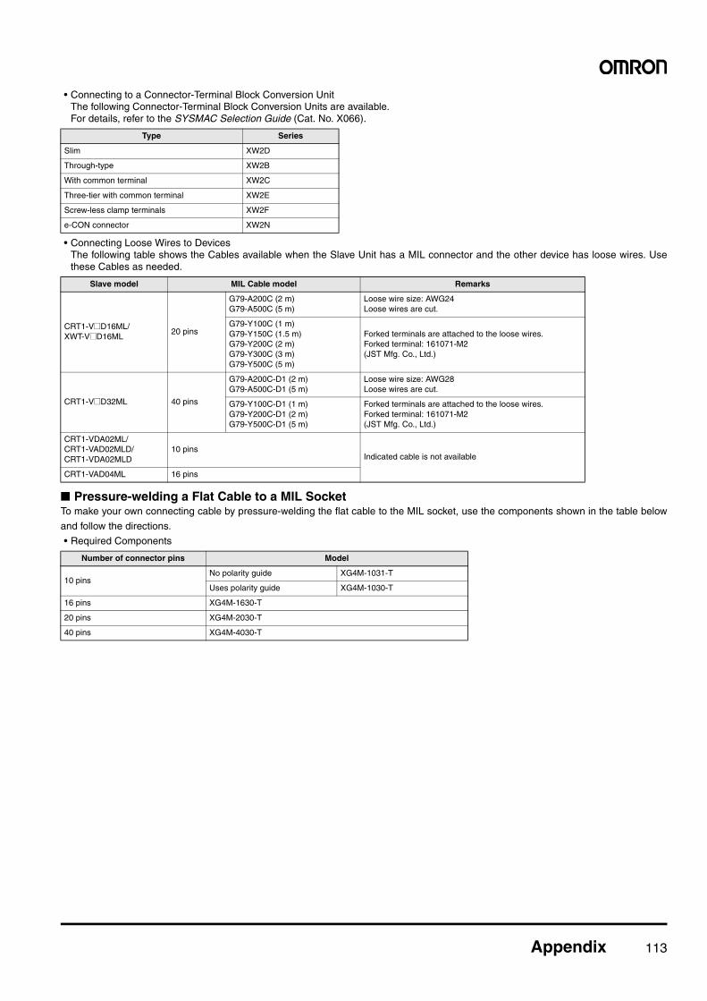
Appendix 113
• Connecting to a Connector-Terminal Block Conversion UnitThe following Connector-Terminal Block Conversion Units are available. For details, refer to the SYSMAC Selection Guide (Cat. No. X066).
• Connecting Loose Wires to DevicesThe following table shows the Cables available when the Slave Unit has a MIL connector and the other device has loose wires. Usethese Cables as needed.
■ Pressure-welding a Flat Cable to a MIL SocketTo make your own connecting cable by pressure-welding the flat cable to the MIL socket, use the components shown in the table below
and follow the directions.
• Required Components
Type Series
Slim XW2D
Through-type XW2B
With common terminal XW2C
Three-tier with common terminal XW2E
Screw-less clamp terminals XW2F
e-CON connector XW2N
Slave model MIL Cable model Remarks
CRT1-V@D16ML/XWT-V@D16ML
20 pins
G79-A200C (2 m)G79-A500C (5 m)
Loose wire size: AWG24Loose wires are cut.
G79-Y100C (1 m)G79-Y150C (1.5 m)G79-Y200C (2 m)G79-Y300C (3 m)G79-Y500C (5 m)
Forked terminals are attached to the loose wires.Forked terminal: 161071-M2 (JST Mfg. Co., Ltd.)
CRT1-V@D32ML 40 pins
G79-A200C-D1 (2 m)G79-A500C-D1 (5 m)
Loose wire size: AWG28Loose wires are cut.
G79-Y100C-D1 (1 m)G79-Y200C-D1 (2 m)G79-Y500C-D1 (5 m)
Forked terminals are attached to the loose wires.Forked terminal: 161071-M2 (JST Mfg. Co., Ltd.)
CRT1-VDA02ML/CRT1-VAD02MLD/CRT1-VDA02MLD
10 pinsIndicated cable is not available
CRT1-VAD04ML 16 pins
Number of connector pins Model
10 pinsNo polarity guide XG4M-1031-T
Uses polarity guide XG4M-1030-T
16 pins XG4M-1630-T
20 pins XG4M-2030-T
40 pins XG4M-4030-T
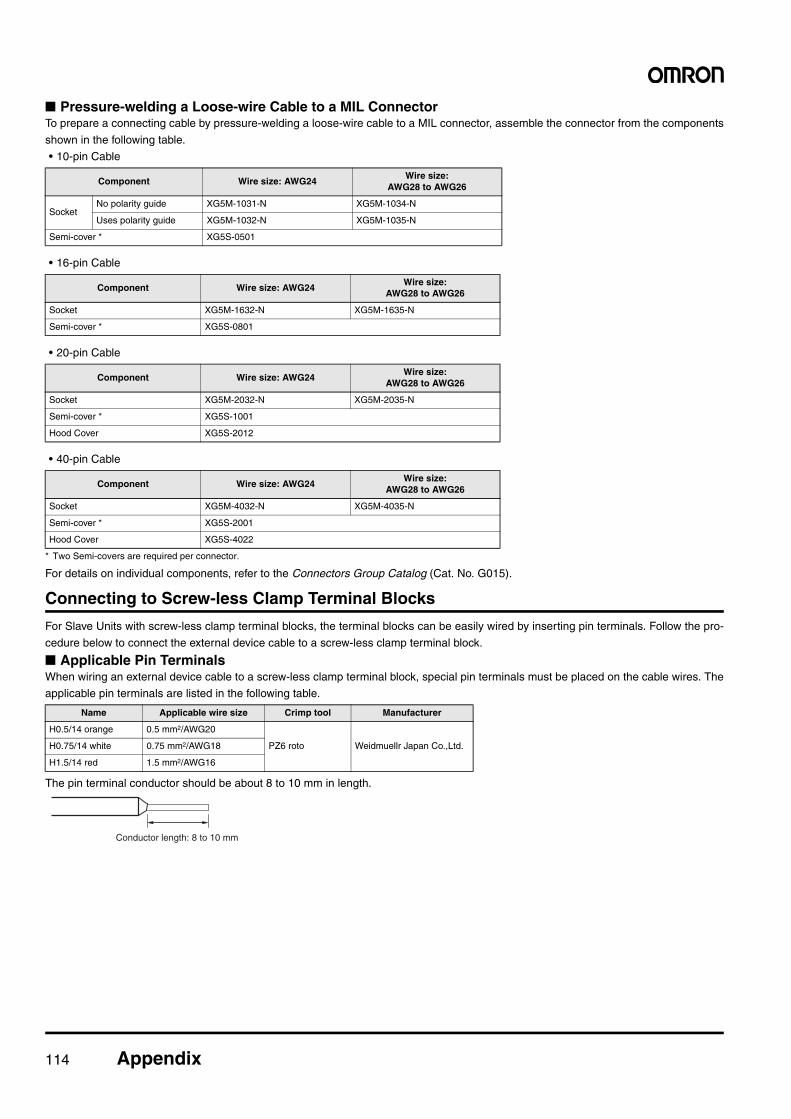
114 Appendix
■ Pressure-welding a Loose-wire Cable to a MIL ConnectorTo prepare a connecting cable by pressure-welding a loose-wire cable to a MIL connector, assemble the connector from the components
shown in the following table.
• 10-pin Cable
• 16-pin Cable
• 20-pin Cable
• 40-pin Cable
* Two Semi-covers are required per connector.
For details on individual components, refer to the Connectors Group Catalog (Cat. No. G015).
Connecting to Screw-less Clamp Terminal Blocks
For Slave Units with screw-less clamp terminal blocks, the terminal blocks can be easily wired by inserting pin terminals. Follow the pro-
cedure below to connect the external device cable to a screw-less clamp terminal block.
■ Applicable Pin TerminalsWhen wiring an external device cable to a screw-less clamp terminal block, special pin terminals must be placed on the cable wires. The
applicable pin terminals are listed in the following table.
The pin terminal conductor should be about 8 to 10 mm in length.
Component Wire size: AWG24Wire size:
AWG28 to AWG26
SocketNo polarity guide XG5M-1031-N XG5M-1034-N
Uses polarity guide XG5M-1032-N XG5M-1035-N
Semi-cover * XG5S-0501
Component Wire size: AWG24Wire size:
AWG28 to AWG26
Socket XG5M-1632-N XG5M-1635-N
Semi-cover * XG5S-0801
Component Wire size: AWG24Wire size:
AWG28 to AWG26
Socket XG5M-2032-N XG5M-2035-N
Semi-cover * XG5S-1001
Hood Cover XG5S-2012
Component Wire size: AWG24Wire size:
AWG28 to AWG26
Socket XG5M-4032-N XG5M-4035-N
Semi-cover * XG5S-2001
Hood Cover XG5S-4022
Name Applicable wire size Crimp tool Manufacturer
H0.5/14 orange 0.5 mm2/AWG20
PZ6 roto Weidmuellr Japan Co.,Ltd.H0.75/14 white 0.75 mm2/AWG18
H1.5/14 red 1.5 mm2/AWG16
Conductor length: 8 to 10 mm
115 Ordering Information 115
Ordering InformationCompoNet Master Units...................................................................................... 116CompoNet Master Board .................................................................................... 116CompoNet Gateway Units................................................................................... 116
■ CompoNet Gateway Unit for CC-Link.......................................................... 116CompoNet Slave Units........................................................................................ 116
■ Word Slave Units ......................................................................................... 116■ Bit Slave Units ............................................................................................. 120■ Repeater Unit .............................................................................................. 120■ SmartSlice GRT1 Series ............................................................................. 121■ Sensor Communications Unit ...................................................................... 122■ Multi-function Compact Inverter................................................................... 122■ Support Software......................................................................................... 122
Peripheral Devices .............................................................................................. 123■ Communications Cables.............................................................................. 123● For Flat Cable I .............................................................................................. 123● For Round Cable I.......................................................................................... 124● For Round Cable II......................................................................................... 124■ Mounting Bracket......................................................................................... 124
● International Standards• The standards are abbreviated as follows: U: UL, U1: UL (Class I Division 2 Products for Hazardous Locations),
C: CSA, UC: cULus, UC1: cULus (Class I Division 2 Products for Hazardous Locations), CU: cUL, N: NK, L:Lloyd, and CE: EC Directives.
• Contact your OMRON representative for further details and applicable conditions for these standards.
● EC DirectivesThe EC Directives applicable to PLCs include the EMC Directives and the Low Voltage Directive. OMRON com-
plies with these directives described below.
● EMC DirectivesApplicable Standards
EMI : EN61131-2EN61000-6-4
EMS: EN61131-2EN61000-6-2PLCs are electrical devices that are incorporated inmachines and manufacturing installations. OMRONPLCs conform to the related EMC standards so thatthe devices and machines into which they are builtcan more easily conform to EMC standards. Theactual PLCs have been checked for conformity toEMC standards. Whether these standards are sat-isfied for the actual system, however, must bechecked by the customer.EMC-related performance will vary depending onthe configuration, wiring, and other conditions of theequipment or control panel in which the PLC is in-stalled. The customer must, therefore, perform finalchecks to confirm that the overall machine or deviceconforms to EMC standards.Note: The applicable EMS standards depend on
the product.
● Low Voltage DirectiveApplicable Standard:EN61131-2
Devices that operate at voltages from 50 to 1,000VAC or 75 to 150 VDC must satisfy the appropriatesafety requirements. With PLCs, this applies toPower Supply Units and I/O Units that operate inthese voltage ranges.These Units have been designed to conform toEN61131-2, which is the applicable standard forPLCs.
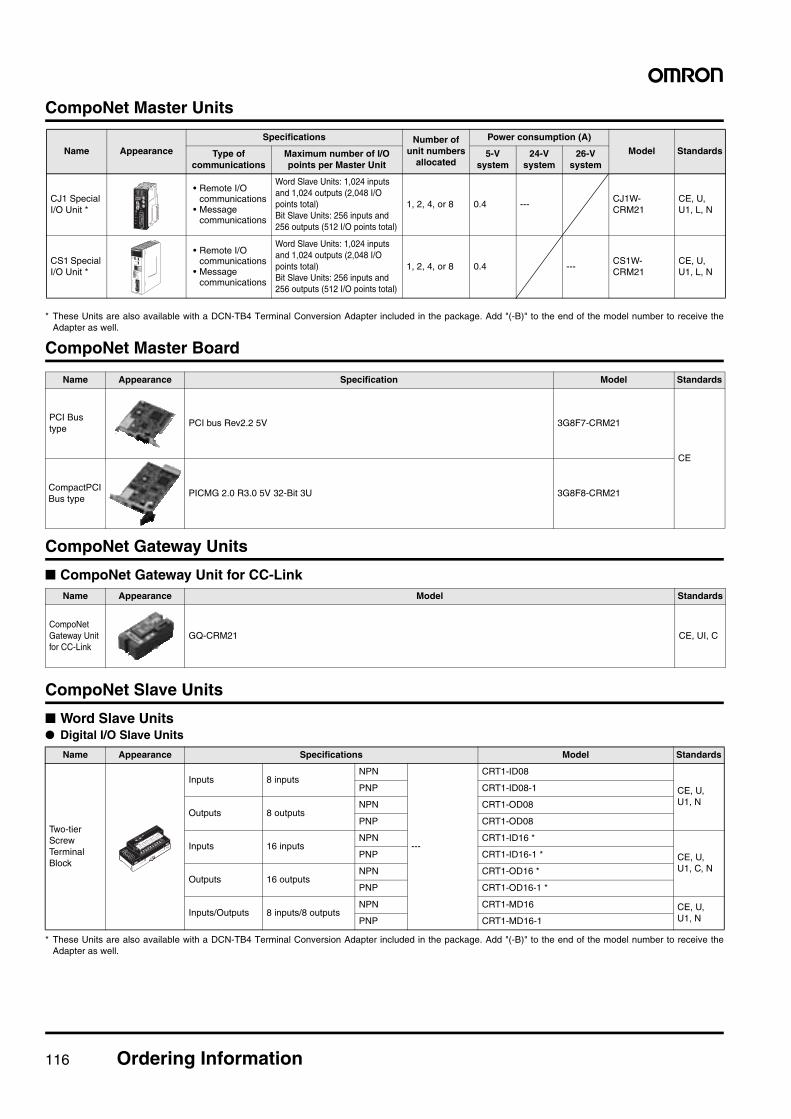
116 Ordering Information
CompoNet Master Units
* These Units are also available with a DCN-TB4 Terminal Conversion Adapter included in the package. Add "(-B)" to the end of the model number to receive theAdapter as well.
CompoNet Master Board
CompoNet Gateway Units
■ CompoNet Gateway Unit for CC-Link
CompoNet Slave Units
■ Word Slave Units● Digital I/O Slave Units
* These Units are also available with a DCN-TB4 Terminal Conversion Adapter included in the package. Add "(-B)" to the end of the model number to receive theAdapter as well.
Name Appearance Specification Model Standards
PCI Bus type
PCI bus Rev2.2 5V 3G8F7-CRM21
CE
CompactPCI Bus type
PICMG 2.0 R3.0 5V 32-Bit 3U 3G8F8-CRM21
Name Appearance Model Standards
CompoNet Gateway Unit for CC-Link
GQ-CRM21 CE, UI, C
Name Appearance Specifications Model Standards
Two-tier Screw Terminal Block
Inputs 8 inputsNPN
---
CRT1-ID08
CE, U, U1, N
PNP CRT1-ID08-1
Outputs 8 outputsNPN CRT1-OD08
PNP CRT1-OD08
Inputs 16 inputsNPN CRT1-ID16 *
CE, U, U1, C, N
PNP CRT1-ID16-1 *
Outputs 16 outputsNPN CRT1-OD16 *
PNP CRT1-OD16-1 *
Inputs/Outputs 8 inputs/8 outputsNPN CRT1-MD16 CE, U,
U1, NPNP CRT1-MD16-1
Name Appearance
Specifications Number ofunit numbers
allocated
Power consumption (A)
Model StandardsType of communications
Maximum number of I/O points per Master Unit
5-V system
24-V system
26-V system
CJ1 Special I/O Unit *
• Remote I/O communications
• Message communications
Word Slave Units: 1,024 inputs and 1,024 outputs (2,048 I/O points total)Bit Slave Units: 256 inputs and 256 outputs (512 I/O points total)
1, 2, 4, or 8 0.4 ---CJ1W-CRM21
CE, U, U1, L, N
CS1 Special I/O Unit *
• Remote I/O communications
• Message communications
Word Slave Units: 1,024 inputs and 1,024 outputs (2,048 I/O points total)Bit Slave Units: 256 inputs and 256 outputs (512 I/O points total)
1, 2, 4, or 8 0.4 ---CS1W-CRM21
CE, U, U1, L, N
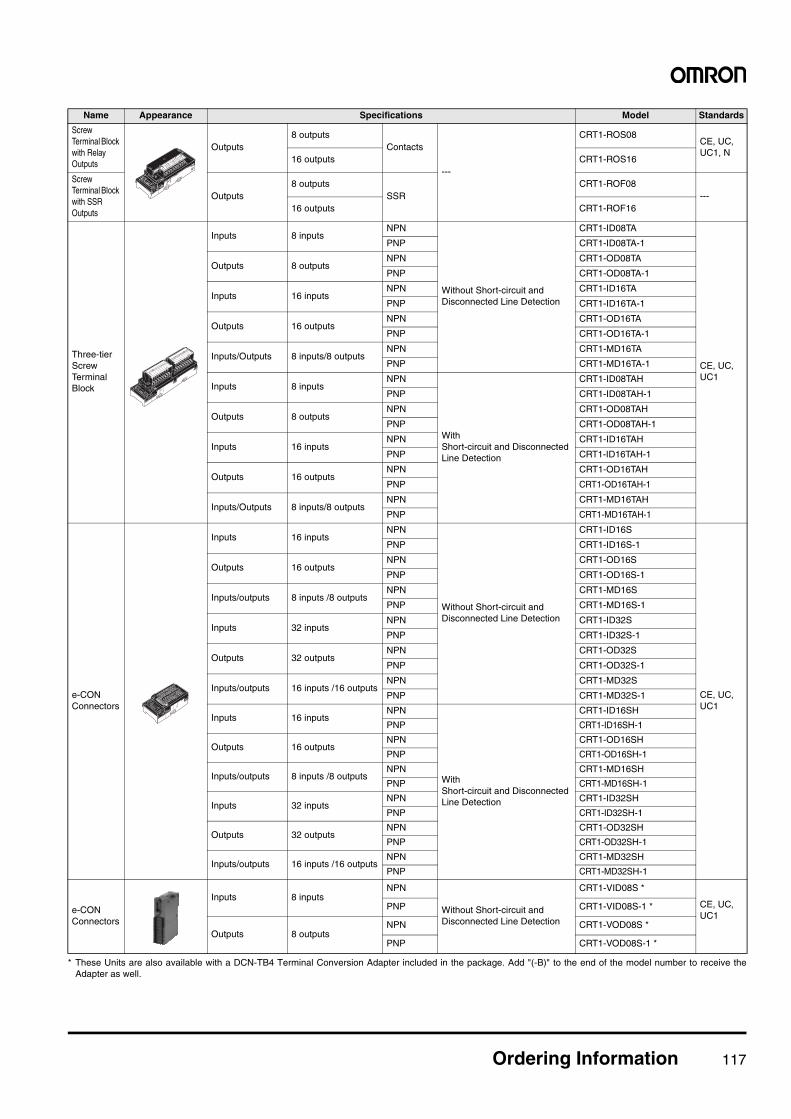
Ordering Information 117
* These Units are also available with a DCN-TB4 Terminal Conversion Adapter included in the package. Add "(-B)" to the end of the model number to receive theAdapter as well.
Name Appearance Specifications Model Standards
Screw Terminal Block with Relay Outputs
Outputs8 outputs
Contacts
---
CRT1-ROS08 CE, UC, UC1, N
16 outputs CRT1-ROS16
Screw Terminal Block with SSR Outputs
Outputs8 outputs
SSRCRT1-ROF08
---16 outputs CRT1-ROF16
Three-tier Screw Terminal Block
Inputs 8 inputsNPN
Without Short-circuit and Disconnected Line Detection
CRT1-ID08TA
CE, UC, UC1
PNP CRT1-ID08TA-1
Outputs 8 outputsNPN CRT1-OD08TA
PNP CRT1-OD08TA-1
Inputs 16 inputsNPN CRT1-ID16TA
PNP CRT1-ID16TA-1
Outputs 16 outputsNPN CRT1-OD16TA
PNP CRT1-OD16TA-1
Inputs/Outputs 8 inputs/8 outputsNPN CRT1-MD16TA
PNP CRT1-MD16TA-1
Inputs 8 inputsNPN
With Short-circuit and Disconnected Line Detection
CRT1-ID08TAH
PNP CRT1-ID08TAH-1
Outputs 8 outputsNPN CRT1-OD08TAH
PNP CRT1-OD08TAH-1
Inputs 16 inputsNPN CRT1-ID16TAH
PNP CRT1-ID16TAH-1
Outputs 16 outputsNPN CRT1-OD16TAH
PNP CRT1-OD16TAH-1
Inputs/Outputs 8 inputs/8 outputsNPN CRT1-MD16TAH
PNP CRT1-MD16TAH-1
e-CON Connectors
Inputs 16 inputsNPN
Without Short-circuit and Disconnected Line Detection
CRT1-ID16S
CE, UC, UC1
PNP CRT1-ID16S-1
Outputs 16 outputsNPN CRT1-OD16S
PNP CRT1-OD16S-1
Inputs/outputs 8 inputs /8 outputsNPN CRT1-MD16S
PNP CRT1-MD16S-1
Inputs 32 inputsNPN CRT1-ID32S
PNP CRT1-ID32S-1
Outputs 32 outputsNPN CRT1-OD32S
PNP CRT1-OD32S-1
Inputs/outputs 16 inputs /16 outputsNPN CRT1-MD32S
PNP CRT1-MD32S-1
Inputs 16 inputsNPN
With Short-circuit and Disconnected Line Detection
CRT1-ID16SH
PNP CRT1-ID16SH-1
Outputs 16 outputsNPN CRT1-OD16SH
PNP CRT1-OD16SH-1
Inputs/outputs 8 inputs /8 outputsNPN CRT1-MD16SH
PNP CRT1-MD16SH-1
Inputs 32 inputsNPN CRT1-ID32SH
PNP CRT1-ID32SH-1
Outputs 32 outputsNPN CRT1-OD32SH
PNP CRT1-OD32SH-1
Inputs/outputs 16 inputs /16 outputsNPN CRT1-MD32SH
PNP CRT1-MD32SH-1
e-CON Connectors
Inputs 8 inputsNPN
Without Short-circuit and Disconnected Line Detection
CRT1-VID08S *
CE, UC, UC1
PNP CRT1-VID08S-1 *
Outputs 8 outputsNPN CRT1-VOD08S *
PNP CRT1-VOD08S-1 *
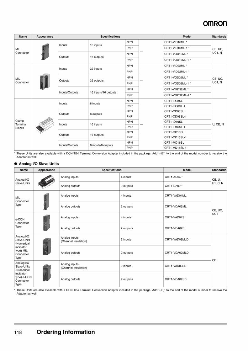
118 Ordering Information
* These Units are also available with a DCN-TB4 Terminal Conversion Adapter included in the package. Add "(-B)" to the end of the model number to receive theAdapter as well.
● Analog I/O Slave Units
* These Units are also available with a DCN-TB4 Terminal Conversion Adapter included in the package. Add "(-B)" to the end of the model number to receive theAdapter as well.
Name Appearance Specifications Model Standards
MIL Connector
Inputs 16 inputsNPN
---
CRT1-VID16ML *
CE, UC, UC1, N
PNP CRT1-VID16ML-1 *
Outputs 16 outputsNPN CRT1-VOD16ML *
PNP CRT1-VOD16ML-1 *
MIL Connector
Inputs 32 inputsNPN
---
CRT1-VID32ML *
CE, UC, UC1, N
PNP CRT1-VID32ML-1 *
Outputs 32 outputsNPN CRT1-VOD32ML *
PNP CRT1-VOD32ML-1 *
Inputs/Outputs 16 inputs/16 outputsNPN CRT1-VMD32ML *
PNP CRT1-VMD32ML-1 *
Clamp Terminal Blocks
Inputs 8 inputsNPN
---
CRT1-ID08SL
U, CE, N
PNP CRT1-ID08SL-1
Outputs 8 outputsNPN CRT1-OD08SL
PNP CRT1-OD08SL-1
Inputs 16 inputsNPN CRT1-ID16SL
PNP CRT1-ID16SL-1
Outputs 16 outputsNPN CRT1-OD16SL
PNP CRT1-OD16SL-1
Inputs/Outputs 8 inputs/8 outputsNPN CRT1-MD16SL
PNP CRT1-MD16SL-1
Name Appearance Specifications Model Standards
Analog I/O Slave Units
Analog inputs 4 inputs CRT1-AD04 *CE, U, U1, C, N
Analog outputs 2 outputs CRT1-DA02 *
MIL Connector Type
Analog inputs 4 inputs CRT1-VAD04ML
CE, UC, UC1
Analog outputs 2 outputs CRT1-VDA02ML
e-CON Connector Type
Analog inputs 4 inputs CRT1-VAD04S
Analog outputs 2 outputs CRT1-VDA02S
Analog I/O Slave Units (Numerical indicator type) MIL Connector Type
Analog inputs(Channel Insulation)
2 inputs CRT1-VAD02MLD
CE
Analog outputs 2 outputs CRT1-VDA02MLD
Analog I/O Slave Units (Numerical indicator type) e-CON Connector Type
Analog inputs(Channel Insulation)
2 inputs CRT1-VAD02SD
Analog outputs 2 outputs CRT1-VDA02SD
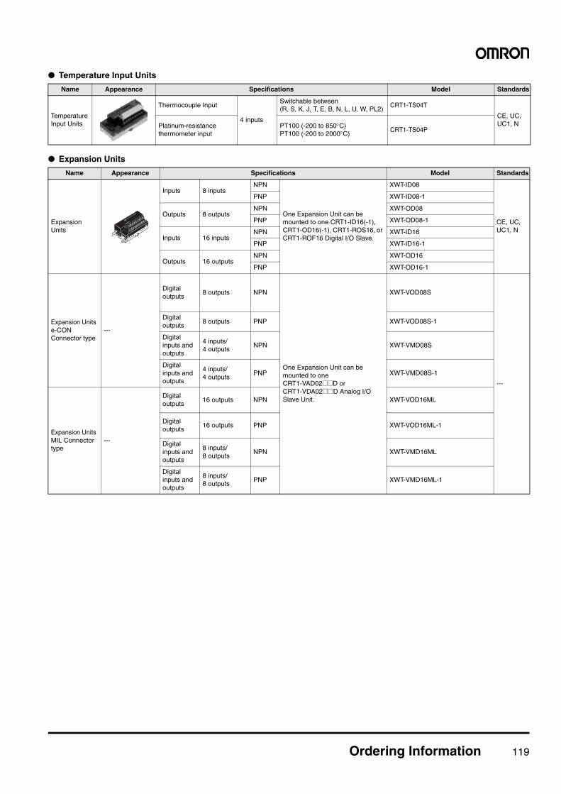
Ordering Information 119
● Temperature Input Units
● Expansion Units
Name Appearance Specifications Model Standards
Temperature Input Units
Thermocouple Input
4 inputs
Switchable between(R, S, K, J, T, E, B, N, L, U, W, PL2)
CRT1-TS04T
CE, UC, UC1, NPlatinum-resistance
thermometer inputPT100 (-200 to 850°C)PT100 (-200 to 2000°C)
CRT1-TS04P
Name Appearance Specifications Model Standards
Expansion Units
Inputs 8 inputsNPN
One Expansion Unit can be mounted to one CRT1-ID16(-1), CRT1-OD16(-1), CRT1-ROS16, or CRT1-ROF16 Digital I/O Slave.
XWT-ID08
CE, UC, UC1, N
PNP XWT-ID08-1
Outputs 8 outputsNPN XWT-OD08
PNP XWT-OD08-1
Inputs 16 inputsNPN XWT-ID16
PNP XWT-ID16-1
Outputs 16 outputsNPN XWT-OD16
PNP XWT-OD16-1
Expansion Units e-CON Connector type
---
Digital outputs
8 outputs NPN
One Expansion Unit can be mounted to one CRT1-VAD02@@D or CRT1-VDA02@@D Analog I/O Slave Unit.
XWT-VOD08S
---
Digital outputs
8 outputs PNP XWT-VOD08S-1
Digital inputs and outputs
4 inputs/4 outputs
NPN XWT-VMD08S
Digital inputs and outputs
4 inputs/4 outputs
PNP XWT-VMD08S-1
Expansion Units MIL Connector type
---
Digital outputs
16 outputs NPN XWT-VOD16ML
Digital outputs
16 outputs PNP XWT-VOD16ML-1
Digital inputs and outputs
8 inputs/8 outputs
NPN XWT-VMD16ML
Digital inputs and outputs
8 inputs/8 outputs
PNP XWT-VMD16ML-1
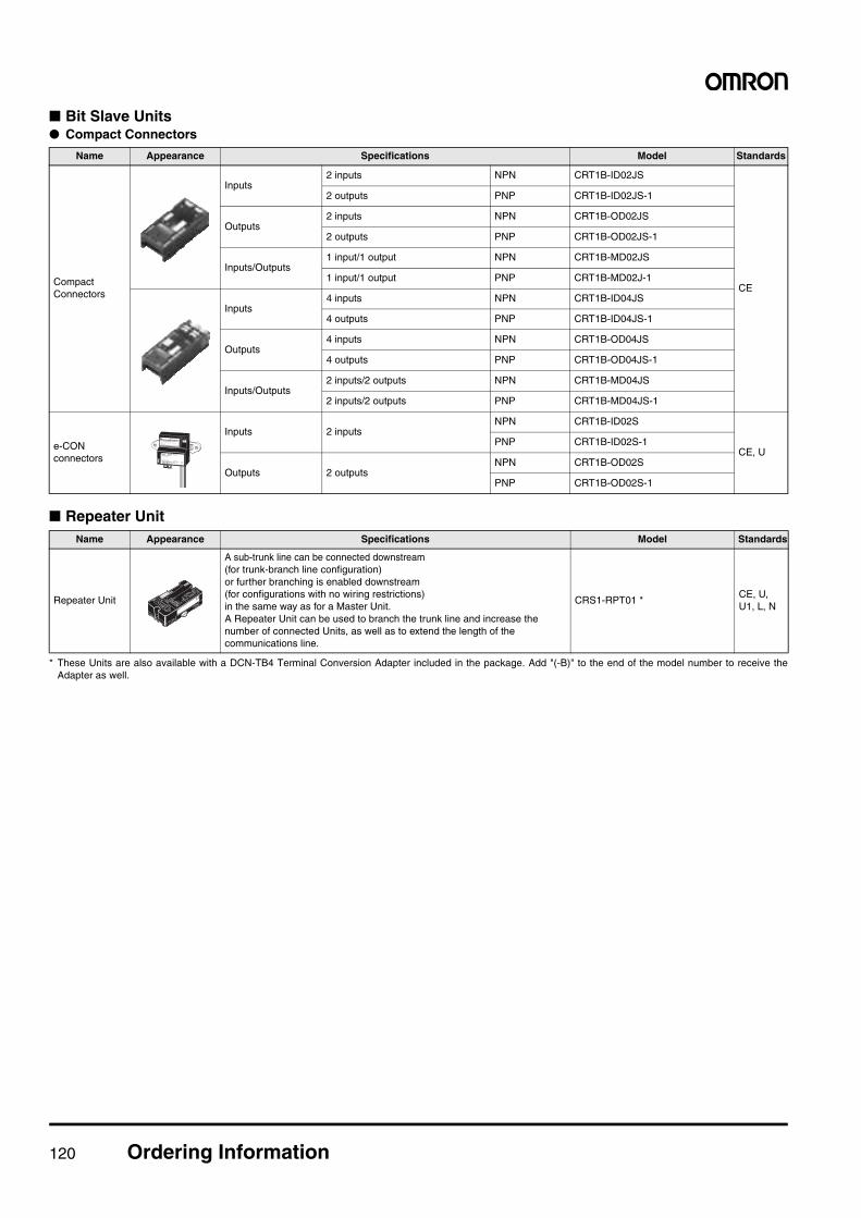
120 Ordering Information
■ Bit Slave Units● Compact Connectors
■ Repeater Unit
* These Units are also available with a DCN-TB4 Terminal Conversion Adapter included in the package. Add "(-B)" to the end of the model number to receive theAdapter as well.
Name Appearance Specifications Model Standards
Compact Connectors
Inputs2 inputs NPN CRT1B-ID02JS
CE
2 outputs PNP CRT1B-ID02JS-1
Outputs2 inputs NPN CRT1B-OD02JS
2 outputs PNP CRT1B-OD02JS-1
Inputs/Outputs1 input/1 output NPN CRT1B-MD02JS
1 input/1 output PNP CRT1B-MD02J-1
Inputs4 inputs NPN CRT1B-ID04JS
4 outputs PNP CRT1B-ID04JS-1
Outputs4 inputs NPN CRT1B-OD04JS
4 outputs PNP CRT1B-OD04JS-1
Inputs/Outputs2 inputs/2 outputs NPN CRT1B-MD04JS
2 inputs/2 outputs PNP CRT1B-MD04JS-1
e-CON connectors
Inputs 2 inputsNPN CRT1B-ID02S
CE, UPNP CRT1B-ID02S-1
Outputs 2 outputsNPN CRT1B-OD02S
PNP CRT1B-OD02S-1
Name Appearance Specifications Model Standards
Repeater Unit
A sub-trunk line can be connected downstream(for trunk-branch line configuration)or further branching is enabled downstream(for configurations with no wiring restrictions)in the same way as for a Master Unit.A Repeater Unit can be used to branch the trunk line and increase the number of connected Units, as well as to extend the length of the communications line.
CRS1-RPT01 *CE, U, U1, L, N
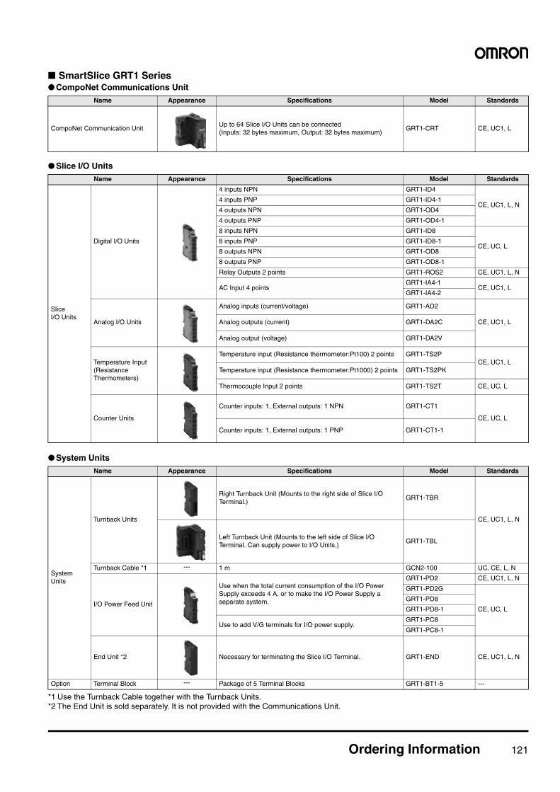
Ordering Information 121
■ SmartSlice GRT1 Series● CompoNet Communications Unit
● Slice I/O Units
● System Units
*1 Use the Turnback Cable together with the Turnback Units.*2 The End Unit is sold separately. It is not provided with the Communications Unit.
Name Appearance Specifications Model Standards
CompoNet Communication UnitUp to 64 Slice I/O Units can be connected(Inputs: 32 bytes maximum, Output: 32 bytes maximum)
GRT1-CRT CE, UC1, L
Name Appearance Specifications Model Standards
Slice I/O Units
Digital I/O Units
4 inputs NPN GRT1-ID4
CE, UC1, L, N4 inputs PNP GRT1-ID4-1
4 outputs NPN GRT1-OD4
4 outputs PNP GRT1-OD4-1
8 inputs NPN GRT1-ID8
CE, UC, L8 inputs PNP GRT1-ID8-1
8 outputs NPN GRT1-OD8
8 outputs PNP GRT1-OD8-1
Relay Outputs 2 points GRT1-ROS2 CE, UC1, L, N
AC Input 4 pointsGRT1-IA4-1
CE, UC1, LGRT1-IA4-2
Analog I/O Units
Analog inputs (current/voltage) GRT1-AD2
CE, UC1, LAnalog outputs (current) GRT1-DA2C
Analog output (voltage) GRT1-DA2V
Temperature Input(Resistance Thermometers)
Temperature input (Resistance thermometer:Pt100) 2 points GRT1-TS2PCE, UC1, L
Temperature input (Resistance thermometer:Pt1000) 2 points GRT1-TS2PK
Thermocouple Input 2 points GRT1-TS2T CE, UC, L
Counter Units
Counter inputs: 1, External outputs: 1 NPN GRT1-CT1
CE, UC, L
Counter inputs: 1, External outputs: 1 PNP GRT1-CT1-1
Name Appearance Specifications Model Standards
SystemUnits
Turnback Units
Right Turnback Unit (Mounts to the right side of Slice I/O Terminal.)
GRT1-TBR
CE, UC1, L, N
Left Turnback Unit (Mounts to the left side of Slice I/O Terminal. Can supply power to I/O Units.)
GRT1-TBL
Turnback Cable *1 --- 1 m GCN2-100 UC, CE, L, N
I/O Power Feed Unit
Use when the total current consumption of the I/O Power Supply exceeds 4 A, or to make the I/O Power Supply a separate system.
GRT1-PD2 CE, UC1, L, N
GRT1-PD2G
CE, UC, L
GRT1-PD8
GRT1-PD8-1
Use to add V/G terminals for I/O power supply.GRT1-PC8
GRT1-PC8-1
End Unit *2 Necessary for terminating the Slice I/O Terminal. GRT1-END CE, UC1, L, N
Option Terminal Block --- Package of 5 Terminal Blocks GRT1-BT1-5 ---
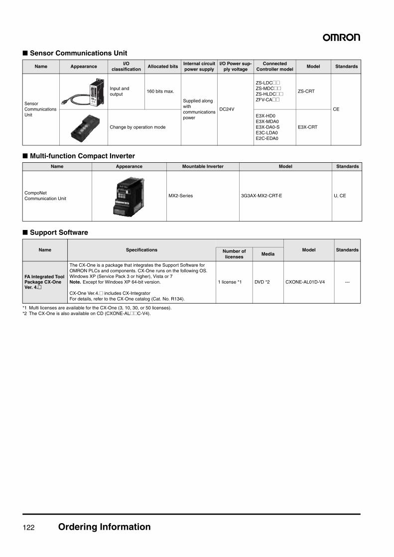
122 Ordering Information
■ Sensor Communications Unit
■ Multi-function Compact Inverter
■ Support Software
*1 Multi licenses are available for the CX-One (3, 10, 30, or 50 licenses).*2 The CX-One is also available on CD (CXONE-AL@@C-V4).
Name AppearanceI/O
classificationAllocated bits
Internal circuit power supply
I/O Power sup-ply voltage
Connected Controller model
Model Standards
Sensor Communications Unit
Input and output
160 bits max.
Supplied along with communications power
DC24V
ZS-LDC@@ZS-MDC@@ZS-HLDC@@ZFV-CA@@
ZS-CRT
CE
Change by operation mode
E3X-HD0E3X-MDA0E3X-DA0-SE3C-LDA0E2C-EDA0
E3X-CRT
Name Appearance Mountable Inverter Model Standards
CompoNet Communication Unit
MX2-Series 3G3AX-MX2-CRT-E U, CE
Name Specifications Model StandardsNumber of licenses
Media
FA Integrated Tool Package CX-OneVer. 4.@
The CX-One is a package that integrates the Support Software for OMRON PLCs and components. CX-One runs on the following OS. Windows XP (Service Pack 3 or higher), Vista or 7Note. Except for Windoes XP 64-bit version.
CX-One Ver.4.@ includes CX-Integrator For details, refer to the CX-One catalog (Cat. No. R134).
1 license *1 DVD *2 CXONE-AL01D-V4 ---
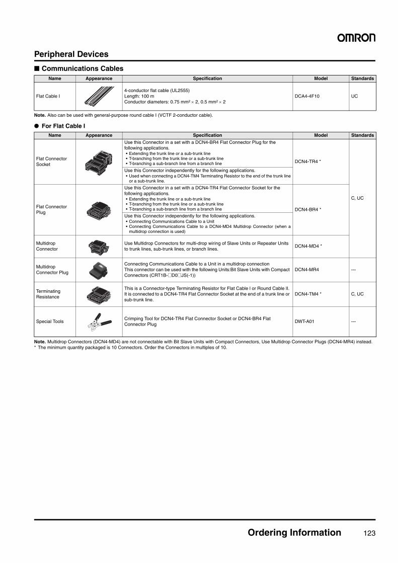
Ordering Information 123
Peripheral Devices
■ Communications Cables
Note. Also can be used with general-purpose round cable I (VCTF 2-conductor cable).
● For Flat Cable I
Note. Multidrop Connectors (DCN4-MD4) are not connectable with Bit Slave Units with Compact Connectors, Use Multidrop Connector Plugs (DCN4-MR4) instead.* The minimum quantity packaged is 10 Connectors. Order the Connectors in multiples of 10.
Name Appearance Specification Model Standards
Flat Cable I4-conductor flat cable (UL2555)Length: 100 m Conductor diameters: 0.75 mm2 × 2, 0.5 mm2 × 2
DCA4-4F10 UC
Name Appearance Specification Model Standards
Flat Connector Socket
Use this Connector in a set with a DCN4-BR4 Flat Connector Plug for the following applications.• Extending the trunk line or a sub-trunk line• T-branching from the trunk line or a sub-trunk line• T-branching a sub-branch line from a branch line DCN4-TR4 *
C, UC
Use this Connector independently for the following applications.• Used when connecting a DCN4-TM4 Terminating Resistor to the end of the trunk line
or a sub-trunk line.
Flat Connector Plug
Use this Connector in a set with a DCN4-TR4 Flat Connector Socket for the following applications.• Extending the trunk line or a sub-trunk line• T-branching from the trunk line or a sub-trunk line• T-branching a sub-branch line from a branch line DCN4-BR4 *
Use this Connector independently for the following applications.• Connecting Communications Cable to a Unit• Connecting Communications Cable to a DCN4-MD4 Multidrop Connector (when a
multidrop connection is used)
Multidrop Connector
Use Multidrop Connectors for multi-drop wiring of Slave Units or Repeater Units to trunk lines, sub-trunk lines, or branch lines.
DCN4-MD4 *
Multidrop Connector Plug
Connecting Communications Cable to a Unit in a multidrop connectionThis connector can be used with the following Units:Bit Slave Units with Compact Connectors (CRT1B-@D0@JS(-1))
DCN4-MR4 ---
Terminating Resistance
This is a Connector-type Terminating Resistor for Flat Cable l or Round Cable lI. It is connected to a DCN4-TR4 Flat Connector Socket at the end of a trunk line or sub-trunk line.
DCN4-TM4 * C, UC
Special ToolsCrimping Tool for DCN4-TR4 Flat Connector Socket or DCN4-BR4 Flat Connector Plug
DWT-A01 ---
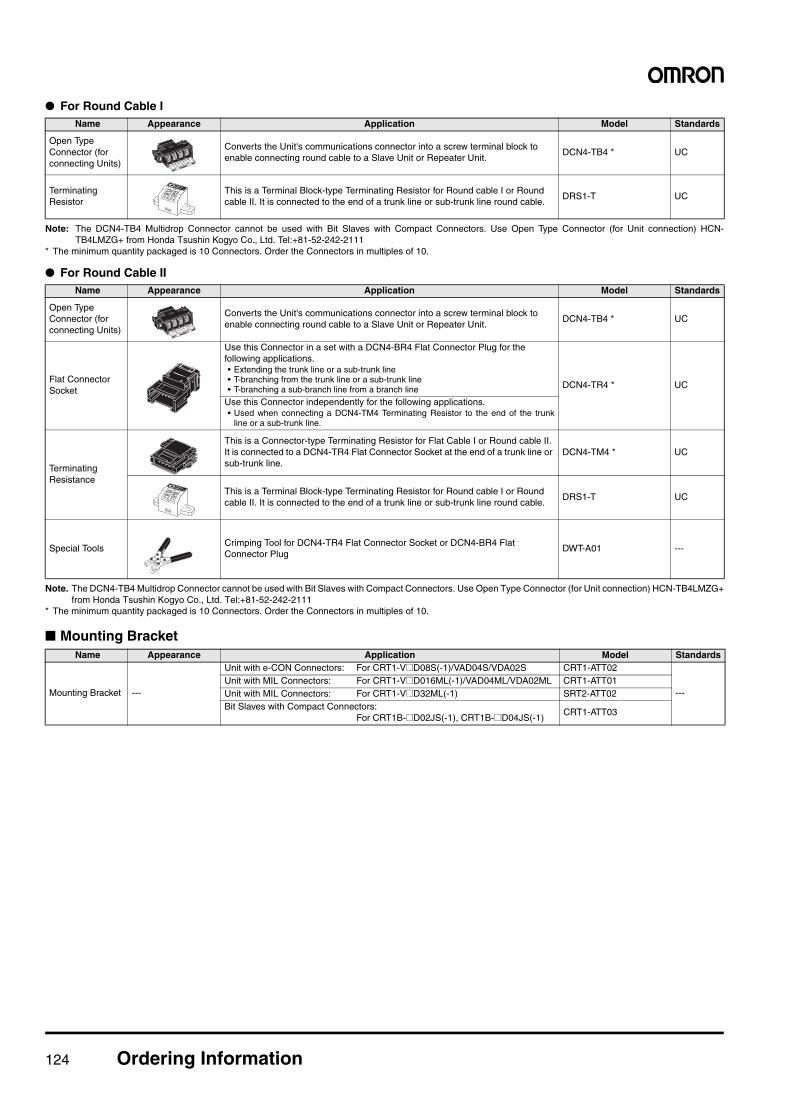
124 Ordering Information
● For Round Cable I
Note: The DCN4-TB4 Multidrop Connector cannot be used with Bit Slaves with Compact Connectors. Use Open Type Connector (for Unit connection) HCN-TB4LMZG+ from Honda Tsushin Kogyo Co., Ltd. Tel:+81-52-242-2111
* The minimum quantity packaged is 10 Connectors. Order the Connectors in multiples of 10.
● For Round Cable II
Note. The DCN4-TB4 Multidrop Connector cannot be used with Bit Slaves with Compact Connectors. Use Open Type Connector (for Unit connection) HCN-TB4LMZG+from Honda Tsushin Kogyo Co., Ltd. Tel:+81-52-242-2111
* The minimum quantity packaged is 10 Connectors. Order the Connectors in multiples of 10.
■ Mounting Bracket
Name Appearance Application Model Standards
Open Type Connector (for connecting Units)
Converts the Unit's communications connector into a screw terminal block to enable connecting round cable to a Slave Unit or Repeater Unit.
DCN4-TB4 * UC
Terminating Resistor
This is a Terminal Block-type Terminating Resistor for Round cable I or Round cable II. It is connected to the end of a trunk line or sub-trunk line round cable.
DRS1-T UC
Name Appearance Application Model Standards
Open Type Connector (for connecting Units)
Converts the Unit's communications connector into a screw terminal block to enable connecting round cable to a Slave Unit or Repeater Unit.
DCN4-TB4 * UC
Flat Connector Socket
Use this Connector in a set with a DCN4-BR4 Flat Connector Plug for the following applications.• Extending the trunk line or a sub-trunk line• T-branching from the trunk line or a sub-trunk line• T-branching a sub-branch line from a branch line DCN4-TR4 * UC
Use this Connector independently for the following applications.• Used when connecting a DCN4-TM4 Terminating Resistor to the end of the trunk
line or a sub-trunk line.
Terminating Resistance
This is a Connector-type Terminating Resistor for Flat Cable I or Round cable II. It is connected to a DCN4-TR4 Flat Connector Socket at the end of a trunk line or sub-trunk line.
DCN4-TM4 * UC
This is a Terminal Block-type Terminating Resistor for Round cable I or Round cable II. It is connected to the end of a trunk line or sub-trunk line round cable.
DRS1-T UC
Special ToolsCrimping Tool for DCN4-TR4 Flat Connector Socket or DCN4-BR4 Flat Connector Plug
DWT-A01 ---
Name Appearance Application Model Standards
Mounting Bracket ---
Unit with e-CON Connectors: For CRT1-V@D08S(-1)/VAD04S/VDA02S CRT1-ATT02
---Unit with MIL Connectors: For CRT1-V@D016ML(-1)/VAD04ML/VDA02ML CRT1-ATT01Unit with MIL Connectors: For CRT1-V@D32ML(-1) SRT2-ATT02Bit Slaves with Compact Connectors:
For CRT1B-@D02JS(-1), CRT1B-@D04JS(-1)CRT1-ATT03
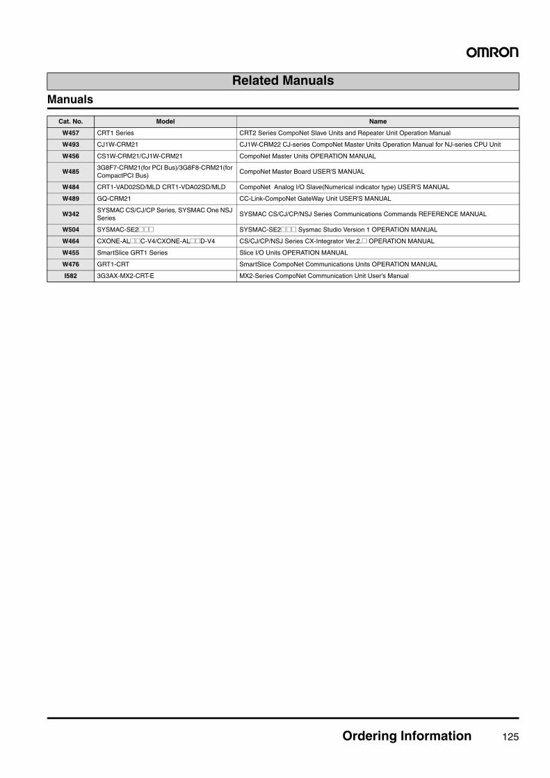
Ordering Information 125
Manuals
Related Manuals
Cat. No. Model Name
W457 CRT1 Series CRT2 Series CompoNet Slave Units and Repeater Unit Operation Manual
W493 CJ1W-CRM21 CJ1W-CRM22 CJ-series CompoNet Master Units Operation Manual for NJ-series CPU Unit
W456 CS1W-CRM21/CJ1W-CRM21 CompoNet Master Units OPERATION MANUAL
W4853G8F7-CRM21(for PCI Bus)/3G8F8-CRM21(for CompactPCI Bus)
CompoNet Master Board USER'S MANUAL
W484 CRT1-VAD02SD/MLD CRT1-VDA02SD/MLD CompoNet Analog I/O Slave(Numerical indicator type) USER'S MANUAL
W489 GQ-CRM21 CC-Link-CompoNet GateWay Unit USER'S MANUAL
W342SYSMAC CS/CJ/CP Series, SYSMAC One NSJ Series
SYSMAC CS/CJ/CP/NSJ Series Communications Commands REFERENCE MANUAL
W504 SYSMAC-SE2@@@ SYSMAC-SE2@@@ Sysmac Studio Version 1 OPERATION MANUAL
W464 CXONE-AL@@C-V4/CXONE-AL@@D-V4 CS/CJ/CP/NSJ Series CX-Integrator Ver.2.@ OPERATION MANUAL
W455 SmartSlice GRT1 Series Slice I/O Units OPERATION MANUAL
W476 GRT1-CRT SmartSlice CompoNet Communications Units OPERATION MANUAL
I582 3G3AX-MX2-CRT-E MX2-Series CompoNet Communication Unit User's Manual

126
MEMO
127
MEMO
128
MEMO
Read and Understand this Catalog
Please read and understand this catalog before purchasing the product. Please consult your OMRON representative if you have any questions or comments.
Warranty and Limitations of Liability
WARRANTYOMRON's exclusive warranty is that the products are free from defects in materials and workmanship for a period of one year (or other period if specified) from date of sale by OMRON.OMRON MAKES NO WARRANTY OR REPRESENTATION, EXPRESS OR IMPLIED, REGARDING NON-INFRINGEMENT,MERCHANTABILITY, OR FITNESS FOR PARTICULAR PURPOSE OFTHE PRODUCTS. ANY BUYER OR USER ACKNOWLEDGESTHATTHE BUYER OR USER ALONE HAS DETERMINEDTHATTHE PRODUCTS WILL SUITABLY MEETTHEREQUIREMENTS OFTHEIR INTENDED USE. OMRON DISCLAIMS ALL OTHER WARRANTIES, EXPRESS OR IMPLIED.
LIMITATIONS OF LIABILITYOMRON SHALL NOT BE RESPONSIBLE FOR SPECIAL, INDIRECT, OR CONSEQUENTIAL DAMAGES, LOSS OF PROFITS OR COMMERCIAL LOSS IN ANY WAY CONNECTED WITHTHE PRODUCTS, WHETHER SUCH CLAIM IS BASED ON CONTRACT,WARRANTY, NEGLIGENCE, OR STRICT LIABILITY.
In no event shall the responsibility of OMRON for any act exceed the individual price of the product on which liability is asserted.
IN NO EVENT SHALL OMRON BE RESPONSIBLE FOR WARRANTY, REPAIR, OR OTHER CLAIMS REGARDINGTHEPRODUCTS UNLESS OMRON'S ANALYSIS CONFIRMSTHATTHE PRODUCTS WERE PROPERLY HANDLED, STORED,INSTALLED, AND MAINTAINED AND NOT SUBJECT TO CONTAMINATION, ABUSE, MISUSE, OR INAPPROPRIATEMODIFICATION OR REPAIR.
Application Considerations
SUITABILITY FOR USEOMRON shall not be responsible for conformity with any standards, codes, or regulations that apply to the combination of the product in the customer's application or use of the product.
At the customer's request, OMRON will provide applicable third party certification documents identifying ratings and limitations of use that apply to the products. This information by itself is not sufficient for a complete determination of thesuitability of the products in combination with the end product, machine, system, or other application or use.
The following are some examples of applications for which particular attention must be given. This is not intended to be an exhaustive list of all possible uses of the products, nor is it intended to imply that the uses listed may be suitable for the products:
nvolving potential chemical contamination or electrical interference, or conditions or uses not described in this document.
amusement machines, vehicles, safety equipment, and installations subject to separate industry or governmentregulations.Systems, machines, and equipment that could present a risk to life or property.Please know and observe all prohibitions of use applicable to the products.
NEVER USETHE PRODUCT FOR AN APPLICATION INVOLVING SERIOUS RISK TO LIFE OR PROPERTY WITHOUT ENSURING THATTHE SYSTEM AS A WHOLE HAS BEEN DESIGNEDTO ADDRESSTHE RISKS, ANDTHAT THE OMRON PRODUCT IS PROPERLY RATED AND INSTALLED FORTHE INTENDED USE WITHINTHE OVERALL EQUIPMENT OR SYSTEM.
PROGRAMMABLE PRODUCTSOMRON shall not be responsible for the user's programming of a programmable product, or any consequence thereof.
Disclaimers
CHANGE IN SPECIFICATIONSProduct specifications and accessories may be changed at any time based on improvements and other reasons. Consult with your OMRON representative at any time to confirm actual specifications of purchased product.
DIMENSIONS AND WEIGHTSDimensions and weights are nominal and are not to be used for manufacturing purposes, even when tolerances are shown.
PERFORMANCE DATAPerformance data given in this catalog is provided as a guide for the user in determining suitability and does not constitute a warranty. It may represent the result of OMRON’s test conditions, and the users must correlate it to actual application requirements. Actual performance is subject to the OMRON Warranty and Limitations of Liability.
Note: Do not use this document to operate the Unit.
This catalog mainly provides information that is necessary for selecting suitable models, and does not contain precautions for correct use. Always read the precautions and other required information provided in product operation manuals before using the product.
The application examples provided in this catalog are for reference only. Check functions and safety of the equipment before use.Never use the products for any application requiring special safety requirements, such as nuclear energy control systems, railroad systems, aviation systems, medical equipment, amusement machines, vehicles, safety equipment, or other application involving serious risk to life or property, without ensuring that the system as a whole has been designed to address the risks, and that the OMRON products are properly rated and installed for the intended use within the overall equipment or system.
Authorized Distributor:
specifications are subject to change without notice.In the interest of product improvement,
Cat. No. P056-E1-07 0612 (1006)Printed in Japan
© OMRON Corporation 2008-2012 All Rights Reserved.
OMRON Corporation Industrial Automation Company
One Commerce Drive Schaumburg, OMRON ELECTRONICS LLC
IL 60173-5302 U.S.A.Tel: (1) 847-843-7900/Fax: (1) 847-843-7787
Regional HeadquartersOMRON EUROPE B.V.Wegalaan 67-69-2132 JD HoofddorpThe NetherlandsTel: (31)2356-81-300/Fax: (31)2356-81-388
Contact: www.ia.omron.comTokyo, JAPAN
OMRON ASIA PACIFIC PTE. LTD.
Singapore 119967Alexandra Technopark, No. 438A Alexandra Road # 05-05/08 (Lobby 2),
Tel: (65) 6835-3011/Fax: (65) 6835-2711
Room 2211, Bank of China Tower, 200 Yin Cheng Zhong Road,
Tel: (86) 21-5037-2222/Fax: (86) 21-5037-2200PuDong New Area, Shanghai, 200120, China
OMRON (CHINA) CO., LTD.
CSM_9_2_0812