


WIRELESS COMMUNICATIONS
101
WIRELESS COMMUNICATIONS A Platform for Wireless Sensor Networks Build an RFID Payment System Ciarcia’s PV System (Part 3) Antenna Technology 101 TCP/IP Socket Communication Firmware Protection & Publishing CIRCUIT CELLAR www.circuitcellar.com THE MAGAZINE FOR COMPUTER APPLICATIONS 7 9 25274 75349 02 > $4.95 U.S. ($5.95 Canada) #211 February 2008 TRANSFORMER BASICS P . 70 • MCU-BASED POLL SERVER RESULTS P . 74 • HOT CHIPS REVIEW P . 78
-
Upload
khangminh22 -
Category
Documents
-
view
0 -
download
0
Transcript of WIRELESS COMMUNICATIONS

WIRELESS COMMUNICATIONSA Platform for Wireless Sensor Networks
Build an RFID Payment System
Ciarcia’s PV System (Part 3)
Antenna Technology 101
TCP/IP SocketCommunication
Firmware Protection & Publishing
CIRCUIT CELLAR
ww
w.circuitcellar.com T H E M A G A Z I N E F O R C O M P U T E R A P P L I C AT I O N S
7 925274 75349
02>
$4.95 U.S. ($5.95 Canada)
#211 February 2008
TRANSFORMER BASICS P. 70 • MCU-BASED POLL SERVER RESULTS P. 74 • HOT CHIPS REVIEW P. 78
Cover.qxp 1/4/2008 2:43 PM Page 1

M5
2550
7595
C5
2550
7595
Y5
2550
7595
K5
2550
7595
MY
CYCM
��
Cypress, the Cypress logo and PSoC are registered trademarks, and Programmable System-on-Chip, PSoC Express, and FirstTouch are trademarks of Cypress Semiconductor Corporation.All other trademarks are properties of their respective owners. ©2007 Cypress Semiconductor Corporation. All rights reserved. *Does not include any applicable sales tax, shipping and handling costs. CPFAP001E
Get Your Ticket to the Ultimate Embedded Design Starter Kit.Fixed-function microcontrollers had their share of the spotlight. It’s time for a revolutionary—and simplified—approach to embedded application development. Get a Cypress PSoC® FirstTouch™ Starter Kit now and discover how much PSoC mixed-signal arrays—powerful, programmable analog and digital blocks, embedded memory and a fast MCU—shorten your time-to-market. This kit includes the easy-to-use PSoC Express™ visual embedded system design tool, and gives you embedded designs you can evaluate right out of the box. Get yours and step into the spotlight today.
Buy your PSoC FirstTouch Ultimate Starter Kit now at:
www.cypress.com/go/FirstTouch
It’s showtime.
Includes four ready-to-use mixed-signal applications on a single platform.TEMPERATURE
SENSINGCAPSENSE TOUCH
SENSING LIGHT SENSING
CAPSENSE PROXIMITY
SENSING
Buy Now$29.95*
1.qxp 10/1/2007 3:50 PM Page 1

56-57.qxp 7/2/2007 10:52 AM Page 1

4 Issue 211 February 2008 www.circuitcellar.comCIRCUIT CELLAR®
FOUNDER/EDITORIAL DIRECTORSteve Ciarcia
MANAGING EDITORC. J. Abate
WEST COAST EDITORTom Cantrell
CONTRIBUTING EDITORSJeff Bachiochi Ingo Cyliax Robert LacosteGeorge MartinEd Nisley
NEW PRODUCTS EDITORJohn Gorsky
PROJECT EDITORSGary BodleyKen Davidson David Tweed
ASSOCIATE EDITORJesse Smolin
ADVERTISING860.875.2199 • Fax: 860.871.0411 • www.circuitcellar.com/advertise
PUBLISHERSean Donnelly Direct: 860.872.3064, Cell: 860.930.4326, E-mail: [email protected]
ADVERTISING REPRESENTATIVEShannon BarracloughDirect: 860.872.3064, E-mail: [email protected]
ADVERTISING COORDINATORValerie LusterE-mail: [email protected]
CONTACTSSUBSCRIPTIONS
Information: www.circuitcellar.com/subscribe, E-mail: [email protected]: 800.269.6301, www.circuitcellar.com/subscribe, Circuit Cellar Subscriptions, P.O. Box 5650, Hanover, NH 03755-5650Address Changes/Problems: E-mail: [email protected]
GENERAL INFORMATION860.875.2199, Fax: 860.871.0411, E-mail: [email protected] Office: Editor, Circuit Cellar, 4 Park St., Vernon, CT 06066, E-mail: [email protected] Products: New Products, Circuit Cellar, 4 Park St., Vernon, CT 06066, E-mail: [email protected]
AUTHORIZED REPRINTS INFORMATION860.875.2199, E-mail: [email protected]
AUTHORS Authors’ e-mail addresses (when available) are included at the end of each article.
CIRCUIT CELLAR®, THE MAGAZINE FOR COMPUTER APPLICATIONS (ISSN 1528-0608) is published monthly by Circuit CellarIncorporated, 4 Park Street, Vernon, CT 06066. Periodical rates paid at Vernon, CT and additional offices. One-year (12 issues)subscription rate USA and possessions $23.95, Canada/Mexico $34.95, all other countries $49.95.Two-year (24 issues) sub-scription rate USA and possessions $43.95, Canada/Mexico $59.95, all other countries $85. All subscription orders payable inU.S. funds only via Visa, MasterCard, international postal money order, or check drawn on U.S. bank. Direct subscription ordersand subscription-related questions to Circuit Cellar Subscriptions, P.O. Box 5650, Hanover, NH 03755-5650 or call800.269.6301.
Postmaster: Send address changes to Circuit Cellar, Circulation Dept., P.O. Box 5650, Hanover, NH 03755-5650.
Circuit Cellar® makes no warranties and assumes no responsibility or liability of any kind for errors in these programs or schematics or for theconsequences of any such errors. Furthermore, because of possible variation in the quality and condition of materials and workmanship of read-er-assembled projects, Circuit Cellar® disclaims any responsibility for the safe and proper function of reader-assembled projects based upon orfrom plans, descriptions, or information published by Circuit Cellar®.
The information provided by Circuit Cellar® is for educational purposes. Circuit Cellar® makes no claims or warrants that readers have a right tobuild things based upon these ideas under patent or other relevant intellectual property law in their jurisdiction, or that readers have a right toconstruct or operate any of the devices described herein under the relevant patent or other intellectual property law of the reader’s jurisdiction.The reader assumes any risk of infringement liability for constructing or operating such devices.
Entire contents copyright © 2008 by Circuit Cellar, Incorporated. All rights reserved. Circuit Cellar is a registered trademark of Circuit Cellar, Inc.Reproduction of this publication in whole or in part without written consent from Circuit Cellar Inc. is prohibited.
CHIEF FINANCIAL OFFICERJeannette Ciarcia
MEDIA CONSULTANTDan Rodrigues
CUSTOMER SERVICEDebbie Lavoie
CONTROLLERJeff Yanco
ART DIRECTORKC Prescott
GRAPHIC DESIGNERCarey Penney
STAFF ENGINEER John Gorsky
Cover photography by Chris Rakoczy—Rakoczy Photographywww.rakoczyphoto.com
PRINTED IN THE UNITED STATES
TASK MANAGER
Last year, we challenged the embedded design community to getcreative and make a concerted effort to design real-world applicationsthat would make waves in 2008. This issue proves that the communityhas stepped up to the challenge and has begun to address the majortechnological topics of the twenty-first century: user-friendly wirelessapplications, cost-effective embedded applications, code efficiency,and renewable energy solutions.
This month, we start with wireless network design. On page 12,Diego Mendez Chaves and his team from Los Andes University intro-duce you to a flexible platform for wireless sensor networks. This articlewill help you get a wireless network up and running.
In keeping with the wireless communications theme, we includetwo articles that will help you develop wireless designs that featuresimple master-to-slave interaction. Carlos Cossio describes his RFIDpayment terminal design on page 34. The well-designed, handheldterminal can be used for contactless payments in a variety of settings,ranging from a convenience store to a subway station. On page 60,Robert Lacoste covers antenna technology and familiarizes you withimpedance matching and antenna simulation. After reading this col-umn, you shouldn’t be wary of incorporating antenna technologies inyour projects.
On the topic of intelligent energy solutions, Steve Ciarcia wraps uphis series about the installation of his home photovoltaic (PV) system(p. 22). The system is now installed and racking up kilowatt-hour cred-its on the meter. This month, he describes the wiring and electronicsbehind this complex renewable energy project.
In the second part of his series on cashing in on code, RichardHoptroff explains how to publish firmware and create an opportunity tomake some big bucks (p. 44). To do so, he draws on his firmwaredevelopment experience. He covers the topics of firmware copyrightprotection, pricing, and publishing.
On page 52, Cass Tyler explains how to implement a TCP/IP sock-et server on a Rabbit RCM2200. As you’ll see, TCP/IP communicationwith embedded processors is quick and easy when using text com-mands.
Ever wonder how transformers really work? Ed Nisley’s column ontransformer basics is a great primer for young and old engineers alike(p. 70). He covers several essential transformer equations and more.
On page 74, Jeff Bachiochi delivers the second part of his serieson his portable poll server. The MCU-based design maximizes thepower of SitePlayer to ask questions, gather responses, and compileresults.
In the last column of the issue, Tom Cantrell brings you up to speedon all of the exciting new chip technologies that he discovered at themost recent Hot Chips and Embedded Systems conferences (p. 78).With chips like these, you’re sure to be able to take your 2008 designsto the next level.
Good luck! I look forward to learning about all of your 2008 designprojects.
Real-World Apps
211_Task_Masthead.qxp 1/7/2008 4:50 PM Page 4

6 Issue 211 February 2008 CIRCUIT CELLAR® www.circuitcellar.com
February 2008: Wireless Communications
4 TASK MANAGERReal-World AppsC. J. Abate
8 NEW PRODUCT NEWSedited by John Gorsky
93 CROSSWORD
FEATURES
DEPARTMENTS94 INDEX OF ADVERTISERS
March Preview
96 PRIORITY INTERRUPTAvoiding StereotypesSteve Ciarcia
60 THE DARKER SIDEAntenna BasicsRobert Lacoste
70 ABOVE THE GROUND PLANETransformersEd Nisley
12 Wireless Sensor Network DesignA Flexible Platform for WSNsDiego Méndez Chaves, Mauricio Guerrero Hurtado, & Néstor Peña Traslaviña
22 INTELLIGENT ENERGY SOLUTIONSSolar-Powering the Circuit CellarPart 3: Wiring & ElectronicsSteve Ciarcia
COLUMNS
34 RFID Payment TerminalCarlos Cossio
44 Cash for CodePart 2: Publish Your FirmwareRichard Hoptroff
52 System ControlTCP/IP Communication with Embedded ProcessorsCass Tyler
PV Power: Wired & Working (p. 22) Payment TerminalDesign (p. 34)
UnderstandingTransformers (p. 70)
74 FROM THE BENCHPortable Poll ServerPart 2: Data Acquisition & ResultsJeff Bachiochi
78 SILICON UPDATEGot Chips?Tom Cantrell
Antennas 101 (p. 60)
211_toc.qxp 1/7/2008 4:49 PM Page 6

Visit www.circuitcellar.com/npnfor more New Product News.
8 Issue 211 February 2008 CIRCUIT CELLAR® www.circuitcellar.com
NEW PRODUCT NEWS Edited by John Gorsky
LOW-POWER CPLDThe new zero-power MAX IIZ CPLD is designed specifi-
cally to address the power, package, and price constraintsof the portable applications market. Offering a resourceadvantage of up to six times the density and three timesthe I/Os compared to competing traditional macrocell-based CPLDs, MAX IIZ devices enable designers to meetchanging functionalrequirements at the sameor lower power while sav-ing board space.
MAX IIZ devices areavailable in densities of 240and 570 logic elements.They are available in ultra-small MBGA packageswith up to 160 I/Os. Thisincreased logic density andgreater I/O count enablesgreater integration of exist-ing functions from otherdevices, substantiallyreducing board space andpower consumption whilelowering overall systemcosts.
MAX IIZ devices break through the power, space, andcost limitations of traditional macrocell-based CPLDsby combining non-volatility and instant-on performancewith an innovative look-up table logic structure. Thedevices use a 0.18-micron process, 1.8-V core voltage,and six-metal-layer flash to provide both high function-
ality and zero-power con-sumption in a singledevice. The advanced sys-tem features MAX IIZCPLDs, such as user flashmemory, an internal oscil-lator, cost optimization,greater density, smallerpackages, and lowerpower consumption farsurpass those of all tradi-tional macrocell-basedCPLDs.
The MAX IIZ seriesstarts at $1.25 in high vol-umes.
Altera Corp.www.altera.com
npn211.qxp 1/10/2008 1:22 PM Page 8

www.circuitcellar.com CIRCUIT CELLAR® Issue 211 February 2008 9
NEW PRODUCT NEWS
LINUX COMPUTER FITS IN A 40-PIN CHIP SOCKETThe Hammer is a tiny, low-cost SBC with an open-hardware design and
Linux-based software. Instead of bringing I/O out to high-density surface-mountconnectors, the Hammer has 40 solder-friendly 0.1″ pins for easy prototyping ofcomplex designs. The Hammer is designed to fit into a DIP socket and is avail-able in kit form. It offers a low-cost USB-based JTAG board, a development “car-rier” breadboard, and software.
The Hammer is based on the S3C2410A SoC. The SoC integrates a 200-MHzARM920T core with an MMU and 16 KB each of instruction and data cache.
The tiny SBC measures just 0.75″ × 2.25″. It has 16 MB of NOR flash solderedonboard, along with 32 MB of 100-MHz SDRAM. Other features include twoUARTs with IrDA support, an I2C interface, two SPI ports, two 16-bittimers/PWMs, and an 8-bit LCD interface. The SBC also has USB host anddevice ports, two 10-bit ADCs, four external interrupt pins, and up to 30 pins ofGPIO. The GPIO and peripherals share the same pins.
On the software side, the Hammer comes with an open-source bootloader, aLinux 2.6 kernel, and a root filesystem based on uClibc and Busybox.
A carrier board for development use and a JTAG board called the Flyswatterfor code transfer anddebugging are also avail-able. The Hammer SBC isavailable now. It costs$160 or $250 for a kit thatincludes the carrier andFlyswatter boards.
Tin Can Toolswww.tincantools.com
LOW-COST ANYTHING I/O FPGA CARDThe 7I43 is a low-cost, general-purpose programmable I/O card that connects
to a host computer via a USB or PC’s parallel port. The 7I43 uses a 200,000- or400,000-gate Xilinx Spartan3 FPGA for all logic, so it is truly an anything I/Ocard. The FPGA is downloadable from the USB or parallel port bus side and haslocal configuration storage via an on-card EEPROM.
Efficient switching regulators are used for the FPGA core and 3.3-V power,enabling the 7I43 to be USB bus powered. The card can also be powered by anexternal 5-V source. The 7I43 has 48 I/O bits available on two 50-pin connec-tors. Both connectors use I/O module rack-compatible pinouts and all I/O bitsare 5-V tolerant. The I/O connectors are compatible with 7-series daughtercards for isolated I/O, motion control, an RS-422 interface, and other applica-tions. Configurations are provided for simple GPIO, smart motion control(SoftDMC), host-based motion control(HostMot2), bufferedstep and directiongeneration, and awaveform generator.
The 7I43, whichcomes in quantities of100, costs $59(200,000-gate version)or $67 (400,000-gateversion).
Mesa Electronicswww.mesanet.com
npn211.qxp 1/10/2008 12:54 PM Page 9

10 Issue 211 February 2008 CIRCUIT CELLAR® www.circuitcellar.com
NEW PRODUCT NEWSLOW-COST, HIGH-PERFORMANCE DSP DEVELOPMENT PLATFORM
The XtremeDSP Solutions Starter Platform—Spartan-3A DSP 1800A FPGAEdition is a low-cost development platform for implementing DSP designsusing the Spartan-3A DSP family of low-cost FPGAs. The platform is ideal forengineers developing DSP applications that require the performance and pricedelivered by Spartan-3A DSP devices.
The new development platform delivers instant access to the Spartan-3ADSP family’s capabilities and supports industry-stan-dard peripherals, connectors, and interfaces. It isdesigned for use with the Xilinx system generator forDSP and ISE software and provides the necessary hard-ware to not only evaluate the advanced features of thefamily, but also to implement complete applicationscharacterized by the need for very high DSP computa-tional requirements while delivering optimum powerefficiency.
The XtremeDSP Solutions Starter Platform—Spartan-3A DSP 1800A FPGA Edition includes a VGA port fordeveloping video processing algorithms, an Ethernet10/100/1000 PHY, as well as an RS-232 port for simplecommunications with a remote console. The starterplatform also comes equipped with 128 Mb × 32 bits ofDDR2 SDRAM, 16 Mb Parallel/BPI configuration flash,and 64 Mb of SPI configuration/storage flash. Also sup-ported is a full JTAG interface for configuration anddebugging, as well as a System ACE module connector.
The XtremeDSP Solutions StarterPlatform—Spartan-3A DSP 1800AFPGA Edition costs $295.
Xilinx, Inc.www.xilinx.com
npn211.qxp 1/10/2008 12:55 PM Page 10

High SpeedPC Oscilloscopes
to check out our full line of pc based instruments or call 1.800.591.2796 for information
www.picotech.com/pco410
11.qxp 12/31/2007 12:32 PM Page 1

12 Issue 211 February 2008 CIRCUIT CELLAR® www.circuitcellar.com
nodes (sensors), router nodes, and coordi-nator nodes. A web server or a remoteconsole application (e.g., SSH) enable youto remotely query the network. The gate-way is the principal device for managingthe network. That is why there must bea way to remotely query and manage itsresources. Although the traffic generatedby a single node is very low, the entirenetwork can generate great traffic,increasing the demand for remote stor-age. All of this functionality is easily pro-vided outside the LAN through a basestation that enables Internet access.
The requirements of a WSN are estab-lished according to the application thatis developed. Refer to Jason Hill’s UC
In this article, we will present thewireless sensor network (WSN) platformdeveloped by the WSN Research Groupat Los Andes University in Bogotá,Colombia. The principal objective wasto develop an entire platform (hardwareand software) that would work as a test-bed for the evaluation of different algo-rithms related to the communicationsstack of the network, such as routingpolicies, transport protocols, topologycontrol, and medium access control.
WIRELESS SENSOR NETWORKSThe great power of the WSN is its abil-
ity to deploy many small nodes (motes)that are self-assembled and self-config-ured. Nodes must consume little powerto be able to operate for a long time ona pair of batteries without human assis-tance. To have a dense network of sen-sors, the cost of a single node must below enough to enable you to build a lotof them. The network must organizeitself, and it must be resistant to attacksor failures. The WSN has the flexibilityto adapt to new topologies and thecommunications are neighborhood-ori-ented. Unlike other networks, the WSNbecomes stronger as it grows.
The architecture required for WSNapplications includes a hardware platform(motes) and an operating system (OS) tomanage all of the hardware resources ofthe mote and provide high-level servic-es. A typical WSN is shown in Figure 1.
The node network may have terminal
Berkeley Ph.D. dissertation, “SystemArchitecture for Wireless Sensor Net-works,” for an interesting classificationof WSN applications.”[2] The first class ofnetworks is Environmental Data Collec-tion. These applications have a high peri-odic collection time with low transmis-sion rates. Power consumption is one ofthe most important requirements to ful-fill. Security Monitoring is another classof WSN where nodes constantly monitortheir sensors, but data is transmitted tothe sink only in special moments. Thereliability of a transmission is moreimportant than power consumption.Node tracking scenarios are another type.The networks are oriented to efficienttopology control. The idea is to know theactual position of a mobile node with thehelp of some reference nodes. Neverthe-less, most of the real applications are afusion of any of the three classifications.
The principal element of a WSN isthe node, which can be divided intofour principal blocks: a sensors blockwith transducers that collect signalsfrom the environment and transformthem into electrical signals; a process-ing block that carries out all the digitalsignal processing and storage of the sig-nals coming from the sensors block; acommunications block that usuallyconsists of a transceiver that processesthe signals to transmit or receive (theantenna is the way the node sends orreceives these signals); and finally, apower supply block, which distributes
FEATURE ARTICLE by Diego Méndez Chaves, Mauricio Guerrero Hurtado, & Néstor Peña Traslaviña
Wireless Sensor Network Design
A group of designers from Los Andes University presents a wireless sensor network (WSN)platform. It is a testbed for the evaluation of different algorithms related to the communicationsstack of a network (e.g., routing policies, transport protocols, topology control, and mediumaccess control).
A Flexible Platform for WSNs
Node network
Server
Server
Gateway Gateway
Transit network
Base station
Internet
SSH, NFS
SSH, NFS
Node network
Figure 1—This is a typical wireless sensor network.Node networks are connected to a transit networkthrough a gateway device. The gateway manages thenetwork and provides remote access.[1]
2802016mendez.qxp 1/8/2008 9:40 AM Page 12

the energy to the rest of the blocks.Another important issue is the OS that
will manage the hardware resources toease the development of applications. Ina typical OS layers model, the hardwareabstraction layer (HAL) enables you toport the OS to new motes with just thedefinition of the functions to access thehardware. Hardware drivers define thetypical actions to send and receive data
from the resources of the mote. The ker-nel gives most of the services of the OS,such as message passing, schedulingpolicies, memory management, accessto hardware resources, and more.Finally, on top of the layers is the userspace where applications are mounted.
WSN NODES “MOTES”Motes have to operate for months
on a single pair of batteries. They alsomust be robust and flexible. The com-putation capabilities are reduced, butthe mote must be able to at leastinclude the kernel image of the OS, theapplication, and enough room for stor-age purposes.[2] Wireless communicationmust be provided to send and receiveinformation to and from the nearbymotes. WSNs are oriented to local com-
www.circuitcellar.com CIRCUIT CELLAR® Issue 211 February 2008 13
Figure 2—The two principal devices are an Atmel ATmega128 microcontroller (top) and a Texas Instruments CC2420 transceiver (bottom). The Atmel AT45DB041B SPI flashmemory and the F-inverted microstrip antenna are also shown.
2802016mendez.qxp 1/8/2008 9:40 AM Page 13

have the same connections between themicrocontroller and the transceiver.With the same HAL, use of the DA-MOTE in any OS is the same as havinga MicaZ mote. The ATmega128L is pro-grammed via an ISP interface using aparallel port and four resistors. A pro-gramming ISP port was included in theDA-MOTE for this purpose. To interfacewith the UART, an RS3223 chip wasused to convert voltage levels.
The DA-MOTE includes an integratedmicrostrip antenna. Texas Instrumentshas a reference design that includes anF-inverted microstrip antenna.[5] By fol-lowing the designs carefully, it was pos-sible to include the F-inverted antennain the DA-MOTE. An RP-SMA connec-tor is also included for an optional exter-nal antenna. One interesting fact aboutthe DA-MOTE is its two-layer design,which enables a significant reduction inthe cost of PCB manufacturing.
A 512-KB SPI DataFlash memoryprovides storage. Two expansion con-nectors make it possible to accessperipherals, including an I2C interface,an eight-channel ADC, a USARTinterface, an analog comparator, threePWMs, three LEDs, a SPI, and com-plete access to Port C (8 I/O). Table 2shows the principal characteristics ofthe designed mote. Refer to Photo 1,which shows the DA-MOTE with theF-inverted microstrip antenna.
SOFTWARE ARCHITECTURESoftware for the WSN must be effi-
cient in terms of memory, processoruse, and power consumption. It alsomust be flexible enough to share thesystem resources between multiple
applications. To achieve this, an OSmust be used to make the developmentof new applications a transparent task.However, you can’t use an ordinary OSbecause traditional OS images are largerthan what can be included on thesemotes. We will cover this topic so youcan choose the best OS.
OPERATING SYSTEMWhen it comes to choosing an OS,
you must consider the following: thescheduler, the services provided, thecommunications stack, flexibility, andthe footprint.
The scheduler should be flexibleenough to implement threads andchange the priorities of every process inthe system. They are services that anOS must have, including message pass-ing controlled by the kernel, the abilityto control the execution, a subscriptionof new functions provided by modulesmounted in user space, synchronismmechanisms (such as mutex and sema-phores), a HAL, high-level runtime pro-gramming (application and communica-tion stack), and primitives to makecommunication between neighbornodes easier (and energy-efficient). Agood option would be to include a soft-ware platform for the simulation anddebugging of virtual and real nodes.
The OS should provide a communi-cations stack with the ability to easilyimplement algorithms for topologydiscovery and the automatic identifi-cation of a new node on the network.The communication services shouldbe mounted and unmounted at run-time, at least at the highest layers(routing, transport, and application).
14 Issue 211 February 2008 CIRCUIT CELLAR® www.circuitcellar.com
munication and self-organizing policies. A typical application has around 100
motes, so each mote must be inexpen-sive and small. To comply with therestrictions given above, the platformcomponents must be carefully selectedand the OS characteristics must betaken into account. Table 1 summa-rizes the typical motes that are usedfor WSN applications.
It is important to note the pertinenceof using an IEEE 802.15.4-compliant RFradio, such as Texas Instruments’sCC2420. It will give you the compatibili-ty to interact with other commercialplatforms and it is one of the transceiverswith the lowest current consumption(RX: 18.8 mA, TX: 17.4 mA).[3] The AtmelATmega128L microcontroller exhibitsgreat characteristics such as a good quan-tity of peripherals and 128 KB of programmemory. One advantage is that a lot ofcurrent platforms use it, so a lot of docu-mentation and information is available.The principal operating systems used forWSNs are ported to the ATmega128L.Texas Instruments’s MSP430F1611microcontroller is also a good optionbecause it was specifically designed forlow power consumption and battery-pow-ered devices.[4] Nevertheless, because ofits low memory program capacity (just48 KB) and the poor software support forthis microcontroller, we decided not touse this device in our platform.
DA-MOTEThe “DA-MOTE” is the mote that we
designed and implemented (see Figure 2).To avoid any porting task, the HALdefinitions of the MicaZ were followedto ensure that the DA-MOTE would
Mica2 MicaZ TelosB CC2431 AMB2130Designer UC Berkeley Crossbow UC Berkeley Chipcon Amber wirelessProcessor Atmel ATmega128 Atmel ATmega128 TI MSP430 8051 CPU CORE Atmel ATmega128Program memory 128 KB 128 KB 48 KB 128 KB 128 KBRAM Memory 4 KB 4 KB 10 KB 8 KB 4 KBNonvolatile storage 512 KB AT45DB041B 512 KB AT45DB041B 128 KB ST M24M01S — —Transceiver CC1000 IEEE 802.15.4-compliant
CC2420IEEE 802.15.4-compliantCC2420
IEEE 802.15.4-compliantCC2420 CORE
IEEE 802.15.4-compliantCC2420 CORE
Data rate 38.4 kbps 250 kbps 250 kbps 250 kbps 250 kbpsFrequency 300 to 1,000 MHz 2,400 to 2,483.5 MHz 2,400 to 2,483.5 MHz 2,400 to 2,483.5 MHz 2,400 to 2,483.5 MHzPeripherals SPI, I2C, ADC, UART,
RTC, PWM, watchdog,and internal oscillator
SPI, I2C, ADC, UART,RTC, PWM, watchdog,and internal oscillator
UART, ADC, DAC, SPI, I2C,watchdog, and DMA con-troller
ADC, internal oscillator, loca-tion engine, sleep timer, DMAcontroller, and UART
ADC, UART
Antenna External connector External connector Microstrip antenna External connector External connector
Table 1—Typical motes include Mica2, MicaZ, TelosB, CC2431, and AMB2130. The University of California, Berkeley, is one institution that has been stimulating WSN developmentwith the motes and with the TinyOS.
2802016mendez.qxp 1/8/2008 9:40 AM Page 14

16 Issue 211 February 2008 CIRCUIT CELLAR® www.circuitcellar.com
The code of the communication stackat the lowest levels (MAC) should belegible, so it can be easily modified.
The mote should be deployed withminimal code (static kernel). Afterdeployment, the mote should receivethe application code at runtime. Systemreconfiguration should just cause apause without losing the executioncontext. Due to the few resources of themote, the binary image should be small.Looking at the most representative OS,the size of the binary image should beat least 32 KB without including theapplication code. Finally, the OS shouldbe an open-source distribution for possi-ble modifications to any level.
OS DESIGNS FOR THE WSNLet’s compare five of the most rep-
resentative operating systemsdesigned specifically for the WSN.TinyOS is an open-source OS devel-oped at the University of California,Berkeley. It is implemented with acomponent-based architecture and itis coded in the nesC language.
Bertha was developed in MIT’s medialab by the Responsive EnvironmentsGroup. Although the pushpin platformwas not designed for a WSN, it is agood reference because the algorithmsit implements are oriented toward dis-tributed sensor networks without thepower management restriction.
Contiki is an open-source OS that is highlyportable with multitaskoptions. It was written byAdam Dunkels at the Net-worked Embedded Systemsgroup at the Swedish Insti-tute of Computer Science.
Mantis was designed atthe University of Coloradoat Boulder by the MantisGroup. It is an open-sourcemultithreaded OS writtenin C language for WSNplatforms.
SOS is an open-sourceOS developed by the Net-worked and EmbeddedSystems Lab (NESL) at theUniversity of California,Los Angeles. It uses a com-mon kernel that imple-ments messaging, dynamic
memory, loading and unloading ofmodules, and other services.
To better compare the operating sys-tems, a comparison table was generatedand a qualitative score to each OS wasassigned in Table 3. After looking at thecomparison table, there is almost a tiebetween Contiki and SOS. The main dif-ference is that SOS does not have anexplicit synchronism mechanism. Weselected SOS for the ability to dynami-cally load modules (also possible in Con-tiki), the ability to include different rout-ing algorithms (μIP is used in Contiki),
and the ability to port to an ARM7-based platform that could be used as agateway in the future.
Contiki has two ways of communica-tion through two stacks: μIP and Rime.When the project was developed, Contikisupported only μIP. This was inconven-ient because any application would haveto use this stack, leaving no space toexperiment with new algorithms. Rimeis a lightweight communication stackdesigned for low-power radios. It pro-vides kernel primitives oriented to localcommunication and reliable multi-hopmessage transmission. Contiki has fea-tures similar to SOS, and the new Rimecommunications stack makes it agood OS to evaluate in the near future.
SOSWe selected SOS for our platform (see
Figure 3). SOS enables you to insert bina-ry modules on the mote at runtime andreconfigure the system without com-pletely stopping the processor. Thus,we can achieve better performance thanwe could with a virtual machine. Thekernel is static and it includes hardwareabstractions and common services, but itis hard to modify after deployment.
The loadable modules can be drivers,network protocols, and applications. Themodules are easy to modify after deploy-ment because the code is position-inde-pendent. Modules and kernels are writ-ten in C language. There is an efficientinterface for messages and function pass-ing that’s managed by the kernel.When the modules are inserted in thesystem, they get registered and thefunctions they provide are announced.Other modules can use these functionswhen they subscribe to the services.SOS implements a non-preemptivescheduler using priority queues.
The typical application (sensor moduleand routing protocol) takes about 32 KBin ROM memory and 1.1 KB in RAM.SOS has been ported to the most com-mon platforms: Mica2, MicaZ, TelosB,iMote2, and XYZ (Yale’s platform). XYZand iMote2 use a 32-bit ARM7 processor.
VALIDATIONTo configure a network with SOS,
you must use a “gateway mote.” Thecomputer runs the sos_server applica-tion, which enables it to send and
DA-MOTE SpecificationsProcessor ATmega128Program memory 128 KBRAM Memory 4 KBEEPROM Memory 4 KBProgramming Parallel UISPNonvolatile storage 512 KB AT45DB041BTransceiver CC2420Data rate 250 kbpsFrequency 2,400 to 2,483.5 MHzOutdoor range 82 m (microstrip antenna)Indoor range 15 m (microstrip antenna)Power consumption 85 mW Tx
92.4 mW RxSupply voltage 3.3 V or two alkaline batteriesAntenna Microstrip integrated and external connectorDimensionsLength 68.4 mmWidth 41.3 mm
Table 2—The most important devices in the DA-MOTE are the AtmelATmega128 microcontroller and the Texas Instruments CC2420 transceiver.One of the mote’s advantages is that it uses an integrated microstrip antenna.
Photo 1—Take a look at the DA-MOTE’s top layer and theprincipal blocks. The F-inverted antenna is connected tothe transceiver as well as the optional RP-SMA connector.
2802016mendez.qxp 1/8/2008 9:40 AM Page 16

Mixed Signal OscilloscopeCapture and display up to 4 analog and 8 logic
channels with sophisticated cross-triggers.
Digital Storage OscilloscopeUp to 4 analog channels using industry standard
probes or POD connected analog inputs.
Spectrum AnalyzerIntegrated real-time spectrum analyzer for each
analog channel with concurrent waveform display.
Logic Analyzer8 logic, External Trigger and special purpose
inputs to capture digital signals down to 25nS.
Data RecorderRecord anything DSO can capture. Supports
live data replay and display export.
BitScope DSO is fast and intuitive multi-channel test and measurement software for yourPC or notebook. Whether it's a digital scope, spectrum analyzer, mixed signal scope,logic analyzer, waveform generator or data recorder, BitScope DSO supports them all.
Capture deep buffer one-shots or display waveforms live just like an analog scope.Comprehensive test instrument integration means you can view the same data indifferent ways simultaneously at the click of a button.
DSO may even be used stand-alone to share data with colleagues, students orcustomers. Waveforms may be exported as portable image files or live captures replayedon other PCs as if a BitScope was locally connected.
BitScope DSO supports all current BitScope models, auto-configures when it connectsand can manage multiple BitScopes concurrently. No manual setup is normally required.Data export is available for use with third party software tools and BitScope's networkeddata acquisition capabilities are fully supported.
PC Oscilloscopes & AnalyzersDSO Test Instrument Software for BitScope Mixed Signal Oscilloscopes
�
�
�
�
�Networking
Flexible network connectivity supporting
multi-scope operation, remote monitoring and
data acquisition.�
Data ExportExport data with DSO using portable CSV files or
use libraries to build custom BitScope solutions.� www.bitscope.comwww.bitscope.com
BitScope DSO Software for Windows and Linux
4 Channel BitScope 2 Channel BitScope Pocket Analyzer
63.qxp 12/4/2007 10:30 AM Page 1
18 Issue 211 February 2008 CIRCUIT CELLAR® www.circuitcellar.com
receive information to the gatewaymote. Using sos_tool and through asocket to the sos_server, it is possibleto insert modules through the gateway.
Once the module has been received,the code is distributed throughout thenetwork in an infective way. If a newmote is inserted in the network, it willreceive the application codes from itsneighbors. If at least one mote has the
modules of the application, all the net-work’s motes will get infected. Thetests were made using the DA-MOTEand MicaZ motes in the same network.
A consumption test was made withthree operation modes of the mote inmind: transmit, receive, and sleep. Inall cases, the CC2420 transceiver wasconfigured with the maximum outputpower (0 dBm). The current consump-
tion modes are shown in Table 4.Two experiments were run to
determine the range of the radiolink using the microstrip antenna.The first consisted of one DA-MOTE working as a gateway andtransmitting a blink module.Another DA-MOTE was continu-ously moved away from the gate-way mote to check the maximumdistance at which the mote wouldreceive the module. In outdoorscenarios, the DA-MOTE has anaverage range of 82 m. For indoorscenarios, the average is 15 m.
We also performed a compari-son test. The DA-MOTE andMicaZ motes were configuredwith an application that was
continuously broadcasting dummypackets. Reading the RSSI value forboth motes always resulted in a simi-lar power received for MicaZ and DA-MOTE packets.
The results for indoor and outdoorexperiments are shown in Figure 4. Avalid RSSI value for the MicaZ’s packetswas received up to a maximum distanceof 54 m. The DA-MOTE radio rangeworks up to a distance of 82 m. Perfor-mance was better with our microstripantenna than with the MicaZ antenna.
APPLICATIONWe built an environmental variable
monitoring system to test the applica-tion. The first stage was the design of asensor acquisition board. The sensorboard measures temperature, relativehumidity (RH), and light intensity.After looking at earlier implementations,we selected a Sensirion SHT11 sensor fortemperature (14-bit resolution) and RH(12-bit resolution) readings.[6] The SHT11has an accuracy of ±3% RH and ±0.4°C.It also has a two-wire digital interface(data and clock), but it is not I2C compat-ible. For light intensity, we used Intersil’sEL7900 light sensor.[7] The EL7900 is alight-to-current optical sensor, so a cur-rent-to-voltage circuit was used. A shut-down circuit was implemented to switchthe power supply for all components ofthe sensor board. Photo 2 shows the DA-MOTE with the sensor board attached.
Four SOS modules were used for themonitoring application. The first modulewas the tree routing module. It generatesthe tree topology for the network andtunnels all of the messages through thetree topology from the nodes to the sink.The module also maintains the topology.When a node dies, the tree routing mod-ule generates another path for all the sonsof this dead node to send data to the sink.
The second module used was theSHT11 and the EL7900 control module.When the module receives a request toacquire data, it turns the sensor boardon and reads the requested sensor. Themodule was based on a previous imple-mentation of a module for the SHT15sensor for the SOS 1.x version. It wasnecessary to port the module to the SOS2.x release and then integrate the codefor acquiring the ADC readings.
In SOS there are no primitives to
SurgeSensormodules
Routingprotocols
Dynamicmemory
Messagescheduler
Dynamiclinker
Sensorsmanagement Messaging Timers
Radio ADC I2C
Kernel components
Device drivers
Services
Statickernel
Dynamicallyloaded
modules
Figure 3—This was adapted from the SOS layers model. The statickernel of SOS includes low-level drivers and common services. Theuser modules can be mounted dynamically on top of the layers. Theycan implement drivers, communication protocols, and applications.
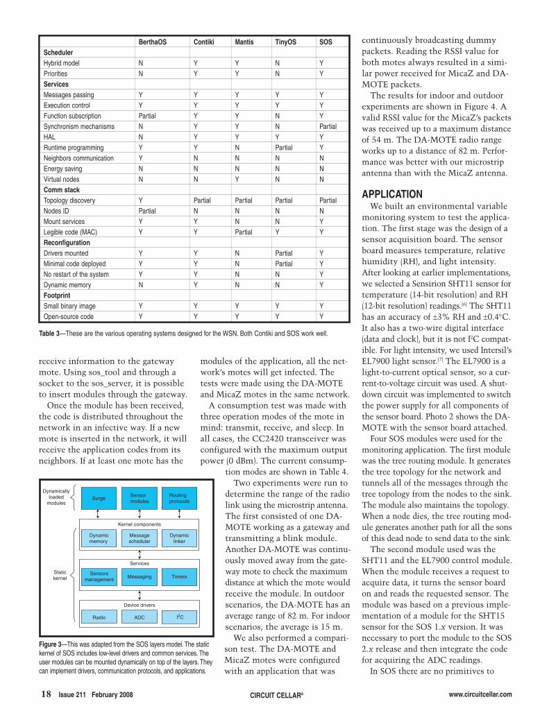
BerthaOS Contiki Mantis TinyOS SOSSchedulerHybrid model N Y Y N YPriorities N Y Y N YServicesMessages passing Y Y Y Y YExecution control Y Y Y Y YFunction subscription Partial Y Y N YSynchronism mechanisms N Y Y N PartialHAL N Y Y Y YRuntime programming Y Y N Partial YNeighbors communication Y N N N NEnergy saving N N N N NVirtual nodes N N Y N NComm stackTopology discovery Y Partial Partial Partial PartialNodes ID Partial N N N NMount services Y Y N N YLegible code (MAC) Y Y Partial Y YReconfigurationDrivers mounted Y Y N Partial YMinimal code deployed Y Y N Partial YNo restart of the system Y Y N N YDynamic memory N Y N N YFootprintSmall binary image Y Y Y Y YOpen-source code Y Y Y Y Y
Table 3—These are the various operating systems designed for the WSN. Both Contiki and SOS work well.
2802016mendez.qxp 1/8/2008 9:40 AM Page 18

Microcontrollers •• Digital Signal Controllers •• Analog •• Serial EEPROMs
Embedded EthernetEmbedded EthernetAny Application, Any LocationAny Application, Any Location
The
Mic
roch
ip n
ame
and
logo
, the
Mic
roch
ip lo
go, d
sPIC
and
PIC
are
reg
iste
red
trad
emar
ks o
f M
icro
chip
Tec
hnol
ogy
Inco
rpor
ated
in t
he U
SA
and
in o
ther
cou
ntrie
s. P
ICD
EM.n
et is
a t
rade
mar
k of
Mic
roch
ip T
echn
olog
y In
corp
orat
ed in
the
U.S
.A.
and
othe
r co
untr
ies.
All
othe
rtr
adem
arks
men
tione
d he
rein
are
pro
pert
y of
the
ir re
spec
tive
com
pani
es.
© 2
008 M
icro
chip
Tec
hnol
ogy
Inco
rpor
ated
. Al
l rig
hts
rese
rved
.
www.microchip.com/Ethernet
Monitor, control or re-program your application remotely with ease
using the integrated Ethernet PIC18F97J60 family and FREE TCP/IP software.
Purchase and program yourEthernet PIC® microcontrollersand related development tools at....
Device PinsFlash
(KB) Features
PIC18F97J60 100 128 10-BaseT Ethernet12 KB RAM
(8 KB dedicatedEthernet)
5x 16-bit timers10-bit ADC, 16 channels2 analog comparators
2 UART with LIN protocol2 SPI, 2 I²C™
Industrial Temperature-40° to +85°C
PIC18F87J60 80 128
PIC18F67J60 64 128
PIC18F96J65 100 96
PIC18F86J65 80 96
PIC18F66J65 64 96
PIC18F96J60 100 64
PIC18F86J60 80 64
PIC18F66J60 64 64
ENC28J60 28 8K RAM MAC, PHY, SPI Interface
Visit www.microchip.com/ethernet for additional devices supporting connectivity solutions and related development tools,application notes, reference designs, web seminars and more!
microchipDIRECT
www.microchipdirect.com
GET STARTED IN 3 EASY STEPSat www.mic roch ip .com/ethernet .1. Learn about our Ethernet devices in
20 minutes
Take advantage of our Ethernet web seminars.
2. Download our FREE TCP/IP software
Our TCP/IP stack is available in source codefor flexible and optimized code size.
3. Check out our low-cost
Ethernet tools
Evaluate the PIC18F97J60 family with the PICDEM.net™ 2 Demo Board.
Adding Ethernet to anyapplication with Microchip’sENC28J60 stand-aloneEthernet controller withfull software support forPIC18, PIC24 anddsPIC® DSCs.
PIC®
MCU
Or you may consider...
Ethernet ad for Circuit Cellar.i1 1Ethernet ad for Circuit Cellar.i1 1 12/3/2007 12:56:34 PM12/3/2007 12:56:34 PM
19.qxp 12/31/2007 12:23 PM Page 1

20 Issue 211 February 2008 CIRCUIT CELLAR® www.circuitcellar.com
Diego Méndez Chaves ([email protected]) is an electronics engineer from deUniversidad Nacional de Colombia inBogotá, Columbia, and a graduate stu-dent in Electronics Engineering at theUniversidad de Los Andes. He hasworked for the microelectronics centerin the Electrical and Electronics Depart-ment since 2005. Diego’s research inter-ests include digital systems, operatingsystems (RTOS, embedded Linux, etc.),high-level systems design, wireless sen-sor networks, and co-design techniques.
automatically transport messagesthrough the network to nodes that aremore than one hop away from thesource. An SOS module was imple-mented to enable us to send messagesto any node of the network.
Finally, a hierarchical superior modulejoins all of the modules. The surge mod-ule was used as the basis and had tobe modified to receive the data fromthe sensing module and then tunnel itthrough the tree routing module. Figure 5shows how the four modules interact.
After inserting the four modules andafter some time (waiting for the dis-covery of the topology), the network isready to be queried by the computer.
SOS has the sos_server (a console appli-cation) as the principal way to interactwith the network through the gatewaymote, but this is not a good interface
for the final user. For this purpose, weused PySOS, which is a Python mod-ule that communicates with thesos_server through a socket to providelow-level access to messaging. PySOSwas designed by the ENALAB at Yale.Because PySOS is a Python module, itenables a simple integration within aweb browser. The mod_python mod-ule (an Apache 2 module that embedsthe Python interpreter within theserver) was used. With this module, itwas easy to send messages to the net-work through a user request and thenwait for the mote response.
For a better performance of the webpage, Ajax (asynchronous JavaScriptand XML) was used. Ajax is a develop-ment technique for creating interac-tive web applications. This enablesthe page to exchange small amounts ofdata with the server. When you makea request, mod_python enables you touse PySOS definitions. Therefore,being able to send a message to thenetwork. PySOS waits for the incom-ing data from the network and thenresponds to the web server with thereading.
FINISHED MOTEA WSN mote was successfully
designed and implemented. The DA-MOTE features anATmega128L microcon-troller and the CC2420IEEE 802.15.4-complianttransceiver. By using thesame HAL definitions, theDA-MOTE is completelycompatible with MicaZmotes, so any applicationdesigned for MicaZ willproperly work with it.However, the use of amicrostrip-integratedantenna and the two-layer design make it anaffordable alternative toMicaZ. After some test-ing, we learned that themicrostrip integratedantenna has a better per-formance than theMicaZ’s external antenna.
We chose SOS for itsgreat characteristics. Itallows dynamically
mounting and unmounting modulesand uses a code distribution protocolthat makes the network flexible androbust. Plus, its small footprint wasperfect for our resource-reduced plat-form.
The next step is to massively repro-duce the mote so we can deploy adense network for complex applica-tions. A network with several nodes isnecessary to test algorithms for thecommunications stack. The develop-ment of a gateway for the WSN is anactual product of the Wireless SensorNetworks Research Group at LosAndes University. An ARM9 proces-sor-based platform is being used forthis purpose. I
Photo 2—This is the DA-MOTE with the sensor boardpowered with a pair of AA batteries. In the sensorboard, an Intersil EL7900 light sensor is on the left. ASensirion SHT11 temperature and relative humiditysensor is in the sensor board. In this case, the moteuses the integrated microstrip antenna.
DA-MOTE Current consumptionAVR MCU CC2420 Total
Transmit 6.8 mA 21.4 mA 28.2 mAReceive 7.2 mA 23.6 mA 30.8 mASleep 2.6 mA 2.48 mA 5.08 mAMeasurement at 3 V
Table 4—Here are the DA-MOTE current consumptionmodes. In Transmit mode, the mote was continuously send-ing dummy packets. In Receive mode, the mote receivedonly dummy bytes and never sent messages. In Sleepmode, the modules inside the transceiver were disabled.
Received power levels (indoor)
0 1 2 3 4 5 6 7 80
-10-20-30
-40
-50
-60-70-80
-90
Distance [m] MicaZDA-MOTE
Received power levels (outdoor)0
-20
-40
-60
-80
-100
-120
0 6 12 18 24 30 36 42 48 54 60 66 72
Distance [m]
Power [dBm]
MicaZDA-MOTE
Power [dBm]
Figure 4—This is the received power level of the packets sent by the DA-MOTE and the MicaZ. Indoor tests (top) were made in offices at Los AndesUniversity and outdoor tests (bottom) were made at a football field.
Mauricio Guerrero Hurtado ([email protected]), an electronics engi-neer from de Universidad del Cauca inPopayán, Colombia, has worked for themicroelectronics center in the Electricaland Electronics Department at the Uni-versidad de Los Andes since 1993. He hasa Master’s degree in Electrical Engineer-ing with an emphasis in Microelectronicsfrom Universidad de los Andes. Mauri-cio’s principal areas of interest are digitalelectronics, high-level systems design,and ASIC design.
2802016mendez.qxp 1/8/2008 9:40 AM Page 20

www.circuitcellar.com CIRCUIT CELLAR® Issue 211 February 2008 21
[4] Texas Instruments, Inc.,“MSP430x15x, MSP430x16x,MSP430x161x Mixed Signal Micro-controller,” SLAS368E, 2006,http://focus.ti.com/lit/ds/symlink/msp430f1611.pdf.
[5] A. Andersen, “Design NoteDN007: 2.4 GHz Inverted F Anten-na,” SWRU120, Texas Instruments,Inc., 2007, http://focus.ti.com/lit/an/swru120/swru120.pdf.
[6] Sensirion, Inc., “SHT1x/SHT7xHumidity and Temperature Sensor,”2007, www.sensirion.com/en/pdf/product_information/Data_Sheet_humidity_sensor_SHT1x_SHT7x_E.pdf.
[7] Intersil Corp., “EL7900: AmbientLight Photo Detect IC,” FN7377.6,2007, www.intersil.com/data/fn/fn7377.pdf.
RESOURCESApache Software Foundation,“Mod_python,” www.modpython.org.
Embedded Networks and ApplicationsLab, “XYZ Sensor node,” Yale Univer-sity, www.eng.yale.edu/enalab/XYZ.
Swedish Institute of Computer Sci-ence, “Contiki: A Dynamic OperatingSystem for Memory-Constrained Net-worked Embedded Systems,”www.sics.se/contiki.
University of California, Berkeley,“TinyOS,” 2004, www.tinyos.net.
PROJECT FILESTo download code, go to ftp://ftp.circuitcellar.com/pub/Circuit_Cellar/2008/211.
REFERENCES[1] A. Mainwaring, J. Polastre, R.
Szewczyk, D. Culler, and J. Ander-son, “Wireless Sensor Networksfor Habitat Monitoring,” IRB-TR-02-006, Intel Corp., 2002, www.intel-research.net/Publications/Berkeley/120520021024_43.pdf.
[2] J. Hill, “System Architecture forWireless Sensor Networks,” Doc-tor of Philosophy Thesis, Universi-ty of California, Berkeley, 2003,www.jlhlabs.com/jhill_cs/jhill_thesis.pdf.
[3] Texas Instruments, Inc., “CC2420:2.4 GHz IEEE 802.15.4 / ZigBee-ready RF Transceiver,” SWRS041B,http://focus.ti.com/lit/ds/symlink/cc2420.pdf.
Surge
Sense _mod
tree_routing
passing_msg
Server
Reading to sink
Acquire sensor
Requestdestination node
Reading source node
Tunnel data tree routing
Figure 5—Messages flow between the implementedmodules for the application. The message comingfrom the computer is received by the passing_msgmodule, which delivers the message to the destinationmote. Inside the destination mote, the sensor is readand the data is sent to the sink mote through thetree_routing module.
Néstor Peña Traslaviña ([email protected]) holds a PhD and a DEA inTelecommunications from the Univer-sité de Rennes in France, a Bachelor’sdegree in Mathematics, an MSc inElectrical Engineering, and an Electri-cal Engineering degree from the Uni-versidad de los Andes. He is an associ-ate professor in the Electrical andElectronics Department at the Univer-sidad de los Andes. Néstor is also thedirector of the group of electronics andtelecommunications systems (GEST)at the Universidad de los Andes. Hisresearch interests include traffic engi-neering and the design of WSNs.
SOURCESATmega128 Microcontroller andAT45DB041B SPI flash memoryAtmel Corp.www.atmel.com
UISP AVR In-system programmer Free Software Foundation, Inc.www.nongnu.org/uisp
EL7900 Light sensorIntersil Corp.www.intersil.com
SHT11 SensorSensirion, Inc. www.sensirion.com
CC2420 TransceiverTexas Instruments, Inc. www.ti.com
2802016mendez.qxp 1/8/2008 9:40 AM Page 21

22 Issue 211 February 2008 CIRCUIT CELLAR® www.circuitcellar.com IEIE
and approvals were concluded. That’s why this series pres-ents subjects primarily in the order in which you have toconfigure and install a PV system. First, you think abouthow much power you need and where to put the panels.Then you do the site preparation and install everything.Aside from a bit of paranoia and calculations about windloading on the two pole-mounted arrays that resulted in aRock of Gibraltar support base, there haven’t been a lot ofengineering issues. It isn’t until you have panels installedand you start wiring and configuring the inverters that youhave to think about the engineering aspects of the system
For the past2.5 months, I’vebeen installing a10.76-kW net-metered photo-
voltaic (PV) electric power system at my house in Connecti-cut. Way back in the beginning of this series, I predicted thatbuilding this system would be an adventure. Because of thelead time associated with presenting all of this in print, Idecided to describe it as a work in progress rather than waituntil the entire system was finished and all of the inspections
INTELLIGENT ENERGY SOLUTIONS
by Steve Ciarcia
Installing a majorrenewable energysource like Steve’shome photovoltaicsystem is no smallfeat. It requires intelli-gent planning, techni-
cal know-how, and the ability to think out-side the box. This month, he describesthe last leg of this long technical adven-ture: wiring and electronics.
Photo 1—This is my finished PV installation.
Solar-Powering the Circuit CellarPart 3: Wiring & Electronics
2802014-ciarcia.qxp 1/10/2008 1:31 PM Page 22

www.circuitcellar.com CIRCUIT CELLAR® Issue 211 February 2008 23IEIE
again. Before I jump into that, however, let me continuewhere I left off last month.
At the end of last month, I had 20 solar panels on thesolarium roof, two 11′8″ diameter schedule 80 poles stick-ing out of the ground, and a backyard completely destroyedby cement trucks and heavy equipment. Just so I don’tkeep you in suspense any longer, Photo 1 shows what thecompleted arrays looked like when mounted on the polesand their location compared to the roof array. Because thepicture was taken from about 100′ away and the pole-mounted arrays are angled at 35°, dimensions can appeardeceptive. The total area of the three solar arrays is almost700 square feet, and those “little” pole mounts in the back-ground are 20′ high and over 200 square feet each.
While fixed-angle roof-mounted solar arrays are the least
expensive to install, you are typically stuck with whateverdirection and angle the roof happens to be. In Connecticutat least, if it is due south and pitched at about 35° then youpretty much have an optimum fixed-angle system. Ofcourse, the best solar generation comes from two-axistracking systems that have pole-mounted motorized arraysthat keep the sun perpendicular to the panels all day. Whilesuch systems do exist, I concluded that I didn’t haveenough available ground area for the poles and that theywould have been prohibitively expensive for an 11-kW sys-tem. The next best solution was a pole-mounted single-axisadjustable system like mine. Using the arrangement I’vedescribed, I can adjust my 6.5-kW pole-mounted arrayswithin a range of 15° to 65°. All it takes is a quick visit tothe PVWATTS energy calculator to determine the optimum
Photo 2a—Bob and Floyd help the Sunlight Solar Energy crew hoist and bolt the 300-lb strongback to the top of the 11′8″ schedule 80 mounting pole. b—Tom Smith andJason Ross bolt the module rails and rail brackets to the strongback. c—Tom and Jason start attaching the SunPower SPR-205 solar panels. d—Tom, Jason, and Ian Applegateadd #6 braided copper cable to each panel to properly ground the entire array.
a) b)
c) d)
2802014-ciarcia.qxp 1/8/2008 9:36 AM Page 23

24 Issue 211 February 2008 CIRCUIT CELLAR® www.circuitcellar.com IEIE
tolerance as one that is significantlymore expensive, and, “electricallyspeaking,” bulletproof. I’d like tothink my system is the latter.
In order to illustrate what I mean,I have to go back and talk about theeffects of shading and temperatureon solar panels, how much powerwe lose in all that wire, the conver-sion efficiencies and input toler-ances of the inverter, and maximumpower point tracking (MPPT).
Figure 1 is the 25°C I-V curve ofthe SPR-210 solar panel used in mysystem. (The SPR-205 is essentiallythe same but 5 W less.) There arefour factors that determine solarpanel output: photovoltaic cell effi-ciency, load resistance, intensity ofthe sun, and cell temperature.
The first two are very straightfor-ward. Solar cell efficiency is deter-mined by the manufacturing
process, and for the SPR-210, it is quoted as 16.9%. Theload resistance sets the operating point on the current andvoltage (I-V) curve and is controlled by the inverter MPPTalgorithm (discussed later).
Solar intensity is a bit more nebulous. The current gener-ated by the solar panel is directly proportional to the inten-sity of the sun and is pretty much independent of tempera-ture. After a five-minute Internet search, you’ll have morecharts, maps, and diagrams of local area sun intensity thanyou’ll know what to do with. The one unquantifiableanomaly affecting irradiance is edge-of-cloud effect andreflection (typically snow). When the sun enters or exits acloud, there is at times an increase in solar intensitycaused by reflection from nearby clouds that causes a sud-den increase in current output. In the short time my sys-tem has been running, I have personally seen 2,000-W
monthly solar angle for any location (http://rredc.nrel.gov/solar/codes_algs/PVWATTS/).
Assembling the pole mounts was not an insignificanttask. This is one of those places where having a profession-al installer like Sunlight Solar Energy comes in handy. Thefirst task in completing the pole mount was to hoist thestrongback to the top of the 11′ schedule 80 pipe and attachit to the mounting sleeve pivot bolt. Estimated as about300 lb, it took the whole Sunlight Solar Energy team plusBob Kuca and Floyd Palmer to get it up there (see Photo 2a).
Once the strongback is attached, module rails and railbrackets are bolted to the strongback (see Photo 2b) andthen solar panels are attached (see Photo 2c). A bunch ofpanels later, the structure starts looking recognizable (seePhoto 2d). The finished arrays were angled at 35° for theparticular time in Connecticut (see Photo 3). Take a look atthe different colors in these photos and perhapsyou’ll understand why I chose SunPower SPR-205s for the pole mounts that I can see from thehouse and the deck. They are much more pleas-ing to the eye than the SunPower SPR-210s onthe roof.
BACK TO THE SOLAR PANELSI’ve been beating around the bush for two arti-
cles, but now we have the ingredients in place toconnect the arrays to the inverters and generatesome power. While some thought had to begiven to sizing all the system components beforestarting the project, this is where the interrela-tionship among solar radiance, solar panel I-V,wiring losses, and inverter dynamics all comeinto play to greatly affect system costs and per-formance. The same wattage solar system can becheaply configured on the hairy edge of acceptable
5.5
6.0
5.0
4.5
4.0
3.5
3.0
2.5
2.0
1.5
1.0
0.5
0.0
0 5 10 20 30 40 45 5015 25 35
Amps
Volts
Open circuit voltage
Maximum power voltage
Maximum power current
Short circuit currentMaximum power point
Figure 1—This is an I-V curve for the SunPower SPR-210 solar panel showing the maximum powerpoint.
Photo 3—The finished pole-mounted arrays are set at 35° for a final test.
2802014-ciarcia.qxp 1/8/2008 9:36 AM Page 24
www.circuitcellar.com CIRCUIT CELLAR® Issue 211 February 2008 25IEIE
power spikes as clouds pass (i.e., a jump from 7,500 to9,500 W).
The final solar cell issue is temperature. As the sun’sbrightness increases, the output voltage and power decreaseas the temperature of the cell increases. The STC powerspec is based on a PV cell temperature of 25°C and the Sun-Power A-300 cells used in the SPR-210 will decrease 0.38%per degree centigrade. Especially in the summer, cell temper-atures can typically run anywhere from 30° to 35°C aboveambient when the module is exposed to “full” sunlight. So,if the cell temp is 35°C above a 30°C (86°F) ambient, cell
temperature will be 65°C (149°F). That’s40°C above the 25°C spec, and the effectcould be 40°C × –0.38%/°C = –15.2%loss in power.
Of course, the opposite should be trueas well, especially in New England. It’squite possible that we can have dayswhen the panels are operating at –18°C(about 0°F) and we should see 43°C ×0.38%/°C = 16.3% power increase. Ingeneral, there isn’t a lot to be concernedabout low temperature increases as longas it doesn’t exceed the inverter’s volt-age input range (it doesn’t). Basically,take the benefits and run.
For typical operation, solar arraysshould be mounted in the sunniest place
and kept as cool as possible. (This is specifically why myroof panels are mounted on high standoffs to allow air cir-culation under them.) No part of a PV array can be shaded.Large solar panels consist of many PV cells in series, andtherefore, all of the cells in the same string are conductingthe same current. If any of the PV cells are shaded, theycannot produce current and will become reverse biased.This means the shaded cells will dissipate power as heat,and over a period of time, failure can occur. Because it isimpossible to prevent occasional shading, solar panelsincorporate bypass diodes to conduct current around shaded
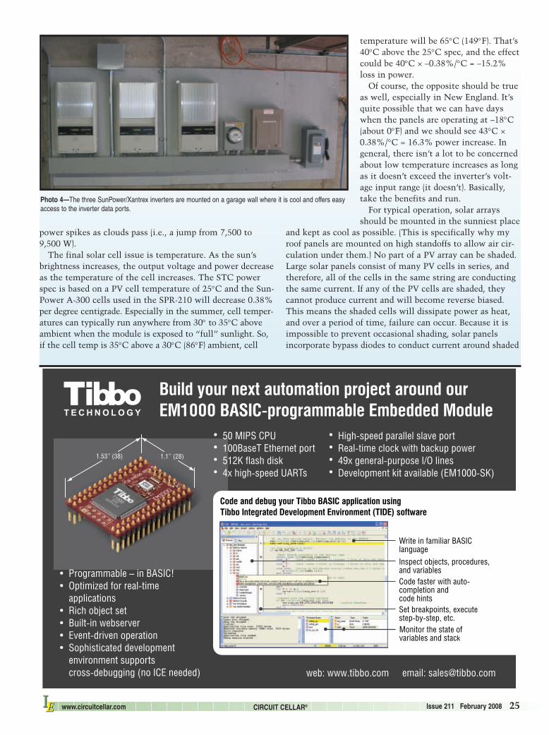
Photo 4—The three SunPower/Xantrex inverters are mounted on a garage wall where it is cool and offers easyaccess to the inverter data ports.
2802014-ciarcia.qxp 1/8/2008 9:36 AM Page 25
26 Issue 211 February 2008 CIRCUIT CELLAR® www.circuitcellar.com IEIE
strings. (I read someplace that while the A-300 cells don’tnecessarily need diodes for cell protection, diodes wereincluded in the panels to provide comfort to customersused to diodes being present in virtually every other brandof panels.) ;-)
WIRING AND INVERTERSWith all that information about the panels, what values
are important when we select wire and inverters? Basically,think big.
Seriously, solar system configuration is an exercise inaccommodating worst-case conditions. While we mightdiscuss array output power at nominal conditions, thewiring from the arrays and the inverter input range mustbe sized for the highest short-circuit currents and open-circuit voltages.
The roof array is configured as two series strings of 10panels connected in parallel. The nominal current and volt-age of this configuration is 400 VDC at 10.5 A. The open-circuit voltage and short-circuit current rating of the panelsincreases these values to 477 V and 11.5 A. Similarly, thepole-mounted SPR-205 arrays are configured with twoseries strings of eight panels connected in parallel andwould be 320 VDC at 10.26 A, 383 VDC, and 11.06 A,respectively. That basically says that the inverter inputsand the wiring insulation have to handle 500 VDC. Howev-er, the national electric code requires a 125% safety marginapplied to the worst-case voltage and current values whenconfiguring the wiring and circuit breakers. For the pole-mounted arrays, the requirement is 478 VDC and 13.83 A.For the roof array, it is 596 VDC and 14.4 A.
Because Sunlight Solar Energy fully understood that“bulletproof” was the primary decision factor on thisinstallation, they decided that the neatest and cleanest wayto deal with three separate arrays of this size was to usethree separate conduits connected to three separate invert-ers. The wire connecting the arrays to the inverters wasabout 100′. Like I said in the first article, using the highervoltage in a grid-tied system eliminates many of the IRlosses associated with low-voltage battery backed off-gridsystems. In my case, we used #6 copper wire (rated for 37 A)from each array to the inverters and #4 copper wire (ratedfor 60 A) from the combined inverter AC outputs to the
service entry panel. The wiring losses for the totalsystem were less than 1%.
The inverters were chosen with the same accom-modation to safety margins. One SPR-3300x wasused for each pole-mounted array and one SPR-5000x was connected to the roof array. The invert-ers are manufactured by Xantrex Technology andare functionally equivalent to their GT3.3 andGT5.0 inverters. Photo 4 shows how Sunlight SolarEnergy mounted them to an inside garage wall(with room for accessories). ;-)
When selecting inverters, it’s important to keepin mind that when we are talking about solar pan-els, we are discussing DC watts of input power toan inverter, and when we are talking about the
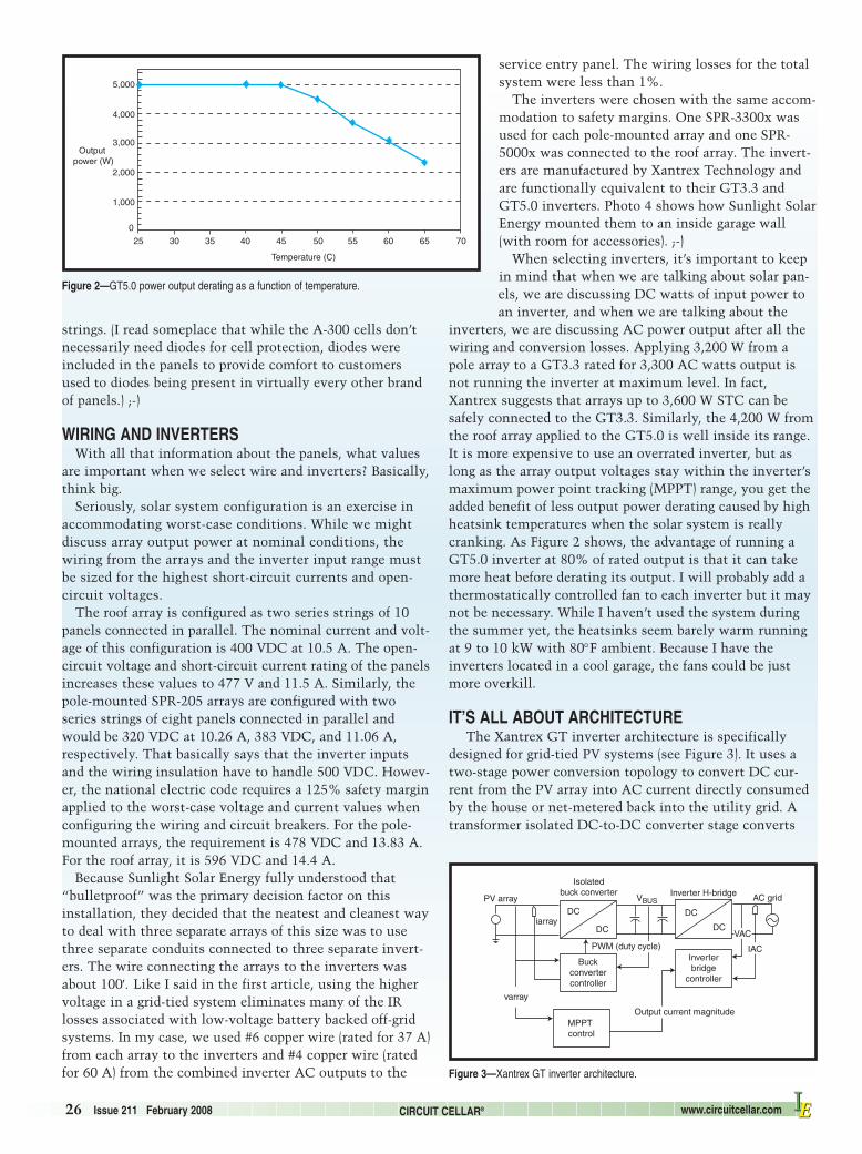
inverters, we are discussing AC power output after all thewiring and conversion losses. Applying 3,200 W from apole array to a GT3.3 rated for 3,300 AC watts output isnot running the inverter at maximum level. In fact,Xantrex suggests that arrays up to 3,600 W STC can besafely connected to the GT3.3. Similarly, the 4,200 W fromthe roof array applied to the GT5.0 is well inside its range.It is more expensive to use an overrated inverter, but aslong as the array output voltages stay within the inverter’smaximum power point tracking (MPPT) range, you get theadded benefit of less output power derating caused by highheatsink temperatures when the solar system is reallycranking. As Figure 2 shows, the advantage of running aGT5.0 inverter at 80% of rated output is that it can takemore heat before derating its output. I will probably add athermostatically controlled fan to each inverter but it maynot be necessary. While I haven’t used the system duringthe summer yet, the heatsinks seem barely warm runningat 9 to 10 kW with 80°F ambient. Because I have theinverters located in a cool garage, the fans could be justmore overkill.
IT’S ALL ABOUT ARCHITECTURE The Xantrex GT inverter architecture is specifically
designed for grid-tied PV systems (see Figure 3). It uses atwo-stage power conversion topology to convert DC cur-rent from the PV array into AC current directly consumedby the house or net-metered back into the utility grid. Atransformer isolated DC-to-DC converter stage converts
PV array
Isolatedbuck converter
iarray
MPPT control
DC
DC
AC grid
Output current magnitude
varray
VBUS
DC
DC
Inverter H-bridge
Inverterbridge
controller
PWM (duty cycle)
Buckconvertercontroller
VAC
IAC
Figure 3—Xantrex GT inverter architecture.
5,000
4,000
3,000
2,000
1,000
0
25 30 35 40 45 50 55 60 65 70
Temperature (C)
Output power (W)
Figure 2—GT5.0 power output derating as a function of temperature.
2802014-ciarcia.qxp 1/8/2008 9:36 AM Page 26

CC_RCM4300_Jan_FP_08019.indd 1 11/29/07 4:04:43 PM
73.qxp 12/4/2007 11:49 AM Page 1
28 Issue 211 February 2008 CIRCUIT CELLAR® www.circuitcellar.com IEIE
the PV array voltage (anywhere within 235 to 550 VDC forthe GT5.0 or 200 to 550 VDC for the GT3.3) and convertsit to a fixed internal bus voltage of around 400 VDC. TheDC-to-DC converter runs at 15 kHz and uses a high-fre-quency switched-mode power conversion technique similarto electronic power supplies. It also exploits the use of arelatively small, high-frequency isolation transformer andefficient PWM voltage regulation.
The internal DC bus has a substantial amount of energystored in electrolytic capacitors. This is needed to decouplethe power flow between the two power converter stages.The output stage delivers power in a “lumpy” fashionbecause the power in a single-phase AC circuit varies assin2 (ωt) (i.e., from zero to maximum at 120 Hz in a 60-Hzcircuit). However, the power drawn from the PV arraymust be continuous to maximize the energy harvestedfrom the array (i.e., no 120-Hz ripple). The DC bus capaci-tors provide the necessary filtering (or energy storage) toensure that the input DC-to-DC converter can operatewith minimal ripple.
The output DC-to-AC inverter stage is an H-bridgeconfiguration using IGBTs, similar to the bridge circuitsused in DC servo motor controllers. It operates as a pulse-width-modulated switched-mode power converter with a20-kHz switching frequency. The pulse-width modulator iscontrolled by an inner feedback loop that operates the con-verter as a controlled AC current source. The inverter con-troller establishes a sinusoidal current reference that is inphase with the utility voltage and the feedback loop con-trols the inverter output current to be a low-distortion (lessthan 5% THD) sinusoid in phase with the utility voltage.An output LC filter (low pass) removes the harmonics pres-ent in the 20-kHz switching. As you might expect, the netresult is an output current that complies with utility stan-dards (derived from IEEE standard 1547) for power quality(harmonic distortion and DC offset) and FCC Class B EMIlimits for conducted emissions.
MAXIMUM POWER POINT TRACKINGThe magnitude of the inverter output current is set by
the MPPT control. If the PV array output power is greaterthan the inverter rating (which may be reduced at elevat-ed ambient temperature), the MPPT control sets the out-put current to match the inverter power rating. If the PVarray output power is less than the inverter power rating,the MPPT sets the inverter output current to maximizethe PV array power (i.e., it tracks the array’s maximum
power point).Because the PV array voltage and current are interrelated
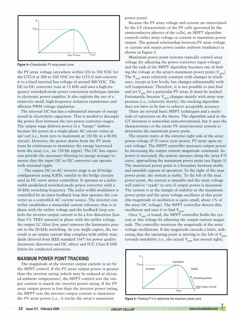
by the I-V characteristic of the PV cells (governed by thesemiconductor physics of the cells), an MPPT algorithmcontrols either array voltage or current to maximize poweroutput. The general relationship between PV array voltageor current and output power (under uniform irradiance) isshown in Figure 4.
Maximum power point systems typically control arrayvoltage (by adjusting the power converter input voltage)and the task of the MPPT algorithm becomes one of find-ing the voltage at the array’s maximum power point (VMPP).The VMPP stays relatively constant with changes in irradi-ance, except at low levels, but changes substantially withcell temperature. Therefore, it is not possible to just findand set VMPP for a particular PV array. It must be tracked.Fortunately, because VMPP changes mainly with array tem-perature (i.e., relatively slowly), the tracking algorithmdoes not have to be fast to achieve acceptable accuracy.
There are several basic MPPT techniques and a multi-tude of variations on the theme. The algorithm used in theGT inverters is somewhat nonconventional, but it uses thecharacteristics of the entire PV array/inverter system todetermine the maximum power point.
The system starts at the extreme right side of the arraypower-voltage (P-V) curve (zero power, PV array open-cir-cuit voltage). The MPPT controller increases output powerby increasing the output current magnitude command. Aspower is increased, the system operates along the array P-Vcurve, approaching the maximum power point (see Figure 5).The maximum power point is a boundary between stableand unstable regions of operation. To the right of the maxpower point, the system is stable. To the left of the maxpower point, the system is unstable and the array voltagewill tend to “crash” to zero if output power is increased.The system is at the margin of stability at the maximumpower point and the array voltage oscillates at this point(the magnitude of oscillation is quite small, about 1% ofthe array DC voltage). The MPPT controller detects thisoscillation and uses it to find VMPP.
Once VMPP is found, the MPPT controller holds the sys-tem at this voltage by adjusting the output current magni-tude. The controller monitors the magnitude of the arrayvoltage oscillations. If the magnitude exceeds a limit, indi-cating that the operating point is moving to the left of VMPP
towards instability (i.e., the actual VMPP has moved right),
PMPP
P
Unstable
Oscillation
Stable
Increasing power
Start (open circuit)
VMPP V
Figure 5—Tracking P-V to determine the maximum power point.
PMPP
P
VMPP or IMPP V or I
Figure 4—Characteristic PV array power curve.
2802014-ciarcia.qxp 1/10/2008 1:36 PM Page 28

www.circuitcellar.com CIRCUIT CELLAR® Issue 211 February 2008 29IEIE
the array voltage is increased to bring the system back toVMPP. Every 0.7 s, the MPPT controller adjusts the VMPP set-point to see if the actual maximum power point has movedto the left. If power can be increased without the magni-tude of oscillations exceeding the limit, the setpoint ischanged to the improved value.
The Xantrex GT series MPPT controller is implementedin a Freescale Semiconductor HC12 microcontroller. Themicrocontroller is also responsible for the user interfaceand data network functions. A separate Microchip Technol-ogy PIC18F series microcontroller is used for the grid inter-connect protection functions specified by the IEEE Stan-dard for Interconnecting Distributed Resources with theElectric Power Systems. These require the inverter to rap-idly shut off the output connected to the grid if the gridvoltage or frequency goes outside specified limits. Thepulse width modulators and inner-control loops are imple-mented with discrete analog and digital circuits.
Finally, like most of the electronics I buy, I always liketo look under the hood. Before taking apart the inverters onmy wall, however, I spent some time e-mailing the kindfolks at Xantrex and they were happy to answer my ques-tions and provide me with a picture of the inside of theGT5 so I didn’t have to disassemble mine (see Photo 5). ;-)
SO, DOES IT WORK?As I write this, the PV system has been operational for
three weeks. I haven’t seen any 10,760-W output, but that’s
primarily because the roof array pitch is maximized for themiddle of the summer and not mid-fall. Ignoring edge-of-cloud effects, I did see 10,000 W being produced one after-noon, but it has typically been about 8,000 to 9,000 W and
Photo 5—This is an inside look at the GT5 inverter. The toroid isolation transformer isat the upper right and the DC bus electrolytic capacitors are to the left of the trans-former. There are a lot of inductors and capacitors—used both as parts of the powerconversion circuits and as filters to remove ripple and EMI. The power semiconduc-tors are not visible because they are attached to the heatsink on the other side of themain PCB.
2802014-ciarcia.qxp 1/10/2008 1:36 PM Page 29

30 Issue 211 February 2008 CIRCUIT CELLAR® www.circuitcellar.com IEIE
I have been racking up a bunch of kWh credits on themeter. (I was intrigued to see the system even generating1,500 W during a moderate rainstorm last week. I guess alot more light filters through the clouds than I realized.)Because I haven’t been using a lot of air conditioning thislate in the fall, I expect that my net-metered electric billfor October could be $0, with perhaps even some additionalsolar credit toward next month. Of course, next July mightbe a whole different story. ;-)
Unfortunately, because this has beena work in progress, I haven’t had theusual six months to a year to design andimplement elaborate solar monitoringsoftware that seems part of everyoneelse’s solar system article these days.The Xantrex inverters have an RS-232data port that enables connection to acomputer for analysis and a CAN busthat connects to an LCD for local moni-toring. The only display software I’veseen thus far is user-supplied and notvery user-friendly. While I was able toconfigure two GridConnect NETDIOserial-to-Ethernet converters into a“tunneling RS-232” arrangement that atleast allowed this software to run on acomputer located farther away than a50′ RS-232 cable, I discarded it for amore innovative kludge. I simplymounted a web cam in front of theXantrex LCD monitor and called thepower display up as a web page. I had to
resort to these methods because I want-ed immediate display solutions, butfortunately, Xantrex has a betteranswer for the long run. In the firstquarter of 2008, Xantrex will have aTCP/IP Ethernet/wireless “Gateway”that connects to the CAN bus and dis-plays both real-time and archive record-ings directly. The next time I presentan article about my system, I should beshowing this new device installed.
Still, seeing what the solar system isproducing in real time is only half thestory. How do I know whether I amproducing more power than I am usingor just how bad is it when I turn on the5-ton air conditioner in the solarium?Obviously, I can wait and rely on thepower company to tell me there’s akilowatt-hour surplus or deficit on mymonthly electric bill (nah!), or I canclose the loop myself. The only way toknow whether I have a surplus is tomonitor the power consumed by theentire house in real time and compareit to the amount being generated at the
same time by the solar system.The classical method for monitoring AC power is to put
current transformers around the AC wires in question, con-nect the core secondary to a true RMS converter, and thenwrite a bunch of software to display and plot the results.Great idea, but I was a bit limited on time for building all myown circuitry. Instead I found an almost perfect off-the-shelfsolution from PICO Technology. Using an EL040 current
Photo 6—This screenshot illustrates a recent daily recording of two data points. The power difference in magni-tude between the blue and red traces represents the power being redirected to the grid (red higher than blue) orconsumed from the grid (red less than blue).
Photo 7—LED bulbs are typically designed as either series/parallel strings of discrete LEDs with simple powerregulators or a small number of very high-power LEDs with sophisticated AC-powered switchmode converters.
2802014-ciarcia.qxp 1/10/2008 1:38 PM Page 30
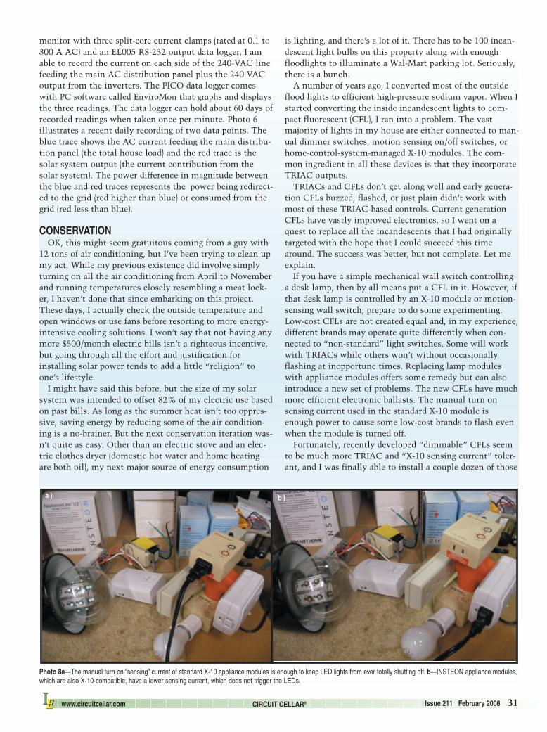
www.circuitcellar.com CIRCUIT CELLAR® Issue 211 February 2008 31IEIE
monitor with three split-core current clamps (rated at 0.1 to300 A AC) and an EL005 RS-232 output data logger, I amable to record the current on each side of the 240-VAC linefeeding the main AC distribution panel plus the 240 VACoutput from the inverters. The PICO data logger comeswith PC software called EnviroMon that graphs and displaysthe three readings. The data logger can hold about 60 days ofrecorded readings when taken once per minute. Photo 6illustrates a recent daily recording of two data points. Theblue trace shows the AC current feeding the main distribu-tion panel (the total house load) and the red trace is thesolar system output (the current contribution from thesolar system). The power difference in magnitude betweenthe blue and red traces represents the power being redirect-ed to the grid (red higher than blue) or consumed from thegrid (red less than blue).
CONSERVATION OK, this might seem gratuitous coming from a guy with
12 tons of air conditioning, but I’ve been trying to clean upmy act. While my previous existence did involve simplyturning on all the air conditioning from April to Novemberand running temperatures closely resembling a meat lock-er, I haven’t done that since embarking on this project.These days, I actually check the outside temperature andopen windows or use fans before resorting to more energy-intensive cooling solutions. I won’t say that not having anymore $500/month electric bills isn’t a righteous incentive,but going through all the effort and justification forinstalling solar power tends to add a little “religion” toone’s lifestyle.
I might have said this before, but the size of my solarsystem was intended to offset 82% of my electric use basedon past bills. As long as the summer heat isn’t too oppres-sive, saving energy by reducing some of the air condition-ing is a no-brainer. But the next conservation iteration was-n’t quite as easy. Other than an electric stove and an elec-tric clothes dryer (domestic hot water and home heatingare both oil), my next major source of energy consumption
is lighting, and there’s a lot of it. There has to be 100 incan-descent light bulbs on this property along with enoughfloodlights to illuminate a Wal-Mart parking lot. Seriously,there is a bunch.
A number of years ago, I converted most of the outsideflood lights to efficient high-pressure sodium vapor. When Istarted converting the inside incandescent lights to com-pact fluorescent (CFL), I ran into a problem. The vastmajority of lights in my house are either connected to man-ual dimmer switches, motion sensing on/off switches, orhome-control-system-managed X-10 modules. The com-mon ingredient in all these devices is that they incorporateTRIAC outputs.
TRIACs and CFLs don’t get along well and early genera-tion CFLs buzzed, flashed, or just plain didn’t work withmost of these TRIAC-based controls. Current generationCFLs have vastly improved electronics, so I went on aquest to replace all the incandescents that I had originallytargeted with the hope that I could succeed this timearound. The success was better, but not complete. Let meexplain.
If you have a simple mechanical wall switch controllinga desk lamp, then by all means put a CFL in it. However, ifthat desk lamp is controlled by an X-10 module or motion-sensing wall switch, prepare to do some experimenting.Low-cost CFLs are not created equal and, in my experience,different brands may operate quite differently when con-nected to “non-standard” light switches. Some will workwith TRIACs while others won’t without occasionallyflashing at inopportune times. Replacing lamp moduleswith appliance modules offers some remedy but can alsointroduce a new set of problems. The new CFLs have muchmore efficient electronic ballasts. The manual turn onsensing current used in the standard X-10 module isenough power to cause some low-cost brands to flash evenwhen the module is turned off.
Fortunately, recently developed “dimmable” CFLs seemto be much more TRIAC and “X-10 sensing current” toler-ant, and I was finally able to install a couple dozen of those
Photo 8a—The manual turn on “sensing” current of standard X-10 appliance modules is enough to keep LED lights from ever totally shutting off. b—INSTEON appliance modules,which are also X-10-compatible, have a lower sensing current, which does not trigger the LEDs.
a ) b )
2802014-ciarcia.qxp 1/8/2008 9:37 AM Page 31

32 Issue 211 February 2008 CIRCUIT CELLAR® www.circuitcellar.com IEIE
even false-triggering the switching regulators and makingthem flash. In my case, the only solution was to still useX-10 communication but eliminate traditional X-10 mod-ules—basically, find a better mousetrap.
The answer for me turned out to be INSTEON controlmodules from Smarthome. Photos 8a and 8b demonstratethe results. When the LED bulb is plugged into the stan-dard X-10 appliance module (forget using lamp moduleswith these bulbs), the manual turn on current is enough tokeep the bulb partially lit. When it is plugged into theINSTEON appliance module, the sensing current is lowenough that the bulb is off. (Of course, every solution has aprice, and if we go back and look at the decision trail, itgives a whole new meaning to the “insanity factor” of thepeople with PV systems. Realize, that we have just gonefrom replacing a $0.60 incandescent bulb first with a $2cheap CFL and then to a $14 expensive CFL, only to finallyend up with a $97 LED light that needs a $35 control mod-ule—but heh, it works.) ;-)
INSTEON modules use a combination of power line andwireless control transmission to facilitate a more reliablemodular control system than plain X-10. And, while myhome control system is not currently INSTEON compati-ble, INSTEON modules can emulate X-10 communicationand function as X-10 replacements. The good news is thatthey are a better mousetrap and don’t need anywhere nearas much sensing current for the manual turn on capability(which apparently can be disabled when not emulating X-10only). Another thing I noticed was that INSTEON modulesappear to be more sensitive than the standard X-10 mod-ules. Some of the occasional flaky responses I had beenexperiencing with standard X-10 went away after I replacedabout 30 modules with INSTEON devices. I can’t waituntil my HCS can use INSTEON’s full benefits.
SOAKING UP SOME PHOTONSBuilding this PV system has been a big undertaking in a cou-
ple of ways. Besides the physical installation of all the hard-ware, it’s the first time I’ve written a series of articles in anumber of years. I’d like to say it was easy getting back intothe saddle, but it took a while after such a long vacation. Ofcourse, now that I’m enjoying my new project, it’s hard to stopre-engineering everything around it. My first priority is to adda lot more instrumentation and remote data monitoring. I willbe back in a few months to describe some of that. Until then,as soon as it gets a bit warmer around here, you can expect tofind me sitting out on the deck with a cool drink watching mysolar panels soak up photons and thinking about my nextrenewable energy project. I
Author’s Note: Special thanks to Konrad Mauch of XantrexTechnology for his help explaining GT5.0 technology.
Steve Ciarcia is an electronics engineer and computerconsultant with experience in process control, digital design,and product development. He founded Circuit Cellar in 1988and currently serves as the magazine’s editorial director. Youmay contact him at [email protected].
with success. The only downside is that the $0.60 incandes-cent that was being replaced by a $2 CFL is now beingreplaced by a $14 “better” CFL. That’s where “faith”becomes part of the renewable energy exercise in order tooffset the obvious financial disconnect. But, it gets worse. ;-)
The bad news is that CFLs just don’t hack it, period, insome of my lighting applications. As you may alreadyknow, I have had a home control system for many years.One of its functions is to control the lighting on the cellarstaircase, in the hallways, and in some of the rooms basedon occupancy. Step onto the stairway and the lights go on.Two minutes after sensing no motion, the lights go off.One of the bad traits about CFLs is that they can have avery long turn on time to get to full brightness—rangingfrom a couple of seconds to almost a minute. And, cyclingthem on and off a hundred times a day puts them in anearly grave.
The CFLs with the fastest turn on time necessary for aquick traverse through a hallway or a staircase seem toexhibit the shortest cycle life. (I heard a number like 8,000times as being the average duty cycle life for many of thesebulbs despite a 20,000-hour operating life.) Similarly, thedimmable fluorescent bulbs that appear not to have auto-matic control sensitivities seem to take forever to turn on.After experiencing a half dozen CFL failures due to exces-sive cycling, I almost had to resort to using incandescentsagain.
I said almost. It turns out that years of technical evolu-tion have benefited another lighting scheme—LEDs. Whilestill first-generation and not even close to the cost-benefitratio of CFLs, they are low power, low heat, and long life.The greater benefit for me is that they are truly instant-onand have no duty cycle limitations that I know of. The badnews is that making them work in a computer-controlledhouse is almost as aggravating as CFLs.
Current LED lights seem to be designed either as dozensor more of discrete LEDs connected in series/parallel com-binations using a simple RC and diode connection to theAC line, or a limited number of special high-power LEDscontrolled by sophisticated built-in wide-input-rangeswitching regulators straight on the AC line (see Photo 7).In fact, there are so many variations on a theme amongbrands and bulb types that except for a simple contact clo-sure, there is no guarantee that a control module or motionswitch that works on one LED bulb type will work on thenext, even within the same brand. Depending on the cur-rent regulation employed, many also seem to exhibit sensi-tivity to TRIAC-controlled switches and X-10 module man-ual trigger sensing currents.
X-10 modules facilitate manual turn on by sensing that asmall leakage current around the TRIAC in a lamp moduleor the relay in an appliance module is interrupted. Because X-10 technology and the basic module design is about 30 yearsold and traditionally applied to incandescent bulbs thatdon’t “glow” with the relatively low sensing current, itwasn’t a big issue how “low” this current is by today’sstandards. The supposedly “low” sensing current is actual-ly enough to keep some LED bulbs from fully turning off or
2802014-ciarcia.qxp 1/8/2008 9:37 AM Page 32

www.circuitcellar.com CIRCUIT CELLAR® Issue 211 February 2008 33IEIE
SOURCESLED BulbsBestHomeLEDLighting www.besthomeledlighting.com
EL005 RS-232 Output data logger, EL040 current monitor,and EnviroMon data logging systemPICO Technology www.picotech.com
Series 225-8/80 Top-of-pole mountPOWER-FAB www.power-fab.com
INSTEON PowerLinc controller Smarthome, Inc.www.smarthome.com
SPR-205-BLK and SPR-210 PV ModulesSunPower Corp.www.sunpowercorp.com
PV Module racksUniRac, Inc. www.unirac.com
GT Series grid tie solar invertersXantrex Technology, Inc. www.xantrex.com
RESOURCESConnecticut Clean Energy Fund (CCEF), www.ctinnovations.com/funding/ccef/about.php.
P. Davidson, “Shocking Electricity Prices Follow Deregula-tions,” USA Today, August 10, 2007.
J. Dunlop, Photovoltaic Systems, American Technical Pub-lications, Inc., Homewood, IL, 2007.
National Renewable Energy Laboratory, “IEEE1547 Stan-dard for Interconnecting Distributed Resources With theElectric Power Systems,” 2003.
POWER-FAB, “Series 225-8/80 Top-Of-Pole Mount Installa-tion Instructions,” 2005.
Renewable Resource Data Center, “PVWATTS Energy cal-culator,” National Renewable Energy Laboratory, http://rredc.nrel.gov/solar/codes_algs/PVWATTS.
Sunlight Solar Energy, Inc., www.sunlightsolar.com.
SunPower Corp., “SPR-205-BLK Residential PV Module,”001-12153, 2006.
———, “SPR-210 High Efficiency PV Module,” 001-03296,2006.
———, “SPRx High Efficiency Inverters,” 001 08227, 2006.
2802014-ciarcia.qxp 1/8/2008 9:37 AM Page 33
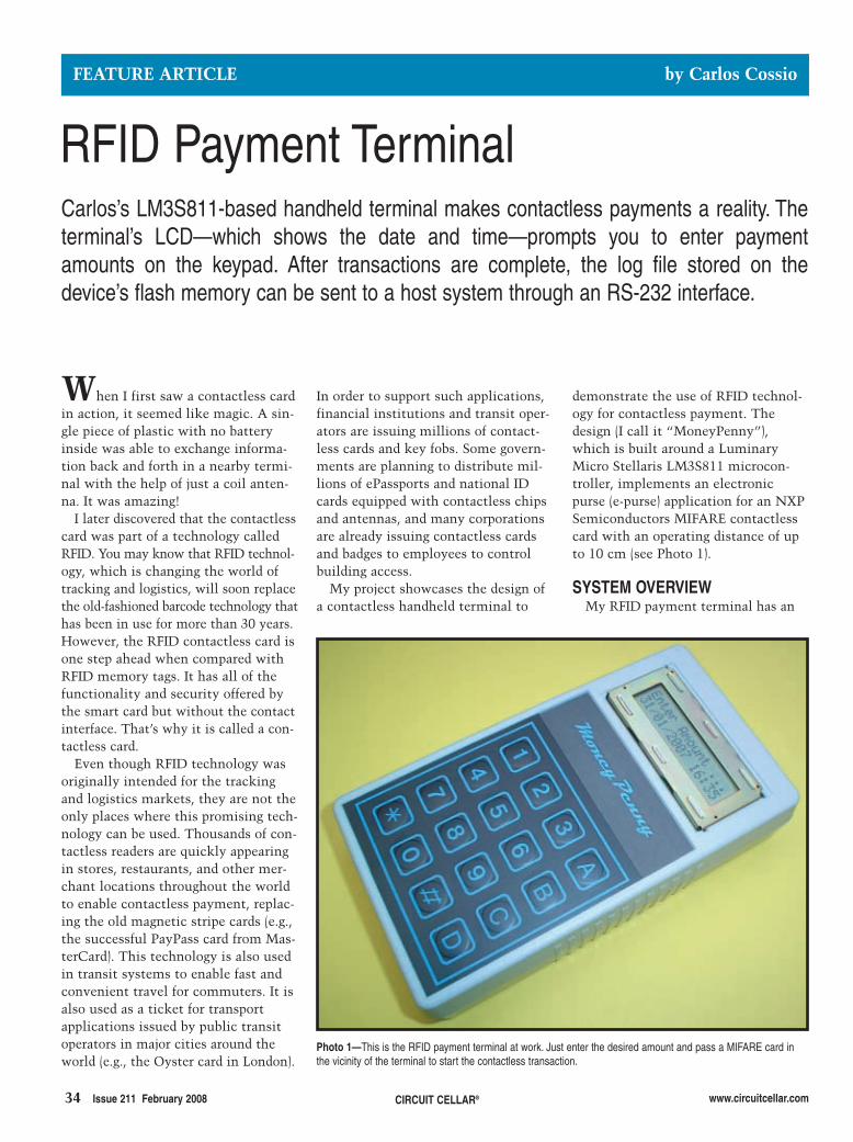
34 Issue 211 February 2008 CIRCUIT CELLAR® www.circuitcellar.com
In order to support such applications,financial institutions and transit oper-ators are issuing millions of contact-less cards and key fobs. Some govern-ments are planning to distribute mil-lions of ePassports and national IDcards equipped with contactless chipsand antennas, and many corporationsare already issuing contactless cardsand badges to employees to controlbuilding access.
My project showcases the design ofa contactless handheld terminal to
When I first saw a contactless cardin action, it seemed like magic. A sin-gle piece of plastic with no batteryinside was able to exchange informa-tion back and forth in a nearby termi-nal with the help of just a coil anten-na. It was amazing!
I later discovered that the contactlesscard was part of a technology calledRFID. You may know that RFID technol-ogy, which is changing the world oftracking and logistics, will soon replacethe old-fashioned barcode technology thathas been in use for more than 30 years.However, the RFID contactless card isone step ahead when compared withRFID memory tags. It has all of thefunctionality and security offered bythe smart card but without the contactinterface. That’s why it is called a con-tactless card.
Even though RFID technology wasoriginally intended for the trackingand logistics markets, they are not theonly places where this promising tech-nology can be used. Thousands of con-tactless readers are quickly appearingin stores, restaurants, and other mer-chant locations throughout the worldto enable contactless payment, replac-ing the old magnetic stripe cards (e.g.,the successful PayPass card from Mas-terCard). This technology is also usedin transit systems to enable fast andconvenient travel for commuters. It isalso used as a ticket for transportapplications issued by public transitoperators in major cities around theworld (e.g., the Oyster card in London).
demonstrate the use of RFID technol-ogy for contactless payment. Thedesign (I call it “MoneyPenny”),which is built around a LuminaryMicro Stellaris LM3S811 microcon-troller, implements an electronicpurse (e-purse) application for an NXPSemiconductors MIFARE contactlesscard with an operating distance of upto 10 cm (see Photo 1).
SYSTEM OVERVIEWMy RFID payment terminal has an
FEATURE ARTICLE by Carlos Cossio
RFID Payment TerminalCarlos’s LM3S811-based handheld terminal makes contactless payments a reality. Theterminal’s LCD—which shows the date and time—prompts you to enter paymentamounts on the keypad. After transactions are complete, the log file stored on thedevice’s flash memory can be sent to a host system through an RS-232 interface.
Photo 1—This is the RFID payment terminal at work. Just enter the desired amount and pass a MIFARE card inthe vicinity of the terminal to start the contactless transaction.
2802018cossio.qxp 1/8/2008 9:35 AM Page 34

LCD to show the current dateand time and prompt you to enteryour desired payment amount. Italso has a numeric keypad forentering data, such as the pay-ment amount, and setting up sev-eral parameters of the terminal.Additionally, thanks to the built-in real-time clock (RTC) and flashmemory, you can keep a log fileof all the transactions performedby the terminal with a time anddate stamp for all approved trans-actions. Upon request, the log file canbe sent to a host system through anRS-232 interface for further storage andanalysis.
I implemented the contactless inter-face with the help of an NXP Semicon-ductors MF RC531 ISO 14443 reader ICfor the modulation and demodulationof the contactless signals at 13.56MHz. Additionally, the contactless ter-minal has an innovative built-in anten-na under the keypad to enable portableoperation right out of the box withoutplugging in an external antenna.
The following is a brief introductionto the principles of contactless tech-nology, which will help you under-stand how the device works.
ENERGY TRANSMISSIONEnergy transmission between the
reader antenna and the passive con-tactless card is based on the trans-former principle. On the reader side,an antenna coil and a card coil imple-mented in the contactless card arerequired. Figure 1 shows the basic
principle and the equivalent electroniccircuitry. The antennas and energytransmission are depicted on the left-hand side of Figure 1.
The current “I” in the reader anten-na coil generates a magnetic flux. Partsof this flux flow through the card coiland induce a voltage in the card coil.The voltage is rectified and the card ICis activated when the operating voltageis reached. The induced voltage varieswithin the distance between the readerantenna and the contactless card. Dueto that voltage variation, the achiev-able operating distance is limited bythe transferred power. The right-handside of Figure 1 shows the equivalentelectrical circuitry, the transformermodel.
100% AMPLITUDE MODULATIONTo transfer data from the reader to
the card, the contactless card uses ahalf-duplex communication structure.The reader talks first and starts thecommunication. The data transmissionfrom the reader to the card is done
using a 100% ASK pulse-pausemodulation according to ISO14443 Type A.
Due to the quality factor Q ofthe antenna, the transmittedsignal deforms. This shape canbe used to measure the tuningof the antenna. Later, I willdescribe the theoretical back-ground of calculating the anten-na quality factor Q and explainhow to calculate the compo-nents of the matching circuitry.
The contactless card is usual-ly passive. To enable communi-cation between the reader andthe card, energy has to be trans-mitted to the card. Therefore,
the contactless card uses opti-mized coding to provide a con-stant level of energy independent-ly from the data transmitted tothe card. This is the modifiedMiller code, which is used totransmit data from the reader tothe card. Figure 2 shows Millercoding in detail.
The data rate of the contactlesscard is 106 kHz, so the length of abit frame is 9.44 μs. A pulse inthe Miller coding has a length of
3 μs. A logical “1” is expressed with apulse in the middle of the bit frame.
Two possibilities are given to code alogical “0.” This coding depends onthe previous bit. On one hand, if theprevious bit was a “0,” the following“0” would be expressed with a 3-μspulse in the first half of the next bitframe. On the other hand, if the previ-ous bit was a “1,” the following “0”would be expressed without a pulse inthe next bit frame.
LOAD MODULATIONData transmission from the card back
to the reader is completed using the prin-ciple of load modulation (see Figure 3).The card is designed as a resonance cir-cuit and consumes energy generated bythe reader. The energy consumptionhas the same reactive effect as a voltagedrop on the reader side. This effect canbe used to transfer data from the cardback to the reader by changing a load ora resistance in the card IC.
The reader antenna should be tuned toa resonance frequency fR of 13.56 MHz.In fact, the resonance circuit generatesvoltages in the reader antenna severaltimes higher than the supply voltage.Due to the small coupling factorbetween the reader and the card antenna,the card response is about 60 dB weakerthan the voltage generated by the reader.The detection of such a signal requires awell-designed receiving circuit. Instead ofusing a direct-load modulation, the con-tactless card uses a sub-carrier frequencyfSUB to modulate the data. The result ofthe sub-carrier modulation is the genera-tion of sidebands at ±fSUB around the car-rier frequency of 13.56 MHz. The sub-carrier load modulation enables easy androbust detection of the received signal.
The contactless RF interface uses
www.circuitcellar.com CIRCUIT CELLAR® Issue 211 February 2008 35
Data bit “1”
Data bit “0”
Previous bit “0”
Previous bit “1”
3 µs
9.44 µs
9.44 µs
3 µs
9.44 µsModulated carrier
Figure 2—The modified Miller coding provides a constant level ofenergy independently from the data transmitted to the card. It isused to transmit data from the reader to the card.
Data
Energy-
RWDantenna Card coil
RWDantenna
I k
Card coil
L1 L2
Figure 1—The transformer model is used to transfer energy and datawirelessly between a reader and a contactless card using inductivecoupling.
2802018cossio.qxp 1/8/2008 9:35 AM Page 35

terminal antenna, the high-speed RF communicationinterface enables you to trans-mit data at 106 kbps.
An intelligent anti-collisionfunction enables you to oper-ate more than one card in thefield simultaneously. Theanti-collision algorithmselects each card individuallyand ensures that the execu-tion of a transaction with aselected card is performed
correctly without data corruptionresulting from other cards in the field.
Special emphasis has been placed onsecurity against fraud. Mutual challengeand response authentication, dataciphering, and message authenticationchecks protect the card from any kindof tampering, thus making it attractivefor ticketing applications. Serial num-bers, which cannot be altered, guaranteethe uniqueness of each card.
The standard MIFARE card has amemory capacity of 1,024 bytes of EEP-ROM and is organized in 16 sectors withfour blocks of 16 bytes each. The lastblock of each sector contains two secretkeys and programmable access condi-tions for each block in the sector. Eachsector can be seen as an application, so itis possible to support multiple applica-tions with key hierarchy. Other membersof the MIFARE family support memoriesranging from 512 bytes to 4 KB.
After the power-on reset (PoR) of aMIFARE card, it can answer to a requestcommand—sent by the RFID paymentterminal to all cards in the antennafield—by sending the answer to requestcode (ATQA according to ISO 14443A).
Manchester coding for the data in thebaseband before the sub-carrier modu-lation is done. Figure 4 shows the typ-ical data coding and the sub-carrierload modulation in the time domain.
First, data are internally coded to theManchester coding. The data rate of thecontactless card for the communicationfrom the card to the reader is 106 kHz.The same goes for the communicationbetween the reader and the card. So, thelength of a bit frame is 9.44 μs. TheManchester code uses rising and fallingedges to code the data.
A logical “1” is expressed with afalling edge in the middle of the bitframe. A logical “0” is expressed witha rising edge in the middle of the bitframe.
The contactless card generates the sub-carrier frequency fSUB = fR/16 = 847.5 kHz.The time T0 expresses the pulse length ofthe operating frequency, T0 = 1/fR = 74 ns.The Manchester coded data is modulat-ed at the sub-carrier frequency. Finally,the sub-carrier load modulation is com-pleted. Thus, the sub-carrier load modu-lation generates two sidebands in thefrequency domain, an upper sideband at14.41 MHz and a lower one at12.71 MHz.
MIFARE CARDMIFARE technology describes
an ISO 14443 Type-A-compliantRF interface for communicationbetween a reader and a contact-less card at 13.56 MHz. TheMIFARE card is connected to acoil with a few turns and thenembedded in plastic to formthe passive contactless smartcard. No battery is needed.When the card is in the prox-imity of the RFID payment
In the anti-collision loop, the serialnumber of a card is read. If there areseveral cards in the operating range ofthe RFID payment terminal, they can bedistinguished by their unique serialnumbers. One can be selected (selectcard) for further transactions. The unse-lected cards return to the standby modeand wait for a new request command.
With the Select Card command, theRFID payment terminal selects onecard for authentication and memory-related operations. The card returnsthe answer to select (ATS), whichdetermines the type of selected card.
After a card is selected, the RFIDpayment terminal specifies the memo-ry location of the following memoryaccess and uses the corresponding keyfor the three-pass authentication proce-dure. After a successful authentication,all memory operations are encrypted.
After authentication, any of the fol-lowing operations may be performed:read a block, write a block, decrementthe contents of a block into a temporaryregister, increment the contents of ablock into a temporary register, transferthe contents of the temporary registerinto a block, and restore the contents ofa block into a temporary register. Thecommands are the basis for the elec-tronic purse application I implementedin the RFID payment terminal.
MIFARE AND ISO 14443MIFARE is reputedly the most wide-
ly installed contactless smart cardtechnology in the world with approxi-mately 500 million smart card chipsand 5 million reader modules in use todate. The technology is patented by
NXP Semiconductors andlicensed to many semiconduc-tor manufacturers, such asInfineon Technologies,Hitachi, and Atmel. MIFAREproprietary technology isbased on the ISO 14443(RFID) Type A 13.56-MHzcontactless smart card stan-dard. The technology isembodied in both cards andreaders (also referred to as aproximity coupling device).
The MIFARE name coverstwo different kinds of con-tactless cards. On one hand,
36 Issue 211 February 2008 CIRCUIT CELLAR® www.circuitcellar.com
“1”
“0”128 T0 = 9.44 µs Baseband data
Manchester coding
Subcarrier
Subcarriercoding
Subcarrierloadmodulation
16 T0 = 1.18 µs
Figure 4—Manchester data coding is used in the RF interface to transmit databack to the reader.
RWD MIFARE Card
data + fSUB
k
Figure 3—The principle of load modulation enables data transmissionfrom the card back to the reader by changing a resistance in thecard IC.
2802018cossio.qxp 1/8/2008 9:35 AM Page 36

www.circuitcellar.com CIRCUIT CELLAR® Issue 211 February 2008 37
MIFARE standard or classic cardsemploy a high-level proprietary proto-col instead of ISO 14443-4 with anNXP Semiconductors proprietary secu-rity protocol for authentication andciphering. On the other hand, MIFAREProX and SmartMX are NXP brandnames for smart cards that complywith ISO 14443-4 (T = CL).
MIFARE technology has been underthe ISO rules for licensing since thedevelopment of the ISO 14443 standard,so there are no licensing issues for com-mercial applications or any additionalfees that are not covered in the purchaseprice of the cards and reader chips.
PAY AS YOU GOOnce the RFID payment terminal is
powered up, a Welcome message is dis-played on the LCD for several seconds.Following this, the display shows thecurrent date and time and prompts youto enter the required amount using thekeypad (see Figure 5).
The function keys on the keypad areavailable for maintenance purposes, suchas powering the device on and off, settingthe date and time, updating the systempassword, or sending the activity log to ahost PC through the serial channel. Assoon as you enter a valid amount, theRFID payment terminal starts the trans-action process by turning on the RF fieldand waiting for a contactlessMIFARE card in the termi-nal range, which is about10 cm. When a valid cardis shown, and after the anti-collision procedure andmutual authentication aresuccessfully resolved, theRFID payment terminal asksthe contactless MIFAREcard for the current balance.If the balance is greater thanthe requested amount, thetransaction can proceed,updating the new balance onthe contactless MIFAREcard and saving a log recordwith a time and date stampin the payment terminal’sflash memory. Otherwise,the payment terminalinforms you that the bal-ance is too small and stopsthe transaction.
If the transaction succeeds,the RFID payment terminalsounds one beep and displaysa Thank You message. In thecase of a failed transaction,the RFID payment terminalsounds a beep twice. In bothcases, at the end of the trans-action, the RF field is turnedoff to save power. When theRFID payment terminal is inan idle state, it is possible toconfigure some parametersand perform some housekeep-ing tasks, such as getting theactivity log to a host comput-er and so on.
After pressing the B func-tion key, the LCD shows amessage requesting that youenter the new time. The timeshould be entered in 24-hourformat. The system checksthat the new time is meaning-ful; otherwise, it requests thetime again. After the time isaccepted by the system, thepayment terminal requests thedesired date, which is enteredusing the format: DDMMYYYY. Onceagain, the system ensures that the newdate is meaningful to avoid any mis-configuration. At last, the systemcomes back to the main screen showing
the prompt and the updated date andtime.
Pressing the C key enables the super-visor password to be changed once theold one has been successfully verified.
Pressing the D function keyenables the activity log storedin the flash memory of thepayment terminal to be sentto a host PC through the seri-al interface. HyperTerminalcould be used to retrieve thelog file and should be config-ured at 115,200 bps, 8 bits ofdata, 1 stop bit, and no pari-ty bits. Each record of thelog file contains the transac-tion amount, the date, thetime, and the card’s serialnumber.
HARDWARE DESIGNI built the hardware
design around the LuminaryMicro LM3S811. It has thesmall footprint required forthis application with a largeflash memory (see Photo 2).
Because the hardware
MoneyPenny HWinitialization
MoneyPenny2007
Updatetime & date
Enter amount ...01/01/2007 00:00
Numerickey (0..9) ?
Functionkey A ?
Functionkey B ?
Functionkey C ?
Functionkey D ?
MoneyPennyprompt menu
MoneyPennypass
MoneyPennyon/off
Setup MoneyPennytime & date
Setup MoneyPennypassword
Send MoneyPennylog
N
N
N
N
N
Y
Y
Y
Y
Y
Figure 5—Here is a flowchart of the main menu. Different options areavailable when a MIFARE card is in the vicinity of the RFID paymentterminal.
Photo 2—This is a close-up view of the RFID payment terminal’s internal circuitry. Thehardware is so simple because all of the complexity dealing with the contactless interfaceis performed by a dedicated IC designed by NXP Semiconductors.
2802018cossio.qxp 1/8/2008 9:35 AM Page 37

38 Issue 211 February 2008 CIRCUIT CELLAR® www.circuitcellar.com
design is intended to work as a portablehandheld payment terminal, it is pow-ered through a 9-V alkaline battery (seeFigure 6). The battery voltage isstepped down to 5 V with the help of a5-V fixed-voltage regulator to power allof the circuitry inside. The EK-LM3S811board has its own voltage regulator toachieve 3.3 V, which is the voltagerequired by the LM3S811. Additional-ly, for longer periods of activity, it ispossible to use an external 9-V powersupply.
The LCD module is a standard 2 × 16display, compatible with the industry-standard Hitachi LCD controller. It isconnected to the LM3S811 using a 4-bitbus configuration to save I/O lines.
The keypad is a 16-key multiplexedkeypad to enter numerical andalphanumerical data when requestedby the device. To save I/O lines, thekeypad is connected to the LM3S811analog input ADC through a resistorladder. The resistor network valuesare chosen so the impedance drop is
proportionally distributed among allkeys in increments of 500 Ω. To ensuregood keypad reliability, it is a good ideato choose all the resistors as precisionresistors of 1% tolerance.
Communications with the outsideworld are accomplished with the helpof a MAX232 level shifter to enable anRS-232 interface. There is a buzzer ofprogrammable frequency used to sig-nal specific events such as transactioncompleted successfully, transactionfailed, or keypad beep.
Figure 6—The main board is built around a Luminary Micro LM3S811 microcontroller. The schematic for the coil antenna is at the bottom.
2802018cossio.qxp 1/8/2008 9:35 AM Page 38

40.qxp 12/31/2007 12:38 PM Page 1

www.circuitcellar.com CIRCUIT CELLAR® Issue 211 February 2008 41
The real-time clocksupport of the RFIDpayment terminal isaccomplished with a32.768-kHz crystaloscillator using a Pierceoscillator design.
The contactless inter-face is implementedwith the help of the MFRC531 ISO 14443 readerIC for the modulationand demodulation of thecontactless signals at13.56 MHz. Additionally,the RFID payment ter-minal has an innovativebuilt-in antenna underthe keypad to enableportable operation rightout of the box withoutplugging in an external antenna.
Finally, note that debugging andfirmware downloading is easy. Thereis a USB port connection for debug-ging and updating the flash if furtherupdates or enhancements are plannedin the future.
ANTENNA DESIGN RULESThe MF RC531 is a single-reader IC. It
is designed to achieve operating dis-tances of up to 100 mm without externalamplifiers. The design of the remainingpassive RF part is straightforward. First,you have to decide which of the possi-ble basic concepts meets the applica-tion requirements best. Two differentconcepts are possible when designingan antenna and a matching circuit.
On one hand, directly matchedantennas can be used to build small,complete terminals with a minimumdistance between a reader and anantenna. Possible applications couldbe an access control reader in a smallhousing or a handheld reader.
On the other hand, 50-Ω matchedantennas can be used for an easy solu-tion to achieve long distances betweenthe reader and the antenna using acoaxial cable. With a coaxial cablebetween the reader matching circuitand the antenna itself, distances up to10 m between these parts are possible.
ANTENNA SIZEThe achievable operating distance
for a contactless card system dependson several factors, such as the readerantenna size, the quality of the match-ing circuit for the given antenna, andother environmental influences. Thecontactless MIFARE card is powered bya flux generated by the reader. The
achievable energy for thecard IC varies dependingon the distance betweenthe reader antenna andthe card. As I mentionedbefore, the contactlessMIFARE card is based onthe transformer principle.One important parameterdescribing a transformeris the coupling coeffi-cient K. It can be definedas a geometrical parame-ter depending on the dis-tance between the readerantenna and the card coiland both the size of thereader antenna and theone on the card coilitself. Assuming that fora standard application the
contactless MIFARE card has chip carddimensions, the card coil dimensionsare fixed.
As a rule of thumb, the maximumcoupling coefficient K for a fixed dis-tance between a reader antenna and acard coil is achieved when the radius
main. c
MoneyPenny.c
Keypad.c MfRc500uC.c
Clock.c RS232.c Flash.c Buzzer.c RTC.c ADC.c
Stellaris driver library
Luminary Micro Stellaris LM3S811
LCD.c SPI.c
Figure 7—The module hierarchy for the firmware is fairly simple. There are different layers ofcomplexity. Each microcontroller peripheral has its own driver in a separate source file. There isno need for an RTOS.
2802018cossio.qxp 1/8/2008 9:35 AM Page 41

42 Issue 211 February 2008 CIRCUIT CELLAR® www.circuitcellar.com
of the reader antenna is equal to thedistance. The calculation is made for acircular antenna. If a rectangular orsquare antenna is used in practice, acircular one with an equivalent areacan be used for the estimation.
However, there are some importantnotes to take into account. First, theestimation that the radius of the read-er antenna should be equal to theachievable operating distance is onlythe first step for a successful antennadesign. For a complete design, theenvironmental influences, as well asantenna size limitations due to appli-cation-related restrictions have to betaken into consideration.
Second, the estimation shows thatincreasing the antenna radius will notautomatically increase the operatingdistance. Energy transmission from thereader to the card is a limiting factor,which can be expressed with a mini-mum coupling coefficient of 0.3. Andfinally, note that the formula for thecalculation of the coupling coefficient isnot dependent on the number of turnsof the reader antenna.
DIRECTLY MATCHED ANTENNAI decided to implement a directly
matched antenna circuit design in theRFID payment terminal, which enablesoperating distances of up to 100 mm.The operating distance primarilydepends on the size of the antenna and
the correct values for theantenna’s matching cir-cuit. The following is abrief description of thenecessary components,the EMC filter, the receiv-ing circuit, and the anten-na matching itself for theproper functionality of thecontactless system (seePhoto 3).
The EMC circuit is a fil-tering and impedancetransformation circuitthat suppresses higher har-monics and optimizespower transmission to thereader antenna. The con-tactless circuit is based onan operating frequency of13.56 MHz. The frequencyhas to be generated by a
quartz oscillator, which also generateshigher harmonics. To conform with inter-national EMC regulations, the third, fifth,and higher harmonics of the 13.56 MHzhave to be adequately suppressed. Inaddition to a multilayer layout, it isstrongly recommended to implement alow-pass filter circuit for the Tx1 andTx2 pins of the MF RC531. The low-passfilter is designed with an inductance of1 μH and a capacitance of 68 pF.
A receiving circuit has to be designedto receive data sent by the card. Theinternal receiving part of the MF RC531uses a new receiving concept to enableeasy and robust detection of the weakreceived signal. Because the MIFAREcard uses a sub-carrier frequency fSUB tomodulate the data sent, instead of usinga direct-load modulation of the carrierfrequency, it results in the generation ofsidebands at ±fSUB around the carrier fre-quency of 13.56 MHz. Because of thesmall coupling factor between the read-er and the card antenna, the cardresponse is much weaker than the volt-age generated by the reader. The detec-tion of that signal requires a well-designed receiving circuit. So, instead ofusing a direct load modulation, the con-tactless card uses a sub-carrier frequen-cy fSUB = 847.5 kHz to modulate the data.The sub-carrier load modulation gener-ates two sidebands in the frequencydomain: an upper sideband at 14.41 MHzand a lower one at 12.71 MHz around the
Photo 3—To test the terminal’s hand-made coil antenna, I used a simpleone-turn coil made with a wire attached to an LED. The energy transferredto the test coil is enough to light up an LED to several centimeters.
2802018cossio.qxp 1/8/2008 9:35 AM Page 42
www.circuitcellar.com CIRCUIT CELLAR® Issue 211 February 2008 43
Carlos Cossio ([email protected])earned a B.S. in Physics (majoring inelectronics) at the University ofCantabria in Spain. He is a seniorembedded systems engineer withmore than 10 years of experiencedesigning trusted security platforms.In his spare time, Carlos enjoysrepairing and bringing old electronicsequipment to life.
PROJECT FILESTo download code, go to ftp://ftp.circuitcellar.com/pub/Circuit_Cellar/2008/211.
RESOURCESK. Finkenzeller, RFID Handbook:Radio-Frequency Identification Fun-damentals and Applications, JohnWiley & Sons, West Sussex, England,1999.
Luminary Micro, Inc. “LM3S811Microcontroller Data Sheet,” DS-LM3S811-00, 2006.
———, “Stellaris Driver LibraryUser’s Guide,” PDL-LM3S-UG-1716,2006.
———, “Stellaris LM3S811 EvaluationBoard User’s Manual,” EK-LM3S811-01, 2006.
NXP Semiconductors, “MF1 IC S50Functional Specification,” 001052, 2007.
———, “Micore Reader IC Family:Directly Matched Antenna Design,”MC077925, Rev. 2.05, 2006.
———, “Mifare MF RC531 ISO 14443Reader IC Short Form Specification,”2005.
———, “Mifare (14443A) 13.56 MHzRFID Proximity Antennas,”MC078010, Rev., 2002.
SOURCESKeil μμVision 3 IDE ARMwww.keil.com
LM3S811 Microcontroller Luminary Micro, Inc.www.luminarymicro.com
MF RC531 ISO 14443 reader IC NXP Semiconductorswww.nxp.com
distance between the turns, theshielding layer, and metal or ferritein the vicinity. So, it may be necessaryto tune the antenna properly in thecomplete design.
FIRMWARE DESIGNI developed all of the firmware with
the help of an ARM Keil μVision 3IDE with a RealView compilertoolset. You may download a trial ver-sion limited to 16 KB of code genera-tion (www.keil.com/arm). The firmwarefor the RFID payment terminal requiresthe installation of the Stellaris driverlibrary (a set of drivers for accessing theperipherals found on the Stellaris familyof ARM Cortex M3 microprocessors) inthe Keil distribution package.
All of the software has been devel-oped in a modular and hierarchicalway and in C language, so mainte-nance and improvements are fairlysimple to perform (see Figure 7).
A description of the modules andthe functions included in every mod-ule is posted in the Software Modulespdf on the Circuit Cellar FTP site.
CATCH THE WAVE!RFID contactless cards are becoming
increasingly popular in many fieldswhere barcodes and smart cards wereused. They open up many new possi-bilities, such as applications in pay-ment cards, passports, or even IDcards. You may see RFID contactlesscards as the next evolution of the con-tact smart card, which has manyadvantages over the contact cards.
You have learned how to exchangeinformation wirelessly with theMIFARE contactless card using a dedi-cated chip, MF RC531, for modula-tion and demodulation of a radiowave signal as well as the coding anddecoding of the data. In addition,thanks to the versatility of the MFRC531, it is possible to upgrade thefirmware to deal with any ISO 14443contactless card without any hard-ware modifications.
You have also learned how to design acoil antenna with a range of up to 10 cm.It is built with off-the-shelf components,using a direct matching antenna tech-nique when the reader and the anten-na are close together. I
carrier frequency, which is 13.56 MHz.The sub-carrier load modulationenables easy and robust detection of thereceived signal. For the design of thereceiving circuit, use the internallygenerated VMID potential as an inputpotential of the Rx pin. To reduce distur-bances, a capacitance to ground of 100 nFhas to be connected to VMID. The receiv-ing part of the reader needs a voltagedivider connected between the Rx andthe VMID pin. This is accomplished withtwo resistors of values 820 and 560 Ω,respectively. Additionally, use a serialcapacitance of 1 nF between theantenna coil and the voltage divider.
Because the matching of the antennaprovides a maximum of power coupledinto the antenna depending on its imped-ance, the voltage at the antenna nodes isslightly different from antenna coil toantenna coil. The Rx input pin of the MFRC531 is high impedance, so a voltage iscoupled back into the Rx input of theMF RC531. So, two rules have to befulfilled. The DC voltage level at the RXinput pin has to be kept at VMID (that’sthe need of the 820-Ω resistor and the100-nF capacitor). In addition, the ACvoltage level at the Rx input has to bekept within limits: 1.5 VPP < VRX < 3 VPP.To avoid exceeding the limit of VRX =±1.5 VPP AC at the Rx input pin, a3.9-kΩ resistor is used. A higher inputvoltage may not destroy the chip, but itresults in a receiving failure.
A matching circuit for the antennacoil is necessary in order to achieve thebest performance and the antenna coilhas to be designed. A connection direct-ly between the antenna and the readeritself is also needed. It is recommendedto design the directly matched antennastep by step. First, the antenna coil hasto be designed. The antenna itself is alow-ohm device. In order to connectthis antenna coil to the MF RC531, amatching circuit is required. Startingwith the estimation of the antenna’sequivalent circuit and the calculationof the quality factor, the recommendedvalues for the capacitors of the match-ing circuit will be reached. Finally, itis worth remembering that the anten-na coil inductance and capacitancedepend on various parameters, such asantenna construction (type of PCB),the thickness of the conductor, the
2802018cossio.qxp 1/8/2008 9:35 AM Page 43

44 Issue 211 February 2008 CIRCUIT CELLAR® www.circuitcellar.com
circumvent it deters all but the mostdetermined personal infringers. And ofthat small group, some do it becausethey can’t afford the product whileothers do it for pure sport. Either way,they are unlikely to pay up anyway. Inother words, even if encryption is not100% bulletproof, it’s good enough forbusiness purposes against personalinfringers.
The second category is pirates.Pirates resell other people’s intellectu-al property for their own profit insteadof the authors’. Because they have ahigh economic incentive, they arelikely to outwit even the strongestattempts at encryption because theprogramming process is ultimatelysusceptible to reverse engineering. Atougher approach is required: the law.
The main legal protection is a copy-right. A copyright is a general principlein law that if you create “intellectualproperty,” which includes firmware,you own it. You can dictate whateverterms you like as to how other peoplemay use it. It is the basis of all legalprotection for ensuring that you arepaid for the creative work you do. Youmight end up needing to sue for copy-right infringement, but that’s unlikely.The technical mechanisms you canput in place, plus an attestation thatyou intend to protect your rights tothe fullest, should be sufficient deter-rents. Licensing firmware is largely abusiness-to-business trade and busi-nessmen don’t like to get caught cheat-ing—the stakes are too high.
So what technical mechanisms can
Last month, I looked at the poten-tial for firmware to become an indus-try in its own right. I also examinedwhat a firmware product offeringwould have to look like if it was goingto succeed in the marketplace. Thismonth, I’ll turn towards the businessside and examine issues such as copyprotection, pricing, and firmwarepublishing.
SECURITY AND COPY PROTECTIONAll vendors of intellectual proper-
ty—be it the written word, music,software, or firmware—face issues ofcopy protection. They want to get paidfor their hard work, after all. Copiersfall into two broad categories and dif-ferent tactics are used to protectagainst each of them.
The first category is personal-useinfringers. All of us are inclined toinfringe a copyright if it is less effortthan playing fair, even if we agreewith the principle of paying for intel-lectual property. Napster showed usthat customers don’t care if a creator’srights are not enforced. But Apple’siTunes proves customers are willing topay up if it is the easiest way to getthe product. So, we need a secure,effortless delivery method.
TEAclipper programming clips,which were introduced last month,provide this through encrypted deliv-ery. The level of protection that canbe provided depends on the features ofthe microcontroller. In general,encryption can be good enough thatthe reverse engineering required to
we put in place to deter copyrightinfringement? The most widely usedin other media are licensing, serialnumbers, and Steinlaus tags.
A license agreement is a clear state-ment of the terms under which youhave agreed to let a customer use yourfirmware. It asserts your claim of acopyright and confers authority to acustomer to make copies. It benefitsthe customer because it provides proofthat the firmware was legitimatelyobtained. This is important, for exam-ple, if it is easier for you to put pres-sure on a U.S. distributor of aninfringing product than, say, its for-eign producer. You would have theright to demand that the distributorobtain proof of license from the manu-facturer, and if he is unable to do so,use this as the basis of a legal casethat he should cease to distribute theproduct. The fact that a license agree-ment asserts claim of a copyright fur-ther protects you because anybodywho falsely claims copyright may beliable for fraud as well as copyrightinfringement.
Serial numbers take the licenseagreement concept further. By assign-ing serial numbers to individual copiesof firmware, it becomes difficult for alegitimate license holder to makemore copies than he is entitled to. Anyduplication or invention of serial num-bers is relatively easy to spot.
It is a two-step process to imple-ment serial numbers in firmware.First, a unique serial number has to beadded to the firmware when the target
FEATURE ARTICLE by Richard Hoptroff
Cash for Code
Richard concludes his series about firmware. In this article, he examines issues such as copyprotection, pricing, and firmware publishing. Firmware-related business opportunities are outthere. It’s time to cash in.
Part 2: Publish Your Firmware
2802015Hoptroff.qxp 1/8/2008 9:30 AM Page 44
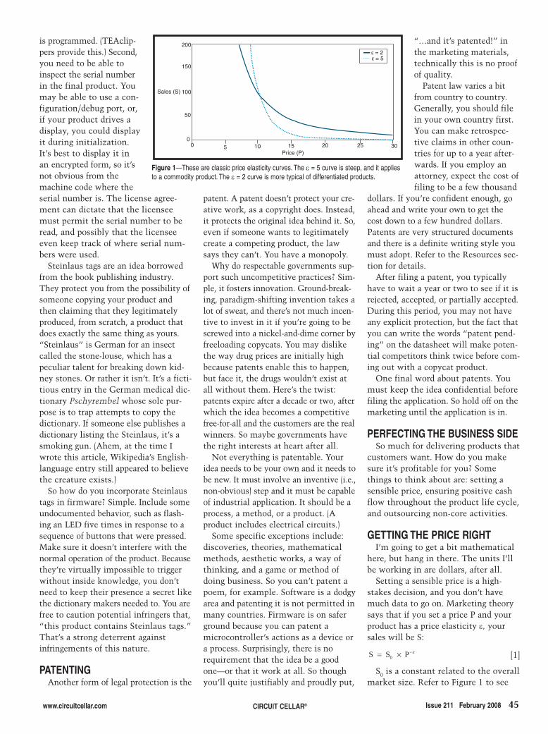
is programmed. (TEAclip-pers provide this.) Second,you need to be able toinspect the serial numberin the final product. Youmay be able to use a con-figuration/debug port, or,if your product drives adisplay, you could displayit during initialization.It’s best to display it inan encrypted form, so it’snot obvious from themachine code where theserial number is. The license agree-ment can dictate that the licenseemust permit the serial number to beread, and possibly that the licenseeeven keep track of where serial num-bers were used.
Steinlaus tags are an idea borrowedfrom the book publishing industry.They protect you from the possibility ofsomeone copying your product andthen claiming that they legitimatelyproduced, from scratch, a product thatdoes exactly the same thing as yours.“Steinlaus” is German for an insectcalled the stone-louse, which has apeculiar talent for breaking down kid-ney stones. Or rather it isn’t. It’s a ficti-tious entry in the German medical dic-tionary Pschyrembel whose sole pur-pose is to trap attempts to copy thedictionary. If someone else publishes adictionary listing the Steinlaus, it’s asmoking gun. (Ahem, at the time Iwrote this article, Wikipedia’s English-language entry still appeared to believethe creature exists.)
So how do you incorporate Steinlaustags in firmware? Simple. Include someundocumented behavior, such as flash-ing an LED five times in response to asequence of buttons that were pressed.Make sure it doesn’t interfere with thenormal operation of the product. Becausethey’re virtually impossible to triggerwithout inside knowledge, you don’tneed to keep their presence a secret likethe dictionary makers needed to. You arefree to caution potential infringers that,“this product contains Steinlaus tags.”That’s a strong deterrent againstinfringements of this nature.
PATENTINGAnother form of legal protection is the
patent. A patent doesn’t protect your cre-ative work, as a copyright does. Instead,it protects the original idea behind it. So,even if someone wants to legitimatelycreate a competing product, the lawsays they can’t. You have a monopoly.
Why do respectable governments sup-port such uncompetitive practices? Sim-ple, it fosters innovation. Ground-break-ing, paradigm-shifting invention takes alot of sweat, and there’s not much incen-tive to invest in it if you’re going to bescrewed into a nickel-and-dime corner byfreeloading copycats. You may dislikethe way drug prices are initially highbecause patents enable this to happen,but face it, the drugs wouldn’t exist atall without them. Here’s the twist:patents expire after a decade or two, afterwhich the idea becomes a competitivefree-for-all and the customers are the realwinners. So maybe governments havethe right interests at heart after all.
Not everything is patentable. Youridea needs to be your own and it needs tobe new. It must involve an inventive (i.e.,non-obvious) step and it must be capableof industrial application. It should be aprocess, a method, or a product. (Aproduct includes electrical circuits.)
Some specific exceptions include:discoveries, theories, mathematicalmethods, aesthetic works, a way ofthinking, and a game or method ofdoing business. So you can’t patent apoem, for example. Software is a dodgyarea and patenting it is not permitted inmany countries. Firmware is on saferground because you can patent amicrocontroller’s actions as a device ora process. Surprisingly, there is norequirement that the idea be a goodone—or that it work at all. So thoughyou’ll quite justifiably and proudly put,
“…and it’s patented!” inthe marketing materials,technically this is no proofof quality.
Patent law varies a bitfrom country to country.Generally, you should filein your own country first.You can make retrospec-tive claims in other coun-tries for up to a year after-wards. If you employ anattorney, expect the cost offiling to be a few thousand
dollars. If you’re confident enough, goahead and write your own to get thecost down to a few hundred dollars.Patents are very structured documentsand there is a definite writing style youmust adopt. Refer to the Resources sec-tion for details.
After filing a patent, you typicallyhave to wait a year or two to see if it isrejected, accepted, or partially accepted.During this period, you may not haveany explicit protection, but the fact thatyou can write the words “patent pend-ing” on the datasheet will make poten-tial competitors think twice before com-ing out with a copycat product.
One final word about patents. Youmust keep the idea confidential beforefiling the application. So hold off on themarketing until the application is in.
PERFECTING THE BUSINESS SIDESo much for delivering products that
customers want. How do you makesure it’s profitable for you? Somethings to think about are: setting asensible price, ensuring positive cashflow throughout the product life cycle,and outsourcing non-core activities.
GETTING THE PRICE RIGHTI’m going to get a bit mathematical
here, but hang in there. The units I’llbe working in are dollars, after all.
Setting a sensible price is a high-stakes decision, and you don’t havemuch data to go on. Marketing theorysays that if you set a price P and yourproduct has a price elasticity ε, yoursales will be S:
[1]
S0 is a constant related to the overallmarket size. Refer to Figure 1 to see
S S P0= × −ε
www.circuitcellar.com CIRCUIT CELLAR® Issue 211 February 2008 45
200
150
100
50
00 5 10 15 20 25 30
Sales (S)
Price (P)
ε = 2ε = 5
Figure 1—These are classic price elasticity curves. The ε = 5 curve is steep, and it appliesto a commodity product. The ε = 2 curve is more typical of differentiated products.
2802015Hoptroff.qxp 1/8/2008 9:30 AM Page 45

uct for free are actually willing to payfor it (see Figures 2 and 3). Conclusion#1: No matter how tempting, don’tgive in to potential customers who saythey would buy your product if it wasless expensive. That argument extendsright down to a price of $0, so you haveto draw the line somewhere. Conclu-sion #2: If you can get a handle on howmany units would be in demand if yougave it away for free, the profit-maxi-mizing price will be when you’re selling25% of that.
Compare the curves for ε = 2 and ε =5. Note how much less profit there isfor ε = 5. If two vendors create a com-modity market by producing identicalproducts and compete solely on price,both lose. The only way to win in acompetitive market is to have a highlydifferentiated product that a proportionof the customer base will pay a premi-um for.
Common sense gives a few morepointers on price. Once you’ve set aprice, there’s not much chance ofincreasing it. Customers who havealready designed you in will cry fouland soon everybody will be wary ofdesigning you in. Gently lowering aproduct price during its life cycle on theother hand is perfectly acceptable, byeven as much as a factorof two or three.
If someone asked youto write the firmware forthem, how much wouldyou charge? The priceyou’d need to set tomake that much rev-enue is your lowestacceptable price.
What is the overallcost of the product the
this equation as a chart. In areally competitive commod-ity market, say gasoline, acustomer’s price elasticity εmight be as much as 5 and a1% decrease in price willlead to a 5% increase insales. In a more value-addedmarket, such as firmware,the price elasticity will becloser to 2, so you canexpect your sales to grow by2% for every 1% decrease inprice.
In an Internet-age intellectual proper-ty market, this model isn’t quite right.You can supply an unlimited number ofcopies at virtually no incremental costover the first copy. But you can’t havean unlimited number of customers.Even if you made it free, only a limitednumber of customers SM would want it.This amounts to shifting the price elas-ticity curve to the left by an amount P0:
[2]
where:
[3]
This equation is illustrated in Figure 2. The marginal cost of every extra
firmware sale to an existing customeris pretty much zero. So our net profitπ is simply sales times price minusthe fixed cost π0 of creating the prod-uct in the first place:
[4]
This equation is illustrated in Figure 3.So what does this tell us, even with-out product-specific numbers?
The fixed cost π0 of producing thefirmware only moves the curve up ordown, not sideways. So it has no bearingon the profit-maximizing price. However,if π0 is so big π never goes above zero,we’ve got a loss-maker at any price.
The curve is pretty flat at the top, soonce you’re near the pricing sweet spot,10% either way won’t make much dif-ference. The slope on the left is muchsteeper than the slope on the right. Sounderpricing will hurt you far morethan overpricing. More subtly, whetherε is 2 or 5, the profit-maximizing priceP+ is roughly when 25% of the cus-tomers who would have taken the prod-
π πε P S P P 0 0 0= × × +( ) −−
S S PM 0= × −0
ε
S S P P0 0= × +( )−ε
customer is making? Howbig a part does your productplay in it? Your price shouldbe more or less proportion-ate. In particular, it is gener-ally accepted that the valueof firmware will be at leastequal, if not many times asmuch, as the microcontrollerit runs on. Compare thiswith the PC world, where aPC retails for around$1,000, but a typical profes-sional software package for
it will be as much as or several timesthat figure.
How much does the customer benefitfrom your product? A customer wouldnormally be prepared to part withsomewhere between 5% and 50% ofthe value they derive, depending onhow easy it is for them to derive it.
How much would it cost for the cus-tomer to write the firmware themselves?They’re unlikely to be willing to paymore than that unless you have patentprotection. This issue is related to thenumber of copies that a customer wants,so it’s really a question of volume dis-counting. Let’s examine that in detail.
VOLUME DISCOUNTINGIf you have no patent protection, a
good rule of thumb is to come down inprice by approximately 50% for everyfactor of 10 above 100 units in sales. (Iftechnically possible, make that cumula-tive sales to an individual customer.Then it’s easier for them to see their ini-tial purchase as an investment, and itfront-loads your revenue cycle.) Refer toTable 1 for an example.
Even with patent protection, if yougive customers a cumulative volumediscount as an incentive to buy more,they will have a strong incentive to try
46 Issue 211 February 2008 CIRCUIT CELLAR® www.circuitcellar.com
0 5 10 15 20 25 30
Sales (S)
Price (P)
100
50
0
ε = 2ε = 5
SM =
Figure 2—These curves represent price elasticity in intellectual property industries.The difference here is that you have to account for the fact that sales cannot be infinite,even if you give it away.
250
200
150
100
50
00 5 10 15 20 25 30
Price (P)
Profit (π) ε = 2ε = 5
Figure 3—This is the price/profit curve in e-publishing. If you learn anythingfrom this, it should be that differentiated products are more profitable.
2802015Hoptroff.qxp 1/8/2008 9:31 AM Page 46
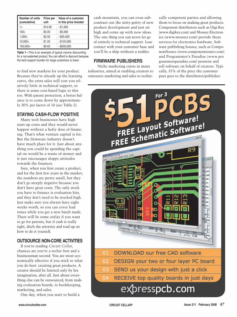
www.circuitcellar.com CIRCUIT CELLAR® Issue 211 February 2008 47
to find new markets for your product.Because they’re already up the learningcurve, the extra sales will cost you rel-atively little in technical support, sothere is some cost-based logic to thistoo. With patent protection, a better bal-ance is to come down by approximate-ly 30% per factor of 10 (see Table 2).
STAYING CASH-FLOW POSITIVEMany tech businesses have high
start-up costs and they would neverhappen without a hefty dose of financ-ing. That’s what venture capital is for.But the firmware industry doesn’thave much place for it. Just about any-thing you could be spending the capi-tal on would be a waste of money andit just encourages sloppy attitudestowards the finances.
Sure, when you first create a product,and for the first few years in the market,the numbers are pretty small, but theydon’t go steeply negative because youdon’t have great costs. The only stockyou have to finance is evaluation kits,and they don’t need to be stocked high.Just make sure you always have eightweeks worth, so you can cover leadtimes while you get a new batch made.There will be some outlay if you wantto go for patents, but if cash is reallytight, ditch the attorney and read up onhow to do it yourself.
OUTSOURCE NON-CORE ACTIVITIESIf you’re reading Circuit Cellar,
chances are you’re a techie first and abusinessman second. You are most eco-nomically effective if you stick to whatyou do best: creating great products. Acreator should be limited only by hisimagination, after all. Just about every-thing else can be outsourced, from mak-ing evaluation boards, to bookkeeping,marketing, and sales.
One day, when you start to build a
cash mountain, you can even sub-contract out the nitty-gritty of newproduct development and just sithigh and come up with new ideas.The one thing you can never let goof entirely is technical support. Losecontact with your customer base andyou’ll be a ship without a rudder.
FIRMWARE PUBLISHERSNiche marketing exists in many
industries, aimed at enabling creators tooutsource marketing and sales to techni-
cally competent parties and allowingthem to focus on making great products.Component distributors such as Digi-Key(www.digikey.com) and Mouser Electron-ics (www.mouser.com) provide theseservices for electronics hardware. Soft-ware publishing houses, such as Compo-nentSource (www.componentsource.com)and Programmer’s Paradise (www.programmersparadise.com) promote andsell software on behalf of creators. Typi-cally, 35% of the price the customerpays goes to the distributor/publisher.
Number of units(cumulative)
Price perunit
Value of a customerin this price bracket
1+ $10.00 ~$1,000
100+ $5.00 ~$5,000
1,000+ $2.50 ~$25,000
10,000+ $1.25 ~$125,000
100,000+ $0.63 ~$630,000
Table 1—This is an example of typical volume discountingfor a non-patented product.You can afford to discount becausethe tech-support burden for large customers is lower.
2802015Hoptroff.qxp 1/8/2008 9:31 AM Page 47

20/40MHz AWG 100MHz DSO 15/20MHz Wfm Gen
Color LCD Scope World’s FastestPicoScope 3206 2/4ch 12-bit USB Scope
6 in 1 Scope Automotive Testing
Comments
8/16ch Voltage LoggerUltimate Temp Logger Voltage Data Logger USB Temp Logging DMM
EMC Spectrum Analyzer
Pen Scope
Line Tester USB Bus Analyzers
Handheld Scope
Wireless Data Loggers
Thermocouple Logger
100/200/300MHz DSO
Logic Analyzer
Mixed -Signal PC Oscilloscope
Customers EMC Spectrum Analyzer
Ethernet Temp/Hum
Low-Cost Scope
AnnouncingScope + Analyzer
Sco
pe
s &
WFM
Ge
ns
Da
ta L
og
ge
rs &
An
aly
ze
rs
60/100/120MHz AWG
Owon - 25MHz 2-ch +
trigger standalone USB bench
scope with 7.8” color LCD.
Battery powered optional.
PDS5022S $325
PDS6062T $599
20MHz or 60MHz rugged
handheld USB scope with 3.8”
color LCD. Built-in meter -
great for your tool kit.
HDS1022M (20MHz) $499
HDS2062M (60MHz) $699
ZeroPlus - Intuitive full-featured
16-channel with 4mb memory.
Sophistcated triggering. I2C, SPI,
and UART monitoring. Includes
clipleads, USB cable and software.
LAP-16128U $299
6-in-1 USB scope adapter! 200kHz 2-ch
10-bit scope, 2-ch spectrum analyzer,
2-ch chart recorder, 16-ch 8MHz logic
analyzer, 5-ch signal gen, 8-ch pattern
gen. SPI/I2C/1-w/UART decoding.
PoScope with probes $199
FREE COFFEE
Call 1-888-7SAELIG
Mention Offer# SBW
to get a free Starbucks Card with your order!
While supplies last -
not available with any other offers
Best
Seller
PS5204 - 2-ch 250MHz Scope with
128 MS/s and real-time sampling of
1GS/s. Adv triggering. 250MHz spec.
analyzer and 125MS/s waveform gen.
PS5203 32MS buffer $2237
PS5204 128MS buffer $3360
2-Ch 20 MS/s 2 MHz 8-bit
scope adapter with 32 kB
buffer and USB 2.0 (fast
screen updates) with case &
probes.
PS2202 Bundle $387
Pico USB TC-08 - USB connected
and powered 8-ch thermocouple
data logger. Samples at up to
10 readings/s with built-in
CJC for -270oC to +1820
oC.
USB TC-08 $466
Pico - New 2/4-ch 12-bit 20MS/s
USB2.0-connected/powered
scope adapters. Scope, FFT,
and meter displayed at once
with included software.
PS3424 / PS3224 $1398 / $793
PS2105 - 25MHz USB powered
scope - i n -a -p robe ! Up t o
100MS/s, 24kS buffer C/VB/
Delphi/LabView/VEE drivers.
PS2105 (25MHz, 100MS/s) $372
PS2104 (10MHz, 50MS/s) $234
PS3206 - Is an impressive 2-ch
200MS/s 8-bit PC scope adapter
- 10GS/s for repetitive signals!
No power supply needed, simple
USB 2.0 connection
PS3206 Bundle $1574
EMC RF & EMF Spectrum -
Analyzer 1Hz to 7GHz for measuring
transmissions from radar, radio/tv
towers, WLAN, WiFi, WiMAX,
Bluetooth, microwave ovens, etc.
from $299 / $1999
USB1.1/2.0/WiMedia analyzers
and now - EX260 can test
USB3.0 5Gbps too! Emulate
host/device, verify compliance.
TR110 / EX200 / EX260
$999 / $2999 / CALL
TTI - high speed/accuracy AC
power analyzer to 16A for easy
product power-compliance
measurements. Measures/displays
1st - 40th harmonics in real time.
HA1600A from $2899
Automotive Diagnostics - Award-
winning Pico kits turn your PC
into a powerful vehicle-electrics
diagnostic tool. 2 & 4 ch.versions for
components & circuits.
PS3423 automotive kit $2293
Pico USB ADC-11 - USB
powered 11-ch voltage data
logger - 10kHz sampling
rates with digital outputs for
control or alarm.
USB ADC-11/10 $178
DLP - Low cost, USB-powered
digital sensor. Easily monitor
temperature/humidity/dew
point from USB port.
DLP-TH1 $99
Log and display temperature,
humidity, voltage, event-time or
pulse-counting data up to 100
meters away from base station.
RTR-50 modules from $170
RTR-57U base $401
T&D - Networked logger for
remote ambient measurement.
Send email or phone warnings if
thresholds exceeded. Optional
WiFi for remote installation.
TR-72W $489
PT104 - 4-ch temperature
logger with 0.001°C resolution,
0.01°C accuracy using platinum
PT100 sensors. Also measure
resistance and voltage.
PT104 $747
Join our huge list ofsatisfied customers:
Intel, Philips, Maxim, GM,GE, NEC, Kodak, Xerox,Nokia, TI, Harris, Sony,
Pelagic, Sandisk, HP,General Dynamics,US Military, etc.
"Thanks for your
excel lent customer
service and dedication
to f ind ing and
represent ing un ique
manufacturers ... "
K.R.
100MHz 2-ch 400MS/s DSO
2000 wfm/s refresh rate.
Ultra Compact Design with
small footprint saves bench
space.
DS1102C $999
100MHz 2-ch /16 logic scope
and logic analyzer. 2000 wfm/s
refresh rate. See waveforms and
logic data simultaneously. Trigger
on data or signal edge.
DS1102CD $1499
100/200/300MHz 2 ch, 2GS/s DSO
2000 wfm/s refresh rate. Ultra
Compact Design with small footprint
saves bench space. DS1102A $1295
DS1202A $1595
DS1302A $1995
15/20MHz USB 14-bit Function/
Arbitrary wfm Generators. 10 built-in
wfms; FM, AM, PM, FSK, SWEEP
and BURST; 6 digit 200MHz
frequency counter.
DG1011 / DG1021 $650 / $795
25/40MHz USB 14-bit ARB w. USB
RS-232, LAN/GPIB. 10 built-in
wfms; FM, AM, PM, FSK, SWEEP
and BURST; 6 digit 200MHz
frequency counter.
DG2021A/DG2041A $995/$1495
60/100/120MHz USB 14-bit ARB
w. USB RS-232, LAN/GPIB. 10
built-in wfms; 6 digit 200MHz
frequency counter; opt. 16-ch
gen. DG3061A $1895
DG3101A/DG3121A $2795/$3995
6 1/2 digit 50KS/s, 2MS mem. Opt.
16-ch mux. Automeasure DC/AC,
2/4-wire R, C, Continuity, Diode,
Frequency, Period, Ratio, Temp,
Sensor, High/Low Limit Math.
DM3061 $795
...a new name in high-end,high reliability, value-priced test gear: RIGOL.
(pronounced ‘regal’)Formerly the partner ofa large scope companywe can't name, Rigolproduces the bestquality/value LCD scopesavailable on the market today.
20-bit 8-ch / 24-bit 16-ch USB
voltage logger w. control output.
Galvanic isolation from the PC
eliminates noise.
ADC-20 (20 bit) $321
ADC-24 (24 bit) $747
Handheld PalmPC-based 2.7GHz
Spectrum Analyzer. Continuous/
single/peak-hold/avg sweeps -
unlimited storage for wfms, set-ups,
etc. Built-in Wi-Fi/Bluetooth/IR.
PSA2701T $1990
100 MHz Scope and Logic Analyzer
lets you do complex triggering to find
hard-to-get-at glitches, spikes, etc.
Huge 4 or 8 MS buffer for deep data
drilling and zooming. Optional built-in
swept signal generator. 2 Analog
channels x 10, 12, 14 bit with more
than 60 dB dynamic range. 8 digital
inputs for mixed signal display/trigger.
CS328A-4 (4MS Buffer) $1149
CS328A-8 (8MS Buffer) $1642
CS700A (signal generator) $249
NEW!
RIGOL
NEW!
RIGOL
NEW!
RIGOL
Also LOTS of other products such as: Antennae, Barcode Readers, Cables, CANbus/LINbus products, Data Loggers,Digital Audio / DSP Filters, Embedded PC's / Controllers, EMC shielding, enclosures and tents, Ethernet boards andserial cable converters, FATfile Chips / Boards, GPS loggers, engineering Software, I/O Boards & Modules,I2C boards and controllers, ICs (USB, Ethernet, RFID), Industrial PC's, OLED / LCD Displays kits, Logic Analyzers,Motor Control, MP3 boards, Panel Meters, Polystyrene Capacitors, Power Supplies, Radio/Wireless modules, Robots,RS232/422/485 Adapters, SMD Adapters, Surge Protection / Isolation, USB-serial and I/O boards, Video,VMEbus boards, Web Servers, etc. Check www.saelig.com often for special offers, bargains, business hints, blog, etc.
NEW!
RIGOL
NEW!
RIGOL
NEW!
RIGOL
NEW!
RIGOL
NEW!
B E S T S C O P E &L O G G E R S E L E C T I O N !
Temp/Humidity LoggerUSB Logger
HumidiProbe - PC-based
temperature and humidity
measurements are quick and
easy with RH-02 data logger.
USB2.0 connected and powered.
PP299 $279
EL-USB-1 - Standalone USB temp
data logger (-25oC to +80
oC). $49
El-USB-2 (+ humidity) $79
EL-USB-3 (voltage) $69
EL-USB-4 (current loop) $69
EL-USB-CO (Carbon Monoxide) $89
48.qxp 12/31/2007 12:35 PM Page 1
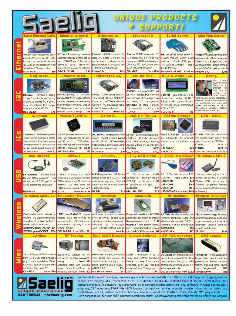
U N I Q U E P R O D U C T S + S U P P O R T !
Serial-Ethernet Cable Ethernet to Serial Serial Server
Devasys - Provides a simple
“drop-in” solution for connecting
your PC to 90kHz I2C + 20 I/O
lines. Free software. Use multiple
boards for more I2C/IO.
USB I2C/IO $79
USB to I2C Blue & White LCD
NM7010A-LF REV 2 - Complete,
hardwired TCP/IP-I2C module. Offloads
stack for hi-speed Internet-enabling
microprocessor systems. Drop-in
W3100A-based board for instant
network speeds to 8Mbps. $22
Ethernet to I2C
Fiveco - TCP/IP server with I2C,
19 x digital I/O, 5 x 10-bit A/D
inputs, and UART serial interface.
Connect I2C devices/sensors
to an Ethernet network!
FMod-TCP from $250
I2C for PCs
Quantum WIZnet TCP/IP IC
PCI93LV: industry-standard I2C card
for PCs. WINI2C/PCI software
gives windows-interface to develop
and debug I2C bus systems.
UCA93LV is USB version.
Transparently monitor at
400kHz! $499
Security
Ether-IO - UDP/IP-controlled 24
digital I/O board 3 x 8-bit TTL
ports each independently
programmable. Connects to any
TCP/IP Ethernet network.
Ether-IO 24 $119
Custom Switches GPS LoggerSM PCB Adapters
TrackStick II - Pocket-sized logger
tracks position data for vehicles,
personnel, etc. Records date, time,
location, route and speed. Shows
data on Google maps! $175
TrackStick PRO $189
Transceiver ModulesWireless Modules Antennae Bluetooth Ethernet Temp/Hum
USBwiz
WIZnet - Ready-to-go serial-to-
Ethernet Gateway. Simple set-up
for 10/100Mbps Ethernet -
230kbps serial. Ethernet/
Internet-enable any serial part.
EG-SR-7150MJ $34
USB - Serial
Quantum ICs - World’s best capacitive
sensor ICs for switching & control.
Patented Adj. Key Suppression,
Spread-spectrum. In use worldwide
by the world’s largest consumer/
appliance mfrs from $1
1/2/4/8/16 x RS232
10/100 Ethernet controller on a
chip! Fully hardwired TCP/IP core.
No OS required. TCP offload
improves system performance.
W5100 (integrated PHY) $6.95
NM7010B+ Eval $22
Wireless USB2.0
RS232/422/485 device server for
network-enabling legacy serial
devices. 1/2/4/8/16/32 ports
10/100Mbps-230kbps. Static
IP/DHCP/PPPoE.
Portbase-3010/RS232 from $149
Micro ALFAT-SD - Easily add
SD storage to your product.
Serial data in - FATfile data
out.
uALFAT-SD $40
uALFAT IC $14
USB On-The Go
4D Systems - Compact, economical
smart OLED with graphics for
‘stand-alone’ functionality to your
project - drive from USB or RS232.
uOLED-96-G1 $101
uOLED-128-GMD1 $84
FATfile Storage
Isol USB485
Network your serial product easily
without a PC using this 28” cable.
Provides an instant IP address.
RS-232 port compatible with most
10/100mpbs Ethernet hubs.
eCOV-110-P $89
RF Modules
Ethernet - IO
Easy OLED Display
USBwiz - Easily add USB
peripherals to your system. Includes
FATfile system for USB thumb &
external USB hard drives. No
USB knowledge needed. Plug-n-play!
IC $20 Demoboard $59
Servo IC
FT232RL - FTDI USB1.1-serial ICwith
new "security-dongle" feature. Each
unique ID and Internal EEPROM,
FT232RL $2.36 (1K)
FT232BL $2.98 (1K)
Check out the whole FTDI line!
CANbus RF Testing
Tiny USB Serial
PicoServTMMiniature Web Server
allows remote I/O and servicing.
Collect analog & digital data over
a web connection. Remote sensing/
control, SCADA, building control.
PP1001-V00 $205
Ethernet to I2C
We search the world for unique, time-saving products - see our website for 100s more: volt/temp data loggers, wirelessboards, LCD display kits, Ethernet/IO, USB/RS232/485, USB-OTG, instant Ethernet-serial, CAN/LINbus, USBcables/extenders, line testers, logic analyzers, color sensors, motion controllers, eng. software, wireless boards, SMDadapters, I2C adapters, FPGA kits, GPS loggers, automotive testing, security dongles, video motion detectors,crystals/oscillators, custom switches, barcode scanners, robots, DSP filters, PLCs, Remote MP3 players. etc. Don't forget to ask for your FREE Starbucks card with order! Check www.saelig.com often for special offers and bargains.
Mini Web Server
Fiveco - TCP/IP server with I2C,
19 x digital I/O, 5 x 10-bit A/D
inputs, and UART serial interface.
Connect I2C devices/sensors
to an Ethernet network!
FMod-TCP from $250
Ethernet - IO
Add COMports via your PC’s
USB Port. USB-COM-S $20
USB-2COM $48
USB-4COM $105
USB-8COM $195
USB-16COM-RM (rackmount) $459
Wor ld ' s sma l l es t USB
adap te rs . Ready -made
CP2101 min iboard USB
inter face to 1 Mbps.
uUSB-MB $27
HR-USBUART $29
KK Systems - Isolated USB-
RS422/RS485 converter. FTDI
chipset. Virtual COM port for all
win32 applications. USB-DB9F.
USB-485-K $99
DLP - Programmable USB Security
Dongle based on FT232RL - log
use/user/expiry, etc. Optional
sophisticated software allows
customizability.
DLP-D $13
Chesen - Sophisticated application
interface. Quickly develops
USB OTG memory- memory
devices without PC connection.
CSC3800 NEW!
OXDK-3800 CALL
PIC-SERVO - complete PID servo
motion control system based
on PIC18F2331. PID servo filter,
motionprofiling, commutation, error
monitoring, communications, etc
PIC-Servo $30
Comfile - LED backlit 4 x 20
character display. CuNET,
RS232 or I2C communication
to 115Kbps. BASIC programmed.
2.36” x 3.86”
CLCD420-B $49
Lorlin - Fantastic array of
stock and custom switching
devices choose from rotary
encoders, push, key, slide and
rotary switches. Voltages up to
250V. CALL
OM-Adapt SM miniboards have
two footprints on each side. Now
use your ultra fine pitch SMD
components with more useful 0.1"
inline spaced holes.
One-to-one pinouts. from $9.52
Janz - Intelligent CAN connection
from PC’s USB port. Provides
plug’n’play opto-isolation. Other
CANbus boards and systems
available from Janz AG.
CAN-USB from $299
I2C
Ethern
et
ICs
USB
Wireles
sMis
c
Economical, portable RF test
enclosures, for initial compliance
testing. from $1295
Shielding Tents with external
frame, instant up/down for
emissions-free room. from $3500
Alan Lowne
says: "I started
Saelig as an
engineer - for
e n g i n e e r s !
Saelig - an
Olde English
word meaning 'happy, prosperous,
blessed' - which is what I want for
my customers, my staff, and
myself! See my blog for behind-
the-scenes company details,
business hints, kudos, etc. "
Wirelessly connect to your USB 2.0
devices with our USB-IF Certified
Wireless USB Hub at up to
480Mbps. For printers, scanners,
memory, cameras, MP3s, (not webcams
or Bluetooth).
T&D - Networked logger for remote
ambient measurement. Send email
or phone warnings if thresholds
exceeded. Optional WiFi for
remote installation.
TR-72W $489
RF TX/RX Modules - simultaneously
transmit composite video and
stereo audio signals. 2.4 GHz
ISM band. 4-ch RF, 5V operation
AWM630TX $16
AWM634RX $27
LPRS easyRADIOTM makes
wireless da ta t ransmiss ion
simple for the US and Europe!
Add wireless capability to your
project today!
ER900TRS from $38 (100)
Antennae - Innovative internal
and external specia l ized
miniature multiband antennas
including Yagi for multiple
uses - 900/1800/2400MHz/GPS.
from $4
Emxys microIceBlue - PIC16F877
based emb. dev. system for shortest
Bluetooth development. $139
PearlBlue - 100m-Bluetoothmodule
(UART master/slave bridge).Connect
micro's to PCs, PDAs, phones, etc.$99
Easily create mesh networks at
910MHz - like Zigbee only better!
Complete RF solution for fast &
reliable data transmission.
B915FHtiny-plus/40-SMD-WA $64
B915FHtiny-plus/40-DIP-EA $804
Saelig
49.qxp 12/31/2007 12:36 PM Page 1

problems, when in fact the real solutionis elsewhere. If his house had a leakyroof, a painter would hide the damage, areal estate agent would sell the house,and a lawyer would sue the builder.None would actually fix the roof!
Likewise, it can be hard to stop think-ing like a techie. But sometimes youneed to. When it comes to strategic
decisions about your prod-uct, it will be tempting tothink about it from a tech-nical perspective, when infact you have to considerwhat customers reallywant.
Techies fall into somecommon traps. “Featurecreep” is the weird beliefthat more complicated isbetter. “Coding addiction”is the problem that creat-ing products gets addic-tive. It’s tempting to avoidother vital tasks such astechnical support. But faceit, if you spend 20% ofyour time in creative
mode, you’re lucky. “Pricing toplease” is the temptation to dropprices in response to customer pres-sure. You wouldn’t give them $100bills just because they asked for them,so why offer a special discount justbecause they ask? You might have toturn a few customers away, but thenagain, so does Ferrari. “Clinging to the
50 Issue 211 February 2008 CIRCUIT CELLAR® www.circuitcellar.com
In return, the customersees far greater sales thanhe would typically recog-nize on his own.
When we started mak-ing TEAclippers, there wasnothing like this forfirmware. So we decided todo something about it. Weare complementing theTEAclipper technologywith a firmware publishingservice called HexWax(www.hexwax.com). Itcomes with a special brows-er that enables you to down-load packages of encryptedfirmware, datasheets, andmore (see Photo 1). At thetime we wrote this article, it was for freedownloads only, but by the time youread this it should be providing a com-plete sales service, offering significantmarket reach at minimal up-front cost.
BREAKING THE TECHIE MOLDPeople tend to make the mistake of
turning to their strengths to fix their
Photo 1—This is the HexWax browser. It enables customers to buy firmware online anddownload it onto a TEAclipper.
International EngineeringConsortiumwww.iec.org
For more information visit www.designcon.com/2008
Connecting the World of Electronic Design Connecting the World of Electronic Design
February 4–7, 2008 Conference
February 5–6, 2008 Exhibition
Santa Clara Convention Center | Santa Clara, California
February 4–7, 2008 Conference
February 5–6, 2008 Exhibition
Santa Clara Convention Center | Santa Clara, California
• 130 exhibiting companies• Nearly 100 technical papers• 10 half-day tutorials• 8 technical panels• Keynotes• Plenary panel• Business Forum
• 130 exhibiting companies• Nearly 100 technical papers• 10 half-day tutorials• 8 technical panels• Keynotes• Plenary panel• Business Forum
Don’t Miss Out on All DesignCon Has to Offer!
2802015Hoptroff.qxp 1/8/2008 9:31 AM Page 50

original concept” is another trap.Chances are your original vision isn’texactly what your customers want.Listen to them and let the productbecome what they need. If you’redoing your job right, it will end uplooking nothing like you originallyintended, but sales will rocket.
“There’s no point in trying. Peoplewill steal my idea.” That is anothertrap. If it was really rewarding to stealideas, people would. But the fact is, itjust creates a commodity market, sothere’s not a lot in it for potentialcompetitors.
The last trap is: “You stole myidea!” On occasion, people have simi-lar ideas at the same time. That’s nota disaster. What you each have to do isfocus on ensuring that your product isdifferentiated enough to succeed inthe marketplace. Don’t get distractedby arguing with each other.
FINAL CHECKLISTTowards the end of the last century,
a few techies realized that they werepresented with a rare opportunity togenerate stunning revenue streamsfrom the value they could deliver to abroad customer base. Similar opportu-nities in the firmware world are open-ing up right now.
Let’s finish off with a checklist fromidea to pay dirt, and you can ask your-self whether you’re ready to roll upyour sleeves and get started.
Shortlist potential applications. Doyou have any code sitting around inyour directories that could be turnedinto a marketable product? Have peo-ple asked you to write firmware thatmight have broader appeal? Whatskills and experiences do you haveoutside of electronics? Where are youuniquely positioned to bring solutions
www.circuitcellar.com CIRCUIT CELLAR® Issue 211 February 2008 51
to customers?Next, narrow the shortlist from a
business perspective. Do you havean estimate of the market size andthe price you could charge? Is theproduct easy to understand andexplain? Can you keep thedatasheet to 20 pages or less?What’s it going to be like to providetechnical support for it? Do youhave potential customers who saythey would buy it? Real people who
you can name?Create the product. Write the first
draft of the datasheet before writing aline of code so you can use it as awork plan. Avoid, at all costs, codingbefore documenting; it makes formessy products. Expect to spend 25%of your creative time fresh-coding,25% testing, and 50% fixing and refin-ing.
Next, create presales support collat-eral. Refer to Table 2 in Part 1 of thisseries for a list of the likely materialsyou will need to prepare (Circuit Cel-lar 210, 2008).
Consider patenting. Are any ele-ments of your creation new, inventivesteps? If so, consider patenting thembefore moving on to the next step.
Take little piggy to market. Targeteasy-to-reach customers first. Consid-er www.hexwax.com as a firmwarepublisher.
Be sure to support your customers.Your job’s not done until they’ve suc-cessfully designed in your product.When they have, ask if you may usethem as a reference.
Finally, don’t give up your day jobyet. Plan on a one to three year ramp-up phase before sales really start kick-ing in. I
Number of units(cumulative)
Price perunit
Value of a customerin this price bracket
1+ $10.00 ~$1,000
100+ $7.00 ~$7,000
1,000+ $5.00 ~$50,000
10,000+ $3.50 ~$350,000
100,000+ $2.50 ~$2.5 million
Table 2—This is an example of typical volume discountingfor a patented product. Even with patent protection, dis-counting is worthwhile because it encourages customers tofind new applications for your product.
RESOURCED. Pressman, Patent It Yourself, Nolo,Berkeley, CA, 2006.
In 1991, Richard Hoptroff startedRight Information Systems, a fore-casting software company that wasacquired by Cognos in 1997. In 2003,he founded FlexiPanel, an electronicsdesign and licensing company.Richard holds a Ph.D. in Physics fromLondon University. You may contacthim at [email protected].
PRESTO The First USB In-Circuit
Multipurpose Programmer
Very fast and flexible in-systemprogrammer for many devices: � Atmel AVR, 8051 architecture� Microchip PIC, dsPIC, rfPIC, ... � Texas Instruments MSP430 � ARM MCUs by Atmel, NXP
(Philips) - including debugging� FPGAs, CPLDs & SCPs
by Xilinx, Altera, Lattice, ... � Serial Flash, EEPROMs, ...
SIGMA Unique Logic Analyzer
With Extremely Large Memory for more than 14,000,000 events, up to 16 inputs, up to 200 MHzsampling, flexible triggering, ...
...and more MUU Beta - unique PIC emulator USBB modules - parallel & serial SPINET - Ethernet-SPI interface Development boards and kits, ...
For developers by developers.
tools.asix.net
[email protected]@asix.net
2802015Hoptroff.qxp 1/8/2008 9:31 AM Page 51
52 Issue 211 February 2008 CIRCUIT CELLAR® www.circuitcellar.com
“complete” system is not feasible. Itmakes more sense to break them intomultiple subsystems that each concen-trate on doing a single job well. Many ofthe subsystems will be used to turnthings on or off or to maintain tempera-tures, pressures, or other environmentalvalues. They are set-and-forget jobsthat don’t require continuous monitor-ing and they can clog up a control algo-rithm when it needs to be doing otherthings that are much more important.Often, channels merely monitor diag-nostic points that don’t participate insystem control at all.
Some systems are so geographicallydispersed that running wires fromeach transducer back to a central loca-tion would be difficult or impossible.Distributing the control to multiplesubsystems puts the controllers nearthe processes being controlled. Thisway, you can wire the subsystem con-trol points with shorter wiring runsand you have to connect only the con-trollers to the network.
Subsystems that can be implement-ed on programmable logic controllers(PLCs) are ideal candidates for embed-ded controllers. You can programthem in C or C++ to implement moresophisticated control algorithms. Thecontrollers can provide continuouscontrol of pressures and temperaturesas well as other types of environmen-tal monitoring and control, even withthe operator interface turned off.
Some subsystems require hard, real-time control. Many of the sophisticatedoperating systems that I prefer to use—
I have been writing control systemsfor a living for a while now. There issomething exciting about flipping aswitch on a computer screen and see-ing a valve open or a light go on. Itgives me a sense of accomplishment. Iautomate a lot of processes to makethem safer and easier to use. A lot ofdistributed embedded controllers areused to accomplish this because I’vefound them to be the fastest and easi-est way to solve certain problems. Thekey to doing this is having the abilityto communicate with the controllers.
In this article, I’ll describe a simpleand easy communication scheme thatuses a text-based command structure.I’ll explain how to implement a TCP/IPsocket server on a Rabbit Semiconduc-tor RCM2200 RabbitCore microproces-sor, which is small, inexpensive, andcan be readily embedded into your proj-ects. I’ll describe two TCP/IP socketclients that run on a PC and communi-cate with the embedded server. Thefirst is a command-line process thatexposes all of the commands to theuser. It is useful for debugging projectsand manually exercising the RCM2200.The second is a C++ application pro-gramming interface (API) that providesprogrammatic access to the embeddedprocessor.
DISTRIBUTED CONTROL CANDIDATESLet’s take a moment to talk about
where and why you should distributethe control.
Some processes are so complicatedthat implementing them as a single
like the Microsoft Windows family orLinux, UNIX, and other systems—can-not provide the dedicated control neces-sary to successfully implement theprocess. However, many of the process-es can be implemented inexpensivelyand effectively on small, embeddedprocessors that are configured and com-manded via a network. Embedded real-time kernels, such as Rabbit Semicon-ductor’s implementation module ofMicrium’s μC/OS-II, provide hard, real-time control along with unencumberedaccess to the raw hardware.
TCP/IP SOCKETS COMMUNICATIONCritical to the systems is the ability to
rapidly and accurately communicatewith them. I will use standard Ethernetprotocols to achieve an effective roundtrip time (RTT), the time it takes the PCto make a request and receive a response,of as little as 3 ms. This method willsupport both the command-line clientand the C++ client API communicatingwith the single embedded server.
Using TCP/IP sockets requires theembedded server and the PC client tobe on the same subnet. The serveruses a fixed port number for commu-nication and, in this example, cancommunicate with a single client at atime. It implements commands asrequest/response pairs. Every requestreceives a response, effectively hand-shaking each command and ensuringthat it was received and acted upon bythe server. The response also passesback status and diagnostic informa-tion to the client.
FEATURE ARTICLE by Cass Tyler
TCP/IP Communication with Embedded Processors
TCP/IP communication with embedded processors, using text commands, is fast and reliable.Best of all, it doesn’t strain a host PC’s resources. Cass describes how to implement aTCP/IP socket server on a Rabbit Semiconductor RCM2200 microprocessor.
System Control
2801017Tyler.qxp 1/8/2008 9:28 AM Page 52
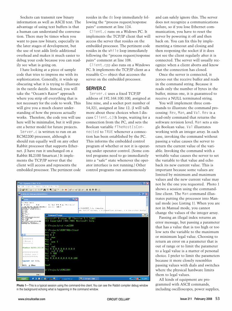
Sockets can transmit raw binaryinformation as well as ASCII text. Theadvantage of using text buffers is thata human can understand the conversa-tion. There may be times when youwant to pass raw binary, especially inthe later stages of development, butthe use of text adds little additionaloverhead and makes it much easier todebug your code because you can read-ily see what is going on.
I hate looking at a piece of samplecode that tries to impress me with itssophistication. Generally, it winds upobscuring what it is trying to illustratein the razzle dazzle. Instead, you willtake the “Occam’s Razor” approachwhere you strip off everything that isnot necessary for the code to work. Thiswill give you a much clearer under-standing of how the process actuallyworks. Therefore, the code you will usehere will be minimalist, but it will pres-ent a better model for future projects.Server.c is written to run on an
RCM2200 processor, although itshould run equally well on any otherRabbit processor that supports Ether-net. (I have run it unchanged on aRabbit BL2100 Smartcat.) It imple-ments the TCP/IP server that theclient will access and represents theembedded processor. The pertinent code
resides in the do loop immediately fol-lowing the “process request/responsepairs” comment at line 124.Client.c runs on a Widows PC. It
implements the TCP/IP client that willaccess the server that resides on theembedded processor. The pertinent coderesides in the while loop immediatelyfollowing the “process request/responsepairs” comment at line 108.Client.cpp also runs on a Windows
PC. It implements the TCP/IP client as areusable C++ object that accesses theserver on the embedded processor.
SERVER.CServer.c uses a fixed TCP/IP
address of 192.168.100.100, assigned atline nine, and a socket port number of54,321, assigned at line 12. (I will talkmore about these choices when I dis-cuss Client.c.) It loops, waiting for aconnection from the PC, and sets theBoolean variable fTheHostIsCon-nected to TRUE whenever a connec-tion has been established by the PC.This informs the embedded controlprogram of whether or not it is operat-ing under operator control. (Some con-trol programs need to go immediatelyinto a “safe” state whenever the oper-ator interface is not running.) Othercontrol programs run autonomously
and can safely ignore this. The serverdoes not recognize a communicationsfailure, so if you lose Ethernet com-munication, you have to reset theserver by powering it off and thenback on. You can fix this by imple-menting a timeout and closing andthen reopening the socket if it doesnot see the client regularly after it isconnected. The server will usually rec-ognize when a client aborts and knowthat the connection has closed.
Once the server is connected, itzeroes out the receive buffer and readsin the command string. Because itreads only the number of bytes in thebuffer, minus one, it is guaranteed toreceive a NULL terminated string.
You will implement three com-mands to illustrate the command pro-cessing: Rev, Man, and Val. Rev is aread-only command that returns thesoftware revision level. Man sets a sin-gle Boolean value. Val illustratesworking with an integer array. In eachcase, invoking the command withoutpassing a value causes the server toreturn the current value of the vari-able. Invoking the command with awritable value causes the server to setthe variable to that value and echoback its new current value. This isimportant because some values arelimited by minimum and maximumvalues and the new current value maynot be the one you requested. Photo 1shows a session using the command-line client. The Man command illus-trates putting the processor into Man-ual mode (see Listing 1). When you arenot in Manual mode, you cannotchange the values of the integer array.
Passing an illegal index returns anerror message, but passing a parameterthat has a value that is too high or toolow sets the variable to the maximumor minimum legal value. Choosing toreturn an error on a parameter that isout of range or to limit the parameterto a legal value is a matter of personalchoice. I prefer to limit the parametersbecause it more closely resemblespassing values with dials and switcheswhere the physical hardware limitsthem to legal values.
All kinds of equipment are pro-grammed with ASCII commands,including oscilloscopes, power supplies,
www.circuitcellar.com CIRCUIT CELLAR® Issue 211 February 2008 53
Photo 1—This is a typical session using the command-line client. You can see the Rabbit compiler debug windowin the background echoing what is happening in the command window.
2801017Tyler.qxp 1/8/2008 9:28 AM Page 53

randomly picked subnet 100 because itis easy to remember and less likely toconflict with existing systems.
Port numbers are assigned by theInternet Assigned Numbers Authority(IANA), and, in order to prevent conflictswith existing applications, I chose 54,321because it is listed as a “dynamic and/orprivate port.”[3] These range from 49,152through 65,535 and are restricted frompermanent assignment. They are set
bench equipment, and a whole range ofother devices. Some use RS-232 as thecommunications media, while othersuse RS-485, GPIB, or Ethernet. Provid-ing a text-based user interface provides avery familiar paradigm for talking toyour device. Because you are writing thecode, you can provide any commandthat you want. Your embedded con-troller interfaces just like any of theother devices and becomes just anotherblack box in your control system.
Even if your embedded system does-n’t require a user interface, it is stilladvantageous to provide a window intothe process so you have a way to seewhat is happening inside your system.
CLIENT.CClient.c provides the command-
line interface to the embedded con-troller. It opens a TCP/IP socket con-nection to the embedded controller,sends commands to the controller, anddisplays their responses to the user.CTRL + C exits the program.
Command-line programs can hang sys-tem logoffs and shutdowns if they don’timplement a console control handler torespond to shutdown events. The Con-trolHandler() function, at line 18, sig-nals the client to exit when shutdownmessages, such as when a “CTRL + C” hasbeen detected. This enables you to per-form all of the necessary cleanup func-tions and gracefully exit the program.
Look at the TCP/IP address and portnumber choices. I implement controlnetworks on dual-homed systems (i.e.,systems with more than one Ethernetconnection). This keeps all of the con-trol communications on a separate net-work segment so that they don’t disturbthe user network and the user networkdoesn’t disturb the control network.
The Internet Engineering Task Force(IETF), the Internet standards organiza-tion, has set aside a range of addressesfor private Internets (RFC 1597), includ-ing the 192.168.<subnet>.<addr> block.[1]
This enables you to define up to 256subnets (subnets 0 to 255) that allow upto 256 addresses each (address 1 to 254).Addresses 0 and 255 are reserved, so youcan connect up to 254 devices, one ofwhich is your host, using this addressscheme.[2] You will find a lot of192.168.0.x subnets already in use, so I
aside for private use. You should keeptrack of the port numbers that you useand avoid reusing them because multipleapplications using the same port numberwould cause a conflict that could be verydifficult to track down.
CLIENT.CPPAlthough a command line environ-
ment is convenient for manual interac-tion, programmatic control requires a bit
54 Issue 211 February 2008 CIRCUIT CELLAR® www.circuitcellar.com
Listing 1—This code snippet shows the code used on the embedded server to process the Rev and Mancommands. The trailing else handles unrecognized commands.
auto byte ucBuffer [ 128 ]; /* Buffer for Message */
auto char * pszCommand; /* Pointer to Command */auto char * pszValue; /* Pointer to Value */
...
/** Get the Command*/
pszCommand = strtok ( ucBuffer, " " );
/** Process a "Rev" Command*/
If ( strcmpi ( pszCommand, "Rev" ) == 0 ){RespondText ( &stSocket, "Rev 0.1" );}
/** Process a "Man" Command*/
else if ( strcmpi ( pszCommand, "Man" ) == 0 ){if ( pszValue = strtok ( NULL, " " ) )
{g_fMan = RANGE ( atoi ( pszValue ), 0, 1 );}
sprintf ( ucBuffer, "Man %d", g_fMan );
RespondText ( &stSocket, ucBuffer );}
...
/** The Command is Invalid*/
else{RespondText ( &stSocket, "Unrecognized Command" );}
Listing 2—These are the exposed “public” methods in the C++ client API. They provide the programmaticclient access to the embedded server. Refer to Try.cpp on the Circuit Cellar FTP site for an example of how thisAPI is used.
Bool IsValid (void);
Bool GetRev ( unsigned int * puMajor, unsigned int * puMinor );
Bool PutMan ( bool fManual );Bool GetMan ( bool * pfManual );
Bool PutVal ( unsigned int uIndex, int nValue );Bool GetVal ( unsigned int uIndex, int * pnValue );
Bool GetVals ( short int anVal [ 10 ] );
2801017Tyler.qxp 1/8/2008 9:28 AM Page 54

CPU
Timer/Counter
PWM
UART
I C/SPI2 Real-Time
Clock
RAM
Debug
Channel
Flash ROM
Interrupt System
DMA
SD/MMC
InterfaceCANEthernet USB
A/D Converter I/O Ports Debug
Run-Control
Keil Cx51 is the de-facto industry standard for all
classic and extended 8051 device variants.
C51Version 8.5 includes the latest devices such as
XC800,ADE7169, and C8051F4xx - F6xx.
More information: www.keil.com/c51
Keil C166 is the complete software development
environment for Infineon C166, XC166, XC2000
and ST Microelectronics ST10 with debug and
programming support via ULINK2.
More information: www.keil.com/c166
RealView MDK combines the best-in-class
ARM C/C++ Compiler, the genuine Keil μVision
IDE/Debugger/Simulator, and the royalty-free
RTX RTOS Kernel.
More information: www.keil.com/arm
Cx51
C166
ARM
Microcontroller
Development
Tools
ARM Microcontroller SolutionARM Powered Microcontrollers
with Keil DevelopmentTools
® –
–
available from many silicon
vendors; offer high computing performance along with rich peripherals.
Turn ARM Microcontrollers into your solution for cost-sensitive
powerful applications .
Learn more about RealView , , and . Download a free
evaluation version from or call .
MDK RL-ARM ULINK2
1-800-348-8051www.keil.com/demowww.keil.com
C/C++ Development Kit
The RealView
is the complete software development
environment for ARM7/9 and Cortex-M1/M3.
MDK is easy to learn and use, yet powerful
enough for the most demanding embedded ARM
application.The integrated Device Database
simplifies tool configuration and includes more
than 250 ARM Powered Microcontroller
variants for your embedded project.
Microcontroller Development
Kit (MDK)
®
RealView Microcontroller
Development Kit
®
RealView C/C++ Compiler
RTX RTOS Kernel Library
μVision
Device Database & IDE
μVision
Debugger & AnalysisTools
Complete Device Simulation
Exam
ple
san
dTem
pla
tes
RealView
Real-Time Library
®
RTX RTOS Source Code
TCPnet Networking Suite
Flash File System
USB Device Interface
CAN Interface
Exam
ple
san
dTem
pla
tes
JTAG Debugger
ULINK2®
connects to
the JTAG or 2-wire debug
interface and supports
on-the-fly debugging and
Flash programming.
RTOS and Middleware
The RealView (RL-ARM)
solves the real-time and communication
challenges of your ARM project and expands
with essential components for
sophisticated communication and interface
peripherals.
Real-Time Library
MDKKeil MCB evaluation boards come with code
size limited tools and extensive example
projects that help you get up and running
quickly with your own embedded application.
More information: www.keil.com/boards
0
5
25
75
95
100
0
5
25
75
95
100
0
5
55.qxp 12/31/2007 12:21 PM Page 1
56 Issue 211 February 2008 CIRCUIT CELLAR® www.circuitcellar.com
more. I prefer to use C++ objects to inter-face with the embedded controllers. Theyare easy to use, easy to program, andcan be used as base objects for derivedobjects. The code reusability is great,especially when you have a base of well-trusted interfaces to inherit from. Thetechniques that you are using here are forTCP/IP sockets, but they work equallywell for RS-232, RS-485, GPIB, or anyother ASCII string command structure.
The CRCM2200Client class publicmethods implemented are the constructor,
the destructor, IsValid, GetRev, Put-Man, GetMan, PutVal, GetVal, andGetVals (see Listing 2). The constructorrequires you to pass the embeddedprocessor’s TCP/IP address as a parame-ter. Constructing the object connects thesocket, retrieves the revision number,and prepares you to start a conversation.If the object fails to connect the socket orget the revision number, it is marked asinvalid. The methods with names thatstart with Get retrieve the current valuesfrom the embedded processor. The meth-
ods that start with Put set new values.The private methods handle the
TCP/IP communications: OpenSocket,CloseSocket, PutRequest, GetRe-sponse, and Query. They basically passan ASCII request string to the embeddedprocessor and receive an ASCII stringback in response. This request/responsesequence handshakes the function. Thefunctions don’t return a “true” unlessthe handshake is successful.
Look at the PutMan method to seehow to process the ASCII commands(see Listing 3). Create the appropriatecommand string in szSndBuf by usingthe sprintf function. Send it to theembedded processor and read back theresponse. Both szSndBuf and szR-cvBuf are initialized to all zeros whenthey are declared, so you don’t have toworry that the strings won’t be null ter-minated. Both are valid ASCII strings.
The returned string is decoded usingthe sscanf function. The embeddedprocessor returns the string “Man<value>” if the command was success-ful. Otherwise, it returns a string thatdoesn’t begin with “Man.” The sscanffunction requires that the charactersoutside the format specification match,so anything other than a leading “Man,”followed by a single integer value, willfail to return one field successfullyscanned, and the function will return“false.” You can also verify that thespecified value was set correctly.
All of the functions return a boolvalue and return values using referenceparameters. If the function returns false,the returned value is unspecified. Becauseyou use the reference parameters in thesscanf function, one or more can bechanged during processing, so you won’treally know what the final values will beif the processing fails. If the function suc-ceeds, you will know that all is well.
This scheme doesn’t use complicat-ed error processing, such as complicat-ed CRC checksums. You know thatcommunications on the local areanetwork (LAN) are highly reliable dueto the error processing in the TCP/IPitself. The timing section that followsruns 6,000 passes at a time, halting onerrors. I have yet to see a failure.
TIMINGYou might assume that because the
2801017Tyler.qxp 1/8/2008 9:28 AM Page 56

www.mouser.com
ProductsTechnologiesSuppliers
Over 900,000 Products Online
2,112 Pages
NEW
The Newest Products and
Technologies Are At mouser.com
Experience Mouser’s time-to-market advantage with no minimums and same-day shipping of the newest products from more than 335 leading suppliers.
(800) 346-6873
The Newest Products For Your Newest Designs
The ONLY New Catalog Every 90 Days
Mouser_CircuitCellar_2-1.indd 1Mouser_CircuitCellar_2-1.indd 1 12/19/07 4:13:36 PM12/19/07 4:13:36 PM
57.qxp 12/31/2007 12:26 PM Page 1

The CHiResTimer class, used totime the command round trip times(RTTs), is based on the performancecounter, which is hardware-depend-ent. On my laptop, it has a frequencyof 3,579,545 Hz, which is accurateenough to time to less than amicrosecond. We are going to time thenumber of seconds that it takes to run1,000 passes. The resulting time willbe the average time to process a singlecall in milliseconds.
In order to remove the effects of
disturbances, run the timing codewith nothing else running. You willalso jack the process and thread priori-ties up to the maximum priorities,which will give you the best possibleperformance under Windows XP. (Ialso use a crossover cable to connectdirectly to the RCM2200.) Thus, thenumbers you see will be the best-casevalue. Your actual results may varydepending on your situation (see Table 1).
Multiple runs confirm that the val-ues are accurate to the nearest one-tenth of 1 ms. Any combination ofcommands can easily run at a 100-Hzprocessing rate.
Running heel to toe, the timingcode jumps the CPU utilization fromabout 1% to about 4%. The calls runin Blocking mode, so it doesn’t satu-rate and starve the rest of the system,even though the program runs at max-imum priority.
The task manager shows that networkutilization during execution variesbetween 2% and 3% on the 10-Mbpsnetwork. This indicates that the bot-tleneck is the processing speed of theembedded processor.
As far as the PC is concerned, theresource requirements are light, evenrunning at full speed. Updates can occurfaster than you can perceive them.
GO PROGRAMUsing text commands to achieve
TCP/IP communication with embed-ded processors is fast, easy, reliable, anddoes not strain the host PC’s resources.It is easily implemented on small, inex-pensive embedded processors withoutundue complication. The same embed-ded server can interact with both acommand-line processor, making iteasy to talk to, and a simple-to-useapplication programming interface(API), making it easy to program. I
58 Issue 211 February 2008 CIRCUIT CELLAR® www.circuitcellar.com
Cass Tyler ([email protected])has a Bachelor of General Studiesfrom the New Mexico Institute ofMining and Technology. He worksfor Ktech in Albuquerque, NM, as asenior control system software engi-neer. Cass’s interests include fullyautonomous systems, as well as fullyintegrated web-based automationand control systems.
commands are ASCII rather than binary,they would be slow. Let’s find out.
Table 1—These are typical round trip times for the functioncalls.You can easily communicate with the embeddedprocessor at better than 100 Hz. (Shorter times are better.)
Function Average round trip timeGetRev() 2.958 ms
PutMan() 3.643 ms
GetMan() 3.369 ms
PutVal() 4.031 ms
GetVal() 3.731 ms
GetVals() 6.331 ms
2801017Tyler.qxp 1/8/2008 9:28 AM Page 58

www.circuitcellar.com CIRCUIT CELLAR® Issue 211 February 2008 59
SOURCERCM2200 RabbitCore microprocessor Rabbit Semiconductor, Inc.www.rabbitsemiconductor.com
RESOURCESThe Internet Engineering Task Force(IETF), www.ietf.org.
Microsoft TechNet, “TCP/IP Funda-mentals for Microsoft Windows,”2007, http://technet.microsoft.com/en-us/library/bb726983.aspx.
Rabbit Semiconductor, Inc., “DynamicC: An Introduction to TCP/IP ForEmbedded System Designers,” 019-0074 070720-J, 2006.
REFERENCES[1] Y. Rekhter, R. Moskowitz, D. Kar-
renberg, and G. de Groot, “AddressAllocation for Private Internets,”IETF RFC 1597, 1994, http://tools.ietf.org/html/rfc1597.
[2] Microsoft Corp., “UnderstandingTCP/IP Addressing and SubnettingBasics,” 164015, 2007, http://support.microsoft.com/kb/164015.
[3] Internet Assigned NumbersAuthority, “Port Numbers”, www.iana.org/assignments/port-numbers.
Listing 3—These are the PutMan() and GetMan() functions implemented in the C++ client API. Theyare examples of functions that convert text-based processing to standard function calls.
bool CRCM2200Client::PutMan ( bool fManual )
{char szSndBuf [ 64 ] = { 0 };char szRcvBuf [ 64 ] = { 0 };
int nMan = 0;bool fMan = false;
// Invoke the "Man <value>" Command
sprintf ( szSndBuf, "Man %d", fManual ? 1 : 0 );
if ( ! Query ( szSndBuf, szRcvBuf, sizeof szRcvBuf ) )return false;
// Successful Return is "Man <value>"
if ( sscanf ( szRcvBuf, "Man %d", &nMan ) != 1 )return false;
// Convert from "int" to "bool"
fMan = nMan == 1 ? true : false;
// Success if the Value Returned Matches the Value Sent
return fMan == fManual;
} // bool CRCM2200Client::PutMan ( bool fManual )
bool CRCM2200Client::GetMan ( bool * pfManual )
{char szRcvBuf [ 64 ] = { 0 };
int nMan = 0;bool fMan = false;
// Invoke the "Man" Command
if ( ! Query ( "Man", szRcvBuf, sizeof szRcvBuf ) )return false;
// Successful Return is "Man <value>"
if ( sscanf ( szRcvBuf, "Man %d", &nMan ) != 1 )return false;
// Convert from "int" to "bool"
fMan = nMan == 1 ? true : false;
// Store the Current Value
* pfManual = fMan;
return true;
} // bool CRCM2200Client::GetMan ( bool * fManual )
PROJECT FILESTo download code, go to ftp://ftp.circuitcellar.com/pub/Circuit_Cellar/2008/211.
2801017Tyler.qxp 1/8/2008 9:28 AM Page 59

60 Issue 211 February 2008 CIRCUIT CELLAR® www.circuitcellar.com
again for your support.Now, which dark subject am I going
to cover this month? Until now, I’vestayed in my comfort zone by coveringsubjects I am comfortable with (i.e.,EMC, FIR, and PLLs). Well, this month,I am going to take a more risky routeand explain a topic that I dug into only
Welcome back to the Darker Side.Circuit Cellar is now 20 years old, andmy first article in this magazine isabout 10 years old. (Remember“PIC’Spectrum: Audio Spectrum Ana-lyzer,” Circuit Cellar 98, 1998?) Asyou know, I started this new columnseveral months ago. Time is passingquickly, which means itmay be time for a review.First, I would like to thankyou, dear readers, because Ihave received more than100 e-mails from you since1998. All of them werereally friendly and encour-aging. More importantly,they often triggered deepand interesting technicalexchanges between us andeven led to ideas for myprojects and articles. I lovethis interaction, and Ibelieve it is an excellentway to keep Circuit Cellar,and particularly The Dark-er Side column, focused onthe content that you need.So don’t hesitate to dropme an e-mail if you have acriticism, a comment, oran idea.
Lastly, you seem to likethe way I have tried to“make the bridge betweencomplex subjects of evenmathematical conceptsand real world designs” (toquote a reader). So, I willcontinue to do so. Thanks
recently: antennas. I have two good rea-sons to do so. First, this is a reallyimportant subject for any wireless proj-ect, and second, it’s a fun one!
IMPEDANCE MATCHINGAs you will see later, the most fun-
damental issue with antennas isimpedance matching, so Iwill start with a shortrefresher on matching.Let’s take the most basicexample first: a DC-pow-ered heater. Suppose thatyou have a battery packwith an internal resistanceof 1 Ω and you want touse it to heat your coffeeduring a cold winter night.You could connect a heat-ing resistor between itstwo terminals, but whatwould the optimal valuefor this resistor have to beto enable you to use yourbattery’s energy in themost effective way? If youuse a high-value resistor,the current going throughit will be small, so dissi-pated power will be low.Conversely, if you use avery low-value resistor(close to a short circuit),then the current will bevery high; but the powerdissipated in your resistor,which is the current timesthe voltage, will be verylow because the voltage
THE DARKER SIDE by Robert Lacoste
Antenna BasicsRobert recently moved out of his comfort zone and stepped into the world of antennatechnology. In this article, he describes the experience and covers the topics of impedancematching, antenna simulation, and more.
Photo 1—This QUCS simulation shows an RLC resonant network. The Uload and Iloadmeters measure the voltage and current across the load, respectively. The equation calcu-lates the product, which is the power dissipated in the load. The graph shows that the dissi-pated power is maximum (1 W) at the resonant frequency. There is no way to extract morethan 1 W from a 14.14-VRMS generator, which has an internal resistance of 50 Ω. When themaximum is achieved, the same power (1 W) is also dissipated inside the generator.
2802005Lacoste.qxp 1/7/2008 4:55 PM Page 60

across a short circuit will be nearlyzero. In fact, in this last case, a lot ofpower will be dissipated, but it willhappen in the battery’s internal resist-ance and not in your heating resistor.So, there is an intermediate optimalresistor value for maximum powertransfer from the battery to your resis-tor. This value is 1 Ω, the same as thesource resistance. It’s easy to calculate:
[1]
It is maximum for R = RSOURCE. If we move from DC to AC, the sit-
uation is exactly the same, replacingresistance with impedance. If youhave a source with a given impedanceZs and connect it to a load with agiven impedance Zl, then the energytransfer will be maximum if both arematched at the working frequency.There is just one difference in AC. Animpedance is a complex value, thesum of a real resistance and an imagi-nary reactance. The reactance is posi-tive if the circuit is inductive at thecurrent frequency and negative if it iscapacitive. It could be written as Zs =Rs + j Xs and Zl = Rl + j Xl.
Matching is achieved when thesource impedance Zs is the complexconjugate of the load impedance Zl,meaning that both resistances areequal (Rs = Rl), but both reactances areequal in value but with an oppositesign (Xs = –Xl).
Let’s look at an example (see Photo 1).This is a simulation of a serial RLCnetwork done with the open-sourceQuite Universal Circuit Simulator(QUCS), a broad target simulator soft-ware. That RLC network has a zeroreactance at its resonant frequency.So, at that frequency, its impedance isequal to the serial resistance, R. Inthis example, R is 50 Ω, the same asthe generator’s internal resistance. Weexpect to have a maximum powertransfer at this resonant frequency. Inthis simple example, the resonancefrequency can be calculated as theinverse of the √L × C/2π, which equals1.59 GHz. This is exactly what isshown in the simulation.
Suppose that you have such a 1.59-GHzresonant circuit that you can’t change, but
= =P RI R URSOURCE R
2
+⎡⎣⎢
⎤⎦⎥
2
you need to con-nect it to a Wi-Fitransmitter (2.4GHz), which hasa 50-Ω outputimpedance likeour generator.Because you arefar from the res-onant frequen-cy, if you con-nect themdirectly, youwill have losses.More exactly,the graph inPhoto 1 showsyou that you willget only around50% of the avail-able power. Whatcould you do?The answer is inPhoto 2. Youcould add amatching net-work, for example, with another coil andcapacitor, and voila, you’ll get a 100%power transfer at 2.4 GHz withoutchanging the load. (I mean the anten-na.) This magical matching networkmust be calculated in order to get amatching condition (to ensure that theoverall impedance of the source plusthe matching network is the complexconjugate of the impedance of theload).
But how can you calculate these com-ponents? Because you already know theimpedance of the source (50 Ω), thefirst step is to calculate or simulate theimpedance of the load at the working
frequency. Using QUCS, just add avoltmeter and an amp meter to meas-ure the current and voltage deliveredby the source, divide them (R = U/I),and simulate the network at 2.4 GHz.You get the impedance, which is 50 + j ×84.5 Ω. The reactance is positive, so thecircuit behaves like an inductor at thisfrequency, which is usually the case forfrequencies above the resonant frequency.You then have to calculate a networkthat can match 50 Ω and 50 + j × 84.5 Ωat 2.4 GHz. You can use the good oldmethods that you will find in yournearest library. Or, if you are like me,you can simply use an online matching
www.circuitcellar.com CIRCUIT CELLAR® Issue 211 February 2008 61
1e09 2e09 3e09 4e09
Frequency
1
0.5
0
S[1.1]S[1.1]
Frequency
Frequency: 2.4e + 09S[1,1]:0.0034-j0.0022
Figure 1—These plots show the reflection coefficient (S11) of the matched network illustrated in Photo 2 in a polarform (Smith diagram) and on an XY plot. Matching is achieved when S11 is null (at the center of the plot in a polarform). A Smith chart shows when the network is inductive (top half) or capacitive (bottom half), and it can be usedto calculate matching networks manually.
Photo 2—Adding a matching network (here a serial L and a parallel C) enables you tomatch the RLC load at any given frequency (2.4 GHz). Note that the RLC values arestill the same as those in Photo 1.
2802005Lacoste.qxp 1/7/2008 4:55 PM Page 61

62 Issue 211 February 2008 CIRCUIT CELLAR® www.circuitcellar.com
its power in the direction(s)you want. That’s the radiationpattern of the antenna.
Let’s first cover matching andassume that the transmitter orreceiver has a standard 50-Ωimpedance. An antenna is funda-mentally a resonant system, andits equivalent circuit could beapproximated by a serial RLCnetwork, such as the one inPhoto 1, at least around reso-nance. Because you have readthe first part of this article, youunderstand that there are two
ways to match the 50-Ω impedance ofthe source and the antenna system. Youcan use an antenna, with a resonant fre-quency as close as possible to the work-ing frequency, which means that itsimpedance will be 50 Ω at that frequen-cy (“radiation resistance”) and no reac-tance. Or you can measure the actualantenna impedance at the desired work-ing frequency and add a matching net-work. There is one important point tounderstand here: both solutions areequally effective. Even a trumpet is aperfect antenna at any frequency withthe proper matching network (assumingit is a metallic trumpet)! Essentially, ifit is matched, then the reflected powerwill be null. And because there aren’tany dissipating resistors in a trumpet, allthe applied power will need to go some-where, which means it will be radiatedin the air without any loss. There areonly two issues: the first is that its radi-ation pattern will probably be a littlestrange. The second issue is a littlemore insidious. Suppose that theimpedance of the antenna is very farfrom 50 Ω and very reactive, say 1 – j ×1,000 Ω, which is not uncommon fornon-optimal antennas. To match it andcancel the 1,000-Ω capacitive reactance,you will need to add a serial inductorwith a reactance of 1,000 Ω. Unfortu-nately, you can’t buy an ideal inductor.Good ones may have a quality factor Qof, say, 200, which means that their para-sitic resistance will be 200 times less thantheir reactance (here 1,000/200 = 5 Ω). Ifyou compare this value to the 1-Ωresistance of this antenna at resonance,you can see that five times more energywill be dissipated in the matchinginductor than radiated by the antenna.
incident and the reflected wave is notedas S11. The coefficient is 0 if the net-work is matched. It is 1 if it is com-pletely unmatched. This is also a com-plex value (amplitude and phase), and itcan be plotted either on an XY scale oron a polar form (the Smith graph). Ofcourse, QUCS can calculate S11 coeffi-cients. Refer to Figure 1 for the S11 ofthe matched network.
ANTENNAS 101What is an antenna? It is simply a
device that transforms an electric wave,coming from a generator with a givenimpedance, into a radiated electromag-netic wave that will propagate in thefree space or that will reciprocally trans-form an electromagnetic wave into anelectric wave to a receiver. Because it isdifficult to transmit power over the air,
an antenna designerwants a reasonablepower efficiency in thetransmission. To dothis, you need to takecare of two things: elec-tric and electromagnet-ic. On the electric side,you need good match-ing between the trans-mitter (or receiver) andthe antenna—or moreexactly, between thetransmitter and thecombination of theantenna and freespace. On the electro-magnetic side, becausethe antenna will trans-form the electric ener-gy into a radiated field,you need it to radiate
calculator. Refer to the CircuitCellar FTP site for the“Matcher2.htm” tool fromJohn Wetherell that I used tocalculate the network used inthis example.
A last word before I move onto antennas. Another way tounderstand unmatching, espe-cially at high frequencies, is toconsider that some part of thepower sent by the generator tothe load is “reflected back” tothe source if the matching con-dition is not achieved. Theamplitude and phase of the reflectedsignal add or subtract to the incidentwave, cancelling part of the energytransfer. And this is actually the caseeven if it seems strange. Just imaginethat you switch on the source. Becauseelectricity moves only at the speed oflight, it can’t instantly “know” if theload is matched or not. Power is goingthrough the cable to the load and thena reflected wave goes back to thesource. This is a very simplified expla-nation, but it’s enough to prove thatmatching is important. These reflectedwaves can have other nasty impacts onRF designs (standing waves on thecables, nonlinear distortion in theamplifiers, and so on), but that is foranother article.
I just want to introduce an importantconcept. The voltage ratio between the
Half-wave dipole
Lambda/4
Lambda/4
Quarter-wave antenna
Lambda/4Lambda/4
Ground plane antenna
Lambda/4
Figure 2—The simplest antenna is the half-wave dipole (left), which is madeby two lambda/4 wires driven by a bipolar source. Take half of it and add a ref-erence ground plane and you have a quarter-wave antenna (middle). Finally, ifyou don’t have a good ground, you can add one or several artificial groundwires for the so-called ground plane antenna (right).
Photo 3—This is a quarter-wave 868-MHz antenna on a small ground planedesigned with 4NEC2. The generator is the little circle at the bottom of theantenna. The ground plane is 30 cm (approximately 1′) above ground.
2802005Lacoste.qxp 1/7/2008 4:55 PM Page 62

www.circuitcellar.com CIRCUIT CELLAR® Issue 211 February 2008 63
This is not optimal. This is only anexample, but it is significant. If youhave an antenna with an impedance farfrom the source impedance, then build-ing a matching network will often beimpossible, even if it theoretically isalways possible.
The easiest way is to try to use anantenna that provides an impedancearound 50 Ω and no reactance at thedesired frequency without any need fora matching network. Two basic antennadesigns have this characteristic and arethen often used. The first one is the half-wave dipole, which has an impedance of68 Ω, not far from 50 Ω (see Figure 2). Itis built with two colinear wires, each l/4long, with lambda the wavelength infree space of an electromagnetic wave atthe desired frequency. As a reminder,lambda is calculated as lambda = C/F,with lambda in meters, F in hertz, andC is the speed of light (300,000,000 m/s).The examples in this article are based on868-MHz antenna designs. (868 MHz isa free ISM band in Europe that’s equiv-alent to the 915-MHz band in the U.S.)Let’s calculate the wavelength in freespace at 868 MHz:
[2]
A dipole at 868 MHz will need two8.65-cm wires (i.e., 34.56/4). Bothwires need to be driven by a bipolarelectrical signal. A common variant ofthe dipole is the quarter-wave antenna(see Figure 2). It is derived from thehalf-wave dipole. The median plane ofa dipole is always at a null potential,so it can be replaced by a groundplane. So an 868-MHz quarter-waveantenna is an 8.65-cm vertical wireabove a large ground plane. In thisinstance, “large” means at least as largeas lambda/4, for example, 10 × 10 cm.Such a quarter-wave antenna has animpedance half of the impedance of a
300 000 000868 000 000
, ,, ,
34.56 cm (or 13.6")=
Photo 4—Running NEC2 on the design shown inPhoto 3 gives this reflection coefficient. It shows theantenna is resonating around 845 MHz. At 868 MHz,the S11 coefficient is –8 dB. For 1 W of applied power,you will have 10–8/10 = 0.15 W reflected back to thesource. That’s 0.85 W transmitted. Not too bad.
500 MHz Sampling / Timing Mode (Internal clock)
200 MHz Sampling / State Mode (External clock)
Multi-level Triggering on Edge, Pattern, Event
Count, Group Magnitude/Range, Duration etc.
Real-Time Hardware Sample Compression
Qualified (Gated) State Mode Sampling
Interpreters for I2C, SPI and RS232
Integrated 300 MHz Frequency Counter
+6V to -6V Adjustable Logic Thresholdsupports virtually all logic families
Full version of software free to download
Mictor adapter available
www.pcTestInstruments.com
Connect this indispensable tool to your PC’sUSB 1.1 or 2.0 port and watch it pay for itself within hours!
Visit our website for screenshots,specifications and to download theeasy-to-use software.
Professional Features – Professional Features – Exceptional Exceptional Price Price
34 Channels sampled at 500 MHz 34 Channels sampled at 500 MHz
Sophisticated Multi-level TriggeringSophisticated Multi-levelTriggering
Transitional Sampling / Timing and State Transitional Sampling /Timing and State
Intronix Test Instruments, Inc.Tel: (602) 493-0674 Fax:(602) 493-2258
www.pcTestInstruments.com
2802005Lacoste.qxp 1/7/2008 4:55 PM Page 63

64 Issue 211 February 2008 CIRCUIT CELLAR® www.circuitcellar.com
dipole, so 68/2 = 34 Ω, which is stillquite close to 50 Ω. The advantages ofthe quarter-wave antenna over the dipoleare that it can be driven by a unipolarsignal (e.g., from a coaxial cable) and it isphysically smaller. Its big disadvantage,often forgotten, is that such an antennaworks only with a good ground plane,which is not an easy thing to get in aportable device. One way to replace adefective ground is to use an artificialground made with a couple of lambda/4ground wires, giving the so-called groundplane antenna (see Figure 2).
What about radiation patterns? Anantenna that would radiate the samepower in every direction is called anisotropic antenna. It is used as a refer-ence to compare real antennas. By com-parison, the radiation pattern of a half-wave dipole or quarter-wave antenna islike a donut, with a null field in the axisof the antenna and a maximum fieldperpendicular to it. In this perpendiculardirection, the radiated field is 2.15 dBhigher for a dipole than an isotropicantenna. Because the dipole is concen-trating the power in this direction, a
dipole antenna is said to have 2.15 dBigain, meaning 2.15 dB more than anisotropic antenna. In real life, thingsare a little more complex, but that’sthe idea. Why not simulate it?
Antenna simulation doesn’t have tobe expensive. Let’s start with a free
simulator, the NEC2, which began as aU.S. military research project and isnow in the public domain, at least inits second version. Arie Voors devel-oped a nice user interface for it with 3-Dfeatures. It’s called 4NEC2. The simula-tor needs you to model your antenna
Photo 5—The 4NEC2 also enables you to plot the radiation pattern of the antenna, either on a graph or on a 3-Dplot. Here, the classic donut pattern of a quarter-wave antenna is perturbated by the proximity of the ground. Thegain in the privileged direction is around 3 dBi. Colors on the antenna wires are an image of the RF current circulat-ing in them.
2802005Lacoste.qxp 1/7/2008 4:55 PM Page 64
95.qxp 1/9/2008 11:14 AM Page 1

for your 868-MHz antenna, which issignificantly lower than the required8.64 cm. One way to have a smallerantenna is to build it on a materialother than air. The length of a resonantantenna is always lambda/4, but thewavelength lambda of a wave is smalleron a substrate (e.g., a ceramic or even aclassic FR4 PCB). Theratio is the inverse ofthe square root of thedielectric constant ofthe material (which is4.3 for FR4), at leastif the antenna isburied inside thematerial. So, if your868-MHz antenna is acopper track on a PCB(a microstrip antenna),its length will be sig-nificantly smallerthan the 8.65 cm cal-culated above. Theactual length is diffi-cult to calculatebecause the antennais at the interfacebetween epoxy andair, but this is a wayto reduce its size.That’s why antennasfor mobile phones areoften built on exoticceramics.
The bad news is that freesimulators, such as NECcan’t help for such anten-nas. A real electromagneticsimulator is needed. Son-net has a key advantage.There is a free version,Sonnet Lite, which youcan download at the website. Some features aren’tincluded in the free ver-sion: Radiation pattern cal-culation is not supportedand design complexity islimited, but this is a greatstarting tool. I was fortunateto use the full version (cour-tesy of Sonnet) for this arti-cle. Photo 6 shows astraight, 3-cm antenna builton FR4 epoxy. Unfortunate-ly, the electromagnetic sim-ulation shows that its reso-
nant frequency is still far too high,around 1,520 MHz. Three centimeters isdefinitively too small for a single anten-na, even on FR4.
One possibility is to extend thelength of the antenna up to a totallength long enough to get a resonance at868 MHz. This is what I did in the
www.circuitcellar.com CIRCUIT CELLAR® Issue 211 February 2008 67
and all its surroundings usinga mesh of round wires. Thiscan be tedious, but it can beautomated with scriptingroutines. Photo 3 shows thedesign of a quarter-wave868-MHz antenna placed ona ground plane. I simulatedthe ground plane with fourhorizontal wires intercon-nected together by a “square”of wires, itself 30 cm (around1′) above ground level. Somemore clicks and NEC2 showsyou the reflection coefficientof your antenna, whichenables you to ensure it iswell matched at 868 MHz(see Photo 4). More impres-sively, 4NEC2 can also showyou the radiation pattern ofyour antenna in a 3-D view(see Photo 5). Designing andexecuting this simulation took me abouttwo hours without any prior experiencewith NEC, so don’t be afraid to try it.
Are you going to present an antennadesign to a customer? Even if your pro-posal is perfectly matched, I bet youwill always get the same answer: “Canwe have a smaller one, please?” Whathappens if you start with a quarter-waveantenna and reduce its length withoutchanging the operating frequency? Itsradiation resistance will decrease moreand more, and its reactance will becomemore and more capacitive (meaning neg-ative). Reciprocally, an antenna longerthan lambda/4 will have a higher radia-tion resistance and an inductive reac-tance (like a long wire), so in both cases,it is no longer matched. You can add amatching network to correct it. If theantenna is just slightly shorter thanlambda/4, you can use the simplestmatching network, a serial inductor. Theinductor will cancel out the capacitivereactance, but it won’t increase the radi-ation resistance, so the match won’t beperfect. The matching inductor is oftenmade with a small helical section in themiddle of a vertical antenna. If you wantto have short antennas or avoid a match-ing network, the other solution is to usemore sophisticated antenna designs.
MICROSTRIP ANTENNASLet’s assume that you have only 3 cm
Photo 7—This is a first attempt to have a resonance at 868 MHz with an antennastill 3 cm long. The length of the S is tuned to get resonance (see Photo 8).
Photo 6—This is a 3-cm microstrip antenna designed under Sonnet. The height of thePCB is 1.6 mm, but it is enlarged on the display. Its bottom side holds a ground planeup to the start of the antenna section. On the top side, the track width is calculated fora 50-Ω impedance. This antenna is far too short for 868 MHz.
2802005Lacoste.qxp 1/7/2008 4:55 PM Page 67
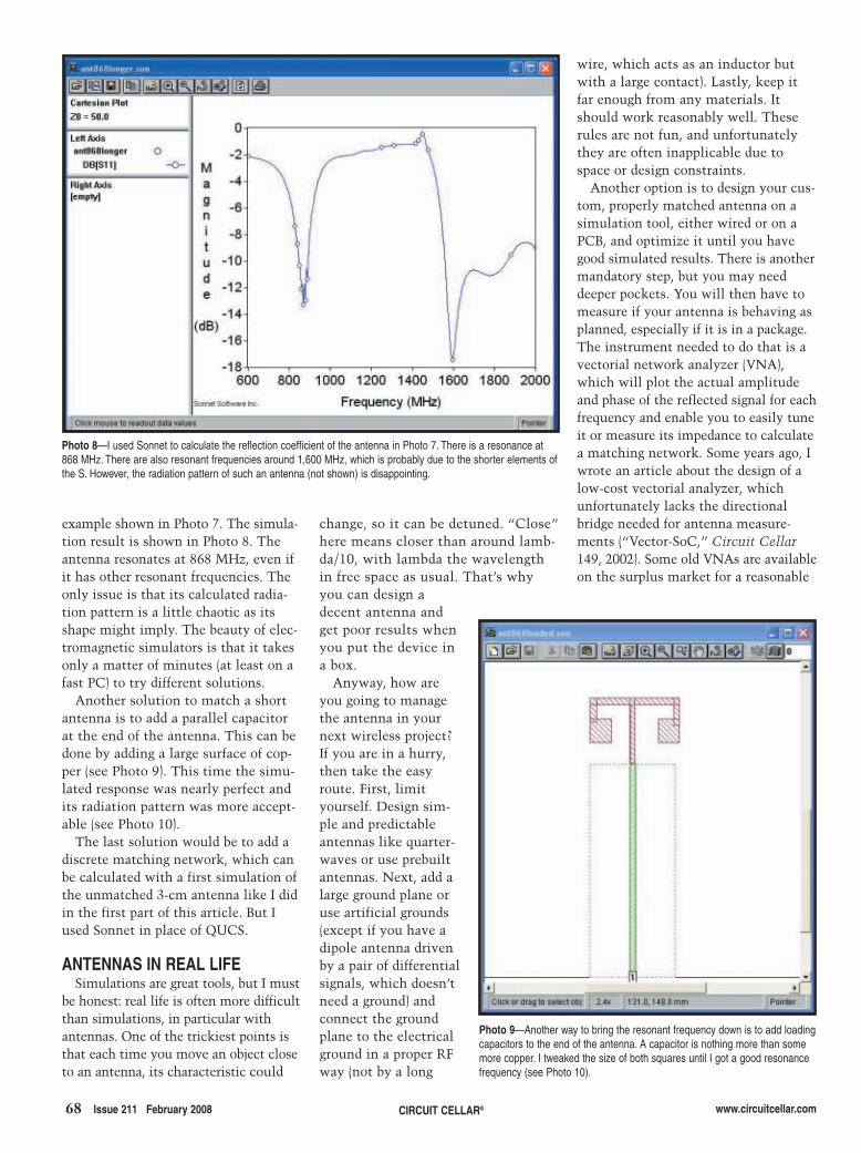
change, so it can be detuned. “Close”here means closer than around lamb-da/10, with lambda the wavelengthin free space as usual. That’s whyyou can design adecent antenna andget poor results whenyou put the device ina box.
Anyway, how areyou going to managethe antenna in yournext wireless project?If you are in a hurry,then take the easyroute. First, limityourself. Design sim-ple and predictableantennas like quarter-waves or use prebuiltantennas. Next, add alarge ground plane oruse artificial grounds(except if you have adipole antenna drivenby a pair of differentialsignals, which doesn’tneed a ground) andconnect the groundplane to the electricalground in a proper RFway (not by a long
68 Issue 211 February 2008 CIRCUIT CELLAR® www.circuitcellar.com
example shown in Photo 7. The simula-tion result is shown in Photo 8. Theantenna resonates at 868 MHz, even ifit has other resonant frequencies. Theonly issue is that its calculated radia-tion pattern is a little chaotic as itsshape might imply. The beauty of elec-tromagnetic simulators is that it takesonly a matter of minutes (at least on afast PC) to try different solutions.
Another solution to match a shortantenna is to add a parallel capacitorat the end of the antenna. This can bedone by adding a large surface of cop-per (see Photo 9). This time the simu-lated response was nearly perfect andits radiation pattern was more accept-able (see Photo 10).
The last solution would be to add adiscrete matching network, which canbe calculated with a first simulation ofthe unmatched 3-cm antenna like I didin the first part of this article. But Iused Sonnet in place of QUCS.
ANTENNAS IN REAL LIFESimulations are great tools, but I must
be honest: real life is often more difficultthan simulations, in particular withantennas. One of the trickiest points isthat each time you move an object closeto an antenna, its characteristic could
wire, which acts as an inductor butwith a large contact). Lastly, keep itfar enough from any materials. Itshould work reasonably well. Theserules are not fun, and unfortunatelythey are often inapplicable due tospace or design constraints.
Another option is to design your cus-tom, properly matched antenna on asimulation tool, either wired or on aPCB, and optimize it until you havegood simulated results. There is anothermandatory step, but you may needdeeper pockets. You will then have tomeasure if your antenna is behaving asplanned, especially if it is in a package.The instrument needed to do that is avectorial network analyzer (VNA),which will plot the actual amplitudeand phase of the reflected signal for eachfrequency and enable you to easily tuneit or measure its impedance to calculatea matching network. Some years ago, Iwrote an article about the design of alow-cost vectorial analyzer, whichunfortunately lacks the directionalbridge needed for antenna measure-ments (“Vector-SoC,” Circuit Cellar149, 2002). Some old VNAs are availableon the surplus market for a reasonable
Photo 9—Another way to bring the resonant frequency down is to add loadingcapacitors to the end of the antenna. A capacitor is nothing more than somemore copper. I tweaked the size of both squares until I got a good resonancefrequency (see Photo 10).
Photo 8—I used Sonnet to calculate the reflection coefficient of the antenna in Photo 7. There is a resonance at868 MHz. There are also resonant frequencies around 1,600 MHz, which is probably due to the shorter elements ofthe S. However, the radiation pattern of such an antenna (not shown) is disappointing.
2802005Lacoste.qxp 1/7/2008 4:55 PM Page 68

www.circuitcellar.com CIRCUIT CELLAR® Issue 211 February 2008 69
SOURCES4NEC2 Simulator Arie Voorshttp://home.ict.nl/~arivoors
Suit professional and Lite electromag-netic field solvers Sonnet Software, Inc. www.sonnetsoftware.com
Quite universal circuit simulator(QUCS)SourceForgehttp://qucs.sourceforge.net
Robert Lacoste lives near Paris,France. He has 18 years of experienceworking on embedded systems, ana-log designs, and wireless telecommu-nications. He has won prizes in morethan 15 international design contests.In 2003, Robert started a consultingcompany, ALCIOM, to share his pas-sion for innovative mixed-signaldesigns. You can reach him at [email protected]. Don’t forget towrite “Darker Side” in the subjectline to bypass his spam filters.
RESOURCESL. B. Cebik, D. Hallidy, D. Jansson,and R. Lewallen, The ARRL AntennaBook: The Ultimate Reference forAmateur Radio Antennas, Transmis-sion Lines And Propagation, 21st edi-tion, American Radio Relay League,Newington, CT, 2007.
M. Loy and I. Sylla, “ISM-Band andShort Range Device Antennas,” TexasInstruments, Inc., SWRA046, 2005.
T. Marshall, “Numerical Electromag-nics Code,” 2002, www.nec2.org.
D. Miron, Small Antenna Design,Newnes, Burlington, MA, 2006.
M. Reppel and Dr. Mühlhaus Consulting& Software, “Analysis of an 868-MHzLoop Antenna,” D-58452, 2005.
J. Wetherell, “Online ImpedanceMatching Network Designer,” 1997,http://home.sandiego.edu/~ekim/e194rfs01/jwmatcher/matcher2.html.
PROJECT FILESTo download code, go to ftp://ftp.circuitcellar.com/pub/Circuit_Cellar/2008/211.
Photo 11—I hooked a hand-made 868-MHz dipolar antenna to my old HP8754 vectorial network analyzer (VNA).The equipment is invaluable for antenna work because it gives me a real-time measurement of the antenna imped-ance matching. The horizontal scale is 0 to 1,300 MHz. The vertical scale is 2.5 dB/div. If you buy an old VNA, don’tforget to buy the mandatory reflection bridge, which is an HP8502A for the HP8754.
Photo 10—This is the simulated reflection coefficient of the antenna in Photo 9. It shows a good match at 868 MHzand no spurious resonances up to 2 GHz. Moreover, the antenna’s radiation pattern is acceptable.
cost. Refer to Photo 11 to see how anold VNA can make your life easier.
Here we are, out of space. I havetouched on only 5% of the subject.Although I didn’t cover several impor-tant topics (e.g., broadband antennas,polarization issues, loop, helical ordirectional antennas, standing waves,
path loss), I hope you are now a littleless afraid of impedance matching andantennas. Don’t hesitate to play withQUCS, NEC2, Sonnet Lite, and realantennas. This is the only way to real-ly understand what’s going on. Anten-nas are not black magic, even if theyare sometimes on the darker side. I
2802005Lacoste.qxp 1/7/2008 4:55 PM Page 69

70 Issue 211 February 2008 CIRCUIT CELLAR® www.circuitcellar.com
Back in the Bad Old Days, you sol-dered metal by heating a chisel-pointedcopper-tipped iron rod in an open-flame furnace and applying tin-leadsolder. No project was too large for amassive red-hot iron!
These days, a needle-pointed 60-Wtemperature-controlled iron and lead-free silver solder suffice for my elec-tronic soldering needs. I sometimesdrag out my hulking 150/230 W sol-dering gun, although even that’s inad-equate for large RF shields, big con-nectors, and structural elements.
Rather than getting a larger iron or abigger fire, I decided to try resistance sol-dering. This process directly heats metal-lic workpieces by passing a high currentthrough them, so only the sectionbetween the electrodes gets hot enoughto melt solder. Direct heating is farmore effective than indirect heating byconduction from a soldering iron’s tip.
Taken to an extreme, resistanceheating can fuse workpieces withoutsolder in a process called spot weld-ing. For example, NiMH cells andnickel-metal interconnects in batterypacks are spot-welded together.
The basic schematic of a resistancesoldering or welding unit has three com-ponents: a voltage source, a switch, anda resistive load. The load, simply thejoint between the workpieces, wouldlook like a short circuit in any otherapplication, so this certainly isn’t afussy high-impedance analog circuit.
The power source, typically a massivetransformer like the one shown inPhoto 1, is a truly unfamiliar electron-ic component. In this column, I’ll look
at some of the fundamental equationsgoverning transformers and measurethe properties of a real transformer.Next time, I’ll explore how to controlthe power it delivers to the workpieces.
FUNDAMENTALSIn the mid-1820s, Hans Christian
Øersted (usually anglicized from theDanish as Oersted) put a husky directcurrent through a wire, observed that itmoved a nearby magnetic compass nee-dle, and concluded that electricitycould produce magnetism. André-MarieAmpère soon demonstrated that theneedle’s deflection was proportional toboth the current and the number ofconductor loops near the compass.
The natural unit of what becameknown as magnetomotive force is theampere·turn. The CGS system of unitsuses the gilbert, abbreviated Gi, payinghomage to William Gilbert, the guy whofirst named “electricity.” It’s defined as:
[1]
Those early experimenters found thatthe converse of Oersted’s effect did notoccur: an unchanging magnetic field didnot produce a corresponding direct cur-rent. In 1831, Michael Faraday discov-ered that moving the wire in relationto the magnetic field induced a currentthat depended on both the wire’s speedand number of turns. The equation forthat effect is:
[2]
The voltage e represents the instan-
e N ddt
10 8= − × −φ
mmf 4 N I 0.4 N I= =π π10
taneous voltage due to changes in thefield. Obviously the induced voltage iszero in an unchanging magnetic field.
The flux φ represents the magneticfield linking the conductor, which isalways less than the total flux. TheCGS unit is the maxwell, in honor ofJames Clerk Maxwell, who combinedall of the various electrical and mag-netic equations into a unified electro-magnetic system that explainedeverything up to that point in histo-ry. Einstein changed all that, but rela-tivity is far beyond the scope of thiscolumn.
Note that Mw, the abbreviation formaxwell, is confusingly similar to MW,the prefix mega applied to the unit watt.Worse, the font flourish that produces Ω,the capital Greek omega, often vanish-es in printed or Web-based text, con-verting a resistance in MΩ (megohm)into power in MW (megawatt) or fluxin Mw (maxwell). You must pay closeattention to the context surroundingthe equation to avoid being tripped upby typography.
As EE professors are wont to say,the derivation of transformer actionfrom Maxwell’s equations should beobvious to the casual observer. Fortu-nately for the rest of us, a host of sim-plifications come into play in practicalpower-transformer applications.
Passing a current I through an N-turn coil wrapped around an iron(steel, ferrite, whatever) core producesthe mmf defined by the first equation.That subsequently creates a magnetiz-ing force H that depends on the mag-netic path length through the core,
TransformersAre you looking to try spot welding or resistance soldering? Ed has you covered with a look attransformer basics. He examines some of the fundamental equations governing transformersand measures the properties of a real transformer.
ABOVE THE GROUND PLANE by Ed Nisley
2802004Nisley.qxp 1/9/2008 11:02 AM Page 70
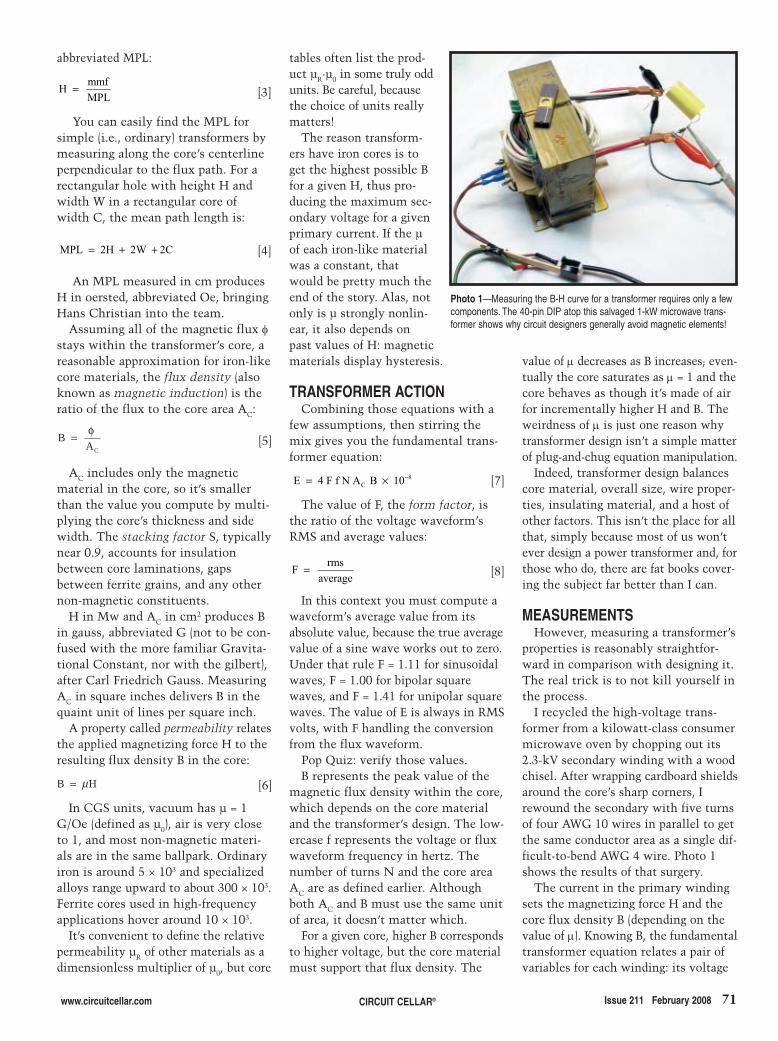
www.circuitcellar.com CIRCUIT CELLAR® Issue 211 February 2008 71
abbreviated MPL:
[3]
You can easily find the MPL forsimple (i.e., ordinary) transformers bymeasuring along the core’s centerlineperpendicular to the flux path. For arectangular hole with height H andwidth W in a rectangular core ofwidth C, the mean path length is:
[4]
An MPL measured in cm producesH in oersted, abbreviated Oe, bringingHans Christian into the team.
Assuming all of the magnetic flux φstays within the transformer’s core, areasonable approximation for iron-likecore materials, the flux density (alsoknown as magnetic induction) is theratio of the flux to the core area AC:
[5]
AC includes only the magneticmaterial in the core, so it’s smallerthan the value you compute by multi-plying the core’s thickness and sidewidth. The stacking factor S, typicallynear 0.9, accounts for insulationbetween core laminations, gapsbetween ferrite grains, and any othernon-magnetic constituents.
H in Mw and AC in cm2 produces Bin gauss, abbreviated G (not to be con-fused with the more familiar Gravita-tional Constant, nor with the gilbert),after Carl Friedrich Gauss. MeasuringAC in square inches delivers B in thequaint unit of lines per square inch.
A property called permeability relatesthe applied magnetizing force H to theresulting flux density B in the core:
[6]
In CGS units, vacuum has µ = 1G/Oe (defined as µ0), air is very closeto 1, and most non-magnetic materi-als are in the same ballpark. Ordinaryiron is around 5 × 10³ and specializedalloys range upward to about 300 × 103.Ferrite cores used in high-frequencyapplications hover around 10 × 103.
It’s convenient to define the relativepermeability µR of other materials as adimensionless multiplier of µ0, but core
B H= μ
B AC
= φ
MPL 2H 2W 2C= + +
H mmfMPL
=
tables often list the prod-uct µR·µ0 in some truly oddunits. Be careful, becausethe choice of units reallymatters!
The reason transform-ers have iron cores is toget the highest possible Bfor a given H, thus pro-ducing the maximum sec-ondary voltage for a givenprimary current. If the µof each iron-like materialwas a constant, thatwould be pretty much theend of the story. Alas, notonly is µ strongly nonlin-ear, it also depends onpast values of H: magneticmaterials display hysteresis.
TRANSFORMER ACTIONCombining those equations with a
few assumptions, then stirring themix gives you the fundamental trans-former equation:
[7]
The value of F, the form factor, isthe ratio of the voltage waveform’sRMS and average values:
[8]
In this context you must compute awaveform’s average value from itsabsolute value, because the true averagevalue of a sine wave works out to zero.Under that rule F = 1.11 for sinusoidalwaves, F = 1.00 for bipolar squarewaves, and F = 1.41 for unipolar squarewaves. The value of E is always in RMSvolts, with F handling the conversionfrom the flux waveform.
Pop Quiz: verify those values.B represents the peak value of the
magnetic flux density within the core,which depends on the core materialand the transformer’s design. The low-ercase f represents the voltage or fluxwaveform frequency in hertz. Thenumber of turns N and the core areaAC are as defined earlier. Althoughboth AC and B must use the same unitof area, it doesn’t matter which.
For a given core, higher B correspondsto higher voltage, but the core materialmust support that flux density. The
F rmsaverage
=
E 4 F f N A B 10C8= × −
value of μ decreases as B increases; even-tually the core saturates as μ = 1 and thecore behaves as though it’s made of airfor incrementally higher H and B. Theweirdness of μ is just one reason whytransformer design isn’t a simple matterof plug-and-chug equation manipulation.
Indeed, transformer design balancescore material, overall size, wire proper-ties, insulating material, and a host ofother factors. This isn’t the place for allthat, simply because most of us won’tever design a power transformer and, forthose who do, there are fat books cover-ing the subject far better than I can.
MEASUREMENTSHowever, measuring a transformer’s
properties is reasonably straightfor-ward in comparison with designing it.The real trick is to not kill yourself inthe process.
I recycled the high-voltage trans-former from a kilowatt-class consumermicrowave oven by chopping out its2.3-kV secondary winding with a woodchisel. After wrapping cardboard shieldsaround the core’s sharp corners, Irewound the secondary with five turnsof four AWG 10 wires in parallel to getthe same conductor area as a single dif-ficult-to-bend AWG 4 wire. Photo 1shows the results of that surgery.
The current in the primary windingsets the magnetizing force H and thecore flux density B (depending on thevalue of μ). Knowing B, the fundamentaltransformer equation relates a pair ofvariables for each winding: its voltage
Photo 1—Measuring the B-H curve for a transformer requires only a fewcomponents. The 40-pin DIP atop this salvaged 1-kW microwave trans-former shows why circuit designers generally avoid magnetic elements!
2802004Nisley.qxp 1/9/2008 11:02 AM Page 71

72 Issue 211 February 2008 CIRCUIT CELLAR® www.circuitcellar.com
and number of turns. Their ratio givesthe transformer’s volts per turn value:
[9]
Every winding on a given trans-former has the same E/N ratio, becauseeach sees the same core flux. Therewound five-turn secondary produces5.3 V with the rated 120 V on the pri-mary, making E/N = 1.1. The primaryshould therefore have 110 turns, closeto my estimated count of 120 turns.
The core laminations are a ratherthick 0.020 in, so I estimated thestacking factor S = 0.95. Multiplyingthe central leg area by S gives AC as:
[10]
The core flux will be sinusoidal, sothe form factor F = 1.11. Solving forthe core flux density gives:
[11]
Plugging in the numbers producesits peak value:
[12]
That’s very high for a laminatediron core, which means the core oper-ates near saturation.
The secondary winding voltage isproportional to the change in coreflux, so the time integral of that volt-age is directly proportional to the flux.Integrating a sine wave signal is triv-ially easy: an RC circuit will suffice.
Figure 1 shows the circuitry requiredto measure the primary current and inte-grate the secondary voltage: a 0.1-Ωpower resistor and an RC low-pass filter,respectively. You’ll also need an oscillo-scope and an isolation transformer.
The current-sensing resistanceshould be much less than the primarywinding’s inductive reactance. I meas-ured the inductance LP = 20 mH,making its reactance:
[13]
I taped a 100-mΩ sandbox resistor, thecoax cable to the ’scope, and the AC linecord to a wood stick acting as ananchor and strain relief, then connectedthe input to an antique Sencore PR57
X 2 f L 7.4 LP = =π Ω
B 1.14 1.11 60 20.5 10
20 kG8=× × × ×
=−
A 0.95 4.45 4.85 20.5 cmC2= × × =
= ×EN
4 F f A B 10C8−
Powerite variable isolation transformer.If you don’t use an isolation transformer,make absolutely certain to connect theresistor on the neutral side of the ACline and measure the differential volt-age across it. Do not connect your’scope ground lead to the AC line!
The core’s MPL works out to 26.7 cm,so the magnetizing force H is:
[14]
The 100-mΩ resistor scales the dis-play by 10 A/V, making the voltage-to-H factor:
[15]
The RC integrator’s –3-dB pointshould be much lower than 60 Hz, so Ipicked R = 220 kΩ and C = 1 μF for a4.5-Hz cutoff. The output voltageacross the capacitor is then:
[16]
Recall that the integral of a sine is thenegative cosine, scale up the result byRC, pop all that into the second equa-tion, and turn the crank to get thevoltage-to-flux-density scale factor:
[17]
The smooth lower trace in Figure 2shows the integrated secondary volt-age has a peak value of 90 mV. Thatcorresponds to a peak core flux densi-ty of 19 kG, comfortably close to the20 kG derived from the turns ratio.
Although the secondary voltage(think “core flux”) is nearly sinu-soidal, the primary current (“magnet-izing force”) sports nasty 14-A peaks.With B nearly sinusoidal and H bear-ing spikes, their ratio μ (“permeabili-ty”) obviously isn’t constant!
BH PLOTSFigure 3 plots B against H for three
values of primary voltage to show howthe transformer operates at three levelsof maximum magnetizing force. Eventhough the peak H values at 120 VAC liewell off-screen, it’s obvious that thistransformer runs very close to com-plete saturation.
It turns out that’s a brutally effectiveway to regulate the microwave oven’s
BV
R C 10N A
215 10CAP
8
C
3= ××
= ×
V 1R C
V dtCAP SEC= ∫
H 52 VRES=
= =H 0.4 N I26.7
5.2 I PRIπ
power output, because even large changesin H caused by line-voltage variationswon’t affect the peak value of B by verymuch and, thus, won’t change the outputvoltage driving the oven’s magnetrontube. Imagine this: no complex electron-ics, no delicate semiconductors, no feed-back loops; just a saturated iron core!
The BH plot shows the hysteresisduring each power-line cycle, whereeach value of H has two correspondingvalues of B that depend on whether His increasing or decreasing. The valueof B also depends on the maximumvalue of H. Obviously, B is not a sin-gle-valued linear function of H!
The size of the BH loop increases asthe applied primary voltage goes up. Itturns out that the area within the loopis proportional to the power dissipa-tion in the core caused by rearrangingall those magnetic domains duringeach power-line cycle.
Pop Quiz: verify that:
[18]
Hint: dimensional analysis is yourfriend.
My Kill A Watt meter reports thatthe transformer draws 76 W with an
Power B H A MPL fC= × × × ×
Power B H A MPL fC= × × × ×
Figure 1—A transformer’s magnetizing force dependson the primary current and the resulting changes incore flux determine the secondary voltage. This circuitproduces voltages proportional to both quantities, butrequires isolation from the power line to prevent electricalor organic damage.
Figure 2—The upper trace shows the primary voltageapplied to the transformer. The peaked trace is the pri-mary current, proportional to the magnetizing force H.The sine-wave lower trace is proportional to the coreflux density B.
2802004Nisley.qxp 1/9/2008 11:02 AM Page 72

www.circuitcellar.com CIRCUIT CELLAR® Issue 211 February 2008 73
open secondary. That seems high, butrecall it’s less than 10% of the originaloven’s rated power level. Because thetransformer also provided outputpower regulation, this seems like areasonable trade-off.
The meter reports 6.6 A of primarycurrent, not the 14-A peaks shown inFigure 2, which is the differencebetween the waveform’s RMS and peakvalues. My oscilloscope’s calculatedRMS value matches the meter’s displayto 10%. I’m mildly surprised that themeter calculates accurate RMS values.
Figure 2 shows that the current peakslag the primary voltage by 90 degrees,so nearly all the current goes intoreactive power. Indeed, the meterreports 780 VA of reactive power and apower factor of just 0.09, so this hulkis a mildly lossy inductor.
CONTACT RELEASEThose waveforms will change when
this transformer sees a load, butexploring that topic requires someelectronics. Meanwhile, make somemeasurements and see how transform-ers really work.
CAUTION! The familiar Variac-stylevariable transformer is an autotrans-former, not an isolation transformer: itsprimary and secondary terminals share asingle winding. If you must use an auto-transformer, make absolutely certainthat both the power-line neutral and themeasurement resistor connect to thewinding’s common terminal. A trivialoversight can destroy your test equip-ment or kill you.
I attempted to use SI units for this col-umn and failed completely; the classicreferences use CGS units, as do many ofthe datasheets. SI has a lot to recommend
it, but most of the equations you findon the web don’t include the appropri-ate conversion factors. Check yourwork!
Resistance heating forces a high cur-rent through the workpieces, making itunsuitable for electronic devices. Use itwith metallic objects, not electronics.
Although I cited Wikipedia in thereferences, treat those articles as astarting point and always cross-checkthe equations with other sources.Their tech articles tend to be stable,but errors do creep in and may remainundiscovered for some time. I’m verydisturbed that some professors havedeliberately introduced errors to seewhether their students are payingattention. I
Ed Nisley is an EE and author in Pough-keepsie, NY. Contact him at [email protected] with “Circuit Cellar” in thesubject to avoid spam filters.
RESOURCESTransformer rewinding and spot welding:
www.users.on.net/~endsodds/psrewind.htm
www.5bears.com/welder.htm
http://users.frii.com/katana/spotweld.html
www.rhunt.f9.co.uk/Electronics/Spot_Welder/Spot_Welder_Page1.htm
Units conversion, http://converter.eu.
Wikipedia, “Dimensional Analysis,”http://en.wikipedia.org/wiki/Dimensional_analysis.
———, “Transformer Design,” http://en.wikipedia.org/wiki/Transformer_design.
SOURCESCalchemy live dimensional calculatorCalchemy Software, Inc.www.calchemy.com/uclive.htm
Kill A Watt meter P3 International Corp. www.p3international.com
PR570 Powerite II Transformer andsafety analyzerSencore, Inc.www.sencore.com
Figure 3—The Y axis is proportional to the core fluxdensity B. The X axis is proportional to the magnetizingforce H. The three curves show various primary volt-ages: 120 VAC drives the core nearly to saturation.
2802004Nisley.qxp 1/9/2008 11:03 AM Page 73

questions and a number of possibleresponses. All of the SitePlayer’s code,including the necessary web pages, isautomatically produced using an appli-cation program written to support theproject. The poll is created from a textfile of questions and multiple-choice
answers. You will need torefer to that column as thebasis of how this second partsupports and makes use ofthe SitePlayer.
SERIAL CONNECTIONSCommunication with the
SitePlayer (SP) is handledthrough a serial connection.The default data rate is9,600 bps, but it may bechanged through theSitePlayer definition (.SPD)file. The SP understands afew basic commands thatenable the retrieval andupdating of its internal
hands of almost every major companythat wishes to get into John Q. Public’shead. Success is often achieved by satis-fying of the masses. Polling provides thedata that indicates the path to take formaximum results (based on what thepoll says people want).
While the projects in this columnaren’t politically (or monetarily) moti-vated, during an election year, ourawareness of polling increases, and itseems fitting to include a project witha polling theme. All those in favor,keep reading. In this column, I willfinish the project I started last month.The hardware discussed last time con-sisted of a small module that includesa web server. A small amount ofexternal circuitry supports theSitePlayer module (see Photo 1). Addi-tional circuitry enables a microcon-troller to assist in data collection insupport of the web pages served.These pages provide you with poll
74 Issue 211 February 2008 CIRCUIT CELLAR® www.circuitcellar.com
The main mode of transportationused in the colonies was horseback.Because information (i.e., the mail)was transmitted by pony, it’s not sur-prising that the tabulation of an elec-tion was a tedious process. Ballotsecurity was more a local issue than anational one. Today, stolen identityconcerns have heightened our intoler-ance to election fraud and electronicvoting issues. Recently, we saw net-work news teams begin predictingelection outcomes as soon as the pollsclosed on the East Coast. Althoughmost voters in the west had alreadyvoted or at least determined how theywould vote, I can not help but feelthat some may have been swayedeither to change their votes or notbother voting at all.
Unfortunately for us, election cam-paigns are beginning earlier in the elec-tion cycle. The amount of money spentcampaigning is spiraling out of control.To win a presidential bidfor election today, candi-dates may have to spend upto $1 billion. Let’s put thatinto perspective. That’sroughly the total budget forthe U.S. Department ofEnergy. What kind of tech-nology breakthroughscould be made if we invest-ed that kind of money intoenergy research?
During the campaignprocess, we are exposed toa lot of polling. While thistool may be used in thepolitical process, it hasfound its way into the
Portable Poll ServerFROM THE BENCH by Jeff Bachiochi
Jeff finishes describing the design of a portable poll server. SitePlayer and a small microprovide Internet access to a poll’s questions and the results.
Part 2: Data Acquisition & Results
Photo 1—This project’s prototype fits in a plasticenclosure slightly larger than 3″ × 4″. The SP moduleplugs into a pair of 1 × 7 SIP connector strips, whichconnect the microcontroller’s UART1 port and theexternal circuitry in support of a LAN connection. AMAX232 converts the microcontroller’s UART2 TTLserial output to RS-232.
SitePlayer serial commandsCommand Command byte DescriptionNOP 00h Do nothing, recommended initializing command
Status 10h Return status of SitePlayer
Reset 20h Perform a watchdog reset
ComParams 33h Set data rate and UART delay
UDPsend 50h Send a UDP packet
Read 0C0h Read object from SitePlayer
Write 80h Write object to SitePlayer
ReadX 0D0h Read using extended 2-byte addressing
WriteX 90h Write using extended 2-byte addressing
ReadBit 0E0h Read a bit variable, one byte address
WriteBit 0A0h Write a bit variable, one byte address
ToggleBit 0B0h Toggle a bit variable, one byte address
Table 1—This table contains the serial commands recognized by the SitePlayer. Mostof these are used to receive data from or send data to SitePlayer’s internal registers.The registers were defined in the “Object” section of the .SPD file.
27802002-Bachiochi.qxp 1/7/2008 4:56 PM Page 74
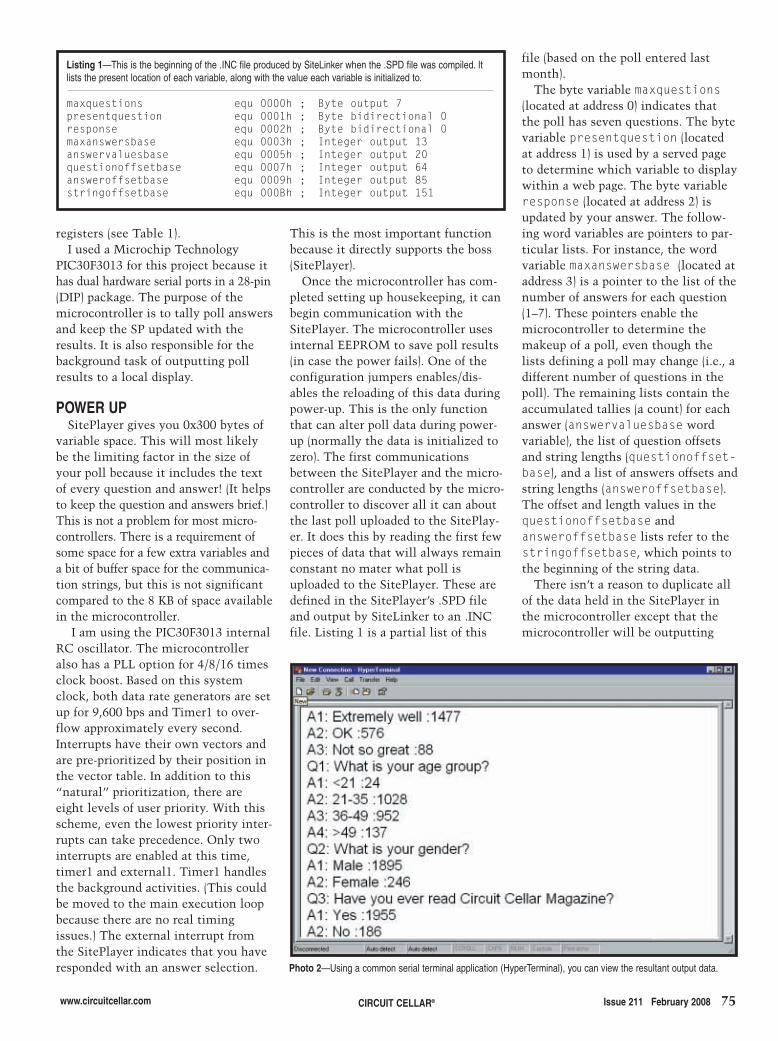
registers (see Table 1).I used a Microchip Technology
PIC30F3013 for this project because ithas dual hardware serial ports in a 28-pin(DIP) package. The purpose of themicrocontroller is to tally poll answersand keep the SP updated with theresults. It is also responsible for thebackground task of outputting pollresults to a local display.
POWER UPSitePlayer gives you 0x300 bytes of
variable space. This will most likelybe the limiting factor in the size ofyour poll because it includes the textof every question and answer! (It helpsto keep the question and answers brief.)This is not a problem for most micro-controllers. There is a requirement ofsome space for a few extra variables anda bit of buffer space for the communica-tion strings, but this is not significantcompared to the 8 KB of space availablein the microcontroller.
I am using the PIC30F3013 internalRC oscillator. The microcontrolleralso has a PLL option for 4/8/16 timesclock boost. Based on this systemclock, both data rate generators are setup for 9,600 bps and Timer1 to over-flow approximately every second.Interrupts have their own vectors andare pre-prioritized by their position inthe vector table. In addition to this“natural” prioritization, there areeight levels of user priority. With thisscheme, even the lowest priority inter-rupts can take precedence. Only twointerrupts are enabled at this time,timer1 and external1. Timer1 handlesthe background activities. (This couldbe moved to the main execution loopbecause there are no real timingissues.) The external interrupt fromthe SitePlayer indicates that you haveresponded with an answer selection.
www.circuitcellar.com CIRCUIT CELLAR® Issue 211 February 2008 75
This is the most important functionbecause it directly supports the boss(SitePlayer).
Once the microcontroller has com-pleted setting up housekeeping, it canbegin communication with theSitePlayer. The microcontroller usesinternal EEPROM to save poll results(in case the power fails). One of theconfiguration jumpers enables/dis-ables the reloading of this data duringpower-up. This is the only functionthat can alter poll data during power-up (normally the data is initialized tozero). The first communicationsbetween the SitePlayer and the micro-controller are conducted by the micro-controller to discover all it can aboutthe last poll uploaded to the SitePlay-er. It does this by reading the first fewpieces of data that will always remainconstant no mater what poll isuploaded to the SitePlayer. These aredefined in the SitePlayer’s .SPD fileand output by SiteLinker to an .INCfile. Listing 1 is a partial list of this
file (based on the poll entered lastmonth).
The byte variable maxquestions(located at address 0) indicates thatthe poll has seven questions. The bytevariable presentquestion (locatedat address 1) is used by a served pageto determine which variable to displaywithin a web page. The byte variableresponse (located at address 2) isupdated by your answer. The follow-ing word variables are pointers to par-ticular lists. For instance, the wordvariable maxanswersbase (located ataddress 3) is a pointer to the list of thenumber of answers for each question(1–7). These pointers enable themicrocontroller to determine themakeup of a poll, even though thelists defining a poll may change (i.e., adifferent number of questions in thepoll). The remaining lists contain theaccumulated tallies (a count) for eachanswer (answervaluesbase wordvariable), the list of question offsetsand string lengths (questionoffset-base), and a list of answers offsets andstring lengths (answeroffsetbase).The offset and length values in thequestionoffsetbase andansweroffsetbase lists refer to thestringoffsetbase, which points tothe beginning of the string data.
There isn’t a reason to duplicate allof the data held in the SitePlayer inthe microcontroller except that themicrocontroller will be outputting
Listing 1—This is the beginning of the .INC file produced by SiteLinker when the .SPD file was compiled. Itlists the present location of each variable, along with the value each variable is initialized to.
maxquestions equ 0000h ; Byte output 7presentquestion equ 0001h ; Byte bidirectional 0response equ 0002h ; Byte bidirectional 0maxanswersbase equ 0003h ; Integer output 13answervaluesbase equ 0005h ; Integer output 20questionoffsetbase equ 0007h ; Integer output 64answeroffsetbase equ 0009h ; Integer output 85stringoffsetbase equ 000Bh ; Integer output 151
Photo 2—Using a common serial terminal application (HyperTerminal), you can view the resultant output data.
27802002-Bachiochi.qxp 1/7/2008 4:56 PM Page 75

76 Issue 211 February 2008 CIRCUIT CELLAR® www.circuitcellar.com
this data in the background. You wantto keep communications with theSitePlayer down to a minimum so itdoesn’t interfere with its web servingresponsibility. Therefore, all of thedata is initially read from the SitePlay-er during the initializing process. Afterthat point, only presentquestionand response need to be read fromthe SitePlayer. A single incrementedanswer value total needs to be updatedfor each answered poll question. Mostpolls don’t display the present totalsto the viewer, but I thought thiswould make the project more interest-ing. You might choose to disable this.
MAINNow that the microcontroller has
“discovered” the poll and updated theSitePlayer’s answer values with eitherzeros or EEPROM values, it happilyawaits an interrupt. After you areserved a web page poll question andyou respond with an answer, SitePlay-er interrupts the microcontroller andexecution is passed to the externalinterrupt 1 vector. This routine thenuses UART1 to retrieve the presen-tquestion. (This value has just been
updated to the nextquestion number.)Next, the responseis retrieved. (This isyour choice to thelast question.) Usingthe list maxanswers,you can determinethe position in theanswervalue list ofthe answer valuethat must be incre-mented. This will bethe total of all of themaxanswers fromthe previous questionsplus the response.The word variable isincremented (in themicrocontroller) andthe new value is sentto SitePlayer toupdate the appropriatevariable in itsanswervalue list.The new value is alsosent to the EEPROMto preserve the change
(in case of a power failure). (Typical byteEEPROM endurance is 1 million writes.If you are worried about approachingthis, you might choose to use anothermethod of determining when an EEP-ROM save is necessary.)
That’s it for SitePlayer support! TheTimer1 overflow determines the back-ground function for the microcontroller.
There is nothing special about theroutine’s 1-s overflow time. This rou-tine’s function is to periodically out-put the poll’s results. The results dataformat is a single question’s text andeach answer’s text (followed by anASCII representation of the answer’stotal hits). The idea here is to havesome kind of serial device capable ofdisplaying the text results sent out bythe microcontroller. This might besimply a PC running HyperTerminal(see Photo 2). If so, you may want toslow down the output rate (e.g., every10 s) to give the user a chance to com-prehend each burst of information.
To make this data more friendly, Iwanted to do a bit more with its out-put. A second PC application readsthe result data and displays it in agraphical format.
The microcontroller updates itsown volatile variable, its nonvolatile(EEPROM) variable, and the SP aswell. Figure 1 shows this interruptroutine (INT0) and the background(Timer1) task.
The background task can be writtento support a number of displayoptions. For this presentation, I choseto use Liberty BASIC (LB) to take inserial data from the microcontrollerand present it with bar graphs to visu-alize the poll results (see Photo 3).
RESULTSWhile the serial output from the
Photo 3—This PC application written in Liberty BASIC monitors and displays the most recent poll results. Theresults are continuously output via the microcontroller’s UART2.
Figure 1—This flowchart shows the two main interrupt routines running in themicrocontroller. The high-priority INT0 routine handles communication betweenthe microcontroller and the SitePlayer module via UART1. The low-priorityTimer1 routine exports result data through UART2.
INT0
Get the PresentQuestion andresponse values from the SitePlayer
Calculate the pointer into theAnswerValuesBase
Get that present value in the micro,add 1, and return it
Update this value to the SitePlayer
Save the value to the EEPROM
RETl
Qcount = Qcount+1
Qcount >MaxQuestions?
Qcount = 1
Enable TX2
Clear Timer1
RETl
Timer1
UART2 busy?
Add “Q” and the ASC of Qcount to theXMIT2 buffer.
Use Qcount to calculate the pointerinto the QuestionOffsetBase.
Use the data at the pointer to retrievethe question text and move it to the
XMIT2 buffer.Add <cr><lf> to the XMIT2 buffer.
Acount = 0
Acount = Acount + 1Add “A” and the ASC of Acount to the
XMIT2 buffer.Use Qcount and Acount to calculate
the pointer into the AnswerOffsetBaseand AnswerValueBase.
Use the data at the pointer to retrievethe answer text and move it to the
XMIT2 buffer.Add “:” to the XMIT2 buffer.
Use the data at the pointer to retrievethe AnswersValue and move it into
the XMIT2 buffer.Add <cr><lf> to the XMIT2 buffer.
Acount =MaxAnswersfor Qcount?
27802002-Bachiochi.qxp 1/7/2008 4:56 PM Page 76

www.circuitcellar.com CIRCUIT CELLAR® Issue 211 February 2008 77
microcontroller includes actual pollnumbers (the number of times eachanswer was chosen), a display showinghow answers rank in the poll makesmore sense than a bunch of numbers.This can also add a bit of color to thedisplay. LB is perfect for such an appli-cation. Once initial data has been col-lected, I can use some simple tech-niques to display the data in a numberof ways. I start by collecting data intovariables. By keeping track of questionand answer numbers, I can tell whenthe data begins to repeat. This way, Ican prevent uninitialized data frombeing displayed.
A display page consists of a ques-tion, its answers, and a bar graph ofeach answer’s percentage. In additionto each answer’s bar graph percentage,the total responses along with thenumber of responses for each answerare also displayed in text form (seePhoto 3). For consistency, I designedthe display using graphic boxes. Thegraphic box is powerful because it cancontain any of the drawing/coloringcommands as well as text. Many ofthe graphic boxes are used to displayonly text. Here font and size com-mands operate independently on eachgraphic box. To create a bar graph, thegraphic box is first filled using the back-ground color “lightgray.” These graphicboxes were initialized to 600 pixelswide by 30 pixels high. You can fillany color to any width by using the“color” and “boxfilled x,y” graphicbox commands. To mix things up abit, each screen randomly selects fourcolors from a given palette and eachanswer’s bar is drawn using a differentcolor. A percentage is calculated foreach answer’s response based on thetotal responses for each question’sanswers. The bar drawn for eachanswer uses the “boxfilled x,y,” wherethe value for x is 600 × percentage(width) and y is 40 (height). The “box-filled x,y” command can be used todraw (a filled rectangle) anywherewithin the graphic box. I chose to leftjustify all of the bars. All variablesused to display information on thepage are arrays where the first dimen-sion is the question number and a sec-ond dimension is the answer number.
With a display page defined, displaying
a particular question is a matter ofchanging the questionnumber vari-able. In the dropdown menu, you cansee three types of display modes: Sin-gle Question, Sequential Questions,and Random Questions. There is alsoa Time Delay menu selection used forall modes. This enables you to set thenumber of seconds (up to 1 min.) thata display remains before updating.This is also used in Single Questionmode because any new data coming inwill need to be updated on the display.
POLL DATAAs I worked on this project, I
thought about how polling is used. Inthis project, each question is really aseparate poll unto itself. There is nocorrelation between the answers ofany two questions. For example, if thefirst question asking the sex of thepoll taker resulted in 75% answering“male” and 25% answering “female,”and if the second question inquiringabout marital status was answered by25% as “married” and 75% as single,then you know that three times asmany males than females took thepoll and most of the polltakers weresingle, but you have no idea what per-centage of the females are married. Itis extremely important that you askthe right questions. Perhaps youshould ask a question with four possi-ble answers: male (single), female (sin-gle), male (married), and female (mar-ried). The usefulness of a poll startswith asking the right questions.
While totals offer specific informa-tion, to be able to correlate an answerbased on another question, a databasemust be used. If all of the answers ofeach polltaker are recorded as a datarecord, correlations can be made byfiltering the records in different ways.This way, one might toss aside all ofthe records that include the answer“female” to specifically see how themales answered another question.Unfortunately, this can require hugeamounts of memory if you need theresults available in real time. There isno reason the serial data used here (foran external display) couldn’t berewritten to output database records.Refer to my column about using Vin-culum’s VNC1L as a serial-to-USB
thumbdrive datalogger (“EmbeddedUSB Breakthrough,” Circuit Cellar200, 2007).
While the SitePlayer module usedhere simplified the end product, sizerestrictions limit the size of the poll.While the file size is limited, the wayin which I designed this project (to bechangeable through the web interface)meant that all of the text had to bepart of the SP’s file. The poll pagescould be designed to use a single mas-ter page for all of the questions. Thatwould enable the microcontroller topump the necessary text into theSitePlayer where it would be served asa dynamic page. While that reducesthe file size necessary for the SP,updating with a new poll through theweb would become much more com-plicated. This could be done on themicrocontroller side by updating orexchanging the poll text (i.e., in anexternal EEPROM), but it requireslocal access.
I hope some part of this projectinduced an “Aha” while you read. Ineither case, you should be able toanswer this question.
Was this article series helpful?
____Yes ____No
Your vote counts! I
PROJECT FILESTo download code, go to ftp://ftp.circuitcellar.com/pub/Circuit_Cellar/2008/211.
SOURCESdsPIC30F3013 Digital signal controllerMicrochip Technology, Inc.www.microchip.com
SitePlayer Webserver moduleNetMedia, Inc.www.siteplayer.com
Jeff Bachiochi (pronounced BAH-key-AH-key) has been writing for CircuitCellar since 1988. His backgroundincludes product design and manufac-turing. He may be reached through themagazine ([email protected]) or his web site(www.imaginethatnow.com).
27802002-Bachiochi.qxp 1/7/2008 4:56 PM Page 77

78 Issue 211 February 2008 CIRCUIT CELLAR® www.circuitcellar.com
phone you got for free. On the otherhand, like The CW TelevisionNetwork’s Beauty and the Geek TVshow, ASICs are supermodel chips thatregular Joe designers can only dream of.
The tutorial that kicked off the HotChips 19 conference, “Approaches toSystem Design for the WorkingEngineer,” took on the ASIC love/hateissue head-on. First, David Witt ofTexas Instruments described what’sinvolved in crafting a state-of-the-artASIC, the 65-nm OMAP 3430 chip thatmay well be inside that shiny new cellphone Santa gave you.[1] Then PeterAlfke of Xilinx countered with his com-pany’s FPGA-uber-alles battle cry.[2]
Judging by the advances in cellphones, it won’t be long before E. T.
can actually call home. Butthe blistering pace of changemakes designing the chips ascary proposition, not some-thing for the faint of heart.The bottom line is thatyou’ve got about a year and ahalf from the time you brain-storm the next-generationcell phone features until youcomplete the chip design. InWitt’s words, “We mustunderstand and close in thistime or die.”
Along the way, watch outfor booby-traps like verifica-tion because proving the chipworks now consumes 40% ofthe effort. With maybe 100Ksignals on-chip, hook-uperrors are practically a given.Power supply (multi-voltages
tomorrow’s predictions.Oh, before I forget, here’s a Hot
Chips heads-up from Silicon Valley’sComputer History Museum. ThroughSeptember 2008 they’ve got one of theoriginal (only two exist) CharlesBabbage difference engines on display(see Photo 1). If you’re headed toSilicon Valley, consider making a pil-grimage to the museum to see whereit all began.
ARC OF ENLIGHTENMENTI’ve got to admit to a bit of a
love/hate relationship with ASICs. Tobe sure, a big-iron ASIC is a wondrousthing to behold, the silicon wizardbehind the scenes that touches every-body’s life, for example in that cell
With 19 years of Hot Chips confer-ences under my belt, I’ve covered hun-dreds of “Hot Chips.” The irony isthat few real-world embedded applica-tions have found occasion to actuallyuse any of them. But make no mis-take; every designer ultimately bene-fits from the worthier ideas as theymigrate from research labs into themainstream chips everybody uses.
“Hot Chips” are like bleeding edgeconcept cars that show us the shapesof things to come. That fact, alongwith the excellent conference execu-tion by the venerable organizers,makes Hot Chips one of my favoriteevents. What better way to get aglimpse of tomorrow’s answers totoday’s questions?
A few weeks after HotChips 19 at StanfordUniversity, I was in Boston forthe Embedded SystemsConference (ESC). Comparedto Hot Chips, ESC is morelike a trip to the auto mallwhere you’ll find real-worldvehicles you can actually buytoday. No highfalutin conceptcars here. But ESC is whereyou go to find a pickup truckon the lot, one with a trailerhitch to haul some blue-collarembedded software.
Having visited Hot Chipsand ESC back-to-back, Icouldn’t help juxtaposing thetwo. Read on and I thinkyou’ll agree that there aresome interesting parallelsbetween today’s news and
Got Chips?
SILICON UPDATE by Tom Cantrell
Tom’s been on the road again, this time heading coast-to-coast from Hot Chips 19 atStanford University to the Embedded Systems Conference in Boston. See where silicon isand where it’s headed as he takes a whirlwind tour of today’s and tomorrow’s chips.
Photo 1—It may not be a chip, but the Babbage difference engine now on displayat the Computer History Museum was certainly hot in its time.
2802003-Cantrell.qxp 1/7/2008 4:56 PM Page 78
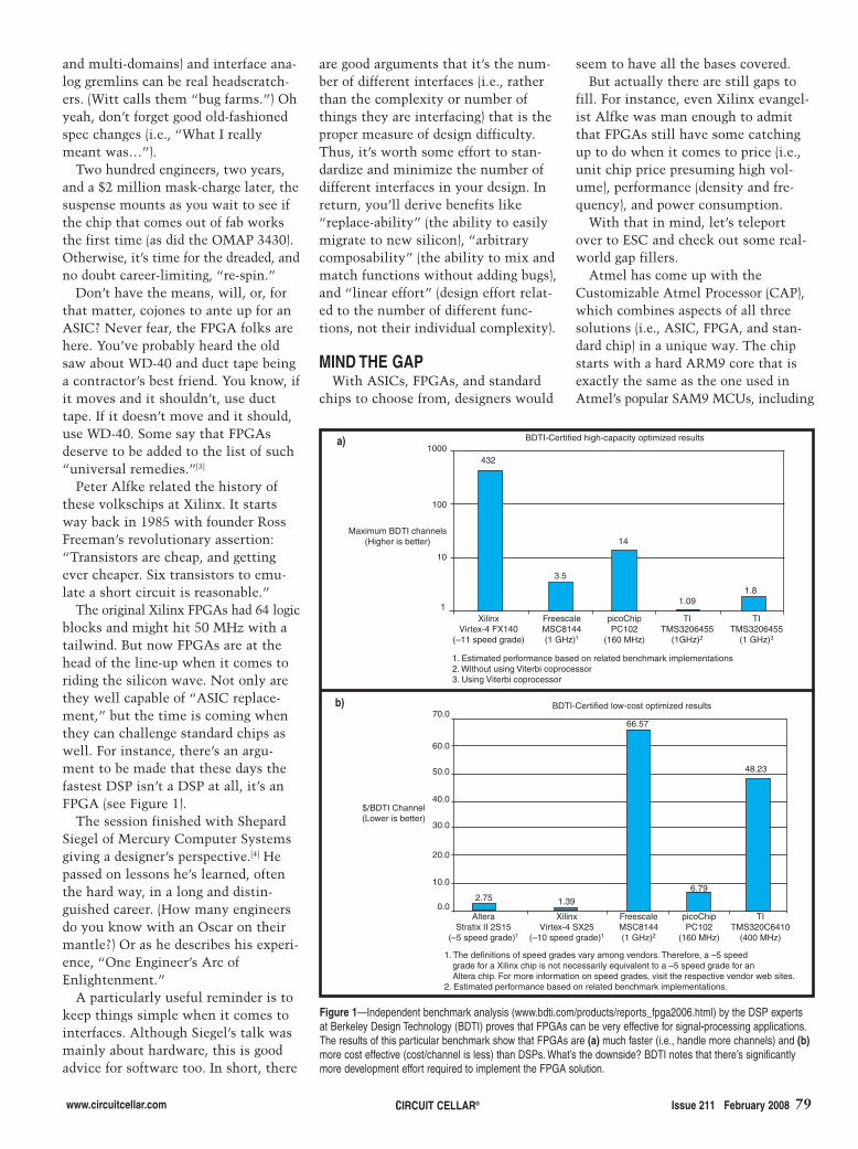
www.circuitcellar.com Issue 211 February 2008 79CIRCUIT CELLAR®
and multi-domains) and interface ana-log gremlins can be real headscratch-ers. (Witt calls them “bug farms.”) Ohyeah, don’t forget good old-fashionedspec changes (i.e., “What I reallymeant was…”).
Two hundred engineers, two years,and a $2 million mask-charge later, thesuspense mounts as you wait to see ifthe chip that comes out of fab worksthe first time (as did the OMAP 3430).Otherwise, it’s time for the dreaded, andno doubt career-limiting, “re-spin.”
Don’t have the means, will, or, forthat matter, cojones to ante up for anASIC? Never fear, the FPGA folks arehere. You’ve probably heard the oldsaw about WD-40 and duct tape beinga contractor’s best friend. You know, ifit moves and it shouldn’t, use ducttape. If it doesn’t move and it should,use WD-40. Some say that FPGAsdeserve to be added to the list of such“universal remedies.”[3]
Peter Alfke related the history ofthese volkschips at Xilinx. It startsway back in 1985 with founder RossFreeman’s revolutionary assertion:“Transistors are cheap, and gettingever cheaper. Six transistors to emu-late a short circuit is reasonable.”
The original Xilinx FPGAs had 64 logicblocks and might hit 50 MHz with atailwind. But now FPGAs are at thehead of the line-up when it comes toriding the silicon wave. Not only arethey well capable of “ASIC replace-ment,” but the time is coming whenthey can challenge standard chips aswell. For instance, there’s an argu-ment to be made that these days thefastest DSP isn’t a DSP at all, it’s anFPGA (see Figure 1).
The session finished with ShepardSiegel of Mercury Computer Systemsgiving a designer’s perspective.[4] Hepassed on lessons he’s learned, oftenthe hard way, in a long and distin-guished career. (How many engineersdo you know with an Oscar on theirmantle?) Or as he describes his experi-ence, “One Engineer’s Arc ofEnlightenment.”
A particularly useful reminder is tokeep things simple when it comes tointerfaces. Although Siegel’s talk wasmainly about hardware, this is goodadvice for software too. In short, there
are good arguments that it’s the num-ber of different interfaces (i.e., ratherthan the complexity or number ofthings they are interfacing) that is theproper measure of design difficulty.Thus, it’s worth some effort to stan-dardize and minimize the number ofdifferent interfaces in your design. Inreturn, you’ll derive benefits like“replace-ability” (the ability to easilymigrate to new silicon), “arbitrarycomposability” (the ability to mix andmatch functions without adding bugs),and “linear effort” (design effort relat-ed to the number of different func-tions, not their individual complexity).
MIND THE GAPWith ASICs, FPGAs, and standard
chips to choose from, designers would
seem to have all the bases covered.But actually there are still gaps to
fill. For instance, even Xilinx evangel-ist Alfke was man enough to admitthat FPGAs still have some catchingup to do when it comes to price (i.e.,unit chip price presuming high vol-ume), performance (density and fre-quency), and power consumption.
With that in mind, let’s teleportover to ESC and check out some real-world gap fillers.
Atmel has come up with theCustomizable Atmel Processor (CAP),which combines aspects of all threesolutions (i.e., ASIC, FPGA, and stan-dard chip) in a unique way. The chipstarts with a hard ARM9 core that isexactly the same as the one used inAtmel’s popular SAM9 MCUs, including
1000
100
10
1
432
3.5
14
1.091.8
BDTI-Certified high-capacity optimized results
Maximum BDTI channels(Higher is better)
XilinxVirtex-4 FX140
(–11 speed grade)
FreescaleMSC8144(1 GHz)1
picoChipPC102
(160 MHz)
TITMS3206455
(1GHz)2
TITMS3206455
(1 GHz)3
1. Estimated performance based on related benchmark implementations2. Without using Viterbi coprocessor3. Using Viterbi coprocessor
Figure 1—Independent benchmark analysis (www.bdti.com/products/reports_fpga2006.html) by the DSP expertsat Berkeley Design Technology (BDTI) proves that FPGAs can be very effective for signal-processing applications.The results of this particular benchmark show that FPGAs are (a) much faster (i.e., handle more channels) and (b)more cost effective (cost/channel is less) than DSPs. What’s the downside? BDTI notes that there’s significantlymore development effort required to implement the FPGA solution.
BDTI-Certified low-cost optimized results70.0
60.0
50.0
40.0
30.0
20.0
10.0
0.02.75 1.39
66.57
6.79
48.23
AlteraStratix II 2S15
(–5 speed grade)1
XilinxVirtex-4 SX25
(–10 speed grade)1
FreescaleMSC8144(1 GHz)2
picoChipPC102
(160 MHz)
TITMS320C6410
(400 MHz)
1. The definitions of speed grades vary among vendors. Therefore, a –5 speed grade for a Xilinx chip is not necessarily equivalent to a –5 speed grade for an Altera chip. For more information on speed grades, visit the respective vendor web sites.2. Estimated performance based on related benchmark implementations.
$/BDTI Channel(Lower is better)
b)
a)
2802003-Cantrell.qxp 1/7/2008 4:57 PM Page 79

special “emulation” versions of theCAP chips work with an external FPGA.
There’s still a bit of black magicinvolved in mapping the Xilinx logicdesign onto the CAP metal-maskprogrammable logic. But with hand-holding from Atmel and their distrib-utors (such as Arrow Electronics),there is clearly intent to make thetransition as painless and as turnkeyas possible.
CAP is a unique technology, butit’s also practical in the biggerscheme of things. You can start witha standard SAM9 MCU. When it’stime to upgrade, you can easily proto-type (and even go into tentative pro-duction) by pairing a CAP emulationchip with an FPGA. If the product is
80 Issue 211 February 2008 CIRCUIT CELLAR® www.circuitcellar.com
flash memory and peripherals. On theASIC side of the equation, CAPsinclude a complement of metal-maskprogrammable logic. Although still“custom” (i.e., factory programmed),metal-mask programmability cuts theNRE (less masks than an ASIC) andreduces lead time (wafers up to metal-mask can be stockpiled).
FPGAs enter the CAP equation inan interesting way that recognizes thepopular design tactic of pairing a stan-dard processor chip and an FPGA. Atrue ASIC design requires a very com-plicated and expensive suite of “chipdesign” tools. By contrast, CAP’s pro-grammable logic is defined using thepopular, and at this point virtually free,Xilinx FPGA tools. For prototyping,
a hit, you can push the metal-maskbutton to shrink the two-chip combointo a single CAP with less time andmoney (not to mention nail-biting)than going the full ASIC route (seeTable 1).
As for power consumption, there’sno doubt that the performance-at-any-price-and-power FPGAs are at a disad-vantage. Six transistors may be cheapenough to duplicate a wire (i.e.,Freeman’s “short-circuit”), but theyuse a heck of a lot more power. Worse,the state-of-the-art processes (65 nmheaded to 45 nm) that high-endFPGAs rely on are at the bleeding edgeof the leakage power crisis.
Enter Actel with their new Igloofamily, a low-power variation of theirflash-based ProASIC parts. Igloo cutspower consumption thanks to alower operating voltage (1.2 V) andthe addition of optimized sleepmodes. Also, the fab process used isless aggressive, and thus less prone toleakage. Put it all together and Igloois arguably the first truly “low-power” FPGA (see Figure 2).
CAP ASICNRE $150,000 $500,000
Minimum order volume 25,000 Units 500,000 Units
Lead time 12 Weeks 40 Weeks
EDA Tool cost Free/low-cost FPGA tools Expensive ASIC toolchain
Table 1—The costs and complexity for ASICs have escalated beyond the reach of most designers. Atmel’s CAPmetal-mask programmable SoC is an “ASIC Lite” alternative. A big advantage for CAP is the use of low-cost FPGAdesign tools to customize the design.
2802003-Cantrell.qxp 1/7/2008 4:57 PM Page 80

Click or call today for a FREE Jameco Catalogand start benefiting from Jameco’s Awesome Prices!
You’re correct, the one on the right costs less becauseit’s from Jameco! When you’re looking to purchasemajor name brand passives or semiconductors, besure to check out Jameco first. They also offermoney-saving generic equivalents at about 20% less, so you’ll save even more! And if you
should find a lower print-advertised price for a product Jameco offers, just let them know andthey’ll offer that product for 10% less than the othercompany’s price, right down to Jameco’s cost!Wouldn’t it be worth your time to check out Jamecotoday at www.Jameco.com?
• Both Major Name Brands and Generic Products for Additional Savings• Over 99% of Catalog Products are in Stock for Immediate Delivery• Only Jameco Guarantees the Lowest Prices
Price!
What’s the difference?
Visit www.Jameco.com/CCXCall 1-800-831-4242
81.qxp 1/4/2008 3:04 PM Page 1

The International Business Development Event for the Personal, Service and Mobile Robotics Industry
April 8-10, 2008
Pittsburgh, PADavid L. Lawrence Convention Center
Now in its fifth year, RoboBusiness Conference & Exposition is the must-attend
event for those interested in the business and technical issues related to the development
of the personal, service and mobile robotics industry.The conference brings emerging
robotics technology out of the lab and into the open market, focusing on the business
of mobile robotics.
RoboBusiness 2008 spotlights industry trends you need to know, like ‘Achieving
Autonomy’ and ‘RoboMedicus’, which includes dedicated sessions and exhibition space
focused on Healthcare Robotics.
RoboBusiness Conference and Exposition promotes business development and a
wide-array of networking opportunities.
�� 30 Conference sessions to build your robotics business
�� Over 75 exhibiting companies
�� Keynotes led by world-renowned industry experts
�� Opening night networking reception
�� Robot Hall of Fame cocktail reception and
induction ceremony
�� Robotics tour of Pittsburgh
�� And much more!
For more information or to register, visit www.robobusiness.com or call 800-305-0634.For sponsorship opportunities, contact Ellen Cotton at 508-663-1500 x240.
Founding Sponsor
Premier Sponsor
Gold Sponsors
Corporate Sponsors
Analysts,Associates & Academic Co-Sponsors
Media Co-Sponsors
Produced by
www.robobusiness.com
Register Early
for the Best
Savings on a Full
Conference Pass
Register Early
for the Best
Savings on a Full
Conference Pass
CCadRoboBiz08.indd 1 12/19/07 11:16:42 AM
82.qxp 12/31/2007 12:33 PM Page 1
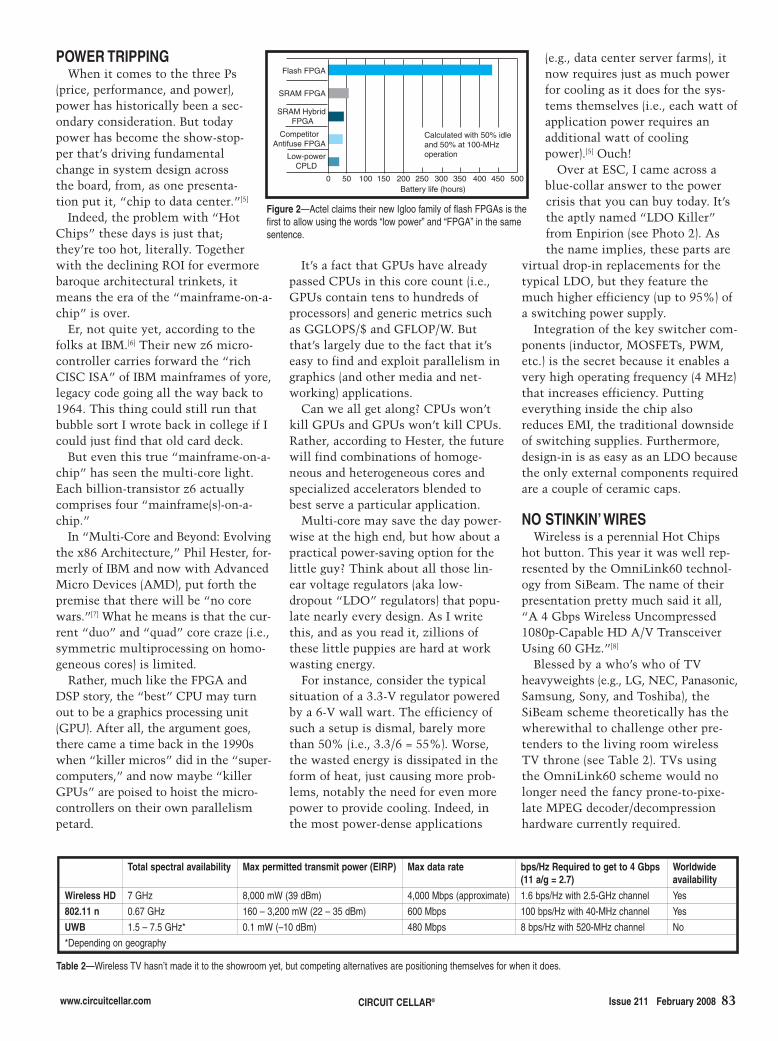
www.circuitcellar.com CIRCUIT CELLAR® Issue 211 February 2008 83
POWER TRIPPINGWhen it comes to the three Ps
(price, performance, and power),power has historically been a sec-ondary consideration. But todaypower has become the show-stop-per that’s driving fundamentalchange in system design acrossthe board, from, as one presenta-tion put it, “chip to data center.”[5]
Indeed, the problem with “HotChips” these days is just that;they’re too hot, literally. Togetherwith the declining ROI for evermorebaroque architectural trinkets, itmeans the era of the “mainframe-on-a-chip” is over.
Er, not quite yet, according to thefolks at IBM.[6] Their new z6 micro-controller carries forward the “richCISC ISA” of IBM mainframes of yore,legacy code going all the way back to1964. This thing could still run thatbubble sort I wrote back in college if Icould just find that old card deck.
But even this true “mainframe-on-a-chip” has seen the multi-core light.Each billion-transistor z6 actuallycomprises four “mainframe(s)-on-a-chip.”
In “Multi-Core and Beyond: Evolvingthe x86 Architecture,” Phil Hester, for-merly of IBM and now with AdvancedMicro Devices (AMD), put forth thepremise that there will be “no corewars.”[7] What he means is that the cur-rent “duo” and “quad” core craze (i.e.,symmetric multiprocessing on homo-geneous cores) is limited.
Rather, much like the FPGA andDSP story, the “best” CPU may turnout to be a graphics processing unit(GPU). After all, the argument goes,there came a time back in the 1990swhen “killer micros” did in the “super-computers,” and now maybe “killerGPUs” are poised to hoist the micro-controllers on their own parallelismpetard.
(e.g., data center server farms), itnow requires just as much powerfor cooling as it does for the sys-tems themselves (i.e., each watt ofapplication power requires anadditional watt of coolingpower).[5] Ouch!
Over at ESC, I came across ablue-collar answer to the powercrisis that you can buy today. It’sthe aptly named “LDO Killer”from Enpirion (see Photo 2). Asthe name implies, these parts are
virtual drop-in replacements for thetypical LDO, but they feature themuch higher efficiency (up to 95%) ofa switching power supply.
Integration of the key switcher com-ponents (inductor, MOSFETs, PWM,etc.) is the secret because it enables avery high operating frequency (4 MHz)that increases efficiency. Puttingeverything inside the chip alsoreduces EMI, the traditional downsideof switching supplies. Furthermore,design-in is as easy as an LDO becausethe only external components requiredare a couple of ceramic caps.
NO STINKIN’ WIRESWireless is a perennial Hot Chips
hot button. This year it was well rep-resented by the OmniLink60 technol-ogy from SiBeam. The name of theirpresentation pretty much said it all,“A 4 Gbps Wireless Uncompressed1080p-Capable HD A/V TransceiverUsing 60 GHz.”[8]
Blessed by a who’s who of TVheavyweights (e.g., LG, NEC, Panasonic,Samsung, Sony, and Toshiba), theSiBeam scheme theoretically has thewherewithal to challenge other pre-tenders to the living room wirelessTV throne (see Table 2). TVs usingthe OmniLink60 scheme would nolonger need the fancy prone-to-pixe-late MPEG decoder/decompressionhardware currently required.
It’s a fact that GPUs have alreadypassed CPUs in this core count (i.e.,GPUs contain tens to hundreds ofprocessors) and generic metrics suchas GGLOPS/$ and GFLOP/W. Butthat’s largely due to the fact that it’seasy to find and exploit parallelism ingraphics (and other media and net-working) applications.
Can we all get along? CPUs won’tkill GPUs and GPUs won’t kill CPUs.Rather, according to Hester, the futurewill find combinations of homoge-neous and heterogeneous cores andspecialized accelerators blended tobest serve a particular application.
Multi-core may save the day power-wise at the high end, but how about apractical power-saving option for thelittle guy? Think about all those lin-ear voltage regulators (aka low-dropout “LDO” regulators) that popu-late nearly every design. As I writethis, and as you read it, zillions ofthese little puppies are hard at workwasting energy.
For instance, consider the typicalsituation of a 3.3-V regulator poweredby a 6-V wall wart. The efficiency ofsuch a setup is dismal, barely morethan 50% (i.e., 3.3/6 = 55%). Worse,the wasted energy is dissipated in theform of heat, just causing more prob-lems, notably the need for even morepower to provide cooling. Indeed, inthe most power-dense applications
Figure 2—Actel claims their new Igloo family of flash FPGAs is thefirst to allow using the words “low power” and “FPGA” in the samesentence.
Flash FPGA
SRAM FPGA
SRAM Hybrid FPGA
CompetitorAntifuse FPGA
Low-powerCPLD
0 50 100 200 250 300 350 400 450 500Battery life (hours)
Calculated with 50% idleand 50% at 100-MHzoperation
150
Total spectral availability Max permitted transmit power (EIRP) Max data rate bps/Hz Required to get to 4 Gbps(11 a/g = 2.7)
Worldwideavailability
Wireless HD 7 GHz 8,000 mW (39 dBm) 4,000 Mbps (approximate) 1.6 bps/Hz with 2.5-GHz channel Yes
802.11 n 0.67 GHz 160 – 3,200 mW (22 – 35 dBm) 600 Mbps 100 bps/Hz with 40-MHz channel Yes
UWB 1.5 – 7.5 GHz* 0.1 mW (–10 dBm) 480 Mbps 8 bps/Hz with 520-MHz channel No
*Depending on geography
Table 2—Wireless TV hasn’t made it to the showroom yet, but competing alternatives are positioning themselves for when it does.
2802003-Cantrell.qxp 1/7/2008 4:57 PM Page 83

84 Issue 211 February 2008 CIRCUIT CELLAR® www.circuitcellar.com
Needless to say, there isplenty of black magicinvolved to get this work-ing, all the more so consid-ering SiBeam manages todo it with regular CMOS.In particular, they have fig-ured out a way to integratea “real-time beam-steer-ing” array of millimeter-scale antennas thatachieves the high band-width required, even innon-line-of-sight situa-tions.
Over at the other end ofthe spectrum, literally, the embeddedwireless craze continues apace. ZigBeegets the most headlines with the long-awaited release of the “final” ZigBeePRO spec (see Table 3). If you’ll allowme to massacre some metaphors,ZigBee may be the elephant in thetent, but sometimes I think it’s morelike a clowder of cats.
ZigBee has feature-creeped farbeyond its humble “home RF” begin-nings. That’s not necessarily bad,
reflecting an understandable migra-tion of application aspirations to big-ger and better things (i.e., large-scalewireless sensor networks with hun-dreds or thousands of nodes). On theother hand, with wireless, it’s alwaysthe more the merrier, and ZigBee fea-ture creep leaves the door open fornew low-end alternatives.
One popular approach is to use thesame IEEE 802.15.4 radio as ZigBee,but running a different protocol stack
on top of it. Examples ofthis approach that I’ve cov-ered before include theMicrochip TechnologyMiWi (“Be All You CanBee,” Circuit Cellar 202,2007) and IETF 6LowPAN(“I Sense, Therefore I Am,”Circuit Cellar 207, 2007)protocols.
A similar phenomenon istaking place with Bluetooth,where a new Wibree proto-col is being proposed. Theidea behind Wibree is totake advantage of compati-
bility with Bluetooth radios for simplesensor applications by trimming the fat(i.e., protocol complexity) and thepower consumption.
Over at ESC, Texas Instrumentswas showing off their latest MSP430-based USB development and demogadget. The eZ430-RF2500 includes a2.4-GHz radio running a TI proprietarywireless network protocol they callSimpliciTI (see Photo 3). The pressmaterials say SimpliciTI targets small
Photo 2—Honey, I shrunk the switcher. By integrating all the key components on-chip,this Enpirion “LDO Killer” aspires to deliver the high efficiency of a switching powersupply with the low cost, small size, and ease of use of a linear regulator.
2802003-Cantrell.qxp 1/7/2008 4:57 PM Page 84

www.circuitcellar.com CIRCUIT CELLAR® Issue 211 February 2008 85
(i.e., tens of nodes) and simple(i.e., non-mesh) networks. PRclaims are one thing, but Ialways say the proof is in theprogram. SimpliciTI lives up toits name by fitting in just 8 KBof flash memory and 1 KB ofSRAM.
ONE STEP BEYONDThe Monday evening panel
sessions are always a highlightof the Hot Chips conference.You might think that after sit-ting through two full days ofintensive briefings with a thirdahead, folks would want togive it a rest. But good food(and good wine…) hath charmsto soothe the savage engi-neer—and encourage him tostick around.
This time the subject was “What’sNext Beyond CMOS?” We’re talkingabout that doomsday scenario knownas “The Wall” (i.e., the end of Moore’sLaw as we know it, due to the physi-cal limits of scaling).
The panel had a line-up of luminar-ies from HP, IBM, Intel, the Universityof California, Berkeley, and Stanford.Unfortunately, I can’t recall exactlywho said exactly what. The slides forthe panel session didn’t make it into
the conference proceedings,and the few notes I took are,er, shall we say cryptic (…goodwine). But here’s the gist of it.
As CMOS gets harder, alter-natives like optical automati-cally become more viable. Iimagine a “screen” of thefuture powered by a flat panelof semiconductor lasers at theback. The light goes in, rattlesaround, and out the frontcomes our visual eye candy.It’s light-in and light-out withnary a transistor or electron inbetween.
Sounds good, but what aboutthe disk drive, network con-nection, and so on. As waspointed out, a nice thing aboutphotons is that they don’tinteract—which is also the
problem (i.e., a big challenge for opti-cal will be connecting it to the elec-tronic ones-and-zeros world).
The quantum computing idea ofusing single electrons as processingelements seems like science fiction.
Photo 3—The TI eZ430-RF2500 development tool represents a new low inwireless sensor design: low cost, low power, and low complexity.
Save Up To 60% On Electronic Components
Wide Range Including,
• Real Time Clocks (DS1307)
• Memory Cards
• Power Supplies
• DC Motor, Stepper Motor
and More
Exciting New Mini-Boards
www.futurlec.com
We are your one-stop shop for Microcontroller Boards,
PCB Manufacture and Electronic Components
ONLY$6.90
• Includes ATMega128
Microcontroller
• High-Speed Operation
• Heaps of I/O
• In-Circuit Programming
• Ideal Embedded Controller
Powerful New ATMega Controller
Save Heaps on Components
ONLY$28.90
ONLY$4.90
We carry a wide range of
Integrated Circuits, Microcon-
trollers, Capacitors, LED's
and LCD's.
All at very competitive prices.
.
2802003-Cantrell.qxp 1/7/2008 4:57 PM Page 85
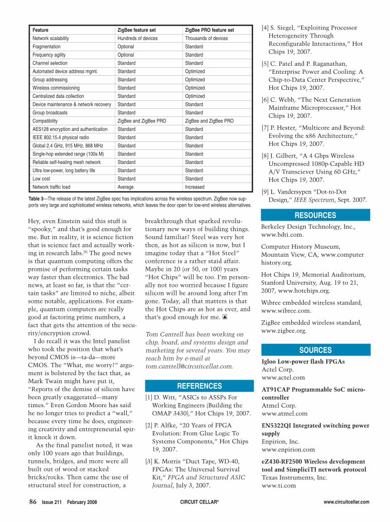
86 Issue 211 February 2008 CIRCUIT CELLAR® www.circuitcellar.com
SOURCESIgloo Low-power flash FPGAs Actel Corp.www.actel.com
AT91CAP Programmable SoC micro-controllerAtmel Corp.www.atmel.com
EN5322QI Integrated switching powersupply Enpirion, Inc.www.enpirion.com
eZ430-RF2500 Wireless developmenttool and SimpliciTI network protocolTexas Instruments, Inc.www.ti.com
Tom Cantrell has been working onchip, board, and systems design andmarketing for several years. You mayreach him by e-mail [email protected].
Hey, even Einstein said this stuff is“spooky,” and that’s good enough forme. But in reality, it is science fictionthat is science fact and actually work-ing in research labs.[9] The good newsis that quantum computing offers thepromise of performing certain tasksway faster than electronics. The badnews, at least so far, is that the “cer-tain tasks” are limited to niche, albeitsome notable, applications. For exam-ple, quantum computers are reallygood at factoring prime numbers, afact that gets the attention of the secu-rity/encryption crowd.
I do recall it was the Intel panelistwho took the position that what’sbeyond CMOS is—ta-da—moreCMOS. The “What, me worry?” argu-ment is bolstered by the fact that, asMark Twain might have put it,“Reports of the demise of silicon havebeen greatly exaggerated—manytimes.” Even Gordon Moore has saidhe no longer tries to predict a “wall,”because every time he does, engineer-ing creativity and entrepreneurial spir-it knock it down.
As the final panelist noted, it wasonly 100 years ago that buildings,tunnels, bridges, and more were allbuilt out of wood or stackedbricks/rocks. Then came the use ofstructural steel for construction, a
REFERENCES[1] D. Witt, “ASICs to ASSPs For
Working Engineers (Building theOMAP 3430),” Hot Chips 19, 2007.
[2] P. Alfke, “20 Years of FPGAEvolution: From Glue Logic ToSystems Components,” Hot Chips19, 2007.
[3] K. Morris “Duct Tape, WD-40,FPGAs: The Universal SurvivalKit,” FPGA and Structured ASICJournal, July 3, 2007.
RESOURCESBerkeley Design Technology, Inc.,www.bdti.com.
Computer History Museum,Mountain View, CA, www.computerhistory.org.
Hot Chips 19, Memorial Auditorium,Stanford University, Aug. 19 to 21,2007, www.hotchips.org.
Wibree embedded wireless standard,www.wibree.com.
ZigBee embedded wireless standard,www.zigbee.org.
[4] S. Siegel, “Exploiting ProcessorHeterogeneity ThroughReconfigurable Interactions,” HotChips 19, 2007.
[5] C. Patel and P. Raganathan,“Enterprise Power and Cooling: AChip-to-Data Center Perspective,”Hot Chips 19, 2007.
[6] C. Webb, “The Next GenerationMainframe Microprocessor,” HotChips 19, 2007.
[7] P. Hester, “Multicore and Beyond:Evolving the x86 Architecture,”Hot Chips 19, 2007.
[8] J. Gilbert, “A 4 Gbps WirelessUncompressed 1080p-Capable HDA/V Transciever Using 60 GHz,”Hot Chips 19, 2007.
[9] L. Vandersypen “Dot-to-DotDesign,” IEEE Spectrum, Sept. 2007.
breakthrough that sparked revolu-tionary new ways of building things.Sound familiar? Steel was very hotthen, as hot as silicon is now, but Iimagine today that a “Hot Steel”conference is a rather staid affair.Maybe in 20 (or 50, or 100) years“Hot Chips” will be too. I’m person-ally not too worried because I figuresilicon will be around long after I’mgone. Today, all that matters is thatthe Hot Chips are as hot as ever, andthat’s good enough for me. I
Table 3—The release of the latest ZigBee spec has implications across the wireless spectrum. ZigBee now sup-ports very large and sophisticated wireless networks, which leaves the door open for low-end wireless alternatives.
Feature ZigBee feature set ZigBee PRO feature set
Network scalability Hundreds of devices Thousands of devices
Fragmentation Optional Standard
Frequency agility Optional Standard
Channel selection Standard Standard
Automated device address mgmt. Standard Optimized
Group addressing Standard Optimized
Wireless commissioning Standard Optimized
Centralized data collection Standard Optimized
Device maintenance & network recovery Standard Standard
Group broadcasts Standard Standard
Compatibility ZigBee and ZigBee PRO ZigBee and ZigBee PRO
AES128 encryption and authentication Standard Standard
IEEE 802.15.4 physical radio Standard Standard
Global 2.4 GHz, 915 MHz, 868 MHz Standard Standard
Single-hop extended range (100s M) Standard Standard
Reliable self-healing mesh network Standard Standard
Ultra low-power, long battery life Standard Standard
Low cost Standard Standard
Network traffic load Average Increased
2802003-Cantrell.qxp 1/7/2008 4:57 PM Page 86

www.circuitcellar.com CIRCUIT CELLAR® Issue 211 February 2008 87
IDEA BOXTHE DIRECTORY OF PRODUCTS AND SERVICES
AD FORMAT: Advertisers must furnish digital submission sheet and digital files that meet the specifications on the digital submission sheet. ALL TEXT AND OTHER ELEMENTS MUST FIT WITHIN A 2" x 3" FORMAT. Call for current rate and deadline information. Send your disk and digital submission sheetto: IDEA BOX, Circuit Cellar, 4 Park Street, Vernon, CT 06066 or e-mail [email protected]. For more information call Shannon Barraclough at (860) 875-2199.
The Suppliers Directory at www.circuitcellar.com/suppliers_dir/ is your guide to a variety of engineering products and services.
UUSSBBAdd USB to your next
project—it’s easier than youmight think!
USB-FIFO up to 8 mbps
USB-UART up to 3 mbps
USB/Microcontroller boards
pre-programmed with firmware
2.4GHz ZigBee™ & 802.15.4RFID Reader/Writer
Absolutely NO driver software
development required!
www.dlpdesign.com
phyCORE® OEMable Single Board Computers
PHYTEC America, LLC � 203 Parfitt Way SW, G100 � Bainbridge Island, WA 98110 USA
XScale:XScale:XScale:XScale:XScale: PXA270, PXA255
ARM:ARM:ARM:ARM:ARM: LPC3180 (ARM9); LPC22xx, LPC229x, AT91 (ARM7)
PowerPC:PowerPC:PowerPC:PowerPC:PowerPC: MPC5554, MPC5200B, MPC565, MPC555
ColdFire:ColdFire:ColdFire:ColdFire:ColdFire: MCF5485
C 1 6 6 / X C 1 6 x / S T 1 0 / 8 0 5 1 CANCANCANCANCANx86x86x86x86x86::::: Elan SC520
www.phytec.com � (800) 278-9913 � www.phycore.com
Faster-to-Market: Save time by
integrating a PHYTEC Single
Board Computer Module into
your target circuitry.
Make -or - Buy: Why make
your own when you can buy
PHYTEC off-shelf solutions,
cost-effective to 1000s units/year?
Integrated Support Services: Let PHYTEC assist you in the design of your
end product: from tools and RTOSes to production. Our hardware is
bundled with leading compilers (Keil, IAR, CodeWarrior), RTOSes (WinCE,
Linux) and debuggers.
Immediate Support: Talk to PHYTEC technical staff with every call. No
waiting for answers.
Your OEM solution: With 20 years design, production, and integration
experience, PHYTEC is your OEM partner.
Blackfin:Blackfin:Blackfin:Blackfin:Blackfin: BF537
���������
Too
ls f
or
Em
bed
ded
Dev
elo
pm
ent
ARM8051COLDFIRE� C/C++*
� Code Wizards� Debugging� Simulation� Support
www.crossware.com360-812-2397
Embedded C++ for ARM andColdFire only
*
Advanced softwaretools since 1984
Three quality tool suites
®
®
®
ib-211.qxp 1/7/2008 4:51 PM Page 87

88 Issue 211 February 2008 CIRCUIT CELLAR® www.circuitcellar.com
2008
MEASUREMENT SCIENCECONFERENCE
MEASUREfor
SUCCESS
Register today!(866) 672-6327
www.msc-conf.com
NETWORK with experts fromgovernment, industry, academia
MORE than 100 Exhibit Booths (Wed-Fri)
EXCELLENT training opportunities
Disneyland HotelAnaheim, California
March 10-14, 2008
ib-211.qxp 1/7/2008 4:51 PM Page 88

www.circuitcellar.com CIRCUIT CELLAR® Issue 211 February 2008 89
Circuit Design and PCB Layout
Embedded Software
Electromechanical Algorithm Development
Rapid Prototype
O’Keefe Electronics Inc.www.okeefe-electronics.com
440 647 5193
Product Line Strategy Consulting
O’Keefe Electronics Inc.
Analog Design
Simulation
Outsource Your NextDesign To Ohio!
Wireless
We specializein designingwith Microchipproducts
IntroducesCapacitive Load Sensors with
True USB connectivity
Integrated signal conditioningDigital USB or Analog 0-5 V output
Accuracies - 0.25% to 0.025% of FSRugged stainless steel construction
Temperature compensatedEasy mounting features built in
www.loadstarsensors.com650.938.4282 | [email protected]
ib-211.qxp 1/7/2008 4:51 PM Page 89

90 Issue 211 February 2008 CIRCUIT CELLAR® www.circuitcellar.com
High-speed USB 2.0 + Xilinx FPGA Complete Software API
XEM3001:� 400,000-gate FPGA � Programmable PLL � Over 80 I/Os � 0.1” expansion headers � Business-card size � $199.95 / Qty 1 � $174.95 / Qty 10
XEM3010-1500P:� 1,500,000-gate FPGA � Programmable PLL � Over 110 I/Os � 32 MB SDRAM � Configuration PROM � 0.8-mm expansion � $399.95 / Qty 1 � $349.95 / Qty 10
FrontPanel Software API:�Windows XP, Mac OS X, Linux � C/C++, Python, Java � Configure FPGA and communicate with your design � The easiest way to integrate USB into your product � Use for image capture, control, test equipment, etc.� Up to 38 MB/s transfer rate!
3.5“ x 2.0”$199.95
75mm x 50mm $399.95
Opal Kelly Visit us online at:
www.opalkelly.com
5% off with Coupon Code: CKTCLR73*
* Valid for first order only. Void 30-days after issue publication.
ib-211.qxp 1/8/2008 10:00 AM Page 90

www.circuitcellar.com CIRCUIT CELLAR® Issue 211 February 2008 91
www.schmartboard.com
ANYONE Can Now Easi ly
Hand Solder Surface- Mount Components!
Even A 10 Year Old!
Low Cost CANUSB Adapter
+1 630-245-1445Naperville, Illinois USAwww.c-a-n.com
$99.95
Qty 1
Simple configuration & use
ib-211.qxp 1/7/2008 4:52 PM Page 91

92 Issue 211 February 2008 CIRCUIT CELLAR® www.circuitcellar.com
DDevelopment Tools for PIC® Microcontrollers
microEngineering Labs, Inc. Phone: (719) 520-5323Fax: (719) 520-1867
Box 60039Colorado Springs, CO 80960
Order online at:www.melabs.com
BASIC Compilers for PICmicro®
PICBASIC PRO™ Compiler $249.95
Easy-To-Use BASIC CommandsWindows 9x/Me/2K/XP Interface
PICBASIC™ Compiler $99.95BASIC Stamp 1 CompatibleSupports most 14-bit Core PICsBuilt-In Serial Comm Commands
Supports Microchip PIC10, PIC12, PIC14, PIC16, PIC17, and PIC18 microcontrollersDirect Access to Internal RegistersSupports In-Line Assembly LanguageInterrupts in PICBASIC and AssemblyBuilt-In USB, I2C, RS-232 and MoreSource Level Debugging
See our full range of products, includingbooks, accessories, and components at:
www.melabs.com
USB Programmer for PIC® MCUs
With Accessories for $119.95:Includes Programmer, Software, USB Cable,and Programming Adapter for 8 to 40-pin DIP.
Pre-Assembled BoardsAvailable for 8, 14, 18, 28, and 40-pin PIC® MCUs2-line, 20-char LCD Module9-pin Serial PortSample ProgramsFull Schematic Diagram
Pricing from $79.95 to $349.95
PICPROTO™ Prototyping BoardsDouble-Sided with Plate-Thru HolesCircuitry for Power Supply and ClockLarge Prototype AreaBoards Available for Most PIC® MCUsDocumentation and Schematic
Pricing from $8.95 to $19.95
LAB-X Experimenter Boards
Parallel Port Programmerstarting at $59.95Serial Port Programmerstarting at $79.95EPIC™
(as shown)$89.95
RoHSCompliantProgramsPIC MCUsincludinglow-voltage(3.3V) devices
IncludesWindows98, Me, NT,2K, and XPSoftware
ib-211.qxp 1/11/2008 9:59 AM Page 92

1
2 3 4
5
7
8
9 10
11
12
13 14 15
16 17
18
6
www.circuitcellar.com CIRCUIT CELLAR® Issue 211 February 2008 93
CCRROOSSSSWWOORRDD
The answers are available atwww.circuitcellar.com/crossword.
Across4. A Windows program that gives users simple options for
what would be a complex task and performs them auto-matically
5. What the Pythagorean theorem is called in China7. The process of using a straightforward system to start a
more complicated system that does the same thing11. A standard for high-speed data transfer12. A computer dedicated to gaming14. The global navigation system that determines locations
with satellites15. A receiver/transmitter that translates data between
serial and parallel16. A program used to perform calculations and display
information in rows and columns18. A device that combines two transistors to give a high
current gain
Down1. The practice of limiting the number of digits to the
right of a decimal point2. The British mathematician (1786–1837) who described
an algorithm for evaluating polynomials in a monomialway
3. A space telescope orbiting the Earth6. The act of playing video or audio on your computer
while you are downloading it8. A type of communication, often over radio waves, that
is not hard-wired9. A deterrent designed to protect your design from illegal
copying. It is an undocumented response to a pro-grammed sequence of events to test if the design is anauthorized copy.
10. A “spot” in a wireless network with effective Internetconnectivity
12. The shape a chain forms when it is hanging from twosupports under its own weight
13. An Internet address17. Do it yourself
crossword2.qxp 1/7/2008 4:47 PM Page 93

94 Issue 211 February 2008 CIRCUIT CELLAR® www.circuitcellar.com
Robotics Made Easy: A Peripheral Chip for Low-Level Functions
Robotics with Ada95
Motor-Controlled Vertical Plotter System
Do-It-Yourself Motion Controller (Part 1): Get Started with a Simple App
Video Stamp: A Video Display for Debugging Programs
Embedded Linux Development (Part 1): A Virtual Linux Environment on a Windows System
Multiplication and Division Techniques for MCUs
LESSONS FROM THE TRENCHES Do You Want to Do a Design?: Linked Lists
FROM THE BENCH Navigating the Heavens
SILICON UPDATE More Bits, Less Filling
91 AAG Electronica, LLC
29 AP Circuits
51 ASIX
56 Ad Hoc Electronics
91 All Electronics Corp.
88 Apex Embedded Systems
7 Atmel
17 Bitscope Designs
95 CTIA Wireless
65 CWAV
58 CadSoft Computer, Inc.
41 Comfile Technology, Inc.
87 Crossware Products, Inc.
92 Custom Computer Services, Inc.
1 Cypress MicroSystems, Inc.
87 DLP Design
51 DMM Technology Corp.
42 Decade Engineering
50 DesignCon
88 Designnotes
84 EMAC, Inc.
89 Earth Computer Technologies
47 ExpressPCB
The Index of Advertisers with links to their web sites is located at www.circuitcellar.com under the current issue.Page
10 ezPCB
87 FDI-Future Designs, Inc.
90 FlexiPanel Ltd.
87 FlyPCB China Co., Ltd.
85 Futurlec
8 Geist Technology
85, 91 Grid Connect
89 Hagstrom Electronics
89 HI-TECH Software LLC
42 HobbyLab LLC
88 IMET
80 IPC (Printed Circuit Expo)
88 IMAGEcraft
63 Intronix Test Instruments, Inc.
91 Intec Automation, Inc.
90 Ironwood Electronics
64, 91 JKmicrosystems, Inc.
81 Jameco
59 Jeffrey Kerr, LLC
55 Keil Software
59 Lakeview Research
88 Lawicel AB
10 Lemos International
29 Linx Technologies
89 Loadstar Sensors, Inc.
15 Luminary Micro
89 MCC (Micro Computer Control)
88 MSC
90, 91 Micro Digital, Inc.
92 Micro Digital, Inc.
19 Microchip
92 microEngineering Labs, Inc.
57 Mouser Electronics
88 Mylydia, Inc.
C2 NetBurner
5 NetMedia, Inc.
59 Nurve Networks LLC
89 O’Keefe Electronics Inc.
90 Opal Kelly Inc.
33 PCB-Pool
C4 Parallax, Inc.
87 Phytec America LLC
11 Pico Technology Ltd USA
90 Pioneer Hill Software
21 Pololu Corp.
91 Pulsar, Inc.
Page Page Page
27, 50 Rabbit, A Digi International Brand
88 Rabbit, A Digi International Brand
89 Reach Technology, Inc.
39 Renesas Technology
82 RoboBusiness 2008
48, 49 Saelig Co.
64 Saelig Co.
91 Schmartboard
9 SEGGER Microcontroller Systems LLC
90 Systronix
C3 Tech Tools
92 Technical Solutions Inc.
2, 3 Technologic Systems
90 Technological Arts
89 Tern, Inc.
25 Tibbo Technology, Inc.
92 Trace Systems, Inc.
90 Triangle Research Int’l, Inc.
73 Trinity College Robot Contest
8 WCSC (Willies Computer Software Co.)
40 Wiznet
90 Zanthic Technologies, Inc.
April Issue 213Deadlines
Space Close: Feb. 12Material Close: Feb. 20
Theme:Embedded Programming
BONUS DISTRIBUTION:ESC West, RoboBusiness
ATTENTION ADVERTISERS
Call Shannon Barraclough now to reserve your space!
860.875.2199e-mail: [email protected]
INDEX OF ADVERTISERS
Preview of March Issue 212Theme: Robotics
94-advertiser's index.qxp 1/9/2008 11:16 AM Page 94

CTIA WIRELESS 2008The convergence of more than 1,100 exhibiting
companies, dozens of industries and over 40,000
professionals from 125 countries all working toward
the common goal of revolutionizing wireless.
Whether in broadband convergence, enterprise,
advertising, social networking or entertainment–
CTIA WIRELESS 2008 is the global marketplace
connecting wireless and you.
April 1-3, 2008Las Vegas Convention Center
Las Vegas, NV, USA
www.ctia.org/ctiawireless
Unorthodox.
The most important global technology event of the year!
95.qxp 1/2/2008 1:51 PM Page 1

96 Issue 211 February 2008 CIRCUIT CELLAR® www.circuitcellar.com
I really hate being stereotyped, but I guess it goes with the territory. Last week, I was having coffee at Barnes & Noble when I noticed the guy at thetable next to me was reading Circuit Cellar. Perhaps he was reading my editorial and saw my picture, but he recognized me and we struck up a conver-sation about technology and gadgets.
It wasn’t long before he felt it was time to take my picture and started emptying his pockets looking for the right device. The first thing he pulled outwas a BlackBerry, then came an iPod, and finally came an iPhone and their associated earpieces and wires. As he snapped my picture, he explainedhow he couldn’t live without his mobile media and that multitasking was his life—like text-messaging on the BlackBerry while listening to music on theiPod and watching a video or talking on the iPhone at the same time. Certainly, being the high-tech guy that I am, I must be doing all that and more.
The problem with being the Editorial Director of a high-tech magazine is that it gives people the impression that I live and breathe high tech. Well,yes and no.Yes, I own lots of the latest gadgets, and Gizmodo and Engadget are among my favorite Internet stops, but I guess I’ve passed the part ofmy life where I want intravenous communications along with all these doohickeys. I silently chuckled as this guy described how he constantly e-mails,phones, and texts friends and associates all day long. I didn’t have the heart to tell him that I dislike “instant communication” so much that I turned offmy voicemail.
Don’t get me wrong. I’m still a confirmed gadget junkie.You already know I like fast cars with lots of features. I couldn’t live without my ultrasonic back-up “radar” screen (’cause I tend to back into things), GPS, and my 13-speaker sound system and satellite radio, but there is a limit to how many featuresI’m willing to take the trouble to use. I suppose it confirms my eccentricity, but I pay $200 a year for an integrated-cellular GPS-based roadside-assis-tance call system (like OnStar), but have never mated my cell phone to the car’s hands-free Bluetooth because I can’t be bothered.
I’m always among the first to experience new technology (like home control, web cams, LED lighting, HDTV, etc.), but it has its downside. I boughta Motorola RAZR phone the day it was introduced by Verizon (about $600 back when) and it drove me nuts. There was no way I could extract the phonefrom my pocket or belt holder without accidentally pushing buttons and reprogramming the phone settings. More than a few times I felt like driving thecar over it. Today, I have the latest-generation RAZR with a camera I’ve never used, a built-in MP3 player with nothing in it, and an empty contact list. IfI could find a truly dumb phone that only made telephone calls and wasn’t trying to be a palm-sized Cray computer with a built-in multi-media entertain-ment center, that’s the one I’d want.
OK, I’m a curmudgeon, but whatever happened to “keep it simple, stupid” in the use of all this technology. It seems like the longer a device is in exis-tence the more complicated each iterative enhancement becomes—kind of like Microsoft bloatware. Turning a cell phone into a handheld multi-mediacenter makes sense only if you can remember the directions for using it. It’s fine if you eat, sleep, and shower with your iPhone, iPod, and BlackBerry.Odds are if you use them that much you’ll remember all their programs and features. However, if you have 30 or 40 of these high-tech gadgets like I do,it is almost impossible to remember 100% of their embedded functions without having the instructions etched on the back of every one.
Remote controls are a perfect example. Ed Nisley and I are credited with inventing the universal programmable remote control, but I don’t use one.Every commercial programmable remote control these days has 500 buttons and a million permutations to accommodate all the conceivable electron-ic appliances. Of course, none of them have everything you need. When I had to start remembering that the XM radio was now DVD2 because theDirecTV was already programmed as “Satellite” and “Jump” really meant “Exit” because there wasn’t any real button for it, that’s when I tossed it. Arrgh!
Yeah, I know I could get a new controller with an LCD and programmable button logos, but at some point, the pile of just plain dumb remotes nextto the easy chair makes more sense to me than spending a week programming the latest and greatest (and I better never lose the manual). Besides,misplace that remote and you are dead in the water.
I guess at this point in my life I don’t like dealing with complicated directions. My idea of useful technology is something that is intuitive.You pick it upand making it work is obvious or requires nothing more than a bit of non-catastrophic trial and error.Yes, I realize it means that I am probably using only25% of the embedded features of most devices I own, but at least if I put it down, I can pick it up again and use it without a whole reeducation program.And, yes, many of you use a single device while I need to buy four or five times as many thingamabobs to enjoy the same activities. I guess owning fivetimes as many gadgets as we need is a cross many of us gadget junkies just have to bear.
Avoiding Stereotypes
PPRRIIOORRIITTYY IINNTTEERRRRUUPPTT
by Steve Ciarcia, Founder and Editorial Director
211_steve_edit.qxp 1/7/2008 4:32 PM Page 96
International EngineeringConsortiumwww.iec.org
Conference Exhibition
February 4–7, 2008 February 5–6, 2008Santa Clara Convention Center | Santa Clara, California
OFFICIAL HOST SPONSOR
DesignCon is the premier educational forum and technology exhibition for engineers and allied professionals from all levels and disciplines. If you desire to stay abreast of the most current informationregarding design engineering theories, techniques, and practical strategies, this event is for you.
DesignCon is the premier educational forum and technology exhibition for engineers and allied professionals from all levels and disciplines. If you desire to stay abreast of the most current informationregarding design engineering theories, techniques, and practical strategies, this event is for you.
• 130 exhibiting companies• Nearly 100 technical papers
• 10 half-day tutorials• 8 technical panels
• Keynotes and plenary panel• Business Forum
• 130 exhibiting companies• Nearly 100 technical papers
• 10 half-day tutorials• 8 technical panels
• Keynotes and plenary panel• Business Forum
CHAIRPERSON
Terry MorrisFellow, High Performance Systems DivisionHewlett-Packard
designcon.com
Connecting the World of Electronic Design
Gain unlimited access to the DesignCon technologyexhibition and other complimentary educational
programming when registering at designcon.com/2008/register/vip_exhibits_reg.htmlFree Exhibits PLUS Pass!
DC08_CircuitCell.qxd 1/18/08 11:10 AM Page 1