
technical specifications - POWERGRID
79
Power Grid Corporation of India Ltd. Volume II – Technical Specifications for Communication Equipment Appendix Page 1 of 1 TECHNICAL SPECIFICATIONS INDEX Section 1: Introduction, General Information and General Requirement Section 2: Network Configuration and Equipment Characteristics Section 3: Environment, EMI, Power Supply, Cabling and Earthing Section 4: Inspection, Test and Availability Section 5: Training and Support Services Annexure I: Technical Specifications for Maintenance after Operational Acceptance during Maint. Period(i.e Warranty/defect liability period & AMC Period) Appendix A: Bill of Quantity (BOQ) Appendix B: Data Requirement Sheets
-
Upload
khangminh22 -
Category
Documents
-
view
7 -
download
0
Transcript of technical specifications - POWERGRID

Power Grid Corporation of India Ltd.
Volume II – Technical Specifications for Communication Equipment
Appendix Page 1 of 1
TECHNICAL SPECIFICATIONS
INDEX
Section 1: Introduction, General Information and General Requirement
Section 2: Network Configuration and Equipment Characteristics
Section 3: Environment, EMI, Power Supply, Cabling and Earthing
Section 4: Inspection, Test and Availability Section 5: Training and Support Services
Annexure I: Technical Specifications for Maintenance after Operational Acceptance during
Maint. Period(i.e Warranty/defect liability period & AMC Period)
Appendix A: Bill of Quantity (BOQ)
Appendix B: Data Requirement Sheets

Power Grid Corporation of India Ltd.
Volume II - Technical Specifications of Communication Equipment
Section-1 Page 1 of 6
Section-1
Introduction, General Information and General Requirement
Table of Content
1.1 Scope and General Requirements -------------------------------------------------------------- 2
1.2 General Requirements ---------------------------------------------------------------------------- 2
1.2.1 Synchronization of the Communication Network -------------------------------------- 3
1.3 General Responsibilities and Obligations ---------------------------------------------------- 3
1.3.1 Responsibilities for the Implementation Plan ------------------------------------------- 4
1.3.2 Contractor's Responsibilities and Obligations ------------------------------------------ 4
1.3.3 The Employer Responsibilities and Obligations ---------------------------------------- 5
1.4 Applicable Standards ----------------------------------------------------------------------------- 6
Power Grid Corporation of India Ltd.
Volume II - Technical Specifications of Communication Equipment
Section-1 Page 2 of 6
Section 1
Introduction, General Information and General Requirement
This Document describes the technical specifications for Communication Equipment for
Establishment of Fibre Optic Communication System under the contract. This specification
describes the functional and performance requirements of the system.
1.1 Scope and General Requirements
The broad scope of the procurement of this part include the survey, planning, design,
engineering, supply, transportation, insurance, delivery at site, unloading, handling, storage,
installation, termination, testing, training, and demonstration for acceptance, commissioning and
documentation for:
(i) SDH Equipment along with suitable optical line interfaces & tributary cards.
(ii) Craft Terminal based Network Management System(NMS)
(iii) All cabling, wiring, Digital Distribution Frame patch facilities and
interconnections to the supplied equipment at the defined interfaces.
(iv) System integration of the supplied subsystems and also integration with
existing communication equipment such as SDH
(v) Integration of supplied system with the User equipments such as RTUs,
SCADA system etc.
(vi) Maintenance of the supplied system
All other associated works/items described in the technical specifications for a viable and fully
functional communication network.
1.2 General Requirements
The Contractor is encouraged to offer standard products and designs. However, the Contractor
must conform to the requirements and provide any special equipment necessary to meet the
requirements stated herein.
It should be noted that preliminary design information and bill of quantity (BoQ) specified in this
specifications are indicative only. The Contractor shall verify the design data during the site
surveys & detail engineering and finalise the BoQ as required for ultimate design & system
performance.
The Bidder's proposal shall address all functional and performance requirements within this
specification and shall include sufficient information and supporting documentation in order to
determine compliance with this specification without further necessity for inquiries.
An analysis of the functional and performance requirements of this specification and/or site
surveys, design, and engineering may lead the Contractor to conclude that additional items are
required that are not specifically mentioned in this specification. The Contractor shall be
responsible for providing at no added cost to the Employer, all such additional items and services
Power Grid Corporation of India Ltd.
Volume II - Technical Specifications of Communication Equipment
Section-1 Page 3 of 6
such that a viable and fully functional communication equipment system is implemented that
meets or exceeds the capacity, and performance requirements specified. Such materials and
services shall be considered to be within the scope of the contract. To the extent possible, the
Bidders shall identify and include all such additional items and services in their proposal.
All equipment provided shall be designed to interface with existing equipment and shall be
capable of supporting all present requirements and spare capacity requirement identified in this
specification.
The communication equipment shall be designed and provisioned for expansions and
reconfigurations without impairing normal operation, including adding and removing circuits.
The offered items shall be designed to operate in varying environments. Adequate measures shall
be taken to provide protection against rodents, contaminants, pollutants, water & moisture,
lightning & short circuit, vibration and electro-magnetic interference etc.
The Bidders are advised to visit sites (at their own expense), prior to the submission of a
proposal, and make surveys and assessments as deemed necessary for proposal submission. The
successful bidder (Contractor) is required to visit all sites. The site visits after contract award
shall include all necessary surveys to allow the contractor to perform the design and
implementation functions. The Contractor shall inform their site survey schedule to the Employer
well in advance. The site survey schedule shall be finalised in consultation with the Employer.
The Employer may be associated with the Contractor during their site survey activities.
After the site survey, the Contractor shall submit to the Employer a survey report on each link
and site. This report shall include at least the following items:
(a) Proposed layout of Equipment in the existing rooms and buildings.
(b) Proposed routing of power, earthing, signal cables and patch cords etc.
(c) Confirmation of adequacy of Space and AC/DC Power supply requirements
(d) Proposals for new rooms/buildings if required
(e) Identification of facility modifications if required
(f) Identify all additional items required for integration for each site/location.
1.2.1 Synchronization of the Communication Network
The Contractor shall be responsible for synchronization of new communication equipment with
existing network utilizing the existing clock. The Contractor shall make an assessment of
additional clock requirement for synchronization of the communication equipment.
1.3 General Responsibilities and Obligations
This section describes the general responsibilities and obligations of the Contractor and the
Employer.

Power Grid Corporation of India Ltd.
Volume II - Technical Specifications of Communication Equipment
Section-1 Page 4 of 6
1.3.1 Responsibilities for the Implementation Plan
The Bidder's technical proposal shall include a project implementation plan and schedule that is
consistent with the implementation plan detailed in this specification. The implementation plan
shall be modelled such that it provides fibre optic cabling system support for the activation of this
Project. The Implementation plan shall include the activities of both the Contractor and the
Employer, showing all key milestones and clearly identifying the nature of all information and
project support expected from the Employer. The Employer and Contractor shall finalise the
detailed Implementation plan following award of the contract.
1.3.2 Contractor's Responsibilities and Obligations
The Contractor shall be responsible for all cables and wiring associated with the equipment
provided, both inside and outside buildings in accordance with technical specifications. The
Contractor shall also be responsible for determining the adequacy of the local power source for
the equipment and for wiring to it, with adequate circuit protective breakers. In addition, the
Contractor shall be responsible for shielding equipment and cabling to eliminate potential
interference to or from the equipment, and for earthing all cabinets and shields.
Contractor's obligations include, but are not limited to, the following:
(1) Site visits, and surveys, necessary to identify and provide all equipment needed to
implementation the network.
(2) Equipment Engineering and design specific to each location including review of,
and conformance with local environmental and earthing considerations.
(3) Overall integration of communication equipments/subsystem procured in present
with existing User equipments such as SDH, RTUs, SCADA system etc.
(4) All cabling, wiring including supply, laying and termination etc of the cables, and
distribution frame at wideband nodes required for full interconnectivity and proper
operation of the telecommunications network including equipment supplied under
this package and the connectivity and interfacing of user equipment.
(5) Installation and integration of network management software, hardware and
firmware.
(6) Project management, project scheduling, including periodic project reports
documenting progress, review meeting during the contract period.
(7) Engineering and technical assistance during the contract and warranty period.
(8) Implement all minor civil works and identify any major civil works i.e. expansion or
construction of rooms, trenches necessary for installation of proposed equipment
and provide the details of such work to the Employer.

Power Grid Corporation of India Ltd.
Volume II - Technical Specifications of Communication Equipment
Section-1 Page 5 of 6
(9) Factory and site testing of all hardware, software, and firmware provided.
(10) Provide documented evidence of satisfactory Type Test performance to the
Employer and if required by The Employer, conduct type test.
(11) Provide a Quality Assurance Plan, ensuring the Employer access to the
manufacturing process.
(12) Training of the Employer personnel.
(13) Hardware, software, and firmware maintenance, debugging, and support of the
equipment through final acceptance, and maintenance on all new equipment
through out the warranty period and for a period of six (6) years after warranty
period.
(14) Availability of service, spare and expansion parts for the supplied items for the
designed life of the equipment or seven (7) years after the declaration of withdrawal
of equipment from production, whichever is earlier. However, the termination of
production shall not occur prior to Operational Acceptance of the system by the
Employer.
Detailed descriptions of the Contractor's obligations, in relation to individual items and services
offered, are delineated in other sections of this specification.
1.3.3 The Employer Responsibilities and Obligations
The Employer will provide the following items and services as part of this Project:
(1) Overall project management of the project
(2) Review and approval of the Contractor's designs, drawings, and recommendations.
(3) Communication network configuration data, including:
(a) Channel assignments for voice and data
(b) Interconnection drawings for existing equipment
(4) Review and approval of test procedures.
(5) Participation in and approval of "Type", factory and site acceptance tests where testing is
required.
(6) Review and approval of training plans.
(7) Providing support and access to facilities at the sites.
(8) Implement the major civil works such as expansions or construction of rooms, trenches
etc. as required for the equipment to be provided by the Contractor.
(9) Coordination of the Contractor's activities with the Employer's and constituents'
concerned departments.
(10) Provide to the extent possible drawings for existing sites and facilities for which
equipment installations are planned.
(11) Approval of the key personnel for the project

Power Grid Corporation of India Ltd.
Volume II - Technical Specifications of Communication Equipment
Section-1 Page 6 of 6
1.4 Applicable Standards
The applicable standards are mentioned in the respective technical section. The offered
equipment shall conform to the standards mentioned in the specification except to the extent
modified by this specification. In case of any discrepancy between the description given in the
specification and the standards, the provisions of the technical specification shall be followed.
The parameters not specifically mentioned in this specification shall conform to the standard
mentioned in this specification.
Specifications and codes shall be the latest version, inclusive of revisions, which are in force at
the date of the contract award. Where new specifications, codes, and revisions are issued during
the period of the contract, the Contractor shall attempt to comply with such, provided that no
additional expenses are charged to the Employer without Employer's written consent.
In the event the Contractor offers to supply material and/or equipment in compliance to any
standard other than Standards listed herein, the Contractor shall include with their proposal, full
salient characteristics of the new standard for comparison.
In case values indicated for certain parameters in the specifications are more stringent than those
specified by the standards, the specification shall override the standards.
-------------------------------------------------- End of this Section --------------------------------------

Power Grid Corporation of India Ltd.
Volume II - Technical Specifications for Communication Equipment
Section-02 Page 1 of 17
Section 2
Network Configuration and Equipment Characteristics
Table of Content
2.1 Introduction --------------------------------------------------------------------------------------- 3
2.2 General Network Characteristics ------------------------------------------------------------- 4
2.2.1 Description ------------------------------------------------------------------------------------ 4
2.2.2 Functional Requirement --------------------------------------------------------------------- 4
2.2.3 General Systems Requirements ------------------------------------------------------------- 4
2.2.3.1 System Synchronization ---------------------------------------------------------------------- 4
2.2.3.2 System Maintainability ----------------------------------------------------------------------- 5
2.2.3.3 System Upgradeability and Expandability ------------------------------------------------ 5
Equipment Availability ---------------------------------------------------------------------------- 5
2.2.3.4 ---------------------------------------------------------------------------------------------------- 5
2.2.3.5 Revision Levels and Modifications --------------------------------------------------------- 5
2.2.3.6 Equipment Capacities ------------------------------------------------------------------------ 5
2.2.3.7 Redundancy Requirements and Protection Schemes ------------------------------------ 6
2.2.3.8 Lost Signal Recovery ------------------------------------------------------------------------- 6
2.2.3.9 Software Upgrades --------------------------------------------------------------------------- 6
2.2.3.10 General Site Considerations -------------------------------------------------------------- 7
2.3 Fibre Optic Transmission System ------------------------------------------------------------ 8
2.3.1 SDH Equipment ------------------------------------------------------------------------------- 9
2.3.1.1 Functional Requirement --------------------------------------------------------------------- 9
2.3.1.2 Redundancy and Protection ----------------------------------------------------------------- 9
2.3.1.3 Service Channel ----------------------------------------------------------------------------- 10
2.3.1.4 Supervision and Alarms -------------------------------------------------------------------- 10
2.3.1.5 Synchronisation ----------------------------------------------------------------------------- 10
Electrical and Optical I/O Characteristics and General Parameters -------------------- 10
2.3.1.6 -------------------------------------------------------------------------------------------------- 10
2.3.2 Optical Link Performance Requirements------------------------------------------------ 11
2.3.2.1 Link Budget Calculations ------------------------------------------------------------------ 11
2.3.2.2 Link Performance --------------------------------------------------------------------------- 12

Power Grid Corporation of India Ltd.
Volume II - Technical Specifications for Communication Equipment
Section-02 Page 2 of 17
2.3.2.3 FODP to SDH Equipment ----------------------------------------------------------------- 12
2.4 DDF and Cabling ------------------------------------------------------------------------------- 12
2.5.1 Digital Distribution Frame Functional Requirements -------------------------------- 12
2.5 Patch Cords -------------------------------------------------------------------------------------- 13
2.6 Telecommunication Management Network / Network Management System ----- 13
2.7.1 Management Functions -------------------------------------------------------------------- 13
2.7.1.1 Configuration Management --------------------------------------------------------------- 13
2.7.1.2 Fault Management -------------------------------------------------------------------------- 14
2.7.1.3 Performance Management ---------------------------------------------------------------- 14
2.7.1.4 Security Management ---------------------------------------------------------------------- 15
2.7 Communication Channel Requirement and Integration ------------------------------ 15
2.8 Craft Terminal ---------------------------------------------------------------------------------- 15
2.9 Hardware Requirements ---------------------------------------------------------------------- 16
2.10.1 Craft Terminal ------------------------------------------------------------------------------ 16
2.10.2 Power Supplies ------------------------------------------------------------------------------ 16
2.10 General Software/Firmware Requirements ---------------------------------------------- 16
2.11.1 Operating System Software ---------------------------------------------------------------- 16
2.11.2 Applications Software ---------------------------------------------------------------------- 16
2.11.3 Software Utilities --------------------------------------------------------------------------- 17
2.11.4 Revisions, Upgrades, Maintainability --------------------------------------------------- 17
2.11.5 Database(s) ---------------------------------------------------------------------------------- 17
2.11.6 Help ------------------------------------------------------------------------------------------- 17
Power Grid Corporation of India Ltd.
Volume II - Technical Specifications for Communication Equipment
Section-02 Page 3 of 17
Section 2
Network Configuration and Equipment Characteristics
2.1 Introduction
This section describes the Fibre Optic Communication network configuration and the
equipment characteristics for communication system to be installed under the project.
The sub-systems addressed within this section are:
(1) Fibre Optic Transmission System (FOTS)
(2) Craft Terminal based Network Management System (NMS)
(3) DDF and Cabling
The requirements described herein are applicable to and in support of network
requirements.
The security related requirements of the equipment shall be as per DoT (Department of
Telecommunication) guidelines and all similar security requirements as amended by DoT
on time to time basis shall be followed/complied by the vendor.
The manufacturer shall allow the Employer and/or its designated agencies to inspect the
hardware, software, design, development, manufacturing,facility and supply chain and
subject all software to a security /threat check any time during the supplies of equipment
The contractor shall ensure that the supplied equipments have been got tested as per
relevant contemporary Indian or International Security Standards e.g. IT and IT related
elements against ISO/IEC 15408 standards, for Information Security Management System
against ISO 27000 series Standards, Telecom and Telecom related elements against
3GPP security standards, 3GPP2 security standards etc. from any international agency/
labs of the standards e.g. Common Criteria Labs in case of ISO/IEC 15408 standards until
31st March 2013. From 1
st April, 2013, the certification shall be got done from authorized
and certified agency/lab in India.
The Contractor shall also ensure that the equipment supplied has all the contemporary
security related features and features related to communication security as prescribed
under relevant security standards. A list of features, equipments, software etc. supplied
and implemented in the project shall be given for use by the Employer
The contractor shall get the Employer’s equipment audited from security point of view
once a year from a network audit and certification agency as identified by DoT. The audit
of the equipment shall be carried once in a financial year till the maintenance service
contract in the bid.
In case of any deliberate attempt for a security breach at the time of procurement or at a
later stage after deployment/installation of the equipment or during maintenance, liability
and criminal proceedings can be initiated against the Contractor as per guidelines of DoT

Power Grid Corporation of India Ltd.
Volume II - Technical Specifications for Communication Equipment
Section-02 Page 4 of 17
and any other Government department.
2.2 General Network Characteristics
2.2.1 Description
The fibre optic network shall be based on the Synchronous Digital Hierarchy (SDH)
having bit rate of STM-4/STM-16 as indentified in the BoQ. The network shall consist of
overhead fibre optic links with a minimum bit rate of Synchronous Transport Module-
4/STM-16 (STM-4/16). The Contractor can propose a system based on higher bit rate
systems, if required, so as to meet the link budget requirements or any other specification
requirement. The detailed BOQ is described in appendices.
2.2.2 Functional Requirement
The primary function of the communication network is to provide a highly reliable voice
and data communication system for grid operation in support of the
SCADA/EMS/RTUs/PMUs. The communications support requirement for
SCADA/EMS/RTUs/PMUs system is for low & high speed data, express voice circuits
and administrative voice circuits as defined in appendices. A brief summary of the
communication system requirements is as follows:
(a) High speed E1 channel support
(b) Data transport supporting Network Management channels
(c ) The connectivity envisaged between RTUs and Control Centre over TCP-IP using
Ethernet interface.
2.2.3 General Systems Requirements
Required characteristics are defined and specified herein at the system level, subsystem
level, and equipment level.
2.2.3.1 System Synchronization
The Contractor shall synchronize the existing equipments and all the new equipments
under the contract using existing Master clock. The Contractor shall provide the
additional clocks as required under the set of clock indicated in BoQ. In addition to GPS
input reference, the synchronization clock must have provision to take INPUT reference
coming from other clock. The contractor shall submit the synchronisation plan as per
standard ITU-T G.811. All sync equipments proposed under this contract should meet
ITU-T G.811 criterion. The holdover quality of slave clock, if any, shall meet ITU-T
G.812 standard requirements.
The Contractor shall provide system wide synchronization fully distributed throughout
the telecom network and connected to all equipments new & existing. The Contractor
shall submit the synchronization plan for the entire network meeting the requirement of

Power Grid Corporation of India Ltd.
Volume II - Technical Specifications for Communication Equipment
Section-02 Page 5 of 17
ITU-T G.803. The synchronization plan shall clearly indicate the requirement of
additional clocks with full justification.
The system equipment requiring “clock” shall be connected to the master clock using
external clocking. For this purpose, appropriate interfaces(s) in the transmission &
termination equipment being supplied and all other associated hardware shall be provided
by the Contractor.
2.2.3.2 System Maintainability
To facilitate performance trending, efficient diagnosis and corrective resolution, the
system shall permit in-service diagnostic testing to be executed both locally and from
remote locations, manually and/or initiated under NMS control. Such testing shall not
affect the functional operation of the system.
2.2.3.3 System Upgradeability and Expandability
Equipment supplied shall be sized (though not necessarily equipped) to support system/
subsystem expansion to full capacity as provided by specified aggregate transmission
rates. Equipment units provisioned for equipped subunits shall be terminated at
appropriate patching facilities or termination blocks. Power supplies and NMS shall be
sized for maximum equipped system capacity.
2.2.3.4 Equipment Availability
The calculated availability of each fibre optic link (E1 to E1)shall be at least 99.999%.
The calculated availability is defined as the theoretical availability determined by a
statistical calculation based on the mean-time-between-failure (MTBF) and the mean-
time-to-repair (MTTR) of the components and subsystems comprising the FOTS. For this
analysis, an MTTR of atleast 4 hours shall be assumed. The down time of the fibre optic
cable shall not be considered in the aforesaid availability calculations. The calculated
failure rates of the units and the calculated availabilities of the equipment being offered
shall be provided by the Contractor during detailed engineering.
2.2.3.5 Revision Levels and Modifications
All hardware, firmware and software delivered as part of the communications network
shall be field proven and at the most of current revision level. All modifications and
changes necessary to meet this requirement shall be completed prior to the start of the
factory tests or under special circumstances, on written approval by Employer, prior to
the completion of SAT.
2.2.3.6 Equipment Capacities
Equipment supplied shall be sized and equipped with sufficient capacity to support BoQ
and configuration requirements as identified in the appendices. Each subsystem supplied
shall be sized (to be equipped as specified) to support full subsystem expansion.

Power Grid Corporation of India Ltd.
Volume II - Technical Specifications for Communication Equipment
Section-02 Page 6 of 17
Data communications channelization required to support the NMS subsystems specified
in Technical Specifications (TS) are not identified in the appendices. Therefore, the
Contractor is required to size and equip the system to include all channelization and
channel cards required to support the NMS function.
2.2.3.7 Redundancy Requirements and Protection Schemes
Equipment redundancy and Automatic Protection Schemes (APS) are specified in the
Table 2-1. The failure of one element shall not prevent the use of any other that has not
failed.
Table 2-1
Equipment Redundancy Requirements Summary
Fiber Optic transmission Equipment :
SDH equipment
Power Supply & Converters ------------------------------
Common Control* Cards -----------------------------------
* = Common control cards which are essentially
required for operation of the equipment.
1:1 APS or distributed power
supply
1:1 APS
The offered equipment shall support at least SNCP as per standard ITU-T G.841. In case
the equipment offered by the Bidder does not support the above mentioned minimum
protection methods, the bidder shall have to provide all additional equipment needed to
provide same level of flexibility, redundancy and functionality at no additional cost to
Employer. The bidders shall provide details of protection schemes supported in the Bid
document.
The offered equipment shall support automatic switchover function between the redundant
modules and all required modules and hardware to support the automatic switch over shall
be provided by the Contractor.
2.2.3.8 Lost Signal Recovery
At any digital signal level, reapplication of a lost signal shall result in automatic
resynchronization and full restoration to normal operation without manual intervention.
All alarms incident to the signal failure, shall be automatically cleared at the equipment,
rack and monitoring levels and normal operation indications restored and reported if
applicable.
2.2.3.9 Software Upgrades

Power Grid Corporation of India Ltd.
Volume II - Technical Specifications for Communication Equipment
Section-02 Page 7 of 17
The Contractor shall provide antivirus software along with all the computer
hardware/software which shall be upgraded periodically till the maintenance services
contract in the bid. Further, to meet all the specifications requirements during
implementation and maintenance, if upgrade in the hardware/software of supplied item is
required, the same shall be done by the contractor without any additional cost to the
Employer.
2.2.3.10 General Site Considerations
All fiber optic links up to 250 kms transmission line length shall be implemented by the
Contractor without repeaters. In order to meet the link budget requirement, the Contractor
shall provide all the necessary equipments only in the end stations. The contractor may
provide the optical amplifier, wave length translator, optical cards or high capacity SDH
equipment with suitable rack/subrack to meet the maximum distance limit. All the
provided equipments shall be monitored by centralized NMS.
2.2.3.11 Proposed Optical Fibre Characteristics
The link budget calculations and equipment design shall be based on the specified fibre
parameters. The optical cables shall have Dual Window Single Mode (DWSM) fibres
conforming to ITU-T Recommendations G.652D and the major parameters of these
optical fibre(s) are defined in Table-2-2:
Table-2-2
Optical Fibre Characteristics
Fibre Description: Dual-Window Single-Mode (DWSM)
Mode Field Diameter: 8.6 to 9.5 μm (±0.6 µm)
Cladding Diameter: 125.0 μm + 1μm
Mode field Concentricity Error: < 0.6μm
Core-Clad concentricity error: < 1.0μm
Cladding non-circularity < 1%
Cable Cut off Wavelength: < 1260 nm
1550 loss performance As per G.652D
Proof Test Level 0.69 Gpa
Attenuation coefficient @1310nm < 0.35 dB/Km
@1550nm < 0.21 dB/Km Attenuation variation with
wavelength
1285 nm - 1330 nm
1525 nm – 1575 nm
Attenuation coefficient @1310 ± 0.05 dB
Attenuation coefficient @1550 ± 0.05 dB Point discontinuities
< 0.1dB

Power Grid Corporation of India Ltd.
Volume II - Technical Specifications for Communication Equipment
Section-02 Page 8 of 17
Table-2-2
Optical Fibre Characteristics
Chromatic Dispersion; Max.:
Zero Dispersion Wavelength:
Zero Dispersion Slope:
18.0 ps/(nm x km) @ 1550 nm
3.5 ps/(nm x km) @ 1288-1339nm
5.3 ps/(nm x km) @ 1271-1360nm
1300 to 1324nm
0.092 ps/(nm2xkm) maximum
Polarization mode dispersion
coefficient
< 0.2 ps/km^1/2
Temperature Dependence:
Induced attenuation < 0.05 dB (-60 deg C -
+85 deg C)
Bend performance: @1310nm (75+2 mm dia Mandrel), 100
turns;
Attenuation rise 0.05 dB
@1550nm (30+1 mm dia Mandrel), 100
turns;
Attenuation rise 0.10 dB
@1550nm (32+0.5 mm dia Mandrel), 1 turn;
Attenuation rise 0.50 dB
2.2.5 Fibre Optic Link Lengths
The fiber optic route lengths are as specified in appendices. The lengths specified in
appendices are the transmission line route lengths; however the actual fiber cable length
shall exceed the route lengths on account of extra cable requirement due to sag, jointing &
splicing, approach cabling etc. For bidding purposes the Contractor may assume an
additional cable length of 5% of given route length + 1Km towards approach cable for
calculating the link length. The exact cable lengths shall be determined by the Contractor
during the survey. The same shall be used by the Contractor for final link design during the
detailed engineering of the project.
2.3 Fibre Optic Transmission System
The Fibre Optic Transmission System (FOTS) is defined herein to include ETSI digital
optical line termination equipment. The FOTS shall be based on SDH technology.
Minimum aggregate bit rate shall be STM-4/STM-16 and equipped with 2 nos. of
minimum 16 port E1 interface(G.703) card, one no. of minimum 4 port Ethernet
interface (IEEE 802.3/IEEE 802.3u) card supporting layer 2 switching as tributaries. The
Ethernet interfaces shall support VLAN (IEEE 802.1P/Q), spanning tree (IEEE 802.1D)
quality of service. Protection scheme for Ethernet traffic should be ERPS based (Ethernet
ring protection scheme) as per ITU-T G.8032.

Power Grid Corporation of India Ltd.
Volume II - Technical Specifications for Communication Equipment
Section-02 Page 9 of 17
The Contractor shall provide (supply and install) connectorised jumpers (patch cords) for
FODP-to-equipment and equipment-to-equipment connection. Two number spare
jumpers shall be provided for each equipment connection. Fiber jumpers shall be of
sufficient lengths as to provide at least 0.5m of service loop when connected for their
intended purpose.
2.3.1 SDH Equipment
2.3.1.1 Functional Requirement
There is a requirement for different types of equipment under this project which are
described in this section. The BOQ is provided in the appendices. For the purpose of
BOQ, the SDH Equipment is considered to be divided in three parts i.e. Optical
interface/SFP, Tributary Cards ( Electrical tributaries such as E1 & Ethernet 10/100 Mbps)
and Base Equipment (Consisting of Common Cards, Control Cards, Optical base card,
Power supply cards, sub-rack, cabinet, other hardware and accessories required for
installation of equipment i.e. everything besides optical interface/SFP and tributary cards).
If bidder is offering equipment with multifunction cards such as cross-connect or control
card with optical interface/SFP or tributary interface, such type of multifunction card shall
be considered as Common control card and shall be the part of base equipment. In case
optical interface/SFP is embedded with control card, the adequate number of optical
interface/SFPs shall be offered to meet the redundancy requirements of the specifications.
Further, control card shall not be equipped with more than one optical interface/SFP and
optical base card shall not be equipped with more than two optical interface/SFPs.
The equipment shall be configurable either as Terminal Multiplexer (TM) as well as
ADM with software settings only.
SDH ADM
The aggregate interfaces shall be (at least) STM-4/STM-16 towards at least two protected
directions (Protected as specified in this specifications). At present the equipment shall be
equipped with a 2 nos., min.16 E-1 port electrical tributary cards & one no., min.4 port
Ethernet interface card as tributaries. The equipment shall provide access to full STM-4
payload.
The offered STM-4 SDH equipment shall be upgradeable to STM-16 by changing optical
line cards only. Cross connection (VC4) capability of offered SDH equipment shall be
provided according to STM-16 equipment. The contractor shall demonstrate the STM-16
upgradeability during FAT.
2.3.1.2 Redundancy and Protection
Two fibre rings shall be implemented wherever the network permits. On linear sections of

Power Grid Corporation of India Ltd.
Volume II - Technical Specifications for Communication Equipment
Section-02 Page 10 of 17
the network, protected links using 4 fibres shall be implemented.
2.3.1.3 Service Channel
Service channels shall be provided as a function of the SDH equipment and shall be
equipped with Service Channel Muldems that shall provide at a minimum: One voice
channel (order wire) with analog interface (0.3 to 3.4 kHz) and one data channel. Both
omnibus and selective calling facilities shall be provided. There shall be a facility to
extend the line system order-wire to any other system or exchange lines on 2W/4W basis.
2.3.1.4 Supervision and Alarms
ISM (In Service Monitoring) circuitry shall be provided as a function of the SDH
equipment. Local visual alarm indicators shall be provided on the equipment, as a rack
summary alarm panel. Alarms shall be as per ITU-T Standards G.774, G.783 and G.784.
Additionally, F2/Q2 interfaces for a local craftsperson terminal interface and remote
equipment monitoring is required.
The Equipment shall support collection of at least four (4) external alarms for monitoring
and control of station associated devices by the NMS.
2.3.1.5 Synchronisation
The equipment shall provide synchronisation as per Table 2-2. One 2MHz
synchronisation output from each equipment shall be provided.
2.3.1.6 Electrical and Optical I/O Characteristics and General Parameters
Table 2-3 provides the electrical and optical characteristics as well as other general
parameters for SDH equipment.
Table 2-3
Electrical and Optical I/O Characteristics and General Parameters Optical Wavelength
NOTE (1)
1310/1550nm
Optical Source
NOTE (2)
Laser
Optical Source Lifespan
Better than 5 X10
5 hours
Optical Fibre Type
G.652 D
Optical Connectors
Type FC-PC
Transmission Quality
Per ITU-T G.821, G.823, G.826
Source Primary Power
-48 Vdc
Equipment Specifications
Per ITU-T G.783
Tributary, Electrical Interface
Per ITU-T G.703, 75 Ω
Ethernet Interface 10/100 Mbps SDH Bit Rates
Per ITU-T G.703
Power Grid Corporation of India Ltd.
Volume II - Technical Specifications for Communication Equipment
Section-02 Page 11 of 17
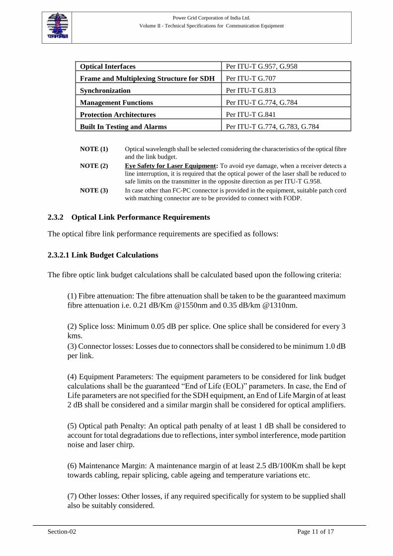
Optical Interfaces Per ITU-T G.957, G.958 Frame and Multiplexing Structure for SDH
Per ITU-T G.707
Synchronization
Per ITU-T G.813
Management Functions
Per ITU-T G.774, G.784
Protection Architectures
Per ITU-T G.841
Built In Testing and Alarms
Per ITU-T G.774, G.783, G.784
NOTE (1) Optical wavelength shall be selected considering the characteristics of the optical fibre
and the link budget.
NOTE (2) Eye Safety for Laser Equipment: To avoid eye damage, when a receiver detects a
line interruption, it is required that the optical power of the laser shall be reduced to
safe limits on the transmitter in the opposite direction as per ITU-T G.958.
NOTE (3) In case other than FC-PC connector is provided in the equipment, suitable patch cord
with matching connector are to be provided to connect with FODP.
2.3.2 Optical Link Performance Requirements
The optical fibre link performance requirements are specified as follows:
2.3.2.1 Link Budget Calculations
The fibre optic link budget calculations shall be calculated based upon the following criteria:
(1) Fibre attenuation: The fibre attenuation shall be taken to be the guaranteed maximum
fibre attenuation i.e. 0.21 dB/Km @1550nm and 0.35 dB/km @1310nm.
(2) Splice loss: Minimum 0.05 dB per splice. One splice shall be considered for every 3
kms.
(3) Connector losses: Losses due to connectors shall be considered to be minimum 1.0 dB
per link.
(4) Equipment Parameters: The equipment parameters to be considered for link budget
calculations shall be the guaranteed “End of Life (EOL)” parameters. In case, the End of
Life parameters are not specified for the SDH equipment, an End of Life Margin of at least
2 dB shall be considered and a similar margin shall be considered for optical amplifiers.
(5) Optical path Penalty: An optical path penalty of at least 1 dB shall be considered to
account for total degradations due to reflections, inter symbol interference, mode partition
noise and laser chirp.
(6) Maintenance Margin: A maintenance margin of at least 2.5 dB/100Km shall be kept
towards cabling, repair splicing, cable ageing and temperature variations etc.
(7) Other losses: Other losses, if any required specifically for system to be supplied shall
also be suitably considered.

Power Grid Corporation of India Ltd.
Volume II - Technical Specifications for Communication Equipment
Section-02 Page 12 of 17
(8) Dispersion: The fibre dispersion shall be taken to be the guaranteed maximum
dispersion i.e. 18 ps/nm.Km @1550 nm & 3.5 ps/nm.km @ 1310 nm for DWSM fibres.
(9) Bit Error Rate: The link budget calculations shall be done for a BER of 10-10
.
The bidders shall determine the total link loss based on the above parameters and shall submit the
system design (including link budget calculations) for each category of fibre optic link during
detailed engineering.
For finalising the FOTS system design & BOQ, above methodology shall be adopted taking into
account fibre attenuation, dispersion and splice loss determined during the detailed engineering.
Accordingly, additions and deletions from the contract shall be carried out based on unit rates
indicated in the contract.
2.3.2.2 Link Performance
The Link performance for ES, SES and BER for the fibre optic links shall correspond to National
Network as defined in ITU-T G.826.
2.3.2.3 FODP to SDH Equipment
The Contractor shall be responsible for connectivity between the FODP and the SDH equipment.
The Contractor shall provide FC PC coupled patch cords. The patch-cord length between the
FODP & equipment rack shall be suitably protected from rodents, abrasion, crush or mechanical
damage.
2.4 DDF and Cabling
For the purposes of the specification, the contractor shall provide cabling, wiring, DDF patching
facilities to the wideband telecommunications system. Equipment and material components for
DDF and cabling are also part of this procurement. It shall be the Contractor's responsibility to
provide all cable support required for full supplied equipment interconnection and shall be in
accordance with communications industry standard practices and the requirements mentioned in
the technical specifications.
2.5.1 Digital Distribution Frame Functional Requirements
The Contractor shall provide DDF for Digital Signal Cross connect (DSX) Broadband-quality
(better than 20 MHz) patching facilities configured "normally-thru" with Equipment, Line and
Monitor Patch Jacks. DDFs shall provide the following basic functions:
(i) "Normally thru" circuit routing
(ii) Circuit rerouting via patch cord assemblies
(iii) Circuit disconnect and termination

Power Grid Corporation of India Ltd.
Volume II - Technical Specifications for Communication Equipment
Section-02 Page 13 of 17
All DDFs shall be sized and equipped to support the offered configuration of the provided
equipment. Independent Transmit and Receive patch jack assemblies (line and equipment) shall
provide for separate transmit and receive single-plug patching. Transmit and receive patch jack
assemblies shall be located side-by-side such that dual-plug patch cord assemblies may be used to
route both transmit and receive for the same circuit.
2.5 Patch Cords
The Contractor has to supply FC PC coupled Patch cords as described in BOQ. The Patch
cord return loss shall be equal to or better than 40 dB and insertion loss equal to or less than
0.5 dB.
2.6 Telecommunication Management Network / Network Management System
The Contractor shall provide Craft Terminal based Telecommunications Management Network
System (NMS) for operational support to the FOTS subsystems. This NMS shall provide the
capability to monitor, reconfigure, and control elements of the telecommunications network with
the help of a portable personal computer to be known as craft terminal. The Contractor shall
submit for Employer’s approval the NMS architecture describing in detail the following
subsystems/features:
(a) Database used in NMS
(b) Peripherals and hardware
(c) Software and operating system
(d) Craft Terminals
2.7.1 Management Functions
The NMS shall support following Management functions:
2.7.1.1 Configuration Management
Configuration management is concerned with management, display, and control of the network
configuration. Minimum specific requirements that shall be satisfied include the following:
a. Provide tools to establish and maintain the backbone topology and configuration
information and provide graphical maps depicting the configurations.
b. Gather descriptive information about the current configuration of the equipment,
provide operator displays, and prepare reports.
c. Provide tools for planning, establishing, and changing the static equipment
configuration. Provide for changes to the equipment configuration in response to
equipment failures, planned upgrades, and operator requests to take equipment
offline for testing.
d. Provide verification testing to support new equipment installation.

Power Grid Corporation of India Ltd.
Volume II - Technical Specifications for Communication Equipment
Section-02 Page 14 of 17
2.7.1.2 Fault Management
Fault management is concerned with detecting, diagnosing, bypassing, directing service
restoration, and reporting on all the backbone network equipment, systems, and links. Minimum
specific requirements that shall be satisfied include the following:
a. Display equipment status in a consistent fashion regardless of the source of the data
on a graphical topological, map-type display. Status shall be displayed through the
use of colours on links and nodes as well as through text.
b. Obtain status and detect faults through periodic polling, processing of unsolicited
alarms and error events, and periodic testing for connectivity.
c. Maintain an alarm summary of unacknowledged alarm events on the management
station display and maintain a log of all received alarms. The operator shall be able
to acknowledge and clear alarms individually and as a group. The use of alarm
correlation techniques is encouraged to minimize the proliferation of alarms caused
by a single, common event. All alarms shall be configurable as critical alarms, major
alarms and minor alarms with different colours.
d. Provide the capability to diagnose and isolate failures through analysis of error and
event reports and through the use of both on-line and off-line diagnostic tests and
display of monitored data.
e. The criteria for fail over shall be configurable as automatic fail over to redundant
equipment wherever possible and through operator-initiated actions where automatic
fail over is not possible. The status of fail over shall be reported to the NMS.
f. Track network equipment failure history.
2.7.1.3 Performance Management
Performance management is concerned with evaluation of the use of network equipments and
their capability to meet performance objectives. Minimum specific requirements that shall be
satisfied include the following:
a. Provide support for an operator to initiate, collect, and terminate performance
metrics under both normal and degraded conditions. For example, BER of each
link, together with other data measured at each node, shall be available on operator
request.
b. Monitor point to point & end to end signal quality and history. Provide operator
controls to monitor performance of specified events, measures, and resources.
Specifically provide displays to permit the operator to:
1. Select/deselect network equipments, events, and threshold parameters to
monitor
2. Set monitoring start time and duration or end time

Power Grid Corporation of India Ltd.
Volume II - Technical Specifications for Communication Equipment
Section-02 Page 15 of 17
3. Set monitoring sampling frequency
4. Set/change threshold values on selected performance parameters
5. Generate alarm events when thresholds are exceeded.
6. Set multiple thresholds on certain performance parameters. Alarm categories
include as a minimum a warning and a failure.
7. Calculate selected statistical data to measure performance on selected
equipment based on both current and historical performance data maintained
in performance logs. Performance data provided is limited to what is
available from the equipment Contractors.
8. Provide graphical displays of point to point and end to end current
performance parameter values. Provide tabular displays of current, peak, and
average values for performance parameters.
9. Generate reports on a daily, weekly, monthly, and yearly basis containing
system statistics.
2.7.1.4 Security Management
The NMS shall be provided with security features to limit access to monitoring and control
capabilities to only authorized personnel. One access level of System Administrator and at least
two levels of operator access shall be provided - read (view) only, and write (configure). The
system administrator shall be able to create, define and modify operators with different access
levels, network domains and perform all kind of maintenance and up gradation of the NMS
system. With "read only" access level, network parameters should only be viewed. Access to
database maintenance, command control and test functions shall be available with "write " access
level. Means shall be provided to ensure only one authorized user has write capability for a
selected domain of the network. It shall be possible to define multiple domains for purposes of
monitoring and control.
Human error and conflict detection are also required. Such errors and access violations shall be
reported to the offending user as error messages and warnings.
2.7 Communication Channel Requirement and Integration
Communication requirements for NMS system have not been considered in Appendices and the
Contractor shall provide these as a part of NMS system. The Contractor shall provide all required
interface cards / devices etc. The NMS data transport shall utilize the wideband communications
transmission system service channel in the overhead whenever possible.
2.8 Craft Terminal
Each equipment on the fibre optic communication network shall include provision for connecting
a portable personal computer (PC) to be known as craft terminal to support local commissioning
and maintenance activities. Through the use of this PC and local displays/controls, the operator
shall be able to:

Power Grid Corporation of India Ltd.
Volume II - Technical Specifications for Communication Equipment
Section-02 Page 16 of 17
a. Change the configuration of the station & the connected NEs.
b. Perform tests
c. Get detailed fault information
The craft terminal shall be connected to the interface available in the communication equipment.
Portable (laptop) computers (Craft terminals), each complete with necessary system and
application software to support the functions listed above, shall be supplied to the employer as
per BOQ given in the appendices.
2.9 Hardware Requirements
2.10.1 Craft Terminal
The craft terminal shall have suitable processor(s) which shall be sufficient to meet all the
functional requirement and expansion capabilities stipulated in this specification. Only reputed
make like Dell, IBM, HP, Compaq make shall be supplied.
The Craft Terminal shall be a laptop. The craft terminal shall have minimum configuration of
2.4 GHz, 2 GB RAM, 256 MB Video Graphics Memory, DVD RW drive, 160 GB Hard Disk
Drive, keyboard, mouse/trackball etc., parallel, serial/USB (2.0) ports to accommodate printers,
and Internal/external Data/Fax modem and a battery back-up of at least 60 minutes. VDUs shall
be 15" TFT active matrix color LCD with a minimum resolution of 1024 X 768.
2.10.2 Power Supplies
The NMS system shall use 220 volts 50 Hz A.C or -48 volt D.C as available at site for its
operation as available at site.
2.10 General Software/Firmware Requirements
Due to various alternative design approaches, it is neither intended nor possible to specify all
software and firmware characteristics. It is the intent herein to provide design boundaries and
guidelines that help to ensure a demonstrated, integrated program package that is maintainable
and meets both hardware systems requirements and the customer's operational requirements.
2.11.1 Operating System Software Operating system software shall be provided to control the execution of system programs,
application programs, management devices, to allocate system resources, and manage
communications among the system processors. The contractor shall make no modifications to the
OEM's operating system, except as provided as USER installation parameters.
2.11.2 Applications Software
All applications software shall be written in a high-level programming language unless developed
using industry proven application programs and development tools provided with the system. The

Power Grid Corporation of India Ltd.
Volume II - Technical Specifications for Communication Equipment
Section-02 Page 17 of 17
contractor shall make no modifications to the applications program except as provided as USER
development tools.
2.11.3 Software Utilities
A utility shall be provided to convert all reports into standard PC application formats such as
excel.
2.11.4 Revisions, Upgrades, Maintainability
All firmware and software delivered under this specification shall be the latest field proven
version available at the time of contract approval. Installed demonstration for acceptance shall be
required. All firmware provided shall support its fully equipped intended functional requirements
without additional rewrite or programming.
All software shall be easily user expandable to accommodate the anticipated system growth, as
defined in this specification. Reassembly recompilation or revision upgrades of the software or
components of the software, shall not be necessary to accommodate full system expansion.
Software provided shall be compliant with national and international industry standards.
2.11.5 Database(s)
The contractor shall develop all the databases for final wideband network following the global
acronyms for all stations. Database(s) to be provided shall contain all structure definitions and
data for the integrated functional requirements of NMS system.
NMS operator Groups shall share the same virtual database. This means that they shall share the
same database and database manager, whether or not physically separate databases are
maintained.
2.11.6 Help
All applications shall be supported by USER accessible HELP commands that shall assist the
user in the performance of its tasks. HELP commands for an application shall be available to the
user from within the active application and shall not interfere with the activities of the
application.
---------------------------------------------------End of the Section------------------------------------

Power Grid Corporation of India Ltd.
Volume II - Technical Specifications for Communication Equipment
Section-04 Page 1 of 10
Section – 3
Environment, EMI, Power Supply, Cabling and Earthing
3.1 Environmental Requirements ----------------------------------------------------------------- 2
3.1.1 Temperature and Humidity ---------------------------------------------------------------- 2
3.1.2 EMI and Electrostatic Interference ------------------------------------------------------- 2
3.1.3 Vibration and Shock Resistance ----------------------------------------------------------- 3
3.1.4 Tropicalization -------------------------------------------------------------------------------- 3
3.1.5 Contaminants --------------------------------------------------------------------------------- 3
3.2 Primary Source AC/DC Power Requirements --------------------------------------------- 3
3.2.1 Primary Source AC Power ----------------------------------------------------------------- 3
3.2.2 -48V DC Power ------------------------------------------------------------------------------- 3
3.2.3 Power Distribution and Protection -------------------------------------------------------- 4
3.3 Equipment Construction, Assembly and Installation ------------------------------------ 4
3.3.1 Identification ---------------------------------------------------------------------------------- 4 3.3.1.1 Equipment ---------------------------------------------------------------------------------- 4 3.3.1.2 Power Distribution ----------------------------------------------------------------------- 5 3.3.1.3 Signal Cabling ----------------------------------------------------------------------------- 5 3.3.1.4 Equipment Racks and Enclosures ---------------------------------------------------- 5
3.3.2 Installation Hardware ----------------------------------------------------------------------- 6 3.3.2.1 Equipment Sub-Racks and Cabinets (Enclosures) -------------------------------- 6 3.3.2.2 Cable Raceways --------------------------------------------------------------------------- 7
3.3.3 Signaling Distribution ----------------------------------------------------------------------- 7
3.3.4 Lightning and Transient Voltage Protection -------------------------------------------- 7
3.3.5 Station Safety Earthing and Signal Grounding ---------------------------------------- 8
3.3.6 Interconnections ----------------------------------------------------------------------------- 9
3.3.7 Finish Colors --------------------------------------------------------------------------------- 9
3.4 Location of Equipment, Cable Routes and Associated Civil Works ------------------ 9
3.4.1 Locations for Supplied Equipment -------------------------------------------------------- 9
3.4.2 Associated Civil Works ---------------------------------------------------------------------- 9
3.4.3 Cable Trenches ----------------------------------------------------------------------------- 10

Power Grid Corporation of India Ltd.
Volume II - Technical Specifications for Communication Equipment
Section-04 Page 2 of 10
Section - 3
Environment, EMI, Power Supply, Cabling and Earthing
The purpose of this section is to describe the minimum general equipment characteristics and
specifications for environmental conditions, source power conditioning and backup, equipment
construction, and installation. The section also highlights the stringent Electro Magnetic
Compatibility (EMC) guidelines for equipment that will be operated under the severest Electro
Magnetic Interference (EMI) and Electro Static Discharge (ESD) conditions expected in an Extra
High Voltage (EHV) power system environment.
3.1 Environmental Requirements
Equipment and their components provided under this specification shall operate reliably under
the following environmental conditions.
3.1.1 Temperature and Humidity
Most of the equipment will not be installed in environmentally controlled shelters. Therefore,
equipment shall operate in accordance with the limits shown in Table 4-1.
Table 4-1
Environmental Operating Limits Temperature Range:
Specification
Operation without damage
Shipping/storage
(Un Controlled Environment)
0 to 45°C
-10 to 55°C
-40 to 60°C Relative Humidity, non-condensing
Upto 90%
Elevation:
Operating
Non-operating
to 3,000 m
to 10,000 m
For each location, the Contractor is required to assess the environmental conditions for the
equipment to be installed under this specification. The Contractor is responsible for all necessary
enclosure, rack or equipment upgrades to ensure the proper operation of the installed equipment.
3.1.2 EMI and Electrostatic Interference
At each location, the Contractor shall assess the need for shielding against radiated emissions and
shall provide recommended solutions for any EMI problem found at each location. Specifications provides the type of immunity tests for which the equipment shall be required to

Power Grid Corporation of India Ltd.
Volume II - Technical Specifications for Communication Equipment
Section-04 Page 3 of 10
pass without failure. For the individual tests to be carried out at the different interfaces,
references are made to the relevant IEC and ITU-T recommendations.
3.1.3 Vibration and Shock Resistance
As per testing requirements indicated in this specification.
3.1.4 Tropicalization
Communications equipment will often be stored and operated in uncontrolled environment areas
and will be subject to mould, growth of fungus, corrosion and oxidation. The equipment and
components shall be suitably tropicalized during manufacture through commissioning, as
necessary.
3.1.5 Contaminants
Communications equipment may be located in areas of poor air quality with the main
contaminant being dust. Cabinets shall be tight fitting utilizing filtered ventilation openings only.
3.2 Primary Source AC/DC Power Requirements
Facilities will be required to support both AC and DC power load requirements of
telecommunications equipment as specified below:
3.2.1 Primary Source AC Power
It will be the Employer's responsibility to provide required Primary AC source Power for
communications equipment installed under this specification. The Primary AC Power supplied
will be 240 VAC ± 10%, 50Hz with a frequency variance between 46 and 55 Hz. Harmonic
distortion will not exceed five (5) percent.
All equipment and components provided under this specification requiring Primary AC Power,
shall be designed for normal operation under the above stated tolerances for 240 VAC supply.
The Contractor shall provide in their Bid as well as in the survey report to the Employer the
projected 240 VAC Primary Power load requirement per equipment and totals, by location, for
equipment provided under this specification. The Contractor shall provide suitable UPS for
communication equipment/module etc. requiring AC power supply at locations other than control
centre.
3.2.2 -48V DC Power
Power supplies/converters for communications equipment (except computer system supplied as
part of NMS which shall use 240 VAC) provided under this specification, shall use -48Vdc
uninterrupted primary source power. The power supply may vary normally within the voltage
range -42 to -58 Vdc and the supplied equipment shall operate satisfactorily within this range.

Power Grid Corporation of India Ltd.
Volume II - Technical Specifications for Communication Equipment
Section-04 Page 4 of 10
3.2.3 Power Distribution and Protection
The Employer will furnish only one source primary 240 VAC and/or -48 VDC power. It shall be
the Contractor's responsibility for the connection and distribution of all Primary AC and -48V dc
source power, in full compliance with all local and national electrical codes.
The Employer shall indicate during the survey by Contractor, on the primary source, the
feeders/points that can be used by the Contractor. The Contractor shall supply & install Primary
AC and -48Vdc feeder cables to Contractor-furnished distribution panels.
The Contractor shall provide required distribution panels, circuit breakers and appropriate Panel
Disconnects. Distribution Panel feeders, Panel Disconnects, distribution panels and circuit
breakers shall be sized and equipped to support at least 100% expanded load requirements.
The Contractor shall provide and install all required primary power distribution sourced from the
distribution panels. The Contractor shall also be responsible for Load Balancing.
The Contractor is responsible for all inter-rack (enclosure) and intra-rack (enclosure) power
distribution required to support equipment supplied under this specification. The Contractor shall
provide all cabling, fusing, switching and circuit breaker and surge protection required.
Partially equipped subsystems shall be installed with provision for expansion. Equipment power
supplies provided under this specification, shall be sized to support fully equipped subsystems.
Primary power distribution protection shall be sized to support and protect maximum operating
load potential whether or not the actual projected load shall meet that maximum load potential.
The Contractor shall provide equipment and rack safety earthing in compliance with this
specification.
3.3 Equipment Construction, Assembly and Installation
All equipment supplied under this specification shall be constructed, assembled and installed in
accordance with the following requirements:
3.3.1 Identification
All cabling, racks/enclosures, equipment, modules and materials shall be uniquely identifiable as
per the following:
3.3.1.1 Equipment
Each equipment component to the level of printed circuit card, shall be clearly marked with the
manufacturer's part number, serial number, month/year of manufacture and revision level.
Changes to components shall be identified by an unambiguous change to the marked revision
level. The Contractor shall be responsible for maintaining the master revision level list until the
Contractor has complied with all requirements of this specification.

Power Grid Corporation of India Ltd.
Volume II - Technical Specifications for Communication Equipment
Section-04 Page 5 of 10
Where custom components and parts are provided, each component/part shall be marked to
specifically identify that component/part. Printed circuit card cages are defined as an equipment
component and as such, shall be clearly identified as stated within this specification.
Equipment chassis and printed circuit card cages having wired backplanes, shall be clearly
marked with the manufacturer's part number, serial number, month/year of manufacture, revision
level and an additional identifier corresponding directly to the applicable backplane wiring
diagram/list.
3.3.1.2 Power Distribution
Power distribution panels shall be clearly marked with their unique identifier, source feed
information, and remote source feed emergency disconnect location and identity.
Power distribution panel "Main Disconnect" and circuit breakers shall be clearly marked with a
unique identifier. Circuit breaker feed lists shall be clear, accurate and the feed list information
shall be posted inside each distribution panel door.
Inter-rack and intra-rack (enclosure) power distribution shall be clearly identified with source
feed, voltage and power rating information. All power feed cabling shall be clearly identified near
the point of termination.
All power distribution identification shall utilize heat-resistant permanent marking techniques
such as stamped non-metallic tags, embossed labels, etc. Marking techniques are subject to
approval by the Employer. Power distribution identifiers and information shall agree with the
Contractor's power cable plant drawings.
3.3.1.3 Signal Cabling
Connectorised signal cabling/wiring requires marking with a unique identifier at each
connectorised end. The signal cable/wire identifier shall include a cable identifier and the
location of both terminations.
Signal cable/wiring installed on terminal blocks requires marking with the cable identifier and
distant end location. The cable tag shall be clearly visible at the cable fanout point.
All signal cable, wiring and terminations shall be clearly labelled/tagged with identifiers
consistent with Contractor supplied cable plant records. Marking techniques are subject to
approval by the Employer.
3.3.1.4 Equipment Racks and Enclosures
All equipment racks, enclosures and equipment, including distribution frames, shall be clearly
labelled with unique identifiers consistent with Contractor supplied floor plans and rack
elevations.

Power Grid Corporation of India Ltd.
Volume II - Technical Specifications for Communication Equipment
Section-04 Page 6 of 10
3.3.2 Installation Hardware
Equipment racks, enclosures, cable raceways and installation hardware shall, at a minimum,
comply with the following requirements:
3.3.2.1 Equipment Sub-Racks and Cabinets (Enclosures)
All equipment provided under this specification, shall be physically mounted in sub-racks and
cabinets (enclosures). The Contractor shall determine and propose for the Employer approval, the
type, size, weight and manner of installation for each location.
Selection of equipment sub-racks and cabinets (enclosures) shall meet the following
requirements:
(A) Equipment SubRack Construction
Equipment Sub Racks provided for installation in environmentally controlled facilities, shall
meet the following minimum requirements:
(1) Equipment Sub Racks shall be steel/aluminium fabricated and finished on all
surfaces. All metal and welds shall be thoroughly cleaned and sanded to obtain a
smooth finish. All surfaces shall be treated for rust and primed to form a bond
between metal and the finish coats of paint.
(2) Equipment covers shall be provided for exposed components mounted in
equipment sub Racks.
(3) Dust and moisture protection shall meet or exceed IP20 standards.
(B) Equipment Cabinet (Enclosure) Construction
(1) Equipment cabinets (enclosures) shall be steel/ steel & Aluminium extrusion
fabricated and finished on all surfaces. All metal and welds shall be thoroughly
cleaned and sanded to obtain a smooth finish. All surfaces shall be treated for rust
and primed to form a bond between metal and the finish coats of paint.
(2) Equipment cabinets (enclosures) shall be designed free-standing but shall be
mounted to the floor. Cabinets (enclosures) shall have secure fitting, lockable,
full-length front doors for access to hardware and wiring. Equipment covers for
exposed components mounted inside cabinets are not required unless specifically
recommended.
(3) All doors and removable panels shall be fitted with long life rubber beading. All
panels shall be fabricated from minimum 2.0mm thickness steel sheet. However,
for racks with load bearing Aluminium extrusion frame, door panels and side
panels may be fabricated from minimum 1.6mm thickness steel sheet and the top
& bottom panels shall be fabricated from minimum 2.0mm thickness steel sheet.

Power Grid Corporation of India Ltd.
Volume II - Technical Specifications for Communication Equipment
Section-04 Page 7 of 10
(4) Equipment cabinets (enclosures) shall be dust and moisture-proof as per IP41
specification, or better.
3.3.2.2 Cable Raceways
The Contractor is required to provide and install all additional necessary indoor and outdoor
cable raceways. The cable raceways shall be in conformance with the following:
(1) Signal cabling and power cabling shall require separate cable raceways. Signal
and power cabling shall not share the same raceways and shall be installed as far
apart as is practical. Adequate shielding shall be provided as required.
(2) All cable raceways shall be sized to support full loading requirements plus at least
a 200% safety loading factor.
(3) Outdoor cable raceways shall be of corrugated construction and shall be fitted
with solid covers overlapping all sides of the cable raceways.
(4) Outdoor cable raceways shall be fabricated from construction grade aluminum,
galvanized iron or anodized sheet metal or any other suitable material approved
by the Employer. Suitable anti-corrosion measures shall be taken. Steel fabricated
raceways shall be finished inside and out, treated to resist rust and to form a
metal-to-paint bond.
(5) Indoor cable raceways fabricated of aluminum or galvanized iron, shall not
normally need special finishing or painting, unless otherwise stipulated by the
Employer. Steel fabricated raceways shall require a red oxide primer coat at a
minimum.
3.3.3 Signaling Distribution
The Contractor shall be responsible for all signal wiring associated with furnished equipment in
accordance with the following:
(1) All signal wiring connections to the communications equipment shall be via
Krone type or equivalent terminal blocks.
(2) The Contractor shall provide subscriber level wiring and patching wherever
required.
3.3.4 Lightning and Transient Voltage Protection
The Contractor shall be required to provide protection from lightning and transient voltages for
all wideband communications equipment, in accordance with the following:
(1) At the outside cable plant point-of-entry of all cabling penetrations for all cabling

Power Grid Corporation of India Ltd.
Volume II - Technical Specifications for Communication Equipment
Section-04 Page 8 of 10
installed by the Contractor, the Contractor shall provide lightning and transient
voltage isolation for the inside plants cabling, wiring, and all terminations and
equipment.
(2) All equipment installed under this specification that requires 240VAC primary
power, shall be surge protected.
3.3.5 Station Safety Earthing and Signal Grounding
For each facility, the Contractor is responsible for meeting the following station and equipment
earthing requirements:
(1) All safety earthing and signal grounding shall be in full compliance with EMI/EMC
requirements as per relevant international standards
(2) Each cabinet (enclosure) or cabinet (enclosure) group shall include suitable signal
ground and safety earth networks. The signal ground network shall terminate at a
separate signal ground stud connection isolated from safety earth.
(3) Each earth/ground network shall utilize copper bus bars, copper braids and/or 16
sqmm or bigger earth cable. All equipment earth/ground connections shall be made
directly to the equipment chassis utilizing grounding lugs and secured metal-to-metal
with star washers. Use of the enclosure frame, skin or chassis mounting hardware as
part of the earthing/grounding networks, is not acceptable.
(4) The safety earth network shall be connected to "earth ground" at the safety earth stud.
The earth stud connection shall be sized for an external earthing cable equipped with
a 2/0 solid copper lug secured metal-to-metal with star washers. Primary AC feeds
and distribution within enclosures requires earthing wire connection to the safety
earth stud.
(5) The safety earth and signal ground networks shall be inter-connected only at the safety
earth stud and signal ground stud.
The Contractor shall extend the existing station earth to the equipment room using suitable G.I.
earthing strip (50 x 6 mm), wherever required. .
The Contractor is responsible for providing all required earthing/grounding cable and installation.
Cabinet (Enclosure) and equipment safety earthing and signal grounding shall be subject to the
Employer’s approval.
The Contractor shall be responsible for determining the suitability of existing station earth for the
equipment to be supplied under this contract. In case existing earthing arrangement at the site is
not adequate, the Contractor shall either make improvement in the existing earthing arrangement
or make new earthing as per requirement.

Power Grid Corporation of India Ltd.
Volume II - Technical Specifications for Communication Equipment
Section-04 Page 9 of 10
3.3.6 Interconnections
All power and signal cabling between component units of the communications systems shall be
supplied and installed by the Contractor and shall be shown on contractor-supplied as-built
drawings.
The Contractor shall supply and install all primary power cords, powerstrips, receptacles, circuit
breakers, fuse panels, switches, earth fault detectors, surge protectors, distribution cabling, and
power connectors required to support all equipment enclosures and system components furnished
and installed under this specification, except as specifically excluded.
Plug-type power connectors with captive fastening (such as "Twist-Lock") shall be used for
interconnection of source power to the equipment enclosures or racks.
Plug-type connectors with captive fasteners (ie. DB-25, etc) shall be used for the interconnection
of all inter and intra-enclosure signalling cable.
3.3.7 Finish Colors
Unless otherwise specified, finish colors for enclosures shall be gloss white enamel on the inside,
and semi-gloss medium grey enamel on the outside. Only brushed aluminum trim shall be used.
Employer reserves the right to approve the proposed color scheme.
3.4 Location of Equipment, Cable Routes and Associated Civil Works
During the Site Surveys, the Contractor shall determine and propose locations for all equipment
to be supplied under this contract. Further, the Contractor shall locate and identify proposed
routing for all cabling between all equipment locations including existing and planned equipment
not provided under this contract, but required to be connected under the scope of this contract.
This subsection defines the requirements and clarifies the responsibilities of the Employer and
the Contractor regarding equipment siting, intra and inter facility interconnectivity and necessary
associated civil works.
3.4.1 Locations for Supplied Equipment
All transmission equipment and associated DDFs, shall generally be co-located in the same
communications room located in the Control Building whenever possible.
3.4.2 Associated Civil Works
The Contractor shall provide all required minor civil works necessary for full connectivity as
required in the Contractor’s scope of work as follows:
(1) All wall and floor penetrations necessary for the installation of all cabling to be
performed in accordance with the requirements of this specification.
(2) Installation of racks, cabinets, cable raceways, and cabling supplied as part of this

Power Grid Corporation of India Ltd.
Volume II - Technical Specifications for Communication Equipment
Section-04 Page 10 of 10
contract.
3.4.3 Cable Trenches
A network of cable trenches and/or ducts may exist at some sites but shall require expansion
and/or new construction at some stations. It shall be a responsibility of the contractor to cooperate
fully with the Employer and all other on-going project contractors in the planning and efficient
use of existing and new cable trenches. The existing cable trenches/ cable raceways proposed to
be used shall be identified in the survey report. The contractor shall make its best effort to route
the cable through the existing available cable trenches. Where suitable existing cable trenches are
not available, suitable alternatives shall be proposed for Employer approval. The Employer shall
provide any additional cable trenches required for such approved alternatives.
It may be noted that in order to utilise the existing trenches, the Contractor supplied cables may
be required to be co-located with LV cables. Accordingly, the contractor shall ensure that
selection and installation of cables is suitable for the purpose. The contractor shall be responsible
for new building penetrations required for supplied cabling. Caution shall be taken to ensure
existing equipment and site personnel are protected from dust and debris incident to the cable
penetration work. Penetration shall be neatly formed and sealed for protection from moisture,
dust wind and vermin intrusion.
All required fitting, supports, accessories, ducts, inner ducts, conduits, riser and any item not
specially mentioned but required for lay and installation of cables in trenches shall be supplied
and installed by the Contractor.
-------------------------------------End of this Section------------------------------
Power Grid Corporation of India Ltd.
Volume II - Technical Specifications for Communication Equipment
Section-05 Page 1 of 18
Section - 04
Inspection, Test and Availability
Table of Content
4.1 Inspection -------------------------------------------------------------------------------------- 2
4.2 Test Plans and Procedures ----------------------------------------------------------------- 3
4.2.1 Factory and Site Test Plans ------------------------------------------------------------ 4
4.2.2 Test Procedures -------------------------------------------------------------------------- 4
4.2.3 Test Records ------------------------------------------------------------------------------ 5
4.2.4 Rejection of Elements ------------------------------------------------------------------- 6
4.2.5 Test Periods Defined -------------------------------------------------------------------- 6
4.3 Type Testing ---------------------------------------------------------------------------------- 6
4.3.1 Type Test Samples ----------------------------------------------------------------------- 7
4.3.2 List of Type Tests ------------------------------------------------------------------------ 8 4.3.2.1 List of type test to be conducted on Telecom equipment -------------------- 8
4.4 Factory Acceptance Tests ---------------------------------------------------------------- 13
4.4.1 Sampling for FAT --------------------------------------------------------------------- 14
4.4.2 Production Testing -------------------------------------------------------------------- 14
4.5 Site Acceptance Tests --------------------------------------------------------------------- 15
4.5.1 Phases for Site Acceptance Testing ------------------------------------------------ 16 4.5.1.1 Installation Testing ---------------------------------------------------------------- 16 4.5.1.2 Link Commissioning Tests ------------------------------------------------------- 16 4.5.1.3 Integrated Testing ------------------------------------------------------------------ 17

Power Grid Corporation of India Ltd.
Volume II - Technical Specifications for Communication Equipment
Section-05 Page 2 of 18
Section - 04
Inspection, Test and Availability
All materials furnished and all work performed under this Contract shall be inspected and
tested. Deliverables shall not be shipped until all required inspections and tests have been
completed, and all deficiencies have been corrected to comply with this Specification and
approved for shipment by the Employer.
Except where otherwise specified, the Contractor shall provide all manpower and materials
for tests, including testing facilities, logistics, power and instrumentation, and replacement of
damaged parts. The costs shall be borne by the Contractor and shall be deemed to be included
in the contract price.
The entire cost of testing for factory & site acceptance, routine tests, production tests and
other test during manufacture & site activities specified herein shall be treated as included in
the quoted unit price of materials, except for the expenses of Inspector/Employer’s
representative.
Acceptance or waiver of tests shall not relieve the Contractor from the responsibility to
furnish material in accordance with the specifications.
All tests shall be witnessed by the Employer and/or its authorized representative (hereinafter
referred to as the Employer) unless the Employer authorizes testing to proceed without
witness. The Employer representative shall sign the test form indicating approval of
successful tests.
Should any inspections or tests indicate that specific item does not meet Specification
requirements, the appropriate items shall be replaced, upgraded, or added by the Contractor
as necessary to correct the noted deficiencies at no cost to the Employer. After correction of a
deficiency, all necessary retests shall be performed to verify the effectiveness of the
corrective action.
The Employer reserves the right to require the Contractor to perform, at the Employer's
expense, any other reasonable test(s) at the Contractor's premises, on site, or elsewhere in
addition to the specified Type, Acceptance, Routine, or Manufacturing tests to assure the
Employer of specification compliance.
All security related features shall be demonstrated during FAT/SAT as required by the
Employer.
4.1 Inspection
Access to the Contractor's facilities during system manufacturing and testing and to any
facility where systems/ equipment are being produced/ tested/ integrated for the fibre optic

Power Grid Corporation of India Ltd.
Volume II - Technical Specifications for Communication Equipment
Section-05 Page 3 of 18
communication network, shall be available to the Employer. At all times the Employer shall
have full facilities for unrestricted inspection of such materials or equipment. To facilitate
this, the Contractor shall submit for the Employer approval, a comprehensive Quality
Assurance Plan using ISO 9000 as a general guideline. In addition, the Quality Assurance
Plan shall satisfy the following:
(a) Sufficient office facilities, equipment, and documentation necessary to complete
all inspections and to verify that the equipment is being fabricated and maintained
in accordance with the Specification shall be provided by the Contractor to the
Employer.
(b) Inspections to be performed by the Employer will include visual examination of
hardware, cable dressings and labeling. Contractor's documentation will also be
examined to verify that it adequately identifies and describes all offered items and
spare parts.
(c) Access to inspect the Contractor's standards, procedures, and records that are
applicable to the supplied equipment shall be provided to the Employer.
Documents will be inspected to verify that the Contractor has performed the
required quality assurance activities.
(d) The inspection rights described above shall also apply to sub Contractors who are
responsible for supplying major components described in this Specification.
These items shall be inspected and tested at the sub Contractor's factory by the
Employer's representatives prior to shipping this equipment to the Contractor's
facility or directly to the Employer.
(e) The above inspection rights shall also apply to sub Contractors supplying
assemblies, subassemblies and components. However, such items will normally
be inspected and tested by the Employer's representatives at the Contractor's site
before acceptance.
4.2 Test Plans and Procedures
Test plans and test procedures for both factory and site acceptance tests shall be provided by
the Contractor. Test plans and test procedures shall ensure that each factory and site test is
comprehensive and verify all the features of the equipment to be tested. Test plans and test
procedures shall be modular to allow individual test segments to be repeated upon request.
The Contractor shall submit a Test Schedule for the Employer's approval within one (1) week
after the award of contract for Type Tests and three (3) months after the award of contract for
all other tests. The test schedule shall list the tests to be carried out, and the approximate test
duration. The test periods shall also be indicated in the PERT chart or equivalent for the
work.

Power Grid Corporation of India Ltd.
Volume II - Technical Specifications for Communication Equipment
Section-05 Page 4 of 18
The Contractor shall give the Employer twenty one (21) days written notice of any material
being ready for testing. Fifteen days prior to the scheduled testing, the Employer shall provide
written notice to the Contractor of any drawings, equipment, material, or workmanship
which, in the Employer’s opinion, are not compliant to the specification. The Contractor shall
give due consideration to such objections, if valid, effecting the corrections as necessary or
shall prove, in writing, that said modifications are unnecessary for contract compliance.
4.2.1 Factory and Site Test Plans
A test plan for factory and site acceptance tests shall be submitted for approval, at least four
(4) weeks before the start of testing. The test plan shall be a single overview document that
defines the overall schedule and individual responsibilities associated with conducting the
tests, documenting the test results, and successfully completing the test criteria. Test Plans
shall include, at a minimum, the information contained in Table 4-1.
Table 4-1
Factory & field Test Plan Requirements Item:
Description:
1. Test schedule
2. Record-keeping assignments, procedures and forms
3. Procedures for monitoring, correcting and retesting
variances 4.
Procedures for controlling and documenting all changes
made to the communications equipment after the start of
testing
4.2.2 Test Procedures
Test procedures for factory and site testing shall be submitted for the Employer approval at
least four (4) weeks before each individual test. Fully approved test procedures shall be
submitted to the Employer at least four weeks prior to the commencement of testing. Testing
shall not commence without approved test procedures. At a minimum, test procedures shall
include the items listed in Table 4-2.
All test equipment and/or instruments shall bear calibration stickers indicating valid
calibration on and beyond the testing date. The time lapsed since last calibration shall not
exceed the test equipment/ jig manufacturer recommended calibration interval or the interval
recommended in the test lab’s internal quality procedures.
The Contractor shall ensure that all testing will be performed by qualified testing personnel
well experienced in performing such tests.

Power Grid Corporation of India Ltd.
Volume II - Technical Specifications for Communication Equipment
Section-05 Page 5 of 18
Table 4-2
Test Procedure Requirements Item:
Description:
1. Test Title and Revision Level, if applicable
2.
List of Standard(s) complied with
3. Function(s) / parameter(s) to be tested
4. Purpose of each test segment
5. List of required test equipment
6.
Description of any special test conditions or special actions required. This includes
complete descriptions, listings and user interface procedures for all special hardware
and software tools and/or display formats to be used during the test.
7.
Test setup including test configuration block diagrams and/or illustrations.
8. Test procedures to be followed.
9. Required inputs and expected outputs for each test segment 10.
Acceptance criteria for each test segment.
11.
List of test data to be supplied by the Contractor(s) and copies of any certified
data to be used
12. Format of test reports.
4.2.3 Test Records
Complete and indexed records of all factory and site acceptance tests results shall be
maintained and provided to the Employer by the Contractor in hardcopy. The records shall be
keyed to the steps enumerated in the test procedures. The minimal items required in test
records are described in Table 4-3.
Table 4-3
Test Record Requirements Item:
Description:
1. Test Title and Revision Level, if applicable; contract references
2. Date and time for test start and test completed
3. Test title and reference to the appropriate section of the test procedures
4. Description of any special test conditions or special actions taken (Includes test-
case data). 5.
Test results for each test segment including an indication of Passed, Conditional
Pass, Incomplete or Failed. 6.
Test procedure modifications made during testing.
7. Variance Report(s) tracking information and copies (if variance(s) was detected).
8. Contractor's test engineer(s) identification, signature and remarks
9. Employer's test witness identification, signature and remarks
10. List of all attachments

Power Grid Corporation of India Ltd.
Volume II - Technical Specifications for Communication Equipment
Section-05 Page 6 of 18
Table 4-3
Test Record Requirements Item:
Description:
11. Attachments (including system logs, printouts, variances, hard copies of visual
test result displays, etc.)
All principle test records, test certificates and performance curves shall be supplied for all
tests carried out as proof of compliance with the specifications and/or each and every
specified test. These test certificates, records and performance curves shall be supplied for all
tests, whether or not they have been witnessed by the Employer within the specified duration
after the completion of test. Information given on such test certificates and curves shall be
sufficient to identify the material or equipment to which the certificates refer, and shall also
bear the Contractor's reference and heading.
4.2.4 Rejection of Elements
Any item or component which fails to comply with the requirements of this Specification in
any respect, at any stage of manufacture, test, erection or on completion at site may be
rejected by the Employer either in whole or part as considered necessary.
Material or components with defects of such a nature that do not meet the requirements of the
Specification by adjustment or modification shall be replaced by the Contractor at his own
expense. After adjustment or modification, the Contractor shall submit the items to the
Employer for further inspection and/or tests.
4.2.5 Test Periods Defined
The terminology used in Volume I, General Conditions of Contract and their correlation with
the tests requirements described within this section is as follows:
Pre-Commissioning & Commissioning Period - The Site Acceptance Test (SAT)
Operational Acceptance - Successful completion of SAT
4.3 Type Testing
"Type Tests" shall be defined as those tests which are to be carried out to prove the design,
process of manufacture and general conformity of the materials to this Specification. Type
Testing shall comply with the following:
(a) All equipment being supplied shall conform to type tests as per technical
specification.

Power Grid Corporation of India Ltd.
Volume II - Technical Specifications for Communication Equipment
Section-05 Page 7 of 18
(b) The test reports submitted shall be of the tests conducted within last five (5)
years prior to the date of bid opening. In case the test reports are older than five
years (5) ago on the date of bid opening, the Contractor shall repeat these tests at
no extra cost to the purchaser.
(c) The Contractor shall submit, within 30 days of Contract Award, copies of test
reports for all of the Type Tests that are specified in the specifications and that
have previously ( before Contract award) been performed. These reports may be
accepted by the Employer only if they apply to materials and equipment that are
essentially identical to those due to be delivered under the Contract and only if
test procedures and parameter values are identical to those specified in this
specifications carried out at accredited labs and witnessed by third party /
customer’s representatives.
In the event of any discrepancy in the test reports or any type tests not carried
out, same shall be carried out by Contractor without any additional cost
implication to the Employer.
(d) Type Tests shall be certified or performed by reputed laboratories using material
and equipment data sheets and test procedures that have been approved by the
Employer. The test procedures shall be formatted as defined in the technical
specifications and shall include a complete list of the applicable reference
standards and submitted for Employer approval at least four (4) weeks before
commencement of test(s). The Contractor shall provide the Employer at least 30
days written notice of the planned commencement of each type test.
(e) The Contractor shall provide a detailed schedule for performing all specified
type tests. These tests shall be performed in the presence of a representative of
the Employer.
(f) The Contractor shall ensure that all type tests can be completed within the time
schedule offered in his Technical Proposal.
(h) In case of failure during any type test, the Supplier is either required to
manufacture a fresh sample lot and repeat all type tests successfully or repeat
that particular type test(s) at least three times successfully on the samples
selected from the already manufactured lot at his own expenses. In case a fresh
lot is manufactured for testing then the lot already manufactured shall be
rejected.
4.3.1 Type Test Samples
The Contractor shall supply equipment/material for sample selection only after the Quality
Assurance Plan has been approved by the Employer. The sample material shall be
manufactured strictly in accordance with the approved Quality Assurance Plan. The
Contractor shall submit for Employer approval, the type test sample selection procedure. The
selection process for conducting the type tests shall ensure that samples are selected at

Power Grid Corporation of India Ltd.
Volume II - Technical Specifications for Communication Equipment
Section-05 Page 8 of 18
random. At least three samples of each of the proposed equipment shall be offered for
selection, out of which one sample for each equipment shall be selected.
4.3.2 List of Type Tests
The type testing shall be conducted on the following equipment
(a) SDH Equipment with all types of cards (optical card, Tributary card or any other
equipment as part of repeater less links)
4.3.2.1 List of type test to be conducted on Telecom equipment
The type tests for SDH Equipment with all types of cards, Primary Multiplexer & Drop –
Insert Mux with subscriber interface card and DACS are described below:
4.3.2.1.1 Temperature and Humidity Tests
The tests listed below are defined in IEC Publication 60068.
(a) Low Temperature Test: Operation to Specifications
Low temperature tests shall be conducted as defined in IEC Publication 60068-2-1, test
method Ad, with the following specifications:
(1) Test Duration: The equipment is started up as soon as thermal equilibrium
has been reached and operated for sixteen (16) hours. Its performance is
checked during the test.
(2) Degree of Severity: Test shall be done at 0°C
(3) Acceptance Criteria: No degradation of performance during and after the test.
(b) Low Temperature Test : Operation without Damage
Low temperature tests shall be conducted as defined in IEC Publication 60068-2-1, test
method Ad, with the following specifications:
(1) Test Duration: The equipment is started up as soon as thermal equilibrium
has been reached and operated for 72 hours. Its performance is checked
during the test and after the test as soon as the thermal equilibrium is reached
at the room temperature (Post-test).

Power Grid Corporation of India Ltd.
Volume II - Technical Specifications for Communication Equipment
Section-05 Page 9 of 18
(2) Degree of Severity: Test shall be done at -10° C
(3) Acceptance Criteria: Degradation of performance is allowable during the test,
however there shall be no degradation of performance in the post-test.
(c) Dry Heat Test: Operation to Specifications
Dry heat test shall be done as defined in IEC Publication 60068-2-2, test method Bd, with the
following specifications:
(1) Test Duration: The equipment is started up as soon as thermal equilibrium
has been reached and operated for 96 hours. Its performance is checked
during the test.
(2) Degree of Severity: As per table 5-1: operation to specification range.
(3) Acceptance Criteria: No degradation of performance during and after the test.
(d) Dry Heat Test: Operation without Damage
Dry heat tests shall be done as defined in IEC Publication 60068-2-2, test method Bd, with
the following specifications:
(1) Test Duration: The equipment is started up as soon as thermal equilibrium
has been reached and operated for 96 hours. Its performance is checked
during the test and after the test as soon as the thermal equilibrium is reached
at the room temperature (Post-test).
(2) Degree of Severity: Test shall be done at 55ºC.
(3) Acceptance Criteria: Degradation of performance is allowable during the test,
however there shall be no degradation of performance in the post-test.
(e) Damp Heat Test
Damp heat testing reveals aging with respect to the humidity level and applies basically to
electronic equipment. This test shall be done as defined in IEC Publication 60068-2-3 with
the following specifications:
(1) Test Duration: The equipment is started up as soon as thermal equilibrium
has been reached and operated for 10 days. Its performance is checked during
the test.

Power Grid Corporation of India Ltd.
Volume II - Technical Specifications for Communication Equipment
Section-05 Page 10 of 18
(2) Acceptance Criteria: The equipment shall meet the specified requirement and
there shall not be any degradation in BER.
(f) Temperature Variation Test
Temperature variation testing shall be as per IEC Publication 60068-2-14 (Gradual
Variations, Method Nb). The equipment shall be powered on and various parameters shall be
monitored continuously during the test period.
(1) Number of cycles required is five (5)
(2) The degree of severity: temperature TL:0°C, TH: As per table 5-1 (Operation
to specification range)
(3) Cycle duration for each temperature is three (3) hours.
(4) Ramp : 1 oC/minute.
(5) Acceptance Criteria: The equipment shall meet the specified requirement and
there shall not be any degradation in BER.
4.3.2.1.2 Power Supply and EMI/EMC tests
The test procedure and acceptance criteria shall be as defined in IEC 60870-2-1.
(a) Immunity Tests
The list of Immunity tests are specified below in Table 4-4:
Table 4-4: Recommended Immunity Tests
S.
No.
Immunity Test
AC
Power
Supply
DC
Power
Supply
Control
&
Signal
Telecom
Line
Para-
metres
1
Voltage
Fluctuations
Yes
Yes
N/A
N/A Table 11 of IEC
60870-2-1: 1995
- Level : 1
2 Voltage dips and
Interruptions
Yes
Yes
N/A
N/A
3
100/1300 μs surge
Yes
Yes
N/A
N/A
Table 12 of IEC
60870-2-1: 1995
4 1.2/50 - 8/20 μs
surges
Yes
Yes
Yes
N/A
Table 12 of IEC
60870-2-1: 1995
- Level : 4 5
Fast transient bursts
Yes
Yes
Yes
Yes

Power Grid Corporation of India Ltd.
Volume II - Technical Specifications for Communication Equipment
Section-05 Page 11 of 18
Table 4-4: Recommended Immunity Tests
S.
No.
Immunity Test
AC
Power
Supply
DC
Power
Supply
Control
&
Signal
Telecom
Line
Para-
metres
6
Damped oscillatory
waves
Yes
Yes
Yes
Yes
7 10/700 μs surges
N/A
N/A
N/A
Yes
8
Electrostatic
discharge
Yes
Table 13 of IEC
60870-2-1: 1995
- Level : 4
9 Power frequency
magnetic field
Yes
Table 14 of IEC
60870-2-1: 1995
- Level : 4
10 Damped oscillatory
magnetic field
Yes
11 Radiated
electromagnetic
field
Yes
Table 15 of IEC
60870-2-1: 1995
- Level : 4
12
Power Frequency
voltage on control
and signal lines
N/A
N/A
Yes
Yes
IEC 61000-4-16
: 2002-07
Level : 4
13 DC voltage on
control and signal
lines
N/A
N/A
Yes
N/A
IEC 61000-4-16
: 2002-07
Level : 4
-End of Table-
(b) Emission Tests
The list of Emission tests are specified below in Table 4-5
Table 4-5:
Recommended Emission Tests
S. NO.
Emission test
AC
Power
Supply
DC
Power
Supply
Contr
ol &
Signal
Telecom
Line
Para-
metres

Power Grid Corporation of India Ltd.
Volume II - Technical Specifications for Communication Equipment
Section-05 Page 12 of 18
Table 4-5:
Recommended Emission Tests
S. NO.
Emission test
AC
Power
Supply
DC
Power
Supply
Contr
ol &
Signal
Telecom
Line
Para-
metres
1
LF disturbance
voltages
CCITT
recommendation
P.53
N/A
Yes
N/A
N/A
Table 17
of IEC
60870-2-1:
1995 -
Class : B
2
Transient
disturbance voltages
Yes
Yes
N/A
N/A
3
RF disturbance
voltages
CISPR 22
Yes
Yes
N/A
N/A
4
RF disturbance
currents
CISPR 22
N/A
N/A
N/A
Yes
5
RF radiated fields
CISPR 22
Yes
-End Of Table-
(c) Insulation Withstand Voltages
As per section 6 of IEC 870-2-1. Recommended class : VW1 of Table 18.
4.3.2.1.3 Mechanical Tests
(a) Mechanical Vibration Test
The procedure for this test is described in IEC Publication 60068-2-6. The testing procedure
shall be carried out in the sequence 8.1 + 8.2.1 + 8.1 as described in document 60068-2-6.
For the vibration response investigation (clause 8.1 of 60068-2-6), the test shall be carried out
over a sweep cycle under the same conditions as for the endurance test (described later), but
the vibration amplitude and the sweep rate may be decreased below these conditions so that
the determination of the response characteristics can be obtained.

Power Grid Corporation of India Ltd.
Volume II - Technical Specifications for Communication Equipment
Section-05 Page 13 of 18
The endurance test conditions are selected according to the vibration withstand requirements.
Transportation tests shall be performed with the equipment packed according to the
Contractor's specifications.
(b) Shock Test
The procedure of this test is defined in IEC Publication 60068-2-27 (each test) with a semi-
sinusoidal shape (clause 3.1.1.2).
The recommended severity shall be A = 294 m/s2, D = 18 ms. Three shocks per axis per
direction shall be applied to the equipment packed according to the Contractor's
specifications.
Or Free Fall Test
This test could be performed as an alternative to the shock or Bump test. The procedure is
defined in IEC publication 60068-2-32. The equipment shall be packed according to the
Contractor's specifications. The drop height shall be defined in accordance with IEC 68-2-32.
The surface of the packing case which comes into contact with the ground is the surface on
which the packing case normally rests; if the packing does not have any features (inscription,
special shape, etc.) identifying this surface, the test is carried out successively on all the
surfaces of the packing.
Or Bump Test
This test could be performed as an alternative to Shock test or Free Fall test. The procedure is
defined in IEC 60068-2-29.
4.4 Factory Acceptance Tests
Factory acceptance tests shall be conducted on randomly selected final assemblies of all
equipment to be supplied. Factory acceptance testing shall be carried out on SDH
Equipments, associated line & tributary cards, Termination Equipments (Primary Mux,
Drop/Insert, DACS, associated Subscriber Line Interface Cards etc), Network Management
System etc. and all other items for which price has been identified separately in the Bid Price
Schedules.
Equipment shall not be shipped to the Employer until required factory tests are completed
satisfactorily, all variances are resolved, full test documentation has been delivered to the
Employer, and the Employer has issued Material Inspection & Clearance Certificate (MICC).
Successful completion of the factory tests and the Employer approval to ship, shall in no way
constitute final acceptance of the system or any portion thereof. These tests shall be carried
out in the presence of the Employer's authorised representatives unless waiver for witnessing
by Employer’s representatives is intimated to the contractor.
Power Grid Corporation of India Ltd.
Volume II - Technical Specifications for Communication Equipment
Section-05 Page 14 of 18
Factory acceptance tests shall not proceed without the prior delivery to and approval of all
test documentation by the Employer.
The factory acceptance test shall demonstrate the technical characteristics of the equipment in
relation to this specifications and approved drawings and documents. List of factory
acceptance tests for Fibre Optic Transmission system, Termination Equipment Sub-system
and NMS are given in specified Tables in this section. This list of factory acceptance tests
shall be supplemented by the Contractor's standard FAT testing program. The factory
acceptance tests for the other items shall be proposed by the Contractor in accordance with
technical specifications and Contractor's (including Sub-Contractor's / supplier's) standard
FAT testing program. In general the FAT for other items shall include at least: Physical
verification, demonstration of technical characteristics, various operational modes, functional
interfaces, alarms and diagnostics etc.
For Test equipment & clock, FAT shall include supply of proper calibration certificates,
demonstration of satisfactory performance, evidence of correct equipment configuration and
manufacturer’s final inspection certificate/ report.
4.4.1 Sampling for FAT
From each batch of equipment presented by the Contractor for Factory acceptance testing, the
Employer shall select random sample(s) to be tested for acceptance. Unless otherwise agreed,
all required FAT tests in the approved FAT procedures, shall be performed on all samples.
The Sampling rate for the Factory acceptance tests shall be minimum 10% of the batch size
(minimum 1) for all items. The physical verification shall be carried out on 100% of the
offered quantities as per the approved FAT procedure. In case any of the selected samples
fail, the failed sample is rejected and additional 20% samples shall be selected randomly and
tested. In case any sample from the additional 20% also fails the entire batch may be
rejected. In case a number of equipments are required for demonstration of the performance
of any equipment during FAT, the sample size shall be taken as that number of equipments
which are necessary to demonstrate the performance, irrespective of the percentage.
Since FAT testing provides a measure of assurance that the Quality Control objectives are
being met during all phases of production, the Employer reserves the right to require the
Contractor to investigate and report on the cause of FAT failures and to suspend further
testing/ approvals until such a report is made and remedial actions taken, as applicable.
4.4.2 Production Testing
Production testing shall mean those tests which are to be carried out during the process of
production by the Contractor to ensure the desired quality of end product to be supplied by
him. The production tests to be carried out at each stage of production shall be based on the
Contractor’s standard quality assurance procedures. The production tests to be carried out
shall be listed in the Manufacturing Quality Plan (MQP), alongwith information such as
sampling frequency, applicable standards, acceptance criteria etc.

Power Grid Corporation of India Ltd.
Volume II - Technical Specifications for Communication Equipment
Section-05 Page 15 of 18
Table 4-6:
Factory Acceptance Testing for Fibre Optic Transmission System Item:
Description:
1.
Physical inspection for conformance to DRS, BOQ, drawings and
appearance of equipment
2. Optical output power
3.
Transmitter lightwave spectral analysis
4.
Low receive level threshold
5.
Generation of bit error rate curve
6.
Measurement of analog and digital service channel parameters as well as
service channel functionality
7. Performance of supervision, alarm, Craftsperson interface, diagnostics,
loop backs etc.
8. Electrical interface tests which include: output and input jitter, bit error
rate, pulse shape, cable compensation, and line rate tolerance for
multiplexers
9. At a minimum tests on Ethernet interface shall include demonstration of
ping test, throughput test, Latency test, Packet Loss test as per RFC 2544
11. Simulation of failure conditions and failover of each redundant unit.
12.
Test of spare card slots
13.
Checks of power supply/converter voltage margins
14.
Random inspections to verify the accuracy of documentation
15.
Test of spare parts/modules/cards as per applicable tests
4.5 Site Acceptance Tests
The Contractor shall be responsible for the submission of all equipment & test equipment
supplied in this contract for site tests and inspection as required by the Employer. All
equipment shall be tested on site under the conditions in which it will normally operate.
The tests shall be exhaustive and shall demonstrate that the overall performance of the
contract works satisfies every requirement specified. At a minimum Site Acceptance Testing
requirement for Telecom equipment, NMS etc. is outlined in following section. This testing
shall be supplemented by the Contractor's standard installation testing program, which shall
be in accordance with his quality plan(s) for Telecom equipment installation.

Power Grid Corporation of India Ltd.
Volume II - Technical Specifications for Communication Equipment
Section-05 Page 16 of 18
During the course of installation, the Employer shall have full access for inspection and
verification of the progress of the work and for checking workmanship and accuracy, as may
be required. On completion of the work prior to commissioning, all equipment shall be tested
to the satisfaction of the Employer to demonstrate that it is entirely suitable for commercial
operation.
4.5.1 Phases for Site Acceptance Testing
The SAT shall be completed in following phases:
4.5.1.1 Installation Testing
The field installation test shall be performed for all equipment at each location. If any
equipment has been damaged or for any reason does not comply with this Specification, the
Contractor shall provide and install replacement parts at its own cost and expense.
In the installation test report, the Contractor shall include a list of all hardware or components
replaced or changed between the completion of factory tests and the start of field tests and
show that documentation and spare parts have been updated.
The minimal installation testing requirements for fiber optic transmission subsystem,
Termination equipment sub-system and NMS are provided in respective Tables in this
section.
4.5.1.2 Link Commissioning Tests
The commissioning tests shall verify that communication can be performed over the fiber
optic link under test. Delay measurement, Bit Error measurements & service channel
performance monitoring shall be made on the fibre optic links to verify compliance with
designed link performance.
For Ethernet interface: At a minimum the following test requirements shall be demonstrated
as per RFC 2544:
a) Ping test
b) Throughput test
c) Latency test
d) Packet Loss
10% of the total links (Chosen by the Employer, generally to cover links from all
configurations used) shall be tested for a duration of 12 Hours. Rest of the links shall be
tested for 1 Hour. In case a link does not meet the performance requirements during 1 hour,
then the duration of the test shall be increased to 12 hours.

Power Grid Corporation of India Ltd.
Volume II - Technical Specifications for Communication Equipment
Section-05 Page 17 of 18
In case any link does not meet the performance requirements during 12 hour, then the cause
of failure shall be investigated and the test shall be repeated after rectifying the defects.
This phase of testing shall be conducted by the Contractor and witnessed by the Employer.
Field adjustments shall be made to meet established standard, however if the field
adjustments fail to correct the defects the equipments may be returned to the Contractor for
replacement at his own expense. In case any adjustments are required to be made during the
interval of the test then the test shall be repeated.
4.5.1.3 Integrated Testing
Prior to commencement of integrated testing the overall system shall be configured as
required to provide all the channesl required to interconnect the various User’s interfaces.
The integrated testing for a batch shall include end-to-end testing of back-bone network
included in that batch. Integrated testing for last batch shall include testing of the entire back-
bone. The intent of integrated testing is to demonstrate that the equipment is operational end
to end under actual conditions, that all variances identified during factory and field
installation and communications testing have been corrected, and that the communication
equipment is compatible with other equipment at all locations. The Integrated System Test
shall include all fibre optic transmission equipment, the network management subsystem and
other components.
At a minimum the following tests shall be included in the integrated testing:
(1) Equipment configuration shall be checked to establish that it supports the channel
routing.
(2) Testing of Craft Terminal to demonstrate proper operation of all functions:
Configuration Management, Performance Management, Fault, Management and
Security management. All the standard features of the Craft Terminal based NMS
shall be demonstrated for proper functioning.
(3) Demonstration of Protection switching and synchronization of equipment as per
synchronization plan.
Table 4-7
Fibre Optic Transmission system Installation Testing Item:
Description:
1.
Physical Inspection for conformance to drawings, rack elevations and
appearance of equipment and cabling
2. Station power supply input and equipment power supply (DC-DC converter)
output voltage measurements
3. Terminal transceiver performance testing (Tx power, Tx spectrum, receive
signal strength, connector losses etc.)
4. Service channel performance
5.
Craftsperson interface, alarm and control functional performance
Power Grid Corporation of India Ltd.
Volume II - Technical Specifications for Communication Equipment
Section-05 Page 18 of 18
6. Rack and local alarms: No alarms shall be present and all alarms shall be
demonstrated to be functional
7. Network management interface and supervision performance
8.
Correct configuration, level setting & adjustments and termination of Input/
output interfaces
9. Proper establishment of Safety and signalling earthing system and resistance to
ground to be checked.
10. Simulation of failure conditions and failover of protected components.
----------------------------------------------End of this Section-------------------------------------------
Power Grid Corporation of India Ltd.
Volume II - Technical Specifications for Communication Equipment
Section-06 Page 1 of 15
Section-5
Training and Support Services
Index
5.1 Training -------------------------------------------------------------------------------------------- 2
5.1.1 System Design & Overview Training ----------------------------------------------------- 2
5.1.2 Installation & Maintenance Training ---------------------------------------------------- 3
5.1.3 Network Management Training ----------------------------------------------------------- 3
5.1.4 Training Course Requirements ------------------------------------------------------------ 3
5.1.4.1 Class Size ----------------------------------------------------------------------------------- 3
5.1.4.2 Training Schedule ------------------------------------------------------------------------ 3
5.1.4.3 Manuals and Equipment ---------------------------------------------------------------- 4
5.2 Support Services ---------------------------------------------------------------------------------- 4
5.2.1 Technical Support---------------------------------------------------------------------------- 4
5.2.2 Contractor's Future Hardware/Software Changes ------------------------------------ 4
5.3 Spare Parts and Test Equipment ------------------------------------------------------------- 5
5.3.1 Mandatory Spare Parts ---------------------------------------------------------------------- 5
5.3.2 Test Equipment ------------------------------------------------------------------------------- 5
5.4 System Maintenance ----------------------------------------------------------------------------- 6
5.4.1 Warranty Period ------------------------------------------------------------------------------ 6
5.4.2 Contractor’s Maintenance Responsibility ----------------------------------------------- 6
5.5 Miscellaneous Supplies -------------------------------------------------------------------------- 6
5.6 Documentation ------------------------------------------------------------------------------------ 6
Annexure-I: Technical Specification for Maintenance after Operational Acceptance

Power Grid Corporation of India Ltd.
Volume II - Technical Specifications for Communication Equipment
Section-06 Page 2 of 15
Section-5
Training and Support Services
This section describes the requirements for Contractor-supplied training, support services, and
maintenance of the FOTS. The intent of the training and support program is to ensure a smooth
transfer of systems and technologies from the Contractor to the Employer, and to ensure that
Employer staff is fully trained to operate, maintain and expand the integrated telecommunication
network. 5.1 Training
The Contractor shall provide a comprehensive training program that prepares the Employer’s
personnel for on-site installation support, operation, and maintenance of the telecommunication
network.
Training may be conducted by the Contractor, the Contractor's subcontractors, and/or original
equipment manufacturers (OEMs). The training requirements of this Specification shall apply to
all such courses.
Training courses shall be conducted by personnel who speak understandable English and who are
experienced in instruction. All necessary training material shall be provided by the Contractor.
The training charges quoted by the Contractor shall include training materials and all associated
expenses. However, for all training courses in India or abroad, the travel (e.g., airfare) and per
diem expenses of the participants will be borne by the Employer. For courses conducted abroad,
however, the Contractor shall extend all necessary assistance for making appropriate lodging
arrangement.
Hands-on training shall be provided with equipment identical to that being supplied to the
Employer.
The schedule, location and detailed training contents shall be submitted by the Contractor to the
Employer for approval.
5.1.1 System Design & Overview Training
This training shall provide a functional description of the fibre optic transmission system and a
discussion of the failover and alternate routing schemes inherent in the configuration. The
training shall include an overview of the network configuration and indicate the functional
responsibilities of all major subsystems including the network monitoring system hardware and
software. The training shall highlight all significant methodologies or concepts utilized by the
hardware and software to perform the required functions. High-level hardware configuration
block diagrams and network/sub-network block/flow diagrams shall be included to enhance the
understanding of the overall capability incorporated into all network and sub-network equipment.
The training shall be oriented to a user's point of view. The Employer/Owner users will include
managers, design & planning personnel, communication support staff and maintenance person-

Power Grid Corporation of India Ltd.
Volume II - Technical Specifications for Communication Equipment
Section-06 Page 3 of 15
nel. As part of the proposal, the Contractor shall identify the number of days deemed appropriate
for this training.
The overview training shall be customized for the specific functions, features, and equipment
purchased by the Employer; it shall not be a general presentation of the Contractor' standard
equipment repertoire. Personnel assigned by the Contractor to implement the Employer's system
shall conduct this overview training. The Employer shall review and approve the contents of the
overview training at least four (4) weeks prior to the course.
5.1.2 Installation & Maintenance Training
There shall be separate modules of the installation & maintenance training for the FO
Transmission System.
The installation & maintenance trainings shall enable the Employer to be self-sufficient in
preventive & restorative maintenance of the respective communications subsystems purchased by
the Employer.
5.1.3 Network Management Training
The Network Management training shall familiarize the Employer’s telecommunication personnel
with the concepts and techniques for configuring, programming, maintaining, and troubleshooting
the Contractor supplied NMS and its associated database. The Network Management training
course shall provide the course participants with hands-on experience using the actual system
being supplied.
5.1.4 Training Course Requirements
This section describes general requirements that apply to all training courses.
5.1.4.1 Class Size
The Employer plans to send a number of participants to the training courses for a specified
duration as described in Appendices.
5.1.4.2 Training Schedule
The Contractor shall provide training in a timely manner that is appropriate to the overall
project schedule. All training courses shall be available to the Employer for a minimum of
five years after final acceptance of the communication system.
The training courses shall be offered in one cycle, such that none of the courses within the
cycle overlap. The Contractor shall take the above requirements into account in developing
the preliminary training schedule. Contractor shall develop a final training schedule in
consultation with the Employer after contract award.

Power Grid Corporation of India Ltd.
Volume II - Technical Specifications for Communication Equipment
Section-06 Page 4 of 15
5.1.4.3 Manuals and Equipment
The Contractor, subcontractor, or OEM shall prepare training manuals and submit them to the
Employer for review at least one month prior to the start of classroom instruction. The
training manuals shall be prepared specifically for use as training aids; reference manuals,
maintenance manuals, and user's manuals may be used as supplementary training material.
Principal documents used for training shall be tailored to reflect all the Employer
requirements specified.
Each course participant shall receive individual copies of training manuals and other
pertinent material at least two weeks prior to the start of each course. The Employer shall
retain the master and two additional copies of all training manuals and materials as reference
documentation. A complete set of instructor's manuals and training aids shall also be
provided.
Upon completion of each course, instructor's manuals, training manuals, and training aids
shall become the property of the Employer. As part of the delivered system documentation
and the final documentation, the Contractor shall supply the Employer with all changes and
revisions to the training manuals and other training documentation. The Employer reserves
the right to copy all training manuals and aids for use in the Employer-conducted training
courses. The Contractor shall furnish for use during training courses all special tools,
equipment, training aids, and any other materials required to train course participants.
5.2 Support Services
Throughout design, implementation, factory testing, and field installation and testing, the
Contractor shall supply consulting assistance, as required by the Employer for site
preparation, field installation, and other areas where technical support may be required.
The Contractor shall be responsible for minor facility renovation, and maintenance of the
supplied system up to and including successful completion of the Site Acceptance Test.
After final acceptance of the communications equipment, the Contractor shall offer
continuing technical support and spare parts for the designed life of the equipment or 7 years
after the declaration of withdrawal of equipment from production whichever is earlier.
However the termination of production shall not occur prior to Operational Acceptance of the
system by the Employer.
5.2.1 Technical Support
Consultation with Contractor's technical support personnel and trained field service personnel
shall be readily available on a short-term/long-term basis to assist the Employer personnel in
maintaining, expanding, and enhancing the telecommunication network upon expiration of
the warranty period. The Contractor shall include in their offer(s), a proposal for ensuring
continued technical support as stated above.
5.2.2 Contractor's Future Hardware/Software Changes

Power Grid Corporation of India Ltd.
Volume II - Technical Specifications for Communication Equipment
Section-06 Page 5 of 15
The Employer shall be informed of all alterations or improvements to the hardware supplied
under this Specification. The Employer shall be placed on the Contractor's mailing list to
receive announcements of the discovery, documentation, and solution of hardware/software
problems as well as other improvements that could be made to supply equipment. The service
shall begin at the time of contract award, and shall continue for 10 years. The Contractor shall
also include a subscription to the hardware subcontractors' change notification service from
the time of contract award through the warranty period, with a Employer renewable option
for extended periods.
5.3 Spare Parts and Test Equipment
The spare parts and test equipment shall be provided for each subsystem as described below.
5.3.1 Mandatory Spare Parts
Appendices provides the Mandatory Spare Parts Requirements described in subsystem sets.
The mandatory spare parts table represents the minimum spares the Contractor shall be
required to supply. The subsystem set of spare parts is defined to include all equipment
modules, subunits and parts required to effect replacement, repair and restoration to full
operational status of a defined unit of a subsystem.
5.3.2 Test Equipment
Appendix-B provides mandatory test equipment requirements, to be provided. The
parameters / features of the mandatory equipments are enumerated in Table 6.2 below:
Table 6.2
S.No. Test equipment Parameter
1 SDH Analyser (upto STM-16) with
Jitter and Wander Options
Equivalent to JDSU MTS8000 or better
2 Handheld 2Mbps BER Tester Equivalent to JDSU EDT-135 or better
3 Digital Multimeter Equivalent to Fluke287 or better
4 Ethernet Tester (with dual port,
10/100 ports Mbps Ethernet option,
layer-1 & layer-2 functionality )
Equivalent to JDSU FST 2802 or better
In case the offered make/model of test equipment has multiple options for the parameters, the
option of higher range shall be acceptable. The supplied test equipment shall be suitable for use
in the high EMI/EMC environment. The Contractor shall submit performance certificate for
offered test equipment from at least one customer. The Contractor shall offer only reputed make
test equipment such as Acterna (JDSU)/Anirutsu/ Fluke/Agilent/EXFO etc.
The Contractor shall provide in their bid, additionally recommended test equipment list necessary
to support system availability figures specified in technical specifications. These lists shall

Power Grid Corporation of India Ltd.
Volume II - Technical Specifications for Communication Equipment
Section-06 Page 6 of 15
include all relevant technical descriptions and recommended minimum quantities based upon the
guidelines consistent with the telecommunications resource management hierarchy and
continuing maintenance concept. The recommended test equipment shall not be considered for
evaluation and may be included in the final scope of supply.
5.4 System Maintenance
As per DoT guidelines, operation and maintenance of the network shall be entirely by Indian
engineers and dependence on foreign engineers shall be minimal within a period of two years
from the date of LoA. The contractor shall be responsible to maintain the confidentiality of the
Employer’s System Information that Employer shares with the contractor for maintenance period.
5.4.1 Warranty Period
The one year period commencing immediately after the operational acceptance is called the
Warranty Period/Defect liability Period. In addition to the responsibilities covered under Vol-I
Condition of Contracts during Defect Liability Period, the Contractor shall also be responsible for
maintenance of the Fibre Optic Transmission System supplied under this Package. The
specification for the maintenance of the system after Operational Acceptance is enclosed at
Annexure-I.
5.4.2 Contractor’s Maintenance Responsibility
The Contractor shall be responsible for carrying out “Non-Comprehensive Maintenance” of the
Communication System for a period of six years after warranty period for ensuring the successful
operation of the system. The Contractor shall be responsible for achieving the system availability
and the response time mentioned in technical specifications. The bidder shall quote the Annual
Maintenance Charges for six years after Warranty Period which shall be considered in the bid
evaluation. Bidder shall submit the detailed procedure for achieving above in the bid. The
specification for the maintenance of the system is enclosed at Annexure-I. Upon expiry of the six
years AMC period Employer may, at its discretion, extend this Maintenance for additional one
year at the same price & terms and conditions.
5.5 Miscellaneous Supplies
The Contractor shall provide all required consumable and non-consumable supplies necessary to
support all installation and test activities through final operational acceptance. However, if there
are any problems in the SAT and additional consumables are required, the same shall also be
supplied by the Contractor at no additional cost.
5.6 Documentation
The Contractor shall submit following documents during detailed engineering:
(a) Data Requirement sheets
(b) Link Budget calculations
(c) MQP, FQP
(d) Bill of Quantity including mandatory spares

Power Grid Corporation of India Ltd.
Volume II - Technical Specifications for Communication Equipment
Section-06 Page 7 of 15
(e) Previous Type test reports
(f) Factory Test report
(g) Manuals for each equipment
(h) Schematic drawing
(i) Numbering, Marking, labelling document
(j) Synchronization plan
(k) Test schedule
(l) Training manual
(m) Configuration diagram
(n) Transportation & handling Procedure
(o) Installation Manuals
(p) Maintenance Manuals

Power Grid Corporation of India Ltd.
Volume II - Technical Specifications for Communication Equipment
Section-06 Page 8 of 15
Annexure-I
Technical Specifications for Maintenance after operational acceptance during
maintenance period (i.e. Warranty/defect liability period & AMC Period)
A -1.0 GENERAL
The Contractor shall be responsible for the maintenance of all the communication
equipment installed under this Contract as follows:
(i) Non-comprehensive Maintenance: Non-comprehensive maintenance shall be on
call basis and shall not require deployment of manpower on Employer’s location
but the maintenance Engineer shall reach the site and restore the system within 24
hours (excluding travel time) after the complaint is registered. However, in case
of non-comprehensive maintenance also, semi-annual planned site visit will be
required as detailed here.
The maintenance contract shall commence after completion of the project i.e. after
Operational Acceptance. Contractor shall meet system availability of 99.9% for fibre
optic system.
Contractor’s maintenance engineer/service engineer shall have minimum qualification of
graduate in Computer or IT or Electronics & Telecommunication with minimum one year
experience or Diploma with three years maintenance/testing & commissioning experience
on the equipment proposed to be supplied & installed. The Degree/Diploma must be
recognised Indian professional qualification. This staff shall be supported by head office
technical staff for restorative problem or other assistance as may be required.
Contractor will arrange for adequate transportation for their staff as per the work demand.
All the spares required during maintenance period shall be provided by the Contractor at
no additional cost to the Employer.
A - 1.1 RESOURCE DEPLOYMENT
The contract shall identify maintenance coordinator who will interact with the Employer
for maintenance requirement.
The contractor shall deploy the maintenance/service engineer at the required locations of
the link on call basis for rectification of fault as well as carry out preventive maintenance
(Half Yearly) of the system.
A 1.2 MONITORING
Network will be monitored by the Employer Network Monitoring Team (NMT),
whenever, notices any fault/abnormality in the system shall notify to the Contractor’s
maintenance Co-ordinator, over phone with an event no. An event report shall be
generated by the Employer as per the formats finalized during detailed engineering. On

Power Grid Corporation of India Ltd.
Volume II - Technical Specifications for Communication Equipment
Section-06 Page 9 of 15
issuance of Event report (may be recorded over phone) by NMT, corrective action/s shall
be carried out by Contractor’s maintenance personnel for rectification. Contractor’s
representative must report within twenty four (24) hours at required location (including
travel time). Time mentioned here is irrespective of normal working hours or holidays.
The NMT shall co-ordinate and control any site visits to ensure that communication
network is operating with a minimum of disruption during these visits. The NMT will
inform the relevant Employer representative to facilitate the access to the site/equipment
where fault is suspected.
The main responsibilities of the Employer’s Network Monitoring Team are:
a) Communication Network monitoring by NMT
b) Detect faults, prioritizing them and notifying to the Contractor for immediate
corrective actions.
c) Follow up on corrective actions to verify that the agreed time frames are met.
d) Record all faults in the fault record sheet and summary of action taken for fault
rectifications.
e) Co-ordinate all planned / breakdown site visits to minimize disturbance of service.
f) Update status information of operated network to user’s communication network.
A 1.3 MAINTENANCE
Maintenance activities are either Event Based (Fault/breakdown maintenance,) or
planned site visits (Semi annual site visit, testing of channel/s, augmentation and
modification in the network if end equipment does not communicate with corresponding
equipment as and when required. Planned visits shall mainly carried out during working
days.
Event based work is to be carried out on call basis. A start status shall be jointly filled by
Employer & Contractors representative at 10.00 Hrs of commencement date of
maintenance contract.
Planned site visits shall be carried out twice in a year (semi-annually) at all the sites in the
network or time to time if speech/data is affected at a particular site. Thus, in a year, not
less than two planned site visits to all locations will be undertaken.
Contractor will maintain record of events during the maintenance services ;
simultaneously Employer shall also record the events in the LOG BOOK.
The tasks during the planned site visits for the system include but are not limited to
following:
Visual inspection of equipment
Alarm measurement verification
Status report of site
Updating of log records

Power Grid Corporation of India Ltd.
Volume II - Technical Specifications for Communication Equipment
Section-06 Page 10 of 15
Cleaning the equipment
Tightening of connectors
Sealing of cabinets to arrest entry of rodents etc.
Measurement of earth resistance
Formats for the works to be taken up during semi-annual site visits shall be finalized
during detailed engineering.
Fault/Breakdown maintenance is a process of fault correction / trouble
shooting/interfacing with other contractor as per the fault reported by NMT. Contractor
will maintain a log of activities carried out at all locations and necessary History will
include site name, visit date, actions taken and site condition. Detailed report in this
respect shall be submitted by the contractor in the monthly meeting.
The Employer representatives will associate in trouble shooting, change of unit as per
programme notified/intimated by the contractor however, due to any reason if Employer
cannot depute their representative, contractor will proceed for the work so as to attend the
breakdown/testing as per their programme.
The scope of corrective maintenance is as follows:
Troubleshooting on a network element and its interfaces as and when required
and directed by NMT, engineer/coordinator of Employer.
Diagnostics on interfaces to locate problems in network elements. If required, the
contractor shall depute maintenance engineer for joint inspection with other
vendors for pin-pointing the fault.
Identification of the faulty hardware unit, replacing it.
Performance of function verification in co-ordination with the NMT operators
Handing over of faulty unit to Employer at site or Control Centre.
A 1.4 HARDWARE SERVICES
In case any failure or malfunction is discovered, the maintenance team shall identify the
problem, organise to promptly attend the fault, replace the faulty equipment/card/module or
any other hardware component with a spare unit and ship the faulty unit to specified location.
Each faulty unit shall be accompanied with correctly filled-out Event Report. Contractor
shall ensure maximum utilisation of the channel capacity, hence healthy channel/s will be put
in use and hardwired to respective DDF point, in coordination with Employer, without
disturbing end user connection so that outright replacement of card is avoided. Card shall be
replaced when all the healthy channels are faulty. Necessary modification (temporary) in
drawing/s in site copy will have to be done without changing original document.
The Contractor shall be responsible for providing all the spares (cards/modules/accessories
etc.) for supplied & installed equipment. The spares shall be provided/arranged by the
contractor at no extra cost to Employer. For early restoration during the emergency condition,
if spares are made available by Employer, the same shall have to be replenished by the

Power Grid Corporation of India Ltd.
Volume II - Technical Specifications for Communication Equipment
Section-06 Page 11 of 15
Contractor within thirty (30) days.
Contractor will carry out the following tasks for hardware services:
a) Handover the faulty unit/s to Employer
b) Replace faulty units from their own spares stock.
c) Send faulty units to Original equipment supplier’s representative in India on Employer
behalf with the correctly completed Failure Report with site information and symptoms of
failure.
d) Test the repaired unit for their healthiness after the same is rectified by the original
manufacturer.
A 1.5 MAINTENANCE SERVICES SUMMARY
The Maintenance Services are summarised below:
MAINTENANCE FAULT/BREAKDOWN
Equipment Scope As per BoQ enclosed in Appendices
Scope Rectification /Corrective maintenance
Availability On call basis as mentioned above in TS
PLANNED SITE VISIT
Equipment Scope As per BoQ enclosed in Appendices
Scope Visual inspection of equipment, alarms measurement verifications,
status report of site, updating of log record, cleaning the
equipment, modification & augmentation
Availability Semi-annual / planned visits
A 1.6 OUTAGE TIME DEFINITION:
An outage time refers to period in which loss of communication is detected on any part of the
telecommunication network / equipment and continues until the fault is cleared by taking into
account conditions listed below.
a) Time of unavailability excludes running with faulty equipment on specific instruction
from POWERGRID/Constituent (not affecting communication or monitoring of other
units other than faulty unit).
b) The time of unavailability excludes the transportation time to a faulty site average of
twelve (12) hours and time to get authorization for access to the telecommunication
room and to the equipment.
c) An event would not be considered as failure when the system features allow to continue
the data transmission utilizing redundancies available in the subsystem/equipment.
d) In case of failure of any E1, no consequential lower level channel failure shall be
accounted for.

Power Grid Corporation of India Ltd.
Volume II - Technical Specifications for Communication Equipment
Section-06 Page 12 of 15
e) In case a loss of communication is detected in system of third party (RTU/SCADA,
existing SDH equipment procured under separate contract) and no corresponding alarm is
detected in NMS the event will be jointly studied with the parties and plan/schedule of
fault finding will be made. However, under such conditions of fault attribution to the
third party, it would be contractor’s responsibility to logically establish such attribution.
f) If it is needed to identify the fault, it is allowed to disconnect/loop circuits for trouble
shootings. This testing time shall not be counted in the outage time calculations.
However, interruption time for healthy channel should not exceed 10 minutes. Proper
planning and coordination with all concerned may be required while carrying out this
activity so as to minimize outage time.
g) Outage due to force majeure conditions ( Not attending fault due to war, curfew,
earthquake at the location of fault, serious accident during traveling for attending fault) or
outage due to failure in power system equipment other than supplied by the Contractor
(or AC/DC).
h) Outages which are not attributable to equipment faults such as fault in fibre optic cable
will not be considered for calculation in system availability.
A 1.7 DOCUMENTATION DURING MAINTENANCE PERIOD
Events shall be recorded by using of event form. The forms shall be filled in duly dated, timed
and signed by representatives of both the parties. Absence of one or the other party’s
representative shall not render the record invalid but assumes only that such representative signs
the record at his earliest convenience.
The initial condition of the system shall be recorded on the start status form to constitute or
reference for later events. All the events recorded in the start status form shall have to be rectified
within 15 days. Faults not attended within 15 days will be considered as outage. Any and all
events such as incoming and existing alarms, fault occurrence, action taken for remedies etc.
shall be recorded in the event report forms. If a unit is replaced or repaired both the new and the
replaced or repaired unit is to be recorded in the event report form. Contractor shall submit the
detailed report for fault occurrence after the cards/equipment is rectified at the works of supplier.
A 1.8 AVAILABILITY REQUIREMENT
The availability of wideband communication equipment shall be measured in categories
as below:
a) management data channels
b) E-1 /Ethernet channels
The availability requirement for type of channels for wideband communication
equipment shall be 99.9%.
However not withstanding the commutation of availability of the communication system
as specified above, the prompt restortion of the faulty equipment/part of the network is
also of equal importance and any delay in restoration of the faulty system shall be
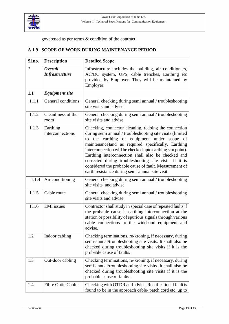
Power Grid Corporation of India Ltd.
Volume II - Technical Specifications for Communication Equipment
Section-06 Page 13 of 15
goverened as per terms & condition of the contract.
A 1.9 SCOPE OF WORK DURING MAINTENANCE PERIOD
Sl.no. Description Detailed Scope
1 Overall
Infrastructure
Infrastructure includes the building, air conditioners,
AC/DC system, UPS, cable trenches, Earthing etc
provided by Employer. They will be maintained by
Employer.
1.1 Equipment site
1.1.1 General conditions General checking during semi annual / troubleshooting
site visits and advise
1.1.2 Cleanliness of the
room
General checking during semi annual / troubleshooting
site visits and advise.
1.1.3 Earthing
interconnections
Checking, connector cleaning, redoing the connection
during semi annual / troubleshooting site visits (limited
to the earthing of equipment under scope of
maintenance)and as required specifically. Earthing
interconnection will be checked upto earthing star point).
Earthing interconnection shall also be checked and
corrected during troubleshooting site visits if it is
considered the probable cause of fault. Measurement of
earth resistance during semi-annual site visit
1.4 1.1.4 Air conditioning General checking during semi annual / troubleshooting
site visits and advise
1.1.5 Cable route General checking during semi annual / troubleshooting
site visits and advise
1.1.6 EMI issues Contractor shall study in special case of repeated faults if
the probable cause is earthing interconnection at the
station or possibility of spurious signals through various
cable connections to the wideband equipment and
advise.
1.2 Indoor cabling Checking terminations, re-kroning, if necessary, during
semi-annual/troubleshooting site visits. It shall also be
checked during troubleshooting site visits if it is the
probable cause of faults.
1.3 Out-door cabling Checking terminations, re-kroning, if necessary, during
semi-annual/troubleshooting site visits. It shall also be
checked during troubleshooting site visits if it is the
probable cause of faults.
1.4 Fibre Optic Cable Checking with OTDR and advice. Rectification if fault is
found to be in the approach cable/ patch cord etc. up to
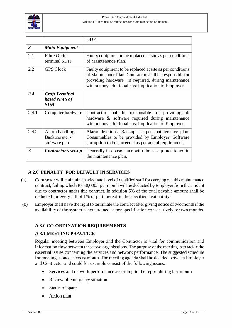
Power Grid Corporation of India Ltd.
Volume II - Technical Specifications for Communication Equipment
Section-06 Page 14 of 15
DDF.
2 Main Equipment
2.1 Fibre Optic
terminal SDH
Faulty equipment to be replaced at site as per conditions
of Maintenance Plan.
2.2 GPS Clock Faulty equipment to be replaced at site as per conditions
of Maintenance Plan. Contractor shall be responsible for
providing hardware , if required, during maintenance
without any additional cost implication to Employer.
2.4 Craft Terminal
based NMS of
SDH
2.4.1 Computer hardware Contractor shall be responsible for providing all
hardware & software required during maintenance
without any additional cost implication to Employer.
2.4.2 Alarm handling,
Backups etc. -
software part
Alarm deletions, Backups as per maintenance plan.
Consumables to be provided by Employer. Software
corruption to be corrected as per actual requirement.
3 Contractor's set-up Generally in consonance with the set-up mentioned in
the maintenance plan.
A 2.0 PENALTY FOR DEFAULT IN SERVICES
(a) Contractor will maintain an adequate level of qualified staff for carrying out this maintenance
contract, failing which Rs 50,000/- per month will be deducted by Employer from the amount
due to contractor under this contract. In addition 5% of the total payable amount shall be
deducted for every fall of 1% or part thereof in the specified availability.
(b) Employer shall have the right to terminate the contract after giving notice of two month if the
availability of the system is not attained as per specification consecutively for two months.
A 3.0 CO-ORDINATION REQUIREMENTS
A 3.1 MEETING PRACTICE
Regular meeting between Employer and the Contractor is vital for communication and
information flow between these two organisations. The purpose of the meeting is to tackle the
essential issues concerning the services and network performance. The suggested schedule
for meeting is once in every month. The meeting agenda shall be decided between Employer
and Contractor and could for example consist of the following issues:
Services and network performance according to the report during last month
Review of emergency situation
Status of spare
Action plan

Power Grid Corporation of India Ltd.
Volume II - Technical Specifications for Communication Equipment
Section-06 Page 15 of 15
Next Meeting
Alarms/events unattended till the date of meeting
The following participants should be present in this meeting:
Co-ordinator (Contractor)
Members of the Contractor team as needed
Co-ordinator Employer representative
Operation and maintenance staff as designated to attend (Employer)
A 3.2 EMERGENCY MEETING
Whenever a major outage occurs in any part of the network, an emergency meeting may be
called if desired by Employer. In the meeting, the outage will be discussed in the context of
cause, correction and prevention.
A 3.3 REPORTING PROCEDURE
The purpose of report is to summarize the activities performed during the reporting period.
The report provides the information on the performance of the services and describes the
current status of the network. The report is a monthly report from Contractor to Employer
which shows the trends in the network and services provided by the Contractor. By analysing
the report data, management and expert of Employer and contractor are able to focus
attention on the areas where further improvement is needed.
Emergency Reports: Contractor reports to Employer every time the emergencies call up and
call out service is invoked. In these cases, on termination of the emergency all details of the
fault and clearance information are submitted within five working days.
----------------------End of this Section-------------------

Power Grid Corporation of India Ltd.
Volume II – Technical Specifications for Communication Equipment
Appendix-BoQ Page 1 of 9
Appendix-A
Bill of Quantities
(BOQ)

Power Grid Corporation of India Ltd.
Volume II – Technical Specifications for Communication Equipment
Appendix-BoQ Page 2 of 9
Table - 1
BOQ for Telecom Equipment
S.NO. Item Description Unit TOTAL
QTY.
1.0 Transmission Equipment
A SDH Equipment - STM- 4 (upto two protected
directions)
(I) Base Equipment (Common cards, Cross-
connect/control cards, Optical base card, Power
supply cards, power cabling, other hardware &
accessories including sub-racks, patch cords, DDF
etc. fully equipped excluding (II) and (III) below)
No.
(II) Optical Interface/SFP# for:
(a) S4.1 No.
(b) L4.1 No.
(c) L4.2 No.
(d) Optical Interface/SFP (to support minimum 150
kms)** No.
(e) Optical Interface/SFP (to support upto 250 kms)** No.
(1) To support minimum 175 km No.
(2) To support minimum 200 km No.
(3) To support minimum 225 km No.
(4) To support minimum 250 km No.
(III) Tributary Cards
(a) E1 Interface card (Minimum 16 interfaces per card) No.
(b) Ethernet interfaces 10/100 Mbps with Layer-2
switching (Minimum 4 interfaces per card.) No.
B SDH Equipment - STM- 16 (upto two protected
directions)
(I) Base Equipment (Common cards, Cross-
connect/control cards, Optical base card, Power
supply cards, power cabling, other hardware &
accessories including sub-racks, patch cords, DDF
etc. fully equipped excluding (II) and (III) below)
No.
(II) Optical Interface/SFP# for:
(a) S16.1 No.
(b) L16.1 No.
(c) L16.2 No.
(d) Optical Interface/SFP (to support minimum 150
kms)** No.
(e) Optical Interface/SFP (to support upto 250 kms)** No.
(1) To support minimum 175 km No.
(2) To support minimum 200 km No.
(3) To support minimum 225 km No.
(4) To support minimum 250 km No.

Power Grid Corporation of India Ltd.
Volume II – Technical Specifications for Communication Equipment
Appendix-BoQ Page 3 of 9
S.NO. Item Description Unit TOTAL
QTY.
(III) Tributary Cards
(a) E1 Interface card (Minimum 16 interfaces per card) No.
(b) Ethernet interfaces 10/100 Mbps with Layer-2
switching (Minimum 4 interfaces per card.) No.
C SDH Equipment - STM- 4 (for more than two
protected directions)
(I) Base Equipment (Common cards, Cross-
connect/control cards, Optical base card, Power
supply cards, power cabling, other hardware &
accessories including sub-racks, patch cords, DDF
etc. fully equipped excluding (II) and (III) below)
No.
(II) Optical Interface/SFP# for:
(a) S4.1 No.
(b) L4.1 No.
(c) L4.2 No.
(d) Optical Interface/SFP card (to support minimum 150
kms)** No.
(e) Optical Interface/SFP (to support upto 250 kms)** No.
(1) To support minimum 175 km No.
(2) To support minimum 200 km No.
(3) To support minimum 225 km No.
(4) To support minimum 250 km No.
(III) Tributary Cards
(a) E1 Interface card (Minimum 16 interfaces per card) No.
(b) Ethernet interfaces 10/100 Mbps with Layer-2
switching (Minimum 4 interfaces per card) No.
D SDH Equipment - STM- 16 (for more than two
protected directions)
(I) Base Equipment (Common cards, Cross-
connect/control cards, Optical base card, Power
supply cards, power cabling, other hardware &
accessories including sub-racks, patch cords, DDF
etc. fully equipped excluding (II) and (III) below)
No.
(II) Optical Interface/SFP# for:
(a) S16.1 No.
(b) L16.1 No.
(c) L16.2 No.
(d) Optical Interface/SFP card (to support minimum 150
kms)** No.
(e) Optical Interface/SFP (to support upto 250 kms)** No.
(1) To support minimum 175 km No.
(2) To support minimum 200 km No.
(3) To support minimum 225 km No.
(4) To support minimum 250 km No.
(III) Tributary Cards

Power Grid Corporation of India Ltd.
Volume II – Technical Specifications for Communication Equipment
Appendix-BoQ Page 4 of 9
S.NO. Item Description Unit TOTAL
QTY.
(a) E1 Interface card (Minimum 16 interfaces per card) No.
(b) Ethernet interfaces 10/100 Mbps with Layer-2
switching (Minimum 4 interfaces per card) No.
2.0 Equipment Cabinets
a) For SDH Equipment No.
3.0 NMS#
(i) Craft Terminal
(a) Hardware Set*
(b) Software Set*
4.0 Synchronization Equipment
GPS clock including all hardware & accessories Set
Note*: Set shall include all required hardware/software for complete TMN system as specified in
technical specifications. NMS facilities for SDH equipment shall include monitoring of Ethernet
ports also.
Note** : Suitable Optical Interface Card(s) or any other solution such as SDH equipment with
optical amplifier, wavelength translator or higher aggregate bit rate SDH equipment may be offer
for the lengths to meet the link budget requirements without repeater.
Note# :Optical interface/SFP can be provided with Optical base card or Control card with the
condition that control card shall not be equipped with more than one Optical interface/SFP and
optical card with not more than two Optical interface/SFP. However main and protection channel
shall be terminated on separate cards.
Note##
: Requirement of NMS as per capacity of Network. For small networks, Craft terminal
based NMS would suffice.

Power Grid Corporation of India Ltd.
Volume II – Technical Specifications for Communication Equipment
Appendix-BoQ Page 5 of 9
Table 2
BOQ of Mandatory spares for Telecom Equipment
S.NO. Item Description Unit TOTAL
QTY.
1.0 Transmission Equipment
A SDH Equipment -STM- 4 (ADM, upto two
protected directions)
(I) Common cards, Cross-connect/control cards,
Optical base card, Power supply cards, power
cabling, other hardware & accessories (each)
Set$$
(II) Optical Interface/SFP@
for:
(a) S4.1 No.
(b) L4.1 No.
(c) L4.2 No.
(d) Optical Interface/SFP (to support minimum 150
kms)**
No.
(e) Optical Interface/SFP (to support upto 250 km)** No.
(1) To support minimum 175 km No.
(2) To support minimum 200 km No.
(3) To support minimum 225 km No.
(4) To support minimum 250 km No.
(III) Tributary Cards
(a) E1 Interface card (Minimum 16 interfaces per
card )
No.
(b) Ethernet interfaces 10/100 Mbps with Layer-2
switching (Minimum 4 interfaces per card.)
No.
B SDH Equipment -STM- 16 (ADM, upto two
protected directions)
(I) Common cards, Cross-connect/control cards,
Optical base card, Power supply cards, power
cabling, other hardware & accessories (each)
Set$$
(II) Optical Interface/SFP@
for:
(a) S16.1 No.
(b) L16.1 No.
(c) L16.2 No.
(d) Optical Interface/SFP@
(to support minimum 150
kms)** No.
(e) Optical Interface/SFP@
(to support upto 250
kms)** No.
(1) To support minimum 175 km No.
(2) To support minimum 200 km No.
(3) To support minimum 225 km No.
(4) To support minimum 250 km No.
(III) Tributary Cards
(a) E1 Interface card (Minimum 16 interfaces per
card) No.
(b) Ethernet interfaces 10/100 Mbps with Layer-2 No.
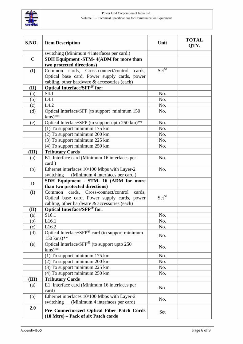
Power Grid Corporation of India Ltd.
Volume II – Technical Specifications for Communication Equipment
Appendix-BoQ Page 6 of 9
S.NO. Item Description Unit TOTAL
QTY.
switching (Minimum 4 interfaces per card.)
C SDH Equipment -STM- 4(ADM for more than
two protected directions)
(I) Common cards, Cross-connect/control cards,
Optical base card, Power supply cards, power
cabling, other hardware & accessories (each)
Set$$
(II) Optical Interface/SFP@
for:
(a) S4.1 No.
(b) L4.1 No.
(c) L4.2 No.
(d) Optical Interface/SFP (to support minimum 150
kms)**
No.
(e) Optical Interface/SFP (to support upto 250 km)** No.
(1) To support minimum 175 km No.
(2) To support minimum 200 km No.
(3) To support minimum 225 km No.
(4) To support minimum 250 km No.
(III) Tributary Cards
(a) E1 Interface card (Minimum 16 interfaces per
card )
No.
(b) Ethernet interfaces 10/100 Mbps with Layer-2
switching (Minimum 4 interfaces per card.)
No.
D SDH Equipment - STM- 16 (ADM for more
than two protected directions)
(I) Common cards, Cross-connect/control cards,
Optical base card, Power supply cards, power
cabling, other hardware & accessories (each)
Set$$
(II) Optical Interface/SFP@
for:
(a) S16.1 No.
(b) L16.1 No.
(c) L16.2 No.
(d) Optical Interface/SFP@
card (to support minimum
150 kms)** No.
(e) Optical Interface/SFP@
(to support upto 250
kms)** No.
(1) To support minimum 175 km No.
(2) To support minimum 200 km No.
(3) To support minimum 225 km No.
(4) To support minimum 250 km No.
(III) Tributary Cards
(a) E1 Interface card (Minimum 16 interfaces per
card) No.
(b) Ethernet interfaces 10/100 Mbps with Layer-2
switching (Minimum 4 interfaces per card) No.
2.0 Pre Connectorized Optical Fiber Patch Cords
(10 Mtrs) – Pack of six Patch cords Set

Power Grid Corporation of India Ltd.
Volume II – Technical Specifications for Communication Equipment
Appendix-BoQ Page 7 of 9
Note** : Suitable Optical Interface Card(s) or any other solution such as SDH equipment with
optical amplifier, wavelength translator or higher aggregate bit rate SDH equipment may be
offered for the length to meet the link budget requirements without repeater.
Note$$: One Set means one of each type of module/unit card etc
Note@: Include each type of optical base card which has been supplied under main quantity
meeting the criteria of 10% spare
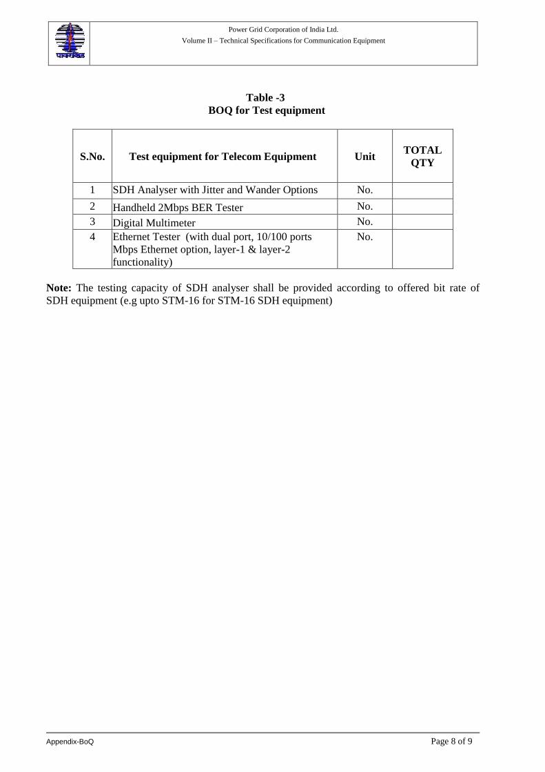
Power Grid Corporation of India Ltd.
Volume II – Technical Specifications for Communication Equipment
Appendix-BoQ Page 8 of 9
Table -3
BOQ for Test equipment
S.No. Test equipment for Telecom Equipment Unit TOTAL
QTY
1 SDH Analyser with Jitter and Wander Options No.
2 Handheld 2Mbps BER Tester No.
3 Digital Multimeter No.
4 Ethernet Tester (with dual port, 10/100 ports
Mbps Ethernet option, layer-1 & layer-2
functionality)
No.
Note: The testing capacity of SDH analyser shall be provided according to offered bit rate of
SDH equipment (e.g upto STM-16 for STM-16 SDH equipment)

Power Grid Corporation of India Ltd.
Volume II – Technical Specifications for Communication Equipment
Appendix-BoQ Page 9 of 9
Table: - 5
Proposed Training Requirements
Table -4
Maintenance Charges
S. No. Items Description Unit Qty
1 Maintenance Charges for Communication
System for 6 year after Warranty period Year
S.NO. Item Description Location No. of Trainees Duration in working days
1
Training on SDH equipment
and Craft Terminal based
NMS
Manufacturer
works/Traini
ng centre

Power Grid Corporation of India Ltd.
Volume II - Technical Specifications for Communication Equipment
Appendix-- DRS Page 1 of 3
Appendix-B Data Requirement Sheets
Power Grid Corporation of India Ltd.
Volume II - Technical Specifications for Communication Equipment
Appendix-- DRS Page 2 of 3
Appendix-C Data Requirement Sheets The following sets of Data Requirement Sheets are required to be filled up by the bidders to aid in the evaluation process. The response shall be brief and to the point and shall be supported by the printed product description and other literature. The DRS duly filled and the relevant drawings shall also be submitted during the detailed engineering along with the relevant technical brochures.
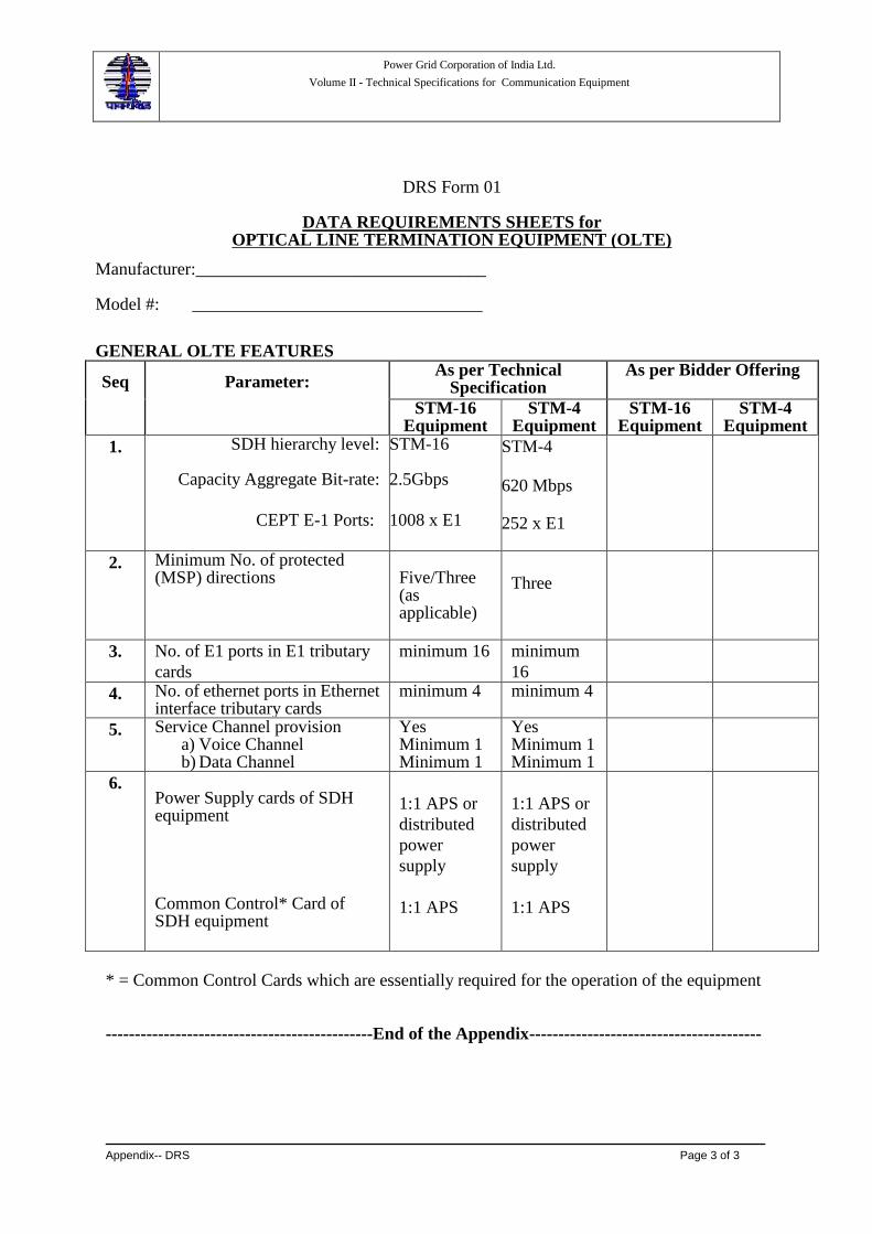
Power Grid Corporation of India Ltd.
Volume II - Technical Specifications for Communication Equipment
Appendix-- DRS Page 3 of 3
DRS Form 01
DATA REQUIREMENTS SHEETS for OPTICAL LINE TERMINATION EQUIPMENT (OLTE)
Manufacturer:_________________________________ Model #: _________________________________
GENERAL OLTE FEATURES Seq
Parameter:
As per Technical Specification
As per Bidder Offering
STM-16 Equipment
STM-4 Equipment
STM-16 Equipment
STM-4 Equipment
1. SDH hierarchy level:
Capacity Aggregate Bit-rate:
CEPT E-1 Ports:
STM-16 2.5Gbps
1008 x E1
STM-4
620 Mbps
252 x E1
2. Minimum No. of protected (MSP) directions
Five/Three (as applicable)
Three
3. No. of E1 ports in E1 tributary
cards
minimum 16 minimum
16
4. No. of ethernet ports in Ethernet interface tributary cards
minimum 4 minimum 4
5. Service Channel provision a) Voice Channel b) Data Channel
Yes Minimum 1 Minimum 1
Yes Minimum 1 Minimum 1
6. Power Supply cards of SDH equipment Common Control* Card of SDH equipment
1:1 APS or
distributed
power
supply
1:1 APS
1:1 APS or
distributed
power
supply
1:1 APS
* = Common Control Cards which are essentially required for the operation of the equipment ----------------------------------------------End of the Appendix----------------------------------------