technical submission section c - part 1 general specifications
Upload
khangminh22Category
view
4download
0
ICE GLOBAL NETWORK & COLOCATION
TECHNICAL SPECIFICATIONS
November 2021
Version 4.1
STATUS
This material may not be reproduced or redistributed in whole or in part without the express, prior written consent of Intercontinental Exchange, Inc.
© Copyright Intercontinental Exchange, Inc. 2021. All Rights Reserved.
1.1 About This Document
The information contained in this document can be used as a technical reference guide for cutomers to facilitate connectivity
and access to the ICE and NYSE markets, as well as access to services from other global and third party services available via
the ICE Global Network. The document also provides information on our Liquidity Center customer colocation services within
the NYSE datacenter in Mahwah, New Jersey and our low latency network connectivity options.
The following services are outlined in this document:
Colocation Services
• Kilowatt and Cabinet
• Partial Cabinet Solutions
• Power Not Used (PNU)
• Hosting Services
• Timing Services
• Meet Me Room (MMR) Services
High Availability & Colocation Network Services
• Liquidity Center Network (LCN)
• IP Liquidity Center (SLC)
• Liquidity Center Cross Connect (LCX)
• HA Direct Connect (SDC)
• HA 40G SDC Bundle
• HA Limited Service Port (LSP)
• HA Virtual Control Circuit (VCC) – (MPLS based L2VPN)
• ICE Gobal Network Optic
• ICE Global Network VPN Access – IP based VPN
Low Latency Connectivity Services
• ICE Global Network Low Latency Network (LLN)
• NMS Network
• ICE Global Network Wireless
Application Services
• Core Application Services (NYSE Markets & National Market Systems (NMS)
• Non-Core Application Services (such as Integrated Feeds)
• Content Service Provider (CSPs, including ICE Markets)
: "Quick Connect Sheet", provides further information for customers connecting directly to the ICE Global Network at the
USLC or High Availability Access Centers. Customers connecting via a third party (e.g. an extranet provider, Application Service
Provider (ASP), Metro Ethernet provider, or other) will also find some of this information applicable. However, customers
that have chosen a third party for connectivity into the ICE Global Network must consult with their third party provider for
interface specific information.

This material may not be reproduced or redistributed in whole or in part without the express, prior written consent of Intercontinental Exchange, Inc.
© Copyright Intercontinental Exchange, Inc. 2021. All Rights Reserved.
1.2 Document Scope
This document specifies how customers will connect to the ICE Global Network network in order to gain access to receive or
provide services. It also specifies connectivity options available to customers when connecting to the ICE and NYSE Group
markets as well as between each other within the U.S. Liquidity Center (USLC) in Mahwah. It provides information associated
with the first three layers of the standard OSI networking model (Physical, Data Link, and Network).
ICE Global Network provides access to the individual ICE and NYSE Group markets including, but not limited to:
• ICE Futures
• ICE Endex
• ICE Clear
• The New York Stock Exchange - Common Access Point (CAP)
• NYSE
• NYSE ARCAEquities
• NYSE Arca Options
• NYSE American Options
• NYSE Bonds
• NYSE American
• NYSE Chicago
• NYSE National
• National Market Systems(NMS)
ICE Global Network also provides access to the National Market Systems (NMS – OPRA & CTA) hosted in the USLC as well as
to over 120 leading Equities, Options, Futures, Fixed Income and FX venues and trading services. This document is not meant
to be a complete guide to the ICE Global Network network or colocation services. It does NOT specify the application level
requirements for each of the services provided by ICE and DMA sourcs via ICE Global Network, i.e. it does not cover supporting
services such as Domain Name Systems (DNS) resolution, authentication mechanisms, APIs, and other message based
requirements. Customers will need to contact each market center/application provider directly to ensure receipt of specific
documentation on message formats, authentication schemes, and any other information required to successfully connect to
or receive information from individual markets.
Additionally, during provisioning, customers will receive service specific network information. This information will cover IP
peering information and service addressing assignments (unicast and multicast addresses, TCP/UDP port assignments, etc.)
for the relevant services ordered.
For additional information, refer to the following documents:
• US Liquidity Center Operating Policies & Procedures
• SFTI® Americas Acceptable Use Policy
• NYSE Common Access Point (CAP) Agreement (for Trading on the NYSE markets)
• NYSE Technologies Connectivity Master Network Access Services
• NYSE Technologies Connectivity Master Services Agreement

This material may not be reproduced or redistributed in whole or in part without the express, prior written consent of Intercontinental Exchange, Inc.
© Copyright Intercontinental Exchange, Inc. 2021. All Rights Reserved.
1.3 Contact Information
For more information on the ICE Global Network and the services available, please visit https://www.theice.com/data-
services/global-network or contact support via one of the numbers below:
For commercial or product questions:
Contact Telephone Email
ICE Global Network & Colocation
Sales
US: +1 770 661 0010, Option 3 Europe: +44 207 429 4610
APAC: +61 3 9249 2093
Technical or operations related questions
Contact Telephone Email
Customer Engineering &
Provisioning
US: +1 212 894 5488 Europe: +44 207 429 4530
Network Operations US: +1 770 661 0010 Europe: +44 203 808 6638
APAC: +61 3 8593 5999 Option 1
USLC Datacenter Operations US: 1-770-661-0010
Option 2 - Sub-Option 2
1.4 Copyright Information
© 2021 Intercontinental Exchange, Inc. All rights reserved. This document contains information that is confidential and proprietary property and/or trade secrets of Intercontinental Exchange, Inc. and/or its affiliates, is not to be published, reproduced, copied, disclosed, or used without the express written consent of Intercontinental Exchange, Inc. The information contained is, to the knowledge of Intercontinental Exchange, Inc., current as of the date hereof, but is subject to change, without notice. The information contained herein is for informational and/or reference purposes with respect to the products and services described only, does not constitute representations or warranties by Intercontinental Exchange, Inc., and does not alter the terms of any agreements that currently exist or may from time to time exist between Intercontinental Exchange, Inc. and/or its affiliates and its clients or their affiliates. Nothing herein is intended to constitute legal, tax, accounting, or other professional advice. Intercontinental Exchange, Inc. and its affiliates do not recommend or make any representation as to possible benefits from any securities or investments, or third-party products or services. Notwithstanding anything to the contrary in this document, the information in this document is for discussion or reference purposes only and only relates to the products and services described in this document. Any agreement with respect to the products and services described herein is subject to the execution and delivery of final documents in form and substance satisfactory to Intercontinental Exchange, Inc. ICE Data Services refers to a group of products and services offered by certain Intercontinental Exchange, Inc. (NYSE:ICE) companies and is the marketing name used globally, including for Connectivity and ICE Global Network.
Trademarks of Intercontinental Exchange, Inc. and/or its affiliates include: Intercontinental Exchange, ICE, ICE block design,
NYSE, ICE Data Services, New York Stock Exchange, and Interactive Data.

This material may not be reproduced or redistributed in whole or in part without the express, prior written consent of Intercontinental Exchange, Inc.
© Copyright Intercontinental Exchange, Inc. 2021. All Rights Reserved.
NOTE: If you have printed or downloaded a copy of this document, make certain to check our website
https://www.theice.com/data-services/global-network for an updated copy as policies might change from time to time.
1.5 Version Information
Version Date Comment
1.0 28 February 2016 Reinstated versioning and added new service information for Wireless and Low Latency
Network
2.0 14 September
2016
Updates to section 6.2.2 LCN for greater detail on CCG vs XDP flows
2.1 8 December 2017 Updated Customer engineering, network operations contact details and LCN diagrams
2.2 8 November 2018 Updated IGN Sales Phone Number
2.3 16 July 2019 Updates to sections 6.3.2 and 6.3.4 for greater detail on HA 40Gb SR4 availability
2.4 8 August 2019 Removed reference to Basildon in section 6.4 and corrected bandwidth units in section 7.1
3.0 21 Octoboer 2019 Branding Update
3.1 29 Octoboer 2019 Updated rate limit policy for 10G LX Ports
3.2 14 April 2020 Updated LCN Latency section
3.3 30 April 2020 Added 100G High Availability Interface Specifications
3.4 1 May 2020 Clarification of NMS Latencies over LCN
3.5 30 July 2020 Added Partial Cabinet Receptacle Specifications
3.6 3 Dec 2020 Updated LCN Policer Latencies
3.7 23 Feb 2021 Added NMS Network, Updated Cabinet Power Specifications and Mahwah Hall Layout
3.8 12 March 2021 Added Hall 4A cabinet size and electrical information to section 4.1
3.9 20 May 2021 Updates to section 4.1 for greater detail on customer provided cabinets
4.0 10 August 2021 Updated NMS section
4.1 6 October 2021 Added Homerun Connectivity Section 6.7.2
ICE Global Network & Colocation US Technical Specifications
This material may not be reproduced or redistributed in whole or in part without the express, prior written consent of Intercontinental Exchange, Inc.
© Copyright Intercontinental Exchange, Inc. 2021. All Rights Reserved.
2. Contents
TECHNICAL SPECIFICATIONS .................................................................................................................... i 1.1 About This Document............................................................................................................................................................ ii 1.2 Document Scope................................................................................................................................................................... iii 1.3 Contact Information ............................................................................................................................................................. iv 1.4 Copyright Information.......................................................................................................................................................... iv 1.5 Version Information .............................................................................................................................................................. v
2. Contents ................................................................................................................................... 1
3. US Liquidity Center (USLC) – Mahwah.................................................................................. 4 3.1 Engineering Specifications ....................................................................................................................................................4
4. Colocation Services ............................................................................................................... 5 4.1 Kilowatts & Cabinets .............................................................................................................................................................5
4.1.1 Power Specification ................................................................................................................................................5 4.1.2 Technical Specification ...........................................................................................................................................6
4.2 Partial Cabinet Solutions .......................................................................................................................................................8 4.2.1 Technical Specification ...........................................................................................................................................9
4.3 Power Not Used (PNU)..........................................................................................................................................................9 4.4 Hosting Services.....................................................................................................................................................................9 4.5 Timing Service ........................................................................................................................................................................9
4.5.1 Network Timing Protocol (NTP) Service................................................................................................................9 4.5.2 Precision Time Protocol (PTP) Service................................................................................................................ 10 4.5.3 GPS........................................................................................................................................................................ 10 4.5.4 Time Service Comparison Table ......................................................................................................................... 11
5. High Availability ................................................................................................................... 12 5.1 Overview ............................................................................................................................................................................. 12 5.2 High Availability Highlights ................................................................................................................................................ 12 5.3 Connectivity Options .......................................................................................................................................................... 12 5.4 High Availability Concepts.................................................................................................................................................. 14 5.5 High Availability US Access Centres .................................................................................................................................. 14 5.6 Protocols Supported........................................................................................................................................................... 14 5.7 Physical connectivity options............................................................................................................................................. 15 5.8 Security Goals ..................................................................................................................................................................... 15
6. Network Connectivity Services: Detailed Specifications.................................................... 16 6.1 Overview ............................................................................................................................................................................. 16 6.2 Liquidity Center Network (LCN) Services .......................................................................................................................... 16
6.2.1 LCN Physical Connectivity ................................................................................................................................... 18 6.2.2 LCN Address Space .............................................................................................................................................. 19 6.2.3 LCN Networking Configuration........................................................................................................................... 19 6.2.4 LCN Multicast ....................................................................................................................................................... 20 6.2.5 LCN Rate Limiting................................................................................................................................................. 21

ICE Global Network & Colocation US Technical Specifications
This material may not be reproduced or redistributed in whole or in part without the express, prior written consent of Intercontinental Exchange, Inc.
© Copyright Intercontinental Exchange, Inc. 2021. All Rights Reserved.
6.3 High Availability Services ................................................................................................................................................... 21 6.3.1 IP Liquidity Center (SLC) Services ....................................................................................................................... 22 6.3.2 IP SLC Physical Connectivity (Mahwah) ............................................................................................................. 22 6.3.3 High Availability Direct Connect (SDC) Ethernet (WAN) ................................................................................... 23 6.3.4 High Availability Physical Connectivity (SDC & LSP) .......................................................................................... 24 6.3.5 High Availability Address Space (SLC, SDC & LSP) ............................................................................................. 25
6.4 High Availability Virtual Control Circuit (VCC) .................................................................................................................. 27 6.4.1 VCC Connectivity Options ................................................................................................................................... 27
6.5 ICE Global Network Optic................................................................................................................................................... 27 6.5.1 ICE Global Network Optic Physical Connectivity ............................................................................................... 29 6.5.2 ICE Global Network Optic Logical Connectivity ................................................................................................. 29 6.5.3 Optical Interfaces ................................................................................................................................................ 30 6.5.4 Monitoring ........................................................................................................................................................... 30
6.6 ICE Global Network Optic Connect.................................................................................................................................... 30 6.7 Liquidity Center Cross Connect (LCX) ................................................................................................................................ 31
6.7.1 LCX Physical Connectivity.................................................................................................................................... 31 6.7.2 Homerun Connectivity ........................................................................................................................................ 32 6.7.3 Administration of the Cross Connect ................................................................................................................. 32
6.8 ICE Global Network VPN Access – IP based VPN .............................................................................................................. 32 6.8.1 Connectivity (LAN to LAN)................................................................................................................................... 33 6.8.2 ICE Global Network VPN: Network Considerations .......................................................................................... 33
7. Low Latency Services.......................................................................................................... 34 7.1 Low Latency Network (LLN) ............................................................................................................................................... 34
7.1.1 LLN Highlights ...................................................................................................................................................... 34 7.1.2 LLN Latency * ....................................................................................................................................................... 35 7.1.3 LLN Physical Connectivity.................................................................................................................................... 35 7.1.4 LLN Address Space............................................................................................................................................... 36 7.1.5 LLN Networking Configuration ........................................................................................................................... 36 7.1.6 Failure Considerations......................................................................................................................................... 36
7.2 NMS Network...................................................................................................................................................................... 37 7.2.1 Latency ................................................................................................................................................................. 37 7.2.2 NMS Physical Connectivity.................................................................................................................................. 37
7.3 ICE Global Network Wireless: New Jersey Metro ............................................................................................................ 39 7.3.1 Technology Highlights ......................................................................................................................................... 40 7.3.2 Latency & Availability Information ..................................................................................................................... 40 7.3.3 Private Bandwidth ............................................................................................................................................... 40 7.3.4 Private Bandwidth - Physical Connectivity ........................................................................................................ 40 7.3.5 Private Bandwidth: Network Considerations .................................................................................................... 41 7.3.6 Market Data ......................................................................................................................................................... 41 7.3.7 Market Data - Physical Connectivity .................................................................................................................. 41 7.3.8 Market Data: Network Considerations .............................................................................................................. 41 7.3.9 Resiliency/Failover Considerations .................................................................................................................... 42
7.4 ICE Global Network Wireless: Toronto - New Jersey ....................................................................................................... 43 7.4.1 Latency Information ............................................................................................................................................ 44 7.4.2 Physical Connectivity........................................................................................................................................... 44 7.4.3 Resiliency/Failover Considerations .................................................................................................................... 44
8. Content Service Providers (CSPs) ...................................................................................... 45
9. Application Services ............................................................................................................ 46
ICE Global Network & Colocation US Technical Specifications
This material may not be reproduced or redistributed in whole or in part without the express, prior written consent of Intercontinental Exchange, Inc.
© Copyright Intercontinental Exchange, Inc. 2021. All Rights Reserved.
9.1 High Availability Virtual Local Area Network (VLAN) ....................................................................................................... 46
10. Carrier Meet-Me Room Services .......................................................................................... 47 10.1 Engineering Consideration................................................................................................................................................. 47 10.2 MMR Layout........................................................................................................................................................................ 47
10.2.1 Power Specifications ...................................................................................................................................... 48 10.2.2 Technical Specification ................................................................................................................................... 48
Appendix A. ICE Global Network Connectivity Options Summary........................................... 49
Appendix B. Technical Terms and Acronyms:.......................................................................... 50
Appendix C. Quick Connect Sheet – High Availability ............................................................. 53
Appendix D. Sample – Layer3 Switch Configuration ................................................................ 55
Appendix E. Sample – Layer3 Designated Market Maker Connectivity ................................... 58
Appendix F. Data Center Cabling & Installation Guidelines..................................................... 60

ICE Global Network & Colocation US Technical Specifications
This material may not be reproduced or redistributed in whole or in part without the express, prior written consent of Intercontinental Exchange, Inc.
© Copyright Intercontinental Exchange, Inc. 2021. All Rights Reserved.
3. US Liquidity Center (USLC) – Mahwah
Since 2010, two data centers house the NYSE markets serving the global equities and derivatives trading communities. The
U.S. Liquidity Center site is located in Mahwah, New Jersey and the European site is in Basildon, England.
The USLC is a state of the art, Tier 4 guided data center located in Mahwah, New Jersey. Special consideration was taken
during its construction to ensure that the building and supporting infrastructure such as electrical, cooling, and
communications entry points are diversified and fault tolerant to meet or exceed 99.995% data availability for the systems
within. USLC’s colocated customers have the opportunity to take advantage of resilient infrastructure that provides direct
access to NYSE trading services such as market data and content service provider data, as well as the ability to gain access to
ICE and other markets, all from a single facility.
(Figure 1) – USLC Layout
USLC Location: 1700 McArthur Boulevard, Mahwah, NJ, 07430
3.1 Engineering Specifications
• 398 000 sq. ft. building situated on a 28 acre site 34 miles from Wall Street, New York
• Tier 4 guided design of all critical infrastructure (2N or N+2)
• Data center white space scalable to 20,000 square ft. at 150 watts per square ft.
• 30,000 sq. ft. colocation halls
• Redundant fiber diversely routed to site
• 28 MW of total site electrical power
• 48 hours of emergency generator fuel storage and cooling tower water (at full load)
• Double action pre-action sprinkler fire suppression
• Armed security staff and state of the art surveillance systems
• Monitoring and Evaluation (M&E) on ground floor and data halls on mezzanine floor
-------------------------------------------------------------------------- 1. MMRs are in 1st Floor of the Data center. 2. Production and Colocation Halls are in 2nd Floor of the Data Center.

ICE Global Network & Colocation US Technical Specifications
This material may not be reproduced or redistributed in whole or in part without the express, prior written consent of Intercontinental Exchange, Inc.
© Copyright Intercontinental Exchange, Inc. 2021. All Rights Reserved.
4. Colocation Services
4.1 Kilowatts & Cabinets
Colocation cabinets come in standard sizes of 4kW, 8kW and 12kW with variable power configurations available up to 15kW.
A standard 4kW cabinet can scale up to 5kW of power, and a standard 8kW cabinet can scale up to 11kW of power. Customers
requiring 12kW or more may purchase an upgrade kit, making the cabinet scalable to 15kW. Partial cabinets are also available
in 1-2kW power configurations for customers with lower space/power requirements.
Customers requesting to use their own cabinets must submit a specification sheet for review and approval by the ICE Data
Center management team. The color of customer supplied cabinets must comply with the Data Center Hall ICE cabinet color
standard where the customer cabinets will be installed.
4.1.1 Power Specification
Hall 3
Colocation Hall 3 cabinets configured as 4kW, 8kW, and up to 15kW of power use branch circuits from Remote Power Panels
(RPP). One RPP provides 'A' feed power while the other provides 'B' feed power. In the event of a failure to either the ‘A’ or
‘B’ feed, the other feed is engineered to provide full power to the cabinet.
4kW Cabinets
Each cabinet has two branch circuits, one from each of the RPPs. Each branch circuit is a single phase, 208VAC 30Amp
feed which can support a maximum of 5kW of power. Both branch circuits are monitored to ensure each carry half
of the 4kW load with an alarm in place for notifying the Data Center Operations personnel should both branch
circuits’ total power exceed 4kW.
8kW Cabinets
Each cabinet has four branch circuits, two from each of the RPPs. Each branch circuit is a single phase, 208VAC 30Amp
feed which can support a maximum of 11kW of power. The four branch circuits are monitored to ensure each carry
half of the 8kW load with an alarm in place for notifying the Data Center Operations personnel should the total
power exceed 8kW.
12kW-15kW Cabinets
Each cabinet has four branch circuits, two from each of the RPPs. Each branch circuit is a three phase, 208VAC 40Amp
feed which can support a maximum of 15kW. The four branch circuits are monitored to ensure each carry half of the
15kW load with an alarm in place for notifying Data Center Operations should the total power exceed 15kW.
Hall 4A
Colocation Hall 4A cabinets configured as 4kW, 8kW, and up to 15kW of power use branch circuits from Overhead Busways.
One overhead busway provides 'A' feed power while the other provides 'B' feed power. In the event of a failure to either the
‘A’ or ‘B’ feed, the other feed is engineered to provide full power to the cabinet.
Hall 4A - 4kW, 8kw, and 12-15kw cabinets
Each cabinet has two branch circuits, one from each of the busways. Each branch circuit is a 3 phase, 230/400VAC
30Amp feed which can support a maximum of 16kW of power. Both branch circuits are monitored to ensure each
carry half of the allocated load with an alarm in place for notifying the Data Center Operations personnel should
both branch circuits’ total power exceed the allocated cabinet kW.

ICE Global Network & Colocation US Technical Specifications
This material may not be reproduced or redistributed in whole or in part without the express, prior written consent of Intercontinental Exchange, Inc.
© Copyright Intercontinental Exchange, Inc. 2021. All Rights Reserved.
4.1.2 Technical Specification
Hall 3
Power Strip
Two vertical power strips are provisioned in each cabinet. Strips will be on either sides of the cabinet. Each strip is fused
with the following standard configuration:
• 4kW & 8kW Cabinets Outlet Size (single phase – single strip):
• 30Amp (18x IEC C13, 6x IEC C19) 208 VAC receptacles
• 30Amp (8x NEMA 5-20R) 120 VAC receptacles
• Optional: 30Amp (24x IEC C13, 6x IEC C19) 208 VAC receptacles
• 12kW-15W Cabinets Outlet Size (three phase – single strip):
• 40Amp (30x IEC C13, 6x IEC C19) 208 VAC receptacles
• Optional Strip for 5-20R outlets
• Vertical Mount
• Local Meter
Standard1 Cabinet
• Manufacturer: Rittal Corporation
• Part: 9963619, Modified Custom TS8
• Color: Black
• Size: 45 Rack Unit (RU)
• Dimensions (Depth × Height × Width): 47.42 in. × 84.64 in. × 31.38 in.
Hall 4A
Power Strip
Two vertical 400VAC class power strips are provisioned in each cabinet. Strips will be on one side of the cabinet. Each strip
is fused with the following standard configuration:
• 4kW, 8kW & 12kW-15kW Cabinets Outlet Size (three phase – single strip):
• 30Amp (24x locking IEC C13, 6x locking IEC C19) 230 VAC receptacles
• L22-30P input power plug
• Customer supplied power strips must be 400VAC class with an L22-30P plug
• Vertical Mount
• Local Meter
Additional power strip outlet configurations are available upon request.
----------------------------------------------------------------- 1 Note that both 28 in. and 24 in. wide cabinets are available upon request and at the discretion of NYSET.

ICE Global Network & Colocation US Technical Specifications
This material may not be reproduced or redistributed in whole or in part without the express, prior written consent of Intercontinental Exchange, Inc.
© Copyright Intercontinental Exchange, Inc. 2021. All Rights Reserved.
Standard1 Cabinet
• Manufacturer: Chatsworth Products Inc (CPI)
• Part: MIS-TS1520039
• Color: Black
• Size: 52 Rack Unit (RU)
• Dimensions (Depth × Height × Width): 46.63 in. × 96.94 in. × 27.53 in.
Common Cabinet Specifications
Server Enclosure Specification
• 2 Server Enclosure Specification
• Hinge and lock points are internal and not accessible from outside cabinet with doors closed. Mounting of server
fans can be installed without need for cutouts
• 3 Server Enclosure Specification
• Enclosure widths equal to or greater than 28 in. (700mm) allow for 19 in., 21 in., and 23 in, rack mounting of
components and/or allow for the offsetting of 19 in. rails, left or right, to allow for additional cable management and
air plenum space.
Material Specifications
Roll formed carbon steel and closed frame members provide a welded, vertical and horizontal structure of symmetrical
profile. All metal components are primed, baked, powder coated, and baked again to assure maximum appearance and
corrosion resistance. RAL 7035 and Sand Texture Black are available as standard colors. Optional color choices are available
upon request.
• Sidewalls: 16 gauge cold rolled carbon steel
• Front and Rear Door: 14 gauge cold rolled steel
• Frame: 16 gauge cold rolled carbon steel with unlimited mounting options provided by installation holes spaced at
0.98 in. (25mm) intervals
Method of Construction
Frame
• Enclosure frame are a 16 fold design, with 0.98 in. (25mm) repetitive hole pattern (round and slotted holes) to allow
installation of various components.
• Rack mounted equipment are installed on four independent vertical mounting rails.
• All metal surfaces are free of burrs, and welded joints are ground free of weld splatter.
• The frame is fully welded and provides minimum 3000lb static load capacity.
• The frame meets Seismic Zone 3, standard, and can be upgraded to Seismic Zone 4.
Doors
• Sheet cold rolled steel, 14 gauge, with horizontal and vertical door stiffeners to provide additional rigidity and
mounting surfaces.
• Front door is provided with a foamed in place perimeter gasket.
• Fully perorated front and split rear doors with 64% air flow.
• Reversible hinges, rated for 66 lbs. per hinge, are design with a minimum of three quick release hinges and captive
hinge pins.
• Minimum of two point latching/locking for security
----------------------------------------------------------------- 1 Note that a 42.69” deep cabinet may be required in certain locations in Hall 4A at the discretion of NYSET.

ICE Global Network & Colocation US Technical Specifications
This material may not be reproduced or redistributed in whole or in part without the express, prior written consent of Intercontinental Exchange, Inc.
© Copyright Intercontinental Exchange, Inc. 2021. All Rights Reserved.
Roof Panels
• Fully perforated with four 4 in. diameter cable entry points
• Grommets are provided to seal unused cable entry holes.
• Gasket
• Mating surfaces are sealed with closed cell foam-in-place (FIP) polyurethane gasket
• Bonding
• All components of the cabinet must have a grounding stud to have common ground potential with the use of
grounding straps.
• Hardware to be provided to for enclosure connection to facility grounding components.
• Component Mounting Rails (19 in.)
• Front and rear mounting rails are depth adjustable multi-fold “Z” shaped, compliant with EIA-310-D standards
• Vertical mounting rails are constructed of 2.5 mm/12 gauge steel with equipment mounting holes using 9.5 mm2.
• Total static load capacity (regardless of location in the cabinet ) of 2000 lbs. ; equivalent to 47.6 lbs. per RU. Weight
is measured using equal weight loading on all four rails.
• Mounting rail depth can be adjusted as desired as along as the maximum useable depth is no less than 2 in. of the
overall enclosure depth (i.e. 38 in. in 40 in. deep frame)
• Designed with floating attachment points in top and bottom of frame only; preventing the interference of interstitial
cable management space from the vertical rails to the sidewalls.
• Individual RU space is identified by a line at the top and the bottom of each RU and sequentially numbered. RUs
have three holes, with the middle hole used as placement for designated space number, and measure 1.75 in. (44.45
mm) high. RU space marking is ink jet applied, not adhesive backed. The rear side of all mounting rails mirror the
same RU space markings.
Additional sets of mounting holes, which replicate the hole pattern of the frame, are available for the installation of various
accessories such as vertical or horizontal cable management, and power strips.
Enclosure widths equal to or greater than 29 in. (700 mm) shall allow for 19 in., 21 in., and 23 in. rack mounting of components
and/or allow for the offsetting of 19 in. rails, left or right, to allow for additional cable management and air plenum space.
Baying
• Baying of cabinets is to be accomplished
• without disturbing any cables or rack mounted equipment
• with the use simple tools.
• after access into the cabinet, as not to compromise cabinet level security.
• Baying of the cabinets is not allowed for the purpose of increasing the width of the row.
4.2 Partial Cabinet Solutions
Partial cabinets solutions provide a packaged solution for colocation customers who only require limited space and power
but wish to take advantage of low latency access to the NYSE markets.
A standard bundle is offered which includes the following base items:
• 8Us of rack space
• 1 x IP SLC connection (dedicated)
• 1 x LCN LX connection (dedicated)
• 2 x LCX cross connects
• Time service
ICE Global Network & Colocation US Technical Specifications
This material may not be reproduced or redistributed in whole or in part without the express, prior written consent of Intercontinental Exchange, Inc.
© Copyright Intercontinental Exchange, Inc. 2021. All Rights Reserved.
Selected items above are also customizable to a limited extent via choices of:
• 1G or 10G SLC & LCN connectivity
• 1kW or 2kW of total power
• NTP or PTP timing services protocol
4.2.1 Technical Specification
Power Strip
Two vertical power strips are provisioned in each Micro cabinet. Strips will be on each side in the back of the cabinet.
1kW & 2kW Micro Cabinet Outlet Size (each strip)
• 20 amp (10 x IEC C13) 208V receptacles
4.3 Power Not Used (PNU)
Power Not Used (PNU) offers the Colocation customer an option to pay a reduced rate for the option to reserve cabinets and
kilowatts that the customer anticipates will be required in the future.
4.4 Hosting Services
The Hosting Services allow approved third party service providers, (Hosting Users), authorization to occupy space in the USLC
for the purpose of providing infrastructure hosting, service bureau services, risk management, order routing and Market Data
delivery services directly to USLC customers.
Hosted Users are able to offer hosting services to Customers and can be categorized as any of the following exchange
participants:
• Member
• Non-Member
• Sponsored Participant (SP)
4.5 Timing Service
Customers within the Colocation hall have the following options for receiving time and synchronization services based on
their precision requirements.
• Network Timing Protocol (NTP) services across the LCN
• Direct Precision Timing Protocol (PTP) service over Ethernet
• Direct GPS feed
4.5.1 Network Timing Protocol (NTP) Service
Customers can receive NTP services from a Stratum 1 time source via their LCN connections. NTP peering IP addresses will
be provided during the provision process. For more information on LCN connection specifications, refer to Liquidity Center
Network Service section later in this document.

ICE Global Network & Colocation US Technical Specifications
This material may not be reproduced or redistributed in whole or in part without the express, prior written consent of Intercontinental Exchange, Inc.
© Copyright Intercontinental Exchange, Inc. 2021. All Rights Reserved.
4.5.2 Precision Time Protocol (PTP) Service
Colocation customers looking for precise synchronization accuracy will be provisioned with PTP IEEE1588 compliant feed. PTP
services can be received by directly connecting to USLC PTP environment via direct Ethernet 1G MMF fiber cross-connection,
which will give them the ability to achieve sub 1µs precision using a NIC with an IEEE1588-compliant hardware clock.
PTP Distribution
The USLC PTP service will receive the local clock reference from GPS receivers, which will be distributed to the
Colocation customers in accordance with the IEEE1588 draft. USLC supports IEEE1588 unicast, multicast-only, and
hybrid PTP profiles.
Each of the USLC Colocation halls are furnished with PTP edge routers, providing the direct point of connectivity
between PTP Distribution Network and the directly connected customers. Each of the directly connected customers
should have two physical connections to the facility for redundancy. Customers connecting to ICE’s PTP environment
should support BGP4 protocol for exchange of source routes and PIM SM in case of implementing multicast-only and
hybrid PTP profiles.
RFC1918 private ranges will be assigned to the customers; alternatively, customers may use their globally registered
IP addresses. BGP Autonomous System (AS) addresses will be assigned from the private space identified by American
Registry for Internet Number (ARIN).
Co-Lo client equipment
Co-Lo client equipment
Co-Lo client equipment
PTP network switches
PTP network switches
Slave Clocks
BMCABest Master Clock
GM Master GM Slave
GPS Aerial Splitter GPS Aerial Splitter
PTP Timing Probe
PTP Timing Probe
Sub 1us precision up to 1Gb fibre hand off
Client experience dependent on the
infrastructure they deploy
100 Mbps hand off
(Figure 2) – PTP Distribution Network
4.5.3 GPS
Customers may receive time services via a direct feed from Global Positioning System (GPS) antennas. GPS time is the atomic
time scale implemented by the atomic clocks in the GPS ground control stations and the GPS satellites themselves. GPS time
was zero at 0h 6-Jan-1980 and since it is not perturbed by leap seconds GPS is now ahead of UTC by 15 seconds.
The USLC is equipped with three separate antennas and GPS receivers. Customers are recommended to subscribe to all three
feeds in order to form a quorum and spot an errant source.
Customers will be provided with precise time offset information as well as the estimated delay associated with the cable
length between the GPS antenna and their cabinet as part of the GPS services installation and calibration process.

ICE Global Network & Colocation US Technical Specifications
This material may not be reproduced or redistributed in whole or in part without the express, prior written consent of Intercontinental Exchange, Inc.
© Copyright Intercontinental Exchange, Inc. 2021. All Rights Reserved.
GPS Distribution
Customers will receive GPS via an ICE -provided cable type LMR400 and the connector types is BNC, TNC, or N;
alternatively, different patch cables can be provided upon request.
4.5.4 Time Service Comparison Table
Media options: Accuracy Delivery Method
NTP A few milliseconds Delivered over LCN network
PTP Sub microsecond to sub 10
microseconds
Delivered over a dedicated PTP network
GPS Sub microsecond Direct connection within USLC

ICE Global Network & Colocation US Technical Specifications
This material may not be reproduced or redistributed in whole or in part without the express, prior written consent of Intercontinental Exchange, Inc.
© Copyright Intercontinental Exchange, Inc. 2021. All Rights Reserved.
5. High Availability
5.1 Overview
Supporting the NYSE exchanges in providing high availability and quality to the production systems operated is the High
Availability network. High Availabiluty is a secure, resilient and redundant multi-exchange, multi-asset class and multi-
participant global network. By connecting to High Availability, a Customer has the potential to connect to to a broad range of
services, including markets, alternative trading systems, clearing and settlement services, market data vendors, content
service providers, and other core securities industry participants.
The High Availability network backbone is comprised of two diverse, logical networks that connect 10 US and 14 European
Access Centers to all ICE & NYSE markets and Data Centers. This provides customers in the financial services industry with
distinct geographical locations to which they can meet the High Availability edge routers.
In addition, the release in 2016 of ICE Global Network low latency products (IGN Wireless and IGN Low Latency Network)
augments the ICE Global Network product portfolio by adding options focused on speed over redundancy.
5.2 High Availability Highlights
• High Availability is a front-end network interface for approved customers to connect to ICE & NYSE markets as well
as third party content. ICE Global Network supports industry-standard network protocols for the transport of
financial market applications and data. It provides a reliable and redundant transport mechanisms for data traffic
and acts solely as a transport network, exclusively supporting the IP protocol suite for connecting to each of the
markets.
• High Availability allows customers to consolidate disparate WAN connections into consolidated connections and to
maintain high-availability network access to market systems.
• Customers connect to High Availability by connecting directly via Ethernet at one or more of the High Availability
Access Centers, or by connecting via a third party (extranet) provider. Customers who access High Availability
through a third party service or extranet provider must confirm interface specifications with their specific provider.
• High Availability provides a carrier-grade infrastructure supporting industry-standard protocols widely accepted and
utilized in Internet connectivity, while maintaining the security, operational integrity, and high standards of
availability of ICE & NYSE trading.
High Availability provides some security functions at the network layer but in addition, each market accessed, and the systems
and services that it supports will have their own set of security requirements that may include/require end systems to perform
authentication and access control.
This document only outlines information regarding the network interface to which customers will connect and not the detail
of the application services offered over High Availability. Customers must work with High Availability & Colocation Sales or
Provisioning teams to learn more about all the service specific details.
5.3 Connectivity Options

ICE Global Network & Colocation US Technical Specifications
This material may not be reproduced or redistributed in whole or in part without the express, prior written consent of Intercontinental Exchange, Inc.
© Copyright Intercontinental Exchange, Inc. 2021. All Rights Reserved.
High Availability supports the following connectivity methods:
• High Availability IP Direct Connect (SDC): Direct access from customers. Customers order their own Ethernet local
loop and configure the equipment directly connected to High Availability.
• Application Service Providers (ASP): provides a form of value added software service to customers and aggregates
them to the ICE Global Network backbone for access to ICE & NYSE applications.
• Extranet Service Providers (ESP): aggregates customers with Layer 3 routing to the ICE Global Network backbone
for access to ICE & NYSE applications.
High Availability is designed to meet the unique needs of members of the financial services industry with varouis product
offerings covering redundancy, high capacity, and ultra-low latency access to markets. For cost-effectiveness, scalability, and
operational efficiency, the traffic of multiple customers will be aggregated onto the high availability fiber-optic backbone and
delivered to relevant Data Centers. For customers requiring optimum latency over redundancy, low latency connectivity
methods, used in conjunction with High Availability SDC will provide a complete solution.
Customers are able to run multiple business services over a single physical connection to High Availability. Direct connectivity
into the High Availability network is currently available from US ( New York, New Jersey, and Chicago) and Europe (Paris,
London, Amsterdam, Lisbon, Brussels, and Frankfurt). This architecture allows customers to implement redundant paths to
at least two Access Centers, one on each logical network from their own sites. Figure 1 shows two logical networks providing
diverse access for customers connecting to Availability Access Centers.
Firm A network Firm B network
HA Access Center
HA Access Center
HA Access Center
HAI Access Center
Data Center
Global MPLS
Network
(Figure 3) – High Availability Logical Overview
ICE Global Network & Colocation US Technical Specifications
This material may not be reproduced or redistributed in whole or in part without the express, prior written consent of Intercontinental Exchange, Inc.
© Copyright Intercontinental Exchange, Inc. 2021. All Rights Reserved.
5.4 High Availability Concepts
To meet the unique requirements of its domestic and international customers and vendors, High Availability provides a high
capacity, high-availability, secure, and easy to use IP-based conduit into and out of the individual datacenters and markets.
By using the industry-standard TCP/IP suite of protocols, High Availability enables customers to implement interactive and
computer-to-computer connections to the services offered with less preparation and development time, and with a greater
assurance of compatibility and interoperability. To the greatest extent practicable, High Availabiluty seeks to empower
existing and new customers to:
• Gain access to market services quickly and easily • Have a range of choices for access and performance, vendor, technology, and cost • Access multiple services over a single physical connection to High Availability • Add additional connenctions designed specifically for low latency • Utilize widely available and accepted industry-standard applications, protocols, and structured data formats, to
reduce complexity, leverage the customers’ resources, and minimize the need for development or customization while still addressing their particular service requirements;
• Minimize the amount of systems development required, and adopt generic solutions consistent with the above; • Increase customers’ control over their interface to services • Simplified process for requesting service changes.
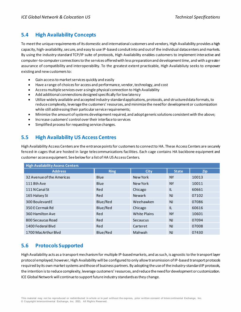
5.5 High Availability US Access Centres
High Availability Access Centers are the entrance points for customers to connect to HA. These Access Centers are securely
fenced-in cages that are hosted in large telecommunications facilities. Each cage contains HA backbone equipment and
customer access equipment. See below for a list of HA US Access Centers.
High Availability Access Centers
Address Ring City State Zip
32 Avenue of the Americas Blue New York NY 10013
111 8th Ave Blue New York NY 10011
111 N Canal St Red Chicago IL 60661
165 Halsey St Red Newark NJ 07102
300 Boulevard E Blue/Red Weehawken NJ 07086
350 E Cermak Rd Blue/Red Chicago IL 60616
360 Hamilton Ave Red White Plains NY 10601
800 Secaucus Road Red Secaucus NJ 07094
1400 Federal Blvd Red Carteret NJ 07008
1700 MacArthur Blvd Blue/Red Mahwah NJ 07430
5.6 Protocols Supported
High Availability acts as a transport mechanism for multiple IP-based markets, and as such, is agnostic to the transport layer
protocol employed; however, High Availability will be configured to only allow transmission of IP-based transport protocols
required by its own market systems and those of business partners. By adopting the use of the industry-standard IP protocols,
the intention is to reduce complexity, leverage customers’ resources, and reduce the need for development or customization.
ICE Global Network will continue to support future industry standards as they change.
ICE Global Network & Colocation US Technical Specifications
This material may not be reproduced or redistributed in whole or in part without the express, prior written consent of Intercontinental Exchange, Inc.
© Copyright Intercontinental Exchange, Inc. 2021. All Rights Reserved.
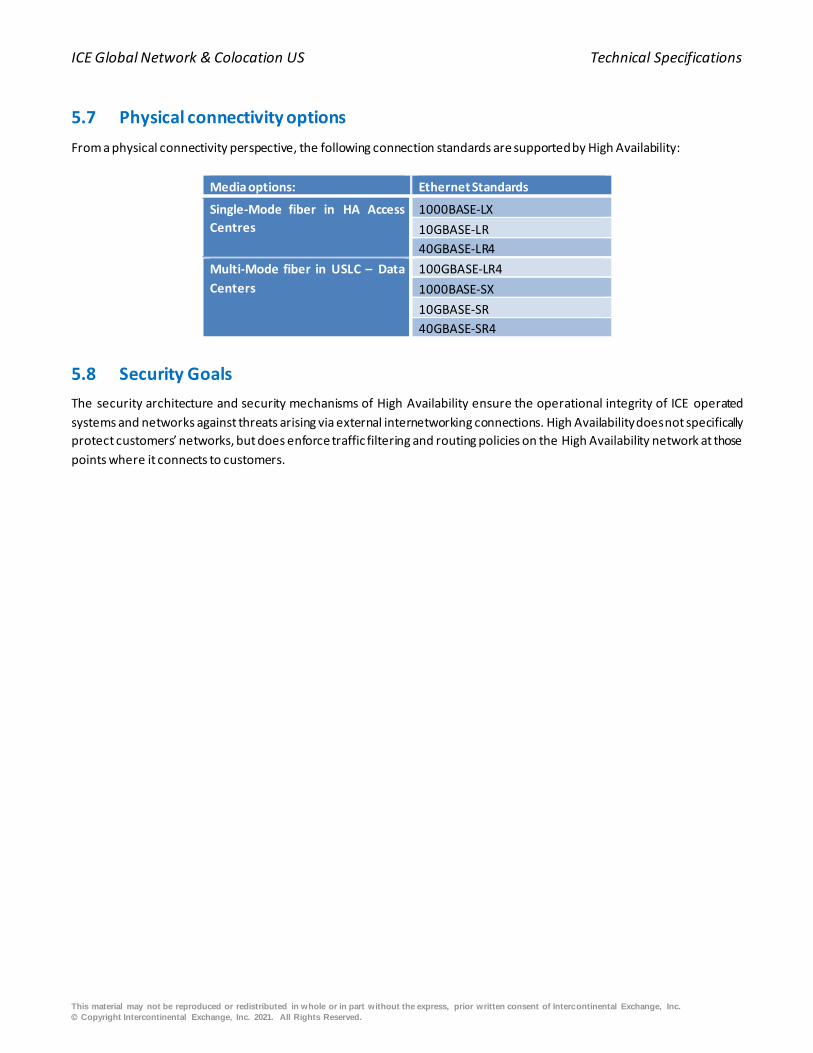
5.7 Physical connectivity options
From a physical connectivity perspective, the following connection standards are supported by High Availability:
Media options: Ethernet Standards
Single-Mode fiber in HA Access
Centres
1000BASE-LX
10GBASE-LR
40GBASE-LR4
Multi-Mode fiber in USLC – Data
Centers
100GBASE-LR4
1000BASE-SX
10GBASE-SR
40GBASE-SR4
5.8 Security Goals
The security architecture and security mechanisms of High Availability ensure the operational integrity of ICE operated
systems and networks against threats arising via external internetworking connections. High Availability does not specifically
protect customers’ networks, but does enforce traffic filtering and routing policies on the High Availability network at those
points where it connects to customers.
ICE Global Network & Colocation US Technical Specifications
This material may not be reproduced or redistributed in whole or in part without the express, prior written consent of Intercontinental Exchange, Inc.
© Copyright Intercontinental Exchange, Inc. 2021. All Rights Reserved.
6. Network Connectivity Services: Detailed Specifications
6.1 Overview
ICE Global Network provides multiple connectivity options to support customers’ individual requirements. Within the USLC,
customers can connect to either LCN or High Availability SLC: LCN is the local network within the Mahwah USLC, for Mahwah
hosted markets and services, and High Availability SLC provides access to NYSE Group test/certification and DR applications,
as well asthe full portfolio of ICE Futures applications and third party services.
Outside of the USLC, for WAN connectivity, customers can select from IP (SDC & LSP), IGN LLN, IGN Optic and IGN Wireless.
High Availability SDC & LSP products provide the ability to access all content available on the ICE Global Network via a single,
consolidated connection. IGN Optic & IGN Optic Connect provide connectivity from the customer colocation hall to resources
outside the Data Center and the addition of Wireless and Low Latency Network services in 2016 will allow fo low latency
connectivity between Mahwah and select Access Centers.
This section outlines the detailed physical and logical interface requirements for each of the different products along with
routing considerations.
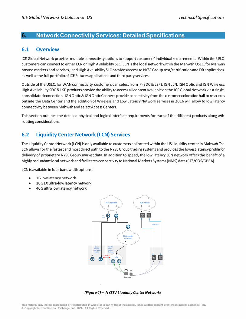
6.2 Liquidity Center Network (LCN) Services
The Liquidity Center Network (LCN) is only available to customers collocated within the US Liquidity center in Mahwah The
LCN allows for the fastest and most direct path to the NYSE Group trading systems and provides the lowest latency profile for
delivery of proprietary NYSE Group market data. In addition to speed, the low latency LCN network offers the benefit of a
highly redundant local network and facilitates connectivity to National Markets Systems (NMS) data (CTS/CQS/OPRA).
LCN is available in four bandwidth options:
• 1G low latency network • 10G LX ultra-low latency network • 40G ultra low latency network
Consumer
HA - PRouter
LiquidityCenter NetworkCustomer
IGN SLCProvider
Edge DeviceHA-PE
LCN/NMS
IGN Optic
LCN
Dtatacenter Network
IGN Network IGN-Optics
(Figure 4) – NYSE / Liquidity Center Networks
ICE Global Network & Colocation US Technical Specifications
This material may not be reproduced or redistributed in whole or in part without the express, prior written consent of Intercontinental Exchange, Inc.
© Copyright Intercontinental Exchange, Inc. 2021. All Rights Reserved.
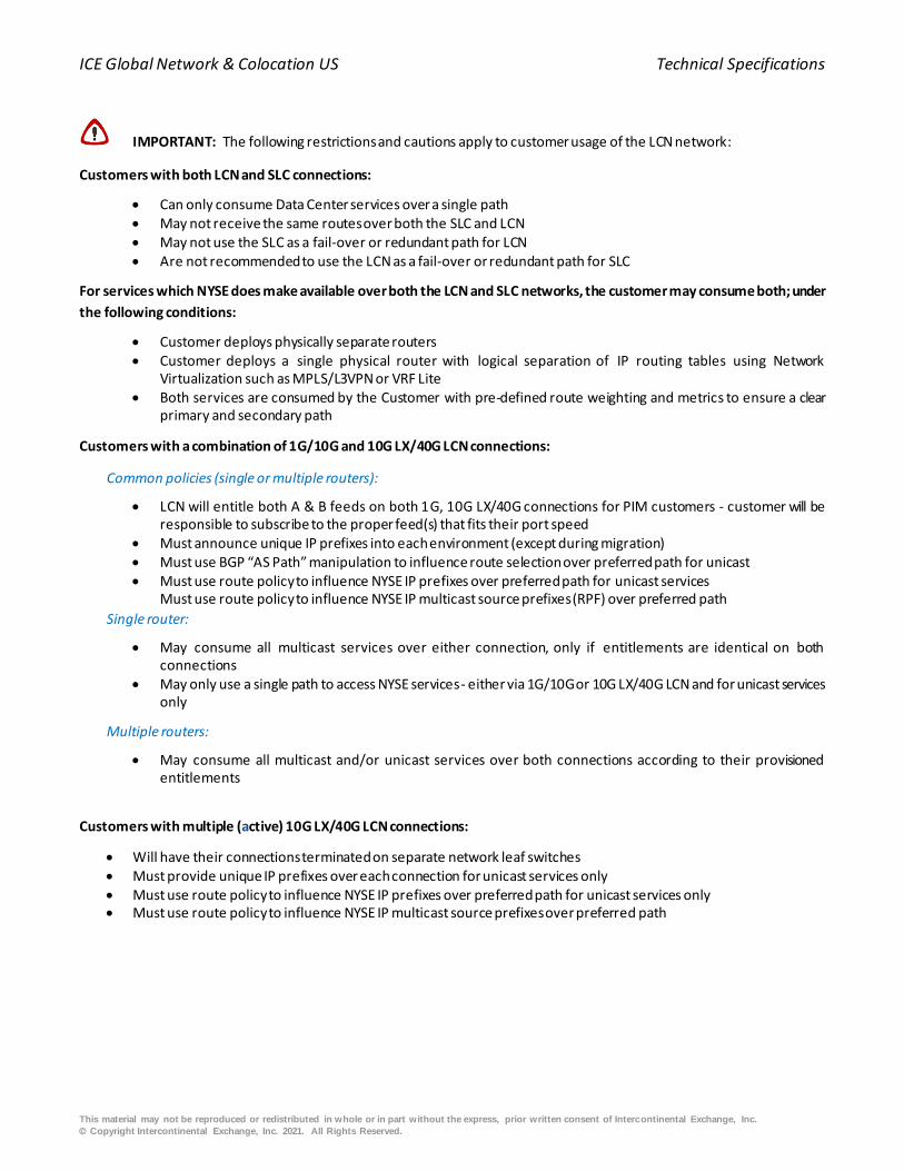
IMPORTANT: The following restrictions and cautions apply to customer usage of the LCN network:
Customers with both LCN and SLC connections:
• Can only consume Data Center services over a single path • May not receive the same routes over both the SLC and LCN • May not use the SLC as a fail-over or redundant path for LCN • Are not recommended to use the LCN as a fail-over or redundant path for SLC
For services which NYSE does make available over both the LCN and SLC networks, the customer may consume both; under
the following conditions:
• Customer deploys physically separate routers • Customer deploys a single physical router with logical separation of IP routing tables using Network
Virtualization such as MPLS/L3VPN or VRF Lite • Both services are consumed by the Customer with pre-defined route weighting and metrics to ensure a clear
primary and secondary path
Customers with a combination of 1G/10G and 10G LX/40G LCN connections:
Common policies (single or multiple routers):
• LCN will entitle both A & B feeds on both 1G, 10G LX/40G connections for PIM customers - customer will be responsible to subscribe to the proper feed(s) that fits their port speed
• Must announce unique IP prefixes into each environment (except during migration) • Must use BGP “AS Path” manipulation to influence route selection over preferred path for unicast • Must use route policy to influence NYSE IP prefixes over preferred path for unicast services
Must use route policy to influence NYSE IP multicast source prefixes (RPF) over preferred path
Single router:
• May consume all multicast services over either connection, only if entitlements are identical on both connections
• May only use a single path to access NYSE services - either via 1G/10G or 10G LX/40G LCN and for unicast services only
Multiple routers:
• May consume all multicast and/or unicast services over both connections according to their provisioned entitlements
Customers with multiple (active) 10G LX/40G LCN connections:
• Will have their connections terminated on separate network leaf switches • Must provide unique IP prefixes over each connection for unicast services only • Must use route policy to influence NYSE IP prefixes over preferred path for unicast services only • Must use route policy to influence NYSE IP multicast source prefixes over preferred path

ICE Global Network & Colocation US Technical Specifications
This material may not be reproduced or redistributed in whole or in part without the express, prior written consent of Intercontinental Exchange, Inc.
© Copyright Intercontinental Exchange, Inc. 2021. All Rights Reserved.
6.2.1 LCN Physical Connectivity
LCN 1G/10G LX physical connections will be terminated on a patch panel in the customer’s Colocation cabinet with an LC
through connector. LCN 40G physical connections will be through an MTP terminated 12 core OM3 Multimode fiber trunk
cable presented in the customer’s Colocation cabinet. Each trunk cable should be connected to a 10G/40GBASE-SR4 (QSFP)
transceiver.
Standard Fiber Connection Requirements
Speed 1G/10G/10G LC 40G
Connector LC Connector MTP Connector - 12 Core OM3
Fibre Multimode Multimode Fiber
Wavelenth 850 nm 4 x 850 nm - 40GBASE-SR4 QSFP Transceiver
Additional LCN Connectivity Options
Customers deploying network switches which support 40 Gigabit Ethernet (IEEE P802.3ba) by combining four sequential SFP+
interfaces into a logical 40 Gigabit Ethernet port, will need to use a breakout or fan/out harness. The resulting interface must
be fully compliant with the IEEE 40 Gigabit Ethernet standard. The fan/out harness is a cable adaptor one end having a pinned
MTP connector and the opposite end breaks out to four MM-50M LC connectors.
Figure 5 - Example - Fan Out Cable
Along with the fan/out harness, an MTP coupler will be needed. The MTP coupler is the means by which the trunk cable and
the fan/out harness are connected together. Please see figure below.

ICE Global Network & Colocation US Technical Specifications
This material may not be reproduced or redistributed in whole or in part without the express, prior written consent of Intercontinental Exchange, Inc.
© Copyright Intercontinental Exchange, Inc. 2021. All Rights Reserved.
Figure 6 - MTP M/M Coupler
Optional Fiber Connection (Agile Port - Fanout)
Type Fan-Out LC 40G - MTP
Connector 4 x LC Connector MTP Connector - 12 Core OM3
Fibre Multimode Fiber Multimode Fiber
wavelenth 850 nm 850 nm - 10G/40GBASE-SR4 QSFP Transceiver
6.2.2 LCN Address Space
Customers’ IP Address Space
Each customer’s IP addressable entity (logical or physical), which accesses market services, requires its own IP address. Given
this IP address, LCN is able to route outbound to the customer’s device via the access method contracted by that customer
(i.e. the address must be reachable). Every IP address that can be assigned to a device must be either a globally unique,
registered IP address or a private IP address from a range of RFC1918 IPs assigned by ICE.
If a customer's device uses a private address from a range not assigned by IGN, the customer might choose to implement
Network Address Translation (NAT) to present a globally registered IP address. However, NAT may limit the customer’s ability
to take advantage of redundant connections seamlessly and could interfere with the functionality of the applications that rely
on knowing the true IP address of the end device. Customers must work with ICE Customer Engineering during their
provisioning process to resolve any related issues.
LCN implements anti-spoofing packet filtering on edge router ports, which will discard inbound IP datagrams with unexpected
source addresses. Customers may wish to implement packet filtering in their router(s) or firewall to limit access to LCN from
within their enterprise.
Network Address Translation / Proxy
The LCN network does not use NAT or proxy services. Each customer connection is filtered to receive the authorized set of
routes and services.
6.2.3 LCN Networking Configuration
Customers’ CPE and LCN switches will exchange IP routes using BGP. The BGP addresses for peering are available from the
ICE Global Network Customer Engineering Team as part of the customer install package.
BGP Hold Times
Customers should set their BGP settings to peer with LCN as follows:
hold time value: 20 seconds
keep alive interval: 6 seconds
ICE Global Network & Colocation US Technical Specifications
This material may not be reproduced or redistributed in whole or in part without the express, prior written consent of Intercontinental Exchange, Inc.
© Copyright Intercontinental Exchange, Inc. 2021. All Rights Reserved.
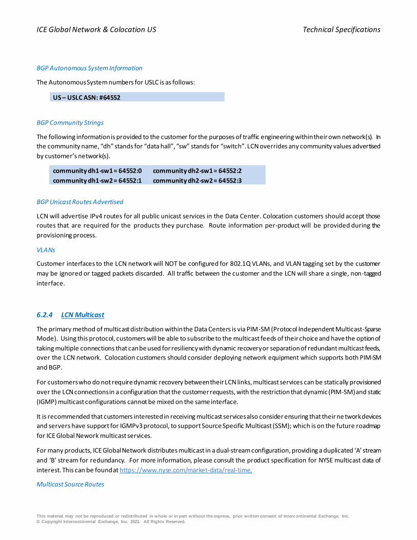
BGP Autonomous System Information
The Autonomous System numbers for USLC is as follows:
US – USLC ASN: #64552
BGP Community Strings
The following information is provided to the customer for the purposes of traffic engineering within their own network(s). In
the community name, “dh” stands for “data hall”, “sw” stands for “switch”. LCN overrides any community values advertised
by customer’s network(s).
community dh1-sw1 = 64552:0
community dh1-sw2 = 64552:1
community dh2-sw1 = 64552:2
community dh2-sw2 = 64552:3
BGP Unicast Routes Advertised
LCN will advertise IPv4 routes for all public unicast services in the Data Center. Colocation customers should accept those
routes that are required for the products they purchase. Route information per-product will be provided during the
provisioning process.
VLANs
Customer interfaces to the LCN network will NOT be configured for 802.1Q VLANs, and VLAN tagging set by the customer
may be ignored or tagged packets discarded. All traffic between the customer and the LCN will share a single, non-tagged
interface.
6.2.4 LCN Multicast
The primary method of multicast distribution within the Data Centers is via PIM-SM (Protocol Independent Multicast-Sparse
Mode). Using this protocol, customers will be able to subscribe to the multicast feeds of their choice and have the option of
taking multiple connections that can be used for resiliency with dynamic recovery or separation of redundant multicast feeds,
over the LCN network. Colocation customers should consider deploying network equipment which supports both PIM-SM
and BGP.
For customers who do not require dynamic recovery between their LCN links, multicast services can be statically provisioned
over the LCN connections in a configuration that the customer requests, with the restriction that dynamic (PIM-SM) and static
(IGMP) multicast configurations cannot be mixed on the same interface.
It is recommended that customers interested in receiving multicast services also consider ensuring that their ne twork devices
and servers have support for IGMPv3 protocol, to support Source Specific Multicast (SSM); which is on the future roadmap
for ICE Global Nework multicast services.
For many products, ICE Global Network distributes multicast in a dual-stream configuration, providing a duplicated ‘A’ stream
and ‘B’ stream for redundancy. For more information, please consult the product specification for NYSE multicast data of
interest. This can be found at https://www.nyse.com/market-data/real-time.
Multicast Source Routes

ICE Global Network & Colocation US Technical Specifications
This material may not be reproduced or redistributed in whole or in part without the express, prior written consent of Intercontinental Exchange, Inc.
© Copyright Intercontinental Exchange, Inc. 2021. All Rights Reserved.
Routes for all public multicast sources in the Data Center including those for NMS (CTS/CQS/OPRA) will be sent to LCN
multicast customers via BGP. Customers are responsible for configuring their equipment appropriately if they wish to balance
or separate ‘A’ and ‘B’ multicast traffic when multiple LCN links are used.
PIM-SM Rendezvous Points
Colocation customers using PIM-SM to dynamically receive multicast products from LCN should configure their CPE to point
to the LCN PIM Rendezvous-Point (RP) for purchased multicast products. LCN provides RP redundancy using Anycast, and
customers must statically configure the RP Anycast address in their equipment. LCN does not support Auto-RP, BSR, or other
dynamic RP discovery protocols.
The IP address of the Data Center RP for NYSE Core multicast services, along with the associated multicast group(s) and
source(s) information, will be provided to the customer during the provisioning process.
For customers who choose to receive NMS (CTS/CQS/OPRA) services over their LCN connections, the multicast RP, group(s)
and source(s) information will be provided during the provisioning process; the RP information used for NMS services will be
independent of that used to provide NYSE Core multicast services in the Mahwah Data Center. The route to the Data Center
and NMS (CTS/CQS/OPRA) RPs’ will be announced to the customers via BGP .
6.2.5 LCN Rate Limiting
LCN 1G/10G LX/40G
Colocation customers’ LCN 10G LX/40G interfaces will be configured with fixed ingress aggregate rate limiter. LCN ports will
be policed at 10% of their port speed except for the 1 GB ports which will have no policer enforced. All ingress (control and
data) traffic on each customer 10G LX port will be limited to 1G and each customer 40G port will be limited to 4G without
any regard to its origin, destination, protocol or priority. Any ingress traffic surpassing the bandwidth threshold s will be
unconditionally discarded. More granular controls will be implemented in the future as the service is developed.
6.3 High Availability Services
The use of logical interfaces and virtual LANs (VLANs) is fundamental to the method by which High Availabiltity delivers access
to multiple content sources simultaneously through a single network interface. For all NYSE markets, for example, an
individual VLAN is used to support all the unicast IP services associated with test and production. This is separate to the NYSE
miulticast VLAN and additional VLANS exist for both ICE Markets access as well as other third party content. This concept
allows High Availability to maintain a logical separation between key services and significantly improves HA’s ability to
provision new services, scale the environment, and at the same time, allows the customers to maintain that logical separation
should they wish to do so.
At the network layer, High Availability requires the logical interfaces to be defined separately on a customer’s Ethernet
interface in order to receive the services available from each of the individual services. These logical interfaces must be
capable of supporting the 802.1Q protocol, which allows for processing IP packets tagged with the 802.1Q information and
interpreting the logical separation associated with the individual virtual LANs, or VLANs. Using this architecture, HA delivers
each set of unicast services on a separate VLAN to the customer ’s edge router. Customers are not required to transport the
traffic via VLANs within their own networking environments.
High Availability services are available both inside the USLC and on the WAN, with different options for connectivity based on
a customer’s key drivers; be that remote location accessible, speed, or resiliency required.
This section outlines key interface information for the various High Availability services:

ICE Global Network & Colocation US Technical Specifications
This material may not be reproduced or redistributed in whole or in part without the express, prior written consent of Intercontinental Exchange, Inc.
© Copyright Intercontinental Exchange, Inc. 2021. All Rights Reserved.
6.3.1 IP Liquidity Center (SLC) Services
IP Liquidity Center (SLC) services offer access to a global MPLS network that connects customers to ICE & NYSE Markets and
Services as well as third party financial industry content service providers. All SLC services are available to Colocation
customers in the USLC (Mahwah) Liquidity Center.
IP SLC
Data Center Core Services
NYSE Liquidity Center
Consumer
NYSE / NYSE MKT
NYSE ARCA
NMS
AMEX
External CSP
LCN Services
HA
Provider
(P)
routers
IP SLC
Provider
Edge (PE)
routers
IP SLC
Provider
Edge (PE)
routers
(Figure 7) – SLC
6.3.2 IP SLC Physical Connectivity (Mahwah)
Physical connections for SLC customers require that customers connect their equipment within the ICE USLC via 1G, 10G or
40G Ethernet connections. Customers’ connections to SLC must be configured for 802.1q trunking to support VLAN tagging.
Standard Fiber Connection Requirements
Speed 1G 10G 40G
Connector LC Connector LC Connector MTP Connector - 12 Core OM3
Fibre Multimode Multimode Multimode
Wavelenth 850 nm 850 nm 4 x 850 nm - 40GASE-SR4 QSFP Transceiver
ICE Global Network & Colocation US Technical Specifications
This material may not be reproduced or redistributed in whole or in part without the express, prior written consent of Intercontinental Exchange, Inc.
© Copyright Intercontinental Exchange, Inc. 2021. All Rights Reserved.
6.3.3 High Availability Direct Connect (SDC) Ethernet (WAN)
High Availability Direct Connection (SDC) enables firms to use their own Ethernet connectivity to connect with ICE Global
Network at geographically diverse and vendor-neutral Access Centers outside of or inside Mahwah.
The High Availability 40G SDC Bundle and the High Availability Limited Service Port are sub-options of the SDC service:
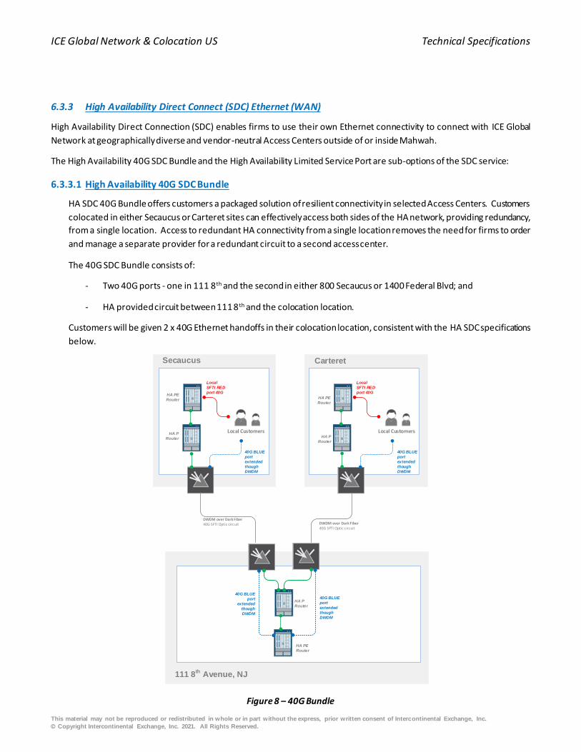
6.3.3.1 High Availability 40G SDC Bundle
HA SDC 40G Bundle offers customers a packaged solution of resilient connectivity in selected Access Centers. Customers
colocated in either Secaucus or Carteret sites can effectively access both sides of the HA network, providing redundancy,
from a single location. Access to redundant HA connectivity from a single location removes the need for firms to order
and manage a separate provider for a redundant circuit to a second access center.
The 40G SDC Bundle consists of:
- Two 40G ports - one in 111 8th and the second in either 800 Secaucus or 1400 Federal Blvd; and
- HA provided circuit between 111 8th and the colocation location.
Customers will be given 2 x 40G Ethernet handoffs in their colocation location, consistent with the HA SDC specifications
below.
Local Customers
Secaucus
111 8th
Avenue, NJ
Carteret
HA PE
Router
DWDM over Dark Fiber40G SFTI Optic circuit DWDM over Dark Fiber
40G SFTI Optic circuit
Local Customers
HA P
Router
HA PE
Router
HA P
Router
HA PE
Router
HA P
Router
Local
SFTI RED
port 40G
Local
SFTI RED
port 40G
40G BLUE
port
extended
though
DWDM
40G BLUE
port
extended
though
DWDM
40G BLUE
port
extended
though
DWDM
40G BLUE
port
extended
though
DWDM
Figure 8 – 40G Bundle

ICE Global Network & Colocation US Technical Specifications
This material may not be reproduced or redistributed in whole or in part without the express, prior written consent of Intercontinental Exchange, Inc.
© Copyright Intercontinental Exchange, Inc. 2021. All Rights Reserved.
6.3.3.2 Limited Service Port (LSP)
LSP enables firms to use their Ethernet connectivity to connect with a limited service High Availability port. It
provides customers with a way to access a single NYSE non-core, ICE or third party service via a directly connected
1G HA port. This port comes with a choice of one of the following non-core services: CSP or VCC. To add further
entitlements onto an LSP, customers will be required to upgrade to a full IP SLC or HA SDC port..
6.3.4 High Availability Physical Connectivity (SDC & LSP)
High Availability supports various circuit types, including: 1G, 10G, and 40G Ethernet. 1G & 10G connections are available in
all locations, 40G is available in 111 8 th Ave, 165 Halsey, Secaucus, Carteret, and 350 East Cermak. The Ethernet handoff to
the client will be the following specification for all locations other than Mahwah:
1G Single-Mode
Ethernet Standard 1000Base-LX
Source Wavelength 1310nm
Receiver Sensitivity -20dBm
Distance 10km limit using 9/125μm
Connector LC
10G Single-Mode
Ethernet Standard 10GBase-LR
Source Wavelength 1310nm
Receiver Sensitivity1 -15dBm
Distance2 10km3 limit using 9/125μm fiber
Connector LC
40G Single-Mode
Ethernet Standard 40GBASE-LR4
Source Wavelength Per Lane
Lane 0– 1264.5 nm through 1277.5 nm
Lane 1– 1284.5 nm through 1297.5 nm
Lane 2– 1304.5 nm through 1317.5 nm
Lane 3– 1324.5 nm through 1337.5 nm
Receiver Sensitivity Per
Lane4 –13.7 dBm
Distance5 10km4 limit using 9/125μm fiber
Connector LC
----------------------------------------------------------------- 1 Customer power received at interface must be equal to or greater than this value. 2 Power level at handoff is the limiting parameter, not distance. 3 Fiber distance not to exceed 10km even if the fiber budget can be attained due to residual dispersion distortion. 4 Customer power received at interface must be equal to or greater than this value. 5 Power level at handoff is the limiting parameter, not distance.

ICE Global Network & Colocation US Technical Specifications
This material may not be reproduced or redistributed in whole or in part without the express, prior written consent of Intercontinental Exchange, Inc.
© Copyright Intercontinental Exchange, Inc. 2021. All Rights Reserved.
100G Single-Mode
Ethernet Standard 100GBASE-LR4
Source Wavelength Per Lane
Lane 0–1294.53 through 1296.59 nm
Lane 1–1299.02 through 1301.09 nm
Lane 2–1303.54 through 1305.63 nm
Lane 3–1308.09 through 1310.19 nm
Receiver Sensitivity Per
Lane1 –10.6 dBm
Distance2 10km3 limit using 9/125μm fiber
Connector LC
6.3.5 High Availability Address Space (SLC, SDC & LSP)
Customer IP Address Space
ICE Global Network customers are encouraged to use the registered IP address range(s) for connectivity. If the registered IP
addresses are not available, ICE will assign the IP addresses from a predefined private IP range. Customers may choose to
implement Network Address Translation (NAT) to present a globally registered IP address to High Availability; however, NAT
may limit customers’ ability to take advantage of redundant connections seamlessly and could interfere with the functionality
of the applications that rely on knowing the true IP address of the end device.
Network Address Translation / Proxy
High Availability does not use NAT or proxy services. Each customer connection is filtered to receive the authorized set of
routes and services.
NOTE that the exception to this is ICE Global Network wireless services with detail outlined later in section 7.2.
Networking BGP Peering
Customers’ will exchange IP routes with High Availability using BGP. The BGP addresses for peering will be allocated by the
Customer Engineering Team as part of the customers install package.
IMPORTANT: BGP peering addresses must be allocated by ICE Global Network, customer provided IPs cannot be
accomodated
----------------------------------------------------------------- 1 Customer power received at interface must be equal to or greater than this value. 2 Power level at handoff is the limiting parameter, not distance. 3 Fiber distance not to exceed 10km even if the fiber budget can be attained due to residual dispersion distortion.

ICE Global Network & Colocation US Technical Specifications
This material may not be reproduced or redistributed in whole or in part without the express, prior written consent of Intercontinental Exchange, Inc.
© Copyright Intercontinental Exchange, Inc. 2021. All Rights Reserved.
BGP Hold Times
Customers should set their BGP settings to peer with HA as follows:
hold time value: 20 seconds
keep alive interval: 6 seconds
BGP Autonomous System Information
The Autonomous System number for HA is as follows:
US – HA ASN: #26585
BGP Unicast Routes advertised
HA will advertise IPv4 routes for all public unicast services in the Data Center. Colocation customers should accept those
routes that are required for the products they purchase. Route information per -product will be provided during the
provisioning process.
Multicast
The primary method of multicast distribution within the ICE and NYSE Data Centers is via PIM-SM (Protocol Independent
Multicast-Sparse Mode). Using this protocol, customers are able to subscribe to the multicast feeds of their choice and have
the option of taking multiple connections that can be used for resiliency with dynamic recovery or separation of redundant
multicast feeds, over the HA network. Colocation customers should consider deploying network equipment which supports
both PIM-SM and BGP.
For customers that do not require dynamic recovery between their HA links, the option exists to be statically provisioned for
multicast services with the following restrictions; dynamic (PIM-SM) and static (IGMP) multicast configurations may not be
mixed on the same interface.
For NYSE’s products, ICE Global Network distributes multicast in a dual-stream configuration, providing a duplicated ‘A’
stream and ‘B’ stream for redundancy. For more information, please consult the product specification for the multicast data
of interest. This can be found at https://www.nyse.com/market-data/real-time.
Multicast Source Routes
Routes for all services multicast sources will be sent to High Availability multicast customers via BGP. Customers are
responsible to configure their equipment appropriately if they wish to balance or separate ‘A’ and ‘B’ multicast traffic when
multiple High Availability links are used.
PIM-SM Rendezvous Points
Colocation customers using PIM-SM to dynamically receive multicast products from High Availability should configure their
side to point to the High Availability PIM Rendezvous-Point (RP) for the specific multicast products ordered. High Availability
provides RP redundancy using Anycast, and customers must statically configure the RP Anycast address in their equipment.
High Availability does not support Auto-RP, BSR, or other dynamic RP discovery protocols.
The IP address of the Data Center RP for NYSE Core multicast services, along with the associated multicast group(s) and
source(s) information, will be provided to the customer during the provisioning process.

ICE Global Network & Colocation US Technical Specifications
This material may not be reproduced or redistributed in whole or in part without the express, prior written consent of Intercontinental Exchange, Inc.
© Copyright Intercontinental Exchange, Inc. 2021. All Rights Reserved.
For customers who choose to receive NMS (CTS/CQS/OPRA) services over High Availability connections, the multicast RP,
group(s) and source(s) information will be provided during the provisioning process. The RP information used for NMS services
will be independent of that used to provide NYSE Core multicast services in the Data Center. The route to the NYSE Data
Center, including NMS (CTS/CQS/OPRA), ICE & relevant third party service RPs’ will be announced to the customers via BGP.
Rate Limiting
High Availability interfaces are configured with ingress (from the customer into High Availability services) rate limits on a per-
product basis. Each product has a base rate limit, which may be customized on a case-by-case basis.
Rate limits are added, but not shared. For example, if a customer purchases two products, each with a 50M rate limit, the
customer may send 50M for each product simultaneously, for a total of 100M. The customer may not, however, send more
than 50M of traffic for either product. The BGP, PIM-SM and other protocol traffic will be restricted to levels appropriate for
the protocol. HA will silently discard inappropriate network control traffic at the HA edge. Traffic destined for the IP ranges
of the ICE & NYSE Markets and Services and to third party financial industry content service providers that have been
provisioned will be allowed; other IP traffic will be silently discarded.
Connection Monitoring
Each customer’s HA connection has the ability to be monitored on-demand, non-intrusively, via atap on the connection. This
connectivity model does not impact latency or line performance.
6.4 High Availability Virtual Control Circuit (VCC)
HA VCC is a Layer2 network connection that provides point-to-point connectivity between any two customer ports from HA
Access Centers to Data Centers HA port (i.e. SDC).
6.4.1 VCC Connectivity Options
There are three types of VCC service offerings:
Inter-Region without protection:
Allows a customer to be configured through any nodes between the US and EU HA regions. The VCC node configuration
is allowed only on either the RED to RED or BLUE to BLUE HA rings respectively. There is no failure recovery between the
regions with this VCC model. Failures within a region, however will have automatic protection and recovery.
Inter-Region with protection:
Allows a customer to be configured through any nodes between the US and EU HA regions. The VCC node configuration
is allowed over any combination of the RED and BLUE HA rings. In this VCC model any failure will result in automatic
recovery within a region and between regions.
Intra-Region:
Allows a customer to be configured through any nodes within a HA region either in the US or EU. The VCC model does
not span across regions and provides automatic VCC protection and recovery in the event of a failure within the region.
VLANs
Customer connections via VCC services must be configured for 802.1q trunking to support VLAN tagging.
6.5 ICE Global Network Optic
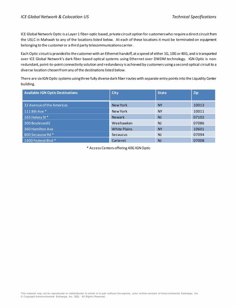
ICE Global Network & Colocation US Technical Specifications
This material may not be reproduced or redistributed in whole or in part without the express, prior written consent of Intercontinental Exchange, Inc.
© Copyright Intercontinental Exchange, Inc. 2021. All Rights Reserved.
ICE Global Network Optic is a Layer 1 fiber-optic based, private circuit option for customers who require a direct circuit from
the USLC in Mahwah to any of the locations listed below. At each of these locations it must be terminated on equipment
belonging to the customer or a third party telecommunications carrier.
Each Optic circuit is provided to the customer with an Ethernet handoff, at a speed of either 1G, 10G or 40G, and is transported
over ICE Global Network’s dark fiber based optical systems using Ethernet over DWDM technology. IGN Optic is non-
redundant, point-to-point connectivity solution and redundancy is achieved by customers using a second optical circuit to a
diverse location chosen from any of the destinations listed below.
There are six IGN Optic systems using three fully diverse dark fiber routes with separate entry points into the Liquidity Center
building.
Available IGN Optic Destinations City State Zip
32 Avenue of the Americas New York NY 10013
111 8th Ave * New York NY 10011
165 Halsey St * Newark NJ 07102
300 Boulevard E Weehawken NJ 07086
360 Hamilton Ave White Plains NY 10601
800 Secaucus Rd * Secaucus NJ 07094
1400 Federal Blvd * Carteret NJ 07008
* Access Centers offering 40G IGN Optic

ICE Global Network & Colocation US Technical Specifications
This material may not be reproduced or redistributed in whole or in part without the express, prior written consent of Intercontinental Exchange, Inc.
© Copyright Intercontinental Exchange, Inc. 2021. All Rights Reserved.
(Figure 9) – IGN Optic
6.5.1 ICE Global Network Optic Physical Connectivity
Liquidity Center Physical Specification
Within the Liquidity Center, ICE will provide a pair of 850 nm multi-mode LC fibers into the customer’s Colocation cabinet
for each IGN Optic circuit purchased. The fiber pair will be terminated on a patch panel in the customer’s Colocation
cabinet, with an LC connector. Customers are responsible for providing a patch cable from the patch panel to their
equipment.
Access Center Physical Specification
Within the Access Centers, customers have two options for terminating their IGN Optic – AC circuit. The circuit can be
extended to the customers’ equipment within the carrier hotel or the circuit can be extended to a third -party provider
circuit. ICE will provide an Ethernet handoff as outlined below.
6.5.2 ICE Global Network Optic Logical Connectivity
IGN Optic provides Ethernet over DWDM connectivity to customers. The service provides full end-to-end transparency.
The service will transport customer MAC address information and VLAN information across the circuit, but will not
directly interact with the customer’s Ethernet CPE.

ICE Global Network & Colocation US Technical Specifications
This material may not be reproduced or redistributed in whole or in part without the express, prior written consent of Intercontinental Exchange, Inc.
© Copyright Intercontinental Exchange, Inc. 2021. All Rights Reserved.
6.5.3 Optical Interfaces
1G Multi-mode Single-mode
Ethernet Standard 1000Base-SX 1000Base-LX
Source Wavelength 850nm 1310nm
Receiver Sensitivity -17dBm -20 dBm
Distance 500m limit using 50/125 μm fiber 10km limit using 9/125 μm
10G Multi-mode Single-mode
Ethernet Standard 10Gase-SR 10Gase-LR
Source Wavelength 850nm 1310nm
Receiver Sensitivity (1) -12dBm -15dBm
Distance (2) 300m limit using 50/125 μm, OM3 fiber
(2000MHz-km) 10km(3) limit using 9/125 μm fiber
40G Multi-mode Single-mode
Ethernet Standard 40GBASE-LR4
Source Wavelength
Lane 0– 1264.5 nm through 1277.5 nm
Lane 1– 1284.5 nm through 1297.5 nm
Lane 2– 1304.5 nm through 1317.5 nm
Lane 3– 1324.5 nm through 1337.5 nm
Receiver Sensitivity (4) -15dBm
Distance (5) 10km (6) limit using 9/125 μm fiber
6.5.4 Monitoring
ICE provides end-to-end monitoring of the IGN Optic circuits. This includes performance monitoring, troubleshooting,
and fault management on a per channel and overall system basis. This does not include the capability of capturing and
analyzing customer application data.
6.6 ICE Global Network Optic Connect
IGN Optic Connect is a point-to-point Ethernet circuit (1G, 10G or 40G) or a dark fiber (DF) from the Mahwah USLC to a
customer-specified location. IGN Optic Connect can be used to extend a IGN Optic circuit to a customer-specified location. It
can also be ordered as a standalone circuit when one end, the "Z" Side, terminate s in a ICE Global Network Access Center
fiber panel. It has three components:
1. One third party circuit,
----------------------------------------------------------------- 1 Customer power received at interface must be equal to or greater than this value. 2 Power level at handoff is the limiting parameter, not distance. 3 Fiber distance not to exceed 10km even if the fiber budget can be attained due to residual dispersion distortion. 4 Customer power received at interface must be equal to or greater than this value. 5 Power level at handoff is the limiting parameter, not distance. 6 Fiber distance not to exceed 10km even if the fiber budget can be attained due to residual dispersion distortion.

ICE Global Network & Colocation US Technical Specifications
This material may not be reproduced or redistributed in whole or in part without the express, prior written consent of Intercontinental Exchange, Inc.
© Copyright Intercontinental Exchange, Inc. 2021. All Rights Reserved.
2. One cross connect at a IGN Access Center location,
3. One cross connect at the customer-specified location
For the IGN Optic Connect offering:
• ICE Global Network is responsible for the third party circuit procurement, implementation and ongoing maintenance
• ICE Data Services is the single point of contact for the service
• ICE Global Network is also responsible for the Access Center cross connect
• Latency figures are measured and not guaranteed. Service Level Agreements (SLAs) do not apply.
• Listed circuit type options below is subject to availability at the selected ICE location.
• Customers are responsible for the cross connect at their specified location
** Note: Only Avialable to existing IGN Optic Customers
6.7 Liquidity Center Cross Connect (LCX)
Liquidity Center Cross Connect (LCX) is a Layer 1, physical connectivity option which provides point to point connections
delivered over single-mode (SM) or multi-mode (MM) fiber between two Mahwah USLC customers’ cabinets and terminated
on ICE provided patch panels.
LCX permits two cabinets, owned by the same customer or two different customers to connect their network environments
together via a multi/single-mode fiber handoffs. LCX is sold in units of 1, 6, 12, 18, and 24 pairs of fiber.
LCX is limited to these deployments:
• Connections between a customer’s non-contiguous cabinets
• Interconnects between two customers’ cabinets
• Connections between a customer and a vendor; except when vendor is providing trade execution or matching. In
this scenario a vendor must become a CSP of either LCN CSP or High Availability to provide these services1.
• Connections between a Sponsored Participant and a Sponsor whose cabinets are not contiguous
6.7.1 LCX Physical Connectivity
Within the Liquidity Centers, customers have two options for terminating optical circuits. Colocation customers will be
provided a handoff of a number of pairs of 850nm OM3 multi-mode and 1310nm SMF (single-mode Fiber) with standard LC
Connections2. These fiber trunks will extend from the cabinet assigned to the customer into a patch panel within a common
communications rack in the Colocation Hall. Cross connects can be provided from this point to any of the approved endpoints;
as specified above.
1G Multi-mode Single-mode
Ethernet Standard 1000Base-SX 1000Base-LX
Source Wavelength 850nm 1310nm
Distance 500m limit using 50/125 μm OM3 Fibre 5 km over 10 µm single-mode fiber
10G Multi-mode Single-mode
Ethernet Standard 10GBase-SR 10GBase-LR
----------------------------------------------------------------- 1 This restriction is required so that all exchanges and ATS are operating in a similar fashion. 2 Additional connectors are available upon request.

ICE Global Network & Colocation US Technical Specifications
This material may not be reproduced or redistributed in whole or in part without the express, prior written consent of Intercontinental Exchange, Inc.
© Copyright Intercontinental Exchange, Inc. 2021. All Rights Reserved.
Source Wavelength 850nm 1310nm
Distance 300m limit using 50/125μm, OM3 fiber 10 km over 10 µm single-mode fiber
40G Multi-mode Single-mode
Ethernet Standard 40GBASE-SR4 40GBASE-LR4
Source Wavelength 4 media x 850nm 4 Lanes
Distance 300m limit 10km using 9/125 μm fiber
6.7.2 Homerun Connectivity
Within the Liquidity Centers, customers have homerun connectivity options to connect between their non-contiguous
cabinets. Colocation customers will be provided a handoff of a number of pairs of 850nm OM3\OM4 MMF(multi-mode Fiber)
and 1310nm SMF (single-mode Fiber) via structured cabling trunks, terminated in new\existing fiber patch panels (FPP) with
standard LC or MPO cassette. Homerun LCX is sold in packs of 6, 12, 18, and 24 pairs of fiber.
1G Multi-mode Single-mode
Ethernet Standard 1000Base-SX 1000Base-LX
Source Wavelength 850nm 1310nm
Distance 500m limit using 50/125 μm OM3 Fibre 5 km over 10 µm single-mode fiber
10G Multi-mode Single-mode
Ethernet Standard 10GBase-SR 10GBase-LR
Source Wavelength 850nm 1310nm
Distance 300m limit using 50/125μm, OM3 fiber 10 km over 10 µm single-mode fiber
40G Multi-mode Single-mode
Ethernet Standard 40GBASE-SR4 40GBASE-LR4
Source Wavelength 4 media x 850nm 4 Lanes
Distance 300m limit 10km using 9/125 μm fiber
6.7.3 Administration of the Cross Connect
ICE provides the connection and maintains the physical state of the connection, but does not administer or provide for any
traffic flow that occurs over the LCX connection.
6.8 ICE Global Network VPN Access – IP based VPN
ICE Global Network VPN Access is an IPsec based LAN-to-LAN connection via Internet providing a secure, encrypted transport
across the internet for all unicast sessions. Customers can securely connect to ICE Global Network unicast services using their
own IPsec devices and Internet connections and variable bandwidth options are available, from 1M to 10M. VPN can be used
for access to ICE (inc. SuperDerivatives), NYSE Core and selected third party content unicast services.

ICE Global Network & Colocation US Technical Specifications
This material may not be reproduced or redistributed in whole or in part without the express, prior written consent of Intercontinental Exchange, Inc.
© Copyright Intercontinental Exchange, Inc. 2021. All Rights Reserved.
Customer
ICE Global Network Service
ICE Global Network
Internet
Data Center
VPN Infrastructure
VPN Concentrators
Data CenterService
IPSec Tunnel
(Figure 10) – ICE Global Network VPN Access
6.8.1 Connectivity (LAN to LAN)
Customers will use their own IPsec enabled devices and Internet connections to access ICE Global Network VPN. The VPN
tunnel encryption method will be agreed upon during provisioning process. Customers will be able to access ICE Global
Network VPN services using ICE Global Network assigned RFC1918 IP addresses.
6.8.2 ICE Global Network VPN: Network Considerations
• Customers must have an IPsec enabled device and Internet connection at their end
• An IPsec enabled device could be either a router capable of IPsec or a firewall with VPN capability and customers are
responsible for configuring and supporting their IPsec enabled device.
• Connectivity is via IPSEC tunnels only, direct internet connectivity is not supported
• Customer must ensure that any Internet facing firewall has its security policy amended to allow the following
protocols:
o IKE – UDP port 500 (Internet Key Exchange)
o IPsec over NAT-T – UDP port 4500
o ESP – Protocol 50 (IPSec)
• It is important that the IPsec device has a static public IP address assigned to the interface which creates the VPN
tunnel
• Customer needs to NAT their host LAN IP addresses to ICE Global Network assigned private IP range

ICE Global Network & Colocation US Technical Specifications
This material may not be reproduced or redistributed in whole or in part without the express, prior written consent of Intercontinental Exchange, Inc.
© Copyright Intercontinental Exchange, Inc. 2021. All Rights Reserved.
7. Low Latency Services
7.1 Low Latency Network (LLN)
LLN is a low latency connectivity option which uses optimized network technology and the fastest available fiber routes
between the USLC in Mahwah and key US tradinglocations of Secaucus and Carteret.
Local Customers
Secaucus
USLC Mahwah
COLO customers
Carteret
Low Latency L3
aggregation switch
Low Latency L3
distribution switch
NYSE / ARCAServices
40 Gbps
40 Gbps
40
Gb
ps
DWDM over Dark FiberDWDM over Dark Fiber
Low Latency L3
distribution switch
BATS *
40 Gbps
* Delivery of away market data into USLC is subject to
customer demand and regulatory approval
* Delivery of away market data into USLC is subject to
customer demand and regulatory approval
Local Customers
Low Latency L3
distribution switch
NASDAQ *
40 Gbps
Direct
10G/40G
DWDM
circuits
Low Latency L3
aggregation switch
Direct
10G/40G
DWDM
circuits
(Figure 11) – IGN Wireless
7.1.1 LLN Highlights
• Market access ports in Secaucus and Carteret are available at either 10Gbps or 40Gbps speeds • Raw bandwidth (circuits) are available on both routes (10Gbps or 40Gbps)
• LLN utilizes the fastest commercially-available fiber links between Mahwah and Secaucus and Mahwah and Carteret
• Uses the fastest carrier grade optical switching hardware available along the entire path

ICE Global Network & Colocation US Technical Specifications
This material may not be reproduced or redistributed in whole or in part without the express, prior written consent of Intercontinental Exchange, Inc.
© Copyright Intercontinental Exchange, Inc. 2021. All Rights Reserved.
• A customer with a traditional HA port can add a LLN port to decrease end-to-end latency, however it should be noted that LLN only offers a subset of the services available over the global ICE Global Network wide area network.
IMPORTANT: LLN is a single path, point-to-point network solution only. Unlike other High Availability options, it does
not offer resilience in case of issue along the route and customers must ensure resiliency via an alternative ICE Global Network
product or provider.
It is also designed to provide access to USLC (NYSE) production services only (proprietary market data and order entry), NYSE
Group test, certification and DR services, along with ICE and other third party content cannot be accessed via LLN.
7.1.2 LLN Latency *
The expected one way, end to end latency profile for the LLN infrastructure outlined in the table below. This measurement
is based on 128 byte average packet size with store and forward components in the path. The listed values include the
Mahwah circuit extension to the network equipment row, but does not include the circuit extensions in Carteret or Secaucus.
Route 10G Customer 40G Customer
Mahwah services to Carteret (to LLN Customer Edge) 344µs 343µs
Carteret services to Mahwah LLN Customer Edge 345µs 344µs
Mahwah to Carteret Optical (DWDM path) 341µs 341µs
Mahwah services to Secaucus (to LLN Customer Edge) 188µs 187µs
Secaucus services to Mahwah LLN Customer Edge 189µs 188µs
* NOTE: LLN latencies are one way based on fiber optic distances, average observed by communication equipment latencies
and estimated cable latencies. Listed values do not include the cable latency to the service provider interface from the LLN
handoff (NYSE/ARCA/NMS, Nasdaq, BATS equipment interface) or the cable latency from the LLN customer edge to the
customer interface.
7.1.3 LLN Physical Connectivity
Customers are connected via 10G or 40G Ethernet cabling to the customer edge switch. The following table lists the standards
used for both DWDM direct circuit services and IP services:
10G Single-mode (Mahwah) Single-mode (Secaucus / Carteret)
Ethernet Standard 10GBase-LR 10GBase-LR
Source Wavelength 1310nm 1310nm
Distance 10 km over 10 µm single-mode fiber 10 km over 10 µm single-mode fiber
40G Single-mode (Mahwah) Single-mode (Secaucus / Carteret)
Ethernet Standard 40GBASE-LR4 40GBASE-LR4
Source Wavelength
Lane 0– 1264.5 nm through 1277.5 nm
Lane 1– 1284.5 nm through 1297.5 nm
Lane 2– 1304.5 nm through 1317.5 nm
Lane 3– 1324.5 nm through 1337.5 nm
Lane 0– 1264.5 nm through 1277.5 nm
Lane 1– 1284.5 nm through 1297.5 nm
Lane 2– 1304.5 nm through 1317.5 nm
Lane 3– 1324.5 nm through 1337.5 nm
Receiver Sensitivity (1) -15dBm -15dBm
----------------------------------------------------------------- 1 Customer power received at an interface must be equal to, or greater than this value.

ICE Global Network & Colocation US Technical Specifications
This material may not be reproduced or redistributed in whole or in part without the express, prior written consent of Intercontinental Exchange, Inc.
© Copyright Intercontinental Exchange, Inc. 2021. All Rights Reserved.
Distance 10km (1) limit using 9/125 μm fiber 10km (2) limit using 9/125 μm fiber
7.1.4 LLN Address Space
Customers’ IP Address Space
Each customer’s IP addressable entity (logical or physical) that accesses market services requires its own IP address. Given
this IP address, LLN is able to route outbound to the customer’s device via the access method contracted by that customer
(i.e. the address must be reachable). Every IP address that can be assigned to a device is either a globally unique, registered
IP address or a private IP address from a range of RFC1918 IPs assigned by ICE/NYSE.
Similar to other ICE Global Network services, customers can use their own public ASN or use a private one provided by ICE.
Network Address Translation / Proxy
The LLN network does not use NAT or proxy services. Each customer connection is filtered to receive the authorized set of
routes and services.
7.1.5 LLN Networking Configuration
Only BGPv4 is allowed between the LLN network and customers (pim and igmp). No static routing or IGMP is allowed.
VLANs
IMPORTANT: Customer interfaces to the LLN network will NOT be configured for 802.1Q VLANs and VLAN tagging set by the
customer may be ignored or tagged packets discarded. All traffic between the customer and the LLN edge will share a single,
non-tagged interface.
7.1.6 Failure Considerations
• As LLN is a non-redundant, point-to-point service, customers must pay attention to all failover scenarios.
• For those connected to both High Availability and LLN, the routing must be carefully configured in order to avoid routing issues.
IMPORTANT: Unicast and Multicast services offered on LLN are already available on High Availability, therefore,
customers must adjust their BGP metrics accordingly to ensure they correctly define primary and secondary paths
As an example, a customer can configure better metrics for NYSE ARCA unicast prefixes received over LLN whilst still also
accepting the same prefixes from the High Availability connection. The same approach can be applied to multicast routing.
Generally, customers are advised to prefer the route toward the NYSE RPs and the multicast source range via LLN.
The key point is to make sure that both paths are available at any given time.
----------------------------------------------------------------- 1 Fiber distance not to exceed 10km, even if the fiber budget can be attained due to residual dispersion distortion. 2 Fiber distance not to exceed 10km, even if the fiber budget can be attained due to residual dispersion distortion.

ICE Global Network & Colocation US Technical Specifications
This material may not be reproduced or redistributed in whole or in part without the express, prior written consent of Intercontinental Exchange, Inc.
© Copyright Intercontinental Exchange, Inc. 2021. All Rights Reserved.
7.2 NMS Network
The Consolidated Tape Association (CTA) and the Options Price Reporting Authority (OPRA) allows the NMS Network in Mahwah to be used to access CTA and OPRA Multicast Feeds distributed by NMS (“CTA” and “OPRA”, and collectively, the “NMS Feeds”).
Utilizing low-latency equipment and optimized network topology, the NMS Network provides additional NMS connectivity options, enabling access to the NMS Feeds in the Mahwah data center without using the High Availability Network or LCN, although connecting via High Availability and LCN continues to be an option.
The NMS Network offers ports in the Mahwah data center to access either or both of the NMS Feeds via an independent infrastructure. These ports can accommodate both participant input and subscriber output. Supported connectivity options are 10 or 40 Gigabit Ethernet client access ports.
7.2.1 Latency
The NMS Network uses low-latency network switches and optimized topology to minimize latency, with a publisher to port one-way latency, across all network hops, of approximately 2.5 (microseconds).
Note: average packet size latencies were measured on 40G ports and latency comparisons may differ depending on customer connectivity choices.
7.2.2 NMS Physical Connectivity
Native 10 and 40 Gigabit Ethernet Access ports will be supported on the NMS Network. Physical network connections to the
NMS Network ports will be provided over structured fiber infrastructure and dependent on access method: Multi -Mode
(MMF) using an MTP/MPO connection for co-location connections and Single-Mode (SMF) using an LC connection for MAC
customers.
NMS 1G/10G LX physical connections will be terminated on a patch panel in the customer’s Colocation cabinet with an LC
through connector. NMS 40G physical connections will be through an MTP terminated 12 core OM3 Multimode fiber trunk
cable presented in the customer’s Colocation cabinet. Each trunk cable should be connected to a 10G/40GBASE-SR4 (QSFP)
transceiver.
Standard Fiber Connection Requirements
Speed 1G/10G/10G LC 40G
Connector LC Connector MTP Connector - 12 Core OM3
Fibre Multimode Multimode Fiber
Wavelenth 850 nm 4 x 850 nm - 40GBASE-SR4 QSFP Transceiver
Additional LCN Connectivity Options
Customers deploying network switches which support 40 Gigabit Ethernet (IEEE P802.3ba) by combining four sequential SFP+
interfaces into a logical 40 Gigabit Ethernet port, will need to use a breakout or fan/out harness. The resulting interface must
be fully compliant with the IEEE 40 Gigabit Ethernet standard. The fan/out harness is a cable adaptor one end having a pinned
MTP connector and the opposite end breaks out to four MM-50M LC connectors.
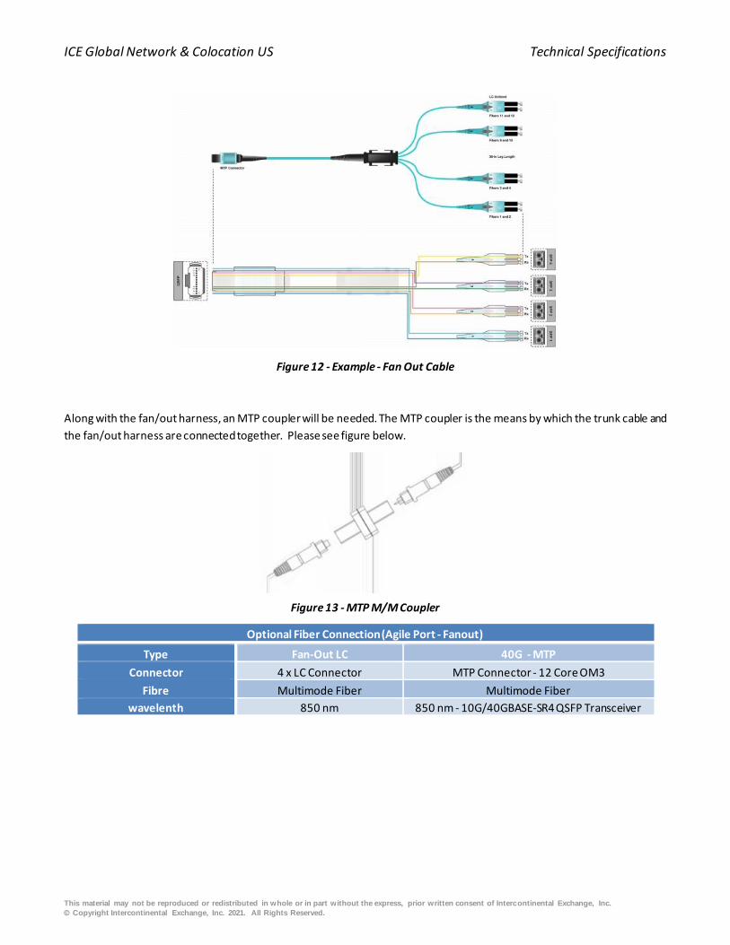
ICE Global Network & Colocation US Technical Specifications
This material may not be reproduced or redistributed in whole or in part without the express, prior written consent of Intercontinental Exchange, Inc.
© Copyright Intercontinental Exchange, Inc. 2021. All Rights Reserved.
Figure 12 - Example - Fan Out Cable
Along with the fan/out harness, an MTP coupler will be needed. The MTP coupler is the means by which the trunk cable and
the fan/out harness are connected together. Please see figure below.
Figure 13 - MTP M/M Coupler
Optional Fiber Connection (Agile Port - Fanout)
Type Fan-Out LC 40G - MTP
Connector 4 x LC Connector MTP Connector - 12 Core OM3
Fibre Multimode Fiber Multimode Fiber
wavelenth 850 nm 850 nm - 10G/40GBASE-SR4 QSFP Transceiver
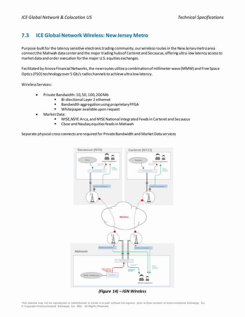
ICE Global Network & Colocation US Technical Specifications
This material may not be reproduced or redistributed in whole or in part without the express, prior written consent of Intercontinental Exchange, Inc.
© Copyright Intercontinental Exchange, Inc. 2021. All Rights Reserved.
7.3 ICE Global Network Wireless: New Jersey Metro
Purpose-built for the latency sensitive electronic trading community, our wireless routes in the New Jersey metro area connect the Mahwah data center and the major trading hubs of Carteret and Secaucus, offering ultra-low latency access to market data and order execution for the major U.S. equities exchanges.
Facilitated by Anova Financial Networks, the new routes utilize a combination of millimeter wave (MMW) and Free Space
Optics (FSO) technology over 5 Gb/s radio channels to achieve ultra low latency.
Wireless Services :
• Private Bandwidth: 10, 50, 100, 200 Mb ▪ Bi-diectional Layer 2 ethernet ▪ Bandwidth aggregation using proprietary FPGA ▪ Whitepaper available upon request
• Market Data: ▪ NYSE,NSYE Arca, and NYSE National Integrated Feeds in Carteret and Secaucus ▪ Cboe and Nasdaq equities feeds in Mahwah
Separate physical cross connects are required for Private Bandwidth and Market Data services
CboeLocal Customers
Secaucus (NY5)
Mahwah
NYSE / NYSE Arca
Nasdaq
LCN 10G port
COLO customers
Local Customers
Carteret (NY11)
Wireless
Market Data Switch
10G customers
connectivity
10G customers
connectivity10G customers
connectivity
NYSE / NYSE Arca
Integrated Feed
(outbound)
Cboe/Nasdaq
(Inbound)
P2P links: Cust distribution
Private
Bandwidth
connectivity
Private
Bandwidth
connectivity
P2P links: Cust distribution
P2P links: Cust distributionP2P links: Cust distribution
Private
Bandwidth
connectivityMarket Data Switch Market Data Switch
(Figure 14) – IGN Wireless

ICE Global Network & Colocation US Technical Specifications
This material may not be reproduced or redistributed in whole or in part without the express, prior written consent of Intercontinental Exchange, Inc.
© Copyright Intercontinental Exchange, Inc. 2021. All Rights Reserved.
7.3.1 Technology Highlights
• Utilizes new 5 Gb/s radio technology on an opmized route • Combination of Millimeter Wave (MMW) and Free Space Optics (FSO) used to ensure reliability • Self-healing is included in some market data services
7.3.2 Latency & Availability Information
IGN Wireless has SLAs for both latency and availability.
7.3.2.1 Latency & Availability
ROUTE LATENCY AVAILABILITY
Mahwah to Carteret 194.5 99.9%
Mahwah to Secaucus 117.7 99.9%
In the event that the service is unable to deliver the specified latency (greater than 1% over the published latency for a period
of more than 1 hour), Customers should raise a service ticket with [email protected] for troubleshooting.
For availability, the service will be deemed unavailable during any period where the BER (Bit Error Rate) exceeds 10-7 for
greater than a one minute interval during the hours of operation.Hours of operation are Monday - Friday: 7:00 AM to 9:00
PM (EST) with the exception of Exchangeholidays and Excused Outages.
7.3.3 Private Bandwidth
Private Bandwidth is delivered via an Ethernet handoff directly on the Bandwidth Manager FPGA device. Bandwdith sizes
are available in 10, 50, 100, and 200 Mb options.. Customers are allowed to order up to 200 Mbps private bandwidth, per
port, on any one route. Customers can have multiple ports, but bandwidth allocated on a single port cannot exceed 200 Mb.
7.3.4 Private Bandwidth - Physical Connectivity
Location of private bandwidth handoff device:
DATA CENTER MAHWAH CARTERET SECAUCUS
ADDRESS 1700 MacArthur Blvd, Mahwah,
NJ, 07430
1400 Federal Blvd, Carteret,
NJ, 07008
800 Secaucus Road, Secaucus,
NJ, 07094
DEMARK LOCATION Meet Me Room - South
Equinix NY5 Anova cabinet:
Cage 51456, Cabinet 112
CROSS CONNECT
RESPONSIBILITY
ICE orders cross connect and
delivers to patch panel near
customers’ location
(Customer to provide LOA to ICE)
Customer orders cross
connect.
(Anova to provide LOA to
customer)
Customer orders cross
connect.
(Anova to provide LOA to
customer)
OPTIC TYPE 10 Gb SMF 10 Gb SMF 10 Gb SMF

ICE Global Network & Colocation US Technical Specifications
This material may not be reproduced or redistributed in whole or in part without the express, prior written consent of Intercontinental Exchange, Inc.
© Copyright Intercontinental Exchange, Inc. 2021. All Rights Reserved.
7.3.5 Private Bandwidth: Network Considerations
• Maximum supported frame size is 2048 bytes. Anything over this size will be discarded. • The service is handed off directly from the bandwidth management hardware (FPGA) to each customer and
therefore no monitoring or TAPing of customer connections takes place. • There is no hardware-related latency difference between the 10 and 200 Mpbs service. No support for VLAN
tagging (802.1q tagged packets).
Interface configuration:
The customer port is configured without VLAN tagging. Each customer will be assigned an RFC1918 /30 subnet as a transit
point-to-point network.
Routing protocols:
Only BGPv4 is allowed.. No static routing or IGP allowed. Similarly to High Availability, customers can use their own public
ASN or use a private one provided by ICE. Only NATed public source ranges will be advertised on the customer peerings. As
there are no Unicast retransmission services over this link, no prefixes will be accepted from the customers.
7.3.6 Market Data
IGN Wireless Market Data distribution uses the same 5 Gb/s radio equipment that is used to deliver the private bandwidth
service. However, the channels are allocated separately for each type of service. Customers located in the Mahwah are able
to subscrive the 3rd party market data feeds - CBOE and NASDAQ. Similarly, NYSE proprietarty exchange data is available in
both Secaucus and Carteret.
7.3.7 Market Data - Physical Connectivity
Customers can connect via 10 Gb Ethernet cabling to the market data switch handoff demarcation.
Location of market data handoff device:
DATA CENTER MAHWAH CARTERET SECAUCUS
DEMARK LOCATION H3E32- cabinet in hall3 ICE cabinet: CAR.001.533-60 Equinix NY5 ICE Cabinet:
Cage 51223, Cabinet 103
CROSS CONNECT
RESPONSIBILITY
ICE orders cross connect and
delivers to patch panel near
customers’ location
(Customer to provide LOA to
ICE)
ICE orders cross connect and
delivers to patch panel near
customers’ location
(Customer to provide LOA to
ICE)
ICE orders cross connect and
delivers to patch panel near
customers’ location
(Customer to provide LOA to
ICE)
OPTIC TYPE 10 Gb MMF 10 Gb SMF 10 Gb SMF
7.3.8 Market Data: Network Considerations
Network Address Translation / Proxy
IGN Wireless offers multicast market data services both inbound and outbound from Mahwah. Outbound services, to Carteret and Secaucus, are the NYSE, NYSE ARCA, and NYSE NATIONAL Integrated Feeds. Inbound market data services are NASDAQ and CBOE data.
• Data services are NATed1, offering a “C” feed

ICE Global Network & Colocation US Technical Specifications
This material may not be reproduced or redistributed in whole or in part without the express, prior written consent of Intercontinental Exchange, Inc.
© Copyright Intercontinental Exchange, Inc. 2021. All Rights Reserved.
• Public IPs have been allocated to alleviate the potential for conflict with existing customer or data routes • Data will be multicast only, no unicast services or retransmission • All multicast group and source information used on the wireless service can be found at:
https://www.nyse.com/publicdocs/nyse/data/IP_Addresses.xls
1 In order to maintain clear separation between the wireless market data service and the regular ICE Global Network market
data service, all the multicast groups and sources will be presented with different addresses to customers using NAT. This
avoids confusion, asymmetric routing and any potential PIM RP mapping issues for customers connected to both networks.
Besides, the wireless service offers a limited subset of the products available on ICE Global Network which makes the NAT
mandatory as the same source may be publishing products only available on ICE Global Network as well as streams available
on the wireless network
Multicast subscription:
The IGN Wireless network doesn’t support PIM or IGMP membership, the market data will be flooded on the customer ports
based on the client entitlement. It is important from a customer perspective to accept the multicast stream and use it for
directly connected receivers. Alternatively, customers can register it against internal Rendezvous points for remote
consumption.
7.3.9 Resiliency/Failover Considerations
IMPORTANT:
• Clients should account for gapping and/or outages. Therefore, it is important to take into account alternative services
for improving availablity where appropriate.
• IGN Wireless is a non-resilient service. Clients can treat it as an isolated service with dedicated multicast groups.while
subscribing to fiber based multicast groups for the same market data from the ICE Global Network.
• IGN Wireless does allow duplicate wireless market data ports for an additional fee.

ICE Global Network & Colocation US Technical Specifications
This material may not be reproduced or redistributed in whole or in part without the express, prior written consent of Intercontinental Exchange, Inc.
© Copyright Intercontinental Exchange, Inc. 2021. All Rights Reserved.
7.4 ICE Global Network Wireless: Toronto - New Jersey
Our Toronto to New Jersey Metro route offers unrivaled ultra-low latency cross-border connectivity between the major
trading hubs in the U.S. and Canada. Using microwave technology, this broadly available commercial service provides market
participants on both sides of the border with access to critical market information and private bandwidth services.
The available market data features a wide range of inter-listed equities and ETFs on the Toronto Stock Exchange (TSX), the
NYSE, NYSE Arca, Cboe, and Nasdaq. The connection links TMX Group's main data center, housing TSX, TSX Venture Exchange,
TSX Alpha Exchange and Montreal Exchange, to Mahwah, Secaucus, and Carteret, New Jersey, where the data centers for the
NYSE markets, Cboe, and Nasdaq are respectively located.
Wireless Services:
• Private Bandwidth: 1, 5, 10 Mb ▪ Bi-diectional ▪ Multiple channels can be supported to add additional end points (source/destination IPs)
• Market Data: ▪ TSX market data (inter-listed symbols) delivered to Carteret (NY11), Secaucus (NY4), and Mahwah ▪ US market data (NYSE, NYSE Arca, Nasdaq, Cboe) delivered to Markham ▪ Proprietary “Strikelight” market data protocol, optimized for wireless services
Separate physical cross connects are required for Private Bandwidth and Market Data services
Markham
Mahwah
Wireless
Private
Bandwidth
connectivity
LEGEND
Nasdaq
Local Customers
Edge Switch
Carteret
NYSE/NYSE Arca
Local Customers
Edge Switch Edge Switch
Cboe
Local Customers
Secaucus
Local Customers
Edge Switch
TSX
Private Bandwidth
NYSE/NYSE Arca Market Data
Cboe Market Data
Nasdaq Market Data
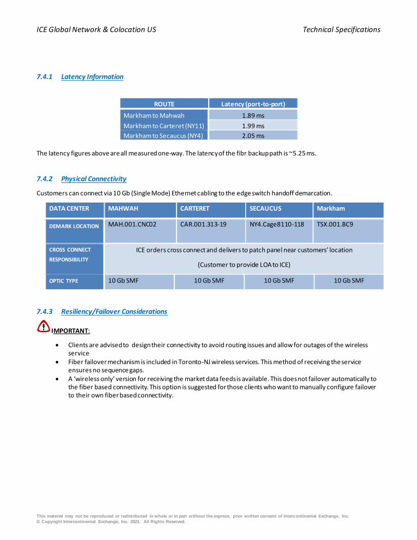
ICE Global Network & Colocation US Technical Specifications
This material may not be reproduced or redistributed in whole or in part without the express, prior written consent of Intercontinental Exchange, Inc.
© Copyright Intercontinental Exchange, Inc. 2021. All Rights Reserved.
7.4.1 Latency Information
ROUTE Latency (port-to-port)
Markham to Mahwah 1.89 ms
Markham to Carteret (NY11) 1.99 ms
Markham to Secaucus (NY4) 2.05 ms
The latency figures above are all measured one-way. The latency of the fibr backup path is ~5.25 ms.
7.4.2 Physical Connectivity
Customers can connect via 10 Gb (Single Mode) Ethernet cabling to the edge switch handoff demarcation.
DATA CENTER MAHWAH CARTERET SECAUCUS Markham
DEMARK LOCATION MAH.001.CNC02
CAR.001.313-19
NY4.Cage8110-118
TSX.001.BC9
CROSS CONNECT
RESPONSIBILITY
ICE orders cross connect and delivers to patch panel near customers’ location
(Customer to provide LOA to ICE)
OPTIC TYPE 10 Gb SMF 10 Gb SMF 10 Gb SMF 10 Gb SMF
7.4.3 Resiliency/Failover Considerations
IMPORTANT:
• Clients are advised to design their connectivity to avoid routing issues and allow for outages of the wireless service
• Fiber failover mechanism is included in Toronto-NJ wireless services. This method of receiving the service ensures no sequence gaps.
• A ‘wireless only’ version for receiving the market data feeds is available. This does not failover automatically to the fiber based connectivity. This option is suggested for those clients who want to manually configure failover to their own fiber based connectivity.

ICE Global Network & Colocation US Technical Specifications
This material may not be reproduced or redistributed in whole or in part without the express, prior written consent of Intercontinental Exchange, Inc.
© Copyright Intercontinental Exchange, Inc. 2021. All Rights Reserved.
8. Content Service Providers (CSPs)
Content Service Provider (CSP) is a third party provider of services to the financial industry, including but not limited to order
routing, order matching, market data, trade clearing, and settlement. A list of CSPs available on ICE Global Network can be
obtained through your account manager. CSPs have the following attributes:
Mandatory:
• Connects to a minimum of two ICE Global Network devices over diverse paths for resiliency.
• Advertises publicly registered IP addresses.
• Accept publicly registered IP address from ICE Global Network clients.
Optional:
• Provide unicast services, with bandwidth policed at the ingress in to ICE Global Network.
• Provide multicast services, with bandwidth policed at the ingress in to ICE Global Network.
• Accept privately registered IP addresses for clients that don’t had public address space.
Limitations:
• Limit unicast services by bandwidth. (i.e. customer may subscribe to the service, it but might not have enough
bandwidth for it to work correctly.)
• Limit multicast services by filters. (i.e. Once the filter is open, customer can get the service and the only bandwidth
limitations are due to capacity or the customer port, ICE Global Network backbone, or CSP ingress interface into ICE
Global Network.)

ICE Global Network & Colocation US Technical Specifications
This material may not be reproduced or redistributed in whole or in part without the express, prior written consent of Intercontinental Exchange, Inc.
© Copyright Intercontinental Exchange, Inc. 2021. All Rights Reserved.
9. Application Services
9.1 High Availability Virtual Local Area Network (VLAN)
Ice Global Network provides a wide range of services to the financial industry, some of which include, order routing, order
matching, market data, trade clearing and settlement.
A list of Application Services available on ICE Global Network can be obtained through your account manager. All applications
services have the following attributes:
• Connects to a minimum of two ICE Global Network devices over diverse paths for resiliency.
• Provide unicast services, with bandwidth policed at the ingress in to ICE Global Network.
• Provide multicast services, with bandwidth policed at the ingress in to ICE Global Network.
• Advertises publicly registered IP addresses.
• Accept publicly registered IP address from ICE Global Network customers.
• Accept privately registered IP addresses for customers that do not have public address space.
• Limit unicast services by bandwidth. (i.e. customer may subscribe to the service, it but might not have e nough
bandwidth for it to work correctly.)
• Limit multicast services by filters. (i.e. Once the filter is open, customer can get the service and the only bandwidth
limitations are due to capacity or the customer port, ICE Global Network backbone, or CSP ingress interface into ICE
Global Network.)
• Customer connects to HA VLAN using standard interface configuration

ICE Global Network & Colocation US Technical Specifications
This material may not be reproduced or redistributed in whole or in part without the express, prior written consent of Intercontinental Exchange, Inc.
© Copyright Intercontinental Exchange, Inc. 2021. All Rights Reserved.
10. Carrier Meet-Me Room Services
Telecommunication providers (Telcos) have access to two Meet-Me-Rooms (MMR) located on the north and south ends of
the first floor of the USLC. The MMRs provide a space for installing equipment and terminating fiber optic cables. Telcos are
welcome to store multiplexing equipment in the MMRs to provide their customers with a single connection between the
MMR and the equipment outside of the MMR. This will allow for a direct and private connection to a several other
organizations residing within the two MMRs. Utilizing the MMRs for storing and/or installing additional equipment is strongly
discouraged.
10.1 Engineering Consideration
The two MMR’s are fed by three Point of Entry (POE) rooms; entering at the east, north, and northwest sides of the building.
Each POE connects to a dedicated zero-manhole at the property line of the Mahwah facility. An ICE owned conduit system
connects each POE to its associated zero-manhole.
The north and northwest zero-manholes have a limited amount of outwardly facing 4 inches conduits which extend beyond
the property line. Telco’s that contract for services in Mahwah can request access to one conduit in each of these zero-
manholes. The east zero-manhole is different in that the outwardly facing conduit system is fully built out and ICE will assign
carriers to inner-ducts. Each Telco will be fully responsible for extending their fiber optic cable into the Mahwah USLC facility.
This includes, but is not limited to, the build to ICE’s zero-manholes by intercepting existing 4 inches conduits if required,
pulling of fiber, any necessary civil works, and the associated legal agreements with third parties.
Distance Between Zero-manhole - MMR
Zero-manhole MMR Length (FT)
East1 South 1260
North South 985
Northwest South 1150
East North 1075
North North 600
Northwest North 1495
10.2 MMR Layout
There are two facility rooms which are located at the north and south sides of the Mahwah USLC which are dedicated for
carriers to land their communications equipment. Rack space in these facilities is separated into two basic components;
“Carrier Frames” and “Distribution Frames”. It is from these locations which carriers may extend their network equipment
and connect to Colocated customers’ equipment in Hall 1, 2, and 3. To extend these connections each carrier frame will have
a dedicated fiber patch panel with 96 strands of 10 µm single-mode fiber (SMF) and 48 strands of OM3 50 µm multi-mode
fiber (MMF) with LC connections pulled into the Main Distribution Frame (MDF); from this point, fiber cross connects are
made to fiber trunks which extend out to network cabinets in the Liquidity Center Halls.
-------------------------------------------------------------------------- 1. Distance for the East Zero-manhole to the MMRs includes the distance from the Utility pole to the zero-manhole.

ICE Global Network & Colocation US Technical Specifications
This material may not be reproduced or redistributed in whole or in part without the express, prior written consent of Intercontinental Exchange, Inc.
© Copyright Intercontinental Exchange, Inc. 2021. All Rights Reserved.
10.2.1 Power Specifications
Branch circuits from Power Distribution Units (PDU) provide the Telco’s cabinet with either 4 or 8 kilowatts of power. One
PDU provides 'A' feed power while the other provides 'B' feed power. Each 4 kilowatts cabinet has two branch circuits, one
from each of the PDU. Each branch circuit is a single phase, 208VAC feed fused at 30 amps generating 6.24 kilowatts of power.
Both branch circuits are monitored (each should carry half of the 4 kilowatts load) with an alarm in place for notifying the
facilities should the two branch circuits total power exceed 4 kilowatts.
10.2.2 Technical Specification
Power Strip
Two vertical power strips are provisioned with a 4kW order and four strips are provisioned with an 8kW order. A 4kW cabinet
has its power strips installed on one side of the cabinet. An 8kW cabinet has its power strips installed two on each side of the
cabinet. Each power strip plugs into a L14-30 outlet installed above the cabinet. Additional power strip outlet configurations
and power outlets are available; customers are responsible for providing the appropriate cables. Each strip is fused with the
following standard configuration:
• Outlet Size: 30 A, 208 VAC (18 x IEC C-13 + 6 x IEC C19) single phase – single strip
• Outlet Size: 30 A, 120 VAC (6 NEMA 5-20R) single phase – single strip
• Local Meter
(Figure 15) – Standard Power Cable Connectors
Cabinet
• Manufacturer: Rittal Corporation
• Size: 52 RU
• Dimensions (Depth × Height × Width): 41.33 in. × 96.4 in. × 27.55 in.
• 19 in. mountable rails

ICE Global Network & Colocation ICE Global Network Connectivity Options Summary
This material may not be reproduced or redistributed in whole or in part without the express, prior written consent of Intercontinental Exchange, Inc.
© Copyright Intercontinental Exchange, Inc. 2021. All Rights Reserved.
Appendix A. ICE Global Network Connectivity Options Summary
Available Network Connectivity Options
LCN A Local Area Network (LAN) within the Data Center that provides local connectivity to resources
residing in the data halls.
LCN – NMS Access to the National Market Systems NMS (CTS/CQS/OPRA) over existing LCN connections.
IP Liquidity Center An IP-based Wide Area Network (WAN) service designed to connect Datacenter collocated
customers to local and remote ICE:NYSE market systems and third party CSPs
High Availability
Direct Connection -
SDC
High Availability Direct Connection (SDC) enables firms to use their own Ethernet connectivity to
connect with ICE Global Network at geographically diverse and vendor-neutral HA Access Centers
outside of the data centers.
VCC A transparent Layer 2 VPN from HA Access Center to Data Center used to connect customers to their
Colocation environments. Customers’ existing SLC, or SDC can be utilized.
LLN Point to point fiber services between USLC in Mahwah and Carteret & Secaucus Access Centers.
Access to all NYSE Core & Premium services including NMS.
Optic A point to point Ethernet service to connect customer’s Colocation environments in the Data Center
to ICE Global Network Access Centers using Dense Wave Division Multiplexing (DWDM) technology.
Wireless Point to point hybrid wireless service using Anova Technologies’ MMW/FSO Aoptix technology.
Provides select market data feeds and raw bandwidth services.
Liquidity Center
Cross Connects
(LCX)
A Layer 1 network providing connections exclusively between non-contiguous intra-customer racks
in the Colocation halls.
VPN Low cost ICE Global Network access point via virtual private network over the internet, secure VPN
tunnel. Supports unicast services up to 10Mbps.
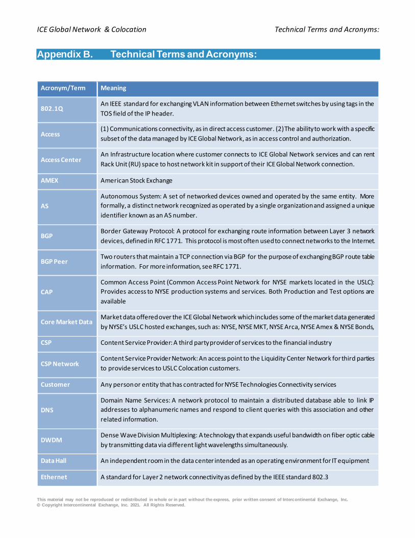
ICE Global Network & Colocation Technical Terms and Acronyms:
This material may not be reproduced or redistributed in whole or in part without the express, prior written consent of Intercontinental Exchange, Inc.
© Copyright Intercontinental Exchange, Inc. 2021. All Rights Reserved.
Appendix B. Technical Terms and Acronyms:
Acronym/Term Meaning
802.1Q An IEEE standard for exchanging VLAN information between Ethernet switches by using tags in the
TOS field of the IP header.
Access (1) Communications connectivity, as in direct access customer. (2) The ability to work with a specific
subset of the data managed by ICE Global Network, as in access control and authorization.
Access Center An Infrastructure location where customer connects to ICE Global Network services and can rent
Rack Unit (RU) space to host network kit in support of their ICE Global Network connection.
AMEX American Stock Exchange
AS
Autonomous System: A set of networked devices owned and operated by the same entity. More
formally, a distinct network recognized as operated by a single organization and assigned a unique
identifier known as an AS number.
BGP Border Gateway Protocol: A protocol for exchanging route information between Layer 3 network
devices, defined in RFC 1771. This protocol is most often used to connect networks to the Internet.
BGP Peer Two routers that maintain a TCP connection via BGP for the purpose of exchanging BGP route table
information. For more information, see RFC 1771.
CAP
Common Access Point (Common Access Point Network for NYSE markets located in the USLC):
Provides access to NYSE production systems and services. Both Production and Test options are
available
Core Market Data Market data offered over the ICE Global Network which includes some of the market data generated
by NYSE’s USLC hosted exchanges, such as: NYSE, NYSE MKT, NYSE Arca, NYSE Amex & NYSE Bonds,
CSP Content Service Provider: A third party provider of services to the financial industry
CSP Network Content Service Provider Network: An access point to the Liquidity Center Network for third parties
to provide services to USLC Colocation customers.
Customer Any person or entity that has contracted for NYSE Technologies Connectivity services
DNS
Domain Name Services: A network protocol to maintain a distributed database able to link IP
addresses to alphanumeric names and respond to client queries with this association and other
related information.
DWDM Dense Wave Division Multiplexing: A technology that expands useful bandwidth on fiber optic cable
by transmitting data via different light wavelengths simultaneously.
Data Hall An independent room in the data center intended as an operating environment for IT equipment
Ethernet A standard for Layer 2 network connectivity as defined by the IEEE standard 802.3

ICE Global Network & Colocation Technical Terms and Acronyms:
This material may not be reproduced or redistributed in whole or in part without the express, prior written consent of Intercontinental Exchange, Inc.
© Copyright Intercontinental Exchange, Inc. 2021. All Rights Reserved.
Acronym/Term Meaning
Extranet A non-public network intended to give system or network access to a set of outside entities that
have individual intranets.
Extranet Provider
Any external vendor that connects to ICE Global Network for the purpose of redistributing ICE Global
Network services to remote customers, often with additional access methods or protocols for the
convenience of the end customer(s).
G Abbrieviation for “Gbps” – short for Gigabits per second and used to indicate data transfer speed
ICE Intercontinental Exchange Group, Inc., parent of NYSET, NYSE Group and its affiliates
Internet The public collection of networks commonly known as the Internet, originally conceived and
implemented by the Department of Defense and public universities as the ARPANet.
IPSec VPN
A standard for Virtual Private Networks that uses the network cryptographic protocols for protecting
IP traffic to provide an encrypted, secure tunnel for IP data traffic across a non-secure public extranet
or the Internet.
LCN Liquidity Center Network, used by Colocation customers to connect to financial services housed
within the ICE:NYSE Mahwah Data Center.
Liquidity Center
A trading environment that houses NYSE matching engines and/or Colocation customers. Customers
who colocate at a Liquidity Center can connect to ICE Global Network services and house their
financial servers in Colocation cabinets.
LAN Local Area Network: A network of machines generally limited to a local area, such as one or more
floors of a building, or nearby buildings.
LSP Limited Service Port: An HA port that allows access to a single NYSE non-core service.
M Abbrieviation for “Mbps” – short for Megabits per second and used to indicate data transfer speed
MAN Metropolitan Area Network: A collection of LANs that would otherwise be a Wide Area Network
(WAN), but which is local to a single metropolitan area.
NIC Network Interface Controller, also known as a network card. A hardware component for servers
that faciliatates network connections
NOC Network Operations Center
NMS National Market Systems: Provides consolidated equity and options market data for the US financial
markets to the financial industry.
NYSE New York Stock Exchange

ICE Global Network & Colocation Technical Terms and Acronyms:
This material may not be reproduced or redistributed in whole or in part without the express, prior written consent of Intercontinental Exchange, Inc.
© Copyright Intercontinental Exchange, Inc. 2021. All Rights Reserved.
Acronym/Term Meaning
NYSET or “NYSE Technologies Connectivity” is NYSE Technologies Connectivity, Inc and the operating entity
of the USLC and the ICE Global Network
OCx Optical Carrier level x: The Synchronous Optical Network (SONET) includes a set of signal rate
multiples for transmitting digital signals on optical fiber. The base rate (OC-1) is 51.84 Mb.
Packet Filtering
A technology that inspects packets as they enter a piece of networking equipment, such as a router,
and take action on the packet (such as to discard, forward, or log it) based on a preconfigured rule
set.
PIM Protocol Independent Multicast: The protocol used by ICE Global Network to route multicast
packets.
POD See Data Hall
Production
Network
A network supported by ICE:NYSE which directly supports the trading functionality and/or core
business of one of internal ICE:NYSE’s business owners.
Proximity Center An infrastructure location where a customer can connect to ICE Global Network services, rent
cabinets to host financial servers, and rent RU space to host network kit.
Public Extranet
Provider See Extranet Provider.
Services Applications provided for customer’s consumption by the Production Networks connected to ICE
Global Network.
HA Access Center A physical facility, usually a Access Center, where ICE:NYSE hosts HA equipment and where
customers may gain direct network access to High Availability.
SLC IP Liquidity Center
SONET
Synchronous Optical Network: A standard for optical telecommunications transport formulated by
the Exchange Carriers Standards Association (ECSA) for the American National Standards Institute
(ANSI). SONET bandwidth is divided into OCx levels
TCP Transport Control Protocol: A connection oriented IP Transport layer protocol.
UDP User Datagram Protocol: A connectionless IP transport layer protocol. Primarily used by ICE Global
Network to transport IP multicast data.
VLAN
Virtual Local Area Network: A networking standard that allows network devices, sometimes even
those that span multiple Layer 2 switches, to appear as if they all reside upon a traditional shared
media Ethernet segment.
WAN Wide Area Network: A network connectivity model using protocols to support distances greater than
a MAN or LAN.

ICE Global Network & Colocation Quick Connect Sheet – High Availability
This material may not be reproduced or redistributed in whole or in part without the express, prior written consent of Intercontinental Exchange, Inc.
© Copyright Intercontinental Exchange, Inc. 2021. All Rights Reserved.
Appendix C. Quick Connect Sheet – High Availability
The following is the list of information High Availabiluty Direct Connection customers need to consider when configuring their
routers.
1. Upon receiving approval to connect to ICE Global Network, customers will be provided with provisioning information
pertinent to the services to which they have been requested to be entitled. This list will be supported by a Customer
Technical interchange (CTI) Meeting and will be provided by a Customer Engineering representative. Detail will include:
o The VLAN IDs associated with each set of services to which the customer is entitled. o The IP addresses of servers for each service network to which the customer will route unicast datagram’s (all of
which will be globally registered IP addresses), including all relevant UDP and TCP port assignments. o Summary IP ranges of FSNs advertised to the customer via BGP-4 over each service VLAN. o List of BGP communities associated with BGP routes announced to the customer for each service. This gives
customers the ability to customize routing to FSNs within their networks according to their needs. o Multicast group addresses associated with the services to which the customer is entitled. This will include the UDP
destination port assignments as applicable. o IP addresses of FSN subnets where multicast sources are located. o HA US registered AS number(26585). o The private IP addresses for use on the connection between customer’s router and the HA edge router; this will
include separate addresses for each of the logical interfaces (each logical interface is required for each VLAN and each will require its own set of unique addresses)
o BGP passwords (MD5) will be supported but are not required and will be administered by Customer Engineering
2. Customers will be required to provide Customer Engineering with the following network-related information for
configuring the HA edge router port:
o Summary IP addresses of subnets within customer’s network which will be advertised by customer’s routers into HA network via BGP.
o Customers’ host IP addresses to which unicast IP services will be routed. If customers’ cannot provide globally registered addresses, ICE will provide private address ranges for use by the requesting customer only.
o Customers will provide Customer Engineering with a registered AS number or ICE will provide the customer with a private number to use for exchanging BGP information with HA ONLY. This is not to be confused with the HA AS number.
3. With respect to PIM Sparse-Dense Mode, HA uses all default values where they apply (see Example L3 Switch
Configuration for an example configuration). With respect to BGP Parameters, BGP Timers for each customer’s direct
connection to HA must NOT be set lower than following values:
o Keep-alive interval – 6 sec o Time-out interval – 20 sec.
4. With respect to RIP2 parameters, recommended minimal values for RIP-2 timers are:
o Update interval – 30 sec o Timeout interval – 75 sec.

ICE Global Network & Colocation Quick Connect Sheet – High Availability
This material may not be reproduced or redistributed in whole or in part without the express, prior written consent of Intercontinental Exchange, Inc.
© Copyright Intercontinental Exchange, Inc. 2021. All Rights Reserved.
Customers who configure their routers with other parameter values will risk interoperability issue s. A separate logical
interface will be required for each VLAN to which the customer will be connecting. On the VLANs supporting unicast services,
BGP will be used for the exchange of unicast routing information between HA and customer’s network. On the VLAN
dedicated for multicast service delivery, RIP2 is the protocol currently used for exchanging unicast routes associated with the
multicast sources. It is assumed, (but not required), that the customer will deploy PIM Sparse-Dense mode with Auto-RP
enabled, and use the unicast route information learned via RIP2 for the purposes of routing multicast packets.
For customers who request it, ICE Global Network will configure static IGMP Joins on the HA edge routers connected to the
customer. Customers who do not implement PIM Sparse-Dense mode with Auto-RP enabled will find this useful for
supporting static "always on" forwarding of multicast data across the HA demarcation to customer’s edge router. Routing
information about the sources of multicast data will be provided via RIP-2.

ICE Global Network & Colocation Sample – Layer3 Switch Configuration
This material may not be reproduced or redistributed in whole or in part without the express, prior written consent of Intercontinental Exchange, Inc.
© Copyright Intercontinental Exchange, Inc. 2021. All Rights Reserved.
Appendix D. Sample – Layer3 Switch Configuration
The information presented here is in no way meant to imply or represent a certification or recommendation. Customers must
make their own evaluations and work with their vendor of choice regarding the solution needed to meet the interface
requirements of HA. The configuration presented here was created for a typical Cisco device capable of connecting to HA
with the following considerations and assumptions:
• the device was configured to connect to all the HA VLANs
• the typical example of a customer who will be receiving both unicast and multicast data
• assumes the Layer 3 switch is connected to a HA edge router via a single 1000Base-SX connection (Port 25) and to
the members internal network with a 1000Bast-T connection (Port1) --------------------------Configuration file example begins below---------------------------- version 12.2 no service pad service password-encryption
! switch 1 provision ws-c3750g-24ts-1u vtp mode transparent ip subnet-zero ip routing
no ip domain-lookup ! ip multicast-routing distributed ! no file verify auto
spanning-tree mode pvst spanning-tree extend system-id ! vlan internal allocation policy ascending
! vlan 10-14,16-21,152,252 ! interface GigabitEthernet1/0/1 description Member side of interface (not routing with HA)
no switchport ip address 192.168.126.26 255.255.255.252 ip accounting output-packets ip pim sparse-dense-mode ip rip advertise 5
ip dvmrp metric 1 ip dvmrp unicast-routing ip igmp query-interval 120 load-interval 30 keepalive 30
speed 1000 duplex full ! interface GigabitEthernet1/0/2 interface GigabitEthernet1/0/3
interface GigabitEthernet1/0/4 interface GigabitEthernet1/0/5 interface GigabitEthernet1/0/6 interface GigabitEthernet1/0/7
interface GigabitEthernet1/0/8 interface GigabitEthernet1/0/9 interface GigabitEthernet1/0/10 ! interface GigabitEthernet1/0/11
!

ICE Global Network & Colocation Sample – Layer3 Switch Configuration
This material may not be reproduced or redistributed in whole or in part without the express, prior written consent of Intercontinental Exchange, Inc.
© Copyright Intercontinental Exchange, Inc. 2021. All Rights Reserved.
interface GigabitEthernet1/0/12 ! interface GigabitEthernet1/0/13
! interface GigabitEthernet1/0/14 ! interface GigabitEthernet1/0/15 !
interface GigabitEthernet1/0/16 ! interface GigabitEthernet1/0/17 ! interface GigabitEthernet1/0/18
! interface GigabitEthernet1/0/19 ! interface GigabitEthernet1/0/20
! interface GigabitEthernet1/0/21 ! interface GigabitEthernet1/0/22 !
interface GigabitEthernet1/0/23 ! interface GigabitEthernet1/0/24 ! interface GigabitEthernet1/0/25
description Gigabit Ethernet WAN connection to HA switchport trunk encapsulation dot1q switchport trunk allowed vlan 10-14,16-21,152,252 switchport mode trunk load-interval 30
speed nonegotiate no cdp enable ! interface GigabitEthernet1/0/26 !
interface GigabitEthernet1/0/27 ! interface GigabitEthernet1/0/28 ! interface Vlan1
no ip address shutdown ! interface Vlan10
description VLAN connection to multicast Virtual Backbone ip address 10.129.6.1 255.255.255.252 ip pim sparse-dense-mode ip dvmrp metric 1 ip igmp query-interval 120
load-interval 30 ! interface Vlan11 description VLAN connection to Unicast Virtual backbone ip address 10.129.14.1 255.255.255.252
ip pim sparse-dense-mode ip dvmrp metric 1 ip igmp query-interval 120 load-interval 30 !
router bgp 65221 no synchronization bgp log-neighbor-changes network 198.140.52.3 aggregate-address 10.53.0.0 255.255.224.0 as-set summary-only

ICE Global Network & Colocation Sample – Layer3 Switch Configuration
This material may not be reproduced or redistributed in whole or in part without the express, prior written consent of Intercontinental Exchange, Inc.
© Copyright Intercontinental Exchange, Inc. 2021. All Rights Reserved.
aggregate-address 204.200.184.0 255.255.248.0 timers bgp 6 20 redistribute connected
redistribute static redistribute rip neighbor HA peer-group neighbor HA remote-as 26585 neighbor HA distribute-list 102 out
neighbor 10.129.6.2 peer-group HA neighbor 10.129.14.2 peer-group HA no auto-summary ! ip classless
ip http server ! ip pim rp-address xxx.xxx.xxx.xxx Static RP Configuration option !
ip access-list standard Multicast-Cash-Feed permit 233.54.12.243 permit 233.54.12.242 permit 233.54.12.241 permit 233.54.12.240
deny any
--------------------------Configuration file example ends above----------------------------
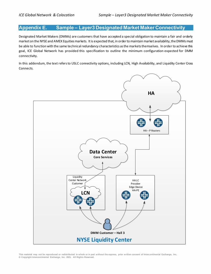
ICE Global Network & Colocation Sample – Layer3 Designated Market Maker Connectivity
This material may not be reproduced or redistributed in whole or in part without the express, prior written consent of Intercontinental Exchange, Inc.
© Copyright Intercontinental Exchange, Inc. 2021. All Rights Reserved.
Appendix E. Sample – Layer3 Designated Market Maker Connectivity
Designated Market Makers (DMMs) are customers that have accepted a special obligation to maintain a fair and orderly
market on the NYSE and AMEX Equities markets. It is expected that, in order to maintain market availability, the DMMs must
be able to function with the same technical redundancy characteristics as the markets themselves. In order to achieve this
goal, ICE Global Network has provided this specification to outline the minimum configuration expected for DMM
connectivity.
In this addendum, the text refers to USLC connectivity options, including LCN, High Availability, and Liquidity Center Cross
Connects.
DMM Customer – Hall 3
HA
NYSE Liquidity Center
HA – P Routers
LiquidityCenter Network
Customer
Data CenterCore Services
HA LCProvider
Edge DeviceHA-PE
LCN

ICE Global Network & Colocation Sample – Layer3 Designated Market Maker Connectivity
This material may not be reproduced or redistributed in whole or in part without the express, prior written consent of Intercontinental Exchange, Inc.
© Copyright Intercontinental Exchange, Inc. 2021. All Rights Reserved.
(Figure 16) – DMM Connectivity Example
NYSE AMEX DMMs are required to occupy cabinets in the USLC Customer Colocation Hall (Hall 3) for recovery purposes or
should be able to demonstrate that they have adequate backup capabilities to operate their DMM business through an offsite
customer location. Exceptions to these guidelines will be reviewed on a case by case basis and must be app roved by the
relevant market operator group. Customers are required to have at a minimum one SLC or LCN connection in Hall 3 or to be
used for access to NYSE’s trade plant. Access to the DMM’s remote office can be configured through SLC, or Optic services.
DMM’s shall not share their LCN trading connections with other non DMM businesses either Supplementary Liquidity Provider
(SLP) or proprietary.
As a general rule, DMM’s shall not colocate, non-DMM equipment (customer businesses, prop business) in their production
hall cabinets. Exceptions will be reviewed on a case by case basis and must be approved by the relevant market operator
group. DMM’s are responsible for maintaining their own resiliency across their primary and backup environments.

ICE Global Network & Colocation Data Center Cabling & Installation Guidelines
This material may not be reproduced or redistributed in whole or in part without the express, prior written consent of Intercontinental Exchange, Inc.
© Copyright Intercontinental Exchange, Inc. 2021. All Rights Reserved.
Appendix F. Data Center Cabling & Installation Guidelines
These data center racking, power and cabling guidelines were developed to establish a baseline of quality and workmanship
within Intercontinental Exchange data center cabinets. The guildelines apply to all ICE Data Center and Access Center
locations and are intended to improve communication between ICE Data Center Operations staff, Customers and their
designated Customer Representatives (including engineers and installers). They maintain a level of expectation for data
center engineering and installation services performed and while not intended to cover every situation or special condition
that an engineer or installer may encounter, nor to be used instead of applicable codes and standards, they do provide a tool
for use alongside relevant codes and standards, outlining minimum standards in terms of quality of work for installations.
The guidelines should be read in conjunction with the USLC Colocation Policies available at https://www.theice.com/data-
services/global-network and when Data Center Operations staff are able to to clarify guidelines or to provide a ruling on
quality and workmanship compliance.
General
- All equipment and materials used within the data center shall be either (a) listed by the Underwriters Laboratories,
Inc. (UL) and other Nationally Recognized Testing Laboratory (NRTL) or (b) inspected and approved by the local
Authority Having Jurisdiction (AHJ).
- All equipment and materials shall be manufactured and installed in accordance with applicable codes and regulations
including but not limited to ANSI, ASME, FM, IEEE, NEC and NEMA standards.
- All equipment and materials will be used in accordance with the manufacturer’s instructions or technical manuals.
- All equipment and materials shall be marked with the manufacturers name, trademark or other descriptive marking
by which the organization responsible for the product may be identified.
- All equipment and materials shall be marked with the voltages, current, wattage or other ratings as necessary.
- All equipment shall be free from recognizable hazards that are likely to cause death or serious physical harm.
- All installation work shall be performed in a neat and workmanlike manner.
- During and post installation work, visitors shall practice “good housekeeping” by keeping the work area clear of all
obstructions – detail of items to be adhered to are outlined in the ISLC Colocation Service Policy docume nt
- Visitors to all ICE Data Center and Access Center locations shall follow and obey the directions on all signs.
- When onsite, Customers shall adhere to all Intercontinental Exchange Critical Site Work Rules. outlined below
- Customers must report any unsafe or hazardous conditions to the Data Center operatorations staff immediately.
Qualified Personnel
- All data center installation work shall be performed by qualified personnel who have the skills and knowledge related
to the specific work method they are tasked with performing.
- Qualified personnel shall have received appropriate training to recognize and avoid the hazards that may be present
with respect to that equipment or work method they are performing.
- Work shall be performed by a licensed or certified installer when required by local jurisdiction.
ICE Global Network & Colocation Data Center Cabling & Installation Guidelines
This material may not be reproduced or redistributed in whole or in part without the express, prior written consent of Intercontinental Exchange, Inc.
© Copyright Intercontinental Exchange, Inc. 2021. All Rights Reserved.
- All electrical branch circuit installation work up to the final service outlet supporting the IT cabinet shall be performed
by the Data Center Operator’s own personnel.
Equipment Mounting
- All IT kit shall be installed in the data center cabinet/rack plumb and level true as intended and secure. All of these
factors shall be immediately apparent.
- All fasteners or supports used in mounting the IT kit shall be sufficient to substantially secure the equipment in place
to the data center cabinet/rack.
Power Cabling
- Only approved and properly maintained equipment line/power cords that have no exposed live parts, exposed
ungrounded metal parts, damage, fraying or splices are to be used in installations.
- Cabinets shall be clearly labeled on the outside rear of the cabinets where three phase power circuit lines cords have
been installed.
- All line cords shall be rated at or above the current capacity and voltage required to continuously power the device
served.
- All line cords shall be suitable for the temperature, conditions, and location where installed.
- All line cords shall be provided with a means of strain relief so that a pull on the flexible line cord will not be
transmitted directly to the wiring terminations.
- Line cords, plugs or cord caps that have different electrical ratings shall not be interchangeable with one another.
- Line cords with a ground conductor that has less current-carrying capacity than the other conductors shall not be
allowed.
- Line cords that have the ground pin cut off or that have had the ground protection compromised in any way shall
not be allowed.
- Adaptors designed to defeat the grounding connection are not allowed.
- Equipment line cords may not be daisy chained (i.e., to plug one power cord into another power cord).
- Equipment line cords shall only be powered from an electrical receptacle located in the same cabinet as the IT device
that the line cord is supporting.
- A line cord that ends with a splitter or “Y” may not feed separate devices or other line cords.
- Insert plugs fully so that no part of the prongs are exposed when the line cord is in use.
- The length of equipment line cords within cabinets shall be sufficient to neatly train the line cord from the receptacle
to the device served while minimizing line cord coils and loops within the IT cabinet/rack.
- All equipment line cords shall be sufficiently supported using devices intended for the purpose.
- The use of extension cords in any application is strictly prohibited with data center cabinets.
Rack Mount Power Distribution Units (PDU) [Powerstrips]

ICE Global Network & Colocation Data Center Cabling & Installation Guidelines
This material may not be reproduced or redistributed in whole or in part without the express, prior written consent of Intercontinental Exchange, Inc.
© Copyright Intercontinental Exchange, Inc. 2021. All Rights Reserved.
- A PDU shall be capable of being readily installed and wired as intended.
- The inherent design of a PDU shall ensure the electrical coordination between the Data Center Operator provided
branch circuit service outlet and the PDU.
- A PDU with an external grounding stud shall be bonded to the data center cabinet ground with a conductor sized in
accordance with the local electrical code.
- Each PDU shall be electrically connected to a separate and distinct permanently installed Data Center Operator
provided branch circuit service outlet.
- Dual supply PDUs with two separate and distinct power circuits within the same PDU enclosure shall be prohibited
unless each of the power circuits terminate in separate, fully electrically segregated partitions within the PDU.
- All PDUs shall be plugged into the Data Center Operator provided service outlet by the Data Center Operator’s own
personnel.
- PDUs are not to be daisy chained to one another or to separate equipment line cords.
- Electrical contact shall be reliably maintained at any point at which a connection is made between current-carrying
parts.
- A PDU shall have all live parts protected against exposure to contact by persons when the PDU is assembled and
installed as intended.
- PDU receptacles shall be constructed so that a standard attachment plug of the same configuration and with
maximum length blades is capable of seating properly without exposure of the blades between the plane of the face
of the plug and the plane of the rim of the PDU receptacle.
- A PDU with integral fuse protection shall be constructed to ensure the enclosure can confine the effects of a fuse
rupture to the interior of the enclosure.
- A PDU with integral fuse protection shall be constructed to ensure that no electrically live parts are exposed to
contact by persons when a fuse is being removed or replaced.
- A PDU with integral fuse protection shall be constructed to provide for a fuse in each ungrounded conductor.
Rack Mount Transfer Switches (TS)
- A TS shall be capable of being readily installed and wired as intended.
- TS line cords should be permanently affixed to and terminated within the enclosure of the TS. Where a TS is supplied
with a removable line cord it shall only be approved for installation where the cabinet that it supports feeds only
single phase equipment loads.
- Each TS shall be electrically connected to a separate and distinct permanently installed Data Center Operator
provided branch circuit service outlet.
- All TSs shall be plugged into the Data Center Operator provided service outlet by the Data Center Operator ’s own
personnel.
- Unless approved by the local AHJ, TSs are not to be daisy chained to one another, from a rack mount PDU receptacle
or to separate equipment line cords.

ICE Global Network & Colocation Data Center Cabling & Installation Guidelines
This material may not be reproduced or redistributed in whole or in part without the express, prior written consent of Intercontinental Exchange, Inc.
© Copyright Intercontinental Exchange, Inc. 2021. All Rights Reserved.
- Electrical contact shall be reliably maintained at any point at which a connection is made between current-carrying
parts.
- A TS shall have all live parts protected against exposure to contact by persons when the TS is assembled and installed
as intended.
- TS receptacles shall be constructed so that a standard attachment plug of the same configuration and with maximum
length blades is capable of seating properly without exposure of the blades between the plane of the face of the
plug and the plane of the rim of the TS receptacle.
- A TS with integral fuse protection shall be constructed to ensure the enclosure can confine the effects of a fuse
rupture to the interior of the enclosure.
- A TS with integral fuse protection shall be constructed to ensure that no electrically live parts are exposed to contact
by persons when a fuse is being removed or replaced.
- A TS with integral fuse protection shall be constructed to provide for a fuse in each ungrounded conductor.
Critical Site Work Rules
- All vendors, contractors and service personnel are to be appropriately attired and act in a professional manner.
- Offensive, abusive or other inappropriate behavior by customers, customer representatives, vendors, contractors or
service personnel will result in immediate and permanent dismissal from the site.
- Fire exits are to be kept clear.
- Smoking is not permitted in critical site spaces.
- Eating or drinking is not permitted in critical site spaces.
- Energized equipment IS NOT PERMITTED to be turned off any unless directed to do so by the Datacenter Operations
Team.
- Non-UPS electrical outlets are only to be used if/when as directed by ICE Datacenter Operations.
- Do not place or lean anything on or against any computer equipment, UPS, PDU, air conditioner, fire system pull
station, live electrical panels or similar devices as identified by Intercontinental Exchange.
- When working in the computer and communications rooms do not remove more than 10-15 floor tiles at a time.
- Use safety cones, barricades, caution tape and other safety equipment/devices to direct people away from open
floor tiles or other hazardous areas.
- Do not remove floor tile stringers unless absolutely necessary.
- Do not step on cables, conduit or electrical boxes under any raised floor.
- Keep cables away from air conditioner valves, strainers, water and drain lines, fire system smoke heads, piping and
other MEP equipment.
- Fire-seal all openings around conduit and cable penetrations between different fire zones.
- All vacuums used in critical spaces must have a HEPA filter on the discharge.

ICE Global Network & Colocation Data Center Cabling & Installation Guidelines
This material may not be reproduced or redistributed in whole or in part without the express, prior written consent of Intercontinental Exchange, Inc.
© Copyright Intercontinental Exchange, Inc. 2021. All Rights Reserved.
- No metal cutting in the computer and communication rooms. Metal cutting in other spaces must be performed in
a manner that will contain the dissipation of metal filings and be approved by Intercontinental Exchange.
- The use of open flame cutting tools IS NOT permitted.
- Gunpowder discharge activated construction tools or devices ARE NOT permitted.
- At the completion of the job, remove all tools and garbage from the site and where applicable verify that all raised
floor tile stringers and floor tiles are secure, straight and level.
Copyright © 2022 FDOKUMEN