01400 - Technical Supplemental Specifications - Google Groups
Upload
khangminh22Category
view
1download
0
CONSTRUCTION OF GIRLS HOSTEL AT IBA STAFF TOWN UNIVERSITY OF KARACHI ENCLAVE
PLANNING & DEVELOPMENT DEPARTMENT INSTITUTE OF BUSINESS ADMINISTRATION KARACHI
GIRLS HOSTEL BLOCK I&II PHASE-II, IBA
STAFF TOWN, KARACHI
VOLUME 2
TECHNICAL SPECIFICATIONS
CONSTRUCTION OF GIRLS HOSTEL PHASE-II AT IBA STAFF TOWN UNIVERSITY OF KARACHI ENCLAVE
PLANNING & DEVELOPMENT DEPARTMENT INSTITUTE OF BUSINESS ADMINISTRATION KARACHI
TECHNICAL SPECIFICATIONS
TABLE OF CONTENTS
PART -1 CIVIL WORKS
SECTION DESCRIPTION
1. CLEARING & GRUBBING
2. EARTH WORK EXCAVATION & BACK FILLING
3. DISMANTLING / DEMOLITION.
4. PLAIN AND REINFORCED CONCRETE.
5. DAMP PROOF COURSE , WATER PROOFING
6. CEMENT CONCRETE BLOCK MASONRY.
7. FLOORING.
8. PLASTER RENDERING.
9. PAINTING &POLISHING
10. GLASS & GLAZING
11 WOODEN CARPENTARY & JOINERY
12 STEEL, ALUMINUM & METAL WORKS
13 MISCELLENIOUS
A) FALSE CEILING B) KITCHEN CABINET C) ROOF INSULATION AERETED CONCRETE TILES
CONSTRUCTION OF GIRLS HOSTEL AT IBA STAFF TOWN UNIVERSITY OF KARACHI ENCLAVE
PLANNING & DEVELOPMENT DEPARTMENT INSTITUTE OF BUSINESS ADMINISTRATION KARACHI
TECHNICAL SPECIFICATIONS
TABLE OF CONTENTS
PART-II PLUMBING, SANITARY, WATER SUPPLY,& GAS UTILITY
SECTION DESCRIPTION
14. PLUMBING, SANITARY PIPING & FITTING INSTALLATION 15. WATER SUPPLY , & GAS WORKS 16. SANITARY, WATERSUPPLY & GAS FITTINGS & FIXTURES
17. SEWERAGE 18. FIRE SUPPRESSION PIPING WORKS SYSTEM
PART-III ROADS & PATHWAYS
SECTION DESCRIPTION
19.
ROAD
20. INTERLOCKING PAVERS & KERB BLOCK
PART -IV
SECTION
21
HORTICULTURE DESCRIPTION HORTICULTURE

CONSTRUCTION OF GIRLS HOSTEL PHASE-II AT IBA STAFF TOWN UNIVERSITY OF KARACHI ENCLAVE
PLANNING & DEVELOPMENT DEPARTMENT INSTITUTE OF BUSINESS ADMINISTRATION KARACHI
PART V
ELECTRICAL WORKS
SECTION
22 23
DESCRIPTION
ELECTRICAL WIRING,CABLES
ELECTRICAL FAN & LIGHTING FIXTURES
24. LT PANELS & DISTRIBUTION BOARDS
25
ELECTRICAL EARTHING & BUILDING LIGHTENING
26. FIRE ALARM & SMOKE DETECTION
27. VOICE & DATA SYSTEM 28 CCTV SURVILLANCE SYSTEM PART VI HVAC WORKS
SECTION DESCRIPTION
29 METAL DUCTING
CONSTRUCTION OF GIRLS HOSTEL AT IBA STAFF TOWN UNIVERSITY OF KARACHI ENCLAVE
PLANNING & DEVELOPMENT DEPARTMENT INSTITUTE OF BUSINESS ADMINISTRATION KARACHI
CHAPTER 1. CLEARING & GRUBBING
1. CLEARING & GRUBBING
1.1 SCOPE The Scope of work includes removal of the bushes, vegetation, debris, garbage,
lose material/ earth etc laying at proposed side of constructions and it shall also be
inclusive of grubbing stumps, roots and matted roots and disposal of all material
resulting from the clearing and grubbing of the proposed site of construction.
1.2 LOCATION OF WORKS The Engineer shall mark the limit of working space. Normally it will be inclusive of ROW
( Right of Way
1.3 DISPOSAL The contactor shall dispose off all the rubbish, bushes etc with in fifteen days. No
tree trunk, stump or other debris shall be removed from site with out prior written
approval of Engineer Incharge.
1.4 PROTECTION AND RESTORATION
The Contractor shall prevent all damages to under ground or on surface, water
supply, Sewerage, Power Supply, Communication Cables, ducts, Land Marking
Posts, property fences, Official Datum Points. If damaged accidentally during work
then it will be restored immediately.
1.5 MEASUREMENT AND PAYMENT
The Measurement and payment for this item including loading unloading and
stacking shall be made corresponding to terms as provided in the BOQ of Contract
Agreement and shall constitute full compensation for performance and completion
of work in all respects as specified and approved by the Engineer-in-Charge. No
additional payment shall be made to Contractor for charges like demurrage, wharf
age, toll tax, zila tax etc.
CONSTRUCTION OF GIRLS HOSTEL PHASE-II AT IBA STAFF TOWN UNIVERSITY OF KARACHI ENCLAVE
PLANNING & DEVELOPMENT DEPARTMENT INSTITUTE OF BUSINESS ADMINISTRATION KARACHI
CHAPTER 2. EARTHWORK
2.0. SCOPE
The Work to be done under this section “Earth work” consists of performing all earth work in
accordance with required levels, elevations and grades shown on the drawings/plans or as
established by the Engineer . a) Excavation and formation of embankment in all types of soils. It also covers lifting and
transporting excavated material. Suitable material intended for use as backfill shall be placed
in temporary stockpiles. The method of carrying out earthwork shall be subject to approval of
the Engineer-in-Charge in writing. b) Any excavation made excess than the required shall be filled by lean concrete for which no
extra payment shall be made.
c) Fill and backfill using selected excavated material or imported material obtained from
approved sources or by blending the excavated and imported materials.
d) Before commencement and during the execution of works, the Contractor shall be responsible
for surveys, layout and their maintenance for execution of works according to contract and as
approved by the Engineer-in-Charge-
2.1. CODES AND STANDARDS
The following Codes and Standards shall be followed wherever relevant and as directed by the Engineer-in-Charge. ASTM D-1556-74 Test for density of soil in place by the sand cone method. B.S 1377-75 Methods of tests for soils for civil engineering purposes.
2.2. CLASSIFICATION OF SOILS The earthwork shall be classified under the following categories and measured separately for
each category:
2.2.1 ORDINARY SOIL It includes cutting in earth which in general can be ploughed. Generally, the ordinary soils
comprise of:
a) Spoil or rubbish of every description. b) Earth and sandy loam c) Any other formation into which a shovel can be entered with foot pressure and can
be easily excavated.
2.2.2. MURUM AND HARD SOILS There are the following two types of hard soils:
It includes a stiff and heavy clay soil having specific gravity of 1.5 and above.
CONSTRUCTION OF GIRLS HOSTEL AT IBA STAFF TOWN UNIVERSITY OF KARACHI ENCLAVE
PLANNING & DEVELOPMENT DEPARTMENT INSTITUTE OF BUSINESS ADMINISTRATION KARACHI
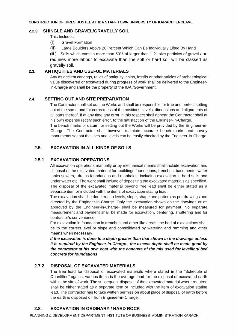
2.2.3. SHINGLE AND GRAVEL/GRAVELLY SOIL
This Includes;
(I) Gravel Formation
(II) Large Boulders Above 20 Percent Which Can Be Individually Lifted By Hand
(iii ) Soils which contain more than 50% of larger than 1-2’’ size particles of gravel and
requires more labour to excavate than the soft or hard soil will be classed as
gravelly soil.
2.3. ANTIQUITIES AND USEFUL MATERIALS
Any as ancient carvings, relics of antiquity, coins, fossils or other articles of archaeological
value discovered or excavated during progress of work shall be delivered to the Engineer-
in-Charge and shall be the property of the IBA /Government.
2.4. SETTING OUT AND SITE PREPARATION The Contractor shall set out the Works and shall be responsible for true and perfect setting
out of the same and for correctness of the positions, levels, dimensions and alignments of
all parts thereof. If at any time any error in this respect shall appear the Contractor shall at
his own expense rectify such error, to the satisfaction of the Engineer-in-Charge.
The bench marks or datum for setting out the Works will be provided by the Engineer-in-
Charge. The Contractor shall however maintain accurate bench marks and survey
monuments so that the lines and levels can be easily checked by the Engineer-in-Charge.
2.5. EXCAVATION IN ALL KINDS OF SOILS
2.5.1 EXCAVATION OPERATIONS
All excavation operations manually or by mechanical means shall include excavation and
disposal of the excavated material for, buildings foundations, trenches, basements, water
tanks sewers, drains foundations and manholes; including excavation in hard soils and
under water etc. The work shall include of depositing the excavated materials as specified.
The disposal of the excavated material beyond free lead shall be either stated as a
separate item or included with the items of excavation stating lead.
The excavation shall be done true to levels, slope, shape and pattern as per drawings and
directed by the Engineer-in-Charge. Only the excavation shown on the drawings or as
approved by the Engineer-in-Charge- shall be measured for payment. No separate
measurement and payment shall be made for excavation, centering, shuttering and for
contractor’s convenience.
For excavation in foundation in trenches and other like areas, the bed of excavations shall
be to the correct level or slope and consolidated by watering and ramming and other
means when necessary.
If the excavation is done to a depth greater than that shown in the drawings unless
it is required by the Engineer-in-Charge-, the excess depth shall be made good by
the contractor at his own cost with the concrete of the mix used for levelling/ bed
concrete for foundations.
2.7.2 DISPOSAL OF EXCAVATED MATERIALS The free lead for disposal of excavated materials where stated in the “Schedule of
Quantities” against various items is the average lead for the disposal of excavated earth
within the site of work. The subsequent disposal of the excavated material where required
shall be either stated as a separate item or included with the item of excavation stating
lead. The contractor has to take written permission about place of disposal of earth before
the earth is disposed of, from Engineer-in-Charge.
2.8. EXCAVATION IN ORDINARY / HARD ROCK
CONSTRUCTION OF GIRLS HOSTEL PHASE-II AT IBA STAFF TOWN UNIVERSITY OF KARACHI ENCLAVE
PLANNING & DEVELOPMENT DEPARTMENT INSTITUTE OF BUSINESS ADMINISTRATION KARACHI
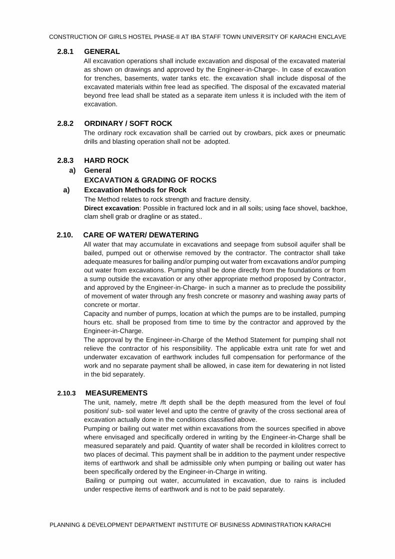
2.8.1 GENERAL
All excavation operations shall include excavation and disposal of the excavated material
as shown on drawings and approved by the Engineer-in-Charge-. In case of excavation
for trenches, basements, water tanks etc. the excavation shall include disposal of the
excavated materials within free lead as specified. The disposal of the excavated material
beyond free lead shall be stated as a separate item unless it is included with the item of
excavation.
2.8.2 ORDINARY / SOFT ROCK The ordinary rock excavation shall be carried out by crowbars, pick axes or pneumatic
drills and blasting operation shall not be adopted.
2.8.3 HARD ROCK
a) General
EXCAVATION & GRADING OF ROCKS
a) Excavation Methods for Rock
The Method relates to rock strength and fracture density.
Direct excavation: Possible in fractured lock and in all soils; using face shovel, backhoe,
clam shell grab or dragline or as stated..
2.10. CARE OF WATER/ DEWATERING All water that may accumulate in excavations and seepage from subsoil aquifer shall be
bailed, pumped out or otherwise removed by the contractor. The contractor shall take
adequate measures for bailing and/or pumping out water from excavations and/or pumping
out water from excavations. Pumping shall be done directly from the foundations or from
a sump outside the excavation or any other appropriate method proposed by Contractor,
and approved by the Engineer-in-Charge- in such a manner as to preclude the possibility
of movement of water through any fresh concrete or masonry and washing away parts of
concrete or mortar.
Capacity and number of pumps, location at which the pumps are to be installed, pumping
hours etc. shall be proposed from time to time by the contractor and approved by the
Engineer-in-Charge.
The approval by the Engineer-in-Charge of the Method Statement for pumping shall not
relieve the contractor of his responsibility. The applicable extra unit rate for wet and
underwater excavation of earthwork includes full compensation for performance of the
work and no separate payment shall be allowed, in case item for dewatering in not listed
in the bid separately.
2.10.3 MEASUREMENTS
The unit, namely, metre /ft depth shall be the depth measured from the level of foul
position/ sub- soil water level and upto the centre of gravity of the cross sectional area of
excavation actually done in the conditions classified above.
Pumping or bailing out water met within excavations from the sources specified in above
where envisaged and specifically ordered in writing by the Engineer-in-Charge shall be
measured separately and paid. Quantity of water shall be recorded in kilolitres correct to
two places of decimal. This payment shall be in addition to the payment under respective
items of earthwork and shall be admissible only when pumping or bailing out water has
been specifically ordered by the Engineer-in-Charge in writing.
Bailing or pumping out water, accumulated in excavation, due to rains is included
under respective items of earthwork and is not to be paid separately.
CONSTRUCTION OF GIRLS HOSTEL AT IBA STAFF TOWN UNIVERSITY OF KARACHI ENCLAVE
PLANNING & DEVELOPMENT DEPARTMENT INSTITUTE OF BUSINESS ADMINISTRATION KARACHI
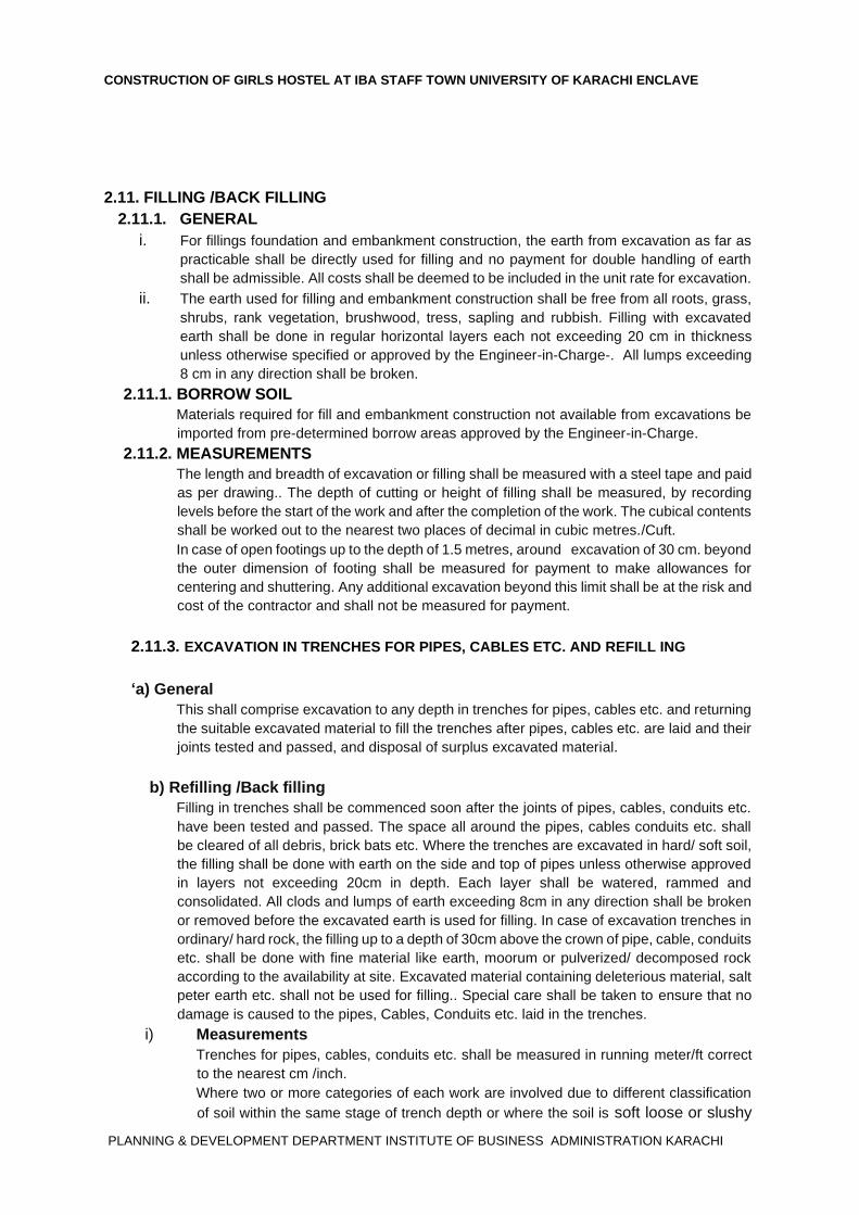
2.11. FILLING /BACK FILLING
2.11.1. GENERAL
i. For fillings foundation and embankment construction, the earth from excavation as far as
practicable shall be directly used for filling and no payment for double handling of earth
shall be admissible. All costs shall be deemed to be included in the unit rate for excavation.
ii. The earth used for filling and embankment construction shall be free from all roots, grass,
shrubs, rank vegetation, brushwood, tress, sapling and rubbish. Filling with excavated
earth shall be done in regular horizontal layers each not exceeding 20 cm in thickness
unless otherwise specified or approved by the Engineer-in-Charge-. All lumps exceeding
8 cm in any direction shall be broken.
2.11.1. BORROW SOIL Materials required for fill and embankment construction not available from excavations be
imported from pre-determined borrow areas approved by the Engineer-in-Charge.
2.11.2. MEASUREMENTS The length and breadth of excavation or filling shall be measured with a steel tape and paid
as per drawing.. The depth of cutting or height of filling shall be measured, by recording
levels before the start of the work and after the completion of the work. The cubical contents
shall be worked out to the nearest two places of decimal in cubic metres./Cuft.
In case of open footings up to the depth of 1.5 metres, around excavation of 30 cm. beyond
the outer dimension of footing shall be measured for payment to make allowances for
centering and shuttering. Any additional excavation beyond this limit shall be at the risk and
cost of the contractor and shall not be measured for payment.
2.11.3. EXCAVATION IN TRENCHES FOR PIPES, CABLES ETC. AND REFILL ING
‘a) General This shall comprise excavation to any depth in trenches for pipes, cables etc. and returning
the suitable excavated material to fill the trenches after pipes, cables etc. are laid and their
joints tested and passed, and disposal of surplus excavated material.
b) Refilling /Back filling Filling in trenches shall be commenced soon after the joints of pipes, cables, conduits etc.
have been tested and passed. The space all around the pipes, cables conduits etc. shall
be cleared of all debris, brick bats etc. Where the trenches are excavated in hard/ soft soil,
the filling shall be done with earth on the side and top of pipes unless otherwise approved
in layers not exceeding 20cm in depth. Each layer shall be watered, rammed and
consolidated. All clods and lumps of earth exceeding 8cm in any direction shall be broken
or removed before the excavated earth is used for filling. In case of excavation trenches in
ordinary/ hard rock, the filling up to a depth of 30cm above the crown of pipe, cable, conduits
etc. shall be done with fine material like earth, moorum or pulverized/ decomposed rock
according to the availability at site. Excavated material containing deleterious material, salt
peter earth etc. shall not be used for filling.. Special care shall be taken to ensure that no
damage is caused to the pipes, Cables, Conduits etc. laid in the trenches.
i) Measurements Trenches for pipes, cables, conduits etc. shall be measured in running meter/ft correct
to the nearest cm /inch.
Where two or more categories of each work are involved due to different classification
of soil within the same stage of trench depth or where the soil is soft loose or slushy
CONSTRUCTION OF GIRLS HOSTEL PHASE-II AT IBA STAFF TOWN UNIVERSITY OF KARACHI ENCLAVE
PLANNING & DEVELOPMENT DEPARTMENT INSTITUTE OF BUSINESS ADMINISTRATION KARACHI
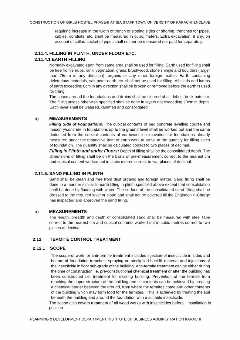
requiring increase in the width of trench or sloping sides or shoring, trenches for pipes,
cables, conduits, etc. shall be measured in cubic meters. Extra excavation, if any, on
account of collar/ socket of pipes shall neither be measured nor paid for separately.
2.11.4. FILLING IN PLINTH, UNDER FLOOR ETC.
2.11.4.1 EARTH FILLING Normally excavated earth from same area shall be used for filling. Earth used for filling shall
be free from shrubs, rank, vegetation, grass, brushwood, stone shingle and boulders (larger
than 75mm in any direction), organic or any other foreign matter. Earth containing
deleterious materials, salt peter earth etc. shall not be used for filling. All clods and lumps
of earth exceeding 8cm in any direction shall be broken or removed before the earth is used
for filling.
The space around the foundations and drains shall be cleared of all debris, brick bats etc.
The filling unless otherwise specified shall be done in layers not exceeding 20cm in depth.
Each layer shall be watered, rammed and consolidated
a) MEASUREMENTS Filling Side of Foundations: The cubical contents of bed concrete levelling course and
masonry/concrete in foundations up to the ground level shall be worked out and the same
deducted from the cubical contents of earthwork in excavation for foundations already
measured under the respective item of earth work to arrive at the quantity for filling sides
of foundation. The quantity shall be calculated correct to two places of decimal.
Filling in Plinth and under Floors: Depth of filling shall be the consolidated depth. The
dimensions of filling shall be on the basis of pre-measurement correct to the nearest cm
and cubical content worked out in cubic metres correct to two places of decimal.
2.11.6. SAND FILLING IN PLINTH Sand shall be clean and free from dust organic and foreign matter. Sand filling shall be
done in a manner similar to earth filling in plinth specified above except that consolidation
shall be done by flooding with water. The surface of the consolidated sand filling shall be
dressed to the required level or slope and shall not be covered till the Engineer-in-Charge
has inspected and approved the sand filling.
a) MEASUREMENTS The length, breadth and depth of consolidated sand shall be measured with steel tape
correct to the nearest cm and cubical contents worked out in cubic metres correct to two
places of decimal.
2.12 TERMITE CONTROL TREATMENT
2.12.1 SCOPE
The scope of work for anti-termite treatment includes injection of insecticide in sides and
bottom of foundation trenches, spraying on stockpiled backfill material and injections of
the insecticide in floor sub-grade of the building. Anti-termite treatment can be either during
the time of construction i.e. pre-constructional chemical treatment or after the building has
been constructed i.e. treatment for existing building. Prevention of the termite from
reaching the super-structure of the building and its contents can be achieved by creating
a chemical barrier between the ground, from where the termites come and other contents
of the building which may form food for the termites. This is achieved by treating the soil
beneath the building and around the foundation with a suitable insecticide.
The scope also covers treatment of all wood works with insecticides before installation in
position.
CONSTRUCTION OF GIRLS HOSTEL AT IBA STAFF TOWN UNIVERSITY OF KARACHI ENCLAVE
PLANNING & DEVELOPMENT DEPARTMENT INSTITUTE OF BUSINESS ADMINISTRATION KARACHI
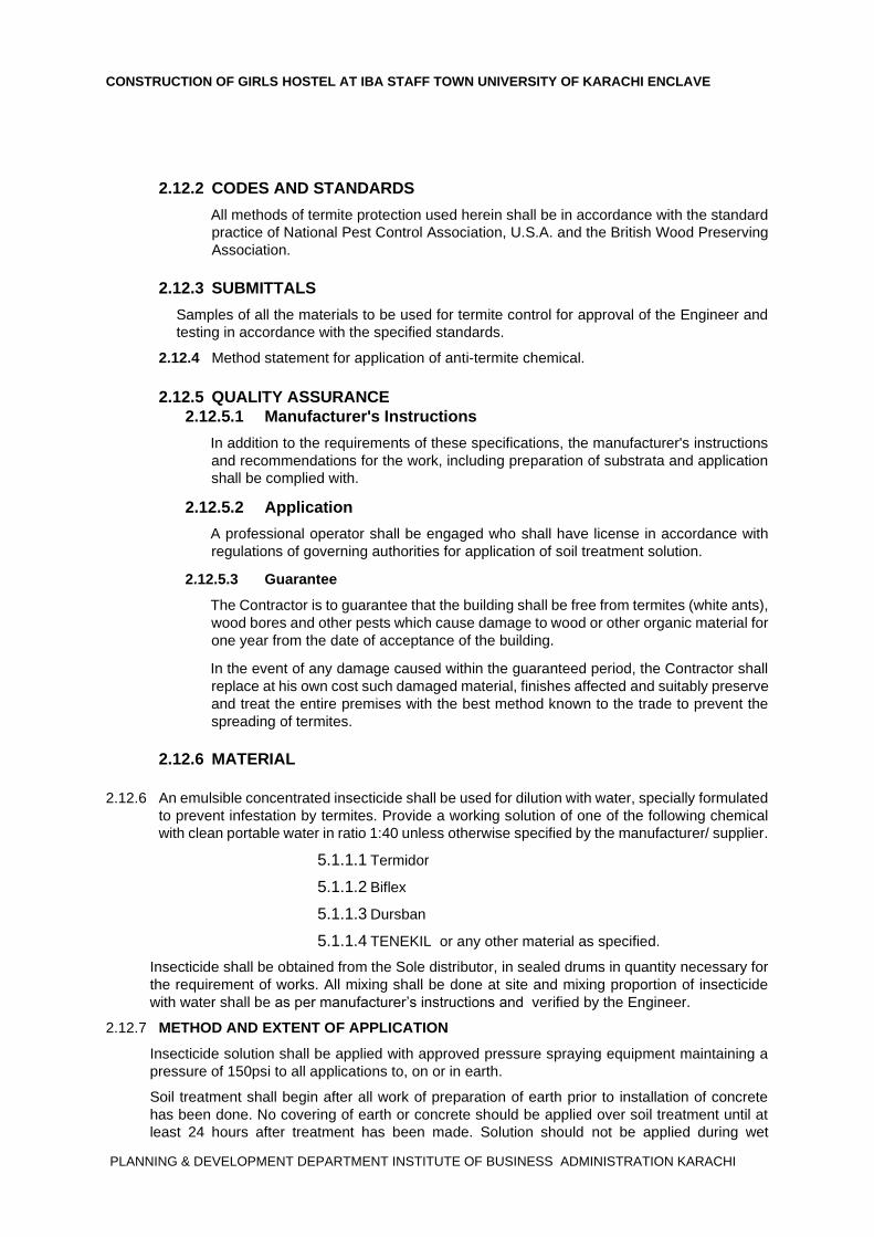
2.12.2 CODES AND STANDARDS
All methods of termite protection used herein shall be in accordance with the standard
practice of National Pest Control Association, U.S.A. and the British Wood Preserving
Association.
2.12.3 SUBMITTALS
Samples of all the materials to be used for termite control for approval of the Engineer and
testing in accordance with the specified standards.
2.12.4 Method statement for application of anti-termite chemical.
2.12.5 QUALITY ASSURANCE 2.12.5.1 Manufacturer's Instructions
In addition to the requirements of these specifications, the manufacturer's instructions
and recommendations for the work, including preparation of substrata and application
shall be complied with.
2.12.5.2 Application
A professional operator shall be engaged who shall have license in accordance with
regulations of governing authorities for application of soil treatment solution.
2.12.5.3 Guarantee
The Contractor is to guarantee that the building shall be free from termites (white ants),
wood bores and other pests which cause damage to wood or other organic material for
one year from the date of acceptance of the building.
In the event of any damage caused within the guaranteed period, the Contractor shall
replace at his own cost such damaged material, finishes affected and suitably preserve
and treat the entire premises with the best method known to the trade to prevent the
spreading of termites.
2.12.6 MATERIAL
2.12.6 An emulsible concentrated insecticide shall be used for dilution with water, specially formulated
to prevent infestation by termites. Provide a working solution of one of the following chemical
with clean portable water in ratio 1:40 unless otherwise specified by the manufacturer/ supplier.
5.1.1.1 Termidor
5.1.1.2 Biflex
5.1.1.3 Dursban
5.1.1.4 TENEKIL or any other material as specified.
Insecticide shall be obtained from the Sole distributor, in sealed drums in quantity necessary for
the requirement of works. All mixing shall be done at site and mixing proportion of insecticide
with water shall be as per manufacturer’s instructions and verified by the Engineer.
2.12.7 METHOD AND EXTENT OF APPLICATION
Insecticide solution shall be applied with approved pressure spraying equipment maintaining a
pressure of 150psi to all applications to, on or in earth.
Soil treatment shall begin after all work of preparation of earth prior to installation of concrete
has been done. No covering of earth or concrete should be applied over soil treatment until at
least 24 hours after treatment has been made. Solution should not be applied during wet
CONSTRUCTION OF GIRLS HOSTEL PHASE-II AT IBA STAFF TOWN UNIVERSITY OF KARACHI ENCLAVE
PLANNING & DEVELOPMENT DEPARTMENT INSTITUTE OF BUSINESS ADMINISTRATION KARACHI
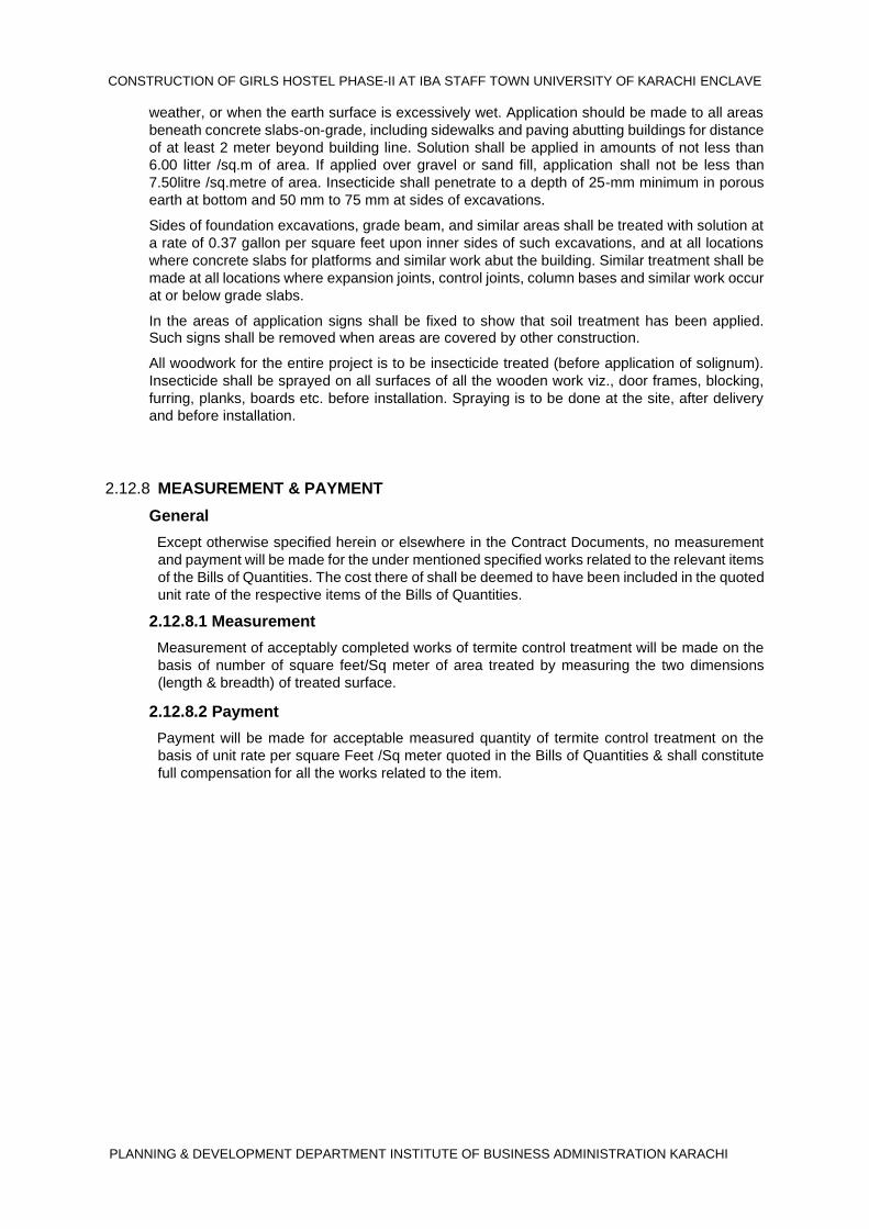
weather, or when the earth surface is excessively wet. Application should be made to all areas
beneath concrete slabs-on-grade, including sidewalks and paving abutting buildings for distance
of at least 2 meter beyond building line. Solution shall be applied in amounts of not less than
6.00 litter /sq.m of area. If applied over gravel or sand fill, application shall not be less than 7.50litre /sq.metre of area. Insecticide shall penetrate to a depth of 25-mm minimum in porous
earth at bottom and 50 mm to 75 mm at sides of excavations.
Sides of foundation excavations, grade beam, and similar areas shall be treated with solution at
a rate of 0.37 gallon per square feet upon inner sides of such excavations, and at all locations
where concrete slabs for platforms and similar work abut the building. Similar treatment shall be
made at all locations where expansion joints, control joints, column bases and similar work occur
at or below grade slabs.
In the areas of application signs shall be fixed to show that soil treatment has been applied. Such signs shall be removed when areas are covered by other construction.
All woodwork for the entire project is to be insecticide treated (before application of solignum).
Insecticide shall be sprayed on all surfaces of all the wooden work viz., door frames, blocking,
furring, planks, boards etc. before installation. Spraying is to be done at the site, after delivery
and before installation.
2.12.8 MEASUREMENT & PAYMENT
General
Except otherwise specified herein or elsewhere in the Contract Documents, no measurement
and payment will be made for the under mentioned specified works related to the relevant items
of the Bills of Quantities. The cost there of shall be deemed to have been included in the quoted
unit rate of the respective items of the Bills of Quantities.
2.12.8.1 Measurement
Measurement of acceptably completed works of termite control treatment will be made on the
basis of number of square feet/Sq meter of area treated by measuring the two dimensions
(length & breadth) of treated surface.
2.12.8.2 Payment
Payment will be made for acceptable measured quantity of termite control treatment on the
basis of unit rate per square Feet /Sq meter quoted in the Bills of Quantities & shall constitute
full compensation for all the works related to the item.
CONSTRUCTION OF GIRLS HOSTEL AT IBA STAFF TOWN UNIVERSITY OF KARACHI ENCLAVE
PLANNING & DEVELOPMENT DEPARTMENT INSTITUTE OF BUSINESS ADMINISTRATION KARACHI
CHAPTER-3. DISMANTLING (DEMOLITION) 3.0 SCOPE
The work shall comprise dismantling/demolishing whole or part of work including all
relevant items consisting of but not limited to , concrete, floorings, roofing and metal
work structural steel as specified and or shown on the drawings. Only such work or
part of works which are designated on the Drawings or by the Engineer to be removed
shall be included in the work to be done under these specifications. When approved by the Engineer, the contractor shall remove the dismantled/works
required to be removed and clear the site, as specified or directed by the Engineer.
3.1. SERVICEABLE AND UNSERVICEABLE MATERIALS
Upon written instructions of Engineer-in-Charge, the Contractor shall make a list of all
such items which in opinion of Engineer-in-Charge can be re-used. The Contractor
shall take such measures to protect these materials / items from damage during
dismantling process. The Contractor shall provide labour and other arrangements to
properly stack / store such items safely until handed over to the Engineer-in-Charge. All unserviceable materials, rubbish etc. shall be disposed off as directed by the Engineer
-in-Charge.
3.2. PRECAUTIONS
a) Before commencement of dismantling/demolition, the Contractor shall prepare
and submit his proposals and program for proceeding with the work for
approval of the Engineer-in-Charge. b) The work should generally be performed in reverse order of the one in which
the structure was constructed. Necessary propping, shoring and or under
pinning shall be provided to ensure the safety of the workers, adjoining work or
property before dismantling and demolishing is taken up and the work shall be
carried out in such a way that no damage is caused to the adjoining work or
property. Temporary enclosures or partitions and necessary scaffolding
wherever specified shall also be provided, as directed by the Engineer-in-
Charge. c) Necessary steps/ precautions should be taken to keep noise and dust nuisance
to a minimum d) No demolition work should be carried out at night especially when the building
or structure to be demolished is in an inhabited area. Screens shall be placed
where necessary to prevent injuries due to falling pieces. Water may be used
to reduce dust while tearing down plaster from brick work. Safety belts shall be
used by labourers while working at higher level to prevent falling from the
structure. First-aid equipment shall be got available at all demolition works of
any magnitude.
3.3. MEASUREMENT AND PAYMENT
All work shall be measured net in the decimal system, as fixed in its place, subject to
the following limits, unless otherwise stated hereinafter in BOQ.
.
CONSTRUCTION OF GIRLS HOSTEL PHASE-II AT IBA STAFF TOWN UNIVERSITY OF KARACHI ENCLAVE
PLANNING & DEVELOPMENT DEPARTMENT INSTITUTE OF BUSINESS ADMINISTRATION KARACHI
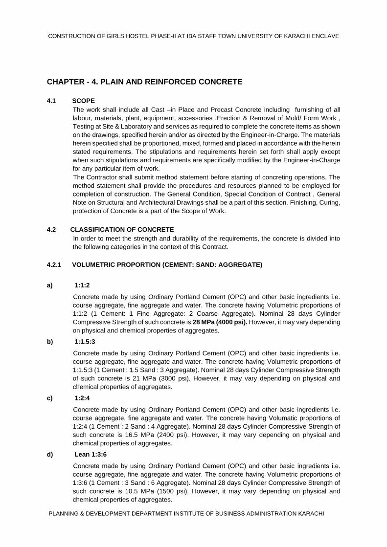
CHAPTER - 4. PLAIN AND REINFORCED CONCRETE
4.1 SCOPE The work shall include all Cast –in Place and Precast Concrete including furnishing of all
labour, materials, plant, equipment, accessories ,Erection & Removal of Mold/ Form Work ,
Testing at Site & Laboratory and services as required to complete the concrete items as shown
on the drawings, specified herein and/or as directed by the Engineer-in-Charge. The materials
herein specified shall be proportioned, mixed, formed and placed in accordance with the herein
stated requirements. The stipulations and requirements herein set forth shall apply except
when such stipulations and requirements are specifically modified by the Engineer-in-Charge
for any particular item of work.
The Contractor shall submit method statement before starting of concreting operations. The
method statement shall provide the procedures and resources planned to be employed for
completion of construction. The General Condition, Special Condition of Contract , General
Note on Structural and Architectural Drawings shall be a part of this section. Finishing, Curing,
protection of Concrete is a part of the Scope of Work.
4.2 CLASSIFICATION OF CONCRETE In order to meet the strength and durability of the requirements, the concrete is divided into
the following categories in the context of this Contract.
4.2.1 VOLUMETRIC PROPORTION (CEMENT: SAND: AGGREGATE)
a) 1:1:2
Concrete made by using Ordinary Portland Cement (OPC) and other basic ingredients i.e.
course aggregate, fine aggregate and water. The concrete having Volumetric proportions of
1:1:2 (1 Cement: 1 Fine Aggregate: 2 Coarse Aggregate). Nominal 28 days Cylinder
Compressive Strength of such concrete is 28 MPa (4000 psi). However, it may vary depending
on physical and chemical properties of aggregates.
b) 1:1.5:3
Concrete made by using Ordinary Portland Cement (OPC) and other basic ingredients i.e.
course aggregate, fine aggregate and water. The concrete having Volumetric proportions of
1:1.5:3 (1 Cement : 1.5 Sand : 3 Aggregate). Nominal 28 days Cylinder Compressive Strength
of such concrete is 21 MPa (3000 psi). However, it may vary depending on physical and
chemical properties of aggregates.
c) 1:2:4
Concrete made by using Ordinary Portland Cement (OPC) and other basic ingredients i.e.
course aggregate, fine aggregate and water. The concrete having Volumatic proportions of
1:2:4 (1 Cement : 2 Sand : 4 Aggregate). Nominal 28 days Cylinder Compressive Strength of
such concrete is 16.5 MPa (2400 psi). However, it may vary depending on physical and
chemical properties of aggregates.
d) Lean 1:3:6
Concrete made by using Ordinary Portland Cement (OPC) and other basic ingredients i.e.
course aggregate, fine aggregate and water. The concrete having Volumetric proportions of
1:3:6 (1 Cement : 3 Sand : 6 Aggregate). Nominal 28 days Cylinder Compressive Strength of
such concrete is 10.5 MPa (1500 psi). However, it may vary depending on physical and
chemical properties of aggregates.

CONSTRUCTION OF GIRLS HOSTEL AT IBA STAFF TOWN UNIVERSITY OF KARACHI ENCLAVE
PLANNING & DEVELOPMENT DEPARTMENT INSTITUTE OF BUSINESS ADMINISTRATION KARACHI
e). Lean 1:4:8
Concrete made by using Ordinary Portland Cement (OPC) and other basic ingredients i.e.
course aggregate, fine aggregate and water. The concrete having Volumetric proportions of
1:4:8 (1 Cement : 4 Sand : 8 Aggregate). Nominal 28 days Cylinder Compressive Strength of
such concrete is 8 MPa (1200 psi). However, it may vary depending on physical and chemical
properties of aggregates. It shall be used for no structural works like floor underlay, lean
concrete etc.
4.3 MATERIALS
4.3.1 CEMENT
a) General
Cement shall be fresh, furnished in sacks or in bulk form as approved by the Engineer-in-
Charge. Unless otherwise permitted, cement from not more than two plants shall be used and
in general, the product of only one plant shall be used in any particular section of the work.
Portland Cement
Portland cement shall be of Pakistan origin as per approved brand and manufacturer and,
shall conform to Pakistan Standard 232 or to British Standard 12 or to ASTM C 150 Type I or
Sulphate Resistant, Type-V or conforming to BS 4027 or ASTM C-150 may also be used in
certain parts of the Works as specified or directed by the Engineer-in-Charge. The slag cement
conforming to BS 146 or ASTM C 595 may also be used with prior approval of Engineer-In
charge.
The mix will normally be designed by the Contractor to have:
i) A mortar bar reduction not less than 75% at 14 days when tested in accordance with
ASTM C441,
ii) A heat of hydration of less than 70 calories per gram of Pozzolanic materials (blast-furnace
slag or fly ash or calcined clay) at 7 days when tested in accordance with ASTM C186.
b. STORAGE OF CEMENT
Cement shall be stored at Site in dry, weather tight and properly ventilated stores. All storage
facilities shall be subject to approval and shall be such as to permit easy access for inspection
and identification of each consignment
c. Sampling, Cement Usage
Sampling of cement shall be in accordance with AASHTO T 127. Mill Test Certificates shall
accompany delivery of the material to the work.
4.3.2 AGGREGATES
a) General Requirements
i) Cleanliness.
The aggregates should be free from injurious amount of clay, salt, alkali, organic matter, shale,
loam, soft flaky particles and other deleterious substance. Aggregate when not obtained in
clean state are invariably washed before use.
Shape.
Crushed aggregate should be sharp, angular and of hard grains, approximately cubical in size
and those obtained from natural source be rounded, well-shaped and of hard grains. The fine
aggregate should be such shape that it covers the maximum voids between coarse
aggregates.
ii) Size.
To obtain high crushing strength of concrete the maximum size of aggregate should be as
large as conveniently possible but it should not be normally greater than one- fourth in plain
concrete and one-fifth in reinforced concrete of the smallest dimension in the structure..
Similarly, the nominal maximum size of the aggregates shall not be larger than one fifth of the
CONSTRUCTION OF GIRLS HOSTEL PHASE-II AT IBA STAFF TOWN UNIVERSITY OF KARACHI ENCLAVE
PLANNING & DEVELOPMENT DEPARTMENT INSTITUTE OF BUSINESS ADMINISTRATION KARACHI
narrowest dimension of the finished wall or slab, or larger than three fourth of the minimum
clear spacing between the reinforcing steel and embedment.
iii) Grading.
Aggregate are required to be graded into different size and mixed in desired proportions for
producing mortar and concrete of specified quality and strength. The aggregates are graded
into minimum of cement per unit volume to give required strength. The aggregates are graded
into nominal size by sieving and their fineness Modulus determined. A smaller value of the
fineness modulus indicated the presence of large proportions of fine particles.
iv) Durability.
Aggregates should be hard to resist grading actions; tough to withstand impact and sound to
remain whole during changes in weather conditions. The soundness test is carried out by
means of Sodium Sulphate Test. Crushing strength test is carried out to determine the
strength. The specific gravity test is required to determine the density.
vi) Storage.
Storing on dusty, muddy or grassy spots, should be avoided. Aggregate which has
deteriorated or which has been contaminated shall not be used for concrete
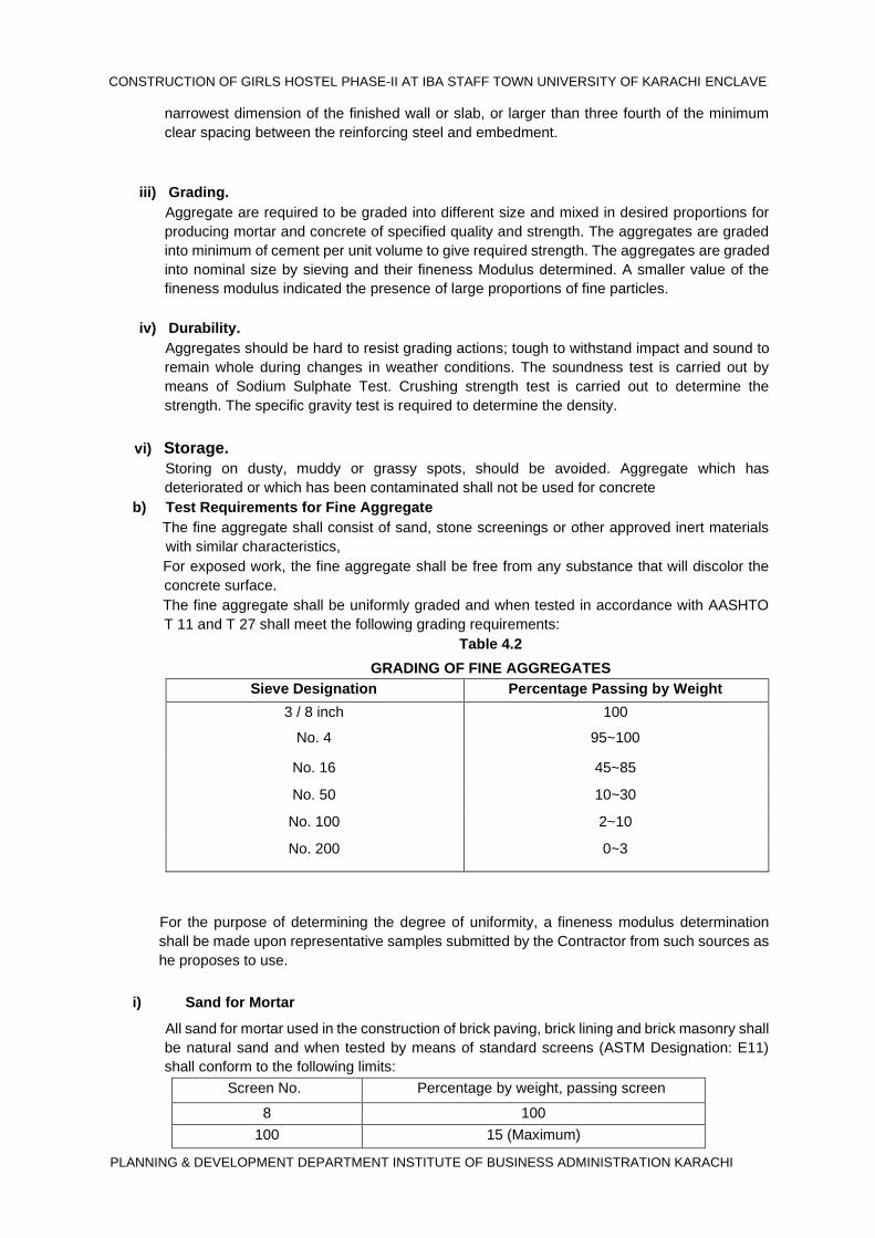
b) Test Requirements for Fine Aggregate The fine aggregate shall consist of sand, stone screenings or other approved inert materials
with similar characteristics, For exposed work, the fine aggregate shall be free from any substance that will discolor the
concrete surface. The fine aggregate shall be uniformly graded and when tested in accordance with AASHTO
T 11 and T 27 shall meet the following grading requirements: Table 4.2
GRADING OF FINE AGGREGATES Sieve Designation Percentage Passing by Weight
3 / 8 inch 100
No. 4 95~100
No. 16 45~85
No. 50 10~30
No. 100 2~10
No. 200 0~3
For the purpose of determining the degree of uniformity, a fineness modulus determination
shall be made upon representative samples submitted by the Contractor from such sources as
he proposes to use.
i) Sand for Mortar
All sand for mortar used in the construction of brick paving, brick lining and brick masonry shall
be natural sand and when tested by means of standard screens (ASTM Designation: E11)
shall conform to the following limits:
Screen No. Percentage by weight, passing screen
8 100
100 15 (Maximum)
CONSTRUCTION OF GIRLS HOSTEL AT IBA STAFF TOWN UNIVERSITY OF KARACHI ENCLAVE
PLANNING & DEVELOPMENT DEPARTMENT INSTITUTE OF BUSINESS ADMINISTRATION KARACHI
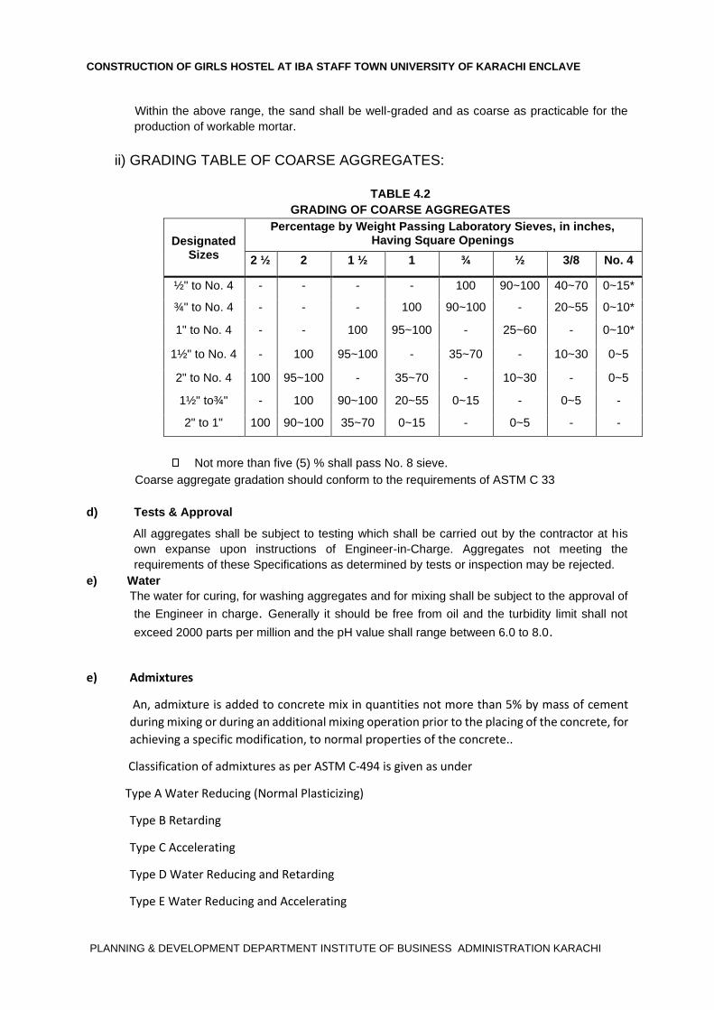
Within the above range, the sand shall be well-graded and as coarse as practicable for the
production of workable mortar.
ii) GRADING TABLE OF COARSE AGGREGATES:
TABLE 4.2 GRADING OF COARSE AGGREGATES
Designated Sizes
Percentage by Weight Passing Laboratory Sieves, in inches, Having Square Openings
2 ½ 2 1 ½ 1 ¾ ½ 3/8 No. 4
½" to No. 4 - - - - 100 90~100 40~70 0~15*
¾" to No. 4 - - - 100 90~100 - 20~55 0~10*
1" to No. 4 - - 100 95~100 - 25~60 - 0~10*
1½" to No. 4 - 100 95~100 - 35~70 - 10~30 0~5
2" to No. 4 100 95~100 - 35~70 - 10~30 - 0~5
1½" to¾" - 100 90~100 20~55 0~15 - 0~5 -
2" to 1" 100 90~100 35~70 0~15 - 0~5 - -
Not more than five (5) % shall pass No. 8 sieve.
Coarse aggregate gradation should conform to the requirements of ASTM C 33
d) Tests & Approval
All aggregates shall be subject to testing which shall be carried out by the contractor at his
own expanse upon instructions of Engineer-in-Charge. Aggregates not meeting the
requirements of these Specifications as determined by tests or inspection may be rejected.
e) Water The water for curing, for washing aggregates and for mixing shall be subject to the approval of
the Engineer in charge. Generally it should be free from oil and the turbidity limit shall not
exceed 2000 parts per million and the pH value shall range between 6.0 to 8.0.
e) Admixtures
An, admixture is added to concrete mix in quantities not more than 5% by mass of cement
during mixing or during an additional mixing operation prior to the placing of the concrete, for
achieving a specific modification, to normal properties of the concrete..
Classification of admixtures as per ASTM C-494 is given as under
Type A Water Reducing (Normal Plasticizing)
Type B Retarding
Type C Accelerating
Type D Water Reducing and Retarding
Type E Water Reducing and Accelerating

CONSTRUCTION OF GIRLS HOSTEL PHASE-II IBA STAFF TOWN UNIVERSITY OF KARACHI ENCLAVE
PLANNING & DEVELOPMENT DEPARTMENT INSTITUTE OF BUSINESS ADMINISTRATION KARACHI
Approval Required
Admixtures, including air-entraining admixtures, foaming chemicals and water-reducing
admixtures, shall not be used, except with the prior approval of the Engineer-in-Charge. Before
using admixtures in concreting process, trial mixes shall be made to determine the mix design
by laboratory testing. Measurement Where so specified, Admixture of approved quality shall be added to the concrete mixture
in accordance with the manufacturer’s specification stating the quantity in litres or kg as
specified and will be paid for separately as per item of BOQ or as approved.
f) Water stops
g) PVC Water-stops
Except as otherwise shown on the Drawings, water-stops shall be installed with an
approximately equal width of material embedded in concrete on each side of the joint. Water
stops shall be sealed to other cut off systems as shown on the Drawings or as directed by the
Engineer-in-Charge. The PVC Stopper confirm the following Properties.
Table 4.3 Physical Characteristics of PVC Waterstop
Physical Characteristics Test Method Typical Values
Ultimate Elongation ASTM D 638 (CRD C 573) 350 % min
Tensile Strength ASTM D 638 (CRD C 573)
1750 psi (12.07 Mpa) min
Low Temperature Brittleness ASTM D 746 (CRD C 570)
No Failure @ - 35 F (-37 C)
Stiffness in Flexure ASTM D 747 (CRD C 571)
400 psi (2.76 Mpa) min
Specific gravity ASTM D 792 1.37 max
Hardness, Shore A ASTM D 2240 70 - 80
g) Joint Sealing Compound
Sealing compound shall be either of the cold application type conforming to ASTM D-1850 or
of the single or multiple component type or of the hot poured type conforming to the
requirements of ASTM D-1190 or their equivalents as specified on drawing or as per approval
Measurements
CONSTRUCTION OF GIRLS HOSTEL PHASE-II IBA STAFF TOWN UNIVERSITY OF KARACHI ENCLAVE
PLANNING & DEVELOPMENT DEPARTMENT INSTITUTE OF BUSINESS ADMINISTRATION KARACHI
The measurement of the finished work shall be measured as per BOQ and be paid as per
approved.
4.1.2 PROPORTIONING & MIXING OF CONCRETE MIX
4.1.2.1 PROPORTIONING OF INGREDIENTS a) The proportioning of the concrete for its ingredients namely cement, sand and coarse
aggregates is specified for BOQ items on volume basis and on weight basis for the specified
use. The proportioning and batching of concrete mix shall accordingly be done on volume
basis. Mix proportions and water- cement ratio shall be so determined as to produced concrete having
suitable workability, density, im-permeability, durability or strength. The contractor shall not be
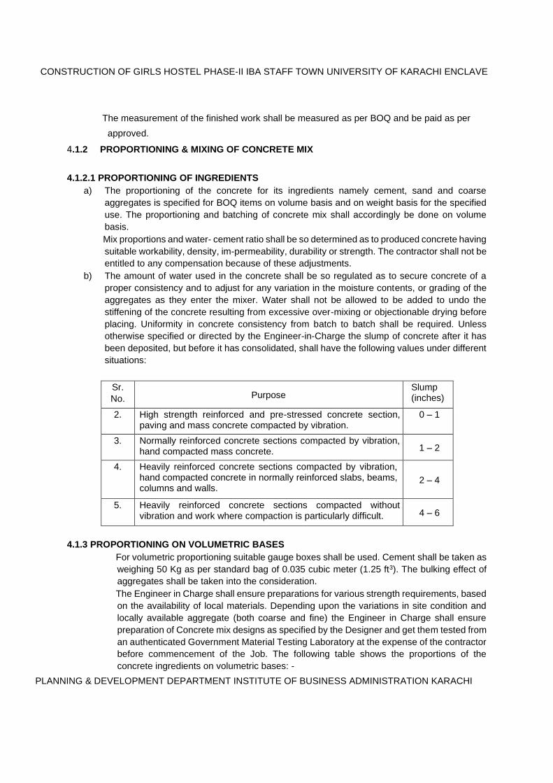
entitled to any compensation because of these adjustments. b) The amount of water used in the concrete shall be so regulated as to secure concrete of a
proper consistency and to adjust for any variation in the moisture contents, or grading of the
aggregates as they enter the mixer. Water shall not be allowed to be added to undo the
stiffening of the concrete resulting from excessive over-mixing or objectionable drying before
placing. Uniformity in concrete consistency from batch to batch shall be required. Unless
otherwise specified or directed by the Engineer-in-Charge the slump of concrete after it has
been deposited, but before it has consolidated, shall have the following values under different
situations:
Sr. No. Purpose
Slump (inches)
2. High strength reinforced and pre-stressed concrete section, paving and mass concrete compacted by vibration.
0 – 1
3. Normally reinforced concrete sections compacted by vibration, hand compacted mass concrete. 1 – 2
4. Heavily reinforced concrete sections compacted by vibration, hand compacted concrete in normally reinforced slabs, beams, columns and walls.
2 – 4
5. Heavily reinforced concrete sections compacted without vibration and work where compaction is particularly difficult. 4 – 6
4.1.3 PROPORTIONING ON VOLUMETRIC BASES For volumetric proportioning suitable gauge boxes shall be used. Cement shall be taken as
weighing 50 Kg as per standard bag of 0.035 cubic meter (1.25 ft3). The bulking effect of
aggregates shall be taken into the consideration. The Engineer in Charge shall ensure preparations for various strength requirements, based
on the availability of local materials. Depending upon the variations in site condition and
locally available aggregate (both coarse and fine) the Engineer in Charge shall ensure
preparation of Concrete mix designs as specified by the Designer and get them tested from
an authenticated Government Material Testing Laboratory at the expense of the contractor
before commencement of the Job. The following table shows the proportions of the
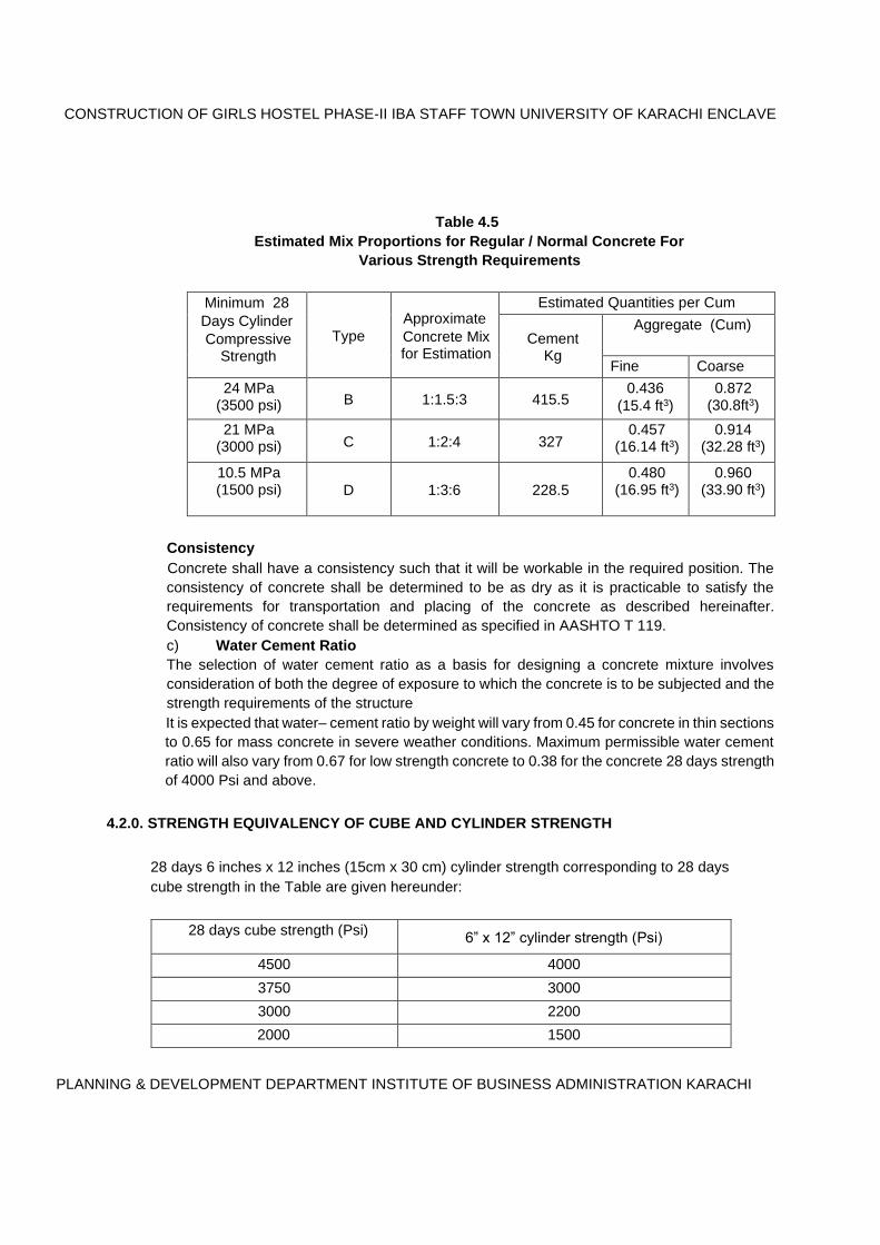
concrete ingredients on volumetric bases: -
CONSTRUCTION OF GIRLS HOSTEL PHASE-II IBA STAFF TOWN UNIVERSITY OF KARACHI ENCLAVE
PLANNING & DEVELOPMENT DEPARTMENT INSTITUTE OF BUSINESS ADMINISTRATION KARACHI
Table 4.5 Estimated Mix Proportions for Regular / Normal Concrete For
Various Strength Requirements
Minimum 28 Days Cylinder Compressive
Strength Type
Approximate Concrete Mix for Estimation
Estimated Quantities per Cum
Cement Kg
Aggregate (Cum)
Fine Coarse
24 MPa (3500 psi) B 1:1.5:3 415.5
0.436 (15.4 ft3)
0.872 (30.8ft3)
21 MPa (3000 psi) C 1:2:4 327
0.457 (16.14 ft3)
0.914 (32.28 ft3)
10.5 MPa (1500 psi) D 1:3:6 228.5
0.480 (16.95 ft3)
0.960 (33.90 ft3)
Consistency Concrete shall have a consistency such that it will be workable in the required position. The
consistency of concrete shall be determined to be as dry as it is practicable to satisfy the
requirements for transportation and placing of the concrete as described hereinafter.
Consistency of concrete shall be determined as specified in AASHTO T 119. c) Water Cement Ratio
The selection of water cement ratio as a basis for designing a concrete mixture involves
consideration of both the degree of exposure to which the concrete is to be subjected and the
strength requirements of the structure It is expected that water– cement ratio by weight will vary from 0.45 for concrete in thin sections
to 0.65 for mass concrete in severe weather conditions. Maximum permissible water cement
ratio will also vary from 0.67 for low strength concrete to 0.38 for the concrete 28 days strength
of 4000 Psi and above.
4.2.0. STRENGTH EQUIVALENCY OF CUBE AND CYLINDER STRENGTH
28 days 6 inches x 12 inches (15cm x 30 cm) cylinder strength corresponding to 28 days
cube strength in the Table are given hereunder:
28 days cube strength (Psi) 6” x 12” cylinder strength (Psi)
4500 4000
3750 3000
3000 2200
2000 1500
CONSTRUCTION OF GIRLS HOSTEL PHASE-II IBA STAFF TOWN UNIVERSITY OF KARACHI ENCLAVE
PLANNING & DEVELOPMENT DEPARTMENT INSTITUTE OF BUSINESS ADMINISTRATION KARACHI
4.2.1 HAND MIXING
No Hand Mix is allowed for Structural Concrete. However for non Structural Concrete Hand mixing shall not be carried out with the approval of the Engineer in Charge.
Unless otherwise specified or directed, hand mixing shall be done on the following lines:
4.2.2 MACHINE MIXING
Concrete Mixtures
Concrete mixers may be of the revolving drum or the revolving blade type and the mixing drum
or blades shall be operated uniformly at the mixing speed recommended by the manufacturer.
The pick-up and throw-over blades of mixer shall be restored or replaced when any part or
sections is worn two and a half (21/2) cm or below than the original height of the manufacturer’s
design. Mixers and agitators, which have an accumulation of hard concrete or mortar, shall not
be used
All concrete shall be mixed for a period of not less than one and a half (11/2) minutes after all
materials, including water, are in the mixer. During the period of mixing, the mixer shall operate
at the speed for which it has been designed.
The first batch of concrete material placed in the mixer shall contain cement, sand and water
in excess to the requirement of mix, to ensure that the drum does not extract mortar from the
mix changing its design characteristics. When mixing is to stop for a period of one hour or
more, the mixer shall be thoroughly cleaned.
4.2.3 Plant Mixing
At central mixing plant, batches shall be discharged from the weighing hopper into the mixer
either directly by gravity or by an elevating container large enough to contain the batch. The
plant shall be arranged to ensure that there is no loss of cement during transfer from weighing
hopper to the mixer drum. The mixing time shall neither be less than fifty (50) second, nor
more than ninety (90) seconds. The plasticizer, accelerator or retarder or water-reducing admixture, if required, shall be fed
separately at the rate recommended by the manufacture, or as established by laboratory trials.
4.2.4 CONVEYING
Concrete shall be conveyed from mixer to the place of final deposit as rapidly as practicable,
by methods which will prevent segregation or loss of ingredients and in accordance with
ACI304. There shall be no vertical drop greater than one metre except where the use of such
equipment is approved in writing by the Engineer-in-Charge, in advance of any use
4.2.5 PLACING
CONSTRUCTION OF GIRLS HOSTEL PHASE-II IBA STAFF TOWN UNIVERSITY OF KARACHI ENCLAVE
PLANNING & DEVELOPMENT DEPARTMENT INSTITUTE OF BUSINESS ADMINISTRATION KARACHI
(a) General
(I) Concrete shall be placed only in presence of the Engineer-in-charge or his
representative. (II) Any concrete which has become so stiff that proper placing cannot be assured shall
be wasted and no payment shall be made to the contractor for such wasted concrete,
Concrete shall not be placed during rains unless proper protection is afforded. (III) Each layer of concrete shall be consolidated to the maximum practicable density so
that it is free from pockets of aggregates, and close snugly against all surface of forms
and embedded materials. (IV) In consolidating each layer of concrete the vibrating head of the vibrator shall be
secured to form or allowed to penetrate and re vibrate the concrete in the upper portion
of the underlying layer. All concrete shall be consolidated with electric or pneumatic
power-driven vibrators having a frequency of not less than 5000 cycles per minute. (V) Special care shall be taken in placing concrete when it has to be dropped from a
height, especially when reinforcement is in the way, and every effort shall be made to
reduce this drop to the minimum. In any case the drop shall not be more than 5 feet. . (VI) Ducts, recess, rebates and holes shall be moulded in the concrete during placing at
their proper position as shown on the drawing or as directed by the Engineer-incharge.
4.2.6 Time Interval Between Mixing and Placing
Concrete mixed in stationary mixers and transported by non-agitating equipment shall be
placed within thirty minutes after it has been mixed, unless otherwise authorized. When a truck
mixer or an agitator is used for transporting concrete, the concrete shall be delivered to the
site of the work and discharge shall be completed within 1.5 hours after introduction of the
cement to the aggregates. The concrete shall be placed within 30 minutes after it has been
discharged. In all cases, concrete shall be placed and compacted well within the initial setting
time.
4.2.7 Placing Temperature Placing temperature unless otherwise approved by the Engineer-in-Charge shall conform to
the requirements herein specified for thin, moderate and mass sections. Concrete shall be
placed at temperatures as follows: a)THIN SECTIONS: Concrete for thin sections shall be delivered to the forms at a temperature in excess of 30oC.
Except as otherwise determined by the Engineer-in-Charge, sections to which this provision
shall apply shall be less than 20 inches (50 cms) in thickness.
b. MODERATE SECTIONS:
CONSTRUCTION OF GIRLS HOSTEL PHASE-II IBA STAFF TOWN UNIVERSITY OF KARACHI ENCLAVE
PLANNING & DEVELOPMENT DEPARTMENT INSTITUTE OF BUSINESS ADMINISTRATION KARACHI
Concrete for moderate sections shall have a temperature of not more than 21oC when placed.
A moderate section will be one that is greater than twenty inches (fifty centimetres) but less
than 40 inches (one metre) in thickness. c.MASS CONCRETE SECTIONS:
Concrete having a measure of 40 inches (one metre) or more in thickness shall have a
temperature not exceeding 18oC.
4.2.8. Placing Concrete through Reinforcement In placing concrete through reinforcement, care shall be taken that no segregation of the
coarse aggregate occurs. In certain cases, like the bottom of beams and slabs, the congestion of steel near the forms
may make placing difficult. In such cases, as decided by the Engineer-in-Charge, a layer of
mortar of a composition compatible with the required concrete strength shall be first deposited
to cover the surface to a depth of 15mm.
4.2.9 Vibration of Concrete
Recommended Practice given in ACI 309 shall be followed for concrete consolidation.. The
duration of vibrations shall be limited to that necessary to produce satisfactory consolidation.
Excessive surface working will not be permitted.
4.3.0. EXPANSION, CONTRACTION AND CONSTRUCTION JOINTS 4.3.1 Expansion and Contraction Joints
Expansion and contraction joints shall be provided at the locations indicated and according to
the details shown on the Drawings. Where indicated on the Drawings, expansion joint filler joint sealing compound, GI, Aluminium
& Copper sheets shall be installed using materials of the type and quality indicated. 4.3.2. Construction Joints General:
As soon as a lift is completed, the top surface of concrete and reinforcing dowels shall be
immediately and carefully protected from any condition that may damage the concrete surface
and the dowels. 4.3.3 Cleaning of Joints :
Horizontal construction joints on lifts with relatively open and accessible surfaces shall be
prepared for receiving the next lift by cleaning with either wet sandblasting or by air-water
cutting. 4.3.4. Vertical Joints:
Vertical construction joints shall be prepared similar to the horizontal construction joints. Where
allowed by the Engineer-in-Charge,
4.3.5 Method of Measurement The measurement shall be taken up to two places of decimal stating the depth and width of
joint as per unit mention in BOQ and paid as per rates agreed..
CONSTRUCTION OF GIRLS HOSTEL PHASE-II IBA STAFF TOWN UNIVERSITY OF KARACHI ENCLAVE
PLANNING & DEVELOPMENT DEPARTMENT INSTITUTE OF BUSINESS ADMINISTRATION KARACHI
4.4.0 CURING OF CONCRETE
a) General All concrete including concrete repair work shall be cured by an approved method or
combination of methods in accordance with ACI 308. Means shall be provided for the
protection of concrete from the sun, drying winds and traffic until the specified curing has been
completed. Horizontal concrete surface cured with water shall be kept wet for at least 14 consecutive days
or as specified on drawing immediately following placement.
Unless otherwise specified, the curing of vertical surface shall be done initially by leaving the
forms in place, hanging canvas or hessian cloth over the completed work and keeping it wet
or by covering plastic sheet or membrane up to the period specified.. 4.4.1. Methods of Curing
a.) Moist Curing
Concrete shall be moist-cured maintaining all surfaces continuously (not periodically) wet for
days specified immediately following the placing or until covered with fresh concrete. Water for
curing shall comply with the applicable requirements . Horizontal construction joints and
finished horizontal surfaces cured with sand shall be covered with a minimum uniform
thickness of 5 cm of sand and kept continuously saturated with water.
b) Curing Compound Method An approved curing compound conforming to ASTM C-309 shall be applied in accordance with
the manufacturer's recommendations immediately after any water sheen which may develop
after finishing has disappeared from the concrete surface.
4.4.2 REPAIR OF CONCRETE
a) General Concrete that is damaged from any cause; concrete that is honeycombed, fractured, or
otherwise defective; and concrete which, because of excessive surface depressions, must be
excavated and built up to bring the surface to the prescribed lines; shall be removed and
replaced with dry pack mortar, or concrete, as hereinafter specified. The Contractor shall keep
the Engineer-in-Charge advised as to when repair of concrete will be performed
Surface finishes of repaired areas: The Contractor shall correct all imperfections on the concrete surface as necessary to produce
surfaces that conform to the requirements specified for the adjacent area. Fins and
encrustations shall be neatly removed from the surfaces.
4.4.3 FINISHES AND FINISHING
a) General Allowable deviations from plumb or level and from the alignment, profile grades and
dimensions shown on the Drawings or specified. Tolerances are defined as tolerances and
are to be distinguished from irregularities in finish as described herein. The classes of finish
and the requirements for finishing of concrete surfaces shall generally be as specified herein
CONSTRUCTION OF GIRLS HOSTEL PHASE-II IBA STAFF TOWN UNIVERSITY OF KARACHI ENCLAVE
PLANNING & DEVELOPMENT DEPARTMENT INSTITUTE OF BUSINESS ADMINISTRATION KARACHI
or as indicated on the Drawings. Finishing of concrete surfaces shall be performed only by
workmen who are skilled concrete finishers.
b) Ordinary Finish (OF) Ordinary finish (OF) applies to surfaces upon or against which fill material or concrete is to be
placed.
c) Rough Concrete Finish (RC) Rough concrete finish (RC) applies to surfaces which are intended to receive tiles, metallic
lining or other applications as indicted on the Drawings..
d) Ordinary Slab Finish (OS) Ordinary slab finish (OS) applies to floor surfaces which are not intended to receive any floor
coverings.
Ordinary surface form finish will follow AASHTO-SS-8.12.2. Non-shrinkable mortar will be used.
e) Fair Faced Finish (FF) Fair Finish (FF) shall be applied to all exposed surfaces of walls and ceilings which are not to
be covered by any other finish.
4.4.4 Surface Rendering All faces of concrete that are to come in contact with back fill or pavement materials, shall be
applied two coats of hot bitumen of approved quality, before placing any material around
concrete.
4.4.5 Cracks
If cracks, which in the opinion of the Engineer in Charge may be detrimental to the stability,
strength and durability of the construction, develop in concrete construction, the Contractor at
his own expense shall test the structure. If under such test loads the cracks develop further,
the Contractor shall dismantle the construction, carry away the debris, replace the construction
and carry out all consequential work thereto.
If any cracks develop in the concrete construction, which in the opinion of the Engineer in
Charge, are not detrimental to the stability of the construction, the Contractor at his own
expense shall grout the cracks with epoxy grout or with other better composition as directed
by Engineer In Charge and also at his own expense and risk shall make good to the satisfaction
of the Engineer in charge all other works such as plaster, moulding, surface finish, which in
the opinion of the Engineer in Charge have suffered damage. 4.4.6 Defective Concrete
Badly executed work not conforming to requirements shall be removed wholly and re-executed at
Contractor’s cost and shall not be incorporated in the works. No plastering or repairs will be
allowed to concrete. Decision of Engineer in Charge will be binding on the Contractor.
CONSTRUCTION OF GIRLS HOSTEL PHASE-II IBA STAFF TOWN UNIVERSITY OF KARACHI ENCLAVE
PLANNING & DEVELOPMENT DEPARTMENT INSTITUTE OF BUSINESS ADMINISTRATION KARACHI
4.5.0 READY MIX CONCRETE
4.5.1 1. Scope
This specification covers ready-mixed concrete manu-factured and delivered to a purchaser in a
freshly mixed and unhardened state as hereinafter specified. Requirements for quality of concrete
shall be as hereinafter specified. This specification does not cover the placement, consolidation,
curing, or protection of the concrete after delivery to the SITE.
The values stated in either SI units, shown in brackets,or inch-pound units are to be regarded
separately as standard. The values stated in each system may not be exact equivalents ;therefore,
each system shall be used independently of the other.
The product supplied shall be in compliance with ASTM and ACI specifications.
In the absence of designated applicable specifications covering requirements for quality of materials,
the following specifications shall govern:
a)Cement
—Cement shall conform to Specification C 150, Specification C 595/C 595M,
b. ) Aggregates
—Aggregates shall conform to Specification C 33 spec. C 330 if light wt. conc
C ) Water
The mixing water shall be clear and apparently clean.
4.5.2. BATCH TICKET INFORMATION
1The manufacturer of the concrete shall furnish with each batch of concrete before unloading at the
site, a delivery ticket on which is printed, stamped, or written, information concerning said concrete as
follows
a) Name of ready-mix batch plant,
b) Serial number of ticket,
c) Date,
d) Truck number,
e) Name of purchaser
f) Specific designation of job (name and location),
g) Specific class or designation of the concrete in conformance with that employed in job
specifications,
h) Amount of concrete in cubic ft (or cubic metres)
i) Time loaded or of first mixing of cement and aggregates, and
j) Water added by receiver of concrete and his initials.
k) Additional information for certification purposes as designated by the purchaser and required by
the job specifications shall be furnished when requested; such information as
l) Reading of revolution counter at the first addition of water
m) Type and brand, and amount of cement,
n) Type and brand, and amount of admixtures,
o) Information necessary to calculate the total mixing water added by the producer. Total mixing
water.
CONSTRUCTION OF GIRLS HOSTEL PHASE-II IBA STAFF TOWN UNIVERSITY OF KARACHI ENCLAVE
PLANNING & DEVELOPMENT DEPARTMENT INSTITUTE OF BUSINESS ADMINISTRATION KARACHI
4.6.0 TESTING OF COMPRESSIVE STRENGTH
Concrete compressive strength requirements consist of a minimum strength at the age of
twenty-eight (28) days and the minimum strength that must be attained before various loads or
stresses are applied to the concrete. The compressive strength of concrete will be determined from test cylinders /CUBE ( As
specified ), which have been fabricated from concrete sampled and tested in accordance with
AASHTO T 23 and T 22. A set of six (6) cylinders /Cube shall be taken from each fifty (50) cu m of each class of concrete
or fraction thereof placed each day, three (3) of the six (6) cylinders to be tested after seven
(7) days and three (3) after twenty-eight (28) days.
a) The minimum average twenty-eight (28) days’ test result of all samples tested at
any time shall be the specified twenty-eight (28) days’ strength.
b) No individual samples tested after 28 days shall show a test result lower than
eighty-five (85) % of the required twenty-eight (28) days. .
In case, seven (7) days’ strength shows less than seventy (70) % of the twenty-eight (28) days’
strength (in case of type-I cement), Engineer in Charge may stop further work on that particular
portion of concrete, unless twenty-eight (28) days’ strength gives satisfactory results
4.7.0 Rejection of Concrete If above test result fails to comply with the requirements, concrete or that particular pour will
be rejected and removed as directed by the Engineer in Charge.
4.8.0 CONCRETE FORM WORK
4.8.1 GENERAL The work shall include design, erecting, supporting, bracing and maintaining form work so that
it will safely and rigidly support all vertical and lateral loads encountered during construction.
The extent of formwork is indicated by the concrete work shown on the Drawings. Unless otherwise specified, no separate measurement or payment shall be made for
“Providing Erection and Removal of Formwork” as specified herein, as all cost thereof shall be
considered to be included in the Contract unit prices for the various concrete items requiring
formwork. 4.8.2 SUBMITTALS
The Contractor shall submit the following to the Engineer-in-Charge for his information/review:
a) FORM WORK SAMPLE The Contractor shall inform and submit the sample of form work material and supporting
scaffolding / wooden supports which he intends to use at site and upon approval the form work
shall be used .

CONSTRUCTION OF GIRLS HOSTEL PHASE-II IBA STAFF TOWN UNIVERSITY OF KARACHI ENCLAVE
PLANNING & DEVELOPMENT DEPARTMENT INSTITUTE OF BUSINESS ADMINISTRATION KARACHI
b) Shop Drawings Shop Drawings for fabrication and erection of architectural finished concrete surfaces as
shown on the Drawings or specified. Design of formwork for structural stability and sufficiency
is the Contractor's responsibility.
4.8.3. FORM MATERIALS a) Form liners for Plain Concrete Finish TIMBER/PLYWOOD:
New Plywood 19 mm or timber planks ( PARTAL) 25 mm thick with continuous support for
edges parallel to framing shall be provided. Timber form shall be will seasoned and free of
loose knots. Re-use of Wood Forms: Projecting nails shall be withdrawn, concrete cleaned off, re-oiling done and Engineer-in
Charge’s approval obtained before re-using the wood forms. The steel formwork surface in contact with concrete shall be free of rust.
b) Form Ties Form ties shall be snap ties. Sample for Engineer in Charge approval shall be submitted before
ordering. Spacing of ties and the rate of placement of concrete shall be consistent with the
strength of ties. The Contractor must obtain approval prior to use of any special ties for metal
forms. c) Form Coatings
Commercial formulation form-coating compounds shall be provided that will not bond with,
stain, nor adversely affect concrete surfaces, and will not impair subsequent treatment of
concrete surfaces requiring bond, painting or adhesion nor impede the wetting of surfaces to
be cured with water or curing compounds.
4.8.4. INSTALLATION
a) General Forms shall be so constructed that the tolerances specified in ACI 347.203.1 are met.
Openings, offsets, chamfers, blocking and other features as required on the work shall be
provided. Easy removal of forms without damage to concrete surfaces shall be provided for.
b) Forms The formwork shall conform to the shape, lines and dimensions as shown on the Drawings
and be so constructed as to remain sufficiently rigid during the placing and compacting of the
concrete, and shall be sufficiently tight to prevent loss of liquid from the concrete. c) Form Ties
Form ties shall be provided at exposed surfaces. Ties shall be set in straight rows and evenly
spaced. Prior approval shall be obtained if any special ties for metal forms are to be used.
CONSTRUCTION OF GIRLS HOSTEL PHASE-II IBA STAFF TOWN UNIVERSITY OF KARACHI ENCLAVE
PLANNING & DEVELOPMENT DEPARTMENT INSTITUTE OF BUSINESS ADMINISTRATION KARACHI
4.8.5 Tolerances In Form Work:-
• Variation from plumb in lines and surfaces of piers, walls and rises, 6mm (1/4”) per 3 M
(10 ft) but not more than 25mm (1”)
• For exposed corners, columns, central joints, grooves and other construction lines,
6mm(1/4”) in any bay of 6M(20 ft)
• Variation in cross sectional thickness of slab & walls be between -6mm(-1/4”) and
12mm(1/2”)
• Variation in footing plan dimensions to be between -12mm (-1/2”) and 50mm (2”).
4.8.6. REMOVAL OF FORMS
Forms for various parts of the structure shall not be removed before the specified time has
elapsed after placing the concrete. Consideration shall be given to the weather and other
conditions influencing the setting of concrete, curing, and materials in the mix. The exact time
shall be determined by the Engineer-in-Charge and will be dependent on curing conditions and
the prevalent temperature. Form shall be removed with care so to avoid any injury to concrete. Min. specified time is :
Min Period for Form-work Removal
Beams and Slabs 14 days Columns and Wall Faces 24 hours Concrete Pedestal 24 hours Sides of Beams, Caps, and Other Parts 24 hours
4.8.7. COORDINATION Formwork shall be coordinated with the work of other trades as required for installation of
inserts, conduit pipe sleeves, drains, hangers, supports, anchors and similar items.
Embedment’s shall be secured in position before concrete is poured. Sufficient time shall be
allowed between erection of forms and placing of the concrete to allow various trades to install
their work properly.
CONSTRUCTION OF GIRLS HOSTEL PHASE-II IBA STAFF TOWN UNIVERSITY OF KARACHI ENCLAVE
PLANNING & DEVELOPMENT DEPARTMENT INSTITUTE OF BUSINESS ADMINISTRATION KARACHI
4.9 CONCRETE REINFORCEMENT
4.9.1 GENERAL
The work shall include providing, cutting, bending, fabricating, assembling and placing of all
concrete reinforcement including rods and fabric in accordance with Drawings, Specifications
and Standards as referred hereunder.
4.9.2 SUBMITTALS
The Contractor shall submit the following to the Engineer-in-Charge for his approval/record
before execution of work: a) Contractor shall submit Shop Drawings for fabrication, bending and placement of concrete
reinforcement. ACI 315 shall be complied with showing bar bending schedules, stirrup
spacing, diagrams of bent bars, arrangement of concrete reinforcement and special
reinforcement required for openings through concrete structures. b) Mill certificates or laboratory test reports as required.
4.9.3 MATERIALS
a) Concrete reinforcement of diameter smaller than 35 mm shall be hot rolled deformed steel bars
conforming to ASTM Designation A 615 and shall have a minimum yield strength of 415 MPa
(60,000 psi). b) Binding wire shall be 1.6 mm dia (16 gauge) soft iron wire. 4.9.4 Deformed Bar A reinforcing bar manufactured with surface deformations to provide bonding strength when
embedded in concrete. The following table showing the different values of deformed bars as
per ASTM A-615
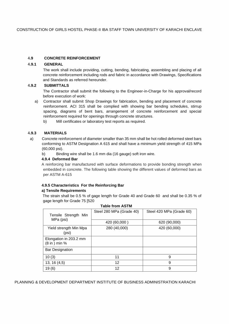
4.9.5 Characteristics For the Reinforcing Bar
a) Tensile Requirements The strain shall be 0.5 % of gage length for Grade 40 and Grade 60 and shall be 0.35 % of
gage length for Grade 75 [520 Table from ASTM
Tensile Strength Min MPa (psi)
Steel 280 MPa (Grade 40) Steel 420 MPa (Grade 60)
420 (60,000 ) 620 (90,000)
Yield strength Min Mpa (psi)
280 (40,000) 420 (60,000)
Elongation in 203.2 mm (8 in ) min %
Bar Designation
10 (3) 11 9
13, 16 (4,5) 12 9
19 (6) 12 9
CONSTRUCTION OF GIRLS HOSTEL PHASE-II IBA STAFF TOWN UNIVERSITY OF KARACHI ENCLAVE
PLANNING & DEVELOPMENT DEPARTMENT INSTITUTE OF BUSINESS ADMINISTRATION KARACHI
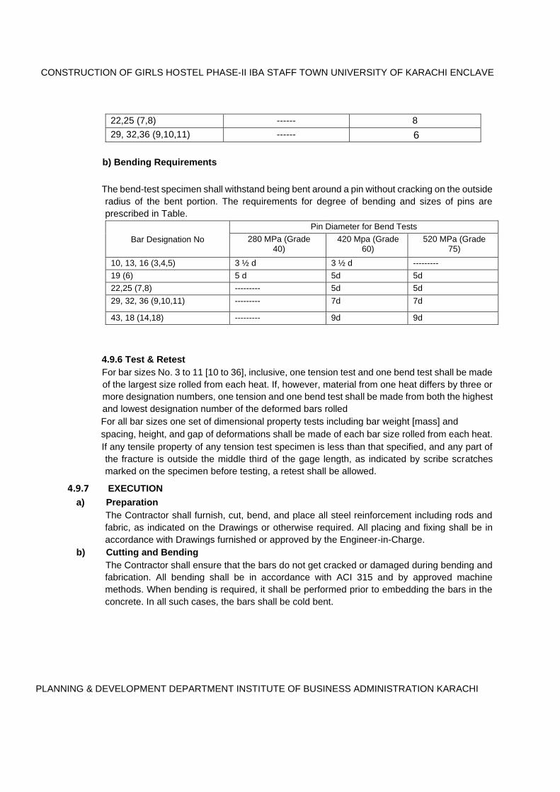
22,25 (7,8) ------ 8
29, 32,36 (9,10,11) ------ 6
b) Bending Requirements
The bend-test specimen shall withstand being bent around a pin without cracking on the outside
radius of the bent portion. The requirements for degree of bending and sizes of pins are
prescribed in Table.
Bar Designation No Pin Diameter for Bend Tests
280 MPa (Grade 40)
420 Mpa (Grade 60)
520 MPa (Grade 75)
10, 13, 16 (3,4,5) 3 ½ d 3 ½ d --------- 19 (6) 5 d 5d 5d 22,25 (7,8) --------- 5d 5d 29, 32, 36 (9,10,11) --------- 7d 7d
43, 18 (14,18) --------- 9d 9d
4.9.6 Test & Retest For bar sizes No. 3 to 11 [10 to 36], inclusive, one tension test and one bend test shall be made
of the largest size rolled from each heat. If, however, material from one heat differs by three or
more designation numbers, one tension and one bend test shall be made from both the highest
and lowest designation number of the deformed bars rolled For all bar sizes one set of dimensional property tests including bar weight [mass] and
spacing, height, and gap of deformations shall be made of each bar size rolled from each heat. If any tensile property of any tension test specimen is less than that specified, and any part of
the fracture is outside the middle third of the gage length, as indicated by scribe scratches
marked on the specimen before testing, a retest shall be allowed.
4.9.7 EXECUTION
a) Preparation The Contractor shall furnish, cut, bend, and place all steel reinforcement including rods and
fabric, as indicated on the Drawings or otherwise required. All placing and fixing shall be in
accordance with Drawings furnished or approved by the Engineer-in-Charge. b) Cutting and Bending
The Contractor shall ensure that the bars do not get cracked or damaged during bending and
fabrication. All bending shall be in accordance with ACI 315 and by approved machine
methods. When bending is required, it shall be performed prior to embedding the bars in the
concrete. In all such cases, the bars shall be cold bent.
CONSTRUCTION OF GIRLS HOSTEL PHASE-II IBA STAFF TOWN UNIVERSITY OF KARACHI ENCLAVE
PLANNING & DEVELOPMENT DEPARTMENT INSTITUTE OF BUSINESS ADMINISTRATION KARACHI
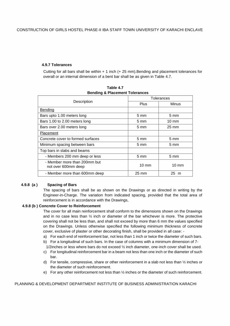
4.9.7 Tolerances
Cutting for all bars shall be within + 1 inch (+ 25 mm).Bending and placement tolerances for
overall or an internal dimension of a bent bar shall be as given in Table 4.7.
Table 4.7 Bending & Placement Tolerances
Description Tolerances
Plus Minus
Bending
Bars upto 1.00 meters long 5 mm 5 mm
Bars 1.00 to 2.00 meters long 5 mm 10 mm
Bars over 2.00 meters long 5 mm 25 mm
Placement
Concrete cover to formed surfaces 5 mm 5 mm
Minimum spacing between bars 5 mm 5 mm
Top bars in slabs and beams - Members 200 mm deep or less 5 mm 5 mm
- Member more than 200mm but not over 600mm deep 10 mm 10 mm
- Member more than 600mm deep 25 mm 25 m
4.9.8 (a ) Spacing of Bars The spacing of bars shall be as shown on the Drawings or as directed in writing by the
Engineer-in-Charge. The variation from indicated spacing, provided that the total area of
reinforcement is in accordance with the Drawings,
4.9.8 (b ) Concrete Cover to Reinforcement The cover for all main reinforcement shall conform to the dimensions shown on the Drawings
and in no case less than ½ inch or diameter of the bar whichever is more. The protective
covering shall not be less than, and shall not exceed by more than 6 mm the values specified
on the Drawings. Unless otherwise specified the following minimum thickness of concrete
cover, exclusive of plaster or other decorating finish, shall be provided in all case: - a) For each end of reinforcement bar, not less than 1 inch or twice the diameter of such bars. b) For a longitudinal of such bars. In the case of columns with a minimum dimension of 7- 1/2inches or less where bars do not exceed ½ inch diameter, one-inch cover shall be used.
c) For longitudinal reinforcement bar in a beam not less than one inch or the diameter of such
bar. d) For tensile, compressive, share or other reinforcement in a slab not less than ½ inches or
the diameter of such reinforcement. e) For any other reinforcement not less than ½ inches or the diameter of such reinforcement.

CONSTRUCTION OF GIRLS HOSTEL PHASE-II IBA STAFF TOWN UNIVERSITY OF KARACHI ENCLAVE
PLANNING & DEVELOPMENT DEPARTMENT INSTITUTE OF BUSINESS ADMINISTRATION KARACHI
f) In case of works in saline or corrosive conditions a minimum of 1-1/2inches cover over
bars, stirrups or links.
4.9.8 (c ) Splicing Except as otherwise shown on the Drawings or specified herein, all splices, lengths of laps,
splice locations, placement and embedment of reinforcement shall conform to the applicable
requirements of ACI 318. All splices and locations of laps in reinforcement shall be as shown
on the Drawings or as directed by the Engineer-in-Charge. Lapped ends of bars may be placed
in contact and securely wired or may be separated sufficiently to permit the embedment of the
entire surface of each bar in concrete. d) Supports
All reinforcement shall be secured in place by use of concrete supports. Chairs, spacers, or
ties may be of metal or as approved by the Engineer-in-Charge. Such supports shall be of
sufficient strength to maintain the reinforcement in place throughout the concreting operations.
Concrete supports shall be manufactured of the same concrete strength as used in the
structure to be concreted. e) Embedded Items
Before placing concrete, care shall be taken to determine that all embedded items are properly
placed as required under the Specifications and are firmly and securely fastened in place as
indicated on the Drawings or as directed by the Engineer-in-Charge.
f.) DELIVERY AND STORAGE
i) All reinforcement bundled, tagged and marked with complete identification shall be
delivered at Site. ii) Reinforcement shall be stored at Site clear of ground and protected from mud and other
deleterious materials.
CONSTRUCTION OF GIRLS HOSTEL PHASE-II IBA STAFF TOWN UNIVERSITY OF KARACHI ENCLAVE
PLANNING & DEVELOPMENT DEPARTMENT INSTITUTE OF BUSINESS ADMINISTRATION KARACHI
4.10.. MEASUREMENT & PAYMENT FOR CONCRETE
4.10.1 GENERAL
All measurements & payments shall be for completed work within the neat lines shown on
drawings unless otherwise specifically directed. Dimensions of length, breadth and thickness shall be measured correct to nearest cm /inch.
except for the thickness of slab and partition which shall be measured to nearest 5 mm.
4.10.2. CAST-IN-SITU CONCRETE
It shall be measured in stages described in the item of work, such as:
(a) Rafts, footings, bases of columns etc. and mass concrete.
(b) All other items up to floor two level.
(c) From floor two level to floor three level and so on. (d) R.C.C. above roof level shall be measured along with R.C.C. Work in floor just below.
4.10.3. Measurement shall be taken before any rendering is done in concrete members. Measurement
will not include rendering. The measurement of R.C.C. work between various units shall be
regulated as below:
(a) Slabs shall be taken as running continuously through except when slab is
monolithic with the beam. In that case it will be from the face to face of the beam.
(b) Beams shall be measured from face to face of columns and shall be including
haunches, if any, between columns and beam. The depth of the beam shall be from
the bottom of slab to the bottom of beam if beam and slab are not monolithic. In case
of monolithic construction where slabs are integrally connected with beam, the depth
of beam shall be from the top of the slab to the bottom of beam.
(c) The columns measurements shall be taken through.
4.13.1. COMPOSITE RATE The measurement and payment for the items of the work of Plain & Reinforced Concrete
hereof shall be made corresponding to the applicable CSR items as provided in Contract
Agreement BOQ or as quoted by the bidder and shall constitute full compensation, for
procurement, transportation, performance in all respects and completion of work as specified
including the site clearance as approved by the Engineer-in-Charge. No separate payment
for form work shall be made but the Reinforcement bar shall be measured and pain
separately as per rate quoted in BOQ.

CONSTRUCTION OF GIRLS HOSTEL PHASE-II IBA STAFF TOWN UNIVERSITY OF KARACHI ENCLAVE
PLANNING & DEVELOPMENT DEPARTMENT INSTITUTE OF BUSINESS ADMINISTRATION KARACHI

CHAPTER 5 DAMP PROOF COURSE AND WATER PROOFING
5.1 DAMP PROOF COURSE
5.1.1 SCOPE The work shall include furnishing all labour, material and equipment and performing all
services to provide the damp-proofing in foundations and over plinths of Structures as shown
on the drawings and/or as directed by the Engineer-in-Charge.
5.1.2. INSTRUCTIONS Damp proofing shall not be applied when the ambient temperature is below 4 degree
Centigrade. The work shall be done by workmen experienced in the application of damp
proofing, and the Contractor shall co-ordinate damp proofing operations with other phases of
the work to prevent staining or damaging finished work. The Contractor shall repair or replace
damaged finished work to the satisfaction of the Engineer-in-Charge. Damp proofing shall be
applied as shown on the Drawings.
5.1.3. DAMP PROOFING MATERIALS
a) Damp Proof Course
i). HORIZONTAL DAMP PROOF COURSE
All Horizontal damp proof courses unless otherwise specified in the drawings shall consists of
class 'B' cement concrete (3000 psi) 2” (50mm) thick, and shall be laid at required levels as per
drawings and instructions of the Engineer. The D.P.C shall be tamped, consolidated, levelled
and edges corners made to the requirements of the relevant drawings including finishing and
curing complete. Including two float coat of . Bitumen emulsion protective coating of
EXPANPROOF-10 by FOSPAK or equivalent confirming to ASTM C-309-93 or BS 6949-1991
applied at a rate of 2Kg / Square Meter
ii). VERTICAL DAMP PROOF COURSE
All vertical damp proof courses unless otherwise specified in the drawings shall consists of ½”
thick cement sand plaster in 1:4, and shall be applied at required elevation as per drawings and
instructions by the Engineer, including Bitumen emulsion protective coating of EXPANPROOF-
10 by FOSPAK or equivalent confirming to ASTM C-309-93 or BS 6949-1991 applied at a rate of
2Kg / Square Meter .
III ) UNDER GROUND WATER TANK& OVER HEAD WATER TANK WATER PROOFING :
For all water retaining Structures concrete not leaner than 1:1 ½ :3 Shall be used if not specified on drawing and pore blocking admixture which alters the microstructure of concrete to stop water transport mechanisms and increase durability like Pudlo Produced by DB Group England or Equivalent as specified. By incorporating PUDLO into the. concrete mix, it is possible to build. watertight structures, without the need. for membranes or drainage systems @ 2.5 Kg per 50 Kg Bag or as per manufactures recommendation. The internal surface of the wall and base shall be plastered with 1:4 CSM if not specified on drawing by adding water proofing PUDLO @ 5% by Wt of Cement or as specified on drawing. A 3”x3” Chamfer shall be made at all the Wall and bottom slab and wall & wall joints.
Chapter-5 [D.P.C. & Water Proofing]
8-1
The External side of the wall two float coat of . Bitumen emulsion protective coating of EXPANPROOF-10 by FOSPAK or equivalent confirming to ASTM C-309-93 or BS 6949-1991 applied at a rate of 2Kg / Square Meter or as specified.
Iv ) ROOF WATER PROOFING
For Flat Roof surface Cold applied bituminous waterproofing membrane Expanproof* GP confirming ASTM D412 Product by M/S Fos Pak or equivalent confirming shall be applied in Two Coats minimum thickness 1.0 mm ( one mm ) per coat but not less than 1.5mm dry thickness of the two coat combined.
INSTRUCTION TO USE (a) SURFACE PREPARATION Concrete surfaces should be float finished and free from cavities and projecting nibs. All surfaces shall be dry and free from frost, surface laitance and contamination. (b) PRIMING
Application Smooth transition should be made at wall/floor slab junctions using a sand/cement mortar and internal and external corners at walls and up stands pre-protected with Expanproof Corner Pieces prior to the application of the membrane. The membrane should be applied to the substrate having first removed the siliconised release paper, pressing the polyethylene film firmly ensuring that the adhesive bitumen compound bonds continuously to the substrate with no air pockets. (b ) CONSTRUCTION CHEMISTRY Expanproof GP is a cold applied self-adhesive sheet membrane comprising of a polymer modified bitumen layer internally reinforced with polyester, bonded on to an outer surface of cross laminated polyethylene film. Expanproof* Primer must be applied to the substrate and allowed to dry until it is tack free, prior to the application of the membrane. All surfaces must be re-primed if left for more than 24 hours prior to the application ofExpanproof* GP. Allow at least a 75mm edge and a 150mm end lap. All laps should be rolled firmly to achieve a good seal. End laps should be staggered. On vertical or inclined surfaces, the membrane shall be laid from the lowest level upwards. The membrane should be protected immediately after application in accordance with BS 8102:1990 by using Protection Board, or as appropriate with a sand/cement screed.
V ) ROO F SCREED
SCREEDING /GRADING ROOF WITH CEMENT CONCRETE 1:2:4 i. Materials
Cement, coarse sand and graded stone aggregate 20 mm nominal size, shall be used as
specified thickness in the item and slope as per shown on drawing. The specifications for the materials and method of preparation of concrete shall conform in
general to the specification described in Section 4. The grading of aggregates shall be
limited between 3/4 inches maximum and 3/16 inches minimum. ii. Laying
Before laying cement concrete for grading, the level markings to the required
slope/gradient shall be made only with cement concrete on the surface of the slab at suitable
spacing, so that the mason can lay the concrete to the required thickness, slope / gradient
easily in between the two level markings. On getting the level marking approved, the surface
should be sprinkled with thick cement slurry and the concrete should be laid carefully,
without throwing from height, in predetermined strips.
Chapter-5 [D.P.C. & Water Proofing]
8-2
The mixed cement concrete must be laid in position, within half an hour of its mixing. In case
any quantity of concrete remains unused for more than half an hour the same should be
rejected and removed from the site.
iii. Finishing The minimum thickness of the concrete at its junction with Khurra or parapets shall be 5 cm.
or as mentioned on drawing. The concrete shall be rounded at the junction of roof slab
and parapet. It is desirable to provide a haunch/gola/filler at the junction of the parapet wall
and the roof slab. The finished concrete surface shall present a smooth surface with correct
slopes and uniform rounding. The concrete should be free from cracks. Excess troweling shall
be avoided.
iv. Thickness Average thickness shall be 2 inches to 3 inches and as specified.
v. Curing Curing shall be done either by spreading straw/Hessian cloth over the graded surface, keeping
the same wet for full 10 days or flooding the graded area with water by making kiaries with
weak cement mortar, for 10 days. Occasional curing by simply spraying water now and then
shall not be permitted.
5.1.5 MEASUREMENT & PAYMENT
Length and breadth shall be measured along the finished surface correct to a cm / INCH and
the area shall be worked out to nearest 0.01 sqm /SQFT. And payment shall be made as per
item mentioned on BOQ of Contract.


Chapter-6 [Solid Concrete Block Masonry]
CHAPTER -6 SOLID & HOLLOW CONCRETE BLOCK MASONRY
6.1 SCOPE The work under this section of the specifications consists of furnishing all plant, labour,
equipment, appliances and materials and performing all operations in any floor and at any
height in connection with the supply and installation of ordinary cement concrete Solid block/
Fair Faced Hollow Concrete Block masonry work including wall ties, anchors, complete in
strict accordance with this section of the Specifications and applicable drawings, and subject
to the terms and conditions of the Contract.
6.1.1. MATERIALS 6.1.2. FOR CONCRETE BLOCK
Cement, aggregates and water for concrete blocks shall conform to the requirements as
specified in Section 4 for Plain and Reinforced Concrete.
6.1.3. FOR MORTAR The cement and sand mortar for concrete block masonry shall specified.
6.1.3.1. SAND
Sand for mortar shall comply with the requirements for BS-1200.
6.1.3.2. CEMENT Cement shall be Ordinary Portland Cement conforming to BS-12.
6.1.3.3. WATER Water shall be clean and free from any harmful impurity. Where the quality of the water is
doubtful, it shall be tested in accordance with BS- 3148.The water shall comply with the
provisions of Clause stated in Chapter 4 Plain & Reinforced concrete.
6.1.3.4. MORTARS AND GROUT Materials for mortar, sand and binding agent and water, shall be mixed by volume or by weight
as specified for at least 3 minutes with the minimum amount of water to produce a correctly
mixed mortar or grout of workable consistency in a mechanical batch mixer Mortar shall be as strong, but no stronger than the materials it bonds together. Mortars shall
be mixed in batches, which can be used within a period before the setting process commences.
Once a mix begins drying off, it shall be rejected. No ingredients shall be added to it once the
setting process has begun.
6.2. CONCRETE BLOCK MAKING
6.2.1 SOLID CONCRETE BLOCK
The Solid blocks shall be factory manufactured/fabricated and be machine moulded. The block
making factory shall be of the standard approved by the Engineer-in-Charge. They shall be
operated according to the instructions laid down by the manufacturers. The contractor shall
submit samples/literature of various manufacturers for Engineer-in-Charge’s approval. The
contractor should note that only blocks supplied by the approved manufacturer(s) shall be
allowed to be used in the work.
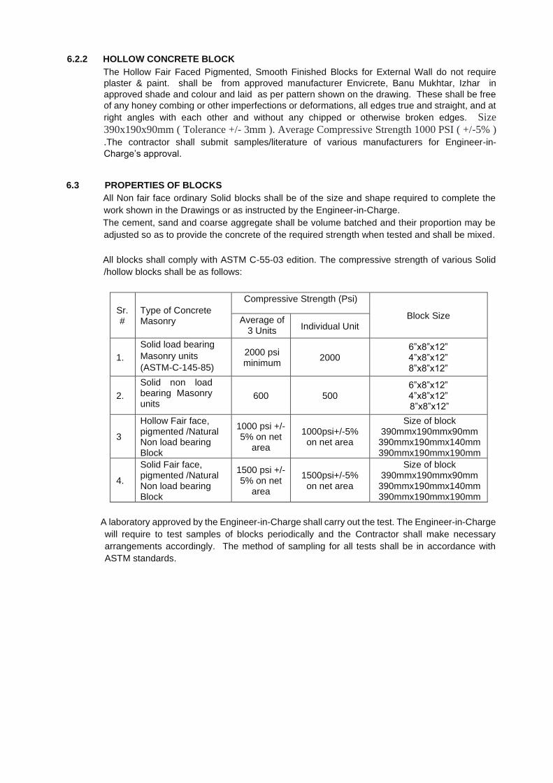
6.2.2 HOLLOW CONCRETE BLOCK
The Hollow Fair Faced Pigmented, Smooth Finished Blocks for External Wall do not require
plaster & paint. shall be from approved manufacturer Envicrete, Banu Mukhtar, Izhar in
approved shade and colour and laid as per pattern shown on the drawing. These shall be free
of any honey combing or other imperfections or deformations, all edges true and straight, and at
right angles with each other and without any chipped or otherwise broken edges. Size
390x190x90mm ( Tolerance +/- 3mm ). Average Compressive Strength 1000 PSI ( +/-5% )
.The contractor shall submit samples/literature of various manufacturers for Engineer-in-
Charge’s approval.
6.3 PROPERTIES OF BLOCKS All Non fair face ordinary Solid blocks shall be of the size and shape required to complete the
work shown in the Drawings or as instructed by the Engineer-in-Charge. The cement, sand and coarse aggregate shall be volume batched and their proportion may be
adjusted so as to provide the concrete of the required strength when tested and shall be mixed.
All blocks shall comply with ASTM C-55-03 edition. The compressive strength of various Solid
/hollow blocks shall be as follows:
Sr. #
Type of Concrete Masonry
Compressive Strength (Psi)
Block Size Average of 3 Units Individual Unit
1.
Solid load bearing Masonry units (ASTM-C-145-85)
2000 psi minimum
2000 6”x8”x12” 4”x8”x12” 8”x8”x12”
2.
Solid non load bearing Masonry units
600 500 6”x8”x12” 4”x8”x12” 8”x8”x12”
3
Hollow Fair face, pigmented /Natural Non load bearing Block
1000 psi +/- 5% on net
area
1000psi+/-5% on net area
Size of block 390mmx190mmx90mm 390mmx190mmx140mm 390mmx190mmx190mm
4.
Solid Fair face, pigmented /Natural Non load bearing Block
1500 psi +/- 5% on net
area
1500psi+/-5% on net area
Size of block 390mmx190mmx90mm 390mmx190mmx140mm 390mmx190mmx190mm
A laboratory approved by the Engineer-in-Charge shall carry out the test. The Engineer-in-Charge
will require to test samples of blocks periodically and the Contractor shall make necessary
arrangements accordingly. The method of sampling for all tests shall be in accordance with
ASTM standards.
Chapter-6 [Solid Concrete Block Masonry]
9-2
6.4 ERECTION Blocks shall be laid true to line, level and laid in accurately spaced courses in stretcher bond
with vertical joints of each course located at centre of units in alternate courses below. Vertical
joints shall be buttered in the entire height of blocks. Each course shall be bonded at corners
and at intersections of walls and shall be properly bonded. Courses of block shall be kept
plumb throughout and corner reveals shall be true and in plumb. Standard width of mortar joints for both horizontal and vertical joints shall be 10mm (maximum).
Mortar joints in walls shall have full mortar coverage on vertical and horizontal faces between
the blocks. Mortar joints on wall including struck joints, shall be thoroughly compacted and
pressed tight against the edges of the blocks with proper tools.
Unless otherwise shown on the drawings or specified by the Engineer-in-Charge, the spaces
around doorframes and other material or built in items shall be solidly filled with mortar.
Spaces around the door and window holdfasts shall be filled in with 1:3:6 concrete. Work
required to be built in with masonry including doorframe anchors, wall plugs, and dovetail
anchors and accessories shall be built in as the erection progresses. The block work shall be carried up in a uniform manner and no portion shall be carried more
than one meter above the adjoining one at any time. All masonry shall be kept strictly true and
square and the whole properly bonded together and levelled round each floor. Walls of blocks indicated, as being non-load bearing shall be constructed on the in situ
concrete floor slab unit after the floor formwork is struck and the concrete has obtained
sufficient strength to support their-weight. Tooting into load-bearing walls shall not be
permitted. All bolts, anchors, ties, pipe sleeves, flushing metal attachments, lintels and the like required
to be built into the work shall be correctly inserted and executed as the work proceeds. Walls
or partitions abutting concrete columns or walls shall be securely anchored and tied with metal
anchors or ties at not more than 450mm vertical centers. Wall ties cast in with concrete shall
be bent down after the removal of formwork and shall be securely jointed into the mortar beds
of walling. Care shall be taken during construction of cavity walls so as to avoid the filling up of cavity with
mortar. G.I. flashing and weep holes shall be provided wherever specified on the drawings or
as per the instructions of the Engineer-in-Charge. Weep holes will be formed by oiled rods,
removed after the mortar is set, at specified locations.
6.5 SCAFFOLDING Contractor shall provide safe scaffolding of adequate strength for use of workmen at all levels
and heights at his own expense. Scaffolding which is unsafe in the opinion of the Engineer-
in-Charge shall not be used until it has been strengthened and made safe for use of workmen.
Cost of scaffolding etc. shall be included by the Contractor in the unit rate for masonry items.
Damage to masonry from scaffolding or from any other object shall be repaired by the
Contractor at his own cost.
6.6 TOLERANCES All block work shall be erected plumb and true to line and level with the maximum variation in
any storey height or any length of wall being one mm in one metre. The maximum tolerance
in the length, height or width of any single masonry unit shall be + 3mm.
6.7 SOLID BLOCK WORK AROUND OPENING OF HOLLOW MASONRY Around all openings in hollow block masonry, the Contractor shall provide solid block work of
same thickness as that of hollow block masonry wall and of width as indicated on the Drawings.
CHAPTER-6 SOLID & HOLLOW CONCRETE BLOCK MASONARY
9-3
6.8 CURING AND REPAIRS All block masonry shall be water cured and shall be kept wet for at least seven days, by an
approved method, which will keep all surfaces to be cured continuously wet. Water used for
curing shall meet the requirements of the specifications for water used in the manufacture of
blocks.
6.9. CAVITY WALL
6.9.1 GENERAL
It is a wall comprising of two leaves, each leaf being built of masonry units and separated by a
cavity so as to provide an air space within the wall and tied together with metal ties or bonding
units to ensure that two leaves act as one structural unit. The width of the cavity shall not be
less than 50 mm and not more than 115 mm. Each leaf of the cavity wall shall not be less than
75 mm. The space between the leaves either left as cavity or filled with non load bearing
insulating and water proofing material.
6.9.2 MATERIALS
The hollow block shall be as specified in this Section. The mortar shall be cement sand mortar
as specified in accordance with the provisions of specification 1 :4 CSM. The laying of block
masonry for cavity walls shall comply with provisions of specification. Curing and scaffolding
shall be as per specifications.
6.9.3 METAL TIES
These may be of galvanized iron, or mild steel bar as specified. The ties shall be built into
horizontal bed joints during erection, placed sloping towards the exterior side to prevent water
from flowing along it from outer to inner leaf side or as specified on drawing & details..
6.9.4 BONDING UNITS
Length of the Bonding units will be sum of thickness of both leaves plus width of cavity if the
leaves are 75 mm or 115 mm. If the leaves are more than 115 mm thick, then the length of a
unit will be [(2 ×115) + width of cavity].
Cement concrete used in the bonding units shall not be leaner than 1:3:6 (1 cement : 3 sand :6
aggregate 20 mm nominal size).
6.9.5 SPACING
Metal ties/bonding units shall be spaced not more than 90 cm apart horizontally and 45 cm
vertically and staggered in each course. Additional ties shall be used near openings.
6.9.6 MEASUREMENTS AND RATE
(a) Block work in cavity walls shall be included and measured with general / Fair Face Block work.
The cavity wall shall measured as and paid as per BOQ item
(b) The item shall include use of device for keeping cavity clear and forming the requisite weep and
vent holes and nothing extra on this account shall be payable
6.10 REINFORCED BLOCK MASONRY
6.16.1 GENERAL
Reinforced BLOCK masonry shall be constructed as specified and shown on drawings.
6.10.1 BLOCK WORK
BLOCK work shall be as specified and conform with the provision for construction of blockwork
of this section. The mortar shall be cement sand mortar as specified and shall conform with the
provision of Clause of this section
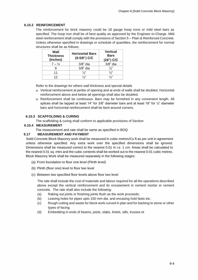
Chapter-6 [Solid Concrete Block Masonry]
9-4
6.10.2 REINFORCEMENT
The reinforcement for brick masonry could be 18 gauge hoop irons or mild steel bars as
specified. The hoop iron shall be of best quality as approved by the Engineer-in-Charge. Mild
steel reinforcement shall comply with the provisions of Section 5 – Plain & Reinforced Concrete.
Unless otherwise specified in drawings or schedule of quantities, the reinforcement for normal
structures shall be as follows;
Wall Thickness (Inches)
Horizontal Bars
(9-5/8”) C/C
Vertical Bars
(24”) C/C
7 – ½ 3/8” dia 3/8” dia
9 3/8” dia ½”
11 ½” ½”
12 ½” ½”
Refer to the drawings for others wall thickness and special details
a) Vertical reinforcement at jambs of opening and at ends of walls shall be doubled. Horizontal
reinforcement above and below all openings shall also be doubled.
b) Reinforcement shall be continuous. Bars may be furnished in any convenient length. All
splices shall be lapped at least 14” for 3/8” diameter bars and at least 18” for ½” diameter
bars and horizontal reinforcement shall be bent around corners.
6.10.3 SCAFFOLDING & CURING
The scaffolding & curing shall conform to applicable provisions of Section
6.10.4 MEASUREMENT
The measurement and rate shall be same as specified in BOQ
6.17 MEASUREMENT AND PAYMENT Solid Concrete Block Masonry work shall be measured in cubic metres/Cu ft as per unit in agreement
unless otherwise specified. Any extra work over the specified dimensions shall be ignored.
Dimensions shall be measured correct to the nearest 0.01 m i.e. 1 cm. Areas shall be calculated to
the nearest 0.01 sq. mtrs and the cubic contents shall be worked out to the nearest 0.01 cubic metres.
Block Masonry Work shall be measured separately in the following stages:
(a) From foundation to floor one level (Plinth level)
(b) Plinth (floor one) level to floor two level
(c) Between two specified floor levels above floor two level
The rate shall include the cost of materials and labour required for all the operations described
above except the vertical reinforcement and its encasement in cement mortar or cement
concrete. The rate shall also include the following: (a) Raking out joints or finishing joints flush as the work proceeds; (b) Leaving holes for pipes upto 150 mm dia. and encasing hold fasts etc. (c) Rough cutting and waste for block work curved in plan and for backing to stone or other
types of facing. (d) Embedding in ends of beams, joists, slabs, lintels, sills, trusses et

CHAPTER -7 FLOORING
14-0
CHAPTER-7 FLOORING
7.1 SCOPE OF WORK.
The works covered under this section of specifications consists of furnishing all labor, materials
and equipment and performing all operations in connection with laying flooring including bases,
dados and skirting in strict accordance with drawings and as specified herein and subject to terms
and conditions of the contract documents.
7.1.1 SAND FILL.
A uniform layer of granular and screened sand shall be laid to the required thickness over the
surface of compacted earth as per drawing & details. The sand layer shall be compacted in the
manner required by the Engineer prior to execution of subsequent item.
7.1.2 STONE SOLING.
The quality & thickness of stone material shall be as per requirements and specified on drawing
,if not otherwise minimum thickness 150mm ( 6 inches ) shall be adopted, as per drawing &
details and shall be approved by the Engineer. The stones shall be laid on edge as approved by
the Engineer, the spaces or voids between and around shall be filled with sand
7.1.3 PLAIN CEMENT CONCRETE SUB-BASE.
The base course of lean cement concrete shall be 1:4:8 or as specified on drawing specified shall
be laid as per thickness shown on drawing & details or as per BOQ item. The surface of the bed
shall be roughened for the grip of the top layer.
7.2 FLOOR FINISHES.
All floor finishes shall be laid on properly cleaned and prepared sub-floors to the thickness as
indicated on the drawings and finished to the satisfaction of Engineer. The Contractor shall make
sample panels of floors for inspection and approved by the Architect/Engineer before actual
flooring works are taken in hand.
7.2.1. PLAIN CEMENT CONCRETE FLOORS.
The concrete ingredients as per specified in Chapter 4 Plain & Reinforced Cement Concrete
shall be mixed in a batch mixer for not less than 2 minutes after all ingredients except the full
amount of water, are in the mixer The concrete shall be uniform in composition and consistency.
Excessive or over mixing or increasing concrete consistency will not be permitted. The concrete
ingredients shall be mixed by volumetric measurement in purpose made boxes approved by the
Engineer.
The screed may be laid in panels as specified on drawings when the concrete is still plastic, The
hardened base should be thoroughly cleaned, wetted, preferably overnight surplus water
removed.
7.2.2 TERRAZO FLOORING (IN SITU). The Contractor shall submit samples of terrazzo flooring required in the various locations and the
samples, which Engineer may select for use in the buildings, shall be available for examination
and comparison by both the Contractor and the Engineer. The finished floors shall conform in all
respects to the characteristics of the samples approved. The size of chips shall be of 3mm to
10mm size and the color will be as selected by the Architect/Engineer.
The Contractor, after tentative color patterns are approved, shall provide sample panels of cast
in place terrazzo wear coat and base. The thickness of the wear coat shall be uniform and at no
CHAPTER-7 FLOORING
14-1
point shall if be less than 15mm.. Finished surfaces of both floors and walls when completed,
ground and polished, shall in air cases show uniformly distributed exposed granules or chips,
free of undesirable blotches of matrix without marble granules or chips. Uneven distribution in
either floor or wall surface will be required to be resurfaced and/or refinished to the satisfaction
of the Engineer. All floors shall be adequately cured for a minimum of 14 days after laying by
means of sand bunds in panels or as required by the Engineer. During the course of construction
of the floors and up to the time of completion of the Project, the Contractor shall protect the
flooring from stains and mechanical damage by his workers or by workers of other
Contractors/Sub-Contractors.
7.2.2 TERRAZZO TILE FLOORING AND STEPS.
All tiles shall be of size 300x300mm or 200x200mm size as shown on drawings or as mentioned
in the Schedule of Quantifies and shall be perfectly leveled square and true to every surface.
Tiles shall be minimum 25mm for 300mm size and minimum 20mm thick for 200mm size with a
marble mosaic tapping firmly bonded to a base of cement concrete, manufactured by the dry
process and machine pressed hydraulically with a pressure of not less than I50 kg per square
centimeter. The thickness of topping shall not be less than 13mm for 300x300mm tiles and 10mm
for 200x200mm tiles.
The marble mosaic topping shall be of colors as selected by the Architect/Engineer, including
sizes of chips, their color proportion and distribution. All tiles shall be of uniform color and liable
to rejection due to difference in any of the above specified conditions.
The Tile shall be vibrated to an extent that it releases air to the surface and consolidates the
aggregate at the wearing surface. Proportion of cement to aggregate shall not be leaner than 1:2
by weight in topping layer. All tiles shall be cured after manufacture for not less than three weeks,
prior to delivery at site, or setting up in floors.
If the Contractor is allowed to use ordinary tiles for stair risers he will have to cut the standard
Tiles for which no payment for the wastage or cutting will be made. The tiles before being used
shall be thoroughly soaked in water for 10 to 20 minutes and stood on their edges to dry for about
the same length of time, Any tiles, which have hair cracks shall be rejected. Should the cracks
be noticed after the tiles are fixed in position, such tiles shall be replaced at contractor's cost and
risk.
7.2.3 EXECUTION The terrazzo Tiles will be laid to the required levels and grades over a setting bed of cement
mortar comprising of 1 part of cement and 4 parts of sand by specified. The overall thickness of
mortar and tile shall be minimum 50mm. The curing period of the setting bed should be as
directed by the Engineer. As large an area of setting bed shall be spread at one time as can be
covered with tiles before the mortar has set. Surplus mortar shall be removed. Floor and wall
surfaces to receive the tiles shall be thoroughly cleaned of all dirt, dust, oil and other objectionable
matters. Tiles shall be laid out from the center line of each space in on outward direction and the
pattern should be made symmetrical with a minimum number of cut tiles. Joints between the tiles
shall be of uniform width. Tiles shall be cut with a suitable cutting tool and rough edges shall be
rubbed smooth. Tiles shall be laid to the straight edges. The Contractor is required to submit his
shop drawing before actual laying of the tiles to show in detail how and where tiles pieces are
planned to be laid. The Drawing shall be approved by the Architect/Engineer. After seven days
the terrazzo tile floors shall be machine ground to a true even surface using various grades of
abrasive stones as required and directed by the Engineer. After the first grinding, the floor shall
be grouted with the same color composition as used for its manufacture. The grout shall be of
the consistency of thick cream and shall be brushed over the floor to fill in the joints and after 72
hours the grouting coat shall be removed by grinding till a smooth and even surface is obtained.
Areas and portion of the floor inaccessible for the grinding machine shall be ground and rubbed
by hand. The final glass shall be given by polishing the surface to the satisfaction of the Engineer.
The tile floor shall be kept wet for at least 72 hours and no one should be allowed to walk on the
tiles during that period.
CHAPTER -7 FLOORING
14-2
7.2.4 Terrazzo Tiles on Stairs
The stair risers and treads shall be provided in 3000 psi. Concrete according to exact sizes including
the terrazzo topping making allowance for grinding of terrazzo. The nosing shall be flush with the
terrazzo toppings, as specified or shown on the Drawings.
Measurement
7.2.5. Measurement of acceptably completed works of Terrazzo Tiles on floor will be made on
the basis of net actual area in square feet of floor laid in position to the line, level & grade as
shown on the Drawing or as directed by the Engineer.
Payment
Payment will be made for acceptable measured of Terrazzo Tiles floor on the basis of unit rate
per Sq feet quoted in the Bills of Quantities and shall constitute full compensation for all the works
related to the item.
7.3 CERAMIC TILE FLOORING AND DADO.
7.3.1 The tiles shall be of approved manufacturer. These will be either white or colored as specified in
the Schedule of Quantifies or as approved by the Engineer. The tiles shall be free from cracks or
crazing, free from twisting and uniform in color and size. Approval of the manufacturer does not
relieve the Contractor to carry-out his own checking to ensure that only the best quality tiles are
used and all defective tiles are rejected and removed from site immediately.
7.3.2 Soaked Ceramic flies shall be laid on cement concrete base of specified grade and the joints
filled with neat white or grey cement or as specified including vertical and horizontal covers. The
curing period of the setting bed shall be as directed by the Engineer,. The thickness of setting
bed shall not be less than 45mm for floor and 12mm for walls or as specified on drawing.. Floor
and wall surfaces to receive the files shall be thoroughly cleaned of all , dust, oil and other
objectionable matters. Tiles shall be laid out from the centre line of each space in an outward
direction and the pattern should be made symmetrical with a minimum number of cut tiles. Joints
between the tiles shall be of uniform width. Tiles shall be cut with a suitable cutting tool and rough
edges shall be rubbed smooth. Tiles shall be laid to the straight edges.
7.4 PRE CAST CONCRETE INTERLOCK PAVERS
7.4.1 The pre-cast interlock concrete pavers of specified size, shape and Color of approved
manufacturer Envicrete, Megnacrete, BanuMuktar or as specified having minimum Compressive
Strength 5000 Psi for non traffic area of minimum thickness 60mm and min. thickness 80mm with
minimum compressive strength 7000 Psi shall be laid to the required lines, levels and grades
over a well compacted setting bed of 100mm thick sand mixed with 37mm down crushed stone
over 50mm thick sand cushion. The joints between the paver shall be filled with neat sand.
7.4.2 The laid paver shall be compacted with the compactor as specified by the Manufactures.
Care shall be taken that full pavers are used as far as possible. Where this is not possible, the
edge pavers shall be neatly cut with an electric saw and the edges rubbed smooth, in case of
patterned pavers, the pavers shall be laid in such a way that the pattern ends symmetrically on
two sides.
7.5. MEASUREMENT AND PAYMENT. Except otherwise specified herein or else wherein the Contract Documents, no measurement
and payment will be made for the under mentioned specified works related to the relevant items
or the Bill of Quantities· The cast thereof shall be deemed to have been included in the quoted
unit rate of the respective items of the Bill of Quantifies. Measurement of acceptably completed works of finished floor, dado, skirting, stair finish,
etc. will be made on the basis of net finished area laid in position as shown on the drawings or
as directed by the Engineer. Exposed edges of tiles, marble, etc. will not be included in the
measurements.

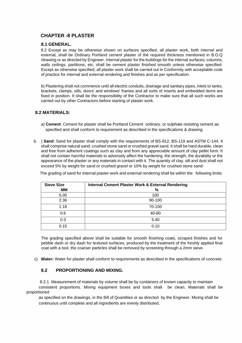
CHAPTER -8 PLASTER
8.1 GENERAL. 8.2 Except as may be otherwise shown on surfaces specified, all plaster work, both internal and
external, shall be Ordinary Portland cement plaster of the required thickness mentioned in B.O.Q
/drawing or as directed by Engineer. Internal plaster for the buildings for the internal surfaces; columns,
walls ceilings, partitions, etc. shall be cement plaster finished smooth unless otherwise specified·
Except as otherwise specified, all plaster work shall be carried out in Conformity with acceptable code
of practice for internal and external rendering and finishes and as per specification.
b) Plastering shall not commence until all electric conduits, drainage and sanitary pipes, inlets to tanks,
brackets, clamps, sills, doors' and windows' frames and all sorts of inserts and embedded items are
fixed in position. It shall be the responsibility of the Contractor to make sure that all such works are
carried out by other Contractors before starting of plaster work.
8.2 MATERIALS:
a) Cement: Cement for plaster shall be Portland Cement ordinary, or sulphate resisting cement as
specified and shall conform to requirement as described in the specifications & drawing.
b. ) Sand: Sand for plaster shall comply with the requirements of BS-812, BS-119 and ASTM C-144. It
shall comprise natural sand, crushed stone sand or crushed gravel sand. It shall be hard durable, clean
and free from adherent coatings such as clay and from any appreciable amount of clay pellet form. It
shall not contain harmful materials to adversely affect the hardening, the strength, the durability or the
appearance of the plaster or any materials in contact with it. The quantity of clay, silt and dust shall not
exceed 5% by weight for sand or crushed gravel or 10% by weight for crushed stone sand·
The grading of sand for internal piaster work and external rendering shall be within the following limits.
Sieve Size MM
Internal Cement Plaster Work & External Rendering %
5.00 100 2.36 90-100
1.18 70-100
0.6 40-80
0.3 5.40
0.15 0.10
The grading specified above shall be suitable for smooth finishing coats, scraped finishes and for
pebble dash or dry dash for textured surfaces, produced by the treatment of the freshly applied final
coat with a tool, the coarser particles shall be removed by screening through a 2mm sieve.
c) Water: Water for plaster shall conform to requirements as described in the specifications of concrete.
8.2 PROPORTIONING AND MIXING.
8.2.1 Measurement of materials by volume shall be by containers of known capacity to maintain
consistent proportions. Mixing equipment boxes and tools shall be clean. Materials shall be
proportioned
as specified on the drawings, in the Bill of Quantities or as directed by the Engineer. Mixing shall be
continuous until complete and all ingredients are evenly distributed.
Chapter-29 [Horticulture] 29-1
8.2.2 Only limited water shall be added for proper workability and such quantity of the mortar shall be
prepared as that which will be consumed in thirty minutes after preparation. Plaster ingredients shall
be thoroughly mixed, either by hand on a clean cement concrete platform or by a mechanical mixer,
as directed by the Engineer.
8.3 PREPARATION OF SURFACE TO BE PLASTERED.
8.3.1 Concrete surface to be plastered shall be cleaned to remove all grease, oil and other surface
impurities, which will otherwise adversely affect the adhesion of plaster to the surface concerned. The
surface of all concrete ceilings, beams and columns shall be lightly hacked by approved means to give
the required key for plastering.
8.3.2 All masonry surfaces to be plastered shall be cleaned to remove all matter which will otherwise
adversely affect the adhesion of plaster to the surface concerned.
8.3.3 APPLICATION OF PLASTER.
8.3.3.1The plaster shall be minimum 12-20mm thick, as mentioned in BOQ and shall not be less than
12mm thick at any internal surface or 20mm at any external surface. The plaster of thickness less
than the specified thickness shall be rejected. If the plaster is to be more than 25mm thick, it shall be
done in two coats. The surface of first coat shall be made rough before the second coat is applied. The
plaster shall not have wavy surface and shall be perfectly in plumb. The edges and corners shall
represent a straight line. The plaster shall be kept wet continuously for at least ten (10) days. No extra
payment shall be allowed for jambs, junctions, comers, edges, round surfaces or for more than one
layer of plaster required due to any unevenness in the work done by the Contractor. The plaster work
is to cover all conduits, pipes etc. fixed in the walls and ceiling. Wherever specified, metal lath shall be
nailed firmly before plastering is commenced. The plaster surface shall be tested frequently with 3
meter straight edge and plumb bob. 8.3.2 Plaster containing cracks, blisters, pits, discoloration or any defects shall not be acceptable. Any
such piaster or loose piaster shall be removed and. replaced with plaster in conformity with these
specifications and as additionally directed by the Engineer. Contractor shall cut and patch all defective
work at his own cost. All damaged plaster shall be patched as directed by the Engineer.
8.4 TOLERANCES.
Surfaces of plaster work shall be finished with a true plane to correct line and level with all angle and
corners to a right angle unless otherwise specified and with wails and reveals plumb and square.
Maximum permitted tolerances shall not exceed 3mm in 2m variation from plumb or level in any
exposed line or surface and 1.5mm variation between planes of abutting edges or ends.
8.5 MEASUREMENT AND PAYMENT. Except otherwise specified herein or elsewhere in the Contract Document, no measurement and
payment will be made for the under mentioned specified works related to the relevant items of the Bill
of Quantities. The cost there of shall be deemed to have been included in the quoted unit rate of the
respective items of the Bill of Quantifies.
8.6 Deductions in measurements, for opening etc. will be regulated as follows:
(a) No deduction will be made for openings or ends of joists, beams, posts, girders, steps etc.
upto 0.5 sqm in area and no additions shall be made either, for the jambs, soffits and sills of such
openings. The above procedure will apply to both faces of wall.
(b) Deduction for opening exceeding 0.5 sqm but not exceeding 3 sqm each shall be made for
reveals, jambs, soffits sills, etc. of these openings.
(c ) When both faces of walls are plastered with same plaster, deductions shall be made for one
face only.
Chapter-29 [Horticulture] 29-2
CHAPTER -9 PAINTING AND POLISHING
9.1 SCOPE OF WORK.
The work covered by this section of the Specification, consists of furnishing all materials, plant, labor,
equipment, appliances and performing all operations in connection with surface preparation, mixing,
painting concrete works, gates, frames, structural steel works, steel pipes, valves, steel and wooden
doors, windows, louvers, wait ceilings and all such surfaces as shown on the drawings/or as directed
by the Engineer, the scope of this section of specification is covered with detailed specifications as
laid down herein.
9.2 GENERAL
9.2.1 Where the work or term 'point' and 'polish' is used or referred to throughout the specifications, it
shall be interpreted to mean and include the surface finish treatment consisting of any, all or some of
the following items :-
Sealers, primers, fillers, body and final coat, emulsion varnish, shellac, wall paper paste, stain or
enamels as more specifically defined hereinafter as to kind and quality and function for various
surfaces and finishes.
All paint, polish and necessary materials incorporated in or forming a part thereof shall be subject to
the approval and selection for color, tint or finish by the Architect / Engineer.
9.2.2 Painting of wood work and for plaster surfaces shall be minimum 3 coats work except otherwise specified. Painting of metal surfaces required to be painted, shall be minimum 3 coats work, in addition to the shop protection coats.
9.2.3 All paints shall be as manufactured locally and approved by the Engineer and shall be
brought on to the site in sealed containers and used without any admixture or adulteration
except where recommended in the Manufacturer's printed instructions, 9.2.4 Surfaces of stainless steel aluminum, bronze, and machines surfaces adjacent to merci
work being cleaned or painted shall be protected by effective masking or other suitable
means, during the cleaning and painting operations.
9.3 PREPARATION AND WORKMANSHIP 9.3.1 No work in this section shall be initiated until all such surfaces or conditions have been
corrected. No work should to be done under the conditions that are unsuitable for the
production of good results, nor at any time when the plastering is in progress or is drying,
or not dry. Neither paint nor any other finish treatment is to be applied over wet or damp
surfaces unless specifically required, nor shall succeeding coats be applied until the
proceeding coat is thoroughly dry.
9.3.2 Before proceeding with any painting or finishing thorough cleaning and removing of all dust
from surfaces, which would affect either the satisfactory execution or permanency of the
work is necessary.
9.3.3 All painting materials are to be applied evenly spread and thoroughly brushed -out only by
skilled workers. All workmanship shall be executed in accordance with the best acceptable
practices applying to the class of work and grade, type and kinds of materials specified.
9.3.4 Plastered surfaces shall be primed before speckling. After application of primer coat,
Contractor shall check all surfaces and do all necessary speckling of cracks, indentations
and other imperfections in any approved manner.
9.3.5 Wood work that is to have a finish treatment, whether executed as field work or shop
finished, shall be smooth and free from raised grain or other surface imperfections that
affect its appearance and shall be lightly sanded or steel wool during finishing operations.
After filler has been applied, if required all nail holes or other similar blemishes shall be
carefully stopped with linseed oil puffy.
Chapter-29 [Horticulture] 29-3
9.3.6 Shop coats provided by others, where required or necessary, shall have all bare spots
touched up by the Contractor, using same materials as used for shop coat, or other
equivalent material, if approved by the Engineer.
9.4 MATERIALS. 9.4.1 All materials shall be stored and mixed only in spaces assigned for this purpose by the
Engineer and all necessary precautions shall be taken to prevent fires by complying with
all applicable local fire prevention and safety ordinances. The contractor shall provide
galvanized iron pans of suitable size in which all mixing paints shall be placed and no
mixing shall be permitted outside of these pans.
9.4.2 The basic materials entering into the compounding and/or manufacture of all paints,
polishes and other treatments referenced herein shall be of the best grade and quality of
their respective kinds for the intended purposes. These
shall be the products or formula of recognized and reputable manufacturers of known
reliability and integrity subject to the approval of the Engineer and shall conform to the
applicable requirements of the British Standard Specifications or approved local standards
regarding kind, qualify and finish, Reference herein to specific paint materials is for the sole
purposes of establishing a basis of "Minimum Standards" of quality and shall not be
construed to be a limit of perfection or quality for any of the materials, ingredients to be
furnished or utilized in this work. The Engineer reserves the right to select and / or accept
only the best grades of standard products, which in his opinion, will provide a finish of
recognized performance and characteristics suitable for their respective surfaces,
irrespective of minimum standards reference herein.
9.4.3 All materials shall be delivered to premises in their original sealed containers or package
bearing the manufacturer's name, label and brand, and be mixed and applied in
accordance with manufacturer's directions and /or instructions. The mixing of all paint or
other covering finish treatments shall be done in premises as and when, if required, under
the supervision and direction of the Engineer.
9.5 PAINTING TO METAL WORK. 9.5.1 All metal work shall have, in addition to shop primer coats, minimum three (3) coats of
enamel paint or as incorporated in the Bill of Quantifies, in the manner as specified herein.
9.5.2 All exposed ornamental and miscellaneous iron and steel shall receive over the shop
primer coat, minimum three (3) coats of enamel paints as specified herein or as
incorporated in the Bill of Quantities.
9.5.3 Galvanized iron not previously shop coated shall receive minimum 4 coats, the first coat to
be of an approved galvanized iron primer and minimum three finish coats of enamel paint
or as incorporated in the Bill of Quantifies.
9.5.4 Where shop coals and/or priming coats are found to be scratched or abraded they shall be
touched up with appropriate paint.
9.6 OIL BOUND DISTEMPERING.
9.6.1 Distempers shall be of approved quality and make as directed by the Engineer. 9.6.2 Before work of distempering is commenced, the surface should be cleaned. The surface
then must be sized with a priming coat of petrifying liquid of approved manufacture.
Chapter-29 [Horticulture] 29-4
Distemper shall be applied quickly and boldly with broad stiff brushes of approved make.
The brush is to be dipped and stroked cross-wise info the wails and them immediately
stroked up and down. This shall be considered to be one coat of distempering. The
distemper shall be mixed in the manner specified by the manufacturer and each coat shall
be inspected and passed by the Engineer before the next coat is applied.
9.6.3 The Contractor shall carry out as many coats as specified in the Schedule of Quantities in
accordance with the above specifications. The number of coats specified is enough for
producing the uniform smooth finish and if the finish produced by the Contractor is not up
to the satisfaction of the Engineer, the Contractor will be required to apply more coats, as
may be required to produce the specified finish without any additional charges.
9.7 SURFACE PREPARATION AND FILLING.
All plaster and masonry surfaces that are to be finished with vinyl emulsion, plastic emulsion or
enamel paint shall be prepared as under prior to application of paint finish.
9.7.1 NEW SURFACES: Rub down the surfaces with a sand paper or carborandum stone to
remove any 1case material. Check that the surface is thoroughly dry before painting.
9.7.2 OLD SURFACES: For previously painted surfaces especially white - washed surfaces,
scrape down to the bare surface and ensure that the surface is free from any contaminant
like grease, oil, etc. and any loose material or dust is completely removed before painting.
9.7.3 SEALING: Apply 1 coat of Alkali Resisting Masonry Sealer and allow to dry overnight.
Alkali Resisting Masonry Sealer may be thinned with 10-15% good quality mineral
turpentine or white spirit if required due to surface absorption.
9.7.4 FILLING: Puffy for filling the walls should be made by mixing 4 parts of good quality chalk
and one part of Zinc Oxide Powder with Alkali resisting masonry sealer till a smooth knifing
paste is formed. Putty should be applied after sealing the walls with Alkali Resisting
Masonry Sealer, and after the tilling work is completed and prior to application of the finish
paint, the filled surfaces should be dry and properly finished, No filling should be carried
out on external surfaces. Each coal of paint shall be allowed to become dry before any
subsequent coat is applied. The finished surface shall be free from runs and sags, defective
coverage and clogging of lines or angles. Edges of paint adjoining other materials or other
colors shall be full and clean - cut without overlapping.
The Contractor shall carry out as many coats as are specified in accordance with the above
specifications. The number of coats specified should be enough for producing uniform
smooth finish and if the finish produced by the Contractor is not up to the requirement, he
will be required to apply as many more coats as may be required to produce the required
uniform finish, and no payment for the extra coats applied to produce the desired uniformity
will be made.
9.8 LACUER POLISHING. 9.8.1 Clear polyurethane lacquer used on the work shall be of ICI / Berger or an approved make.
9.8.2 The surface to be lacquer polished should be sand papered and a staining compound
should be applied if required.
9.8.3 When the stain coat dries up the surface should be rubbed down with sand
paper. Approved polyurethane lacquer of a proprietary brand shall then be
applied.
Chapter-29 [Horticulture] 29-5
The surface shall then be wiped with a dry cloth and the process repeated several times in
succession until the surface assumes the desired degree of gloss as approved by the
Engineer.
9.8.4 SAMPLES.
Prior to the start of the application of any paint and /or finish treatment otherwise, the contractor
shall apply samples of the required finish treatments to specific representative wall and ceiling
surfaces or other areas or surfaces where indicated by the Engineer. The sizes of the sample
paint and finishes shall be as determined by the Engineer.
9.8.5 PROTECTION.
The Contractor shall protect all the work against damage or injury by his employees or by the
materials, tools used in connection with the work of this contract. Any and all work damages as
a result of the execution of this shall be repaired at Contractor's expense or if in the opinion of
the Engineer it cannot be properly repaired, it shall be replaced with new work by the Contractor
without additional compensation. At all times, the general and liberal use of drop cloths shall be
a primary requirement for protection purposes.
9.8.6 TOUCHING UP.
At the completion of all work specified herein, all painted work shall be touched up and restored
where damaged or defected and the entire work left free from blemishes, to the complete
satisfaction of the Engineer.
9.8.7 CLEANING.
The Contractor shall clean all paint, spots, dubs, oil and stain from all floors, wood work, glass
hardware, metal work, electrical fittings and all similar items, and leave the work in perfect
condition, upon completion in every respect to the satisfaction of the Engineer.
9.9 EMULSION PAINTING
9.10.1 SCOPE
The work include the provision of all materials, labour, plant and equipment and completion of work
as specified and approved by Engineer-in-Charge
9.10.2 MATERIALS
Emulsion paints shall be of make and type as specified and approved by the Engineer-inCharge.
9.10.3 EMULSION PAINT APPLICATION
For emulsion paint application the specifications laid for distempering under clause 15.5 shall apply.
9.10.4 SYNTHETIC FINISH
Synthetic finishes consist of application of synthetic finishes like Rockwall, Durock Graphic,
Cemec or equivalent as specified and approved by the Engineer-in-Charge. The work shall be
carried out according to supplier’s instructions.
9.10.5 FRENCH POLISH (SPIRIT POLISH)
It is a spirit varnish applied to the prepared wood surface with a polishing pad of soft cloth and not
with a brush with quick and light strokes along the grain. The cloth contains absorbent cotton filling.
Several coats will be necessary before the desired shine and finish is achieved. The pad may be
dabbed with a drop of olive or mustard oil after each coat to allow a smooth working and finish. The
wood to be polished is first painted with a filler composed of 5 Lb. of whiting mixed with 1/2 gallon of
Chapter-29 [Horticulture] 29-6
methylated spirit and then sand papered, when dried. Fillers can also be made in any of the following
ways:
i) Whiting mixed with water.
ii) Linseed oil and bee's wax (3:1) boiled. ii) Plaster of Paris either in water
or raw linseed oil.
French polish is worked upon the surface of hard wood to obviate the effect of grain.
9.10.6 WAX POLISH
The surface of wood work is smeared with wax polish and rubbed with a soft flannel to a fine polish
after 24 hours of its application. Wax polishing is mostly used for polishing the cement concrete
floors.
9.10.7 PAINTING IRON WORK In order to protect metallic products from corrosion, surface treatment is extremely essential, and
painting is one of the many methods employed for this purpose. In addition, it improves the
appearance of the article or structure.
PREPARING IRON WORK FOR PAINTING-
It is essential to remove all rust, scale and dirt and have the surface absolutely cleaned before
painting. Special attention is paid to the cleaning of corners and re-entrant angle. Usually anyone of
the following methods is employed depending upon the nature of surface to be cleaned:-
1) Loose dust is removed by bristle or wood fiber.
2) Rust scale and perished old paints are burnt off by the application of flat oxyacetylene flame
and then rubbed off with wire brushes and scrapers,
3) Oil and grease can be removed by gasoline (petrol) or benzene, excess of which shall be
wiped off from the surface.
4) Old paint can be loosened by applying a solution of country soda and fresh slaked lime in
equal parts.
No chemical of any kind will be allowed to be used for cleaning the metal.
PRIMING OR UNDER COAT:
Priming coat can be a mixture of pure linseed oil and dry red lead in the proportions of 1 gallon of oil
to 33 Lbs. of red lead. It is applied by brush or spraying machine immediately after cleaning the
surface of the metal when it has completely dried up. If this coat is spoiled by rain within 24 hours of
its application, it is removed and another coat is applied.
SECOND AND SUBSEQUENT COATS:
The second coat is applied when the priming or first coat has thoroughly dried and set i.e. after about
four days. It may be red oxide paint or paint with aluminum or graphite base.
Standard paints available in market should be used as specified and approved by the Engineer-in
Charge.
9.10 SCHEDULE OF MEASUREMENT OF PAINT AREA.
Irrespective of prime coats and number of paint coats applied to exposed painting surfaces, area of
column, walls, projections, ceilings and other surfaces (except gates, doors, windows and ventilators)
shall be measured as per actual paint surface area for single time only and paid in accordance with
quoted rate of Bill of Quantities

Chapter-29 [Horticulture] 29-7
CHAPTER -10 GLASS AND GLAZING
10.0 SCOPE OF WORK. The work covered under this section of the Specifications consists of furnishing all labor, equipment,
scaffoldings and providing glass, gaskets, sealants, compounds and accessories required for
performing alt operations in connections with the installation and setting of glass, glazing and glass
blocks and butt jointed glazed partitions complete in every respect in accordance with the Drawings or
as directed by the Engineer. The scope of this section of specifications is covered with detailed
specifications as fold down herein.
10.1 GENERAL. The Contractor shall submit two samples of each type of glass required. These samples shall be
of 300mm x 300mm size or as directed. He will also submit lengths of installed (mock-up) glazing
materials together with samples of glazing sealants and glazing gaskets.
10.2 DELIVERY, STORAGE AND HANDLING
Contractor shall handle the materials in a manner to prevent breakage of glass and damage to
surfaces, and shall exercise exceptional care to prevent edge damage to glass.
10.3 MATEIRALS,
Plain and Tinted Glass: Glass shall be free from all blemishes, bubbles, distortions and other
flaws of any kind and shall be properly cut to fit the rebates so as to have a uniform clearance
round the panels between the edges of glass and the rebates.. Glass shall be of plate or float type,
in thickness and size as shown on the drawings or Bill of Quantities. All glass shall be of such
quality that surface deterioration' will not develop under normal conditions of use. Glass shall have
parallel surfaces and without physical impurities.
10.4 Glazing Sealants and Materials. General: Provide color of exposed sealant/compound indicated or if not otherwise indicated, as
selected by Architect from manufacturer's standard colors, Comply with manufacturer's
recommendations for selection or hardness, depending upon the locations of each application,
conditions at the time of installation, and performance requirements as indicated. Select materials,
and variations or modifications, carefully for compatibility with surfaces contacted in the
installation.
10.5.0 INSTALLATION OF GLAZING.
1.1 Glazing work shall comply with the recommendations of the glass and glazing materials
manufacturers.
Chapter-29 [Horticulture] 29-8
1.2 Examine each piece of glass and discard and replace glass with edge damage or face
imperfection.
1.3 Cure glazing sealants and compounds in compliance with manufacturer's instructions, to
obtain high early bond strength internal cohesive strength and surface durability.
1.4 No glazing shall be considered complete until and unless paint and other stains have been
removed from the surface of the glass.
1.5 While glass operation is in progress, great care shall be taken to avoid breakage or damage
to the glass and adjoining glazing. The Contractor shall make good, at his own cost, all glass
broken by his workmen while cleaning or carrying out other operations. On the completion of
the glazing work, all glass that has been set by the Contractor shall, if it becomes loose, within
the maintenance period, be re-fixed at Contractor's expenses.
10. 6. PROTECTION AND CLEANING OF GLAZING. Remove all smears, labels and excess glazing sealant, leave clean inside and outside and free
from scratches. The Contractor shall be responsible for the protection of installed glass. Before
final acceptance, damaged or broken glass shall be removed and replaced with new glass of no
additional expense to the Owner. All glazed surfaces shall be washed clean both inside and
outside prior to final acceptance.
10. 7 MEASUREMENT AND PAYMENT.
No payment shall be made for the works involved within the scope of this section of specifications
unless otherwise specifically stated in the Bill of Quantities. The cost thereof shall be deemed to be
included in the quoted unit rate of the relevant items of the Bill of Quantities.
Measurement: Measurement of acceptably completed works will be made on the basis of net
actual area in square meter / square feet of glozing material provided and installed in position as
shown on the drawing or as directed by the Engineer.
Payment: Payment will be made for acceptable measured quantity of glazing material on the
basis unit rate quoted in the Bill of Quantifies. The unit rate shall include the cost of glazing,
wastage, sealants and compound for fixing the glass, all hardware fittings as per manufacturer's
recommendations or as shown on the drawings. Payment shall constitute full compensation for all
the works related to the item.

Chapter-29 [Horticulture] 29-9
CHAPTER -11 WOOD CARPENTRY AND JOINERY
11.1 SCOPE OF WORK. The work covered by this section of specifications consists of providing all labor equipment and
materials including performance of all operations in connection with fixing and installation of all wood
work and mill work, construction, assembly and surface finish treatment and building in of all cabinet
type items, complete in every respect and all related items support, etc., of wood or metal and
incidentals, associated wood work appurtenances, the application of all Finish Hardware in connection
with finished wood work, strictly in accordance with the requirements and drawings, as specified herein
or as required by the Engineer and subject to the terms and conditions of the contract.
11.2 GENERAL REQUIREMENTS. All materials specified herein shall be the products of one mill as for as possible. Only first class type
workmanship will be admissible in execution of this work, performed by artisans skilled in this trade.,
Care shall be exercised to avoid strong contrasts in color and graining of finished wood for all wood
surfaces.
11.2.1 All cuttings, framing and fitting shall be done as required for accommodation of work of other trades.
Use of wood chips, or other shrinkage material for leveling or plumbing will not be permitted in any
form. Mortise and tennon joints, shall be set in an approved type of glue with wedges and/or pinned.
No wood work in the building shall be allowed until such time plastering is entirely dry. As for as
practicable, all wood work shall be assembled in shop, painted and finished throughout before
fixing/installation in the building.
11.2.2 All wood work shall be fitted to plaster or other finished work in a careful manner so as not to injure
these surfaces in any way. Where plaster or other work is damaged or disturbed, it shall be made good
and/or restored to its original conditions at the expense of the Contractor.
11.2.3 The whole of the timber shall be of good qualify, properly seasoned, "free from large, loose or dead,
knots, or tight knots, the diameter of which exceeds one quarter of the width of the exposed face, or
one inch whichever is less, or injurious open shakes" and shall not contain sap wood and having a
moisture content of not more than 15 percent, nor less than 12 percent of the dry weight at the time of
fixing.
11.2.4 All work shall be accurately set out and properly framed together with close fitting mortise and tennon
joints accurately cut and carefully fitted and wedged solid in the best and most substantial manner.
The joinery work shall be started after the commencement of the construction of the building but not
Chapter-29 [Horticulture] 29-10
wedged up until required, for fixing in position within the building. No lathery shall be wedged or built
into position until it has been accepted and approved by the Engineer.
11.2.5 Door frames built into the structure before the surrounding carcass is built shall be set plumb & true
and shall be adequately braced and protected against damage during subsequent building operations.
11.2.6 All timber shall be of first class soft wood /deodar) except those specified in the Bill of Quantities and
as shown on the drawings.
11.2.7 Plywood used for doors, paneling and other similar works shall be shown on the drawings or directed
by the Engineer. The grade shall be first quality and the face and back shall be free from end joints,
dead knots, overlaps, patches and other similar defects. The surfaces shall be free, smooth for painting
or polishing. The veneer shall be of the required thickness and quality including base veneer and shall
be impregnated with on approved adhesive and machine compressed. Such machine pressed
veneered wood shall be fixed on all sides of the inner core wood (soft wood of approved qualify) after
it has been treated with water resistant hot setting glue.
11.3.0 DOOR AND WINDOW FRAMES, 11.3.1 The door and windows frames shall be of the first class soft wood or hard wood as specified in the Bill
of Quantities and description of works. These shall be fabricated to the exact sizes and dimensions as
provided in the drawings.The Contractor shall also fully protect door and window frames from damage
or injury during construction and shall replace the damaged or injured frames at his own cost, the
frames must have primary coat painted on or before fixing. All framing members shall be properly
mortised, tennoned and all joints properly wedged and glued and pinned. Frames shall be secured to
the anchors by means of two counter-sunk screws per anchor. All frames should must be antitermite
treated properly.
11.3.2 Wherever the drawings and Bill of Quantities require door and/or frame of metal, these shall be
constructed of prime quality galvanized steel of 16 swg unless otherwise specified. The width and
shape shall be as indicated on drawings. The frames shall be recessed at the point of location of
hinges and shall have integral reinforcement to allow the butt hinges, pivot hinges, door closers and
other finish hardware to be screwed on, The door frames shall also have a provision to allow recessed
installation of door lock strike plate with a back up boxing to keep concrete away from the lock strike
plate. The number and type of anchors shall be as per wooden frames. These anchors must not be
welded onto the inner side of the exposed surface of the frames as indicated in the drawings. Under
no circumstances must the Contractor manufacture the metal frames prior to approval of a sample by
the Architect/Engineer. The protection of the metal frames from the plastered surface if shown on the
drawings must be uniform throughout the project..
11.3.3 Preservatives
All portions of timber built into or against or close to masonry or concrete, and all junctions or rafters,
purlins, beams and wall plates shall be given two coats of hot solignum, creosote or other wood
preservative approved by the Engineer-In-Charge.
11.4 FLUSH WOOD DOOR SHUTTERS.
11.4.1 The door leaf has to be flushed type on both sides manufactured as approved. It shall be of well-
seasoned solid core black board. Flush door shall be screwed to the frames by means of butt hinges.
Hinges where provided shelf be countersunk in the order for veneered leaves shall intimate the
Engineer and also a sample of the leaf of the proposed manufacturer, Completed doors shall be sound,
rigid and free from defects and warp. All edges shall be aligned and smooth, Joints shall be close
fittings, hardwood doweled or mortised frames and of strength to maintain the structural properties of
the members connected. All adjoining faces and edges shall be flush and smooth. Edges shall be
rectangular and solid. If a lipping is required on the edges of the flush door shutter, this shall be of the
required size and shall be recessed and glued and nailed info the edge frame of the shutter.
11.4.2 GLAZED DOORS AND WINDOWS.

Chapter-29 [Horticulture] 29-11
All doors and windows Leaves shall be cut out and framed together as soon as possible after the
commencement of the works and stacked in the shade for seasoning. These ore not to be wedged and
glued for four months where possible and where the contract time permits. If it is not possible, these
should be wedged and glued just prior to being hung. Any or all portions, in which defects appear, shall
be replaced by the contractor before final gluing up the same. All tennons at the final assembly of the
doors (top and bottom) shelf be glued and wedged. Immediately after gluing, the frames shall be tightly
clamped and so Jeff till the glue has set. Unless otherwise specified, leaves are to be hung on hinges of
the size and numbers required. The hinges shall be countersunk info the frames as well as in the leaf, the
recesses being cut of the exact size and depth of the hinges. No subsequent packing shall be allowed.
11.5 WOODEN HAND RAIL. The wooden hand-rail shall be in accordance with the dimensions and shape shown in the drawings.
If shall be fixed to the balustrades with counter screws at maximum 250mm centers or with bolts in an
approved manner and the top neatly covered in with an appropriate wood stopper. The wood shall be
carefully selected and shall be free from all knots in addition to conforming to the specifications for
wood work section.
11.6 WOODEN CABINETS. All cabinets including fittings and fixtures shall be as approved and shall be of best quality.
11.6.1 The Contractor shall submit a finished sample of each type of cabinet including all lettings and fixtures
and the same shall be got approved from the Engineer before fabrication. Samples of materials to be
used in cabinets together with specifications and literature shall be supplied to the Engineer for his
approval. The color shade shall be as approved.
11.6.2 All cabinets shall be installed in position by the skilled workmen. The Contractor shall inspect delivered
cabinets and related parts for indication of location, size required by field measurements, finishing
hardware and similar preliminary works. Verify locations for installation, required floor and wall finishes,
painting and all other related work. Unsatisfactory conditions shall be repaired. Concealed fasteners,
all joints surfaces shall be smooth and even. Doors and other moving parts shall exactly fit in the frame.
Refit, as necessary to ensure proper and easy operations. Refit, if necessary, all cabinet hardware,
test for proper operation, remove for painting and other finishing and properly replace in position with
all fittings and accessories. All work shall be thoroughly protected from damage at all times by suitable
methods approved by the Engineer, Adjacent work shall similarly be protected from damage. Any
damage or disfigurement shall be immediately made good at Contractor's expense.
11.7.0 WOOD SKIRTING/DADO AND PANELLING. Wood skirting/dado and paneling shall be provided where shown on the drawings and the schedule of
finishes. These shall be installed in position conforming to detailed drawings and as per direction of
the Engineer. Shop drawings and sample shall be submitted to the Engineer for approval. In the event
of non-conformance to specifications and drawings, the work shall be rejected by the Engineer and
the Contractor shall remove and replace the rejected work by new work as per specification,
Surfaces shall be prepared in the manner as directed by the Engineer for clear polish finish or as
specified.
11.8 HARDWARE. Hardware shall be of best qualify and make, strong and fine finished according to the
weight/dimension, material as per specified hardware schedule. The Contractor shall obtain prior
approval from the Engineer for quality, shape, pattern and brand of all hardware materials by providing
samples and catalogue etc. and shall provide and fix only the approved hardware materials.
Hardware shall be carefully and securely fitted. Upon handing over the work, hardware shall be
demonstrated to operate freely. Keys shall be placed info respective lacks and upon acceptance of
the work keys shall be tagged and delivered to the Engineer.
11.9 MEASUREMENT AND PAYMENT. Except otherwise specified herein or elsewhere in the Contract Documents, no measurement and
payment will be made for the under mentioned specified works related to the relevant items of the Bill
Chapter-29 [Horticulture] 29-12
of Quantities. The cost thereof shall be deemed to have been included in the quoted unit rate of the
respective items of the Bill of Quantities, All finished hardware/fittings in carpentry and joinery works.
CHAPTER -12 STEEL, ALUMINUM & METAL WORKS
12.1.0 IRON AND STEEL WORKS
12.1.1 SCOPE
This Section covers general requirements of Iron steel, steel work fabrication, methods including
erection of steel structures, painting and other general requirements incidental to steel work, for
complete job as shown on the design drawings or as directed by the Engineer-in-Charge.
The applicable requirements of this section shall apply to all Iron and structural steel works. The work
covered by this section, consists of supply of all material, labour, plant, equipment and appliances
including welding, bolts, nuts, washers, anchor bolts, embedded parts etc., fabrication, erection and
painting in accordance with the specifications and as per drawings and as directed by the Engineer-
in- Charge.
Chapter-29 [Horticulture] 29-13
12.1.2 CODES AND STANDARDS
The work shall conform to the requirements of the following Codes and Standards, unless otherwise
specified.
ASTM A-36-81 Structural steel specifications
BS 729-71 Hot dip galvanized coating on iron and steel articles.
AWS D-12 Recommended Practice for welding steel
12.1.3 SUBMITTALS
Prior to execution of work and sufficiently in advance, the Contractor shall submit the following to the
Engineer-in-Charge for approval:
a) Shop Drawings
Shop Drawings, which shall show full construction details, quantities and locations, with metal
gauges, reinforcing, cut-outs, holdfasts & attachment to adjacent construction and materials.
b) Samples
Representative samples of a typical metal window and ventilator, hardware, accessories and
any other product required.
For metal doors and shutters, cross-sections of typical welded jointed or assembled frame, in
specified thickness showing reinforcing, welding and prime paint coat.
c) Methodology
Methodology for fabrication, installation, erection and fixing.
12.1.4 QUALITY ASSURANCE
a) Type and Form of Product
All metal doors, windows, ventilators and shutters shall be the product of reputable manufacturer
and. shall be of the type indicated on the Drawings and shall conform to the requirements specified
herein
b) Metal Doors and Shutters
All metal door and shutter frames shall be made of good quality cold rolled steel; exterior frames and
doors shall be galvanized steel. Frames shall be fabricated form locally available hot flush hollow pressed sections, ‘Z’ section angle,
tee and channel or pipe sections as specified in the drawings. Materials shall conform to ASTM-A-36.
All frames shall be secured to the structure with strong wrought iron holdfasts. Holdfast shall be 50
mm wide and 6 mm thick and shall be secured to frames. Attachment shall be concealed.
Shutters shall be double skin made of frames of any of the sections noted above with faceplate of at
least 18 S.W.G. or as shown in the drawings.
The internal surfaces of frames and shutter including frame shall be painted with one coat of epoxy
primer or as specified.
External surfaces in contact with or embedded in concrete shall not be painted, greased or oiled.
However, such surfaces shall be given a cement wash after sandblast cleaning. All other external
surfaces shall be given two coats of primer and two coats of epoxy enamel paint or as specified.
Accessories such as hinges, steel standard track, roller and guides, standard bracket, anchors, bolts,
locks handles, latches, L--drops, stoppers, hydraulic door closure shall be heavy duty and shall
conform to the requirements shown on the drawings or as directed by the Engineer -in-Charge. c)
Metal Window and Ventilators
• Window frame and ventilator sections shall be of mild steel.
Chapter-29 [Horticulture] 29-14
• Hinges shall be subject to the approval of the Engineer-in-Charge. • All operating hardware shall be of bronze lacquered iron as specified.
d) Structural Steel
All structural steel shall conform to the requirements of ASTM A-36 or equivalent.
e) Welding
All welding shall be executed and inspected in accordance with the provisions of the applicable code
of the American Welding Society.
f) Bolts
All bolts, including anchor bolts shall conform to the requirements of ASTM A-307 or equivalent.
12.1.5 DOORS AND WINDOWS
12.1.6 PRODUCTS – GENERAL REQUIREMENTS
a) All contours and arises in metal door shall be true and sharp as can be produced in the thickness of
metal required.
b) Construction joint of steelwork welded to full depth and width, or equivalent splice plates shall be
welded on unexposed faces of frames. Exposed surfaces of welded joints shall be dressed and
ground smooth to produce invisible connections.
c) Reinforcement and stiffeners shall be welded to the inside of the frame surfaces.
d) Window frames and ventilators shall conform to the sections shown on the detailed Drawings and all
corners shall be electrically flash welded and finished smooth.
12.1.7 FABRICATION OF DOORS AND WINDOWS
a) Shape
The steel sections shall be thoroughly straightened in the shape by methods that will not injure it
before being laid off or worked in any way.
b) Cutting and Forming
All members shall be so cut and formed that they can be accurately assembled without being unduly
cracked strained or forced into position.
c) Jointing
The jointing of different parts of the members of mild steel shall be carried out by welding process in
conformity with the requirements of American Welding Society for such joints. Welding points shall
be made quite smooth by filing them and making smooth.
d) Galvanizing
If required all exterior doors frames, anchors reinforcing and related items shall be fabricated from
hot dipped galvanized steel, conforming to BS-729, Part-1. After fabrication all welds shall be touched
up with liquid zinc.
Window frames and ventilators shall be hot dipped galvanized after fabrication conforming to BS-729
Part-1 as specified.
12.1.8 INSTALLATION
a) Doors, Windows and Ventilators
The Contractor shall be responsible for proper protection and installation of all items furnished. Should the prime coat be damaged, or rust scale appears, he shall at his own expense and at the
Engineer-in-Charge's direction, have all exposed surfaces cleaned to bare bright and re-primed with
an approved priming coat before finish painting.
All items shall be installed plumb and square and shall be solidly anchored in a good workman-like
manner in accordance with the approved Shop Drawings. The Contractor shall be responsible for the
Chapter-29 [Horticulture] 29-15
protection of installed items from damages by other trades. All items shall be left in operating neat
and clean condition free from dirt, finger marks, etc. The Contractor shall be responsible for final
cleaning before final acceptance.
b) Shutters
The installation of all components of the shutter shall be done true to line and level and in perfect
plumb. It should be ensured that the shutter should roll up automatically after initial manual lifting upto
a desired height. The shutter closing should also be easy smooth and unobstructed. The operation
shall be performable by a single person.
12.1.9 PRIMARY COAT AND FINISHING
a) Two coats of red primer and one coat of synthetic enamel paint shall be applied on all components of
shutters except galvanized shutter, after fabrication and before installation. One coat of synthetic
enamel paint shall be applied to all exposed surfaces after installation. Before applying paint all
surfaces shall be cleaned from rust, burrs, scale, dust or grease.
b) The finished work shall be strong and rigid; neat in appearance and free from defects. Plain
surfaces shall be smooth and free from warp or buckle. Molded members shall be clean, straight and
true. Fastenings shall be concealed where practicable.
12.1.10 MEASUREMENT
a) Shutters The width and height of shutters shall be measured to the nearest cm. The area shall be calculated
in square metre correct to two places of decimal.The rate shall include the cost of materials and labour
involved in all the operation described above. Nothing extra shall be paid for cement concrete block
or wooden blocks nor anything deducted for these from the measurement of the masonry wall. b) Pressed Steel Door Frames
The length shall be measured in running metre correct to a cm along the centre line of the frames.
c) Items of work for which unit of measurement is Kg in CSR Doors
Unit of measurement shall be Kg and Weight of cleats, brackets, packing pieces bolts nuts, washers
distance pieces separators diapharam gussests (taking overall square dimensions) fish plates, etc.
shall be added to the weight of respective items unless otherwise specified. No deduction shall be
made for skew cuts.
12.2.0 MISCELLANEOUS STEEL WORK
12.2.1 GENERAL
The work covered shall include furnishing; fabricating, installing and painting Miscellaneous
Steel Work including the following:
Chapter-29 [Horticulture] 29-16
- Steel stairs - Steel Joists, Protection angles and channels - Steel Grating - Steel Hand Rail - Steel Gates - Embedded plate, anchor bolts and other miscellaneous items
Drawings, material, fabrication, surface preparation shall conform to the applicable requirements of
relevant clauses of these specifications. Any proposed deviation due to field conditions and availability
of local material shall be submitted to the Engineer-in-Charge for approval a week prior to the start of
the work.
a) Steel Stairs
i) General
Structural steel stairs complete with grating treads or checkered plate treads, landings, supporting
structures, handrail supports etc. shall be furnished and installed in accordance with working
drawings.
ii) Material
Except otherwise indicated in the working drawings, materials shall conform to the requirements of
ASTM A36 (specifications for structural steel).
iii) Installation
The stairs shall be installed in a first class workman like manner. Connections to adjacent concrete
structures shall be made with anchor bolts or shall be welded to embedded part at site as shown on
the drawings. .
b) Steel Grating
Steel grating shall conform to the requirement as shown on drawings. All panels shall be banded on
the all edges as specified.
c) Steel Hand Rail
Steel Hand Rail shall be fabricated in accordance with the drawing or as directed by the Engineer-in-
Charge and shall conform to the applicable requirement of ASTM A53 for the type and class of pipe
indicated.
12.2.2 FENCING
GENERAL
This work shall consist of constructing post and barbed wire fence or chain link fence in accordance
with the details and at the locations shown on the Drawings or as directed by the Engineer-in-Charge.
12.2.1 MATERIALS
a) Barbed Wire
Barbed wire shall conform to the requirements of ASTM A-121 Class-1. The barbed wire shall consist
of two (2) strands of twelve and a half (12½ ) gauge wire, twisted with two (2) points, fourteen (14)
gauge barbs spaced ten (10) cm apart.
b) Chain Link Fabric
Chain link fabric shall be fabricated from ten (10) gauge galvanized wire conforming to AASHTO M-
181 and shall be of the type shown in the Drawings. Before ordering the chain link fabric the
Contractor shall submit a sample of the material to the Engineer-in-Charge for his approval. c)
Concrete Posts
Concrete posts shall be made from 1:2:4 (4000 psi – 6”x12” cylinder strength) concrete in accordance
with Section 5 – Plain & Reinforced Concrete. The posts shall be cast to the length shown on the
detailed drawings and shall have a smooth surface finish.
Chapter-29 [Horticulture] 29-17
d) Steel Posts
Steel posts shall be of the section length as specified or as shown on the Drawings. The posts shall
be of copper bearing steel and shall confom to the requirements of AASHTO M-183 for the grade
specified.
e) Steel Reinforcement
Steel reinforcement for the concrete posts shall be deformed steel bars Grade-60 or Grade-40 as
specified conforming to the provisions of Section 5 – Plain & Reinforced Concrete.
The Concrete shall comply with provisions of Section 5 – Plain & Reinforced Concrete. g)
Hardware
Nuts, bolts, washers and other associated hardware shall be galvanized after fabrication as specified
in ASTM 153.
12.3 ALUMINIUM WORKS
12.3.1 APPLICABLE STANDARDS
Latest editions of following ISO and British Standards are relevant to these Specifications wherever
applicable.
ISO (International Organization for Standardization) 6612 Windows & Doors - Wind resistance tests 6613 Windows & Door - Air permeability test BSI (British Standard Institution)
1227 Hinges 4873 Aluminum alloy windows 12.3.2 SUBMITTALS
a) General
The Contractor shall in general comply with the provisions of Clause
b) Manufacturer’s Certificate
The Contractor shall on request get certificate signed by the manufacturer stating that each lot has
been sampled tested and inspected and has met the requirements in accordance with these
specifications and the same shall be furnished to the Engineer-in-Charge.
c) Guarantee
The manufacturer shall furnish his standard written guarantee against leakage of rain water excessive
infiltration of dust air and all defects in materials, workmanship covering all the work under this section.
Such guarantee shall be in addition to and not in lieu of all other liabilities which manufacturers and
the Contractor may have by law or other provision of the Contract Agreement.
12.3.2 INSPECTION & TESTING
a) Contractor shall arrange tests and analysis if directed by the Engineer- in-Charge of scaled models
of each Door, window ventilator type at the maker's works or any laboratory specified by the Engineer-
in-Charge for the material supplied by him to be tested in the presence of the Engineer- in-
Charge/Inspector to whom test certificates, proof sheets etc. shall be furnished. The models shall be
submitted to the Engineer-in-Charge for approval prior to testing.
b) After approval of shop drawings and tests etc. the Contractor shall submit at his own cost one mock-
up sample of each type of aluminum works complete with glazing, all components assembly method
and required fittings and accessories prior to the actual fabrication of the bulk. The samples shall be
returned to the Contractor for incorporation in the works after installation of at least 80% of the works.
12.3.3 PRODUCT DELIVERY AND STORAGE

Chapter-29 [Horticulture] 29-18
a) The Contractor shall deliver doors windows ventilator and louvers in a manner preventing damage to
units. The contractor shall store materials off the ground under cover in a manner preventing
deterioration or damage.
b) All embedded parts and anchor bolts shall be delivered to the site carefully and keeping the fabricated
shape and configuration. All these parts shall be suitably marked for identification.
12.3.4 MATERIAL
a) All the sections used for Doors, windows, ventilators & fly screens shall be of best quality aluminum
products such as equal and unequal angles, channels, tubes, corrugated strips mouldings etc; in
accordance with international standards conforming to ASTM B-308 & B-221. b) Frames
The frames of aluminum doors, windows, ventilator, louvers and fly proof shutters shall be formed
from rolled, strip or extruded aluminum and be at least 2mm thick deluxe section. Fastenings bolts
and screws shall be made from hardened aluminum. c) Fasteners shall be stainless steel of a type selected to prevent galvanic action with the components
fastened. d) Gaskets shall be vinyl glazing channel gasket according to commercial standard CS-230-60. e) Hardware as required shall be manufacturer's standard hardware of aluminum, stainless steel or other
corrosion resistant materials and shall blend in design with the frame finishes. f) Joint sealant shall be approved elastomeric. g) Fittings and fixtures shall be as per approved samples.
12.3.5 FINISHED COATING a) General
The finished coating shall be as stated on the Drawings and applied strictly in accordance with the
manufacturer's instructions. The color of the coating shall be selected from available ranges if not stated in the drawing and or bill
of quantities. The Contractor shall offer samples for approval prior to the final selection and the
manufacture of these elements. b) Anodized coating
The aluminum anodizing shall comply with BS 3987 and be integral color hard coat anodizing 550
kp/mm2 hardness, minimum 25 microns thick. The color of anodizing shall be as described on the drawings. Samples of color including limits of
color variation shall be submitted to the Engineer-in-Charge for his approval before work commences.
The Engineer-in-Charge reserves the right to reject the products of any supplier who cannot
guarantee a reasonable limit of color variation, the acceptable limit of variation being at the Engineer-
in-Charge's discretion. c) Dissimilar Materials
All aluminum surfaces that are to be in contact with cured concrete, mortar, steel and other metals
shall have the contact surfaces protected wherever they may entrap moisture or corrosive elements. 12.3.6 FABRICATION
a) General
All nuts, bolts, washers and screws used for assembly and fixing shall be of adequate strength for
their purpose within the design and shall be stainless steel grade 18/8.
All sealants used in the assembly of, and in the fixing of cladding and window framing, shall be non-
setting to allow thermal movement without detriment to those joint sealants used for peripheral
caulking and shall be one part silicone sealant and shall conform to BS 4245. All spliced joints
between mullions will be sealed with an approved silicone product, compatible with other sealants
and packing used. All ironmongery which is to have the same finish as the frames and shall be
approved by the Engineer-in-Charge.
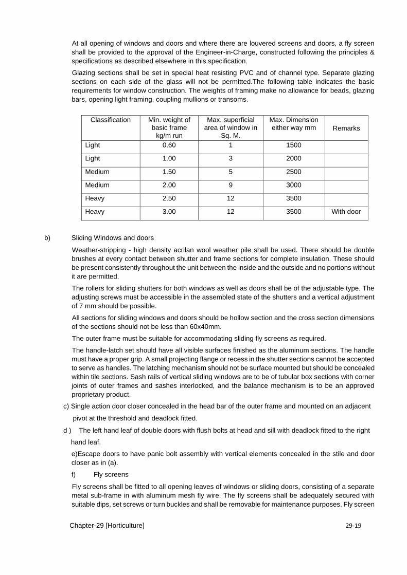
Chapter-29 [Horticulture] 29-19
At all opening of windows and doors and where there are louvered screens and doors, a fly screen
shall be provided to the approval of the Engineer-in-Charge, constructed following the principles &
specifications as described elsewhere in this specification.
Glazing sections shall be set in special heat resisting PVC and of channel type. Separate glazing
sections on each side of the glass will not be permitted.The following table indicates the basic
requirements for window construction. The weights of framing make no allowance for beads, glazing
bars, opening light framing, coupling mullions or transoms.
Classification Min. weight of basic frame
kg/m run
Max. superficial area of window in
Sq. M.
Max. Dimension either way mm Remarks
Light 0.60 1 1500
Light 1.00 3 2000
Medium 1.50 5 2500
Medium 2.00 9 3000
Heavy 2.50 12 3500
Heavy 3.00 12 3500 With door
b) Sliding Windows and doors
Weather-stripping - high density acrilan wool weather pile shall be used. There should be double
brushes at every contact between shutter and frame sections for complete insulation. These should
be present consistently throughout the unit between the inside and the outside and no portions without
it are permitted.
The rollers for sliding shutters for both windows as well as doors shall be of the adjustable type. The
adjusting screws must be accessible in the assembled state of the shutters and a vertical adjustment
of 7 mm should be possible.
All sections for sliding windows and doors should be hollow section and the cross section dimensions
of the sections should not be less than 60x40mm.
The outer frame must be suitable for accommodating sliding fly screens as required.
The handle-latch set should have all visible surfaces finished as the aluminum sections. The handle
must have a proper grip. A small projecting flange or recess in the shutter sections cannot be accepted
to serve as handles. The latching mechanism should not be surface mounted but should be concealed
within tile sections. Sash rails of vertical sliding windows are to be of tubular box sections with corner
joints of outer frames and sashes interlocked, and the balance mechanism is to be an approved
proprietary product.
c) Single action door closer concealed in the head bar of the outer frame and mounted on an adjacent
pivot at the threshold and deadlock fitted.
d ) The left hand leaf of double doors with flush bolts at head and sill with deadlock fitted to the right
hand leaf.
e)Escape doors to have panic bolt assembly with vertical elements concealed in the stile and door
closer as in (a).
f) Fly screens
Fly screens shall be fitted to all opening leaves of windows or sliding doors, consisting of a separate
metal sub-frame in with aluminum mesh fly wire. The fly screens shall be adequately secured with
suitable dips, set screws or turn buckles and shall be removable for maintenance purposes. Fly screen
Chapter-29 [Horticulture] 29-20
doors shall consist of similar section to metal casement doors and shall be fitted with removable
panels of fly wire.
The aluminum frame .to the fly screen shall be finished to match the framing of the window or sliding
door with color and type of mesh to Engineer-in-Charge 's approval.
g) Glazing
The glass shall conform to specification laid down under Section 28.1.6; 'Glazing' and shall be free
from all blemishes, bubbles, distortions and other flaws .of any kind and shall be properly cut to size
as shown on drawings, so as to fit the grooves in window members. All the glass shall be best quality
of approved manufacture or equivalent standard as approved by the Engineer-in-Charge.
12.3.7 ERECTION AND WORKMANSHIP
12.3.7.1 ERECTION
a) Raw plugs and anchoring bolts shall be embedded into the concrete or masonry for holding the doors,
windows, ventilators and louvers in their correct position.
b) Care shall be taken to install the doors and windows, ventilators and louvers in line and plumb, solidly
anchored in a good workman-like manner in accordance with the Drawings. Should any scale or
scratch appear on the surface of doors, windows, ventilators and louvers the Contractor shall at .his
own expense and at the Engineer-in-Charge's direction have all exposed surface cleaned to bare
bright metal and made good as required.
All joints between structure and the metal shall be fully caulked and painted. All works shall be
installed in strict accordance with the manufacturer’s instructions.
12.3.7.2 WORKMANSHIP
The Contractor shall be responsible for the protection and installation of all items furnished. All items
shall be installed plumb and square and shall be solidly anchored in a good workmanship like manner
in accordance with the manufacturer's instructions and as specified herein.
No door and window shall be considered complete until the finger prints and other stains and marks
have been removed from the surface of glass and aluminum.
Temporary protection shall be achieved by applying water soluble protective coating capable of
withstanding the action of mortar.
Protective coating shall be applied in the manufacturer's plant to the exposed surface of all
components after removing all fabrication compounds, mixture and dirt accumulations.
12.3.7.3 FINISHING
All exposed surfaces shall be carefully polished and all alloy defects, die marks scratches, strokes or
other surface blemishes shall be buffed to a clear surface and given an anodic oxides treatment. The
structural shape of aluminium members shall be of uniform quality, color and temper; clean, round,
commercially straight and free from injurious defects
12.3.7.4 PROTECTION AND CLEANING
- Temporary protection shall be achieved by applying water soluble protective coating capable of
withstanding the action of mortar. - Apply coating in the manufacture(s plant to the exposed surfaces of all components. - Before application of coating, remove all fabrication compounds, moisture and dirt
accumulations.
12.3.7.5 DEFECTIVE WORK
In the event of non-conformance to specifications and drawings the aluminum work shall be rejected
by the Engineer-in-Charge and the Contractor shall remove and - replace the rejected works by new
work of same specifications.
Chapter-29 [Horticulture] 29-21
12.3.7.6 MEASUREMENT
The height and breadth shall be measured correct to a cm. The height of the Window and Doors
shall be measured as the length and breadth from outside to outside of the end . The area
shall be calculated in square metres, correct to two places of decimal.
CHAPTER -13 MISCALLENOUS WORKS
13.1 FALSE CEILINGS
13.1.1 GENERAL A typical dropped ceiling consists of a grid-work of metal channels in the shape of an upside-
down "T", suspended on wires from the overhead structure. These channels snap together in a
regularly spaced pattern of cells.
13.1.2 MATERIALS
i) Gypsum Board False Ceiling Standard Gypsum Board ½” thick unless otherwise indicated on the
Drawings, ends square cut, tapered edges as manufactured by US Gypsum or approved equivalent
and of approved pattern, size and thickness as per approved shop drawings.
ii) Lasani Board /MDF False Ceiling
Lasani Board / MDF false ceiling shall be of the approved manufacturer and of approved pattern, size
and thickness as per approved shop drawings.
iii) Plaster of Paris False Ceiling
The Plaster of Paris false ceiling comprise of POP tiles 1/2" thick size 2'-0"x2'-O" or as shown on the
Drawings, reinforce with hessian-mat.
iv) Dampa AL-15
Suspended aluminum false ceiling shall be standard products offered by the manufacturer /
supplier DAMPA grid system shall be 0.5mm thick aluminum strips. They shall be profiled units
available in standard foil and a pad of mineral wood 12mm thick. The approved manufacturers
shall be DAMPA. The type of ceiling used shall be DAMPA AL-15 perforated.
v) Hangers
Hangers shall be of 5/8"x1/8" M.S. flat. It shall be the responsibility of the Contractor to get the sample
of hanger approved by the Engineer-in-Charge.
vi) Angles and Tees
Angles and Tees shall be of Aluminum section 1.6mm of approved pattern as per shop drawings
approved by the Engineer-in-Charge.
13.1.3 SUBMITTALS
The Contractor shall submit the following for approval of Engineer-in-Charge.
• The shop drawings showing reflected ceiling plan, locations of built-in products and access
facilities, dimensions, layout arrangements, hanger locations, structural connection, details of
level changes, direction of pattern and panel-joint details.
• Samples of false ceiling panels, suspension system, and accessories including
sealant, furring and runner channel etc.
13.1.4 DELIVERY AND STORAGE
• Material shall be delivered in original, unopened, protective packaging, with manufacturer's
labels indicating brand name, pattern, size, thickness and fire rating.
Chapter-29 [Horticulture] 29-22
• Material shall be stored in original protective packaging to prevent soiling, physical damage
or wetting.
• Cartons shall be stored in the installation area, opened at each end to stabilize moisture
content and temperature, for 48 hours prior to installation.
13.1.5 QUALITY ASSURANCE
Installer Qualifications: Engage an experienced Installer who has successfully completed
false ceilings similar in material, design and extent to those indicated for this Project.
.
13.1.6 TOLERANCES:
Deflection:
Suspension system components, hangers and fastening devices supporting light fixtures,
ceiling grilles, and acoustical panels, maximum deflection 1/360th of the span.
Deflection test: ASTMC635.
Field Constructed Mock-Up: Install acoustical ceiling in designated area.. After the
acceptance of the Engineer-in-Charge, retain mock-up as a standard of quality for entire
acoustical panel ceiling installation.
13.1.7 MEASUREMENT:
Length and breadth of the False Ceiling shall be measured correct to a cm and the surface area
worked out in square metre of the finished work.
No deduction shall be made for openings of areas upto 40 square decimetre. No extra payment
will be made for any extra material or labour involved in forming such openings. For openings
exceeding 40 square decimetre in area, deduction for the full opening will be made, but no extra
will be paid for any extra material or labour involved in forming such openings.
13.2 KITCHEN CABINET
All wooden kitchen cabinet works shall be fabricated by approved subcontractor/manufacturer and
shall be of best quality.
A) Shop Drawings
The details of these items shown on the drawing are tentative and show basic configuration and
design of these items.
The contractor shall submit detailed shop drawings of these items on the basis of tentative detail
shown on the drawings including all fitting, fixtures and hardware for the proper execution of kitchen
cabinet for the approval of the Engineer before fabrication.
B) Installation All the works shall be installed in position by the manufacturer’s skilled workmen
specialized in the job. Works shall be executed in accordance with approved shop drawings and
or as directed by the Engineer.
All work shall be thoroughly protected from the damage at all times by suitable methods approved
by the Engineer. Adjacent works shall similarly be protected from damage. Any damage or
disfigurement shall immediately made good at contractor’s expense.
13.2.1 MEASUREMENTS AND PAYMENT:
Length and width of the cabinet shall be measured to the nearest cm in closed position covering
the rebates of the frames but excluding the gap between the shutter and the frame. Area is
calculated to the nearest 0.01 sqm.
The payment for the items of the work shall be made corresponding to the applicable
items as provided in Contract Agreement and shall constitute full compensation, for
procurement, transportation, performance in all respects and completion of work as
Chapter-29 [Horticulture] 29-23
specified including the site clearance as approved by the Engineer-in-Charge.
13.3 ROOF HEAT INSULATION TILES
13.3.1 : SCOPE
The work under this section of specification includes furnishing all labor, equipment, appliances and
materials and performing all operations in carrying out the work of Lightweight insulation roof tile
made from a combination thermopore and cellular concrete also known as aerated concrete subject
to the terms and conditions of the Contract.
13.3.2 MATERIALS :
Aerated concrete is a cement mortar, classified as lightweight concrete, in which air-voids are
fentrapped in the mortar matrix by means of a suitable aerating agent. The prominent advantage of aerated
concrete is its lightweight. It provides a high degree of thermal insulation and considerable savings in material
due to the porous structure. By appropriate method of production, aerated concrete with a wide range of
densities (300± 1800 kg/m3) can be obtained thereby offering ¯flexibility in manufacturing products for
specific applications (structural, partition and insulation grades).
Tile size 300mm x300mmx50mm
A) Aerated Concrete top thickness 1” (inch) in varying colour Concrete Compressive Strength 3000psi
B ) Thermopore : Average density 16 Kg /m 3 average thickness 1” (inch)
13.3.2 : PROPERTIES :
Composite roof insulation tiles provides following properties
• Double insulation of cellular concrete and thermopore • Lightweight • Absorption less than 2% • Concrete compressive strength, approximately 3,000 psi • Micro reinforcement with high strength synthetic fiber • Cellular Concrete Density: 1,500 kg/m3, approximately • Thermopore Density: 16 kg/m3 approximately • Thermopore Thickness: 25 mm approximately
13.3.4 SIZE : 300MMX300MMX50MM
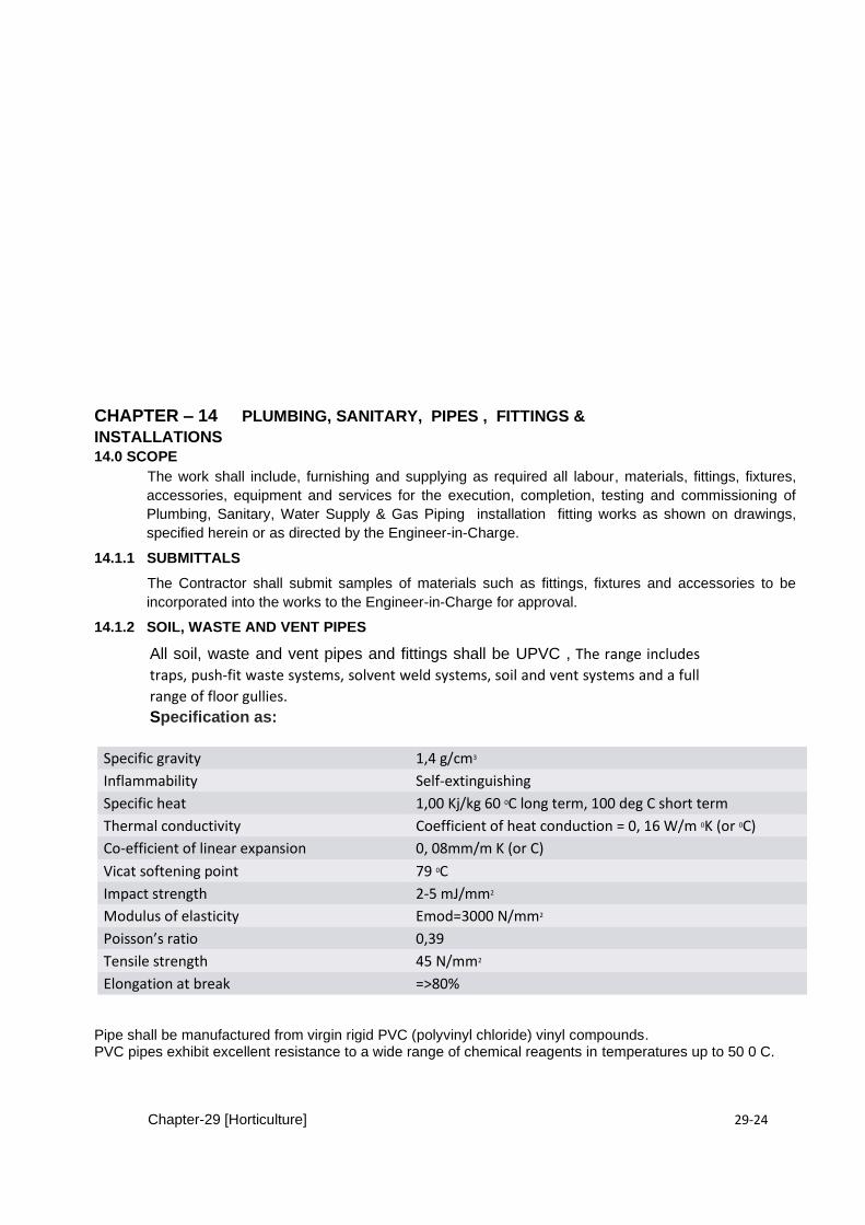
Chapter-29 [Horticulture] 29-24
CHAPTER – 14 PLUMBING, SANITARY, PIPES , FITTINGS &
INSTALLATIONS 14.0 SCOPE
The work shall include, furnishing and supplying as required all labour, materials, fittings, fixtures,
accessories, equipment and services for the execution, completion, testing and commissioning of
Plumbing, Sanitary, Water Supply & Gas Piping installation fitting works as shown on drawings,
specified herein or as directed by the Engineer-in-Charge.
14.1.1 SUBMITTALS
The Contractor shall submit samples of materials such as fittings, fixtures and accessories to be
incorporated into the works to the Engineer-in-Charge for approval.
14.1.2 SOIL, WASTE AND VENT PIPES
All soil, waste and vent pipes and fittings shall be UPVC , The range includes
traps, push-fit waste systems, solvent weld systems, soil and vent systems and a full
range of floor gullies.
Specification as:
Specific gravity 1,4 g/cm3
Inflammability Self-extinguishing
Specific heat 1,00 Kj/kg 60 0C long term, 100 deg C short term
Thermal conductivity Coefficient of heat conduction = 0, 16 W/m 0K (or 0C)
Co-efficient of linear expansion 0, 08mm/m K (or C)
Vicat softening point 79 0C
Impact strength 2-5 mJ/mm2
Modulus of elasticity Emod=3000 N/mm2
Poisson’s ratio 0,39
Tensile strength 45 N/mm2
Elongation at break =>80%
Pipe shall be manufactured from virgin rigid PVC (polyvinyl chloride) vinyl compounds. PVC pipes exhibit excellent resistance to a wide range of chemical reagents in temperatures up to 50 0 C.
Chapter-29 [Horticulture] 29-25
14.1.3 INSTALLATION Installation shall comply with the latest installation instructions published by the Pipe manufacturer and shall conform to all applicable plumbing, and building requirements. Buried pipe shall be installed in accordance with ASTM D 2321 and ASTM F 1668. Solvent cement joints shall be made in a two-step process with primer conforming to ASTM F 656 and solvent cement conforming to ASTM D 2564. The pipe shall be protected from chemical agents, plasticized vinyl products, or other aggressive chemical agents not compatible with PVC compounds.
i) All soil waste and vent pipes and fittings shall be installed plumb and true to lines and grades shown
on the drawings or as directly by the Engineer-in-Charge.
ii) Where installed vertically, pipes shall be supported from wall by metal clamps of approved type and
make at each floor just below the Horizontal branch pipe connection and at intermediate levels.
The spacing of vertical and horizontal pipe supports shall be 1.5 mm to 3 mm respectively and dia
of steel support shall be 13 mm.
iii) Pipes passing through walls, floors or roof shall be placed in metal sleeves of approved design. The
annular space between the sleeve and pipe shall be at least 15 mm. The space shall be packed with
approved filler and shall be sealed at both ends with approved sealant .
iv) Drainage pipes shall be installed with a slope of not less than 1% unless specifically indicated
otherwise on the drawings. Drainage pipes installed underground shall be minimum 2" diameter.
Before installing any pipe, it shall be internally cleaned from dirt, debris, etc, by passing through it a
cleaning cloth.
v) Pipes shall be installed in a neat manner with runs parallel and branching or changes in
direction at 90 or 45 degrees. Change in direction and size, branching and jointing of pipes shall be
made with regular pipe fittings (elbows, tees, reducers etc...). Pipe bending shall not be accepted.
All elbows shall be long radius. All drainage fittings shall be long radius sweep type.
vi) Sleeves shall be supplied and installed wherever pipes cross slabs, walls, partitions, etc,
Sleeves shall be cuts of galvanized steel pipes having an internal diameter of not less than 1 1/2"
(4cms) larger than the outside diameter of the bare sleeved pipe or the insulated sleeved pipe.
vii) Floor sleeves shall protrude about 3/4" (2cms) above finished floor level and shall be flush
with finished walls. Gaps between sleeves and pipes shall be filled with non-flowing plastic or
waterproof mastic filler or paste.
14.1.4 FITTINGS
Store fittings supplied in plastic bags away from direct sunlight. If this is not possible, open bags to prevent a build-up of temperature. Fittings in cardboard packaging (e.g. Fire Stop Seals and Air Admittance Valves) should be stored under cover until required. Store degreasing cleaners, silicone lubricant, solvent cement and fillers in a cool place away from any heat source and out of direct sunlight.
14.1.4 JOINTING :
For jointing there are two types adopted as follow :
14.1.4.1.RUBBER RING JOINTS
The rubber ring joint is integrally moulded on one end of the pipe. The joint incorporates a factory
fitted rubber sealing ring which is retained in position by a polypropylene lock ring. The opposite
(spigot) end of the pipe is chamfered and has a “depth of entry’’ mark near the end. Each joint is
capable of handling some expansion and contraction as well as angular deflection. The seal ring is
designed to provide a watertight joint at high and low pressures.
14.1.4.2 SOLVENT WELD JOINT
Solvent cement jointing is a welding process and not a gluing process. If done correctly, separation
will not be possible after the curing period. Jointing of pipe should be an interference fit between the
Chapter-29 [Horticulture] 29-26
components before solvent cement is applied. There are different solvent cements available for
applications. Be sure to use the correct cement and that it has not “dried out’’ prior to use.
14.1.5 TRAPS AND CLEANOUTS
14.1.5.1 FLOOR TRAPS
Traps shall be of self-cleaning design, provided with water seal. Traps of the specified size used for
underground installation shall be UPVC confirming specification EN 1329 & EN 1401 as under :
14.1.5.2 Floor Drains - Type FDV, FD
Supply and install all floor drains wherever shown on drawings and as specified .
Floor drains are to be bottom outlet for FDV, and horizontal outlet for FD, of type suitable for connection
to UPVC non-pressure pipes, or approved equal.
14.1.5.3 FLOOR CLEAN OUTS
Supply and install all clean-outs wherever shown on the drawings and as specified herein.
Each clean-out shall be of the same material and dimension as the pipe shall conform with the
following requirements:
a. For pipes exposed or in false ceilings, clean-outs shall consist of a threaded cap
screwed onto pipe end.
b.) Floor FCO and wall clean-outs WCO shall consist of capped wide elbows ending under a
chrome plated bronze tile 20 x 20cms with screwed cover or .
All cleanouts in the sewerage system shall be closed with brass screw caps. All brass screw caps
shall be extra heavy and not less than 3 mm thick. Each screw cap shall have solid square or
hexagonal nut not less than 25 mm high, with a minimum diameter of 38 mm.
14.1.6 Roof Vents and Vent Caps
Supply and install all roof vents and vent caps wherever shown on the drawings and as specified
herein.
a. Vent cap shall be full size of stack connected to it and provided with cap. UPVC with hooded
vent cap.
b. Vent shall be provided with an extension nipple for fixing onto the vented stack.
14.1.7 INSTALLATION OF TRAPS, DRAINS AND CLEAN OUTS
i. Floor traps shall have openings for connection of inlet pipes from fixtures. The invert level of inlet
pipes shall be at least 25 mm above the trap weir level.
ii. Floor traps shall be well set in position so that there is no leakage at the joint between trap and the
floor. The requirements specified above for floor traps are equally applicable for floor drains except
that no water seal is required and it shall be of the specified size.
iii. Roof drain shall have strainers extending at least 10mm above the roof surface immediately adjacent
to them when installed on flat part. Bottom of strainer shall be flush with the roof surface when
installed on vertical part. Strainer shall have an available inlet area, above roof level, of not less than
1-1/2”
times the area of the down-pipe to which the drain is connected. The connection between roof and
roof drain shall be made watering by use of proper flashing material.
iv. Clean outs shall be turned up through floors by long sweep fittings, wherever the space so permits.
Top finish of clean outs shall be flush with the floor when located in open area. They may not be
flush with the floor when installed near wall and levels are not deep enough to make them flush.
Clean out shall be so installed that there is a clearance of at least 300 mm for pipe less than 75 mm
diameter and at least 450 mm for pipes of 75 mm and larger diameter for the purpose of rodding.
Permanent finishing material shall not be placed over clean out plug.

Chapter-29 [Horticulture] 29-27
Clean out in open areas shall be placed in concrete boxes with access cover of heavy duty 300 x
300 mm size. Clean out near wall shall be embedded in concrete, and excepting cast iron pipe used
with cleanout all other work of ferrule, plug, concrete work, frame and cover etc. shall be included
under clean out item.
v. Gulleys shall be fixed on concrete foundation 300 mm square and not less than 150 mm thick. A
brick curb in cement mortar about 75 mm high from the ground level shall be built round top edge of
gulley in such a manner that surface water shall not be allowed to enter the gulley. It shall be used
for waste water only before entering into the manhole.
14.1.7 MEASUREMENTS
Traps, Vent Caps and Cleanouts shall be measured in numbers as per BOQ item.
CHAPTER -15 WATER SUPPLY & GAS UTILITY PIPING
15.0 PRESSURE PIPE FOR POTABLE WATER SUPPLY
15.1.1 PRESSURE UPVC PIPES AND FITTINGS
Supply and install all pressure UPVC pipes and fittings as specified& shown on Drawing as herein.
a. All pressure UPVC pipes shall be of extruded unplasticized Polyvinyl Chloride to BS 3505
class E or UPVC pressure pipes conforming to Pakistan Standard PS 3051 : 1991 or approved equal
International Standards. Fittings shall be of same material and pressure as pipe.
b. All joints shall be of the solvent weld joint.
15.1.2 Polypropylene Random (PPR)
Polypropylene pipe shall be of high grade polypropylene random (PPR), to comply with DIN 16962
appropriate to the service working pressure. The tube shall be provided in straight lengths form.
Joints and fittings shall be welded type, of the Saul material and type of the tube. Fittings shall consist
of gunmetal bodies coated with polypropylene suitable to be welded to the tube at one end and to
receive a threaded coupling at the other end.
Welding shall in all cases be carried out by skilled craftsmen who are in possession of a current
certificate of competency issued by an approved authority. Specimen welds, representative of the
thickness and diameter of the joints and the condition of site welding, shall be submitted as required
by the Engineers in request of every craftsman employed in such work.
When the general hydraulic tests of the completed systems are carried out, each weld shall be lightly
hammered whilst pressure is maintained. If any leaks occur, the portion of the weld near the leak shall
be cut out and re-welded. Should a considerable portion of the welded joints made by a particular
operative be found to be defective due to faulty workmanship, all such welds shall be cut out and re-
welded by another operative whose work has proved satisfactory.
All expansion loops shall be proportioned such that the total stress set up in the material of the pipe
wall; taking into account the components due to internal pressure, torsion and bending; is taken up in
the geometry of the changes of direction.
All expansion loops shall be generally inserted in the pipe lines in such a manner that cold draw to
extend of one-third of the anticipated expansive movement is taken up. Such conditions shall be
agreed on the site with the Engineer at time that erection is taking place.
Chapter-29 [Horticulture] 29-28
Expansion loops shall be factory fabricated of similar materials to the pipe work
15.1.3 PIPE HANGERS AND SUPPORTS General Requirements
a. Supply and install pipe hangers and supports to properly carry weight of pipes and accessories
without sagging as specified and required.
b. Hangers and supports shall be designed and tested to sustain a load 8 times the actual
supported load, and shall be easily adjustable.
c. Hangers and supports shall be steel with smooth flat bearing surfaces and shall allow free
movement of pipes due to expansion and contraction without any deformation. Hangers and
supports for UPVC Pipes shall be of material, type and spacing strictly in accordance with
manufacturer’s recommendations.
d. Hangers and supports on insulated pipes shall have galvanized steel sheet protection saddles
or shields, 3mm thick, 30cms long to fit outside diameter of insulation and cover 180° of arc.
e. Pipe anchors and guides shall be 3/4" diameter U-bolt.
f. Piping to be independently supported of equipment and located at adequate intervals to avoid
air pockets and dirt traps. All branching shall be directly supported.
g. Spring cushions shall be used where pipe is subject to considerable vertical movement or
vibration.
h. Insulated hot pipes shall be supported on a clevis hanger or pipe clamp lined with protection
shields. The contractor shall submit shop drawings for all types of supports showing
construction details. Hangers and supports locations shall be shown on shop drawings. 15.2.0 GAS UTILITY SERVICES
SCOPE
The work for piped utility services in buildings shall include furnishing of all labour, plant, equipment,
materials and services and supplying, installing, testing and commissioning of cold and hot water
supply and gas supply systems in the buildings as shown in the drawings, required as per
specifications and or directed by the Engineer-in-Charge.
The gas pipeline and fittings shall be carried out strictly complying with the regulations of Gas
Authority. Where required, the Contractor shall be responsible for their acceptance certificate for
gas connection.
15.2.1 SUBMITTALS
The Contractor shall submit samples of fittings, fixtures and accessories to be incorporated into the
works.
15.2.2 G.I. PIPES
i) The galvanized iron pipes shall conform to BS specifications No. 1387 for “Steel tubes and Tubulars,
suitable for screwing to BS-21 pipe threads”.
ii) All screwed tubes and sockets shall have threads in accordance with BS-21. In order to prevent
damage to the leading thread, the end of the sockets shall be chamfered internally.
iii) A complete and uniform adherent coating of zinc shall be provided for galvanized iron pipes.
iv) Every tube shall be tested at the manufacturer's works to a hydraulic test pressure of 5 MPa and
shall be maintained at the test pressure sufficiently long for proof and inspection.
v) The threads of all tubes shall be effectively covered with good quality grease or other suitable
compound, and each tube above 50 mm nominal bore shall have a protecting ring affixed to the un-
socket screwed ends.
15.2.3 MEASUREMENT
G.I. Pipes shall be measured in Running Meters correct to cm.
Chapter-29 [Horticulture] 29-29
15.2.4 FITTINGS AND SPECIALS
15.2.5 G.I FITTINGS
i) Malleable Iron Galvanized Fittings (i.e. coupling, elbows, tees etc.) for G.I pipes of diameter
lower than 75 mm shall conform to BS-143/BS-1740 and shall be at least same thickness and quality
as G.I. pipe.
ii) Cast Iron Threaded Flanges for joining G.I pipe of dia 75 mm and above shall conform to BS-4504.
iii) Cast Iron Flanged Fittings for G.I. pipe 75 mm and above shall conform to BS-2035, a working
pressure 122 meters of water.
15.2.5 MEASUREMENTS
Cost of G.I fittings and Specials is included in cost of Pipes
CHAPTER – 16 SANITARY, WATER SUPPLY & GAS FIXTURES
16.0 SANITARY FIXTURES
16.1 WASH BASINS
The wash basins shall be glazed earthen ware in sizes and colours as specified and as per shown on
drawing. The wash basins shall be of specified make as approved and the following shall generally be
provided at the time of manufacture;
a) Brackets
The length of the brackets shall be such as to enable 10 cm (4") embedding in the wall or fixed to the
wall with the help of screws. Bracket shall be of painted iron on white porcelain enameled.
b) Pillar Taps
Pillar taps shall be manufactured from gun metal and shall be chromium plated. These shall be of
screw type with jam nut. Internal dia of the tap shall be 13 mm (1/2").
d) Plug and Chain
Plug shall be of rubber. The diameter of the plug shall be such as to fit snugly in the waste hole.
The chain shall be of brass, chromium plated, one end fixed to the plug and the other held in the
chain stay hole.
e) Combined (Mixes) Supply and Waste Fitting
This shall comprise of 13 mm (1/2") combine taps with discharge nozzle and 3.17 cm (1-1/4") pop
up waste. Waste outlet shall be screwed 3.17 cm (1-1/4") to B.S pipe male. All of these fittings shall
be of gun metal with chromium plating.
f) Waste Pipe
This shall be either of PVC, nickel or C.P Brass and shall have diameter to fit at the bottom of the
waste fitting flange. Its length shall extend from the bottom of waste flange to the floor.
g) Pedestal
Pedestal shall conform to the corresponding specifications of wash basin for composition,
manufacture and quality. It shall be completely recessed at the back for the reception of supply and
waste pipes. It shall be such that the basin is tightly and adequately supported and shall be so
Chapter-29 [Horticulture] 29-30
arranged that the height from the floor to the top of the rim of basin is 79 cm (31"). The Wash Basin
shall be supplied complete with fittings and accessories as specified.
h) MIRROR (LOOKING GLASS)
One beveled edge glass mirror of first class quality and make as specified securely fixed on bard
board packing required to be fixed on the wall for wash basin shall be at least 6 mm thick and shall
be of requisite dimensions.
16.2 KITCHEN SINKS
a) Sinks
Kitchen sink shall be stainless steel or glazed earthenware of approved make, single or double bowl
with integral drain board. The sizes of the sinks shall be either 61 cm x 45 cm x 25 cm (24"x18"x10")
or 51 cm x 101 cm x 25 cm (20"x40"x10") or 51 cm x 122 cm x 25 cm (20"x48"x10") or 82.5 cm x
4.5 cm x 2.5 cm (33”x18”x10”).
b) Brackets
The Brackets shall be either of such a length as to enable 10 cm (4") embedding in the wall or
shall be such as to be fixed to the wall with the help of screws. The bracket shall be of painted iron
or porcelain enameled.
c) Pillar Taps
Pillar taps shall be manufactured from gun metal and shall be chromium plated. These shall
be of screw down type with jam nuts. Internal diameter of the taps shall be 13 mm (1/2").
d) Plug
The rubber or vulcanite plug shall fit in the waste pipe.
e) Waste Fitting Flanges
The waste fitting flanges shall be 85 mm (3-3/8) diameter, the tail 87 mm (3-1/2") long, screwed with
37 mm (1-1/2") B.S parallel thread and the sliding flange of back-nut of 81 mm (3-1/4") diameter.
f) Waste Pipe
This shall be either of PVC, nickel of C.P Brass and shall have diameter to fit at the bottom of the
waste fitting flange. Its length shall extend from the bottom of waste pipe flange to the floor.
16.3 WATER CLOSETS
a) European Type Water Closets
The W.C shall be pedestal type white glazed earthen ware or of color as specified durable non-
absorbent material with a water pool of good effective seal not less than 5 cm (2"). There shall be
no sharp angles, the surface shall be so rounded as to be easily cleaned. The closets shall be of
syphonic action or washed down type or as directed by the Engineer-in-Charge. Four holes 6 mm
(0.25") shall be provided in the pedestal for fixing the W.C to the floor.
b) Indian Type Water Closets (Orisa Type W.C)
The water closets shall be of glazed earthen ware of color as specified nonabsorbent durable
material. There shall be no sharp angles, the surface shall be so rounded as to be easily cleaned.
The closets shall be embedded below the flow in lean concrete with its stop level with the floor. The
foot rest shall be either integral part of the W.C or shall be provided separately in which case shall
be of the same material as the pan.
c) Trap
The trap P or S for European type W.C shall be self- cleaning with a minimum water seal of 50 mm
Chapter-29 [Horticulture] 29-31
(2") and made of the same materials as the pan. For squatting type W.C it shall be of cast iron.
d) Seat
The seat for the European type W.C shall be of approved quality backlite plastic seat with lid hinged
and fixed to the closets by pillar bolts. The hinged device and pillar and nuts shall be of non-corrosive
material. The pillar bolts shall be 6 cm (2-3/8") long and shall be held securely by the nuts
underneath the pan seat plugs. The backlite seat should have rubber buffers securely fixed to the
under-side to prevent damage to the pan. The seat cover shall be of the same material as that of
the seat. The backlite cover shall have rubber buffers.
e) Flushing Cistern
i) Low Level Flushing Cistern
The low level cistern shall be of 10 liters (2.9 gallons) capacity. It shall be either of glazed earthen
ware or PVC as approved by the Engineer-in-Charge, complete with all internal fittings. The bottom
of the cistern shall be 30 cm (2.5 feet) above ground level.
The inlet to the cistern shall be controlled by 13 mm (1/2") ball wall and 13mm (1/2") stop cock both
made from gun metal or brass. The cistern shall be silent filling with an over flow arrangement.
The cistern shall be supported on M.S or C.I cantilever brackets and painted with approved enamel
paint with 10 cm (4") support in the wall or it may be attached to the wall with the help of rowl plugs.
The flush pipe shall be 30 mm (1-1/4") G.I or PVC painted with approved paint. Moulded
rubber cone shall be provided for connection with the pan.
a) Soil Connection
Ordinarily in case of European type W. C the closet shall have trap above the floor and the
connection with the soil pipe through an external wall.
b) Size of Closet
Ordinarily the closet shall be 40 cm (16") on shorter side. For schools, nurseries 35 cm (14") 30 cm
(12") and 25 cm (10") be adopted as per instructions of the Engineer-in-Charge.
c) Connection of Water Closet with Soil Pipe
If the trap is of earthen ware, it shall be connected with the water closet with 1:2 cement sand mortar
joint. If the trap is of cast iron, it shall be connected with gaskets and 1:2 cement sand mortar joint.
d) Connection between Trap and Soil Pipe
Soil pipe is the pipe leading from trap to manhole.
If the trap is of earthen ware and the soil pipe is of cast iron then it shall be connected through C.I
piece the joints between earthen ware and C.I piece be as per para (h) above. If the trap is of C.I it
shall be connected with C.I soil pipe with ordinary lead metallic joint through a C.I connecting piece.
16.4 TOILET ACCESSORIES
a) TOILET PAPER HOLDER
The toilet paper roll holder shall be wooden/ plastic with either glazed earthenware or CP brass or
plastic brackets and screws etc and shall be fixed in the wall adjacent to water closet.
b)SHOWERS
A shower head shall consist of corrosion resisting cast or fabricated sheet metal rose having
perforations and shall be adjustable to give varying degrees of spray. Shower unit shall be complete
with or without hot and cold water mixing arrangements and stainless steel rigid or flexible pipe
extension and an additional low down water trap.
C ) TAPS, COCKS AND MUSLIM SHOWER
Chapter-29 [Horticulture] 29-32
All the taps, cocks and muslim shower shall be of brass, gun metal or other equally suitable
corrosion resisting alloy conforming to BS 1010 and shall be chrome plated. The nominal size
specified shall be the nominal bore of the seating. The water area of the way throughout the body
shall be not less than the area of a circle of diameter equal to the nominal size of tap/cock/muslim
shower. Washers for cold water cocks shall be of specially selected leather, rubber asbestos
composition or other equally suitable material.
Washers for hot water cocks shall be of good quality fibre, rubber – asbestos composition or other
equally suitable material. Every tap/cock shall be tested, complete with its component parts, to a
hydraulic pressure of at least 1.96 MPa (284.4 psi). During test it shall neither leak nor sweat. The
connecting pipe of muslim shower shall be of C.P Chain or of make approved by the Engineer-in-
Charge.
d.) TOWEL RAIL, SOAP DISH& TUMBLER HOLDER
The towel rail shall be ¾ inches round or square C.P brass or stainless steel rod with end brackets
and screws of similar material. Soap dish shall be straining type heavy duty glazed earthen ware,
chromium plated stainless steel or plastic complete with screws. Tumbler holder shall be of glazed
earthen ware, chromium plated, stainless steel or plastic complete with screws. Tooth brush holder
with tooth paste dish shall be of glazed earthen ware, chromium plated stainless steel or plastic
complete with screws etc
e) ABLUTION TAP/ SPRINKLER
Adjacent to the water closet, a water connection of ½ inch diameter for ablution will be either a C.P
brass water tap or a water sprinkler with flexible pipe armoured with stainless steel strip.
f) GLASS SHELVES
Glass shelves may be provided below the mirror above the wash basin. The length of the shelf
shall depend on the size of the mirror its width shall be 5 inches (130 mm) & thickness 6 mm and
shall be held by 2 Nos. CP brackets. The shelf may be provided with CP railing.
16.5 MEASUREMENTS
All fixtures shall be measured in numbers as per BOQ
16.6 VALVES
A. General Requirements
Supply and install, wherever shown on the drawings and as specified herein, all valves and specialties.
In addition to valves proper, this section is applicable to the strainers, safety valves, automatic air
vents, float valves, etc,
The drawings indicate locations of major valves only. This does not limit the Contractor's responsibility
to supply and install all valves and specialties specified separately under equipment or systems and
in full compliance with the requirements of this section and the following stipulations:
a. Valves shall be designed for a working pressure of not less than 125 psi steam working
pressure rating and 200 psi cold water non-shock pressure rating unless otherwise specified.
b. Valves 2" diameter and less shall be bronze, threaded ends.
c. Valves 2 1/2" diameter and larger shall be cast iron, flanged ends.
d. Valves on fire service pipes are to be of the indicating type.
e. Unless specifically stated otherwise, valves shall be of the same size as the pipes on which
they are installed.
Chapter-29 [Horticulture] 29-33
Whenever the pipe size on which valves are to be installed is larger or smaller than the
equipment connection provided, an enlarger or reducer shall be first installed at the equipment
connection to the required pipe size, after which the valves can be installed
f. A conical union shall be supplied and installed with each threaded valve.
g. Install silent check valves on pump discharge pipes.
h. Approved Manufacturers: As per specified or approved equal.
B. Gate Valves
Supply and install, wherever shown on the drawings and as specified herein, all gate valves.
Each gate valve shall conform with the following requirements:
a. Bronze gate valves shall have bronze body and trim and shall be non-rising stem, screwed
bonnet and solid wedge disc.
b. Cast iron gate valves shall have cast iron body and shall be inside screw, non-rising stem,
bolted bonnet, wedge disc and bronze trimmed.
C. Globe Valves
Supply and install, wherever shown on the drawings and as specified herein, all globe valves.
Each globe valve shall conform with the following requirements:
a. Bronze globe valves shall have bronze body and trim and shall be inside screw, rising stem,
screwed bonnet and renewable composition disc.
b. Cast iron globe valves shall have cast iron body and shall be outside screw and yoke, rising
stem, bolted bonnet, renewable bronze disc and seat ring and bronze trimmed.
D. Check Valves
Supply and install, wherever shown on the drawings and as specified herein, all check valves.
Each check valve shall horizontal or vertical lift, non-slam type and shall conform with the
following requirements:
a. Bronze check valves shall have bronze body and bronze trim and shall be screwed bonnet
and renewable composition disc.
b. Cast iron check valves shall have cast iron body and shall be bolted bonnet, renewable bronze
disc and seat ring and bronze trimmed.
c. Silent check valves 2" diameter and under shall be non-slam, spring loaded, screwed, with
bronze body, seat and disc, 18-8 stainless steel spring with body having 300 psi working
pressure rating.
d. Silent check valves 2 1/2" diameter and above shall be non-slam, spring loaded, flanged, with
cast iron body, bronze seat and disc, 18-8 stainless steel spring, with body having 250 psi
working pressure rating.
e) Strainers
Supply and install, wherever shown on the drawings and as specified herein, all strainers.
Each strainer shall conform with the following requirements:
Strainers 2" diameter and under shall be bronze body, 150 psi steam working pressure, screwed, "Y"
type with 20 mesh stainless steel screen and screwed end-cleaning cap with 1/2" tapped hole for blow
down valve.
a. Strainers 2 1/2" and larger shall be flanged, cast iron body, 125 psi steam working pressure
"Y" or basket type with 20 mesh stainless steel screen and bolted end-cleaning cap with 3/4" diameter
tapped hole at bottom for blow down valve.
Chapter-29 [Horticulture] 29-34
f) Float Valves
Supply and install, wherever shown on the drawings and as specified herein, all float valves.
Each float valve shall conform with the following requirements:
a. All bronze construction including levers and arms suitable for 150 psi cold water working pressure.
b. Balancing piston type flow control mechanism.
c. Adjustable bronze rod.
d. Copper float.
g) Safety Valves
Supply and install, wherever shown on the drawings and as specified herein, all safety valves. Each
safety valve shall conform with the following requirements:
a. Bronze body and trim, suitable for 150 psi steam working pressure.
b. Adjustable, spring loaded relief mechanism testing arm.
c. Spring pressure adjusted locknut.
d. Relief outlet for piped connection.
Setting of safety valves shall be at 125% of the system operating pressure. After adjustment, the
adjusting screw shall be locked by an adequate lead sealed wire.
h ) Expansion Joints
Supply and install, wherever necessary and as specified herein, all expansion joints.
Expansion joints shall be installed on piping to relieve expansion stresses and shall be located at all
structural expansion joints and on all straight runs of pipes at 30 meters intervals.
U-bends expansion joints may be accepted under certain conditions after written Engineer's approval.
Each expansion joint shall conform with the following requirements:
a. Pack less bellows type, monel metal for pressure pipes services suitable for 150 psi steam working pressure.
b. Packing type for gravity piped.
c. Expansion joints shall have screwed flanged or welding ends as required for the pipe size and system served.
I. Automatic Air Vents (AAV)
Supply and install, wherever shown on the drawings and as specified herein, all automatic air vents.
Each automatic air vent shall be completed as specified herein:
a. Cast iron body.
b. Standard float.
c. Single lever orifice vent.
d. Vent test cock.
e. Isolating valve.

Chapter-29 [Horticulture] 29-35
J) Hose Bibs (HB)
Supply and install, wherever shown on the drawings and as specified herein, all hose bibs.
Each hose bib shall conform with the following requirements:
a. All brass, chrome plated construction.
b. 3/4" threaded end connection with serrated hose bib nipple for 3/4" hose connection.
K) Flexible Connections
Supply and install, wherever shown on the drawings and as specified herein, all flexible connections.
Flexible connections shall be installed on all pipe connections to rotating equipment.
Each flexible connection shall conform with the following requirements:
a. Seamless bronze tubing with annular corrugations covered with high tensile bronze braid
suitable for 200 psi cold working pressure. Screwed ends for pipes 2" diameter and smaller
and flanged ends for pipes 2 1/2" diameter and larger.
16. 7 MEASUREMENTS
Float Valve, Level Controller, Flow Switch, Fire Hydrants shall be measured in numbers as per rate
in BOQ
16.8 INSTALLATION OF FIXTURES
i) Plumbing fixtures shall be installed in a manner to afford easy access for cleaning. The space
between the fixture and the wall shall be closely fitted and painted so that there is no chance for dirt
or vermin to collect.
ii) Where practical, all pipes from fixtures shall be run to the nearest wall.
iii) Where fixtures shall be rigidly supported by metal supporting members so that no strain is
transmitted to the connections. Flush tanks and similar appurtenances shall be secured by approved
non-corrosive screws or bolts.
iv) Fixtures shall be set level and in proper alignment with reference to adjacent walls. No water closet
shall be set closer than 400 mm from its center to any side wall. No urinal shall be set closer than
300 mm from its center to any side wall or partition nor closer than 1200 mm center to center. No
wash basin shall be set closer than 100 mm to the side wall or partition nor closer than 600 mm
center to center.
v) The supply lines or fittings for every plumbing fixture shall be so installed as to prevent backflow.
vi) All cuttings and holes shall be made good.
Chapter-29 [Horticulture] 29-36
17.0 SEWERAGE
17.0.1 SCOPE
The work covered by this section of the specifications consists in furnishing all reinforced concrete
pipes, plant, labour, equipment, appliances and materials and in performing all operations required for
installing and testing the sewer pipes in strict accordance with the specifications of this section and the
applicable drawings and subject to the terms and conditions of the contract.
17.0.2 RELATED WORKS SPECIFICATIONS
• Section 3 – Earthwork
• Section 4 – Plain & Reinforced Concrete
17.1.1 SEWER LINES
MATERIALS
All materials used in the manufacture of reinforced cement concrete pipes for use shall conform to
ASTM Designation C-76-03 or latest revision .
17.1.2 NON-REINFORCED CEMENT CONCRETE PIPES
The non-reinforced cement concrete pipes shall conform to ASTM C-14, latest revision Class II
equivalent. Pipe ends shall be thus tongue and groove or bell and spigot. The physical dimensions
shall be as described in applicable provisions of ASTM C-14.
Chapter-29 [Horticulture] 29-37
17.1.3 REINFORCED CONCRETE PIPES
17.1.4 CLASSES OF PIPE
The reinforced cement concrete pipes to be furnished and installed shall be of the strength Class II
or specified otherwise on the Drawings.
Following technical criteria shall be adhered to:
Class of Pipe : Class-II
Concrete Strength : 4000 Psi (Cylinder Test)
The design requirements for these classes of reinforced cement concrete pipes shall be as
described in ASTM Designation C-76, Table 1 to 5 for the respective strength classes. Unless
otherwise called for in other parts of these Technical Specifications or as ordered, all reinforced
cement concrete pipes shall comply with the Wall-B design requirements as set forth in said Table
1 to 5 of ASTM Designation C-76-82 or latest revision. For pipes smaller than 12 inches dia BSS
556, Class-L shall be strictly followed:
17.1.5 BASIS OF ACCEPTANCE
Acceptance of reinforced cement concrete pipes will be on the basis of three edge bearing
and material tests as per ASTM Designation C-76-79 or latest revision and inspection of
manufactured pipes for defects and imperfections. The Contractor shall bear the cost of
such tests and pay fees etc., and also pay for the carriage of such samples and all other
expenses contingent to tests.
17.1.6 PIPE DIMENSIONS
The internal diameters and wall thicknesses of reinforced concrete pipes under this contract shall
be as set forth in ASTM Designation C-76-82 or latest revision in Tables 1 to 5 for "Wall-B" pipes as
required and shown on the Drawings.
For Class II Pipes, the Wall Thickness for various dia pipes is as under:
12 inch dia pipe : 2.00 inch
15 inch dia pipe : 2.25 inch
18 inch dia pipe : 2.50 inch
17.1.7 CERTIFIED DRAWINGS AND DATA SHEETS
The Contractor shall submit in triplicate, for approval by the Engineer-in-Charge certified drawings
and data sheets as required to provide complete information on all concrete sewer pipes,
dimensions, type and dimensions of pipe ends, joint details proposed concrete design mix for each
different strength class of reinforced pipe and any other information needed to demonstrate full
compliance with these specifications.
No concrete sewer pipe shall be delivered to the work site until the Engineer-in-Charge has formally
approved the certified drawings and data sheets and until all test requirements called for in the
respective ASTM Standard Specifications C-76 or latest revision have been met.
17.1.8 JOINTS FOR CONCRETE PIPE SEWERS
The joints for concrete pipes shall be as specified and could be as follows:-
a) Rubber Gaskets Joints
Rubber gasket joints shall be used for either tongue and groove or bell and spigot pipes.

Chapter-29 [Horticulture] 29-38
Rubber gasket joints shall be made using specially designed rubber gaskets, made to fit the
applicable tongue and groove or bell and spigot pipes and adequately tested under operating
conditions.
The rubber gasket joints shall conform to all applicable requirements of the latest revision of ASTM
Designation C443, entitled "Joints for Circular Concrete Sewer and Culvert pipe, using Flexible
Watertight Rubber Type Gaskets" except that the test pressure need not exceed 10 feet of head at
which the complete sewers shall meet the infiltration or exfiltration limits set forth hereinafter.
b) Cement Mortar Joints
Cement mortar may be used where called for. This type of joint will normally be permitted only for
sewers laid above the water table. Bell and spigot joints with cement mortar shall be made as
follows:
The first pipe shall be in place to the established line and grade. The interior surface of the bell
(socket) shall be thoroughly cleaned with a wet brush, and a sufficient layer of stiff mortar shall be
applied to the lower portion of the bell.
Tongue & groove joints with cement mortar shall be made as follows:
The first pipe (downstream) shall be in place to the established line and grade with groove upstream.
The groove of the first pipe shall be thoroughly cleaned with a wet brush and a layer of soft mortar
shall be applied to the groove in the entire lower half of the pipe.
The Portland cement mortar used for making joints shall consist of one part cement and one part
clean sand, thoroughly mixed dry with sufficient water slowly added to give proper consistency. The
mortar shall be promptly used after it is made.
17.1.9 INSTALLATION
a) Handling of Pipes
Concrete sewer pipes shall be handled with special care at all times during the manufacture, while
transporting to the site of work, and while installing. Each pipe shall be carefully inspected before
being laid and no cracked, broken or defective pipe shall be used in the work. Chipping of the tongue
and groove or bell and spigot pipe ends, which in the Engineer-in-Charge's opinion may cause
defective joints, shall be sufficient cause for the rejection of any concrete pipe.
b) Excavation and Backfill
The excavation and backfill for sewer installations shall be as specified in applicable
provisions of Section 3 - Earthwork and will be paid for under separate contract items as
classified.
C) Laying of Sewers
Neither any sewer pipe nor the bedding shall be laid or placed till the alignment of the sewer and its
levels and gradients have been carefully checked and tested with the trench excavation and found
correct.
Each length of sewer pipe shall be checked for cracks and defects before placing in the line. Defects
which in the opinion of the Engineer-in-Charge indicate imperfect placing, shall make, the pipe liable
to rejection. Each pipe shall be placed carefully to line and grade and in close contact with adjoining
pipe. These specifications require rejection of the work, if the sewer invert varies as much ½ inch
from the proper elevation. As shown on Drawings, the bottom of the trench must be shaped to fit
the pipe barrel, with holes left for the bells. If excavation has been carried below the correct grade,
refilling must be done with satisfactory materials as approved by the Engineer-in-Charge at no extra
cost. The concrete pipe joints shall be of the type specified above and shall be made in accordance
with the aforesaid specifications.
Chapter-29 [Horticulture] 29-39
When laying is not in progress, the open pipe shall be closed with a tapered wooden plug to keep
out foreign matter.
17.2 TESTING OF SEWER LINES
a) General
All sewer built shall be tested for infiltration or ex-filtration as specified . The tests shall be made at
times selected or approved by the Engineer-in-Charge. Sections of the completed sewer shall be
isolated and measurements of the infiltration or ex-filtration shall be made by approved method. The
contractor shall furnish all labor, material and equipment required for making the tests with no extra
compensation over and above the agreed contract prices for the laying of sewer lines.
17.3.0 MEASUREMENT
The lengths of pipes shall be measured in running metres nearest to a cm as laid or fixed, from
inside of one manhole to the inside of the other manhole. The length shall be taken along the centre
line of the pipes over all fittings such as bends, junctions, etc. which shall not be measured
separately.
Excavation, refilling, shoring and timbering in trenches, and cement concreting wherever required
shall be measured separately under relevant items of work.
17.3 UPVC SWER NON PRESSURE PIPE
17.3.1 UN PLACTICIZED POLYVINYL CHOLRIDE PIPES
The UPVC pipes to be furnished and installed shall be of the Class B to Class E, as specified on
the Drawings. The design requirements for these classes of UPVC pipes shall be as described in
Pakistan Standard Designation PS 3051 or British Standard BS 3505.
17.3.2 CERTIFIED DRAWINGS AND DATA SHEETS
The Contractor shall submit in triplicate, for approval by the Engineer-in-Charge certified drawings
and data sheets as required to provide complete information on all concrete sewer pipes,
dimensions, type and dimensions of pipe ends, joint details proposed concrete design mix for each
different strength class of reinforced pipe and any other information needed to demonstrate full
compliance with these specifications.
No concrete sewer pipe shall be delivered to the work site until the Engineer-in-Charge has formally
approved the certified drawings and data sheets.
17.3.4 PRESSURE TESTING
It is recommended to test the pipeline in accordance with PS standards 3051 and BS 3505.
17. 4 MEASUREMENT
The lengths of pipes shall be measured in running metres nearest to a cm as laid or fixed. The length
shall be taken along the centre line of the pipes over all fittings such as bends, junctions, etc. which
shall not be measured separately.
Excavation, refilling, shoring and timbering in trenches, and cement concreting wherever required shall
be
measured separately under relevant items of work.
17. 5 MANHOLES
17.5.1 MATERIALS
Chapter-29 [Horticulture] 29-40
Portland cement concrete, and other materials shall meet the specified requirements of the relevant
sections of the specifications, listed under clause 25.2 and elsewhere as necessary. Cast iron frame
shall conform to the specifications as per B.S.S. 497, Manhole steps shall be of galvanized mild
steel.
17.5.2 CONSTRUCTION REQUIREMENTS
Manholes shall be constructed built on 1:2:4 concrete base slab and as specified. The cover slab
shall be 1:2:4 reinforced cement concrete, fitted with cast iron frame which shall have reinforced
cement concrete cover as shown in the drawing. Reinforcement and concrete shall conform to the
requirements or Section 4 – Plain & Reinforced Concrete. The outside and inside of the walls shall
be plastered (½ inch thick) with 1:3 cement sand mortar and two coats of hot PB-4 bitumen shall be
applied outside. At the bottom of manholes for sewers, a proper channel as per Drawings, shall be
constructed in the whole length of the manhole along the centerline of the sewers, to lead the
sewage from one sewer to the other. Galvanized mild steel steps shall be installed at 12 inches
interval inside the manhole during the construction of the manhole walls. Cutting holes into the wall
for the steps after construction will not be permitted. Top rung shall be 18 inches below the manhole
cover and the lowest not more than 12 inches above the benching (floor).
Depth of manhole shall be from invert level of sewer to the top of manhole.
Where specified cast iron manhole covers conforming to the dimensions and weights as shown on
drawings shall be used.
17.5.3 MEASUREMENT
The manhole covers shall be enumerated under relevant items.
Manholes shall be enumerated under relevant items. The depth of the manhole shall be reckoned
from the top level of C.I. cover to the invert level of channel. The depth shall be measured correct
to a cm. The extra depth shall be measured and paid as extra over the specified depth.
CHAPTER – 18 FIRE SUPRESSION SYSTEM PIPING & PUMPS
Chapter-29 [Horticulture] 29-41
18.1 GENERAL REQUIREMENTS OF FIREFIGHTING SYSTEM:
The installation, testing of fire fighting system should be in accordance with all latest relevant
codes/standards of National Fire Protection Association (NFPA) including but Not limited to the
following.
a. NFPA – 10 For Fire Extinguisher(Portable)
b. NFPA – 14 Installation stand pipe, double hose reel cabinet.
c.. NFPA – 20 Installation of Pumps
18.2 SCOPE OF WORK:
The scope of work shall include, but is not limited to the following:
1. Double hose reel cabinet provided as shown in drawing.
2. All riser will be connected to pump room.
3.Where indicated halls dry powder extinguisher capacity 5 Kgs. And CO2
extinguisher capacity 5 Kgs. will be provided.
18.3 WARRANTY:
a. The contractor shall provide warranty in accordance with the General Conditions
b. This warranty shall further provide that in the event of any system or its components requirement
items or the improper functioning there of, during the period of the warranty, the Contractor shall
available within six hours or less, competent service personnel for the restoration of all systems and
equipment for complete operation.
18.4 SHOP DRAWINGS
The drawings enclosed herewith are for the general guidance to the Contractor. The contractor shall
upon the award of the work, furnish detailed and coordinated shop drawings necessary to carry out
the work at site. These shall be submitted to the Engineer for the approval and the work shall be
commenced only after the approval of drawing by the Engineer.
18.5 INSPECTION AND APPROVAL
The contractor shall arrange all necessary inspection by Fire Brigade Authority. He shall also
arrange for the tests and obtain and deliver to the Employer any approval required as per local bye
laws / statutory requirements.
18.6 WELDING
The two ends of MS/GI pipes shall be cut to the perfect level with the machine. Both the ends of the
pipe shall be chamfered in-ordered to achieve a V groove at the welding joint. The tack welding shall
18.7 FIRE PROTECTION PIPING, ACCESSORIES AND EQUIPMENTS:
Reference: All materials shall be UL listed and FM approved
PIPE AND FITTINGS - GENERAL
Chapter-29 [Horticulture] 29-42
Pressure ratings:
Pressure ratings of all fittings shall meet or exceed maximum working pressures available within
the system.
B. Corrosion protection: All piping and hangers, where exposed to the weather or installed in a corrosive
atmosphere, shall be protected against corrosion. Piping and hangers in such areas shall be stainless steel
and/or hot dipped galvanized. Piping having an external only galvanized finish in such areas is unacceptable.
18.8 ABOVEGROUND PIPING COMPONENTS
A. Pipe Sizes 2.5 inches (65 mm) and Larger.
1. Piping shall be ASTM A-53/A-135/A-795, Weight Class STD (Standard),Schedule 40 (except for Schedule
30 for pipe sizes 8 inches (200 mm) and greater in diameter), Type E or Type S, Grade A; black steel pipe.
Steel pipe shall be joined by means of flanges welded or screwed to the pipe, threaded fittings, or grooved
couplings only. Piping shall not be joined by welding or weld fittings.
B. Piping Sizes 2 inches (50 mm) and Smaller
1. Steel Pipe: Steel piping shall be ASTM A-53/A-135/A-795, Weight Class STD (Standard), Schedule 40,
Type E or Type S, Grade A, steel pipe with threaded end connections. Fittings shall be ASME B16.39, Class
150, cast or ductile iron threaded fittings. Unions shall be ASME B16.39, Class 150, unions. Pipe may also be
joined using grooved couplings and fittings. Where grooved joining is used, cut or rolled grooves are
acceptable.
C. Pipe Hangers and Supports
1. Pipe hangers and supports shall be UL listed and/or FM approved, and shall be the adjustable type.
Installation shall be according to the manufacturers’ listing.
2. Seismic hangers and bracing shall be UL listed and/or FM approved for fire protection use and shall be
installed in accordance with their listings and manufacturers’ recommendations. Type, quantity, and spacing
shall be in
accordance with the requirements for the specific seismic zone requirements and those of NFPA.
18.9 CONTROL AND DRAIN VALVES:
A. Sprinkler system control and drain valves shall be the following types:
1. OS & Y gate valves.
2. Butterfly valves with gear operator assembly and open/closed position indicator. Butterfly valves shall have
an integrated, factory-installed supervisory (tamper) switch.
3. Brass seated, straight-way or angle globe valves for main drain and inspector’s test. System Gauges shall
be riser mounted to ¼ inch, three way globe valves.
D Pressure Ratings: Pressure ratings of all valves shall meet or exceed maximum working pressures
available within the system.
E. Supervision: All system control valves shall be capable of being locked in the open position. System
control valves shall be equipped with electronic supervisory (tamper) switch having two normally open contacts
(rated for 24vdc service).

Chapter-29 [Horticulture] 29-43
CHAPTER – 19 ROADS & PATHS
19.1 CONSTRUCTION OF ROADS
19.1.1 EARTHWORK
19.1.1.1 General The earthworks for Construction of Roads shall generally conform to the provisions of Section 3,
Earthwork subject to the further provisions stated hereunder. AASHTO (American Associations
State Highways Officials) Specifications shall apply for construction of roads unless otherwise
specified.
19.1.2 CLEARING & GRUBBING The clearing & grubbing required for construction of roads shall be carried out in accordance with
applicable provisions of under chapter 3 – Earthwork.
After the clearing and grubbing operation, all the depressions and cavities etc. shall be filled
back with suitable material at. the Contractor's cost to the average level of the undisturbed
original ground. 19.1.3 MEASUREMENT
Length and breadth shall be measured along the surface. Area shall be worked out in sqm /sqft
correct to two places of decimal.
The quantity of material thus measured shall be paid under other items of works of formation .
19.1.4 COMPACTION OF NATURAL GROUND The work shall consist of the compaction of the natural ground/original ground, the cleared and
grubbed surface (i.e. the surface after cleaning and grubbing), stripped surface after stripping and
the excavated surface after excavation, prior to commencement of the embankment construction
in accordance with these specifications as shown on the Drawings or as directed by the Engineer-
inCharge.
19.1.5 EMBANKMENT CONSTRUCTION
Chapter-29 [Horticulture] 29-44
The work shall consist of formation of embankment, including preparation of area for placing and
compaction of embankment material in layers and in holes, pits and other depressions within the road-
way area in accordance with the specifications and in conformity with the lines, grades, thickness and
typical cross-section shown on the plans or established by the Engineer-in-Charge. The work shall
also include the compaction, trimming and shaping of the side slopes as shown on the plans and
removal of any excess fill as directed by the Engineer prior to placement of top soil on slopes of the
embankment where required
19.1.6 Material Requirements
Material for embankment shall consist of suitable material excavated from road way excavation or
structural excavation or borrow. Borrow material will be used only when material obtained from
roadway or structural excavation is not suitable or is deficient for embankment formation and shall
include all lead and lift. Wet excavated material which will be suitable when dry and if approved by the
Engineer-in-Charge shall first be allowed to dry before being placed in the embankment
The material under this item shall conform to the following specification.
a) Contractor shall use AASHTO Class A-1, A-2, A-3, A-4, A-5, soil as specified in AASHTO M-145 or
other
material approved by the Engineer-in-Charge.
b) C.B.R. of the material shall not be less than five (5) percent, determined in accordance with AASHTO
T-
193. CBR value shall be obtained at a density corresponding to the degree of compaction required for
the
corresponding layer.
c) The soil shall be compacted at optimum moisture content with +1 % to -2 % tolerances,
commensurate with the soil type, unless otherwise directed by the Engineer. When compaction is
determined by "Relative Density Test" the tolerance for moisture content shall be finalized
during the compaction trial and approved by the Engineer-in-Charge.
19.1.7 Construction Requirements
A ) Relative Density Test
For cohesion-less free-draining soils for which impact compaction will not produce a well-defined
moisture density relationship curve and the maximum density, the Test for the Relative density of
Cohesion-less soils ASTM D-4253/4254 shall be used to determine the relative density.
19.1.8 SUB-GRADE PREPARATION The sub-grade preparation shall include that part of the work on which the sub-base is placed or in
the absence of sub-base acts as the base of the pavement structure. It shall extend to the full width
of the road bed including the shoulders and lay-byes as indicated on the drawings or as specified
herein.
19.1.9. Construction Requirements
a) Compaction Requirement All materials down to a depth of 30 cm below the sub-grade level in earth cut or embankment shall
be compacted to at least 95 percent of the maximum dry density as determined according to
AASHTO T-180 Method 'B' or 'D' whichever is applicable or corresponding relative density as per
ASTM D-4254-83.
19.2.0 Granular Sub-Base Course General
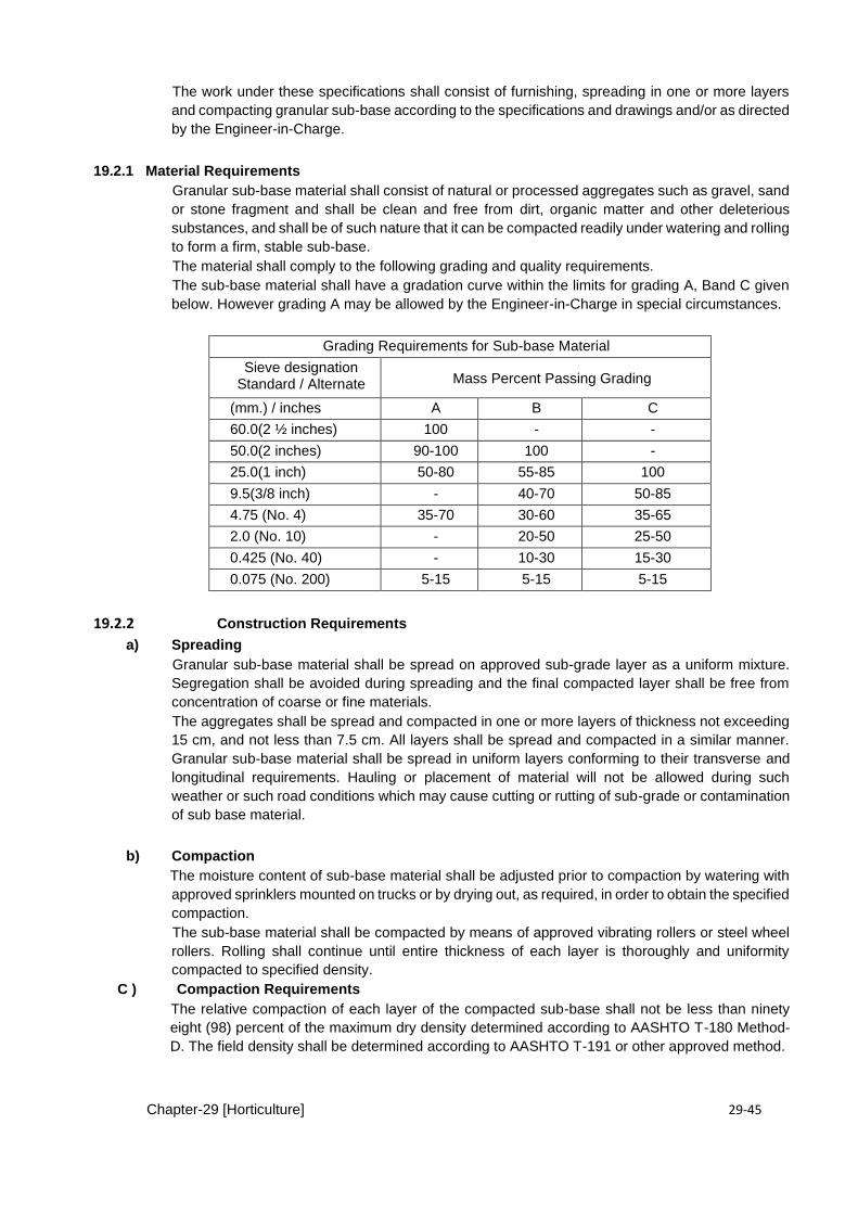
Chapter-29 [Horticulture] 29-45
The work under these specifications shall consist of furnishing, spreading in one or more layers
and compacting granular sub-base according to the specifications and drawings and/or as directed
by the Engineer-in-Charge.
19.2.1 Material Requirements Granular sub-base material shall consist of natural or processed aggregates such as gravel, sand
or stone fragment and shall be clean and free from dirt, organic matter and other deleterious
substances, and shall be of such nature that it can be compacted readily under watering and rolling
to form a firm, stable sub-base. The material shall comply to the following grading and quality requirements. The sub-base material shall have a gradation curve within the limits for grading A, Band C given
below. However grading A may be allowed by the Engineer-in-Charge in special circumstances.
Grading Requirements for Sub-base Material
Sieve designation Standard / Alternate Mass Percent Passing Grading
(mm.) / inches A B C
60.0(2 ½ inches) 100 - -
50.0(2 inches) 90-100 100 -
25.0(1 inch) 50-80 55-85 100
9.5(3/8 inch) - 40-70 50-85
4.75 (No. 4) 35-70 30-60 35-65
2.0 (No. 10) - 20-50 25-50
0.425 (No. 40) - 10-30 15-30
0.075 (No. 200) 5-15 5-15 5-15
19.2.2 Construction Requirements
a) Spreading Granular sub-base material shall be spread on approved sub-grade layer as a uniform mixture.
Segregation shall be avoided during spreading and the final compacted layer shall be free from
concentration of coarse or fine materials. The aggregates shall be spread and compacted in one or more layers of thickness not exceeding
15 cm, and not less than 7.5 cm. All layers shall be spread and compacted in a similar manner.
Granular sub-base material shall be spread in uniform layers conforming to their transverse and
longitudinal requirements. Hauling or placement of material will not be allowed during such
weather or such road conditions which may cause cutting or rutting of sub-grade or contamination
of sub base material.
b) Compaction The moisture content of sub-base material shall be adjusted prior to compaction by watering with
approved sprinklers mounted on trucks or by drying out, as required, in order to obtain the specified
compaction. The sub-base material shall be compacted by means of approved vibrating rollers or steel wheel
rollers. Rolling shall continue until entire thickness of each layer is thoroughly and uniformity
compacted to specified density. C ) Compaction Requirements
The relative compaction of each layer of the compacted sub-base shall not be less than ninety
eight (98) percent of the maximum dry density determined according to AASHTO T-180 Method-
D. The field density shall be determined according to AASHTO T-191 or other approved method.
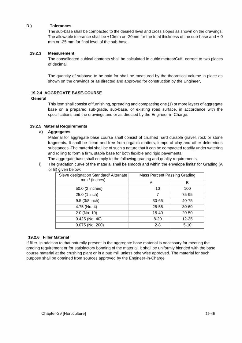
Chapter-29 [Horticulture] 29-46
D ) Tolerances The sub-base shall be compacted to the desired level and cross slopes as shown on the drawings.
The allowable tolerance shall be +10mm or -20mm for the total thickness of the sub-base and + 0
mm or -25 mm for final level of the sub-base.
19.2.3 Measurement
The consolidated cubical contents shall be calculated in cubic metres/Cuft correct to two places
of decimal.
The quantity of subbase to be paid for shall be measured by the theoretical volume in place as
shown on the drawings or as directed and approved for construction by the Engineer,
19.2.4 AGGREGATE BASE-COURSE General
This item shall consist of furnishing, spreading and compacting one (1) or more layers of aggregate
base on a prepared sub-grade, sub-base, or existing road surface, in accordance with the
specifications and the drawings and or as directed by the Engineer-in-Charge.
19.2.5 Material Requirements a) Aggregates
Material for aggregate base course shall consist of crushed hard durable gravel, rock or stone
fragments. It shall be clean and free from organic matters, lumps of clay and other deleterious
substances. The material shall be of such a nature that it can be compacted readily under watering
and rolling to form a firm, stable base for both flexible and rigid pavements. The aggregate base shall comply to the following grading and quality requirements.
i) The gradation curve of the material shall be smooth and within the envelope limits' for Grading (A
or B) given below:
Sieve designation Standard/ Alternate mm / (inches)
Mass Percent Passing Grading
A B
50.0 (2 inches) 10 100
25.0 (1 inch) 7 75-95
9.5 (3/8 inch) 30-65 40-75
4.75 (No. 4) 25-55 30-60
2.0 (No. 10) 15-40 20-50
0.425 (No. 40) 8-20 12-25
0.075 (No. 200) 2-8 5-10
19.2.6 Filler Material If filler, in addition to that naturally present in the aggregate base material is necessary for meeting the
grading requirement or for satisfactory bonding of the material, it shall be uniformly blended with the base
course material at the crushing plant or in a pug mill unless otherwise approved. The material for such
purpose shall be obtained from sources approved by the Engineer-in-Charge
Chapter-29 [Horticulture] 29-47
19.2.7 Construction Requirements a) Preparation of Surface for Aggregate Base Course
In case crushed aggregate base is to be laid over prepared sub base course, the sub base course
shall not have loose material or moisture in excess to optimum moisture content.
b) Spreading Aggregate base material shall be deposited on the roadbed in a quantity which will provide the
required compacted thickness without resorting to spotting, picking up or otherwise shifting the
base material. Aggregate base material shall be spread on approved sub-base layer as a uniform
mixture. The aggregates shall be spread and compacted in one or more layers of thickness not exceeding
15 cm, and not less than 7.5 cm
c) Compaction The moisture content of base material shall be adjusted prior to compaction by watering with
approved sprinklers mounted on trucks or by drying out, as required, in order to obtain the specified
compaction. The base material shall be compacted by means of approved vibrating rollers or steel
wheel rollers (rubber tyre rollers may be used as a supplement) progressing gradually from the
outside towards the centre, except on super-elevated curves, where the rolling shall begin at the
low side and progress to the high side. Each succeeding pass shall overlap the previous pass by
at least one third of the roller width
d) Compaction Requirements The relative compaction of each layer of the compacted base shall not be less than 100 percent
to the maximum dry density determined according to AASHTO T-191 or other approved method.
e) Tolerances The completed base course shall be tested for required thickness and smoothness before
acceptance. Any area having waves, irregularities in excess of one (1) cm in three (3) M or two (2)
cm in fifteen (15) M shall be corrected by scarifying the surface, adding approved material,
reshaping, re-compacting and finishing as specified.
19.2.8 Measurement . The consolidated cubical contents shall be calculated in cubic metres / cuft. correct to two places
of decimal. The quantity of Base-Course to be paid for shall be measured by the theoretical volume in place
as shown on the drawings or as directed and approved for construction by the Engineer,. No
allowance will be given for materials placed outside the theoretical limits as shown on the cross
sections.
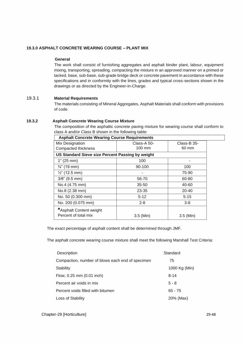
Chapter-29 [Horticulture] 29-48
19.3.0 ASPHALT CONCRETE WEARING COURSE – PLANT MIX
General The work shall consist of furnishing aggregates and asphalt binder plant, labour, equipment
mixing, transporting, spreading, compacting the mixture in an approved manner on a primed or
tacked, base, sub-base, sub-grade bridge deck or concrete pavement in accordance with these
specifications and in conformity with the lines, grades and typical cross-sections shown in the
drawings or as directed by the Engineer-in-Charge.
19.3.1 Material Requirements
The materials consisting of Mineral Aggregates, Asphalt Materials shall conform with provisions
of code.
19.3.2 Asphalt Concrete Wearing Course Mixture The composition of the asphaltic concrete paving mixture for wearing course shall conform to
class A and/or Class B shown in the following table:
Asphalt Concrete Wearing Course Requirements
Mix Designation Compacted thickness
Class-A 50-100 mm
Class-B 35-60 mm
US Standard Sieve size Percent Passing by weight 1" (25 mm) 100 -
¾” (19 mm) 90-100 100
½” (12.5 mm) - 75-90
3/8” (9.5 mm) 56-70 60-80
No.4 (4.75 mm) 35-50 40-60
No.8 (2.38 mm) 23-35 20-40
No. 50 (0.300 mm) 5-12 5-15
No. 200 (0.075 mm) 2-8 3-8
*Asphalt Content weight Percent of total mix
3.5 (Min)
3.5 (Min)
The exact percentage of asphalt content shall be determined through JMF.
The asphalt concrete wearing course mixture shall meet the following Marshall Test Criteria:
Description Standard
Compaction, number of blows each end of specimen 75
Stability 1000 Kg (Min)
Flow, 0.25 mm (0.01 inch) 8-14
Percent air voids in mix 5 - 8
Percent voids filled with bitumen 65 - 75
Loss of Stability 20% (Max)
Chapter-29 [Horticulture] 29-49
19.3.3 Job-Mix Formula The Job-Mix Formula (JMF) shall comply with the provisions of code.
19.3.4 Construction Requirements Construction requirements for this job shall conform to the requirements as specified for Asphaltic
Concrete Base Course Plant Mix .
a) Preparation of Base Surface Before wearing coat, the surface of the previously and accepted base course on which the mix is
to be placed shall be applied a tack coat, or as directed by the Engineer-in-Charge.
b) Pavement Thickness and Tolerances The asphalt concrete wearing course shall be compacted to the desired level and cross slope as
shown on the drawing or as directed by the Engineer-in-Charge. The tolerance in compacted thickness of the wearing course shall be + five percent (5%) from
the desired thickness shown on the drawings. The surface of the wearing course shall be tested by the Engineer-in-Charge using a 3 meter
straightedge at selected locations. All humps or depressions exceeding the specified tolerance
shall be corrected by removing the defective work and replacing it with new material, by
overlaying, or by other means satisfactory to the Engineer-in-Charge.
19.3.5 Measurement
The length and width of the finished work shall be measured correct to a cm along the finished
surface of the road. The area shall be calculated in square metre, correct to two places of
decimal.
Chapter-29 [Horticulture] 29-50
CHAPTER – 20 INTERLOCKING CONCRETE PAVING BLOCKS
20.0 General . Paving blocks covered by these Specifications are designed to form a structural element and
the surfacing of pavements having the block to block joints filled, so as to develop frictional
interlock and placed in conformity with the lines, grades, thicknesses and typical cross-section
shown on the drawings or as directed by the Engineer-in-Charge.
20.1.0 Material Requirements For execution of this item provisions made in BS 6717 shall be applicable. Detailed requirement
of materials and construction shall be as under:
1. Binders and Binder Constituents Paving blocks shall be made using one or more of the following binders or binder constituents
complying with the requirements of the relevant standards:
Description Standard
Ordinary Portland Cement BS 12
Portland Blast-furnace BS 146:
Aggregates
Paving blocks shall be made using one or more of the following aggregates complying with the
relevant standards: Description Standard
BS : 882 : 1983 Natural Aggregates
a) Acid Soluble Material (Fine Aggregate) When tested as described in BS 812 : Part 119, the fine aggregate (material passing a 4.75 mm
sieve complying with BS 410) shall contain no more than 25% by mass of acid soluble material either
in the fraction retained on or in the fraction passing, a 600µm sieve.
b.) Water The water shall be of drinking quality or in accordance with the provisions in Sub-Section 5.3.1.6
under Plain & Reinforced Concrete. c) Admixtures and Pigments
Proprietary accelerating, retarding and water reducing agents shall comply with Sub-Section
5.3.1.7 under Plain & Reinforced Concrete. Pigments shall comply with BS 1014. Calcium
chloride shall comply with BS 3587. d) Finishes
The finish should be agreed between the manufacturer and the Engineer-in-Charge. Concrete
described as “natural colour” shall contain no pigment.
In composite paving blocks the surface layer shall be formed as an integral part of the block and
shall be not less than 5 mm thick. e) Binder Content
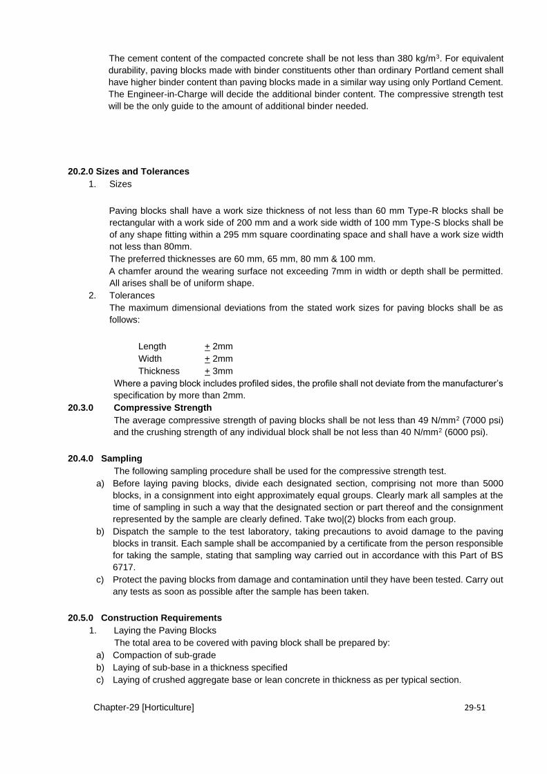
Chapter-29 [Horticulture] 29-51
The cement content of the compacted concrete shall be not less than 380 kg/m3. For equivalent
durability, paving blocks made with binder constituents other than ordinary Portland cement shall
have higher binder content than paving blocks made in a similar way using only Portland Cement.
The Engineer-in-Charge will decide the additional binder content. The compressive strength test
will be the only guide to the amount of additional binder needed.
20.2.0 Sizes and Tolerances 1. Sizes
Paving blocks shall have a work size thickness of not less than 60 mm Type-R blocks shall be
rectangular with a work side of 200 mm and a work side width of 100 mm Type-S blocks shall be
of any shape fitting within a 295 mm square coordinating space and shall have a work size width
not less than 80mm. The preferred thicknesses are 60 mm, 65 mm, 80 mm & 100 mm.
A chamfer around the wearing surface not exceeding 7mm in width or depth shall be permitted.
All arises shall be of uniform shape. 2. Tolerances The maximum dimensional deviations from the stated work sizes for paving blocks shall be as
follows:
Length + 2mm Width + 2mm Thickness + 3mm
Where a paving block includes profiled sides, the profile shall not deviate from the manufacturer’s
specification by more than 2mm. 20.3.0 Compressive Strength
The average compressive strength of paving blocks shall be not less than 49 N/mm2 (7000 psi)
and the crushing strength of any individual block shall be not less than 40 N/mm2 (6000 psi).
20.4.0 Sampling The following sampling procedure shall be used for the compressive strength test.
a) Before laying paving blocks, divide each designated section, comprising not more than 5000
blocks, in a consignment into eight approximately equal groups. Clearly mark all samples at the
time of sampling in such a way that the designated section or part thereof and the consignment
represented by the sample are clearly defined. Take two|(2) blocks from each group. b) Dispatch the sample to the test laboratory, taking precautions to avoid damage to the paving
blocks in transit. Each sample shall be accompanied by a certificate from the person responsible
for taking the sample, stating that sampling way carried out in accordance with this Part of BS
6717. c) Protect the paving blocks from damage and contamination until they have been tested. Carry out
any tests as soon as possible after the sample has been taken.
20.5.0 Construction Requirements 1. Laying the Paving Blocks
The total area to be covered with paving block shall be prepared by: a) Compaction of sub-grade b) Laying of sub-base in a thickness specified c) Laying of crushed aggregate base or lean concrete in thickness as per typical section.
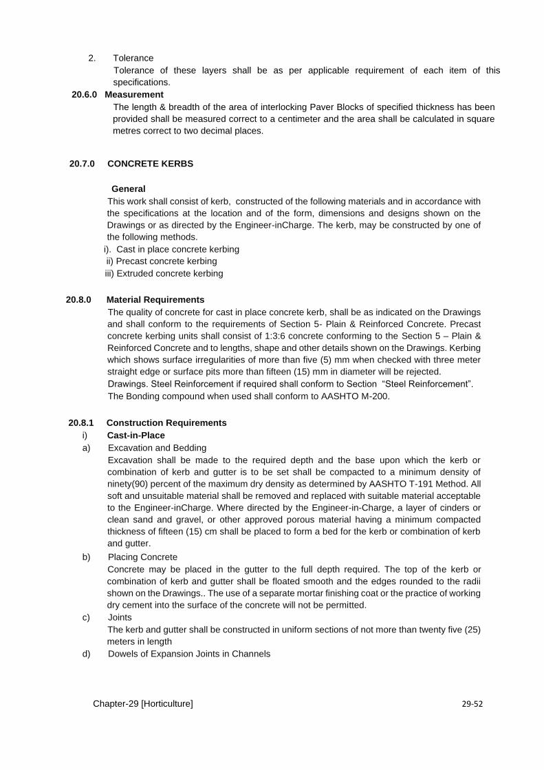
Chapter-29 [Horticulture] 29-52
2. Tolerance Tolerance of these layers shall be as per applicable requirement of each item of this
specifications. 20.6.0 Measurement
The length & breadth of the area of interlocking Paver Blocks of specified thickness has been
provided shall be measured correct to a centimeter and the area shall be calculated in square
metres correct to two decimal places.
20.7.0 CONCRETE KERBS
General This work shall consist of kerb, constructed of the following materials and in accordance with
the specifications at the location and of the form, dimensions and designs shown on the
Drawings or as directed by the Engineer-inCharge. The kerb, may be constructed by one of
the following methods. i). Cast in place concrete kerbing
ii) Precast concrete kerbing iii) Extruded concrete kerbing
20.8.0 Material Requirements The quality of concrete for cast in place concrete kerb, shall be as indicated on the Drawings
and shall conform to the requirements of Section 5- Plain & Reinforced Concrete. Precast
concrete kerbing units shall consist of 1:3:6 concrete conforming to the Section 5 – Plain &
Reinforced Concrete and to lengths, shape and other details shown on the Drawings. Kerbing
which shows surface irregularities of more than five (5) mm when checked with three meter
straight edge or surface pits more than fifteen (15) mm in diameter will be rejected. Drawings. Steel Reinforcement if required shall conform to Section “Steel Reinforcement”. The Bonding compound when used shall conform to AASHTO M-200.
20.8.1 Construction Requirements i) Cast-in-Place
a) Excavation and Bedding Excavation shall be made to the required depth and the base upon which the kerb or
combination of kerb and gutter is to be set shall be compacted to a minimum density of
ninety(90) percent of the maximum dry density as determined by AASHTO T-191 Method. All
soft and unsuitable material shall be removed and replaced with suitable material acceptable
to the Engineer-inCharge. Where directed by the Engineer-in-Charge, a layer of cinders or
clean sand and gravel, or other approved porous material having a minimum compacted
thickness of fifteen (15) cm shall be placed to form a bed for the kerb or combination of kerb
and gutter.
b) Placing Concrete Concrete may be placed in the gutter to the full depth required. The top of the kerb or
combination of kerb and gutter shall be floated smooth and the edges rounded to the radii
shown on the Drawings.. The use of a separate mortar finishing coat or the practice of working
dry cement into the surface of the concrete will not be permitted. c) Joints
The kerb and gutter shall be constructed in uniform sections of not more than twenty five (25)
meters in length d) Dowels of Expansion Joints in Channels
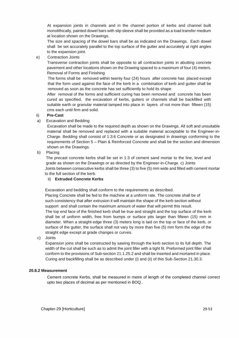
Chapter-29 [Horticulture] 29-53
At expansion joints in channels and in the channel portion of kerbs and channel built
monolithically, painted dowel bars with slip sleeve shall be provided as a load transfer medium
at location shown on the Drawings. The size and spacing of the dowel bars shall be as indicated on the Drawings. Each dowel
shall be set accurately parallel to the top surface of the gutter and accurately at right angles
to the expansion joint. e) Contraction Joints
Transverse contraction joints shall be opposite to all contraction joints in abutting concrete
pavement and other locations shown on the Drawing spaced to a maximum of four (4) meters.
Removal of Forms and Finishing The forms shall be removed within twenty four (24) hours after concrete has placed except
that the form used against the face of the kerb in a combination of kerb and gutter shall be
removed as soon as the concrete has set sufficiently to hold its shape After removal of the forms and sufficient curing has been removed and concrete has been
cured as specified, the excavation of kerbs, gutters or channels shall be backfilled with
suitable earth or granular material tamped into place in layers of not more than fifteen (15)
cms each until firm and solid. ii) Pre-Cast
a) Excavation and Bedding Excavation shall be made to the required depth as shown on the Drawings. All soft and unsuitable
material shall be removed and replaced with a suitable material acceptable to the Engineer-in-
Charge. Bedding shall consist of 1:3:6 Concrete or as designated in drawings conforming to the
requirements of Section 5 – Plain & Reinforced Concrete and shall be the section and dimension
shown on the Drawings. b) Placing
The precast concrete kerbs shall be set in 1:3 of cement sand mortar to the line, level and
grade as shown on the Drawings or as directed by the Engineer-in-Charge. c) Joints Joints between consecutive kerbs shall be three (3) to five (5) mm wide and filled with cement mortar
to the full section of the kerb. ii) Extruded Concrete Kerbs
Excavation and bedding shall conform to the requirements as described.
Placing Concrete shall be fed to the machine at a uniform rate. The concrete shall be of
such consistency that after extrusion it will maintain the shape of the kerb section without
support and shall contain the maximum amount of water that will permit this result.
The top end face of the finished kerb shall be true and straight and the top surface of the kerb
shall be of uniform width, free from bumps or surface pits larger than fifteen (15) mm in
diameter. When a straight-edge three (3) meters long is laid on the top or face of the kerb, or
surface of the gutter, the surface shall not vary by more than five (5) mm form the edge of the
straight edge except at grade changes or curves. c) Joints
Expansion joins shall be constructed by sawing through the kerb section to its full depth. The
width of the cut shall be such as to admit the joint filler with a tight fit. Preformed joint filler shall
conform to the provisions of Sub-section 21.1.25.2 and shall be inserted and mortared in place. Curing and backfilling shall be as described under (i) and (ii) of this Sub-Section 21.30.3.
20.8.2 Measurement
Cement concrete Kerbs, shall be measured in metre of length of the completed channel correct
upto two places of decimal as per mentioned in BOQ..
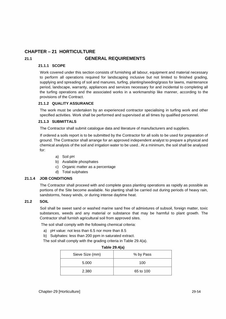
Chapter-29 [Horticulture] 29-54
CHAPTER – 21 HORTICULTURE
21.1 GENERAL REQUIREMENTS
21.1.1 SCOPE
Work covered under this section consists of furnishing all labour, equipment and material necessary
to perform all operations required for landscaping inclusive but not limited to finished grading,
supplying and spreading of soil and manures, turfing, planting/seeding/grass for lawns, maintenance
period, landscape, warranty, appliances and services necessary for and incidental to completing all
the turfing operations and the associated works in a workmanship like manner, according to the
provisions of the Contract.
21.1.2 QUALITY ASSURANCE
The work must be undertaken by an experienced contractor specialising in turfing work and other
specified activities. Work shall be performed and supervised at all times by qualified personnel.
21.1.3 SUBMITTALS
The Contractor shall submit catalogue data and literature of manufacturers and suppliers.
If ordered a soils report is to be submitted by the Contractor for all soils to be used for preparation of
ground. The Contractor shall arrange for an approved independent analyst to prepare a physical and
chemical analysis of the soil and irrigation water to be used.. At a minimum, the soil shall be analysed
for:
a) Soil pH b) Available phosphates c) Organic matter as a percentage d) Total sulphates
21.1.4 JOB CONDITIONS
The Contractor shall proceed with and complete grass planting operations as rapidly as possible as
portions of the Site become available. No planting shall be carried out during periods of heavy rain,
sandstorms, heavy winds, or during intense daytime heat.
21.2 SOIL
Soil shall be sweet sand or washed marine sand free of admixtures of subsoil, foreign matter, toxic
substances, weeds and any material or substance that may be harmful to plant growth. The
Contractor shall furnish agricultural soil from approved sites.
The soil shall comply with the following chemical criteria:
a) pH value: not less than 6.5 nor more than 8.5 b) Sulphates: less than 200 ppm in saturated extract.
The soil shall comply with the grading criteria in Table 29.4(a).
Table 29.4(a)
Sieve Size (mm) % by Pass
5.000 100
2.380 65 to 100
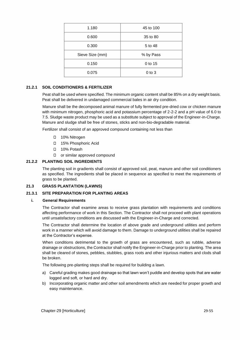
Chapter-29 [Horticulture] 29-55
1.180 45 to 100
0.600 35 to 80
0.300 5 to 48
Sieve Size (mm) % by Pass
0.150 0 to 15
0.075 0 to 3
21.2.1 SOIL CONDITIONERS & FERTILIZER
Peat shall be used where specified. The minimum organic content shall be 85% on a dry weight basis.
Peat shall be delivered in undamaged commercial bales in air dry condition.
Manure shall be the decomposed animal manure of fully fermented pre-dried cow or chicken manure
with minimum nitrogen, phosphoric acid and potassium percentage of 2-2-2 and a pH value of 6.0 to
7.5. Sludge waste product may be used as a substitute subject to approval of the Engineer-in-Charge.
Manure and sludge shall be free of stones, sticks and non-bio-degradable material.
Fertilizer shall consist of an approved compound containing not less than
10% Nitrogen
15% Phosphoric Acid
10% Potash
or similar approved compound
21.2.2 PLANTING SOIL INGREDIENTS
The planting soil in gradients shall consist of approved soil, peat, manure and other soil conditioners
as specified. The ingredients shall be placed in sequence as specified to meet the requirements of
grass to be planted.
21.3 GRASS PLANTATION (LAWNS)
21.3.1 SITE PREPARATION FOR PLANTING AREAS
i. General Requirements
The Contractor shall examine areas to receive grass plantation with requirements and conditions
affecting performance of work in this Section. The Contractor shall not proceed with plant operations
until unsatisfactory conditions are discussed with the Engineer-in-Charge and corrected.
The Contractor shall determine the location of above grade and underground utilities and perform
work in a manner which will avoid damage to them. Damage to underground utilities shall be repaired
at the Contractor’s expense.
When conditions detrimental to the growth of grass are encountered, such as rubble, adverse
drainage or obstructions, the Contractor shall notify the Engineer-in-Charge prior to planting. The area
shall be cleared of stones, pebbles, stubbles, grass roots and other injurious matters and clods shall
be broken.
The following pre-planting steps shall be required for building a lawn.
a) Careful grading makes good drainage so that lawn won’t puddle and develop spots that are water
logged and soft, or hard and dry. b) Incorporating organic matter and other soil amendments which are needed for proper growth and
easy maintenance.
Chapter-29 [Horticulture] 29-56
c) Blending of top soil with native soil is done to make a transitional layer between top soil and native
soil as it avoids trapping roots in a shallow top soil basin in which they would be dependent on
frequent feeding and very frequent watering.
The Engineer-in-Charge shall verify that sub-grades are as specified. ii. Sub-Surface Grading
All perennial weeds shall be treated with an approved herbicide and the period of time recommended
by the manufacturer shall be allowed to elapse prior to commencing grading operations.
Grading operations shall occur when the sub-soil is reasonably dry and workable.
Areas to be graded shall be graded to smooth flowing contours with all minor hollows and ridges
removed, minimum of 150 mm of approved soil in accordance with 29.2 shall be spread uniformly
over the loosened area and incorporated into the sub-grade soil to obtain a uniform and well
pulverized soil mix.
The area shall be compacted to a minimum of 90 % of maximum dry density as determined in
accordance with Test 13 of BS 1377.
iii. Finished Grading
Grades shall be brought to the finished ground levels agreed with the Engineer-in-Charge to a
tolerance of ± 25 mm. Finished ground levels shall be 30 mm below adjoining paving or kerbs after
compaction and settlement. Grading shall be carried out in such a manner that even gradients are
formed between the spot levels with a pleasant contour. No depressions shall remain which could
collect standing water.
Soil shall be placed in lifts not greater than 150 mm in thickness.
The filled area shall be compacted to a minimum of 90% of maximum density as determined in
accordance with Test 13 of BS 1377. The manure shall be spread uniformly for the specified
thickness.
iv. Scalping Old Lawns
The old lawn contains noxious weed grasses as Bermuda grass and old sod shall be stripped off with
flat back spade before building a new lawn. The existing sod shall not be dug into soil as clumps of
buried sod.
v. Making the lawn bed smooth
A lawn bed shall be as smooth and flat as possible. However it should have slight pitch, even
in flattened garden. Figure on fall of 6 to 12 inches in 100 feet so that water can run off once the root
has reached its saturation point.
21.3.2 SEEDING A PREPARED LAWN BED
Divide the amount of seed necessary for the area into four equal portions, so that there are four
approaches over the seed bed. Divide the seed bed half by running a string down the middle.
Broadcast one quarter portion down each half, spreading it evenly and uniformly within each marked
area. Then run the string across the middle of the lawn in the opposite directions and scatter the
remaining two quarter portions on the two halves.
After the seed is broadcast, rake it in lightly to ensure a thorough contact of seed with seed-bed soil.
Very lightly brush up the seeded surface with a wire rake using light circular motion so that the seed
is dispersed evenly. In case there are concentrated patches, swirl them out lightly into the surrounding
area to make an even covering. At this stage, do the cross raking and mulching in flat soled shoes,
tennis shoes, or barefooted. In case of hot dry weather or drying winds, in the 30 days after sowing, apply a thin, moisture holding
mulch, over the seed. After seeding and cross raking, put on a 1/8 to 1/16 inch layer of peat moss of
screened sawdust that has been aged at last one year. Don’t toss it upward so that it falls in piles.
Chapter-29 [Horticulture] 29-57
Whatever the covering, roll it smooth with a light roller (empty) after you have applied it. If a peat moss
covering is lumpy, chop up the lumps with the back side of a wire rake before rolling.
For initial watering, use adequate length of hose to get all the way around the lawn without dragging
across it and a hand sprinkler that throws out a through but gentle spray. An hour a day for 20 to 30
days of watering shall be needed when days are warm and windy, waters 2 to 3 times a day to keep
the surface continuously wet and keep the top dark with moisture until all the grasses are up.
If seeds and mulch happens to wash off on to an adjoining paved area, don’t attempt to blast them
back into place with the spray as it may washout more seeds along the sides of the seedbed.
After the first week, the little seeding will have gained enough stature to take a bending. It is possible
at that time, to pull the weeds that come up with the seeds, lay a plank out across the seedbed and
walk along it to pull the weeds.
Mow the lawn first time, when the grass is about 2 inches high or when the blades of grass take on a
noticeable curvature. Bent grasses that are to be cut at 1 inch height should never be allowed to grow
much higher than 1 inch. It is important that the mower be sharp at all times.
21.3.3 SEEDING ON A SLOPE
Lawns can be planted successfully on the ground that slopes upto 15%. If the slope is steeper, a
ground cover or a system of terraces would be more satisfactory.
Prepare the seedbed as described in specifications 29.2.2.with following special care;
When racking the seed bed, rake across the slope, when rolling the seed bed, roll it up and down.
Burlap or specially manufactured anti-erosion net spread over a newly seeded slope will keep
moisture in the ground and prevent seed from washing away. If burlap is of a tight weave, remove it
as soon as the grass begun to come up. Anti-erosion net or loose weave burlap can be left in place
to vet. Sprinkler system can be used if the slope can be covered with burlap and holes are cut for the
sprinklers head. Otherwise water the seedbed by hand, standing at the bottom of the top. Don’t use
sprinklers for at least two weeks and then run them slowly to avoid puddling or washout.
If erosion is likely to be a problem, install a drain scraper across the top of the slope to carry water off
to one side.
Sodding with desired permanent grasses is a good solution where an immediate erosion hazard
exists.
21.3.4 SODDING A PREPARED LAWN BED
i. Shipping and Delivery
Prior to shipping the grass to be planted shall be inspected, dug, and made ready for shipping in
accordance with standard practices and procedures. The Engineer-in-Charge shall be notified of the
delivery schedule in advance so the grass may be inspected upon arrival at the Site.
All unacceptable grass shall be removed from the Site immediately. The Engineer-in-Charge may
request inspection at the source prior to delivery of grass to the Site. The Engineer-in-Charge reserves
the right to reject any delivery that does not meet the quality requirements.
ii. Storage
Grass shall be installed as soon as possible after delivery to the Site. Grass shall be protected from
exposure to wind and direct sunlight prior to installation. Grass not installed on the day of arrival shall
be stored in shaded areas, protected from the wind and maintained and watered to good horticultural
standards until planted. Care shall be taken to ensure that the grass does not dry out.
Chapter-29 [Horticulture] 29-58
Soil, compost, fertilisers and other amendments shall be delivered to the Site and stored separately
in approved locations and in a manner to avoid contamination and wetting until soil mixing operations
commence.
iii. Procedure
Unroll the sod on prepared soil, lay the strips parallel with the strips staggered as in the brick layer
running bond patterns. Press each successively laid strip snugly up against the one next to it.
21.3.5 SPRINGING OR PLANTING GRASS ROOTS
i. Grass Materials
Grass sprigs shall be provided as healthy living stems stolons or rhizomes with attached roots
including two to three nodes. They shall be 5 to 15 mm long without adhering soil.
Grass seed shall be the latest season’s crop and shall be delivered in original sealed packages.
On-site seeding shall be done in the presence of the Engineer. The seed mixture shall be sown at the
rate of 35 g/m2. Grass seed mixtures shall be listed by schedule with information as follows:
a) botanical name
b) common name c) proportion by weight d) minimum percentage of pure seed e) minimum percentage of germination f) maximum percentage of weed seed
Turf shall be strongly rooted, not less than 2 years old, free of weeds and undesirable native grass.
Only turf that is capable of vigorous growth and development when laid shall be used.
Turf shall be of a uniform size in width and length. Broken pads or pads with uneven ends will not be
acceptable.
ii. Grass Sowing
(i) The soil shall be suitably moistened and then the operation of planting grass shall be
commenced. The grass shall be dibbled at 10 cm, 7.5 cm, 5 cm apart in any direction or other spacing
as specified to a depth of 15 cm. Dead grass and weeded shall not be planted. The Contractor
shall be responsible for watering and maintenance of levels and the lawn for 30 days or till the
grass forms a thick lawn free from weeded and fit for mowing whichever is later.
Generally planting in other direction at 15 cm, 10 cm, spacing is done in the case of large open
spaces, at 7.5 cm spacing in residential lawn and at 5cm spacing for Tennis Court and sports ground
lawn.
(ii) During the maintenance period, any irregularities arising in ground levels due to watering or due to
trampling by labour, or due to cattle straying thereon, shall be constantly made up to the proper levels
with earth as available or brought from outside as necessary Constant watch shall be maintained to
ensure that dead patches are replanted and weeds are removed. 21.3.6 INTERVALS FOR WATERING OF LAWN
Alternate wetting and partial drying out of soil, encourage healthier plant growth and deeper rooting
in hot summer areas.
Normally the soils would need more than 1” deep irrigation every week depending upon the
penetration, aeration and the wilting coefficient of soil. Deep watering once a week shall be preferable
which is however practicable only in canal irrigated area. In other areas light irrigation is resorted
every 2nd or 3rd day or daily sprinkling.
21.4 LAWN MAINTENANCE DURING PLANT ESTABLISHMENT PERIOD

Chapter-29 [Horticulture] 29-59
The Contractor shall be responsible for maintenance of lawn as specified. Maintenance shall consist
of watering, fertilising, weeding, mowing, trimming and other operations as required to establish a
smooth acceptable lawn free of eroded or bare areas. The Contractor shall maintain lawns for not less than the period stated below and longer as required
to establish an acceptable lawn.
Seeded lawn areas shall be maintained through three (3) maintenance cuttings but not less than sixty
(60) days after substantial completion.
21.5 FINAL ACCEPTANCE
Prior to the completion of the plant establishment period, a preliminary inspection shall be undertaken
by the Engineer-in-Charge. The time for this inspection shall be established in writing.
A final inspection, if required, shall be undertaken by the Engineer-in-Charge to determine that the
deficiencies noted in the preliminary inspection have been corrected. The time for this inspection shall
be established in writing.
21.7 GROUND COVERS
In many situations grass lawns are neither practical nor desirable. Areas immediately adjacent to
woodlots also rarely form good lawn. Steep banks are difficult to mow, are frequently dry and infertile,
and rarely can be successfully seeded because of runoff and erosion, All of these situations are being
handled by planting ground cover plants. These should not be considered as second choices or
compromise plantings, many ground covers are handsome and colorful additions to the landscape .
Contrasting textures, foliage colors, and splashes of flower color add greatly to the total view of a
garden.
Most effective ground covers are herbaceous perennials or small woody shrubs. They may trail along
the ground or spread by rhizomes so that bare areas are quickly covered. Some ground covers are
essentially care-free, requiring only minimal fertilizing and watering, while others need as much or
more attention as lawn grasses. Because of the large number of possible ground covers, selection is
based not only on prevailing environmental conditions, but also on considerations of hardiness, foliage
and flower interest, and the landscaping plan.
Many low-growing perennial flowering plants can be used as ground covers, Baby's breath
(Gypsophila repens) turfing daisy (Matricaria tchihatchewe), some saxifrages, lily of the valley
(Convaltaria majolis), and others can fill in shaded areas .For southern areas (Hardiness Zones 9 to
10), gopher apple (Geobalanus spp.), peperomia, creeping charley (Pilea hummulariaefolia) inch plant
(Zebrina pendula), and several species of veronica are excellent shade-tolerant ground covers.
Although not usually considered as ground covers, there are herbs to suit most conditions and
locations. Included among those that are often used as ground covers are catnip, tarragon, mint,
pennyroyal, burnet, germander, lovage.

Chapter-29 [Horticulture] 29-60
21.8 MEASUREMENT AND PAYMENT
The measurement and payment for the items of the work of horticulture hereof shall be made
corresponding to the applicable CSR item as provided in BOQ OF Contract Agreement and shall
constitute full compensation, for procurements, transportations, performance in all respect and
completion of work as specified including the site clearance as approved by the Engineer-in-Charge.
CHAPTER-22 ELECTRICAL WIRING & CABLES
22.0. GENERAL
22.1 SCOPE
The work shall include furnishing of all labour, materials, equipment tools and plants as required and
providing the internal electrification and other works as specified consisting of but not limited to
conduits and pipes, wires and cables, wiring fixtures, The Contractor shall execute the works as
shown on the Drawings specified herein and or as directed by the Engineer-in-Charge, and shall be
responsible for proper functioning, testing, commissioning and satisfactory operation and
performance during the maintenance period.
The Tender drawings, Specifications and bills of Quantities are to be considered as supplementing
each other to jointly define and describe the Scope of work.
22.1.1 CODES AND STANDARDS
The work shall conform to the requirements of the following Codes and Standards, unless otherwise
specified:
BS 31-79 Steel conduit and fittings for electrical wiring.
BS 3505-82 Un-plasticized PVC pipe for cold water services
BS 4607-71 (P- 2) Rigid PVC conduits and Conduit fittings
BS 6004-84 Specification for PVC insulated cables for electric power and lighting.

Chapter-29 [Horticulture] 29-61
BS 6360-81 Specification for conductors in insulated cables and cords
22.1.2 QUALIFICATIONS
a) The Electrification Works shall be carried out by licensed workmen authorized to undertake such
works under the provisions of Electricity Act, 1910 and the Electricity Rules 1937, as adopted and
modified by the Government of Pakistan from time to time and registered with Pakistan Engineering
Council PEC under relevant Category.
b) The installation in general shall be carried out in conformity with the Electricity Rules 1937, and the
latest edition of British/Pakistan standard.
c) Any defective electrification work carried out by the Contractor shall be rectified or made good by the
Contractor.
d) The electrical works shall keep pace with the civil works and the works of any other specialist
contractor. The Engineer-in-Charge shall be kept informed about the programme and the progress of
work so that there is no hindrance in the progress of work at Site.
22.1.3 SUBMITTALS
The Contractor shall submit for approval of the Engineer-in-Charge:
a) All drawings of equipment, appliances, fixtures and accessories that are to be furnished under the
Contract. These shall include detailed electrical drawings, wiring diagram, foundation details, etc. for
all electrical switchgear, fuse gear and all other systems.
Drawings and data for each equipment to be furnished before commencement of fabrication and
manufacture. The drawings to be supplied by the Contractor shall be as follows.
b) Manufacturer's installation, operation and maintenance manuals wherever applicable.
c) Specimens of all wiring accessories, fittings, fixtures, conduits, pipes, wires, cables and all the
materials to be incorporated into the Works along with specifications of each.
22.1.4 GUARANTEE
The Contractor shall furnish written guarantee against performance of each equipment. Such
guarantee shall be for replacement and repair of a part or whole equipment which may be found
defective in material or workmanship. The guarantee shall cover a minimum period of 12 months after
commissioning of the equipment as per contract.
22.1.5 SHOP DRAWINGS
The Contractor shall provide following shop drawings for approval of the Engineer, well in time before
commencement of work :
a.) Complete Conduit route between Distribution panels.
b.) LT Panel and distribution boards
c.) Equipment lay outs in Electrical and IT Room, including incoming and out going race ways &
Connections. External Routes of LV and ELV services including Conduits and Man holes
/Chambers.
22.1. 6 RECORD / AS BUILT DRAWING
The Contractor Shall submit the as built drawing in triplicate with Soft Copy for which no additional
payment shall be made. After Completion of the Project, the Contractor shall clean the exterior
surface of equipment and fixtures including Concrete and Paint residue. The Contractor shall protect
the completed work from damage through out the contract period. Deliver all the equipment & panels
with Standard factory finish or as specified.
22.1.7 TEST, ACCEPTANCE & CERTIFICATES
All tests necessary and directed shall be performed before final acceptance of work in presence of
the Engineer.
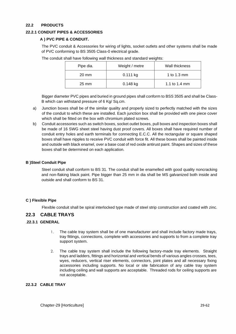
Chapter-29 [Horticulture] 29-62
22.2 PRODUCTS
22.2.1 CONDUIT PIPES & ACCESSORIES
A ) PVC PIPE & CONDUIT.
The PVC conduit & Accessories for wiring of lights, socket outlets and other systems shall be made
of PVC conforming to BS 3505 Class-0 electrical grade.
The conduit shall have following wall thickness and standard weights:
Pipe dia. Weight / metre Wall thickness
20 mm 0.111 kg 1 to 1.3 mm
25 mm 0.148 kg 1.1 to 1.4 mm
Bigger diameter PVC pipes and buried in ground pipes shall conform to BSS 3505 and shall be Class-
B which can withstand pressure of 6 Kg/ Sq.cm.
a) Junction boxes shall be of the similar quality and properly sized to perfectly matched with the sizes
of the conduit to which these are installed. Each junction box shall be provided with one piece cover
which shall be fitted on the box with chromium plated screws.
b) Conduit accessories such as switch boxes, socket outlet boxes, pull boxes and inspection boxes shall
be made of 16 SWG sheet steel having dust proof covers. All boxes shall have required number of
conduit entry holes and earth terminals for connecting E.C.C. All the rectangular or square shaped
boxes shall have nipples to receive PVC conduit with force fit. All these boxes shall be painted inside
and outside with black enamel, over a base coat of red oxide antirust paint. Shapes and sizes of these
boxes shall be determined on each application.
B )Steel Conduit Pipe
Steel conduit shall conform to BS 31. The conduit shall be enamelled with good quality noncracking
and non-flaking black paint. Pipe bigger than 25 mm in dia shall be MS galvanized both inside and
outside and shall conform to BS 31.
C ) Flexible Pipe
Flexible conduit shall be spiral interlocked type made of steel strip construction and coated with zinc.
22.3 CABLE TRAYS
.22.3.1 GENERAL
1. The cable tray system shall be of one manufacturer and shall include factory made trays,
tray fittings, connections, complete with accessories and supports to from a complete tray
support system.
2. The cable tray system shall include the following factory-made tray elements. Straight
trays and ladders, fittings and horizontal and vertical bends of various angles crosses, tees,
wyes, reducers, vertical riser elements, connectors, joint plates and all necessary fixing
accessories including supports. No local or site fabrication of any cable tray system
including ceiling and wall supports are acceptable. Threaded rods for ceiling supports are
not acceptable.
22.3.2 CABLE TRAY
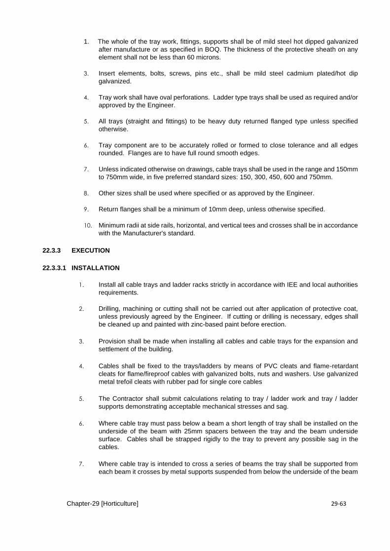
Chapter-29 [Horticulture] 29-63
1. The whole of the tray work, fittings, supports shall be of mild steel hot dipped galvanized
after manufacture or as specified in BOQ. The thickness of the protective sheath on any
element shall not be less than 60 microns.
3. Insert elements, bolts, screws, pins etc., shall be mild steel cadmium plated/hot dip
galvanized.
4. Tray work shall have oval perforations. Ladder type trays shall be used as required and/or
approved by the Engineer.
5. All trays (straight and fittings) to be heavy duty returned flanged type unless specified
otherwise.
6. Tray component are to be accurately rolled or formed to close tolerance and all edges
rounded. Flanges are to have full round smooth edges.
7. Unless indicated otherwise on drawings, cable trays shall be used in the range and 150mm
to 750mm wide, in five preferred standard sizes: 150, 300, 450, 600 and 750mm.
8. Other sizes shall be used where specified or as approved by the Engineer.
9. Return flanges shall be a minimum of 10mm deep, unless otherwise specified.
10. Minimum radii at side rails, horizontal, and vertical tees and crosses shall be in accordance
with the Manufacturer's standard.
22.3.3 EXECUTION
22.3.3.1 INSTALLATION
1. Install all cable trays and ladder racks strictly in accordance with IEE and local authorities
requirements.
2. Drilling, machining or cutting shall not be carried out after application of protective coat,
unless previously agreed by the Engineer. If cutting or drilling is necessary, edges shall
be cleaned up and painted with zinc-based paint before erection.
3. Provision shall be made when installing all cables and cable trays for the expansion and
settlement of the building.
4. Cables shall be fixed to the trays/ladders by means of PVC cleats and flame-retardant
cleats for flame/fireproof cables with galvanized bolts, nuts and washers. Use galvanized
metal trefoil cleats with rubber pad for single core cables
5. The Contractor shall submit calculations relating to tray / ladder work and tray / ladder
supports demonstrating acceptable mechanical stresses and sag.
6. Where cable tray must pass below a beam a short length of tray shall be installed on the
underside of the beam with 25mm spacers between the tray and the beam underside
surface. Cables shall be strapped rigidly to the tray to prevent any possible sag in the
cables.
7. Where cable tray is intended to cross a series of beams the tray shall be supported from
each beam it crosses by metal supports suspended from below the underside of the beam
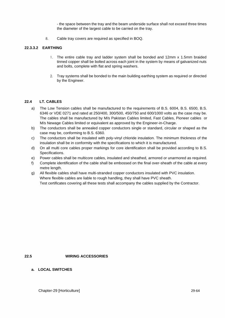
Chapter-29 [Horticulture] 29-64
- the space between the tray and the beam underside surface shall not exceed three times
the diameter of the largest cable to be carried on the tray.
8. Cable tray covers are required as specified in BOQ.
22.3.3.2 EARTHING
1. The entire cable tray and ladder system shall be bonded and 12mm x 1.5mm braided
tinned copper shall be bolted across each joint in the system by means of galvanized nuts
and bolts, complete with flat and spring washers.
2. Tray systems shall be bonded to the main building earthing system as required or directed
by the Engineer.
22.4 LT. CABLES
a) The Low Tension cables shall be manufactured to the requirements of B.S. 6004, B.S. 6500, B.S.
6346 or VDE 0271 and rated at 250/400, 300/500, 450/750 and 600/1000 volts as the case may be.
The cables shall be manufactured by M/s Pakistan Cables limited, Fast Cables, Pioneer cables or
M/s Newage Cables limited or equivalent as approved by the Engineer-in-Charge.
b) The conductors shall be annealed copper conductors single or standard, circular or shaped as the
case may be, conforming to B.S. 6360.
c) The conductors shall be insulated with poly-vinyl chloride insulation. The minimum thickness of the
insulation shall be in conformity with the specifications to which it is manufactured.
d) On all multi core cables proper markings for core identification shall be provided according to B.S.
Specifications.
e) Power cables shall be multicore cables, insulated and sheathed, armored or unarmored as required.
f) Complete identification of the cable shall be embossed on the final over-sheath of the cable at every
metre length.
g) All flexible cables shall have multi-stranded copper conductors insulated with PVC insulation.
Where flexible cables are liable to rough handling, they shall have PVC sheath.
Test certificates covering all these tests shall accompany the cables supplied by the Contractor.
22.5 WIRING ACCESSORIES
a. LOCAL SWITCHES

Chapter-29 [Horticulture] 29-65
1.1 The local switches shall be 10 amp. Gang type , one-way, two-way, intermediate or double
pole as indicated on the drawings and as per approved make and model. Where more
than one switch is indicated at any position multiple gang units shall be used.
1.2 Switches shall be of the quick start make, slow break type specially designed for AC
circuits to BS Standards. The operation of the switch shall not depend wholly on the
action of the spring. The switches shall generally be of the rocker operated type.
1.3 All switch boxes shall be supplied with adjustable steel grids and earthing terminals.
1.4 Generally, switch units shall be of the adjustable grid pattern and to be secured to the
adjustable grid by means of screws. For flush mounting switches the switch-plate shall
overlap all edges of the box by not less than 7mm. For surface mounting switches the
switch plate shall finish flush with the edges of the switch boxes. Switches for water
heaters and fan coil units shall be complete with neon indicator lights.
1.5 Local switches shall be arranged in convenient positions for switching the various circuits
and generally as indicated on the drawings.
1.6 The switches shall be of the same manufacture for a particular type of switch throughout
the installation. All accessories in wet and damp areas shall be of the splash-proof
type to IP54 protection standard.
1.7 All switch boxes should be galvanized steel.
1.8 To ensure easy and correct connection of the conductors during installation, the necessary
terminal shall be easily identified, grouped in line, upward facing, captive and backed out
prior to the installation.
1.9 All dimmer switches shall be suitably rated to the lighting load being Controlled with 25%
spare capacity and shall be adequate for tungsten and / or fluorescent lighting as specified.
b. ) SWITCHES - OUTDOOR USE/WEATHER PROOF:
The switches shall be pole rated for 10 Amps, 250 Volt with cast iron or steel body and gasketed
cover. The conduit entry hole in the body shall have long threads to provide watertight fitting. Sealing
compounds for water-tight connection shall be used at conduit entry in the body of the switch.
C ) POWER OUTLETS
i.) The switch socket outlets, shall be in accordance with BS1363 Standard as appropriate and shall
be of the three pin grounding type.
ii.) Switch socket outlet in the different areas shall comply with section 607 of BS7671 :2001
iii ) Live contact of the socket shall be completely shuttered such that it is not possible to engage
any pin of the plug into a live contact whilst any other pin of the plug is exposed.
Iv ) All floor mounted socket outlets shall be fixed as part of the under floor trunking service boxes.
V ) These outlets shall be of the same manufacturer throughout the installation.
vi. ) The sockets should provide a double earth terminal as per latest BS7671, 2001, Section 607.
d.) Outlet Box
The outlet boxes for installation of switches, fan regulators/dimmer and socket outlets shall be 16
SWG sheet steel or of PVC as specified having appropriate dimensions. The box shall have suitable
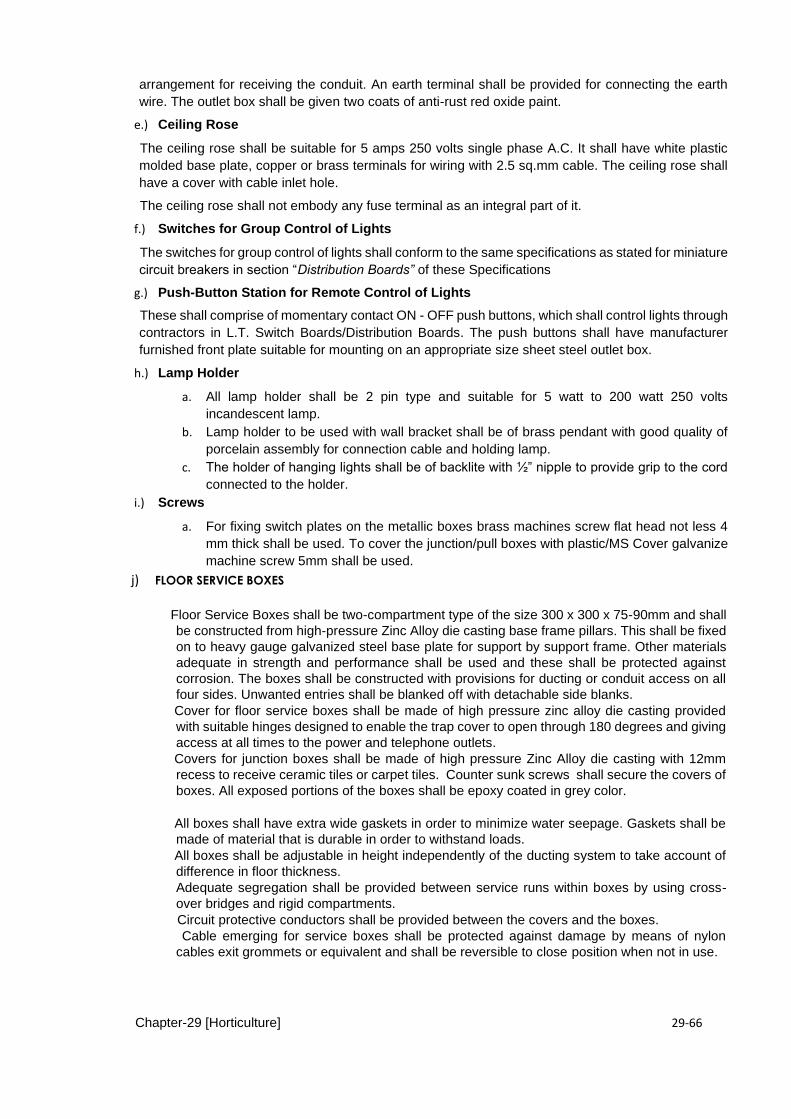
Chapter-29 [Horticulture] 29-66
arrangement for receiving the conduit. An earth terminal shall be provided for connecting the earth
wire. The outlet box shall be given two coats of anti-rust red oxide paint.
e.) Ceiling Rose
The ceiling rose shall be suitable for 5 amps 250 volts single phase A.C. It shall have white plastic
molded base plate, copper or brass terminals for wiring with 2.5 sq.mm cable. The ceiling rose shall
have a cover with cable inlet hole.
The ceiling rose shall not embody any fuse terminal as an integral part of it.
f.) Switches for Group Control of Lights
The switches for group control of lights shall conform to the same specifications as stated for miniature
circuit breakers in section “Distribution Boards” of these Specifications
g.) Push-Button Station for Remote Control of Lights
These shall comprise of momentary contact ON - OFF push buttons, which shall control lights through
contractors in L.T. Switch Boards/Distribution Boards. The push buttons shall have manufacturer
furnished front plate suitable for mounting on an appropriate size sheet steel outlet box.
h.) Lamp Holder
a. All lamp holder shall be 2 pin type and suitable for 5 watt to 200 watt 250 volts
incandescent lamp.
b. Lamp holder to be used with wall bracket shall be of brass pendant with good quality of
porcelain assembly for connection cable and holding lamp.
c. The holder of hanging lights shall be of backlite with ½” nipple to provide grip to the cord
connected to the holder.
i.) Screws
a. For fixing switch plates on the metallic boxes brass machines screw flat head not less 4
mm thick shall be used. To cover the junction/pull boxes with plastic/MS Cover galvanize
machine screw 5mm shall be used.
j) FLOOR SERVICE BOXES
Floor Service Boxes shall be two-compartment type of the size 300 x 300 x 75-90mm and shall
be constructed from high-pressure Zinc Alloy die casting base frame pillars. This shall be fixed
on to heavy gauge galvanized steel base plate for support by support frame. Other materials
adequate in strength and performance shall be used and these shall be protected against
corrosion. The boxes shall be constructed with provisions for ducting or conduit access on all
four sides. Unwanted entries shall be blanked off with detachable side blanks.
Cover for floor service boxes shall be made of high pressure zinc alloy die casting provided
with suitable hinges designed to enable the trap cover to open through 180 degrees and giving
access at all times to the power and telephone outlets.
Covers for junction boxes shall be made of high pressure Zinc Alloy die casting with 12mm
recess to receive ceramic tiles or carpet tiles. Counter sunk screws shall secure the covers of
boxes. All exposed portions of the boxes shall be epoxy coated in grey color.
All boxes shall have extra wide gaskets in order to minimize water seepage. Gaskets shall be
made of material that is durable in order to withstand loads.
All boxes shall be adjustable in height independently of the ducting system to take account of
difference in floor thickness.
Adequate segregation shall be provided between service runs within boxes by using cross-
over bridges and rigid compartments.
Circuit protective conductors shall be provided between the covers and the boxes.
Cable emerging for service boxes shall be protected against damage by means of nylon
cables exit grommets or equivalent and shall be reversible to close position when not in use.
Chapter-29 [Horticulture] 29-67
CHAPTER- 23.0 ELECTRICAL FIXTURES
23.1 FANS
a) Ceiling Fans
Ceiling fans shall be capacitor type, Energy Saver 55~60 watts, five speed suitable for 250 volts single
phase 50 Hz. The air displacement shall be 330 cubic metre per minute for 1422 mm (56") sweep.
The fan motor shall be capacitor type and bearing shall be groove type to give noiseless operation.
Fan dimmers rated for 100 W, 250 Volts of approved make (PAK fans, GFC, Millat or as approved by
the Engineer-in-Charge could be used.
The fan hook shall be made of 16 mm diameter mild steel rod. It should be in the form of a loop about
75 mm long and about 50 mm wide. The rod should be bent to have at least 200 mm extension on
both sides for tying to reinforcement steel of slab. The fan and Dimmer shall be the first quality product
from an approved manufacturer as above.
b) Wall Bracket Fans
Fan motor shall be capacitor type and bearing shall be groove type to give noiseless operation. The
fan regulator shall be built-in type with high grade steel laminations and shall have five speed marks
and one "OFF" mark. The fan shall be of an approved make.
c) Exhaust Fans
Exhaust fans shall be direct driven type complete with motor, angle iron frame, back draft dampers
and mounting accessories. Blades shall be of steel and factory adjusted for pitch. Blades of back draft
damper shall have a link rod and the design shall be such that damper remains in full open position
without rattling when the fan is operating.
23.2 LIGHTING FIXTURES
a) Incandescent Light Fixtures
The glass globes/shades/diffusers of the incandescent light fixtures shall be of first class quality glass
free from any air bubbles or voids. The glass shall generally be of opal white colour unless otherwise
specified. Surface mounted fixtures shall have white stove enamelled sheet steel body. It may also
be satin brass or aluminium anodized finish as required. The fixing holes shall match the outlet box.
Wall bracket light fixtures shall have back plates with matching holes of the outlet box and decorative
finish as required. All light fixtures shall have bi-pin brass lamp holders and LED Bulbs of approved
type and make and shall be from an approved manufacturer conforming to BS 161. Light fixtures clear
or frosted, shall have a minimum useful life of 1000 hours.
b) Fluorescent light Fixtures
All the light fixtures shall have LED lamps of the wattage specified. The fluorescent lamp shall be
either 600 mm - or 1200 mm and the colour shall generally be as specified with an average output pf
2600 lumens + (5%) for 1200mm and 1030 lumens (+ 5%) for 600mm. The fluorescent lamps shall
be from Philips or as approved manufacturer conforming to BS 1853 and having a minimum useful
life of 5000 hours or with standard warranty..
The internal wiring of the light fixture shall be carried out at manufacturer's factory with heat resistance
wires of size not less than 1.5 mm square. The louvers of light fixtures shall be made of anodized
aluminium and/or moulded plastic. The diffusers shall be made of acrylic perspex with a minimum
sheet thickness of 3 mm.
The body of the light fixture shall be white or grey stove enamel as required. The industrial reflector
shall have white stove enamel finish inside and grey / green stove enamel finish outside. Appropriate-
sized bushed entry holes and fixing holes shall be provided. The thickness of the sheet steel used in
the fabrication of the body and reflector shall not be less than 20 gauge.

Chapter-29 [Horticulture] 29-68
The materials for louvers and paint of metal parts shall not deteriorate due to ultra-violet radiation
from lamp with a minimum guarantee of 5 years. Pendent type fixtures shall have 2 Nos. 13 mm dia
chromium plated pendent tubes for suspension or as per detail shown on the Drawings.
C ) LED LIGHT FIXTURES.
a) All the LED light fixtures shall have efficient driver circuitry suitable for 230V, + 10% for AC supply,
conversation efficiency more than 92% along with No speckle, no flickering, no humming, no buzzing, no
RF interference. The luminaire suitable for input voltage range from 85 VAC- 265 VAC and power factor
=> 0.9, suitable for at 50 Hz frequency as per utility power characteristics.
b) All aspects of the lighting system shall be appropriate, consistent and suitable for the specific environment
or work task required, and where appropriate, a mixture of light fittings, including down lighters, wall
washers and uplighters shall be provided.
c) Luminaires shall have an efficacy of NOT less than 80lm/W with THD less than 20%.
d) The housing for of light must have feasible material for maximum heat dissipation to insure the maximum
life of the luminaire along with frosted non-brittle, non-decoloring cover with minimum 5 years of life span
as per recommendation of engineer-in-charge.
e) The luminaire should have CRI Index greater than 75 along with the color temperature range as
specified by engineer in-charge available from 3000 K to 6500 K having IP Rating 20-40 (for indoor use)
and IP-65 or greater for outdoor use.
f) The manufacturer should provide third party test reports from reputable laboratory (Local PCSIR/ CERAD
UET /Equivalent) or international firm along with all the photometric data specification as per CIBSE/IEC,
CE, RoHS relevant standards.
g) The manufacturer should provide lifetime warranty 30,000 Hours or more (per LED Chip LM80 report),
three-year service warranty to engineer in-charge.
D ) DIMMERS.
The dimmers used shall be universal type i.e. suitable for use with incandescent and fluorescent
lamps. The planning of making three phase assemblies and integration with relevant distribution
boards specified hereinafter shall be contractor's responsibility. The dimmer rack assemblies shall
be sheet steel clad, flush wall mounting type, modular in construction and solid-state design
comprising of automatic and slave dimmers suitable for operation on 3 phase, 400 volts, 50Hz
supply. Each dimmer rack assembly shall be provided with direct or remote, as most suitable to
requirement, push button control plates with the following five standard options: -
Light dark-preset-stop-ON/OFF.
The capacity of the dimmer rack assembly shall be commensurate with the installed lighting load.
The schematic wiring diagram of the dimmers showing the relative position of its components e.g.
Isolators, thyristors, contractors, RYB indicator, instruments, fuses, relays and MCB's for final sub-
circuit protection and push button controls shall be submitted to the Engineer for approval.
he dimers shall be manufactured by M/s. Polaron Controls U.K., M/s. Strand Lighting U.K. and/or
M/s. Altenburg Germany.
7 MEASUREMENT.
Actual number of units installed shall be taken as the basis for measurement or as specified in
BOQ.
Chapter-29 [Horticulture] 29-69
CHAPTER – 24 SWITCH GEAR
24.1 MAIN LT. SWITCH BOARD
a) General
The LT. switchboard shall be indoor type, free standing, self supporting, floor mounted, totally
enclosed, sheet steel clad, dust and vermin proof, completely wired, factory assembled and suitable
for operation on 3 phase 4 wire system, 415 V, 50 Hz, AC supply. The switchboard shall comprise of
multi panels suitable for housing air circuit breakers, moulded case breakers or load break switches
as shown on the Drawings. The switch board shall be designed to suit service conditions and ensure
security and safety during operation, inspection, operation, cleaning and maintenance. The switch
board shall be designed and tested to International Electro Technical Commission (lEC)
recommendations. Each panel shall withstand a voltage of 2000 volts insulation level for one minute
power frequency test. The switchboard shall be divided into panels and panels divided into
compartments to accommodate the required number of circuit breakers of fuse switches, bus bars,
instrument transformers, protective relays metres, etc.
b) Air Circuit Breakers
The Air Circuit Breaker (A.C.B) shall be triple pole of specified rating, fixed type, trip free, spring
charged, quick make, quick break manually operated mechanism and visual ON/OFF position
indicator. The circuit breaker shall be suitable for continuous duty for the rated current for indefinite
period of time under service conditions. The circuit breaker shall have specified breaking capacity.
The A.C.B. shall conform to BS 4752. The contacts of the A.C.B. shall be heavy duty, spring charged
and silver plated. Replaceable electric arc contacts and arc chutes shall be provided. The operating
handles if made of metal shall be either earthed or additionally insulated to withstand full insulation
voltage. A certified copy of full type tests carried out by an independent agency on identical breakers
shall be acceptable in lieu of the following type and routine tests:
- Making capacity, breaking capacity and short time current tests. - Mechanical and electrical life endurance tests. - Temperature rise test. - Power frequency withstand test. - Milli volt drop test.
c) Meters The following instruments shall be included in the main switchboard unless otherwise specified: -
1 - KWH metre - 1 - Voltmeter 0-500 volts - 1 - Voltmeter phase selector switch - 1 - Ammeter commensurate with rating of ACB - 1 - Ammeter phase selector switch
All the instruments shall be flush mounted and back connected in a transparent dust proof cover with
96 mm or 144 mm Square dial which shall have prominent black graduations on white surface. The
instruments shall be manufactured and tested in accordance with IEC Publications 51.
d) Moulded Case Circuit Breakers
The moulded case circuit breakers (MCCB) shall be triple pole and of the rating specified on the
drawings. The MCCB shall be fixed type, having trip-free, manually operated mechanism and
on/off/trip position indicators. The tripping devices shall have related time current characteristics so
that positive discrimination and selective tripping is obtained assuring the tripping under fault
Chapter-29 [Horticulture] 29-70
conditions of only the breaker in the circuit ahead of the fault location. The MCCB shall have a
rupturing capacity of 35 KA (or as specified) and shall be manufactured and tested to lEC Publication
157-1 Part I or BS 4752 or BS 3871 Part I. The MCCBs shall be of BOCH, CLIPSAL, LEGNOL or
equivalent approved by the Engineer-in Charge.
e) Load Break Switches
The load break switches shall be on load type having quick make and quick break mechanism with
spring loaded handles and ON/OFF visual indications. The load break switches shall be designed for
continuous operation on rated current, rated voltage and rated frequency to BS 5419.
The load break switches shall be of BOCH, CLIPSAL, LEGNOL or equivalent approved by the
Engineer-in-Charge.
f) HRC Fuses The HRC fuses shall be manufactured and tested to BS 88. A supplement of 100% spare fuses of
each size shall be supplied with the switch-board. The fuse carriers and bases shall be made from
moulded phenolic compound and/or porcelain.
g) Bus Bars and Connections
A set of four bus bars, three for phases and one for neutral, made of copper having 98% IASC
conductivity shall be provided. All the bus bars shall be mounted on insulators at suitable intervals
and should be extensible on both ends. The marking and arrangement of bus bars, main connections
and small wiring shall conform to BS 159. Bus bars and bus bar connections shall also conform to BS
159.
h) Enclosures
The enclosures shall be fabricated from 3 mm thick high grade sheet steel and shall be designed to
house all the live parts which shall be accessible through front doors. Adequate air circulation by
means of vent covered with suitable metal gauze shall be provided in the enclosures. All exterior and
interior surfaces of the enclosure shall be thoroughly cleaned and freed of dust, rust and greasy
matter. The enclosures shall be given three coats of paint. The primer shall be zinc chromate and/or
iron oxide. The second and third coats shall be top quality battleship grey enamel. Enclosures for
each panel shall be provided with designation labels as directed by the Engineer-in-Charge.
i) Earthing
The switchboard shall be effectively earthed at two points by means of a copper strip of suitable cross-
section bolted to connections near the bottom of the switchboard.
j) Accessories
Designation labels, lifting lugs, foundation bolts, interconnecting nuts, bolts, washers, thimbles, lugs,
levelling shims, cable glands and/or cable end boxes for all the sizes of incoming and outgoing cable
shall be supplied with the switchboard.
24.2 SUBMAIN BOARDS
The sub-main boards shall be similar to the Main L.T. Board and the components in its fabrication
may differ and shall comprise of the components as shown on the Drawings. The rupturing capacity
of each component for sub-main boards shall be as specified.
All other details and specifications as provided in sub-section 17.4.1 shall be applicable.
24.3 DISTRIBUTION BOARDS
a) General
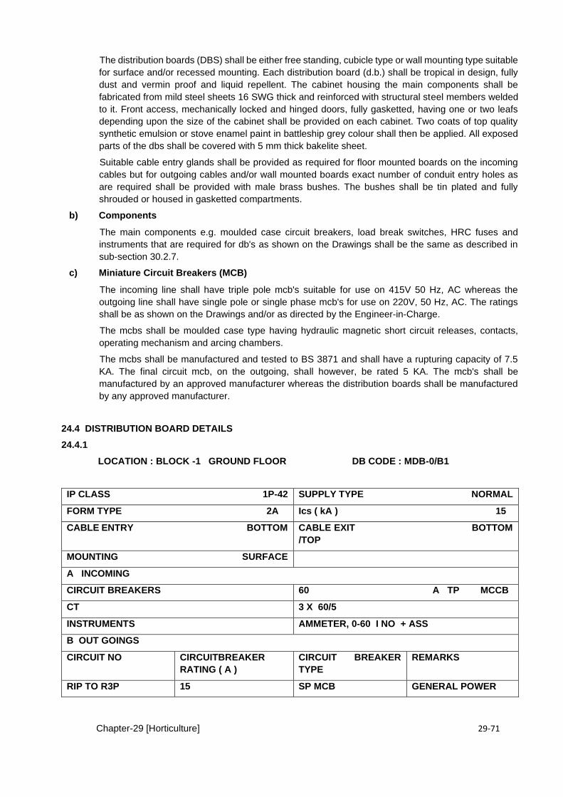
Chapter-29 [Horticulture] 29-71
The distribution boards (DBS) shall be either free standing, cubicle type or wall mounting type suitable
for surface and/or recessed mounting. Each distribution board (d.b.) shall be tropical in design, fully
dust and vermin proof and liquid repellent. The cabinet housing the main components shall be
fabricated from mild steel sheets 16 SWG thick and reinforced with structural steel members welded
to it. Front access, mechanically locked and hinged doors, fully gasketted, having one or two leafs
depending upon the size of the cabinet shall be provided on each cabinet. Two coats of top quality
synthetic emulsion or stove enamel paint in battleship grey colour shall then be applied. All exposed
parts of the dbs shall be covered with 5 mm thick bakelite sheet.
Suitable cable entry glands shall be provided as required for floor mounted boards on the incoming
cables but for outgoing cables and/or wall mounted boards exact number of conduit entry holes as
are required shall be provided with male brass bushes. The bushes shall be tin plated and fully
shrouded or housed in gasketted compartments.
b) Components
The main components e.g. moulded case circuit breakers, load break switches, HRC fuses and
instruments that are required for db's as shown on the Drawings shall be the same as described in
sub-section 30.2.7.
c) Miniature Circuit Breakers (MCB)
The incoming line shall have triple pole mcb's suitable for use on 415V 50 Hz, AC whereas the
outgoing line shall have single pole or single phase mcb's for use on 220V, 50 Hz, AC. The ratings
shall be as shown on the Drawings and/or as directed by the Engineer-in-Charge.
The mcbs shall be moulded case type having hydraulic magnetic short circuit releases, contacts,
operating mechanism and arcing chambers.
The mcbs shall be manufactured and tested to BS 3871 and shall have a rupturing capacity of 7.5
KA. The final circuit mcb, on the outgoing, shall however, be rated 5 KA. The mcb's shall be
manufactured by an approved manufacturer whereas the distribution boards shall be manufactured
by any approved manufacturer.
24.4 DISTRIBUTION BOARD DETAILS
24.4.1
LOCATION : BLOCK -1 GROUND FLOOR DB CODE : MDB-0/B1
IP CLASS 1P-42 SUPPLY TYPE NORMAL
FORM TYPE 2A Ics ( kA ) 15
CABLE ENTRY BOTTOM CABLE EXIT BOTTOM
/TOP
MOUNTING SURFACE
A INCOMING
CIRCUIT BREAKERS 60 A TP MCCB
CT 3 X 60/5
INSTRUMENTS AMMETER, 0-60 I NO + ASS
B OUT GOINGS
CIRCUIT NO CIRCUITBREAKER
RATING ( A )
CIRCUIT BREAKER
TYPE
REMARKS
RIP TO R3P 15 SP MCB GENERAL POWER
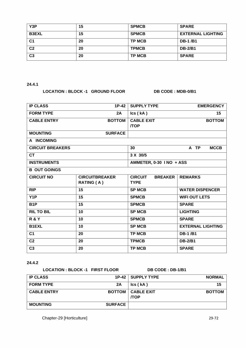
Chapter-29 [Horticulture] 29-72
Y3P 15 SPMCB SPARE
B3EXL 15 SPMCB EXTERNAL LIGHTING
C1 20 TP MCB DB-1 /B1
C2 20 TPMCB DB-2/B1
C3 20 TP MCB SPARE
24.4.1
LOCATION : BLOCK -1 GROUND FLOOR DB CODE : MDB-0/B1
IP CLASS 1P-42 SUPPLY TYPE EMERGENCY
FORM TYPE 2A Ics ( kA ) 15
CABLE ENTRY BOTTOM CABLE EXIT BOTTOM
/TOP
MOUNTING SURFACE
A INCOMING
CIRCUIT BREAKERS 30 A TP MCCB
CT 3 X 30/5
INSTRUMENTS AMMETER, 0-30 I NO + ASS
B OUT GOINGS
CIRCUIT NO CIRCUITBREAKER
RATING ( A )
CIRCUIT BREAKER
TYPE
REMARKS
RIP 15 SP MCB WATER DISPENCER
Y1P 15 SPMCB WIFI OUT LETS
B1P 15 SPMCB SPARE
RIL TO BIL 10 SP MCB LIGHTING
R & Y 10 SPMCB SPARE
B1EXL 10 SP MCB EXTERNAL LIGHTING
C1 20 TP MCB DB-1 /B1
C2 20 TPMCB DB-2/B1
C3 20 TP MCB SPARE
24.4.2
LOCATION : BLOCK -1 FIRST FLOOR DB CODE : DB-1/B1
IP CLASS 1P-42 SUPPLY TYPE NORMAL
FORM TYPE 2A Ics ( kA ) 15
CABLE ENTRY BOTTOM CABLE EXIT BOTTOM
/TOP
MOUNTING SURFACE
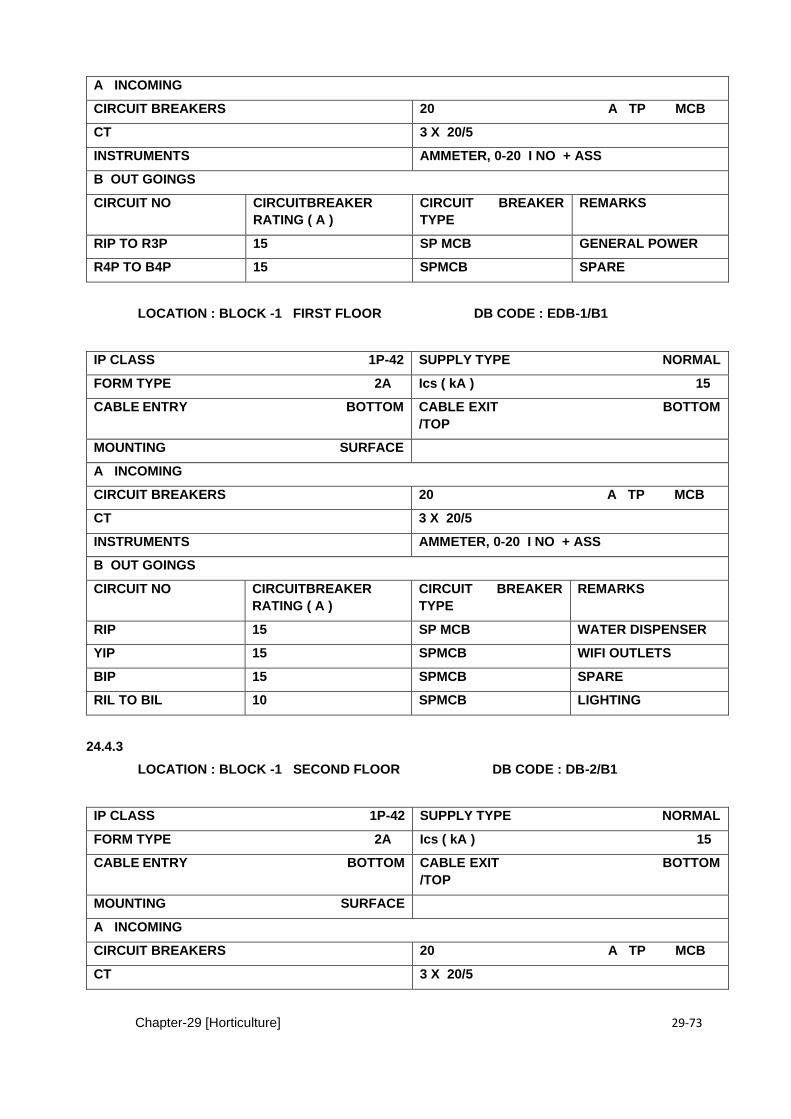
Chapter-29 [Horticulture] 29-73
A INCOMING
CIRCUIT BREAKERS 20 A TP MCB
CT 3 X 20/5
INSTRUMENTS AMMETER, 0-20 I NO + ASS
B OUT GOINGS
CIRCUIT NO CIRCUITBREAKER
RATING ( A )
CIRCUIT BREAKER
TYPE
REMARKS
RIP TO R3P 15 SP MCB GENERAL POWER
R4P TO B4P 15 SPMCB SPARE
LOCATION : BLOCK -1 FIRST FLOOR DB CODE : EDB-1/B1
IP CLASS 1P-42 SUPPLY TYPE NORMAL
FORM TYPE 2A Ics ( kA ) 15
CABLE ENTRY BOTTOM CABLE EXIT BOTTOM
/TOP
MOUNTING SURFACE
A INCOMING
CIRCUIT BREAKERS 20 A TP MCB
CT 3 X 20/5
INSTRUMENTS AMMETER, 0-20 I NO + ASS
B OUT GOINGS
CIRCUIT NO CIRCUITBREAKER
RATING ( A )
CIRCUIT BREAKER
TYPE
REMARKS
RIP 15 SP MCB WATER DISPENSER
YIP 15 SPMCB WIFI OUTLETS
BIP 15 SPMCB SPARE
RIL TO BIL 10 SPMCB LIGHTING
24.4.3
LOCATION : BLOCK -1 SECOND FLOOR DB CODE : DB-2/B1
IP CLASS 1P-42 SUPPLY TYPE NORMAL
FORM TYPE 2A Ics ( kA ) 15
CABLE ENTRY BOTTOM CABLE EXIT BOTTOM
/TOP
MOUNTING SURFACE
A INCOMING
CIRCUIT BREAKERS 20 A TP MCB
CT 3 X 20/5
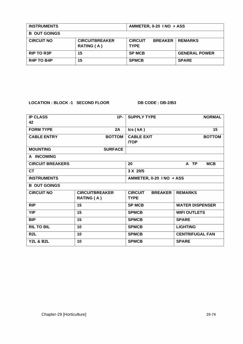
Chapter-29 [Horticulture] 29-74
INSTRUMENTS AMMETER, 0-20 I NO + ASS
B OUT GOINGS
CIRCUIT NO CIRCUITBREAKER
RATING ( A )
CIRCUIT BREAKER
TYPE
REMARKS
RIP TO R3P 15 SP MCB GENERAL POWER
R4P TO B4P 15 SPMCB SPARE
LOCATION : BLOCK -1 SECOND FLOOR DB CODE : DB-2/B3
IP CLASS 1P-
42
SUPPLY TYPE NORMAL
FORM TYPE 2A Ics ( kA ) 15
CABLE ENTRY BOTTOM CABLE EXIT BOTTOM
/TOP
MOUNTING SURFACE
A INCOMING
CIRCUIT BREAKERS 20 A TP MCB
CT 3 X 20/5
INSTRUMENTS AMMETER, 0-20 I NO + ASS
B OUT GOINGS
CIRCUIT NO CIRCUITBREAKER
RATING ( A )
CIRCUIT BREAKER
TYPE
REMARKS
RIP 15 SP MCB WATER DISPENSER
YIP 15 SPMCB WIFI OUTLETS
BIP 15 SPMCB SPARE
RIL TO BIL 10 SPMCB LIGHTING
R2L 10 SPMCB CENTRIFUGAL FAN
Y2L & B2L 10 SPMCB SPARE
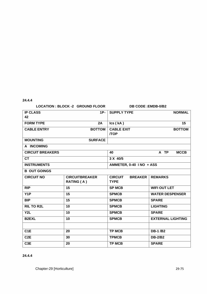
Chapter-29 [Horticulture] 29-75
24.4.4
LOCATION : BLOCK -2 GROUND FLOOR DB CODE :EMDB-0/B2
IP CLASS 1P-
42
SUPPLY TYPE NORMAL
FORM TYPE 2A Ics ( kA ) 15
CABLE ENTRY BOTTOM CABLE EXIT BOTTOM
/TOP
MOUNTING SURFACE
A INCOMING
CIRCUIT BREAKERS 40 A TP MCCB
CT 3 X 40/5
INSTRUMENTS AMMETER, 0-40 I NO + ASS
B OUT GOINGS
CIRCUIT NO CIRCUITBREAKER
RATING ( A )
CIRCUIT BREAKER
TYPE
REMARKS
RIP 15 SP MCB WIFI OUT LET
Y1P 15 SPMCB WATER DESPENSER
BIP 15 SPMCB SPARE
RIL TO R2L 10 SPMCB LIGHTING
Y2L 10 SPMCB SPARE
B2EXL 10 SPMCB EXTERNAL LIGHTING
C1E 20 TP MCB DB-1 /B2
C2E 30 TPMCB DB-2/B2
C3E 20 TP MCB SPARE
24.4.4

Chapter-29 [Horticulture] 29-76
LOCATION : BLOCK -1 FIRST FLOOR DB CODE : DB-1/B2
IP CLASS 1P-42 SUPPLY TYPE NORMAL
FORM TYPE 2A Ics ( kA ) 15
CABLE ENTRY BOTTOM CABLE EXIT BOTTOM
/TOP
MOUNTING SURFACE
A INCOMING
CIRCUIT BREAKERS 20 A TP MCCB
CT 3 X 20/5
INSTRUMENTS AMMETER, 0-20 I NO + ASS
B OUT GOINGS
CIRCUIT NO CIRCUITBREAKER
RATING ( A )
CIRCUIT BREAKER
TYPE
REMARKS
RIP TO R2P 15 SP MCB GENERAL POWER
Y2P TO B2P 15 SPMCB SPARE
24.4.5
LOCATION : BLOCK -1 FIRST FLOOR DB CODE : EDB-1/B2
IP CLASS 1P-
42
SUPPLY TYPE NORMAL
FORM TYPE 2A Ics ( kA ) 15
CABLE ENTRY BOTTOM CABLE EXIT BOTTOM
/TOP
MOUNTING SURFACE
A INCOMING
CIRCUIT BREAKERS 20 A TP MCB
CT 3 X 20/5
INSTRUMENTS AMMETER, 0-20 I NO + ASS
B OUT GOINGS
CIRCUIT NO CIRCUITBREAKER
RATING ( A )
CIRCUIT BREAKER
TYPE
REMARKS
RIEP 15 SP MCB WIFI OUT LET
Y1EP 15 SPMCB WATER DESPENSER
RIL TO R2L 10 SPMCB LIGHTING
Y2L & B2L 10 SPMCB SPARE
24.4.6
LOCATION : BLOCK -2 FIRST FLOOR DB CODE : DB-2/B2
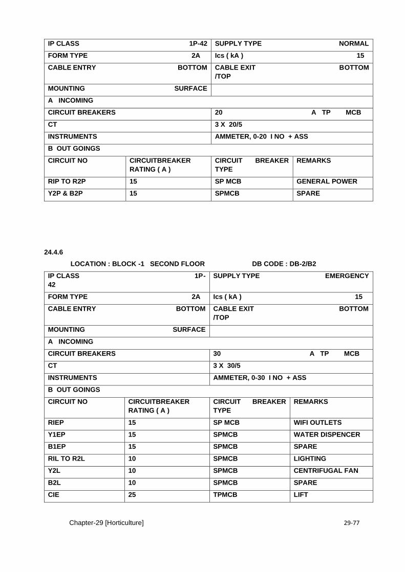
Chapter-29 [Horticulture] 29-77
IP CLASS 1P-42 SUPPLY TYPE NORMAL
FORM TYPE 2A Ics ( kA ) 15
CABLE ENTRY BOTTOM CABLE EXIT BOTTOM
/TOP
MOUNTING SURFACE
A INCOMING
CIRCUIT BREAKERS 20 A TP MCB
CT 3 X 20/5
INSTRUMENTS AMMETER, 0-20 I NO + ASS
B OUT GOINGS
CIRCUIT NO CIRCUITBREAKER
RATING ( A )
CIRCUIT BREAKER
TYPE
REMARKS
RIP TO R2P 15 SP MCB GENERAL POWER
Y2P & B2P 15 SPMCB SPARE
24.4.6
LOCATION : BLOCK -1 SECOND FLOOR DB CODE : DB-2/B2
IP CLASS 1P-
42
SUPPLY TYPE EMERGENCY
FORM TYPE 2A Ics ( kA ) 15
CABLE ENTRY BOTTOM CABLE EXIT BOTTOM
/TOP
MOUNTING SURFACE
A INCOMING
CIRCUIT BREAKERS 30 A TP MCB
CT 3 X 30/5
INSTRUMENTS AMMETER, 0-30 I NO + ASS
B OUT GOINGS
CIRCUIT NO CIRCUITBREAKER
RATING ( A )
CIRCUIT BREAKER
TYPE
REMARKS
RIEP 15 SP MCB WIFI OUTLETS
Y1EP 15 SPMCB WATER DISPENCER
B1EP 15 SPMCB SPARE
RIL TO R2L 10 SPMCB LIGHTING
Y2L 10 SPMCB CENTRIFUGAL FAN
B2L 10 SPMCB SPARE
CIE 25 TPMCB LIFT

Chapter-29 [Horticulture] 29-78
25.0 EARTHING SYSTEM
a) General
The earthing system shall consist of earth electrodes, earth connecting points, earthing leads, earth
continuity conductors and all accessories necessary for the satisfactory operation of the associated
electrical system. The earthing system shall also comply with the requirements of CP-1013.
b) Earth Continuity Conductor
The earth continuity conductor (ECC) shall be green or green/yellow coloured PVC insulated copper
wire of sizes indicated on the Drawings. The ECC shall comply with the specifications as given for
single core cable in Section 30.2.3. For bonding of miscellaneous metalwork, the size of ECC shall
be as specified. All sockets, lugs, thimbles etc., shall be provided for a complete earthing installation.
c) Earth Electrodes
The earth point shall comprise of a 600 x 600 x 5 mm electrolytic copper plate, tinned for protection
against corrosion. The edges of the copper plate shall be chamfered. The plate shall have holes for
connecting each earthing lead or tape to earth terminals. The terminals shall comprise of 16 mm dia.
copper bolts and nuts and double spring washers. 13 mm dia G.I. Pipe with a tee at the top end shall
be provided for watering purpose during dry season.
d) Earth Connecting Point The earth connecting points shall comprise of tinned copper bar, rectangular in shape, having
dimensions of 350x50x6mm, if not otherwise specified. Terminals for connection shall be arranged
as required.
The terminals shall have brass or tinned copper bolts, nuts and washers for protection against
corrosion. A hole shall be provided in the centre of the copper bar for fixing to the wall by means of
10 mm dia nut and bolt using brass or tinned copper washers.

Chapter-29 [Horticulture] 29-79
e) Earthing Lead The earthing lead shall connect the earth electrode to the earth connecting point. It shall be of round
hard drawn bare electrolytic copper wire of the size shown on the Drawings.
f) Earthing by Earth Rods The earth rod shall be of mild steel and shall be protected against rusting by a thick exterior layer of
copper (not less than 0.33 millimeter), permanently molten or electrolytically deposited on a high
strength steel core which shall provide rigidity for easy driving without bending.
g) Earth Rod Dimensions The earth rod shall have a nominal dia of 16mm with chamfered head of 2mm x 45 chamfer. The
overall length of earth rod shall be 3000 + 5mm.
25.1 LIGHTING PROTECTION SYSTEM
a) Applicable Standards/Codes
Latest editions of the following standards and codes shall be applicable for the material specified
within the scope of this section.
BS 6651 : Protection of structures against lightning
CP 326 : Protection of structures against lightning (code of practice).
IEC 1024-1 : Protection of structures against lightning
b) Material i) General
The installation of lightning protection system shall comprise;
- Lighting arrestors - Down/Roof conductors. - Testing terminals - Earth electrodes ii) Air Terminals
The Air Terminals for lightning protection system shall be solid copper to ensure good corrosion
resistance. The thread should be roll formed for maximum strength, with a bronze nut. The terminal
base and the plate type test clamp shall be cast gun metal, designed with appropriate section
thickness, mechanically strong, corrosion resistant with low electrical resistance. All other accessories
for fixing of air terminals to the concrete surface and/or roof conductor/down conductor shall be of
copper or brass, as approved by the Engineer-in-Charge.
iii) Down/Roof Conductors The down/roof conductors for lightning protection system shall be bare copper conductor of sizes as
per approved shop drawings. All connections between metal work on the roof shall be with the same
conductor sizes and material as for roof conductor. All accessories for fixing of copper conductor to
concrete surface shall be of copper or brass as approved by the Engineer.
iv) Testing Terminals For each down conductor, a testing point shall be provided. It shall be installed 1.5 meters above the
finished floor level or as convenient for testing purposes and as directed by the Engineer-inCharge.
The testing terminals shall have removable connections.
v) Earth Electrode
Chapter-29 [Horticulture] 29-80
The earth electrode for lightning protection system shall comprise 3 meter long, 14 mm dia. copper
clad or galvanised steel rod having flat head at drive end and pointed conical tip at the driven end. The tip shall be hardened to facilitate driving. At the top of the pipe, a clamp for bolted connections
shall be provided suitable for connection to the down conductor.
a) Air Terminals
The Air Terminals shall be installed on the roof as per approved shop drawings. The terminal base
shall be firmly secured to the concrete surface. It should be ensured that air terminals and/or roof
conductors/down conductors shall be firmly fixed together, so that electro dynamic or accidental
mechanical forces will not cause any damage to the clamping. The materials used shall withstand the
electromagnetic effects of lightning current and predictable accidental stresses without being
damaged.
The Contractor shall submit the fixing arrangement for the approval of the Engineer-in-Charge. b)
b.) Roof Conductor
The roof conductors shall be installed on the roof as per approved shop drawings. The copper
conductor shall be firmly secured to the concrete surface by means of copper or brass clamps of
approved design at a maximum interval of 1000 mm.
The roof conductor shall be connected to the copper rod by means of copper clamps. The clamp to
be tightly fixed to the rod and brazed to ensure low resistance path to earth. The contact surface
between copper clamp and conductor shall be cleaned, silver painted, brazed after bolting and
provided with a coat of anti- corrosive paint after installation.
c) Down Conductors
The down conductor shall be installed along the shortest possible route from roof to earth electrode.
It shall be secured on the surface of wall by means of clamps at a maximum interval of 1000 mm. In
general, bends shall be avoided along the routes of down conductor and maximum possible bending
radius will be provided at turns. All joints between conductors shall be electrically and mechanically
strong and effective. Straight joints in the down conductor shall be bolted. The joint shall be given a
coat of anti -corrosive paint after connection. All accessories such as nuts, bolts, washers, solder,
paint etc. shall be furnished by the Contractor.
For each down conductor a removable terminal shall be provided for testing purpose at approximately
1.5 meter height. The location of testing terminals are not shown on the drawings. The Contractor must
ensure that testing terminals are installed so as to facilitate testing. The testing terminals shall be
bolted type and made in accordance with the specifications for straight bolted joints. The connecting
earth lead from testing terminals to earth electrodes shall be continuous without any joint. All metal
work, pipes etc., at the roof and within 2 meters along the route of down conductor shall be bonded to
the lightning protection system. The bonding shall be effective and approval of the Engineer-in-Charge
shall be obtained for the bonding method.
d) Earth Electrode
In case the soil conditions at site permit, the earth electrodes may be installed by hammering the
electrode in soil, until the top of the pipe is about 300 mm below the proposed ground level. If
hammering down is not possible due to site conditions, a pit shall be first excavated in bare ground
upto the required depth and electrode shall be installed upright in the pit. The excavated pit shall be
backfilled in layers of 500 mm, each layer tamped and compacted. At the ground level an inspection
chamber of cement concrete shall be constructed having dimensions as shown on the drawings. The
inspection chamber shall have a cover supported on angle iron frame. The cover shall be approved
by the Engineer-in-Charge and shall finish flush with the ground level.
Chapter-29 [Horticulture] 29-81
26.0 Fire Alarm & Fire Detection System
26.0 GENERAL
26.1 RELATED DOCUMENTS
A. Manuals, brochures, technical submittals and general provisions of the Contract, including
general and Special Conditions, apply to this Section.
26.2 SUMMARY
A. This section includes the intelligent addressable fire alarm and detection system for ensuring safety
and asset protection.
26.3 SUBMITTALS
Chapter-29 [Horticulture] 29-82
A. Submit the product information for approval and final documentation in the quantities
listed.
B. Documents for Approval:
1. Bill of material
2. Technical specifications of all the material
3. Connectivity diagrams
4. Any variance (in case of deviation from the given specifications)
C. Final Documents: Record documentation to include:
1. Documents listed above.
2. Recommended spare parts list for start-up support
3. Instruction manual
4. Testing Certificates
26.4 QUALITY ASSURANCE
A. Manufacturer Qualifications: Engage a firm with at least 15 years experience in
manufacturing fire alarm detection system.
B. Supplier is to have a local service team with available spare parts in Lahore, Pakistan.
C. Service personnel are to have at least 10 years in the installation, start-up and
servicing of the said system.
26.5 WARRANTY
A. The manufacturer’s standard warranty shall in no event be for a period of less than 36 months
starting from beneficial use of the equipment. Submittals received without written warranties as
specified will be rejected in their entirety. Maintenance during reliability period shall also be
covered in the warranty section.
26.6 SCOPE OF WORK
26.6.1 GENERAL
The contractor shall supply and test the complete fire alarm system as described herein and as shown
on the plans. The system shall include Intelligent Addressable main control panel, Addressable smoke
sensors, Multi/heat sensors, wiring, termination, electrical boxes, and all other necessary material for
a complete operating system.
The supplier has to verify that complete installation shall confirm to the applicable sections of NFPA72,
NFPA-71, EN-54 and BS-5839.
Chapter-29 [Horticulture] 29-83
The system shall have the capability of recalling alarms and trouble conditions in chronological order
for the purpose of creating an event history of 600 events.
The system shall have a single key that will allow the operator to display all alarm, troubles, and
supervisory service conditions including the time of each occurrence.
The system shall have provisions for disabling and enabling all circuits individually for maintenance or
testing purposes.
The system batteries shall be supervised for disabling and enabling all circuits individually for
maintenance or testing purposes.
The panels shall be capable of networking upto 99 more nodes as nodes as and when required without
modification of hardware except adding network cards.
26.6.2 POWER REQUIREMENTS
The system shall be provided with sufficient battery capacity to operate the entire system upon loss of
normal 230VAC power in a normal supervisory mode for a period of 24 hours with 30 minutes of alarm
operation at the end of this period. The system shall automatically transfer to the stand-by batteries
upon power failure. All battery charging and recharging operations shall be automatic. Contractor shall
submit standby and alarm power calculations in support of the selected battery size. The batteries
used for the system shall be maintenance free type.
26.6.2 FIRE ALARM CONTROL PANEL
The control panel shall be Intelligent Addressable type of adequate point capacity with 20% spare and
the construction shall be modular with solid state, microprocessor based electronics. It shall display
only those primary controls and display essential to operation during a fire alarm condition.
The following primary controls shall be visible through a front access panel:
▪ Eighty character liquid crystal display.
▪ Individual red system alarm LED.
▪ Individual yellow supervisory service LED.
▪ Silent Walktest with History Logging
26.6.3 MULTIPLE ADDRESSABLE PERIPHERAL NETWORK
The system must provide communication with initiating and control devices individually. Alarm
▪ Trouble
▪ Open
▪ Short
▪ Device missing/failed
▪ Automatic environmental compensation.
▪ Variable Sensitivity setting
26.6.4 -ADDRESSABLE DEVICE TYPES
25.6.4 GENERAL
The system control panel must be capable of communicating with the types of addressable devices
specified below. Addressable Devices will be located as shown on the drawings. The system shall
identify when a smoke sensor becomes too dirty to operate properly.
The panel shall provide the following features:
Chapter-29 [Horticulture] 29-84
- Individual sensitivity selection for each sensor
- Peak value logging allowing accurate analysis for sensitivity selection
- Automatic, once per minute individual; sensor calibration check to verify sensor
- integrity
- Display of sensitivity directly in per cent per foot
- Multi-stage alarm operation
- Ability to display and print detailed sensor information
26.6.5 ADDRESSABLE SENSOR BASES
The addressable sensor bases shall contain integral addressable electronics that constantly monitor
the status of the detachable photoelectric, ionization or heat sensors. Each sensors output shall be
digitized and transmitted to the control panel every four seconds. Soft addressable sensors are also
will be acceptable subject to compliance with other requirements of the specifications.
26.6.6 ADDRESSABLE OPTICAL SMOKE SENSORS
Optical sensor shall use a stable, pulsed infra red LED light source and a silicon photodiode receiver
to provide consistent and accurate low power smoke sensing. Seven levels of sensitivity shall be
available for each individual sensor, ranging from 0.2% to 3.7% per foot of smoke obscuration. It shall
be possible to select and monitor the sensitivity at the control panel.
The head be designed to allow 360 deg. Smoke entry for optimum response to smoke from any
direction. A built-in screen shall keep insects from entering the smoke chamber.
26.6.7 ADDRESSABLE OPTICAL HEAT SENSOR
The addressable type heat sensor shall be self restoring and provide a combination of rate and fixed
temperature rate compensated sensing. It shall have low thermal mass to accurately and quickly
measure the local temperature at the fire alarm panel.
It shall be possible to select the rate of rise temperature detection for either 15 oF or 20 oF per minute.
Fixed temperature sensing and shall be programmable to operate at 135 °F or 155 °F. It shall be
possible to program these sensors as a utility device to monitor for temperature extremes in the range
from 32 oF to 120 oF (optional).
26.6.8 INTELLIGENT OPTICAL MULTI SENSOR
The Addressable Multi Sensor gathers analog information from one photoelectric fire sensing
element and one heat sensing element and converts it into digital signals. The sensitivity of the
Device shall be variable.
• Sensitivity variable
• Operating voltage 24VDC
• Standby Condition ≤100µA
• Alarm Condition ≤7mA
• Transmission Method Digital Communications
• Maximum Humidity 93% RH- Non Condensing (at 40◦C)
• Temperature range -10◦C - + 50◦C
26.6.9 ADDRESSABLE PULL STATION
Chapter-29 [Horticulture] 29-85
They shall be manufactured from high impact red lexan. Station shall mechanically latch upon
operation and remain so until manually reset by opening with a key common to all system locks. Pull
stations shall be double action type requiring smashing glass and pulling a lever to initiate an alarm.
26.6.10ADDRESSABLE DEVICE SUPERVISION
All devices shall be supervised or trouble conditions. The system control panel will be capable of displaying
the type of trouble condition (open, short, device missing, failed). Should a device fail it will not hinder the
operation of other system devices.
26.6.10 NOTIFICATION APPLIANCES
Notification appliances shall include visible, audible or Audible / visible as shown in the drawing.
Audible appliance shall be loudspeaker or dc vibrating bells and the visible appliance shall be strobes.
The sounders must be capable of projecting the pre-recorded voice messages. The prerecorded
messages shall be in various languages i.e English , Urdu or any other as specified by the end user.
26.6.12 STROBES WITH SOUNDER (SINGLE UNIT)
Strobes shall be suitable for wall or ceiling mounting as shown in the drawings. Xenon flash tubes
shall be 24VDC powered from the panel. Visible output shall be 30 candela. The reflective design shall
provide light output in key axis directions allowing vertical or horizontal mounting. The unit shall be of
red finish with white 'FIRE" lettering . Flash rate shall be 1 Hz.
26.6.13 INTEGRATION
Fire Alarm system shall be integrated with Emergency Voice Evacuation system, Access control
system and Building Management system for sequential operations and status monitoring.
Chapter-29 [Horticulture] 29-86
CHAPTER 27 DATA & VOICE SYSTEM
27.0 GENERAL
27.0.1DESCRIPTION:
A. The Work shall consist of furnishing and installation of voice and data communication cabling
as shown on the drawings and specified herein.
17.0.2 REFERENCES:
A. ISO – International Standards Organization
ISO/IEC 11801 Information Technology – Generic Cabling for Customer Premises
B. IEC - International Electrotechnical Commission
IEC 60603-7 Connectors for Electronic Equipment – Part 7-1 & 7-7
IEC 60332 Test on electric cables under fire conditions
IEC 60754 Tests on Gases Evolved During Combustion of Material from Cables
EIA/TIA 568-B.3 Optical Fiber Cabling Components (ANSI)
C IEEE - Institute of Electrical and Electronic Engineers
ICEA S-83-596 Standard for Fiber Optic Premises Distribution Cable
1.3 SUBMITTALS:
A. General: Submit the necessary complete sets of documentation indicating type, size, rating,
style, catalog number, Manufacturers names, photographs and / or catalog data sheets for all items to
ensure compliance with Specifications. This documentation shall be subject to the approval of the
Owner Representative and no equipment shall be ordered without his approval for all equipment and
devices, which are shown on documents (drawings, BOQ, etc). During technical submittal stage,
contractor shall submit all required technical document for study and approval.
B. Product Data: Submit manufacturer's technical product data, including:
1. Compliance sheet to the specification with cross reference to related items in data sheet, point by
point, indicating deviations, if any, with reasons for such deviations, also indicate any extra features /
specifications.
2. Complete one-line riser diagram(s) showing all system components
3. Complete description data including UL listing or any equivalent standards for all system components
4. Provide all system related calculations supported by manufacturer specific software and perform all
necessary calculations validating the shop drawing system distribution and related installations.
5. Complete description and data including related standards for all system components.
6. Submit Wi Fi Coverage patterns and accordingly modify, add, relocate wi fi outlets to provide full
coverage of the building enabling VOIP over Wi Fi network in all building areas.
C. Shop Drawings: Provide shop drawings & Composite drawings showing equipment, device locations,
labeling, part number and connecting wiring of the systems, including riser diagrams, rack elevations etc.
Shop drawings shall include, but not be limited to the following:
1. Installation details for all system components. Installation details drawings shall show all
accessories used in installation such as back boxes, glands, washers, etc.
Chapter-29 [Horticulture] 29-87
2. Complete Grounding details as per system manufacturer requirements.
D. Manuals: Submit complete manufacturer Installations, maintenance and operation manuals
including spare parts list for each system component, including furnished specialties and accessories.
Include this data, product data, and shop drawings in the manuals in accordance with other relevant
documentation.
1.4 WARRANTY:
A. The manufacturer must guarantee to the End User that the products referenced within the specific
Warranty Modules (Class E System) when correctly installed in accordance with installation guidelines for a
duration of 20 years
B. All components including the patch cords have to be produced by the same cabling system
manufacturer to ensure warranted performances and applications against the standards.
1.6 QUALITY ASSURANCE:
A. Manufacturer's Qualifications: The items provided under this contract will be from
manufacturers that have a minimum of 5 years experience in producing the types of systems and
equipment specified.
B. Installer Qualifications: Specialist subcontractor with at least 5 years of successful
installation experience with projects utilizing data system similar to that required for this project.
Subcontractor shall be subject to approval of Engineer.
PART 2 – PRODUCTS
2.1 SYSTEM DESCRIPTION:
A. The voice and data communication cabling shall consist of horizontal and backbone cables and
connecting hardware to transport data (including LAN/WAN) and voice (telephone) system signals between
related as shown on drawings. Numbers of outlets shall be as shown on drawings and documents. The Data
Local Area Network (LAN) Sub-Contractor shall coordinate his work with telephone equipment Sub-
Contractor(if any).
C. The Data Network will perform all switching and routing functions for voice, video
and data services and applications. The network shall serve all IP based services such as
VOIP, IP CCTV, IPTV, etc, as applicable.
D. The Core Switches will be located at the heart of the network and shall provide very
fast switching, intelligent high performance platform for deploying numerous concurrent
intelligent services without degrading the overall performance of the network. The core
switches shall perform various functions using various service modules for wan interfaces,
security firewalls…etc. Core Switches should support MPLS and act as P-Routers.
E. Connectivity between DC Switches and Core Switches should be based on 40G/ per
BOQ/Risers.
F. Connectivity between Core Switches and Distribution Switches should be based on
40G/ per BOQ/Risers.
G. Access Switch: Access Switches will be located per per BOQ/Risers/Dwgs.
P. The maximum allowable horizontal cable length is 90 m. This maximum allowable length does not
include an allowance for the length of 4.9 m to the workstation equipment. The maximum allowable length
does not include an allowance for the length of 4.9 m in the horizontal cross connect.
Q. Backbone cabling system shall provide interconnections between communications equipment rooms,
main terminal space, and entrance facilities in the telecommunications cabling system structure. Cabling
Chapter-29 [Horticulture] 29-88
system consists of backbone cables, intermediate and main cross-connects mechanical terminations, and
patch cords or jumpers used for backbone-to-backbone cross-connection.
R. Backbone cabling cross-connects may be located in communications equipment rooms or at
entrance facilities. Bridged taps and splitters shall not be used as part of backbone cabling.
2.2 GENERAL:
A. Materials and equipment shall be the standard products of a manufacturer regularly engaged in the
manufacture of the products and shall be of latest technology/version available at the time of installation,
and has been in satisfactory use for at least 1 year prior to installation. Materials and equipment shall
conform to the respective publications and standards specified.
2.3 HORIZONTAL CABLING:
A. Horizontal Distribution Cable:
1. Horizontal distribution cable shall be Category 6.
2. The cable shall be a four, thermoplastic-insulated, individually twisted pairs of copper
conductors; No.23 AWG, color-coded; enclosed in PVC jacket or a material.
3. Cable shall be designed to support the IEEE 802.3 1000Base.
4. All pairs must have impedance of 100 Ohms, with a tolerance of +/- 15
Ohms. In the construction of the cable cross-talk performance shall be maintained using a C3 (Central
dielectric Cross-talk Cancellation) member set between the 4 pairs.
5. Insulators in standard Blue/White, Orange/White, Green/White, Brown/White colors
must cover the conductors.
6. Cable shall be of latest technology/speed manufactured and available at the installation time.
7. Cable shall be used for horizontal run between data, voice (telephone), clock and security
system outlets and floor communicable cabinet.
10. Meet the following electrical characteristics per consultant’s recommendations (if any):
Max DC Resistance (@ 20°C) <8.5Ω /100m
Characteristic Impedance
(no impedance averaging allowed) 1-100 MHz: 100 ohms ± 15%
100 - 750MHz: 100 ohms ± 22%
Nominal Velocity of Propagation (NVP)
LSOH – 67%
11. Provide the following 100m, 4-connector topology performance (std ref. values in grey cells):
2.4 BACKBONE CABLING:
A. Data Backbone: This backbone will link the Switches located in the Floor Distributors (FD) to the
Data network server through the Building Distributor (BD).
1. Optical Fiber Cable: The cable shall be suitable for connector manufacturer
termination processes (LC, SC or ST connectors). Fiber splicing method should be used for
termination of Fiber Cables using fiber pigtails manufactured by the same vendor.
Chapter-29 [Horticulture] 29-89
Construction: Tight buffered with water blocking Aramid/Glass yarn reinforcements or tape and shall be
suitable for indoor or outdoor use making it ideal for short campus links without the use of transition
joints. The cable strength member shall be glass yarn laid longitudinally between the fibers and the
inside wall of the outer jacket. The cable shall be dielectric construction, i.e. with no metallic content.
The cable shall be a dry construction i.e. with no gel content. The jacket material shall be waterproof
LSZH with a minimum fire performance of IEC 332 part 3C.
2. Single Mode Fiber Optic Cable
a. The Cabling system must be designed and installed according to ISO 11801 OS1 for indoor
use, and ISO 11801 OS2 for outdoor use, compliant and should also meet EN50173 2nd editions
and TIA/EIA 568B3. The Cable shall have 6 or 12 or 24 cores, 9.2/125 µm universal distribution
cable with improved performance.
b. Low Smoke Zero Halogen - LSZH Jacket that does not give off toxic fumes in case of fire
and offer flame propagation retardant properties.
c. Shall contain a Rip Cord applied longitudinally under the cable jacket for easy cable jacket
removal.
d. Shall contain a lightweight Central Strength member located in the middle of the fibre
bundles.
e. Shall contain both colour-coded buffered fibres as well as colour- coded buffer tubes.
f. Cables shall have length markings in 2 ft. increments.
g. Fibre will be available in strand counts of 4, 6, 12, 24, 36, 48, 72, 96, 144 and 288.
h. Shall meet these minimum performance parameters per standards specified above.
3. Optical Fiber Patch Panel:
a. Optical fiber Patch Panels shall be mounted in 19" frames of the cabinets. The patch panels shall be
equipped with a mechanism that ensures the retention and support of incoming cables. An Earth Key
shall be provided within the patch panel to earth any metallic part of the cable. The patch panel shall be
designed with a sliding mechanism enabling front side installation and maintenance work to be carried out
without having to remove the entire panel.
b. The patch panel shall provide facilities to recess the front connector plate deeper than the front
of the 19" rails of the cabinet. This will provide sufficient bend radius for the patch cords once connected to
the panel. This shall also prevent damage to the patch cords when the cabinet doors are closed.
c. Direct Termination of the connectors on to the fibers as well as splicing of pigtails shall be possible.
The Patch Panel shall provide management for 1m of fiber per link after breaking the fibers out from the cable.
The Patch Panel shall support the connector type specified for this installation. For multimode fiber links, these
can be LC, SC and ST. The panel-mounted couplers shall be protected on the front presentation side of the
patch Panel for safety purposes.
4. Optical Fiber Patch Cords
a. The Fiber adapters will be connected to the active equipment by means of duplex patch cords 2LC-
2LC, 2 SC-2 SC or 2 ST-2ST as per client site standard.
b. The patch cords consist of 50/125 microns fibers and a LSHF-FR jacket. The SC or ST connectors
shall comply with the International standard IEC 74-13. The patch cords should be available in lengths of 2
and 5 meters.
c. To avoid mix of patch cords built around different types of fiber, cords produced with
LASERoptimized fiber will be used for both OM1 and OM2 optical fiber cables. When using OM3 optical fiber
cables, patch cords produced with the same OM3 fiber have to be installed.
Chapter-29 [Horticulture] 29-90
d. Fiber cables shall interface and connect to fiber interface unit at both ends as part of the fiber
contractor work.
2.5 CABINETS:
A. The metal cabinets shall have a footprint of 800x1000 mm. In the frames 19” components can be
mounted by means of the standard cage nuts. The front door consists of a metal framework with hinges and
a central perforated panel. The side panels and the panel in the back have to be equipped with a hinge on
the left or the right in order to facilitate the access to the equipment. A 42 U cabinet is preferred providing
enough space for active equipment.
B. For an orderly cord storage and easy to manage installation, the following accessories shall
be used:
• Closed 1 or 2 U patch guides between the patch panels;
• Lateral cable rings installed at both sides of the frames. The patch rings can be removed
very easily by rotation and have to be located on the front rails of the 19" frames in the cabinets.
The cabinets should be supplied with:
• Provide power strip with 8 * 240VAC BS 1363 electrical sockets, No ON/OFF switch, 3-meter
power cord and commando socket (male) at the end. Female commando outlet to be provided by the
electrical contractor.
• Provide seismic kit, casters, leveling feet, and bolt down stabilization bracket for each
cabinet.
• Provide Horizontal/Vertical Cable Management. 1 RU of cable management per 24 port
patch panel and 1 RU above and below per 48 port patch panel.
C. Earthing has to be achieved .The cabinet and frame assembly when installed will also serve as
equi-potential plane so that damaging external EMI currents can be drained off. To this end, the inter-cabinet
connections shall also be made off by extending the earth connection from cabinet to cabinet in a suite of
cabinets. The suite of cabinets shall be connected to the grounding network of the building.
D. The Earth key of the cabinet must be connected to the protective earth. The dimension of the earth
conductor is 6mm². If no or only a poor protective earth system is present in the building, a separate earthing
to the main earth terminal of the building is required. The dimensions of the conductor should then be
16mm².

Chapter-29 [Horticulture] 29-91
CHAPTER 28 CCTV System
1.0 IP BASED CCTV SYSTEM
1.1 SCOPE OF WORK
The scope of the work includes the installation, testing and commissioning the complete CCTV
system as described herein and as shown on the plans. The system shall include NVRs, PTZ cameras,
Dome Cameras, Box type cameras, PTZ controller, LCD screens, wiring, termination, electrical boxes,
and all other necessary material for a complete operating system.
1.1.1 FIXED DOME / BOX TYPE IP COLOUR DAY/NIGHT CAMERA
The fixed camera should have the following features:
▪ Directly IP based without requirement of encoder.
▪ Day / Night camera. Should switch automatically to monochrome mode (black and white) at
night.
▪ Imaging Device 1/3 inch complementary metal oxide semiconductor (CMOS) or charge
Coupled Device (CCD) with wide dynamic range (WDR)
▪ Image Control with Automatic white balance (AWB), automatic back light compensation
(BLC), automatic gain control (AGC)
▪ Iris setting should be auto/manual with definitions for sharpness, image quality and also time
stamp and camera ID.
▪ Minimum Illumination should be:
Color mode: F1.4 @ 0.1 lux (.01 fc)
Black and white mode: F1.4 @ 0.04 lux (0.004 fc)
▪ Vari-focal CS mount lens 3.5mm to 50mm required
▪ Supported Video Compression should be H.264 and Motion JPEG (MJPEG)
▪ 704 x 576 @ 25 fps PAL (minimum required )
1920 x1080 @ 25 fps PAL (maximum required)

Chapter-29 [Horticulture] 29-92
▪ Should support dual Video Streaming with both streams originating independently from the
camera
▪ Should support multicasting
▪ Should support Power over Ethernet (PoE) 802.3af
▪ Should provide at least two digital inputs and two digital outputs for hardwire integration.
▪ Camera should provide 802.1X authentication
▪ Camera should support at least 128 bit encryption using hardware-based Advanced
Encryption Standard (AES)
▪ Multiple user access levels with password protection.
1.1.2 PAN/TILT/ZOOM DAY/NIGHT INDOOR/OUTDOOR COLOUR DOME CAMERA
The PTZ Camera should have the following features:
▪ The camera should be IP based.
▪ The camera should be true outdoor model suitable for use in Pakistan.
▪ It shall be a discreet camera dome system consisting of a dome drive with a variable
speed/high speed pan/tilt drive unit with continuous 360° rotation.
▪ Imaging device should be 1/3 inch CCD and support both color and monochrome black and
white. With 540 TVL horizontal resolution.
▪ Should provide 27x optical zoom and 12x digital zoom (minimum) with auto focus feature
▪ The camera should provide high-quality MPEG-4, MJPEG or H.264 compressed images.
▪ The camera should provide images @ 4CIF i.e. with a resolution of 704x576 pixels in PAL
mode.
▪ The supported frame rate should be 30ips or 25ips in PAL mode.
▪ The camera should support two simultaneous streams
▪ Should support Day/Night mode and should switch automatically to monochrome mode at
night with below 1 lux sensing at variable shutter speeds.
▪ Should provide super quick, 400° per-second pan and 200° per-second tilt speeds with 256
pre-set positions. Each pre-set position should support the programmable camera settings
such including selectable auto focus modes, iris level, Low Light limit, and backlight
compensation for each preset.
▪ Should support wide dynamic range (128x) appropriate for high contrasting environments

Chapter-29 [Horticulture] 29-93
▪ Should support Automatic focus, automatic Iris control, gain control horizontal and vertical
aperture control.
▪ Should be installed in a High-impact, weather-resistant dome enclosure
▪ Camera must provide at least 7 Inputs and 2 outputs that can be programmed individually.
Inputs should be able to trigger an alarm condition. Outputs should be able to drive an external
device.
▪ Should support intelligent privacy masking by providing 8, four-sided user-defined shapes,
each side with different lengths; window blanking setting to turn off at user-defined zoom ratio;
window blanking set to opaque gray or translucent smear; blank all video above user-defined
tilt angle; blank all video below user-defined tilt angle .
▪ Should support at least 8 user-defined programmable patterns including pan/tilt/zoom and
preset functions, and pattern programming through control keyboard or through dome system
on-screen menu
▪ Should support a web interface utility for 5 simultaneous users when using MJPEG/MPEG-4
in uni-cast mode. When configured in multicast mode (MPEG-4), the camera should support
an unlimited number of users.
▪ Should support On-screen display for time, date and location. The position of the display and
text should be user definable.
▪ Should support On-screen display of compass heading and user-definable compass setup so
as to indicate direction that the camera is looking in.
▪ Should support multi level password protection.
▪ Should support Secure Sockets Layer (SSL) 128 bit encryption
1.1.3 VIDEO MANAGEMENT AND RECORDING SYSTEM
The Video Surveillance Management platform should be optimized for applications to view, store,
and manage real-time and recorded video in a networked environment. The system should use
an open suite of URL-based programmatic interfaces to communicate with applications. The
system shall provide a highly scalable and reliable platform to enable customized, network-based
surveillance applications. The Video Surveillance Management platform shall include but not
limited to the minimum of the following features/functions/specifications:
▪ The system shall display any combination of live and recorded camera feeds on multiple
workstations simultaneously using an IP network.
▪ The system shall provide low latency video with high quality images and support H.264,
MPEG-4, and Motion-JPEG compression schemes simultaneously.
▪ The system shall provide replication of individual video feeds at different frame rates for
multiple users and other system processes.
▪ The system shall support simultaneous video feeds across multiple locations for centralized
and decentralized storage, display, and distribution of video without limitation, but shall
minimize load on video servers by streaming only the active video channels.
▪ The system shall be capable of streaming and recording video at different bit rates and
variable frame rates up to full motion 25 fps (PAL) video on all camera feeds and shall support

Chapter-29 [Horticulture] 29-94
QCIF, CIF, VGA (640x480 pixels), D1 (720x576pixels) and 4CIF (704x576 pixels) camera
resolution.
▪ The system shall provide the ability to remotely configure the cameras and shall allow
configuration data to be imported from a spreadsheet.
▪ The system shall allow instant replay of video and will permit pausing of live video, forward
and backward review of recorded video, and return to live viewing.
▪ The system shall manage storage of real-time video at any specified frame rate, duration, and
physical location on the network.
▪ The system shall provide flexible archiving capability in terms of frame rate, duration, and
location and shall utilize dynamic file allocation to ensure that the full duration of the selected
video stream will be recorded, regardless of lighting condition, motion, or scene detail.
▪ System shall support access to the archived video, to seek to any point in the archive, to set
the pre and post time, and to loop that segment of the archive.
▪ The system shall cater for redundant multi-site video storage. Meaning that the video feeds
coming from the sites must be stored on primary and backup storage.
▪ The system shall provide a Management Console that shows the status of CPU, Memory,
Disk Usage, and traffic analysis.
▪ The System shall support H.264 Compression Protocol and 128 bit encryption. The system
shall provide diagnostic tools that support Simple Network Management Protocol (SNMP).
▪ The system shall provide for integration with other software applications through an open and
published Application Programming Interface (API). Such applications shall include, but not
be limited to, access control, video analytics, and other alarms and sensor inputs.
▪ The system shall be capable of running on a single physical server or distributed across the
network, scaling to handle thousands of cameras and users.
▪ The system shall provide for or have the capability of interoperating with the functional
modules providing the capability for multiple web-based display consoles to configure,
manage, display, and control video throughout the IP network; multiple options to store video
and audio; virtual matrix switching; client PC viewing; and, remote encoding and storage.
▪ The system shall be capable of simultaneously supporting 3rd party IP based cameras from
a variety of different vendors.
The system shall provide the following administrator functionalities:
▪ Secure login
▪ Server, encoder, and camera administration
▪ Scheduled and event-based video recording
▪ User and role management
▪ Fine-grained activity reports and system audit
▪ Ability to push pre-defined views to any number of digital monitors with Virtual Matrix
Ability to schedule to operator shifts, event filters, temporary views.
The operator workstations running as part of the Video Management System shall provide
the following operator functionalities:

Chapter-29 [Horticulture] 29-95
▪ Secure login
▪ Flexible video displays
▪ PTZ controls including presets and advanced camera options (e.g. focus, white balance,
iris)
▪ Digital zoom and instant replay
▪ Create instant recordings, “Record Now”
▪ Client-side video enhancements (adjusting brightness, color, transparency, etc.)
▪ Instantly swap between live and archive video of the same camera feed
▪ Archive review and clipping
▪ Event notifications
▪ Ability to search archived video based on motion within a predefined window within the video
frame
▪ Synchronize playback of multiple archives
Supported file format types shall include or as per BOQ:
▪ WMV - A standard file format for downloading and playing audio/video data or to stream data
on a PC.
▪ AVI - A standard file format for storing audio/video data on a PC.MP2
▪ Clip (BWM) - A segment of video extracted from an existing stream-able archive.
▪ Digitally Signed Clip (BWX) - A segment of video extracted from an existing stream-able
archive and signed with a digital signature to verify content has not been tampered with.
Operator Workstation:
▪ The minimum configuration of the Operator workstation PCs and the Video Wall PCs shall be
or as per BOQ:
• workstation based on the new Intel® X38 Express performance chipset and the latest
workstation-class dual core Intel processors:
• Intel’s Core™ 2 Duo (2.83 GHz, 4 MB L2 Cache) or better
• DDR-2 800 MHz ECC
▪ Should include the following Components or as per BOQ:
• 160 GB SATA 3 GB/s NCQ 7200, 1st HDD
• Intel Core 2 Duo E6850 3.0 4 MB/1333 CPU
• 2 GB (2x1 GB) DDR2-800 ECC Memory
• 768 MB PCIe Graphics
• Microsoft Windows XP Pro 32-bit OS
• Graphic card: NVIDIA®, GeForce® FX 5700 Ultra, FX 5900 Ultra or FX 5950 Ultra,
Matrox Parhelia™, ATI RADEON® 8500,9500,9800
▪ The Operator workstation PC and the Video Wall PC will be separate and the two applications
will not be combined on the same PC.
The minimum configuration of the Management and Recording servers shall be:
▪ Rack mounted, high end server - Multi processor based on a latest Intel processor.
▪ Minimum 2 GB of RAM
▪ Network adapter 1000 Mbps Ethernet
▪ Standard sound card is optional and recommended.
▪ Minimum 750GB storage capacity for installation.
▪ Redundant Power Supply.

Chapter-29 [Horticulture] 29-96
1.1.4 STORAGE REQUIREMENTS
The video storage system shall have following features:
▪ Recording of all the camera streams must be stored for the period of 30days on DAS, NAS or
SAN.
▪ The storage media must be SATA drives or Fiber Channel drivers or Flash Drives.
▪ Minimum storage requirement is 64TB raw (The supplier to confirm the storage requirement
as per number of cameras, pixel resolutions, video compression and number of recording
days)
▪ The storage servers must have redundant power supply and meet high availability standards
▪ The storage should be RAID 5 configured for disaster recovery.
▪ Each recording unit/server should allow for internal storage up to 32 TB per recording unit so
as to allow expansion if later required
CCTV Color LCD Monitor
▪ The Video Color LCD Monitor shall be high performance with high resolution.
▪ Its image signal input / output port terminal allow bridge connection.
▪ The Video monitor shall have operating controls & shall be mounted below or on side-front of
its screen.
▪ It should have 450v lines Resolution and variable control Knobs to control contrast, V hold
HHold & brightness.
▪ Push buttons switch to control power On / Off and separate LED pilot light.
▪ The video monitor screen size shall be 21 inches flat & square tube shall produce clear
distortion less viewing all the way out to the edge and corners of the screen.
▪ It shall consist of S- video input / output connectors separated output. Input signal shall be
1.0V p-p and impedance 75 ohms.
▪ The power source shall be AC 198-264 auto and power consumption shall be not more than
36 W.
▪ It shall consist of Automatic Voltage selector (AVS) to level voltage fluctuation instantly and
automatically.
1.1.5 INTEGRATION (OPTIONAL)
CCTV system shall be integrated with Fire alarm system, Emergency Voice Evacuation system,
Access control system and Building Management system for sequential operations and status
monitoring.

Chapter-29 [Horticulture] 29-97
Chapter-29 [Horticulture] 29-98
PART VI HVAC WORKS
CHAPTER –29 DUCTING
1.1 RELATED REQUIREMENTS
Electrical General Requirements
1.1 All equipment shall be of such overall dimensions, operating weights, service area requirements
and configuration that it can be located where shown on the plans without any adverse effect on
its performance and clearance requirements. Electrical input KW shall not exceed KW listed in
Schedules. Any change in other trades work, anticipated by offering alternate equipment shall
be estimated by the Contractor and its cost shall be included in the quoted price for HVAC
works.
1.2 All equipment supplied under this section shall be brand-new, factory manufactured and factory
assembled and complete in all respects. The type, characteristics, capacity rating, component
sections of all equipment shall be as scheduled in the drawings.
1.3 All equipment furnished by the contractor shall include vibration isolation mounting, pads,
anchors bolts frames or any other mounting or supporting accessories.
1.4 All power driven equipment shall include motor drives, motor foundation bases and accessories.
2. SHEET METAL DUCTING.
2.1 All sheet metal work for various air systems shall be furnished, installed, completely connected,
tested and adjusted.
2.2 The Contractor shall make shop drawings of all duct work and the same shall included details of
all splitters, takeoffs, vanes, dampers, elbows an all other necessary fittings required for the
proper operation of the air system. Drawings and other details shall be submitted to the
consultants for approval before fabrication.
2.3 Exact dimensions and locations of diffusers, registers and grilles shall be, submitted to the
Consultants for approval, otherwise any changes directed after installation shall be made
without additional cost. For diffusers and registers adequate provision shall be made in the neck
connections for installation of deflectors and dampers.
2.4 All diffuser, register and grille necks/boxes must be tightly closed during construction to keep
out rubbish.
2.5 All ducts passing through walls shall have 20 gauge G.I. sheet sleeves, extending 1/4”(6 mm)
beyond the finished face of the wall both sides. The sleeves shall be of sufficient size to cover
duct insulation or any other duct covering and allow at least 1/8”(3 mm) clearance in the sleeve
for free movement of the ducting. The Contractor shall be responsible for supplying, locating
and setting of all necessary duct sleeves.
2.6 All sheet metal ductwork shall be cut lengths coated by the Hot-Dip Method and manufactured
per ISO standard 3575-76 Zinc Coating designation Z-275 and base metal quality.
Chapter-29 [Horticulture] 29-99
2.7 All ducting shall be substantially built with approved joints and seams, shall be made smooth on
the inside and neat on the outside. The duct joints shall be made as air-tight as possible. The
laps shall be made in the direction of air flow and no flaking shall project inside the ducting.
2.8 Ducts, the width of the greater dimension of which exceeds 30 inches (750 mm), shall be
constructed of not more than four feet sections. Ducts, the width of the greater dimension of
which is less than 30 inches (750 mm), shall be constructed of not more than eight feet
sections.
2.9 All elbows shall preferably be full radius type. If space does not permit, square elbows may be
used with double thickness, shop fabricated, turning vanes reverted with the ducting. Due to
space limitations curved elbows with less than a full radius bend may also be used provided
single thickness turning vanes are installed in the elbow. Such short radius elbows of size up to
40”(1000 mm) - 60” (1500 mm) shall have one and over 60”(1500 mm) shall have two single
curved turning vanes spaced around 3 inches (75 mm).
2.10 The supply and return air duct connections with the fans and equipment shall be made through
heavy-duty air tight at least 8 oz. weight canvas flexible connection, at least 4”(100 mm) wide to
prevent transmission of vibrations. The canvas collar shall be properly sewn and clamped at
both ends.
2.11 The ducts shall be adequately supported from hangers firmly fixed and generally suspended
from the building structure with the help of concrete inserts, bolts or shooting bolts. The hangers
and supports shall not pierce the insulation, which shall be suitably protected and reinforced at
that location. The bottom support shall be 1-1/4” x 1/4” M.S. flat or 1” x 1/8” angle for ducts upto
12” wide. 1-1/4” x 1/8” angle upto 30” width, 1-1/2”x 1/8” angle upto 72” width and 2” x 3/16”
angle upto 96” width. Hangers shall be spaced on average at 10 feet centers with a hanger no
further than 1 ft. on each side of any changes of direction. Ducting passing through building
expansion joints shall be supported on either side of the joint. The hangers for horizontal ducts
shall be 3/8” round rods for ducts upto 30” wide, 1/2” round rods or 1-1/2” x 1/8” M.S. flat upto
72” width and 1-1/2” x 3/16” M.S. flat upto 96” width. The vertical ducts shall be supported at
each floor with M.S. angle or channel supports resting on the slab and bolted with the duct
bracing of M.S. flat straps riveted with the duct. Perforated band or wire shall not be used in any
circumstance for supporting ducts.
2.12 The ducting shall be fabricated according to the following schedule: Rectangular Ducting
to 8” (200 mm) larger dimension 26 gauge
9” - 27”(225-675 mm) 24 “
28” - 51” (700-1275 mm) 22 “
52” - 81” (1300-2025 mm) 20 “
87” to above (2175 mm) 18 “
2.13 The ducts shall be fabricated with following type of joints or as approved:
(a) Longitudinal: Pittsburgh lock, double seam, or grooved seam.
(b) Circumferential:
Duct larger dimension to 23”(575 mm) Drive slip
24” - 42” (600 mm-750 mm) 1” (25 mm)high pocket lock or standing seam
Chapter-29 [Horticulture] 29-100
43” - 72” (1075 mm-1800 mm) 1-1/2” high pocket lock standing seam.
2.14 The bracing for ducting shall be as follows:
Duct larger dimension Size of bracing M.S. angle
To 23” (575 mm) None
24” - 30” (600 mm-750 mm) Joints at 4’ (1200 mm) centers without bracing or joints at 8’
(2400 mm)centers with 1” x 1” x 1/8”(300 x 300x3) bracing
between joints.
31” - 42” (775 mm-1050mm) 1” x 1” x 1/8” (300 x 300 x 3 ) at 4’
(1200 mm) centers 43” - 72” (1075 mm-1800 mm)
1-1/2” x 1-1/2” x 1/8”(450 x 450 x 3) at 4’ (1200
mm)centers
Special joints, bracing and hangers, as specified by the Consultants, shall be used for ducts with
larger dimension over 96” (2400 mm)
3. DUCT FLEXIBLE CONNECTION.
Flameproof flexible connections shall be furnished and installed on all suction and discharge
connections of fans and air-conditioning units for presentation of transmission of vibration through the
ducts to occupy spaces.
Flexible connections also be provided wherever ducts cross building expansion joints. Flexible
connections shall be factory fabricated from Cotton Cloth as specified above or chemically
impregnated canvas if approved by the Employer/Consultant. Connections shall fit closely and are to
be secured in an airtight fashion at connections to ductwork, fans and apparatus. The unclamped
section of the flexible connection between apparatus and ductwork shall not be less than 150mm (6
in.) in length. Flexible connections shall not be painted or insulated. Samples of the material shall be
presented to the Employer/Consultant for approval before installation.
4. AIR DAMPERS.
3.1 Furnish and install all dampers of the specified capacities and sizes as shown on the
drawings, complete in all respects.
3.2 All dampers shall be of rigid construction, free of vibration, balanced, and control air volume
properly.
3.3 Splitter dampers shall be fabricated of sheet metal, two gauges heavier than the duct gauge
in which the damper is installed. The damper shall be fabricated of wood of an aerofoil
shape, over which sheet metal shall be formed to completely cover the wood. The damper
shall be operated by a 3/16 inch (5 mm) rod brought through the side of the duct with brass
locking set-screw and bushing. The bushing shall be of thickness equal to the thickness of
the duct insulation. The locking set screw shall be 1/4”(6 mm), arranged for easy locking of
the damper operator at the desired position. The damper shall be installed with a full length
hinge. Rubber gaskets shall be installed to minimize air leakage. The damper operator shall
be galvanized and shall be designed for convenience of operation.
Chapter-29 [Horticulture] 29-101
3.4 The quadrant volume damper shall be multi-leaf, opposed blade type, with a maximum blade
width of 8 inches (200 mm). The damper shall be constructed of sheet metal, two gauges
quadrant operators manufactured of brass. Operators shall be provided with standoff
mountings on thermally insulated ducts to provide clearance between the duct surface and
operator, equal to the thickness of the insulation. The quadrant operator shall be heavy duty,
capable of being locked at desired position conveniently. Dampers, after fabrication, shall be
provided with a baked enamel finish.
3.5 Duct test holes, with patches or threaded plugs in ducts and plenums, shall be provided,
where directed or necessary, for using pitot tubes for taking air measurement to balance the
air systems. At each of these locations where ducts or plenums are insulated, extensions
shall be provided with plug fittings.
3.6 All dampers shall be of approved quality to meet the Consultant’s satisfaction.
4. AIR DEVICES.
4.1 Furnish where shown on drawings, all ceiling diffusers, all grilles, registers and louvers of
sizes, capacities and types as specified.
4.2 The Contractor shall check and confirm with the air devices manufacturer that proposed
diffusers, grilles and registers shall meet the capacity and “throw” requirements, without
draught, dead spots and noise.
4.3 All air devices shall have a sponge rubber gasket around the perimeter for tight fit against
adjoining structure.
4.4 Diffusers shall be round, square, rectangular or linear and furnished with multi-louver type
volume dampers in neck controlled from face of the diffuser.
4.5 All wall type supply air grilles and registers shall have horizontal and vertical adjustable
deflecting bars, and registers shall also have opposed blade volume control dampers,
adjustable from the face with a removable key. Registers and grilles shall have a minimum of
75% free area.
4.6 All return grilles shall be of the fixed bar type to match supply out-lets and have a minimum of
75% free area. Return air registers, with opposed blade volume control dampers, adjustable
from the face, one to be fixed where shown on the drawings.
4.7 All air devices shall be thoroughly cleaned, given anti-corrosion chemical treatment, one coat
of acrylic melamine based baked primer and finished with anticorrosion and weather
resistant acrylicmelamine plain or styrenated alkyd hammer baked enamel paint of approved
color.
4.8 The fresh air intake and exhaust discharge louver shall be fixed where shown on drawings.
These louvers shall be of fixed blades, angled to provide adequate weather protection and a
free area of not less than 70%. They should be constructed, unless otherwise specified, of
aluminum with vertical supports as necessary to ensure complete rigidity.
4.9 Registers and grilles on sidewalls shall be fixed on approved wooden frames. Perfect
alignment and symmetry shall be maintained.
4.10 Unless otherwise specified, all grilles, registers, diffusers and louvers shall be of Aluminum,
local manufacture of approved design and quality.
Chapter-29 [Horticulture] 29-102
5. DUCT THERMAL INSULATION.
5.1 No insulation shall be applied to any ductwork, or to any surface, until all sections are sealed,
tested & inspected by employer engineer, after words contractor has to ensure that all
foreign matter has been removed from the surfaces to be insulated. All insulation shall be
applied in a manner consistent with good practice and methods. Before applying insulation
the whole ductwork shall be pressure tested and perfectly sealed with silicon gum or with any
other purpose made duct sealant, to be approved by the Engineer, around all the joints and
possible leakage points.
5.2 The insulation shall be continuous through floors, walls, partitions, etc., except when
otherwise indicated or specified. Where space will not permit application of insulation in wall
or slab chase, the chase will be packed full of 85% magnesia mineral wool, asbestos rope,
tape (multi layering), as approved by the Employer/Engineer.
5.3 Ducts shall be insulated with 3/8” (9mm) thick Built-in Microban with Green Guard certificate
(antimicrobial & ant i fungal protection) Elastomeric Closed-Cell FM approved Foam type
insulation having min. density 65 Kg/m3, thermal conductivity of 0.035 W/M at 0 Deg C and
fire performance shall conform to UK building regulation i.e Class-0 rating with factory
applied fire retardant type high density closely woven fiberglass cloth. Practical fire behavior
of insulation should be self-extinguishing, non-drip and non-spreading flame type.
5.4 The weather exposed insulated ducting shall be insulated with ¾” (19mm) thick insulation of
similar type as specified above in clause-25.3; further protected with fire retardant type high
density closely woven shiny fiberglass cloth and finally covered with 26 gauge G.I. sheet
cladding.
6. SOUND LINER.
Supply and install sound liner up to a length of 10 ft. from fan discharge / suction connections of each air-
handler and at locations where specified. The liner shall be ¼” (6mm) thick fiber free, super silent and
Microbe resistant synthetic rubber foam having density of 110 Kg/m3. The liner shall be capable of
withstanding an air velocity of 4000 FPM. The liner shall adhere to all interior sides of duct with 75%
coverage of fire retardant approved adhesive. Mechanical fastening on a maximum of 18% center in ducts
exceeding 24” shall be provided.
Chapter-29 [Horticulture] 29-103
CHAPTER -30 SPLIT TYPE AIR CONDITIONER
1. SCOPE : The Scope of work under this section comprises of Supply &
Installation of Split type Room Air Conditioner with Condensing units of the type,
make, model and capacity rating as shown on BOQ and equipment & material
Schedule .
2. EVAPRATOR UNIT
The unit shall be supported by a rugged frame and enclosed by metal sheet panels.
Panels should be coated with two coats of baked enamel paint and insulated on the
inside by ½” thick insulation. The insulated drain pan shall have connections on both
sides. The evaporator coil shall be 10mm dia seamless copper tubes mechanically
bounded to Aluminum fins. Coils shall be factory tested and dehydrated and provided
with quick connect couplings. Evaporator blower fans shall be centrifugal forward
curved type statically and dynamically balanced, direct coupled to the motor. The fan
motor shall be multispeed type with built in thermal overload protection. Filters shall
be cleanable and easily accessible.
3. CONDENSING UNIT
The unit shall be weather proofed for outdoor use and shall be assembled on a rugged
frame. The Cabinet shall have sheet panels coated with two coats of baked enamel
paint. Internal protection devices on the compressor shall include a thermal overload
relay and a pressor relief valve. The compressor shall have internal spring mounts
and external vibration isolator to minimize noise and vibration. Condenser coils shall
be 10mm diameter seamless copper mechanically bonded to Aluminum fins. Coils
shall be factory tested and provided with quick connect couplings.
4.CONTROLS :
Refrigerant Control Shall be provided by capillary tube, unit control shall be through
a control box which has a unit on-off switch, fan speed selector switch and room
thermostat, all installed in it.
5.INSTALLATION OF SPLIT UNITS
a).Supply and Install the Air- Conditioning units where shown on drawings.
b). Provision of Space Clearance required for units ( Indoor & Out door ) shall be
strictly followed as per manufacturer’s recommendations.
Chapter-29 [Horticulture] 29-104
C )Indoor & Outdoor units shall be installed properly levelled and aligned.
d) Indoor & Out door unit will be fixed with appropriate size anchor.
6.REFRIGRANT PIPING: a.)Refrigerant piping shall be copper tubing confirming to standards and sources as
per schedule.
b.)Use copper phosphorus filler metal for brazing rods.
c) All pipe passage through walls /roof shall be through a suitable sizes GI pipe to act
as sleeve as per drawing
d)Install closed cell foam insulation 10mm thick on liquid and suction lines. Wrap all
joints with self adhesive Aluminum tapes.
e) Insulated pipe shall be installed on a race way
7.COMMISSIONING & TESTING The Contractor shall be responsible for commissioning the Air Conditioning Unit in
accordance with manufacturer’s recommendations. The Split unit will have a
guarantee /warranty of 12 months from the date of Commissioning /hand over of the
building.

Chapter 31 (Miscellaneous)
31-1
Copyright © 2022 FDOKUMEN