Annex (A) Technical Specifications for Distribution Transformers
Upload
khangminh22Category
view
2download
0
YM Technical Committee
Page 1 of 40
Republic of Yemen
Yemen Mobile Co.
Technical Committee
ProjectName:
MAHRAH and HADRMOUT LG BTS ReplacementProject
Tender No: 19/2013
For The Supply , Installation and Commissioning of MAHRAH andHADRMOUT LG BTS Equipment'sReplacement
Project Components &Technical Specifications

YM Technical Committee
Page 2 of 40
Chapter -1Introduction and General Requirement

YM Technical Committee
Page 3 of 40
1.1 IntroductionYEMEN MOBILE CO”, is a Yemeni Company for Mobile Telephony that started its commercial operations inSeptember 22, 2004, and currently has over 3,000,000 subscribers (up to end of 2010). With over 600 BTSstations, YEMEN MOBILE provides full coverage of the Republic of Yemen.YEMEN MOBILE already provides CDMA services to major corporations. Moreover new supplementary andvalue added intelligent network services are being offered to subscribers , educational institutions ,government departments and banks. With the primary objective to carry Mobile traffic nationwide in order tocreate a competitive network compared to other local Mobile/Fixed operators, YEMEN MOBILE proposes toadd BTS equipment for his network following :
1.2 Project Components.All the following project components is mandatory, and it will introduce in the technical and financialproposal as the following:
1.2.1 Last LG BTS Replacement requirement BTS Type& 1X Capacity (Software and Hardware)
SN Site Name BTS 1X CONFIGURATION No.1X TRX 1X BTS CE Sofware BTS Type
1 Gaida1 S323 8 330 Outdoor Macro BTS
2 Gaida2 S333 9 375 Outdoor Macro BTS
3 Shehin S311 5 210 Outdoor Macro BTS
4 Sayhoot city S311 5 210 Outdoor Macro BTS
5 Raida S112 4 165 Outdoor Macro BTS
6 Qusaier S122 5 210 Outdoor Macro BTS
7 Aldees Mt. S113 5 210 Outdoor Macro BTS
8 Al-olaib S222 6 250 Outdoor Macro BTS
9 Alhami S221 5 210 Outdoor Macro BTS
10 Nashtoon S111 3 125 Outdoor Micro BTS
11 Sayhoot Mt. S111 3 125 Outdoor Micro BTS
12 Maseela Mt. S111 3 125 Outdoor Micro BTS
13 Qeshen S111 3 125 Outdoor Micro BTS
14 Yaroob S111 3 125 Outdoor Micro BTS
15 Hawf S111 3 125 Outdoor Micro BTS
16 Hasyun S111 3 125 Outdoor Micro BTS
17 Dhaboot S111 3 125 Outdoor Micro BTS
18 Haat S111 3 125 Outdoor Micro BTS
19 Etab S111 3 125 Outdoor Micro BTS
20 Sagr S111 3 125 Outdoor Micro BTS
21 Rabaah Mt. S111 3 125 Outdoor Micro BTS

YM Technical Committee
Page 4 of 40
1- For the table above 9 BTS are multicarrier macro outdoor BTS Units.2- for the table above 15 BTS are 3 sector multicarrier micro outdoor BTS Units3- for the table above new additional 4 BTS are 3 sector micro outdoor BTS Units4- for the table above total BTS CE 4585 (Software and Hardware) & will added as software license (either
BTS or BSC level licenses control) in any current BSCswhich determine by YEMEN MOBILE.5- for the table above total 1X TRX 110 (Software and Hardware) & will added as software license (either
BTS or BSC level licenses control) in any current BSCs which determine by YEMEN MOBILE.
1.2.2 DO Expansion (mandatory Software and Hardware)
SN Site Name BTS DOCONFIGURATION No.DO TRX DO BTS CE Software
per 3SectDO BTS CE Hardware
per 3Sect
1 Gaida1 S111 3 192 284
2 Gaida2 S111 3 192 284
3 Shehin S111 3 192 284
4 Sayhoot city S111 3 192 284
5 Raida S111 3 192 284
6 Qusaier S111 3 192 284
7 Aldees Mt. S111 3 192 284
8 Al-olaib S111 3 192 284
9 Alhami S111 3 192 284
22 Ras Howaira S121 4 165 Outdoor Micro BTS
23 Hision S111 3 125 Outdoor Micro BTS
24 Hisay S111 3 125 Outdoor Micro BTS
25 NEW1 S111 3 125 Outdoor Micro BTS
26 NEW2 S111 3 125 Outdoor Micro BTS
27 NEW3 S111 3 125 Outdoor Micro BTS
28 NEW4 S111 3 125 Outdoor Micro BTS

YM Technical Committee
Page 5 of 40
1- for the table above total DO BTS CE 1728 (Software and Hardware)& will added as software license(either BTS or BSC level licenses control) in any current BSCs which determine by YEMEN MOBILE.
2- for the table above total DO TRX 27 (Software and Hardware) & will added as software license (eitherBTS or BSC level licenses control) in any current BSCswhich determine by YEMEN MOBILE.
1.2.3 Replacement BTS RF Parts Requirements for 1X & DO (mandatory Software and Hardware)
SN
Site Name No.1XTRX
1XNominalPower(W perTRX)
No.DOTRX
DONominal
Power (Wper TRX)
Allowedone TRXPower1X&DO(W/TRX)
TotalRFunitPower1X&DO
(W)
Antenna Type\ModelFeederLength
(perfeeder )
E1 interfacetype
1 Gaida1 8 30 3 20 100 100XPol Panel 790–960 85° 16.5dBi 0°–
10°T\ 80010300V01 558E1 IPMode
2 Gaida2 9 30 3 20 100 100XPol Panel 790–960 85° 16.5dBi 0°–
10°T\ 80010300V02 408E1 IPMode
3 Shehin 5 30 3 20 100 100XPol Panel 790–960 85° 16.5dBi 0°–
10°T\ 80010300V03 608E1 IPMode
4 Sayhoot city 5 30 3 20 100 100XPol Panel 790–960 85° 16.5dBi 0°–
10°T\ 80010300V04 808E1 IPMode
5 Raida 4 30 3 20 100 100XPol Panel 790–960 85° 16.5dBi 0°–
10°T\ 80010300V05 708E1 IPMode
6 Qusaier 5 30 3 20 100 100XPol Panel 790–960 85° 16.5dBi 0°–
10°T\ 80010300V06 808E1 IPMode
7 Aldees Mt. 5 30 3 20 100 100XPol Panel 790–960 85° 16.5dBi 0°–
10°T\ 80010300V07 708E1 IPMode
8 Al-olaib 6 30 3 20 100 100XPol Panel 790–960 85° 16.5dBi 0°–
10°T\ 80010300V08 708E1 IPMode
9 Alhami 5 30 3 20 100 100XPol Panel 790–960 85° 16.5dBi 0°–
10°T\ 80010300V09 608E1 IPMode
10 Nashtoon 3 30 0 0 100 100XPol Panel 790–960 85° 16.5dBi 0°–
10°T\ 80010300V10 508E1 IPMode
11 Sayhoot Mt. 3 30 0 0 100 100XPol Panel 790–960 85° 16.5dBi 0°–
10°T\ 80010300V11 508E1 IPMode
12 Maseela Mt. 3 30 0 0 100 100XPol Panel 790–960 85° 16.5dBi 0°–
10°T\ 80010300V12 608E1 IPMode
13 Qeshen 3 30 0 0 100 100XPol Panel 790–960 85° 16.5dBi 0°–
10°T\ 80010300V13 708E1 IPMode
14 Yaroob 3 30 0 0 100 100XPol Panel 790–960 85° 16.5dBi 0°–
10°T\ 80010300V14 708E1 IPMode
15 Hawf 3 30 0 0 100 100XPol Panel 790–960 85° 16.5dBi 0°–
10°T\ 80010300V15 708E1 IPMode
16 Hasyun 3 30 0 0 100 100XPol Panel 790–960 85° 16.5dBi 0°–
10°T\ 80010300V16 708E1 IPMode
17 Dhaboot 3 30 0 0 100 100XPol Panel 790–960 85° 16.5dBi 0°–
10°T\ 80010300V17 708E1 IPMode
18 Haat 3 30 0 0 100 100 XPol Panel 790–960 85° 16.5dBi 0°– 80 8E1 IP

YM Technical Committee
Page 6 of 40
10°T\ 80010300V18 Mode
19 Etab 3 30 0 0 100 100XPol Panel 790–960 85° 16.5dBi 0°–
10°T\ 80010300V19 658E1 IPMode
20 Sagr 3 30 0 0 100 100XPol Panel 790–960 85° 16.5dBi 0°–
10°T\ 80010300V20 808E1 IPMode
21 Rabaah Mt. 3 30 0 0 100 100XPol Panel 790–960 85° 16.5dBi 0°–
10°T\ 80010300V21 808E1 IPMode
22 Ras Howaira 4 30 0 0 100 100XPol Panel 790–960 85° 16.5dBi 0°–
10°T\ 80010300V23 608E1 IPMode
23 Hision 3 30 0 0 100 100XPol Panel 790–960 85° 16.5dBi 0°–
10°T\ 80010300V24 608E1 IPMode
24 Hisay 3 30 0 0 100 100XPol Panel 790–960 85° 16.5dBi 0°–
10°T\ 80010300V25 658E1 IPMode
21 NEW1 3 30 0 0 100 100XPol Panel 790–960 85° 16.5dBi 0°–
10°T\ 80010300V21 508E1 IPMode
22 NEW2 3 30 0 0 100 100XPol Panel 790–960 85° 16.5dBi 0°–
10°T\ 80010300V23 508E1 IPMode
23 NEW3 3 30 0 0 100 100XPol Panel 790–960 85° 16.5dBi 0°–
10°T\ 80010300V24 508E1 IPMode
24 NEW4 3 30 0 0 100 100XPol Panel 790–960 85° 16.5dBi 0°–
10°T\ 80010300V25 508E1 IPMode
1- For the table above 1X Nominal Power per 1TRX mandatory 30 watt Hardware and Software.2- For the table above DO Nominal Power per 1TRX mandatory 20 watt Hardware and Software.3- For the table above allowed Power 1X&DO per 1TRX mandatory 100 watt Hardware and Software will
added as software license (either BTS or BSC level licenses control) in any current BSCs4- For the table above Total Power of one RF unit 1X&DO together mandatory at least 100 watt Hardware
and Software will added as software license (either BTS or BSC level licenses control) in any current BSCs5- For the table above The antenna total NO is 84 antenna and The antenna type\Model each BTS sector is
XPol Panel 790–960 85° 16.5dBi 0°–10°T\ 80010300V246- For the table above feeder type is low lose foam 7\8" copper dielectric in average length 61m per one feeder
in total length 61*6*28=10,300 m7- For the table above the E1 interface type for all BTS is 8E1 IP over E1\T1 mode, with mandatory 1X& DO
sharing in same interface.
YM Technical Committee
Page 7 of 40
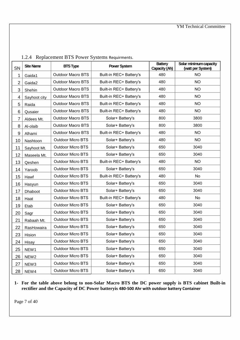
1.2.4 Replacement BTS Power Systems Requirments.
SN Site Name BTS Type Power System BatteryCapacity (Ah)
Solar minimum capacity(watt per System)
1 Gaida1 Outdoor Macro BTS Built-in REC+ Battery's 480 NO
2 Gaida2 Outdoor Macro BTS Built-in REC+ Battery's 480 NO
3 Shehin Outdoor Macro BTS Built-in REC+ Battery's 480 NO
4 Sayhoot city Outdoor Macro BTS Built-in REC+ Battery's 480 NO
5 Raida Outdoor Macro BTS Built-in REC+ Battery's 480 NO
6 Qusaier Outdoor Macro BTS Built-in REC+ Battery's 480 NO
7 Aldees Mt. Outdoor Macro BTS Solar+ Battery's 800 3800
8 Al-olaib Outdoor Macro BTS Solar+ Battery's 800 3800
9 Alhami Outdoor Macro BTS Built-in REC+ Battery's 480 NO
10 Nashtoon Outdoor Micro BTS Solar+ Battery's 480 NO
11 Sayhoot Mt. Outdoor Micro BTS Solar+ Battery's 650 3040
12 Maseela Mt. Outdoor Micro BTS Solar+ Battery's 650 3040
13 Qeshen Outdoor Micro BTS Built-in REC+ Battery's 480 NO
14 Yaroob Outdoor Micro BTS Solar+ Battery's 650 3040
15 Hawf Outdoor Micro BTS Built-in REC+ Battery's 480 No
16 Hasyun Outdoor Micro BTS Solar+ Battery's 650 3040
17 Dhaboot Outdoor Micro BTS Solar+ Battery's 650 3040
18 Haat Outdoor Micro BTS Built-in REC+ Battery's 480 No
19 Etab Outdoor Micro BTS Solar+ Battery's 650 3040
20 Sagr Outdoor Micro BTS Solar+ Battery's 650 3040
21 Rabaah Mt. Outdoor Micro BTS Solar+ Battery's 650 3040
22 RasHowaira Outdoor Micro BTS Solar+ Battery's 650 3040
23 Hision Outdoor Micro BTS Solar+ Battery's 650 3040
24 Hisay Outdoor Micro BTS Solar+ Battery's 650 3040
25 NEW1 Outdoor Micro BTS Solar+ Battery's 650 3040
26 NEW2 Outdoor Micro BTS Solar+ Battery's 650 3040
27 NEW3 Outdoor Micro BTS Solar+ Battery's 650 3040
28 NEW4 Outdoor Micro BTS Solar+ Battery's 650 3040
1- For the table above belong to non-Solar Macro BTS the DC power supply is BTS cabinet Built-inrectifier and the Capacity of DC Power batteryis 480-500 Ahr with outdoor battery Container
YM Technical Committee
Page 8 of 40
2- For the table above for non-Solar Micro BTS DC power supply is BTS cabinet Built-in rectifier andthe Capacity of DC Power battery per is 480-500 Ahr with outdoor bae r y Cont ai ner
3- For the table above belong to Solar System BTS the DCSolar Power System designed and compatiblewith same required BTS with capacity depend on the maximum power consumptions, not less than thevalue in above table and the Capacity of DC Power battery per solar micro outdoor BTS is 600- 690 Ahrand the Capacity of DC Power battery per solar macro outdoor BTS is 800-850 Ahr and both type withoutdoor battery Container
1.2.5 Replacement BTS-BSC Software Requirements.
1- The BTS Software compatible with current BSCs software and all BTS resources will joined to thecurrent BSC without any additional cost, which mean the resources license in BSC side will beincreased equivalent to required BTS resources licenses TRX and CE (if the vendor have some financialcondition should clarify and added in financial offer).
2- 1X 307Kbps function is mandatory enabled for all replacement BTS (if vendor have some financialcondition added in financial offer)
1.2.6 Training.See detail in training chapter.
1.3 General Requirements1.3.1 The vendor must identify and describe every equipment proposed, including hardware,software, installation materials, peripherals, installation services, configuration and tests, applications,integration with management systems, report customization, software licenses etc.
1.3.2 The vendor must also describe the resources for Operation, Maintenance, Supervision, Supportand Technical Assistance, as well as for Charging, Invoicing and Training. Supportshould be provided during the BSS installation. Such support must include the transfer of knowledgeto technicians and engineers .
1.3.3 The vendor must be responsible for the interconnection and integration issues.
1.3.4 The vendor shall attach user certificates (or site references) of at least 10 commercial BSSnetworks with a total capacity of 35 million subscribers or more, who are currently using thoseproposed equipment's, system and software. Details must include Operator (or service provider) name,country, date of installation, model of equipment, and type of service
1.3.5 The vendor will determine the software version of each BTS type where all BTS softwaremandatory compatible with current BSCs version for all vendors, which currently work in YEMENMOBILE.

YM Technical Committee
Page 9 of 40
1.3.6 BUILDING:1.3.6.1It should be possible to install any equipment on any floor/place. Floor lay out for equipment's(at actual site) and dimensioning of equipment shall be done by bidder in consultation with YEMENMOBILE.1.3.6.2 The Air Conditioning plant, standby Engine alternator, A.C. Power supply, and lights will be provided byYEMEN MOBILE.1.3.6.3The smoke detection/Fire alarm will be provided by bidder.1.3.6.4 The vendor shall inspect the site in advance, give layout plans and also indicate requirementsregarding Civil/Electrical works, well in advance, so that the user could provide these.
1.3.7 ENVIRONMENTAL CONDITIONS1.3.7.1 The vendor shall indicate the heat dissipation of the equipment for initial and ultimate equipped capacityof the and BTS. The Vendor shall clearly indicate any special environmental requirement, if any.1.3.7.2 vendor should be supply out of range environmental alarm sensor and extend it to control room.
1.3.8 DDF/FDFFor the equivalent quantity of offered E-1, the DDF equipment (Slim Rack Type) and associated itemsshall be provided. DDF equipment for both “TDM” side, and “network” side should be supplied for atleast 1.5 times the initial capacity.YEMEN MOBILE will arrange to terminate all trunks and junctions on the “TDM side”. The Vendor shallprovide all cabling from the BTS to the DDF. The Vendor shall supply the cabling required for jumpering E1’son the DDF.
1.3.9 DC powerThe D.C power supply shall be included in the offer with a capacity not less than 1.5 times of the consumptionfor BTS equipment.Rectifiers are required for Out Door BTS & must put the Rectifiers in the same cabinet with BTS(Built inRectifier) . i.e. 10 Rectifiers .
The Capacity of DC Power battery per non-Solar BTS is 480-500 Ahr with outdoor battery Container,the DC Solar Power System designed with same required BTS with capacity depend on the maximum powerconsumptions, the Capacity of DC Power battery per solar micro outdoor BTS is 600- 690 Ahr and the Capacityof DC Power battery per solar macro outdoor BTS is 800-850 Ahr and both type with outdoor battery ContainerThe duty cycles of batteries at least 1700 Cycles at 50% DOD.

YM Technical Committee
Page 10 of 40
Chapter -2Technical Specification of ProjectComponents

YM Technical Committee
Page 11 of 40
2. BTS Technical Requirements2.1 Generala. Frequency band (800 MHz) 824 – 849 MHz paired with 869 – 894 MHz,b. Channel centre frequencies As per TIA/EIA/IS-2000c. Channel Spacing 1.25 MHzd. TX-RX separation 10/45 MHzf. Air Interface TIA/EIA IS-2000g. Frame Structure As per TIA/EIA/IS-2000h. Duplexing method Frequency Division Duplexing (FDD)i. Voice Coding 8Kbps Enhanced variable rate vocoder (EVRC) , 8K QCELP & 13KQCELPj. Transmission bit rate As per TIA/EIA/IS - 2000k. Modulation scheme As per TIA/EIA/IS - 2000l. Demodulation scheme As per TIA/EIA/IS - 2000 m Forward compatibility 1x EVDO, (EVDO rA , rB)n. Local Oscillators Synthesized, frequency shall be settable in steps to achieve desired frequency.o. The proposed BTS system should offer a Power efficiency with not less than 33%p. The proposed BTS should support remote login from one BTS to another BTS or BSCq. The proposed BSS shall support inverse spectrum scanning which can quickly check the interference condition in the
network.r. The Abis interface of the proposed BTS must support the function of sharing transmission for 1X services traffic and
EVDO services traffic. in E1’s/FE interface in same resource . in the same time the QoS must be supported to assurethe quality of 1X voice service.
s. E1 Performance and E1 BER bit error rate and other performance of all BTS must be collected and reportedautomatically similar to BSC statistics hourly or daily as basic requirement without any additional license , feeor conditions .
t. Performance of call fail reasons (in TXT or CSV log files format ) of all BTS must be collected and reportedautomatically similar to BSC statistics daily or hourly as basic requirement without any additional license , feeor conditions.
u. The vendor shall provide single RAN: unified BTS supporting different modes,likeCDMA1X/EVDO/LTE (For every mode point vendor must mention what to change in hardware board and whichboard need software upgrade); unified BSC ,OMC and site solution, to reduce the operator cost and ensure investmentprotection for future.v. For indoor coverage, vendor must provide effective solution to solve pilot pollution and absorb indoor traffic.
2.2 BTS2.2.1 Basic Function1. MACRO OUTDOOR BTS upto 24TRX - one cabinet3. The outdoor MACRO BTS should be all-in-one design with built-in battery, aircondition or heat exchanger.
Please provide the photos of your MACRO OUTDOOR BTS.4. MICRO OUTDOOR BTS– All-in-one design, needs to support 3Sector, up to (12) TRX in onecabinet5. Optical RF unit, Minimum cascading distance shall be 70 km, this function important when need to connect
RF unit from other RF unit and the distance between them 70 km or more.6. The BTS’s output power per sector at antenna port must be more than 60W or above7. The nominal transmit power MICRO OUTDOOR BTS must be at least 20W~80W (per

YM Technical Committee
Page 12 of 40
carrier) and The nominal transmit power of MACRO OUTDOOR BTS must be at least 20W~100W (per carrier)without any additional license ,fee or conditions.
8. The vendor should provide detailed description of the series BTS products, including the specification(TRX, Erl per sector/carrier, etc.) and expansion capability.
9. Multiple Frequency Bands (such as 1900MHz/800MHz, 450MHz/800MHz) must be supported in one RFModule. describe their implementation.
10. The number of E1 ports at Abis interface with load sharing function should no less than 8 E1s (per board)11. The remote switch off,RF cards temperature control, VSWR alarms, and RSSI
measurements,anddiversty signal alarm must be supported12. The MACRO OUTDOOR BTS&MICRO OUTDOOR BTSCan be switch on easly(by battery ) with out AC
power input.13. The proposed BTS should support multi-carrier & multi-mode and capable of serving CDMA & LTE or GSM in single
cabinet .14. For the IP BSS evolution ability consideration ,the vendor should support IP Clock solution to reduce
GPS number and provide clock resource for failure of GPS15. The vendor should support MICRO OUTDOOR BTSwhich can support 1X and DO at the same time in
one cabinet. & provide the necessary documents.16. For the IP BSS evolution ability consideration , the proposed BTS shall support E1 and FE transmission
at same time and the FE interface should be ready now.
2.2.2 Specifications of Transmitter and ReceiverI. Basic Requirements:The output power at the top of the cabinet for each carrier (and in multi-carrier case too) must be changeablerange according to Yemenmobile configuration demands in range of 1 W ~ 100W.The output power from the port of power amplifier for each carrier also for each carrier must be changeablerange according to Yemenmobile configuration demands in range of 1 W ~ 100W.Expansion through adding extra carriers on the existing multi-carrier module and using the existing PowerAmplifier must not cause power output decreasing for the existing carriers, and the coverage must notdecrease.The RF Module must be has two RF sample port, one port for transmitter measurement & one port for receivermeasurement.For MACRO OUTDOOR BTS one RF Module must be support 100W output at leastFor MICRO OUTDOOR BTSone RRU Module must be support 80W output at least.MACRO OUTDOOR BTS&MICRO OUTDOOR BTSmust be support the total output power measurement forRFU Module by using PC measure and power meter measure for single or multi carrier .MACRO OUTDOOR BTS&MICRO OUTDOOR BTSmust be support 1XRTT also Multi-Frequency Bands mustbe supported in one BTS.Please describe their implementation.II. Transmitter:a. Nominal Transmit Power per sector per carrier As per TIA/EIA/IS – 2000b. Tx Power Limits As per TIA/EIA/IS – 2000c. Transmitter Frequency Accuracy As per TIA/EIA/IS – 2000d. Channel Allocation in full band of operation. As per TIA/EIA/IS – 2000e. Spurious emission at Antenna port As per TIA/EIA/IS – 2000f. Protection Transmitter shall be protected against infinite VSWR. III. Receiver:a. Receiver sensitivity (at 1% FER) better than –126dBm

YM Technical Committee
Page 13 of 40
b. Channel de-sensitization or Single As per TIA/EIA/IS – 2000, tone desensitizationc. Inter modulation spurious response As per TIA/EIA/IS – 2000d. Conducted Spurious Emission As per TIA/EIA/IS – 2000e. Receiver Interference performance As per TIA/EIA/IS – 2000 and IS97D2.2.3 Evolution Capability• The proposed BTS must be able to operate within ONE-SINGLE cabinet in thefollowing modes:CDMA2000 1X modeCDMA2000 DOrA /DOrB modeCDMA2000 1X/DOrA/DOrB hybrid modeCDMA / GSMCDMA /LTE GSMLTELTE (For every mode point vendor must mention what to change in hardware board and which board needsoftware upgrade)• The base stations proposed should adopt broadband platform and digital transceiver technology to provide
better performance and smooth evolution to 1xEV-DO RevA/1x EV-DO RevB , GSM , LTE(For every mode point vendor must mention what to change in hardware board and which board need softwareupgrade). And also for (CDMA & LTE or GSM) during launch two deferent system network in the same time (Thevendor must provide detailed description For every mode point vendor must mention what to change in hardwareboard and which board need software upgrade.
• BTS transceiver should satisfy the requirements of “C0032 RecommendedMinimum Performance Standards for cdma2000 High Rate Packet Data Access Network” to guarantee thesmooth evolution to 1xEV-DO RevA/ 1xEV-DO RevB and also for (LTE, GSM) (The vendor must providedetailed description For every mode point vendor must mention what to change in hardware board and whichboard need software upgrade..2.2.4 Interfaces• BTS must be connected to BSC through E1/T1/FE interface at the Abis reference point.• IMA (Inverse Multiplex ATM) shall be supported to guaranty Abis transmission in using multiple E1s when
part of E1 is broken.• MLPPP( Multi-link point to point protocol )shall be supported to guaranty Abis transmission in using multiple
E1s when part of E1 is broken• The proposed BTS system must be capable to support satellite transmission mode. The satellite
transmission mode should supports the voice, data, fax, DO services and the performance that the delay oftwo hops should less than 700ms. In addition, vendors should provide at least six user reports.• BTS 1x and EVDO service mut be share the same transmission E1 to connect BTS- BSC throughE1/T1/FE interface .
2.2.5 PerformancePerformance and call fail reasons and hardware log files (in TXT or CSV log files format ) of all BTS must becollected and reported automatically similar to BSC statistics.Performance of E1 BER and other performance of all BTS must be collected and reported automatically similarto BSC statistics hourly or daily.

YM Technical Committee
Page 14 of 40
Chapter -3Important Requirements

YM Technical Committee
Page 15 of 40
3.1 Global Evolution PlatformThe Network shall be on a global platform that supports evolution through all defined phases of CDMA2000 (1X,1xEV-DOrA, 1xEV-DOrB , GSM , LTE ). Also, the Radio Access Network must offer highly scalable, high-capacity product design that supports highspeed 3G data and increased voice capacity.The Vendor is required to propose shared platforms across CDMA2000 nodes for switching, radio access, IPservices and applications results in reduced operations and maintenance expenses due to fewer spares.
3.2 Multi-vendor SupportStandard compliant & Multi-vendor Support: System shall be based on CDMA 2000 1x Standard and otherstandards mentioned in Standards Requirements. IOT test report with current vendor NSS system (VendorATCA C9) on A interfaces (A1/A2, A3/A7,A10/A11,A12,A13,A16,A1p/A2p,A5), C/D interfaces shall beprovided.
3.3 General Function Requirements3.3.1 Mobility functions.It must be possible to restrict the services of the subscriber within the sector, within the BTS, within a Groupof BTSs, within BSC area and within a group of BSCs/MSCs in a area.3.3.2 Handoff functionsThe action of switching a call in progress i.e. hand-off from one sector to another sector of same or adjacentBTS of same or different BSCs shall be automatic and smooth without the user noticing it. Continuous controlof call quality shall be maintained automatically to get the optimum transmission quality. System shall supporthard handoff, soft handoff, softer handoff and inter-BSC handoff with Inter-MSC handoff in future The systemsupport Access Handoff, which can improve the performance of CDMA system and increase connectionsuccess ratio3.3.3 Quick Paging ChannelThe system shall support Quick Paging Channel as defined by IS –2000 standards to reduce “Wake –up”time required by mobile/FWT terminals.3.3.4 Power ControlThe system shall support power control between Mobile/FWT Terminal and BTS automatically to get theoptimum transmission quality. It shall support the following power control capabilities specified in IS-2000• Enhanced Reverse Link Open Loop Power Control• Reverse Link Closed Loop Power Control, Inner Loop and Outer Loop• Forward Link Open Loop Power Control• Forward Link Closed Loop Power ControlAll modes of forward Power Control as defined in the standards shall be supported.Reverse Link Power Control step size shall be configurable by the base station and the Precise shall be0.25dB. Fast access solution should be provided with detailed description.3.3.5 Radio Resource ManagementThe system must support the following:1. Call admission control algorithm that would permit dynamic allocation of system resources betweenvoice and data users. It shall also be possible to pre-set desired thresholds for resource-allocation in terms ofresources to be used by voice and data applications.

YM Technical Committee
Page 16 of 40
2. Radio Congestion control algorithm that would monitor the availability of resources and takecorrective action when a transition from the normal state to the congested state is detected, to avoid driftinginto the overload state.3. Support anti-interference technologies that assumed to improve the voice quality and increase thesystem capacity and decrease the power consumption of terminal. Please provide description4- The system(hardware or software) must support applying the maximal power implementation of radioequipment RRU with existing carrier license (even one carrier per RRU unit) without any additional license orconditions.5- the load balance between carriers in the same sector must be controlled by power or by number ofsubscribers.3.3.6 Deployment FlexibilityDeployment flexibility of Radio Base Stations is an essential factor and should be easily mountable indifferent environments, including poles, outdoors and indoors.3.3.7 Call ReleaseEither Party release must be acceptable.
3.4 SecurityThe system shall provide confidentiality, subscriber authentication features and high security. Latest digitalencryption technologies to support secure communications for message and voice privacy shall be provided.
3.5 Wireless Public PhoneThe system shall support Wireless Public Phone.• Vendor shall provide details about all supported mechanism for complete Wireless Public Phonesolution on prepaid basis.• The system should be capable of displaying real time metering to the subscriber. • Bidder shallpropose the type of customer premises equipment required for this purpose.• Vendor shall describe how an ordinary FWT could be used for Wireless Public Phone purposes.• Vendor shall describe how real time metering shall be performed for wireless Public Phoneservice in multi-vendor environment.
3.6 Diagnostic/TestingThe equipment shall support diagnostic capabilities (which will run as background tasks) to verify theequipment's proper operation within the network and self-adaptive network parameter adjustment accordingto the system’s running status. Built -in test capabilities shall be provided which will run at specific events oron demand. Health monitoring signals shall be continuously passed between the various modules to ensurethe detection of any failure in a module. Individual channel element functionality shall be also be monitored toprevent call blocking due to a lack of channel element resources. Markov call testing shall be supported toverify local coverage and channel element Frame Error Rates (FER)
3.7 Quality of ServiceThe quality of service shall conform to the following quality standards:a. Speech Quality - As per 3GPP2 standard C. S0012-0 (TIA/EIA/IS 125 A)(Recommended Minimum Performance Standard for Digital Cellular WidebandSpectrum Speech Service Option 1) b. Speech Delay - As per ITU-T Rec G.173.c. Free from Echo - As per ITU-T G.165.d. Voice Band Data Requirements • DTMF Signaling as per
ITU-T Rec. G.174• Data as per TIA/EIA/IS-707-A(Data Service Options for Spread SpectrumSystem)

YM Technical Committee
Page 17 of 40
• Connection Performance as per ITU-T Res. E.770• Reliability Performance as per ITU-T Rec. E.800
3.8 ExpansionExpansion techniques of the system shall be easy, economical and must not interrupt a workingsystem. Expansion shall be required when the number of subscribers (capacity) in the area isincreased, the GOS deteriorates or when the geographical coverage is increased.The equipment shall be modular in construction permitting expansion, without any major hardwarechanges by simply adding shelves and modules.3.9 EvolutionThe 1XEV-DO shall be smoothly upgraded from existing CDMA 2000 1x platforms with the minimuminvestment possible at all components of the system. Also specify what would be require when upgrading to1XEV-DOrB.
3.10 Reliability Requirements3.10.1 RedundancyThe power supply of main equipments as well as the control equipments shall be provided 1 + 1 hot standby/N + 1 mode redundancy, in case of all equipment such as BTS, BSC and MSC based Core Network. Theequipment Vendor shall indicate any other redundancy provided.3.10.2 MTBFVENDOR shall provide the description of Mean Time between Failure (MTBF) analysis report for BTS.The MTBF and MTTR (predicted and observed values) figures shall be at least as the following figures.• Base Transceiver Station:MTBF (hours) 100,0003.11 Markingsa. The plug-in units -whose removal or insertion (while the equipment is in operation) might endanger the
reliability or performance of the equipment -shall have suitable protection and caution marking.b. Each sub-assembly shall be clearly marked to show its functions and circuit reference so that its
complete description can be located in the handbook.c. The components shall be marked with their schematic references so that they are identifiable from the
component layout diagram in the handbook.d. All controls, switches, indicators etc. shall be clearly marked to show their circuit designations and
functions.e. Each terminal block and terminal shall be marked with an identifying code.
3.12 Softwarei. The vendor should have attained CMM /CMMI(Capability Maturity Model) certificate at least theCMM Level-4. (The CMM is a model that evaluates the process maturity of software development. Itis an assessment method that was developed by the Software Engineering Institute of Carnegie-Mellon University in 1991 as requested by the U.S. government. The CMM certificate is the world'smost recognized standard certificate.) ii. Software commands shall be user friendly menu- driven.The software shall be modular in architecture. Complete software for the system operation andmaintenance including Operation & Maintenance Centre (OMC) shall be provided. The architectureof the software shall be open so that the growth can be handled in practice without any need ofredesign of the software. The software supporting documentation shall be in English. iii. Theequipment Vendor shall undertake to supply on continuing basis all software updates. Theseupdates shall include new features and services and other maintenance updates. The software up -

YM Technical Committee
Page 18 of 40
gradation shall be possible with minimum interruption to the service. iv. The systemhardware/software shall not pose any problem due to changes in date and time caused by eventssuch as changeover of millennium/ century, leap year etc, in the normal functioning of the system.v- In case of BSC mode license or module mode license the system(hardware or software) must use essentiallythe maximal resource pool for hardware resource capacity of Channel element Boards with any BTS carrierconfiguration (with any carrier number in the base station) without any restriction or any additional license,fee orconditions.
3.13 Documentation3.13.1 General RequirementsThis describes the general requirements to be met by documentation to be provided by the equipmentVendor. Hard & Soft copy of all documents shall be provided in English. The documents shall comprise of:iSystem description documents ii System operating documents including system repair document.3.13.2 System Description DocumentsThe following system description documents shall be supplied along with the system:• Overall system specification and description of hardware and software.• Installation manuals, testing procedures and commissioning forms with specified levels. Installation
manuals to be provided that contain step-by-step process of installation of system. • Equipment layoutdrawings
• Schematic drawings of all circuits in the system with timing and level diagrams wherever necessary.• Spare parts catalog including information on individual component values, tolerances etc. Enabling
procurement from alternate sources.• Detailed description of software describing the principles, functions, interactions with hardware, structure
of the program and data.3.13.3 System Operation DocumentsThe equipment Vendor shall provide the following system operational documents: - • Operating manualof the system• Maintenance manual.• Man-machine language manual.• Faulty location and trouble shooting instructions including fault dictionary.• Test procedures with auxiliary test equipments.• Emergency action procedures and online alarm dictionary.
3.14 Quality StandardsThe equipment shall be manufactured in accordance with the International Quality Standard ISO-9002 forwhich the manufacturer shall be duly accredited. Alternatively the product design/manufacture shall conformto the international/national quality standards. A quality manual describing the quality of the system to befollowed during bulk manufacturing of the product would be required to be submitted by the manufacturer.The quality plan describing the quality assurance system followed by the manufacturer shall be submitted
YM Technical Committee
Page 19 of 40
Chapter -4Operational Requirements

YM Technical Committee
Page 20 of 40
4.1 SupervisionSupervision of complete network, including BSC, BTS, MSC and HLR shall be both automatic and YEMENMOBILE controlled and centralized at OMC/NMC, which supports remote operation. All entire man/machineoperation terminals should support MML&GUI interface for YEMEN MOBILE operators.The hosting of commands must not be less than two months.
4.2 Alarm IndicationsIn case of all major alarms both audio and visual alarm indications shall be provided .In case of minor alarms,visual indications shall be provided and provision of audio alarms is desirable. It shall be possible to definethe major and minor alarm conditions and set the threshold by faulty operations to either a pager, a shortmessage service system, an electronic mail or additional alarm windows in the OMC interface. It shall alsobe possible to extend the alarms at the BTS as well as external alarms to the BSC. Centralized alarmterminal for alarm management should be provided. Both visual and audible alarms to be extendible toexternal lights (visual) and speakers (audible). In case of alarms, there should be facility to switch of BTSremotely from BSC.All BTS cards alarms must be transfer in real-time to BSC OMC side all kinds of cards even channel cardsPower Solar System alarms mandatory transfer and be shown in OMC system. .
4.3 SynchronizationAt certain locations, it may be necessary to co-locate a number of BTSs. In such cases, the BTSs shall besynchronized so that all the traffic channels are accessible by all the subscribers served by these BTSs. TheCDMA 1X2000 would be synchronized with YEMEN MOBILE network ..BTS should support GPS/GLONASS dual-satellite system synchronization mode, providing twosynchronization solutions (GPS or GPS/GLONASS) as required by the operator. In GPS/GLONASS dual-satellite synchronization, the whole network can operate normally without any adverse effect when GPS orGLONASS system is not available.BTS should provide other system external synchronization interface, whenGPS/GLONASS is not available, it makes the system clock synchronized with external clock.Vendor should provide detailed description of the system radio synchronization solutions, including allexternal synchronization interfaces which the system can support. Redundancy of links between BTS-BSCand GPS receiver (along with other fixtures) if required, shall be indicated by the vendor at the time oftendering.The system should support the man-machine command to check the locked-satellite status for convenienceof trouble shooting. The check functionality should include the following:1) Whether the clock signals of a base station are correct.2) Whether the clock module and GPS or GLONASS antenna are well connected.3) Whether the captured GPS or GLONASS satellites are more than 4.• Internal Clock• Recovered Clock from any incoming 2048 Kbps signal.In case of failure of recovered clock, the equipment shall support "Hold Over Mode ", the stability of whichshall be equal to or better than 1×10E-8 for at least 24 hours.
4.4 Maintenance Aspects1. In case of testing traffic load, BTS channel load simulation function must be supported.2. Maintenance philosophy is to replace faulty units after quick analysis of monitoring and alarm indications.
Actual repair will be undertaken at a repair centre.

YM Technical Committee
Page 21 of 40
3. Procedure for repair of equipment giving full details of testing instruments must be provided by theequipment Vendor. Test jigs, fixtures required for maintenance/repair shall also be provided. The Vendorshall ensure the repair of faulty equipment during and after warranty period.
4. The equipment must have easy access for servicing and maintenance.5. All important switches/controls on front panel shall be provided with suitable safeguards such as interlock
system to avoid accidental operation by the maintenance personnel.6. Extensive facilities for testing, supervision and monitoring functions msut be provided for quick isolation
and rectification of faults. These functions must be performed by Operations and Maintenance Centre(OMC). Any additional instruments required shall be provided by the equipment Vendor with details. Thecapabilities such as alarm reporting, automatic operation test and on-hook test of subscriber line isdesirable. The number of subscribers which can be tested simultaneously may be indicated.
7. There must be facility in the BTS for send the alarm to BSC in case of high VSWR.
4.5 DimensionsMacro outdoor Maximum height of BTS rack shall be restricted to 1800-2000mm. range of dimensionDimensions/Weight – Actual Dimension and weight of each of the equipment shall be Indicated by theequipment Vendor.Micro outdoor Maximum height of BTS rack shall be restricted to 600-700mm. range of dimensionDimensions/Weight – Actual Dimension and weight of each of the equipment shall be Indicated by theequipment Vendor.
4.6 Power SupplyThe power supply unit shall form an integral part of the equipment and must have protection against outputover voltage, short circuit, input reverse polarity protection &must have visual indication for output undervoltage.Outdoor BTSInput supply(110V and 220V) +/- 20%; Nominal 240 V AC 50/60 Hz And support working in DCvoltage only.4.7 Power ConsumptionThe equipment shall have low power consumption. Equipment Vendor shall specify the power requirement ofthe BTS for various configurations e.g.1 Cell 3 Sector (1C 3S), 2C 3S, 3C 3S, 4C 3S, in order to engineersuitable and optimum power infra- structure. The power system.
4.8 Cooling ArrangementThe equipment must have necessary self-cooling arrangement with or without in -built fan. The equipmentVendor shall specify the recommended life of the fan when used.
4.9 Antenna Tpye/ModelModel XPol Panel 790–960 85' 16.5dBi 0–10T\ 80010300V02
4.10 Feeder CableType of feeder cable will be is low lose foam 7\8" copper dielectric 800 MHZ and the length of the cablewhichdetermine by the Yemen Mobile . Detailed specifications (technical as well as mechanical) shall befurnished by equipment Vendor.A 7/8" Feeder cable is used for base station, which includes wireless mobile communication, cellular, microwaveand broadcast applications.The Vendor should introduce ISO 9001 & ISO 14001 Quality Certifications from manufacturer of feeders.

YM Technical Committee
Page 22 of 40
4.10 Outdoor EquipmentAll outdoor equipment must be housed in robust, compact lightweight weatherproof cabinets suitable formounting on telephone pole/tower/wall. Suitable lighting protection must be provided at the antenna ports.The cabinets shall have a locking facility with a single master key for opening it.
4.11 Lightning ProtectionThe equipment including Antenna & feeder shall have adequate protection against lightning& power surges.All equipment except for Handheld subscriber terminal shall have provision for grounding.4.12 Environmental Specifications(a) Base Transceiver Station: 1. Outdoor macroCell Temperature:-40°C ~ 55°CRelative humidity5% ~ 100%2. Micro Cell (indoor/outdoor): Temperature:-40°C ~ 55°CRelative humidity5% ~ 100%
4.13 Interference to Existing Wireless NetworksThe system must not cause any interference to the existing wireless networks (GSM,CDMA or any other wireless system)

YM Technical Committee
Page 23 of 40
CHAPTER-5INSPECTION, TEST, INSTALLATION
&COMMISSIONING

YM Technical Committee
Page 24 of 40
5.1. TESTS AND MEASUREMENTS5.1.1 TEST CATEGORIESi) The following tests shall be conducted for acceptance of the equipment and the system beforefinal acceptance of the system. The testprocedure must be discussed between the vendor and YEMENMOBILE during installation and testing.A1 ,A2 , A3 , A4 & A5Pre-Factory Acceptance Testing Factory AcceptanceTesting (FAT)Pre-commissioning test (after installation) for total integrated system. Site Acceptance Testing(SAT) Trial Run
ii) These tests shall be carried out on all equipment supplied by Vendor including those suppliedby sub-vendors, if any.
iii) Vendor shall arrange all necessary test instruments, manpower, test-gear, accessories etc.
iv) All technical personnel assigned by Vendor shall be fully conversant with the systemspecifications and requirements. They shall have the specific capability to make the system operativequickly and efficiently and shall not interfere or be interfered by other concurrent testing, constructionand commissioning activities in progress. They shall also have the capability to incorporate anydifferent from the specifications or reseasonable minor modifications/suggestions put forward byPurchaser/Engineer.
v) The Vendor shall arrange Necessary temporary commissioning facility includingcommunication system required for installation/testing/commissioning of the telecommunicationequipment.
vi) Test Plan: The Vendor shall discussed with Yemenmobile ‘Test Plans’ well in advance ofcommencement of actual testing in each of the above mentioned test categories. The plans shallinclude:0) System/Equipment functional and performance description (in short)and Tests to be conducted and purpose of test.1) Test procedures (including time schedule for the tests) andidentification of test inputs details and desired test results2) Test Report:
The observations and test results obtained during various tests conducted shall be compiled anddocumented to produce Test Reports by Vendor. The Test Reports must be given for eachi) Test resultsii) Comparison of test results and anticipated (as per specifications) testresult as given in test plans and reasons for deviations, if any.iii) The data furnished shall prove convincingly that a. The system meetsthe Guaranteed Performance objectivesMechanical and Electrical limits were not exceeded.

YM Technical Committee
Page 25 of 40
Failure profile of the equipment during the tests are well within the specifiedlimitsv) The observations and test results obtained during various tests conducted
shall be compiled and documented to produce Test Reports by Vendor. TheTest Reports must be given for each equipment/item and system as a whole. Thereport shall contain the following information to a minimum:
vi) Failure of Components:Till the system is accepted by the Purchaser, a log of each and every failure of components shall bemaintained. It shall give the date and time of failure, description of failed component, circuit, module,component designation, effect of failure of component on the system/equipment, cause of failure, dateand time of repair, mean time to repair etc. Repair/modification done at any point of time at one site,shall be carried out by Vendor at all thesites. Detailed documentation for the same shall be submitted to Purchaser for future reference.If the malfunction and/or failures of a unit/module/sub-system/equipment repeat during the test, the testshall be terminated and Vendor shall replace the necessary component or module to correct thedeficiency. Thereafter, the tests shall commence all over again from the start.If after the replacement the equipment still fails to meet the specification, Vendor shall replace theequipment with a new one and tests shall begin all over again. If a unit/ subsystem/module hasfailed during the test, the test shall be suspended and restarted all over again only after the Vendorhas placed the Equipment back into acceptable operation. Purchaser’s approval shall be obtained forany allowable logical time required to replace the failed component/unit/module/sub-system.
vii) ReadjustmentsNo adjustments shall be made to any equipment during the acceptancetests. If satisfactory test results cannot be obtained unless readjustments are made, Vendorshall carry out only those readjustment needed to ready the equipment/system for continuanceof tests. A log of all such adjustments shall be kept giving date and time, equipment, module,circuit, adjustments, reasons, test result before and after adjustment etc. Fresh acceptancetests shall be conducted after the readjustments have been completed.
3 Pre Factory Acceptance TestingThe Vendor on his own exactly in line with FAT shall conduct prefactory acceptance testing and testreports for the same shall be forwarded to Purchaser/Engineer before start of FAT.
4 Factory Acceptance Testing (FAT)Factory acceptance tests shall be carried out after review and approval of FATprocedure/documents as per bid requirements and review of Pre- Factory acceptance results &shall be conducted at the manufacturing facilities from where the respective equipment/subsystemsare offered. The factory acceptance testing shall be conducted in the presence of thePurchaser/Engineer. The tests shall be carried out on all equipment/items including those suppliedby Sub-vendoRS and factory acceptance certificates shall be issued. The factory tests shall includebut not be limited to:
YM Technical Committee
Page 26 of 40
A) Equipment Testing :i) Mechanical checks to the equipment for dimensions, inner and outer supports,finishing, welds, hinges, terminal boards, connectors, cables, painting etc.ii) Electrical checks including internal wiring, external connections to otherequipment etc.iii) Check for assuring compliance with standards mentioned in the specifications.vii) Individual check on each/module/sub-assembly in accordance with the modesand diagnostics programs of the Vendor.viii) Checks on power consumption and heat dissipation characteristics of variousequipment vi) Environment testing and other laid down tests in Type Tests plan of thespecification of the equipment.Functional testing.Any other test not included in FAT document but relevant to the project as desiredby the Purchaser/Engineer at the time of factory acceptance testing.
B) System Integration TestingFunctional and performance test should be conducted for the complete system concerningand connecting the NLD equipment and all major equipment constituting the system(including the equipment supplied by sub-VENDORS, as applicable) simulating the completenetwork.The system shall include the total Network Management System. All the functions of NMS shall bedemonstrated in totality (as per requirements/specifications of this document).All equipment shall be connected using the same cables(interfaces/components) as will be used during final installation so that the system can be testedin its final configuration. This testing shall be conducted at the manufacturing facility of the BSSOEM.
5 InstallationAfter successful completion of factory acceptance testing, equipment shall besent to site for installation. Equipment without factory acceptance certificates shall not be acceptableat site.Prior to installation, all equipment shall be checked for completeness as per the specifications ofequipment required for a particular station. Installation shall be carried out in accordance with theinstallation manuals and approved installation drawings in the best workmanship. Vendor shallbring all installation tools, accessories, special tools, test gears, spares parts etc. at his own cost asrequired for the successful completion of the job. If during installation and commissioning anyrepairs are undertaken, the maintenance spares supplied with equipment shall not be used for therepair. Vendor shall arrange his own spare parts for such activities till such time the system hasbeen finally accepted by the Purchaser. A detailed report & log of all such repairs shall be madeavailable by the Vendor to Purchaser/Engineer and shall include cause of faults and repair details,within 2 weeks of fault occurrence. A detailed time schedule for these activities shall be submittedby Vendor toPurchaser/Engineer to enable their representatives to be associated with the job.
YM Technical Committee
Page 27 of 40
Vendor shall supply all installation materials required for proper installation of the equipment. Theseshall include but not be limited to, all connectors, interbay and inter equipment cables, power supplycables and connectors, power distribution boxes, anchoring bolts, nuts, screws, washers, audiodistribution frames, voice frequency cables, junction boxes etc. The installation of equipment shall bedone as to present neat and clean appearance in accordance with approved installation documentdrawings. All inter bay, power supply and other cables shall be routed through wall mounted cabletrays. No cable shall be visible. All through wall openings, trenches etc. shall be properly sealed toprevent the entry of rodents, insects and foreign materials.
6 Pre-Commissioning & Network IntegrationOn completion of installation of equipment, the correctness and completeness of the installation as perManufacturer’s manual and approved installation documents shall be checked by the Vendor on hisown.A list of Pre-Commissioning tests (same as approved by the Purchaser/Engineer for siteacceptance testing) and activities shall be prepared by Vendor and the test shall be carried out bythe Vendor on his own. After the tests have been conducted to the Vendor’s own satisfaction,the Vendor shall provide the test results for review by Purchaser/Engineer and then offer thesystem for Site Acceptance Testing.During pre-commissioning , if any fault occuRS to any equipment or system, Vendor shall identifythe same and provide report/history of all faults to the Purchaser.During installation and pre-commissioning of the telecom system, Vendor shall have enough numberof commissioning spares so that the installation is not held up because of non-availability ofcommissioning spares. Vendor shall ensure that the spares meant for operation and maintenance arenot used during installation , commissioning and Network integration.
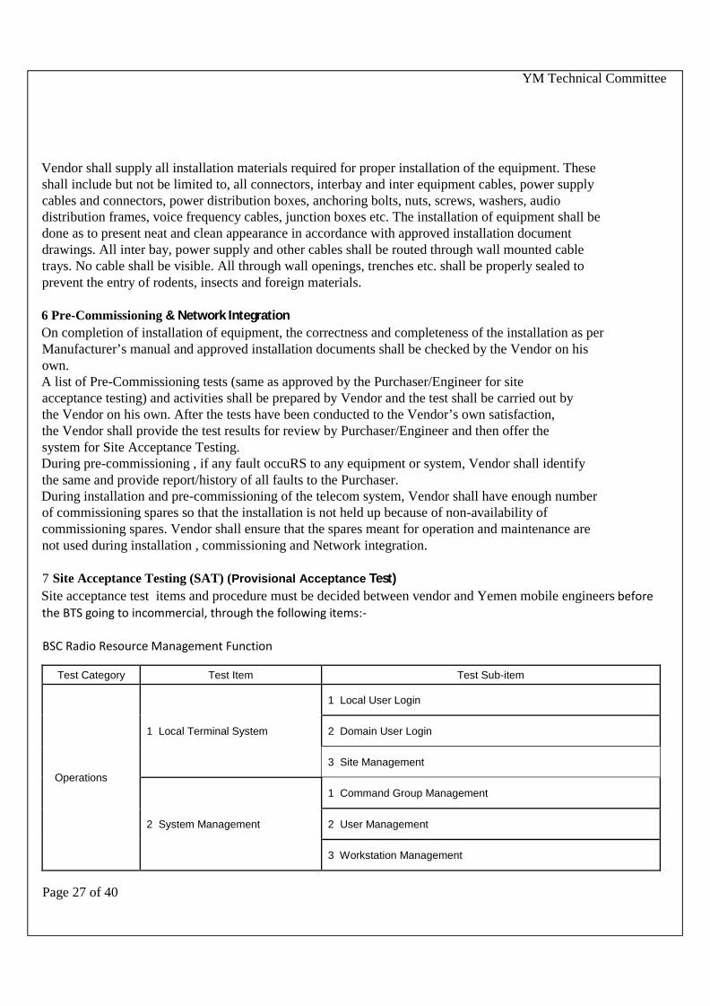
7 Site Acceptance Testing (SAT) (Provisional Acceptance Test)Site acceptance test items and procedure must be decided between vendor and Yemen mobile engineers beforethe BTS going to incommercial, through the following items:-
BSC Radio Resource Management Function
Test Category Test Item Test Sub-item
Operations
1 Local Terminal System
1 Local User Login
2 Domain User Login
3 Site Management
2 System Management
1 Command Group Management
2 User Management
3 Workstation Management

YM Technical Committee
Page 28 of 40
4 Command Log Management
5 Scheduled Task Management
6 Database Management
3 Alarm Management 1 Alarm Query
4 Performance Management 1 Traffic Measurement Through OMC Management system
5 Dynamic Configuration
1 Dynamic Modification of SID and NID
2 Dynamic Sector Addition/DeletionObjective
Verify that the cBSC66 product supports dynamically adding ordeleting a sector.
3 Dynamic Board Addition/Deletion
4 BTS Configuration
6 BTS Networking 1 Information Management for a BTS
7 BTS Configuration Management1 BTS Software Loading
2 BTS Parameter Configuration
8 BTS Maintenance andManagement
1 Equipment Management
2 Test Management
3 BTS Tracing
7 Link Troubleshooting 1 BSC-BTS Link Troubleshooting
8 System Test Function 1 Subscriber Interface Tracing Test
2 System Status Monitoring
Configuration ofIP Transmission
1 Configuration of IP-Based AbisInterface
1 Configuration of IP-Based Abis Interface Links in the E1-PPPMode
3 Configuration of IP-Based Abis Interface Links in the E1-MLPPPMode
SٍomeCDMA Key FPC_MODE FPC_MODE

YM Technical Committee
Page 29 of 40
AlgorithmProportional Allocation Between
Voice and Data ServicesProportional Allocation Between Voice and Data Services Based onWalsh Codes
Services Functions and Radio System Evolution (Radio Work) Items :-
RNP&OATP Items
This list defines RNP&OATP items suggestions for 1x & EVDO.
The procedures of test we will provide later.
The criteria depend on agreement between the YM and vendors
1X ATP items
Coverage KPI DT Acceptance Test (Network\Cluster Level)
• Voice quality / FER in case of voice calls (FER) and Call Drop Rate Test
• Pilot Scan Test Voice Coverage Testing
• Pilot Pollution Rate Acceptance Test
• Origination Failure Rate Test
• Termination Failure Rate Test
• Pilot Scan Test Voice Coverage Testing
• Cells Coverage Area rang Test
1X DATA DT KPI
• EC/IO max for supplemental channel
• Average user throughput
• Convergence of FCH and SCH FERs
Functionality 1X DT Testing (Cell Level)
• Mobile Originated Call Setup (MS in Idle State)
• Mobile Terminated Call Setup (MS in Idle State)
• Handoffs During a Voice Call
• Voice Call in FCH Softer Handoff
• Voice Call in FCH Soft Handoff (Intra-BSC / Inter-BSC)

YM Technical Committee
Page 30 of 40
• Voice Call in FCH Hard Handoff (intra BSC, inter BSC\Intra MSC\inter MSC)
• Single Cell Coverage rang Test
• Test Voice Originations in a Data Loaded Cell
• Data Coverage Testing
• Data Call in FCH Softer Handoff
• Data Call in FCH Soft Handoff (Intra-BSC / Inter-BSC)
• Data Call in FCH Hard Handoff
EVDO ATP items
Connection Setup
• PPP Session Setup Time
• Mobile IP Registration
• AT Initiated Connection Setup Time Handoffs
• DRC Re-pointing, Softer Handoff DRC re-pointing, Soft-Handoff (Default FTCMAC)
• DSC Switch / DRC Re-pointing, Soft Handoff (Enhanced FTCMAC)
• 1xEV-DO Revision A to Release 0 Personality Switch
• EVDO Rel 0 to Revision A personality switch
Radio Access Network
• Single User Packets
• Multi-User Packets
• Multi-User Packet NAKs
• Null-rate DRC mapping to DRC=1
• RAN Latency Test Release 0 (Physical Layer Subtype 0)
Reverse Link Test
• Steps to fix the reverse link packet size transmitted by the AT
• Reverse Link Packet Error Rate
• Reverse link data performance in softer handoff with full buffer traffic
• Reverse link data performance in soft handoff with full buffer traffic

YM Technical Committee
Page 31 of 40
Release 0 and Revision A Mixed AT’s
• 1xEV-DO AN Initiated Connection Setup..
• Voice Call Origination and Termination in Idle State
• Voice Call Origination and Termination in Dormant State
• Voice Call Origination and Termination in Connected State
System Coverage Tests
• SINR Distribution Test
• Receive and Transmit Power Distribution Test
• DRC Distribution Test
• Packet Error Rate Distribution Test
• Active Set Size Distribution Test
• AT Initiated Connection Setup Success Rate Test
• Connection Drop Distribution Test
• Packet Error Rate (Reverse Link)
• Imbalance Scenarios
Hybrid Mode – 1xEV-DO and 1x/IS-95
• Voice Call Origination and Termination in Idle State
• Voice Call Origination and Termination in Dormant State
• Voice Call Origination and Termination in Active Data Session
• SMS Origination and Termination in Idle State
• SMS Origination and Termination in Dormant State
• SMS Origination and Termination in Active Data Session
• cdma2000 to HRPD Dormant Data Session Handoff - Existing HRPD Session
• cdma2000 to HRPD Dormant Data Session Handoff - New HRPD Session
• HRPD to cdma2000 Dormant Packet Data Session Handoff
• Access Network support for Hybrid Mode Terminals
Network Management Systems

YM Technical Committee
Page 32 of 40
• Connection failures reporting/management
• Probe number reporting/management
• Configuration Management
• Performance Management
• Fault Management
• Overload Detection & Control
• Stability in Overload
• Session Keep Alive
Radio Equipment Test(BTS & Radio Test )
All minimum standard values depend on 3GPP standard)
Note: Please see 3GPP2 C.S0010-C v2.0 ( Recommended Minimum Performance Standards for cdma2000Spread Spectrum Base Stations)
Test Items
1. FREQUENCY COVERAGE
2 . FREQUENCY TOLERANCE
3 . PILOT TIME TOLERANCE
4 . PILOT CHANNEL TO CODE CHANNEL TIME TOLERENCE
5. PILOT CHANNEL TO CODE CHANNEL PHASE TOLERENCE
6. WAVEFORM QUALIT
7. TOTAL POWER
8. PILOT POWER
9. CODE DOMAIN POWER
10. CONDUCTED SPURIOUS EMISSIONS
11. OCCUPIED BANDWIDTH
12. RX GAIN BUDGET ( receiver sensitivity test for many values )
13. TX GAIN BUDGET (Transmitter Gain test for many values )

YM Technical Committee
Page 33 of 40
8 OPTIMIZATIONThe vendor will participate with YEMEN MOBILE engineer for all the following optimization works:
8.1Network BenchmarkingConduct tests timely after the project implementation is complete.Compare and analyze the test results.8.2System Parameter AuditAudit and check all system parameters, including cell parameters and network8.3Network Drive Test, Analysis, and TuningTest services and performance the network, tune the RF parameters of sites according to the test result,to get the network reach the launch requirement.8.4Optimization of Traffic Statistics KPIMonitor and analyze the traffic statistics data to find TOPN problems in the network. Analyze and solvethe TOPN problems. Check the network quality is promoted.8.5Coverage Performance OptimizationConduct drive tests to test the coverage and services, and make relevant adjustment to have thecoverage and services reach targets.8.6Care for VIP and Hotspot AreasMonitor the network quality at VIP areas by taking the following actions: analyzing the RF complaintsfrom VIP customers, monitoring the network quality of CBD areas by means of drive tests, dialingtests.8.7Radio Network KPI MonitoringMonitor and analyze the network at the implementing and ending stages of the RNO to guarantee therequired KPI of the network.8.8RF Trouble ShootingAnalyze and solve the RF problems that are detected in network monitoring process to improve thenetwork performance and promote satisfaction of end users.8.9Benchmark Drive TestConduct benchmark drive tests on the coverage performance.
9 SPARES9.1 MANDATORY SPARES20 % mandatory spares (for operation and maintenance) must be provided for all electronic Boards , sub-system,equipment, etc.Spares must be provided from the same manufacturing facilities/location from where the respectiveequipment, subsystems are offered. Unit rates for each spares required for operation and maintenanceshall be provided.Vendor must provide the address, contact person, fax, telephone no. of the manufacturer of the spare parts. TheVendor must warrant that spare part for the system would be available for minimum of 10 years after systemcommissioning (taking over). After this period if the Vendor discontinues the production of the spare parts, thenhe must give at least 6 months notice prior to such discontinuation so that Purchaser may order the requirementsof spares in one lot.The list of the required spares being supplied with unit cost and total cost should be attached along with the bid.9.2 Commissioning spares

YM Technical Committee
Page 34 of 40
The commissioning spare must be decided between the Vendor to bring the requirement during installation,commissioning, site acceptance testing, trial run and warrantee period. These spares shall be readily available with theVendor. These commissioning spares are different from mandatory spares andVendor must not use mandatoryspares as commissioning spares.

YM Technical Committee
Page 35 of 40
CHAPTER-6TRAINING AND DESIGN GUIDELINES

YM Technical Committee
Page 36 of 40
1.TRAININGVendor must train 13 Engineers Trainees of engineer in all aspects of Telecommunication system.There must be at least three training course;1- The first course must be conducted for BSS system,This course for 5 BSS engineers.2- The second course must be conducted for YEMEN MOBILE Network Engineering, This course for 5 RF
engineers.3- The third course must be conducted for YEMEN MOBILE POWER System This course for 3 Power
engineers.
Vendor’s offer excludes costs of transportation, lodging and boarding of the trainees which shallbe arranged by the Purchaser. Vendors offer is on man-week basis.
Vendor shall specify in his offer the types of courses he intends to impart, including but notlimited to, the ones aforementioned.
Vendor shall provide comprehensive documentation, course material, manuals, literature etc.as required for proper training of personnel at his own cost. Consolidated and comprehensivedocumentation shall be available to each participant. After the completion of course, all suchmaterials shall become the property of the PURCHASER. Vendor shall update the coursematerial of manuals in case there are any changes owing to revision/modifications inequipment/system specifications.

YM Technical Committee
Page 37 of 40
CHAPTER-7MISCELLANEOUS ITEMS

YM Technical Committee
Page 38 of 40
7.1 ACCESSORIES/ OTHER ASSOCIATED ITEMSThe Vendor shall be responsible for1. Procurement, supply and installation of equipment racks, all patch cords, DDF and allother items not indicated here but required for completion of the system.2. Supply and installation of necessary equipment, cables and accessories to meet thesystem requirements .3. Carrying out factory acceptance tests of the BTS equipment as per the approvedspecifications and procedures at the respective manufacturers works in the presence ofPurchaser/Engineer’s representatives.4. Training of Purchaser/Engineer’s personnel at manufacturer’s works for each individualsystem and at site.5. Provide suitable power distribution box and complete wiring from the distribution boxto the respective telecom equipment at each telecom station as per specifications.

YM Technical Committee
Page 39 of 40
Annex 1The Key Items for Evaluation of MACRO OUTDOOR BTS&MICRO OUTDOOR BTS
S Item Compliance Remarks
1 BTS1.1 All Project Componentsand items in tables (1.2.1, 1.2.2, 1.2.3, 1.2.4, 1.2.5, 1.2.6)
(should be approved in the tender quotation)
1.2 The capacity of MACRO OUTDOOR BTS is at least 24 TRX in One SingleCabinet& The capacity of MICRO OUTDOOR BTSis at least 12 TRX in one singlecabinet. Multi carrier added by s/w commands and assigned any amount ofpower by commands per carrier.
1.3 The proposed BTS system should offer a Power efficiency with not less than 40%1.4 The proposed BTS must support remote login from one
BTS to another BTS or fromBSC and OMC terminal
1.5 The proposed BTS must basically monitor inversespectrum scanning which can quickly check the interference condition inthe network
1.6 The Abis interface of the proposed BTS must essentially implement the function oftransmission sharing of 1X carrier traffic and EVDO carriers traffic together in thesame E1’s/FE (1 E1 or more E1”s) interface in unified unit . QoSmust be supportedto assure the quality of 1X voice service.
1.7 The Abis interface of the proposed BTS must has the function of automaticadapting Bandwidth management, fault detection and recovery
1.8 Performance and call fail reasons according IMSI and ESN and …. (in TXT or CSVlog files format ) of all BTS must be collected and reported automatically similar toBSC statistics daily or hourly.
1.9 The proposed BTS must be able to operate within ONESINGLE cabinet in thefollowing modes:CDMA2000 1X modeCDMA2000 DOrA /DOrB modeCDMA2000 1X/DOrA/DOrB hybrid modeCDMA / GSMCDMA /LTEGSMLTEFor each point what to change in hardware board and which board need software upgrade
1.10 VSWR alarms , RSSI measurements, transmitting power must be Supported local& remote.
1.11 The proposed outdoor BTS power supply could be 48VDC/110VAC/220VAC/ solarsystem.

YM Technical Committee
Page 40 of 40
1.12 In case of BTS mode license or BSC module mode license:- the system(hardware andsoftware) must essentially use the maximal hardware resource capacity of CEBoards. All BTS CE boards work as unique resource pool (from one channel boardand adding more cards to the pool only after resource congestion not for necessity ofadding new carrier configuration at all) with any BTS carrier configuration (with anycarrier number in the base station for ex. S999) without any restriction or anyadditional license,fee or conditions.
1.13 The system(hardware or software) must essentially applying the maximal powerimplementation of radio equipment RF with existing carrier license (even one carrierper RF unit for ex. 100W/one sector/carrier) without any additional license , fee orconditions
1.14 E1 Performance daily and hourly and E1 BER bit error rate and other performance ofall BTS must be collected and reported automatically similar to BSC statistics hourly ordaily.
1.15 BTS 1x and EVDO services must be essentially share the same transmission E1 toconnect BTS- BSC through E1/T1/FE interface .
1.15 All BTS Boards essentially must transfer in real time the alarm when any RF cards(for ex. High power amplifier cards) or CSM chip or Channel element damaged or theirtemperature becomes more than set threshold in OMC side or their performance havedecreased than normal state to OMC client without any restriction or any additionallicense,fee or conditions.
1.16 Antenna model XPol Panel 790–960 85° 16.5dBi 0°–10°T\ 80010300V02Type of feeder cable will be is low lose foam 7\8" copper dielectric 800 MHZ and thelength of the cable which determine by the Yemen Mobile .The Vendor should introduce ISO 9001 & ISO 14001 Quality Certifications frommanufacturer of feeders.
1.17 RF cards temperature control Available
1.18 Expansion through adding extra carriers on the existing multi-carrier module and usingthe existing Power Amplifier must not cause poweroutput decreasing for the existing carriers, and the coverage shall notdecrease.The RF Module must be has two RF sample port, one port for transmitter measurement& one port for receiver measurement.For MACRO OUTDOOR BTS one RF Module must be support 100W output at leastFor MICRO OUTDOOR BTS one RF Module must be support 80W output at least.MACRO OUTDOOR BTS & MICRO OUTDOOR BTS must be support the total outputpower test.power measurement for RF Module by using PC measure and power meter measurefor single or multi carrier .MACRO OUTDOOR BTS & MICRO OUTDOOR BTS must be support 1XRTT. IfMultiple Frequency Bands must be supported in one BTS.
1.19 the load balance between carriers in the same sector must be controlled by power orby number of subscribers.
1.20 The proposed outdoor MACRO BTS & MICRO OUTDOOR BTS When thetemperature reach to the threshold, there is a temperature alarm and (RF unit ) stopwork automatically.The proposed MACRO OUTDOOR BTS & MICRO OUTDOOR BTS must be )
supports (ATM over E1/T1) and supports (IP over E1/T1) and (FE) for Abis interface.
Copyright © 2022 FDOKUMEN